
The Development of a Virtual Myoelectric Prosthesis Controlled by an EMG Pattern Recognition System...
15
P1: XXX Journal of Intelligent Information Systems KL2031-05 May 24, 2003 21:52 UNCORRECTED PROOF Journal of Intelligent Information Systems, 21:2, 127–141, 2003 c 2003 Kluwer Academic Publishers. Manufactured in The Netherlands. The Development of a Virtual Myoelectric Prosthesis Controlled by an EMG Pattern Recognition System Based on Neural Networks ALCIMAR SOARES ADRIANO ANDRADE EDGARD LAMOUNIER ∗ [email protected] RENATO CARRIJO Federal University of Uberlˆ andia/Faculty of Electrical Engineering, Biomedical and Computer Graphics Laboratories, Uberlˆ andia/MG, Brazil Abstract. One of the major difficulties faced by those who are fitted with prosthetic devices is the great mental effort needed during the first stages of training. When working with myoelectric prosthesis, that effort increases dramatically. In this sense, the authors decided to devise a mechanism to help patients during the learning stages, without actually having to wear the prosthesis. The system is based on a real hardware and software for detecting and processing electromyografic (EMG) signals. The association of autoregressive (AR) models and a neural network is used for EMG pattern discrimination. The outputs of the neural network are then used to control the movements of a virtual prosthesis that mimics what the real limb should be doing. This strategy resulted in rates of success of 100% when discriminating EMG signals collected from the upper arm muscle groups. The results show a very easy-to-use system that can greatly reduce the duration of the training stages. Keywords: EMG, neural networks, prosthesis, AR, signal processing, virtual reality 1. Introduction The idea of replacing a lost member by an artificial limb is not new. At the beginning of the 20th century lots of science fiction writers had forecasted how a cybernetic human being would be in 90’s. Wolf (in Childress, 1973) described this in his science fiction book, “New York: Random House”: “. . . They had perfected an artificial limb superior in many ways to the real thing, inte- grated into the nerves and muscles of the stump, powered by a built in atomic energy plant, equipped with sensory as well as motor functions . . .” Since then a great effort has been applied on the control of artificial limbs for patients with congenital defects or who have lost their limbs in accidents or surgery (Patterson and Katz, 1992; Merletti and Lo Conte, 1995a, 1995b; Doringer and Hogan, 1995). One of the major challenges for prosthesis development is to produce devices to mimic their natural ∗ Author to whom all correspondence should be addressed.
-
Upload
independent -
Category
Documents
-
view
0 -
download
0
Transcript of The Development of a Virtual Myoelectric Prosthesis Controlled by an EMG Pattern Recognition System...
P1: XXX
Journal of Intelligent Information Systems KL2031-05 May 24, 2003 21:52
UNCORRECTEDPROOF
Journal of Intelligent Information Systems, 21:2, 127–141, 2003c© 2003 Kluwer Academic Publishers. Manufactured in The Netherlands.
The Development of a Virtual Myoelectric ProsthesisControlled by an EMG Pattern Recognition SystemBased on Neural Networks
ALCIMAR SOARESADRIANO ANDRADEEDGARD LAMOUNIER∗ [email protected] CARRIJOFederal University of Uberlandia/Faculty of Electrical Engineering, Biomedical and Computer GraphicsLaboratories, Uberlandia/MG, Brazil
Abstract. One of the major difficulties faced by those who are fitted with prosthetic devices is the great mentaleffort needed during the first stages of training. When working with myoelectric prosthesis, that effort increasesdramatically. In this sense, the authors decided to devise a mechanism to help patients during the learning stages,without actually having to wear the prosthesis. The system is based on a real hardware and software for detectingand processing electromyografic (EMG) signals. The association of autoregressive (AR) models and a neuralnetwork is used for EMG pattern discrimination. The outputs of the neural network are then used to control themovements of a virtual prosthesis that mimics what the real limb should be doing. This strategy resulted in ratesof success of 100% when discriminating EMG signals collected from the upper arm muscle groups. The resultsshow a very easy-to-use system that can greatly reduce the duration of the training stages.
Keywords: EMG, neural networks, prosthesis, AR, signal processing, virtual reality
1. Introduction
The idea of replacing a lost member by an artificial limb is not new. At the beginning of the20th century lots of science fiction writers had forecasted how a cybernetic human beingwould be in 90’s. Wolf (in Childress, 1973) described this in his science fiction book, “NewYork: Random House”:
“. . . They had perfected an artificial limb superior in many ways to the real thing, inte-grated into the nerves and muscles of the stump, powered by a built in atomic energyplant, equipped with sensory as well as motor functions . . .”
Since then a great effort has been applied on the control of artificial limbs for patientswith congenital defects or who have lost their limbs in accidents or surgery (Patterson andKatz, 1992; Merletti and Lo Conte, 1995a, 1995b; Doringer and Hogan, 1995). One of themajor challenges for prosthesis development is to produce devices to mimic their natural
∗Author to whom all correspondence should be addressed.
P1: XXX
Journal of Intelligent Information Systems KL2031-05 May 24, 2003 21:52
UNCORRECTEDPROOF
128 SOARES ET AL.
counterparts. In general, artificial limbs don’t have proper feedback by which the user canassess the status of the prosthesis and the control is very unnatural.
A very popular approach for prosthesis control is based on the use of EMG signals,collected from remnant muscles, as control inputs for the artificial limb. As these devices,known as myoelectric prostheses, use a biological signal to control their movements, it isexpected that they should be much easier to control. In fact, as described by Soares et al.(2002a), the prosthesis control is very unnatural and requires a great mental effort, especiallyduring the first months after fitting. As a result, a number of patients give up the use of thosedevices very soon.
Therefore, this work has emerged as an attempt to devise better strategies for myoelectriccontrol and a better technique to be used in those critical initial months of training. Thisinvolves not only the development of better methods for detection and processing EMGsignals, but also new means of getting the patient used to an artificial device attached to hisbody.
2. System architecture
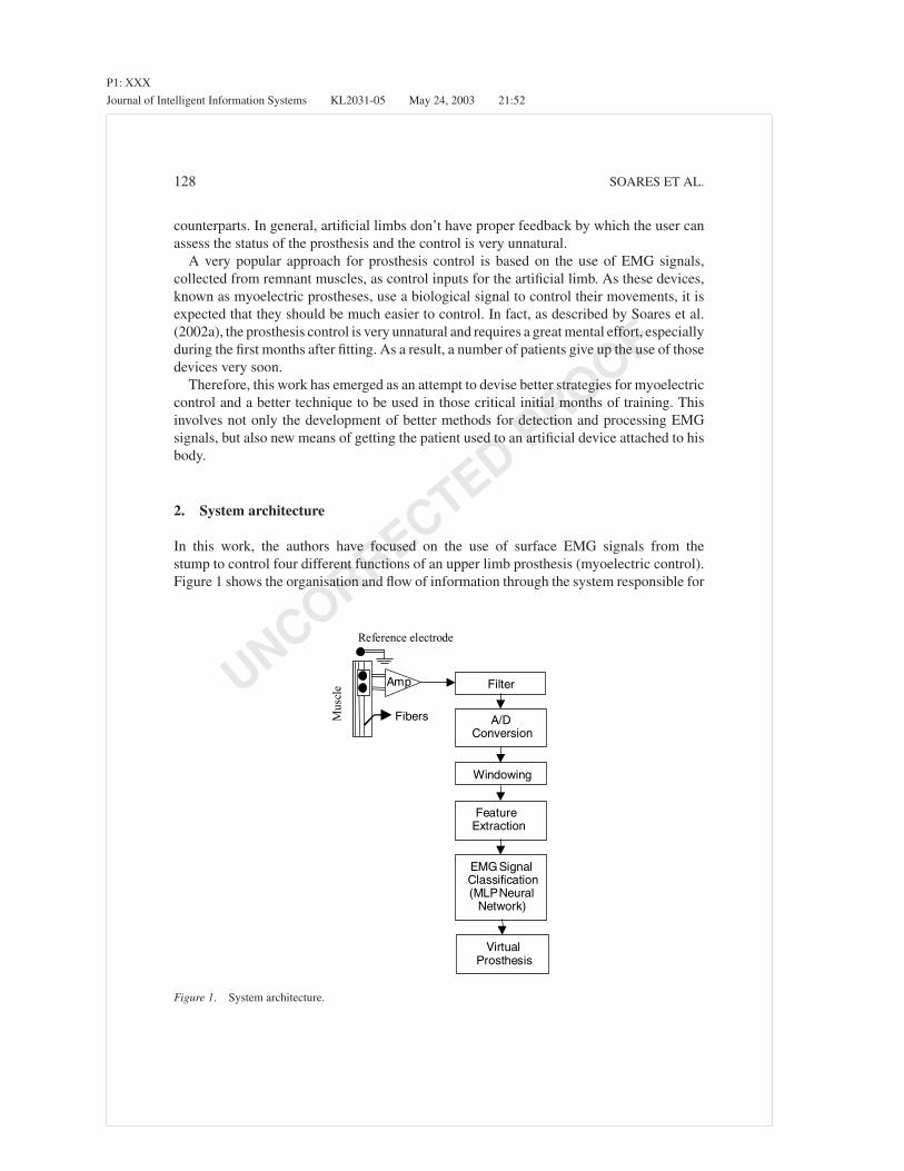
In this work, the authors have focused on the use of surface EMG signals from thestump to control four different functions of an upper limb prosthesis (myoelectric control).Figure 1 shows the organisation and flow of information through the system responsible for
Filter
Reference electrode
Fibers
Amp
A/DConversion
Windowing
FeatureExtraction
EMGSignalClassification(MLPNeural
Network)
VirtualProsthesis
Mus
cle
Figure 1. System architecture.

P1: XXX
Journal of Intelligent Information Systems KL2031-05 May 24, 2003 21:52
UNCORRECTEDPROOF
DEVELOPMENT OF A VIRTUAL MYOELECTRIC PROSTHESIS 129
generating the control signals. The EMG signal detected by surface electrodes are amplifiedand filtered prior to data acquisition. In order to process the correct section of the acquiredsignal, it is necessary to find out where the EMG activity starts and extract a portion of it(windowing). The resulting signal is then processed to find out some characteristics thatwill be used by an artificial neural network to classify the EMG pattern into four classes ofmovement. The output of the neural network can then be used to activate the correct func-tion of an real or virtual artificial limb. The necessary hardware and software to developthose functions were designed and built by the authors. The next sections will describe thedevelopment of each one of the units, paying special attention to the techniques for clearEMG detection and processing.
3. Origins and detection of the EMG signal
The myoelectric signal (figure 2) is the electrical manifestation of the neuromuscular activa-tion associated with a contracting muscle. It is an exceedingly complicated signal affectedby various factors such as the anatomical and physiological properties of muscles, the con-trol scheme of the peripheral nervous system and the characteristics of the instrumentationused for detection and processing (De Luca, 1979, 1996; O’Neill et al., 1994; Cram et al.,1998).
The process of detecting an EMG signal is not a trivial issue. The main problem is thatthis signal is easily affected by impure signals that come from different sources of noisesuch as 50/60 Hz electromagnetic induction from power lines. This occurs mainly due tothe small amplitude of the EMG signal (micro-milivolts). Also, when working with surfaceEMG, a number of factors related to the electrode-skin interface may affect the qualityof the detected signal (the impedance of the skin may vary as function of the moistureof the skin, the superficial skin oil content and the density of dead cell layer). Anothervery important factor that must be observed for proper detection is the distance betweenpairs of electrodes and the region where they are placed. Those issues have been carefullyconsidered during the experimental procedures used in this work. For example, appropriateabrasive substances and a proper gel were used to clean the patient’s skin and improvedthe contact impedance between the skin and the electrode. An “electrode jig” made ofacrylic (figure 3) was also designed to guarantee that the distances between electrodes wereconstant for different experiments.
Figure 2. Typical EMG pattern.

P1: XXX
Journal of Intelligent Information Systems KL2031-05 May 24, 2003 21:52
UNCORRECTEDPROOF
130 SOARES ET AL.
Figure 3. Surface electrodes and the designed “EMG jig”.
Figure 4. Differential amplification.
4. Amplifying and filtering the EMG signal
In order to perform adequate amplification, special differential instrumentation amplifierswere used. The main characteristics of this kind of amplifiers are extremely high inputimpedance and a very high common mode of rejection ratio (CMRR).
Figure 4 shows the basic process for differential amplification. The output signal is theresult of the subtraction of the signals captured by two electrodes placed above the musclegroup of interest, with respect to a reference electrode place on a “non-active” area, forinstance, above a bony surface. Note that, due to the high CMRR, if an interference signal,such as cable movement or 50/60 Hz induction, reaches both inputs of the amplifier, theoutput signal will have almost no trace of such interference.
The next step is to remove the unwanted components of the EMG signal. This can beachieved by means of a band pass filter. This filter should remove low frequencies (below20 Hz), related to artefact movements and some instabilities in the EMG signal, as wellas high frequencies, associated with RF (Radio Frequency) interference (De Luca, 1996,1997). As the power spectrum of EMG signals is concentrated in the 20–500 Hz range (withthe full range up to 1 kHz), the authors designed a hardware using a second order bandpass Butterworth filter with cut-off frequencies of 20 Hz (low) and 1 kHz (high). Furtherfiltering can be applied by means of digital filters implemented in the software for EMGprocessing.
P1: XXX
Journal of Intelligent Information Systems KL2031-05 May 24, 2003 21:52
UNCORRECTEDPROOF
DEVELOPMENT OF A VIRTUAL MYOELECTRIC PROSTHESIS 131
5. Data acquisition
The conditioned signal is then acquired using a simultaneous sample-and-hold data ac-quisition system. The authors used a high performance data acquisition board capable ofacquiring multiple channels at high speeds, with 12 bits resolution. The EMG signals wereacquired at 5 kHz per channel (five channels were used to acquire signals from the bicepslong head, biceps short head, triceps short head, triceps median head and triceps lateralhead). As the sample frequency is well above the minimum frequency (Nyquist frequency =2 ∗ 500 Hz), it is correct to say that all components of the EMG signal will be representedin the acquired signal.
6. Processing the EMG signal
Processing the EMG signal is an exceedingly difficult task. When working with this kindof signal one must bear in mind that it is a stochastic process that doesn’t have a formal ruleof formation and its shape varies frequently (Shanmugan and Breipohl, 1988; Akay, 1994,1996). The main purpose of this work is to apply a systematic methodology for extractingthe appropriate (and correct) features of the signal in order to use them as input to an artificialneural network. The results of the neural network can then be used to decide which functionis be performed by a prosthetic limb.
As the acquired signal may contain areas of inactivity, it is important to find out exactlywhen the EMG activity started. This was achieved by searching the beginning of the EMGactivity and using a windowing method (in this case a rectangular window) to extract thecorrect portion (a 200 ms window). The authors’ strategy to find out the limits of the EMGactivity is based on a threshold value for the variance of the signal. The underlying researchthat led the authors to the use of that strategy can be found in Soares et al. (2002a, 2002b).
The next step is to decide for the correct features to be extracted from the EMG signal.Those features must contain enough information to represent the EMG signal adequately.However, one must bear in mind that the main purpose of this system is to be part ofa control system for a prosthetic device, that should use a microcontroller (with limitedmemory for data etc) to run the software. Therefore, in order to achieve real time control, thecalculations and the data must be kept to a minimum. In other words, the EMG features mustbe simple to process and reduced to a minimum necessary. After a number of experiments(see Soares et al., 2002a), and bearing those limitations in mind, the authors decided to useautoregressive models (AR) for modelling the signals. Such models allow us to represent theEMG by means of a few coefficients. Also, it is worth to observe some important advantagesof modelling the signal in this way:
• Variations in the positioning of the electrodes on the surface of the muscle do not severelyaffect the AR-coefficients.
• The amount of information to be presented to the classifier is greatly reduced. Therefore,the total processing time is also reduced.
As the correct modelling is the key to achieve the required results it is important to exploreits underlying process.

P1: XXX
Journal of Intelligent Information Systems KL2031-05 May 24, 2003 21:52
UNCORRECTEDPROOF
132 SOARES ET AL.
6.1. Time-series analysis—The AR model
A time series is a chronological sequence of observations of a particular variable, in thiscase, the amplitude of the raw EMG signal. The time series is based on the modelling ofa signal to predict future values as a linear combination of its past values and the currentvalue (Cryer, 1986).
A model that depends only on the previous outputs of the system is called an autore-gressive model (AR). A model that depends only on the inputs to the system is called amoving average model (MA). And finally, a model based on the inputs and on the outputsis considered an autoregressive-moving-average model (ARMA).
Hefftner et al. (1988) observed that an AR model of finite order M , with a specifieddegree of closeness, might approximate any model. The order of an autoregressive modelrepresents the amount of information necessary to predict an estimated signal that can berepresented by the AR-coefficients.
A formal definition describes the AR model as being part of a major group of linearprediction formulas that attempt to predict an output y[n] of a system based on the previousoutputs (y[n −1], y[n −2], . . .). Deriving the linear prediction model involves determiningthe coefficients a1, a2, . . . aM . Equation (1) defines the AR model.
y(n) =M∑
m=1
am(n)y(n − m) + e(n) (1)
Where:
• y(n) is the estimated signal in a discrete time n.• am are the AR-coefficients.• e(n) is the estimation error.• M is the order of the model (number of coefficients a).
Equation (1) shows that, to predict, for instance, the 9th output value of a time series,modelled by an AR model of order 3, one must solve the following equation:
y(9) = a1(9)y(9 − 1) + a2(9)y(9 − 2) + a3(9)y(9 − 3) + e(9)
A common strategy to calculate the AR-coefficients is to use the least mean square(LMS) algorithm. It provides an iterative and fast method to figure out the parameters ofthe AR-model adaptively. Akay (1994) suggests the following steps to calculate the ARcoefficients:
1. Initialise the filter coefficients with zeros.2. Calculate the predicted value (y(n)) of the input signal (y(n)).
y(n) =M∑
m=1
am(n)y(n − m) (2)
P1: XXX
Journal of Intelligent Information Systems KL2031-05 May 24, 2003 21:52
UNCORRECTEDPROOF
DEVELOPMENT OF A VIRTUAL MYOELECTRIC PROSTHESIS 133
3. Estimate the prediction error e(n).
e(n) = y(n) − y(n) = y(n) + a1(n)y(n − 1) + · · · + aM (n)y(n − M) (3)
4. Update the AR-coefficients am using the constant of convergence µ.
am(n + 1) = am(n) − 2µe(n)y(n − m) (4)
Note that the basic process for calculating the AR coefficients is not very complex, it isonly a matter of using formula (4) to calculate all M AR coefficients. However, the correctand fast convergence of the LMS algorithm is another matter. It is commonly known thatan ideal value for the constant of convergence (µ) cannot be found. Furthermore, it is notpractical to look for a specific value of µ for every single EMG signal to be processed.Based on the experience of other researchers (Hefftner et al., 1988) the authors decided touse a very small positive value (0,001) for the constant of convergence. In so doing, theLMS algorithm showed very small errors when processing the whole EMG data set (usingthat single value for µ). The resulting AR coefficients were then used to train a neuralnetwork classifier (see next section). However, the performance of the EMG classifier fordiscriminating non-trained EMG patterns was not very impressive.
The authors looked into the causes of such poor performance and found that the estimatedsignal, using that small constant of convergence, had some small errors (mainly at thebeginning of the EMG activity). A new strategy was then devised to improve the ARestimator. The idea was to iterate the LMS algorithm as a whole. In the first iteration the ARcoefficients were initialised with zeros, as described above. After finishing the estimationof the first AR coefficients, a new iteration to calculate new AR coefficients was initiated.However, the AR coefficients, for this second iteration, were initialised with the valuescalculated in the first iteration. This process continued until a certain maximum numberof iterations was reached or a minimum error, between the real signal and the predictedsignal, was reached. This strategy greatly improved the efficiency of the system as a whole,as shown later.
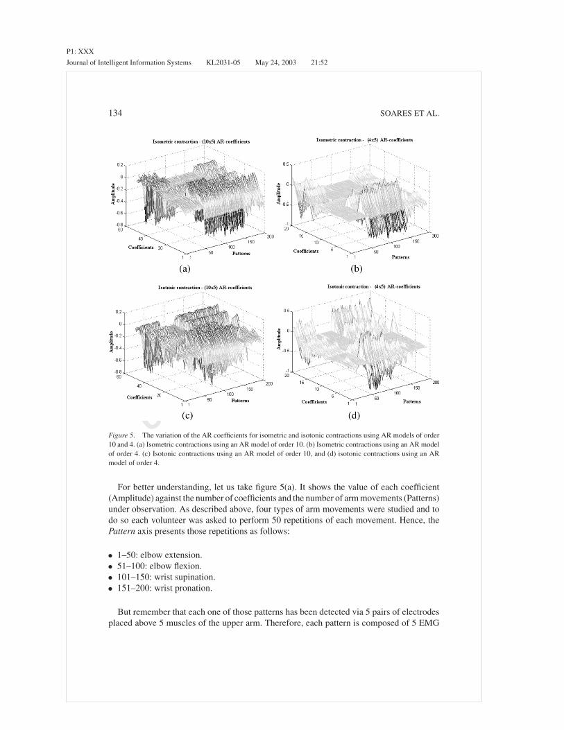
Figure 5(a)–(d) shows how the AR coefficients vary for each class of arm movement usedin this research. Each figure shows 200 EMG patterns, collected from a single volunteer,divided into four groups of arm movements (elbow flexion, elbow extension, wrist pronationand wrist supination).
The EMG signals were detected via 5 pairs of electrodes, resulting in 5 raw signals to beprocessed, for each movement. Since each EMG signal must be modelled by a particularAR set of coefficients (a1, a2, . . . aM ), there will be M ∗ 5 coefficients for each musclecontraction. In figure 5(a)–(d), the coefficient axis has the following meaning:
• 1 to m: coefficients related to the EMG signals detected at the biceps long head.• m + 1 to 2m: coefficients related to the EMG signals detected at the biceps short head.• 2m + 1 to 3m: coefficients related to the EMG signals detected at the triceps long head.• 3m + 1 to 4m: coefficients related to the EMG signals detected at the triceps median
head.• 4m + 1 to 5m: coefficients related to the EMG signal detected at the triceps lateral head.
P1: XXX
Journal of Intelligent Information Systems KL2031-05 May 24, 2003 21:52
UNCORRECTEDPROOF
134 SOARES ET AL.
Figure 5. The variation of the AR coefficients for isometric and isotonic contractions using AR models of order10 and 4. (a) Isometric contractions using an AR model of order 10. (b) Isometric contractions using an AR modelof order 4. (c) Isotonic contractions using an AR model of order 10, and (d) isotonic contractions using an ARmodel of order 4.
For better understanding, let us take figure 5(a). It shows the value of each coefficient(Amplitude) against the number of coefficients and the number of arm movements (Patterns)under observation. As described above, four types of arm movements were studied and todo so each volunteer was asked to perform 50 repetitions of each movement. Hence, thePattern axis presents those repetitions as follows:
• 1–50: elbow extension.• 51–100: elbow flexion.• 101–150: wrist supination.• 151–200: wrist pronation.
But remember that each one of those patterns has been detected via 5 pairs of electrodesplaced above 5 muscles of the upper arm. Therefore, each pattern is composed of 5 EMG

P1: XXX
Journal of Intelligent Information Systems KL2031-05 May 24, 2003 21:52
UNCORRECTEDPROOF
DEVELOPMENT OF A VIRTUAL MYOELECTRIC PROSTHESIS 135
signals. Each one of those 5 signals were processed and modelled by an AR model of order10 (10 ∗ 5 coefficients).
Figure 5(a) and (b) shows isometric contractions (a contraction without movement of thelimb) versus the coefficients calculated for AR models of order 10 and 4. Figure 5(c) and(d) shows isotonic contractions (a contraction associated with movement at constant force)versus the coefficients calculated for AR models of order 10 and 4. One may ask why worryabout both isotonic and isometric contractions. The reason is that, as this system must beused for controlling an artificial limb based on EMG signals, the classifier must recogniseany type of contraction in real time. Also, depending on the level of amputation, someusers may perform isometric contractions of the remaining part of the limb, while othermay perform isotonic contractions, for the same movement. Besides, even if a single userperforms only isometric or isotonic contractions, there will not be two identical contractionsfor the same movement. Therefore, the classifier must have the ability to learn and laterrecognise those signals as being part of the same class of movement (elbow extension,elbow flexion, wrist pronation and wrist supination). In this paper, the authors will describethe use of an artificial neural network to fulfil those requirements.
It is important to note that the method used by the authors to extract the necessaryfeatures from the EMG signals resulted in four distinct surfaces for each group of movement.Consider, for instance, figure 5(a) where the graph shows that there is a very distinct surfacefor the first 50 patterns (associated with elbow extension) that is clearly different from thenext 3 surfaces (of 50 pattern each). This clear distinction means that the neural networkshould have no problems to discriminate those four classes of movement.
6.2. EMG signal classifiers
The classifier is a fundamental element of the system. It must generate the correct signalfor controlling the prosthetic limb. Hence, it must be precise and as fast as possible. Theprecision of a classifier lies on its capability to give the correct answers in spite of someinaccuracies that may occur during the process of detection and acquisition of the EMGsignal. As we have observed, those inaccuracies generally are the result of misplacing theelectrodes on the skin or interference.
To be used in a control system for upper limb prostheses, the classifier must process andgive “answers” in real time. Prosthetic users generally will not accept delays much longerthan 100 mS between the command (muscle contraction) and the activation of the prosthesis.Besides, a classifier must be able to correctly understand the EMG features extracted by theAR-model, even if those features are not identical to features previously learned.
To fulfil those requirements the authors decided to use an artificial neural network based onthe Multi-Layer Perceptron (MLP) architecture (Fausett, 1994; Haykin, 1994). It may alsobe possible that other methods of pattern classification, such as Bayesian models (Lampinenand Vehtari, 2001) and Fuzzy Logic (Pal and Majumder, 1986), could lead to reasonableresults, however they have not been tested at this stage of the research, which shall be donein the near future. The MLP architecture is a very well known strategy and have alreadybeen used in a number of applications concerning pattern recognition (Gunawardana, 1998;Kelly et al., 1990; Fausett, 1994; Haykin, 1994).

P1: XXX
Journal of Intelligent Information Systems KL2031-05 May 24, 2003 21:52
UNCORRECTEDPROOF
136 SOARES ET AL.
Figure 6. MLP neural network.
The backpropagation algorithm (standard method for training the MLP), has been usedfor the training stage.
As shown in figure 6, the neural network is composed of n neurons in the input layer(where n is the number of AR coefficients), 80 neurons in the hidden layer and 4 neuronsin the output layer (one for each class of movement). The number of neurons of the hiddenlayer has been defined after a set of trials with different number of neurons. Note that thereis no clear algorithm to define the number of neurons of the hidden layer. Therefore, theauthors tried different configurations in search of satisfying results.
The MLP topology may contain several hidden layers. However, according to the Uni-versal Approximation Theorem (Haykin, 1994), only one hidden layer is enough to guar-antee the convergence of the MLP training. This theorem defines the number of hiddenlayers, but does not specify the number of neurons of that layer (which had to be doneempirically).
The EMG classification was divided into two stages: training and execution (test). Eachstage received a group of 25 patterns (randomly chosen) for each one of the 4 classes ofmovement (total of 100 patterns for training and 100 patterns for test). All patterns referredto the EMG signals from a single volunteer. Patterns used for training were not used forexecution and vice-versa. Note that generalisation is one of the most important featuresof artificial neural networks and the main issue for obtaining a good generalisation is thetraining set. Two alternative stopping criteria have been used during the training stage: (1)a total mean squared error of 0.01 is achieved or (2) the training will be stopped after 100epochs. One may argue that 100 epochs seems rather low. However, that number was definedafter observing the convergence behaviour of the training process for some experimentaltrials, which showed convergence for all patterns with less than 100 epochs. The authorsbelieve that such fast training can be explained by the small number of features (number ofcoefficients of the AR model) that the network had to learn and by the optimisation of theLMS algorithm, as described earlier, that improved the “quality” of those coefficients. Notethat a minimal error equal to zero is not desirable, since this could decrease the networkgeneralisation degree. Also, for some configurations, as it is the case of continuous sigmoidfunctions and desired ‘1’s at the network’s output (as for classification), the zero value can
P1: XXX
Journal of Intelligent Information Systems KL2031-05 May 24, 2003 21:52
UNCORRECTEDPROOF
DEVELOPMENT OF A VIRTUAL MYOELECTRIC PROSTHESIS 137
never obtained. Hence, the neural network training parameters were:
• fixed learning rate: 0.01;• fixed momentum: 0;• binary sigmoid activation function for all layers;• Random weight initialisation (between 0 and 1);• Random presentation of the training patterns.• Target vectors.
Class of movement Desired network’s response
Elbow extension 1 0 0 0
Elbow flexion 0 1 0 0
Wrist supination 0 0 1 0
Wrist pronation 0 0 0 1
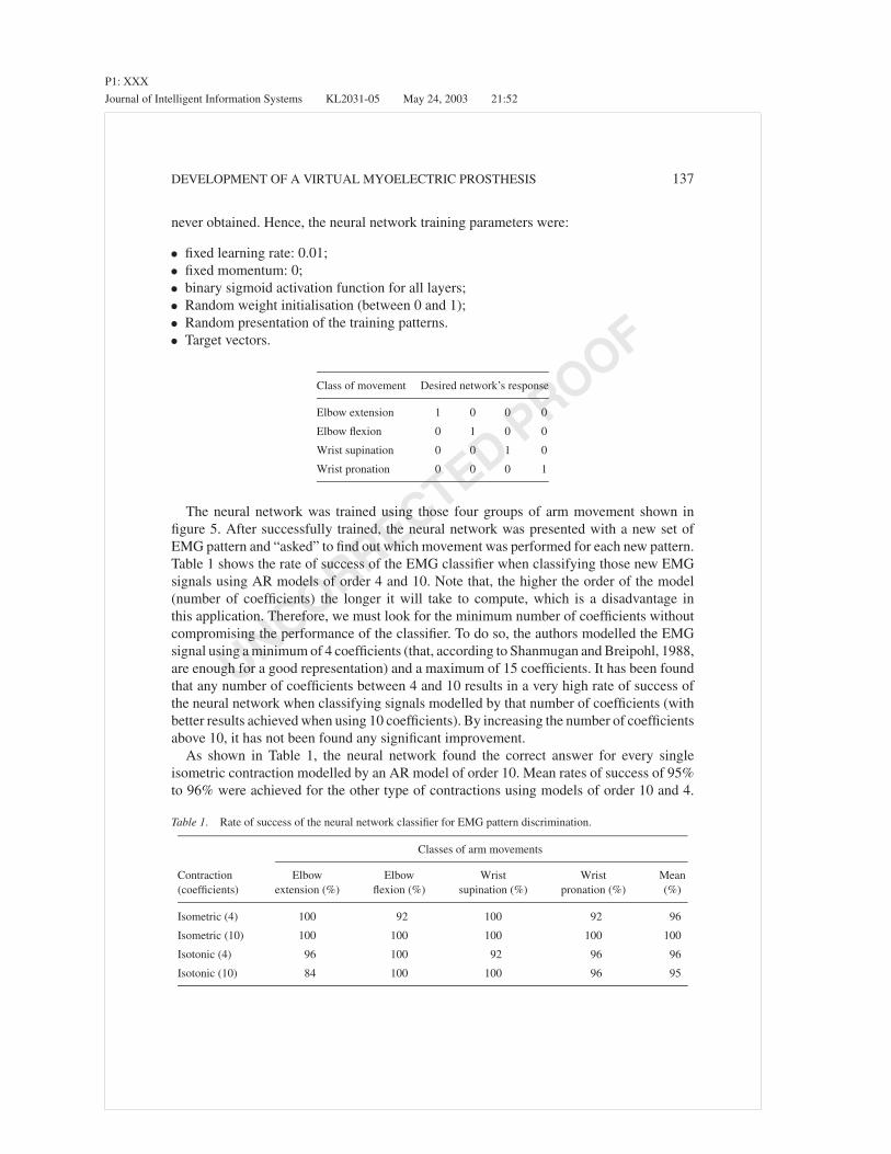
The neural network was trained using those four groups of arm movement shown infigure 5. After successfully trained, the neural network was presented with a new set ofEMG pattern and “asked” to find out which movement was performed for each new pattern.Table 1 shows the rate of success of the EMG classifier when classifying those new EMGsignals using AR models of order 4 and 10. Note that, the higher the order of the model(number of coefficients) the longer it will take to compute, which is a disadvantage inthis application. Therefore, we must look for the minimum number of coefficients withoutcompromising the performance of the classifier. To do so, the authors modelled the EMGsignal using a minimum of 4 coefficients (that, according to Shanmugan and Breipohl, 1988,are enough for a good representation) and a maximum of 15 coefficients. It has been foundthat any number of coefficients between 4 and 10 results in a very high rate of success ofthe neural network when classifying signals modelled by that number of coefficients (withbetter results achieved when using 10 coefficients). By increasing the number of coefficientsabove 10, it has not been found any significant improvement.
As shown in Table 1, the neural network found the correct answer for every singleisometric contraction modelled by an AR model of order 10. Mean rates of success of 95%to 96% were achieved for the other type of contractions using models of order 10 and 4.
Table 1. Rate of success of the neural network classifier for EMG pattern discrimination.
Classes of arm movements
Contraction(coefficients)
Elbowextension (%)
Elbowflexion (%)
Wristsupination (%)
Wristpronation (%)
Mean(%)
Isometric (4) 100 92 100 92 96
Isometric (10) 100 100 100 100 100
Isotonic (4) 96 100 92 96 96
Isotonic (10) 84 100 100 96 95
P1: XXX
Journal of Intelligent Information Systems KL2031-05 May 24, 2003 21:52
UNCORRECTEDPROOF
138 SOARES ET AL.
Other works can be found using similar techniques. However, the rates of success normallyachieved are not much higher then 70% (Graupe and Cline, 1975; Saridis and Gootee, 1982;Doerschuk et al., 1983; Kelly et al., 1990; Hudgins et al., 1993; Gunawardana, 1998).
7. Virtual simulation
The output of the neural network can be used as control input for a real prosthetic deviceor, as it is the case of this work, as input to a virtual device that can mimic a real system.In general, the initial stages of learning to use a prosthetic device are deeply distressful,iterative and error-prone and also can be very frustrating. With this in mind, the authorsdecided to design a virtual simulation as a possible tool to help the users during those initialstages. The system may also be used to simulate real devices when testing a novel controlsystem.
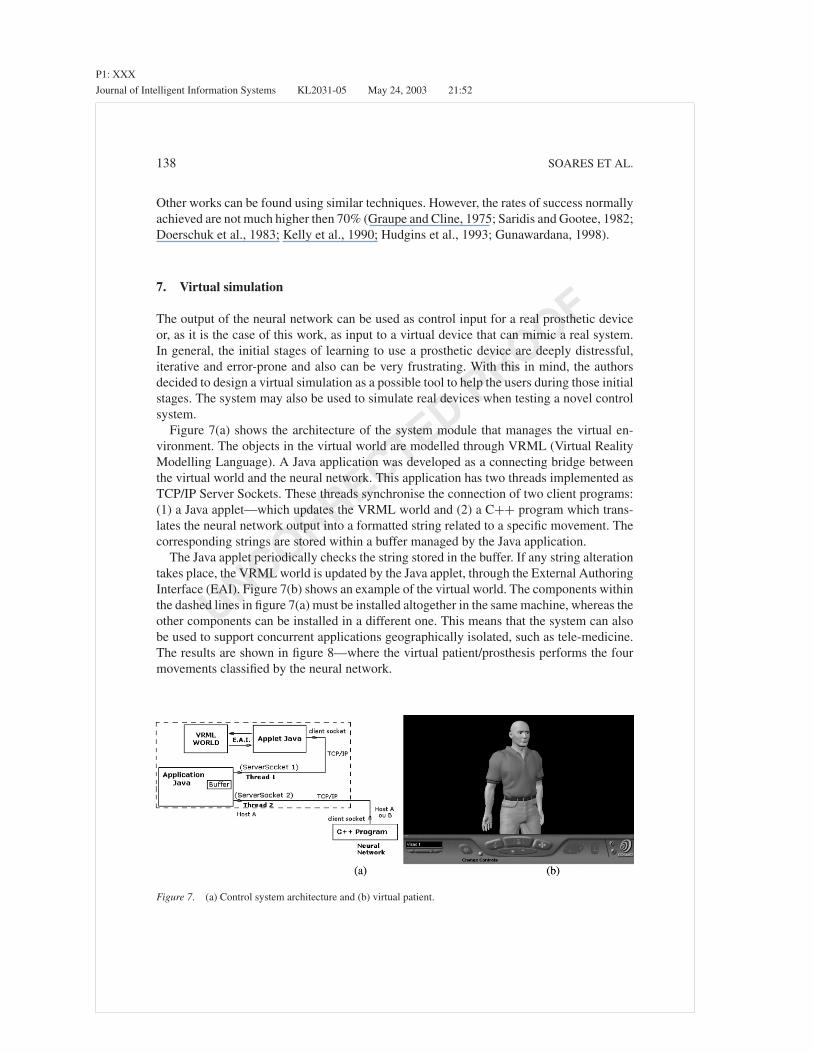
Figure 7(a) shows the architecture of the system module that manages the virtual en-vironment. The objects in the virtual world are modelled through VRML (Virtual RealityModelling Language). A Java application was developed as a connecting bridge betweenthe virtual world and the neural network. This application has two threads implemented asTCP/IP Server Sockets. These threads synchronise the connection of two client programs:(1) a Java applet—which updates the VRML world and (2) a C++ program which trans-lates the neural network output into a formatted string related to a specific movement. Thecorresponding strings are stored within a buffer managed by the Java application.
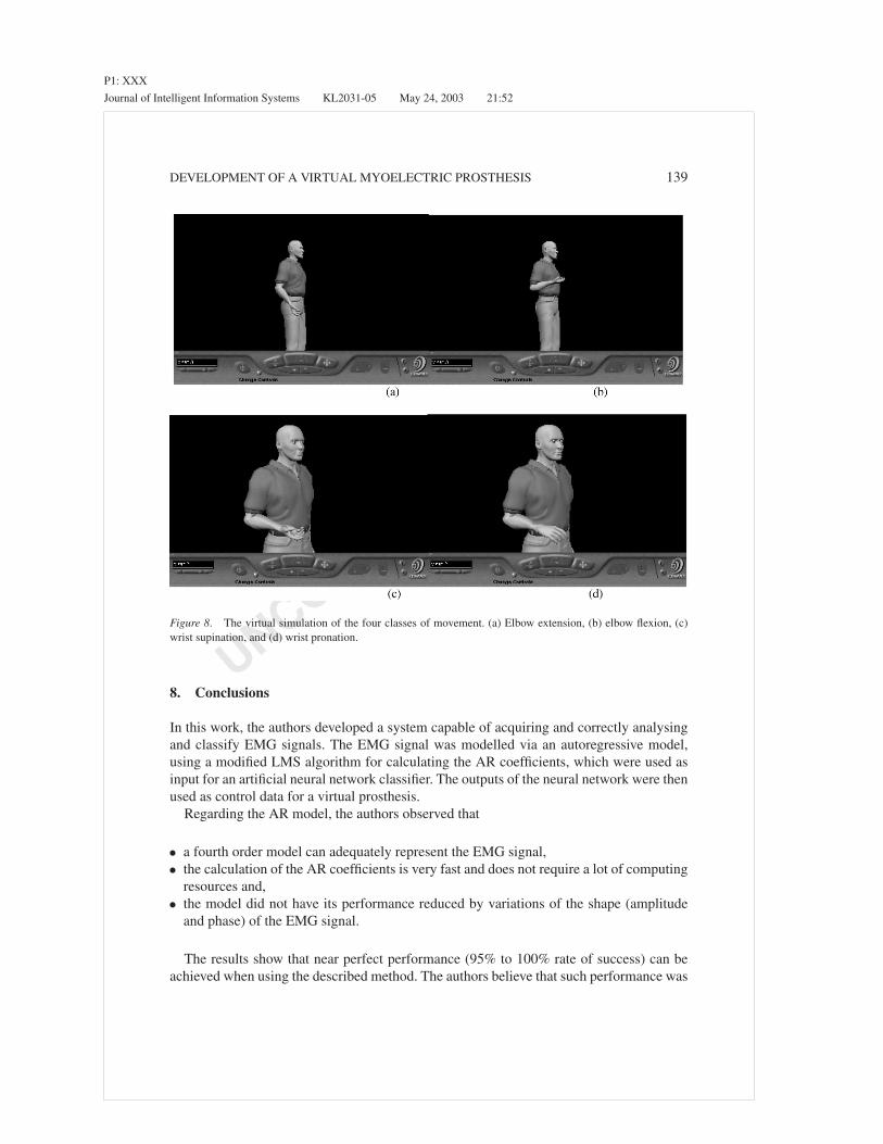
The Java applet periodically checks the string stored in the buffer. If any string alterationtakes place, the VRML world is updated by the Java applet, through the External AuthoringInterface (EAI). Figure 7(b) shows an example of the virtual world. The components withinthe dashed lines in figure 7(a) must be installed altogether in the same machine, whereas theother components can be installed in a different one. This means that the system can alsobe used to support concurrent applications geographically isolated, such as tele-medicine.The results are shown in figure 8—where the virtual patient/prosthesis performs the fourmovements classified by the neural network.
Figure 7. (a) Control system architecture and (b) virtual patient.
P1: XXX
Journal of Intelligent Information Systems KL2031-05 May 24, 2003 21:52
UNCORRECTEDPROOF
DEVELOPMENT OF A VIRTUAL MYOELECTRIC PROSTHESIS 139
Figure 8. The virtual simulation of the four classes of movement. (a) Elbow extension, (b) elbow flexion, (c)wrist supination, and (d) wrist pronation.
8. Conclusions
In this work, the authors developed a system capable of acquiring and correctly analysingand classify EMG signals. The EMG signal was modelled via an autoregressive model,using a modified LMS algorithm for calculating the AR coefficients, which were used asinput for an artificial neural network classifier. The outputs of the neural network were thenused as control data for a virtual prosthesis.
Regarding the AR model, the authors observed that
• a fourth order model can adequately represent the EMG signal,• the calculation of the AR coefficients is very fast and does not require a lot of computing
resources and,• the model did not have its performance reduced by variations of the shape (amplitude
and phase) of the EMG signal.
The results show that near perfect performance (95% to 100% rate of success) can beachieved when using the described method. The authors believe that such performance was
P1: XXX
Journal of Intelligent Information Systems KL2031-05 May 24, 2003 21:52
UNCORRECTEDPROOF
140 SOARES ET AL.
achieved due to the judicious process used to detect and acquire clear EMG signals, alongwith the improvements made on the estimation of the AR coefficients.
With respect to EMG signal classification, it has been observed that the neural networkhas successfully achieved the segmentation of AR coefficients into four distinct patternclasses with very high rates of success.
Finally, the use of a virtual patient/prosthesis to respond to the classified EMG signalshas shown a great potential as a tool for patient training, especially during the first monthsafter the prosthesis is fitted. It also can be used as a simulation environment to study newdesigns and control strategies.
References
Akay, M. (1994). Biomedical Signal Processing. Academic Press.Akay, M. (1996). Detection and Estimation Methods for Biomedical Signals. Academic Press.Childress, D.S. (1973). Powered Limb Prostheses: Their Clinical Significance. IEEE Transactions on Biomedical
Engeneering, BME-20(3), 200–207.Cram, J.R., Kasman, G.S., and Holtz, J. (1998). Introduction to Surface Electromyography. Gaithersburg, MA:
Aspen Publication.Cryer, J.D. (1986). Time Series Analysis. Boston: University of Iowa, Duxbury Press.De Luca, C.J. (1979). Physiology and Mathematics of Myoletric Signals. IEEE Transactions on Biomedical
Engeneering, BME-29(6), 313–325.De Luca, C.J. (1996). Surface Electromyography: Detection and Recording. www.delsys.com/emg.shtml, Delsys
Inc.De Luca, C.J. (1997). The Use of Surface Electromyography in Biomechanics. www.delsys.com/emg.shtml,
Neuromuscular Research Center and Biomedical Engeneering Dept. and Neurology Dept., Boston University,Delsys Inc.
Doerschuk, P.C., Gustafson, D.E., and Willsky, A.S. (1983). Upper Extremity Limb Function DiscriminationUsing EMG Signal Analysis. IEEE Transactions on Biomedical Engeneering, BME-30(1), 18–29.
Doringer, J.A. and Hogan, N. (1995). Performance of Above Elbow Body-Powered Prostheses in Visually GuidedUnconstrained Motion Tasks. IEEE Transactions on Biomedical Engeneering. 42(6), 621–631.
Fausett, L. (1994). Fundamentals of Neural Networks—Architectures, Algorithms and Applications. Florida Insti-tute of Technology, Prentice Hall International, Inc.
Graupe, J. and Cline, K. (1975). Functional Separation of EMG Signals Via ARMA Identification Methods forProsthesis Control Purposes. IEEE Transactions on Systems, Man, and Cybernetics, SMC-5, 252–259.
Gunawardana, A. (1998). EMG Extraction and Processing, www.fen.bris.ac.uk/elec/research/ccr/medelec/emgext.html, University of Bristol, Faculty of Engeneering.
Haykin, S. (1994). Neural Networks—A Comprehensive Foundation. Macmillan Publishing Co.Hefftner, G., Zucchini, W., and Jaros, G.G. (1988). The Eletromyogram (EMG) as a Control Signal for Functional
Neuromuscular Stimulation—Part I: Autoregressive Modeling as a Means of EMG Signature Discrimination.IEEE Transactions on Biomedical Engeneering, 35(34), 230–237.
Hudgins, B., Parker, P., and Scott, R.N. (1993). A New Strategy for Multifunction Myoeletric Control. IEEETransactions on Biomedical Engeneering, 40(1), 82–94.
Kelly, M.F., Parker, P.A., and Scott, R.N. (1990). The Application of Neural Networks to Myoeletric SignalAnalysis: A Preliminary Study. IEEE Transactions on Biomedical Engeneering. BME-37(3), 221–230.
Lampinen, J. and Vehtari, A. (2001). Bayesian Approach for Neural Networks—Review and Case Studies. NeuralNetworks, 14(3), 7–24.
Merletti, R. and Lo Conte, L.R. (1995a). Advances in Processing of Surface Myoeletric Signals: Part 1. Medical& Biological Eng. & Computing, 33, 362–372.
Merletti, R. and Lo Conte, L.R. (1995b). Advances in Processing of Surface Myoeletric Signals: Part 2. Medical& Biological Eng. & Computing, 33, 373–384.

P1: XXX
Journal of Intelligent Information Systems KL2031-05 May 24, 2003 21:52
UNCORRECTEDPROOF
DEVELOPMENT OF A VIRTUAL MYOELECTRIC PROSTHESIS 141
O’Neill, P.A., Morin, E.L., and Scott, R.N. (1994). Myoletric Signal Characteristics from Muscles in ResidualUpper Limbs. IEEE Trans. Rehab. Eng., 2(4), 266–270.
Pal, S.K. and Majumder, D.K.D. (1986). Fuzzy—Mathematical Approach to Pattern Reconition. Calcuta, India:John and Wiley & Sons, Inc. Indian Statistical Institute.
Patterson, P.E. and Katz, J.A. (1992). Design and Evoluation of a Sensory Feedback Systems that Provides GraspingPressure in a Myoletric Hand. Journal of Rehabilitation Research and Development, 29(1), 1–8.
Saridis, G.N. and Gootee, T.P. (1982). EMG Pattern Analysis and Classification for a Prosthetic Arm. IEEETransactions on Biomedical Engeneering, BME-29(6), 403–412.
Shanmugan, K.S. and Breipohl, A.M. (1988). Random Signals: Detection, Estimation and Data Analysis. JohnWiley & Sons, Inc.
Soares, A.B., Berzin F., and Andrade, A.O. (2002a). Power Spectrum Estimation of EMG Signals via Chirp-ZTransform. In Proceedings of the XIVth Congress of the International Society of Electrophysiology andKinesiology (p. 43). Vienna, Austria.
Soares, A.B., Veiga, A.C.P., Andrade, A.O., Pereira, A.C., and Barbar, J.S. (2002b). Functional Languages inSignal Processing Applied to Prosthetic Limb Control. Systems Analysis Modelling Simulation, 42(9/2002),1377–1389.