The Development and Tryout of Criterion Referenced ... - ERIC
111
DOCUMENT RESUME ED 107 698 TM 004 522 AUTHOR Shriver, Edgar L.; Foley, John P., Jr. TITLE Evaluating Maintenance Performance: The Development and Tryout of Criterion Referenced Job Task Performance Tests for Electronic Maintenance. Final Report for Period January 1969-May 1974. INSTITUTION Air Force Human Resources Lab., Wright-Patterson AFB, Ohio. Advanced Systems Div.; URS Systems Corp., Falls Church, Va. Matrix Research Div. SPONS AGENCY Air Force Human Resources Lab., Brooks AFB, Texas. REPORT NO AFHPL-TR-74-57 (II) PUB DATE Sep 74 NOTE 111p.; For related documents, see TM 004 444, 643, 644 and 645 ERRS PRICE MF-$0.76 HC-$5.70 PLUS POSTAGE DESCRIPTORS *Criterion Referenced Tests; Electronic Equipment; *Electronics; *Equipment Maintenance; Military Personnel; Models; *Performance Tests; Scoring; Task Performance; *Test Construction IDENTIFIERS *Air Force ABSTRACT A battery of criterion referenced job task performance tests (JIPT) for typical electronic maintenance activities were developed. The construction of a battery of such tests together with an appropriate scoring for reporting the results is detailed. The development of a Test Administrators Handbook also is described. This battery is considered to be a model for future criterion JTPT development and is intended for both formal training and field use. The battery includes separate tests for the following classes of job activities: (1) equipment checkout, (2) alignment/calibration, (3) removal/replacement, (4) soldering, (5) use of general and special test equipment, and (6) troubleshooting. (Author/BJG)
-
Upload
khangminh22 -
Category
Documents
-
view
0 -
download
0
Transcript of The Development and Tryout of Criterion Referenced ... - ERIC

DOCUMENT RESUME
ED 107 698 TM 004 522
AUTHOR Shriver, Edgar L.; Foley, John P., Jr.TITLE Evaluating Maintenance Performance: The Development
and Tryout of Criterion Referenced Job TaskPerformance Tests for Electronic Maintenance. FinalReport for Period January 1969-May 1974.
INSTITUTION Air Force Human Resources Lab., Wright-Patterson AFB,Ohio. Advanced Systems Div.; URS Systems Corp., FallsChurch, Va. Matrix Research Div.
SPONS AGENCY Air Force Human Resources Lab., Brooks AFB, Texas.REPORT NO AFHPL-TR-74-57 (II)PUB DATE Sep 74NOTE 111p.; For related documents, see TM 004 444, 643,
644 and 645
ERRS PRICE MF-$0.76 HC-$5.70 PLUS POSTAGEDESCRIPTORS *Criterion Referenced Tests; Electronic Equipment;
*Electronics; *Equipment Maintenance; MilitaryPersonnel; Models; *Performance Tests; Scoring; TaskPerformance; *Test Construction
IDENTIFIERS *Air Force
ABSTRACTA battery of criterion referenced job task
performance tests (JIPT) for typical electronic maintenanceactivities were developed. The construction of a battery of suchtests together with an appropriate scoring for reporting the resultsis detailed. The development of a Test Administrators Handbook alsois described. This battery is considered to be a model for futurecriterion JTPT development and is intended for both formal trainingand field use. The battery includes separate tests for the followingclasses of job activities: (1) equipment checkout, (2)alignment/calibration, (3) removal/replacement, (4) soldering, (5)use of general and special test equipment, and (6) troubleshooting.(Author/BJG)

AIR FORCE 13.
H
I IU S DEPARTMENT OF HEALTH
EDUCATION A WELFARENATIONAL INSTITUTE OF
EDUCATIONM . DOCUMENT HAS BFEN REPRO
DL :ED EXACTLY AS RECEIVED FROMD.; PERSON OR ORGANIZATION ORIGINAUNG IT POiN Ts OF VIEW OR OPINIONSST,,TED DO NOT NECESSARILY REPRESENT OFFICIAL NATIONAL INSTITUTE OFEC uCAT,ON POSITION OR POLICY
UMAN
RE
S0
e
AFHRL-TR-7457110,Part I
EVALUATING MAINTENANCE PERFORMANCE:
THE DEVELOPMENT AND TRYOUT OF CRITERIONREFERENCED JOB TASK PERFORMANCE TESTS
FOR ELECTRONIC MAINTENANCE
By
Edgar L. ShriverURS/Matrix Research CompanyFalls Church, Virginia 22042
John P. Foley, Jr.ADVANCED SYSTEMS DIVISION
Wright - Patterson Air Force Base, Ohio 45433
September 1974Final Report for Period 1 January 1969 3 May 1974
Approved for public release; distribution unlimited.
LABORATORY
AIR FORCE SYSTEMS COMMANDBROOKS AIR FORCE BASE,TEXAS 78235
2

NOTICE
When US Government drawings, specifications, or other data are used
for any purpose other than a definitely related Governmentprocurement operation, the Government thereby incurs noresponsibility nor any obligation whatsoever, and the fact that theGovernment may have formulated, furnished, or in any way suppliedthe said drawings, specifications, or other data is not to be regarded byimplication or otheiwise, as in any manner licensing the holder or anyother person or corporation, or conveying any lights or permission tomanufacture, use, or sell any patented invention that may in any waybe related thereto.
This final report was submitted by Advanced Systems Division, AirForce Human Resources Laboratory (AFSC), Wright-Patterson AirForce Base, Ohio 45433, under project 1710. It is a compilation andexpansion of materials submitted by URS/Matrix Research Company,Falls Church, Virginia 22042 under Contracts F33615-69C-1232 andF33615-70C-1695. Dr., John P. Foley and Mr. John K. Klesch,Advanced Systems Division, shared the contract monitorship.
This report has been reviewed and cleared for open publication and/orpublic release by the appropriate Office of Information (0I) inaccordance with AFR 190-17 and DoDD 5230.9. There is no objectionto unlimited distribution of this report to the public at large, or oyDDC to the National Technical Information Service (NTIS).
This technical report has been reviewed and is approved.
GORDON A. ECKSTRAND, DirectorAdvanced Systems Division
Approved for publication.
HAROLD E. FISCHER, Colonel, USAFCommander
3

U111'11Iss I lied
SEC:FR Ty CLASSIFICA r.osi PAGE (When Dare Eeeed)
REPORT DOCUMENTATION PAGE READ INS fRUCTIONSBEFORE COMPLETING FORM
PEPC,RT NUMBER 12 GOVT ACCESSION NO
. EHRL-1 R:74-57(11), Part 1I
3 RECIPIENT'S CATALOG NUMBEk
4 TITLE (and Subutte)EVALUATING MAINTENANCE PERFORMANCE. THE DEVELOP-\IFNT AN!) TRYOL f OF CRITF RION REFERENCED JOB TASKPERFORMANCE TES FS FOR Ll.rCTRONIC MAINTENANCE:
S TYPE OF REPORT 6 PERIOD COVERED
Final1 1January 1969 3 May 1974f 6 PERFORMING ORG REPORT NUMBER
7
'71
i 1
A THCP'tjLagar L ShriverJohn P. Foley. Jr
B CONTRACT OR GRANT NUMBER(s)133615 69C -1232F33615-70C-1695
".%-ii%3RMING ORGANIZATION P ARE ANC AOORESS ri-0URStMatrtx 12,:sench Company7245 Arlington BoulevardFalls Churi.h, Virginia 22042
PROGFAM ELEMENT PROJECT. TASKAREA 6 WORK UNIT NUMBERS
62703F1710041637101003.17101006
CONTROLLING OFFICE NAME AND ADDRESc
lig Air Foice Human Resources Laboratory (AFSC)Brooks Air Force Base, Texas 78235
12 REPORT DA7E
September 197413 NUMBER OF PAGES
112
14 MJNITuRING AGENCY NAME 6 ADORESS(if differen from Controlling ("Rite)Advanced Systems Division.A,r Force Human Resources LaboratoryWrighT-Patterson Air Eoice Base Ohio 45433
15 SECURITY CLASS (of this report)
Unclassified
ISet DECLASSIFoC ATION, DOWNGRADINGSC4EDULE
1,3 OISTRf9u11!ON STATEMENT (of this Repot.,
Approved for rublic release, distribution unlimited.
17 DISrR'S:ITION STATEMENT (of the abstract entered in Block 20, if different from Report)
18. SUPPLEMENTARY NOTES
Volumes I, III, and IV of this report in press.
iq KEY WORDS (Continue on reverse stele if necessary and identify by block number)
Job Task Performance Tests psychology -- individual and groupCriterion referenced tests measurement and evaluation technical trainingvideo testing measurement and evaluation maintenance trainingmaintenance effectiveness measurement and evaluation electronics trainingPersonnel selection measurement and evaluation vocational education
20 ABSTRACT (Cc ntinue on recrse aide 11 necessary and identify by block number)
1 he previous Volume. AR IRL-TR-74-57(1), recommended the development of criterion referenced Job TaskPerformance Tests (JTPT) for typical electronic maintenance activities. This Volume reports the development of abattery of such tests together with an appropriate scoring scheme for reporting the results of administering them.The development of a Test Administrators Handbook also is described. This battery is considered to be a model forfuture criterion JTPT development and is intended for both formal training and field use.
The battery includes separate tests for the following classes of job activities: (1) equipment checkout, (2).,alignment/calibration, (3) removal/replacement, (4) soldering. (5) use of general and special test equipment, and (6)troubleshooting, The DopplerRadar, the AN/APN- 147 and its computer the AN/ASN-35 were selected as a typical
DD 1 e,c)AN9m73 1473 EDITION OF 1 NOV 55 IS OBSOLETE
4 UnclassifiedSECURI r CLASSIFICATION OF THIS PAGE (When Date Entered)

Unclassified
SECURITY CLASSIFICATION OF THIS PAGE(Whon Data Entered)
Item 20 (Continued)
electronic system. This system was used as the test bed for this model battery. The soldenag and general testequipment JTPT are applicable to all electronic technicians. The other tests of the battery apply to techniciansconcerned with this specific doppler radar system.
Each class of activity for which JTPT were developed contifins its individual mix of behaviors, but it is notmutually exclusive. There are dependencies among the classes. As a result a four level hierachy of dependencies canbe stated: (I) checkout: removal/replacement, and soldering, (2) use of general and special test equipment; (3)alignment/calibration, and (4) troubleshooting. For example, troubleshooting may include all the activitiesmentioned before it.
Due to the diverse character of the various mixes of behaviors involved in each class of maintenance activity, asingle score report of test results would be meaningless. A profile of test results therefore was developed whichprovides for an individual cell for each test problem. The tests are structured so that each problem produces aproduct. The results for each problem is reported in terms of a go, no-go score. Either the test subject produces asatisfactory product or he does not. Where time is important, he must produce the satisfactory product in a specifiedtime. Although process may be valuable as a diagnostic tool, it is not considered as an appropriate factor for scoringpurposes.
The hierachy of dependencies mentioned previously has implication for the order in which tests areadministered as well as for diagnostics. For example, since troubleshooting includes the use of test equipment andother activities in the hierachy, logic would dictate that administration of the tests for the subactivitics wouldprecede the troubleshooting tests and that a test subject would not be permitted to take the troubleshooting tests
ittl he had passed these other subtest.
Due to the unavailability of a sufficient number of experienced test subjects at the time of the tryout of theJTPT battery, the tryout was not as extensive as planned. The limited tryout did indicate that the tests as developedare administratively feasible.. There continued use, no doubt, would result in further modifications and polish. Thereport also includes a discussion of several implementation considerations and suggestions.
Unclassified
SE iTY CLASSIFICATION OF THIS PAGE(When Data Entered)

SUMMARY
Problem
The in-depth review of the literature reported in Volume I of this series of reports strongly reiteratedthe fact that paper and pencil tests of job knowledge and electronic theory tests have very poorcriterion-related or empirical validity with respect to the ability of electronic maintenance men foeperforming their job tasks. This literature review, also produced little evidence that anything was beingaccomplished in a systematic way to develop adequate job measures. Most of the reported test efforts wereof the "ad hoc" variety. Such tests usually covered only parts of the maintenance job and attempted toreport results in terms of a single score, providing little diagnostic information. Another facet of thisproblem was that even though criterion-referenced job performance tests were recognized as being superiorby many training people, paper and pencil tests were substituted because they were more easily and cheaplydeveloped and administered.
Approach
Hypotheses were suggested for improving the job coverage and scoring of Job Task PerformanceTests (JTPT) and for developihg symbolic substitute tests that would have higher empirical validity than thetraditio tal paper and pencil job knowledge tests. Such symbolic substitutes could not be developed untilgood JTPT were available as criteria. This effort was aimed a` "e development of such criterion tests. Thehypotheses that were offered for improving JTPT included the following:
1 Separate tests could be developed for each type of job activity. The activities to be consideredwere checkout procedures; align, adjust, and calibrate activities; remove and replace activities;troubleshooting; use of test equipment; and use of hand tools.
2. A separate and appropriate scoring and diagnostic scheme could be developed for reporting theresults from each type of test,
Based on these hypotheses plans were made to develop a battery of JTPT together with appropriatescoring schemes for each type of electronic maintenance activity. The doppler radar, the AN/APN-147 andits computer, the AN/ASN-35, were selected as typical equipments for test development These plans calledfor a testing system that could be administered by personnel that were not experts in the maintenance ofthese equipments. The system was to include the JTPT, an administrator's handbook, and a trainingprogram for test administrators. This system was to be considered as model for the development of futuretests for measuring ability to perform electronic maintenance tasks. The model was to be appropriate foruse in field maintenance units, for use in training, and for use in research projects. The plans called for arather extensive tryout of this testing system in field maintenance units in the Military Airlift Command(MAC).
Results
A model JTPT system was developed. This system included 48 JTPT that covered the typicalorganizational and intermediate maintenance activities mentioned; and administrator's manual instep-by-step format and a training program for Air Force administrators. The training program was givensuccessfully to members of the MAC maintenance standardization team. Each test was administeredsuccessfully at least seven times to experienced Air Force mair tenance personnel, Due to fewerstandardization team field visits than planned during the tryout period and to a "non-interference" policyfor the MAC standardization team, the plans to gather additional hIrd data concerning electronictechnicians' job abilities were not achieved.
As to the scoring scheme, product, process and time were considered as to their appropriateness. Atest subject has not reached criterion on a task until he has produced a complete satisfactory product.. Thisis a go, no-go criterion. In most cases, time is not a critical factor but forsome organizational (flight line)tasks it might be. Where time is critical, the subject must produce this product within a prescribed time.Otherwise, 'le must produce his product in a reasonable time. The product for each type of test will ofcourse be mewhat different. Process information was not considered an appropriate basis for a score but
6

such 'information may be used for diagnostic purposes. During the test development and tryout it becameapparent that the activities were not mutually exclusive. These activities can be arrat4,ed in a tuur levelhierachy of dependencies as follows:
I. Check out. remove and replace. and soldering activities.
2 Use of general and special test equipment.
3. Align, adjust, and calibrate activities.
4. Troubleshooting.
This hierarchy of dependencies among activities together with the go, no-go product criterioit foreach test problem made possible the development of a diagnostic profile for reporting test results (Figures10 and 11).
In addition to the reporting of the development and tryout of the JTPT system, the report discussesother relevant factors concerning the development and implementation of JTPT. Some examples follow.The soldering tests and the tests on use of general equipment have general application from equipment toequipment, whereas the other tests are equipment specific. Current personnel and training systems are builtaround paper and pencil testing practice but an orderly modification of training and testing practice ispossible
Conclusions
The tryout of the JTPT system indicated that the system is an adequate model for JTPT on otherequipments, that Air Force Maintenance Technicians can be successfully trained as test administrators andthat they are able to administer tests to Air Force Maintenance personnel. The tests on soldering and use ofgeneral test equipment together with appropriate training packages can be used in the field electronicmaintenance shops and in formal and on -the job training plograms.,These actions can be accomplished witha minimum of modifications of current Air Force maintenance and training programs. Such action wouldresult in great benefit to the Air Force. The use of equipment specific tests in the field and in trainingwould require a much more expensive test development program and an extensive modification of trainingand maintenance procedures. But until maintenance, training and personnel specialists and administratorsaccept and understand the fact that most paper and pencil job knowledge tests and theory tests haveextremely low empirical validity, we can expect no large scale shift to JTPT.,
7 2

PREFACE
This document represents a portion of the Exploratory Development program of the AdvancedSystems Division of the Air Force Human Resources Laboratory. It is a compilation and expansion ofmaterials submitted by URS/Matrix Research Company, Falls Church, Virginia 22042 under contractsF33615-69C-1232 and F33615-70C-1695. Dr. Edgar L. Shriver was the Principal Investigator.
This document is Part I of the second volume (AFEIRL-TR-74-57(11), Part I) of a four volume reportto be published concerning the evaluation of maintenance performance., The other documents are entitled:
1, Evaluating Maintenance Performance: An Analysis. AFHRL-TR-74-57(I). In press...
2. Evaluating Maintenance Performance: Test Administrator's Manual and Test Subject'sInstructions for Criterion Referenced Job Task Performance Tests for Electronic Maintenance. AFHRL-TR-74-57(II), Part II. In press.
3. Evaluating Maintenance Performance: The Development of Graphic Symbolic Substitutes for CriterionReferenced Job Task Performance Tests for Electronic Maintenance. AFHRL-TR-74-57(III). In press.
4. Evaluating Maintenance Performance; A Video Approach to Symbolic Testing of ElectronicMaintenance Tasks. AFHRL-TR- 74- 57(IV). In press.
The preparation of all these documents has been documented under task area and work unit 171010,Evaluating the Performance of Air Force Operators and Technicians of Project 1710, Training for AdvancedAir Force Systems. Identification of this document by work units included work units 17101003,17100416 and 17101006. Dr. John P. Foley was task scientist. Dr. John P. Foley and Mr. John K. Kleschof the Advanced Systems Division shared the contract monitorship. Dr. Ross L. Morgan was the ProjectScientist,
The authors wish to acknowledge the cooperation and assistance of many individuals whocontributed to this effort. Mr, John F. Hayes and Mr. William R. Hufhand of URS/Matrix ResearchCompany expended a great deal of effort during the development and tryout of the Job Task PerformanceTest (JTPT) system. At various stages during the planning, development and tryout many Military AirliftCommand people were involved. Some of the MAC Headquarters personnel that should be mentionedinclude Col Donald H. Watt, Lt Col Shelby Corpsman, Lt Col Lloyd B. McKeetlien, Capt Gary E. Clark,Capt Warren E. Spenser, Capt Robert A. Letz, Special mention is due to CMS Jack Brown and SMS JohnBeaucher of the MAC Maintenance Standardization Team who served as test administrators. At McGuireAFB, Col Gerald Auger, Lt Col Edward Kaiatt, CMS Wilbur Easey, CMS James Townes, Mr., Milton Willsand M. David Bond. At Norton AFB, Lt Col Leon Creed. At Altus AFB, Maj Louis P. Gerac and CaptStephen R. Millers. Mr., John K. Klesch of the Advanced Systems Division, AFHRL, must be thanked forhis contributions as well as for his several extended trips to operational sites. Dr. Ross L. Morgan and Dr.Gordon A. Eckstrand provided many helpful suggestions.
38

TABLE OF CONTENTS
1. Test Development Methodology . . ... .. .....Introduction ... .... .. .. ... .. .....Objectives , .. ... .. . , , . , , ....Scope of CoverageApproach
...,
.
.
... , .. ,
.
...Page
9
99
1012
Main Elements of Approach , .... .. , , , , , . , . , , . . 12Other Approach Considerations . . , . .... , , , . . .. , ... . 18Tryout and Revision 18
Summary of Steps for JTPT Development 18
Relation to Previous Efforts 19
II. Test Development : : 19
Introduction . .... .. . . ... ...... .... . , , . .. . , . 19Troubleshooting , ,
Time to Perform ,
:
,
, : : :
.
19
Prompting , , . , ... .. .., , . . .Application of Rationale , ,
.....:
. , .... ..
. , . 2222
Alignment/Adjustment/Calibration , . ,., .. , . . : , , . , ..... , . 22Tests on Use of Test Equipment , : : , . 23
Oscilloscope Test , . , . . , , , ..... ...... . ... , .
Voltohmmeter Test : , , : : . . 27Transistor Checker Test , : , . 27Electron Tube Test Set, Model TV-2 . . .: .... - ,., , , . . , , . 27Audio Oscillator, TS-382 ,
, 27Signal Generator, AN/URM-25D ..... .. , ,.,
, ....... ., 27Doppler Generator, CMA-546A : : 27
Operational Checkout .. .. , ... , .. .... .. ,., . . , , , . 30Removal and Replacement Tests , . 30Soldering Tests 30Summary : , 31
III. Administrative, Scoring and Diagnostic Considerations 31
Introduction 31The Reporting of Test Results 31
Tests, Problems and Scorable Results 31A Profile for Reporting Test Results 37
JTPT as Analytical and Diagnostic Tools 39
The Role of the Test Administrator (TA) . . . , . 40Job Coverage 40
5 9

Table of Contents (Continued)
Innate Ability, Acquired Ability and Motivation . ... .. ... .. .
Group vs Individual MeasurementTest Security
. . , .... Page
414242
IV, Test Administrators' Manual and Training Program for Test Administrators , , . .... 42
The Development of Instructions for the Administration of JobTask Performance Tests (JTPT) 43
General Administration Information and Equipment Orientation 43
Specific Step-by-Step Instructions 43
Training Program Development . .
V. Tryout of Job Task Performance Test (JTPT) System 44
Purpose and Extent of Tryout . : ,. . . : : 44Selection of Trial Application , . ... , .. , ...... . , , , .. .... , 46Tryout of the Training Program 46Field Tryout of the JTPT : 46
Benefits Expected from Policy Modification 47
VI, Application Considerations and Suggestions 48
Objections 48Application Considerations ........ . . . .. ... .. .. 49
Disregard for Empirical Validity -. . 49
Proficiency . : 50In-Depth Training on One System . . : . , . . . . . . ,., ... ,, , . . 52Individual vs Group Administration of JTPT . , ., . . ... . , ... . . . 53
Suggested Applications 54
Need for Hard Data Concerning the Performance of Maintenance 54
Suggested Uses of JTPT in Maintenance Squadrons , .. .. ... .. . , , . 54
Suggestions for Expanding the Use of JTPT in Training 55Suggestions for Research and Development .. , , , ... ..... .... 56
VII. Summary and Conclusions 56
Development and Tryout of JTPT 56Other Relevant Factors Concerning the Development and Use of JTPT .. ... . , . , 58
VIII. Recommendations , . , ... ... ......... . , .. , . .. , ... 59
References . ; , 60
Appendix A: A Sample of Job Task Performance Test (JTPI) Materials .. . , , 61
dr%6
10

Table of Contents (Continued)
PageAppendix B:, Job Task Performance Test (JTPT) Scoring and Diagnostic Information 69
Appendix C: A Sample of Materials from Test Administrator's Handbookfor Job Performance Tests (JTPT) 85
LIST OF ILLUSTRATIONS
Fig= Page1 Job Task Performance Tests 11
2 Electronic maintenance task relationships , . eee 14
3 Functional components faulted 21
4 Schematic diagram waveform generator console 25
5 Waveform generator console . .. .... . . ..... . . 266 Schematic diagram voltage/resistance test console 287 Voltage/resistance console 29
8 Schematic diagram, wire circuit soldering .. ........ . . . . . . . 329 Wire circuit soldering enclosure 33
10 A profile for displaying the results obtained by an individual subject from aBattery of Job Task Performance Tests concerning an Electronic Systemthe AN/APN-147 and the AN/ASN-35. The results for only two tests are indicated . . 36
11 A profile for displaying the results obtained by an individual subject from aBattery of Job Task Performance Tests concerning an Electronic Systemthe AN/APN-147 and the AN/ASN-35. This represents the profile ofan individualwho has successfully completed most of the battery .... . , . . .... 38
12 Test Administrator training program schedule 45
LIST OF TABLES -
TablePage
I The Relationship and Dependencies Among Maintenance Activities 162 Major Test Classes 343 Tests, Problems, and Scorable Products 354 Percent of Correct Measurements for Each Type of Test Equipment in a Navy
Study (Anderson, 1962) and an Air Force Study (Foley, 1969) 51
B1 JTPT Scoring and Diagnostic Information 70
117

EVAULATING MAINTENANCE PERFORMANCE:. THE DEVELOPMENT AND TRYOUT OFCRITERION REFERENCED JOB TASK PERFORMANCE TESTS FOR ELECTRONIC MAINTENANCE
SECTION I. TEST DEVELOPMENT METHODOLOGY
Introduction
In AFHRL-TR-74.57(1) of this series of reports, the background of evaluating technical personnel wasdescribed and the case for performance based evaluations made. AFHRL-TR-74-57(I) therefore is recom-mended as a valuable prelude for a fuller appreciation of this volume. Based on that report, this project wasundertaken to develop a series of criterion referenced performance tests that achieve valid evaluations ofreadiness, training on-the-job performance, job performance aids, and other new concepts for themaintenance process.
The main thrust of the efforts reported in this volume was for the development of an administrativelyfeasible battery of criterion referenced Job Task Performance Tests (JTPT) and adequate scoring schemesfor the key tasks of electronic maintenance jobs. The types of such key tasks considered are outlined inAFHRL- TR- 74 -57(I) and include checkout, use of hand-tools, use of general and special test equipment,remove/replace, align/adjust/calibrate, and troubleshooting. The hand-tools and general test equipmentJTPT concern activities which have general use among all electronic technicians. Although the battery wasdeveloped as a model, the remainder of the tests is systems specific to the doppler radar, the AN/APN-147,and its computer, the AN/ASN-35. The battery as developed includes 48 tests.
During and after development each of these tests was administered at least seven times to insure itsadministrative feasibility. This administrative feasibility requirement was achieved. Since these tests weredesigned to be as near to the ultimate lob criterion as possible, no validation of their empirical validity waspossible or necessary. The tests are empirically valid by definition. Original plans called for additional fieldadministrations of the battery for the purpose of obtaining some hard data on how well technicians canperform the key tasks of their jobs. Unfortunately, due to lack of subject time, this desirable secondaryobjective was not achieved.
JTPT, in the context of this report, refer specifically to evaluating an individual's ability to perform atask that has been identified as a component of his present or anticipated job. In this rationale, no"knowledges" are separately testa They may be applied or not applied. What is tested is the ability toperform the task, and the evidence is a completed job product which meets job specifications. The testsubject may have used knowledges and physical skills to produce that product, but no attempt is made inthese tests to separate the knowledge and skill components for individual evaluation. Ability to perform thejob task in such a way as to produce the job task products is accepted as prima facie evidence of possessionof requisite knowledges.
In addition to measuring ability to perform job tasks, these performance tests were also to bedeveloped so as to provide "diagnostic" information. The test should be able to provide some indications ofthe specific nature of a performance deficiency even though the test does not assign scores to factorscontributing to over-all performance.
The training/testing rale,' into which the products of a project such as this one will fit can bedescribed as "job-referenced," "performance-oriented," or "criterion referenced." That is, the primeemphasis of such a system win be the production of personnnel equipped with the necessary training,job-aids, and techniques to pe. nit them to accomplish assigned job tasks under operational conditions. Thecriterion of performance is production of products which meet job specifications. This is a "go, no-go"criterion for the production of each job product. ..
Objectives
Based on the discussion in AFHRL-TR-74.57(I) and the preceding discussion, the objective of thisproject was to develop as a model a set of JTPT that serve the purposes specified and have the followingcharacteristics.
9 12
Am.

Job Relevance or Empirical Validity. Performance is evaluated by inspecting the job products of eachtask performed in the test. If the job products are those required on the job, then the test is job relevant,There is no more ultimate test of test validity than this.
Scorability. Each test item must be scorable objectively. The score for each item should indicatewhether the task has been correctly performed or not (go, no-go). The score is given when the job productof the task performed meets job specifications. If the product does not meet specifications no score is given
for the test item no matter how much of the performance process was "correct." The criterion of noriorm-ancc is in the product. The score is not given for correctly performing steps in the job preceproducing a job product according to job specifications. Under certain conditions, "time 'in ,ay
become part of a task "go, no-go" specification.
Representativeness. A job requires numerous kinds of products, processes or inputs. It is not feasibleto test for all But each kind must be tested in order to determine if the test subject is capable in all theseareas. The test constructor must state which kinds of tasks the test tests. But he cannot prove that there isnot some other kind of task in the job. He can only state what kinds of tasks the test does test.,
Process Independence, Each test item must measure only whether the job product is produced or not.This measure must be independent of the process for producing that product., This means the test can beused to evaluate alternative processes; e.g., different documentation or training for the job.
Diagnostics. Since the test does not measure or give scores for steps in the performance process, itprovides no formal indication of "why" a test subject failed to produce a particular job product. But thetest can be designed to provide supplementary information for such diagnostic purposes. Furthermore,these diagnostics may be organized into a formal framework of dependences to be organized into subtests.For instance, a subtest on "special tool use" should be administered before personnel are tested on jobproducts that require "special tools" for ;heir products. Since production of job products is dependent onuse of specia: ,00is, no useful purpose is served' by testing personnel on job products until his determinedthat they can use the special too'is. However, this diagnostic framework is based on assumptions made forefficiency in testing. The ultimate criterion is always production of job products and subtests can only bereferenced to that criterion.,
Administrative Feasibility, The test situation must be such as to allow the test subject to produce thejob product or a product that is tantamount to that: This imposes a considerable administrative effort, fargreater, for instance, than would be required for a paper and penal test of job knowledges assumed to beprerequisites for the job. But to make the administration of a criterion reference test feasible there may beneed to separate the main test into a series of subtests referenced to the job products. Careful though andanalyses should go into all the administrative details for maximizing the number of personnel tested in agiven period of time.
Standardization of Test Conditions. Test conditions should be standardized except for the treatmentunder test. For instance, if the treatment of subjects being tested is use of different documentation, than allother conditions should be standardized; e.g., hand-tools, location of spares or lubricants, test equipment,etc. This does not mean that multiple treatments cannot be tested at the same time; e.g., documentationand training, but then the results cannot be traced to one treatment or the other, but must he attributed towhatever was allowed to vary.
Scope of Coverage
The tasks that maintenance men perform for the Air Force are many and varied. A convenient modelfor indicating and classifying this wide variety of activities is presented in Figure 1. The various types ofmaintenance activities (such as, checkout procedures; align, adjust and calibrate procedures; trouble-shooting; remove and replace procedures; and the use of tools and test equipment) are represented on oneaxis of the model. Since mechanical equipment and electronic equipment usualy require a different varietyof maintenance actions, they are represented by another axis. The third axis of the model represents thethree levels or categories of maintenance now found in the military services. Organizational maintenance isthe first level. It is usually aimed at checking out a whole machine subsystem and correcting any identifiedfaults as quickly as possible. Flight line maintenance falls in this category. A system is checked out. If itdoes not work, the line replaceable unit (LRU) or "black box" causing the malfunction is identified and
10 13

A Functional Representation of the AF
Maintenance Structure
Use of Handtools
Use of Test Equipment 67/1"11.\\A
Repair 5 : .... . '' :::.
... : .......... .Remove a Replace 4
.
Align, Adjust, Calibrate 3 .
...
Troubleshoot 2
Checkout
ELECTRONIC A
MECHANICAL B
. .
. .
. ../A
r .
%VV.\
I II
&a1/42'
6I
Figure 1. Job Task Performance Tests.
11 14

replaced. This major component is then taken to the field shop (intermediate maintenance) where it is again
checked out and the faults, authorized for correction, are corrected. The corrective actions, authorized atthe intermediate level, vary greatly from system to system depending on the maintenance concept of eachsystem. On some systems, the maintenance man will troubleshoot the "black box" to the piece part level.
In more modern equipment, he will identify a replaceable module made up of many piece parts. Somemodules are thrown away, others sent to the depot for repair: Any line replaceable units which the field
shop are unable, or unauthorized to repair are sent to the depot for overhaul.
Organizational and intermediate level organizations are manned primarily by enlisted technicianswhose average length of service is rather short (slightly more than 4 years in the Air Force). Depots aremanned largely by civilian personnel with a much higher level of experience and longer retention time.Using this model it has been possible to specify areas of concentration for study.
The scope of this test development effort includes the shaded cells of the model. The actual testswere to be developed for the intermediate level of maintenance but all of the job activities of the organiza-tional level of maintenance are included in the intermediate level. The only difference is that these commonjob activities are usually performed in a different job environment, (For example, for organizationalmaintenance on aircraft these common tasks are performed on the flight line while for intermediatemaintenance they are performed in the field shop.)
The AN/APN-147-AN/ASN-35 system was used ps a test bed for the application of the model. Tobroaden the coverage would be to reduce the practicality of the model for Implementation, and restrict itto an abstract level of conceptual thinking and discussion. The type of tests described here can be used bysupervisors or standardization teams to test the job capability of personnel at any level of maintenance. Butmore importantly, the tests can be used to measure the effectiveness of any job processes, job aids, or jobtraining, because they are process independent.
The intention of this effort was to add to the concept of criterion referenced JTPT by specificsgenerated through implementation and practice. The authors do not know how far the specifics can bestretched to become generalities. But, a reasonable assumption is that the tests in the battery which hasbeen developed can serve as models for tests for measuring the effectiveness of maintenance on otherelectronic hardware.
Approach
During the course of this project an approach to criterion referenced JTPT and scoring schemedevelopment evolved that appears to be a valid general model, at least for classes of maintenance outlinedpreviously.
Main Elements of Approach
The main elements for implementing this approach are as follows:
The first step is to identify the major classes or kinds of tasks that are involved in the job or skill areaunder consideration. For this project, these classes have been initially identified in ARIRL-TR-74-57(I) andare discussed above under Scope of Coverage. They include equipment check-out, alignment/adjustment,component replacement, fault isolation, test equipment usage, and hand tool usage. These classes served asthe representative kinds of tasks required by the job. During the development process and test try-outs,certain shifts in emphasis and definition became necessary.
The second step is to define and describe the input, processing and output conditions for each of thekinds of tasks established in Step One. The output requirements were stated in terms of the specificationsof the output products in each class of tasks. In electronic maintenance the product is always an item ofequipment repaired and ready for field use. To produce this product the test subject must perform certainprocesses on the inputs to him. Even though the process which the test subject uses is not measured directlyin the criterion referenced JTPT, it is still the performance process that is of interest to us. For instance, agiven unit which has been repaired represents one product. But it can fail in many ways, each of whichrequires a certain repair process. After any repair the product is the same, a unit ready for field use. But weare interested in the performance process. We measure its accomplishment by the product. But we want to
1512

know if the test subject can fix the equipment regardless of its input condition: The input conditionsshould be those common to the job but standardized for the test,
It is also important to consider the performance processes in order to make diagnoses from the testperformances, that is, to help answer questions about why the subject does not produce a criterion outputas the result of his performance process. By analyzing and defining the process in general terms, suchdiagnostic categories as "test equipment" or 'hand tools" can be identified as potential areas of weaknessin electronic maintenance. That is, a common cause of failure to produce criterion outputs may betraceable to an inability to produce the proper outputs on test equipment or from the improper use of handtools. These common causes are themselves candidates for subtests. That is, subtests can be established for"use of test instruments" or other "sub-routines" in the performance process for the whole job. Anycommon causes of difficulty should have tests constructed for them And personnel should be able toperform correctly on those tests before taking a test for the whole job:
The third step is to select certain job products or job processes*? each kind of job duty for the test.,In some jobs it may be possible to test all the job products in one kind of job duty. But that is not alwaysadministratively feasible, and in the present case of electronic technicians it certainly is not. In the case ofan electronic technician the "job products" of troubleshooting are at least as large in number as the numberof parts in the equipment because a different job process is involved in repairing each part, There is aquestion of "how many" or "what percentage" of the total number of job processes or outputs willconstitute a "representative" sample. There is no absolute answer to this question.
Whatever answer is arrived at, short of testing 100% of the job products, is subject to challenge. It canbe argued that one process or output not tested out of a thousand tested would not show the same resultsas the others. Admittedly, objecting to one process out of a thousand is a feeble argument. A job supervisorwould be happy to get and electronic technician who could solve a thousand problems, but be of doubtfulability on only one, In fact, a job supervisor might be happy to get a man who could solve only half theproblems in the equipment. This example is given to show that "representativeness" is not iiist a theoreticalquestion, but a practical one. In a practical sense, the question may reduce to one of specifying to the jobsupervisor what percentage of the job outputs the test subject has been tested on and let him say whetherhe would be satisfied with a man of proven ability on that job sample. The ultimate question of "represent-ativeness" comes down to such practical considerations. But there are other actions to be taken to improverepresentativeness in the test.
In second step the processes of producing job products were examined. This provides the testconstructor with an idea of further subdivisions within a given kind of job area. For instance, in thecategory of "alignment" several different processes might be found, One alignment might be identifiedwhich requires disassembly of many parts and another that requires none, This indicates, somewhatdifferent processes involved in the performance of each. The test should include some products from eachof these categories.
In developing the present model test, the adjustment/alignment/calibrate category had 40 jobproducts. The troubleshooting category had thousands of job products (one for each part). The equipmentwas subdivided into electronic stages, and one job product selected from each stage to gain represent-ativeness, But representativeness cannot be guaranteed. After taking a battery of criterion referenced JTPTwe can say quite accurately what tasks the test subject can do, but we can't go beyond that. It is essentiallyup to the user to accept or reject such a person.
Figure 2 presents a flowchart type representation of the relationship among the kinds of tasks forelectronic jobs., The solid lines indicate the series of relationships found to be the most common pattern oftechnicians' actions. The dotted lines indicate possible but less likely relationships.
The fourth step is to construct a framework of subtests referenced- to the main criteria. This is donefor efficiency in testing, not for theoretical reasons. In fact, theoretically it is undesirable. It would bedesirable to test each person on a full scale of criterion referenced tests, covering every possible task of hisjob, then there would be no question of the relevance of the performance required, But for practicalreasons the subtests are introduced to make the administration of the tests feasible.. The framework ofsubtests is a rational one, but the reasoning on which it is based is always subject to some question.
1613

r-
FU
NC
TIO
N
CH
EC
KO
UT
(CO
)
CO
1.1m
wilr EN
D
ALI
GN
ME
NT
-
AD
JUS
TM
EN
T
CO
TE
ST
EQ
UIP
ME
NT
RE
PLA
CE
i co
HA
ND
TO
OLS
°1C
O
Figu
re 2
.E
lect
roni
c m
aint
enan
ce ta
sk r
elat
ions
hips
.

However, with the criterion reference available, the questions can always be answered. .If a representativegroup of men fail on a subtest but can produce the jt,b products in a full scale of criterion referenced tests,the reasoning or assumptions on which the subtest are based are incorrect and the subtest must be revisedor eliminated. So there is a "fail safe" feature to subtests which are referenced to the job criterion.
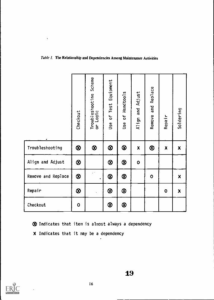
The framework is constructed on the basis of assumed dependencies. Table 1 presents a structure forconsidering this rationale of dependencies. This table indicates that troubleshooting is the most complexand demanding task. Within the concept of troubleshooting is included not only fault isolation but also thenecessary activities for returning the equipment to field ready use once a fault is isolated. Within the faultisolation portion of troubleshooting, several types of activities are required. Fault isolation usually requiresthe use of a checkout procedure to surface "out of tolerance" conditions. It requires the use of somecognitive activity usually structured in terms of some sort of troubleshooting scheme, strategy or logic. Butthe execution of this scheme requires that the troubleshooter gather information about the operation of theequipment under test. This requires the proper use of test equipment. It makes little difference how goodhis cognitive scheme for fault isolation is if his improper use of test equipment is feeding him faultyinformation about the equipment's operation.
If we give a subject a fault to isolate and he fails to isolate it, his lack of ability could be: the result ofimproper checkout, a faulty cognitive process, improper use of test equipment or inability to use handtools. We have no way of knowing which one from this test alone. But if we have given him subtests on useof test equipment, on use of hand tools and on the checkout procedure and he has demonstrated that hecan perform these activities, we can be reasonably sure that his cognitive processes are at fault. If on theother hand such subtests indicate that he cannot use his test equipment properly, there is little to be gainedby concentrating on the cognitive processes until his lack of ability to use his test equipment has beencorrected.
Once the troubleshooter has isolated the fault he must take the necessary corrective action to returnthe equipment to field ready condition. This could include align and adjust action, or remove, replace orrepair actions including soldering. A weakness in any one or all of the eight activities indicated in Table 1for troubleshooting could result in the troubleshooter not returning the faulty equipment to field readycondition.
The table also indicates that align and adjust procedures, as well as, remove and replace, repair, andcheckout procedures may under certain job conditions be considered independent activities, each in its ownright, with its own set of dependencies. The tests and subtest developed during this effort reflect theframework indicated in this table and in Figure 2.
The fifth step is to de:ermine the means for measuring the task output or product that will indicatethat the task has been contpletely and correctly performed. This is accomplished by inspecting the finalproduct to see if it meets specifications. In practice the test administrator does not necessarily have to makea special measurement of his own. As a rstical matter he can observe the unit check-out results obtainedby the test subject in lieu of making th*-: checks himself. But the test should state, for the Test Admin-istrator (TA), what the specifications for each product are (by reference or with a special piece of paper,template, or whatever is necessary). The TA merely scores the test subject as "go" if his product meets allspecifications or as "no-go" if any product specifications are not met.
It should be noted that some products become "sealed units" when they are repaired. In this eventthe TA must be told to make certain inspections before the unit is "sealed." For instance, a lubricant maybe placed in a unit before it is closed up The test administrator cannot determine whether the correctlubricant has been used, or if any has been used, by inspecting the sealed unit. He must observe themarkings on the lubricant container during the performance process to see if specifications have been metThere are other instances in which the easiest and best way to measure the product specifications is toobserve some aspect of the performance process. But this performance is not scored as a performance. It isonly used as a convenient way of measuring part of a product specification.
The sixth step is to determine how to simulate the input and output conditions for the test in thesame way they occur on the job. In the case of mechanical or electronic maintenance the input conditionsmay occur in several ways. For instance, a supervisor may be part of the input conditions. He might say,"There is a crack in the drive shaft. I want you to take this section out and replace it." Or the same man
1518
Table
I. The
Relationship
and
Dependencies
Am
ong
Maintenance
Activities
.1.4 U
W.0
(..)
EwcU
(1)oc
.--4--2 oo
_c
13
o
=J0
s-
s-1 0
4--) cwE
a,- =
cr
Lo+
1 0w
oW0=
V)
r^ oo
4--2-0Cm
o0=
+10=
-;-0
cc
-0c
cn.
wo
maw
c4-o 0
>o E
wcc
,-
Mo
Wcc
0:W
-01-6
,..)
Troubleshooting
OD OD
OD
OD X OD X X
Align
and
Adjust
OD
OD
OD 0
Remove
and
Replace
®
.
OD
OD 0 X
Repair
OD
40
OD 0 X
Checkout
0 OD
OD
®Indicates
that
item
is
almost
always
a dependency
X Indicates
that
it may
be a d
ependency
19
16

might discover the same crack while lubricating a joint on the drive shaft. Or it might be discovered during aroutine inspection: The question for the test developer becomes one of "which condition to simulate." Theanswer is quite straightforward. It is to state clearly what it is you are simulating in the test. If you want totest the man's ability to remove and replace the driveshaft, start with input conditions that tell him toremove and replace it, just as a supervisor would do on the job. If you want to test his ability to recognize acrack then use input conditions which start with an inspection. The test constructor must state what it isthat has been tested, and he must give the specifications for it.
He must also use the proper input conditions for the situation he says he is testing. For the test thisinput condition must be standardized; e.g., the same crack for all test subjects. A hairline crack should notbe used for one man and an eighth-inch gash for another. The same thing is true for failure. The causeusually must remain a constant condition of the test so long as it is being used for a particular purpose. Inaddition to specifying the means for measuring the main job products, subtests also require the creation ofsimulated job products or outputs. For instance, it special test equipment such as an oscilliscope isseparated out as a subtest, a "simulated product" may have to be generated for it. By making this a subtest,we have taken away the regular job product: a repaired item of equipment. We must create a replacementproduct. The replacement should impose the same demands on the test subject, with respect to theoscilliscope, that the regular job does. The substitute product should have output specifications similar.tothe real job product. Also a similar input should be provided.
But the process can be attenuated. An example of this attenuation is as follows: A substituteequipment to be measured by an oscilliscope would Se generated. It would produce a signal similar to thereal equipment. But it would not require the test subject to find the right place to measure, or even whatthe measurement should be. It would not require any further processing other than to be measured by anoscilliscope. This greatly attenuates the job process and leaves only the requirement for a measurement bythe oscilliscope. This attenuation is a major way in which the administration of the battery of criterionreferenced JTPT is simplified and made feasible.
But this item of substitute equipment must give the test subject no hint of how to operate hisoscilliscope to get the right output from the equipment. The output of this substitute box is known by theTA. The test subject's job is to compare his reading with a reading given him for this substitute equipmentand say whether it is good or bad. This is the same thing the job requires. The test should not require thetest subject to verbalize or write the output in volts, microseconds, frequency, etc., but only to say good orbad, as the job requires. Examples of such substitute products for subtests are presented later in thisvolume.
The seventh step is development of the administrative arrangements for the tests, The decisionsregarding criterion test items and their specifications have a direct impact on how the test will be admin-istered. It must be remembered that the (administered) situation for each test item must allow for the testsubject to produce a job referenced product or output, Within this condition every effort must be made tomake the tests simple to administer. In some cases it may be necessary to reexamine the criterion productin order to devise a more administratively feasible method of evaluating performance.
The primary administrative considerations are cost, time, test security, administrator-test subjectratio, equipment degradation, and administrative instructions. After establishing the administrative detailsof the test, a final product or output still must be producted or the process performed must be tantamountto producing the product. An example of a process stopped short of a product which is consideredtantamount to production of a product is as follows:
A faulty part is inserted in the equipment by the test administrator,The test subject's job is to restorethe equipment to field ready condition. He goes through whatever process he chooses to accomplish this.But to achieve the final product the final step in this process is to unsolder the faulty part and solder in agood one (then check to see that this accomplishes the repair).* Administratively this last step is undesirable.Administratively it is much more efficient to stop the test subject before he unsolders the faulty part.(Soldering and unsoldering places much wear and tear on equipment and, in a test situation, equipmentwould soon wear out around this faulty part.) Also the equipment with the same faulty part is needed forthe "next" test subject. But if we accede to these administrative efficients, we are not producing theproduct of a field ready item of equipment. In the present tests this dilema was resolved by saying that theidentification of the faulty part was tantamount to producing the final product. Soldering and unsoldering
2017

of parts were tested in a subtest, and it was assumed that if the test subject could solder and unsolder parts
in a subtest he could do the same in the main test. But this was an assumption. It is open to question atany time, It can be answered by having the test subject complete the job product.. This option is alwaysavailable in a criterion referenced JTPT. But this does not mean that the option mustalways be exercised.
The present writers feel that it is sufficient for the option to exist and the assumption identified as open tochallenge. This is the same basis on which a framework of subtests is established. These concessions aremade to make the tests more administratively feasible and here the matter must rest. The test constructorcan resolve the administrative dilemmas any way he chooses. But he must state what he has done so thatthe ultimate criterion reference is always attainable if sufficient administrative resources are expended to
achieve it. It is not desirable to make these administrative concessions. To some extent they weaken thestrength of the reference to the job criterion. But it is not a bad compromise so long as the reference thread
is not lost and can be established to "test the test" at any time.
Other Approach Considerations
The following discussion broadens the issue just introduced to aspects of the electronic maintenancejob other than troubleshooting to a faulty part.; In performance testing, the equipment damage considera-
tion is a major one for several reasons. First, the equipment must operate properly and reliably to permitsmooth progress of the test administration. Equipment down time can ruin a testing schedule. Secondly,since students will be altering the equipment, there is a possibility of equipment detuning and of testcompromise by overworking a given part of the equipment.
Several steps can be taken to overcome these tendencies. First, keep the test subject's equipmentalteration requirements to a minimum. In the troubleshooting portion of the tests developed in this project,test subjects are not permitted to unsolder and connections. A replacement routine is utilized instead.- Thetest subject soldering capability is then tested on work samples which are not part of the prime equipment:When it was not possible to conduct the test without test subject alteration of the equipment, as inalignment or component removal and replacement, detailed instructions and aids were developed for theTest Administrator, so that he could quickly restore equipment to its proper operating condition withoutthe use of sophisticated test equipment.
Second test administration procedures and instructions should be set up so that the normal technicalsupervisor can administer the tests with a minimum of difficulty. By keeping the administrator require-ments for technical expertise to a minimum, the probability that the tests will be properly administered willbe increased. Administration instructions must be explicitly detailed and amply supplemented by graphicdepictions of equipment test configurations. In addition, Test Administrators should be given practice inadministering he tests to become familiar with testing idiosyncrasies.
Tryout and Revision
The eighth and final step in, test development is tryout and revision. For performance testing the TestAdministrator tryout is as important as the test subject tryout, if not more so. The purposes of the tryoutare to ascertain whether the written instructions communicate as intended and to determine the feasibilityof test procedures. In this project, several such tryouts were held at various stages of development andproved invaluable in pointing up where instructions were inadequate or confusing and for verifying testprocedure feasibility. Such trials, of course, are much more meaningful if the samples of test subjects andadministrators approximate the ultimate target population.
Summary of Steps for JTPT Development
1. Identify major classes of job tasks.
2. Define and describe each class of tasks in terms of inputs, outputs, and processing conditions.
3.; Select a representative sample of job products or processes to be measured.
4. Construct a frame work of subtests referenced to the main criteria.
5. Specify standards by which to evaluate output
6. Simulate input and output conditions in job-like ways.
2118

7: Develop the administrative arrangements for the tests.
8. Try out and revise the tests.
Relation to Previous Efforts
Performance tests are not new in the Air Force. Many have been developed on an ad hoc basis for usein research concerning training. During and after World War II the Air Training Command used elaborateand comprehensive check rooms in their technical schools. Some of these operations still exist on a modestscale. What is new is the systematic approach for developing JTPT, the results of which will be moremeaningful in terms of demonstrated performance of typical job tasks. Important aspects of this approachinclude the following:
1. A more precise description or definition of ajob criterion in terms of job products has been usedconsistently throughout the tests. This criterion of specified job products is used (criterion referenced)rather than stating that some percentage of the total number of necessary performance steps in theproduction process is correct (norm reference). This is the essential difference between a criterion refer-enced test and a norm referenced test.
2. But beyond that, the present study is intended to describe systematic ways of dealing with themany types of activities that are contained within a single job: This is done through a classification ofmaintenance activities and a framework of subtests referenced to a single criterion of producing field readyequipment. Electronic and mechanical maintenance jobs have the characteristics of many types of taskswithin one job. To treat them, the concept of criterion referenced testing had to be extended in some way.This is a report of one way in which it was done in a manner making such tests administratively feasible.
3. Each type of job activity has been considered separately for the purpose of test development andscoring. A number of tests have been developed for each type of job activity.
4. Since the factors being measured are so complex and diverse, the result of each test is reportedseparately. No attempt has been made to report test results in terms of a meaningless single score for anindividual.
SECTION II. TEST DEVELOPMENT
Introduction
As stated previously, the prime equipment selected for this project was the AN/A.PN-147 DopplerNavigational Radar and its associated AN/ASN-35 Computer. This equipment is standard on several opera-tional aircraft and its maintenance is fairly complex. Responsibility for its maintenance is assigned topersonnel with Air Force Specialty Code (AFSC) 328X4, Avionics Inertial and Radar Navigation SystemsTechnician. This AFSC is also responsible for many other electronic systems, and an individual in thisAFSC may or may not be exposed to all of these systems during his time as a technician. The intermediatelevel of maintenance was the primary concern of this project. Most organizational activities also areincluded in intermediate maintenance activities. As a' result, tests for organizational maintenance can bereadily developed using the tests developed for this project as models.
Throughout the development of all of these criterion referenced JTPT, the steps outlined in Section Iwere followed. The following discussions concentrate on the peculiar problems that were associated withthe development of each type of test.
Troubleshooting
The objective of the troubleshooting process is to isolate the faulty component and to return theequipment to a field ready condition. The first step taken was to identify the range of equipment faultsthat could occur by analysis of the equipment. This was done by identifying from the equipmentschematics all of the "functional elements" or "stages" of the system. Then a piece part from each stage
1922

was identified as a candidate for fault insertion. These parts were selected so as to provide a basis fordevelopment of both "within-stage" and "between stage" troubleshooting tests, since both types oftroubleshooting are required at the intermediate level of maintenance. Figure 3 lists the functionalelements, references the schematic from Technical Order (TO) 12P5-2APN147-2, and identifies the partselected for faulting, along with its identification from the TO.
These tests are administered at a normal work station where all of their usual job aids, such asreferences, test equipment and hand tools, are available. The test subject is told the equipment is mal-functioning and is given several symptoms of the type that would normally be on the tag when theequipment comes into the shop from the aircraft. The test subject is instructed to isolate and identify thefaulty component. He is told that he may use any procedures, references, or test equipment which hechooses. (None are suggested, recommended, or graded). To this point the test situation exactly duplicatedthe job situation. However, at this point there is a deviation to increase administrative feasibility., The testsubject is instructed not to unsolder any parts in the equipment. He is told that any time he wants toreplace a suspected component he is to remove the module containing that part and request a module fromthe TA which contains a replacement for the specified part. The TA will take the module and, if thereplacement part requested by the test subject was in fact the faulty one inserted into the equipment, agood module is returned to the student. If the replacement part requested by the test subject is not thefaulty one, the TA, after a standard delay, will return the module to the subject indicating that thesuspected component has been replaced.
After the exchange, the test subject has to replace the module and determine whether the fault hasbeen found (checkout). When the test subject performs the checkout and is satisfied that he has found thetrouble, he lists the faulty part on his answer sheet and turns it in. That completes the test. His answer sheetcan then be graded on the basis of right or wrong on a measure that is tantamount to producing the finalproduct.
To provide additional diagnostic information about each test subject's performance, the TestAdministrator will record each part that the subject requested and the subject will indicate what testequipment he utilized. in this way, a complete record of the individual's troubleshooting strategy will beavailable. This information on process may be of interest, but in terms of scoring, only the faulty part listedby the test subject on his answer sheet will be graded. The test subject identifies the faulty part or hedoesn't (go, no-go). (A detailed description of all graded items is included in Section III.)
While this "module exchange" technique represents a difference from the job situation, incorrectestimates of the problem still penalize the test subject by requiring him to remove a module, present it tothe TA, describe the suspected malfunctioning part, install the replacement module, and check it out. Thisprocess will generally be equal to or slightly less than the time normally spent by the technician inunsoldering, testing, removing, acquiring a replacement from supply room, and installing a new component.While the activities are some what different from the actual troubleshooting activities, they do not promoteor reward significantly a typical behavior on the part of the technician (e.g., random trial and errorsearching does not have either a higher payoff or lesser penalities than in the actual job situation).
Time to Perform
The amount of time required to correct the equipment and bring it to field ready status is a functionof a number of factors. There is some theoretical minimum time required to perform each process. But likea "four minute mile," the absolute minimum time is never known for certain in practice. The theoreticalminimum time required for accomplishing each process in the test could be estimated. For instance, atechnician might be rehearsed on a procedure for a day or so and then timed with a stop watch. But there isa question of what this would mean in terms of job standards. In electronic and mechanical maintenancejobs, there are no exact time standards on the job. There are estimates of what is "reasonable." But in thefield shopjob incumbents are not usually held to strict accountability for performing within these times.(Time to perform on the flight line at times is more critical than in the shop).
So for these tests there were approximations made of how much time each process would require.This time was "tried out" in pretrials, rounded off to quarter hour increments and used. The final timelimits on each test item represent an amount of time that a supervisor would "not complain about" if a job
20 23

Schematic
Frequency Tracker
Power Supply
(Fig. 8-36)
Frequency Tracker
Power Supply
(Fig. 8-36)
(3)
Modulator
(Fig. 7-15)
(4)
Modulator
(Fig. 7-15)
(5)
Modulator
(Fig. 7-15)
(6)
Modulator
(Fig. 7-15)
(7)
Modulator
(Fig. 7-15)
(8)
IF Amplifier
(Fig. 7-17)
(9)
IF Amplifier
(Fig. 7-17)
(10)
IF Amplifier
(Fig. 7-17)
(11)
Electronic
Control
Amplifier
(Fig. 8-30)
Part
Nubber
V-07
(6080WA)
CR-03
(IN256)
Q-07
(2N491)
R- 34
(2 7K)
C-03
(4700PF)
L-01
C-27
(82PF)
V-01A
(5670)
R-08
(5.6K)
CR-01
(IN277)
R-37
(10K)
Schematic
Part
Number
(12)
Electronic
V-02
Control
Amplifier
(Fig. 8-30)
(5670)
(13)
Electronic
R-26
Control
Amplifier
(Fig. 8-30)
(14)
Electronic
Control
Amplifier
(Fig. 8-30)
(470K)
CR-01
(IN756)
(15)
Signal
V-02
Comparator
(5725)
(Fig. 8-28)
Signal
Comparator
(Fig. 8-28)
Signal
Comparator
(Fig. 8-28)
Frequency
Mixer
(Fig. 8-26)
(19)
Frequency
Mixer
(Fig. 8-26)
C-14
(.047uf)
R-21
(120K)
V-01
(5670)
C-15
(6000PF)
Figu
re 3
. Fun
ctio
nal c
ompo
nent
s fa
ulte
d.
Schematic
(20)
Frequency
Mixer
(Fig. 8-26)
Part
Number
K-01
(21)
Relay Chassis
CR-24
Assembly
(1N2070)
(Pig. 7-45)
(22)
PNP Multiar
& F/F Board
Assembly
Q- 04
(2N502A)

incumbent took that amount of time to perform that task on the job. It is a great administrative con-venience to have set amounts of time for eact item. But the time limits should be set so that test subjectsfailed because they didn't know how to perform, not because they weren't fast enough.
The question of using time as a measure of performance effectiveness could be argued. That is, itcould be argued that a man who performs in less time than another man is "better." Time to perform is animportant norm referenced concept: to compare times for individuals in training required to reach the "go"criteria on the various criterion referenced tests may become an important factor for the standardization ofselection tests. But time is not germane to the criterion referenced aspects of criterion reference tests asdefined here that is, the product which the test subject generates. Generally, individuals are not ratedprecisely on their speed of performance of maintenance activities on the job. To repeat, the time limits setfor each test item is a time that supervisors would accept as OK.
Prompting
No "promptings" are allowed in the test: The TA is under strict instructions not to helpor prompt atest subject, There is no way to standardize these "prompts." One type of prompt may make the differencebetween accomplishing the product or not. Another may save the test subject a minute or so and stillanother "prompt" may interfere with the test subject. So it is of little value to count the number ofprompts, as they do not have an equal effect on test subjects. It is true that a man might receive a"prompt" on the job, particularly if he asked for help. But in such a case the man is not actuallyperforming the whole task on his own, he is receiving help. Each performance test is designed to ascertainwhether the test subject can perform the task on his own, not how well the TA can perform the task. Andfinally, when TM are allowed to give help, they have been known to virtually "take over" from the testsubject and do the job themselves. This array of reasons against promptings makes it very clear that TAmust be strictly prohibited from prompting test subjects. Experience from this project indicates that TAscan be prohibited from this kind of interference with the test, but it does require stern admonitions,sometimes multiple.
This is not to say that a TA cannot derive diagnostic information from observing a test subject'sperformance. That is, even if he is prohibited from prompting the test subject, the TA can still try todiagnose why the test subject gets "hung up" at certain points. (It is the opinion of the authors that thediagnostic nature of the subtests is much more useful than the diagnoses of a TA made during a test. Aformal record of inadequacies on subtests is felt to be more useful to a training operation than are thefleeting impressions and hypotheses of a TA. This is not to say that the TA can't develop some judgementsbased on test results.)
Application of Rationale
With this generartesting rationale developed and with the equipment functional components defined,it was then possible to develop a series of troubleshooting tests that represent within and between stagetroubleshooting for the AN /APN- 147- AN /ASN -35 system. Several sample tests were prepared along withthe necessary test administration instructions and both were tried out on a group of technicians. Thisadministration demonstrated that the component exchange rationale was feasible and easily handled byboth the student and the TA. The ground rules concerning time to perform and prompting also wereapplied to the development of the later criterion referenced JTPT.
It was also discovered that test subjects tended to go first into an alignment/adjustment routine whenpresented with an inoperative set of equipment. Since these skills were to be tested separately and since, forpurposes of the troubleshooting tests, no random adjustments of the equipment could be permitted, aspecific instruction was added to each test stating that the test problem was not a function of a misalign-ment.,
Alignment/Adjustment/Calibration
Equipment calibration is a major task of the electronic technician. This task is variously called"alignment" and/or "adjustment." An initial attempt was made to differentiate between these terms forpurposes of test rationale development. Adjustment is generally taken to mean manipulating controls to
22 25

bring a series of equipment parameters into alignment. However, since alignment checking also requirescontrol manipulation, it was found that no meaningful and consistent difference exists between them fortesting purposes. Therefore, the same testing rationale was applied to both. The test categories "alignment"and "adjustment," then, reflect only the terms applied to these activities by the official TO.
To discover the nature of the alignment task, (i.e., inputs, outputs, processing), the proceduresdescribed in the TO for this equipment were exercised and analyzed. In attempting to carryout thealignment and adjustment procedures for the AN/APN-147-AN/ASN-35 system, it was found that the TOfor these procedures could not be followed in all cases. If a technician attempted to follow someprocedures, he would not be able to accomplish the task. This poses a problem for the test constructorbecause he has no way to correct the TO in a formal authorized way in the time available for testconstruction. So he should avoid such problems by selecting other items for his test. But in some cases, likethe present one, this was not possible. One particular procedure was a very common one for the check outof many equipment repairs, so it was included in the test battery,
In this case the local solution was accepted as correct for the purposes of the test. This meant thatinput conditions for the test were established in accordance with the local procedure. The special test jigswere included as part of the standard equipment provided the test subject. He could use them or not as hechose., The criterion was correctly adjusted or aligned equipment regardless of what process the test subjectused to achieve IL
It is necessary to have measurement criteria which can be applied consistently from installation toinstallation, and person to person. Therefore, alignment items were selected that give constant values andcan be set and unset by TA without going through complicated adjustment procedures themselves. Thisrequirement for administrative simplicity eliminated some alignment items from inclusion in the test. Butthe few excluded items turned out to be some of the rarely performed alignment procedures. This trade-offwas considered acceptable to simplify the test administratively.
The testing approach developed was administered as follows: The TA sets up the problem bymisadjusting a specified parameter. The Test Administrator's Handbook [AFHRL-TR-74-57(10, Part 11]includes instructions to the TA regarding the specific control to adjust and provides him with pictures ofprecisely where each control is located. The test subject's instructions then tell him to check a specificalignment (e.g., "Lock-Check Alignment" or "Frequency Modulator Adjustment") and to adjust it ifrequired. He then must demonstrate to the TA that the parameter has been adjusted to within tolerancelimits. He does this by obtaining the required value on an appropriate item of test equipment and havingthe TA check it. This is the criterion output measured by the TA. The TA completes an evaluation sheet toindicate whether or not the test subject successfully (go, no-go) performed that alignment according tospecifications. The test subject completes a sheet of diagnostic information on which he indicates whatequipment he utilized in performing the alignment. This information is part of the diagnosis of hisperformance process, but not part of his score.
Whenever test subjects are required to make adjustments or alignments, some subjects are going tomake "over" adjustments resulting in badly misaligned equipment. The TA should be able to quicklyrealign the equipment. Therefore, in addition to the graphics and value descriptions for measuring thecriterion output, a series of plastic adjustment templates or guides were developed. With these key guidesthe TA can quickly bring a set back to within acceptable operating conditions for test purposes. Thesetemplates are unique to a given type of equipment, but such aids can be constructed for any equipment. Itwas found during the test that the aids would work properly on all equipments used in the test though ithad been anticipated that they might be unique to a given set of equipment. (Such aids could be consideredfor use on the job, but that is beyond the scope of the present project.)
When subjected to preliminary tryout, these procedures proved to discriminate very well betweenindividuals who could and could not perform specified alighments.
Tests on Use of Test Equip.s sit
An examination of Table I indicates that the use of test equipment is an important commonsubactivity of all product producing activities. What the table does not show is that there are generally two
23 K

categories cf test equipment special test equipments that are specific to a certain prime equipment suchas the AN/APN-147 and the AN/ASN-35 and general test equipments that may be used with theAN/APN-147 and the AN/ASN-35 as well as with many other prime equipments. At the intermediate level
of maintenance for the AN/APN-147 and AN/ASN-35, as it is currently structured, the following seven testequipments are required:
1. Tektronics Oscilloscope, Model 545B
2. Voltohmeter, PSM-63. Transistor Checker, Model 1890M4. Electron Tube Test Set, Model TV-25., Audio Oscillator, TS-3826. Signal Generator, AN/URM-25D7. Doppler Generator, CMA-546A
Of these seven test equipments, only one, the Doppler Generator, CMA-546A, is specific to theAN/APN-147 and AN/ASN-35. The AN/ASN-35 and AN/APN-147 equipment has the characteristic that itmust be stimulated by this special generator and have special procedures performed on it in order to obtainoutputs from it. The others are six general items of test equipment which are used.for testing many items ofprime equipment. The developmental considerations for each test equipment subtest constructed for thiseffort are discussed below.
Oscilloscope Test
The oscilloscope has a wide variety of features and capabilities: more than are needed in most jobs,including the present one. A special input simulator (waveform generator) was constructed to serve in placeof the prime equipment for this subtest. It required the same type of output measieremen s as did the primeequipment. Therefore, test subjects used those features of the scope which the prime equipment required toobtain diagnostic information.
This waveform generator was designed to produce a variety of waveforms on the scope. A schematicof this generator is shown in Figure 4. The components were then enclosed in a box and a dumniy circuit(Figure 5) depicted or the cover of the box, integrating the leads from the circuit 'nside. This was done sothat accomplishea technicians could not solve the problems by inspection of the simple circuit inside.
A series of equipment outputs was then defined which the test subject has to obtain on the scope.Each of the outputs is the waveform present at a specified test point. He must then compare thewaveform obtained on the scope with the one drawn on the answer sheet for that item and indicatewhether the two are within specified tolerances of each other, The waveform obtainable at any given testpoint is, of course, constant., By varying the standard given on the answer sheet, however, the answers todifferent forms of the same problem can be varied. This is a substantial gain in administrative feasibility.
The test subject also recorded certain control settings used in theadjusted the equipment and properly evaluated the value of the resultthan a "no-go." To disguise the critical control settings, several extra sThese are not evaluated in the scoring. The test subject's answers, theprocessed immediately or later.
problem. He must have properlyt waveform to get a "go" rather
ttings are required to be recorded.n, are recorded on paper and can be
The test probe calibration is an operation which the TA must evaluate separately.. This is necessary toinsure that the probe was calibrated before each test subject started his test. It was included as the firstproblem for administrative convenience.
Several tryouts of this test were required to debug the instructiqns associated with the test. Theseinstructions were more complicated than those required in other tests and it was also difficult to findpersonnel sufficiently familiar with the scope operation to apply the instructions. This provides evidencethat training in the practical use of the scope should be improved and that the present subtest would be auseful one in electronic technician training programs.
24 27

co
USE
TR
IM
(P
OT
1004
1-
5K
US
E M
ER
CU
RY
BA
TT
ER
Y
Vec
+G
VD
C
470"
.
I
3 IN
PU
T G
AT
E
1.8K
II .005
J-K
FF
I
OU
TP
UT
10
OU
TP
UT
2
Figu
re 4
. Sch
emat
ic d
iagr
am w
avef
orm
gen
erat
or c
onso
le.
MI
I
9 H
EP
558 65
J-K
FF
2
F--
-o O
UT
PU
T 3
500

CIN'A 6; ," N\:C
Ni)
r:111klY "a,
wpop,1477P
fA
1,
144 11.-wtf-- i-D\V
. a
. li !r".s&bS
i-ni
0 0114
,Oe3
74
\kZ-1t,
cl0Cam!:e
VePia AR.A. __I
) . - \/Li- *go ,v,.
i. i (b
1°A41 alVirnAle
krilOreiial 141- 1 . - ; I * eIt r"".. iriltv- e (3, ' ?:-.;I),.. c.viTik 0 w._1....,( le...., N Ns,.
\ 7 J P..ar it?",..
\ kkk ,4t ILa I
0-)

Voltohmmeter Test
The primary skills associated with voltohmmeter usage are voltage range settings, meter reading, andknowledge of where to apply it on the equipment: The last named skill was not included in this particularsubtest-because it is part of each troubleshooting test.
To provide a standard test environment, a voltage generator was constructed to give a variety of ACand DC outputs. The different voltage outputs and resistance values are achieved by turning the selectorswitch to specified positions. The test subject's answer sheet lists specified value tolerances for eachposition. The test subject must measure the existing value at that position and indicate whether he found itto be in or out of tolerance. This permits, as in the oscilloscope test, the development of alternate testforms. A schematic of the AC/DC voltage generator is displayed in Figure 6. The test box in which it isenclosed is displayed in Figure 7.
Transistor Checker Test
The 1890M Transistor Checker is an in-circuit testing device that permits the testing of a transistorwithout removing It from the circuit. To provide a suitable subtest, a printed circuit board was utilized thatincluded a variety of transistors. Since the 1890M provides a wide range of measures, the subject is requiredto make a series of measurements on several test transistors and to record both the parameter values foundand whether the transistor is good or bad. This provides an evaluation of the test subject's ability to employall of the features of the 1890M. Alternate forms of the test were developed by varying the transistors to betested. It might be noted that this subtest does not require the test subject to use this equipment in thetests. It merely measures his ability to use it.
Electron Tube Test Set, Model TV-2
The TV-2 checks a number of parameters of vacuum tubes, as the 1890M does for transistors.However, the TV-2 checks tubes on an out-of-circuit basis. The test subject is required to record a series oftube parameter values for several specific tubes and also indicate whether the tube is good or bad. Alternatetest forms are provided by varying the tubes provided.
Audio Oscillator, TS-382
The audio oscillator is a frequently used item of test equipment. It is used to generate standard signalsfor input into a system for alignment purposes. The technician must be able to use this piece of equipmentto perform various adjustments on the AN /APN -147 system.
To test the test subject capability to use the device, he is told to set up for a specified equipmentalignment., He is further instructed that he must utilize the TS-382 in this alignment process. This and thecriterion measure are the only difference between this test and the corresponding alignment test. When hehas the equipment set urand operating, the test subject must demonstrate to the TA that he is getting theproper value reading at a specified point on the prime equipment, This indicates that the TS-382 has beenproperly connected and adjusted. The TA then completes an evaluation sheet to indicate whether the testsubject was successful or unsuccessful,
Signal Generator, AN/URM-25D
This equipment performs the same type of function as the audio oscillator except it generates signalsin the RF range rather than in the audio range. The same testing approach is used as in the audio oscillatortest,
Doppler Generator, CMA-546A
The doppler generator is used only with the AN/APN-147 and drives the equipment for a specificoperational check. To test the subject's ability to employ this test equipment item, he is instructed to set itup and to demonstrate its use to the TA. The TA in turn has an evaluation sheet of standards to which theprime equipment must perform if the generator has been properly connected and adjusted. As the testsubject demonstrates the use of the generator, the TA completes the evaluation on each output specifications.
27 30

6.5
VA
C13
VA
C19
.5 V
AC
26 V
AC
TI
O
R II
26.8
VD
C'N
A&
I KC
lii., AI E
zz 3
.9V
22.9
VD
C
CR
2..-
Alz
s 4s
7 V
18.2
VD
C
OF
F 0
UN
US
ED
()
SE
LEC
TO
RS
WIT
CH
SE
CT
ION
"A
"
4
CO
MM
ON
ME
TE
R
CR
31-A
-Ezs
8.2
V10
VD
C
CR
4 ,,
- A
LE
zz 1
0 V
=
1037
-^-
630
VD
C
I K-r
t 3727
" 10"-
10" O
a,9
OF
F 0
O /1
0-
/ 0 /i-
/
\/
\/
\/
\ - -
.....
-J
2(1
)3
/ /
R4
R5
,
10K
"47
K".
581"
d_ 07 1
58".
0625
8 K
."-
0?.._
.gi_
iIC
.".
1.7
Mit
RT
R8
100K
"
100
Kft
470
K-"
-
R92
1M
"
Fig
ure
6. S
chem
atic
dia
gram
vol
tage
/res
ista
nce
teat
con
aok.
SE
LEC
TO
R S
WIT
CH
SE
CT
ION
"8"

Figure 7. Voltage/resistance console,
3229

Operational Checkout
The equipment checkout task constitutes the beginning and ending point for all other task and joboutputs. It consists of making a proper bench setup of the prime equipment and the doppler generator, andthen exercising the equipment according to TO procedures to ascertain that it is functioning properly.
For test purposes the TA, after checking that the equipment is functioning properly, disconnects thebench setup. The test subject is then required to re-establish the checkout setup and demonstrate to theTA, via operational checks, that the equipment is functioning properly. The TA then records whether ornot the test subject was able to perform the required demonstration. The TA scores the performance in ago, no-go manner depending on whether all the outputs are according to job specifications or not. Inaddition, there is considerable diagnostic information available which could be recorded if desired.
At the present time, it is felt that the Checkout and Doppler Generator subtests are too similar to beseparate, and the Doppler Generator Test should be eliminated. The ability of the test subject to connectthe wiring harness might be kept as a separate subtest, but a man could easily go through years of job dutywithout having to perform this task.
Removal and Replacement Tests
The technician must disassemble and assemble the prime equipment in order to carry out his trouble-shooting and alignment tasks and to replace faulty components when found. This subtest consists ofidentification of the proper component and proper use of hand tools so as not to damage the equipment orcomponents. A series of typical components, that the test subject has to remove and replace on theAN/APN-147-AN/ASN-35 system, was identified. Each item constitutes a separate test in which he must:
1. Insure that the test equipment is functioning properly (perform operational check-out which willbe already set up for him).
2. Locate the component specified for removal.
3. Remove the component from the equipment and show it to the TA.
4. Replace the component in the equipment.
5. Deomonstrate proper component replacement by performing on check-out for theTA.
The TA will evaluate and record the subject's performance on these tests. The subject will be im.edon the basis of whether he removed the right component and whether the equipment functioned correctlyupon re-assembly. To aid the TA, a series of photographs is provided showing the equipment and thecomponent in both their assembled and disassembled configurations. This test series does not includeremoval and replacement tasks that require soldering. Due to the high probability of equipmentdegradation, all soldering skills are evaluated separately in a subtest utilizing expendable components.
Soldering Tests
This series of tests was provided to cover the soldering tasks. The soldering task consists of severalassociated elements. Viewed in sequence, the total soldering task proceeds as follows:
1. Unsolder while disconnecting the proper leads to remove faulty component.
2. Select proper replacement component.
3. Install replacement component:
4. Re-connect all associated leads.
5. Solder.
The soldering tasks related to the AN/APN-147-AN/ASN-35 are of two types conventional wirecircuitry and circuit boards. To test both types, as well as soldering and associated tasks, two subtests weredevised. One test requires modification of a conventional circuit and the other requires circuit boardsoldering.
30 33

For the conventional circuit soldering, a dummy circuit was built and installed in a box of moderateconfinement. In this test the range of soldering tasks described above are evaluated. The TA must inspectthe test subject's work to insure that the proper component was removed, that the proper replacement wasinstalled, that the replacement was installed with the correct polarity, that excessive heat was not generatedon associated parts during soldering, and that a good solder joint resulted.;To perform this evaluation, theTA has a checklist, and the beginning and ending configuration Schematics. The TA must treat the leads ofthe test circuit with heat sensitive material that liquifies if too much heat is applied in soldering. Aschematic diagram of the starting configuration is shown in Figure 8, and a drawing of the enclosure isshown in Figure 9,
The second subtest, is conducted on a circuit board, The test subject is told what component toremove and which replacement to use. When he has completed the replacement, the TA inspects eachsolder-joint and compares it with pictorial representations of acceptable and unacceptable soldering. Hethen records his evaluation of the soldering on an evaluation sheet.
Summary
The framework of subtests developed in this project, their purpose, and the approach used aresummarized in Table 2. A sample of test materials including the test subjects information and identificationsheet, test instructions and answer sheets are displayed in Appendix A. In addition, a complete copy ofinstructions for each test subject for all the JTPT developed together with the Test Administrator'shandbook are provided under separate cover as AFHRL-TR-74-57(11), Part H.
SECTION III. ADMINISTRATIVE, SCORING AND DIAGNOSTIC CONSIDERATIONS
Introduction
Some of the administrative and scoring considerations have already been discussed in the precedingsections as they pertained to the test development technology and to the actual test development. Therationale of dependent maintenance tasks for electronic equipment maintenance, as well as, scoringconsiderations for these tests also have been discussed. But no scheme for systematically recording thesescores and applying the rationale has been provided. A proposed profile for recording and analyzing testresults in the light of the dependency rationale is presented in this section.
Additional diagnostic information is provided by detailed descriptions or the scoring schemeassociated with each individual test and a description of the diagnostic information provided by each test.Other considerations include individual and group uses of test as well as test security considerations.
The Reporting of Test Results
Tests, Problems and Scorable Results
The scoring rationale used throughout these tests is that only specifications of job products aremeasured and each of these job products is scored on a "go, no-go" basis. Table 2 indicates that tests havebeen prepared for seven classes of tasks; namely, (1) checkout, (2) physical skill tasks (soldering), (3)remove and replace, (4) test equipment, (5) adjustment, (6) alignment, and (7) troubleshooting.
Table 3 summarizes the number of tests, problems, and scorable products by class of tests developedfor the AN/APN147 and AN/ASN-35. The simple addition of numbers shown in Table 3 indicates thatthere are 48 tests, 81 problems, and 133 scorable products. But these numbers tell us nothing in terms ofthe content of the tests. To say that one test subject accomplished 100 scorable products while anotheraccomplished 90 tells us nothing about the job readiness of either of these individuals or that one is betterthan the other. The varieties of scorable products are so diverse that any combination of them withoutregard to what they represent is meaningless. The only meaningful presentation of such information mustbe in terms of a profile designed. to attach meaning to such numbers. A sample of such a profile is shown inFigure 10.
3431

Cl(
. luf200WVDC
V
R1 6KR2
-n. __,\AA,__> ISW 120 41-
1W atir
C2
I(47uf
1000 WVDC
47K /1. 270.n. CR1w ilw 1
47K .ii-1W
C3IC
.00auf200 WVDC
1.8K au1/2W
330K J11/2W
Figure 8. Schematic diagram, wire circuit soldering.
3235


TEST CLASS
Table 2. Major Test Classes
PURPOSE APPROACH
Alignment(AL Series)
Adjustment(AD Series)
Troubleshooting(TS Series)
Test Equipment Usage(SE Series)
0
Removal and Replacemen(RR Series)
Peripheral(PT Series)
Check-Out(CO Series)
To determine whether atechnician can performa representative setof alignments on theAN/APN-147-AN/ASN-35system.
To determine whether atechnician can performa representative seriesof adjustments on theAN/APN-147-AN/ ASN-35system.
To determine whether atechnician can locateand identify specificwithin-stage and be-tween-stage faults inthe prime equipment.
To determine whether atechnician can proper-ly use the test equip-ment specific to hiswork assignment.
To determine whether atechnician can correct-ly identify, remove,and replace a primeequipment module andretain the set in anoperational status.
To determine whether atechnician can solderproperly under jobconditions.
To determine whether a,technician can properlyconnect the subjectprime equipment to itsbench test set-up con-figuration and performoperational check-outof system.
A specific alignmentparameter is thrown outof tolerance and thetechnician must demon-strate that he can re-align the system.
As specific adjustmentis thrown out of toler-ance and the technicianmust demonstrate that hecan readjust the equip-ment.
A specific fault is in-serted into the equip-ment and the technicianmust locate and identifythe faulty component.
The technician is re-gulled to use a specificitem of test equipmentand demonstrate that hecan properly utilize thefeatures of that item.
Modules will be specifiedfor the test subject toremove and replace andupon completion," the
operational status of theequipment will be checked.
The technician must pro-perly identify, removeand replace a solderedpiece part in a testcircuit.
Require the technician toconnect the prime equip-ment to the bench testset-up and demonstratethat the required systemschecks can be made.
34
&MA 37

Table 3. Tests, Problems, and Scorable Products
.
Classes Code * Tests * Problems,
* ScorableProducts
1. Checkout CO 2 2 2
2. Physical Skill PT 2 5 17
Tasks (soldering)
3. Remove 8 Replace RR 10 10 20
4. Test equipment SE 7 37 67
5. Adjustment AD 6 6 6
6. Alignment AL 10 10 10
7. Troubleshooting TS 11 11 11
Total 7 48 81 133
35
38

MUMMUMMIMMUMMIUMMUMMU IIIIMMERMWOMMUMMINIMMENMONEMOMMEHMIIHMEHMINIM HIIIIMMEMEMUMMINIMMINIMEMI.-
011MM11MMOMMIIHMI11MIU1UNIM IIMMOMMOMMINIMHEMOMMOMMP, ONMEUMMOMMEHMMUMMIIMMUMEHMOMMOMMOOMHEMOMMOMMPMHEMBEMOMMMUMEHMEHMEHMIIHMMOM MEMOMMIIMMOMMOMMMUMMUMMOMMIIHMMUMMUMMHMEHMEMM OMMOOMOMMOMMOMILAINIMOMMMOMMEHMEHIMMINIMIHMMOMMOMMMEMOMMOMMOMMOHMEMMOMEMMUMMHIMMINIMMHINOMMMOMMOMEMEMMINIOMMMUMMOMMOMMMUMMUMMINIMMINIMMEMOMM MOOMMEMOMMOMOMESMEMMEMIIHMEHMEHMMOMMOMMOMMO MOMMIUMOMMOMMMM10011MMOMMEMMEMEMEMMOMMOMMMEMMEMMOOMMMEMEMEM
0
I

A Profile for Reporting Test Results
The profile provides reporting information and space for each problem. For example: there are onlytwo checkout tests; one for the AN/APN-147 and one for the AN/ASN-35. Each of these checkout testsrepresents a single maintenance problem. For each of these problems, there is only one output or productto be measured. When scored on a "go, no-go" basis, a test subject can receive only a 1 or 0 for either ofthese problems. This represents the case of one test, one problem, one scorable product.
If a test subject took the two checkout tests and demonstrated that he could perform the checkout ofthe AN/ASN-35 (Test 2) but was unable to perform the checkout of the AN/APN-147 (Test 1), theseresults would appear as follows on the profile chart.
TESTS
COx Checkout Possible score
Earned score
Bar presentation
The "0" shown in line 2 for Test 1 indicates that the test subject was unable to accomplish Test 1. The halffilled cell (0) on line 3 under Test 1 indicates that the subject has tried Test 1 but has failed. The "1"shown on line 2 or Test 2 indicates that the subject successfully accomplished Test 2. The filled cell () online 3 presents this same information in bar form. If the subject had performed both checkout taskssuccessfully, the bar would of course be solid.
The oscilloscope test (SE7) within the test equipment area represents another case. These are eightproblems in this test. Most of these problems contain more than one scorable product. For example,problem 2 contains six scorable products. But the test subject must obtain all six scorable products or ascore of "6" to receive a "go" on this problem. Since there are eight problems, the subject must receive:eight "go's" to indicate proficiency in the use of the oscilloscope. As an example (next profile chart), a testsubject was able to perform all the problems except. problem 5 and on problem 5 he only obtained three ofthe seven products.
TESTS 4
SE7x545B
SCOPE
A glance at the bar ofsthe profile indicates that the subject has tried all problems of the oscilloscope test,and that he has successfully performed all but one of the problems. It, also, tells us that he is not fullyqualified on the oscilloscope and will not be until he can perform the operations called for by problem 5.The objective of course is full qualification.
A nearly complete profile is shown in Figure 11. This profile indicates that the subject hasdemonstrated his ability to perform all of the test problems down to troubleshooting. To date, he hasattempted nine of the eleven troubleshooting tests and successfully completed eight of the nine tests. He,therefore, is not completely qualified in troubleshooting.
37 40

DEPENDENCIES TESTSSUB TESTS OR
PROBLEMS
1 2 3 4 5 6 7 8 9 10 11
COx Checkout
4/ /
and PT2x
Soldering
, / 5 5 5
/ / 5 5 5
RRx Ramon and
Replace
2 2 2 2 2 2 2 2 2 22 1 2 2 2 2 2 2 2 2.
, .
TEST EQUIPMENT
SEI AN/URN-6Signal Gen
SE2 CMA-546
Doppler Gen
SE3 TS-382Audio OSC
SE4 1890 M TransistorTester
I/ / /
SE3 TV-2 Tube
Tester
I/ / /
SE6 VOM
Prob 1-10
I/1 1111 I I I/ / / / / / / / / /
Prob 11-20I 1 I /111/1
/ / / / / / / / / /
SE7 545Scope
6 4 6 7 515 4/ I s 7 516 I
ADx Adjustment / / / / / /
ALx Alignment1111 I/ // / / / / / /
TSx TroubleshootingI/ I I 11/' / 0 / / / / / /
Figure 11. A profile for displaying the results obtained by an individual subject from a battery of Job TaskPerformance Tests concerning an Electronic System the AN/APN-147 and the AN/ASN-35. This representsthe profile of an individual who has successfully completed most of thilitery.
38

This profile is not presented as the final solution to the profile problem for JTPT for electronicmaintenance. It does contain most of the important information regarding a test subject's success on thefull range of tests. It gives a meaningful picture of the subject's job abilities as measured by the test battery,indicating the subject's strengths and weaknesses. An examination of the profile (Figure 11) indicates thatmost of the tests in this battery contain only one problem. For example, there are two checkout tests,having one problem each and there are eleven troubleshooting tests havingone problem each. There are twosoldering tests; one has two problems and the other has three. The Voltohmmeter (VOM) test has 20problems. The subject receives no "credit" for a problem unless he obtains all of the expected products. Noattempt is made, to combine these scoresTn terms of meaningless numbers.
Proposed uses of these tests and of this profile in field maintenance unit, formal training and researchenvironments will be discussed in Section VI of this report, The dependency column of the profile will bediscussed later under diagnostics.
JTPT as Analytical and Diagnostic Tools
Diagnostics have come to have a rather negative connotation identifying faults andascertaining what has caused the faults. Criterion referenced JTPT if proper]; ructured and used canprovide a large amount of such diagnostics concerning what is wrong with the world of maintenance. They,also, can provide a great deal of information concerning what is right with the world of maintenance. (Theword analytical has been added to the subtitle to reflect these positive aspects of the use of JTPT). Thefollowing paragraphs are concerned with ways and means for obtaining specifics about the world ofmaintenance.
Job Readiness. There are a great many contention concerning what it takes and how long it takes anew enlistee to become "job ready," but there is little hard data concerning the empirical or job relatedvalidity of these contenions. In fact, we do not know a great deal about how truly "job ready" people withmany years of maintenance experience are to say nothing about new people. A valid question followsWhat will a battery of JTPT (such as those developed during this effort) tell us about an individual's "jobreadiness?" And the answer is a great deal if properly utilized certainly a great deal more than scoresobtained on a job knowledge test (such as the Specialty Knowledge Test) or scores obtained from tests onelectronic theory.
As discussed earlier, the test battery has been designed so that the pattern of successful andunsucc 'ssful tent performance indicated by the profile gives a good indication of the job readiness of anindivitival: The hierarchy of job activities and their dependencies are reflected graphically in thedependency column of the profile (Figures 10 and 11). A successful trouble isolation and repair activity,for example, is always dependent on a technician's ability to check out his equipment; it is almost alwaysdependent on his ability to align and adjust; and it may be dependent on his ability to remove and replacedefective items including in some cases his ability to solder. If an alignment or adjustment activity isconsidered to be a maintenance activity in its own right, a similar set of dependencies becomes apparent.The successful accomplishment of such an activity is dependent on the maintenance man's ability to checkout his equipment and to use tcsi Nuipment.
Returning to the troubleshooting activity, if a test subject is given a troubleshooting problem and isunable to find the trouble, ..he failure could be a result of his inability to perform any one or a combinationof the dependent activities discussed above. Without further information we can only guess as to why. Butif we apply the whole test battery and the proposed profile to the diagnosis and find that he cannotuse histest equipment well, we know that at least one part of his troubleshooting weaknesses is his inability to usetest equipment. If this weakness is corrected and he still has difficulty troubleshooting by the process ofelimination, we can conclude that his troubleshooting strategy is faulty.
From a further projection of this dependency rationale, we can conclude that a technician shoulddemonstrate his ability to perform checkout procedures, to use his test equipment, to perform remove andreplace procedures and to perform align and adjust procedures before he is permitted to perform trouble-shooting. In like manner, he should not be tested on his ability to troubleshoot until his test profileindicates that he is proficient in these dependent activities.
39 42

The test profile will provide the maintenance supervisor and manager and the training supervisor with
an instrument which will tell them the degree to which an individual is job ready. The lowest step in jobreadiness is, of course, the subject's ability to perform his checkout procedures. The highest step in this
structure of progression would of course be his ability to troubleshoot.
In the use of such a profile, supervisors and managers should not conclude that because anindividual's profile of tests taken a year or two in the past is still valid. The subject may have lost hisproficiency in some important areas through lack of use-in the same manner, as a pilot loses his proficiency
to operate an aircraft. More will be said about maintenance of proficiency later.
In addition to the major diagnostic information to be obtained from the tests profile just described,Appendix B (Table B1) provides a description in tabular form of additional diagnostic information availablefor each test in the battery.,This appendix also provides a short description of each test and a description ofthe product or products expected from each test. These are important items of information for thedescription of maintenance . ;aknesses identified by the profile.
The Role of the Test Administrator (TA)
The role of the TA was briefly discussed in Section II in conjunction with the rationale for developingthe troubleshooting tests where it was indicated that the TA should not be permitted to prompt testsubjects. In regard to diagnosis, it might be argued that the TA can diagnose individual's difficulties fromwatching his overall performance. The TA can be said to represent any number of roles. He can stand forthe job supervisor who wants to know what quality product he is getting. He could stand for the trainingschool that wants to know what kind of product they have turned out. He could stand for the researchscientist who has developed a new method of documentation or training and wants to know how good it is.He also could stand for the analyst who is trying to determine why the test subject fails to performperfectly. The TA can be said to represent all those roles. But in the present research, a model has beendesigned to take on all of these roles in an objective manner. In this model test, the TA exercises virtuallyno judgment e,:cept to say whether certain products produced during the test meet the product specific-ations. Other than that, he has the role of a traffic copto see that test subjects move smoothly through thetesting process, without prompting. The framework of subtests and classes of test items available in thepresent test battery provides a much more objective type of diagnosis regardless of who is the TA.
Job Coverage
Although a great deal can be learned from the proper application of the test profile, it won't tell useverything; and the level of confidence is greater for some testing activities than for others.
Checkout Procedures. The job coverage of checkout procedures of course complete. There is onecheckout procedure for the AN/APN-147 and another for the AN/ASN-35. If an individual performs theseactivities under test conditions, we can be confident tfiat he can perform all checkout procedures.
Use of Test Equipment. The coverage of the uses of test equipment for the AN/APN-147 andAN/ASN-35 also is complete. If a'.! individual can generate the oroducts as called for by these test equip-ment tests, we can be confident that he can use his test equipment with the AN/APN-147 and AN/ASN-35.The VOM and Oscilloscope tests have more general application. Even with their current coverage, we can bereasonably confident that an individual who can perform these test problems successfully can perform mostof the capabilities of the VOM and the oscilloscope. With some expansion, all capuoilities could beincluded. The test concerning the transistor and tube checking include all of the capabilities of these testequipments.
Alignment, Adjustment and Calibration. The sample of problems concerning alignment and adjust-ment is large and covers very typical activities. As a result, we can be reasonably confident that subjectswho perform these problems successfully can perform the alignments, adjustments and calibrations requiredby the organizational and intermdediate levels of maintenance for the AN/APN-147 and the AN/ASN-35.
Remove and Replace The sample of remove and replace problems is rather large and the problems aretypical. In addition, most remove and replace actions are not too difficult. As a result, we can be reasonablyconfident that subjects who perform the ten remove and replace tests can perform all remove actions forthe AN/APN-147 and the AN/ASN-35.,
40 43

Troubleshooting, The testing of troubleshooting ability would seem to present a much greatersampling problem than the other testing areas just discussed. This would seem to be especially true whenconsidering equipments such as the AN/APN-147 and the AN/ASN-35 which contain what is nowconsidered older circuit technology. The AN/APN-147, for example, contains approximately 14000 FieldReplaceable Units (FRU), each of which represents a potential fault to be isolated. Equipments whichreflect more modern electronic technology have much fewer FRU. The Inertial Doppler NavigationalEquipment (IDNE) on the C-5 aircraft, for example, contains only 28 FRU. The AN/APN-147 and theIDNE perform much the same operational functions. (The fewer FRU of course reduce the difficulty oftest sampling as well as the difficulty of troubleshooting itself for the organizational and intermediate levelsof maintenance.)
When considered from the point of view of the number of possible troubles in the AN/APN-147 andthe AN/ASN-35, a battery of only 11 troubleshooting tests is certainly a small sample. Considered as anisolated and independent test battery, such troubleshooting tests would certainly not tell us much about anindividual's ability to troubleshoot, especially when we consider the many different human abilities orfactors called for by the troubeshooting process.
But when, considered in light of the entire battery of maintenance JTPT, we have a differentsampling problem. If the test battery is administered as recommended, we will have previously determinedthat the test subject is proficient in all of the important troubleshooting sub-activities excgpt his cognitiveactivity of applying a troubleshooting scheme or logic or strategy (whichever we wish to call it). What weare primarily measuring under these conditions is the effectiveness of the test subject's troubleshootingstrategy in a realistic job environment (which includes the normal interference of information gatheringactivities). The normal model of a troubleshooting strategy is the troubleshooting tree. There are fewerbranches in any troubleshooting tree than the number of possible troubles. Another way of saying this isthat each branch of a troubleshooting tree has many trouble signatures. The 11 troubleshooting testsrequire the test subject to sample all the main branches and many of the sub-branches of his trouble-shooting strategy. As a result, the 11 tests sample the branches of his troubleshooting strategy rather well.If the subject can solve these 11 troubleshooting problems, we can reasonably assume that he will be able tofind most of the possible troubles in this equipment. But this rationale is only valid if he has previouslydemonstrated his sub-abilities on the other subtests of the battery before he is given the troubleshootingtests. Under these conditions the writers are of the opinion that the trouble-shooting sub-battery, becomesa powerful test instrument for determining whether or not the test subject can effectively troubleshoot theAN/APN-147 and AN/ASN-35.
Innate Ability, Acquired Ability and Motivation
When an individual performs a task in the test situation, it can usually be considered his maximumeffort at the time of the test. This effort will usually be somewhat greater than he would normally exert toperform the same task in a normal job situation. Such differences must be considered in interpreting theresults of JTPT.
An individual brings to a test situation or to his job situation at least three determinantshis innateability, his acquired ability, and his motivation. Most individuals will make a special effort to increase theiracquired ability prior to a test, if they know or think they know which tasks they are going to be requiredto perform. They will do this by practicing these tasks. In addition, they will be motivated to make amaximum effort during the test. For these two reasons, a test is normally a maximum effort situation.
The JTPT such as developed for this effort can determine the test subject's ability (innate plusacquired) to perform the tasks of his job. Such tests will not predict how well the subject will be motivatedto perform these tasks on the job. It, also, is difficult to predict how long an individual will retain his abilityto perform tasks after he is tested. If he does not continue to practice their performance, he will lose hisproficiency, This rate of loss will vary from individual to individual, and will be greatly influenced by howwell the performance of the task has been learned. It is, therefore, important that an individual "over learn"the performance of important tasks. It, also, follows that he should be tested frequently on important tasksto motivate him to practice enough to maintain a high level of proficiency,
4441

Group vs Individual Measurement
So far, our discussion concerning test administration and scoring has been orientated toward themeasuring of the individual. It is sometimes desirable to know how well as group such as a maintenance unitor a graduating class can perform. The ideal way to ascertain such group information would be to give eachmember of the group the full battery of JTPT. But many times maintenance and training supervisors oradministrators do not think thatsthey have the time nor the resources for such extensive testing. In suchcases, a great deal can be learned about the group by administering the entire battery to representativeindividuals of the group or by administering selected tests of the battery to the entire group or to selectedrepresentatives of the group. The profile developed earlier can be modified to accommodate such admin-istrations. More will be said about these considerations in Section VI concerning suggested applications.
Test Security
Test security for "objective" type written tests has always been a problem. If a test subject is able toacquire a key to such a test (even if the key is not exact), it becomes rather easy for him to learn thenecessary numbers, words, or word chains for obtaining a good score without knowing the subject matterthe test is sampling. With most of the subtests of this test battery, we do not have this problem. We areinterested in the test subject performing typical tasks of his job. If he practices these tasks in preparationfor a test, which he knows he issgoing to have, so much the better. His good performance on the test willresult in better performance on the job.
For example, the test subjectsknows he is going to have a performance test on checkout procedures.He knows that there is only one checkout procedure for each equipment. He knows that the checkoutprocedure is in the TO. He, also, should know that most TO checkout procedures are not entirely completeand should be practiced if he expects to receive a passing score. If he practices his checkout proceduresbefore the tests, he will not only perform better on the test but he, also, will perform the checkoutprocedure better on the job. If he already can perform the checkout procedure, the added practice willcontribute to desirable "over learning." This will contribute to his long range retention of the skill and tothe better transfer of his checkout skill to unfamiliar equipments. Much the same can be said for theremove and replace tests, the soldering tests, the align/adjust tests, and the test equipment tests.
There could possibly be some compromise of the VOM tests if the exact voltage and resistancereading should happen to be known by test subjects:-These values, however, can be modified very easily andshould therefore be changed frequently. The short cut scoring scheme used in the oscilloscope tests couldpossibly result in minor compromise. But the oscilloscope tests are so complex that it is doubtful that suchknowledge would help a test subject unless he already knows a great deal about using the oscilloscope.
The compromise of the "bugs" of troubleshooting tests could easily become a problem. The trouble-shooting tests have twc common characteristics with "objective" type written test items. There is only oneright answer and the tests cover only a sample of the "subject matter." Precautions can be taken toovercome these weaknesses. The orders of administration should be different for every test subject.Equivalent tests can be produced for each test by faulting different signItures of the same subbranches ofthe troubleshooting tree. This would result in different faults giving the same or similar symptoms. Variouscombinations of equivalent tests could then be administered so that no two test subjects would receive thesame combination of tests during any administration.
If the test battery is administered as recommended, most of the abilities support troubleshooting willhave been measured previously by performance tests which cannot be easily compromised. This wouldreduce the number of people taking the troubleshooting tests before having the necessary supportingmaintenance skills. The temptation to cheat on the troubleshooting tests would thus be greatly reduced.
SECTION IV. TEST ADMINSTRATORS' MANUAL ANDTRAINING PROGRAM FOR TEST ADMINISTRATORS
The previous sections have discussed the JTPT development methodology; have described thedevelopment of a series of 48 JTPT in :::.eping with this methodology; and have discussed administrative,
42 45

scoring and diagnostic considerations. No system of testing is complete until adequate instructions for testadministration are available. In addition, the writers felt that a training program for TA, if not necessary,was highly desirable. This section is devoted to a description of the development of an administrator'smanual as well as to a training program for TA.
The Development of Instructions for The Administrationof Job Task Performance Tests (JTPT)
As discussed previously, JTPT were structured to facilitate administration as much as possible. Whatwas now required were instructions on test administration procedures that were sufficiently detailed topermit administrative personnel, without extensive electronics backgrounds, to accurately administer thetests and evaluate performance. The basis for presuming that such personnel could be so utilized is the workwhich has been done for the Air Force on proceduralized job performance aids.
Beginning with a number of AFHRL studies early in the 1960's, a set of techniques has been evolvingfor presenting complex job task instructions to relatively untrained personnel in such a manner that theycould follow them and satisfactorily perform the tasks (Foley, 1973). Generally, the techniques involvebreaking down the task into short, clear instructions, and giving an abundance of graphic support to theinstructions. A sample of proceduralized instructions developed for the TA is included as Appendix C tothis document. A complete set is provided as Part H of this Volume. The main elements of theseinstructions are:
1. general information on how to organize and control the test administration environment;
2. orientation to the AN/APN-147 radar and its associated AN/ASN-35 computer;
3. specific step-by-step instructions on all aspects of each performance test, from set-up toevaluation and recovery,
General Administration Information and Equipment Orientation
The general administration information covers such topics as overall support requirements, safetyprecautions required, test security considerations, and how to structure the testing environment. Theorientation materials on the radar set and computer cover in detail the configuration, functioning andstandard checkout procedures that pertain. The information in both of these sections is supplemented bythe training program, discussed later.
Specific Step-by-Step Instructions
The instructions for administering each test are set up so that the TA can follow each step insequence for complete test administration. The support materials and equipment required are specified first(both in text and graphics) and then the TA is told how to set up the test problem. In cases where problemset up requires maladjustment of the radar equipment or other complex problems, the test instructionsprovide graphic depictions of each step to support the written instructions. The same type of detail isprovided for evaluating test subject performance. The results which are to be obtained are depicted in bothtextual and graphic formats.
An important part of test administration, especially if the TA are not qualified technicians, isrecovering from test subject errors. When a test subject is unsure of himself, he may make some randomattempts to solve the problem. This results in the equipment having additional malfunctions put into itbesides the known test problem, or else the original problem is increased. As part of the testing package, theTA is provided a series of adjustment gauges which can be used to set critical parameters of the equipmentwithout the use of test equipment. While this does not do the same caliber of job as would be required bynormal maintenance standards, it does keep the equipment operatfonal and permit testing to continue.
'F.
4643

Not included as part of the original Test Administrator's Manual package are the evaluation and otheradministrative forms required. Due to the volume of materials, these were provided with the instructionalmaterials for the test subjects as part of the original test development package. Both the Test Administor'sManual and the Test Subject's Instructions are row packaged in Part II of this volume. Neither the currentadministrator's manual nor the test package contains the scoring profile presented in Figures 10 and 11,Section III. This performance test project has been developmental. The profile was developed after theoriginal JTPT and the administrator's manual had been developed and tried out. Such a profile shouldcertainly be included as the reporting device for test results in any future test administration or develop-ment.
Training Program Development
The training program was developed, as were the test administration instructions, for individuals withlittle electronics background. It is geared to completely familiarizing the TA to the radar set and computerand consists of::
1. Instruction on the mechanics of conducting JTPT, to include: scheduling, test security,simulataneous testing, and recording scores and other administrative data.
2. Video tape of correction criterion performance of each of the JTPT on live equipment.,
3. Demonstration on actual equipment without power. ,4. Instruction on how to recover from equipment malfunctions induced by test subjects' errors.
5. Practical exercises in test administration.
Figure 12 shows the breakdown of the time allocated to the training program.
SECTION V. TRYOUT OF JOB TASK PERFORMANCE TEST (JTPT) SYSTEM
Purpose and Extent of Tryout
The main thrust of the efforts reported in this volume has been concerned with the development ofan administratively feasible battery of criterion referenced JTPT and adequate scoring schemes for the keytasks of electronic maintenance. The previous sections of this volume describe the test developmentmethodology, the 48 JTPT developed, a scoring profile, the Test Administerator's Manual and a trainingprogram for Test Administrators. During the development of these tests, every effort was made to assurethat each, test required the test subject to perform a typical job task. As discussed in AFHRL-TR-74-57(I),these tests were designed to approach the ultimate job criterion as closely as possible. As a result, novalidation of their empirical validity is possible. They are empirically valid by definition.
The main objective of the tryout was the ascertain whether or not the testing system wasadministrable. During their initial development, each of the 48 tests was administered to at least twoexperienced technicians at McGuire Air Force Base, New Jersey. Some tests were administered three timesat McGuire. The Administrator's Manual also, was checked out at McGuire. After necessary "debugging" ofthe Test Subject's Instructions and the Test Administrator's Manual, two members of the Military AirliftCommand's (MAC) Maintenance Standarization Evaluation Team (MSET) were trained to administer theJTPT using the Test Administrator's Handbook. During this training program at Scott Air Force Base,Illinois each MSET TA administered every test at least once. After being trained the MSET TA administeredeach JTPT during official field visits to other MAC bases at least three times. Each test in the batterytherefore was administered at least seven times during ale development and tryout efforts described in thisvolume. Based upon these test administrations, and upon the performance of the MSET TA when theyconducted the JTPT, it can be concluded that the battery of JTPT as constructed can be administered byMr Force Personnel and that meaningful results can be obtained from their administration, The mainobjective of ascertaining test administrability therefore was achieved.
4447

HOUR
1 2 3 4
.i: t...
15 6 7 8
DAY 1
23
5
PROJECT
ORIENTATION
CHECKOUT TEST
ADMINISTRATION
REMOVAL AND RE
PLACEMENT TEST
ADMINISTRATION
ALIGNMENT
TEST
ADMINISTRATION
PRACTICAL
EXERCISES
RADAR SYSTEM
ORIENTATION
PERIPHERAL TEST
ADMINISTRATION
SPECIAL EQUIP
MENT TEST AD
MINISTRATION
ADJUSTMENT
TEST
ADMINISTRATION
GENERAL TEST
EQUIPMENT
TEST ADMINIS
TRATION
REVIEW,
CRITIQUES,
&
PLANNING
TROUBLESHOOTING
TEST
ADMINISTRATION
Figure 12. Test Administrator training program schedule.

Original plans called for additional field administrations of the JTPT battery to obtain some neededhard data on how well experienced technicians can perform the tasks of their assigned jobs. Due tounfortunate circunstances explained in detail below. This desirable and important secondary objective wasnot achieved. In this regard the various JTPT administrations described previously to experiencedtechnicians indicated that they could perform checkout and remove /replace tasks. They did fairly well onsoldering tasks. However they had trouble with the test equipment tests, the align/adjust tests and thetroubleshooting tests. These JTPT were used as criterion tests for the validation of symbolic substitutetests. That effort is described in AFHRL-TR-74-57(III). In that effort eight troubleshooting JTPT weregiven to 15 ex: .rienced technicians. The data obtained in that effort also support the contention thatexperienced technician cannot troubleshoot very effectively.
The comments that follow concern why MAC units were selected for the trial application describedpreviously as well as some of the administrative difficulties experienced during these application effortsSome suggestions are made for future field applications in MAC.
Selection of Trial Application
As stated previously, the design of criterion referenced JTPT anticipated their use in research projects,in both formal and on the job training, and in field maintenance units. Therefore, realistic implementationof the performance testing system required that the tests be administered in operational units, by Air Forcepersonnel, and in connection with a standard activity of the Air Force. The objective was to reduce as muchas possible the "exceptional" nature of the testing activity generally associated with training programs orresearch projects, and integrate it into an existing activity to provide a more accurate estimate of thefeasibility of such testing.
The support of the Military Airlift Command (MAC) was solicited, since they operate MaintenanceStandardization Evaluation Teams (MSET). These teams are on a continuing program of evaluatingmaintenance activities of units within MAC, and they presently use a form of uncontrolled performanceevaluation discussed below. This organization represented an area whose mission was thought to be highlycompatible with the use of controlled performance testing.
MAC authorities were briefed on the project, its goals and its methods, and they agreed to furnish theservices of two of their senior electronics evaluators to conduct the JTPT during their regular evaluationtrips on a "time-available" basis.
Tryout of the Training Program
The personnel who were assigned to the project were more highly qualified than had beenanticipated. One NCO was fully acquainted with the AN/APN-147 radar and the other had an extensiveelectronics background. As a result both the test administration instructions and the training program weremore detailed than they required. (Program objectives, however, required that the materials be developedfor the more general type of test administrator originally anticipated, since it could not be assumed thatsuch highly-qualified personnel would always be available.) Due to the experience of the TA,coverage ofthis material was completed in about three days instead of five. After d description of the project and itsgoals, each of the JTPT was reviewed and a video-tape of its correct .performance shown. Test admin-istration aids and strategies related to each of the tests were then described and discussed. Practical workwas given by taking the TA to a field maintenance shop and having them administer the tests to availabletechnicians.
As the final portion of the training program, the TA described their assigned duties during evaluationvisits to MAC installations. Based on this, plans were made for test data collection and for the researchers toaccompany the TA dunng their first subsequent evaluation visit.
Field Tryout of the JTPT
Once the TA were trained, it was planned that they would administer as many JTPT as possibledunng their inspection visits over a period of several months. Test results would then be sent back to
.... 4946

project personnel who would evaluate them and set up a processing system that would begin converting theperformance test results into meaningful analytical tools.
At the outset of this phase of the program, two difficulties were encountered. The evaluationphilosophy and practices of the MAC MSET program were fundamentally different from objectiveperformance testing. The MSET operated on a policy of minimum interference with the operations of theunit being evaluated They also covered a great deal of unit administrative procedures that were not thesubject of the performance tests. In evaluating job or task performance, their approach is to observetechnicians performing whatever work is in progress in the shop at the time. They evaluate a technician'sperformance in terms of use of technical documentation, safety precautions observed, and technicalprocedures followed. While they may provide some incidental comments or evaluation pertaining to anindividual, their primary mission is to rate the overall unit effectiveness according to common standardsbased on subjective judgements.
This policy of not making any additional work conflicted with the requirements of performancetesting, -sirice the JTPT are objective measures of individual performance on standard work units undercontrolled condition. The planned procedures for administrating performance tests require the diversion ofpersonnel from their immediate tasks, even though they may be doing the same or similar work at the time.These procedures insure that the input condition of the equipment must be known and constant, from oneindividual to another for each given test item.
Since this MAC policy could not be waived during the evaluation period it was agreed that the TAwould give such performance tests as there was time for them upon completion of the normal MSETevaluation work. As a result of this arrangement, only three batteries of JTPT were administered during thebalance of the program. There were two reasons for this. First, there were fewer inspection visits conductedduring the time period of the program than were anticipated: Whereas the normal schedule of MSET hadbeen to conduct approximately one inspection a month, during this time only three such visits wereconducted due to higher priority requirements. Second, there apparently was not sufficient extra timeavailable during the evaluation trips to permit the administration of the new performance tests. Most of thesubstantive equipment tests, such as troubleshooting or adjustment, require from one to two hours each toconduct. Unless such tests are part of the primary evaluation, such blocks of time are hard to come by. Thetests also require a number of supporting elements such as faulted parts and standard testing devices toachieve the necessary consistency of test conditions.
These support problems combined with the time required to administer such tests, are typical ofadministrative problems that surface when a new concept is attempted for ti e first time. It is emphasizedthat all of these conditions are administrative hurdles. They in no way rech.,:e the quality of the JTPTconcept or the urgent require.nent for the use of such tests. Ways must be found to overcome suchadministrative problems. The remainder of this section and the next section of this report are devoted tothis objective.
Benefits Expected from Policy Modification
The following discussion is not intended to Teflect adversely on the present work of the MAC MSET.There is no doubt that the personnel of these teams are doing a good job within the limits of theirmanpower and resources. The MSET evaluation is designed to insure that there are no major deficienciesand that the personnel appear to be competent in their jobs. There are, however, no strictly definedstandards of performance or production in electronic repair shops today, The JTPT being tried out in thisstudy provide a means for measuring performance and production according to strict standards. But acommand decision would be needed to require the development and enforcement of strict standards. Andthe development of such standards for all avionics in MAC would require more resources than are presentlyavailable for the evaluative function.
The spectrum of equipments found in MAC shops are but a part of the total spectrum of equipmentsassigned to personnel holding AFSC 328X4 Air Force wide. So the holder of this AFSC is actually asubspecialist in a MAC squadron. Any further specialization within a MAC shop makes the technician asub-subspecialist. The criterion referenced JTPT being tried out in this study are concerned only with theAN/APN-I47 Doppler Radar and its associated computer the AN/ASN-35. And within a MAC squadronspecialization on one or another aspect of a Doppler Radar is not uncommon.
5047

Although many holders of AFSC 328X4 function as sub-subspecialists, each is officially supposed tobe able to perform maintenarc' cn several equipments in MAC.. If any of these 328X4's are transferred toother commands, they will be faced with different mixes of equipment. This raises a question of whatstandards of production a man holding AFSC 328X4 should be expected to meet. It raises still more basicquestions in regard to the realism of personnel assignment policies. But, in the opinion of the writers wewill never be able to improve maintenance Air Force wide until we have strict performance standards at themaintenance squadron level. The use of JTPT cannot resolve any of these policy questions but their use willcertainly emphasize the requirement for finding workable answers to such questions.
Assuming for the moment that strict standards of performance and production would be desirable, letus examine the implications. The JTPT would have to be broadened to include all equipments within aMAC squadron. The periodic use of these tests would quickly identify the personnel who are "bottlenecks"in the production process. They would also provide practical diagnosis in what areas those personnel wereweak; i.e., checkout, alignment, troubleshooting, and use of special or general test equipment. Thisdiagnosis would provide the basis for command action. It would provide specifics. And specifics are neededto accomplish effective corrective actions. Command action would be required to enforce correction ofspecifics, but it would not be the general type of action that says "shape up" without also indicating thespecifics of how.
Under present manpower and money restraints it may be impossible to develop JTPT for each of thelarge number of equipment specific tasks such as checkout, align, adjust, calibrate, remove and replace, andtroubleshoot. But the limited number the JTPT on the use of general test equipments and on soldering havebroad applications for most electronic technicians. In the opinion of the writers the development andenforcement of performance standards for the general test equipment spectrum of activities and forsoldering are well within the current manpower limitations of a command like MAC. The enforcementaspect would, of course, require some change in MSET policy. A block of time for JTPT on the use of testequipments and on soldering would have to be scheduled for each team visit. In addition, a limited numberof technicians would have to be diverted from their regular duties during each MSET visit in order to takethese tests.
SECTION VI. APPLICATION CONSIDERATIONS AND SUGGESTIONS
The Department of Defense as well as industry may be forced into using criterion referenced testsbefore adequate consideration has been given to their developmental technology and their effectiveintroduction and utilization in the training and work environments. Serious consideration must be given tothese matters or a great deal of money and time will be spent uselessly before effective criterion referencedtesting systems become a reality. The previous sections of this report have presented a developmentaltechnology for criterion refernced tests for electronic maintenance..
The purpose of this section is to suggest approaches for accomplishing the introduction and effectiveutilization of such tests. Although aimed primarily at criterion referenced JTPT for electronic maintenance,much of what is presented also will be applicable to the measurement of job success in other areas of theworld of work. The section begins with a statement of a number of objections to the use of JTPT, followedby a discussion of a number of topics which in the writers' opinion are closely related to the introductionand utilization of such tests. This is followed by some specific suggestions for the introduction of such testsinto the Air Force work environment and into training. Some suggestions, also, are made concerning futureresearch and development considerations.
Objections
When compared to the cost of paper and pencil objecthe tests, criterion referenced JTPT are moreexpensive to develop in terms of time, personnel and equipment both in the field and in training. Andthere is no doubt that JTPT do cost more to administer than paper and pencil tests, especially in the formaltraining situation even if they are administered by classroom or shop instructors. When the administrationof such tests are assigned to the classroom or shop instructors, many times they do not find the time toadminister them properly. When they are administered properly by a special unit (as in Air Training
48

Command checkrooms) they are even more expensive. Such a unit usually requires additional personnel and
equipment. When administered by supervisors of a maintenance unit, less time is available for thesesupervisors' other activities.
&corollary to the first objection is that when job performance tests are given in the formal trainingsituation they emphasize the requirement for sufficient equipment in the shops or laboratory. The usualresult is a requirement for more equipment: If students are to be tested on job tasks, they must havesufficient opportunity to practice these tasks. This added practice on school equipment usually results in arequirement for more maintenance personnel. [The writers do not believe this latter requirei.-ent to belegitimate since the students and the instructors should be able to maintain their own equipment.] Theadded practice also causes the equipment to wear out faster:
The administration of criterion referenced JTPT results in scores having no variance against which tostandardize aptitude tests. If administered against a go, no-go standard, criterion referenced tests bydefinition result in no continuum of test scores from subject to subject, much less a normal distribution oftest scores. The result is two groups of subjects one including those who can accomplish the task undertest and the other including those who cannot. Such go, no-go scores cannot be handled by parameticstatistical procedures traditionally used to standardize aptitude tests.
Some test and measurement psychologists prefer to use single factor statistical procedures whenstandardizing aptitude tests. JTPT such as the ones developed for this project are not single factor tests.Such tests to be truly representative of the maintenance jobs must inclwle many factors; and to bemeaningful, their reported results must reflect many factors meaningfully.
Application Considerations
There are a number of factors concerning or closely related to JTPT that have been considered in thepreparation of the suggestions and recommendations for the implementation and use of JTPT. Thesefactors are discussed in the following paragraphs. The writers also believe that these paragraphs providesome necessary background information for anyone considering the recommendations of this document.
Disregard for Empirical Validity
It should be noted that most of the objections ignore the fact that paper and pencil objective tests arenot empirically valid measures of job ability. The fact that they are given, the fact that great confidence isplaced in their results by most of their users and the fact that many important and expensive personneldecisions are based on their results, indicate that the validity of these such tests is seldom questioned. Manyof the reasons given for using paper and pencil tests are based on administrative convenience totallydisregarding empirical validity. Lyman (1971) has indicated that "Almost anything else can be forgiven ifthe test has very high (empirical) validity." Tne writers of this report are convinced that the current
-disregard of empirical validity in field and training situations would be unforgivable if the people involvedreally understood how invalid their current testing practices really are. No matter how cheaply paper andpencii job knowledge tests can be prepared or how easily they can be administered, such tests are not abargain. Their results are often meaningless in terms of ability to perform maintenance tasks. AFHRL-TR-74-57(1) contains a detailed discussion of criteria and validity.
The writers, also, are aware of the fact that many current personnel and training systems are builtaround paper and pencil testing practice. To change such systems suddenly could be disastrous. What werecommend is an orderly modification of the current training and personnel systems. We purpose that JTPTbe introduced so that the greatest improvement in maintenance efficiency can be obtained with the leastdisruption of our training and personnel procedures. But if Air Force is to have more efficient maintenanceand formal training for maintenance, it is extremely important that the Air Force obtain hard data on howwell maintenance men can actually perform the key tasks of their jobs. All available hard data wouldindicate that maintenance both in and out of the Air Force, although sometime effective, is very inefficient.
Part of this inefficiency results from many Americans having undue faith in written tests. An exampleis cited from the civilian world of maintenance. Certification of auto mechanics has recently receivedconsiderable attention. Such certification is based on the ability of the test subjects to pass a series of jobknowledge tests on such subjects as engine repair, engine tune up and brake repair. What research tells us
49 52

about such tests would indicate that the empirical relationship between the mechanics' success on this seriesof tests and their ability to actually perform these job activities is not very high. Little reliance can beplaced in certification of maintenance proficiency which is based on scores obtained from paper and penciljob knowledge tests. But some garages require all of their mechanics to be certified:
Proficiency
For efficient operation, the acquiring of and maintenance of proficiency to perform the key tasks oftheir jobs are just as important for the maintenance personnel as it is for pilot personnel. As we all know,the Air Force as well as commercial airlines, have developed very extensive systems for insuring that theirpilots have a high level of proficiency on the key job tasks before they are placed on-the-job, and forinsunng the maintenance of their proficiency once they are on the job: Although the commandmaintenance standardization teams are a small step in this direction, there are no comparable testingsystems for maintenance men. The standardization teams in their present stage of development do notInsure that each maintenance man has obtained a prescribed level of proficiency in the performance of thekey tasks of his job.
Just because a man works on a job daily does not insure that he is maintaining his proficiency on' mportant jolt` activities. An example, in the case of the pilot is instrument flying. It is certainly importantthat a pilot have a high level of proficiency in this area of his job. But it is highly possible that he could flyfor months without having to rely solely on his instruments. As a result, when faced with a bad weathersituation, he would not be able to perform, even though he had adequate proficiency at some time in thepast In i real sense, the electronic maintenance man is "flying on instruments" most of the time; that is, hemast use his test equipment to determine what the electrons are doing since he cannot see them. Yet mostmaintenance men have never been required to take test equipment job performance tests. No one reallyknows including themselves) how well or how poorly they can operate these instruments. Even if atechnician had demonstrated at one time that he could use all the capabilities of his oscilloscope, there aresome important capabilities of this instrument which he uses infrequently on his particular job. He usuallycannot maintain a high level of proficiency on this instrument unless he receives proficiency practice in itsuse Just as with the pilot's instruments, if the maintenance man was tested periodically on all theimportant uses of his oscilloscope, he would be motivated to maintain his proficiency.
Proficiency and Visibility. It would seem that those occupations or activities which are most visibleare those in which a high level of demonstrated proficiency are demanded: And where a high level ofperformance is demanded, formal performance tests in some form are given to insure an adequate level. Forexample, we all see people drive automobiles. Most states now administer "a behind the wheel" perform-ance test before issuing an individual a driver's license. Some states require a periodic retest after a personreaches a certain age. States and local governmental units have traffic control programs that monitorpeople's driving, which in a sense is a performance test on certain aspects of driving. As mentioned before,the Air Force and commercial airlines have very extensive job performance testing programs both intraining and after job assignment. These tests ascertain that the pilot has the necessary proficiency uponinitial placement and to insure that he maintains such proficiency while assigned to the job. Air Force bandmembers who constantly are on exhibit to the public, must pass a performance test on two instruments inorder to qualify in their AFSC. Sports are another area in which people are judged on their performance. Aprofessional football player is not hired or given a pay increase on the basis of his ability to pass a writtenexamination on football. All of the mentioned occupations are highly visible.
On the other hand, very few mechanics are ever required to demonstrate their ability to maintain anauto on a job performance test. And they repair most of the cars that are being operated by licenseddrivers. As mentioned earlier, there is a national certification program, but this certification program forauto mechanics is based on a series of paper and pencil tests not on demonstrated ability to actuallyperform maintenance tasks. And the public generally is not permitted to see the auto mechanic working. Asfar as Air Force maintenance specialists are concerned, they are qualified on paper and pencil job knowl-edge tests (Specialty Knowledge Tests). (Not like band members whose SKT is a perforMance test.) Thecivilian airlines have a much tighter system of certification: An aircraft engine or airframe mechanic mustpass both a written and a performance test to be certified by the Federal Aviation Administration (FAA).But once he has his certificate, he is not given periodic performance tests to ascertain that he hasmaintained his proficiency. The FAA certification of electronic maintenance men is similar to the Air ForceSKT where no performance tests are required,
nve- 53

JTPT on the Use of Test Equipment. One of the expected benefits from the use of JTPT in the AirForce training and maintenance systems will be the improvement of maintenance. When implementing atechnology it is always desirable to start with an area that effects the greatest improvement with the leastexpenditure of effort. For many reasons, performance tests concerning general test equipment would be anexcellent vehicles for effecting such an improvement.,
1. The uses of such test equipments are key maintenance activities. An examination of thedependencies among maintenance tasks indicated in Table 1 and in the profi'e presented in Figure 10indicates that the ability to perform most maintenance tasks requires the ability to use such test equip-ments. If a maintenance technician cannot use his test equipments well, he ce:tainly cannot performdependent maintenance activities well, This especially is true of the oscilloscope and the voltohmmeter(VOM). For example, if an electronic maintenance technician cannot properly operate and interpret hisoscilloscope or VOM, he can read troubles into his prime equipment that are not there
2: Such test equipments have general applicability across the entire range of electronic equipmentsand are used by all personnel possessing electronic maintenance AFSCs. Stated differently the use of testequipment is a "g" factor common to all maintenance activity. As a result, the administration of a ratherlimited number of JTPT concerning the use of test equipmen should, thus, result in a general improvementin the quality of maintenance,
3.- Based on available information few electronic technicians are expert in the use of the oscilloscopeor the VOM. A comprehensive Navy study by Anderson (1962) covered 415 Navy Electronic Techniciansfrom the Pacific Fleet. A smaller Air Force study covered thirty "5" and "7" personnel (Foley, 1969).Both indicated that technicians were not able to use their equipment effectively. The results of these twostudies are summarized from Foley (1969) in Table 4.,
Table 4. Percent of Correct Measurements for Each Type of Test Equipmentin a Navy Study (Anderson, 1962) and an Air Force Study (Foley, 1969)
Percent of Correct MeasurementsType of TestEquipment
Number ofActivities Navy N = 415* Air Force N = 30
Multtmeter (VOM) 7 73.5 51.7
Vacuum Tube Voltmeter (VTVM) 4 63.0 76.6Signal Generator 4 57.1 643Oscilloscope 6 32.0
*Sample included 68 chiefs, 55 first class petty officers (POs, 66 second class POs, 131 third class POs, and 95seamen.
**Sample included 5 and 7 level, mostly staff sergeants and technical sergeants.
As mentioned earlier in this report, during the development and tryout of the test equipment JTPTfor this project, a great amountsof difficulty was experienced when trying to find Air Force technicianswho were expert in the uses of the 545B Tektronix Oscilloscope. This is still more evidence supporting thecontention that maintenance technicians generally are not proficient in using test equipments. Large scaleadministration of JTPT on the uses of common test equipment both in training and in the field would giveus much needed, up-to-date hard data on how well electronic personnel can use their test equipments.
4. Considering the large number of prime electronic systems now assigned to each electronicmaintenance AFSC, it is impossible for a maintenance man to have an in-depth knowledge of each system.But if he can operate his test equipment with a high degree of proficiency and he has confidence in hisability., he can manage to perform a great deal of maintenance on an unfamiliar system. On the other hand,if he is unsure of himself on both his test equipment and his prime equipment, it is extremely difficult forhim to function. So he is faced with either doing nothing or with removing and replacing components untilhe gets the system to operate,
5. A common complaint of designers and managers of electronic systems is that systems do notfunction with the sensitivity for which they were designed to operate. The writers believe that a majorcause of this problem is that maintenance technicians are not able to properly adjust and calibrate these
51 ....
54

systems due to their limited ability to use test equipment, especially the oscilloscope. The writers alsobelieve that there has been a great tendency on the part of many electronic maintenance technicians toavoid the use of the oscilloscope because they do not know how to use this instrument and as a result areafraid of it.
Use of Part Task Trainers and Simulators. One of the reasons frequently sighted for not utilizingJTPT in training is the added equipment required for practice and testing. As soon as performance tests aregiven, the amount of "hands on" practice always increases. This is probably one of the reasons that suchtests are not found in great numbers in Air Training Command. With only a limited number of equipmentsand a large number of students, the practice of checkout procedures alone soon wears out components onequipments which are not designed for such constant adjustment. There arc training innovations that canease equipment wear and usage. Some of these
1. Photographic trainers for practicing procedures, and for interpreting VOM, VacuumTube Voltmeter (VTVM), and oscilloscope displays. Unpublished work of AFHRL has indicated thatsubjects can learn check out procedures using full scale photographic trainers as well as they can using theactual equipments.
2.. Special inexnensively built signal sources that cover the range of capabilities of VOM, VTVM, andoscilloscopes. (Sa of such signal generators have been developed for this project.) Such signal sourcesmake it possible '( .,,dents and technicians to practice all of the capabilities of these test instrumentswithout tying up prime equipments.
3. Inexpensive part-task trainers for practicing many of the maintenance activities. For example,alignment trainers could be constructed that would p-ovide practice on many alignment behaviors.
4. Full-task simulators for some jobs. Full task simulators can be developed for such tasks as theflight line checkout and troubleshooting to the blackbox level for many electronic subsystem found onaircraft, An example is found in the trainer developed for the Learned Centered Training Project (Rifkin,Pieper, Folley, & Valverde, 1969).
In-Depth Training on One System
Due to the large number of electronic systems assigned to most electronic maintenance AFSC, it hasbeen considered impossible to give in-depth formal training on all systems. The current formal trainingsolution to this situation has been to expose all airmen entering all electronic AFSCs to a commonelectronic fundamentals course. This common training is followed by "sets" training on several typicalsystems found in the specific AFSC to which the airmen is assigned. The "sets" training is usually of theorientation variety in which the student receives very little "hands on" training. As a result, students,although exposed to several systems, receive no in-depth "hands on" training on any one system. What"hands on" expenence each airman receives is after he is in place in his first job. The result is that he maynever receive any al-depth training and practice in many key maintenance tasks even on that job. At thepresent time, it would be impossible to administer a complete battery of JTPT such as those developed forthis project for any system dunng formal training because students have not been trained to perform manyof the tasks covered by the JTPT battery.. Many maintenance technicians will not learn to perform manymaintenance tasks with a high degree of proficiency unless they know they are going to have todemonstrate their proficiency on a formal performance test.
Considering the current structure of the personnel system with regard to maintenance, the mosteffective but also most costly training system in terms of time, money and equipment, would be to providein-depth "hands on" training supported by JTPT for every system on which a technician is required toperform maintenance. Considering the large number of systems in the Air Force inventory, such a solutionis out of the question. But in the opinion of the writers indepth "sets" training on one system wouldprovide a solution that would insure i "roved demonstrated maintenance performance during formaltraining.
There are research results that would indicate that "hands on" in-depth training on one typicalequipment is more effective than orientations on several system (Shriver, 1960; Shriver, Fink, & Trexler,1964). In this FORECAST Project, the students were given comprehensive JTPT on the one system onwhich they were trained to insure that they could perform all the maintenance tasks on that one system. Itwas found that these students could perform maintenance tasks successfully on similar equipments ;nth alimited amount of orientation. Students, who had received orientationon a number of equipments, without
52 53

in-depth training on any one equipment, were not able to perform adequately on any equipment. Thesefindings would indicate that many complex maintenance behaviors, once learned well for one system, canbe transferred to another system, In the opinion of the writers such transfer can be facilitated by trainingprograms which are designed to teach transfer, For example, maintenance procedures can be learnedin-depth for one system followed by an orientation on a second system, which points out the maintenancesimilarities between the two systems. The technician will learn to look for such similarities in unfamiliarsystems.
Individual vs Grorp Administration of JTPT
This subject was discussed earlier in this report with respect to the utilization of profiles. Furtherdiscussion is included here as a possible solution to the current application barriers outlined previously, In#' opinion of the writers, if management considers that the administration of JTPT on an individual basis1,, unfeasible with respect to expense and time, their administration on a group basis, using systematicsampling techniques, should be given serious consideration. A great deal can be learned about themaintenance ability of a given maintenance unit or the relative effectiveness of abilities between units usingsuch techniques. Technical training job effectiveness can be measured by applying the same type of samplingtechniques to the members of each graduating class. As stated before, sampling could be across individuals,by giving selected representative individuals from each group the entire battery of tests. Sampling could beacross classes of tasks; that is, give all members of one group a selected class of tests such as alignment andthe next group tests concerning another class of tasks such as checkout, etc. Another mix could be to selectone test such as the oscilloscope test and administer it to a limited number of subjects from each group foran extended period of time. This last suggestion would be ideal if it was decided to concentrate on use oftest equipment to the exclusion of other performance tests. Many other sampling mixes could be suggested.However, whatever sampling scheme is utilized there is no doubt, in the opinion of the writers, thatvaluable hard data would be obtained about quality of maintenance for manager and trainers. In addition,the quality of maintenance would improve in the areas of test coverage.
Symbolic Substitute Test. A somewhat promising adjunct to actual JTPT are symbolic substitutes.Symbolic substitute tests are tests that rec uire the subject to perform in a manner similar to the real worldof maintenance, but not using actual krdward: Such tests may use pictorial or inexpensive whole orpart-task simulators. They are not traditional job knowledge tests. A follow on research project supportedby AFHRL has developed some symbolic substitute tests, The development and limited tryout of thesetests are reported in AFHRL-TR-74-57(II1). They are mentioned here only because they have implicationsconcerning the introduction of JTPT to both the Air Force training and field environments. For example,such tests if successful, might be used to supplement performance tests in troubleshooting. An individualsubject might be given only one or two troubleshooting problems on actual equipment but a large numberof such problems by symbolic substitution. However, such tests should not be used until it can bedemonstrati ' 'hat they have high empirical validity.
Prediction of Training and Job Success. For over twenty years the Air Force has had a selectionsystem that has included the use of prediction or aptitude tests. Personnel selected using these tests aresuccessful when current training procedures are used. These aptitude tests have been standardized on thebasis of the final graduating _ores of students. Such scores are ' lavily weighted with the results of paperand pencil objective tests scores. These end-of-course scores for a very convenient basis for standardizingaptitude since they usually produce a wide range of variance.
Selection tests of this type have recently been subjected to a great deal of criticism because they havenot selected personnel of different -thnic groups equally. It has been demonstrated that many of thepersonnel who have been rejected by this system can be taught to successfully perform the tasks of theactual job when job oriented training procedures ar used. The measurement of training success under theseconditions is based on the criterion of job success rather than on the criterh,n of paper and pencil tests.
Job criterion referenced tests such as JTPT would provide a much more realistic basis forstandardizing aptitude or selection tests for training than the current type of school scores. However, go,no-go scores in themselves provide no variance for the current standardizing procedures. The writers believethat there are several possible solutions to this situation. One solution would be to use the time in trainingrequired for individual students to reach criterion as the norm for standardizing such aptitude tests. Underproper conditions, such time scores would probably provide scores with sufficient variance to apply current
53

standardizing procedures. More modern training technologies encourage individually paced training. Ifindividual pacing were applied in job oriented "sets" training, time to criterion should produce a sufficientamount of empirically valid variance. (This of,course assumes that paper and pencil aptitude test items canbe found that would discriminate on the bats '' f this source of variance.) The traditional "locked step"training practices, which, tend to force most nts to complete training in a standard amount of time,would not produce the nec1ssary variance.
Z.
Another possible solution would be to use e number of attempts an individual student requiresbefore he successfully reaches criterion on each J that he is given during training. (This could be datagathered either during formal training or during on- e-job training.) Such a system would result in eachclass of job activity providing a separate factor agai which to standardize aptitude test items. To use thisapproach, test psychologists may have to shift to- on-parametric statistical procedures to determine thepredctiveness of each aptitude test item in relation to the number of attempts on each JTPT.
Suggested Applications
Need for Hard Data Concerning the Performance of Maintenance
The Air Force is authorized approximately 180,000 maintenance men. More than 80 percent of theseairmen will spend only four years with the Air Force. Most of the first enlistment airmen receive ratherextensive formal technical training as well as on-the-job training. Asa result, the support of thismaintenance personnel system is extremely costly, The Air Force's large investment in initial training issoon lost.; Yet, there is no bank of hard data, even on a sampling basis, concerning how job effective andhow job relevant this extensive training exercise is. And there is no bank of hard data on how wellmaintenance men can perform the tasks of their jobs. What limited hard data, which have been obtainedfrom time to time, would indicate that neither training nor job performance are too effective. But whensuch data are presented the often heard reaction is "it can't be that bad."
The writers have reviewed the limited hard data, and in addition, have observed maintenance in manyfield settings. They are of the considered opinion that "it is that bad" and that the Air Force maintenanceestablishment as well as many civilian maintenance establishments are getting very inefficient results fromtheir maintenance training dollars. The only way we can determine how well individuals or units canperform key maintenance tasks is to administer well designed JTPT to airmen graduating from training andto airmen on the job.
It is often said that the Air Force does not have the time nor the money for the development andadministration of JTPT for all of the hardware systems in the Air Force. This may be true. But even a fewwell selected tests will give Air Force managers much better information than they now possess. In thefollowing paragraphs some suggestions are made as to how the Air Force can start gathering such data on arather modest basis for electronic maintenance, and at the same time develop better tools for measuring thetrue efficiency of training and maintenance.
Suggested Uses of JTPT in Maintenance Squadrons
Individual maintenance performance is a key factor in determining how efficiently the totalmaintenance of that squadron is performed. Maintenance can be performed effectively without beingperformed efficiently. Current evaluation procedures do tell us if maintenance is performed effectively; butas stated earlier, they do not provide specifics concerning the efficiency of individuals. Until such specificsare available, no effective corrective action can be taken to improve the overall effi ;iency of a maintenancesquadron. And no great improvement in the overall efficiency of maintenance in the Air Force can beobtained until more specific hard data are available based on the efficiency of individual squadronmaintenance :rsonnel. Until such hard data are available maintenance organizations cannot give specificfeedback to their related training organizations as to their real training requirements. The MaintenanceStandardization Team of each command is an existing organization that can be used for obtaining at leastsome of the necessary specific data. A gradual modification of their current procedures is suggested in thefollowing paragraphs.
JTPT c Use of Common Test Equipments. Since common electronic test equipment is used by allelectronic technicians, serious consideration should be given to systematic administration of these JTPT.
,..Tr
54

For the first few visits to each maintenance squadron, these tests could be administered to maintenancetechnicians identified by each squadron as proficient in the use of test equipment. Later such tests could beadministered to technicians selected at random by the standardization team. The idea being that if thesquadron supervisors expected such tests they would insure that all their technicians would be proficient intheir use. The writers are of the opinion that the maintenance of a high proficiency by all electronictechnicians in the use of common test equipment would greatly improve the quality ofmaintenance. Suchtests would also provide common measures to compare squadron effectiveness.
Thp Injection of JTPT on Prime Equipments into the Maintenance System. After JTPT on testequipment are implemented as suggested above, a second step would be to insert test items of equipment(from the JTPT) for repair in the regular work load of the unit. These items would be assigned for repair ona regular basis and would not be identified as special test items. Performance on these items would bemeasured by a TA according to the standard conditions of the JTPT. Thisaction would be similar to that ofdriving a car with a known standard fault into a number of repair stations to obtain estimates of damageand cost to repair. The progress of a standard item through the unit could be tracked to determine thenumber of parts replaced, number and level of man-hours expended and quality of repairs made, Thiswould provide base line performance data with standard times by which performance across units could becompared and standardized.
The third step would be to produce similar faulted units for other systems within the MAC squadron,and finally for all the equipments assigned to the AFSC. Th se items would serve as the standard referencefor work in units. The way in which they were handled, on a routine basis, would serve as both a standardand as a diagnosis of what specific corrective actions needed to be taken to bring units up to specificstandards and keep them there.
These steps represent a gradual implementation of a change in policy. Under the present policy,technicians are expected to "do their best," and the MSET inspections are used to determine that this isbeing done. The alternative provided by the criterion referenced JTPT is that men would be expected tomeet a standard that is above their present "best." By improving performances, through diagnosis ofspecific weaknesses, the "best" performance of technicians would become better.
Suggestions for Expanding the Use of JTPT in Training
For the last five or six years there has been a movement in Air Training Command to increase the useof JTPT in technical training. Such usage in itself will help improve the job skills of students sinceinstructors teach and students learn whatever is emphasized in the testing program. The expansion of thisJTPT Program should be encouraged for this reason alone. However, the scores from such tests arecombined in some manner with the many paper and pencil test scores administered during training. Sowhen and airmen graduates, we really know nothing concerning his success in job like activities duringtraining.
Tests on Use of Test Equipment. As discussed earlier, standard tests on the use of common testequipments especially on the oscilloscope, the VOM, and the VTVM offer very effective vehicles forinsuring a high degree of proficiency in the common activities of allelectronic maintenance jobs. One set ofcommon tests could be used for all electronic maintenance students. Examples of such tests have alreadybeen developed for this effort.
Students cannot be expected to pass these tests on a "go, no go" basis without sufficient "hands on"practice. Students cannot be expected to develop a high degree of proficiency in the use of their testequipments by watching someone else use them or by using them from time to time as an incidental aspectof their "sets" training. A common task oriented block of programmed instruction could be easilydeveloped for this purpose. There is already a model for such a program for the Tektronix 545 Oscilloscope(Woods, Trudo, & Pieper, 1966). But more practice exercises would have to be added to that program.
A profile of each student's success should be maintained and no student should be permitted tograduate until he has demonstrated that he can perform all of the required functions of these equipments.Such a test should be given to students upon completing the test equipment block of instruction.Immediately before graduation, these tests should be administered to at least a sample of students toascertain how well they have maintained their proficiency.
The use of these common JTPT would provide an opportunity for teaching many instructors how toadminister JTPT in an objective manner. 58
55

Tests on Checkout Procedures. Checkout procedures are important activities which performed for all
electronic equipment. The writers suggest that each graduate should be able to demonstrate highproficiency in the checkout procedures on one or two typical equipments for his AFSC in both theorganizational and intermediate maintenance ,Inviornoments. This skill would then be more easilytransferred to other equipments in his AFSC. Since such procedures can be practiced on inexpensive fullsized photographic mock-ups, JTPT on checkout procedures could be added to "sets" training withoutincreasing wear on the actual equipment.
Suggestions for Research and Development
Development of a Model Job Oriented Training Program. Students given the current orientation typeof "sets" training would probably be unable to pass a battery of JTPT similar to those developed for thisproject. It is suggested that a model self-paced training program be developed for one broad basedelectronic AFSC. One typical electronic systems maintain by this AFSC should be selected for in-depthtraining and a battery of JTPT should be developed for that system. The training program should providesufficient practice on the performance of the typical tasks and should reflect the dependency reflected inthe scoring profile in the ordering of such practice.
This training should be followed by orientation training on a similar typical system. followed by theadministration of a battery of performance tests. Successful performance would support the hypothesisthat in-depth training on one system is transferred to similar equipments,
Development of Aptitude Tests Based on Criterion Referenced Tests. Aptitude tests should bedeveloped using the data available from the training and testing on common test equipment and from thesuggested model course as the base for standardization.
Reporting of Maintenance Research Results. In the past, a great deal of confusion has developedconcerning the scope of coverage of various maintenance research projects concerning both training andmeasurement. A diagram, similar to that shown in Figure 1, is recommended for inclusion in reports of suchwork so that the reader can easily ascertain the scope of the work..
Needed Research and Development Required on Other Areas of Measurement. No in-depth develop-mental projects of criterion referenced JTPT for typical mechanical hardware have been reported to date. Atypical jet engine is recommended as the test bed for such a development, Work in this area is greatlyneeded if maintenance of engines is to become less expensive.
SECTION YIL SUMMARY AND CONCLUSIONS
This report describes the development and tryout of a Job Task Performance Test (JTPT) System forElectronic Maintenance Technicians. In addition, a number of other factors related to the use of JTPT arediscussed in the report. The summary and conclusion statements are listed under two appropriate sub-headings Development and Tryout of JTPT and Other Relevant Factors Concerning the Development andUse of JTPT.
Development and Tryout of JTPT
The main thrust of this effort was on the development of the criterion referenced Job Task Perform-ance Tests. A comprehensive classification of tasks of electronic maintenance jobs already existed.Representative tasks were selected from each of these classes. The requirement to perform a task become atest of the test battery. A test was developed for each selected task. Every effort was made to insure thateach test required the test subject to perform the task being tested in the same manner as he would on hisetual job.,These developmental actions were taken to make these tests as near to the ultimate criterion, the
job, as possible. On these bases the tests are assumed to be empirically valid by definition and no furtherproof of their validity is possible or necessary. It is realized that all aspects of job performance are notreflected in these tests. The ability to perform the job tasks required by the tests is an absolutely necessaryaspect of the maintenance job, but it is not necessarily sufficient for complete job performance.
5956

2. A total of 48 Job Task Performance Tests (JTPT) was developed covering typical organizational andintermediate maintenance activities for electronic systems. The activities covered include checkout; align,adjust and calibrate; remove and replace; troubleshooting; soldering; and use of test equipment.
3. JTPT were developed for typical organizational and intermediate maintenance activities for electronicsubsystems. JTPT were not developed for depot maintenance for electronic systems. No JTPT weredeveloped for the maintenance of mechanical systems such as engines.
4. The developed JTPT, together with the accompanying administrators' manual and training programfor Air Force administrators, are intended as a model system for future developments of job task criterionreferenced tests for electronic maintenance. A large number of the tests are system specific for the DopplerRadar, the AN/APN-147 and its computer AN/ASN-35. However, the soldering tests and the tests on use ofgeneral test equipment have applicability across systems.
5. The criterion of success for any test problem is the generation of an acceptable product withoutassistance of another person. This is a go, no-go criterion. Process may be used for diagnostic purposes butno credit is given for accomplishing part of the problem correctly. If time is a critical factor for theparticular task (such as checkout on the flight line), it will be included as part of the go, no-go criterion forthat particular task. Otherwise, the subject is required to complete the problem in a reasonable time.,
6. The activities tested are not mutually exclusive. For example, the troubleshooting activity canin ude all the other activities. The activities can be arranged in a our level hierachy of inausiveness asfollows: (1) checkout, remove and replace, and soldering activities; (2) use of general and special testequipment; (3) align, adjust, and calibrate activities; (4) troubleshooting.
7 This hierachy of dependencies among activities made possible the development of a diagnostic profilefor reporting test results in terms of the "go, no-go" criterion (Figures 10 and 11). A further application ofthis hierarchy of dependencies requires that an individual demonstrate proficiency in first and second levelsof the hierachy before he is permitted to be tested on the third and fourth levels. For example, a subjectmust demonstrate his ability to use general and special test equipment without error before being allowedto take the align, adjust, or calibrate tests. He should not be permitted to take the troubleshooting testsuntil he has passed the align, adjust, and calibrate tests. This hierachy of maintenance activities also hassimilar implications concerning the order in which a newly assigned apprentice or technician should bepermitted to perform the maintenance tasks on an unfamiliar equipment. In addition, it has implications asto the order in which JTPT should be introduced into the field and training situations.
8. No attempt should be made to combine the results indicated on this JTPT profile into a singlenumerical score such a score would be meaningless in terms of how job successful or job ready anindividual is. And certainly no attempt should be made to combine the results obtained from JTPT withscores obtained from paper and pencil theory and job knowledge tests.
9. The go, no-go type of scores resulting from criterion referenced tests such as JTPT provides novariance from individual to individual, except the dichotomy made up of the group of individuals whichachieves criterion and the group that does not. Current procedures which standardizeaptitude tests againsta single final school score for each individual would also have to be modified.
10. The JTPT were designed as model criterion referenced tests for use in field maintenance units; for usein formal and on-the-job training; and for use as criterion tests in research projects involving maintenance.,Since field maintenance units are responsible for the performance of the activities covered by the UTPT,such units were deemed to be the most desirable situations for the initial tryout of the JTPT system.Another consideration was to reduce as much as possible the "exceptional" nature of the testing activitygenerally 'associated with training programs or research projects. It also was desired that the tests beadministered by Air Force maintenance personnel. The Military Airlift Command (MAC) agreed thatpersonnel of its Maintenance Standardization Evaluation Team (MSET) be trained as test administratorsand that tests be administered in the MAC maintenance units during evaluation visits.
11. Since the tests were developed to be empirically valid, the main objective of their tryout was toascertain that the tests were administrable. A secondary objective was included for their tryout, that ofobtaining a needed bank of hard data concerning how well a large sample of Air Force electronictechnicians could perform key tasks of their jobs. Only the first objective of the planned tryout wasachieved.
57GO

12: During and after development each of these JTPT was administered at least seven times to insure itsadministrative feasibility. In addition, the tryout of the JTPT system indicated that Air Force maintenancetechnicians can be successfully trained as administrators and they are able to administer tests toAir Force
maintt nance personnel. '
13. The secondary objective of the planned tryout was not achieved because it was not possible for theMAC Maintenance Standardization Team to administer as many of those tests as had been anticipated.Several factors contributed to this result. The standardization teams made fewer evaluation visits thanoriginally planned during the tryout period. In addition, the team operates on a basis of minimuminterference with the operations of the field maintenance unit being evaluated. Since this policy could notbe waived during the tryout period, it was agreed that the team would give such performance tests astimepermitted upon completion of their regular evaluation. As a result there was little time left for these formalperformance tests.
14. Currently there are no strictly defined standards of performance for the maintenance of electronicequipments.. And there seems to be no "felt need" for such standards at the present time, The currentMSET evaluations are designed to insure that there are no major deficiencies and that personnel appear tobe competent in their jobs. Until strictly defined standards are developed and enforced no great improve-ments in maintenance efficiency can be expected. Such a program would require several man-years of effortto develop and implerrent, but some steps in this direction could be taken within present manpowerlimitations, such as, ilk. administration of the b.:..cral test equipment JTPT.
Other Relevant Factors Concerning the Development and Use of JTPT
15. High empirical validity or criterion-related validity is the most important single attribute required ofjob-related tests. JTPT are criterion based tests and have high empirical validity by definition. All available
research studies indicate that most paper and pencil job knowledge tests and theory tests have extremelylow empirical validity. But many Americans accept the validity of such paper and pencil tests withoutquestion.
16. Paper and pencil job knowledge tests are more easily developed and administered than JTPT., They
require no equipment. They usually require less time to administer. But they do not measure how wellindividuals can perform the tasks of the maintenance jobs; and maintenance men are paid to performmaintenance tasks. Such job knowledge tests are no bargain, no matter how cheaply they can be developed
or how conveniently and easily they can be administered.
17. Current personnel and training systems are built around paper and pencil testing practices. To changesuch systems suddenly could result in disaster. But an orderly modification of training and testing practiceis possible.
18. For efficient Air Force operation, the acquisition of and maintenance of proficiency for performingthe key tasks of their jobs is just as important for maintenance personnel as it is for pilot personnel. The AirForce, as well as commercial airlines, have developed very extensive systems for insuring that their pilotshave a high level of proficiency on the key tasks of their jobs before they are placed on the job, and forinsuring the maintenance of such proficiency once they are on the job. Although the command standardiza-tion teams are a small step in this direction, there are no comparable testing systems for maintenance men.
19. Soldering and the use of general test equipment (such as the oscilloscope, the Voltohmmeter (VOM),the Vacuum Tube Voltmeter (VTVM), tube tester, and transister tester) are common activities performedby all electronic maintenance personnel. Available hard data indicates that many technicians do not havehigh proficiency in some of these activities. A common systematic training and testing program for insuringa high degree of proficiency in these activities would result in great benefit to the Air Force.
20. The administration of more JTPI would increase the amount of "hands on" practice by students andtechnicians. Excessive practice on in-place prime equipments can cause wear. The use of inexpensiveequipment substitutes such. as photographic trainers, part-task trainers, and inexpensive simulators cangreatly reduce the requirement for practice on prime equipments.
6158

21. Under the current Air Force personnel system, a person assigned to any electronic maintenance AFSCis responsible for the maintenance of a large variety of electronic systems. Initial training cannot possiblycover all such systems. However, in-depth "hands on" training, including performance testings on onetypical electronic system, is probably more effective training for transfer than "hands off" orientations onmany typical systems.
22. The administration of the entire battery of JTPT such as developed for this project requires a greatamount of time.. Under some circumstances, time does not permit complete testing. For situations such asend of training evaluations and evaluation of maintenance units, the systematic sampling across tasks andacross individuals would provide valuable evaluative Information certainly much better than randomunstructured observations.
SECTION VIII. RECOMMENDATIONS
1. There is very little relationship between success on paper and pencil job knowledge and theory tests,and ability to perform tasks of maintenance jobs. This information should be given wide publicity to AirForce people at all levels in maintenance, personnel, and training. The current confidence placed on theresults of these paper and pencil tests is unjustified.
2. JTPT on the use of common test equipments and on soldering should become a scheduled andreported part of each command standardization team's evaluation of a maintenance squadron. Eventually,subjects for such tests should be selected at random from the electronic technicians assigned to eachsquadron being evaluated.
3. Each electronic technician should be required to demonstrate his proficiency in the use of general testequipment and in soldering on an annual basis, just as pilots must demonstrate their ability to fly oninstruments.
4. Rather than attempting off line administration of equipment specific JTPT, the command stand-ardization teams should inject "black boxes" with standardized faults into the normal equipment repairpipe line and observe the results. The diagnostic information obtained from such a modified administrationof JTPT should be used for command action for improving personnel performance in specifically identifiedarea, f weakness, Repeated applications of equivalent tests should be used to insure that performance isbrought up to the specified standard across all units responsible for this equipment.
5, JTPT on the use of common test equipments and on soldering, together with appropriate programmedinstruction packages requiring sufficient "hands on" practice, should be included in all formal Air Forceelectronic technician training programs. No student should be permitted to graduate from an electronicmaintenance training program until he has successfully passed these JTPT;
6. The hypothesis, that "in depth," "hands on" training on one typical electronic system for an AFSCwould be more effective for transfer of training than "hands off" orientation on many such systems, shouldbe tested. For this purpose, a model training program should be developed which would include thefollowing characteristics: (1) it should be developed for one typical equipment or system of a typicalelectronic AFSC; (2) its criteria of success should be a battery of JTPT such as those described in thisreport; (3) it should be self-paced and no one should be graduated until he successfully demonstratedcriterion performance; (4) a profile such as the one described in this technical report should be used toreport training success; (5) it should provide for a large number of "hands on" maintenance exercises; (6)the ordering of these training exercises should be based on the dependencies described in this report; and,(7) maximum use of inexpensive equipment substitutes; such as photographic trainers, part-task trainers,and inexpensive simulators, should be developed for and be used in this training program.7. After a training program with the desired charateristics has been developed, exploratory work should
be started on an aptitude testing program, which would predict job success based on success in this trainingprogram and on JTPT results from maintenance squadrons. The feasibility of such sources of variance astime to complete training and number of attempts required to reach criterion on each JTPT should beexplored as well as the possible use of non-parametric statistical procedures.
8.. A model JTPT system should be developed and tried out for mechanical systems. A typical jet engineis recommended as the test bed for such a development.
6259

REFERENCES
Anderson, A.V. Training, utilization and proficiency of Navy electronics technicians: III. Proficiency in the
use of test equipment. Navy Technical Bulletin 62-14, AD-294 550. U.S. Navy Personnel Research
Activity, 1962.
Foley, J.P., Jr. Evaluating maintenance performance: Vol I. An analysis. AFHRL-TR-74-57(I). Wright-Patterson AFB, OH: Advanced Systems Division, Air Force Human Resources Laboratory, 1974.
Foley, JP., Jr. Factors to consider in developing new test and evaluation techniques. Proceedings of the
Human Factors Testing Conference, 1-2 October 1968. Snyder, M.T. (Chm), Kincaid, J.P., andPotempa, K.W. (Ed.) AFHRLTR-69 -6, AD-866 485. Wright-Patterson AFB, OH, Air Force HumanResources Laboratory, October 1969.
Foley, J.P., Jr. Task analysis for job performance aids and related training. A FHRL-TR-72-73, AD-771 001.
Wright-Patterson AFB, OH, Advanced Systems Division, Air Force Human Resources Laboratory,
November 1973.
Lyman, H.B. Test cores and wh, :t they mean. Englewood Cliffs, NJ: Prentice-W11, Inc., 1971.
Rifkin, K.I., Pieper, W.J., Folley, J.D., Jr., & Valverde, H.H. Learner-centered instruction (LCI ): Vol IVThe simulated maintenance task environment (SMTE): A job specific simulator, AFHRL-TR-68-14,AD-855 142. Wright-Patterson AFB, OH: May 1969,
Rowan, T.C. Improving DOD maintenance through better performance aids. Final Report ARPAOrder No.2244, Advanced Research Project Agency, Arlington, VA: March 1973.
Shriver, E.L. Determining training requirements for electronic system maintenance: Development and testof a new method of skill and knowledge analysis. Technical Report 63, AD239 416. Project FORE-CAST, Human Resources Research Office, Washington, D.C.: The George Washington University,1960.
Shriver, E.L., Fink, C.D., & Trexler, R.C. FORECAST. Research report 13, AD-441 248. Human ResourcesResearch Office, The George Washington University, May 1964.
Shriver, E.L., & Trexler, R.C. A description and analytic discussion of ten concepts for electronicmaintenance. HumRRO-TR-66-23, AD-647 229. Human Resources Research Office, Alexandria,VA.: May 1966.
Woods, R.H., Trudo, & Pieper, W.J. An instructional program on operation of the tektronix 545Aoscilloscope. AMRL-TR-66-81, AD-'38 328. Wright-Patterson AFB, OH: Aerospace Medical ResearchLaboratory, June 1966.
6360

APPENDIX A: A SAMPLE OF JOB TASKPERFORMANCE TEST (JTPT) MATERIALS
1. Test Subject Information Sheet
2. Test Subject Identification Sheet
3. Test SE7 - Problem 5 - Oscilloscope Test
Subject's Instructions
Subject's Answer Sheet
4. Test TS-1 - Troubleshooting Test - 1
Subject's Instructions
Subject's Answer Sheet
1. The test materials for all JTPT developed for this effort areprovided in AFHRL-TR-74-57(II), Part II.
6461

TEST SUBJECT INFORMATION SHEET
This series of tests is being conducted to determine job proficiency
among electronics maintenance personnel. The tests cover the use of
electronic test equipment, hand tool use, and equipment troubleshooting.
Testing will be conducted in your normal work areas. You will be
given specific instructions as to the order in which you will take the
tests.
This package contains all of the instructions and answer sheets for
each test. As you are assigned to a test station, you will be told which
set of instructions to use and how to proceed.
Some of the instructions are rather complex and may need to be read
several times to gain full comprehension of what is expected of you. It
will be well worthwhile for you to take the time and read the instructions
carefully. If there is any question in your mind as to what you are
required to do, feel free to ask the test administrator. It is also
important that before you actually begin the test you know what answers
are required.
You may direct requires for any technical data, test equipment and
other support requirements to the test administrator. The test
administrator will assist you with any problems that you may encounter.
Please complete the Identification Sheet on the next page and turn
it in when requested.
6562

NAME
RANK
Identification No.
IDENTIFICATION SHEET
ORGANIZATION
SOCIAL SECURITY NO.
PRIMARY AFSC TIME HELD DUTY AFSC
DOES YOUR PRESENT JOB INCLUDE MAINTENANCE OF THE AN/APN -147 -AN/ASN-35
SYSTEM? YES NO
WHAT USAF SCHOOL COURSES HAVE YOU HAD?
COURSE DATE LOCATION
6663

TEST SE7
PROBLEM 5, FORM 3
PROCEDURES:
a. Channel "A" on the oscilloscope will be used for this problem.
b. Ground the oscilloscope to the "Ground" connection indicated onthe Waveform Generator Console.
c. Set the sweep to display seven pulse of the waveform present atTest Point 6710 on the Waveform Generator Console.
d. Utilize the delayed pulse feature to display the center pulse(4th positive going pulse from the left) in the center of the
graticule.
e. Compare all of the resultant values of the waveform on theoscilloscope with the one shown below to determine if it iswithin tolerance of + 10%.
f. Mark the appropriate answer box below to indicate whether theTest Point waveform is in or out of tolerance.
g. Record your selected scope control settings on the OscilloscopeControl Setting Answer Sheet.
h. Return your answer sheet to the Test Administrator to go to the
next problem.
Ft
160 sec
Within Tolerance 0Out of Tolerance 0
64
4.
61

TEST SE7
PROBLEM 5, FORM 3
OSCILLOSCOPE CONTROL SETTING ANSWER SHEET
CONTROL SETTING
Trigger Mode (Time Base A)
Horizontal Display
DELAY Multiplier (Read -out)
Stability (Time Base A)
Time/CM (Time Base A)
Time/CM (Time Base B)
6568

TEST INSTRUCTIONS
1. TEST
TS-1
2. TIME ALLOTTED
30 minutes
3. INSTRUCTIONS
a. A problem in the Radar Set, AN/APN-147, makes the system
function incorrectly. Troubleshoot and isolate the mal-
function to the defective part. Use whatever techniques
and equipment that are available to localize the problem.'
b. Radar inoperative - Malfunction is NOT an alignment or
adjustment.
c. DO NOT UNSOLDER ANY PART FROM THE CIRCUIT FOR ANY REASON.
d. You can remove "plug-in" type parts such as tubes, crystals,
relays, etc., and test on appropriate test equipment.
e. If you suspect that a certain resistor, capacitor, transis-
tor or other non plug-in item is defective, remove the
module containing that part from its chassis. Ask the Test
Administrator for a replacement module in which that part is
good.
f. If you decide a tube or other plug-in is defective, ask the
Test Administrator for a good replacement.
g. After you receive a serviceable part or module from the Test
Administrator, replace the item and recheck tie system.
h. Complete your answer sheet as soon as you have identified
the defective part.
66 69

TEST TS-1
ANSWER SHEET
A. What defective part did you find? Name part and schemati, designation.
B. Check Test Equipment You Used for Troubleshooting
ElOscilloscope
VOM
vrvm
ElFrequency Meter
Power Meter
CISpectrum Analyzer
LTube Tester
[::] Transistor Checker
SemiconductorDiode Tester
0 Signal Gener ..tor 0 Distortion Indicat,7 El Audio Oscillator
0 Sweep Generator
List any Specialized Test Equipment You Used for Troubleshooting.
7067

APPENDIX B: JOB TASK PERFORMANCE TEST (JTPT)SCORING AND DIAGNOSTIC INFORMATION
69 71

Tab
le B
l. JT
PT S
cori
ng a
nd D
iagn
ostic
Inf
orm
atio
n
SCORING SCHEMA
TEST
CODE
TEST
DESCRIPTION
NO. OF
PROBLEMS
NO. OF
GRADED
ELEMENTS/
PROBLEM*
GRADED ELEMENT DESCRIPTION
MAXIMUM
SCORE
POSSIBLE
DIAGNOSTICS PROVIDED
AL1
Subject makes an
Antenna Synchr,:
Alignment.
11
The Test Administrator (TA)
evaluates whether or not the
alignment 0As done correctly.
...
1Subject Answer
et
contains an equipment
checklist and the sub-
ject places a check
next to equipment that
he used.
This infor-
mation may be reviewed
and anlyzed.
AL2
Subject makes a
200-KC Bandpass
Filter Alignment.
11
The TA evaluates whether or
not the alignment was done
correctly.
1Equipment checklist
completed by the sub-
ject may be reviewed
and anlyzed.
AL3
Subject makes
90-KC Bandpass
Filter Alignment.
11
The TA evaluates whether or
not the alignment was done
correctly.
1Equipment checklist
completed by the sub-
ject may be reviewed
and analyzed.
AL4
Subject makes a
Computer Binary
Division Ratio
Alignment Check.
11
The TA evaluates whether or
not the alignment was done
correctly.
1Equipment checklists
completed by the sub-
ject may be reviewed
and analyzed.
*All parts of a problem must be correct for the problemto be graded correct.

Tab
le B
1 (C
ontin
ued)
SCORING SCHEMA
TEST
CODE
TEST
DESCRIPTION
NO. OF
PROBLEMS
NO. OF
GRADED
ELEMENTS/
PROBLEM*
GRADED ELEMENT DESCRIPTION
MAXIMUM
SCORE
POSSIBLE
DIAGNOSTICS PROVIDED
AL5
Subject makes a
Computer Resolver
Bridge Balancing
Alignment Check.
11
The TA evaluates whether or
not the alignment was done
correctly.
1Equipment checklist
completed by the sub-
ject may be reviewed
and analyzed.
AL6
Subject makes
Transmitter
Synchros TX-501,
TX-5'
,TX-503
11
The TA evaluates whether or
not the alignment was done
correctly.
1Equipment checklist
completed by the sub-
ject may be reviewed
and analyzed.
Alie,Inent Checks.
,
AL7
Subject makes a
Control Trans-
former, CT-501
Alignment.
11
The TA evaluates whether or
not the alignment was done
correctly.
1Equipment checklist
completed by the sub-
ject may be reviewed
and analyzed.
AL8
Subject makes a
Control Trans-
former CT-301
Alignment.
11
The TA evaluates whether or
not the alignment was done
correctly.
1Equipment checklist
completed by the sub-
ject may be reviewed
and analyzed.
-----
._
_
*All parts of a problem must be correct for the problem to be graded correct.

Tab
le B
l (C
ontin
ued)
SCORING SCHEMA
TEST
CODE
TEST
DESCRIPTION
NO. OF
PROBLEMS
-
NO. OF
GRADED
ELEMENTS/
GRADED ELEMENT DESCRIPTION
MAXIMUM
SCORE
DIAGNOSTICS PROVIDED
AL9
Subject makes a
Transmitter Syn-
chro, TX-302
Alignment.
11
The TA evaluates whether or
not the alignment was done
correctly.
1Equipment checklist
completed by the sub-
ject may be reviewed
and analyzed.
AL10
Subject makes a
Transmitter Syn-
chro, TX-301
Alignment.
11
The TA evaluates whether or
not the alignment was done
correctly.
1Equipment checklist
completed by the sub-
ject may be reviewed
and analyzed.
AD1
Subject makes a
Transmitter
Output Power
Adjustment.
11
The TA evaluates whether or
not the adjustment was done
correctly.
1Equipment checklist
completed by the sub-
ject may be reviewed
and analyzed.
AD2
Subject makes a
Modulator
Adjustment.
11
The TA evaluates whether or
not the adjustment was done
correctly.
1Equipment checklist
completed by the sub-
ject may be reviewed
and analyzed.
AD3
Subject makes a
Crystal Oscilla-
tor, V-6701A
Adjustment.
11
The TA evaluates whether or
not the adjustment was done
correctly.
1Equipment checklist
completed by the sub-
ject may be reviewed
and analyzed.
1
*A11 parts of a problem must be correct for the problem to be graded correct.

Tab
le B
1 (C
ontin
ued)
SCORING SCHEMA
TEST
CODE
TEST
DESCRIPTION
NO. OF
PROBLEMS
NO. OF
GRADED
ELEMENTS/
PROBLEM*
GRADED ELEMENT DESCRIPTION
MAXIMUM
SCORE
POSSIBLE
DIAGNOSTICS PROVIDED
AD4
Subject makes a
second Balanced
Modulator V-6709
Cathode Balance
11
The TA evaluates whether or
not the adjustment was done
correctly.
1Equipment checklist
completed by the sub
ject may be reviewed
and analyzed.
Adjustment.
ADS
Subject makes a
Phantastron
Frequency
Adjustment.
11
The TA evaluates whether or
not the adjustment was done
correctly.
1Equipment checklist
completed by the sub-
ject may be reviewed
and analyzed.
AD6
Subject makes a
Sine-Cosine
Potentiometer
R-301 Adjustment.
11
The TA evaluates whether or
notIthe adjustment was done
correctly.
1Equipment checklist
completed by the
subject may be reviewed
and analyzed.
TS1
1
Subject locates,
identifies and
repairs a defect-
ive V-7207 (6080
11
The subject records the part
he found to be defective and
the TA compares the subject's
answer with the Answer Key.
1The TA records in
sequence the replace-
ment components re-
uested by the subject.
WA) tube from
Frequency Tracker
Power Supply and
returns the Radar
Also the subject iden-
tifies on a checklist
the test equipment he
utilized.
Set, AN/APN-147
to an operational
status.
*All parts of a problem must be correct for the problemto be graded correct.

Tab
le B
1 (C
ontin
ued)
SCORING SCHB1A
-- TEST
CODE
TEST
DESCRIPTION
.
NO. OF
PROBLEMS
NO. OF
GRADED
ELEMENTS/
PRORLFM*,
GRADED ELEMENT DESCRIPTION
MAXIMUM
SCORE
POSSTRTF
DIAGNOSTICS PROVIDED
,. TS2
TS3
----
.
Subject locates,
identifies, and
replaces a defec-
tive L-8101 Coil
in the Modulator
Module and returns
the Radar Set,
AN/APN-147 to an
operational sta-
tus.
Subject locates,
identifies and
replaces a defer=
tive V-6401
A[5670] tube from
IF Amplifier and
returns the Radar
Set, AN/APN-147 to
an operational
status.
1 1
1 1
The subject records the part
he found to be defective and
the TA compares the subject's
answer with the Answer Key.
The subject records the part
he found to be defective and
the TA compares the subject's
answer with the Answer Key.
.
1 1
The TA records in
sequence the pieces of
equipment that the sub-
ject requests to per-
form the Troubleshooting
Task.
The subject com-
pletes an Equipment
Checklist.
This infor-
mation may be reviewed
and analyzed.
The TA records in
sequence the pieces of
equipment that the sub-
ject requests to per-
form the Troubleshoot-
ing Task.
The subject
completes an Equipment
Checklist.
This infor-
mation may be reviewed
and analyzed.
*All parts of a problem must be correct for the problem to be graded correct.

Table Bl (Continued)
SCORING SCHEMA
TEST
CODE
TEST
DESCRIPTION
NO. OF
PROBLEMS
NO. OF
GRADED
ELEMENTS/
PROBLEM*
GRADED ELEMENT DESCRIPTION
MAXIMUM
SCORE
PngSTRTP
DIAGNOSTICS PROVIDED
TS4
TS5
Subject locates,
identifies and
replaces a defec-
tive Diode CR-6401
from IF Amplifier
and returns the
Radar Set, AN/APN-
147 to an opera-
tional status.
Subject locates,
identifies and
replaces a defec-
tive V-7902 [5470]
tube from Elec-
tronic Control
Amplifier and
returns the Radar
Set, AN/APN-147
to an operational
status.
1 1
1 1
The subject records the part
he found to be defective and
the TA compares the subject's
answer with the Answer Key
.
The subject records the part
he found to be defective and
the TA compares the subject's
answer with the Answer Key.
1 1
The TA records in
sequence the pieces
of equipment that
the subject requests
to perform the
Troubleshooting Task.
The subject complestes
an Equipment Check-
list.
This informa-
tion may be reviewed
and analyzed.
The TA records in
sequence the pieces
of equipment that the
subject requests to
perform the Trouble-
shooting Task.
The
subject completes an
Equipment Checklist.
This information may
be reviewed and
analyzed.
*All parts.of a problem must be correct for the problem
to be graded correct.

Tab
leB1
(Con
tinue
d)
SCORING SCHEMA
TEST
CODE
TEST
DESCRIPTION
NO. OF
PROBLEMS
NO. OF
GRADED
ELEMENTS/
PROBLEM*
GRADED ELEMENT DESCRIPTION
MAXIMUM
SCORE
POSSIBLE
DIAGNOSTICS PROVIDED
TS6
TS7
Subject locates,
identifies and
replaces a defec-
tive Diode CR-7901
[IN 756] from
Electronic Control
Amplifier Module
-
and returns the
Radar Set, AN/APN-
147 to an opera-
tional status.
Subject locates,
identifies and
replaces a defec-
tive capacitor
C-6814 from Signal
Comparator Module
and returns the
Radar Set, AN/APN-
147 to an opera-
tional status.
1 1
1 1
The subject records the part
he found to be defective and
the TA compares the subject's
answer with the Answer Key.
The subject records the part
he found to be defective and
the TA compares the subject's
answer with the Answer Key.
1 1
The TA records in
sequence the pieces
of equipment that the
subject requests to
perform the Trouble-
shooting Task.
The
subject completes an
Equipment Checklist.
This information may
be reviewed and ana-
lyzed.
The TA records in
sequence the piecesof
equipment that the sub-
jest requests to per-
form the Troubleshoot-
ing Task.
The subject
completes an Equipment
Checklist.
This infor-
mation may be reviewed
and analyzed.
*All parts of a problem must be correct for the problem to be graded correct.

SCORING SCIIEMA
TEST
CODE
TEST
DESCRIPTION
NO. OF
PROBLEMS
NO. OF
GRADED
EL:10 S/
PROBLEM*,
GRADED ELEMENT DESCRIPTION
MAXIMUM
SCORE
MSSTRLF.
DIAGNOSTICS PROVIDED
TS8
TS9
Subject locates,
identifies and
replaces a defec-
tive Resistor
R-6821 from Signal
Comparitor Nodule
and returns the
Radar Set, AN/APN-
147 to an opera-
tional status.
Subject locates,
identifies, and
replaces a defec-
tive V-6701
[56701 tube from
frequency and
returns the Radar
Set, AN/APN-147
to an operational
status.
1 1
1 1
The subject records the part
he found to be defective and
the TA compares the subject's
answer with the Answer Key.
The subject records the part
he found to be defective and
the TA compares the subject's
answer with the Answer Key.
1 1
The TA records in
sequence the pieces
of equipment that fie
subject requests to
perform the Trouble-
shooting Task.
The
subject completes an
Equipment Checklist.
This information
may be reviewed and
analyzed.
The TA records in
sequence the pieces
of equipment that the
subject requests to
perform the Trouble-
shooting Task.
The
subject completes an
Equipment Checklist.
This information may
be reviewed and ana-
lyzed.
*A11 parts of a problem must be correct for the problem
to be graded correct.

CO
CO
Tab
le B
1 (C
ontin
ued)
1
TEST
CODE
TEST
DESCRIPTION
T
NO. OF
PROBLEMS
T
NO. OF
GRADED
ELEMENTS/
PROBLEM*
,...,..v,
,-,-...>
GRADED ELEMENT DESCRIPTION
MAXIMUM
SCORE
POSSIBLE
DIAGNOSTICS PROVIDED
TS10
1TS11
1
Subject locates,
identifies and
replaces a defec-
tive Relay K-8001
from Sequential
Timer Module and
returns the Radar
Set, AN/APN-147
to an operational
status.
Subject locates,
identifies and
replaces a defec-
tive Diode CR424
from Relay Chassis
Assembly,
Assembly, 3158-150
and returns the
Radar Set, AN/APN-
147 to an opera-
tional status.
1 1
1 1
4
The subject records the part
he found to be defective and
the TA compares the subject's
answer with the Answer Key.
The student records the part
he found to be defective and
the TA compares the subject's
answer with the Answer Key.
1 1
The TA records in
sequence the pieces
of equipment that the
subject requests to
perform the Trouble-
shooting Task.
The
subject completes an
Equipment Checklist.
This information may
be reviewed and
analyzed.
The TA records in
sequence the pieces of
equipment that the
subject requests to
perform the Trouble -
shooting Task.
The
subject completes an
Equipment Checklist.
This information may
be reviewed and ana-
lyzed.
f
*All parts of a problem must be correct for the problem to be graded correct.

Table B1 (Continued)
SCORING SCHEMA
TEST
CODE
TEST
DESCRIPTION
1
NO. OF
PROBLEMS
NO. OF
GRADED
ELEMENTS/
PROBLEM*
GRADED ELEMENT DESCRIPTION
MAXIMUM
SCORE
POSSIBLE
DIAGNOSTICS PROVIDED
SE1.
Subject demon-
strates usage of
Signal Generator,
AN/URM-25D.
11
The TA evaluates whether or
not the subject was able to
adjust the AGC Circuit using
the Signal Generator.
1None
SE2
Subject demon-
strates usage of
Doppler Generator
CMA-546.
11
The TA evaluates whether or
not the subject was able to
place the Lock-Check Opera
tion within tolerance limits
using the Doppler Generator.
1None
SE3
Subject demon-
strates usage of
Audio Oscillator
11
The TA evaluates whether or
not the subject was able to
place the Frequency Mixer
1None
TS-382.
Stage Distortion within
tolerance using the Audio
Oscillator.
SE4
Subject demon-
strates usage of
31
The subject records if a
transistor is good or bad.
3Subject records values
obtained on his Answer
1890 M Transistor
Tester.
The TA compares the subject's
answers with the Answer Key.
Sheet.
These may be
reviewed and analyzed.
SE5
Subject demon-
strates usage of
Model TV-2
Electron Tube
Test Set by test-
ing three tubes.
31
The subject records if a tube
is good or bad.
The TA com-
pares the subject's answers
with the Answer Key.
3Subject records all
values found for each
tube on his Answer
Sheet.
These may be
reviewed and analyzed.
*All parts of a problem mist be correct for the problem
to be graded correct.

Tab
le B
1 (C
ontin
ued)
SCORING SCHEMA
TEST
CODE
TEST
DESCRIPTION
NO. OF
PROBLEMS
NO. OF
GRADED
ELEMENTS/
PROBLEM*
GRADED ELEMENT DESCRIPTION
MAXIMUM
SCORE
POSSIBLE
DIAGNOSTICS PROVIDED
SE6
SE7
Subject demon-
strates usage
of PSM-6
Voltohmeter.
Subject demon-
strates usage of
20 8:
1The subject records whether
or not a given value is with-
in + 10% tolerance with a
value he obtained from use of
the voltohmeter.
The TA com-
pares the subject's answers
with the Answer Key.
The TA evaluates whether the
subject has calibrated the
20 8
Graded Elements may
be reviewed and
analyzed.
,
Individual problems
may be reviewed to
the Tektronic
545B Oscilloscope.
1)
1test probe.
evaluate ability to
use specific scope
2)
6In problems 2-8; the subject
features.
3)
4sets the scope at various
4)
6settings and records values
5)
7obtained and tolerance status
6)
5on his Answer Sheet.
The
7)
5TA compares the subject's
8)
4answers with Answer Key.
RR1
Subject identi-
fies, removes and
replaces Crystal,
Y-6701.
11
The TA records whether or not
the correct item was removed
and he evaluates if the item
was replaced properly.
k
2None
RR2
Subject identi-
fies, removes and
replaces RF
11
The TA records whether or not
the correct item was removed
and he evaluates if the item
2None
Oscillator, V-6201
_was replaced properly.
*All parts of a problem must be correct for the problem to be graded correct.

Tai
oiz
B1
(Con
tinue
d)
ING
S
TEST
CODE
TEST
DESCRIPTION
NO. OF
PROBLEMS
NO. PF
GRADED
ELEMENTS/
PROBLEM*
GRADED ELEMENT DESCRIPTION
MAXIMUM
SCORE
POSSIBLE
DIAGNOSTICS PROVIDED
RR3
Subject identi-
fies, removes
and replaces
Frequency Mixer
12
The TA records whether or not
the correct item was removed
and he evaluates if the item
was replaced properly.
1None
CV-1186/APN-147.
RR4
Subject identi-
fies, removes
and replaces
Signal Comparator
12
The TA records whether or not
the correct item was removed
and he evaluates'if the item
was replaced properly.
1None
CM-213/APN-147.
-
RRS
Subject identi-
fies, removes
and replaces
Sequential Timer,
TD-505A/APN-147.
12
The TA records whether or not
the correct item was removed
and he evaluates if the item
was replaced properly.
1None
RR6
Subject identi-
fies, removes and
replaces Crystal
Mixer, CR-6702.
12
The TA records whether or not
the correct it
was removed
and he evaluates if the item
was replaced properly.
1None
*All parts of a problem must be correct for the problem
to be graded correct.

Tab
leB1
(Con
tinue
d)
SCORING SCHEMA
TEST
CODE
CODE
TEST
DESCRIPTION
NO. OF
PROBLEMS
NO . OF
GRA
ELEMENTS/
PROBLEM*
GRADED ELEMENT DESCRIPTION
MI SCORE
POSSIBLE
DIAGNOSTICS PROVIDED
RR7
Subject identi-
fies, removes and
replaces Blower
Motor Assembly,
B-501.
12
The TA records whether or not
the correct item was removed
and he evaluates if the item
was replaced properly.
')
1None
RR8
Subject identi-
fies, removes and
replaces Track
Resolver Drive
12
The TA records whether or not
the correct item was removed
and he evaluates if the item
was replaced properly.
1None
Assembly.
RR9
Subject identi-
fies, removes and
replaces Trans-
lator Drive
12
The TA records whether or not
the correct item was removed
and he evaluates if the item
was replaced properly.
-1
None
Assembly.
RI210
Subject identi-
fies, removes and
replaces Relay,
K-410
12
The TA records whether or not
the correct item was removed
and he evaluates if the item
was replaced properly.
1None
*All parts of a problem must be correct
for the problem to be graded correct.

Table B1 (Continued)
S
TEST
CODE
TEST
DESCRIPTION
NO. OF
PROBLEMS
NO. OF
GRADED
ELEMENTS/
PROBLEM*
GRADED ELEMENT DESCRIPTION
NIAM'Ai
SCORE
FOSSIBLI:
DIAGNOSTICS PROVIDED
PT1
Subject performs
a soldering task
on a circuit
board.
21
The quality of the subject's
soldering is evaluated by the
TA and graded either accept-
able or unacceptable.
2If the quality of
soldering was an-
acceptable, the
reason is checked
by the TA.
PT2
Subject identi-
fies, removes and
installs piece/
parts on a Tutran-
sitron Circuit.
35
The subject's performance is
evaluated by TA in terms of
part recognition, proper
installation, and amount of
hdat applied.
3TA's evaluation of
subject's performance
can be reviewed and
analyzed.
C01
Go m
Subject performs
Radar-Set, AN/APN-
147 Operational
Check.
11
The TA evaluates how the
subject set up the equipment
and observes subject's perfor-
mance on checkout procedures.
1None.
CO2
Subject performs
Navigational Com-
11
The TA evaluates how the
subject set up the equipment
1None
puter Set, AN/ASN-
35 Operational
and observes subject's perfor-
mance on checkout procedures.
Check.
* All parts of a problem must be correct for the problem to be graded correct.

APPENDIX C: A SAMPLE OF MATERIALS FROM TESTADMINISTRATOR'S HANDBOOK FOR JOB PERFORMANCE TESTS (JTPT)
1. Table of Content
2. Test Administrator General Instructions
3. Test SE, (GE4) Tektronic 545B Oscilloscope
General Instructions
Instructions - Problem 1
Instructions - Problem 5
4. Test TS-1 Troubleshooting TS-1
1. The complete Test Administrator's Handbook is provided in AFHRL-TR-74-57(II), Part II.
85
86

TEST ADMINISTRATOR'S HANDBOOK
TABLE OF CONTENTS
Section A General Information
Part I -- Soldering 2
Part II -- Radar Set AN/APN-147 (V)
A. Equipment Description. 4
B. Radar Set Control 6
C. Drift Angle Indicator 8
Part III -- Radar Set Special Test Equipment
A. Doppler Simulator CMA-544/T(H) 10
B. Doppler Test Harness CMA-543/T(H) 12
C. Doppler Generator CMA-546/T(H) 14
D. Doppler Spectrum Analyzer CMA- 545/T(H) 14
Part IV -- Radar Set Bench Test Set-up 16
Part V -- Radar Set Checkout 36
Part VI -- Computer Set'AN/ASN-35 48
A. Equipment Description 48
B. Controls and Indicators 50
C. Special Test Equipment - Computer Test HarnessCMA-549/T(H) 56
Part VII -- Computer Bench Test Set-up 58
Part VIII -- Computer Set Checkout 72
86
TEST ADMINISTRATOR'S HANDBOOK
TABLE OF CONTENTS (Con't)
Section B Test Administrator Instructor 79
Peripheral Equipment Tests (PT) 80
PT-1, Circuit Board Soldering 81
PT-2, Electronic Piece/Part Removal and Replacement . . . 86
General Equipment Tests (GE) 95
GE-1, 1890M Transistor Testor 95
GE-2, Model TV-2 Electron Tube Test Set 100
GE-3, Model 410B Electronic Voltmeter 106
GE-4, Tektronic 545B Oscilloscope 112
Operational Checkout Tests (CO) 166
CO-1, Radar Set AN/APN-147 Operational Check 166
CO-2, Navigational Computer AN/ASN-35 Operational Check . 170
Special Equipment Tests (SE) 176
SE-1, Signal Generator, AN/URM-25D Usage 177
SE-2, Doppler Generator, CMA-546 Usage 182
SE-3, Audio Oscillator, TS-382 Usage 188
Removal and Replacement, Tests (RR) 196
RR-1, Crystal, Y-6701, Removal and Replacement 196
RR-2, RF Oscillator, V-6201, Removal and Replacement. . . 202
RR-3, Frequency Mixer, CV-1186/APN-147, Removal andReplacement 208
RR-4, Signal Comparator, CMA-213/APN, Removaland Replacement 214
RR-5, Sequential Timer, TD-505A/APN-147, Removaland Replacement 220
87 88

TEST ADMINISTRATOR'S HANDBOOK
TABLE OF CONTENTS (Con't)
RR-6, Crystal Mixer, CR-6702, (Side A) Removal andReplacement 226
RR-7, Blower Motor Assembly, 8-501 Removal andReplacement 232
RR-8, Track Resolver Drive Assembly, Removal andReplacement 238
RR-9, Translator Drive Assembly, Removal andReplacement 244
RR-10, Relay, D-410. lIemoval and Replacement 250
Adjustment Tests (AD) 256'
AD-1, Transmitter Output Power Adjustment 256
AD-2, Modulator Adjustment 266
AD-3, Crystal Oscillator V-6701A Adjustment 276
AD-4, Lock-Check Resistor R-6806 Adjustment 286
AD-5, Power Supply Adjustments 296
AD-6, Potentiometer R-301 Adjustment 308
Alignment Tests (AL) 318
AL-1, Antenna Synchro 318
AL-2, 200KC Bandpass Filter 328
AL-3, Groundspeed and Drift Circuits 338
AL-4, Computer Binary Division Ratio 348
AL-5, Computer Resolver Bridge Balancing 358
AL-6, Zeroing Transmitter Synchros 368
AL-7, Zeroing Control Transformer 378
8988

TEST ADMINISTRATOR'S HANDBOOK
TABLE OF CONTENTS (Con't)
AL-8, Zeroing Control Transformer CT-301 388
AL-9, Zeroing Transmitter Synchro TX-302 398
AL-10, Zeroing Transmitter Synchro, TX-301 408
Troubleshooting Tests (TS) 418
TS-1, Frequency Tracker Power Supply 418
TS-2, Modulator 426
TS-3, I-F Amplifier 434
TS-4, I-F Amplifier 442
TS-5, Electronic Control Amplifier 450
TS-6, Electronic Control Amplifier 458
TS-7, Signal Comparator 466
TS-8, Signal Comparator 474
TS-9, Frequency Mixer Stage 482
TS-10, Sequential Timer Sub-Assembly 490
TS-11, Plug-In Board 498
9089
1

TEST ADMINISTRATOR INSTRUCTIONS
A. GENERAL INSTRUCTION"
1. Introduction
The AN/APN-147-AN/ASN-35 test package contains a comprehensiveseries of tests developed to measure job performance of the elec-tronic technician. These tests encompass all phases of day-co-daypreventive and corrective maintenance that technicians are respon-sible for in their respective repair activities.
2. Test Administration Support Criteria
For effective test administration, it is important thatordinary support materials, such as hand tools, test equipment, etc.,are readily available for the technician. Adequacy in number andserviceability is of prime importance. Sufficient time should beallotted by the Test Administrator prior to the test schedule tocheck prime equipment, test equipment and other required supportitems for reliability.
Test Administration locations will be at job sites at variousinstallations. Each installation will vary in number of personnelto be tested; types of maintenance available; and in facilitiesavailable. All of these factors have to be considered beforetesting can be organized.
Test Administrators should allow sufficient time at each newAdministrative Center for familiarization and test supportpreparation.
3. Safety
Test Administrators must observe the technician to insure thats2fe maintenance practices are adhered to at all times. GROUNDS..FETY considerations take precedence over all others.
4. Recommended Technician - Test Administrator Ratio
The number of technicians that can be tested at once willdepend on three conditions:
a. amount of test support equipment availableb. number of technicians availablec. experience of the Test Administrator
90

Items a and b are self-explanatory. Item c means that as theTest Administrator gains some experience giving the test, he willsee ways of giving several technicians the same test at once andalso ways of administering several different tests simultaneously.
5. Test Security
A number of features have been ';built-in" to these tests toreduce the possibility of test compromise. For example, differentforms of the same test are provided that may appear the same, butrequire a different answer. However, enforcement of test securityis the responsibility of the rest Administrator and common pre-cautions should be exercised:
a. Prohib't collaboration between technicians during testing.b. Provide sufficient space between test stations for uninhi-
bited individual work.c. Do not permit technicians not actually engaged in testing
in the test station area.d. Insure that test instructions and all support items are
accounted for at the conclusion of each test.e. Do not leave Test Administrator's Manual unattended.
6. Organization of Test Administration Materials
Section A of this Manual provides general information on theAN/APN-147 radar and AN/ASa-35 computer. It describes the equip-ment, the bench set-up for checking it out, and the procedures forconducting operational checks.
The detailed instructions for administering each individualtest are contained in Section B. This includes: test equipmentrequired; test set-up procedures; technician evaluation standards;answer keys; and ways to recover from likely test situations.
,Bound separately in the accompanying manual are the Technicians'Test Instructions. This contains the supply of forms, instructions,and answer sheets that the technician will receive. It is important,however, that the technician never be given this whole set ofinstructions. The Test Administrator is to maintain control ofthese instructions as well as his own. Such materials as thetechnician being tested needs are to he removed and provided to himindividually.
9291

The Technician's Test Instruction Manual contains:
a. a general background description of the testsb. a background data sheet for the technician to completec. individual test instructionsd. alternate forms of teste. evaluation forms for each test
The Test Administrator must select all the relevant materialsfrom the manual, give them to the technician and insure that hegets all the materials back at the conclusion of each test.Figure 1 gives an overview of the events that are to occur in testadministration. (Note: Each technician tested will complete abackground data sheet only once.)
7. Evaluation Procedures
Test results are obtained in two ways in these tests -- theTest Administrator evaluates the technician's performance, and/orthe technician records his findings. Answer Sheets are providedwhen the technician must record his findings. PerformanceEvaluation Sheets are provided when the Test Administrator is toevaluate performance. Supplies of both these forms, as requiredby each test, are provided in the Technician's Test InstructionManual.
8. Test Administration
The PT series of tests (Peripheral Tests) can be set up in aseparate area frcm the actual work location where the other testswill be administered. This area, however, should be relativelyclose and easily reached. The tests in the PT series can then beset up in a "country fair" fashion and technicians rotated throughthem as they come from or go to the other test area (actual worklocation).
All of the other test series will be administered to techni-cians at their normal work stations. This is to insure that thetechnician ha available his normal supply of equipment, tools,references, et Under good conditions, where each technicianhas a set of p me equipment, he should be given the test seriesin The followi order: GE, CO, SE, RR, AD, AL, TS, with the PTseries taken as convenient. When there is a shortage of equip-ment, i will be necessary t, utilize the available equipment asavailability dictates. For example, if there was only one avail-able prime equipment test set, then only one series could be runat a time and test scheduling would have to be set up. accordingly.
In this case, test security has to be carefully attend to, sincethere is a greater possibility of exchange of information amongtechnicians. Greater use of the alternate test forms would berequired than under conditions of simultaneous testing.
9392

TA
sel
ects
Tes
tto
be
give
nT
A r
evie
ws
Tes
tA
dmin
ist r
titio
nIn
stru
ct io
tisV
'T
A p
erfo
rms
re-
quir
ed P
re-T
est
set-
up--
t>
Tec
hnic
ian
arri
ves
and
com
plet
esIn
form
atio
n sh
eet
-t>
11=
11.1
*
TA
col
lect
s In
form
atio
nSh
eet a
nd is
sues
Tes
tIn
stru
ctio
ns
Tec
hnic
iah
begi
n T
est
TA
che
cks
Tec
hnic
ian'
seq
uipm
ent h
ook-
upT
A m
onito
rsT
echn
icia
n's
perf
orm
ance
TA
col
lect
s T
ech-
nici
an's
Ans
wer
Shee
t-I
>
TA
eva
luat
esT
echn
icia
n's
perf
orm
ance
TA
file
s A
nsw
er S
heet
and/
or E
valu
atio
nSh
eet w
ith I
nfor
rnat
ioSh
eet
t
TA
pre
pare
sfo
r ne
xt T
est
Adm
inis
trat
ion
Figu
re C
l. T
ypic
al s
eque
nce
of e
vent
s in
Tes
t Adm
inis
trat
ion.

9. Test Recovery Guides
It is probable that situations will arise where technicianswill unintentionally grossly misalign the prime equipment. Avariety of guides are included to serve as short-cuts for theTest Administrator to return the equipment to an operationalstatus. While it is important to get the equipment functioningat the best level possible, it was not feasible to gear thecreation of these guides towards absolute peak performance. Suchitems as the trimpot settings and the template for coils, as theyappear in the guides, are relative to the different equipmentsystems being used. Thus, it is anticipated thatalthough theguides will not enable the Test Administrator toperfectly" alignthe equipment, they will enable him to render the equipment"operational."
9594

im
TEST ADMINISTRATOR INSTRUCTIONS
TEST
GE-4, Tektronic 5458 Oscilloscope
TIME ALLOTTED
60 minutes
SUPPORT MATERIALS REQUIRED
a. Tektronic 5458 Oscilloscope with CA plug-in (1)
b. Two 10:1 Probes (2)
c. Instruction manuals for oscilloscope and plug-in
d. Waveform Generator Console (3) (special test box)
PRE-TEST SET-UP
a. Insure that the above listed materials are available
at each of the testing stations tobe used.
b. There are three versions of this test - Forms 1, 2, & 3.
Each contains eight problems.
95


GE-4
c. If several technicians are being tested at once, give
different forms of the test to adjacent technicians.
d. If technicians are being tested one after the other, give
different forms each administration.
e. Decalibrate the test probe by loosening the collar
(see opposite page) and turning the sleeve 1/2 turn
counter-clockwise. Retighten the collar.
TEST ADMINISTRATION PROCEDURES
a. Have the technician read his instructions for test GE-4.
b. Note the time and instruct the technician to begin the test.
PERFORMANCE EVALUATION PROCEDURES
a. Problem 1.
1. This problem consists of calibrating the test probe.
It is the same on all forms of the test.
97 98

Figure C3. Scope Probe.
9899

GE-4
2. When the technicians has calibrated the probe, collect
his Instruction Sheet for Problem 1.
3. Compare the indication that the technician has obtained
on the oscilloscope with that shown on the Answer
Key (see opposite page).
4. If the probe has been properly calibrated:
- Check "YES" on the Performance Evaluation portion
of the Instruction Sheet
- Instruct the technician to continue the test.
5. If the probe has not been properly calibrated:
- Check "NO" on the Performance Evaluation portion
of the Instruction Sheet
- Assist the technician to properly calibrate the probe
- Instruct the technician to continue the test.
99
100

INTENSITY FOCUS TRACE NOTATION SCALE ILLASTIGMATISM
L
111111111111111
111111111111111
TYPE 5458 OSCILLOSCOPE
e
MODE [ I ONLYA ONLY
AXETYPE CA PLUG -IN UNIT
LOEDRAICALLYCHOPPED
DC
VAN, AIREVOLTS/CM
CHANNEL 8 2 I 36
IAAD
I WI .05CALIONATED
VERTICALNORMAL WV. POSITION
TIME BASEmown. A TRAMPING MOD[
TRIGGERINO LEVEL TOMO SLOPEO LE REJECT tr. INT-4AC
LNE
MOIO LTDC
PRESETADJuST
MOMINPUT
HORIZONTAL DISPLAYVARIASLETIME /CM
w SEC 2 I .....------7---.'N2 )5.sout,UT 11.
tisoo SO I.
30 Q 20.0 ...c.
.21,.
RESET
11111SINGLE
CPsoon.
EXT
IIIMMOMIER
ON Q ORTIME BASE
B TOSSER IlLOPEAC C;INT :70C
1:11
STAINLITYTRIMINERINS LEVEL
0
TIME/CM OR DELAY TRWLERWTH
..e. -.....RCM 1. 210CM
lac" .1
L5° SOSO
I 10
EE5
2,MMIC
HORIZONTALPOSITIONVERNIER
POWERON
LINE
AUTO
VANIAILE
INPUT
DELAY -T11. MULTIPLIER
0*:: -"*.
*4"4400.1) TRIG
StMe01
AMPLITUDE CALMINATON
:"TO
W VO/(1 asjT. + sr
6
sat,.
VENT WOOUT CAL OUT
Figure C4. Typical scope pattern answer presentation.
100
101

GE-4
b. Problems'2 through 8
1. When'the technician has completed the problems,
collect his Instructions and Answer Sheets and insure
that his identification number is on them.
2. Compare his answers to the Answer Key for that form
(see pages 119 to 165).
3. Each problem has two parts:
(a) Is the signal withir tolerance?
(b) What control settings were used?
4. Part (a) is to be answered at the bottom of the
Instruction Sheet. If it is answered incorrectly,
mark it with an "X".
5. Part (b) is answered on a second sheet. Check the
settings used to see that they are the same as those
on the Answer Key.
6. Where the Answer Key indicates "N/A", disregard the
technicians settings. These are irrelevant settings.
7. Mark any other answers that are wrong with an "X":
102101

TEST ADMINISTRATOR ANSWER KEY 1
GE-4, PROBLEM 5, FORM 1
PROCEDURES:
a. Channel "A" on the oscilloscope will be used for this problem.
b. Ground the oscilloscope to the "Ground" connection indicated onthe Waveform Generator Console.
c. Set the sweep to display seven pulses of the.waveform present atTest Point 6710 on the Waveform Generator Console.
d. Utilize the delayed pulse feature to display the center pulse(4th positive going pulse from the left) in the center of thegraticule.
e. Compare all of the resultant values of the waveform on theoscilloscope with the one shown below to determine if it iswithin tolerance of + 10%.
f. Mark the appropriate answer box below to indicate whether theTest Point waveform is in or out of tolerance.
g. Record your selected scope control settings on the OscilloscopeControl Setting Answer Sheet.
h. Return your answer sheet to the Test Administrator and go to thenext problem.
80 sec
Within Tolerance
Out of Tolerance
X
102
103
EIP

TEST ADMINISTRATOR ANSWER KEY 2
GE-4, PROBLEM 5, FORM 1
OSCILLOSCOPE CONTROL SETTING
CONTROL SETTING
Trigger Mode (Time Base A) Any setting except Auto
Horizontal Display "A" Dly'd by "B"
DELAY Multiplier (Read-out) Approximately 4:60
Stability (Time Base A) Fully Clockwise
Time/CM (Time Base A) 10 usec
Time/CM (Time Base B) .1 cosec
104103

TEST ADMINISTRATOR INSTRUCTIONS
TEST
TS-1, Frequency Tracker Power Supply Troubleshooting
TIME ALLOTTED
60 minutes
SUPPORT MATERIALS REQUIRED
a. Bench test set-up as described in Section A, Part IV.
b. Test Equipment, to be available upon request. (See
opposite page.)
c. Hand Tools
d. Defective 6080WA Tube
PRE-TES SET-UP
a. Perform an operational checkout of the Radar set to
insure that it is functioning properly. Use the pro-
cedures outlined in Section A, Part V.
104105

Atti 1 4:
tI4Wek
Radar Set AN/APN-147
)000g00@
ler
EnVi Z.,.n
Doppler Simulator, CMA-544
i fia.i.F.1F.
F)
()
\\\74,0 j o i
...M.0o-
:TS-148 or equivalent
-(6 t
ME-6 or equivalent
./4x7.7.rAkc414-
;
(6)--
oo 9-6Q
USM-2E or equivalent
0 r
00 0
,UPM-10 or equivalent
a
:Doiiler:0eneratOrCMA -54
545B Oscilloscope
IAIN,
tt 6.0 © 121A
189un
Figure CS.
URM-25D
e e
6'.111 te O. OM.,
410B VTVM or equivalent
Gice#44:111AMM'Aili727) stittairil ciYevairtWFaill-;
()1Doppler Teat Harness CIA-543'
oo or) 61 .:tfox4 eff...4" ,
7.1
Equipment required for bench checkout of AN/APN-147.
105 106
TS-382

TS-1
b. Remove operative V-7207 (tube 6080WA) from Frequency
Tracker Power Supply (see opposite page).
c. Install the defective 6080WA tube in V-7207.
d. Review the technician's Test Instructions to familiarize
youeSelf with them.
TEST ADMINISTRATION PROCEDURES
a. Have the technician read his instructions and pilt his
identification number on his Answer Sheet and Performance
Evaluation Sheet.
b. Collect the technician's Performance Evaluation Sheet.
c. Note tthe time and have the technician begin the test.
d. When the technician wants to replace a suspected faulty
part or module, he must remove it from the set (WITHOUT
UNSOLDERING ANY COMPONENTS) and bring it to you.
107
106

4,
10R
oo
R40
A
t'
141i
-0
4s,-
t4,1
vIi"t
-wv
-tor
tiNoD
1(4,
_cl
A"
VIM
4111
1111
1111
11U
LMvi
i
MIX
ER
ST
AG
E F
RE
QU
EN
CY
Cv-
IIBE
/AP
N-1
17(V
)C
MC
' 332
0-51
0 B
LOC
K 5
70()
"44
.
Figu
re C
o.F
requ
ency
trac
ker
pow
er s
uppl
y.
F.
.lo
b

TS-1
e. When the technician requests a replacement component, he
must specify the exact piece/part that he wants replac
f. If the technician has not properly specified the part he
Wants replaced on the module he has turned in, make him
re-specify.
g. Once you are satisfied with the request, you either:
1. Go to a remote area and exchange the module or part
turned in for the good one, if the technician has
identified the faulty part;
OR
2. Go to a remote area and simulate the exchanging of
one module or part for another, if the technician has
not identified the faulty component.
h. Return the module pr part to the technician and inform
him that the part he requested is now good.
108
109

TS-1
i. Mark the part requested in sequence (1, 2, 3, etc.) on the
technician's Performance Evaluation Sheet.
j. When the technician has completed the test or time has
elapsed, collect his Answer Sheet.
PERFORMANCE EVALUATION PROCEDURE
a. When the technician turns in his answer sheet, compare
his answer with the correct one.
b. Mark the technician's ans.-er with an "X" if it is wrong.
c. Fasten the technician's Answer Sheet and Performance
Evaluation Sheet together, insuring that his identifica-
tion number is on both.
POST-TEST RECOVERY
a. If the technician has found and corrected the malfunction
inserted into the equipment, perform an operational check-
out to insure proper equipment functioning.ti-
109 110

TS-1
b. If the technician was ureable to repair the radar set;
correct the fault by re-installing the good tube (see
page 421).
c. Perform an operational checkout.
d. If equipment is still malfunctioning, request assistance
from local support.
110111