The cdma2000 ITU-R RTT Candidate Submission (0.18)
309
Notice ©1998 Telecommunications Industry Association (TIA). All rights reserved. Permission is granted for copying, reproducing, or duplicating this document only for the legitimate purposes of the TIA. No other copying reproduction, duplication, or distribution is permitted. TITLE: The cdma2000 ITU-R RTT Candidate Submission (0.18) SOURCE: Steve Dennett Chair TR45.5.4 847-632-6868/847-632-6999 (fax) [email protected] (email) INTRODUCTION: cdma2000 represents TR45.5’s ITU-R RTT candidate submission.
-
Upload
khangminh22 -
Category
Documents
-
view
0 -
download
0
Transcript of The cdma2000 ITU-R RTT Candidate Submission (0.18)

Notice©1998 Telecommunications Industry Association (TIA). All rights reserved. Permission is granted forcopying, reproducing, or duplicating this document only for the legitimate purposes of the TIA. No othercopying reproduction, duplication, or distribution is permitted.
TITLE:
The cdma2000 ITU-R RTT Candidate Submission (0.18)
SOURCE:
Steve Dennett
Chair TR45.5.4847-632-6868/847-632-6999 (fax)[email protected] (email)
INTRODUCTION:
cdma2000 represents TR45.5’s ITU-R RTT candidate submission.

cdma2000 System Description
Page 1 V0.18 / 27-Jul-98
1
cdma2000 System Description2
1 INTRODUCTION AND STRUCTURE OF THE PROPOSAL..................................................... 103
1.1 STRUCTURE OF THE PROPOSAL...................................................................................................... 1041.2 OVERVIEW OF THE CDMA2000 RTT .............................................................................................. 1051.3 KEY DESIGN CHARACTERISTICS.................................................................................................... 116
2 FEATURES OF THE CDMA2000 RTT........................................................................................... 127
2.1 FLEXIBILITY AND SCALABILITY ...................................................................................................... 1282.1.1 Performance Range .............................................................................................................. 1292.1.2 Environments ........................................................................................................................ 13102.1.3 Signaling............................................................................................................................... 13112.1.4 Services................................................................................................................................. 1312
2.2 EVOLUTION.................................................................................................................................... 13132.2.1 Evolution from Reuse of Existing Standards ........................................................................ 1414
2.2.1.1 Reuse of the TIA/EIA-95-B Family..................................................................................................14152.2.1.2 Support for TIA/EIA-41-D ...............................................................................................................14162.2.1.3 Support for IS-634-A........................................................................................................................1417
2.2.2 Evolution to Future Standards.............................................................................................. 14182.3 FUNCTIONAL REQUIREMENTS........................................................................................................ 1519
2.3.1 TIA/EIA-95-B Backward Compatibility ................................................................................ 15202.3.1.1 Services.............................................................................................................................................1521
2.3.1.1.1 Handoff TIA/EIA-95-B to cdma2000 ........................................................................................15222.3.1.1.2 Handoff cdma2000 to TIA/EIA-95-B ........................................................................................15232.3.1.1.3 Deployment Flexibility...............................................................................................................1624
2.3.1.2 Reuse of Infrastructure......................................................................................................................16252.3.1.3 Support for TIA/EIA-95-B in the Same Channel..............................................................................16262.3.1.4 cdma2000 Support for TIA/EIA-95-B in the Same Band .................................................................16272.3.1.5 TIA/EIA-95-B Standards Reuse .......................................................................................................16282.3.1.6 Support for 5 MHz Frequency Band.................................................................................................1729
2.3.2 Co-existence with TIA/EIA-95-B........................................................................................... 17302.3.2.1 Adjacent Channels ............................................................................................................................17312.3.2.2 Support for Overlay ..........................................................................................................................17322.3.2.3 Transition Complexity from TIA/EIA-95-B (Deployment and Upgrade) .........................................1733
2.3.2.3.1 Reuse of Cell Sites .....................................................................................................................17342.3.2.3.3 Reuse Same Cell Sizes ...............................................................................................................18352.3.2.3.4 Reuse of BS (BSC, BTS) ...........................................................................................................18362.3.2.3.5 Radio Planning and Tools ..........................................................................................................18372.3.2.3.6 Operational Systems...................................................................................................................18382.3.2.3.7 Billing Systems ..........................................................................................................................1839
2.3.3 IMT-2000 Performance Requirements ................................................................................. 18402.3.4 Signaling Characteristics Requirements............................................................................... 1941
2.3.4.1 Commonality with TIA/EIA-95-B ....................................................................................................19422.3.4.2 Enhancements for Advanced Services ..............................................................................................19432.3.4.3 IS-41 Impacts....................................................................................................................................19442.3.4.4 IS-634 Impacts..................................................................................................................................20452.3.4.5 Interfrequency Handoff.....................................................................................................................2046
2.3.5 Services................................................................................................................................. 20472.3.5.1 Simultaneous Voice/Data..................................................................................................................20482.3.5.2 Multimedia Services Support............................................................................................................2049
2.3.5.2.1 Multimedia QoS Control and Negotiation .................................................................................20502.3.5.2.2 Multimedia Services Data Transport..........................................................................................2151
2.3.5.3 WLL..................................................................................................................................................21522.3.5.3.1 Wireless Wireline.......................................................................................................................21532.3.5.3.2 Wireline Replacement ................................................................................................................2154

cdma2000 System Description
Page 2 V0.18 / 27-Jul-98
2.3.5.4 Location Services..............................................................................................................................2212.3.5.4.1 Resolution ..................................................................................................................................2222.3.5.4.3 Coverage ....................................................................................................................................223
2.3.6 Mobile Station Complexity.................................................................................................... 2242.3.6.1 Forward (High Rate) .........................................................................................................................2252.3.6.2 Reverse (High Rate)..........................................................................................................................2262.3.6.3 Forward (Voice)................................................................................................................................2272.3.6.4 Reverse (Voice) ................................................................................................................................2282.3.6.5 Forward Dual Mode w/TIA/EIA-95-B 1.25 MHz ............................................................................2292.3.6.6 Reverse Dual Mode w/TIA/EIA-95-B 1.25 MHz .............................................................................22102.3.6.7 Forward Multi-Band .........................................................................................................................23112.3.6.8 Reverse Multi-Band..........................................................................................................................23122.3.6.9 Battery Life .......................................................................................................................................2313
2.3.6.9.1 Voice Talk Time.........................................................................................................................23142.3.6.9.2 Standby Time .............................................................................................................................2315
2.3.6.10 Battery Life (High Rate):..............................................................................................................23162.3.6.10.1 Circuit Data..............................................................................................................................23172.3.6.10.2 Packet Data ..............................................................................................................................2318
2.3.6.11 Size/Weight ..................................................................................................................................23192.3.6.12 Receiver Linearity Requirements .................................................................................................23202.3.6.13 Waveform Quality and Emissions Requirements .........................................................................23212.3.6.14 Transmit Power Classes and Requirements..................................................................................24222.3.6.15 Antenna Requirements .................................................................................................................24232.3.6.16 Frequency Stability.......................................................................................................................2424
2.3.7 Base Station Complexity ....................................................................................................... 24252.3.7.1 Forward Radio Interface ...................................................................................................................2426
2.3.7.1.1 Design Complexity.....................................................................................................................24272.3.7.1.2 Linearity Requirements ..............................................................................................................24282.3.7.1.3 Waveform Quality and Emissions Requirements .......................................................................2429
2.3.7.2 Reverse Radio Interface....................................................................................................................24302.3.7.2.1 Design Complexity.....................................................................................................................24312.3.7.2.2 Linearity Requirements ..............................................................................................................2532
2.3.7.3 Antenna Requirements......................................................................................................................25332.3.8 Technology Evolution Synergy ............................................................................................. 2534
2.3.8.1 Antenna Arrays/Beam Forming ........................................................................................................25352.3.8.2 Synchronization Requirements .........................................................................................................2536
2.3.9 Bio-medical Interference ...................................................................................................... 25372.3.10 Interference........................................................................................................................... 2538
2.3.10.1 Adjacent Channels........................................................................................................................25392.3.10.2 Adjacent Bands.............................................................................................................................25402.3.10.3 With Other Technologies .............................................................................................................2641
3 RADIO TRANSMISSION TECHNOLOGY DESCRIPTION....................................................... 2742
3.1 FUNCTIONAL BLOCKS AND LAYERING STRUCTURE....................................................................... 27433.1.1 Overview of High Level Structure of the LAC, MAC, and Physical Layers.......................... 2744
3.1.1.1 Upper Layers.....................................................................................................................................28453.1.1.1.1 Voice Service Entities ................................................................................................................28463.1.1.1.2 Data Service Entities ..................................................................................................................28473.1.1.1.3 Signaling Entities .......................................................................................................................2948
3.1.1.2 Link Layer.........................................................................................................................................29493.1.1.2.1 LAC Sublayer.............................................................................................................................30503.1.1.2.2 MAC Sublayer ...........................................................................................................................3151
3.1.1.3 Overview of the cdma2000 RTT Plane Structure .............................................................................40523.1.1.3.1 Signaling Control .......................................................................................................................40533.1.1.3.2 LAC Control ..............................................................................................................................40543.1.1.3.3 RMAC PLICF............................................................................................................................41553.1.1.3.4 Voice PLICF ..............................................................................................................................41563.1.1.3.5 Signaling PLICF ........................................................................................................................41573.1.1.3.6 Packet Data PLICF.....................................................................................................................41583.1.1.3.7 Circuit Data PLICF ....................................................................................................................4259

cdma2000 System Description
Page 3 V0.18 / 27-Jul-98
3.1.1.3.8 Mux and QoS Control ................................................................................................................4213.1.1.3.9 Physical Layer Resource Control ...............................................................................................4223.1.1.3.10 Resource Control .....................................................................................................................423
3.1.1.4 Physical Layer...................................................................................................................................4343.1.1.4.1 Dedicated Physical Channel (DPHCH)......................................................................................4453.1.1.4.2 Common Physical Channel (CPHCH) .......................................................................................4563.1.1.4.3 Forward Sync Channel ...............................................................................................................4673.1.1.4.4 Forward Paging Channel............................................................................................................468
3.1.1.5 Bearer Service Profiles and Physical Channels.................................................................................4693.1.1.5.1 Grades of Service .......................................................................................................................47103.1.1.5.3 Bearer Service Profiles...............................................................................................................4711
3.2 PHYSICAL LAYER DESCRIPTION..................................................................................................... 50123.2.1 Forward Link ........................................................................................................................ 5013
3.2.1.1 Forward Link Physical Layer Characteristics ...................................................................................50143.2.1.1.1 Common Pilot ............................................................................................................................50153.2.1.1.2 Auxiliary Pilots ..........................................................................................................................51163.2.1.1.3 Independent Data Channels........................................................................................................51173.2.1.1.4 Orthogonal Modulation..............................................................................................................51183.2.1.1.5 Transmit Diversity......................................................................................................................51193.2.1.1.6 Rate Matching............................................................................................................................52203.2.1.1.7 Fast Forward Power Control ......................................................................................................52213.2.1.1.8 Reverse Power Control ..............................................................................................................52223.2.1.1.9 Frame Length .............................................................................................................................5223
3.2.1.2 Forward Error Correction .................................................................................................................52243.2.1.2.1 Convolutional Codes..................................................................................................................52253.2.1.2.2 Turbo Codes...............................................................................................................................5326
3.2.1.3 Forward Link Channels.....................................................................................................................56273.2.1.3.1 Forward Common Channels.......................................................................................................56283.2.1.3.2 Forward Dedicated Channels .....................................................................................................5929
3.2.1.4 Block Interleaving.............................................................................................................................67303.2.1.5 Data Scrambling ...............................................................................................................................67313.2.1.6 Symbol Repetition and Puncturing ...................................................................................................68323.2.1.7 Modulation and Spreading................................................................................................................6833
3.2.1.7.1 N = 1 Spreading .........................................................................................................................68343.2.1.7.2 Multi-Carrier ..............................................................................................................................71353.2.1.7.3 N > 1 Direct Spreading ..............................................................................................................8036
3.2.2 Reverse Link.......................................................................................................................... 88373.2.2.1 Forward Error Correction .................................................................................................................8838
3.2.2.1.1 Convolutional Codes..................................................................................................................88393.2.2.1.2 Turbo Codes...............................................................................................................................8840
3.2.2.2 Reverse Link Physical Layer Characteristics ....................................................................................89413.2.2.2.1 Continuous Waveform ...............................................................................................................89423.2.2.2.2 Orthogonal Channels Provided Using Different Length Walsh Sequences................................90433.2.2.2.4 Rate Matching............................................................................................................................90443.2.2.2.5 Low Spectral Sidelobes..............................................................................................................90453.2.2.2.6 Independent Data Channels........................................................................................................90463.2.2.2.7 Power-Control............................................................................................................................90473.2.2.2.8 Separate Dedicated Control Channel .........................................................................................91483.2.2.2.9 Frame Length .............................................................................................................................91493.2.2.2.10 Direct-Spread Chip Rate ..........................................................................................................9150
3.2.2.3 Reverse Link Modulation and Coding..............................................................................................91513.2.2.3.1 Reverse Dedicated Channel........................................................................................................92523.2.2.3.2 Reverse Common Channel.......................................................................................................10353
3.2.2.4 Power Control.................................................................................................................................108543.2.2.5 Filtering ..........................................................................................................................................10855
3.2.3 Radio Resource Function ...................................................................................................109563.2.3.1 Code Planning.................................................................................................................................109573.2.3.2 System Acquisition .........................................................................................................................109583.2.3.3 Handoff Procedures ........................................................................................................................11059
3.2.3.3.1 Mobile Assisted Soft-Handoff Procedures...............................................................................11060

cdma2000 System Description
Page 4 V0.18 / 27-Jul-98
3.2.3.3.2 Dynamic Soft-Handoff Thresholds ..........................................................................................11113.2.3.3.3 Soft-Handoff Flexibility...........................................................................................................1132
3.2.2.3 Reverse Common Channel Procedures...........................................................................................11433.2.2.3.1 Access Attempts.......................................................................................................................11443.2.2.3.2 Access Probe Sequences ..........................................................................................................1165
3.2.2.4 Access Probe Handoff.....................................................................................................................11663.2.2.5 Randomization between Probes and Sequences..............................................................................1167
3.2.2.5.1 Types of Access Procedures and Flow Control ........................................................................11683.3 MEDIUM ACCESS CONTROL (MAC) LAYER ................................................................................ 1179
3.3.1 MAC PLICF Sublayer......................................................................................................... 117103.3.1.1 Logical Channels ............................................................................................................................117113.3.1.2 Data Services ..................................................................................................................................11712
3.3.1.2.1 Packet Services.........................................................................................................................117133.3.1.2.2 Circuit Services ........................................................................................................................118143.3.1.2.3 RMAC PLICF States for Data Services ...................................................................................118153.3.1.2.4 PLICF States for Data Services................................................................................................119163.3.1.2.5 Details of PLICF State Transitions ..........................................................................................122173.3.1.2.6 Details of RMAC PLICF State Transitions..............................................................................133183.3.1.2.7 Release Procedures...................................................................................................................136193.3.1.2.8 Packet Service State Transitions: An Example.........................................................................13620
3.4 ADDITIONAL FEATURES............................................................................................................... 140213.4.1 Auxiliary Pilots ................................................................................................................... 14022
3.4.1.1 Forward Link ..................................................................................................................................140233.4.1.1.1 Generating Auxiliary Pilots......................................................................................................140243.4.1.1.2 Beam-Forming Modes of Operation ........................................................................................141253.4.1.1.3 Soft-Handoff Procedures in Spot Beam Mode.........................................................................141263.4.1.1.4 Adaptive Beam Steering Mode ................................................................................................14227
3.4.1.2 Reverse Link ...................................................................................................................................142283.4.2 Orthogonal Transmission Diversity.................................................................................... 142293.4.3 Multi-carrier Transmission Diversity ................................................................................. 14330
4 TIME DIVISION DUPLEXING (TDD) SYSTEM DESCRIPTION............................................ 14531
4.1 FRAME STRUCTURE OF TDD SYSTEM ......................................................................................... 145324.2 FORWARD LINK CHANNEL STRUCTURE OF TDD SYSTEM FOR MC.............................................. 14633
4.2.1 N = 1 Modulation and Spreading....................................................................................... 147344.2.2 N > 1 Modulation and Spreading for Multiple Carrier...................................................... 147354.2.3 Guard Time Puncture and TDD Burst Generator .............................................................. 14836
4.2.3.1 Example of the Signal Flow in TDD System ..................................................................................149374.2.4 Modulation Parameters for MC.......................................................................................... 15038
4.3 FORWARD LINK CHANNEL STRUCTURE OF TDD SYSTEM FOR DS............................................... 156394.3.1 I & Q Channel Mapping, Walsh Modulation, PC and Guard Time insertion, PN Spreading40
156414.3.2 Modulation Parameters for DS with N > 1........................................................................ 15742
4.4 REVERSE LINK CHANNEL STRUCTURES....................................................................................... 161434.4.1 Modulation Parameters ...................................................................................................... 16244
4.5 REVERSE LINK OPEN LOOP POWER CONTROL............................................................................. 165454.6 BASE STATION TRANSMISSION SPACE DIVERSITY......................................................................... 16546
7 ANNEX 1 - RADIO TRANSMISSION TECHNOLOGIES DESCRIPTION TEMPLATE...... 16747
8 ANNEX 2 - TEST ENVIRONMENTS AND DEPLOYMENTS MODELS ................................ 20048
8.1 LINK BUDGETS............................................................................................................................ 201498.2 Spectrum Efficiency ................................................................................................................ 227508.2.1 Simulation Assumptions............................................................................................................ 227518.2.2 Simulation Description .............................................................................................................. 22952
8.2.2.1 Forward Link Model.......................................................................................................................229538.2.2.1.1 Two Way Soft Handoff ............................................................................................................22954

cdma2000 System Description
Page 5 V0.18 / 27-Jul-98
8.2.2.1.2 No Soft Handoff.......................................................................................................................23018.2.2.2 Reverse Link ...................................................................................................................................2302
8.2.3 Results................................................................................................................................. 23038.2.3.1 First Simlulator....................................................................................................................................23148.2.3.2 Second Simulator ................................................................................................................................2355
8.2.4 Deployment models............................................................................................................ 23868.2.4.1 Indoor office test environment deployment model .........................................................................23878.2.4.2 Outdoor to indoor and pedestrian deployment model.....................................................................23988.2.4.3 Vehicular environment deployment model .....................................................................................24098.2.4.4 Mixed-cell pedestrian/vehicular test environment deployment model............................................24010
8.2.5 Deployment model result matrix......................................................................................... 24111
ANNEX 3: CDMA2000 DETAILED EVALUATION.......................................................................... 25112
ANNEX Q. QUASI-ORTHOGONAL FUNCTIONS............................................................................ 31013
14

cdma2000 System Description
Page 6 V0.18 / 27-Jul-98
LIST OF FIGURES12
FIGURE 1. HIGH LEVEL VIEW OF LOWEST THREE LAYERS OF CDMA2000 RTT.............................................273FIGURE 2. SUBLAYERING OF THE LINK LAYER...............................................................................................304FIGURE 3. COMPONENTS OF THE LAC SUBLAYER .........................................................................................315FIGURE 4. COMPONENTS OF THE MAC SUBLAYER........................................................................................326FIGURE 5. BASIC CONTROL AND DATA PLANE MODEL FOR A SINGLE DATA SERVICE...................................397FIGURE 6. STRUCTURE OF THE FORWARD AND REVERSE DEDICATED PHYSICAL CHANNELS ........................448FIGURE 7. STRUCTURE OF THE FORWARD AND REVERSE COMMON PHYSICAL CHANNELS............................459FIGURE 8. MULTI-CARRIER AND DIRECT SPREAD CONFIGURATION (EXAMPLE FOR N = 3) ............................5010FIGURE 9. GENERAL BLOCK DIAGRAM OF TURBO ENCODER.........................................................................5311FIGURE 10. GENERAL BLOCK DIAGRAM FOR A TURBO CODE DECODER........................................................5412FIGURE 11. FORWARD LINK TURBO ENCODER...............................................................................................5513FIGURE 12. N = 1 PILOT, SYNC AND PAGING CHANNELS ..............................................................................5614FIGURE 13. N = 3 PILOT, SYNC AND PAGING CHANNELS ..............................................................................5715FIGURE 14. FORWARD COMMON CONTROL CHANNEL STRUCTURE (N=1) ....................................................5816FIGURE 15. FORWARD COMMON CONTROL CHANNEL STRUCTURE (N=3) .....................................................5817FIGURE 16. N = 1 F-FCH RS1 ......................................................................................................................6018FIGURE 17. N = 1 F-FCH RS2 ......................................................................................................................6019FIGURE 18. N = 3 F-FCH RS1 .......................................................................................................................6120FIGURE 19. N = 3 F-FCH RS2 ......................................................................................................................6221FIGURE 20. F-SCH (N = 1, 1.25 MHZ) ..........................................................................................................6422FIGURE 21. F-SCH MULTI-CARRIER, N = 3 ...................................................................................................6423FIGURE 22. N = 1 F-DCCH............................................................................................................................6724FIGURE 23. F-DCCH FOR N = 3.....................................................................................................................6725FIGURE 24. N = 1 I AND Q MAPPING, AND WALSH MODULATION .................................................................6926FIGURE 25. N = 1 PN SPREADING, BASEBAND FILTERING, AND FREQUENCY MODULATION ..........................6927FIGURE 26. MULTI-CARRIER CDMA FORWARD LINK STRUCTURE................................................................7228FIGURE 27. COMPLEX PN SPREADING............................................................................................................7329FIGURE 28. FORWARD LINK MULTI-CARRIER SPECTRUM (N = 3) ..................................................................7430FIGURE 29. EXAMPLE OF MC OVERLAY DEPLOYMENT IN A 10 MHZ CONTIGUOUS ALLOCATION ................7531FIGURE 30. N = 3, 6, 9, AND 12 I AND Q MAPPING AND WALSH MODULATION ...........................................8132FIGURE 31. N = 3, 6, 9, AND 12 PN SPREADING, BASEBAND FILTERING, AND FREQUENCY MODULATION...8133FIGURE 32. COMMON CONSTITUENT ENCODER FOR REVERSE LINK TURBO CODES......................................8934FIGURE 33. REVERSE DEDICATED CHANNEL STRUCTURE.............................................................................9235FIGURE 34. PILOT CHANNEL STRUCTURE FOR REVERSE DEDICATED CHANNELS..........................................9336FIGURE 35. R-FCH STRUCTURE WITH RATES DERIVED FROM RATE SET 1 ...................................................9437FIGURE 36. R-FCH STRUCTURE WITH RATES DERIVED FROM RATE SET 2 AND 1.2288 MCPS......................9538FIGURE 37. R-FCH STRUCTURE WITH RATES DERIVED FROM RATE SET 2 AND 3.6864, 7.3728, 11.0592,39
AND 14.7456 MCPS................................................................................................................................9540FIGURE 38. R-SCH CHANNEL STRUCTURE....................................................................................................9641FIGURE 39. R-SCH HIGH DATA RATE STRUCTURE WITH 1.2288 MCPS.......................................................9742FIGURE 40. R-SCH HIGH DATA RATE STRUCTURE WITH 3.6864 MCPS........................................................9743FIGURE 41. R-SCH HIGH DATA RATE STRUCTURE WITH 7.3728 MCPS........................................................9844FIGURE 42. R-SCH HIGH DATA RATE STRUCTURE WITH 11.0592 MCPS......................................................9945FIGURE 43. R-SCH HIGH DATA RATE STRUCTURE WITH 14.7456 MCPS....................................................10046FIGURE 44. R-DCCH...................................................................................................................................10347FIGURE 45. ACCESS PROBE.........................................................................................................................10448FIGURE 46. ACCESS CHANNEL STRUCTURE.................................................................................................10549FIGURE 47. ACCESS CHANNEL MODULATION AND SPREADING...................................................................10550FIGURE 48. COMMON CONTROL CHANNEL STRUCTURE..............................................................................10651FIGURE 49. TIME OFFSETTING DIFFERENT ACCESS CHANNELS ....................................................................10752FIGURE 50. MOBILE STATION SYSTEM ACQUISITION TIMING ......................................................................11053FIGURE 51. DYNAMIC AND STATIC THRESHOLDS........................................................................................11254FIGURE 52. TIME GRAPH OF SOFT HANDOFF USING DYNAMIC THRESHOLDS..............................................11355

cdma2000 System Description
Page 7 V0.18 / 27-Jul-98
FIGURE 53. ACCESS ATTEMPT.....................................................................................................................1141FIGURE 54. ACCESS CHANNEL REQUEST AND RESPONSE ATTEMPTS..........................................................1152FIGURE 55. EXAMPLE OF A REVERSE LINK SHORT DATA BURST.................................................................1193FIGURE 56. RMAC PLICF STATE DIAGRAM...............................................................................................1194FIGURE 57. PLICF DATA SERVICES STATE DIAGRAM .................................................................................1215FIGURE 58. RE-ESTABLISHMENT OF DEDICATED CHANNELS AND TRANSITION OUT OF THE PLICF6
SUSPENDED AND RMAC PLICF DORMANT STATES............................................................................1237FIGURE 59. Q BIT OVERVIEW ......................................................................................................................1288FIGURE 60. SUB-STATES OF THE CONTROL HOLD STATE..............................................................................1309FIGURE 61. SUB-STATES OF THE SUSPEND STATE........................................................................................13210FIGURE 62. AN EXAMPLE OF THE PACKET SERVICE STATE TRANSITION ADDITIONAL FEATURES...............13911FIGURE 63. EXAMPLE SHOWING TRAFFIC CHANNEL AND AUXILIARY PILOT TRANSMISSION IN A SPOT BEAM14012FIGURE 64. EXAMPLE OF MULTI-CARRIER TRANSMISSION DIVERSITY ANTENNA CONFIGURATION.............14413FIGURE 65. FRAME STRUCTURE OF TDD SYSTEM WITH 20 MS FRAME FOR A BASE STATION .....................14614FIGURE 66. FRAME STRUCTURE OF TDD SYSTEM WITH 5 MS FRAME FOR A BASE STATION .......................14615FIGURE 67. I & Q CHANNEL MAPPING, PC BIT AND GUARD TIME PUNCTURING, WALSH MODULATION AND16
TDD BURST GENERATOR FOR N = 1....................................................................................................14717FIGURE 68. MULTI-CARRIER CDMA FORWARD LINK STRUCTURE FOR MC N > 1 .....................................14818FIGURE 69. DETAILED I & Q CHANNEL MAPPING AND GUARD TIME PUNCTURING FOR N = 3, 6, 9, 12......14819FIGURE 70. TDD GUARD TIME PUNCTURING AND TDD BURST GENERATION............................................14920FIGURE 71. I & Q MAPPING, WALSH MODULATION, PC BIT AND GUARD TIME INSERTION FOR N = 3, 6, 9,21
12 .........................................................................................................................................................15722FIGURE 72. REVERSE LINK TRAFFIC CHANNEL STRUCTURE........................................................................16123FIGURE 73. EXAMPLE OF A FUNCTIONAL DIAGRAM FOR OPEN LOOP POWER CONTROL..............................16524FIGURE 74. EXAMPLE OF A FUNCTIONAL DIAGRAM FOR TDD BASE STATION............................................16625FIGURE 75. INDOOR OFFICE DEPLOYMENT SCHEME....................................................................................22826FIGURE 76. DEPLOYMENT RESULT MATRIX FOR VEHICULAR 76.8 KBPS PACKET........................................24427FIGURE 77. DEPLOYMENT RESULT MATRIX FOR OUTDOOR TO INDOOR AND PEDESTRIAN 76.8 KBPS LONG28
DELAY ..................................................................................................................................................24429FIGURE 78. DEPLOYMENT RESULT MATRIX FOR OUTDOOR TO INDOOR AND PEDESTRIAN 76.8 KBPS LOW30
DELAY ..................................................................................................................................................24531FIGURE 79. DEPLOYMENT RESULT MATRIX FOR OUTDOOR TO INDOOR AND PEDESTRIAN 76.8 KBPS PACKET24532FIGURE 80. DEPLOYMENT RESULT MATRIX FOR INDOOR OFFICE 76.8 KBPS LONG DELAY .........................24633FIGURE 81. DEPLOYMENT RESULT MATRIX FOR INDOOR OFFICE 76.8 KBPS LOW DELAY...........................24634FIGURE 82. DEPLOYMENT RESULT MATRIX FOR INDOOR OFFICE 76.8 KBPS PACKET..................................24635FIGURE 83. DEPLOYMENT RESULT MATRIX FOR VEHICULAR 153.6 KBPS LONG DELAY .............................24736FIGURE 84. DEPLOYMENT RESULT MATRIX FOR VEHICULAR 153.6 KBPS LOW DELAY ...............................24837FIGURE 85. DEPLOYMENT RESULT MATRIX FOR VEHICULAR 153.6 KBPS PACKET......................................24838FIGURE 86. DEPLOYMENT RESULT MATRIX FOR OUTDOOR TO INDOOR AND PEDESTRIAN 460.8 KBPS LONG39
DELAY ..................................................................................................................................................24940FIGURE 87. DEPLOYMENT RESULT MATRIX FOR OUTDOOR TO INDOOR AND PEDESTRIAN 460.8 KBPS LOW41
DELAY ..................................................................................................................................................24942FIGURE 88. DEPLOYMENT RESULT MATRIX FOR OUTDOOR TO INDOOR AND PEDESTRIAN 460.8 KBPS PACKET25043FIGURE 89. QOF GENERATION AND MASKING FUNCTION FOR LENGTH 256 QOF ......................................31144
45

cdma2000 System Description
Page 8 V0.18 / 27-Jul-98
List of Tables1
2
TABLE 1. CONVENTION FOR LOGICAL CHANNEL NAMING .............................................................................333TABLE 2. PHYSICAL CHANNELS.....................................................................................................................334TABLE 3. BEARER SERVICE PROFILES...........................................................................................................485TABLE 4. FORWARD LINK CONVOLUTIONAL CODE POLYNOMIALS .................................................................536TABLE 5. GENERATOR POLYNOMIALS FOR TURBO ENCODER.........................................................................557TABLE 6. SUPPORTED FRAME SIZES AND DATA RATES FOR F-CCCH ............................................................588TABLE 7. F-FCCCH CODING PARAMETERS FOR 5 MS, 10 MS, AND 20 MS FRAMES......................................589TABLE 8. F-FCH RS1 CODING PARAMETERS FOR 5 MS AND 20 MS FRAMES.................................................6210TABLE 9. F-FCH RS2 CODING PARAMETERS FOR 20 MS FRAMES................................................................6311TABLE 10. FORWARD SUPPLEMENTAL CHANNEL RATES DERIVED FROM RS1 ...............................................6412TABLE 11. FORWARD SUPPLEMENTAL CHANNEL RATES DERIVED FROM RS2...............................................6513TABLE 12. F-DCCH CODING PARAMETERS FOR 5 MS AND 20 MS FRAMES....................................................6714TABLE 13. N=1 F-PCH AND F-CCCH MODULATION PARAMETERS..............................................................6915TABLE 14. N = 1 F-FCH RS1 MODULATION PARAMETERS...........................................................................7016TABLE 15. N = 1 F-FCH RS2 MODULATION PARMAETERS...........................................................................7017TABLE 16. N = 1 F-SCH MODULATION PARAMETERS FOR DATA RATES DERIVED FROM RS1 ......................7018TABLE 17. N = 1 F-SCH MODULATION PARAMETERS FOR DATA RATES DERIVED FROM RS2 ......................7119TABLE 18. N = 1 F-DCCH MODULATION PARAMETERS................................................................................7120TABLE 19. MULTI-CARRIER EFFECTIVE RF CHANNEL BANDWIDTHS .............................................................7321TABLE 20. MULTICARRIER F-PCH AND F-CCCH MODULATION PARAMETERS............................................7522TABLE 21. MULTI-CARRIER F-FCH RS1 MODULATION PARAMETERS...........................................................7623TABLE 22. MULTI-CARRIER F-FCH RS2 MODULATION PARAMETERS..........................................................7724TABLE 23. MULTI-CARRIER F-SCH MODULATION PARAMETERS FOR DATA RATES DERIVED FROM RS1 .....7825TABLE 24. MULTI-CARRIER F-SCH MODULATION PARAMETERS FOR DATA RATES DERIVED FROM RS2 .....7826TABLE 25. MULTI-CARRIER F-DCCH MODULATION PARAMETERS...............................................................8027TABLE 26. MULTI-CARRIER RF CHANNEL BANDWIDTHS...............................................................................8128TABLE 27. DIRECT SPREAD N > 1 F-PCH AND F-CCCH MODULATION PARAMETERS..................................8229TABLE 28. N > 1 DIRECT SPREAD F-FCH RS1 MODULATION PARAMETERS.................................................8230TABLE 29. N > 1 DIRECT SPREAD F-FCH RS2 MODULATION PARAMETERS.................................................8431TABLE 30. N > 1 DIRECT SPREAD F-SCH MODULATION PARAMETERS FOR DATA RATES DERIVED FROM RS18432TABLE 31. N > 1 DIRECT SPREAD F-SCH MODULATION PARAMETERS FOR DATA RATES DERIVED FROM33
RS2 ........................................................................................................................................................8534TABLE 32. N > 1 DIRECT SPREAD F-DCCH MODULATION PARAMETERS.....................................................8635TABLE 33. REVERSE LINK CONVOLUTIONAL CODES POLYNOMIALS .............................................................8836TABLE 34. REVERSE LINK TURBO CODES POLYNOMIALS..............................................................................8837TABLE 35. R-SCH HIGH DATA RATE PARAMETER SUMMARY ....................................................................10138TABLE 36. R-SCHI (MULTIPLE R-SCH) PARAMETER SUMMARY ...............................................................10239TABLE 37. SUPPORTED FRAME SIZES AND DATA RATES FOR R-CCCH.......................................................10640TABLE 38. TYPES OF ACTIVE SETS..............................................................................................................11441TABLE 39. SUMMARY OF THE DATA SERVICE STATE ATTRIBUTES.............................................................12442TABLE 40. DATA SERVICE STATE ATTRIBUTES...........................................................................................13443TABLE 41. VALID RMAC PLICF AND DATA SERVICE PLICF STATE COMBINATIONS................................13444TABLE 42. F-FCH CHANNEL RS1 MODULATION PARAMETERS FOR N = 1..................................................15145TABLE 43. F-FCH CHANNEL RS2 MODULATION PARAMETERS FOR N = 1..................................................15146TABLE 44. F-SCH MODULATION PARAMETERS OF VARIABLE RATES DERIVED FROM RS1 FOR N = 1.......15147TABLE 45. F-SCH MODULATION PARAMETERS OF VARIABLE RATES DERIVED FROM RS2 FOR N = 1.......15248TABLE 46. F-FCH CHANNEL RS1 MODULATION PARAMETERS FOR N = 3, 6, 9, 12....................................15249TABLE 47. F-FCH CHANNEL RS2 MODULATION PARAMETERS FOR N = 3, 6, 9, 12....................................15350TABLE 48. F-SCH MODULATION PARAMETERS OF VARIABLE RATES DERIVED FROM RS1 FOR N = 3, 6, 9,51
12 .........................................................................................................................................................15452TABLE 49. F-SCH MODULATION PARAMETERS OF VARIABLE RATES DERIVED FROM RS2 FOR N = 3, 6, 9,53
12 .........................................................................................................................................................15554

cdma2000 System Description
Page 9 V0.18 / 27-Jul-98
TABLE 50. F-DCCH CHANNEL MODULATION PARAMETERS FOR MC..........................................................1561TABLE 51. F-FCH CHANNEL RS1 MODULATION PARAMETERS FOR N = 3, 6, 9, 12 ....................................1572TABLE 52. F-FCH CHANNEL RS2 MODULATION PARAMETERS FOR N = 3, 6, 9, 12 ....................................1583TABLE 53. F-SCH MODULATION PARAMETERS OF VARIABLE RATES DERIVED FROM RS1 FOR N = 3, 6, 9,4
12 .........................................................................................................................................................1595TABLE 54. F-SCH MODULATION PARAMETERS OF VARIABLE RATES DERIVED FROM RS2 FOR N = 3, 6, 9,6
12 .........................................................................................................................................................1607TABLE 55. F-DCCH CHANNEL MODULATION PARAMETERS FOR DS WITH N = 3, 6, 9, 12..........................1618TABLE 56. R-FCH CHANNEL MODULATION PARAMETERS..........................................................................1629TABLE 57. R-SCH CHANNEL MODULATION PARAMETERS WITH 2-BIT WALSH............................................16310TABLE 58. R-SCH CHANNEL MODULATION PARAMETERS WITH 4-BIT WALSH............................................16311TABLE 59. R-DCCH MODULATION PARAMETERS.......................................................................................16412TABLE 60. IMT-2000 OPERATING ENVIRONMENTS AND PARAMETERS......................................................20013TABLE 61. OPERATING ASSUMPTIONS TO ACHIEVE IMT-2000 ERROR RATE REQUIREMENTS....................20114TABLE 62. EXAMPLE OF LINK LEVEL SIMULATION OUTPUT FOR TWO WAY SOFT HANDOFF.......................22915TABLE 63. EXAMPLE OF LINK-LEVEL SIMULATION OUTPUT FOR NO SOFT HANDOFF..................................23016TABLE 64. SPECTRUM EFFFICIENCY FOR VOICE SERVICES...........................................................................23217TABLE 65. CAPACITY RESULTS FOR CIRCUIT DATA SERVICES (LONG DELAY)..............................................23318TABLE 66. SPECTRUM EFFICIENCY FOR CIRCUIT DATA SERVICES (LOW DELAY)..........................................23419TABLE 67. CAPACITY RESULTS FOR PACKET DATA. .....................................................................................23420TABLE 68. SPECTRUM EFFICIENCY FOR VOICE SERVICES.............................................................................23521TABLE 69. SPECTRUM EFFICIENCY FOR CIRCUIT DATA SERVICES (LONG DELAY) ........................................23622TABLE 70. SPECTRUM EFFICIENCY FOR CIRCUIT DATA SERVICES (LOW DELAY)..........................................23623TABLE 71. SPECTRUM EFFICIENCY FOR PACKET DATA SERVICES.................................................................23824TABLE 72. INDOOR OFFICE DEPLOYMENT MODEL MARKET REQUIREMENTS.................................................23925TABLE 73. INDOOR OFFICE DEPLOYMENT MODEL PHYSICAL ENVIRONMENT................................................23926TABLE 74. OUTDOOR TO INDOOR AND PEDESTRIAN DEPLOYMENT MODEL MARKET REQUIREMENTS...........23927TABLE 75. DEPLOYMENT MODEL PHYSICAL ENVIRONMENT........................................................................24028TABLE 76. VEHICULAR DEPLOYMENT MODEL MARKET REQUIREMENTS......................................................24029TABLE 77. VEHICULAR DEPLOYMENT MODEL PHYSICAL ENVIRONMENT.....................................................24030TABLE 78. MIXED TEST DEPLOYMENT MODEL MARKET REQUIREMENTS.....................................................24031TABLE 79. MIXED TEST DEPLOYMENT MODEL PHYSICAL ENVIRONMENT.....................................................24032TABLE 80. DEPLOYMENT MODEL RESULT MATRIX FOR VEHICULAR VOICE...............................................24133TABLE 81. DEPLOYMENT MODEL RESULT MATRIX FOR OUTDOOR TO INDOOR AND PEDESTRIAN VOICE...24234TABLE 82. DEPLOYMENT MODEL RESULT MATRIX FOR INDOOR OFFICE VOICE.........................................24235TABLE 83. DEPLOYMENT MODEL RESULT MATRIX FOR VEHICULAR 76.8 KBPS LONG DELAY....................24336TABLE 84. CORRELATION VALUE BETWEEN QOFS AND WALSH CODES.....................................................31037
38

cdma2000 System Description
Page 10 V0.18 / 27-Jul-98
1 Introduction and Structure of the Proposal1
This document describes the Radio Transmission Technology (RTT) that is under development within the2TIA TR-45.5 Subcommittee. The scope of this document is primarily focused on the design description of3the lower two ISO/OSI layers (i.e., Physical Layer and part of the Link Layer) for the third generation4evolution of the TIA/EIA-95-B family of standards to meet the ITU IMT-2000 requirements. The5evaluation of this RTT against the requirements and criteria set forth in ITU M.1225 (REVAL) is also6included.7
Additional information describes the relationship of this RTT to existing standards and the integration of8this RTT with existing and future network environments. This information is provided to describe the9operating context of the proposed RTT and to convey the motivating factors that were used to make design10decisions during the formulation of this RTT. This document also includes a description of some of the11functional requirements that were identified in TIA Subcommittee TR-45.5 above and beyond the ITU12REVAL requirements.13
1.1 Structure of the Proposal14
This document is composed of six major sections and four annexes:15
x Section 1 presents a high level overview and a summary of the high level design features of the RTT.16
x Section 2 includes the key features and functional requirements that were used during the development17of the RTT.18
x Section 3 is the technical description of the RTT; this section is further subdivided into four19subsections describing: the major functional blocks and layered structure of the RTT; a detailed20description of the RTT Physical Layer (Forward and Reverse Air Interfaces); the Medium Access21Control (MAC) functions of the RTT; and additional miscellaneous features and capabilities of the Air22Interface.23
x Annex 1 contains the completed ITU-R M.1225 evaluation process (REVAL) RTT description24template.25
x Annex 2 describes in detail the test environments and deployment models used in the performance26evaluation of the RTT.27
x Annex Q describes Quasi-Orthogonal Functions.28
1.2 Overview of the cdma2000 RTT29
The cdma2000 RTT is a wideband, spread spectrum radio interface that uses Code Division Multiple30Access (CDMA) technology to meet the needs for the next generation of wireless communication systems.31This RTT meets or exceeds all requirements specified in the ITU circular letter and corresponding32documents. The requirements are satisfied for the Indoor Office, Indoor to Outdoor/Pedestrian, and33Vehicular environments. In addition, the RTT meets all of the requirements for the next generation34evolution of the current TIA/EIA-95-B family of standards, including support for the following:35
x a wide range of operating environments (indoor, low mobility, full mobility, and fixed wireless);36
x a wide performance range (from voice and low speed data to very high speed packet and circuit data37services);38
x a wide range of advanced services (including voice only, simultaneous voice and data, data only, and39location services);40
x an advanced Multimedia QoS Control capability supporting multiple concurrent voice, high speed41packet data, and high speed circuit data services along with sophisticated Quality of Service (QoS)42management capabilities;43

cdma2000 System Description
Page 11 V0.18 / 27-Jul-98
x a modular structure to support existing Upper Layer Signaling protocols as well as a wide range of1future third generation Upper Layer Signaling protocols;2
x seamless interoperability and handoff with existing TIA/EIA-95-B systems;3
x smooth evolution from existing TIA/EIA-95-B based systems (including support for overlay4configurations within the same physical channel as existing TIA/EIA-95-B systems);5
x highly optimized and efficient deployments in clear spectrum (in cellular, PCS, and IMT-20006spectrum); and7
x support for existing TIA/EIA-95-B services, including speech coders, packet data services, circuit data8services, fax services, Short Messaging Services (SMS), and Over the Air Activation and Provisioning.9
1.3 Key Design Characteristics10
The key design characteristics of the cdma2000 RTT are:11
x Wideband CDMA radio interface offering significant advances to increase performance and capacity:12
x coherent pilot based Reverse radio interface;13
x continuous reverse radio interface waveform;14
x fast forward and reverse radio interface power control; and15
x Auxiliary Pilot to support beam forming applications and to increase capacity.16
x data rates from 1.2 Kbps to greater than 2 Mbps;17
x support for a wide range of RF channel bandwidths:18
x 1.25 MHz;19
x 3.75 MHz;20
x 7.5 MHz;21
x 11.25 MHz; and22
x 15 MHz.23
x advanced Medium Access Control (MAC) for highly efficient High Speed Packet Data Services;24
x Physical Layer optimized for MAC operation:25
x Dedicated Control Channel (DCCH);26
x variable frame size packet data control channel operation (5 and 20 ms); and27
x enhanced paging and access channels for fast Packet Data Service access control (Common28Control Channel - CCCH).29
x ability to overlay TIA/EIA-95-B 1.25 MHz channels;30
x Turbo codes for higher transmission rates and increased capacity;31
x flexible signaling structure designed to support a wide range of radio interface signaling alternatives:32
x backward compatible TIA/EIA-95-B Layer 3 Signaling;33
x native cdma2000 Upper Layer Signaling; and34
x other existing or future Upper Layer Signaling entities (e.g., ITU-T defined signaling services).35
x advanced Multimedia QoS Control capabilities:36

cdma2000 System Description
Page 12 V0.18 / 27-Jul-98
x support for multiple Link Access Control (LAC) and MAC entities with varying QoS1requirements;2
x sophisticated Multiplexing and QoS Sublayer that controls scheduling and prioritization among3competing services to implement negotiated QoS commitments; and4
x support for multiple Supplemental Channels with varying QoS attributes so that multiple services5with differing QoS requirements can be operated concurrently with optimal radio interface6efficiency.7
x flexible voice, voice/data, and data only modes of operation optimized according to application and8environment:9
x support for distributed and centralized Packet Data control functions;10
x support for operation of data bearing channels in soft handoff or in reduced soft handoff11configuration; and12
x optional ability to separate packet control and signaling information from the physical channel that13carries voice (for enhanced voice quality and/or higher performance Packet Data Service14operation).15
x support for forward radio interface transmit diversity:16
x for Multi-Carrier (MC) configurations - assignment of each carrier to independent transmit17antennas; and18
x for Direct-Spread (DS) configurations - Orthogonal Transmit Diversity (OTD).19
x support for both Frequency Division Duplex (FDD) as well as Time Division Duplex (TDD)20configurations; and21
x support for handoff between cdma2000 systems and enhanced TIA/EIA-95-B systems.22
Two additional features are under investigation for potential future enhancements to the cdma2000 RTT as23described in this document:24
x Forward Link Direct Spread Orthogonal Overlay; and25
x 1-chip Multipath Resistant Spreading.26
These features are documented in the TIA TR-45.5 Working Group IV working document Proposed27Enhancements to cdma2000, Version 1.0.28
2 Features of the cdma2000 RTT29
2.1 Flexibility and Scalability30
2.1.1 Performance Range31
The cdma2000 system provides a wide range of implementation options that support data rates (for circuit32and packet data services) starting from TIA/EIA-95-B compatible 9.6 Kbps up to greater than 2 Mbps.33Maximum flexibility is provided by permitting carriers to make engineering tradeoffs between:34
x channel sizes of 1, 3, 6, 9, and 12x1.25 MHz (e.g., wider channels offer any combination of higher35data rates, increased total capacity, and/or increased range);36
x support for advanced antenna technologies (e.g., support for beam forming can potentially provide37large improvements in link budgets which can be realized in any combination of higher data rates,38increased total capacity, and/or increased range);39

cdma2000 System Description
Page 13 V0.18 / 27-Jul-98
x cell sizes (e.g., the cdma2000 system’s increased performance can be realized in terms of increased1range thus permitting carriers to reduce the total number of cell sites);2
x higher data rates that can be supported in all channel sizes; and3
x support for advanced services that are not possible or practical in other systems (e.g., high speed4circuit data B-ISDN or H.224/223 teleservices).5
2.1.2 Environments6
The cdma2000 system can be operated economically in a wide range of environments:7
x Outdoor Megacells (greater than 35 km radius);8
x Outdoor Macrocells (1-35 km radius);9
x Indoor/Outdoor Microcells (up to 1 km radius);10
x Indoor/Outdoor Picocells (less than 50 m radius);11
x deployment models:12
x Indoor/Office environment;13
x Wireless Local Loop;14
x Vehicular; and15
x mixed Vehicular and Indoor/Outdoor.16
x varying mobility requirements (ranging from Fixed Wireless to high velocities up to 500 kmph).17
2.1.3 Signaling18
cdma2000 provides a layered structure that supports the integration of the bottom two layers of the RTT19into systems that implement virtually any network standards (e.g., ITU-T defined signaling services). Of20course, cdma2000 also supports backward compatible TIA/EIA-95-B signaling and call control models and21an extended cdma2000 Upper Layer Signaling structure capable of supporting a wide range of advanced22services (e.g., Multimedia Services) in a highly optimized and efficient manner.23
2.1.4 Services24
cdma2000 provides a flexible layered structure to offer a comprehensive, well defined service interface25model with sophisticated, multiple concurrent service operating modes (e.g., Multimedia Services). These26capabilities support the advanced services that are defined within TIA TR-45.5, by other TR-4527organizations (e.g., third generation Wireless Intelligent Networking (WIN) services), and by the ITU-T or28other international standards organizations.29
2.2 Evolution30
Graceful evolution from existing second generation TIA/EIA-95-B systems is provided by the inclusion of31the following features:32
x support for overlay configurations (i.e., cdma2000 system operating in common channels with existing33TIA/EIA-95-B 1.25 MHz channels);34
x support for backward compatible TIA/EIA-95-B signaling and network (i.e., initial cdma200035deployments need not introduce new call models or advanced features; the advanced cdma2000 Upper36Layer Signaling based services can be gradually implemented and introduced);37

cdma2000 System Description
Page 14 V0.18 / 27-Jul-98
x support for graceful and gradual upgrade from second generation systems to cdma2000 (i.e., the ability1to incrementally deploy the cdma2000 system in a subset of cells embedded within an existing second2generation TIA/EIA-95-B system); and3
x sharing of common channels with an underlay TIA/EIA-95-B system during transition periods (e.g.,4Paging, Access, Pilot, and Sync channels can be shared between the overlay and the underlay system).5
2.2.1 Evolution from Reuse of Existing Standards6
2.2.1.1 Reuse of the TIA/EIA-95-B Family7
Because the cdma2000 system provides full backward compatibility with TIA/EIA-95-B, a considerable8base of standards development experience has been leveraged to ensure the completeness and quality of the9initial cdma2000 standard (and consequently of systems based on those standards). Specifically reusable10aspects of the TIA/EIA-95-B family of standards include:11
x TIA/EIA-95-B (Mobile Station and radio interface specification);12
x IS-707 Data Services (Packet, Async, and Fax);13
x IS-127 Enhanced Variable Rate Codec (EVRC) 8.5 Kbps speech coder;14
x IS-733 13 Kbps speech coder;15
x IS-637 Short Message Services (SMS);16
x IS-683 Over the Air Activation and Parameter Administration (supporting the configuration and service17activation of mobile stations over the radio interface);18
x IS-97 and 98 (minimum performance specifications);19
x the basic TIA/EIA-95-B Channel Structure;20
x extensions to the TIA/EIA-95-B Fundamental/Supplemental Channel structure, multiplex layer, and21signaling to support higher rate operation; and22
x common broadcast channels (Pilot, Paging, and Sync).23
Because of this level of reuse, the cdma2000 standard can be completed sooner, and products based on24these standards can be developed and deployed earlier.25
2.2.1.2 Support for TIA/EIA-41-D26
No significant changes are required for the cdma2000 system to work effectively with the TIA/EIA-41-D27standards family. The layered structure of the cdma2000 system offers the potential for easy integration28with enhanced network services (e.g., Wireless Intelligent Network (WIN) services).29
2.2.1.3 Support for IS-634-A30
No significant changes are expected for the cdma2000 system to work effectively with the IS-634-A31standards family. The layered structure of the cdma2000 system integrates smoothly with the component32structure of IS-634-A.33
2.2.2 Evolution to Future Standards34
The layered and modular structure of the cdma2000 system ensures that integration with future standards35defined within the TIA, the ITU, or other standards bodies can occur with minimal disruption. In many36cases, the rich set of services and component interfaces within the cdma2000 system provides all of the37capabilities required to integrate with future standards. If extensions are required, they can be made to38individual components without disrupting the bulk of the cdma2000 standard.39

cdma2000 System Description
Page 15 V0.18 / 27-Jul-98
2.3 Functional Requirements1
2.3.1 TIA/EIA-95-B Backward Compatibility2
This section describes specific cdma2000 compatibility functional requirements with respect to3TIA/EIA-95-B.4
2.3.1.1 Services5
2.3.1.1.1 Handoff TIA/EIA-95-B to cdma20006
The cdma2000 system provides the ability to handoff voice and data calls and other services from an7TIA/EIA-95-B system into the proposed cdma2000 system:8
x at a handoff boundary and within a single frequency band;9
x at a handoff boundary and between frequency bands (assuming the MS has multi-band capability) ;10
x within the same cell footprint and within a single frequency band;11
x within the same cell footprint and between frequency bands (assuming the MS has multi-band12capability);13
The backwards compatible cdma2000 or enhanced TIA/EIA-95-B infrastructure sends cdma2000 signaling14message to the TIA/EIA-95-B/cdma2000 capable cdma2000 MS directing the MS to perform a TIA/EIA-1595-B to cdma2000 hard handoff. Voice service handoffs from TIA/EIA-95-B to cdma2000 that do not16require a change of service option (e.g., in which the vocoder is unchanged) can be executed with no service17interruption or a minimal service interruption.18
Data service handoffs from TIA/EIA-95-B to cdma2000 occur seamlessly with minimal service19interruption.20
TIA/EIA-95-B to cdma2000 handoff procedures are straightforward extensions of the TIA/EIA-95-B hard21handoff procedures.22
2.3.1.1.2 Handoff cdma2000 to TIA/EIA-95-B23
The cdma2000 system provides the ability to handoff voice and data calls and other services1 from the24proposed cdma2000 system to a TIA/EIA-95-B system:25
x at a handoff boundary and within a single frequency band;26
x at a handoff boundary and between frequency bands (assuming the MS has multi-band capability);27
x within the same cell footprint and within a single frequency band; and28
x within the same cell footprint and between frequency bands (assuming the MS has multi-band29capability).30
The cdma2000 infrastructure sends a cdma2000 signaling message to the TIA/EIA-95-B/cdma2000 dual31mode capable cdma2000 MS directing the MS to perform a cdma2000 to TIA/EIA-95-B hard handoff.32
"Hand-down" from cdma2000 to TIA/EIA-95-B occurs with an appropriate reduction in service capability33if the currently connected cdma2000 service options can be successfully mapped into TIA/EIA-95-B34services. Otherwise, connected service options are terminated gracefully as necessary. Voice service35handoffs from cdma2000 to TIA/EIA-95-B that do not require a change of service option (e.g., in which the36vocoder is unchanged) can be executed with no service interruption or a minimal service interruption. Data37
1 Assuming that the cdma2000 services can be appropriately mapped to TIA/EIA-95-B services, e.g., with areduction in data rate, etc.

cdma2000 System Description
Page 16 V0.18 / 27-Jul-98
service handoffs from cdma2000 to TIA/EIA-95-B do not require reconnections of protocol layers above1RLP resulting in only a minor service interruption in the worst case.2
cdma2000 to TIA/EIA-95-B handoff procedures are straightforward extensions of the TIA/EIA-95-B hard3handoff procedures.4
2.3.1.1.3 Deployment Flexibility5
The cdma2000 standard supports seamless upgrading from and flexibility of intermixing with existing6TIA/EIA-95-B systems. An existing TIA/EIA-95-B system can be upgraded incrementally and seamlessly7to cdma2000 within a portion of the carrier’s service area, or throughout the entire service area at the8carrier's discretion.9
2.3.1.1.3.1 Multi-Carrier Systems10
Nx1.25 MHz (N = 1, 3, 6, 9, and 12) Multi-Carrier systems can be deployed as an overlay on up to N 1.2511MHz TIA/EIA-95-B carriers. In this configuration, the resulting system can provide TIA/EIA-95-B and12cdma2000 services to TIA/EIA-95-B and cdma2000 MSs concurrently. In an overlay configuration, the13TIA/EIA-95-B and cdma2000 systems share common pilot channels, and can optionally share common14paging channels. The cdma2000 system can also be deployed in another set of channels within the same or15in a different frequency band.16
2.3.1.1.3.2 Direct-Spread Systems17
Nx1.25 MHz DS systems can be deployed in any frequency band with sufficient bandwidth available.18
2.3.1.2 Reuse of Infrastructure19
The cdma2000 system supports the reuse of existing TIA/EIA-95-B infrastructure equipment when20upgrading from an embedded TIA/EIA-95-B system (BS, MSC, and Network). Existing cell site21mechanical infrastructure (building, towers, locations, access rights, etc.) can be reused in upgraded22cdma2000 systems. Existing RF plans can be readily modified to accommodate cdma2000 RF plans with23the same cell footprints. The proposed standard does not preclude the ability to implement equipment that24reuses significant portions (or all) of the BS, MSC, and Network (e.g., IS-634 and IS-41).25
2.3.1.3 Support for TIA/EIA-95-B in the Same Channel26
The cdma2000 system provides the ability to coexist with TIA/EIA-95-B in the same frequency channel via27an overlay configuration.28
2.3.1.4 cdma2000 Support for TIA/EIA-95-B in the Same Band29
The cdma2000 system provides the ability to coexist with TIA/EIA-95-B systems in the same frequency30band (e.g., cellular or PCS).31
2.3.1.5 TIA/EIA-95-B Standards Reuse32
The cdma2000 system provides the ability to reuse the existing TIA/EIA-95-B family of standards33(including all related standards such as IS-97 and IS-98).34
The cdma2000 standard is an upwardly and backwardly compatible upgrade to TIA/EIA-95-B. All35TIA/EIA-95-B signaling is a subset of the cdma2000 system. Extensions to support newer capabilities36(e.g., higher date rates) are done in a manner that is common to, similar to, or consistent with TIA/EIA-95-37B signaling and radio interface wherever possible. Specific examples include the following:38
x channel structure based on TIA/EIA-95-B basic channel structure with orthogonal extensions for higher39rate operation;40

cdma2000 System Description
Page 17 V0.18 / 27-Jul-98
x higher rate data services implemented with extensions to TIA/EIA-95-B fundamental/supplemental1channel structure, multiplex layer, and signaling (with MAC layer improvements to support shared2packet data control and transport channels, QoS negotiation, etc.); and3
x Pilot Channel common (and shared) with the TIA/EIA-95-B Pilot Channel.4
2.3.1.6 Support for 5 MHz Frequency Band5
The cdma2000 system provides the capability to operate within a 5 MHz PCS band including the ability to6coexist with TIA/EIA-95-B channels in the same band. The cdma2000 system supports 3x1.25 MHz7channel operation within a 5 MHz channel. Guard banding and interference characteristics permit operation8in a 5 MHz PCS block. For Multi-Carrier Systems, the cdma2000 system can be configured as an overlay9over one or more existing TIA/EIA-95-B 1.25 MHz channels.10
2.3.2 Co-existence with TIA/EIA-95-B11
2.3.2.1 Adjacent Channels12
cdma2000 can be deployed in channels immediately adjacent to TIA/EIA-95-B and cdma2000 channels.13For example, TIA/EIA-95-B 1.25 MHz channels can be deployed with a center frequency that is 2.5 MHz14above or below the center frequency for a 3x1.25 MHz cdma2000 channel.15
2.3.2.2 Support for Overlay16
An Nx1.25 MHz cdma2000 system (N = 3, 6, 9, or 12) can be overlayed over one to N existing TIA/EIA-1795-B channels.18
2.3.2.3 Transition Complexity from TIA/EIA-95-B (Deployment and Upgrade)19
The cdma2000 system can be deployed in part of or all of a carrier's service footprint. For Multi-Carrier20Systems, overlay configurations permit deployment without requiring the clearing of spectrum. The21cdma2000 system can also be deployed in a clear frequency band. For Direct-Spread Systems, the22cdma2000 system should be deployed in clear frequency band for optimal performance.23
2.3.2.3.1 Reuse of Cell Sites24
The cdma2000 system provides the ability to reuse existing TIA/EIA-95-B cell sites. Existing TIA/EIA-95-25B RF, frequency, and channel plans can be easily adapted for cdma2000 systems.26
When deploying a cdma2000 system using existing cell footprints, the cell sites can be configured to27achieve a carrier specified combination of the following improvements (i.e., tradeoffs between these28performance improvements can be made based on system needs):29
x increased range;30
x increased data rates; and31
x increased capacity.32
2.3.2.3.2.1 Multi-Carrier Systems33
Nx1.25 MHz cdma2000 channels can be overlayed over N existing adjacent 1.25 MHz TIA/EIA-95-B34channels. Existing plans can also be adapted to accommodate cdma2000 carriers in clear spectrum within35the same frequency band or in other frequency bands.36
2.3.2.3.2.2 Direct-Spread Systems37

cdma2000 System Description
Page 18 V0.18 / 27-Jul-98
Existing plans can be adapted to accommodate cdma2000 carriers in clear spectrum within the same1frequency band or in other frequency bands.2
2.3.2.3.3 Reuse Same Cell Sizes3
The cdma2000 system permits the reuse of existing TIA/EIA-95-B cell layouts and footprints. Existing cell4layouts and footprints can be reused without restrictions. Range and coverage exceed existing TIA/EIA-95-5B systems while also offering increased capacity.6
2.3.2.3.4 Reuse of BS (BSC, BTS)7
The cdma2000 system supports the reuse of BS hardware. The cdma2000 standard does not preclude BS8manufacturers from implementing systems that provide partial or complete reuse of many BS components,9including:10
x BS base hardware: frames, power supply, housings, etc. (partial);11
x BS RF components: antennas, up converters, down converters, duplexers, etc. (partial);12
x BS and MSC software components which implement common service options (e.g., vocoders, protocol13stacks, and signaling processing software);14
x backhaul (with obvious upgrades to handle the increased system capacity);15
x IS-634 BS elements (with extensions to support higher rate operation and new services); and16
x Power Amplifiers (reuse is possible under some circumstances with some potential restrictions or17capacity limitations depending on vendor implementation choices).18
2.3.2.3.5 Radio Planning and Tools19
The cdma2000 system provides the ability to reuse TIA/EIA-95-B radio plans and RF planning tools20(including the ease with which existing tools may be migrated from TIA/EIA-95-B to cdma2000). The21cdma2000 standard does not preclude the reuse of existing RF plans and planning tools. Due to common22RF parameters with TIA/EIA-95-B, vendors may readily extend existing tools from TIA/EIA-95-B systems23to cdma2000 systems without significant engineering difficulties.24
2.3.2.3.6 Operational Systems25
The cdma2000 system provides the ability to reuse existing TIA/EIA-95-B Operational Systems. The26cdma2000 standard has been designed to be maximally compatible (backward and forward) with existing27TIA/EIA-95-B systems. No characteristics of the standard preclude vendors from designing operational28systems that are evolved from, and backward compatible with, existing TIA/EIA-95-B operational systems.29
2.3.2.3.7 Billing Systems30
The cdma2000 system provides the ability to reuse existing TIA/EIA-95-B Billing Systems. The cdma200031standard has been designed to be maximally compatible (backward and forward) with existing TIA/EIA-95-32B systems (including call models). No design characteristics preclude vendors from designing billing33systems that are evolved from and backward compatible with existing TIA/EIA-95-B billing systems.34Billing system extensions may be required to support newly defined cdma2000 services.35
2.3.3 IMT-2000 Performance Requirements36
The cdma2000 system meets the IMT-2000 packet and circuit data performance requirements as37summarized here (assuming IMT-2000 REVAL definitions from ITU-R M.1225).38

cdma2000 System Description
Page 19 V0.18 / 27-Jul-98
3x1.25 MHz bandwidth cdma2000 systems can exceed all packet data IMT-2000 performance requirements1for Vehicular and Pedestrian environments. 9x1.25 MHz bandwidth configurations meet all packet data2IMT-2000 requirements for the ITU Indoor Office environment.3
3x1.25 MHz bandwidth cdma2000 systems can meet all circuit data IMT-2000 performance requirements4for Vehicular and Pedestrian environments. 9x1.25 MHz bandwidth configurations meet all circuit data5IMT-2000 requirements for the ITU Indoor Office environment.6
Packet data minimum performance requirements are as follows:7
x support for symmetric and asymmetric data rates in all environments;8
x minimum data rates:9
x Vehicular environment - 144 Kbps;10
x Pedestrian environment - 384 Kbps; and11
x Indoor Office environment - 2 Mbps.12
Circuit data minimum performance requirements are as follows:13
x support for symmetric and asymmetric data rates in all environments;14
x minimum data rates:15
x Vehicular environment - 144 Kbps;16
x Pedestrian environment - 384 Kbps; and17
x Indoor Office environment - 2 Mbps.18
2.3.4 Signaling Characteristics Requirements19
2.3.4.1 Commonality with TIA/EIA-95-B20
x The cdma2000 system supports the signaling protocols, messages, and procedures of the existing21TIA/EIA-95-B family of standards. All TIA/EIA-95-B signaling is a subset of the cdma2000 system,22and is therefore fully supported. Extensions to support newer capabilities (e.g., higher date rates) are23done in a manner that is common to, similar to, or consistent with TIA/EIA-95-B signaling and radio24interface wherever possible.25
2.3.4.2 Enhancements for Advanced Services26
The cdma2000 system provides significant enhancements to signaling protocols, messages, and procedures27with respect to TIA/EIA-95-B standards and implementations. In particular, the cdma2000 system28incorporates enhancements to the MAC layer to accommodate packet data services, including:29
x packet data control channel;30
x shared packet data transport channel;31
x QoS negotiation (e.g., ATM Constant Bit Rate (CBR), Available Bit Rate (ABR), and Variable Bit32Rate (VBR) classes of service); and33
x enhanced traffic channel assignment mechanisms (e.g., protocol improvements to reduce latency and34system overhead when assigning a traffic channel from the paging channel or shared packet data35control channel).36
2.3.4.3 IS-41 Impacts37
The cdma2000 system requires only minor extensions to support higher rate data operations and new38services uniquely supported by cdma2000 systems.39

cdma2000 System Description
Page 20 V0.18 / 27-Jul-98
2.3.4.4 IS-634 Impacts1
The cdma2000 system requires only minor extensions to support higher rate data operations and new2services uniquely supported by cdma2000 systems.3
2.3.4.5 Interfrequency Handoff4
The cdma2000 system uses a hard handoff approach that is similar to TIA/EIA-95-B hard handoff5procedures. Mobile Assisted HandOff (MAHO) procedures have been extended in an upwardly compatible6manner to handle frequency scan operations for both TIA/EIA-95-B and cdma2000 systems. Enhancements7permit the mobile station to perform MAHO frequency scans with minimal or no disruption of voice or8other circuit data operations.9
For the Multi-Carrier system, the cdma2000 common pilot structure with a TIA/EIA-95-B underlay system10provides for minimal changes to TIA/EIA-95-B MAHO procedures.11
2.3.5 Services12
This section describes functional requirements for services that must be supported by the cdma2000 system.13
2.3.5.1 Simultaneous Voice/Data14
The cdma2000 system supports simultaneous Voice/Data operations without impacting voice quality or15sacrificing high speed data performance. Voice can be mixed with high speed Packet Data, High Speed16Circuit Data, or a combination of multiple packet and/or circuit data services. cdma2000 uses a Physical17Layer channel structure that shares much of the Fundamental/Supplemental Channel structure from18TIA/EIA-95-B. This design provides for simultaneous voice/data structure and procedures that are19upwardly compatible with TIA/EIA-95-B.20
2.3.5.2 Multimedia Services Support21
The cdma2000 extends support for multiple simultaneous services far beyond the services in TIA/EIA-95-B22by providing much higher data rates and a sophisticated Multimedia QoS Control capability to support23multiple voice/packet data/circuit data connections with differing QoS requirements. The cdma2000 system24Medium Access Control (MAC) layer provides extensive enhancements to negotiate Multimedia25connections, operates multiple concurrent services, and manages QoS tradeoffs between multiple active26services in an efficient, structured, and extensible manner. Delivery of these multiple concurrent data27streams over the radio interface is accomplished by the cdma2000 Layer 1 (Physical Layer). Layer 128supports multiple Supplemental Channels that can be operated with varying QoS characteristics tailored to29the individual service’s requirements. For example, one channel can carry circuit data with low Bit Error30Rate (BER) and low latency transmission requirements, while another channel carries packet data that can31tolerate a much higher BER and relatively unconstrained latency. The cdma2000 Physical Layer also32supports a Dedicated Control Channel (DCCH) that can be utilized in a number of flexible configurations to33provide for the highest level of independence between competing services (e.g., voice and data) while34maintaining the highest level of performance.35
2.3.5.2.1 Multimedia QoS Control and Negotiation36
High Speed Data service negotiation procedures are extended far beyond TIA/EIA-95-B to include37ATM/B-ISDN QoS parameters, including:38
x data rate requirements (CBR, ABR, VBR, etc.);39
x data rate symmetry/asymmetry requirements; and40
x tolerable delay/latency characteristics.41

cdma2000 System Description
Page 21 V0.18 / 27-Jul-98
The QoS negotiation procedures provide a service that is functionally equivalent to B-ISDN Q.29311procedures. This provides for ease of implementing transparent Multimedia Call service via a gateway to2ATM/B-ISDN networks (e.g., landline ATM networks).3
Additionally, cdma2000 packet data services (i.e., IP) supports QoS negotiation upper layer protocols such4as the Resource ReSerVation Protocols (RSVP) that perform end to end service negotiation procedures to5provide Multimedia Call support.6
2.3.5.2.2 Multimedia Services Data Transport7
The general approach is to employ:8
x a conventional Radio Link Protocol (RLP) (i.e., an ARQ protocol similar to the RLP protocol in IS-9707-A) to provide reduced error rates; along with10
x higher levels of channel coding and higher transmit power levels; and11
x to provide the desired BER and delay characteristics required by the specified data service.12
Higher data rate operation with circuit switched B-ISDN service models (i.e., low FER circuit switched data13services) is provided as follows:14
x apply nominal forward error correcting channel coding (e.g., to achieve a 1-3% FER); and15
x apply ARQ algorithms to reduce the aggregate BER to required rate (typically 10E-6).16
This combination provides extremely low BER at the expense of added latency. When extremely low BER17rates (e.g., 10E-6) are required concurrently with low delays:18
x Higher levels of channel coding and higher transmission power are applied to achieve very low (e.g.,1910E-3 or 10E-4) FER.20
The resulting service from this configuration provides a sufficiently low BER along with low latency at the21cost of reduced system capacity.22
2.3.5.3 WLL23
The cdma2000 system provides extensive capabilities to support highly efficient and cost effective Wireless24Local Loop implementations. Optimal radio interface capacity along with high single user throughput is25provided. Delay and cell/sector capacity can be traded off to optimize for the desired environment.26Optimized packet data service modes of operation provide excellent Internet service that is highly27competitive with wireline and other wireless environments. Voice quality that is equal to or better than toll28quality and high system capacity provide for a highly competitive replacement for landline voice systems.29
Improved capacity and single user throughput using the same cell footprint as an existing TIA/EIA-95-B30system permit the integration of WLL services with general cellular high mobility traffic using the same31infrastructure.32
2.3.5.3.1 Wireless Wireline33
The cdma2000 system will be designed to support all requirements for Wireless Wireline that are being34defined in the TR-45 WLL Ad Hoc group.35
2.3.5.3.2 Wireline Replacement36
The cdma2000 system will be designed to support all requirements for Wireless Wireline that are being37defined in the TR-45 WLL Ad Hoc group.38

cdma2000 System Description
Page 22 V0.18 / 27-Jul-98
2.3.5.4 Location Services1
High chip rates and diversity gains significantly improve location service positional accuracy with respect to2TIA/EIA-95-B.3
It is also possible for carriers to increase the Pilot Channel transmission level to provide a Power Up4Function-like capability while still transmitting on the Fundamental Channel (to avoid voice service5interruptions).6
2.3.5.4.1 Resolution7
Horizontal and Vertical resolutions exceed TIA/EIA-95-B resolution.8
2.3.5.4.3 Coverage9
Coverage area and probability of success for the location service exceeds TIA/EIA-95-B coverage.10
2.3.6 Mobile Station Complexity11
This section describes attributes of the cdma2000 RTT that affect mobile station complexity. Note that12these attributes may be somewhat subjective in nature.13
2.3.6.1 Forward (High Rate)14
The cdma2000 high data rate MS receiver requires no special design enhancements relative to other 3G15proposals offering similar capabilities. In general:16
x High data rate requires more processing.17
x Wide bandwidth requires more complex filtering.18
2.3.6.2 Reverse (High Rate)19
The cdma2000 high data rate MS transmitter requires no special design enhancements relative to other 3G20proposals offering similar capabilities. In general, wide bandwidth and high data rate require power21amplifier upgrades to support larger dynamic range.22
2.3.6.3 Forward (Voice)23
The cdma2000 mobile stations receiver requires no special design enhancements with respect to24theTIA/EIA-95-B mobile station receiver.25
2.3.6.4 Reverse (Voice)26
The cdma2000 system is similar to TIA/EIA-95-B with regard to factors affecting cost and ease of27implementation of mobile station for voice only operation.28
2.3.6.5 Forward Dual Mode w/TIA/EIA-95-B 1.25 MHz29
The cdma2000 system mobile station receiver has the following implementation complexity in a dual mode30mobile station receiver supporting both cdma2000 and TIA/EIA-95-B operation:31
x For Multi-Carrier Systems, the receiver requires filtering for multiple forward radio interface carriers.32
x For Direct-Spread Systems, the receiver requires filtering for two different bandwidths.33
2.3.6.6 Reverse Dual Mode w/TIA/EIA-95-B 1.25 MHz34
The cdma2000 system mobile station transmitter has the following implementation complexity in a dual35mode mobile station supporting both cdma2000 and TIA/EIA-95-B operation:36

cdma2000 System Description
Page 23 V0.18 / 27-Jul-98
x The analog filtering and power amplifier must support both bandwidths.1
2.3.6.7 Forward Multi-Band2
The cdma2000 mobile station receiver in a multi-band implementation is similar in implementation3complexity to other Wideband CDMA based solutions.4
2.3.6.8 Reverse Multi-Band5
The cdma2000 mobile station transmitter in a multi-band implementation is similar in implementation6complexity to other Wideband CDMA based solutions.7
2.3.6.9 Battery Life8
2.3.6.9.1 Voice Talk Time9
Voice talk time is greater than for a TIA/EIA-95-B mobile station with the same capacity battery. This is10achieved through lower average transmission power requirements due to enhanced diversity and the11coherent reverse link.12
2.3.6.9.2 Standby Time13
Standby time is greater than or equal to a TIA/EIA-95-B mobile station with the same capacity battery.14
2.3.6.10 Battery Life (High Rate):15
2.3.6.10.1 Circuit Data16
Battery life for a cdma2000 mobile station is greater than for a TIA/EIA-95-B mobile station at comparable17high rate Circuit Data transmission rates with the same capacity battery. This is achieved by lower average18transmission power requirements due to enhanced diversity and improved modulation efficiency.19
2.3.6.10.2 Packet Data20
Battery life for a cdma2000 mobile station is greater than for a TIA/EIA-95-B mobile station at comparable21high rate Packet Data transmission rates with the same capacity battery. This is achieved by lower average22transmission power requirements due to enhanced diversity, improved modulation efficiency, and an23enhanced packet data MAC layer.24
2.3.6.11 Size/Weight25
Weight and size for a cdma2000 mobile station is less than a comparable TIA/EIA-95-B mobile station with26the same talk time/standby time. This is achieved by lower average transmission power requirements due to27enhanced diversity and high speed data transmission efficiency. These factors can also yield the same28talk/standby time as TIA/EIA-95-B MSs with smaller batteries.29
2.3.6.12 Receiver Linearity Requirements30
Receiver linearity requirements for a cdma2000 mobile station are not significantly different from31TIA/EIA-95-B.32
2.3.6.13 Waveform Quality and Emissions Requirements33
Waveform quality and emissions requirements for a cdma2000 mobile station are not significantly different34from TIA/EIA-95-B scaled for higher channel bandwidths.35

cdma2000 System Description
Page 24 V0.18 / 27-Jul-98
2.3.6.14 Transmit Power Classes and Requirements1
All TIA/EIA-95-B power classes are supported by cdma2000. Additional power classes will be defined as2necessary to support very high data rates.3
2.3.6.15 Antenna Requirements4
cdma2000 places no special antenna requirements on the mobile station as compared to TIA/EIA-95-B.5
2.3.6.16 Frequency Stability6
cdma2000 places no special frequency stability requirements on the mobile stations as compared to7TIA/EIA-95-B.8
2.3.7 Base Station Complexity9
This section describes attributes of the cdma2000 RTT that affect base station complexity. Note that these10attributes may be somewhat subjective in nature.11
2.3.7.1 Forward Radio Interface12
2.3.7.1.1 Design Complexity13
The cdma2000 base station (including the BSC and BTS) transmitter implementation complexity compares14to the TIA/EIA-95-B base station complexity as follows:15
x For Multi-Carrier Systems, base station complexity for an Nx1.25 MHz bandwidth overlay system is16the same order of magnitude as for an N carrier TIA/EIA-95-B system.17
x For Direct-Spread Systems, base station complexity is the same as for a TIA/EIA-95-B single carrier18system scaled to the higher chip rate.19
2.3.7.1.2 Linearity Requirements20
The cdma2000 base station (including the BSC and BTS) transmitter linearity requirements compare to the21TIA/EIA-95-B base station complexity as follows:22
x For Multi-Carrier Systems, linearity requirements are the same as in TIA/EIA-95-B for the same23number of carriers.24
x For Direct-Spread Systems, linearity requirements are the same as in TIA/EIA-95-B with a higher25bandwidth power amplifier.26
2.3.7.1.3 Waveform Quality and Emissions Requirements27
The cdma2000 base station (including the BSC and BTS) transmitter implementation complexity required28to meet waveform quality and emissions restrictions compares to the TIA/EIA-95-B base station complexity29as follows:30
x For Multi-Carrier Systems, waveform quality and emissions requirements are the same as in TIA/EIA-3195-B for the same number of carriers.32
x For Direct-Spread Systems, waveform quality and emissions requirements are the same as in TIA/EIA-3395-B with a higher bandwidth power amplifier.34
2.3.7.2 Reverse Radio Interface35
2.3.7.2.1 Design Complexity36

cdma2000 System Description
Page 25 V0.18 / 27-Jul-98
The cdma2000 cost and complexity of designing a BS (BSC and BTS) receiver are less than for a TIA/EIA-195-B receiver at comparable data rates.2
2.3.7.2.2 Linearity Requirements3
The cdma2000 system implementation complexity of implementing a BS receiver that meets linearity4requirements is comparable to TIA/EIA-95-B.5
2.3.7.3 Antenna Requirements6
Antenna requirements for the cdma2000 system (e.g., geometry, diversity, requirements or support for7antenna arrays, etc.) are as follows:8
x Multi-Carrier Systems may employ spatial diversity between carriers on the forward radio interface to9achieve significant capacity increases.10
x Direct-Spread Systems may employ spatial diversity by transmitting orthogonal codes on multiple11antennas on the forward radio interface to achieve significant capacity increases.12
The cdma2000 auxiliary pilot structure supports optimal handoffs in narrow beam sectorization13configurations.14
2.3.8 Technology Evolution Synergy15
2.3.8.1 Antenna Arrays/Beam Forming16
The cdma2000 Auxiliary Pilot structure supports optimal handoffs in narrow beam sectorization17configurations.18
2.3.8.2 Synchronization Requirements19
The cdma2000 system can operate with BS synchronization with the same tolerance as TIA/EIA-95-B to20yield higher system performance and capacity. While cdma2000 does require certain BS synchronization21timing constraints, cdma2000 does not specifically require the use of Global Positioning System (GPS) for22time synchronization.23
2.3.9 Bio-medical Interference24
The cdma2000 system employs continuous transmission to yield significantly lower bio-medical25interference (e.g., to hearing aids and pacemakers) than TIA/EIA-95-B (which is already significantly better26than other 2G technologies). This provides a significant differentiator of this technology compared to many27other IMT-2000 proposals.28
2.3.10 Interference29
2.3.10.1 Adjacent Channels30
For the cdma2000 system, restrictions for and tolerance to interference in adjacent channels due to the same31cdma2000 system or to a TIA/EIA-95-B system are the same as for TIA/EIA-95-B.32
2.3.10.2 Adjacent Bands33
For the cdma2000 system, restrictions for and tolerance to interference in adjacent bands due to the same34cdma2000 system or from a TIA/EIA-95-B system are the same as for TIA/EIA-95-B.35

cdma2000 System Description
Page 26 V0.18 / 27-Jul-98
2.3.10.3 With Other Technologies1
For the cdma2000 system, restrictions for and tolerance to interference in adjacent bands due to TDMA,2GSM, or other radio interface technologies is the same as for TIA/EIA-95-B.3

cdma2000 System Description
Page 27 V0.18 / 27-Jul-98
3 Radio Transmission Technology Description1
3.1 Functional Blocks and Layering Structure2
3.1.1 Overview of High Level Structure of the LAC, MAC, and Physical Layers3
This section describes the high level structure for the lower three layers (Physical, Link, and Network) of the4cdma2000 RTT. The lower three layers are designed to provide a high degree of modularity for the following5reasons:6
x generality to support a wide range of voice, data, and multi-media applications (including support for7multiple streams of data with varying QoS requirements);8
x efficiency to support optimized signaling and operation of common services (e.g., voice, packet data,9and simultaneous voice and packet data);10
x flexibility to permit the integration of the cdma2000 lower three layers into any network environment;11
x extensibility to permit the addition of new services, protocols, and capabilities without disruption of12existing standards or implementations of those standards;13
x scalability to support a wide range of implementations of cost effective products that require14performance and capacity that differ over a wide range;15
x decomposability into component entities with precisely defined service interfaces that foster accurate,16complete, and precise implementations;17
x reusability to leverage existing standards and implementations;18
x conformance to ITU M.1225 Layering structure; and19
x evolvability and smooth transition from existing TIA/EIA-95-B standards and implementations.20
Figure 1 summarizes the highest level view of the lower three layers. As can be seen in this figure, various21Upper Layer entities utilize data transport services provided by the cdma2000 Link Layer. For purposes of22discussion in this section, all higher layer services above the Link Layer (i.e., the ISO/OSI Network, Transport,23Session, Presentation, and Application Layers) are collectively abstracted as Upper Layer entities). The Link24Layer, in turn, delivers the data transport services and utilizes base air interface coding and modulation services25of the Physical Layer to communicate with the base station.26 27
28
cdma2000 Physica l Layer
cdma2000 L ink Layer
UpperLayers
LinkLayer
PhysicalLayer
IS-95 2GLayer 3
Signal ing
OtherUpper Layer
Signal ing
Packet DataService
cdma2000Upper Layer
Signal ing
Circui t DataService
VoiceServ ices
2930
Figure 1. High Level View of Lowest Three Layers of cdma2000 RTT31

cdma2000 System Description
Page 28 V0.18 / 27-Jul-98
1
3.1.1.1 Upper Layers2
The cdma2000 Radio Transmission Technology (RTT) provides a flexible, open framework for the inclusion of3Upper Layer services in many different configurations depending on the capabilities that are required and the4surrounding network into which the RTT is integrated. The term Upper Layer Services is used to refer5collectively to ISO/OSI reference model layers 3 (Network) and above. The cdma2000 Radio Transmission6Technology Upper Layers contain various services that fall into three basic categories:7
8x Voice Services – Voice telephony services (including PSTN access, mobile station to mobile station9
voice services, and Internet Telephony);10
x End User Data Bearing Services – Services that deliver any form of data on behalf of the mobile station11end user, including packet data (e.g., IP service), circuit data services (e.g., B-ISDN emulation service),12and Short Messaging Services (SMS); and13
x Signaling – Services that control all aspects of the operation of the mobile station;14
15 In addition, the cdma2000 RTT supports a generalized layering and control structure to support advanced Multi-16media services (and Multi-media call models) that integrate any or all of these types of services. To meet these17objectives, the following capabilities are provided:18
19x support for multiple concurrent active sessions with any combination of service types (voice, packet20
data, and circuit data);21
x advanced Quality of Service (QoS) control mechanisms to specify, negotiate, deliver, and re-negotiate22dynamically (if necessary) the QoS parameters for each active session; and23
x sophisticated Medium Access Control (MAC) that provides for efficient operation, high single user24throughput, as well as optimal air interface capacity. High efficiency is possible even when many25mobile stations are concurrently active with multiple active services having different QoS requirements.26
3.1.1.1.1 Voice Service Entities27
cdma2000 provides a flexible framework for the inclusion of voice services in many different configurations28depending on the capabilities that are required and the surrounding network into which the cdma2000 RTT is29integrated. The following specific voice service configurations are supported by the cdma2000 standard30(although nothing precludes integration with any other non-cdma2000 Upper Layer voice services):31
32
x TIA/EIA-95-B Backwards Compatible Voice – Voice traffic encoded with an TIA/EIA-95-B33compatible vocoder (e.g., EVRC) transported directly within a Fundamental Channel without34additional cdma2000 LAC and MAC capabilities;35
x cdma2000 Voice Services over Packet Data Transport – Voice traffic encoded with an application36specific vocoder transported as packet data using a standard cdma2000 packet data service (e.g.,37Internet Telephony using encoded voice over UDP/IP); and38
x cdma2000 Voice Services over Circuit Data Transport – Voice traffic encoded with an application39specific or cdma2000 defined vocoder transported as circuit data using the standard cdma2000 circuit40data LAC and MAC layers (e.g., coded voice over a guaranteed QoS circuit connection).41
3.1.1.1.2 Data Service Entities42
cdma2000 defines two general data service types (although virtually any data service can be integrated readily as43a cdma2000 Upper Layer service):44

cdma2000 System Description
Page 29 V0.18 / 27-Jul-98
x Packet Data Services - Bearer services that conform to industy standard connection oriented and1connectionless packet data services including Internet Protocol (IP) based protocols (e.g., TCP and2UDP) and ISO/OSI Connectionless Internetworking Protocol (CLIP); and3
x Circuit Data Services - Bearer services that emulate international standards defined connection oriented4services such as asynchronous dial-up access, FAX, V.120 Rate Adapted ISDN, and B-ISDN services.5
3.1.1.1.3 Signaling Entities6
cdma2000 can support the integration of arbitrary Upper Layer signaling services, however, two specific7signaling services are defined within cdma2000:8
x IS-95 2G Signaling Services – backward compatible signaling with TIA/EIA-95-B2; and9
x cdma2000 Upper Layer Signaling Entity – rich signaling service that provides full support for all initial10and future cdma2000 end user services.11
In addition, cdma2000 has been designed to accommodate other Upper Layer signaling services such as ITU12defined signaling services. These services may be supported in two ways (refer to Figure 5):13
x Emulated Signaling – If a signaling service request corresponds directly to a compatible cdma2000 (or14TIA/EIA-95-B) signaling service capability (e.g., simple voice call setup), then the Other Signaling15service request is mapped directly by the Upper Layer Signaling Mapping Function into the16corresponding TIA/EIA-95-B/cdma2000 signaling request.17
x Encapsulated Signaling – If a signaling service request does not correspond directly to a compatible18cdma2000 (or TIA/EIA-95-B) signaling service capability (e.g., a future ITU defined advanced calling19feature), then the Other Signaling service request is treated as signaling data and is transported20(transparently) by the Link Layer (via the Standard Link Layer Service Interface) to the proper Other21Signaling service provider outside of the mobile station (e.g., in the base station or MSC).22
3.1.1.2 Link Layer23
The Link Layer provides the protocol support and control mechanisms to provide data transport services. The24Link Layer supports varying levels of reliability and Quality of Service (QoS) characteristics according to the25needs of the specific Upper Layer service. Finally, the Link Layer performs all of the functions that are26necessary to map the data transport needs of the Upper Layers into the specific capabilities and characteristics of27the Physical Layer. In particular, the Link Layer maps logical data and signaling channels into code channels28that are specifically supported by the coding and modulation functions of the Physical Layer.29
The Link Layer is further subdivided into two sublayers (as shown in Figure 2):30
x Link Access Control (LAC); and31
x Media Access Control (MAC).32
33
34
35
2 Note that the TIA/EIA-95-B standard designates signaling using the term ìLayer 3 Signalingî even though thefunctions included in this layer do not fit within the conventional ISO/OSI definition of Layer 3 (NetworkLayer). In this document, the term IS-95 2G Layer 3 Signaling is used according to the definition withinTIA/EIA-95-B. Within a cdma2000 context, the term ìcdma2000 Upper Layer Signalingî is used to indicatethat the functions span ISO/OSI Layers 3 through 7.

cdma2000 System Description
Page 30 V0.18 / 27-Jul-98
cdma2000 Physical Layer
UpperLayers
LinkLayer
PhysicalLayer
Link Access Control (LAC)
Media Access Control (MAC)
IS-95 2GLayer 3
Signaling
OtherUpper Layer
Signaling
Packet DataService
cdma2000Upper Layer
Signaling
Circuit DataService
VoiceServices
1
Figure 2. Sublayering of the Link Layer2
3
The LAC sublayer provides transport of data over the air interface between peer Upper Layer entities. The LAC4sublayer supports scalable transmission reliability capabilities to meet the varying needs of the Upper Layer5entities. To provide this service, the LAC employs a number of different protocols to match the quality of6service requirements of each Upper Layer entity to the characteristics of the MAC sublayer. For Upper Layer7entities that require a higher QoS than is provided directly by the MAC, the LAC enhances reliability through8the use of various end to end reliable ARQ protocols that use sequence numbering, ACKs/NAKs, and9retransmission of lost or damaged packets. These protocols guarantee error free delivery in sequence at the10expense of added latency.11
The MAC sublayer provides a control function that manages resources that are supplied by the Physical Layer12(e.g., physical code channels for communication of information over the air interface) and coordinates the usage13of those resources desired by various LAC service entities. This coordination function (which operates under14direct control of the base station MAC function) resolves contention issues between LAC service entities within15a single mobile station, as well as between competing mobile stations. The MAC sublayer is also responsible16for delivering the QoS level requested by a LAC service entity (e.g., by reserving air interface resources or by17resolving priorities between competing LAC service entities).18
3.1.1.2.1 LAC Sublayer19
The primary focus of the LAC sublayer is to manage the point to point communication channels between peer20Upper Layer entities. The LAC provides a framework to support a wide range of different end to end reliable21Link Layer protocols (in fact, the LAC is extensible to incorporate any suitable Link Layer protocol). The22motivating factors for this extensibility are the following:23
x Upper Layer entities have differing QoS requirements (e.g., error rate, delay, degree of transparency,24etc.).25
x The MAC sublayer provides differing QoS to the LAC sublayer (e.g., in different modes of operation).26
x The MAC sublayer may be constrained by backwards compatibility (e.g., for TIA/EIA-95-B signaling27layer 2).28
x The MAC sublayer may be required to be compatible with other Link Layer protocols (e.g., for29compatibility with non-IS-95 air interfaces or for compatibility with future ITU defined protocol30stacks).31
32

cdma2000 System Description
Page 31 V0.18 / 27-Jul-98
cdma2000 Physical Layer
UpperLayers
LACSublayer
PhysicalLayer
IS-95 2GSignalingLayer 2
cdma2000 MAC SublayerM A C
Sublayer
PacketData
Layer 2
Circuit DataLayer 2
NullLayer 2
cdma2000SignalingLayer 2
OtherSignalingLayer 2
L A C S e r v i c e I n t e r f a c e
IS-95 2GLayer 3
Signaling
OtherUpper Layer
Signaling
Packet DataService
cdma2000Upper Layer
Signaling
Circuit DataService
VoiceServices
1
Figure 3. Components of the LAC Sublayer2
3
The Link Layer protocols (see Figure 3) supported by the LAC include (but are not limited to):4
x IS-95 2G Signaling Layer 2;5
x cdma2000 Signaling Layer 2;6
x cdma2000 Packet Data Layer 2;7
x cdma2000 Circuit Data Layer 2; and8
x a Null Link Layer Protocol (in situations where the MAC provides an adequate QoS without further9enhancement).10
3.1.1.2.2 MAC Sublayer11
The MAC Sublayer is further subdivided into sublayers (see Figure 4):12
x the Physical Layer Independent Convergence Function (PLICF) and13
x the Physical Layer Dependent Convergence Function (PLDCF), which is further subdivided into:14
x the Instance Specific PLDCF; and15
x the PLDCF MUX and QoS Sublayer.16
17

cdma2000 System Description
Page 32 V0.18 / 27-Jul-98
cdma2000 Physica l Layer
UpperLayers
L A CSublayer
PhysicalLayer
PLICF forMAC Instance 1(e.g., Signal ing)
M A CSublayer
Upper Layer Ent i t ies
LAC Sublayer
PLICF forMAC Instance 2
(e.g., Packet or Circui t Data Service)
PLDCF Speci f ic toInstance 1
PLDCF Speci f ic toInstance 2
PLDCF Mux and QOS Sub layer
1
Figure 4. Components of the MAC Sublayer2
3
3.1.1.2.2.1 Physical Layer Independent Convergence Function (PLICF)4
The PLICF is a component of the MAC layer that provides services to the LAC Sublayer and incorporates all5MAC operational procedures and functions that are not unique to the Physical Layer. Each instance of the6PLICF maintains service states for the corresponding service (e.g., Packet Service states are maintained in the7Packet Data Service PLICF instance). The PLICF utilizes services provided by the PLDCF to implement the8actual communications activities in support of the MAC layer service. The services that the PLICF uses are9defined as a set of logical channels that carry differing types of control or data information. Note that these10logical channels do not map in a one to one manner to the physical channels in the Physical Layer (air11interface). At a conceptual level, the PLICF can be integrated with any air interface by providing the12appropriate PLDCF for that Physical layer.13
Multiple types of PLICFs may exist within the same mobile station, and there may be multiple instances of the14same PLICF type. Examples of PLICFs that are defined for cdma2000 include:15
x Signaling PLICF – to support Signaling LAC instances;16
x Packet Data PLICF – to support packet data services (see Section 3.1.9); and17
x Circuit Data PLICF – to support circuit data services (see Section 3.1.9).18

cdma2000 System Description
Page 33 V0.18 / 27-Jul-98
3.1.1.2.2.1.1 Logical Channel Naming Convention1
A logical channel name consists of three or four letters followed by "ch" (channel). The fourth letter applies2only for common channels that are used in the Dormant or Suspended States. Table 1 shows the parsing rule for3the logical channels that are referred to in this document.4
5
Table 1. Convention for Logical Channel Naming6
1ST LETTER 2ND LETTER 3RD LETTER
f = Forward
r = Reverse
d = Dedicated
c = Common
t = Traffic
m = MAC
s = Signaling
7 Furthermore, the suffix "_control" at the end of a logical channel indicates that the channel is used to carry8control information to or from the PLDCF & QoS MUX Sublayer. This control information is then integrated9with the similar logical channels generated by the PLICF of other service options to generate a single logical10channel. For example, the 'r-dmch_control' channels from multiple service options are integrated in the PLDCF11& QoS MUX Sublayer to generate the r-dmch.12
3.1.1.2.2.1.2 Physical Channel Naming Convention13
Physical channels are represented by upper case acronyms. As for the logical channels, the first letter in the14name of the channels indicate the direction of the channel (i.e., forward or reverse) except for the Paging and15Access channels where the direction is implicitly specified. Table 2 shows the channel names and their16meanings.17
Table 2. Physical Channels18
CHANNELNAME
PHYSICAL CHANNEL
F/R-FCH Forward/Reverse Fundamental Channel
F/R-SCH Forward/Reverse Supplemental Channel
F/R-DCCH Forward/Reverse Dedicated Control Channel
F-PCH Forward Paging Channel
R-ACH Reverse Access Channel
F/R CCCH Forward/Reverse Common Control Channel
F-DAPICH Forward Dedicated Auxiliary Pilot Channel
F-CAPICH Forward Common Auxiliary Pilot Channel
F/R-PICH Forward/Reverse Pilot Channel
F-SYNC Forward Sync Channel
3.1.1.2.2.1.3 Logical Channels Used by the PLICF19

cdma2000 System Description
Page 34 V0.18 / 27-Jul-98
Specific logical channels used by the PLICF are defined in the sections that define the service specific PLICFs,1however, the logical channels can be summarized as follows (note the convention that logical channels are2named with lower case acronyms):3
x Dedicated Traffic Channels (dtch) – LAC bearer data dedicated to a single PLICF instance;4
x Common Traffic Channels (ctch) – LAC bearer data with shared access among many mobile stations5and/or PLICF instances;6
x Dedicated MAC Channels (dmch_control) – control information dedicated to a single PLICF instance;7
x Common Control Channels (cmch_control) – control information with shared access among many8mobile stations and/or PLICF instances;9
x Dedicated Signaling Channels (dsch) – Upper Layer Signaling data dedicated to a single PLICF10instance; and11
x Common Signaling Channels (csch) – Upper Layer Signaling data with shared access among many12mobile stations and/or PLICF instances.13
3.1.1.2.2.2 Physical Layer Dependent Convergence Function (PLDCF)14
The PLDCF provides the services required by the PLICF, and incorporates all MAC operational procedures and15functions that are specific to the Physical Layer. Fundamentally, the PLDCF performs three basic functions:16
x mapping of logical channels from the PLICF to the logical channels supported by the specific Physical17Layer (air interface);18
x multiplexing, de-multiplexing, and consolidation of control information with bearer data from the19control and traffic channels from multiple PLICF instances in the same mobile station; and20
x implementation of QoS capabilities, including resolution of priorities between competing PLICF21instances (and between multiple mobile stations) and mapping of QoS requests from PLICF instances22into the appropriate Physical Layer service requests to deliver the desired QoS.23
These functions are assigned to two sublayers of the PLDCF. The Instance Specific PLDCF performs the first24function, and the PLDCF MUX and QoS Sublayer performs the last two functions.25
3.1.1.2.2.2.1 The Instance Specific PLDCF26
The internal structure of the Instance Specific PLDCF is shown in Figure 5. The major functions of this27sublayer are:28
x To perform any required mapping of the simpler logical channels from the PLICF into the logical29channels supported by the Physical Layer; and30
x To perform any (optional) ARQ protocol functions that are tightly integrated with the Physical Layer,31and are therefore Physical Layer dependent and inappropriate for the LAC Sublayer to perform (e.g.,32some of the Physical Layer specific low level functions of the TIA/EIA-95-B Radio Link Protocol33(RLP)). This Physical Layer dependent ARQ function may not be provided (i.e., Null ARQ).34
For cdma2000, four specific PLDCF Non-reliable ARQ protocols are defined:35
x Radio Link Protocol (RLP) – provides a highly efficient streaming service that makes a best effort to36deliver data between peer PLICF entities. RLP provides both a transparent and a non-transparent mode37of operation. In the non-transparent mode, RLP uses ARQ protocols to retransmit data segments that38were not delivered properly by the Physical Layer. Non-transparent mode RLP can introduce some39transmission delay. In the transparent mode, RLP does not retransmit missing data segments, however,40RLP does maintain byte synchronization between the sender and receiver and notify the receiver of the41missing portions of the data stream. Transparent RLP does not introduce any transmission delay, and is42useful for implementing voice services over RLP.43

cdma2000 System Description
Page 35 V0.18 / 27-Jul-98
x Radio Burst Protocol (RBP) – provides a mechanism for delivering relatively short data segments with1best effort delivery over a shared access Common Traffic Channel (ctch). This capability is useful for2delivering small amount of data without incurring the overhead of establishing a Dedicated Traffic3Channel (dtch).4
x Signaling Radio Link Protocol (SRLP) – provides a best effort streaming service for signaling5information analogous to RLP, but optimized for the Dedicated Signaling Channel (dsch).6
x Signaling Radio Burst Protocol (SRBP) – provides a mechanism for delivering signaling messages7with best effort delivery analogous to RBP, but optimized for signaling information and the Common8Signaling Channel (csch).9
The PLDCF includes a Radio Link Access Control (RLAC) function that abstracts the RLP and RBP protocols10from the PLICF and coordinates the transmission of data (traffic or signaling) between RLP and RBP according11to the current operational state of the MAC (e.g., restrict the use of RBP to cases in which the PLICF is in the12packet data Dormant State; see Section 3.3).13
3.1.1.2.2.2.2 The PLDCF MUX and QoS Sublayer14
The PLDCF MUX and QoS Sublayer coordinates the multiplexing and demultiplexing of code channels from15multiple PLICF instances and implements and enforces QoS differences between those instances. This sublayer16also maps the data streams and control information on multiple logical channels from different PLICF instances17into requests for logical channels, resources, and control information from the Physical Layer. The PLDCF18MUX and QoS Sublayer contains the following subfunctions (see Figure 5):19
x Functions that combine (and separate) control and/or traffic data on logical channels from multiple20PLICF instances into (and from) logical channels supported by the Physical Layer:21
x Dedicated Traffic Channel (dtch) Mapping Function;22
x Common Traffic Channel (ctch) Mapping Function;23
x Dedicated MAC Channel (dmch) Mapping Function;24
x Common Control Channel (cmch) Mapping Function;25
x Dedicated Signaling Channel (dsch) Mapping Function;26
x three special Multiplexing/Demultiplexing Functions that perform the lowest level combination27(separation) of logical traffic and signaling channel information into (from) physical channels that28correspond directly to the code channels that the Physical Layer encodes and modulates (demodulates29and decodes):30
x Fundamental Channel (FCH) and Dedicated Control Channel (DCCH) Mux/Demux Function;31
x Common Control, Access, and Paging Channels (CCCH & R-ACH/F-PCH) Mux/Demux32Function; and33
x Supplemental Channel (SCH) Mux/Demux Function;34
x light weight transmission protocols for control information:35
x Control Channel Link Protocol (CCLP) – provides Physical Layer dependent best effort transmission36for control information transmitted on the Dedicated Control Channel (DCCH); and37
x Control Channel Burst Protocol (CCBP) – provides Physical Layer dependent best effort transmission38for control information transmitted on the Common Control Channel (CCCH) or Access/Paging39Channel (R-ACH/F-PCH).40
The PLDCF MUX and QoS Sublayer also contains a QoS Control Function that:41
x coordinates requests for QoS from PLICF instances;42
x supports QoS negotiation with PLICF instances (initial and ongoing throughout a session);43

cdma2000 System Description
Page 36 V0.18 / 27-Jul-98
x consolidates QoS requests from PLICF instances and maps the aggregated QoS requests into the1appropriate Physical Layer resource requests;2
x negotiates QoS from the peer function in the base station (to reconcile competing requests from other3mobile stations); and4
x coordinates the Mapping and Multiplexing/Demultiplexing functions in the PLDCF MUX and QoS5Sublayer to deliver committed QoS to PLICF instances (e.g., scheduling and prioritizing).6
Global management of QoS for cdma2000 multimedia sessions is beyond the scope of the RTT. In general,7QoS services are anticipated to be managed by Upper Layer Protocols (for example, using the IETF Resource8ReSerVation Protocol (RSVP) defined in IETF RFC 2205 and other supporting RFCs). The PLDCF MUX and9QoS Sublayer is designed to provide control interfaces and functional capabilities that effectively deliver QoS10services such as IETF RSVP. Support for other QoS frameworks and Upper Layer Services is for further study.11

cdma2000 System Description
Page 37 V0.18 / 27-Jul-98
DataPlane
ControlPlane
RLPQueue
RLPQueue
Mux and QoS Sublayer
Voice LAC(or Null)
Null ARQ
Mux andQoS
Control
R-C
CC
H
F-C
CC
HR-F
CH
F-F
CH
R-D
CC
H
F-D
CC
H AC
H
PC
H
Physical LayerCoding and Modulation
PhysicalLayer
ResourceControl
R-S
CH
F-S
CH
ResourceControl
SignalingPLICF
VoicePLICF
Rec
ourc
eC
onfig
urat
ion
Dat
abas
e
Packet orCircuit
PLICF(s)
Packet orCircuit
PLICF(s)
Buffer
Packet orCircuitPLICF
SRLP SRBP
r-dsch f-ds
ch
r-csch f-cs
ch
Queue
RLP
r-ctch f-ct
ch
r-dtch f-dt
ch
SignalingControl
UpperLayers
LACSublayer
PLICFSublayer
InstanceSpecif icPLDCF
Sublayer
PLDCFMux and QoS
Sublayer
PhysicalLayer
QueueStatus
andControl
TCP/UDP
IP
PPP
RMAC
RBP
Data LAC(or Null)
f/r-cmch_control
f/r-dmch_control
RLP
r-dtch f-dt
ch
Ckt. DataLAC (or
Null)
r-dtch f-dt
ch
QueueStatus
andControl
UpperLayer
Signaling
SignalingLAC
SRMAC
SignalingData
IS-95Voice
RMACPLICFRMACPLICF
LACControl
Voice Application(Vocoder)
Voice Application(Vocoder)
Voice Application(Vocoder)
Data ApplicationData ApplicationData Application
TCP/UDP
IP
PPP
TCP/UDP
IP
PPPUserData
Figure 5. Entities of the Control Plan and the Data Plane

cdma2000 System Description
Page 39 V0.18 / 27-Jul-98
ControlPlane
DataPlane
Packet orCircuitPLICF
Data LAC(or Null)
RLPQueue
RMAC
RLP RBP
Mux andQoS
Control
r-dtch f-dt
ch
CTCH MappingPLDCF
Mux and QoSSublayer
R-C
CC
H
F-C
CC
HR-F
CH
F-F
CH
R-D
CC
H
F-D
CC
H AC
H
PC
H
Physical LayerCoding and Modulation
PhysicalLayer
ResourceControl
PhysicalLayer
SCHMapping
R-S
CH
F-S
CH
f/r-cmch_control
f/r-dmch_control
CMCH Mapping
DMCH Mapping
CCLP CCBP
CCCH/ACH/PCH Mapping
FCH and DCCHMux and Demux
RMACPLICF
Data LAC(or Null)
RLPQueue
RMAC
RLP RBP
r-dtch f-dt
ch
r-ctch f-ct
ch
r-ctch f-ct
ch
DTCH Mapping
LACSublayer
PLICFSublayer
InstanceSpecif icPLDCF
Sublayer
QueueStatus
andControl
Figure 5. Basic Control and Data Plane Model for a Single Data Service

cdma2000 System Description
Page 40 V0.18 / 27-Jul-98
3.1.1.3 Overview of the cdma2000 RTT Plane Structure1
The cdma2000 RTT layering structure is composed of two separate planes: the control plane, and the data2plane. The principal advantage of this structuring is to aid in the clear definition of the service interfaces3between all of the functional entities described by the cdma2000 layering structure (section 3.1 of the RTT).4
Finally, the cdma2000 standard defines a Resource Configuration Database which is a data structure that5captures all of the complexity of the advanced multi-media/multi-service operating modes supported by a6cdma2000 mobile station. The database can be read from and written to by the infrastructure to precisely7control the operating configuration of the mobile station, including such attributes as the current logical to8physical channel mapping assignments and the currently defined physical channel configuration (e.g.,9dedicated vs. common control operation; number of active SCHs; DCCH vs. FCH; etc.).10
Figure 5 depicts the major functional blocks of the Control and Data Planes. The following subsections11describe the major entities within the revised functional model12
Figure 6 contains a more specific example of the proposed structures for the cdma2000 layering for data13services only. In this instance, two data service instances (e.g., Packet Data Service) are decomposed into14their constituent entities in the Control Plane and the Data Plane. Additional details of the structure for the15Mux and QoS Sublayer are shown as well.16
Many other functions, which are not shown in Figure 6, also exist in the Control Plane. A partial list of the17functional entities in the Control Plane is as follows:18
1. Signaling Control (one per mobile station);19
2. Signaling PLICF (one per mobile station);20
3. RMAC PLICF (one per instance of Packet Data Service including Packet Voice);21
4. Packet PLICF (one per instance of Packet Data Service including Packet Voice);22
5. Circuit PLICF (one per instance of Circuit Data Service including Voice over Circuit Data);23
6. Voice PLICF (one per instance of IS-95-B Voice Service);24
7. Resource Control (one per mobile station);25
8. Resource Configuration Database (one per mobile station);26
9. Mux and QoS Control (one per mobile station); and27
10. Physical Layer Resource Control (one per mobile station).28
3.1.1.3.1 Signaling Control29
There is a single instance of the Signaling Control entity in each mobile station. This entity serves primarily30as an agent to perform any required Control Plane operations on behalf of Upper Layer Signaling. This31includes performing any required access operations on the Resource Configuration Database (RCD) to32satisfy Upper Layer Signaling requests to read/write from/to the RCD. Signaling Control also transmits to33Upper Layer Signaling any indications of events within the Control Plane that are significant from a34signaling perspective. These indications are passed to the Signaling Control Entity from the Resource35Control Entity (which acts as a central clearinghouse for resource requests).36
For example, if the PLICF for a particular service (e.g., Packet Data Service) requests a resource that can37not be satisfied by the current Physical Layer configuration (e.g., a request for a DMCH when no DCCH or38FCH exists), the Signaling Control entity passes an indication on to Upper Layer Signaling. Upper Layer39Signaling may then make a request on the appropriate signaling channel (e.g., csch) to obtain the required40physical and logical resources.41
3.1.1.3.2 LAC Control42

cdma2000 System Description
Page 41 V0.18 / 27-Jul-98
There is one instance of the LAC Control entity for each mobile station. This entity provides Control Plane1services on behalf of the Signaling LAC entity.2
3.1.1.3.3 RMAC PLICF3
There is one instance of the Signaling RMAC (SRMAC) PLICF entity in each mobile station to provide4control plane functions on behalf of the Signaling Radio MAC (SRMAC) entity. The SRMAC entity5supports the multiplexing and demultiplexing of signaling data between the dedicated channel oriented6SRLP protocol and the common channel oriented SRBP protocols. The SRMAC PLICF entity for SRMAC7provides the necessary configuration status information from Resource Control to SRMAC in order to8determine whether signaling LAC PDUs should be transmitted over a Dedicated Signaling Channel (dsch)9or a Common Signaling Channel (csch).10
There is one instance of the RMAC PLICF for each active instance of Packet Data Service (including voice11over Packet Data Service) that implements a non-null Radio MAC (RMAC) function. A non-null RMAC12supports the multiplexing and demultiplexing of packet data between the connection oriented RLP protocol13and the connectionless RBP protocols. The RMAC PLICF entity for a Data Service instance provides the14necessary configuration status information from Resource Control to RMAC in order to determine whether15LAC PDUs should be transmitted over a connection oriented RLP dedicated channel or over a16connectionless RBP common channel (i.e., over a Dedicated Traffic Channel (dtch) or a Common Traffic17Channel (ctch).18
The RMAC PLICF enables Dormant State Short Data Bursts by ensuring a unique Packet Data LAC PDU19delivery path depending on whether the Packet Data Service is operating over a Dedicated or Common20Traffic Channel. This is accomplished by directing the transfer of LAC PDUs to RLP or RBP depending21on whether the Packet Data Service Option is connected (RLP) or not (i.e., Dormant Burst Mode via RBP).22The RMAC PLICF instance exists even when the Packet Data Service is in the Dormant State (in contrast to23the Data Service PLICF which exists only when a Packet Data Service Option is connected). The RMAC24PLICF accesses Resource Control to determine whether the Packet Data Service is communicating over a25Dedicated Traffic Channel (dtch) or a Common Traffic Channel (ctch). When the dtch is active, the RMAC26PLICF directs the RMAC to send Packet Data LAC SDUs to the RLP Queue. Conversely, when the ctch is27active, the RMAC PLICF directs the RMAC to send Packet Data LAC SDUs to RBP to be transmitted via28the ctch.29
3.1.1.3.4 Voice PLICF30
There is one instance of the Voice PLICF for each instance of TIA/EIA-95-B voice services on the mobile31station. In general, it is not anticipated (based on currently defined cdma2000 functional requirements) that32there will ever be more than one such instance. This entity performs the Control Plane functions required to33support the voice protocol stack (MAC and LAC). The primary function of the Voice PLICF is to request34resources from the Resource Control entity to satisfy the needs of TIA/EIA-95-B Voice Services, e.g., to35allocate a dedicated traffic logical channel (dtch), and to indirectly cause the allocation of Physical Layer36resources on which this logical channel is carried (FCH).37
3.1.1.3.5 Signaling PLICF38
There is one instance of the Signaling PLICF on each mobile station. This entity performs the Control39Plane functions required to support the signaling protocol stack (MAC and LAC), but not to support Upper40Layer Signaling (see section 0). The primary function of the Signaling PLICF is to request resources from41the Resource Control entity to satisfy the needs of Upper Layer Signaling, e.g., to allocate common and42dedicated signaling logical channels (dsch or csch), and to indirectly cause the allocation of Physical Layer43resources on which those logical channels are carried (FCH, ACH, PCH, or CCCH).44
3.1.1.3.6 Packet Data PLICF45

cdma2000 System Description
Page 42 V0.18 / 27-Jul-98
There is one instance of the packet Data PLICF for each instance of Packet Data Service on the mobile1station. The operational states of this entity are identical to the MAC PLICF states in Section 3.3.1 of the2cdma2000 RTT.3
3.1.1.3.7 Circuit Data PLICF4
There is one instance of the circuit Data PLICF for each instance of Circuit Data Service on the mobile5station. The operational states of this entity are identical to the MAC PLICF states in Section 3.3.1 of the6cdma2000 RTT.7
3.1.1.3.8 Mux and QoS Control8
There is one instance of the Mux and QoS Control entity in each mobile station. The Mux and QoS Control9entity performs all Control Plane functions of the Mux and QoS Control Sublayer of the PLDCF (per RTT10section 3.1). Whereas Resource Control coordinates all long term requests for resources (including logical11channels), Mux and QoS Control acts as a clearinghouse for the realtime prioritization of the use of12dedicated traffic resources (especially physical channels). This entity moderates between competing PLICF13entities with respect to determining priority of access to limited Physical Layer air interface resources (i.e.,14the FCH and SCHs).15
Mux and QoS Control also interacts with Resource Control to request and lock resources to be dynamically16allocated by requests from PLICFs (e.g., SCHs for packet data bursts). Resource Control is responsible for17obtaining the resources (potentially by means of requests through Upper Layer Signaling to the18infrastructure). Resources are requested in realtime by the PLICFs, and once granted, the PLICFs may use19the resources autonomously (for example, by initiating packet data bursts by send a SCRM to the Mux and20QoS Sublayer in the Data Plane).21
In the case of Circuit Data Services (or Packet Data Services where QoS is required), the Mux and QoS22Control entity receives requests for longer allocations with a specified level of QoS (e.g., delay constraint or23guaranteed streaming data rate). In these cases, the Mux and QoS Control entity requests and locks any24resources that are required to meet the requested QoS level, and responds to the requesting PLICF25appropriately. If, in realtime, the Mux and QoS Control entity can not honor all of its outstanding resource26commitments to a PLICF (e.g., if interference conditions have reduced throughput, or a higher priority27PLICF must take precedence), then the Mux and QoS Control entity sends a revised allocation indication to28the affected PLICF(s).29
3.1.1.3.9 Physical Layer Resource Control30
There is one instance of the Physical Layer Resource Control entity on each mobile station. This entity is31responsible for performing any Control Plane functions associated with the low level Physical Layer32functions. This consists primarily of configuring the Physical Layer parameters according to the service33configuration directed by the PLDCF Mux and QoS Control Function for resources that have been secured34by the Resource Control entity. Examples of these parameters are Walsh codes, channel numbers for radio35tuning, and active channel configurations for decoding (e.g., common vs. dedicated control channel36operation).37
3.1.1.3.10 Resource Control38
There is one instance of the Resource Control entity on each mobile station. This entity acts as a central39clearinghouse for all resource requests on the mobile station (including both logical and physical channels).40Resource Control also maintains a database of all configuration information about the mobile station in the41Resource Configuration Database. This configuration information is under direct control of the42infrastructure, which updates the database via Upper Layer Signaling messages. Accesses to the database43are performed on behalf of Upper Layer Signaling by the Signaling Control entity.44
All resource requests to the Resource Control (normally from PLICF Control Plane entities) are made via a45set of primitives based on a two stage model:46
1. Request a resource to be allocated (and all associated local resources) and initialized; and47

cdma2000 System Description
Page 43 V0.18 / 27-Jul-98
2. Lock the resource for use by the requesting entity.1
Because the cdma2000 association of logical to physical channels is not a simple one to one mapping, it is2necessary to “logically or” the logical channel requests from each of the active services (e.g., voice, packet3data, and circuit data) to arrive at a set of physical channels that are required for the currently active bearer4service configuration. This function is accomplished by the Resource Control entity. Resource Control5essentially “merges” the resource lock requests from all PLICF entities, and determines the minimal set of6physical resources that are required to meet the needs. Resource Control then makes requests to the7Physical Layer Resource Control entity for any resources that are under local control. Resource Control8also makes requests (via Signaling Control) to Upper Layer Signaling to request any required resources9from the infrastructure (e.g., physical channels).10
When Resource Control determines (via indications from Physical Layer Resource Control and Signaling11Control) that all resources requested by a PLICF have been secured, Resource Control sends lock12confirmations to the appropriate PLICF entities. The PLICF entities may then complete any required state13transitions based on the confirmed resource availability (e.g., transitioning from the Control Hold to the14Active State).15
Resource Control maintains an association in the RCD of all requesting entities to the actual logical and16physical resources. Whenever a resource is unlocked by all PLICF entities, that resource can be released by17Resource Control. Following this release, a resource release indication is sent to any PLICF entities that18had previously requested the resource. From this point on, the PLICF may not use the released resource19(e.g., by performing another lock request). The resource must be requested again before it may be locked20for use.21
3.1.1.4 Physical Layer22
The cdma2000 Physical Layer provides coding and modulation services for a set of logical channels that are23utilized by the PLDCF Mux and QoS Sublayer. The Physical Layer service interface consists of the24following channels that have a one-to-one mapping to the actual physically transmitted channels (see Figure255):26
x Forward and Reverse Fundamental Channel (F/R-FCH)27
x Forward and Reverse Dedicated Control Channel (F/R-DCCH)28
x Forward and Reverse Supplemental Channels (F/R-SCHs)29
x Forward and Reverse Common Control Channel (F/R-CCCH)30
x Reverse Access Channel (R-ACH)31
x Forward Paging Channel (F-PCH)32
Following coding and modulation, the Physical Layer generates a set of Physical Channels that are directly33transmitted over the air. PHCHs can be broadly categorized into two basic classes:34
x Dedicated Physical Channel (DPHCH) - the collection of all physical channels that carry35information in a dedicated, point to point manner between the base station and a single mobile36station.37
x Common Physical Channel (CPHCH) - the collection of all physical channels that carry38information in a shared access, point to multipoint manner between the base station and multiple39mobile stations.40
The following subsections decompose the DPHCH and the CPHCH into their constituent Physical41Channels.42

cdma2000 System Description
Page 44 V0.18 / 27-Jul-98
1
3.1.1.4.1 Dedicated Physical Channel (DPHCH)2
Figure 6 depicts the types of Physical Channels that compose the Dedicated Physical Channel (DPHCH).3
The Forward DPHCH (F-DPHCH) is the collection of all Physical Channels that carry information from the4base station to a single mobile station. The F-DPHCH is composed of a subset of the following channels5(depending on the active services):6
x the Forward Fundamental Channel (F-FCH);7
x the Forward Supplemental Channel Type (F_SCHT) channels: a set of Forward Supplemental8Channels (F-SCH1, F-SCH2, …);9
x the Forward Dedicated Control Channel (F-DCCH); and10
x an optional Forward Dedicated Auxiliary Pilot Channel (F-DAPICH).11
The Reverse DPHCH (R-DPHCH) is the collection of all Physical Channels that carry information from a12single mobile station to the base station. The R-DPHCH is composed of the following channels:13
x the Reverse Fundamental Channel (R-FCH);14
x the Reverse Supplemental Channel Type (R_SCHT) channels: zero or more Reverse Supplemental15Channels (R-SCH1, R-SCH2, …);16
x the Reverse Dedicated Control Channel (R-DCCH); and17
x the Reverse Pilot Channel (R-PICH).18
F - D P H C H(Forward
DedicatedPhysicalChannel)
F -DAPICH Forward Dedicated Auxi l iary Pi lot Channel
F -FCH Forward Fundamental Channel
F - D C C H Forward Dedicated Control Channel
F - S C H T(ForwardSupplementalChannelType)
F -SCH1 Forward Supplemental Channel - 1
F -SCH2 Forward Supplemental Channel - 2 . . .
R - S C H 1 Reverse Supplemental Channel - 1
R - S C H 2 Reverse Supplemental Channel - 2 . . .
R -P ICH Reverse Pi lot Channel
R - F C H Reverse Fundamenta l Channel
R - D C C H Reverse Dedicated Contro l Channel
R - S C H T(ReverseSupplementalChannelType)
R - D P H C H(Reverse
DedicatedPhysicalChannel)
19
Figure 6. Structure of the Forward and Reverse Dedicated Physical Channels20

cdma2000 System Description
Page 45 V0.18 / 27-Jul-98
1
3.1.1.4.2 Common Physical Channel (CPHCH)2
Figure 7 depicts the types of Physical Channels that compose the Common Physical Channel (CPHCH).3
The Forward CPHCH (F-CPHCH) is the collection of all Physical Channels that carry information from the4base station to a set of mobile stations in a point to multi-point manner. Multiple mobile stations may5receive the same F-CPHCH. There are two types of messages on the F-CPHCH:6
x overhead messages (broadcast) in which multiple mobiles are to receive the message (e.g., the7System Parameters Message); and8
x directed messages in which a single mobile determines that the message is destined for it by use of9an explicit address (e.g., Paging Messages).10
The Forward CPHCH is composed of:11
x the Forward Pilot Channel (F-PICH);12
x the Forward Common Auxiliary Pilot Channel (F-CAPICH); and13
x the Forward Common Channel Type (F-CCHT) channels: the Forward Paging Channel (F-PCH); the14Forward Common Control Channel (F-CCCH); and the Forward SYNC Channel (F-SYNC).15
The Reverse CPHCH (R-CPHCH) is the collection of all Physical Channels that carry information from16multiple mobile stations to the base station on a contention basis (i.e., the constituent Physical Channels are17shared among more than one mobile station). The Reverse CPHCH is composed of the Reverse Common18Channel Type (R-CCHT) channels:19
x the Reverse Access Channel (R-ACH); and20
x the Reverse Common Control Channel (R-CCCH).21
22
F-CPHCH(ForwardC o m m o nPhysicalChannel )
R -CPHCH(ReverseC o m m o nPhysicalChannel )
F-PICH Forward Pi lot Channel
F-CAPICH Forward Common Auxi l iary Pi lo t Channel
F -CCHT(ForwardC o m m o nChanne lType)
R-CCHT(ReverseC o m m o nChanne lType)
F -PCH Forward Paging Channel
F -CCCH Forward Common Cont ro l Channel
F -SYNC Forward Sync Channel
R-ACH Reverse Access Channel
R -CCCH Reverse Common Cont ro l Channe l
23
Figure 7. Structure of the Forward and Reverse Common Physical Channels24

cdma2000 System Description
Page 46 V0.18 / 27-Jul-98
3.1.1.4.3 Forward Sync Channel1
There are two types of cdma2000 Sync Channels:2
1. Shared Sync Channel: In this mode, the Sync Channel service is provided to both the TIA/EIA-95-B3channel as well as to the cdma2000 wideband channel by a Sync Channel in a TIA/EIA-95-B underlay4channel. This mode is only applicable in overlay configurations.5
2. Wideband Sync Channel: In this mode, the Sync Channel is modulated across the entire wideband6channel. The Sync Channel (F-SYNC) is modulated as a separate channel within the Forward7Common Physical Channel (F-CPHCH). This mode is applicable to both overlay and non-overlay8configurations.9
Either the wideband or enhanced TIA/EIA-95-B Sync channel can direct the mobile station to a wideband10Paging Channel (F-PCH) or to an enhanced TIA/EIA-95-B Pilot Channel. The specific modulation and11channel structure for the Shared Sync Channel are specified in TIA/EIA-95-B, and are not repeated in this12document. Within this RTT candidate, the term “Sync Channel” and “F-SYNC” refer exclusively to the13Wideband Sync Channel.14
3.1.1.4.4 Forward Paging Channel15
There are two types of cdma2000 Paging Channels:16
1. Shared Paging Channel: In this mode, the Paging Channel service is provided to both the TIA/EIA-1795-B channel as well as to the cdma2000 wideband channel by a Paging Channel in a TIA/EIA-95-B18underlay channel. This mode is only applicable in overlay configurations.19
2. Wideband Paging Channel: In this mode, the Paging Channel is modulated across the entire wideband20channel. The Paging Channel (F-PCH) is modulated as a separate channel within the Forward21Common Physical Channel (F-CPHCH). This mode is applicable to both overlay and non-overlay22configurations.23
The specific modulation and channel structure for the Shared Paging Channel are specified in24TIA/EIA-95-B, and are not repeated in this document. Within this RTT candidate, the terms “Paging25Channel” and “F-PCH” refer exclusively to the Wideband Paging Channel.26
3.1.1.5 Bearer Service Profiles and Physical Channels27
This section describes some of the key bearer service profiles that have been formulated to define the28physical channel structure and MAC layers of the cdma2000 RTT. These profiles fall into three general29categories:30
x voice service only;31
x packet data service only;32
x circuit data services only;33
x concurrent voice and packet data services;34
x concurrent voice and circuit data services;35
x concurrent packet data and circuit data services; and36
x concurrent voice, packet data, and circuit data services.37
The exact Physical Layer and MAC capabilities required to support each of these bearer service profiles38depends not only on the set of active services, but also on the required grade of service. For this reason,39

cdma2000 System Description
Page 47 V0.18 / 27-Jul-98
there are multiple profiles specified for each of the sets of bearer services. The distinguishing1characteristics between the profiles for the same set of bearer services are:2
x the grade of service required; and3
x the ability to support centralized and/or distributed packet data service control (for profiles that include4packet data services).5
3.1.1.5.1 Grades of Service6
Higher grades of service can be achieved at the expense of requiring additional channels by separating7voice, Upper layer Signaling, and MAC messages onto independent physical channels. In particular,8transmission of Upper Layer Signaling on a separate physical channel may result in better voice quality due9to fewer interruptions by signaling. Similarly, less scheduling delay for high speed packet services may be10possible by allocating a dedicated channel for the transmission of MAC signaling. Another factor that11discriminates between different bearer service profiles is the support for centralized or distributed Medium12Access Control and scheduling. Centralized scheduling refers to an architecture in which MAC related13information is gathered from the cell-sites and channel scheduling is performed at a unit which is located in14the Selection and Distribution Unit (SDU). The SDU is the element which combines reverse link frames15received from different base stations (cell-sites) and distributes forward link frames to the base stations16participating in the Soft Handoff. Distributed scheduling refers to performing the scheduling task in a17distributed manner (for example, in the base station, and not at the SDU).18
An advantage of distributed scheduling is the reduction in the forward and reverse high-speed scheduling19delays due to the fact that rate request messages can be generated locally in the base station and not at the20SDU. Scheduling, however, can be performed more optimally when it is done centrally since more21information can be available to the scheduler, but this is at the expense of more complexity and potentially22more delay. In general, it is possible to implement either a distributed or a centralized scheduling algorithm23with or without the use of soft handoff on the channel that conveys the MAC messages. In some cases,24however, it may be easier to implement a distributed scheduling algorithm when the channel that conveys25the MAC messages is not operated in soft handoff.26
3.1.1.5.3 Bearer Service Profiles27
Table 3 summarizes the bearer service profiles for combinations of voice, circuit data, and packet data28services with a brief description of the characteristics of each service profile.29
The specific Physical Layer channel assignments and MAC procedures to support each bearer service30profile are specified in Section 3.4.5.31

cdma2000 System Description
Page 48 V0.18 / 27-Jul-98
Table 3. Bearer Service Profiles1
ServiceProfileName
Bearer ServiceCombination
Grade of Service Central or Distributed Packet MAC
V1 Voice Option 1 Voice service requiring the mobilestation to support the fewestpossible physical channels.
N/A
V2 Voice Option 2 Voice service requiring anadditional physical channel onwhich signaling is carried (i.e., noblank and burst or dim and burstsignaling).
N/A
P1 Packet Data Option 1(with Central Control)
Packet data service requiring themobile station to support thefewest possible physical channels.
Scheduling of the Supplementalchannel is done in a central fashion(e.g., at the SDU).
P2 Packet Data Option 2(with Centralized orDistributed Control)
Packet data service requiring themobile station to support thefewest possible physical channels.
Scheduling of the Supplementalchannel may be done in a distributed(e.g., at the BS) or centralized manner(e.g., at the SDU).
P3 Packet Data Option 3(with Centralized orDistributed Control)
Packet service optimized forefficient packet data transmissionat the expense of requiring anadditional physical channel onwhich MAC and Upper LayerSignaling messages are carried.
Scheduling of the Supplementalchannel may be done in a distributed(e.g., at the BS) or centralized manner(e.g., at the SDU).
C1 Circuit Data Option 1 Circuit data service requiring themobile station to support thefewest possible physical channels.
N/A for Circuit Data operation,however, shares a common channelstructure with the P1 Service Profile.
C2 Circuit Data Option 2 Circuit data service requiring themobile station to support thefewest possible physical channelsand supporting low ratediscontinuous transmission.
N/A for Circuit Data operation,however, shares a common channelstructure with the P2 Service Profile.
C3 Circuit Data Option 3 Circuit data service requiring anadditional physical channel onwhich signaling is carried (i.e., noblank and burst or dim and burstsignaling).
N/A for Circuit Data operation,however, shares a common channelstructure with the P3 Service Profile.
VP1 Voice and Packet DataOption 1 (withCentralized Control)
Packet and voice service requiringthe mobile station to support thefewest possible physical channels.
Scheduling of the Supplementalchannel is done in a central fashion(e.g., at the SDU).

cdma2000 System Description
Page 49 V0.18 / 27-Jul-98
ServiceProfileName
Bearer ServiceCombination
Grade of Service Central or Distributed Packet MAC
VP2 Voice and Packet DataOption 2 (withCentralized orDistributed Control)
Packet service and voice servicerequiring the mobile station tosupport an additional physicalchannel on which MAC messagesand potentially Upper LayerSignaling messages are carried.
Scheduling of the Supplementalchannel may be done in a distributed(e.g., at the BS) or centralized manner(e.g., at the SDU).
VC1 Voice and Circuit DataOption 1
Circuit service and voice servicerequiring the mobile station tosupport the fewest possiblephysical channels.
N/A
VC2 Voice and Circuit DataOption 3
Circuit service and voice servicerequiring the mobile station tosupport an additional physicalchannel on which Upper LayerSignaling messages are carried.
N/A
PC1 Packet Data and CircuitData Option 1
Packet and circuit servicerequiring the mobile station tosupport the fewest possiblephysical channels.
Scheduling of the Supplementalchannel is done in a central fashion(e.g., at the SDU).
PC2 Packet Data and CircuitData Option 2
Packet and circuit servicerequiring the mobile station tosupport the fewest possiblephysical channels and supportinglow rate discontinuoustransmission.
Scheduling of the Supplementalchannel may be done in a distributed(e.g., at the BS) or centralized manner(e.g., at the SDU).
PC3 Packet Data and CircuitData Option 3
Packet and circuit servicerequiring the mobile station tosupport an additional physicalchannel on which MAC messagesand potentially Upper LayerSignaling messages are carried.
Scheduling of the Supplementalchannel may be done in a distributed(e.g., at the BS) or centralized manner(e.g., at the SDU).
VPC1 Voice, Packet Data, andCircuit Data Option 1
Packet, circuit, and voice servicerequiring the mobile station tosupport the fewest possiblephysical channels.
Scheduling of the Supplementalchannel is done in a central fashion(e.g., at the SDU).
VPC2 Voice, Packet Data, andCircuit Data Option 3
Packet, circuit, and voice servicerequiring the mobile station tosupport an additional physicalchannel on which MAC messagesand potentially Upper LayerSignaling messages are carried.
Scheduling of the Supplementalchannel may be done in a distributed(e.g., at the BS) or centralized manner(e.g., at the SDU).

cdma2000 System Description
Page 50 V0.18 / 27-Jul-98
3.2 Physical Layer Description1
3.2.1 Forward Link2
The forward link supports chip rates of N X 1.2288 Mcps (N = 1, 3, 6, 9, 12). For N = 1, the spreading is3similar to TIA/EIA-95-B, however QPSK modulation and fast closed loop power control are employed.4There are two options for chip rates corresponding to N > 1: multi-carrier and direct spread. The multi-5carrier approach de-multiplexes modulation symbols onto N separate 1.25 MHz carriers (N = 3, 6, 9, 12).6Each carrier is spread with a 1.2288 Mcps chip rate. The N > 1 direct spread approach transmits modulation7symbols on a single carrier which is spread with a chip rate of N X 1.2288 Mcps (N = 3, 6, 9, 12). Figure 88shows both configurations for a system of 3 times the TIA/EIA-95-B bandwidth.9
10
0 3 MHz 5 MHz4 MHz2 MHz1 MHz
Multi-Carrier
Direct Spread
0 3 MHz 5 MHz4 MHz2 MHz1 MHz
1.2288 McpsSpreading
3.6864 McpsSpreading
1.25 MHz 1.25 MHz1.25 MHz1.25 MHz
1112
Figure 8. Multi-Carrier and Direct Spread Configuration (example for N = 3)13
3.2.1.1 Forward Link Physical Layer Characteristics14
3.2.1.1.1 Common Pilot15
The cdma2000 system provides a common code multiplexed pilot for all users. The common pilot is an all16zero sequence prior to Walsh spreading with Walsh code 0. This Pilot Channel is shared by all traffic17channels, and thus, it provides for an efficient utilization of resources. The Pilot Channel is used for the18following purposes:19
(1) estimating channel gain and phase;20
(2) detecting multipath rays (i.e., multipath search) such that rake fingers are efficiently assigned to the21strongest multipaths;22
(3) cell acquisition and handoff.23
A strong common pilot channel allows for more accurate estimation of the fading channel and faster24detection of weak multipath rays than a per-user pilot approach. Furthermore, for a common pilot, it is25

cdma2000 System Description
Page 51 V0.18 / 27-Jul-98
possible to send the pilot signal without incurring significant overhead for each user. As a result, a system1with a common pilot approach can achieve better performance than that in the case of a per-user pilot2approach.3
In particular, for voice traffic, the common pilot approach can provide better channel estimation and lower4overhead resulting in improved receiver performance. It can also provide improved search and handoff5performance.6
3.2.1.1.2 Auxiliary Pilots7
Certain applications such as antenna arrays and antenna transmit diversity require a separate pilot for8channel estimation and phase tracking. Auxiliary Pilots are code multiplexed with other forward link9channels and use orthogonal Walsh codes. Since a pilot contains no data (all ‘0’), Auxiliary Pilots may use a10longer Walsh sequence to lessen the reduction of orthogonal Walsh codes available for traffic. Section 3.4.111gives more details on the generation of Auxiliary Pilots.12
Auxiliary Pilots can also be used for orthogonal diversity transmission in the direct spread forward link as13described later. Furthermore, if the CDMA system uses a separate antenna array to support directional or14spot beams, it is necessary to provide a separate forward link pilot for channel estimation. Section 3.4.1.1.215Beam-Forming Modes of Operation identifies the different uses of adaptive antennas and spot beams and16explains the benefits of the Auxiliary Pilot approach.17
3.2.1.1.3 Independent Data Channels18
The cdma2000 system provides two types of forward link physical data channels (Fundamental and19Supplemental) that can each be adapted to a particular type of service. The use of Fundamental and20Supplemental Channels enables the system to be optimized for multiple simultaneous services. The two21physical channels are separately coded and interleaved and in general have different transmit power levels22and frame error rate set points. Each channel carries a different type of service depending on the service23scenarios (see section 3.4.5.1.3 for more details on the mapping of services to physical channels).24
3.2.1.1.4 Orthogonal Modulation25
To reduce or eliminate intra-cell interference, each forward link physical channel is modulated by a Walsh26code. To increase the number of usable Walsh codes, QPSK modulation is employed prior to spreading.27Every two information bits are mapped into a QPSK symbol. As a result, the available number of Walsh28codes is increased by a factor of two relative to BPSK (pre-spreading) symbols. Furthermore, the Walsh29code length varies to achieve different information bit rates.30
The forward link may be interference limited or Walsh code limited depending on the specific deployment31and operating environment. When a Walsh code limit occurs, additional codes may be created by32multiplying Walsh codes by the masking functions in Annex Q. The codes created in this way are called33Quasi-Orthogonal Functions. For more details on these masking functions and their properties, see Annex34Q. Other suboptimal codes may be used.35
3.2.1.1.5 Transmit Diversity36
Transmit diversity can reduce the required Ec/Ior (required transmit power per channel) and thus enhance37capacity. Transmit diversity can be implemented in different ways, as described in sections 3.2.1.1.5.1 and383.2.1.1.5.2.39
3.2.1.1.5.1 Multi-Carrier Transmit Diversity40
Antenna diversity can be implemented in a multi-carrier forward link with no impact on the subscriber41terminal, where a subset of the carriers is transmitted on each antenna. This provides improved frequency42diversity and hence increases forward link capacity.43

cdma2000 System Description
Page 52 V0.18 / 27-Jul-98
In addition, antennas can be substantially separated to provide good spatial diversity. If antennas are1substantially separated, e.g., different walls of an indoor complex, a separate time tracking loop is required2for each finger on each frequency.3
3.2.1.1.5.2 Direct-Spread Transmit Diversity4
Orthogonal Transmit Diversity (OTD) may be used to provide transmit diversity for direct spread. The5implementation of OTD is as follows. Coded bits are split into two data streams and are transmitted via6separate antennas. A different orthogonal code is used per antenna for spreading. This maintains the7orthogonality between the two output streams, and hence self-interference is eliminated in flat fading. Note8that by splitting the coded data into two separate data streams, the effective number of spreading codes per9user is the same as the case without OTD. An Auxiliary Pilot is introduced for the additional antenna.10
3.2.1.1.6 Rate Matching11
The cdma2000 system uses several approaches to match the data rates to the Walsh spreader input rates.12These include adjusting the code rate, using symbol repetition with or without symbol puncturing, and13sequence repetition. Specifically, subrates of speech signals are generated by symbol repetition and by14symbol puncturing when necessary. A Supplemental Channel rate not equal to a given channel data rate is15realized by sequence repetition or by symbol repetition with symbol puncturing to match the desired16channel data rate. Both of these rate matching approaches provide flexibility in matching data rates to17channel rates.18
3.2.1.1.7 Fast Forward Power Control19
The cdma2000 system uses fast closed loop power control on the forward link dedicated channels with 80020updates per second. The closed loop power control compensates for medium to fast fading and for21inaccuracies in open loop power control. Furthermore, fast forward link power control is effective for22adaptation of dynamically changing interference conditions due to the activation and deactivation of high23power high data rate users.24
The cdma2000 reverse link design also ensures the implementation of the fast power control of the forward25link. The reverse link sends 800 bits per seconds of forward link power control information enabling 80026updates/s of the forward link transmitter power.27
3.2.1.1.8 Reverse Power Control28
The power of the reverse link channels for a specific user is adjusted at a rate of 800 bits per second. The29reverse power control bits are punctured onto a dedicated forward link channel.30
3.2.1.1.9 Frame Length31
The cdma2000 system supports 5 and 20 ms frames for control information on the Fundamental and32Dedicated Control Channels, and uses 20 ms frames for other types of data (including voice). Interleaving33and sequence repetition are over the entire frame interval. This provides improved time diversity over34systems that use shorter frames.35
The 20 ms frames are used for voice. A shorter frame would reduce one component of the total voice delay,36but degrade the demodulation performance due to the shorter interleaving span.37
3.2.1.2 Forward Error Correction38
3.2.1.2.1 Convolutional Codes39
The cdma2000 forward link uses K=9 convolutional codes for the Fundamental Channel (F-FCH). The40Supplemental Channel (F-SCH) uses K=9 convolutional codes for rates up to and including 14.4 kbps.41Convolutional codes for higher data rates on the F-SCH are optional and Turbo codes are preferred.42

cdma2000 System Description
Page 53 V0.18 / 27-Jul-98
The parameters of the convolutional codes used for the forward link are given in Table 4 (polynomials1given in octal).2
3
Table 4. Forward Link Convolutional Code Polynomials4
Rate ConstraintLength (K)
GeneratorPolynomial g0
GeneratorPolynomial g1
GeneratorPolynomial g2
GeneratorPolynomial g3
1/2 9 753 561 N/A N/A
1/3 9 557 663 711 N/A
1/4 9 765 671 513 473
3.2.1.2.2 Turbo Codes5
The Forward Supplemental Channel (F-SCH) uses Turbo codes with K=4, R = 1/4, 1/3, and 1/2. Turbo6codes for data rates greater than 14.4 kbps are preferred.7
3.2.1.2.2.1 Turbo Code Background8
Turbo codes have been shown to provide near Shannon capacity limit performance over Additive White9Gaussian Noise (AWGN) channels by means of an iterative, soft-input/soft-output decoding algorithm and,10thus, significantly outperform conventional convolutional codes of similar decoding complexity. As the11capacity of all CDMA technologies are highly dependent on the operating Eb/No, improved performance12
translates directly to higher capacity.13
The general Turbo code encoder is shown in Figure 9. The Turbo encoder employs two systematic14recursive convolutional codes connected in parallel, with an interleaver (the “Turbo interleaver”) preceding15the second recursive convolutional encoder. The two recursive convolutional codes are called the16constituent codes of the Turbo code. The information bits are encoded by both encoders. The first encoder17operates on the input bits in their original order, while the second encoder operates on the input bits as18permuted by the Turbo interleaver. The information bits are always transmitted across the channel.19Depending on the code rate desired, the parity bits from the two constituent encoders are punctured before20transmission. For example, with constituent codes of rate 1/2 and for a rate 1/3 turbo code, all parity bits21are transmitted; whereas, for a rate 1/2 turbo code , the parity bits from the constituent codes are punctured22alternately. For transmission over a fading channel, the coded bits are further interleaved by a channel23interleaver before transmission.24
Const i tuentEncoder #1
Informat ionBits
Inter leaverConst i tuentEncoder #2
ParityBits
ParityBits
Puncture
25
Figure 9. General Block Diagram of Turbo Encoder26
Figure 10 gives a general block diagram for a Turbo code decoder. Soft-decision (likelihood) information27for the systematic and parity bits from the first constituent code are sent to the first decoder. The decoder28

cdma2000 System Description
Page 54 V0.18 / 27-Jul-98
generates updated soft-decision likelihood values for the information bits that are passed to the second1decoder as a priori information after reordering in accordance with the Turbo interleaver. In addition, the2second decoder accepts the updated likelihood information for the systematic bits, and the soft-decision3information from the channel corresponding to the parity bits from the second constituent encoder. The4soft-decision output of the second decoder, regarding updated likelihood information for the systematic bits,5is then fed back to the first decoder to repeat the process. The process can be repeated as many times as6desired. However, only a relatively small number of iterations is usually needed, since additional iterations7generally produce diminishing returns. Hard decisions on the systematic information bits are made after the8last decoder iteration is completed.9
1st ConstituentDecoder
Interleaver
Soft-Decision
Soft-Decision
2nd ConstituentDecoder
De-interleaver
Soft-Decision
Soft-Decision
De-interleaver
Final Output
Received parity bits 2nd code
ReceivedInfo bits
ReceivedParity bits1st Code
Interleaver
10
Figure 10. General Block Diagram for a Turbo Code Decoder11
3.2.1.2.2.2 Forward Link Turbo Codes12
The Turbo encoder is comprised of two constituent encoders, as shown in Figure 11, where each employs13the generator polynomials listed in Table 5.14
15

cdma2000 System Description
Page 55 V0.18 / 27-Jul-98
1
X(t)
X(t)
Y0 (t)
Y1 (t)
Y’0 (t)
Y’1 (t)
Interleaver
X’(t)2
Figure 11. Forward Link Turbo Encoder3
Table 5. Generator Polynomials for Turbo Encoder4
Rate ConstraintLength (K)
GeneratorPolynomial d
GeneratorPolynomial n0
GeneratorPolynomial n1
1/2, 1/3, 1/4 4 13 15 17
5
A block diagram for the forward link constituent encoder is shown in Figure 11. For the rate 1/4 Turbo6code, the parity bits n0(D) from the one of the constituent encoders and n1(D) from the other constituent7encoder are alternately punctures. For the rate 1/3 Turbo code, the parity bits n1(D) from both encoders are8punctured. For the rate 1/2 Turbo code, the parity bits n1(D) and every other parity bit n0(D) from both9encoders are punctured. The code rates of 3/8, 4/9, 9/16, and 9/32 based on Table 10 and Table 11 are10supported by optimizing puncturing patterns of the common constituent (R=1/4) encoder.11
At the end of each frame, tail bits are employed for flushing the encoder state, where the tail bits are taken12from register feedback (dashed line). Since the register contents of the constituent encoders are different at13the beginning of the flushing operation, the value of the feedback, for each encoder, will also be different.14Therefore, the constituent encoders are flushed separately. Each constituent encoder, being eight-state,15needs three tail bits to flush the registers to zero state. Hence, a total of 3x2=6 tail bits are needed to flush16both of the encoders.17

cdma2000 System Description
Page 56 V0.18 / 27-Jul-98
3.2.1.3 Forward Link Channels1
This section describes encoding and numerology for all forward link physical channels. Later sections2describe the modulation and spreading.3
The Forward Link CDMA channels consist of the following physical channels: Pilot Channel, Sync4Channel, Paging Channels, Control Channels, optional Auxiliary Pilot Channels, Fundamental Channels,5Dedicated Control Channels, and Supplemental Channels.6
Note that the term repeat n times is used throughout this document to mean a multiplication factor on the7input rate. For example, if the input rate into a repeat 2 times operation is 4.8 kbps then the output rate is89.6 kbps, where repetition is “bit by bit” rather than by the entire sequence. Furthermore, the output bits of9an error correction encoder are referred to as code symbols. Information bits are input to the encoder and10code symbols are output from the encoder.11
3.2.1.3.1 Forward Common Channels12
The forward common channels use a long code mask and spreading that is known by all mobile stations.13The functional capabilities provided by the forward common channels include: soft handoff, coherent14detection, paging, synchronization and data communications. The channels aiding in soft handoff and15coherent detection are the Forward Common Pilot Channel (F-PICH) and the Forward Common Auxiliary16Pilot (F-CAPICH). The channels enabling paging functions are the Forward Paging Channel (F-PCH) and17the Forward Common Control Channels (F-CCCH). The F-CCCH differs from the F-PCH in that the F-18CCCH offers additional data rates (i.e., 19.2 and 38.4 kbps) and frame sizes (i.e., 5 and 10 ms) when19compared to the F-PCH. The channel providing the mobile station with synchronization and system20information is the Forward Sync Channel (F-SYCH). The channels providing a short burst capability for21data communications are the F-PCH and the F-CCCH.22
The minimum required forward common channels to provide TIA/EIA-95B functionality are the F-PICH,23F-PCH and F-SYCH. The F-CAPICH is an optional channel that offers performance enhancements through24the use of spot coverage for a group of mobile stations. The F-CCCH improves packet data performance by25reducing L2 signaling delay and increased data rates for Dormant Burst.26
3.2.1.3.1.1 Forward Pilot Channel (F-PICH)27
The pilot channel, shown in Figure 12 (for N = 1) and Figure 13 (for N = 3), spreads the all 0’s sequence28with Walsh code 0. The channel is continuously broadcast throughout the cell in order to provide timing29and phase information. The pilot is shared between all mobiles in the cell and is used to obtain fast30acquisition of new multipaths and channel estimation (i.e., phase and multipath strength).31
Pilot Channel( All 0’s)
Sync ChannelBits
k = 9, R = 1/2Conv. Encoder
Repeat 1 or 2Times
BlockInterleaver
k = 9, R = 1/2Conv. Encoder
Repeat2 Times
BlockInterleaver
1.2 kbps
4.8 kbps
9.6 kbps 19.2 ksps
9.6 ksps
2.4 ksps
19.2 ksps
19.2 ksps
4.8 ksps
Paging ChannelBits
A
A
A
32
Note, signal point A feeds into Figure 24.33
Figure 12. N = 1 Pilot, Sync and Paging Channels34

cdma2000 System Description
Page 57 V0.18 / 27-Jul-98
Pilot Channel( All 0’s)
Sync ChannelBits
k = 9, R = 1/3Conv. Encoder
Repeat 1 or 2Times
BlockInterleaver
k = 9, R = 1/3Conv. Encoder
Repeat2 Times
BlockInterleaver
1.2 kbps
4.8 kbps
9.6 kbps 28.8 ksps
14.4 ksps
3.6 ksps
28.8 ksps
28.8 ksps
7.2 ksps
X
X
XPaging Channel
Bits1
Note, for the case of multi-carrier spreading, signal point X feeds into Figure 26; and, for2the case of N > 1 direct spreading, signal point X feeds into Figure 30.3
Figure 13. N = 3 Pilot, Sync and Paging Channels4
3.2.1.3.1.2 Forward Common Auxiliary Pilot (F-CAPICH)5
A number of optional Auxiliary Pilots can be generated as described in section 3.4.1.1. Common Auxiliary6Pilots are used with antenna beam-forming applications to generate spot beams. Spot beams can be used to7increase coverage towards a particular geographical point or to increase capacity towards hot spots. The8Common Auxiliary Pilot can be shared among multiple mobile stations in the same spot beam. Section93.4.1.1 describes in more details the operation of spot beams.10
3.2.1.3.1.3 Forward Sync Channel (F-SYNC)11
The Sync Channel is used by mobile stations operating within the coverage area of the base station to12acquire initial time synchronization. The structure of the N = 1 cdma2000 Sync Channel, shown in Figure1312 (for N = 1) and Figure 13 (for N = 3), is similar to that of TIA/EIA-95-B. Modifications to the14cdma2000 Sync Channel, for N = 3, 6, 9, and 12, are for further study.15
3.2.1.3.1.4 Forward Paging Channel (F-PCH)16
A cdma2000 system can have multiple Paging Channels per base station. A Paging Channel can transmit at17a data rate of 9600 bps or 4800 bps.18
3.2.1.3.1.5 Forward Common Control Channel (F-CCCH)19
The Forward Common Control Channel (F-CCCH) is a common channel used for communication of layer 320and MAC messages from the base station to the mobile station. The coding parameters are identical to21those of the F-PCH for 9.6 kbps rate (20 ms framelength) and are shown in Figure 12 for N = 1 and Figure2213 for N=3. Figure 14 and Figure 15, show the F-CCCH physical layer design for data rates of 19.2 kbps23and 38.4 kbps and different frame lengths. Possible frame sizes and data rates for the F-CCCH are shown24in Table 6. The coding parameters for N = 1, 3, 6, 9, and 12 are listed in Table 7. The base station may25indicate (via a broadcast message) the frame length and data rate of the F-CCCH to mobile stations26depending upon the operating environment.27
28
29

cdma2000 System Description
Page 58 V0.18 / 27-Jul-98
1
Note, signal point A feeds into Figure 24.2
Figure 14. Forward Common Control Channel Structure (N=1)3
4
5
Note, for the case of multi-carrier, signal point X feeds into Figure 26; and, for the case of N > 1 direct6spreading, signal point X feeds into Figure 30.7
Figure 15. Forward Common Control Channel Structure (N=3)8
Table 6. Supported Frame Sizes and Data Rates for F-CCCH9
Data Rate(kbps)
Frame Size(ms)
38.4
5
10
20
19.210
20
9.6 20
10
Table 7. F-FCCCH Coding Parameters for 5 ms, 10 ms, and 20 ms Frames11
Data Rate (bps)
Parameter 38400 19200 9600 4800 UnitsCode Rate bits/code symbol
K=9, R=1/2Conv. Encoder
BlockInter leaver
192 bi ts, 19.2 kbps wi th 10 ms frame and 38.4 kbps with 5 ms frame
384 bi ts
384 bi ts, 19.2 kbps wi th 20 ms frame and 38.4 kbps with 10 ms frame
768 bi ts
768 bi ts, 38.4 kbps with 20 ms frame length 1536 bi ts
A
K=9, R=1/3Conv. Encoder
BlockInter leaver
192 bi ts, 19.2 kbps wi th 10 ms frame and 38.4 kbps with 5 ms frame
576 bi ts
384 bi ts, 19.2 kbps wi th 20 ms frame and 38.4 kbps with 10 ms frame
1,152 bi ts
768 bi ts, 38.4 kbps with 20 ms frame length 2,304 bi ts
X

cdma2000 System Description
Page 59 V0.18 / 27-Jul-98
Data Rate (bps)
Parameter 38400 19200 9600 4800 UnitsN = 1
N = 3, 6, 9, 121/21/3
1/21/3
1/21/3
1/21/3
Code Symbol Repetition 1 1 1 1 repeated codesymbols/ code
symbolPuncturing
N = 1, 3, 6, 12N = 9
none1 of 4
none1 of 4
none1 of 4
none1 of 4
punctured codesymbols
1
3.2.1.3.2 Forward Dedicated Channels2
3.2.1.3.2.1 Forward Dedicated Auxiliary Pilot (F-DAPICH)3
An optional Auxiliary Pilot can be generated as described in section 3.5.1 and associated with a particular4mobile station. The Dedicated Auxiliary Pilot is used with antenna beam-forming application and beam5steering techniques to increase the coverage or data rate towards a particular mobile station. Section 3.4.1.16describes in more detail the operation of individual beams used with Dedicated Auxiliary Pilots.7
3.2.1.3.2.2 Forward Fundamental Channel (F-FCH)8
This channel is transmitted at variable rate as in TIA/EIA-95-B and consequently requires rate detection at9the receiver. Each F-FCH is transmitted on a different orthogonal code channel and supports frame sizes10corresponding to 20 ms and 5 ms. The 20 ms frame structure supports data rates corresponding to Rate Set111 (RS1) and Rate Set 2 (RS2), where the rates are 9600 bps, 4800 bps, 2700 bps, and 1500 bps for RS1,12and 14400 bps, 7200 bps, 3600 bps, and 1800 bps for RS2.13
The N = 1 RS1 F-FCH is shown in Figure 16 and the N = 1 RS2 F-FCH is shown in Figure 17. For N = 3,14the RS1 and RS2 F-FCHs are shown in Figure 18 and Figure 19, respectively. For N = 1 and RS1, a rate 1/215(R = 1/2) convolutional encoder is employed. For N = 1 and RS2, a rate 1/3 convolutional code followed by16puncturing every ninth bit effectively provides a 3/8 code rate. For N = 3, 6, 9 , 12, and RS1, a 1/3 code rate17is utilized. For N = 3, 6, 12, and RS2, code rates of 1/2 and 1/4 are supported. The choice of the code rate18can be made depending on the radio environment. The 1/2 code rate will allow two times the number of19Walsh codes as the rate 1/4 code at the cost of FEC performance. For N = 3 and RS2, the code rate is 1/3.20For RS2 and 5 ms frames, a R = 1/3 code is used for N=3, 6, 9, and 12. A listing of the coding parameters21for the N = 1, 3, 6, 9, and 12 F-FCH is provided in Table 8 for RS1 and Table 9 for RS2.22

cdma2000 System Description
Page 60 V0.18 / 27-Jul-98
48
bits
40
bits
24 bits 96
bits
20 ms Frames
5 ms Frames
Full Rate
172 Bits
1/2 Rate
80 Bits
1/4 Rate
40 Bits
1/8 Rate
16 Bits
Add 8-BitEncoder
Tail
K = 9R = 1/2Encoder
192
Bits
Add 8-BitEncoder
Tail
K = 9R = 1/2Encoder
96
Bits
Add 8-BitEncoder
Tail
K = 9R = 1/2Encoder
54
Bits
30
Bits
Add12-BitCRC
Add8-BitCRC
Add6-BitCRC
Add6-BitCRC
Add 8-BitEncoder
Tail
K = 9R = 1/2Encoder
Deleteevery 9thSymbol
432
Bits
BlockInterleaver
BlockInterleaver
Bits
384A
Bits
384A
Bits
384A
Repeat2 times
Repeat4 times
BlockInterleaver
Deleteevery 5thSymbol
480
Bits Bits
384A
Repeat
8 timesBlock
Interleaver
AAdd16-BitCRC
Add 8-BitEncoder
Tail
K = 9R = 1/2Encoder
BlockInterleaver
1
Note, signal point A feeds into Figure 24.2
Figure 16. N = 1 F-FCH RS13
5 ms Frames
20 ms Frames
Full Rate
267 Bits
1/2 Rate
125 Bits
1/4 Rate
55 Bits
1/8 Rate
21 Bits
Add 8-BitEncoder
Tail
K = 9R = 1/3Encoder
288
Bits
Add 8-BitEncoder
Tail
144
Bits
Add 8-BitEncoder
Tail
72
Bits
36
Bits
Add12-BitCRC
Add10-BitCRC
Add8-BitCRC
Add6-BitCRC
Add 8-BitEncoder
Tail
Bits
768A
Add 1Reserved
Bit
Add 1Reserved
Bit
Add 1Reserved
Bit
Add 1Reserved
Bit
Repeat2 times
BlockInterleaver Bits
768A
Bits
432
Bits
768ARepeat
4 timesBits
216
Bits
768ARepeat
8 timesBits
108
48
bits
40
bits
24 bits 96
bitsA
Add16-BitCRC
Add 8-BitEncoder
Tail
K = 9R = 1/2Encoder
BlockInterleaver
BlockInterleaver
BlockInterleaver
BlockInterleaver
K = 9R = 1/3Encoder
K = 9R = 1/3Encoder
K = 9R = 1/3Encoder
Deleteevery 9thSymbol
Deleteevery 9thSymbol
Deleteevery 9thSymbol
Deleteevery 9thSymbol
Bits
864
Bits
864
Bits
864
Bits
864
4
Note, signal point A feeds into Figure 24.5
Figure 17. N = 1 F-FCH RS26

cdma2000 System Description
Page 61 V0.18 / 27-Jul-98
1
2
Full Rate
172 bitsAdd 12 Bit
CRCAdd 8 Bit
Encoder TailK = 9, R = 1/3Conv. Encoder
BlockInterleaver
1/2 Rate
80 bitsAdd 8 Bit
CRCAdd 8 Bit
Encoder TailK = 9, R = 1/3Conv. Encoder
Repeat2 Times
BlockInterleaver
1/4 Rate
40 bitsAdd 6 Bit
CRCAdd 8 Bit
Encoder TailK = 9, R = 1/3Conv. Encoder
Repeat4 Times
BlockInterleaver
1/8 Rate
20 bitsAdd 6 Bit
CRCAdd 8 Bit
Encoder TailK = 9, R = 1/3Conv. Encoder
Repeat8 Times
BlockInterleaver
X
X
XDelete
Every 9thSymbol
192
96
54
30
576
576
576
576
648
720
288
162
90
48
bits
40
bits
24 bits 144
X
X
20 ms Frame
5 ms Frame
DeleteEvery 5thSymbol
Add 8 BitEncoder Tail
Add 16 BitCRC
K = 9, R = 1/3Conv. Encoder
BlockInterleaver
bits
bits
bits
bits
bits
bits
bits
bits
bits
bits
bits
bits
bits
bits
3
Note, for the case of multi-carrier, signal point X feeds into Figure 26; and, for the case of4N > 1 direct spreading, signal point X feeds into Figure 30.5
Figure 18. N = 3 F-FCH RS16

cdma2000 System Description
Page 62 V0.18 / 27-Jul-98
1
Full Rate
267 bits
Add 1Reserved Bit
Add 12 BitCRC
Add 8 BitEncoder Tail
K = 9, R = 1/4 or 1/2Conv. Encoder
BlockInterleaver
1/2 Rate
125 bits
Add 1Reserved Bit
Add 10 BitCRC
Add 8 BitEncoder Tail
Repeat2 Times
BlockInterleaver
1/4 Rate
55 bits
Add 1Reserved Bit
Add 8 BitCRC
Add 8 BitEncoder Tail
Repeat4 Times
BlockInterleaver
1/8 Rate
21 bits
Add 1Reserved Bit
Add 6 BitCRC
Add 8 BitEncoder Tail
Repeat8 Times
BlockInterleaver
X
X
X
X
20 ms Frame
5 ms Frame
1,152 or576
136
64
28
48
bits
40
bits
24 bits 144X
Add 8 BitEncoder Tail
Add 16 BitCRC
K = 9, R = 1/3Conv. Encoder
BlockInterleaver
K = 9, R = 1/4 or 1/2Conv. Encoder
K = 9, R = 1/4 or 1/2Conv. Encoder
K = 9, R = 1/4 or 1/2Conv. Encoder
1,152 or576
1,152 or576
1,152 or576
280 288
144
72
36
576 or288
288 or144
144 or72
bits
bits
bits
bits
bits
bits
bits
bits
bits
bits
bits
bits
bits
bits
bits
bits
2
Note, for the case of multi-carrier spreading, signal point X feeds into Figure 26; and, for3the case of N > 1 direct spreading, signal point X feeds into Figure 30.4
Figure 19. N = 3 F-FCH RS25
Table 8. F-FCH RS1 Coding Parameters for 5 ms and 20 ms Frames6
Data Rate (bps)
Parameter *9600 4800 2700 1500 UnitsCode Rate
N = 1N = 3, 6, 9, 12
1/21/3
1/21/3
1/21/3
1/21/3
bits/code symbol
Code Symbol Repetition 1 2 4 8 repeated codesymbols/ code
symbolPuncturing
N = 1, 3, 6, 12N = 9
none1 of 4
none1 of 4
1 of 91 of 3
1 of 51 of 3
punctured codesymbols
* Applicable to 5 ms frames7

cdma2000 System Description
Page 63 V0.18 / 27-Jul-98
Table 9. F-FCH RS2 Coding Parameters for 20 ms Frames1
Data Rate (bps)
Parameter 14400 7200 3600 1800 UnitsCode Rate
N = 1N = 3, 6, 12
N = 9
1/31/4 or 1/2
1/3
1/31/4 or 1/2
1/3
1/31/4 or 1/2
1/3
1/31/4 or 1/2
1/3
bits/codesymbol
Code Symbol Repetition 1 2 4 8 repeated codesymbols/ code
symbolPuncturing
N = 1N = 3, 6, 12
N = 9
1 of 9nonenone
1 of 9nonenone
1 of 9nonenone
1 of 9nonenone
code symbol/repeated code
symbol
2
3.2.1.3.2.3 Forward Supplemental Channel (F-SCH)3
The Supplemental Channel (F-SCH) can be operated in two distinct modes. The first mode is used for data4rates not exceeding 14.4 kbps and uses blind rate detection (no scheduling or rate information provided). In5the second mode the rate information is explicitly provided to the base station (no blind rate detection is6performed).7
In the first mode, the variable rates provided are those derived from the TIA/EIA-95-B Rate Set 1 (RS1)8and Rate Set 2 (RS2). The structures for the variable rate modes are identical to the 20 ms F-FCH. In the9second mode, the high data rate modes can have K = 9 convolutional coding or turbo coding with K = 410component encoders. For the case of convolutional codes, there are 8 tail bits. For the case of Turbo codes,11there are 6 tail bits and 2 reserve bits.12
There may be more than one F-SCHs in use at a given time. The individual F-SCH target FERs may be set13independently with respect to the F-FCH and other F-SCHs, since the optimal FER set point for data is in14general different than for voice. For classes of data services that have less stringent delay requirements, the15FER may also be managed by retransmissions.16
Figure 20 shows the overall structure of an N = 1 1.2288 Mcps F-SCH. The F-SCH supports 20 ms frames.17For example, for data rates derived from RS1, the F-SCH supports data rates from 9.6 kbps to 307.2 kbps.18Figure 21 shows the F-SCH coding for N = 3 and data rates which are a derived from RS1 and RS2. Table1910 and Table 11 list the coding parameters for the F-SCH (N = 1, 3, 6, 9, and 12) with rates derived from20RS1 and RS2, respectively.21
22

cdma2000 System Description
Page 64 V0.18 / 27-Jul-98
21 octets45 octets93 octets
189 octets381 octets765 octets
9.6 kbps19.2 kbps38.4 kbps76.8 kbps
153.6 kbps307.2 kbps
Add16-BitCRC Encode
r
BlockInterleaver
384 bits768 bits
1,536 bits3,072 bits6,144 bits
12,288 bits
33 octets69 octets
141 octets286 octets573 octets
14.4 kbps28.8 kbps57.6 kbps
115.2 kbps230.4 kbps
Add16-BitCRC
BlockInterleaver
768 bits1,536 bits3,072 bits6,144 bits
12,288 bits
EncoderTail&ReserveBits
Encoder
EncoderTail&ReserveBits
AR=1/2
R=1/31 of 9
Puncture A
1
Note, signal point A feeds into Figure 24.2
Figure 20. F-SCH (N = 1, 1.25 MHz)3
21 octets45 octets93 octets
189 octets381 octets765 octets
9.6 kbps19.2 kbps38.4 kbps76.8 kbps
153.6 kbps307.2 kbps
Add16-BitCRC Encoder
BlockInterleaver
576 bits1,152 bits2,304 bits4,608 bits9,216 bits
18,432 bits
33 octets69 octets
141 octets285 octets573 octets
14.4 kbps28.8 kbps57.6 kbps
115.2 kbps230.4 kbps
Add16-BitCRC
BlockInterleaver
1,152 bits2,304 bits4,608 bits9,216 bits
18,432 bits
EncoderTail &
ReserveBits
Encoder
EncoderTail &
ReserveBits
X
1,533 octets 614.4 kbps 36,864 bits
1,149 octets2,301 octets
460.8 kbps921.6 kbps (R=1/2)
R=1/4
R=1/3
36,864 bits36,864 bits
X
4
Note, for the case of multi-carrier spreading, signal point X feeds into Figure 26; and, for5the case of N > 1 spreading, signal point X feeds into Figure 30.6
Figure 21. F-SCH Multi-Carrier, N = 37
8
Table 10. Forward Supplemental Channel Rates Derived from RS19
Chip Rate(Mcps)
Information Bitsper Frame
Encoder InputRate(kbps)
Code Rate Puncturing
N = 1, 1.2288 168360744151230486120
9.619.238.476.8153.6307.2
1/21/21/21/21/21/2
NoneNoneNoneNoneNoneNone
N = 3, 3.6864 168360744151230486120
9.619.238.476.8153.6307.2
1/31/31/31/31/31/3
NoneNoneNoneNoneNoneNone

cdma2000 System Description
Page 65 V0.18 / 27-Jul-98
Chip Rate(Mcps)
Information Bitsper Frame
Encoder InputRate(kbps)
Code Rate Puncturing
12264 614.4 1/3 NoneN = 6, 7.3728 168
360744151230486120122642455624556
9.619.238.476.8153.6307.2614.41036.81228.8
1/31/31/31/31/31/31/31/41/3
NoneNoneNoneNoneNoneNoneNone1 of 9None
N = 9, 11.0592 1683607441512304861201226420712245524144849128
9.619.238.476.8153.6307.2614.41036.81228.82073.62457.6
1/31/31/31/31/31/31/31/31/31/31/3
1 of 41 of 41 of 41 of 41 of 41 of 41 of 41 of 91 of 41 of 91 of 4
N = 12, 14.7456 1683607441512304861201226420712245524144849128
9.619.238.476.8153.6307.2614.41036.81228.82073.62457.6
1/31/31/31/31/31/31/31/41/31/41/4
NoneNoneNoneNoneNoneNoneNone1 of 9None1 of 9None
1
Table 11. Forward Supplemental Channel Rates Derived From RS22
Chip Rate (Mcps) Information Bitsper Frame
Encoder InputRate(kbps)
Code Rate Puncturing
N = 1, 1.2288 264552112822884584
14.428.857.6115.2230.4
1/31/31/31/31/3
1 of 91 of 91 of 91 of 91 of 9
N = 3, 3.6864 264264 552552 112811282288228845844584919291921840820712
14.414.428.828.857.657.6115.2115.2230.4230.4460.8460.8921.61036.8
1/21/41/21/41/21/41/21/41/21/41/21/41/21/2
NoneNone NoneNone NoneNoneNoneNoneNoneNoneNoneNoneNone1 of 9
N = 6, 7.3728 26426455255211281128228822884584
14.414.428.828.857.657.6115.2115.2230.4
1/21/41/41/41/21/41/21/41/2
NoneNoneNoneNoneNoneNoneNoneNoneNone

cdma2000 System Description
Page 66 V0.18 / 27-Jul-98
Chip Rate (Mcps) Information Bitsper Frame
Encoder InputRate(kbps)
Code Rate Puncturing
458491929192184081840820712207123684041448
230.4460.8460.8921.6921.61036.81036.81843.22073.6
1/41/21/41/21/41/21/41/21/2
NoneNoneNoneNoneNone1 of 91 of 9None1 of 9
N = 9, 11.0592 264552112822884584919218408207123684041448
14.428.857.6115.2230.4460.8921.61036.81843.22073.6
1/31/31/31/31/31/31/31/31/31/3
NoneNoneNoneNoneNoneNoneNone1 of 9None1 of 9
N = 12, 14.7456 264264552552112811282288228845844584919291921840818408207122071236840368404144841448
14.414.428.828.857.657.6115.2115.2230.4230.4460.8460.8921.6921.61036.81036.81843.21843.22073.62073.6
1/21/41/21/41/21/41/21/41/21/41/21/41/21/41/21/41/21/41/21/4
NoneNoneNoneNoneNoneNoneNoneNoneNoneNoneNoneNoneNoneNone1 of 91 of 9NoneNoneNone1 of 9
1
3.2.1.3.2.4 Forward Dedicated Control Channel (F-DCCH)2
The F-DCCH supports 5 and 20 ms frames at a 9.6 kbps encoder input rate. 16 CRC bits are added to the3information bits for 5 ms frames or 12 CRC bits for 20 ms frames followed by the addition of 8 tail bits,4convolutional encoding, interleaving, and scrambling. The overall structure of the F-DCCH for an N = 15system is given in Figure 22 for 5 ms frames and Table 18 for 20 ms frames. For N = 3, the F-DCCH is6shown in Figure 23. The coding parameters for N = 1, 3, 6, 9, and 12 are a listed in7
Table 12.8
Add 16-bitCRC
Add 8-bitEncoder
Tail
BlockInterleaver
A
24 bits 40 bits 48 bits 96 bits
172 bits 184 bits 192 bits 384 bits
5-ms Frame:
20-ms Frame:
K=9, R=1/2Encoder
Add 12-bitCRC
Add 8-bitEncoder
Tail
BlockInterleaver
AK=9, R=1/2Encoder
9

cdma2000 System Description
Page 67 V0.18 / 27-Jul-98
Note, signal point A feeds into Figure 24.1
Figure 22. N = 1 F-DCCH2
3
Add 16-bitCRC
Add 8-bitEncoder
Tail
BlockInterleaver
X
24 bits 40 bits 48 bits 144 bits
172 bits 184 bits 192 bits 576 bits
5-ms Frame:
20-ms Frame:
K=9, R=1/3Encoder
Add 12-bitCRC
Add 8-bitEncoder
Tail
BlockInterleaver
XK=9, R=1/3Encoder
4
Note, for the case of multi-carrier direct spreading, signal point X feeds into Figure 26;5and, for the case of N > 1 direct spreading, signal point X feeds into Figure 30.6
Figure 23. F-DCCH for N = 37
8
Table 12. F-DCCH Coding Parameters for 5 ms and 20 ms Frames9
Parameter Parameter Value Units
Code RateN = 1
N = 3, 6, 9, 121/21/3
bits/code symbol
Code Symbol Repetition 1 Repeated code symbols/code symbol
PuncturingN = 1, 3, 6, 12
N = 9none1 of 4
Punctured code symbols
10
3.2.1.4 Block Interleaving11
The Sync, Paging Channel, and Supplemental Channels use a bit-reversed block interleaver spanning 20 ms.12The Fundamental Channel and Dedicated Control Channel uses a bit-reversed block interleaver spanning135ms or 20 ms.14
3.2.1.5 Data Scrambling15
Data scrambling is performed on the symbols output from the interleaver for the Paging Channel, Dedicated16Control Channel, Fundamental Channel and Supplemental Channels. The rate at which the scrambler17operates depends on the code symbol rate at the output of the interleaver.18
The data scrambling is accomplished by performing modulo-2 addition of the interleaver output symbol19with the binary value of the long code PN chip that is valid at the start of the transmission period of that20symbol.21

cdma2000 System Description
Page 68 V0.18 / 27-Jul-98
3.2.1.6 Symbol Repetition and Puncturing1
Code symbol repetition and/or puncturing are used on the different forward link channels to give the desired2symbol rate at the input of the block interleaver.3
The code symbol repetition rate for the F-FCH varies with the data rate. For the full rate of RS1 and 2 (9.64kbps and 14.4 kbps) , code symbols are not repeated. For 1/2 rate (4.8 kbps and 7.2 kbps) each code symbol5is repeated 2 times. For 1/4 rate (2.7 kbps and 3.6 kbps), each code symbol is repeated 4 times. For 1/8 rate6(1.5 kbps and 1.8 kbps) each symbol is repeated 8 times. For the F-FCH operating at 1/4 rate (2.7 kbps) of7RS1, the required symbol rate is achieved at the input of the block interleaver by puncturing one of every8nine symbols after the symbol repetition for N = 1, 3, 6, and 12, and puncturing one of every three symbols9for N = 9. For the F-FCH operating at 1/8 rate of RS1 (1.5 kbps), the required symbol rate is achieved by10puncturing one of every five symbols for N = 1, 3, 6, and 12, and puncturing one of every 3 symbols for N11= 9. For N = 9, the F-FCH operating at full rate or half rate of RS1, the required symbol rate is achieved by12puncturing 1 of every 4 symbols.13
For the F-SCH symbol repetition is not required. For some data rates, puncturing is employed for rate14matching.15
3.2.1.7 Modulation and Spreading16
3.2.1.7.1 N = 1 Spreading17
The N = 1 system can be deployed in new spectrum or as a backwards compatible upgrade anywhere a18TIA/EIA-95-B forward link is deployed in the same RF channel. The new cdma2000 channels can coexist19in an orthogonal manner with the code channels of existing TIA/EIA-95-B3.20
The N=1 spreading is shown in Figure 24. First the user data is scrambled by the user long code followed21by I and Q mapping, channel gain, power control puncturing, and Walsh spreading. The power control bits22may or may not be punctured onto the forward link channel depending on the specific logical to physical23channel mapping. The Pilot Channels (i.e., F-PICH, F-CAPICH, F-DAPICH) and F-SYNC Channel are not24scrambled with a long code. The Pilot Channels, F-SYNC Channel, and F-PCH Channel are not punctured25with power control bits. Next, as shown in Figure 25, the signal is complex PN spread, followed by26baseband filtering, and frequency modulation.27
MUXand
SignalPoint
Mapping0£ +11£ –1
A
Long CodeMask forUser m
LongCode
Generator
BitSelector
MUX Control
DataChannel
Gain
PCChannel
Gain
DataChannel
Gain
Puncture
PC Sym.
Q
I
PC Bits16 bits/frame
±1 ValuesWalsh
1.2288 Mbps
Puncture
PC Sym.
YI
YQ
(Optional)
(Optional)
28
29
Notes:30
1) For the F-PCH and F-CCCH the corresponding long code is used.31
3 This backward compatibility includes previous releases of TIA/EIA-95-B.

cdma2000 System Description
Page 69 V0.18 / 27-Jul-98
2) Power control bits may only be punctured on the F-FCH or F-DCCH depending on the logical to physical1channel mapping.2
3) The pilot channels (F-PICH , P-CAPICH, and F-DAPICH) are only mapped to the I-channel.3
Figure 24. N = 1 I and Q Mapping, and Walsh Modulation4
5
BasebandFilter
BasebandFilter
PN I
PN I
PN Q
PN Q
cos(2S f ct)
sin(2 S fct)
s(t)
+
-
+
+
Y I
Y Q
PN I = I-Channel PN Sequence,1.2288 Mcps
PN Q = Q-Channel PN Sequence,1.2288 Mcps6
Figure 25. N = 1 PN Spreading, Baseband filtering, and Frequency Modulation7
3.2.1.7.1.1 RF Channel Bandwidths8
Within an operator’s allocated band, the N = 1 cdma2000 forward link has a 3-dB bandwidth of 1.22889MHz. Typically an N=1 system would occupy the same bandwidth as TIA/EA-95-B forward link systems10(i.e., 1.25 MHz). A guard band of at least 1.25 MHz/2 = 625 kHz would typically be used on both sides of11the operator’s allocated band.12
3.2.1.7.1.2 Chip Rates13
The chip rate of the N = 1 cdma2000 forward link is 1.2288 Mcps.14
3.2.1.7.1.3 N=1 F-PCH and F-CCCH Modulation Parameters15
The modulation parameters for the N=1 F-PCH and F-CCCH are listed in Table 13.16
Table 13. N=1 F-PCH and F-CCCH Modulation Parameters17
Data Rate (bps)
Parameter 38400 19200 9600 4800 UnitsPN Chip Rate 1.2288 1.2288 1.2288 1.2288 Mcps
Modulation Symbol Rate 38400 19200 9600 4800 sps
Walsh Length 32 64 128 256 PN Chips/ ModulationSymbol
Processing Gain 32 64 128 256 PN chips/bitNote, the F-PCH may operate at 9600 or 4800 bps and the F-CCCH at 38400, 19200, and 9600 bps.18
3.2.1.7.1.4 N = 1 F-FCH Modulation Parameters19
The modulation parameters are listed in Table 14 and Table 15 for the F-FCH with RS1 and RS2,20respectively. For RS1, the modulation symbol rate (i.e., after I and Q mapping) is 9600 sps (symbols per21second). For RS2, the modulation symbol rate is 9,600 sps when R = 1/2 coding is employed and 19,20022

cdma2000 System Description
Page 70 V0.18 / 27-Jul-98
sps for R = 1/4 coding. When a F-FCH is assigned, power control bits for reverse link power control are1punctured onto the F-FCH.2
3
Table 14. N = 1 F-FCH RS1 Modulation Parameters4
Data Rate (bps)
Parameter 9600 4800 2700 1500 UnitsPN Chip Rate 1.2288 1.2288 1.2288 1.2288 Mcps
Modulation Symbol Rate 9600 9600 9600 9600 spsWalsh Length 128 128 128 128 PN Chips/ Modulation
SymbolProcessing Gain 128 256 455.1 819.2 PN chips/bit
5
6
Table 15. N = 1 F-FCH RS2 Modulation Parmaeters7
Data Rate (bps)Parameter4 14400 7200 3600 1800 Units
PN Chip Rate 1.2288 1.2288 1.2288 1.2288 McpsModulation Symbol Rate 19,200 19,200 19,200 19,200 sps
Walsh Length 64 64 64 64 PN Chips/Modulation Symbol
Processing Gain 85.33 170.66 341.33 682.67 PN chips/bit8
3.2.1.7.1.5 N = 1 F-SCH Modulation Parameters9
The N = 1 F-SCH modulation parameters are listed in Table 16 for data rates derived from RS1 and Table1017 for data rates derived from RS2. For example, for rates derived from RS1, the Supplemental Channel11supports data rates from 9.6 kbps to 307.2 kbps, and correspondingly the Walsh code lengths vary from 4-12chips to 128-chips. Power control bits for reverse link power control are not punctured onto the F-SCH.13
Table 16. N = 1 F-SCH Modulation Parameters for Data Rates Derived from RS114
Chip Rate (Mcps) InformationBits perFrame
EncoderInputRate(kbps)
Code Rate Puncturing ModulationSymbol Rate(ksps)
Walsh CodeLength
1.2288 168360744151230486120
9.619.238.476.8153.6307.2
1/21/21/21/21/21/2
NoneNoneNoneNoneNoneNone
9.619.238.476.8153.6307.2
12864321684
15
4 These modulation parameters correspond to the encoder rates defined in Section 3.2.1.3.2.2.

cdma2000 System Description
Page 71 V0.18 / 27-Jul-98
1
Table 17. N = 1 F-SCH Modulation Parameters for Data Rates Derived from RS22
Chip Rate (Mcps) InformationBits perFrame
EncoderInputRate(kbps)
Code Rate Puncturing ModulationSymbol Rate(ksps)
Walsh CodeLength
1.2288 264552112822884584
14.428.857.6115.2230.4
1/31/31/31/31/3
1 of 91 of 91 of 91 of 91 of 9
19.238.476.8153.6307.2
64321684
3.2.1.7.1.6 N = 1 F-DCCH Modulation Parameters3
The N = 1 F-DCCH modulation parameters are listed in Table 18. Power control bits for reverse link power4control may be punctured onto the F-DCCH depending on the specific service mapping. The modulation5symbols are spread by a Walsh code of length as listed in the tables.6
Table 18. N = 1 F-DCCH Modulation Parameters7
Parameter Parameter Value UnitsPN Chip Rate 1.2288 Mcps
Modulation Symbol Rate 9600 spsWalsh Length 128 PN Chips/ Modulation
SymbolProcessing Gain 128 PN chips/bit
3.2.1.7.1.7 Orthogonal Spreading8
Each physical channel is spread with a Walsh code word to provide orthogonal channelization among9different channels and different users. For example, a 9.6 kbps F-FCH is assigned a 128 bit Walsh code10word and each F-SCH is assigned a Walsh code of length 4 bits to 128 bits. F-SCHs assigned to a user may11use different Walsh code lengths from one another.12
The forward link may be interference limited or Walsh code limited depending on the specific deployment13and operating environment. When a Walsh code limit occurs, additional codes may be created by14multiplying Walsh codes by the masking functions in Annex Q. The codes created in this way are called15Quasi-Orthogonal Functions. For more details on these masking functions and their properties, see Annex16Q. Other suboptimal codes may be used.17
3.2.1.7.1.8 Quadrature Spreading18
The spread QPSK sequences of each code channel are scrambled by a quadrature PN sequence. The real19and imaginary parts of the quadrature PN sequence are two real PN sequences, which are the same as the20TIA/EIA-95-B I and Q short PN sequences and have a period of 215 chips, so they repeat 75 times every 221seconds.22
3.2.1.7.1.9 Filtering23
The characteristics for filtering are the same as specified in TIA/EIA-95-B.24
3.2.1.7.1.10 Reverse Link Power Control Subchannel25
Power control bits for reverse link closed loop power control are punctured onto the F-FCH at a rate of 80026Hz. Each punctured bit is a command indicating that the power should be increased or decreased by a27known step size.28
3.2.1.7.2 Multi-Carrier29

cdma2000 System Description
Page 72 V0.18 / 27-Jul-98
The multi-carrier system can be deployed in new spectrum or as a backwards compatible upgrade anywhere1a TIA/EIA-95-B forward link is deployed in the same N RF channels. The new cdma2000 channels can2coexist in an orthogonal manner with the code channels of existing TIA/EIA-95-B5.3
The overall structure of the multi-carrier CDMA channel is shown in Figure 26. After scrambling with the4long code corresponding to user m, the user data is demultiplexed onto N carriers, where N = 3, 6, 9, or 12.5On each carrier, the demultiplexed bits are mapped onto I and Q followed by Walsh spreading. When6applicable, power control bits, for reverse closed loop power control, may be punctured onto the forward7link channel at a rate of 800 Hz. The Pilot Channels (i.e., F-PICH, F-CAPICH, F-DAPICH) and F-SYNC8Channel are not scrambled with a long code. The Pilot Channels, F-SYNC Channel, and F-PCH Channel9are not punctured with power control bits. The signal on each carrier is orthogonally spread by the10appropriate Walsh code function in such a manner as to maintain a fixed chip rate of 1.2288 Mcps per11carrier, where the Walsh code may differ on each carrier. The signal on each carrier is then complex PN12spread, as shown in Figure 27, followed by baseband filtering, and frequency modulation.13
14
Dem
ultip
lexe
r
Carrier N
Carrier 2
Carrier 1
I1
Q1
ComplexPN
SpreadingBaseband
filter
IN
QN
I2
Q2
cos(2Sf 1t)
sin(2Sf 1t)
I1(t)
Q1(t)
cos(2Sf 2t)
sin(2Sf 2t)
I2(t)
Q2(t)
WmN cos(2Sf Nt)
sin(2Sf Nt)
IN(t)
QN(t)
X
Muxand
IQ Map0 o +11 o-1
PC Bits16 bits/20 msr1 Values (Optional)
Z
Basebandfilter
Long CodeGenerator
Long CodeMask ForUser m
BitSelector
Z
ComplexPN
Spreading
Wm2
Muxand
IQ Map0 o +11 o -1
Basebandfilter
Basebandfilter
Basebandfilter
ComplexPN
Spreading
Wm1
Muxand
IQ Map0 o +11 o -1
Basebandfilter
.
.
.
.
.
.
.
.
.
Z
Z
15
Notes16
1) For the F-PCH and F-CCCH the corresponding long code is used.17
2) Power control bits may only be punctured on the F-FCH or F-DCCH depending on the logical to physical18channel mapping.19
3) The pilot channels (F-PICH , P-CAPICH, and F-DAPICH) are only mapped to the I-channel.20
Figure 26. Multi-Carrier CDMA Forward Link Structure21
22
23
5 This backward compatibility includes previous releases of TIA/EIA-95-B.

cdma2000 System Description
Page 73 V0.18 / 27-Jul-98
XI
XQ
PNQPNQ
PNI
PNI
+
+
+
-
1
Figure 27. Complex PN Spreading.2
3.2.1.7.2.1 RF Channel Bandwidths3
The bandwidths for the N = 3, 9, and 12 forward links are listed in Table 19. Each carrier is similar to a4TIA/EIA-95-B carrier with a 3-dB bandwidth of 1.2288 MHz and spaced at 1.25 MHz apart from another5carrier. Figure 28 illustrates the frequency domain representation of the multi-carrier forward link in a 56MHz deployment. As shown in the figure, a guard band of 625 kHz is used on both sides of the allocated7band.8
Table 19. Multi-Carrier Effective RF Channel Bandwidths9
10
N (Number of carriers) 3-dB Bandwidth,(n-1)1.25+1.2288 (MHz)
3 3.72886 7.47889 11.228812 14.9788

cdma2000 System Description
Page 74 V0.18 / 27-Jul-98
f1 f2 f3
-3 dB
Guard Guard
1.25 MHz 1.25 MHz 1.25 MHz 1.25 MHz1
Figure 28. Forward Link Multi-Carrier Spectrum (N = 3)2
3
3.2.1.7.2.2 Chip Rates4
The chip rate on each carrier is 1.2288 Mcps. For a given N, the total chip rate is the aggregate chip rate5over the N carriers. For example, with N = 3, 6, 9, and 12 the total chip rate is N times 1.2288 Mcps.6
3.2.1.7.2.3 Multi-Carrier Overlay7
The forward link multi-carrier (MC) approach provides flexibility in bandwidth allocation and deployment8strategy by allowing multiple bandwidth systems to be overlaid on top of each other.9
Each forward link carrier operates at the TIA/EIA-95-B 1.2288 Mcps chip rate and occupies a 1.25 MHz10bandwidth.11
The MC approach allows orthogonality to be maintained between overlaid CDMA 1.25 MHz carriers12belonging to different generations and between cdma2000 and TIA/EIA-95-B6 systems. Each overlaid13system may have a total bandwidth of 1.25, 3.75, 7.5, 11.25, or 15 MHz and may correspond to different14services (voice only, medium data rate, high data rate). Each system’s reverse link may operate in an15overlaid direct-spread approach of 1.2288, 3.6864, 7.3728 Mcps.16
Figure 29 shows an example of an overlaid approach in a contiguous 10 MHz allocation. In this example, it17is assumed that the 10 MHz is allocated to a single operator. Guard-bands are required on each side of the18allocated band. Guard-bands between multiple carriers are not required and depend on the implementation.19
The following example can be considered. Frequencies f1, f2, and f3 (3.75 MHz) are allocated for voice20and data services up to 1 Mbps. If a higher transmission rate system (e.g., 2 Mbps) is desired to be21deployed, then a higher bandwidth system can overlay f1, f2, and f3 using the set of frequencies f1, f2, f3,22f4, f5, and f6. For example, a system capable of offering voice and medium data rate services can share the23same allocated channel bandwidth with a system offering potentially higher data rates.24
25
6 In this section the term TIA/EIA-95-B includes previous releases of the standard (e.g., TIA/EIA/IS-95-A).

cdma2000 System Description
Page 75 V0.18 / 27-Jul-98
0 3 MHz 5 MHz4 MHz2 MHz1 MHz
Forward Link
Reverse Link
0 3 MHz 5 MHz4 MHz2 MHz1 MHz
1.25 MHz
1.2288 McpsSpreading
3.6864 McpsSpreading
8 MHz 10 MHz9 MHz7 MHz6 MHz
7.3728 McpsSpreading
8 MHz 10 MHz9 MHz7 MHz6 MHz
1
Figure 29. Example of MC Overlay Deployment in a 10 MHz Contiguous Allocation2
The possibility of overlaying multiple bandwidth systems allows a compatible, graceful evolution of3systems within an allocated band. For example, an operator with a 10 MHz allocation may first deploy a43X7 MC system. Subsequently, a 6X MC system may be overlaid within the same bandwidth, offering5higher capabilities without requiring allocation of additional spectrum or clearing of existing spectrum.6This capability offers flexibility in system evolution; the bandwidth deployed initially does not necessarily7constrain the deployment bandwidth increment.8
For areas where the load in a 3.75 MHz allocation is light, an MC overlaid approach will reduce the total9bandwidth allocation necessary to offer higher rate data services.10
Inexpensive and less complex voice and low-speed data mobile terminals can co-exist with more11sophisticated high data rate capable terminals.12
cdma2000 services can be deployed in 5 MHz band allocations where existing TIA/EIA-95-B system are13already deployed (examples are the US D, E, and F PCS blocks).14
3.2.1.7.2.4 Multicarrier F-PCH and F-CCCH Modulation Parameters15
The modulation parameters for the N=1 F-PCH and F-CCCH are listed in Table 13.16
Table 20. Multicarrier F-PCH and F-CCCH Modulation Parameters17
Data Rate (bps)
Parameter 38400 19200 9600 4800 UnitsPN Chip Rate 1.2288 1.2288 1.2288 1.2288 Mcps
Modulation Symbol RateN = 3, 6, 12
N = 957,60043,200
28,80021,600
14,40010,800
7,2005,400
sps
Modulation SymbolRate/Carrier
sps
7 i.e., a 3 multi-carrier system.

cdma2000 System Description
Page 76 V0.18 / 27-Jul-98
Data Rate (bps)
Parameter 38400 19200 9600 4800 UnitsN = 3N = 6N = 9N = 12
19,2009,6004,8004,800
9,6004,8002,4002,400
4,8002,4001,2001,200
2,4001,200600600
Walsh LengthN = 3N = 6N = 9N = 12
64128256256
128256512512
25651210241024
512102420482048
PN Chips/ ModulationSymbol/Carrier
Processing Gain/Carrier 32 64 128 256 PN chips/bit/CarrierNote, the F-PCH may operate at 9600 or 4800 bps and the F-CCCH at 38400, 19200, and 9600 bps.1
2
3.2.1.7.2.5 Multi-Carrier F-FCH Modulation Parameters3
The modulation parameters for N = 3, 6, 9, and 12 are given in Table 21 for RS1 and Table 22 for RS2.4The modulation symbol rate per carrier (i.e., after I and Q mapping) ranges from 4,800 sps to 1,200 sps for5N = 3 to N = 12 carriers. For RS1, the Walsh length corresponding to N = 3, 6, 9, and 12 is 256, 512, 1024,6and 1024, respectively. For RS2, the modulation parameters depends on the FEC code rate of R = 1/2 or R7= 1/4. When an F-FCH is assigned, power control bits for reverse link power control are punctured onto the8F-FCH.9
Table 21. Multi-Carrier F-FCH RS1 Modulation Parameters10
Data Rate (bps)
Parameter 9600 4800 2700 1500 UnitsPN Chip Rate/Carrier 1.2288 1.2288 1.2288 1.2288 Mcps
Modulation Symbol RateN = 3, 6, 12
N = 914,40010,800
14,40010,800
14,40010,800
14,40010,800
sps
Modulation SymbolRate/Carrier
N = 3N = 6N = 9N = 12
4,8002,4001,2001,200
4,8002,4001,2001,200
4,8002,4001,2001,200
4,8002,4001,2001,200
sps
Walsh LengthN = 3N = 6N = 9N = 12
25651210241024
25651210241024
25651210241024
25651210241024
PN Chips/ ModulationSymbol/Carrier
Processing Gain/Carrier 128 256 455.1 819.2 PN chips/bit/Carrier11

cdma2000 System Description
Page 77 V0.18 / 27-Jul-98
1
Table 22. Multi-Carrier F-FCH RS2 Modulation Parameters2
Data Rate (bps)Parameter8 14400 7200 3600 1800 Units
PN Chip Rate/Carrier 1.2288 1.2288 1.2288 1.2288 McpsModulation Symbol Rate
N = 3, 6, 12, R = 1/2N = 3, 6, 12 , R = 1/4
N = 9, R = 1/3
14,40028,80021,600
14,40028,80021,600
14,40028,80021,600
14,40028,80021,600
sps
Modulation Symbol Rate/CarrierN = 3, R = 1/2N = 3, R = 1/4N = 6, R = 1/2N = 6, R = 1/4N = 9, R = 1/3N = 12, R = 1/2N = 12, R = 1/4
4,8009,6002,4004,8002,400600
1,200
4,8009,6002,4004,8002,400600
1,200
4,8009,6002,4004,8002,400600
1,200
4,8009,6002,4004,8002,400600
1,200
sps
Walsh LengthN = 3, R = 1/2N = 3, R = 1/4N = 6, R = 1/2N = 6, R = 1/4N = 9, R = 1/3
N = 12, R = 1/2,N = 12, R = 1/4
2561285122565125121024
2561285122565125121024
2561285122565125121024
2561285122565125121024
PNChips/ModulationSymbol/Carrier
Processing Gain/Carrier 85.33 170.66 341.33 682.67 PN chips/bit/Carrier
3.2.1.7.2.6 Multi-Carrier F-SCH Modulation Parameters3
The multi-carrier F-SCH modulation parameters are listed in Table 23 and Table 24. For example, for data4rates derived from RS1 and N = 3, the Walsh length range is from 256 to 4-bits corresponding to data rates5of 9.6 kbps to 614.4 kbps. For the case of N = 9, the Walsh code lengths range from 1024 to 4-bits with6corresponding data rates from 9.6 kbps to 2.4576 Mbps. One F-SCH may allocated to a user for each7service and Parallel F-SCHs need not use the same Walsh code length. Power control bits for reverse link8power control are not punctured onto the F-SCH.9
8 These modulation parameters correspond to the encoder rates defined in Section 3.2.1.3.2.2.

cdma2000 System Description
Page 78 V0.18 / 27-Jul-98
1
Table 23. Multi-Carrier F-SCH Modulation Parameters for Data Rates Derived from RS12
3
Chip Rate (Mcps) InformationBits perFrame
EncoderInputRate(kbps)
Code Rate Puncturing ModulationSymbol Rate perCarrier(ksps)
Walsh CodeLength
N = 3, 3.6864 16836074415123048612012264
9.619.238.476.8153.6307.2614.4
1/31/31/31/31/31/31/3
NoneNoneNoneNoneNoneNoneNone
4.89.619.238.476.8153.6307.2
25612864321684
N = 6, 7.3728 168360744151230486120122642455624556
9.619.238.476.8153.6307.2614.41036.81228.8
1/31/31/31/31/31/31/31/41/3
NoneNoneNoneNoneNoneNoneNone1 of 9None
2.44.89.619.238.476.8153.6307.2307.2
512256128643216844
N = 9, 11.0592 1683607441512304861201226420712245524144849128
9.619.238.476.8153.6307.2614.41036.81228.82073.62457.6
1/31/31/31/31/31/31/31/31/31/31/3
1 of 41 of 41 of 41 of 41 of 41 of 41 of 41 of 91 of 41 of 91 of 4
1.22.44.89.619.238.476.8153.6153.6307.2307.2
10245122561286432168844
N = 12, 14.7456 1683607441512304861201226420712245524144849128
9.619.238.476.8153.6307.2614.41036.81228.82073.62457.6
1/31/31/31/31/31/31/31/41/31/41/4
NoneNoneNoneNoneNoneNoneNone1 of 9None1 of 9None
1.22.44.89.619.238.476.8153.6153.6307.2307.2
10245122561286432168844
4
Table 24. Multi-Carrier F-SCH Modulation Parameters for Data Rates Derived from RS25
Chip Rate (Mcps) InformationBits perFrame
EncoderInputRate(kbps)
Code Rate Puncturing ModulationSymbol Rate perCarrier(ksps)
Walsh CodeLength
N = 3, 3.6864 264264 552552112811282288228845844584919291921840820712
14.414.4 28.828.857.657.6115.2115.2230.4230.4460.8460.8921.61036.8
1/21/41/21/41/21/41/21/41/21/41/21/41/21/2
NoneNoneNoneNoneNoneNoneNoneNoneNoneNoneNoneNoneNone1 of 9
4.89.69.619.219.238.438.476.876.8153.6153.6307.2307.2307.2
256128 12864 643232161688444

cdma2000 System Description
Page 79 V0.18 / 27-Jul-98
Chip Rate (Mcps) InformationBits perFrame
EncoderInputRate(kbps)
Code Rate Puncturing ModulationSymbol Rate perCarrier(ksps)
Walsh CodeLength
N = 6, 7.3728 26426455255211281128228822884584458491929192184081840820712207123684041448
14.414.428.828.857.657.6115.2115.2230.4230.4460.8460.8921.6921.61036.81036.81843.22073.6
1/21/41/41/41/21/41/21/41/21/41/21/41/21/41/21/41/21/2
NoneNoneNoneNoneNoneNoneNoneNoneNoneNoneNoneNoneNoneNone1 of 91 of 9None1 of 9
2.44.84.89.69.619.219.238.438.476.876.8153.6153.6307.2153.6307.2307.2307.2
5122562561281286464323216168848444
N = 9, 11.0592 264552112822884584919218408207123684041448
14.428.857.6115.2230.4460.8921.61036.81843.22073.6
1/31/31/31/31/31/31/31/31/31/3
NoneNoneNoneNoneNoneNoneNone1 of 9None1 of 9
2.44.89.619.238.476.8153.6153.6307.2307.2
5122561286432168844
N = 12, 14.7456 264264552552112811282288228845844584919291921840818408207122071236840368404144841448
14.414.428.828.857.657.6115.2115.2230.4230.4460.8460.8921.6921.61036.81036.81843.21843.22073.62073.6
1/21/41/21/41/21/41/21/41/21/41/21/41/21/41/21/41/21/41/21/4
NoneNoneNoneNoneNoneNoneNoneNoneNoneNoneNoneNoneNoneNone1 of 91 of 9NoneNoneNone1 of 9
1.22.42.44.84.89.69.619.219.238.438.476.876.8153.676.8153.6153.6307.2153.6307.2
102451251225625612812864643232161681688484
1
3.2.1.7.2.7 Multi-Carrier F-DCCH Modulation Parameters2
The modulation parameters for the F-DCCH are listed in Table 25. Power control bits for reverse link3power control may be punctured onto the F-DCCH depending on the specific service mapping. The4modulation symbols are spread by a Walsh code of length as listed in the tables.5

cdma2000 System Description
Page 80 V0.18 / 27-Jul-98
1
Table 25. Multi-Carrier F-DCCH Modulation Parameters2
Parameter 9600 Units
PN Chip Rate/CarrierN = 3N = 6N = 9N = 12
3.68647.372811.059214.7456
Mcps
Modulation Symbol RateN = 3, 6, 12
N = 91440010800
sps
Walsh LengthN = 3N = 6
N = 9, 12
2565121024
PN Chips/ ModulationSymbol/Carrier
Processing Gain/ Carrier 128 PN chips/bit/Carrier
3.2.1.7.2.8 Orthogonal Spreading3
On each carrier, modulation symbols are spread independently by a Walsh function, where the length of the4Walsh function varies according to the data rate. For example, for a 9.6 kbps supplemental channel with N5= 3, the QPSK symbol rate per carrier is 4.8 ksps and thus a Walsh code of length 256 chips spreads the6signal to 3.6864 Mcps. Similarly, for a data rate of 614.4 kbps, the QPSK symbol rate per carrier is 307.27ksps and a Walsh code of length 4 is used. When parallel F-SCHs are used, different Walsh code lengths8may be employed.9
The forward link may be interference limited or Walsh code limited depending on the specific deployment10and operating environment. When a Walsh code limit occurs, additional codes may be created by11multiplying Walsh codes by the masking functions in Annex Q. The codes created in this way are called12Quasi-Orthogonal Functions. For more details on these masking functions and their properties, see Annex13Q. Other suboptimal codes may be used.14
3.2.1.7.2.9 Quadrature Spreading15
Quadrature spreading is performed independently on each carrier using complex multiplication. The spread16QPSK sequences of each channel are scrambled by a quadrature PN sequence. The real and imaginary parts17of the quadrature PN sequence are two real PN sequences, which are the same as the TIA/EIA-95-B I and Q18short PN sequences and have a period of 215 chips, so they repeat 75 times every 2 seconds.19
3.2.1.7.2.10 Filtering20
The characteristics for filtering are the same as specified in TIA/EIA-95-B.21
3.2.1.7.2.11 Reverse Link Power Control Subchannel22
Power control bits for reverse link closed loop power control are punctured onto the F-FCH at a rate of 80023Hz. Each punctured bit is a command indicating that the power should be increased or decreased by a24known step size.25
3.2.1.7.3 N > 1 Direct Spreading26
N = 3, 6, 9, and 12 direct spreading is illustrated in Figure 30 and Figure 31. First the user data is scrambled27by the user long code followed by I and Q mapping, channel gain, power control puncturing, and Walsh28spreading. Note that the power control bits may not be punctured onto the forward link channel depending29

cdma2000 System Description
Page 81 V0.18 / 27-Jul-98
on the specific logical to physical channel mapping. The Pilot Channels (i.e., F-PICH, F-CAPICH, F-1DAPICH) and F-SYNC Channel are not scrambled with a long code. The Pilot Channels, F-SYNC2Channel, and F-PCH Channel are not punctured with power control bits. Next, the signal is complex PN3spread, followed by baseband filtering, and frequency modulation.4
MUXand
SignalPoint
Mapping0£ +11£ –1
X
Long CodeMask forUser m
LongCode
Generator
BitSelector
MUX Control
DataChannel
Gain
PCChannel
Gain
DataChannel
Gain
PuncturePC Sym.
Q
I
PC Bits16 bits/frame
±1 Values
Walsh
N X 1.2288 Mbps
Puncture
PC Sym.
YI
YQ
(Optional)
(Optional)
5
1) For the F-PCH and F-CCCH the corresponding long code is used.6
2) Power control bits may only be punctured on the F-FCH or F-DCCH depending on the logical to physical7channel mapping.8
3) The pilot channels (F-PICH , P-CAPICH, and F-DAPICH) are only mapped to the I-channel.9
Figure 30. N = 3, 6, 9, and 12 I and Q Mapping and Walsh Modulation10
11
BasebandFilter
BasebandFilter
PN I
PN I
PN Q
PN Q
cos(2S f ct)
sin(2 S fct)
s(t)
+
-
+
+
Y I
Y Q
PN I = I-Channel PN Sequence,N X 1.2288 Mcps
PN Q = Q-Channel PN Sequence,N X 1.2288 Mcps12
Figure 31. N = 3, 6, 9, and 12 PN Spreading, Baseband Filtering, and Frequency Modulation13
3.2.1.7.3.1 RF Channel Bandwidths14
The 3-dB bandwidths for N = 3, 6, 9, and 12 are listed in Table 19.15
Table 26. Multi-Carrier RF Channel Bandwidths16
17
N 3-dB Bandwidth, (MHz)
3 3.6864

cdma2000 System Description
Page 82 V0.18 / 27-Jul-98
N 3-dB Bandwidth, (MHz)
6 7.37289 11.059212 14.7456
1
3.2.1.7.3.2 Chip Rates2
The cdma2000 N > 1 direct spread forward link uses direct-sequence spreading with a N X 1.2288 Mcps3chip rate, where N = 3, 6, 9, and 12.4
3.2.1.7.3.3 Direct Spread N>1 F-PCH and F-CCCH Modulation Parameters5
The modulation parameters for the N=1 F-PCH and F-CCCH are listed in Table 25.6
Table 27. Direct Spread N > 1 F-PCH and F-CCCH Modulation Parameters7
Data Rate (bps)
Parameter 38400 19200 9600 4800 UnitsPN Chip Rate
N = 3N = 6N = 9N= 12
3.68647.372811.059214.7456
3.68647.372811.059214.7456
3.68647.372811.059214.7456
3.68647.372811.059214.7456
Mcps
Modulation Symbol RateN = 3, 6, 12
N = 957,60043,200
28,80021,600
14,40010,800
7,2005,400
sps
Walsh LengthN = 3N = 6N = 9N = 12
64128256256
128256512512
25651210241024
512102420482048
PN Chips/ ModulationSymbol
Processing GainN = 3N = 6N = 9N = 12
96192288384
192384576768
38476811521536
768153623043072
PN chips/bit
Note, the F-PCH may operate at 9600 or 4800 bps and the F-CCCH at 38400, 19200, and 9600 bps.8
3.2.1.7.3.4 Direct Spread (N > 1) F-FCH Modulation Parameters9
The modulation parameters for N = 3, 6, 9, and 12 are given in Table 28 for RS1 and Table 29 for RS2.10The modulation symbol rate (i.e., after I and Q mapping) ranges from 9,600 sps to 10,800 sps for N = 3 to11N = 12. For RS1 the Walsh length corresponding to N = 3, 6, 9, and 12 is 256, 512, 1024, and 1024,12respectively. For RS2, the modulation parameters depend on the FEC code rate of R = 1/2 or R = 1/4. When13an F-FCH is assigned, power control bits for reverse link power control are punctured onto the F-FCH.14
Table 28. N > 1 Direct Spread F-FCH RS1 Modulation Parameters15
16
Data Rate (bps)Parameter 9600 4800 2700 1500 Units

cdma2000 System Description
Page 83 V0.18 / 27-Jul-98
Data Rate (bps)Parameter 9600 4800 2700 1500 Units
PN Chip RateN = 3N = 6N = 9N = 12
3.68647.372811.059214.7456
3.68647.372811.059214.7456
3.68647.372811.059214.7456
3.68647.372811.059214.7456
Mcps
Modulation Symbol RateN = 3, 6, 12
N = 914,40010,800
14,40010,800
14,40010,800
14,40010,800
sps
Walsh LengthN = 3N = 6
N = 9, 12
2565121024
2565121024
2565121024
2565121024
PN Chips/ModulationSymbol
Processing GainN = 3N = 6N = 9N = 12
38476811521536
7681,5362,3043072
1365.332730.674,096
5461.33
2457.64915.27372.009830.4
PN chips/bit
1

cdma2000 System Description
Page 84 V0.18 / 27-Jul-98
1
Table 29. N > 1 Direct Spread F-FCH RS2 Modulation Parameters2
Data Rate (bps)Parameter9 14400 7200 3600 1800 Units
PN Chip RateN = 3N = 6N = 9N = 12
3.68647.372811.059214.7456
3.68647.372811.059214.7456
3.68647.372811.059214.7456
3.68647.372811.059214.7456
Mcps
Modulation Symbol RateN = 3, 6, 12, R = 1/2N = 3, 6, 12, R = 1/4
N = 9, R = 1/3
14,4007,20010,800
14,4007,20010,800
14,4007,20010,800
14,4007,20010,800
sps
Walsh LengthN = 3, R = 1/2N = 3, R = 1/4N = 6, R = 1/2N = 6, R = 1/4N = 9, R = 1/3N = 12, R = 1/2N = 12, R = 1/4
25612851225610241024512
25612851225610241024512
25612851225610241024512
25612851225610241024512
PN Chips/Modulation Symbol
Processing GainN = 3N = 6N = 9N = 12
2565127681024
512102415362048
1024204830724096
2048409661448192
PN chips/bit
3.2.1.7.3.5 Direct Spread (N > 1) F-SCH Modulation Parameters3
The N > 1 Direct Spread F-SCH Modulation parameters are listed in Table 30 and Table 31. For example,4for data rates derived from RS1 and N = 3, the Walsh length range is from 256 to 4-bits corresponding to5data rates of 9.6 kbps to 614.4 kbps. For the case of N = 9, the Walsh code lengths range from 1024 to 4-6bits with corresponding data rates from 9.6 kbps to 2.4576 Mbps. One F-SCH may be allocated to a user for7each service and multiple F-SCHs need not use the same Walsh code length. Power control bits for reverse8link power control are not be punctured onto the F-SCH.9
Table 30. N > 1 Direct Spread F-SCH Modulation Parameters for Data Rates Derived from RS110
Chip Rate (Mcps) InformationBits perFrame
EncoderInputRate(kbps)
Code Rate Puncturing ModulationSymbol Rate(ksps)
Walsh CodeLength
N = 3, 3.6864 16836074415123048612012264
9.619.238.476.8153.6307.2614.4
1/31/31/31/31/31/31/3
NoneNoneNoneNoneNoneNoneNone
14.428.857.6115.2230.4460.8921.6
25612864321684
N = 6, 7.3728 168360744
9.619.238.4
1/31/31/3
NoneNoneNone
14.428.857.6
512256128
9 These modulation parameters correspond to the encoder rates defined in Section 3.2.1.3.2.2.

cdma2000 System Description
Page 85 V0.18 / 27-Jul-98
Chip Rate (Mcps) InformationBits perFrame
EncoderInputRate(kbps)
Code Rate Puncturing ModulationSymbol Rate(ksps)
Walsh CodeLength
151230486120122642071224556
76.8153.6307.2614.41036.81228.8
1/31/31/31/31/41/3
NoneNoneNoneNone1 of 9None
115.2230.4460.8921.61843.21843.2
643216844
N = 9, 11.0592 1683607441512304861201226420712245524144849128
9.619.238.476.8153.6307.2614.41036.81228.82073.62457.6
1/31/31/31/31/31/31/31/31/31/31/3
1 of 41 of 41 of 41 of 41 of 41 of 41 of 41 of 91 of 41 of 91 of 4
10.821.643.286.4172.8345.6691.21382.41382.42764.82764.8
10245122561286432168844
N = 12, 14.7456 1683607441512304861201226420712245524144849128
9.619.238.476.8153.6307.2614.41036.81228.82073.62457.6
1/31/31/31/31/31/31/31/41/31/41/3
NoneNoneNoneNoneNoneNoneNone1 of 9None1 of 9None
14.428.857.6115.2230.4460.8921.61843.21843.23686.43686.4
10245122561286432168844
1
Table 31. N > 1 Direct Spread F-SCH Modulation Parameters for Data Rates Derived from RS22
Chip Rate (Mcps) InformationBits perFrame
EncoderInputRate(kbps)
Code Rate Puncturing ModulationSymbol Rate perCarrier(ksps)
Walsh CodeLength
3.6864 264264552552112811282288228845844584919291921840820712
14.414.428.828.857.657.6115.2115.2230.4230.4460.8460.8921.61036.8
1/21/41/21/41/21/41/21/41/21/41/21/41/21/2
NoneNoneNoneNoneNoneNoneNoneNoneNoneNoneNoneNoneNone1 of 9
14.428.828.857.657.6115.2115.2230.4230.4460.8460.8921.6921.6921.6
25612812864643232161688444
7.3728 2642645525521128112822882288458445849192919218408184082071220712
14.414.428.828.857.657.6115.2115.2230.4230.4460.8460.8921.6921.61036.81036.8
1/21/41/41/41/21/41/21/41/21/41/21/41/21/41/21/4
NoneNoneNoneNoneNoneNoneNoneNoneNoneNoneNoneNoneNoneNone1 of 91 of 9
14.428.828.857.657.6115.2115.2230.4230.4460.8460.8921.6921.61843.2921.61843.2
51225625612812864643232161688484

cdma2000 System Description
Page 86 V0.18 / 27-Jul-98
Chip Rate (Mcps) InformationBits perFrame
EncoderInputRate(kbps)
Code Rate Puncturing ModulationSymbol Rate perCarrier(ksps)
Walsh CodeLength
3684041448
1843.22073.6
1/21/2
None1 of 9
1843.21843.2
44
11.0592 264552112822884584919218408207123684041448
14.428.857.6115.2230.4460.8921.61036.81843.22073.6
1/31/31/31/31/31/31/31/31/31/3
NoneNoneNoneNoneNoneNoneNone1 of 9None1 of 9
21.643.286.4172.8345.6691.21382.41382.42764.82764.8
5122561286432168844
14.7456 264264552552112811282288228845844584919291921840818408207122071236840368404144841448
14.414.428.828.857.657.6115.2115.2230.4230.4460.8460.8921.6921.61036.81036.81843.21843.22073.62073.6
1/21/41/21/41/21/41/21/41/21/41/21/41/21/41/21/41/21/41/21/4
NoneNoneNoneNoneNoneNoneNoneNoneNoneNoneNoneNoneNoneNone1 of 91 of 9NoneNoneNone1 of 9
14.428.828.857.657.6115.2115.2230.4230.4460.8460.8921.6921.61843.2921.61843.21843.23686.41843.23686.4
102451251225625612812864643232161681688484
1
3.2.1.7.3.6 Direct Spread (N > 1) F-DCCH Modulation Parameters2
The modulation parameters for the F-DCCH are listed in Table 32. Power control bits for reverse link3power control may be punctured onto the F-DCCH depending on the specific service mapping. The4modulation symbols are spread by a Walsh code of length as listed in the tables.5
6
Table 32. N > 1 Direct Spread F-DCCH Modulation Parameters7
Parameter Value UnitsPN Chip Rate/Carrier
N = 3N = 6N = 9N = 12
3.68647.372811.059214.7456
Mcps
Modulation Symbol RateN = 3, 6, 12
N = 9
96001440010800
sps
Walsh LengthN = 3N = 6
N = 9,12
2565121024
PN Chips/ ModulationSymbol

cdma2000 System Description
Page 87 V0.18 / 27-Jul-98
Parameter Value UnitsProcessing Gain
N = 3N = 6N = 9N = 12
12838476811521536
PN chips/bit
1
2
3.2.1.7.3.7 Orthogonal Spreading3
Each physical channel is spread with a Walsh code word to provide orthogonal channelization among4different channels and different users. The F-SCHs assigned to a user may use different Walsh code lengths5from one another.6
The forward link may be interference limited or Walsh code limited depending on the specific deployment7and operating environment. When a Walsh code limit occurs, additional codes may be created by8multiplying Walsh codes by the masking functions in Annex Q. The codes created in this way are called9Quasi-Orthogonal Functions. For more details on these masking functions and their properties, see Annex10Q. Other suboptimal codes may be used.11
3.2.1.7.3.8 Quadrature Spreading12
The spread QPSK sequence of each code channel is scrambled by a quadrature PN sequence. The real and13imaginary parts of the quadrature PN sequence are two real PN sequences, which are similar to the14TIA/EIA-95-B I and Q short PN sequences and repeat 75 times in every 2 seconds (i.e., once every 26.6615ms).16
3.2.1.7.3.9 Filtering17
The characteristics for filtering are similar to those specified in TIA/EIA-95-B, but scaled to the multiple of18the TIA/EIA-95-B chip rate.19
3.2.1.7.3.10 Reverse Link Power Control Subchannel20
Power control bits for reverse link closed loop power control are punctured onto the F-FCH at a rate of 80021Hz. Each punctured bit is a command indicating that the power should be increased or decreased by a22known step size23
24

cdma2000 System Description
Page 88 V0.18 / 27-Jul-98
3.2.2 Reverse Link1
3.2.2.1 Forward Error Correction2
3.2.2.1.1 Convolutional Codes3
The cdma2000 reverse link uses a K=9, R=1/4 convolutional code for the Fundamental Channel (R-FCH).4
The better codeword distance properties of this low rate code provides performance gains versus higher rate5codes in fading and Additive White Gaussian Noise (AWGN) channel conditions. The constraint-length K6= 9, R = 1/4 convolutional code provides a gain of approximately 0.5 dB over a K = 9, R = 1/2 code even in7AWGN. The Supplemental Channel (R-SCH) uses convolutional codes for data rates up to 14.4 kbps.8Convolutional codes for higher data rates on the Supplemental Channel are optional and the use of Turbo9codes is preferred. For some of the highest data rates R=1/3 and R=1/2 codes are used.10
The parameters of the convolutional codes used are given in Table 33 (polynomials given in octal).11
Table 33. Reverse Link Convolutional Codes Polynomials12
Rate ConstraintLength (K)
GeneratorPolynomial g0
GeneratorPolynomial g1
GeneratorPolynomial g2
GeneratorPolynomial g3
1/2 9 753 561 N/A N/A
1/3 9 557 663 711 N/A
1/4 9 765 671 513 473
3.2.2.1.2 Turbo Codes13
A common constituent code is used for reverse link Turbo codes of rate 1/4, 1/3, and 1/2 for all14Supplemental Channels (R-SCH). The generator polynomials for this constituent code are given in Table1534 (polynomials given in octal).16
Table 34. Reverse Link Turbo Codes Polynomials17
Rate ConstraintLength (K)
GeneratorPolynomial d
(feedback)
GeneratorPolynomial n0
(Y0)
GeneratorPolynomial n1
(Y1)
1/2, 1/3, 1/4 4 15 13 17
18
A block diagram for the reverse link constituent encoder is shown in Figure 32. For the rate 1/4 Turbo19code, the parity bits n1(D) from the two constituent encoders are alternately punctured. For the rate 1/320Turbo code, the parity bits n0(D) from both encoders are punctured. For the rate 1/2 Turbo code, the parity21bits n1(D) and every other parity bit n0(D) from both encoders are punctured. The code rates of 3/8, 4/9,229/16, and 9/32 based on Table 35 and Table 36 are supported by optimized puncturing patterns of the23common constituent encoder.24
25

cdma2000 System Description
Page 89 V0.18 / 27-Jul-98
X(t)
X(t)
Y0 (t)
Y1 (t)
Y’ 0 (t)
Y’ 1 (t)Interleaver
X’(t)1
Figure 32. Common Constituent Encoder for Reverse Link Turbo Codes2
3
For the tail part, the switch allows to take tail (input) bits from register feedback (shown as dashed lines in4Figure 32). Since the register contents of the constituent encoders are different at the beginning of the tail5part, the value of the tail bits (dashed lines) for the two encoders will also be different. Therefore, the6constituent encoders are flushed separately. Each of the three states constituent encoder needs three tail bits7to flush the registers to zero state. Hence, a total of 3x2=6 tail bits are needed to flush both of the encoders.8
3.2.2.2 Reverse Link Physical Layer Characteristics9
3.2.2.2.1 Continuous Waveform10
The cdma2000 system provides a continuous waveform for all data rates. This includes a continuous pilot11and continuous data-channel waveforms. This continuous waveform minimizes biomedical interference to12devices such as hearing aids and pacemakers. It also permits a range increase at lower transmission rates.13The continuous waveform also enables the interleaving to be performed over the entire frame, rather than14just the portions that are not gated off. This enables the interleaving to achieve the full benefit of the frame15time diversity.16
The base station uses the pilot for multipath searches, tracking, coherent demodulation, and to measure the17quality of the link for power-control purposes.18
The cdma2000 system uses separate orthogonal channels for the pilot and each of the data channels. Hence,19the relative levels of the Pilot and the physical data channels can easily be adjusted without changing the20

cdma2000 System Description
Page 90 V0.18 / 27-Jul-98
frame structure or power levels of some symbols of a frame. Also, this flexibility is provided with no1performance degradation relative to an approach where the pilot is only sent in short bursts.2
3.2.2.2.2 Orthogonal Channels Provided Using Different Length Walsh Sequences3
The cdma2000 system uses orthogonal channels for the Pilot and the other physical data channels. These4orthogonal channels are provided by using different length Walsh sequences, with the higher rate channels5using shorter Walsh sequences. Short Walsh sequences allow high encoder output rates to be6accommodated. The cdma2000 system takes advantage of this by using a low code rate.7
3.2.2.2.4 Rate Matching8
The cdma2000 system uses several approaches to match the data rates to the Walsh spreader input rates.9These include adjusting the code rate, using puncturing, symbol repetition, and sequence repetition. The10general design approach is to first try to use a low rate code, but to not reduce the rate below R = 1/4 since11the gains of smaller rates would be small and the decoder implementation complexity would increase.12
3.2.2.2.5 Low Spectral Sidelobes13
The cdma2000 system achieves low spectral sidelobes with non-ideal mobile power amplifiers by splitting14the physical channels between the in-phase (I) and quadrature (Q) data channels and by using a complex-15multiply-type PN spreading approach.16
3.2.2.2.6 Independent Data Channels17
The cdma2000 system provides two types of physical data channels (Fundamental and Supplemental) on the18reverse link that can each be adapted to a particular type of service. The use of Fundamental and19Supplemental Channels enables the system to be optimized for multiple simultaneous services. These20channels are separately coded and interleaved and may have different transmit power levels and frame error21rate set points. Each channel carries different types of services depending on the service scenarios (see22section 3.4.5.1.3 for more details on the mapping of services to physical channels).23
3.2.2.2.7 Power-Control24
3.2.2.2.7.1 Reverse Power Control25
There are three components of reverse power control: open loop, closed loop, and outer loop. Open loop26power control sets the transmit power based upon the power that is received at the mobile station. Open27loop power control compensates for the path loss from the mobile station to the base station and handles28very slow fading. Closed loop power control consists of an 800 bps feedback loop from the base station to29the mobile station to set the transmit power of the mobile station. Closed loop power control compensates30for medium to fast fading and for inaccuracies in open loop power control. Outer loop power control is31implementation specific but typically adjusts the closed loop power control threshold in the base station in32order to maintain a desired frame error rate.33
3.2.2.2.7.2 Forward Power Control34
The power of the forward link channels for a specific user is adjusted at a rate of 800 bits per second. The35forward power control information is time-multiplexed with the reverse link pilot.36

cdma2000 System Description
Page 91 V0.18 / 27-Jul-98
3.2.2.2.8 Separate Dedicated Control Channel1
The cdma2000 reverse link includes a separate low rate, low power, continuous, orthogonal, Dedicated2Control Channel. This allows for a flexible Dedicated Control Channel structure that does not impact the3other pilot and physical channel frame structures.4
3.2.2.2.9 Frame Length5
The cdma2000 system supports 5 and 20 ms frames for control information on the Fundamental and6Dedicated Control Channels, and uses 20 ms frames for other types of data (including voice). Interleaving7and sequence repetition are over the entire frame interval. This provides improved time diversity over8systems that use shorter frames.9
The 20 ms frames are used for voice. A shorter frame would reduce one component of the total voice delay,10but degrade the demodulation performance due to the shorter interleaving span.11
3.2.2.2.10 Direct-Spread Chip Rate12
The cdma2000 system uses a chip rate that is a multiple of the TIA/EIA-95-B chip rate of 1.2288 Mcps, and13nominal channel spacings that are a multiple of 1.25 MHz. This channel spacing provides a flexible and14convenient spacing for carrier frequency allocations of 5-, 10-, 15-, and 20 MHz. For example, in a 15 MHz15allocation, an operator could use three cdma2000 systems with a chip rate of 3.6864 Mcps and channel16spacing of 3(1.25 MHz) in the center of the band, one cdma2000 system with a chip rate of 1.2288 Mcps17and a channel spacing of 1.25 MHz on either side of that, and a guard band of 1.25/2 MHz on both sides. If18an operator is allowed to use two adjacent licensed bands, another CDMA carrier can be placed in the two191.25 MHz/2 guard bands between the licensed bands.20
3.2.2.3 Reverse Link Modulation and Coding21
The cdma2000 reverse link uses direct-sequence spreading with the TIA/EIA-95-B chip rate of 1.228822Mcps (denoted as a 1X chip rate) or chip rates that are 3, 6, 9, or 12 times the TIA/EIA-95-B chip rate.23Higher chip rate systems are denoted as 3X, 6X, 9X, and 12X and they are respectively operated at 3.6864,247.3728, 11.0592, and 14.7456 Mcps.25
The 1X system can be used anywhere that a TIA/EIA-95-B reverse link is used. A TIA/EIA-95-B reverse26link carrier frequency can also be shared with mobiles transmitting the TIA/EIA-95-B waveform and those27transmitting the 1X cdma2000 waveform. The higher chip rate reverse links can be used in applications28where larger bandwidth allocations are available. Mobiles that support a higher chip rate would typically29also support the 1X chip rate. This will allow these mobiles to access base stations that only support the 1X30chip rate and allow operators with larger bandwidth allocations the flexibility of using a mixture of 1X and31higher chip rate systems.32
Within an operator’s allocated band, the 1X cdma2000 reverse links would typically occupy the same33bandwidth as TIA/EIA-95-B reverse link systems (i.e., 1.25 MHz) and higher chip rate cdma2000 links34would typically occupy a bandwidth that is 1.25 MHz times the higher chip rate factor. A guard band of351.25 MHz/2 = 625 kHz would typically be used on both sides of the operator’s allocated band.36
The Reverse CDMA Channel is composed of Reverse Common Channels and Reverse Dedicated Channels.37
The Reverse Common Channel is used by the mobile station to initiate communications with the base38station and to respond to Forward Link Paging Channel messages. The Reverse Common Channel uses a39random-access protocol. Reverse Common Channels are uniquely identified by their long code.40
The Reverse Dedicated Channel may be used for the transmission of user traffic, control, and signaling41information to the base station.42

cdma2000 System Description
Page 92 V0.18 / 27-Jul-98
3.2.2.3.1 Reverse Dedicated Channel1
3.2.2.3.1.1 Walsh and PN Spreading2
Reverse Dedicated Channels consist of up to several physical channels: a Reverse Pilot Channel, which is3always used, and a Reverse Fundamental Channel (R-FCH), one or more Reverse Supplemental Channels4(R-SCH), and a Reverse Dedicated Control Channel (R-DCCH). The R-FCH, R-SCH, R-DCCH may or5may not be used depending on the service scenario. Each physical channel is spread with a Walsh code6sequence to provide orthogonal channelization among these physical channels. The spread Pilot and R-7DCCH are mapped to the in-phase (I) data channel. The spread R-FCH and R-SCH are mapped to the8quadrature (Q) data channel. Then, the I and Q data channels are spread using a complex-multiply PN9spreading approach. Figure 33 shows this Reverse Dedicated Channel structure.10
The Supplemental Channel (R-SCH) is spread using a two bit Walsh function. Optionally two Supplemental11Channels (denoted as R-SCH1 and R-SCH2 on Figure 33) can be accommodated to support bearer service12profiles where more than one R-SCH is needed. In that case both Supplemental Channels are spread using a13four bit Walsh functions (reducing the maximum supported data rate of each Supplemental for 1X, 3X, and146X). R-SCH1 is mapped to the I Channel and R-SCH2 is mapped to the Q channel.15
Additional Supplemental Channels can be accommodated by increasing the Walsh length for Supplemental16Channel to 8 bits and mapping additional R-SCHs to the I and Q channel.17
The quadrature direct-sequence spreading uses the TIA/EIA-95-B I-channel and Q-channel PN sequences.18These sequences have a period of 215 chips. So for the 1X chip rate they repeat 75 times in 2 seconds (i.e.,19once every 26.66 ms). For the higher chip rates, they repeat more frequently. The mobile station aligns20these sequences as in TIA/EIA-95-B such that the first chip on every even second mark, as referenced to the21transmit time reference, is the ‘1’ after 15 consecutive ‘0’s.22
The TIA/EIA-95-B long code, with a period of 242 – 1 chips, is used for all of the chip rates.23
24
3G_RL_I&Q_1
Supplementa lChanne l
(R-SCH 1)
PilotChanne l
+PC Bi ts
Fundamenta lChanne l(R-FCH)
P N I P N QL o n gC o d e
•
•
•
•
•
Complex Mult ip ly
Wa l sh
RelativeGainG S 0
Wa lsh (+ + – –)
RelativeGain
G F
B
A
+
+
D Q
D I
Note: Binary signals are represented with ±1 valueswi th the mapping 0 -> +1 and 1 -> -1. Unused
channels and gated-of f symbols arerepresented with zero values.
+
–
+
+
BasebandFilter
GainG P
BasebandFilter
GainG P
cos(2 S fc t)
sin (2S fc t)Wa l sh (+ + + + – – – –)
RelativeGain
G C
C
+
+
DedicatedContro l
Channe l(R -DCCH)
D
Supplementa lChanne l
(R-SCH 2)
Wa lsh (+ – – +)
RelativeGainG S 1
B
+
(+ –)or
(+ –+ –)(*)
(*) :I f only R-SCH 0 is transmitted than Walsh (+ - ) is used.I f both R-SCH 0 and R-SCH 1 are t ransmit ted than Walsh (+ - + -) is used
25
Figure 33. Reverse Dedicated Channel Structure26
27

cdma2000 System Description
Page 93 V0.18 / 27-Jul-98
Figure 33 shows the physical channels separated by orthogonal Walsh functions, and the I and Q channel in1phase quadrature. The I data channel and the Q data channel are labeled as DI and DQ, respectively.2
The Reverse Pilot Channel is used for initial acquisition, time tracking, Rake-receiver coherent reference3recovery, and power-control measurements. This permits reverse link closed-loop power control to be4independent of the data rate being transmitted and to be at a constant rate. The reverse link closed-loop5power control adjusts the overall transmit gain given by GP. The levels of the Fundamental, Supplemental,6and Dedicated Control Channels are adjusted relative to the Reverse Pilot Channel by using the gains GF,7GS, and Gc. These are slow adjustments to adapt to different coding and interleaving and to adapt to8different propagation conditions.9
3.2.2.3.1.2 Reverse Pilot Channel(R-PICH)10
The Pilot Channel for the Reverse Dedicated Channels consists of a fixed reference value and multiplexed11forward Power-Control (PC) information as illustrated in Figure 34. This time multiplexed forward Power12Control information is referred to as the power control sub-channel. This sub-channel provides information13on the quality of the forward link at the rate of 1 bit per 1.25 ms Power-Control Group (PCG) and is used14by the forward link channels to adjust their power. The power-control symbol repetition means that the 1-bit15value is constant for that repeated-symbol duration. The power-control bit uses the last portion of each16power-control group.17
The +1 pilot symbols and the multiplexed power-control symbols are all sent with the same power level.18The binary power-control symbols are represented with r1 values in Figure 34.19
3G_RL_Pi lo t_2
P C
384 x N PN Chips
1 Power Contro l Group (PCG)4 Groups of 384N PN Chips
Pilot
Symbo lRepet i t ion
384N Cop ies
N = 1 for 1 .2288 McpsN = 3 for 3.6864 McpsN = 6 for 7.3728 Mcps
N = 9 for 11.0592 McpsN = 12 for 14.7456 Mcps
1 PC Bi t per PCG16 PC Bi ts per
F rame
Pilot(+1 Value)
M U X
PilotChanne l
+PC Bi ts
D
20
21
Figure 34. Pilot Channel Structure for Reverse Dedicated Channels22
23
3.2.2.3.1.3 Reverse Fundamental Channel (R-FCH)24

cdma2000 System Description
Page 94 V0.18 / 27-Jul-98
Figure 35, Figure 36, and Figure 37 describe the modulation for the Reverse Fundamental Channel (R-1FCH) 10. This channel supports 5 and 20 ms frames. The 20 ms frame structures provide rates derived from2the TIA/EIA-95-B Rate Set 1 or Rate Set 2 rate sets. The 5 ms frames provide 24 information bits per frame3with a 16-bit CRC.4
Within each 20 ms frame interval, either one 20 ms R-FCH structure, up to four 5 ms R-FCH structure(s),5or nothing can be transmitted. In addition, when the 5 ms R-FCH structure is used, it can be “on” or “off”6in each of the four 5 ms segments of a 20 ms frame interval.7
8
Add 8-BitEncoder
Tail
K = 9R = 1/4
Encoder
192
Bits
Add 8-BitEncoder
Tail
K = 9R = 1/4
Encoder
96
Bits
Add 8-BitEncoder
Tail
K = 9R = 1/4
Encoder
54
Bits
30
Bits
Add12-BitCRC
Add8-BitCRC
Add6-BitCRC
Add6-BitCRC
Add 8-BitEncoder
Tail
K = 9R = 1/4
EncoderA
Bits
768A
A
SymbolRepetitionN Times
AFull Rate172 Bits
1/2 Rate80 Bits
1/4 Rate40 Bits
1/8 Rate16 Bits
20-msFrame
SymbolRepetitionN Times
SymbolRepetitionN Times
SymbolRepetitionN Times
N = 8 for 1.2288 McpsN = 24 for 3.6864 McpsN = 48 for 7.3728 McpsN = 72 for 11.0592 McpsN = 96 for 14.7456 Mcps
24 Bits48
Bits
Add 8-BitEncoder
Tail
K = 9R = 1/4
EncoderA
5-msFrame
Add16-BitCRC
SymbolRepetitionN Times
Repeat 4
t imes
Deleteevery 9th
symbol
768 bitsBlock
Interleaver
Bits
768Repeat 8
t imes
Deleteevery 5th
symbol
768 bitsBlock
Interleaver
Bits
192192 bitsBlock
Interleaver
Bits
768Repeat2
t imes
768 bitsBlock
Interleaver
Bits
768768 bitsBlock
Interleaver
9
Figure 35. R-FCH Structure with Rates Derived from Rate Set 110
11
10 The element Repeat n Times on the following figures should be interpreted as follow: for each code symbol at theinput of the Repeat n Times element there are n symbols at the output.

cdma2000 System Description
Page 95 V0.18 / 27-Jul-98
3G_R-FCH_RS2_1x
Add 8-BitEncoder
Tail
K = 9R = 1/4Encoder
288
Bits
Add 8-BitEncoder
Tail
K = 9R = 1/4Encoder
144
Bits
Add 8-BitEncoder
Tail
K = 9R = 1/4Encoder
72
Bits
36
Bits
Add12-BitC R C
Add10-BitC R C
Add8-BitC R C
Add6-BitC R C
Add 8-BitEncoder
Tail
K = 9R = 1/4Encoder
Add 1Reserved
Bit
Bits
6,144
Bits
1,536A
Bits
6,144
Bits
1,536A
Bits
6,144A
Bits
6,144SymbolRepetit ion4 TimesBits
1,536A
Add 1Reserved
Bit
Add 1Reserved
Bit
Add 1Reserved
Bit Bits
1,536
Ful l Rate267 Bits
1/2 Rate125 Bits
1/4 Rate55 Bits
1/8 Rate21 Bits
20-msFrame
24 Bits5 -ms
Frame
48
Bits
Add 8-BitEncoder
Tail
K = 9R = 1/4Encoder
AAdd
16-BitC R C Bits
384
SymbolRepetit ion4 Times
SymbolRepetit ion4 Times
SymbolRepetit ion4 Times
SymbolRepetit ion4 Times Bits
1,536
Repeat 2
t imes
Deleteevery 3rd
symbol
1536 bitsBlock
Interleaver
Repeat 4
t imes
Deleteevery 3rd
symbol
1536 bitsBlock
Interleaver
Repeat 8
t imes
Deleteevery 3rd
symbol
1536 bitsBlock
Interleaver
Repeat 16
t imes
Deleteevery 3rd
symbol
1536 bitsBlock
Interleaver
Repeat 2
t imes
384 bitsBlock
Interleaver
1
Figure 36. R-FCH Structure with Rates Derived from Rate Set 2 and 1.2288 Mcps2
3
3G_R-FCH_RS2_1y
Add 8-BitEncoder
Tail
K = 9R = 1/4Encoder
288
Bits
Add 8-BitEncoder
Tail
K = 9R = 1/4Encoder
144
Bits
Add 8-BitEncoder
Tail
K = 9R = 1/4Encoder
72
Bits
36
Bits
Add12-BitCRC
Add10-BitCRC
Add8-BitCRC
Add6-BitCRC
Add 8-BitEncoder
Tail
K = 9R = 1/4Encoder
Add 1Reserved
Bit
Bits
1,152A
Bits
1,152A
A
SymbolRepetitionN TimesBits
1,152A
Add 1Reserved
Bit
Add 1Reserved
Bit
Add 1Reserved
Bit Bits
1,152
Full Rate267 Bits
1/2 Rate125 Bits
1/4 Rate55 Bits
1/8 Rate21 Bits
20-msFrame
24 Bits5-ms
Frame
48
Bits
Add 8-BitEncoder
Tail
K = 9R = 1/3Encoder
N = 16 for 3.6864 McpsN = 32 for 7.3728 Mcps
N = 48 for 11.0592 McpsN = 64 for 14.7456 Mcps
AAdd
16-BitCRC Bits
288
SymbolRepetitionN Times
SymbolRepetitionN Times
SymbolRepetitionN Times
SymbolRepetitionN Times
1,152 bitsBlock
Interleaver
Repeat 2
t imes
1,152 bitsBlock
Interleaver
Repeat 4
t imes
1,152 bitsBlock
Interleaver
Repeat 8
t imes
1,152 bitsBlock
Interleaver
Repeat2
t imes
288 bitsBlock
Interleaver
4
Figure 37. R-FCH Structure with Rates Derived from Rate Set 2 and 3.6864, 7.3728, 11.0592, and514.7456 Mcps6
7
3.2.2.3.1.4 Reverse Supplemental Channel (R-SCH)8
The Supplemental Channel (R-SCH) can be operated in two distinct modes as shown on Figure 38. The first9mode is used for data rates not exceeding 14.4 kbps and uses blind rate detection (no scheduling or rate10information provided). In the second mode, the rate information is explicitly known by the base station (no11blind rate detection is performed).12

cdma2000 System Description
Page 96 V0.18 / 27-Jul-98
In the first mode, the variable rates provided are those derived from the TIA/EIA-95-B Rate Set 1 (RS1)1and Rate Set 2 (RS2). The structures for the variable-rate modes are identical to the 20 ms Reverse2Fundamental Channel (R-FCH) structures followed by a 2-symbol repetition factor. This repetition factor3compensates for the shorter Walsh sequence of the R-SCH compared to that of the R-FCH.4
When two Supplemental Channels are used (R-SCH1 and R-SCH2) each Supplemental Channel is spread5using a four bit Walsh sequence. Since the R-FCH is also spread by a four bit Walsh sequence, the 2 symbol6repetition factor is removed in the case when two Supplemental Channels are being used.7
In the second mode, the high data rate modes can have convolutional coding with K = 9, or turbo coding8with two K = 4 component encoders. Figure 39, Figure 40, Figure 41, Figure 42, and Figure 43 give the R-9SCH structures for the high data rate modes with K = 9 convolutional coding and 1X, 3X, 6X, 9X, and 12X10chip rates. With turbo coding, the structures are changed as follows:11
x The K = 9 encoder is replaced by a turbo encoder with the same basic (before puncturing) rate.12
x The 8-bit encoder tail is replaced by a 6-bit encoder tail.13
x Two reserved bits are added after the 6-bit encoder tail to keep the number of information bits constant14regardless of the encoding method.15
Table 35 gives a summary of the high data rate R-SCH parameters with K = 9 convolutional coding and16with turbo coding.17
Table 36 gives a summary of the Supplemental Channel parameters when two R-SCH (R-SCH1 and R-18SCH2) are simultaneously transmitted19
20
3G_R-SCH_Structure_1
B
R - S C HVar iable Rates
with RatesDer ived
f rom RS1 or RS2
R - S C HHigh Data
Rates
BR - S C H
High Data RateStructure
SymbolRepet i t ion
2 Copies (*)
R -FCH20-ms
Structure
For data rates below14.4 kbps
(*) Optional if two Supplemental Channelsare used (R-SCH1 and R-SCH2)
21
22
23
Figure 38. R-SCH Channel Structure24
25

cdma2000 System Description
Page 97 V0.18 / 27-Jul-98
Add Tail /Reserved
bits(*)
AddCRC
168 bits 16 bits 9.6 kbps R = 1/4 1 Copy None 768 bits 16 Copies360 bits 16 bits 19.2 kbps R = 1/4 1 Copy None 1,536 bits 8 Copies744 bits 16 bits 38.4 kbps R = 1/4 1 Copy None 3,072 bits 4 Copies
1,512 bits 16 bits 76.8 kbps R = 1/4 1 Copy None 6,144 bits 2 Copies3,048 bits 16 bits 153.6 kbps R = 1/4 1 Copy None 12,288 bits 1 Copy6,120 bits 16 bits 307.2 kbps R = 1/2 1 Copy None 12,288 bits 1 Copy
3 G _ R - S C H _ H 1 X _ 1 x
Encoder(**)
BlockInterleaver
BRepetit ionN Times
12,288
Bits
SymbolRepetit ion
PunctureInputData
(*) Convolutional Encoder: add 8 tai l bitsTurbo Encoder: add 6 tai l bits + 2 reserved bits
(**) Convolut ional Encoder: K=9Turbo Encoder: K=4
12
Figure 39. R-SCH High Data Rate Structure with 1.2288 Mcps3
4
AddCRC
168 bits 16 bits 9.6 kbps R = 1/4 1 Copy None 768 bits 48 Copies264 bits 16 bits 14.4 kbps R = 1/4 1 Copy None 1,152 bits 32 Copies360 bits 16 bits 19.2 kbps R = 1/4 1 Copy None 1,536 bits 24 Copies552 bits 16 bits 28.8 kbps R = 1/4 1 Copy None 2,304 bits 16 Copies
744 bits 16 bits 38.4 kbps R = 1/4 1 Copy None 3,072 bits 12 Copies1,128 bits 16 bits 57.6 kbps R = 1/4 1 Copy None 4,608 bits 8 Copies1,512 bits 16 bits 76.8 kbps R = 1/4 1 Copy None 6,144 bits 6 Copies2,280 bits 16 bits 115.2 kbps R = 1/4 1 Copy None 9,216 bi ts 4 Copies
3,048 bits 16 bits 153.6 kbps R = 1/4 1 Copy None 12,288 bits 3 Copies4,584 bits 16 bits 230.4 kbps R = 1/4 1 Copy None 18,432 bits 2 Copies6,120 bits 16 bits 307.2 kbps R = 1/3 1 Copy None 18,432 bits 2 Copies9,192 bits 16 bits 460.8 kbps R = 1/4 1 Copy None 36,864 bits 1 Copy
20,712 bits 16 bits 1,036.8 kbps R = 1/2 1 Copy 2 of 18 36,864 bits 1 Copy
3G_R-SCH_H3X_1x
BlockInterleaver
BRepetit ionN Times
36,864
Bits
SymbolRepetit ion
PunctureInputData
Add Tail /Reserved
bits(*)
Encoder(**)
(*) Convolutional Encoder: add 8 tail bitsTurbo Encoder: add 6 tail bits + 2 reserved bits
(**) Convolutional Encoder: K=9Turbo Encoder: K=4
56
Figure 40. R-SCH High Data Rate Structure with 3.6864 Mcps7
8

cdma2000 System Description
Page 98 V0.18 / 27-Jul-98
AddC R C
168 bits 16 bits 9.6 kbps R = 1/4 1 Copy None 768 bits 96 Copies264 bits 16 bits 14.4 kbps R = 1/4 1 Copy None 1,152 bits 64 Copies360 bits 16 bits 19.2 kbps R = 1/4 1 Copy None 1,536 bits 48 Copies552 bits 16 bits 28.8 kbps R = 1/4 1 Copy None 2,304 bits 32 Copies
744 bits 16 bits 38.4 kbps R = 1/4 1 Copy None 3,072 bits 24 Copies1,128 bits 16 bits 57.6 kbps R = 1/4 1 Copy None 4,608 bits 16 Copies1,512 bits 16 bits 76.8 kbps R = 1/4 1 Copy None 6,144 bits 12 Copies2,280 bits 16 bits 115.2 kbps R = 1/4 1 Copy None 9,216 bi ts 8 Copies
3,048 bits 16 bits 153.6 kbps R = 1/4 1 Copy None 12,288 bits 6 Copies4,584 bits 16 bits 230.4 kbps R = 1/4 1 Copy None 18,432 bits 4 Copies6,120 bits 16 bits 307.2 kbps R = 1/4 1 Copy None 24,576 bits 3 Copies9,192 bits 16 bits 460.8 kbps R = 1/4 1 Copy None 36,864 bits 2 Copies
12,264 bits 16 bits 614.4 kbps R = 1/3 1 Copy None 36,864 bits 2 Copies18,408 bits 16 bits 921.6 kbps R = 1/4 1 Copy None 73,728 bits 1 Copy20,712 bits 16 bits 1,036.8 kbps R = 1/4 1 Copy 2 of 18 73,728 bits 1 Copy41,448 bits 16 bits 2,073.6 kbps R = 1/2 1 Copy 2 of 18 73,728 bits 1 Copy
3G_R-SCH_H6X_1x
BlockInterleaver
BRepetit ionN Times
73,728
Bits
SymbolRepetit ion Puncture
InputData
Add Tail /Reserved
bits (*)
Encoder(**)
(*) Convolut ional Encoder: add 8 tail bitsTurbo Encoder: add 6 tail bits + 2 reserved bits
(**) Convolut ional Encoder: K=9Turbo Encoder: K=4
12
Figure 41. R-SCH High Data Rate Structure with 7.3728 Mcps3

cdma2000 System Description
Page 99 V0.18 / 27-Jul-98
1
AddC R C
168 bi ts 16 bi ts 9.6 kbps R = 1/4 1 Copy None 768 bi ts 144 Copies264 bi ts 16 bi ts 14.4 kbps R = 1/4 1 Copy None 1,152 bi ts 96 Copies360 bi ts 16 bi ts 19.2 kbps R = 1/4 1 Copy None 1,536 bi ts 72 Copies552 bi ts 16 bi ts 28.8 kbps R = 1/4 1 Copy None 2,304 bi ts 48 Copies
744 bi ts 16 bi ts 38.4 kbps R = 1/4 1 Copy None 3,072 bi ts 36 Copies1,128 bi ts 16 bi ts 57.6 kbps R = 1/4 1 Copy None 4,608 bi ts 24 Copies1,512 bi ts 16 bi ts 76.8 kbps R = 1/4 1 Copy None 6,144 bi ts 18 Copies2,280 bi ts 16 bi ts 115.2 kbps R = 1/4 1 Copy None 9,216 bi ts 12 Copies
3,048 bi ts 16 bi ts 153.6 kbps R = 1/4 1 Copy None 12,288 bi ts 9 Copies4,584 bi ts 16 bi ts 230.4 kbps R = 1/4 1 Copy None 18,432 bi ts 6 Copies6,120 bi ts 16 bi ts 307.2 kbps R = 1/3 1 Copy None 18,432 bi ts 6 Copies9,192 bi ts 16 bi ts 460.8 kbps R = 1/4 1 Copy None 36,864 bi ts 3 Copies
12,264 bi ts 16 bi ts 614.4 kbps R = 1/3 1 Copy None 36,864 bi ts 3 Copies18,408 bi ts 16 bi ts 921.6 kbps R = 1/3 1 Copy None 55,296 bi ts 2 Copies20,712 bi ts 16 bi ts 1,036.8 kbps R = 1/4 1 Copy 4 of 12 55,296 bi ts 2 Copies41,448 bi ts 16 bi ts 2,073.6 kbps R = 1/4 1 Copy 4 of 12 110,592 bi ts 1 Copy
3 G _ R - S C H _ H 9 X _ 2 x
BlockInter leaver
BRepeti t ionN T imes
110,592
Bits
SymbolRepeti t ion
PunctureInputData
Add Tail /Reserved
bits (*)
Encoder(**)
(*) Convolut ional Encoder: add 8 tai l bitsTurbo Encoder : add 6 tai l bi ts + 2 reserved bits
(**) Convolut ional Encoder: K=9Turbo Encoder : K=4
23
Figure 42. R-SCH High Data Rate Structure with 11.0592 Mcps4
5

cdma2000 System Description
Page 100 V0.18 / 27-Jul-98
AddC R C
168 bi ts 16 bi ts 9.6 kbps R = 1/4 1 Copy None 768 bi ts 192 Copies264 bi ts 16 bi ts 14.4 kbps R = 1/4 1 Copy None 1,152 bi ts 128 Copies360 bi ts 16 bi ts 19.2 kbps R = 1/4 1 Copy None 1,536 bi ts 96 Copies552 bi ts 16 bi ts 28.8 kbps R = 1/4 1 Copy None 2,304 bi ts 64 Copies
744 bi ts 16 bi ts 38.4 kbps R = 1/4 1 Copy None 3,072 bi ts 48 Copies1,128 bi ts 16 bi ts 57.6 kbps R = 1/4 1 Copy None 4,608 bi ts 32 Copies1,512 bi ts 16 bi ts 76.8 kbps R = 1/4 1 Copy None 6,144 bi ts 24 Copies2,280 bi ts 16 bi ts 115.2 kbps R = 1/4 1 Copy None 9,216 bits 16 Copies
3,048 bi ts 16 bi ts 153.6 kbps R = 1/4 1 Copy None 12,288 bi ts 12 Copies4,584 bi ts 16 bi ts 230.4 kbps R = 1/4 1 Copy None 18,432 bi ts 8 Copies6,120 bi ts 16 bi ts 307.2 kbps R = 1/4 1 Copy None 24,576 bi ts 6 Copies9,192 bi ts 16 bi ts 460.8 kbps R = 1/4 1 Copy None 36,864 bi ts 4 Copies
12,264 bi ts 16 bi ts 614.4 kbps R = 1/4 1 Copy None 49,152 bi ts 3 Copies18,408 bi ts 16 bi ts 921.6 kbps R = 1/4 1 Copy None 73,728 bi ts 2 Copies20,712 bi ts 16 bi ts 1,036.8 kbps R = 1/4 1 Copy 1 of 9 73,728 bi ts 2 Copies41,448 bi ts 16 bi ts 2,073.6 kbps R = 1/4 1 Copy 1 of 9 147,456 bi ts 1 Copy
3 G _ R - S C H _ H 1 2 X _ 2 x
BlockInter leaver
BRepeti t ionN T imes
147,456
Bits
SymbolRepeti t ion Puncture
InputData
Add Tail /Reserved
bits (*)
Encoder(**)
(*) Convolutional Encoder: add 8 tai l bitsTurbo Encoder: add 6 tai l bits + 2 reserved bits
(**) Convolut ional Encoder: K=9Turbo Encoder: K=4
12
Figure 43. R-SCH High Data Rate Structure with 14.7456 Mcps3
4

cdma2000 System Description
Page 101 V0.18 / 27-Jul-98
Table 35. R-SCH High Data Rate Parameter Summary1
Chip K = 9, Conv. Coding Turbo Coding Encoder Code Puncturing Symbol Processing
Rate Information Bits Tail Bits Reserved Bits Tail Bits Input Rate Rate Rate Repetition Gain
(Mcps) per Frame per Frame per Frame per Frame (kbps) Factor (N)
1.2288 168 8 2 6 9.6 1/4 None 16 128
1.2288 360 8 2 6 19.2 1/4 None 8 64
1.2288 744 8 2 6 38.4 1/4 None 4 32
1.2288 1,512 8 2 6 76.8 1/4 None 2 16
1.2288 3,048 8 2 6 153.6 1/4 None 1 8
1.2288 6,120 8 2 6 307.2 1/2 None 1 4
3.6864 168 8 2 6 9.6 1/4 None 48 384
3.6864 264 8 2 6 14.4 1/4 None 32 256
3.6864 360 8 2 6 19.2 1/4 None 24 192
3.6864 552 8 2 6 28.8 1/4 None 16 128
3.6864 744 8 2 6 38.4 1/4 None 12 96
3.6864 1,128 8 2 6 57.6 1/4 None 8 64
3.6864 1,512 8 2 6 76.8 1/4 None 6 48
3.6864 2,280 8 2 6 115.2 1/4 None 4 32
3.6864 3,048 8 2 6 153.6 1/4 None 3 24
3.6864 4,584 8 2 6 230.4 1/4 None 2 16
3.6864 6,120 8 2 6 307.2 1/3 None 2 12
3.6864 9,192 8 2 6 460.8 1/4 None 1 8
3.6864 20,712 8 2 6 1,036.8 1/2 1 of 9 1 3.56
7.3728 168 8 2 6 9.6 1/4 None 96 768
7.3728 264 8 2 6 14.4 1/4 None 64 512
7.3728 360 8 2 6 19.2 1/4 None 48 384
7.3728 552 8 2 6 28.8 1/4 None 32 256
7.3728 744 8 2 6 38.4 1/4 None 24 192
7.3728 1,128 8 2 6 57.6 1/4 None 16 128
7.3728 1,512 8 2 6 76.8 1/4 None 12 96
7.3728 2,280 8 2 6 115.2 1/4 None 8 64
7.3728 3,048 8 2 6 153.6 1/4 None 6 48
7.3728 4,584 8 2 6 230.4 1/4 None 4 32
7.3728 6,120 8 2 6 307.2 1/4 None 3 24
7.3728 9,192 8 2 6 460.8 1/4 None 2 16
7.3728 12,264 8 2 6 614.4 1/3 None 2 12
7.3728 18,408 8 2 6 921.6 1/4 None 1 8
7.3728 20,712 8 2 6 1,036.8 1/4 1 of 9 1 7.11
7.3728 41,448 8 2 6 2,073.6 1/2 1 of 9 1 3.56
11.0592 168 8 2 6 9.6 1/4 None 144 1152
11.0592 264 8 2 6 14.4 1/4 None 96 768
11.0592 360 8 2 6 19.2 1/4 None 72 576
11.0592 552 8 2 6 28.8 1/4 None 48 384
11.0592 744 8 2 6 38.4 1/4 None 36 288
11.0592 1,128 8 2 6 57.6 1/4 None 24 192
11.0592 1,512 8 2 6 76.8 1/4 None 18 144
11.0592 2,280 8 2 6 115.2 1/4 None 12 96
11.0592 3,048 8 2 6 153.6 1/4 None 9 72
11.0592 4,584 8 2 6 230.4 1/4 None 6 48
11.0592 6,120 8 2 6 307.2 1/3 None 6 36
11.0592 9,192 8 2 6 460.8 1/4 None 3 24
11.0592 12,264 8 2 6 614.4 1/3 None 3 18
11.0592 18,408 8 2 6 921.6 1/3 None 2 12
11.0592 20,712 8 2 6 1,036.8 1/4 1 of 3 2 10.6711.0592 41,448 8 2 6 2,073.6 1/4 1 of 3 1 5.3314.7456 168 8 2 6 9.6 1/4 None 192 153614.7456 264 8 2 6 14.4 1/4 None 128 102414.7456 360 8 2 6 19.2 1/4 None 96 76814.7456 552 8 2 6 28.8 1/4 None 64 51214.7456 744 8 2 6 38.4 1/4 None 48 38414.7456 1,128 8 2 6 57.6 1/4 None 32 25614.7456 1,512 8 2 6 76.8 1/4 None 24 19214.7456 2,280 8 2 6 115.2 1/4 None 16 12814.7456 3,048 8 2 6 153.6 1/4 None 12 9614.7456 4,584 8 2 6 230.4 1/4 None 8 6414.7456 6,120 8 2 6 307.2 1/4 None 6 4814.7456 9,192 8 2 6 460.8 1/4 None 4 3214.7456 12,264 8 2 6 614.4 1/4 None 3 2414.7456 18,408 8 2 6 921.6 1/4 None 2 1614.7456 20,712 8 2 6 1,036.8 1/4 1 of 9 2 14.2214.7456 41,448 8 2 6 2,073.6 1/4 1 of 9 1 7.112

cdma2000 System Description
Page 102 V0.18 / 27-Jul-98
1
Table 36. R-SCHi (multiple R-SCH) Parameter Summary2
Chip K = 9, Conv. Coding Turbo Coding Encoder Code Puncturing Symbol Processing
Rate Information Bits Tail Bits Reserved Bits Tail Bits Input Rate Rate Rate Repetition Gain
(Mcps) per Frame per Frame per Frame per Frame (kbps) Factor (N)
1.2288 168 8 2 6 9.6 1/4 None 8 128
1.2288 360 8 2 6 19.2 1/4 None 4 64
1.2288 744 8 2 6 38.4 1/4 None 2 32
1.2288 1,512 8 2 6 76.8 1/4 None 1 16
1.2288 3,048 8 2 6 153.6 1/2 None 1 8
3.6864 168 8 2 6 9.6 1/4 None 24 384
3.6864 264 8 2 6 14.4 1/4 None 16 256
3.6864 360 8 2 6 19.2 1/4 None 12 192
3.6864 552 8 2 6 28.8 1/4 None 8 128
3.6864 744 8 2 6 38.4 1/4 None 6 96
3.6864 1,128 8 2 6 57.6 1/4 None 4 64
3.6864 1,512 8 2 6 76.8 1/4 None 3 48
3.6864 2,280 8 2 6 115.2 1/4 None 2 32
3.6864 3,048 8 2 6 153.6 1/3 None 2 24
3.6864 4,584 8 2 6 230.4 1/4 None 1 16
3.6864 6,120 8 2 6 307.2 1/3 None 1 12
3.6864 9,192 8 2 6 460.8 1/2 None 1 8
7.3728 168 8 2 6 9.6 1/4 None 48 768
7.3728 264 8 2 6 14.4 1/4 None 32 512
7.3728 360 8 2 6 19.2 1/4 None 24 384
7.3728 552 8 2 6 28.8 1/4 None 16 256
7.3728 744 8 2 6 38.4 1/4 None 12 192
7.3728 1,128 8 2 6 57.6 1/4 None 8 128
7.3728 1,512 8 2 6 76.8 1/4 None 6 96
7.3728 2,280 8 2 6 115.2 1/4 None 4 64
7.3728 3,048 8 2 6 153.6 1/4 None 3 48
7.3728 4,584 8 2 6 230.4 1/4 None 2 32
7.3728 6,120 8 2 6 307.2 1/4 None 1.5 24
7.3728 9,192 8 2 6 460.8 1/4 None 1 16
7.3728 12,264 8 2 6 614.4 1/3 None 1 12
7.3728 18,408 8 2 6 921.6 1/2 None 1 8
7.3728 20,712 8 2 6 1,036.8 1/2 1 of 9 1 7.11
11.0592 168 8 2 6 9.6 1/4 None 72 1152
11.0592 264 8 2 6 14.4 1/4 None 48 768
11.0592 360 8 2 6 19.2 1/4 None 36 576
11.0592 552 8 2 6 28.8 1/4 None 24 384
11.0592 744 8 2 6 38.4 1/4 None 18 288
11.0592 1,128 8 2 6 57.6 1/4 None 12 192
11.0592 1,512 8 2 6 76.8 1/4 None 9 144
11.0592 2,280 8 2 6 115.2 1/4 None 6 96
11.0592 3,048 8 2 6 153.6 1/4 None 4.5 72
11.0592 4,584 8 2 6 230.4 1/4 None 3 48
11.0592 6,120 8 2 6 307.2 1/3 None 3 36
11.0592 9,192 8 2 6 460.8 1/4 None 1.5 24
11.0592 12,264 8 2 6 614.4 1/3 None 1.5 18
11.0592 18,408 8 2 6 921.6 1/3 None 1 12
11.0592 20,712 8 2 6 1,036.8 1/4 1 of 3 1 10.6711.0592 41,448 8 2 6 2,073.6 1/2 1 of 3 1 5.3314.7456 168 8 2 6 9.6 1/4 None 96 153614.7456 264 8 2 6 14.4 1/4 None 64 102414.7456 360 8 2 6 19.2 1/4 None 48 76814.7456 552 8 2 6 28.8 1/4 None 32 51214.7456 744 8 2 6 38.4 1/4 None 24 38414.7456 1,128 8 2 6 57.6 1/4 None 16 25614.7456 1,512 8 2 6 76.8 1/4 None 12 19214.7456 2,280 8 2 6 115.2 1/4 None 8 12814.7456 3,048 8 2 6 153.6 1/4 None 6 9614.7456 4,584 8 2 6 230.4 1/4 None 4 6414.7456 6,120 8 2 6 307.2 1/4 None 3 4814.7456 9,192 8 2 6 460.8 1/4 None 2 3214.7456 12,264 8 2 6 614.4 1/4 None 1.5 2414.7456 18,408 8 2 6 921.6 1/4 None 1 1614.7456 20,712 8 2 6 1,036.8 1/4 1 of 9 1 14.2214.7456 41,448 8 2 6 2,073.6 1/2 1 of 9 1 7.113

cdma2000 System Description
Page 103 V0.18 / 27-Jul-98
1
3.2.2.3.1.5 Reverse Dedicated Control Channel (R-DCCH)2
The Reverse Dedicated Control Channel (R-DCCH) supports 5 and 20 ms frames at a 9.6 kbps encoder3input rate as shown in Figure 44.4
192 Bits9.6 kbps
48 Bits9.6 kbps
Add 8-BitEncoder
Tail
K = 9R = 1/4
Encoder
192
Bits
Add12-BitCRC
BlockInterleaver
SymbolRepeti t ionN TimesBits
768C
Full Rate172 Bits
24 Bits48
Bits
Add 8-BitEncoder
Tail
K = 9R = 1/4
EncoderC
192
Bits
Add16-BitCRC
BlockInterleaver
SymbolRepeti t ionN Times
N = 4 for 1.2288 McpsN = 12 for 3.6864 McpsN = 24 for 7.3728 Mcps
N = 36 for 11.0592 McpsN = 48 for 14.7456 Mcps
5 -msDedicated
ControlChanne l
(R-DCCH)24 Bits
20-msDedicated
ControlChannel
(R-DCCH)172 Bits
N = 4 for 1.2288 McpsN = 12 for 3.6864 McpsN = 24 for 7.3728 Mcps
N = 36 for 11.0592 McpsN = 48 for 14.7456 Mcps5
Figure 44. R-DCCH6
7
3.2.2.3.2 Reverse Common Channel8
The Reverse Access Channel (R-ACH) and the Reverse Common Control Channel (R-CCCH) are common9channels used for communication of Layer 3 and MAC messages from the mobile station to the base station.10The characteristics described in this section apply to both the R-ACH and the R-CCCH. The R-CCCH11differs from the R-ACH in that the R-CCCH offers extended capabilities beyond the Reverse Access12Channel (R-ACH). For example, the R-CCCH supports lower latency access procedures required for13efficient operation of the Packet Data Suspended State (see Section 3.3).14
The R-ACH and R-CCCH are multiple access channels as mobile stations transmit without explicit15authorization by the base station. The Reverse Access Channel and Reverse Common Control Channel use16a slotted Aloha type of mechanisms with higher capture probabilities due to the CDMA properties of the17channel (simultaneous transmission of multiple users).18
There can be one or more access channels per frequency assignment. Different access channels are19distinguished by different long codes.20
The Reverse Common Control Channel (R-CCCH) uses a physical structure similar to the Reverse Access21Channel (R-ACH). The main difference between the R-CCCH and the R-ACH is in the addition of frame22sizes of 5 and 10 ms as well as data rates of 19.2 and 38.4 kbps. The R-CCCH may use the same long23codes as the R-ACH (and are thus the same) or they may use different long codes.24
3.2.2.3.2.1 Access Transmissions25
Each transmission on the R-ACH or R-CCCH (denoted as an access probe) consists of an Access Preamble26and an Access Channel Message Capsule (see Figure 45). The Access Preamble is a transmission of only27

cdma2000 System Description
Page 104 V0.18 / 27-Jul-98
the non-data bearing Reverse Pilot Channel (R-PICH) at an increased power level; the Access Channel1Message Capsule transmission consists of the data bearing R-ACH or R-CCCH and the associated, non-data2bearing Reverse Pilot Channel.3
4
SystemTime
Access Preamble Access ChannelMessage Capsule
20, 10, and 5 ms
Access Probe Transmission
Reverse Pilot Channel Transmission
Reverse Access Channel Transmission
PreambleT ransmission
N x 1.25 ms
Tx Power
Pilot Channel
Access Channel
5
Figure 45. Access Probe6
3.2.2.3.2.2 Reverse Pilot Channel and the Access Preamble7
The Reverse Pilot Channel associated with the Reverse Access Channel or Reverse Common Control8Channel has a similar structure to the Reverse Pilot Channel used when the mobile station is communicating9with the base station in a dedicated mode. The key difference is that the Reverse Pilot Channel associated10with the Reverse Access Channels (i.e., R-ACH and R-CCCH when the R-CCCH is used for access) does11not have a Power Control sub-channel and therefore no Power Control bits are time-multiplexed with the12Reverse Pilot Channel. The Reverse Pilot Channel associated with the Reverse Access Channels consists of13an all ‘0’ (unmodulated) channel.14
The Access preamble consists of transmissions only on the Reverse Pilot Channel. The preamble length is15an integer number of 1.25 ms intervals. A zero length preamble (no preamble) is permitted. The number of161.25 ms intervals to be used is indicated by the base station. The preamble length depends upon the rate at17which the base station can search the PN space, the cell radius, and the multipath characteristics of the cell.18The base station search rate is dependent upon the hardware configuration of the cell. When more possible19PN hypotheses can be searched in parallel, then the base station can acquire the mobile station faster.20Similarly, when the cell radius is larger, the number of PN hypotheses increases. In addition, different21multipath conditions may make combining losses higher or have more fading, resulting in more22accumulations being required for a given probability of detection.23
The preamble for the R-ACH and R-CCCH is transmitted at a specified power setting stronger than the24Reverse Pilot Channel depending upon data rate and mobile station power limitations. If the mobile station25must reduce its R-ACH or R-CCCH transmission rate due to insufficient output power, then the mobile26station transmits the preamble (as well as the access probe itself) at the maximum available power.27

cdma2000 System Description
Page 105 V0.18 / 27-Jul-98
3.2.2.3.2.3 Access Channel Structure1
The R-ACH physical layer design closely parallels the Reverse Fundamental Channel. The difference is2that the R-ACH is transmitted at a fixed rate of either 9600 or 4800 bps. The normal mode is 9600 bps.3The base station may enable the 4800 bps mode and indicate it to mobile stations via a broadcast message.4If the mobile station is unable to supply the needed power to transmit at 9600 bps, then the mobile station5may autonomously reduce its transmission rate to 4800 bps. The R-ACH transmission rate is constant6during an access channel probe. Figure 46 and Figure 47 show the structure of the R-ACH.7
8
9600 bps mode
172 BitsAdd 8-Bit Encoder
Tail
K = 9 R = 1/4 Encoder
192
Bits
Add 12-Bit CRC
Block Interleaver
Symbol Repetition N TimesBits
768A
80 BitsAdd 8-Bit Encoder
Tail
K = 9 R = 1/4 Encoder
96
Bits
Add 8-Bit CRC
Block Interleaver
384
Bits
Symbol Repetition N TimesBits
768A
Transmit the Sequence 2 Times
4800 bps mode9
Figure 46. Access Channel Structure10
3 G _ R - A C H _ I & Q _ 1
P N I P N QR-ACH Speci f ic
Long Code
•
•
•
•
•
Complex Mult iply
Access
Channel
(R-ACH)
Wa lsh (+ + – –)
Relative
Gain
G F
AD Q
D I
Note: Binary signals are represented with ±1 valueswith the mapping 0 -> +1 and 1 -> -1. Unused
channels and gated-of f symbols arerepresented with zero values
+
–
+
+
Baseband
Filter
Gain
G P
Baseband
Filter
Gain
G P
cos(2 S f c t)
s in (2 S f c t)
Pilot
ChannelD
1112
Figure 47. Access Channel Modulation and Spreading13
The R-CCCH physical layer design is shown in Figure 48 for data rates of 19.2 kbps and 38.4 kbps. The14physical layer design for 9.6 kbps is identical to the R-ACH and is shown in Figure 46. Possible frame15sizes and data rates for the R-CCCH are shown in Table 37. The transmit power at the mobile station for1619.2 kbps and 38.4 kbps is 3 dB and 6 dB respectively above the power settings for 9.6 kbps depending17upon the power limitations of the mobile station. The base station may indicate (via a broadcast message)18the access parameters to mobile stations depending upon the operating environment. If the mobile station is19unable to supply the power to transmit with the specified access parameters, then the mobile station may20autonomously reduce its transmission rate (and increase the frame size accordingly). If necessary due to21power limitations, the mobile station may also transmit on an R-ACH (if available).22

cdma2000 System Description
Page 106 V0.18 / 27-Jul-98
1
2
172 BitsAdd 8-BitEncoder
Tail
K = 9R = 1/4
Encoder
192
Bits
Add12-BitCRC
BlockInterleaver
SymbolRepetitionM TimesBits
768A
19.2 kbps with 10 ms frame length and 38.4 kbps with 5 ms frame length M=N/2 for 19.2 kbps
M=N/4 for 38.4 kbps
360 BitsAdd 8-BitEncoder
Tail
K = 9R = 1/4
Encoder
384
Bits
Add16-BitCRC
BlockInterleaver
SymbolRepetitionM TimesBits
1536A
19.2 kbps with 20 ms frame length and 38.4 kbps with 10 ms frame length M=N/2 for 19.2 kbps
M=N/4 for 38.4 kbps
744 BitsAdd 8-BitEncoder
Tail
K = 9R = 1/4
Encoder
768
Bits
Add16-BitCRC
BlockInterleaver
SymbolRepetitionM TimesBits
3072A
38.4 kbps with 20 ms frame lengthM=N/4 for 38.4 kbps
3
Figure 48. Common Control Channel Structure4
5
Table 37. Supported Frame Sizes and Data Rates for R-CCCH6
Data Rate(kbps)
Frame Size(ms)
38.4 5
10
20
19.2 10
20
9.6 20
7
8 Multiple Access Channels are permitted per Paging Channel. The number of R-ACHs/R-CCCHs per9Paging Channel that are used is indicated by the base station. The R-ACHs/R-CCCHs and their associated10Reverse Pilot Channel are spread by the same long code; different R-ACHs/R-CCCHs and their associated11R-PICHs are spread by different long codes from other R-ACHs/R-CCCHs and their associated R-PICHs.12The R-ACH/R-CCCH number is part of the long code, thus providing different long code spreading13sequences to distinguish transmissions on different Access Channels.14
3.2.2.3.2.4 Slotting and Channel Arrangement15
Access probe transmissions are slotted. The slot is long enough to accommodate the preamble and the16longest message. The slot length is indicated by the base station. The transmission must begin at the17

cdma2000 System Description
Page 107 V0.18 / 27-Jul-98
beginning of the slot; the transmission is not required to last any longer than the number of frames required1to transmit the message.2
To reduce delay, the slotting for different access channels can be offset as is shown in Figure 49 for four3channels.4
ACH transmission
Preamble
Channel 0
Channel 1
Slot
ACH transmission
Preamble
Slot
Channel 2ACH
transmissionPreamble
Slot
Channel 3ACH
transmissionPreamble
Slot
Slot
Slot
Slot
SlotSlot
Slot
Slot
5 6
7
Figure 49. Time Offsetting Different Access Channels8
9 The acquisition process is substantially simpler due to the system slotted design. The base station attempts10to acquire mobile station at the beginning of slots, during the time in which the mobile station would send11the acquisition preamble. This increases throughput (just as a slotted Aloha system has higher throughput12than a non-slotted Aloha system).13

cdma2000 System Description
Page 108 V0.18 / 27-Jul-98
3.2.2.4 Power Control1
The Reverse Access Channel uses the same open loop power control that is used on the Reverse Dedicated2Channels; it uses a different form of closed loop power control. The closed loop power control consists of3waiting for an acknowledgment from the base station. If an acknowledgment is not received, then the4mobile station retransmits the message at a higher power (relative to the open loop value). Consequently,5the mobile station uses a sequence of corresponding higher power probes when no acknowledgment is6received (Section 3.2.2.3 gives more details on this process).7
3.2.2.5 Filtering8
The characteristics for filtering are similar to those specified in TIA/EIA-95-B, but scaled to the appropriate9multiple of the TIA/EIA-95-B chip rate.10

cdma2000 System Description
Page 109 V0.18 / 27-Jul-98
3.2.3 Radio Resource Function1
3.2.3.1 Code Planning2
The cdma2000 system uses a short pseudo-noise (PN) code sequence for scrambling. The length of the PN3sequence is n x 215. For a Multi-Carrier system n is equal to 1, regardless of the total number of carriers4(N=1, 3, 6, 9, 12). For a Direct Spread system n is directly proportional to the chip rate (n=1 for 1.22885Mcps, n=3 for 3.6864 Mcps, n=6 for 7.3728 Mcps, and n=12 for 14.7456 Mcps). The I and Q PN6components are comprised of two different short codes (each one with a different polynomial generator).7All base stations in the system use the same pair of PN codes. Neighboring base stations are identified by8using a different offset of the same PN code. A mobile station (MS) uniquely identifies a base station from9its neighbors by its offset (referred to as PN offset) in the PN code sequence.10
A minimum offset must be maintained between every code used to identify a base station throughout the11system. This value is equal to n x 64 x Pilot_Inc. Pilot_Inc is a code reuse parameter depending on the12topology of the network and is set by the operator as part of the CDMA network parameters. For a multi-13carrier system, the minimum offset is constant regardless of the total bandwidth occupied by the system.14For a direct spread system, the minimum offset is directly proportional to the total bandwidth occupied by15the system.16
Using the same code with different offset between base stations simplifies the searcher implementation,17speeds-up initial acquisition, and facilitates neighboring base station detection.18
3.2.3.2 System Acquisition19
Upon power up, the mobile station searches on the preferred frequencies for the Forward Pilot Channel.20For example, the searching can be done by correlating the locally generated short codes with the received21signal. This process is continued until a "match" is found. The mobile station chooses the Forward Pilot22Channel whose correlation value is the highest, corresponding to the strongest base station.23
Once the Forward Pilot Channel is acquired, the mobile station can demodulate the Forward Sync Channel24(F-SYNC). This is possible because the F-SYNC timing is such that its frame boundary is always aligned to25the Forward Pilot Channel PN roll-over. In other words, the F-SYNC frame boundary is always offset from26the System Time by the PN offset of the corresponding F-PICH. The F-SYNC carries the Sync Channel27Message which contains the system identification, the F-PICH PN offset and timing information such as the28state of the long code generator, the System Time, the number of leap seconds passed since the start of the29System Time, the local time offset and the daylight savings time indicator. The Sync Channel Message also30contains information such as the protocol revision number, the minimum supported protocol revision31number and the Forward Paging Channel (F-PCH) data rate. The mobile station adjusts its internal timing32according to the PN offset and the System Time sent in the Sync Channel Message. The timing information33carried in the Sync Channel Message is valid at time equal to ST - F-PICH PN offset after the end of the last34F-SYNC Superframe containing the Sync Channel Message. ST is the setup time required by the mobile35station to adjust its timing. An F-SYNC Superframe consists of 3 F-SYNC frames (3 x 26.667 ms = 80 ms)36(see Figure 50).37
Once the mobile station has acquired the System Time it can derive the Forward Paging Channel and38Forward Dedicated Channels frame boundaries since they are aligned to the System Time. The mobile39station sets the content of its user long code generator according to the long code state specified in the Sync40Channel Message.41
By knowing the F-PCH frame boundary and the F-PCH data rate, the mobile station is now capable of42demodulating the F-PCH signal. Once a message is successfully received on the F-PCH, the process of43initial acquisition is complete.44
Figure 50 shows the mobile station internal timing with the alignment of the F-SYNC to the System Time.45
46

cdma2000 System Description
Page 110 V0.18 / 27-Jul-98
Forward Sync Channel
System Timeshowing zero
shift pi lotrol lover
Pi lo t PNSequence
Offset
Time speci f ied inSync Channe l
Message26.667 ms
ForwardSync Channel
Super f rame
Sync Channe lMessage
ST1
Figure 50. Mobile Station System Acquisition Timing2
3
3.2.3.3 Handoff Procedures4
3.2.3.3.1 Mobile Assisted Soft-Handoff Procedures5
The mobile station monitors the Forward Pilot Channel level received from neighboring base stations and6reports to the network those F-PICHs which cross a given set of thresholds. Those thresholds can be7dynamically adjusted as will be explained in the next section.8
Two types of thresholds are used: the first one to report F-PICHs with sufficient power to be used for9coherent demodulation, and the second one to report F-PICHs whose power has declined to a level where it10is not beneficial to be used for coherent demodulation. The margin between the two thresholds sets a11hysteresis avoiding a ping-pong effect due to fluctuation of F-PICH power.12
Based on this information, the network orders the mobile station to add or remove F-PICHs from its Active13Set. The Active Set is defined as the set of base stations which are transmitting to the mobile station.14
The same user information modulated by the appropriate base station code is sent from multiple base15stations. Coherent combining of the different signals from different sectorized antennas, from different base16stations, or from the same antenna but on different multiple path components is performed in the mobile17station by the usage of Rake receivers. A mobile station will typically place at least one Rake receiver18finger on the signal from each base station in the Active Set. However, this is not required. If the signal19from the base station is temporarily weak, then the mobile station can assign the finger to a stronger base20station.21
The signal transmitted by a mobile station is processed by base stations with which the mobile station is in22soft handoff. The received signal from different sectors of a base station (cell) can be combined in the base23station (on a symbol by symbol basis), and the received signal from different base stations (cells) can be24selected in the infrastructure (on a frame by frame basis). Soft handoff results in increased coverage range25and capacity on the reverse link.26
This soft handoff mechanism results in seamless handoff without any disruption of service.27
The spatial diversity obtained reduces the frame error rate in the handoff regions and allows for improved28performance in difficult radio environments.29

cdma2000 System Description
Page 111 V0.18 / 27-Jul-98
3.2.3.3.2 Dynamic Soft-Handoff Thresholds1
While soft handoff improves overall performance, it has been observed in the field that it may in some2situations negatively impact system capacity and network resources. On the forward link, excessive handoff3reduces system capacity (more power amplifier resources required) while on the reverse link, it costs more4network resources (backhaul connections).5
Adjusting the handoff thresholds at the base station will not necessarily solve the problem. Some locations6in the cell receive only weak F-PICHs (requiring a lower threshold) and other locations receive a few strong7and dominant F-PICHs (requiring higher handoff thresholds).8
The principle of dynamic threshold for adding F-PICHs (i.e., adding soft handoff branches to the mobile9station) is as follows:10
The mobile station detects F-PICHs crossing a given static threshold T1. The metric for the F-PICH (signal11from a given base station) in this case is the ratio of F-PICH energy per chip to total received power (noted12Ec/Io).13
When crossing this threshold the F-PICH is moved to a candidate set. It is then searched more frequently14and tested against a second dynamic threshold T2.15
Comparison with this second threshold T2 will determine if the F-PICH is worth adding to the Active Set16(starting to be used for coherent demodulation). Threshold T2 is a function of the total energy of the F-17PICHs demodulated coherently (in the Active Set).18
Letting Pcj denote the strength of F-PICH j, NA the number of F-PICHs in the Active Set, and Pai the19strength of the i-th F-PICH in the Active Set, the condition for reporting a F-PICH can be expressed as (i.e.,20crossing dynamic threshold T2):21
22
¿¾½
¯®
�t ¦AN
1=i1
ai
cj T EPT,ADD_INTERC)Plog( 10 SOFT_SLOPE MAX )(P log 1023
where SOFT_SLOPE and ADD_INTERCEPT are system parameters to be adjusted.24
When F-PICHs in the Active Set are weak, adding an additional F-PICH (even weak) will improve25performance.26
When there is one or more dominant F-PICHs, adding an additional weaker F-PICH above T1 will not27improve performance but will utilize more network resources. The method described above reduces and28optimizes the network resources utilization.29
Figure 51 graphically shows the difference between a static and dynamic threshold.30
31

cdma2000 System Description
Page 112 V0.18 / 27-Jul-98
With dynamic thresholds MS won’t request pilots (F-PICH) inthis region, with static thresholds only it will
New Pilot (F-PICH) Ec/Io
Active Set Total Ec/Io
T2
T1
1
Figure 51. Dynamic and Static Thresholds2
After detecting a F-PICH above T2, the mobile station will report it back to the network. The network will3then set up the handoff resources and order the mobile station to coherently demodulate this additional F-4PICH.5
F-PICHs can be dropped from the Active Set (removing a soft handoff connection) according to the same6principles.7
When the F-PICH strength decreases below a dynamic threshold T3, the handoff connection is removed.8The F-PICH is moved back to the candidate set. The threshold T3 is a function of the total energy of F-9PICHs in the Active Set (similar to T2). F-PICHs not contributing sufficiently to the total F-PICH energy10will be dropped. When further decreasing below a static threshold T4 a F-PICH is removed from the11candidate set.12
A F-PICH dropping below a threshold (e.g., T3 and T4) is reported back to the network only after being13below the threshold for a specific period. This timer allows for a fluctuating F-PICH not to be prematurely14reported.15
Figure 2 shows a time representation of soft handoff and associated event when the mobile station moves16away from a serving base station (F-PICH 1) towards a new base station (F-PICH 2).17
Combining static and dynamic thresholds (versus static thresholds only) results in reduced soft handoff18regions.19
The major benefit of this technique is to limit soft handoff to areas and times when it is most beneficial.20
21

cdma2000 System Description
Page 113 V0.18 / 27-Jul-98
Pilot Ec/Io
Time
Pilot 1Pilot 2
T1
T4
Active Set total Ec/Io
1 2 3 4 5 61: Pilot 2 exceeds T1. MS moves it to Candidate Set2: Pilot 2 Exceeds T2 (dynamic). MS reports it back to the network3: MS receives order to add Pilot 2 to Active Set4: Pilot 1 drops below T3 (relative pilot 2)5: Handoff timer expires on Pilot 1. MS reports pilot strength to the network6: MS receives order to remove Pilot 17: Handoff timer expires after Pilot 1 drops below T4
Dynamic thresholds: MS in soft handoff between points 3 & 6
Static thresholds only: MS in soft handoff between points1&7
7
1
Figure 52. Time Graph of Soft Handoff using Dynamic Thresholds2
3.2.3.3.3 Soft-Handoff Flexibility3
In quasi-stationary applications, it is often undesirable to operate the forward link in a soft-handoff mode,4while for link integrity reasons it is necessary to maintain a signaling channel in soft-handoff. This is5particularly true when forward link diversity techniques are employed. No significant additional diversity6gains are achieved by the use of soft-handoff in these situations and the optimal power allocation strategy is7to allocate all the needed power on the better link. The better link is easily determined by the mobile station8based on the Reverse Pilot Channel measurements, and indicated to the network.9
Multiple physical channels dedicated to a mobile station can have different non-disjoint Active Sets. The10reduced Active Set of a specific physical channel must be a subset of a larger Active Set. There are two11classes of Active Sets for a set of physical channels dedicated to a mobile station:12
x Full Active Set: the Active Set is determined by regular soft handoff procedures13
x Reduced Active Set: the Active Set is a subset of the Full Active Set.14
15
The type of Active Set depends more on the type of information (i.e., the logical channel) the physical16channel is conveying rather than on the physical channel itself. The following table shows an example of17the relationship of the type the type of information carried by a physical channel and the type of Active Set.18

cdma2000 System Description
Page 114 V0.18 / 27-Jul-98
Table 38. Types of Active Sets1
Information Carried on Forward Link PhysicalChannels
Type of Active Set
power control commands Full
layer 3/upper layer signaling Full
voice traffic Full
delay sensitive high reliability data application Full
Unconstrained delay data application Reduced
2
Not maintaining all physical channels in Full Active Set reduces the forward link resource usage and3increases the capacity of the forward link.4
3.2.2.3 Reverse Common Channel Procedures5
The procedures for the R-CCCH are essentially the same as the R-ACH. The description in following6sections is in terms of the R-ACH.7
3.2.2.3.1 Access Attempts8
The entire process of sending one message and receiving (or failing to receive) an acknowledgment for that9message on the R-ACH is called an access attempt. One access attempt consists of one or more access sub-10attempts. Each sub-attempt consists of one or more access probe sequences. Each transmission in an11access probe sequence is called an access probe. The access sub-attempt is shown in more detail in Figure1254.13
3G_Access_A t temp t_1
••• ••• ••••••
•••
Access At tempt
Access Sub-At tempt(BS1)
Access Sub-At tempt(BSn)
Access Sub-At tempt(BS2)
SystemTime
14
Figure 53. Access Attempt15
16

cdma2000 System Description
Page 115 V0.18 / 27-Jul-98
Seq 2 Seq 3Seq MAX_REQ_SEQ
PD
Request message ready for transmission
Access Sub-attempt
System Time
Access Probe Sequence 1
REQUEST ATTEMPT
RS PDRS PD
Seq 2 Seq 4Seq 3Seq MAX_RSP_SEQ
RSRS
Access Sub-attempt
RS
System Time
Access Probe Sequence 1
RESPONSE ATTEMPT
Select Access Channel (RA), initialize transmit power
ACCESS PROBE
SEQUENCE
IP (Initial Power)
TA RT TA RT TA RT
PI
TA
Access Probe 1
Access Probe 2
Access Probe 3
Access Probe 4
Access Probe
PI
PI
System Time
Response message ready for transmission
1
Figure 54. Access Channel Request and Response Attempts2

cdma2000 System Description
Page 116 V0.18 / 27-Jul-98
3.2.2.3.2 Access Probe Sequences1
Within an access probe sequence, the mobile station transmits at successively higher powers. The first2probe of a sequence is transmitted at a power level given by the open loop power level plus two offsets3which are indicated to the mobile station by the base station, plus an adjustment for the R-ACH4transmission rate. The first offset is the Initial Power (IP) offset which is the nominal offset power that5corrects for the open loop power control imbalance between the forward and reverse links. The second6offset is the Power Increment (PI). This adjusts the received level at the base station for access probes7relative to dedicated channel transmissions. As shown in Figure 54, each successive probe within a probe8sequence is transmitted at a level that is PI greater compared to the previous probe (after taking into account9the open loop change).10
The mobile station transmits probes at corresponding higher powers until an acknowledgment is received, a11complete sequence of probes is transmitted, it performs an access probe handoff, or it fails the access12attempt. The number of probes in a sequence is determined by parameters indicated by the base station. If13a complete sequence of probes has been transmitted, then the mobile station can transmit another sequence14beginning at the original power setting. The maximum number of sequences is also determined by15parameters indicated by the base station.16
3.2.2.4 Access Probe Handoff17
If the mobile station is unable to receive the forward link or if a neighboring base station is sufficiently18strong, the mobile station may stop the access probe sequence and perform an access probe handoff. The19overhead messages provide the mobile station with the set of base stations to which the mobile station is20permitted to perform an access probe handoff.21
When the mobile station performs an access probe handoff, the mobile station adjusts its receiver, by22changing the F-PICH PN offset, to receive the neighboring base station. Depending upon the configuration23of the neighboring base station, the mobile station may have to change the code channels or the long codes24that it is using. Whether this must be done, and the correct code channels to use, is provided by the25overhead messages.26
When the mobile station performs an access probe handoff, it begins a new access sub-attempt. The27overhead messages indicate the maximum number of access sub-attempts that are permitted. Each access28sub-attempt also has the mobile station begin a new access probe sequence.29
3.2.2.5 Randomization between Probes and Sequences30
Because there are collisions (multiple simultaneous transmissions which the base station cannot31simultaneously receive), the time of retransmission should be randomized so that the retransmissions will32not collide again. Whenever an acknowledgment is not received to a probe (after a time-out period denoted33by TA on Figure 54), the mobile station waits a random time, called the probe backoff, before beginning the34next access probe. The probe backoff is shown by RT in Figure 54. Between access probe sequences, a35different random time interval is used (called the sequence backoff) which is given by RS in Figure 54.36
3.2.2.5.1 Types of Access Procedures and Flow Control37
There are two basic types of access procedures: request procedures, and response procedures. Response38procedures are used to respond to transactions that are initiated by the base station. For these transactions,39the base station can provide flow control on the access channel by the rate in which it transmits messages40requiring mobile stations to respond. For these types of transactions, there is no explicit flow control.41
Access channel requests are those that a mobile station generates autonomously. For these transmissions,42flow control uses a standard persistence algorithm. The overhead messages transmit a value that is used by43the mobile station to determine a transmission probability P. Each slot the mobile station generates a44random number between 0 and 1. If the random number is greater than P, the mobile station is not allowed45to transmit during the slot. The delay due to this algorithm is given by PD in Figure 54. When the channel46is lightly loaded, P would be set to 1; if the channel becomes overloaded, P would be set to less than 1.47

cdma2000 System Description
Page 117 V0.12 / 27-Jul-98
3.3 Medium Access Control (MAC) Layer1
The medium access control (MAC) layer as defined here performs functions essential to the set up,2maintenance and release of logical link connection(s). In addition, the MAC controls the physical layer3radio link and performs link quality control and mapping of data flow into this radio link. The MAC4Service model defines the states and state transitions for setting up and releasing the service. The MAC5layer is composed of three sublayers (the PLICF, the Instance Specific PLDCF, and the PLDCF Mux and6QoS sublayers). The following subsections describe the operational states and procedures for the MAC7PLICF and Instance Specific PLDCF sublayers of the MAC.8
3.3.1 MAC PLICF Sublayer9
3.3.1.1 Logical Channels10
The following is a list of the logical channels that are referred to in this section. Note that these channels11reflect the logical channels and the mapping from the logical channels to physical channels is discussed in12Section 3.3.2.13
f/r-ctch - Common Traffic Channel14
ctch is the forward or reverse logical channel that is used to carry short data bursts associated15with the data service in the Dormant/Burst Substate of the Dormant State. This logical16channel is a point-to-point channel that is allocated for the duration of the short burst.17
f/r-dmch_control - Dedicated MAC Channel18
dmch_control is the forward or reverse logical channel that is used to carry Medium Access19Control (MAC) messages. This logical channel is a point-to-point channel that is allocated20throughout the Active State and Control Hold State of the data service.21
f/r-dtch - Dedicated Traffic Channel22
dtch is the forward or reverse logical channel that is used to carry user data traffic. This23logical channel is a point-to-point channel that is allocated for use throughout the Active State24of the data service.25
r-cmch_control - Reverse Common MAC Channel26
The r-cmch_control is the reverse logical channel which is used by the mobile station while27data service is in the Dormant/Idle Substate of the Dormant State or Suspended State. This28logical channel is used to carry MAC messages. The r-cmch_control is shared by a group of29mobile stations in the sense that access to this channel is gained on a contention basis.30
f-cmch_control - Forward Common MAC Channel31
The f-cmch_control is the forward logical channel which is used by the base station while data32service is in the Dormant/Idle Substate of the Dormant State or Suspended State. This logical33channel is used to carry MAC messages. The f-cmch_control is a point-to-multipoint channel.34
3.3.1.2 Data Services35
Two types of data services are being considered – packet and high speed circuit data services. Section 036defines the MAC service model for packet data services, whereas Section 0 defines the service model for37circuit data services. Section 0 defines the states for the PLICF for Data Services.38
3.3.1.2.1 Packet Services39
The packet service and the MAC layer are designed to support a large number of mobile stations using40packet data services. Many of the packet data services exhibit highly bursty traffic patterns with relatively41long periods of inactivity. Due to limited air-interface capacity, limited base station equipment, and42

cdma2000 System Description
Page 118 V0.12 / 27-Jul-98
constraints on mobile station power consumption, dedicated channels for packet service users are allocated1on demand and released shortly after the end of the activity period.2
However, releasing the dedicated channels and re-establishing them introduces latency and signaling3overhead due to the re-negotiation process that has to take place between the base station and the mobile4station prior to user data exchange. In particular, the overhead of re-establishing the dedicated channels5includes the cost of synchronization of RLP and signaling overhead associated with service negotiation to6re-connect the packet service. The cdma2000 MAC avoids this latency and overhead by permitting the7mobile station and the base station to save a set of state information after the initialization phase is8completed.9
To further reduce the overhead associated with assignment of dedicated channels, the packet service allows10for the exchange of short bursts of user data when no dedicated channels are present (see Dormant/Burst11Substate description below). For example, this mode of operation may be suitable for Mobile-IP12registration, notification services (e.g., email notifications), and location tracking services where typically13the volume of data to be exchanged is small.14
3.3.1.2.2 Circuit Services15
Circuit services can be viewed as a special case of the packet services in the sense that dedicated traffic and16control channels are typically assigned to the mobile station for extended periods of time during circuit17service sessions. This will lead to a less efficient use of the air-interface capacity. However, some delay18sensitive services such as video applications require a dedicated channel for the duration of the call.19
3.3.1.2.3 RMAC PLICF States for Data Services20
The RMAC PLICF enables Dormant State Short Data Bursts by ensuring a unique Packet Data LAC PDU21delivery path depending on whether the Packet Data Service is operating over a Dedicated or Common22Traffic Channel. This is accomplished by directing the transfer of LAC PDUs to RLP or RBP depending23on whether the Packet Data Service Option is connected (RLP) or not (i.e., Dormant Burst Mode via RBP).24The RMAC PLICF instance exists even when the Packet Data Service is in the Dormant State (in contrast to25the Data Service PLICF which exists only when a Packet Data Service Option is connected). The RMAC26PLICF accesses Resource Control to determine whether the Packet Data Service is communicating over a27Dedicated Traffic Channel (dtch) or a Common Traffic Channel (ctch). When the dtch is active, the RMAC28PLICF directs the RMAC to send Packet Data LAC SDUs to the RLP Queue. Conversely, when the ctch is29active, the RMAC PLICF directs the RMAC to send Packet Data LAC SDUs to RBP to be transmitted via30the ctch.31
Short Data Bursts (SDBs) are messages or data consisting of a small number of frames which are32transmitted when a dedicated traffic channel is not present to carry such traffic and where the message or33data is generally associated with the packet data service. The SDB is transmitted on a Common Channel (F-34PCH, F-CCCH, R-ACH, or R-CCCH). On Common Channels, sending an SDB is identical to sending35other messages (e.g., signaling information over the csch). The distinction is that the data in the SDB is36associated with the packet service. On the reverse link, the SDB transmission consists of a preamble37followed by a message (i.e., bearer data) consistent with the slot structure and modulation parameters of the38R-ACH or R-CCCH. Figure 55 illustrates an example of an SDB transmitted from a mobile station to the39base station. If the SDB is received successfully, the base station responds with an RBP ACK. In the case40in which the SDB is either not received successfully or the ACK is not returned to the sender successfully,41the SDB sender (i.e., the mobile station in this example) times out and retransmits the SDB.42

cdma2000 System Description
Page 119 V0.12 / 27-Jul-98
1
Figure 55. Example of a Reverse Link Short Data Burst2
3
Figure 56 depicts the states of the RMAC PLICF entity.4
5
RMAC PL ICFNull State
Data Serv iceConnected State
Data Serv icerequested; ServiceOpt ion connected
RMAC PL ICFRelease Sent ;
PPP Terminated
Data Serv icePLICF Release
Message is sent ;PPP not
Terminated
P P PTerminated;
RMAC PL ICFRelease Sent
SO Connected:
SO not Connected:
Note: The Dormant State is only appl iable to packet data services
Have data to send;Service Opt ion
connected
Dormant State
6
Figure 56. RMAC PLICF State Diagram7
8
3.3.1.2.4 PLICF States for Data Services9
The PLICF data service consists of the following states/substates:10
x Null State11
BaseStation
MobileStation
R-ACH or R-CCCHShort Data Burst
F-PCH or F-CCCHA C K

cdma2000 System Description
Page 120 V0.12 / 27-Jul-98
x Control Hold State1
x Normal Substate2
x Slotted Substate3
x Active State4
x Suspended State5
• Virtual Traffic Substate6• Slotted Substate7
These states can be categorized in two groups depending on the status of the data service option (i.e., being8connected or not). The data service option is connected in the Control Hold State, Active State, and9Suspended State. The data service is not connected in the Null State. Figure 57 depicts the state diagram10for the PLICF data service option.11
12

cdma2000 System Description
Page 121 V0.12 / 27-Jul-98
PLICF Nul l State
Act ive State
Not exchangingdata for more
than Tactive;Re lease
Message sent
dtch isestabl ished
d m c hestabl ished
Control Hold State
Data Serv icerequested; Serv iceOpt ion connected;
dmch _contro lestabl ished
PLICF ReleaseMessage Sent
dtch: Dedicated Traf f ic Channeldmch_cont ro l : Ded ica ted MACChannel Cont ro l
Note: The Suspended State is only appl iable to packet data serv ices
Not exchangingdata for more
than Thold
Suspended Sta te
Release Sent
Not exchanginguser data for more
than Tsuspend
1
Figure 57. PLICF Data Services State Diagram2

cdma2000 System Description
Page 122 V0.12 / 27-Jul-98
3.3.1.2.5 Details of PLICF State Transitions1
The Null State is considered to be the default state prior to activation of the packet service. After the packet2service is invoked, transition to the Control Hold State takes place after establishment of the dmch_control3channel. In order to initialize RLP and PPP, a dedicated traffic channel is required. Exchange of RLP4frames takes place in the Active State where dedicated forward and reverse, control and traffic channels are5maintained.6
After a period of inactivity, the mobile station transitions from the Active State to the Control Hold State.7In this state, dedicated traffic channel resources are released, however, the dmch_control channel remains in8operation to provide for very fast reassignment of traffic channel resources when needed.9
For delay sensitive applications, fast access to a dedicated traffic channel is needed to satisfy QoS delay10requirements. When an application requires QoS with delay less than a system defined threshold tdelay, it11may be necessary to provide the ability to transition from a power saving slotted mode of operation to the12Active State very quickly. It is possible to transition back to the Active State much more quickly from the13Control Hold State rather than from the Suspended State. The cdma2000 MAC provides the ability to14quickly return to the Active State while also providing the low power consumption of a slotted mode of15operation. A mobile station can remain in the Control Hold State by transitioning to the Slotted Substate of16the Control Hold State in lieu of transitioning into the Suspended State. This transition can occur after a17period of inactivity in the Normal Substate of the Control Hold State. In the Slotted Substate, the pilot and18power control channels are periodically enabled and disabled to provide a limited degree of power control19while reducing mobile station transmit power consumption.20
While in the Slotted Substate of the Control Hold State, the mobile station is continuously processing the21forward link dmch. The forward link power control channel is only processed when the reverse link is22active. Furthermore, the mobile station may transition from the Slotted Substate to the Normal Substate at23any time. Therefore, the latency of re-enabling the reverse dmch is minimal. Note that this power saving24option is only available to data service options with QoS requirements for delay less than tdelay.25
For packet service options that are delay insensitive (i.e., if the application’s delay requirement is not less26than tdelay ),use of the Slotted Substate does not provide the most efficient use of radio resources and the27highest level of reduction of mobile station power consumption. In this case, it is generally preferable to28use the Suspended State. The packet service enters the Suspended State after leaving the Active State and29transitioning through the Normal Substate of the Control Hold State. In this mode of operation, the30dedicated channels are released but the mobile can be given a dedicated traffic/control channel relatively31quickly since the state information is maintained by both the base station and the mobile station.32
The state information stored in the Suspended State includes the following:33
x RLP state including the round-trip delay;34
x Traffic channel configuration including service configuration, the connected service options and their35characteristics;36
x Encryption variables.37
While in the Suspended State, the mobile station monitors the f-cmch_control. When in the Virtual Traffic38Substate of the Suspended State, the mobile station sends location update messages to the base station in39order to maintain a Virtual Active Set and to make the base station aware of its current location.40
There is a cost associated with maintaining the Virtual Active Set due to the exchange of location update41messages, and in most cases this cost prohibits the mobile station from operating in this state for a long42period of time. For this reason the packet service should transition to the Slotted Substate of the Suspended43State where the Virtual Active Set is no longer maintained and the f-cmch_control is monitored in the44slotted mode to reduce power consumption.45
Typically, the information maintained in the Suspended State is valid for a certain duration of time (e.g., the46RLP round-trip delay may change). Therefore, when there is no user data to exchange for a relatively long47period of time, the data service option is disconnected, and the packet or circuit data PLICF instance is48

cdma2000 System Description
Page 123 V0.12 / 27-Jul-98
terminated (i.e., returned to the non-existent NULL State). Note that the termination of the data Service1Option causes the RMAC PLICF entity to transition to the Dormant State, however, this state is not2reflected in the data service PLICF which is applicable only when a Service Option is connected.3
4
5
MS Or ig inated
Channe l Ass ignmentMessage ( f -dsch)
RMAC PLICF in Dormant Sta te
MAC Ass ignmen tM e s s a g e
( f -cmch_contro l )
M S B SPage Message
(f -cmch_contro l )
Page ResponseM e s s a g e
(r-cmch_contro l )
M S B S
Service Neg. ( f / r -dsch)
RLP Sync ( f / r -dtch)
MS Terminated
1. Send FL sched.( f -dmch_contro l )
2 . User data exchange(f/r-dtch)
Encrypt ion Ini t . ( f / r-dsch)
1 . Send FL sched.( f -dmch_contro l )
2 . User data exchange(f/r-dtch)
Or ig inat ionM e s s a g e
(r-cmch_contro l )
MAC Ass ignmen tM e s s a g e
(f -cmch_contro l )
Packet Transact ionReques t Message(r-cmch_contro l )
M S B S M S B S
Service Neg. ( f / r -dsch)
RLP Sync ( f / r -dtch)
1 . Send Rate Req.(r -dmch_contro l )
2. Get the schedule( f -dmch_contro l )
3 . User data exchange(f/r-dtch)
Encrypt ion Ini t . ( f / r-dsch)
MAC Ass ignmen tM e s s a g e
(f -cmch_contro l )
PLICF in SuspendedState
RMAC PLICF in Dormant Sta tePLICF in Suspended
State
1. Send Rate Req.(r -dmch_contro l )
2. Get the schedule( f -dmch_contro l )
3 . User data exchange(f/r-dtch)
6
Figure 58. Re-establishment of Dedicated Channels and Transition out of the PLICF Suspended and7RMAC PLICF Dormant States8
9
As demonstrated in Figure 58, initialization of encryption variables, service negotiation, and RLP10synchronization are avoided when transitioning out of the Suspended State since both the mobile station and11the base station have acquired enough information prior moving to the Suspended State.12
In general, all state transitions within a data service PLICF are initiated by the base station, and an13indication is sent to the mobile station over the dedicated or common control channel (dmch_control or14cmch_control) notifying the mobile station to make the corresponding synchronized state transition. All15timers that trigger state transitions (e.g., the Activity Timer) are maintained in the base station. The base16station may initiate any valid state transition (i.e., those permitted in Figure 57) by sending the appropriate17MAC control channel signaling message when the applicable timer expires or at any other time.18
The remainder of this section explains each state and substate of the PLICF for data services in more detail.19Table 39 summarizes the attributes of the data service states and the channels that are used in each state.20

cdma2000 System Description
Page 124 V0.12 / 27-Jul-98
1
Table 39. Summary of the Data Service State Attributes2
State RLPSaved•
RLP
Connected•
/
Connecting•
SlottedReversePowerControl andReversePilot
VirtualActive SetMaintained
f/r-dmch
_control
f/r-dtch
PLICF Null
Active • • • • •
Control Hold(Normal)
• • •
Control Hold(Slotted)
• • • •
Suspended(VirtualTraffic)
• •
Suspended(Slotted)
•
3
4
• RLP Saved: RLP parameters such as resequencing buffers, round-trip delay, and other RLP internal variables are saved5
• RLP Connected: RLP synchronization has been performed and exchange of RLP data frames, control frames, or idle frames is possible6
• RLP Connecting: RLP is exchanging synchronization frames7

cdma2000 System Description
27-Jul-98125
1
3.3.1.2.5.1 Null State2
Prior to activation of the packet data service, the packet service is in the Null State Service negotiation to3connect a packet service option takes place in the Null State where an attempt is made to establish4dmch_control by either the mobile station or the base station.5
3.3.1.2.5.1.1 Attributes of the Null State6
x Packet data service has not been activated;7
x No forward or reverse link dedicated channels are allocated;8
x F-PCH/F-CCCH is used on the forward link for paging and the R-ACH/R-CCCH is used on the9reverse link for access.10
x Mobile station initializes its PPP instance;11
x Mobile station attempts to connect a packet service option;12
x Mobile station or the base station initiate the authorization process for usage of the packet service;13
x F-PCH/F-CCCH is used on the forward link for paging and R-ACH/R-CCCH is used on the reverse14link for access;15
x Mobile station attempts to establish a dmch_control for MAC messages on both forward and reverse16directions.17
3.3.1.2.5.1.2 Transition out of the Null State18
The packet service may be invoked by either the base station or the mobile station. Packet service19transitions out of Null State into Control Hold State upon connection of the packet service option and20establishment of the dmch_control channel.21
3.3.1.2.5.2 Active State22
3.3.1.2.5.2.1 Attributes of the Active State for Packet Data Services23
x The dmch_control and dtch are established in both forward and reverse directions;24
x RLP frames are exchanged in this state;25
x While in the Active State, the base station may transmit at rates up to RFmin (assigned to each mobile26station independently by the base station) at any time without sending an explicit forward link burst27assignment to the mobile station. Transmission from the base station to the mobile station at rates28above RFmin requires the base station to send an explicit forward link burst assignment to the mobile29station prior to the start of the high data rate burst. A high speed forward data burst assignment30consists of:31
• a specification of the physical code channel resources (e.g., Forward Supplemental Channels)32that the mobile station shall decode during the forward data burst;33
• the data transmission rate(s) (explicit or implicit) that will be employed on those physical code34channels; and,35
• the start time and duration of the forward data burst11.36
11 The duration can be set to infinity, which indicates that the forward data burst can continue until the basestation sends an updated forward burst assignment that reduces or retracts the previous assignment.

cdma2000 System Description
27-Jul-98126
x While in the Active State, the mobile station may transmit at rates up to RRmin (assigned to each1mobile station independently by the base station) at any time without explicit permission from the base2station (e.g., without sending a high speed reverse burst request). Transmission of high data rate3reverse bursts at rates above RRmin requires an explicit high data rate reverse burst request from the4mobile station to the base station followed by an explicit high speed reverse data burst assignment5from the base station. A high speed reverse burst request (from the mobile station) describes the6reverse transmission capabilities that the mobile station is requesting and also provides additional7interference and transmission power information to assist the base station in making optimal high8speed reverse burst assignments. Some examples of the types of information that may be contained in9a high speed reverse burst request are:10
• the amount of data that the mobile station desires to transmit (e.g., the amount of data11currently in the mobile station’s buffers and the rate at which data is currently arriving at the12mobile station);13
• the desired transmission rate;14
• a specification of the transmission power limitations (if any) that the mobile station is15currently experiencing (i.e., transmission power headroom); and16
• other pertinent RF parameters.17
x The base station may accept or reject the mobile station’s high speed reverse burst request. If the18base station accepts the mobile station’s request (with possible modifications, e.g., a reduction from19the requested data rate due to insufficient air interface capacity to grant the requested data rate), the20base station responds with a high speed reverse data burst assignment consisting of:21
• a specification of the physical code channel resources (e.g., Reverse Supplemental Channels)22that the mobile station may use for the reverse data burst (if there is more than one Reverse23Supplemental Channel);24
• the data transmission rate(s) (explicit or implicit) that may be employed on those physical25code channels; and,26
• the start time and duration of the reverse data burst12.27
x PPP is in open state28
x Forward and Reverse link scheduling are independent of each other29
3.3.1.2.5.2.2 Attributes of the Active State for Circuit Data Services30
x The dmch_control and dtch are established in both the forward and reverse directions;31
x RLP frames are exchanged in this state;32
x While in the Active State, the base station may transmit at rates up to RCFmin (assigned to each mobile33station independently by the base station) at any time without sending an explicit forward link stream34assignment to the mobile station. Transmission from the base station to the mobile station at rates35above RCFmin requires the base station to send an explicit forward link stream assignment to the36mobile station prior to the start of the high data rate stream. A high speed forward data stream37assignment consists of:38
• a specification of the physical code channel resources (e.g., Forward Supplemental Channels)39that the mobile station shall decode during the forward data stream;40
• the data transmission rate(s) (explicit or implicit) that will be employed on those physical code41channels; and,42
• the start time of the forward data stream13.43
12 The duration can be set to infinity, which indicates that the reverse data burst can continue until the basestation sends an updated reverse burst assignment that reduces or retracts the previous assignment.

cdma2000 System Description
27-Jul-98127
x While in the Active State, the mobile station may transmit at rates up to RCRmin (assigned to each1mobile station independently by the base station) at any time without explicit permission from the base2station (e.g., without sending a high speed reverse stream request). Transmission of a high data rate3reverse stream at rates above RCRmin requires an explicit high data rate reverse stream request from4the mobile station to the base station followed by an explicit high speed reverse data stream5assignment from the base station. A high speed reverse stream request (from the mobile station)6describes the reverse transmission capabilities that the mobile station is requesting and also provides7additional interference and transmission power information to assist the base station in making8optimal high speed reverse stream assignments. Some examples of the types of information that may9be contained in a high speed reverse stream request are:10
• the desired transmission rate;11
• a specification of the transmission power limitations (if any) that the mobile station is12currently experiencing (i.e., transmission power headroom); and13
• other pertinent RF parameters.14
x The base station may accept or reject the mobile station’s high speed reverse stream request. If the15base station accepts the mobile station’s request (with possible modifications, e.g., a reduction from16the requested data rate due to insufficient air interface capacity to grant the requested data rate), the17base station responds with a high speed reverse data stream assignment consisting of:18
• a specification of the physical code channel resources (e.g., Reverse Supplemental Channels)19that the mobile station may use for the reverse data burst (if there is more than one Reverse20Supplemental code channel);21
• the data transmission rate(s) (explicit or implicit) that may be employed on those physical22code channels; and,23
• the start time of the reverse data stream14.24
x PPP is in open state25
x Forward and Reverse link scheduling are independent of each other26
3.3.1.2.5.2.3 The Activity Timer27
The Activity Timer (Tactive) is restarted in the base station data service PLICF whenever bearer data from28
the Packet or Circuit Data Service PLICF is delivered to or received from lower layers on the f/r-dtch. If29the Activity Timer has not been previously initialized, it is also done at this time15. The expiration value of30this timer may be substantially different for packet and circuit data services.31
3.3.1.2.5.2.4 Use of the Q bit to Determine Initiate a Transition Out of the Active State32
The base station may use a mechanism to determine that all pending data (from the data service PLICF to33lower layers) has been successfully sent and received by the peer PLICF entities. This capability is34supported through a mechanism that transmits a single bit of control information between MAC layer35PLICF peers that can be used to signal the completion of delivery of any pending data. This control bit (the36Q bit) is a single bit of information that is delivered by RLP from the sender to the receiver as part of each37RLP frame that bears user data, as part of control frames, and as part of IDLE frames (see Figure 59).38
39
13 The duration can be set to infinity, which indicates that the forward data burst can continue until the basestation sends an updated forward burst assignment that reduces or retracts the previous assignment.14 The duration can be set to infinity, which indicates that the reverse data burst can continue until the basestation sends an updated reverse burst assignment that reduces or retracts the previous assignment.15 The Activity Timer can be infinite, in which case the packet service can stay in the Active Stateindefinitely until the base station indicates otherwise to the mobile station.

cdma2000 System Description
27-Jul-98128
DataPlane
ControlPlane
PLICF
LAC
RLPQueue
RLP
QueueStatus
andControl
Mux andQoS
Control
LACSublayer
PLICFSublayer
PLDCFMux and
QoSSublayer
f/r-cmch_control
f/r-dmch_control
InstanceSpecif icPLDCF
Sublayer
Mux and QoS Sublayer
r-dtch
f-dt
ch
Q bit
RLP User DataQ
RLP User DataQ
12
Figure 59. Q bit Overview3
The procedures for use of the Q bit are as follows:4
1. When the base station detects that all pending data has been sent (i.e., the PLICF queue for outgoing5RLP data is empty) and that the base station PLICF entity is prepared to transition to the Control Hold6State (e.g., Tactive has expired or is set to zero), the base station PLICF sets the Q bit to ‘1’. In all7
other cases, the base station PLICF sets the Q bit to ‘0’.8
2. When the mobile station’s RLP entity receive a frame with a Q bit set to ‘1’, the mobile stations’s9PLICF echoes the Q bit (i.e., sets its Q bit to ‘1’) in the next RLP frame that is transmitted back to the10base station if the mobile station is prepared to transition from the Active State to the Control Hold11State (i.e., that the mobile station’s outbound RLP queue is empty). The mobile station continues to12send frames with the Q bit set to ‘1’ until the mobile station receives an RLP frame with the Q bit set to13‘0’ from the base station.14
3. If the mobile station receives a frame with the Q bit set to ‘1’ but the mobile station is not prepared to15transition to the Control Hold State, the mobile station PLICF may delay echoing the Q bit set to ‘1’16back to the base station. The mobile station may not delay echoing a Q bit set to ‘1’ more than a17system defined upper limit time value, tMaxQbitDelay. (Note that the base station may continue to set18

cdma2000 System Description
27-Jul-98129
its Q bit to ‘1’ requesting an acknowledgment from the mobile station, and, in fact, the base station may1force the transition from the Active State to the Control Hold State if necessary).2
4. When the base station receives the echoed Q bit (set to ‘1’), the base station may use this information to3determine that it is an appropriate time to transition to the Control Hold State. The base station then4sends a message over the dmch channel to the mobile station to force the transition.5
5. The base station may also force the transition to the Control Hold State at any time; the Q bit is merely6an advisory mechanism.7
6. The mobile station may also set the Q bit autonomously as an indication to the base station that the8mobile station is prepared to make the transition to the Control Hold State. This information is only9advisory, however, and the base station may still choose to implement a confirming exchange of Q bits10before triggering the transition.11
It is important to note that the only way that the transition from the Active State to the Control Hold State12can occur is via a command sent over the dmch logical channel from the base station to the mobile station.13
3.3.1.2.5.2.4.1 Transition out of the Active State14
The base station data service PLICF can initiate a transition out of the Active State to the Control Hold15State at any time. Typically this transition is triggered when the Activity Timer expires. The base station16may also use the Q bit mechanism described in the previous section to determine more accurately that any17pending data has been successfully sent and received by the lower layers prior to making the transition to18the Control Hold State. The base station sends an indication over the dmch directing the mobile station19data service PLICF to transition out of the Active State and enter the Control Hold State.20

cdma2000 System Description
130
3.3.1.2.5.3 Control Hold State1
The Control Hold State consists of two Substates, namely the Normal Substate and the Slotted Substate.2Sub-states of the Control Hold State are depicted in Figure 60.3
4
Control Hold - Normal
Slotted Hold Timer expires
MS directed by BS to return toNormal substate or
MS has data to send
Release msg sent;PPP terminated
Release msg sent;PPP is not terminated
Control Hold State
From the Active,Initialization, and
Reconnect States
To Null state
Control Hold - Slotted
To Dormant State
dtch established
To Active State
Hold Timer expires
To SuspendedState
56
Figure 60. Sub-states of the Control Hold State7
3.3.1.2.5.3.1 Attributes of the Control Hold State8
The following are the set of attributes that are common between the substates of the Control Hold State:9
x The Forward and Reverse link dmch_control channels are allocated; and10
x No forward or reverse dtch is established, and therefore no RLP frames can be exchanged11
3.3.1.2.5.3.2 Substates of the Control Hold State12
3.3.1.2.5.3.2.1 Normal Substate13
The following attribute identifies this substate in addition to the common properties of the Control Hold14State:15
x The Forward and Reverse dmch_control channels are connected16
3.3.1.2.5.3.2.2 Slotted Hold Timer17
The Slotted Hold Timer is initialized and restarted in the base station when the data service PLIC F enters18the Normal Substate of the Control Hold State, and the timer is considered expired when it reaches the19value TNormal. When the Slotted Hold Timer expires, the base station sends an indication over the dmch to20the mobile station directing the mobile station’s data service PLICF to enter the Control Hold State.21
3.3.1.2.5.3.2.3 Hold Timer22
The Hold Timer is used by the base station data service PLICF to transition from the Control Hold State to23the Suspended State. If no data is exchanged for a time interval exceeding Thold, the base station sends an24

cdma2000 System Description
131
indication over the dmch to the mobile station directing the mobile station’s PLICF to enter the Control1Hold State. At that time, both the base station and the mobile station PLICFs release the dmch_control and2transition to the Suspended State. The expiration value of this timer may be infinite for circuit data services3(i.e., there may be no transition to the Suspended State for circuit data services).4
3.3.1.2.5.3.2.3.1 Transitions out of the Normal Substate5
The following transitions out of the Normal Substate are permitted:6
x To the Active State: If there are RLP frames to be exchanged and a dtch can be established;7
x To the Slotted Substate: When the Slotted Hold Timer expires.8
x To the Suspended State: If the Hold Timer expires (the forward and reverse dmch_control are9released at this point). Note that RLP and service configuration is saved, and the PPP connection10remains open during this transition;11
x To the Dormant State: If the forward and reverse dmch_control are released, and the RLP and service12configuration is not saved. The PPP connection remains open in this transition;13
x To the Null State: If the forward and reverse dmch_control are released, the RLP and service option14information is not saved, and the PPP connection is terminated;15
3.3.1.2.5.3.2.3.2 Slotted Substate16
The following attributes identify this substate in addition to the common properties of the Control Hold17State:18
• The reverse Pilot channel operates in the slotted mode.19
3.3.1.2.5.3.2.3.3 Transition out of the Slotted Substate20
Transition out of this substate can only occur to the following substate:21
x Normal Sub-state: when22
• the mobile station is directed by the base station to return to the Normal Substate; or23
x the mobile station has a data to send; or24
x the hold Timer expires25
3.3.1.2.5.4 Suspended State26
The Suspended State consists of two substates, namely, the Virtual Traffic Substate and the Slotted27Substate. Sub-states of the Suspended State are depicted in Error! Reference source not found..28

cdma2000 System Description
132
1
Suspended - V i r tua lTraf f ic
Vi r tual Traf f ic T imer expi red
MS d i rected by BS to re turn toVir tual Traf f ic substate
dmch & dsch ass igned
dmch & dsch ass igned
Slot ted T imer exp i red
Suspended State
From the Cont ro lHo ld S ta te
To the Cont ro lHo ld S ta te
To the Cont ro lHo ld S ta te
Suspended - S lo t ted
To theDormant S ta te
2
Figure 61. Sub-states of the Suspend State3
3.3.1.2.5.4.1 Attributes of the Suspended State4
The following are the set of attributes that are common between the substates of the Suspended State:5
x Packet Service Option is connected;6
x No forward or reverse dtch is established and, therefore, no RLP frames can be exchanged;7
x The following state information is maintained by both the mobile station and the base station to8expedite establishment of dedicated channels:9
• RLP state including the round-trip delay;10
• Traffic channel configuration including service configuration (the connected service options11and their characteristics);12
• Encryption variables.13
x PPP is in the Open State.14
3.3.1.2.5.4.2 Sub-states of the Suspended State:15
3.3.1.2.5.4.2.1 Virtual Traffic Sub-state16
The following attributes identify this substate in addition to common properties of the Suspended State:17
x The mobile station is assigned a Packet Service Identifier (PSI) by the BS. The Virtual Active Set18(VAS), managed using the PSI, is maintained both in mobile station and the network to expedite the19traffic channel assignment.20

cdma2000 System Description
133
x The VAS is the list of pilot offset(s) of the Forward channel whose Packet MAC Channel(s) (f-1cmch_control) is (are) being monitored in non-slotted mode. When in the Virtual Traffic Substate, the2Mobile Station transmits a PSMM-MAC message over the csch logical channel to the Network. The3Network responds with a VActive_Update message which lists the Base Stations (by short PN code4offset) for which network connections are in place and also a Mobile Station identifier field. This5means that the Base Stations, each identified associated with a PSI, are ready to route data to the IWF6if the data service requires a transition to the Active State. In case of a possible Mobile Station7terminated transaction, the cmch’s of these Base Stations should be monitored by the Mobile Station8for initiation messages.9
x The Virtual Active Set is maintained by the exchange of PSMM_MAC and VActive_Update10messages with the object of putting in place Physical Layer, MAC Layer, and Upper Layer resources11for quick return to the Active State, if needed. The values of T_ADD, T_DROP, T_COMP, etc. to be12used are delivered to the Mobile Station by an In-Traffic Systems Parameters-type message and by the13VActive_Update message. Reverse and forward link messages related to the Virtual Active Set are14sent over the csch logical channel. These messages are terminated in Upper Layer Signaling. If15multiple PLICFs are instantiated, only one Virtual Active Set is maintained. Maintenance of this16single Virtual Active Set is done by the Radio Resource Control entity of Upper Layer Signaling.17
x The elements of the Virtual Active Set are very nearly the same as those that would be in the Active18Set if a dedicated traffic channel were in existence. Some differences will occur because of the19flexibility of assigning different threshold parameters (T_ADD, T_DROP, T_COMP, etc.) that are in20effect while in the Virtual Traffic State. Simultaneous existence of the Active Set and Virtual Active21Set will not occur. For two or more PLICFs, one cannot be in the Suspended State while others are in22the Active State.23
3.3.1.2.5.4.2.2 Virtual Traffic Timer24
The Virtual Traffic Timer is initialized and restarted by the base station data service PLICF when the packet25service enters the Virtual Traffic Substate, and the timer is considered expired when it reaches the value26Tvirtual.27
3.3.1.2.5.4.2.3 Slotted Sub-state28
The following attributes identify this substate in addition to common properties of the Suspended State:29
x f-cmch_control is monitored in the slotted mode and r-cmch_control is used on the reverse link for30access;31
x The Virtual Active Set is not maintained.32
3.3.1.2.5.4.2.4 Slotted Timer33
The Slotted Timer is initialized and restarted by the base station data service PLICF when the packet34service enters the Slotted Substate of the Suspended State. The timer is considered expired when the timer35reaches the value Tslotted.36
3.3.1.2.5.4.2.4.1 Transition out of the Slotted Sub-state37
Transition out of this substate can occur to the following states/substates:38
x To the Virtual Traffic Sub-state: If the mobile station is directed by the base station to return to the39Virtual Traffic Substate;40
x To the Control Hold State: When forward and reverse dmch_control are established;41
To the Dormant Idle Sub-state: When the Slotted Timer expires.42
3.3.1.2.6 Details of RMAC PLICF State Transitions43

cdma2000 System Description
134
The RMAC PLICF Null State is considered to be the default state prior to activation of data service. When1the data service is invoked and the service option is connected, the RMAC PLICF transitions to the Data2Service Connected State. The Data Service Connected State corresponds to a mobile station actively3communicating and leads to the allocation of resources in the infrastructure and possibly over the air.4Therefore, when no user data is exchanged for a relatively long period of time, there is a transition to the5Dormant State where most of the resources can be released.6
In the Dormant State, the packet data session is still maintained over a logical connection. However, there7is no physical path allocated between mobile station and the infrastructure. In this state, the MIN/IMSI to8IWF mapping information remains stored at the infrastructure and the PPP remains open at both the mobile9station and the infrastructure side. None of the call related states are maintained. The Dormant State allows10transition back to the Service Connected State once active communications are required again.11
When the data service ends, such as when the user initiates termination, the mobile station closes the PPP12connection and transitions back to the RMAC PLICF Null State.13
Table 40 summarizes the attributes of the states of the RMAC PLICF. For each particular instance of the14RMAC PLICF there is a unique identifier called the Service Reference (SR). This SR is maintained for the15lifetime of the service including the Dormant State. A service option is associated with an SR.16
Table 40. Data Service State Attributes17
State PPPopen
MIN/IMSI toIWF Mapping
ServiceReferenceMaintained
SO Connected /ServiceConfigurationSaved; RLPState Saved
RMAC PLICF Null
Data Service Connected • • • •
Dormant • • •
18
Table 41 specifies the relationship between the RMAC PLICF states and the Data Service PLICF states.19
Table 41. Valid RMAC PLICF and Data Service PLICF State Combinations20
RMAC PLICF State Permitted DataService PLICFState(s)
RMAC PLICF Null PLICF Null
Data Service Connected Active,
Control Hold,
Suspended
Dormant PLICF Null
21
22
3.3.1.2.6.1 RMAC PLICF Null State23

cdma2000 System Description
135
Prior to the connection of the data service, the data service is in the Null State. Service negotiation to1connect a data service option takes place in the Null State. Once the service option is connected, the2RMAC transitions to the Service Connected State.3
3.3.1.2.6.1.1 Attributes of the Null State4
x Data service has not been activated;5
x No service option has been connected.6
x No forward or reverse link dedicated channels are allocated;7
x F-PCH/F-CCCH is used on the forward link for paging and the R-ACH/R-CCCH is used on the8reverse link for access.9
x Mobile station attempts to connect a data service option;10
x Mobile station or the base station initiate the authorization process for usage of the packet service;11
3.3.1.2.6.2 Data Service Connected State12
The RMAC PLICF is in the Data Service Connected State when the corresponding Data Service PLICF is13in a state in which service option is connected; i.e., Active State, Control Hold State, or Suspended State.14
3.3.1.2.6.2.1 Attributes of the Data Service Connected State15
• A data service option is connected.16
• The corresponding data service PLICF is in the Active, Control Hold or Suspended States. See the17corresponding PLICF Data Service states in 018
3.3.1.2.6.3 Dormant State19
The Dormant State includes three substates, namely, Dormant Dedicated, Dormant Common, and Dormant20Burst Substates.21
3.3.1.2.6.3.1 Attributes of the Dormant State22
The following are the set of attributes that are common among the three substates:23
x PPP is in the Open State;24
x The data service associated with this instance of the RMAC PLICF has not been exchanging user data25for some period.26
x No dedicated channels (dmch, dtch) are established for this data service and thus no RLP frames can27be exchanged.28
x The data service option for this RMAC PLICF is not connected;29
x RLP state and service configuration is not saved for this data service.30
3.3.1.2.6.3.2 Sub-states of the Dormant State31
3.3.1.2.6.3.2.1 Dormant Dedicated Substate of the Dormant State:32
The following attributes identify this substate in addition to common properties of the Dormant State:33
x This substate is where dormant data services wait while other data services are more active. This34means that although this instance of the RMAC PLICF is in the Dormant State, some other instances35of the RMAC PLICF are currently in the Service Connected State.36

cdma2000 System Description
136
x Some other data service has dedicated channels allocated. This data service is not allowed to1communicate over the common channels since dedicated channels are allocated. This means that2SDBs cannot be sent at this time.3
x If this data service needs to exchange user data, it must go to the Service Connected State.4
3.3.1.2.6.3.2.2 Dormant Common Substate5
The following attribute identifies this substate in addition to common properties of the Dormant State:6
x Dormant data services enter this substate when there are no dedicated channels allocated by any7service (i.e., no data service PLICFs are in the Active or Control Hold states).8
x This data service is allowed to communicate over the common channels.9
x SDBs may be received over the ctch.10
x SDB transmissions may be requested at this time.11
3.3.1.2.6.3.2.3 Dormant Burst Substate12
The following attribute identifies this substate in addition to common properties of the Dormant State:13
x Actively sending a short data burst associated with the packet data service using the ctch.14
x SDBs may be received over the ctch.15
3.3.1.2.7 Release Procedures16
Release procedures refer to the procedures that are required to be followed in order to release the dedicated17traffic channels, close the data link (PPP), and transition to the Null State.18
The Null State can be reached from any of the following states by first moving to the Active State in order19to exchange PPP Terminate packets to close the PPP link:20
x From Control Hold State:21
• Control Hold o Active (terminate PPP) o Control Hold o Null22
x From Suspended State:23
• Suspended o Control Hold o Active (terminate PPP) o Control Hold o Null24
25
3.3.1.2.8 Packet Service State Transitions: An Example26
27
Figure 62 demonstrates a scenario in which a mobile station with packet service option in the Active State,28transitions through various states of the packet service option and ends back in the Null State (with the29RMAC PLICF potentially transitioning to the Dormant State). At point 'a' in the figure, the mobile station30and the base station stop exchanging non-idle RLP frame and after a short period of inactivity, Tactive, the31dtch is released by the base station and the packet service option enters the Control Hold State (point 'b' in32the figure).33
In this scenario, neither the mobile station nor the base station have data to send and the forward and34reverse dmch_control are released after the Hold Timer expires at point 'c' in35
Figure 62. Between points 'c' and 'd', the packet service option is in the Virtual Traffic Substate of the36Suspended State where a Virtual Active Set is maintained by the base station and the mobile station and f-37cmch_control is monitored in non-slotted mode.38

cdma2000 System Description
137
After the expiration of the Virtual Traffic Timer, the packet service option enters the Slotted Substate of the1Suspended State where the f-cmch_control channel is monitored in the slotted mode. The Virtual Active Set2is no longer maintained in this substate3
The maximum duration of time that the packet service can remain in the Slotted Substate of the Suspended4State is Tslotted after which the state information is purged and the service option becomes disconnected and5a transition to the Null State occurs (this may be accompanied by a transition of the RMAC PLICF to the6Dormant State). This event is marked as point 'e' in7
Figure 62.8

cdma2000 System Description
Page 139 V0.17 / 27-Jul-98
In Suspended State In Nul l State; RMAC PLICF in the DormantStateIn Act ive State Control Hold State
Suspend Message issent by the BS
T slotted
T virtual
Exchanging user DataNot Exchanging
user Data
t ime
dmch_control and dtch al locatedOnly dmch_contro l
al located
t ime
dmch_control and dtch are notal located. Monitor ing the f-cmvch in
non-slot ted mode
T hold
PPP is open and cal l /RLP states are retainedPPP is open but cal l /RLP states
are not retained
t ime
dmch_control and dtch are notal located. Monitoring the f-
cmsch_control in s lot ted mode
a
b c d
e
Send a"short"packet
NotExchanginguser Data
dmch_contro l and dtchare not al located;monitor ing the f-cmdch_control in
s lot ted mode
dmch_control and dtchare not al located;
using the ctch
Suspended Vir tual Traf f ic Suspended Slot ted
R M A CPLICF
DormantIdle
R M A CPLICF
DormantBurst
R M A CPLICF
DormantIdle
States
Sub-states
T act ive
dmch_contro l and dtchare not al located;
monitor ing f-cmdch_control in
s lot ted mode
12
Figure 62. An Example of the Packet Service State Transition Additional Features3

cdma2000 System Description
Page 140 V0.17 / 27-Jul-98
3.4 Additional Features1
3.4.1 Auxiliary Pilots2
3.4.1.1 Forward Link3
The use of antenna beam forming and adaptive antennas on the forward link (FL) may increase the4performance of a CDMA system by improving the link budget for a single mobile station or a cluster of5mobile stations. Antenna beam-forming can extend the range toward voice terminals in difficult6propagation conditions (e.g., at the edge of coverage, when experiencing high building penetration loss,7etc.) or increase the supported data rate for high speed data terminals.8
The common pilot channel (spread using Walsh function 0) is broadcast throughout a sector to provide cell9identification, phase reference, and timing information to the mobile stations. When a sector is sub-divided10into multiple narrower spot beams, a common pilot channel cannot be used for channel estimation because11the reference signal (pilot) used for channel estimation must go through the exact same path (including12antennas) as the data; consequently each antenna beam requires a separate Auxiliary Pilot. Figure 6313depicts a spot beam using an Auxiliary Pilot with the Traffic Channel.14
15
Auxiliary Pilot ChannelTraffic ChannelBeam Pattern with SDMA
BTSAntenna
SectoredBeam Pattern
16
Figure 63. Example Showing Traffic Channel and Auxiliary Pilot Transmission in a Spot Beam17
18
3.4.1.1.1 Generating Auxiliary Pilots19
Code multiplexed Auxiliary Pilots are generated by assigning a different Walsh code to each Auxiliary20Pilot. This approach reduces the number of orthogonal codes available for traffic channels. The approach21taken to alleviate this limitation is to expand the size of the Walsh code set used for Auxiliary Pilots. Since22a pilot signal is not modulated by data, the pilot Walsh sequence length can be extended, thereby yielding23an increased number of available Walsh codes.24

cdma2000 System Description
Page 141 V0.17 / 27-Jul-98
Every Walsh code Wim (where i is the index of the Walsh sequence and m is the length or equivalently the1
order of the Walsh sequence) can be used to generate N Auxiliary Walsh codes, where N must be a power2of 2 (N=2n, n is a nonnegative integer). A longer Walsh sequence is built by concatenating N times Wi
m,3where each concatenated Wi
m may have a different polarity. The sequence of polarity must be selected to4generate N additional orthogonal Walsh sequences of order N * m.5
Taking N=4 as an example, one can build the following 4 auxiliary Walsh codes of order 4*m from Wim :6
7
W W W W W W W W W W W W W W W Wim
im
im
im
im
im
im
im
im
im
im
im
im
im
im
im, , ,8
9
Each of the N * m generated Walsh sequences is orthogonal to all other Wjm (j z i) Walsh sequences and10
therefore to other traffic channels.11
All Walsh sequences can be used but W0m. Auxiliary Pilots generated from W0
m will interfere with the12common pilot if integrated over a shorter time than the extended Walsh length N * m.13
Walsh Wim used to generate Auxiliary Pilots cannot be used by another traffic channel. The limit of14
extending the Walsh sequence by N is constrained by the necessity to have a stationary channel of the15extended Walsh period N * m. This limits the number of Auxiliary Pilots that may be generated from a16Walsh Wi
m.17
3.4.1.1.2 Beam-Forming Modes of Operation18
A code multiplexed Auxiliary Pilot approach decouples the auxiliary pilot from the actual traffic user data19being sent. The advantage is that a pilot reference is not bound to a particular user data stream. This20permits operating a spot beam for coverage purposes, regardless of the number of mobile stations in that21beam. It also allows mobile stations to be placed in the same spot beam using a common Auxiliary Pilot.22
Auxiliary Pilots and adaptive antennas can be operated in various modes for added flexibility:23
x Spot Beam: A spot beam can be radiated to increase coverage to a particular geographical point or24improve capacity. In this mode the beam is not associated with a particular mobile station pattern25and does not change dynamically in an attempt to track mobile stations as they move in the26network. Two areas benefiting from spot beams are: (1) geographical locations suffering high27propagation loss and (2) hot spots such as shopping malls, business centers, or transportation28centers with high capacity demands. In both cases, the required transmit power is reduced in the29base station and in the mobile station, resulting in increased capacity and coverage. Mobile30stations can be placed in soft-handoff with a spot beam using similar procedures as TIA/EIA-95-B31soft-handoff. Beam patterns for spot coverage may be agile to accommodate environmental32changes or fluctuations in network requirements.33
x Adaptive Beam Steering: For high data rate mobile stations or individual mobile stations in a high34propagation loss environment, a spot beam can be dedicated to a single mobile station or a group35of mobile stations. Allocation of the spot beam to a single mobile station is often referred to as36Spatial Division Multiple Access (SDMA). When using adaptive antennas in this mode the37channel response in angle and delay space between each mobile station in the beam and the serving38base station is measured periodically and used to adjust the FL antenna pattern. Handoff to an39adaptive beam steered channel may be based upon base station metrics that include capacity and40mobility considerations or based on TIA/EIA-95-B soft handoff procedures triggered by the41Auxiliary Pilot signal strength.42
3.4.1.1.3 Soft-Handoff Procedures in Spot Beam Mode43
From an operational perspective, each code multiplexed Auxiliary Pilot used on a particular sector can be44part of the sector's neighbor list. The mobile station will then search for that auxiliary pilot in a similar way45

cdma2000 System Description
Page 142 V0.17 / 27-Jul-98
to the search for other sectors' pilots (the mobile station will search for a different Walsh pilot instead of1searching for other PN offsets). The mobile station can report the auxiliary pilot (that is, the spot beam)2using the same procedures as used for reporting another regular sector. In this way, mobile stations can go3in and out of the coverage of the beam in similar way to the soft-handoff mechanism between sectors. This4allows placement of mobile stations in the coverage of the beam when interference conditions require it.5This extra capability can be made optional by not instructing the mobile stations to search for auxiliary6pilots (e.g., for Individual Beam mode).7
3.4.1.1.4 Adaptive Beam Steering Mode8
Adaptive beam steering requires the base station to dynamically change the direction of antenna patterns as9mobile stations move in the network. The impact of high capacity mobile stations on the aggregate cell10capacity can be reduced. Base stations with adaptive beam steering capability may use capacity (i.e., a11mobile station requests a rate above a threshold), neighboring pilot strengths and mobility as a consideration12for invoking handoff to beam steered channels.13
When adaptive beam steered channels are employed, a L3 message will direct the mobile station to a beam14steered channel. At this point, an auxiliary pilot channel will be used by the mobile station to coherently15demodulate the traffic channel. The mobile station continues receiving the FL transmission on the beam16steered channel until a L3 message directs the mobile station to a non-beam steered channel or terminates17transmission on the beam steered channel.18
3.4.1.2 Reverse Link19
For a particular mobile station power setting, demodulation performance of the reverse link (RL) can be20improved by narrowing the beam shape and increasing the antenna gain in the direction of one or more21mobile stations. Adaptive beam forming of the RL mobile station transmission is one method for narrowing22the beam space in the direction of each mobile station. In many beam-forming applications, a reference23signal is required for adjusting the RL beam pattern. The RL pilot channel provides the reference for24adjusting the RL beam pattern for each mobile station. Unlike the FL, one RL pilot channel is used for25traffic channel demodulation regardless of the technique used for adjusting the antenna pattern.26
The use of adaptive beam forming on the reverse link is similar to the FL in that it is controlled by the base27station and may be a function of capacity requirements and mobility. RL beam forming may also improve28the capacity in areas experiencing coverage limitations due to shadowing.29
3.4.2 Orthogonal Transmission Diversity30
The cdma2000 direct spread forward link employs Orthogonal Transmission Diversity (OTD) to improve31the forward link performance.32
OTD is implemented by transmitting signals of forward link channels for the same user by splitting coded33bits into two (or more) data streams. These coded bit streams are transmitted through two (or more)34separate antennas after being spread by different Walsh codes orthogonal to each other for each antenna.35The spread sequences are scrambled by a quadrature pseudo-noise (PN) sequence, which is the same for all36the users of the same sectors. Thus, orthogonality is maintained between the two output streams, and hence37same-cell interference is eliminated in flat fading channels. By splitting the coded data into two or more38separate data streams, the effective number of spreading codes per user is the same as the case without39OTD.40
In the case of two transmission antennas, one preferred method of assigning Walsh codes to different41antennas is as follows. Assuming that without transmission diversity, Walsh code Wk of length 2m is42assigned for a certain data rate, with transmission diversity, the coded bit stream is split in to two and the43coded bit rate of each antenna is reduced to half of the original rate. As a result, each of the bit streams is44spread by Walsh codes of length 2m+1. We can simply construct two such codes from Wk by forming [Wk45Wk] and [Wk –Wk]. A block diagram of such an OTD transmitter is given below. The length of Wk is46defined in this section as the Walsh code length.47

cdma2000 System Description
Page 143 V0.17 / 27-Jul-98
It should be noted that different orthogonal pilot signals must be used and transmitted over different1antennas. In other words, the common pilot is transmitted over one antenna and an auxiliary pilot is2transmitted over the second antenna. This allows coherent detection of the signals received from both3antennas.4
3.4.3 Multi-carrier Transmission Diversity5
The cdma2000 forward link performance can be improved significantly by transmitting on multiple6antennas. Performance gain, in a fading channel, is obtained due to independent fading of the signals7transmitted on the separate antennas without modification of the mobile station receiver, nor is any8modification required in the coding of the forward link signal.9
The method of transmitting on multiple antennas is straightforward. The multi-carrier forward link splits10the code bits into multiple streams, one stream of code bits per carrier, followed by I and Q mapping, Walsh11coding, PN spreading, and carrier modulation of N carriers. It is possible to transmit the N carriers on one12antenna (i.e., no transmission diversity) or on multiple antennas, as shown in Figure 64. For the case of13transmission diversity with N=3, each carrier can be transmitted on a separate antenna to facilitate three14antenna diversity. Alternatively, two carriers can be transmitted on one antenna and the remaining carrier15transmitted on another antenna to facilitate two-antenna diversity. For the latter case, it is desirable to place16carriers with the greatest frequency separation on a given antenna. This improves the frequency diversity17for the transmissions of a given antenna. In general, the N carriers can be transmitted on M antennas, where181dMdN.19
At the mobile station, a Rake receiver processes the energy received on the N carriers, where each Rake20finger is tuned to a multipath component corresponding to the N carriers. Since the pilot is distributed over21N carriers, channel phase and multipath strength estimation are derived from the pilot on each of the N22carriers. It is, therefore, not necessary to generate additional pilots for the case of transmission diversity.23
24

cdma2000 System Description
Page 144 V0.17 / 27-Jul-98
f1 f2 f3 f1 f2 f3 f4 f5 f6
f1f3f5
f2f4f6
f1
f2
f3
1.25 MHz
3 Carriers 6 Carriers
A
B
A
B
f1
f2
f3
B
C
A
f1
f4 B
C
A
f2
f5
f3
f6
a) two antennas configuration
b) three antennas configuration1
Figure 64. Example of Multi-carrier Transmission Diversity Antenna Configuration2
3

cdma2000 System Description
Page 145 V0.17 / 27-Jul-98
4 Time Division Duplexing (TDD) System Description1
A TDD system is applicable in the environments where a paired frequency band is not available. The TDD2system shares the same common coding schemes, modulation method, PN sequence and processing gain3with FDD system described in Section 3.2. The TDD system frame structure is also based on the FDD4system with the modifications for implementing guard time. All overall channel structures used in FDD5system are supported by the TDD system. The I & Q channel mapping, PC bit puncturing, Walsh6modulation and PN spreading functional blocks used in the TDD system are also similar with the ones used7in the FDD system, but with the modifications for implementing guard time and TDD burst generation.8Compared with FDD system, the TDD system requires two additional functional blocks: Guard Time9Puncturing and the TDD Burst Generator. More detailed information will be given in later sections.10
x Flexible and effective usage of the allocated frequency bands11
The TDD system can provide bi-directional communication in a single frequency band, without the12need of a paired frequency band. This can make the system more flexible in utilizing different13frequency bands, where the frequency bands might have been allocated in different regions and/or14countries.15
x Base station transmission space diversity and reverse link open-loop power control16
In a TDD system, the forward link and the reverse link are time division duplexed in the same17frequency band. Therefore, base station transmission space diversity and open-loop power control can18be efficiently implemented. Very good system performance can be achieved by selecting the best path19from the base station. The base station transmission space diversity can also provide high system20performance especially in small delay spread environments (e.g., indoor use).21
x Asymmetric traffic of service22
The TDD system has a potential capability to support an asymmetric traffic service between the23forward link and the reverse link with high spectrum efficiency. Supporting asymmetric data services is24important. In a particular service area where the forward link is heavily loaded with traffic all the time,25the TDD system could efficiently utilize the entire allocated frequency band.26
x Less complexity of TDD terminals27
TDD terminals have less hardware complexity due to the lack of the duplexer. The hardware28complexity increment for a dual mode terminal with the combined FDD/TDD system is small29compared with the FDD only terminal.30
4.1 Frame Structure of TDD System31
In the TDD system, the maximum coverage area is limited by the Guard Time (GT) between time slots in32each frame. Given a guard time of 52.08 Ps per time slot and r 3 Ps as the base station time synchronization33accuracy, then the estimated maximum cell radius will be 7 km approximately. In this proposed TDD34system, the guard time of 52.08 Ps has been used for Forward Link channels in MC and 69.44 Ps in DS35cases. For low user data rates with a wider RF bandwidth (e.g., N = 3 or 6 or 9 or 12) and MC spreading36techniques, the guard time may vary depending on the specific modulation symbol rate per carrier. The37minimum guard time is 52.08 Ps based on the desired cell size and coverage. For details, please refer to the38modulation parameter tables in Section 4.2.4. If it is necessary, the designed guard time can be changed39depending on the desired cell size and coverage.40
Figure 65and Figure 66 show frame structures of 20 ms and 5 ms respectively corresponding to base41stations. Mobile station has the similar frame structures as shown in Figure 65 and Figure 66, except that the42transmitting and receiving time slots are reversed. For a 20 ms frame structure, 8 pairs of time slots (1.2543ms per slot) have been allocated for transmission and reception. Correspondingly, 2 pairs of time slots (1.2544ms per slot) have been allocated for a 5 ms frame structure. The 20 ms frame structure is mainly used for45

cdma2000 System Description
Page 146 V0.17 / 27-Jul-98
supporting a Fundamental Channel, Supplemental Channel and Dedicated Control Channel (DCCH). In1addition, DCCH is also supported by a 5 ms frame structure in both the Forward Link and Reverse Link.2
3
20ms
1.25ms1.25ms
Tx Data Tx Data Tx Data GT GT GT
GT GT
GT Rx Data Rx Data Rx Data
0 1 7
GT: Guard Time
4
Figure 65. Frame Structure of TDD System with 20 ms Frame for a Base Station5
6
7
5ms
1.25ms1.25ms
Tx Data Tx Data GT GT
GT GT
Rx Data Rx Data
0 1
GT: Guard Time
8
Figure 66. Frame Structure of TDD System with 5 ms Frame for a Base Station9
10
4.2 Forward Link Channel Structure of TDD system for MC11
Both the logical and physical channel configurations used in the FDD system are supported by the TDD12system. The mapping formats used between logical channels and physical channels in the TDD system are13kept the same as the ones used in FDD systems except that the mapping has to be assigned into separate14transmission and reception time slots reciprocally within the TDD frame structure.15
Because all Forward Link channel structures used in the TDD system are the same as the ones defined in the16FDD system, therefore, they will not be re-described here. For details of all Forward Link channel17structures, please refer to the corresponding subsections in Section 3.2.1.3.18
Also, due to the needs for Guard Time and TDD burst transmissions in a TDD system, additional functional19blocks will be added to the original FDD structures. The Guard Time Puncturing and TDD Burst Generator20

cdma2000 System Description
Page 147 V0.17 / 27-Jul-98
functional blocks have been combined with I & Q mapping, Walsh modulation and PN spreading block1diagrams described in FDD system of Section 3.2.1.3. Section 4.2.3 will give more details about Guard2Time Puncturing and the TDD Burst Generator. An extensive example will be also given in that section.3
The detailed modified functional block diagrams of I & Q mapping, Power Control Bits (PC Bits) & Guard4Time Puncturing and Walsh modulation will be given later in each section separately.5
4.2.1 N = 1 Modulation and Spreading6
Figure 67 shows the detailed functional block diagram of I & Q channel mapping, PC bit and Guard Time7puncturing as well as Walsh modulation for the case N = 1. This block diagram shall be used for all F-FCH,8F-SCH, F-DCCH with both 5 ms frames and 20 ms frames where they are applicable. Figure 67 is9applicable to both MC and DS with N = 1. The Pilot Channels (i.e., F-PICH, F-CAPICH, F-DAPICH) and10F-SYNC Channel shall not be scrambled with a long code. For Paging Channel, the long code11corresponding to Paging Channel shall be used. PC Bits shall be only punctured on F-FCH and F-DCCH12depending on the logical and physical channel mapping. The given guard time for N = 1 is 52.08 Ps. The13bursted data rate of the output of TDD Burst Generator is 1.2288 Mcps. Section 4.2.3.1 gives an extensive14example to show how the signal flows through the functional blocks. For the detailed modulation15parameters used in all channels, please refer to Section 4.2.4.16
17
A
Q
I
Walsh
PuncturePC Sym
&Guard Sym
1.2288Mbps
To YI of Figure 24Section 3.2.1.7.1
To YQ of Figure 24Section 3.2.1.7.1
TDD BurstGenerator
TDD BurstGenerator
I nput from all correspondingForward Link channel structures
for case N = 1 described inSection 3.2.1.3.2.2
1.2288Mbps
PuncturePC Sym
&Guard Sym
MUX&
SignalPoint
Mapping0 o + 11 o - 1
BitSelector
Long CodeGenerator
Long CodeMask forUser m
PC Bits8 bits/20ms Frame(2 bits/5ms Frame)
±1 Values
DataChannel
Gain
DataChannel
Gain
PCChannel
Gain
Z
Z
Z
Note: 1. The Pilot Channels and F-SYNC Channel shall not be scrambled with a long code 2. For Paging Channel, the long code corresponding to Paging Channel shall be used 3. PC Bits shall be only punctured on F-FCH or F-DCCH depending on the logical and physical channel mapping18
19
Figure 67. I & Q Channel Mapping, PC Bit and Guard Time Puncturing, Walsh Modulation and20TDD Burst Generator for N = 121
4.2.2 N > 1 Modulation and Spreading for Multiple Carrier22
The overall structure of the multi-carrier CDMA channel is similar to the one described in Figure 25 of23Section 3.2.1.7.2 with extra Guard Time puncturing functionality and TDD Burst Generator functional24block. Figure 68 shows the overall structure in MC with N > 1. Figure 69 gives more details of the25functional block “I&Q Mapping and Guard Time Puncturing” of the MC overall structure. The Pilot26Channels (e.g., F-PICH, F-CAPICH, DAPICH) shall not be scrambled with a long code. For Paging27Channel (F-PCH), the long code corresponding to Paging Channel shall be used. PC Bits shall be only28punctured on F-FCH or F-DCCH depending on the logical and physical channel mapping. The signal on29each carrier is orthogonally spread by the appropriate Walsh code function in such manner as to maintain a30fixed chip rate of 1.2288 Mcps per carrier, where the Walsh code may differ on each carrier. The guard31time punctured on most F-SCH applications is 52.08 Ps. For F-FCH RS1 and RS2 data rates, the guard time32varies depending on the effective chip rates on MC. For the detailed modulation parameters, please see the33tables in Section 4.2.4.34
35

cdma2000 System Description
Page 148 V0.17 / 27-Jul-98
Carrier 1
I&QMappingPC Bit
&Guard TimePuncturing
ComplexPN
SpreadingWm1
I1
Q1
cos(2Sf 1t)
DMUX
BasebandFilter
X
x N is the carrier number, N=3, 6, 9 or 12
x The Pilot Channels and F-SYNC Channel shal l not be scrambled with a long codex For Paging Channel (F-PCH), the long code corresponding to Paging Channel
shall be usedx PC Bit shall be only punctured on F-FCH or F-DCCH depending on the logical
and physical channel ma pping
x Detailed I&Q Mapping, PC bit and Guard Time puncturing shown in Figure 5
PC Bits 8 bits/20ms(2 bits/5ms) +/-1 Value(F-FCH or F-DCCH)
&Guard Time Puncturing
sin(2Sf1t)
Long CodeMask ForUser m
Long CodeGenerator
BitSelector Z
Z
I&QMappingPC Bit
&Guard TimePuncturing
Z
I&QMappingPC Bit
&Guard TimePuncturing
TDD BurstGenerator
Z
Input from all correspondingForward Link channel structuresfor cases N > 1 as described in
Section 3.2.1.3.2.2
614.4Ksps
614.4Ksps
614.4Ksps
614.4Ksps
614.4Ksps
614.4Ksps
TDD BurstGenerator
TDD BurstGenerator
TDD BurstGenerator
TDD BurstGenerator
TDD BurstGenerator
Wm2
Wm1
WmN
ComplexPN
Spreading
BasebandFilter
I 1(t)
Q1(t)
Carrier 2
I2
Q2
cos(2Sf 2t)
BasebandFilter
sin(2Sf2t)
BasebandFilter
I 2(t)
Q2(t)
Carrier NComplexPN
Spreading
IN
QN
cos(2SfNt)
BasebandFilter
sin(2SfNt)
BasebandFilter
IN(t)
QN(t)
12
Figure 68. Multi-carrier CDMA Forward Link Structure For MC N > 13
4
5
DataChannel
Gain
I
PC Bits8 (2) bits/frame
±1 Values
Output fromDMUX
Puncture 1PC Sym &Guard Sym
in everyTransmitting
Time Slot
To Walshmodulation
MUX&
SignalPoint
Mapping0 o +11 o -1
PCChannel
Gain
DataChannel
Gain
Q
Puncture 1PC Sym &Guard Sym
in everyTransmitting
Time Slot
To Walshmodulation
Z
Z
6
Figure 69. Detailed I & Q Channel Mapping and Guard Time Puncturing for N = 3, 6, 9, 127
8
4.2.3 Guard Time Puncture and TDD Burst Generator9
The TDD system provides bi-directional communications in a single frequency band. The transmitting and10receiving signals are multiplexed in time. Due to the mobility of user terminal, the delay time between the11source transmitter and destination receiver varies. In order to avoid the collision of the received signals12

cdma2000 System Description
Page 149 V0.17 / 27-Jul-98
from different sources arrived at the receiving end due to different path delay, a guard time is necessary for1a system using Time Division Duplexing technologies. As described in Section 4.1, the desired guard time2of each time slot for an estimated cell radius of 7 km is 52.08 Ps.3
The TDD system supports both 20 ms and 5 ms frame structures. The following discussion will be only4focused on a 20 ms frame, but the same discussion can be also applied to 5 ms Frames.5
In a 20 ms frame structure, there are 8 (eight) pairs of TDD bursts in each frame. Each pair of time slots6consists of one transmitting slot and one receiving time slot as shown in Figure 65 of Section 4.1. TDD7burst generation is a desirable functionality in a TDD system. The purpose of the TDD Burst Generator8functional block is to generate the transmitting TDD bursts suitable to fit the designed TDD frame structure9of Figure 65.10
4.2.3.1 Example of the Signal Flow in TDD System11
The TDD system can support all channel structures specified in the FDD system with modifications to12implement the necessary Guard Time and burst data transmission for both MC and DS. This section gives13an extensive example to show how the signal flows through a conceptual TDD channel structure with the14same parameters used in a FDD system. Figure 70 shows the example, which is based on the FDD system15channel structure with the use of MC spreading techniques. The similar principle can be also applied to DS16cases. In this particular example, F-SCH channel structure with Encoder Input Rate of 153.6 ksps and N = 617has been used. The detailed channel structure is described in Figure 20 of Section 3.2.1.3.2.2.18
As described in Figure 20 of Section 3.2.1.3.2.2, the modulation symbol rate of 460.8 ksps which is 9,21619bits per 20 ms frame will be fed into the input of Figure 68. TDD system supports the same modulation20symbol rate as FDD system. Therefore, the corresponding modulation symbol rate per carrier of this21example is 38.4 ksps. The following Figure 70 shows the detailed channel structures of the one of the 622(six) carriers (N = 6) in Figure 68 for this example.23
DataChannel
GainI
PC Bits8 bits/frame±1 Values
Puncture1 PC Sym
&4 Guard Symin every 96Data Sym
TDD BurstGenerator
MUX&
SignalPoint
Mapping0 o +11 o -1
Q
16-bit Walsh
DataChannel
Gain
DataChannel
Gain
Puncture4 PC Sym
&1 Guard Symin every 96Data Sym
TDD BurstGenerator
PN SpreadingFiltering
&FrequencyModulation
76.8 ksps(1,536 syms/frame)Output from DMUXof Figure 4 Section
10.1.1.3.2
38.4ksps(768 syms/frame)
38.4ksps(768 syms/frame)
38.4ksps
38.4ksps
614.4ksps
614.4ksps
1.2288Mcps(bursted data symbol rate)
1.2288Mcps(bursted data symbol rate)
1.2288McpsTransmitting
chip rate
768 symbols(Each frame)
4 GuardSymbol Time
8 Transmitting Time Slots(Each frame)
96 symbols
768 symbols(Each frame)
92 symbols
4 CompressedGuard Symbols
4 GuardSymbol Time
Walsh modulated data symbols(Each frame)
92 Compressed Walshmodulated Symbols
2.5 ms
2.5 ms
1.25 ms
Z
Z
2425
Figure 70. TDD Guard Time Puncturing and TDD Burst Generation26

cdma2000 System Description
Page 150 V0.17 / 27-Jul-98
1
As shown in Figure 70, a Guard Time puncturing functional block has been combined with the original PC2Bits puncturing functional block as shown in FDD system. The Guard Time Puncturing functional block3will puncture the modulation user data symbol stream for the desired guard time of 52.08 Ps.4
For this particular example, the Guard Time Puncturing functional block will puncture out 4 modulation5data symbols from every 96 modulation data symbols. After the guard time puncturing, the original6continued modulation user data symbol stream will have 4 symbol empty spots (104.17 Ps) at the end of7every 92 continuous modulation data symbols time period.8
This punctured data symbol stream will have the same symbol rate of 38.4 ksps, and it will be modulated by9a Walsh code with proper length of 16-bit in such manner to make sure the Walsh modulated user data10stream has the desired data rate of 614.4 kcps. This Walsh modulated data stream is a discontinuous data11stream separated into 8 (eight) sections with a gap of 4 (four) modulation user data symbol time between the12sections.13
Then, this discontinuous Walsh modulated user data stream will be fed into the TDD Burst Generator. And14it is time compressed in such way that the symbol time of the output data symbol from the TDD Burst15Generator will be only half of the symbol time of the input Walsh modulated user data symbols. This time16compression results that the output data signals from the TDD Burst Generator are in burst structures; and17each data burst shall be separated by 1.25 ms in time in addition to the time compressed guard symbols18within each data burst. The total time of the time compressed guard symbols is about 52.08 Ps as the19designed guard time.20
As shown in Figure 70, the output of the TDD Burst Generator is a discontinuous data stream. This21discontinuous Walsh modulated data stream consists of 8 (eight) bursts per 20 ms frame with 1.25 ms gaps22between the data bursts. Within each data burst, the designed guard time of 52.08 Ps is achieved by the23punctured and time compressed symbols. This time compressed Walsh modulated data stream has the rate24of 1.2288 Mcps.25
4.2.4 Modulation Parameters for MC26
This section gives the detailed modulation parameters for all channel structures with the use of Multi-27Carrier spreading techniques. The following Table 42, Table 43, Table 44 and Table 45 are for the case of28N = 1., Table 47, and are for the cases of N = 3, 6, 9 and 12. shows F-DCCH modulation parameters. For29MC cases, the bursted data rate per carrier is kept constant as 1.2288 Mcps. In the following tables, a30column called “Effective Code Rate” has been added. The “Effective Code Rate” includes effects caused by31all parameters except the punctured PC Bits. For those user data rates, in which the Effective Code Rate is32equal to or greater than 2/3, they are not recommended due to possible performance degradation. The user33data rates corresponding to these Effective Code Rates could be used in some circumstances.34

cdma2000 System Description
Page 151 V0.17 / 27-Jul-98
1
Table 42. F-FCH Channel RS1 Modulation Parameters For N = 12
Data Rate (bps)
Parameter 9600 4800 2700 1500 Units
PN Chip Rate 1.2288 1.2288 1.2288 1.2288 Mcps Code Rate 1/2 1/2 1/2 1/2 bits/code symbol
Code Symbol Repetition 1 2 4 8 repeated symbols/ code symbol Rate Puncturing None None 1 of 9 1 of 5 punctured code symbols
Modulation Symbol Rate 9,600 9,600 9,600 9,600 sps Guard Time Puncture 1 1 1 1 1 guard symbol per 24 data
symbols Walsh Length 64 64 64 64 PN Chips/Modulation Symbol
Processing Gain 128 256 455.1 819.2 PN chips/bit Bursted Data Rate 1.2288 1.2288 1.2288 1.2288 Mcps
3
Table 43. F-FCH Channel RS2 Modulation Parameters For N = 14
Data Rate (bps)
Parameter 14400 7200 3600 1800 Units
PN Chip Rate 1.2288 1.2288 1.2288 1.2288 Mcps Code Rate 1/3 1/3 1/3 1/3 bits/code symbol
Code Symbol Repetition 1 2 4 8 repeated symbols/ codesymbol
Rate Puncturing 1 of 9 1 of 9 1 of 9 1 of 9 Punctured coded symbols Modulation Symbol Rate 19,200 19,200 19,200 19,200 sps
Guard Time Puncture 2 2 2 2 2 guard symbol per 48 datasymbols
Walsh Length 32 32 32 32 PN Chips/ModulationSymbol
Processing Gain 85.33 170.66 341.33 682.67 PN chips/bit Bursted Data Rate 1.2288 1.2288 1.2288 1.2288 Mcps
5
6
Table 44. F-SCH Modulation Parameters Of Variable Rates Derived From RS1 For N = 17
ChipRate
(Mcps)
EncoderInput Rate
(kbps)
EncodeRate
RatePuncture
ModulationSymbol Rate
(ksps)
GuardTime
Puncture
EffectiveCode Rate
WalshLength
BurstedData Rate
(Mcps)
ProcessingGain
(PN Chips/bit)
1.2288 9.6 1/2 None 9.6 1 of 24 276/529 64 1.2288 128 1.2288 19.2 1/2 None 19.2 2 of 48 276/529 32 1.2288 64 1.2288 38.4 1/2 None 38.4 4 of 96 276/529 16 1.2288 32 1.2288 76.8 1/2 None 76.8 8 of 192 276/529 8 1.2288 16 1.2288 153.6 1/2 None 153.6 16 of 384 276/529 4 1.2288 8
8

cdma2000 System Description
Page 152 V0.17 / 27-Jul-98
1
Table 45. F-SCH Modulation Parameters Of Variable Rates Derived From RS2 For N = 12
ChipRate
(Mcps)
EncoderInput Rate
(kbps)
EncodeRate
RatePuncture
ModulationSymbol Rate
(ksps)
GuardTime
Puncture
EffectiveCode Rate
WalshLength
BurstedData Rate
(Mcps)
ProcessingGain
(PN Chips/bit)
1.2288 14.4 1/3 1 of 9 19.2 2 of 48 2/5 32 1.2288 64 1.2288 28.8 1/3 1 of 9 38.4 4 of 96 2/5 16 1.2288 32 1.2288 57.6 1/3 1 of 9 76.8 8 of 192 2/5 8 1.2288 16 1.2288 115.2 1/3 1 of 9 153.6 16 of 384 2/5 4 1.2288 8 1.2288 230.4 2/3 1 of 9 153.6 16 of 384 3/4 4 1.2288 4
3
4
Table 46. F-FCH Channel RS1 Modulation Parameters For N = 3, 6, 9, 125
Chip Rate(Mcps)
EncoderInput Rate
(kbps)
CodeRate
CodeSymbol
Repetition
RatePuncture
ModulationSymbol Rate
/carrier (ksps)
GuardTime
Puncture
EffectiveCode Rate
WalshLength
ProcessingGain
3.6864 9.6 1/3 1 None 4.8 1 of 12 4/11 128 384 3.6864 4.8 1/3 2 None 4.8 1 of 12 2/11 128 768 3.6864 2.7 1/3 4 1 of 9 4.8 1 of 12 1/10 128 1,365.33 3.6864 1.5 1/3 8 1 of 5 4.8 1 of 12 5/88 128 2,457.6 7.3728 9.6 1/3 1 None 2.4 1 of 6 2/5 256 768 7.3728 4.8 1/3 2 None 2.4 1 of 6 1/5 256 1,536 7.3728 2.7 1/3 4 1 of 9 2.4 1 of 6 1/10 256 2,730.7 7.3728 1.5 1/3 8 1 of 5 2.4 1 of 6 1/16 256 4,915.2 11.0592 9.6 1/3 1 1 of 4 1.2 1 of 3 2/3 512 1,152 11.0592 4.8 1/3 2 1 of 4 1.2 1of 3 1/3 512 2,304 11.0592 2.7 1/3 4 1 of 3 1.2 1 of 3 3/16 512 4,096 11.0592 1.5 1/3 8 1 of 3 1.2 1 of 3 5/48 512 7,372.8 14.7456 9.6 1/3 1 None 1.2 1 of 3 1/2 512 1,536 14.7456 4.8 1/3 2 None 1.2 1of 3 1/4 512 3,072 14.7456 2.7 1/3 4 1 of 9 1.2 1 of 3 9/64 512 5,461.3 14.7456 1.5 1/3 8 1 of 5 1.2 1 of 3 5/64 512 9,830.4
6

cdma2000 System Description
Page 153 V0.17 / 27-Jul-98
1
Table 47. F-FCH Channel RS2 Modulation Parameters For N = 3, 6, 9, 122
Chip Rate(Mcps)
EncoderInput Rate
(kbps)
CodeRate
CodeSymbol
Repetition
RatePuncture
ModulationSymbol Rate
/carrier (ksps)
GuardTime
Puncture
EffectiveCode Rate
WalshLength
ProcessingGain
3.6864 14.4 1/2 None None 4.8 1 of 12 6/11 128 256 14.4 1/4 None None 9.6 1 of 24 6/23 64 256 7.2 1/2 2 None 4.8 1 of 12 3/11 128 512 7.2 1/4 2 None 9.6 1 of 24 3/23 64 512 3.6 1/2 4 None 4.8 1 of 12 3/22 128 1,024 3.6 1/4 4 None 9.6 1 of 24 3/46 64 1,024 1.8 1/2 8 None 4.8 1 of 12 3/44 128 2,048 1.8 1/4 8 None 9.6 1 of 24 3/92 64 2,048
7.3728 14.4 1/2 None None 2.4 1 of 6 3/5 256 512 14.4 1/4 None None 4.8 1 of 12 3/11 128 512 7.2 1/2 2 None 2.4 1 of 6 3/10 256 1,024 7.2 1/4 2 None 4.8 1 of 12 3/22 128 1,024 3.6 1/2 4 None 2.4 1 of 6 3/20 256 2,048 3.6 1/4 4 None 4.8 1 of 12 3/44 128 2,048 1.8 1/2 8 None 2.4 1 of 6 3/40 256 4,096 1.8 1/4 8 None 4.8 1 of 12 3/88 128 4,096
11.0592 14.4 1/3 None None 2.4 1 of 6 2/5 256 768 7.2 1/3 2 None 2.4 1 of 6 1/5 256 1,536 3.6 1/3 4 None 2.4 1 of 6 1/10 256 3,072 1.8 1/3 8 None 2.4 1 of 6 1/20 256 6,144
14.7456 14.4 1/2 None None 1.2 1 of 3 3/4 512 1,024 14.4 1/4 None None 2.4 1 of 6 3/10 256 1,024 7.2 1/2 2 None 1.2 1 of 3 3/8 512 2,048 7.2 1/4 2 None 2.4 1 of 6 3/20 256 2,048 3.6 1/2 4 None 1.2 1 of 3 3/16 512 4,096 3.6 1/4 4 None 2.4 1 of 6 3/40 256 4,096 1.8 1/2 8 None 1.2 1 of 3 3/32 512 8,192 1.8 1/4 8 None 2.4 1 of 6 3/80 256 8,192
3
4

cdma2000 System Description
Page 154 V0.17 / 27-Jul-98
Table 48. F-SCH Modulation Parameters Of Variable Rates Derived From RS1 For N = 3, 6, 9, 121
Chip Rate(Mcps)
EncoderInput Rate
(kbps)
CodeRate
CodeSymbol
Repetition
RatePuncture
ModulationSymbol Rate
/carrier (ksps)
GuardTime
Puncture
EffectiveCode Rate
WalshLength
ProcessingGain
3.6864 9.6 1/3 None None 4.8 1 of 12 4/11 128 384 19.2 1/3 None None 9.6 1 of 24 8/23 64 192 38.4 1/3 None None 19.2 2 of 48 8/23 32 96 76.8 1/3 None None 38.4 4 of 96 8/23 16 48 153.6 1/3 None None 76.8 8 of 192 8/23 8 24 307.2 1/3 None None 153.6 16 of 384 8/23 4 12 614.4 2/3 None None 153.6 16 of 384 16/23 4 6
7.3728 9.6 1/3 None None 2.4 1 of 6 2/5 256 768 19.2 1/3 None None 4.8 1 of 12 4/11 128 384 38.4 1/3 None None 9.6 1 of 24 8/23 64 192 76.8 1/3 None None 19.2 2 of 48 8/23 32 96 153.6 1/3 None None 38.4 4 of 96 8/23 16 48 307.2 1/3 None None 76.8 8 of 192 8/23 8 24 614.4 1/3 None None 153.6 16 of 384 8/23 4 12 1,036.8 1/2 None 1 of 9 153.6 16 of 384 27/46 4 7.11 1,228.8 1/2 None 1 of 4 153.6 16 of 384 16/23 4 6
11.0592 9.6 1/3 None 1 of 4 1.2 1 of 3 2/3 512 1152 19.2 1/3 None 1 of 4 2.4 1 of 6 8/15 256 576 38.4 1/3 None 1 of 4 4.8 1 of 12 16/33 128 288 76.8 1/3 None 1 of 4 9.6 1 of 24 32/69 64 144 153.6 1/3 None 1 of 4 19.2 2 of 48 32/69 32 72 307.2 1/3 None 1 of 4 38.4 4 of 96 32/69 16 36 614.4 1/3 None 1 of 4 76.8 8 of 192 32/69 8 18 1,036.8 1/3 None 1 of 9 153.6 16 of 384 9/23 4 10.67 1,228,8 1/3 None 1 of 4 153.6 16 of 384 32/69 4 9 2,073.6 3/4 None 1 of 9 153.6 16 of 384 18/23 4 5.33 2,457.6 2/3 None 1 of 4 153.6 16 of 384 64/69 4 4.5
14.7456 9.6 1/3 None None 1.2 1 of 3 1/2 512 1,536 19.2 1/3 None None 2.4 1 of 6 2/5 256 768 38.4 1/3 None None 4.8 1 of 12 4/11 128 384 76.8 1/3 None None 9.6 1 of 24 24/69 64 192 153.6 1/3 None None 19.2 2 of 48 24/69 32 96 307.2 1/3 None None 38.4 4 of 96 24/69 16 48 614.4 1/3 None None 76.8 8 of 192 24/69 8 24 1,036.8 1/4 None 1 of 9 153.6 16 of 384 27/92 4 14.22 1,288.8 1/3 None None 153.6 16 of 384 24/69 4 12 2,073.6 1/2 None 1 of 9 153.6 16 of 384 54/92 4 7.11 2,457.6 2/3 None None 153.6 16 of 384 48/69 4 6
2
3

cdma2000 System Description
Page 155 V0.17 / 27-Jul-98
Table 49. F-SCH Modulation Parameters Of Variable Rates Derived From RS2 For N = 3, 6, 9, 121
Chip Rate(Mcps)
EncoderInput Rate
(kbps)
CodeRate
CodeSymbol
Repetition
RatePuncture
ModulationSymbol Rate
/carrier (ksps)
GuardTime
Puncture
EffectiveCode Rate
WalshLength
ProcessingGain
3.6864 14.4 1/2 None None 4.8 1 of 12 6/11 128 256 14.4 1/4 None None 9.6 1 of 24 6/23 64 256 28.8 1/2 None None 9.6 1 of 24 12/23 64 128 28.8 1/4 None None 19.2 2 of 48 6/23 32 128 57.6 1/2 None None 19.2 2 of 48 12/23 32 64 57.6 1/4 None None 38.4 4 of 96 6/23 16 64 115.2 1/2 None None 38.4 4 of 96 12/23 16 32 115.2 1/4 None None 76.8 8 of 192 6/23 8 32 230.4 1/2 None None 76.8 8 of 192 12/23 8 16 230.4 1/4 None None 153.6 16 of 384 6/23 4 16 460.8 1/2 None None 153.6 16 of 384 12/23 4 8 518.4 1/2 None 1 of 9 153.6 16 of 384 27/46 4 7.11
7.3728 14.4 1/2 None None 2.4 1 of 6 3/5 256 512 14.4 1/4 None None 4.8 1 of 12 3/11 128 512 28.8 1/2 None None 4.8 1 of 12 6/11 128 256 28.8 1/4 None None 9.6 1 of 24 6/23 64 256 57.6 1/2 None None 9.6 1 of 24 12/23 64 128 57.6 1/4 None None 19.2 2 of 48 6/23 32 128 115.2 1/2 None None 19.2 2 of 48 12/23 32 64 115.2 1/4 None None 38.4 4 of 96 6/23 16 64 230.4 1/2 None None 38.4 4 of 96 12/23 16 32 230.4 1/4 None None 76.8 8 of 192 6/23 8 32 460.8 1/2 None None 76.8 8 of 192 12/23 8 16 460.8 1/4 None None 153.6 16 of 384 6/23 4 16 921.6 1/2 None None 153.6 16 of 384 12/23 4 8 1,036.8 1/2 None 1 of 9 153.6 16 of 384 27/46 4 7.11
11.0592 14.4 1/3 None None 2.4 1 of 6 2/5 256 768 28.8 1/3 None None 4.8 1 of 12 4/11 128 384 57.6 1/3 None None 9.6 1 of 24 8/23 64 192 115.2 1/3 None None 19.2 2 of 48 16/23 32 96 230.4 1/3 None None 38.4 4 of 96 8/23 16 48 460.8 1/3 None None 76.8 8 of 192 8/23 8 24 921.6 1/3 None None 153.6 16 of 384 24/69 4 12 1,036.8 1/3 None 1 of 9 153.6 16 of 384 99/253 4 10.67 1,843.2 2/3 None None 153.6 16 of 384 48/69 4 6 2,073.6 3/4 None None 153.6 16 of 384 198/253 4 5.33
14.7456 14.4 1/2 None None 1.2 1 of 3 3/4 512 256 14.4 1/4 None None 2.4 1 of 6 3/10 256 256 28.8 1/2 None None 2.4 1 of 6 3/5 256 128 28.8 1/4 None None 4.8 1 of 12 3/11 128 128 57.6 1/2 None None 4.8 1 of 12 6/11 128 64 57.6 1/4 None None 9.6 1 of 24 6/23 64 64 115.2 1/2 None None 9.6 1 of 24 12/23 64 32 115.2 1/4 None None 19.2 2 of 48 6/23 32 32 230.4 1/2 None None 19.2 2 of 48 12/23 32 16 230.4 1/4 None None 38.4 4 of 96 6/23 16 16 460.8 1/2 None None 38.4 4 of 96 12/23 16 8 460.8 1/4 None None 76.8 8 of 192 6/23 8 8 921.6 1/2 None None 76.8 8 of 192 12/23 8 7.11 921.6 1/4 None None 153.6 16 of 384 6/23 4 7.11 1,036.8 1/2 None 1 of 9 153.6 16 of 384 621/2116 4 7.11 1,036.8 1/4 None 1 of 9 153.6 16 of 384 621/2116 4 14.22 1,843.2 1/2 None None 153.6 16 of 384 12/23 4 8 2,073.6 1/2 None 1 of 9 153.6 16 of 384 621/1058 4 7.11
2
3

cdma2000 System Description
Page 156 V0.17 / 27-Jul-98
Table 50. F-DCCH Channel Modulation Parameters for MC1
ChipRate
(Mcps)
Inforbit/frame
FrameTime(ms)
CRC EncodedInput Rate
(kbps)
Code Rate
RatePuncture
ModulationSymbol Rate
/carrier (ksps)
GuardTime
Puncture
EffectiveCodeRate
WalshLength
ProcessingGain
1.2288 172 20 12 9.6 1/2 None 9.6 1 of 24 12/23 64 128 24 5 16 9.6 1/2 None 9.6 1 of 24 12/23 64 128
3.6864 172 20 12 9.6 1/3 None 4.8 1 of 12 4/11 64 384 24 5 16 9.6 1/3 None 4.8 1 of 12 4/11 64 384
7.3728 172 20 12 9.6 1/3 None 2.4 1 of 6 2/5 64 768 24 5 16 9.6 1/3 None 2.4 1 of 6 2/5 64 768
11.0592 172 20 12 9.6 1/3 1 of 4 1.2 1 of 3 2/3 64 1,152 24 5 16 9.6 1/3 1 of 4 1.2 1 of 3 2/3 64 1,152
14.7456 172 20 12 9.6 1/3 None 1.2 1 of 3 1/2 64 1,536 24 5 16 9.6 1/3 None 1.2 1 of 3 1/2 64 1,536
2
3
4.3 Forward Link Channel Structure of TDD System for DS4
All FDD channel configurations used for DS are supported by the TDD system. For the detailed channel5structures, please refer to Section 3.2.1.3. The detailed Guard Time Puncturing and TDD Burst Generator6functional block diagram will be described in the following section of I & Q mapping, Walsh modulation7and PN spreading. In normal situations, the guard time punctured in DS is 69.44 Ps. For more detailed8channel modulation parameters, please see Section 4.32.9
4.3.1 I & Q Channel Mapping, Walsh Modulation, PC and Guard Time insertion, PN Spreading10
Figure 71 shows functional block diagram of I & Q channel mapping, Walsh modulation, PC bit and Guard11Time insertion for N > 1 in DS case. The input signals of Figure 71 come from all corresponding Forward12Link channel structures described in FDD system of Section 3.2.1.3. Figure 30 of Section 3.2.1.7.3 shows13PN spreading for DS with the cases of N > 1. The Pilot Channels (i.e., F-PICH, F-CAPICH, F-DAPICH)14and F-SYNC Channel shall not be scrambled with a long code. For Paging Channel (F-PCH), the long code15corresponding to Paging Channel shall be used. PC Bits shall be only punctured on F-FCH or F-DCCH16depending on the logical and physical channel mapping. In DS cases, the bursted data rate of the output of17TDD Burst Generator shall be N u 1.2288 Mcps where N = 3, 6, 9 or 12. For detailed channel modulation18parameters, refer to Section 4.3.2.19

cdma2000 System Description
Page 157 V0.17 / 27-Jul-98
1
X
Long CodeMask forUser m
LongCode
Generator
BitSelector
DataChannel
Gain
PCChannel
Gain
Q
I
PC Bits8 (2) bits/frame
±1 Values
To YI of Figure 30Section 3.2.1.7.3
(2 for 5ms frame)
TDD BurstGenerator
Puncturing1 PC sym &
Guard Time inevery
TransmittingTime Slot
DataChannel
Gain
To YQ of Figure 30Section 3.2.1.7.3
TDD BurstGenerator
MUX&
SignalPoint
Mapping0 o +11 o -1
Walsh
Puncturing1 PC sym &
Guard Time inevery
TransmittingTime Slot
Input from all correspondingForward Link channel structuresfor cases N > 1 as described in
Section 3.2.1.3.2.2
Z
Z
ZNote: 1. The Pilot Channels and F-SYNC Channel shall not be scrambled with a long code 2. For Paging Channel (F-PCH), the long code corresponding to Paging Channel shall be used 3. PC Bits shall be only punctured on F-FCH or F-DCCH depending on the logical channel and physical channel mapping2
3
Figure 71. I & Q Mapping, Walsh Modulation, PC bit and Guard Time insertion for N = 3, 6, 9, 124
4.3.2 Modulation Parameters for DS with N > 15
The modulation parameters of Forward Link channels for DS with N > 1 are shown in the following Table651, Table 52, Table 53, Table 54, and Table 55. Table 51 and Table 52 are the modulation parameters of7F-FCH RS1 and RS2. and are the modulation parameters of F-SCH variable data rates derived from RS18and RS2. is for F-DCCH channel modulation parameters with N = 3, 6, 9, 12. For F-DCCH with N = 1,9please refer to for details. Same as described in MC cases, a column called “Effective Code Rate” has been10added to all tables. The “Effective Code Rate” includes effects caused by all parameters except the11punctured PC Bits. For those user data rates, in which the Effective Code Rate is equal to or greater than122/3, they are not recommended due to possible performance degradation. The user data rates corresponding13to these Effective Code Rates could be used in some circumstances. The “Bursted Data Rate” is the data14rate of the output of TDD Burst Generator, and it is equal to the chip rate as N u 1.2288 Mcps where N = 3,156, 9 or 12.16
17
Table 51. F-FCH Channel RS1 Modulation Parameters for N = 3, 6, 9, 1218
ChipRate
(Mcps)
EncoderInput Rate
(kbps)
CodeRate
CodeSymbol
Repetition
RatePuncture
ModulationSymbol Rate
(ksps)
GuardTime
Puncture
EffectiveCodeRate
WalshLength
ProcessingGain
3.6864 9.6 1/3 None None 14.4 2 of 36 6/17 128 384 4.8 1/3 2 None 14.4 2 of 36 3/17 128 768 2.7 1/3 4 1 of 9 14.4 2 of 36 27/272 128 1,365.3 1.5 1/3 8 1 of 5 14.4 2 of 36 15/272 128 2,457.6
7.3728 9.6 1/3 None None 14.4 2 of 36 6/17 256 768 4.8 1/3 2 None 14.4 2 of 36 3/17 256 1,536 2.7 1/3 4 1 of 9 14.4 2 of 36 27/272 256 2,730.6 1.5 1/3 8 1 of 5 14.4 2 of 36 15/272 256 4,915.2
11.0592 9.6 1/3 None 1 of 4 10.8 2 of 27 12/25 512 1,152 4.8 1/3 2 1 of 4 10.8 2 of 27 6/25 512 2,304 2.7 1/3 4 1 of 3 10.8 2 of 27 27/200 512 4,096 1.5 1/3 8 1 of 3 10.8 2 of 27 3/40 512 7,372.8
14.7456 9.6 1/3 None None 14.4 2 of 36 6/17 512 1,536 4.8 1/3 2 None 14.4 2 of 36 3/17 512 3,072 2.7 1/3 4 1 of 9 14.4 2 of 36 27/272 512 5,461.3 1.5 1/3 8 1 of 5 14.4 2 of 36 15/272 512 9,830.4
19

cdma2000 System Description
Page 158 V0.17 / 27-Jul-98
1
Table 52. F-FCH Channel RS2 Modulation Parameters for N = 3, 6, 9, 122
ChipRate
(Mcps)
EncoderInput Rate
(kbps)
CodeRate
CodeSymbol
Repetition
RatePuncture
ModulationSymbol Rate
(ksps)
GuardTime
Puncture
EffectiveCodeRate
WalshLength
ProcessingGain
3.6864 14.4 1/2 None None 14.4 2 of 36 9/17 128 256 14.4 1/4 None None 28.8 4 of 72 9/34 64 256 7.2 1/2 2 None 14.4 2 of 36 9/34 128 512 7.2 1/4 2 None 28.8 4 of 72 9/68 64 512 3.6 1/2 4 None 14.4 2 of 36 9/68 128 1,024 3.6 1/4 4 None 28.8 4 of 72 9/136 64 1,024 1.8 1/2 8 None 14.4 2 of 36 9/136 128 2,048 1.8 1/4 8 None 28.8 4 of 72 9/272 64 2,048
7.3728 14.4 1/2 None None 14.4 2 of 36 9/17 256 512 14.4 1/4 None None 28.8 4 of 72 9/34 128 1,024 7.2 1/2 2 None 14.4 2 of 36 9/34 256 2,048 7.2 1/4 2 None 28.8 4 of 72 9/68 128 4,096 3.6 1/2 4 None 14.4 2 of 36 9/68 256 512 3.6 1/4 4 None 28.8 4 of 72 9/136 128 1,024 1.8 1/2 8 None 14.4 2 of 36 9/136 256 2,048 1.8 1/4 8 None 28.8 4 of 72 9/272 128 4,096
11.0592 14.4 1/3 None None 21.6 3 of 54 6/17 256 768 7.2 1/3 2 None 21.6 3 of 54 3/17 256 1,536 3.6 1/3 4 None 21.6 3 of 54 3/34 256 3,072 1.8 1/3 8 None 21.6 3 of 54 3/68 256 6,144
14.7456 14.4 1/2 None None 14.4 2 of 36 9/17 512 1,024 14.4 1/4 None None 28.8 4 of 72 9/34 256 2,048 7.2 1/2 2 None 14.4 2 of 36 9/34 512 4,096 7.2 1/4 2 None 28.8 4 of 72 9/68 256 8,192 3.6 1/2 4 None 14.4 2 of 36 9/68 512 1,024 3.6 1/4 4 None 28.8 4 of 72 9/136 256 2,048 1.8 1/2 8 None 14.4 2 of 36 9/136 512 4,096 1.8 1/4 8 None 28.8 4 of 72 9/272 256 8,192
3
4
5

cdma2000 System Description
Page 159 V0.17 / 27-Jul-98
Table 53. F-SCH Modulation Parameters Of Variable Rates Derived From RS1 For N = 3, 6, 9, 121
ChipRate
(Mcps)
EncoderInput Rate
(kbps)
CodeRate
CodeSymbol
Repetition
RatePuncture
ModulationSymbol Rate
(ksps)
Guard TimePuncture
EffectiveCode Rate
WalshLength
ProcessingGain
3.6864 9.6 1/3 None None 14.4 2 of 36 6/17 128 384 19.2 1/3 None None 28.8 4 of 72 6/17 64 192 38.4 1/3 None None 57.6 8 of 144 6/17 32 96 76.8 1/3 None None 115.2 16 of 288 6/17 16 48 153.6 1/3 None None 230.4 32 of 576 6/17 8 24 307.2 1/3 None None 460.8 64 of 1,152 6/17 4 12 614.4 2/3 None None 460.8 64 of 1,152 12/17 4 6
7.3728 9.6 1/3 None None 14.4 2 of 36 6/17 256 768 19.2 1/3 None None 28.8 4 of 72 6/17 128 384 38.4 1/3 None None 57.6 8 of 144 6/17 64 192 76.8 1/3 None None 115.2 16 of 288 6/17 32 96 153.6 1/3 None None 230.4 32 of 576 6/17 16 48 307.2 1/3 None None 460.8 64 of 1,152 6/17 8 24 614.4 1/3 None None 921.6 128 of 2,304 6/17 4 12 1,036.8 1/2 None 1 of 9 921.6 128 of 2,304 81/136 4 7.11
11.0592 9.6 1/3 None 1 of 4 10.8 2 of 27 6/13 256 1,152 19.2 1/3 None 1 of 4 21.6 3 of 54 8/17 256 576 38.4 1/3 None 1 of 4 43.2 6 of 108 8/17 128 288
76.8 1/3 None 1 of 4 86.4 12 of 216 8/17 64 144
153.6 1/3 None 1 of 4 172.8 24 of 432 8/17 32 72 307.2 1/3 None 1 of 4 345.6 48 of 864 8/17 16 36 614.4 1/3 None 1 of 4 691.2 96 of 1,728 8/17 8 18 1,036.8 1/3 None 1 of 9 1,382.4 192 of 3,456 27/68 4 10.67 1,228,8 1/3 None 1 of 4 1,382.4 192 of 3,456 8/17 4 9 2,073.6 3/4 None None 1,382.4 192 of 3,456 27/34 4 5.33
14.7456 9.6 1/3 None None 14.4 2 of 36 6/17 512 1,536 19.2 1/3 None None 28.8 4 of 72 6/17 256 768 38.4 1/3 None None 57.6 8 of 144 6/17 128 384 76.8 1/3 None None 115.2 16 of 288 6/17 64 192 153.6 1/3 None None 230.4 32 of 576 6/17 32 96 307.2 1/3 None None 460.8 64 of 1,152 6/17 16 48 614.4 1/3 None None 921.6 128 of 2,304 6/17 8 24 1,036.8 1/4 None 1 of 9 1,843.2 256 of 4,608 81/272 4 14.22 1,228.8 1/3 None None 1,843.2 256 of 4,608 6/17 4 12 2,073.6 1/2 None 1 of 9 1,843.2 256 of 4,608 162/272 4 7.11 2,457.6 2/3 None None 1,843.2 256 of 4,608 12/17 4 6
2
3
4

cdma2000 System Description
Page 160 V0.17 / 27-Jul-98
Table 54. F-SCH Modulation Parameters Of Variable Rates Derived From RS2 For N = 3, 6, 9, 121
ChipRate
(Mcps)
EncoderInput Rate
(kbps)
CodeRate
CodeSymbol
Repetition
RatePuncture
ModulationSymbol Rate
(ksps)
Guard TimePuncture
EffectiveCode Rate
WalshLength
ProcessingGain
3.6864 14.4 1/2 None None 14.4 2 of 36 9/17 128 256 14.4 1/4 None None 28.8 4 of 72 9/34 128 256 28.8 1/2 None None 28.8 4 of 72 9/17 64 128 28.8 1/4 None None 57.6 8 of 144 9/34 64 128 57.6 1/2 None None 57.6 8 of 144 9/17 32 64 57.6 1/4 None None 115.2 16 of 288 9/34 32 64 115.2 1/2 None None 115.2 16 of 288 9/17 16 32 115.2 1/4 None None 230.4 32 of 576 9/34 16 32 230.4 1/2 None None 230.4 32 of 576 9/17 8 16 230.4 1/4 None None 460.8 64 of 1,152 9/34 8 16 460.8 1/2 None None 460.8 64 of 1,152 9/17 4 8
7.3728 14.4 1/2 None None 14.4 2 of 36 9/17 256 512 14.4 1/4 None None 28.8 4 of 72 9/34 256 512 28.8 1/2 None None 28.8 4 of 72 9/17 128 256 28.8 1/4 None None 57.6 8 of 144 9/34 128 256 57.6 1/2 None None 57.6 8 of 144 9/17 64 128 57.6 1/4 None None 115.2 16 of 288 9/34 64 128 115.2 1/2 None None 115.2 16 of 288 9/17 32 64 115.2 1/4 None None 230.4 32 of 576 9/34 32 64 230.4 1/2 None None 230.4 32 of 576 9/17 16 32 230.4 1/4 None None 460.8 64 of 1,152 9/34 16 32 460.8 1/2 None None 460.8 64 of 1,152 9/17 8 16 460.8 1/4 None None 921.6 128 of 2,304 9/34 8 16 921.6 1/2 None None 921.6 128 of 2,304 9/17 4 8 1,036.8 1/2 None 1 of 9 921.6 128 of 2,304 81/136 4 7.11
11.0592 14.4 1/3 None None 21.6 3 of 54 6/17 256 768 28.8 1/3 None None 43.2 6 of 108 6/17 128 384 57.6 1/3 None None 86.4 12 of 216 6/17 64 192 115.2 1/3 None None 172.8 24 of 432 6/17 32 96 230.4 1/3 None None 345.6 48 of 864 6/17 16 48 460.8 1/3 None None 691.2 96 of 1,728 6/17 8 24 921.6 1/3 None None 1,382.4 192 of 3,456 6/17 4 12 1,036.8 1/3 None 1 of 9 1,382.4 192 of 3,456 27/68 4 10.67 1,843.2 2/3 None None 1,382.4 192 of 3,456 12/17 4 6 2,073.6 3/4 None None 1,382.4 192 of 3,456 54/68 4 5.33
14.7456 14.4 1/2 None None 14.4 2 of 36 9/17 512 1024
14.4 1/4 None None 28.8 4 of 72 9/34 256 1024 28.8 1/2 None None 28.8 4 of 72 9/17 256 512 28.8 1/4 None None 57.6 8 of 144 9/34 128 512 57.6 1/2 None None 57.6 8 of 144 9/17 128 256 57.6 1/4 None None 115.2 16 of 288 9/34 64 256 115.2 1/2 None None 115.2 16 of 288 9/17 64 128 115.2 1/4 None None 230.4 32 of 576 9/34 32 128 230.4 1/2 None None 230.4 32 of 576 9/17 32 64 230.4 1/4 None None 460.8 64 of 1,152 9/34 16 64 460.8 1/2 None None 460.8 64 of 1,152 9/17 16 32 460.8 1/4 None None 921.6 128 of 2,304 9/34 8 32 921.6 1/2 None None 921.6 128 of 2,304 9/17 8 16 921.6 1/4 None None 1,843.2 256 of 4,608 9/34 4 16 1,036.8 1/2 None 1 of 9 921.6 128 of 2,304 81/136 8 14.22 1,036.8 1/4 None 1 of 9 1,843.2 256 of 4,608 81/272 4 14.22 1,843.2 1/2 None 1 of 9 1,843.2 256 of 4,608 9/17 4 8 2,073.6 1/2 None 1 of 9 1,843.2 256 of 4,608 162/272 4 7.11
2
3
4

cdma2000 System Description
Page 161 V0.17 / 27-Jul-98
Table 55. F-DCCH Channel Modulation Parameters for DS with N = 3, 6, 9, 121
ChipRate
(Mcps)
Inforbit/frame
FrameTime(ms)
CRC EncodedInput Rate
(kbps)
Code Rate
RatePuncture
ModulationSymbol Rate
(ksps)
GuardTime
Puncture
EffectiveCodeRate
WalshLength
ProcessingGain
3.6864 172 20 12 9.6 1/3 None 14.4 2 of 36 6/17 128 38424 5 16 9.6 1/3 None 14.4 2 of 36 6/17 128 384
7.3728 172 20 12 9.6 1/3 None 14.4 2 of 36 6/17 256 76824 5 16 9.6 1/3 None 14.4 2 of 36 6/17 256 768
11.0592 172 20 12 9.6 1/3 1 of 4 10.8 2 of 27 12/25 512 1,15224 5 16 9.6 1/3 1 of 4 10.8 2 of 27 12/25 512 1,152
14.7456 172 20 12 9.6 1/3 None 14.4 2 of 36 6/17 512 1,53624 5 16 9.6 1/3 None 14.4 2 of 36 6/17 512 1,536
2
4.4 Reverse Link Channel Structures3
TDD system can support all FDD Reverse Link channel structures and share the same parameters including4user data rates, coding methods, encoder rates, rate puncturing, Walsh code, PN spreading as well as5processing gain. The total repetition number used in TDD system will be half as the ones used in FDD6system because of the necessary time domain compression for locating both transmitting and receiving time7slots into one frame. The corresponding TDD frame structures are shown in Figure 65 of Section 4.1.8
Because the TDD system shares the same channel structures with FDD system, therefore, the detailed9channel structures of Reverse Link will not be described here even though TDD system will use different10repetition numbers. For the detailed Reverse Link channel descriptions of R-FCH, R-SCH and R-DCCH,11please see Section 3.2.2. The detailed modulation parameters for all Reverse Link channels of TDD system12are described in the tables of Section 4.1.13
Figure 72 shows the modified Reverse Link Traffic Channel Structure that contains two additional14functional blocks: Guard Time Puncture and TDD Burst Generator. The guard time punctured in all15Reverse Link channels is 52.08 Ps.16
17
Guard TimePuncture
PC Bits &Guard Time
Puncture
Guard TimePuncture
Guard TimePuncture
Guard TimePuncture
TDD BurstGenerator
TDD BurstGenerator
RelativeGain
RelativeGain
RelativeGain
RelativeGain
BasebandFilter
BasebandFilter
Gain
Gain
PNQPNI
Long Code
sin (2Sfct)
cos (2Sfct)Complex Multiply
R-SCH 2
R-SCH 1
R-FCH
R-DCCH
Pilot
Walsh (+ - - +)
Walsh (+ + + + - - - -)
Walsh (+ - or + - + -)
Walsh (+ + - -)
B
B
D
C
A
�
�
�
�
�
�
�
�
�
DI
DQ
(*) --- If only R-SCH1 is transmitted then Walsh (+ -) is used. If both R-SCH1 and R-SCH2 are transmitted then Walsh (+ - + -) is used.Note: Binary signals are represented with + / � 1 values with the mapping 0 o + 1 and 1 o � 1. Unused channels and gated-off symbols are represented with zero values.18
19
Figure 72. Reverse Link Traffic Channel Structure20

cdma2000 System Description
Page 162 V0.17 / 27-Jul-98
1
4.4.1 Modulation Parameters2
The detailed modulation parameters of the reverse link channels are summarized in the following Table 56,3Table 57, Table 58 and Table 59. Table 56 is for R-FCH modulation parameters. Table 57 and Table 58 are4for R-SCH modulation parameters with 2-bit Walsh and 4-bit Walsh respectively. Table 59 is for R-DCCH5modulation parameters.6
Same as the Forward Link, the “Effective Code Rate” marked in the following modulation parameter tables7includes effects caused by all parameters except the punctured PC Bits. For those user data rates, in which8the Effective Code Rate is equal to or greater than 2/3, they are not recommended due to possible9performance degradation. The user data rates corresponding to these Effective Code Rates could be used in10some circumstances.11
The “Bursted Data Rate” is the data rate of the output of TDD Burst Generator, and it is equal to the chip12rate as N u 1.2288 Mcps where N = 1, 3, 6, 9 or 12.13
14
Table 56. R-FCH Channel Modulation Parameters15
ChipRate
(Mcps)
EncodedInput Rate
(kbps)
Code Rate
Repetition(before
Interleaver)
RatePuncture
SymbolRepetition
ModulationSymbol Rate
(ksps)
Guard TimePuncture
EffectiveCode Rate
ProcessingGain
1.2288 9.6 1/4 None None 4 153.6 16 of 384 3/46 128 4.8 1/4 2 None 4 153.6 16 of 384 3/92 256 2.7 1/4 4 1 of 9 4 153.6 16 of 384 27/1,472 455.1 1.5 1/4 8 1 of 5 4 153.6 16 of 384 15/1,472 819.2 14.4 1/4 2 1 of 3 2 153.6 16 of 384 9/92 85.33 7.2 1/4 4 1 of 3 2 153.6 16 of 384 9/184 170.67 3.6 1/4 8 1 of 3 2 153.6 16 of 384 9/368 341.33 1.8 1/4 16 1 of 3 2 153.6 16 of 384 9/736 682.66
3.6864 9.6 1/4 None None 12 460.8 48 of 1,152 1/46 384
4.8 1/4 2 None 12 460.8 48 of 1,152 1/92 768 2.7 1/4 4 1 of 9 12 460.8 48 of 1,152 1/184 1,365.3 1.5 1/4 8 1 of 5 12 460.8 48 of 1,152 5/1,472 2,457.6 14.4 1/4 None None 8 460.8 48 of 1,152 9/276 256 7.2 1/4 2 None 8 460.8 48 of 1,152 9/552 512 3.6 1/4 4 None 8 460.8 48 of 1,152 9/1,104 1,024 1.8 1/4 8 None 8 460.8 48 of 1,152 9/2,208 2,048
7.3728 9.6 1/4 None None 24 921.6 96 of 2,304 1/92 768 4.8 1/4 2 None 24 921.6 96 of 2,304 1/184 1,536 2.7 1/4 4 1 of 9 24 921.6 96 of 2,304 9/2,944 2,730.6 1.5 1/4 8 1 of 5 24 921.6 96 of 2,304 5/2,944 4,915.2 14.4 1/4 None None 16 921.6 96 of 2,304 3/184 512 7.2 1/4 2 None 16 921.6 96 of 2,304 3/368 1,024 3.6 1/4 4 None 16 921.6 96 of 2,304 3/732 2,048 1.8 1/4 8 None 16 921.6 96 of 2,304 3/1,472 4,096
11.0592 9.6 1/4 None None 36 1,382.4 144 of 3,456 1/138 1,152 4.8 1/4 2 None 36 1,382.4 144 of 3,456 1/276 2,304 2.7 1/4 4 1 of 9 36 1,382.4 144 of 3,456 3/1,472 4,096 1.5 1/4 8 1 of 5 36 1,382.4 144 of 3,456 5/4,416 73,728 14.4 1/4 None None 24 1,382.4 144 of 3,456 1/92 768 7.2 1/4 2 None 24 1,382.4 144 of 3,456 1/184 1,536 3.6 1/4 4 None 24 1,382.4 144 of 3,456 1/368 3,072 1.8 1/4 8 None 24 1,382.4 144 of 3,456 1/736 6,144
14.7456 9.6 1/4 None None 48 1,843.2 192 of 4,608 1/184 1,536 4.8 1/4 2 None 48 1,843.2 192 of 4,608 1/368 3,072 2.7 1/4 4 1 of 9 48 1,843.2 192 of 4,608 9/5,888 6,144 1.5 1/4 8 1 of 5 48 1,843.2 192 of 4,608 5/5,888 9,830.4 14.4 1/4 None None 32 1,843.2 192 of 4,608 3/368 1,024 7.2 1/4 2 None 32 1,843.2 192 of 4,608 3/736 2,048 3.6 1/4 4 None 32 1,843.2 192 of 4,608 3/1,472 4,096 1.8 1/4 8 None 32 1,843.2 192 of 4,608 3/2,944 8,192
16
17

cdma2000 System Description
Page 163 V0.17 / 27-Jul-98
Table 57. R-SCH Channel Modulation Parameters with 2-bit Walsh1
ChipRate
(Mcps)
EncodedInput Rate
(kbps)
Code Rate
Repetitionbefore
Interleaver
RatePuncture
SymbolRepetition
ModulationSymbol Rate
(ksps)
Guard TimePuncture
EffectiveCode Rate
ProcessingGain
1.2288 9.6 1/4 None None 8 307.2 32 of 768 3/92 128 19.2 1/4 None None 4 307.2 32 of 768 3/46 64 38.4 1/4 None None 2 307.2 32 of 768 3/23 32 76.8 1/4 None None None 307.2 32 of 768 6/23 16 153.6 1/4 None 1 of 2 None 307.2 32 of 768 12/23 8
3.6864 9.6 1/4 None None 24 921.6 96 of 2,304 1/92 384 14.4 1/4 None None 16 921.6 96 of 2,304 3/184 256 19.2 1/4 None None 12 921.6 96 of 2,304 1/36 192 28.8 1/4 None None 8 921.6 96 of 2,304 3/92 128 38.4 1/4 None None 6 921.6 96 of 2,304 1/23 96 57.6 1/4 None None 4 921.6 96 of 2,304 3/46 64 76.8 1/4 None None 3 921.6 96 of 2,304 2/23 48 115.2 1/4 None None 2 921.6 96 of 2,304 3/23 32 153.6 1/3 None None 2 921.6 96 of 2,304 4/23 24 230.4 1/4 None None None 921.6 96 of 2,304 6/23 16 307.2 1/3 None None None 921.6 96 of 2,304 8/23 12 460.8 1/4 None 1 of 2 None 921.6 96 of 2,304 12/23 8
7.3728 9.6 1/4 None None 48 1,843.2 192 of 4,608 1/184 768 14.4 1/4 None None 32 1,843.2 192 of 4,608 3/368 512 19.2 1/4 None None 24 1,843.2 192 of 4,608 1/92 384 28.8 1/4 None None 16 1,843.2 192 of 4,608 3/184 256 38.4 1/4 None None 12 1,843.2 192 of 4,608 1/46 192 57.6 1/4 None None 8 1,843.2 192 of 4,608 3/92 128 76.8 1/4 None None 6 1,843.2 192 of 4,608 1/23 96 115.2 1/4 None None 4 1,843.2 192 of 4,608 3/46 64 153.6 1/4 None None 3 1,843.2 192 of 4,608 2/23 48 230.4 1/4 None None 2 1,843.2 192 of 4,608 3/23 32 307.2 1/3 None None 2 1,843.2 192 of 4,608 4/23 24 460.8 1/4 None None None 1,843.2 192 of 4,608 6/23 16 614.4 1/3 None None None 1,843.2 192 of 4,608 8/23 12 921.6 1/4 None 1 of 2 None 1,843.2 192 of 4,608 12/23 8 1,036.8 1/2 None 1 of 9 None 1,843.2 192 of 4,608 27/46 7.11
11.0592 9.6 1/4 None None 72 2,764.8 288 of 6,912 1/276 1,152 14.4 1/4 None None 48 2,764.8 288 of 6,912 1/184 768 19.2 1/4 None None 36 2,764.8 288 of 6,912 1/138 576 28.8 1/4 None None 24 2,764.8 288 of 6,912 1/92 384 38.4 1/4 None None 18 2,764.8 288 of 6,912 1/69 288 57.6 1/4 None None 12 2,764.8 288 of 6,912 1/46 192 76.8 1/4 None None 9 2,764.8 288 of 6,912 2/69 144 115.2 1/4 None None 6 2,764.8 288 of 6,912 1/23 96 153.6 1/4 None 1 of 4 6 2,764.8 288 of 6,912 4/69 72 230.4 1/4 None None 3 2,764.8 288 of 6,912 2/23 48 307.2 1/3 None None 3 2,764.8 288 of 6,912 8/69 36 460.8 1/4 None 1 of 4 2 2,764.8 288 of 6,912 4/23 24 614.4 1/3 None 1 of 4 2 2,764.8 288 of 6,912 16/69 18 921.6 1/3 None None None 2,764.8 288 of 6,912 8/23 12 1,036,8 1/2 None 1 of 3 2 2,764.8 288 of 6,912 9/23 10.67 2,073.6 1/2 None 1 of 3 None 2,764.8 288 of 6,912 18/23 10.67
14.7456 9.6 1/4 None None 96 3,686.4 384 of 9,216 1/368 1,536 14.4 1/4 None None 64 3,686.4 384 of 9,216 3/736 1,024 19.2 1/4 None None 48 3,686.4 384 of 9,216 1/184 768 28.8 1/4 None None 32 3,686.4 384 of 9,216 3/368 512 38.4 1/4 None None 24 3,686.4 384 of 9,216 1/92 384 57.6 1/4 None None 16 3,686.4 384 of 9,216 3/184 256 76.8 1/4 None None 12 3,686.4 384 of 9,216 1/46 192 115.2 1/4 None None 8 3,686.4 384 of 9,216 3/92 128 153.6 1/4 None None 6 3,686.4 384 of 9,216 1/23 96 230.4 1/4 None None 4 3,686.4 384 of 9,216 3/46 64 307.2 1/3 None None 3 3,686.4 384 of 9,216 2/529 48 460.8 1/4 None None 2 3,686.4 384 of 9,216 3/23 32 614.4 1/3 None None 2 3,686.4 384 of 9,216 4/529 24 921.6 1/4 None None None 3,686.4 384 of 9,216 6/23 16 1,036.8 1/4 None 1 of 9 None 3,686.4 384 of 9,216 135/460 14.22 2,073.6 1/2 None 1 of 9 None 3,686.4 384 of 9,216 27/46 7.11
2
3
Table 58. R-SCH Channel Modulation Parameters with 4-bit Walsh4

cdma2000 System Description
Page 164 V0.17 / 27-Jul-98
ChipRate
(Mcps)
EncodedInput Rate
(kbps)
Code Rate
Repetitionbefore
Interleaver
RatePuncture
SymbolRepetition
ModulationSymbol Rate
(ksps)
Guard TimePuncture
EffectiveCode Rate
ProcessingGain
1.2288 9.6 1/4 None None 4 153.6 16 of 384 3/46 128 19.2 1/4 None None 2 153.6 16 of 384 6/46 64 38.4 1/4 None None None 153.6 16 of 384 6/23 32 76.8 1/4 None 1 of 2 None 153.6 16 of 384 12/23 16
3.6864 9.6 1/4 None None 12 460.8 48 of 1,152 1/46 384 14.4 1/4 None None 8 460.8 48 of 1,152 3/96 256 19.2 1/4 None None 6 460.8 48 of 1,152 1/23 192 28.8 1/4 None None 4 460.8 48 of 1,152 3/46 128 38.4 1/4 None None 3 460.8 48 of 1,152 2/23 96 57.6 1/4 None None 2 460.8 48 of 1,152 3/23 64 76.8 1/4 None 1 of 4 2 460.8 48 of 1,152 4/23 48 115.2 1/4 None None None 460.8 48 of 1,152 6/23 32 153.6 1/4 None 1 of 4 None 460.8 48 of 1,152 8/23 24 230.4 1/4 None 1 of 2 None 460.8 48 of 1,152 12/23 16 307.2 1/3 None 1 of 2 None 460.8 48 of 1,152 16/23 12
7.3728 9.6 1/4 None None 24 921.6 96 of 2,304 1/92 768 14.4 1/4 None None 16 921.6 96 of 2,304 3/184 512 19.2 1/4 None None 12 921.6 96 of 2,304 1/46 384 28.8 1/4 None None 8 921.6 96 of 2,304 3/92 256 38.4 1/4 None None 6 921.6 96 of 2,304 1/23 192 57.6 1/4 None None 4 921.6 96 of 2,304 3/46 128 76.8 1/4 None None 3 921.6 96 of 2,304 2/23 96 115.2 1/4 None None 2 921.6 96 of 2,304 3/23 64 153.6 1/4 None 1 of 4 2 921.6 96 of 2,304 4/23 48 230.4 1/4 None None None 921.6 96 of 2,304 6/23 32 307.2 1/4 None 1 of 4 None 921.6 96 of 2,304 8/23 24 460.8 1/4 None 1 of 2 None 921.6 96 of 2,304 12/23 16 614.4 1/2 None 1 of 4 None 921.6 96 of 2,304 16/23 12
11.0592 9.6 1/4 None None 36 1,382.4 144 of 3,456 1/138 1,152 14.4 1/4 None None 24 1,382.4 144 of 3,456 1/92 768 19.2 1/4 None None 18 1,382.4 144 of 3,456 1/69 576 28.8 1/4 None None 12 1,382.4 144 of 3,456 1/46 384
38.4 1/4 None None 9 1,382.4 144 of 3,456 2/69 288 57.6 1/4 None None 6 1,382.4 144 of 3,456 1/23 192 76.8 1/4 None 1 of 4 6 1,382.4 144 of 3,456 4/69 144 115.2 1/4 None None 3 1,382.4 144 of 3,456 2/23 96 153.6 1/4 None 1 of 4 3 1,382.4 144 of 3,456 8/69 72 230.4 1/4 None 1 of 4 2 1,382.4 144 of 3,456 4/23 48 307.2 1/3 None 1 of 4 2 1,382.4 144 of 3,456 16/69 36 460.8 1/4 None 1 of 4 None 1,382.4 144 of 3,456 8/23 24 614.4 1/3 None 1 of 4 None 1,382.4 144 of 3,456 4/9 18 921.6 1/3 None 1 of 2 None 1,382.4 144 of 3,456 2/3 12 1,036,8 1/2 None 1 of 3 None 1,382.4 144 of 3,456 3/4 10.67
14.7456 9.6 1/4 None None 48 1,843.2 192 of 4,608 1/184 1,536 14.4 1/4 None None 32 1,843.2 192 of 4,608 3/368 1,024 19.2 1/4 None None 24 1,843.2 192 of 4,608 1/92 768 28.8 1/4 None None 16 1,843.2 192 of 4,608 3/184 512 38.4 1/4 None None 12 1,843.2 192 of 4,608 1/46 384 57.6 1/4 None None 8 1,843.2 192 of 4,608 3/92 256 76.8 1/4 None None 6 1,843.2 192 of 4,608 1/23 192 115.2 1/4 None None 4 1,843.2 192 of 4,608 3/46 128 153.6 1/4 None None 3 1,843.2 192 of 4,608 2/23 96 230.4 1/4 None None 2 1,843.2 192 of 4,608 3/23 64 307.2 1/3 None None 2 1,843.2 192 of 4,608 4/23 48 460.8 1/4 None None None 1,843.2 192 of 4,608 6/23 32 614.4 1/3 None None None 1,843.2 192 of 4,608 8/23 24 921.6 1/4 None None 1 of 2 1,843.2 192 of 4,608 12/23 16 1,036.8 1/4 None 1 of 9 1 of 2 1,843.2 192 of 4,608 27/46 14.22
1
2
3
Table 59. R-DCCH Modulation Parameters4
ChipRate
(Mcps)
Inforbit/frame
FrameTime(ms)
CRC EncodedInput Rate
(kbps)
Code Rate
SymbolRepetition
ModulationSymbol Rate
(ksps)
GuardTime
Puncture
EffectiveCodeRate
ProcessingGain
1.2288 172 20 12 9.6 1/4 2 76.8 8 of 192 3/23 128 24 5 16 9.6 1/4 2 76.8 8 of 192 3/23 128

cdma2000 System Description
Page 165 V0.17 / 27-Jul-98
3.6864 172 20 12 9.6 1/4 6 230.4 24 of 576 1/23 384 24 5 16 9.6 1/4 6 230.4 24 of 576 1/23 384
7.3728 172 20 12 9.6 1/4 12 460.8 48 of 1,152 1/46 768 24 5 16 9.6 1/4 12 460.8 48 of 1,152 1/46 768
11.0592 172 20 12 9.6 1/4 18 691.2 72 of 1,728 1/69 1,152 24 5 16 9.6 1/4 18 691.2 72 of 1,728 1/69 1,152
14.7456 172 20 12 9.6 1/4 24 921.6 96 of 2,304 1/92 1,536 24 5 16 9.6 1/4 24 921.6 96 of 2,304 1/92 1,536
1
2
4.5 Reverse Link Open Loop Power Control3
TDD systems can achieve effective transmission power control by using only open loop control. This open4loop power control can be expected to provide a wider dynamic range under the environment in which the5received signal fluctuates instantaneously. Applying transmission diversity in the forward link, the6instantaneous fluctuation of the received power at the mobile station (MS) can be reduced, and it is possible7for the MS to receive signals at a pre-set signal level with less power fluctuation. If the received signal8power can always be settled to the pre-set level, then a relatively simple open loop power control can be9implemented. As an example, a possible functional block diagram in Figure 73 shows how this open loop10power control can be implemented.11
12
Rake Combining Receiver IF Circuit
Power Measurement
Power Control
Variable AttenuatorPower Amplifier of
TransmitterModulator
13
Figure 73. Example of A Functional Diagram for Open loop Power Control14
15
The time, used for estimating the received power level, should be less than 1.25 ms. The circuit design and16detailed control algorithm for the open loop power control should be subject to each MS manufacturer’s17design.18
4.6 Base station transmission space diversity19
The base station (BS) transmission space diversity in TDD systems provides an improved CIR and BER20reduction for the mobile station (MS) and excellent system capacity will be expected. By using BS21transmission space diversity into the fundamental and supplemental channels of forward link, the desired22signal on the forward link can always be transmitted on a path with good condition, but the interference23signals generated from other MSs will be not, so this can provide a partial reduction of interference signals24to the MS at least. Therefore, improved CIR for the MS on the forward link can be achieved. This25

cdma2000 System Description
Page 166 V0.17 / 27-Jul-98
approach can work effectively in an environment where delay spread is so small, such as less than 1 chip1duration (about 0.27 Ps for 3.6864Mcps), and the path diversity or any Rake receivers can not work2properly. By effectively utilizing the BS transmission space diversity, the distributed antenna in FDD3system is not necessarily required for the operation under these environments in TDD system. Figure 744shows an example of a functional block diagram of the BS structure for DS system, and the same concept5can also be applied to MC case. A decoder of BS receiver can estimate the antenna for best condition by6comparing the received signals from each antenna. One time slot later, an encoder of the BS transmitter can7select the antenna with the estimated best path for its data transmission under the guidance of preceding8received signals. The time required for the estimation of the input signal level in the receiver is less than91.25 ms. This can insure that the BS can select the best antenna for signal transmission for every10transmitting burst, but this time requirement should be subject to the system design. In case of broadcasting11signals (e.g., for pilot channel), a single antenna should be used constantly. The conceptual functional block12diagram of the TDD base station is shown in Figure 74.13
14
SW
SW
SW
SW-1
SW-2
SW-8
DIV
DIV
DIV
ADD
ADD
ADD
CODER-1
CODER-2
CODER-8
DECODER-1
DECODER-2
DECODER-8
Antennas 1, 2, 3Receiver
Transmitter
ReceivedData
TransmittingData
15
Figure 74. Example of A Functional Diagram for TDD Base Station16
17

cdma2000 System Description
Page 167 V0.17 / 27-Jul-98
7 Annex 1 - Radio Transmission Technologies Description Template1
2
A1.1 Test environment support
A1.1.1 In what test environments will the SRTT operate? Indoor (Office)
Outdoor (Microcells)
Pedestrian (Microcells)
Vehicular (Macrocells)
A1.1.2 If the SRTT supports more than one test environment, what testenvironment does this technology description templateaddress?
All the above
A1.1.3 Does the SRTT include any features in support of FWAapplication? Provide detail about the impact of those featureson the technical parameters provided in this template, statingwhether the technical parameters provided apply for mobile aswell as for FWA applications.
Yes. There is no distinction in the air interface’stechnical parameters between fixed and mobileapplications. The system is optimized to handleboth mobile and FWA. Fixed users and mobileusers can co-exist within the same system.Procedures and messages already included inTIA/EIA-95-B to support FWA and WLL(Wireless Local Loop) applications are part of theRTT.
A1.2 Technical parameters
Note: Parameters for both forward link and reverse link shouldbe described separately, if necessary.
A1.2.1 What is the minimum frequency band required to deploy thesystem (MHz)?
FDD: 2x 1.25 MHz (if coordinated with adjacentfrequency bands) or
2x [1.25MHz + 2 x 625kHz guard band] = 2x2.5MHz
TDD: 1.25 MHz (if coordinated with adjacentfrequency bands) or
1.25 MHz + 2 x 625 kHz = 2.5 MHz
A1.2.2 What is the duplex method: TDD or FDD? FDD, TDD
A1.2.2.1 What is the minimum up/down frequency separation for FDD? 45 MHz (cellular);
80 MHz (PCS)
Those parameters are utilized for existing bandplans. The RTT does not preclude the usage ofother frequency separation.

cdma2000 System Description
Page 168 V0.17 / 27-Jul-98
A1.2.2.2 What is requirement of transmit/receive isolation? Does theproposal require a duplexer in either the mobile station (MS) orBS?
FDD: Yes - duplexer required in MS.
TDD: No
Different requirements may apply for differentMS classes. A typical Class II MS will requireabout 55 dB of Tx to Rx isolation to be providedby the Rx
duplexer filter.
A BS will require about 90 dB of Tx to Rxisolation. This increased requirement
is due to high effective BS power and about 5 dBbetter noise figure in the receiver. This isolationcould be provided from a combination of antennaspacing and Rx filtering.
A1.2.3 Does the SRTT allow asymmetric transmission to use theavailable spectrum? Characterize.
Yes. Forward and reverse links have variable bitrate capability. Data rates on forward and reverselinks are independent over a wide range from1.2kbps to 2Mbps.
A1.2.4 What is the RF channel spacing (kHz)? In addition, does theSRTT use an interleaved frequency plan?
Note: The use of the second adjacent channel instead of theadjacent channel at a neighbouring cluster cell is called"interleaved frequency planning". If a proponent is going toemploy an interleaved frequency plan, the proponent shouldstate so in A1.2.4 and complete A1.2.15 with the protectionratio for both the adjacent and second adjacent channel.
Minimum channel spacing is 1250 kHz (1X).
NX would typically occupy N times thatbandwidth.
Using a mixture of NX systems is allowed.
All BSs can operate on the same frequency.Interleaved frequency planning is therefore notrequired.
A1.2.5 What is the bandwidth per duplex RF channel (MHz) measuredat the 3 dB down points? It is given by (bandwidth per RFchannel) x (1 for TDD and 2 for FDD). Provide detail.
FDD:
1X: 2 x 1.23 = 2.46 MHz
3X: 2 x 3.69 = 7.38 MHz
6X: 2 x 7.37 = 14.74 MHz
9X: 2 x 11.1 = 22.2 MHz
12X: 2x14.74 = 29.48 MHz
TDD:
1X: 1 x 1.23 = 1.23 MHz
3X: 1 x 3.69 = 3.69 MHz
6X: 1 x 7.37 = 7.37 MHz
9X: 1 x 11.1 = 11.1 MHz
12X: 1x14.74 = 14.74 MHz
A1.2.5.1 Does the proposal offer multiple or variable RF channelbandwidth capability? If so, are multiple bandwidths orvariable bandwidths provided for the purposes of compensatingthe transmission medium for impairments but intended to befeature transparent to the end user?
Yes. Multiple or variable bandwidth capability issupported. It is not for the purposes ofcompensating the transmission medium forimpairments but intended to be feature transparentto the end user.

cdma2000 System Description
Page 169 V0.17 / 27-Jul-98
A1.2.6 What is the RF channel bit rate (kbps)?
Note: The maximum modulation rate of RF (after channelencoding, adding of in-band control signalling and anyoverhead signalling) possible to transmit carrier over an RFchannel, i.e., independent of access technology and ofmodulation schemes.
The RF channel bit rate assigned to a singlemobile station can vary dynamically. Forillustrative purposes the maximum RF channel bitrate assigned to a single mobile station is givenbelow:
For 3X systems:
FORWARD LINK
1843.2 ksps (1036.8 Kbps after rate 9/16 coding)
REVERSE LINK
1843.2 ksps 1036.8 Kbps after rate 9/16 coding)
The above rates can be scaled proportionally forhigher bandwidths (6X, 9X and 12X systems)
The RF channel chip rate is:
1X: 1.2288 Mcps
3X: 3.6864 Mcps
6X: 7.3728 Mcps
9X: 11.0592 Mcps
12X: 14.7456 Mcps

cdma2000 System Description
Page 170 V0.17 / 27-Jul-98
A1.2.7 Frame Structure: Describe the frame structure to give sufficientinformation such as:
- frame length
- the number of time slots per frame
- guard time or the number of guard bits
- user information bit rate for each time slot
- channel bit rate (after channel coding)
- channel symbol rate (after modulation)
- associated control channel (ACCH) bit rate
- power control bit rate.
Note 1: Channel coding may include forward error correction(FEC), cyclic redundancy checking (CRC), ACCH, powercontrol bits and guard bits. Provide detail.
Note 2: Describe the frame structure for forward link andreverse link, respectively.
Note 3: Describe the frame structure for each user informationrate.
Details on the frame structure, channel bit rate(before and after coding), and modulation symbolrates can be found in the RTT System Description(forward link: section 3.2.1; reverse link: section3.2.2)
Frame length: 20 ms and 5 ms (depending on typeof channel and service configurations)
Time Slots: N/A
Guard time: FDD mode - none, TDD mode -52.08 Ps
User information bit rate for each time slot: N/A
FORWARD LINK
Forward Fundamental Channel:
Bit rate (before channel coding) = 1500, 1800,2700, 3600, 4800, 7200, 9600, 14400 bps.
Bit rate (after channel coding) = 28800, 57600bps (depending on chip rate and coding option)
Modulation symbol rate = ranging from 600 to14400 sps (depending on data rate, chip rate, andspreading option)
Forward Supplemental Channel:
Bit rate (before channel coding) = 9.6, 14.4, 19.2,28.8, 38.4, 57.6, 76.8, 115.2, 153.6, 230.4, 307.2,460.8, 614.4, 921.6, 1036.8, 2073.6kbps.
Bit rate (after channel coding)
= ranging from 28.8to 7,3728.8kbps (dependingon data rate, chip rate, and spreading option).
Modulation symbol rate = ranging from 4.8 to3,686.4 ksps (depending on data rate, chip rate,and spreading option)
Power control bit rate: 800 Hz

cdma2000 System Description
Page 171 V0.17 / 27-Jul-98
A1.2.7 Frame Structure: Describe the frame structure to give sufficientinformation such as:
- frame length
- the number of time slots per frame
- guard time or the number of guard bits
- user information bit rate for each time slot
- channel bit rate (after channel coding)
- channel symbol rate (after modulation)
- associated control channel (ACCH) bit rate
- power control bit rate.
Note 1: Channel coding may include forward error correction(FEC), cyclic redundancy checking (CRC), ACCH, powercontrol bits and guard bits. Provide detail.
Note 2: Describe the frame structure for forward link andreverse link, respectively.
Note 3: Describe the frame structure for each user informationrate.
Details on the frame structure, channel bit rate(before and after coding), and modulation symbolrates can be found in the RTT System Description(forward link: section 3.2.1; reverse link: section3.2.2)
Frame length: 20 ms and 5 ms (depending on typeof channel and service configurations)
Time Slots: N/A
Guard time: FDD mode - none, TDD mode -52.08 Ps
User information bit rate for each time slot: N/A
REVERSE LINK
Reverse Fundamental Channel:
Bit rate (before channel coding) = 1500, 1800,2700, 3600, 4800, 7200, 9600, 14400 bps
Bit rate (after channel coding) = 38.4, 57.6, 76.8kbps
Modulation symbol rate (after symbol repetitionand before spreading) = ranging from 307.2 to3,686.4 ksps (depending on data rate and chiprate).
Reverse Supplemental Channel:
Bit rate (before channel coding) =1.5, 1.8, 2.7.3.6, 4.8, 7.2, 9.6, 14.4, 19.2, 28.8, 38.4, 57.6,76.8, 115.2, 153.6, 230.4, 307.2, 460.8, 1036.8,2073.6 kbps
Bit rate (after channel coding) = ranging from38.4 to 7,372.8 kbps (depending on data rate andchip rate)
Modulation symbol rate (after symbol repetitionand before spreading) = ranging from 614.4 to7,372.8 ksps (depending on data rate and chiprate)
Power control bit rate: 800 Hz
A1.2.8 Does the SRTT use frequency hopping? If so, characterize andexplain particularly the impact (e.g., improvements) on systemperformance.
No
A1.2.8.1 What is the hopping rate? N/A
A1.2.8.2 What is the number of the hopping frequency sets? N/A
A1.2.8.3 Are BSs synchronized or non-synchronized? N/A
A1.2.9 Does the SRTT use a spreading scheme? Yes.

cdma2000 System Description
Page 172 V0.17 / 27-Jul-98
A1.2.9.1 What is the chip rate (Mchip/s)? Rate at input to modulator. 1X: 1.2288 Mcps
3X: 3.6864 Mcps
6X: 7.3728 Mcps
9X: 11.0592 Mcps
12X: 14.7456 Mcps
A1.2.9.2 What is the processing gain? 10 log (Chip rate / Informationrate).
Processing gain given for 3X system. Processinggain to be scaled accordingly for NX.
33.9 dB - 1.5 kbps
33.3 dB - 1.8 kbps
31.4 dB - 2.7 kbps
30.1 dB - 3.6 kbps
28.9 dB - 4.8 kbps
27.1 dB - 7.2 kbps
25.9 dB - 9.6 kbps
24.1 dB - 14.4 kbps
22.8 dB - 19.2 kbps
21.1 dB - 28.8 kbps
19.8 dB - 38.4 kbps
18.1 dB - 57.6 kbps
16.8 dB - 76.8 kbps
15.1 dB - 115.2 kbps
13.8 dB - 153.6 kbps
12.0 dB - 230.4 kbps
10.8 dB - 307.2 kbps
9.0 dB - 460.8 kbps
7.8 dB - 614.4 kbps
6.0 dB - 921.6 kbps
5.5 dB - 1036.8 kbps

cdma2000 System Description
Page 173 V0.17 / 27-Jul-98
A1.2.9.3 Explain the uplink and downlink code structures and providethe details about the types (e.g., personal numbering (PN) code,Walsh code) and purposes (e.g., spreading, identification, etc.)of the codes.
FORWARD LINK Orthogonal Walsh codes areused for channelization on the forward link.
Forward Fundamental Channel: Walsh codeslength varying from 64 to 1024 are used(depending on the chip rate and the coding used)
Reverse Supplemental Channel: variable Walshcode lengths are used to support variable datarates. The Walsh code lengths range from 4-bits to256-bits.
n x 215 Pilot code used for BS identification(Walsh code 0) (where n is the multiple of 1.2288Mcps for the chip rate of interest)
A Walsh code is reserved for the Forward SyncChannel
A number of Walsh codes are reserved for Pagingchannels. 241-1 long code used for paging channelidentification
Remainder of Walsh codes used for dedicated andcommon channels. 241-1 long code used for useridentification
The spreading QPSK sequence of all channels inthe same sector are scrambled by a quadrature PN(pseudo-noise) sequence which consists of tworeal PN sequences with a period of n x 215 chips.
REVERSE LINK
Pilot Channel uses Walsh code 0. 8-bit Walshcode (++++----) used for Control Channel. 4-bitWalsh code (++--) used for Reverse FundamentalChannel. 2-bit Walsh code (+-) used for ReverseSupplemental Channel (optionally longer Walshcodes are used to support multiple concurrentSupplemental Channels). 241-1 long code used foruser identification.
The quadrature for each carrier spreading uses theTIA/EIA-95-B I/Q PN sequences. Thesesequences have a period of n x 215 chips.
A1.2.10 Which access technology does the proposal use: TDMA,FDMA, CDMA, hybrid, or a new technology?
In the case of CDMA, which type of CDMA is used: FrequencyHopping (FH) or Direct Sequence (DS) or hybrid?Characterize.
CDMA.
Direct Sequence.

cdma2000 System Description
Page 174 V0.17 / 27-Jul-98
A1.2.11 What is the baseband modulation technique? If both the datamodulation and spreading modulation are required, describe indetail.
What is the peak to average power ratio after baseband filtering(dB)?
Data modulation: QPSK (Forward link)
BPSK (Reverse link)
Spreading modulation: Complex QuadratureSpreading
P/A = 4 dB (Assumes full-rate voice, andTIA/EIA-95-B baseband filters. Value not to beexceeded 99% of the time)
A1.2.12 What are the channel coding (error handling) rate and form forboth the forward and reverse links? E.g., does the SRTT adopt:
- FEC or other schemes?
- unequal error protection? Provide details.
- soft decision decoding or hard decision decoding? Providedetails.
- iterative decoding (e.g., turbo codes)? Provide details.
- Other schemes?
FORWARD LINK
6-bit, 8-bit, 10-bit,12-bit, or 16-bit CRC frameerror checking
, 1/2, 1/3,1/4 rate, K=9 convolutional coding(other derived rates obtained via puncturing)
Equivalent rate Turbo Codes are used onSupplemental Channels. Each SupplementalChannel may use a different encoding scheme.
20 ms and 5 ms interleaving
REVERSE LINK
6-bit, 8-bit, 10-bit,12-bit, or 16-bit CRC CRCframe error checking
9/16, 1/2, 1/3, 1/4 rate, K=9 convolutional coding
Equivalent rate Turbo Codes are used onSupplemental Channels. Each SupplementalChannel may use a different encoding scheme.
20 ms and 5 ms interleaving
A1.2.13 What is the bit interleaving scheme? Provide detaileddescription for both uplink and downlink.
Block interleaving is used as follows:
FORWARD LINK
Bit-reversed block interleaver spanning 5 ms or20ms
REVERSE LINK
Bit-reversed block interleaver spanning 5 ms or20ms
A1.2.14 Describe the approach taken for the receivers (MS and BS) tocope with multipath propagation effects (e.g., via equalizer,RAKE receiver, etc.).
A RAKE receiver is typically used with multipledemodulating elements and at least one searchcontrol element.
A1.2.14.1 Describe the robustness to intersymbol interference and thespecific delay spread profiles that are best or worst for theproposal.
CDMA provides inherent robustness against bothmultipath and intersymbol interference.
The RTT supports up to 184 Ps delay spreads(limited by the size of the search window).
A1.2.14.2 Can rapidly changing delay spread profile be accommodated?Describe.
Yes. Implementation dependent and depends onthe performance of the searcher.

cdma2000 System Description
Page 175 V0.17 / 27-Jul-98
A1.2.15 What is the adjacent channel protection ratio?
Note: In order to maintain robustness to adjacent channelinterference, the SRTT should have some receivercharacteristics that can withstand higher power adjacentchannel interference. Specify the maximum allowed relativelevel of adjacent RF channel power in dBc. Provide detail howthis figure is assumed.
At 3.75 MHz it is estimated both base station andmobile station could have adjacent channel powerat +12 dBc for equal in and out of band energy(processing gain provides an additionalprotection).
At 5 MHz adjacent channel powers can be in theorder of +50 dBc for mobile and base station dueto full protection of baseband filters.
A1.2.16 Power classes
A1.2.16.1 Mobile terminal emitted power: What is the radiated antennapower measured at the antenna? For terrestrial component, give(in dBm). For satellite component, the mobile terminal emittedpower should be given in e.i.r.p. (effective isotropic radiatedpower) (in dBm).
The maximum power levels are expected to besimilar to
TIA/EIA-95-B EIRPs per class (1.9 GHz band):
Class I: 28 dBm < EIRP < 33 dBm
Class II: 23 dBm < EIRP < 30 dBm
Class III: 18 dBm < EIRP < 27 dBm
Class IV: 13 dBm < EIRP < 24 dBm
Class V: 8 dBm < EIRP < 21 dBm
The maximum power level is subject toconstraints from regulatory agencies.
A1.2.16.1.1 What is the maximum peak power transmitted while in activeor busy state?
Same as maximum EIRPs above (A1.2.16.1)
A1.2.16.1.2 What is the time average power transmitted while in active orbusy state? Provide detailed explanation used to calculate thistime average power.
In the active state, the time-averaged maximumoutput power levels are the same as the maximumEIRPs in A.2.16.1.
However the exact transmitted average is less andis service dependent (example: for voice servicesthe voice activity factor significantly reduces thetransmitted power)
A1.2.16.2 Base station transmit power per RF carrier for terrestrialcomponent
A1.2.16.2.1 What is the maximum peak transmitted power per RF carrierradiated from antenna?
The RTT itself does not impose any constraints onthis value.
Those values are subject to radio regulatoryagencies (e.g., the FCC in the United States).
Power levels are expected to be less than themaximum specified in TIA/EIA-95-B PCS band,which are:
Maximum total EIRP of 1640 Watts in transmitbandwidth and a maximum total radiated power of100W per carrier

cdma2000 System Description
Page 176 V0.17 / 27-Jul-98
A1.2.16.2.2 What is the average transmitted power per RF carrier radiatedfrom antenna?
Depending on system loading conditions, theEIRP can range from maximum EIRP above to theminimum required for overhead channels (about17% of total power).
A1.2.17 What is the maximum number of voice channels available perRF channel that can be supported at one BS with 1 RF channel(TDD systems) or 1 duplex RF channel pair (FDD systems),while still meeting ITU-T G.726 performance requirements?
For 3X systems, 253 Walsh codes are availablefor voice per BS sector. Scale accordingly for thenumber of sectors used.
A1.2.18 Variable bit rate capabilities: Describe the ways the proposal isable to handle variable baseband transmission rates. Forexample, does the SRTT use:
-adaptive source and channel coding as a function of RF signalquality?
-variable data rate as a function of user application?
-variable voice/data channel utilization as a function of trafficmix requirements?
Characterize how the bit rate modification is performed. Inaddition, what are the advantages of your system proposalassociated with variable bit rate capabilities?
The RTT supports adaptive source and channelcoding through reduced rate modes in codec (e.g.,TIA/EIA/IS-733).
The RTT provides variable rates as a function ofthe user application. For both the FundamentalChannel and the Supplemental Channel a widerange of data rates can be selected on a frame byframe basis (see section 3.2.1 and 3.2.2 of theRTT System Description for more details).
Parallel Supplemental Channels can also be usedfor simultaneous transmission of separately codedand interleaved services (such as variable ratevoice and data) and may have different transmitpower levers and FER set points.
For data rate up to 14.4 kbps (e.g., for low bit rateservices such as voice) blind rate detection isperformed on a frame by frame basis, eliminatingthe need for associated rate information signaling.
For higher data rates the rate information isprovided to the receiver via schedulingmechanisms or associated signaling.
A1.2.18.1 What are the user information bit rates in each variable bit ratemode?
The user information bit rate can vary from 0 to2.072 Mbps.
For bit rates up to 14.4 kbps the mobile stationcan select prior to connection setup between twosets of data rates:
Rate Set 1: 1.5, 2.7, 4.8, 9.6 kbps
Rate Set 2: 1.8, 3.6, 7.2, 14.4 kbps
Blind estimation is performed on a frame by framebasis for each rate set.

cdma2000 System Description
Page 177 V0.17 / 27-Jul-98
A1.2.19 What kind of voice coding scheme or CODEC is assumed to beused in proposed SRTT? If the existing specific voice codingscheme or CODEC is to be used, give the name of it. If aspecial voice coding scheme or CODEC (e.g., those notstandardized in standardization bodies such as ITU) isindispensable for the proposed SRTT, provide detail, e.g.,scheme, algorithm, coding rates, coding delays and the numberof stochastic code books.
Existing codecs
TIA/EIA/IS-127 (8.5 kbps)
TIA/EIA/IS-733 (13.3 kbps)
The RTT does not preclude the usage of other 20ms based codecs.
A1.2.19.1 Does the proposal offer multiple voice coding rate capability?Provide detail.
Yes. Transmitted bit rates depend on voiceactivity and voice coding schemes.
A1.2.20 Data services: Are there particular aspects of the proposedtechnologies which are applicable for the provision of circuit-switched, packet-switched or other data services likeasymmetric data services? For each service class (A, B, C andD) a description of SRTT services should be provided, at leastin terms of bit rate, delay and BER/frame error rate (FER).
Note 1: See Recommendation ITU-R M.1224 for the definitionof: - “circuit transfer mode” - “packet transfer mode” - “connectionless service”and for the aid of understanding “circuit switched” and “packetswitched” data services.
Note 2: See ITU-T Recommendation I.362 for details about theservice classes A, B, C and D.
Both circuit switched data and packet switcheddata services are supported.
Variable data rates are also supported.
Non-transparent circuit mode services have zeroresidual error rates while transparent circuit modeservices have residual error rates that are FERdependent.
Packet services use RLP (Radio Link Protocol -efficient lower link layer protocol reducing theBER of the channel) and have FERs that areadjustable (roughly between 1E-4 to 1E-6). Upperlayers of protocol stack essentially reduce errorrate to zero.
A1.2.20.1 For delay constrained, connection oriented. (Class A) Circuit switched, low delay data service.
Data rates: 64 Kbps – 384 Kbps
A1.2.20.2 For delay constrained, connection oriented, variable bit rate(Class B)
Data rates: 8 Kbps – 32 Kbps
Delays: on the order of 30 ms one –way
A1.2.20.3 For delay unconstrained, connection oriented. (Class C) Circuit switched, long delay data service.
Data rates: 64 Kbps – 384 Kbps
Delays: on the order of 0 – 60 ms in addition toframe transmission time for air interface(depending on FER and required retransmissions)
A1.2.20.4 For delay unconstrained, connectionless. (Class D) Packet data service.
Data rates: 64 Kbps – 384 Kbps
Delays: on the order of 30 ms – 750 ms
A1.2.21 Simultaneous voice/data services: Is the proposal capable ofproviding multiple user services simultaneously withappropriate channel capacity assignment?
Yes, multiple parallel services with different delayconstraint, FER and BER requirements can besupported.

cdma2000 System Description
Page 178 V0.17 / 27-Jul-98
Note: The following describes the different techniques that areinherent or improve to a great extent the technology describedabove to be presented.
Description for both BS and MS are required in attributes fromA1.2.22 through A1.2.23.2.
A1.2.22 Power control characteristics: Is a power control schemeincluded in the proposal? Characterize the impact (e.g.,improvements) of supported power control schemes on systemperformance.
Yes. Power control is an essential component ofany CDMA system to minimize interference.Open loop, closed loop power control aresupported.
A1.2.22.1 What is the power control step size in dB?
1.0 dB nominal
0.5 dB and 0.25 dB are available as options.
A1.2.22.2 What are the number of power control cycles per second? 800 Hz nominal
A1.2.22.3 What is the power control dynamic range in dB? Expected to be similar to TIA/EIA-95-B
Open loop: ± 40 dB
Closed loop: ± 24 dB (around open loop estimate)
A1.2.22.4 What is the minimum transmit power level with power control? -50 dBm
A1.2.22.5 What is the residual power variation after power control whenSRTT is operating? Provide details about the circumstances(e.g., in terms of system characteristics, environment,deployment, MS-speed, etc.) under which this residual powervariation appears and which impact it has on the systemperformance.
Power control error can vary from about 1.3 dB(low mobility case) to 2.7 dB (high speedvehicular case).
A1.2.23 Diversity combining in MS and BS: Are diversity combiningschemes incorporated in the design of the SRTT?
Yes.

cdma2000 System Description
Page 179 V0.17 / 27-Jul-98
A1.2.23.1 Describe the diversity techniques applied in the MS and at theBS, including micro diversity and macro diversity,characterizing the type of diversity used, for example:
- time diversity : repetition, RAKE-receiver,etc.,
- space diversity : multiple sectors, multiplesatellite, etc.,
- frequency diversity : FH, widebandtransmission, etc.,
- code diversity : multiple PN codes,multiple FH code, etc.,
- other scheme.
Characterize the diversity combining algorithm, for example,switch diversity, maximal ratio combining, equal gaincombining. Additionally, provide supporting values for thenumber of receivers (or demodulators) per cell per mobile user.State the dB of performance improvement introduced by theuse of diversity.
For the MS: what is the minimum number of RF receivers (ordemodulators) per mobile unit and what is the minimumnumber of antennas per mobile unit required for the purpose ofdiversity reception?
These numbers should be consistent to that assumed in the linkbudget template of Annex 2 and that assumed in the calculationof the “capacity” defined at A1.3.1.5.
Time diversity: symbol interleaving and errorcoding and correction.
Path Diversity: RAKE receiver
Space diversity: BS uses 2 antennas; MS antennadiversity is optional
Orthogonal Transmit Diversity can be used on theforward link
Frequency Diversity: 1.2288, 3.686, 7.3728,11.0592, or 14.7456 MHz spreading
Delay transmit diversity: may be employed forboth MC and DS
Diversity combining: either maximal-ratio orequal gain combining may be used with multipleRAKE fingers.
Minimum number of demodulators/receivers:
1 per MS
2 per BS
minimum number of antennas:
1 per MS (antenna diversity is optional)
2 per BS
A1.2.23.2 What is the degree of improvement expected in dB? Alsoindicate the assumed conditions such as BER and FER.
The diversity improvement results from acombination of all of the factors listed onA1.2.23.1 and is dependent on channelconditions/models, MS location, system loading,etc. Diversity gains of the order of up to 10 dBmay be realized (without power control and at lowspeeds) at 1% or lower FERs. Smaller diversityimprovements may be typically realized withpower control and at high speeds.

cdma2000 System Description
Page 180 V0.17 / 27-Jul-98
A1.2.24 Handover/Automatic Radio Link Transfer (ALT): Do the radiotransmission technologies support handover?
Characterize the type of handover strategy (or strategies) whichmay be supported, e.g., MS assisted handover. Giveexplanations on potential advantages, e.g., possible choice ofhandover algorithms. Provide evidence whenever possible.
Yes, handover is supported.
Soft Handover between neighboring CDMA basestations on the same frequency (see section 3.2.3.3of the RTT System Description).
Soft handover results in increased coverage rangeon the reverse link.
This soft handover mechanism results in seamlesshandover without any disruption of service.
The spatial diversity obtained reduces the frameerror rate in the handover regions and allows forimproved performance in a difficult radioenvironment.
Hard Handover between CDMA base stations ondifferent frequencies.
Hard Handover CDMA to other bandwidths ortechnologies.
Mobile Assisted Handover (MAHO) is supported.
The Supplemental Channel Handover does notnecessarily use the complete Active Set of theFundamental Channel. The optimal policy varieswith channel conditions.
A1.2.24.1 What is the break duration (sec) when a handover is executed?In this evaluation, a detailed description of the impact of thehandover on the service performance should also be given.Explain how the estimate was derived.
Soft-handover does not cause any disruption ofservice (make before break).
Handover procedures are designed to minimizeloss of service.
Break duration for TIA/EIA-95-B:
- Soft handover: none(seamless)
- Hard handover:
Inter-frequency: in the order of 20 ms on forwardlink, 40 ms on reverse link (exact value isimplementation dependent).

cdma2000 System Description
Page 181 V0.17 / 27-Jul-98
A1.2.24.2 For the proposed SRTT, can handover cope with rapiddecrease in signal strength (e.g., street corner effect)?
Give a detailed description of
- the way the handover detected, initiated and executed,
- how long each of this action lasts (minimum/maximum time inmsec),
- the time-out periods for these actions.
Mobile searches for pilots from list of neighboringbase stations, both on the same and on differentfrequencies. When a pilot with sufficiently highsignal-to-interference ratio is detected, this isentered into the candidate set and the basestation(s) is informed. The threshold used foradding and deleting pilots is dynamically adjustedbased on the existing total pilot energy (seesection 3.2.3.3.2 of the RTT System Description)The base station decides whether to proceed withthe handover and if so, sets up a channel on thenew base station. The mobile station is theninformed by the base station to start demodulatingthe path from the new base station. For soft andsofter handover (handovers between different BSsectors), the old connection remains until thecorresponding signal strength drops below apreset threshold. For a hard handoff, the oldconnection is dropped.
The length of time for each of these actions andtime-out periods are system-implementationdependent.
A1.2.25 Characterize how the proposed SRTT reacts to the systemdeployment (e.g., necessity to add new cells and/or newcarriers) particularly in terms of frequency planning.
All base stations can be on the same frequencyand no frequency planning is required. Differentoperators are generally on different frequencies.
A1.2.26 Sharing frequency band capabilities: To what degree is theproposal able to deal with spectrum sharing among IMT-2000/FPLMTS systems as well as with all other systems:
- spectrum sharing between operators
- spectrum sharing between terrestrial and satellite IMT-2000/FPLMTS systems
- spectrum sharing between IMT-2000/FPLMTS and non-IMT2000/non-FPLMTS systems
- other sharing schemes.
Different operators generally (but not necessarily)operate on different frequencies.
System allows flexible deployment to ensuremeeting all spectrum sharing requirements as perradio regulatory agencies.
A1.2.27 Dynamic channel allocation: Characterize the DynamicChannel Allocation (DCA) schemes which may be supportedand characterize their impact on system performance (e.g., interms of adaptability to varying interference conditions,adaptability to varying traffic conditions, capability to avoidfrequency planning, impact on the reuse distance, etc.).
DCA on a channel basis is not required as theinterference level is controlled via power controlschemes and interference averaging inherent toCDMA systems.However on a system wide basis, the capacity ofneighboring base stations can be dynamicallyshared automatically or through the technique of'cell breathing': as the loading on one base stationin a cluster increases toward its limit, theinterference on the reverse link increases and itscoverage area shrinks. The particular basestation's forward link pilot power can be reducedto change the forward link coverage to match thatof the reverse link.

cdma2000 System Description
Page 182 V0.17 / 27-Jul-98
A1.2.28 Mixed cell architecture: How well does the SRTTaccommodate mixed cell architectures (pico, micro andmacrocells)? Does the proposal provide pico, micro and macrocell user service in a single licensed spectrum assignment, withhandoff as required between them? (terrestrial component only)
Note: Cell definitions are as follows:
pico - cell hex radius (r) < 100 mmicro - 100 m < (r) < 1000 mmacro - (r) > 1000 m
A mixed cell architecture is supported.
Cell layers can be on the same or differentfrequencies, depending on capacity required.
A1.2.29 Describe any battery saver / intermittent reception capability.
A1.2.29.1 Ability of the MS to conserve standby battery power: Providedetails about how the proposal conserves standby batterypower.
Slotted mode when in idle mode (most of themobile stations circuits can be turned off).
Tight reverse link power control.
Variable rate speech and data services.
A1.2.30 Signaling transmission scheme: If the proposed system will useRTTs for signaling transmission different from those for userdata transmission, describe the details of the signalingtransmission scheme over the radio interface between terminalsand base (satellite) stations.
The physical layer characteristics (modulation,coding, and spreading) for signaling are similar tothe one used for user data.
A1.2.30.1 Describe the different signaling transfer schemes which may besupported, e.g., in connection with a call, outside a call. Doesthe SRTT support:
- new techniques? Characterize.
- signalling enhancements for the delivery of multimediaservices? Characterize.
Signaling messages can be transferred by dim-and-burst (with signaling and traffic data sharingthe frame), blank and burst (with signalingoccupying the whole frame) or using a separateDedicated Control Channel.
A1.2.31 Does the SRTT support a Bandwidth on Demand (BOD)capability? BOD refers specifically to the ability of an end-userto request multi-bearer services. Typically, this is given as thecapacity in the form of bits per second of throughput. Multi-bearer services can be implemented by using such technologiesas multi-carrier, multi-time slot or multi-codes. If so,characterize these capabilities.
Note: BOD does not refer to the self-adaptive feature of theradio channel to cope with changes in the transmission quality(see A1.2.5.1).
Yes. Bit rates up to 1036.8 kbps for 3X and up to2Mbps for 6X, 9X and 12X are supported and canbe dynamically requested and allocated.
High data rate is achieved by adjusting the coderate and Walsh length on the forward link(variable spreading factor), and by adjusting thesymbol repetition factor on the reverse link.
A1.2.32 Does the SRTT support channel aggregation capability toachieve higher user bit rates?
Channel aggregation is supported for multiplebearer services through the use of parallelSupplemental Channels. Use of parallelSupplemental Channels to increase user rate for asingle service is optional.
A1.3 Expected performances
A1.3.1 for terrestrial test environment only
A1.3.1.1 What is the achievable BER floor level (for voice)?
Note: The BER floor level is evaluated under the BERmeasuring conditions defined in Annex 2 using the data ratesindicated in section 1 of Annex 2.
Implementation dependent and significantly belowthe GoS requirements.

cdma2000 System Description
Page 183 V0.17 / 27-Jul-98
A1.3.1.2 What is the achievable BER floor level (for data)?
Note: The BER floor level is evaluated under the measuringconditions defined in Annex 2 using the data rates indicated insection 1 of Annex 2.
Implementation dependent and significantly belowthe GoS requirements. ARQ reduces residualBER even further.
A1.3.1.3 What is the maximum tolerable delay spread (in nsec) tomaintain the voice and data service quality requirements?
Note: The BER is an error floor level measured with theDoppler shift given in the BER measuring conditions of Annex2.
The RTT supports up to 184 Ps delay spreads(limited by the size of the search window).
A1.3.1.4 What is the maximum tolerable Doppler shift (in Hz) tomaintain the voice and data service quality requirements?
Note: The BER is an error floor level measured with the delayspread given in the BER measuring conditions of Annex 2.
Approximately 1 kHz
A1.3.1.5 Capacity: The capacity of the radio transmission technologyhas to be evaluated assuming the deployment models describedin Annex 2 and technical parameters from A1.2.22 throughA1.2.23.2.
A1.3.1.5.1 What is the voice traffic capacity per cell (not per sector):Provide the total traffic that can be supported by a single cell inErlangs/MHz/cell in a total available assigned non-contiguousbandwidth of 30 MHz (15 MHz forward/15 MHz reverse) forFDD mode or contiguous bandwidth of 30 MHz for TDDmode. Provide capacities for all penetration values defined inthe deployment model for the test environment in Annex 2. Theprocedure to obtain this value is described in Annex 2. Thecapacity supported by not a standalone cell but a single cellwithin contiguous service area should be obtained here.
See Deployment Results Matrices in Annex 2
A1.3.1.5.2 What is the information capacity per cell (not per sector):Provide the total number of user-channel information bitswhich can be supported by a single cell in Mbps/MHz/cell in atotal available assigned non-contiguous bandwidth of 30 MHz(15 MHz forward/15 MHz reverse) for FDD mode orcontiguous bandwidth of 30 MHz for TDD mode. Providecapacities for all penetration values defined in the deploymentmodel for the test environment in Annex 2. The procedure toobtain this value is described in Annex 2. The capacitysupported by not a standalone cell but a single cell withincontiguous service area should be obtained here.
See Deployment Results Matrices in Annex 2
A1.3.1.6 Does the SRTT support sectorization? If yes, provide for eachsectorization scheme and the total number of user-channelinformation bits which can be supported by a single site inMbps/MHz (and the number of sectors) in a total availableassigned non-contiguous bandwidth of 30 MHz (15 MHzforward/15 MHz reverse) in FDD mode or contiguousbandwidth of 30 MHz in TDD mode.
Yes. Number of sectors is implementationdependent and so is capacity. Sectorization cangreatly increase capacity due to universalfrequency reuse.
A1.3.1.7 Coverage efficiency: The coverage efficiency of the radiotransmission technology has to be evaluated assuming thedeployment models described in Annex 2.

cdma2000 System Description
Page 184 V0.17 / 27-Jul-98
A1.3.1.7.1 What is the base site coverage efficiency in km2/site for thelowest traffic loading in the voice only deployment model?Lowest traffic loading means the lowest penetration casedescribed in Annex 2.
See Deployment Results Matrices in Annex 2
A1.3.1.7.2 What is the base site coverage efficiency in km2/site for thelowest traffic loading in the data only deployment model?Lowest traffic loading means the lowest penetration casedescribed in Annex 2.
See Deployment Results Matrices in Annex 2
A1.3.2 for satellite test environment only N/A
A1.3.2.1 What is the required C/No to achieve objective performancedefined in Annex 2?
N/A
A1.3.2.2 What are the Doppler compensation method and residualDoppler shift after compensation?
N/A
A1.3.2.3 Capacity: The spectrum efficiency of the radio transmissiontechnology has to be evaluated assuming the deploymentmodels described in Annex 2.
N/A
A1.3.2.3.1 What is the voice information capacity per required RFbandwidth (bits/sec/Hz)?
N/A
A1.3.2.3.2 What is the voice plus data information capacity per requiredRF bandwidth (bits/sec/Hz)?
N/A
A1.3.2.4 Normalized power efficiency: The power efficiency of theradio transmission technology has to be evaluated assuming thedeployment models described in Annex 2.
N/A
A1.3.2.4.1 What is the supported information bit rate per required carrierpower-to-noise density ratio for the given channel performanceunder the given interference conditions for voice?
N/A
A1.3.2.4.2 What is the supported information bit rate per required carrierpower-to-noise density ratio for the given channel performanceunder the given interference conditions for voice plus data?
N/A
A1.3.3 Maximum user bit rate (for data): Specify the maximum userbit rate (kbps) available in the deployment models described inAnnex 2.
2072.4 kbps
A1.3.4 What is the maximum range in metres between a user terminaland a BS (prior to hand-off, relay, etc.) under nominal trafficloading and link impairments as defined in Annex 2?
See Link Budget Templates in Annex 2.
A1.3.5 Describe the capability for the use of repeaters. Repeaters can be used.

cdma2000 System Description
Page 185 V0.17 / 27-Jul-98
A1.3.6 Antenna Systems: Fully describe the antenna systems that canbe used and/or have to be used; characterize their impacts onsystems performance, (terrestrial only); e.g., does the SRTThave the capability for the use of:
- Remote antennas: Describe whether and how remote antennasystems can be used to extend coverage to low traffic densityareas.
- Distributed antennas: Describe whether and how distributedantenna designs are used, and in which IMT-2000/FPLMTStest environments.
- Smart antennas (e.g., switched beam, adaptive, etc.):Describe how smart antennas can be used and what is theirimpact on system performance.
- Other antenna systems.
Remote antennas can be used.
Distributed antennas can be used in microcellularenvironments.
Smart antennas can be used to reduce interferencefrom other mobiles and to direct beams to specificmobiles.
Impact on system performance is dependent onimplementation and deployment scenarios.
Spot antennas can be used to direct a beam to agroup of mobiles. A spot beam can be static orcan follow a group of mobiles.
A1.3.7 Delay (for voice)
A1.3.7.1 What is the radio transmission processing delay due to theoverall process of channel coding, bit interleaving, framing,etc., not including source coding? This is given as transmitterdelay from the input of the channel coder to the antenna plusthe receiver delay from the antenna to the output of the channeldecoder. Provide this information for each service beingprovided. In addition, a detailed description of how thisparameter was calculated is required for both the uplink and thedownlink.
Some of these delays may be implementationdependent. Typical values are shown for bothforward and reverse links and voice transmissiononly.
Delay (ms.)
Channel processing (MS + BS) 4.0
Frame trans. Time 20.0
Viterbi decoding 1.6
-------
Total 25.6 ms

cdma2000 System Description
Page 186 V0.17 / 27-Jul-98
A1.3.7.2 What is the total estimated round trip delay in msec to includeboth the processing delay, propagation delay (terrestrial only)and VOCODER delay? Give the estimated delay associatedwith each of the key attributes described in Figure 1 of Annex 3that make up the total delay provided.
This delay varies depending on vocoder used. Thefollowing delay budget assumes EVRC is used.Typical reverse link delays are shown (forwardlink results are comparable)
Delay (ms.)
Mobile Station
Vocoder delay 33.0
Vocoder processing 10.0
Channel processing 2.0
Air transmission
Frame trans. Time 20.0
Base station
Channel processing 2.0
Viterbi decoding 1.6
Vocoder speech
Generation 1.0
--------------
Total delay 69.6 ms
A1.3.7.3 Does the proposed SRTT need echo control? Yes, for voice services.
A1.3.8 What is the MOS level for the proposed CODEC for therelevant test environments given in Annex 2? Specify itsabsolute MOS value and its relative value with respect to theMOS value of ITU-T G.711(64k PCM) and ITU-T G.726 (32kADPCM).
Note: If a special voice coding algorithm is indispensable forthe proposed SRTT, the proponent should declare detail withits performance of the CODEC such as MOS level. (SeeA1.2.19)
The following MOS for EVRC and the 13 kbpsvocoders are for clear channel conditions. MOSfor other schemes are provided for reference.
IRS Filtering of Clean Input Speech
Codec MOS
64K P-law PCM 4.27
32K ADPCM (G.726) 3.76
IS-127 EVRC 4.14
IS-733 13K 4.13
A1.3.9 Description of the ability to sustain quality under certainextreme conditions.

cdma2000 System Description
Page 187 V0.17 / 27-Jul-98
A1.3.9.1 System overload (terrestrial only): Characterize systembehaviour and performance in such conditions for each testservices in Annex 2, including potential impact on adjacentcells. Describe the effect on system performance in terms ofblocking grade of service for the cases that the load on aparticular cell is 125%, 150%, 175%, and 200% of full load.Also describe the effect of blocking on the immediate adjacentcells. Voice service is to be considered here. Full load means atraffic loading which results in 1% call blocking with the BERof 10-3 maintained.
System overload causes graceful degradation ofthe system. The technique called "cell-breathing"can be applied to reduce blocking on theoverloaded cell and to minimize its impact on thesystem. When a particular cell is overloaded itsreverse link interference level increases. Theeffective
reverse link range of the cell is reduced due topower constraints in the
mobile station. By adjusting the forward linkpower accordingly, a mobile
station at the border of the overloaded cell willnaturally and gracefully
handoff to adjacent cells. This will reduce theeffective coverage of the
overloaded cell and reduce its interference.
A1.3.9.2 Hardware failures: Characterize system behaviour andperformance in such conditions. Provide detailed explanationon any calculation.
Hardware failures are implementation dependent.
A1.3.9.3 Interference immunity: Characterize system immunity orprotection mechanisms against interference. What is theinterference detection method? What is the interferenceavoidance method?
Interference immunity is inherent due to the use ofspread spectrum and power control. In addition,smart antennas can be used to mitigateinterference even further.
A1.3.10 Characterize the adaptability of the proposed SRTT to differentand/or time-varying conditions (e.g., propagation, traffic, etc.)that are not considered in the above attributes of the sectionA1.3.
These conditions can be mitigated through the useof:
a) Dynamic cell sizing;
b) Soft handoffs; and
c) Flexible MAC layer to accommodate time-varying traffic.
d) Outer loop power control: use of a variablepower control threshold adjusting thetransmitted power to maintain a constant linkquality for time varying conditions.
A1.4 Technology design constraints
A1.4.1 Frequency stability: Provide transmission frequency stability(not oscillator stability) requirements of the carrier (includelong term - 1 year - frequency stability requirements in ppm).
A1.4.1.1 For Base station transmission (terrestrial component only) 0.05 ppm
A1.4.1.2 For Mobile station transmission 0.08 ppm (assuming approx. r 150 Hz MStransmit accuracy)
The mobile station obtains its frequency for theBS. The mobile station’s transmit frequency isrequired to be within 150 Hz of the ideal transmitfrequency

cdma2000 System Description
Page 188 V0.17 / 27-Jul-98
A1.4.2 Out-of-band and spurious emissions: Specify the expectedlevels of base or satellite and mobile transmitter emissionsoutside the operating channel, as a function of frequency offset.
Emission limits established by local radioregulatory agencies generally apply (e.g., FCC inthe U.S.) The limits given below arerepresentative for a chip rate of 3.6864 Mcps forboth MS and BS.
Freq. Offset (MHz) Power
2.5 < |'f | < 3.5 -13 dBm/37 kHz
|'f | > 3.5 -13 dBm/1 MHz
where 'f = center frequency of the CDMA signal– closer measurement edge frequency
A1.4.3 Synchronization requirements: Describe SRTT’s timingrequirements, e.g.
- Is BS-to-BS or satellite land earth station (LES)-to-LESsynchronisation required? Provide precise information, the typeof synchronisation, i.e., synchronisation of carrier frequency,bit clock, spreading code or frame, and their accuracy.
- Is BS-to-network synchronisation required? (terrestrial only)
- State short-term frequency and timing accuracy of BS (orLES) transmit signal.
- State source of external system reference and the accuracyrequired, if used at BS (or LES) (for example: derived fromwireline network, or GPS receiver).
- State free run accuracy of MS frequency and timing referenceclock.
- State base-to-base bit time alignment requirement over a 24hour period, in microseconds.
The same as in TIA/EIA-95-B:
BS-to-BS synchronization is required, usually byGPS in current implementations.
Short-term timing accuracy = ±10 Ps
Short-term frequency accuracy = 0.05 ppm
The mobile station corrects its referencefrequency and adjusts it to that of the BS duringacquisition and operation.
Base-to-base bit time alignment over a 24 hourperiod = ±10 µs
A1.4.4 Timing jitter: For BS (or LES) and MS give:
- the maximum jitter on the transmit signal,
- the maximum jitter tolerated on the received signal.
Timing jitter is defined as r.m.s. value of the time variancenormalized by symbol duration.
Transmit timing error is on the order of one eighthof a chip duration or 34 ns (at a chip rate of3.6864 Mcps)
A1.4.5 Frequency synthesizer: What is the required step size, switchedspeed and frequency range of the frequency synthesizer ofMSs?
Switch speed: implementation dependent.
Step size = 50 kHz
Frequency range = 60 MHz
The actual frequency range depends on thefrequency band in use.
A1.4.6 Does the proposed system require capabilities of fixednetworks not generally available today?
No.

cdma2000 System Description
Page 189 V0.17 / 27-Jul-98
A1.4.6.1 Describe the special requirements on the fixed networks for thehandover procedure. Provide handover procedure to beemployed in proposed SRTT in detail.
No special requirements are needed over those ofTIA/EIA-95-B. For detailed description seesection 3.2.3.3 of the RTT System Description
A1.4.7 Fixed network feature transparency
A1.4.7.1 Which service(s) of the standard set of ISDN bearer servicescan the proposed SRTT pass to users without fixed networkmodification.
The Supplemental Channel can provide bothcircuit-switched and packet
switch bearer services from 1.2 kbps to over 2Mbps (see section3.2.1.3.2.3 and 3.2.2.2.1.4 ofthe RTT System Description for the list of circuitswitch data rates supported).
Unrestricted ISDN circuit-switch bearer servicesof 64kbps, 2x 64 kbps, 384
kbps, 1536 kbps, 1920 kbps are all supported. Inaddition 64 kbps, 8-kHz
Structure speech service is supported via lower-bitrate vocoders and
transcoders. Multiuse and multi rate ISDNterminals can take advantage of
the simultaneous multiple bearer capability withdifferent QoS of the RTT.
The RTT also supports ISDN teleservices andsupplementary services via
emulated or encapsulated upper layer signaling(see section 3.1 and 3.1.1.1.3 of the RTT SystemDescription).
A1.4.8 Characterize any radio resource control capabilities that existfor the provision of roaming between a private (e.g., closeduser group) and a public IMT-2000/FPLMTS operatingenvironment.
Signalling allowing mobile-assisted handover issupported to accomplish this.
A1.4.9 Describe the estimated fixed signalling overhead (e.g.,broadcast control channel, power control messaging). Expressthis information as a percentage of the spectrum which is usedfor fixed signalling. Provide detailed explanation on yourcalculations.
About 5% for the Forward Paging Channels andthe Forward Sync Channel.
A1.4.10 Characterize the linear and broadband transmitter requirementsfor BS and MS. (terrestrial only)
Base Station: Class A amplifiers
Mobile Station: Class A-B amplifiers
A1.4.11 Are linear receivers required? Characterize the linearityrequirements for the receivers for BS and MS. (terrestrial only)
Linear receivers are employed by both MS and BS(see linearity requirements below)
A1.4.12 Specify the required dynamic range of receiver. (terrestrialonly)
The specifications below are for static channelconditions (AWGN)
MS: 79 dB
BS: 52 dB

cdma2000 System Description
Page 190 V0.17 / 27-Jul-98
A1.4.13 What are the signal processing estimates for both thehandportable and the BS?
- MOPS (Millions of Operations Per Second) value of partsprocessed by DSP
- gate counts excluding DSP
- ROM size requirements for DSP and gate counts in Kbytes
- RAM size requirements for DSP and gate counts in Kbytes
Note 1: At a minimum the evaluation should review the signalprocessing estimates (MOPS, memory requirements, gatecounts) required for demodulation, equalization, channelcoding, error correction, diversity processing (including RAKEreceivers), adaptive antenna array processing, modulation, A-Dand D-A converters and multiplexing as well as some IF andbaseband filtering. For new technologies, there may beadditional or alternative requirements (such as FFTs etc.).
Note 2: The signal processing estimates should be declaredwith the estimated condition such as assumed services, user bitrate and etc.
MS and BS signal processing and memoryrequirements are implementation dependent. It isestimated that third generation requirements willrange from 1.0 times (for voice applications) to1.5 times (for high speed data applications) thoseof second generation requirements.
The complexity of a second generation voicemobile station demodulator is as follows (exampleof one particular implementation):
Gates RAM
57 K 36 K
A1.4.14 Dropped calls: Describe how the SRTT handles dropped calls.Does the proposed SRTT utilize a transparent reconnectprocedure - that is, the same as that employed for handoff?
The RTT system provides hard-handoff failurerecovery procedures as described in TIA/EIA-95-B.
No special call recovery have been defined,however nothing precludes such mechanism to beadded in the future.
A1.4.15 Characterize the frequency planning requirements:
- Frequency reuse pattern: given the required C/I and theproposed technologies, specify the frequency cell reuse pattern(e.g., 3-cell, 7-cell, etc.) and, for terrestrial systems, thesectorization schemes assumed;
- Characterize the frequency management between differentcell layers;
- Does the SRTT use an interleaved frequency plan?
- Are there any frequency channels with particular planningrequirements?
- All other relevant requirements.
Note: The use of the second adjacent channel instead of theadjacent channel at a neighbouring cluster cell is called"interleaved frequency planning". If a proponent is going toemploy an interleaved frequency plan, the proponent shouldstate so in A1.2.4 and complete A1.2.15 with the protectionratio for both the adjacent and second adjacent channel.
Frequency reuse per cell/sector = 1.
Different layers can either be on the samefrequency or different frequencies, depending onthe capacity required.
A1.4.16 Describe the capability of the proposed SRTT to facilitate theevolution of existing radio transmission technologies used inmobile telecommunication systems migrate toward this SRTT.Provide detail any impact and constraint on evolution.
The third generation (cdma2000) system will befully backward compatible with TIA/EIA-95-B(2G). Handovers from a cdma2000 system to aTIA/EIA-95-B system will be supported.
In addition the deployment of cdma2000 systemin the same frequency as TIA/EIA-95-B (overlaysituation) is supported.

cdma2000 System Description
Page 191 V0.17 / 27-Jul-98
A1.4.17 Are there any special requirements for base siteimplementation? Are there any features which simplifyimplementation of base sites? (terrestrial only)
None.
A1.5 Information required for terrestrial link budget templateProponents should fulfil the link budget template given inTable 1.3 of Annex 2 and answer the following questions.
Note: The values shown below are as per ITU linkbudget requirements on Annex 2. Actual valuesare implementation dependent and can vary fromthose below.
A1.5.1 What is the BS noise figure (dB)? 3.0 dB
A1.5.2 What is the MS noise figure (dB)? 10.0 dB
A1.5.3 What is the BS antenna gain (dBi)? 13 dBi (vehicular)
10 dBi (pedestrian)
2 dBi (indoor)
A1.5.4 What is the MS antenna gain (dBi)? 0 dBi
A1.5.5 What is the cable, connector and combiner losses (dB)? 0 dB (forward link)
2 dB (reverse link)
A1.5.6 What are the number of traffic channels per RF carrier? 253 (max) per sector
A1.5.7 What is the SRTT operating point (BER/FER) for the requiredEb/No in the link budget template?
Voice: 1% FER
Data: 2% FER or higher
A1.5.8 What is the ratio of intra-sector interference to sum of intra-sector interference and inter-sector interference within a cell(dB)?
| 1.0 dB (0.8)
Ratio is dependent on antenna directivity.
Assumes 3-sector antennas with 120q spacing
A1.5.9 What is the ratio of in-cell interference to total interference(dB)?
-1.7 dB (1/1.5)
Assumes omni-directional antennas
A1.5.10 What is the occupied bandwidth (99%) (Hz)? Approximately 3.63 MHz at a chip rate of 3.6864Mcps (assumes a linear power amplifier andspecified TX filter characteristics)
A1.5.11 What is the information rate (dB-Hz)? Fundamental Channel Rate Set 1: 39.82 dB-Hz
Fundamental Channel Rate Set 1: 41.58 dB-Hz
Supplemental. Channel: 60.16 dB-Hz (max.)
A1.6 Satellite system configuration (applicable to satellitecomponent only): Configuration details in this sub-section arenot to be considered as variables. They are for informationonly.
N/A
A1.6.1 Configuration of satellite constellation N/A
A1.6.1.1 GSO, HEO, MEO, LEO or combination? N/A
A1.6.1.2 What is the range of height where satellites are in activecommunication?
N/A
A1.6.1.3 What is the orbit inclination angle? N/A
A1.6.1.4 What are the number of orbit planes? N/A
A1.6.1.5 What are the number of satellites per orbit plane? N/A
A1.6.2 What is the configuration of spot beams/cell layout pattern? N/A
A1.6.3 What is the frequency reuse plan among spot beams? N/A

cdma2000 System Description
Page 192 V0.17 / 27-Jul-98
A1.6.4 What is the service link G/T of satellite beam (average,minimum)?
N/A
A1.6.5 What is the service link saturation e.i.r.p. of each beam(average, minimum), when configured to support ‘Hot spot’?
N/A
A1.6.6 What is the service link total saturation e.i.r.p. per satellite? N/A
A1.6.7 Satellite e.i.r.p. per RF carrier for satellite component N/A
A1.6.7.1 What is the maximum peak e.i.r.p. transmitted per RF carrier? N/A
A1.6.7.2 What is the average e.i.r.p. transmitted per RF carrier? N/A
A1.6.8 What is the feeder link information? N/A
A1.6.9 What is the slot timing adjustment method (mainly applicableto TDMA system)?
N/A
A1.6.10 What is the satellite diversity method, if applicable? N/A
1
2

cdma2000 System Description
Page 193 V0.17 / 27-Jul-98
4. Table 1: Technical Requirements and Objectives Relevant to the Evaluation1
of Candidate Radio Transmission Technologies2
3
Item Description Obj/Req Source Meets Comments /Assumptions
Voice and data performance requirements
1. One-way end to end delay less than 40 ms Req G.174,§7.5
Yes For data only.
Not met for voice ifvocoder delays areconsidered. SeeA.1.3.7.1 andA.1.3.7.2 in Annex1 for more details.
2. For mobile videotelephone services, the FPLMTSterrestial component should operate so that the maximumoverall delay (as defined in ITU-T Rec F.720) should notexceed 400 ms, with the one way delay of transmissionpath not exceeding 150 ms.
Req Suppl.F.720,F.723,G.114
Yes
3. Speech quality should be maintained during <3%frame erasures over any 10 second period. The speechquality criterion is a reduction of < 0.5 mean opinionscore unit (5 point scale) relative to the error-freecondition (G.726 at 32 kbit/s).
Req G.174,§7.11 andM.1079,§7.3.1
Yes As per IS-127
4. DTMF signal reliable transport (for PSTN is typicallyless than one DTMF errored signal in 104
Req G.174,§7.11 andM.1079,§7.3.1
Yes DTMF implementedvia signaling withARQ
5. Voiceband data support including G3 facsimile. Req M.1079,§7.2.2
Yes
6. Support packet switched data services as well ascircuit switched data; requirements for data performancegiven in ITU-T G.174.
Req M.1034,§10.8,10.9
Yes
Radio interfaces and subsystems, network relatedperformance requirements
7. Network interworking with PSTN and ISDN inaccordance with Q.1031 and Q.1032.
Req M.687-1,§5.4
Yes
8. Meet spectral efficiency and radio channelperformance requirements of M.1079
Req M.1034,§12.3.3/4
Yes
9. Provide phased approach with data rates up to 2Mbit/s in phase 1
Obj M.687,§1.1.14
Yes Supported in 15MHz bandwidth
10. Maintain bearer channel bit-count integrity (e.g.,synchronous data services and many encryptiontechniques)
Obj M.1034,§10.12
Yes

cdma2000 System Description
Page 194 V0.17 / 27-Jul-98
Item Description Obj/Req Source Meets Comments /Assumptions
11. Support for different cell sizes, for example
Mega cell Radius 100-500 km,
Macro cell Radius <35 km, Speed < 500 km/h
Micro Cell Radius < 1 km, Speed < 100 km/h
Pico Cell Radius < 50 m, Speed < 10 km/h
Obj M.1035,§10.1
Yes Special designconsiderations maybe required tosupport mega-cellsand speeds higherthan 120 Kmph
Application of IMT-2000 for fixed services anddeveloping countries
12. Circuit noise - idle noise levels in 99% of the timeabout 100 pWp
Obj M.819-1,§ 10.3
Yes
13. Error performance - as specified in ITU-R F.697 Obj M.819-1,§ 10.4
Yes
14. Grade of service better than 1% Obj M.819-1,§ 10.5
Yes Actual GoS isdeploymentdependent
1

cdma2000 System Description
Page 195 V0.17 / 27-Jul-98
5. Table 2: Generic Requirements and Objectives Relevant to the Evaluation of Candidate Radio1Transmission Technologies2
3
FPLMTS Item Description Source Req/Obj Meets?
Yes/No
Comments/Assumptions
1. Security Comparable to that ofPSTN/ISDN
M.687-1
§ 4.4
Obj Yes cdma2000 offers authentication andencryption.
2. Support Mobility, interactive anddistribution services
M.816
§ 6
Req Yes cdma2000 supports mobility,conversational, messaging, retrieve andstorage services.
3. Support UPT and maintain commonpresentation to users
M.816
§ 4
Obj Yes Implementation of this service is at theupper layers and is inherently supportedby RTT
4. Voice quality comparable to thefixed network (applies to both mobileand fixed service)
M.819-1
Table 1
M.1079
§7.1
Req Yes The EVRC MOS scores indicate thatthe voice quality of cdma2000 iscomparable to that of fixed networks.The delay will be between 50 and 100ms.
5. Support encryption and maintainencryption when roaming and duringhandover
M.1034
§11.3
Req Yes cdma2000 will provide authentication,signaling message encryption, and voiceprivacy. For example, see section 6.3.12of IS-95-A.
6. Network access indication similar toPSTN (e.g., dial tone)
M.1034
§11.5
Req Yes
7. Meet safety requirements andlegislation
M.1034
§11.6
Req Yes cdma2000 satisfies current safetyrequirements (especially hearing aidcompatibility)
8. Meet appropriate EMC regulations M.1034
§11.7
Req Yes
9. Support multiplepublic/private/residential FPLMTSoperators in the same locality
M.1034
§12.1.2
Req Yes Coexistence between different FPLMTSoperators in the same locality willrequire some frequency coordination.
10. Support multiple mobile stationtypes
M.1034
§12.1.4
Req Yes cdma2000 supports mobile stations ofvarious power class and servicecapabilities.
11. Support roaming between FPLMTSoperators and between differentFPLMTS radio interfaces/environments
M.1034
§12.2.2
Req Roaming between different FPLMTSradio interfaces require multi-modeterminals and network function tosupport such terminals.

cdma2000 System Description
Page 196 V0.17 / 27-Jul-98
FPLMTS Item Description Source Req/Obj Meets?
Yes/No
Comments/Assumptions
12. Support seamless handover betweendifferent FPLMTS environments suchthat service quality is maintained andsignaling is minimized
M.1034
§12.2.3
Req Yes cdma2000 supports intra-cell handoverwith softer handoff and inter-cellhandover with soft and hard handoff.Handoff between multiple operators aresupported in the standards. Handoffbetween different FPLMTS operators isto be defined.
13. Simultaneously support multiplecell sizes with flexible base location,support use of repeaters and umbrellacells as well as deployment in lowcapacity areas
M.1034
§12.2.5
Req Yes Capacity is shared between umbrellaand internal cells
14. Support multiple operatorcoexistence in a geographic area
M.1034
§12.2.5
Req Yes Multiple operators have to operate ondifferent frequency bands.
15. Support different spectrum andflexible band sharing in differentcountries including spectrum sharingbetween different FPLMTS operators(see M.1036) ??
M.1034
§12.2.8
Req Yes With appropriate frequencycoordination and channel assignment, itis possible to share spectrum with otherservices. cdma2000 supports manyfrequency band in TDD/FDD manners
16. Support Mechanisms forminimizing power and interferencebetween mobile and base stations.
M.1034
§12.2.8.3
Req Yes Both forward and reverse link arecontrolled by closed loop power control.
17. Support various cell typesdependent on environment (M.1035§10.1)
M.1034
§12.2.9
Req Yes Standards support many cell types -small to large cells, indoor, mobile, andpedestrian. The size of the cell dependson the user population and terminalpower class.
18. High resistance to multipath effects M.1034
§12.3.1
Req Yes cdma2000 uses RAKE receivers tominimizes multipath effects
19. Support appropriate vehicle speeds M.1034
§12.3.2
Req Yes Special design considerations may berequired to support speeds higher than120 Kmph
20. Support possibility of equipmentfrom different vendors.
M.1034
§12.1.3
Req Yes Multiple vendors can supply bothsubscriber and infrastructure equipment.
21. Offer operational reliability as leastas good as 2nd generation mobile.
M.1034
§12.3.5
Req Yes Reliability will meet or exceed that of2nd generation mobile.
22. Ability to use terminal to accessservices in more than one environment,desirable to access services from oneterminal in all environments
M.1035
§7.1
Obj Yes System supports various environmentsand services with the same radiointerface, which can be optimizedaccordingly.
23. End-to-end quality during handovercomparable to fixed services.
Obj Yes For soft handoff, end-to-end quality iscomparable to fixed services. For hardhandoff, the quality will be affected.

cdma2000 System Description
Page 197 V0.17 / 27-Jul-98
FPLMTS Item Description Source Req/Obj Meets?
Yes/No
Comments/Assumptions
24. Support multiple operator networksin a geographic area without requiringtime synchronizations.
Obj Yes (Further investigation by Denso)
25. Layer 3 contains functions such ascall control, mobility management andradio resource management some ofwhich are radio dependent. It isdesirable to maintain layer 3 radiotransmission independent as far aspossible.
M.1035
§8
Obj Yes
26. Desirable that transmission qualityrequirements from the upper layer tophysical layers be common for allservices.
M.1035
§8.1
Obj ITUClarificati
on ispending
Various service requires differentquality requirements for MAC andphysical layer. It is desirable to adjustthe quality of service for each layer forefficient spectrum utilization.
27. The link access control layer shouldas far as possible not contain radiotransmission dependent functions.
M.1035
§8.3
Obj Yes For each service, access to logicalchannel mapping is independent tological to physical channel mapping.
28. Traffic channels should offer afunctionally equivalent capability to theISDN B Channels
M.1035
§9.3.2
Obj Yes cdma2000 supports data rate up to2MB/sec.
29. Continually measure the radio linkquality on forward and reverse channels.
M.1035
§11.1
Obj Yes The qualities of both the forward andreverse link are controlled by powercontrol loop.
30. Facilitate the implementation anduse of terminal battery savingtechniques.
M.1035
§12.5
Obj Yes cdma2000 supports variable data rateand associated output power control.
31. Accommodate various types oftraffic and traffic mixes.
M.1036
§1.10
Obj Yes cdma2000 supports voice, circuit data,packet switch data and mixed traffic.
Application of IMT-2000 for fixedservices and developing countries
32. Repeaters for covering longdistances between terminals and basestations, small rural exchanges withwireless trunks etc.
M.819-1Table 1
Req Yes
33. Withstand rugged outdoorenvironment with wide temperature andhumidity variations
M.819-1Table 1
Req Yes
34. Provision of service to fixed usersin either rural or urban areas
M.819-1§ 4.1
Obj Yes
35. Coverage for large cells (terrestrial) M.819-1§ 7.2
Obj Yes
36. Support for higher encoding bitrates for remote areas
M.819-1§ 10.1
Obj Yes

cdma2000 System Description
Page 198 V0.17 / 27-Jul-98
1
Table 3: Subjective Requirements and Objectives Relevant to the Evaluation of Candidate Radio2Transmission Technologies3
4
FPLMTS Item Description Source Req/Obj Comments/Assumptions
1. Fixed Service - Power consumptionas low as possible for solar and othersources
M.819-1
Table 1
Req This rec. is mainly concerned with FPLMTS fordeveloping countries and, as such, this requirementis probably best interpreted in connection withWLL applications. Although lowest powerconsumption is certainly a target (especially forhandset implementations), this should probably notbe a very stringent requirement for the BS. Mostof the requirements included in Table 1 of this rec.(voice encoding, radio coverage, design life,reliability, environmental, power consumption andantenna directivity) will be met in the widebandsystem.
2. Minimize number of radiointerfaces and radio sub-systemcomplexity, maximize commonality(M. 1035 §7.1)
M.1034
§12.2.1
Req A common radio interface is used for all operatingenvironments
3. Minimize need for specialinterworking functions
M.1034
§12.2.4
Req This refers to interworking between mobile andfixed networks for data service applications. Thisissue should ideally be addressed in thestandardization process for high speed/packet datain the wideband system.
4. Minimum of frequency planningand inter-network coordination andsimple resource management undertime-varying traffic
M.1034
§12.2.6
Req Due to “universal” frequency reuse, frequencyplanning and inter-network coordination foroperation of a single FPLMTS operator’s networkis simplified. Resource management under varyingtraffic loads is similarly simplified, but new issueswill have to be addressed as mixtures of voice, lowand high speed data begin to proliferate
5. Support for traffic growth, phasedfunctionality, new services ortechnology evolution
M.1034
§12.2.7
Req This is already being addressed and high data rateand other services are introduced.
6. Facilitate the use of appropriatediversity techniques avoidingsignificant complexity if possible
M.1034
§12.2.10
Req The use of diversity is intrinsic in the widebandsystem design since RAKE receivers are employedat both MS and BS. In addition, space diversity(with two antennas and/or receivers) may beemployed at the BS and MS. This is deemed areasonable compromise between performance andcomplexity.
7. Maximize operational flexibility M.1034
§12.2.11
Req This refers to the ability to provide modification ofoperational data to mobile stations via the radiointerface and is addressed by the radio linkprotocol (e.g., rate set 1 or 2 multiplex sublayers)

cdma2000 System Description
Page 199 V0.17 / 27-Jul-98
FPLMTS Item Description Source Req/Obj Comments/Assumptions
8. Designed for acceptabletechnological risk and minimal impactfrom faults
M.1034
§12.2.12
Req RTT is based on a proven CDMA standard(TIA/EIA-95-B) which greatly reduces risk
9. When several cell types areavailable, select the cell that is themost cost and capacity efficient
M. 1034
§10.3.3
Obj To serve a mobile in the wideband system,generally the cell that requires the least amount ofpower from a mobile is selected. This minimizesinterference and enhances capacity, thus theobjective is directly addressed.
10. Minimize terminal costs, size andpower consumption, where appropriateand consistent with other requirements
M.1036
§1.12
Obj This is a general objective of all viable wirelesssystems which is being addressed by the widebandsystem
1

cdma2000 System Description
Page 200 V0.17 / 27-Jul-98
8 Annex 2 - Test Environments and Deployments Models1
This Annex provides the link budget templates, spectrum efficiency and coverage efficiency information for the RTT2submission. Deployment models considered in this proposal are: Indoor Office, Outdoor to Indoor and Pedestrian,3Vehicular, and Mixed. Detailed definitions for these deployment models can be found in ITU-R M.1225 (i.e.,4information physical channel parameters). Four different test services and three different test environments are5considered as shown in Table 60 where link budget information, spectrum efficiency and coverage efficiency is6provided for the bolded rates. A 30 MHz frequency duplex bandwidth is provided for performance evaluation. A7chip rate of 3.686 Mcps (or three 1.2288 Mcps carriers for the multi-carrier forward link) is used for all rates below82048 kbps. A chip rate of 11.059 Mcps (or nine 1.2288 Mcps carriers for the multi-carrier forward link) is used for9evaluation of 2048 kbps.10
11
Table 60. IMT-2000 Operating Environments and Parameters12
Test environments Indoor Office Outdoor to Indoor and Pedestrian Vehicular
Test services bit rates
BER
Channel activity
bit rates
BER
Channel activity
bit rates
BER
Channel activity
Representative lowdelay data bearer for
speech16
8-16-32 Kbps
d 10-3
50%
8-16-32 Kbps
d 10-3
50%
8-16-32 Kbps
d 10-3
50%
Data (circuit-switchedlow delay)1
64-144-384-512-1024-2048 Kbps
d 10-6
100%
64-144-384 Kbps
d 10-6
100%
64-144 Kbps
d 10-6
100%
Data (circuit-switched, long delay
constrained)1
64-144-384-512-1024-2048 Kbps
d 10-6
100%
64-144-384 Kbps
d 10-6
100%
64-144 Kbps
d 10-6
100%
Data (packet)1 64-144-384-512-1024-2048 Kbps
d 10-6
Poisson arrivals17
64-144-384 Kbps
d 10-6
Poisson arrivals2
64-144 Kbps
d 10-6
Poisson arrivals2
13
The definition for circuit-switched low delay and circuit-switched long delay constrained is a mobile station that is14not in soft handoff and a mobile station that may be in soft handoff, respectively. The rational for this definition is15that the majority of the delay in retransmission for the reverse link when the mobile station is in soft handoff is the16time required to decide that a frame is in error at the output of the frame selector between two base stations. When17the mobile station is not in soft handoff, the decision that a frame is in error can occur at the base station receiver.18
The target operating points for the rates specified in Table 60 are shown in Table 61. The method used to achieve a1910-6 BER is to operate at a Frame Error Rate (FER) in excess of that required to achieve 10-6 BER and use20retransmissions to reduce the residual BER to below 10-6.21
16 Proponents must indicate the achieved one-way delay (excluding propagation delay and processing delay of voicechannel coding) for all the test services.17 For packet data service an interarrival process with Poisson distribution has to be considered. Packet call size is ofexponential length with a mean of 12 kbytes for the forward link and 2.25 kbytes for the reverse link .

cdma2000 System Description
Page 201 V0.17 / 27-Jul-98
1
Table 61. Operating Assumptions to Achieve IMT-2000 Error Rate Requirements2
Target Data Rate cdma2000 data rate Target FER withoutretransmissions
Number ofRetransmissions
64 kbps 76.8 kbps 10 % 3
144 kbps 153.6 kbps 5 % 2
384 kbps 460.8 kbps 15 % 3
3
8.1 Link Budgets4
A link budget template for the terrestrial RTTs is provided for all test environments and services in Table 60. For5higher rates, two sets of link budgets are presented for the FL. The first is based upon ITU-R M.1225 specifications.6The second is based upon fixing the maximum total transmit power (this is a more reasonable assumption for CDMA7systems). The assumptions used in preparing the link budgets are as follows:8
1. Mobile stations are uniformly distributed over coverage area unless otherwise specified.9
2. The base station has two receive and transmit antennas.10
3. Eb/Nt values are based upon the ratio of the required energy per bit at the transmitter vs total noise power.11
4. Handoff gain is calculated as the difference between the fading margin for a cell in isolation (using an analytical12model based upon a circle from Jakes’ “ “) minus the actual calculated fade margin from a multi-cell model.13
5. With no soft handoff, the handoff gain is based upon a calculated fade margin using the best-of-two handoff14legs.15
6. With soft handoff, the handoff gain is based upon a calculated fade margin using the average of two handoff16legs.17
7. In calculating the interference density on the forward link, the ratio of the other cell interference (not in handoff)18to target cell interference is calculated assuming that the mobile station is receiving two equal strength paths and19the third is 6 dB down. A maximum of two-way soft handoff is assumed for interference density calculations.20
8. The unloaded maximum range is calculated assuming a noise rise, (I0+N0)/N0, of 0.01 dB21
9. Link budgets are offered for ITU-R M.1225 parameters and also on the forward link with a power setting that22has been modified to reflect a maximum base station power of 50 W. The per channel power is only limited by23the maximum transmit power of the base station.24
25

cdma2000 System Description
Page 202 V0.17 / 27-Jul-98
Item Reverse Link Reverse Link Reverse Link Reverse Link Reverse Link
Test Environment Vehicular Vehicular Vehicular Vehicular Vehicular
Test Service cdma2000 cdma2000 cdma2000 cdma2000 cdma2000
9.6 kbps 76.8 kbps 76.8 kbps 153.6 kbps 153.6 kbps
Speech Long-Delay Data Low-Delay Data Long-Delay Data Low-Delay Data
ITU Values ITU Values ITU Values ITU Values ITU Values
Multipath Channel Class A A A A A
Spreading Rate (N = 1, 3, 6, 9, or 12) 3 3 3 3 3
(a0) Average Transmitter Power per Traffic Channel (dBm) 24.0 24.0 24.0 24.0 24.0
(mW) 251.2 251.2 251.2 251.2 251.2
(a1) Maximum Transmitter Power per Traffic Channel (dBm) 24.0 24.0 24.0 24.0 24.0
(mW) 251.2 251.2 251.2 251.2 251.2
(a2) Maximum Total Transmitter Power (dBm) 24.0 24.0 24.0 24.0 24.0
(b) Cable, Connector, and Combiner Losses (dB) 0.0 0.0 0.0 0.0 0.0
(c) Transmitter Antenna Gain (dBi) 0.0 0.0 0.0 0.0 0.0
(d1) Transmitter EIRP per Traffic Channel = (a1 - b + c) (dBm) 24.0 24.0 24.0 24.0 24.0
(d2) Total Transmitter EIRP = (a2 - b + c) (dBm) 24.0 24.0 24.0 24.0 24.0
(e) Receiver Antenna Gain (dBi) 13.0 13.0 13.0 13.0 13.0
(f) Cable and Connector Losses (dB) 2.0 2.0 2.0 2.0 2.0
(g) Receiver Noise Figure (dB) 5.0 5.0 5.0 5.0 5.0
(h) Thermal Noise Density (dBm/Hz) -174.0 -174.0 -174.0 -174.0 -174.0
(H) (mW/Hz) 3.98E-18 3.98E-18 3.98E-18 3.98E-18 3.98E-18
Rise Over Thermal, (I 0 + N0)/N0 (dB) 7.0 7.0 7.0 7.0 7.0
(i) Receiver Interference Density (dBm/Hz) -163.0 -163.0 -163.0 -163.0 -163.0
(I) (mW/Hz) 5.05E-17 5.05E-17 5.05E-17 5.05E-17 5.05E-17
(j) Total Effective Noise Plus Interference Density (dBm/Hz) -162.0 -162.0 -162.0 -162.0 -162.0
= 10 Log (10((g+h)/10)
+ I)
(k) Information Rate at Full Rate (dB-Hz) 39.8 48.9 48.9 51.9 51.9
(kbps) 9.6 76.8 76.8 153.6 153.6
(l) Required Eb/(N0 + I0) (dB) 2.5 1.1 1.5 1.3 2.0
(m) Receiver Sensitivity = (j + k + l) (dBm) -119.7 -112.0 -111.6 -108.8 -108.1
(n) Handoff Gain (dB) 5.0 5.0 5.0 5.0 5.0
(o) Explicit Diversity Gain (dB) 0.0 0.0 0.0 0.0 0.0
(o') Other Gain (Building Penetration Loss for Outdoor to Indoor) (dB) 0.0 0.0 0.0 0.0 0.0
(p) Log-Normal Fade Margin (dB) 11.4 11.4 11.4 11.4 11.4
(q) Maximum Path Loss = (d1 - m + e - f + o + n + o' - p) (dB) 148.3 140.6 140.2 137.4 136.7
(r) Maximum Range (m) 3,429.6 2,149.3 2,097.3 1,765.7 1,691.6
Unloaded Maximum Path Loss (dB) 155.3 147.6 147.2 144.4 143.7
Unloaded Maximum Range (m) 5,265.2 3,299.6 3,219.8 2,710.7 2,597.0

cdma2000 System Description
Page 203 V0.17 / 27-Jul-98
Item Reverse Link Reverse Link Reverse Link Reverse Link Reverse Link
Test Environment Vehicular Vehicular Vehicular Vehicular Vehicular
Test Service cdma2000 cdma2000 cdma2000 cdma2000 cdma2000
9.6 kbps 76.8 kbps 76.8 kbps 153.6 kbps 153.6 kbps
Speech Long-Delay Data Low-Delay Data Long-Delay Data Low-Delay Data
ITU Values ITU Values ITU Values ITU Values ITU Values
Multipath Channel Class B B B B B
Spreading Rate (N = 1, 3, 6, 9, or 12) 3 3 3 3 3
(a0) Average Transmitter Power per Traffic Channel (dBm) 24.0 24.0 24.0 24.0 24.0
(mW) 251.2 251.2 251.2 251.2 251.2
(a1) Maximum Transmitter Power per Traffic Channel (dBm) 24.0 24.0 24.0 24.0 24.0
(mW) 251.2 251.2 251.2 251.2 251.2
(a2) Maximum Total Transmitter Power (dBm) 24.0 24.0 24.0 24.0 24.0
(b) Cable, Connector, and Combiner Losses (dB) 0.0 0.0 0.0 0.0 0.0
(c) Transmitter Antenna Gain (dBi) 0.0 0.0 0.0 0.0 0.0
(d1) Transmitter EIRP per Traffic Channel = (a1 - b + c) (dBm) 24.0 24.0 24.0 24.0 24.0
(d2) Total Transmitter EIRP = (a2 - b + c) (dBm) 24.0 24.0 24.0 24.0 24.0
(e) Receiver Antenna Gain (dBi) 13.0 13.0 13.0 13.0 13.0
(f) Cable and Connector Losses (dB) 2.0 2.0 2.0 2.0 2.0
(g) Receiver Noise Figure (dB) 5.0 5.0 5.0 5.0 5.0
(h) Thermal Noise Density (dBm/Hz) -174.0 -174.0 -174.0 -174.0 -174.0
(H) (mW/Hz) 3.98E-18 3.98E-18 3.98E-18 3.98E-18 3.98E-18
Rise Over Thermal, (I0 + N0)/N0 (dB) 7.0 7.0 7.0 7.0 7.0
(i) Receiver Interference Density (dBm/Hz) -163.0 -163.0 -163.0 -163.0 -163.0
(I) (mW/Hz) 5.05E-17 5.05E-17 5.05E-17 5.05E-17 5.05E-17
(j) Total Effective Noise Plus Interference Density (dBm/Hz) -162.0 -162.0 -162.0 -162.0 -162.0
= 10 Log (10((g+h)/10)
+ I)
(k) Information Rate at Full Rate (dB-Hz) 39.8 48.9 48.9 51.9 51.9
(kbps) 9.6 76.8 76.8 153.6 153.6
(l) Required Eb/(N0 + I0) (dB) 2.7 1.1 1.5 1.2 1.9
(m) Receiver Sensitivity = (j + k + l) (dBm) -119.5 -112.0 -111.6 -108.9 -108.2
(n) Handoff Gain (dB) 5.0 5.0 5.0 5.0 5.0
(o) Explicit Diversity Gain (dB) 0.0 0.0 0.0 0.0 0.0
(o') Other Gain (Building Penetration Loss for Outdoor to Indoor) (dB) 0.0 0.0 0.0 0.0 0.0
(p) Log-Normal Fade Margin (dB) 11.4 11.4 11.4 11.4 11.4
(q) Maximum Path Loss = (d1 - m + e - f + o + n + o' - p) (dB) 148.1 140.6 140.2 137.5 136.8
(r) Maximum Range (m) 3,387.9 2,149.3 2,097.3 1,776.5 1,702.0
Unloaded Maximum Path Loss (dB) 155.1 147.6 147.2 144.5 143.8
Unloaded Maximum Range (m) 5,201.1 3,299.6 3,219.8 2,727.4 2,612.9

cdma2000 System Description
Page 204 V0.17 / 27-Jul-98
Item Reverse Link Reverse Link Reverse Link Reverse Link Reverse Link
Test Environment Pedestrian Pedestrian Pedestrian Pedestrian Pedestrian
Test Service cdma2000 cdma2000 cdma2000 cdma2000 cdma2000
9.6 kbps 76.8 kbps 76.8 kbps 460.8 kbps 460.8 kbps
Speech Long-Delay Data Low-Delay Data Long-Delay Data Low-Delay Data
ITU Values ITU Values ITU Values ITU Values ITU Values
Multipath Channel Class A A A A A
Spreading Rate (N = 1, 3, 6, 9, or 12) 3 3 3 3 3
(a0) Average Transmitter Power per Traffic Channel (dBm) 14.0 14.0 14.0 14.0 14.0
(mW) 25.1 25.1 25.1 25.1 25.1
(a1) Maximum Transmitter Power per Traffic Channel (dBm) 14.0 14.0 14.0 14.0 14.0
(mW) 25.1 25.1 25.1 25.1 25.1
(a2) Maximum Total Transmitter Power (dBm) 14.0 14.0 14.0 14.0 14.0
(b) Cable, Connector, and Combiner Losses (dB) 0.0 0.0 0.0 0.0 0.0
(c) Transmitter Antenna Gain (dBi) 0.0 0.0 0.0 0.0 0.0
(d1) Transmitter EIRP per Traffic Channel = (a1 - b + c) (dBm) 14.0 14.0 14.0 14.0 14.0
(d2) Total Transmitter EIRP = (a2 - b + c) (dBm) 14.0 14.0 14.0 14.0 14.0
(e) Receiver Antenna Gain (dBi) 10.0 10.0 10.0 10.0 10.0
(f) Cable and Connector Losses (dB) 2.0 2.0 2.0 2.0 2.0
(g) Receiver Noise Figure (dB) 5.0 5.0 5.0 5.0 5.0
(h) Thermal Noise Density (dBm/Hz) -174.0 -174.0 -174.0 -174.0 -174.0
(H) (mW/Hz) 3.98E-18 3.98E-18 3.98E-18 3.98E-18 3.98E-18
Rise Over Thermal, (I0 + N0)/N0 (dB) 7.0 7.0 7.0 7.0 7.0
(i) Receiver Interference Density (dBm/Hz) -163.0 -163.0 -163.0 -163.0 -163.0
(I) (mW/Hz) 5.05E-17 5.05E-17 5.05E-17 5.05E-17 5.05E-17
(j) Total Effective Noise Plus Interference Density (dBm/Hz) -162.0 -162.0 -162.0 -162.0 -162.0
= 10 Log (10((g+h)/10)
+ I)
(k) Information Rate at Full Rate (dB-Hz) 39.8 48.9 48.9 56.6 56.6
(kbps) 9.6 76.8 76.8 460.8 460.8
(l) Required Eb/(N0 + I0) (dB) 5.0 1.6 3.6 1.8 3.9
(m) Receiver Sensitivity = (j + k + l) (dBm) -117.2 -111.5 -109.5 -103.6 -101.5
(n) Handoff Gain (dB) 5.0 5.0 5.0 5.0 5.0
(o) Explicit Diversity Gain (dB) 0.0 0.0 0.0 0.0 0.0
(o') Other Gain (Building Penetration Loss for Outdoor to Indoor) (dB) 0.0 0.0 0.0 0.0 0.0
(p) Log-Normal Fade Margin (dB) 11.2 11.2 11.2 11.2 11.2
(q) Maximum Path Loss = (d1 - m + e - f + o + n + o' - p) (dB) 133.0 127.3 125.3 119.4 117.3
(r) Maximum Range (m) 420.4 304.0 270.9 192.0 170.2
Unloaded Maximum Path Loss (dB) 140.0 134.3 132.3 126.4 124.3
Unloaded Maximum Range (m) 629.0 454.9 405.4 287.3 254.6

cdma2000 System Description
Page 205 V0.17 / 27-Jul-98
Item Reverse Link Reverse Link Reverse Link Reverse Link Reverse Link
Test Environment Pedestrian Pedestrian Pedestrian Pedestrian Pedestrian
Test Service cdma2000 cdma2000 cdma2000 cdma2000 cdma2000
9.6 kbps 76.8 kbps 76.8 kbps 460.8 kbps 460.8 kbps
Speech Long-Delay Data Low-Delay Data Long-Delay Data Low-Delay Data
ITU Values ITU Values ITU Values ITU Values ITU Values
Multipath Channel Class B B B B B
Spreading Rate (N = 1, 3, 6, 9, or 12) 3 3 3 3 3
(a0) Average Transmitter Power per Traffic Channel (dBm) 14.0 14.0 14.0 14.0 14.0
(mW) 25.1 25.1 25.1 25.1 25.1
(a1) Maximum Transmitter Power per Traffic Channel (dBm) 14.0 14.0 14.0 14.0 14.0
(mW) 25.1 25.1 25.1 25.1 25.1
(a2) Maximum Total Transmitter Power (dBm) 14.0 14.0 14.0 14.0 14.0
(b) Cable, Connector, and Combiner Losses (dB) 0.0 0.0 0.0 0.0 0.0
(c) Transmitter Antenna Gain (dBi) 0.0 0.0 0.0 0.0 0.0
(d1) Transmitter EIRP per Traffic Channel = (a1 - b + c) (dBm) 14.0 14.0 14.0 14.0 14.0
(d2) Total Transmitter EIRP = (a2 - b + c) (dBm) 14.0 14.0 14.0 14.0 14.0
(e) Receiver Antenna Gain (dBi) 10.0 10.0 10.0 10.0 10.0
(f) Cable and Connector Losses (dB) 2.0 2.0 2.0 2.0 2.0
(g) Receiver Noise Figure (dB) 5.0 5.0 5.0 5.0 5.0
(h) Thermal Noise Density (dBm/Hz) -174.0 -174.0 -174.0 -174.0 -174.0
(H) (mW/Hz) 3.98E-18 3.98E-18 3.98E-18 3.98E-18 3.98E-18
Rise Over Thermal, (I0 + N0)/N0 (dB) 7.0 7.0 7.0 7.0 7.0
(i) Receiver Interference Density (dBm/Hz) -163.0 -163.0 -163.0 -163.0 -163.0
(I) (mW/Hz) 5.05E-17 5.05E-17 5.05E-17 5.05E-17 5.05E-17
(j) Total Effective Noise Plus Interference Density (dBm/Hz) -162.0 -162.0 -162.0 -162.0 -162.0
= 10 Log (10((g+h)/10)
+ I)
(k) Information Rate at Full Rate (dB-Hz) 39.8 48.9 48.9 56.6 56.6
(kbps) 9.6 76.8 76.8 460.8 460.8
(l) Required Eb/(N0 + I0) (dB) 3.4 1.5 2.4 1.8 2.6
(m) Receiver Sensitivity = (j + k + l) (dBm) -118.8 -111.6 -110.7 -103.6 -102.8
(n) Handoff Gain (dB) 5.0 5.0 5.0 5.0 5.0
(o) Explicit Diversity Gain (dB) 0.0 0.0 0.0 0.0 0.0
(o') Other Gain (Building Penetration Loss for Outdoor to Indoor) (dB) 0.0 0.0 0.0 0.0 0.0
(p) Log-Normal Fade Margin (dB) 11.2 11.2 11.2 11.2 11.2
(q) Maximum Path Loss = (d1 - m + e - f + o + n + o' - p) (dB) 134.6 127.4 126.5 119.4 118.6
(r) Maximum Range (m) 461.0 305.8 290.3 192.0 183.4
Unloaded Maximum Path Loss (dB) 141.6 134.4 133.5 126.4 125.6
Unloaded Maximum Range (m) 689.7 457.5 434.4 287.3 274.4

cdma2000 System Description
Page 206 V0.17 / 27-Jul-98
Item Reverse Link Reverse Link Reverse Link Reverse Link Reverse Link
Test Environment Outdoor to Indoor Outdoor to Indoor Outdoor to Indoor Outdoor to Indoor Outdoor to Indoor
Test Service cdma2000 cdma2000 cdma2000 cdma2000 cdma2000
9.6 kbps 76.8 kbps 76.8 kbps 460.8 kbps 460.8 kbps
Speech Long-Delay Data Low-Delay Data Long-Delay Data Low-Delay Data
ITU Values ITU Values ITU Values ITU Values ITU Values
Multipath Channel Class A A A A A
Spreading Rate (N = 1, 3, 6, 9, or 12) 3 3 3 3 3
(a0) Average Transmitter Power per Traffic Channel (dBm) 14.0 14.0 14.0 14.0 14.0
(mW) 25.1 25.1 25.1 25.1 25.1
(a1) Maximum Transmitter Power per Traffic Channel (dBm) 14.0 14.0 14.0 14.0 14.0
(mW) 25.1 25.1 25.1 25.1 25.1
(a2) Maximum Total Transmitter Power (dBm) 14.0 14.0 14.0 14.0 14.0
(b) Cable, Connector, and Combiner Losses (dB) 0.0 0.0 0.0 0.0 0.0
(c) Transmitter Antenna Gain (dBi) 0.0 0.0 0.0 0.0 0.0
(d1) Transmitter EIRP per Traffic Channel = (a1 - b + c) (dBm) 14.0 14.0 14.0 14.0 14.0
(d2) Total Transmitter EIRP = (a2 - b + c) (dBm) 14.0 14.0 14.0 14.0 14.0
(e) Receiver Antenna Gain (dBi) 10.0 10.0 10.0 10.0 10.0
(f) Cable and Connector Losses (dB) 2.0 2.0 2.0 2.0 2.0
(g) Receiver Noise Figure (dB) 5.0 5.0 5.0 5.0 5.0
(h) Thermal Noise Density (dBm/Hz) -174.0 -174.0 -174.0 -174.0 -174.0
(H) (mW/Hz) 3.98E-18 3.98E-18 3.98E-18 3.98E-18 3.98E-18
Rise Over Thermal, (I0 + N0)/N0 (dB) 7.0 7.0 7.0 7.0 7.0
(i) Receiver Interference Density (dBm/Hz) -163.0 -163.0 -163.0 -163.0 -163.0
(I) (mW/Hz) 5.05E-17 5.05E-17 5.05E-17 5.05E-17 5.05E-17
(j) Total Effective Noise Plus Interference Density (dBm/Hz) -162.0 -162.0 -162.0 -162.0 -162.0
= 10 Log (10((g+h)/10)
+ I)
(k) Information Rate at Full Rate (dB-Hz) 39.8 48.9 48.9 56.6 56.6
(kbps) 9.6 76.8 76.8 460.8 460.8
(l) Required Eb/(N0 + I0) (dB) 5.0 1.6 3.6 1.8 3.9
(m) Receiver Sensitivity = (j + k + l) (dBm) -117.2 -111.5 -109.5 -103.6 -101.5
(n) Handoff Gain (dB) 7.2 7.2 7.2 7.2 7.2
(o) Explicit Diversity Gain (dB) 0.0 0.0 0.0 0.0 0.0
(o') Other Gain (Building Penetration Loss for Outdoor to Indoor) (dB) -12.0 -12.0 -12.0 -12.0 -12.0
(p) Log-Normal Fade Margin (dB) 17.8 17.8 17.8 17.8 17.8
(q) Maximum Path Loss = (d1 - m + e - f + o + n + o' - p) (dB) 116.6 110.9 108.9 103.0 100.9
(r) Maximum Range (m) 163.6 118.3 105.4 74.7 66.2
Unloaded Maximum Path Loss (dB) 123.6 117.9 115.9 110.0 107.9
Unloaded Maximum Range (m) 244.7 177.0 157.7 111.8 99.0

cdma2000 System Description
Page 207 V0.17 / 27-Jul-98
Item Reverse Link Reverse Link Reverse Link Reverse Link Reverse Link
Test Environment Outdoor to Indoor Outdoor to Indoor Outdoor to Indoor Outdoor to Indoor Outdoor to Indoor
Test Service cdma2000 cdma2000 cdma2000 cdma2000 cdma2000
9.6 kbps 76.8 kbps 76.8 kbps 460.8 kbps 460.8 kbps
Speech Long-Delay Data Low-Delay Data Long-Delay Data Low-Delay Data
ITU Values ITU Values ITU Values ITU Values ITU Values
Multipath Channel Class B B B B B
Spreading Rate (N = 1, 3, 6, 9, or 12) 3 3 3 3 3
(a0) Average Transmitter Power per Traffic Channel (dBm) 14.0 14.0 14.0 14.0 14.0
(mW) 25.1 25.1 25.1 25.1 25.1
(a1) Maximum Transmitter Power per Traffic Channel (dBm) 14.0 14.0 14.0 14.0 14.0
(mW) 25.1 25.1 25.1 25.1 25.1
(a2) Maximum Total Transmitter Power (dBm) 14.0 14.0 14.0 14.0 14.0
(b) Cable, Connector, and Combiner Losses (dB) 0.0 0.0 0.0 0.0 0.0
(c) Transmitter Antenna Gain (dBi) 0.0 0.0 0.0 0.0 0.0
(d1) Transmitter EIRP per Traffic Channel = (a1 - b + c) (dBm) 14.0 14.0 14.0 14.0 14.0
(d2) Total Transmitter EIRP = (a2 - b + c) (dBm) 14.0 14.0 14.0 14.0 14.0
(e) Receiver Antenna Gain (dBi) 10.0 10.0 10.0 10.0 10.0
(f) Cable and Connector Losses (dB) 2.0 2.0 2.0 2.0 2.0
(g) Receiver Noise Figure (dB) 5.0 5.0 5.0 5.0 5.0
(h) Thermal Noise Density (dBm/Hz) -174.0 -174.0 -174.0 -174.0 -174.0
(H) (mW/Hz) 3.98E-18 3.98E-18 3.98E-18 3.98E-18 3.98E-18
Rise Over Thermal, (I0 + N0)/N0 (dB) 7.0 7.0 7.0 7.0 7.0
(i) Receiver Interference Density (dBm/Hz) -163.0 -163.0 -163.0 -163.0 -163.0
(I) (mW/Hz) 5.05E-17 5.05E-17 5.05E-17 5.05E-17 5.05E-17
(j) Total Effective Noise Plus Interference Density (dBm/Hz) -162.0 -162.0 -162.0 -162.0 -162.0
= 10 Log (10((g+h)/10)
+ I)
(k) Information Rate at Full Rate (dB-Hz) 39.8 48.9 48.9 56.6 56.6
(kbps) 9.6 76.8 76.8 460.8 460.8
(l) Required Eb/(N0 + I0) (dB) 3.4 1.5 2.4 1.8 2.6
(m) Receiver Sensitivity = (j + k + l) (dBm) -118.8 -111.6 -110.7 -103.6 -102.8
(n) Handoff Gain (dB) 7.2 7.2 7.2 7.2 7.2
(o) Explicit Diversity Gain (dB) 0.0 0.0 0.0 0.0 0.0
(o') Other Gain (Building Penetration Loss for Outdoor to Indoor) (dB) -12.0 -12.0 -12.0 -12.0 -12.0
(p) Log-Normal Fade Margin (dB) 17.8 17.8 17.8 17.8 17.8
(q) Maximum Path Loss = (d1 - m + e - f + o + n + o' - p) (dB) 118.2 111.0 110.1 103.0 102.2
(r) Maximum Range (m) 179.3 119.0 112.9 74.7 71.3
Unloaded Maximum Path Loss (dB) 125.2 118.0 117.1 110.0 109.2
Unloaded Maximum Range (m) 268.3 178.0 169.0 111.8 106.7

cdma2000 System Description
Page 208 V0.17 / 27-Jul-98
Item Reverse Link Reverse Link Reverse Link
Test Environment Indoor Office Indoor Office Indoor Office
Test Service cdma2000 cdma2000 cdma2000
9.6 kbps 76.8 kbps 76.8 kbps
Speech Long-Delay Data Low-Delay Data
ITU Values ITU Values ITU Values
Multipath Channel Class A A A
Spreading Rate (N = 1, 3, 6, 9, or 12) 3 3 3
(a0) Average Transmitter Power per Traffic Channel (dBm) 4.0 4.0 4.0
(mW) 2.5 2.5 2.5
(a1) Maximum Transmitter Power per Traffic Channel (dBm) 4.0 4.0 4.0
(mW) 2.5 2.5 2.5
(a2) Maximum Total Transmitter Power (dBm) 4.0 4.0 4.0
(b) Cable, Connector, and Combiner Losses (dB) 0.0 0.0 0.0
(c) Transmitter Antenna Gain (dBi) 0.0 0.0 0.0
(d1) Transmitter EIRP per Traffic Channel = (a1 - b + c) (dBm) 4.0 4.0 4.0
(d2) Total Transmitter EIRP = (a2 - b + c) (dBm) 4.0 4.0 4.0
(e) Receiver Antenna Gain (dBi) 2.0 2.0 2.0
(f) Cable and Connector Losses (dB) 2.0 2.0 2.0
(g) Receiver Noise Figure (dB) 5.0 5.0 5.0
(h) Thermal Noise Density (dBm/Hz) -174.0 -174.0 -174.0
(H) (mW/Hz) 3.98E-18 3.98E-18 3.98E-18
Rise Over Thermal, (I0 + N0)/N0 (dB) 7.0 7.0 7.0
(i) Receiver Interference Density (dBm/Hz) -163.0 -163.0 -163.0
(I) (mW/Hz) 5.05E-17 5.05E-17 5.05E-17
(j) Total Effective Noise Plus Interference Density (dBm/Hz) -162.0 -162.0 -162.0
= 10 Log (10((g+h)/10)
+ I)
(k) Information Rate at Full Rate (dB-Hz) 39.8 48.9 48.9
(kbps) 9.6 76.8 76.8
(l) Required Eb/(N0 + I0) (dB) 5.0 1.8 3.7
(m) Receiver Sensitivity = (j + k + l) (dBm) -117.2 -111.3 -109.4
(n) Handoff Gain (dB) 6.1 6.1 6.1
(o) Explicit Diversity Gain (dB) 0.0 0.0 0.0
(o') Other Gain (Building Penetration Loss for Outdoor to Indoor) (dB) 0.0 0.0 0.0
(p) Log-Normal Fade Margin (dB) 15.2 15.2 15.2
(q) Maximum Path Loss = (d1 - m + e - f + o + n + o' - p) (dB) 112.1 106.2 104.3
(r) Maximum Range (m) 318.1 203.3 175.7
Unloaded Maximum Path Loss (dB) 119.1 113.2 111.3
Unloaded Maximum Range (m) 544.4 348.0 300.8

cdma2000 System Description
Page 209 V0.17 / 27-Jul-98
Item Reverse Link Reverse Link Reverse Link
Test Environment Indoor Office Indoor Office Indoor Office
Test Service cdma2000 cdma2000 cdma2000
9.6 kbps 76.8 kbps 76.8 kbps
Speech Long-Delay Data Low-Delay Data
ITU Values ITU Values ITU Values
Multipath Channel Class B B B
Spreading Rate (N = 1, 3, 6, 9, or 12) 3 3 3
(a0) Average Transmitter Power per Traffic Channel (dBm) 4.0 4.0 4.0
(mW) 2.5 2.5 2.5
(a1) Maximum Transmitter Power per Traffic Channel (dBm) 4.0 4.0 4.0
(mW) 2.5 2.5 2.5
(a2) Maximum Total Transmitter Power (dBm) 4.0 4.0 4.0
(b) Cable, Connector, and Combiner Losses (dB) 0.0 0.0 0.0
(c) Transmitter Antenna Gain (dBi) 0.0 0.0 0.0
(d1) Transmitter EIRP per Traffic Channel = (a1 - b + c) (dBm) 4.0 4.0 4.0
(d2) Total Transmitter EIRP = (a2 - b + c) (dBm) 4.0 4.0 4.0
(e) Receiver Antenna Gain (dBi) 2.0 2.0 2.0
(f) Cable and Connector Losses (dB) 2.0 2.0 2.0
(g) Receiver Noise Figure (dB) 5.0 5.0 5.0
(h) Thermal Noise Density (dBm/Hz) -174.0 -174.0 -174.0
(H) (mW/Hz) 3.98E-18 3.98E-18 3.98E-18
Rise Over Thermal, (I0 + N0)/N0 (dB) 7.0 7.0 7.0
(i) Receiver Interference Density (dBm/Hz) -163.0 -163.0 -163.0
(I) (mW/Hz) 5.05E-17 5.05E-17 5.05E-17
(j) Total Effective Noise Plus Interference Density (dBm/Hz) -162.0 -162.0 -162.0
= 10 Log (10((g+h)/10)
+ I)
(k) Information Rate at Full Rate (dB-Hz) 39.8 48.9 48.9
(kbps) 9.6 76.8 76.8
(l) Required Eb/(N0 + I0) (dB) 4.2 1.8 3.2
(m) Receiver Sensitivity = (j + k + l) (dBm) -118.0 -111.3 -109.9
(n) Handoff Gain (dB) 6.1 6.1 6.1
(o) Explicit Diversity Gain (dB) 0.0 0.0 0.0
(o') Other Gain (Building Penetration Loss for Outdoor to Indoor) (dB) 0.0 0.0 0.0
(p) Log-Normal Fade Margin (dB) 15.2 15.2 15.2
(q) Maximum Path Loss = (d1 - m + e - f + o + n + o' - p) (dB) 112.9 106.2 104.8
(r) Maximum Range (m) 338.3 203.3 182.6
Unloaded Maximum Path Loss (dB) 119.9 113.2 111.8
Unloaded Maximum Range (m) 578.9 348.0 312.5

cdma2000 System Description
Page 210 V0.17 / 27-Jul-98
Item Forward Link Forward Link Forward Link Forward Link Forward Link
Test Environment Vehicular Vehicular Vehicular Vehicular Vehicular
Test Service cdma2000 cdma2000 cdma2000 cdma2000 cdma2000
9.6 kbps 76.8 kbps 76.8 kbps 153.6 kbps 153.6 kbps
Speech Long-Delay Data Low-Delay Data Long-Delay Data Low-Delay Data
ITU Values ITU Values ITU Values ITU Values ITU Values
Multipath Channel Class A A A A A
Spreading Rate (N = 1, 3, 6, 9, or 12) 3 3 3 3 3
(a0) Average Transmitter Power per Traffic Channel (dBm) 30.0 30.0 30.0 30.0 30.0
(mW) 1,000.0 1,000.0 1,000.0 1,000.0 1,000.0
(a1) Maximum Transmitter Power per Traffic Channel (dBm) 30.0 30.0 30.0 30.0 30.0
(mW) 1,000.0 1,000.0 1,000.0 1,000.0 1,000.0
(a2) Maximum Total Transmitter Power (dBm) 47.0 42.0 37.2 37.6 33.7
(W) 50.0 15.8 5.2 5.8 2.3
Maximum Traffic Channel Fraction of Total Power, Ec/Ior (dB) -17.0 -12.0 -7.2 -7.6 -3.7
(b) Cable, Connector, and Combiner Losses (dB) 2.0 2.0 2.0 2.0 2.0
(c) Transmitter Antenna Gain (dBi) 13.0 13.0 13.0 13.0 13.0
(d1) Transmitter EIRP per Traffic Channel = (a1 - b + c) (dBm) 41.0 41.0 41.0 41.0 41.0
(d2) Total Transmitter EIRP = (a2 - b + c) (dBm) 58.0 53.0 48.2 48.6 44.7
(e) Receiver Antenna Gain (dBi) 0.0 0.0 0.0 0.0 0.0
(f) Cable and Connector Losses (dB) 0.0 0.0 0.0 0.0 0.0
(g) Receiver Noise Figure (dB) 5.0 5.0 5.0 5.0 5.0
(h) Thermal Noise Density (dBm/Hz) -174.0 -174.0 -174.0 -174.0 -174.0
(H) (mW/Hz) 3.98E-18 3.98E-18 3.98E-18 3.98E-18 3.98E-18
(i) Receiver Interference Density (dBm/Hz) -177.9 -169.0 -163.1 -169.0 -163.1
(I) (mW/Hz) 1.63E-18 1.26E-17 4.86E-17 1.26E-17 4.86E-17
(j) Total Effective Noise Plus Interference Density (dBm/Hz) -168.5 -166.0 -162.1 -166.0 -162.1
= 10 Log (10((g+h)/10)
+ I)
(k) Information Rate at Full Rate (dB-Hz) 39.8 48.9 48.9 51.9 51.9
(kbps) 9.6 76.8 76.8 153.6 153.6
Required Geometry, Îor/(N0 + Ioc) (dB) -0.4 6.0 -2.0 6.0 -2.0
(l) Required Eb/(N0 + I0) (dB) 5.5 7.8 7.6 9.2 8.1
(m) Receiver Sensitivity = (j + k + l) (dBm) -123.2 -109.3 -105.7 -104.9 -102.2
(n) Handoff Gain (dB) 6.2 6.2 5.0 6.2 5.0
(o) Explicit Diversity Gain (dB) 0.0 0.0 0.0 0.0 0.0
(o') Other Gain (Building Penetration Loss for Outdoor to Indoor) (dB) 0.0 0.0 0.0 0.0 0.0
(p) Log-Normal Fade Margin (dB) 11.4 11.4 11.4 11.4 11.4
(q) Maximum Path Loss = (d1 - m + e - f + o + n + o' - p) (dB) 159.0 145.1 140.3 140.7 136.8
(r) Maximum Range (m) 6,611.0 2,825.5 2,099.8 2,158.1 1,694.7
Maximum Total Transmitter Power with Only Two Fully Loaded Cells (dBm) 47.0 42.0 37.1 37.6 33.6
Max. Traffic Channel Fraction of Total Power, Ec/Ior, with Only Two Fully Loaded Cells (dB) -17.0 -12.0 -7.1 -7.6 -3.6
Required Geometry, Îor/(N0 + Ioc), with Only Two Fully Loaded Cells (dB) -0.4 6.0 -2.2 6.0 -2.2
Maximum Path Loss with Only Two Fully Loaded Cells (dB) 159.5 148.1 142.8 143.7 139.3
Maximum Range with Only Two Fully Loaded Cells (m) 6,828.9 3,399.7 2,453.0 2,596.7 1,979.8

cdma2000 System Description
Page 211 V0.17 / 27-Jul-98
Item Forward Link Forward Link Forward Link Forward Link Forward Link
Test Environment Vehicular Vehicular Vehicular Vehicular Vehicular
Test Service cdma2000 cdma2000 cdma2000 cdma2000 cdma2000
9.6 kbps 76.8 kbps 76.8 kbps 153.6 kbps 153.6 kbps
Speech Long-Delay Data Low-Delay Data Long-Delay Data Low-Delay Data
ITU Values ITU Values ITU Values ITU Values ITU Values
Multipath Channel Class B B B B B
Spreading Rate (N = 1, 3, 6, 9, or 12) 3 3 3 3 3
(a0) Average Transmitter Power per Traffic Channel (dBm) 30.0 30.0 30.0 30.0 30.0
(mW) 1,000.0 1,000.0 1,000.0 1,000.0 1,000.0
(a1) Maximum Transmitter Power per Traffic Channel (dBm) 30.0 30.0 30.0 30.0 30.0
(mW) 1,000.0 1,000.0 1,000.0 1,000.0 1,000.0
(a2) Maximum Total Transmitter Power (dBm) 47.0 42.2 37.5 38.0 34.0
(W) 50.0 16.6 5.6 6.3 2.5
Maximum Traffic Channel Fraction of Total Power, Ec/Ior (dB) -17.0 -12.2 -7.5 -8.0 -4.0
(b) Cable, Connector, and Combiner Losses (dB) 2.0 2.0 2.0 2.0 2.0
(c) Transmitter Antenna Gain (dBi) 13.0 13.0 13.0 13.0 13.0
(d1) Transmitter EIRP per Traffic Channel = (a1 - b + c) (dBm) 41.0 41.0 41.0 41.0 41.0
(d2) Total Transmitter EIRP = (a2 - b + c) (dBm) 58.0 53.2 48.5 49.0 45.0
(e) Receiver Antenna Gain (dBi) 0.0 0.0 0.0 0.0 0.0
(f) Cable and Connector Losses (dB) 0.0 0.0 0.0 0.0 0.0
(g) Receiver Noise Figure (dB) 5.0 5.0 5.0 5.0 5.0
(h) Thermal Noise Density (dBm/Hz) -174.0 -174.0 -174.0 -174.0 -174.0
(H) (mW/Hz) 3.98E-18 3.98E-18 3.98E-18 3.98E-18 3.98E-18
(i) Receiver Interference Density (dBm/Hz) -179.4 -169.0 -163.1 -169.0 -163.1
(I) (mW/Hz) 1.14E-18 1.26E-17 4.86E-17 1.26E-17 4.86E-17
(j) Total Effective Noise Plus Interference Density (dBm/Hz) -168.6 -166.0 -162.1 -166.0 -162.1
= 10 Log (10((g+h)/10)
+ I)
(k) Information Rate at Full Rate (dB-Hz) 39.8 48.9 48.9 51.9 51.9
(kbps) 9.6 76.8 76.8 153.6 153.6
Required Geometry, Îor/(N0 + Ioc) (dB) -1.8 6.0 -2.0 6.0 -2.0
(l) Required Eb/(N0 + I0) (dB) 4.1 7.6 7.3 8.8 7.8
(m) Receiver Sensitivity = (j + k + l) (dBm) -124.7 -109.5 -106.0 -105.3 -102.5
(n) Handoff Gain (dB) 6.2 6.2 5.0 6.2 5.0
(o) Explicit Diversity Gain (dB) 0.0 0.0 0.0 0.0 0.0
(o') Other Gain (Building Penetration Loss for Outdoor to Indoor) (dB) 0.0 0.0 0.0 0.0 0.0
(p) Log-Normal Fade Margin (dB) 11.4 11.4 11.4 11.4 11.4
(q) Maximum Path Loss = (d1 - m + e - f + o + n + o' - p) (dB) 160.5 145.3 140.6 141.1 137.1
(r) Maximum Range (m) 7,270.4 2,860.3 2,138.7 2,211.7 1,726.1
Maximum Total Transmitter Power with Only Two Fully Loaded Cells (dBm) 47.0 42.2 37.4 38.0 33.8
Max. Traffic Channel Fraction of Total Power, Ec/Ior, with Only Two Fully Loaded Cells (dB) -17.0 -12.2 -7.4 -8.0 -3.8
Required Geometry, Îor/(N0 + Ioc), with Only Two Fully Loaded Cells (dB) -1.8 6.0 -2.2 6.0 -2.2
Maximum Path Loss with Only Two Fully Loaded Cells (dB) 160.9 148.3 143.1 144.1 139.6
Maximum Range with Only Two Fully Loaded Cells (m) 7,440.2 3,441.6 2,498.5 2,661.0 2,016.5

cdma2000 System Description
Page 212 V0.17 / 27-Jul-98
Item Forward Link Forward Link Forward Link Forward Link
Test Environment Pedestrian Pedestrian Pedestrian Pedestrian
Test Service cdma2000 cdma2000 cdma2000 cdma2000
9.6 kbps 76.8 kbps 76.8 kbps 460.8 kbps
Speech Long-Delay Data Low-Delay Data Long-Delay Data
ITU Values ITU Values ITU Values ITU Values
Multipath Channel Class A A A A
Spreading Rate (N = 1, 3, 6, 9, or 12) 3 3 3 3
(a0) Average Transmitter Power per Traffic Channel (dBm) 20.0 20.0 20.0 20.0
(mW) 100.0 100.0 100.0 100.0
(a1) Maximum Transmitter Power per Traffic Channel (dBm) 20.0 20.0 20.0 20.0
(mW) 100.0 100.0 100.0 100.0
(a2) Maximum Total Transmitter Power (dBm) 41.8 34.0 26.7 25.0
(W) 15.1 2.5 0.5 0.3
Maximum Traffic Channel Fraction of Total Power, Ec/Ior (dB) -21.8 -14.0 -6.7 -5.0
(b) Cable, Connector, and Combiner Losses (dB) 2.0 2.0 2.0 2.0
(c) Transmitter Antenna Gain (dBi) 10.0 10.0 10.0 10.0
(d1) Transmitter EIRP per Traffic Channel = (a1 - b + c) (dBm) 28.0 28.0 28.0 28.0
(d2) Total Transmitter EIRP = (a2 - b + c) (dBm) 49.8 42.0 34.7 33.0
(e) Receiver Antenna Gain (dBi) 0.0 0.0 0.0 0.0
(f) Cable and Connector Losses (dB) 0.0 0.0 0.0 0.0
(g) Receiver Noise Figure (dB) 5.0 5.0 5.0 5.0
(h) Thermal Noise Density (dBm/Hz) -174.0 -174.0 -174.0 -174.0
(H) (mW/Hz) 3.98E-18 3.98E-18 3.98E-18 3.98E-18
(i) Receiver Interference Density (dBm/Hz) -169.0 -169.0 -163.1 -169.0
(I) (mW/Hz) 1.26E-17 1.26E-17 4.86E-17 1.26E-17
(j) Total Effective Noise Plus Interference Density (dBm/Hz) -166.0 -166.0 -162.1 -166.0
= 10 Log (10((g+h)/10)
+ I)
(k) Information Rate at Full Rate (dB-Hz) 39.8 48.9 48.9 56.6
(kbps) 9.6 76.8 76.8 460.8
Required Geometry, Îor/(N0 + Ioc) (dB) 6.0 6.0 -2.0 6.0
(l) Required Eb/(N0 + I0) (dB) 7.0 5.8 8.1 7.0
(m) Receiver Sensitivity = (j + k + l) (dBm) -119.1 -111.3 -105.2 -102.3
(n) Handoff Gain (dB) 6.2 6.2 5.0 6.2
(o) Explicit Diversity Gain (dB) 0.0 0.0 0.0 0.0
(o') Other Gain (Building Penetration Loss for Outdoor to Indoor) (dB) 0.0 0.0 0.0 0.0
(p) Log-Normal Fade Margin (dB) 11.2 11.2 11.2 11.2
(q) Maximum Path Loss = (d1 - m + e - f + o + n + o' - p) (dB) 142.1 134.3 127.0 125.3
(r) Maximum Range (m) 711.3 454.0 297.4 270.4
Maximum Total Transmitter Power with Only Two Fully Loaded Cells (dBm) 41.8 34.0 26.6 25.0
Max. Traffic Channel Fraction of Total Power, Ec/Ior, with Only Two Fully Loaded Cells (dB) -21.8 -14.0 -6.6 -5.0
Required Geometry, Îor/(N0 + Ioc), with Only Two Fully Loaded Cells (dB) 6.0 6.0 -2.2 6.0
Maximum Path Loss with Only Two Fully Loaded Cells (dB) 145.1 137.3 129.5 128.3
Maximum Range with Only Two Fully Loaded Cells (m) 846.4 540.2 344.2 321.8

cdma2000 System Description
Page 213 V0.17 / 27-Jul-98
Item Forward Link Forward Link Forward Link Forward Link
Test Environment Pedestrian Pedestrian Pedestrian Pedestrian
Test Service cdma2000 cdma2000 cdma2000 cdma2000
9.6 kbps 76.8 kbps 76.8 kbps 460.8 kbps
Speech Long-Delay Data Low-Delay Data Long-Delay Data
ITU Values ITU Values ITU Values ITU Values
Multipath Channel Class B B B B
Spreading Rate (N = 1, 3, 6, 9, or 12) 3 3 3 3
(a0) Average Transmitter Power per Traffic Channel (dBm) 20.0 20.0 20.0 20.0
(mW) 100.0 100.0 100.0 100.0
(a1) Maximum Transmitter Power per Traffic Channel (dBm) 20.0 20.0 20.0 20.0
(mW) 100.0 100.0 100.0 100.0
(a2) Maximum Total Transmitter Power (dBm) 41.0 32.8 28.1 24.2
(W) 12.6 1.9 0.6 0.3
Maximum Traffic Channel Fraction of Total Power, Ec/Ior (dB) -21.0 -12.8 -8.1 -4.2
(b) Cable, Connector, and Combiner Losses (dB) 2.0 2.0 2.0 2.0
(c) Transmitter Antenna Gain (dBi) 10.0 10.0 10.0 10.0
(d1) Transmitter EIRP per Traffic Channel = (a1 - b + c) (dBm) 28.0 28.0 28.0 28.0
(d2) Total Transmitter EIRP = (a2 - b + c) (dBm) 49.0 40.8 36.1 32.2
(e) Receiver Antenna Gain (dBi) 0.0 0.0 0.0 0.0
(f) Cable and Connector Losses (dB) 0.0 0.0 0.0 0.0
(g) Receiver Noise Figure (dB) 5.0 5.0 5.0 5.0
(h) Thermal Noise Density (dBm/Hz) -174.0 -174.0 -174.0 -174.0
(H) (mW/Hz) 3.98E-18 3.98E-18 3.98E-18 3.98E-18
(i) Receiver Interference Density (dBm/Hz) -169.0 -169.0 -163.1 -169.0
(I) (mW/Hz) 1.26E-17 1.26E-17 4.86E-17 1.26E-17
(j) Total Effective Noise Plus Interference Density (dBm/Hz) -166.0 -166.0 -162.1 -166.0
= 10 Log (10((g+h)/10)
+ I)
(k) Information Rate at Full Rate (dB-Hz) 39.8 48.9 48.9 56.6
(kbps) 9.6 76.8 76.8 460.8
Required Geometry, Îor/(N0 + Ioc) (dB) 6.0 6.0 -2.0 6.0
(l) Required Eb/(N0 + I0) (dB) 7.8 7.0 6.7 7.8
(m) Receiver Sensitivity = (j + k + l) (dBm) -118.3 -110.1 -106.6 -101.5
(n) Handoff Gain (dB) 6.2 6.2 5.0 6.2
(o) Explicit Diversity Gain (dB) 0.0 0.0 0.0 0.0
(o') Other Gain (Building Penetration Loss for Outdoor to Indoor) (dB) 0.0 0.0 0.0 0.0
(p) Log-Normal Fade Margin (dB) 11.2 11.2 11.2 11.2
(q) Maximum Path Loss = (d1 - m + e - f + o + n + o' - p) (dB) 141.3 133.1 128.4 124.5
(r) Maximum Range (m) 679.3 423.7 322.4 258.3
Maximum Total Transmitter Power with Only Two Fully Loaded Cells (dBm) 41.0 32.8 28.0 24.2
Max. Traffic Channel Fraction of Total Power, Ec/Ior, with Only Two Fully Loaded Cells (dB) -21.0 -12.8 -8.0 -4.2
Required Geometry, Îor/(N0 + Ioc), with Only Two Fully Loaded Cells (dB) 6.0 6.0 -2.2 6.0
Maximum Path Loss with Only Two Fully Loaded Cells (dB) 144.3 136.1 130.9 127.5
Maximum Range with Only Two Fully Loaded Cells (m) 808.3 504.2 373.1 307.3

cdma2000 System Description
Page 214 V0.17 / 27-Jul-98
Item Forward Link Forward Link Forward Link Forward Link
Test Environment Outdoor to Indoor Outdoor to Indoor Outdoor to Indoor Outdoor to Indoor
Test Service cdma2000 cdma2000 cdma2000 cdma2000
9.6 kbps 76.8 kbps 76.8 kbps 460.8 kbps
Speech Long-Delay Data Low-Delay Data Long-Delay Data
ITU Values ITU Values ITU Values ITU Values
Multipath Channel Class A A A A
Spreading Rate (N = 1, 3, 6, 9, or 12) 3 3 3 3
(a0) Average Transmitter Power per Traffic Channel (dBm) 20.0 20.0 20.0 20.0
(mW) 100.0 100.0 100.0 100.0
(a1) Maximum Transmitter Power per Traffic Channel (dBm) 20.0 20.0 20.0 20.0
(mW) 100.0 100.0 100.0 100.0
(a2) Maximum Total Transmitter Power (dBm) 41.8 34.0 26.7 25.0
(W) 15.1 2.5 0.5 0.3
Maximum Traffic Channel Fraction of Total Power, Ec/Ior (dB) -21.8 -14.0 -6.7 -5.0
(b) Cable, Connector, and Combiner Losses (dB) 2.0 2.0 2.0 2.0
(c) Transmitter Antenna Gain (dBi) 10.0 10.0 10.0 10.0
(d1) Transmitter EIRP per Traffic Channel = (a1 - b + c) (dBm) 28.0 28.0 28.0 28.0
(d2) Total Transmitter EIRP = (a2 - b + c) (dBm) 49.8 42.0 34.7 33.0
(e) Receiver Antenna Gain (dBi) 0.0 0.0 0.0 0.0
(f) Cable and Connector Losses (dB) 0.0 0.0 0.0 0.0
(g) Receiver Noise Figure (dB) 5.0 5.0 5.0 5.0
(h) Thermal Noise Density (dBm/Hz) -174.0 -174.0 -174.0 -174.0
(H) (mW/Hz) 3.98E-18 3.98E-18 3.98E-18 3.98E-18
(i) Receiver Interference Density (dBm/Hz) -169.0 -169.0 -163.1 -169.0
(I) (mW/Hz) 1.26E-17 1.26E-17 4.86E-17 1.26E-17
(j) Total Effective Noise Plus Interference Density (dBm/Hz) -166.0 -166.0 -162.1 -166.0
= 10 Log (10((g+h)/10)
+ I)
(k) Information Rate at Full Rate (dB-Hz) 39.8 48.9 48.9 56.6
(kbps) 9.6 76.8 76.8 460.8
Required Geometry, Îor/(N0 + Ioc) (dB) 6.0 6.0 -2.0 6.0
(l) Required Eb/(N0 + I0) (dB) 7.0 5.8 8.1 7.0
(m) Receiver Sensitivity = (j + k + l) (dBm) -119.1 -111.3 -105.2 -102.3
(n) Handoff Gain (dB) 8.3 8.3 7.2 8.3
(o) Explicit Diversity Gain (dB) 0.0 0.0 0.0 0.0
(o') Other Gain (Building Penetration Loss for Outdoor to Indoor) (dB) -12.0 -12.0 -12.0 -12.0
(p) Log-Normal Fade Margin (dB) 17.8 17.8 17.8 17.8
(q) Maximum Path Loss = (d1 - m + e - f + o + n + o' - p) (dB) 125.6 117.8 110.6 108.8
(r) Maximum Range (m) 275.1 175.6 115.7 104.6
Maximum Total Transmitter Power with Only Two Fully Loaded Cells (dBm) 41.8 34.0 26.6 25.0
Max. Traffic Channel Fraction of Total Power, Ec/Ior, with Only Two Fully Loaded Cells (dB) -21.8 -14.0 -6.6 -5.0
Required Geometry, Îor/(N0 + Ioc), with Only Two Fully Loaded Cells (dB) 6.0 6.0 -2.2 6.0
Maximum Path Loss with Only Two Fully Loaded Cells (dB) 128.6 120.8 113.1 111.8
Maximum Range with Only Two Fully Loaded Cells (m) 327.4 209.0 133.9 124.5

cdma2000 System Description
Page 215 V0.17 / 27-Jul-98
Item Forward Link Forward Link Forward Link Forward Link
Test Environment Outdoor to Indoor Outdoor to Indoor Outdoor to Indoor Outdoor to Indoor
Test Service cdma2000 cdma2000 cdma2000 cdma2000
9.6 kbps 76.8 kbps 76.8 kbps 460.8 kbps
Speech Long-Delay Data Low-Delay Data Long-Delay Data
ITU Values ITU Values ITU Values ITU Values
Multipath Channel Class B B B B
Spreading Rate (N = 1, 3, 6, 9, or 12) 3 3 3 3
(a0) Average Transmitter Power per Traffic Channel (dBm) 20.0 20.0 20.0 20.0
(mW) 100.0 100.0 100.0 100.0
(a1) Maximum Transmitter Power per Traffic Channel (dBm) 20.0 20.0 20.0 20.0
(mW) 100.0 100.0 100.0 100.0
(a2) Maximum Total Transmitter Power (dBm) 41.0 32.8 28.1 24.2
(W) 12.6 1.9 0.6 0.3
Maximum Traffic Channel Fraction of Total Power, Ec/Ior (dB) -21.0 -12.8 -8.1 -4.2
(b) Cable, Connector, and Combiner Losses (dB) 2.0 2.0 2.0 2.0
(c) Transmitter Antenna Gain (dBi) 10.0 10.0 10.0 10.0
(d1) Transmitter EIRP per Traffic Channel = (a1 - b + c) (dBm) 28.0 28.0 28.0 28.0
(d2) Total Transmitter EIRP = (a2 - b + c) (dBm) 49.0 40.8 36.1 32.2
(e) Receiver Antenna Gain (dBi) 0.0 0.0 0.0 0.0
(f) Cable and Connector Losses (dB) 0.0 0.0 0.0 0.0
(g) Receiver Noise Figure (dB) 5.0 5.0 5.0 5.0
(h) Thermal Noise Density (dBm/Hz) -174.0 -174.0 -174.0 -174.0
(H) (mW/Hz) 3.98E-18 3.98E-18 3.98E-18 3.98E-18
(i) Receiver Interference Density (dBm/Hz) -169.0 -169.0 -163.1 -169.0
(I) (mW/Hz) 1.26E-17 1.26E-17 4.86E-17 1.26E-17
(j) Total Effective Noise Plus Interference Density (dBm/Hz) -166.0 -166.0 -162.1 -166.0
= 10 Log (10((g+h)/10)
+ I)
(k) Information Rate at Full Rate (dB-Hz) 39.8 48.9 48.9 56.6
(kbps) 9.6 76.8 76.8 460.8
Required Geometry, Îor/(N0 + Ioc) (dB) 6.0 6.0 -2.0 6.0
(l) Required Eb/(N0 + I0) (dB) 7.8 7.0 6.7 7.8
(m) Receiver Sensitivity = (j + k + l) (dBm) -118.3 -110.1 -106.6 -101.5
(n) Handoff Gain (dB) 8.3 8.3 7.2 8.3
(o) Explicit Diversity Gain (dB) 0.0 0.0 0.0 0.0
(o') Other Gain (Building Penetration Loss for Outdoor to Indoor) (dB) -12.0 -12.0 -12.0 -12.0
(p) Log-Normal Fade Margin (dB) 17.8 17.8 17.8 17.8
(q) Maximum Path Loss = (d1 - m + e - f + o + n + o' - p) (dB) 124.8 116.6 112.0 108.0
(r) Maximum Range (m) 262.8 163.9 125.4 99.9
Maximum Total Transmitter Power with Only Two Fully Loaded Cells (dBm) 41.0 32.8 28.0 24.2
Max. Traffic Channel Fraction of Total Power, Ec/Ior, with Only Two Fully Loaded Cells (dB) -21.0 -12.8 -8.0 -4.2
Required Geometry, Îor/(N0 + Ioc), with Only Two Fully Loaded Cells (dB) 6.0 6.0 -2.2 6.0
Maximum Path Loss with Only Two Fully Loaded Cells (dB) 127.8 119.6 114.5 111.0
Maximum Range with Only Two Fully Loaded Cells (m) 312.7 195.0 145.2 118.9

cdma2000 System Description
Page 216 V0.17 / 27-Jul-98
Item Forward Link Forward Link Forward Link
Test Environment Indoor Office Indoor Office Indoor Office
Test Service cdma2000 cdma2000 cdma2000
9.6 kbps 76.8 kbps 76.8 kbps
Speech Long-Delay Data Low-Delay Data
ITU Values ITU Values ITU Values
Multipath Channel Class A A A
Spreading Rate (N = 1, 3, 6, 9, or 12) 3 3 3
(a0) Average Transmitter Power per Traffic Channel (dBm) 10.0 10.0 10.0
(mW) 10.0 10.0 10.0
(a1) Maximum Transmitter Power per Traffic Channel (dBm) 10.0 10.0 10.0
(mW) 10.0 10.0 10.0
(a2) Maximum Total Transmitter Power (dBm) 31.9 24.2 16.4
(W) 1.5 0.3 0.0
Maximum Traffic Channel Fraction of Total Power, Ec/Ior (dB) -21.9 -14.2 -6.4
(b) Cable, Connector, and Combiner Losses (dB) 2.0 2.0 2.0
(c) Transmitter Antenna Gain (dBi) 2.0 2.0 2.0
(d1) Transmitter EIRP per Traffic Channel = (a1 - b + c) (dBm) 10.0 10.0 10.0
(d2) Total Transmitter EIRP = (a2 - b + c) (dBm) 31.9 24.2 16.4
(e) Receiver Antenna Gain (dBi) 0.0 0.0 0.0
(f) Cable and Connector Losses (dB) 0.0 0.0 0.0
(g) Receiver Noise Figure (dB) 5.0 5.0 5.0
(h) Thermal Noise Density (dBm/Hz) -174.0 -174.0 -174.0
(H) (mW/Hz) 3.98E-18 3.98E-18 3.98E-18
(i) Receiver Interference Density (dBm/Hz) -169.0 -169.0 -163.1
(I) (mW/Hz) 1.26E-17 1.26E-17 4.86E-17
(j) Total Effective Noise Plus Interference Density (dBm/Hz) -166.0 -166.0 -162.1
= 10 Log (10((g+h)/10)
+ I)
(k) Information Rate at Full Rate (dB-Hz) 39.8 48.9 48.9
(kbps) 9.6 76.8 76.8
Required Geometry, Îor/(N0 + Ioc) (dB) 6.0 6.0 -2.0
(l) Required Eb/(N0 + I0) (dB) 6.9 5.6 8.4
(m) Receiver Sensitivity = (j + k + l) (dBm) -119.2 -111.5 -104.9
(n) Handoff Gain (dB) 7.3 7.3 6.1
(o) Explicit Diversity Gain (dB) 0.0 0.0 0.0
(o') Other Gain (Building Penetration Loss for Outdoor to Indoor) (dB) 0.0 0.0 0.0
(p) Log-Normal Fade Margin (dB) 15.2 15.2 15.2
(q) Maximum Path Loss = (d1 - m + e - f + o + n + o' - p) (dB) 121.3 113.6 105.8
(r) Maximum Range (m) 646.3 357.9 196.0
Maximum Total Transmitter Power with Only Two Fully Loaded Cells (dBm) 31.9 24.2 16.3
Max. Traffic Channel Fraction of Total Power, Ec/Ior, with Only Two Fully Loaded Cells (dB) -21.9 -14.2 -6.3
Required Geometry, Îor/(N0 + Ioc), with Only Two Fully Loaded Cells (dB) 6.0 6.0 -2.2
Maximum Path Loss with Only Two Fully Loaded Cells (dB) 124.3 116.6 108.3
Maximum Range with Only Two Fully Loaded Cells (m) 815.0 451.3 238.1

cdma2000 System Description
Page 217 V0.17 / 27-Jul-98
Item Forward Link Forward Link Forward Link
Test Environment Indoor Office Indoor Office Indoor Office
Test Service cdma2000 cdma2000 cdma2000
9.6 kbps 76.8 kbps 76.8 kbps
Speech Long-Delay Data Low-Delay Data
ITU Values ITU Values ITU Values
Multipath Channel Class B B B
Spreading Rate (N = 1, 3, 6, 9, or 12) 3 3 3
(a0) Average Transmitter Power per Traffic Channel (dBm) 10.0 10.0 10.0
(mW) 10.0 10.0 10.0
(a1) Maximum Transmitter Power per Traffic Channel (dBm) 10.0 10.0 10.0
(mW) 10.0 10.0 10.0
(a2) Maximum Total Transmitter Power (dBm) 32.2 23.8 16.7
(W) 1.7 0.2 0.0
Maximum Traffic Channel Fraction of Total Power, Ec/Ior (dB) -22.2 -13.8 -6.7
(b) Cable, Connector, and Combiner Losses (dB) 2.0 2.0 2.0
(c) Transmitter Antenna Gain (dBi) 2.0 2.0 2.0
(d1) Transmitter EIRP per Traffic Channel = (a1 - b + c) (dBm) 10.0 10.0 10.0
(d2) Total Transmitter EIRP = (a2 - b + c) (dBm) 32.2 23.8 16.7
(e) Receiver Antenna Gain (dBi) 0.0 0.0 0.0
(f) Cable and Connector Losses (dB) 0.0 0.0 0.0
(g) Receiver Noise Figure (dB) 5.0 5.0 5.0
(h) Thermal Noise Density (dBm/Hz) -174.0 -174.0 -174.0
(H) (mW/Hz) 3.98E-18 3.98E-18 3.98E-18
(i) Receiver Interference Density (dBm/Hz) -169.0 -169.0 -163.1
(I) (mW/Hz) 1.26E-17 1.26E-17 4.86E-17
(j) Total Effective Noise Plus Interference Density (dBm/Hz) -166.0 -166.0 -162.1
= 10 Log (10((g+h)/10)
+ I)
(k) Information Rate at Full Rate (dB-Hz) 39.8 48.9 48.9
(kbps) 9.6 76.8 76.8
Required Geometry, Îor/(N0 + Ioc) (dB) 6.0 6.0 -2.0
(l) Required Eb/(N0 + I0) (dB) 6.6 6.0 8.1
(m) Receiver Sensitivity = (j + k + l) (dBm) -119.5 -111.1 -105.2
(n) Handoff Gain (dB) 7.3 7.3 6.1
(o) Explicit Diversity Gain (dB) 0.0 0.0 0.0
(o') Other Gain (Building Penetration Loss for Outdoor to Indoor) (dB) 0.0 0.0 0.0
(p) Log-Normal Fade Margin (dB) 15.2 15.2 15.2
(q) Maximum Path Loss = (d1 - m + e - f + o + n + o' - p) (dB) 121.6 113.2 106.1
(r) Maximum Range (m) 661.4 347.1 200.5
Maximum Total Transmitter Power with Only Two Fully Loaded Cells (dBm) 32.2 23.8 16.6
Max. Traffic Channel Fraction of Total Power, Ec/Ior, with Only Two Fully Loaded Cells (dB) -22.2 -13.8 -6.6
Required Geometry, Îor/(N0 + Ioc), with Only Two Fully Loaded Cells (dB) 6.0 6.0 -2.2
Maximum Path Loss with Only Two Fully Loaded Cells (dB) 124.6 116.2 108.6
Maximum Range with Only Two Fully Loaded Cells (m) 833.9 437.7 243.7

cdma2000 System Description
Page 218 V0.17 / 27-Jul-98
Item Forward Link Forward Link Forward Link Forward Link Forward Link
Test Environment Vehicular Vehicular Vehicular Vehicular Vehicular
Test Service cdma2000 cdma2000 cdma2000 cdma2000 cdma2000
9.6 kbps 76.8 kbps 76.8 kbps 153.6 kbps 153.6 kbps
Speech Long-Delay Data Low-Delay Data Long-Delay Data Low-Delay Data
Modified Power Modified Power Modified Power Modified Power Modified Power
Multipath Channel Class A A A A A
Spreading Rate (N = 1, 3, 6, 9, or 12) 3 3 3 3 3
(a0) Average Transmitter Power per Traffic Channel (dBm) 26.6 35.0 39.8 39.4 43.3
(mW) 456.0 3,154.8 9,527.3 8,689.0 21,329.0
(a1) Maximum Transmitter Power per Traffic Channel (dBm) 26.6 35.0 39.8 39.4 43.3
(mW) 456.0 3,154.8 9,527.3 8,689.0 21,329.0
(a2) Maximum Total Transmitter Power (dBm) 47.0 47.0 47.0 47.0 47.0
(W) 50.0 50.0 50.0 50.0 50.0
Maximum Traffic Channel Fraction of Total Power, Ec/Ior (dB) -20.4 -12.0 -7.2 -7.6 -3.7
(b) Cable, Connector, and Combiner Losses (dB) 2.0 2.0 2.0 2.0 2.0
(c) Transmitter Antenna Gain (dBi) 13.0 13.0 13.0 13.0 13.0
(d1) Transmitter EIRP per Traffic Channel = (a1 - b + c) (dBm) 37.6 46.0 50.8 50.4 54.3
(d2) Total Transmitter EIRP = (a2 - b + c) (dBm) 58.0 58.0 58.0 58.0 58.0
(e) Receiver Antenna Gain (dBi) 0.0 0.0 0.0 0.0 0.0
(f) Cable and Connector Losses (dB) 0.0 0.0 0.0 0.0 0.0
(g) Receiver Noise Figure (dB) 5.0 5.0 5.0 5.0 5.0
(h) Thermal Noise Density (dBm/Hz) -174.0 -174.0 -174.0 -174.0 -174.0
(H) (mW/Hz) 3.98E-18 3.98E-18 3.98E-18 3.98E-18 3.98E-18
(i) Receiver Interference Density (dBm/Hz) -169.0 -169.0 -163.1 -169.0 -163.1
(I) (mW/Hz) 1.26E-17 1.26E-17 4.86E-17 1.26E-17 4.86E-17
(j) Total Effective Noise Plus Interference Density (dBm/Hz) -166.0 -166.0 -162.1 -166.0 -162.1
= 10 Log (10((g+h)/10)
+ I)
(k) Information Rate at Full Rate (dB-Hz) 39.8 48.9 48.9 51.9 51.9
(kbps) 9.6 76.8 76.8 153.6 153.6
Required Geometry, Îor/(N0 + Ioc) (dB) 6.0 6.0 -2.0 6.0 -2.0
(l) Required Eb/(N0 + I0) (dB) 8.4 7.8 7.6 9.2 8.1
(m) Receiver Sensitivity = (j + k + l) (dBm) -117.7 -109.3 -105.7 -104.9 -102.2
(n) Handoff Gain (dB) 6.2 6.2 5.0 6.2 5.0
(o) Explicit Diversity Gain (dB) 0.0 0.0 0.0 0.0 0.0
(o') Other Gain (Building Penetration Loss for Outdoor to Indoor) (dB) 0.0 0.0 0.0 0.0 0.0
(p) Log-Normal Fade Margin (dB) 11.4 11.4 11.4 11.4 11.4
(q) Maximum Path Loss = (d1 - m + e - f + o + n + o' - p) (dB) 150.1 150.1 150.1 150.1 150.1
(r) Maximum Range (m) 3,835.3 3,835.3 3,824.2 3,835.3 3,824.2
Maximum Transmitter Power per Traffic Channel with Only Two Fully Loaded Cells (dBm) 26.6 35.0 39.9 39.4 43.4
Max. Traffic Channel Fraction of Total Power, Ec/Ior, with Only Two Fully Loaded Cells (dB) -20.4 -12.0 -7.1 -7.6 -3.6
Required Geometry, Îor/(N0 + Ioc), with Only Two Fully Loaded Cells (dB) 6.0 6.0 -2.2 6.0 -2.2
Maximum Path Loss with Only Two Fully Loaded Cells (dB) 153.1 153.1 153.1 153.1 153.1
Maximum Range with Only Two Fully Loaded Cells (m) 4,614.7 4,614.7 4,612.6 4,614.7 4,612.6

cdma2000 System Description
Page 219 V0.17 / 27-Jul-98
Item Forward Link Forward Link Forward Link Forward Link Forward Link
Test Environment Vehicular Vehicular Vehicular Vehicular Vehicular
Test Service cdma2000 cdma2000 cdma2000 cdma2000 cdma2000
9.6 kbps 76.8 kbps 76.8 kbps 153.6 kbps 153.6 kbps
Speech Long-Delay Data Low-Delay Data Long-Delay Data Low-Delay Data
Modified Power Modified Power Modified Power Modified Power Modified Power
Multipath Channel Class B B B B B
Spreading Rate (N = 1, 3, 6, 9, or 12) 3 3 3 3 3
(a0) Average Transmitter Power per Traffic Channel (dBm) 25.9 34.8 39.5 39.0 43.0
(mW) 388.1 3,012.8 8,891.4 7,924.5 19,905.4
(a1) Maximum Transmitter Power per Traffic Channel (dBm) 25.9 34.8 39.5 39.0 43.0
(mW) 388.1 3,012.8 8,891.4 7,924.5 19,905.4
(a2) Maximum Total Transmitter Power (dBm) 47.0 47.0 47.0 47.0 47.0
(W) 50.0 50.0 50.0 50.0 50.0
Maximum Traffic Channel Fraction of Total Power, Ec/Ior (dB) -21.1 -12.2 -7.5 -8.0 -4.0
(b) Cable, Connector, and Combiner Losses (dB) 2.0 2.0 2.0 2.0 2.0
(c) Transmitter Antenna Gain (dBi) 13.0 13.0 13.0 13.0 13.0
(d1) Transmitter EIRP per Traffic Channel = (a1 - b + c) (dBm) 36.9 45.8 50.5 50.0 54.0
(d2) Total Transmitter EIRP = (a2 - b + c) (dBm) 58.0 58.0 58.0 58.0 58.0
(e) Receiver Antenna Gain (dBi) 0.0 0.0 0.0 0.0 0.0
(f) Cable and Connector Losses (dB) 0.0 0.0 0.0 0.0 0.0
(g) Receiver Noise Figure (dB) 5.0 5.0 5.0 5.0 5.0
(h) Thermal Noise Density (dBm/Hz) -174.0 -174.0 -174.0 -174.0 -174.0
(H) (mW/Hz) 3.98E-18 3.98E-18 3.98E-18 3.98E-18 3.98E-18
(i) Receiver Interference Density (dBm/Hz) -169.0 -169.0 -163.1 -169.0 -163.1
(I) (mW/Hz) 1.26E-17 1.26E-17 4.86E-17 1.26E-17 4.86E-17
(j) Total Effective Noise Plus Interference Density (dBm/Hz) -166.0 -166.0 -162.1 -166.0 -162.1
= 10 Log (10((g+h)/10)
+ I)
(k) Information Rate at Full Rate (dB-Hz) 39.8 48.9 48.9 51.9 51.9
(kbps) 9.6 76.8 76.8 153.6 153.6
Required Geometry, Îor/(N0 + Ioc) (dB) 6.0 6.0 -2.0 6.0 -2.0
(l) Required Eb/(N0 + I0) (dB) 7.7 7.6 7.3 8.8 7.8
(m) Receiver Sensitivity = (j + k + l) (dBm) -118.4 -109.5 -106.0 -105.3 -102.5
(n) Handoff Gain (dB) 6.2 6.2 5.0 6.2 5.0
(o) Explicit Diversity Gain (dB) 0.0 0.0 0.0 0.0 0.0
(o') Other Gain (Building Penetration Loss for Outdoor to Indoor) (dB) 0.0 0.0 0.0 0.0 0.0
(p) Log-Normal Fade Margin (dB) 11.4 11.4 11.4 11.4 11.4
(q) Maximum Path Loss = (d1 - m + e - f + o + n + o' - p) (dB) 150.1 150.1 150.1 150.1 150.1
(r) Maximum Range (m) 3,835.3 3,835.3 3,824.2 3,835.3 3,824.2
Maximum Transmitter Power per Traffic Channel with Only Two Fully Loaded Cells (dBm) 25.9 34.8 39.6 39.0 43.2
Max. Traffic Channel Fraction of Total Power, Ec/Ior, with Only Two Fully Loaded Cells (dB) -21.1 -12.2 -7.4 -8.0 -3.8
Required Geometry, Îor/(N0 + Ioc), with Only Two Fully Loaded Cells (dB) 6.0 6.0 -2.2 6.0 -2.2
Maximum Path Loss with Only Two Fully Loaded Cells (dB) 153.1 153.1 153.1 153.1 153.1
Maximum Range with Only Two Fully Loaded Cells (m) 4,614.7 4,614.7 4,612.6 4,614.7 4,612.6

cdma2000 System Description
Page 220 V0.17 / 27-Jul-98
Item Forward Link Forward Link Forward Link Forward Link
Test Environment Pedestrian Pedestrian Pedestrian Pedestrian
Test Service cdma2000 cdma2000 cdma2000 cdma2000
9.6 kbps 76.8 kbps 76.8 kbps 460.8 kbps
Speech Long-Delay Data Low-Delay Data Long-Delay Data
Modified Power Modified Power Modified Power Modified Power
Multipath Channel Class A A A A
Spreading Rate (N = 1, 3, 6, 9, or 12) 3 3 3 3
(a0) Average Transmitter Power per Traffic Channel (dBm) 25.2 33.0 40.3 42.0
(mW) 330.3 1,990.5 10,689.8 15,811.4
(a1) Maximum Transmitter Power per Traffic Channel (dBm) 25.2 33.0 40.3 42.0
(mW) 330.3 1,990.5 10,689.8 15,811.4
(a2) Maximum Total Transmitter Power (dBm) 47.0 47.0 47.0 47.0
(W) 50.0 50.0 50.0 50.0
Maximum Traffic Channel Fraction of Total Power, Ec/Ior (dB) -21.8 -14.0 -6.7 -5.0
(b) Cable, Connector, and Combiner Losses (dB) 2.0 2.0 2.0 2.0
(c) Transmitter Antenna Gain (dBi) 10.0 10.0 10.0 10.0
(d1) Transmitter EIRP per Traffic Channel = (a1 - b + c) (dBm) 33.2 41.0 48.3 50.0
(d2) Total Transmitter EIRP = (a2 - b + c) (dBm) 55.0 55.0 55.0 55.0
(e) Receiver Antenna Gain (dBi) 0.0 0.0 0.0 0.0
(f) Cable and Connector Losses (dB) 0.0 0.0 0.0 0.0
(g) Receiver Noise Figure (dB) 5.0 5.0 5.0 5.0
(h) Thermal Noise Density (dBm/Hz) -174.0 -174.0 -174.0 -174.0
(H) (mW/Hz) 3.98E-18 3.98E-18 3.98E-18 3.98E-18
(i) Receiver Interference Density (dBm/Hz) -169.0 -169.0 -163.1 -169.0
(I) (mW/Hz) 1.26E-17 1.26E-17 4.86E-17 1.26E-17
(j) Total Effective Noise Plus Interference Density (dBm/Hz) -166.0 -166.0 -162.1 -166.0
= 10 Log (10((g+h)/10)
+ I)
(k) Information Rate at Full Rate (dB-Hz) 39.8 48.9 48.9 56.6
(kbps) 9.6 76.8 76.8 460.8
Required Geometry, Îor/(N0 + Ioc) (dB) 6.0 6.0 -2.0 6.0
(l) Required Eb/(N0 + I0) (dB) 7.0 5.8 8.1 7.0
(m) Receiver Sensitivity = (j + k + l) (dBm) -119.1 -111.3 -105.2 -102.3
(n) Handoff Gain (dB) 6.2 6.2 5.0 6.2
(o) Explicit Diversity Gain (dB) 0.0 0.0 0.0 0.0
(o') Other Gain (Building Penetration Loss for Outdoor to Indoor) (dB) 0.0 0.0 0.0 0.0
(p) Log-Normal Fade Margin (dB) 11.2 11.2 11.2 11.2
(q) Maximum Path Loss = (d1 - m + e - f + o + n + o' - p) (dB) 147.3 147.3 147.3 147.3
(r) Maximum Range (m) 959.0 959.0 956.3 959.0
Maximum Transmitter Power per Traffic Channel with Only Two Fully Loaded Cells (dBm) 25.2 33.0 40.4 42.0
Max. Traffic Channel Fraction of Total Power, Ec/Ior, with Only Two Fully Loaded Cells (dB) -21.8 -14.0 -6.6 -5.0
Required Geometry, Îor/(N0 + Ioc), with Only Two Fully Loaded Cells (dB) 6.0 6.0 -2.2 6.0
Maximum Path Loss with Only Two Fully Loaded Cells (dB) 150.3 150.3 150.3 150.3
Maximum Range with Only Two Fully Loaded Cells (m) 1,141.1 1,141.1 1,140.6 1,141.1

cdma2000 System Description
Page 221 V0.17 / 27-Jul-98
Item Forward Link Forward Link Forward Link Forward Link
Test Environment Pedestrian Pedestrian Pedestrian Pedestrian
Test Service cdma2000 cdma2000 cdma2000 cdma2000
9.6 kbps 76.8 kbps 76.8 kbps 460.8 kbps
Speech Long-Delay Data Low-Delay Data Long-Delay Data
Modified Power Modified Power Modified Power Modified Power
Multipath Channel Class B B B B
Spreading Rate (N = 1, 3, 6, 9, or 12) 3 3 3 3
(a0) Average Transmitter Power per Traffic Channel (dBm) 26.0 34.2 38.9 42.8
(mW) 397.2 2,624.0 7,744.1 19,009.5
(a1) Maximum Transmitter Power per Traffic Channel (dBm) 26.0 34.2 38.9 42.8
(mW) 397.2 2,624.0 7,744.1 19,009.5
(a2) Maximum Total Transmitter Power (dBm) 47.0 47.0 47.0 47.0
(W) 50.0 50.0 50.0 50.0
Maximum Traffic Channel Fraction of Total Power, Ec/Ior (dB) -21.0 -12.8 -8.1 -4.2
(b) Cable, Connector, and Combiner Losses (dB) 2.0 2.0 2.0 2.0
(c) Transmitter Antenna Gain (dBi) 10.0 10.0 10.0 10.0
(d1) Transmitter EIRP per Traffic Channel = (a1 - b + c) (dBm) 34.0 42.2 46.9 50.8
(d2) Total Transmitter EIRP = (a2 - b + c) (dBm) 55.0 55.0 55.0 55.0
(e) Receiver Antenna Gain (dBi) 0.0 0.0 0.0 0.0
(f) Cable and Connector Losses (dB) 0.0 0.0 0.0 0.0
(g) Receiver Noise Figure (dB) 5.0 5.0 5.0 5.0
(h) Thermal Noise Density (dBm/Hz) -174.0 -174.0 -174.0 -174.0
(H) (mW/Hz) 3.98E-18 3.98E-18 3.98E-18 3.98E-18
(i) Receiver Interference Density (dBm/Hz) -169.0 -169.0 -163.1 -169.0
(I) (mW/Hz) 1.26E-17 1.26E-17 4.86E-17 1.26E-17
(j) Total Effective Noise Plus Interference Density (dBm/Hz) -166.0 -166.0 -162.1 -166.0
= 10 Log (10((g+h)/10)
+ I)
(k) Information Rate at Full Rate (dB-Hz) 39.8 48.9 48.9 56.6
(kbps) 9.6 76.8 76.8 460.8
Required Geometry, Îor/(N0 + Ioc) (dB) 6.0 6.0 -2.0 6.0
(l) Required Eb/(N0 + I0) (dB) 7.8 7.0 6.7 7.8
(m) Receiver Sensitivity = (j + k + l) (dBm) -118.3 -110.1 -106.6 -101.5
(n) Handoff Gain (dB) 6.2 6.2 5.0 6.2
(o) Explicit Diversity Gain (dB) 0.0 0.0 0.0 0.0
(o') Other Gain (Building Penetration Loss for Outdoor to Indoor) (dB) 0.0 0.0 0.0 0.0
(p) Log-Normal Fade Margin (dB) 11.2 11.2 11.2 11.2
(q) Maximum Path Loss = (d1 - m + e - f + o + n + o' - p) (dB) 147.3 147.3 147.3 147.3
(r) Maximum Range (m) 959.0 959.0 956.3 959.0
Maximum Transmitter Power per Traffic Channel with Only Two Fully Loaded Cells (dBm) 26.0 34.2 39.0 42.8
Max. Traffic Channel Fraction of Total Power, Ec/Ior, with Only Two Fully Loaded Cells (dB) -21.0 -12.8 -8.0 -4.2
Required Geometry, Îor/(N0 + Ioc), with Only Two Fully Loaded Cells (dB) 6.0 6.0 -2.2 6.0
Maximum Path Loss with Only Two Fully Loaded Cells (dB) 150.3 150.3 150.3 150.3
Maximum Range with Only Two Fully Loaded Cells (m) 1,141.1 1,141.1 1,140.6 1,141.1

cdma2000 System Description
Page 222 V0.17 / 27-Jul-98
Item Forward Link Forward Link Forward Link Forward Link
Test Environment Outdoor to Indoor Outdoor to Indoor Outdoor to Indoor Outdoor to Indoor
Test Service cdma2000 cdma2000 cdma2000 cdma2000
9.6 kbps 76.8 kbps 76.8 kbps 460.8 kbps
Speech Long-Delay Data Low-Delay Data Long-Delay Data
Modified Power Modified Power Modified Power Modified Power
Multipath Channel Class A A A A
Spreading Rate (N = 1, 3, 6, 9, or 12) 3 3 3 3
(a0) Average Transmitter Power per Traffic Channel (dBm) 25.2 33.0 40.3 42.0
(mW) 330.3 1,990.5 10,689.8 15,811.4
(a1) Maximum Transmitter Power per Traffic Channel (dBm) 25.2 33.0 40.3 42.0
(mW) 330.3 1,990.5 10,689.8 15,811.4
(a2) Maximum Total Transmitter Power (dBm) 47.0 47.0 47.0 47.0
(W) 50.0 50.0 50.0 50.0
Maximum Traffic Channel Fraction of Total Power, Ec/Ior (dB) -21.8 -14.0 -6.7 -5.0
(b) Cable, Connector, and Combiner Losses (dB) 2.0 2.0 2.0 2.0
(c) Transmitter Antenna Gain (dBi) 10.0 10.0 10.0 10.0
(d1) Transmitter EIRP per Traffic Channel = (a1 - b + c) (dBm) 33.2 41.0 48.3 50.0
(d2) Total Transmitter EIRP = (a2 - b + c) (dBm) 55.0 55.0 55.0 55.0
(e) Receiver Antenna Gain (dBi) 0.0 0.0 0.0 0.0
(f) Cable and Connector Losses (dB) 0.0 0.0 0.0 0.0
(g) Receiver Noise Figure (dB) 5.0 5.0 5.0 5.0
(h) Thermal Noise Density (dBm/Hz) -174.0 -174.0 -174.0 -174.0
(H) (mW/Hz) 3.98E-18 3.98E-18 3.98E-18 3.98E-18
(i) Receiver Interference Density (dBm/Hz) -169.0 -169.0 -163.1 -169.0
(I) (mW/Hz) 1.26E-17 1.26E-17 4.86E-17 1.26E-17
(j) Total Effective Noise Plus Interference Density (dBm/Hz) -166.0 -166.0 -162.1 -166.0
= 10 Log (10((g+h)/10)
+ I)
(k) Information Rate at Full Rate (dB-Hz) 39.8 48.9 48.9 56.6
(kbps) 9.6 76.8 76.8 460.8
Required Geometry, Îor/(N0 + Ioc) (dB) 6.0 6.0 -2.0 6.0
(l) Required Eb/(N0 + I0) (dB) 7.0 5.8 8.1 7.0
(m) Receiver Sensitivity = (j + k + l) (dBm) -119.1 -111.3 -105.2 -102.3
(n) Handoff Gain (dB) 8.3 8.3 7.2 8.3
(o) Explicit Diversity Gain (dB) 0.0 0.0 0.0 0.0
(o') Other Gain (Building Penetration Loss for Outdoor to Indoor) (dB) -12.0 -12.0 -12.0 -12.0
(p) Log-Normal Fade Margin (dB) 17.8 17.8 17.8 17.8
(q) Maximum Path Loss = (d1 - m + e - f + o + n + o' - p) (dB) 130.8 130.8 130.9 130.8
(r) Maximum Range (m) 370.9 370.9 372.1 370.9
Maximum Transmitter Power per Traffic Channel with Only Two Fully Loaded Cells (dBm) 25.2 33.0 40.4 42.0
Max. Traffic Channel Fraction of Total Power, Ec/Ior, with Only Two Fully Loaded Cells (dB) -21.8 -14.0 -6.6 -5.0
Required Geometry, Îor/(N0 + Ioc), with Only Two Fully Loaded Cells (dB) 6.0 6.0 -2.2 6.0
Maximum Path Loss with Only Two Fully Loaded Cells (dB) 133.8 133.8 133.9 133.8
Maximum Range with Only Two Fully Loaded Cells (m) 441.4 441.4 443.7 441.4

cdma2000 System Description
Page 223 V0.17 / 27-Jul-98
Item Forward Link Forward Link Forward Link Forward Link
Test Environment Outdoor to Indoor Outdoor to Indoor Outdoor to Indoor Outdoor to Indoor
Test Service cdma2000 cdma2000 cdma2000 cdma2000
9.6 kbps 76.8 kbps 76.8 kbps 460.8 kbps
Speech Long-Delay Data Low-Delay Data Long-Delay Data
Modified Power Modified Power Modified Power Modified Power
Multipath Channel Class B B B B
Spreading Rate (N = 1, 3, 6, 9, or 12) 3 3 3 3
(a0) Average Transmitter Power per Traffic Channel (dBm) 26.0 34.2 38.9 42.8
(mW) 397.2 2,624.0 7,744.1 19,009.5
(a1) Maximum Transmitter Power per Traffic Channel (dBm) 26.0 34.2 38.9 42.8
(mW) 397.2 2,624.0 7,744.1 19,009.5
(a2) Maximum Total Transmitter Power (dBm) 47.0 47.0 47.0 47.0
(W) 50.0 50.0 50.0 50.0
Maximum Traffic Channel Fraction of Total Power, Ec/Ior (dB) -21.0 -12.8 -8.1 -4.2
(b) Cable, Connector, and Combiner Losses (dB) 2.0 2.0 2.0 2.0
(c) Transmitter Antenna Gain (dBi) 10.0 10.0 10.0 10.0
(d1) Transmitter EIRP per Traffic Channel = (a1 - b + c) (dBm) 34.0 42.2 46.9 50.8
(d2) Total Transmitter EIRP = (a2 - b + c) (dBm) 55.0 55.0 55.0 55.0
(e) Receiver Antenna Gain (dBi) 0.0 0.0 0.0 0.0
(f) Cable and Connector Losses (dB) 0.0 0.0 0.0 0.0
(g) Receiver Noise Figure (dB) 5.0 5.0 5.0 5.0
(h) Thermal Noise Density (dBm/Hz) -174.0 -174.0 -174.0 -174.0
(H) (mW/Hz) 3.98E-18 3.98E-18 3.98E-18 3.98E-18
(i) Receiver Interference Density (dBm/Hz) -169.0 -169.0 -163.1 -169.0
(I) (mW/Hz) 1.26E-17 1.26E-17 4.86E-17 1.26E-17
(j) Total Effective Noise Plus Interference Density (dBm/Hz) -166.0 -166.0 -162.1 -166.0
= 10 Log (10((g+h)/10)
+ I)
(k) Information Rate at Full Rate (dB-Hz) 39.8 48.9 48.9 56.6
(kbps) 9.6 76.8 76.8 460.8
Required Geometry, Îor/(N0 + Ioc) (dB) 6.0 6.0 -2.0 6.0
(l) Required Eb/(N0 + I0) (dB) 7.8 7.0 6.7 7.8
(m) Receiver Sensitivity = (j + k + l) (dBm) -118.3 -110.1 -106.6 -101.5
(n) Handoff Gain (dB) 8.3 8.3 7.2 8.3
(o) Explicit Diversity Gain (dB) 0.0 0.0 0.0 0.0
(o') Other Gain (Building Penetration Loss for Outdoor to Indoor) (dB) -12.0 -12.0 -12.0 -12.0
(p) Log-Normal Fade Margin (dB) 17.8 17.8 17.8 17.8
(q) Maximum Path Loss = (d1 - m + e - f + o + n + o' - p) (dB) 130.8 130.8 130.9 130.8
(r) Maximum Range (m) 370.9 370.9 372.1 370.9
Maximum Transmitter Power per Traffic Channel with Only Two Fully Loaded Cells (dBm) 26.0 34.2 39.0 42.8
Max. Traffic Channel Fraction of Total Power, Ec/Ior, with Only Two Fully Loaded Cells (dB) -21.0 -12.8 -8.0 -4.2
Required Geometry, Îor/(N0 + Ioc), with Only Two Fully Loaded Cells (dB) 6.0 6.0 -2.2 6.0
Maximum Path Loss with Only Two Fully Loaded Cells (dB) 133.8 133.8 133.9 133.8
Maximum Range with Only Two Fully Loaded Cells (m) 441.4 441.4 443.7 441.4

cdma2000 System Description
Page 224 V0.17 / 27-Jul-98
Item Forward Link Forward Link Forward Link
Test Environment Indoor Office Indoor Office Indoor Office
Test Service cdma2000 cdma2000 cdma2000
9.6 kbps 76.8 kbps 76.8 kbps
Speech Long-Delay Data Low-Delay Data
Modified Power Modified Power Modified Power
Multipath Channel Class A A A
Spreading Rate (N = 1, 3, 6, 9, or 12) 3 3 3
(a0) Average Transmitter Power per Traffic Channel (dBm) 25.1 32.8 40.6
(mW) 322.8 1,900.9 11,454.3
(a1) Maximum Transmitter Power per Traffic Channel (dBm) 25.1 32.8 40.6
(mW) 322.8 1,900.9 11,454.3
(a2) Maximum Total Transmitter Power (dBm) 47.0 47.0 47.0
(W) 50.0 50.0 50.0
Maximum Traffic Channel Fraction of Total Power, Ec/Ior (dB) -21.9 -14.2 -6.4
(b) Cable, Connector, and Combiner Losses (dB) 2.0 2.0 2.0
(c) Transmitter Antenna Gain (dBi) 2.0 2.0 2.0
(d1) Transmitter EIRP per Traffic Channel = (a1 - b + c) (dBm) 25.1 32.8 40.6
(d2) Total Transmitter EIRP = (a2 - b + c) (dBm) 47.0 47.0 47.0
(e) Receiver Antenna Gain (dBi) 0.0 0.0 0.0
(f) Cable and Connector Losses (dB) 0.0 0.0 0.0
(g) Receiver Noise Figure (dB) 5.0 5.0 5.0
(h) Thermal Noise Density (dBm/Hz) -174.0 -174.0 -174.0
(H) (mW/Hz) 3.98E-18 3.98E-18 3.98E-18
(i) Receiver Interference Density (dBm/Hz) -169.0 -169.0 -163.1
(I) (mW/Hz) 1.26E-17 1.26E-17 4.86E-17
(j) Total Effective Noise Plus Interference Density (dBm/Hz) -166.0 -166.0 -162.1
= 10 Log (10((g+h)/10)
+ I)
(k) Information Rate at Full Rate (dB-Hz) 39.8 48.9 48.9
(kbps) 9.6 76.8 76.8
Required Geometry, Îor/(N0 + Ioc) (dB) 6.0 6.0 -2.0
(l) Required Eb/(N0 + I0) (dB) 6.9 5.6 8.4
(m) Receiver Sensitivity = (j + k + l) (dBm) -119.2 -111.5 -104.9
(n) Handoff Gain (dB) 7.3 7.3 6.1
(o) Explicit Diversity Gain (dB) 0.0 0.0 0.0
(o') Other Gain (Building Penetration Loss for Outdoor to Indoor) (dB) 0.0 0.0 0.0
(p) Log-Normal Fade Margin (dB) 15.2 15.2 15.2
(q) Maximum Path Loss = (d1 - m + e - f + o + n + o' - p) (dB) 136.4 136.4 136.4
(r) Maximum Range (m) 2,058.0 2,058.0 2,050.4
Maximum Transmitter Power per Traffic Channel with Only Two Fully Loaded Cells (dBm) 25.1 32.8 40.7
Max. Traffic Channel Fraction of Total Power, Ec/Ior, with Only Two Fully Loaded Cells (dB) -21.9 -14.2 -6.3
Required Geometry, Îor/(N0 + Ioc), with Only Two Fully Loaded Cells (dB) 6.0 6.0 -2.2
Maximum Path Loss with Only Two Fully Loaded Cells (dB) 139.4 139.4 139.4
Maximum Range with Only Two Fully Loaded Cells (m) 2,594.9 2,594.9 2,593.5
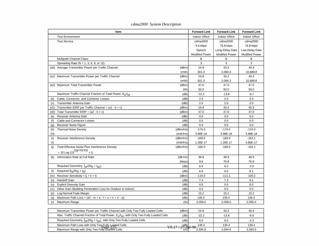
cdma2000 System Description
Page 225 V0.17 / 27-Jul-98
Item Forward Link Forward Link Forward Link
Test Environment Indoor Office Indoor Office Indoor Office
Test Service cdma2000 cdma2000 cdma2000
9.6 kbps 76.8 kbps 76.8 kbps
Speech Long-Delay Data Low-Delay Data
Modified Power Modified Power Modified Power
Multipath Channel Class B B B
Spreading Rate (N = 1, 3, 6, 9, or 12) 3 3 3
(a0) Average Transmitter Power per Traffic Channel (dBm) 24.8 33.2 40.3
(mW) 301.3 2,084.3 10,689.8
(a1) Maximum Transmitter Power per Traffic Channel (dBm) 24.8 33.2 40.3
(mW) 301.3 2,084.3 10,689.8
(a2) Maximum Total Transmitter Power (dBm) 47.0 47.0 47.0
(W) 50.0 50.0 50.0
Maximum Traffic Channel Fraction of Total Power, Ec/Ior (dB) -22.2 -13.8 -6.7
(b) Cable, Connector, and Combiner Losses (dB) 2.0 2.0 2.0
(c) Transmitter Antenna Gain (dBi) 2.0 2.0 2.0
(d1) Transmitter EIRP per Traffic Channel = (a1 - b + c) (dBm) 24.8 33.2 40.3
(d2) Total Transmitter EIRP = (a2 - b + c) (dBm) 47.0 47.0 47.0
(e) Receiver Antenna Gain (dBi) 0.0 0.0 0.0
(f) Cable and Connector Losses (dB) 0.0 0.0 0.0
(g) Receiver Noise Figure (dB) 5.0 5.0 5.0
(h) Thermal Noise Density (dBm/Hz) -174.0 -174.0 -174.0
(H) (mW/Hz) 3.98E-18 3.98E-18 3.98E-18
(i) Receiver Interference Density (dBm/Hz) -169.0 -169.0 -163.1
(I) (mW/Hz) 1.26E-17 1.26E-17 4.86E-17
(j) Total Effective Noise Plus Interference Density (dBm/Hz) -166.0 -166.0 -162.1
= 10 Log (10((g+h)/10)
+ I)
(k) Information Rate at Full Rate (dB-Hz) 39.8 48.9 48.9
(kbps) 9.6 76.8 76.8
Required Geometry, Îor/(N0 + Ioc) (dB) 6.0 6.0 -2.0
(l) Required Eb/(N0 + I0) (dB) 6.6 6.0 8.1
(m) Receiver Sensitivity = (j + k + l) (dBm) -119.5 -111.1 -105.2
(n) Handoff Gain (dB) 7.3 7.3 6.1
(o) Explicit Diversity Gain (dB) 0.0 0.0 0.0
(o') Other Gain (Building Penetration Loss for Outdoor to Indoor) (dB) 0.0 0.0 0.0
(p) Log-Normal Fade Margin (dB) 15.2 15.2 15.2
(q) Maximum Path Loss = (d1 - m + e - f + o + n + o' - p) (dB) 136.4 136.4 136.4
(r) Maximum Range (m) 2,058.0 2,058.0 2,050.4
Maximum Transmitter Power per Traffic Channel with Only Two Fully Loaded Cells (dBm) 24.8 33.2 40.4
Max. Traffic Channel Fraction of Total Power, Ec/Ior, with Only Two Fully Loaded Cells (dB) -22.2 -13.8 -6.6
Required Geometry, Îor/(N0 + Ioc), with Only Two Fully Loaded Cells (dB) 6.0 6.0 -2.2
Maximum Path Loss with Only Two Fully Loaded Cells (dB) 139.4 139.4 139.4
Maximum Range with Only Two Fully Loaded Cells (m) 2,594.9 2,594.9 2,593.5

cdma2000 System Description
227
8.2 Spectrum Efficiency1
Performance evaluation of the cdma2000 system is an important aspect of assessing the viability of the RTT.2The steps taken to determine the spectrum efficiency are as follows:3
x Calculate the path loss between different base stations and mobile stations;4
x Determine the required Traffic Ec/Ior (for forward link) or Eb/Nt (for reverse link) for the geometry and5each ITU channel model;6
x Determine the transmitted power requirements;7
x Calculate outage; and8
x Calculate spectrum efficiency9
Two independent simulations are performed to provide the required spectrum efficiency information (i.e.,10
Mbps/MHz/cell for a desired blockage) and coverage (i.e., km2/site). In both simulations, the link level11simulations are performed separately from the system level as follows:12
x Perform a link level simulation to determine the energy requirements for a specific ITU channel model13(i.e., Traffic Ec/Ior and Eb/Nt) and generate a table for different relative differences in received power14between base stations and mobile stations; and15
x Perform system calculations separately from the link level using the link level results as a lookup table to16determine the spectrum efficiency.17
The purpose of two independent simulators is to provide a means of checking the consistency of the results18provided in the RTT. The results from the two simulations are presented separately in tabular format and19averaged when reporting spectrum efficiency results in the deployment results matrices. Greater detail of the20two approaches can be found in the sections that follow.21
8.2.1 Simulation Assumptions22
The following common assumptions were made for determining spectrum efficiency:23
1. Omnidirectional antennas.24
2. Convolutional codes were used for all results.25
3. Two antenna transmit diversity was used on the forward link.26
4. Base station to base station correlation = 0.5.27
5. For reverse link, (I0 + N0)/N0 = 7 dB.28
6. Imperfect power control is modeled as log-normal random variable with standard deviation of 1.5 dB29
7. Soft handoff assumptions:30
x Two-way soft handoff allowed for voice and circuit data (long delay) users.31
x No soft handoff is considered for low delay circuit data and packet data users.32

cdma2000 System Description
228
8. The capacity is obtained based on 5% outage probability, which translates into 95% coverage as required1by ITU.2
9. For vehicular and outdoor-to-indoor/pedestrian environment, hexagonal grid is used as a physical3deployment model. Base station antenna height is 15m for vehicular environment. For outdoor-to-4indoor/pedestrian environment the ratio of outdoor users to indoor users is 6:5.5
10. For indoor office environment the physical layout consists of a three floor model, where each floor has a6top down view as shown in Figure 75, where the dots denote the placement of the base stations. The7statistics is collected around the center of the middle floor.8
11. For the mixed test environment, 60% pedestrian (outdoor) users and 40% vehicular users are simulated.9
12. Voice activity factor = 50%. Circuit data activity factor = 100%.10
13. For packet data services Poisson arrivals of packets and exponential packet lengths (calls) are simulated.11Mean packet lengths for reverse and forward links are 2250 bytes and 12 kbytes respectively. The mean12delay is the mean service time per packet call. For packet data, service time is a function of channel bit13rate and ARQ overhead (MAC layer RLP). For example, if the assigned channel bit rate is 76.8 kbps with14target FER of 10%, ARQ overhead (ideal) with up to 3 frame re-transmissions is 1 + 0.1 + 0.12 + 0.13 =151.111. Thus, average user throughput is 76.8 kbps/1.111 = 69.1 kbps. Note that 69.1 kbps is greater than16
64 kbps as required by the ITU M.1225. Also, after ARQ, frame error rate is reduced to (0.1)4 = 0.01%17
which translates to roughly a BER of 10-6 as specified by the ITU-R M.1225.18
19
20
21
Figure 75. Indoor Office Deployment Scheme22

cdma2000 System Description
229
8.2.2 Simulation Description1
The simulation methodology follows a “snap-shot” approach. For each run, or ‘snap shot,’ a given number of2MS’s are randomly positioned in the service area according to the subscriber density profile. Based on the3MS locations, the path loss (deterministic) and shadowing (random) between each pair of MS and BS is4computed. Many runs are performed after each increment in the MS number. At some point, the required5transmit power at a BS or an MS will exceed the maximum allowed, implying an outage. Spectral efficiency6is then derived from the amount of traffic load at the maximum allowed outage levels.7
8.2.2.1 Forward Link Model8
The system level simulations for the forward link are separated into two cases. In the first, the forward link9channel is assumed to see a maximum of two handoff legs. In the second, the forward link channel will not be10in soft handoff. In both cases, base stations in the deployment are assumed to be transmitting at full power.11Below is a brief description of the two cases and how link level tables are used in determining spectrum12efficiency.13
14
The forward link-level simulation is performed to get the Traffic Ec/Ior for the desired BER, where Traffic15Ec/Ior is the percentage of a BS’s power that is used by an MS. This is done for a set of different16�I or /(No+Ioc) (sometimes called ‘geometry’) values, where �I or is the total received power in all code17
channels from all BS in the active set of the MS and Ioc is the total received power from all other BS’s. For18each BS in the active set of fading paths are simulated according to the test environment. For No+Ioc, a single19AWGN source is used. For the particular base station of interest, the Ec/Ior values of all the mobiles served by20
that base station are summed to determine the total Ec/Ior. To determine the proper �I or /(No+Ioc) value to21
use for a given MS at a specific location, the path losses from all BS’s are first determined. These BS’s are22ranked according to their path losses to the MS.23
8.2.2.1.1 Two Way Soft Handoff24
If the second strongest BS is within ' dB of the strongest, it is assumed to be in handoff with the MS. A set of25paths are created for that BS in addition to the first set for the strongest BS. The total power of this second set26of paths is quantized (i.e., 0 dB, -3 dB, and -6 dB) relative to that of the first set. The total power from the27
strongest two BS’s is treated as �I or and the total power from all other BS’s is Ioc. The forward link table of28
required Traffic Ec/Ior for �I or /(No+Ioc) values of, 0, 3, 6, 9 dB with two-way handoff are used in the system29
model where the strength of the weaker BS is below that of the stronger BS for each particular �I or /(No+Ioc)30
value. This is showhn in Table 62 below. Values between 3 dB steps are obtained by interpolating Traffic31
Ec/Ior values. For �I or /(No+Ioc) values less than 0 dB and greater than 12 dB, Traffic Ec/Ior values are32
interpolated.33
34
Table 62. Example of Link Level Simulation Output for Two way Soft Handoff35
Required forward link Traffic Ec/Ior for the required FER for data rate X kbps and MS speed Y km/hr, in fadingchannel Z, two-way soft handoff
�I or /(No+Ioc) (dB) 0 3 6 … 12

cdma2000 System Description
230
' �I or1 - �I or2 (dB) 0 3 6 0 3 6 0 3 6 0 3 6 0 3 6
Required TrafficEc/Ior (dB)
- - - - - - - - - - - - -
1
8.2.2.1.2 No Soft Handoff2
When no soft handoff is modeled, only the strongest BS is used (i.e., no soft handoff is allowed) even though a3criterion based on Pilot Ec/Io might allow soft handoff. The signal from the strongest BS is modeled as4�I or for the forward link and its multipath fading is simulated. The signal power from all other BS’s is5
considered Ioc and is modeled in the same way No is modeled, that is, the average power levels are added6
together but individual fades are not tracked. The actual ratio �I or /(No+Ioc) is used to find the nearest entry7
in the table for the required Traffic Ec/Ior for that BS. In other words, for each data rate and mobile speed,8
the link-level simulation generates a table of required Traffic Ec/Ior for �I or /(No+Ioc) values of, 0, 3, 6, 9,9
and 12 dB under no soft handoff. The table looks like the one in Table 84. Interpolation is used for values10
between 3 dB steps and extrapolation is used for �I or /(No+Ioc) less than 0 dB and greater than 12 dB.11
Table 63. Example of Link-level Simulation Output for No Soft Handoff12
Required forward link Traffic Ec/Ior for the required FER for data rate X kbps and MS speed Y km/hr, in fadingchannel Z, no soft handoff
�I or /(No+Ioc) (dB) 0 3 6 9 12
Required Traffic Ec/Ior (dB) - - - - -
8.2.2.2 Reverse Link13
Assuming the reverse link has two receiving antennas per omni-directional BS and that it uses switching14diversity between BSs, the link level simulation is performed for one BS only. The diversity gain from the15other BSs can be obtained from the same set of FER vs. Eb/(No+Io) curves. Depending on the link level16simulation results, a range of path loss differences to the two closest BSs is evaluated. For example, if the17reverse path losses from an MS to two BSs are the same, then the FER per BS is 90% if the required FER18from both BSs is 1%. During the 10% of the time when BS 1 is not receiving frames correctly, there is a 90%19chance BS 2 is receiving the frames correctly. Corresponding to the 10% FER point, one can find the20Eb/(No+Io) per BS. Similarly, assuming the two path losses are X dB apart, one can use the above argument21to find the corresponding operating Eb/(No+Io) values at both of the two BSs from an FER vs Eb/(No+Io)22curve.23
24
The system level simulation calculates the total received power, Io at each BS. Io is the interference for any25given mobile transmitting to that BS.26
8.2.3 Results27
Below are the results for the two different simulators. Included are a list of the different assumptions used for28the two simulators.29

cdma2000 System Description
231
8.2.3.1 First Simlulator1
x FL Direct Spread with transmit diversity2
x The overhead due to the percentage of power dedicated to the pilot, sync and3paging channels is assumed to be 17%.4
x A 4.8 kbps DCCH is assumed for packet data services.5
x For the hexagonal layout, at each simulation run ni users are placed uniformly within the geographic area6of the ith cell (i=1,2,…,M), where ni is a random variable drawn from a Poisson distribution with mean N.7Note that since the sum of Poisson random variables is also Poisson, the total number of users within the8coverage area is a Poisson random number. For the cubical indoor layout, at each simulation run ni users9are placed uniformly on each floor, where ni is a random variable drawn from a Poisson distribution with10mean N.11
x Soft handoff '=3 dB12
x The outage probability on the RL is defined as prob ( Io+No/No > 7 dB). The outage probability on the13FL is defined as the prob (achieved FER < target FER ). The target FERs for voice (9.6 kbps), 76.814kbps, 153.6 kbps and 460.8 kbps, are chosen to be 1%, 10%, 5% and 15% respectively.15

cdma2000 System Description
232
Table 64. Spectrum effficiency for voice services
Service Environment Channel A Channel B
Cell capacity(users/cell)(RL/FL)
Spectrumefficiency
(users/MHz/cell)(RL/FL)
Cell capacity(users/cell)(RL/FL)
Spectrumefficiency
(users/MHz/cell)(RL/FL)
Voice Vehicular 109 / 169 29 / 45.1 110 / 179 29.3 / 47.7
9.6 kbps Pedestrian 162 / 170 43.2 / 45.3 115 / 138 30.7 /36.8
1 % FER Indoor 130 / 126 34.7 / 33.6 124 / 107 33.1 / 28.5
Mixed 134 / 173 35.7 / 46.1 113 / 172 30.1 / 45.9

cdma2000 System Description
233
Table 65. Capacity results for circuit data services (Long Delay).
Service Environment Channel A Channel B
Cell capacity(users/cell)(RL/FL)
Spectrumefficiency
(Mbps/MHz/cell)(RL/FL)
Cell capacity(users/cell)(RL/FL)
Spectrumefficiency
(Mbps/MHz/cell)(RL/FL)
Circuit Vehicular 11.6/ 7.5 0.238 / 0.154 11.6 / 8.2 0.238 / 0.168
76.8 kbps Pedestrian 14.8 / 9 0.303 / 0.184 14.5 / 7 0.297 / 0.143
10 % FER Indoor 12.5/ 8.4 0.256 / 0.172 12.3 / 6.5 0.252 / 0.133
Mixed 14.3 /8.2 0.293 / 0.168 14.1 / 7.8 0.289 / 0.160
Circuit
153.6 kbps Vehicular 5.4 /2.5 0.221 / 0.102 5.4 / 2.8 0.221 / 0.115
5 % FER
Circuit
460.8 kbps
15 % FER
Pedestrian 2.0 / 0.5 0.246 / 0.061 2.0 / 0.5 0.246 / 0.061
Circuit
460.8/
153.6 kbps
Mixed 3.0 / 1 2.9 / 1

cdma2000 System Description
234
Table 66. Spectrum efficiency for circuit data services (Low Delay).
Service Environment Channel A Channel B
Cell capacity(users/cell)(RL/FL)
Spectrumefficiency
(Mbps/MHz/cell)(RL/FL)
Cell capacity(users/cell)(RL/FL)
Spectrumefficiency
(Mbps/MHz/cell)(RL/FL)
Circuit Vehicular 11.3 / 7.5 0.231 / 0.154 11.3 / 8.2 0.231 / 0.168
76.8 kbps Pedestrian 14.3 / 6 0.293 / 0.123 14.1 / 7.5 0.289 / 0.154
10 % FER Indoor 12.3 / 3.8 0.252 / 0.078 12.3 / 3.5 0.252 / 0.072
Mixed 14.2 / 7.2 0.291 / 0.147 13.8 / 8 0.283 / 0.164
Circuit
153.6 kbps Vehicular 4.8 / 2.4 0.200 / 0.100 4.9 / 2.6 0.205 / 0.109
5 % FER
Circuit
460.8 kbps
15 % FER
Pedestrian 1.9 / * 0.233 / * 1.9 / * 0.233 / *
Table 67. Capacity results for packet data.1

cdma2000 System Description
Page 235 V0.17 / 27-Jul-98
Service Environment
Channel A Channel B
Spectrum efficiency(RL/FL)
MeanDelay (s)(RL/FL)
Spectrum efficiency(RL/FL)
MeanDelay (s)(RL/FL)
(kbps/carrier)
(Mbps/MHz/cell)
(kbps/carrier)
(Mbps/MHz/cell)
Packet Vehicular 784 / 518 0.209/0.138 0.26 / 1.39 784 / 566 0.209/0.151 0.26 / 1.39
76.8kbps
Pedestrian 991 / 415 0.264/0.111 0.26 / 1.52 972 / 519 0.259/0.138 0.26 / 1.52
10%FER
Indoor 849 / 263 0.226/0.070 0.26 / 1.39 849 / 242 0.226/ 0.065 0.26 / 1.39
Packet
153.6kbps
Vehicular 702/350 0.187/0.093 0.12 / 0.66 716 / 379 0.191 /0.101 0.12 / 0.66
5 %FER
Packet
460.8kbps
15 %FER
Pedestrian 740 / * 0.197/ * 0.04 / * 740/* 0.197 /* 0.04 /*
1
* : service cannot be supported for the given outage level2
8.2.3.2 Second Simulator3
x FL Multi-carrier with transmit diversity4
x The overhead due to the percentage of power dedicated to the pilot, sync and paging channels is5assumed to be 20%.6
x For each trial, a given number of mobile stations are uniformly distributed in the service area according7to the specific deployment model.8
x Soft handoff '=6 dB9
x The outage probability on the FL is defined as the probability that the sum of all user traffic power10Ec/Ior exceeds the total available power. The outage probability on the RL is defined as the probability11that the base station receives an average Eb/(Io+N0) level from the mobiles that is below what is12required for achieving target FER.13
Table 68. Spectrum efficiency for voice services14

cdma2000 System Description
Page 236 V0.17 / 27-Jul-98
Service Environment Channel A Channel B
Cell capacity(users/cell)(RL/FL)
Spectrumefficiency
(users/MHz/cell)(RL/FL)
Cell capacity(users/cell)(RL/FL)
Spectrumefficiency
(users/MHz/cell)(RL/FL)
Voice Vehicular 109 / 106 29 / 28.2 109 / 127 29 / 33.8
9.6 kbps Pedestrian 158 / 172 42.1 / 45.8 136 / 122 36.2 / 32.5
1 % FER Indoor 146 / 122 38.9 / 32.5 132 / 136 35.2 / 36.2
Mixed 128 / 130 34.1 / 34.6 117 / 125 31.2 / 33.3
Table 69. Spectrum efficiency for circuit data services (Long Delay)1
Service Environment Channel A Channel B
Cell capacity(users/cell)(RL/FL)
Spectrumefficiency
(Mbps/MHz/cell)(RL/FL)
Cell capacity(users/cell)(RL/FL)
Spectrumefficiency
(Mbps/MHz/cell)(RL/FL)
Circuit Vehicular 9.1 / 5.61 0.186 / 0.114 9.1 / 5.91 0.186 / 0.121
76.8 kbps Pedestrian 13.4 / 9.61 0.274 / 0.196 11.3 / 6.71 0.231 / 0.137
10 % FER Indoor 11.7 / 6.51 0.239 / 0.133 10.1 / 5.71 0.206 / 0.116
Mixed 10.9 / 7.51 0.223 / 0.153 9.8 / 6.21 0.2 / 0.126
Circuit
153.6 kbps Vehicular 4.2 / 1.3 0.172 / 0.053 4.2 / 1.6 0.172 / 0.065
5 % FER
Circuit
460.8 kbps
15 % FER
Pedestrian 1.8 / 0.5 0.221 / 0.061 1.5 / 0.4 0.184 / 0.049
2
Table 70. Spectrum efficiency for circuit data services (Low Delay)3

cdma2000 System Description
Page 237 V0.17 / 27-Jul-98
Service Environment Channel A Channel B
Cell capacity(users/cell)(RL/FL)
Spectrumefficiency
(Mbps/MHz/cell)(RL/FL)
Cell capacity(users/cell)(RL/FL)
Spectrumefficiency
(Mbps/MHz/cell)(RL/FL)
Circuit Vehicular 9.1 / 5.21 0.186 / 0.106 9.1 / 5.61 0.186 / 0.114
76.8 kbps Pedestrian 13.0 / 5.61 0.266 / 0.114 11.2 / 7.21 0.229 / 0.147
10 % FER Indoor 11.2 / 3.61 0.229 / 0.073 9.8 / 3.61 0.200 / 0.073
Mixed 10.7 / 5.41 0.219 / 0.11 9.7 / 7.11 0.198 / 0.145
Circuit
153.6 kbps Vehicular 3.8 / 1.3 0.155 / 0.053 3.8 / 1.5 0.155 / 0.061
5 % FER
Circuit
460.8 kbps
15 % FER
Pedestrian 1.7 / 0.5 0.208 / 0.061 1.5 / 0.4 0.184 / 0.049
1 Results based on 15% FER1

cdma2000 System Description
Page 238 V0.17 / 27-Jul-98
1
Table 71. Spectrum efficiency for packet data services2
Service Environment
Channel A Channel B
Spectrum efficiency(RL/FL)
MeanDelay (s)(RL/FL)
Spectrum efficiency(RL/FL)
MeanDelay (s)(RL/FL)
(kbps/carrier)
(Mbps/MHz/cell)
(kbps/carrier)
(Mbps/MHz/cell)
Packet Vehicular 662 / 355 0.176 / 0.094 0.25 / 1.28 674 / 376 0.179 / 0.1 0.25 / 1.28
76.8kbps
Pedestrian 950 / 373 0.253 / 0.099 0.25 / 1.3 850 / 485 0.226 / 0.129 0.25 / 1.3
10%FER
Indoor 820 / 240 0.218 / 0.064 0.26 / 1.28 700 / 242 0.186 / 0.064 0.26 / 1.28
Mixed 755 / 362 0.201 / 0.096 0.26 / 1.29 697 /460 0.185 / 0.122 0.26 / 1.29
Packet
153.6kbps
Vehicular 551 / 182 0.146 / 0.048 0.12 / 0.63 551 / 194 0.146 / 0.051 0.12 / 0.63
5 %FER
Packet
460.8kbps
15 %FER
Pedestrian 695 / 195 0.185 / 0.052 0.04 / 0.22 611 / 160 0.162 / 0.042 0.04 / 0.22
3
8.2.4 Deployment models4
The spectrum efficiency data is provided for all deployment. The offered traffic is calculated as:5
offered traffic user density u (bhca/sub/3600) u call duration6
where:7
bhca: busy hour call attempts8
sub: subscriber.9
8.2.4.1 Indoor office test environment deployment model10
This deployment scenario describes conditions relevant to the operation of an IMT-2000 system for indoor11office test environment. The test service requirements for the indoor office environment are listed in12

cdma2000 System Description
Page 239 V0.17 / 27-Jul-98
Table 1. The assumptions made about market requirements are summarized in Table 72. Indoor office1deployment model market requirements.2
Table 72. Indoor office deployment model market requirements3
4
For this indoor deployment scenario a model office environment is specified below and consists of a large5office building with an open floor plan layout. The specific assumptions about the indoor physical6deployment environment are summarized in Table 73. Indoor office deployment model physical7environment.8
Table 73. Indoor office deployment model physical environment9
10
8.2.4.2 Outdoor to indoor and pedestrian deployment model11
The physical environment description for the outdoor to indoor and pedestrian model includes both indoor12and outdoor users. The indoor coverage is to be provided by the outdoor base stations. This requires that the13additional loss due to building penetration be accommodated in the link budget. The test service14requirements for the outdoor to indoor pedestrian environment are listed in Table 1. The assumptions made15about market requirements are summarized in Table 74. Outdoor to indoor and pedestrian deployment16model market requirements.17
Table 74. Outdoor to indoor and pedestrian deployment model market requirements18
19
20
The specific assumptions about the outdoor physical deployment environment are summarized in21
Grade of serviceTraffic level(bhca/sub)(1) Coverage(2)
Subscriber penetration(% of potential users)
1% blocking 3 for speech 95% 50 for spectrum efficiency
3 for data 5 for coverage efficiency(1) bhca: busy hour call attempts e.g., assuming a call duration of 2 min (speech) and 2 min (data).(2) Let “A” be the declared geographical area over which the service is planned. It is required that good operating conditions (for the
receivers) be maintained over X % (95%), of the area “A” during Y % (95%) of the time. Further definition of “A” is needed.
Area per floor(m2)
Potential usersper floor Number of floors
Log-normalstandard deviation
(dB)Mobile velocity
(km/h)10 000 1 000 10 12 3
Grade of serviceTraffic level(bhca/sub)(1) Coverage(2)
Subscriber penetration(% of potential users)
1% blocking 1.2 for speech 95% 10 for spectrum efficiency
1.2 for data 0.1 for coverage efficiency(1), (2) See Table 72. Indoor office deployment model market requirements.

cdma2000 System Description
Page 240 V0.17 / 27-Jul-98
Table 75. Deployment model physical environment1
2
8.2.4.3 Vehicular environment deployment model3
The test service requirements for the vehicular environment are listed in Table 60. Assumptions about4market requirements are summarized in Table 76. Vehicular deployment model market requirements. The5base station antenna height must be above the average roof top height of 12 m.6
Table 76. Vehicular deployment model market requirements7
8
The specific assumptions about the vehicular physical deployment environment are summarized in Table977. Vehicular deployment model physical environment.10
11
Table 77. Vehicular deployment model physical environment12
13
8.2.4.4 Mixed-cell pedestrian/vehicular test environment deployment model14
This deployment scenario describes conditions relevant to the operation of an IMT-2000 system that are15found in the mixed test environment. The test service requirements for the mixed-cell environment are listed16inTable 60. The general assumptions about market requirements are summarized in Table 78. Mixed test17deployment model market requirements. The link budget uses the calculations for pedestrian and vehicular18environments.19
Table 78. Mixed test deployment model market requirements20
21
The specific assumptions about the outdoor and vehicular physical deployment environment are22summarized in Table 79. Mixed test deployment model physical environment.23
Table 79. Mixed test deployment model physical environment24
Type Area(km2)
Potential usersper km2
Building penetrationloss/standard deviation
(dB)
Log-normalstandard deviation
(dB)Mobilevelocity(km/h)
Outdoor 40 9 000 Not applicable 10 3Indoor 25 12 000 12/8 12 3
Grade of service Traffic level(bhca/sub) (1) Coverage (2)
Subscriber penetration(% of potential users)
1% blocking 0.75 for speech 95% 10 for spectrum efficiency
0.75 for data 0.1 for coverage efficiency(1), (2) See Table 72. Indoor office deployment model market requirements.
Area(km2)
Potential users perkm2
Log-normalstandard deviation
(dB)Mobile velocity
(km/h)150 3 500 10 120
Grade of serviceTraffic level(bhca/sub) (1) Coverage (2)
Subscriber penetration(% of potential users)
1% blocking 1 for speech 95% 10 for spectrum efficiency
1 for data 0.1 for coverage efficiency(1), (2) See Table 72. Indoor office deployment model market requirements.

cdma2000 System Description
Page 241 V0.17 / 27-Jul-98
1
8.2.5 Deployment model result matrix2
The results for all deployment models are shown in the following tables where the average of Channel A3results and then Channel B results are computed for Simulator 1 and Simulator 2. The deployment results4are then selected based upon the worst case between Channel A and Channel B. The coverage efficiency5and number of cell sites for each deployment are determined from the link budgets where the reverse link is6calculated based upon the Unloaded Maximum Range.7
8
Table 80. Deployment Model Result Matrix for Vehicular Voice9
Input Assumptions
Test Environment Vehicular
Test Service Voice
Base Station Antenna Height 15 meters
Any Other Assumptions Made by the Proponents(e.g., Antenna Pattern, Sectorization, etc.)
Simulation results obtained using omni-directionalcells
Deployment Results
Total Number ofCell Sites
RL/FL
2.1/1.3
Total Number ofRF Channels
3
Number of VoiceChannels per RF
Channels
CoverageEfficiency
(km2/site)RL/FL
72.1/113.6
Spectrum Efficiency(Erlangs/MHz/cell)
OmniRL/FL
29/36.7
3 SectorsRL/FL
69.6/88.1
10
Path loss type Area(km2)
Log-normalstandard deviation
(dB)Mobile velocity
(km/h)%
usersPedestrian (outdoor) 4 10 3 60
Vehicular 150 10 120 40

cdma2000 System Description
Page 242 V0.17 / 27-Jul-98
Table 81. Deployment Model Result Matrix for Outdoor to Indoor and Pedestrian Voice1
Input Assumptions
Test Environment Outdoor to Indoor and Pedestrian
Test Service Voice
Base Station Antenna Height Not Applicable
Any Other Assumptions Made by the Proponents(e.g., Antenna Pattern, Sectorization, etc.)
Simulation results obtained using omni-directionalcells
Deployment Results
Total Number ofCell Sites
RL/FL
166.2/173.4
Total Number ofRF Channels
3
Number of VoiceChannels per RF
Channels
CoverageEfficiency
(km2/site)RL/FL
0.391/0.375
Spectrum Efficiency(Erlangs/MHz/cell)
OmniRL/FL
33.5/34.7
3 SectorsRL/FL
80.4/83.3
Table 82. Deployment Model Result Matrix for Indoor Office Voice2
Input Assumptions
Test Environment Indoor Office
Test Service Voice
Base Station Antenna Height Not Applicable
Any Other Assumptions Made by the Proponents(e.g., Antenna Pattern, Sectorization, etc.)
Simulation results obtained using omni-directionalcells. A minimum of 1 cell site per floor isconsidered.
Deployment Results
Total Number ofCell Sites
RL/FL
10/10
Total Number ofRF Channels
3
Number of VoiceChannels per RF
Channels
CoverageEfficiency
(km2/site)RL/FL
0.01/0.01
Spectrum Efficiency(Erlangs/MHz/cell)
OmniRL/FL
34.2/32.3
3 SectorsRL/FL
82.1/79.7
3

cdma2000 System Description
Page 243 V0.17 / 27-Jul-98
Table 83. Deployment Model Result Matrix for Vehicular 76.8 kbps Long Delay1
Input Assumptions
Test Environment Vehicular
Test Service 76.8 kbps long delay
Base Station Antenna Height 15 meters
Any Other Assumptions Made by the Proponents(e.g., Antenna Pattern, Sectorization, etc.)
Simulation results obtained using omni-directionalcells
Deployment Results
Total Numberof Cell Sites
RL/FL
5.3/7.5
Total Number ofRF Channels
3
Number of VoiceChannels per RF
Channels
CoverageEfficiency
(km2/site)RL/FL
28.3/20.0
Spectrum Efficiency(Mbps/MHz/cell)
OmniRL/FL
0.212/0.134
3 SectorsRL/FL
0.509/0.322
2
Table 23. Deployment Result Matrix for Vehicular 76.8 kbps Low Delay3
Input Assumptions
Test Environment Vehicular
Test Service 76.8 kbps low delay
Base Station Antenna Height 15 meters
Any Other Assumptions Made by the Proponents(e.g., Antenna Pattern, Sectorization, etc.)
Simulation results obtained using omni-directionalcells
Deployment Results
Total Numberof Cell Sites
RL/FL
5.6/13.1
Total Number ofRF Channels
3
Number of VoiceChannels per RF
Channels
CoverageEfficiency
(km2/site)RL/FL
27.0/13.1
Spectrum Efficiency(Mbps/MHz/cell)
OmniRL/FL
0.209/0.111
3 SectorsRL/FL
0.502/0.266
4

cdma2000 System Description
Page 244 V0.17 / 27-Jul-98
Figure 76. Deployment Result Matrix for Vehicular 76.8 kbps Packet1
Input Assumptions
Test Environment Vehicular
Test Service 76.8 kbps packet
Base Station Antenna Height 15 meters
Any Other Assumptions Made by the Proponents(e.g., Antenna Pattern, Sectorization, etc.)
Simulation results obtained using omni-directionalcells
Deployment Results
Total Numberof Cell Sites
RL/FL
5.3/7.5
Total Number ofRF Channels
3
Number of VoiceChannels per RF
Channels
CoverageEfficiency
(km2/site)RL/FL
28.3/20.0
Spectrum Efficiency(Mbps/MHz/cell)
OmniRL/FL
0.193/0.116
3 SectorsRL/FL
0.463/0.278
2
Figure 77. Deployment Result Matrix for Outdoor to Indoor and Pedestrian 76.8 kbps Long Delay3
Input Assumptions
Test Environment Outdoor to Indoor and Pedestrian
Test Service 76.8 kbps long delay
Base Station Antenna Height Not Applicable
Any Other Assumptions Made by the Proponents(e.g., Antenna Pattern, Sectorization, etc.)
Simulation results obtained using omni-directionalcells
Deployment Results
Total Numberof Cell Sites
RL/FL
376.8/459.8
Total Number ofRF Channels
3
Number of VoiceChannels per RF
Channels
CoverageEfficiency
(km2/site)RL/FL
0.172/0.141
Spectrum Efficiency(Mbps/MHz/cell)
OmniRL/FL
0.264/0.140
3 SectorsRL/FL
0.634/0.336
4

cdma2000 System Description
Page 245 V0.17 / 27-Jul-98
Figure 78. Deployment Result Matrix for Outdoor to Indoor and Pedestrian 76.8 kbps Low Delay1
Input Assumptions
Test Environment Outdoor to Indoor and Pedestrian
Test Service 76.8 kbps low delay
Base Station Antenna Height Not Applicable
Any Other Assumptions Made by the Proponents(e.g., Antenna Pattern, Sectorization, etc.)
Simulation results obtained using omni-directionalcells
Deployment Results
Total Numberof Cell Sites
RL/FL
418.3/759.8
Total Number ofRF Channels
3
Number of VoiceChannels per RF
Channels
CoverageEfficiency
(km2/site)RL/FL
0.155/0.086
Spectrum Efficiency(Mbps/MHz/cell)
OmniRL/FL
0.259/0.150
3 SectorsRL/FL
0.622/0.360
2
Figure 79. Deployment Result Matrix for Outdoor to Indoor and Pedestrian 76.8 kbps Packet3
Input Assumptions
Test Environment Outdoor to Indoor and Pedestrian
Test Service 76.8 kbps packet
Base Station Antenna Height Not Applicable
Any Other Assumptions Made by the Proponents(e.g., Antenna Pattern, Sectorization, etc.)
Simulation results obtained using omni-directionalcells
Deployment Results
Total Numberof Cell Sites
RL/FL
376.8/459.8
Total Number ofRF Channels
3
Number of VoiceChannels per RF
Channels
CoverageEfficiency
(km2/site)RL/FL
0.172/0.141
Spectrum Efficiency(Mbps/MHz/cell)
OmniRL/FL
0.259/0.105
3 SectorsRL/FL
0.622/0.252
4

cdma2000 System Description
Page 246 V0.17 / 27-Jul-98
Figure 80. Deployment Result Matrix for Indoor Office 76.8 kbps Long Delay1
Input Assumptions
Test Environment Indoor Office
Test Service 76.8 kbps long delay
Base Station Antenna Height Not Applicable
Any Other Assumptions Made by the Proponents(e.g., Antenna Pattern, Sectorization, etc.)
Simulation results obtained using omni-directionalcells. A minimum of 1 cell site per floor isconsidered.
Deployment Results
Total Numberof Cell Sites
RL/FL
10/10
Total Number ofRF Channels
3
Number of VoiceChannels per RF
Channels
CoverageEfficiency
(km2/site)RL/FL
0.01/0.1
Spectrum Efficiency(Mbps/MHz/cell)
OmniRL/FL
0.229/0.125
3 SectorsRL/FL
0.50/0.30
2
Figure 81. Deployment Result Matrix for Indoor Office 76.8 kbps Low Delay3
Input Assumptions
Test Environment Indoor Office
Test Service 76.8 kbps low delay
Base Station Antenna Height Not Applicable
Any Other Assumptions Made by the Proponents(e.g., Antenna Pattern, Sectorization, etc.)
Simulation results obtained using omni-directionalcells. A minimum of 1 cell site per floor isconsidered.
Deployment Results
Total Numberof Cell Sites
RL/FL
10/10
Total Number ofRF Channels
3
Number of VoiceChannels per RF
Channels
CoverageEfficiency
(km2/site)RL/FL
0.01/0.01
Spectrum Efficiency(Mbps/MHz/cell)
OmniRL/FL
0.226/0.073
3 SectorsRL/FL
0.542/0.175
4
Figure 82. Deployment Result Matrix for Indoor Office 76.8 kbps Packet5

cdma2000 System Description
Page 247 V0.17 / 27-Jul-98
Input Assumptions
Test Environment Indoor Office
Test Service 76.8 kbps packet
Base Station Antenna Height Not Applicable
Any Other Assumptions Made by the Proponents(e.g., Antenna Pattern, Sectorization, etc.)
Simulation results obtained using omni-directionalcells. A minimum of 1 cell site per floor isconsidered.
Deployment Results
Total Numberof Cell Sites
RL/FL
10/10
Total Number ofRF Channels
3
Number of VoiceChannels per RF
Channels
CoverageEfficiency
(km2/site)RL/FL
0.01/0.01
Spectrum Efficiency(Mbps/MHz/cell)
OmniRL/FL
0.206/0.065
3 SectorsRL/FL
0.494/0.156
1
Figure 83. Deployment Result Matrix for Vehicular 153.6 kbps Long Delay2
Input Assumptions
Test Environment Vehicular
Test Service 153.6 kbps long delay
Base Station Antenna Height 15 meters
Any Other Assumptions Made by the Proponents(e.g., Antenna Pattern, Sectorization, etc.)
Simulation results obtained using omni-directionalcells
Deployment Results
Total Numberof Cell Sites
RL/FL
7.8/12.4
Total Number ofRF Channels
3
Number of VoiceChannels per RF
Channels
CoverageEfficiency
(km2/site)RL/FL
19.1/12.1
Spectrum Efficiency(Mbps/MHz/cell)
OmniRL/FL
0.197/0.078
3 SectorsRL/FL
0.473/0.187
3

cdma2000 System Description
Page 248 V0.17 / 27-Jul-98
Figure 84. Deployment Result Matrix for Vehicular 153.6 kbps Low Delay1
Input Assumptions
Test Environment Vehicular
Test Service 153.6 kbps low delay
Base Station Antenna Height 15 meters
Any Other Assumptions Made by the Proponents(e.g., Antenna Pattern, Sectorization, etc.)
Simulation results obtained using omni-directionalcells
Deployment Results
Total Numberof Cell Sites
RL/FL
8.6/20.1
Total Number ofRF Channels
3
Number of VoiceChannels per RF
Channels
CoverageEfficiency
(km2/site)RL/FL
17.5/7.5
Spectrum Efficiency(Mbps/MHz/cell)
OmniRL/FL
0.178/0.077
3 SectorsRL/FL
0.427/0.185
2
Figure 85. Deployment Result Matrix for Vehicular 153.6 kbps Packet3
Input Assumptions
Test Environment Vehicular
Test Service 153.6 kbps packet
Base Station Antenna Height 15 meters
Any Other Assumptions Made by the Proponents(e.g., Antenna Pattern, Sectorization, etc.)
Simulation results obtained using omni-directionalcells
Deployment Results
Total Numberof Cell Sites
RL/FL
7.8/12.4
Total Number ofRF Channels
3
Number of VoiceChannels per RF
Channels
CoverageEfficiency
(km2/site)RL/FL
19.1/12.1
Spectrum Efficiency(Mbps/MHz/cell)
OmniRL/FL
0.167/0.071
3 SectorsRL/FL
0.401/0.170
4

cdma2000 System Description
Page 249 V0.17 / 27-Jul-98
Figure 86. Deployment Result Matrix for Outdoor to Indoor and Pedestrian 460.8 kbps Long Delay1
Input Assumptions
Test Environment Outdoor to Indoor and Pedestrian
Test Service 460.8 kbps long delay
Base Station Antenna Height Not Applicable
Any Other Assumptions Made by the Proponents(e.g., Antenna Pattern, Sectorization, etc.)
Simulation results obtained using omni-directionalcells
Deployment Results
Total Numberof Cell Sites
RL/FL
877.3/1090
Total Number ofRF Channels
3
Number of VoiceChannels per RF
Channels
CoverageEfficiency
(km2/site)RL/FL
0.074/0.060
Spectrum Efficiency(Mbps/MHz/cell)
OmniRL/FL
0.215/0.055
3 SectorsRL/FL
0.516/0.132
2
Figure 87. Deployment Result Matrix for Outdoor to Indoor and Pedestrian 460.8 kbps Low Delay3
Input Assumptions
Test Environment Outdoor to Indoor and Pedestrian
Test Service 460.8 kbps low delay
Base Station Antenna Height Not Applicable
Any Other Assumptions Made by the Proponents(e.g., Antenna Pattern, Sectorization, etc.)
Simulation results obtained using omni-directionalcells
Deployment Results
Total Numberof Cell Sites
RL/FL
1217.7/-
Total Number ofRF Channels
3
Number of VoiceChannels per RF
Channels
CoverageEfficiency
(km2/site)RL/FL
0.053/-
Spectrum Efficiency(Mbps/MHz/cell)
OmniRL/FL
0.207/0.049
3 SectorsRL/FL
0.497/0.118
4

cdma2000 System Description
Page 250 V0.17 / 27-Jul-98
Figure 88. Deployment Result Matrix for Outdoor to Indoor and Pedestrian 460.8 kbps Packet1
Input Assumptions
Test Environment Outdoor to Indoor and Pedestrian
Test Service 460.8 kbps packet
Base Station Antenna Height Not Applicable
Any Other Assumptions Made by the Proponents(e.g., Antenna Pattern, Sectorization, etc.)
Simulation results obtained using omni-directionalcells
Deployment Results
Total Numberof Cell Sites
RL/FL
877.3/1090
Total Number ofRF Channels
3
Number of VoiceChannels per RF
Channels
CoverageEfficiency
(km2/site)RL/FL
0.074/0.060
Spectrum Efficiency(Mbps/MHz/cell)
OmniRL/FL
0.150/0.042
3 SectorsRL/FL
0.36/0.101
2
3

cdma2000 System Description
Page 251 V0.17 / 27-Jul-98
Annex 3: cdma2000 Detailed Evaluation1
2
3
Index Criteria and attributesQorq
Gn ReferenceSection
(Annex 1)
Proponent’s
Comments
Evaluator’s
Comments
A3.1 Spectrum efficiency
The following entries are considered in the evaluation of spectrum efficiency:
A3.1.1 For terrestrial environment

cdma2000 System Description
Page 252 V0.17 / 27-Jul-98
Index Criteria and attributesQorq
Gn ReferenceSection
(Annex 1)
Proponent’s
Comments
Evaluator’s
Comments
A3.1.1.1 Voice traffic capacity (E/MHz/cell) in a total available assigned non-contiguous bandwidth of 30 MHz (15 MHz forward/15 MHz reverse) forFDD mode or contiguous bandwidth of 30 MHz for TDD mode.
This metric must be used for a common generic continuous voice bearerwith characteristics 8 kbit/s data rate and an average BER 1 u 10-3 as wellas any other voice bearer included in the proposal which meets the qualityrequirements (assuming 50% voice activity detection (VAD) if it is used).For comparison purposes, all measures should assume the use of thedeployment models in Annex 2, including a 1% call blocking. Thedescriptions should be consistent with the descriptions under criterion§ 6.1.7 – Coverage/power efficiency. Any other assumptions and thebackground for the calculation should be provided, including details of anyoptional speech codecs being considered.
Qandq
G1 A1.3.1.5.1 Voice traffic capacity(at 9.6 Kbps)
(Erlangs/MHz/cell)
Vehicular Environment
Omni 3-SectorCells CellsRL/FL RL/FL29/36.7 69.6/88.1
Pedestrian Environment
Omni 3-SectorCells CellsRL/FL RL/FL33.5/34.7 80.4/83.3
Indoor Environment
Omni 3-SectorCells CellsRL/FL RL/FL34.2/32.3 82.1/79.7
Key assumptions:GoS: 1% blockingCapacity was computed andverified using two independentsimulators. See Annex 2 foradditional details on evaluationprocedures.Note: RL = reverse link FL = forward link

cdma2000 System Description
Page 253 V0.17 / 27-Jul-98
Index Criteria and attributesQorq
Gn ReferenceSection
(Annex 1)
Proponent’s
Comments
Evaluator’s
Comments
A3.1.1.2 Information capacity (Mbit/s/MHz/cell) in a total available assigned non-contiguous bandwidth of 30 MHz (15 MHz forward/15 MHz reverse) forFDD mode or contiguous bandwidth of 30 MHz for TDD mode.The information capacity is to be calculated for each test service or trafficmix for the appropriate test environments. This is the only measure thatwould be used in the case of multimedia, or for classes of services usingmultiple speech coding bit rates. Information capacity is the instantaneousaggregate user bit rate of all active users over all channels within thesystem on a per cell basis. If the user traffic (voice and/or data) isasymmetric and the system can take advantage of this characteristic toincrease capacity, it should be described qualitatively for the purposes ofevaluation.
Notes: For CDMA2000 information capacity evaluation, thefollowing FER targets were used for the various simulated data rates:
Rate (Kbps) Target FER (%)
76.8 10
153.6 5
460.8 15
Capacity estimates for long delay data assume soft-handoff.
Capacity was computed and verified using two independentsimulators. See Annex 2 for additional details on evaluationprocedures.
Qandq
G1 A1.3.1.5.2 Information capacity(Kbps/MHz/cell)
Vehicular Environment76.8 Kbps Long Delay DataOmni 3-SectorRL/FL RL/FL212/134 509/322
153.6 Kbps Long Delay DataOmni 3-SectorRL/FL RL/FL197/78 473/187
Pedestrian Environment76.8 Kbps Long Delay DataOmni 3-SectorRL/FL RL/FL264/140 634/336
460.8 Kbps Long Delay DataOmni 3-SectorRL/FL RL/FL215/55 516/132
Indoor Environment76.8 Kbps Low Delay DataOmni 3-SectorRL/FL RL/FL226/73 542/175
Note: RL = reverse link FL = forward link

cdma2000 System Description
Page 254 V0.17 / 27-Jul-98
Index Criteria and attributesQorq
Gn ReferenceSection
(Annex 1)
Proponent’s
Comments
Evaluator’s
Comments
A3.1.2 For satellite environment
These values (§ A3.1.2.1 and A3.1.2.2) assume the use of the simulation conditions in Annex 2. The first definition is valuable for comparing systems with identical userchannel rates. The second definition is valuable for comparing systems with different voice and data channel rates.
A3.1.2.1 Voice information capacity per required RF bandwidth (bit/s/Hz) Q G1
A3.1.2.2 Voice plus data information capacity per required RF bandwidth (bit/s/Hz)Q G1
Comments
Summary
1

cdma2000 System Description
Page 255 V0.17 / 27-Jul-98
1
Index Criteria and attributesQorq
Gn ReferenceSection(Annex 1)
Proponent’s
Comments
Evaluator’s
Comments
A3.2 Technology complexity – Effect on cost of installation and operation
The considerations under criterion § 6.1.2 – Technology complexity apply only to the infrastructure, including BSs (the handportable performance is consideredelsewhere).
A3.2.1 Need for echo control Q G4 A1.3.7.2
A1.3.7.3
The need for echo control is affected by the round trip delay, which iscalculated as shown in Fig. 6.
Referring to Fig. 6, consider the round trip delay with the vocoder (D1,ms) and also without that contributed by the vocoder (D2, ms).
NOTE 1 – The delay of the codec should be that specified by ITU-T forthe common generic voice bearer and if there are any proposals foroptional codecs include the information about those also.
This delay varies depending onvocoder used. The followingdelay budget assumes EVRC isused. Typical reverse linkdelays are shown (forward linkresults are comparable)
Delay (ms.)Mobile StationVocoder delay 33.0Vocoder processing 10.0Channel processing 2.0Air transmissionFrame trans. Time 20.0Base stationChannel processing 2.0Viterbi decoding 1.6Vocoder speechGeneration 1.0
Total delay 69.6 ms
Delay without vocoder is 25.6ms. Echo control is needed forvoice services.

cdma2000 System Description
Page 256 V0.17 / 27-Jul-98
Index Criteria and attributesQorq
Gn ReferenceSection(Annex 1)
Proponent’s
Comments
Evaluator’s
Comments
A3.2.2 Transmitter power and system linearity requirements
NOTE 1 – Satellite e.i.r.p. is not suitable for evaluation and comparison of RTTs because it depends very much on satellite orbit.
The RTT attributes in this section impact system cost and complexity, with the resultant desirable effects of improving overall performance in other evaluation criteria.They are as follows.
A3.2.2.1 Peak transmitter/carrier (Pb) power (not applicable to satellite) Q G1 A1.2.16.1 &A1.2.16.2.1
Mobile Stations
The maximum power levels areexpected to be similar to
TIA/EIA-95-B EIRPs per class(1.9 GHz band):
Class I: 28 dBm < EIRP < 33dBm
Class II: 23 dBm < EIRP < 30dBm
Class III: 18 dBm < EIRP < 27dBm
Class IV: 13 dBm < EIRP < 24dBm
Class V: 8 dBm < EIRP < 21dBm
The maximum power level issubject to constraints fromregulatory agencies.

cdma2000 System Description
Page 257 V0.17 / 27-Jul-98
Index Criteria and attributesQorq
Gn ReferenceSection(Annex 1)
Proponent’s
Comments
Evaluator’s
Comments
Peak transmitter power for the BS should be considered because lowerpeak power contributes to lower cost. Note that Pb may vary with testenvironment application. This is the same peak transmitter power assumedin Annex 2, link budget template (Table 6).
Base Stations
The RTT itself does not imposeany constraints on this value.
BS power levels are subject toradio regulatory agencies (e.g.,the FCC in the United States).
Power levels are expected to beless than the maximum specifiedin TIA/EIA-95-B PCS band,which are:
Maximum total EIRP of 1640Watts in transmit bandwidth anda maximum total radiated powerof 100W per carrier
A3.2.2.2 Broadband power amplifier (PA) (not applicable to satellite) Q G1 A1.4.10
A1.2.16.1 &A1.2.16.1.2
Linearity Requirements as perA1.4.10:
Base Station: Class A amplifiers
Mobile Station: Class A-Bamplifiers
Is a broadband power amplifier used or required? If so, what are the peakand average transmitted power requirements into the antenna as measuredin watts.
Maximum power levels areconstrained to values given inA3.2.2.1 above
A3.2.2.3 Linear base transmitter and broadband amplifier requirements (notapplicable to satellite)

cdma2000 System Description
Page 258 V0.17 / 27-Jul-98
Index Criteria and attributesQorq
Gn ReferenceSection(Annex 1)
Proponent’s
Comments
Evaluator’s
Comments
A3.2.2.3.1
Adjacent channel splatter/emission and intermodulation affect systemcapacity and performance. Describe these requirements and the linearityand filtering of the base transmitter and broadband PA required to achievethem.
q G3 A1.4.10 Emission limits established bylocal radio regulatory agenciesgenerally apply (e.g. FCC in theU.S.) The limits given beloware representative for a chip rateof 3.6864 Mcps for both MSand BS.
Freq. Offset
(MHz) Power
2.5 < |'f | < 3.5 -13 dBm/37kHz
|'f | > 3.5 -13dBm/1MHz
where 'f = center frequency ofthe CDMA signal – closermeasurement edge frequency
A3.2.2.3.2
Also state the base transmitter and broadband PA (if one is used) peak toaverage transmitter output power, as a higher ratio requires greaterlinearity, heat dissipation and cost.
Qandq
G2 A1.2.16.2.1
A1.2.16.2.2
Average power will depend onsystem loading conditions. Peaktransmit power is limited by thevalues given in A3.2.2.1 above.
Depending on system loadingconditions, the EIRP can rangefrom maximum EIRP above tothe minimum required foroverhead channels.
A3.2.2.4 Receiver linearity requirements (not applicable to satellite) q G4 A1.4.11 &A1.4.12
Linear receivers are employed byboth MS and BS (see linearityrequirements below)

cdma2000 System Description
Page 259 V0.17 / 27-Jul-98
Index Criteria and attributesQorq
Gn ReferenceSection(Annex 1)
Proponent’s
Comments
Evaluator’s
CommentsIs BS receiver linearity required? If so, state the receiver dynamic rangerequired and the impact of signal input variation exceeding this range, e.g.,loss of sensitivity and blocking.
The dynamic rangespecifications below are forstatic channel conditions(AWGN)
MS: 79 dB
BS: 52 dB

cdma2000 System Description
Page 260 V0.17 / 27-Jul-98
Index Criteria and attributesQorq
Gn ReferenceSection(Annex 1)
Proponent’s
Comments
Evaluator’s
Comments
A3.2.3 Power control characteristics (not applicable to satellite)Does the proposed RTT utilize transmitter power control? If so, is it usedin both forward and reverse links? State the power control range, step size(dB) and required accuracy, number of possible step sizes and number ofpower controls per second, which are concerned with BS technologycomplexity.
Qandq
G4 A1.2.22A1.2.22.1A1.2.22.2A1.2.22.3A1.2.22.4A1.2.22.5
Power control is an essentialcomponent of the RTT tominimize interference. Open loopand closed loop power controlschemes are employed.
Power Control Step Size:
1.0 dB nominal
(0.5 dB and 0.25 dB are availableas options)
Power Control Cycles persecond:
800 Hz nominal
Power control dynamic range:Open loop: ± 40 dB
Closed loop: ± 24 dB (aroundopen loop estimate)
Minimum transmit power levelwith power control:
-50 dBm
Power control accuracy:
Power control error can varyfrom about 1.3 dB (lowmobility case) to 2.7 dB (highspeed vehicular case).

cdma2000 System Description
Page 261 V0.17 / 27-Jul-98
Index Criteria and attributesQorq
Gn ReferenceSection(Annex 1)
Proponent’s
Comments
Evaluator’s
Comments
A3.2.4 Transmitter/receiver isolation requirement (not applicable to satellite)
If FDD is used, specify the noted requirement and how it is achieved.
q G3 A1.2.2A1.2.2.1A1.2.2.2
Duplexer required in MS forFDD operation.
Different requirements mayapply for different MS classes.A typical Class II MS willrequire about 55 dB of Tx to Rxisolation to be provided by theRx duplexer filter.
A BS will require about 90 dBof Tx to Rx isolation. Thisincreased requirement is due tohigh effective BS power andabout 5 dB better noise figure inthe receiver. This isolationcould be provided from acombination of antenna spacingand Rx filtering.
A3.2.5 Digital signal processing requirements

cdma2000 System Description
Page 262 V0.17 / 27-Jul-98
Index Criteria and attributesQorq
Gn ReferenceSection(Annex 1)
Proponent’s
Comments
Evaluator’s
Comments
A3.2.5.1 Digital signal processing can be a significant proportion of the hardwarefor some radio interface proposals. It can contribute to the cost, size,weight and power consumption of the BS and influence secondary factorssuch as heat management and reliability. Any digital circuitry associatedwith the network interfaces should not be included. However any specialrequirements for interfacing with these functions should be included.
Qandq
G2A1.4.13 MS and BS signal processing
and memory requirements areimplementation dependent. It isestimated that third generationprocessing requirements willrange from 1.0 times (for voiceapplications) to 1.5 times (forhigh speed data applications)those of second generationrequirements.
This section of the evaluation should analyze the detailed description ofthe digital signal processing requirements, including performancecharacteristics, architecture and algorithms, in order to estimate the impacton complexity of the BSs. At a minimum the evaluation should review thesignal processing estimates (MOPS, memory requirements, gate counts)required for demodulation, equalization, channel coding, error correction,diversity processing (including Rake receivers), adaptive antenna arrayprocessing, modulation, A-D and D-A converters and multiplexing as wellas some IF and baseband filtering. For new technologies, there may beadditional or alternative requirements (such as FFTs).
The complexity of a secondgeneration voice mobile stationdemodulator is as follows(example of one particularimplementation):
Gates RAM
57 K 36 K
Although specific implementations are likely to vary, good sampledescriptions should allow the relative cost, complexity and powerconsumption to be compared for the candidate RTTs, as well as the sizeand the weight of the circuitry. The descriptions should allow theevaluators to verify the signal processing requirement metrics, such asMOPS, memory and gate count, provided by the RTT proponent.

cdma2000 System Description
Page 263 V0.17 / 27-Jul-98
Index Criteria and attributesQorq
Gn ReferenceSection(Annex 1)
Proponent’s
Comments
Evaluator’s
Comments
A3.2.5.2 What is the channel coding/error handling for both the forward and reverselinks? Provide details and ensure that implementation specifics aredescribed and their impact considered in DSP requirements described in §A3.2.5.1.
q G4 A1.2.12A1.4.13 FORWARD LINK
6-bit, 8-bit, 10-bit,12-bit, or 16-bit CRC frame error checking
, 1/2, 1/3,1/4 rate, K=9convolutional coding (otherderived rates obtained viapuncturing)
Equivalent rate Turbo Codesare used on SupplementalChannels. Each SupplementalChannel may use a differentencoding scheme.
20 ms and 5 ms interleaving
REVERSE LINK
6-bit, 8-bit, 10-bit,12-bit, or 16-bit CRC CRC frame errorchecking
9/16, 1/2, 1/3, 1/4 rate, K=9convolutional coding
Equivalent rate Turbo Codesare used on SupplementalChannels. Each SupplementalChannel may use a differentencoding scheme.
20 ms and 5 ms interleaving

cdma2000 System Description
Page 264 V0.17 / 27-Jul-98
Index Criteria and attributesQorq
Gn ReferenceSection(Annex 1)
Proponent’s
Comments
Evaluator’s
Comments
A3.2.6 Antenna systems
The implementation of specialized antenna systems while potentially increasing the complexity and cost of the overall system can improve spectrum efficiency (e.g. smartantennas), quality (e.g. diversity), and reduce system deployment costs (e.g. remote antennas, leaky feeder antennas).
NOTE 1 – For the satellite component, diversity indicates the number of satellites involved; the other antenna attributes do not apply.

cdma2000 System Description
Page 265 V0.17 / 27-Jul-98
Index Criteria and attributesQorq
Gn ReferenceSection(Annex 1)
Proponent’s
Comments
Evaluator’s
Comments
A3.2.6.1
Part 1 of2
Diversity : describe the diversity schemes applied (including micro andmacro diversity schemes). Include in this description the degree ofimprovement expected, and the number of additional antennas andreceivers required to implement the proposed diversity design beyond andomni-directional antenna.
Q G2 A1.2.23A1.2.23.1A1.2.23.2
Time diversity: symbolinterleaving and error codingand correction.Path Diversity: RAKEreceiverSpace diversity: BS uses 2antennas; MS antenna diversityis optionalOrthogonal TransmitDiversity can be used on theforward linkFrequency Diversity: 1.2288,3.686, 7.3728, 11.0592, or14.7456 MHz spreadingDelay transmit diversity: maybe employed for both Multi-carrier and Direct Spreaddeployments.Diversity combining: eithermaximal-ratio or equal gaincombining may be used withmultiple RAKE fingers.Minimum number ofdemodulators/receivers:1 per MS2 per BSMinimum # of antennas:1 per MS (antenna diversity isoptional)2 per BS

cdma2000 System Description
Page 266 V0.17 / 27-Jul-98
Index Criteria and attributesQorq
Gn ReferenceSection(Annex 1)
Proponent’s
Comments
Evaluator’s
Comments
A3.2.6.1
Part 2 of2
Diversity : describe the diversity schemes applied (including micro andmacro diversity schemes). Include in this description the degree ofimprovement expected, and the number of additional antennas andreceivers required to implement the proposed diversity design beyond andomni-directional antenna.
Q G2 A1.2.23A1.2.23.1A1.2.23.2
Performance Improvementdue to Diversity:
The diversity improvementresults from a combination of allof the factors listed above and isdependent on channelconditions/models, MS location,system loading, etc. Diversitygains of the order of up to 10 dBmay be realized (without powercontrol and at low speeds) at 1%or lower FERs. Smaller diversityimprovements may be typicallyrealized with power control andat high speeds.
A3.2.6.2 Remote antennas : describe whether and how remote antenna systems canbe used to extend coverage to low traffic density areas.
q G2 A1.3.6 Remote antennas can be used.
Impact on system performanceis dependent on implementationand deployment scenarios.
A3.2.6.3 Distributed antennas : describe whether and how distributed antennadesigns are used.
q G3 A1.3.6 Distributed antennas can beused in microcellularenvironments.

cdma2000 System Description
Page 267 V0.17 / 27-Jul-98
Index Criteria and attributesQorq
Gn ReferenceSection(Annex 1)
Proponent’s
Comments
Evaluator’s
Comments
A3.2.6.4 Unique antenna : describe additional antenna systems which are eitherrequired or optional for the proposed system, e.g., beam shaping, leakyfeeder. Include in the description the advantage or application of theantenna system.
q G4 A1.3.6 Smart antennas can be used toreduce interference from othermobiles and to direct beams tospecific mobiles.
Spot antennas can be used todirect a beam to a group ofmobiles. A spot beam can bestatic or can follow a group ofmobiles.
A3.2.7 BS frequency synchronization/time alignment requirements Qand
G3 (A1.2.8.3)A1.4.1A1.4.3
The same as in TIA/EIA-95-B:
BS-to-BS synchronization isrequired, usually by GPS incurrent implementations.
Does the proposed RTT require base transmitter and/or receiver stationsynchronization or base-to-base bit time alignment? If so, specify the longterm (1 year) frequency stability requirements, and also the required bit-to-bit time alignment. Describe the means of achieving this.
q Short-term timing accuracy =±10 Ps
Short-term frequency accuracy= 0.05 ppm
The mobile station corrects itsreference frequency and adjustsit to that of the BS duringacquisition and operation.
Base-to-base bit time alignmentover a 24 hour period = ±10 µs
A3.2.8 The number of users per RF carrier/frequency channel that the proposedRTT can support affects overall cost – especially as bearer trafficrequirements increase or geographic traffic density varies widely withtime.
Q G1 A1.2.17 For a 5 MHz deployment, 253Walsh codes (and thus an equalnumber of channels) are availablefor voice per BS sector. Thisresult can be scaled accordinglyfor the number of sectors used fora particular BS.

cdma2000 System Description
Page 268 V0.17 / 27-Jul-98
Index Criteria and attributesQorq
Gn ReferenceSection(Annex 1)
Proponent’s
Comments
Evaluator’s
Comments
Specify the maximum number of user channels that can be supported whilestill meeting ITU-T Recommendation G.726 performance requirements forvoice traffic.
A3.2.9 Base site implementation/installation requirements (not applicable tosatellite)
q G1 A1.4.17 None.
BS size, mounting, antenna type and height can vary greatly as a functionof cell size, RTT design and application environment. Discuss its positiveor negative impact on system complexity and cost.
A3.2.10
Part 1 of2
Handover complexity Q G1A1.2.24A1.4.6.1 Various types of handover are
supported (see below)
Soft Handover betweenneighboring CDMA basestations on the same frequency(see section 3.2.3.3 of the RTTSystem Description).
Soft handover results inincreased coverage range on thereverse link.
This soft handover mechanismresults in seamless handoverwithout any disruption ofservice.
The spatial diversity obtainedreduces the frame error rate inthe handover regions and allowsfor improved performance in adifficult radio environment.

cdma2000 System Description
Page 269 V0.17 / 27-Jul-98
Index Criteria and attributesQorq
Gn ReferenceSection(Annex 1)
Proponent’s
Comments
Evaluator’s
Comments
A3.2.10
Part 2 of2
Handover complexity Q G1A1.2.24A1.4.6.1 Various types of handover are
supported (see below)
Hard Handover between CDMAbase stations on differentfrequencies.
Hard Handover CDMA to otherbandwidths or technologies.
Mobile Assisted Handover(MAHO) is supported.
The Supplemental ChannelHandover does not necessarilyuse the complete Active Set ofthe Fundamental Channel. Theoptimal policy varies withchannel conditions.
Consistent with handover quality objectives defined in criterion § 6.1.3,describe how user handover is implemented for both voice and dataservices and its overall impact on infrastructure cost and complexity.
andq
For detailed description ofhandover procedures, see section3.2.3.3 of the RTT SystemDescription
Comments
Summary
1

cdma2000 System Description
Page 270 V0.17 / 27-Jul-98
1
Index Criteria and attributesQorq
Gn ReferenceSection(Annex 1)
Proponent’s
Comments
Evaluator’s
Comments
A3.3 Quality
A3.3.1 Transparent reconnect procedure for dropped calls q G2 A1.4.14 The RTT system provides hard-handoff failure recoveryprocedures as described inTIA/EIA-95-B.
No special call recovery schemeshave been defined, howevernothing precludes suchmechanisms to be added in thefuture.
Dropped calls can result from shadowing and rapid signal loss. Airinterfaces utilizing a transparent reconnect procedure – that is, the same asthat employed for hand-off – mitigate against dropped calls whereas RTTsrequiring a reconnect procedure significantly different from that used forhand-off do not.

cdma2000 System Description
Page 271 V0.17 / 27-Jul-98
Index Criteria and attributesQorq
Gn ReferenceSection(Annex 1)
Proponent’s
Comments
Evaluator’s
Comments
A3.3.2 Round trip delay, D1 (with vocoder (ms)) and D2 (without vocoder (ms))(See Fig. 6).
Q G2 A1.3.7A1.3.7.1A1.3.7.2
Some of these delays may beimplementation dependent.Typical values are shown forboth forward and reverse linksand voice transmission only(excluding vocoder delay)
Delay (ms.)
Channel processing(MS + BS) 4.0
Frame trans. Time
20.0
Viterbi decoding
1.6
--------Total 25.6ms
NOTE 1 – The delay of the codec should be that specified by ITU-T forthe common generic voice bearer and if there are any proposals foroptional codecs include the information about those also. (For the satellitecomponent, the satellite propagation delay is not included.)
For a delay budget that includesvocoder delay, see A3.2.1 above.

cdma2000 System Description
Page 272 V0.17 / 27-Jul-98
Index Criteria and attributesQorq
Gn ReferenceSection(Annex 1)
Proponent’s
Comments
Evaluator’s
Comments
A3.3.3 Handover/ALT quality Q G2A1.2.24A1.2.24.1A1.2.24.2A1.4.6.1
Soft-handover does not causeany disruption of service(“make before break”principle).
Handover procedures aredesigned to minimize loss ofservice.
Break duration for TIA/EIA-95-B:
- Soft handover: none(seamless)
- Hard handover:Inter-frequency: in the order of20 ms on forward link, 40 ms onreverse link (exact value isimplementation dependent).
Intra switch/controller handover directly affects voice service quality.
Handover performance, minimum break duration, and average number ofhandovers are key issues.

cdma2000 System Description
Page 273 V0.17 / 27-Jul-98
Index Criteria and attributesQorq
Gn ReferenceSection(Annex 1)
Proponent’s
Comments
Evaluator’s
Comments
A3.3.4
Part 1of 2
Handover quality for data
There should be a quantitative evaluation of the effect on data performanceof handover.
Q G3 A1.2.24A1.2.24.1A1.2.24.2A1.4.6.1
Mobile searches for pilots fromlist of neighboring base stations,both on the same and ondifferent frequencies. When apilot with sufficiently highsignal-to-interference ratio isdetected, this is entered into thecandidate set and the basestation(s) is informed. Thethreshold used for adding anddeleting pilots is dynamicallyadjusted based on the existingtotal pilot energy (see section3.2.3.3.2 of the RTT SystemDescription). The base stationdecides whether to proceed withthe handover and if so, sets up achannel on the new base station.The mobile station is theninformed by the base station tostart demodulating the pathfrom the new base station. Forsoft and softer handover(handovers between differentBS sectors), the old connectionremains until the correspondingsignal strength drops below apreset threshold. For a hardhandoff, the old connection isdropped.

cdma2000 System Description
Page 274 V0.17 / 27-Jul-98
Index Criteria and attributesQorq
Gn ReferenceSection(Annex 1)
Proponent’s
Comments
Evaluator’s
Comments
A3.3.4
Part 2of 2
Handover quality for data
There should be a quantitative evaluation of the effect on data performanceof handover.
Q G3 A1.2.24A1.2.24.1A1.2.24.2A1.4.6.1
The length of time for each ofthese actions and time-outperiods are system-implementation dependent.
A3.3.5 Maximum user bit rate for data (bit/s)
A higher user bit rate potentially provides higher data service quality (suchas high quality video service) from the user’s point of view.
Q G1 A1.3.3 The maximum allowable datarate depends on spectrumallocation. In FDD mode themaximum data rate per codechannel for a given bandwidthconfiguration is as follows:
1X: 307.2 kbps3X: 1036.8 kbps6X: 2073.6 kbps9X: 2073.6 kbps12X: 2457.6 kbps
A3.3.6 Channel aggregation to achieve higher user bit
There should also be a qualitative evaluation of the method used toaggregate channels to provide higher bit rate services.
q G4 A1.2.32 Channel aggregation is supportedfor multiple bearer servicesthrough the use of parallelSupplemental Channels. Use ofparallel Supplemental Channelsto increase user rate for a singleservice is optional.

cdma2000 System Description
Page 275 V0.17 / 27-Jul-98
Index Criteria and attributesQorq
Gn ReferenceSection(Annex 1)
Proponent’s
Comments
Evaluator’s
Comments
A3.3.7 Voice quality
Recommendation ITU-R M.1079 specifies that FPLMTS speech qualitywithout errors should be equivalent to ITU-T Recommendation G.726(32 kbit/s ADPCM) with desired performance at ITU-T RecommendationG.711 (64 kbit/s PCM).
NOTE 1 – Voice quality equivalent to ITU-T Recommendation G.726error free with no more than a 0.5 degradation in MOS in the presence of3% frame erasures might be a requirement.
Qandq
G1 A1.2.19A1.3.8 Existing codecs:
TIA/EIA/IS-127 (8.5 kbps)
TIA/EIA/IS-733 (13.3 kbps)The RTT does not preclude theusage of other 20 ms basedcodecs.
The following MOS for EVRCand the 13 kbps vocoders arefor clear channel conditions.MOS for other schemes areprovided for reference.
IRS Filtering of CleanInput Speech
Codec MOS
64K P-law PCM 4.27
32K ADPCM (G.726) 3.76
IS-127 EVRC 4.14
IS-733 13K 4.13

cdma2000 System Description
Page 276 V0.17 / 27-Jul-98
Index Criteria and attributesQorq
Gn ReferenceSection(Annex 1)
Proponent’s
Comments
Evaluator’s
Comments
A3.3.8 System overload performance (not applicable to satellite)
Evaluate the effect on system blocking and quality performance on boththe primary and adjacent cells during an overload condition, at e.g. 125%,150%, 175%, 200%. Also evaluate any other effects of an overloadcondition.
Qandq
G3 A1.3.9.1 System overload causesgraceful degradation of thesystem. The technique called"cell-breathing" can be appliedto reduce blocking on theoverloaded cell and to minimizeits impact on the system. Whena particular cell is overloadedits reverse link interferencelevel increases. The effective
reverse link range of the cell isreduced due to powerconstraints in the
mobile station. By adjusting theforward link power accordingly,a mobile station at the border ofthe overloaded cell willnaturally and gracefully handoffto adjacent cells. This willreduce the effective coverage ofthe overloaded cell and reduceits interference.
Overload conditions could behandled depending on loadingon adjacent cells.
Comments
Summary
1

cdma2000 System Description
Page 277 V0.17 / 27-Jul-98
Index Criteria and attributesQorq
Gn ReferenceSection
(Annex 1)
Proponent’s
Comments
Evaluator’s
Comments
A3.4 Flexibility of radio technologies
A3.4.1 Services aspects
A3.4.1.1
Part 1 of2
Variable user bit rate capabilities
Variable user bit rate applications can consist of the following:
– adaptive signal coding as a function of RF signal quality;adaptive voice coder rate as a function of traffic loading as long as ITU-TRecommendation G.726 performance is met;– variable data rate as a function of user application;variable voice/data channel utilization as a function of traffic mixrequirements.
Some important aspects which should be investigated are as follows:
– how is variable bit rate supported?– what are the limitations?
Supporting technical information should be provided such as
– the range of possible data rates,the rate of changes (ms).
qandQ
G2 A1.2.18A1.2.18.1
The RTT provides adaptivesignal coding as a function of RFsignal quality and RFenvironment through automaticreduction of data rate andincrease of symbol repetition(e.g. reduced rate modes in codec–TIA/EIA/IS-733).
The user information bit rate canvary from 0 to 2.457 Mbps.
For bit rates up to 14.4 kbps themobile station can select prior toconnection setup between twosets of data rates:
Rate Set 1: 1.5, 2.7, 4.8, 9.6 kbps
Rate Set 2: 1.8, 3.6, 7.2, 14.4kbps
The rate can be changed on aframe by frame basis (i.e. every20 ms). The rate can be blindlydetected by the receiver (basedon a given Rate Set) or signaledto the receiver via scheduling.
If the rate is scheduled, then itcan be varied on a frame byframe basis from 0 to 2.457 Mbpsaccording to the user needs.

cdma2000 System Description
Page 278 V0.17 / 27-Jul-98
Index Criteria and attributesQorq
Gn ReferenceSection
(Annex 1)
Proponent’s
Comments
Evaluator’s
Comments
A3.4.1.1
Part 1 of2
Variable user bit rate capabilities
Variable user bit rate applications can consist of the following:
– adaptive signal coding as a function of RF signal quality;adaptive voice coder rate as a function of traffic loading as long as ITU-TRecommendation G.726 performance is met;– variable data rate as a function of user application;variable voice/data channel utilization as a function of traffic mixrequirements.
Some important aspects which should be investigated are as follows:
– how is variable bit rate supported?– what are the limitations?
Supporting technical information should be provided such as
– the range of possible data rates,the rate of changes (ms).
qandQ
G2 A1.2.18A1.2.18.1
If a Rate Set is negotiated prior tothe call, then the rate can varybetween each sub rate of the RateSet based on:
1) signal quality
2) voice activity
3) signaling needs
4) user data requirements

cdma2000 System Description
Page 279 V0.17 / 27-Jul-98
Index Criteria and attributesQorq
Gn ReferenceSection
(Annex 1)
Proponent’s
Comments
Evaluator’s
Comments
A3.4.1.2 Maximum tolerable Doppler shift, Fd (Hz) for which voice and dataquality requirements are met (terrestrial only)
Supporting technical information: Fd
qandQ
G3 A1.3.1.4 The RTT uses a continuous piloton both the forward and reverselink for phase estimation.Therefore, the pilot filter outputsampling rate is implementationdependent and is not imposed bythe pilot design of the RTT. Thisapproach does not introduce anyparticular limitation on themaximum Doppler frequency.There is a tradeoff between thetolerance of the pilot filter to highDoppler shift and requirements ofuser data Eb/Nt. The set pointbetween the two isimplementation dependent. For atypical pilot power setting andpilot filter Doppler shift up to900 Hz can be tolerated (thiscorresponds to a maximum phasechange of S/8 during onesymbol).
A3.4.1.3 Doppler compensation method (satellite component only)
What is the Doppler compensation method and residual Doppler shift aftercompensation?
Qandq
G3

cdma2000 System Description
Page 280 V0.17 / 27-Jul-98
Index Criteria and attributesQorq
Gn ReferenceSection
(Annex 1)
Proponent’s
Comments
Evaluator’s
Comments
A3.4.1.4 How the maximum tolerable delay spread of the proposed technologyimpact the flexibility (e.g., ability to cope with very high mobile speed)?
q G3 A1.3.1.3A1.2.14A1.2.14.1A1.2.14.2A1.3.10
CDMA provides inherentrobustness against both multipathand intersymbol interference.
There is no inherent limitation onthe maximum tolerable delayspread on the reverse link.
On the forward link, themaximum tolerable delay spreadis limited by the constraint of theminimum time offset in PNscrambling codes between twoadjacent base stations. CarefulPN code planning takes care ofthis issue.
The RTT currently supports up to184 Ps delay spreads (limited bythe size of the search window)based on code planningconsideration.
There is a trade-off between themaximum delay spread anyRAKE receiver needs to searchfor and the speed of the mobile.The maximum delay spread isdirectly linked to theimplementation of the RAKEreceiver and the searchers.

cdma2000 System Description
Page 281 V0.17 / 27-Jul-98
Index Criteria and attributesQorq
Gn ReferenceSection
(Annex 1)
Proponent’s
Comments
Evaluator’s
Comments
A3.4.1.5 Maximum user information bit rate, Ru (kbit/s)
How flexibly services can be offered to customers ?
What is the limitation in number of users for each particular service? (e.g.no more than two simultaneous 2 Mbit/s users)
Qandq
G2 A1.3.3A1.3.1.5.2A1.2.31A1.2.32
The maximum user informationbit Rate is 2457 Kbps.
Services can be defined both interms of bit rates (0 to 2457Kbps by multiples of 9.6 kbps or14.4 Kbps with finer resolutionfor bit rates < 14.4 Kbps) and interms of Quality of Service(BER and latency).
A single user can have multipleconcurrent services (multipleBearer Channels) with differentbit rates and QoS.
The deployment matrices ofAnnex 2 of the cdma2000 RTTprovides the maximum numberof users for each service andenvironment.

cdma2000 System Description
Page 282 V0.17 / 27-Jul-98
Index Criteria and attributesQorq
Gn ReferenceSection
(Annex 1)
Proponent’s
Comments
Evaluator’s
Comments
A3.4.1.6 Multiple vocoder rate capability
bit rate variability,delay variability,error protection variability.
Qandq
G3 A1.2.19A1.2.19.1A1.2.7A1.2.12
The following 20 ms framelength variable codecs aresupported :TIA/EIA/IS-127 (8.5 kbps)TIA/EIA/IS-733 (13.3 kbps)The RTT does not preclude theusage of other codecs.A fixed minimum end to enddelay of approx. 70ms isachieved based on a 20ms framelength.The channel coding is eitherconvolutional codes with K=9 orParallel Turbo codes with K=4.Different code rates (e.g. R=1/2or R=1/4) can be selected for agiven service based on the radioenvironment (e.g. fixed vs mobileenvironments). A CRC is usedfor frame error checking.In addition the power allocatedfor each channel can bedynamically varied to achievedifferent target FER and BER.

cdma2000 System Description
Page 283 V0.17 / 27-Jul-98
Index Criteria and attributesQorq
Gn ReferenceSection
(Annex 1)
Proponent’s
Comments
Evaluator’s
Comments
A3.4.1.7 Multimedia capabilities
The proponents should describe how multimedia services are handled.
The following items should be evaluated:possible limitations (in data rates, number of bearers),ability to allocate extra bearers during of the communication,constraints for handover.
Qandq
G1 A1.2.21A1.2.20A1.3.1.5.2A1.2.18A1.2.24A1.2.30A1.2.30.1
Multiple parallel services withdifferent delay constraint, FERand BER requirements can besupported.Both circuit switched data andpacket switched data serviceswith frame by frame variable bitrates are supported.Each Supplemental channel candeliver a service with a givendelay constraint and FER/BERrequirements. The number ofsimultaneous SupplementalChannels to a given user islimited by the Walsh code spaceon the forward link and by themaximum output power in themobile station.There are no particularconstraints imposed by handoverin the delivery of multimediaservices. Different parallelservices can indeed have differentActive Sets (number of ForwardLink active legs in soft handover)to achieve various QoS.Service Negotiation permits theaddition of bearers during a call.The maximum number ofsimultaneous service is given inAnnex 2 of the cdma2000 RTTfor each service and deploymentmodel.
A3.4.2 Planning
A3.4.2.1 Spectrum related matters

cdma2000 System Description
Page 284 V0.17 / 27-Jul-98
Index Criteria and attributesQorq
Gn ReferenceSection
(Annex 1)
Proponent’s
Comments
Evaluator’s
Comments
A3.4.2.1.1
Flexibility in the use of the frequency band
The proponents should provide the necessary information related to thistopic (e.g., allocation of sub-carriers with no constraints, handling ofasymmetric services, usage of non-paired band).
q G1 A1.2.1A1.2.2A1.2.2.1A1.2.3A1.2.2.5
The system has both an FDD andTDD mode. The FDD moderequires a paired band while theTDD mode does not.
The minimum frequency bandrequired to deploy the system isas follow:FDD: 2x 1.25 MHz (ifcoordinated with adjacentfrequency bands) or2x [1.25MHz + 2 x 625kHzguard band] = 2x 2.5MHzTDD: 1.25 MHz (if coordinatedwith adjacent frequency bands) or1.25 MHz + 2 x 625 kHz = 2.5MHzFor FDD, the Duplex separationis as follow:45 MHz (cellular);80 MHz (PCS)Those parameters are selected forexisting band plans. The RTTdoes not preclude the usage ofother frequency separation.
A3.4.2.1.2
Spectrum sharing capabilities
The proponent should indicate how global spectrum allocation can beshared between operators in the same region.
The following aspects may be detailed:means for spectrum sharing between operators in the same region,– guardband between operators in case of fixed sharing.
qandQ
G4 A1.2.26 Different operators generally (butnot necessarily) operate ondifferent frequencies.
System allows flexibledeployment to ensure meeting allspectrum-sharing requirements asper radio regulatory agencies.
In case of fixed sharing, 625 kHzguard-band on each side arerecommended.

cdma2000 System Description
Page 285 V0.17 / 27-Jul-98
Index Criteria and attributesQorq
Gn ReferenceSection
(Annex 1)
Proponent’s
Comments
Evaluator’s
Comments
A3.4.2.1.3
Minimum frequency band necessary to operate the system in goodconditions
Supporting technical information:– impact of the frequency reuse pattern,bandwidth necessary to carry high peak data rate.
Qandq
G1 A1.2.1A1.4.15A1.2.5
The frequency reuse is 1regardless of the operatingconfiguration.Minimum bandwidth required perduplex RF channel:FDD:1X: 2 x 1.23 = 2.46 MHz3X: 2 x 3.69 = 7.38 MHz6X: 2 x 7.37 = 14.74 MHz9X: 2 x 11.1 = 22.2 MHz12X: 2x14.74 = 29.48 MHzTDD:1X: 1 x 1.23 = 1.23 MHz3X: 1 x 3.69 = 3.69 MHz6X: 1 x 7.37 = 7.37 MHz9X: 1 x 11.1 = 11.1 MHz12X: 1x14.74 = 14.74 MHz
In FDD mode the maximum datarate per code channel for a givenbandwidth configuration is asfollows:1X: 307.2 kbps3X: 1036.8 kbps6X: 2073.6 kbps9X: 2073.6 kbps12X: 2457.6 kbps
In TDD mode this maximum datarate is approximately reduced bya factor 2.

cdma2000 System Description
Page 286 V0.17 / 27-Jul-98
Index Criteria and attributesQorq
Gn ReferenceSection
(Annex 1)
Proponent’s
Comments
Evaluator’s
Comments
A3.4.2.1.4
The proponent should describe how their system will provide globalservice delivery in the different regional/national band plans andfrequency duplexing arrangements for IMT-2000 systems
Qandq
G1 A1.2.2.5A1.2.2.6
The system has not been designedfor a particular band plan and canoperate wherever the minimumspectrum requirements specifiedin A3.4.2.1.3 can be met.In addition the different chiprates (multiples of 1.2288 Mcps)have been chosen to fit in allexisting band plans.
A3.4.2.2 Radio resource planning

cdma2000 System Description
Page 287 V0.17 / 27-Jul-98
Index Criteria and attributesQorq
Gn ReferenceSection
(Annex 1)
Proponent’s
Comments
Evaluator’s
Comments
A3.4.2.2.1
Part 1 of2
Allocation of radio resources
The proponents and evaluators should focus on the requirements andconstraints imposed by the proposed technology. More particularly, thefollowing aspects should be considered:what are the methods used to make the allocation and planning of radioresources flexible?what are the impacts on the network side (e.g. synchronization of BSs,signaling,)?other aspects.
Examples of functions or type of planning required which may besupported by the proposed technology:– DCA,– frequency hopping,– code planning,– time planning,– interleaved frequency planning.
NOTE 1 – The use of the second adjacent channel instead of the adjacentchannel at a neighboring cluster cell is called “interleaved frequencyplanning”.
In some cases, no particular functions are necessary (e.g. frequencyreuse 1).
q G2 A1.2.25A1.2.26A1.2.27A1.4.15
Allocation of radio resources:All base station can be on thesame frequency (frequency reuse= 1) and no frequency planning isrequired. Different operators aregenerally on differentfrequencies.
Code planning:All base stations share the sameunique long code for forward linkscrambling. Each base station isuniquely identified by an offset inthe PN long code.Different offset steps can beselected for code planning,depending on the density of basestation and average cell radius.The number of available codeoffsets (maximum of 512) doesnot impose a tight constraint onbase station code planning.
Code resources forchannelization:The number of orthogonalfunctions for channelization onthe forward link is:
128 for 1X256 for 3X512 for 6X1024 for 9X1024 for 12X

cdma2000 System Description
Page 288 V0.17 / 27-Jul-98
Index Criteria and attributesQorq
Gn ReferenceSection
(Annex 1)
Proponent’s
Comments
Evaluator’s
Comments
A3.4.2.2.1
Part 1 of2
Allocation of radio resources
The proponents and evaluators should focus on the requirements andconstraints imposed by the proposed technology. More particularly, thefollowing aspects should be considered:what are the methods used to make the allocation and planning of radioresources flexible?what are the impacts on the network side (e.g. synchronization of BSs,signaling,)?other aspects.
Examples of functions or type of planning required which may besupported by the proposed technology:– DCA,– frequency hopping,– code planning,– time planning,– interleaved frequency planning.
NOTE 1 – The use of the second adjacent channel instead of the adjacentchannel at a neighboring cluster cell is called “interleaved frequencyplanning”.
In some cases, no particular functions are necessary (e.g. frequencyreuse 1).
q G2 A1.2.25A1.2.26A1.2.27A1.4.15
In the rare event of shortage oforthogonal code channels on theforward link Quasi-Orthogonalfunction may be used to increasethe channelization code space.
No frequency hopping, frequencyplanning or time planning isrequired.
DCA: cf. next point

cdma2000 System Description
Page 289 V0.17 / 27-Jul-98
Index Criteria and attributesQorq
Gn ReferenceSection
(Annex 1)
Proponent’s
Comments
Evaluator’s
Comments
A3.4.2.2.2
Adaptability to adapt to different and/or time varying conditions (e.g.,propagation, traffic)
How the proposed technology cope with varying propagation and/or trafficconditions?
Examples of adaptive functions which may be supported by the proposedtechnology:– DCA,– link adaptation,– fast power control,adaptation to large delay spreads.
Some adaptivity aspects may be inherent to the RTT.
q G2 A1.3.10A1.2.27A1.2.22A1.2.14A1.2.24.2
DCA (in the sense used inTDMA) on a channel basis is notrequired as the interference levelis controlled via power controlschemes and interferenceaveraging inherent to CDMAsystems.However, on a system wide basis,the capacity of neighboring basestations can be dynamicallyshared automatically or throughthe technique of 'cell breathing':as the loading on one base stationin a cluster increases toward itslimit, the interference on thereverse link increases and itscoverage area shrinks. Theparticular base station's forwardlink pilot power can be reducedto change the forward linkcoverage to match that of thereverse link.
When multiple CDMA carriersare deployed, the load can beshared and dynamicallybalanced between differentcarriers using inter-frequencyhandover mechanism. A mobileon a heavily loaded CDMAcarrier can be handed over toanother CDMA carrier on thesame cell or different cell forload balancing.
A3.4.2.3 Mixed cell architecture (not applicable to satellite component)

cdma2000 System Description
Page 290 V0.17 / 27-Jul-98
Index Criteria and attributesQorq
Gn ReferenceSection
(Annex 1)
Proponent’s
Comments
Evaluator’s
Comments
A3.4.2.3.1
Frequency management between different layersWhat kind of planning is required to manage frequencies between thedifferent layers? e.g.– fixed separation,dynamic separation,possibility to use the same frequencies between different layers.Possible supporting technical information:– guard band.
qandQ
G1 A1.2.28A1.4.15
Multiple frequencies andhierarchical cell structure can beimplemented by deployingmultiple CDMA carriers.Adjacent CDMA carriers can bedeployed at fixed bandwidthseparation. The number ofCDMA carriers that can bedeployed depends on theavailable spectrum and thesystem bandwidth (1X, 3X, 6X,9X, or 12X). No guard bandsbetween carriers are necessary ifmultiple frequencies are used atthe same cell. Guard bands mayor may not be necessary forhierarchical cell structuresdepending on the relative cellsizes.
Auxiliary Pilots can be used tocreate different layers within thesame frequency and the samesector.
A3.4.2.3.2
User adaptation to the environmentWhat are the constraints to the management of users between the differentcell layers? e.g.constraints for handover between different layers,adaptation to the cell layers depending on services, mobile speed, mobilepower.
q G2 A1.2.28A1.3.10
Inter-frequency search and inter-frequency hard handoverprocedures enables thedeployment of adjacent CDMAcarriers within a same system andthe management of hierarchicalcell structures. No soft handoveris possible between differentCDMA carriers.When layers are deployed usingauxiliary pilot and beam formingtechniques or micro-cell on thesame frequency users can go intosoft-handover between thedifferent layers.
A3.4.2.4

cdma2000 System Description
Page 291 V0.17 / 27-Jul-98
Index Criteria and attributesQorq
Gn ReferenceSection
(Annex 1)
Proponent’s
Comments
Evaluator’s
Comments
A3.4.2.4.1
The proponents should indicate how well its technology is suited foroperation in the fixed wireless access environment.Areas which would need evaluation include (not applicable to satellitecomponent):ability to deploy small BSs easily,use of repeaters,use of large cells,ability to support fixed and mobile users within a cell,network and signaling simplification.
q G4 A1.1.3A1.3.5A1.4.17A1.4.7A1.4.7.1
There is no distinction in the airinterface’s technical parametersbetween fixed and mobileapplications. The system isoptimized to handle both mobileand FWA. Fixed users andmobile users can co-exist withinthe same system. Each user’sspecific FER and BERrequirement are adjustedindependently to the radioenvironment (mobile or fixed) byfast closed loop and outer looppower control.Procedures and messagesalready included in TIA/EIA-95-B to support FWA and WLL(Wireless Local Loop)applications are part of the RTT.
The standard set of ISDN circuitswitched and packet switchedbearers can be provided over theSupplemental Channel.Repeaters can be used andadjusting the search window ofthe mobile station receiver canaccommodate large cells withlarge delay spread.

cdma2000 System Description
Page 292 V0.17 / 27-Jul-98
Index Criteria and attributesQorq
Gn ReferenceSection
(Annex 1)
Proponent’s
Comments
Evaluator’s
Comments
A3.4.2.4.2
Possible use of adaptive antennas (how well suited is the technology) (notapplicable to satellite component)Is RTT suited to introduce adaptive antennas? Explain the reason if it is.
q G4 A1.3.6 The RTT is well suited for allform of advanced adaptiveantenna technology.
A separate Auxiliary Pilot withina sector can be associated witheach sub-beam of a sector.
Auxiliary Pilots can be sharedamong a group of mobiles toimprove coverage towardscoverage holes or to increasecapacity towards a high trafficload area. Alternatively,Auxiliary Pilots can be dedicatedto a mobile user to enableconnection specific antenna beamsteering techniques.
A3.4.2.4.3
Existing system migration capability q G1A1.4.16 The third generation (cdma2000)system will be fully backwardcompatible with TIA/EIA-95-B(2G). Handovers from acdma2000 system to a TIA/EIA-95-B system will be supported.In addition the deployment ofcdma2000 system in the samefrequency as TIA/EIA-95-B(overlay situation) is supported.A flexible layering structureaccommodates various kind ofsignaling for a smooth integrationwith existing and newly definedsignaling protocols.Inter-frequency hard handoverenables handover to existing ornewly defined technologies(TIA/EIA-95-B already provideshard handover to AMPS).

cdma2000 System Description
Page 293 V0.17 / 27-Jul-98
Index Criteria and attributesQorq
Gn ReferenceSection
(Annex 1)
Proponent’s
Comments
Evaluator’s
Comments
Comments
Summary
1

cdma2000 System Description
Page 294 V0.17 / 27-Jul-98
1
Index Criteria and attributesQorq
Gn ReferenceSection(Annex 1)
Proponent’s
Comments
Evaluator’s
Comments
A3.5 Implication on network interface
A3.5.1 Examine the synchronization requirements with respect to the networkinterfaces.
Best case : no special accommodation necessary to providesynchronization.
Worst case : special accommodation for synchronization is required, e.g.additional equipment at BS or special consideration for facilities.
q G4 A1.2.8.3 A1.4.3
BS-to-BS synchronization isrequired, usually by GPS incurrent implementations.
Short-term timing accuracy =±10 Ps
Short-term frequency accuracy= 0.05 ppm
The mobile station corrects itsreference frequency and adjustsit to that of the BS duringacquisition and operation.
Base-to-base bit time alignmentover a 24 hour period = ±10 µs
A3.5.2 Examine the RTTs ability to minimize the network infrastructureinvolvement in cell handover.
Best case : neither PSTN/ISDN nor mobile switch involvement inhandover.
Worst case : landline network involvement essential for handover.
q G3 A1.4.6.1 The system can be implementedsuch that neither PSTN/ISDN nor
mobile switch involvement inhandover is necessary.
No special requirements areneeded over those of TIA/EIA-95-B. For detailed descriptionsee section 3.2.3.3 of the RTTSystem Description
A3.5.3 Landline feature transparency

cdma2000 System Description
Page 295 V0.17 / 27-Jul-98
Index Criteria and attributesQorq
Gn ReferenceSection(Annex 1)
Proponent’s
Comments
Evaluator’s
Comments
A3.5.3.1
Part 1 of2
Examine the network modifications required for the RTT to pass thestandard set of ISDN bearer services.
Best case : no modifications required.
Worst case: substantial modification required, such as interworkingfunctions.
q G1 A1.4.7.1 The following services can bepassed to the users withoutfixed network modification:
The Supplemental Channel canprovide both circuit-switchedand packet switch bearerservices from 1.2 kbps to over 2Mbps (see section 3.2.1.3.2.3and 3.2.2.2.1.4 of the RTTSystem Description for the listof circuit switch data ratessupported).
Unrestricted ISDN circuit-switch bearer services of64kbps, 2x 64 kbps, 384
kbps, 1536 kbps, 1920 kbps areall supported. In addition 64kbps, 8-kHz
Structure speech service issupported via lower-bit ratevocoders and transcoders.Multiuse and multirate ISDNterminals can take advantageof the simultaneous multiplebearer capability with differentQoS of the RTT.

cdma2000 System Description
Page 296 V0.17 / 27-Jul-98
Index Criteria and attributesQorq
Gn ReferenceSection(Annex 1)
Proponent’s
Comments
Evaluator’s
Comments
A3.5.3.1
Part 2 of2
Examine the network modifications required for the RTT to pass thestandard set of ISDN bearer services.
Best case : no modifications required.
Worst case: substantial modification required, such as interworkingfunctions.
q G1 A1.4.7.1 The RTT also supports ISDNteleservices and supplementaryservices via
emulated or encapsulated upperlayer signaling (see section 3.1and 3.1.1.1.3 of the RTT SystemDescription).
A3.5.3.2 Examine the extent of the PSTN/ISDN involvement in switchingfunctionality.
Best case : all switching of calls is handled by the PSTN/ISDN.
Worst case : a separate mobile switch is required.
q G2 A1.4.6A1.4.8
Switching of calls betweenmobile stations and the PSTN isprovided by the PSTN viastandard ISDN signaling. Thechoice to include a separatemobile switch as an alternativeswitching design is animplementation choice beyondthe scope of standards. However,the PSTN interface can alwaysfollow ISDN signaling, and canbe fully integrated with thePSTN.
A3.5.3.3 Examine the depth and duration of fading that would result in a droppedcall to the PSTN/ISDN network. The robustness of an RTTs ability tominimize dropped calls could be provided by techniques such astransparent reconnect.
Qandq
G3 A1.2.24
A1.4.14
Depth and duration of fadingthat would result in a droppedcall are implementationdependent.
The RTT system provides hard-handoff failure recoveryprocedures as described inTIA/EIA-95-B.

cdma2000 System Description
Page 297 V0.17 / 27-Jul-98
Index Criteria and attributesQorq
Gn ReferenceSection(Annex 1)
Proponent’s
Comments
Evaluator’s
Comments
A3.5.3.4 Examine the quantity and type of network interfaces necessary for the RTTbased on the deployment model used for spectrum and coverageefficiencies. The assessment should include those connections necessaryfor traffic, signaling and control as well as any special requirements, suchas soft handover or simulcast.
Q G2 A1.2.30A1.2.30.1A1.4.9
Signaling messages can betransferred by dim-and-burst(with signaling and traffic datasharing the frame), blank andburst (with signaling occupyingthe whole frame) or using aseparate Dedicated ControlChannel. The quantity dependson the application. Fixedsignaling overhead is about 5%.
A3.5.4 Mandated Capabilities
A3.5.4.1 Explain how the RTT will support:
x Lawfully Authorized Electronic Surveillance Services
x Location and TTY support
x Emergency Services Access (e.g., 911, 112, etc.)
q G1 No specific changes to the RTTare required to implement theseservices. Their implementation,however, is carrier dependent.
Comments
Summary
1

cdma2000 System Description
Page 298 V0.17 / 27-Jul-98
1
Index Criteria and attributesQorq
Gn ReferenceSection(Annex 1)
Proponent’s
Comments
Evaluator’s
Comments
A3.6 Handportable performance optimization capability
A3.6.1 Isolation between transmitter and receiver
Isolation between transmitter and receiver has an impact on the size andweight of the handportable.
Q G2 A1.2.2A1.2.2.1A1.2.2.2
FDD: duplexer required in MS.
TDD: duplexer not required inMS.
Different requirements mayapply for different MS classes.A typical Class II MS willrequire about 55 dB of Tx to Rxisolation to be provided by theRx
Duplexer filter.
A BS will require about 90 dBof Tx to Rx isolation. Thisincreased requirement
is due to high effective BS powerand about 5 dB better noisefigure in the receiver. Thisisolation could be provided froma combination of antenna spacingand Rx filtering.

cdma2000 System Description
Page 299 V0.17 / 27-Jul-98
Index Criteria and attributesQorq
Gn ReferenceSection(Annex 1)
Proponent’s
Comments
Evaluator’s
Comments
A3.6.2 Average terminal power output P0 (mW)
Lower power gives longer battery life and greater operating time.
Q G2 A1.2.16.1.2 In the active state, the time-averaged maximum outputpower levels are the same as themaximum EIRPs.
However the exact transmittedaverage is less and is servicedependent (example: for voiceservices the voice activity factorsignificantly reduces thetransmitted power)

cdma2000 System Description
Page 300 V0.17 / 27-Jul-98
Index Criteria and attributesQorq
Gn ReferenceSection(Annex 1)
Proponent’s
Comments
Evaluator’s
Comments
A3.6.3 System round trip delay impacts the amount of acoustical isolationrequired between handportable microphone and speaker components and,as such, the physical size and mechanical design of the subscriber unit.
NOTE 1 – The delay of the codec should be that specified by ITU-T forthe common generic voice bearer and if there are any proposals foroptional codecs include the information about those also. (For the satellitecomponent, the satellite propagation delay is not included.)
Qandq
G2 A1.3.7A1.3.7.1A1.3.7.2A1.3.7.3
This delay varies depending onvocoder used. The followingdelay budget assumes EVRC isused. Typical reverse linkdelays are shown (forward linkresults are comparable)
Delay (ms.)
Mobile Station
Vocoder delay 33.0Vocoder processing 10.0Channel processing 2.0
Air transmission
Frame trans. Time 20.0
Base station
Channel processing 2.0Viterbi decoding 1.6Vocoder speechGeneration 1.0 --------Total delay 69.6 ms
Echo control is needed forvoice services.

cdma2000 System Description
Page 301 V0.17 / 27-Jul-98
Index Criteria and attributesQorq
Gn ReferenceSection(Annex 1)
Proponent’s
Comments
Evaluator’s
Comments
A3.6.4 Peak transmission power Q G1 A1.2.16.1.1Similar to TIA/EIA-95-B EIRPsper class (1.9 GHz band):
Class I: 28 dBm < EIRP < 33dBm
Class II: 23 dBm < EIRP < 30dBm
Class III: 18 dBm < EIRP < 27dBm
Class IV: 13 dBm < EIRP < 24dBm
Class V: 8 dBm < EIRP < 21dBm
The maximum power level issubject to constraints fromregulatory agencies.
A3.6.5 Power control characteristics
Does the proposed RTT utilize transmitter power control? If so, is it used in both forward and reverse links? State the power control range, step size (dB) and requiredaccuracy, number of possible step sizes and number of power controls per second, which are concerned with mobile station technology complexity.
A3.6.5.1 Power control dynamic range
Larger power control dynamic range gives longer battery life and greateroperating time.
Q G3 A1.2.22A1.2.22.3A1.2.22.4
Expected to be similar toTIA/EIA-95-B
Open loop: ± 40 dB
Closed loop: ± 24 dB
(around open loop estimate)

cdma2000 System Description
Page 302 V0.17 / 27-Jul-98
Index Criteria and attributesQorq
Gn ReferenceSection(Annex 1)
Proponent’s
Comments
Evaluator’s
Comments
A3.6.5.2 Power control step size, accuracy and speed Q G3A1.2.22A1.2.22.1A1.2.22.2A1.2.22.5
Power control step size:
1.0 dB nominal
0.5 dB and 0.25 dB
are available as options.
Residual power variationafter power control:
Varies from about 1.3 dB (lowmobility case) to 2.7 dB (highspeed vehicular case).
Power control speed:
800 Hz nominal
A3.6.6 Linear transmitter requirements q G3A1.4.10 Base Station: Class A amplifiers
Mobile Station: Class A-Bamplifiers
A3.6.7 Linear receiver requirements (not applicable to satellite) q G3A1.4.11 Linear receivers are employed byboth MS and BS.
A3.6.8 Dynamic range of receiver
The lower the dynamic range requirement, the lower the complexity andease of design implementation.
Q G3 A1.4.12 The specifications below are forstatic channel conditions(AWGN)
MS: 79 dB
BS: 52 dB

cdma2000 System Description
Page 303 V0.17 / 27-Jul-98
Index Criteria and attributesQorq
Gn ReferenceSection(Annex 1)
Proponent’s
Comments
Evaluator’s
Comments
A3.6.9 Diversity schemes
Diversity has an impact on handportable complexity and size. If utilizeddescribe the type of diversity and address the following two attributes.
Qandq
G1 A1.2.23A1.2.23.1A1.2.23.2
Time diversity: symbolinterleaving and error codingand correction.
Path Diversity: RAKE receiver
Space diversity: BS uses 2antennas; MS antenna diversityis optional
Orthogonal Transmit Diversitycan be used on the forward link
Frequency Diversity: 1.2288,3.686, 7.3728, 11.0592, or14.7456 MHz spreading
Delay transmit diversity: may beemployed for both MC and DS
Diversity combining: eithermaximal-ratio or equal gaincombining may be used withmultiple RAKE fingers.
A3.6.10 The number of antennas Q G1A1.2.23.1 minimum number of antennas:
1 per MS (antenna diversity isoptional)
2 per BS

cdma2000 System Description
Page 304 V0.17 / 27-Jul-98
Index Criteria and attributesQorq
Gn ReferenceSection(Annex 1)
Proponent’s
Comments
Evaluator’s
Comments
A3.6.11 The number of receivers Q G1A1.2.23.1 Minimum number ofdemodulators/receivers:
1 per MS
2 per BS
A3.6.12 Frequency stability
Tight frequency stability requirements contribute to handportablecomplexity.
Q G3 A1.4.1.2 BS: 0.05 ppm
MS: 0.08 ppm (assumingapprox. r 150 Hz MS transmitaccuracy)
The mobile station obtains itsfrequency for the BS. The mobilestation’s transmit frequency isrequired to be within 150 Hz ofthe ideal transmit frequency
A3.6.13 The ratio of “off (sleep)” time to “on” time Q G1A1.2.29A1.2.29.1
This ratio depends on the slotcycle index used in slottedmode while monitoring a pagingchannel (a mobile stationmonitors all slots whileoperating in non-slotted mode).
The maximum length slot cycleis 2048 slots and the maximumsleep/on ratio is obtained whena mobile station is required tomonitor just one slot.Therefore, the maximumsleep/on ratio is 2047:1, withsmaller ratios obtained whendifferent slot cycles are used.

cdma2000 System Description
Page 305 V0.17 / 27-Jul-98
Index Criteria and attributesQorq
Gn ReferenceSection(Annex 1)
Proponent’s
Comments
Evaluator’s
Comments
A3.6.14 Frequency generator step size, switched speed and frequency range
Tight step size, switch speed and wide frequency range contribute tohandportable complexity. Conversely, they increase RTT flexibility.
Q G2 A1.4.5 Switch speed: implementationdependent.
Step size = 50 kHz
Frequency range = 60 MHz
The actual frequency rangedepends on the frequency band inuse.
A3.6.15 Digital signal processing requirements
Digital signal processing can be a significant proportion of the hardwarefor some radio interface proposals. It can contribute to the cost, size,weight and power consumption of the BS and influence secondary factorssuch as heat management and reliability. Any digital circuitry associatedwith the network interfaces should not be included. However any specialrequirements for interfacing with these functions should be included.
This section of the evaluation should analyze the detailed description ofthe digital signal processing requirements, including performancecharacteristics, architecture and algorithms, in order to estimate the impacton complexity of the BSs. At a minimum the evaluation should review thesignal processing estimates (MOPS, memory requirements, gate counts)required for demodulation, equalization, channel coding, error correction,diversity processing (including Rake receivers), adaptive antenna arrayprocessing, modulation, A-D and D-A converters and multiplexing as wellas some IF and baseband filtering. For new technologies, there may beadditional or alternative requirements (such as FFTs).
Qandq
G1 A1.4.13 MS and BS signal processingand memory requirements areimplementation dependent. It isestimated that third generationrequirements will range from1.0 times (for voiceapplications) to 1.5 times (forhigh speed data applications)those of second generationrequirements.
The complexity of a secondgeneration voice mobile stationdemodulator is as follows(example of one particularimplementation):
Gates RAM
57 K 36 K
Although specific implementations are likely to vary, good sampledescriptions should allow the relative cost, complexity and power
consumption to be compared for the candidate RTTs, as well as the sizeand the weight of the circuitry. The descriptions should allow the
evaluators to verify the signal processing requirement metrics, such asMOPS, memory and gate count, provided by the RTT proponent.

cdma2000 System Description
Page 306 V0.17 / 27-Jul-98
Index Criteria and attributesQorq
Gn ReferenceSection(Annex 1)
Proponent’s
Comments
Evaluator’s
Comments
Comments
Summary
1

cdma2000 System Description
Page 307 V0.17 / 27-Jul-98
1
Index Criteria and attributesQorq
Gn ReferenceSection(Annex 1)
Proponent’s
Comments
Evaluator’s
Comments
A3.7 Coverage/power efficiency
A3.7.1 Terrestrial
Coverage efficiency:– the coverage efficiency is considered for the lowest traffic loadings;
– the base site coverage efficiency can be quantitatively determined by addressing coverage limitation and/or by calculating the maximum coverage range for the lowesttraffic loading.

cdma2000 System Description
Page 308 V0.17 / 27-Jul-98
Index Criteria and attributesQorq
Gn ReferenceSection(Annex 1)
Proponent’s
Comments
Evaluator’s
Comments
A3.7.1.1 Base site coverage efficiency
The number of base sites required to provide coverage at system start-upand ongoing traffic growth significantly impacts cost. From § 1.3.2 ofAnnex 2, determine the coverage efficiency, C (km2/base sites), for thelowest traffic loadings. Proponent has to indicate the background of thecalculation and also to indicate the maximum coverage range.
Q G1 A1.3.1.7A1.3.1.7.1A1.3.1.7.2A1.3.4
Voice Traffic (9.6 Kbps)
Coverage Efficiency (km2/site)
Vehicular Environment
RL/FL72.1/113.6Pedestrian Environment
RL/FL0.391/0.375Indoor Environment
RL/FL0.01/0.01
Key assumptions:
Derived from link budgetcalculations
Note: RL = reverse link
FL = forward link

cdma2000 System Description
Page 309 V0.17 / 27-Jul-98
Index Criteria and attributesQorq
Gn ReferenceSection(Annex 1)
Proponent’s
Comments
Evaluator’s
Comments
A3.7.1.2 Method to increase the coverage efficiency
Proponent describes the technique adopted to increase the coverageefficiency and drawbacks.
Remote antenna systems can be used to economically extend vehicularcoverage to low traffic density areas. RTT link budget, propagation delaysystem noise and diversity strategies can be impacted by their use.
Distributed antenna designs – similar to remote antenna systems –interconnect multiple antennas to a single radio port via broadband lines.However, their application is not necessary limited to providing coverage,but can also be used to economically provide continuous buildingcoverage for pedestrian applications. System synchronization, delayspread, and noise performance can be impacted by their use.
q G1 A1.3.5A1.3.6
Distributed antennas can beused in microcellularenvironments to extendcoverage.
Similarly, spot antennas can beused to direct a beam to a groupof mobiles to extend coverage.A spot beam can be static or canfollow a group of mobiles.
The degree to which the abovetechniques can be used toextend coverage is dependenton implementation anddeployment scenarios.
A3.7.2 Satellite
Normalized power efficiency
Supported information bit rate per required carrier power-to-noise densityratio for the given channel performance under the given interferenceconditions for voice
Supported information bit rate per required carrier power-to-noise densityratio for the given channel performance under the given interferenceconditions for voice plus data mixed traffic.
Q G1
1
2
3
4

cdma2000 System Description
V0.17 / 27-Jul-98310
Annex Q. Quasi-Orthogonal Functions1
QOFs are functions that are generated by multiplying Walsh code set by a specific masking function. Using2this technique, a set of Walsh codes and a single masking function can be used to generate a Quasi-3Orthogonal Function Set (QOFS). For any set of Walsh codes there exist at least three masking functions4and corresponding QOFSs. For example, for a set of Walsh codes of length 256, there are six masking5functions that generate six QOFSs.6
Within the QOFS, the orthogonality property between QOFs is preserved. Between QOFs from different7QOFSs, there exists a quasi-orthogonality condition which is satisfied for the full-length correlation.8Correlation values for QOFs of varying lengths are shown in Table 84.9
10
Table 84. Correlation Value Between QOFs and Walsh Codes11
12
Correlation
Value
Walsh Function Length
512 256 128 64 32 16 8 4
QOC
Length
512 0,
+/-32
+/-16 0,
+/-16
+/-8 0,
+/-8
+/-4 0,
+/-4
+/-2
256 0,
+/-32
+/-16 0,
+/-16
+/-8 0,
+/-8
+/-4 0,
+/-4
+/-2
128 0,
+/-32
0,
+/-16
+/-8 0,
+/-8
+/-4 0,
+/-4
+/-2
64 0,
+/-16
+/-8 0,
+/-8
+/-4 0,
+/-4
+/-2
13
14
The QOF is used as a spreading sequence. The spreading process using the QOF is the same as the process15when using a Walsh code. Using a QOFS generated from a Walsh code of length 2n, the number of16available code channels is increased to (m+1)*2n, where m is the number of masking functions associated17with the set of Walsh codes. These functions are used to spread the Dedicated Control Channel in cases18when there are no Walsh codes available. QOFs from the same QOFS are used until that set has been19exhausted, at which time QOFs from another QOFS may be used.20
The technique of generating Quasi-Orthogonal Functions using a mask of length 256 is demonstrated in21Figure 89.22

cdma2000 System Description
V0.17 / 27-Jul-98311
Figure A1. QOF Generation and Masking Function for length 256 QOF1
2
3
W
f1 + W
f6 + W
x
Q =
w h e r e W = N u N Walsh mat r ix , fi=1 u N row vec tor
f1 = 77b4b477774bb48887bb447878bbbb7877b44b88774b4b77784444788744bb78f2 = 7e4ddbe817244d7ed41871bd428e18d4d4e77142bd8ee7d47eb2db17e824b27ef3 = 417214d87db1281beb274172d7e47db1b17de4d78dbed8141b28b17d27eb8dbef4 = 144ee441b114bee44eebbee4144e1bbe8d287d27d78dd87dd78d278272d77d27f5 = 488b7b471dded1edb88474b7edd1de1d122ede1d477b74b71dde2e12488b84b8f6 = 1db78bded17b47121d488b212e7bb8122e7b47ed1d4874ded17bb8ed1db77421
x
x
4
Figure 89. QOF Generation and Masking Function for Length 256 QOF5
6
The masking functions shown in Figure 89 are optimal in the sense that they minimize the maximum7correlation between the QOFs generated by these masking functions and the set of Walsh codes of length8256. In fact, as Table 84 shows, this correlation is at worst exactly +/- 16 for every QOF.9
10