
Seismic Data Acquisition, Reporting & Submission
26
Seismic Data Acquisition, Reporting & Submission: Mineral Exploration Guidance Document Geoscience Regulation Office Version 2021.01 June 2021 Prepared by the Department of the Environment, Climate and Communications gov.ie
-
Upload
khangminh22 -
Category
Documents
-
view
3 -
download
0
Transcript of Seismic Data Acquisition, Reporting & Submission

Seismic Data Acquisition, Reporting & Submission: Mineral Exploration Guidance Document Geoscience Regulation Office Version 2021.01
June 2021
Prepared by the Department of the Environment, Climate and Communications gov.ie
i
Table of Contents Table of Contents ...................................................................................................................... i
1 Introduction ...................................................................................................................... 3
2 Planning and Acquisition Requirements .......................................................................... 3
2.1 Planning Stage ......................................................................................................... 3
2.2 Acquisition Stage ...................................................................................................... 4
2.2.1 Fold Coverage ................................................................................................... 5
2.3 Seismic Validation Drilling ........................................................................................ 5
3 Seismic Exploration Expenditure ..................................................................................... 6
3.1 Apportioning Cost ..................................................................................................... 6
3.1.1 Seismic Data Acquisition and Initial Processing; ............................................... 6
3.1.2 Seismic Validation Drilling ................................................................................. 6
3.1.3 Reprocessed Data & Interpretative Products .................................................... 7
3.1.4 Carry-Over of Expenditure ................................................................................ 7
4 Reporting Requirements .................................................................................................. 7
4.1 Report Contents ....................................................................................................... 7
4.1.1 Daily Operations Report .................................................................................... 8
4.1.2 Acquisition/Operations Report ........................................................................... 8
4.1.3 Processing/Reprocessing Reports .................................................................... 8
4.1.4 Interpretation Reports ........................................................................................ 9
4.1.5 PL/Block Review and Renewal Reports ............................................................ 9
4.2 Confidentiality ......................................................................................................... 10
4.3 Open Filing ............................................................................................................. 11
4.4 Naming Conventions .............................................................................................. 11
4.4.1 Naming Conventions for Seismic Surveys and Datasets ................................ 11
4.4.2 Naming Conventions for Seismic Validation Drilling ....................................... 12
4.4.3 EBCDIC and Standard Trace Header ............................................................. 12

ii
4.5 Location Coordinates .............................................................................................. 12
4.6 Reports and Data Submission Tables .................................................................... 14
5 Appendices .................................................................................................................... 19
5.1 Appendix A – Daily Operations Report Template ................................................... 19
5.2 Appendix B - EBCDIC Header ................................................................................ 20
5.3 Appendix C – 240-byte Standard Trace Header .................................................... 21
5.4 Appendix D – Glossary of Terms ............................................................................ 25
Table 4.6. 1 2D/3D Seismic Survey Reports and Data Submission Table ........................... 14
Table 4.6. 2 Reprocessed Seismic Survey Reports and Data Submission Table ................ 17

3
1 Introduction
The Geoscience Regulation Office (GSRO) of the Department of the Environment, Climate
and Communications manages the regulation, licensing, compliance and enforcement roles
for the mineral exploration and mining sector in the Republic of Ireland.
The purpose of GSRO is to oversee the regulation of the designated geoscience activities
that come within the remit of DECC and in a transparent, sustainable and robust manner that
protects the public interest and the environment.
The Department’s responsibilities include the collation, archiving and public release of
mineral exploration and mining data. This data includes (but is not restricted to) geological,
geophysical, geochemical and drillhole data.
The purpose of this document is to provide guidance on the acquisition of seismic data
under the Minerals Development Acts, 1940 to 1999. The guidance includes but is not
limited to the GSRO requirements for seismic acquisition, seismic validation drilling,
expenditure and reporting.
For further information or clarification on these guidelines, please contact GSRO at
2 Planning and Acquisition Requirements
The following sections provide guidance to the Licensee or Contracted Representative on
the requirements for acquisition of a seismic survey and associated data under the Minerals
Development Acts, 1940 to 1999. Licence holders will also be expected to observe the
‘Guidelines for Good Environmental Practice in Mineral Exploration’.
2.1 Planning Stage GSRO must be notified in writing at least three calendar months prior to the
commencement of the seismic survey in order to allow adequate time for screening.
Notifications to the GSRO should include the following information:
a) details of the Licensee and, if applicable, the Contracted Representative;
b) identification of the Prospecting Licence or Licences (PL/PLs) under which the
survey is being acquired;
c) the type of survey and the expected date of commencement and duration;

4
d) location of the proposed survey; tabulated coordinates of planned profile km or 3D
seismic volume and a location map, together with a map at an appropriate scale
showing proposed receiver and source layout/route, local infrastructure and PL
outlines;
e) ESRI shape files (SHP) / MapInfo tab files (TAB) of the proposed survey location
(clearly labelled pre-acquisition);
f) survey equipment specifications to include energy source (associated noise levels)
and receivers; and
g) proximity to Natura 2000 Sites.
Screenings for Appropriate Assessment and Aarhus will be required for all seismic surveys.
The requirements for screening are provided independent of this document; please contact
the GSRO at [email protected] for further information.
Such necessary licences or permissions that are additionally required must be obtained by
the Licensee or Contracted Representative from the relevant authorities, such as Local
Authorities, Transport Infrastructure Ireland (TII), Gas Networks Ireland (GNI) etc.
Where practicable, agreement should be obtained from landowners before entering onto
lands. There must be due regard for activities of landowners, and the geophysical surveying
should be appropriately scheduled so as to cause minimum or no disturbance to such
activities. Where disturbance of land or farming activity is expected it is to be agreed with the
landowner beforehand. Any damage to vegetation, land surface or landowner property that
may occur as a result of exploration should be corrected without undue delay. Cables must
not be left unattended in areas where livestock are present. If necessary, arrangements
should be made with the landowner to remove livestock at a mutually convenient time for the
duration of the survey work.
2.2 Acquisition Stage The Licensee or Contracted Representative must notify the GSRO 1 week prior to the start
of the acquisition operations. GSRO should be kept informed of the progress of the survey
with daily operations reports. A template of what is to be included in the daily operations
reports can be found in section 5.1 Appendix A. The GSRO also requires notification
immediately upon completion of data acquisition; this will be recorded as the ‘Completion
Date’. The notifications should be made electronically to [email protected].
Contact details of the Licensee or Contracted Representative responsible for the acquisition
of the survey should be provided, including daytime and after hour’s telephone numbers.

5
Contact details of GSRO officials will be provided to the Licensee or Contracted
Representative to be used in case of an emergency.
2.2.1 Fold Coverage Seismic acquisition can only be carried out within the PL blocks licenced area. Receivers
may be placed outside of the Licensees PL area in order to increase fold coverage only if:
a) the GSRO is given advance notice as per section 2.1;
b) Permission is obtained from the Licensee of the PL Area on which the receivers
have been laid out, should the adjacent ground be licensed;
c) the Licensee has sufficient insurance to acquire data outside of their PL area; and
d) on submitting information for the purposes of environmental screening the area was
included in the operational area.
2.3 Seismic Validation Drilling Seismic validation drilling is undertaken in order to correlate the well information to the
recently acquired seismic survey. Expenditure for seismic validation drilling may be
apportioned as set out in section 3. In order for a drillhole to be considered seismic validation
drilling, the following requirements must be met:
a) drilling should be no more than 300m from the seismic line. A distance of up to 500m
may be considered if there are instances related to access or environmental
sensitivity;
b) drilling is undertaken after acquisition of the seismic survey has commenced and
within four years of the ‘Completion Date’ of acquisition, in exceptional
circumstances the Minister may extend this time limit;
c) seismic validation drilling must be referred to as such in the initial drilling application,
review/renewal letter and report and must be named according to the naming
convention in section 4.4.2; and
d) The release date for the drillhole data will be identical to that of the seismic data,
which is six years from the ‘Completion Date’ of seismic acquisition (see section 4.2
Confidentiality).
Seismic validation drilling will be considered in a separate application to seismic acquisition,
to be submitted to GSRO. For guidance please refer to the ‘Guidelines for Drilling’ on the
Minerals Ireland website.

6
3 Seismic Exploration Expenditure
Where a seismic survey is conducted by or on behalf of the holder of a PL under the
Minerals Development Acts, 1940 to 1999, the total cost of that survey (which may include;
costs incurred in the technical field programme, environmental screening, survey acquisition,
initial data processing & interpretation and validation drilling), will be accepted by GSRO
towards the required exploration expenditure for any licensed area covered by the survey for
a period of up to two years after the ‘Completion Date’. This is on condition that the GSRO
are in receipt of all required data and reports, to the GSRO’s satisfaction. Costs of drilling
for the purpose of seismic validation will be considered in the total cost of the survey under
certain conditions detailed in section 2.3.
3.1 Apportioning Cost
3.1.1 Seismic Data Acquisition and Initial Processing; The costs incurred in the technical field programme, environmental screening, survey
acquisition, initial data processing & interpretation and validation drilling can be apportioned
out through a Block of Licences. Companies can choose to apportion the expenditure
equally to each of the licences on the Block or on the basis of relative proportion of seismic
data acquired within individual PL’s.
At review/renewal reporting stage the company must provide:
a) the line name;
b) amount in line km or km2 per PL; and
c) total expenditure of the overall survey.
Where the reporting of the licences are over different licence periods the company must
provide the expenditure to be apportioned for each licence for the entirety of the survey not
just for the licences being reported at that time, this includes the expenditure to be
apportioned to licences held by a third party.
3.1.2 Seismic Validation Drilling The cost of one drillhole per 10 line km of 2D seismic acquisition or the equivalent line km for
3D seismic acquisition may be included in the total cost of the seismic survey.
The cost of the seismic validation drilling can be apportioned equally to each of the licences
on the PL Bock as per section 3.1.1, if drilling falls under the conditions outlined in section
2.3.
7
3.1.3 Reprocessed Data & Interpretative Products Expenditure for reprocessing or interpretation of seismic surveys may be claimed beyond the
two year period; however this new data/interpretation cannot be apportioned equally to each
of the licences on the PL Block and can only be apportioned to the licences in which the
survey took place. All data/interpretation along with associated reports must be submitted to
the GSRO along with the review/renewal reports in the formats listed in section 4.6.
3.1.4 Carry-Over of Expenditure Expenditure on seismic surveying may be carried over if the expenditure incurred during a
phase of a licence is greater than €10,000 of the minimum expenditure requirement for that
phase. In the next phase 25% of the expenditure requirements for each PL will still need to
be met. Apportioned expenditure, to a PL in which the seismic survey was not acquired or in
which the seismic validation drilling was not drilled, is not permitted to be used for carry-over.
Excess seismic expenditure can be carried forward into the subsequent licence phase only.
4 Reporting Requirements
It is the Licensees responsibility to ensure that data and reports are delivered within the
required timeframes to the Department and that they are of appropriate quality and
completeness. All data shall be provided to the GSRO free of charge.
All data that is submitted shall be clearly identified and labelled in approved digital storage
media and in approved formats. Details on required formats for all data, reports and
interpretative products and the reporting timelines are set out in section 4.6.
Acquisition, processing and interpretative reports and data must not be combined; they
should be submitted as separate files and in separate folder directories.
Reporting guidance for drillhole data is provided separately to this document, details of
which can be found in the ‘Prospecting Licence Reporting Requirements 2016’.
All data and scientific analysis claimed on the Summary of Work form (Form 5) must be
submitted to the Department, this includes data and scientific analysis that falls outside of
the PL or Block area, e.g. regional interpretative results.
4.1 Report Contents When a seismic survey has been completed, separate acquisition, processing and
interpretation reports shall be submitted to GSRO, below is guidance on the content required

8
in each of these reports. The Licensee is required to notify the contractor, if one is used, of
these guidelines and should ensure that the Contractor's report(s) follows these guidelines.
4.1.1 Daily Operations Report The reports should include, but not be limited to; details on acquisition status and any
matters related to environmental or social issues as they arise. A proposed template for the
reports is available in section 5.1 Appendix A.
4.1.2 Acquisition/Operations Report The Acquisition/Operations Report is to be submitted within 3 months of the ‘Completion
Date’ of the survey. The reports should include but not be limited to:
a) name and location of the survey, including a location map;
b) the start and end dates of acquisition;
c) the names of acquisition contractors used;
d) the final line kilometres recorded, and for a 3D seismic survey, the full fold area
acquired;
e) The number and length of lines and number of data acquisition points along each
line;
f) geometry of the acquisition parameters;
g) particulars of the system and equipment used for data acquisition, positioning and
navigation;
h) results of any data processing;
i) comments on health, safety & environment during acquisition;
j) summary of acquisition including any data quality issues and recommendations, if
any, regarding processing;
k) itemised field tape listing showing tape number, survey name, line number, shotpoint
range and data type;
l) an itemised list of expenditure; and
m) a copy of the daily operations reports submitted.
4.1.3 Processing/Reprocessing Reports The original Processing Report is to be submitted within 12 months of the ‘Completion Date’
of the survey. The reports should include but not be limited to:
a) name of the survey as per the acquisition report;
b) the start and end dates of processing;
c) name of processing contractors;
9
d) the purpose of the processing;
e) a summary of the data acquisition parameters;
f) details of all processing sequences and techniques;
g) for a geophysical survey a sample Extended Binary Coded Decimal Interchange
Code (EBCDIC) header from the final data set;
h) a list of processed data, including a location map;
i) summary of processing including any issues with data quality and recommendations,
if any, for further processing; and
j) detailed list of deliverables submitted with the processing report.
4.1.4 Interpretation Reports A full interpretation report for the entirety of the seismic survey is to be submitted to the
GSRO within 24 months of the ‘Completion Date’ of the survey. This report is in addition to
the reporting submitted at review/renewal stage. As well as this an interpretation report is to
be submitted for all interpretation completed on reprocessed data (to be provided at the
review/renewal stage). The interpretation report is to include but is not be limited to:
a) the survey name as per the acquisition and processing reports;
b) a list of input data (seismic, magnetic, drillhole etc.)
c) a description of the objectives of the interpretation, including comments on data
quality;
d) a discussion and justification of the interpreted results;
e) digital images of appropriately scaled maps showing location of seismic lines and any
associated interpretative products (grids, fault polygons etc.);
f) digital images of seismic lines with and without interpretation;
g) conclusions drawn from the interpretation; and
h) detailed list of deliverables/final products.
4.1.5 PL/Block Review and Renewal Reports Reporting on seismic surveys and seismic validation drilling within Individual PL or Block
Review and Renewal reports as per licence schedule should include but not be limited to:
a) 2D/3D survey/line names being reported and a map of the 2D survey lines/3D
footprint over the PL/Block (see section 4.4 naming conventions);
b) digital images of scaled maps showing location of seismic lines and any associated
interpretative products (grids, fault polygons etc.);
c) digital images of seismic lines with and without interpretation;
d) itemised list of all reports and data being submitted in this review/renewal phase;

10
e) notification if the seismic is to be claimed equally across each of the licences on the
PL Block; or on the basis of relative proportion of seismic surveys acquired within
individual PLs;
f) amount in line km or km2 per PL being reported, and provide a note if the survey will
be reported as expenditure under another Block review/renewal by the Licensee or
another Licensee;
g) the total expenditure of the overall survey;
h) the apportioned expenditure for each licence within the block not just the licences
being reported at that time (i.e. where reporting of the licences for a block are over
different licence periods); and
i) confirmation a drillhole is to be reported as seismic validation drilling, including use of
the naming convention outlined in section 4.4.2, as this will have implications with
regards to apportioning cost and the confidentiality period.
For a full list of work report requirements please refer to ‘Prospecting Licence Reporting
Requirements 2016’.
4.2 Confidentiality Each acquisition/processing/interpretation report and the corresponding survey data will
remain confidential for a period six years after the ‘Completion Date’ however, the report
and data may be released earlier into the public domain, in the event that (a) the Licensee
surrenders all PLs over which the seismic survey was acquired or (b) the Licensee
voluntarily agrees to its public release.
The location of acquired seismic lines will be made publically available on receipt of the GIS
data for final 2D line and/or 3D footprint (within 3 months of the ‘Completion Date’). The
locations will be visible in the Department’s mineral exploration GIS viewer.
The confidentiality period for individual PL/Block Reports will remain consistent with current
GSRO procedures i.e. public release after a six year confidentiality period or upon surrender
of the PL, whichever is the earlier.
If, over a Block of PLs covered by a seismic survey, some PLs are subsequently
surrendered and other PLs remain held by the Licensee, the seismic data and all associated
reports and data will not be released until either the six year confidentiality period has lapsed
or all remaining PLs covered by the seismic survey are surrendered, whichever is the earlier.
Drilling claimed as seismic validation drilling will be considered a fundamental part of the
seismic survey and therefore will have the same release date as that survey, i.e. six years

11
after the ‘Completion Date’ of the seismic survey. Drillhole data may be released earlier into
the public domain, in the event that (a) the Licensee surrenders the PL where the drilling
was undertaken or (b) the Licensee voluntarily agrees to its public release.
Reprocessing and interpretation reports submitted more than two years after the ‘Completion
Date’ will be subject to the confidentiality period of the review/renewal reporting phase.
4.3 Open Filing At the end of the six year confidentiality period, GSRO shall release all data and reports
associated with each seismic survey into the public domain.
4.4 Naming Conventions The following naming conventions must be used when submitting seismic data and drillholes
for seismic validation to the GSRO.
4.4.1 Naming Conventions for Seismic Surveys and Datasets Full Survey (2D/3D) PL holder name NN
Acquisition year YY
Survey type (e.g. PSTM, PSDM, Angle Stack. INV)
Original Data PL holder name NN
Acquisition year YY
Survey type (e.g. PSTM, PSDM, Angle Stack. INV)
Line number (for 2D)
Reprocessed Data PL holder name NN
Acquisition year YY
R to indicate reprocessed
Reprocessing year YY
Company contracting the reprocessing NN
Data/reprocessing type (e.g. PSTM, PSDM, Angle Stack)
Line number (for 2D)
Merged and Merged & Reprocessed Data PL holder name NN
Acquisition year YY
M to indicate merged, MR if merged and reprocessed

12
Merged year, merged/reprocessed year YY
Company contracting the merging NN
Data/reprocessing type (e.g. PSTM, PSDM, Angle Stack)
Original Line names/numbers (For 2D)
Naming Examples Original Data example 2D: NN(N)-YY-PSTM-01
Original Data example 3D: NN(N)-YY-PSTM-3D
Reprocessed example 2D: NN(N)-YY-R-XX-NN(N)-PSTM-01
Reprocessed example 3D: NN(N)-YY-R-XX-NN(N)-PSTM-3D
Merged example 2D: NN(N)-YY-M-XX-NN(N)-PSTM-01
Merged example 3D: NN(N)-YY-M-XX-NN(N)-PSTM-3D
Merged & Reprocessed 2D: NN(N)-YY-MR-XX-NN(N)-PSTM-01
Merged & Reprocessed 3D: NN(N)-YY-MR-XX-NN(N)-PSTM-3D
The (N) represents a third party if one is in a joint venture with the Licensee.
4.4.2 Naming Conventions for Seismic Validation Drilling All drillholes claimed as seismic validation drilling must have the following naming
convention;
PL NNNN
Year YY
Drillhole number XXX (alphanumeric permitted)
PL holder name NN
Seismic Acquisition year YY
Seismic Validation SV
Example: 1234-YY-012-NN-YY-SV
4.4.3 EBCDIC and Standard Trace Header Examples of data to be included in SEGY Extended Binary Coded Decimal Interchange
Code (EBCDIC) header for processed seismic data can be found in 5.2 Appendix B.
Examples of data to be included in standard trace header for processed seismic data can be
found in 5.3 Appendix C.
4.5 Location Coordinates All seismic survey, validation drilling and spatial data coordinates should be submitted in the
Irish Transverse Mercator/IRENET95 coordinate reference system (CRS). Where any
coordinate transformation has been performed, full transformation parameters should be

13
included. Wherever location grid co-ordinates are used (including grids on plans, figures
etc), complete CRS details must be stated.
Legacy datasets acquired prior to 2021 can be submitted on Irish Grid/TM65.

14
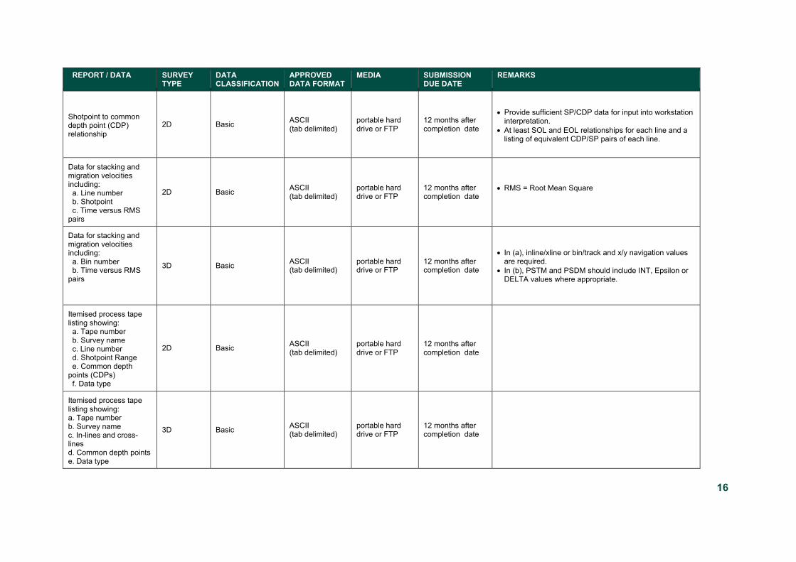
4.6 Reports and Data Submission Tables Table 4.6. 1 2D/3D Seismic Survey Reports and Data Submission Table
REPORT / DATA SURVEY TYPE
DATA CLASSIFICATION
APPROVED DATA FORMAT
MEDIA SUBMISSION DUE DATE
REMARKS
Seismic Survey Reports and Location Data
Acquisition Report 2D / 3D Basic PDF portable hard
drive or FTP 3 months after completion date
• Include daily operations reports as an appendix. • Clearly identify the seismic line prefix and line numbers.
Processing Report 2D / 3D Basic PDF portable hard
drive or FTP 12 months after completion date
• Include sample print out of SEGY/EBCDIC header. • Must define 3D grid definitions for loading into
interpretation work stations.
Interpretation Report 2D / 3D Interpretative PDF portable hard
drive or FTP 24 months after completion date
Location Data 2D / 3D Basic ESRI shape files (SHP) / MapInfo tab files (TAB)
portable hard drive or FTP
3 months after completion date
• Submission of final 2D line and/or 3D footprint. All spatial data should include full metadata.
Acquisition Data
Raw navigation data 2D / 3D Basic IOGP
portable hard drive or FTP
12 months after completion date
• IOGP P2/11 or subsequent format with all associated data sufficient to reprocess seismic data.
Seismic field data 2D / 3D Basic SEG Standard portable hard drive or 3592 cartridge
12 months after completion date
Seismic support data 2D / 3D Basic PDF/XLSX portable hard drive or FTP
12 months after completion date

15
REPORT / DATA SURVEY TYPE
DATA CLASSIFICATION
APPROVED DATA FORMAT
MEDIA SUBMISSION DUE DATE
REMARKS
Itemised field tape listing including : a. Tape number b. Survey name c. Line number d. Shotpoint range e. Data type
2D / 3D Basic ASCII/XLSX
portable hard drive or FTP
12 months after completion date
Processed Data
Raw and final stacked data including near/mid and far stacks if generated.
2D / 3D Basic SEG-Y Standard portable hard drive or FTP
12 months after completion date
• Provide sample print of SEG-Y header with survey processing report (PDF) and include 3D grid definition details used for loading SEG-Y into interpretation work stations, including the CRS.
• Include fully annotated EBCDIC header.
Raw and final migrated data including: a. Pre-stack time migration (PSTM) b. Pre-stack depth migration (PSDM) c. Near/mid/far sub-stacks (if generated)
2D / 3D Basic SEG-Y Standard portable hard drive or FTP
12 months after completion date
• Include fully annotated EBCDIC header with information on CDP Easting and Northing and CRS.
Final processed navigation, elevation 2D / 3D Basic IOGP
(P1/11 or later) portable hard drive or FTP
12 months after completion date
• 2D header information of navigation /shotpoint location data including elevations. Header data must include geodetic datum, spheroid, projection and transformation parameters.
• For 3D: Include all data sufficient to re-process seismic data including shot and receiver coordinates.
Final navigation data in the form of a. Final processed (grid) bin coordinates b. Polygonal position data (outline of the full fold area)
3D Basic IOGP (P6/11 or later)
portable hard drive or FTP
12 months after completion date
• IOGP 3D binning grids • Listing major inflection points of a polygon describing the
location of the survey providing survey name, polygon point, inline/crossline nomenclature, latitude and longitude.
• In (a), ‘grid” coordinates refer to bin centre coordinates.
16
REPORT / DATA SURVEY TYPE
DATA CLASSIFICATION
APPROVED DATA FORMAT
MEDIA SUBMISSION DUE DATE
REMARKS
Shotpoint to common depth point (CDP) relationship
2D Basic ASCII (tab delimited)
portable hard drive or FTP
12 months after completion date
• Provide sufficient SP/CDP data for input into workstation interpretation.
• At least SOL and EOL relationships for each line and a listing of equivalent CDP/SP pairs of each line.
Data for stacking and migration velocities including: a. Line number b. Shotpoint c. Time versus RMS pairs
2D Basic ASCII (tab delimited)
portable hard drive or FTP
12 months after completion date
• RMS = Root Mean Square
Data for stacking and migration velocities including: a. Bin number b. Time versus RMS pairs
3D Basic ASCII (tab delimited)
portable hard drive or FTP
12 months after completion date
• In (a), inline/xline or bin/track and x/y navigation values are required.
• In (b), PSTM and PSDM should include INT, Epsilon or DELTA values where appropriate.
Itemised process tape listing showing: a. Tape number b. Survey name c. Line number d. Shotpoint Range e. Common depth points (CDPs) f. Data type
2D Basic ASCII (tab delimited)
portable hard drive or FTP
12 months after completion date
Itemised process tape listing showing: a. Tape number b. Survey name c. In-lines and cross-lines d. Common depth points e. Data type
3D Basic ASCII (tab delimited)
portable hard drive or FTP
12 months after completion date

17
REPORT / DATA SURVEY TYPE
DATA CLASSIFICATION
APPROVED DATA FORMAT
MEDIA SUBMISSION DUE DATE
REMARKS
Interpretative Data
Digital images of interpretation maps 2D / 3D Interpretative TIF or PDF portable hard
drive or FTP 24 months after completion date
• These include TWT and depth structure maps at key horizons and representative sections showing seismic horizon picks as TIF or PDF images.
Interpreted horizons, grids and faults, fault polygons and additional modelling
2D / 3D Interpretative ASCII portable hard drive or FTP
24 months after completion date • Provide x, y, z values along with information on CRS
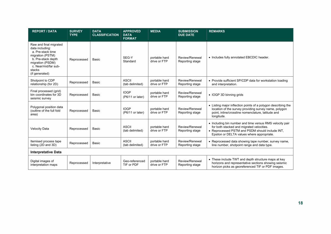
Table 4.6. 2 Reprocessed Seismic Survey Reports and Data Submission Table
REPORT / DATA SURVEY TYPE
DATA CLASSIFICATION
APPROVED DATA FORMAT
MEDIA SUBMISSION DUE DATE
REMARKS
Reprocessed Reports
Final Reprocessing Report
Reprocessed Basic PDF portable hard drive or FTP
Review/Renewal Reporting stage
• Original survey names and lines are to be clearly defined.
• Cleary identify the reprocessing project name, using the same project name for all submissions.
Final Interpretative (Reprocessing) Report
Reprocessed Interpretative PDF portable hard drive or FTP
Review/Renewal Reporting stage
• TIF to include TWT and depth structure maps at key horizons and representative sections showing seismic horizon picks.
• Horizons, grids, faults, fault polygons and additional modelling
Reprocessed Data
Raw and final stacked data including near/mid/far stacks, if generated. (2D and 3D)
Reprocessed Basic SEG-Y Standard
portable hard drive or FTP
Review/Renewal Reporting stage
• EBCDIC header to be fully annotated. • Clearly identify original survey name and line prefixes. • Clearly identify the reprocessing project name and use
the same project name for all submissions.
18
REPORT / DATA SURVEY TYPE
DATA CLASSIFICATION
APPROVED DATA FORMAT
MEDIA SUBMISSION DUE DATE
REMARKS
Raw and final migrated data including: a. Pre-stack time migration (PSTM) b. Pre-stack depth migration (PSDM) c. Near/mid/far sub-stacks (if generated)
Reprocessed Basic SEG-Y Standard
portable hard drive or FTP
Review/Renewal Reporting stage
• Includes fully annotated EBCDIC header.
Shotpoint to CDP relationship (for 2D) Reprocessed Basic ASCII
(tab delimited) portable hard drive or FTP
Review/Renewal Reporting stage
• Provide sufficient SP/CDP data for workstation loading and interpretation.
Final processed (grid) bin coordinates for 3D seismic survey
Reprocessed Basic IOGP (P6/11 or later)
portable hard drive or FTP
Review/Renewal Reporting stage • IOGP 3D binning grids
Polygonal position data (outline of the full fold area)
Reprocessed Basic IOGP (P6/11 or later)
portable hard drive or FTP
Review/Renewal Reporting stage
• Listing major inflection points of a polygon describing the location of the survey providing survey name, polygon point, inline/crossline nomenclature, latitude and longitude.
Velocity Data Reprocessed Basic ASCII (tab delimited)
portable hard drive or FTP
Review/Renewal Reporting stage
• Including bin number and time versus RMS velocity pair for both stacked and migrated velocities.
• Reprocessed PSTM and PSDM should include INT, Epsilon or DELTA values where appropriate.
Itemised process tape listing (2D and 3D) Reprocessed Basic ASCII
(tab delimited) portable hard drive or FTP
Review/Renewal Reporting stage
• Reprocessed data showing tape number, survey name, line number, shotpoint range and data type.
Interpretative Data
Digital images of interpretation maps Reprocessed Interpretative Geo-referenced
TIF or PDF portable hard drive or FTP
Review/Renewal Reporting stage
• These include TWT and depth structure maps at key horizons and representative sections showing seismic horizon picks as georeferenced TIF or PDF images.
19
5 Appendices
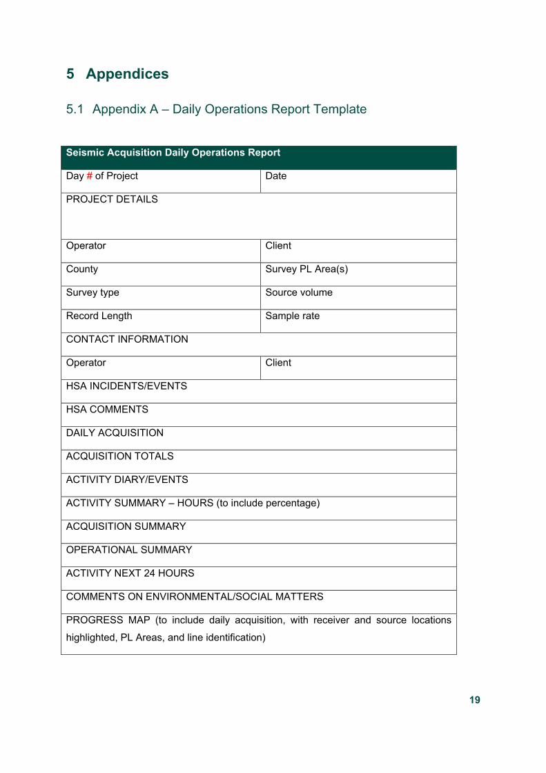
5.1 Appendix A – Daily Operations Report Template
Seismic Acquisition Daily Operations Report
Day # of Project Date
PROJECT DETAILS
Operator Client
County Survey PL Area(s)
Survey type Source volume
Record Length Sample rate
CONTACT INFORMATION
Operator Client
HSA INCIDENTS/EVENTS
HSA COMMENTS
DAILY ACQUISITION
ACQUISITION TOTALS
ACTIVITY DIARY/EVENTS
ACTIVITY SUMMARY – HOURS (to include percentage)
ACQUISITION SUMMARY
OPERATIONAL SUMMARY
ACTIVITY NEXT 24 HOURS
COMMENTS ON ENVIRONMENTAL/SOCIAL MATTERS
PROGRESS MAP (to include daily acquisition, with receiver and source locations
highlighted, PL Areas, and line identification)

20
5.2 Appendix B - EBCDIC Header The text file header should include the following information:
• Client (Name of survey operator); • Survey Name, Project name, Survey ID; • Area name; • Identification of processing contractor, place and time of processing; • Processing history as agreed with client and contractor; • SP/CDP relation for 2D data at a given point on the line or Byte position for
inline/crossline information in trace header for 3D data; • Identification of survey and line by names. Line name should follow convention
specified in section 4.4.1; and • Identification of geodetic datum, projection, and spheroid for survey coordinates.
For 2D data, the EBCDIC Header should clearly identify the CDP to shotpoint relationship, at one tiepoint or as a formula.
For 3D data EBCDIC header should clearly identify byte position for inline/crossline information in trace header.
For 3D data EBCDIC header should clearly identify coordinates of grid origin.
For 3D data EBCDIC header should clearly identify grid rotation in seconds related to grid North and clockwise in inline direction.

21
5.3 Appendix C – 240-byte Standard Trace Header Bytes marked in blue should be considered mandatory
Byte Description 1-4 Trace sequence number within line — Numbers continue to increase if the same line continues across multiple
SEG-Y files 5-8 Trace sequence number within SEG-Y file — Each file starts with trace sequence one. 9-12 Original field record number 13-16 Trace number within the original field record 17-20 Energy source point number 21-24 Ensemble number (i.e. CDP, CMP, CRP, etc.) 25-28 Trace number within the ensemble — Each ensemble starts with trace number one. 29-30 Trace identification code:
–1 = Other 0 = Unknown 1 = Time domain seismic data 2 = Dead 3 = Dummy 4 = Time break 5 = Uphole 6 = Sweep 7 = Timing 8 = Waterbreak 9 = Near-field gun signature 10 = Far-field gun signature 11 = Seismic pressure sensor 12 = Multicomponent seismic sensor – Vertical component 13 = Multicomponent seismic sensor – Cross-line component 14 = Multicomponent seismic sensor – In-line component 15 = Rotated multicomponent seismic sensor – Vertical component 16 = Rotated multicomponent seismic sensor – Transverse component 17 = Rotated multicomponent seismic sensor – Radial component 18 = Vibrator reaction mass 19 = Vibrator baseplate 20 = Vibrator estimated ground force 21 = Vibrator reference 22 = Time-velocity pairs 23 = Time-depth pairs 24 = Depth-velocity pairs 25 = Depth domain seismic data 26 = Gravity potential 27 = Electric field – Vertical component 28 = Electric field – Cross-line component 29 = Electric field – In-line component 30 = Rotated electric field – Vertical component 31 = Rotated electric field – Transverse component 32 = Rotated electric field – Radial component 33 = Magnetic field – Vertical component 34 = Magnetic field – Cross-line component 35 = Magnetic field – In-line component 36 = Rotated magnetic field – Vertical component 37 = Rotated magnetic field – Transverse component 38 = Rotated magnetic field – Radial component 39 = Rotational sensor – Pitch 40 = Rotational sensor – Roll 41 = Rotational sensor – Yaw 42 … 255 = Reserved 256 … N = optional use, (maximum N = 16,383) N+16,384 = Interpolated, i.e. not original, seismic trace
31-32 Number of vertically summed traces yielding this trace. (1 is one trace, 2 is two summed traces, etc.) 33-34 Number of horizontally stacked traces yielding this trace. (1 is one trace, 2 is two stacked traces, etc.) 37-40 Distance from centre of the source point to the centre of the receiver group (negative if opposite to direction in
which line is shot). 41-44 Elevation of receiver group. This is, of course, normally equal to or lower than the surface elevation at the group

22
location. 45-48 Surface elevation at source location. 49-52 Source depth below surface 53-56 Seismic Datum elevation at receiver group. (If different from the survey vertical datum, Seismic Datum should
be defined through a vertical CRS in an extended textual stanza.) 57-60 Seismic Datum elevation at source. (As above) 61-64 Water column height at source location (at time of source event). 65-68 Water column height at receiver group location (at time of recording of first source event into that receiver). 69-70 Scalar to be applied to all elevations and depths specified in Standard Trace Header bytes 41–68 to give the
real value. Scalar = 1, ±10, ±100, ±1000, or ±10,000. If positive, scalar is used as a multiplier; if negative, scalar is used as a divisor. A value of zero is assumed to be a scalar value of 1.
71-72 Scalar to be applied to all coordinates specified in Standard Trace Header bytes 73–88 and to bytes Trace Header 181–188 to give the real value. Scalar = 1, ±10, ±100, ±1000, or ±10,000. If positive, scalar is used as a multiplier; if negative, scalar is used as divisor. A value of zero is assumed to be a scalar value of 1.
73-76 Source coordinate – X. 77-80 Source coordinate – Y. 81-84 Group coordinate – X. 85-88 Group coordinate – Y. 89-90 Coordinate units:
1 = Length (meters or feet as specified in Binary File Header bytes 3255-3256 and in Extended Textual Header if Location Data are included in the file) 2 = Seconds of arc (deprecated) 3 = Decimal degrees (preferred degree representation) 4 = Degrees, minutes, seconds (DMS) Note: To encode ±DDDMMSS set bytes 73–88 = ±DDD*104 + MM*102 + SS with bytes 71–72 set to 1; To encode ±DDDMMSS.ss set bytes 73–88 = ±DDD*106 MM*104 + SS*102 + ss with bytes 71–72 set to –100.
91-92 Weathering velocity. (ft/s or m/s as specified in Binary File Header bytes 3255-3256) 93-94 Subweathering velocity. (ft/s or m/s as specified in Binary File Header bytes 3255–3256) 95-96 Uphole time at source in milliseconds. 97-98 Uphole time at group in milliseconds. 99-100 Source static correction in milliseconds. 101-102 Group static correction in milliseconds. 103-104 Total static applied in milliseconds. (Zero if no static has been applied) 105-106 Lag time A — Time in milliseconds between end of 240-byte trace identification header and time break. The
value is positive if time break occurs after the end of header; negative if time break occurs before the end of header. Time break is defined as the initiation pulse that may be recorded on an auxiliary trace or as otherwise specified by the recording system.
109-110 Delay recording time — Time in milliseconds between initiation time of energy source and the time when recording of data samples begins. In SEG-Y rev 0 this entry was intended for deep-water work if data recording did not start at zero time. The entry can be negative to accommodate negative start times (i.e. data recorded before time zero, presumably as a result of static application to the data trace). If a non-zero value (negative or positive) is recorded in this entry, a comment to that effect should appear in the Textual File Header
111-112 Mute time — Start time in milliseconds. 113-114 Mute time — End time in milliseconds 115-116 Number of samples in this trace. The number of bytes in a trace record must be consistent with the number of
samples written in the Binary File Header and/or the SEG-defined Trace Header(s). 117-118 Sample interval for this trace. Microseconds (µs) for time data, Hertz (Hz) for frequency data, meters (m) or feet
(ft) for depth data. 119-120 Gain type of field instruments:
1 = fixed 2 = binary 3 = floating point 4 … N = optional use
121-122 Instrument gain constant (dB). 123-124 Instrument early or initial gain (dB). 125-126 Correlated:
1 = no 2 = yes
127-128 Sweep frequency at start (Hz). 129-130 Sweep frequency at end (Hz). 131-132 Sweep length in milliseconds. 133-134 Sweep type:
1 = linear 2 = parabolic 3 = exponential

23
4 = other 135-136 Sweep trace taper length at start in milliseconds. 137-138 Sweep trace taper length at end in milliseconds 139-140 Taper type:
1 = linear 2 = cos 3 = other
141-142 Alias filter frequency (Hz), if used 143-144 Alias filter slope (dB/octave). 145-146 Notch filter frequency (Hz), if used 147-148 Notch filter slope (dB/octave). 149-150 Low-cut frequency (Hz), if used. 151-152 High-cut frequency (Hz), if used 153-154 Low-cut slope (dB/octave) 155-156 High-cut slope (dB/octave) 157-158 Year data recorded - should be recorded as the complete 4-digit Gregorian calendar year, e.g., the year 2001
should be recorded as 2001 159-160 Day of year (Range 1–366 for GMT, UTC, and GPS time basis). 161-162 Hour of day (24 hour clock). 163-164 Minute of hour 165-166 Second of minute. 167-168 Time basis code.
1 = Local 2 = GMT (Greenwich Mean Time) 3 = Other, should be explained in a user defined stanza in the Extended Textual File Header 4 = UTC (Coordinated Universal Time) 5 = GPS (Global Positioning System Time)
169-170 Trace weighting factor — Defined as 2–N units (volts unless bytes 203–204 specify a different unit) for the least significant bit. (N = 0, 1, …, 32767)
171-172 Geophone group number of roll switch position one 173-174 Geophone group number of trace number one within original field record. 175-176 Geophone group number of last trace within original field record. 177-178 Gap size (total number of groups dropped). 179-180 Over travel associated with taper at beginning or end of line:
1 = down (or behind) 2 = up (or ahead)
181-184 X coordinate of ensemble (CDP) position of this trace (scalar in Standard Trace Header bytes 71–72 applies). The coordinate reference system should be identified through an Extended Textual Header
185-188 Y coordinate of ensemble (CDP) position of this trace (scalar in Standard Trace Header bytes 71–72 applies). The coordinate reference system should be identified through an Extended Textual Header
189-192 For 3-D poststack data, this field should be used for the in-line number. If one in-line per SEG-Y file is being recorded, this value should be the same for all traces in the file and the same value will be recorded in bytes 3205–3208 of the Binary File Header
193-196 For 3-D poststack data, this field should be used for the cross-line number. This will typically be the same value as the ensemble (CDP) number in Standard Trace Header bytes 21–24, but this does not have to be the case.
197-200 Shotpoint number — This is only applicable to 2-D poststack data. Note that it is assumed that the shotpoint number refers to the source location nearest to the ensemble (CDP) location for a particular trace. If this is not the case, there should be a comment in the Textual File Header explaining what the shotpoint number actually refers to.
201-202 Scalar to be applied to the shotpoint number in Standard Trace Header bytes 197–200 to give the real value. If positive, scalar is used as a multiplier; if negative as a divisor; if zero the shotpoint number is not scaled (i.e. it is an integer. A typical value will be –10, allowing shotpoint numbers with one decimal digit to the right of the decimal point).
203-204 Trace value measurement unit: –1 = Other 0 = Unknown 1 = Pascal (Pa) 2 = Volts (v) 3 = Millivolts (mV) 4 = Amperes (A) 5 = Meters (m) 6 = Meters per second (m/s) 7 = Meters per second squared (m/s2) 8 = Newton (N) 9 = Watt (W)

24
10-255 = reserved for future use 256 … N = optional use. (maximum N = 32,767)
205-210 Transduction Constant — The multiplicative constant used to convert the Data Trace samples to the Transduction Units (specified in Standard Trace Header bytes 211–212). The constant is encoded as a four-byte, two's complement integer (bytes 205–208) which is the mantissa and a two-byte, two's complement integer (bytes 209–210) which is the power of ten exponent (i.e. Bytes 205–208 * 10**Bytes 209–210).
211-212 Transduction Units — The unit of measurement of the Data Trace samples after they have been multiplied by the Transduction Constant specified in Standard Trace Header bytes 205–210. –1 = Other 0 = Unknown 1 = Pascal (Pa) 2 = Volts (v) 3 = Millivolts (mV) 4 = Amperes (A) 5 = Meters (m) 6 = Meters per second (m/s) 7 = Meters per second squared (m/s2) 8 = Newton (N) 9 = Watt (W)
213-214 Device/Trace Identifier — The unit number or id number of the device associated with the Data Trace (i.e. 4368 for vibrator serial number 4368 or 20316 for gun 16 on string 3 on vessel 2). This field allows traces to be associated across trace ensembles independently of the trace number (Standard Trace Header bytes 25–28).
215-216 Scalar to be applied to times specified in Trace Header bytes 95–114 to give the true time value in milliseconds. Scalar = 1, +10, +100, +1000, or +10,000. If positive, scalar is used as a multiplier; if negative, scalar is used as divisor. A value of zero is assumed to be a scalar value of 1.
217-218 Source Type/Orientation — Defines the type and the orientation of the energy source. The terms vertical, cross-line and in-line refer to the three axes of an orthogonal coordinate system. The absolute azimuthal orientation of the coordinate system axes should be defined in the CRS. –1 to –n = Other 0 = Unknown 1 = Vibratory - Vertical orientation 2 = Vibratory - Cross-line orientation 3 = Vibratory - In-line orientation 4 = Impulsive - Vertical orientation 5 = Impulsive - Cross-line orientation 6 = Impulsive - In-line orientation 7 = Distributed Impulsive - Vertical orientation 8 = Distributed Impulsive - Cross-line orientation 9 = Distributed Impulsive - In-line orientation
219-224 Source Energy Direction with respect to the source orientation — Three twobyte two’s complement binary integers for vertical, cross-line and in-line inclinations respectively. The positive orientation direction is defined in Bytes 217–218 of the Standard Trace Header. The energy direction is encoded in tenths of degrees (i.e. 347.8º is encoded as 347810).
225-230 Source Measurement — Describes the source effort used to generate the trace. The measurement can be simple, qualitative measurements such as the total weight of explosive used or the peak air gun pressure or the number of vibrators times the sweep duration. Although these simple measurements are acceptable, it is preferable to use true measurement units of energy or work. The constant is encoded as a four-byte, two's complement integer (bytes 225– 228) which is the mantissa and a two-byte, two's complement integer (bytes 209–230) which is the power of ten exponent (i.e. Bytes 225–228 * 10**Bytes 229–230).
231-232 Source Measurement Unit — The unit used for the Source Measurement, Standard Trace header bytes 225–230. –1 = Other 0 = Unknown 1 = Joule (J) 2 = Kilowatt (kW) 3 = Pascal (Pa) 4 = Bar (Bar) 4 = Bar-meter (Bar-m) 5 = Newton (N) 6 = Kilograms (kg)
233-240 Either binary zeros or the eight character trace header name “SEG00000”. May be ASCII or EBCDIC text. (Ref: SEG Technical Standards Committee, 2017, SEG-Y Rev. 2.0 Data Exchange format, SEG, Tulsa, OK,
www.seg.org)

25
5.4 Appendix D – Glossary of Terms Block of Licences - where two or more contiguous Prospecting Licences are held by a
Licensee. Unless non-contiguous areas are, in the opinion of the Minister, part of a wider
integrated exploration programme. In this context, "a wider integrated exploration
programme" shall mean an exploration programme carried out in non-contiguous areas
dealing with the same geological terrain, results from which should be equally applicable to
all the non- contiguous areas. Such areas should not normally be separated by more than
two Prospecting Licence Areas.
Completion Date – The date seismic acquisition operations were completed.
Licensee – Holder of a Prospecting Licence for mineral exploration.