The CDF Run IIb Silicon Detector: Design, preproduction, and performance

Nuclear Instruments and Methods in Physics Research A271 (1988) 387-403
387North-Holland, Amsterdam
THE CDF DETECTOR: AN OVERVIEW
F . ABE P), D. AMIDEI `), G . APOLLINARI k) , G. ASCOLI 9), M . ATAC d) , P. AUCHINCLOSS "), A.R . BADEN),A . BARBARO-GALTIERI '), V .E . BARNES'), E . BARSOTTI d), F . BEDESCHI k) , S . BELFORTE k) , G. BELLET-FINI k),
J. BELLINGER`), J . BENSINGER b), A . BERETVAS "), P . BERGE d) , S. BERTOLUCCI e), S . BHADRA 9), M . BINKLEY d) ,R . BLAIR a), C . BLOCKER b), J . BOFILL d), A.W . BOOTH d) , G. BRANDENBURG), A. BRENNER d), D . BROWN),A . BYON 1), K.L . BYRUM q), M . CAMPBELL'), R . CAREY F), W. CARITHERS '), D . CARLSMITH 9>, J .T. CARROLL d) ,R. CASHMORE 1 ), F. CERVELLI k) , K. CHADWICK 1),d), T. CHAPIN '), G . CHIARELLI k) , W. CHINOWSKY '),S . CIHANGIR°), D. CLINE v, D . CONNOR J), M . CONTRE 'AS b) , J . COOPER d >, M. CORDELLI '), M . CURATOLO '),C . DAY d) , R . DELFABBRO k) , M. DELL'ORSO k) , L . DEMORTIER b), T. DEVLIN "), D . DIBITONTO °), R . DIEBOLD a) ,F . DITTUS d) , A. DIVIRGILIO k ), R . DOWNING 9), G . DRAKE d) , T. DROEGE d) , M. EATON f), J .E . ELIAS d) , R . ELY'),S . ERREDE 9), B. ESPOSITO `), A . FELDMAN 0, B. FLAUGHER "), E. FOCARDI k) , G.W . FOSTERd), M . FRANKLIN O,9),J . FREEMAN d) , H. FRISCH'), Y . FUKUI h) , S . GALEOTTI k) , I . GAINES d) , A.F . GARFINKEL '), P. GIANNETTI k) ,N. GIOKARIS '), P . GIROMINI'), L . GLADNEY )), M . GOLD'), K . GOULIANOS '), J . GRIMSON d) ,C. GROSSO-PILCHER `), C . HABER'), S.R. HAHN J), R . HANDLER v, D. HANSSEN d) , R.M . HARRIS'),J . HAUSER'), Y . HAYASHIDE P), T . HESSING °), R. HOLLEBEEK'), L . HOLLOWAY 9), P . HU "), B. HUBBARD'),P. HURST 9), J. HUTH d) , M. ITO P), J. JASKE q), H . JENSEN d) , R.P . JOHNSON d), U . JOSHI "), R.W . KADEL d),T . KAMON °), S. KANDA P), I . KARLINER 9), H . KAUTZKY d), K. KAZLAUSKIS "), E . KEARNS f), R . KEPHART d) ,P. KESTEN b), H . KEUTELIAN 9), Y . KIKUCHI P), S . KIM P), L. KIRSCH b) , S . KOBAYASHI 1 ), K. KONDO P)
U . KRUSE 9), S .E. KUHLMANN 1 ), A.T . LAASANEN 1), W. LI a) , T . LISS °), N . LOCKYER J), F . MARCHETTO~°),R . MARKELOFF v, L.A. MARKOSKY a), M . MASUZAWA P), P. MCINTYRE °), A . MENZIONE k) , T. MEYER °),S . MIKAMO h) , M. MILLER'), T . MIMASHI P), S . MISCETTI e), M . MISHINA h) , S . MIYASHITA P), H . MIYATA P),N . MONDAL 9), S . MORI P), Y . MORITA P), A . MUKHERJEE d) , A. MURAKAMI 2), Y. MURAKI 3) , C. NELSON d) ,C . NEWMAN-HOLMES d) , L . NODULMAN a) , J . O ,MFARA d ), G . OTT 9), T . OZAKI P), S . PALANQUE °),R . PAOLETTI k), A . PARA d) , D. PAZZUELLO k) , J . PATRICK d) , R. PERCHONOK d) , T.J PHILLIPS 0, H . PIEKARZ b),
R . PLUNKETT '), L. PONDROM w, J. PROUDFOOT a), G. PUNZI k) , D. QUARRIE d) , K . RAGAN J),G . REDLINGER `), R. REZMER a) , J . RHOADES q), L . RISTORI k) , T . ROHALY J), A . ROODMAN `), H . SANDERS'),A SANSONI e), R. SARD s), V. SCARPINE s>, P . SCHLABACH 9), E.E . SCHMIDT d) , P . SCHOESSOW a), M.H . SCHUB 1),R. SCHWITTERS f), A . SCRIBANO k) , S . SEGLER d), M. SEKIGUCHI P), P. SESTINI k), M . SHAPIRO f), M . SHEAFF `),M . SHIBATA P), M . SHOCHET `), J . SIEGRIST'), V . SIMAITIS 9), J.K . SIMMONS 1 ), P . SINERVO'), M. SIVERTZ 5),
J . SKARHA 9), D.A. SMITH 9), R . SNIDER'), L . SPENCER b, R. ST. DENIS 0, A. STEFANINI k) , Y . TAKAIWA P),K . TAKIKAWA P), S . TAREM b), D. THERIOT d), J . TING `), A . TOLLESTRUP d) , G. TONELLI k), W. TRISCHUK r),Y. TSAY `), K. TURNER d), F . UKEGAWA P), D. UNDERWOOD °), C. VAN INGEN d ), R. VAN BERG J), R. VIDAL d ),R.G . WAGNER a), R.L. WAGNER d), J. WALSH J), T. WATTS "), R . WEBB °), T. WESTHÜSING 9), S . WHITE '"),V . WHITE d), A . WICKLUND a), H.H . WILLIAMS J), T. WINCH v), R. YAMADAd ), T. YAMANOUCHI d),
A . YAMASHITA P), K . YASUOKA P), G.P . YEH d), J . YOH d) and F. ZETTI k)
CDF Member Institutions°) Argonne National Laboratory, n) Brandeis University, `) University of Chicago, d) Fermi National Accelerator Laboratory,`) INFN, Laboratoryi Nazionah di Frascati, Italy, f) Harvard University, s) University of Illinois, h) KEK, Japan,') Lawrence Berkeley Laboratory, J) University of Pennsylvania, k) INFN, University and Scuola Normale Superiore of Pisa, Italy,')Purdue University, -)Rockefeller University, ") Rutgers University, °) Texas A & M University, P) University of Tsukuba, Japan,v) University of Wisconsin
Visitors1) Oxford University, England, z) Saga University, Japan, 3) ICRR, Tokyo University, Japan, 4) CEN Saclay, France,5 ) Haverford College, Haverford, PA, USA
Received 25 March 1988
The Collider Detector at Ferrmlab (CDF) is a 5000 t magnetic detector built to study 2 TeV pp collisions at the FermilabTevatron. Event analysis is based on charged particle tracking, magnetic momentum analysis and fine-grained calonmetry. Thecombined electromagnetic and hadron calorimetry has approximately uniform granularity m rapidity-azimuthal angle and extends
0168-9002/88/$03.50 © Elsevier Science Publishers B.V .(North-Holland Physics Publishing Division)

388
F. Abe et aL / The CDF detector
down to 2° from the beam direction . Various tracking chambers cover the calorimeter acceptance and extend charged particletracking down to 2 mrad from the beam direction . Charged particle momenta are analyzed m a 1 .5 T solenoidal magnetic field,generated by a superconducting coil which is 3 m m diameter and 5 m m length . The central tracking chamber measures particlemomenta with a resolution better then SpT/pT = 2 X 10 -s (GeV/c)-1 m the region 40 ° < 0 < 140 ° and SP .r/P2 <4x 10 -s for21' < 0 < 40' and 140 o < 0 <159' . The calorimetry, which has polar angle coverage from 2 ° to 178' and full azimuthal coverage,consists of electromagnetic shower counters and hadron calorimeters, and is segmented into about 5000 projective "towers" or solidangle elements . Muon coverage is provided by drift chambers m the region 56° < 0 < 124°, and by large forward toroid systems mthe range 3 ° < 0 <16' and 164' < 0 <177o . Isolated high momentum muons can be identified in the intermediate angular range bya comparison of the tracking and calorimeter information in many cases. A custom front-end electronics system followed by a largeFastbus network provides the readout of the approximately 100000 detector channels . Fast Level 1 and Level 2 triggers make adetailed pre-analysts of calonmetry and tracking information ; a Level 3 system of on-line processors will do parallel processing ofevents . This paper provides a summary of the aspects of the detector which are relevant to its physics capabilities, with references tomore detailed descriptions of the subsystems.
1 . Introduction
The Fermilab Tevatron collider is currently theworld's highest energy accelerator, colliding antiprotonswith protons at a center-of-mass energy of 1 .8 TeV . TheCollider Detector at Fermilab (CDF) is the first generalpurpose detector built to exploit this machine . Thepartially completed apparatus detected the first pp colli-sions at the Tevatron in October, 1985 . The first physicsrun, from January 1987 to May 1987, was with anessentially complete detector . Analysis of these data isnow in full swing.
The individual sub-systems of the detector have beendescribed in a series of detailed papers [1] . Here we give
an overview of these systems, with particular emphasison details such as geometrical coverage which have adirect bearing on physics results, and provide in oneplace a list of references for those interested in thetechnical details .
2 . Overall layout
The detector consists of a 2000 t moveable centraldetector which is made up of the solenoidal magnet,steel yoke, tracking chambers, electromagnetic showercounters, hadron calorimeters and muon chambers, andtwo identical forward/backward detectors consisting of
FCRI,~RC EL' -r:,oUacH~ - I",f,D H_'Cq_'f1 __ C C :+_H I~ICT-R
Fig . 1 . A perspective view of the CDF detector showing the central detector and the forward and backward detectors .

segmented time-of-flight counters, electromagneticshower counters, hadron calorimeters, and muontoroidal spectrometers . A perspective view is shown infig . 1 . A photograph of the central detector alone isshown in fig . 2. The steel yoke forms a large "box" 9.4m high by 7.6 m wide by 7.3 m long . The 3 m diameter,5 m long superconducting coil and the calonmeterizedend-plugs are supported by the yoke . The centralcalorimeter consists of 48 wedge-shaped modules as-sembled into four self-supporting arches which rest onthe yoke base . The arches can be retracted to service themodules (fig . 3) . The whole yoke assembly, with thearches resting on it, rolls from its garaged position inthe CDF assembly building to its position on theTevatron beam line (fig . 4) . The cables follow it on an
E Abe et al / The CDF detector
Fig . 2. TheCDF Central Detector m its assembly position .
"Ik
389
overhead flexible cable tray . The 31 .4 m move takes oneday.
An elevation view of the forward half of the com-plete detector is shown to fig . 5. The detector is dividedinto a central detector (10 ° < 0 < 170 ° ), which in-cludes the end-plugs which form the pole pieces for thesolenoidal
magnet
(10 ° < 9, < 30 ° ),
and
theforward/backward regions (6, < 10 ° ), where BS is thepolar angle measured from either the proton or antipro-ton beam. At angles less than 10' to either beam,particles produced at the interaction point exit theconical hole in the end plug and strike the forwardshower counters and hadron calorimeters . On each endthe calorimeters are followed by two 7.6 m diametersteel toroidal magnets used as muon spectrometers. A

390
FAbe et al / The CDFdetector
Fig 3 The Central Detector with the calorimeter arches retracted for servicing. The end plugs have been removed, and the centraltracking chamber is being installed m the solenoid magnet .
ASSEMBLY HALL
DETECTOR POSITION
'200 10N
ALTERNATE DETECTORON BEAM LINE
SHIELDING DOOR
POSITION FOR SERVICING
Fig. 4 An elevation view of the collision hall and assembly budding for the detector
0
1011
EL-740 It
r/ 1I MO
0
111RADRON
ENDPLwHADRON
CALORAETI
CENTRALTRACKINGCHAMBER
DRIFT CHAMBERS
LOW ß OUADRUPOLE
EL-710 It
ELEVATION VIEW LOOKING SOUTH
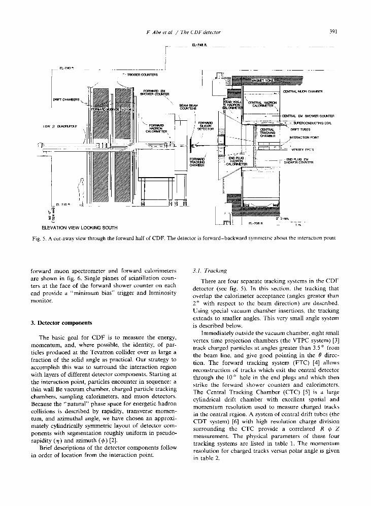
Fig . 5 . A cut-away view through the forward half of CDF . The detector is forward-backward symmetnc about the interaction point
forward muon spectrometer and forward calorimetersare shown in fig. 6 . Single planes of scintillation coun-ters at the face of the forward shower counter on eachend provide a "minimum bias" trigger and luminositymonitor.
3 . Detector components
- , TRIGGER COUNTERS
F Abe et al / The CDFdetector
EL-745 ft
The basic goal for CDF is to measure the energy,momentum, and, where possible, the identity, of par-ticles produced at the Tevatron collider over as large afraction of the solid angle as practical . Our strategy toaccomplish this was to surround the interaction regionwith layers of different detector components . Starting atthe interaction point, particles encounter in sequence : athin wall Be vacuum chamber, charged particle trackingchambers, sampling calorimeters, and muon detectors .Because the "natural" phase space for energetic hadroncollisions is described by rapidity, transverse momen-tum, and azimuthal angle, we have chosen an approxi-mately cylindrically symmetric layout of detector com-ponents with segmentation roughly uniform in pseudo-rapidity (rl) and azimuth (0) [2] .
Brief descriptions of the detector components followin order of location from the interaction point.
3.1 . Tracking
0',D rtrrt
EL-706 M
CENTRAL MUON CHALEER
vERTEx TRCs
END PLUG EMSHOWER COUNTER
39 1
CENTRAL EM SHOWER COUNTER
SUPERCONDUCTING COIL
DRIFT TUBES
INTERACTION POINT
There are four separate tracking systems in the CDFdetector (see fig . 5) . In this section, the tracking thatoverlap the calorimeter acceptance (angles greater than2 ° with respect to the beam direction) are descnbed .Using special vacuum chamber insertions, the trackingextends to smaller angles. This very small angle systemis described below.
Immediately outside the vacuum chamber, eight smallvertex time projection chambers (the VTPC system) [3]track charged particles at angles greater than 3.5 ° fromthe beam line, and give good pointing in the 0 direc-tion . The forward tracking system (FTC) [4] allowsreconstruction of tracks which exit the central detectorthrough the 10 ° hole in the end plugs and which thenstrike the forward shower counters and calorimeters .The Central Tracking Chamber (CTC) [5] is a largecylindrical drift chamber with excellent spatial andmomentum resolution used to measure charged tracksin the central region . A system of central drift tubes (theCDT system) [6] with high resolution charge divisionsurrounding the CTC provide a correlated R-q)-Zmeasurement . The physical parameters of these fourtracking systems are listed in table 1 . The momentumresolution for charged tracks versus polar angle is givenin table 2 .
r
FORWARD EMSHOWER COLRTER
BEAM-BEAMCOUNTERS I
FORWAß1FORVOViO SILICONHADRON
/DETECTOR
CALORMETER\
ë
rr~r i

392
F Ahe et al / The CDFdetector
Table 1A summary of the properties of tracking chambers
Fig. 6 . A forward muon spectrometer and forward shower counter and hadron calorimeter.
Trackingsystem
Wireorganization
Inner layercoverage
Outer layercoverage
Numberof(sense)wires
Spatialprecision(per hit)
2-trackresolution
VTPC 8 modules 3 .5 ° < 0 < 176 .5 ° 8 .7 ° < 0 < 171 .3 ° 3072 wires 200-500 pin 6 mm/0 (Z)16 octants/module -3.5 < < 3 .5 -2 6 < rl < 2.6 3072 pads (0-15 cm 6 mm (r)24 wires/octant drift) 3 cm (0)24 pads/octant
CTC 9 superlayers 15 ° < 0 < 165 ° 40 ° < 0 < 140 ° 6156 < 200 wm (r-.~) 3 .5 mm5 axial superlayers - 2 .0 < il < 2 0 -1 0 < 77 < 1 .0 < 6 mm (Z)of 12 wires each
4 stereo superlayersof 6 wires each
CDT 3 layers of drift 40 ° < 0 < 140 ° 40 ° < 0 < 140 ° 2016 200 Am (r-0)tubes -1.0<q<1.0 -1.0<q <1 .0 2 .5 mm (Z)
FTC one chamber each end 2 ° < 0 < 10 ° 2 ° < 0 < 10 ° 3024 150 A m (r-"~") 2 nun (¢)72 cells each 2.4<71<4 24<q <421 wires/cell
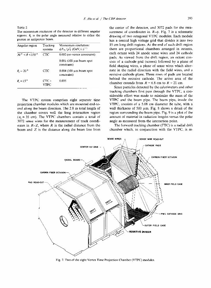
Table 2The momentum resolution of the detector in different angularregions. Bs is the polar angle measured relative to either theproton or antiproton beam .
The VTPC system comprises eight separate timeprojection chamber modules which are mounted end-to-end along the beam direction. The 2.8 m total length ofthe chamber covers well the long interaction region(az = 35 cm). The VTPC chambers contain a total of3072 sense wires for the measurement of track coordi-nates in R-Z, where R is the radial distance from thebeam and Z is the distance along the beam line from
F. Abe et al / The CDF detector 39 3
the center of the detector, and 3072 pads for the mea-surement of coordinates in R-4, . Fig. 7 is a schematicdrawing of two octagonal VTPC modules. Each modulehas a central high voltage grid that divides it into two15 cm long drift regions. At the end of each drift regionthere are proportional chambers arranged in octants,each octant with 24 anode sense wires and 24 cathodepads . As viewed from the drift region, an octant con-sists of a cathode grid (screen) followed by a plane offield shaping wires, a plane of sense wires which alter-nate in the radial direction with the field wires, and aresistive cathode plane. Three rows of pads are locatedbehind the resistive cathode. The active area of thechamber extends from R = 6.8 cm to R = 21 cm .
Since particles detected by the calorimeters and othertracking chambers first pass through the VTPC, a con-siderable effort was made to minimize the mass of theVTPC and the beam pipe. The beam pipe, inside theVTPC, consists of a 5.08 cm diameter Be tube, with awall thickness of 500 pm. Fig. 8 shows a detail of theregion surrounding the beam pipe. Fig. 9 is a plot of theamount of material in radiation lengths versus the polarangle as measured from the interaction point.
The forward tracking chamber (FTC) is a radial driftchamber which, in conjunction with the VTPC, is re-
Fig. 7 . Two of the eight Vertex Time Projection Chamber (VTPC) modules.
Angular region Trackingsystems
Momentum resolution :dPT/pT (GeV/c)-1
30 ° < 0 < 150 ° CTC 0.002 (no vertex constraint)
0.001 (100 ~Lm beam spotconstraint)
Bs °= 20 CTC 0.004 (100 pin beam spotconstraint)
0,=15 ° CTC+ 0A35VTPC

394
R=29 7cm --
R=22 3 cm -
30
ABLES
7-MI11"17~]11t7l-l
---- MYLAR WINDOW
-CENTRAL TRACKING CHAMBER--(1549 cm)
-- B(15T)
INNERMOST CTC SENSE WIRE
sponsible for tracking in the angular region 2° < BS <
10 ° . The 72 wedge shaped cells of an FTC are shownschematically in fig. 10 . The chamber contains planes of
RADIATION LENGTH A VS POLAR ANGLE 0
VTPC
CTC
INSIDE CTC/FTC ACTIVE VOLUME-
BEAM PIPE AND VTPC SYSTEMINSIDE VTPC ACTIVE VOLUME
Fig. 9. The amount of material in radiation lengths vs polarangle.
F. Abe et aL / TheCDFdetector
80
SSAME
ht ENDPLUG -EM SHOWERCOUNTER
FsANE
0 10-SCALE
ENDPLUG HADRON CALORIMETER
Fig. 8. An elevation view of the beam pipe and the tracking systems nearest to it. Note that the transverse scale has been magnified.
FORWARDTRACKINGCHAMBER
- 2'
Fig. 10. One of the Forward Tracking Chambers (FTC), show-ing the radial layout of the wires.
VERTEX T PC BELLOWSMODULE (35 3cm) 5 cm Dia BERYLLIUM BEAM PIPE
FLANGE143 5 cm
FLARED ALUMINUM BEAM PIPE

2760 .00 m m O.D . --
Fig. 11 . An endplate of the Central Tracking Chamber (CTC)showing the arrangement of the blocks which hold the 84
layers of sense wires.
radial anode and field shaping wires which alternatewith planes of cathode strips . The planes are slanted by2° relative to the beam axis so that left-right ambigui-ties can be resolved by demanding that tracks pointback to the vertex . Each anode plane has twenty-onesense wires and twenty-six field shaping wires. Four ofthe twenty-one sense wires are instrumented for charge
14283 mm -v
1419 0 mm
1399 8 mm
1382 0 mm1380 0 mm
F. Abe et aL / The CDF detector
Central Tracking ChamberSL8 Sense Wire Planes
division, so that an R-~S-Z measurement can be madefor each track.
The Central Tracking Chamber (CTC) is a 1 .3 mradius 3.2 m long cylindrical drift chamber which givesprecise momentum measurements in the angular region40 0 <0< 140 0 (-1 < ,q< 1). In this region themomentum resolution is better than 8PT/PT <0.002(GeV/c)-l . The chamber contains 84 layers of sensewires grouped into 9 "superlayers" . Five of the super-layers consist of 12 axial sense wires; four stereo super-layers consist of 6 sense wires tilted by ± 3 ° relative tothe beam direction. Fig. 11 shows an endplate of thechamber displaying the 45 ° tilt of the superlayers to theradial direction to correct for the Lorentz angle of theelectron drift in the magnetic field.
The CDT system consists of three layers of 3 m long,1.27 cm diameter stainless steel tubes mounted on theouter perimeter of the CTC. A correlated R-q>-Z de-termination (i .e . a space point) is made by making bothdrift-time and charge division measurements . Typicalresolutions are 2.5 mm in the axial (beam direction and200 ,am in the azimuthal direction. Fig. 12 shows across section of a small region of the CDT system .
3.2 . Solenoid magnet coil
39 5
Precise momentum determination for charged par-ticles produced in the central region is provided by theCTC, which is in a uniform 1.5 T magnetic field ori-ented along the incident beam direction. The field isproduced by a 3 m diameter 5 m long superconductingsolenoidal coil [7] . The coil is made of 1164 turns of analuminum-stabilized NbTi/Cu superconductor fabri-
Inner Wall of Solenoid Cryostat
\ Central Drift Tube ArrayRadial Track
Fig. 12 . A section of the Central Drift Tube (CDT) system showing the three layers of drift tubes which give a correlated n-.P-zmeasurement for particle tracks . Also shown is the outer superlayer of wires (superlayer 8) of the CTC.

39 6
cated by the EFT method (extrusion with front tension)in which high purity aluminum is friction welded to thesuperconducting wire during the extrusion process [8] .The coil was designed to have no inner bobbin : theradially outward magnetic forces are supported by athin aluminum-alloy cylinder outside the coil. Coolingis by forced flow of two-phase helium through analuminum tube welded to the outer support cylinder.The overall radial thickness of the solenoid is 0.85radiation lengths.
3.3 . Calorimeters
Because of the importance of hadromc jets in highenergy proton-antiproton collisions, a "tower" geome-try was chosen for all calorimeters . The coverage of thecalorimeter towers in rl-,p space [2] is shown in fig. 13 .Each tower has an electromagnetic shower counter infront of a corresponding hadron calorimeter, so thatone can make a detailed comparison of electromagneticto hadronic energy on a tower-by-tower basis. Thetowers are projective, i.e ., they point at the interactionregion, and are 0.1 units of 71 wide by 15' (centralregion) or 5 ° (plug and forward regions) in 0. Thephysical size of a tower ranges from about 24 .1 cm(77) x 46.2 cm ((A) in the central region to 1.8 cm x 1.8
cm in the forward region . A summary of the calorimeterproperties in the different angular regions is given intable 3.
The electromagnetic shower counters use lead sheetsinterspersed with scintillator as the active detectormedium in the central region, and with proportionalchambers with cathode pad readout elsewhere. The elec-tromagnetic shower counters have a spatial resolutionof = 2 mm over the complete solid angle. The depthsegmentation for each tower of the central shower coun-
F Abe et aL / The CDFdetector
ter [9] (0 < I n I < 1 .1) consists of a single overall sam-ple, with an additional measurement with high spatialresolution transverse to the shower using a proportionalchamber located at a depth of 6 radiation lengths. Inthe end plug shower counters [10] (1 .1 < 1711 < 2.4)there are 3 samples in depth, integrating over 3.8, 14 .2,and 3.0 radiation lengths. Each wire plane in depth, 34in number, is also digitized by quadrant, giving a de-tailed shower profile in addition to the three depthsamples for isolated electrons or photons. The forwardregion shower counters [111 (2 .2 < 1 711 < 4.2) have twodepth segments, each integrating over 12 radiationlengths . As in the plug, the wire planes at each depthare read out for profile information, but with fiveseparate regions per quadrant.
The hadron calorimeters consist of steel plates alter-nated with active detectors: plastic scintillator in thecentral region, and gas proportional chambers in theplug and forward/ backward regions. The hadromccalorimeters have a slightly different sharing of therapidity coverage from the electromagnetic showercounters due to the geometry of the solenoid . Thecalorimeters in the central detector [12] consist of thehadronic towers in the wedges, and also additionaltowers in the "endwalls," which are attached to theyoke (see fig. 5) . The rapidity coverage of the centraltowers is 0 < I n I < 1 .3 . The end plug hadron calorime-ters [13] cover the region 1 .3 < 1711 < 2.4, while theforward calorimeters [14] cover 2.3 < J q I <4.2 . All thehadron calorimeters have only one depth sample, al-though the plug and forward calorimeters have thewires of each wire plane per quadrant digitized individ-ually to provide shower profile information .
The calibration of each scintillator-based "wedge"calorimeter was determined with 50 GeV electrons andcharged peons in a test beam [15] and with cosmic ray
® Partial depth coverage only due to cut for low beta quodrupoles
No coverage
Fig. 13 . Hadron calorimeter towers in one of eight identical 71-¢ quadrants (40= 90 °, 71 > 0) . The heavy lines indicate module orchamber boundaries. The EM calorimeters have complete 4p coverage out to il = 4.2 .

Table 3A summary of the calorimeter properties by system
a> An imbedded proportional tube chamber at shower maximum gives some additional information. The quoted position resolutionis measured with this chamber.
b) The first number is for the vertical boundary, the second for the horizontal .
muons [16] . Long term gain variations are monitored bya set of 137CS sources, one per wedge, which can bemoved through the module under remote control [17] .Short term gain changes are also monitored by lightflasher systems [17] . The central EM calorimeters use aXe lamp system connected by quartz fibers to thecalorimeter, and also a light-emitting diode system con-nected by quartz fibers to a transition piece directly infront of each photomultiplier tube [18] . The hadroncalorimeters employ a nitrogen laser, also connected byquartz fibers to the transition piece. Fig. 14 shows thereproducibility of the calibration procedure for fourwedges . Over a period of a few months, the procedurehas an accuracy of better than 2% .
Changes in gain of the gas-based calorimeters due tovariations in pressure, temperature or gas compositionare tracked by calibrated monitor tubes. Gain changes
F. Abe et al. / The CDFdetector
3.4. Muon detection
397
of 25% over a 24 hour period have been recorded whena pressure front moves through the laboratory, butdifferent monitor tubes show the same gain change towithin about 2%. It appears that the ultimate precisionwith which the gas-based calorimeter gain changes canbe tracked with the monitor tubes will be about 2% .
There are two systems in CDF to measure muonswhich penetrate the calorimeters . In the central detec-tor, each wedge contains 4 layers of muon chambers[19] at the end of the hadron calorimeter section. Inboth the forward and backward regions there is a muonspectrometer [20] consisting of large magnetized steeltoroids with drift chamber planes and triggering scintil-lation counters . In the intervening intermediate region
Central
EM Hadron
Endwall
Hadron
Endplug
EM Hadron
Forward
EM Hadron
1 711 coverage 0-1.1 0-0.9 0.7-1 .3 1.1-2.4 1.3-2.4 2.2-4 .2 2.3-4 .2Tower size, -0.1x15 ° -0.1x15° -0.1x15 ° 0.09x5 ° 0.09x5° 0.1x5 ° 0.1x5 °A?,xd4.
Longitudinal 1 a> 1 1 3 1 2 1samples mtower
Active polystyrene acrylic acrylic Proportional tube chambers Proportional tube chambersmedium scintillator scintillator scintillator with cathode pad readout with cathode pad readout
Scmtillator 0.5 cm 1 .0 cm 1.0 cm 0.7 X0.7 cm2 1.4 x 0.8 cm2 1.0X0 .7 cmz 1 .5 x 1 .0 cm2thickness orproportional tube size
Number of 31 32 15 34 20 30 27layers
Absorber Pb Fe Fe Pb Fe 94%Pb, 6% Sb FeAbsorber 0.32 2.5 5.1 0.27 5.1 0.48 5.1
thickness [cm]Typical -1100 -1500 -1100 +1700 +2120 +1900 +2200
phototube orwire high voltage [V]
Typical 1.2x10⁵ 6X10 5 10 6 2x10³ 2x10° 5x10 3 10 4
phototubeor wire gain
Typical -4 -4 -4 +1.25 +1 .3 + 2 +0.7tower signal [pC/GeV]
Energy (a/E) 2 11 14 4 20 4 20resolution at 50 GeV[%]
Typical 0.2x0.2 a) 10x5 10x5 0.2x0.2 2x2 0.2x0 .2 3x3position resolutionat 50 GeV [cm2]
Characteristic 3.5 4.1 3.8, 0.9 0.8 0.7 ; 1.3 ;width of azimuthal 8.9 3.2 b) 3.2 b)
boundary region [cm] alternating

398
CENTRAL EM CALORIMETER
Calibration Differences
0=ee S° ;
U=65 9°
F. Abe et al. / The CDFdetector
Wedge 30
Wedge II
Wedge I
Wedge 30
Fig. 14 . Reproducibility of the calibration procedure for fourwedges . The arrow indicates the expected shift of +0.22% inthe beam/source ratio due to the 30 yr half-life of 13-7Cs . The
rms error is 0.6%.
there is partial coverage for isolated muons. For exam-ple, the combination of the excellent momentum andspatial resolution of the central tracking chamber withthe requirement of a minimum ionizing particle in the(finely-segmented) calorimeters allows finding the sec-ond muon in a Z ° decay.
The layout of the central muon chambers is shown infig. 15 . The chambers measure four points along the
2260 --
CENTRALCALORIMETER
.EDGE
Fig. 15 . The layout of the central muon chambers in one of thecentral wedges .
to pp interaction vertex
Fig. 16 . The arrangement of the four planes of central muonchambers in a view along the beam direction. The drift times tzand t4 are used at the trigger level to determine a muon
momentum cutoff
trajectory with an accuracy of 250 p.m per point in the¢ direction (fig. 16). Charge division gives an accuracyof a = 1 .2 mm per point in the Z direction. The cham-bers cover the angular region 56 ° <0< 124° ; in thisregion their average coverage is 84% due to the spacesbetween the chambers at the q, boundaries of the wedgesand the boundary between the arches at 0 = 90 °. Thesystem is essentially 100% efficient for muons in itssolid angle when the muon momentum is above 3GeV/c. Muons are matched both in position and angleto tracks in the central chamber (CTC). As with anyhigh momentum track in the CTC, the momentumresolution on a central muon is better than °pT/pT <0.002 (GeV/c) -1 .
The layout of the forward/ backward muon spec-trometers is shown in fig . 5; an r-4) view is shown infig . 17 . Each spectrometer contains two 1 m thick, 7.82m diameter, 395 ton steel toroids . The inner diameter is
24 santillator trigger counters
15 5* cathode pads
Fig. 17 . One of the detector planes in the forward muonspectrometer.

0.914 m . Four coils excite the toroids to a magnetic fieldranging from 2.0 T at the inner radius to 1 .6 T at theouter radius . Three layers of electrodeless drift cham-bers measure the muon trajectory with an accuracy of5 ° in the q> direction, and = 200 itm in the r direction .Two layers of scintillation counters provide trigger in-formation. The angular region covered by each spec-trometer lies between 3° and 16 ° from each beam line.The momentum resolution is 13%, independent ofmomentum, for muons with total momentum P above 8GeV (remember that PT = P sin 0) . Muons are matchedto the FTC and VTPC tracking systems ; isolated muonscan also be matched to the calorimetry in front of themuon spectrometer.
3.5. Trigger counters and luminosity monitoring
F. Abe et al. / TheCDFdetector
0
Fig . 18 . A beam's-eye view of ine of the beam-beam counter planes .
There is a plane of scintillation counters on the frontface of each of the forward and the backward showercounters. These scintillators, called the beam-beamcounters (BBC), provide a "minimum-bias" trigger forthe detector, and are also used as the primary luminos-ity monitor . The counters have excellent timing proper-ties (a < 200 ps), and so provide the best measurementof the time of the interaction. A crude (±4 cm) mea-surement of the vertex position is also obtained fromthe timing . The counters are arranged in a rectanglearound the beam pipe as shown in fig. 18 . They coverthe angular region (measured along either the horizontal
i meter
399

400
F Abe et al / The CDFdetector
ANTIPROTON
PROTONSPECTROMETER
ELASTIC SCATTERING
SPECTROMETER
n
S 3
or vertical axes) from 0.32° to 4.47°, corresponding toa pseudo-rapidity of range of 3.24 to 5.90. The mini-mum bias trigger requires at least one counter in eachplane to fire within a 15 ns window centered on thebeam crossing time .
3.6 . The small angle silicon detector and chamber system
A system of seven stations of detectors (see fig . 19)along the accelerator ring tracks particles produced atvery small angles . Each of the outer stations, Si , S2 , S3 ,
S6 and S� consists of a pair of "pots" which can beremotely moved to within a few mm of the beam . Thetwo inner stations, S4 , and S5 , each have two pairs ofpots separated by lm which track particles in the angu-lar 2 < 0, < 6 mrad, and drift chambers which cover therange 8 < 0, < 35 mrad . Every pot contains two scintil-lation counters and a drift chamber with 4 sense wiresand delay line readout. The stations also contain asingle silicon detector with both horizontal and verticalstrips, giving 50 ft m resolution in the horizontal planeand 300 ,um in the vertical . The subsystem S3-S6 coversthe angular range 0.2 < 0, < 1 .2 mrad, corresponding toelastic scattering with momentum transfer 0.04 < I t I <1.5 (GeV/c) Z . Because the SI, S2, S3 spectrometer usesthe Tevatron dipoles (and not just the low-/3 quadru-poles) the momentum resolution for "leading particles"is good (,Ap/p = 0.1% for p = 900 GeV/c at all accessi-ble angles and momentum transfers. In the protondirection momentum analysis is performed by thequadrupole field only, and the momentum resolutiondepends on angle (at 9= 1 .0 mrad, Ap/p =2%).
TEVATRON VACUUM!
I:j58m-~-58m;-~1
PIPE (3"DIAM)
TRIGGER COUNTERS
^ji~ 30m ~~f- - 30m i
~-35m-j "55m
--1 i~-1 .5m
Fig. 19. The locations along the accelerator of the small-angle silicon detector and tracking system (S,-S 7 ) . BO is the interactionpoint, and Cq_ 5 are the beam-beam counters . The magnets closest to the interaction point are the low-ß quadrupoles ; the others are
part of the Tevatron normal lattice.
4. Data acquisition, front-end electronics and readout
The CDF detector has a total of approximately100000 electronic channels consisting of photomulti-pher tubes, strip/wire/pad chambers, drift chambers,drift chambers with current division readout, and sili-con strip detectors. The calorimetry requires a verylarge dynamic range for the electronic readout, extend-ing from a few tens of MeV to many hundreds of GeV.A special crate-based analog front-end system called theRABBIT system [21] was developed to deal with thisproblem. The RABBIT system consists of 129 cratesmounted on the detector which service all of thecalorimeters, about 60 000 channels of the 100 000 total.The drift chambers make up the bulk of the remainder:their signals are shaped at the detector and brought upfrom the collision hall to commercial Fastbus TDCmodules to the counting room .
The measurement method upon which the RABBITsystem is based involves sampling two voltage levels foreach event to avoid pileup and common mode noise:one dust before the interaction time to establish a refer-ence level and another after the interaction . The dif-ference between voltage levels is proportional to theintegrated signal charge . This approach makes use ofthe bunched structure of the beams. Normally, theTevatron operates with three or six approximatelyequally spaced bunches of protons and antiprotons .Thus, interactions occur at relatively well defined"windows" in time, separated by 7 or 3.5 its . Thisgeneral approach is referred to as "before-after" sam-pling. Digitization is performed in each crate .

As the RABBIT channels are digitized they are readout by fast intelligent scanners called MXs [21] . Thescanners interface to the Fastbus data acquisition sys-tem [221 . Most of the tracking systems use commercialFastbus modules which are read out by a second type ofintelligent scanner called the SSP [221 . Each scanner canbuffer four events, and handles approximately 1000channels . There are approximately 60 MX scanners and25 SSP scanners in the system.
The Fastbus network which comprises the dataacquisition (DAQ) system consists of 53 crates, 16 cablesegments, and 66 segment-interconnect modules. Manycustom designed Fastbus modules, such as a hardwareevent builder, allow for the bandwidth necessary totransmit the data for each event. For a nominal eventsize of 100 Kbytes the DAQ system reads out events at20-30 Hz into the Level 3 system (see below) . A detailedtechnical description is given in ref. [22] .
5. Trigger system
5.1 . Level 1 and Level 2
The trigger [231 is designed to exploit the projectivegeometry of the calorimeter towers . Both hadron andelectromagnetic calorimeter towers are summed intotrigger towers with a width in pseudorapidity of An = 0.2and a width in ¢ of A0 = 15 ° . This results in a repre-sentation of the entire detector as a 42 (in n) by 24 (in
array for both the electromagnetic and hadroniccalorimeters . Outputs from all phototubes are broughtto the counting room individually and summed, fourtubes per channel, into the a-p = 15 ° and An = 0.2trigger towers . All gas calorimeter pad signals aresummed at the detector into the trigger towers. Thesignals are weighted by sin 6 to represent the "trans-verse energy", ET, deposited in the tower.
The trigger signals from the calorimeters are sent tothe trigger electronics on dedicated cables . The signalsare do levels (0-100 GeV in ET is 0-1 V) from thebefore-after sampling of the beam crossing . The voltagelevels stay on these trigger cables until a Level 1 deci-sion is made : if Level 1 is not satisfied in a givencrossing a reset will automatically be sent m time forthe next beam crossing . No deadtime is introduced byevents which do not pass level 1.
The Level 1 calorimeter triggers require that the sumof ET for all calorimeter towers which are individuallyover a low threshold (typically 1 GeV) be greater than ahigher threshold (typically 30-40 GeV). Both electro-magnetic and hadronic energy, or either one, can besummed in a given tower. The two thresholds are pro-grammable, and four such comparisons are made in agiven beam crossing. The results of these comparisonsare combined in a trigger "lookup" table with the
F. Abe et al. / The CDFdetector
beam-beam counter coincidence, the muon triggers[20,24], a stiff track trigger from a fast hardware trackprocessor [25], and other optional signals to generatethe Level 1 decision to accept or reject the event.Different patterns can be rate-limited so that minimumbias events, for example, can be taken intermixed withjet or electron triggers .
The Level 2 trigger starts after a Level 7 trigger hasaccepted an event. Level 2 uses the same hardware tosearch the 42 x 24 array of towers in n-,p for clusters oftotal energy or of electromagnetic energy . Towers belowa programmable threshold are ignored; a hardware clus-ter finder identifies clusters of energy in a time of about200 ns/cluster . The energies of all towers identified asbeing in a cluster are summed to form the total ET andthe ET-weighted first and second 71 and (p moments ofthe cluster . Separate sums are kept for hadronic andelectromagnetic energy . These are digitized and pre-sented as a list of clusters to a fast hardware Level 2processor. For each cluster a match is made to tracksfound in the CTC by the fast (10 ps) hardware trackingprocessor, and a coarse PT measurement appears in thelist if a match is found. Muons are matched to the CTC,and with their momenta also appear in the cluster list.
The final trigger is then a selection on muons, elec-trons, photons, bets and missing ET by the programma-ble Level 2 processor . Many combinations of the abovecan be programmed in parallel .
5.2. Level 3
6. On-line control systems
40 1
The Level 3 system is designed to execute FOR-TRAN-77 filter algorithms as the last stage of on-linetrigger selection . Level 3 uses Advanced Computer Pro-gram [26] (ACP) 32-bit processor installed in VMEcrates with VME bus control and interface modules. Aninterface allows a Fastbus master to transfer data to aprocessor memory at 20 Mbytes/s [27] . The processorsare double height VME cards based on the Motorola68020 CPU and 68881 floating point coprocessor . Be-nchmark studies show the processing capacity of anACP processor to be about 67% of a VAX 780. For thenext run 50 processors will be installed: each processorwill have 6 Mbytes of DRAM. Events which pass theLevel 3 filter algorithm will be written to tape foroff-line analysis .
The control of the reading of events, detectorcalibrations, and hardware diagnostics is by a computerprocess called Run -Control. Subsystems of the detectorcan be isolated into separate DAQ systems for calibra-tion or diagnosis by multiple copies of Run-Control

402
executing simultaneously on one or several of the VAXprocessors in the CDF cluster of computers.
During physics data acquisition a single Run_Con-trol process manages the DAQ hardware and the flowof data . Monitoring programs and data diagnostics aswell as physics analysis and event selection filters accessthe data as independent "consumer processes" on eitherany VAX in the CDF cluster, or remotely via a net-work . For example, standard processes which accessevents during data acquisition are programs to identifybad electronics channels, to monitor trigger rates, andto accumulate luminosity information. A separate pro-cess ("Alarms and Limits") monitors the status of thedetector .
Between data runs calibration processes measurepedestal offsets and gains for the calorimeters, andmeasure constants for other systems. These data arethen stored in large data bases, where they can beextracted at the start of each data run for downloadingto the detector subsystems . Other data bases have beencreated for storing data on external run conditions,integrated luminosity, etc., which are generated both bythe monitoring consumer processes and by the FermilabAccelerator Control System (ACNET).
7. Off-line reconstruction of events
The structure of the offline reconstruction packagewas determined by the requirement that each physicistfrom the 17 institutions which constitute the collabora-tion should be able to do physics with fully correcteddata from every CDF subsystem. Thus the analysis isbased on "parton level" algorithms, available to thewhole collaboration, which identify jets, electrons,muons, and neutrinos (by missing ET), and whichincorporate the detailed knowledge of the experts foreach subsystem.
Raw data go through a "production" analysis atFermilab which generates physics oriented outputstreams such as jets above several thresholds, multijets,electrons, minimum bias physics, etc ., which are writtento data summary tapes (DSTs) .
Before new analysis code is inserted into the librariesit is automatically tested for compatibility with IBMand ACP computers. The libraries of reconstructionsoftware at computers other than the main FermilabVAX cluster (including the VAX cluster used by thedetector) can be automatically updated by software"servers", providing institutions with a current commonphysics analysis framework.
Acknowledgements
We extend deep thanks to the many staff membersof our institutions who have helped us in so many ways
F. Abe et al. / The CDFdetector
in the design and construction of this detector . Thiswork was supported by the Department of Energy,Contract Nos. W-31-109-ENG-38 (ANL); DE-AC02-76ER03230 (Brandeis) ; DE-AC02-76CH03000 (Fern-ti-lab) ; DE-AC02-76ER03064 (Harvard); DE-AC02-76ER01196 (Illinoios) ; DE-AC02-76SF00098 (LBL);DE-AC02-76ER03071 (Pennsylvania) ; DE-AC02-76ER01428 (Purdue) ; DE-AC02-87ER40325 (Rocke-feller) ; DE-AS05-81ER40039 (Texas A & M) ; DE-AC02-76ER00881 (Wisconsin) ; the National ScienceFoundation, Grant No . NSF-PHY-86-01628 (Chicago),NSF-PHY-85-14193 (Rutgers) ; Istituto Nazionale diFisica Nucleare (Frascati, Pisa) ; and Ministry of Sci-ence, Culture and Education of Japan (KEK, Tsukuba) .
References
Each of the systems discussed below is described m detailin Nucl. Instr and Meth . For even more detail, there existCDF internal notes on almost all aspects of the detectorwhich can be obtained through the CDF Department, MS223, Fermilab .
[2] The pseudorapidity, rl, is defined by rl -- - ln(tan 0/2),where 0 is the polar angle measured from the protonbeam direction 0 is the azimuthal angle CDF uses aconventional right-handed coordinate system with x outof the Tevatron ring in the horizontal plane, y vertical,and z in the proton direction . Forward refers to theproton direction (positive z and rl) . In the text where theangle coverage of systems is given we use 0, to measurethe angle from either the proton or antiproton beam, asthe detector is forward/backward symmetric .F Snider et al ., Nucl . Instr. and Meth. A268 (1988) 75 .M. Atac et al., Nucl . Instr . and Meth . A269 (1988) 40 .F Bedeschi et al., Nucl . Instr. and Meth . A268 (1988) 50 .S. Bhadra et al ., Nucl . Instr . and Meth . A268 (1988) 92 .H . Mmemura et al ., Nucl . Instr . and Meth. A238 (1985)18
[8] S. Suzulu et al ., Hitachi Densen 1982 .12, no . 2, p. 57 (mJapanese).
[9] L. Balka et al ., Nucl . Instr . and Meth . A267 (1988) 272.[101 Y. Fukui et al ., Nucl . Instr. and Meth . A267 (1988) 280.[111 G. Brandenburg et al ., Nucl . Instr. and Meth . A267 (1988)
257.[12] S. Bertolucci et al ., Nucl . Instr . and Meth . A267 (1988)
301.[13] W. Carithers et al ., to be submitted to Nucl . Instr . and
Meth .[14] S. Cihangir et al ., Nucl . Instr . and Meth. A267 (1988) 249.[15] K. Yasuoka et al ., Nucl . Instr . and Meth. A267 (1988)
315.[16] R.G . Wagner et al, Nucl. Instr . and Meth . A267 (1988)
330.[17] S. Hahn et al ., Nuc] . Instr . and Meth. A267 (1988) 351.[18] T. Devlin et al ., Nucl . Instr . and Meth . A268 (1988) 24 .[19] G. Ascoli et al ., Nucl . Instr . and Meth. A268 (1988) 33,
41 .[20] K. Byrum et al., Nuc] Instr . and Meth . A268 (1988) 46 .
[3][4][5][6][71

[201 K. Byrum et al ., Nucl. Instr. and Meth. A268 (1988) 46 .[21] G. Drake et al ., Nucl. Instr. and Meth. A269 (1988) 68.[221 E. Barsotti et al ., Nucl . Instr. and Meth . A269 (1988) 82 .[23] D. Amidei et al ., Nucl . Instr. and Meth . A269 (1988) 51 .[241 G. Ascoli et al ., Nucl. Instr. and Meth . A269 (1988) 63 .[25] G.W . Foster et al ., Nucl . Instr. and Meth . A269 (1988) 93 .
F. Abe et al. / The CDFdetector 403
[261 H. Areti et al., Proc . 23rd Conf . on High Energy Physics,Berkeley, California (July 1986).
[271 B. Flaugher et al ., 5th Conf. on Real-Time ComputerApplications mNuclear Particle and Plasma Physics, IEEETrans. on Nucl . Sci. NS-34 (1987) 865.
Copyright © 2022 FDOKUMEN