THE CALCULATION OF THE MAGNETIC FIELD ... - CiteSeerX
12
621.313.322—81.013.2 The Institution of Electrical Engineers Paper No. 3489 S Mar. 1961 THE CALCULATION OF THE MAGNETIC FIELD OF ROTATING MACHINES p ar t 2.—The Field of Turbo-Generator End-Windings By D. S. ASHWORTH, B.A., and P. HAMMOND, M.A., Member. (The paper wasfirstreceived 19/// May, and in revised form \4th October, 1960. // was published in March, 1961, and was read before the SUPPLY SECTION 12/// April, 1961.) SUMMARY The magnetic field of turbo-generator end-windings is analysed. Particular attention is given to the field at the surface of the stator- core end-plate. The effects of varying the cone angle of the end- winding, the chording angle and the length of the axial portion of the end-winding are discussed. The effect of power factor is con- sidered with particular reference to the largefieldsobserved at leading power factors. Experimental results on a model winding show reasonable agreement with the computed results. LIST OF SYMBOLS A r Ao t A 2< = Vector potential. b = 7r/g. g = Spacing between successive current tubes. H r , HB, H 2 = Magnetic field strength. /,., /'e, i z = Current line density. i s = Twice the maximum value of current line density in a single stator-winding layer. l p , \' p --- Modified Bessel function and derivative of modi- fied Bessel function of the first kind and order p. K p , Kp — Modified Bessel function and derivative of mod- ified Bessel function of the second kind and order p. 2/ = Axial length of tubular current elements. L ~~- Length along generator of cone of stator end- winding. L R = Axial length of rotor end-winding. //, N = Integers. p — Number of pole pairs, r — Radius. R = Radius of current tube or disc. A/? = Annular width of current disc. s = Odd integer. / = Time. x = Variable (0< JC< 1). Z -•-- Distance from start of conical end-winding to end-plate. jS = Semi-angle of end-winding cone. 2S — Angular spread of rotor slot conductors. 2/A = Chording angle. fx 0 = Primary magnetic constant. p, p R = Radius of stator, rotor, current sheet. a» = Angular frequency. Mr. Ashworth is with A.E.I. Ltd., Turbine Generator Division, and Mr. Hammond is in the Department of Engineering, University of Cambridge. (1) INTRODUCTION The paper forms the second part of an investigation of the magnetic field of rotating machines. In the first part of the work 1 an outline was given of a method of calculating the 3-dimensional magnetic field of windings possessing cylindrical symmetry. The method was illustrated by considering the field of a tubular current similar to the rotor current system of a squirrel-cage induction motor. It is now proposed to apply the method to the end-windings of turbo-generators. In the past the end-winding field has often been treated briefly under the heading of end-leakage reactance. Frequently such treatment has made it appear that this leakage field is in some sense an imperfection in the design of a machine and that it is of no great importance. Such an impression is misleading. The leakage field of the end-windings is of great importance. It is directly useful in limiting short-circuit currents and forces. It is also harmful in causing eddy-current losses in the windings and adjacent metal structures such as the core end-plates. Such losses have never been adequately analysed. They are generally grouped together as 'stray' losses and designers have to rely on past experience in estimating these stray losses of a machine. It is therefore highly desirable to analyse the magnetic field of the end-windings as a step towards calculating and reducing the stray losses. The necessity for such analysis has been underlined by the remarkable increase in the rating of turbo-generators in the last ten years. This increase in rating has been achieved with only a slight increase in rotor dimensions, since these are limited by mechanical considerations. Thus the current loading of the machines has had to be increased sharply and the stray losses have become a major difficulty. The present paper is offered to design engineers as a tool for the calculation of end-leakage fields. It is hoped that the method will enable a correct diagnosis of stray losses to be arrived at. The diagnosis should make possible a less empirical approach to the urgent problem of reducing these losses. (2) GENERAL CONSIDERATIONS The method of attack is very similar to that of the previous paper.' The actual conductors of the stator and rotor windings are replaced by equivalent current sheets. As before, we ignore in general the effect of iron in the vicinity of the windings. Some allowance for the effect of the stator core can be made by the theory of images. 2 It is hoped to deal with the effect of iron in a future paper and the present work is incomplete. It should, however, be pointed out that this work is an essential stage on the way to a full understanding of the stray losses, because we cannot proceed until we are able to calculate the magnetizing field at the surface of the stator core. Recent papers 3 - 4 have sought to deal with the end-field of the windings and the core in one step, but the results are very difficult to interpret. We [527] Authorized licensed use limited to: Princeton University. Downloaded on June 04,2010 at 16:03:43 UTC from IEEE Xplore. Restrictions apply.
-
Upload
khangminh22 -
Category
Documents
-
view
0 -
download
0
Transcript of THE CALCULATION OF THE MAGNETIC FIELD ... - CiteSeerX
621.313.322—81.013.2 The Institution of Electrical EngineersPaper No. 3489 S
Mar. 1961
THE CALCULATION OF THE MAGNETIC FIELD OF ROTATING MACHINES
pa r t 2.—The Field of Turbo-Generator End-Windings
By D. S. ASHWORTH, B.A., and P. HAMMOND, M.A., Member.
(The paper was first received 19/// May, and in revised form \4th October, 1960. // was published in March, 1961, and was read before theSUPPLY SECTION 12/// April, 1961.)
SUMMARYThe magnetic field of turbo-generator end-windings is analysed.
Particular attention is given to the field at the surface of the stator-core end-plate. The effects of varying the cone angle of the end-winding, the chording angle and the length of the axial portion ofthe end-winding are discussed. The effect of power factor is con-sidered with particular reference to the large fields observed at leadingpower factors. Experimental results on a model winding showreasonable agreement with the computed results.
LIST OF SYMBOLSAr Aot A2< = Vector potential.
b = 7r/g.g = Spacing between successive current tubes.
Hr, HB, H2 = Magnetic field strength./,., /'e, iz = Current line density.
is = Twice the maximum value of current line densityin a single stator-winding layer.
lp, \'p --- Modified Bessel function and derivative of modi-fied Bessel function of the first kind andorder p.
Kp, Kp — Modified Bessel function and derivative of mod-ified Bessel function of the second kind andorder p.
2/ = Axial length of tubular current elements.L ~~- Length along generator of cone of stator end-
winding.LR = Axial length of rotor end-winding.
//, N = Integers.p — Number of pole pairs,r — Radius.
R = Radius of current tube or disc.A/? = Annular width of current disc.
s = Odd integer./ = Time.x = Variable ( 0 < JC< 1).Z -•-- Distance from start of conical end-winding to
end-plate.jS = Semi-angle of end-winding cone.
2S — Angular spread of rotor slot conductors.
2/A = Chording angle.fx0 = Primary magnetic constant.
p, pR = Radius of stator, rotor, current sheet.a» = Angular frequency.
Mr. Ashworth is with A.E.I. Ltd., Turbine Generator Division, and Mr. Hammondis in the Department of Engineering, University of Cambridge.
(1) INTRODUCTIONThe paper forms the second part of an investigation of the
magnetic field of rotating machines. In the first part of thework1 an outline was given of a method of calculating the3-dimensional magnetic field of windings possessing cylindricalsymmetry. The method was illustrated by considering the fieldof a tubular current similar to the rotor current system of asquirrel-cage induction motor. It is now proposed to apply themethod to the end-windings of turbo-generators.
In the past the end-winding field has often been treated brieflyunder the heading of end-leakage reactance. Frequently suchtreatment has made it appear that this leakage field is in somesense an imperfection in the design of a machine and that it isof no great importance. Such an impression is misleading.
The leakage field of the end-windings is of great importance.It is directly useful in limiting short-circuit currents and forces.It is also harmful in causing eddy-current losses in the windingsand adjacent metal structures such as the core end-plates. Suchlosses have never been adequately analysed. They are generallygrouped together as 'stray' losses and designers have to rely onpast experience in estimating these stray losses of a machine.It is therefore highly desirable to analyse the magnetic field of theend-windings as a step towards calculating and reducing thestray losses.
The necessity for such analysis has been underlined by theremarkable increase in the rating of turbo-generators in the lastten years. This increase in rating has been achieved with onlya slight increase in rotor dimensions, since these are limitedby mechanical considerations. Thus the current loading of themachines has had to be increased sharply and the stray losseshave become a major difficulty. The present paper is offered todesign engineers as a tool for the calculation of end-leakage fields.It is hoped that the method will enable a correct diagnosis ofstray losses to be arrived at. The diagnosis should make possiblea less empirical approach to the urgent problem of reducingthese losses.
(2) GENERAL CONSIDERATIONSThe method of attack is very similar to that of the previous
paper.' The actual conductors of the stator and rotor windingsare replaced by equivalent current sheets. As before, we ignorein general the effect of iron in the vicinity of the windings. Someallowance for the effect of the stator core can be made by thetheory of images.2 It is hoped to deal with the effect of iron ina future paper and the present work is incomplete. It should,however, be pointed out that this work is an essential stage onthe way to a full understanding of the stray losses, because wecannot proceed until we are able to calculate the magnetizingfield at the surface of the stator core. Recent papers3-4 havesought to deal with the end-field of the windings and the corein one step, but the results are very difficult to interpret. We
[527]
Authorized licensed use limited to: Princeton University. Downloaded on June 04,2010 at 16:03:43 UTC from IEEE Xplore. Restrictions apply.
528 ASHWORTH AND HAMMOND: THE CALCULATION OF THE MAGNETIC FIELD OF ROTATING MACHINES
propose, therefore, to proceed more cautiously by consideringfirst the field of the windings in air.
We shall deal first with the stator winding, then with the rotorwinding and finally with the field due to both stator and rotorwindings acting together.
(3) STATOR END-WINDINGS
(3.1) Description of WindingThe stator windings of modern turbo-generators are made up
from a large number of identical coils. These coils fit intoaxial slots in an iron core and there are as many coils as thereare slots. Thus there are two conductors, or coil sides, in eachslot and the winding is described as a 2-layer winding. Thestraight slot portion of the coils is known as the active length,and it is here that the electromotive force is induced. Thewinding is arranged in pole groups and there are generally twosuch groups in a turbo-generator winding. The end-windingsconvey the current from each slot to another, which is approxi-mately one pole pitch away. It is usually desirable to makethe coil pitch slightly shorter than a pole pitch. This is called'short-pitching' or 'short-chording' the coil, and reference ismade to the chording angle, which will be somewhat less thana pole pitch.
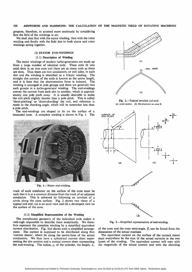
The end-windings are shaped to lie on the surface of atruncated cone. A complete winding is shown in Fig. 1. The
Fig. 1.—Stator end-winding.
track of each conductor on the surface of the cone must besuch that it is at a constant distance from the track of an adjacentconductor. This is achieved by following an involute of acircle along the cone surface. Fig. 2 shows two views of atypical coil end; (a) is an axial view and (6) a developed view onthe surface of the cone.
(3.2) Simplified Representation of the WindingThe complicated geometry of the individual coils makes it
well-nigh impossible to describe them analytically. We there-fore represent the complete winding by a simplified equivalentcurrent distribution. Fig. 3 (a) shows such a simplified arrange-ment. The current is supposed to be distributed along thin'current sheets', which lie along the centre-lines of the actualconductors. We thus have a cylindrical current sheet repre-senting the slot portion and a conical current sheet representingthe end-winding. The radius, p, of the cylinder, the length, L,
Fig. 2.—Typical involute coil-end.(o) Axial section, (b) Development on cone X.
SURFACE OFEND-PLATE
D 1 2 ( 3 4
t
•t
(C)
Fig. 3.—Simplified representation of end-winding.
of the cone and the cone semi-angle, j8, can be found from thedimensions of the actual machine.
The equivalent current on the surface of the current sheetsmust everywhere be the sum of the actual currents in the twolayers of the winding. The equivalent current will vary withthe magnitude of the actual current and with the chording
Authorized licensed use limited to: Princeton University. Downloaded on June 04,2010 at 16:03:43 UTC from IEEE Xplore. Restrictions apply.
ASHWORTH AND HAMMOND: THE CALCULATION OF THE MAGNETIC FIELD OF ROTATING MACHINES 529
angle, 2/x. The length, L, of the cone will be related to p and j8.L has been assumed proportional to p, and variation in p canthus be treated as a mere scale effect. The independent variablesare the cone angle, 2j8, and the chording angle, 2fi. Thedependence of the magnetic field on these two variables is dis-cussed in Section 5.
The stator end-winding is thus represented by current sheetsin the shape of a cylinder and a cone. Since the use of conicalco-ordinates is difficult we make the further simplification ofreplacing the 'conical' current sheet by a series of steps as shownin Fig. 3(6). On the conical current sheet the current will flowboth along the generators of the cone and perpendicularly tothem. In the equivalent representation of Fig. 3(6) we supposethat the current flows axially and circumferentially on thecylindrical sheets and that it flows radially on the annulardiscs.
The conical current sheet of Fig. 3(a) can thus be replacedby a stepped current sheet as in Fig. 3(6). The steps can becombined into a number of tubes and discs as shown in Fig. 3(c).It will be seen that the steps numbered 1, 2, 3 and 4 in Fig. 3(6)have been combined into a single disc and a single tube inFig. 3(c). This involves the expansion of steps 1 and 2 and thecontraction of steps 3 and 4. The errors introduced by thesechanges will tend to cancel out.
In Fig. 3(c) a final representation of three tubes and discswas chosen to account for the conical end-winding. Clearly itwould be possible to improve the accuracy of the representationby increasing the number of tubes and discs. The results of thispaper were obtained by using three tubes and three discs. Inone case, however, this result was compared with that obtainedby using six tubes and six discs. The maximum difference inthe field calculated was only 2 %. This amply justifies the useof the simpler representation by three tubes and discs.
The magnitude of the current varies along the cone. Thisvariation depends on the cone dimensions and on the chordingangle of the winding. A method of calculating the current atany point on the cone is given in Section 11.1. The currentsin the equivalent tubes and discs of Fig. 3(c) are taken as thecomponents of current on the cone at the mid-points of thetubes and discs.
It should be noted that the current sheets represent the currentin all three phases of the actual stator winding. By means ofFourier series it can be shown that the equivalent current can beexpressed as a series of rotating harmonics of which the funda-mental is strongly dominant. This equivalent current can bedescribed by the expression i = i cos (cot — pa), where i is theline density of current and a is the angle measured around thestator.
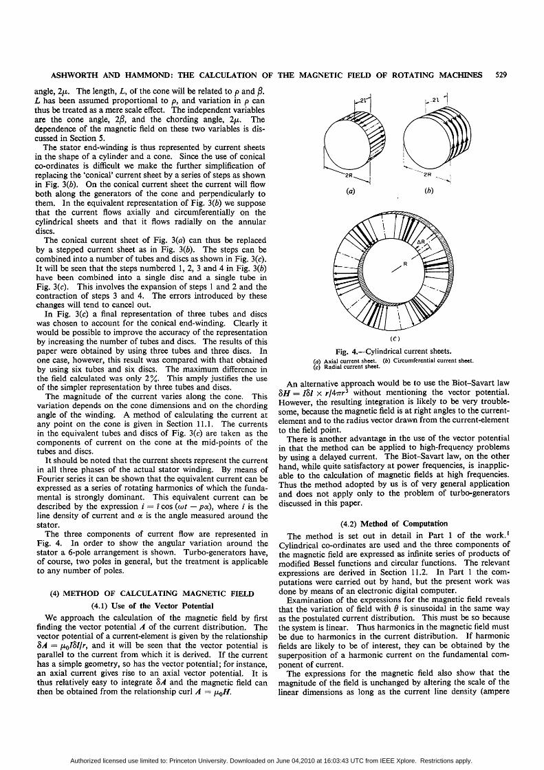
The three components of current flow are represented inFig. 4. In order to show the angular variation around thestator a 6-pole arrangement is shown. Turbo-generators have,of course, two poles in general, but the treatment is applicableto any number of poles.
(4) METHOD OF CALCULATING MAGNETIC FIELD(4.1) Use of the Vector Potential
We approach the calculation of the magnetic field by firstfinding the vector potential A of the current distribution. Thevector potential of a current-element is given by the relationship8A = juo/8//r, and it will be seen that the vector potential isparallel to the current from which it is derived. If the currenthas a simple geometry, so has the vector potential; for instance,an axial current gives rise to an axial vector potential. It isthus relatively easy to integrate 8A and the magnetic field canthen be obtained from the relationship curl A = fx0H.
Fig. 4.—Cylindrical current sheets.a) Axial current sheet, (b) Circumferential current sheet,c) Radial current sheet.
An alternative approach would be to use the Biot-Savart law8H = Ibl X rjArrr3 without mentioning the vector potential.However, the resulting integration is likely to be very trouble-some, because the magnetic field is at right angles to the current-element and to the radius vector drawn from the current-elementto the field point.
There is another advantage in the use of the vector potentialin that the method can be applied to high-frequency problemsby using a delayed current. The Biot-Savart law, on the otherhand, while quite satisfactory at power frequencies, is inapplic-able to the calculation of magnetic fields at high frequencies.Thus the method adopted by us is of very general applicationand does not apply only to the problem of turbo-generatorsdiscussed in this paper.
(4.2) Method of ComputationThe method is set out in detail in Part 1 of the work.1
Cylindrical co-ordinates are used and the three components ofthe magnetic field are expressed as infinite series of products ofmodified Bessel functions and circular functions. The relevantexpressions are derived in Section 11.2. In Part 1 the com-putations were carried out by hand, but the present work wasdone by means of an electronic digital computer.
Examination of the expressions for the magnetic field revealsthat the variation of field with d is sinusoidal in the same wayas the postulated current distribution. This must be so becausethe system is linear. Thus harmonics in the magnetic field mustbe due to harmonics in the current distribution. If harmonicfields are likely to be of interest, they can be obtained by thesuperposition of a harmonic current on the fundamental com-ponent of current.
The expressions for the magnetic field also show that themagnitude of the field is unchanged by altering the scale of thelinear dimensions as long as the current line density (ampere
Authorized licensed use limited to: Princeton University. Downloaded on June 04,2010 at 16:03:43 UTC from IEEE Xplore. Restrictions apply.
530 ASHWORTH AND HAMMOND: THE CALCULATION OF THE MAGNETIC FIELD OF ROTATING MACHINES
conductors per metre) is unchanged. For a 2-layer winding wecan describe the line density in a single layer by an expressioni — -£fscos (cot — pot). The value of ts will be determined bythe actual conductor current and will be independent of chordingangle. The results given in Figs. 5-10 are calculated for ts = 1
0-4
0-3
0-2
0-1
-0-1
-0Q.
- 0 3
/
—A
A\\
\ \
\
V
A
•A
— —
•
0-4 0-8 1-2 1-6 2-0r/p
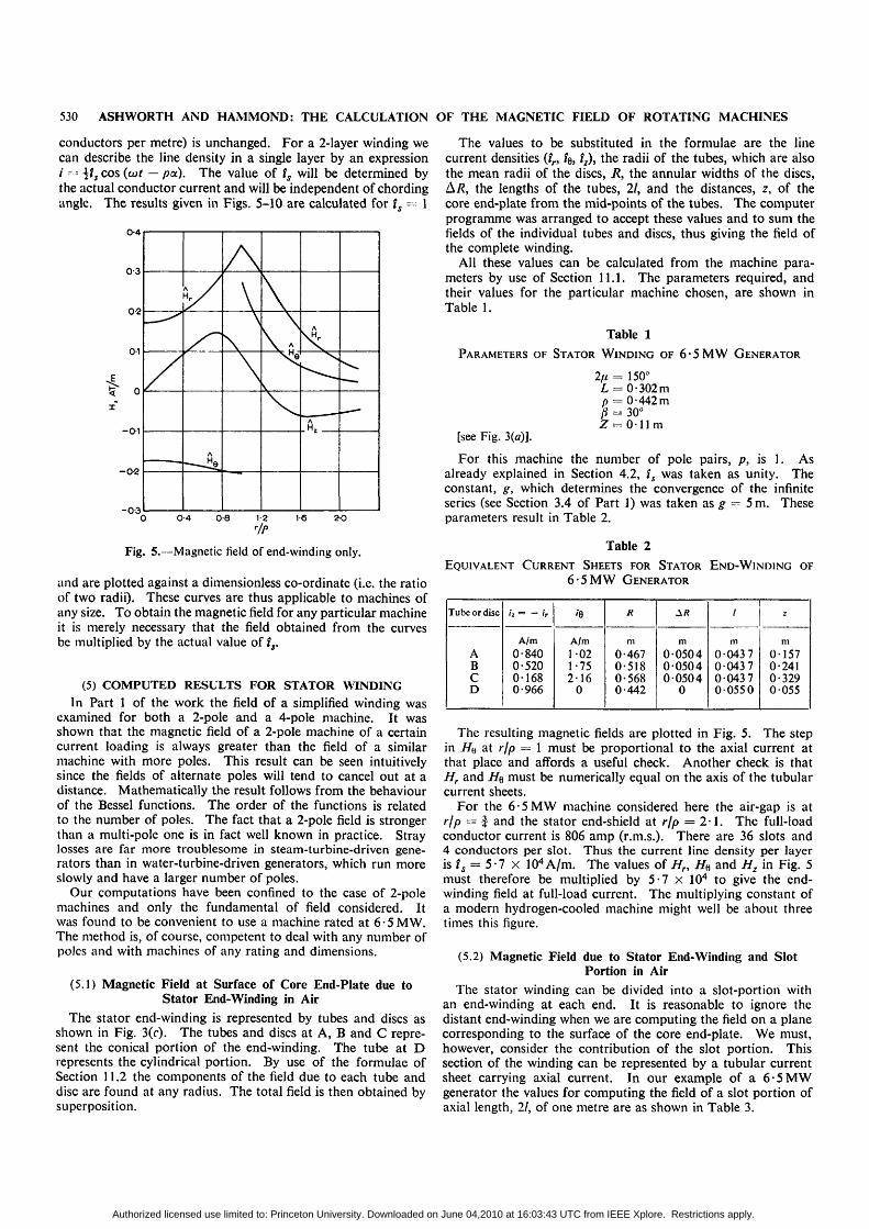
Fig. 5.—Magnetic field of end-winding only.
and are plotted against a dimensionless co-ordinate (i.e. the ratioof two radii). These curves are thus applicable to machines ofany size. To obtain the magnetic field for any particular machineit is merely necessary that the field obtained from the curvesbe multiplied by the actual value of f,.
(5) COMPUTED RESULTS FOR STATOR WINDINGIn Part 1 of the work the field of a simplified winding was
examined for both a 2-pole and a 4-pole machine. It wasshown that the magnetic field of a 2-pole machine of a certaincurrent loading is always greater than the field of a similarmachine with more poles. This result can be seen intuitivelysince the fields of alternate poles will tend to cancel out at adistance. Mathematically the result follows from the behaviourof the Bessel functions. The order of the functions is relatedto the number of poles. The fact that a 2-pole field is strongerthan a multi-pole one is in fact well known in practice. Straylosses are far more troublesome in steam-turbine-driven gene-rators than in water-turbine-driven generators, which run moreslowly and have a larger number of poles.
Our computations have been confined to the case of 2-polemachines and only the fundamental of field considered. Itwas found to be convenient to use a machine rated at 6 • 5 MW.The method is, of course, competent to deal with any number ofpoles and with machines of any rating and dimensions.
(5.1) Magnetic Field at Surface of Core End-Plate due toStator End-Winding in Air
The stator end-winding is represented by tubes and discs asshown in Fig. 3(0- The tubes and discs at A, B and C repre-sent the conical portion of the end-winding. The tube at Drepresents the cylindrical portion. By use of the formulae ofSection 11.2 the components of the field due to each tube anddisc are found at any radius. The total field is then obtained bysuperposition.
The values to be substituted in the formulae are the linecurrent densities (ir, i$, i2), the radii of the tubes, which are alsothe mean radii of the discs, R, the annular widths of the discs,AT?, the lengths of the tubes, 21, and the distances, z, of thecore end-plate from the mid-points of the tubes. The computerprogramme was arranged to accept these values and to sum thefields of the individual tubes and discs, thus giving the field ofthe complete winding.
All these values can be calculated from the machine para-meters by use of Section 11.1. The parameters required, andtheir values for the particular machine chosen, are shown inTable 1.
Table 1PARAMETERS OF STATOR WINDING OF 6-5MW GENERATOR
2fi = 150°L = 0-302mp = 0-442 mft = 30°Z = 0-llm
[see Fig. 3(o)].
For this machine the number of pole pairs, p, is 1. Asalready explained in Section 4.2, ts was taken as unity. Theconstant, g, which determines the convergence of the infiniteseries (see Section 3.4 of Part 1) was taken as g — 5 m. Theseparameters result in Table 2.
Table 2EQUIVALENT CURRENT SHEETS FOR STATOR END-WINDING OF
6-5MW GENERATOR
Tube or disc
ABcD
iz = - ir
A/m
0-8400-5200-1680-966
'6
A/m1-021-752-16
0
R
m0-4670-5180-5680-442
m005040050400504
0
/
m0-04370-04370043700550
z
m0-1570-2410-3290 055
The resulting magnetic fields are plotted in Fig. 5. The stepin i/y at r/p = 1 must be proportional to the axial current atthat place and affords a useful check. Another check is thatHr and H% must be numerically equal on the axis of the tubularcurrent sheets.
For the 6-5MW machine considered here the air-gap is atr/p = % and the stator end-shield at rip — 2-1. The full-loadconductor current is 806 amp (r.m.s.). There are 36 slots and4 conductors per slot. Thus the current line density per layeris is = 5-7 x 10⁴A/m. The values of Hn H« and Hz in Fig. 5must therefore be multiplied by 5-7 x 10⁴ to give the end-winding field at full-load current. The multiplying constant ofa modern hydrogen-cooled machine might well be about threetimes this figure.
(5.2) Magnetic Field due to Stator End-Winding and SlotPortion in Air
The stator winding can be divided into a slot-portion withan end-winding at each end. It is reasonable to ignore thedistant end-winding when we are computing the field on a planecorresponding to the surface of the core end-plate. We must,however, consider the contribution of the slot portion. Thissection of the winding can be represented by a tubular currentsheet carrying axial current. In our example of a 6-5MWgenerator the values for computing the field of a slot portion ofaxial length, 21, of one metre are as shown in Table 3.
Authorized licensed use limited to: Princeton University. Downloaded on June 04,2010 at 16:03:43 UTC from IEEE Xplore. Restrictions apply.
ASHWORTH AND HAMMOND: THE CALCULATION OF THE MAGNETIC FIELD OF ROTATING MACHINES 531
Table 3
EQUIVALENT CURRENT SHEET FOR STATOR SLOT PORTION OF
6-5MW GENERATOR
/» - - fr
A/m0-966
fe
A/m0
R
m0-442
&R
m0
/
m0-5
z
m
-0-5
The distance z is negative because the slot portion lies on theother side of the plane of the core end-plate. It was found thatthe magnitude of the field was very insensitive to a change of axiallength of the slot portion, as long as this length was considerable.In particular a length of 2 m gave the same field as a lengthof lm. This shows that it must be substantially correct toneglect the distant end-winding.
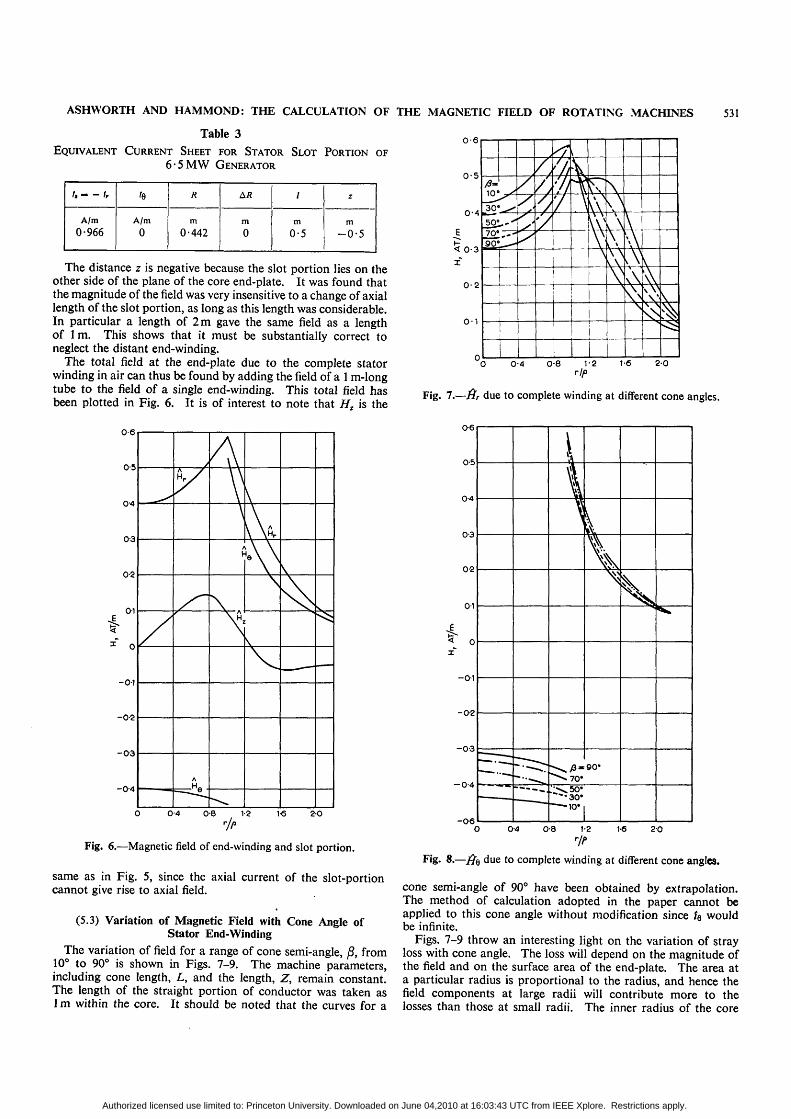
The total field at the end-plate due to the complete statorwinding in air can thus be found by adding the field of a 1 m-longtube to the field of a single end-winding. This total field hasbeen plotted in Fig. 6. It is of interest to note that HT is the
0-6
0-5
0-4
0-3
0-2
01
-0-1
-0-2
- 0 3
-0-4
/
" •.
/
JV
\
Ay
V ,
\
vV\ V•v\IvV •
0-4 0-8 1-2 1-6 2 0
Fig. 6.—Magnetic field of end-winding and slot portion.
same as in Fig. 5, since the axial current of the slot-portioncannot give rise to axial field.
(5.3) Variation of Magnetic Field with Cone Angle ofStator End-Winding
The variation of field for a range of cone semi-angle, j8, from10° to 90° is shown in Figs. 7-9. The machine parameters,including cone length, L, and the length, Z, remain constant.The length of the straight portion of conductor was taken as1 m within the core. It should be noted that the curves for a
0-6
0-5
0-4
< 0-3
X*
0-2
0-1
10°_-^30"so;10'90"
/
y
>
/ '/,
•'/
' 11t t
\
1\\\
\
\;N
L VvN\ \
0 0-4 0-8 V2 1-6 2-0rip
Fig. 7.—fir due to complete winding at different cone angles.
0-6
0-5
0-4
0-3
0 2
0-1
-0-1
-0-2
-0-3 -
-0-4
O 04 0-8 1-2 1-6 20
Fig. 8.—j?e due to complete winding at different cone angles.
cone semi-angle of 90° have been obtained by extrapolation.The method of calculation adopted in the paper cannot beapplied to this cone angle without modification since fe wouldbe infinite.
Figs. 7-9 throw an interesting light on the variation of strayloss with cone angle. The loss will depend on the magnitude ofthe field and on the surface area of the end-plate. The area ata particular radius is proportional to the radius, and hence thefield components at large radii will contribute more to thelosses than those at small radii. The inner radius of the core
•• — • — ' —
\
\
\
^ 7 0 "
30*10*
\
90*
\
Authorized licensed use limited to: Princeton University. Downloaded on June 04,2010 at 16:03:43 UTC from IEEE Xplore. Restrictions apply.
532 ASHWORTH AND HAMMOND: THE CALCULATION OF THE MAGNETIC FIELD OF ROTATING MACHINES
02
0-3
0-2
0-1
-0-1
- 0 2
-
4
-
i
ft*''
/">
^ \\
i I
^ .
1 10-4 0-8 1-2 V 8 2 0
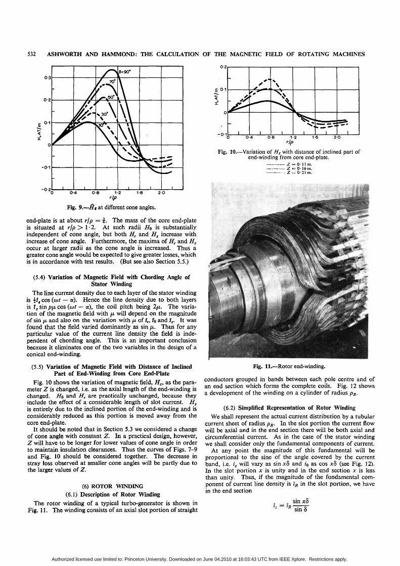
Fig. 9.—Hs at different cone angles.
end-plate is at about rip = £. The mass of the core end-plateis situated at r/p > 1 • 2. At such radii HQ is substantiallyindependent of cone angle, but both Hr and Hz increase withincrease of cone angle. Furthermore, the maxima of Hr and Hzoccur at larger radii as the cone angle is increased. Thus agreater cone angle would be expected to give greater losses, whichis in accordance with test results. (But see also Section 5.5.)
(5.4) Variation of Magnetic Field with Chording Angle ofStator Winding
The line current density due to each layer of the stator windingis if, cos (cot — a). Hence the line density due to both layersis ts sin p\i cos (cot — a), the coil pitch being 2/Lt. The varia-tion of the magnetic field with \i will depend on the magnitudeof sin JU. and also on the variation with fj, of tn ?e and tz. It wasfound that the field varied dominantly as sin fi. Thus for anyparticular value of the current line density the field is inde-pendent of chording angle. This is an important conclusionbecause it eliminates one of the two variables in the design of aconical end-winding.
(5.5) Variation of Magnetic Field with Distance of InclinedPart of End-Winding from Core End-Plate
Fig. 10 shows the variation of magnetic field, Hz, as the para-meter Z is changed, i.e. as the axial length of the end-winding ischanged. He and Hr are practically unchanged, because theyinclude the effect of a considerable length of slot current. H2is entirely due to the inclined portion of the end-winding and isconsiderably reduced as this portion is moved away from thecore end-plate.
It should be noted that in Section 5.3 we considered a changeof cone angle with constant Z. In a practical design, however,Z will have to be longer for lower values of cone angle in orderto maintain insulation clearances. Thus the curves of Figs. 7-9and Fig. 10 should be considered together. The decrease instray loss observed at smaller cone angles will be partly due tothe larger values of Z.
(6) ROTOR WINDING(6.1) Description of Rotor Winding
The rotor winding of a typical turbo-generator is shown inFig. 11. The winding consists of an axial slot portion of straight
E0-1
-0-1
-
/ ^
I
<*_*—t
I
\
I i !0-4 0 8 1-2 1-6 2 0
rip
Fig. 10.—Variation of Hz with distance of inclined part ofend-winding from core end-plate.
z = o-iim.Z «= 0 1 6 m .Z = 0-21 m.
Fig. 11.—Rotor end-winding.
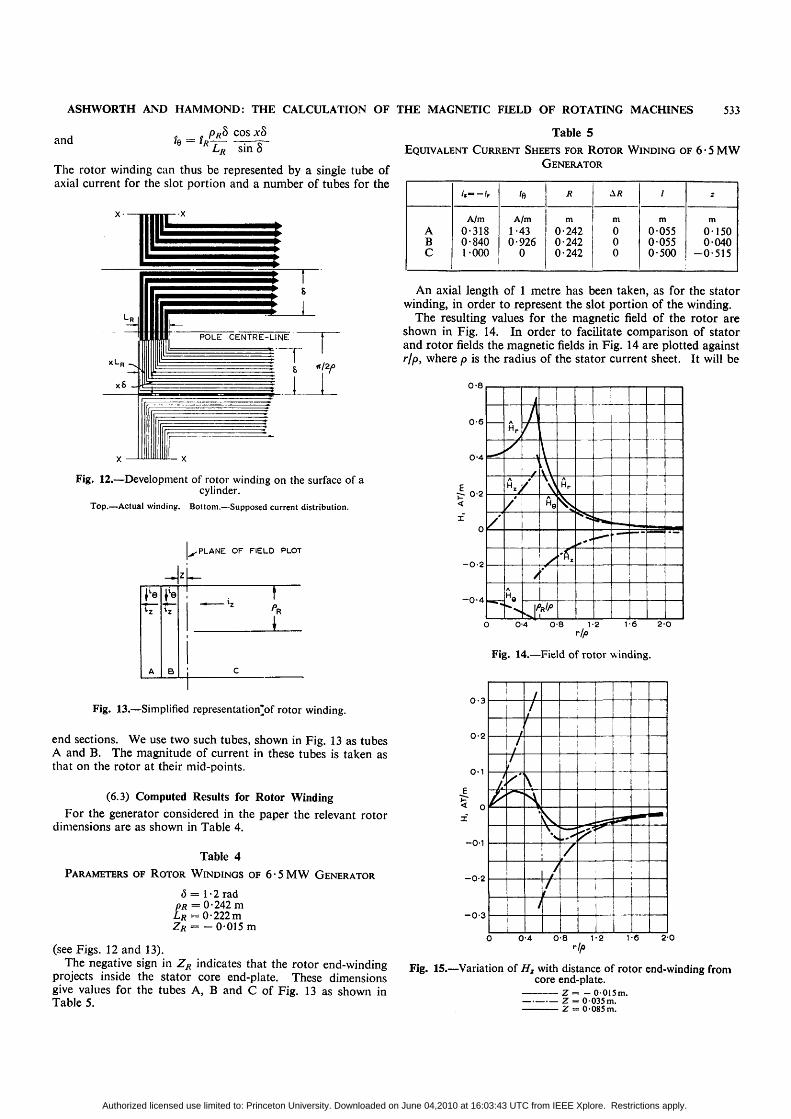
conductors grouped in bands between each pole centre and ofan end section which forms the complete coils. Fig. 12 showsa development of the winding on a cylinder of radius pR.
(6.2) Simplified Representation of Rotor WindingWe shall represent the actual current distribution by a tubular
current sheet of radius pR. In the slot portion the current flowwill be axial and in the end section there will be both axial andcircumferential current. As in the case of the stator windingwe shall consider only the fundamental components of current.
At any point the magnitude of this fundamental will beproportional to the sine of the angle covered by the currentband, i.e. iz will vary as sinxS and /e as cos x8 (see Fig. 12).In the slot portion x is unity and in the end section x is lessthan unity. Thus, if the magnitude of the fundamental com-ponent of current line density is iR in the slot portion, we havein the end section
„ _ „ sinxSR sin S
Authorized licensed use limited to: Princeton University. Downloaded on June 04,2010 at 16:03:43 UTC from IEEE Xplore. Restrictions apply.
ASHWORTH AND HAMMOND: THE CALCULATION OF THE MAGNETIC FIELD OF ROTATING MACHINES 533
and
The rotor winding can thus be represented by a single tube ofaxial current for the slot portion and a number of tubes for the
xS J
POLE CENTRE-LINE
Fig. 12.—Development of rotor winding on the surface of acylinder.
Top.—Actual winding. Bottom.—Supposed current distribution.
-PLANE OF FIELD PLOT
—
A
*z
a
zL_-
c
Fig. 13.—Simplified representation'of rotor winding.
end sections. We use two such tubes, shown in Fig. 13 as tubesA and B. The magnitude of current in these tubes is taken asthat on the rotor at their mid-points.
(6.3) Computed Results for Rotor Winding
For the generator considered in the paper the relevant rotordimensions are as shown in Table 4.
Table 4
PARAMETERS OF ROTOR WINDINGS OF 6-5MW GENERATOR
6 = l-2radPR = 0-242 mLR = 0-222 mZR = - 0 0 1 5 m
(see Figs. 12 and 13).
Table 5
EQUIVALENT CURRENT SHEETS FOR ROTOR WINDING OF 6 • 5 MW
GENERATOR
ABC
U lr
A/m0-3180-8401-000
'a
A/m1-430-9260
R
m0-2420-2420-242
m000
/
m0 0550 0550-500
m01500040
—0-515
An axial length of 1 metre has been taken, as for the statorwinding, in order to represent the slot portion of the winding.
The resulting values for the magnetic field of the rotor areshown in Fig. 14. In order to facilitate comparison of statorand rotor fields the magnetic fields in Fig. 14 are plotted againstrip, where p is the radius of the stator current sheet. It will be
0-8
0-6
0-4
0-2
-O-2
- 0 - 4 .•s-
—
/
j
/
AA/v"/'
VA\
//'
Hr
k
**.mm
0-4 0-8 2-0
Fig. 14.—Field of rotor winding.
0-3
0-2
0-1
-0-1
-0-2
-0 -3
/
/
/
/
\
y//
/
i
\
0-4 0-8rip
1-2 1-6 2-0
The negative sign in ZR indicates that the rotor end-winding F i g . i5._Variation of Hz with distance of rotor end-winding fromprojects inside the stator core end-plate. These dimensions core end-plate,give values for the tubes A, B and C of Fig. 13 as shown inTable 5. z-o-rasm.
Z = -0015m.= OO35m.= 0085 m.
Authorized licensed use limited to: Princeton University. Downloaded on June 04,2010 at 16:03:43 UTC from IEEE Xplore. Restrictions apply.
534 ASHWORTH AND HAMMOND: THE CALCULATION OF THE MAGNETIC FIELD OF ROTATING MACHINES
noted that there is a discontinuity in Hz as well as in HQ. Thisarises from the fact that the plane of the field plot intersects therotor winding where it carries not only axial but also circum-ferential current.
The machine considered here has a rotor current of 265 ampat full load and rated power factor. There are 168 turns per pole.This corresponds to a fundamental current line density, iR) of1-8 X 10⁵A/m. The ordinates in Fig. 14 must therefore bemultiplied by this number to give the full-load field of the rotor.
(6.3.1) Variation of Magnetic Field with Distance of Rotor End-Windingfrom Core End-Plate.
Hr and H$ are practically unchanged with variation of Z.This is to be expected, because they both depend on the longslot portion. Hz is, however, considerably reduced as Z isincreased. This is shown in Fig. 15.
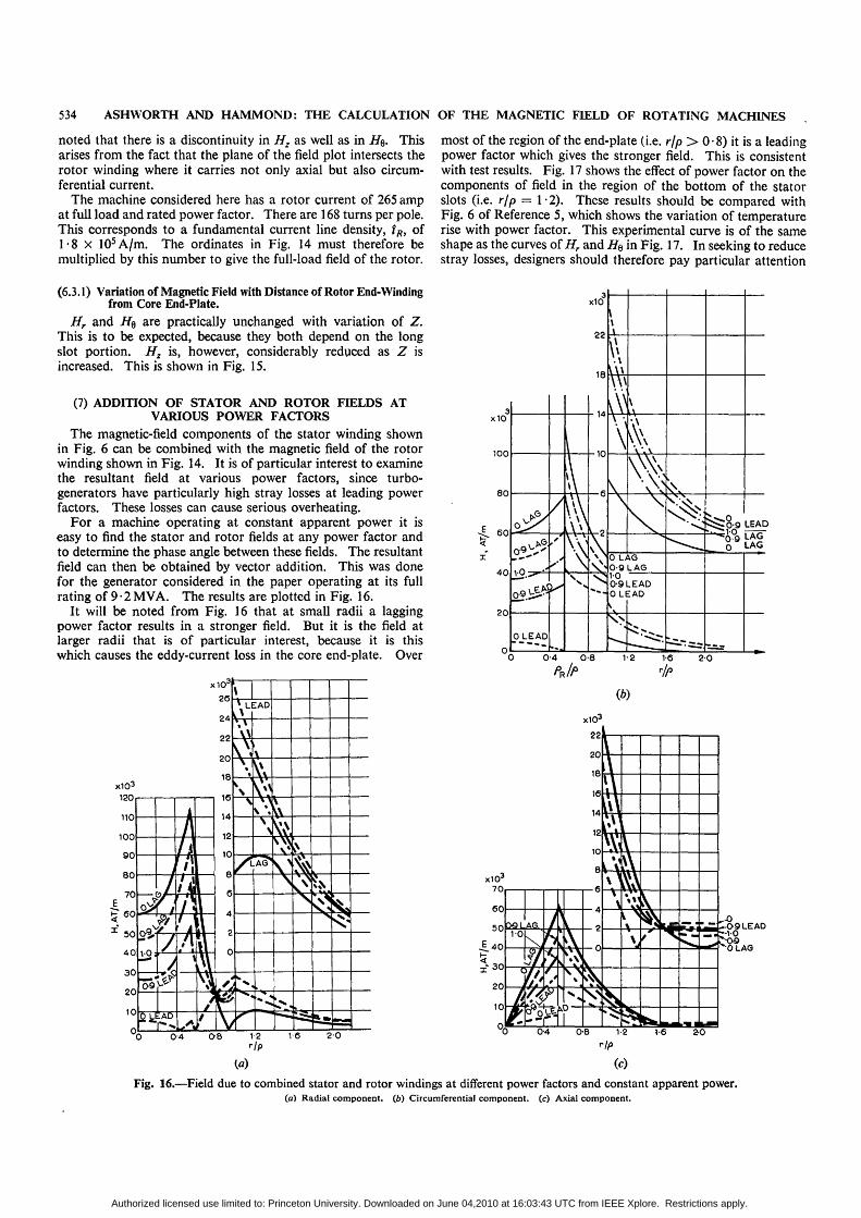
(7) ADDITION OF STATOR AND ROTOR FIELDS ATVARIOUS POWER FACTORS
The magnetic-field components of the stator winding shownin Fig. 6 can be combined with the magnetic field of the rotorwinding shown in Fig. 14. It is of particular interest to examinethe resultant field at various power factors, since turbo-generators have particularly high stray losses at leading powerfactors. These losses can cause serious overheating.
For a machine operating at constant apparent power it iseasy to find the stator and rotor fields at any power factor andto determine the phase angle between these fields. The resultantfield can then be obtained by vector addition. This was donefor the generator considered in the paper operating at its fullrating of 9-2MVA. The results are plotted in Fig. 16.
It will be noted from Fig. 16 that at small radii a laggingpower factor results in a stronger field. But it is the field atlarger radii that is of particular interest, because it is thiswhich causes the eddy-current loss in the core end-plate. Over
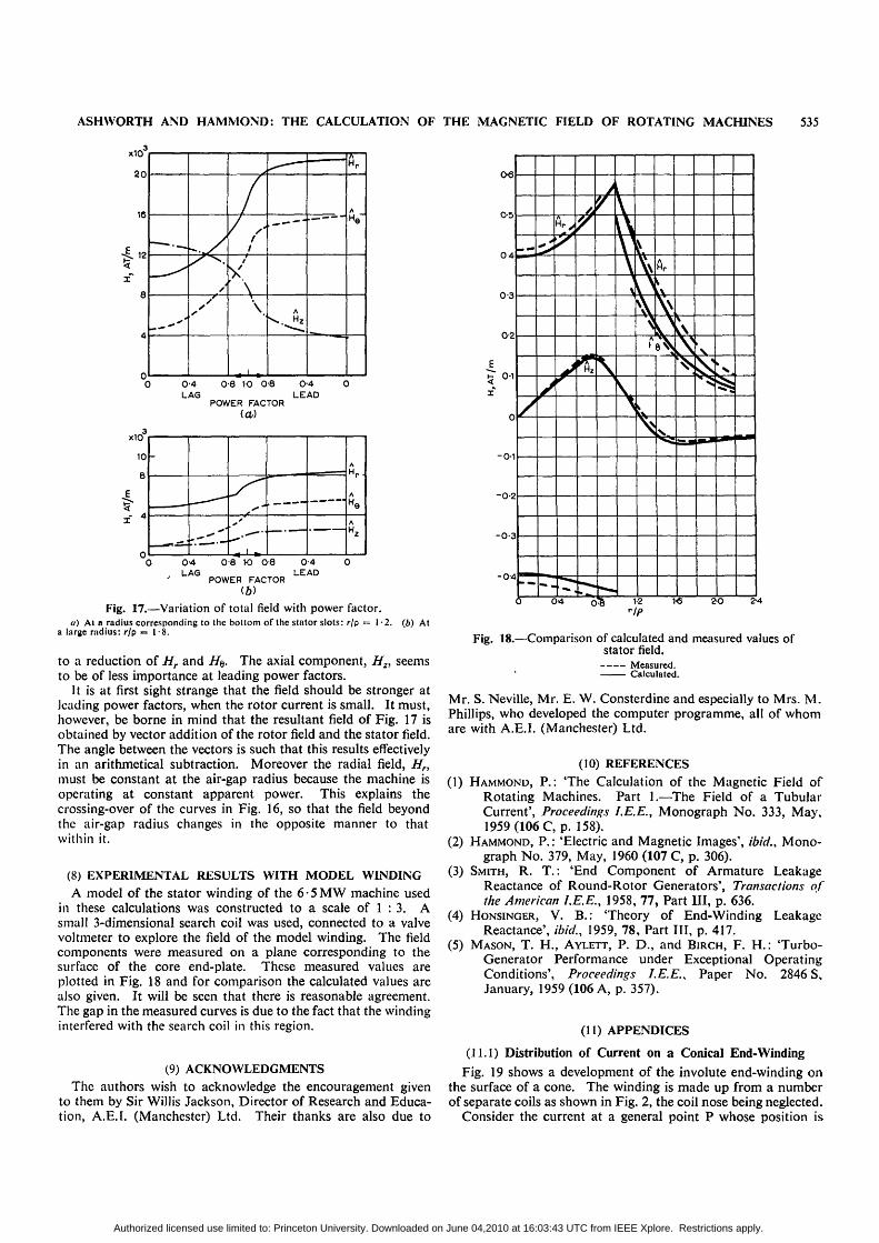
most of the region of the end-plate (i.e. rjp > 0 • 8) it is a leadingpower factor which gives the stronger field. This is consistentwith test results. Fig. 17 shows the effect of power factor on thecomponents of field in the region of the bottom of the statorslots (i.e. r/p = I-2). These results should be compared withFig. 6 of Reference 5, which shows the variation of temperaturerise with power factor. This experimental curve is of the sameshape as the curves of Hr and ife in Fig. 17. In seeking to reducestray losses, designers should therefore pay particular attention
x1O
(b)
Fig. 16.—Field due to combined stator and rotor windings at different power factors and constant apparent power.(a) Radial component, (b) Circumferential component, (c) Axial component.
Authorized licensed use limited to: Princeton University. Downloaded on June 04,2010 at 16:03:43 UTC from IEEE Xplore. Restrictions apply.
ASHWORTH AND HAMMOND: THE CALCULATION OF THE MAGNETIC FFELD OF ROTATING MACHINES 535
x10
ao
16
12— .
y
/
y\\.
i
^ —
A
^ . . Hz
•A
HP
A
He
0-4 0-8 10 0-8 0-4LAG LEAD
POWER FACTOR
xiO
10
8
-
. 1 w-A
Hr-
A
He
AHz
0-4LAG
0 8 K) 0-8
POWER FACTOR(6)
0-4LEAD
Fig. 17.—Variation of total field with power factor.a) A t a r a d i u s c o r r e s p o n d i n g t o t h e b o t t o m o f t h e s t a t o r s l o t s : r /p = 1 - 2 . (b) A t
a l a r g e r a d i u s : r / p = 1 - 8 .
to a reduction of Hr and H$. The axial component, Hz, seemsto be of less importance at leading power factors.
It is at first sight strange that the field should be stronger atleading power factors, when the rotor current is small. It must,however, be borne in mind that the resultant field of Fig. 17 isobtained by vector addition of the rotor field and the stator field.The angle between the vectors is such that this results effectivelyin an arithmetical subtraction. Moreover the radial field, Hnmust be constant at the air-gap radius because the machine isoperating at constant apparent power. This explains thecrossing-over of the curves in Fig. 16, so that the field beyondthe air-gap radius changes in the opposite manner to thatwithin it.
(8) EXPERIMENTAL RESULTS WITH MODEL WINDINGA model of the stator winding of the 6 • 5 MW machine used
in these calculations was constructed to a scale of 1 : 3. Asmall 3-dimensional search coil was used, connected to a valvevoltmeter to explore the field of the model winding. The fieldcomponents were measured on a plane corresponding to thesurface of the core end-plate. These measured values areplotted in Fig. 18 and for comparison the calculated values arealso given. It will be seen that there is reasonable agreement.The gap in the measured curves is due to the fact that the windinginterfered with the search coil in this region.
(9) ACKNOWLEDGMENTSThe authors wish to acknowledge the encouragement given
to them by Sir Willis Jackson, Director of Research and Educa-tion, A.E.I. (Manchester) Ltd. Their thanks are also due to
Fig. 18.—Comparison of calculated and measured values ofstator field.
Measured.Calculated.
Mr. S. Neville, Mr. E. W. Consterdine and especially to Mrs. M.Phillips, who developed the computer programme, all of whomare with A.E.I. (Manchester) Ltd.
(10) REFERENCES(1) HAMMOND, P.: 'The Calculation of the Magnetic Field of
Rotating Machines. Part 1.—The Field of a TubularCurrent', Proceedings I.E.E., Monograph No. 333, May,1959 (106 C, p. 158).
(2) HAMMOND, P.: 'Electric and Magnetic Images', ibid.. Mono-graph No. 379, May, 1960 (107 C, p. 306).
(3) SMITH, R. T.: 'End Component of Armature LeakageReactance of Round-Rotor Generators', Transactions ofthe American I.E.E., 1958, 77, Part III, p. 636.
(4) HONSINGER, V. B.: 'Theory of End-Winding LeakageReactance', ibid., 1959, 78, Part HI, p. 417.
(5) MASON, T. H., AYLETT, P. D., and BIRCH, F. H.: 'Turbo-Generator Performance under Exceptional OperatingConditions', Proceedings I.E.E., Paper No. 2846 S,January, 1959 (106 A, p. 357).
(11) APPENDICES
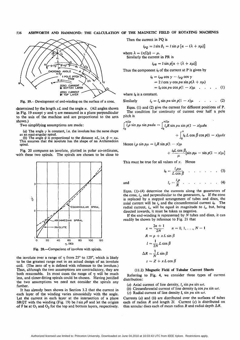
(11.1) Distribution of Current on a Conical End-WindingFig. 19 shows a development of the involute end-winding on
the surface of a cone. The winding is made up from a numberof separate coils as shown in Fig. 2, the coil nose being neglected.
Consider the current at a general point P whose position is
Authorized licensed use limited to: Princeton University. Downloaded on June 04,2010 at 16:03:43 UTC from IEEE Xplore. Restrictions apply.
536 ASHWORTH AND HAMMOND: THE CALCULATION OF THE MAGNETIC FIELD OF ROTATING MACHINES
Then the current in PQ is
iPQ = i sin 9\ — I sin/? [a — (A + Xfi)]
where A = (TT/2/?) — fju.Similarly the current in PR is
iPR = I sin/?[a + (A + x/x)]
Thus the component k of the current at P is given by
k = hR c o s y — I'PQ c o s y
= 2 / cos y cos pa sin/?(A + x/x)
= t$ cos pa. cos p(l — x)fj, . . . . (1)
where fe is a constant.
Similarly i z = i z s i n p a s i n p ( l — X ) [ M . . . . ( 2 )
Eqns. (1) and (2) give the current for different positions of P.The condition for continuity of current over half a pole
pitch is
ZERO CURRENTKsl BOTTOM LAl'ER
ZERO CURRENTIN TOP LAYER
Fig. 19.—Development of end-winding on the surface of a cone.
•determined by the length xL and the angle a. (All angles shownin Fig. 19 except y and r\ are measured in a plane perpendicularto the axis of the machine and are proportional to the arcsshown.)
Two simplifying assumptions are made:
(a) The angle y is constant, i.e. the involute has the same shapeas an equi-angular spiral.
(6) The angle ip is proportional to the distance xL, i.e. ift = X/J..This assumes that the involute has the shape of an Archimedeanspiral.
Fig. 20 compares an involute, plotted in polar co-ordinates,with these two spirals. The spirals are chosen to be close to
ARCHIMEDIAN SPIRAL
INVOLUTE
•EQUIANGULAR SPIRAL
O 20 40 60 80 100 120tj, DEG
Fig. 20.—Comparison of involute with spirals.
the involute over a range of 77 from 25° to 120°, which is likelyto be the greatest range met in an actual design of an involutecoil. (The zero of 17 is defined with reference to the involute.)Thus, although the two assumptions are contradictory, they areboth reasonable. In most cases the range of 17 will be muchless, and closer-fitting spirals could be chosen. Having justifiedthe two assumptions we need not consider the spirals anyfurther.
It has already been shown in Section 3.2 that the current ineach layer of the winding varies sinusoidally with the angle.Let the current in each layer at the intersection of a planeSRQT with the winding (Fig. 19) be t sin pO and let the originsof d be at O( and O2 for the top and bottom layers, respectively.
TT/2/J r7t/2p
i>sin/?/zsin/>ada = izR sin pa sin p(l — x)fxdaJo
+ !QL COS 8 cos/?(l — x)fxdxJo
Hence isp sin p\x. — 1ZR sin p(l — x)/x
, IQL COS J3r .4 ^ r £ [ s i
This must be true for all values of x. Hence
and
(3)
(4)
Eqns. (l)-(4) determine the currents along the generators ofthe cone, iz, and perpendicular to the generators, z"e. If the coneis replaced by a stepped arrangement of tubes and discs, theaxial current will be iz and the circumferential current /e. Theradial current, /„ will be equal in magnitude to i2, but, beingdirected inwards, it must be taken as negative.
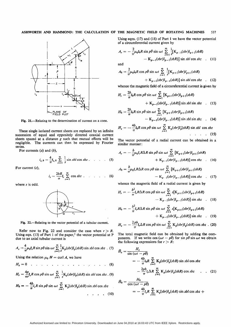
If the end-winding is represented by N tubes and discs, it canreadily be shown by reference to Fig. 21 that
* =2n
R = p +x.Lsinj5
Ai? = — L sin 8N
z = Z + xLcos 6
(11.2) Magnetic Field of Tubular Current Sheets
Referring to Fig. 4, we consider three types of currentdistribution:
(a) Axial current of line density, i2 sin pa sin cor.(b) Circumferential current of line density fe cos/?a sin cot.(c) Radial current of line density tr sin pa sin cot.
Currents (a) and (b) are distributed over the surfaces of tubeseach of radius R and length 21. Current (c) is distributed onthin annular discs each of mean radius R and radial depth Ai?.
Authorized licensed use limited to: Princeton University. Downloaded on June 04,2010 at 16:03:43 UTC from IEEE Xplore. Restrictions apply.
ASHWORTH AND HAMMOND: THE CALCULATION OF THE MAGNETIC FIELD OF ROTATING MACHINES 537
Using eqns. (17) and (18) of Part 1 we have the vector potentialof a circumferential current given by
2Ar =
77
and
1s i n w ' 2 -[Kp | l(sbr)lp+i{sbR)Sm.l S
- Kp_ {(sbr)Ip_ i(sbR)] sin sbl cos sb: . (11)
PLANE OFFIELD PLOT
Fig. 21.—Relating to the determination of current on a cone.
These single isolated current sheets are replaced by an infinitesuccession of equal and oppositely directed coaxial currentsheets spaced at a distance g such that mutual effects will benegligible. The currents can then be expressed by Fourierseries.
For currents (a) and (b),
2 °° 1AQ = -fjboiBR cos pd sin cot 2 ~[Kp+l(sbr)Ip+l(sbR)
77 j _ l S
+ Kp_ i(sbr)Ip_ i(sbR)] sin sbl cos sbz . (12)
whence the magnetic field of a circumferential current is given by
2b °°Hr = — %R cos pd sin cot 2 [Kp+1(sbr)Ip+l(sbR)
77 5—1
2bt
+ Kp_ i(sbr)lp^ iisbRj] sin sbl sin s&z . (13)
= — t$R sinpd sin cot 2 [Kp+iCs£r)Ip+1CyZ>i?)77 . v = 1
- K_ ! sin . (14)
r, = - * W 90 sin cor 2 Kp(sbr)Ip(sbR) sin 56/ cos J6Z
. . . . (15)
The vector potential of a radial current can be obtained in asimilar manner:
bAr =
4 1i : e = - f : e 2 - s i n ^ 6 / c o s s b z . . . . ( 5 )
7T ' 5 = 1 5
sin p8 sin cot
+ Kp _
For current (c),
where 5 is odd.
"• 5 = 1(6)
p p . (16)
b °°^e = -fxotrRAR cos pd sin ojt 2 [Kp+^jfcOIp+iCjA/J)
- Kp . , (^ r ) I p _ x(sbR)] cos J6Z . (17)
whence the magnetic field of a radial current is given by
b2 °°Hr= irRAR cospd sin
^(sbr)!{sbR)] sin sbz . (18)
sin cot 2
Kp sin *6z . (19)
Fig. 22.—Relating to the vector potential of a tubular current.
Refer now to Fig. 22 and consider the case when r>R.Using eqn. (13) of Part 1 of the paper,1 the vector potential at Pdue to an axial tubular current is
4 °° 1Az = -uotzR sinpd sin cot 2 -KD(^r)L(^i?) sin sbl cos sbz . (7)
77 Sm.\S y "
Using the relation fi0 H = curl A, we have
#z = 0 (8)
InhInh2 = - — ?rA/?cos/70sino>/ 2 KJsbr)JJsbR) cos *6z . (20)
5 = 1
The total magnetic field can be obtained by adding the com-ponents. If we write cos (cot — p6) for sin pd sin cot we obtainthe following expressions for r>R:
sin (cot — pd)
4b °°= IQR 2 Kp(sbr)l'(sbR) sin sbl cos sbz
4o °° 1r = -f z i? cos/>0 sin cot 2 -KJsbr)lB(sbR) sin
77T S77T
. (9)
46
- 2—tAR 277 5 = 1
He
cos sbz . (21)
46f,i? sinpd sin cof 2 K'(sbr)IJsbR) sin .s6/ cos 56z
7 7 " 5 - 1
cos (cot — pd)
4b. _. (10) 77 5 = 1
Authorized licensed use limited to: Princeton University. Downloaded on June 04,2010 at 16:03:43 UTC from IEEE Xplore. Restrictions apply.

538 ASHWORTH AND HAMMOND: THE CALCULATION OF THE MAGNETIC FIELD OF ROTATING MACHINES
+ 2-kR £ [Kp+l(sbr)Jp+l(sbR)
+ Kp_1(sbr)Jp_l(sbR)] sin sbl sin sbz
r-hR £ [Kp+l(sbr)lp+l(sbR)
— Kp_l(sbr)lp_i(sbR)] sin sbl sin sbz
irRAR £ s[Kpi_tsbr)Ip+l(sbR)J T = 1
-'- Kr sin sbz (22)
ft. 3sin (cot
•nr*KB(j*/-)I-(d>/?) sin 56/ cos sbz +
p p
b-i,RAR £
- Kp_ i(sbr)lp_ i(sbR)] sin j&r . (23)
The expressions for the magnetic field when r < R can beobtained by transposing r and R in the argument of the Besselfunctions of eqns. (21)—(23).
[The discussion on the above paper will be found on page 549.]
621.313.322 81.013.2 The Institution of Electrical EngineersPaper No. 3490 S
Mar. 1961
THE MAGNETIC FIELD OF THE END-WINDINGS OF TURBO-GENERATORS
By P. J. LAWRENSON, M.Sc, Graduate.
{The paper was first received 19/// May, and in revised form \4th October, 1960. // was published in March, 1961, and was read before theSUPPLY SECTION 12th April, 1961.)
SUMMARYAn investigation of the magnetic field generated by the currents in
the stator end-windings of a 3-phase 2-pole turbo-generator is described.It includes an examination of the influence of winding design, namelythe effects of cone angle, straight projection and coil pitch, of theinfluence of the air-gap, and also of the permeability, or eddy-currentscreening, of the core end-plate.
The simple and accurate method which is used to calculate the fieldof the stator currents, and which can be used for a circuit of any shape,is described. The effect of the air-gap is represented by a fictitiousconductor, and the influence of the end-plate is accounted for by useof the method of images. Results are presented for the magnitudeand phase of the fundamental and harmonic waves of the rotatingfields on the end-plate and rotor-coil retaining-ring surfaces.
From the results the following points appear:{a) The predominant loss-producing component of the field at the
end-plate surface arises from the fringing at the end of the air-gap.(/>) In order to reduce loss-producing components of the field at
the end-plate due to the winding the cone angle should be made smalland the straight projection large.
(r) The use of a non-magnetic end-plate reduces the axial componentof the field.
(d) The use of eddy-current screening, whilst eliminating the axialcomponents, increases the radial components.
{e) Near the winding and the air-gap, the field contains a highproportion of harmonic components which induce loss in the rotor-coil retaining ring. They increase in magnitude with increases in thestraight projection of the winding and the air-gap magnetomotive force.
(/) Changes in coil pitch do not significantly influence either thefundamental or the harmonics of the end field.
(1) INTRODUCTIONThe need for careful investigation of the effects of the magnetic
fields generated by the currents in the end-windings of turbo-generators (and other large electrical machines) has long been
Mr. Lawrenson was formerly with A.E.I. (Manchester) Ltd., and is now in theElectrical Engineering Dept., Leeds University.
appreciated,1 3 and during the last 10-15 years, because of theenormous increases in electrical loadings which have been made,this need has become more urgent. The stray fields have twoparticularly important effects. First, they produce, in all con-ducting parts of the end structure, eddy-current and powerlosses which not only represent a large part of the total lossin the machine but also are liable to cause damage owing tooverheating in localized regions; examinations of eddy-currenteffects in certain parts of the machine, e.g. in the stator wind-ing1* 4>5 or in the end-plate teeth,6 have been described in manypapers. Secondly, the stray fields result in the development,on the end-winding itself, of forces which can also cause severedamage during short-circuit conditions; this subject, too, hasbeen discussed in a number of papers.7"9
The complete analysis of the magnetic field in the end regionsof the machine is an extremely difficult one. Not only is thefield generated by a very complicated pattern of primary currentsbut also it is modified by boundaries which are of very com-plicated shape, which have varying values of permeability,and which are the seat of modifying eddy currents. Con-sideration of these features indicates that no exact analytical ornumerical solution for the field is possible at present or fore-seeable in the future. Nevertheless, by making certain simplify-ing assumptions with regard to the form of the enclosingboundaries, it is possible to calculate a considerable amountof information which can provide useful guidance to designers.This includes, for example, a knowledge of the general distribu-tion of field in the end space and of the forces experienced bythe winding.
References 5, 7, 8 and 9 are typical of previous theoreticalwork on the end-field problem and in all of them the boundarysurfaces, when considered, are represented as being plane. Theassumptions made in these works with regard to the form of thewindings vary more widely and, in general, the representationsof the winding shapes have been inadequate; only the one
Authorized licensed use limited to: Princeton University. Downloaded on June 04,2010 at 16:03:43 UTC from IEEE Xplore. Restrictions apply.