BLUE DUMORTIERITE FROM, HABARANA, SRI LANKA: FIELD OCCURRENCE AND MINERAL CHEMISTRY
Upload
khangminh22Category
view
0download
0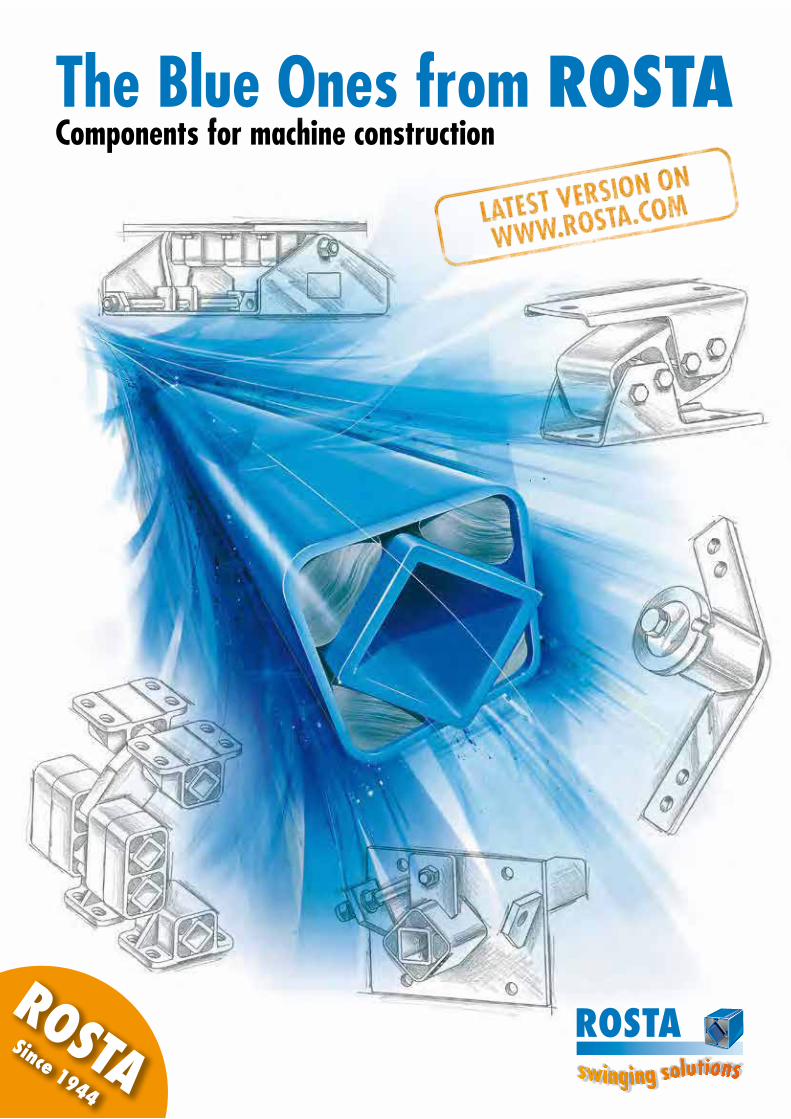
T.1
www.rosta.comROSTA
Components for machine constructionThe Blue Ones from ROSTA
ROSTASince 1944

www.rosta.com
ROSTA – We are in our element
We are in our element, whenever there is a need for resilient suspen-sions, elastic supports, cushioning mounts or smooth guidance in the machine industry – there is (almost) always a cost-efficient solution with our ROSTA rubber suspension elements!We are in our element, when long service life, resistance to wear, durability and less maintenance are demanded – our jointed, rubber-metal torsion bearings can withstand (almost) everything and achieve “biblical” service lifes!We are in our element, when we have to develop customised machine de-signs for our customers using ROSTA rubber suspension units – anything is fea-sible; our wide range of ideas, our laboratory equipment and our individual manufacturing processes are the guarantee for (almost) unlimited solutions!We are in our element, when oscillations, vibrations and agitating move-ments in the processing industry have to select, separate and convey bulky ma-terials – our rubber mounts offer the ideal solution for the suspension of (almost) every type of screen, conveyor or sifting machine!We are in our element, when our customers need direct support and help in order to find a solution – the Blue Ones from ROSTA are (almost) always avail-able from stock, and we also offer on-site customer service worldwide!
We look forward to your task – set us a challenge! We will do (almost) anything for you!

Table of contents
Rubb
er S
uspe
nsio
n Un
itsTe
chno
logy
Oscil
latin
g M
ount
ings
Anti-
vibr
atio
n M
ount
sTe
nsio
ner D
evice
sM
otor
base
s
Rubber Suspension Units 1.1–1.20
Technology T.1–T.11
Oscillating Mountings 2.1–2.40
Anti-vibration Mounts 3.1–3.16
Tensioner Devices 4.1–4.16
Motorbases 5.1–5.16

www.rosta.com
T.1
ROSTA – yesterday, today, tomorrow
founded in 1944
It started in the mid forties with the production of a few elastic wheel suspensions and, over the years, developed into a company that manufactured standardised rub-ber suspension axes for trailers. But it was the design and marketing of machine components such as the unique chain and belt tension elements that opened up the world market for the ingenious ROSTA rubber suspension system. Best-selling machine components such as the vibratory suspensions for screening technolo-gy helped ROSTA rubber suspensions to achieve their international breakthrough.This was followed by motorbases and anti-vibration mounts, which have now become indispensable in general machine construction. ROSTA rubber suspen-sion units will also make their mark in the future in machine construction technology – whether in the recycling industry or in the production of renewable energy – the blue spring-loaded assemblies from Hunzenschwil in Switzerland are already fully involved in these forward-looking technologies!
ROSTA
ROSTA
Tech
nolo
gy

www.rosta.com
T.2
ROSTA – a unique spring system from experienced specialists
Quality validation obtains highest importance at ROSTA. The well-equipped Research and Development department leaves nothing to chance; the material tests that take place before and periodically during the series production are the guaran-tee for a comprehensive quality standard – a spare part element produced in ten years time will still have the same characteristics as the series product supplied today!
Production machines, handling equipments, tooling machines and processing systems equipped with state-of-the-art technology can only function perfect-ly if reliable and motivated employees of the manu-facturer stand fully behind even the smallest structur-al components. It is their competence, their quality considerations and their great willingness to work
that lay the foundations for the production of high quality goods. At ROSTA AG, we enjoy a very low staff fluctuation and make every effort to treat our employees with great respect and ensure that they feel that they are part of a large family— the Blue Ones from ROSTA.
Tech
nolo
gy

www.rosta.com
T.3
ROSTA Element Determination
Supplier of rubber inserts and subsidiary company of ROSTA AG:
The adjacent exploded view shows a rubber suspen-sion type DW-A 45 x 100.
Wherefrom comes this (relatively old) designation based on the German language?“D” stays for Drehelement (e: torsion-element)“W” stays for Winkelsupport am Aussengehäuse
(e: included fastening bracket)“A” stays for Aluminiuminnenvierkantprofil
(e: core-profile made of aluminium)“45” stays for the core dimension 45/45 mm
(dimension a)“100” stays for the effective element-length
100 mm (dimension b)
The following product catalogues are indicating the standardized element dimensions with numbers like 18 or 45 or 50 etc., always related to the dimen-sion in mm of the inner element-core (dimension a). E.g. a type AU 38 is a suspension for oscillating shaker troughs (g: Aufhängung = suspension) with inner core dimensions 38/38 mm.
An AB 50 is an Abstützung = support element for oscillating screens with inner core dimensions 50/50 mm, etc., etc.
Throughout the full product variety of ROSTA there are Rubber Suspension Units, Oscillating Mountings, Anti-vibration Mounts, Tensioner Devices and Motorbases in the following sizes (inner core dimen-sion in mm): DR 11, 15, 18, 27, 38, 45, 50, 60, 70, 80 and 100 (not all final products are available in all afore mentioned DR-sizes).
In the end, the ROSTA rubber sus-pension element is only as good, as the rubber inserts mounted in it. Or in other words: If the rub-ber quality is not very good, the ROSTA element will not be able to deliver the required perfor-mance and characteristics. For many years, ROSTA AG has been supplied with high-quality rubber inserts for its component production by two leading Swiss manufacturers of rubber profiles. The cooperation with these two suppliers was always ex-cellent and very tight. There has, however, always been one downside to this good cooperation: the very high supplier dependency!In the spring of 2007, the unique opportunity arose for ROSTA AG to purchase both the rubber mixing plant of the one long-term supplier and the extrusion
a
b
and vulcanisation operation of the other. The two pro-duction branches were then merged together, creat-ing the COMPOUNDS AG. In the year 2010, the company moved into its new, spacious production and administration building in CH-8330 Pfäffikon.Besides the covering of the supply-continuity, many new possibilities for the improvement of the quality and of developing rubber inserts for specific and/or customized applications will arise from the close col-laboration with the “own” rubber supplier.
Tech
nolo
gy

www.rosta.com
T.4
ROSTA Technology
1 FunctionThe ROSTA rubber suspension elements are mainly designed for applications as torsional spring devices offering operation angles of ± 30°. Depending on the particular function, not only torsional moments are ge-nerated by pivoting the spring device. According to the specific application additional radial Fr, axial Fa and/or cardanic Mk forces have usually to be taken in consideration. The occurring torques of the different element sizes and the additional load characteristics are indicated in the table on page 1.5.
2 Spring CharacteristicBy pivoting the unique ROSTA torsional spring device a virtually linear spring characteristic occurs with a slightly progressive upper end, when load is applied in the high pivoting range, close at 30° element rota-tion. If purely linear or even degressive spring charac-teristics are required, the design of the leverage has to be altered and/or a cam-disc has to be used as arm guidance in order to obtain a function adapted spring characteristic. Furthermore, please note that elastome-ric bonds are incompressible, i.e. of constant volume.
3 Internal element dampingThe occurring energy damping in the ROSTA element is addicted to the resulting energy loss work in the rub-ber inserts during the pivoting activity of the spring de-vice. In the process of the element actuation a part of the resulting energy is transformed into frictional work generating heat. The shaded surface between load and relieve headline indicates the effective energy loss. At element actuation out of the zero position up to 30°, the resulting average energy loss is at 15 to 20 %. At the actuation of a pre-tensioned element, the resulting ± working angle is usually only a few de-grees, therefore the energy loss reduces within a limit (see graph: “Energy loss per oscillation”). Uniquely animated element oscillations fade within short term, due to the occurring energy loss at each following post-pulse oscillation. (Very important at the use of ROSTA screen mountings – during the opera-tion procedure of the screen the resulting power loss in the ROSTA mountings is negligible; during the running down phase, close to the resonance frequen-cy of the suspensions, an important amplitude exag-geration occurs. The high energy loss in the ROSTA screen mountings dampens and absorbs these exag-gerations within only a few post-pulse oscillations.)
Federweg
Bela
stun
g
Belastung
Am
plitu
de
Zeit
Entla
stung
Energieverlustpro Schwingung
3
1
Tech
nolo
gy
2 + Torsion Range
Torsion angle in degree
Torsion angle in degree
Time elapsed
Charge
Relie
ve
Energy loss per oscillation
– Torsion Range
Relie
ve
Charge
Charge Relie
ve
Torq
ue in
Nm
Torq
ue in
Nm

www.rosta.com
T.5
4 Natural Frequency of a ROSTA suspensionThe determination of the natural frequency of a ROSTA suspension has to be carried out by spreading the tangent at the loading point “A” on the parabolic arc of the load deflection curve. The resulting dis-tance s1 on the axis of abscissa comes up to the ar-ithmetical spring deflection in mm, required for the determination of the natural frequency.
ROSTA Technology
5 Cold flow and settling of the rubber suspensions
If, over a certain period of time, load is permanently applied on an elastic component (e.g. rubber sus-pension) consistent deformation occurs (cold flow). Cold flow or settling appears during a linear loga-rithmic sequence. According to the respective dia-gram more than 50 % of this overall settling or cold flow of a ROSTA element under load occurs after only one day of service. After approx. one year of operation the total cold flow deformation will be compensated (depending on environmental tempera-tures and applied frequencies). The empirical settling factor of a ROSTA rubber suspension lies within 3° to 5°, i.e. the inner core does not totally move back to the neutral 0° position of the element. In applica-tions with series or parallel configurations of several elements (e.g. AB screen mountings) the effective cold flow factor lies at approx. +10 % of the nominal deflection curve. This fact has to be taken into con-sideration while designing axle bearings or screen mountings with ROSTA elements.
4
5
Cold flow
Natural frequency ne = = min-1300
√s1 (in cm)
or fe = = Hz5√s1 (in cm)
ne = ≅ 134 min-1 or 2.2 Hz300√5.0
Example s1 = 5 cm:
Tech
nolo
gy
Initial deflection
Time elapsed in sec.
1 da
y
1 ye
ar
spring deflection s
Abscissa
assumed load G
Load
G in
N
Tangent

www.rosta.com
T.6
ROSTA Technology
6 Temperature InfluenceThe ROSTA rubber suspension elements equipped with the standard rubber quality “Rubmix 10” are designed to be applied in the temperature range of –40 °C to +80 °C (–40 °F to +180 °F). With rising temperatures the mechanical stiffness of the rubber inserts and consequently the resulting element torque decrease within acceptable tolerances (at +80 °C approx. –5%). At lower temperatures (below the freezing point) the torsional element stiffness rises up to max. +15% at –40 °C. Furthermore, the internal damping factor (hysteresis) of the ROSTA rubber sus-pensions increases at lower temperatures and de-clines again at rising conditions. Due to the internal molecular friction through element torsion, the rub-ber inserts warm up in a continuous manner. Thus, the effective occurring element temperature can vary in relation to the environmental temperature.
7 Service Life Provided the rubber suspension elements are selected according to our technical specifications, i.e. are oper-ating within the given frequencies and oscillation an-gles and under the mentioned surrounding conditions, no loss of performance and functionality can be ex-pected for many years. Extremely low or high per-manent surrounding temperatures considerably shorten the lifetime expectancy of the rubber suspen-sion elements. The opposite service life curve indicates the relevant life deduction at extreme ± temperatures from factor 1 at room temperature of +22 °C.
8 Quality Control and TolerancesSince December 1992 ROSTA AG has been an ISO 9001 standard certified development, manufac-ture and distribution company. All products are submitted to a periodical function and quality con-trolling. On the test machines of the in-house labora-tory the rubber inserts are continuously tested and controlled with regard to Shore A hardness, com-pression set, abrasive wear, rebound resilience, ten-sile strength, breaking elongation and aging be-haviour. The dimensional tolerance of the rubber in-serts is defined according DIN 7715 standard and the Shore A hardness according to DIN 53505
stand ard. The housings and the inner-core profiles of the rubber suspensions are subjected to the toler-ance guidelines of the relevant production process and respective supplier (e.g. casted, extruded, edge rolled) and the individual material consistence (e.g. light metal casting, steel tube, nodular cast iron part, etc.). The resulting torsional moments and spring de-flections of the ROSTA rubber suspension elements are residing in a tolerance range of ± 15% at most, but lie usually in an essentially nar-rower range!
6
7
Tech
nolo
gy
Torq
ue in
Nm
Serv
ice
life
Temperature in ºC
Temperature in ºC
ambi
ent
tem
pera
ture
ambi
ent t
empe
ratu
re

www.rosta.com
T.7
ROSTA Technology
Rubber qualityFactor in relation to the list “torque and loads” (page 1.5)
Working temperature Rubber Specification
Rubmix 10 1.0 –40 ° to +80 °C NR – Standard quality
Rubmix 20 approx. 1.0 –30 ° to +90 °C CR – Good oil-resistance– Elements marked with yellow dot
Rubmix 40 approx. 0.6 from +80 °to +120 °C EPDM-Silicone – High temperature resistance
– Elements marked with red dot
Rubmix 50 approx. 3.0 –35 ° to +90 °C PUR
– Max. oscillation angle ±20°– Limited oscillation frequencies– No permanent water contact– Elements marked with green dot
9 Permissible Element FrequenciesAlignment chart for the determination of the permis-sible frequencies at different angles of oscillation in relation to the appropriate element size (DR 11, 15, 18, etc.). The higher the frequency in rpm, the lower the angle of oscillation has to be and vice versa.
Example: (see blue indication on chart) A rubber suspension of type DR 50 may be rotated from the neutral position (0°) to an oscillation angle of ± 6° by a max. frequency of 340 min-1. For applications of “pre-tensioned” elements working, e.g. under 15° of pre-tension and describ-ing oscillation angles of ± 5° at 250 min-1, it is ab-solutely necessary to consult ROSTA.
10 Rubber QualitiesNearly 80 % of all ROSTA rubber suspension ele-ments are equipped with rubber inserts of standard quality “Rubmix 10”. This rubber quality based on a high content of natural rubber (caoutchouc) of-fers a good shape-memory, small settling factors (cold flow), high mechanical load capacities and
moderate aging behaviours (little hardening of the inserts). Where high oil-consistency, heat-re-sistance or higher torque is required, other qualities of elastomeric inserts can be applied in the ROSTA rubber suspension elements.
9
10
Tech
nolo
gy
Ang
le o
f osc
illat
ion
± in
deg
ree
Frequency in min-1

www.rosta.com
T.8
ROSTA Technology
11 Chemical ConsistencyThe standardized ROSTA rubber suspension ele-ments are equipped with elastic inserts of quality type “Rubmix 10”. This rubber quality is based on a high content of natural rubber. It offers against large media a high chemical consistency. In some specific applications, however, some additional pro-tective barrier or the application of elements with synthetical elastomeric inserts (qualities “Rubmix 20”,
“Rubmix 40” or “Rubmix 50”) is required. Applying these alternative inserts, the general element charac-teristics slightly differ (see chapter 10 “rubber quali-ties”). The below indicated consistency table is mere-ly a guideline and is incomplete. For specific appli-cations please contact ROSTA and inform us about the environmental conditions and about the detailed concentration of liquid or aerial media being in con-tact with the rubber suspension elements.
11Rubmix 10 20 40 50
Acetone + oo ++ oo
Alcohol ++ ++ ++ o
Benzene oo oo oo oo
Caustic soda solution up to 25 % (20°) ++ ++ ++ oo
Citric acid ++ + o oo
Diesel oo + oo +
Formic acid + + o oo
Glycerine + + ++ oo
Hydraulic fluid o + oo oo
Hydrochloric acid up to 15 % ++ + o oo
Javelle water + + ++ oo
Lactic acid ++ ++ ++ +
Liquid ammonia + + ++ oo
Lubricating grease and oil oo + oo +
Nitric acid up to 10 % oo + + oo
Nitro thinner oo oo oo oo
Petrol (fuel) oo o oo ++
Petroleum oo + oo ++
Phosphoric acid up to 85 % oo oo oo oo
Seawater ++ + ++ oo
Sulphuric acid up to 10 % + o o oo
Tannic acid ++ + ++ oo
Toluene oo oo oo oo
Treacle ++ ++ ++ o
Legend: ++ excellent consistency+ good consistencyo sufficient consistencyoo insufficient consistency
Tech
nolo
gy

www.rosta.com
T.9
ROSTA Stainless Steel Range
In the food processing and pharmaceutical industries the very high hygienic standards are raising perma-nently. We accommodate these facts in our compo-nent development through expanding and improving continuously our range of stainless steel machine com-ponents. As a result, many of the ROSTA oscillating and tensioning elements are as standard elements in stainless steel material available from stock. For pro-duction-related reasons some dimensions of our stain-less steel elements do slightly differ from the measure-ments of the standard range (steel versions).
Please ask for our “stainless steel” catalogue!

www.rosta.com
T.10
ROSTA Customized Elements
Does the ready-made suit not fit your re-quirements, we will “tailor” it!
The proverbially worldwide availability of our stan-dardized rubber suspension elements is one of the most positive arguments for the application of our products. By large batch production of machines and installations, however, a “tailored” and cus-tomized system component can significantly reduce the assembly time. In addition, the original equipment manufacturer gets the certitude that its customized ROSTA component is supplied exclusively to its or-ganisation and consequently the potential spare part business stays under its own survey.
Please ask for a consulting call! We will be pleased to take measurement on your spe-cific machine configuration for designing your customized ROSTA built-in part!
Tech
nolo
gy

www.rosta.com
T.11
ROSTA Rubber Suspensions
Springing – cushioning – guiding all three functions in one machine compo-nent! This proverbial triple function is raising the ROSTA rubber suspension system in the status of uniqueness among the machine components. The ROSTA technolo-gy, for years solely focusing on mechanical engineering and machine construc-tion, is now continuously finding admission in equipments of human bodybuilding. Besides amusement installations, innumerable open-air gymnastic parks are raising up like mushrooms in our contemporary agglomerations. As expander hinge, as see-saw bearing or as stepping-stone cushion, the threefold function of the indestructible rubber suspension encouraged the relevant industries for the use of the Blue Ones from ROSTA.
See-saw bearing
Protective stepping cushion
Expander
Tech
nolo
gy

Multifunctional Modules for the Machine Industriesguiding – tensioning – absorbing
ROSTA Rubber Suspension Units
ROSTA

1.2
www.rosta.com
Rubb
er S
uspe
nsio
n Un
its
fully customized rubber suspensions in exclusive design according specific request
torsional springs for continous surface pressure
pendulum suspensions for unbalanced motorstorque supports for gear motors
DW-C
DR-S
torsion-elastic spring assemblies for the contemporary machine engineering ROSTA Rubber Suspension Units

1.3
www.rosta.com
Rubb
er S
uspe
nsio
n Un
its
torsion elastic mounts offering constant pressure on workparts (infeed devices)
energy absorbing impact suspensionsDO-A
DK-A
torsion-elastic spring assemblies for the contemporary machine engineering ROSTA Rubber Suspension Units

1.4
www.rosta.com
Rubb
er S
uspe
nsio
n Un
its
Selection chart for rubber suspension standard elements with Rubmix 10
Specification DR-A 15 x 25
Effective element lengthSize S
Inner squareHousing
General•Light metal profiles: extruded profiles, seawater resistant (DIN 1725).•Blue protection paint: water-soluble paint, coating thickness 0.04 – 0.08 mm.•Fixation screws: minimum strength class of 8.8•Welding on elements: do not weld on rubber suspensions – welding heat
will affect or destroy the rubber inserts – ask for customized elements•Most of the elements can be supplied in stainless steel version – also
zinc-plated versions or special paintings are available.
Further customized elements: see examples on page 1.14 to 1.19.
Inner square
Housing
ALight metal profile,as from size 60 in steel
CLight metal profile
SSteel tube for plug-in connection
Accessories for housing
Steel parts
DRSteel tube
DR-A 15 to 50
Page 1.6
DR-C 15 to 50
Page 1.6
DR-S 11 to 50
Page 1.7
Bracket BR 11 to 50
Page 1.7
DKLight metal profile
DK-A 15 to 50
Page 1.8
DK-C
on request
DK-S 11 to 50
Page 1.8
Bracket BK 11 to 50
Page 1.9
DWLight metal profile
DW-A 15 to 38
Page 1.10
DW-C 15 to 38
Page 1.10
DW-S
on request
Accessories for inner square A
Steel parts
DWNodular cast iron
DW-A 45 and 50
Page 1.11
DW-C 45 and 50
on request
DW-S
on request
WS 11 to 50
Page 1.13
DWSteel welded construction
DW-A 60 to 100
Page 1.11
DOLight metal profileSize 50 in nodular cast iron
DO-A 15 to 50
Page 1.12
DO-C
on request
DO-S
on request
Ideal for alternating mo-tions over neutral element position.For sizes DR 15 – 45: Fixa-tion by means of 2 to 4 per-sistent threaded bars (sizes DR 27 – 45 also available with threaded holes).
Friction locking of the core by means of one central bolt, can be positioned in full 360° angle-range. For ideal friction locking, please remove paint cover on face side. For alternating el ement motion of max. ±10°.
For plug-in connection with square profile*. Plug-in length min. 2 x width across flat “C”. Connection is not recommendable by alternating motions – play between the plugged squares.
* The square should be made out of bright steel, tolerance h9 – h11. Possi-bly, the edges have to be overwinded (edge-radius in element profile max. 1.5 mm).
Specification inner squares
Housing

1.5
www.rosta.com
Rubb
er S
uspe
nsio
n Un
its
List of torque and loads
Element Torque Cardanic Radial Axial
Nominal size x Length Md [Nm] angle ±a°
Mk [Nm]angle ±β°
Deflection± sr
LoadFr
Deflection ± sa
LoadFa
5° 10° 15° 20° 25° 30° 1° [mm] [N] [mm] [N]
11 x 20 0.3 0.8 1.3 2.0 2.9 4.0 0.4
0.25
200
0.25
60
30 0.4 1.2 2.0 3.1 4.3 6.0 1.1 340 80
50 0.7 2.0 3.4 5.1 7.2 10.0 5.6 600 150
15 x 25 0.7 1.6 2.6 4.0 5.7 8.2 0.6
0.25
200
0.25
70
40 1.1 2.5 4.2 6.4 9.2 13.2 2.0 300 100
60 1.6 3.8 6.3 9.6 13.8 19.8 5.5 500 160
18 x 30 1.9 4.5 7.5 11.0 15.0 20.6 1.6
0.25
400
0.25
80
50 3.2 7.5 12.5 18.3 25.0 34.4 7.0 700 160
80 5.1 12.0 20.0 29.3 40.0 55.0 28.0 1000 300
27 x 40 4.7 10.7 17.5 26.9 39.5 57.0 3.8
0.5
800
0.5
200
60 7.0 16.0 26.3 40.3 59.3 85.5 11.5 1300 300
100 11.7 26.7 43.8 67.2 98.8 142.5 48.0 2400 600
38 x 60 13.0 30.4 50.6 78.0 113.0 162.0 11.4
0.5
1500
0.5
300
80 17.3 40.5 67.5 104.0 151.0 216.0 24.7 2000 500
120 26.0 60.8 101.2 156.0 226.0 324.0 76.0 3000 600
45 x 80 27.6 62.4 104.0 160.0 222.0 320.0 28.0
0.5
1900
0.5
560
100 34.5 78.0 130.0 200.0 278.0 400.0 54.0 3000 700
150 51.8 117.0 195.0 300.0 420.0 600.0 140.0 4800 1000
50 x 120 51 133 250 395 570 780 80
0.5
2800
0.5
800
160 77 197 363 570 820 1115 145 4500 950
200 102 260 475 745 1070 1450 250 6300 1100
300 150 385 700 1100 1590 2160 1200 8600 2200
60 x 150 75 170 300 460 700 1010 90
1.0
5400
1.0
1600
200 95 220 385 610 930 1380 250 7200 2200
300 140 365 630 995 1550 2240 900 9400 3200
70 x 200 140 380 650 1040 1490 2120 280
1.0
9000
1.0
2200
300 190 525 910 1470 2160 3150 1200 12'000 3600
400 250 765 1315 2160 3175 4750 2200 14'000 4000
80 x 200 200 500 850 1300 1900 2700 680
1.0
10'000
1.0
2500
300 300 800 1300 2000 2900 4100 1500 15'000 3800
400 400 1060 1800 2800 3900 5600 4600 19'000 4700
100 x 250 400 1080 1800 2800 4100 6300 1200
1.0
15'000
1.0
3200
400 640 1700 2900 4500 6600 10'000 4300 28'000 5800
500 800 2160 3600 5600 8200 12'000 8000 38'000 7500
The values stated in the below mentioned list have been meas ured statically and are valid for the standard rubber quality “Rubmix 10”. Intermediate values can be interpolat-ed. By applications with combined dynamic forces and high angles of oscillation please consult our ROSTA general cata-logue, chapter “Technology” or contact ROSTA.

1.6
www.rosta.com
Rubb
er S
uspe
nsio
n Un
its
Rubber Suspension Units
DR-A DR-C
xD xS L L1 ± 0.2
Weight[kg]Art. No. Type ø A +0.5
0 B Art. No. Type ø A
01 011 001 DR-A 15x 255 10 ± 0.2
01 031 010 DR-C 15x 2510 +0.4 +0.2 27 +0.4
0 15
25 30 0.06
01 011 002 DR-A 15x 40 01 031 011 DR-C 15x 40 40 45 0.10
01 011 003 DR-A 15x 60 01 031 012 DR-C 15x 60 60 65 0.15
01 011 004 DR-A 18x 306 12 ± 0.3
01 031 001 DR-C 18x 3013 +0.4 –0.2 32 +0.3
–0.1 18
30 35 0.10
01 011 005 DR-A 18x 50 01 031 002 DR-C 18x 50 50 55 0.16
01 011 006 DR-A 18x 80 01 031 003 DR-C 18x 80 80 85 0.25
01 011 007 DR-A 27x 408 20 ± 0.4
01 031 004 DR-C 27x 4016 +0.5 +0.3 45 +0.4
0 27
40 45 0.25
01 011 008 DR-A 27x 60 01 031 005 DR-C 27x 60 60 65 0.36
01 011 009 DR-A 27x100 01 031 006 DR-C 27x100 100 105 0.60
01 011 010 DR-A 38x 6010 25 ± 0.4
01 031 007 DR-C 38x 6020 +0.5 +0.2 60 +0.3
–0.2 38
60 70 0.60
01 011 011 DR-A 38x 80 01 031 008 DR-C 38x 80 80 90 0.79
01 011 012 DR-A 38x120 01 031 009 DR-C 38x120 120 130 1.16
01 011 023 DR-A 45x 8012 35 ± 0.5
01 031 023 DR-C 45x 8024 +0.5 +0.2 75 +0.3
–0.2 45
80 90 1.25
01 011 024 DR-A 45x100 01 031 024 DR-C 45x100 100 110 1.53
01 011 025 DR-A 45x150 150 160 2.30
01 011 026 DR-A 50x120M12x40 40 ± 0.5
01 031 025 DR-C 50x12030 +0.5 +0.2 80 +0.3
–0.2 50
120 130 2.07
01 011 027 DR-A 50x200 01 031 026 DR-C 50x200 200 210 3.45
01 011 028 DR-A 50x300 300 310 5.15
List of torque and loads on page 1.5.Further information to customized elements and installation examples as from page 1.14.
S
A
B
D
B
L
L1
S
A
D
L
L1
DR-A 50: ø 20 +0.5 0
Type DR-C
Type DR-A
new new
new new
new new
new new
new
new

1.7
www.rosta.com
Rubb
er S
uspe
nsio
n Un
its
Rubber Suspension Units
DR-S
xD xS L L1 ± 0.2
Weight[kg]Art. No. Type xC
01 021 001 DR-S 11x 208 +0.25 0 20 +0.3
–0.1 11
20 25 0.04
01 021 002 DR-S 11x 30 30 35 0.05
01 021 003 DR-S 11x 50 50 55 0.08
01 021 004 DR-S 15x 2511 +0.25 0 27 +0.4
0 15
25 30 0.07
01 021 005 DR-S 15x 40 40 45 0.12
01 021 006 DR-S 15x 60 60 65 0.18
01 021 007 DR-S 18x 3012 +0.25 0 32 +0.3
–0.1 18
30 35 0.12
01 021 008 DR-S 18x 50 50 55 0.20
01 021 009 DR-S 18x 80 80 85 0.32
01 021 010 DR-S 27x 4022 +0.25 0 45 +0.4
0 27
40 45 0.26
01 021 011 DR-S 27x 60 60 65 0.39
01 021 012 DR-S 27x100 100 105 0.65
01 021 013 DR-S 38x 6030 +0.25 0 60 +0.3
–0.2 38
60 70 0.67
01 021 014 DR-S 38x 80 80 90 0.90
01 021 015 DR-S 38x120 120 130 1.32
01 021 026 DR-S 45x 8035 +0.4 0 75 +0.3
–0.2 45
80 90 1.42
01 021 027 DR-S 45x100 100 110 1.76
01 021 028 DR-S 45x150 150 160 2.62
01 021 029 DR-S 50x12040 +0.4 0 80 +0.3
–0.2 50
120 130 2.37
01 021 030 DR-S 50x200 200 210 3.91
01 021 031 DR-S 50x300 300 310 5.80
Bracket BR
D G H ø l K MWeight
[kg]Art. No. Type
01 500 001 BR 11 20 37 50 6 20 2 0.03
01 500 002 BR 15 27 50 65 7 25 2 0.04
01 500 003 BR 18 32 60 80 9 30 2.5 0.08
01 500 004 BR 27 45 80 105 11 35 3 0.15
01 500 005 BR 38 60 100 125 13 40 4 0.27
01 500 026 BR 45 75 120 150 13 45 5 0.48
01 500 027 BR 50 80 135 175 18 50 6 0.71
List of torque and loads on page 1.5.Further information to customized elements and installation examples as from page 1.14.
CS
D L
L1
D
G
H
I
K
M
D
Type DR-S
D
G
H
I
K
M
D
Accessory Bracket BR
new
new
new
new
new
new
new
new
1.8
www.rosta.com
Rubb
er S
uspe
nsio
n Un
its
Rubber Suspension Units
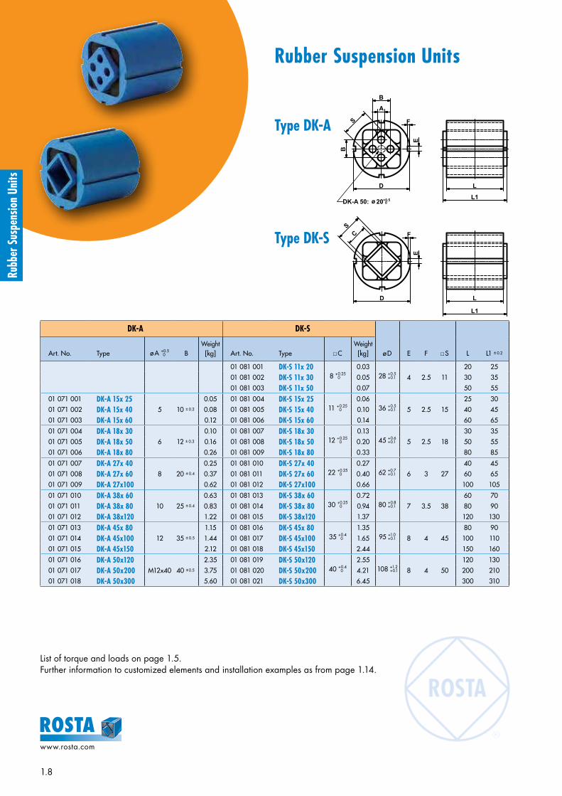
DK-A DK-S
ø D E F xS L L1 ± 0.2Art. No. Type ø A +0.5 0 B
Weight[kg] Art. No. Type xC
Weight[kg]
01 081 001 DK-S 11x 208 +0.25 0
0.0328 +0.5
+0.1 4 2.5 11
20 25
01 081 002 DK-S 11x 30 0.05 30 35
01 081 003 DK-S 11x 50 0.07 50 55
01 071 001 DK-A 15x 255 10 ± 0.2
0.05 01 081 004 DK-S 15x 2511 +0.25 0
0.0636 +0.5
+0.1 5 2.5 15
25 30
01 071 002 DK-A 15x 40 0.08 01 081 005 DK-S 15x 40 0.10 40 45
01 071 003 DK-A 15x 60 0.12 01 081 006 DK-S 15x 60 0.14 60 65
01 071 004 DK-A 18x 306 12 ± 0.3
0.10 01 081 007 DK-S 18x 3012 +0.25 0
0.1345 +0.6
+0.1 5 2.5 18
30 35
01 071 005 DK-A 18x 50 0.16 01 081 008 DK-S 18x 50 0.20 50 55
01 071 006 DK-A 18x 80 0.26 01 081 009 DK-S 18x 80 0.33 80 85
01 071 007 DK-A 27x 408 20 ± 0.4
0.25 01 081 010 DK-S 27x 4022 +0.25 0
0.2762 +0.7 +0.1 6 3 27
40 45
01 071 008 DK-A 27x 60 0.37 01 081 011 DK-S 27x 60 0.40 60 65
01 071 009 DK-A 27x100 0.62 01 081 012 DK-S 27x100 0.66 100 105
01 071 010 DK-A 38x 6010 25 ± 0.4
0.63 01 081 013 DK-S 38x 6030 +0.25 0
0.7280 +0.8
+0.1 7 3.5 38
60 70
01 071 011 DK-A 38x 80 0.83 01 081 014 DK-S 38x 80 0.94 80 90
01 071 012 DK-A 38x120 1.22 01 081 015 DK-S 38x120 1.37 120 130
01 071 013 DK-A 45x 8012 35 ± 0.5
1.15 01 081 016 DK-S 45x 8035 +0.4 0
1.3595 +1.0 +0.1 8 4 45
80 90
01 071 014 DK-A 45x100 1.44 01 081 017 DK-S 45x100 1.65 100 110
01 071 015 DK-A 45x150 2.12 01 081 018 DK-S 45x150 2.44 150 160
01 071 016 DK-A 50x120M12x40 40 ± 0.5
2.35 01 081 019 DK-S 50x12040 +0.4 0
2.55108 +1.2
+0.1 8 4 50
120 130
01 071 017 DK-A 50x200 3.75 01 081 020 DK-S 50x200 4.21 200 210
01 071 018 DK-A 50x300 5.60 01 081 021 DK-S 50x300 6.45 300 310
List of torque and loads on page 1.5.Further information to customized elements and installation examples as from page 1.14.
D L
E
FS
A
B
B
L1DK-A 50: ø 20 +0.5
0
E
D L
CS
F
L1
Type DK-S
Type DK-A

1.9
www.rosta.com
Rubb
er S
uspe
nsio
n Un
its
Rubber Suspension Units
Bracket BK
D G H ø l K M N OWeight
[kg]Art. No. Type
01 520 001 BK 11 28 45 60 6.5 20 1.5 6 15.5 0.04
01 520 002 BK 15 36 55 75 6.5 25 2 7 20.0 0.09
01 520 003 BK 18 45 68 90 8.5 30 2 8 24.5 0.14
01 520 004 BK 27 62 92 125 10.5 35 2.5 10 33.5 0.29
01 520 005 BK 38 80 115 150 12.5 40 3 11 43.0 0.45
01 520 006 BK 45 95 130 165 12.5 45 4 14 51.5 0.74
01 520 007 BK 50 108 152 195 16.5 50 4 15 58.0 0.93
List of torque and loads on page 1.5.Further information to customized elements and installation examples as from page 1.14.
D M
N
O
G
H
I
K
With the use of the BK bracket the working position of the DK element can be selected in the full angle-range of 360°.
Accessory Bracket BK
Example of an individually adjustable pressure-roll on the material feeding device of a profile cutting machine, equipped with DK-A rubber suspension and BK bracket.
Example of an element connection in series (±60° element torsion) as strong wind swivel mount for solar panels, con-sisting of a series connection DW-C and DK-C elements with BK bracket.

1.10
www.rosta.com
Rubb
er S
uspe
nsio
n Un
its
Rubber Suspension Units
DW-A 15 to 38 DW-C 15 to 38
E G H ø l O Q xS L L1+ 04 –0.3 M
Weight[kg]Art. No. Type ø A +0.5
0 B Art. No. Type ø A
01 101 016 DW-A 15x 255 10 ± 0.2
01 121 101 DW-C 15x 2510 +0.4 +0.2 29 50 65 7 3 15 15
25 30 - 0.05
01 101 017 DW-A 15x 40 01 121 102 DW-C 15x 40 40 45 - 0.07
01 101 018 DW-A 15x 60 01 121 103 DW-C 15x 60 60 65 40 0.11
01 101 019 DW-A 18x 306 12 ± 0.3
01 121 104 DW-C 18x 3013 0 –0.2 35 60 80 9 3.5 18 18
30 35 - 0.08
01 101 020 DW-A 18x 50 01 121 105 DW-C 18x 50 50 55 - 0.13
01 101 021 DW-A 18x 80 01 121 106 DW-C 18x 80 80 85 50 0.21
01 101 022 DW-A 27x 408 20 ± 0.4
01 121 107 DW-C 27x 4016 +0.5 +0.3 49 80 105 11 4.5 25 27
40 45 - 0.21
01 101 023 DW-A 27x 60 01 121 108 DW-C 27x 60 60 65 - 0.31
01 101 024 DW-A 27x100 01 121 109 DW-C 27x100 100 105 60 0.52
01 101 025 DW-A 38x 6010 25 ± 0.4
01 121 110 DW-C 38x 6020 +0.5
+0.2 67 100 125 13 6 34 38
60 70 - 0.59
01 101 026 DW-A 38x 80 01 121 111 DW-C 38x 80 80 90 40 0.77
01 101 027 DW-A 38x120 01 121 112 DW-C 38x120 120 130 80 1.15
List of torque and loads on page 1.5.Further information to customized elements and installation examples as from page 1.14.
A
BS
B
Q O
E
G
I
H
L
L1
L
L1
M
A
G
H
OQ
E
S
I
L
L1
M
L
L1
Type DW-C 15 to 38
Type DW-A 15 to 38

1.11
www.rosta.com
Rubb
er S
uspe
nsio
n Un
its
Rubber Suspension Units
DW-A 45 and 50
A B ±0.5 E G H O Q xS T U L L1 ± 0.2 MWeight
[kg]Art. No. Type
01 101 015 DW-A 45x100 ø 12 +0.5 0 35 80 115 145 8 41 45 13 20 100 110 65 2.9
01 101 013 DW-A 50x120M12x40 40 88 130 170 12 45 50 17 27
120 130 60 3.7
01 101 028 DW-A 50x160 160 170 70 5.0
01 101 014 DW-A 50x200 200 210 70 6.1
DW-A 60 to 100
A B D E G H ø l ø J N O Q xS V W L L1 ± 0.2 M PWeight
[kg]Art. No. Type
01 101 031 DW-A 60x150M16 45 100 115 160 220 18 16.5 60 8 65 60
40 70 150 160 60 130 8.9
01 101 032 DW-A 60x200 50 80 200 210 100 170 11.1
01 101 033 DW-A 60x300 50 80 300 310 200 270 15.9
01 101 034 DW-A 70x200M20 50 120 140 200 260 22 20.5 65 9 80 70 50
200 210 100 170 15.4
01 101 035 DW-A 70x300 90 300 310 200 270 21.7
01 101 036 DW-A 70x400 400 410 300 370 28.2
01 101 037 DW-A 80x200M20 60 136 153 220 280 22 20.5 80 10 85 80 50
200 210 80 170 21.7
01 101 038 DW-A 80x300 90 300 310 180 270 30.4
01 101 039 DW-A 80x400 400 410 280 370 39.4
01 101 040 DW-A 100x250M24 75 170 195 300 380 26 25 100 12 110 100 50
250 260 110 220 43.8
01 101 041 DW-A 100x400 100 400 410 260 370 64.7
01 101 042 DW-A 100x500 500 510 360 470 78.7
List of torque and loads on page 1.5.Further information to customized elements and installation examples as from page 1.14.
SB
A
BO
Q
E
T
G
H M
L1
L
U U
M M
L
L1
I
G
H
B
Q
E
B
D
S A
J
V
M
N
P
W
L
L1
O
Type DW-A 45 and 50
Type DW-A 60 to 100
DW-A 50x200
new
new
new
new
new
new
new
new
new
new
new
new

1.12
www.rosta.com
Rubb
er S
uspe
nsio
n Un
its
Rubber Suspension Units
DO-A
B D E F xS G H L L1 ± 0.2
Weight[kg]Art. No. Type ø A +0.5
0
01 041 001 DO-A 15x 255 10 ± 0.2 28 ±0.15 25.5 53.5 ±0.2 15 - -
25 30 0.07
01 041 002 DO-A 15x 40 40 45 0.10
01 041 003 DO-A 15x 60 60 65 0.15
01 041 004 DO-A 18x 306 12 ± 0.3 34 ±0.15 31 65 ±0.2 18 - -
30 35 0.12
01 041 005 DO-A 18x 50 50 55 0.20
01 041 006 DO-A 18x 80 80 85 0.30
01 041 007 DO-A 27x 408 20 ± 0.4 47 ±0.15 44 91 ±0.2 27 - -
40 45 0.32
01 041 008 DO-A 27x 60 60 65 0.47
01 041 009 DO-A 27x100 100 105 0.78
01 041 010 DO-A 38x 6010 25 ± 0.4 63 ±0.2 60 123 ±0.3 38 - -
60 70 0.87
01 041 011 DO-A 38x 80 80 90 1.15
01 041 012 DO-A 38x120 120 130 1.68
01 041 013 DO-A 45x 8012 35 ± 0.5 85 ±0.5 73 150 ±1 45 - -
80 90 1.85
01 041 014 DO-A 45x100 100 110 2.25
01 041 015 DO-A 45x150 150 160 3.35
01 041 016 DO-A 50x120M12 40 ± 0.5 ca. 89 78 ca. 168 50
30 60 120 130 5.50
01 041 019 DO-A 50x160 30 60 160 170 7.40
01 041 017 DO-A 50x200 40 70 200 210 8.50
List of torque and loads on page 1.5.Further information to customized elements and installation examples as from page 1.14.
D D*
40*
A
B
S
B
E
F
L
L1
R180*
* DO-A 45
B
S
B
E
F
D
AØ 1
2.25 G
H
L
L1
ø 20+0.5 0
Type DO-A 50
Type DO-A 15 to 45

1.13
www.rosta.com
Rubb
er S
uspe
nsio
n Un
its
Rubber Suspension Units
Bracket WS Fit for tensioner devices Fit for DR-A, DK-A, DW-A
C D E F G J K L MWeight
[kg]Art. No. Type SE size ø A HElement
size ø B N O
06 590 001 WS 11–15 11 6.5 27 15 5.5 35 10 7 7.5 30 13 11.5 4 45 30 46 0.08
06 590 002 WS 15–18 15 8.5 34 18 6.5 44 12 7 7.5 40 13 13.5 5 55 32 58 0.15
06 590 003 WS 18–27 18 10.5 43 27 8.5 55 20 9.5 10 50 15.5 16.5 6 70 38 74 0.28
06 590 004 WS 27–38 27 12.5 57 38 10.5 75 25 11.5 12.5 65 21.5 21 8 90 52 98 0.70
06 590 005 WS 38–45 38 16.5 66 45 12.5 85 35 14 15 80 24 21 8 110 55 116 0.90
06 590 006 WS 45–50 45 20.5 80 50 12.5 110 40 18 20 100 30 26 10 140 66 140 1.80
Accessory Bracket WS
Serial ConnectionDoubled oscillating angle(±60°) at constant torque of a single unit.
Parallel ConnectionDoubled torque momentumat constant oscillating angle (±30°).
A
B
OH
N
M
J
C
E
K
D
G F
L

1.14
www.rosta.com
Rubb
er S
uspe
nsio
n Un
its
ROSTA Rubber Suspension UnitsShort delivery time for the following special elements:
Not all sizes are available in all combinations. Please contact ROSTA.
• Delivery summary for ROSTA rubber qualities
• Elements with different length of housings and/or inner squares.
• DW light metal profiles with customized bores in the flange plates (quantity and position).
• Element with threaded bores in inner square: selectable for A or C inner squares, or full steel profile with required bores.
• Elements DK-C, DO-C, DW-C, DW-S and DO-S (see page 1.4):
Rubber qualityFactor in relation to the list “torque and loads” (page 1.5)
Working temperature Rubber Specification
Rubmix 10 1.0 –40 ° to +80 °C NR – Standard quality
Rubmix 20 approx. 1.0 –30 ° to +90 °C CR – Good oil-resistance– Elements marked with yellow dot
Rubmix 40 approx. 0.6 from +80 °to +120 °C EPDM-Silicone – High temperature resistance
– Elements marked with red dot
Rubmix 50 approx. 3.0 –35 ° to +90 °C PUR
– Max. oscillation angle ±20°– Limited oscillation frequencies– No permanent water contact– Elements marked with green dot

1.15
www.rosta.com
Rubb
er S
uspe
nsio
n Un
its
ROSTA, your system supplier since 70 years
Today, about 50 % of all supplied rubber suspension elements are fully customized parts. With pleasure we do await your project definition for the development of an ingenious and cost-saving rubber suspension, fitting your specific requirements.
Zinc-plated double element structure brush suspension in car wash site
Customized laser parts on housing front wheel suspension for wheelchair
Customized nodular cast housing swivel-mount for ripper comb in shredder
60° series connection (cast housings)hinge bearing for truck engine hood
Cataphoretic housing protection, “Rubmix 40” insertsmarker light suspension for truck trailers
60° series connection (light metal profiles)hinge bearing for glass shelf-cover
Stainless precision casting, machined core swivel-mount for machine cover
Welded structure, “Rubmix 50” inserts hinge for wheelchair-ramp on busses

1.16
www.rosta.com
Rubb
er S
uspe
nsio
n Un
its
ROSTA Rubber Suspension UnitsExamples of fixations to Housing
Fig. 1 Square tubular housing with bracket BR Fig. 2 Round housing with bracket BK
Fig. 3 Outer housing in clamping jaw Fig. 4 Double bracket welded on housing
Fig. 5 Plug-in connection Fig. 6 Dual-threaded plate welded on housing
Fig. 7 Dual-levers welded on housing Fig. 8 Bridge-clamp over housing
Fig. 9 Flange welded on housing Fig. 10 Housing in cast iron

1.17
www.rosta.com
Rubb
er S
uspe
nsio
n Un
its
ROSTA Rubber Suspension UnitsExamples of fixations to Inner Square Section
Fig. 11 Inner square section with four through bores and bracket UV
Fig. 12 Inner square section with four through bores and brackets
Fig. 13 Plug-in connection with lever and welded-on square steel piece Fig. 14 Lever connection with one through bolt
Fig. 15 Inner square section made of solid metal and machined threads on both sides
Fig. 16 Inner square section made of solid metal and cross bores on both protruding sides
Fig. 17 Inner square section with four through bores and bolted-on lever
Fig. 18 Inner square section made of solid steel and welded-on bracket
Fig. 19 Inner square section with a central through bore Fig. 20 Inner square section made of solid steel and welded-on flange

1.18
www.rosta.com
Rubb
er S
uspe
nsio
n Un
its
Lever bearing in concrete mixer Pressure rollers in saw device Pendulum on harrow rollers
Conveyor-belt scraper Handle-bar insulation See-saw support
Elastical brush and scraper suspension Suspended crane rail Shock absorber
Control unit insulation Chain and belt tensioner Independent wheel suspension
ROSTA Rubber Suspension UnitsInstallation Examples

1.19
www.rosta.com
Rubb
er S
uspe
nsio
n Un
its
Pendulum on amusement ride Compensation bearing for car brush Impact suspension in feeder
Double suspension Motorbase Shaker conveyor
Compactor-suspension Guide rail Suspended pawl
Impact-idler suspension Passive insulation Suspended unbalanced motor
ROSTA Rubber Suspension UnitsInstallation Examples

www.rosta.com
T201
4.83
4
ROSTA
Applications!Examples:
ROSTA AGCH-5502 HunzenschwilPhone +41 62 889 04 00Fax +41 62 889 04 99E-Mail [email protected] www.rosta.com
Changes regarding data reserved.Any reprint, also in extracts, requires our explicit and confirmed approval.
Rubb
er S
uspe
nsio
n Un
its

Elastic Suspensions for Screens and Shaker Conveyors High dampening – long lifetime – overload proof
ROSTA Oscillating Mountings
ROSTA

2.2
www.rosta.com
Oscil
latin
g M
ount
ings
elastic suspensions for all types of screening machines and shaker conveyors
Rocker arms and drive heads for crank shaft driven shaker conveyors– maintenance-free and long lasting guide arms for shakers– resilient rod heads for alternating loads
Spring accumulators for natural frequency shakers– for the powerful, harmonic actuation of feeders– energy-saving and silent power packs
Double rocker arms for high speed shaker conveyors– 1 : 1 mass balancing, reaction
neutral suspensions– high dynamic spring rates for natural frequency systems
AU Rocker Arm
ROSTA Oscillating Mountings

2.3
www.rosta.com
Oscil
latin
g M
ount
ings
elastic suspensions for all types of screening machines and shaker conveyors
AK Universal Joint
AB Screen Mount
Vibration absorbing mounts for circular and linear motion screens– long lasting– high isolation degree– corrosion-resistant– overload-proof
Universal joint suspensions for gyratory sifters– long lasting articulations
for guiding horizontal gyrations– offering extremely high
supporting force, up to 40'000 N per mounting
maintenance-free, long lasting, noiseless, corrosion-resistant and overload-proof for all oscillatory equip-ments and machinery
ROSTA Oscillating Mountings

2.4
www.rosta.com
Oscil
latin
g M
ount
ings
Selection table for free oscillating systems (with unbalanced excitation)
Selection table for gyratory sifters
One mass systemcircular motion screen
One mass systemlinear motion screen
Two mass systemwith counterframe
One mass systemlinear motion screen hanging
ABPage 2.11
Oscillating Mounting – universal mounting. High vibration isolation and low residual force transmission. Natural frequencies approx. 2–3 Hz. 9 sizes from 50 N to 20’000 N per AB.
AB-HDPage 2.12
Oscillating Mounting for impact loading and high production peaks. (Heavy Duty)Natural frequencies approx. 2.5–3.5 Hz. 6 sizes from 500 N to 14’000 N per AB-HD.
AB-DPage 2.13
Oscillating Mounting in compact design. Optimal in two mass systems as counterframe mounting. Natural frequencies approx. 3–4.5 Hz. 7 sizes from 500 N to 16’000 N per AB-D.
ABIPage 2.14
Oscillating Mounting made from stainless steel for the food and pharmaceutical industry. High vibration isolation and low residual force transmission. Natural frequencies approx. 2–3 Hz. 6 sizes from 70 N to 6’800 N per ABI.
HSPage 2.15
Oscillating Mounting for hanging systems. Natural frequencies approx. 3–4 Hz. 5 sizes from 500 N to 14’000 N per HS.
AKPage 2.36
Universal Joint for the support or suspension of positive drive or freely oscillating gyratory sifting machines. 10 sizes up to 40’000 N per AK.
Gyratory sifter upright staying
Gyratory sifter hanging
AVPage 2.38
Single Joint specially designed with large rubber volume for the suspension of gyratory sifting machines. Models with right-hand and left-hand threads. 5 sizes up to 16’000 N per AV.
2.5
www.rosta.com
Oscil
latin
g M
ount
ings
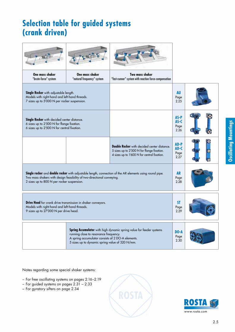
Selection table for guided systems (crank driven)
One mass shaker“brute-force” system
One mass shaker“natural frequency” system
Two mass shaker“fast-runner” system with reaction force-compensation
Single Rocker with adjustable length. Models with right-hand and left-hand threads. 7 sizes up to 5’000 N per rocker suspension.
AUPage 2.25
Single Rocker with decided center distance. 6 sizes up to 2’500 N for flange fixation. 6 sizes up to 2’500 N for central fixation.
AS-PAS-CPage 2.26
Double Rocker with decided center distance. 5 sizes up to 2’500 N for flange fixation. 4 sizes up to 1’600 N for central fixation.
AD-PAD-CPage 2.27
Single rocker and double rocker with adjustable length, connection of the AR elements using round pipe. Two mass shakers with design feasibility of two-directional conveying.2 sizes up to 800 N per rocker suspension.
ARPage 2.28
Spring Accumulator with high dynamic spring value for feeder systems running close to resonance frequency.A spring accumulator consists of 2 DO-A elements. 5 sizes up to dynamic spring value of 320 N/mm.
DO-APage 2.30
Drive Head for crank drive transmission in shaker conveyors. Models with right-hand and left-hand threads. 9 sizes up to 27’000 N per drive head.
STPage 2.29
Notes regarding some special shaker systems:
– For free oscillating systems on pages 2.16–2.19– For guided systems on pages 2.31 – 2.33– For gyratory sifters on page 2.34

2.6
www.rosta.com
Oscil
latin
g M
ount
ings
Introduction
Free oscillating systems are either activated in using exci ters, unbalanced motors or unbalanced shafts. The oscillation amplitude, type of vibration and the direction of vibration of the screen are determined by the dimension-ing and arrangement of these actuators. The excitation force, the angle of inclination of the excitation, the inclina-tion of the screen-box and the position of the center of gravity determine the resulting oscillation amplitude of the device. The oscillation amplitude, and thereby the conveying speed of the machine, can be optimized by augmenting these.
ROSTA spring suspensions support the desired oscillation movement of the screen machine. Through their shape and function, they help to achieve a purely linear conveyor mo-tion without unwanted lateral tumbling.
Circular motion screens
Technology of free oscillating systems with unbalanced excitation
These ideal spring suspensions harmonically support the run-ning of the vibrating screen. Because of their high spring deflection capacity, they offer a good detuning of the excita-tion frequency with a very low natural frequency, which guarantees a high isolation effect with regard to the ma-chine substructure. The ROSTA mounts effectively dissipate the large residual force peaks at start-up and shut-down, when passing through the natural frequency of the suspen-sion.
Circular motion screens or circular vibrators are normally excited by unbalanced weights that create a circular rotating oscillation of the screening frame. Relatively low ac-celerations of the screened material are achieved with this form of excitement. Circular vibrators thereby normally work with a screening frame inclination of 15° to 30°, so that an adequate material throughput is ensured.
It is recommended to mount circular vibratory screens of this kind on ROSTA type AB or AB-HD oscillating mountings. Experi-ence has shown that the positioning of the AB suspensions under circular vibrators should be a mirror-inverted of each other, which, with the above-mentioned frame inclination, will counteract the tendency of the shifting of the center of gra vity. If the suspension of the screening frame requires two supporting suspensions per brace support for reasons of capacity, these should also be preferably arranged in mirror-inverted manner for the above-mentioned reason.

2.7
www.rosta.com
Oscil
latin
g M
ount
ings
Linear motion screensLinear motion screens or linear vibrators are normally excit-ed by two unbalanced motors or by means of linear exciters, as well as through double unbalanced shafts (Eliptex), which generate a linear or slightly elliptical oscillation of the screen-ing frame. Depending on the inclination positioning of the exciter, the angle of throw of the screened product can be adapted to the desired form of processing. A very high ac-celeration of the screened product, i.e. a higher material throughput, is achieved with linear vibrating screens. The screening frame of the linear vibrator is normally in the hori-zontal position.
Linear vibrating screens are preferably mounted on ROSTA oscillating mountings type AB or AB-HD. Depending on the posi-tioning of the exciter on the screening frame, the feed-end: discharge-end load distribution can be different. The feed-end side is normally lighter, as the exciters are positioned close to the discharge-end and thereby pull the material through the screening frame; in many cases, the feed-end: discharge-end distribution is thereby 40% to 60%. In the interest of an even suspension, it is thereby recommended to mount the screening frame on six or more ROSTA oscillating mountings. All oscillating mountings should stand in the same direction, with the “knee” pointing in the discharge-end direction.
Linear motion screens with counterframe
Discharge chutes hanging under silos and bunkers
If, due to the demands of the process, large screens are mounted at a very high position in a building or in a purely steel construction, the transmission of the re-sidual forces of a single-mass machine can set the
entire structure into unwanted vibrations. Or if a new and more powerful machine is mounted in an existing building, the residual force transmission could be too high for the older building. The residual force transmission is drastically reduced through the mounting of a counterframe under the screen, with only a negligible loss of oscillation amplitude (compensation movement of the counterframe reduces the oscillation amplitude). ROSTA also has the ideal supports for the suspension of counterframes, the very compact mountings type AB-D.
Discharge chutes under silos are normally supported by means of complicated yoke constructions and are suspend-ed on pressure springs. With its HS suspensions (HS = hang-ing screen), ROSTA offers the possibility of the direct, cost-effective suspension of the discharge unit on silos and bun-kers. The geometry of the HS suspensions has been designed to accommodate tensile loads.
Oscil
latin
g M
ount
ings

2.8
www.rosta.com
Oscil
latin
g M
ount
ings
TechnologyDesign layout and evaluation
Subject Symbol • Example Unit
Mass of the empty channel and drive m0 680 kg
Products on the channel 200 kg
of which approx. 50 % coupling * 100 kg
Total vibrating mass * m 780 kg
Mass distribution: feed end % feed end 33 %
discharge end % discharge end 67 %
Acceleration due to gravity g 9.81 m/s2
Load per corner feed end F feed end 1263 N
Load per corner discharge end F discharge end 2563 N
• Element choice in example 6 x AB 38
Working torque of both drives AM 600 kgcm
Oscillating stroke empty channel sw0 8.8 mm
Oscillating stroke in operation sw 7.7 mm
Motor revolutions ns 960 rpm
Centrifugal force of both drives Fz 30’319 N
Oscillating machine factor K 4.0
Machine acceleration a = K · g 4.0 g
• Natural frequency suspensions fe 2.7 Hz
Degree of isolation W 97 %
6.0
5.5
5.0
4.5
4.0
3.5
3.0
2.5
2.0
600
700
800
900
1000
1100
1200
1300
1400
1500
1600
1700
1800
1900
2000
2100
2200
2300
2400
2500
2600
2700
2800
2900
3000
Diagram of the vibration isolation W [%]
* The following has to be observed for the determination of the coupling effect and material flow:– High coupling or sticking of humid bulk material– Channel running full– Fully stacked screen deck with humid material– Weight distribution with and without conveyed material– Centrifugal force does not run through the center of gravity (channel full or empty)– Sudden impact loading occurs– Subsequent additions to the screen structure (e.g. additional screening deck)
• Example:The proportion of the relationship between exciter frequency 16 Hz (960 rpm) and mount frequency 2.7 Hz is offering a degree of isolation of 97%.
Calculation formulas
Oscillating machine factor
Centrifugal force
Oscillating stroke (Amplitude peak to peak)
Loading per corner
fens
90 %
92 %
94 %
95 %
96 %
97 %
98 %
99 %
sw0 = · 10 sw = · 10AM AM
m0 m
Ffeed-end = m · g · % feed-end
2 · 100Fdischarge-end =
m · g · % discharge-end
2 · 100
Fz = = · ns · AM · 10
2 · 1000
2π60 ns
2 · AM
18’240
K = = · ns · sw
2 · g · 1000
2π60 ns
2 · sw
1’789’000
W = 100 –
( )
( )
Isola
tion
< 85 %
2
2
100
– 1ns
60 · f e ( )2
Vibration isolation
discharge end conveying direction feed end
[ mm ]
[ N ]
[ N ]
[ – ]
[ % ]

2.9
www.rosta.com
Oscil
latin
g M
ount
ings
90° ± 1°
TechnologyDetermination of the average material conveying speed vm
Main influencing factors:– Conveying ability of the
material– Height of the bulk goods– Screen box inclination– Position of unbalanced motors– Position of the center of gravity
The material speed on circular motion screens does vary, due to differing screen-box inclina-tion angles.
• Example:The horizontal line out of the intercept point of stroke (7.7 mm) and motor revolutions (960 rpm) is indicating an average theoretical speed of 12.3 m/min or 20.5 cm/sec.
Alignment of the elements
If the suspensions for linear motion screens are arranged as shown on page 2.7, a harmonic, noiseless oscillation of the screen will result. The rocker arm fixed to the screen carries out the greater part of the oscillations. The rocker arm fixed to the substructure remains virtually stationary and ensures a low natural frequency, and thereby also a good vibration isolation. The mounting axis has to be arranged to be at right angles (90°) to the conveying axis, with maximum tolerance of ±1°.
Resonance amplification and continuous runningAt the screen start-up and run-out the suspension elements are passing through the resonance frequency. By the result-ing amplitude superelevation the four rubber suspensions in the AB mountings do generate a high level of damping which is absorbing the remaining energy after only a few strokes. The screen box stops its motion within seconds.
Laboratory measurements of a typical development of the residual forces on a ROSTA screen suspension:
Screen box fixation
Substructure
cm/s m/min
53 32
50 30
47 28
43 26
40 24
37 22
33 20
30 18
27 16
23 14
20 12
17 10
13 8
10 6
7 4
3 2
1 2 3 4 5 6 7 8 9 10 11 12 13 14 15 16 17 18 19 20 21 22
9 g
8 g
7 g
6 g
5 g
4 g
3 g
2 g
ns = 720
ns = 960
ns = 14
40
ns =
288
0
Oscillating stroke sw [mm]
Mat
eria
l con
veyi
ng s
peed
vm
Diagram for angle of inclination β = 45°to the horizontal
start-up continuous running run-out
verti
cal f
orce
time
Oscillation
direction

2.10
www.rosta.com
Oscil
latin
g M
ount
ings
Deflection curves and cold flow behaviours
Diagrams showing the vertical de-flection s (in mm) by compression or tensile load G (in kN). The shown values comprehend the initial cold flow settling after one day of operation. The final element deflection after the full cold flow compensation (after ap-prox. 1 year) is usually factor x 1,09 higher (depending on spe-cific application, climate etc.).
Final element deflection = s x 1,09
The deflection values are based on our catalogue specifications and should be understood as ap-proximate values. Please consult also our tolerance specifications in chapter “Technology” in the general catalogue.
Com
pres
sion
load
AB
Com
pres
sion
load
AB-
HDCo
mpr
essio
n lo
ad A
B-D
Com
pres
sion
load
ABI
Tens
ile lo
ad H
S
0.0
0.1
0.2
0.3
0.4
0.5
0.6
0.7
0.8
0.910 15 20 25 30 35 40 45 50 55 60 65
G [kN]
s [mm]
AB 27
AB 18
AB 15
0
1
2
3
4
5
6
7
8
9
10
11
10 20 30 40 50 60 70 80 90 100
110
G [kN]
s [mm]
AB 50
AB 45
AB 38
AB 50-2
0
2
4
6
8
10
12
14
16
18
20
22
10 20 30 40 50 60 70 80 90 100
110
G [kN]
s [mm]
AB 50-2 TWIN
AB 50 TWIN
0.0
0.1
0.2
0.3
0.4
0.5
0.6
0.7
0.8
0.910 15 20 25 30 35 40 45 50 55 60 65
G [kN]
s [mm]
AB 27
AB 18
AB 15
0
1
2
3
4
5
6
7
8
9
10
11
10 20 30 40 50 60 70 80 90 100
110
G [kN]
s [mm]
AB 50
AB 45
AB 38
AB 50-2
0.0
0.5
1.0
1.5
2.0
2.5
3.0
3.5
4.0
4.5
5.0
10 15 20 25 30 35 40 45 50 55 60
G [kN]
s [mm]
AB-HD 45
AB-HD 38
AB-HD 27
0123456789
10111213141516
10 15 20 25 30 35 40 45 50 55 60 65 70G [kN]
s [mm]
AB-HD 50-2
AB-HD50-1.6
AB-HD 50
0.00.1
0.20.30.40.5
0.60.70.80.91.0
1.1
1.2
10 15 20 25 30 35 40 45 50 55 60 65
G [kN]
s [mm]
ABI 30
ABI 20
ABI 15
0.00.51.01.52.02.53.03.54.04.55.05.56.06.57.07.58.0
10 20 30 40 50 60 70 80 90 100
G [kN]
s [mm]
ABI 50
ABI 40-12
ABI 40
0.0
0.5
1.0
1.5
2.0
2.5
3.0
3.5
4.0
4.5
5.0
10 15 20 25 30 35 40 45 50 55 60
G [kN]
s [mm]
HS 45
HS 38
HS 27
0123456789
10111213141516
10 15 20 25 30 35 40 45 50 55 60 65 70
G [kN]
s [mm]
HS 50-2
HS 50
0.0
0.5
1.0
1.5
2.0
2.5
3.0
3.5
4.0
4.5
5.0
10 15 20 25 30 35 40 45 50 55 60G [kN]
s [mm]
HS 45
HS 38
HS 27
0123456789
10111213141516
10 15 20 25 30 35 40 45 50 55 60 65 70
G [kN]
s [mm]
HS 50-2
HS 50
0.00.1
0.20.30.40.5
0.60.70.80.91.0
1.1
1.2
10 15 20 25 30 35 40 45 50 55 60 65
G [kN]
s [mm]
ABI 30
ABI 20
ABI 15
0.00.51.01.52.02.53.03.54.04.55.05.56.06.57.07.58.0
10 20 30 40 50 60 70 80 90 100
G [kN]
s [mm]
ABI 50
ABI 40-12
ABI 40
0.0
0.5
1.0
1.5
2.0
2.5
3.0
3.5
4.0
4.5
10 15 20 25 30 35 40 45G [kN]
s [mm]
AB-D 38
AB-D 27
AB-D 18
0
2
4
6
8
10
12
14
16
18
10 15 20 25 30 35 40 45 50 55 60 65
G [kN]
s [mm]
AB-D 50-2
AB-D50-1.6
AB-D 45
AB-D 50
0.0
0.5
1.0
1.5
2.0
2.5
3.0
3.5
4.0
4.5
10 15 20 25 30 35 40 45
G [kN]
s [mm]
AB-D 38
AB-D 27
AB-D 18
0
2
4
6
8
10
12
14
16
18
10 15 20 25 30 35 40 45 50 55 60 65
G [kN]
s [mm]
AB-D 50-2
AB-D50-1.6
AB-D 45
AB-D 50
0.0
0.5
1.0
1.5
2.0
2.5
3.0
3.5
4.0
4.5
5.0
10 15 20 25 30 35 40 45 50 55 60
G [kN]
s [mm]
AB-HD 45
AB-HD 38
AB-HD 27
0123456789
10111213141516
10 15 20 25 30 35 40 45 50 55 60 65 70
G [kN]
s [mm]
AB-HD 50-2
AB-HD50-1.6
AB-HD 50
Ope
ratin
gra
nge

2.11
www.rosta.com
Oscil
latin
g M
ount
ings
A
E
F
H
D
C
N
K L
MB
Z
L
M
K
N N
K L
M
N
L
M
K
N
K L
N
M
N
K L
M
Oscillating MountingsType AB
Art. No. Type
Load capacityGmin. – Gmax.
[N]
A un-
loaded
A*max.load
Bun-
loaded
B*max.load C D E F H K L M N
Weight[kg]
07 051 056 AB 15 50 – 160 169 115 71 89 80 ø 7 50 65 3 10 40 52 – 0.5
07 051 057 AB 18 120 – 300 208 154 88 107 100 ø 9 60 80 3.5 14 50 67 – 1.2
07 051 058 AB 27 250 – 800 235 170 94 116 100 ø 11 80 105 4.5 17 60 80 – 2.2
07 051 059 AB 38 600 – 1’600 305 225 120 147 125 ø 13 100 125 6 21 80 104 40 5.1
07 051 054 AB 45 1’200 – 3’000 353 257 141 172 140 13 x 20 115 145 8 28 100 132 65 11.5
07 051 061 AB 50 2’500 – 6’000 380 277 150 184 150 17x27 130 170 12 35 120 160 60 20.8
07 051 055 AB 50-2 4’200 – 10’000 380 277 150 184 150 17x27 130 170 12 40 200 245 70 32.2
07 051 008 AB 50 TWIN 5’000 – 12’000 380 277 150 184 150 17x27 130 170 12 50 120 300 60 35.0
07 051 009 AB 50-2 TWIN 8’400 – 20’000 380 277 150 184 150 17x27 130 170 12 60 200 470 70 54.0
Art. No. Type
Natural frequency
Gmin. – Gmax.[Hz] Z**
Dynamic spring valueCapacity limits by different rpm
720 min-1 960 min-1 1440 min-1
Ligh
t met
al p
rofil
e
Stee
l wel
ded
cons
truct
ion
Nod
ular
cas
t iro
n
ROST
A b
lue
pain
ted
cdvertical[N/mm]
cdhorizontal[N/mm]
swmax.[mm]
Kmax.[–]
swmax.[mm]
Kmax.[–]
swmax.[mm]
Kmax.[–]
07 051 056 AB 15 4.3–2.8 65 10 6 14 4.1 12 6.2 8 9.3 x x x
07 051 057 AB 18 3.6–2.6 80 18 14 17 4.9 15 7.7 8 9.3 x x x
07 051 058 AB 27 3.7–2.7 80 40 25 17 4.9 14 7.2 8 9.3 x x x
07 051 059 AB 38 3.0–2.4 100 60 30 20 5.8 17 8.8 8 9.3 x x x
07 051 054 AB 45 2.8–2.3 115 100 50 21 6.1 18 9.3 8 9.3 x x x x
07 051 061 AB 50 2.4–2.1 140 190 85 22 6.4 18 9.3 8 9.3 x x
07 051 055 AB 50-2 2.4–2.1 140 320 140 22 6.4 18 9.3 8 9.3 x x
07 051 008 AB 50 TWIN 2.4–2.1 140 380 170 22 6.4 18 9.3 8 9.3 x x x
07 051 009 AB 50-2 TWIN 2.4–2.1 140 640 280 22 6.4 18 9.3 8 9.3 x x x
Values in nominal load range at 960 rpm and sw of 8 mm
Acceleration > 9.3 g is not recommended
Material structure
These types can be combined with one another (identical heights and operation behaviour)
* compression load Gmax. and final cold flow compensation (after approx. 1 year).** separate assembly instructions are available, please ask for details.
A
E
F
H
D
C
N
K L
MB
Z
L
M
K
N N
K L
M
N
L
M
K
N
K L
N
M
N
K L
M
A
E
F
H
D
C
N
K L
MB
Z
L
M
K
N N
K L
M
N
L
M
K
N
K L
N
M
N
K L
M
AB 50 TWINAB 45–50AB 15–27
AB 38 AB 50-2 AB 50-2 TWIN
G
AB TWIN

2.12
www.rosta.com
Oscil
latin
g M
ount
ings
H
F
A
C
B
Z E
D
K
M
L
K
M
L
N
M
LK
N
M
LK
NN
AB-HD 27
AB-HD 38
AB-HD 50-1.6
AB-HD 50-2
G
AB-HD 45 to
Oscillating MountingsType AB-HD
Please find elements for higher load capacities on page 2.17.
These types can be combined with one another (identical heights and operation behaviour)
* compression load Gmax. and final cold flow compensation (after approx. 1 year).** separate assembly instructions are available, please ask for details.
Art. No. Type
Load capacityGmin. – Gmax.
[N]
Aun-
loaded
A*max.load
Bun-
loaded
B*max.load C D E F H K L M N
Weight[kg]
07 051 070 AB-HD 27 500 – 1’250 215 182 59 78 70 ø11 80 105 4.5 17 60 80 – 1.6
07 051 071 AB-HD 38 1’200 – 2’500 293 246 79 106 95 ø13 100 125 6 21 80 104 40 4.9
07 051 072 AB-HD 45 2’000 – 4’200 346 290 98 130 110 13 x 20 115 145 8 28 100 132 65 11.3
07 051 062 AB-HD 50 3’500 – 8’400 376 313 105 141 120 17 x 27 130 170 12 40 120 165 60 22.7
07 051 063 AB-HD 50-1.6 4’800 – 11’300 376 313 105 141 120 17 x 27 130 170 12 40 160 205 70 27.1
07 051 060 AB-HD 50-2 6’000 – 14’000 376 313 105 141 120 17 x 27 130 170 12 45 200 250 70 35.5
Art. No. Type
Naturalfrequency
Gmin. – Gmax.
[Hz] Z**
Dynamic spring valueCapacity limits by different rpm
720 min-1 960 min-1 1440 min-1Li
ght m
etal
pro
file
Stee
l wel
ded
co
nstru
ctio
n
Nod
ular
cas
t iro
n
ROST
A b
lue
pain
ted
cdvertical[N/mm]
cdhorizontal[N/mm]
swmax.[mm]
Kmax.[–]
swmax.[mm]
Kmax.[–]
swmax.[mm]
Kmax.[–]
07 051 070 AB-HD 27 4.8 – 3.1 70 70 33 12 3.5 10 5.2 8 9.3 x x x
07 051 071 AB-HD 38 3.6 – 2.7 90 100 48 15 4.3 13 6.7 8 9.3 x x x
07 051 072 AB-HD 45 3.3 – 2.5 100 150 72 17 4.9 14 7.2 8 9.3 x x x x
07 051 062 AB-HD 50 3.2 – 2.4 120 270 130 18 5.2 15 7.7 8 9.3 x x
07 051 063 AB-HD 50-1.6 3.2 – 2.4 120 360 172 18 5.2 15 7.7 8 9.3 x x x
07 051 060 AB-HD 50-2 3.2 – 2.4 120 450 215 18 5.2 15 7.7 8 9.3 x x
Values in nominal load range at 960 rpm and
sw of 8 mm
Acceleration > 9.3 g is not recommended
Material structure
new
new
new
new
new
new

2.13
www.rosta.com
Oscil
latin
g M
ount
ings
Oscillating MountingsType AB-D
Art. No. Type
Load capacityGmin. – Gmax.
[N]
Aun-
loaded
A*max.load B C D E F H I J K L M
Weight[kg]
07 281 000 AB-D 18 500 – 1’200 137 112 115 61 50 12.5 90 3 9 9 74 31 30 1.3
07 281 001 AB-D 27 1’000 – 2’500 184 148 150 93 80 15 120 4 9 11 116 44 50 2.9
07 281 002 AB-D 38 2’000 – 4’000 244 199 185 118 100 17.5 150 5 11 13.5 147 60 70 7.5
07 281 003 AB-D 45 3’000 – 6’000 298 240 220 132 110 25 170 6 13.5 18 168 73 80 11.5
07 281 004 AB-D 50 4’000 – 9’000 329 272 235 142 120 25 185 6 13.5 18 166 78 90 17.9
07 281 005 AB-D 50-1.6 6’000 – 12’000 329 272 235 186 160 25 185 8 13.5 18 214 78 90 24.5
07 281 006 AB-D 50-2 8’000 – 16’000 329 272 235 226 200 25 185 8 13.5 18 260 78 90 29.0
I
D
K
C
J
H
A
B
L
E F
Z
M
Art. No. Type
Natural frequency
Gmin. – Gmax.
[Hz] Z**
Dynamic spring valueCapacity limits by different rpm
720 min-1 960 min-1 1440 min-1Li
ght m
etal
pro
file
Stee
l pla
te
Nod
ular
cas
t iro
n
ROST
A b
lue
pain
ted
cdvertical[N/mm]
cd at sw[mm]
cdhorizontal[N/mm]
swmax.[mm]
Kmax.[–]
swmax.[mm]
Kmax.[–]
swmax.[mm]
Kmax.[–]
07 281 000 AB-D 18 6.1–4.4 30 100 4 20 5 1.4 5 2.6 4 4.6 x x x
07 281 001 AB-D 27 5.4–3.9 35 160 4 35 7 2.0 6 3.1 5 5.8 x x partial
07 281 002 AB-D 38 4.3–3.4 40 185 6 40 9 2.6 8 4.1 6 7.0 x x partial
07 281 003 AB-D 45 3.7–3.1 55 230 8 70 11 3.2 9 4.6 7 8.1 x x partial
07 281 004 AB-D 50 3.7–2.9 55 310 8 120 12 3.5 10 5.2 8 9.3 x x x x
07 281 005 AB-D 50-1.6 3.6–2.9 55 430 8 160 12 3.5 10 5.2 8 9.3 x x x x
07 281 006 AB-D 50-2 3.5–2.8 55 540 8 198 12 3.5 10 5.2 8 9.3 x x x x
Values in nominal load range at 960 rpm
Acceleration > 9.3 g is not recommended
Material structure(zinc-plated couplings)
These types can be combined with one another (identical heights and operation behaviour)
* compression load Gmax. and final cold flow compensation (after approx. 1 year).** separate assembly instructions are available, please ask for details.
G

2.14
www.rosta.com
Oscil
latin
g M
ount
ings
A
D
B
F
H
E
C
K
M
L Z
M
K L
I
M
K L
I
N
Oscillating MountingsType ABI
Description of stainless steel:X5CrNi18-10 (1.4301) andGX5CrNi19-10 (1.4308)
* compression load Gmax. and final cold flow compensation (after approx. 1 year).** separate assembly instructions are available, please ask for details.
Art. No. Type
Load capacityGmin. – Gmax.
[N]
Aun-
loaded
A*max.load
Bun-
loaded
B*max.load C D E F H I K L M N
Weight[kg]
07 171 107 ABI 15 70 – 180 167 114 70 88 80 7 x 10 50 65 3 – 10 40 52 – 0.7
07 171 108 ABI 20 160 – 460 214 147 89 111 100 9 x 15 65 85 3 – 14 50 67 – 1.6
07 171 103 ABI 30 400 – 1’000 241 176 99 121 100 ø 11 85 110 4 35 17 70 90 – 3.3
07 171 104 ABI 40 700 – 1’600 317 237 128 155 125 ø 13 115 150 4 40 21 80 104 – 7.9
07 171 106 ABI 40-12 1’300 – 3’200 281 214 111 133 100 ø 13 115 150 4 100 21 120 144 60 11.3
07 171 105 ABI 50 2’500 – 6’800 372 274 151 184 150 ø 18 140 180 5 120 33 150 187 70 20.9
Art. No. Type
Natural frequency
Gmin. – Gmax.
[Hz] Z**
Dynamic spring valueCapacity limits by different rpm
720 min-1 960 min-1 1440 min-1St
ainl
ess
stee
l w
elde
d co
nstru
ctio
n
Stai
nles
s st
eel
casti
ng
Unp
aint
edcdvertical[N/mm]
cdhorizontal[N/mm]
swmax.[mm]
Kmax.[–]
swmax.[mm]
Kmax.[–]
swmax.[mm]
Kmax.[–]
07 171 107 ABI 15 4.0–2.8 65 10 6 14 4.1 12 6.2 8 9.3 x x x
07 171 108 ABI 20 3.6–2.4 80 22 14 17 4.9 15 7.7 8 9.3 x x x
07 171 103 ABI 30 3.5–2.6 80 48 27 17 4.9 14 7.2 8 9.3 x x
07 171 104 ABI 40 3.0–2.4 100 60 30 20 5.8 17 8.8 8 9.3 x x
07 171 106 ABI 40-12 3.4–2.6 90 115 55 16 4.6 13 6.7 8 9.3 x x
07 171 105 ABI 50 2.8–2.2 140 220 100 22 6.4 18 9.3 8 9.3 x x
Values in nominal load range at 960 rpm and
sw of 8 mm
Acceleration > 9.3 g is not recommended
Material structure
ABI 15–20
ABI 30–40as from ABI 40–12
G

2.15
www.rosta.com
Oscil
latin
g M
ount
ings
Oscillating MountingsType HS
M
K L
N
M
K L
NN
Z
A
D
B
F
E
M
K L
NH
C
The HS Mountings shall be fastened with the foreseen amount of screws (existing fixation holes or slots) of quality 8.8 with consideration of the prescribed fastening torque.
These types can be combined with one another (identical heights and operation behaviour)
* tensile load Gmax. and final cold flow compensation (after approx. 1 year).** separate assembly instructions are available, please ask for details.
Art. No. Type
Load capacityGmin. – Gmax.
[N]
Aun-
loaded
A*max.load
Bun-
loaded
B*max.load C D E F H K L M N
Weight[kg]
07 311 001 HS 27 500 – 1’250 164 202 84 68 70 11 80 105 4.5 17 60 80 35 1.6
07 311 002 HS 38 1’200 – 2’500 223 275 114 92 95 13 100 125 6 21 80 104 40 4.9
07 311 003 HS 45 2’000 – 4’200 265 325 138 113 110 13 x 20 115 145 8 28 100 132 65 11.3
07 311 004 HS 50 3’500 – 8’400 288 357 148 118 120 17 x 27 130 170 12 40 120 165 60 20.2
07 311 005 HS 50-2 6’000 – 14’000 288 357 148 118 120 17 x 27 130 170 12 45 200 250 70 34.0
Art. No. Type
Naturalfrequency
Gmin. – Gmax.
[Hz] Z**
Dynamic spring valueCapacity limits by different rpm
720 min-1 960 min-1 1440 min-1
Ligh
t met
al p
rofil
e
Stee
l wel
ded
co
nstru
ctio
n
Nod
ular
cas
t iro
n
ROST
A b
lue
pain
ted
cdvertical[N/mm]
cdhorizontal[N/mm]
swmax.[mm]
Kmax.[–]
swmax.[mm]
Kmax.[–]
swmax.[mm]
Kmax.[–]
07 311 001 HS 27 4.2–3.8 70 65 32 12 3.5 10 5.2 8 9.3 x x x
07 311 002 HS 38 3.6–3.3 90 95 46 15 4.3 13 6.7 8 9.3 x x x
07 311 003 HS 45 3.3–3.0 100 142 70 17 4.9 14 7.2 8 9.3 x x x x
07 311 004 HS 50 3.2–3.0 120 245 120 18 5.2 15 7.7 8 9.3 x x
07 311 005 HS 50-2 3.2–2.9 120 410 200 18 5.2 15 7.7 8 9.3 x x
Values in nominal load range at 960 rpm and
sw of 8 mm
Acceleration > 9.3 g is not recommended
Material structure
HS 27–38
HS 45–50 HS 50-2
G
for HS 50 according 2006/42/EG (hanging load bearing capacities)

2.16
www.rosta.com
Oscil
latin
g M
ount
ings
Fig. 3
~45
S
ROSTA Oscillating Mountings and Accessories for individual Customer Solutions
Pendulum joint, the cost-efficient drive solution with only one unbalanced motorIf a single vibration motor is built onto an elastic pendulum joint (e.g. a DK element), the device will carry out a slightly elliptical oscillation shape (linear movement). The final oscil-lation motion is dependent on the distance between pendu-lum axis and motor axis. The pendulum suspension has only been used on rather smaller feeding devices. The inclination angle of the motor configuration is approx. 45°.
Suspensions of spiral or coil feedersSpiral-shaped conveyors are used in processing systems where bulk goods should stay on the conveying trough in the smallest possible space for a long period in order to cool down or dry. Not infrequently, the resulting channel length can be 25–30 meters in a spiral tower that is only five me-ters high! With a spiral conveyor supported on ROSTA Oscillating Mountings Type AB-D, there is no need for ad-ditional fall-prevention devices such as cable bracings or securing pipes in the spiral, as is the case for helical spring supports. If a spring breaks here, the complete spiral tower tilts – unless it has been secured with cable bracings. ROSTA AB-D suspensions offer a high isolation effect, clear-ly defined oscillations up to the topmost spiral and absolute stability for the spiral tower.
Art. No. DK Type Centrifugal force max.
Number of brackets Type Art. No. BK
01 071 008 DK-A 27 x 60 1’000 N 1 BK 27 01 520 004
01 071 011 DK-A 38 x 80 2’000 N 2 BK 38 01 520 005
01 071 014 DK-A 45 x 100 3’500 N 2 BK 45 01 520 006
01 071 015 DK-A 45 x 150 5’250 N 3 BK 45 01 520 006
01 071 017 DK-A 50 x 200 10’000 N 3 BK 50 01 520 007
01 071 018 DK-A 50 x 300 15’000 N 4 BK 50 01 520 007ROSTA components for pendulum mounts are mentioned in the general catalogue “Rubber suspension units”.
Conveying direction
Allocation table

2.17
www.rosta.com
Oscil
latin
g M
ount
ings
30° Conveying direction
m2
m1
AU-DO The AU-DO rocker suspensions have been mainly devel-oped for the channel support in continuously loaded, base frame excited two-mass oscillation systems with unbalanced drive (energetic amplification). The base frame m1 is excited by means of unbalanced motors and the spring accumula-tors of the AU-DO rocker suspensions amplify the marginal frame oscillation amplitude into a considerable throw ampli-tude on the conveying channel m2. The base frame is ideally supported on ROSTA Oscillating Mountings Type AB. These systems are characterised by low, hardly measurable resid-ual force transmission into the substructure and are therefore suitable for installation on steel frameworks and interme-diate floors in processing buildings. Additional customer benefits are the low-noise operation, the low involved motor power and the simple installation.
The AU-DO elements are available in 5 sizes. We will be glad to calculate your specific system, please ask for our relevant questionnaire.
Oscil
latin
g M
ount
ings
Customized Oscillating Mountings Type AB-HD with low natural frequency and high load capacity
Art.-No. Type
Load capacityGmin. – Gmax.
[N]
Aun-
loaded
A*max.load
Bun-
loaded
B*max.load C øD E F H L M N
Weight[kg]
07 051 076 AB-HD 70-3 9’000 – 20’000 592 494 160 215 180 22 200 260 9 300 380 200 82
07 051 080 AB-HD 100-2.5*** 15’000 – 37’000 823 676 222 302 250 26 300 380 12 250 350 110 170
07 051 081 AB-HD 100-4*** 25’000 – 60’000 823 676 222 302 250 26 300 380 12 400 500 260 230
Art.-No. Type
Natural frequencyGmin. – Gmax.
[Hz] Z**
Dynamic spring valueCapacity limits by different rpm
720 min-1 960 min-1 1440 min-1
Stee
l wel
ded
co
nstru
ctio
n
ROST
A b
lue
pain
ted
cdvertical[N/mm]
cdhorizontal[N/mm]
swmax.[mm]
Kmax.[–]
swmax.[mm]
Kmax.[–]
swmax.[mm]
Kmax.[–]
07 051 076 AB-HD 70-3 2.4 – 2.1 200 670 320 25 7.3 18 9.3 8 9.3 x x
07 051 080 AB-HD 100-2.5*** 2.4 – 1.8 250 1150 530 30 8.6 18 9.3 8 9.3 x x
07 051 081 AB-HD 100-4*** 2.4 – 1.8 250 1840 850 30 8.6 18 9.3 8 9.3 x x
Values in nominal loadrange at 960 rpm and
sw of 8 mm
Acceleration > 9.3 g is not recommended
Material structure
These types can be combined with one another (identical heights and operation behaviour)* compression load Gmax. and final cold flow compensation (after approx. 1 year).** separate assembly instructions are available, please ask for details.*** We will be glad to calculate your specific system, please ask for our relevant questionnaire.
new
new
new
new
EZ
F
B
D
H
A
C
N
L
M
G

2.18
www.rosta.com
Oscil
latin
g M
ount
ings Washing- and dewatering-screen for vegetables on AB Mountings
Selection-screen for potato chips on stainless steel AB Mountings
Circular motion screen for minerals on AB TWIN Mountings
Vegetable-feeder on stainless steel ABI Mountings
Washing- and dewatering-screen for vegetables on AB Mountings
Circular motion screen for gravel on AB TWIN Mountings

2.19
www.rosta.com
Oscil
latin
g M
ount
ingsCircular motion screen in mobile crushing plant on AB Mountings
Pre-selection screen for gemstone on AB Mountings
Wheat-cleaning plant on AB Mountings
Fluid-bed cooler on AB-D Mountings
Cement screening and feeding device on AB Mountings
Pasta-feeding channel hanging on HS Mountings

2.20
www.rosta.com
Oscillating shaker conveyors with crank shaft drive are wide-ly used for the transportation and selection of bulk material. A shaker conveyor consist of a heavy and (infinitely) stiff de-signed shaker and/or screening trough, which is supported by several pairs of guiding rocker arms. The rocker arms are also connected with the lower base frame which is anchored in the building foundation by means of tie bolts. The eccen-tric shaft transmitting the oscillations to the trough is always driven by elastic belt drive to compensate the hits by the dead centers of the crank shaft drive. A driving rod with an elastic drive head connects the crank drive with the base frame of the trough and transmits the required oscillations for the transport of the bulk material on the feeder. According to the length, stiffness and weight of the shaker trough several pairs of supporting and guiding rocker arms are required between base frame and conveyor.
The “brute-force” shaker conveyor system is widely used in the processing industries due to its constructive simplicity and cost efficient design method. It characterizes by a massive feeding trough mounted on several pairs of guiding rocker arms connected with a ground frame and driven by a crank shaft system. The relatively low costs for the design and con-struction of this feeding system are favouring this standard shaker for the use in many processing operations where rather low material speeds are fully adequate. Too high speeds and too long strokes would generate in this one mass system too high shocks by the change in direction of the crank shaft drive. Therefore, accelerations of >1,7 g-forces are not applicable with this “brute-force” shaker.
To avoid high material fatigue stress on the trough structure, the relevant design should feature heavy stiffening rips and border strips to make the feeding channel more or less “in-finitely” stiff. One mass shaker conveyors have to be bolted down on the foundations by means of tie anchors.
Technology of crank shaft driven shaker conveyors
Relatively slow acting oscillating conveyors are usually de-signed as positive movement systems (“brute-force” systems) transmitting the high reaction forces of the crank reverse mo-tion into the building foundation. Faster running shaker con-veyors with crank shaft drive are therefore usually designed as two mass systems with direct compensation of the reaction forces by the counter-mass hanging at the lower end of so said double rocker arms directly underneath the trough mass (“fast-runner” systems).
To achieve a very “smooth” course of motions on fast acting shaker conveyors based on one or two masses the installation of additional spring accumulators offering an actuation of the shaker system close by the resonance frequency (“nat-ural frequency” systems) is recommended. These pre-loaded spring accumulators compensate the hard hits of the crank shaft drive at the dead centers and are heavily supporting the eccentric trough motion with their high dynamic stiffness.
One mass shaker conveyor systems without spring accumulatorsDesign Characteristics ROSTA elements
“brute-force” system as basic version
acceleration:1.1 to 1.7 g-forces
conveying speed:6 to 15 m/min
trough lengths:max. 12 to 15 meters
oscillating mountings:AU, AS-P, AS-C, AR
drive heads:ST
Introduction
Oscil
latin
g M
ount
ings

2.21
These “natural frequency” feeding system generally shows the same constructive design like the “brute-force” shaker, but is disposed with additional spring accumulator sets installed be-tween trough structure and ground frame in order to reduce the hard hits by the change in direction of the crank shaft drive. Furthermore, due to the high dynamic stiffness of the spring accumulator sets, the course of motions of the trough becomes harmonic, energy-saving and gentle avoiding material stress and early fatigue cracks on the structure. This system runs very silent due to the permanent, bidirectional spring action support at the stroke ends. The max. acceleration of this one mass sys-tem should not exceed 2.2 g-forces. The quantity and size of the required spring accumulators depends on the trough weight and the relevant rpm’s of the crank shaft drive.
This system is the “fast-runner” among the crank shaft driven shaker conveyors offering a very high material throughput. The lower counter-mass frame, directly connected with the feeding trough by means of ROSTA double rocker arms, fully compen-sates the resulting inertia forces of the mass 1 (trough) provided that its overall weight is identical with the trough weight. The up-per shaker trough and also the counter-mass frame (or trough) offer a procedural field of applications. Both are feeding bulk material in the same direction; e.g. adding a sieve fraction in the upper trough bottom the small particles are sorted out and drop on the lower counter-mass or counter-trough being also shaken to the discharge-end of the machine. For the most part, these two mass high-speed shaker conveyors are designed as smooth running “natural frequency” systems. Adding a quantitatively sufficient number of double rocker arms between trough, machine frame and counter-mass, the resulting
One mass shaker conveyor systems equipped with spring accumulators
Two mass shaker conveyor systems with direct reaction force-compensation
Design Characteristics ROSTA elements
“natural frequency” system offering smooth course
acceleration:1.1 to 2.2 g-forces
conveying speed:6 to 22 m/min
trough lengths:up to 20 meters
oscillating mountings:AU, AS-P, AS-C, AR
drive heads:ST
spring accumulators:DO-A elements
Design Characteristics ROSTA elements
“fast-runner” system offering high capacities
acceleration:1.5 to 5.0 g-forces
conveying speed:10 to 45 m/min
trough lengths:up to 25 meters
oscillating mountings:AD-P, AD-C, AR
drive heads:ST
spring accumulators:additional DO-A elements
high dynamic stiffness of the elastic suspensions keeps the shaker machine running close to the natural frequency of the rocker arms. Otherwise, also by installing some additional DO-A spring accumulators between machine frame and trough or between machine frame and counter-mass a natural frequency acting of the system can be attained.
Oscil
latin
g M
ount
ings
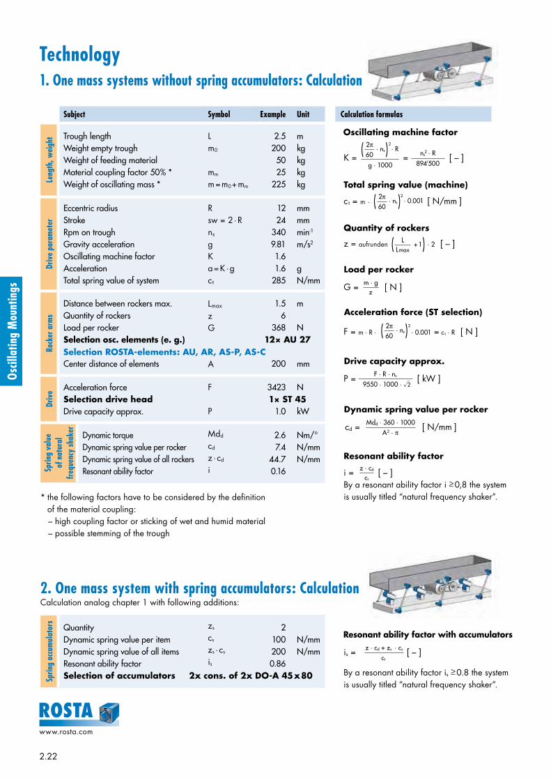
2.22
www.rosta.com
Oscil
latin
g M
ount
ings
Technology1. One mass systems without spring accumulators: Calculation
Subject Symbol Example Unit Calculation formulas
Leng
th, w
eigh
t Trough lengthWeight empty troughWeight of feeding materialMaterial coupling factor 50% *Weight of oscillating mass *
Lm0
mm
m = m0 + mm
2.5 m 200 kg 50 kg 25 kg 225 kg
Driv
e pa
ram
eter
Eccentric radiusStrokeRpm on troughGravity accelerationOscillating machine factorAccelerationTotal spring value of system
Rsw = 2 · Rns
gKa = K · gct
12 mm 24 mm 340 min-1
9.81 m/s2
1.6 1.6 g 285 N/mm
Rock
er a
rms
Distance between rockers max.Quantity of rockersLoad per rockerSelection osc. elements (e. g.)
Center distance of elements
Lmax zG
A
1.5 m 6 368 N
12× AU 27
200 mm
Driv
e Acceleration forceSelection drive headDrive capacity approx.
F
P
3423 N1× ST 45
1.0 kW
Sprin
g va
lue
of n
atur
al
freq
uenc
y sh
aker Dynamic torque
Dynamic spring value per rockerDynamic spring value of all rockersResonant ability factor
Mdd
cd
z · cd
i
2.6 Nm/° 7.4 N/mm 44.7 N/mm 0.16
* the following factors have to be considered by the definition of the material coupling:– high coupling factor or sticking of wet and humid material– possible stemming of the trough
2. One mass system with spring accumulators: CalculationCalculation analog chapter 1 with following additions:
Sprin
g ac
cum
ulat
ors
QuantityDynamic spring value per itemDynamic spring value of all itemsResonant ability factorSelection of accumulators
zs
cs
zs · cs
is
2 100 N/mm 200 N/mm 0.86
Selection ROSTA-elements: AU, AR, AS-P, AS-C
2x cons. of 2x DO-A 45 x 80
Oscillating machine factor
Resonant ability factor with accumulators
By a resonant ability factor is ≥ 0.8 the system is usually titled “natural frequency shaker”.
is = [ – ]z · cd + zs · cs
ct
K = = [ – ] · ns · R
g · 1000
2π60 ns
2 · R
894’500
( )2
c t = m · [ N/mm ] · ns · 0.0012π60( )2
Total spring value (machine)
z = aufrunden · 2 [ – ] + 1L
Lmax( )Quantity of rockers
G = [ N ]m · gz
Load per rocker
F = m · R · · 0.001 = c t · R [ N ] · ns 2π60( )2
Acceleration force (ST selection)
P = [ kW ]F · R · ns
9550 · 1000 · √2
Drive capacity approx.
cd = [ N/mm ]Mdd · 360 · 1000 A2 · π
Dynamic spring value per rocker
i = [ – ]By a resonant ability factor i ≥ 0,8 the system is usually titled “natural frequency shaker”.
z · cd ct
Resonant ability factor

2.23
www.rosta.com
Oscil
latin
g M
ount
ings
conveying direction
Technology3. One mass shaker conveyor systems: Installation instructions
4. Average material speed on shakers vmMain influence factors– layer height of material– property trough bottom (slip-
resistance)– mounting angle β of the rockers– feeding capability of the material
depending on size, form and hu-midity of the grains, e.g. very dry and fine grained material is submit-ted to slippage factors up to 30 %.
Example: One mass system with eccentric driveOut of the intersection point R = 12 mm and the revolutions ns = 340 min-1 is resulting a theoretical material speed of vm = 12 m/min or 20 cm/sec.
By acceleration factors K > 2 and rocker mounting angles of β = 30° (to the perpendicular line) the vertical acceleration is getting bigger than 1 g, therefore the material starts lift-ing from the trough bottom = material throw.
m/min
40
38
36
34
32
30
28
26
24
22
20
18
16
14
12
10
8
6
4
cm/s
67
63
60
57
53
50
47
43
40
37
33
30
27
23
20
17
13
10
7
4 6 8 10 12 14 16 18 20 22 24 26 28 30 32 34
Ave
rage
mat
eria
l spe
ed v
m
Eccentric radius R [mm]
K = 2
K = 1.8
K = 1.6
K = 1.4
K = 1
K = 1.2
ns =
380
K = 2.2
K = 2.5
K = 3
K = 4K = 5
ns =
600 ns
= 5
20
ns =
460
ns =
420
ns =
360
ns =
340
ns =
320 ns
= 3
00
ns =
400
K = 3.3
Speed graph by rocker mounting angle β = 30°K ≥ 2 material throwK < 2 material sliding, vm speed not exactly definable
Distance between rockers Lmax:– Usually, the distance between the rocker arms on the trough along-
side is up to 1.5 meters, depending on the stiffness of the trough.– By trough widths >1.5 m we do recommend to provide the trough
bottom side with a third, centrical row of rocker arms for stability reasons.
Mounting position drive head ST:For one mass shaker systems it is recommendable to position the drive head slightly ahead of the center of gravity of the trough, towards the discharge end.
Depth of thread engagement Z:The depth of engagement should be at least 1.5 x the thread nominal width.
Angle of oscillation α:The machine parameters, angle of oscillation and revolutions should be determined in the ad-missible area of operations (see chapter 5).
Screw quality:The screw quality should be grade 8.8 secured by the required tightening moment.
Rocker mounting angle β:According to the relevant processing function of the shaker conveyor, the rocker arms are posi-tioned at mounting angles between 10° to 30° in relation to the perpendicular line. (The ideal com-bination of fast conveying speed with high materi-al throw is given by a rocker inclination angle of 30°.) The power input position of the drive-rod from the eccentric drive should stay at right an-gles to the rocker arms, this orthogonal position-ing offers a harmonic course of the drive system.

2.24
www.rosta.com
Oscil
latin
g M
ount
ings
m1
m2
The 9 installation steps for a two mass system with double rocker arms:1. All fixation holes for the rockers in trough, counter-mass and machine frame have to be
drilled very accurately previous the final machine assembling.2. Installation of the middle elements of the rocker arms on the central machine frame, all inclina-
tion angles duly adjusted (e.g. 30°), tightening of the screws with required fastening torque.3. Lifting of the counter-mass with accurate horizontal alignment until the bores in the counter-mass
frame stay congruent with the bore holes of the lower element. Jamming of the counter-mass with e.g. wooden chocks.
4. Tightening of the fixation screws on counter-mass with required fastening torque.5. Inserting of the feeding trough into machine frame structure. Accurate horizontal alignment
until the bores in the trough stay congruent with the bore holes of the upper element. Jam-ming of the trough with e.g. wooden chocks.
6. Tightening of the fixation screws on trough with required fastening torque.7. Installation of the driving rod with drive head ST in “neutral” position i.e. eccentric drive
should stay in between the two stroke ends. Length adjustment of the driving rod and tighten-ing of the counternuts.
8. Removal of the jamming chocks under counter-mass and trough.9. Test start of the shaker conveyor.
Technology5. Maximum rocker load G, revolutions ns and angle of oscillation α
6. Two mass shaker systems with direct reaction force-compensation– Maximum acceleration forces of approx. 5 g, shaker lengths up to 20 meters– Equipped with ROSTA double rockers AD-P, AD-C and/or made out of AR elements– Ideal compensation when m1 = m2
– Element selection analogue chapter 1, but with load of the two masses: Actuated mass (+ material coupling of feeding mass) m1 [kg] Driven mass (+ material coupling of feeding mass) m2 [kg] Total oscillating mass m = m1 + m2 [kg]
Dynamic spring value cd per double rocker [N/mm]
– Calculation of ct and F based on the total mass (m1 and m2)– Power input from eccentric drive with ST arbitrary on m1 or m2 at any point alongside
m1 or m2
– On demand, special double rocker arms with varying center distances A are available as “customized rockers”
Size (e.g. AU 15)
max. load capacity per rocker [N] max. revolutions ns [min-1] *
K < 2 K = 2 K = 3 K = 4 α + 5° α + 6°
15 100 75 60 50 640 480
18 200 150 120 100 600 450
27 400 300 240 200 560 420
38 800 600 500 400 530 390
45 1’600 1’200 1’000 800 500 360
50 2’500 1’800 1’500 1’200 470 340
60 5’000 3’600 3’000 2’400 440 320
Please contact ROSTA for the permissible load indications by higher accelerations and for rocker elements offering higher load capacities. Usually are the revolutions ns between 300 to 600 min-1 and the oscillation angles max. ±6°.* basics: “permissible frequencies” in the Technology part of the ROSTA catalogue.
The angle of oscillation α of each oscillat-ing component (rockers accumulators and drive head) has to be settled within the permissible range (ns and α).
Calculation oscillation angle for rockers
Eccentric radius R [mm]Center distance A [mm]Oscillation angle α ± [°]
α = arctan [°]A R
cd =3 · Mdd · 360 · 1000
2 · A2 · π
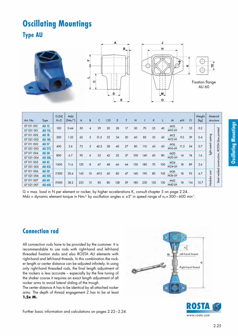
2.25
www.rosta.com
Oscil
latin
g M
ount
ings
Oscillating Mountings Type AU
Art. No. TypeG [N]K<2
Mdd
[Nm/°] A B C D E F H J K L M ø N OWeight
[kg]Material structure
07 011 001 AU 15100 0.44 50 4 29 20 28 17 50 70 25 40
M10M10-LH
7 33 0.2
Nod
ular
cas
t
lig
ht m
etal
cas
ting
Stee
l wel
ded
cons
truct
ion,
RO
STA
blu
e pa
inte
d
07 021 001 AU 15L07 011 002 AU 18
200 1.32 62 5 31.5 22 34 20 60 85 35 45M12
M12-LH9.5 39 0.4
07 021 002 AU 18L07 011 003 AU 27
400 2.6 73 5 40.5 28 40 27 80 110 45 60M16
M16-LH11.5 54 0.7
07 021 003 AU 27L07 011 004 AU 38
800 6.7 95 6 53 42 52 37 100 140 60 80M20
M20-LH14 74 1.6
07 021 004 AU 38L07 011 005 AU 45
1’600 11.6 120 8 67 48 66 44 130 180 70 100M24
M24-LH18 89 2.6
07 021 005 AU 45L07 011 006 AU 50
2’500 20.4 145 10 69.5 60 80 47 140 190 80 105M36
M36-LH18 93 6.7
07 021 006 AU 50L07 011 007 AU 60
5’000 38.2 233 15 85 80 128 59 180 230 120 130M42
M42-LH18 116 15.7
07 021 007 AU 60L
Fixation flange AU 60
Connection rod
All connection rods have to be provided by the customer. It is recommendable to use rods with right-hand and left-hand threaded fixation stubs and also ROSTA AU elements with right-hand and left-hand threads. In this combination the rock-er length or center distance can be adjusted infinitely. In using only right-hand threaded rods, the final length adjustment of the rockers is less accurate – especially by the fine tuning of the shaker course it requires an exact length adjustment of all rocker arms to avoid lateral sliding of the trough.The center distance A has to be identical by all attached rocker arms. The depth of thread engagement Z has to be at least 1.5x M.
G = max. load in N per element or rocker, by higher accelerations K, consult chapter 5 on page 2.24.Mdd = dynamic element torque in Nm/° by oscillation angles α ±5° in speed range of nS = 300 – 600 min-1.
Further basic information and calculations on pages 2.22 – 2.24.
B
A
C
LF
D
E
M
O
K
N
H
J
70
Left-hand thread
Right-hand thread

2.26
www.rosta.com
Oscil
latin
g M
ount
ings
Single Rockers
D
E
C
B
FH
K
A
B1
AS-PV
AS-P
S
E
K
B
D
A
S
E
K
B
D
A
Art. No. TypeG [N]K<2
cd
[N/mm] A B B1 C D E ø F H ø KWeight
[kg] Material structure
07 081 001 AS-P 15100 5 100
50–
–56
4 50 70 7 25 18 0.5
Steel welded constructions,
ROSTA blue painted
07 091 001 AS-PV 1507 081 002 AS-P 18
200 11 12062–
–68
5 60 85 9.5 35 24 0.807 091 002 AS-PV 1807 081 003 AS-P 27
400 12 16073–
–80
5 80 110 11.5 45 34 1.807 091 003 AS-PV 2707 081 004 AS-P 38
800 19 20095–
–104
6 100 140 14 60 40 3.607 091 004 AS-PV 3807 081 005 AS-P 45
1’600 33 200120–
–132
8 130 180 18 70 45 5.507 091 005 AS-PV 4507 081 006 AS-P 50
2’500 37 250145
––
16010 140 190 18 80 60 8.3
07 091 006 AS-PV 50
G = max. load in N per rocker, by higher K consult chapter 5 on page 2.24.cd = dynamic spring value by oscillation angles α + 5° in speed range of ns = 300–600 min–1
Further basic information and calculations on pages 2.22–2.24.
AS-P /AS-PV
AS-C
Art. No. TypeG [N]K<2
cd
[N/mm] A B D – 0.3 ø E ø K S
Weight[kg]
Material structure
Inner square Housing
07 071 001 AS-C 15 100 5 100 40 45 10 + 0.4+ 0.2 18 15 0.4
Light metal profile
Steel welded construction, ROSTA blue
painted
07 071 002 AS-C 18 200 11 120 50 55 13 0– 0.2 24 18 0.6
07 071 003 AS-C 27 400 12 160 60 65 16 + 0.5+ 0.3 34 27 1.3
07 071 004 AS-C 38 800 19 200 80 90 20 + 0.5+ 0.2 40 38 2.6
07 071 005 AS-C 45 1’600 33 200 100 110 24 + 0.5+ 0.2 45 45 3.9
07 071 006 AS-C 50 2’500 37 250 120 130 30 + 0.5+ 0.2 60 50 6.1
0
Type AS-PV with inverted flange
for flange fixation
for frictional center connection
26242220181614121086420
0 1 2 3 4 5 6
Ecce
ntric
radi
us R
[mm
]
Angle of oscillation α ± [°]
AS 50
AS 27
AS 18
AS 15
AS 38/45

2.27
www.rosta.com
Oscil
latin
g M
ount
ings
S
E B
D
K K
AA
S
E B
D
K K
AA
G = max. load in N per rocker, by different K consult chapter 5 on page 2.24.cd = dynamic spring value by oscillation angles α + 5° in speed range of ns = 300–600 min–1
Further basic information and calculations on pages 2.22–2.24.
AD-P /AD-PV
AD-C
Double Rockers
K
FHDE
K
B1
AA
C
B
AD-PV
AD-P
Type AD-PV with inverted flange
for flange fixation
for frictional center connection
Art. No. TypeG [N]
K=2 K=3cd
[N/mm] A B B1 C D E ø F H KWeight
[kg] Material structure
07 111 001 AD-P 18150 120 23 100
62–
–68
5 60 85 9.5 35 40 x 20 1.2
Steel welded constructions,
ROSTA blue painted
07 121 001 AD-PV 1807 111 002 AD-P 27
300 240 31 12073–
–80
5 80 110 11.5 45 55 x 34 2.607 121 002 AD-PV 2707 111 003 AD-P 38
600 500 45 16095–
–104
6 100 140 14 60 70 x 50 5.507 121 003 AD-PV 3807 111 004 AD-P 45
1’200 1’000 50 200120–
–132
8 130 180 18 70 80 x 40 8.507 121 004 AD-PV 4507 111 005 AD-P 50
1’800 1’500 56 250145
––
16010 140 190 18 80 90 x 50 12.9
07 121 005 AD-PV 50
Art. No. TypeG [N]
K=2 K=3cd
[N/mm] A B D – 0.3 ø E K SWeight
[kg]
Material structure
Inner square Housing
07 101 001 AD-C 18 150 120 23 100 50 55 13 0– 0.2 40 x 20 18 0.8
Light metal profile
Steel welded construction, ROSTA blue
painted
07 101 002 AD-C 27 300 240 31 120 60 65 16 + 0.5+ 0.3 55 x 34 27 1.8
07 101 003 AD-C 38 600 500 45 160 80 90 20 + 0.5+ 0.2 70 x 50 38 4.1
07 101 004 AD-C 45 1’200 1’000 50 200 100 110 24 + 0.5+ 0.2 80 x 40 45 6.1
0
26242220181614121086420
0 1 2 3 4 5 6
Ecce
ntric
radi
us R
[mm
]
Angle of oscillation α ± [°]
AD 50
AD 38
AD 27
AD 18
AD 45

2.28
www.rosta.com
Oscil
latin
g M
ount
ings
10–30°
A
C
S
H M
N
O
BA
L
L1
Oscillating MountingsType AR
C
S
H M
N
O
BA
L
L1
10–30°
feeding direction
AA
The two AR mounts are inserted on the round connecting tube. The required center distance should be positioned on the straightening plate (parallelism), subsequently tightening of the two collars with the required fastening torque.
The three AR mounts are inserted on the round connecting tube, with the direction inverted center element. This so said “boomerang”-configuration is offering on the counter-mass trough a direction inverted flow of material, what could sim-plify selection and screening processing.
Two-Way Rocker
G = max. load in N per rocker, by higher K consult chapter 5 on page 2.24.Mdd = dynamic element torque in Nm/° by oscillating angles α + 5° in speed range of ns = 300–600 min–1
Dimensioning of the connecting tubesThe connecting tubes have to be provided by the customer. For Single Rockers the wall thickness of 3 mm (up to center distance A = 300 mm) is fully sufficient. For Double Rockers, due to resulting shear forces, higher wall thicknesses are required – see below-mentioned table.
Type Tube-ømin. thickness
of tubemax. center distance A
min. mounting angle β[°] with two-way rocker
AR 27 30345
160220300
26.019.514.6
AR 38 40345
200250300
27.522.619.1
Art. No. TypeG [N]K<2
Mdd
[Nm/°] A + 0.2 B ø C H L L1 –0.3 ø M N O SWeight
[kg]
Material structure
Inner square Housing
07 291 003 AR 27 400 2.6 39 21.5 16 48 60 65 30 35 M8 27 0.5 Light metal profile
Light metal casting, ROSTA
blue painted07 291 004 AR 38 800 6.7 52 26.5 20 64 80 90 40 50 M8 38 1.0
0
+ 0.5+ 0.3
+ 0.5+ 0.2
The three AR mountings are inserted on the round connecting tube (please check required material thickness by the relevant center distance on below-mentioned table). The counter-mass can be used as second trough with identical feeding direction.
Double Rocker
feeding direction
feeding direction
14,6
AA
Further basic information and calculations on pages 2.22–2.24. By differing center distances A, please consult ROSTA.
Single Rocker feeding direction feeding direction

2.29
www.rosta.com
Oscil
latin
g M
ount
ings
F
Drive HeadsType ST
Installation guidelinesFor the installation of the drive heads type ST under the trough-bottom it requires a stiff structure, ideally a heavy and rather long frame construction surrounding the power input from the eccentric drive. Too light and too short mounting structures for the drive heads could be submitted to early material fatigue and generate cracks on the feeding trough. The drive heads have to be installed fully free of play (frictional connection). By multiple power transmission with several drive heads, all driving rods have to be adjusted on exactly the same length. The force transmission from the ec-centric drive should stay right-angled to the guiding rocker arms. This supports a smooth course of the shaker.
Art. No. TypeF max.
[N]ns [min–1]
max. αST + 5° A B C D E H J K L M SWeight
[kg]Material structure
07 031 001 ST 18400 600 50 55 0
– 0.3 31.5 45 20 12 + 0.3 6 22 39M12
M12-LH18 0.2
Ligh
t met
al c
astin
g
Ligh
t met
al p
rofil
e
Hou
sing
ROST
A b
lue
pain
ted07 041 001 ST 18L
07 031 002 ST 271’000 560 60 65 0
– 0.3 40.5 60 27 20 + 0.4 8 28 54M16
M16-LH27 0.4
07 041 002 ST 27L07 031 003 ST 38
2’000 530 80 90 0– 0.3 53 80 37 25 + 0.4 10 42 74
M20M20-LH
38 1.107 041 003 ST 38L07 031 004 ST 45
3’500 500 100 110 0– 0.3 67 100 44 35 + 0.5 12 48 89
M24M24-LH
45 1.807 041 004 ST 45L07 031 005 ST 50
6’000 470 120 130 0– 0.3 69.5 105 47 40 + 0.5 M12 x 40 60 93
M36M36-LH
50 5.5
Nod
ular
cas
t iro
n
07 041 005 ST 50L07 031 015 ST 50-2
10’000 470 200 210 0 – 0.3 69.5 105 47 40 + 0.5 M12 x 40 60 93
M36M36-LH
50 6.907 041 015 ST 50-2L07 031 026 ST 60
13’000 440 200 210 + 0.2 85 130 59 45 M16 80 117M42
M42-LH60 15.6
Stee
l
ROST
A b
lue
pain
ted
07 041 026 ST 60L07 031 016 ST 60-3
20’000 440 300 310 + 0.2 85 130 59 45 M16 75 117M42
M42-LH60 20.2
07 041 016 ST 60-3L07 031 027 ST 80
27’000 380 300 310 + 0.2 100 160 77 60 M20 90 150M52
M52-LH80 36.7
07 041 027 ST 80L
+ 0.5 0
Further basic information and calculations on pages 2.22–2.24.
ns = max. revolutions by oscillation angle + 5°; if osc. angle is below, higher rpm’s are applicable, consult “permissible fre-quencies” in the Technology part of the ROSTA general catalogue.Fmax. Calculation of the acceleration force F on page 2.22.
Length of driving rod AST and eccentric radius RTo follow the guidelines of the permissible frequencies the angle of oscillation αST should not exceed + 5.7°. This angle is corresponding to the ratio R : AST of 1 : 10.
Calculation of the oscillation angle for STEccentric radius R [mm]
Center distance AST [mm]
Oscillation angle αST + [°]αST = arcsin
RA ST
Series connection of 4 pcs. ST 50
F
H
J H
L
S
M
K
C
D E
A
B
ø16
,5
50
80
J
M
K
C
D E
A
B
J H
H
L
S
J 50
ST 60-3: 80ST 80: 90
ST
60-
3: ø
16,5
ST
80:
ø20
,5
ST 50-2
ST 18 – ST 50 ST 60
ST 60-3 and ST 80
new
new
new
new
new
new
new
new
[°]
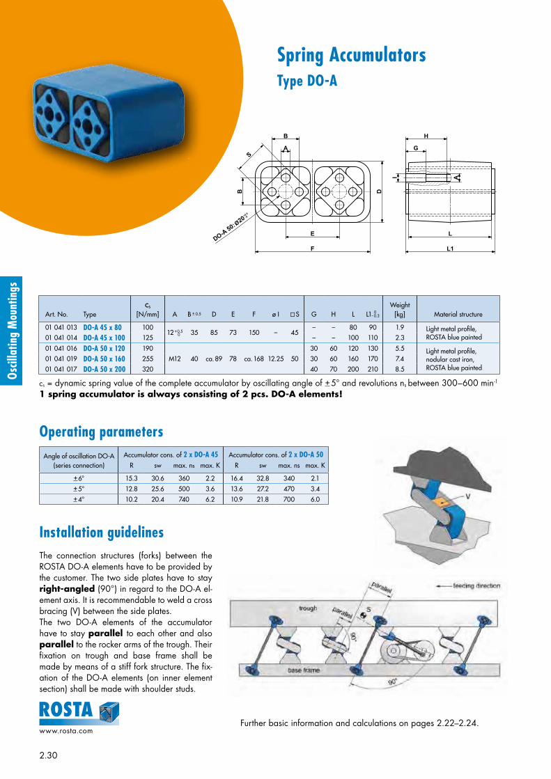
2.30
www.rosta.com
Oscil
latin
g M
ount
ings
Spring AccumulatorsType DO-A
A
B
B
S
E
F
L
L1
I A
G
H
D
Further basic information and calculations on pages 2.22–2.24.
Art. No. Typecs
[N/mm] A B + 0.5 D E F ø I S G H L L1– 0.3
Weight[kg] Material structure
01 041 013 DO-A 45 x 80 10012 + 0.5 35 85 73 150 – 45
– – 80 90 1.9 Light metal profile,ROSTA blue painted
Light metal profile,nodular cast iron,ROSTA blue painted
01 041 014 DO-A 45 x 100 125 – – 100 110 2.3
01 041 016 DO-A 50 x 120 190
M12 40 ca. 89 78 ca. 168 12.25 50
30 60 120 130 5.5
01 041 019 DO-A 50 x 160 255 30 60 160 170 7.4
01 041 017 DO-A 50 x 200 320 40 70 200 210 8.5
Angle of oscillation DO-A(series connection)
Accumulator cons. of 2 x DO-A 45 Accumulator cons. of 2 x DO-A 50R sw max. ns max. K R sw max. ns max. K
+ 6° 15.3 30.6 360 2.2 16.4 32.8 340 2.1+ 5° 12.8 25.6 500 3.6 13.6 27.2 470 3.4+ 4° 10.2 20.4 740 6.2 10.9 21.8 700 6.0
0
0
cs = dynamic spring value of the complete accumulator by oscillating angle of + 5° and revolutions ns between 300–600 min-1
1 spring accumulator is always consisting of 2 pcs. DO-A elements!
Installation guidelinesThe connection structures (forks) between the ROSTA DO-A elements have to be provided by the customer. The two side plates have to stay right-angled (90°) in regard to the DO-A el-ement axis. It is recommendable to weld a cross bracing (V) between the side plates. The two DO-A elements of the accumulator have to stay parallel to each other and also parallel to the rocker arms of the trough. Their fixation on trough and base frame shall be made by means of a stiff fork structure. The fix-ation of the DO-A elements (on inner element section) shall be made with shoulder studs.
Operating parameters

2.31
www.rosta.com
Oscil
latin
g M
ount
ings
ROSTA Oscillating Mountings and Accessories for Customized Applications
Asymmetrical double rockers for high-speed shaker conveyors
To achieve highest material speed (up to 60 m/min) on shak-er conveyors we recommend the installation of ROSTA double rocker arms with asymmetrical center distances be-tween the elastic suspensions (ratio 2 : 1). Usually, the eccen-tric drive-input goes on the counter-mass frame which is con-nected to the shorter arm end and therefore weighs 200% of the upper feeding trough. The trough is connected to the longer arm end of the rocker. That is why it describes the double stroke in relation to the counter-mass. This gear ratio offers a long material throw on the trough by low reac-tion-force transmittance on the overall machine structure.Please ask for our special application manual asymmetric-al double rockers.
Oversized drive heads for heavy-duty crank shaft driven shaker conveyors
The biggest standardized ROSTA drive head type ST 80 is laid out to transmit acceleration forces up to 27’000 N on shaker troughs. For the actuation of e.g. heavy feeding hop-pers or very long wood-waste shaker conveyors this capacity is not sufficient. For the actuation of very large crank shaft driven shaker con-veyors ROSTA also supplys the drive heads type ST 80-4 and ST 100-5 with acceleration force capacities F of 36’000 N respectively 63’000 N per head. These two heads are all made in steel welded construction and offer instead of the usually centrical tapped bore a box-shaped holding fixture for the drive rod (see drawing below). These two drive heads are not available from stock and will be manufactured only upon request (longer delivery time).
Oscil
latin
g M
ount
ings

2.32
www.rosta.com
Oscil
latin
g M
ount
ings
ROSTA guiding rods for “Flip-Flow” two mass shaker systems
ROSTA Oscillating Mountings and Accessories for Customized Applications
Free oscillating screening systems with counter-mass frames and directly actuated flexible screen mats offer the great benefit of the mesh self-cleaning. Furthermore, the flexible mats generate a very high and wide material throw on the screen deck. In these systems the counter-mass m2 does usually overswing the screen-box mass m1 at the ratio of 2 : 1 generating the so-called “Trampoline-Effect” with wide throws and the self-cleaning of the screen meshes. For the elastic suspension and the linear guiding of the counter-mass frames in “Flip-Flow” systems ROSTA offers dif-ferent guiding-rods and spring accumulators, which are sup-porting the phase-shifted acting of the two masses. (Please ask for our manual “Dual Amplifying Systems”).
ROSTA rocker arms AS-P and AD-P with shifted fixation flanges (30° position)
The fixation flanges of the standardized ROSTA single and double rocker arms type AS-P and AD-P are installed at right angle (90°) to the rocker arm axis. The practical experience showed that most of the shaker manufacturers install the rocker arms at inclination angle of 30° out of the vertical line to obtain an ideal combination of fast material feeding and high screen-ing throw. In case of very concise mounting conditions with low-pitched feeding troughs and slim machine frames and counter-masses the right-angled fixation flange sometimes protrudes the ma-chine structure – and in extremely crowded constructions a bolt-ed assembly through both flange bores is simply impractical. For such applications ROSTA offers as customized parts AS-P and AS-D rocker arms with fixation flanges staying 30° to the rocker arm axis allowing a very low mounting option of the rockers on trough and frame. Due to the rocker installation by pairs it is necessary to order right and left hand execution of the relevant rocker arms.
m2
m1

2.33
www.rosta.com
Oscil
latin
g M
ount
ingsTwo-mass “natural frequency” shaker conveyor equipped with dou-
ble rocker arms made out in light metal casting
Stainless steel rocker arms in welded construction supporting a
foodstuff shaker conveyor
Two-directional acting seed cleaning machine equipped with
AR-”Boomerang” double rocker arms
Two-mass shaker conveyor for the transport of bulk material equip-
ped with double rocker arms AD-P 50
One mass shaker conveyor with built-in screening fraction for the
transport and sorting of wood-chips
20-meter long two mass shaker conveyor for tobacco leaves equip-
ped with double rocker arms AD-PV 45

2.34
www.rosta.com
Introduction
Gyratory sifters stay mainly in use in the processing sectors of the flour and grain conditioning, in the pharmaceutical powder preparation and in the chipboard industry for the selection and cleaning of the different wood-chip sizes.
Gyratory sifter machines (plan sifter)Technology
Customized solutions
Gyratory screening machine installed on 8 pcs. AK-I 40 universal joints(joints made out of stainless steel)
Wood-chip sorting screen mounted on 8 pcs. AK 100-4 suspensions
Free oscillating gyratory sifter for the flour selection on 8 pcs. AV 38 elements
The circular screening motion is offering a fast and complete covering of the entire screen surface = very high throughput.
Oscil
latin
g M
ount
ings

2.35
www.rosta.com
Oscil
latin
g M
ount
ings
Hanging gyratory siftersHanging gyratory sifters are almost exclusively used in the milling sector for the sorting of the different types of flour (white flour, dark flour, black flour). These screens, which are equipped with a central unbalanced shaft, normally hang from the building ceiling on rattan or round fibre-glass rods. Due to the relatively high weight of the screening ma-chines, several rattan or fibre-glass rods are needed at each corner of the box to ensure the suspension. In cases of very high humidity in the buildings, both types of rods can slip out of the clamps. Furthermore, it is very difficult to set it up so that all the rods support approximately the same weight.
For these applications, ROSTA recommends the use of the AV mounts, which have a very high carrying capacity. Only one mounting set is thereby needed for each corner of the screening box. In addition, the AV mountings can be deliv-ered with right-hand and left-hand threads, which facilitates the horizontal adjustment of the box. The AV mountings have a long service life, and do not have to be periodically re-placed, as it is the case with the rattan rods.
Upright staying gyratory sifters with eccentric shaft drive
Upright staying gyratory sifters with unbalanced shaft drive
Upright staying gyratory sifter machines frequently have this classical type of crank drive. These screens are mainly used in the flour processing sector, as well as in chipboard manu-facturing plants. An eccentric shaft driven by belts transfers the circular movement to the screen box. The screen box is supported by four legs, each consisting of two ROSTA uni-versal joints. The weight of the box lies completely on the four supports, which accurately guide the box movement.
A very cost-efficient version of the upright staying gyratory sifter. Requires no complicated eccentric drive. The AK mountings or even the AV mountings must be over- dimensioned, however, due to the lack of a precisely defined guidance.
Please contact ROSTA for projects using upright staying gy-ratory sifters with unbalanced shaft drive.

2.36
www.rosta.com
Oscil
latin
g M
ount
ings
Oscillating Mountings for Gyratory SiftersType AK – Universal Joints
S
D C
F
G
L
L1
A
B
A
H A B
S
L
L1
AK 100-5: Ø30 H7 x 30
Art. No. TypeWeight
[kg]
Material structure
Bolting on inner squareInner square Housing Protection
07 061 001 AK 15 0.4
Light metal profile
Steel welded construction
ROST
A b
lue
pain
ted
End-to-end screw or threaded bar quality 8.8
07 061 002 AK 18 0.6
07 061 003 AK 27 1.9
Nodular cast iron
07 061 004 AK 38 3.7
07 061 005 AK 45 6.7
07 061 011 AK 50 11.4
Shoulder studs quality 8.8 for optimizing
frictional connection
07 061 012 AK 60 37.4
Steel07 061 013 AK 80 85.4
07 061 009 AK 100-4 124
07 061 010 AK 100-5 137 Steel welded construct.
Art. No. Type
Max. load G [N] by system:
A B C D F G ø H L L1 + 0.2 Shanging staying
crank drivenstaying
free oscillating07 061 001 AK 15 160 128 80 5 + 0.5 10 + 0.2 27 54 – – – 60 65 15
07 061 002 AK 18 300 240 150 6 + 0.5 12 + 0.3 32 64 – – – 80 85 18
07 061 003 AK 27 800 640 400 8 + 0.5 20 + 0.4 45 97 – – – 100 105 27
07 061 004 AK 38 1’600 1’280 800 10 + 0.5 25 + 0.4 60 130 – – – 120 130 38
07 061 005 AK 45 3’000 2’400 1’500 12 + 0.5 35 + 0.5 72 156 – – – 150 160 45
07 061 011 AK 50 5’600 4’480 2’800 M12 40 + 0.5 78 172 40 70 12.25 200 210 50
07 061 012 AK 60 10’000 8’000 5’000 M16 45 100 218 50 80 16.5 300 310 60
07 061 013 AK 80 20’000 16’000 10’000 M20 60 136 283 50 90 20.5 400 410 80
07 061 009 AK 100-4 30’000 24’000 15’000 M24 75 170 354 50 100 25 400 410 100
07 061 010 AK 100-5 40’000 32’000 20’000 M24 75 170 340 50 100 25 500 510 100
0
0
0
0
0
G = max. load in N per support column
Usual drive parameters out of practice– Driving speed ns
up to approx. 380 min-1
– Oscillation angle α up to approx. + 3.5°
General advisesThe operating parameters shall not exceed the guidelines of the “frequency spectrum” in the Technology part of the ROSTA general catalogue.

2.37
www.rosta.com
Oscil
latin
g M
ount
ings
Calculation ExampleMachine type: staying sifter with positive crank drive
Description Symbol Example Unit Calculation formula
Total oscillating mass (material included) m 1600 kg Angle of oscillationEccentric radius R 25 mmLength of support column X 600 mmAngle of oscillation (out of R and X) α + 2.4 °Revolutions ns 230 min–1
Quantity of support columns z 4 pcs. Load per columnLoad per column G 3924 NMax. load capacity per column with AK 50 mounts Gmax 4480 N
Element selection: 4 columns consisting of 2 pcs. AK 50 ➝ 8 psc. AK 50
Hanging and freely oscillating gyratory sifter Staying gyratory sifter with positive crank shaft drive
Installation guidelines for AK universal joints
1 Install the two AK per column in the same line, in order that the dis-tance X between the two inner squares of the 90° “distorted” ele-ment parts and the two inner squares of the “in-line” element parts is identical.
2 Install the four identical connection columns (provided by the cus-tomer) between the two AK. Also by slightly inclined screen-boxes the distance or length X of the connection columns has to be iden-tical – compensate the inclination with e.g. the higher positioning of the fixation brackets by the discharge-end of the screen-box.
3 Up to the size AK 50 we do recommend to use our fixation brackets type WS for the AK mounting on machine frame and screen-box – see ROSTA general catalogue “Rubber suspensions”.
4 To avoid unwanted tilting motions or screen-box distortions (by standstill) we do recommend the installation of the upper AK-brack-ets on the level of the center of gravity “S” of the screen-box.
1
1
3
X 42
24
α = arctanRX
G = [N]m · g
z
[°]

2.38
www.rosta.com
Oscil
latin
g M
ount
ings
Oscillating Mountings for hanging Gyratory SiftersType AV
Art. No. TypeG [N] per suspension A B + 0.2 C D H L M ø N O S
07 261 001 AV 18600 – 1’600 60 65 40.5 28 27 60
M16M16-LH
13 – 0.2 54 1807 271 001 AV 18L07 261 002 AV 27
1’300 – 3’000 80 90 53 42 37 80M20
M20-LH16 + 0.3 74 27
07 271 002 AV 27L07 261 003 AV 38
2’600 – 5’000 100 110 67 48 44 100M24
M24-LH20 + 0.2 89 38
07 271 003 AV 38L07 261 014 AV 40
4’500 – 7’500 120 130 69.5 60 47 105M36
M36-LH20 + 0.2 93 40
07 271 014 AV 40L07 261 005 AV 50
6’000 – 16’000 200 210 85 80 59 130M42
M42-LH– 116 50
07 271 005 AV 50L
0
+ 0.5
+ 0.5
+ 0.5
Art. No. TypeWeight
[kg]
Material structure Bolting on inner squareInner square Housing Prot.
07 261 001 AV 180.4
Light metal profile
Light metal casting
ROST
A b
lue
pain
ted
End-to-end screw or threaded bar
quality 8.8.
07 271 001 AV 18L07 261 002 AV 27
1.007 271 002 AV 27L07 261 003 AV 38
1.707 271 003 AV 38L07 261 014 AV 40
5.0
Nodular cast iron07 271 014 AV 40L07 261 005 AV 50
12.3M12 shoulder studs
quality 8.8.07 271 005 AV 50L
General advisesThe operating parameters shall not exceed the guidelines of the “frequency spectrum”, see Tech-nology part in the ROSTA general catalogue.
The threaded connection rod has to be provided by the customer.
G = max. load in N per suspensionElements for higher load on request
M
C
D
LH
A
B
S
O
N
Inner square AV 50 and AV 50L
40 40
M12
30
40
Ø12
.25
new
new
new
new

2.39
www.rosta.com
Oscil
latin
g M
ount
ings
Installation guidelines for AV mountings1 With the right-hand and left-hand threaded connection in the AV housing the
length X of the suspension rod can easily be adjusted, this length has to be iden-tical for all four suspension rods. The indicated angular oscillating lim-itations have to be respected!
2 Only the crosswise (90° offset) installation of the two AV elements per suspen-sion rod is guaranteeing for a harmonic and circular motion of the screen-box.
3 The crosswise installation of the AV elements has to be identical on all four suspen-sion rods, e.g. all upper AV mounts shall stay 90° offset. (For the suspension or support of the discharge-ends of “ROTEX” sifter types the two elements per rod shall stay parallel to each other.)
4 To avoid unwanted tilting motions or screen-box distortions (by standstill) we do recommend the installation of the lower AV-brackets on the level of the center of gravity “S” of the screen-box.
5 Please consult ROSTA by the selection of AV elements for staying, free oscillating gyratory sifters.
β ≤ ± 2°
X
β ≤ ± 2°
β ≤ ± 2°α ≤ ± 5°
1
Calculation Example
Description Symbol Example Unit Calculation formula
Total oscillating mass (material included) m 800 kg Angle of oscillationEccentric radius 2 R 20 mmLength of suspension rod X 600 mmAngle of oscillation (out of R and X), shall not exceed ±2 ° 2 β + 1.9 °Revolutions ns 230 min–1
Quantity of suspension rods z 4 pcs. Load per suspension rodLoad per suspension rod G 1962 NMax. load capacity per rod with AV 27 mountings Gmax 3000 N
Element Selection: 4 pcs. AV 27 and 4 pcs. AV 27 L (left-hand threaded), the two AV elements per suspension rod have to be installed crosswise (90° offset).
β = arctan [°]RX
G = [N]m · g
z
2 circular oscillation
β ≤ ± 2°
X
β ≤ ± 2°
β ≤ ± 2°α ≤ ± 5°
3 elliptical oscillation (“ROTEX” sifter types)
β ≤ ± 2°
X
β ≤ ± 2°
β ≤ ± 2°α ≤ ± 5°
X
4
1

2.40
www.rosta.com
Swinging Applications!Examples:
T201
4.83
5
Changes regarding data reserved.Any reprint, also in extracts, requires our explicit and confirmed approval.
ROSTA
Oscil
latin
g M
ount
ings
ROSTA AGCH-5502 HunzenschwilPhone +41 62 889 04 00Fax +41 62 889 04 99E-Mail [email protected] www.rosta.com

Shock and Vibration absorbing Machine Mounts high degree of isolation – tearproof – absorption of solid-borne noise
ROSTA Anti-vibration Mounts
ROSTA
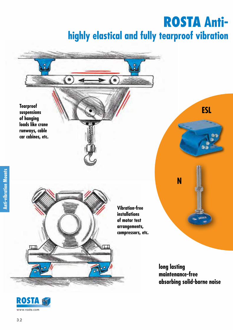
3.2
www.rosta.com
Vibration-free installations of motor test arrangements, compressors, etc.
long lastingmaintenance-freeabsorbing solid-borne noise
ROSTA Anti- vibration Mountshighly elastical and fully tearproof vibration dampers based on torsional rubber pivots
Tearproof suspensions of hanging loads like crane runways, cable car cabines, etc.
N
ESL
Anti-
vibr
atio
n M
ount
s

3.3
www.rosta.com
Shock absorbing levelling feet for machine mounting
Wide range of standardized mounts, for load capacities of 20 –2’000 kg
Impact-proof suspensions of transfer cradles offering conveyor- belt protection
ROSTA Anti- vibration Mountshighly elastical and fully tearproof vibration dampers based on torsional rubber pivots
V
Anti-
vibr
atio
n M
ount
s
ISOCOL

3.4
www.rosta.com
Anti-
vibr
atio
n M
ount
s
Selection table for Anti-vibration Mounts
Type Description Details Illustration
ESL
Anti-vibration Mounts for the absorption of tensile, pressure and shear load. Also ideal for wall and ceiling installations.8 load sizes from 200 N to 19'000 N per mount.Natural frequency between 3,5 – 8 Hz. Mounts are mainly used for overcritical machine installations (machine frequency > mount frequency).
Page3.8 – 3.9
V
Anti-vibration Mounts for the absorption of tensile, pressure and shear load. Also ideal for wall and ceiling installations. 6 load sizes from 300 N to 12’000 N per mount. Natural frequency between 10 – 30 Hz. Mounts can be used for subcritical ma chine installations (machine frequency < mount frequency).
Page3.10 – 3.11
N
Mounting Feets consisting of insulating plate, glued-on top cover with built-in level-ling jackscrew with spherical joint for compensation of up to 5° of floor unevenness. Insulating plate oil- and acid-proof. 3 load sizes from 1’500 N to 20’000 N per mount. Natural frequency between 19 – 25 Hz.
Page3.12
NOX
Mounting Feets consisting of insulating plate, stainless steel glued-on top cover with built-in stainless levelling jackscrew with spherical joint for compensation of up to 5° of floor unevenness. Insulating plate oil- and acid-proof. 2 load sizes from 5’000 N to 20’000 N per mount. Natural frequency between 19 – 22 Hz.
Page3.12
Base plate PAccessories: For all N and NOX mounting feet light metal cast base plates are available for the compensation of possible shear loads and/or for the positioning of the installation on the floor.
Page3.12
ISOCOLAdhesive cushioning plates, self-adhesive plates for the installation of smaller ma-chines/equipments. Plates oil- and acid-proof. (Adhesive power can be increased by moistening the plate with nitro thinner.)
Page3.13
ISOCOL UAdhesive cushioning plates, self-adhesive plates with glued-on cast cover. With central hollow in cover for the positioning of the levelling jackscrew – also with lateral stop bar for machine positioning.
Page3.13
Further information to customized elements and installation examples as from page 3.14.

3.5
www.rosta.com
Anti-
vibr
atio
n M
ount
s
Technology Anti-vibration Mounts
The vibration technology basically differentiates between two principal types of oscillation appearances (fig. 1 ). Si-nusoidal oscillations of working equipments are usually amortised in an overcritical installation manner, shocks and impacts in a subcritical mounting manner.
Manufacturers and suppliers of anti-vibration mounts usually offer different types of machine mount with varying natural fre-quencies to meet the required detuning between the excitation frequency of the machine and the natural frequency of the anti-vibration mount.
Oscillations
Shocks
W
Frequency Proportion l (fig. 2 )l > √2: Overcritical efficient vibration isolation, clearly definable ef-
fectiveness, also efficient solid-borne noise ab-sorption
l = 1: Resonance field uncontrolled swing-up, in the long term destruc-
tive for machine and mounts
l < 1: Subcritical vibration isolation not definable, isolation results
have to be measured out (before and after mount installation).
1
Overcritical installations (l > √2) On overcritical installations the natural frequency of the mounts should show at least a detuning factor of 1:1,414 in regard to the excitation frequency of the machine. Usually, very efficient anti-vibration mounts feature a deep deflection capability offering a low natural frequency. Most of the gen-erators, compressors, blowers and chargers are, therefore, in overcritical manner installed on relatively “soft” mounts. The resulting detuning proportion provides information about the expected isolation-effectiveness in % of the machine suspension. The adjacent chart (fig. 3 ) and the cal-culation formula (fig. 4 ) inform about the resulting vibration isolation in %.
2
3
1. Isolation of Oscillations and Shocks
0.2
1 2 3 4 5√2
0.4
0.6
0.8
1
2
(20%)
(40%)
(60%)
(80%)
unterkritischesGebiet
überkritischesGebiet
D = 1.0
D = 0.25
D = 0
Isolierbereich
Reso
nanz
Dämpfung
Tran
smis
sibi
lity
V =
trans
mitt
ed p
ower
exci
ted
pow
er
Frequency proportion l = Excitation frequency (machine)Natural frequency (damper)
Frequency proportion l
Isolation range
Damping
functionfunctionovercriticalsubcritical
Reso
nanc
e
Vibration isolation W[%]

3.6
www.rosta.com
Anti-
vibr
atio
n M
ount
s
Acoustic isolation, Steel 1 : 1related to steel: Bronze 1 : 1.3 Cork 1 : 400 Rubber 1 : 800 Air 1 : 90 000
6.0
5.5
5.0
4.5
4.0
3.5
3.0
2.5
2.0
600
700
800
900
1000
1100
1200
1300
1400
1500
1600
1700
1800
1900
2000
2100
2200
2300
2400
2500
2600
2700
2800
2900
3000
Diagram of the vibration isolation W [%]
ns = Revolution exciter (machine)
fe = Natural frequency damper
Vibration isolation
fens
90 %
92 %
94 %
95 %
96 %
97 %
98 %
99 %
W = 100 – 100
2 – 1
ns
60 · f e ( )Iso
latio
n < 8
5 %
4
Resonance field (l = 1) At equal values of the excitation frequency and the mount natural frequency an uncontrollable swing-up of machine and damper occurs. In the long run, this appearance will be destructive for machine and mount (fig. 2 ).
Subcritical installations (l < 1) On subcritical installations (fig. 2 ) an anti-vibration mount with high mechanical stiffness and only small deflection be-haviours should be chosen, e. g. ROSTA V mounts (high machine stability on mounts). In spite of the fact that the de-gree of isolation is not definable, this suspension efficiently absorbs shocks and impacts generated by relatively slow turning machines like e. g. mixers, crushers (cone-crushers), punching presses, sheet iron shears, etc. On subcritical installations the degree of isolation is not definable. Isolation results have to be measured out (before and after mount in-stallation).
2. Solid-borne Noise IsolationWhereas the isolation of mechanically generated oscilla-tions and shocks are determined and dissipated by means of the aforementioned vibration dampening theory, the sol-id-borne noise isolation is subject to the technology of wave mechanics. The dampening effect is related to the pro-portion of the relevant acoustic resistance (acoustic resis-tance or wave resistance = acoustic velocity x material den-sity). The adjacent chart (fig. 5 ) shows some comparative values of the resulting isolation proportions. Generally, using a rubber-steel composite mount, an ideal isolation result of the solid-borne noise can be expected – through the entire frequency range.
5
[ % ]
[ rpm ]
[ Hz ]

3.7
www.rosta.com
Anti-
vibr
atio
n M
ount
s
3. Active and Passive IsolationActive or direct isolation (fig. 6 ) means the direct ab-sorption of oscillations, vibrations and shocks of a running machine by anti-vibration mounts, i. e. to prevent directly the transfer of the numerous machine vibrations into the sub-structure, basis frame and entire building. For the anti-vibra-tion mount selection the knowledge of the interfering fre-quency (disturbance frequency), the stiffness of the machine structure and its gravity center as well as of the specific machine location in the building is required. Active isolations are usually overcritical machine installations on anti-vibration mounts (e. g. on ROSTA ESL mounts).
Passive or protective isolation (fig. 7 ) means to in-stall a protective barrier between all kind of existing vibra-tions and shocks occurring in a factory or workshop towards sensitive installations like e. g. weighing and measuring in-struments, laboratory equipment or electronic control units. The vibration technological situations usually vary in each case and are related to environmental situations, too. Often shocks and impacts come from outside, e. g. from motor-ways, railways, building sites or tooling machines, like punching presses, etc. Generally, the sensitive equipments shall be protected by installing them on rather “soft” anti-vi-bration mounts, e. g. ROSTA ESL or AB-D mounts absorbing most of these environmental impacts. It is frequently recom-mendable to consult also an engineering company having the tools and instruments to analyse the specific vibration appearances.
Protective suspension mounts for e.g. tooling ma-chines are usually rather “hard” and show only little deflec-tion under load. Too soft tooling machine mounts could actu-ate bending of the machine base what would influence neg-atively the precision of the work piece machining. Therefore, mounting feet for tooling machines are often consisting of hard rubber cushions deflecting only a few millimetres under load, but “shield” all combined vibration and shock appear-ances from the sensitive precision machine. Transmitted shocks and vibrations could affect the clean surface finishing of the work piece. Of course, in the interest of the fully hori-zontal positioning of the tooling machines, these anti-vibra-tion mounts have to dispose of a levelling jackscrew with spherical joint for the compensation of the possible floor unevenness (e. g. ROSTA N or NOX mounts).
Active isolation6
Passive isolation7

3.8
www.rosta.com
Anti-
vibr
atio
n M
ount
s
These types can be combined with one another (identical heights and operation behaviour)
* compression load Gmax. and final cold flow compensation (after approx. 1 year).
Guidelines concerning customized mounts and examples as from page 3.14.
D E
BK
H
xL
J
A
N
F
C
M
xL
J
A
ED
K B
H
N
FO
P
C
M
as from ESL 50
up to ESL 45
Art. No. Type
LoadGmin. – Gmax.[N] on Z-axis
Aun-
loaded
A*max.load B C D E øF H J K L M N
Weight[kg]
05 021 001 ESL 15 200 – 550 54 43 85 49 10 65 7 91 2 5.5 25.5 40 58.5 0.4
05 021 002 ESL 18 450 – 1'250 65 51 105 60 12.5 80 9.5 111 2.5 5.5 31 50 69 0.6
05 021 003 ESL 27 700 – 2'000 88 68 140 71 15 110 11.5 148 3 8 44 60 85.3 1.3
05 021 004 ESL 38 1'300 – 3'800 117 91 175 98 17.5 140 14 182 4 7 60 80 117 3.4
05 021 005 ESL 45 2'200 – 6'000 143 110 220 120 25 170 18 235 5 13 73 100 138 5.3
05 021 016 ESL 50 4'000 – 11'000 170 138 235 142 25 185 18 244 6 9 78 120 162 10.8
05 021 017 ESL 50-1.6 5'500 – 15'000 170 138 235 186 25 185 18 244 8 9 78 160 206 15.4
05 021 018 ESL 50-2 7'000 – 19'000 170 138 235 226 25 185 18 244 8 9 78 200 246 17.8
Art. No. Type
Natural frequencyGmin. – Gmax.
[Hz] O Px
max.Material structure
(zinc-plated screws)
05 021 001 ESL 15 8.2 – 5.8 - - 1.5
Light metal profiles, steel brackets,
ROSTA blue painted
05 021 002 ESL 18 7.5 – 5.0 - - 1.9
05 021 003 ESL 27 6.2 – 4.5 - - 2.7
05 021 004 ESL 38 5.5 – 4.0 - - 3.6
05 021 005 ESL 45 5.0 – 3.5 - - 4.4
05 021 016 ESL 50 5.0 – 3.5 13.5 90 10 Light metal profiles, cast housings, steel brackets,
ROSTA blue painted
05 021 017 ESL 50-1.6 5.0 – 3.5 13.5 90 10
05 021 018 ESL 50-2 5.0 – 3.5 13.5 90 10
Anti-vibration MountsType ESL
The max. load on X-axis should not ex-ceed 200 % of the Z-axis capacity.
The max. load on Y-axis should not ex-ceed 20 % of the Z-axis capacity.
Applicable on tensile, pressure and shear load.
Z
X
Y
new
new
new
new
new
new

3.9
www.rosta.com
Anti-
vibr
atio
n M
ount
s
Anti-vibration MountsType ESL
Deflection curves and cold flow behaviourThe below mentioned deflection values are comprising the ini-tial cold flow, occurring after a few hours of operation.The final cold flow (after one year) is usually s x 1.09.The mentioned deflection values are not suitable for type test-ing. Please consult also our tolerance data in the general cata-logue, chapter “Technology“.
ApplicationsFor active and passive isolation of vibrations and maximum damping of solid-borne noise transmission in weighbridges and scales, measuring systems, control equipment, rotary ma-chinery such as compressors, refrigerating systems, blowers, pumps, mills, mixers, shock-absorbent buffers, etc.
Bem.: ohne $ arbeiten, damit Formeln für alle Grössen gelten!
0.00.20.40.60.81.01.21.41.61.82.02.22.4
2 4 6 8 10 12 14 16 18 20
G [kN]
s [mm]
ESL 18
ESL 15
ESL 27
0.00.51.01.52.02.53.03.54.04.55.05.56.06.57.0
5 10 15 20 25 30 35
G [kN]
s [mm]
ESL 38
ESL 45
0
2
4
6
8
10
12
14
16
18
20
22
5 10 15 20 25 30 35 40
G [kN]
s [mm]
ESL50-1.6
ESL 50
ESL 50-2
Installation guidelinesThe ESL elements must generally be installed in the same direction.
Wall mountingDynamic forces lateralDynamic forces longitudinal
Ope
ratin
gra
nge

3.10
www.rosta.com
Anti-
vibr
atio
n M
ount
s
Anti-vibration MountsType V
Further information to customized elements and installation examples as from page 3.14.
J
KH
A
E
B
F
C
N
M L
E
B
HK
A
J C
N
212
262
LM
18x30
up to V 45
V 50
Art. No. Type
LoadGmin. – Gmax. [N]
on X- and Z-axis A B C E øF H øJ K L M NWeight
[kg]
05 011 001 V 15 300 – 800 49 80 51 55 9.5 3 20 10 40 M10 59 0.3
05 011 002 V 18 600 – 1'600 66 100 62 75 9.5 3.5 30 13 50 M10 74 0.7
05 011 003 V 27 1'300 – 3'000 84 130 73 100 11.5 4 40 14.5 60 M12 85 1.305 011 024 V 38 2'600 – 5'000 105 155 100 120 14 5 45 17.5 80 M16 117 2.705 011 005 V 45 4'500 – 8'000 127 190 122 140 18 6 60 22.5 100 M20 143 4.6
05 011 006 V 50 6'000 – 12'000 150 140 150 100 - 10 70 25 120 M20 193 7.5
Art. No. Type
Natural frequencyGmin. – Gmax.
[Hz]Material structure
(zinc-plated screws)
05 011 001 V 15 30 – 23
Light metal profiles, welded steel housings, ROSTA blue painted
05 011 002 V 18 25 – 15
05 011 003 V 27 28 – 20
05 011 024 V 38 14 – 12
05 011 005 V 45 15 – 12
05 011 006 V 50 12 – 10
* Alternativ mounting position 180° turned.
The max. load on Y-axis should not exceed 20 % of the X- resp. Z-axis capacity.
Momentary shock loads of 2.5 g in X- and Z-axis admissible.
Applicable on tensile, pressure and shear load.
Z
*
Y
X
new
new

3.11
www.rosta.com
Anti-
vibr
atio
n M
ount
s
Anti-vibration MountsType V
Deflection curvesThe mentioned deflection values are not suitable for type test-ing. Please consult also our tolerance data in the general cata-logue, chapter “Technology”.
ApplicationsFor active and passive isolation of vibrations and damping of solid-borne noise transmission in crushing plants, compressors, blowers, pumps, rotary converters, generators, mills, crane track supports, etc.
Installation guidelines45° diagonal configuration by rotary motions. Reduced load ca-pacities.
e. g. mixer, crusher installationDynamic forces lateralDynamic forces longitudinal
0.00.20.40.60.81.01.21.41.61.82.02.22.42.62.83.03.23.4
0.0
0.2
0.4
0.6
0.8
1.0
1.2
1.4
1.6
1.8
2.0
2.2
2.4
2.6
G [kN]
s [mm]
V 18
V 15
V 27
0123456789
10111213
0.0
0.5
1.0
1.5
2.0
2.5
3.0
3.5
4.0
4.5
5.0
G [kN]
s [mm]
V 38
V 45
V 50
Ope
ratin
gra
nge

3.12
www.rosta.com
Anti-
vibr
atio
n M
ount
s
For further information to customized elements and installation examples as from page 3.14.
SW
C
L
A
D
` 5°
I L
F
K
E
G
H
Mounting Feets
Art. No. Type
LoadGmin. – Gmax.
[N]
Natural frequencyGmin. – Gmax.
[Hz] øA C D L SWWeight
[kg]Material structure
(rubber pad NBR with 50 ShA)
05 058 001 N 80 M12 1'500 – 6'000 25 – 22 80 55 M12 100 10 0.3 zinced, cover blue painted
05 058 002 N 80 M165'000 – 12'000 22 – 19 80 136 M16 182 13 0.5
zinced, cover blue painted
05 058 102 NOX 80 M16 stainless steel 1.4301 and 1.4305
05 058 004 N 120 M2010'000 – 20'000 22 – 19 120 139 M20 195 16 1.0
zinced, cover blue painted
05 058 103 NOX 120 M20 stainless steel 1.4301 and 1.4305
Art. No. Type Accessory to øE F G H I øK LWeight
[kg] Material structure
05 060 101 P 80 N / NOX 80 80 92 110 140 4 12 5 0.1Light metal cast
05 060 102 P 120 N / NOX 120 120 135 170 210 5 16 7 0.3
Base plate P
N and NOX
Options by high volume supplies– other thread sizes and lengths– higher load capacities– other painting– imprint of company logo
ApplicationsFor the isolation of vibrations and solid-borne noise, also for machinery and apparatus requiring levelling, such as air conditioning plants, woodworking machinery, pumps, tanks, containers, transport systems, tooling machines, assembly lines and workshop equipment.
Type N Type NOX
Accessory: Base plate P

3.13
www.rosta.com
Anti-
vibr
atio
n M
ount
s
Art. No. Type
LoadGmin. – Gmax.
[N]
Natural frequencyGmin. – Gmax.
[Hz] A B C øD EWeight
[kg] Material structure
05 030 001 ISOCOL 50500 – 1'500* 25 – 16
50 8 - - - 0.02
Rubber NBR/SBR with 40 ShA.ISOCOL U with cast cover.
05 040 001 ISOCOL U 50 60 14 3 11 2 0.15
05 030 002 ISOCOL 801'200 – 3'800* 25 – 16
80 8 - - - 0.05
05 040 002 ISOCOL U 80 90 15 3 14 2 0.40
05 030 003 ISOCOL 400 32'000 – 96'000* 25 – 16 400 8 - - - 1.30
Adhesive cushioning plates
For further information to customized elements and installation examples as from page 3.14.
Installation Guidelines
ApplicationsFor extremely low installation situations, for the damping of vibrations and solid-borne noise, under air conditioning plants, heating boilers, pumps, office machines, laboratory equipment, wood working machines and workshop equip-ment, etc.
NoticeThe deflection of the cushioning plates by the mentioned max. catalogue load capacities is 1.5 mm.
* Besides the mentioned catalogue dimensions, these cushion-ing plates are also available in sheet-dimensions 400x400 mm = ISOCOL 400. Relevant footprint shapes can easily be cutted out by means of carpet cutters. Calculation of load capacity with 20 to 60 N/cm2.
Type ISOCOL Type ISOCOL U
In order to obtain optimal stabilisation of the machine, it is recommended to allow the ISOCOL plates to protude ap-prox. 10 mm from the machine base. The single plates must be mounted such as the load is evenly distributed.
In cases where levelling is not neces-sary the ISOCOL U elements can be layed directly under the machine base, up to the lateral stops. Additional fixa-tion is not necessary.
In case the machine frame includes a levelling screw, the central hollow of the ISOCOL U mounting is placed directly under the screw, which allows the accu-rate levelling.

3.14
www.rosta.com
Anti-
vibr
atio
n M
ount
s
ROSTA Anti-vibration Mounts type ESL as impact absorbing suspensions of transfer stations in belt conveyor systems
1.0 1.5 2.0 2.5 3.0 3.5 4.0 4.5 5.0 5.5 6.0 6.5 7.0 7.5 8.0 8.5 9.0 9.5 10.05 4 4 4 4 4 4 4 4 4 4 4 4 4 4 4 4 4 4 4
10 4 4 4 4 4 4 4 4 4 4 4 4 4 4 4 4 4 4 420 4 4 4 4 4 4 4 4 4 6 6 6 6 6 6 6 6 6 630 4 4 4 4 4 6 6 6 6 6 6 6 6 6 8 8 8 8 840 4 4 4 4 6 6 6 6 6 6 8 8 8 8 6 6 6 6 650 4 4 4 6 6 6 6 6 8 8 8 6 6 6 6 6 6 8 860 4 4 6 6 6 6 8 8 8 6 6 6 6 6 8 8 8 8 870 4 6 6 6 6 8 8 6 6 6 6 6 8 8 8 8 8 8 880 4 6 6 6 8 8 6 6 6 6 8 8 8 8 8 8 8 8 890 4 6 6 6 8 6 6 6 6 8 8 8 8 8 8 8 8 8 8100 4 6 6 8 8 6 6 6 8 8 8 8 8 8 8 8 8 8 8110 6 6 6 8 6 6 6 8 8 8 8 8 8 8 8 8 8 10 10120 6 6 8 8 6 6 8 8 8 8 8 8 8 8 8 10 10 10 10130 6 6 8 6 6 6 8 8 8 8 8 8 8 8 10 10 10 10 12140 6 6 8 6 6 8 8 8 8 8 8 8 8 10 10 10 10 12 12150 6 6 8 6 6 8 8 8 8 8 8 8 10 10 10 12 12 12 12200 6 8 6 8 8 8 8 8 8 10 10 12 12 12 14 14 16 16 16300 8 6 8 8 8 10 10 12 12 14 16 16400 6 8 8 8 10 12 14 16 16500 8 8 8 10 12 14 16
ROSTA AG, 20.08.12
ESL 50-1.6 1000 NmESL 50-2 1250 Nm
10x ESL 50-1.6 = 8x ESL 50-2
ESL 45ESL 50
ESL 38Alternativ - Kombinationen
Tabelle: Anzahl ESL der entsprechenden Grössezur Abführung des Aufschlages
6x ESL 38 = 4x ESL 45
8x ESL 50 = 6x ESL 50-1.6
250 Nm375 Nm750 Nm
8x ESL 45 = 4x ESL 50
IMPACT - AUSLEGUNG: Auswahl der ESL-Elemente für Aufschlagtische
IMPACT TABLE APPLICATIONS - ESL mount selection
Table: Size and quantity of ESL for the absorption of the occurring kinetic energy
At the transfer stations of large belt conveyor systems for the pit and quarry industries, some belt damages may occur on the next downstream conveyor generated by the high impact force of falling sharp-edged mineral lumps. Furthermore, the continuously undamped material impacts of sharp and abra-sive mineral lumps cause a high material wear on the very expensive belts, shortening considerably their lifetime.
Transfer or impact stations equipped with ROSTA anti-vibra-tion mounts type ESL offer an effective absorption of the occur-ring kinetic energy of falling lumps with their progressive de-flection characteristics. The belt surface is protected from scis-sures and high abrasion wear. Please ask for our specif-ic information manual “Impact Beds” and “Elastic Garland Suspensions”.
Weightbiggestlump [kg]
Height of fall [m]
Max. absorption of energy per ESL

3.15
www.rosta.com
Anti-
vibr
atio
n M
ount
s
ROSTA Anti-vibration Mounts as customized system elements
Art. No. Type
05 091 002 ST-R 2705 091 003 ST-R 3805 091 004 ST-R 45
0.5 m 0.75 m 1.0 m 1.5 m
ø 350 mm ST-R 38 ST-R 38 ST-R 45 ST-R 45
ø 250 mm ST-R 27 ST-R 38 ST-R 38 ST-R 45
ø 200 mm ST-R 27 ST-R 27 ST-R 27 ST-R 38
ø 150 mm ST-R 27 ST-R 27 ST-R 27 ST-R 27
Height of fall (lumps)
Gra
in s
ize
(dia
met
er)
Cost optimized anti-vibration mount type V 18 for large series applicationPre-investment study for a high volume need of anti-vibration mounts type V 18. The housing of the mount is planned as “endless” light metal extrusion profile, cut in required element lengths.
Impact cushioning mounts type ST-R on transfer stations in belt conveyor systemsProtective suspensions of roller garlands on belt transfer sta-tions. The garland rollers in bulk material stations are elasti-cally mounted on ROSTA Anti-vibration Mounts type ST-R. With the impact of heavy lumps, the ST-R mount absorbs the high kinetic energy in describing a deflection arc. The pro-gressive spring characteristics of these mounts protect the belt surface from scissures and high abrasion.
Basics:– ST-R installation of a single garland always by pairs– Always at least 4 to 5 garlands with elastic suspensions in
each transfer station– For belt widths of 800 to 1’200 mm– For specific material weight of approx. 2 kg/dm3
3 standard dimensions available:
Selection of the ST-R garland suspension:
Cab assembly suspension on all-wheel crane truckTearproof low frequency suspension of the driver’s cab on an off-road crane truck. These specific crane trucks are plan-ned for the employment in pathless areas for the pipeline emplacement. The elastic suspensions of the driver’s cab shall offer a high comfort at road transfer of the vehicle – and should offer a very high side stability while off-road acting without indefinable “floatage” of the cab. Cab sus-pension with four ESL 50 mounts and customized brackets.
Tearproof mounting of wind generators on anti-vibration mounts type V 45Tearproof installation of wind generators on high steel girder masts and building roofs. On the one hand the anti-vibration mounts type V 45 avoid the transmission of vibrations and solid-borne noise from the wind generator on the building or structure, on the other hand the absolutely tearproof suspen-sions offer safe stability at strong wind emergence.

www.rosta.com
ROSTA
T201
4.83
6
Applications!A few examples:
Changes regarding contents reserved.Any reprint, also in extracts, requires our explicit and confirmed approval.
Anti-
vibr
atio
n M
ount
s
ROSTA AGCH-5502 HunzenschwilPhone +41 62 889 04 00Fax +41 62 889 04 99E-Mail [email protected] www.rosta.com

ROSTA
Maintenance-free tensioner systems for belt and chain drives Easy to install – available in 7 standard sizes – wide range of accessories available
ROSTA Tensioner Devices

4.2
www.rosta.com
• Guarantees the lowest possible maintenance outlay• Is tensioned “for life” (belts)• Transmits a constant torque• Gentle belt handling – longer service life
• Offers continuous contact pressure• Compensates for wear on the scrapers• Effectively dampens vibrations in the belt band• Guarantee for clean conveyor belts
Customer Benefits from using ROSTA Tensioner Devices in Belt and Chain Drives
• Prevents the polygon effect in the slack side• Increases the chain contact arc• Excludes any jumping of the chain links• Causes the slack side to run tautly and almost silently
SE
SE-W
SE-F

4.3
www.rosta.com
• Offers an extremely quiet chain run• Reduces wear on rollers and bearings• Effectively dissipates vibrations• 3-fold slack compensation with “Boomerang®”
• Compensates for belt lengthening• Prevents excessive slippage and over-heating• Offers constant torque transfer• Guarantees longer belt lifetimes
• Offers an exactly defined contact pressure• Accurately transports workpieces• Maintenance-free and long lasting• Is a cost-effective alternative to pressure cylinders
Customer Benefits from using ROSTA Tensioner Devices in Belt and Chain Drives
SE-G
SE-B
SE-I

4.4
www.rosta.com
Tens
ione
r Dev
ices
Selection table
Identification Characteristics Working temperature Details Illustration
Stan
dard
tens
ione
r de
vice
s
SEStandard
componentSteel parts ROSTA blue painted.
Rubber quality Rubmix 10.
Hou
sing
and
inne
r co
re m
ade
out o
f ste
el.
– 40 ° to + 80 ° C Page 4.6
SE-G Oil resistantSteel parts galvanized.
Rubber quality Rubmix 20. Marked with yellow dot.
– 30 ° to + 90 ° C Page 4.6
SE-W Heat resistant
Steel parts ROSTA blue painted. Rubber quality Rubmix 40.
Marked with red dot. Tension force 40% less than SE.
+ 80 ° to + 120 ° C max.
Page 4.6
Add
ition
al te
nsio
ner
devi
ces
SE-RReinforced lever arm
Arm and inner core especially welded for use on combustion engines and compressors.
Steel parts ROSTA blue painted. Marked with white ring.
Hou
sing
and
inne
r co
re m
ade
out o
f ste
el, i
nser
ts R
ubm
ix 1
0.
– 40 ° to + 80 ° C
Page 4.6
SE-I Stainless steelFor the use in food- and pharmaceutic industries.
Material: GX5CrNi19-10. Exception: SE-I 40 made out of X5CrNi18-10.
Page 4.6
SE-FFront
mounting- device
For installations on blind-hole frames (fixation from the front only).
Steel parts ROSTA blue painted. Hex socket screw quality 12.9.
Page 4.7
SE-B Boomerang ®For the tensioning of very long chain and belt drives
(triple compensation). Steel parts ROSTA blue painted.
Page 4.7
Acc
esso
ries
chai
n dr
ives
Sprocket wheel set NAllows accurate positioning of relevant chain track.
Ball-bearings 2Z/C3, permanently lubricated.– 40 ° to + 100 ° C Page 4.8
Sprocket wheel N
Chain rider set P For double sided use. Max. allowed chain speed 1.5 m/sec.
Material: POM-H.– 40 ° to + 100 ° C Page 4.9
Chain rider P
Acc
esso
ries
belt
driv
es
Tensioning roller RMaterial: PA 6.
Ball-bearings 2Z/C3, permanently lubricated.– 35 ° to + 100 ° C Page 4.10
Further information to customized elements and installation examples as from page 4.12.

4.5
www.rosta.com
Tens
ione
r Dev
ices
Tensioning force FThe tensioning force can be continuously adjusted. The max. pre-tensioning angle is + 30° out of neutral position. Tensioning force table for types SE / SE-G / SE-R / SE-F / SE-I by using hole- position “normal” for sprocket-, rider- and roller fixation.
General technology
SE-I 40: same tensioning force like SE 38.SE-W: 40 % lower tensioning force than standard versions (Rubmix 40 inserts). When fixing the sprockets, riders and rollers in arm-position “hard”, tensioning force will increase on about 25 %.
Quality 8.8Quality 12.9
only with SE-F
M6 10 Nm 17 Nm
M8 25 Nm 41 Nm
M10 49 Nm 83 Nm
M12 86 Nm 145 Nm
M16 210 Nm 355 Nm
M20 410 Nm 690 Nm
M24 750 Nm
Use of SE-B Boomerang ® tensionersIn very long chain and belt drives it was recommendable to install on the slack-side several tension ers, in order to compensate occurring elongation. The “Boomerang” with its bent double-arm equipped with two chain sprockets or a combina tion of grooved pulley and flat-roller (belt-drives) offers a triple-compensation of chain and belt elongations, due to S-shape contact-arc.
Tensioner mountingTighten the flange screw slightly. Grip the housing with flat-wrench and set needful pre-tension by rotating the housing in the required direction. Tight-en the central screw according the above mentioned tighten ing moment MA.
Z-configuration of sprockets or ridersIf there is the need to install sprockets, riders or rollers on the outer arm-side of the tensioner, then the distance “Z” should be as little as possible to avoid a misalignment in element parallelism. Fur-thermore the pre-tension force should not exceed 50 % of the capacity = max. pre-tension angle of ~ 20 °.
Fpretension infinitely variable in the positions “normal” or “hard”
torsion angle scale
adjustable chain track
shock absorption
360 ° position flexibility
positioning notch
MA
one bolt central mounting on front or base
The ROSTA tensioners should be installed on a stiff, even and clean machine part by means of the central bolt. The frictional connection on flange is usually fully suffi cient for final positioning. The positioning notch on flange can be used to assure the tensioner additionally on uneven and dirty surfaces by setting a roller-pin.
Tightening moment MA for attachment screwTable mentioning the tightening moment for the central screw (included in scope of delivery).
position flat-wrench close by the flange-bottom
Mounting instructionsFor further mounting instructions please consult the pages 4.9 – 4.11.
Z
F
Size SEPre-tension 10°
F [N] s [mm]
Pre-tension 20°
F [N] s [mm]
Pre-tension 30°
F [N] s [mm]
11 15 14 40 28 80 40
15 25 17 65 34 135 50
18 75 17 180 34 350 50
27 150 22 380 44 800 65
38 290 30 730 60 1500 87
45 500 39 1300 78 2600 112
50 750 43 2150 86 4200 125

4.6
www.rosta.com
Tens
ione
r Dev
ices
H
M
øD
O
E
G P
�N
K
T
T
J
JL
s normal
U
hard
normal
2
1
F F
MA
Tensioner DevicesType SE/SE-G/SE-WType SE-RType SE-I
Standard Tensioner Devices Types SE / SE-G / SE-WType Art. No. D E G H J1 J2 K L M N O P T U
Weight[kg]
SE 11 06 011 00135 51 +1
–0.55 M6 80 60 20 90 20 22 6 8 8.5 16.5 0.2
SE 11-G 06 013 201
SE 15 06 011 002+1
SE 15-G 06 013 202 45 64 5 M8 100 80 25 112.5 25 30 8 8.5 10.5 20.8 0.4
SE 15-W 06 015 002–0.5
SE 18 06 011 003+1.5
SE 18-G 06 013 203 58 79 7 M10 100 80 30 115 30 35 10.5 8.5 10.5 25.3 0.6
SE 18-W 06 015 003–0.5
SE 27 06 011 004+2
SE 27-G 06 013 204 78 108 8 M12 130 100 50 155 40 52 15 10.5 12.5 34.3 1.7
SE 27-W 06 015 004–0.5
SE 38 06 011 005+2
SE 38-G 06 013 205 95 140 10 M16 175 140 60 205 40 66 15 12.5 20.5 42.0 3.6
SE 38-W 06 015 005–0.5
SE 45 06 011 006+3
SE 45-G 06 013 206 115 200 12 M20 225 180 70 260 50 80 18 12.5 20.5 52.0 6.4
SE 45-W 06 015 006–1
SE 50 06 011 007+3
SE 50-G 06 013 207 130 210 20 M24 250 200 80 290 60 87 20 17 20.5 57.5 9.0
SE 50-W 06 015 007–1
SE-R Tensioning element with strengthened tensioning arm
Type Art. No. D E G H J1 J2 K L M N O P T UWeight
[kg]
SE-R 15 06 011 702 45 64 +1 5 M8 100 80 25 112.5 25 30 8 8.5 10.5 20.8 0.4–0.5
SE-R 18 06 011 703 58 79 +1.5 7 M10 100 80 30 115 30 35 10.5 8.5 10.5 25.3 0.6–0.5
SE-I Tensioning element made out of stainless steel, INOX
Type Art. No. D E G H J1 J2 K L M N O P T UWeight
[kg]
SE-I 15 06 071 111 45 64 +1 5 M8 100 80 25 112.5 25 30 8 8.5 10.5 20.8 0.4–0.5
SE-I 18 06 071 112 58 79 +1.5 7 M10 100 80 30 115 30 35 10.5 8.5 10.5 25.3 0.7–0.5
SE-I 27 06 071 113 78 108 +2 8 M12 130 100 50 155 40 52 15 10.5 12.5 34.3 2.1–0.5
SE-I 40 06 071 104 100 140 +2 10 M16 175 140 70 205 40 70 15 12 20.5 41.5 3.8–0.5
Further product and performance datas on pages 4.4–4.5.
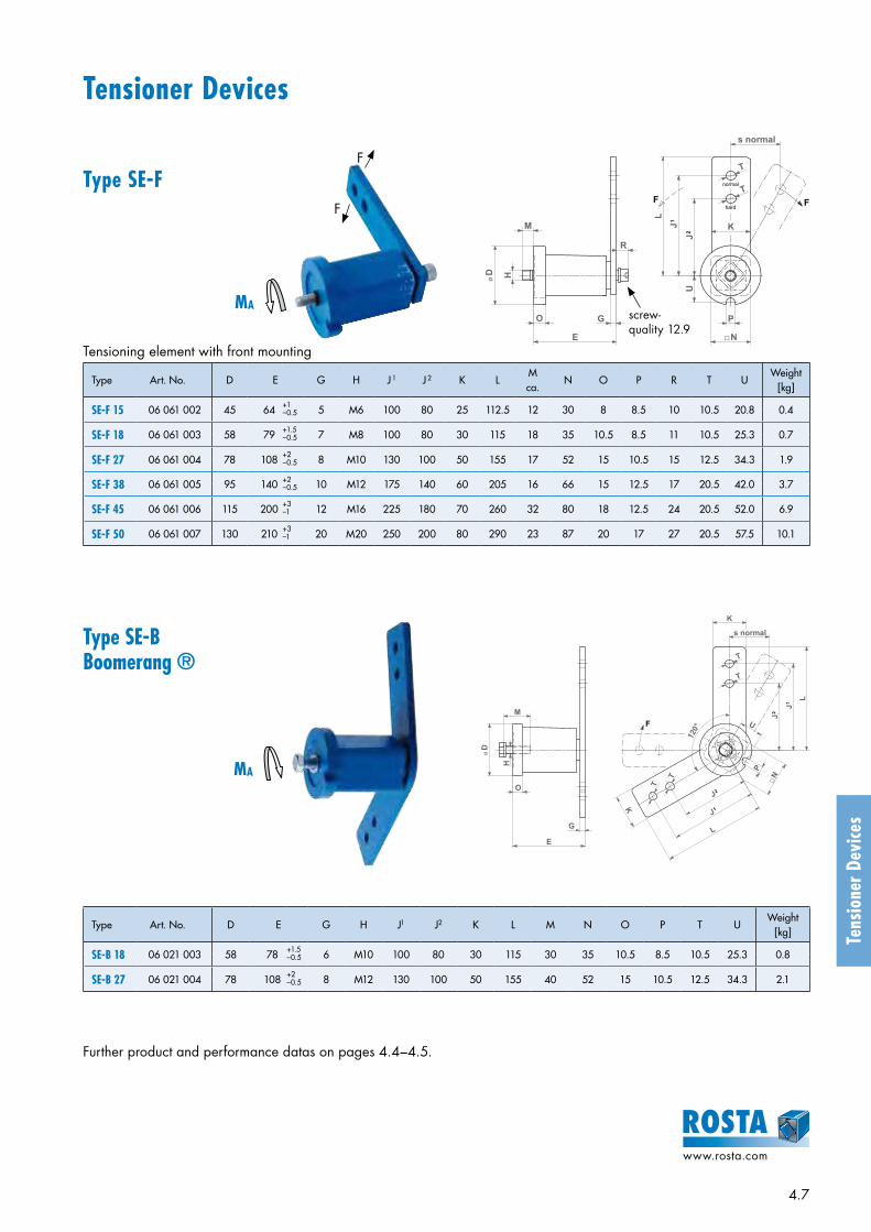
4.7
www.rosta.com
Tens
ione
r Dev
ices
Tensioning element with front mounting
Type Art. No. D E G H J 1 J 2 K LM ca.
N O P R T UWeight
[kg]
SE-F 15 06 061 002 45 64 +1 5 M6 100 80 25 112.5 12 30 8 8.5 10 10.5 20.8 0.4–0.5
SE-F 18 06 061 003 58 79 +1.5 7 M8 100 80 30 115 18 35 10.5 8.5 11 10.5 25.3 0.7–0.5
SE-F 27 06 061 004 78 108 +2 8 M10 130 100 50 155 17 52 15 10.5 15 12.5 34.3 1.9–0.5
SE-F 38 06 061 005 95 140 +2 10 M12 175 140 60 205 16 66 15 12.5 17 20.5 42.0 3.7–0.5
SE-F 45 06 061 006 115 200 +3 12 M16 225 180 70 260 32 80 18 12.5 24 20.5 52.0 6.9–1
SE-F 50 06 061 007 130 210 +3 20 M20 250 200 80 290 23 87 20 17 27 20.5 57.5 10.1–1
Type SE-BBoomerang ®
Type Art. No. D E G H J1 J2 K L M N O P T UWeight
[kg]
SE-B 18 06 021 003 58 78 +1.5 6 M10 100 80 30 115 30 35 10.5 8.5 10.5 25.3 0.8–0.5
SE-B 27 06 021 004 78 108 +2 8 M12 130 100 50 155 40 52 15 10.5 12.5 34.3 2.1–0.5
Further product and performance datas on pages 4.4–4.5.
LJ
J
T
T
K
�N
P
s normal
G
E
O
øD H
M
R
U
hard
normal
F F
1
2
MA
MA
F
F
screw- quality 12.9
øD
H
M
O
G
E
120°
J
P
J
J
�N
J
L
L
K
T
T
K
T
T
s normal
UF
2
1
2
1
Tensioner Devices
Type SE-F

4.8
www.rosta.com
Tens
ione
r Dev
ices
RollerchainANSI DIN 8187
Type Art. No.Number of teeth
W LTorque
hex nut 0.5 d[Nm]
Adjusting range track
R
Size SE
Weight [kg]
Simplex “S”354050606080100120
ISO 06 B-1ISO 08 B-1ISO 10 B-1ISO 12 B-1ISO 12 B-1ISO 16 B-1ISO 20 B-1ISO 24 B-1
N3/8" –10 SN1/2" –10 SN5/8" –12 SN3/4" –12 SN3/4" –20 SN1" –20 SN1 1/4" –20 SN1 1/2" –20 S
06 510 00106 510 00206 510 00306 510 00406 510 00506 510 00606 510 00706 510 008
1515151515131311
M10M10M12M12M20M20M20M20
55558080100100100140
20203535172172172172
22 – 43 / 23 – 4323 – 4427 – 6527 – 6540 – 8040 – 80
40 – 80 / 48 – 8040 – 120 / 48 – 120
15 /181827273838
45 / 5045 / 50
0.150.200.350.550.851.252.002.35
Duplex “D”354050606080100120
ISO 06 B-2ISO 08 B-2ISO 10 B-2ISO 12 B-2ISO 12 B-2ISO 16 B-2ISO 20 B-2ISO 24 B-2
N3/8" –10 DN1/2" –10 DN5/8" –12 DN3/4" –12 DN3/4" –20 DN1" –20 DN1 1/4" –20 DN1 1/2" –20 D
06 520 00106 520 00206 520 00306 520 00406 520 00506 520 00606 520 00706 520 008
1515151515131311
M10M10M12M12M20M20M20M20
55558080120120140140
20203535172172172172
27 – 39 / 28 – 3930 – 3736 – 5737 – 5650 – 9055 – 84
60 – 102 / 68 – 10265 – 97 / 73 – 97
15 /181827273838
45 / 5045 / 50
2.000.350.601.051.352.103.604.25
Triplex “T”354050506080100120
ISO 06 B-3ISO 08 B-3ISO 10 B-3ISO 10 B-3ISO 12 B-3ISO 16 B-3ISO 20 B-3ISO 24 B-3
N3/8" –10 TN1/2" –12 TN5/8" –12 TN5/8" –20 TN3/4" –20 TN1" –20 TN1 1/4" –20 TN1 1/2" –20 T
06 530 00106 530 00206 530 00306 530 00406 530 00506 530 00606 530 00706 530 008
1515151515131311
M10M12M12M20M20M20M20M20
708080120120160160180
203535172172172172172
33 – 4841 – 5143 – 5056 – 8459 – 8074 – 108
78 – 105 / 86 – 10590 – 111/ 98 – 111
182727383845
45 / 5045 / 50
0.250.500.951.251.502.905.206.20
Roller chain ANSI DIN 8187
Type Art. No.Number of teeth
A B C DWeight
[kg]
3540405050606080100120
ISO 06 BISO 08 BISO 08 BISO 10 BISO 10 BISO 12 BISO 12 BISO 16 BISO 20 BISO 24 B
N3/8" –10N1/2" –10N1/2" –12N5/8" –12N5/8" –20N3/4" –12N3/4" –20N1" –20N1 1/4" –20N1 1/2" –20
06 500 00106 500 00206 500 00306 500 00406 500 00506 500 00606 500 00706 500 00806 500 00906 500 010
15151515151515131311
10101212201220202020
5.37.27.29.19.1
11.111.116.118.524.1
991212151215151515
45.8161.0861.0876.3676.3691.6391.63
106.14132.67135.23
0.060.150.150.270.290.470.470.881.601.93
øA
øD
B
C
Sprocket wheel type N
Accessories Chain Drives
Sprocket wheel set type N
Sprocket wheel set type NSprocket wheel type N
R
W
L
W
R
L
R
L
W
Simplex “S” Duplex “D” Triplex “T”

4.9
www.rosta.com
Z Z Z
L
W
R
W
R
L
Tens
ione
r Dev
ices
Chain rider set type PChain rider type P
Roller chain ANSI DIN 8187
Type Art. No. W L X Y ZTorque
hex nut 0.5 d[Nm]
Adjusting range track
R
Size SE
Weight [kg]
Simplex “S”35405060
ISO 06 B-1ISO 08 B-1ISO 10 B-1ISO 12 B-1
P3/8" – 8 SP1/2" –10 SP5/8" –10 SP3/4" –12 S
06 550 00106 550 00206 550 00306 550 004
M8M10M10M12
45555580
7496126148
37486372
10.213.916.619.5
11202035
19 – 3423 – 4124 – 3930 – 61
1115 /18
1827
0.050.100.120.18
Duplex “D”
35405060
ISO 06 B-2ISO 08 B-2ISO 10 B-2ISO 12 B-2
P3/8" – 8 DP1/2" –10 DP5/8" –10 DP3/4" –12 D
06 560 00106 560 00206 560 00306 560 004
M8M10M10M12
45557080
7496126148
37486372
10.213.916.619.5
11202035
25 – 3030 – 3434 – 4640 – 52
1115 /18
1827
0.070.120.170.26
BA D
C
Roller chain ANSI DIN 8187
Type Art. No. A +0.2 0 B C D
Weight[kg]
35405060
ISO 06 BISO 08 BISO 10 BISO 12 B
P3/8"P1/2"P5/8"P3/4"
06 540 00106 540 00206 540 00306 540 004
8101012
10.213.916.619.5
37486372
7496126148
0.020.030.050.07
Mounting instructions for Chain DrivesSee also complementary mounting instructions on page 4.5.
Standard positioningThe ROSTA tensioning device should be placed on the slack-side of the chain drive, close by the smaller sprocket wheel in order to enlarge its contact-arc, therefore contact applica-tion from outer side of drive. In mounted position the tension-er-arm should stay close to parallel to the chain run, in drain direction. By ex tremely long chain drives it is recommend-able to install several tensioners or the type “Boomerang®” in order to enlarge the slack compensation.
Reversible chain driveBy reversible chain transmis-sions it is recommendable to install a tensioner on each side of the chain-strands. Due to the alternate occurring of the slack, both tensioners should only be pre-tensioned up to max. 20°, in order to retain a re-set-path of 10°, when strains are changing from slack span on working span in reversible applications.
Sprocket teeth in meshBy the initial tensioning of the chain at least three teeth of the tensioner sprocket wheel should be in mesh with the rollers. The min. distance between sprocket wheel of the tensioner to the next sprocket wheel in the chain drive should be at least four chain-pitches.
Adjustment of chain-trackThe wheel of the sprocket wheel set is adjust-able according to the position of the chain drive track. The wheel is positioned between two nuts on the threaded shaft. In changing the adjustment band “R”, the track of the ten-sioner wheel can be set according to relevant strand course. After positioning of sprocket, re-tighten the two nuts on the side. The count-er-nut “B” remains always tightened.
Chain rider type P
Chain rider set type P
Accessories Chain Drives
R
C B
Z Z Z
L
W
R
W
R
L Y
X
Glid
e an
gle
of r
ider
m
ax. 9
0°
For an ideal positioning of the chain rider/s on the threaded rod we do recommend to position them on each side by means of two nuts, secured against each other, with some play for swivelling into working position.
Simplex “S” Duplex “D”

4.10
www.rosta.com
Tens
ione
r Dev
ices
Type Art. No.Max. speed
[ rpm ]Max.
belt widthA B C D E
max.F
Torquehex nut[Nm]
Size SEWeight
[kg]
R 11R 15/18R 27R 38R 45
06 580 00106 580 00206 580 00306 580 00406 580 005
80008000600050004500
30405585130
3040608090
35456090135
268810
1416172527
5781012
M8M10M12M20M20
202035160160
1115/18
273845
0.080.170.401.151.75
Tensioning roller Type R ø
A F
E
CB D
a) Selection of the adequate ROSTA Tensioner sizeSelection table mentioning the most conventional V-belt types.
V-belt typeWidth[mm]
Height[mm]
Diam. of smal-ler pulley [mm]
Initial operation test-force FI** [N]
Operational test-force FO** [N]
Size SE* (without SE-W and SE-B)
1 belt 2 belts 3 belts 4 belts 5 belts
XPZ, SPZ 10 8 56–7175–9095–125≥ 125
20222528
16182022
11111515
18181818
18181818
18181827
18272727
XPA, SPA 13 10 80–100106–140150–200
≥ 200
28384550
22303640
15151818
18181818
18272727
27272727
27272738
XPB, SPB 16 13 112–160170–224236–355
≥ 355
50627781
40506265
18181818
18272727
27273838
27383838
38383838
XPC, SPC 22 18 224–250265–355
≥ 375
87115144
7092115
182727
273838
383838
384545
384545
Z 10 6 56–100 5–7.5 11 11 11 15 15
A 13 8 80–140 10–15 11 15 18 18 18
B 17 10 125–200 20–30 15 18 18 27 27
C 22 12 200–400 40–60 18 27 27 38 38
D 32 19 355–600 70–105 18 27 38 38 45
* General basic selection criteria:F resulting tensioning force by a pre-tension angle of 20° (see table page 4.5)FI initial operation test-force according guidelines of the belt manufacturerz quantity of belts in drive2 multiplier for the compensation of belt-slippage and/or of centrifugal force generated on belt strands.
** required test-force for belt deflection of 16 mm per 1000 mm of centre distance. The relevant deflection by shorter or longer centre distance has to be interpolated accordingly.
F = FI · z · 2
16 mm belt deflection
per 1000 mm centre distance
Instructions for belt drives
Accessories belt drives

4.11
www.rosta.com
Tens
ione
r Dev
ices
Tensioning from “inside” of the belt drive with grooved pulley– Installation in slack span of the belt drive, make sure that the belts are
maintaining sufficient contact-arc on the driver- and driven-pulley.– By extremely long centre distances between driver and driven pul-
ley it is recommendable to use on the tensioner a deep-grooved pulley to avoid excessive slack beating.
Tensioning with flat roller on belt back– The diameter of the flat tensioning roller should at least measure 2⁄3
of the diameter of the smallest pulley in the drive.– The width of the tensioning roller should be at least 20% wider than
the overall width of the belt set.– Installation on the belt back in the slack span, make sure that the
belts are maintaining sufficient contact-arc on the driver and driven pulley.
b) Modalities of tensioningSee also complementary mounting instructions on page 4.5.
c) Control procedure for checking belt tensionProceed according to the mentioned guidelines on page 4.5 and 4.10 – 4.11.
There are several instruments for checking with the adequate test-force the right tension on your frictional V-belt drive. Don't make it with your thumb, you will make an estimation mistake and your belts will wear out prematurely!
Optikrik-tester from Optibelt Spring scale tester from Gates Infrared-frequency tester
Re-tension of belts: Generally, there is no re-tension maintenance service required, however we would recommend to check the test-force after some days of running-in with the required operational test-force (see table page 4.10).

4.12
www.rosta.com
ROSTA Tensioner Devices and Accessories to meet individual customer requirements
Support bracket type WSFor the easy mounting of all standardized ROSTA Tension-ers (except SE 50).
Safety Sockets SS 27 and SS 38By uneven surfaces and/or by paint coatings, which are giving insuffi-cient friction locking, the positioning and further re-tensioning can be made with these standardized Safety Sockets.
Type Art. No.suitable to
Size SEA B C D E F G H J K L M N O
Weight[kg]
WS 11WS 15WS 18WS 27WS 38WS 45
06 590 00106 590 00206 590 00306 590 00406 590 00506 590 006
111518273845
6.58.510.512.516.520.5
5.56.58.510.512.512.5
77
9.511.51418
7.57.510
12.51520
3040506580100
1313
15.521.52430
11.513.516.5212126
273443576680
4568810
45557090110140
303238525566
46587498116140
3544557585110
101220253540
0.080.150.280.700.901.80
ROSTA
Type Art. No.suitable to
Size SEA B C D E F
Weight[kg]
SS 27SS 38
06 618 40006 618 394
2738
104128
130161
6075
1317
810
7996.5
0.350.65
A
B
O
H
N
M
J
C
E
K
D
G F
L
Tens
ione
r Dev
ices

4.13
www.rosta.com
Tens
ione
r Dev
ices
Guide roller suspensions with tensioners SE and pre-tensioning devices VSFor the accurate definition of the required pre-tension and limitation of the roller travel we do recommend the use of our pre-tensioning clamp VS allowing angle adjustments from 0 – 15° (for all SE-sizes available).
DAT (Double Arm Tensioner)For the transfer of very high tension-forces we do recom-mend to use this double arm tensioner, avoiding any mis-alignment or fault of parallelism between tensioner housing and inner square-core-generating belt eating angular off-set of the tensioning pulley.

4.14
www.rosta.com
Elastic suspension of conveyor belt scrapers with tensioner devices SEThe ROSTA suspension is offering continuous and wear compensating cleaning pressure on conveyor belt scrapers to abrade small particle sizes.For belt widths:– 400–600 mm = 2 units SE 18– 600–800 mm = 2 units SE 27– 800–1000 mm = 2 units SE 38– 1000–1300 mm = 2 units SE 45
ROSTA
ROSTA Tensioner Devices type SE-F (W) 38 for the Bus Industries
Today, nearly all busses for passenger transport are equipped with an air-conditioning system.
The Diesel engine of the bus serves thereby as ener-gy source of the cooling compressor. The piston- or rotation compressors are driven via V- or Poly-V-belts from the spur wheel of the main engine. This belt transmission requires a slippage-free power train to ensure the full capacity of the cooling compressors.
ROSTA designed for this specific application a heat resistant tensioner – powerful, compact with a long compensation travel.
Different versions available. Please do not hesitate to contact ROSTA directly.
Tens
ione
r Dev
ices
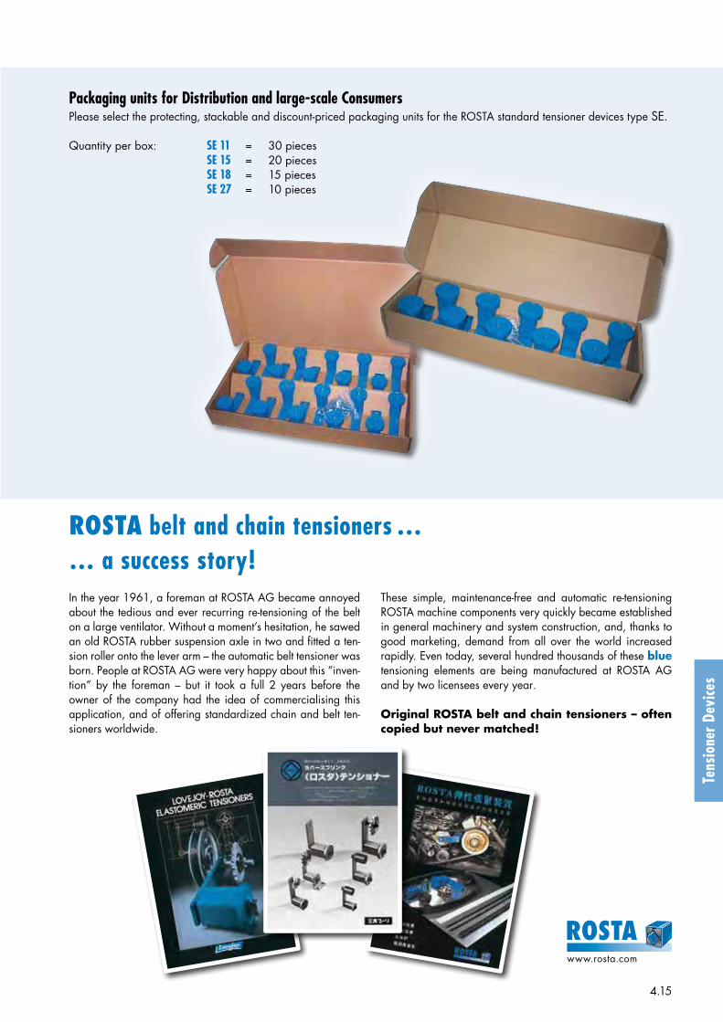
4.15
www.rosta.com
Tens
ione
r Dev
ices
Packaging units for Distribution and large-scale ConsumersPlease select the protecting, stackable and discount-priced packaging units for the ROSTA standard tensioner devices type SE.
Quantity per box: SE 11 = 30 pieces SE 15 = 20 pieces SE 18 = 15 pieces SE 27 = 10 pieces
ROSTA belt and chain tensioners …… a success story!In the year 1961, a foreman at ROSTA AG became annoyed about the tedious and ever recurring re-tensioning of the belt on a large ventilator. Without a moment’s hesitation, he sawed an old ROSTA rubber suspension axle in two and fitted a ten-sion roller onto the lever arm – the automatic belt tensioner was born. People at ROSTA AG were very happy about this “inven-tion” by the foreman – but it took a full 2 years before the owner of the company had the idea of commercialising this application, and of offering standardized chain and belt ten-sioners worldwide.
These simple, maintenance-free and automatic re-tensioning ROSTA machine components very quickly became established in general machinery and system construction, and, thanks to good marketing, demand from all over the world increased rapidly. Even today, several hundred thousands of these blue tensioning elements are being manufactured at ROSTA AG and by two licensees every year.
Original ROSTA belt and chain tensioners – often copied but never matched!
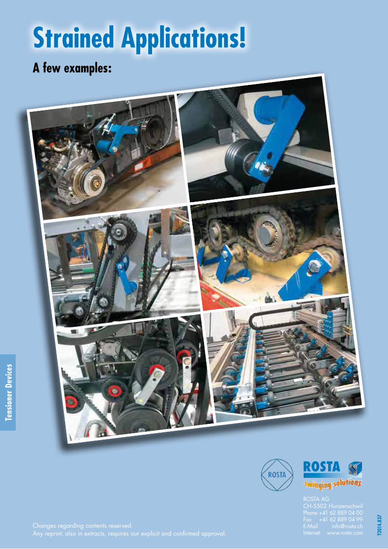
Strained Applications!A few examples:
ROSTA
T201
4.83
7
Changes regarding contents reserved.Any reprint, also in extracts, requires our explicit and confirmed approval.
Tens
ione
r Dev
ices
ROSTA AGCH-5502 HunzenschwilPhone +41 62 889 04 00Fax +41 62 889 04 99E-Mail [email protected] www.rosta.com

ROSTA
ROSTA MotorbasesSelf-tensioning Motor Mounts for all Friction Belt Drivesslippage-free – belt protecting – maintenance-free
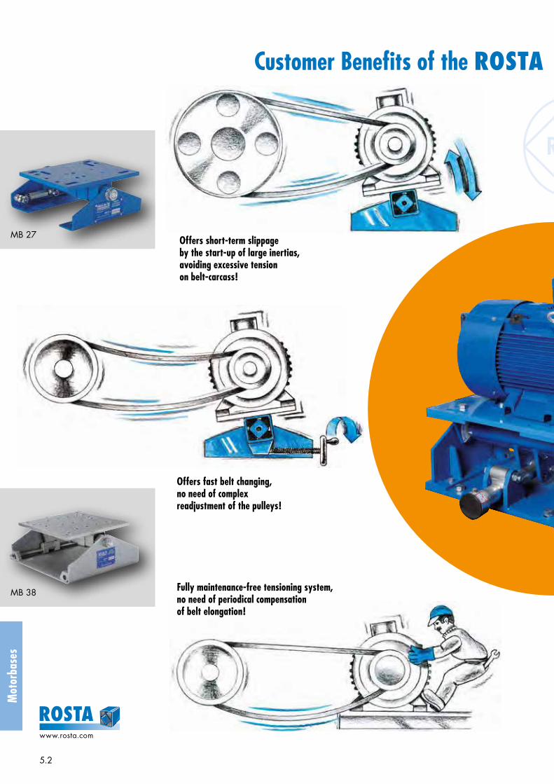
5.2
www.rosta.com
Mot
orba
ses
Offers short-term slippage by the start-up of large inertias, avoiding excessive tension on belt-carcass!
Offers fast belt changing, no need of complex readjustment of the pulleys!
Fully maintenance-free tensioning system, no need of periodical compensation of belt elongation!
Customer Benefits of the ROSTA Motorbases in Friction Belt Drives
MB 27
MB 38

5.3
www.rosta.com
Prevents from slack accruement, avoids heat generating slippage of the belts and averts from premature belt failure!
Offers ideal belt tension, constant transmission of nominal torque, less energy consumption, can lead to threefold belt lifetime!
Noiseless power transmission, all time ideally tightened belt sets!
Customer Benefits of the ROSTA Motorbases in Friction Belt Drives
MB 50
MB 70
MB 100

5.4
www.rosta.com
Mot
orba
ses
Selection table of ROSTA Motorbases according to the motor frame sizes
IEC NEMA
Type of Motorbase
Details Standard DesignMotor FrameSize
P [kW]1000 min–1
6-pole motor
P [kW]1500 min–1
4-pole motor
Motor FrameSize
P [HP]1200 min–1
6-pole motor
P [HP]1800 min–1
4-pole motor
90S90L
0.751.1
1.11.5
143T145T
0.751
11.5 / 2
MB 27 × 120Pages 5.6 – 5.7 M
B 27
100L 1.5 2.2 / 3 182T 1.5 3
112M 2.2 4 184T 2 5
132S132M
34 / 5.5
5.57.5
213T215T
35
7.510
MB 38 × 300Pages 5.6 – 5.7 M
B 38
160M160L
7.511
1115
254T256T
7.510
1520
160M160L
7.511
1115
254T256T
7.510
1520 MB 50 × 270-1
Pages 5.8 – 5.9
MB
50
180M180L
–15
18.522
284T286T
1520
2530 MB 50 × 270-2
200L 18.5 / 22 30324T326T
2530
4050 MB 50 × 400
225S225M
–30
3745
364T365T
4050
6075 MB 50 × 500
250M 37 55 404T 60 100 MB 70 × 400
Pages 5.10 – 5.11
MB
70
280S280M
4555
7590
405T444T
75100
100 / 125125 / 150 MB 70 × 550
315S 75 110 445T 125 / 150 150 / 200 MB 70 × 650
315M315L
90 / 110110–160
132–160160–200
447T449T
150–200200–300
200–250 250–300 MB 70 × 800
315M315L
90 / 110110–160
132–160160–200
447T449T
150–200200–300
200–250 250–300
MB 100 × 750Pages 5.12 – 5.13
MB
100
355S355M355L
132–160200–250200–250
200–250250250
586/7 250–350 300–350
Directions regarding customized designs of motorbases on pages 5.14 – 5.15.In case of possibly not mentioned motor frame sizes, please contact ROSTA.

5.5
www.rosta.com
Mot
orba
ses
Test force table by initial V-belt installation(standard values for the most common types of V-belts)
Test forces for ideal belt tensioningThe ROSTA Motorbase is offering with its mechanical pretensioning device the ideal calibration of the relevant belt tension, based on the test force recommendations of the belt suppliers. These recommended test forces for the most common V-belt sizes are mentioned in the test force table on the right.
ExceptionFor screen applications the belt only tigh-ten enough that they do not slip during start-up and operation.
* Test force for V-belts. By ideal belt tensioning a deflection of 16 mm per 1000 mm pulley center distance shall occur. (By shorter or longer span, the value 16 mm has to be interpolated.)
V-belt typeWidth[mm]
Height[mm]
Diam. of smal-ler pulley [mm]
Initial operation test-force FI* [N]
Operational test-force FO* [N]
XPZ, SPZ 10 8 56–7175–9095–125≥ 125
20222528
16182022
XPA, SPA 13 10 80–100106–140150–200
≥ 200
28384550
22303640
XPB, SPB 16 13 112–160170–224236–355
≥ 355
50627781
40506265
XPC, SPC 22 18 224–250265–355
≥ 375
87115144
7092115
Z 10 6 56–100 5–7.5
A 13 8 80–140 10–15
B 17 10 125–200 20–30
C 22 12 200–400 40–60
D 32 19 355–600 70–105
ø d
F
16 mm deflection
Per 1000 mm of span
Usual positioning of the ROSTA MotorbaseThese recommendations are based on practical experience, a test run will show the ideal adjustment.
Screen drive applications
„Overhead“ Configuration
ca.45°
ca.15°
„Along-Side“ Configuration
Motor ca. –15° to –45° Motor ca. +15° to +45°
ca.15°
„Foot-Mounting“ Configuration, FeederExtended “off-set” and larger Motorbase
size recommended.
ca.30°
Pump drive applications Crusher applications
„Overhead“ ConfigurationMotor plate „off-set“, towards the pretensioning device.
ca.30°
„Along-Side“ Configuration Variable LoadsMotor plate „off-set“, towards the pretensioning device.
ca.15°

5.6
www.rosta.com
Mot
orba
ses
164
4 11
50 30( )
272
B
185230
K
A
25
160
220
30 30( )
2510
100,
5
Offset 60
68
Motorbases Type MB 27 Type MB 38
ROSTA MB 38 × 300Steel parts galvanized
1
2
3 4
1
23 4
MB 27 × 120Steel parts blue painted
1 Motor plate2 Side supports3 Pretensioning device4 Rubber suspension element with brackets (MB 27: 2 brackets / MB 38: 3 brackets)
Art. No. Type
IEC NEMAWeight
[kg]Motor FrameSize
A B KMotor Frame
SizeA B K
02 200 201 MB27 × 120
90S90L
140140
100125
10.510.5
143T145T
140140
102127
10.510.5
8100L 160 140 10.5 182T 190 114 10.5
112M 190 140 10.5 184T 190 140 10.5
02 000 301 MB38 × 300
132S132M
216216
140178
M10M10
213T215T
216216
140178
M10M10
26160M160L
254254
210254
1313
254T256T
254254
210254
1313
Details regarding special designs, see pages 5.14 – 5.15.
* Is the resulting tension-travel of the motorbase not effectual, we recommend to position the motor plate in “off-set” configuration, offering enlarged compensation travel.
120
A
310
K
250
388
50 50( )
12
162
265
412,5
55 55( )
20
B
310
Offset 50
35 13,5
6
*
MB 27 × 120
MB 38 × 300
*

5.7
www.rosta.com
Mot
orba
ses
2 Support fixations MB 27: 4 oblong holes 11 × 25 mm MB 38: 4 oblong holes 13.5 × 35 mm
5 Insert and tension the belts, control belt test force Tensioning of the belts according to belt suppliers recommended test force
(table on page 5.5).MB 27: by means of MB 38: by means of threaded bushing M10 threaded shaft M16 × 1.5
4 Loosen of the shaft screw (element axis) MB 27: M16 and MB 38: M20
3 Alignment of pulleys and motor fixation 4 screws according relevant motor
size
Retension:Generally retensioning is not necessary, however, we recommend to inspect the belt tension after a few days of operation (after “running-in” of the belts).
6 Tighten of the shaft screw (element axis), start of operation MB 27: M16 (locking torque 210 Nm) MB 38: M20 (locking torque 410 Nm)
MB 38
alter position of pretensioning device
MB 27longest tensioning travel, ideal position of the MB
sufficient travel of the MB
in this position, insuf fi-cient travel is given (contact ROSTA)
Mounting instructions for MB 27 and MB 381 Ascertainment of the ideal motorbase position

5.8
www.rosta.com
Mot
orba
ses
Motorbases Type MB 50
1
2
4
1 Motor plate2 Side supports3 Pretensioning device (MB 50 × 270-1 and MB 50 × 270-2: 1 device / MB 50 × 400 and MB 50 × 500: 2 devices)4 Rubber suspension element with axial-guide bearings and brackets (depending on size = 3–5 brackets)
* All ROSTA Motorbases MB 50 will be supplied with motor plate installed in “off-set” configuration. Accord-ing to the final positioning of the base, the operating angle of the belts and the required tensioning travel, the motor plate can be altered in “centered” position on top of the element axis (recommendable by screen drive applications). Relevant threaded fixation holes are exist-ent in plate.
For possibly required additional tensioning travel of the motor plate, the adjusting block of the pretensioning de-vice can be set in the second hole-position of the friction plate (3).
3
60
28070
400
264,
5
150 20
4
B
C90
18
D
90
K
205
F
10
A
Offset E
15
BBAB
*
*
Art. No. Type
IEC NEMA
AB BB C D E F
Weight[kg]Motor Frame
SizeA B K
Motor FrameSize
A B K
02 200 516 MB 50 × 270-1160M160L
254254
210254
1414
254T256T
254254
210254
1414
320 315 245 463 25 437 41
02 200 507 MB 50 × 270-2180M180L
279279
241279
1414
284T286T
279279
241279
1414
350 350 245 463 72 452 43
02 200 508 MB 50 × 400 200L 318 305 18324T326T
318318
267305
1818
405 390 345 563 55 463 53
02 200 509 MB 50 × 500225S225M
356356
286311
1818
364T365T
356356
286311
1818
465 420 425 643 72 510 60
Details regarding special designs, see pages 5.14 – 5.15.
new

5.9
www.rosta.com
Mot
orba
ses
Mounting instructions for MB 501 Ascertainment of the ideal motorbase position
Operation area “above”Motor plate standing ~ 30° inclined
Operation area “below”Motor plate standing ~ horizontal
longest tensioning travel, ideal position of the MB sufficient travel of the MB in this position, insufficient travel is given
(contact ROSTA)
2 Support fixations 4 oblong holes 18 × 60 mm
5 Insert and tension the belts, control belt test force Tensioning of the belts according to belt suppliers recommended test force
(table on page 5.5).Operation area “below”: Operation area “above”: adjust with M20 × 1.5 screw adjust with M20 × 1.5 screw(for tightening = screw block upwards) (for tightening = screw block downwards)
4 Loosen of the shaft screw (element axis) and of the screws on friction plate(s) M20 and M16
3 Alignment of pulleys and motor fixation 4 screws according relevant motor
size
Retension:Generally retensioning is not necessary, however, we recommend to inspect the belt tension after a few days of operation (after “running-in” of the belts).
6 Tighten of the shaft and fixing screws on friction plate(s), start of operation M20 (locking torque 410 Nm), M16 (locking torque 210 Nm)

5.10
www.rosta.com
Mot
orba
ses
Motorbases Type MB 70
1
2
3
4
*
1 Motor plate2 Side supports3 Pretensioning devices = 2 devices4 Rubber suspension element with axial guide bearings
Art. No. Type
IEC NEMAWeight
[kg]Motor Frame Size
A B KMotor
Frame SizeA B K AB BB C D E
02 200 710 MB 70 × 400 250M 406 349 22 404T 406 311 22 510 410 513 643 50 142
02 200 711 MB 70 × 550280S 457 368 22 405T 406 349 22
560 565 663 793 50 169280M 457 419 22 444T 457 368 22
02 200 712 MB 70 × 650 315S 508 406 26 445T 457 419 22 630 660 763 893 70 191
02 200 713 MB 70 × 800315M 508 457 28 447T 457 508 22
630 805 913 1043 70 216315L 508 508 28 449T 457 635 22
Details regarding special designs, see pages 5.14 – 5. 15.
We will be glad to calculate your specific system, please ask for our relevant questionnaire.
* All ROSTA Motorbases MB 70 will be supplied with motor plate installed in “centered” configuration on top of the element axis. According to the final positioning of the base, the operating angle of the belts and the re-quired tensioning travel, the motor plate can be altered in “off-set” position. Relevant threaded fixation holes are existent in plate.
For possibly required additional tensioning travel of the motor plate, the fork head of the pretensioning device can be set in one of the eleven hole positions of the fric-tion plate (3).
265
365
20
KOffset E
A
AB
54
50 550
650
22
C
D
52,5
B
BB
15
350
only MB70x800

5.11
www.rosta.com
Mot
orba
ses
Mounting instructions for MB 701 Ascertainment of the ideal motorbase position
longest tensioning travel, ideal position of the MB
sufficient travel of the MB
in this position, insufficient travel is given (contact ROSTA)
2 Support fixations 4 oblong holes 22 × 54 mm
5 Insert and tension the belts, control belt test force Tensioning of the belts according to belt suppliers recommended test force
(table on page 5.5).
4 Loosen of the center screws (element axis) and of the screws on friction plates M30 and M16
3 Alignment of pulleys and motor fixation 4 screws according relevant motor size
Retension:Generally retensioning is not necessary, however, we recommend to inspect the belt tension after a few days of operation (after “running-in” of the belts).
6 Tighten of the center and fixing screws (friction plates), start of operation
M30 (locking torque 1400 Nm), M16 (locking torque 210 Nm)
Do not usecompressed-air powertools for tensioning!
1
1
2
2
Adjust tension with screws M20
Readjustment of the pretensioning device to required tension travel1. Tighten center screws and screws on friction plates 2. Loosen M12 hex-screws of fork head, select new position, assure new position of fork head again 3. Loosen the shaft and fixing screws again4. Continue the tensioning with screws M20

5.12
www.rosta.com
Mot
orba
ses
Motorbases Type MB 100
1
2
3
4
1 Motor L-supports2 Side supports3 Pretensioning device4 Rubber suspension element
Art. No. Type
IEC NEMAWeight
[kg]Motor FrameSize
A B KMotor Frame
SizeA B K
02 200 900 MB 100 × 750
315M315L
508508
457508
2828
447T449T
457457
508635
2121
490355S 610 500 28
355M 610 560 28 586/7 584 560 30
355L 610 630 28
Details regarding special designs, see pages 5.14 – 5.15.
We will be glad to calculate your specific system, please ask for our relevant questionnaire.
* For possibly required longer tensioning travel of the motor L-supports, the pretensioning device (3) shall be bolted into the front holes of the fork-head on the rubber suspension element.
570
32
200
970
25
B
865
70
57065 (65)
92031
0
450
20
K
A
740
*
new

5.13
www.rosta.com
Mot
orba
ses
Mounting instructions for MB 1001 Ascertainment of the ideal motorbase position
longest tensioning travel, ideal position of the MB sufficient travel of the MB in this position, insufficient travel is given
(contact ROSTA)
2 Support fixation 4 oblong holes 32 × 70 mm
4 Insert and tension the belts, control belt test force Tensioning of the belts according to belt suppliers recommended test force (table on page 5.5). Adjust tension with 46 mm hook wrench
3 Alignment of pulleys and motor fixation 4 screws according relevant motor size
Retension:Generally retensioning is not necessary, however, we recommend to inspect the belt tension after a few days of operation (after “running-in” of the belts).
Do not usecompressed-air powertools for tensioning!
1
21 2

5.14
www.rosta.com
ROSTA Motorbases in customized design for special applications
Fan drive in heat exchanger with vertically installed motor on MB 50, special
The MB 50 had been equipped with an additional bronze glide bearing to assure the axial position of the motor on the elastic ROSTA element.
Installation of cooling compressors in busses on MB 45 special, equipped with heat-resistant elastic inserts Rubmix 40
In this specific application, the ROSTA Motorbase is ful filling two main functions: keeps the belt tightened between Diesel-engine and cooling compressor, does prevent the transmission of compressor vibrations into the bus chassis.
ROSTA
Calculation: Tensioning Motorbase
D, R diameter and radius of the driven pulley, D=
280 mm
d, r diameter and radius of the drive pulley (above the ROSTA element), d=190 mm
n speed of the drive pulley (above the ROSTA element)
2040 rpm
P power of the motor above the ROSTA element
45 kW
i factor of the overturning torque (during start of the motor)
2.3 -
Pi max. required power during the start process of the motor = P * i103.5 kW
A distance of the pulleys
calculation 1 mm
X horizontal distance of the pulleys
700 mm
Y vertical distance of the pulleys
300 mm
a half of the belt opening angle
calculation 2 °
FRvbelt force for pretensioning one belt
721 N
FRmbelt force for the running process of one belt
721 N
sFresulting lever for tensioning the belts
214 mm
sRresulting lever of the pulled belt
308 mm
z number of belts
3 -
MSvtensioning moment during pretension process
calculation 3 Nm
MSmtensioning moment during running process
calculation 4 Nm
MPtorque out of the power
calculation 5 Nm
calculation 1
762 mm
calculation 2
3.4 °
calculation 3
924 Nm
calculation 4
924 Nm
calculation 5
1571 Nm
max. torque to the ROSTA element
1571 Nm
element choice
DR 50x400
0
50
100
150
200
250
300
350
400
450
-200 0
200 400
600 800
1000
y [
mm
]
x [mm]
d=190
n=2040
P=45 D=280
A=579
sF=200
sR1=293
center of the ROSTA element
sR2=308
Questionnaire Motorbases for friction belt-drivesCustomer:Date:Machine type:
Please consult our catalogue for further information.
Motor and operating data:1. Motor frame size5. Daily operating time
hrs.
2. Motor power6. Run-up control3. Motor speed
no4. Motor weightkg yes, power of consumption kW
Dimensions and configuration:7. ø drive pulley8. ø driven pulley9. Center distance pulleys
10. Center positioning or Off-set positioning
11. Special positionings: Wall mounting, element horizontal Wall mounting, element vertical overhead, ceiling installation12. Please send us the positioning configurationand the direction of rotation(drawing 3D, 2D or sketch)13. Please send us the data sheet of the belt selection from the belt supplier14. Further notices (temperature, chemical influences etc.):
ROSTA AG, CH - 5502 Hunzenschwil09.10
Tel.: +41 (0)62 897 24 21, Fax: +41 (0)62 897 15 10, E-mail: [email protected], Internet: www.rosta.com
min-1
mm
mm
kW
mm
Our proposal is based on the received information and technical data from you. Other, unknown factors may influence the
proper function of our products. In this case our proposal has to be revised.
Center positioning
Off-set positioning
Mot
orba
ses

5.15
www.rosta.com
Mot
orba
ses
Drive motor of slurry-pump (centrifugal pump) installed on MB 50 × 270 special
The ROSTA Motorbase is assuring the continuous and slippage-free transmission of the required drive torque to maintain the high column of slurry material in mining fluid-transport systems.
Heavy-Duty belt and chain tensioners made out of Motorbase components
The ROSTA Motorbase elements are offering extremely high torques to tension heaviest chains and oversized belt drives.

ROSTA
Unlimited possibilities!A few examples:
T201
4.83
8
Changes regarding contents reserved.Any reprint, also in extracts, requires our explicit and confirmed approval.
Mot
orba
ses
ROSTA AGCH-5502 HunzenschwilPhone +41 62 889 04 00Fax +41 62 889 04 99E-Mail [email protected] www.rosta.com
www.rosta.com
Administrative and Technical Information
1. Guidance, services and offers Please contact your local ROSTA representative listed in our representatives list on the back of the catalogue if you have any questions or concerns.
We require a full list of technical specifications in-cluding any available sketches and data sheets for the preparation of an appropriate offer. This informa-tion makes it possible for us to determine whether a standard or custom element is the most cost-effective solution for you. For complex applications, our repre-sentative or the home office will send you a question-naire about the exact specifications for what you need.
Terms and conditions for payments and deliveries are included with our offer or available on our website at www.rosta.com ➝ Company ➝ General Terms.
2. Orders and deliveriesPlease include the offer number on your order along with the exact quantity, product name and number. Please send your order to your local ROSTA repre-sentative.
3. AvailabilityMost of the standard products listed in our catalogue are available from stock through your local represen-tative or directly from ROSTA AG.
Custom pieces for a specific customer requirement are produced and delivered as specified in your order confirmation. The delivery time for special custom pieces can be reduced by signing a call order agreement (make-and-hold-order) with ROSTA AG. Please contact us if you would like to discuss this.
4. Technical informationPlease observe the capacity limits for our elements as specified in the catalogue. If you are in doubt, please contact us or your ROSTA representative.
Please follow the assembly instructions detailed in the catalogue. Make sure that your assembly workers are instructed correctly. If you have any questions, please contact us or your ROSTA representative.
Assembling elements: To attach our elements or mounts, please always use the largest dimensioned standard machine bolts possible with a minimum strength class of 8.8 that fit into the drilled holes in the elements or attachment clamps. Use an ISO 898 table or your screw supplier’s guidelines for the max-imum tightening torque.
If in doubt, control your bolt attachments using the VDI Guidelines 2230.
Use DIN 125A stamped washers to attach housings with unworked drilled holes in the casting (for exam-ple AB 50) or oblong holes (for example MB sup-ports).
5. ProvisoThis catalogue and our other technical information are intended solely for your orientation and informa-tion; they may not be construed as absolutely bind-ing in any way. We ask that you adapt the assembly and use of our products in a way suited to the pre-vailing conditions and situation.
The reproduction of this document in full or in part may only be done with our expressed written per-mission.

Ingenious technology from an approved Source – worldwide in operation!
ARGENTINA
Enrique Heuchert AR-1879 Quilmes Oeste / Buenos Aires
AUSTRALIA
CRUSHING & MINING EQUIPMENT Pty. Ltd. AU-Naval Base W.A. 6165www.crushingandmining.com.au
AUSTRIA
HABERKORN GmbH AT-6961 Wolfurt www.haberkorn.com
BELGIUm/LUxEmBURG
ATB n.v BE-1600 Sint-Pieters-Leeuw www.atb-automation.be
BRAzIL
A.T.I. Brasil BR-81030-000 Curitiba www.atibrasil.com.br
CANADA
ROSTA Inc. CA-Uxbridge, Ontario L9P 1S9 www.rostainc.com
ChILE
Riosan Cia. Ltda. CL-Concepción www.riosan.cl
ChINA
ROSTA MP (Shanghai) Co. Ltd. CN-201108 Shanghaiwww.rostachina.com
CzEChIA
Rupet Int. s.r.o. CZ-25301 Hostivice www.rupet.eu
DENmARk
JENS S. Transmissioner A/S DK-2635 Ishøj www.jens-s.dk
FINLAND/ESTONIA
Lektar OY SF-00701 Helsinki www.lektar.com
FRANCE
PRUD‘HOMME Transmissions FR-93203 Saint Denis www.prudhomme-trans.com
GERmANy
ROSTA GmbH DE-58332 Schwelm www.rosta.de
GREAT BRITAIN
KOBO (UK) Ltd. GB-Manchester M22 4RBwww.kobo.co.uk
GREECE
GEORG P. ALExANDRIS S.A. GR-185 45 Piraeus www.alexandris.com
ICELAND
FALKINN Ltd. IS-128 Reykjavik www.falkinn.is
INDIA
Technotalent Pvt. Ltd. IN-560058 Bangalore www.technotalent.in
ITALy
ROSTA S.r.l. IT-20020 Lainate-Milano www.rostaitalia.com
JAPAN
MIKI PULLEY Co. Ltd. JP-Zama-City, Kanagawa www.mikipulley.co.jp
LIThUANIA / LATvIA
Techvitas LT-94107 Klaipeda www.techvitas.lt
mALAySIA
Master Jaya Engineering SDN BHD MY-43300 Seri Kemban-gan, Selangor www.masterjaya.com.my
NEThERLANDS
Mijnsbergen BV NL-3640 AD Mijdrecht www.mijnsbergen.nl
NEW zEALAND
SAECO Wilson NZ-Auckland 1640www.saecowilson.co.nz
NORWAy
JENS S. Transmisjoner A/S NO-0612 Oslo www.jens-s.no
PERU
Ducasse PE-Miraflores Lima 18 www.ducasse.com.pe
Grupo I. S. C. PE-Arequipa www.grupo-isc.com
PhILIPPINES
Severo Syling Inc. New Manila, Quezon City Philippines 1112www.severosyling.com
POLAND
ARCHIMEDES sp.z.o.o. PL-87-100 Torun www.archimedes.pl
PORTUGAL
APRIL Lda. PT-1514-801 Lisboawww.april.pt
RUSSIA
FAM Machinery Components Parts RU-199178 St. Petersburgwww.fam-drive.ru
SINGAPORE
SM Component RS-128384 Singapore
SLOvENIA
M-Trade Gornja-Radgona SI-9250 Gornja-Radgona www.m-trade.si
SOUTh AFRICA
Orange Vibrator Motor Co. Pty. Ltd. ZA-0017 Doornpoort/Pretoriawww.orangevmc.co.za
SOUTh kOREA
SEWON Industrial Ltd. KR-Seoul www.sewonworld.co.kr
SPAIN
TRACSA S.L. ES-08015 Barcelona www.tracsa.com
SWEDEN
KONTIMA AB SE-14901 Nynaeshamn www.kontima.se
ThAILAND
VIRTUS Company Ltd. TH-10600 Bangkok www.virtus.co.th
TURkEy
Entatek Industry Ltd. TR-34776 Umraniye/Istanbul www.entatek.com
USA
ROSTA USA CORP. US-South Haven Michigan 49090 www.rosta.com
ROSTA AGCH-5502 HunzenschwilPhone +41 62 889 04 00Fax +41 62 889 04 99E-Mail [email protected] www.rosta.com
ROSTA
T201
4.83
3
Changes regarding data reserved.Any reprint, also in extracts, requires our explicit and confirmed approval.
Copyright © 2022 FDOKUMEN