the bimmer pub | october 2020 - Automotive Tech Info
36
1 october 2020 bimmer the pub October 2020 V 8 | N1 Technical Knowledge for Independent BMW Service Professionals Fuel Injectors | Headlight Technology | High Mileage Service | X5 Electronic Throttle ®
-
Upload
khangminh22 -
Category
Documents
-
view
1 -
download
0
Transcript of the bimmer pub | october 2020 - Automotive Tech Info

1october 2020
bimmerthe
pubOctober 2020 V 8 | N1
Technical Knowledge for Independent BMW Service Professionals
Fuel Injectors | Headlight Technology | High Mileage Service | X5 Electronic Throttle
®

2 the bimmer pub
Welcome to the first ever virtual annual meeting of the BIMRS organization.
We welcome members and non members alike to this event from all 50 states and several foreign countries, for some outstanding training and interaction. We encourage you to make the most of your time in our sessions, try to avoid the obvious distractions of a virtual event, and use the information presented to make your business run more efficiently and further empower your technicians to “get it right the first time.”
Due to its popularity with BIMRS members, we are including the BIMRS Diagnostic Challenge session in the lineup. A car will be presented with faults and an ISTA diagnosis plan. Attendees will break out into groups and try to come up with a solution, then rejoin the group to present their theories. The answer, as well as how the fix was achieved, will be terrific learning for all.
We won’t waste time discussing the very challenging events of 2020 other than to say that we all
perform much better when we help each other. Knowing that we are all in the same boat and that we can share our experiences, both positive and negative, gives us great power against any adversary.
But let’s focus on preparing for the year ahead. We are coming together to educate ourselves and equip our shops to make the best of a recovering environment. We believe that we have assembled an outstanding array of educators and topics to present as fine a training event as possible. We encourage you to make the most of this opportunity, ask questions, and interact as much as the virtual format will allow.
This group has relied on its founders and members to remain a credible, professional, and respected group in the industry. It takes a lot of volunteer effort to maintain that vision. We, as an organization, want to make sure that we are listening and reacting to the industry that we serve. That means that we must constantly evaluate and refine our objectives to be sure we serve our membership.
This may be the first time you are hearing about BIMRS. Be sure to check us out at www.bimrs.org and learn what our organization has to offer shops specializing in European automotive repair.
The instructors and vendors that have participated with us on a regular basis, and continue to participate with us in this virtual format, are our allies in this industry. We value these relationships that we have developed over many years as we look to the future and define our new objectives and overcome obstacles together.
Thank you for joining us in this new format. We encourage you to support the vendors, sponsors, and educators that you’ll interact with over the next couple of weeks. They are a significant part of what makes this possible. Your commitment to training and raising the bar of our industry is to be commended, and we look forward to working together in pursuit of a stronger industry and the next generation of automotive service professionals.
Thank you,
The BIMRS Board of Directors
Technical Knowledge for Independent BMW Service Professionals
bimmerthe
pub®
October 2020 V 8 | N 1
Contents
BMW Fuel Injectors Theory, Operation, Diagnosis, and RecallsPiezo injectors aren’t just for diesels. Understanding new technology is the key to successful repairs.
Publisher, VP, Business Development | Tamra Ayers Banz | [email protected] Publisher | Christopher M. Ayers, Jr. [email protected] Editorial Director | Glenn Quagmire | [email protected] Writers | Peter Caro, Eric Dibner, Dave Facciuto, Agostino (Augie) Ferron,
Luke Murray, Pierre Respaut, Wayne Riley, Gary Smith, Seth Thorson, Frank Walker
VP, Creative Director | Christopher Michael Ayers, III | [email protected] Manager | Joann Turner | [email protected] Offices | the bimmer pub, 134B River Rd., Montague, NJ 07827
the bimmer pub is an Automotive Tech Info publication. No part of this publication may be reproduced without the express written permission of Automotive Data Media, LLC. Editorial and Circulation Offices: 134B River Road, Montague, NJ 07827.
CAUTION: VEHICLE SERVICING PERFORMED BY UNTRAINED PERSONS COULD RESULT IN SERIOUS INJURY TO THOSE PERSONS OR OTHERS. INFORMATION CONTAINED IN THIS NEWSLETTER IS INTENDED FOR USE BY TRAINED, PROFESSIONAL AUTO REPAIR TECHNICIANS ONLY. THIS INFORMATION IS PROVIDED TO INFORM THESE TECHNICIANS OF CONDITIONS WHICH MAY OCCUR IN SOME VEHICLES OR TO PROVIDE INFORMATION WHICH COULD ASSIST THEM IN PROPER SERVICING OF THESE VEHICLES. PROPERLY TRAINED TECHNICIANS HAVE THE EQUIPMENT, TOOLS, SAFETY INSTRUCTIONS AND KNOW-HOW TO PERFORM REPAIRS CORRECTLY AND SAFELY. IF A CONDITION IS DESCRIBED, DO NOT ASSUME THAT A TOPIC COVERED IN THESE PAGES AUTOMATICALLY APPLIES TO YOUR VEHICLE OR THAT YOUR VEHICLE HAS THAT CONDITION. BMW OF NORTH AMERICA, LLC, THE BMW NAME AND BMW LOGO ARE REGISTERED TRADEMARKS OF BMWAG.
Cover Photo: Dave Facciuto
Keep the Lights OnHere are tips for diagnosing BMW computer-controlled Intelligent Headlight technology, including intermittent or flickering lights, lens cracks or condensation in housings, and plugged headlight washer nozzles.
BMW High Mileage ServiceThis article is intended for the young and learning technicians. This is also intended for us old folks that need another addition to our bag of tricks.
X5 Electronic Throttle DriveSometimes in the world of diagnosing BMW vehicles we run into “That Car.” The one vehicle that tests your patience, your knowledge, your understanding of theory, and your customer management skills.
20 26124
Also inside...19 Low Speed PreIgnition33 Introduction to BMW DSCi: Dynamic Stability Control Integrated34 BIMRS Schedule

feature
X5 Electronic Throttle Drive Can’t Thrive and Stay Alive — Because the DME Was Speaking Jive...Sometimes in the world of diagnosing BMW vehicles we run into “That Car.” Yes, you already know what I’m referring to — the one vehicle that tests your patience, your knowledge, your understanding of theory, and your customer management skills.
By Gary Smith

5october 2020
separate active or passive modulized components, all talking on the various networks to make things work seamlessly, safely, and smoothly… until they don’t.
Every one of us is familiar with some form of “That Car,” aren’t we? But when working with any vehicle built after 2010, especially a BMW vehicle that fits this explosive technology criteria, we’ve got to sharpen our diagnostic skills and pay attention to the small clues.
Too much can go wrong for a tech today, as compared to 15 years ago, when “only” 11 modules on a single bus line was considered a huge technological leap and a tough diagnostic challenge.
Yeah, right. Just try to be a tech today, and chase an intermittent problem affecting three or four interconnected systems simultaneously. Try to figure out the vehicle that has ONE single errant 1 or 0 in its millions of lines of computer code and worse, try to explain to that customer why the vehicle suddenly decides to lock its doors on left turns, on Tuesday nights, going uphill when the moon is blue.
Try to explain how after the vehicle depowered the throttle and the car coasted to the side of the road; then explain how it is now fine and acting like nothing happened after it was towed into the shop, and yet drives perfectly for the entire three days we have the car, only to fail on the customer again as soon as she picks it up from the shop. “Like
They used to say those cases were only 10-20 percent of the service mix equation, but today this paradigm is rapidly changing.
The onslaught of engineering complexity, along with the explosive growth in the number of active and passive modules, AI and software complexity running in the modern vehicle platform have all combined to create a trend toward “That Car” being up to 20 and 30 percent of the diagnostic and repair mix today.
These vehicles present a challenge to shop owners, customers, and technicians more now than ever, because the diagnostic calls we are having to make all over that vehicle, no matter the system we are working on, often cost into the thousands of dollars.
This means that getting through a simple driveability concern (or a seemingly simple one…) can turn into a big problem for the shop and the customer very quickly if we are not well studied in our electrical theory and testing strategy on BMWs or any other vehicle make we service these days.
Because electronics, sensing, and computer actuations drive and control virtually every mechanical component in the vehicle, and indeed even allow the vehicle to control (and drive) itself, technicians are now faced with vehicles that contain six to eight different networks supporting five different protocols and up to 100 or more

6 the bimmer pub
sands through the hourglass, so are the days of our lives...”
We come together at BIMRS every year to network and study all things BMW, which is of critical importance if we are to remain relevant as technicians and European repair shops in today’s world.
Here’s how one particular (and real) case study wentBy the way, this old 2007 vehicle “only” has 3 networks and 39 modules on board…
A 2007 E70 came in on the hook with a throttle default and dead-pedal, so to speak. It came from another repair facility, having been towed in there too, but the first shop did not solve the issue. There were however, some new parts on the car.
The vehicle had 2 DTCs, a 2CF9 indicating Throttle Valve Potentiometer 1 Circuit Fault, and the other DTC, 2CFB was indicating Throttle Valve Adaptation Value. This DTC was setting because the throttle valve wouldn’t pass the initialization for reasons explained and outlined below.
To shorten a long story, the previous repair attempts had the technician replacing the MAF sensor, and after some further diagnosis, a new throttle motor was installed. This is when the challenges started.
The new throttle motor would not accept the teach-in procedure. Wouldn’t even run the process in fact. Every tool in the shop was tried. It just kept failing every time the throttle learn command was attempted.
ISTA Fault Code Descriptions for the two recurring faults with associated data. Note neither of these faults sets a MIL. In both examples, the total POT1 and POT2 signals never add up to source voltage. This clue is key in tracking the causal source of the fault.
X5 Electronic Throttle

7october 2020
Frustrated, the technician went over his work again to be sure nothing was awry in the connections, mounting, or installation of the part. Nothing. UGH. Same condition again! Same codes, and the throttle will NOT learn no matter what.
So the original throttle valve went back in. Same thing. The ORIGINAL ETM won’t even relearn now. Huh? Uh-oh.
In looking up the DTCs and test plans for this code, we notice a pretty clear explanation for how the DME sums and uses the two Potentiometer 1 and 2 signals; it’s pretty simple in concept.
Throttle POT1 signal goes low to high from 0 to 5.0 volts, and Throttle POT2 signal goes from high to low, from 5.0 volts, to zero volts.
Cool. The DME supplies all three legs of each sensor circuit with power, signal return circuit, and ground. The power flows through the sensor, and back to the DME, with the signal on the sensor return.
Because the DME supplies the power and samples the return, it has reference of the EXACT voltage being supplied to the sensor circuit. The two potentiometer signals are then summed by the chip and compared at the point of transition as they switch from high to low.
The signal voltage summed at this point must match the supplied voltage EXACTLY or the system will set a fault, disable the throttle, and fail the initialization. Which is what was occurring in this case.
Next, we checked the live data PIDs on the X5 for Potentiometer 1 and Potentiometer 2 signals and, sure enough, the data PIDs summing the two potentiometer signals added up to only 4.3 volts, not source voltage.
A clearer understanding of the two DTCs is now coming into focus. The 2CF9 has been reporting the Potentiometer A Circuit Fault all along, and the DTC won’t clear.
The 2CFB describes a fault where the throttle learn procedure won’t run, and now we know that this is caused by the potentiometer A circuit fault, the resultant corrupt data that the DME sees, is forcing a failed initialization of the Throttle Control Valve (ETM) every time.
Now, exactly where is this fault occurring? What is causing this corrupt data? With a negative voltage reading on the Potentiometer A PID, which should not be occurring in any case, we’ve got a voltage problem here somewhere in the circuit.
The next step was to hook up the scope, and start acquiring the voltage and signal data from the potentiometer sensor circuits themselves. The sensors both had 4.99 volts strong at the pedal sensor module itself. The ground was also verified while the circuit was operated and no voltage drop appeared on the ground leg of the pedal sensor either.
A sweep test was then performed on both potentiometers. Our signals swept from 5.0 to zero, and zero to 5.0 nicely, with no dropout characteristics, so the potentiometers – the pedal sensor passed beautifully.
Now, we uncover the DME, remove the connector covers and back probe the scope directly into the circuits at the DME connector with two channels, and keep two channels on at the sensor end. We conclude that the analog voltages measured are equal and steady at both ends of the circuit.
The DME is then disconnected, the throttle valve sensor is
The two potentiometers are swept from low to high (red trace POT1) and from high to low, (blue trace POT2). The two signals are sampled and summed as they sweep past midpoint where the signals cross. The two signals must equal the sensor circuits’ supplied source voltage, or a DTC sets.

8 the bimmer pub
disconnected and the two signal wires are electrically loaded and voltage drop tested independently from the two modulized components.
Voltage drops recorded were 0.002 volt drop on one wire and recorded a 0.001 volt drop on the other, proving beyond a doubt that the wiring was intact, analog voltage supplied by the DME was good, and said voltage was in fact getting all the way back to the signal circuit connector at the DME, adding up to exactly 5.0 volts.
At this point, since everything is apart, we decided to pin-drag each of the connectors on both ends of the circuit, just in case. After this was done, everything was reassembled so we could resume testing.
But what next?Here we have a vehicle exhibiting this condition and, after hours of physical testing, literally every signal and analog voltage circuit we could test that was related to these faults has been verified as fault-free and yet, we still have this condition.
Let’s return to the scan data we were observing, and apply some math to understand the difference between what the DME sees here, and what the analog voltages and scope activity are physically telling us. Herein lies the answer to the problem with this X5.
We decided to monitor the scope and the scan tool simultaneously so we could visualize what was going on “inside the box.” We seemingly had a logic issue, because copious physical testing proved the actual
circuits and sensors were found to be working perfectly.
When we looked at this circuit from both angles and did the math, we found that the issue was that the Potentiometer A circuit’s data PID was exactly 0.7 volts – seven tenths of a volt less than the actual sensor signal voltage available at the DME pin. This was causing a negative voltage reading on the DME’s Potentiometer 1 PID. Logic said NO-GO, initialization failed, and the DTCs set immediately.
In looking at how these circuits do work inside the box, we can quantify to the highest degree possible what has happened here. What is meant by the highest degree possible, is that as technicians, we can only know what we know, and do what we can do.
But what we do know is that we can use our knowledge of how electrical components work (theory) and how electronics work (theory) to take the analog readings and use them to confirm without a doubt that the failure that we are seeing IS inside the box, the DME.
Why are we going through all this? Because the DME is a $2,500 call or more, when it’s all said and done. And there has already been a good chunk of money thrown at the car to try to fix it.
This X5 needs a DME. We just needed to be sure, as close to 100 percent as possible, that this was going to fix the car, based on the situation with the client.
Why can we be so sure that the DME will correct the fault and the 2 DTCs?
If we have perfect analog readings up to the DME connector, which is really as far as we can go testing-wise, how does the module actually process this potentiometer signal, and how does the DME know what the voltages are on each leg of Potentiometer A and Potentiometer B?
Inside modules, sensor signals are translated from the analog world (our world) to the digital world (the DME’s world) by a device called a comparator. The comparator is made up of multiple transistors, networked in such a way as to be able to interpret that analog voltage very accurately and very quickly using strings of transistors configured to split down the voltage in chunks, to target and interpret the analog voltage using feedback circuits.
Comparators, for our purposes, provide an almost instantaneous conversion of that analog voltage to digital binary information for the DME’s logic chips to use. The converted data is then processed through the programming algorithm’s truth tables, and the TCV/ETM will then be driven by the processor’s input to the ETM’s H-bridge controller, which contains the current drivers.
In addition, most all sensor circuits contain a signal sampling resistor that taps off of the sensor input. This sample is compared to the inputs at the chip level by monitoring voltage dropping across the sensor circuit and provides feedback to the chip for logic and fault detection.
Anyway, back to our vehicle under test. Our physical testing caught that the actual analog
X5 Electronic Throttle
october 2020

9october 2020
AUTOMOTIVETECH
Got Access Yet?the bimmer pub is an AutomotiveTechInfo.com (ATI) publication. In addition to the print version, the bimmer pub shares a digital platform with a number of marque-specific publications, including more than 1600 technical articles on a variety of import brands.
Technicians and shop owners can: • Completea short shop profile• Enjoy immediate, free access to
the entire library by completing a short profile the first time you visit AutomotiveTechInfo.com
• After establishing an ID and Password, you have unlimited access anytime.
AutomotiveTechInfo.com produces four new technical articles per month.
We welcome you to visit, learn and feel free to share how we can make content even more useful in your every day job of fixing vehicles right the first time.
Visit AuomotiveTechInfo.com today!

10 the bimmer pub
input voltages were exactly what the DME wants and expects. However, the DME in this case has a transistor problem inside the module.
How do we know specifically it is a transistor, even though we don’t have micro-board repair ability?
Because of the amount of voltage that is missing from the Potentiometer A circuit data PID inside the DME.
A typical transistor requires 0.7 volts of forward bias to turn it on. And as it happens, once we took the true analog voltage readings at the DME, and overlaid this data with the scan tool data PID, we were missing exactly 0.7 volts.
Because the analog signal was correct, right into the DME’s input pin, we also knew that the sampling resistor inside the DME would essentially be seeing the correct voltage too, so the issue was further on down the line. Where, exactly? Most likely, in the comparator (transistor stack) in the DME chip processing the sensor signal.
The bottom line on the X5? A DME fixed the condition.
Understanding how the DME or any other module processes signals, along with some robust physical testing and persistence helped us to not only identify, but to find, isolate and prove the cause of the fault on the X5 accurately without replacing any further parts on a guess and a prayer.
During our BIMRS class on PWM and 3-Phase Diagnosis in BMW cars this October, Eric Scharping and I will be carrying the sensing
and circuit diagnosis techniques outlined here, over to the output side, as we study Pulse-Width Modulation, Smart Motor Controls, and 3-Phase electrical applications in BMW vehicles.
We believe the tough ones can be solved efficiently when we
put BMW service information together with a scope, a solid understanding of theory, and a strategic and careful approach to your test plan.
Enjoy the BIMRS Virtual event this year, it is going to be AWESOME! •
Here is a crude depiction of an approximate succession comparator, used to process analog sensor voltages to digital information. This is known as an ADC, or Analog to Digital Converter. We know it as a “chip,” or part of a chip.
Schematic showing DME and TCV sensor (APP) testing points. The DME was dropping 0.7 volts of the POT1 signal. This was a fault inside the DME’s control chip or board. (Image courtesy DiagNation.)
X5 Electronic Throttle
october 2020

11october 2020
PENTOSIN HAS BMW COVERED.
PENTOSIN TECHNICAL FLUIDS ARE DESIGNED TO MEET THE STRICT STANDARDS OF BMW.
FROM THE FIRST FILL TO THE LAST.
VISIT OUR ONLINE CATALOG AT SHOWMETHEPARTS.COM/CRP FOR COMPLETE APPLICATION DATA.
MOTOR OIL0W-20 BMW LL-14 FE and
in 2020: 0W-20 LL-17-FE
5W-30 HP BMW LL-01
5W-40 SP BMW LL-01
5W-30 SPIII BMW LL-04
5W-40 HPII BMW LL-04
HYDRAULIC FLUIDCHF11S
TRANSMISSION FLUIDATF 5 ZF 4 HP // ZF 5 HP
ATF 6 ZF 6 HP
ATF 8 ZF 8 HP BMW ATF 3+
ATF 9 ZF 9 HP BMW ATF 3+
ATF 44 BMW # 83-22-7-542-290
FFL-3 ZF TE-ML11
BRAKE FLUIDDOT4 LV ISO 4925 Class 6
DOT 4 ISO 4925 Class 4
ANTIFREEZEPentofrost NF (Blue, full concentrate)
© 2020 CRP Industries Inc. All rights reserved.
feature
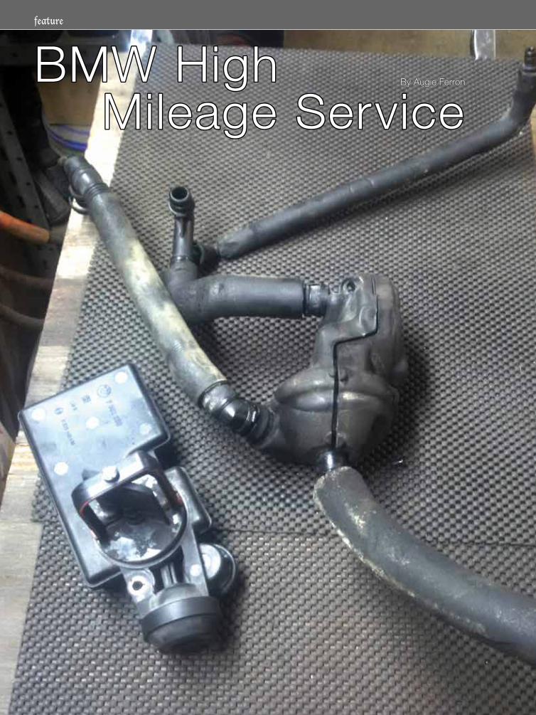
BMW High BMW High Mileage Service Mileage Service
By Augie FerronBy Augie Ferron

13october 2020
The saga of this BMW enabled the use of various testing tools over many months off and on, when the vehicle owner returned for known service updates and repairs. The article describes tools from a factory setup to Android devices with “olde school” slack tube manometer and simple meters that send data via Bluetooth.
Victim2004 BMW X3 2.5i with M54 and manual transmission.
To date having 250,000 kilometers, this model has been well taken care of.
The only non-factory installation is a radio with folding screen.
Simple adviceModern scan/test equipment offers many ways to capture events with captured images, but at times a video recording may offer different results during a mixed city/highway road test. Look at it as “proof over time.”
Adding extra “high tech” recording software is not difficult.
The best option with BMW models is the factory equipment because of the incorporation of bi-directional control with test plans and supporting documents. There are other options with less setup time.
Incident 1The first complaint (210,000 km) about the BMW was a constant/repeating rough running condition on the first start and the occasional misfire while driving.
The factory equipment offers a view of the various network connections and a quick view of any controller that may or my not have a fault. That view will also include any controller that may not be communicating within the network.
After the initial identification, the control unit tree indicates three controllers with faults and a radio that is not communicating (it was replaced). The virtual PDF printer saved each step and repair.
The primary DME fault leads to a lean condition. Data
This article is
intended for the
young and learning
technicians, and us
old folks that need
another addition to
our bag of tricks.
Tools usedLaptop running ISTA + and ICOM
Screen capturing and screen (video) recording software
Built-in/added PDF printer to save scan data
90 amp power supply with DLC breakout box
Android tablet running Launch (Easy Diag) and various OBD II platforms
Olde school Dwyer slack tube manometer and mechanical vacuum gauge
40, 60 and 200 amp clamp testing
Sperry Smartmeter
Primary scan
Opposite page: The shaft at the intake flap was also damaged upon inspection; therefore a complete kit (cold weather package) was installed.

14 the bimmer pub
via MAF is an indicator, but “standing on the fenders” and attempting to remove the oil filler cap was a chore. It would seem this model has an internal leak with the ventilation system. The choice was to replace the defective assembly with the intake manifold attached. Disassembly/inspection offers an added defect.
An external oil leak at the valve cover was noticed with this high mileage vehicle, so it was certainly prudent to remove the ignition coils (oil soaked on three) and replace the gasket. Cleaning the coil towers and replacing the spark plugs proved a success with a cautionary mention to the owner for a future replacement of the ignition coils.
With this many miles/kilometers, it wasn’t such a surprise that the internals of the engine were so clean with proper service over a long period of time. That meant high quality oils and fuel had been used. Now that all the parts were installed, what does the repaired ventilation system look like with a vacuum gauge and a slack tube manometer? Unfortunately there are no “before” images, but the “after” images are a good known guide.
Attaching a simple vacuum gauge to the dipstick opening offers a view of the ventilation system not having an internal leak. The reading should be near zero. It is simplistic but it works. High vacuum may indicate internal damage to the ventilation system.
Reinsert the dipstick and think about this. Now imagine positive pressure at the crankcase. Would that also mean serious blow-by pressure or compression gases entering the crankcase?
Is there another simple test?An aftermarket oil cap was found to fit many BMW and VW/Audi models. The cap was modified by drilling a hole on the top and inserting a new/used elbow from a battery ventilation tube with some JB Weld.
A hose is connected from the test cap to one open end of the slack tube. The other end of the slack tube is open to the atmosphere. With vacuum applied (engine hot and at idle), the red liquid will rise
on one side while the opposite side drops.
The difference at each level is the sum of the readings.
Gasket replacement
Dipstick vacuum test
Oil test cap
BMW High Mileage Service

15october 2020
This indicates the amount of vacuum measured (inches of water).
MAF valuesThe original measured value was about 3.29 g/s at a hot idle condition.
The expected value should be close to 5.0 g/s and was after repairs.
Stick test
Therefore, keep all records and research to match known values.
Clearing the remaining faults and resetting learned adaptations gave this model a new lease on life.
Incident 2The same vehicle owner called and expressed something odd about throttle control and a complete lack of engine torque. This also included a shudder when the BMW began to move/accelerate. The shudder was repeated at the repair facility.
A quite interesting scan and capture found the throttle pedal was complaining but gave up some interesting data.
The madness was to try out other tools and create some images for the younger technicians that were interested. ISTA, an Android device, and even graphing data from ISTA created a teaching moment.
With ISTA, the potentiometers were tested from closed throttle to wide open throttle. During the throttle opening in a slow and deliberate application, screen capturing software
was faster than writing the output of each potentiometer
Seven screen captures offered the following data:
P1 V P2 V APP0.88 0.35 1.950.88 0.36 2.340.88 0.77 2.340.84 0.94 1.170.00 1.07 0.003.5 1.29 0.003.54 1.82 0.00
The graph offered the defect at the throttle pedal potentiometer as immediate proof and repeatable every time.
Is there another test?With another “quick tool” and used during road testing, the Launch EasyDiag was set up to read the “bad actor.” Looking at the next image, follow PV1 in the Excel graph and match the repeating drop on the next image that was recorded over time. Each drop was the movement of the throttle from closed to WOT.
Oxidized screws were the enemy when the part arrived!
Incident 2
Throttle defect

16 the bimmer pub
The cureExtra coffee, liquid SeaFoam, lots of patience, and a neat tool from MAC that “bit” the internal hex of the bolt(s) allowed complete removal without any damage
When the parts are placed side by side, it is obvious that this new part was updated along with the wiring position mounted higher than the original.
To ensure perfect connectivity, the original harness was cleaned and Stabilant-22 was applied to the connection blades.
What does it look like with a “quick tool?” With the Android device and “dongle” connected to the DLC, the image indicates that the new pedal operates and, at the same time, the Android device will delete all the DME faults.
As a last measure, ISTA will capture the final scan.
With the faults deleted and performing a simple road test, ISTA should provide a cleared network scan.
Extra tests with the AndroidWith ISTA and the Launch tool, there was a need to know how close each tool performed with this BMW model. ISTA is the “no nonsense ” tool of choice with amazing features built into the system. One drawback is the setup. It can be awkward with extra in-vehicle power supplies during a road test (a second technician is required). Screen video recording can be an aid to record the road test with playback.
The Android version is much faster and far simpler to use.
Added to the Android that’s in service is screen video recording software with playback ability. This Android version, however, does NOT include bi-directional control compared to ISTA. Not included is any test plan compared to ISTA.
Comparing the network connectionAnother difference is the terms used between the diagnostic platforms when describing the installed controllers. There are similarities, but attention needs to be paid to access the named controller that’s being tested.
CommonalitiesBoth ISTA and the Launch have access to:
• Read the model and display the information related to the model
• Read all controllers on the network
• Read and produce all faults related to the controllers in communication
• Clear all related faults that are communicating
Sensor 1
New pedal
BMW High Mileage Service

17october 2020
The following images are a quick snapshot of the identification and list of controllers that are communicating with the scan tool.
The list of controllers is stitched together because the Android list continues with a “swipe up” motion.
Incident 3In between incident 1 and 2, there was a period when the owner required a complete
clutch assembly replacement. How the 02 sensors failed is a mystery, but one “tell tale” sign is the red/orange silicone that is sealing the connection after the catalytic converters. That part of the exhaust was removed at the transmission shop. It is assumed that modern shops know enough to never use high temperature silicone to seal exhaust flanges.
A decision was made to replace the “complaining” oxygen sensors with Bosch versions.
Total mileage and time were part of the discussion, with the agreement that all four sensors would be replaced. Always clean the threads!
Stable potentiometer
Final scan
Identification
Complete scan

18 the bimmer pub
Graphing a parasitic drawDuring Incident 1, there were a few faults that were related to the General Module. All of the faults were saved, printed and deleted.
00000F GM Anti-trap protection of power window unit rear driver’s side
000081 GM Anti-theft alarm memory door contact front driver’s side
000088 GM Anti-theft alarm memory engine-bonnet/hood contact
00008A GM Anti-theft alarm memory interior movement detector front
At the time, all window and latch operations worked as intended, but there was, in the previous week, a very cold snow/ice condition that lasted a few days. With the vehicle thawed, input and output tests passed and the battery was charged/tested. The vehicle didn’t complain again.
The BMW was tested for a parasite with the common amp clamp(s) and a Fluke multimeter. One issue was “babysitting” the BMW and watching the display over time. This model tested OK.
The need at the time was to measure multiple vehicles that had either a parasite or no parasites at all. Testing included vehicles that were in sleep mode but with keys either in the ignition switch or not. Testing included direct injection vehicles that were in a cold or hot state. All models were tested over time.
This particular vehicle was tested with the Sperry Smartmeter that has Bluetooth communications with an Android or IOS device.
The meter was never intended to connect to an amp clamp; this one is and works well!
Now the BMW can be graphed over time with the Bluetooth device on the work bench. No intense babysitting required.
The BMW has a battery in the cargo area. The negative connection is one cable attached to a clean connection on the body. Orienting the amp clamp correctly offers the image on the Android or IOS device. A screen capture offered the parasitic load when the driver’s door was opened and closed for the experiment.
The path of least resistanceElectrical energy will always take low resistance paths and will include the one with least resistance. Electrical energy will also take every other path available to it.
TranslationLearned over time was the simple fact that multiple ground connections at the battery negative cable are not an accurate test. One major problem is disturbing a “bad actor” to reset and possibly misbehave in the future. That means disconnecting the battery negative and applying a single service cable may create more problems than the vehicle arrived with.
With this particular BMW, the test was set to 15 minutes and recorded every second. The display offered one second interval
tests that measured the parasite every second for 354 seconds. This test was applied multiple times with no key in the ignition, but it seemed to go to sleep faster if the door was opened and closed once and no one entered or “woke up” the ignition system.
Different model tests seem to repeat with time intervals that are longer or shorter. The same tests were applied to vehicles in sleep mode but with the key removed. That “key” parasite was graphed. Some other models also expressed a last spike that appears to command sleep mode within the last moments of the graph. Different models and manufacturers display this spike at different times and intensity. Most, however, look similar to each other, recording different longer or shorter sleep time.
In later articles, much more information and tests will be
Parasite recording
BMW High Mileage Service

19october 2020
provided as an aid to testing, measuring, and especially discounting false and repeated misinformation as to measuring any parasite and or network sleep mode.
This model tested perfect despite a radio replacement.
Parasite testing rulesAsk for the customer’s interpretation of what happened to the vehicle.
Scan and record the condition of the vehicle when it arrives.
Follow obvious defects and repair them first.
Open and latch the needed doors, hood, and gate.
Test/charge the battery, and it must be in perfect condition.
Test at ONE ground cable only; multiple ground connections are misleading.
Ensure there is no added or non OEM equipment installed.
Any document that professes a parasite test across a fuse is used as a guide only.
Advertisements about networks that take an hour to two hours to enter sleep mode “must have sold lots of batteries” in the course of testing.
Direct inject models are completely different to test.
Always be aware of software updates with the model being tested.
Test in a building when the vehicle is COLD or at ambient temperature.
While testing for a parasite, measure and record CAN or serial data activity.
A scan tool or anything that is attached to the DLC is a parasite.
Be attentive to proximity remotes (place them in a metal cookie container). •
Visit these interesting linksdwyer-inst.com/Products/ManometerIntroduction.cfm
stabilant.com/appnt01.php
sperryinstruments.com/en/smartmeter
One last mention, and poking a bit of fun towards Sperry; when was the last time a AAA battery was read on the AC scale with a voltage of 000.4 V?
(Low Speed PreIgnition) aka “Stochastic PreIgnition (SPI)”
Abnormal combustion can sometimes be attributed to combustion chamber particles which can be caused by debris inside the intake port and fuel droplets coalescing around the intake valves.
LSPI is unpredictable; events can be sudden and costly, causing severe internal engine damage.
Engineered modern oils requirements: a) Operate under any condition
b) Anti-wear properties
c) Cleaning properties
d) Oxidization control
Harsh environmentDirect injected engines use fuel pressures far greater than those found in port injection engines. DI engines also experience greater cylinder pressures.
Fuel and oil mixingThe API SN Plus is the current specification oil that all DI engines require to sustain the harsh environments. This will include the ability to achieve increased economy and longevity.
LSPI is problematic if using low quality fuels exhibiting boiling properties and octane numbers that can contribute to LSPI counts or incidences. Another fuel prediction is the heat or engine temperatures, that low quality fuels can cause.
A DI engine that’s not running at design temperatures will not expand internal components to specification. Cooler than normal engines will have higher than normal levels of blow-by, meaning that the fuel could dilute the engine oil.
Under-specification fuel will have major consequences that will include oil dilution. Diluted mixtures of fuel with the oil can migrate into the combustion chamber via the piston rings if the engine runs cooler than normal.
Any migration into the combustion chamber that is unusually hot while remaining within that chamber can cause LSPI.
LSPI has been studied to death with distinct analysis to ensure that DI engines use the correct fuel/oil specifications. •
Low Speed PreIgnition (LSPI)
LSPI phenomenon (Courtesy Professor. Dr. Boris Zhmud)

feature
BMW Fuel Injectors Theory, Operation, Diagnosis, and Recalls
Piezo injectors aren’t just for diesels. Understanding new technology is the key to successful repairs.
New decoupling rings must be installed each time an injector is removed or replaced.
By Dave Facciuto

21october 2020
When we discuss BMW fuel injectors we will focus primarily on the direct injection type or GDI. Port injection has been phased out and you will mostly see the direct type injectors in the field. Direct injection is not all that new.
BMW used direct injection in airplane engines in the 1930s. However they did not implement DI in automotive applications until the mid 2000s. In 2007 BMW introduced the N54 engine featuring direct injection and turbocharging on the 335i model.
BMW’s current lineup features almost all turbocharged and direct injected engines. BMW made the switch to direct injection for good reason — namely, improved fuel efficiency, lower emissions, better performance, and cooler cylinder temperatures. Are they bullet proof? Of course not . Yes Virginia, there is a recall. But before we get into that, let’s delve into what makes the modern BMW injector work.
Modern BMW piezo injectorsAlthough manufacturers such as Bosch, Siemens, and Delphi are all working on a solenoid
based injector design that will perform as well as the piezo type, we will focus on the latter as these injectors are what you will encounter most often.
According to Bosch, which introduced piezo injectors to the industry, a piezo actuator acts up to five times faster than a standard injector solenoid and the motion is frictionless. This translates into precise fuel metering and allows for multiple injector events to occur each combustion cycle.
A piezo element only expands a miniscule amount, so hundreds of slices are stacked on top of each other so that the net movement is only about 0.004 inch. The actual movement is microscopic, but enough to make the piezo element act as the valve.
Since this movement is a downward motion, a lever and spring setup inside the injector allows the pintle to open and close. In a piezo injector, the electronic engine management system sends an electrical signal to the valve, much like the solenoid operated valve. But the unique property of a piezo crystal, as mentioned before, is that it changes shape when exposed to electric current.
First high pressure fuel enters the injector; all the pressure throughout the injector is equal at this point. The piezo stack is energized by the fuel control unit and the injection event takes place. Piezo injectors are quieter and more precise than solenoid units, a huge benefit when microseconds count!
Some basics of piezo or high voltage injectors:
• The drivers in the DME control both voltage and current.
• The driver will provide a boost voltage of up to 200 volts.
• The driver will boost current to around 10 amps for a few hundred microseconds.
• Voltage returns to approximately 13.5 V and the holding current drops to around 3 to 4 amps for the remainder of the injection event.
Fuel system monitoringWe won’t spend much time on the theory and operation of the GDI system and how it works other than a bit of a refresher in regard to how the monitoring system affects the injectors. Previous articles have looked in depth at the GDI system as a whole. The self-diagnosis system as it pertains to fuel system monitoring, and particularly fuel injectors, can be broken down into:
• Lambda adaptation
• Trim control plausibility monitoring
The inner workings of a piezo injector. Note the stacked discs.

22 the bimmer pub
BMW Fuel Injectors
• Diagnosis of injector aging
• High pressure fuel control system
Diagnosis of injector aging is simply a way of monitoring injector adaptation. A small proportion of the short term fuel deviation is used for diagnostic injector aging and is stored as an injector adaptation value in a separate map. The values of the separate map are renewed every 497 miles. A fault will be stored if the injector adaptation exceeds a calibratable minimum or maximum value.
In the monitoring of the high pressure fuel control system you will be dealing with codes such as p3282, p3284, p3003, and p3090. The high pressure system consists of a common fuel rail for all high pressure piezo injection valves, a fuel rail pressure sensor, a high pressure fuel pump with a built in fuel volume control valve, and an overpressure valve.
Based on the engine load and speed, the high pressure needs to be adjusted to pressures set forth in the map. To accomplish this the pressure in the rail is measured and controlled with the help of the fuel volume control valve. Using the desired fuel mass and pressure preset value, a precontrol calculates the driver signal as inputs for the fuel volume control valve.
In diagnosis, the high pressure monitoring system analyzes the difference between the measured fuel pressure and the set point pressure. Your scan tool often has PIDs that display requested fuel pressure and actual pressure. The monitor determines whether or not the set point value of the fuel rail
pressure can be adjusted by the high pressure control.
If the rail pressure is too high, the result in the difference in the two values is negative. If the pressure is too low, then the difference in the two values will result in a positive. If either of these two values, negative or positive, exceeds a calibrated threshold for a certain amount of time, a malfunction will be detected with a fault set. The high pressure sensor signal is also monitored for plausibility by using the lambda controller.
If the adaptation shows rich while the fuel pressure controller is below a calibrated threshold, then a too high pressure signal will be detected. The reverse will occur when a lean condition is detected and the fuel pressure controller is above a calibrated threshold. This will result in a too low pressure signal.
DiagnosisBMW models with turbocharged N54 engines and MSD80 DME software can develop fuel injector MOSFET driver failure. MOSFET stands for Metal–Oxide–Semiconductor Field-Effect Transistor. It is a field-effect transistor where the voltage determines the conductivity of the device. It is used for switching or amplifying signals, in this case switching the injector.
The ability to change conductivity with the amount of applied voltage can be used for amplifying or switching electronic signals. This driver failure will cause an injector to stop delivering fuel and an engine misfire to occur. The Check Engine light will be ON with these related fault codes (error messages):
• 30BA DME digital motor electronics, internal failure
• 30BB DME digital motor electronics, internal failure
• Here are some of the affected models:
• 2007-2013 BMW 135i (E82)
• 2007-2008 BMW 335i (E90)
• 2007-2008 BMW 335xi (E91)
• 2007-2010 BMW 335i (E92)
• 2007-2010 BMW 335i (E93)
• 2009-2010 BMW 535i & 535xi (E60)
• 2009-2016 BMW Z4 35i (E89)
BMW models with MSD80 DME software may set the fault codes 30BA or 30BB. These fault codes set when fuel injectors on bank 1 or bank 2 develop circuit faults or when an injector MOSFET driver fails. Most times these fault codes will be permanent and will not clear. However, be mindful there are situations where the fault codes will set intermittently.
When diagnosing piezo fuel injector fault codes it is a good idea to begin by checking fuel injector voltage and current using a lab scope. This will aid in determining whether the fault code is caused by the injector itself, the circuit, or the driver.
Remember, piezo injectors normally operate at extremely high voltages, so use extreme care when working around connections. Do not touch any of the injector terminals while the engine is running. Set your scope to display voltage and current at the same time. Set the voltage range to -200 volts DC to +200 volts DC. Current range should be set around 10 amps. Beginning on a cylinder with no faults, establish a possible known

23october 2020
good pattern. Insert a back probe into the white wire, then attach your current probe around the same wire. Be sure to consult the wiring diagram for the specific model you are working on.
Voltage should range from 0 to almost 160 volts DC. The current pattern will peak at around 8 amps when the injector is switched on, then the current will drop while the injector is open, and, finally reverse when the injector is switched off. Current reverses because the piezo element acts as a capacitor, and when switched off, the voltage travels back through the injector. If the
pattern isn’t right you most likely have a faulty injector or driver. Most times when the DME is at fault, the current pattern will try to climb, but fail. The MOSFET drivers fail when the attempt to charge the injector begins.
In the event you feel as though you have a faulty injector or driver, turn off the engine, remove your test equipment and disconnect all the injectors. Connect your scan tool, either ISTA-D or a factory compatible scan tool, and try to clear the codes. If the codes will not clear you most likely have a DME fault or wiring issue. If the fault clears then most likely the injector is faulty. Double check this as these babies are expensive!
In checking your wiring integrity you will want to perform a voltage drop test of the wiring under load. This is a bit tricky in that, due to the high voltages the engine management applies, you can’t energize the circuit just by powering it up. You will have to supply your own load. First disconnect the negative battery terminal, then locate the DME and disconnect both DME connectors. Consult an accurate wiring diagram and use your ohmmeter to verify that you are on the correct wire from the DME to the injector.
Now that you have identified the correct wire, connect the injector side of the wiring harness to battery negative. Then, at the DME side, connect a test light (the load) to the injector terminal to be tested, then connect it to battery positive. You can use the jump start terminal if you wish, and the test light should illuminate. Use your voltmeter now and check the voltage at the DME connection and you
Your lab scope should graph both the current ramp on and off plus the voltage patterns. (Courtesy Opus IVS™)
In the case of this 535 model the injector wires are white.

24 the bimmer pub
should have 0.2 V or less. Check the integrity of all your suspect circuits including both legs of each injector.
If the fault code does not clear even when disconnecting all the injectors, and if the injector wiring tests OK, the issue has been isolated to the DME. There is a method for opening the DME and checking the MOSFET; however there are no serviceable parts internally so a new unit from BMW is the answer.
We have covered a possible electrical failure of the injectors and drivers, but what about a mechanical failure? A common symptom of a mechanical failure is a misfire coupled with: black smoke from the tailpipe; rich smelling exhaust; engine oil dilution; and even engine hydro lock. You may have misfire codes and rich fuel trims alerting you to the problem. What typically happens is the injector doesn’t completely shut and drips excess fuel into the cylinders. This is why it is imperative to not let these symptoms continue in your customer’s vehicle, and to repair the condition as soon as possible.
Recalls and warrantiesBMW has issued a recall on certain models. This emissions recall involves E60, E61, E71, E82, E88, E90, E92, and E93 vehicles with N54 engines which were produced from 04/02/2007 through 11/30/2008. The piezo
injectors may cause misfire faults with erratic engine operation.
Your customer may be entitled to repair from the BMW dealer. To check for recalls go to: www.bmwusa.com/safety-and-emission-recalls.html
Also, BMW has issued extended warranties on injectors for certain models according to TIS bulletin SI B01 05 18. N63T ENGINE FUEL INJECTORS: LIMITED WARRANTY EXTENSION TO 10 YEARS/120,000 MILES. TIS bulletin SI B01 02 15 has also extended the warranty on N54 Engine Fuel Injectors – Limited Warranty Extension to 10 Years/120,000 Miles.
New injectors have been released from BMW for the N63, N74, and N54 with “improved internal filtering” and “special thermo compensating oil.” Unfortunately the new injectors have calibration and construction differences that prevent them from being intermixed with older style injectors “index 10,” but they can be intermixed with newer “index 11” injectors. So in some cases of injector failure, BMW owners might have
to replace ALL fuel injectors depending on which injectors are already installed on their BMW.
What do all those numbers mean?Here is a typical FI part number: 13537585261-12. The following is how the part number will read on the actual fuel injector. Here is the breakdown: BMW Part Number -13537585261 Fuel Injector Index: 12. BMW only manufactures injectors with an index of 11 or higher. There are two points to remember:
1. Direct injection fuel injectors must use a new decoupling ring (13537564751) and a new seal (13537584315) when removed or replaced. These part numbers may vary depending on the fuel injector part number. New injectors will come with a seal installed, otherwise you will need a special tool to expand the seal when installing and compress it again.
2. Fuel injectors with an index of 10 or lower cannot be paired with injectors that have an index of 11 or higher. They are calibrated differently and
You should have 0.2 V or less when checking the voltage drop of the injector circuit. (Courtesy Opus IVS™) This removal and installation tool is needed for the
N55 engine. With N54 engines you can use the slide hammer type puller.
BMW Fuel Injectors

25october 2020
the newer injectors (index 11 and up) are made as a replacement for the faulty/defective injectors (index 10 and lower). This means that if the customer is replacing some injectors, but not all, you must check the index on the remaining injectors and to see if any of them have an index of less than 11. If so, those injectors will have to be replaced at the same time to prevent driveability issues and possible catastrophic engine damage.
In the end, all of the fuel injectors on a particular engine must have an index of 11 or higher. Most shops agree you should go with all new injectors index 12 and not have any issues in the future.
CalibrationDuring vehicle assembly, after installation of the DME control module, the calibration values of
each installed injector are stored in the DME control module. The calibration values are allocated to the individual cylinders according to the installation of the injectors. The injection volumes calculated by the DME control module are corrected by these calibration values, thus improving the exhaust emissions. Using ISTA-P or compatible scan tool these values can be changed or new values entered. The calibration values are printed in two blocks each with three digits on each injector. The inscription can be located either on the plastic bracket or on the metallic upper part. If injectors are renewed or replaced, it must be assured that the printed calibration values of each injector are assigned to the correct cylinder in the DME.
The menu on your scan tool will read something like this:
• Vehicle identification
• Function selection
• Select “Service functions”
• Select “Engine electronics”
• Select “Adjustment functions”
• Select “Adjust injectors”
• Injection quantity compensation
For each replaced injector, the adjustment value must be entered according to the installation location.
As these vehicles get more mileage on them, you are bound to see more fuel injector failures. Providing accurate diagnosis coupled with the latest parts updates will ensure your customers of a quality repair and peace of mind. •
Be sure the latest index markings are on the injectors you are replacing (BMW TSB SI B13 14 10).
Calibration numbers marked on the injectors
AUTO
MOTIV
ETECH
AutomotiveTechInfo.com
Log on for free access to 1600+ technical articles!

feature
Keep the Lights OnBy Frank Walker

27october 2020
BMW Intelligent Headlight systems feature adaptive lighting technology that responds to different driving conditions. The state-of-the-art lighting provides better illumination for night driving, highlights pedestrians and potential obstacles in the road and, depending on the BMW model, reduces glare into the eyes of oncoming drivers.
These computer-controlled lights may experience rare problems such as flickering while driving, flashing on and off at ignition startup, trapping moisture inside the headlight housings, and developing cracks in the lens covers. We’ve collected a few tips to help understand the causes and show where to find repair information.
Unless otherwise noted, all repair information in this article is based on instructions found in various Service Information (SI) bulletins published by BMW. Refer to the BMW Technical Information System (TIS) for model-specific repair procedure details.
When following any of the tips provided here, always connect a BMW-approved battery charger/power supply (refer to BMW SI B04 23 10 for list of approved chargers) before starting repairs to the LED headlight system. A steady power supply is absolutely critical to the success of any effort to reprogram, encode, or initialize a control module after repairing an adaptive headlight system. Note that charging parameters must be set manually by the user, and procedures vary based on the battery type and which charger is used.
Here are tips for diagnosing BMW computer-controlled Intelligent Headlight technology, including intermittent or flickering lights, lens cracks or condensation in housings, and plugged headlight washer nozzles.
The 2020 BMW M5 continues pushing innovative lighting technology forward.

28 the bimmer pub
1. Headlight flickers while driving
On BMW F-Series vehicles produced up to September 2014 with option 552 (adaptive LED headlights), you may get a customer complaint that the headlight on one side flickers on and off while driving. The problem, which applies to the BMW X5, X3, 4 Series Coupe, and 4 Series Convertible, may be intermittent. Check the TIS bulletin SI B63 09 14 “LED Headlight Malfunction” for details.
This situation is typically caused by a poor connection, not a defective headlight. The connectors at either the LED headlight or the LED main light control module (LHM2) end of the circuit could be loose.
The low or high beam headlight could be affected. If it is the low beam, the system will store an 805980 fault code. An 805981 code is set for a high beam problem.
A poor connection could also cause faulty communication between the headlight and the LHM2, even if the headlight is not failing. In that scenario, the controller receives function status signals that don’t match factory performance parameters for the headlight. Code 8044BB sets if the right-hand LHM2 receives an implausible low beam function status. A code 8044BA is stored if the left-hand LHM2 sees low beam data that does not match specifications.
When any of the four codes mentioned are stored, a Check Control message indicates that a problem exists within the parking or driving light system.
Repair procedurePerform a vehicle test using ISTA. The ISTA scan tool soft-ware offers powerful BMW and Mini vehicle diagnostic (ISTA/D) and reprogramming (ISTA/P) capabilities, plus vehicle iden-tification assistance for highly
specific information searches and guided troubleshooting. Refer to the BMW Tech Info website for subscription details.
If communication fault codes have been set in the Body Domain Controller (BDC), in the Footwell Module (FRM), or in the LED main light module (LHM2), work through the repair procedures for those codes first. Eliminating a communication error may clear up other problems without requiring replacement of the control module or other major component.
If checking and repairing any communication faults does not eliminate headlight operating problems, perform the BMW test plan (“ABL_DIT_AT6300_BDC_LED_SCHW” in ISTA) to swap the left and right LED main light modules. You will have to pull the front bumper (ISTA repair 51 11 156 “Removing and in-stalling front bumper panel”) to access the LHM2 modules.
On the LED headlight, check to confirm that the connector is down to the position shown in the picture. If it is not, push the connector all the way down.
Lift the connector up until you hear a clicking sound. The click means the locking tab has engaged and the connector is properly and securely positioned.
Keep the Lights On

29october 2020
If the problem moves to the opposite side when you swap the LHM2 modules, the module that the error follows is defective and must be replaced.
If the lights function correctly after switching the LHM2
modules to opposite sides, check to make sure the connector on each LED headlight is properly positioned and not loose. Remove the LED headlight. Push its connector down, then pull it back up until it locks into place. Do the same for each headlight.
To prevent the connector from becoming loose again, apply an adhesive to the locking tab before reinstalling the headlight.
2. Low beam flashes briefly after startup
On BMW F-Series vehicles produced from August 31, 2008 to July 9, 2014 with option 552 (adaptive LED headlights), the LED low beam headlight may flash briefly once the ignition is on. The problem applies to the BMW 7 Series Sedan and Sedan LWB, 6 Series Coupe, Gran Coupe and Convertible, 5 Series Sedan and Gran Turismo, and the X3 (F25).This issue can occur each time the vehicle is started. See the TIS bulletin SI B63 11 14 “LED Low Beam Flashes Briefly After Ignition Switched ON” for additional details.
When the LED low beam headlight begins flashing on and off, the system may store one or both of the fault codes 0xDA1411 or 0xD9D411. Both faults reflect a problem with the operational status of the headlights. The codes are set when the operating function signal that is transmitted from an LED main light (LHM2) module is invalid or does not fall within parameters set in the control module software.
The cause of the problem is typically a faulty LHM2.
Repair procedureDiagnose the fault by performing a vehicle test using ISTA/D. If both fault codes 0xDA1411 or 0xD9D411 have not been set or stored by LHM2, follow the diagnostic instructions in the ISTA/D test plan. If the test shows that both codes have
Use the BMW-approved K6 adhesive set (83 19 2 317 925). One set covers two vehicles.
Apply adhesive behind the tabs (see red arrows in picture) on each side of the connector. Do not place glue along the long edge of the connector (red “x”). Before applying the glue, clean the area per the instructions from the adhesive manufacturer. Apply adhesive to both sides at the same time, and only after the tab is in its locked position. After ten minutes of drying time, reconnect the LHM on both sides. Confirm that the headlight works before completing installation into the vehicle. Reinstall the front bumper and delete any stored headlight fault codes.

30 the bimmer pub
been set, replace both LED main headlight modules.
To access the LHM2 module, pull the front bumper (ISTA repair 51 11 156 “Removing and installing front bumper panel”) and remove the headlight assembly (ISTA repair 63 12 140, “Removing and installing left/right headlight - LED technology”).
Remove the LHM2 per ISTA repair instruction 63 11 800, “Replacing LED main light module left.”
Reprogram the control moduleAfter installing a new LED headlight, you must reprogram the control unit to enable communication with the replacement light. In the ISTA/P program/encode menu, select the control unit you replaced (LHM2_R or LHM2_L), or both, to initialize.
NOTE: ISTA/P will automatically update coding for all programmable control modules that are not already using the latest software version. For more information on programming using ISTA/P, refer to CenterNet/Aftersales Portal/Service/Workshop Technology/Vehicle Programming in the BMW TIS.
3. Stress cracks in headlight lens cover
Second-generation BMW F25 (X3) models produced from September 30, 2010 to June 21, 2012 may experience stress cracks in the headlight lens covers. See TIS bulletin SI B63 03 13 “Stress Cracks in Headlight Lens Covers” published in March 2013 for details.
This fault in the lens cover material has two different potential causes. One is bump stops (pedestrian safety buffers) that are cracked, misaligned, or missing, and cause the front of the hood to weigh down excessively on the headlight lens cover. Another source of stress is old design hood lip seals that
may press too tightly against the top of the headlight housings when the hood is closed.
Repair procedureReplace only the headlight on the damaged side. Refer to ISTA REP 63 12 010 “Removing and installing or replacing headlight” for repair instructions. Install
BMW X3 models produced from October 2010 to June of 2012 may develop stress cracks in the headlight lens covers. The cracks often begin at the lower edge of the lens cover and spread upward.
Install only headlights produced in November, 2012 or later. They feature a new, more crack-resistant design. In the sample label here, the production date is highlighted in red. The first two digits are the month, the third and fourth are the day, and the fifth and sixth digits are the year.
Keep the Lights On

31october 2020
only a headlight produced on or after November 10, 2012.
After replacing the headlight, check and replace any cracked, misaligned, or missing bump stops. Refer to ISTA REP
51 23 “Installing/Replacing bump stops” for procedural details. NOTE: Ask for the vehicle’s recent repair history. The bump stops may be out of alignment due to an incorrect previous repair.
Beginning with June 20, 2012 production of the F25, BMW introduced a new dual-chamber, reinforced seal designed to prevent the front lip of the hood from applying excess pressure on the headlight housings when closed. If you are working on a vehicle with the pre-June 2012 seals, replace them with the new design. After your repair, check to make sure the hood does not come into contact with the headlight housings.
4. Condensation or water droplets inside the headlight housings
A customer may complain of moisture inside the headlight assembly. Your inspection will
If bump stops (pedestrian protection buffers, circled in yellow) are damaged or incorrectly positioned, they may allow the front end of the hood to press down excessively on the headlight housings, causing cracks and fissures in the lens covers.
Replace the old design seals (see yellow circles) on the left and right sides of the hood front lip with new dual-chamber reinforced sealing.
Large droplets of water (A) inside the headlight lens cover are caused by leaks passing through failing seals or cracks in the housing. A fine mist (B) is due to the natural process of condensation.
B
A

32 the bimmer pub
reveal either a fine condensate mist or large droplets of liquid inside the headlight housing. Look for TIS bulletin SI B63 05 16 “Headlight Assemblies Have Visible Internal Moisture/Condensation” for further details.
The problem and repairs discussed here apply to all BMW headlights in all BMW models, including the i3, i8, and the 7 Series Hybrid.
This problem can be caused by either a moisture leak into the headlight housing or condensation. How can you tell which has occurred? A leak will appear only on the headlight side that has a weakened seal or cracked housing. If the problem is due to condensation, you will see misting in both headlights. Additionally, a leak shows large droplets, while condensation appears as a fog or mist.
Condensation is naturalAll air, even that inside a sealed compartment such as a headlight, contains some amount of moisture in the form of water vapor. Condensation occurs because cool air cannot hold as much moisture as warmer air. A quick chill in the weather can cause a temperature differential between the inside and outside of the headlight, creating ideal conditions for condensation to develop.
When warm, moist air inside the headlight touches the cooler surface of the lens cover, the air cools, and some of its water vapor condenses onto the surface. The same principle is behind the formation of
condensation on the inside of windows in your home, which you’ll notice more in the cooler months than the summer. So condensation is a natural process, not a defect.
An easy fixIf the headlight lens is cracked or a seal is failing, replace the damaged component. If condensation is the problem, the solution is to dry out both headlights. See BMW TIS Service Bulletin # SI B63 05 16 (published in March of 2018) for repair procedure details.
Run the high beam to clear out the condensation. If after 30 minutes there is still a mist inside the lens, open all the service covers in the headlight assembly and, using a hot air blower, dry out the light. Do not let the temperature exceed 80 degrees C (176 degrees F).
After the repair, check your work. Make sure that the headlights function properly. If you see lime scale, crusty edges, or other permanent water stains on the lens, replace the affected headlight.
Reassemble the lens cover and attachments on the headlight. Make sure that the seals and rubber grommets are in their correct locations and are firmly seated. Reinstall the headlights per the instructions in the BMW TIS.
5. Headlight cleaning nozzles leak
When a customer complains of washer fluid leaking from the headlight cleaning jets on a BMW F25 (X3), the cause is typically calcification of minerals
in the solution. The hardened material prevents a seal from seating properly, and allows fluid to leak from the nozzles. Information in this bulletin (SI B61 14 16) applies to vehicles produced up to March 31, 2015.
The solution is to replace the windshield washer reservoir and filler pipe, flush the system, and then install new washer nozzles, in that order. You don’t want to place new jets in until all other components have been flushed.
Repair procedureYou’ll need three different repair instruction documents.
1. ISTA/AIR 6171061 “Replacing washer fluid reservoir for windscreen washer system”
2. 6167122 “Removing and installing/renewing right high-pressure nozzle of headlight cleaning system”
3. 6167120 “Removing and installing/replacing left high-pressure nozzle of headlight cleaning system”
When done, refill the system with 5 liters of windshield washer cleaning fluid. Verify that the headlight cleaning function works and check that the nozzles do not leak.
Always check for bulletinsAll of the information in this article was extracted from service bulletins published by BMW. The Technical Information System (TIS) at www.bmwtechinfo.com is the best source for factory-approved diagnostic and repair information. Use it and help your customers keep their lights on. •
Keep the Lights On

33october 2020
Starting with the BMW X5 G05 chassis, BMW has rolled out an integrated braking system. BMW has used electro-hydraulic brake-by-wire systems for over a decade, starting with the X6 E72 chassis; however, only recently is it being used on conventionally driven vehicles in a widespread manner.
DSCi is another step towards electrification and offers many benefits over previous DSC systems. It can be integrated with driver assistance systems, offers improved braking performance, component reduction, and provides increased safety. DSCi uses a 3 phase AC motor which greatly reduces hydraulic pressure build-up time resulting in more precise DSC intervention.
DSC or ABS control operation events no longer create pressure pulses on the brake pedal. Furthermore, pulsing of the brake pedal due to excessive lateral runout of the brake discs can no longer be perceived by the driver. The BMW M8 G15 chassis also comes with driver control of brake pedal firmness by means of selecting ‘comfort’ or ‘sport’ braking characteristics through the iDrive menu.
When utilizing brake-by-wire mode the brake pedal effort is sensed by a travel sensor incorporated into the DSCi. The hydraulic pressure generated by the brake pedal movement acts on a brake pedal force simulator which generates the appropriate counterforce to provide the driver with braking feedback. The travel sensor signal is processed by the DSCi electronics, and a linear actuator driven by an AC motor is utilized to route the generated brake pressure to the disc brake system. The need for a vacuum brake servo and conventional master cylinder is eliminated.
DSCi does, however, incorporate an internal tandem master cylinder to be used in the fallback level in the event of failure of the electrical system. Several other safety measures are incorporated such as fluid leakage detection software by means of monitoring the brake fluid level sensor with four integrated Hall effect sensors, and the brake pressure sensor. The system is intelligent enough to determine which hydraulic circuit is leaking by closing and opening the two pressure retaining valves in succession while monitoring the brake pressure. It will then permanently close the leaking circuit via the corresponding pressure retaining valve.
The DSCi electronics monitors plausibility of the brake pedal travel sensor, brake pressure, linear travel sensor, wheel speed, brake fluid level, and brake pad linings to ensure safe and reliable operation. Moreover, when the data bus is awakened, the DSCi preforms a pre-flight check of the
internal separator valve, diagnosis valve, and linear actuator.
The DSCi consists of two electronic control units which share a printed circuit board and microprocessor. The Virtual Integration Platform (VIP) is the second electronic control unit within the DSCi. It performs many value computations based on the signals of various external sensors such as yaw and acceleration sensors. Consequential to integration is reduced serviceability and, as such, if the electronic control unit fails, the DSCi can only be purchased and replaced as a complete assembly.
After replacement, programming/encoding is required along with several ABL service functions such as bleeding, pressure sensor adjustment, and adjustment of dynamic drive sensors. Thus far most failures have been software related (programming abort or software updates based on service bulletins); however, some internal sensor failures have been developing. •
Introduction to BMW DSCi: Dynamic Stability Control Integrated
Thanks to Brandon Mathews at Opus IVS™ for this excellent educational content.
Control Unit Electronics
Hydraulic Valve Block
Brake Pedal Force Simulator
3-Phase AC Motor
Brake Control Linkage to Pedal
Brake Fluid Reservoir
Integrated Brake Fluid Level Sensor

34 the bimmer pub
Tuesday, October 6, 2020 2:00 - 4:00 PM*
“Registration” Open and Getting to Know the App Get familiar with everything and ask for help if needed — our team will be here to assist you.
7:00 - 8:30 PM*
Virtual Welcome Reception & Opening General Session Kick off the event with special accommodations that arrive in your conference box, including wearing your own conference t-shirt. Points are accumulated by attending events and participacting in activities. More details to come.
Wednesday, October 7, 202012:00 - 1:30 PM*
Management Training: Green Light Sales Process - Your Path to Higher Profits & Client Satisfaction
by Jeremy O’Neal | sponsored by AdvisorFix
Effective selling today puts the customer in a position of wanting to buy vs. being sold. Learn how to identify the roadblocks that create sales objection and jeopardize relationships. Increasing sales can be done in an easy and effortless way. It is simple, make sure you have the green light before you proceed. The Green Light Sales Process will show you how to gain your clients permission through every step of the sales process. Learn how to spot potential obstacles and ensure your get the green light at the end to proceed with the repairs.
Thursday, October 8, 2020 12:00 - 1:30 PM*
Management Training: How to Showcase Your Value to Customers
by Carolyn Coquilette
sponsored by Shop-Ware and Bosch
This class will demonstrate collaborative methods you can use to display your shop’s technical expertise while educating your customers on the valuable services that you provide.Going above and beyond Digital Vehicle Inspections, you’ll walk away with a deployable guide on how to document and sell your work.
12:00 - 1:30 PM*
Technical Training: BMW Diesel Diagnostic Strategies
by Seth Thorson and Justin Morgan
sponsored by LMV
Are Diesel engines tricky to diagnose? There are many common codes that come up with the M57y, and N57t. Nox sensors, SCR, and DEF filling problems to name a few. Join Seth and Justin as they present an overview of theory on these engines and introduce you to some diagnostic strategies to save you time and money.
7:00 - 8:30 PM*
Exhibitor Showcase: Meet with Exhibitors, Door Prizes, and Reward Points
Wednesday, October 7, 2020 (cont.)12:00 - 2:00 PM*
Technical Training: BMW ISTA - AIR
by Drew Wolfe | sponsored by WORLDPAC
AIR is the application used by dealers to reduce the time spent searching for fault codes, find labor times and repair information.
7:00 - 9:00 PM*
Management Training: Profitability Analysis: A Better Understanding of Your Numbers
by Hunt Demarest
sponsored by Paar, Melis & Associates
The objective of this course is to provide auto shop owners with a comprehensive understanding of their financials. We provide the important analytical tools for understanding the operations of the business.
7:00 - 9:00 PM*
Technical Training: BMW Data Analysis - Fixing BMW’s Without Breaking the Bank
by Scot Manna | sponsored by WORLDPAC
This presentation will examine several BMW vehicles that will be diagnosed and repaired to illustrate an efficient path to determining the root cause of failure. During this presentation we will ANALYZE DATA and perform testing to determine our repair path. With an understanding of the operation and strategy used in control systems the correct repair can be determined without “replacing everything”!
Visit bimrstraining.com/agenda for updates/changes
Wednesday, October 7, 2020 (cont.)7:00 - 8:30 PM*
Technical Training: PicoScope Tips and Tricks
by Matt Fanslow
Have you heard about PicoScope Math Channels, Filtering, Rotational Cursors, and Advanced Triggers but don’t know where to begin on using them? Join Matt and he shares is PicoScope screen live and takes you through the features and offers tips and tricks along the way. See features of the PicoScope 6 and 7.

35october 2020
*All times are Central Time Zone.
Tuesday, October 13, 2020 12:00 - 1:00 PM*
Management Training: Onboarding for Success
by Seth Thorson | sponsored by LMV
Seth would like to share how he goes about onboarding his staff. He will cover how he hires and trains his staff to be great stewards of his company. Included will be how to implement an LMS, as well as proper 30-60-90/day process to set your employees up for success.
12:00 - 1:30 PM*
Technical Training: BMW DCT Transmission Technology
by Niel Speetjens and Dirk Fuchs
sponsored by ZF
The attendees will gain knowledge of the DCT transmission. Topics like torque flow and shifting elements will be covered as well as the valve body will be discussed. The Trainer will introduce common failures as well as the best diagnostic strategy for these units. Participants will be exposed to oil and filter change service and there will learn to set the oil level correctly.
7:00 - 9:00 PM*
Technical Training: ISTA, J2534 & ICOM (Part 1)by Brandon Mathews | sponsored by Opus IVS
Computer requirements & installation of the ISTA software using both an ICOM and J2534 pass-thru interfaces. Interface connections, & settings will be overviewed along with outlining the ISTA software user interface. Navigation & ISTA functionality will be the highlighted focus.
7:00 - 9:00 PM*
Technical Training: BMW Three Phase Motors
by Gary Smith & Eric Scharping
sponsored by WORLDPAC and DiagNation
Pulse Width Modulation (PWM) theory and specifically how it applies to various automotive systems. The web class will flow theory to scanner and scope analysis during diagnosis of several recent case studies. Anyone seeking a deeper understanding of the concepts of PWM motor control, AC current flow and motor controls from DC drivers should attend.
Wednesday, October 14, 2020 12:00 - 1:30 PM*
Technical Training: Oil Seals and the Effects of Different Material to the Repair
by Trainer TBD | sponsored by ElringKlinger
Using oil seals made of PTFE vs. FPM requires different background knowledge to do a proper repair. There are challenges such as the incorporation of integrated sensor rings which require special tools for a replacement. There are many tips and tricks are lesser known. It’s also import to understand how to use sealing compounds on those applications and which different sealants are in the market.
7:00 - 8:00 PM*
Management Training: Cyber Insecurity Workshop
by Mark Claypool
Cybersecurity is a major issue that can have a severe negative impact on you, and/or your business. Just ask Ryan Cropper, owner of Able Body Shop in Anchorage, Alaska. A hacker got into Ryan’s office computer via an open port and took over, holding Ryan’s computer system for a $4,000 ransom. Learn how to protect yourself from this and other threats in this important workshop.
7:00 - 8:30 PM*
Technical Training: BIMRS Diagnostic Challenge
by Seth Thorson and Justin Morgan
sponsored by LMV
Put your thinking cap on and allow Seth and Justin to present a problem vehicle. We split up into private groups. You will diagnose and map out the problem amongst yourselves and present your findings to the group at the end of the session.
Thursday, October 15, 2020 12:00 - 1:30 PM*
Selecting the Proper BMW Engine Oils for Your Shop
by Stefan Braun | sponsored by LIQUI MOLY
Learn the engine oil basics for BMW engines and why it’s important to use the proper BMW longlife specification. We will cover basics of oils, viscosity, ACEA v. OE specifications, the latest oil specification offerings available, and more. Attending this seminar will help you choose the best oils for the vehicles you service.
7:00 - 8:00 PM*
Management Training: Reviews and Responding
by Mike Delacruz | sponsored by Broadly
7:00 - 8:00 PM*
Technical Training: Latest Gasket Technology for Cylinder Head Gaskets with Stopper Technologies with Failure Analysis
by Trainer TBD | sponsored by ElringKlinger
The most important aspect to understand is how to install properly and which mistakes can be avoided. This includes using failure analysis which trains you to identify leaking gaskets and the reason for this leakage.
8:00 - 9:00 PM*
Closing Exhibitor Reception and Giveaways(must be present to win)
Visit bimrstraining.com/training for class details
Register online at bimrstraining.com/register
Tuesday, October 13, 2020 (cont.) 7:00 - 8:30 PM*
Technical Training: BMW Driver Assistance Systems
by Brian Chaffe | sponsored by Opus IVS
An in depth view of how these systems operate: Speed Control Systems; Collision Prevention; Systems; Parking System; Head Up Display; Night Vision.
Wednesday, October 14, 2020 (cont.) 7:00 - 9:00 PM*
Technical Training: ISTA, J2534 & ICOM (Part 2)by Brandon Mathews | sponsored by Opus IVS

36 the bimmer pub