BMA Info 39
32
39/2001 Information 39/2001 Design and construction of plants, machinery and equipment for the sugar industry, starch industry, chemical industry and food industry Environmental engineering Drying
-
Upload
khangminh22 -
Category
Documents
-
view
0 -
download
0
Transcript of BMA Info 39

39/2001
Information
39/2001
Design and construction
of plants,
machinery and
equipment for the
sugar industry,
starch industry,
chemical industry
and food industry
Environmental engineering
Drying
Dear Readers,
As international and European markets change, companies must adapt to these changes and makethe required modifications to meet future demands.Such is the case at BMA.
During the past few months we have made great efforts to restructure our company, and thesehave now been completed. We have increased our efficiency and present ourselves with an equallyyoung and experienced team.
BMA is an economically sound company, has comfortable capital resources and is in the positionto develop its traditional lines of business and create new ones. Appropriate changes with regardto organization and personnel, a substantial increase in development funds, and the establishmentof a team of engineers highly qualified in process technology, chemistry, thermodynamics andmaterial science for duties in research and development, project planning and test centre operationwill contribute to making us even more efficient and successful on the European and globalmarkets for both your - our customers’ - and our benefit.
This also applies to our associated company, BMA Groep Nederland B.V., and its subsidiaryUticon Dynatherm B.V., in the Netherlands.
We trust the excellent co-operation BMA has enjoyed in the past will continue in the future.
Yours sincerely,
Braunschweigische Maschinenbauanstalt
Dr. Rolf Mayer Carl-Gerrit Deilmann Siegfried Matusch
(from left)
Preface

1
SUGAR-Division
STARCOSA-Division
TAG DRYER-Division
Nederland
BMA,
12 BMA cane diffusers – new plants in India and Vietnam
14 BMA beet extraction plants – an innovation is winning through
17 New BMA pulp presses for Brugelette and Ochsenfurt
10 Frauenfeld sugar factory – now practising continuous crystallization
12 B-type centrifugals for Brottewitz
13 The biggest BMA sugar drum dryer ever
14 Positive balance: BMA fluidized-bed reactors for anaerobic waste
water treatment
BMA,
16 Plant for the production of crystalline fructose
17 Crystallizer for Südzucker AG
BMA,
18 The world‘s biggest fructose dryer
19 New preserving sugar production process
21 Spray dryer for Borculo-Domo-Ingredients
21 CO2 dosing systems
BMA,
22 Water management: Uticon Dynatherm starts new activity
24 News & Personalities
SUGAR-Div is ion
2
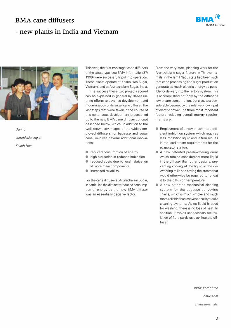
This year, the first two sugar cane diffusersof the latest type (see BMA Information 37/1999) were successfully put into operation.These plants operate at Khanh Hoa Sugar,Vietnam, and at Arunachalam Sugar, India.
The success these two projects scoredcan be explained in general by BMA’s un-tiring efforts to advance development andmodernization of its sugar cane diffuser. Thelast steps that were taken in the course ofthis continuous development process ledup to the new BMA cane diffuser conceptdescribed below, which, in addition to thewell-known advantages of the widely em-ployed diffusers for bagasse and sugarcane, involves several additional innova-tions:
reduced consumption of energyhigh extraction at reduced imbibitionreduced costs due to local fabricationof more main componentsincreased reliability.
For the cane diffuser at Arunachalam Sugar,in particular, the distinctly reduced consump-tion of energy by the new BMA diffuserwas an essentially decisive factor.
BMA cane diffusers
- new plants in India and Vietnam
From the very start, planning work for theArunachalam sugar factory in Thiruvanna-malai in the Tamil Nadu state had been suchthat cane processing and sugar productiongenerate as much electric energy as poss-ible for delivery into the factory system. Thisis accomplished not only by the diffuser’slow steam consumption, but also, to a con-siderable degree, by the relatively low inputof electric power. The three most importantfactors reducing overall energy require-ments are:
Employment of a new, much more effi-cient imbibition system which requiresless imbibition liquid and in turn resultsin reduced steam requirements for theevaporator station.A new patented pre-dewatering drumwhich retains considerably more liquidin the diffuser than other designs, pre-venting cooling of the liquid in the de-watering mills and saving the steam thatwould otherwise be required to reheatit to the diffusion temperature.A new patented mechanical cleaningsystem for the bagasse conveyingchains, which is much simpler and muchmore reliable than conventional hydrauliccleaning systems. As no liquid is usedfor washing, there is no loss of heat. Inaddition, it avoids unnecessary recircu-lation of fibre particles back into the dif-fuser.
During
commissioning at
Khanh Hoa
India: Part of the
diffuser at
Thiruvannamalai
The two latter factors alone can reduce thesteam consumption of a diffusion plant byup to 10%.
The entire concept is designed to allowmanufacture of the cane or bagasse diffu-ser (except for a few key components) bythe customer in the immediate vicinity ofthe site. Further optimizations aimed at in-creasing the percentage of local manufac-ture made it possible for these two plantsthat 95% of the diffuser equipment couldbe fabricated locally. Important items in-volved therein are the novel main drive shaftand a modified driving system. In additionto the direct cost-saving effect and the ab-sence of long-distance transport, the useof locally fabricated components alsomeans easy and low-cost stocking ofspare parts.
The patented rain-type system for dis-tribution of the liquid on the bagasse bed,which is employed here for the first time,enables the diffuser to be optimized undertwo different aspects - subject to the im-portance attached to the respective appli-cation: Either a higher extraction of sucroseat the same imbibition rate as before, or asubstantially reduced imbibition rate at thesame extraction as before.
This is accomplished by uniformly spread-ing the imbibition liquid across the entiresurface, providing for continuous and,above all, uniform wetting of the bagassebed and thus producing the said advan-tages. The high degree of availability andreliability of BMA diffusers has been triedout and proved in many plants. Due to theirsimple, though sturdy design and construc-tion to cope with arduous operating con-ditions, these diffusers can be run by a mini-mum of operators. Users say the labourinput is about 70% less than that requiredfor mill tandems.
Proven diffuser components such as thecane feeder conveyor, the rotating bagassedischarger and the bagasse conveyingsystem equipped with special block chainsdeveloped by BMA were again chosen foruse in this advanced diffuser. The simple,efficient, and maintenance-free mechanicalchain cleaning system mentioned beforealso contributes a great deal to the high re-liability of the diffuser.
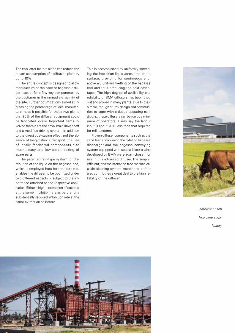
Vietnam: Khanh
Hoa cane sugar
factory

SUGAR-Div is ion
The success the advanced market and pro-gress oriented concept of the proven BMAtower extraction concept (see BMA Infor-mation 37/1999) has scored was stunninglyconfirmed by another plant erected for theCroswell sugar factory of Imperial SugarCompany, Michigan, USA.
BMA beet extraction plants
– an innovation is winning through
Reference stress
calculation of
tubular shaft
segment (FEM)
The new extraction plant for Croswell wasdesigned and erected on a basic idea andon the experience gathered with the firstextraction tower of the new generation {to-wer 2000) erected at the Hungarian Szer-encs sugar factory of Eridania Beghin-SaySA. The Croswell tower 2000 went onstream on schedule early in October 2000,replacing two obsolete horizontal extrac-tors; it is designed for a nominal beet slicerate of 5,000 sht/d (4,535 mt/d).
The units BMA supplied, installed andsuccessfully commissioned for Croswellwere:
1 extraction tower, 7.0 m dia x 19.93 m1 countercurrent cossette mixer, 4.5 mdia x 7.0 m, with defoamer2 cossette pumps
The technological results that were achiev-ed after plant commissioning and during thelong beet campaign have fully come up toexpectations.
A very tight schedule called for a specialfabrication and erection sequence. To allowassembly and erection at site to be carriedout within the available time, manufactureof the equipment to be supplied by BMAhad to be planned in a completely newmanner. The solution was pre-fabrication ofshaft sections with conveying flights andshell, thus reducing the number of com-ponents to be assembled at site. Thismeant a substantially shorter erection time- a decisive contribution to the successfulaccomplishment of the project within thisshort stretch of time.
A characteristic feature of the previousBMA extraction tower is that the towerjuice is drawn off through bottom and sidescreens, where the maximum bottomscreen load is approx. 65 m3/[m2*h]. Thelimit to this load is the superjacent cossettemass which affects juice flow. Series oftests have shown that the specific through-put of side screens, unlike that of bottomscreens, can easily be increased up to 200m3/[m2*h]. The new extraction tower hascompletely re-designed side screens onlyfor tower juice withdrawal.
5
Elements of
tower base under
construction at BMA’s
shops
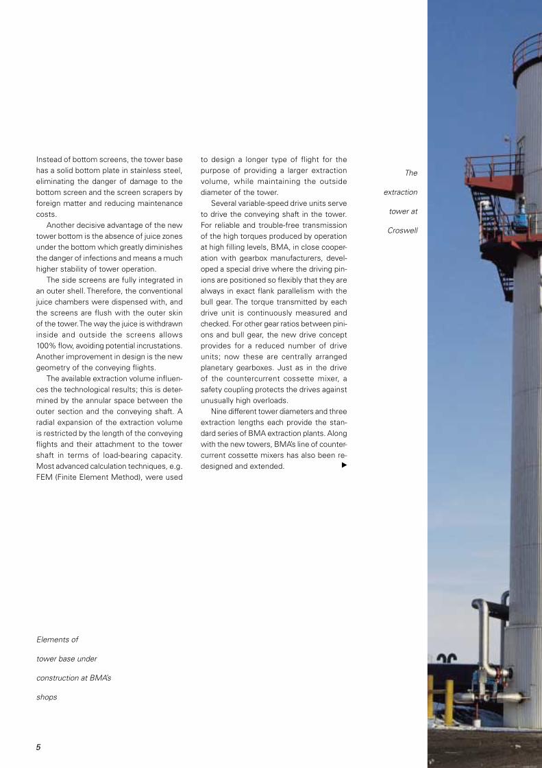
The
extraction
tower at
Croswell
Instead of bottom screens, the tower basehas a solid bottom plate in stainless steel,eliminating the danger of damage to thebottom screen and the screen scrapers byforeign matter and reducing maintenancecosts.
Another decisive advantage of the newtower bottom is the absence of juice zonesunder the bottom which greatly diminishesthe danger of infections and means a muchhigher stability of tower operation.
The side screens are fully integrated inan outer shell. Therefore, the conventionaljuice chambers were dispensed with, andthe screens are flush with the outer skinof the tower. The way the juice is withdrawninside and outside the screens allows100% flow, avoiding potential incrustations.Another improvement in design is the newgeometry of the conveying flights.
The available extraction volume influen-ces the technological results; this is deter-mined by the annular space between theouter section and the conveying shaft. Aradial expansion of the extraction volumeis restricted by the length of the conveyingflights and their attachment to the towershaft in terms of load-bearing capacity.Most advanced calculation techniques, e.g.FEM (Finite Element Method), were used
to design a longer type of flight for thepurpose of providing a larger extractionvolume, while maintaining the outsidediameter of the tower.
Several variable-speed drive units serveto drive the conveying shaft in the tower.For reliable and trouble-free transmissionof the high torques produced by operationat high filling levels, BMA, in close cooper-ation with gearbox manufacturers, devel-oped a special drive where the driving pin-ions are positioned so flexibly that they arealways in exact flank parallelism with thebull gear. The torque transmitted by eachdrive unit is continuously measured andchecked. For other gear ratios between pini-ons and bull gear, the new drive conceptprovides for a reduced number of driveunits; now these are centrally arrangedplanetary gearboxes. Just as in the driveof the countercurrent cossette mixer, asafety coupling protects the drives againstunusually high overloads.
Nine different tower diameters and threeextraction lengths each provide the stan-dard series of BMA extraction plants. Alongwith the new towers, BMA’s line of counter-current cossette mixers has also been re-designed and extended.

6
SUGAR-Div is ion
Towerjuice
Cossette/juice
The world’s biggest countercurrent cos-sette mixer so far, with a diameter of 8.2 mand a length of 10 m, designed for a beetslice rate of 16.000 sht/d (14.500 mt/d), wasrecently put into operation at SouthernMinnesota Beet Sugar Coop’s factory inRenville, USA (see BMA Information 38/2000).
The extended re-designed line of BMAbeet extraction plants now allows beet slicerates of more than 16,000 tons per day perunit.
Beet slice rate* Extraction tower Cossette mixer
Nominal[t/d] Diameter [m] Diameter/length [m]
4,000 6.5 4.2 / 7.0 5,000 7.0 4.7 / 8.0 6,000 7.6 5.2 / 8.0
7,000 8.2 5.6 / 8.0 8,000 8.9 6.0 / 8.0 9,000 8.9 6.0 / 8.010,000 9.6 6.7 / 8.511,000 10.6 6.7 / 8.512,000 10.6 7.5 / 9.513,000 12.0 7.5 / 9.514,000 12.0 8.2 / 10.015,000 13.6 8.2 / 10.016,000 13.6 9.0 / 11.017,000 13.6 9.0 / 11.0
Tower extraction lengths vary subject to application and plant size.* in metric tons
Re-
designed
tower
base

7
75
70
65
60
55
50
45
40
35
30
25
20
23 24 25 26 27
hardened
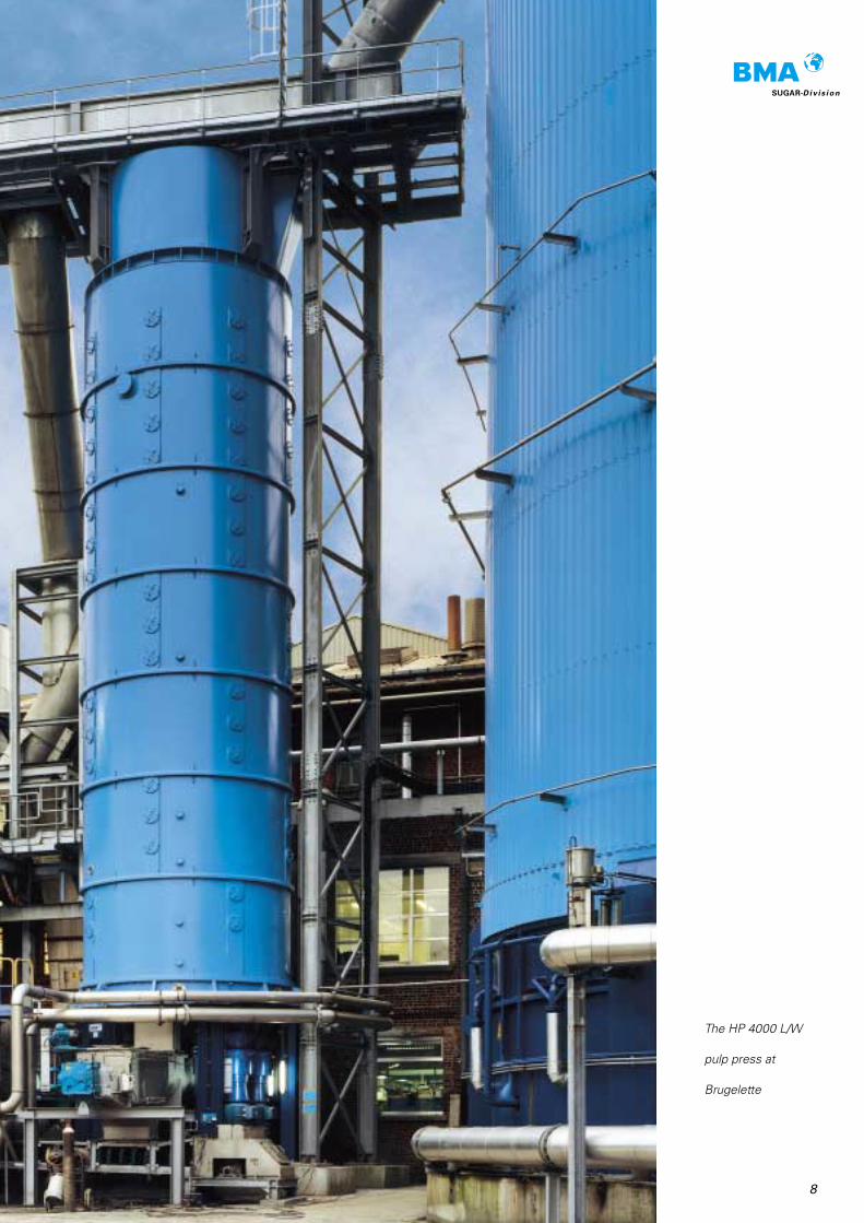
For last year’s campaign BMA receivedorders for one high-capacity pulp presseach for the Brugelette factory of Raffine-rie Tirlemontoise S.A., Belgium, and for theOchsenfurt factory of Südzucker AG Mann-heim/Ochsenfurt, Germany. Both pressesare of the long (L) type of the proven HP4000 series, which provides a screen bas-ket diameter of 4,000 mm and a spindlelength of 13,900 mm.
Though they look exactly the same,there are certain differences in design.While the press for Ochsenfurt dewatersthe pulp to a dry substance content beyond30%, the one for Brugelette is intended toproduce pressed pulp which will not bedried, but will be sold directly. For such anapplication, i.e. production of pressed pulpfor use as cattle feed, either direct or forsilage, it is not advisable to achieve a highdry substance content by means of electricpower and then add water again beforeselling it.
New BMA pulp presses for Brugelette
and Ochsenfurt
The Belgian Brugelette sugar factory is inthe fortunate position that there is no needto practise pulp drying, as all its pressedpulp is sold directly, plus a small percentageof wet pulp. Therefore, BMA was expectedto provide a press which can produce morethan 50 t of pressed pulp per hour with adry substance content of at least 24%.
The only press that would be suited inthis case must operate, unlike the standardtype for high dry substance contents, at ahigher layer thickness and a lower pressure.The new W type with modified spindlegeometry meets these requirements in anideal way, as the successful guarantee runhas finally proved. The average results ofseveral series of tests yielded 55.4 t ofpressed pulp per hour with 25.6% drysubstance, with addition of a small, thoughnot always constant, quantity of gypsuminto the extraction liquid.
Performance chart of
HP 4000 L/W
not hardened
Pres
sed
pulp
[t/h
]
Pressed pulp [% DS]
8
SUGAR-Div is ion
The HP 4000 L/W
pulp press at
Brugelette
9
This new press supplements the range asoffered so far and covers dry substancecontents between 23% and 27% at cor-respondingly higher throughputs. The W-type press is available also as an HP 3000and HP 4000, though with two spindlelengths only (13,900 mm and 11,900mm).
Tests have shown that this type of press,also, behaves differently in terms of through-put and dry substance content, dependingon whether a pressing aid is added or not.
As it is to be assumed that for a low drysubstance content there will be no incli-nation towards using pressing aids, thispress will also be suitable, though at a re-duced throughput, for these applications.
The performance chart shows the ex-pected throughputs of an HP 4000 L/W ver-sus dry substance content with and with-out hardening of the extraction liquid.
What mattered for Südzucker AG whenthey purchased the press for their Ochsen-furt factory was that the existing pressingstation, mainly consisting of horizontal dou-ble-spindle presses, was to be considerablyrelieved so that the pulp drying plant couldbe supplied with pressed pulp with thehighest possible average dry substancecontent. BMA selected a standard HP 4000with the longest spindle (L), which providesthe preconditions to meet these require-ments. During the two-day guarantee run,which was conducted in the agreed rangebetween 30% and 32% dry substance, theaverage throughput was 33.6 t/h at 30.8%dry substance.
Just as during earlier capacity tests andguarantee runs, it again confirmed how es-sential constant operation of the extractionplant is for pressing work. The influence ofextraction temperature, pH-value and hard-ness of the extraction liquid is generallyknown and can be clearly defined, but suchfactors as uniform wet pulp output, cos-sette quality, raw juice draught, residualsugar content and dry substance contentin the wet pulp should not be underesti-mated. While these parameters can beinfluenced (but for a few exceptions), theproperties of the beets processed alwaysis the unknown and, quite often, varyingelement.
After all, this is a natural product whichis subject to changes and cannot be stand-ardized. The marc content which variessubject to the area in which the beets aregrown, even within one campaign, be-comes apparent in both extraction and wetpulp pressing. The time that has passedbetween beet harvest and processing alsoaffects extraction and pressing.
These factors have an influence on everypulp press, irrespective of the type andmanufacturer concerned. The importantthing is to be aware of these influences andtheir effects on pulp pressing.

10
SUGAR-Div is ion
After the 1990 and 1991 campaigns the su-gar house of Zuckerfabrik + Raffinerie Aar-berg, Switzerland, was completely swit-ched to the employment of BMA verticalcontinuous vacuum pans (VKT) for whitesugar, raw sugar and low-raw sugar (seeBMA Information 30/1992). Now, the Frau-enfeld factory of Zuckerfabriken Aarbergund Frauenfeld AG, too, has also begun toequip its sugar house with such continuousvacuum pans.
For the 2000 campaign, BMA suppliedand commissioned a low-raw VKT for athroughput of 25 t/h and a seed magmabatch pan designed for a volume of 60 tand a heating surface of 385 m2. It turnedout that due to the excellent heat transferon the heating tubes and the low masse-cuite level the heating steam pressure of1.0 bar (abs) calculated for the VKT couldbe reduced by approx. 0.2 bar (equivalentto 6 Kelvin).
Optimization of the pan vapour pressurecontrol system provided, just as in otherVKTs before, a very uniform pressure,which is an important precondition for aconstant, good crystal quality.
Frauenfeld sugar factory - now practising
continuous crystallization
The low-raw VKT
for 60 t
massecuite

11
In addition, this uniform load extends theVKT operating cycles: routine steam-outafter 50 campaign days illustrated that therewere a minimum of incrustations in thecalandria and vapour chest areas.
These excellent results, also with regardto purity drop in the mother solution, in theearly phase of the campaign allowed to dis-pense with an official guarantee run.
Continuous crystallization will continueto play an important part at the Frauenfeldsugar factory.
For next campaign, raw-sugar crystalli-zation will be switched to continuous oper-ation, and BMA will design and supply acontinuously operating raw-sugar cascade(VKH) composed of four vacuum pans. Thethroughput will be 55 t per hour.
Plant layout and pipe routing will haveto make allowance for the fact that prior tothe campaign proper there will be a so-called bio-sugar campaign for which someof the cascaded units are used for batchproduction of raw bio-sugar.
Continuous crystallization in the raw andlow-raw station allows to tap the necessaryheating steam from the last effects of theevaporator station, which means a higherthick juice concentration and less totalsteam requirements for the sugar house.
VKT and VKH at the Frauenfeld sugar factory
Low-raw VKT Raw-sugar VKHNumber of chambers 4 4Diameter [mm] 4,000 4,400Heating surface [m2] 1,276 1,540Production of massecuite [t/h] 25 55Purity of massecuite [%] 76 88Dry substance in massecuite [%] 95 92Seed magma flow rate [t/h] 6.7 12.4Throughput [t/h] 4.3 9.7Pan vapour pressure [bar abs.] 0.2 0.2Heating steam pressure [bar abs.] 1.0 0.7
The
raw-sugar
VKH
12
SUGAR-Div is ion
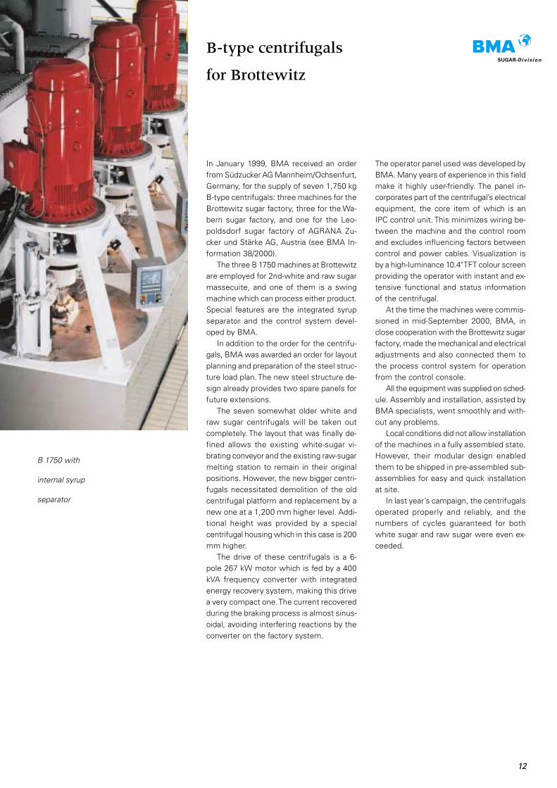
B 1750 with
internal syrup
separator
In January 1999, BMA received an orderfrom Südzucker AG Mannheim/Ochsenfurt,Germany, for the supply of seven 1,750 kgB-type centrifugals: three machines for theBrottewitz sugar factory, three for the Wa-bern sugar factory, and one for the Leo-poldsdorf sugar factory of AGRANA Zu-cker und Stärke AG, Austria (see BMA In-formation 38/2000).
The three B 1750 machines at Brottewitzare employed for 2nd-white and raw sugarmassecuite, and one of them is a swingmachine which can process either product.Special features are the integrated syrupseparator and the control system devel-oped by BMA.
In addition to the order for the centrifu-gals, BMA was awarded an order for layoutplanning and preparation of the steel struc-ture load plan. The new steel structure de-sign already provides two spare panels forfuture extensions.
The seven somewhat older white andraw sugar centrifugals will be taken outcompletely. The layout that was finally de-fined allows the existing white-sugar vi-brating conveyor and the existing raw-sugarmelting station to remain in their originalpositions. However, the new bigger centri-fugals necessitated demolition of the oldcentrifugal platform and replacement by anew one at a 1,200 mm higher level. Addi-tional height was provided by a specialcentrifugal housing which in this case is 200mm higher.
The drive of these centrifugals is a 6-pole 267 kW motor which is fed by a 400kVA frequency converter with integratedenergy recovery system, making this drivea very compact one. The current recoveredduring the braking process is almost sinus-oidal, avoiding interfering reactions by theconverter on the factory system.
B-type centrifugals
for Brottewitz
The operator panel used was developed byBMA. Many years of experience in this fieldmake it highly user-friendly. The panel in-corporates part of the centrifugal’s electricalequipment, the core item of which is anIPC control unit. This minimizes wiring be-tween the machine and the control roomand excludes influencing factors betweencontrol and power cables. Visualization isby a high-luminance 10.4" TFT colour screenproviding the operator with instant and ex-tensive functional and status informationof the centrifugal.
At the time the machines were commis-sioned in mid-September 2000, BMA, inclose cooperation with the Brottewitz sugarfactory, made the mechanical and electricaladjustments and also connected them tothe process control system for operationfrom the control console.
All the equipment was supplied on sched-ule. Assembly and installation, assisted byBMA specialists, went smoothly and with-out any problems.
Local conditions did not allow installationof the machines in a fully assembled state.However, their modular design enabledthem to be shipped in pre-assembled sub-assemblies for easy and quick installationat site.
In last year’s campaign, the centrifugalsoperated properly and reliably, and thenumbers of cycles guaranteed for bothwhite sugar and raw sugar were even ex-ceeded.

The biggest sugar drum dryer ever built byBMA operates at the Wanze factory of Raf-finerie Tirlemontoise S.A., Belgium, sincethe 2000 beet campaign. The drum has adiameter of 4,000 mm and is designed fora sugar throughput of 135 t/h. It replacesthree smaller, overloaded drum dryers/cool-ers with a downstream fluidized-bed cool-er to reduce the temperature of the sugarto be stored to an acceptable level.
For this new sugar drying and coolingplant project, re-use of the existing fluid-ized-bed cooler was a must. Consequently,the new drum dryer had to be designed anddimensioned with due regard to the pro-cessing and cooling capacity of the fluid-ized-bed cooler.
In order to meet these requirements,BMA chose a countercurrent-type sugardrying drum where, at a very low drying airtemperature and by withdrawal of intrinsicheat, the sugar is dried to a residual mois-ture of 0.02 to 0.03% and cooled to a tem-perature of 40 °C.
In addition to the sugar drying drum,BMA’s scope of supply also included nec-essary fans, drying air conduits, and a com-mon wet dust separating plant for dryingand cooling air.
The following results of measurementsthe customer made in October 2000 showthat the new drying plant has come up toexpectations in each and every respect.
The biggest BMA sugar drum dryer ever
Haulaway from
Braunschweig
The new sugar
dryer replaces three
small ones
Throughput 133 – 143 t/hTemperature of sugar upon entry into drying drum 51 – 56 °CTemperature of drying air 26 – 32 °CTemperature of sugar upon exit from drying drum 38 – 40 °CResidual moisture of sugar upon exit from drying drum < 0,02 %Temperature of sugar after fluidized-bed cooling 28 – 30 °C
14
SUGAR-Div is ion
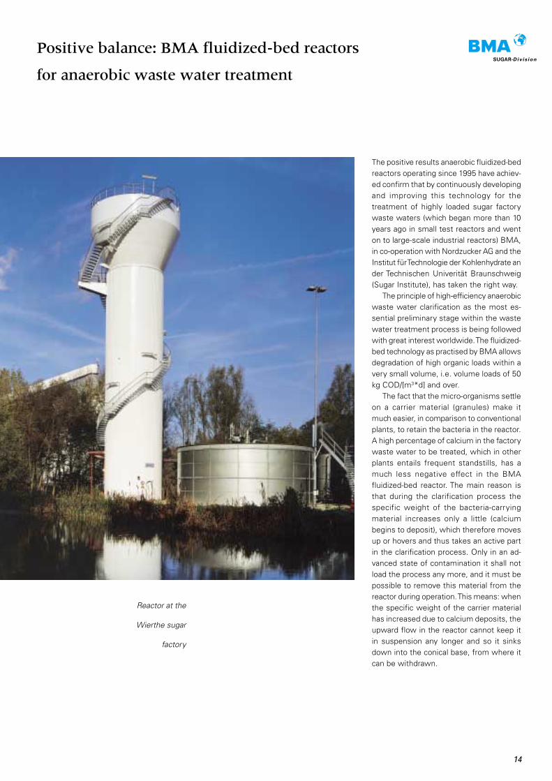
Reactor at the
Wierthe sugar
factory
The positive results anaerobic fluidized-bedreactors operating since 1995 have achiev-ed confirm that by continuously developingand improving this technology for thetreatment of highly loaded sugar factorywaste waters (which began more than 10years ago in small test reactors and wenton to large-scale industrial reactors) BMA,in co-operation with Nordzucker AG and theInstitut für Technologie der Kohlenhydrate ander Technischen Univerität Braunschweig(Sugar Institute), has taken the right way.
The principle of high-efficiency anaerobicwaste water clarification as the most es-sential preliminary stage within the wastewater treatment process is being followedwith great interest worldwide. The fluidized-bed technology as practised by BMA allowsdegradation of high organic loads within avery small volume, i.e. volume loads of 50kg COD/[m3*d] and over.
The fact that the micro-organisms settleon a carrier material (granules) make itmuch easier, in comparison to conventionalplants, to retain the bacteria in the reactor.A high percentage of calcium in the factorywaste water to be treated, which in otherplants entails frequent standstills, has amuch less negative effect in the BMAfluidized-bed reactor. The main reason isthat during the clarification process thespecific weight of the bacteria-carryingmaterial increases only a little (calciumbegins to deposit), which therefore movesup or hovers and thus takes an active partin the clarification process. Only in an ad-vanced state of contamination it shall notload the process any more, and it must bepossible to remove this material from thereactor during operation. This means: whenthe specific weight of the carrier materialhas increased due to calcium deposits, theupward flow in the reactor cannot keep itin suspension any longer and so it sinksdown into the conical base, from where itcan be withdrawn.
Positive balance: BMA fluidized-bed reactors
for anaerobic waste water treatment
D
d H
15
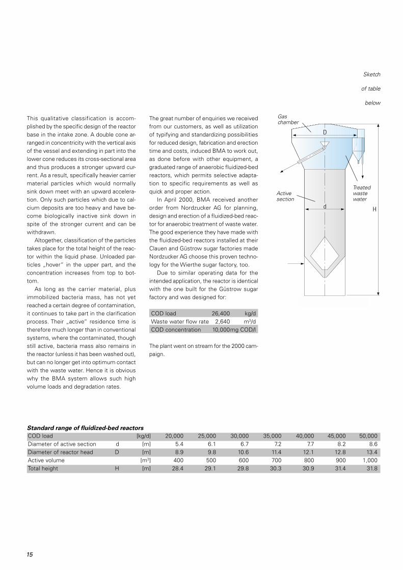
This qualitative classification is accom-plished by the specific design of the reactorbase in the intake zone. A double cone ar-ranged in concentricity with the vertical axisof the vessel and extending in part into thelower cone reduces its cross-sectional areaand thus produces a stronger upward cur-rent. As a result, specifically heavier carriermaterial particles which would normallysink down meet with an upward accelera-tion. Only such particles which due to cal-cium deposits are too heavy and have be-come biologically inactive sink down inspite of the stronger current and can bewithdrawn.
Altogether, classification of the particlestakes place for the total height of the reac-tor within the liquid phase. Unloaded par-ticles „hover“ in the upper part, and theconcentration increases from top to bot-tom.
As long as the carrier material, plusimmobilized bacteria mass, has not yetreached a certain degree of contamination,it continues to take part in the clarificationprocess. Their „active“ residence time istherefore much longer than in conventionalsystems, where the contaminated, thoughstill active, bacteria mass also remains inthe reactor (unless it has been washed out),but can no longer get into optimum contactwith the waste water. Hence it is obviouswhy the BMA system allows such highvolume loads and degradation rates.
The great number of enquiries we receivedfrom our customers, as well as utilizationof typifying and standardizing possibilitiesfor reduced design, fabrication and erectiontime and costs, induced BMA to work out,as done before with other equipment, agraduated range of anaerobic fluidized-bedreactors, which permits selective adapta-tion to specific requirements as well asquick and proper action.
In April 2000, BMA received anotherorder from Nordzucker AG for planning,design and erection of a fluidized-bed reac-tor for anaerobic treatment of waste water.The good experience they have made withthe fluidized-bed reactors installed at theirClauen and Güstrow sugar factories madeNordzucker AG choose this proven techno-logy for the Wierthe sugar factory, too.
Due to similar operating data for theintended application, the reactor is identicalwith the one built for the Güstrow sugarfactory and was designed for:
COD load 26,400 kg/dWaste water flow rate 2,640 m3/dCOD concentration 10,000mg COD/l
The plant went on stream for the 2000 cam-paign.
Standard range of fluidized-bed reactors
COD load [kg/d] 20,000 25,000 30,000 35,000 40,000 45,000 50,000Diameter of active section d [m] 5.4 6.1 6.7 7.2 7.7 8.2 8.6Diameter of reactor head D [m] 8.9 9.8 10.6 11.4 12.1 12.8 13.4Active volume [m3] 400 500 600 700 800 900 1,000Total height H [m] 28.4 29.1 29.8 30.3 30.9 31.4 31.8
Sketch
of table
below
Gaschamber
Treatedwastewater
Activesection
Div is ion o f BMA
In late December 1999, the STARCOSA-Division of BMA received an order fromIsrael covering the supply of a plant for theproduction of crystalline fructose. The Is-raeli customer, who already produces citricacid from sugar, will now use EG2-qualitysugar to make crystalline fructose. Aftermelting and inversion, the invert sugar issubjected to chromatographic separation toseparate it into fructose and glucose. Thefructose is then concentrated and crystal-lized and, at the end of the process, driedto its final moisture. The plant output is 72t/d of crystalline fructose. The finished pro-duct is packed and sold in big bags or 25kg bags.
Plant for the production of
crystalline fructose
The glucose fraction of the chromato-graphic separation process is concentratedand serves as a starting material for theproduction of citric acid. This combinationof the production of crystalline fructosefrom sugar and the use of a lower-valuefraction (glucose) for the production of citricacid makes this project a very special oneand ensures maximum economic effi-ciency.
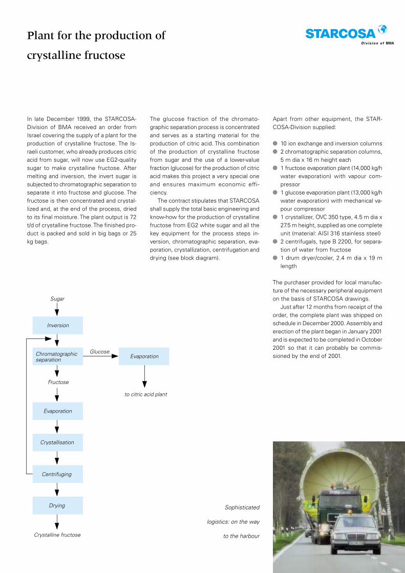
The contract stipulates that STARCOSAshall supply the total basic engineering andknow-how for the production of crystallinefructose from EG2 white sugar and all thekey equipment for the process steps in-version, chromatographic separation, eva-poration, crystallization, centrifugation anddrying (see block diagram).
Apart from other equipment, the STAR-COSA-Division supplied:
10 ion exchange and inversion columns2 chromatographic separation columns,5 m dia x 16 m height each1 fructose evaporation plant (14,000 kg/hwater evaporation) with vapour com-pressor1 glucose evaporation plant (13,000 kg/hwater evaporation) with mechanical va-pour compressor1 crystallizer, OVC 350 type, 4.5 m dia x27.5 m height, supplied as one completeunit (material: AISI 316 stainless steel)2 centrifugals, type B 2200, for separa-tion of water from fructose1 drum dryer/cooler, 2.4 m dia x 19 mlength
The purchaser provided for local manufac-ture of the necessary peripheral equipmenton the basis of STARCOSA drawings.
Just after 12 months from receipt of theorder, the complete plant was shipped onschedule in December 2000. Assembly anderection of the plant began in January 2001and is expected to be completed in October2001 so that it can probably be commis-sioned by the end of 2001.
Sophisticated
logistics: on the way
to the harbour
Chromatographicseparation
Evaporation
Crystallisation
Centrifuging
EvaporationGlucose
to citric acid plant
Sugar
Fructose
Drying
Crystalline fructose
Inversion
17
In October 1999, the STARCOSA-Divisionreceived an order from Südzucker AG forthe supply of a crystallizer. This order waspreceded by series of crystallization testsat BMA’s own research centre, where thecrystallizer’s suitability and parameterswere tried out in practical 24-hour operationfor several days in order to have a reliablebasis for scale-up to a large-scale plant.
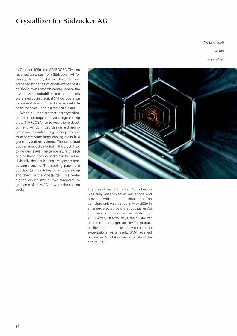
When it turned out that this crystalliza-tion process requires a very large coolingarea, STARCOSA had to resort to re-devel-opment: An optimized design and appro-priate new manufacturing techniques allowto accommodate large cooling areas in agiven crystallizer volume. The calculatedcooling area is distributed in the crystallizerto various levels. The temperature of eachone of these cooling packs can be set in-dividually, the result being a very exact tem-perature profile. The cooling packs areattached to lifting tubes which oscillate upand down in the crystallizer. This re-de-signed crystallizer allows temperaturegradients of a few °C between the coolingpacks.
Crystallizer for Südzucker AG
The crystallizer (2.8 m dia., 19 m height)was fully assembled at our shops andprovided with adequate insulation. Thecomplete unit was set up in May 2000 inan annex erected before at Südzucker AGand was commissioned in September2000. After just a few days, the crystallizeroperated at its design capacity. The productquality and outputs have fully come up toexpectations. As a result, BMA receivedSüdzucker AG’s take-over certificate at theend of 2000.
Climbing shaft
in the
crystallizer

DRYER-Division of BMA
Complete
in stainless
steel
In connection with a complete plant for theproduction of fructose supplied by theSTARCOSA-Division (see report on page16), the TAG DRYER-Division of BMA sup-plied the world’s biggest fructose dryer,designed for a maximum throughput of4,000 kg/h.
TAG has years of experience in dryingand cooling of crystalline products, es-pecially of saccharose and starch deriva-tives such as dextrose and fructose, influidized-bed or drum-type dryers andcoolers. In this particular case, the decisionwas in favour of an integrated drum dryer/cooler. The specific advantages of thissystem, which have been proved in manycases, are:
The world’s biggest fructose dryer
Drying and cooling in one single unit,which means only one drive plus pres-sure/suction-type fansUniform drying and cooling of fructosecrystals by special internal drum ele-ments and optimized drying and coolingair flowInsusceptibility to varying fructose crys-tal feed and ingoing fructose tempera-ture and moistureFree flowability of fructose crystals aftera very short stretch due to counter-current dryingLow outgoing fructose temperature bycooling in countercurrent with dehumid-ified air
Minimized formation of lumps and dam-age of crystals in the drumDryer equipped with high-efficiencylifting blades and dry dust separatingsystemSpecial drum seals at inlet and outlethousings preventing contact of unfil-tered ambient air with the product.
The customer’s high demands on hygieneand surface quality were a great challengefor BMA’s workshops.

19
Preservation of fruit marmalades, jellies andjams probably is one of the oldest methodsman has used to extend the life of food-stuffs by increasing their percentage of sol-uble dry matter. For the household, pre-serving sugar, a special product made bythe sugar industry in the world, is used forthis purpose. Conventional preserving sug-ar is composed of crystal sugar, pectin andcitric acid. In general, however, pectin canbe substituted by other gel-forming poly-saccharides.
In order that during the cooking processthe preserving sugar produces a homo-geneous gel strength, the powdery gel-forming polysaccharide must agglomerateto the surfaces of the white-sugar crystalsas uniformly and durably as possible. Thisrequirement arises, in the first place, outof the consumers’ demand for a steadyquality of their preserves. But for the pro-ducers, too, a strong attachment of thegelling agent to the formula componentsis an important criterion with a view tominimizing the losses of high-cost gellingagent during the logistic processes throughto packaging.
The technologies practised so far arenormally based on a mechanical mixing pro-cess where by the introduction of a bindingagent (water, steam or vegetable oil) thecomponents are made into a compoundproduct. Sometimes pre-mixes of superfinewhite sugar, pectin and citric acid are usedfor this purpose. However, both the productquality and the conventional conditions ofproduction can be improved by the novelBMA process, and this is for the followingreasons:
New preserving sugar production process
Quite often, preserving sugar is packedat a (technologically induced) high mois-ture content, and this involves the riskof an autocatalytic breakdown of thepectin and, consequently, a decrease ingelling ability.Preserving sugar with increased mois-ture or oil on the crystal surfaces nor-mally requires expensive PE-lined multi-layer packing.Insufficient resistance of the agglo-merated pectin to abrasion entails disad-vantages for both the producer and theconsumer:Mechanical stresses acting on the pro-duct during packaging and the logisticprocesses through to the end user leadto partial detachment and subsequentde-mixing of the pectin, which in turnmeans fluctuations in quality.Detached pectin powder, along with ahigh residual moisture, results in incrus-tations in the packaging machine andcalls for frequent cleaning (reduced avail-ability).
Therefore, BMA and the Uelzen sugar fac-tory of Nordzucker AG set about developinga preserving sugar which would featurebetter properties, the emphasis being onthe following targets:
Maximum resistance to abrasion of thepectin to be agglomerated to the sugarcrystalHomogeneous distribution of the pectinin the final productAdherence to the required gel strengthDe-mixing stabilityNo use of additivesContinuous process.
Preserving
sugar
formulae
Sugar
Carbohydrates such assucrose, fructose,sorbitoland others
Pectins
HE - high esterifiedLE - low esterifiedAM - amidized
Preserving sugar
Additives
such as organic acids,salts of organic acids,solvents, binding agents,alginates and others

20
DRYER-Division of BMA
The development of the novel preservingsugar production process was greatly in-fluenced by the vast experience BMA hasgathered in the use of solid-matter fluidi-zation for drying and cooling of sugar andother grainy products. After initial testsmade at a research centre level, severaltons of preserving sugar were produced bythe new process on a semi-industrial scaleto allow testing of its properties during andafter packaging under practical conditions.When the preserving sugar campaign be-gan in March 2000, a prototype plant prac-tising the new technology was put intooperation in the new screening and pack-aging building of the Nordzucker ServiceCentre at the Uelzen factory of NordzuckerAG. Technologically, the various processsteps of the novel process (patents pen-ding) are as shown below.
Schematic diagram
of BMA preserving
sugar production
process
Coating Drying /cooling
Mixing
Pectin Binding agent Sugar solution Citric acid
Whitesugar
PreservingsugarAgglomeration
It was found that an essential criterion foran improved quality of the product is to fixthe pectin agglomerated on the sugar crys-tal by subsequently coating it with an un-dersaturated sugar solution. It turned outthat this measure considerably improvesthe resistance to abrasion as comparedwith ordinary products. The uniform andthin film of sugar solution applied throughnozzles to the crystal surfaces is thoroughlydried in a fluidized bed. This develops anexternal protective micro-crystalline layerwhich offers a high stability against mech-anical stresses.
Any superfine particles not adhering tothe sugar crystals exit together with theexhaust air, are separated in the exhaustair filter and are then pneumatically recycledinto the coating zone where the particlesare agglomerated to the sugar crystals. Thisensures a uniform pectin concentration anddust-free preserving sugar.
In the mixing zone, a quantity of citric acidas specified by the formula is added, thecrystal size spectrum of which correspondswith that of the white sugar used in orderto prevent de-mixing. A constant productquality in this continuous process depends,in the first place, on proper operation ofthe nozzles in the agglomeration zone andthe coating zone. Therefore, these nozzleshave a special pneumatic cleaning systemto prevent choking. In addition, the nozzlecarriers can be removed during operationfor inspection and cleaning.
The first plant set up at the Uelzen sugarfactory furnished evidence that it produc-es preserving sugar with a quality whichcomes up to and, in some cases, even ex-ceeds the specifications.
In August 2000, BMA was awarded anorder for the supply of another preservingsugar plant practising the new technologyby the Nantes/France refinery which be-longs to Eridania Beghin-Say. The plant wassuccessfully commissioned as early asFebruary 2001. It furnished proof that thenovel process is able to produce high-quality preserving sugar for two differentformulae. On the basis of this two-productconcept, BMA supplied all the necessarylogistic equipment, including an integratedautomatic cleaning system (CIP), allowingchangeover from one product to the otherwithin a very short time.
Apart from the fact that pectin can besubstituted by other gel-forming polysac-charides, the process is even suited for theproduction of preserving sugar varietieswith a higher pectin content, which can beused to make preserves at a fruit to pre-serving sugar ratio of 2:1 or 3:1. Additivesrequired for such formulae (e.g. preserv-ants) can be fed into this plant in the formof either liquids or powders.

21
Moreover, the novel process is even suitedfor the production or conditioning of otherspecial products in the sugar and food in-dustries, where the following problemsmust be solved:
Uniform agglomeration of additives tograiny products, even at low concen-trationsParticle coarsening by agglomerationand simultaneous separation of super-fine particlesConditioning by coating of particle sur-facesImproved free-flowing ability of sticky-surface productsImproved quality of crystalline or grainyproducts by distinctly higher resistanceto abrasion.
The preserving
sugar plant at
Uelzen
Reconstruction of spray dryer for
Borculo-Domo-Ingredients
Planning work for the reconstruction of thisspray drying plant dates back to the year1999: A spray tower was to be convertedfrom production of cattle feed to productsfor human nutrition - along with an increasein output to 5 t of final product per hour.
Not an easy job that was, the less so asdemands on hygiene are a multiple of thosein the production of cattle feed. Becauseof the convincing concept, the order wasawarded to the TAG Dryer-Division of BMA.
The plant was equipped with a new airsupply system for the spray tower and thefluidized-bed unit. Apart from necessaryfans, air heaters, reconstruction of the spraysystem and alterations to the air distributor,the existing fluidized-bed unit was sub-jected to certain modifications. In addition,a completely new exhaust air system withCIP bag filter for 140,000 m3/h exhaust airwas installed. Therefore, this filter is oneof the biggest of its kind.
The project was realized in close co-operation with the customer, Borculo-Do-mo-Ingredients (BDI). Civil work and elec-trical equipment, including measuring andcontrol equipment, were provided by thecustomer. The job was completed on sched-ule, and the agreed output was easilyachieved.
New: High and low pressure CO2
dosing systems
For years the TAG DRYER-Division has beenselling special dosing systems for liquidCO2 operating at pressures between 65 barand more than 400 bar. Such systems areemployed in a great number of spray dryingplants. Their main duty, besides producingcertain structures and an improved solu-bility, is the adjustment of an exact bulkweight. The advanced TAG version providesfor very exact dosing in the start-up andshutdown phases in order to minimize pro-duct losses. CO2 flow recording allows toset alarm points and thus increase plant re-liability.
Another feature developed by the TAGDRYER-Division enables the existing plantto be employed even for the gaseous me-dium, at nozzle pressure of 10 bar, at thesame precision and range of applicationsas for the liquid medium. This means gase-ous and liquid CO2 can be handled, at pres-sures between 10 bar and over, through aPCL or a hardware- controlled system.
The equipment is completed by a CIP-suited injection nozzle which was especiallydesigned by TAG for this purpose: a low-wear long-life nozzle using no sintered met-als.
Nederland
22
Optimization of
water
management
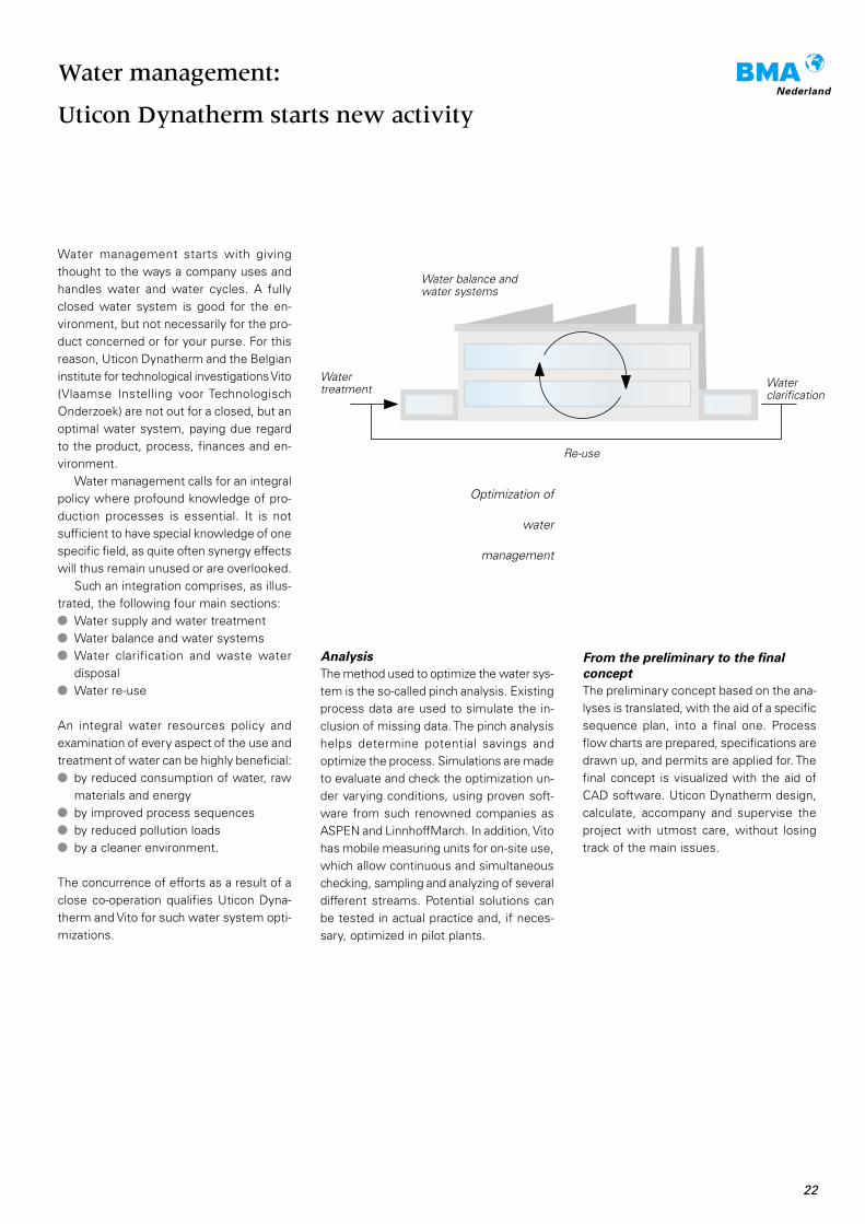
Water management starts with givingthought to the ways a company uses andhandles water and water cycles. A fullyclosed water system is good for the en-vironment, but not necessarily for the pro-duct concerned or for your purse. For thisreason, Uticon Dynatherm and the Belgianinstitute for technological investigations Vito(Vlaamse Instelling voor TechnologischOnderzoek) are not out for a closed, but anoptimal water system, paying due regardto the product, process, finances and en-vironment.
Water management calls for an integralpolicy where profound knowledge of pro-duction processes is essential. It is notsufficient to have special knowledge of onespecific field, as quite often synergy effectswill thus remain unused or are overlooked.
Such an integration comprises, as illus-trated, the following four main sections:
Water supply and water treatmentWater balance and water systemsWater clarification and waste waterdisposalWater re-use
An integral water resources policy andexamination of every aspect of the use andtreatment of water can be highly beneficial:
by reduced consumption of water, rawmaterials and energyby improved process sequencesby reduced pollution loadsby a cleaner environment.
The concurrence of efforts as a result of aclose co-operation qualifies Uticon Dyna-therm and Vito for such water system opti-mizations.
Water management:
Uticon Dynatherm starts new activity
Analysis
The method used to optimize the water sys-tem is the so-called pinch analysis. Existingprocess data are used to simulate the in-clusion of missing data. The pinch analysishelps determine potential savings andoptimize the process. Simulations are madeto evaluate and check the optimization un-der varying conditions, using proven soft-ware from such renowned companies asASPEN and LinnhoffMarch. In addition, Vitohas mobile measuring units for on-site use,which allow continuous and simultaneouschecking, sampling and analyzing of severaldifferent streams. Potential solutions canbe tested in actual practice and, if neces-sary, optimized in pilot plants.
From the preliminary to the final
concept
The preliminary concept based on the ana-lyses is translated, with the aid of a specificsequence plan, into a final one. Processflow charts are prepared, specifications aredrawn up, and permits are applied for. Thefinal concept is visualized with the aid ofCAD software. Uticon Dynatherm design,calculate, accompany and supervise theproject with utmost care, without losingtrack of the main issues.
Watertreatment Water
clarification
Water balance andwater systems
Re-use
23
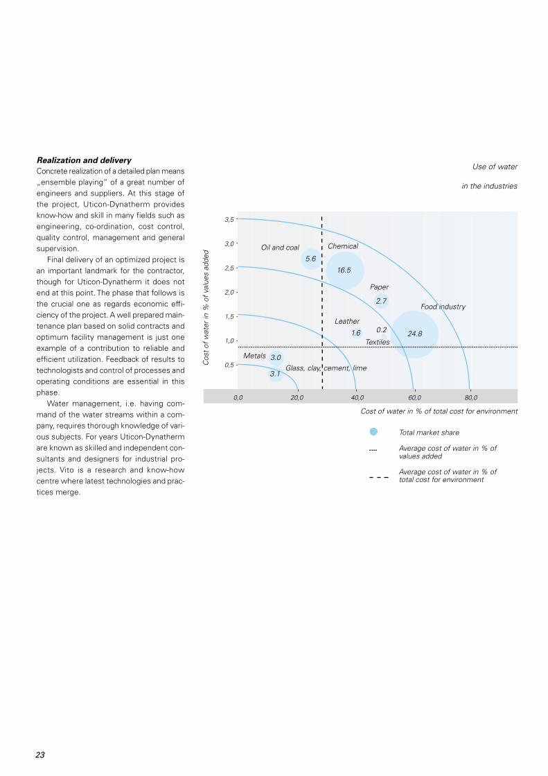
3,5
3,0
2,5
2,0
1,5
1,0
0,5
0,0 20,0 40,0 60,0 80,0
Realization and delivery
Concrete realization of a detailed plan means„ensemble playing“ of a great number ofengineers and suppliers. At this stage ofthe project, Uticon-Dynatherm providesknow-how and skill in many fields such asengineering, co-ordination, cost control,quality control, management and generalsupervision.
Final delivery of an optimized project isan important landmark for the contractor,though for Uticon-Dynatherm it does notend at this point. The phase that follows isthe crucial one as regards economic effi-ciency of the project. A well prepared main-tenance plan based on solid contracts andoptimum facility management is just oneexample of a contribution to reliable andefficient utilization. Feedback of results totechnologists and control of processes andoperating conditions are essential in thisphase.
Water management, i.e. having com-mand of the water streams within a com-pany, requires thorough knowledge of vari-ous subjects. For years Uticon-Dynathermare known as skilled and independent con-sultants and designers for industrial pro-jects. Vito is a research and know-howcentre where latest technologies and prac-tices merge.
Cos
t of w
ater
in %
of v
alue
s ad
ded
Textiles
0.2 24.8
Leather
1.6
3.0
3.1
Metals
Glass, clay, cement, lime
Total market share
Average cost of water in % ofvalues added
Average cost of water in % oftotal cost for environment
Oil and coal5.6
Chemical
16.5
Paper
2.7Food industry
Use of water
in the industries
Cost of water in % of total cost for environment

news & personalities
Falling-film evaporators for Warcoing
For the 2000 campaign, the Warcoing sugarfactory of Warcoing Industrie S.A., Belgium,installed three falling-film evaporators oftype Alpha 2 manufactured on the basis ofBMA drawings. These evaporators have anoverall height of 19,500 mm and a heatingsurface of 500 m2 each; their calandrias are1,200 / 1,500 mm and the vapour chests2,000 mm in diameter.
The juice distributors required for thesefalling-film evaporators were supplied byBMA. They have three distributing levelswhich are separately adjustable for opti-mum distribution of the juice. Via a prelimi-nary, an intermediate and a final stage, thejuice, which the circulation pump feeds tothe evaporator, is uniformly divided intoever smaller quantities which eventuallyreach the webs of the tube plate and thenwet the inside walls of the heating tubeswith an even film of juice,
Together with the units installed in 1995and 1998, Warcoing now operates a totalof 11 BMA falling-film evaporators.
Centrifugals for France and Italy
The SUGAR-Division of BMA concluded amaster contract with the French sugar pro-ducer Eridania Béghin-Say (EBS). This con-tract covers the supply of a total of 30 cen-trifugals till the year 2006. The batch cen-trifugals designed for a throughput of 1,750kg per charge will be equipped with BMA’snew syrup separating system (see BMAInformation 38/2000).
EBS’ sister company Eridania, too, plac-ed an order with BMA for the supply of acentrifugal station, i.e. five type B 2200batch centrifugals for 2,200 kg white-sugarmassecuite per charge and three type K2300 Turbo continuous machines for low-raw massecuite.
As of mid-January, BMA has firm ordersfor the supply of more than 50 centrifugalsin 2001. Systematic standardization of mostcentrifugal assemblies and utilization of full-blown production planning software (PPS)allow smooth production sequences andshorter deliveries.
A delegation from
S.F.I.R. Spa., Italy,
visits BMA
25
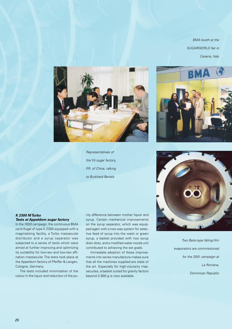
K 2300 M Turbo
Tests at Appeldorn sugar factory
In the 2000 campaign, the continuous BMAcentrifugal of type K 2300 equipped with amagmatizing facility, a Turbo massecuitedistributor and a syrup separator wassubjected to a series of tests which wereaimed at further improving and optimizingits suitability for low-raw and low-raw affi-nation massecuite. The tests took place atthe Appeldorn factory of Pfeiffer & Langen,Cologne, Germany.
The tests included minimization of thecolour in the liquor and reduction of the pu-
rity difference between mother liquor andsyrup. Certain mechanical improvementson the syrup separator, which was equip-ped again with a two-way system for selec-tive feed of syrup into the wash or greensyrup, a basket provided with two syrupdrain slots, and a modified water nozzle unitcontributed to achieving the set goals.
Immediate adoption of these improve-ments into series manufacture makes surethat all the machines supplied are state ofthe art. Especially for high-viscosity mas-secuites, a basket suited for gravity factorsbeyond 2,900 g is now available.
Representatives of
the Yili sugar factory,
P.R. of China, talking
to Burkhard Bartels
BMA booth at the
SUGARWORLD fair in
Cesena, Italy
Two Beta-type falling-film
evaporators are commissioned
for the 2001 campaign at
La Romana,
Dominican Republic

26
Drum dryer 5 at Hagenow
commissioned successfully
At Mecklenburger KartoffelveredelungGmbH (MKV), Hagenow, Germany, a sec-ond unit of the world’s biggest drum dryerfor potato flakes was installed in May 2000(see BMA Information 37/1999). It providesa diameter of 2,200 mm and a cylindricallength of 6,000 mm and can produce up to800 kg potato flakes per hour, which MKVprocesses into several different products.The decision in favour of the TAG drum dryerwas substantially influenced by the higheconomic efficiency of the TAG equipment.
Production of white sugar
at Doukkala
COSUMAR S.A., Casablanca, Morocco, de-cided to change their Doukkala beet sugarfactory production from raw to white sugar.Against international competitors, BMA re-ceived an order covering the reconstructionof the evaporator station, the sugar houseand the sugar drying plant. In addition toextensive engineering and drawings forlocal fabrication of components, the scope
of supplies and ser-vices also included onefalling-film evaporator, two continuouslyoperating vacuum pans (VKT), one low-rawcooling crystallizer, batch centrifugals, andone fluidized-bed sugar dryer/cooler. Thenew white-sugar production is scheduledto start in the 2002 campaign. A detailedreport will follow in the next issue of BMAInformation.
In Doukkala: Carl-Gerrit
Deilmann and the BMA
delegation, Abdelkader
Benassila and colleagues
of COSUMAR
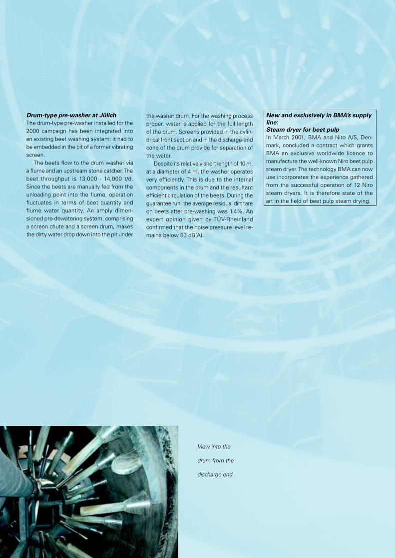
Drum-type pre-washer at Jülich
The drum-type pre-washer installed for the2000 campaign has been integrated intoan existing beet washing system: it had tobe embedded in the pit of a former vibratingscreen.
The beets flow to the drum washer viaa flume and an upstream stone catcher. Thebeet throughput is 13,000 - 14,000 t/d.Since the beets are manually fed from theunloading point into the flume, operationfluctuates in terms of beet quantity andflume water quantity. An amply dimen-sioned pre-dewatering system, comprisinga screen chute and a screen drum, makesthe dirty water drop down into the pit under
the washer drum. For the washing processproper, water is applied for the full lengthof the drum. Screens provided in the cylin-drical front section and in the discharge-endcone of the drum provide for separation ofthe water.
Despite its relatively short length of 10 m,at a diameter of 4 m, the washer operatesvery efficiently. This is due to the internalcomponents in the drum and the resultantefficient circulation of the beets. During theguarantee run, the average residual dirt tareon beets after pre-washing was 1.4%. Anexpert opinion given by TÜV-Rheinlandconfirmed that the noise pressure level re-mains below 83 dB(A).
New and exclusively in BMA’s supply
line:
Steam dryer for beet pulp
In March 2001, BMA and Niro A/S, Den-mark, concluded a contract which grantsBMA an exclusive worldwide licence tomanufacture the well-known Niro beet pulpsteam dryer. The technology BMA can nowuse incorporates the experience gatheredfrom the successful operation of 12 Nirosteam dryers. It is therefore state of theart in the field of beet pulp steam drying.
View into the
drum from the
discharge end

A spray dryer for special powders
Milchwerke Mittelelbe (Krüger Group)bought a second-hand TAG spray tower,which was to be employed at their Stendalfactory in the production of chicory coffeesurrogates and other special powders. Soit seemed obvious to ask the original sup-plier to turn it into a state-of-the-art systemand, at the same time, almost double itscapacity.
The tower itself was equipped with a newair distributor provided with appropriatenozzle units, and with a specially designedcone. In addition, a powder recycling sys-tem was installed.
The peripheral equipment was re-de-signed by modifications to the tower air sys-tem, including necessary air filtering andheating facilities, to the air conditioning sys-tem for an external fluidized bed, and tothe exhaust air system, including replace-ment of all fans. This project was completedlast year to the customer’s full satisfaction.
Centrifugals for Indonesia
BMA received an order from P.T. SumberMadu Bukari, Jakarta, Indonesia, whichcovers two batch centrifugals of type B1750 for white-sugar massecuite and onecontinuous centrifugal of type K 2300 Tur-bo for low-raw massecuite. The factory islocated in Kendari in the south east of Sula-wesi.
Spare parts on
their way to Midas
Chemical, Lahore,
Pakistan
Ready to sign a contract in
Braunschweig: V. Kennan and
V. Baskaran, together with their wives
and BMA representatives

BMA Information goes www
If you require another copy of this issue ofBMA Information, you can from now ondownload the respective pdf file to yourcomputer and open it with the AcrobatReader. You will find it on BMA’s homepagewww.bma-de.com in the printed mediasection, where you can also order a printedcopy and retrieve lots of latest news andaddresses of BMA contacts.
Published by:BMABraunschweigischeMaschinenbauanstalt AGGermanyJuly 2001
Text and illustrations by:BMADesign and layout by:Ideeal Werbeagentur, BraunschweigLithography by:Rolf Neumann, digitale bildbearbeitung,BraunschweigPrinted by:Ruth Printmedien, Braunschweig
Printed onnon-chlorine Phoeno-Matt paper

BraunschweigischeMaschinenbauanstalt AGPostfach 32 25D-38022 BraunschweigGermanyPhone +49 531·804-0Fax +49 531·804-216http://[email protected]