The Balancing of Steam Locomotives: A Dynamical Problem ...
544
The Balancing of Steam Locomotives: A Dynamical Problem of the Nineteenth and Twentieth Centuries by PETER SIDNEY BARDELL A thesis submitted to the University of London for the award of the degree of Doctor of Philosophy History of Science & Technology Group Imperial College of Science, Technology and Medicine December 1988
-
Upload
khangminh22 -
Category
Documents
-
view
0 -
download
0
Transcript of The Balancing of Steam Locomotives: A Dynamical Problem ...

The Balancing of Steam Locomotives:
A Dynamical Problem of the Nineteenth and
Twentieth Centuries
by
PETER SIDNEY BARDELL
A thesis submitted to the University of London for the award of the degree of
Doctor of Philosophy
History of Science & Technology Group Imperial College of Science, Technology and Medicine
December 1988

2
SUMMARY
Following a brief survey of the prehistory of balancing
and its emergence as a technique of vibration control early in
the nineteenth century, this thesis examines the problem of
steam locomotive balancing. From 1845 when the investigations
of the Gauge Commission highlighted the importance of the
stability of the locomotive at speed the subject occupied the
attention of British engineers for over a century.
The study examines the reasons for the persistence of
the problem over such a prolonged period and the contribution of
engineering science to the design of the locomotive.
The thesis deals with the identification of the
dynamical problem, the development of a theory of balancing and
its presentation to engineers. Also considered here are some
locomotive examples and proposals emanating from engineers
dissatisfied with the inherent instability of the conventional
two-cylinder engine. The relationship between locomotive
practice and balancing is then traced. Economic aspects of
bridge maintenance eventually focused the attention of
engineers on the nub of the issue and culminated in the work of
the Bridge stress Committee, during the mid-1920s, which clearly
exposed the significance of the dynamic interaction between
locomotive and track, and led to the introduction of proper
balancing parameters in locomotive design.
During the 1930s good balancing practice combined with

3
other rationalised design procedures enabled British express
passenger locomotive practice to attain the peak of its
achievement, although this was accomplished with three- and
four-cylinder engines. Thereafter, the final phase of steam
locomotion in Britain, which saw the production of the British
Railways Standard Classes, convincingly demonstrated that with
careful design it was possible to put powerful two-cylinder
locomotives into service with hammer-blow characteristics
considerably superior to those permitted in the recommendations
of the Bridge Stress Committee.
Far from being resolved, however, the issue was directed
once more to the effects of horizontal forces on the locomotive
- its point of origin a hundred years earlier.

Acknowledgements
My grateful thanks are expressed to Dr N.A.F. Smith and
to Professor A. Rupert Hall, whose initial interest and
encouragement laid the foundation for this piece of work, also
to the History of Science and Technology Group at Imperial
College for the stimulus which has sustained this work
throughout its progress. A special word of thanks is due to Dr
S.A. Smith and to Mr R. Spain for their discussion and helpful
comments which have been of considerable assistance to me. In
particular my gratitude is due to Dr N.A.F. Smith for his
guidance throughout the period during which the research was
carried out and for his valuable critical analysis of my work as
the thesis was written.
Without the support and understanding of my family this
work could not have been completed and my indebtedness to Anne,
my wife, and to Andrew, Mary, Jane and Matthew is gratefully
acknowledged.
I also record my thanks to Mrs Susan Buchanan, for
secretarial assistance, and to Miss Ainslee Rutledge for typing
this thesis.
For their kind permission to use material included in
the thesis I express my thanks to the following:
Messrs Ian Allan Ltd Fig.7.7

5
Birmingham Public Libraries
Messrs Blackie & Son Ltd
British Museum
Greater Manchester Museum
of Science and Industry Trust
H.M. Stationery Office
Institution of Mechanical
Engineers
Mr B.C. Lane
Museum of Science and
Industry, Birmingham
National Railway Museum, York
Fig.1.2
Figs.3.5, 3.6, 3.7
Fig.2.4
Figs.3.8-3.12
Figs.6.1-6.12, 6.17, 6.18
Figs.3.17, 3.18, 4.17, 5.5, 5.6,
5.7, 5.13, 7.3-7.6
Fig.6.16
Figs.1.1, 4.9
Figs.5.1-5.4, 5.9, 5.10, 7.1 ,
7.2, 7-8, 7.9. Appendix 3

6
CONTENTS
Page
Summary 2
Acknowledgements 4
List of illustrations 9
Chapter 1 : Introduction 14
1. Background to the Study 152. The Prehistory of Balancing : Rotary Motion 203. Grain Mills 224. Windmills and Watermills 305. The Lathe ; 'Balancing* enters history 336. Heaton's Steam Carriage 38
Chapter 2 : The Railway Locomotive 49
1. Early locomotives and speed 502. Accidents 553. Stability of the locomotive 60
a. Steam pressure reaction 61b. Height of the centre of gravity 64c. Coned Wheels 67
4. The Problem Identified 705. The Gauge Commission and its Report 756. The Early Use of Balance Weights in 83
Locomotives
Chapter 3 : Balancing - Theory and Practice: The 105Second Half of the Nineteenth Century
1. The Theory of William Fernihough 1062. The Emergence Of a Theory of Balancing 1123. Nollau's Experimental Work 1184. The Mathematical Work of H. Nollau 1215. H. Nollau - Concluding Comments 1236. The Work of Louis Le Chatelier 1277. D.K. Clark 1358. Rules-of-Thumb 1429. Confused Views 15010. The Deteriorating Situation 15611. Graphical Analysis 15912. a. The Contribution of W.E. Dalby 160
b. 'The Balancing of Locomotives' 162c. The Adoption of Dalby's Method 166
13. a. Locomotive Testing 172b. The Work of W.F. Goss at Purdue 173c. Other Views ~ ' 180
14. Final Comments 186

7
Chapter 4 : Some Unconventional Locomotives 206
1. Single-cylinder Locomotives 2092. Opposed-pistons working in a Cylinder 218
a. The designs of John George Bodmer 218b. J.G. Bodmer - concluding remarks 235c. Ritchie’s Locomotive 237
3. The use of reciprocating balance masses 239a. The Patent of A.W. Makinson and 245
W.F. Bathob. The Krauss Locomotive 247c. French 2-8-2 Tank Engines 251d. Contra-rotating balance weights 252
4. Multi-cylinder locomotives 254a. The Three-cylinder Locomotive of Isaac 256
Dodds and William Owenb. The Balanced Locomotives of Stephenson 259
and Howec. The 'Duplex’ Passenger Express Engine 261d. H.F. Shaw's Four-cylinder Balanced 266
Locomotive5. Designs avoiding the use of reciprocating 268
steam enginesa. The Jet Reaction Steam Locomotive 269b. Steam-Turbine Locomotives 272
Chapter 5 : The Missed Opportunity 286
1. Multi-cylinder propulsion 2902. The First Four-cylinder Locomotives 2913. The ’Decapod' 2964. The Designs of G.J. Churchward and Sir 302
Vincent Raven5. The Preference of H.N. Gresley for Three- 309
Cylinder Locomotives6. General Conditions 317
Chapter 6 : The Permanent Way and the Bridge Stress 346Committee
1. Early Train-Track Experience 3472. The Safety of Iron Bridges 3553. Ministry of Transport Tests on Railway 363
Bridges4. The Bridge Stress Committee and its 374
Worka. Aims 378b. Experimental Work 381c. Mathematical Analysis 389d. The Locomotives Used in the Tests 395
Chapter 7 : To the End of Steam 425
1. Aftermath of the Bridge Stress Committee 426Report
2. The Final Phase 444

3. The Post-War Period 460
Chapter 8 : Concluding Remarks 481
Appendix 1 George Heaton 503
Appendix 2 W.E. Dalby's Semi-Graphical Method of 509Balancing
Appendix 3 Balancing of Locomotives. L.M. & S.R. Loco. 519Drawing Office, Crewe, 1939 '

Page
34
39
65
66
66
90
109
115
126
1 27
138
139
141
1 45
146
147
9
LIST OF ILLUSTRATIONS
Syllabus of a Course of Lectures at the Birmingham Philosophical Institution
Heaton's Steam Carriage, 1830
Trevithick's 'Cornwall', 1847
Colburn's Design of Locomotive Double Boilers, with Driving Axle Between
MM. Blavier and Larpent's Locomotive, 'L'Aigle', 1855
Rastrick's 'Stourbridge Lion'
The Simple Engine Mechanism
Nollau's diagram of the piston, connecting-rod and crank mechanism
Title page of Louis Le Chatelier's 'Etudes sur la stabilite des Machines Locomotives en Mouvement'
Le Chatelier's oscillation diagrams from a passenger engine
D.K. Clark's diagram showing the horizontal disturbance of a locomotive in motion
D.K. Clark's diagram illustrating the variation in vertical force between wheel and rail
D.K. Clark's rules for the determination of balance weights
Balancing calculations for Beyer, Peacock 2-2-2 locomotive for the Edinburgh & Glasgow Railway, 1856
Edinburgh & Glasgow Railway, 2-2-2 Locomotive, 1856
Beyer, Peacock 'As built' drawing of the Edinburgh & Glasgow Railway, 2-2-2 locomotive, 1856

148
149
174
175
176
176
182
183
215
220
220
224
224
226
234
238
240
246
10
Balancing calculations for Beyer, Peacock 0-4-0T engine for the Great North of Scotland Railway, 1855
Beyer, Peacock 'As built' drawing of the Great North of Scotland Railway, 0-4-0T engine, 1855
The Locomotive 'Shenectady' in the Engineering Laboratory, Purdue University
Arrangement for feeding lengths of iron wire beneath the driving wheels of the locomotive
Graph showing wire deformation
Graph illustrating lack of contact between wheel and rail
W.E. Dalby's graph showing variation in wheel- rail contact force for an Inside Cylinder Single Engine
W.E. Dalby's graph comparing driving torque with the couple resisting slipping for an express passenger engine
W. Neilson's single-cylinder locomotive
J.G. Bodmer's first locomotive
Schematic diagram showing the principle of operation of Bodmer's design for a balanced engine with a piston rod passing through each end of the cylinder
J.G. Bodmer's engine design using telescopic piston rods
J.G. Bodmer's locomotive drawing of 31 May 1842
J.G. Bodmer's locomotive built for the South- Eastern and Brighton Railway, 1845
J.G. Bodmer's design of 2-4-0 Goods Tank Locomotive, 1844
C. Ritchie's New Locomotive Engine, 1856
George Heaton's model
The design of A.W. Makinson and W.F. Batho for balancing a single-cylinder locomotive with reciprocating balance masses

248
250
251
253
257
259
262
264
265
267
270
298
303
306
307
311
312
312
318
319
320
11
The Krauss Locomotive
Reciprocating balance mass on the Krauss locomotive
Balancing arrangement on French 2-8-2 Tank Engine
M. Tolle’s scheme for balancing by the use of contra-rotating balance masses
The three-cylinder locomotive of I. Dodds and W. Owen
G. Stephenson’s and W. Howe’s three-cylinder locomotive
J. Haswell's 'Duplex' locomotive for the Austrian State Railway
(a) Passenger locomotive(b) Goods locomotive designed by M. Petiet for
the Northern Railway of France
M. Jules Morandi^re's proposed three-cylinder engine
H. F. Shaw's four-cylinder balanced locomotive
The Jet Reaction steam locomotive of J.A.E. De Grand
'The Decapod', Great Eastern Railway, 1902
'North Star', Great Western Railway, 1906
GWR four-cylinder 'Star' Class Locomotive
GWR two-cylinder 'Saint' Class Locomotive
Variation of tractive effort for 2-, 3", and 4-cylinder engines
Characteristic Drawbar pulls at slow speeds with two- and three-cylinder passenger engines
Characteristic Drawbar pulls at high speeds with two- and three-cylinder mineral engines
Hammer-blow at 6 rps for 4-4-0 locomotives
LNWR 'George V' Class, two-cylinder locomotive
LNWR 'Claughton' Class, four-cylinder locomotive

12
5.11 Highland Railway ’River’ Class locomotive 324
5.12 Hammer-blow at 6 rps of the Highland Railway 325’River’ and ’Clan’ Class locomotives
5.13 Balancing arrangements for George Hughes’, 337four-cylinder locomotive
6.1 Curves illustrating various impact formulas 360
6.2 (a) Ministry of Transport Results of Tests on 368Maunby Bridge, North Eastern Railway
(b) Details of Test Load used and of the 369Bridge
6.3 Ministry of Transport Deflection Records, 370Maunby Bridge
6.4 Bridge Stress Committee Deflection Record, 382Maunby Bridge
6.5 Bridge Stress Committee Deflection Record, 384Newby Wiske Bridge
6.6 Bridge Stress Committee Deflection Curves, 385Newark Dyke Bridge
6.7 Bridge Stress Committee Bridge Oscillator 386
6.8 Bridge Stress Committee Oscillator Records 387
6.9 Bridge Stress Committee Comparison between 390theory and experiment for model bridge
6.10 Curve illustrating two critical frequencies on 391a bridge of intermediate span
6.11 Single critical speed on a long-span bridge 392
6.12 Effect of spring movement on amplitude- 394frequency diagrams
6.13 Table showing number of locomotives exceeding 397the combined loading recommendations
6.14 Table - analysis based on the number of two-, 398three- and four-cylinder engines operated byeach company
6.15 Table - analysis of two-cylinder locomotives 398
6.16 Locomotive ’K’, Lancashire and Yorkshire 399Railway, 0-8 -0 Engine No. 1438

13
6.17 Curves for Loads producing Bending Moment. Single Track Bridges
408
6.18 Curves for Reduced Speed 408
7.1 'Lord Hawke', Southern Railway 'Lord Nelson' Class Locomotive, 1929
429
7.2 Great Northern Railway, H.N. Gresley's three- cylinder, 2-6-0, '1000' Class Locomotive, 1920
434
7.3 LMSR Tests. Illustrating wheel lift 447
7.4 Kink in Track after Slipping Tests 448
7.5 Damaged Rail after Removal 449
7.6 Diagram to illustrate Wheel Bouncing 450
7.7 Balancing Particulars - British Railways Standard two-cylinder locomotives
464
7.8 British Railways Standard Locomotive 'Britannia' Class' 4-6-2
465
7.9 British Railways Standard Locomotive, Class 3MT, 2-6-0
465

Chapter 1
INTRODUCTION

15
1 . Background to the study
One of the most striking aspects of the development of
machinery during the nineteenth century was the phenomenal
increase in operating speeds and, indeed, in men's concept of
speed. This inexorable upward trend was a characteristic of
modes of transport, machine tools, and processes alike. The
evolution of engines created the opportunity to raise their
speeds and hence obtain greater power without necessarily
enlarging the size and mass of the components required for its
generation and transmission.
Since, for a rotating body, the disturbing force brought
into action increases as the square of the speed, the importance
of operating speed in the design, construction and operation of
machinery assumed a significance which grew throughout the
nineteenth century and which has continued to the present day.
Concomitant with the upward trend of speeds was the requirement
for 'balancing1 moving machine elements, and the emergence of
this process as an engineering technique at the beginning of the
nineteenth century and its growing importance as the steam
engine was employed to drive an ever-increasing variety of
machines. While the balance of rotating masses was relatively
easily accomplished and its necessity perceived and met in
earlier years, the problem of coping with the inertia forces of
reciprocating masses was entirely a matter of the nineteenth
century.
This study originated from an interest in the

16
application of ’engineering science’ and its contribution to the
evolution and the construction of machinery, and more
specifically to the practice of 'balancing' as a pre-requisite
for true-running and freedom from vibration in the operation of
machines. The undesirable and potentially dangerous effects of
vibration manifested themselves early in the last century and
recurred with increasing frequency as the years passed.
Essentially, vibration control became a major issue and received
its first publicity as a specifically defined area of concern
with the considerable attention devoted to the steadiness of
railway locomotives in motion at the hearings of the Gauge
CommissionJ Thereafter problems of a similar nature arose in
different fields of engineering activity and established the
subject as one of common and fundamental importance. And this
situation has persisted. Today, 'Vibrations' have ceased to be
but one topic in a 'Theory of Machines' course and have become a
subject in their own right and an integral part of many
university and college courses for the education of engineers.
Initially it was intended that this piece of work would
examine the origin and significance of the balancing problem, as
one of the major sources of vibration and the methods adopted to
solve it, in various types of machinery including electrical
machines, internal combustion engines, locomotive engines,
machine tools, marine engineering, stationary steam engines,
textile machinery and turbines. However, it soon became
apparent that such an undertaking was far too ambitious. In the
first place the task was of such a magnitude that the time
available for the necessary research did not permit such a

17
comprehensive investigation. Secondly, and undoubtedly of far
greater moment for any historian of technology attempting to
study a specific topic is the existence of the necessary
evidence for appraisal and analysis and from which some
meaningful conclusions could possibly be drawn. Preliminary
enquiries to industrial companies, to museums and to record
offices did not reveal the preservation of any such technical
records nor did the responses provide any real basis for hope
that such documents, etc., might have survived in anything but
the most isolated and fragmentary manner.2
Of the various types of machinery listed in the
preceding paragraph the railway locomotive can be distinguished
from the other categories in one particular respect. Unlike
other branches of engineering, for example marine engines and
internal combustion engines, where the problem of dynamic
balance was encountered, acceptable practical solutions^ found
with a consequent relatively quick disappearance of the topic
from the deliberations of professional engineers, locomotive
engineering is characterised by the persistence of the topic of
balancing as a continuing theme virtually throughout the whole
life of the steam locomotive as a railway traction vehicle.
Unquestionably the nature of the problem had been clearly
identified by the mid-nineteenth century but incredibly it
persisted as a problem engaging the attention and discussion of
engineers for over a century. And even then the matter was not
settled. The need for more work, and the increasing importance
of the subject, was articulated by senior engineers, civil and
mechanical, as late as 19^1.^ An object of the thesis is to

18
examine the reasons for this remarkable state of affairs.
A major difficulty in undertaking a task of this nature,
that is, a historical investigation of a specialised technical
aspect of the design, construction and operation of steam
locomotives is the fragmentary and disparate nature of the
source materials available. Because locomotive design on a
rational basis was never consistently assisted by the
availability of good contemporary books on the subject by
British engineers, it has not been possible to trace the history
of this particular subject through a succession of 'standard’
texts or through various, updated, editions of design manuals.
Apart from D.K. Clark's Railway Machinery which appeared in
1855, and was supplemented by Clark's co-authorship with Zerah
Colburn in producing Recent Practice in the Locomotive Engine
five years later the works of W.F. Pettigrew? and C.E. Wolff,®
which date from about the turn of the century, comprise the only
substantial literature on the topic. The contribution of
practising railway engineers to the literature of the subject
is, likewise, somewhat limited and even their meagre literary
output tends to be of restricted value to the reader in search
of detailed information on any specific aspect of locomotive
design. The majority of them, presumably under the weight of
their professional responsibilities appear never to have had
either the time or the inclination for such pursuits. Of the
few who did, and the list includes such acknowledged names as
Vaughan Pendred, E.L. Ahrons, H. Holcroft and E.S. Cox himself,
who was responsible for the design of the last steam locomotives
to be built for service on British metals, their books are

19
essentially general surveys for the technically-minded reader
who wanted a comprehensive treatment of the subject rather than
a specialised account of design philosophy and procedures. That
there was such a demand cannot be doubted. By 1914 the series
of articles ’Some Historical Points in the Details of British
Locomotive Design' written by E.L. Ahrons for The Locomotive
Magazine during 1908-9 was, at the request of the magazine's
editor, revised and expanded for publication as a book.9
To this relatively small group of writers must be added
another little band of men, including, for example, C.J. Allen,
O.S. Nock, E.C. Poultney and B. Reed who were trained in railway
engineering and subsequently turned to technical journalism.
Often maintaining close personal relationships and friendships
with the senior staff in railway companies and locomotive
companies, they were knowledgeable and reliable critics of
locomotive design and performance. But in studying their
writings it must be recognised that their information was
gathered and their interpretations made as keen spectators
rather than as participants in the actual engineering processes.
Inevitably this will demand a certain amount of caution in
evaluating their comments because decisions made under the
actual pressures of conflicting technical requirements,
production facilities, material availability, time constraints,
and so on are not always appreciated by the onlooker. Here,
too, of course it must also be noted that the identical
limitation of lack of detailed design analysis also applies to
their work since they were writing for the same group of
readers.

20
In attempting to examine the history of locomotive
balancing, no simple task since the limited documentary evidence
is fragmentary in nature and widely scattered, the approach has
been essentially one of synthesis. This study has been based on
a wide variety of evidence ranging from official government
reports to anecdotal incidents10 but drawing mainly on the
Proceedings of both the Institution of Civil Engineers and the
Institution of Mechanical Engineers together with the specialist
journals The Engineer and Engineering. These varied sources
seemed to offer a selection of evidence that could be studied
and analysed and from which, perhaps, some conclusions could be
drawn. The challenge was to determine the quality and nature of
the evidence available to the historian seeking to pursue a
specific but technically important aspect of locomotive design
and operation and then, from this, to ascertain how the
dynamical problems of the locomotive were perceived by the
engineers involved and their response to them.
Before concentrating on the problems of the steam
railway locomotive, however, a brief consideration will be given
to the pre-history of balancing and its appearance in
engineering literature at the beginning of the nineteenth
century.
2. The Prehistory of Balancing: Rotary Motion
The importance of rotary motion in the processes of
mechanisation, given an impetus and an enduring position as the
foundation of present industrial societies during the period
generally called the industrial revolution, requires little

21
emphasis. Nor do the remarkable subsequent developments in
electricity generation, land and marine transport and aviation.
Imbalance is inherent in rotary motion which is a
prehistoric invention. To ’throw’ clay successfully a minimum
speed of 100 revolutions per minute is required and so it
appears that the potter’s wheel, which is about 6,000 years
old,H is almost certainly man’s first fast-moving rotary
device. Despite Childe’s statement that 'Undocumented
speculations as to how wheels might have developed [have] no
place in history’,12 it does not seem unreasonable to conclude
that early experience taught that if a wheel was to run smoothly
it must possess symmetry about its rotational axis. By
observation alone, prehistoric man could, and probably did,
discover this condition. A natural achievement of symmetry was
a direct consequence of the manufacturing process when, in due
course, the lathe made its appearance and became an established
tool in the hands of the craftsmen. Thus by classical times the
production of various types of wheel, and also bearings, with an
acceptable standard of operational performance was a commonplace
achievement.
Probably, too, tests of a simple but effective nature
were devised but of such procedures we have no knowledge and it
is hardly worth speculating on the possibilities available to
the contemporary craftsmen although the occasional, and rare,
reference to such matters suggests that they were worthwhile and
that the subject had received considerable thought and
attention. Thus, Joseph Needham mentions a Chinese text, of
perhaps the fourth century B.C., giving information on the

22
elaborate testing of completed chariot wheels by ’the use of
geometrical instruments, flotation, weighing, and the
measurement of empty spaces in the assembly by means of millet
grains'.13 Such sophistication, although hardly likely to have
been anything other than exceptional, nevertheless reveals an
awareness of the intricacies involved and the measures to be
taken to ensure the desired result, that is, a wheel of high
performance characteristics.
At a less-demanding level, and more generally, it seems
reasonable to claim that, at a fairly early period, the
wheelwright’s art included appropriate methods of measurement
and testing.
3. Grain Mills
During the first century B.C. continuous rotary motion
was applied to grain and pulse grinding and remained the common
practice until the second half of the nineteenth century when
the introduction of roller mills brought about the steady but
inevitable decline of milling with stones in Britain; the
practice of which, nevertheless, persisted on a small but
significant commercial scale until the time of the 191^-1918
War.
The grinding of grain by this method has confronted the
millwright, from the earliest period, with the intricate
mechanical problem of keeping the runner stone concentric with
the bed stone, maintaining the grinding surfaces in virtually
parallel planes with a carefully controlled clearance between
them, whilst permitting the continuous feed of grain through the

23
mill. These requirements of the millstones used in water mills
and windmills were, of course identical with those encountered
in querns. To produce a uniform quality meal, that is, to
achieve good grinding - and later, in large mills, to prevent
the fire hazard of sparks generated by the stones running
together -it was necessary for the runner stone to be
dynamically balanced.
Again, progress via refinements made as the result of
observation of the relationship between millstone and product
seem to explain the developments in milling. This trend was
assisted by the process of diffusion. In writing of Celtic
querns in Britain J. Storck and W.D. Teague remark that one of
the results of Roman influence was that 'stones became thinner
and increased in diameter...but better balanced and 1 lisupported.'1M
The role of the Roman armies in spreading the use of the
quern and the improvements in milling practice achieved by the
Romans have also been briefly acknowledged by R. Bennett and J.
Elton1 and by L.A. Moritz.1 In Rome, during the classical
period, the appearance of flour in various grades is an
indication of the attainment of a relatively high and
sustainable control of the milling operation together with the
associated sieving processes, the former being dependent in
large measure on a satisfactory dynamic performance of the
millstones themselves.
How regulation of the millstones was accomplished then,
and throughout the ages, is not known with any certainty. The
millwrights who built and maintained mills for something like

two thousand years probably learned their craft by experience as
they moved from mill to mill or from one region to another, or
by trial and error, or from rules-of-thumb which were
transmitted orally from one generation to the next. Their
knowledge did not find its way into books most likely because
many of these craftsmen were illiterate and since, likewise,
those to whom such works would have been of value were also
unable to read there was hardly a demand or use for them.
Man’s need of bread, a daily requirement, made milling
an ever-present task and no doubt maintained interest in the
process. It received considerable attention and literary
expression in the works of Mariano Taccola,^ Francesco di
Giorgio Martini^ and Agostino Ramelli,^ f0r example.
Martini’s Treatise depicts some 67 different ways of driving
millstones while of the 195 devices included in Ramelli's book,
apart from 110 used for water-raising, the next largest group
consisted of 21 grain mills, of which 20 possessed conventional
millstones. These were variously operated by manpower,
horsepower, waterpower and windpower. These, and other volumes
by Renaissance authors, however, contain little practical,
operational detail but even if they are regarded as no more than
displays of the ingenuity of their authors their very choice of
subjects is an indication of the importance attached to them and
deemed likely to appeal to their patrons and readers as devices
for the benefit of mankind.
A deficiency in practical technical detail may, in
general, be said to characterise the somewhat later generation
of books, specifically devoted to the subject of milling, by

25
British authors, such as those by John Banks,2 Andrew Gray2
and Robertson Buchanan.22 Despite the rather theoretical nature
of Banks’ Treatise, with consideration given to topics such as
centrifugal forces, centres of gyration and percussion, etc. it
was no indication that milling was commonly based on ’science’
or that millwrighting was institutionalised in the sense that it
possessed a reference group comparable with the Institutions of
Civil and Mechanical Engineers, for instance. Indeed it is
unlikely that, as a group, British or even European millwrights
possessed uniform views even on many fundamental points. This
consensus could have been promoted by the availability of a
practical technical literature on the subject but in Great
Britain (and Europe) with enough millwrights living close enough
together to be always at the service of the mills presumably
there was not a perceived need for this. The New World,
however, appears to have been confronted with a vastly different
situation. In America with a shortage of skilled craftsmen of
all types and much greater distances to be covered, the miller
had to be more self-reliant and therefore the book was of
practical utility in assisting him in his difficulties. It is
not surprising to find that the more practical books on the
subject are of American origin.
Oliver Evans’s The Young Millwright and Millers'ppGuide, first published in 1795 had reached its thirteenth
edition by 1850 and by this latter date the writer distinguished
between static and dynamic balance, emphasising the need for
true balance to be achieved by 'running lead into, the lightest
side'.

26
No evidence yet appears to have come to the notice of
historians to enable them to even approximately date when
millstones were first ’balanced’ by pouring molten metal into
holes specially formed for this purpose but, in the absence of
contrary evidence, it may be regarded as a post-medieval milling
development. Since it was the middle of the nineteenth century
before Evans referred to the practice in the later editions of
his book, and allowing for the erratic and tardy rates at which
innovations spread, it seems reasonable, based upon our present
knowledge, to date the origin of this method of balancing the
runner stone to the eighteenth or the early nineteenth century.
Likewise, Henry Pallett introduced the second edition ofp hhis book, M ’with considerable additional information and
greatly improved and enlarged illustrations’ in 1866 because the
demand for the first edition had been ’so great and
satisfactory’. Here, again, precise details were given about
the location, shape and depth of hole into which molten lead was
to be poured and his readers warned that failure to observe
these points would lead to ’imperfect' balance when running.2
Correctly constructed and balanced millstones were seen
to be important by these writers and probably by the more
percipient of the millers and millwrights but good practice was
not universal nor had the means of achieving it reached all
ears. As late as the second edition of his book Pallett could
state that some builders put blocks of burr, of varying
thickness (some nearly twice the thickness of others) into the
stones making proper balance almost impossible.
Variations in milling practice were clearly great with a

27
consequent wide range of mill operating efficiencies. Inferior
methods were perpetrated through lack of knowledge and the slow
diffusion of improvements. Both these points were made by John
Sutcliffe who, in his Treatise on Canals and Reservoirs, 6
devoted a few pages to grain milling. His contention was that
failure to adopt the ’balance rine’ as opposed to the ’fixed
rine’ resulted in inexcusable, costly inefficiency and from a
small consideration of milling costs determined that an annual
saving of £1,250,000 was possible in the United Kingdom, but he
concluded,
__few millers know of it, and still fewer know how to
use it; which shows the necessity of making its utility
as public as possible.
Whilst the actual accuracy of his claim cannot be
verified the point of his argument can hardly be denied. The
hanging, balancing, and adjustment of the runner stone was
clearly critical to its proper control and hence the
satisfactory conduct of the milling operation. The exacting
requirements of the stones in use has been described by Stanley
Freese, a later commentator on the subject;
Dressing, and subsequent re-balancing, of the stones is
a fine art, on which much of the efficiency of the mill
depends; indeed, it is claimed that the work should be
so finished that the ’nip’ or closeness of the stones

28
will only permit of a piece of brown paper being placed
between them at the centre, and a piece of tissue paper
at the periphery.
Although, no doubt, these incredibly fine limits
prescribe a desired ideal rather than a realistic essential
condition to be achieved it must be acknowledged that with
runner stones of 4ft diameter, weighing about half a ton and
rotating at 120 rpm, the importance of correct balance requires
little emphasis.
It is, perhaps, indicative of the mounting pressure on
millers to increase their output by reducing the time that the
stones were out of action that in the years 1859 and i860 three
patents were taken out in Britain to simplify and quicken the
process of balancing the runner stone by means of adjustable
weights contained within boxes which, in turn, were set into the
upper surface of the stone. Greater acuteness of the situation
confronting millers in the United States probably accounts for
the fact that two of these three designs originated there.
Henry C l a r k e , a corn factor of Wakefield, Yorkshire,
obtained a patent on behalf of Thomas Narburgh of St Louis,
Missouri, whilst Alfred Newton,30 a draughtsman at the Patent
Office, carried out a similar service for John Fairclough, of
Louisville, Kentucky. The third patent was granted to William
Gough,31 a miller from Birmingham.
These three patents, all based on the principle of
providing quick and relatively easy adjustment of the plane in
which the balance weights acted, show a significant advance in

29
an understanding of the true, dynamic, nature of the problem and
both its technical and economic solution. Since the runner
stone needed re-balancing every time the millstones were dressed
the facility for easily modifying both the magnitude and the
planar position of the weights offered great advantages over the
older method of pouring molten lead into cavities in the top of
the stone.
However, the appearance of the relatively sophisticated
'balance boxes' in runner stones during the later years of the
nineteenth century came too late to have any significant impact
on milling practice. The introduction of roller milling, during
the 1870s, increasing urbanisation with the consequent depletion
of the rural population, growth in grain imports - with the
imported produce processed at the ports and then distributed via
the well-established national railway system, were all factors
which contributed to the decline of stone milling. And if the
availability of the portable steam engine is taken into account
the simultaneous decline of windmilling and watermilling is more
readily appreciated.
By the time that millstones could be quickly and
properly balanced their use on a commercial scale was
effectively over. By the time the solution was found the
problem had ceased to exist because the technology had been
supplanted by a different and a superior method of grinding
grain. A parallel situation may be discerned in the matter of
balancing steam railway locomotives. The problem persisted for
a hundred years and when, at last, it was rationally solved it,
too, was irrelevant since steam traction was replaced by diesel

30
and electric power.
Far from being unusual, however, this appears to be an
essential characteristic of technological development or
evolution, and similar discontinuities may be envisaged in the
transition from timber to iron in the construction of ships’
hulls, for example, or in the adoption of steam turbines to
supersede reciprocating steam engines for electricity
generation, or in the decline of the glass thermionic valve in
radio technology following the advent of the transistor.
Reflection upon such issues emphasises the ’problem-solving’
nature of engineering as an intellectual achievement of man
quite distinct from ’science’ with its search for understanding
through general laws.
4. Windmills and Watermills
Although of crucial importance the millstones were not
the only concern of the millwright with the problem of
balancing.
It was necessary for the sails of a windmill to be
balanced. To start a mill with common sails, each sweep in turn
had to be brought down near the ground so that the cloth could
be unrolled and spread across the bars. Likewise, to control
the speed of the mill, the ordinary cloth-rigged sails were
reefed with knots - like a ship’s sail. For reefing, the mill
had to be stopped successively with each sweep in the lowest
position so that some of the canvas could be rolled up. Thus
the operational need to bring any sail into its lowest position
when required made balance an important matter.

31
Later developments, including Andrew Meikle's spring
sail, invented in 1772, and patent sails, did not diminish the
need for balanced sails because this was also necessary for
smooth turning. And as Rex Wailes^2 has pointed out, although
rotational speeds in England have been low, usually 12 to 16
revolutions per minute, tip velocities are high with the result
that lack of balance imposes severe strain on the sails and
shaft bearings.
Where necessary, the sails were balanced by fixing a
piece of iron of convenient shape on to the whip33 near its
outer end.
The matter of sail balance also favoured the general use
of four-sailed mills although multi-sailed mills with an even
number of sails were built and could continue to work if one
sail broke, by removing the opposite one of a pair to maintain
the balance. Almost certainly multi-sailed mills were built to
provide more power, and possibly greater ease of starting,
rather than from any consideration of balance. Clearly this
latter point was not deemed important by John Smeaton, who had
conducted experiments on the design of sails and progressed from
the conventional four-sails to five sails in his last three
mills, despite the inherent disadvantage that serious damage to
a sail rendered the mill completely unbalanced and unworkable.
His assessment of operational requirements obviously convinced
him that the advantages to be derived from his design when the
mills were working conclusively outweighed the consequences of a
mill being completely out of action.
Somewhat incongruously, perhaps, E.L. Hill introduced a

32
paper^ on balancing railway locomotives, given at the
Institution of Civil Engineers in 1891, with a reference to the
balance of wooden water wheels. He stated, without any
indication of the source of his information, that one of the
earliest instances of balancing was to keep wooden water wheels
turning very slowly instead of stopping them altogether since,
if they were allowed to stop for any length of time the part
above water would dry out while that below would remain wet, so
that the wheel on starting again would run in a succession of
jerks, being heavier on one side than the other. Undoubtedly
this irregular motion would occur in the circumstances described
but almost certainly a reason other than balance would account
for the practice.
Improved balance of a wooden water wheel came as a
natural and beneficial consequence of keeping the wheel wet
rather than being the reason for maintaining it in that
condition. Our present knowledge of water wheels does not seem
to permit any other conclusion on this point and in the absence
of reliable evidence to the contrary not only must Hill's claim
be questioned it can only be cautiously accepted as an
incomplete and inaccurate interpretation of his source material.
Due to dimensional inaccuracies in wheel fabrication
resulting in lack of symmetry about the rotational axis, and
inconsistency in the materials of construction, unbalanced water
wheels were not unknown. The defects could be found in both
wooden and iron wheels and were remedied by the use of balance
weights. Millwrights, even in the 'iron age' of millwrighting,
did not have recourse to science but proceeded, as their

33
predecessors had done, by empirical means. They knew when a
wheel was not running truly and smoothly and with their craft
knowledge and skills they also knew how to make it do so.
5. The Lathe: balancing* enters history
When the lathe was used to cut metals the impetus to
achieving continuous rotation became critical. Continuous drive
gave possibilities for development; by the use of suitable
pulleys the rotational speed of the workpiece could be
substantially increased and also varied to suit the turner’s
needs, thus enlarging the scope and the flexibility of this
basic machine tool.35 But higher speeds were accompanied by the
possibility of difficulties arising from the lack of dynamic
balance.
The application of a small steam engine to drive a lathe
in the workshop of the Earl of Craven, at Combe Abbey, in 1810,
provides us with the first clear and documented evidence of the
ill effects of imbalance. Details of the incident were related
by Dr J.B. Melson, in the sixth of a course of nine lectures on
Physical Mechanics given at the Birmingham Philosophical
Institution on 28 March 1842. The Syllabus for these lectures
is shown in Fig.1.1 This was possibly the first public lecture
on the topic and is the earliest evidence of the subject being
so presented that this piece of research has revealed.
There are no transactions of the Philosophical
Institution and our knowledge of the lecture is based on a
report in the Midland Counties Herald^^ which was subsequently
extensively quoted in the Mechanics Magazine. Later, J.E.

Birmingham: philosophical institution.2
SYLLABUSM fc
m m i L i g T y K i iM
THTSICAL MECHANICS,•1
JO H N B A B IU T T M E LSO N , A .B., M.l)., F.C.P.S.,C M f r t K M m t o X Ha n » w |> n l h o m at Btala; l a r v a * “ iraral t t i ,a a i» n la l
r>ii-T»>i - *~r' * -* **-*——■* *—i—r ri|»m nt a I M a ■ aa^ial. > w n |> a *
net tie im i i u cimhiici ai am-rist u n i itioci raceis11r.
LECTURE I.—Monday, February 21, 1642.
An outline of tbo History of the Physical Bdeaeea.—Nature o f tbo Court*.
LECTURE II.—Rood*7 , February 28.
T i l o m u l paoraBTiaa OF M a m a .—E rtn t.—Im^MUttrabdU^.—
Poranif^-DtvuibilUg+—l* matter infinitely dliiaible! Atom*—The theories of
Lucretius, Gassendi, Wolf, Swedenborg, and Berkeley.—EUuticitj.—Comprcjii-
bilitf.— ifokiiitj.— lojrtia.—UniTenaJ ittnetioD—Molecular attraction end repula ion.
LECTURE III.—Monday, March 7.
A rra ACTIOW coafiaurd. Cohesion—Capillary attraction.—Endotmote.—Exosmose.—Gravitation—Centre of [rarity,—Law a op M ottos.
LECTURE IV.—Monday, March 14.
L av a op M o n o s m ti*u*4. Equilibrium—Composition of fgrcua—Effect*
of (neltatioa—Vertical descent of bodice.—Attwood's Machine.— Projectiles—
Descent oo an Inclined plane—Curvilinear descent Momentum.—Impact.—7"A#
Pen i/tium—Cycloid—Centres of oscillation and persuasion.
LECTURE T.—Monday, Mareh 21.
Tb i M acs an ics op Solids. Tbo Slmpio JfocAia**. The Lever—The Wheel and Axle—Pulliee—Inclined Plane—The Cape tan.
LECTURE VI.—Monday, March 28.
Tub Mbchabical Pow aaa coaifaned. The Wedge—The Screw.
Fb ic iio v b i s Balabcibo. Bcatoo’a Experimcnta.
LECTURE VII.—Monday, April 4.
Mbchahics op QaaBonsBodies.—P jb cb o ita tics . Principal aeriform
bodies.—Tub Atxobpbebb .—Its height, prescore, and elastic Caret.—Barometer.—
Law of Mcrriotte.—Experiments with the Air Pump.
LECTURE VIII.—Monday, April 11.
Thb Mechanics op Fluid*.—HTom oatatica. Laws of finida at real.—
Pressure.—Equilibrium.—Equilibrium of floating bodies. Specific [rarity, bow
ascertained, of bodice solid, fluid, and aeriform. Tie B ydrom tttr. Hydrostatic
Bellows. Natural fountains and sprint;*.
LECTURE IX.—Monday, April 18.
Tub I t ecu an tea op O aaas atm Fluid* m im w tcL—Paxnuo-DT-
a ax tea . Phenomena of the Winds. Elastic force of Steam.Utdso-D tn a tries.—Artificial fountains.—Pump*. Siphons. Tha move
ment of fluids through orifices, tubes, and cans la. The reciprocal action of liquids
and solids. Mr. Rofe'e experiments. Bramah's Press. Wares.—Tidal Obsecra
tions.—Conclusion.
NON-SUBSCRIBER'S TXCRET TO TH B COURSE, £ \ . l a .
Gentlemen subscribing £1. l i t . Qd. annually, are entitled to personal ad-
mis lion to the News-room, and a Transferable Ticket to the Lectures, Mu arum,
and Library of the Institution.
Subscribed of £1. Is. to a Noo-tranafcrable Ticket to the Lecture*, Museum,
Ac. Ac.
Ladies subscribing £1. Is. per annum, are entitled to a Ticket to the Lectures,
Museum, Ac. transferable amongst Indies only.
h m X Sr 1— IS O s ss4 «■*. B i|l a im . ! « ■«>■
Fig.1.1 Syllabus of a Course of Lectures at the Birmingham Philosophical Institution

35
McConnell, Vice-President of the Institution of Mechanical
Engineers, introduced his first paper^? to the Institution
entitled 'On the Balancing of Wheels' with a lengthy extract
from this report.
We learn that the lathe was kept by his lordship for the
amusement of himself and his visitors in the practice of
mechanical pursuits. The Earl and 'many of his visitors' were
surprised to find that when the speed of the lathe was raised to
about 600 revolutions per minute it began to shake, and shook to
such an extent as the speed was increased that the whole lathe
and its frame jumped from the floor.
Mr George Heaton, an engineer, of Shadwell Street Mills,
Birmingham, then in the service of the Earl, was consulted as to
the cause of the vibration and unhesitatingly attributed it to
the imbalance of the revolving parts of the machine. This he
remedied by boring a hole in the light side of the pulley, three
and a half inches from the centre and inserted nine ounces of
lead, the requisite amount to achieve 'perfect' balance of the
pulley. Thereafter, at a speed of 600 rpm and any other speed
required for its work, the motion of the lathe was undisturbed
by vibration.
A reason for the fault was also conjectured, '...it was
probable that the texture of the wood being closer on one side
than on the other when dry was the cause of this inequality in
the weight.'38
In this statement the word 'texture' is not unambiguous
but it appears to refer to the density of the timber, rosewood
in this particular case. We have no dimensional information

36
about the pulley but within a single piece of rosewood the
density variation would not be significant. It would not
require the nine ounces of lead necessary to restore balance.
Most likely the cause of imbalance was due to the irregular
shrinkage of the timber displacing the mass centre from the
rotational axis. Such a phenomenon would not be unusual where
only partly seasoned timber was used and this explanation is
consistent with the implication that the variation only
developed when the wood was dry. However, a difficulty arises
with this interpretation because the report claims that the
lathe was of beautiful workmanship and made by one of the best
makers in London and so to accept it leads to the conclusion
that the maker, a skilled craftsman, was prepared to and did use
unseasoned timber and also that he was not aware of the possible
consequences of doing so. Although the former seems improbable,
we have no knowledge of the history of the pulley after it was
manufactured and it may have been exposed to conditions that
could have affected its stability, the latter is distinctly
possible since at the very beginning of the nineteenth century
it is by no means certain that the necessity for good rotary
balance was universally recognised or practised. Testimony to
this is provided by Dr Melson who, in introducing his lecture,
referred to above, stated ’There is not among machinists
sufficient care taken to construct all revolving machinery as
nearly as possible in balance.'
To illustrate this thesis he described how Heaton had
been called in to solve problems of uneven motion in guide
pulleys used on railways where rope was employed to draw the

37
train along, and to correct deficiencies of operation in both
light and heavy machinery. He cited the case of a fan required
to run at 1,000 rpm (but found incapable of doing so) to provide
a blast for melting iron which tore itself from its foundations,
shook the whole building and disturbed the neighbourhood to such
an extent that the proprietors were threatened with prosecution
for nuisance. This was but an early illustration of a problem
that was to recur on a more serious scale fifty years later when
reciprocating steam engines were used to drive electrical
generators. London experienced the vexation in good measure.
Vibration troubles at the Manchester Square power station
actually led to litigation,39 and similar problems were also
encountered at other generating plants including Bankside,
Leyton and Mason’s Yard. Those at the Greenwich station
affected instruments at the Observatory half a mile away.
Having dismantled the troublesome fan, Heaton found it
to be two and a half pounds out-of-balance and the fault was
rectified with satisfactory results, the machine being able to
run at its intended speed without displaying any tendency to
wander from its moorings. Probably 'out-of-balance effects' of
this magnitude were not uncommon in the 1830s and 1840s, and
even much later. The many exacting requirements of satisfactory
sandcasting were not appreciated and not attainable at that
period. Lack of homogeneity due to blow-holes, caused by
furnace gases dissolved in the metal during the melting process
or by chemical reactions occurring in the molten metal, has
always tended to make such castings one of the most unreliable
metallurgical structures. And a century later this point was

38
emphasised in connection with locomotive balancing. In his
paper2*0 on locomotive balancing read to the Institution of
Locomotive Engineers in 1938 D.C. Brown stated that one of the
principal requirements was to ensure that the wheels as cast
conformed to the designer's specification. Porosity often
resulted in balance weights being light and requiring
correction.2*1
6. Heaton's Steam Carriage
From the late 1820s the application of the reciprocating
steam engine to locomotive uses created a new situation
involving dynamical problems which manifested themselves in an
unmistakable and forceful manner.
Again, the first clear evidence comes from the work ofH oGeorge Heaton and his brothers who invented and patented^ the
design for a steam-propelled road carriage. An illustration of
this occupied the front page of Mechanics Magazine on Saturday,
14 September 1833. The drawing shown here, Fig.1.2 is from the
original drawing in the Birmingham Reference Library. Such was
the confidence in the vehicle and its commercial viability that
in October 1833 a business was formed under the name of 'The
Birmingham General Steam Carriage Company' and within
twenty-four hours three thousand out of the total of five
thousand shares had been sold within the town. However, the
initial optimism was not sustained and the affairs of the
Company were wound up on 27 January 1836. Throughout its
existence, its Chairman was Henry Merry and in 1958 Miss D.T.
Merry donated the minute book and the correspondence of the

39
Fig.1.2 Heaton’s Steam Carriage, 1830

40
Company to the Birmingham Museum of Science and Industry.^3 This
contains a letter from Heaton Brothers, dated 11 April 1834,
which is the only genuinely contemporary document relating to
the engineering work of their business that this study has
revealed. Its subject matter concerned the results of tests
which were not successful,
...convince us that it is improbable that our machine
will work to profit on the Common Road with the steam at
such a pressure as will be safe for the public to
trust.
Factors other than steam pressure account for the lack
of success of the steam carriage at this period and have been
briefly discussed in an article by F.T. Evans.^
Prudently and honestly Heaton Brothers admitted their
failure and abandoned the attempts to apply steam power to road
carriages, but not before a valuable lesson had been learned.
During their early trips it was found that the engine was so
unsteady when working at 160 or 180 strokes per minute, that it
was impossible for the men to keep their seats. They observed,
Being aware that this motion could only be produced by
some portions of our machinery being out of balance, we
placed a compensating weight opposite each crank, and
repeated our former experiment upon the same road and
found we attained greater speed with no greater

41
consumption of fuel, and the machine travelled perfectly
steady at any speed, and free from any symptoms of
rocking or shaking.
This brief comment, our first recorded evidence of the
dynamical problems associated with the reciprocating mechanism,
gives no indication that the true nature of the trouble was
perceived. It does, however, suggest that the source of the
bother had been identified, the matter given some attention, and
an empirical solution found and, indeed, one that was in the
course of time to be applied to the counter-weighting of
locomotive driving wheels. But, seemingly, this expedient did
not satisfy George Heaton for, as Chapter 4 will show, he
devised and patented a ’theoretically correct’ solution to the
problem of balancing reciprocating masses.
Unquestionably George Heaton is a man of some importance
in the early history of balancing in this country since, from
his efforts in 1810 he appears to have devoted a major part of
his life’s work to the study of the subject and to effecting
proper balancing in machinery of all kinds. Unfortunately
virtually nothing is known of him, but the few biographical
details acquired during the course of this study are presented
in Appendix 1.
By the middle of the nineteenth century the consequences
of imbalance were unmistakably manifesting themselves throughout
industry. Heaton’s experience of being summoned to diagnose and
correct deficiencies in machinery of all kinds, together with
the fact that McConnell chose to address the recently formed

42
Institution of Mechanical Engineers on the importance of
properly balancing machinery, provides clear evidence that at
this period many of those who designed, manufactured, operated
and maintained machinery had no real awareness of the
significance of the topic.

Chapter 1
INTRODUCTION
References and Notes
Report of the Gauge Commissioners. Presented to both
Houses of Parliament by Command of Her Majesty. Printed
by T.R. Harrison, London, 1846. For details of the
constitution and the function of the Gauge Commission
see Chapter 2 Section 5.
This situation is typically illustrated by the Archives
Department of Courtaulds Limited, in connection with the
development of textile machinery and by the Avery
Historical Museum on the subject of balancing machines.
W. & T. Avery Limited, although more widely known as
manufacturers of weighing machines, was the most
prominent British producer of balancing machines during
the 1920s and 1930s.
The former Company ’do not have any records’
while the latter, with one or two undated photographs
’regret that our records have fallen short on this
aspect of Avery products, but they are outside the
normal scope of the museum, which concentrates on ’The
History of Weighing’.

41]
Likewise, the early records of Samuel Courtauld
& Co. Ltd which are deposited in the Essex County Record
Office, deal with matters such as factory administration
and operation, staffing, wages, etc. and are devoid of
technical records.
3. See Chapter 3, section 12.a.
4. These views were expressed at a Joint Meeting of the
Institutions of Civil and Mechanical Engineers in
December 1941. The two papers ’Hammer-Blow in
Locomotives: Can it not be Abolished Altogether?’ by
Colam, Sir H.N. and Watson, Major J.D. and ’Balancing of
Locomotive Reciprocating Parts' by Cox, E.S. are
considered in greater detail in Chapter 7.
5. Clark, D.K., Railway Machinery, Vol.1 Text and Vol.2
Plates, Blackie & Son, Glasgow 1855.
6. Clark, D.K. and Colburn, Z., Recent Practice in the
Locomotive Engine, Blackie & Son, Glasgow i860.
7. Pettigrew, W.F., A Manual of Locomotive Engineering,
Charles Griffin & Co. Ltd., London, 1909, (3rd edn.).
8. Wolff, C.E., Modern Locomotive Practice, The Scientific
Publishing Company, Manchester, 1904.
9. Ahrons, E.L., The Development of British Locomotive
Design, The Locomotive Publishing Co. Ltd., London
1914.
10. It could be argued that the anecdote has no place in a
serious historical study and few would dispute that as a
technique in which a small number of examples is offered

45
as proof, it is unacceptable. And yet in the peculiar
circumstances in which the historian of technology finds
himself it might possess a small but justifiable place.
That mechanics and engineers were, and
essentially still are, practical men not inclined to
literary work is a fact so well known as to need no
further elaboration here. Their reluctance (or in
earlier days, inability) to record their views,
opinions, reasons, decisions, etc. leaves the historian
with no alternative but to offer little more than
conjecture, or even qualified guesses, on many points.
In this situation when a conjecture can be supported by
an anecdote the corroborative value of the latter is not
to be summarily dismissed. This point is illustrated,
in connection with the apparent lack of knowledge of
performing balancing calculations and 0. Bulleid's
experience as Nigel Gresley's assistant, in Chapter 5.
11. Childe, E.L., ’Rotary Motion’, in History of Technology,
Vol.1, ed. C. Singer, E.J. Holmyard & A.R. Hall, Oxford
U.P., 1954, p.187.
12. Ibid., p.196.
13. Needham, Joseph, Science and Civilisation in China,
Vol.IV, Part 2, Mechanical Engineering, Cambridge U.P.,
1977, p.75.
14. Storck, J. and Teague, W.D., Flour for Man's Bread: A
History of Milling, University of Minnesota Press,
Minneapolis, 1952, p.90.

46
15. Bennett, R. and Elton, J., History of Corn Milling,
Vols.1-4, Simpkin, Marshall & Co. Ltd., London,
1898-1904.
16. Moritz, L.A., Grain Mills and Flour in Classical
Antiquity, Clarendon Press, Oxford, 1958.
17. Taccola, Jacopa Mariano, De Machinis, The Engineering
Treatise of 1449, Dr Ludwig Reichert Verlag, Wiesbaden,
Vols.I and II, 1971.
18. di Giorgio Martini, Francesco, Trattati De Architettura
Ingegneria E. Arte Militare, Edizioni il Polifilo,
Milano, 1967, Vols.I and II.
19. Ramelli, Agostina, The Various and Ingenious Machines of
Agostino Ramelli (1588), The Scolar Press, 1976.
20. Banks, John, Treatise on Mills, W. Richardson, London:
W. Pennington, Kendal, 1795.
21. Gray, Andrew, The Experienced Millwright, A. Constable &
Co. Edinburgh, 2nd edn., 1806.
22. Buchanan, Robertson, Essays on Millwork, J. Taylor,
Edinburgh, 1814.
23. Evans, Oliver, The Young Mill-Wright and Millers* Guide,
Lea & Blanchard, Philadelphia, 13th edn., 1850, Article
107, Of Hanging Mill-Stones, pp.264-6.
24. Pallett, Henry, The Millers, Millwright's and
Engineers Guide, Henry Carey Baird, Philadelphia, 2nd
edn., 1866.
25. Ibid, p.20.
26. Sutcliffe, John, Treatise on Canals and Reservoirs,
Rochdale, 1816.

47
27. Ibid., pp.266-267.
28. Freese, Stanley, Windmills and Millwrighting, Cambridge
University Press, London, 1957, p.49.
29. Patent No.1182, H. Clarke, 11 May 1859.
30. Patent No.1372, A.V. Newton, 3 June 1859.
31. Patent No.1846, W. Gough, 30 July i860.
32. Wailes, Rex, The English Windmill, Routledge & Kegan
Paul Ltd., London, 1954, p.98.
33. The ’whip’ is the main longitudinal framing member of
the individual windmill sail.
34. Hill, Edmund L., 'The Counter-Balancing of Locomotive
Engines’, Proceedings of the Institution of Civil
Engineers, Vol.CIV, 1890-91, Part 11, pp.265-286.
35. For a review of the evolution of the lathe see Woodbury,
Robert S., History of the Lathe to 1850, The M.I.T.
Press, Cambridge, Massachusetts, 1961.
36. The material on this topic and the work of George
Heaton, in the form of uncatalogued and unreferenced
photocopies of newscuttings, etc. is held by the Museum
of Science and Industry, Birmingham. It was examined
there by kind permission of the Director, Mr P.
Robinson, B.Sc, C.Eng., MIEE. Unless otherwise stated
the unreferenced quotations in the thesis relating to
George Heaton and Dr J.B. Melson are taken from the
documents in this archive.
37. McConnell, J.E., 'On the Balancing of Wheels',
Proceedings of the Institution of Mechanical Engineers,
June 1848, pp.1-9.

48
38. As ref.36.
39. Parsons, R.H., The Early Days of the Power Station
Industry, Cambridge University Press, 1939, p.79.
40. Brown, D.C., 'Counterbalancing and its Effects on the
Locomotives and on the Bridges', Journal of the
Institution of Locomotive Engineers, Vol.28, 1938,
pp.52-111.
41. Ibid, p.60.
42. Patent No.6006, J.W.G. & R. Heaton, 5 October 1830.
43. Documents relating to the steam carriage were the
subject of the following Newcomen Society Paper, Titley,
Arthur, 'Notes on Heaton's Steam Carriage of 1830',
Transactions of the Newcomen Society, Vol.II, 1921-22,
pp.121-126.
44. Evans, Francis T., 'Roads, Railways and Canals:
Technical Choices in 19th Century Britain', Technology
and Culture, Vol.22, No.1, January 1981, pp.29“30.

49
Chapter 2
THE RAILWAY LOCOMOTIVE

50
1. Early Locomotives and Speed
There are many varied disturbing forces connected with
the running of a steam locomotive along a track and it took a
number of years before the consequences of imbalance were
isolated from the rest. When, in 1812, John Blenkinsop and
Matthew Murray produced the first two-cylinder locomotive with
the cranks at right-angles they initiated a design principle
which, years later, became established and subsequently
persisted throughout the entire history of the steam locomotive.
This feature was responsible for the related problems of
unsteady motion of locomotives and recurring damage to the
track. Design variations characterise this embryonic stage of
locomotive development as engineers grappled with the
unprecedented problems of adapting the high-pressure steam
engine to tractive use. During the early years when a number of
locomotives followed the Blenkinsop and Murray arrangement of
two vertical cylinders partially immersed into the boiler and on
the boiler centre-line (and this disposition of cylinders was
used by George Stephenson for 'Locomotion' in 1825) the design
was adequate. Coal haulage at slow speeds was the functional
requirement and although the enginemen must have been conscious
of the up-and-down heaving of the vehicle as the pistons
reciprocated the cylinder layout minimised the tendency of the
locomotive to ’nose’ its way along the track.
Once the cylinders were moved from the central position
the consequences quickly revealed themselves. John Dixon,

51
surveyor of the Stockton and Darlington Company, informed his
brother James, in a letter dated 16 October 1829 that
Hackworth’s ’Sans Pareil’ "...rolls about like an Empty Beer
Butt on a rough Pavement.
This locomotive had its two cylinders mounted vertically
outside the boiler, at the rear of the engine and driving via
connecting-rods on to crank-pins on the rear wheels which were
coupled to the front wheels. This cylinder arrangement with
disturbing forces acting alternately on each side of the vehicle
would have maximised the rolling tendency and Dixon’s apposite
comment on the behaviour of this Rainhill contestant can hardly
be doubted. However, even the victor in these Trials, the
’Rocket' displayed a significant ’shouldering’ motion when it
was run at speed and led the Stephensons to adopt the expedient
of reducing the inclination of its cylinders, from 35° to 7°.2
During 1830, Bury and Kennedy's locomotive "Liverpool'
and Stephenson's ’Planet’ appeared, both with horizontal
cylinders, and this layout, whether the cylinders were 'inside'
or 'outside', became the predominant form. By this time, then,
the combination of two cylinders, with cranks at right-angles,
in a low-down horizontal position had cast the die for what was
to prove to be the most widely used form of steam locomotive.
A dynamical consequence of this design was the tendency
of the locomotive to oscillate from side-to-side as it travelled
along the rails, with wheel flanges alternately grinding against
one rail and then the other, together with a variation in draw
bar pull. The result of these two effects, besides its
deleterious effect upon locomotive, train and permanent way was

52
transmitted to the passengers as an unpleasant and uncomfortable
jarring and vibration. Minimisation of these effects was the
reason for balancing the reciprocating masses of the locomotive
and once this fact was recognised and accepted the subject
became a matter for consideration and discussion among railway-
engineers until the ’end of steam’.
Since these disturbing forces increased in magnitude as
the square of the speed, rather than as with the speed itself,
operating speeds were of crucial importance in the safe running
of public railways. Early developments quickly changed people's
ideas of realistically attainable speeds. Concentration on the
immediate tangible effects of the new transport system tends to
mask a significant psychological impact. Suddenly man was
confronted with an entirely new concept, that of speed. Well
into the nineteenth century man's rate of movement was
restricted by his own muscle-power or by that of the horse and,
no doubt, his thoughts on the subject were conditioned
accordingly. Universally, the common experience of mankind knew
nothing faster. A natural consequence of this was the
incapacity to think about the matter and to conjecture on its
possible increase, a limitation naturally shared by the early
locomotive engineers themselves who did not anticipate the
impending dramatic and far-reaching developments. Nor did the
transport scene in the mid-l820s suggest the likelihood of any
marked change in the situation. In 1825 the Parliamentary
opponents of the Liverpool and Manchester Company's first Bill
made much of the fact that in terms of speed the locomotive was
inferior to the horse-drawn coach which was then running on

53
important roads at 9_10 mph. 3 Clearly, the advocates of the
railway did not imagine that this speed would be appreciably
exceeded.
Nicholas Wood, a professional engineer and an authority
on early railways, published in 1825 what can be accepted as a
considered and responsible view of envisaged locomotive speeds
when he wrote
It is far from my wish to promulgate to the world that
the ridiculous expectations, or rather professions, of
the enthusiastic speculist will be realised, and that we
shall see them travelling at the rate of 12, 16, 18 or
20 miles an hour, nothing could do more harm towards
their adoption or general improvement than the
promulgation of such nonsense.1*
Four years later, in 1829, the Rainhill Trials revealed
both the under-estimation of actual attainable speeds by Woods
and also a demonstration of the potential for higher speeds of
the steam locomotive. Whereas the original conditions for these
trials stipulated that the engine, if it weighed six tons,
should draw a train of gross weight of twenty tons on the level
at 10 mph, this speed was exceeded by ’Rocket’ on the very first
day of the competition. During the period of these trials
’Rocket’ made two runs, without a tender, at 30 mph while
’Novelty' in an exhibition run hauled a carriage with about
forty-five passengers at 30 mph.^ Furthermore these speeds, far
from being exceptional were very quickly destined to become

54
customary. So rapid was the potential for increased speed
realised that by 1830, on the Liverpool and Manchester Railway,
30 mph was being peaked in daily service.? Not surprisingly,
when the second edition of Wood’s book, quoted above, was
published in 1831 this reference to speeds was omitted. Later
in the 1830s speeds of 40 mph although in many instances unsafe,
were not uncommon and the trend was inexorably upwards. In
these circumstances the impact of speed-related vibration
problems was dramatic and crucial.
Unquestionably the emergent public railway system
confronted the entire nation with an unprecedented and an
unparalleled experience during the fourth and fifth decades of
the nineteenth century.
To the engineers fell the immense technical tasks of
establishing, maintaining and operating a complex transport
system that was in a state of continuous expansion. Previous
experience of railways, where it existed, was of limited use.
Conditions were vastly different from those described by C. vonoOeynhausen and H. von Dechen in their survey0 of English
railways in 1826 and 1827. The short, light rails of cast-iron
and wrought iron used for the tracks of colliery and quarry
railways reported on by these mining engineers were never even
contemplated for the Liverpool and Manchester Railway. And, as
mentioned in Chapter 6, this railway had, in the light of
experience, to double the weight of its rails within ten years
of commencing operation.
In the welter of problems with which the locomotive
engineer had to contend the stability of the engine on the track

55
was to emerge, by the time of the Gauge Commission in 1845, as a
prominent and urgent issue. Quite apart from the unsteadiness
of motion attributable to the track itself, including rail joint
effects, gauge variation, inadequate foundations, subsidence and
the defects caused by climatic conditions, there were several
features of the locomotive itself which were not conducive to
smooth and undisturbed motion along the track.
2. Accidents
William Huskisson’s tragic and untimely end on the
opening day of the Liverpool and Manchester Railway was a
poignant indication that users of this mode of travel were
exposed to risks to life and limb. Whatever its advantages and
merits, passengers were threatened by new dangers.
Unequivocally, these were expressed by Thomas Creevy after his
five mile journey at 20 miles an hour in November 1829;
...it is impossible to divest yourself of the notion of
instant death to all, upon the least accident
happening.^
From the beginning of public services in the early 1830s
accidents (mainly derailments and collisions) involving
passenger fatalities occurred and aroused public fears and
concern for the safety of railway transport. Such unfamiliar
and erratic contraptions as the early locomotives can hardly
have commended themselves to the public as the power units of a
reliable, safe and comfortable means of travel. It is against

56
this background of accidents and worries over safety that the
problem of locomotive balance must be seen. It was not j ust a
mechanical problem, although it was certainly that; it was also
a danger.
Ideas of safety appear to have developed slowly and a
proper examination of this topic would call for a separate
extensive study because it involves virtually all aspects of
railway operation and ranges from simple human actions to
complex technical issues. However, it is worth commenting in
passing that notions of safety originate from the railways.
Prior to the railway period failures and disasters appear to
have been regarded as bad luck or as Acts of God whereas the
railways brought to the fore the idea that accidents were the
result of bad design, mismanagement, or other aspects of human
behaviour. Culpability and legal liability became a reality.
It is reasonable to assume that from the outset railway
companies in general have conducted their business
professionally. Since loss of life, injury, and inconvenience
to customers with the associated financial burdens of
compensation, replacement and repair, together with the adverse
publicity, reduced their potential profitability they have
always had the incentive to treat safety responsibly and
seriously. However, scarcely a year passed without a train
accident in which passengers lost their lives.
In 1840 six separate accidents claimed fifteen
lives, the following year three accidents claimed a total of
fourteen lives and in 1844, between 28 August and 21 November,
four accidents claimed another six lives.

57
The anxiety aroused by this state of affairs and the
prominence given to these accidents by the press led to the
demand for legislative control of railway operation. Such
clamour was not welcomed by engineers and was specifically
repudiated by I.K. Brunei who was of the opinion that
engineering matters were best left to engineers. Not, of
course, that all of these accidents could be directly attributed
to technical faults and failures. Nevertheless, as the railway
system itself was a new and newsworthy national development with
opponents and critics besides protagonists its failures and
deficiencies received maximum publicity, much of it biased and
unjustified. A Select Committee on Railway Communication was
appointed in April 1839, the first parliamentary inquiry to
investigate railway questions in general. The witnesses who
appeared before it were of the opinion that some governmental
board of control for railways was necessary. Government action
came the following year with the establishment of the Railway
Department as a branch of the Board of Trade. Although
empowered by the authority of Parliament it was not intended
that the Board should have any right of control or regulation in
the operation of a railway company unless requested by the
company. Further legislation, intended to secure better
inspection of railways before their opening, followed with the
Regulation of Railways Act of 1842. While neither of these two
Acts sanctioned inquiries by the inspecting officers into the
causes of accidents, such inquiries were held, the first being
into the fatal derailment on 7 August 1840 at Howden, on the
Hull and Selby Railway when five passengers were killed.

58
Reports on accidents, however, were not made public until they
appeared with the annual reports of the officers of the Railway
Department.^ 0
These early reports are bereft of detailed analyses and,
in general, merely indicated major contributory factors
-frequently excessive speed and defective track - or sometimes
they say simply ’cause unknown'. Nor were some of the
inspector’s recommendations particularly useful or appropriate
to the rapidly developing railway system, as may be appreciated
from the report,^ signed by Sir Frederick Smith, the chief
inspecting officer of railways, on the accident which occurred
on the Brighton Railway on 2 October 1841 . Here, the derailment
at Cuckfield, in which four passengers died was attributed to
high speed and "...partly to the defective state to which the
Road has been reduced by the long continuance of heavy r a i n . 2
The inspector called the attention of the London and
Brighton Company to the necessity for a considerable reduction
in speeds on falling gradients and of paying constant and close
attention to the state of their track. He also urged cessation
of the practice of double-heading; especially when the leading
locomotive was the lighter of the two and had only four wheels.
He then referred to a most important and very safe practice on
some of the northern railways which he recommended should be
immediately introduced on the Brighton line and ought to be
adopted on all lines of recent construction
...that of making each Policeman carry a gauge and walk
over his beat before the arrival of every train, trying

59
the gauge of the rails in such a number of points as to
ascertain whether the line is throughout in perfect
order, and it is the Policeman’s duty to stop a train or
give the signal of caution, according to the degree of
risks he may discover.^
One trembles at the awful responsibility so
inappropriately and so unwarrantably, and yet seemingly so
casually, placed on the shoulders of the policeman.
Furthermore, this precaution advocated with the full authority
of the chief inspecting officer of railways was an expedient of
limited value. Apart from most obvious defects of lack of
gauge, broken rails and chairs, ground subsidence or other
manifest sources of danger, for example, a policeman could
hardly have been expected to assess the consequences of a
locomotive and train, weighing many tons and travelling at high
speed, moving over any section of the permanent way.
Accidents at this period were attributable to a variety
of causes. The engineers and inspectors involved lacked
experience in the technology of the new, rapidly growing
transport system - a deficiency which only time could give them
the opportunity to remedy - and methodical investigative
procedures had yet to be formulated. Additionally, and
pertinently, theoretical aspects of railway engineering were
still undeveloped. Even in those instances where faulty
locomotive running was deemed to be the major cause of a mishap,
these reports give no indication that men such as Sir Frederick
Smith, Professor P. Barlow, I.K. Brunei and other prominent

60
engineers grasped the true, or rather the main, reason for the
irregular motion of the locomotive which preceded the accidents
This seems to have dawned on them slowly, over the years, as
other assumed reasons for the unsteady motion were successively
eliminated from their reckoning or relegated to a lower degree
of significance.
3. The Stability of the Locomotive
Numerous factors and effects contributed to the lack of
stability of the locomotive in its motion along the track and
the identification of the causes due to unbalanced masses and
forces was not quick. Despite J. Bodmer’s patent1 of 183*1,
suggesting that he perceived the true nature of the problem
associated wih reciprocating masses at an early date, other
engineers were not aware of its significance at this time or
alternatively, they recognised the source of trouble but
considered that the situation had not developed to the stage
where separate counter-balancing provision was required. Most
likely the dynamic effects of reciprocating masses were not
appreciated. Nor is this surprising in the circumstances.
Confronted with the immense tasks of building and operating the
new and rapidly developing railway transport system,
inadequacies and failures had to be analysed and experience
gained before design ideas and practices could be refined,
problems identified and improvements incorporated into the
system. These processes were applicable to all the constituent
parts of the system, locomotive power, rolling stock, permanent
way and civil engineering works, and signalling and control

61
methods. In the early years of the railways the pressures of
new work and the responsibilities of maintaining existing
services clearly retarded theoretical consideration and
development of the subject.
It is not the purpose of this study to examine the
undoubtedly complex interacting issues of the emerging railway
system, nor even the growing awareness and response of
contemporary engineers to the causes of unsteady motion of
locomotives. Neglecting those attributable to the track itself,
and these were several, including form, inclination, foundation,
sleepers, chairs, rail-joints, subsidence, and deviation from
gauge there were others, equally numerous, inherent in the
locomotive itself.
3a. Steam Pressure Reaction
The source of instability in the moving locomotive
presented engineers with a complex challenge. Before a solution
could be devised the problem itself had to be identified and
this task was neither quickly accomplished nor was it a
clear-cut issue.
During the 1830s one theory attributed unsteadiness to
the action of the steam pressure. An idea which gained
currency, no doubt, from the erratic behaviour of several of the
early types of outside-cylinder locomotive with a short wheel
base. Their short connecting-rods accentuated the vertical
components of the force transmitted and, because the alternating
upward and downward thrusts of the cross-heads against the
slide-bars occurred on each side of the vehicle at the equivalent

62
of 90-degree crank angles, augmented the tendency of the
locomotive to rock. As wheel-bases increased in length, as they
did almost from the beginning because the growth in power made
greater weights inevitable which in turn necessitated six
wheeled engines, so too, connecting-rods were lengthened with a
consequent reduction in their operational obliquity and an
improvement in the dynamical performance of the locomotive.
Resulting from this trend the theory was eventually discarded.
Although, of course, slide-bar reaction remained one of the
disturbing forces on a locomotive, but one of diminished
significance. Essentially, the general idea of unsteadiness due
to steam-pressure reaction was one of the 1830s and by the
following decade it was no longer seriously maintained. Even
so, the topic was still subject to some discussion and Robert
Stephenson obviously considered it worthwhile to inform the
Gauge Commission that he did not believe that steam pressure
contributed to irregular motion.^
By the artifice of a little pyrotechnical demonstration
George Heaton confirmed this view. He bored a small hole in the
middle of a gun barrel and placed two pieces of iron, fitting
the bore of the barrel, each weighing 20oz up to each side of
the hole and then put a few grains of gunpowder between them.
The barrel was placed on a bed of sand so that any movement
would be marked. Upon firing the gunpowder, the pieces of iron
were blown the same distance as each other from the hole, while
the barrel remained unmoved.^ Thus Heaton showed that the
explosive force of the gunpowder, representing the effects of
steam pressure, on the two pieces of iron, simulating the

63
cylinder-head and the piston respectively, was equal and
opposite and had no disturbing effect on the gun barrel
representing, in his experiment, the locomotive frame. He
repeated the experiment several times. On some occasions he
merely substituted pieces of iron of a different weight; in
other tests he made the two pieces of metal, representing
cylinder-head and piston, unequal in weight. In these latter
cases, upon detonation, the two were blown unequal distances.
But in every instance the barrel remained stationary. It was
not, of course, a strictly valid test because the iron mass
representing the piston had no kinetic relationship with the gun
barrel whilst on the locomotive, as mentioned above, the piston
was directly connected to the frame via the connecting-rod and
slide-bars. Nevertheless, this series of experiments provides
further evidence that George Heaton was an engineer fully
cognisant of current technical problems and also prepared, by
means of experimental investigations, to examine them in a
methodical way. In this he appears to have been outside the
general run of railway engineers. Whereas they almost certainly
lacked the time and inclination for such activities he, unlike
them, was a proprietor of his own business and with obvious
technical interests he also possessed sufficient leisure,
resources and facilities for conducting such tests. Despite
early indications that valuable results could be obtained from
experimental work, remarkably little of it appears to have been
performed by Railway Companies and it was not until the final
years of the nineteenth century, when locomotive testing
stations were established in both Russia and the United States

64
of America, that the opportunities thus afforded were recognised
and taken somewhat more seriously. This trend which accords
with the craft origins and development of locomotive engineering
was in marked contrast with, for example, electrical engineering
and chemical technology^ which were both born and nurtured in a
laboratory environment.
3b. Height of the Centre of Gravity
Another misconception of the early railway engineers,
which persisted for many years and led to some abnormal designs,
concerned the height of the centre of gravity. A low centre of
gravity was deemed of importance in the beginning partly from
general ignorance of the locomotive as a vehicle, but also from
fear of over-turning or derailing on the very poor tracks of the
time. (Fishplates, for example, were not used before 1849“50
and many sections of main line still retained the original
stoneblock sleepers until 1852-53).
The main advocate of a low centre of gravity appears to
have been T.R. Crampton although the extreme manifestation of
this theory in Great Britain occurred in Francis Trevithick’s
’Cornwall’, see Fig.2.1, built at Crewe in 1847. The design
necessitated a complicated boiler placed beneath the driving
axle. A divided boiler with the driving axle located between
the two sections was proposed by Zerah Colburn in 1854, Fig.2.2,
while the following year MM. Blavier and Larpent's ’L’Aigle’,
Fig.2.3, was built in France. It was taken as axiomatic by the
Gauge Commission that the centre of gravity of the locomotive
should be kept low and as the preceding examples from the United

65
States and France reveal that idea was seriously entertained
among locomotive engineers in other countries too until at least
the middle of the nineteenth century. In actual fact the higher
the centre of gravity the better the locomotive behaved with
respect to riding since the resultant lateral forces and hunting
at the flanges were diminished. Indeed, if normal speed
restrictions on curves were complied with it was impossible to
get a centre of gravity that was high enough to be dangerous.
G.P. Bidder showed the height of the centre of gravity to be of
no practical consequence when he told the Commissioners that
with a centre of gravity 5ft above rail level and rounding a
curve of half-a-mile radius a narrow gauge carriage could
theoretically travel at 130 mph before overturning while a broad
gauge vehicle would probably require a speed of 150-160 mph.
Not unrealistically he added that such speeds were hardly likely
to be either attainable or required. lo

66
Fig.2.2 Colburn's Design of Locomotive Double Boilers, with Driving Axle Between
These three drawings are reproduced from Development of the
Locomotive Engine by Angus Sinclair. Angus Sinclair Publishing
Co., New York, 1907.
This notion about the centre of gravity was only
gradually discounted. John Gray thought that it was a matter of
little consequence, a view shared by J.E. McConnell, but other
engineers among whom can be counted Joseph Locke, William
Cubitt, Daniel Gooch and William Fernihough were all of the
opinion that it should be kept low. The fallacy of the low

67
centre of gravity could easily have been appreciated from the
usual triangular form of diagram, and Daniel Gooch provided such
a diagram^ to the Gauge Commission in claiming superiority for
the broad gauge. However, it must be remembered in assessing
such claims that the argument is founded on the assumption that
the base line is rigid and not liable to spreading or sinking.
Experience on railways during the 1830s and 1840s showed that
these very failings were not uncommon.
Theoretical considerations were clearly of little
influence against the opinion of the prominent engineers and it
seems not unreasonable to conjecture that the three locomotive
designs referred to, and illustrated above, all originated from
the authoritative recommendation of the Gauge Commission. Of
the two engines built neither was successful. When, eventually,
this idea was gradually abandoned it was in the light of
practical experience rather than as a result of scientific
analysis.
3c. Coned Wheels
The early short wheel-base engines, especially those
with overhanging masses, e.g. outside cylinders at the front
end were prone to oscillatory motion, this tendency was promoted
by the use of coned wheel treads which gave the vehicle a
natural sinuous motion. W.J.M. Rankine was an early advocate
of cylindrical rather than conical wheel treads for locomotives
and carriages not only on account of reducing power loss and the
inevitable acceleration of wear of track and rolling stock, due
to the lateral shocks as wheel flanges periodically ground along

68
the track, but also because he deemed than safer.
Saving in power by using cylindrical wheels is a minor
advantage, in comparison with their superiority over
conical wheels in point of safety. It is well known that
locomotive engines moving at a high speed are liable to
be thrown off the rails by trifling obstacles; and,
indeed, that they sometimes leap off spontaneously,
without having met with any obstacle that can be
detected. This evidently arises from the circumstance,
that a carriage, and especially a locomotive engine,
with conical wheels, never moves straight forward but
for an instant at a time; so that whenever a small
accidental obstruction, or an increase of speed beyond a
certain limit, causes it to leap higher than the depth
of the flanges, it is almost certain to alight off the
track.
This source of danger, which has been the cause
of many accidents, is entirely removed by the use of
cylindrical wheels.
Although the experiments on which Rankine's paper is
based were carried out on the Edinburgh and Dalkeith Railway, a
horse-worked line, tests were conducted with elevated outer
rails when a branch line was constructed to the harbour of Leith
in 1837, and the cylindrical wheels negotiated curves smoothly,
at 10-12 mph without ’flange grinding'. Nevertheless he clearly
regarded the system as applicable to high-speed locomotive

69
working.
The practice of coning wheel tyres for the twofold
purpose of reducing the abrasion of the flanges on the rails and
to facilitate the motion of wagons round curves was noted on the
Stockton and Darlington Railway during 1 8 2 6 - 2 7 . Certainly it
was well-established before the introduction of high operating
speeds brought to the fore the dynamic consequences of this
design feature. The taper of 1 in 20 on tyre treads, referred
to by D.K. Clark^ in 1856, remained the norm in Great Britain
thereafter, although to reduce the concomitant sinusoidal motion
and to increase passenger comfort on express trains it was
sometimes reduced to 1 in 100. However the improvement secured
was temporary because wear resulted in a deterioration of riding
quality to the extent that there was little discernible
difference from tyres originally coned at 1 in 2 0 . The
evidence suggests that this topic has continuously received the
attention of engineers, and over the years a variety of tapers
have been tried with practice in America being significantlyo hdifferent from that in Europe.
The use of high-speed cine-cameras used to investigate
wheel-lift, mentioned in Chapter 7, was also applied to the
study of the lateral oscillations of railway coach wheels.2
Indeed, towards the middle of the twentieth century, with the
aid of the latest photographic technology the motion of railway
vehicle wheels received greater detailed examination than had
previously been undertaken, or for that matter, had hitherto
even been possible.

70
4. The Problem Identified
When writing the words, quoted above, about locomotives
travelling at high speeds spontaneously leaping off the rails
Rankine did not refer to the presence of other disturbing
effects either separately or in combination with the sinuous
motion generated by coned wheels. Furthermore there was no hint
that the relationship between speed and the operational
stability of the locomotive could be or, indeed, should be the
subject of experimental enquiry.
This is also true of, for example, the reports of the
inspecting officer for railways. Clearly, at this period, which
extended until the mid-l840s, there was no serious suggestion
that the source of the trouble was amenable to systematic
investigation. If the locomotive ran unsteadily at high speed
the remedy was speed reduction. "Why does the machine become
unsteady at increased speeds?" was a question which never
appears to have been articulated.
However, by 1845, when the work of the Gauge Commission
examined many aspects of the railway system major contributory
factors to unsteady locomotive motion were identified. One of
them was, of course, excessive speed and when the Commissioners’
Report was published the following year it included the following
observation on the topic.
...it is the stability of the road and not the power of
the engine that will prescribe the limits of safe speed.
...accidents arising from engines running off the
rails...have been more numerous within the last seven

71
months than within the preceding five years, and it is
questionable whether this contest for speed ought to be
carried to any greater length.2^
Safety was obviously a necessary and major concern of
the growing railway system and the Report itself enumerated
details of six accidents, taken from the Reports of the Railway
Department of the Board of Trade, which occurred between June
and December 1845. In these "...the Engine and Carriages or
some part of the Train have run off the Line, without any known
obstruction...n2?
Public anxiety was aroused and was mounting, too, and
there was an unmistakable demand for action which coincided with
the period during which the Gauge Commission sat. The Times
urged
It is high time there should be an end to the dangers on
Railways, and the abuses practised by Railway Companies.
Scarce a day passes without swelling the list of
accidents, and if we were to publish all the complaints
we receive on this subject, there would be very littlepOroom left in our columns for any other. °
Attitudes to public safety, and the responsibilities of
engineers and company officials to such matters are not the
purpose of this study although it must be noted, in passing,
that much of the criticism was undoubtedly exaggerated and
unjustified. In his paper2 on railway accidents given to the

72
Institution of Civil Engineers in 1852, Captain Mark Huish,
while not making any excuses for the failings of railway
companies nevertheless attempted to maintain a sense of
proportion and to keep matters in perspective with his statement
that the railway system was incomparably safer than any earlier
transport system. As he pointed out, the publication of
Government statistics on railway accidents directed public
attention to this topic in a way which did not occur in respect
to casualties in steam-boat accidents, deaths in mining, or even
the pedestrian casualties of horse traffic accidents (which
probably exceeded railway accident victims). Of course, much
the same situation still obtains. A railway accident involving
a single passenger fatality will receive national newspaper
coverage, while the deaths from road accidents, which on average
exceed one hundred per week, are generally unmentioned.
Public alarm, warranted or not, did focus the attention
of engineers on the matter of safety with a consequent concern
for the stability of the vehicle when running at speed. In the
issue of The Times quoted above, a brief report was given on the
recent accident on the Norfolk Railway where the locomotive
after acquiring an oscillatory motion left the rails. In its
Editorial the paper stated that the first step was to ascertain
the cause of all the accidents and then claimed that in almost
every case the reason was mismanagement. Technical reasons, in
the sense of the dynamic effects of high speed, were not
mentioned and probably were not perceived. It was easier to
apportion blame to directors or to drivers driving at excessive
speeds to maintain time schedules.

73
Uncertainty and doubt, however, did not afflict Dr J.B.
Melson and in a forthright letter to the Editor of the Iron
T i m e s , published on 25 August 1845 he asserted that "the
continual recurrence of a particular type of accident and the
consequent mortality demanded a public inquiry. The mystery
supposed by all to surround the matter should long since have
been stripped away and the gratitude of the community given to
George Heaton."
Referring to newspaper accounts of the accidents which
occurred on the Eastern Counties Railway during June and August
1839, and on the London and Brighton Railway in October 1841,
Melson said that the same features characterised these
calamities. These were, in order of sequence, high speed, an
oscillation progressively increasing in violence, a jumping or
jerking motion and a final leap of the engine from the rails.
With undoubted exaggeration he claimed that the rails were
perfect before the accident although afterwards, he more
realistically commented, "__the indications of lateral pressure
were clear and unquestionable". Then to the crux of the issue.
Unequivocally he attributed the cause of the accidents to
neglect of proper attention to the accurate balancing of all the
rotating parts, those of the locomotive itself, its tender and
the carriages. His argument was illustrated by the quotation of
some relevant figures. The cranks and connecting-rods were
generally 180 pounds out-of-balance and when the train was
travelling at a speed of only 30 mph they had to turn at 180-200
rpm. Situated at right-angles to each other and at some
distance from the axis of the engine they were the obvious cause

74
of instability. In this action they were assisted by the lack
of balance in the wheels which, he claimed, were often many
pounds heavier on one side than the other.
The mechanism of disaster was then detailed in a
penetrating analysis which, incidentally, provides an
interesting early description of resonance.
...at a high speed the springs are acted upon by the
unevenness or swinging of the cranks, connecting rods,
etc. until at length, the springs and cranks keep time
with each other, when the jumping motion commences, and
at every stroke of the engine is increased to a great
extent; when, if the speed cannot be immediately and
seriously altered, which, with a heavy train is found to
be impossible, the engine, in spite of all other efforts
to prevent it, jumps off the rails.
An appreciation of the dynamic effects of the machinery
of the locomotive on its steady motion is manifest here. From
his description, Dr Melson clearly saw that the laws of
mechanics could be used to analyse the nature of the problem
and presumably from the magnitudes quoted he could have
quantified the disturbing forces generated by the unbalanced
rotating masses of the locomotive. Likewise, his observation on
the effects of synchronisation of the cranks and springs in
amplifying the vibratory motion, many years before the emergence
of mechanical vibration theory, was an early and unrecognised
indication of the potential role of ’mechanics' in understanding

75
the locomotive. About eighty years later the investigations of
the Bridge Stress Committee, discussed in Chapter 6, clearly
revealed the magnification of hammer-blow effects due to
resonance.
In his letter Dr Melson had warned that until attention
was paid "...to this utterly disregarded but important element
in the construction of railway machinery..." the public had no
safeguard against the continuance of the type of accident in
question. It could well be that his motive in writing the
letter at that particular moment was to draw the attention of
the Gauge Commissioners to the topic. The Gauge Commission had
started taking evidence on 6 August 1845.
5. The Gauge Commission and its Report
Appointed to consider matters relating to the
inconveniences caused by the co-existence of different gauges,
the means of overcoming or mitigating them and the desirability
of having a uniform gauge throughout the country, and associated
issues, the Commissioners were: Lieut.Col. J.M.F. Smith, R.E.,
former Inspector General of Railways, G.B. Airey, Royal
Astronomer and P. Barlow, Professor of Mathematics, Royal
Military Academy, Woolwich.
In the course of their enquiries which involved the
examination of forty-eight witnesses over a period of several
months, extending from 6 August to 18 December 1845, many
matters pertaining to the railway system and its functioning
were considered. The witnesses included carriers, chairmen,
contractors, directors, managers, secretaries and military

76
personnel as well as engineers, engine builders and locomotive
superintendents. Every major railway company in England was
represented. The topics examined ranged from the inconvenience
caused to passengers at points of break of gauge, to the
transport of goods and livestock, strategic matters involving
troop movements, and technical points concerned with the design,
construction and running of locomotives and rolling stock plus
matters on the permanent way.
Six thousand five hundred and thirty-five questions and
answers are incorporated in the Commissioners' Report, which
together with its Appendix containing supplementary replies to
questions, statistical returns and 'An Account of Experiments
Made Under the Sanction of the Commissioners' amounts to a
document of eight hundred and eighteen pages. Quite apart from
its significance at the time, and it led to legislation
requiring all future construction to be on the narrow gauge, the
Report is now of immense value to the historian since it
provides an official record of the railway system as it was in
the mid-l840s and additionally it contains the views of those
engaged in railway affairs.
Locomotive stability was a matter that loaned large in
the business of the Commission and in the answers to questions
we have the opinions of the major engineers of the period on a
variety of technical issues. Resulting from these lengthy
deliberations the Report singled out as the primary causes of
derailments, excessive speed, defective track, bad rail-joints
and badly balanced engines.31 Thus by 18^5 the problem had been
unmistakably identified and publicly acknowledged and through the

77
evidence of William Fernihough the beginnings of a ’theory of
balancing' had been established. This is discussed in Chapter
3. Of the man we know no more than he, himself, told the Gauge
Commissioners, that is, having worked at Forrester's in
Liverpool he had been with Edward Bury for something over two
years and at the time of giving evidence to the Commission he
was the Locomotive Superintendent of the Eastern Counties
Railway, an appointment (his first with a railway company) that
he had held for two years. William Fernihough thus remains a
shadowy figure who emerged, seemingly from nowhere, fleetingly
appeared before the Gauge Commissioners for a day towards the
end of October 18^5 and thereafter disappeared into oblivion.32
The content and quality of his answers indicate that he was a
knowledgeable and competent engineer, technically the peer of
any of the more eminent railway engineers to give evidence, and
yet of his life and work our only source of knowledge is his
replies to the questions of the Commissioners.
Notwithstanding the complete lack of biographical detail
it cannot be doubted that in the history of locomotive balancing
Fernihough must occupy a pre-eminent position because his
expedient of compensating the inertia forces of the
reciprocating components by rim weights in the driving wheels
became and remained the general method of meeting this
requirement. How he was led to the problem and its solution
remains a matter of surmise. Possibly it was an awareness of
the mounting seriousness of unsteady running or perhaps may be
an interest awakened or stimulated by the letter of T.R.
Crampton to The Railway Times in which he attributed the

78
oscillation in locomotives to unbalanced reciprocating masses.35
Perhaps, even more pertinently, since he had been employed by
George Forrester, it was familiarity with that Company’s 2-2-0
locomotives built for the Dublin and Kingstown Railway in 183^-
These engines, the first built with horizontal outside cylinders
had a very short wheelbase and displayed a violent swaying
motion at speed, a characteristic which earned thou the nickname
’boxers’. Steadiness was improved a couple of years later by
adding another pair of wheels to lengthen the wheelbase. Thus
direct experience of troublesome locomotives could have
attracted the attention of Fernihough to the problem of unsteady
motion. Whether or not this originated with Forrester's
locomotives is open to question but his familiarity with the
issue on the Eastern Counties Railway is attested in his
evidence to the Gauge Commission.
According to C.J. Allen the first passenger engines
built by Braithwaite Milner & Co. for the Eastern Counties
Railway in 1839 were notorious for unsteady running.3^ The day
after the formal opening of this railway a derailment killed
both the locomotive driver and fireman while a year later
another accident claimed the lives of the engine crew and one
passenger. It does not seem unreasonable to conjecture, then,
that William Fernihough had had direct and convincing experience
of the consequences of unsteady running and was, on the Eastern
Counties Railway confronted with a major problem that demanded
immediate and effective action. There was no doubt in his mind;
the main cause of unsteadiness was sinuous motion.35 His
opinion was not based merely upon theory, although he was

79
capable of theorising, nor on the views of his contemporaries,
but on the incontrovertible evidence of his own senses. His
knowledge was derived from personal acquaintance with his own
locomotives and he told the Commissioners that he always
travelled on the footplate and knew the state of his engines
better than his own foreman.36 Quite probably this personal
experience and his practical solution to the problem by adding
rim weights convinced him that his answer was the correct one.
In the sense that it provided a simple solution, relatively
cheap and easily incorporated into the locomotive, despite the
fact that it introduced the ’hammer-blow* effect to the rails,
it was a satisfactory method of dealing with the instability of
the machine. Although a compromise which eventually led to
significant difficulties it solved the immediate trouble and
since during the 18M0s the most pressing issue was improvement
of the dynamic behaviour of the railway engine, it proved to be
an acceptable compromise. In this it cannot be regarded as
anything extraordinary. Compromise is the very essence of
engineering and the value of Fernihough’s compromise was that,
knowledgeably and competently applied, it was capable of meeting
the balancing requirements of the steam locomotive over a
century after he had announced his method to the Gauge
Commission. However, this is a conclusion drawn with hindsight
and it is by no means certain to what extent the rim balance
weight was regarded as a compromise by Fernihough. He clearly
recognised the generation of vertical forces but confidently
discounted any consequent adverse effects from them and insofar
as his method gave a ’perfectly steady’ engine, it might be

80
argued that he regarded his method not as a compromise but as a
definitive solution. But the more detailed analysis of the
evidence presented in the following chapter will reveal that
opinions on this matter differed among contemporary engineers
and the compromise nature of the method was certainly perceived
and the fact that it could create a bigger problem than the one
it solved was acknowledged.
Reference has been made, above, to the improvement in
behaviour in Forrester's 'boxers' secured by adding a further
pair of wheels, converting them from 2-2-Os to 2-2-2s. This, in
fact, was the expedient adopted by a number of engineers. Since
the steadiness of locomotives was enhanced by increasing the
number of wheels some of the accidents, mentioned earlier, led
to a vociferous and growing demand for the use of six-wheeled
engines. Major General C.W. Pasley concurred with this and in
answering the final question of the Gauge Commissioners he
voiced the opinion that not only all locomotives but their
tenders, too, should have six wheels and the tenders, he
emphasised, ought to have powerful brakes capable of acting on
all six wheels simultaneously.37
As a point of reflection on the design philosophy of the
locomotive engineers during the 1830s and 1840s, and in
particular in their appreciation of the hazards associated with
the momentum of heavy trains moving at high speeds, it is
interesting to note that in their efforts to obtain more power
and higher speeds from their engines they did not regard the
development and incorporation of an efficient braking system as
a necessary concomitant.

81
Undoubtedly contemporary evidence clearly reveals that
the need to improve the stability of locomotives and
considerations of passenger comfort gave impetus to the move
towards six-wheeled engines^ and the practice of stiffly
coupling tenders to their locomotives. This trend reached its
climax, perhaps, with Bidder’s advice to the London and
Birmingham Railway Co. that Stephenson ’A* type locomotives
should be connected to the tender by a screw coupling to secure
’’almost a 12-wheeled machine”. Whilst admitting that the
arrangement increased the resistance in negotiating curves he
claimed that it gave "great steadiness and security to the
engine.
Additionally, and in similar vein, the railway companies
took other precautions in the attempt to isolate their
passengers from the worst effects of the erratic motion of the
locomotives. Not that this earned them universal gratitude. Dr
Melson, for example, scathingly rebuked them for
...the miserable expediencey of inserting empty trucks
and luggage vans between the engines and passengers,
with a view of making the thumping of the public a
little less severe.^
In a more restrained manner Edward Bury admitted use of
the same artifice when he told the Gauge Commission

82
When we have taken any part of the royal family, we
have always put more carriages on the train than we
wanted for the accommodation of the passengers, in order
to have the engine steadier.^
Such pragmatic responses, although productive of the
immediately desired result were not conducive to a permanent
solution of the problem and their adoption suggests that the
engineers responsible were ignorant of the real causes.
However, as this chapter has shown, others were more
knowledgeable. George Heaton, for example, had indicated that
the tendency to rocking and jumping existed in the six-wheeled,
as in the four-wheeled, locomotives and from this aspect they
were no safer.
Of the theories for the irregular motion of locomotives
two of them, those of steam pressure reaction and the
requirement for a low centre of gravity were erroneous and
misleading. The former had been discarded by the time of the
Gauge Commission and the latter, probably as a result of the
Commission’s advocacy, led to a few designs - briefly described
earlier in this chapter - specifically aimed at securing this
condition. However, these locomotives were not satisfactory and
the height of the centre of gravity above the track gradually
ceased to be an issue of concern.
Balancing, on the other hand, was established as an
important parameter of locomotive design and remained so
thereafter. Indeed, so far as the locomotive is concerned this
is unquestionably the most significant outcome of the Gauge

83
Commission for in no other aspect did its deliberations lead to
advantageous innovations or modify the slow, natural growth of
the machine in size and power. Before taking up the story of
balancing again, in Chapter 3, some consideration must be given
to the subject of priority in the use of balance weights in the
wheels of locomotives.
6. The early use of balance weights in locomotives
The proper credit for priority is an important and an
inevitable problem for the historian of technology and
particularly so when dealing with the railway locomotive. Its
development is characterised by a number of valuable
improvements and while it is, perhaps, natural to ask who
invented a particular device it is not possible to provide a
definite answer. Uncertainty prevails on many points and this
situation seems likely to persist. Nevertheless if questions of
priority cannot be answered with any certainty they cannot be
entirely avoided either.
If some inventions were the outcome of inspiration or
intuition others appear to have been the result of experience,
observation and operating difficulties and such appears to be
the case with locomotive balancing.
By 18^5, despite Dr Melson’s assertions (see Section H)
the balancing of locomotives - although not generally practised
- was not utterly disregarded. Indeed, by that time, claims and
counter-claims to priority of invention were already six years
old.
In a letter to the Mechanics Magazine of April 1839,^3

84
George Heaton claimed to have introduced crank balances^ in
1838 but this was challenged by Mr Richard Evans of Manchester,
the following month, who wrote that all engines built by Messrs
Sharp, Roberts & Co., since December 1838, were fitted with such
b a l a n c e s . And, he added, Sharp, Roberts made no claim for the
originality of the device since they had previously seen it
applied to a locomotive on the London and Southampton Railway
and credited its invention or application to Mr Dawson of that
line. However, while Dawson is stated to have filled the space
between two spokes of the wheel in the form of a panel as a
counterpoise, Roberts achieved the same result, more
economically, by the use of a rim weight.
Pursuing the matter in the June (1839) issue of the same
journal1 Heaton invited Evans to visit ’Mr Dockry' (R.B.
Dockray), the Resident Engineer of the London and Birmingham
Railway, who would show him a model of a crankshaft and two
wheels with the balance weights placed exactly as Evans had
described them to be on Sharp, Roberts engines. The model had
been in Dockray’s possession since the beginning of October
1838, having been made during August or September at the request
of one of the directors of the London and Birmingham line. Its
purpose was to demonstrate Heaton’s claim that balance weights
would not only prevent the rocking of engines but would also
effect a saving of power.
Presumably these model tests were convincing because the
directors ordered the ’Brockhall’ one of the Company’s
locomotives at that time undergoing repairs at the Vulcan Iron
Foundry, Birmingham, to have balance weights fitted to it

85
according to Heaton’s plan and under his supervision. As a
result of these modifications it was reported that the
locomotive exerted one uniform steady pull at its work, the side
sway disappeared, while the engine ran equally steady whether it
made 6 or 160 strokes per minute. After running like this for
seven weeks during which time the machine acquired the
reputation of being a very steady engine the balance weights
were removed, after which it displayed the same snatching and
swinging motion that was common to all locomotive engines of the
usual construction, that is, with unbalanced revolving masses.
In this condition Heaton found that the engine when running at
22 mph, or faster, would advance and recede from the tender from
three-quarters of an inch to one inch every stroke of the
engine.
The correspondence on the priority of balancing the
revolving masses of locomotives, in the Mechanics Magazine, did
not go beyond Heaton's second letter in which having stated that
he entertained no fear of being forestalled in the invention he
modestly and summarily brought the matter to an end by expressing
his satisfaction at being instrumental in the adoption of so
useful an invention.
Early in 1880, in the pages of The Engineer^ the
subject of priority was raised again, when the three letters to
Mechanics Magazine of 1839 were reprinted. The writer of the
article in The Engineer thought that Heaton's second letter was
conclusive, in Heaton's favour, since it elicited no reply.
Much earlier than this, however, during June 1848, in
the discussion following the reading of J.E. McConnell's paper1

86
at the Institution of Mechanical Engineers the issue was
referred to but in such terms that any real conclusions can
hardly be drawn from this evidence, apart from the important
point for the historian, that engineers speaking from memory are
frequently inaccurate. A contributor, Mr Middleton,
acknowledged George Heaton to be the originator of the system
and claimed to have been associated with him in having it tried
on the London and Birmingham Line, where it was first introduced
in 1839, and on other railways. But, he reported, that they had
met ’with great discouragement*.50 McConnell himself was less
certain of the origins of the method. He told the audience that
it had been introduced to him by Heaton six years earlier and
that he had adopted it on the Birmingham and Gloucester Railway
which he believed was one of the first instances of its
implementation.
According to Mr Cowper, another participant, when he
visited Birmingham and learned of Heaton’s scheme he discovered
that it was identical to that used by Messrs Braithwaite and
Milner to balance wheels on the Eastern Counties Railway eleven
years previously^ (i.e. 1837). In making this statement he
appears to have initiated an error destined to be repeated more
times than was excusable and indeed by no less an authority on
locomotive history than E.L. Ahrons in his major work on the
subject, The British Steam Locomotive 1825~1925.^2
The first four locomotives for the Eastern Counties
Railway, O-M-Os reputed to be of the ’Bury’ type, were not built
by Braithwaite, Milner & Co. until 1838 and the first engines
did not run on this railway until the following year when, from

87
the beginning, as referred to above, derailments occurred.
Probably these accidents focused the attention of the engineers
on the problem of instability and the necessity of neutralising
unbalanced forces.
In attempting to assess these claims and counter-claims
it must be borne in mind that in the late 1830s and the early
18M0s identical difficulties were being experienced by railway
engineers throughout the country and it is not surprising that
more than one locomotive superintendent should arrive at the
same solution. By that time the effects of rotary unbalance had
clearly manifested themselves. Recalling that Dawson,53 0n the
London and Southampton line, had been acknowledged by Sharp,
Roberts to have preceded themselves in the use of counter
weights in the wheels and that at the same period George
Heaton's ideas were being tried by McConnell, while Thomas Hunt
on the North Union Railway and John Braithwaite on the Eastern
Counties Railway were adding counter-weights either to crank
bosses or wheel rims, the evidence leads to the conclusion that
their adoption occurred on a few railways, independently and
contemporaneously to solve a common problem.
It was not until 1937 that the anonymous author of an
article 'A Century of B a l ancingdrew attention to the
mistaken claim of wheel balancing on the Eastern Counties
Railway a hundred years earlier. In correcting this error the
author inexcusably perpetrated another with his statement that
Thomas Rogers, founder of the Rogers Locomotive Works, had in
the United States during 1837 patented the application of
weights opposite the cranks to balance the revolving parts.55

88
Whether Rogers actually applied for a patent is not clear but
American patent records reveal that one was not granted. Nor is
it likely that he could have hoped to patent such a basic
principle for the idea of counter-balancing was hardly a new
one. Some of Richard Trevithick’s earliest engines pre-dating
Roger's alleged patent by about thirty years possess large
flywheels with very obvious counterweights for the same purpose.
A piece of evidence, from the United States, shows that
a balance weight was incorporated in the driving wheel of a
locomotive as early as 1830.
James Renwick, Professor of Natural Experimental
Philosophy and Chemistry, in Columbia College, New York,
published in that city during 1830 a small book entitled
Treatise on the Steam Engine^ which contained an engraving of
the newly imported 'Stourbridge Lion' (see Fig.2.4). This
drawing shows the locomotive fitted with rim counterweights
opposite the crank on the rear driving wheels. Clearly, for a
slow-speed engine at this very early date, the counterweight was
included to effectively give static balance to the heavy rocking
beam rather than from any consideration of dynamic balance which
only really became significant at much higher running speeds.
What is of particular interest and importance for the history of
locomotive balancing in Great Britain is that this locomotive
had a sister engine, the Agenoria, built at the same time and
probably carrying similar balance weights. It was built for the
Earl of Dudley's Colliery Railway and, according to Ahrons,^?
worked for about thirty years during which time it was modified
in several important respects including the fitting of new cast

89
iron wheels which also incorporated balance weights in the rear
driving wheels, although it is not clear when Agenoria acquired
them. The locomotive is now preserved in the National Railway
Museum at York. On the basis of this evidence it seems likely
that 'Agenoria' was the first locomotive to run in Britain with
balance weights in the wheels and quite possibly some engineers
observed, and appreciated that if a revolving balance weight
could compensate the motion of the overhead beam it could fulfil
a similar duty for the crank and its appendages.
Before leaving ’Stourbridge Lion’ it is worth noting one
or two other points since they highlight the problems
confronting the historian. Renwick did not name the engine he
illustrated but merely stated that it was made under the
direction of Mr Horatio Allen for the Delaware and Hudson
Rail-Road Co. at Stourbridge, in England. The engraving
depicts the engine devoid of a nameplate, although later
versions of the drawing based on the Renwick illustration, for
example that shown by Ahrons,^ prominently feature the name
’Stourbridge Lion’ on the side of the boiler. We cannot be
certain of its original name. In his Newcomen Society paper
'The Four Locomotives imported into America in 1829 by the
Delaware & Hudson Company' 9 L.F. Loree quotes a letter written
by John B. Jervis during August 1829 which refers to it simply
as the 'Lion'. Thus, although we confidently speak and write of
'Stourbridge Lion' as, indeed, many books have described and
illustrated it there is no contemporary evidence that this was
its official designation and possibly 'Stourbridge' was

90
Fig.2.4 Engraving of the 'Stourbridge Lion' prepared by James Renwick from the original locomotive

91
subsequently bestowed on the locomotive to distinguish it from
other 'Lions’.
In 1932 the Delaware and Hudson Railroad built a
full-scale replica of this famous locomotive but omitted the
counterbalance weights from the driving wheels. The exclusion
of what must have been one of the most remarkable features of
the engine is incredible and if, as seems almost certain, the
work was based on the Renwick engraving, it was also deliberate.
Of course, it could be contended that the illustration is
ambiguous and the wheels do not carry balance weights but in
questioning the acceptability of this interpretation with the
Smithsonian Institution, the opinion of John H. White,^0 the
American railway historian, is that the drawing is indisputable.
Indeed, on this topic his appraisal of the locomotive is
"Possibly the most interesting feature of the wheels, if not of
the entire engine, is the counterweighting of the rearC *
drivers."D 1
Likewise, the Wayne County Historical Society,
Honesdale, Pennsylvania confirm that in their view the Renwick
drawing is correct which must, by any reasonable assessment, be
accepted by the historian since it is the only authentic
contemporary drawing of the engine. Why then was this
significant innovation omitted from the reconstruction? It is
improbable that the actual reason will ever be discovered and the
historian can only speculate. Possibly the engineers
responsible for building the replica were aware that technically
such balance weights were not necessary and indeed were not used
on other locomotives (for example, Hedley's 'Puffing Billy') of

92
similar design. Furthermore, they probably ’knew* that in
1829, and for many years thereafter, locomotives were not
balanced. Therefore the reconstruction was based on their
perception of the state of locomotive technology in 1829 rather
than an explicit adherence to a particular drawing - and one
which they may have regarded as unrepresentative of current
practice. In other words they interpreted the past in terms of
their own engineering knowledge and practice, that is, primarily
as engineers rather than as historians with a meticulous respect
for a documentary source.
Having established from what may be considered
conclusive evidence that Rastrick was using rim weights on a
locomotive engine in 1829 the question arises as to how he
acquired the idea. The evidence suggests that it was from
Richard Trevithick. An early association obviously existed
between Rastrick and Trevithick since in 1808 the former assisted
as resident engineer, under Trevithick, on the Thames Driftway.
Subsequently Rastrick joined Hazeldine’s foundry, eventually
entering into partnership as Hazeldine, Rastrick & Co. By 1806
Hazeldine was a large manufacturer of Trevithick engines and he
is reputed to have built the 1808 London locomotive.
In his biography of his father, Francis Trevithick
quotes a draft of a letter from Richard to Rastrick, dated 7
December 1812, in which he gives the instruction, "Mind to cast
a lump, or screw on a balance, of about 1 cwt. on one side of
the flywheel."63
Thus, about seventeen years before ’Stourbridge Lion’
and ’Agenoria' were constructed the attention of Rastrick had

93
been directed to the matter of counterbalancing and its
desirability, if not its necessity. The lesson he learned on
stationary, agricultural engines probably struck him as being
applicable to a locomotive. Seemingly, therefore, and in a
sense by default, priority for the use of balance weights in the
driving wheels of a steam locomotive must be accorded to John
Rastrick. On balance, the evidence suggests that his two
locomotives carried them and yet, so far as the evidence goes,
his knowledge and understanding of the real problem was
deficient. He appears not to have had any clear comprehension
of the elementary laws of mechanics or the nature of the dynamic
problems of the locomotive. With his long-standing, if somewhat
qualitative and incomplete, appreciation of the need for
balancing and in his capacity as a Rainhill Trial judge it might
have been expected that he would have made some comment on
’Rocket’ which, as mentioned earlier, displayed a marked
unsteadiness when running at speed. However, his ’Rainhill’
notebook0 does not even refer to the subject. Even more
inexplicable are his views expressed to the Gauge Commissioners
on the subject of locomotive oscillation when he declared it
impossible for outside cylinders to produce any yawing motion
unless there was play in the frame of the engine.^
If, on the basis of Renwick’s illustration, priority is
given to Rastrick it must be conceded that he was not
influential in establishing the practice of balancing, indeed
his influence on locomotive design was negligible and his
excursion into the manufacture of these machines was short
lived.

Of far greater importance than judging the merits of the
individual claims discussed so far, all of which were concerned
with balancing rotating masses only, is to determine when the
beneficial practice was generally accepted into locomotive
design and construction. We must also recognise that many of
the claims made by the engineers involved were no more than
enthusiastic and exaggerated reports based on improvements
secured rather than objective analyses of dynamic behaviour.
For example, the report that the 'Brockhall', when subjected to
Heaton's scheme, produced an even pull free from nosing is just
not to be believed. Without some balance for the reciprocating
masses this smooth action was simply unattainable. And as this
chapter has shown, it was the mid-l840s before Fernihough
provided some 'overbalance' to compensate the inertia forces.
From this time onwards it is possible that locomotives could
have been reasonably well balanced and steady running but,
again, as the following pages will show the evidence suggests
that the majority were not. Over ten years after Fernihough had
divulged his method, D.K. Clark reported that "the locomotive
stock of this country is very imperfectly balanced".^
Quite remarkably, in this paper, Clark claimed for
himself the honour of being the first in the country to
accomplish a complete balance - in the outside cylinder engines
he had designed for the Great North of Scotland Railway, for
which Company he was Locomotive Superintendent from 1853_55. Of
course, it is not possible to determine with any exactitude what
Clark meant by 'complete balance' or why he ranked his
achievement over that of Fernihough for example, because since,

95
like Fernihough, he only used rim counterweights his design did
not eliminate vertical forces. Theoretically, and in practice,
Bodmer's locomotive of 184^-45 was entitled to the distinction.
A trace of hero-worship is also to be detected in his
attribution to George Stephenson of defining the condition of
making provision for reciprocating masses by balance weights in
the wheels. Indeed, in the Introductory Preface to his book
Railway Locomotives he goes even further and writes
...the superior method of equilibration suggested by Mr
Stephenson, propounded by Mr Fernihough, investigated by
Nollau and others, and developed in this Work,...67
Contemporary evidence indicates that Stephenson's role
was far less significant in this matter. As noted above, the
use of balance weights on steam engines seems to originate with
Richard Trevithick and there is no evidence to indicate that
either George Stephenson, or his son Robert, was influenced by
the Cornish engineer in this respect. Indeed, although they met
briefly in South America, Robert Stephenson and Trevithick did
not know each other. Far from being leaders in the technique of
balancing locomotives the Stephensons initially appear to have
taken little interest in the topic and only somewhat tardily
adopted rim balance weights. Major General C.W. Pasley,
Inspector of Railways, and the last witness to appear before the
Gauge Commission told the Commissioners of the importance, in his
opinion, of balancing all the parts of a locomotive engine as
much as possible. And he continued by telling them that many

96
locomotive superintendents shared his views and acted
accordingly. Revealingly, he added,
Some few, amongst whom is Mr Robert Stephenson, have not
attached so much importance, or any importance that I am
aware of, to this point.^
The study of McConnell's paper^9 referred to earlier
attests to the prejudice existing in railway companies to the
practice of balancing and the author himself stated that
Stephenson was a late convert to viewing it favourably. No
doubt the subject was forced to his attention by the derailment
of one of his locomotives during the Gauge Experiments. Even
then his answer to the problem appeared not to be weights in the
wheels but a three-cylinder locomotive. This will be considered
in greater detail in Chapter 4. Preoccupation with the multi
farious problems of railways and railway schemes on a large
scale probably prevented Stephenson, and others, from giving the
matter the close, detailed attention it merited. But as this
chapter has shown the issue had become one of major concern by
the mid-I^Os. In this trend the role of the Gauge Commission
was of vital importance for it dealt extensively with questions
of locomotive stability and established balancing as a major
consideration in the design of a steady and safe vehicle.
William Fernihough's evidence to the Gauge Commission
will be examined in the next chapter which will also deal with
the development of the theory of locomotive balancing during the
second half of the nineteenth century.

Chapter 2
The Railway Locomotive
References and Notes
Dixon, John. This letter, describing the Rainhill
Trials, is quoted in full by J.G.H. Warren in his book A
Century of Locomotive Building by Robert Stephenson &
Co., 1823~1923> Andrew Reid & Co. Newcastle Upon Tyne,
1923, pp.205, 208.
Ahrons, E.L., The British Steam Railway Locomotive
1825-1925, The Locomotive Publishing Company Ltd.,
London, 1927, p.16. The author attributes these details
to Edward Woods.
Simmons, Jack, The Railway in England and Wales
1830-1914, Vol.1, The System and its Working, Leicester
University Press, 1978, p.17.
Woods, Nicholas, A Practical Treatise on Rail-roads and
Interior Communication in General, First edition,
London, 1825, p.290.
Marshall, C.F. Dendy, Centenary History of the Liverpool
& Manchester Railway, The Locomotive Publishing Company
Ltd., London, 1930. This work contains a transcription
of John Rastrick's Rainhill Notebook which records that

98
on Tuesday, 6 October 1829, Stephenson’s engine attained
12 mph (p.21) and on Tuesday, 13 October 1829,
Hackworth’s locomotive averaged 13.87 mph (pp.50-51).
6. Ibid, p.55.
7. Reed, Brian, 150 Years of British Steam Locomotives,
David & Charles, Newton Abbot, 1975, p.23.
8. Oeynhausen, C. von and Dechen, H. von, Railways in
England 1826 and 1827, published for the Newcomen
Society by W. Heffer and Sons Ltd., Cambridge, 1971.
9. Marshall, C.F. Dendy, Centenary History of the Liverpool
& Manchester Railway, p.64.
10. Public Records Office, Inspectors’ Reports, Ref.MT29,
vols.1-9 Vol.4 (18*15) is missing.
11. Ibid, Ref.MT29/1 , pp.352-35*1.
12. Ibid, Ref.MT29/1, p.352.
13. Ibid, Ref.MT29/1 , p.35*1 -
14. Patent No.6616, J.G. Bodmer, 24 May 1834. The work of
this engineer on balanced locomotives and engines is
considered in greater detail in Chapter 4.
15. Report of the Gauge Commissioners. Presented to both
Houses of Parliament by Command of Her Majesty. Printed
by T.R. Harrison, London, 1846, Q.247.
16. Unless otherwise indicated all statements referring to
George Heaton, the Heaton family, and to Dr J.B. Melson
are based on the unreferenced material in the Museum of
Science and Industry, Birmingham. See Chapter 1, Note
36.

99
17. The development and growth of these industries has been
characterised by a dependence on a greater theoretical
understanding of the appropriate technologies which in
turn has been based upon accompanying laboratory
experimental activity. This phenomenon has achieved
increased significance in many of the important
twentieth century technologies including aeronautics,
electronics, materials science, petro-chemicals, and
radio communication. Their progress is not to be
explained in terms of a simple paradigm of evolution and
growth such as can be applied to the steam locomotive.
With the possible exception of the superheater,
introduced into Great Britain in the early years of the
present century, locomotive engineering was not
characterised by the leaps encountered, for instance, in
aeronautical engineering resulting from the introduction
of engine supercharging, metal airframe construction and
the jet engine or in electrical engineering by the
appearance of the thermionic valve, the transistor, the
printed circuit and the integrated circuit. However,
these parallels, interesting in highlighting the
seemingly capricious nature of technological development
nevertheless preclude the possibility of explaining the
process in terms of a simple model such as
’craft-origin' as opposed to a ’science-based’ industry.
Although, perhaps, in seeking to sustain the argument of
parallels between different technologies it could be
contended that in railway terms the diesel-electric

100
transition provided the equivalent of the jet-engined
all-metal aircraft, from many practical, operational
aspects such a conclusion is hardly valid. At the most
fundamental level the development of aircraft capable of
carrying passengers in large numbers depended upon this
development whereas this was not the case with railway
trains.
On the other hand, the motor-car, indubitably
not from the craft stable and despite an immense amount
of development work by the automobile manufacturers up
to the present day has, nevertheless, remained
essentially as it was a century ago.
18. Report of the Gauge Commissioners, Q.M133-
19. Ibid., Q.3^93.
20. Rankine, W.J.M., An experimental inquiry into the
advantages attending the use of cylindrical wheels on
railways; with an explanation of the theory of adapting
curves for these wheels..., Edinburgh, 18*12.
21. Oeynhausen, C. von and Dechen, H. von, op.cit., p.28.
22. Clark, Daniel Kinnear, Railway Locomotives: Their
Progress, Mechanical Construction and Performance; With
the Recent Practice in England and America, Blackie and
Son, Glasgow, 1860, p.180.
23. Reed, Brian, Modern Railway Motive Power, Temple Press
Ltd., London, 1950, p.109.
24. Lomonossoff, George V., Introduction to Railway
Mechanics, Oxford University Press, London, 1933, p.61.

101
25. Johansen, F.C., ’Cinematographic Studies of the Motion
of Railway-Vehicle Wheels’. An abridgement of this
Paper presented at the Seventh International Congress of
Applied Mechanics, London, September 1948, is reprinted
in Engineering, Vol.166, Nov. 1948, pp.476-80 and
500-503.
26. Report of the Gauge Commissioners, p.13•
27. Ibid., p.23.
28. The Times, 29 December 1845, p.4.
29. Huish, Mark, ’Railway Accidents; their cause and means
of prevention; detailing particularly the various
contrivances which are in use, and have been proposed’.
Proceedings of the Institution of Civil Engineers,
Vol.XI, 1851-52, pp.434-450.
30. Heaton papers. See note 16.
31. Report of the Gauge Commissioners, p.10.
32. In the introduction to his book A Biographical
Dictionary of Railway Engineers, John Marshall wrote of
the inevitable omission of a number of important
engineers because research, extending over seven years,
had failed to reveal sufficient information to warrant
their inclusion. Fernihough does not even rank among
those who he mentioned as being excluded for that
reason. Likewise, Cecil J. Allen in The Great Eastern
Railway (p.84), having acknowledged that a number of
significant ideas in the development of locomotive
design had their origin on that railway, failed to name

102
Fernihough among the Locomotive Superintendents he
mentions in the book.
33* Railway Times, Vol.VI, 4 February 1843, p.136.
34. Allen, Cecil J., The Great Eastern Railway, Ian Allan
Ltd., London, 1955, p.85.
35. Report of the Gauge Commissioners, Q.4283.
36. Ibid., Q.4286.
37. Ibid., Q.6535.
38. The main reason for increasing the number of wheels on a
locomotive was to distribute the weight of the
locomotive and this remained so long after arguments
about its utility in promoting stability had ceased.
Nevertheless, at the period in question, this remedy was
seriously advocated and, indeed, implemented. Edward
Woods, in his paper f0n certain Forms of Locomotive
Engines’, Proceedings of the Institution of Civil
Engineers, Vol.1, 1838, pp.140-141, stated ’The
advantages obtained were almost immediately apparent.
The engine lost in a great degree its peculiar rocking
motion, as also the unsteadiness arising from lateral
undulations; which latter effect was in like manner
attributable to the diminution of the angle of which the
oscillations were susceptible.’
39. The letter from G.P. Bidder to the Secretary of the
London & Birmingham Railway Company, on the conclusion
of the gauge experiments is quoted by J.G.H. Warren,
op.cit.,p.393.
See ref.16.40.

103
41. Report of Gauge Commissioners, Q.1216.
42. See ref.16.
43. Mechanics Magazine, 13 April 1839, pp.20-21.
44. The initial method of balancing the crank pin appears to
have been by an extension of the centre boss of the
wheel diametrically opposite the crank pin.
45. Mechanics Magazine, 25 May 1839, p.117-
46. Ibid., 8 June 1839, pp.164-165.
47. Ibid., 13 April 1839, pp.20-21.
48. The Engineer, 30 January 1880, pp.77“78.
49. McConnell, J.E., 'On the Balancing of Wheels',
Proceedings of the Institution of Mechanical Engineers,
13 June 1848, pp.1-9.
50. Ibid., p.9.
51. Ibid., p.9.
52. Ahrons, E.L., op.cit., p.61.
53. Dawson is another railway man of whom we have no
biographical details, although according to Brian Reed
he was 'running foreman' of the London and Southampton
Railway based at the Nine Elms depot.
54. Locomotive Carriage and Wagon Review, 'A Century of
Balancing', Vol.XLIII, 14 August 1937, pp.249-251.
55. Ibid., p.249.
56. Renwick, James, Treatise on the Steam Engine, G. & C. &
H. Carvill, New York, 1830.
57. Ahrons, E.L., op.cit., p. 11.
58. Ibid., p.10.

59. Loree, L.F., 'The Four Locomotives imported into America
in 1829 by the Delaware & Hudson Company', Transactions
of the Newcomen Society, Vol.IV, 1923-24, pp.64-72.
60. Private correspondence.
61. White, John H., American Locomotives. An Engineering
History, 1830-1880, The Johns Hopkins Press, Baltimore,
1968, p.243, where, following the quotation given, the
author states that this is the earliest known use of
counterweights for locomotives.
62. Private correspondence.
6 3. Trevithick, Francis, Life of Richard Trevithick, With an
Account of His Inventions, E. & F.N. Spon, London, 1872,
Vols.I & II. Vol.II, pp.18-21. This letter concerned a
threshing engine for Lord de Dunstanville of Tehidy.
64. See ref.5.
65. Report of the Gauge Commissioners, Q.926.
66. Clark, D.K., 'On the Improvement of Railway Locomotive
Stock, and the Reduction of the Working Expenses',
Proceedings of the Institution of Civil Engineers,
Vol.XVI, 1856-57, p.18.
6 7. Clark, Daniel Kinnear, op.cit., p.VI.
68. Report of the Gauge Commissioners, Q.6531 -
69. McConnell, J.E., op.cit.

105
Chapter 3
BALANCING - THEORY AND PRACTICE
THE SECOND HALF OF THE NINETEENTH CENTURY

106
At mid-century the theoretical basis of locomotive
balancing was enunciated by William Fernihough, in his evidence
to the Gauge Commissioners, and also by two Continental
engineers, H. Nollau in Germany and Louis Le Chatelier in
France. This chapter examines the work of these men, its
presentation to the English-speaking world by the writings of
D.K. Clark and the ensuing progress, or lack of it, in
locomotive practice during the second half of the nineteenth
century.
1. The Theory of William Fernihough
On Monday 27 October 1845 W. Fernihough appeared before
the Gauge Commission. In his reply to Question No.4294 of theiGauge Commissioners1 the locomotive superintendent of the Eastern
Counties Railway, provides the first evidence of mathematics and
mechanics being applied to the analysis of the balancing
problem.
Replying to the request for his opinion on Bodmer’s
locomotive, in which one piston was balanced by the opposite
action of a second piston, Fernihough stated that he had seen
the locomoitve, at New Cross, but was not disposed to employ the
principle on his own railway since it was a complicated way of
achieving what the Eastern Counties Railway did ’completely’ by
more simple means. He did not challenge or question the
theoretical correctness of Bodmer’s solution to the problem of

107
balancing the reciprocating masses nor did he comment upon the
locomotive's superiority as a track-working vehicle. Its
unacceptability, so far as he was concerned, was essentially due
to its complex mechanism.
The suspicion and the dislike of 'complexity' in the
railway locomotive by the engineers of the 1830s and 1840s, the
crucial period during which the 'two cylinder engine with cranks
at right-angles' design conclusively established itself as the
norm, must be evaluated in the light of prevailing conditions,
economic and social, as well as technical. Even at this early
stage in its evolution the number of different components in a
locomotive was counted in thousands rather than hundreds but the
rapidly growing railway industry was confronted with a shortage
of skilled labour. At this time nearly all of the processes
used in building a locomotive were hand-tool operations and
although this predicament gave impetus to the development and
adoption of machine tools, a trend in which railway engineering
became a pace-setter, until mid-century at least, these serious
deficiencies severely constrained those responsible for the
design, construction and maintenance of locomotives. And in
these circumstances their eschewment of sophisticated mechanisms
or, indeed, of any elaboration beyond the minimum requirements
of adequate operation is understandable. Thus, during these
formative years, locomotive practice was governed and moulded by
several interacting factors of which theoretically correct
dynamic design was far from being the most important.
Faced with the necessity of improving the steadiness of
locomotives by counteracting the sinuous motion, which in his

108
opinion was the principal cause of the trouble, Fernihough
applied rim weights to the driving wheels heavy enough not only
to completely balance the revolving masses but also the pistons
and other reciprocating parts.
For the benefit of the Commissioners, Fernihough
described his theory of the action of the balance weight which,
he claimed, had not been recognised by other engineers, but
which he had found to stand the test of practice.
In view of its importance as the first piece of evidence
on the subject it is worth recording this practising engineer’s
explanation to the Commissioners in his own words.
They [other engineers] have thought that the weight
should only be applied to balance the action of the
crank itself. Now I find, by laying down this action of
this weight, and making a calculation of the centrifugal
force at every degree of the whole circle, and at each
degree resolving that force into a vertical and
horizontal pressure by the ordinary rule of the
resolution of forces, I find that the vertical pressure
may be considered as nothing, because it merely acts
upon the rail, and never lifts the wheels; the
horizontal pressure is always equal and contrary at
every degree of the circle to the momentum or inertia of
the moving parts, which is a most singular coincidence,
and very beautiful indeed: that is, if the weight is
rightly proportioned, and the centrifugal force becomes
more a vertical and less a horizontal pressure, I

109
apprehend that the momentum or inertia is exactly equal
or contrary to it, so that they balance each other, and
the engine becomes perfectly steady.2
Thus, Fernihough’s theory was that the inertia force of
the piston and its appendages, the main cause of the trouble,
could be neutralised by inserting extra balance mass in the rim
of the driving wheels such that the horizontal component of the
centrifugal force generated by it equalled in magnitude the
inertia force.
stn0
cos0
Fig.3.1 The Simple Engine Mechanism
In other words if m is the mass of the reciprocating components
and a is the instantaneous acceleration, then the inertia force
acting along the line of stroke is m ^ and the excess balance
mass m2 is so chosen that the centrifugal force m2w2r, at
rotational speed w, has a horizontal component m2w2r cose equal
and opposite to the disturbing force. By calculating the

centrifugal force due to the balance mass for a number of
angular positions of the wheel and resolving it into horizontal
and vertical components Fernihough verified that the horizontal
effect always balanced the reciprocating parts.
However, as will be appreciated from his own words and
from Fig.3.1, the procedure introduced an unwanted vertical
component of the centrifugal force, which varied cyclically and
possessed the same peak value as the inertia force balanced.
Pleasure in the elegance of his solution and
satisfaction with the successful result of his idea are apparent
from Fernihough’s answer particularly so since his theory was
confirmed by an improvement in the behaviour of his locomotives.
Furthermore, his technical expertise clearly impressed the
Commissioners for he was requested to assist them by commenting
on the evidence of Daniel Gooch, the principal witness for the
broad gauge party.3
In advocating the balance of the entire reciprocating
masses Fernihough was obviously primarily concerned with
eradicating the variation in the pull between engine and tender
whilst discounting any possibility of adverse effects on either
the locomotive or track from variation in rail pressure which,
of course, was maximised by his desire for complete balance in
the horizontal direction. With the relatively light six-wheeled
passenger engines of his day the consequences of his ’theory’
were not unduly troublesome with regard to track damage although
as the work of H. Nollau was soon to show some degree of
compromise was necessary in this matter. In any case, he was of
the opinion that the track was suitable for the function it had

111
to perform and that no improvement of the permanent way was a
necessary precondition for running services at increased
speeds.^
At the request of the Commissioners, Fernihough gave his
opinion. His reply gives no indication that his knowledge was
founded upon quantitative data or, indeed, was other than a
judgement made as a result of his own immediate experience. Nor
is this remarkable. Many decisions were made on the basis of
subjective views frequently of necessity. In this particular
case, early crystallisation of the organisation and structure of
railway companies separated the responsibility for rolling stock
and permanent way between different engineers. Many years were
to pass before the dynamic interaction between track and vehicle
was investigated methodically. The locomotive superintendent
was preoccupied with his engines; their behaviour had to be
improved in the simplest manner possible. To meet economic
constraints the cost of achieving this was also a significant
factor. The vertical force was dismissed as nothing 'because it
merely acts upon the rail'. The possibility of it actually
lifting the wheel was not envisaged.
Since the utilisation of 'overbalance' became the norm
in locomotive engineering, and William Fernihough's skeletal
description of the principle to the Gauge Commissioners, quoted
above, is the first published record of it to come to light so
far, credit for the method to be almost universally employed
throughout the entire history of the two-cylinder steam
locomotive must be accorded to the locomotive superintendent of
the Eastern Counties Railway.

112
2. The Emergence of a Theory of Balancing
The brief paper^ on the subject of counterweights on the
driving wheels of locomotives by H. Nollau, Chief Engineer of
the Holstein Railway, brought the topic into print and thus laid
the foundation of the theory of locomotive balancing.
The starting point of Nollau’s analysis was the
recognition that almost all locomotives exhibit a variation in
drawbar-pull, 'a jolting action in connection with the tender’,
especially when only hauling a small number of wagons or when
running fast the regulator is closed and steam is completely
turned off, with the consequence that the coupling gear is
frequently damaged and subject to repair. In acknowledging that
this inconvenience is lessened by a spring connection between
the engine and tender he makes the point that such a remedy does
not eliminate the cause of the uneven motion. Since such
irregular motion could not be attributed to the tender or to the
wagons it must be generated by the engine and he states that
this opinion was confirmed by careful observation which revealed
that the oscillations corresponded exactly with motion of the
piston.
Before proceeding to a more detailed examination of
Nollau's paper it should be emphasised that the necessity to
overcome persistent, serious difficulties at different levels
eventually directed the attention of some of these early
engineers to the dynamic problem to be solved. Essentially
these levels can be classified as ’vehicle behaviour’ and
’component failure’. The evidence suggests that concern with
one particular aspect of the problem led to a recognition of the

113
disturbing effects of the reciprocating masses and the ultimate
formulation of the problem as one of securing an acceptable
degree of dynamic balance.
As the previous chapter has shown, instability of the
locomotive itself was of paramount importance because of the
vehicle’s inherent tendency to derail. Even if this potential
catastrophe did not occur, the irregular motion of the engine
mechanism was transmitted, via the locomotive-tender coupling to
the train and hence - on passenger trains - to the discomfort
and fatigue of the passengers.7 Whereas Fernihough, for
example, was preoccupied with the ’swaying' of the engine -
perhaps as a result of his experience with Forrester's ’boxers’
or the notoriously unsteady Braithwaite Milner locomotives on
the Eastern Counties Railway - Melson and Bury saw the problem
in terms of passenger comfort.
At another level, damage or failure of the coupling
appears to have been the focus of other engineers. It was
certainly a common experience in the working life of Thomas Hunt
and on the basis of Nollau's paper, it was also the origin of
his interest in the matter. Significantly the source of the
trouble was identified and remedied by engineers responsible for
the routine working and repair of the engines rather than byQthose who designed them. Both Nollau and Hunt were dismissive
of the idea of employing a spring coupling between engine and
tender because it did not eradicate the cause of the trouble,
but their approach to employing the same method, i.e. the use of
wheel balance weights, to overcome the problem was vastly
different. Hunt, of whom more will be said later (Section 9 of

114
this chapter), did not make any calculation while Nollau made a
careful analysis. Having rejected as a minor factor the jolting
which would occur due to a change in speed of the train, as
during starting or stopping, Nollau claimed the major cause of
oscillation to be the result of centrifugal force and the
inertia force generated during the rotation of the driving axle.
Following consideration of the rotating parts, where
necessary reducing them to equivalent weights at the crank-pin
radius, Nollau gave the effective centrifugal force as
3V 2
P ~~ 2 . y =j ^
where r = crank pin radius
q = equivalent weight of the rotating parts
v = constant velocity of the crank pin
He noted that when the crank approximately made a right-
angle with the connecting rod,10 or when the piston had its
greatest speed (i.e. when the acceleration was zero), then this
force alone existed.
To determine the force p' required to accelerate and
decelerate the piston and its accessories he stated that the
weight q’ of the reciprocating parts must include the portion of
the connecting-rod which rested upon the crosshead. No
indication is given as to how he apportioned the weight of this
component between the rotating and reciprocating masses but
probably this would have been by direct weighing. That is, by
placing the rod with its centres on knife edges individually

115
carried by separate weighing-machines. This technique, which
became widely adopted in locomotive practice gave only an
approximation, albeit a satisfactory one, because the motion of
the rod, partly reciprocating and partly revolving and varying
continuously, was complex.
Following his analysis of the piston, connecting-rod and
crank mechanism, which he depicted as shown in the diagram,
Figure 3*2, Nollau showed that the force necessary to accelerate
Fig.3.2 Nollau’s diagram of the piston, connecting-rod and crank mechanism
and decelerate the piston and its accessories is given by the
closoL + r + r*siv>4°£■J (62- r^siivb^ 3
From this he noted that because of the finite length of
the connecting-rod the piston inertia forces are bigger in
motion to and from the top dead centre than in motion to and
from bottom dead centre, and deduced that the accelerating force
would vary between the limits.
equation: _ v H\z

116
1 . For point A, when a = 0, v 2 / i + rZ r j t
2. For point F, when a = 180°, p1£ r ? 2.
The smaller Z is compared to r, the greater is the
difference between these limits and for this reason alone he
advocated the use of long connecting-rods as being conducive to
the steady action of the engine. It is probable that this fact
had already been learnt from practical experience and later, in
the correspondence in The Engineer, it was noted by 'Hastings',
an anonymous correspondent, who frankly admitted his inability
to deal with locomotive design in a scientific manner. D
To reduce the analysis to manageable proportions he took
the mean value of the inertia force as the one of practical
importance and further, assumed a connecting-rod of infinite
length, which resulted in the more tractable expression for the
accelerating force
P

which reaches a maximum value of
P
when the piston is at dead centre.
The total disturbing force tending to push the driving
axle and hence the whole locomotive alternately backwards and
forwards was obtained by combining this equation with the
equation for the centrifugal force due to the rotating masses,
hence
the motion parts under consideration to an equivalent weight at
the crank pin and then calculating the corresponding centrifugal
force. Since his analysis was of a single cylinder engine to
this point he extended his treatment to two cylinders, and
hence to the locomotive, with their driving cranks at 90 degrees
to each other and each forming an angle of 45 degrees with the
horizontal axis of the cylinders, and showed that the variation
P +P
or14
Thus, the procedure was one of reducing the effect of
in draw-bar pull of the locomotive for each turn of the driving

wheel was
P" = 1 -4 1 4 - Qr 5
(5
These disturbing forces were to be neutralised by fixing
weights on to the driving wheels, opposite the cranks, such that
the centrifugal force generated by the weights was equal in
magnitude but opposite in direction to the disturbing forces.
3. Nollau's experimental work
Nollau’s theoretical results were confirmed by testing a
number of locomotives under different sets of conditions and his
paper gives a detailed description of a test on an inside-
cylinder, single driver engine for which he calculated the
disturbing force as 5383 lb.^ To investigate the effects of
the internal disturbing forces on the behaviour of the
locomotive and to eliminate the external factors (imperfections
of the permanent way obviously affected the stability and
riding characteristics of the engine), it was suspended by four
iron rods from beams with the wheels several inches above the
rails. This arrangement not only permitted freedom of movement
in a horizontal plane but also, due to the elasticity of the
beams, vertical movement was also possible. With the engine
'steamed* and the driving wheels rotating at their usual
operating speed the whole locomotive surged backwards and
forwards, synchronously with the piston movements, through a
distance of about two inches although there was hardly any

119
lateral swinging of the smoke-box. Simultaneously the engine
exhibited an ’up and down' movement which was described as
’considerable’, although Nollau commented that this vertical
disturbance was not usually observable since the rails prevent
it but the usual wear of the tyres on the side of the crank is
attributable to the phenomenon. J.E. McConnell noted the same
defect in his paper given at the Institution of Mechanical
Engineers during June 1848.
By adding counterweights of 51 lb, at a distance of 30
inches from the axle centre, it was not possible to observe any
vertical movement even at a speed of 250 rev. min-1 although
there was a strong surging movement, backwards and forwards,
along the longitudinal axis of the machine. This was completely
eliminated when the balance weight was increased to 133 lb but
at the expense of the reintroduction of the vertical movement
plus an appreciable sideways swing of the front part of the
engine. The counter-weights were now too large to neutralise
the vertical forces and since they were twice as far as the
pistons from the centre-line of the engine they increased the
nosing couple. From the beginning, then, it was obvious that
the whole of the reciprocating weight should not be balanced.
As a compromise Nollau adopted a counterbalance of 92 lb, the
arithmetic mean of 51 lb and 133 lb and found this expedient
successful to the extent that after about a year in service
there was no evidence of wear at the coupling, in contrast to
previous experience where, despite spring couplings, bolts were
constantly worn and footplates torn loose. In a second test to
investigate the variation in draw-bar pull the tender was

120
coupled to the engine in such a way that the draw gear permitted
two inches of free movement between the two vehicles and when
with a counterweight of 133 lb the locomotive moved off with
normal speed there was no surging action between the engine and
tender, but a variation in the counterbalance of about 20 lb was
sufficient to re-introduce the irregular motion between the
vehicles.
The paper also noted that inside cylinder engines with
coupled drivers in most cases did not require balance weights
because the external cranks and their coupling rods, mounted
opposite the inner cranks, replaced them. And although these
engines were remarkable because of their quieter operation, the
author observed, this ceased to be the case as soon as the
external coupling rods were removed.
Locomotives with external cylinders possessed the
unpleasant characteristic that with every movement of the piston
the front part of the engine was pushed from side to side.
Nollau commented on the difficulty of finding the cause for this
and stated that numerous explanations had been attempted, many
people attributing it to the variation in load on the front
springs due to the obliquity of the connecting rods but he found
this argument untenable because observation revealed that there
was hardly a regular movement of the springs, especially with
horizontal cylinders and, furthermore, the uneven motion of the
locomotive remained even when the steam was cut off. He then
identified the cause as the couples brought into play.

121
With inner cylinders, because of their small distance
from the central axis, the force exerted by the crank at
dead centre results almost only in a push along the
longitudinal axis; with cylinders mounted externally,
however, this force acts in a one-sided manner, and
tries to turn the engine around an imaginary central
axis.^
At this point when discussing the balancing of outside-
cylinder engines he came close to recognising the effect of
placing a balance weight in the rim of a driving wheel for he
remarked that the weight and the piston were ’Placed at nearly
equal distances from the central axis’.
Outside-cylinder locomotives with coupled driving wheels
presented the most unfavourable situation from the aspect of
balancing because in this case the coupling rods, instead of
balancing the weight of the piston, actually added to the effect
of the reciprocating parts necessitating the use of the largest
counterweights although these could be suitably arranged by
dividing them between all four coupled wheels.
Even three-cylinder engines were mentioned in this brief
publication and Nollau pointed out that whilst in this case
there was no tendency to sway from side to side, without the use
of counterweights the surging along the longitudinal axis would
be as marked as with any other locomotive.
4. The Mathematical Work of H. Nollau
H. Nollau was undoubtedly a competent engineer who

122
established the ’science’ of locomotive balancing on a sure
foundation. The significance of his analysis and formulation of
the problem in terms of a mathematical model should not be
under-estimated. It demonstrated the potential value of
rational analysis as opposed to ad hoc adjustments and
modifications to secure improvements but which did not enlighten
the mind as to the real nature of the problem, or eliminate the
actual sources of the trouble. His use of the differential
calculus indicates his possession of a mathematical facility not
shared by the majority of his British counterparts, and
demonstrated that mathematics and mechanics could be of great
utility in this particular aspect of locomotive design.
The value of the mathematical approach is that it is the
only means of revealing the fundamental nature of a problem in
certain situations and thus, within its limitations, permits a
rational method to replace empirically determined, frequently
inferior, substitutes. Clearly there are limitations since
idealization, or simplification, is a prerequisite for an
engineering problem to be rendered amenable to analytical
treatment and this, in turn, demands the exercise of careful
discrimination and sound judgement on the part of the engineer.
Attempting to evaluate the impact of mathematical
methods on locomotive design is an intricate job, fraught with
difficulty. Improvements could be secured without any
theoretical knowledge. And in the early years of the locomotive
they undoubtedly were. Engineers were not slow to recognise and
adopt good practice. As shown in this chapter, simple
observation revealed that engines with long, as opposed to

123
short, connecting rods were steadier in motion; while Thomas
Hunt achieved balance in his locomotive by purely trial and
error techniques. Theory, then, could explain and confirm
current practice achieved through a process of evolution. But
the possibility of the reverse process must not be overlooked.
Writing of a later period and in particular of Lomonossoff's
contributions to railway engineering M.C. Duffy makes the point
that it was possible for an engineer 'who scorned complex
mathematical methods' to identify and emulate the best current
practice. Thus, even the results of academic research could be,
unknowingly, incorporated into a contemporary design.19
5. H. Nollau - concluding comments
Nollau's contribution to locomotive engineering was
outstanding. However, of the man himself, his education, his
technical training and his career nothing appears to be known.2
All that can be said, based on the available evidence,
that is his own paper on the subject, is that when it was
published in 1 8 he was the Maschinenmeister of the Holstein
Railways. However, the title itself is not without ambiguity.
According to Prof.Dr.-Ing. K. Mauel the word may mean 'technical
leader' or 'chief engineer', although in 1848 the
designation ingenieur had not yet come into use. Furthermore,
he states that '...with a fair degree of certainty it may be
assumed that Nollau was responsible for running the railways,
hence for the locomotives and the rolling stock.'21
It was, then, the 'running' engineer who carefully noted
the precise correspondence between the troublesome oscillations

124
and the piston motion and examined the problem analytically.
He also identified the salient features of the problem
of balancing the various types of locomotive then in use but his
analytical work, put to the test on actual locomotives, in no
way provided a ’theoretical solution’ to the problem.
Conclusively his investigation showed that, if counterweights
were to be used in the driving wheels of a locomotive, the
degree of balance had to be a compromise between the diminution
of the various parasitic motions, that, is, in current
terminology, between nosing, hammer-blow and surging. Thus
analysis provided an efficient and reliable basis upon which
could be superimposed the compromise but in the determination of
this latter element the expertise of the engineer was a vital
constituent.
In reviewing Nollau’s cogent seminal paper it is
interesting to note that the only omission of practical
consequence was his failure to comment upon the unbalanced
couple introduced by the addition of the balance weight in the
rim of a driving wheel. Because the weight and the piston
assembly were not in the same longitudinal plane a couple was
generated which, acting on the frame of the locomotive, tended
to make it sway from side to side across the track. Possibly he
recognised, but chose to ignore the effect as inconsequential.
Compensating for it, or ’cross-balancing’ as the procedure
became designated, could perhaps have been regarded as an
unnecessary refinement at the time. Not until well into the
twentieth century did it become part of general locomotive
practice in the United States of America.

125
On the basis of his evidence to the Gauge Commissioners,
discussed earlier, it is not unreasonable to suppose that
Fernihough had also made a mathematical analysis of the problem
- and it is surely significant that he did so - but, at present
there is no known evidence that he published anything on the
subject or that any of his manuscript notes have survived.
Accordingly, the German engineer must be credited with priority
in bringing the theory of balancing into history. With his
paper the topic makes the transition from prehistory to history.
Whether or not Nollau acquired the idea of ’overbalance’
from Fernihough is not easily determined. Indeed on the basis
of present evidence and knowledge a conclusive answer is not
possible. Certainly the German did not make any acknowledgement
but nevertheless the possibility of such influence cannot be
summarily discounted. Fernihough gave a fairly detailed
description of his ideas on the subject to the Commissioners in
the autumn of 1845 and the official Report was published in
1846. Nollau’s paper did not appear until October 1848. The
first locomotives used in Germany were supplied, by Stephenson,
from England and because of England's lead in railway technology
during the 1830s and 1840s it is most likely that Continental
railway engineers kept themselves informed of developments in
Britain. Without question, L. Le Chatelier’s book published in
1849, and discussed later, showed him to be aware of the latest
developments in Germany, Great Britain and the United States of
America. And it is not unreasonable to assume that other
engineers grappling with the problems of the new technology had
a genuine interest and a real motive for keeping abreast of the

126
ETUDES
SUR LA STABILITE
DIS
MACHINES LOCOMOTIVESEN 3IOUYEMENT
P A R L . L E C 1 IA T E L IE Rn c b t u t o ts m u • ;
\
PARISLIBIlAIRIE SCIENT1FIQUE-I.VDUSTR1ELLE
de L . 3IA TJIIA S (Acgfstin)
QrAt ■AL&QrAIS, It
1849
Fig.3.3 Title page of Louis Le Chatelier’s Etudes sur la Stabilite des Machines Locomotives en Mouvement

127
latest practice within their own particular spheres of activity
and responsibility.
6. The Work of Louis Le Chatelier
Contemporaneously with the work of Nollau, in Germany,
Louis Le Chatelier, in France, was engaged in similar
experimental work on locomotives and also in the preparation of
his comprehensive treatise Etudes sur la Stabilite des Machines
Locomotives en Mouvement,22 Fig.3 .3, which was published in
1849.
Representative of his experimental work was his test on
an outside-cylinder long-boiler passenger locomotive, suspended
by ropes in the workshops of the Orleans Railway. The
horizontal movements of the locomotive were traced out by a
pencil fixed to the buffer beam, the paper being arranged to
move with the vertical movements of the pencil and thus maintain
contact and produce a continuous curve. These tests were
carried out at rotational speeds of the driving wheel of up to
three revolutions per second, corresponding to a track speed of
57 kilometres per hour, under conditions of no balance, partial
balance and complete balance. These yielded the following
oscillation diagrams
Fig. 6 F ig. 7 .
No.1. No.2. Mo.3.
Fig.3 .4 Le Chatelier's oscillation diagrams from a passenger engine

128
No.1 Without any counterweight
No.2 With a partial balance of 151 kg referred to the crank-
pin
No.3 With the total balance of 247 kg.
The tests revealed that for a given state of balance the
magnitude of the free oscillation was independent of the speed
since the diagrams obtained were the same for all tested speeds.
Furthermore they gave a direct measure of the nature and extent
of the parasitic motions due to the disturbing forces and also
of the effectiveness of the balance weights in reducing and
eliminating them.
Excluding shocks due to track imperfections this engine,
in the balanced condition ran steadily on the track at a speed
of 80 to 90 km hr-1 although, when the balance weights were
removed, the oscillatory motion with the accompanying violent
concussion of the draw-gear returned.
Results of these investigations, carried out with the
cooperation of MM Polonceau and Petit of the Orleans Railway and
the Northern Railway of France, respectively, were published in
the Etudes. In this book of five chapters plus eight appendices
(Pieces justificatives) the author treated the subject
methodically and thoroughly, defining the various disturbing
forces, mathematically analysing the mechanics of the machine
and illustrating his theories with numerical examples. This
treatment of the subject together with the extensive coverage,
144 pages, undoubtedly laid the foundation for a more methodical
approach to the matter in the design and construction of locomotives.

129
Le Chatelier gave a consideration of both passenger and
goods locomotives with outside and inside cylinders, with single
and coupled driving wheels. He also reviewed, with regard to
their stability, Crampton locomotives, American machines, and
engines with inclined cylinders. Indeed his book indicates
quite clearly that he was aware of contemporary work in this
field in both England and Germany, and includes details of
Nollau’s paper, McConnell’s paper to the I.Mech.E., and Heaton’s
patent of 1848.
Like Nollau, Le Chatelier derived an equation for the
inertia force, which he expressed as:
and achieved a simplification by supposing the connecting-rod to
be always horizontal, that is, of infinite length, in which case
the equation reduced to
1G
TT y ra.siV\ o 3
E7c o s o<L
which possesed a maximum value of q’v2/gr when a had the two
values 0° and 180°.

130
Thus, Le Chatelier, like Nollau, derived the
mathematically exact equation for the piston acceleration but
not considering it amenable for use in design calculations
reduced it to a single term by adopting the simplifying
assumption of a connecting-rod of 'infinite length'.
Mathematical exactitude was partially sacrificed to mathematical
tractability or practical utility. There was nothing
unreasonable in this course of action since the number of
variables influencing the stability of a locomotive in motion
was so great, and some of them were, at any one time,
indeterminate that it would have been meaningless to have
attempted a mathematically rigorous and precise evaluation of
the disturbing force generated by the inertia of the
reciprocating masses. Le Chatelier obviously considered the
reciprocating masses to be the most significant of these and
furthermore he determined the error introduced by his
simplification which he judged acceptable within the customary
design parameter of connecting-rod to crank ratios.
As Nollau's paper had indicated, acceptable performance
- i.e. freedom from snatching in the draw gear - was achieved
within the limits of about plus or minus 20 lb in the requisitepO
balance weight of 133 lb to eliminate this tendency. Thus
deviation of up to 15 per cent from his calculated value gave an
operationally 'correct' design value for the magnitude of this
component. Whilst the German engineer did not quantify the
error introduced by his simplification, Le Chatelier briefly
commented upon the matter. Noting that for the usual design
proportions of the connecting-rod being five times the length of

131
the crank the maximum error was only about 12 per cent and
approximately half this amount for goods engines.29
Later analysis also achieved the same simplification,
either by using a binomial expansion to give an approximation
for piston displacement, and hence via a double differentiation,
the acceleration or by neglecting the terms sin^a and sin2a in
the Nollau-Le Chatelier expressions for acceleration. Hence,
aosdL + r + rVi^V.J (V-- rVsirft*)3
is more simply expressed as
CosoC -f- -jr CoS ZoL
an approximation which produces a degree of accuracy sufficient
for the values of the ratio of crank to connecting-rod length
commonly used in practice.
During the present century, when considering the balance
of the reciprocating parts of high-speed engines and greater
accuracy was required, the approximate method was employed, and
extended to yield the required degree of accuracy, by expressing
the piston acceleration in the form of a Fourier series. For
example,
v2acceleration = r [cosa + A1 cos2a + B-j cosset + C-| cos6a +...]

132
where , B-] , C-| , etc. are coefficients. For a connecting-rod
five times the length of the crank, the ratio used by Le
Chatelier, these coefficients have the values,3°
A1 = 0.2020
B1 = 0.0021
C1 = 0.000022
As this equation shows the magnitude of the components
of acceleration diminishes rapidly whilst their frequency
increases, again illustrating the acceptability of the
simplification of these two engineers but also indicating
another practical difficulty in attempting to achieve a
theoretically correct balance. The components of acceleration,
and hence of force, to be balanced are multiples of the driving-
wheel speed and would thus require balance weights to rotate at
twice, four times, six times, etc. the speed of the locomotive
driving wheels. Such a complexity was never seriously
contemplated throughout the entire history of the steam
locomotive and, indeed, even in balancing of motor car engines,
although it was tried, the practice never became established.
Nevertheless, apart from the locomotive, the general trend to
higher speeds and powers has accentuated the importance of the
frequency at which forces are applied as a significant
contributory factor to the generation of noise and vibration,
and hence of their control. To evaluate how far the actual
design calculations departed from what was theoretically, or
mathematically possible it is convenient to consider further the

133
simplification of Le Chatelier’s expression for acceleration
given above, i.e. acc. = v^/r [cosa + r/Jl cos 2a]. From this it
follows that the corresponding inertia force of a piston for an
engine mechanism with a connecting-rod of finite length, may be
represented by the equation,
Co5 oC -f- H oo5 -oLeBecause this equation is difficult to deal with as a whole its
two terms are generally considered separately in the following
manner. The first term,
p _ V V \ v _r
coscC r
is the force that would be generated by the actual mass, m,
concentrated at the crankpin and revolving at crank speed. (As
has been seen earlier, this is obtained by reducing the effect
of the reciprocating components to an equivalent mass at the
crank pin.) In fact, this defines the motion of the piston as
simple harmonic, or that which would be obtained with a
connecting-rod of infinite length. For convenience, this is
known as the primary force. The second term,
^ V5. £ cos ZoL r (>

134
is considered to be the force set up by an imaginary mass, m,
concentrated at the crankpin and rotating twice as fast as the
actual crankpin. This effect is called the secondary force, and
as has been noted, has been neglected in locomotive design from
the beginning. Because the ratio of the length of the
connecting-rod to the length of the crank is usually large, the
secondary forces are small, and in the case when the cranks are
at right-angles - the norm in two-cylinder engines - the
secondary force for one set of reciprocating masses is always
balanced by the secondary force for the reciprocating parts on
the other side of the locomotive, although these forces do not
act through the centre of gravity of the vehicle and thus give
rise to a secondary couple.
From the earliest conscious attempts to balance the
conventional two-cylinder locomotive, then, considered
theoretically only a partial balance has been sought in
practice. Engineers have contended with the primary disturbing
forces which not only cause the troublesome variation in
draw-bar pull but because of the lateral separation of cylinder
centre-lines, greater in outside-cylinder locomotives than in
inside-cylinder engines, introduced a nosing couple which,
because it occurred in the plane of the cylinders, was resisted
by the side pressure between the wheel-flanges and the inside of
the rails.

135
7. D.K. Clark
The subject was introduced to the English-speaking world
by the publication, in 1852, of D.K. Clark’s writing on the
subjects of 'Conditions of Stability', 'Internal Disturbing
Forces', 'Balancing the Locomotive', sections of his Railway
Machinery which were published in parts from June 1851 onwards.
In a brief historical summary, having acknowledged the earlier
work done by McConnell, on the Birmingham and Gloucester
Railway, Messrs Braithwaite and Milner on the Eastern Counties
Railway, and Messrs Sharp and Roberts, of Manchester, all of
whom had employed counter-weights between the spokes of driving
wheels to balance the revolving masses, he then paid tribute to
W. Fernihough for the idea of increasing the magnitude of this
counterweight to balance the reciprocating masses. According to
Clark, English engineers were somewhat tardy in recognising the
importance of reciprocating balance and preferred to increase
stability by the artifices, mentioned in Chapter 2, of lowering
the centre of gravity, extending the wheelbase and providing a
stiff coupling between the engine and tender. He obviously
shared Fernihough's dismissal of variation in pressure between
wheel and rail as of little or no consequence and accepted his
solution as the attainment of 'a complete balance'. Clark's
view was, in his own words,
The truth is, that centrifugal disturbances vertically,
however potently it may affect the motion of carriages
and other lighter vehicles, is by far the least
important element of instability in locomotives.

136
However, the substance of Clark's words on the subject
was Le Chatelier's treatise to which his indebtedness was
acknowledged. Starting with a consideration of the nature of
the internal disturbing forces generated by the inertia of the
mechanism he defined the parasitic motions brought into play as
sinuous, pitching, rolling, and longitudinal reciprocating and
then went on to a detailed examination of these with the
assistance of some numerical examples taken from Le Chatelier's
work and converted into English units. However, Clark's
presentation was a complete contrast to that of Nollau's brief
paper and the book of Le Chatelier, in that it is devoid of
mathematical analysis. There is not the slightest hint that the
calculus or trigonometry could contribute anything meaningful or
useful to understanding or to successful engineering practice,
and even the use of algebraic expression was restricted to a
minimum and most elementary form. Thus, whilst the Continental
engineers concisely and generally expressed centrifugal force as
2qvrg
where the symbols possessed defined meanings, Clark instructed
his readers on how to determine this by the application of a
rule:
Multiply the weight in pounds by the square of the
velocity in the circular path, in feet per second, -

137
divide by the radius of the circle in feet, - and by 32.
The quotient is the central force in pounds.33
Obviously, his work was directed to a different category
of readers and reflects the fact that educationally, the
engineers of France and Germany were in advance of their British
counterparts with respect to the application of mathematics and
scientific theory to practical engineering problems. However,
accepting this situation as the predicament facing Clark, when
in his leisure time, following the feverish activity of the
years of the railway mania, he sought to produce his book on
locomotive engineering his work must be judged on his ability to
give an insight into the working of machinery for engineers
whose only technical education was, almost universally, that
gained in the school of practical working experience. In these
circumstances a diagram such as Fig.3*5^ showing the horizontal
disturbance of a locomotive in motion, due to the inertia of
the mechanism would convey more than an equation of the form
1 Qv2 / • \35— :±JL_ e(cos a -sm a)2 gr

138
TABLE, No.LXXXVI.— IHOWING THE HORIZONTAL DISTURBANCE OF A LOCOMOTIVE IN MOTION, DUE TO THE INERTIA OF THE MECHANISM.
* I
light Crank. Left Crank.Ookisovtal Dinoiaiao Foacna.
Dtoctka tha Diatariimg Vtorat, that of tha Progrcaaira Motfcvsf tha Engiaa hatag thru ---- *Daring tha inecaadra parti of • larolntioo.latQurtar. MOaartar. Id Qoaitar. 4th Quartar.
C ra n k A *— — ► — .
C ra n k B — ►
A an d B com bined
N a tu re o f th e com
pound d istu rb a n c e
p roduoed.
D ire c t B ook w ard
Im p u lse to th e whole
M achine,
H o rizo n ta l O scilla tion ,
sw ay ing h e ad of engine
to th e left.
D irec t F o rw ard Im p u lse
to tb e whole M achine .
H o rizo n ta l O scilla tion ,
sw ay in g head o f eng ine to th e r ig h t.
(a) (b)
Fig.3.5 horizontal
D.K. Clark’s diagram showing the disturbance of a locomotive in motion
Similarly the lines m and n in Clark’s diagram, Fig.3.6,^ drawn
to scale vertically, give a clear indication, in graphical form,
of the variation in vertical force between wheel and rail for a
mass, of 2 cwt., revolving at the crankpin at speeds of 25 and
50 miles per hour respectively, and how this variation coincides
with the motion of the crankpin.

139
Memoir or Locomotitk*.—T!la»tr»th»n of thi Vertical Aetlno of Centrifugal Forecast]* Driving Wind, it 31 and K> a il« per boor.
Fig.3.6 D.K. Clark’s diagram illustrating the variationin vertical force between wheel and rail
Whereas, in a book of 14 4 pages, Le Chatelier used only ten
figures to illustrate his text Clark in his five short chapters
employed over thirty diagrams, including two from the
Frenchman’s book. From the work of both Nollau and Le Chatelier
and his own investigations on the Caledonian Railway, Clark drew
some conclusions. Even running of inside-cylinder locomotives
was achieved by sizing the balance weight to counteract the
sinuous motion although this was significantly less than that
required to balance the longitudinal oscillations. The
limitations of the value of calculated weights were implied by
his reference to Nollau’s experiment in which a counter-weight
of only 65 per cent of the whole distrubing weight gave very
good results although it was less than would have been derived
by calculation to balance the sinuous action. Similarly,
Gouin’s inside-cylinder, 2 - 1 1 - 0 , engine built for the
Orlean's Railway worked steadily with but 60 per cent of the
whole disturbing weight balanced whereas 78 per cent would have
been necessary to counteract the sinuous motion. And he

140
summarised his findings,
In general, for inside cylinders, a counterweight in the
wheels equivalent to three-fourths of the gross
disturbing weight on each side of the engine, is
practically sufficient to secure the external stability
of the engine on the rails. For outside cylinders it
ought to be equivalent to the whole, or, in single
engines, not less than seven-eighths of the weight.37
From his considerations Clark then gave four practical
rules for the application of counterweights, covering the
following types of locomotive:
(a) Outside - Cylinder Single Engines
(b) Outside - Cylinder Coupled Engines
(c) Inside - Cylinder Single Engines
(d) Inside - Cylinder Coupled Engines
The British locomotive engineer, from the mid-l850s,
relying on Railway Machinery, the most authoritative English-
language text available, was guided in the matter of balancing
by the following rules, Fig.3 .7, augmented by a few practical
instructions, such as distributing the balance weight over at
least two or three spaces between the spokes of the wheels, to
distribute and reduce the unequal wear of the tyres by 'vertical
action', and the tendency to slip at high speeds, and making the
reciprocating parts as light as possible.38

im
Hulk I.—To find the Counterweight for Outeido-Cylinder BingU Engines. Find the total weight, in pounds, of tits revolving and reciprocating masses for one side, samel/, the piston and appendages, oonnecting rod, crank, and crank- pin, (the crault being referred to the pin)—multiply by the length of crank in inehee,—and divide by the radial distance, in inches, of the centre of gravity of the space to be oooupled by the counterweight. The result is the counterweight in pounds, to be placed exactly opposite to the crank.
Bulb II.— To find the Counterweights for Outside-Cylin- dor Coupled Enginoo. Find the separate revolving weights, in pounds, of orank-pin, coupling rods and connecting rod, for each wheel,—also the reciprocating weight of the piston and appendages, and half the oonnecting rod; divide the reolprocating weight equally between the ooupled wheels, and add the aliquot part, so allotted, to the revolving weight on eaoh wheel. The sums so obtained are the weights to be balanced at the several wheels, for which the neeea- sary counterweight may be found by Bnle 1.
Buli III .— To find tie Counterweight for Intide-Cylinder Single Enginet, 1st, To find its value. Find the total weight, in pounds, to be balanced on each side, as in BuieI . ;—multiply it by the sum of the widths apart eentres of the cylinders and the wheels, in inohes,—and divide by twice the width apart of the cy lin d erssu b trac t the quotient (a) from the total weight, leaving a remainder (b), —square the quantities A and a, add,the squares, and find the square root of the sum. This root is the resulting weight in pounds, to be balanced at the crank-pin, for whioh the counterweight may be found by Buie I.
2d. To find its direction. Divide the greater weight (a) by the less (b). The quotient is the denominator of the fraotion of whioh the numerator is 1, which expresses the inclination of the direction sought, with the centre line of the near crank, diverging/roro the off crank.
Bulb IV.—To find the Counterweights for Intide-Cylinder Coupled Engines. Find the value and direction of the counterweights for the inside revolving and reciprocating masses to be balanoed, as in Buie I I I . ; and key the driving wheels on the axle in such positions as to place the outside cranks in the direction so found, or key on the cranks themselves as required, if independent of the wheels;—find the total weight of the outside cranks and coupling rods, referred to the inside crank-pin,—and, if leas than the inside weight, snbtraot the outside weight from it, and distribute the difference between the ooupled wheels, to be balanoed according to Buie I .;—or, if greater, balance the difference by counterweights opposed to the outside cranks.
Fig.3.7 D.K. Clark’s rules for the determination of balance weights

Thus the theory of balancing initiated by Nollau and
developed by Le Chatelier was transmuted by D.K. Clark into a
set of working rules and the French engineer’s influence on
British locomotive design, if it occurred or to the extent it
did so, was via Railway Machinery and in unrecognisable form
because by the time it was presented here it was diluted and
stripped of its mathematical and scientific form. Creditably,
Clark perceived the deficiency and weakness in British practice
and acted to remedy the situation. Recognising the immediate
practical value of the work of Nollau and Le Chatelier, without
delay he translated their results into a set of instructions
suitable for use by British engineers.
8. Rules-of-thumb
Arguably such rules, if they were employed correctly,
had some immediate value by enabling the ordinary locomotive
designer to benefit from the theoretical work and the experience
of leading engineers and to produce machines with acceptable
running characteristics. However, the danger with established
codes of practice and design rules is that, by their very
nature, they tend to relate to outdated or conventional designs
and thereby have little or nothing to contribute to future
development. In extreme circumstances they can prove positively
harmful to later generations of practitioners who apply them in
a routine manner with no understanding of the real nature of the
problem. And this proved to be the case with the Le
Chatelier-Clark proportions for balance weights. They were
related to the small relatively light-weight (20 to 30 tons),

1H3
short-wheelbase six-wheeled locomotives of the mid-century and
were entirely inappropriate at the end of the century and even
more so in the third decade of the present century. Thus the
rules which gave good balancing when they were formulated were
responsible for so much bad practice fifty years and more later;
the use of the adjective 'good' here implies no more than an
acceptable degree of stability as judged by contemporary
engineers. In their view and with their experience of very
unsteady unbalanced engines the improvements achieved must have
seemed highly satisfactory but it must be recognised that their
apparent success was based upon a total neglect of what later
became known as the 'hammer-blow' effect.39
Small incremental improvements in performance
accompanied by the persistent demands for simplicity and
cheapness in construction and maintenance with, above all, the
paramount requirement of no diminution of reliability inhibited
innovation in design and reinforced the custom in which many of
the variables involved in design were summarily dealt with by
long-established rules-of-thumb, without the contribution of
much thought. In these circumstances the existence, or even the
availability, of a theoretical basis for design decisions was
not of relevance or, generally of much interest.
The 'theory' of balancing as it was defined in the
middle of the nineteenth century is open to the severe criticism
that it was founded on the magnitude of the disturbing forces
only rather than, what would have been a more difficult task, on
the relationship between the magnitude of these forces and the
mass and inertia of the vehicle. In other words, on the effect

144
of these forces on the engine. Nevertheless, as the generally
accepted and used method of influential engineers it could have
been anticipated that it would have had a tolerably successful
and widespread adoption by practising locomotive designers
during the second half of the nineteenth century and whilst the
surviving pictorial evidence1** suggests that the technique of
balancing, as a deliberate act to promote even motion of the
engine by the use of counterweights, became the norm, there is
also evidence1*1 to suggest that the actual balancing was
defective.
Caution is necessary, however, in drawing conclusions
from contemporary illustrations. Collectively they provide
evidence of the unmistakable trend towards the increasing use of
balanceweights in the wheels of locomotives and the individual
drawing, if it shows them, is likely to be accurate because of
this. More problematic is the drawing which does not indicate
their use. M. Duffy has conjectured that possibly such machines
were balanced by the owning company upon receipt from the4?manufacturer and, of course, this is not unlikely. But
another interpretation is possible, that is, the locomotive was
balanced by the manufacturer but the draughtsman or artist chose
not to incorporate the feature in his depiction of the machine.
Improbable though this argument may seem, there is some evidence
to support it.

Fig.3.8 Balancing calculations for Beyer, Peacock 2-2-2 locomotive for the Edinburgh & Glasgow Railway, 1856

Fig.3.9 Edinburgh & Glasgow Railway, 2-2-2 locomotive, 1856

-fcr
Fig.3.10 Beyer, Peacock 'As built' drawing of the Edinburgh & Glasgow Railway2-2~2 locomotive, 1856

-------------------
7 5 H'Tf''
S'> ■^ *,C ¥* * J = y ^ y / / f \ r ^ j r y . j ^ _ /S^ C*fc< , //?
~ ///;j//f. jr?. sy) __.^ //^
— *¥*
4 '*
l' ? t ^__^ *?Ac/.'///}?M. / /. V* /».'. *■ r/" «*.
?~T?'- S Y ' S - s > . ^ ; / / ; / / - / * T -, _
*•'■•• ' -<* v X - - ' - j/- -,?/*# - >-// c ?
t /*' "SS 4 SJt'J~ Jf*.s 'sf / y + w ? .
~*s*~ ■ ^ ^ ^• ^ / * / / . . ^ . * y -- ^ *
V
[V- V *.3
J •'• \
/•,
*I-(
' " 1
/,
n
L, X'
✓
a ^ ' " ^ > ?■&*£+' */s/, r sst.'rf?, J;
> V ^ j / 9 ^
Fig.3.11 Balancing calculations for Beyer, Peacock O-^-OT engine for theGreat North of Scotland Railway, 1855
-Er00

Fig.3.12 Beyer, Peacock 'As built' drawing of the Great North of Scotland Railway, 0-4-0T engine, 1855

150
In 1856 Messrs Beyer, Peacock built six 2-2-2
locomotives for the Edinburgh & Glasgow Railway Company and the
actual balancing calculations for this design still survive, as
do the ’as-built* drawing plus a photograph of the engine and
its tender. From the year 1856 this firm had every class of
locomotive they built photographed and the surviving
illustrations provide excellent pictorial evidence for the
historian. Thus in this particular case there is the balancing
calculation (Fig.3 .8 ), the photograph (Fig.3 .9) showing the
balance weight on the driving wheel but an 'as built’ drawing
(Fig.3 .10) showing an unbalanced locomotive!
Similarly the calculation (Fig.3.11) exists for an
O-iJ-OT engine built for the Great North of Scotland Railway in
1855 - the earliest documentary calculation discovered in this
research - but the ’as-built’ drawing (Fig.3 .12) does not show a
balanced engine.^3
Quite possibly aesthetic reasons were responsible for
the omission of this asymmetrical, but technically necessary,
protuberance. Many later photographs ’posed’ locomotives with
cranks downwards, coupling-rods horizontal, and balanceweights
conveniently hidden by splashers.
9. Confused Views
A decade after the publicity given to the stability of
the locomotive engine on the track by the Gauge Commission and
five years after the publication of the works of both H. Nollau
and L. Le Chatelier an interesting, and at times acrimonious,
correspondence in the columns of The Engineer revealed an

151
extraordinarily wide divergence of opinions on the effect of the
extra balance weight on the rails.^ Additionally, it provides
us with some indication of the slow dissemination, or acceptance
and utilisation, of locomotive design theory.
Indeed, so eccentric and erroneous were some of the
ideas put forward with writers manifestly lacking worthwhile
knowledge on the topic that an exasperated plea from the
anonymous author, 'C', of the articles which started the
correspondence suggested that the contributors should determine
the facts of the case by trial
...before wasting their time in speculative nonsense,
and pronouncing dogmatically upon subjects which
obviously they do not comprehend.^
And yet in the second of his articles 'Internal
Disturbing Causes - Horizontal Oscillation, its Prevention by
Counterweights' in considering the question whether the vertical
play of the extra balance weight does any harm, the author
replies negatively and emphatically.
The vertical action expends itself harmlessly upon the
non-yielding rails, downwards; and upon the heavily-
loaded driving springs upwards. No sensible instability
results from it.1

152
This is obviously the contemporary view of a locomotive
engineer who, seemingly, genuinely failed to appreciate the
potential hazard of an ’overbalanced' engine for the
satisfactory service of the permanent way. However, this view
was immediately challenged by another correspondent who asserted
that it was
Not correct to remedy one evil by means which will
evidently produce another and, as many believe, a
greater one.^7
Notwithstanding all that had gone before, as late as
1856 the cause of the oscillation of the locomotive was
specifically attributed to influences external to the machine
itself. The source was identified as the permanent way;
deficiencies in the track, curves and conical tyres, sleepers
and ballast. Indeed the author of this view, although not
disputing the need to balance the revolving masses, was
untroubled by any doubts on this matter to the extent of
categorically denying any influence of the reciprocating parts
on the stability of the vehicle,
...but let us once obtain a really permanent way...On
such a road the unbalanced engine of 1856 will hold the
'even tenor of its way', and smile undisturbed by the
puny efforts of reciprocating parts to cause a wrinkle
on the brow of the go-a-head whole.^

153
In a further communication1 on the topic, including
some elementary calculations purporting to illustrate his
argument, and claiming to have investigated the subject
theoretically in combination with some simple experiments,
although their nature was not revealed, the correspondent
claimed to have established that the disturbances under
discussion arose from causes external to the engine itself.
Such views suggest a lack of practical experience as well as
betraying an ignorance (perhaps not surprising) of elementary
mechanics. However, if they were genuinely held and the writer
occupied a position of responsibility in the design or operating
departments of a railway company the existence of some badly
balanced engines was inevitable. And there were many such
locomotives in the middle of the nineteenth century.
The importance of the subject can be appreciated from
the lively correspondence it engendered and sustained over a
period of several months and as already mentioned its value to
the historian is evidence of the disparate and often
contradictory views held by the various writers. Nevertheless
many of them were held with conviction and tenacity emphasised
by large measures of denigration and vituperation as deemed
appropriate by the writer. Perhaps, not surprisingly, almost
the entire correspondence was above either just initials or
pseudonyms. At the time this, the unhelpful and undesirable
incursion of animosity, arrogance, and condescension was noted
and regretted.
The value of this evidence is somewhat diminished
because it has not so far been possible to identify either the

154
engineers who held these views or the positions they held.
Because of the significance of the topic and the interest in it
displayed at the time an examination of the correspondence
reveals what appears to be two remarkable omissions. No
contributor actually illustrated his method of determining the
magnitude and position of balance weights and none of the
prominent locomotive superintendents of the period, from their
position of influence and authority, availed themselves of the
opportunity to give enlightenment where it was so manifestly
needed.
A possible and plausible explanation for this could be
that whilst the opinions expressed were largely theoretical and
contributed by those with an interest in this aspect of
locomotive design, the actual balancing of the engines was the
responsibility of engineers who worked on the basis of empirical
rules and subsequently achieved an optimum performance by making
adjustments to the vehicles once they were in service. Such a
procedure was probably well established by the mid-nineteenth
century and is testified by Thomas Hunt who, writing of events
forty years earlier when he was the locomotive superintendent of
the North Union Railway, described his experience with the
engines under his command which were all of the 'Bury' type.
Fractured draw-pins between locomotive and tender were almost a
daily occurrence and to resolve this problem although a draw
spring was considered the idea was abandoned in favour of rim
balance weights in the driving wheels opposite each crank. His
approach to the task is described in his own words:

155
I made no preliminary calculation as to the quantity of
live weight to be balanced, but applied such a weight as
I thought might be under rather than above that
required, and if in the working of the engine my
expectations were realised, I purposed increasing the
weight in other engines until I arrived at something
like a successful result.50
In the first instance this method obviously depended
upon an estimate on the part of Hunt followed by trial-and-error
adjustments until an acceptable standard of behaviour was
secured. Thereafter, the engineer was in possession of some
experience and could make a more knowledgeable and accurate
assessment of the initial balancing mass to be employed and thus
the number of subsequent adjustments could be reduced. From
his own words, 'something like a successful result' it is
apparent that a technically perfect result was neither expected
nor sought and indicates the commonsense attitude of the
practising engineer to 'compromise' as the norm in the solution
of technological problems. Since there were many other factors
and influences contributing to the unsteadiness and motion of a
locomotive in its daily work it was obviously a pointless
exercise, from both economic and technical considerations, to
seek the ultimate in balancing the machine.
Whatever improvement Hunt secured was not regarded as
the ultimate because he subsequently employed a draw-spring
coupling between engine and tender in addition to balance
weights.

156
In these circumstances it is not difficult for us to
appreciate that calculation seemed to offer no advantage to the
contemporary engineers. The locomotive was a crudely-built
machine, made by men who had hardly any craft skills and
subsequent adjustments and modifications were necessary on the
majority of engines built.51 Thus it would not be unexpected or
unusual for balancing arrangements to require subsequent
alteration.
10. The Deteriorating Situation
However, in certain quarters the current state of the
art was deemed to be unsatisfactory and the need for a more
scientific approach to the whole business of locomotive design
and construction in general and the balancing of engines in
particular was appreciated and disquiet was voiced. The
advantageous position of the French had been noted by a
contributor to the correspondence in The Engineer during 1856^2
and a decade later the methods of English engineers were
questioned in the pages of Engineering. T.W. Rumble, an
engineer with chambers in Westminster, lauded the scientific
approach of Le Chatelier and
because of the paramount importance of the subject to
all connected with the manufacture or repairing of
locomotives, I am at present preparing a translation of
the work, which will be shortly published if
arrangements can be made with the author.53

157
Whether or not arrangements of any sort were made the work never
appeared in print in English. Nor is it likely that it would
have served a very useful purpose if it had. Almost certainly
it would have been beyond the comprehension of many, maybe the
majority, of British engineers at that period.
In the 1890s, some forty years after the publication of
the works of Nollau, Le Chatelier and Clark the balancing of
locomotives, where it was carried out, was not always
successfully achieved. Some contemporary evidence suggests that
the attempt to apply design rules without an understanding of
the underlying principles was not conducive to untroubled
railway operation. Practice and theory were no longer in
harmony. From the frequent letters arriving on the editorial
desk at the offices of Engineering to a clear and unequivocal
cry from the antipodes, the message was unmistakable.
...a careful examination of actual locomotives in
various parts of Australia, and also of a large
collection of photographs of locomotives by various
English and American makers shows that, while many of
them are balanced in a rational and intelligible way,
others are either quite devoid of balance weights, or
possess balance the magnitude and position of which
cannot be reconciled with the principles of dynamics.^
The author of these words, Professor W.C. Kernot,
presided over an inquiry, in 1893, during the course of which an
investigation was carried out on some newly designed and built

158
six-coupled inside-cylinder locomotives that damaged the
permanent way to the extent of actually fracturing the rails.
Examination revealed that the engines carried no balance weights
at all, the designer presumably considered that the outside
coupling rods and their crank pins and bosses were sufficient to
balance the inside cranks and their connections whereas balance
weights of 200 lb. were needed. He also cited the case of an
outside-cylinder locomotive which had been rebalanced and, as a
consequence of an erroneous calculation, carried in each driving
wheel a balance weight 300 lb. in excess of that required and
reported the effects in the following terms:
Running freely down along a steep grade the critical
speed was exceeded; the driving wheels bounded along the
rails, which were bent and broken in the most
extraordinary way, as by blows of a gigantic hammer, the
points of impact being situated at distances apart
exactly equal to the circumference of the wheels. As
the critical speed at which the wheels should begin to
lift off the rails was only 48 miles per hour, while the
actual speed, according to the finding of a board of
inquiry, was 75, the wonder is, not that a long stretch
of heavy railway was utterly disorganised, but that the
engine and train escaped total destruction.-^
Thus quite apart from the question of what percentage of
the reciprocating masses of the locomotives it was appropriate to
balance at the turn of the century, and it seems that this

159
matter was not seriously questioned, a simple and reliable
method of evaluating the size and position of the balance
weights was a desperate requirement.
11 . Graphical Analysis
A third avenue of approach to the solution of a variety
of engineering problems opened and was developed during the
second half of the nineteenth century and that was the
application of geometrical techniques as an alternative to
mathematical analysis. For example, the velocity and the
acceleration of a piston in the reciprocating engine mechanism
could be found either analytically or geometrically. As has
already been seen exact analytical expressions for the velocity
and for the acceleration are complex and, from the beginning,
were rarely used being replaced in practical design by simpler,
and more easily manipulated, approximations. Theoretical
exactitude is inherent in many of the graphical methods
although, of course, the accuracy of the result is limited both
by the accuracy with which the geometrical constructions can be
drawn and scaled. ^ However, in many practical situations this
limitation is not unacceptably serious because the results
obtained are within reasonable working tolerances.
The application of geometrical methods to engineering
problems was encouraged by the British Association for the
Advancement of Science during the latter years of the nineteenth
century and who indeed set up a committee for this purpose,
whose first report was published in 1899.-^ Again, the use of
graphical methods, although originating with the work of Gaspard

160
Monge^ in the 1780s, was largely a development of the
nineteenth century, significant work being done in France,
Germany, Italy, Switzerland, as well as in Great Britain.59
There were immediate and urgent practical problems to which
graphics could be applied. Structural theory^ advanced as
civil engineers had to provide railway bridges^ to carry large
live loads over spans of unprecedented length; whilst the trend
towards a more rational approach to machine design stimulated
extensive activity in the field of kinematic analysis which
culminated in some outstanding work and publications by A.B.W.
Kennedy, Franz Reuleaux and R.H. Smith^2
Where problems were amenable to solution either by
simple mathematics or increasingly towards the end of the
nineteenth century by graphical means, the graphical procedures
were an attractive alternative to mathematical methods.
Furthermore, the technique should have appealed to draughtsmen
and engineers as a natural means of solving problems and also
should have been within their level of competence. But it must
be emphasised, graphical techniques - however convenient to use
- also had their limitations the most serious of which was the
fact that they did not, necessarily, promote an understanding of
the nature of the problem involved. Their perfunctory, routine
use was no guarantee of a successful conclusion.
1 2a. The Contribution of W.E. Dalby
It was within this general development and extension of
graphics that the greatest contribution to balancing theory,
since the fundamental basis was formulated at mid-century, was

161
made. And it was made by Professor W.E. Dalby. His
semi-graphical method of determining the magnitude and position
of the balance weights for a locomotive, for example, is a
general geometrical solution of the balancing problem based upon
the law that moments can be combined in the same way as forces.
Its value, in Dalby’s own opinion, was that it enabled a
competent draughtsman to determine the balance weights for a
complex system of masses about an engine crankshaft, with
drawing-board, slide rule, accurate draughtsmanship and
arithmetic. The value of the technique was enhanced because of
the facility with which it could be checked and in the case of
symmetrically arranged engines, such as the conventional steam
locomotive it was self-checking.
Dalby's ideas were first presented in 1899 to the
Institution of Naval Architects,^3 and this raises the question
of cross-connections between the various branches of engineering
at the end of the nineteenth century, when undoubtedly the
matter of balancing engines and machinery generally was
confronting engineers in many fields of endeavour. Actually,
there is little evidence to suggest anything significant, and
the reasons are not difficult to discern. In the first place
the situations were vastly different, as a simple consideration
of the role of the locomotive engineer compared with that of his
marine counterpart will reveal. Essentially, the former was
committed to attempting to satisfy insistent demands for ever
more power with an established direct drive reciprocating
mechanism and restricted by the severe limitations of track
gauge (controlling the maximum diameter of inside cylinders) and

162
loading gauge (which put a constraint upon the size of outside
cylinders). In other words, space was the major parameter.
Economy of operation, however, was a more important factor for
the marine engineer and so, without the same constrictions of
space, compound engines became the norm and ’single-expansion’
working developed into double-, triple- and even
quadruple-expansion operation. Compound working involved
engines with several cylinders, of different sizes and hence
with reciprocating parts of different masses, thus affording the
designer the opportunity to reduce the out-of-balance forces to
a minimum. Internal combustion engines, of course, presented
quite a new and separate state of affairs.^
Secondly, resulting from the accelerated rate of
technological development and diversification during the second
half of the nineteenth century engineering became more
specialised and fragmented in organisation and, in the process,
various groups became increasingly isolated from each other.^5
A natural consequence of this trend was a diminution in the
opportunities for an exchange of information and ideas.
12b. ’The Balancing of Locomotives'
Although, as noted above, the scientific basis
upon which Dalby's theories were founded was first published
within the context of marine engineering and as we learn from
his paper to the Naval Architects, it was prepared for that
audience at the suggestion of Mr A.F. Yarrow.66 The professor
who by training was a railway engineer, from his academic
position formulated a general method of solving balancing
163
problems which had wide application and has been taught and used
throughout the twentieth century or, as he himself has written,
The method has found wide acceptance, is now used in all
parts of the world, and has found its way into textbooks
with and without acknowledgement.^7
On 15 November 1901, Dalby presented his paper ’The
Balancing of Locomotives’ to a large audience of some three
hundred people at the Institution of Mechanical Engineers and in
doing so offered to locomotive engineers a comprehensive means
of accomplishing the necessary task which recent operating
experience had revealed to be inadequately carried out. In one
important respect his paper also marked a significant advance on
the thinking of half a century earlier because it stated that
one of its objectives was a consideration of the effect of the
counterweights on the track. At last, in the enunciation of a
theory of balancing there was an explicit recognition that
machine and track were complementary components in a single
system.
In the event, as the following pages will show, Dalby
did not pursue this topic in any depth. Nor did the revelations
of Goss, at Purdue, appear to stimulate much interest amongst
locomotive men although, of course, it must be conceded that he
was interested in vehicle behaviour rather than railway track.
The failure of the 'systems’ approach to the subject is probably
best accounted for the following terms. The existence of so
many badly balanced locomotives during the second half of the

164
nineteenth century and, indeed, into the twentieth century
indicates a lack of understanding of the dynamics of the
locomotive itself. And this deficiency precluded a proper
appreciation of the significance of the dynamic interaction of
vehicle and track. Engineers concerned themselves with the
issue meaningfully when circumstances compelled them to do so.
As will be shown in Chapter 6, it was only when the
deterioration of bridges became a matter of grave concern that
the subject was taken seriously and then the initiative came
from civil, rather than locomotive, engineers.
Before moving on to a consideration of Dalby’s paper and
his method of carrying out balancing calculations it is
necessary to appreciate what he meant by ’balancing’ and to
recognise that his definition marked no advance on the ideas of
Nollau, Le Chatelier and Clark. His approach to the problem is
stated in Article 7 of his paper:
The moving masses in an engine may be divided
into those which revolve with the crank shaft, and those
which the crank shaft reciprocates. The preceding
principles [Articles 2 to 6, inclusive, of the paper
summarise the fundamental ideas of his method as
detailed in his paper to the Institution of Naval
Architects] applying to revolving mass may be made to
apply to the reciprocating masses. It is only necessary
to suppose that the reciprocating masses are transferred
to their respective crank-pins, and to treat them there
as a separate revolving system, the balance weights

165
found being those which when reciprocated will balance
the reciprocating masses. This method of treatment
really assumes an infinitely long connecting-rod so that
the solution obtained for ordinary rods is only
approximate. The error involved is however negligible
in locomotive work. Again in locomotive work it is
almost the universal custom to balance the reciprocating
masses by revolving masses placed in the wheels, the
actual balance weight in a wheel being the resultant of
the balance weights required for the revolving and
reciprocating parts respectively. There is therefore no
need to discriminate between the revolving and
reciprocating parts in the process of finding the
balance weights. Having settled how much of the
reciprocating parts it is desirable to balance, include
it with the revolving masses at the crank-pin, and
consider the whole as a revolving system.^
Thus the underlying assumptions and aims are identical
with those made half a century earlier. There is a tacit
acknowledgement that there could be a method of balancing the
reciprocating masses by means other than revolving masses in the
driving wheels although the matter is not pursued. Clearly
Dalby was attempting to cope with contemporary locomotive
practice accepting current ideas and limitations without either
attempting to improve or to modify them. Indeed, he seems not
to have questioned them. At the very best his method offered
the possibility of performing successfully what a number of

166
engineers were unsuccessfully trying to do. And that was, to
get a balance weight of the right size (based on their
assumptions of percentage of reciprocating masses to be
compensated) in the right place. Judged from this point of view
his method must be recognised as a major contribution to better
balancing practice.
Details of Dalby’s semi-graphical method of balancing
with an illustrative example of its use are given in Appendix 2.
12.c The Adoption of Dalby’s Method
Professor Dalby's method, as he claimed, depended
ultimately on no more than accurate drawing and simple
arithmetic. Within the context of balancing a locomotive it was
an elegant partial solution to the problem. ’Partial’ because
its use required the pre-determination, or the assumption, of the
proportion of reciprocating masses to be balanced. On this, the
most critical aspect of the exercise, it offered no assistance.
Nevertheless, in the circumstances in which it was published it
could have been expected that it would have found a ready and
enthusiastic acceptance and widespread use but the scanty
evidence that survives suggests that the case was otherwise.
The two Great Western Railway 'Balance Weight’ books,
covering the period 1910-1924, held at the National Railway
Museum, in York, reveal that throughout this period one of the
major railway companies of this country - and, indeed, one
generally regarded as being progressive - adhered to the old
multi-calculating methods. In the absence of far more
contemporary design documents it is obviously impossible to

167
generalise about the adoption of the semi-graphical method
although it does not seem unreasonable to suppose that the
situation on the GWR was not much different from that in design
offices elsewhere. Other evidence, based on the recollections
of engineers engaged in locomotive design during the 1920s
indicates that it was towards the end of that decade before the
method really penetrated into the design offices of railway
companies and locomotive builders. According to Brian Reed,
Dalby’s methods were used on the Southern Railway from the
formation of that company and they were also used by the LMS
railway and by the North British Locomotive Company for the
’Royal Scots’ in 1927, ’but my memory is that it had not been
used much by N.B.L. before that'.^O This tends to be
corroborated by O.S. Nock who wrote,
The extent to which ’rule of thumb’ methods and
guesswork prevailed in locomotive drawing offices was
quite incredible, even at places like Swindon and Crewe;
and it was not until the time of the Bridge Stress
Committee that bridge and locomotive engineers really
got down to the problems of balancing in anything like a
scientific way.^
The few British Railways’ drawings of the 1950s, from
the drawing offices at Brighton and Doncaster indicate that the
graphical approach was generally applied then. Thus it seems
that within the field of locomotive engineering it took between
a quarter and a half a century for a simple, sound and practical

168
method of carrying out balancing calculations to come into
general use. In seeking to explain the apparent tardiness in
adopting it two possible reasons come to mind, first a lack of
information and secondly a conservative attitude on the part of
those responsible for design. Inadequate information is a
hypothesis that can hardly be sustained because shortly after
Dalby’s paper to the Institution of Mechanical Engineers, the
first edition of his book The Balancing of Engines?2 was
published, and this was followed by a second edition in 1906.
In the following year, another book on the subject, by Archibald
Sharp, was also published in London.73 And then, in 1917, the
third edition of Dalby's book, which by that time had obviously
established itself as the standard work on the subject,
appeared.
A real demand for the book during the first twenty years
of the present century is indicated by the provision of three
separate editions in a period of fifteen years and this in
itself provides convincing testimony that scarcity of knowledge
was not a significant contributory factor. It is not suggested
by this argument, of course, that the demand for the work was
entirely, or even largely, from locomotive engineers but it
would be unrealistic to suppose that, as a group, they were
unaware of its existence or of the possibility that it might
have something to offer them. But this thought, perhaps, would
occur only to the curious or to those so dissatisfied with the
existing situation that an alternative method was being actively
sought.
More tenable is the notion of conservatism, a thesis

169
sustained by the delay of about twenty five years noted in the
preceding paragraph. Probably the main reason why Dalby's
method was not more widely adopted earlier was because those in
authority, that is those charged with responsibility for
initiating changes of procedure, were reluctant to abandon their
customary methods if these had given reasonable satisfaction.
Hesitancy on the part of a busy chief mechanical engineer,
preoccupied with multifarious matters and problems associated
with the operation and maintenance of a large locomotive stud in
addition to intermittent involvement in design and so on, in
making a swift transition to new practices is understandable.
The adjective ’new* is, or may be, of tremendous consequence
here because in seeking a plausible explanation for the
seemingly undue delay in accepting the semi-graphical solution
there is a distinct possibility that one can either overlook or
under-rate the difficulties involved for those making the
departure from traditional practices. Today, looking back to
the early decades of this century and comparing the vectorial
method with the earlier multi-calculation process the former is
considered immeasurably superior because in addition to its
simplicity, it is a quicker process and provides fewer
opportunities for error. But the engineer who makes this
assessment is likely, almost certainly, through his education
and training to be accustomed to vector methods. Equally, it is
most unlikely that senior engineers at the time in question were
familiar with them. A glance at the first chapter or two of
either Dalby’s or Sharp’s books will give an idea of these
difficulties. They introduced a new vocabulary, the distinction

170
between scalar and vector quantities, the manipulation of
vectors, the vectorial representation of couples, and associated
sign conventions. In fact before it could commend itself or
make a ready appeal, new concepts and a new terminology had to
be assimilated. Albeit no more than a conjecture it is not
unreasonable to suppose that those who studied these books in
the years prior to the grouping of the railways were responsible
for the introduction of the vectorial methods from the mid-1920s
onwards.
Earlier it has been stated that Professor Dalby's method
provided a partial solution to the problem of balancing a
locomotive. He appears never to have seriously considered how
much of the reciprocating masses should be balanced and in
Article 7 of his paper quoted above he merely stated, 'Having
settled how much of the reciprocating parts it is desirable to
balance...’ without comment or any indication of how such
settlement was achieved. In his illustrative examples of
Lancashire and Yorkshire engines he introduces his consideration
with the statement 'Following a usual custom two-thirds of the
reciprocating masses are balanced in each case.'^ In the
discussion following the reading of this paper some surprise was
expressed that no data was provided to permit a determination of
the percentage of reciprocating weights to be balanced.
Acknowledging that two-thirds was generally accepted as good
practice, Mr J. Fraser Masterton pointed out that whilst this
might be sufficient in one class of engine, in another class it
might be too much. At the turn of the century this was the crux
of the matter. What percentage of the reciprocating weights

171
should be balanced?
According to M.C. Duffy this became a subject of great
controversy.76 But there is no real evidence that the issue was
one of much concern around 1900, and certainly Dalby himself had
no clear quantitative ideas on the topic. His philosophy on
this, expressed in a communication on his paper, was that as
much as possible of the reciprocating parts should be balanced.
But since in a two-cylinder engine whatever was balanced
horizontally only appeared again vertically in the form
of a hammer-blow, the proportion must not be greater
than that required to keep the hammer-blow within
reasonable limits for the sake of the bridges and the
permanent way, and to be sure that there was no danger
of the balance weight lifting the wheel clear of the
rail at high speeds. In a four-cylinder engine
undoubtedly the proper answer was - balance all the
reciprocating parts completely.77
Opinions on the appropriate percentage to be balanced
were personal and varied from one extreme to the other. Whereas
Professor Unwin thought that none of the reciprocating weights
should be balanced Professors Perry and Rankine considered that
they should be balanced entirely.7$ Ultimately, in actual
practice it resulted in a dependence on individual judgement on
the part of a locomotive superintendent which in turn was based
upon steadiness of running. Interaction between engine and
track was not perceived as a significant factor.

172
As the steam locomotive entered the twentieth century,
then, there was in the almost unquestioning adherence to the Le
Chatelier-Clark recommendations, an unwarranted degree of
over-balance.
13a. Locomotive Testing
The stability and riding characteristics of a locomotive
were obviously affected by the imperfections of the permanent
way over which it ran.?9 By suspending the engine under test
with its wheels clear of the track Nollau, Le Chatelier and
Clark eliminated this external source of disturbance. In this
early example of ’controlling' the test by isolating the machine
under investigation from extraneous influences and sources of
error these workers demonstrated the value of a 'scientific'
approach to the problem and pointed to the potential value of a
testing station where the many aspects of a locomotive could be
methodically examined. However, forty years were to pass before
such stations were erected and even then the initiative was not
taken by the railway industry.
A special plant which could accommodate a locomotive in
working condition, whilst remaining stationary, together with
the associated equipment and instrumentation to record and
evaluate the results possessed a number of distinct advantages.
The behaviour of individual components could be examined under
pre-determined and controlled conditions, leading to the
possibility of rationalising design proportions and to better
future designs. Specific problems, or the effect of alterations
could be investigated as well as carrying out general

173
performance and efficiency tests.
Aware of the benefits derived from the methodical
testing of stationary steam engines in plants established for
the purpose, it was Purdue University, an academic institution
not well endowed either with funds or with personnel experienced
in locomotive technology, which perceived the advantages to be
gained from an engineering laboratory devoted to the study of
locomotive performance.^ with the cooperation of a locomotive
manufacturer who provided an engine, typical of good contemporary
practice, for the small sum of money available, this university
opened the first^ locomotive testing plant in the world in
1 8 9 1 . To the advantages described above could be added those
of the education of students in locomotive engineering and the
facilities for research.
13b. The Work of W.F. Goss at Purdue
During the academic year 1891~2, the first series of
tests was carried out under the direction of W.F.M. Goss. These
were mainly low-power efficiency tests but the work did include
an investigation of balancing. The results of the latter were
presented to the American Society of Mechanical Engineers in
December 1894, being included in Vol.XVI of their Transactions.
Likewise, results of other tests were published as work
progressed and hence the influence of Goss and the work at
Purdue was immediate and extended to Europe. This process was
given impetus in 1907 when a number of papers, originating in
these researches, was collected and published in a single
volume.^3

Concern with the increasing seriousness of the
consequences - ’Heavy rails have been kinked, and bridges have
been shaken to their fall1 - of running overbalanced locomotives
at high speeds is indicated by the fact that this topic was
selected for investigation in the first year of operation of the
laboratory. The object of the experiment was to demonstrate the
E L E V A T IO N
LOCOMOTIVE MOUNTINGCnfifiMrinf Lftbomto'7 Pvrtfwft
U f a j i t U , lid *
Fig.3.13 The Locomotive ’Schenectady’ in the Engineering Laboratory, Purdue University

175
variation in pressure between the driving wheels and the rail
and to determine whether the drivers would actually lift from
the track at speeds likely to be attained in service. This was
to be accomplished by the ingenious technique of passing a
small-diameter wire beneath the revolving wheel. Variation in
pressure being registered by the resulting varying thickness of
the wire whilst actual wheel lift would be revealed by sections
of the test wire retaining its full diameter.®1*
An ’American’ type H-H-0 locomotive Schenectady,
supplied by the Schenectady Locomotive Works, weighing nearly HO
tons, was used for the tests (see Fig.3.13)®^
Straight lengths of annealed iron wire, 0.037 inch in
diameter and weighing about one ounce (per length of 20ft) were
used. The wire which was to be passed under the driver was
guided by a length of 3/8 inch gas pipe fixed to the laboratory
floor in front of each driver as shown in the diagram
(Fig.3.1H) and apart from a plate fixed behind the front
driving wheel to deflect the wire passing under it away from the
rear driver the passage of the wire was uncontrolled after it
left the wheel.
W ir*_ ,»v ~ Boat
Fig.3.1H Arrangement for feeding lengths of iron wire beneath the driving wheels of the locomotive

176
A permanent record of the engine's speed was given by a speed
recorder and by means of cuts made across the face of each
driving wheel a correlation was obtained between the movement of
the wheel and its effect on the wire.
Careful measurements were made at five-inch intervals
along the test wires, the results plotted and a smooth curve
drawn through the points, to give graphs such as the following
Figs.3 .15 and 3 .16 taken from Goss's paper, Fig.200 and
Fig.2 0 1. The small circles indicate the actual thickness of
the wire.
Fig.3.15 Graph showing wire deformation
I en ffth O ne d iv is ion***aCOM ^ J ^ c n e m One d iv is ion —O J
B e a r D river-B ig h t S id e fip e e d -9 5 m ile s p e r h o u r -3 4 1 .0 rev. p e r m in .
Fig.3.16Graph illustrating lack of contact between wheel and rail
Fig. 201.

177
Besides showing to a greater or lesser extent what they
set out to demonstrate these tests also revealed several other
important characteristics of the interaction between wheel and
rail at high speeds. Prior to their commencement the engine
was rebalanced, by the addition of further weights, to achieve a
complete horizontal balance and thus increase its steadiness on
the rollers in the laboratory. A consequence of this was that
the rear drivers were overbalanced to a degree that would not
have been permitted in good practice although, tellingly, Goss
comments that this condition was not rare.®® Comparison of the
two graphs (Fig.3.15) clearly shows the greater variation in
wire thickness (Wire II) due to the excess in this wheel. The
second diagram (Fig.3.16) (Wire IV) indicates that between
points B and C there is no contact between wheel and rail for a
distance of about 40 inches; the wire passing between them
without deformation. Not so obvious but nevertheless not
unimportant is the destructive effect of the variation in wheel
loading even when this was insufficient to cause the rise of the
wheel from the rail. The parts of the wires not included in the
graphs did not show much variation in thickness because, as
stated in the paper, they were rolled so thin by the normal
contact pressure that further increments in pressure made little
difference.
Quite apart from the effects of the balance weights on
the motion of a wheel on a rail these tests clearly indicated
the influence of other disturbing factors, that is, vibrations.
Three different classes of vibrations were identified:

178
1. The rocking of the locomotive on its springs which
tended to vary the contact pressure between wheel and
rail independently of the effect of the balance weight
and which could augment, reduce, or alter in a complex
manner the action of the counterbalance. This phenomenon
made it impossible to duplicate test wires even under
conditions of constant speed and added to the
difficulties of predicting wheel behaviour whether based
upon experimental or analytical considerations.
2. Vibration of the wheel as a whole revealed by an
alternate increase and decrease in the thickness of the
wire at successive measuring points (see Fig.3-15, Wires
I and II). The amplitude of these vibrations was small
and Goss, not unreasonably, conjectures as his only
reference to their origin the process of introducing the
test wires, although he admits that the experiment does
not show any connection.
A suddenly applied load, such as the feeding of the wire
between wheel and roller, would certainly induce a transient
vibration into the system under examination and whilst on the
one hand this may be considered undesirable since it introduced
an extraneous factor into the investigation, on the other hand,
it might give some appreciation of the effect of rail joints,
points, and imperfections in the permanent way as a continuous,
and potentially more dangerous, source of random vibrations.

179
3. At high rotational speeds of the driving wheel the
single mark cut across its face, made two projections on
the wire, separated by about 1/8 inch - and representing
a time interval of about 8 ms, indicating that after
making one impression the tyre momentarily lost contact
with the wire before making the second impression.
Contact of the turning wheel with the rail, even in the
region of maximum contact pressure, was not continuous
but a succession of impacts. These vibrations which
affected only the region of contact of wheel and rail,
and not the whole wheel, were due to the elasticity of
the interacting components.
To summarise, then, Professor Goss had shown that whilst
locomotives balanced according to the usual rules, that is, all
the revolving parts and from 40 to 80 per cent of the
reciprocating parts, were not likely to be derailed because of
the action of the balance weights, unless the speed was
excessive; badly overbalanced engines could be expected to leave
the track. A wheel caused to lift from the rail by the action
of its counter-balance rose comparatively slowly and descended
rapidly, its maximum rise occurring after the balance weight had
passed its highest point. The tendency of the counterbalance to
lift the wheel could either be assisted or opposed by the
movement of the locomotive on its springs and, perhaps most
startlingly, the contact between wheel and rail at high speeds
was a series of impacts rather than continuous.^9
These conclusions clearly revealed that the interaction

180
between wheel and track was far more complex than analyses based
upon rigid-body dynamics indicated. Sinusoidal curves
portraying a rhythmic variation of contact pressure throughout
each revolution of the driving wheel although, maybe, a not
unreasonable first approximation hardly represented reality.
And the consequences for the rails were serious but generally
unacknowledged by locomotive engineers.
The findings of Goss, obtainable only from a careful
investigation such as he performed, permit us to comprehend why
other engineers, both his predecessors and his contemporaries,
lacked an appreciation of the true nature of the interaction
between vehicle and track.
13c. Other Views
In discussing this matter and its effect upon the engine
Clark’s assessment of the situation was:
The downward pressure is met by the rails, and the
stability can be affected only by the upward pressure,
when it exceeds the weight of the wheels and axles and
the mounting, for otherwise the springs cannot be
affected.
Pursuing his argument and considering the situation in
which there could be a resultant force acting on the springs
which ’could not affect the compass of the spring materially
above 1/8 inch’ he concluded that this was insignificant and

181
confirmed in practice.
With a consideration of the effect of the balance
weights on the permanent way as one of his objectives Professor
Dalby did not carry the matter much further and his view
neglects the implications of the elasticity of constructional
materials. He wrote:
The variation of the pressure between the wheel and the
rail, caused by the vertical component of the
centrifugal force due to the part of the balance weight
concerned in balancing the reciprocating masses, is
called the ’hammer blow’. This description of the
effect does not describe what takes place very well,
because the variation of the pressure is not sudden, but
continuous, except in the extreme case where the maximum
value of the variation is greater than the weight on the
wheel; in which case the wheel lifts for an instant,
and coming down again gives the rail a true blow.91
In small-wheeled, coupled goods engines, the extreme
cases were not entirely unknown in practice. However, of more
general significance from the point of view of locomotive
performance was the possibility of wheel slip if the variation
of contact pressure exceeded certain limits, the likelihood of
this being greatest in ’single’ engines. Dalby’s graph showing
the variation in rail pressure for the Lancashire and Yorkshire
Railway engine considered above is given below, Fig.3.17.92

182
Fig.3.17 W.E. Dalby’s graph showing variation in wheel-rail contact force for an Inside
Cylinder Single Engine
The incidence of wheel slip could be detected from a
comparison of the torque on the crank axle with the couple
resisting slipping, in fact it occurred when these two effects
were equal. The resisting couple itself varied directly with
the magnitude of the contact pressure. This tendency was also
illustrated in a combined graph of average crank effort and
couple resisting slipping for a four-coupled bogie express
passenger engine of the same railway, Fig.3.1 8 .^

183
7 feet, Four-Coupled Bogie Expreu Patnenger Engine, L. and Y. By. Cyli. IS" X 26". Beeip. Matte* 551 Ubt. per Cyl.
Driving Effort and Couple retitling Slipping.
Fig.3.18 W.E. Dalby's graph comparing driving torque with the couple resisting slipping for an express
passenger engine.
It can be seen from this diagram that for crank position 1 the
curves Nos.1 and 2 come close together. A coincidence or
intersection of two such curves for a ’single driver' engine
would result in slipping although in this particular case the
effect of the coupled wheels would prevent it.
Wheel slip, with the possible consequent hazard of track
damage, was also to be avoided because it subjected the crank
shaft to undesirable torsional strain, induced by a reduction in
tyre-rail contact pressure on the wheel tending to lift with an
accompanying increase in wheel contact pressure on the other,
non-slipping, side of the locomotive. In the extreme case of
actual wheel lift this transmitted the torque from both cranks

184
to the wheel without slip. As a result of these considerations
he concluded that for a 'single* engine the greatest proportion
of reciprocating masses that should be balanced was 'about
two-thirds'.9^ In the case of 'coupled' locomotives, the
variation of rail pressure was achieved by dividing the balance
weight used, to balance the reciprocating masses, between the
coupled wheels.95
So far as future work was concerned the reference to
'singles' was hardly pertinent except, perhaps, with reference
to the re-balancing of existing stock, because as a type its
usefulness had already been surpassed in the nineteenth century.
And his treatment of coupled locomotives, indeed all future
construction, was - as has been noted above - to divide the
reciprocating balance:
This is unquestionably the best way to deal with
whatever proportion of the reciprocating masses is
balanced, so far as the permanent way is concerned; and
with regard to the variation of tractive effort, the
whole of the reciprocating masses may be balanced
without introducing too great a variation of rail 96pressure.
Although these words, written at the end of an
illustrative example, may be intended to refer to a specific
locomotive, the sentence itself has the form of a generalisation
and, as such, can scarcely be accepted as a recommendation
conducive to future successful balancing practice.

185
Professor Dalby's treatment postulated a simple
relationship between wheel and rail and apart from his brief
reference to the beneficial effect on the track of dividing the
reciprocating balance weight between the coupled wheels, the
permanent way, as such, did not receive any serious attention.
The possible results of wheel bounce, or excessive slip, or a
combination of both was not recognised. Neither in his paper,
delivered almost seven years after the publication of Goss's
work at Purdue, nor in any edition of his book did he make
reference to the fundamentally important investigation carried
out in the United States of America. It must be conceded that
Goss and his co-workers did not concern themselves with the
track either.
At the beginning of the present century, then, although
the complexity of the wheel-track interaction had been
identified and partially revealed at least as a subject
warranting further and closer attention it did not receive it.
Undoubtedly, the major reason for this was the organisation of
railway engineering into separate and virtually autonomous
spheres of responsibility. Whilst the locomotives and rolling
stock were the concern of the locomotive superintendent or the
chief mechanical engineer, the track together with bridges and
buildings came under the jurisdiction of the civil engineer. At
the crucial point of contact, the wheels upon the rails, there
was nobody with a meaningful overall responsibility.
Undoubtedly there was a general awareness amongst locomotive
engineers that for the sake of the track and underline bridges
the hammer-blow effect should not be excessive. Additionally

186
they believed, or at least worked on the assumption, that this
would be contained within acceptable limits provided that the
percentage of reciprocating masses balanced conformed to the
norm, i.e. about sixty-six per cent.
Similarly, civil engineers were satisfied with
information on the dimensions of wheel bases and provided
specified static axle loads were not exceeded.
This procedure although well-established and tolerated
during the nineteenth century led to a worsening situation in
the first twenty years of the twentieth century and was shown by
the Bridge Stress Committee to be quite inadequate.97
14. Final Comments
Once the desirability of balancing locomotives had been
established, it might have been expected that Railway companies
would quickly adopt the practice since the results of both Le
Chatelier's and Clark's experiments had conclusively
demonstrated not only improved steadiness of motion at speed,
significant from the point of view of safety, but also an
economy of coal consumption. Indeed, Clark's trials on the
'Canute', one of Joseph Beattie's 6ft 6in 'singles' on the
London and South Western Railway achieved a substantial saving
in coal - estimated to be about 20 per cent. He also claimed
that some of his outside-cylinder 2-4-0 freight engines, which
were rebalanced at the same period, produced fuel savings of 11
per cent.9^
Although fuel costs for locomotives were but a small

187
part of the overall costs of operating a railway, and any
economy achieved was not really significant, the topic was one
of continuing interest and consideration and was deemed worthy
by Clark to be emphasised as an advantage of balancing. Arising
from this is the question of why the whole LSWR locomotive stud,
and indeed the locomotives of the whole country were not
immediately rebalanced, but they were not. Clark himself noted
the imperfect state of balance of the locomotive stock of the
country and as the preceding pages have shown this
unsatisfactory situation persisted throughout the remaining
years of the nineteenth century. However, following Clark's
work, locomotive balancing was gradually extended but it was of
an irregular character and ranged from a competent
accomplishment through unsuccessful attempts to complete
omission.
In attempting to understand this, the possibility must
be acknowledged that confronted with the need for economy in the
operation of existing locomotive stock, superintendents could
not secure the necessary finance for these modifications from
boards of directors. Especially would this be likely to be the
case with engines whose operating performance was satisfactory
and relatively trouble-free. On the other hand locomotives in
the course of construction or new designs for future service
would, in general, almost certainly incorporate some degree of
reciprocating balance, probably in accordance with the rules
laid down by Clark.
Another, and perhaps more significant impediment to the
implementation of a universal balancing policy, was

188
consideration of the strength of the track. The 'overbalance*
required for the reciprocating masses was likely to cause a
more-or-less serious hammer-blow on the rails, depending on the
weight and state of the track and the speed of the engine. It
has been stated by an earlier commentator on the subject that
for this reason many single driving wheel type of passenger
engines were balanced for the revolving masses only, while some
four-coupled locomotives, even of the same type and class, were
balanced for reciprocating masses and others were not.99 it is
not unreasonable to conjecture that the basis for this variation
in treatment followed from a consideration of the running
requirements and route allocation of the individual engines.
A revealing aspect of the overall scene during the
period here considered is the absence of any serious recognition
of the interaction between the locomotive and the track on which
it ran. Michael Duffy, in his 'Stephenson Bicentenary Address'
accords Stephenson the honour of being an early exponent of the
'systems' approach^*"1 (in the modern sense of the expression)
with his locomotive-track combination although it seems not
unreasonable, if such credit is to be given, to bestow it upon
Richard Trevithick who indisputably had priority in running a
steam locomotive on a track. Both had the experience of
building a locomotive which destroyed the track. Certainly
during the second half of the nineteenth century the evidence
does not suggest a 'systems' treatment of the problems of
railway engineering, indeed the die was cast for almost the
opposite approach. With the rapid growth of the railway network
it became necessary to divide responsibilities within the

189
various companies and so responsibility for motive power and
rolling stock became separated from that for the permanent way.
Such organisation led to increased specialisation and physical
separation of various departments which increased the problems
of communication and cooperation and in the absence of effective
management, sometimes led to direct conflict between civil and
mechanical engineering departments. Incidents of this sort
occurred well into the present century. Apart from not
possessing authority or responsbility in connection with the
permanent way locomotive superintendents (and in the twentieth
century - chief mechanical engineers) had sufficient problems
with keeping their locomotive studs in action, building new
engines and providing new designs for ever more powerful
machines, without concerning themselves unduly about the track.
The demand for greater power in general necessitated heavier
locomotives which in turn required heavier track, and this was
the unmistakable trend, all called for considerable expenditure
which frequently directors were reluctant to sanction. The
conflicting requirements of the various departments were, in
themselves, not conducive to harmonious relationships between
them.
Of the numerous diverse problems confronting the
locomotive engineer during this period none could have been
greater or more significant than the simultaneous transformation
in methods of production and transition in materials of
construction.

190
If locomotive superintendents were not particularly
preoccupied with balancing as such, and on the available evidence
it seems that they were not, it is probably because they were
engaged on matters of a larger scale as just suggested.

References and Notes
Report of the Gauge Commissioners. Presented to both
Houses of Parliament by Command of Her Majesty. Printed
by T.R. Harrison, London, 1846.
Ibid., Question No.4294.
Ibid., Question No.4295.
Ibid., Question No.4297.
Nollau, H., ’Eisenbahn Betriebsmittel’, Eisenbahn Zeitung,
(Stuttgart), 1848, pp.323“4.
Ibid., p.323.
The generous springing and upholstery introduced in the
seats of first and second class railway carriages for
the function of insulating passengers from the vibration
and jolts of this mode of travel is thought to have had
a direct influence on the design of late nineteenth-
century domestic furniture (see Wolfgang Schivelbusch,
The Railway Journey, pp.123“125 ).
Through private correspondence, I have been informed by
Prof.Dr-Ing. K. Mauel, of Verein Deutscher Ingenieure,
that the "maschinenmeister” of a railway company,
generally, was not responsible for either design or
building of locomotives.
Nollau, op.cit., p.323, equation I.

192
10. Nollau uses the term ’piston-rod’ rather than
'connecting-rod. Acknowledgement is made here to Mr T.
Summers, BSc, for translating H. Nollau’s paper into
English and for his assistance with German language
material.
11. The connecting-rod was also dealt with by a rule-of-
thumb apportionment of its total weight between its two
ends. Sometimes this was equally divided but more
frequently, one third of the weight was regarded as
reciprocating and two-thirds as rotating. However, it
seems that Nollau initiated a practice which has been
employed almost generally ever since in balancing
problems - that of treating the connecting-rod as two
point masses.
12. Nollau, op.cit., p.323.
13. The Engineer, 18 April 1856, pp.214-215.
14. Nollau, op.cit., p.324, equation II.
15. Ibid., p.324, equation III.
16. Ibid., p.324. The weights and measures quoted here and
taken from Nollau's paper, are expressed in Prussian
units. The relationship between the English and
Prussian units of length and weight is:
1 foot (English) = 0.97113 foot (Prussian)
1 lb Avoirdupois = 0.9665577 lb (Prussian)
These equivalents are taken from C. von Oeynhausen and
H. von Dechen, Railways in England 1826 and 1827, The
Newcomen Society, 1971 , p.3.

193
17. McConnell, J.E., ’On the Balancing of Wheels’,
Proceedings of the Institution of Mechanical Engineers,
13 June, 1848 , p.6.
18. Nollau, op.cit., p.324.
19. Duffy, M.C., 'Mechanics, thermodynamics and locomotive
design: analytical methods and the classic form’, History
and Technology, Vol.2, No.1, 1985, p.37.
20. Enquiries to the Deutsche Museum, Miinchen, the Deutsche
Gesellschaft fur Eisenbahn-Geschiete e.V. Heilbronn, and
the Verein Deutscher Ingenieure, Dtisseldorf have not
been successful in revealing any biographical
information about H. Nollau.
21. Private correspondence.
22. Le Chatelier, L., Etudes sur la Stabilite des Machines
Locomotives en Mouvement, Librairie
Scientifique-Industrielle de L. Mathiar (Augustin),
Paris, 1849.
23. Op.cit., Fig.6.
24. Op.cit., pp.94-99.
25. Le Chatelier defined the parasitic motions of the
locomotive generated by the mechanism as
i) mouvement de lacet - nosing
ii) mouvement de galop - pitching
iii) mouvement de roulis - rolling
iv) mouvement de tahgage - variation in draw-bar
pull
26. Op.cit., p.16, equation 10.
27. Op.cit., p.18, equation 11.

194
28. Nollau, op.cit., p.324.
29. Le Chatelier, op.cit., pp.18-19.
30. Bevan, Thomas, The Theory of Machines, Longmans, London,
1948, p.86.
31. Clark, D.K., Railway Locomotives: Their Progress,
Mechanical Construction and Performance with the Recent
Practice in England and America, Blackie and Son,
Glasgow, i860, Introductory Preface, p.viii.
32. Op.cit., p.166.
33- Op.cit., p.168.
34. Op.cit., p.167, Table LXXXVI.
35. Le Chatelier, op.cit., p.21, equation 20, which gives
the resultant nosing couple.
36. Clark, op.cit., p.170, Fig.192.
37. Op.cit., p.179.
38. Op.cit., p.179.
39. Terminology.
The early workers in any field are obviously confronted
with the problems of communicating their ideas and
findings and of necessity must frequently devise their
own terminology. Inherent in this practice is the
probability that different expressions will be applied
to the same phenomenon or feature. This confusing
situation could be, and was, further worsened if a
single worker, for variation or literary effect, chose
to employ different words for the same thing. For
example, a writer (The Engineer, 15 February 1856, p.75,
Author ’C’) on the topic of ’Horizontal Oscillation’ in

195
locomotives used no fewer than four different nouns in a
short article to designate ’balance-weights' and while
this may not have troubled the knowledgeable it was
hardly conducive to the enlightenment of the
uninitiated. The pedagogic value of much writing at
this period was diminished by the rather loose use of
technical terms. Thus Fernihough, in explaining his
theory to the Gauge Commissioners (Section 1 of this
chapter), did not draw any distinction between ’force'
and ’pressure’ and used the words synonymously. In
similar vein he referred to equating centrifugal force
to 'momentum' or ’inertia' and quite clearly, in his
mind at least, these were not concepts with precise and
different meanings.
Although, in general, a more-or-less uniform
terminology did evolve in this field of work in some
instances it lacked precision as, for example, the
application of the expression 'hammer-blow' to describe
the variation in wheel-track contact pressure.
Additionally, anomalies remained well into the twentieth
century because of adherence to old-established
phraseology. In American railway engineering language
'cross-balancing' was called 'dynamic balancing' to
distinguish it from 'static balancing', or balancing
without compensation for the couples introduced by the
insertion of weights into the wheels despite the fact
that in balancing operations generally the term
'static-balancing' possessed a somewhat different

196
meaning. Indeed, because a true balance of the machine,
or anything approaching real equilibration of the motion
parts, was not even attempted it was a misnomer to call
the exercise 'balancing' but with this title it remained
a topic for discussion and debate in the railway world
throughout the life of the reciprocating steam
locomotive.
A study of the evolution of technical vocabulary
and its contribution to the development of industrial
and scientific endeavour at this period seems to be a
worthwhile and illuminating activity, with the potential
of assisting our understanding of the emergence and
growth of the 'engineering sciences', but one which, as
yet, does not appear to have been undertaken by the
historian of technology. Undoubtedly, the nebulous
vocabulary of the early writings on this particular
aspect of dynamics is indicative both of the embryonic
state of the art and also of the difficulties
encountered by those wishing to learn or to communicate
on the topic.
40. Illustrations in works such as
i) Ahrons, E ,L ., The British Steam Railway
Locomotive 1825-1925, The Locomotive Publishing Company
Ltd., London, 1927, and
ii) Alexander, E.P., Iron Horses 1829~1900 (a
collection of contemporary lithographs and line drawings
of American locomotives), Bonanza, New York, 1941

197
reveal that between about 1850 and 1865 the use of
driving-wheel balance weights increased so that by the
latter date the practice, for outside-cylinder engines,
was general.
41. See, for example,
i) Correspondence on the subject in Engineering,
1894-5, volumes lvii, lviii, and lix.
ii) Kernot, W.C., 'On the Balancing of Locomotive
Engines', Australasian Association for the Advancement
of Science, Melbourne, 1901.
iii) Pettigrew, W.F., A Manual of Locomotive
Engineering, Charles Griffin & Co., London, 1909, 3rd
(revised) edition.
These sources indicate that as the nineteenth century
drew to a close difficulties were being encountered
because counterbalances of incorrect weight were being
applied in the wrong position.
42. Duffy, M.C., Rail Stresses, Impact Loading and Steam
Locomotive Design in the 19th and 20th Centuries,
Stephenson Bicentenary Address, given at Sunderland
Polytechnic, 9 June 1981, p.17 -
43. The calculations, drawings and photographs of these
locomotives are in the possession of the North Western
Museum of Science and Industry, Manchester.
44. The correspondence was initiated by an article on the
'Stability of the Locomotive as a Carriage' by an
unnamed author who merely identified himself by the

198
letter *C ', The Engineer, 15 February 1856, p.75. It
continued over a period of several months, concluding on
6 June 1856.
45. The Engineer, 11 April 1856, pp.198-199, author ’C ’.
46. Op.cit., 28 March 1856, pp.166-167, author 'C'.
47. Op.cit., 4 April 1856, p.187, author ’W ’.
48. Op.cit., 14 March 1856, p.136, author ’KRU’.
49. Op.cit., 11 April 1856, p.198, author ’KRU’.
50. Op.cit., 30 January 1880, p.82.
51. Reed, Brian, 150 Years of British Steam Locomotives,
David & Charles, Newton Abbott, 1975, p.26. Deals with
the industrial environment in which the locomotive
construction industry developed.
52. The Engineer, 18 April 1856, p.215, author ’A’. A
comparative assessment of the running characteristics of
French and British locomotives has not been attempted in
this study but, in general, it seems that problems of
unsteady motion do not characterise French railway
engineering as they did in Britain. It is quite
possible that the early theoretical work of Le
Chatelier, confirmed by practical testing on two of the
country’s major railways, established good balancing
practice on a far wider scale than occurred here. The
organisation of the railway system in France, grouped
into six major railways during the 1850s and always
subject to government supervision, was conducive to
closer control of locomotive design and operation, than
was the case in Britain with its large number of small,

199
independent companies. Again, operating speeds in
France were not so high as in this country and were, by
law, subject to specified limits. The maximum speed
permitted anywhere throughout the entire national rail
network was 120 km hr- and this limit was maintained
until 1937.
53* Engineering, 23 November 1866, p.392.
5*1. Kernot, W.C., op.cit., p.363*
55. Op.cit., pp.364-365.
56. For example, Klein’s construction for finding the
acceleration of a piston is given by Professor W.E.
Dalby in the third edition of his book The Balancing of
Engines, Edward Arnold, London, 1917, pp.172-174.
However, in the fourth edition of this work this method
is omitted in favour of a simpler alternative attributed
to Mr G.T. Bennett, of Emmanuel College, Cambridge.
57. British Association for the Advancement of Science,
'First Report of the Committee...appointed to report on
the Development of Graphic Methods in Mechanical
Science’, Newcastle-on-Tyne Meeting, 1899, pp.322-327.
58. i) Booker, P.J., ’Gaspard Monge (1746-1818) and his
Effect on Engineering Drawing and Technical Education’,
Transactions of the Newcomen Society, Vol.34, pp.15_36.
ii) Booker, P.J., A History of Engineering Drawing,
Chatto and Windus, London, 1963* Chapters 9 and 10 of
this book are devoted to Monge and his work.
Singer, Charles, et al, A History of Technology, Vol.V,
Oxford University Press, 1958, pp.492-493*
59.

200
60. Hamilton, S.B., 'The Historical Development of
Structural Theory', Proceedings of the Institution of
Civil Engineers, Vol.1, Part III, 1952, pp.3 7 9 .
61. Timoshenko, S.P., History of Strength of Materials,
McGraw Hill, New York, 1953, Chapter VII.
62. Ferguson, Eugene S., Kinematics of Mechanisms from the
Time of Watt, United States National Museum, Smithsonian
Institution, Washington, 1962, Bulletin 288, Paper 27,
pp.185-230.
6 3 . Dalby, W.E., 'The Balancing of Locomotives, with Special
Reference to Marine Work', Transactions of the
Institution of Naval Architects, March 1899,
pp.185-225.
64. Whereas steam engines could have large-bore cylinders,
and in the case of stationary engines frequently did,
the combustion characteristics in the spark-ignition
engine restricted the size of the cylinder. Also whilst
the double-acting steam engine gave two working strokes
per revolution, the Otto-cycle engine produced only one
working stroke in two crankshaft revolutions
necessitating four times as many cylinders to obtain
comparable torque characteristics. Thus,
internal-combustion engines are of necessity,
small-bore, multi-cylinder devices running at high-speed
to produce their power and present a somewhat different
problem from the point of view of balancing. Again,
multi-cylinders give the opportunity for greater
internal balance and this in combination with flexible

201
engine mounts provided an acceptable solution to the
problem, although serious consideration of the topic did
not occur until the second decade of the present
century. In 1914 the following papers were read:
1. Fullagar, H.F., ’Balancing of Internal-Combustion
Engines’, Proceedings of the Institution of Mechanical
Engineers, 1914, Parts 3 and 4, pp.559-580.
2. Lanchester, F.W., 'Engine Balancing’, Proceedings of
the Institution of Automobile Engineers, Vol.VIH, 1914,
pp.195-278.
65. While in 1850 there were only two professional
engineering Institutions, the Institution of Civil
Engineers (founded 1818) and the Institution of
Mechanical Engineers (founded 1847), between i860 and
1897 professional technological interests were
formalised by the establishment of ten separate
Institutions or Societies and the early years of the
present century witnessed a continuation of the process
with the formation of separate Institutions of
Automobile Engineers (1906), Structural Engineers (1908)
and Locomotive Engineers (1911).
66. Dalby, W.E., op.cit., p.185.
67. Dalby, W.E., The Balancing of Engines, Edward Arnold,
London, 1929, Fourth Edition, Preface, p.iii.
68. Dalby, W.E., 'The Balancing of Locomotives', Proceedings
of the Institution of Mechanical Engineers, 1901,
pp. 1 157-1 208.
Op.cit., pp.1162-116 3 .69.

202
70. Reed, Brian, private correspondence, letter 29 July
1980.
71. Nock, O.S., private correspondence, letter 4 May 1982.
72. Dalby, W.E., The Balancing of Engines, Edward Arnold,
London, 1902, First Edition.
73- Sharp, Archibald, The Balancing of Engines, Longmans,
Green & Co., London, 1907.
74. Dalby, W.E., ’The Balancing of Locomotives’, p.1163.
75. Op.cit., p.1197i comment by J. Fraser Masterton.
76. Duffy, Michael, ’Rail Stresses, Impact Loading and Steam
Locomotive Design’, History of Technology, Ninth Annual
Volume, 1984, Ed. Norman Smith, Mansell, London, p.50.
77. Dalby, W.E., op.cit, p.1207. Professor Dalby’s comment
upon the communication of Mr S. Rendell.
78. This statement, which appeared in a letter to
Engineering, 6 April 1894, p.458, without citation of
the sources was subsequently repeated in a paper by
Scoular, J., ’A method of balancing, revolving and
reciprocating weights in locomotives, as applied to
inside-cylinder engines', Proceedings of the Engineering
Association of New South Wales, Vol.XVI, 11 April 1901,
pp.6 4-79.
79. Track testing of locomotives, in the sense of
determining performance capabilities goes back to the
very early days of their existence. George Stephenson
and Nicholas Wood constructed a device to measure
draw-bar pull in 1818 whilst about 1837 a dynamometer
car was built by Brunei, Babbage and Gooch. This type

203
of vehicle has been in continuous use ever since. There
are, however, many and serious difficulties involved in
• carrying out tests whilst an engine is in normal service
amongst the most important being changing gradients,
curves, special restrictions, climatic and atmospheric
variations plus the restrictions imposed by the
necessity of making the test run conform to the
arrangements of the normal traffic schedules. Certain
features and components are extremely difficult or even
impossible to observe when the engine is on the line.
80. Goss, William F.M., Locomotive Performance, John Wiley,
New York, 1907, p.2. Remarkably, Goss stated that no
member of the Purdue staff involved in establishing the
test station had been trained in a railway motive-power
department.
81. Chronologically, priority is due to Russia, where a
testing station of restricted purpose was built in
1881-2. Although a test plant in the sense that it was
used to investigate steam-jacketing and compounding it
did not have the facility for accepting a locomotive
under normal operating conditions. The locomotive was
mounted clear of the track and its power output was
absorbed, via a belt transmission from the drivers, in
operating workshop machinery. The results of this work
are described by Borodin, Alexander, 'Experiments on the
Steam-jacketing and Compounding of Locomotives in
Russia', Proceedings of the Institution of Mechanical
Engineers, 1886, pp.297-354.

204
82. Carling, D.R., 'Locomotive Testing Stations',
Transactions of the Newcomen Society, Vol.XLV, 1972-73,
pp.105-182.
83. Goss, William F.M., op.cit.
84. The actual report of this series of experiments is given
in Chapter XVIII (pp.321~332) of Goss's book - ref.80.
85. Goss, op.cit., p.8. This illustration shows the
locomotive positioned on the friction-brakes, designed
by Professor George I. Alden, which provided the load to
the locomotive.
86. Op.cit., p.323, Fig.197.
8 7 . Op.cit., p.325, Figs.200 and 201.
88. Op.cit., p.328.
89. Op.cit., pp.331-332.
90. Clark, D.K., Railway Locomotives; Their Progress,
Mechanical Construction and Performance with the Recent
Practice in England and America, Blackie & Son, Glasgow,
1860, p.170.
91. Dalby, W.E., 'The Balancing of Locomotives', Proceedings
of the Institution of Mechanical Engineers, 1901,
p.1174.
92. Op.cit., p.1176, Fig.11.
93. Op.cit., p.1179, Fig. 1 2.
94. Op.cit., p.1177.
95. Op.cit., p.1182.
96. Op.cit., p.1184.
97. Report of the Bridge Stress Committee, Department of
Scientific and Industrial Research, HMS0, London, 1928.

205
98. Clark, D.K. , ’On the Improvement of Railway Locomotive
Stock and the Reduction of the Working Expenses’,
Proceedings of the Institution of Civil Engineers,
V01.XVI, 1856-57, p.18.
99 Brewer, F.W., ’Historical Notes on the Counterbalancing
of British Locomotives’, The Locomotive, 15 December
1930, P.H19.
100. Duffy, M.C., Rail Stresses, Impact Loading and Steam
Locomotive Design in the 19th and 20th Centuries,
Stephenson Bicentenary Address, given at Sunderland
Polytechnic, 9 June 1981, p.2.

206
Chapter
SOME UNCONVENTIONAL LOCOMOTIVES

207
It has just been shown that the internal disturbing
forces generated by the mechanism of the locomotive were
partially balanced in the horizontal direction, and hence the
nosing of the vehicle on the track was reduced, by the insertion
of balance weights in the driving wheels. Although this
expedient effected an improvement in the stability of the
locomotive on the rails and diminished the variation in the
draw-bar pull of the engine on its train these benefits were
only achieved at the expense of introducing unbalanced forces
acting on the upper surface of the rails. While this effect was
acknowledged and noted by workers such as William Fernihough and
D.K. Clark it was dismissed as being of no practical
consequence. With the relatively slow speeds then in normal use
the "hammer-blow" effect had not manifested itself as a separate
issue. This was to emerge later in the nineteenth century when
heavier locomotives were run at higher speeds. Thus, the
whole exercise of securing an acceptable mode of behaviour of
the engine on the track, inappropriately but nevertheless
universally and persistently called ’balancing’, had as its
objective the attainment of an acceptable compromise between the
nosing, pitching, rolling and surging tendencies of the moving
vehicle.
The potential difficulties associated with a
recriprocating mechanism were perceived during the 1830s,
notably George Heaton's experience with his steam carriage and
J. Bodmer's patent of 183^ mentioned earlier, long before the

208
publicity given to the unsteady running of locomotives by the
work of the Gauge Commission, and designs were produced and
patents were taken out to remedy the deficiencies of the
conventional two-cylinder steam locomotive. It is the object of
this chapter to examine some of these specifically
unconventional locomotives. While a few of them came to
fruition in the construction of actual locomotives and
seemingly, on the scant and inconclusive evidence, almost as
quickly disappeared into oblivion, many, indeed most, never
progressed beyond the paper of the drawing sheet or of the
patent specification.
Earlier comments, in Chapter 1, about the inadequacy of
source materials available on the conventional and therefore
longer enduring locomotives are even more pertinent to the type
of engine now under consideration and this makes the problem of
lack of evidence even more acute and the task of the historian
more difficult. However, the lack of complete details cannot
conceal the genuine concern of engineers to solve the problem of
producing a more 'steadily running' locomotive and the available
evidence, sparse and incomplete though it may be, provides us
with an insight to the thoughts of the engineers concerned.
The designs envisaged or produced to overcome or obviate
the inherent deficiencies of the conventional two-cylinder
locomotive with cranks at right-angles may be conveniently
grouped under five headings and will be considered as such here.
The categories being

209
1 . Single-cylinder locomotives.
2. Opposed-pistons working in a cylinder.
3. The use of reciprocating balance masses.
4. Multi-cylinder locomotives.
5. Designs avoiding the use of reciprocating steam
engines.
1 . Single-cylinder locomotives
In December 1862 a serious suggestion of a reversion to
single-cylinder locomotives was put to the Institution of Civil
Engineers by A.E. MakinsonJ Acknowledging the high state of
perfection to which the permanent way had been brought and the
denunciation by eminent engineers of high speed on the railways
as dangerous to the extent of even justifying, or demanding,
Government interference for its prohibition, the author
realistically acknowledged that the safe transit of passengers
at high speeds was a problem to be solved rather than avoided.
In the light of experience some of these engineers had obviously
changed their minds. Whereas at the time of his evidence to the
Gauge Commissioners G.P. Bidder was no opponent of high speeds
by 1860-61 he declared to the Institution of Civil Engineers:
...he recollected the time when he thought an engine
could scarcely be driven too fast; but now he would never
again travel by express trains if he could possibly
avoid it.2
Although generally against Government interference,

210
Bidder was of the opinion that the railway companies should be
obliged to restrict speeds until the permanent way was
strengthened.
Thus Bidder wanted stronger track while Makinson saw the
solution in the design and construction of locomotives free from
the internal disturbing forces which tended to make them leave
the rails. The onus was on the locomotive engineer. Modestly,
the author presented his paper with the hope that he could
’further the progress of engineering practice’. Essentially,
his thesis was that the most serious of the disturbing forces
were those causing ’sinuous motion’ and since the origin of
these was in the two cylinders with cranks at right-angles the
defect was to be remedied by a return to the locomotive practice
of sixty years earlier. With only Trevithick’s engines in
existence it is not really meaningful to speak of locomotive
practice in the first decade of the century in a general way
although it can be applied in connection with Makinson's view of
the locomotive scene. As he told his audience, 'the early
experimenters, Murdoch, Trevithick, and others, constructed
their engines with a single cylinder only’ and he regarded this
as the optimum design. Subsequent deviation in the form of the
introduction of a second cylinder, adopted as an expedient to
facilitate starting and produce uniform motion, although
adequate for the speeds then in use, was in fact a degeneration
and inappropriate for the speeds being attained with more
powerful locomotives in the second half of the century. His
major purpose was to show that with respect to uniformity of
motion the standard two-cylinder engine was surpassed in

performance by the single-cylinder locomotive at all speeds in
excess of 26 miles per hour.3
The verification of this assertion formed the substance
of his paper, which concerned itself with uniformity of motion
rather than the ’dead centre’ problem of a single cylinder
engine. But even in this respect his thinking was deficient and
his appeal to the ideal of Trevithick’s early engines was
inconsistent, for the Cornish mining engineer clearly recognised
the superior motion to be obtained from a two-cylinder engine
which he specifically stated, with reasons, in his patent
specification of 1802.
We also on some occasions produce a more equable rotary
motion in the several parts of the revolution of any
axis moved by steam engines, by causing the piston-rods
of two cylinders to work on the said axis by cranks at
one quarter turn asunder. By this means the strongest
part of the action of one crank is made to assist the
weakest or most unfavourable part of the action in the
other, and it becomes unnecessary to load the work with
a fly.
Questioned about the difficulty of starting a single
cylinder engine, the author revealed that he had devised a means
of overcoming this. It consisted of a pair of friction discs
which were to be engaged with the two sides of the tyre of the
driving wheel and operated, via a shaft carrying a worm-gear and
meshing with teeth in the periphery of a friction disc, by a

212
handwheel from the driver’s cab. His idea had already been
patented earlier in the year.5
Discussion on the paper, which extended over two
evenings, did not reveal a single contributor sympathetic to the
proposal although it did provide evidence that one successful
locomotive engineer had at least considered the matter and, in
principle, had experimented with the design.
Robert Sinclair, at that time Locomotive Superintendent
of the Eastern Counties Railway, and a man with much experience
in locomotive operation reported that ’a long time ago' he had
modified an engine, which had deteriorated in condition by long
use as a ballast engine and which at a speed of 15 miles an hour
was uncomfortable to ride on, by putting its two cylinders on
the same centre. That is, from a dynamical aspect, he converted
the machine into a single-cylinder locomotive. When it could be
got to go he stated that it travelled at 50 or 70 miles an hour
with 'perfect steadiness’.
'Perfect' is an adjective used liberally, indeed too
liberally, by nineteenth century engineers and must be accepted
with caution. In general, its use seems to imply that the
person concerned was satisfied that a significant improvement
over the existing state of affairs had been achieved rather than
the ultimate condition upon which no further progress could be
made or envisaged. Clearly this is so with respect to
Sinclair's remarks since the use of wheels with conical tyres
generated oscillatory motion in all railway vehicles, carriages
as well as locomotives where this phenomenon was augmented by
the inertia forces created and sustained by the engine

213
mechanism. By putting the two cylinders on the same centre he
obviously eliminated the nosing tendency caused by the
quadrature of the two cranks in the conventional design but this
expedient did nothing to diminish the variation in the draw-bar
pull and, whatever improvement had been accomplished, it is not
unreasonable to conclude that the resulting motion of the
locomotive was far from steady.
However, even if Sinclair’s assessment is accepted at
its face value it must be acknowledged that he frankly admitted
that this desirable condition could not be achieved in general
practice because of the difficulties of starting and reversing.
In favour of the single-cylinder engine, if it was
equipped with a reliable and practical means of starting, it
could be claimed that with a centrally positioned cylinder the
tendency to nosing was minimised and it would be simpler in
construction and contain fewer working parts than the
two-cylinder locomotive. Preoccupation, seemingly to the point
of obsession, with his scheme to avoid the nosing tendency of
the two-cylinder locomotive, blinded Makinson to the greater
dangers and defects of his own proposals. To have concentrated
the whole power of a locomotive into one cylinder would have
increased the variation in draw-ball pull and also have
concentrated the thrust of the piston onto one point of the
crank-axle, that is its centre and weakest region. This in
itself was virtually justification for condemning the idea since
the crank-axle was notoriously the most troublesome component in
the inside-cylinder engine. However, such a mundane technical
constraint might not deter the enthusiastic inventor and

21 4
certainly patents for single-cylinder locomotives were taken
out in 1852? and 1856*® It is interesting to note in passing
that whereas Britain succeeded in manufacturing sound double
throw crank-axles and inside-cylinder engines were common in
this country during the second half of the nineteenth century,
American experience was less fortunate with the result that this
type of locomotive was a rarity across the Atlantic.
Certainly a single-cylinder would have restricted
further progress in developing larger and more powerful engines
because of both the limitation of space between the frames and
the tendency of increasing the crank-throw to raise the height
of the boiler. Indeed several of Makinson’s critics complained
that a result of his design was to raise the centre of gravity
of the locomotive and the advocates of a low c.g. persisted for
many years.
In seeking to explain the quite remarkable proposals of
A.W. Makinson for such a late period it is possible to
conjecture that his attention was drawn to the single-cylinder
machine by the patent of Walter Neilson, referred to above, and
more likely by the fact that locomotives to this design were
actually built, by Neilson & Co., of Glasgow, for use on the
colliery and ironworks railways of Scotland. Details of these
engines were published in The Engineer during December 1856,
including drawings showing a side elevation, see Fig.4.1, and a
sectional plan. The centrally positioned cylinder, 10 inches

Fig.H. 1 W. Neilson's single-cylinder locomotive
215

216
diameter by 16 inches stroke, was located beneath the firebox
and the piston rod was connected to a crosshead beneath the
footplate. The crosshead drove, via connecting rods on both
sides of the locomotive, onto crank pins on the rear wheels
which were coupled to the front wheels. To obtain a better
action in passing the dead centres the crank pins on the two
sides of the engine were in quadrature. What the difficulties
were in starting these engines from a dead centre position we
have no details although F.J. Bruton in his Newcomen paper10 on
industrial steam locomotives has suggested that it could have
been a part of the duties of the fireman to move the engine with
a crowbar or even physically pushing the machine; neither course
of action could have been particularly easy especially as a
frequent occurrence. It does not seem unreasonable to conclude
that the art of driving the engine included the skill of
bringing it to a halt with the piston in the region of mid
stroke. This might not always have been the end of the trouble,
especially in frosty weather etc., because if the wheels were
prone to slipping (although it must be remembered that it was a
saddle tank engine) the engine would be most likely to stall on
a dead centre position. Whatever the operating difficulties,
they were presumably far from insurmountable because quite a
number of these locomotives were built. Exactly how many is not
known and this again highlights the difficulty of the historian.
We have no contemporary record of their operational behaviour
and we have no precise knowledge of the number built. Ahron's
gives a few technical details11 most likely culled from The
Engineer but without further comment. According to Bruton about

217
a dozen12 were built although this figure was challenged during
the ensuing discussion and was amended to a number of about
thirty.13 Even if the lower figure is accepted this, in itself,
is evidence suggesting that these machines gave satisfaction in
service, although at slow speeds.
Aveling and Porter, of Rochester, an established builder
of traction engines also introduced, in 1866, a single-cylinder
industrial locomotive which, again according to Bruton, was
fairly extensively employed. Essentially this was a traction
engine on railway wheels and proved economical in service,
operating at about only half the cost of using horses and, for
equal work, consuming about half the amount of coal used by a
conventional direct-coupled locomotive. The geared drive also
gave a more uniform turning effort to the wheels which
apparently did not require balance weights.
This firm built a single-cylinder locomotive as late as
1921 and according to G. Alliez, a contributor to the Newcomen
discussion on Bruton's paper, an Aveling single-cylinder engine
built in 1881 was still intermittently working in 1956.
However, the fact that these machines appeared in the
late 1850s and, evidently, in some cases this type was still
being used almost a century later, is no indication that it was
capable of adaptation to high-speed passenger work. The haulage
of coal, minerals, slate, and similar commodities in industrial
regions or quarries was a far different proposition from the
conveyance of passengers who, increasingly were becoming
accustomed to expecting and demanding greater comfort in their
travel. Undoubtedly the single-cylinder engine could have

218
diminished the nosing tendency of locomotives but apart from
this the idea had nothing to contribute to locomotive practice
in the 1860s nor its subsequent development.
2. Opposed-pistons working in a cylinder
2a. The designs of John George Bodmer
It was appreciated fairly early in the history of the
steam locomotive that a true balance of reciprocating masses
could best be achieved by the equal and opposite movement of
other reciprocating masses, that is by the internal cancellation
of inertia forces.
Credit for priority in recognising the importance of
balancing the reciprocating parts of steam engines was claimed
for John George Bodmer by H.T. Walker^ in 1909 and this was
repeated by E.L. Ahrons^ some years later. Almost certainly,
of course, Ahrons was dependent on Walker for his information
about the Swiss-born engineer. Our only source of reference for
details on Bodmer’s locomotives is the series of short articles
on the subject published in both The Locomotive1 and also The
Railway Gazette^ during 1909. Arising from his interest in the
origin of the four-crank balanced locomotive and failing to find
information in periodical literature and text-books Walker was
eventually led by the Gauge Commissioners' Report to Bodmer. As
a result of his contact with Bodmer’s family in Switzerland a
large number of the engineer’s working drawings of locomotives
plus all his diaries and papers were made available to Walker
and form the basis of his writing.
It must be emphasised here that the preservation of

219
Bodmer’s drawings and papers is quite uncharacteristic of the
fate of similar documents of many British engineers. Although
his locomotive work was carried out in Britain and the
associated drawings were produced here Walker located them in
the safe custody of the engineer’s family in Switzerland. Their
survival is most likely attributable to the unique circumstances
of Bodmer himself. Whereas British railway engineers worked for
companies and the designs and drawings they produced were the
property of and remained with the company, Bodmer during each of
his three spells in this country operated on his own behalf.
The diverse multiplicity of his designs, which included
armaments, textile machinery, machine tools and a variety of
devices besides his railway locomotives and stationary engines,
and his several business enterprises obliged him, for his own
reference and use, to carefully maintain and safeguard his own
records. Presumably when he left London for Vienna in 1848 they
went with him as was the case when he returned to his birthplace
Zurich, in i860, and on his death there four years later they
passed to his family. Walker's articles are of especial value
since they reproduce Bodmer's own drawings of his locomotive
engines which in turn reveal his method of balancing.
Certainly Bodmer's patent of 1834 in which he made the
claim for a balanced engine is the earliest record of the idea
revealed by this study and seems to justify Walker’s assertion.
His scheme, as outlined in the specification was,

220
Fig.^.2 Bodmer’s first locomotive. Patent drawing of 183^
Fig.*1.3 Schematic diagram showing the principle of operation of Bodmer's design for a balanced engine with a
piston rod passing through each end of the cylinder

221
>
...The employment of two pistons in one cylinder, moving
in opposite directions, each piston working a separate
crank on the same shaft, by which arrangement the power
applied to the shaft is balanced or equalized, for as
one piston forces its crank one half of a revolution,
the other piston pulls its crank the other half, thereby
communicating a rotatory motion to the shaft without
strain or stress upon its bearings; and further, that as
the expansive force of the steam acts upon the pistons,
and through them upon the cranks alone, it is evident
that there will not be any strain exerted upon any part
of the framework or foundation of the engines. By
employing two pistons the power is doubled, and
therefore, two cranks, each four inches radius, would
exert the same power upon the shaft as one crank of
eight inches, and the speed of the engine may be doubled
without causing more wear and tear in the piston and
cylinders than in engines of the ordinary construction
when working at half the speed; and owing to the
shortness of the stroke and increased size of steam
ways, great speed can be obtained without diminishing
the power of the engine.1
These patent claims were applicable to both stationary
and locomotive engines but it is probable that the first
balancing arrangement described in the patent specification and
adopted for his first locomotive design, Fig.4.2, was never

222
used. On this inside-cylinder engine the two pistons had their
rods extending through opposite ends of the cylinder, and each
worked a separate crank on the same shaft. The principle of
operation of this mechanism is shown in Fig.4.3. However, this,
the first locomotive designed by Bodmer, was never built. An
alternative design for the two opposed pistons working in one
cylinder was also included in this patent and consisted of both
pistons driving coaxially through the rear end of the cylinder.
This was accomplished by the front piston possessing a solid
piston rod which passed through the tubular piston rod of the
rear piston, the piston rods being connected to separate
crossheads. A diagrammatic representation of this is shown in
Fig.4.4.
An experimental stationary engine, successful from a
vibrational consideration was made in 1834 with a 10-inch
diameter cylinder which, according to a later description,
...was simply bolted to posts in the middle of the
workshop...and allowed to revolve at a speed of more
than one hundred revolutions per minute, there was no
perceptible shaking or vibration in any part of the
building, which was a very old one.17
His very success, technically, militated against
Bodmer’s engine. The reciprocating parts being in balance could
be and were made lighter than corresponding components in
conventional steam engines and this development was not looked
upon favourably by Peter Rothwell of Rothwell & Co.'s Union

223
Foundry, in Bolton, where Bodmer had hired a floor and built the
engine. Two criteria were here opposed: technical excellence
and economic performance. In the estimation of Rothwell the
sophistication of a well-balanced engine was subordinate to the
maximum use of iron and since a reduction in the weight of iron
used per engine was not regarded as serving the profitability of
the foundry the firm declined to manufacture the engines. The
possibility of a superior engine selling in larger numbers and
hence increasing business, if considered, was not seen as an
opportunity to be exploited. Additionally textile manufacturers
and others, like the railway engineers at a later date, were
suspicious of the complexity of the mechanism, and cautious of
the dangers of high speeds, besides the opposition of those who
regarded him as ’a foreigner' and this, apparently, was not
insignificant.
Evidence as to which of the two schemes of balancing was
used in the earliest stationary engines is completely lacking
and so whether dissatisfaction with the initial idea, possibly
in the light of experience with an early stationary engine, or
perhaps in response to charges of complication from his critics
remains a matter of conjecture. However, when he designed his
next locomotive, and the earliest drawing of this, Fig.4.5, is
dated 31 May 1842, the opposed pistons were both driven from the
rear end of the cylinder. And this arrangement, which was
delineated in greater detail in his patent of 1843^ was
employed in the locomotives he subsequently built. By this time
Bodmer was obviously convinced of its superiority over his

224
Fig.4.4 Bodmer's engine design using telescopic piston rods
Fig.4.5 Bodmer's locomotive drawing of May 1842

225
original scheme and when, in 18^5, he read his paper on
Stationary and Marine Engines2 to the Institution of Civil
Engineers he was using this method exclusively.
Uncertainty prevails on the question of whether or not
this engine was actually built. Bodmer’s papers are
characterised by many omissions and Walker’s record is obviously
incomplete but he does record that the drawings of this engine
reveal that they had been sent into the shops and he further
claimed that 'by patient investigation it had been learned that
an engine very similar to it was built for the South Eastern
Railway and designated by the builder (Bodmer himself) as
No.1'.22 Walker did not give details of the nature or methods
of his enquiries and consequently it does not seem possible to
evaluate his conclusion more closely although it appears to be
corroborated by circumstantial evidence. Bodmer certainly told
the Gauge Commissioners that he had been connected with
locomotives for about three years and also that he had built
three locomotives for the South Eastern Railway. His evidence
before the Commission was given on 25 October Which gives
a close correspondence between the beginning of his association
and the date of the drawing of his locomotive in question.
According to Walker, the diaries did not provide
evidence that locomotive 'No.1' was sold to any railway and it
is not unreasonable to conjecture that in order to convince the
Directors of the South Eastern Railway of the power and
reliability of such an unconventional and innovative design

226
. t
Fig.4.6 Bodmer’s locomotive built for the South Eastern and Brighton Railway, 1845
Bodmer supplied the Company with an experimental prototype for apiitrial period. The fate of the machine is unrecorded and it
finally departed from view with a note in the diary, dated 11
October 1846, that his son, Rudulph, had informed him of its
sale for £1,600. The purchaser was not mentioned.

227
If this surmise is correct, and Bodmer’s own statement
affirmed that he had constructed three locomotives for the South
Eastern Railway, it is likely that the Company were suitably
impressed by the engine for in July 1845 they took delivery of
Locomotive No.2. (Fig.4.6). This inside cylinder engine had
driving wheels 5ft 6in diameter. Each cylinder, 16 inches
diameter, contained two opposed pistons each with a stroke of 15
inches, connected to cranks spaced 180 degrees apart, as shown
in Fig.4.4. However, the double cranks associated with each
cylinder were in quadrature. The general layout of the design
may be seen in the plan view of Fig.4.6 which clearly shows the
unequal length of the connecting rods used with the opposed
pistons. The engine is of particular interest since it was the
subject of some comment at the hearings of the Gauge Commission.
A few witnesses, including Benjamin Cubitt2 (locomotive
engineer to the Brighton, Croydon and Dover Railways) commented
upon its virtues, some of which contributed to its steady
motion, but its opponents criticised the complexity of the
machine.
Thus John Gray, the locomotive superintendent of the
Brighton line, in admitting its steadiness of running observed
’The common engine well balanced arrives at the same thing withPfia great deal less parts' and a similar opinion was shared and
expressed by William Fernihough2 of the Eastern Counties Railway. By the standard of the mid-nineteenth century
conventional two-cylinder locomotive, complexity is a feature of
Bodmer's engine that cannot be denied. The four-throw
crankshaft, the four separate crossheads, the hollow and the

228
solid piston rods operating telescopically were all innovations
and potential sources of trouble regarded with suspicion by
contemporary engineers. Their combination in a vehicle
generally acknowledged to be smooth-running, at a time when this
was very much in the minds of engineers as an important
characteristic of locomotive performance, was regarded as an
unnecessary and an unacceptable refinement by these experienced
engineers responsible for the day-to-day running of locomotives.
In their view Bodmer's engine was a liability rather than an
asset. Their judgement accorded it no superiority over the
simpler, cheaper and more easily maintained conventional
locomotive properly balanced. Clearly they were satisfied with
the degree of stability achieved, or at least achievable, by the
use of rim weights in the driving wheels.
Unfortunately for Bodmer at the end of August 1845 his
locomotive was out of action undergoing repairs due to breakage
of the front axle, an incident which occurred while it was
hauling a passenger train. Adverse publicity, seemingly ill-
informed, was not conducive to an objective appraisal of his
engines. Their performance as powerful, smooth-running engines
was testified by some of the country's leading practising
locomotive engineers and there can be no doubt that in principle
their design was sound. Constructed of better quality materials
it is likely that their success would have been more widely
acclaimed. However, at this early period in locomotive
manufacture insistent demands for ever more constructional
materials combined with deficient metallurgical knowledge, an
absence of instrumentation (for example, pyrometers were not

229
introduced at Crewe until the beginning of the twentieth
century) and no reliable methods - in our present sense - of
material testing and quality control meant that inconsistencies
in the properties of materials were an unknown hazard that had
to be accepted and provided for in design. But in this, of
course, they were not different from other contemporary railway
engines. They, like virtually every other locomotive built in
the early days, suffered from defects, inadequacies and mishaps
but what was accepted as normal procedure with conventional
engines was attributed to novelty in his designs. One of his
engine failures, involving broken pistons, was caused by
differential thermal expansion of the brass piston rings.
Again, the tenders of these engines were faulty and accidents
originating from this source were, apparently, blamed on the
engines themselves. Probably, the fate of Bodmer's design was
sealed by the fatal accident involving locomotive No.2 when on
23 May 1846, en route from Dover to London, it was derailed at a
speed of about 40 mph, and killed the driver, an event which
caused Bodmer much anguish. According to Walker, the attempt to
attribute blame to the engine failed because of the evidence of
J. Cudworth, the locomotive superintendent of the line, Major-
General Pasley, and others. However, facts are not necessarily
significant when minds are made up or prejudices are well
entrenched. In 1849, a correspondent to the Railway Chronicle
confidently apportioned blame for the accident to the novel
design which was also the cause of the frequent repairs
necessary to the locomotive.it is, perhaps indicative of the
lack of detailed knowledge at the time - and also of the

230
difficulty confronting the historian in attempting to assess the
technical competence of the people involved - that the anonymous
contributor responsible for this allegation, when challenged,
shifted his ground to the extent of completely contradicting his
original assertion and then, again without any substantiation,
blaming the calamity on the permanent way.29
The locomotive was repaired and modifications, some the
responsibility of Bodmer and others due to the railway company
itself, were incorporated before the locomotive was put back on
the line, where, apparently, it was used for experimental
purposes before eventually being broken up in 1880. Whether the
alterations included conversion to the conventional cylinder
arrangement and drive is not recorded but the third locomotive
supplied by Bodmer and Company to the Brighton Railway Company
in December 1845 was rebuilt with ordinary cylinders in 1849.
Despite the acknowledged merits of these machines as steady
running vehicles their relatively short life as supplied by
Bodmer suggests that in the experience of the railway companies
this desirable characteristic was certainly not paramount in
their order of priorities. There was nothing unusual in making
the occasion of a repair an opportunity to incorporate
modifications but, nevertheless, the conversion of the third
locomotive within four years - a very short period in the normal
life of an engine, is an implicit acknowledgement that the
opposed cylinder design possessed disadvantages which outweighed
the advantages. Undoubtedly their complexity compared to the
usual inside-cylinder locomotives would have made accessibility
and the task of maintenance more difficult and costly, factors

231
hardly likely to commend the engines to the management and staff
particularly so if they were not dissatisfied with the behaviour
of their locomotives of standard design.
That Bodmer attached great importance to the matter of
balancing engines is attested by his 1844 patent^0 for further
improvements in locomotive, marine and stationary engines in
which he claimed, but did not show, the invention of a
four-cylinder balanced locomotive with a pair of inside
cylinders working on a cranked axle, and the two outside
cylinders working on crank pins, the two pistons of each pair of
cylinders working in opposite directions. However, his
attachment to the idea of opposed pistons working in one
cylinder was strong, suggesting his conviction in the intrinsic
worth of this arrangement, and manifested itself again in his
design, produced early in 1846, for an outside cylinder balanced
express locomotive, and to which he referred in his evidence to
the Gauge Commissioners.31 Once more the destiny of this design
is, with our present state of knowledge, shrouded in mystery
for, as Walker concluded his articles in The Locomotive,
...not a scrap of documentary evidence can be found to
show that this engine was ever built, though the
drawings show many indications of having been in the
shops. They were beautifully executed, but they have
been ruined by rough handling.
An inherent weakness of Bodmer’s design was the unequal
length of the two connecting rods. The angularity of these

232
transmitted a vertical thrust through the cross-heads on to the
guide bars and hence constituted a disturbing effect on the
engine, this being more pronounced the shorter the length of the
connecting rod. Different vertical thrusts were thus generated
by the connecting rods of unequal length and this caused some
problem for in his diary Bodmer recorded ’engine No.2 broke the
short connecting rod’.33 This difficulty was not peculiar to
his design but rather was a matter to be considered with all
conventional engines although, as noted earlier, the natural
trend to longer connecting rods minimised these effects. Close
though Bodmer may have come to the ideal of complete balance his
design did not achieve it. Quite apart from the guide bar
reactions, since the connecting rods for each cylinder were not
coplanar, their inertia effects acting at different distances
from the longitudinal axis of the locomotive generated a couple
tending to turn the locomotive about a vertical central axis,
alternately, in opposite directions. Furthermore, because the
two rods, both in front of the driving axle, were always moving
in opposite directions and the inertia forces on forward and
return strokes were unequal true balance was unattainable. Thus
the perception that the true balance of reciprocating masses
required the equal and opposite movement of other masses was one
thing, but its practical accomplishment quite another, because
the mechanism required to produce the complementary motion
itself introduced unbalanced forces. Such was the case with
Bodmer’s engine. The piston assemblies and crossheads were
self-balanced but to secure this condition he required
connecting rods in different planes which, as described above,

233
induced unwanted disturbing effects. Overall, then, he
succeeded in reducing the magnitude of the resultant unbalanced
forces within the locomotive but not in eliminating them
entirely. He produced a better balanced engine but not a
completely balanced machine.
As a result of his experience with the connecting rod
failure he decided to equalise the lengths of the connecting
rods although he did not give any details of how he intended to
achieve this on his ’single-driver' engines and his method
remains unknown. It was accomplished in his 2-4-0 goods tank
locomotive, Fig.4.7, designed in 1844 by attaching the
connecting rod associated with the solid piston rod to the
coupling rod rather than, conventionally, directly to its crank.
A number of these locomotives were built in 1845-1846
for the Manchester and Sheffield Railway but the discrepancies
between the two sources of information on them are significant
and do not permit details to be established with any claim to
accuracy. Thus, while Walker, basing his drawings on Bodmer's
working drawings states that the cylinders were 17in diameter
with a total piston stroke of 30in, and the driving wheels were
6ft 2in diameter.
G.A. Sekon^ whom Walker cites as a source of
information on these engines, gives the cylinder diameter as
I8in and the stroke as 24in. Additionally he stated that these
engines possessed driving wheels 4ft 6in diameter. It is
possible, of course, that both sets of dimensions were quoted
accurately and merely record variations deliberately introduced
into the designs of the individual locomotives. Apart from the

234
Fig.4.7 J.G. Bodmer’s design of 2-4-0 Goods Tank Locomotive, 1844
fact that they were reputed to be powerful goods locomotives we
do not have any record of the operational behaviour and life of
these engines and once more, on the scant evidence, it is not
possible to conclude other than whatever their merits, the
design was not deemed worthy of repetition or development.

235
2b. J.G. Bodmer - concluding remarks
Bodmer was not a locomotive engineer, not even a railway
engineer and his excursion into locomotive work was of
relatively short duration beginning, according to his own
statement to the Gauge Commissioners, about 18^2. It lasted,
perhaps, four or five years. Clearly he was outside the
mainstream of British locomotive design and practice and, unlike
many of his contemporaries, he had no railway operating
experience. This must be regarded as an important deficiency
because it is likely that a continuous, direct involvement with
running locomotives would have led him to modify his designs as
a result of comparing his machines with others of a more
conventional kind. His locomotives have frequently been
categorised by locomotive historians as ’freaks'. A trend which
seems to have originated from the influential and authoritative
pen of D.K. Clark, who in his book on railway engineering, while
not illustrating Bodmer’s engines or delineating his method of
balancing nevertheless ackowledges its existence with the
seemingly superficial and patronising dismissal, 'It is needless
to add that Mr Bodmer’s plan was too complicated for general
use.'35
This of course proved to be the case. His opinion
cannot be denied. But Clark was concerned with the contemporary
state of locomotive technology and its economics. He did not
attempt an evaluation of the potential of Bodmer’s scheme to
meet the balancing requirements of future locomotives or to
compare it, in this respect, with the practice of putting rim
weights in the driving wheels of engines.

236
If, however, hammer-blow problems had forced themselves
to the attention of engineers earlier the situation would have
been somewhat different and it is possible that his scheme might
have been taken more seriously and have proved more influential.
The fact that it possessed better characteristics in the
vertical plane when engineers were not interested in these
effects was an unappreciated virtue.
Following Clark, Clement E. Stretton was equally brief
and condescending. In a single dogmatic and potentially
misleading sentence he informed his readers that
Mr Bodmer, in 1845, built an engine for the Brighton
Railways, No.7, having his system of patent double
pistons moving in opposite directions, but it proved a
failure and was rebuilt.36
The unacceptable complexity of Clark's statement has now become
failure, and of a number of reasons why the locomotive could be
so classified none are given or even directly suggested. The
implied hint, since its lack of success appears to be associated
with the system of double pistons, is that it was attributable
to technical inadequacy. This however, is the one aspect of the
engine where contemporary evidence affirms its success.
Unquestionably one of the most inventive and versatile
engineers of the nineteenth century, between 1834 and 1844
Bodmer took out 17 patents, he possessed the ability to perceive
the true nature of a problem and find a technically correct
solution. Nevertheless, history and the historian have not paid

237
much attention to John George Bodmer or accorded his work the
recognition it surely deserves.
2c. Ritchie’s Locomotive
The Engineer,37 in its very first issue reported a new
locomotive which had been seen in steam at Kew and which also
was built with opposed pistons working in a single cylinder,
Fig.4.8. The design of this engine, attributed to Mr Charles
Ritchie, not only aimed to produce a properly balanced machine
but also to solve a number of other problems confronting the
engineer.
Like Bodmer’s later designs the cylinders were outside,
with the cranks on either side of the engine disposed at 90° to
each other. To facilitate access to the cylinder covers and
pistons the conventional cross-heads and guide bars were
dispensed with in favour of a parallel motion mechanism in which
the whole assembly of pistons and motion parts constituted a
symmetrical arrangement in which corresponding components moved
in opposite directions and produced a complete balance and hence
freedom from the troublesome disturbing forces. However, the
wheels were not coupled by the customary rods but by this
flimsy-looking linkage which almost certainly, in the event of
uneven tyre wear, was not robust enough to maintain synchronous
motion of the wheels.
The outside-cylinder design avoided the weak and
potentially dangerous crank-axle and to provide for safety
should an axle fail the wheels were partially encased in guards
strong enough to sustain the weight of the locomotive.

Fig.4.8 Ritchie's New Locomotive Engine, 1856

239
Furthermore, these box-section guards were lined with timber,
elder being a suggested type, leaving just enough clearance to
allow for the play of the springs, so that on the occurrence of
a failure they acted as brakes. As the drawing reveals the
designer adhered to the belief that the centre of gravity should
be kept low and accordingly positioned the boiler very low
between the axles which were placed at the extremities of the
vehicle to keep the weight of the locomotive between the points
of support.
Use of the boiler as the main structural member of the
whole engine was a reversion to Trevithick’s practice at the
beginning of the century and not a feature conducive to
successful operation. And presumably the engine was not
successful because its disappearance from the scene was as swift
and complete as its appearance was sudden and unexpected.
When opposed pistons next appeared on a steam locomotive
they were in separate adjacent cylinders and they will be
referred to in section H of this chapter.
3. The use of reciprocating balance masses
Theoretical balance of a reciprocating mass would be
achieved by a mechanism in which the mass to be balanced was
connected to another reciprocating mass in such a way that their
directions of motion were always opposed and this was secured by
a symmetrical arrangement with a dummy crank and connecting-rod
of such length that its obliquity was always the same as that of
the connecting-rod driven by the piston.
This was George Heaton’s solutions to the problem and

240
Fig.4.9 George Heaton's model

241
he made a model, Fig.4.9, to illustrate his ideas on the cause
and prevention of oscillation in railway engines and this still
exists, being in the possession of the Museum of Science and
Industry at Birmingham.
Made to a scale of one-eighth, the model represents a
locomotive with driving wheels 6ft diameter and cylinders 16
inches diameter with a piston stroke of 22 inches.
By means of an operating handle and gear train the
pistons can be driven at the speed of those of locomotives at
high velocities. If each wheel is balanced for revolving masses
only, that is, it carries a balance weight in it equal to the
weight of the crank pin and the boss which carries the crank
pin, and the handle is turned slowly (without the auxiliary
cranks) the machine remains stationary but as the speed is
increased, it causes the model to oscillate and jump about.
Since Heaton’s object was to show the importance of moving
weights in opposite directions to each other, a dummy piston
together with connecting rod and crank, equal in weight to the
piston and its mechanism, can be added to the model and their
effect of producing steadier motion demonstrated.
In June 1848, McConnell^ claimed that he had
successfully experimented with the system at Wolverton but his
statement is ambiguous and it is uncertain whether he adopted
the method, or for how long it was used if he did. There is no
evidence to indicate that it was employed to any significant
extent on the London and North Western Railway or that it was
even tried by any other company.
Despite the improvement in steadiness of the engine, the

242
design involved an extra connecting-rod, heavy cross-head and
slide bars increasing the frictional resistance in the mechanism
and thereby diminishing the tractive power of the locomotive.
Together with the additional cost and complexity of the
arrangement this was probably regarded as a greater disadvantage
than the unsteady motion it sought to prevent.
Based upon a rational assessment of the balancing
problem this design had little to commend it and, indeed, as
Osborne Reynolds observed during 1882, in his series of articles
'On the Fundamental Limits to Speed',^ it was rarely, if ever,
adopted in practice. The idea is but another example of
preoccupation with one aspect of the locomotive's behaviour
obscuring other equally important matters. Makinson's advocacy
of a return to single-cylinder engines to eliminate the nosing
tendency has already been cited earlier in this chapter.
Whereas Bodmer's opposed-pistons design, while effecting good
balance also contributed to the power output of the engine,
although at a cost of increased mechanical complexity, Heaton's
arrangement, while also complicating the mechanism, actually
absorbed power. This, in itself, was an unacceptable feature in
the light of contemporary dislike of complexity coupled with the
general and irreversible demand for more powerful locomotives.
Nevertheless, it is interesting to contemplate that in
its day the scheme earned the approbation of the Society of Arts
even if, many years later, it also received the undeserved
opprobrium of G.A. Sekon, the locomotive historian.
Reference has already been made in Chapter 2 to the
mounting concern over the unsteady motion of locomotives which

243
made it a major topic of discussion in the investigations of the
Gauge Commission and led to the Society of Arts offering a Gold
Medal for the best paper on the subject during the three
consecutive years 1848, 1849 and 1850.
The Minutes of the Society1*1 for these years make some
scattered references to the matter, including a brief record of
the receipt of a few communications from entrants both named and
anonymous. In one or two instances a decision is simply
minuted, 'resolved paper is not of sufficient merit to qualify
for an award' and another more detailed note rejected the
submission of 'F.B.R.' on the basis that it did not contain
'enough of novelty or of utility'. Apart from providing the
historian with some evidence that a number of entries were
received by the Society the absence of any detail on the nature
of their ideas and proposals seriously diminishes the value of
these books. Furthermore, even allowing for the illegibility,
the documents are clearly not a complete and comprehensive
record of the entries received nor the decisions made. Thus,
while they do not contain any evidence, in the form of a note
recording the fact, of an entry made by or on behalf of George
Heaton they do signify the occurrence of such a submission.
The Minutes of the Committee of Mechanics for 1 4 July
1850 report the receipt of a letter, dated 14 February 1850,
from the Secretary's Office of the London and South Western
Railway. This letter, signed by Wyndham Harding, referred to
the return of Heaton's paper, on the Causes of oscillation in
Locomotive Engines, together with a 'model' and makes the
observation,

244
I consider the communication as sound and valuable, and
as describing an enquiry conducted to useful results in
a diligent spirit and in a mechanic-like manner. I think
it worthy of a high class of medal and worth recording
in our Transactions if room can be found for it.1*2
The minute book records that both Heaton's paper and Mr
Harding's letter were read and that it was resolved that by his
work and model, etc. Heaton was entitled to the Society's Gold
Medal.
On the basis of this evidence it seems reasonable to
conclude that Heaton's paper and model were submitted to Harding
for assessment on behalf of the Society of Arts. Furthermore,
the paper was most likely substantially the same as that he read
to the British Association, at its meeting in Birmingham during
1850 while the model was that referred to above, now in the
Museum in Birmingham. However, it is important to acknowledge
that there is no proof of this.
The award of a Gold Medal appears to have been a reward
for ingenuity rather than recognition of a practical solution to
the balancing problem. Despite McConnell's undocumented
assertions of successful trials the method was not adopted and
this piece of research has not revealed further similar
experiments until the appearance of the 'Krauss' locomotive in
1901. Further reference to this engine will be made later in
this section.
From Harding's letter, quoted above, it is clear that he

245
was also impressed by the skilled craftsmanship exhibited in
Heaton’s model and another factor, i.e. personal acquaintance
with George Heaton, possibly influenced his judgement on the
matter. During the 1830s Harding was a pupil of T.L. Gooch, one
of the Assistant Engineers under Robert Stephenson with
responsibility for the northern end of the London and Birmingham
Railway. Later, at the time of the Gauge Commission, Harding
worked for this railway. Obviously, he was in the Birmingham
area at the period of Heaton’s intense activity in the field of
balancing and it is not unreasonable to assume that he was
acquainted with both George Heaton and his work. However,
neither the honour bestowed on the man nor the recognition
accorded his design gave it any practical advantage in
locomotive performance and in this field of engineering it was
not exploited although it is necessary to acknowledge, as
mentioned in Chapter 3, that the method of using bob weights for
engine balancing was successfully adopted in marine engineering.
Impracticable though the idea may have been for
adaptation to railway locomotives it was sound as an exercise in
theoretical mechanics and, as the work of A.F. Yarrow1 had
shown, it could be profitably employed in some circumstances.
3a. The Patent of A.W. Makinson and W.F. Batho
At the beginning of 1862, the year in which he read his
paper 'On some of the Internal Disturbing Forces of Locomotive
Engines' to the Institution of Civil Engineers, A.W. Makinson

2^6
i— • — \
F i g . 10 The design of A.W. Makinson and W.F. Batho for balancing a single-cylinder locomotive
with reciprocating balance masses

2H7
together with W.F. Batho, took out a patent^ for a design to
balance the reciprocating parts of the single-cylinder
locomotive by means of reciprocating balance masses. Their
scheme is illustrated in Fig.4.10.^ it consists of a system of
levers, actuated by the crosshead, which drove two balance
masses (one on either side of the engine) in a reciprocating
motion equal and opposite in direction to that of the crosshead.
Once again, we find concentration upon solving one
problem leading to the introduction of a complex arrangement of
levers, pin joints and heavy balance weights to be driven in
guides significantly increasing frictional losses and hence the
power required to operate the mechanism itself. And this, of
course, with a cylinder of limited size and restricted maximum
steam pressures, could only be at the expense of the power which
otherwise would have been available for traction. Only the
total failure of the customary rim balance weights to give
adequate counter-balance and hence an acceptable mode of
locomotive vehicular behaviour would have induced the engineers
involved to have adopted such mechanical complication with the
inherent loss of haulage capacity. This extremity was never
reached and consequently the use of reciprocating balance
weights was never either seriously contemplated or adopted in
general locomotive practice.
3b. The Krauss Locomotive
The prominence of engine balancing in the deliberations
of marine engineers during the latter years of the nineteenth
century has been briefly noted in the preceding chapter. Whilst,

248
generally, in terms of actual practice, this had little effect
on locomotive engineers in one or two isolated cases
possibilities for exploitation were perceived.
Herr Otto Schlick certainly regarded his method of
balancing multiple cylinder engines as applicable to locomotives
and protected it by patent in 1 8 9 4 . ^ 6
In 1900, the German company, Locomotivfabrik Krauss,
displayed in the Paris Exhibition a quite remarkable express
locomotive and one in which the basic design philosophy was not
to eschew complication and sophistication. It is illustrated in
Fig.4.11.
Fig.4.11 The Krauss Locomotive

249
As Engineering rightly observed,
The most striking feature of the engine is the auxiliary
axle placed between the forward pair of truck axles, and
on which is placed a pair of wheels, usually raised
clear of the rail. By means of a system of control
gear, these wheels can be lowered to the rail and
converted into an extra pair of driving wheels when the
necessity of the service requires.^
These auxiliary wheels, driven by two high-pressure
cylinders, outside the frames, were for starting heavy trains
and to assist in negotiating steep inclines. They were not used
for speeds in excess of 40 mph.
For express running the locomotive was powered by its
inside compound cylinders. The high-pressure cylinder had a
diameter of 440mm and the low-pressure cylinder a diameter of
650mm. The unsymmetrical displacement of the longitudinal axes
of these cylinders about the axis of the locomotive obviously
warranted serious consideration of the balancing of the moving
parts. In the response we find the direct influence of marine
practice and the only documented evidence that this study has
revealed of bob weights being used by a prominent locomotive
constructor. Cast-iron blocks, located in guides mounted
between the coupled and rear axles, were driven by
connecting-rods. Fig.4.12 shows the arrangement.

250
Fig.4.12 Reciprocating balance mass on the Krauss Locomotive
Unfortunately, it has not been possible to determine the
effectiveness of Yarrow's system of balancing incorporated in
this engine. Inextricably combined with other innovative
features of the design it did not, apparently elicit separate
and special comment at the time and like many other
unconventional engines the fate of this machine if not
unrecorded is certainly obscure. Lack of time and facility has
prevented this particular matter being pursued further but it
does not seem unreasonable to conclude that, so far as balancing
is concerned, the locomotive was not influential.

251
3c. French 2-8-2 Tank Engines
Although not typical of general practice either in
France or elsewhere the balancing of the two cylinder side-tank
engine built in the 1930s for suburban service on the Northern
Railway of France illustrates good balance secured by the
ingenious exploitation of an opportunity presented by other
design parameters.1*®
These engines were fitted with Cossart Rotary valve gear
which was actuated by rods and levers through motion derived
from a return-crank on either main crank-pin. This layout is
shown in the following diagram, Fig. 4.13-
Fig.iJ. 13 Balancing arrangement on French 2-8-2 Tank Engine
As will be seen from this, the rod between the crank-pin
and the suspension lever has a reciprocating motion which is
opposed to that of the piston connecting-rod, the piston and its

252
accessories. By loading the former rod with a balance mass the
reciprocating masses could be balanced to any desired amount.
On these particular locomotives a mass of 500kg was used to
balance 40 per cent of the reciprocating masses, no part of
which was balanced in the wheels.50 The success of this
arrangement was reported by The Locomotive by comparing it with
the four-cylinder machine,
In this two-cylinder engine M. Cossart has retained much
of the balancing effect without mechanical complication
or added cost of upkeep, and even at the high velocity
of 7 turns per second nothing adverse to this device
has come to light.
Although not applicable as a general balancing technique
and therefore something of an exceptional and isolated case made
possible by the use of this particular form of valve gear it
does, nevertheless, provide more evidence of the great attention
being given to the subject in the years following the
publication of the Report of the Bridge Stress Committee. A
trend which was materially assisted by the conscious attempt to
reduce the weight of motion parts by the adoption of alloy
steels and a reduction of cross-sectional dimensions.
3d. Contra-rotating balance weights
It is, perhaps, surprising that among the many unusual,
sometimes more accurately described as bizarre, designs produced
for locomotives during the nineteenth century - some of them

253
specifically aimed at solving the problem of balancing the
inertia forces of reciprocating masses - the artifice of
employing contra-rotating balance weights does not even seem to
have been suggested.
The impracticality of the idea could be advanced as an
explanation for this apparent failure of the scheme to surface
on the paper of engineers and inventors, both amateur and
professional. But all of the evidence surviving from this
period, some of it considered earlier in this chapter, does not
indicate that feasibility was a significant criterion. Nor did
it deter the presentation of quite eccentric ideas.
M. Tolle, in his consideration of locomotive balancing,
acknowledged the possibility and showed that two contra-rotating
shafts or gears carrying equal balance masses could completely
balance a reciprocating m a s s . H i s diagrammatic explanation of
the method is shown in Fig.4.14.53
iP
Fig. t.l-M M. Tolle’s scheme for balancing by the use of contra-rotating balance masses

254
This refinement of W. Fernihough’s use of one revolving
mass to balance a reciprocating system avoids the introduction
of an unbalanced component force at right angles to the line of
stroke. By equally dividing the single balance mass and
positioning the halves on shafts turning in opposite directions,
the component forces of these two equal masses in the line of
stroke balance the inertia force of the reciprocating system
while their component forces at right-angles to the line of
stroke neutralise each other. But this elegant, seemingly
simple, and theoretically superior method of balancing never
made any contribution to overcoming the dynamic problems of
locomotive performance. Its eventual development and use was
within the field of internal combustion engines.
Fernihough’s method was simple, the single balance mass
was easily positioned in the driving wheels of an engine. Such
facility was not inherent in the arrangement under discussion.
The contra-rotating masses had to be co-planar and in turn their
plane of rotation had to coincide with the axis of the
reciprocating masses. This requirement was not easily met with
the large masses involved in locomotive engines and it is not
surprising, therefore, that the technique did not find
application in this field. Tolle, himself, having outlined the
difficulties concluded that general opinion accepted partial
balancing as adequate.
4. Multi-cylinder locomotives
The use of more than two cylinders whereby the motion of
one set of reciprocating parts could be counterbalanced, either

255
wholly or partially, by another set was a far more rational
approach to securing dynamic equilibrium and it is not
surprising that a few ideas and experiments on this theme
emerged during the nineteenth century. Such designs obviously
had the potential for contributing to the power output of the
locomotive.
The early appearance of this idea, with Bodmer’s patent
of 183^ and his subsequent locomotive designs and locomotives,
has already been considered in Section 2 of this chapter. With
two cylinders, each containing two opposed pistons, he was
effectively seeking the advantages of a four-cylinder engine but
with only two cylinders to manufacture and maintain. Quite
possibly the technical and economic advantages of such an
arrangement seemed significant in the light of contemporary
production technology. In the mid-l830s, when his patent was
taken out the requirement of only two bored cylinders per
locomotive instead of three or four must have appeared as a
sound engineering decision. The task of fitting two pistons to
one cylinder was quite possibly considered preferable to
matching two pistons to two cylinders. However, it must be
acknowledged that Walker’s study of Bodmer's locomotives, based
on the engineer’s diaries and notes, does not reveal that the
reason was ever explicitly recorded. Ten years later, in his
patent for improvements in engines, he claimed - as mentioned
earlier - the invention of a four-cylinder locomotive.
It was during the late 1840s, with the construction of
two three-cylinder locomotives to Stephenson and Howe's patent^
of 1846 that the first serious attempt was made to introduce

256
multi-cylinder locomotives into railway operation. Before
considering this, mention must be made of a three-cylinder
locomotive patented in 1839, thus having the priority for such a
design.
4a. The Three-Cylinder Locomotive of Isaac Dodds and William
Owen
Isaac Dodds, a former pupil of George Stephenson,
devoted himself in the years 1838-1845 to the improvement and
manufacture of railway equipment.55 in 1839 he became
associated with William Owen, an inventive engineer with an
established reputation for the production of forgings (before
the invention of the steam hammer), and in this year they jointly
took out a patent^ for improvements to locomotive engines.
Amongst the improvements was the elimination of coupling
rods between the driving wheels,
...by applying the power of two or more engines direct
to two or more different shafts or axles of the wheels,
thereby making all these wheels driving wheels.
To achieve this they claimed that two or more cylinders
could be used although they expressed their preference for three
cylinders and their patent specification drawing showed a three-
cylinder locomotive. This is reproduced as Fig.4.15.

257
Fig.M.15 The three-cylinder locomotive of I. Dodds and W. Owen

258
As may be seen from this the engine had two outside
cylinders at the rear of the locomotive, located at the side of
the firebox and a central, inside cylinder positioned beneath
the smokebox. In this 0-4-2 engine the outside cylinders were
to drive the front wheels while the inside cylinder powered the
rear driving axle. The specification made provision for an
alternative cylinder arrangement in which all three cylinders
were to be placed in line, in the smokebox. This proposal was
not without a major drawback. It would have resulted in a very
short connecting rod for the drive on to the front axle.
While this design is of some interest in that it shows
that these engineers were thinking in terms of a layout which
offered the potential for securing a better-balanced machine it
cannot be claimed that the intention was to improve the
steadiness in any way. The drawing of the locomotive shows
cylinders all of equal size and does not indicate a conscious
attempt to achieve an optimum degree of balance. Indeed, at the
time of the patent the issue of balancing locomotives had hardly
acquired the prominence it was destined to achieve within a few
years. According to Snell-^ both the Dodds, father and son,
were in the habit of conducting costly experiments with a
variety of mechanical devices but there is not any known
evidence, at present, to suggest that the three-cylinder
locomotive project ever materialised. It is possible, however,
that the idea sowed the seed which germinated and subsequently
came to fruition in the patent and the locomotive of Stephenson
and Howe.

259
Hb. The Balanced Locomotives of Stephenson and Howe
The three-cylinder design patented by George Stephenson
and William Howe in 18M6 was specifically aimed at minimising
the rolling action of the locomotive caused by the difference in
slide bar reactions on each side of an outside cylinder engine
with its cranks set at 90 degrees. F i g . 16 showing this
locomotive is reproduced from J. Warren's history of locomotive
construction by Robert Stephenson & Co.^S
Fig.M.16 G. Stephenson's and W. Howe's three-cylinder locomotive

260
This design may, not unreasonably be seen as Stephenson's
immediate response to the problem of improving the dynamic
stability of railway engines. Interestingly, his first reaction
was not to adopt the rim balance weights in the driving wheels
described by Fernihough and, on a limited scale, being employed
by other engineers too. His design to overcome the problem
incorporated three horizontal cylinders placed in line across
the locomotive and all connected to the single driving axle.
The two outside cylinders drove cranks on the same centre, i.e.
the pistons reciprocated in unison, and 90 degrees in advance of
the inside cylinder. Not only did this arrangement eliminate
the rolling motion it also got rid of the 'nosing' tendency as
well although it did not diminish in any way the variation in
draw-bar pull. The problem was still perceived in terms of the
locomotive only with deleterious reactions on the track not
entering the consideration.
Ahrons, citing The Times of 29 April 18*17, states that
one of these engines hauled a train of five carriages the *11
miles from Wolverton to Coventry in *12 mintues.59 Their
steadiness in operation was noteworthy, a fact attested by D.K.
Clark and quoted by Warren who also refers to the fact that one
of these engines, in a modified form, was usually employed to
haul the Royal train between York and Berwick when Queen
Victoria travelled on the East Coast r o u t e . G . P . Bidder also
spoke of their remarkable steadiness but opined that cost and
complication prevented adoption of the scheme^ while T.E.
Harrison expressed the view that the locomotives gave no
advantage over any other well-balanced e n g i n e . A t least one

261
of the two locomotives was rebuilt within a few years, its
original *1-2-0 wheel arrangement being modified to a 2-2-2 type.
But whatever the operational merits of these engines,
their performance was not such as to lead to the design being
perpetuated or developed and, according to Warren, a drawing of
Robert Stephenson & Co. of a type of locomotive supplied to the
York, Newcastle and Berwick Railway in 1848, shows balance
weights in the wheels.^3 Evidently this firm quickly found that
the simple compromise of partial balancing by this means was an
easier, but acceptable, alternative.
At this period several other patents were taken out for
multi-cylinder locomotives^ but the next significant engine of
this type appeared not in England but on the Continent of
Europe.
4c. The duplex1 Passenger Express Engine
Confronted with the task of providing a new passenger
express locomotive for the Austrian State Railway, John
Haswell’s solution to achieve steady running at express speeds
was a four-cylinder locomotive with four cranks on a single
driving axle. The following diagram, Fig.4.17^ shows the
principle of operation of the mechanism.
The pairs of outside cylinders on each side of the
locomotive were located side by side and connected to a crank
and return crank, opposed to each other, so that the two pistons

262
Fig.4.17 for
J. Haswell's 'Duplex’ locomotive the Austrian State Railway
and their associated driving mechanisms moved in opposite
directions. As with Stephenson's three-cylinder engine, this
locomotive built in 1861, was acknowledged to possess steadiness
at high speeds, and it received considerable attention at the
International Exhibition of 1862, but this advantage was
obviously not deemed to be of such worth as to build more
locomotives of the type. There is certainly little evidence to
substantiate Duffy's claim that the design proved to be 'very
influential'*^ and D.K. Clark's appraisal of the design, made in
1863, offers a reason for this.

263
There can be no question that this system is
perfectly successful in effecting the object in view;
and had it been brought out twenty years ago, it would
no doubt have been highly appreciated. But as the
balancing of engines with two cylinders has for the last
ten years been completely accomplished for all practical
purposes by means of couterweights, the use of four
cylinders as in this engine is not likely now to become
popular.’67
Despite occasional appearances over the following years
of multi-cylinder designs to deal with the balancing problem,
Clark’s pragmatic assessment summarised the almost universal
view of locomotive engineers until the machine ceased to be used
for railway traction.
Although by the 1860s the destructive effects of
’hammer-blow’ on the rails had not been identified the adverse
results of running locomotives of ever-increasing size and
weight on the track was unmistakable and led to some radical
designs to remedy the situation. In this respect French
engineers were much more adventurous than their British counter
parts and in a sense locomotive practice in the two countries
diverged at this period and thereafter developed independently.
During November 1866 Engineering reported and illustrated two
new French multi-cylinder locomotives. In its issue of 2
November it dealt with the engines, both passenger and goods,

264
Fig.4.18 (a) Passenger locomotive and (b)goods locomotive designed by M. Petiet for the Northern
Railway of France

265
designed for the Northern Railway by its Engineer-in-Chief, M.
Petiet.68 These are illustrated in Fig.4.18. To avoid injury
to the permanent way the great weight of these engines was
carried by ten and twelve wheels respectively. On the passenger
engine four cylinders were used rather than coupling the wheels
together whilst the goods engine, in which the wheels were
grouped into two sets of six coupled wheels, was also propelled
by four cylinders.
Three weeks later the same journal published details of
M. Jules Morandifere’s proposed three-cylinder locomotive for
heavy passenger traffic on metropolitan lines.^9 This engine,
too, was powered by a divided drive - the front group of wheels
being driven by two outside cylinders while the rear wheels were
powered by a single inside cylinder beneath the boiler.
Fig.4.19 shows this locomotive.
Fig.4.19 M. Jules Morandibre’s proposed three-cylinder engine

266
The real significance of these locomotives and the ideas
they embodied is not that they were outstandingly successful
because, yet again, there is no evidence that their design was
perpetrated but rather that their appearance did not give birth
to an aversion to multi-cylinder locomotives which characterised
locomotive engineering both in Britain and in the United States
of America. In the following decade, when compound locomotives
arrived on the scene and in general proved faster and more
powerful than the simple expansion engines they replaced they
earned a reputation and an acceptance which was to persist and
fundamentally differentiate French locomotive practice from both
British and American. With the much more common use of compound
locomotives in France, with the inherent opportunities for
better balance, balancing does not seem to have been the
perennial problem in that country that it became and remained
here.
4d. H.F. Shaw's Four-Cylinder Balanced Locomotive
Notwithstanding the comment in the preceding paragraph
concerning American dislike of engines with more than two
cylinders, their engineers were no less fertile than their
European counterparts in producing new designs. Shaw's
locomotive, built at the Hinkley Locomotive Works, Boston, in
1881, may be regarded as the New World's equivalent of 'Duplex'.
In this locomotive, shown in F i g . .20^0 the two horizontal
cylinders on either side on the engine were placed side by side
rather than one above the other.

267
Fig.4.20 H.F. Shaw's Four-Cylinder Balanced Locomotive
The pistons drove crank pins on the wheels diametrically
opposite each other and so the inertia forces generated by the
reciprocating masses associated with each pair of cylinders
were mutually self-neutralising. But this locomotive shared the
same fate as Stephenson's and Haswell's. Whatever its merits,
and these were fully exploited through lavish advertising and
demonstration, the design did not commend itself to contemporary
railway officials. Indeed this conclusion applied to multi
cylinder locomotives is generally applicable to the several
schemes and expedients considered in this chapter.
When three- and four-cylinder engines did make their
appearance in British railway operation it was primarily to meet
increased power requirements rather than to improve their

268
dynamic characteristics.
5. Designs avoiding the use of reciprocating steam engines
A reciprocating piston in a cylinder, with its associated
connecting-rod and crank mechanism is hardly a rational design
for the production of rotary motion and from the time of Watt’s
experimental ’steam wheel’, built in 177^,^ numerous attempts
have been made to apply the power of steam directly to the
generation of rotary motion by means of rotary engines.
According to W.J.M. Rankine, by 1878 over two hundred had been
patented in Britain a l o n e . W i t h its potential for supplying a
uniform continuous power output this type of engine was the
ideal propulsive unit for the steam locomotive, obviating the
troublesome parasitic disturbances to its smooth running on the
track, and it is not surprising that the rotary engine should
have engaged the attention of inventors seeking a steadier
vehicle. Examination of patent specifications, however, does
not enable us to ascertain the extent to which many of these
early engineers appreciated the true nature of the vibration
problem although, clearly, in the early 1830s both J.G. Bodmer
and G. Heaton perceived the effects of the inertia forces
generated by reciprocating masses. But where writers or
patentees explicitly refer to the avoidance of the reciprocating
mechanism we cannot be sure of the reasons. The number of ideas
patented for the application of these engines to railway
locomotives is relatively small, perhaps the difficulties of
making a reliable rotary machine were well known even to amateur
inventors, but the actual proposals ranged from the simple to

269
the utterly bizarre. Direct rotation from steam power was
eventually successfully accomplished by the high-speed turbine
but to maintain a chronological sequence brief consideration
will be given to the scheme of J.A. De Grand to propel the
locomotive by steam jet reaction.
5a. The Jet Reaction Steam Locomotive
De Grand's purpose, explicitly stated, was to eliminate
steam cylinders, pistons, piston-rods and cranks. In 1838 it
was quite possible that he, too, recognised the significance of
the inertia forces and in seeking to get rid of these
components he was consciously attempting to improve vehicle
stability. His proposed design is shown in Fig.4.21.
Essentially it consists of three pipes emerging from the top of
the boiler and turned into a horizontal direction, two of them
backward and the other one forward. Each of these pipes was to
be fitted with a valve, to control the flow of steam from the
boiler, and terminated in a trumpet-shaped orifice. Of the two
nozzles directed backwards, one, f, with a throat diameter of
one and a half inches was to be used for short periods, to
augment the thrust from nozzle b, during starting and to
accelerate the train when required. Nozzle b, with a throat
diameter of 0.8 inch, and which De Grand considered to be an

270
Fig.^.21 The Jet Reaction Steam Locomotive of J.A.E. De Grand

271
appropriate substitute for conventional locomotive cylinders of
12 inches diameter and 18 inches stroke, was to be used for
normal forward propulsion once the train had acquired the
desired running speed. The forward-facing orifice was for
reverse motion.
An appreciation of the impracticality of the idea is
derived from the fact that, at the proposed boiler pressure of
50 psi, the steam jet would issue from the normal propulsion
nozzle with a velocity of about 2,300 feet per second and would
discharge steam at the rate of around 27,0001b per hour. In
other words the evaporative capacity required of the miniscule
boiler was that attained by large locomotives such as Bulleid’s
’Merchant Navy’ Class or the British Railways Standard Class 7,
the ’Britannias’ over a century later. Additionally, assuming a
locomotive weight of ten tons and total resistances to motion of
about 301b per ton this vast consumption of steam would provide
just about enough propulsive force to move the locomotive and
its tender. However, it is obviously worthwhile making a
comparison with what was being achieved in contemporary
locomotive performance and Bury's four-wheeled engines of the
London and Birmingham Railway had an evaporative capacity of -15,3001b hr 1 although larger, six-wheeled, locomotives of the
mid-century could evaporate about 10,0001b per hour.^ But
these figures are far removed from De Grand's requirements which
were obviously grossly in excess of what could have been
provided by the existing state of railway technology.
In leaving this particular locomotive it is also worth
observing that the trumpet-mouthed orifices, just above the

272
driver’s head, are not the right shape for efficient operation
(they need to have a long divergent section with an included
angle of not more than 20°) and would cause the vapour stream to
break away from the nozzle walls both increasing the frictional
losses and envelop the driver’s head in a cloud of scalding
steam. In a design apparently so carefully contrived to
eliminate the sources of irregular motion it is rather droll to
find the inventor resorting to a crank-driven reciprocating feed
pump to supply the boiler with water.
5b. Steam-Turbine Locomotives
Indubitably at the end of the nineteenth century the
steam turbine made an immediate and what proved to be a
permanent impact on the industrial world with its phenomenally
successful application to both stationary power-plant, for
driving generators, and to marine propulsion. It was
inevitable, perhaps, that this development should have
stimulated the interest of locomotive engineers who were
constantly seeking to improve the thermal efficiency of their
engines. And indeed, such was the case.
A number of these machines were built in Sweden,
Britain, France, Germany, Italy, Switzerland and the United
States of America. Although they gave varying degrees of
satisfaction in service none of them could be considered
successful in the sense that the experiment was repeated.
From a mechanical point of view the turbine possessed a
number of significant advantages over conventional railway
locomotives. The absence of reciprocating parts gave a

273
locomotive that produced no hammer-blow effect on the track at
any speed, while rotating balance within the turbine was easily
achieved. As a power unit the turbine was relatively compact
and offered the advantage of a constant torque output giving a
steadier draw-bar pull and thus, from this aspect, it would seem
the ideal propulsive unit for the locomotive. The L.M.S.R.
Turbomotive, built at Crewe in 1935, was permitted by the civil
engineer to have a static axle load of tons maximum compared
with 22.5 tons maximum for reciprocating steam locomotives.^
Small though this additional allowance of 1 .5 tons per axle may
seem, in the relentless pursuit for more power every such
increment was eagerly sought and used to the full by the
locomotive engineer because it gave a worthwhile increase in
adhesion weight. But this, and the steadier-running engine were
advantages of secondary importance here.
The motive power engineers' prime concern was to improve
the thermal efficiency and this he was unable to do in a
meaningful way because the conditions under which a turbine
operated most efficiently, that is, constant load and speed,
were not characteristic of railway working.
Additionally, of course, the maximum thermal efficiency
was only gained by using the greatest practical temperature
range which involved the use of a condenser but railway
experience had shown that condensing did not produce a net gain
in either power or efficiency because of the extra weight and
complications arising from the employment of this piece of
equipment. In this respect the turbine locomotives differed in
no significant manner from their conventional counterparts. The

274
necessary additional maintenance work involved and the
consequential reduction in operational availability more than
offset the economy in coal consumption, although, of course,
this could be expected with a single locomotive, the only one of
its kind, operating in a system established to cater for an
entirely different type of machine. Nevertheless, in
performance, the Turbomotive showed little advantage over a
conventional reciprocating engine of similar capacity and,
operating on standard pressures and temperatures, there was no
hope that it could be made to compete on an economic basis. But
it must be remembered that the locomotive covered over 300,000
miles in revenue-earning service, a feat unequalled by any other
British locomotive of unconventional design. Built as an
experimental engine it suffered from its share of customary
teething troubles to be anticipated with such enterprises but
these problems were not insurmountable and the turbine
locomotive, after ten years' service, was predicted to possess
potential for future development. In his paper, read to the
Institution of Locomotive Engineers in 1946, R.C. Bond
summarised his assessment of the position,
On present indications, the next five years should show
up the turbine locomotive in an increasingly favourable
light...it is not beyond the bounds of possibility that
a limited number of non-condensing turbine locomotives,
in a more highly developed form based on the experience
with No.6202, will be regularly employed on the heaviest

275
and fastest express trains, with profit to their
owners.??
These expectations were not realised. Changed
conditions in the immediate post-War years prevented any further
work on turbine locomotives and No.6202 was rebuilt as a
conventional reciprocating engine. So Turbomotive, like the
other locomotives discussed in this chapter, never seriously
challenged the traditional reciprocating steam locomotive.
Despite its ten years’ service (some of them during the abnormal
time of war) it never had the opportunity to do so. The
envisaged further developments were never carried out.
Similar was the fate of the other engines considered
here. They have been selected because they represent a
deliberate attempt to produce a well-balanced, steady-running
engine. Far from being unique, they are but a tiny fraction of
a rich and wide diversity of 'special1 locomotives designed over
the years to overcome all sorts of problems, both real and
imagined, but which were never accepted.^ The simple, reliable
and robust but ubiquitous reciprocating locomotive of
conventional design, running in all sorts of systems, from small
independent companies to large national networks, did not give
any other type the chance to establish itself and survive.
Entirely was the infrastructure of the railway industry and its
technology committed to the 'standard' locomotive and to serving
its needs. In these circumstances the innovative design and the
raw prototype, whatever their potential merits, were not given

276
serious and methodical development but, being considered a
nuisance because they did not fit into the system, they were
rejected.

277
References and Notes
1. Makinson, A.W. 'On some of the Internal Disturbing
Forces of Locomotive Engines', Proceedings of the
Institution of Civil Engineers, Vol.22, 1862,
pp.65~110.
2. Fox, Francis, 'On the Results of Trials of Varieties of
Iron Permanent Way', Proceedings of the Institution of
Civil Engineers, Vol.20, 1860-61, p.291.
3. Makinson, op.cit., p.72.
Patent No.2599 R. Trevithick and A. Vivian 2k March
1802.
5. Patent No.5^6 A.W. Makinson and W.F. Batho 28 February
1862.
6. Makinson, op.cit., p.99.
7. Patent No.774 J. Hinchcliff and R. Salt 17 November
1852 .
8. Patent No.988 W. Neilson 2k April 1856.
9. The Engineer, 5 December 1856, p.660.
10. Bruton, J.F., 'Some Industrial Steam Locomotives and
Railways', Transactions of the Newcomen Society,
Vol.XXX, 1955-1956 and 1956-1957, p.660.
11. Ahrons, E.L., The British Steam Railway Locomotive
1825-1925, The Locomotive Publishing Company Ltd.,
London, 1927, pp.125-6.

278
12.13.
11.
15.
16.
17.
18.
19.
20.
21 .
22.
23.
Bruton, op.cit., p.78.
Ibid., p.88.
Walker, H.T., ’The Origin of the Balanced Locomotive',
The Locomotive, 15 January 1909, p.10.
Ahrons, op.cit., p.61 .
Walker, op.cit., Vol.XV, 15 January 1909, pp.10-12; 15
March 1909, pp.56-58; 15 June 1909, pp. 11 0-11 3, Vol.XVI,
15 March 1910, pp.58-60; 15 November 1910, pp.2116-248.
Walker, H.T., 'The Earliest Balanced Locomotives', The
Railway Gazette, 6 August 1909, pp.181-183; 13 August
1909, pp.217-220.
Patent No.9702 J.G. Bodmer 20 April 1843.
Memoir of J.G. Bodmer, Proceedings of the Institution of
Civil Engineers, Vol.28, 1869, pp.583~584.
Patent No.9702 J.G. Bodmer 20 April 1843.
Bodmer, J.G., 'The Advantages of Working Stationary and
Marine Engines with High-Pressure Steam, Expansively and
at Great Velocities, and of the Compensating or
Double-Crank System', Proceedings of the Institution of
Civil Engineers, Vol.IV, 1845, pp.372-399.
The Railway Gazette, 6 August 1909, p.183.
Report of the Gauge Commissioners, Presented to both
Houses of Parliament by Command of Her Majesty. Printed
by T.R. Harrison, London, 1846. Bodmer's evidence given
on Saturday, 25 October 1845, consisted of answers given
to questions numbers 4160 to 4218 inclusive.

279
24. It was not unusual at that period for locomotive
manufacturers to build engines of their own design and
then with the cooperation of a railway company to try
them on that company’s lines. According to Clement E.
Stretton, The Locomotive Engine and its Development,
Crosby Lockwood and Son, London, 1903, p.2, Edward
Bury’s 'Dreadnought1 built in 1830 was tried on no less
than five lines and then taken back to Bury’s works and
broken up. In some cases the railway company
subsequently purchased the engines.
25. Report of the Gauge Commissioners, Question No.1323*
26. Ibid., Question No.2210.
27. Ibid., Question No.4294.
28. Railway Chronicle, 10 February 1849, p.84, Correspondent
'H.F.' .
29. Ibid., 3 March 1849, pp.147—148, Correspondent ’H.F.’.
30. Patent No.10243, J.G. Bodmer, 3 July 1844.
31. Report of the Gauge Commissioners, Question Nos.4208 and
4215.
32. The Locomotive, 15 November 1910, p.248.
33- Ibid., 14 February 1931, p.43.
34. Sekon, G.A., The Evolution of the Steam Locomotive, The
Railway Publishing Co. Ltd., London, 1899, p.100.
35. Clark, Daniel Kinnear, Railway Locomotives: Their
Progress, Mechanical Construction and Performance; with
the Recent Practice in England and America, Blackie and
Son, Glasgow, MDCCCLX, p.166.

280
36.
37.
38.
39.
Stretton, Clement E., The Locomotive Engine and its
Development: A Popular Treatise on the Gradual
Improvements Made in Railway Engines Between 1803 and
1903, Crosby Lockwood and Son, London, 1903, p.97.
The Engineer, 4 January 1856, p.9.
Aspects of George Heaton’s work have already been
examined in Chapter 2, Section 6.
(i) McConnell, J.E., ’On the Balancing of Wheels',
Proceedings of the Institution of Mechanical Engineers,
13 June 1848, pp.8-9.
(ii) See also Sekon, G.A., The Evolution of the Steam
Locomotive (1803~1898), The Railway Publishing Co. Ltd.,
London 1899, 2nd edition. Referring to this trial,
Sekon gave a confused and grossly erroneous description
of the event. According to him McConnell's test was
made on the London and North Western Railway with engine
No.175, the 'Snake'. Having described Heaton’s
mechanism, he concluded
The result was a rude disillusion of the idea,
and a complete wreckage of both the theory and
the 'Snake', the engine breaking down on its
first trip, after being fitted with this
reciprocating counterbalance.
Now McConnell did not have any connection with the two
'Snakes' then in existence. The first was a 7ft gauge
locomotive on the Great Western Railway while the second
built at Nine Elms in 1843 for the London and South
Western Railway, ran until 1866. Furthermore, the LNWR

281
engines with which McConnell was concerned did not have
names but only numbers. No.175 was a successful design
goods engine built in 1859 (see ref.11, p.63 and also
Lowe, James, British Steam Locomotive Builders, Goose
and Son Publishers Ltd., Cambridge, 1975, pp.307 and
386). Probably Sekon was confusing this issue with
McConnell’s large 2-2-2 engine with outside cylinders
which was built in 18*49. It was slightly out of gauge
and various platforms had to be moved back to provide
cylinder clearance which earned the locomotive the
nickname ’Mac’s Mangle’.
Details such as this highlight the difficulties
of the present-day historian in using this, and similar
’locomotive histories’ as sources of information.
*40. The Engineer, 17 March 1882, pp. 197 —198.
*41. Society of Arts, Manuscript Minutes of the Committee of
Mechanics for the years 18*49-1852. I am indebted to Dr
D.G.C. Allan, of the Royal Society of Arts, for
permitting me to examine these documents.
*42. Ibid., p. 19.
*43. Yarrow, A.F., ’On Balancing Marine Engines and the
Vibration of Vessels’, Transactions of the Institution
of Naval Architects. April 1892, pp.213~228.
*4*4. Patent No.5*46, A.W. Makinson and W.F. Batho, 28 February
1862 .
*45. This drawing is reproduced from the Abridged Patent
Specification.
46. Patent No.2813, E.O. Schlick, 8 February 1894.

282
47. Engineering, 12 April, 1901, p.469. Figs.4.11 and 4.12
are reproduced from this article.
48. The Locomotive, 15 April 1933, pp.109-113, ’The Cossart
Rotary Valve Gear’.
49. Ibid., 15 May 1933, pp.140-143, 'New Locomotives for
Suburban Service, Northern Railway of France'.
50. Ibid., p.142.
51. Ibid., p.143.
52. Tolle, M. Die Regelung der Kraftmaschinen, Verlag von
Julius Springer, Berlin, 1905, pp.199-200.
53. Ibid., p.199, Fig.180.
54. Patent No.11086 G. Stephenson and W. Howe 11 February
1846.
55. Snell, S. A Story of Railway Pioneers: Being an Account
of the Inventions and Works of Isaac Dodds and his Son
Thomas Weatherburn Dodds, Selwyn and Blount Ltd.,
London, 1921.
56. Patent No.8219, I. Dodds and W. Owen, 16 September
1839.
57. Snell, op.cit., p.102.
58. Warren, J.G.H., A Century of Locomotive Building by
Robert Stephenson & Co., 1823~1923» Andrew Reid & Co.
Ltd., Newcastle Upon Tyne, 1923, p.392.
59. Ahrons, op.cit., p.75.
60. Warren, op.cit., p.393.
61. Makinson, op.cit ., p.102
62. Ibid., p.84.
Warren, op.cit., p.394.63.

283
64. In 1847, A.S. Livingstone took out a patent, No.11845,
for a locomotive in which two cylinders of equal size
were placed on each side of the engine '...by which
oscillating motion...is prevented'. J. Barber, in 1856
(Patent No.373) and J. Gregory, in 1859 (Patent No.1910)
also produced designs for four-cylinder locomotives,
while J.W. Clare (Patent No.6, 1858) reverted to opposed
pistons in three cylinders to produce a uniform motion.
65. Fig.4.17 showing Haswell's 'Duplex' is reproduced from
the Proceedings of the Institution of Mechanical
Engineers, 1863, Plate 27.
66. Duffy, M.C. 'Rail Stresses, Impact Loading and Steam
Locomotive Design', History of Technology, Ninth Annual
Volume, Mansell Publishing Limited, London, 1984, p.58.
Duffy does not substantiate his claim that the design of
'Duplex' was 'destined to prove very influential' and
appears to contradict himself in his following paragraph
where he wrote '...it was not reproduced, probably being
thought too complex'. Although he does add an
observation that 'the "Duplex" idea was continually
revived in different guises until the end of steam
traction', but accepting that Haswell's principle, of
four outside cylinder locomotives constructed with a
pair of self-balancing cylinders on each side of the
engine did occasionally appear, generally as a short
lived experiment, it hardly merits the claim of very
influential.

284
6 7 . Clark, D.K. , ’On the Locomotive Engines in the
International Exhibition of 1862', Proceedings of the
Institution of Mechanical Engineers, 1863, pp.78-111.
See pp.97“98 for Clark's comments on 'Duplex'.
68. Engineering, 2 November 1866, p.334. Fig.4.18 is
reproduced from this issue.
69. Engineering, 23 November 1866, p.392. Fig.4.19 is
reproduced from this issue.
70. Alexander E.P., 'Iron Horses' American Locomotives
1829~1900, W.W. Norton & Co. Inc., New York, 1941.
Fig.4.20 is reproduced from this book, p.189.
71. Dickinson, H.W. and Jenkins, R., James Watt and the
Steam Engine, Moorland Publishing Co. Ltd., Ashbourne,
1981, p.146.
72. Rankine, W.J.M., A Manual of the Steam Engine and Other
Prime Movers, Charles Griffin & Co., London, 1878, 9th
Edition, p.504.
73. Patent No.7903, J.A.E. De Grand, 12 December 1838.
74. Reed, Brian, 150 Years of British Steam Locomotives,
David & Charles, Newton Abbot, 1975, p.51.
75. An exception to this statement is probably justified in
the case of Swedish experience on the Grangesberg-
Oxelosund Railway because having operated its first
locomotive of this type from 1930 it obtained another
two in 1936 and they remained in service until
electrification in 1954.
76. Nock, O.S., The British Steam Railway Locomotive
1925-1965, Ian Allan Ltd., London, 1983, p.113•

Bond, R.C., ’Ten Years' Experience with the LMS 4-6-2
Non-Condensing Turbine Locomotive No.6202', Journal of
the Institution of Locomotive Engineers, Vol.XXXVI,
1946, p.223.
Ernest F. Carter's Unusual Locomotives (Frederick
Muller, London, I960) is devoted to this theme and
surveys a number of locomotives, from the very
beginning of railway traction to Bulleid's 'Leader'
engine almost at the end of the steam era. More
specifically, J. Dunlop's series of articles 'The
Balancing of Locomotives' published in The Mechanical
Engineer, February-April 1912, also reviews several
locomotives in this category.

286
Chapter 5
THE MISSED OPPORTUNITY

287
By the end of the nineteenth century several stimuli to
the development of more powerful locomotives had occurred. Of
fundamental importance was the increase in traffic, especially
the passenger side of the business. Since 1872, when both the
Midland and the Great Eastern Railways started to carry
third-class passengers on all trains, and began a movement which
gradually grew, the number of passengers per year increased by a
factor of 2.7*1 to a total of 1,11*1,600,000 in 1900.1
Not only were more passengers carried but they were
conveyed in greater comfort, with the railway companies
competing for more custom through the provision of better, in
some cases luxurious, accommodation; cheap fares, excursions and
so on. The facilities provided were certainly of benefit to the
travelling public and, on the evidence of the immense growth in
the volume of passenger traffic, were appreciated. Pullman
cars, sleeping-cars and dining-cars successively made their
appearance and met the apparently insatiable needs of the
people. Early trains were provided with breakfast cars and no
long-distance train was considered properly equipped without at
least one third-class dining-car. However, the era of the
dining-car did not really begin until 1892 when the Great
Western Railway introduced the first complete corridor train.
The primitive conditions and hardships of travel in earlier
years were rapidly giving way as the amenities and comforts of
gracious living were becoming an integral part of the railway
service. These developments euphorically welcomed by George

288
Montagu, who regarded progress at the turn of the century to be
'...perhaps the most important, at any rate the most interesting
period in the railway history of this country',2 were seen in a
somewhat different light by Clement Stretton, another
commentator on the railway scene.
An obvious and profound consequence of the provision of
all these amenities was that the weight of trains became much
heavier and in the case of long-distance trains this increase
was quite out of proportion to the number of passengers carried.
Indeed, the corridor coach reduced the carrying capacity of the
vehicle. This trend increased operating expenses and reduced
profits and, therefore, was hardly likely to be viewed with
satisfaction, much less pleasure, by shareholders and more
economically-conscious students of the transport system. By the
time, December 1902, he had written the Preface to the Sixth
Edition of his book on the development of the steam locomotive
Stretton provided details to substantiate his claim that the
machine had become '...an expensive and extravagant appliance'.3
Whereas the express train of 1875, with an engine and
tender weighing about 55 tons, hauled a train of about 150 tons,
at an average speed of iJ3“46 mph with a coal consumption of
I8~221b per mile, the contemporary express with a locomotive and
tender weighing 100 tons, drew a train of some 320 tons at 53~60
mph with a coal consumption of M0-56lb per mile. However, the
increased working expenses of the modern express were not met by
a greater paying load, the reverse was the case, for it carried
fewer passengers and took less receipts per mile than its
counterpart of 1875.

289
Stretton's view of locomotive development was certainly
less enthusiastic than Montagu's and in noting that the present-
day locomotive and tender required more steam, coal and water to
propel themselves alone than was needed by the entire engine and
train in 1875 he questioned the rationality of hauling 100 tons
of prime mover at the head of a train when electric traction
could achieve the same result with 'two conductors'.
Regardless of the views of contemporary observers, the
sentiments of these two writers representing, perhaps, the range
of outlook allowed by the situation, the implication of these
innovations for the design of express passenger locomotives is
unmistakable.
The railway races of 1895, between London and Aberdeen,
over the East and West coast routes, a contest made possible by
the opening of Sir Benjamin Baker's Forth Bridge in 1890, gave
the railway companies a new appreciation of the possibilities of
improving train services. Accomplishment of this was to be
achieved by increasing the distances between stops, permitted by
the installation of water troughs enabling the train to pick up
water when travelling at speed, and running at higher speeds. A
prerequisite of this development was, again, more powerful
locomotives.
Simultaneously, the growth of suburban traffic was coped
with by increasing the number of trains and the frequency of
services in addition to making trains heavier by enlarging the
coaching stock, in some cases to the limit of the loading gauge,
and increasing the accommodation per compartment from ten to
twelve passengers. Also the number of carriages per train went

290
up, reaching a limit only when the length of the train equalled
that of the platform. More frequent trains meant greater rates
of acceleration and heavier trains to be hauled both led to the
requirement of engines of greater power.
It is against this background that J.F. McIntosh’s
’Dunalastair' 4-4-0, introduced on the Caledonian Railway in
1896, is regarded as the locomotive ’that began the big-boiler
high-output era on British R a i l w a y s ' A trend confirmed
shortly afterwards with the appearance of the large Atlantics of
H. A. Ivatt (1898) and J.A.F. Aspinall (1899).
I. Multi-cylinder propulsion
The need for bigger and more powerful locomotives led to
a consideration of exploring the possibilities of multi-cylinder
propulsion and speculation on the suitability of four-cylinder
engines for working heavy traffic was considered to be a topic
’which possesses daily increasing interest’ as early as 1866.^
This need for more powerful locomotives meant that the
inside-cylinder arrangement, so much favoured by British
railways during most of the nineteenth century, gave way to the
outside-cylinder design. Restricted space between the frames
limited the potential for increasing the power output by
enlarging cylinder sizes. The alternative of securing greater
piston thrusts by raising the working steam pressures was not an
option considered seriously at the time. Exceptionally, G.J.
Churchward, adopted a pressure of 2251bf in-2 on his very
successful four-cylinder Atlantic locomotive 'North Star' as
early as 1906. This remained the standard pressure for all

291
large main line locomotives on the Great Western Railway until
1927 when it was raised to 250 lbf in-2 for the new class of
'Kings’. On one hand the advent of superheating, which
significantly raised the thermal efficiency of locomotives, and
consequently pleased and satisfied their engineers and
operators, was accompanied by steam loss until efficient piston-
valves were developed. And on the other hand satisfactory
motion parts necessary to transmit bigger thrusts depended upon
better materials if scantlings were not to be unduly increased,
and this possibility was not to be realised until the 1920s when
alloy steels became constructional materials available to
locomotive designers.
Progress in achieving greater power was through the
adoption of multi-cylinder propulsion. That is, in the design
and building of locomotives with three or four cylinders.
Despite the occasional proposal for, or appearance of, such
machines during the nineteenth century - and Stephenson's,
Haswell's and Shaw's engines have been mentioned earlier
-multi-cylinder locomotives only became an established feature
of British railway operation during the early years of the
present century. Although a serious interest in their
possibilities can be dated to the late 1890s.
2. The First Four-Cylinder Locomotives
In examining this relatively widespread introduction of
multi-cylinder engines it must be constantly borne in mind that
the reason for this progression on the part of the larger
railway companies was first and foremost the demand for more

power. However, this requirement had to be balanced against
other considerations, mainly of an economic nature, and in no
sense can the exercise be seen as a conscious, deliberate step
to improve the behaviour of locomotives either in terms of
improving their unsteady pull on trains or to reduce the
hammer-blow effects on the permanent way. The opportunity that
the development offered for better balancing was incidental and
as such seems to have been recognised and acted upon with
varying degrees of awareness, competence and success.
But having acknowledged this it must also be conceded
that the opportunity for achieving better balance brought
immediate and important practical consequences not only in terms
of the locomotive and its train but also with respect to that
part of the railway system that came under the aegis of the
civil engineer. The history of railway operation from a
technical point of view provides repeated examples of conflicts
between civil and mechanical engineering departments of railway
companies. To protect and preserve the permanent way and
underline bridges and hence minimise maintenance and replacement
costs the civil engineer imposed what he regarded as reasonable
loading limits on the track whilst the locomotive engineer, to
meet the persistent demands for more power, in general
contributed to the immutable evolution of the species by
producing a larger and heavier variety. Normal, efficient
operation of the system dictated a system of weight
restrictions, of course, because economically or technically it
would never have made sense, nor was it seriously contemplated,
to use the large, heavy, powerful express locomotives on minor

293
routes and branch lines. Dynamic augment, or hammer-blow, on
bridges could be more important than dead weight although, as
will be seen later, its significance was not perceived at the
time. It was simply a fact that the conventional practice of
balancing two-thirds of the weight of reciprocating parts in
two-cylinder locomotives imparted a severe dynamic augment to
the rails and the bridges over which the engine passed.
A better inherent balance was attainable with the use of
three or four cylinders permitting a considerable reduction in
the magnitude of the balance weights with as a consequence, and
a bonus, the opportunity to increase locomotive axle-loadings
without a corresponding deleterious effect on the vibrational
behaviour of bridges. Diminution of the hammer-blow
characteristics of a locomotive also improved the operational
versatility of the engine by increasing its route availability.
In 1897 there appeared three four-cylinder,
simple-expansion, locomotives: one to the design of James Manson
for the Glasgow and South Western Railway, the second due to
F.W. Webb for the London and North Western Railway, whilst the
third, the responsbility of Dugald Drummond, designed on the
unpredictable ’split-drive* arrangement known as a
’Double-Single’, was built for the London and South Western
Railway. However, none of these can be regarded as particularly
influential as forerunners of multi-cylinder locomotives in this
country because the designs were not repeated, and Webb's engine
which started life as a ’simple’ named ’Iron Duke’ in June 1897
was converted into a four-cylinder compound the following May
and renamed 'Diamond Jubilee'.

294
Precise and detailed reasons for the innovative steps
taken by these engineers in radically departing from the
standard two-cylinder design cannot be determined but the very
fact of their doing so is indicative of a perceived need which
they felt could not be met by existing practice. Confronted
with the evidence that neither Manson nor Drummond pursued the
development of this type of locomotive perhaps it is not
unreasonable to conclude that the anticipated advantages did not
meet their expectations. With his well-known attachment to
compound working it is rather surprising that Webb should have
entertained the idea of simple-expansion at all. Quite likely
it was no more than a comparative test, an idea confirmed by
E.L. Ahrons,^ and its brevity suggests, again, that it was
deemed lacking in scope for future exploitation and utilisation.
Opportunities for achieving better balance of the
reciprocating parts, and hence obtaining a more smoothly running
locomotive less damaging in its effects upon the track and on
the underline bridges, came with the introduction of three and
four-cylinder locomotives. As Stephenson had shown many years
earlier a three-cylinder engine is much easier to balance than
the conventional two-cylinder locomotive, while both Haswell in
the 1860s and Shaw in the 1880s had clearly demonstrated that a
four-cylinder locomotive could, and in their engines did,
virtually balance itself. From a dynamical point of view there
was a strong case for using more than two cylinders when
high-speed running was an operational parameter.
Manson's design? possessed the potential for a
beneficial exploitation. It placed the four cylinders in line
295
across the front of the engine and all driving the leading
coupled axle. On each side of the engine adjacent cranks were
at 180 degrees while one pair of cranks was at 90 degrees to the
other pair, thus giving four equally-spaced cranks. This design
layout of all four cylinders driving one axle was of fundamental
importance in optimising balancing arrangements within the
locomotive because its use permitted the reciprocating
components to work as opposed pairs and thus eliminated the need
for balance weights in the driving wheels to compensate them.
Later, this 'single-axle' drive was used to great effect
by C.J. Bowen Cooke in his 'Claughton' class locomotive, despite
the possibility of imposing bigger bending moments on the crank
axle than occurred with the 'divided drive', the design avoided
the transmission of balancing forces through the axleboxes which
led to a complete elimination of hammer-blow and produced a
smoother running locomotive. In his simple-expansion engine
referred to above and also in his compounds of 1897 F.W. Webb
balanced each inside crank by extending the crank-arms on the
opposite side of the axle to form balance weights, thus avoiding
the bending moments created by the load on each crank with the
associated balance weights in the wheels.
The evidence considered so far suggests that the
engineers concerned made some conscious attempt to secure better
balance but D. Drummond's locomotive of the same year, i.e.
1897, indicates otherwise. The two pairs of driving wheels were
not coupled but were independently driven, the front wheels by
the inside cylinders and the rear wheels by the outside
cylinders. From the aspect of balancing it was almost certainly

296
worse than, and by any reckoning no improvement on, a
two-cylinder engine. Writing on this feature of the locomotive
E.L. Ahron's summarises its dynamic characteristics thus,
Although it had the advantages of dividing the power
between two axles...it had the disadvantage of irregular
turning moment, and also of irregular balancing effects,
owing to the absence of coupling-rods.®
Shortly after its construction this engine had to have
its cylinders replaced by smaller ones and, later, a large
boiler was fitted again suggesting that other aspects of its
design were not approached rationally.
Reference has already been made to the impossibility of
indefinitely increasing the power rating of inside-cylinder
locomotives because of restrictions on cylinder diameter. A
similar argument was applicable to outside-cylinder engines, the
constraining factor in this case being the height of station
platforms which again set definite limits on the maximum size of
cylinder and, consequently, power. Thus, in British railway
engineering the demand for more power at the beginning of the
twentieth century had to be met, by those committed to
simple-expansion working, by employing more than two cylinders.
3. The ’Decapod1
To meet both the needs of rapidly growing suburban
commuter traffic and to demonstrate that steam could compete
with electric traction on these busy services, J. Holden built a

297
0-10-OT (The ’Decapod’), Fig.5.1, for the Great Eastern Railway,
at the end of 1902. Described by W.O. Skeat as ’one of the most
remarkable steam locomotives ever designed’ he also precisely
stated the magnitude of the transport problem facing the Great
Eastern,
The number of persons using the Liverpool Street
terminus daily was 220,000, about twice as great as the
next busiest station, which was London Bridge, used by
about 110,000 persons daily. Moreover Liverpool Street
had only 18 platforms, but even so it managed to deal
with about double the number of daily passengers
recorded at the world’s largest railway terminus, the
Grand Central at New York, with its double-deck layout
and H2 platforms.9
Technically, it was claimed that an electric train of
315 tons could be accelerated from rest to 30 mph in 30 seconds
and Holden was set the task of matching this performance. To
secure the necessary power three cylinders were adopted with the
cranks equally spaced at 120° (the first time that this crank
arrangement had been used) to give the uniform turning moment
necessary for smooth and rapid acceleration. This accentuated
the compromise nature of the balancing problem because to give
the desired acceleration to the train it was necessary to
produce a uniform maximum draw-bar pull which demanded total
adhesion with minimum variation in wheel-rail contact pressure.
(A concomitant of this was good balance because variation in

298
Fig.5♦1 The 'Decapod', Great Eastern Railway, 1902
wheel-rail contact pressure would adversely affect the essential
total adhesion.) To avoid the vertical component force which
would have arisen from the inclination of the central cylinder a
horizontal position was adopted for this, necessitating a

299
special design of connecting rod and leading axle, the design of
these components being the subject of a patent taken out jointly
by J. Holden and F.V. Russell.^
The size of their task and the significance of their
result was concisely and lucidly expressed by W.O. Skeat, fifty
years later, when in his Newcomen Paper he wrote
This would be Ma tall order” for any locomotive engineer
today. ...the seemingly impossible demands were not only
triumphantly achieved, but were even exceeded.11 It was
a magnificent experimental effort and a mechanical
engineering tour de force of the first magnitude,
yielding results which have never been surpassed in the
history of steam traction on railways.12
The great magnitude of the reciprocating masses made
balancing a critical issue, demanding considerable attention.
Convention was abandoned and the entire reciprocating masses
were balanced instead of the customary two-thirds, the balance
weights being distributed, as far as possible, equally between
all the wheels.
Such a departure from normal practice elicited the
following comments from The Engineer:
...the conditions are so peculiar that although careful
calculations have been made, the balancing must be
regarded as in a measure tentative.13

300
Promptly, from Stratford, came Holden's reply
The calculations for these weights were most carefully
worked out in my drawing office; data was also supplied
to a gentleman well known to many readers of your paper
as an expert in balancing. He was in America at the
time, from which place he posted his result. No other
communication was made, and the two final results
although worked out by two different methods, were
practically identical.^
No doubt because of the unusual nature of the enterprise
not only did Holden and Russell give especial attention to the
balancing themselves but they also deemed it worthwhile to have
the matter checked by an independent 'expert', even if it meant
transatlantic communication to do so. Unnamed by Holden, the
expert, according to W.O. Skeat^ was Professor Dalby, who also
many years later checked the balancing calculations and
diagrams, carried out by the use of his own method, for
Gresley's A1 Class Pacific.1 Occasionally locomotive engineers
did seek independent expert confirmation of their balancing
arrangements or advice on the matter but the scant evidence of
such occurrences permits the generalisation that practice of
private consultation was unusual. However, as subsequent
discussion will indicate, since many engineers were unaware of
the results of their balancing designs, for good or ill, the
possible benefits of such assessment were simply not perceived.
While 'Decapod' was being built the circumstances which

301
called it into existence started to change, that is, passenger
traffic instead of continuing to increase annually as it had
during the 1890s began to drop off. The Great Eastern, like all
the other London suburban train services (and, indeed, the
railway system nationally) was beginning to feel the competition
of the new electric tramways and motor-bus services. Plans to
strengthen bridges, necessary for ’Decapod's* regular service
use, were abandoned as, too, were any further thoughts of
electrification. The need for a locomotive of the power and
capacity of Holden's masterpiece had already passed. Because it
never went into revenue-earning service and was scrapped after a
few years, it has not received the attention it appears to
deserve from the locomotive historian. 'Bizarre' is an
adjective that such a knowledgeable and restrained historian as
B. Reed has considered not inappropriate to apply to 'Decapod'
and in the sense that the design unquestionably broke with
conventional practice this is understandable. In another, and
perhaps more significant way, it is not. This interpretation is
as traditional as the whole process of locomotive design
throughout almost its entire history and it fails to recognise
the potential for future development. The design clearly and
convincingly demonstrated that in the hands of an enterprising
and innovative engineer, prepared to break with custom, the
steam locomotive was capable of meeting extraordinary demands
for performance. More specifically from the point of view of
this study the episode indicates that at the beginning of the
century, with careful analysis of the problem and due
consideration given to all the pertinent factors to establish

302
the appropriate priorities, it was possible to put a heavy,
high-powered locomotive into service without unacceptable
consequences for the track.
4. The Designs of G.J. Churchward and Sir Vincent Raven
The real precursors of multi-cylinder simple expansion
locomotives in Britain were G.J. Churchward’s four-cylinder,
’North Star', Fig.5.2, which was built at Swindon in 1906, and
Sir Vincent Raven's three-cylinder 'Z' class which appeared in
1911.
'North Star' originally built as an 'Atlantic' (4-4-2)
was immediately followed by a batch of ten 4-6-Os and thus was
born the famous GWR 'Star' Class which continued in production
from 1906 until 1923, when C.B. Collett - Churchward's successor
as C.M.E. at Swindon - introduced an enlarged version, the
'Castle' Class which was built until 1950. A short-lived
progression from the 'Castles' were the 'Kings' of which class
30 engines were constructed between 1927 and 1930. Thus the
four-cylinder, 4-6-0 basic design which was adopted by
Churchward in 1906 was perpetuated for almost half a century
transcending the Grouping of 1923 and surviving the demise of
the GWR itself when it was absorbed into British Railways upon
nationalisation on 1 January 1948.
G.J. Churchward's awareness of locomotive engineering on
an international scale and his willingness to accept, adapt and
develop new ideas is a characteristic of the man generally
acknowledged by all railway locomotive historians. In this may
be detected the germination of his interest in multi-cylinder

303
'North Star', Great Western Railway, 1906
Fig.5.2

304
engines. His importation of the four-cylinder 4-4-2, de Glehn
compound 'La France' in October 1903 is well known. But he did
not adopt compound working although he accepted the
four-cylinders, adapted them to simple expansion and, as just
mentioned, they remained a feature of Great Western express
passenger locomotives for as long as the Company existed.
M. Edouard Sauvage,^ speaking of compounds in his
papers to the Institution of Mechanical Engineers had emphasised
that the division of the drive between the two coupled axles
reduced the loading due to piston thrust on the axle-boxes. An
expected advantage of this was an increased mileage between
general repairs and also an improvement in the riding qualities
of the locomotive, compared with a two-cylinder engine, because
of the improved balance attainable with four cylinders. The
rough-riding that developed with mileage in locomotives with two
outside cylinders was a common feature of their behaviour and
had been attested by witnesses before the Gauge Commission.
With the development of long-distance passenger expresses at
this time Churchward was particularly interested in having
smooth-riding locomotives and it is in the discussion on the
second paper that we find his emerging ideas on the introduction
of four-cylinder locomotives.
Although the use of four cylinders makes it possible to
eliminate the dynamic augment completely, this is not achieved
automatically and a number of factors have to be taken into
account. Churchward, working from the divided drive, and to
keep both the inside and outside connecting rods of equal length
(necessary to maximise the effects of balancing) positioned the

305
inside cylinders over the leading axle of the bogie and the
outside cylinders over the rear axles of the bogie. A
proportion of the reciprocating parts for the inside cylinders
was balanced in the leading coupled wheels while for the outside
cylinders the balance weights were applied to the middle pair of
coupled wheels. This procedure, while giving a relatively small
hammer-blow for the whole engine, since the balances applied to
the two axles concerned were in opposition, did not minimise the
hammer-blow from the axles individually. Indeed, they produced
a hammer-blow which exceeded that of the two-cylinder
locomotives of the 'Saint1 class. Thus the opportunity to
secure a real improvement had been missed. Caution is necessary
here and it is important when studying the nature of the
collaboration between locomotive superintendents and civil
engineering departments. In this particular case, but seemingly
generally typical of conditions elsewhere - as will be seen
later in this chapter, it was minimal, indeed virtually
non-existent. The opposition of the balance masses applied to
the two driving axles concerned gave good balance in the
horizontal plane and the 'Stars', Fig.5.3, ran very smoothly.
They were clearly superior to the 'Saints', Fig.5.1!, and their
performance was such as to satisfy the locomotive engineers and
the operating departments. Subsequent events indicate either
that a full analysis of the balancing design had not been made,
the most likely explanation, or, following a complete
investigation the vertical forces generated were ignored. It
appears reasonable to conclude that all the possibilities of the
situation were just not appreciated at the time nor for many

306
years afterwards. Only as a result of the work of the Bridge
Stress Committee were the actual results of the balancing
arrangements of the 'Stars' laid bare. Immediately a revised
method was adopted by the Great Western Railway and the
offending locomotives rebalanced. That one of the major railway
companies of the country should perpetuate bad practice when
better practice, with its inherent advantages, was a distinct
possibility is indicative of an unquestioning, routine approach
to locomotive design with no real understanding of the theory of
balancing nor an appreciation that expertise could be utilised.
Undoubtedly, Churchward's conversion to four-cylinder
propulsion derived from his experience with the de Glehn
compounds and his adaptation of the divided drive to his simple
expansion 'Stars' established the norm, for Great Western
locomotive engineering, of four-cylinders with a divided drive.
Thus, this Company had many of these engines but no
three-cylinder locomotives.
Fig.5.3 G.W.R. 4 cylinder 'Star' Class Locomotive

307
Fig.5.^ G.W.R. 2 cylinder 'Saint* Class Locomotive
Experience on the northern lines laid the foundation for
a different standard. The G.N.R. had three four-cylinder
compounds built in the period 1905~1907, one of which could be
worked either simple or compound. Two of these were later
converted to two-cylinder simple expansion locomotives. On the
N.E.R. two four-cylinder express engines were built by W.
Worsdell in 1906, presumably for experimental purposes, but
compounding obviously showed no convincing advantage and E.L.
Ahrons states 'Though these engines have been very successful,
they have not been repeated, and the three cylinder simple
engine has become standard.
This standard originated with Sir Vincent Raven's 'Z'

308
class, three-cylinder, 4-4-2, locomotives the first of which
were built by the North British Locomotive Company in 1911, and
the class continued in production until 1917. Continuing the
trait, Gresley produced his three-cylinder 2-8-0 coal engine in
1918, his '1000' class Moguls in 1920 and the trend was fully
confirmed with the appearance of his A1 Class Pacifies in 1922.
By the time Grouping was imposed upon the railway system
of the country in 1923 the basic design preferences of the four
large companies were marked by distinct regional differences.
While the G.W.R. did not have any three-cylinder
locomotives, the L.N.E.R. did not have any four-cylinder engines
(excepting a few experimental engines and a few inherited from
the Great Central Railway, e.g. J.G. Robinson’s ’Lord Faringdon’
Class). The L.M.S.R. which, with the locomotive stud of the
Midland Railway, acquired a significant number of three-cylinder
compound engines continued to build and operate this type of
engine (unlike the other railways). But during the 1920s and
1930s it built both three- and four-cylinder locomotives as did
the Southern Railway.
This situation arose from personal opinions moulded by
the results of experiments, not always comparative, or from
satisfaction with an established practice, which in turn could
formulate the whole design philosophy of an engineer.
Ultimately it depended upon the nature and character of the man
and the constraints within which he had to discharge his
responsibilities. Churchward’s receptiveness to new ideas has
been noted already and its antithesis has been noted by E.S.
Cox.

309
Whereas Hughes sought however imperfectly to ascertain
the best, to Fowler and Anderson all that was Midland
was already automatically the best.19
It was within these deliberately and consciously chosen
parameters of three- or four-cylinder engines that the
optimisation, or otherwise, of balancing must be sought rather
than between them. Thus the G.W.R. only had the opportunity to
make the best use of four-cylinder designs while the L.N.E.R.
was constrained by its adherence to three-cylinder layouts.
Only in the two companies that used both could a genuine
appraisal of the suitability of one arrangement as opposed to
the other for any specific application be made. And there is
little evidence to indicate that a choice was made on a
consideration of balance alone. Nor is this surprising. A
successful locomotive was a revenue-earning machine whose value
to the company was measured by its ability to do a maximum
amount of work for a minimum overall cost. However, there was
not a universally acceptable method of determining this and so
ultimately the matter resolved itself into satisfying the
engineers concerned.
5. The Preference of H.N. Gresley for Three-Cylinder
Locomotives
In control of locomotive engineering following the
Grouping H.N. Gresley had his feet firmly on the traditional
ground of the G.N.R. and the N.E.R. in favouring three-cylinder

310
engines. Unlike Churchward who, when the necessity for more
than two cylinders arose - and with some hesitancy he
acknowledged that that situation was imminent in 1904
-unhesitatingly adopted four cylinders, Gresley subscribed to
the philosophy of simplicity in terms of meeting power
requirements with a minimum number of parts. He was of the
school that believed
...It is sound engineering to hold that every piece
added to a machine, after it has reached the practical
stage, is a source of weakness.2^
This view was predominant throughout the history of the
steam locomotive and those of the opposite outlook, who thought
that progress was often achieved by complication were not, in
general - despite the few notable exceptions of such outstanding
engineers as George Churchward, and later, Andre Chapelon - the
most successful or influential, although with hindsight, it is
possible to conclude that their approach was the more objective
and rational. Nor were those of the ’simple' school consistent
in their behaviour for as de Glehn pointedly reminded the
critics of the four-cylinder divided and balanced compound
engine, because of its complexity, the automatic air-brake, far
from being simple, was very complicated and yet they were happy
to have it.2^
Gresley's views on the subject pronounced from his two
positions of eminence within his profession, the Chief
Mechanical Engineer of the L.N.E.R. and Member of Council of the

311
Institution of Mechanical Engineers, were given in his paper
’The Three-Cylinder High-Pressure Locomotive’ delivered to
the Institution at its Summer Meeting at Newcastle-on-Tyne in
July 1925.
While referring to a number of four-cylinder locomotives
which had proved satisfactory, so far as turning effort was
concerned they were little better than two-cylinder engines and
distinctly inferior to three-cylinder engines, with their cranks
at 120°, in this respect. This was illustrated by the following
diagram, Fig.5.5.
The paper described tests carried out with two- and
three-cylinder express passenger engines of similar type and
power, and likewise, with 2-8-0 type mineral engines.
By means of a series of diagrams, Figs.5.6^ and 5.7^,
of characteristic draw-bar pulls the steadier pull of the three-
cylinder engines is shown.Z C T U M O M S J l ’ tX W H T M
C tA N K S S O PIC .
S criiNOf«i it! D>*nrrr* ctANKS irotxv
4 CTlINOtlS t i l UAnCTtl C B A N K S S O W 6 .
Fig.5.5 Variation of tractive effort for 2-, 3" and 4-cylinder engines

C haracteristic drawbar p u l l s a t slo w s p e e d s
with 2 s 3 cylinder p a s s e n g e r engines, 4 - 4 - 2 TYPE.
2 cylinder engine 3 cylinder engine
Fig.5.6 Characteristic Drawbar pulls at slow speeds with 2- and 3-cylinder passenger engines
I ^ —C h a ra c ter is tic D ra w -b a r P u lls a t H ig h S peeds w ith 2 a n d 3 C y lin d e r M in e r a l E n g in es , 2 -8-0 T yp e .
3 CVLi TONS S
2 CVL.
Speed 29-5 m.p.h. P u ll 3-8 tons. Speed 29*5 m .p.h. Pull 3-8 tons.
^ 11 ^ —C h a ra c ter is tic D ra w -b a r P u lls a t H ig h S peeds w ith 2 a n d 3 C y lin d e r P assen ger E n g in es , 4 -4-2 T yp e .
© ® ®3 CVL. 2 CYL. 2 CYL.
TONS 2
TONS2
Cylinders 16J x 26 inches.; Speed 61*5 m .p.h. Pu ll 1*1 ton.
Cylinders 20 x 24 inches. Speed 60 m .p.h. P u ll 1*0 ton.
Cylinders 21 x 28 inches. Speed 63 m.p.h. P u ll 1*2 ton
Fig.5.7 Characteristic Drawbar pulls at high speeds with 2- and 3-cylinder mineral engines

313
Commenting upon these he states
The three-cylinder locomotive has proved itself to be
very steady running at high speeds; in this respect it
is superior to two-cylinder engines, but probably not as
good as the four-cylinder type. The effect of the
revolving parts can, of course, be neutralized by other
revolving weights, but the reciprocating parts can only
be properly balanced by other reciprocating weights
moving in a directly opposite direction; this is
impracticable, and therefore a portion of the
reciprocating masses is balanced by revolving weights.
This decreases the disturbance in the horizontal plane,
but introduces one in a vertical direction, due to the
centrifugal action of the excess counterbalance. This
vertical disturbance is usually referred to as
"hammer-blow", and if large, has a bad effect on the
track and bridges, so to keep it within safe limits, it
is only possible to balance a proportion of the
reciprocating parts. The usual practice in this country
is to balance from half to two-thirds of them.
With the three-cylinder arrangement the parts
are lighter per cylinder, so the weight of the excess
counterbalance can be reduced. Further, owing to the
equal spacing of the cranks, it is not necessary to
balance the same proportion, so the excess
counter-balance can be still further reduced.
Another advantage is that the phase difference

314
of the balance weights on the opposite sides of the
engine is much greater than in the case of the
two-cylinder engine, the resultant of the two forces
being much smaller on this account.^6
A little further on, referring to Fig.5.7(ii) he
comments
The nature of the pull curve is about the same for all
engines, but the three-cylinder engine has a great
advantage over the two-cylinder ones, inasmuch that it
gives as regular a pull with practically no
hammer-blow. 7
These remarks, taken together, give a comprehensive view
of this eminent designer’s thoughts on the subject of balancing
three-cylinder locomotives and their advantages in this respect
compared with two-cylinder engines. But it is also revealing in
a number of other ways and not least by the fact that in the
mid-1920s the speaker should have deemed it not inappropriate,
even with an audience composed almost entirely of professional
mechanical engineers, to detail the conditions of rotary and
reciprocating balance. Similarly, his assertion that the
balance of reciprocating parts by other reciprocating parts
moving in opposite directions was impracticable was manifestly
false, belied by historical evidence, and could only be regarded
as relevant in the somewhat arbitrary, self-imposed, commitment
to a complete and utter disregard of the possibility of using

315
four-cylinder locomotives. A significant merit of the
four-cylinder arrangement was precisely its facility for
balancing the reciprocating parts amongst themselves without the
need of revolving balance weights in the driving wheels. Early
in the century it had been stated in the Institution that there
were over 2,000 such engines in use on the Continent and in his
own country the G.W.R. had been operating them for about twenty
years, facts of which Gresley could not have been ignorant, and
therefore on this argument his position was not tenable.
Summarising the advantages of the three-cylinder
locomotive he stated that it permitted a reduction in the
hammer-blow which, of course, was true but it is equally true
that the four-cylinder arrangement allowed the hammer-blow to be
eliminated entirely - a fact which he omitted to mention.
In looking at this piece of evidence, however, it is
important to set it within the context not only of the general
and urgent problem of the dynamic relationship between
locomotive and track but also in the sphere of Gresley’s own
experience and view of the locomotive world. Undoubtedly, his
standing and authority as a competent designer was established
in 1922 with his 1A1' class locomotives which soon earned the
reputation of ’steady runners’ at high speeds. They fulfilled
requirements and he must have been satisfied with a very
successful design. (The success of this design may be judged
from the fact that A.H. Peppercorn’s ’Pacifies’ - the last
express engines to be designed and built by a British railway
company were its direct descendants.)
For further enlightenment his design philosophy must be

316
taken into account. Since greater power could not be secured
within existing parameters of locomotive boilers (steam raising
capacity and steam pressures) and the restrictions of loading
gauges it could only be obtained by increasing the number of
cylinders. It is appropriate here to quote the man himself.
A three-cylinder engine is a cheaper engine to build and
maintain than one with four cylinders, and moreover
possesses certain characteristics in which it is
superior. It will meet the requirements of the near
future for increased power which, owing to physical
limitations, cannot be met by the two-cylinder
arrangement.
Undoubtedly a four-cylinder engine can be
designed, the power of which will exceed that of a
three-cylinder within the same gauge limits, but the
construction of such an engine at the present momentp Qwould be premature.
Since he had no significant experience with
four-cylinder engines his comment on the comparative cost of
maintenance was presumably surmise. In the course of his paper
he had claimed that greater mileage between general repairs was
attained with three-cylinder locomotives compared with
two-cylinder machines, a practical advantage which he attributed
principally to lower stresses in the motion parts and the better
balancing obtainable. With equal validity this line of argument
could be extended to four-cylinder engines because the same

317
principles would apply with even greater force - as indeed they
had been advocated by the exponents of four-cylinder propulsion
from the beginning. Although conceding that the initial cost
was’a little more1 M. Edouard Sauvage had claimed that the cost
of maintenance did not appear greater with four than with
two-cylinder engines.
The large number of variables involved, and the
different methods of making assessments employed by different
railway companies make an objective analysis of the innumerable
claims and counter-claims seemingly impossible. An
investigation of this topic might be worthwhile but it would
necessarily have to be a separate study.
6. General Conditions
Reference has already been made to the situation on the
G.W.R. where the balancing arrangements were such that the axle
hammer-blow from the four-cylinder ’Star’ class exceeded that of
the two-cylinder 'Saint' class, clear evidence that sufficient
consideration had not been given to the subject by those
concerned. This phenomenon was not peculiar to the G.W.R. and
balancing practice varied to a marked degree not only between
the companies but within themselves. Available evidence leads
to the inevitable conclusions that the whole topic was treated
in a haphazard and inconsistent manner by the locomotive
engineers on one hand and that there was little real cooperation
between the mechanical and the civil engineers on the other
hand. The first point is graphically illustrated by the Report
of the Bridge Stress Committee which revealed,

318
An examination of the data collected with regard to the
balancing of locomotives in the country shows that even
two-cylinder engines differ widely in this respect, some
exerting far more hammer-blow than others.^
Bearing in mind the fact that the two-cylinder machine
had been the norm throughout the nineteenth century and even
during the present century remained by far the most numerous
type of locomotive, it is clear from this statement that no
consensus of opinion on the subject, nor uniformity of practice,
had been established.
Examples of the effects of various methods of balancing
are revealed by the hammer-blow figures for three 4-4-0
locomotives of the early twentieth century, given in the
following table.3°
Speed at Max. Hammer blow Max.6 rps axle
loadat 6 irps combined
load at 6 rpsCompany Class Whole
engineAxle
mph tons tons tons tons
LNWR George V 87 19.15 9.7 14.1 33.2
MR 2P 90 17.5 11 .1 11 .8 29.3
GWR County 86 19.4 16.6 8.5 27.9
Fig.5.8 Hammer-blow at 6 rps

319
When considering the LNWR ’George V’ Class, Fig.5.9, a
two-cylinder locomotive in which the entire balance for the
reciprocating parts was concentrated on the driving axle with
the result that at 6 rps the hammer-blow increased the static
axle load by 73-6 per cent and contrast this with the same
Fig.5.9 LNWR ’George V’ Class, 2-cylinder locomotive

320
Fig.5.10 LNWR ’Claughton’ Class, ^-cylinder locomotive

321
company’s ’Claughton’ class, Fig.5.10, four-cylinder engine,
mentioned earlier, with no hammer-blow at the same wheel speed,
it is not unreasonable to question what detailed knowledge Bowen
Cooke and his staff had of the subject.
Apparently with the 'George V', so far as balancing was
concerned, he merely followed established LNWR practice. When
it came to planning the much bigger main-line express passenger
locomotive it seems reasonable to conclude that, alerted by
developments in the Netherlands he was directed to an
arrangement used by F.W. Webb, in the two four-cylinder 4-4-0
engines built at Crewe in 1897. One of these was a
simple-expansion locomotive, referred to in section 2 of this
chapter, and the other a ’compound' but both had the same
cylinder layout, that is, all in line with the two inside
cylinders located beneath the smokebox, and driving the leading
coupled axles. The excellent balancing characteristics of this
arrangement, if noted by Webb and his colleagues were not
paramount in their priorities because, as noted earlier, within
months the locomotive was converted to compound working. That
is, its balance was deliberately worsened by the disturbing
effects introduced by the difference in piston sizes in the
compound version. On the basis of Webb's one brief experiment,
Bowen Cooke can hardly be regarded as following a tradition
although, it must be acknowledged that, as a former pupil of
Webb, he was probably aware of the arrangement. An equally
significant factor was that Cooke, who had received some of his
technical education in Germany, throughout his career retained a
keen interest in Continental railway engineering. He must have

322
been well acquainted with circumstances in Holland where civil
engineers allowed bigger and heavier locomotives provided that
they had four cylinders all driving on to one axle. Locomotives
conforming to this specification were supplied to the Dutch
State Railways by Beyer, Peacock & Co., in 1910 with repeat3iorders following in 1911, 1912 and 1913. Knowledge of events
elsewhere, then, and it must be emphasised that it was on the
Continent that the necessary investigations had been conducted,
enabled Cooke, probably without any thorough dynamical analysis,
to put a well-balanced, powerful and steady-running locomotive,
the ’Sir Gilbert Claughton’ on the rails in 1913* In Holland
the achievement was the result of informed cooperation between
civil engineers and the locomotive designers while on the LNWR
Cooke’s success was in spite of the hindrance of the civil
engineer.
Dead weight on the axles was the criterion of the civil
engineer and in a number of cases, probably indicative of the
general situation, there does not seem to have been any
appreciation of the significance of dynamic augment. On the
insistence of E.F.C. Trench, the civil engineer, Bowen Cooke,
had to reduce the size of the boiler on the ’Claughton’ design
to lighten the weight to produce an acceptable axle weight.
Perhaps Trench could not believe that a locomotive could be
without hammer-blow, but on the LNWR he permitted the ’George V’
class, with a total weight in working order of 59 tons 17 cwt.,
which produced a maximum axle hammer-blow of 14.1 tons while for
the 'Claughtons' the corresponding figures were 77 tons 15 cwt.
and nil hammer-blow. The maximum static axle loads were 19.15

323
tons and 19.75 tons respectively. Thus we find the anomalous
situation where the larger locomotive produced a maximum
combined load, at 6 rps of only 19.75 tons whereas the smaller
engine gave 33.2 tons!
Similarly on the Highland Railway where in 1915 F.G.
Smith’s ’River' class locomotives, Fig.5.11, designed and
ordered, according to O.S. Nock,^2 without consulting the Civil
Engineer were considered too heavy by the latter and he
prohibited their use. More recently the episode of these
locomotives has been the subject of an article^ which suggests
that there had originally been communication between Smith and
A. Newlands, the civil engineer, on them and that the latter had
accepted the original estimated weights. According to C.P.
Atkins it is probable that Newlands was not advised of the
revised weight of the engine. The accuracy of the details of
this affair, although once more highlighting the difficulties of
the historian because of the destruction of records, are not
particularly important so far as the implications for this study
are concerned. What is indisputable is the lack of close
cooperation between the two engineers in matters affecting them
jointly and Newland's preoccupation with dead weight to the
exclusion of any serious analysis of dynamic effects. Smith had
seemingly given proper thought to the matter and produced a
locomotive with a small hammer-blow.^^ But this was not
appreciated by Newlands. Smith was effectively sacked, his
locomotives, of which it has been written,

324
19 19 2 17 3 O 17 6 2 17 2 2
Fig.5.11 F.G. Smith's 'River' Class Locomotive, Highland Railway, 1915

325
Without a doubt they were the most advanced 4-6-Os to be
built for any British railway other than the Great
Western prior to 1923^
were sold to the Caledonian Railway (at a handsome profit) and
yet the ’Clan* class locomotives which were accepted by Newlands
in place of the 'Rivers’ were, in respect of the hammer-blow per
axle, for the whole engine, and in terms of the maximum combined
load at 6 rps, worse than the rejected engines as the following
figures^ show:
Speed at 6 rps
Max.axleload
Hammer at 6
blowrps
Max.combined load at
Class Whole Axle 6 rps
mph tonsenginetons tons tons
River 77 17.75 1 .7 4.2 21 .4
Clan 77 15.33 15.3 7.1 22.4
Fig.5.1 2 Hammer-blow at 6 rps of the Highland Railway 'River' and 'Clan' Class Locomotives

326
Comparable situations existed elsewhere. On the Great
Western Railway, for example, minimal communication between the
mechanical and civil engineering departments resulted in an
incredible divergence of practice between them. Locomotive
design continued on the basis of a maximum permissible axle load
of 19.5 tons for over twenty-two years after the civil engineers
had been allowing 22 tons for this parameter. And even then the
inconsistency only came to light through an informal
conversation between Sir Aubrey Brocklebank, a director of the
GWR, Sir Felix Pole, the Company’s General Manager, and C.B.
Collett, the Chief Mechanical Engineer. Details of this episode
are given in the memoirs^? of Sir Felix Pole, which also provide
an account of the organisation and management of the company.
His astonishment on making this discovery reveals yet another
factor in the deterioration of the train-on-track relationship;
that is, the lack of effective management in securing the
necessary coordination between the appropriate groups. Here, in
one of the most prominent - and generally regarded as the most
progressive - railway companies the two major engineering
departments were manifestly working in isolation while the
management, in some crucially important matters, were obviously
unaware of what either department was doing. Such criticism was
indeed envisaged by Pole himself when he cogently summarised the
state of affairs,
A critic of railway management may well comment on the
fact that neither the General Manager nor the Chief
Mechanical Engineer knew that for twenty-two years

327
bridges were being designed to enable heavier loads to
be conveyed. This, however, was quite in keeping with
the highly departmentalized position of affairs that
existed at Paddington for so many years....the Chief
Engineer submitted his proposals to the Engineering
Committee of directors without reference to the General
Manager, and there is little doubt that the then General
Manager and Superintendent of the Line were not even
aware of what the directors had authorized as the basis
of future engineering practice....Also, we may well
moralize on the length of time that might still have
elapsed before the extra expenditure on bridge
construction would have become remunerative but for Sir
Aubrey Brocklebank's inquiring mind.
Although in this particular case bridges were being
over-designed, with the tendency to suppress the effects of
badly balanced engines, technically and economically the
procedure was inefficient and not conducive to successful
railway operation. Inadmissible though it may be to generalise
on the basis of what pertained on the Great Western Railway it
is not unreasonable to suppose that conditions on other railways
were much the same. Such a supposition is corroborated by the
investigations of the Ministry of Transport after the War of
1914—1918 and which are discussed in the next chapter.
Incidents such as these indicate quite clearly how, in
the absence of proper cooperation between the departments
concerned, the deleterious effects of locomotives on the
328
permanent way and underline bridges were bound to become
accentuated as locomotives increased in weight and civil
engineers judged their acceptability simply on dead weight on
the axle. During the period under consideration the evidence
suggests that civil engineers, and probably many of the
locomotive engineers too, had no real appreciation of the
significance of the dynamic forces involved. The fact that a
locomotive could be banned or be modified at their insistance
while they allowed the running of more harmful machines leads to
the conclusion that, rather than analyse the effect of a new
design on the track and the bridges, they made a summary
decision on a rule-of-thumb basis of static axle weight. The
reaction of say, E.F.C. Trench, the civil engineer who compelled
C. Bowen Cooke to lighten the ’Claughton* and who subsequently
became a member of the Bridge Stress Committee, to the Report’s
revelation that these locomotives had no hammer-blow whatever is
an interesting matter for speculation. A red face, perhaps!
This point cannot meaningfully be pursued further. A major
problem for the historian of technology is that engineers, in
general, do not produce written records describing their work.
If they lack the time and inclination to chronicle their
successes it can hardly be expected that failures will be
enumerated.
In the absence of evidence to the contrary one can only
conclude that these men, within their professional milieu, were
acting in a competent and conscientious manner. They made their
decisions on the empirically derived rules-of-thumb that were
the contemporary relevant standards; the need for a more

329
analytical, scientific treatment had not yet emerged although
its appearance was not far in the future. Meanwhile, the
authority of the civil engineer was supreme and, apparently,
seldom challenged and even more rarely successfully so. For
example, Cox cites the case of a 4-6-4 Baltic Tank engine
designed by George Hughes, of which ten were built at Horwich in
1924, where the design proposals were rejected eight times
before acceptance was granted.39 He also relates how Stanier,
in submitting proposals for a two-cylinder 2-6-0 received in
reply twenty-one pages of running restrictions, because the
width over the cylinders was thought to be too great.^ But,
unlike his predecessors, instead of accepting this Stanier
demanded proof and after a 'negligible amount of setting back of
platform coping stones at a few stations', the universal use of
outside cylinder locomotives on the system became possible.
Reference has already been made, concerning C.J. Bowen
Cooke, to the knowledge of balancing possessed by the locomotive
engineers themselves and by their staffs. This engineer was
responsible for both the 'George V' class and the 'Claughton'
class in which the achievement in balance ranged from the
appallingly bad to the exceedingly good and this remarkable
contrast leads to the question of who was actually responsible
for the balancing of the locomotives. Ultimately, of course, it
was the Chief Mechanical Engineer but in practice the task seems
to have devolved upon the anonymous drawing office staff or
exceptionally upon one of the CME's assistants. Probably not
untypical of events elsewhere, H.A.V. Bulleid, in his biography
of his father, describes the latter's experience during the

330
mid-1920s as Gresley's assistant in the matter of balancing the
three-cylinder Class K3 2-6-0 locomotive. Bulleid received the
order, ’Get the balancing worked out, the Drawing Office don’t
know how to do it properly.’1*1
And the biographer tellingly continues, ’ Nor did
Bulleid know how to do it, but he acquired and studied the
recently published paper on balancing by Professor Dalby and saw
to it that it was correctly applied by the Drawing Office.’
Subsequently the calculations were checked and confirmed by
Professor Dalby. Amusingly he concludes this little anecdote by
quoting his chuckling, satisfied father, ’H.N.G. never thought
of asking me where I got my information'.
These events occurred after the return of Oliver Bulleid
to Doncaster in March 1919 and presumably the ’recently
published paper’ refers to Dalby’s 'The Balancing of
Locomotives’,1*2 his only 'paper' on the subject - but that was
given to the Institution in 1901 and could hardly be regarded as
'recent'. Additionally, the five examples with which the paper
was illustrated were all confined to two-cylinder engines and
its usefulness must have been in terms of giving the general
method which Bulleid then applied to the three-cylinder engine.
This in itself suggests that Dalby, at the time, felt that the
two-cylinder locomotive was the only type of practical
significance. Replying to an observation that his paper had not
illustrated the case of a three-cylinder locomotive he stated
that he would have liked to have included one but the absence of
data and the desire not to lengthen the paper had prevented him
from doing so. Subsequent events lead to the conclusion that

331
this was a polite impromptu answer and in reality he did not
deem multi-cylinder locomotives important enough to warrant
treatment. With considerably more space at his disposal he
chose not to give examples of three- or four-cylinder
locomotives in the first three editions of his book on the
subject which appeared in 1902, 1906 and 1917 respectively.
They were accorded space only in the fourth and final edition of
the work published in 1929, that is, after the advantages of
these types for heavy, powerful locomotives had been emphasised
by the Bridge Stress Committee.
It is also possible that Bulleid was led, by the
discussion on the paper^3 in the Proceedings of the Institution
of Mechanical Engineers, to a specific treatment of the
three-cylinder machine in the pages of Engineering.
The accuracy of the scanty details related by Bulleid’s
son, especially identification of the actual document consulted
by his father, are obviously open to question. Nevertheless,
the episode is not without its message insofar as it shows that
not only was the necessary knowledge lacking in those who should
have possessed it but even an awareness of how to obtain it was
absent.
Three-cylinder locomotives had been used on the
neighbouring NER since 1911 and Gresley himself had built one in
1918 and so his own Drawing Office had obviously contended with
the problem, even if not to his satisfaction. In these
circumstances, bearing in mind the growing importance of
multi-cylinder propulsion and the likely recurrence of the task,
it might have been expected that Gresley would have instructed

332
his staff on the correct procedure or at least have provided
them with some reliable information from which they could have
informed themselves of the proper method but, apparently, he did
neither. Instead, without ascertaining whether he was capable
of undertaking the job, he merely handed it over to his
assistant. Unquestionably balancing practice was largely aL-Kc*
matter of convention, persisting beyond grouping, and giving
variable results ranging from satisfactory to poor with the
distinction hardly recognised and not acknowledged. This
situation is not peculiar to balancing and has a parallel in the
application of long travel piston valves to high degree
superheated locomotives by the Lancashire and Yorkshire Railway
in 1908.
...the arrangement which in combination produced the
modern steam locomotive in its final form. It did not
however develop or even recognise the treasure it had
found.^
Difficulties with the lubrication of these piston valves
caused their replacement with short travel valve gear even at
the expense of a marked drop in engine performance. Indeed
piston valve lubrication and other tribological problems, like
those of balancing, confronted the locomotive engineer until the
end of steam traction. In the case just cited, of course, there
is a distinction to be made in the comparison with the problem
of balancing. The choice of reverting to short travel valves
with the consequent inferior performance of the machine was

333
consciously made by the locomotive engineers in the light of
their own experience and is merely an example of the compromise
nature of engineering. Less efficient steam utilisation was
accepted as a worthwhile exchange for an amelioration of the
lubrication problem. Success, however, was not essentially
dependent upon understanding but upon the results of observation
and experience sensibly applied. A striking example of this,
which I have discussed e l s e w h e r e , was the axle-box designed by
W. Bridges Adams and used for over thirty years before the
discovery of hydrodynamic lubrication by Beauchamp Tower in the
early 1880s.
In the case of balancing the situation was different
insofar as the poor performance in this respect, due to
inadequate understanding, was within neither the purview nor the
responsibility of the mechanical engineer. He would, of course,
have been aware of the failures and inevitable wear and
deterioration of his machines, these processes being accentuated
by the unnecessarily high stresses induced by improper
balancing, but this cause did not manifest itself in isolation
and thus attract his attention. Eventually his notice was
forcefully drawn to the matter by the increasing concern of the
civil engineers and in particular those charged with the
provision and maintenance of bridges. This is the subject of
the next chapter.
Before passing to this, however, it is worth recalling
that the possibility of achieving a much better standard of
balancing with three- and four-cylinder locomotives existed
during this period. The necessary information had been

published. Although, as mentioned earlier, Professor Dalby’s
paper of 1901 did not give illustrative examples of
multi-cylinder locomotives it briefly stated the conditions
under which, with a four-cylinder engine, both variation of
tractive force exerted by the engine and variation of rail
pressure could be avoided. C.E. Wolff's Modern Locomotive
Practice,^ published in 1904, gave a somewhat lengthier but
general consideration of three- and four-cylinder engines and
E.L. Ahrons' paper1*? to the Institution of Locomotive Engineers
in 1914 made particular reference to these types.
This comprehensive paper, stimulated by the growing
numbers of three- and four-cylinder locomotives and using
Professor Dalby's method, illustrated in detail the balancing of
British engines with two, three and four cylinders. In a
separate section special consideration was given to the question
of determining the proportion of reciprocating masses to be
balanced. Ahrons was of the opinion that '...in this country
with modern heavy engines too great a proportion of theNOreciprocating masses is balanced.' ° It was a clarion call that
went unheeded for many years and even in the final stages of
steam traction the matter was never resolved completely.
To those who would listen the ideal of perfection had
been proclaimed. In the penultimate paragraph of his paper
Dalby had unequivocally issued the challenge,
...it is possible to construct a locomotive in complete
balance (neglecting the obliquity of the connecting rod)
without the addition of balance-weights of any kind, by

335
properly proportioning the masses and crank angles, but
whether such an engine would be satisfactory in all of
the many other exacting conditions it has to fulfil is a
matter which can only be decided by experiment.^9
His pragmatic qualification acknowledged the compromise
nature of the locomotive designer’s task. An appreciation of
this may be gained from a study of 'Locomotives Designed and
Built at Horwich, With Some Results'.50 Rarely do we find a
Chief Mechanical Engineer giving explicit details of his design
decision but here, faced with the need to provide a powerful
locomotive capable of rapid acceleration the four-cylinder
arrangement was chosen because of its ’...many advantages from a
mechanical standpoint, such as division of stresses and superior
balancing'
The balancing could have been most successfully achieved
by all four cylinders driving on to one axle but a divided drive
was adopted because Hughes commented 'Four cylinders, of a
necessity, bring about steam and exhaust pipe complications'^2,
and his solution to the problem was an arrangement where
The inside cylinders drive on the first axle, and a
reasonable length of connecting-rod results. The
oustide cylinders are fixed behind the inside, and about
midway between the bogie wheels; these drive on to the
second axle. By this disposition the steam and exhaust
pipes can be kept within the smoke-box, thus minimizing
the additional condensation brought about by exposed

336
steam-pipes, and also obviating the increased
back-pressure which necessarily follows when the exhaust
has to be led through long and tortuous passages.^3
Hughes also considered the ideal of 'perfect balancing'
and it is interesting to have the thoughts of a practising
engineer on this possibility. They are, in effect, an answer to
Dalby and the reason why this degree of perfection was never
sought in this country.
Absolutely perfect balancing could have been achieved
without the aid of balance weights, if the angles of the
cranks, the disposition of the cylinders, and the
weights of the reciprocating parts had been arranged to
neutralize amongst themselves the reciprocating
disturbing forces; and then by balancing the revolving
masses, the variations of rail load, and horizontal
swaying couple, would have disappeared. The engine
would have then been perfectly balanced, except for a
slight vertical component produced by the obliquity of
the connecting rod. This arrangement, known as theCMYarrow-Schlick-Tweedy system,^ introduces complications
from the fact that the disposition of the cranks
involves the use of an independent set of valve-gear for
each cylinder. All these refinements are extremely
costly, and the author came to the conclusion that the
compromise arrived at was not only sound commercially,

337
but as near scientific perfection as common sense
dictated.55
fbur Cylinder, Six Wheeled Couplnl Bogie Passenger, and Fast Goods Engine. Arrwu/vicnt of Balancing.
FiffM.Outsltl* Connecting Red.
_C. of Cravity S3, ti —
Kl« <n.__ Had. at Cyration t4jS.__
Nutiide (\im drr Heciprocating Ports.Onr Cunnnrting /list.
IUMAWC. of Crtwihj frum centre of Pin A. CJl7*
Cit'Percussion from, centre c f I'm A. iuj.JHndsf Gyration frtan rrntrr o f l in A. o sdConnecting Hud Olotiitind. t i t /
Connrctxng fh*l UlrrifimcnUnd" It . HITS
One Pidan. and turn lluig*. ftM S
One Piston //or/. Cutter, a n d A’at. Itft USOne/Yjfuri MW CrtM trml u/mJ Ci*Ljm Din.
Ms."SIS
FVM. FV.sk/F ), ' rl^ .u .
r jp ifJ - tnsids Connecting Rod
.. * tini | | F_T. of Gravity
I f e\ H a d . a f C y r a U s n S S j i
Inside Cylinder fled prorating Parts.(hie CiMinrtiijitf Hod. it
4SJ
V. o f Gruritg t h e n centre if Pin A. 4 9
C. of Percussion from centre of Pm .-f t*sJRad.of Gyration tram rrntre i f Pin A S t i f
Cnmuvting Hud IH c tn /in g ) . iJEJtConnecting Hnl (H/npramting). U. *' Uh>8One t'iiton. and two Hings.
’it*M S
Onr Piston //.«/, Cotter, mil Mil. It."tOLS
Cktr /Hdtin Hod (Vmahrod.wtd QtdyrwnPtn. Ita u
Fig.5.13 Balancing arrangements for George Hughes’ ^-cylinder locomotive

338
According to Hughes he gave this system some thought
when considering the question of balancing but he admitted that
perfection in the design of the engine had been sacrificed to
obtain simplicity and to conform to existing workshop
procedures. Nevertheless, his balancing arrangements which,
unusually, were depicted in detail in his paper, Fig.5.13,-^
’resulted in making this engine a very steady and smooth-running
machine*. He had obviously given the subject the attention it
merited and clearly saw the possibility of increasing the
axle-load by the diminution or elimination of the hammer-blow.
The appearance of his paper in the early days of four-cylinder
locomotives and just before the entry, on a significant scale,
of three-cylinder engines focused attention on this important
topic. It emphasised the design opportunities afforded by good
practice and highlighted the dire consequences of neglect of the
issue. But the message went unnoticed or largely unheeded.
As this chapter has shown the story of balancing during
this period is one of inconsistency with the level of
achievement ranging from the appallingly bad to virtual
perfection and precious little evidence to suggest that the
majority of those involved and responsible for this state of
affairs could distinguish between the two states.
Nor was this unfulfilled state of affairs confined to
the dynamics of locomotives alone; it was paralleled by other
aspects too. Of this period it has been written

339
Few locomotives came near the potential output because
the huge boilers, large cylinders and rising pressures
were negated first by inadequate valves, motion and
draughting, and secondly by serious leakage of
superheated steam past the piston valves.57
The opportunity to optimise design potentials was missed
and not until the work of the Bridge Stress Committee was
undertaken in the 1920s was the variation in balancing
procedures revealed, the importance of the subject forced upon
the attention of locomotive engineers, the signficance ofA
dynamic augment as opposed to static axle loads put into context
for civil engineers, and the way cleared for a more rational
treatment of both balancing problems and bridge design.

References and Notes
Mitchell, B.R. and Deane, Phyllis, Abstract of British
Historical Statistics, Cambridge University Press, 1962,
p.226. The accuracy of this statistical information is
diminished to the extent that the figures quoted for the
numbers of passengers carried do not include the holders
of season tickets. Similar figures quoted by J. Simmons
in The Railway in England and Wales 1830-1914, Vol.1,
p.276, give an incremental factor of 2.66.
Over the same period, according to Mitchell and Deane,
freight traffic growth is represented by a factor of
2.38.
Montagu, George, Ten Years of Locomotive Progress,
Alston Rivers Ltd., London, 1907, p.1.
Stretton, Clement E., The Locomotive Engine and its
Development, Crosby Lockwood and Son, London, 1903,
Sixth edition, Preface, p.vi.
Reed, Brian, 150 Years of British Steam Locomotives,
David & Charles, Newton Abbot, 1975, p.85.
Engineering, 16 November 1866, p.369.
Ahrons, E.L., The British Steam Railway Locomotive
1825~1925, The Locomotive Publishing Company Ltd.,
London, 1927, p.301.
Without reference or qualification, Ahrons* (as ref.6),
asserts that Manson’s main objective was to produce a

341
better balanced engine but, as noted, Manson did not
repeat the design. Nevertheless, it is reasonable to
conclude that its performance was satisfactory because
when, after a quarter of a century’s service, the
locomotive was completely rebuilt by R.H. Whitelegg, in
1923, it was reconstructed as a four-cylinder engine,
albeit with slightly different cylinder sizes.
8. Ahrons, op.cit., p.301.
9. Skeat, W.O., ’The Decapod Locomotive of the Great
Eastern Railway’, Transactions of the Newcomen Society,
Vol.XXVIII, 1951-52 and 1952-53, p-169.
10. Holden, J. and Russell, F.V., Patent No.28946, 31
December 1902.
11. Skeat, op.cit. , p.170.
1 2. Ibid., p.183.
13. The Engineer, Vol.95, 6 February 1903, pp.135-136
14. The Engineer, 13 February 1903, p.173.
15. Skeat, W.O., ’The Decapod Locomotive of the Great
Eastern Railway: Supplementary Note’, Transactions of
the Newcomen Society, Vol.XXIX, 1953~1954 and 1954-1955,
pp.263-264.
16. Bulleid, O.V.S., ’Locomotives I Have Known’, Proceedings
of the Institution of Mechanical Engineers, Vol.152,
1945, pp.343-344.
17. Sauvage, Edouard, (i) ’Recent Locomotive Practice in
France', Proceedings of the Institution of Mechanical
Engineers, 1900, pp.375-433; (ii) ’Compound Locomotives
in France', Proceedings of the Institution of Mechanical

342
Engineers, 1904, pp.327-468.
18. Ahrons, op.cit., p.326.
19. Cox, E.S., Locomotive Panorama, Vol.1, Ian Allan,
London, 1965, p.47.
20. Sinclair, Angus, Development of the Locomotive Engine,
MIT Press Edition, 1970, p.489.
21. Sauvage, op.cit., (ii).
22. Gresley, H.N., ’The Three-Cylinder High-Pressure
Locomotive’, Proceedings of the Institution of
Mechanical Engineers, 1925, pp.927_986.
23. Ibid. This diagram is reproduced from p.936 of the
paper where it is Fig.2.
24. Ibid. This diagram is reproduced from p.940 of the
paper where it is Fig.4.
25. Ibid. These diagrams are reproduced from p.942 of the
paper where they are Figs.6 and 7.
26. Ibid., pp.941 and 943.
27. Ibid., p.943.
28. Ibid., p.948.
29. Department of Scientific and Industrial Research, Report
of the Bridge Stress Committee, HMSO, London, 1928,
p.13.
30. Nock, O.S., The British Steam Railway Locomotive
1925~1965, Ian Allan, London, 1966, p.3 6 .
31. Hills, R.L. and Patrick, D., Beyer, Peacock Locomotive
Builders to the World, The Transport Publishing Company,
Glossop, 1982, p.130.
343
32. Nock, O.S., The Highland Railway, Ian Allan, London,
1966, p.153.
33. Atkins, C.P., ’More Light on the Highland ’Rivers’ - the
mystery solved?’, Railway World, February 1978,
pp.75-77.
34. In the absence of conclusive evidence, however, the
possibility cannot be entirely excluded that the small
hammer-blow was the outcome of a fortuitous choice of
the magnitude of the balance masses rather than as the
result of careful design.
35. Atkins, C.P., The Scottish 4-6-0 Classes, Ian Allan,
London, 1976, p.26.
36. Nock, O.S., The British Steam Railway Locomotive
1925-1965. These figures are abstracted from the table
of 'Weights and Hammer-blow Effects in Typical British
Locomotives at 6 r.p.s.' given on p.3 6 .
37. Pole, Sir Felix J.C., Felix J.C. Pole: His Book, Town
and Country Press Ltd., Bracknell, 1968, pp.8 7-8 8.
38. Ibid., pp.88-89.
39. Cox, op.cit., p.3 1 .
40. Ibid., pp.109 and 111.
41. Bulleid, H.A.V., Bulleid of the Southern, Ian Allan,
London, 1977, p.27.
42. Dalby, W.E., 'The Balancing of Locomotives’, Proceedings
of the Institution of Mechanical Engineers, 1901,
pp.1157-1208.
43. Ibid., pp.1204-1205.
44. Cox, op.cit., p.8.

344
45. Bardell, P.S., ’Some Aspects of the History of Journal
Bearings and Their Lubrication*, History of Technology,
Fourth Annual Volume, Mansell Publishing Limited,
London, 1979, pp.5~13.
46. Wolff, C.E., Modern Locomotive Practice, The Scientific
Publishing Company, Manchester, 1904, pp.205-211. Based
on the assumption that the four-cylinder compound engine
was destined for future development, the end of the
chapter on balancing was devoted to it, followed by a
brief general consideration of three-cylinder
locomotives. Appendix B, pp.266-267, of this work gives
a summary of Professor Dalby's method.
47. Ahrons, E.L., ’The Internal Disturbing Forces in and
Balancing of Locomotives (with special reference to
three- and four-cylinder Engines)’, Journal of the
Institution of Locomotive Engineers, Vol.IV, 1914,
pp.3-78.
48. Ibid., p.35.
49. Dalby, op.cit., p.1187 -
50. Hughes, George, 'Locomotives Designed and Built at
Horwich, With Some Results’, Proceedings of the
Institution of Mechanical Engineers, 1909, Parts 3 and
4, pp.561-653.
51. Ibid., p.575.
52. Ibid., p.576.
53- Ibid., p.576.
54. A development of Yarrow’s work, in which a marine engine
was balanced by bob weights driven by eccentrics,

345
described in his paper to the Institution of Naval
Architects (see Ch.4, Ref.43), led to a method, known as
the Yarrow-Schlick-Tweedy system. In this, adjustment
of the reciprocating masses and the crank angles,
enabled balance to be achieved, in the line of stroke,
of primary and secondary forces and primary couples,
leaving only secondary couples unbalanced.
55. Hughes, op.cit., p.578.
56. Ibid., p.579.
57. Reed, op.cit., p.86,

346
Chapter 6
THE PERMANENT WAY AND THE BRIDGE STRESS COMMITTEE

3^7
1. Early Train-Track Experience
It was from the civil engineering side of railway
operation that the attention of locomotive engineers was
eventually drawn to the unsatisfactory state of balancing and
its consequences for the permanent way and the underline bridges
were made manifest. Throughout the history of steam traction
there has been a conflict of requirements which led from the
very beginning to a separation of the activities of the
engineers involved resulting in the ’systems' nature of the
enterprise being lost.
The relationship between locomotive and track however
envisaged by the early pioneers, Trevithick, Blenkinsop and the
Stephensons as a harmonious system was not successfully achieved
for a number of reasons and recent writers who see this as an
accomplishment of the nineteenth century appear to base their
judgement on the ideal itself rather than on the basis of any
evidence of its attainment.
The following statements are typical of this view:
It is arguable that the locomotive engineers of the
nineteenth century had more vision than the automobile
engineers of the twentieth; for in the nineteenth
century they conceived of the vehicle and its road as
one system and designed them together.1
The history of locomotives is too often thought of

348
solely in terms of mechanical engineering. Their
relationship to the track on which they ran is a
fundamental element in their design.2
The successful union of locomotive and permanent way...
resulted in a system termed "Machine-Ensemble".3
Ideas such as these originated in the marked contrast
between the railway and other transport systems and also by
developments in the locomotive-track relationship but,
nevertheless, excluding the dynamic interaction which came to
the fore only after earlier problems had been identified and
solved. Unlike both road transport and canals where
individually controlled vehicles and vessels, respectively,
could operate simultaneously and satisfactorily because of their
manoeuvrability the railway was inflexible in the sense that the
train was both guided and constrained by the track.
Possibilities of 'overtaking* or 'moving over' to give way to an
oncoming train did not exist. These technical aspects of the
inseparability of train and track were reinforced by the
economic structure of the railway as opposed to the other modes
of transport. In the former case both track and locomotives
operating on it were owned by the railway company whereas
turnpike and canal companies owned the road or waterway while
the carriages and boats using them were, in the main, separately
owned.
So, too, the various stages in the transition from flat-
tyred wheels on cast-iron plateways, to flanged wheels on rolled

349
wrought-iron, and eventually steel, edge-rails confirmed this
view. The brittle and weak cast-iron soon gave way to
wrought-iron which, because of its low abrasion resistance,
quickly wore away and needed frequent renewal. Thus constant
breakage, weakness and wear which characterised railway
operation during the early years and necessitated frequent track
replacement, not only established this practice as the norm in
the minds of engineers and management (although they disliked
the requirement), it effectively masked the track-working
problem. Steel rails, with their superior wear-resisting
qualities, began to appear in the 1860s and the upward trend in
locomotive weights, accompanied by an increasing volume of
traffic, from the 1870s brought about the situation where the
track-working characteristics of locomotives unmistakably forced
themselves to the attention of engineers.
Extensive fracture of the plate rails by the unsprung
mass of Trevithick’s Penydarren locomotive terminated its
traction service; machine and its way were clearly incompatible.
A conscious attempt was made by Blenkinsop to overcome the
difficulty of securing adequate adhesion with plain wheels on
contemporary track by employing a rack drive and his patent^ was
for a railway system rather than for an engine. Indeed it did
not specify any particular prime mover although the patentee
expressed his preference for the steam engine. Although not
destined for widespread adoption this was a successful railway
system, indeed the first measured by the criterion of commercial
success.
The Stockton and Darlington Railway, laid with both

350
Birkinshaw wrought-iron rails and cast-iron rails, was troubled
by locomotive-track interaction essentially due to the the use
of unsprung engines on light and weak rails, the situation being
worsened by poor construction and maintenance problems.
Maintenance was let out in length contracts and was not always
well done. This practice was also adopted by the Liverpool and
Manchester Railway (and, indeed, by other railways) but in 1837,
by which time the Company had had to renew its whole line, it
undertook this task itself.
It is not the purpose here to investigate the
development of the track and this subject may be studied
elsewhere^ but the constant breakages indicate a failure to
match the locomotive and track to each other. Thus within two
years of its opening the original wrought iron 'fish-bellied’
rails, fifteen feet long and weighing 351b per yard had proved
inadequate and had led the Liverpool and Manchester Railway into
a series of experiments with the object of improving the rails.
By the early 18H0s the employment of rails weighing 701b per
yard (and sometimes more) was usual. And so, after no more than
ten years, in the attempt to keep pace with the constantly
growing locomotives it had been necessary to double the weight
of the rails with a consequent increase in the weight of chairs
to hold them and so on. In this progression the track lagged
behind the locomotive, never were they in phase. There are a
number of factors which account for this predicament. Most
significant, of course, is the fact that engineers had no
precedents to guide them and the acquisition of experience was
both a function of time and of careful observation and analysis

351
of the operation of all the component parts of the system. The
complexity and scale of the undertaking precluded the
possibility of one man keeping the entire business under his
personal purview. That the occupation of the Stephensons with
the promotion of railway schemes prevented their involvement
with the detail design of locomotives after a very short period
is well-known. Likewise Brunei’s appointment of Daniel Gooch as
his Locomotive Superintendent in 1837 initiated and formalised
the separation of responsibility for locomotives as a
characteristic of railway engineering and organisation. As with
the Stephenson's, Brunei devoted himself to the civil
engineering side of railways. Within the separate spheres
experience had to be gained, lessons learned and erroneous
opinions corrected and modified. Commonly, but erroneously, the
idea was held by engineers, Brunei and the Stephensons among
their number, that a rigid track was essential for smooth riding
although as early as 1837 W.B. Adams, by analogy with carriages
on roads, had expressed the view that the track should possess
’elasticity’. Experience proved him right, flexibility was
necesssary. The track itself had to have a good foundation
capable of sustaining the heavy track and the pounding it took
from locomotives and their trains. With rail lengths of 30ft
there would be 176 joint impacts per rail per mile and it was
not until the 1880s that these lengths were in common use on the
LSWR for example. Before 1847, when W.B. Adams and R.
Richardson patented the fishplate for joining two rails
together, and thereby brought about a great advance in track
construction and performance, the locomotive on the rails can

352
hardly be regarded as a successful unison, designed together, to
produce a harmonious mode of operation.
As we have seen it had been in these far from
satisfactory circumstances that W. Fernihough had adopted the
use of weights in the rims of locomotive driving wheels to
balance the inertia forces generated by the reciprocating
masses. Although he recognised that this introduced a vertical
force he dismissed this from the reckoning as has been noted
earlier, Chapter 3 section 1, with a bland ’...(it) may be
considered as nothing, because it merely acts upon the rail.1
As this earlier chapter has shown although this view was not
universally held and did not go unchallenged, the practice of
balancing by the use of weights in wheels became general and
with it the cyclic load it placed upon the rails.
Despite the occasional reference to the state of
perfection of the permanent way® the tenor of a number of papers
read before the Institution of Civil Engineers from the 1860s
onwards is its failure to meet the demands of the enormous
increase of traffic and the introduction of heavier engines and
rolling stock.^
Lack of experience and failure to foresee this trend
resulted frequently in little or no provision in the finances of
a railway at its beginning for renewal and improvement of the
track. G.P. Bidder spoke of the difficulty in obtaining the
sanction of Boards of Directors for increased expenditure on the
permanent way to provide better materials, for rails, sleepers
and chairs.10 In his paper on Railway Accidents J. Brunlees
claimed that for high speed working some tracks were in such a

353
defective state that traffic could not be worked economically.11
The use of better quality materials was seen as the main
requirement by R. Price Williams while in the discussion on this
paper C. Vignoles argued for a permanent way with the minimum
number of components. He advocated the adoption of the
flat-bottomed rail with the weight of the abandoned chairs to be
added to the rails, thus obtaining a better rail at little extra
cost.12
The discussions on these papers and indeed generally on
the papers read before the professional institutions provide a
valuable source of information on the views and opinions of
contemporary engineers. Thus in this last paper referred to we
discover Henry Bessemer suggesting that the first cost of steel
rails could be reduced by diminishing the weight of the rail13 -
an unusual idea in the light of previous railway experience and
fortunately one which was ignored by those in the business.
More significantly for the future of railways F.W. Webb revealed
to the audience that arrangements were almost complete at Crewe
for the production of 350 tons of steel each week, of which 300
tons would be used for the manufacture of rails.111
Only slowly was the transition from wrought iron to
steel rails accomplished beginning in the 1860s and not being
complete for main lines until early in the present century. Far
from Bessemer's idea of a reduction in rail section being
possible the inexorable upward trend of locomotive weights was
accompanied by an increase in rail section to a standard of 951b
per yard for most important main lines in the early years of
this century.

354
By this time, however, in the face of experience of the
permanent way engineers and more particularly of the bridge
engineers the variation in wheel-rail contact pressure could no
longer be dismissed as of no consequence, nor could it be
acknowledged and ignored. It had become sufficiently obtrusive
and important to be both formally recognised as a force to be
contended with and to be accorded its own name. And it was
called 'hammer-blow*. This term was first used in the title of
a published article in the Journal of the Franklin Institute
during January 1887 and soon gained common acceptance and
u s a g e . j t is imprecise except in the special case when the
centrifugal force generated by the balance weight in the driving
wheel of a locomotive exceeds the static load on the wheel when
the wheel will lift from the rail and impart a blow on its
return. In normal locomotive operation this situation is not
allowed to occur for obvious reasons. Nevertheless, at high
rotational speeds of the driving wheel the alternate action of
the balance weight in increasing and decreasing the contact
pressure could be likened to a series of blows, and the general
adoption of the term 'hammer-blow' enriched the vocabulary of
locomotive engineering with another graphic but somewhat
inaccurate expression.
Another consequence of alternating stresses induced in
metals, that is, fatigue, had engaged the attention of engineers
much earlier, serious concern following the first major railway
tragedy. On 8 May 1842, the failure of a locomotive axle led to
a disaster on the Paris-Versailles line which claimed fifty-five
lives and badly injured more than a hundred other travellers.

355
The accident was attributed to fatigue.1 Besides the thorough
investigation carried out in France, the subject came to the
fore in Britain. Papers on the subject were presented to the
Institution of Civil Engineers in 1843 by W.J.M. Rankine,1? and
in 1854 by F. Braithwaite,1® and to the Institution of
Mechanical Engineers in 1849 by J.E. McConnell.19 A summary of
the early work on fatigue is given by S.P. Timoshenko.2
Although recognised and discussed the topic never acquired the
importance and prominence of 'hammer-blow’ and was not treated
as a separate issue by the Bridge Stress Committee in the
1920s.21 The rapid cyclic variation of stress induced in
laboratory specimens, by tests such as Wohler's fatigue tests,
was not considered representative of railway bridge loading
under working conditions and, furthermore, the low working
stresses used in bridge design were so chosen to make provision
for possible fatigue effects, impact and other indeterminate
factors.
2. The Safety of Iron Bridges
Towards the end of the nineteenth century the safety of
iron bridges under the dynamic action of rolling loads was being??questioned by civil engineers. Although divided in their
opinions on this topic, with some disputing any real
significance of the effects of the speed of the rolling load
with a properly maintained track others felt that in certain
circumstances the very structure could be endangered in spite of
the customary factors of safety. The balance weights of
locomotives were identified as the cause of important variations

356
in vertical loads.^3
The effects of synchronisation of the ’period of
vibration’ of a bridge with the ’period of application’ of the
loads had been observed and confirmed by experiments made for
the State of Ohio Commission in 188 4. Likewise experiments
conducted by Baron von Weber revealed large increases in the
stresses in bridge girders due to badly balanced locomotives.
This cause was clearly specified as a matter of concern by the
author of a paper read to the Institution of Civil Engineers at
the turn of the century which provides evidence of the emergence
of the problem on an international s c a l e . H e cited two
unnamed classes of British locomotives where the heavier, better
balanced engines could pass over a bridge 'quite silently' and
produce a smaller deflection in the girders than that of the
lighter, badly balanced locomotives in their ’very noisy'
passage across the structure.
While the last chapter has shown that during the first
twenty years or so of the present century locomotive engineers
in general did not optimise their opportunities to improve the
degree of balance possible in locomotives, largely through
adherence to, and seemingly rule-of-thumb application of, the Le
Chatelier-Clark rule of ’two-thirds', examination of the
evidence indicates that the same period was one of mounting
anxiety for the civil engineers.
It is not the purpose of this study to examine the
parameters and methods of bridge design but since the state of
locomotive balancing practice on a nationwide scale was only
laid bare as a consequence of the concern and investigations of

357
the civil engineers concerned with bridge construction and
maintenance it is pertinent to note in passing the origins of
their growing interest in the subject.
Briefly, the only guide to designers was the Board of
Trade rule which in 1859 fixed the maximum permissible tensile
stress at 5 tons per square inch for wrought iron. With the
increasing use of mild steel as a structural material the Board
of Trade regulations were amended in 1877 to raise the maximum
stress for steel to 6.5 tons per square inch. These regulations
did not appear to some engineers to make any provision for the
extra stresses induced in girders by rapidly moving loads.^5
The problem and the task confronting bridge engineers
was described by W.B. Farr,
It is of the highest importance that railway
under-bridges should now be designed of such strength
that they may not become obsolete in a short time owing
to augmented loads on them from increasing weights of
locomotives, etc., or from an underestimation of the
effects of moving loads upon them, as has been the case
in the past. Owing to want of knowledge on the part of
designers of the earlier railway bridges, enormous sums
of money have been spent, and indeed are still being
spent, by railway companies in Great Britain, on the
Continent of Europe, in the United States of America, in
Canada, and in India and Australia, in reconstructing
numbers of girder underbridges which have been taken
down and replaced by stronger structures, not from

358
reasons of wear or decay, but simply because they are
incapable of carrying with safety the modern heavy
rolling loads.2^
The economic inducement to secure an improvement was
obviously imperative and it is not surprising that an
examination of existing procedures and an attempt to determine a
rational method for 'impact' allowances should be made. Once
again we find the vocabulary of the subject burdened by another
inaccurate term. Although a 'live', quickly moving load running
on to a bridge will have a dynamic effect, increasing the stress
beyond what it would be if the load were stationary and for
which some allowance must be made it was, and is, nevertheless
an unfortunate expression. A scientific treatment of a topic is
not assisted by an imprecise terminology and yet once coined and
having won acceptance through widespread circulation and common
usage such a word establishes its own right to existence, a
right paramount over accuracy, common sense and logic. By the
time of the publication of the Report of the Bridge Stress
Committee, it passively accepted 'impact' with the tame comment,
'The name, though scarcely logical, is usual and convenient; it
will be used throughout our Report.
Thus the body charged to put railway girder bridge
design on a scientific basis acquiesced in its acceptance of the
unscientific associated vocabulary.
In bridge design the Pencoyd formula2 had been used in
both India and the United States of America where the allowance
to be added to the estimated train load was given by

359
Impact allowance, I = •jUU300 + L
where L is the span of the girder in feet.
The purpose of the formula was to determine the amount
by which the live load, i.e. the estimated greatest train load,
should be increased to allow for impact.29 Hence for a span of
3 0 0ft the train load is increased by 50 per cent and as the span
decreases the impact allowance approaches a limit of unity. In
other words, when L = 0 the train load is doubled, a result
which conforms to the simple approximate analysis which shows
that a suddenly applied load produces a stress double that
induced by the static application of the same load.
Various formulae of this kind were in use and details of
them are to be found in both Cassier's Engineering Monthly^0 for
September and October 1915 and in the Bridge Stress Committee
Report. F i g . 6 . 1 , 3 2 taken from this latter document, shows the
wide variation of allowance, the only consensus being on the
inverse ratio of allowance to span. For example, while the
Pencoyd formula gives an impact allowance of 50 per cent on a
span of 300ft, as noted above, the Fyson formula yields an
allowance of approximately one tenth of this. The other
formulae, in general lying between the limits represented by
these two curves, distribute the allowance over the wide
intermediate range in such a way as to bewilder the designer
seeking guidance. Such significant differences are probably due
to the basic assumptions on which the individual relationships
were formulated. Although the various formulae no doubt

360
Fig.6.1 Curves illustrating various impact formulas
satisfactorily met the conditions which intially led to their
adoption, the passage of time revealed weaknesses and
inadequacies and, in some cases, led to modification.
Criticism was made of the Pencoyd formula in the two
countries where it was widely used on the grounds that the
allowances it made on the smaller spans were deficient and on
the larger spans, excessive.33 Mounting suspicion of their
validity and increasing dissatisfaction with the derived results
directed the attention of engineers and, as mentioned above, of
those footing the bills, to the need for further investigations.

361
During 1907-1909 an extensive series of experiments on bridges
in the United States was conducted by the American Railway
Engineering and Maintenance of Way Association and its report
was issued in 1910. The Russian Rail Commission of 1912-1914
was engaged in similar activities.34 in 1 9 1 5 , in a paper
entitled 'On Impact Co-efficients for Railway Girders' the
author stressed before a British audience the special interest
of the subject because of
lack of recent experimental data which would assist in
the formation of more positive conclusions than at
present exist as to the proper allowance to be made for
the dynamic effect of moving loads.35
In 1917 a Committee was appointed by the Indian Railway
Board, whose work lasted throughout several years and resulted
in the publication of five reports between 1917 and 1921.
Thus we can see there was a mounting world-wide pressure
to cope with the problem of the dynamic effects of locomotives
and rolling stock on railway bridges. Whilst the locomotives
were the chief offenders they were not the only source of
trouble and W.B. Farr, in his paper referred to earlier,
recounts his own observation of the wagons of a goods train,
where the axles were about equally loaded as well as equally
spaced, bringing about a near resonant vibration at moderate
speeds which did not occur at higher speeds.36 Thus more
vibration could be caused by the train than by its locomotive.
When, after the end of the First World War, the Ministry of
362
Transport took some action in this matter it was a late
involvement in a movement which had much earlier origins. And
it is arguable that but for the war, which put the railways
under Government control, the large scale inquiry which revealed
the extent of variation in impact allowances and permissible
stresses in bridges would not have been conducted. In this
pre-Grouping era, when virtually every company adopted codes of
practice to meet its own perceived requirements uniformity of
provision in civil engineering matters was clearly as
individualistic as was the provision of locomotive power. This
almost chaotic state was obviously unsatisfactory and was so to
the extent that even a uniform system of replies to the inquiry
was unattainable.37 in the attempt to rectify this situation
the Railway Engineers' Association immediately set up a
committee to review the matter and make appropriate suggestions.
Recommending experiments to verify its suitability, the
committee advised the immediate general adoption of the Pencoyd
formula in this country to achieve a uniformity of practice with
respect to the allowance for impact. This seems to be
incontrovertible evidence of the seriousness of the situation in
the view of the Association and, despite its call for
verification, also a measure of its desperation. Advocacy of
the adoption of a parameter under suspicion in the two countries
where it had been extensively used - and where concerted efforts
were being made to discard it in favour of something better
- suggests that a somewhat deficient uniformity was regarded as
superior to the existing state of unknown diversity. Activity
now reached a feverish pitch. The Ministry of Transport also

363
set up a committee, under the chairmanship of Colonel (later
Sir) John W. Pringle, the Chief Inspecting Officer of Railways,
which suggested that the Ministry should conduct more tests.
Simultaneously the British Engineering Standards Association
appointed a committee to produce a standard specification for
the design of girder bridges and this body too, called for
further experiments but, in the event, they were not performed.
However, tests organised by the Ministry of Transport were
carried out during the summer and early autumn of 1920 and the
results were published during the following year in the report
of Major A.H.L. Mount.38
3. Ministry of Transport Tests on Railway Bridges
The work of the committee must be viewed as a
preliminary exercise and a reasonably large-scale preparation
for the full-scale investigation that followed. Its aim was the
prompt establishment of a common design practice until a more
thorough and comprehensive examination of the matter had been
completed. Certainly its own initial survey had revealed a wide
divergence of practice among the Railway Companies in allowing
for impact. Some related the working stress (the maximum
permissible being 6.5 tons per square inch) to the span, others
employed a range of stress formula, while yet others - a
minority - made no allowance at all. In these circumstances its
task, stated in its terms of reference was
To determine...some formula or curve giving the minimum
desirable increments for impact to form the basis for

364
calculation of stress in the immediate future.39
The achievement of even this limited objective provides
us with some understanding of the complex issues involved in
securing an acceptably successful locomotive-track, and
especially a locomotive-track-bridge, working relationship.
And, furthermore, why success was so long in coming. Generally,
the view is held that until the grouping of the railways in 1923
the railway system of the nation was composed of many companies,
large and small, each concerned with its own problems and,
technically, designing its own locomotives and its own civil
engineering projects to meet its own needs; Its own needs as
perceived by the personnel involved rather than on the basis of
a rational assessment. Additionally, the organisation of the
companies was such that cooperation between the civil and
mechanical engineering departments far from being close was
frequently minimal to the point of being almost non-existent.
Moreover, it is not unreasonable to assume that the companies
lacked the financial resources quite apart from the incentive to
prosecute scientific investigations which probably, in the views
of Boards of Directors, had little to contribute to the
profitability of the enterprises. ’Research and Development’,
an essential function and characteristic of many twentieth
century technologies cannot be regarded as, nor was it in fact,
an integral part of the railway system.
In organising the tests the Committee needed the
cooperation of railway companies in making available suitable
bridges, locomotives, dynamometer cars and staff. It also had

365
to negotiate the loan of the necessary stress recording
instruments, supplied by Messrs Rendel, Palmer and Tritton, and
arrange for the services of experienced staff to use them.
Instrumentation was, in itself, a specialised
requirement essential to a meaningful investigation of the kind
undertaken and one not without its own problems which, however,
produced both experience and enlightenment which were to prove
of value a few years later in the work of the Bridge Stress
Committee. Amongst a variety of difficulties encountered in
association with calibration, datum errors, instrument mounting
techniques and the effects of temperature variation perhaps the
most significant, in the exercise being carried out, was the
natural frequency of the stress recorder employed. In the
measurement of vibration it is important to use an instrument
whose natural frequency is not in the range to be measured. The
tests revealed a coincidence of instrument and structure
frequencies with certain types of troughing and rail-bearer
members with the consequent effects of resonance yielding
unreliable results. Appendix 1 of the Report is devoted to
Fereday & Palmer's Patent Stress Recorder. This instrument was
again used by the Bridge Stress Committee.
The tests on twenty steel bridges, selected as being
typical of British practice, with spans ranging from 15*0" to
1^6'8", were performed on the lines of, and with locomotives
provided by, the following companies:

366
South East Chatham Railway-
Great Western Railway
North Eastern Railway
London and North Western Railway
Attendance at the tests of representatives of other
railway companies, including the Great Eastern, Great Northern,
London and South Western, Midland, Caledonian plus the Chief
Engineer of the Indian Government Railway Board, amongst others,
testifies to the importance attached to them.
Selection of the locomotives was not on known
’hammer-blow* characteristics but rather
The engines were of typical two-cylinder passenger type,
chosen from approximately the heaviest working on each
system.^
Thus, we can see that the selection was on a dead-weight
basis and as such was a choice which vitiated the results.
Limitations of the work done and the results obtained were
recognised and acknowledged in the Report. Since speeds in
passenger traffic greater than those employed in the tests
(55-65 mph) were not uncommon the report conceded that
...greater impact effect than that recorded is quite
likely to result under ordinary running conditions.
Moreover, no steps have been purposely taken in these

367
tests to locate engine driving wheels in their worst
positions, so it is improbable, for this reason also,
that maximum results have, in any case been attained.^
Many of the trial runs were made with two locomotives
coupled together and hauling a dynamometer car or a coach and on
those conducted on the North Eastern Railway, by means of a
contact on the slide bar, the relative positions of the balance
weights on the two engines were recorded. See Fig.6.21*2 which
shows the presentation of results for Maunby Bridge, together
with Fig.6.3^3 which gives the corresponding deflection records.
Implicit in the work of the Committee is the assumption
that the heaviest locomotives would give the greatest impact
effects and there appears to be no recognition that the dynamic
behaviour of the machines, in the sense of well-balanced as
opposed to badly-balanced engines, not only was a major cause of
the trouble but also offered the potential for reducing the
magnitude of the impact forces. The dynamic properties of the
locomotives used were not referred to and there is no suggestion
in the Report that it would have been helpful to have this
information. It tabulated both the calculated and recorded
stress due to static live load and noted ’in nearly every case,
the instrument has read less stress than was calculated for'.2*1*
In view of this it cautiously stated that the methods of
calculation provided ’plenty of margin for safety’!
Bearing in mind that two of the companies participating
in the exercise, that is, the Great Western Railway and the
North Eastern Railway, operated four-cylinder and three-cylinder

368
B r i d g e , N ^ i o i . L e e d s N o r t -me-r n .
N . E . R l v .
N®
or
T*.»t
S-rwess in Ton* ren Sa In . 1MPACT y«
Mean Locatom or 9», awx Wucmtb
or T«t two Chsmm.
WHEN ON TKC SPAN
R CMA*tf0 .S p k o
In Mn.CS
Pen Houn
vevewwsw® M*1Main GiOm
Sot iumBoci
hi*t nrii.TO 4
mZTgZtoo
SomxBo»
r*nv<iL»no
Kwfiaoa
Tor Boom
At
HuiOrau
HUT THHi TO 4.
KUniGma
WnO«lew
f»n mr*m
Mwt&tgu
"ferBaOM
AT
133 CRAWL •35 * 1-65 26 - ~
134 39-3 136 S IS 136 40-15 523 oe> ©■• NU7
135 *24 1*37 2 7 • 951* C62 I7J S t* OO OO Mvt Locavso
136 392 •-B4S6 too 2? *62 8 S27 OO OO In P.Atc
137 484 1-49 KVO SO C U D OO QO138 4€ 1-27 8-00 31 322 OO QO133 CRANL 1-00 4 *67210 - -
MO 31 1-22 1-25-22 *6 44 240 OO <30Ml 444 123 1*311 to 29 C.5I 230) OO <3OM2 561 143 1*7 46 46 OO (SO
tTHM OoC TO DCod Load
1-82 176 144
OmjCUCATCOSra«M duc to
Live Load776 270 216
N° or Te.*-r 133 134 135 136 137 13* 139 u c Ml •42
OtritCTiONin Incmcs
•710 •741 •736 725 •725 •694 •713 •716 •694
Calculatcd Cutical Sp ttO 4 7 m.km.
Omlrvio CftrriCAL S rtto U t o K aa a .
•*■ Mcan or C«ANk St*CM « -t7 V.IV9 AIM.
Fig.6.2(a) Results of Tests on Maunby Bridge North Eastern Railway

369
D E S C t t i a n o a t .
S t e e l B r i d g e . N * t o t , { m m u b y B r i d g e ) L e e d s /Vo o t w c t n D o r m £ b a d
Trro Mat** Girders (fj'rt ri/fe Aypm) Cross Girders, AhiA&carsrS'/ongrAjdiraf rot'/ furthers
carrying a deuDfm AraoAc. EAifieoAtr* Span /EOST
Main Girders 2 7 -6 " apart centres. Ooss Gtrdnrs- eAAacAi'r* span E7-£
Cross Gt'refmrs f2-0~ apSart centres.
ffoit-6*ar*rs - S-AficAi*m span fZ-O.
Supinefe nation A2*. Afigh rat! adja cent- to Main Girder — Donrn Road-
Gradient- Easing fin 1360 up to Sri d9*
■ V^f I Of En&iI •« • « an- •*».
Te s t L o a d u s e d . Vf*CuM» Ckuni a Tindc* O rn tiM M IT tK Can.
»« •« M S* • « «D- •»« A* • « M Ii »T Irg> Q___CD CD Q T Q Q g p ff i? Q___Q Q ..Q I q . jQ________ Q Q Jj j-------- «*:-------- j : j-------------------- j j j----- --------- , j
■ t M l ‘ . _*ajVnc-VTVtal W i«t * r En c m i TS** IbrAL Mikmt o r I m m i 7 6 -4 leriu. Ml
▼ • C T A-* “ ThNOU 4 5 - 6 * • TkMVU 4 S -ft
t .c t - c-Total Wucht o r CneiNt kTknoCK I2JHO 76tal Nneirr ao Entoii k lin o c a 12140
Total Wcicmt er TMoEneiNU • OwtAMOMkrci Ca* 2 IS^ CouivalIH T U nm ilM iT DIATRlOUTCO L w t Lo a d f i a 9mo-r Hun • * T4ACH W l T
« - - » - * t **ck « » a T• • ~ " * ok Oo4« «ioe SiSdcb 196-4^
Ocao Load ok Oohn »<o( 6 i« o m I24 5T
Ratio o r OlAD to Live Load 0 - 0 4 .
Fig.6.2(b) Details of Test Load Used and of the Bridge

370
B r id g e Im pa c t T c k ts
N.E.Ruv.to-n* October tWZO.
^ * > o c c N ? i Q i f M ^ u N t t v Batt>cO Lrccx. N o b t h c k n .
j . ' t l l * MAJ<i o i r u
•▼!*? M A b O t f L :
engines respectively the decision to limit the trials to
two-cylinder locomotives exclusively is not without interest.
Unfortunately the historian relying on official reports for his

371
evidence is confronted with a vexatious problem. Such documents
tend to state what was done without giving the reasons and yet,
in some cases, as for example in the matter under discussion
here, the reasons would be of equal, if not greater, interest.
Undoubtedly, two-cylinder locomotives in service vastly
outnumbered the three- and four-cylinder varieties and from this
point of view they represented the norm and additionally, since
weight was the stated criterion in selection, they were not
significantly different in this respect.^5 The notion that
three- and four-cylinder locomotives were inherently better
balanced machines than two-cylinder engines may also have been
held by those responsible for making the choice. Without a
detailed knowledge of the topic this would not have been an
unreasonable assumption but, as the previous chapter has shown,
there was not a comprehensive understanding of the subject.
Civil engineers, in general, were not aware of, nor interested
in, the dynamics of locomotive behaviour. Furthermore, it did
not follow that they were necessarily better-balanced and in due
course the work of the Bridge Stress Comittee revealed theft
existence of four-cylinder engines with greater hammer-blow than
two-cylinder locomotives.
The final recommendation of the Report was the offering
of a formula for impact allowance which was but another variant
on the form of the Pencoyd formula, that is
120I90 + L

372
This curve is also shown in Fig.6 .1 .^ As will be seen
from the diagram it answers the criticism of the Pencoyd formula
insofar as it increases the allowance for short spans and
reduces the excess in long spans but it is obviously of
identical form and susceptible to the same charge that it lacked
any sound scientific basis.
Something approaching a crisis situation is clearly
indicated by the very formation of the committee. Both the size
and increasing importance of the task of strengthening bridges
plus the revelation of such diversity of practice throughout the
country were obviously of great concern to the Ministry of
Transport but the approach to the problem was essentially a
perpetuation of the old philosophy. Bridges and their design,
construction and maintenance were the business of civil
engineers. An awareness of the fundamental and inseparable
functional inter-relationship between the two had not dawned.
Thus the work of the Committee was undertaken by civil engineers
to produce some results of immediate value in bridge
engineering. The dynamic behavioural properties of the
locomotives were not known, nor does the report intimate any
hint of recognition that such information was pertinent or could
have been of value inasmuch as the attempt could have been made
to relate the behaviour of the bridge to that of the locomotive.
Although the relative positions of locomotive balance weights
were ascertained for the tests conducted on the North Eastern
Railway the Report does not give any reason for doing so nor
does it appear to correlate these with the associated deflection
curves. In these trials the locomotives were almost certainly
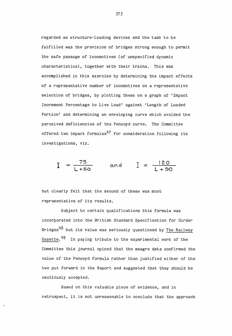
373
regarded as structure-loading devices and the task to be
fulfilled was the provision of bridges strong enough to permit
the safe passage of locomotives (of unspecified dynamic
characteristics), together with their trains. This was
accomplished in this exercise by determining the impact effects
of a representative number of locomotives on a representative
selection of bridges, by plotting these on a graph of ’Impact
Increment Percentage to Live Load’ against ’Length of Loaded
Portion’ and determining an enveloping curve which avoided the
perceived deficiencies of the Pencoyd curve. The Committee
offered two impact formulae1*? for consideration following its
investigations, viz.
I 75L +50
an d r 2 0
L + 30
but clearly felt that the second of these was most
representative of its results.
Subject to certain qualifications this formula was
incorporated into the British Standard Specification for GirderhOBridges ° but its value was seriously questioned by The Railway
Gazette.^ in paying tribute to the experimental work of the
Committee this journal opined that the meagre data confirmed the
value of the Pencoyd formula rather than justified either of the
two put forward in the Report and suggested that they should be
cautiously accepted.
Based on this valuable piece of evidence, and in
retrospect, it is not unreasonable to conclude that the approach

37
of the Ministry of Transport and its officers and the other
engineers involved did not envisage a cooperative effort to
provide a 'systems' solution to the problem. Indeed the Report
did nothing to advance design procedure but merely offered the
reassurance of another impact formula specifically derived to
meet British requirements. Their results, albeit only offered
as an interim measure, were of questionable value. Indubitably
the true significance of the work of the Committee was its
articulated cognisance of the need for a wider and more thorough
investigation if the subject was to be placed on a scientific
basis, combined with an unmistakeable indication of the
magnitude and nature of the task to be undertaken.
H. The Bridge Stress Committee and its Work
The momentum of this burst of activity in the early
1920s was maintained and impetus was added by the involvement of
the Department of Scientific and Industrial Research. In May
1922 this Department convened a meeting of railway engineers and
others as a result of which arrangements were made for
conducting an inquiry and led in March 1923 to the appointment
of the Bridge Stress Committee. Besides being charged with the
continuation of the earlier work of the Ministry of Transport on
impact effects this committee also had the duty to carry out,
concurrently with the experimental work, mathematical
investigations, a requirement which was reflected in the
composition of the membership. Under the chairmanship of Sir J.
Alfred Ewing, Principal and Vice-Chancellor of the University of
Edinburgh, the committee consisted of representatives of the

375
four Grouped railways, a consultant engineer, the Chief
Inspecting Officer of Railways, Professors W.E. Dalby and C.E.
Inglis and Mr R.V. Southwell, a mathematician.
An examination of the list of members of the Committee
reveals an absence of locomotive engineers.5° This is, perhaps,
a surprising omission in view of Lord Balfour’s comment in his
Introductory Note that ’Fixed bridges and trains in motion
become for brief periods parts of a single mechanical system.’51
Even more surprising is the statement concerning the subsequent
invitation to Sir Henry Fowler to become a member.
At a later stage the Committee, finding that the problem
was intimately connected with questions of locomotive
design...
a pronouncement which suggests that at the beginning of the work
the eminent civil engineers representing the railway companies
were still unappreciative of the nature of the problem they were
trying to solve. Confirmation of this view seems to be afforded
by the incidents related in the previous chapter of the emphasis
of civil engineers on static axle loads and an apparent total
neglect of the dynamic forces brought into action by the motion
of the locomotive. Obviously one or two isolated cases and
examples do not provide conclusive proof but it is the only
evidence which this piece of work has brought to light and in
the absence of contrary evidence it appears reasonable to accept
the situation on two large British railway companies, that is
the Great Western and the London and North Western, as typical

376
of the general 'state of the art'. Verification of this
interpretation of the evidence is provided by the comment of
Conrad Gribble, in the introduction of his paper to the
Institution of Civil Engineers on 5 March 1929.^3 This man, the
Chief Engineer responsible for the field work carried out by the
Bridge Stress Committee, stated that even in the absence of a
less definite result the research carried out would have been
useful for a number of reasons, and of those he mentions
priority of position is accorded to the sentence
It shows the effect on the oscillations of bridges of
two factors that have not previously been fully
considered in relation thereto, namely, the hammer-blows
of the unbalanced parts and the frictional resistance of
the spring-gear of locomotives.^
Even when, at a later stage, it was recognised and
acknowledged that the locomotive was an essential component in
the system being investigated the opportunity was not taken to
secure a wider representation of mechanical, as opposed to civil
engineers. And in this respect the composition of the Committee
was unbalanced. Whereas the civil engineering departments of
the four companies were represented, Sir Henry Fowler was chosen
to represent locomotive engineering for the whole country. In
view of the marked regional differences in locomotive design and
practice this was, perhaps, a surprising decision. It was
unquestionably a failure to seize the opportunity to bring the
Chief Mechanical Engineers of the four companies into immediate

377
contact with the work of the Committee, to the direct and
unmediated benefit of their departments. Such a step would also
have brought the civil and mechanical engineers of each of the
companies together in the consideration of a common problem and
in so doing given them a new experience and an example of the
usefulness of cooperative endeavour on issues of common
interest.
The limitation of locomotive interest to a solitary
engineer makes the selection of Sir Henry Fowler an interesting
topic for speculation. The four Chief Mechanical Engineers then
in office, C.B. Collett, H.N. Gresley, G. Hughes and R.E.L.
Maunsell, were, with the possible excepton of Collett, all
interested and directly involved, in the design of locomotives
and yet the choice fell upon one outside their ranks and one,
furthermore, whose interest in design if not non-existent was
undoubtedly minimal.55 Although but conjecture, it is quite
likely that when it was decided that such a nominal,
representative, appointment was desirable the choice was based
on the eminence of Sir Henry as an engineer who had been
knighted for his contribution to the war effort, rather than for
his expertise in locomotive affairs.
As has just been discussed, with its single 'locomotive*
representative the Committee was from its inception and
remained, overwhelmingly, a civil engineering body. Its field
work conducted under the supervision of C. Gribble, was
performed by a team of engineers together with a photographer
and a clerk,56 and consisted mainly of deflection and stress
determination in bridge-structural members under specified

378
conditions of loading. This aspect of the work will not be
considered here because details of it, besides being found in
the Report itself, are summarised in Gribble's paper^7 referred
to earlier.
However, a brief summary of its work is necessary to
give an indication of its relevance to locomotive engineers and
its unmistakeable demonstration of the fundamental relationship
between engine and structures over which it was to run.
4a. Aims
The wide terms of reference under which the Committee
was appointed were 'To conduct researches with reference to the
stresses in Railway Bridges, especially as regards the effects
of moving loads.'
Intended as a continuation of the Ministry of Transport
Committee's investigations, the Bridge Stress Committee defined
and limited its own role to
...our immediate task was to elucidate the question of
"impact" stress by examining its actual character and
causes. These were felt to be somewhat obscure,
not-withstanding all the attention the subject had
already received.^9
Practically, the main objective of the exercise was to
provide bridge designers with a rational means of making an
allowance for impact as an additional load on the structure. A
modified, more accurate empirical formula of the Pencoyd and

379
Ministry of Transport types, universally applicable to all
bridges carrying any type of locomotive, was not envisaged.
Through the concurrent prosecution of experimental field work
and scientific analysis it was hoped to reach a proper
understanding of the causes of impact, its effects upon bridges
and to produce a scientifically-based method of catering for it
in the design process. Increments to the dead weight to be
carried, for this purpose, based simply either on the span of
the bridge or the weight of the engine itself, were obviously
imprecise and in a rational analysis of the matter could hardly
be justified. That many bridges formerly built or strengthened
in accordance with the old empirical forumlae had successfully
carried loads far in excess of those for which they were
designed was no reason for their continued use as design
parameters. This success was attributable largely to the sound
instinct of their engineers to produce 'safe* structures,
through the use of large factors of safety to cope with the
various indeterminate loading conditions. Commendable and
essential as this precaution was and, indeed, must ever remain
where human life is involved the method used possesses inherent
limitations. These had begun to manifest themselves with
accelerating urgency from the beginning of the present century.
After some ninety years' public railway operation in the country
it was accepted, through force of circumstances, that the
utility of empirically determined formulae and rule-of-thumb
procedures had been exhausted. Their inability to cope
adequately with contemporary requirements was serious, andiinordinately expensive in financial terms, while their deficencyA

380
in scientific foundation rendered them useless for purposeful,
economic future design.
To remedy this situation the Bridge Stress Committee
aimed at a fundamental improvement both for the immediate
benefit of the railway system and from which future development
could confidently and successfully progress. In fulfilling its
mission it gave locomotive engineers a salutary lesson.
The inestimable value of the Committee’s work for the
purposes of this study is that it chose the locomotives to be
employed on the basis of their dynamic behaviour. Whereas the
Ministry of Transport tests were confined to two-cylinder
passenger locomotives selected on the basis of dead-weight alone
the Committee's investigations were to cover different types of
engines including two-, three- and four-cylinder varieties. And
the railway companies were specifically requested
...to provide for testing purposes engines capable of
producing large variations of rail pressure, in order
that the oscillations produced, and the effects of these
oscillations, might be thoroughly investigated.^
Selection, however, was not based on quantitative
knowledge in other than a minority of cases, where the magnitude
and direction of the resultant unbalanced forces had been
determined on a balancing machine during the construction of the
locomotive. For most of the engines these measurements were
made at the request of the Committee from which we may conclude
that the practice of putting into service locomotives whose

381
dynamic characteristics were unknown was a common occurrence.
The engines, then, were the loading devices and
supplemented with a ’bridge-oscillator’ they produced the
effects measured and recorded in the tests and from which the
conclusions were derived. Fifty-two bridges, representative of
British practice but excluding special and obsolete designs,
with spans ranging from 16.5 feet to 3^5 feet were used in the
tests.6”! Some of them were of wrought iron construction and the
report in acknowledging that this material was seldom, if
ever,used in contemporary construction, justified their use on
the assumption that steel and wrought iron bridges could be
expected to respond identically to impact effects.
b. Experimental Work
The following diagram, Fig.6.4,^ is typical of many
records included in the Report, which in turn contains only a
representative selection of those made during the field work.
The two curves show the deflection against time of
mid-span of the bridge, Maunby Bridge - for which Ministry of
Transport test details have been included earlier (Fig.6.2 and
6.3), due to the passage of two locomotives. The horizontal
scale at the top of the diagrams represents time, calibration
being in tenths of a second, omission of the tenth mark
indicating a complete second.
Locomotive AG, travelling at a speed of 36.7mph,
produces a gradual deflection and restoration with little
vibration although the effects of individual hammer-blows may be
discerned. With locomotive K, at 33.0mph, the correspondence of

382
SPAN N9 6 A - M A U N B Y1-46 FT. BINS.
-uvaruri n .
T5-7-r.*•* . >K>J
Fig.S.M Deflection record, Maunby Bridge
this, its critical speed, with the natural frequency of the
bridge produces through the action of the hammer-blow, a gradual
build-up of the oscillations to a state of resonance. The
decaying oscillations on the right of the diagram signify the
passing off the bridge of the locomotive and the effects of
damping. Thus the effects of hammer-blow are magnified by
resonance, a state induced by the coincidence of a critical
speed of the locomotive and the natural frequency of vibration
of the bridge. Similarity of the natural frequencies of
bridges, except the extremes of span length, i.e. the shortest

383
and the longest, and the frequency of hammer-blows from engines
at ordinary speeds is fairly common and thus made this situation
one to be seriously considered.
The inherent high natural frequency of short span
bridges and the relatively low frequency of hammer-blow input,
even by locomotives travelling at express speeds gives rise to
an entirely different situation. Resonance and its effects are
completely eliminated. But in such cases each hammer blow
produces a distinct individual effect. This is shown in
Fig.6.5,^3 the deflection curves for the two girders of Newby
Wiske bridge, with a span of 44ft 8in, under the action of
locomotive K.
Because the natural frequency of vibration of a bridge
is inversely proportional to its span the conditions for
resonance are more readily attained in long bridges than in
short ones but in the long lengths, as opposed to those of
intermediate span, the phenomenon is not so serious. In this
case the natural frequency is low and the corresponding critical
speed of the locomotive is also low with the consequence that
the hammer-blow forces which induce the vibrations are also
small. The following diagram, Fig.6.6,^ shows the effects of
running locomotive K at various speeds over Newark Dyke Bridge,
a single track lattice girder bridge of 262ft 6in span. As the
locomotive speed increases from 2.l4cps the build-up of
oscillation is clearly seen on the deflection curves until at a
frequency of 2.4cps, which is also the natural frequency of the
loaded bridge, a state of resonance exists. With further
increases of speed the engine moves out of its critical speed

384
S P A N N2 2 0 A NEWBY W IS K E .Loco. K . E nfina Fraquancy 6*£5 p.p.a.
OaMaeritn. Lair Cirdtr. Diaj.l.
Fig.6.5 Deflection record, Newby Wiske Bridge
range and the effects of hammer-blow in generating vibrations
within the structure rapidly diminish.
Reference has been made earlier to a 'bridge-oscillator’
as a loading device. This is shown in Fig.6.7^ taken from
Appendix H of the Report.
As may be seen it consists of a truck on which is
mounted a frame carrying a pair of contra-rotating axles, each
bearing two wheels to which could be attached weights whose
magnitude could be varied to simulate any desired amount of
hammer-blow. The purpose of this piece of equipment was

385
...to apply a pulsating force to a bridge for an
unlimited number of times without any change in the
position of the load or variation in frequency of the
structure.^6
SPAN N? 2 NEWARK DYKE
TEST LOAD LOCO K
16*01 Weigh* 1 0 7 * 0 T
I0>s* M 103 10 s BTS XT A 17 4 r**3 T m
d)6cj)(j) dxjxj)0is'*"* j 'y i -is'rAsWVs'iufl- V o ' -|: ! ■ W httlbete 4 4 ' 7 V i" ——J :)' iHt~ — — J-Wh#Hbo»r 4 4 • 7 Vi
— O verall L c n q ih S 9 '
D r rv e t-1 4 'O V ."
1 1 1 1 1 I " 111 1 i 11 1 1 I I n i l l I I 11 1 i p 1 1 1 1 11 1 1 [ 1 11 1 11 1 1 I | r i I 1 1 1-1 I I [ I 1 I 1 I I n r p 1 1 1 | 1 1 1 1 1 1 1 1 1 | 1 i 1 1 [ m i | p 1 1 v i 1 ; | . ■ 1 ; j
Fig.6.6 Deflection curves, Newark Dyke Bridge

386
Fig.6.7 Bridge-oscillator
It was thus an extremely useful device permitting
amongst other things a study of resonance and its effects not
attainable with a moving locomotive. Because of the motion of
the engine and hence a variation in the system of loading on the
bridge its natural frequency would not remain constant during
the passage of the vehicle and the maximum vibration of the
structure could not be attributed to a specific critical
velocity but rather to a limited range of speed.
By jacking the oscillator off its springs and clamping
it solidly to the rails it was used to determine the natural
frequency of the longer bridges in both their loaded and
unloaded conditions.
Deflection readings, taken on the River Aire Bridge,
with different weights mounted on the wheels to give different
hammer-blows clearly indicated, within the limits of
experimental error, a direct proportionality between the
amplitude of the vibration and the magnitude of the hammer-blow,

387
as will be seen from Fig.6.8.67
**
i1i ^4
✓✓✓✓> 'o
<✓
y
?--
---\ \ \
. Xy 1
*****o“ cvis io i-3 zo 55 3-0
Hommer Blow. Tons.
Deflections of near girder.100 lbs. wt. 3 -6 0 p.p.s. 0 *7 1 tons H .B .
ms.secs. Vl n1n_rwnj-Y ir\^ '\n j\r\r\rv— ltu t u v v v v -u—Lrv\.
Revs. Twice actual size.
2 0 0 lbs. wi\ 3 - 6 9 p.p.s. I-4 -9 tons H-B-
jtvt ^LTTjnjn_nj~Ln- ^m s. secs.
u Li j \_nj~vn_r\_r
Fig.6.8 Oscillator records, River Aire Bridge

388
Whatever reservations were intially entertained by the
members of the Committee as to the true causes of impact these
experimental results undoubtedly established that hammer-blow
was the major contributory factor. Other sources, such as those
due to track irregularities, rail-joints and the movements of a
locomotive, lateral and vertical, on its springs although of
sufficient importance to be taken into account were not of the
same order of magnitude. So far had the practice of railway
engineering departed from the 'systems’ concept that, despite
the international work and the publications referred to earlier,
these findings were a cause of surprise. And when in 1929,
Gribble told the Institution of Civil Engineers that '...the
hammer-blow of engines is a factor novel to many
bridge-engineers,'^ it seems to indicate that they were
satisfied with working to rule-of-thumb 'static axle load'
criteria rather than that they were unaware of the potential
problems arising from hammer-blow. Indeed, an engineer would
have led a very introspective, insular professional life not to
have been at least conscious of a topic which had merited
regular mention during the preceding thirty years. The absence
of calamities or even of serious trouble, due to lack of
provision for impact loading in bridges probably convinced those
involved in the business that sound and sensible codes of
practice were already in existence and could be used with
confidence. Since they were not professionally concerned with
locomotives the need or the desirability for a rational design
procedure to match the two elements of the railway system into a
harmonious working relationship was not perceived. Perception,

389
when it arrived, was dramatic because it simultaneously resulted
in an appreciation of the true nature of the problem, its
magnitude and even more startlingly, perhaps, a realisation of
the inadequacy of contemporary methods. The state of affairs
revealed by the Bridge Stress Committee was no less harrowing
for the locomotive engineers. However, before passing on to
this topic it is necessary to consider briefly the analytical
work which was performed concurrently with the experimental
activities.
He. Mathematical Analysis
An examination of the analytical theory of bridge
oscillations is obviously outside the scope of this study but it
was an integral and vitally important part of the work of the
Committee, carried out largely by Professor C.E. Inglis of
Cambridge University, which provided a rationally based series
of impact allowances for civil engineers together with
corresponding hammer-blow limits for locomotive engineers. In
providing common, compatible standards for both a generalised
theory was obviously a fundamental prerequisite because as the
Report itself stated,
The determination of Bridge Impact Allowances will
attain finality only when it ceases to depend upon
empirical rules and becomes founded on a sound
analytical basis. This ideal cannot be attained by a
mere multiplicity of experiments. Experimental research
is necessarily restricted in its application, and

390
experimental records, no matter how numerous, fail to
achieve their full value until they are shown to be
particular cases fitting into a comprehensive theory.69
In his paper delivered before the Institution of Civil
Engineers Professor Inglis had stressed that for the proper
study of such a problem mathematical work and experimental
research should cooperate ’...until they come into harmonious
agreement.’ To assist in this he had a model bridge
constructed in his laboratory over which he could run an
idealised locomotive, which in turn could be adjusted to deliver
hammer-blows of predetermined frequencies. Tests with this
apparatus, of which Fig.6.9^ is a record taken from the Report,
together with a full-scale test on Newark Dyke Bridge verified a
correspondence between theory and experiment sufficient to
warrant the use of the general analytical method to predict
bridge oscillations sufficiently accurate for practical
purposes.
Fig.6.9 Comparison between theory andexperiment for model bridge

391
However, this situation was not persistent and led to
further investigations which revealed another interesting facet
of locomotive behaviour. In long-span bridges where, as has
already been seen, the bridge oscillations were not very great
the theory was applicable. But in bridges of intermediate span-
length not only was resonance present at the theoretical
frequency of the loaded bridge but frequency-amplitude curves
indicated the tendency of the amplitude, having peaked and
dropped again as the locomotive passed through its critical
speed range, to rise again to a second peak. This phenomenon is
illustrated by comparing Fig.6.10,^2 which shows the curve for
locomotive K on a bridge of 112ft span, with Fig.6.11^3 showing
the curve for the same locomotive on a bridge of 262ft 6in span.
LOCO. K, N 9 H 5 6 .
P P S
Fig.6.10 Curve illustrating two critical frequencies on a bridge of intermediate span

392
LOCO K. No 1456
Fig.6.11 Single critical speed on a long-span bridge
This peculiarity was not immediately understood but it
was eventually traced to the effects of the locomotive’s
springs. At the lower speed the frictional resistance within
the springs effectively locks them so that the locomotive
vibrates almost solidly with the bridge whereas at the higher
speed range the springs come into action and only the
non-spring-borne parts move solidly with the bridge. In this
state, the second or higher critical frequency of the bridge
approximates to the natural frequency of the unloaded bridge.
In spans where resonance could occur at two frequencies it was

393
essential to base the impact allowance on the higher frequency
because this condition produced the largest hammer-blow.
Under certain conditions, then, it was found that the
locomotive suspension was either undamped or underdamped and the
fact that the springs could be free at one point in its motion
and locked at another point put limitations on 'the application
of mathematical analysis to predict every undulation in a bridge
deflection r e c o r d . However, this was not considered
particularly disadvantageous since the object was to predict the
maximum amplitude of oscillation. The analysis was based on the
idealisation of a stationary locomotive in the centre of a
bridge with its wheels slipping at a uniform speed. Originally
the model assumed viscous damping^ in the locomotive springs
but this was replaced by a constant damping force which
approximated better to observed behaviour. Classification of
locomotives by their spring damping characteristics as well as
by their hammer-blows was not possible because of lack of
information of the former.^6 To allow, with safety, for extreme
cases of oscillation, a constant spring damping force of eight
tons was adopted to cover both high and low frequency
vibrations.
Theoretical curves showing two modes of behaviour of a
locomotive on its springs are given in Fig.6.12.^®
In these diagrams the full lines represent its behaviour
when the springs remain locked while the dotted lines indicate
the effect of the action of the springs, again clearly
illustrating their potential for increasing the dynamic effects
of the hammer-blow on spans of intermediate length. This

394
Fig.6.12 Effect of spring movement on amplitude-frequency diagrams
analytical work done by Professor Inglis and its explanation of
the seemingly intractable problem given by the perplexing
results obtained from the experimental work was judged by Sir
Alfred Ewing to be ’...the most distinctive contribution to
engineering theory which we have been able to make. ’ 9
Furthermore, it was of immediate practical use since, as
noted above, its reckoning constituted an essential factor in
the determination of the appropriate impact allowance.
Thus, the field work carried out by the civil engineers
together with the simultaneous analysis was of direct interest
to the mechanical engineers because it led to a better
understanding of the behaviour of the locomotive as a vehicle

395
and it also supplied quantitative information on the effects of
hammer-blow.
4d. The Locomotives Used in the Tests
The recommendations of the Bridge Stress Committee were
not based exclusively on the results of its own tests but also
on information supplied by the railway companies at the request
of the Committee. To provide the details on balancing sought
they had had to measure the hammer-blow of a large number of
locomotives chosen from all the principal types.®0 The
magnitude of this operation may be appreciated from the
reference to this exercise in the words of the Report:
The individual engines tested are representative of
upwards of 9 ,000 modern engines and include all heavy
and important classes of both tender and tank
engines.®^
This job, with the subsequent collation of the results
and finally their publication in the Report of the Committee,
where they appeared in Appendix D of this document, produced a
record unprecedented in the history of locomotive engineering in
this country. The hammer-blow characteristics of every
important class of locomotive in service throughout the whole
country are tabulated. As such, they are evidence of prime
importance for this study.
In addition to presenting the raw data which
unambiguously reveal the appalling state of affairs existing in

396
the mid-1920s the Report has an enhanced value for the historian
since its contents also largely, albeit in general terms,
explain the reasons for the unsatisfactory situation.
For example, while the important locomotive building
centres of Crewe, Doncaster and Swindon possessed dynamic
balancing machines, the Southern Railway, at Ashford relied on a
static balance test only to obtain an approximate check on the
correctness of balance weights. At other locomotive centres not
only did they not possess a balancing machine at all but
generally no checks were made on the state of balance either.®2
This, in itself, of course, is hardly surprising since if the
question of balance was treated so lightly that a machine was
not provided for the task it is hardly likely that those
concerned would go to more troublesome lengths to perform the
job. It must also be acknowledged that in the absence of
convincing evidence of the ill-effects of excessive hammer-blows
on rails or bridges, or the lack of protestation from the civil
engineers (hardly likely in view of the traditional lack of
communication between the departments), there were no pressures
on the locomotive engineers either to make them aware of the
consequences of bad practice or to treat the matter more
seriously. This stimulus came during the work of the Committee
but more dramatically with the publication of its Report.
In summary, of the 171* classes of locomotive either
tested or considered by the Committee only one gave no
hammer-blow at the reference speed of 6rps. Out of the total
9,309 engines included in the survey, 1,022 exceeded the
recommended combined loads whilst of the remaining 8,287

397
locomotives, 1 ,575 were identified as improperly balanced in
that the hammer-blow of a single axle exceeded that of the whole
engine. The following table, Fig.6.13, compiled from data given
in Appendix D of the Report, gives the numbers of classes and
locomotives exceeding the combined loading recommendations, and
those not doing so, belonging to the four railway companies.
L MS LNER GWR S R
062
Nio. No. NOr
Classes Locos Classes Lo CoS Claires Locos Classes- Locos
E xorcd ir<=.CQ i/v\wi e u v c /e d
c o w i b i a c d t a o - d i v-vj 1 i i/w 11
3 560 li 418 — 4 44
Mot Cxceedliaarecoc o w \ b m c d loculii l iw \ i b
37 3186 79 3 143 16 137<S 583
Total <46 3746 90 3560 1 6 1376 82 627
Fig.6.13 Table showing numbers of locomotives exceeding the combined loading recommendations
Based on information from the same source the following
table, Fig.6.14, gives a more detailed presentation of the above
analysis based on the numbers of two-, three- and four-cylinder
engines operated by each company.

398
LMS LNER GWR SR
No .of cylinders a 3 4 2 3 4- 2 3 4 a 3 4
Classes 40 2 4 75 13 2 13 — 3 20 1 1
No-of I oca motives 3241 295 220 3153 363 44 1239 — 138 625 1 l
Fig.6.14 Table - analysis based on the numbers of 2-, 3_, and 4-cylinder engines operated by each company
The table below gives details of two-cylinder locomotives which
did not exceed the recommended combined loading limit.
L M S L N E R G -W R SR
z o Mo. of No. of N o .a j
C l a t t e r LocaS Classes LacaS Classes Locos C lasses Lo cos
Ha.v\nw\.er~ bl aus o rn ex
SiV\p(<= ootle exceedsthxr at ovikalc
CvAe8 8C0 10 702 — — 1 13
|4 c u \A r \A c r - lo lo u i a v \ a.
Slir lc axle betv<\j le.5S t k x x t aj
fc-Uo usl'vale me2 4 2056 53 2033 13 1238 15 568
”Ta toJ 32 2916 63 2735 13 1238 IG 581
Fig.6.15 Table - analysis of 2-cylinder locomotives

399
Fig.6.16 Locomotive *K' , Lancashire and Yorkshire Railway, 0-8-0 Engine, No.1438

These figures clearly reveal that in the two largest
companies the number of badly balanced engines was significant,
although this evidence must be treated with caution because the
consequences of this state of affairs were not necessarily
serious. The hammer-blow magnitudes quoted in the tables were
all calculated at a reference frequency of 6rps.®3 For
comparative purposes it was obviously desirable to have a
standard and as such the speed of express locomotives was a
reasonable choice since the hammer-blow, being directly
proportional to the square of the speed, was a maximum under
these conditions. And it was these conditions for which the
bridge-engineer had to make an adequate impact allowance.
However, adoption of this procedure by the Committee did not
truly reflect the hammer-blow input to rails and bridges of the
slower types of locomotive. The quotation of such figures for
speeds that were never going to be attained in normal service,
while useful as a basis for comparison, could and apparently in
some cases did give a false impression. This is clear from the
discussion on Gribble's paper to the Institution of Civil
Engineers where contributors obviously responded to Sir Alfred
Ewing's comment that with the aid of 'locomotive K' the
Committee had been able 'to punish certain bridges as they had
perhaps never been punished before', and he told his listeners
that
They had run it at speeds which caused a fluctuation of
pressure upon the rails of more than 50 tons in every
revolution of the wheels. They had become much attached

401
to "locomotive K" and hoped it would some day be given
honourable burial.®1*
Locomotive 'K' was the designation given by the
Committee to two former Lancashire and Yorkshire 0-8-0 engines
used extensively in its tests. The photograph, Fig.6.16, of one
of them, No.1438, was taken c.1923. They were heavy and
powerful engines built in 1903 (No.1438) and 1905 (No.1456)
respectively and intended for mineral traffic.
However, instead of interment another participant
preferred preservation.Undoubtedly, the machine was regarded
as something of a freak by the 'bridge* men and it was left to
Sir Henry Fowler, on behalf of the locomotive engineers who were
conspicuously absent from the meeting, to inform the audience
that an engine designed to haul a load of 1,000 tons at an
average speed of 17mph could hardly be expected to behave so
well when run at two and a half times its normal speed.
The recently acquired notoriety of the locomotive so
incensed Engineering that 'Locomotive K' was accorded the
prominence and honour of the first leader in its issue of 22
March 1929. Sympathetically and more graphically it emphasised
Fowler's point with the rather acid remark, 'One might as well
expect a dignified performance from an old barnyard hen chasedQ £
by a motor car on the highway.'00
In fairness, of course, it must be recognised that the
Committee itself acknowledged this fact.®? Commenting upon four
types of LNER engines on which the percentage of reciprocating
parts balanced varied from 19 per cent underbalance to 86 per

402
cent overbalance the Report states
...we are informed that no noticeable defects were
observed in their running...are slow-running engines in
which the effects of unbalanced parts are unlikely to be
much in evidence.
Likewise it admitted that some of the engines listed as
exceeding the recommended loading limits did so only marginally
whilst others coming into this category at the reference
frequency (6rps) did not do so at lower frequencies.
Even allowing for the fact that the tabulated data does
not provide a completely accurate record in that it gives
hammer-blow magnitudes at reference frequency rather than at
operating frequencies, it clearly reveals that many locomotives
were badly balanced, to the detriment of both themselves and the
rails and bridges on which they ran. This unfavourable bias is
partially offset, to an unknown extent, by the fact that some
locomotives were found to have greater hammer-blows than those
listed and consequently were not included in the tables. Of
these, some were modified to reduce the hammer-blow while other
obsolescent engines were scrapped.
Overall, then, the data obtained from its own
experimental work augmented by the information determined and
supplied by the railway companies produced a picture of almost
unimaginable chaos characterising the state of balancing
practice on British railways. Viewed comprehensively, but in
terms of individual classes, achievement ranged from virtual

403
perfection, in the 'Claughton', to unspeakable badness in those
omitted from the records. The 'Claughton' class as such was
very successful and the ability of the locomotive to haul heavy
express passenger trains satisfactorily ensured its growth, by
1917 it numbered 60 locomotives and reached a total of 130
engines in 1923.®^ However, it appears that satisfaction with
these smooth-running locomotives was not specifically attributed
to their excellent qualities of balance. Contemporary evidence
does not suggest that they were regarded as outstanding machines
in this respect and it is likely that they were not appreciated,
but neither were the bad characteristics of other locomotives.
At the other end of the scale the mighty hammer-blow of the
George V Class (see Chapter 5. Fig.5.8) did not prevent the
engines from acquiring a good reputation. The impressive
performance of the first locomotive led to an immediate order
for a further nine. In the assessment of O.S. Nock the success
of these locomotives was a triumph for Bowen Cooke.90 How is
this situation to be explained? At the expense of a
generalisation the answer seems to be that the matter was not
taken seriously by those responsible for the design,
construction and operation of locomotives.
Design, of course, was ultimately the responsibility of
the Chief Mechanical Engineer and traditionally, that is until
the time of the Nationalised British Railways' standard steam
locomotives, this officer was always credited with an engine
appearing during his tenure. In reality he was not necessarily
involved in the design process, and even if he was one of those
genuinely interested in locomotive design his many duties and

responsibilities almost certainly prevented him from being
directly concerned with the various aspects of detail design.91
With responsibility for building new engines, the repair and
day-to-day maintenance of the existing locomotive stud to meet
operating requirements, besides similar obligations in respect
of carriages, wagons and, indeed, all rolling stock not to
mention the accompanying administrative, financial and staffing
work the Chief Mechanical Engineer was left with little time to
devote to design matters.
The actual design process appears to have been a
co-operative task performed by a group, or groups of drawing
office personnel, hidden behind a shield of anonymity that
defies and defeats the penetrative assaults of the inquisitive
student of locomotive design. Within such a milieu and
proceeding by entrenched rule-of-thumb methods standards of
competence and achievement could and, the evidence indicates,
did vary tremendously. Its distinguishing characteristic was
often inconsistency. Thus we find, for example, that in 1930
the LMSR produced a 2-6-2T passenger and mixed traffic engine of
which E.S. Cox has written ’[it was] one of the feeblest
locomotives of modern times’ and yet 'The same office, but
another part, had already produced an entirely excellent 2-6-4
Tank.'92
As the preceding chapter has shown standards of
balancing practice displayed no more consistency and despite the
anecdotal nature of some of the evidence presented there, the
Report of the Bridge Stress Committee confirms its general
veracity. Indeed, its comments on the balancing of two-cylinder

405
engines justify the above assertion that it was simply treated
in a superficial, routine manner.
Our observations point to the necessity not only of
calculating the position and amounts of balance weights
which will eliminate variations of rail pressure so far
as may be consistent with other requirements, but also
of ensuring that when the engines are constructed the
balance weights are in accordance with the calculations.
Tests which have been carried out to check the balancing
of a number of engines have revealed serious differences
between the unbalanced vertical forces as calculated
from the drawings and those which are actually produced
by the engine.93
The emphasis here on the need to calculate both
magnitude and position of the balance weights implicitly
suggests that the investigations of the Committee had revealed
instances where this had not been done. Even where this, the
essential design requirement if a dynamically acceptable
locomotive was to be constructed, was carried out there is
reason to suspect that the calculations were not always
correctly performed. Indeed, based on Gresley's remark to
Bulleid it seems that in one drawing office the staff were
deemed by their chief engineer to be incapable of doing so. And
then another factor of practical consequence was the adopted
practice within the particular drawing office or for a
particular class of engine. Appendix D of the Report reveals

406
many variations. Some of them undoubtedly originated from
conscious design decisions, such as concentrating the whole of
the balance weight for the reciprocating masses on the driving
axle, and different methods of distributing this balance weight
between the coupled axles. Others, such as lack of sufficient
balance even for the revolving parts, and balance weights
located in an incorrect angular position probably derived from
errors, or carelessness, or both.
Added to this chaotic situation was the failure, in many
cases, to achieve what was desired. The hammer-blow of
locomotives was not checked. In fact some locomotive works did
not even possess the equipment to make such a check. And so
badly balanced engines in their hundreds were pounding the
tracks and bridges with an unnecessary and unwarranted severity.
Failure to appreciate the effects of this on both the permanent
way and the locomotives themselves, accompanied by a railway
management and organisation which separated to the point of
complete isolation the civil and mechanical engineering
functions led to the situation depicted here.
As this chapter has shown it was the increasing anxiety
of the bridge engineers which culminated, in the early 1920s, in
direct Government intervention, initially through the Ministry
of Transport and almost immediately afterwards, the Department
of Scientific and Industrial Research, that led to the
quantitative revelation of the dynamic consequences of the
locomotive on the way. It presented locomotive designers with a
clear, unambiguous, picture of balancing technique as it
existed, convincingly demonstrating the deficiencies of routine

407
methods unthinkingly applied. Further, it gave some positive
guidelines and criteria for future use.
It would not be appropriate or relevant here to consider
the findings and recommendations of the Committee as they
affected the bridge designer apart from noting that they
provided him with tables of impact allowances, which included
besides hammer-blow, rail-joint and lurching effects.9^
For the locomotive engineer the main message was clear,
the hammer-blow should be kept to the practical minimum, since
bridges with spans in the range 100ft to 200ft were particularly
vulnerable as a result of resonance. This may be appreciated
from Fig.6.17^5 which shows, for a single track bridge, the live
load plus impact allowances (including rail-joint effects)
expressed as a uniformly distributed load.
The curve marked C, is the enveloping curve for impact
effects to be provided for under loading C while that marked A
and B shows the greatest impact effects experienced under
loadings A and B. The advantage of avoiding the heavy
hammer-blow of loading C is conspicuous.
Fig.6.18^ shows the reduction of impact effects when
the locomotive speed is limited to 4.5rps instead of the
reference speed of 6rps. This limit and provision was
applicable to many branch lines.
In making allowances for impact the Committee adopted
the standard of axle loading defined by the British Engineering
Standards Association and made recommendations for hammer-blow
effects by three loading ranges. These were:

Fig.6.17 Curves for Loads producing Bending Moment - single track bridges
Fig.6.18 Curves for reduced speed

Loading A : 20 units wi th 5.0 tons hammer-blow (at
5rps)
Loading B : 16 n IT 12.5 h n Tt
Loading C : 15 tt It 15.0 m tt tt
Since the report stated that there were not any engines
in existence whose weight was represented by 20 units, 18 units
being the highest found in practice, some provision was made for
future growth. Even so the point was made, based on received
information, that future, heavier steam locomotives would have
more than two cylinders and that their hammer-blow would not
exceed 5 tons at 5rps. As the above table clearly shows, the
Committee restricted the heaviest locomotives to the smallest
hammer-blow because it assumed that in future the most powerful
engines would possess either three or four cylinders and thus
afford the opportunity to secure minimum hammer-blow.
Indeed, here we find the first tangible evidence of the
fruitful outcome of the cooperation between the major
departments of railway engineering, at last recognising the
interaction of locomotive and track.
We are informed by Sir Henry Fowler that the locomotive
engineers of the principal railways of this country are
prepared to limit the hammer-blow at 5rps on any axle of
engines of future design to one-fourth of the normal
load on that axle, or to 5 tons as a maximum, and

410
further to limit the total hammer-blow of such engines
at the same frequency to 12.5 tons.9?
These parameters were established for two-cylinder
engines, the most numerous types in use, which were thus to
conform to loading B. Loading A was to cover three- and
four-cylinder engines while loading C made provision for
comparatively light two-cylinder engines with large
hammer-blows.
The words of the Report were, then, a frank admission
that the job could be done better than it had been in the past
and an undertaking that it would be carried out in a methodical,
rational manner. This achievement had taken a century of
railway engineering to accomplish and its successful conclusion
depended upon a prolonged and expensive investigation involving
the willing cooperation of the Government, the four railway
companies, universities, and a number of specialists. But the
simultaneous prosecution of practical and theoretical work by
distinguished engineers and scientists is not sufficient to
guarantee that a complex problem can be resolved according to
plan. In this particular case both an extension of time and an
increase of funding were necessary.9® The magnitude of the
undertaking was such that it demanded resources beyond the power
of any one of the groups of participants to supply. Essentially
it was a task that required a large-scale cooperative effort;
that it received it is almost certainly due to propitious
circumstances. In particular the coincidence of Government
involvement in railway operation during and in the aftermath of

m 1
the First World War, the Grouping of the Railways, and the acute
prominence of the problem throughout the railway world.
Unquestionably, the Report made it possible for railway
engineering to be put on a more scientific basis regarding the
locomotive-track relationship. A quantitative loading scale was
promulgated which was commonly applicable to both civil
engineers and mechanical engineers. The former were enabled to
allow for the dynamic action of locomotives, not as an unknown
quantity to be safely provided for by means of a universal
empirical formula based upon the bridge span alone, but
implicitly on accurate detailed knowledge of hammer-blow
magnitudes. Likewise the locomotive engineer, instead of being
under a general obligation to 'balance* the machine but with no
specific requirements to fulfil, was confronted with the problem
of not exceeding precisely defined maxima in terms of both axle
loading and 'whole engine' effect. Complying with the two
parameters demanded adequate consideration being given to the
proper weight to be balanced and also to the method of
distributing the balance weight between the axles.
However, what the correct proportion of the
reciprocating masses to be balanced was remained a topic
untouched by the Committee. The tests conducted had revealed
the illogicality of adhering to an arbitrary percentage, such as
the popular 66 per cent. This fact was noted and the following
observation was made:
The influence of inertia forces on the engine is
affected by the following factors which should be

1J12
considered in prescribing the amount of the balance
weights:
(a) The number of cylinders and crank arrangements.
(b) The spacing of the cylinders.
(c) The weight of the locomotive.
(d) the length of the locomotive.99
and in its General Conclusions as to Balancing it advised
The proportion of reciprocating parts which is balanced
should be limited to what is absolutely necessary to
ensure smooth running, and should be distributed between
the axles so as to keep the maximum blow per axle and
the maximum blow per wheel to the lowest limits.
Professor Dalby, in Appendix C of the Report, stated
that this question required further experimental research.^
Bearing in mind that one of the problems confronting the
Committee was
To investigate the characteristics of locomotives, and
the possibility of modifying their design, with a view1 n?to reducing impact effects.1
it is surprising and somewhat disappointing that the Committee
did not enlist a few locomotive engineers to investigate this
particular problem. It was the crux of the whole matter.
Hammer-blow was generated by the overbalance and its magnitude

413
was directly proportional to the percentage of the reciprocating
masses balanced. To secure optimum benefits from the whole
exercise required this very piece of work and yet it was not
initiated. The major cause of the trouble the Committee was
instituted to deal with, having been clearly identified was not
subjected to the rigorous examination of the response of bridges
to the locomotive-induced impacts. Thus, as has been seen
above, limits of hammer-blow acceptable to the civil engineer
were laid down and agreed by the locomotive engineer and,
without question, this marked an unprecedented advance on
previous practice but the opportunity was not taken to
investigate the dynamics of locomotive behaviour. Having
indicated that factors such as locomotive weight, length of
wheelbase, number and disposition of cylinders all had an
influence on the motion of an engine and should be considered,
the Committee stopped short of giving guidance on the subject.
Hammer-blow in the conventional steam locomotive arises
from the deliberate insertion of balance weights to mitigate the
effects of the horizontal disturbing forces. The compromise
nature of the exercise was hardly given any emphasis in the
Report and in this respect it can be justly claimed that its
value to locomotive engineers could have been greater. The
tables given in Appendix D, for instance, would have been more
informative and interesting if they had included details of the
percentage of reciprocating masses balanced and of the
horizontal disturbing forces - or data from which these forces
could have been determined. Control of the hammer-blow was
important, it formed the basis of the loading recommendations,

414
and yet reduction in its magnitude was at the expense of
increasing the other disturbing forces. A study of the
interrelationship of these would have been a valuable
contribution to the work of the Committee.
In its membership, however, it was not adequately
staffed for this task. And within the constraints of time and
of finance it probably considered itself unable to embark upon a
major investigation of locomotive design. Its main function of
providing bridge designers with a rational method of allowing
for impact was successfully even if not simply accomplished. In
the course of this achievement locomotive engineers had been
shown, in dramatic and convincing fashion, the effects of bad
balancing - not only on the track and bridges but upon the
locomotives themselves. It was an old lesson repeated. A.W.
Makinson, who did not subscribe to the very early ideas of the
vertical forces expending themselves harmlessly on an unyielding
track unequivocally stressed the pertinence of Newton’s Third
Law of Motion to his audience at the Institution of Civil
Engineers in 1863-1
And so the work of the Bridge Stress Committee, although
incomplete in important aspects of locomotive design,
nevertheless raised the subject of balancing to its rightful
position of importance and established it on a more rational
basis. The rewards for doing so were almost immediate. During
the 1930s locomotive design and performance reached their
zenith. This was the result of the combination of a number of
contributory factors, not least among them being better
balancing practice.

References and Notes
Pye, David, The Nature of Design, Studio Vista, London,
1964, p.15
Simmons, Jack, The Railway in England and Wales
183Q~1914, Leicester University Press, 1978, p.142.
Duffy, Michael, 'Rail Stresses, Impact Loading and Steam
Locomotive Design', History of Technology, Ninth Annual
Volume, Mansell Publishing Limited, London, 1984, p.43.
Patent No.3431 , Blenkinsop, John, 10 April 1811.
Four of Blenkinsop's gear-driven locomotives were built
and they were in revenue earning service for over twenty
years.
(i) Simmons, J., op.cit., pp.142-151.
(ii) Morgan, Bryan, Civil Engineering: Railways,
Longman, London, 1971.
(iii) Allen, Cecil H., Modern British Permanent Way,
The Railway News, London, 1915. This includes a
history of the development of the modern
bull-headed steel rail.
Adams, William Bridges, English Pleasure Carriages,
Charles Knight & Co., London, 1837, p.303. He claims
that the necessary characteristic of a railroad is 'a
continuous equable surface' and admits 'if this surface

416
can be made perfectly solid and unchangeable, it may
answer' but then more practically concluding '...in
default of this, it is absolutely necessary that it
should possess the quality of vibration.'
8. Makinson, A.W., 'On some of the Internal Disturbing
Forces of Locomotive Engines', Proceedings of the
Institution of Civil Engineers, Vol.22, 1862-63, p.65.
9. (i) Fox, Francis, 'On the Results of Trials of
Varieties of Iron Permanent Way', Proceedings of
the Institution of Civil Engineers, Vol.20,
1860-61, pp.259-291.
(ii) Brunlees, James, 'Railway Accidents - their
causes and means of prevention', Proceedings of
the Institution of Civil Engineers, Vol.21 ,
1862, pp.345-424.
(iii) Williams, R. Price, 'On the Maintenance and
Renewal of Permanent Way', Proceedings of the
Institution of Civil Engineers, Vol.25, 1865-66,
pp.353-428.
10. Fox, Francis, op.cit., p.290.
11. Brunlees, J., op.cit., p.346.
12. Williams, R. Price, op.cit., pp.380-381.
13. Ibid., p.403.
14. Ibid., p.409.
15. Booth, W.H., 'Hammer-Blow in Locomotives' , Journal of
the Franklin Institute, Vol.CXXIII, No.1, January 1887,
pp.42-47.

417
16. Schivelbusch, W. , The Railway Journey. Trains and Travel
in the 19th Century, Basil Blackwell, Oxford, 1980,
p.127.
17. Rankine, W.J.M., ’On the causes of the unexpected
breakage of the Journals of Railway Axles; and on the
means of preventing such accidents by observing the Law
of Continuity in their construction', Proceedings of the
Institution of Civil Engineers, Vol.2, 1843,
pp.105-108.
18. Braithwaite, F., 'On the Fatigue and Consequent Fracture
of Metals', Proceedings of the Institution of Civil
Engineers, Vol.XIII, 1854, p.463.
19. McConnell, J.E., 'On Railway Axles', Proceedings of the
Institution of Mechanical Engineers, 1847-1849,
pp. 13-27.
20. Timoshenko, S.P., History of Strength of Materials,
McGraw-Hill, New York, 1953, pp.162-173.
21. Department of Scientific and Industrial Research (DSIR),
Report of the Bridge Stress Committee, HMSO, London,
1928, p.8. The Report dismisses the notion that
provision should be made for possible fatigue: 'There is
no reason to suppose that fatigue becomes operative
under the conditions of stress which actually apply in
bridges; and there appears to be no experience of
failures in steel or wrought iron bridges traceable to
this cause.'
22. The particular concern at this period was caused by
recent trends of growth in both the weight and speed of

418
locomotives. Essentially the problem had occupied the
minds of bridge engineers from the beginning of the
railway era and it was given impetus by the failure of
Robert Stephenson's girder bridge over the river Dee at
Chester in 1847. Following this accident an
investigation of the behaviour of beams under the action
of moving loads was conducted at Portsmouth dockyard.
For further details on this topic see Timoshenko,
ref.20.
23. Melan, J., 'On the Dynamic Action of Rolling-Loads on
Iron Bridges', Proceedings of the Institution of Civil
Engineers, Vol.117» 1894, pp.411-412.
24. Farr, William Bean, 'Moving Loads on Railway
Underbridges', Proceedings of the Institution of Civil
Engineers, Vol.141, 1899-1900, pp.2-106.
25. Cookson, A.C., 'The Strength of Railway Bridges',
Engineering, 8 September 1922, p.293. The point is made
by this engineer that the early engineers had made an
allowance for 'impact' and that it was included in the
maximum working stress adopted, i.e. 5 tons per square
inch.
26. Farr, William Bean, op.cit., p.6.
27. DSIR, op.cit., p.5.
28. This formula, due to C.C. Schneider, had its origin in
his investigations into the impact effects of rapidly
moving loads on bridge members. It was incorporated
into his bridge specification written for the Pencoyd
Iron Company in 1887 and thereafter was adopted by the

419
Government of India, many American railway companies and
was included in the 'General Specifications for Railway
Bridges' of the American Railway Engineering
Association.
29. Identical unit stresses were used for both static and
dynamic loads. However, the value used depended upon
the user of the Pencoyd formula, for example, the
American Bridge Company, with steel, used a stress of
7.5 tonf in~2 while the Indian Government Railways used
a stress of 8 tonf in“ . See ref.21.
30. Gribble, Conrad, 'Allowance for "Impact" in Bridge
Design', Cassier's Engineering Monthly, Vol.XLVIII,
1915, September pp.135-141; October, pp.212-216.
31. DSIR, op.cit, Appendix A, pp.143—145.
32. Ibid., p.144.
33- The Railway Gazette, 12 August 1921, p.278.
34. Lomonossoff, George V., Introduction to Railway
Mechanics, Oxford University Press, London, 1933,
p.169.
35. Anderson, Charles William, 'On Impact Coefficients for
Railway Girders', Proceedings of the Institution of
Civil Engineers, Vol.CC, 1914-1915, pp.178-286.
36. Farr, William Bean, op.cit., p.4.
37. The Railway Gazette, Vol.50, 1 February 1929, p.158.
3 8 . Ministry of Transport (MOT), Tests of Railway Bridges in
Respect of Impact Effect, HMSO, London, 1921. Report of
Major A. Mount, RE, Inspecting Officer of Railways.
39. Ibid., p.2

420
40. Ibid., p.4.
41. Ibid., pp.6 and 7 .
42.,43. Ibid., Diagrams are located between Sheet No.12 and
Sheet No.13 of the Report.
44. Ibid., p.5.
45. The GWR 'L' Class 2-6-2T engine used in the experiments
was stated, in the Report to have a total weight in
working order of 78 tons and 16 cwt. The same Company’s
4-cylinder 4-6-0 tender engine, 4046 Class, had a total
weight in working order of 75 tons 12 cwt.
46. The formula given here,
1I 2 0 _______
9 0 + ( n i i ) L
covers bridges with more than one track, ’n ’ refers to
the number of tracks and in the case of a bridge
carrying a single track the formula obviously reduces to
the form given in Major A. Mount's Report.
47. MOT, op.cit., p.7 and also Appendix III.
48. DSIR, op.cit., p.6.
49. The Railway Gazette, 12 August 1921, p.278.
50. Members of the Bridge Stress Committee appointed in
March 1923: Sir J. Alfred Ewing (Chairman), Mr C.J.
Brown (LNER), Mr A.C. Cookson (GWR), Professor W.E.
Dalby, Mr G. Ellson (SR), Sir Robert R. Gales, Professor
C.E. Inglis, Colonel Sir John W. Pringle, Mr R.V.
Southwell, Mr E.F.C. Trench, (LMSR). As listed in the
Report of the Committee p.7.

51. DSIR, op.cit., p.111.
52. Ibid. , p.7.
53. Gribble, Conrad, 'Impact in Railway Bridges, with
Particular Reference to the Report of the Bridge Stress
Committee', Proceedings of the Institution of Civil
Engineers, Vol.228, 1928-29, pp.46-79.
54. Ibid., p.47.
55. Sir Henry's lack of interest in locomotive design is
attested by:
(i) Cox, E.S., Locomotive Panorama, Vol.1, Ian
Allan, London, 1965, pp.48-49, 60.
(ii) Marshall, John, A Biographical Dictionary of
Railway Engineers, p.85.
56. DSIR, op.cit., p.10.
57. Gribble, Conrad, op.cit.
58. DSIR, op.cit., p.5.
59. Ibid., p.7
60. Ibid., p. 1 2.
61. Ibid., Appendix B of the Report gives details and
drawings of the bridges tested.
62. Ibid., Fig.16.
6 3 . Ibid., Fig.35.
64. Ibid., Fig.1.
6 5 . Ibid., Appendix H of the Report describes the Bridge
Oscillator and other Special Apparatus (pp.199-200).
66. Ibid., p.18.
6 7 . Ibid., Fig.19.
6 8 . Gribble, Conrad, op.cit., p.51.

422
69. DSIR, op.cit., p.89.
70. Inglis, C.E., ’Theory of Transverse Oscillations in
Girders, and its Relation to Live-Load and Impact
Allowances’, Proceedings of the Institution of Civil
Engineers, Vol.218, 1923-24, Pt.II, p.225.
71. DSIR, op.cit., p.97, Fig.49.
72. Ibid., p.51.
73. Ibid., p.47.
74. Ibid., p.99.
75. Viscous damping postulates a damping force which is
proportional to displacement from an equilibrium
position.
76. The springing of locomotives, the relative advantages of
coil springs and laminated springs, suspension designs,
etc. were topics pertinent to the vehicular behaviour of
locomotives on bridges but not considered in detail by
the Bridge Stress Committee.
77. DSIR, op.cit., p.100.
78. Ibid., p.97.
79. Ewing, Sir J. Alfred, ’The Vibrations of Railway
Bridges: An Example of Co-operative Research', Journal
of the Royal Society of Arts, Vol.LXXVII, 3 May 1929,
p . 6 41.
80. According to the Report of the Committee (p.169), the
railway companies ’experimentally checked the
hammer-blows...' of locomotives. This was done either
on a balancing machine or statically, this latter method
being less satisfactory since it yields the overall

423
effect of two wheels on an axle rather than the
unbalanced force on each individual wheel. Further
details on this topic are to be found on pp.13 and 166
of the Report.
81. DSIR, op.cit., p.169 .
82. Ibid., p.12.
83* Although a reference speed of 5rps was used to express
the hammer-blow of locomotives examined for the
Committee, the tables given in Appendix D of the Report
quote the hammer-blow calculated at a frequency of 6rps.
This speed, 'being the maximum frequency for which it is
now proposed to calculate impact allowances...' (Report
p.169) '...a condition which is approached in express
running' (Report, p.4).
84. Gribble, Conrad, op.cit., p.82.
85. Ibid., p.106. Comment of Mr J.S. Wilson.
86. Engineering, 22 March 1929, p.363*
8 7 . On the subject of speed the Report stated 'The maximum
speeds asked for and attained during these tests were
often extremely high. With the mineral engines they
were very much greater than are ever attained by these
engines in ordinary working.' Specifically referring to
locomotive 'K' it continued, '[it] has in very many of
the trials travelled at over 60mph...' (Report, p.39).
88. DSIR, op.cit., p.171.
89. Nock, O.S., British Locomotives of the 20th Century,
Vol.1, Patrick Stephens Ltd., Cambridge, 1983, p.158.
90. Ibid., p.45.

424
91. Johnson, John and Long, Robert A., British Railways
Engineering 1948-80, Mechanical Engineering Publications
Ltd., London, 1981, p.120. Also see Ref.55. E.J.H.
Lemon, who succeeded Sir Henry Fowler as CME, had been
the Carriage and Wagon Superintendent of the LMS and,
'Of locomotives he was largely ignorant', Cox, E.S.,
op.cit., p.77. Similarly, C.B. Collett, who succeeded
G.J. Churchward, '...was primarily a workshop man, and
his main interests proved to lie in the improving of
constructional techniques, and the incorporation in
existing designs of details likely to reduce the
maintenance costs of locomotives', Nock, O.S., op.cit,
p.233.
92. Cox, E.S., op.cit., p.66.
93* DSIR, op.cit., p.13•
94. Ibid., pp.133-138.
95. Ibid., Fig.75, Diagram 1.
96. Ibid., Fig.75, Diagram 2.
97. Ibid., pp.114-115.
98. Ibid. , p.7.
99. Ibid., p.171.
100. Ibid., p.172.
101 . Ibid. , p.168.
102. Ibid., p.9 .
103. Makinson, A.W., op.cit., p.66.

425
Chapter 7
TO THE END OF STEAM

426
1 . The Aftermath of the Bridge Stress Committee Report
Modifications to the balancing of the GWR,
four-cylinder, 4.6.0, 'Star* class locomotives and also to the
same company's two-cylinder, 4-6-0, 'Saint' class engines
produced improvements in the hammer-blow characteristics of
these classes while the Bridge Stress Committee was still in the
midst of its labours.^ Thus it is no exaggeration to claim that
benefits deriving from its work were immediate. By the time the
Report of the Committee was published all of this Company's
locomotives complied with the recommended loading limits and of
the four Grouped Companies, details of whose locomotives were
tabulated in Appendix D of the Report, it was the only one with
no engines 'above the line'.2
Modification and scrapping obsolescent engines secured
improvement in the dynamic behaviour of existing locomotive
stock. These natural processes, long-established
characteristics of locomotive engineering, were given impetus by
the Grouping of 1923. This major change in the organisation of
the country's railway system brought to three of the four new
companies that is, the LMS, the LNER and the SR, an inheritance
of locomotives both numerous and diverse in types.^
Rationalisation demanded a reduction of numbers and types and
provided the opportunity for a degree of standardisation and
economy as replacement occurred over the ensuing years. It was
not, however, a sudden change but a gradual transition over a

-427
period of ten years or more.1* The evidence does not indicate
that locomotives were scrapped simply because they were badly
balanced but the revelation of this state of affairs in
combination with other factors probably hastened the process.
Locomotives ’K', the two engines of this designation used in the
tests conducted by the Bridge Stress Committee, were early
victims, both being broken up in 1928.5 By this date, however,
they were getting on for thirty years old and were thus
approaching the end of a normal working life. Additionally, and
perhaps more significantly, the Grouping had brought them into
direct competition with other locomotives, a situation which
clearly demonstrated that the former Lancashire and Yorkshire
Railway locomotives were no match for their LMS counterparts.
Grouping did not promote a conscious effort to adopt a uniform
approach to locomotive practice on a national scale, it merely
provided scope for this on a regional as opposed to an
individual company basis and the results reflected the
interpretations of requirements by the four Chief Mechanical
Engineers. Some of these have been referred to in Chapter 5.
But such differences did not prevent a more rational approach to
the balancing problem which, from origins in the 1920s, was
dealt with successfully during the 1930s.
In 1923, confronted with the task of providing a
locomotive capable of hauling a 500-ton train at an average
speed of 55 mph, R.E.L. Maunsell, on the Southern Railway,
initiated investigations to meet this requirement while, at the
same time, complying with the weight restrictions of the Civil
Engineer. The question of balancing was thoroughly examined

428
and following trials with a modified Drummond four-cylinder,
4-6-0 engine, in which the cranks were set at an angle of 135°
giving eight exhausts per revolution (producing a softer blast
but a more even turning moment), this arrangement was adopted
for the new locomotive - the 'Lord Nelson', Fig.7.1. When
completed at Eastleigh Works in August 1926 this engine had the
distinction of possessing the highest nominal tractive effort of
any British passenger express locomotive. The engine is
significant in the history of British locomotive development
because it illustrates that by careful, ingenious design and
construction it was possible to achieve a marked increase in the
power of the 4-6-0 type with a minimum increase in weight. By
the use of high tensile steel for revolving and reciprocating
parts it was possible to reduce the balance weights in the
wheels and hence the hammer-blow; the maximum on any wheel being
only 1.51 tons.^ Conformity to overall weight limitation was
also assisted by manufacturing refinements such as the machining
of components normally left as forged or cast. The great care
taken over the design of this locomotive included the submission
of the balancing calculation results to Professor Dalby for hisoconfirmation. In another important respect the balancing
arrangements for the 'Lord Nelson' signalled the beginning of a
new phase in extending good practice by providing a model for
the study of locomotive engineers. Comprehensive details of the
balancing design, instead of being hidden in a design office or
printed in the rather inaccessible transactions of a
professional institution, were published in the pages of The
Engineer.9

^29
Fi g.7.1 'Lord 'Lord Nelson'
Hawke' , Southern Railway- Class locomotive, 1929
430
The Report of the Bridge Stress Committee set an example
too, because it presented in diagrammatic form the hammer-blow
characteristics of the locomotives used in its tests.
Thereafter, 'Hammer-blow Diagrams' were widely used for
summarising information on locomotive wheel-loading.
A realisation that improvement could be secured by
giving proper attention to the subject at the design stage led
to the adoption of methodical procedures for carrying out the
necessary calculations and presenting the results. Appendix 3
shows the document produced for this purpose by the Locomotive
Drawing Office of the LMSR, at C r e w e . T h e three-part
structure of this specification, consisting of detailed
instructions together with relevant formulae, a completely
solved illustrative example, and a typical hammer-blow diagram,
and the requirement that calculations should be recorded and
laid out in a certain prescribed manner was conducive to the
subject being dealt with in a logical and uniform fashion. The
value of a hammer-blow diagram (such as that given on p.21 of
Appendix 3, for example) to both civil and mechanical engineers
is obvious, and as will be seen from this Appendix the
production of a 'Hammer-blow Diagram' became an integral part of
the drawing office procedure on the LMSR.
Experiments with some of Maunsell's two-cylinder 'King
Arthur' class locomotives, originally built in 1925, in which
the overbalance was reduced to 30 per cent proved successful and
when in 1930 he produced his three-cylinder 'Schools' class it,
too, had only 30 per cent of its reciprocating masses balanced.
Subsequent alterations to some of these engines removed the

431
overbalance completely and their satisfactory performance in
this unbalanced condition is thought to have given O.V.S.
Bulleid justification for omitting reciprocating balance
entirely from his three-cylinder ’Merchant Navy’ class in
1941.^ Not that this was a new idea at that time. In Appendix
C of the Bridge Stress Committee’s report, Professor Dalby had
indicated the conditions for self-balance of the reciprocating
masses although noting the existence of an unbalanced horizontal
couple.12 Likewise, H.A.F. Campbell, simultaneously noted the
lack of need to balance reciprocating components.^
The reduction in the percentage of reciprocating parts
balanced, so long overdue, was well-established by the mid-1930s
and the trend was even more marked in Europe where balancing
rules restricting the magnitude of the hammer-blow - e.g.
maximum hammer-blow 15 per cent of static axle load - limited
the percentage of reciprocating masses balanced to low values,1 iioften to the range of ten to twenty per cent.1 In this country
the diminution did not go so far and in general it was about 40$
on larger engines and 50$ on the smaller types but,
nevertheless, compared with the old, almost universal,
rule-of-thumb 66$ these were significant reductions and
constituted a great advance on earlier practice. Progressive
growth in the power, size and weight of locomotives had reduced
the effects of inertia forces generated by reciprocating masses
on their motion. Limitations of the structure gauge effectively
confined growth in physical dimensions to an increase of vehicle
length, the beneficial effects of which had already been
discovered and exploited, during the first half of the

H32
nineteenth century, by the expedient of rigidly coupling the
tender to the engine. So, too, the upward trend of steam
working pressures had a direct, if incidental, contribution to
ameliorating the balancing problem. A higher pressure permitted
a smaller piston which resulted in a decrease in the
reciprocating mass with yet another concomitant bonus because
the smaller cylinders enabled their centres to be located closer
to the longitudinal axis of the engine thereby reducing the
horizontal nosing couple. There is no suggestion here, of
course, that steam pressures were consciously chosen to assist
with the dynamical problems of locomotive design. And in any
case, the move to higher pressures was hardly a simultaneous
move on the part of railway companies. For example, Gresley's
tardiness and caution in adopting GWR standards here, following
the exchange trials of 1925, is a well-known fact of locomotive
history. Nor was this delay, of itself, perverse. High-pressure
steam only possessed merit if it could be utilized efficiently,
which in turn depended largely on the valve gear employed. Again
the lag of the LNER on the GWR is part of the same story.
Indeed, the whole history of locomotive engineering is
complicated by the fact that the engineers involved did not have
an objective standard to which to aspire and their success, or
lack of it, is not necessarily to be measured in a quantitative
manner by comparison with either the personalities or the
products of their contemporaries but by their own satisfaction,
or that of their superiors, with their achievement. Thus, if an
engineer fulfilled his aim of producing an engine that was
cheaper, more simple to construct, easier to maintain, in

433
possession of greater haulage capacity, faster, more efficient
in terms of coal consumption, and so on than its predecessor
then he, and probably his board of directors, were pleased with
the result. Rather than being peculiar to the railway system,
however, this situation is still a characteristic of
manufacturing industry. Through a wide range of products, from
domestic appliances to motor cars and even aircraft,
manufacturing companies offer their own 'state of the art'
products to potential customers at appropriate levels, from the
small shop to large national and even international exhibitions
and trade fairs. Although the differences between products are
smaller today due to the effects of standardisation and the
complex structure of fewer, but bigger companies, the principle
nevertheless persists. Success was thus measured by improvement
upon an existing machine and as such the whole process of
design, construction and operation could be carried on by a
company with almost a total disregard for what was being done
elsewhere.
Unsought as were the advantages of higher pressures to
the balancing of locomotives they were nevertheless tangible.
A further reduction in the mass of the reciprocating
parts was made possible from the 1920s by the replacement of
plain carbon steels by alloy steels. The development of alloy
steels, which I have discussed elsewhere, was prosecuted with
vigour during the early years of this century and these
metallurgical advances added another term to the series of
ferrous materials available to engineers.^ The sequence, cast
iron, wrought iron, plain carbon steels, alloy steels

successively put at the disposal of engineers constructional
Fig.7.2 Great three-cylinder, 2
Northern Railway, H.N. Gresley's -6-0, '1000* Class Locomotive, 1920

435
metals of enhanced physical properties, in particular increased
tensile strength. Potentially, this offered locomotive
engineers significant opportunities in design and their response
was unhesitant. In 1920, Gresley's three-cylinder, 2-6-0,
No.1000 class appeared in which, probably for the first time in
this country, all the motion rods were of alloy steel, Fig.7.2.
The substitution of nickel-chrome steel for the usual carbon
steel effected a saving in weight of 51 per cent on the outside
connecting rods and 33 per cent on the coupling rods.1 Not
since the introduction of John Ramsbottom's pistons in the 1850s
had a comparable reduction in the weight of motion parts been
possible. Although conscious attempts had been made to reduce
this weight by design. Thus Gresley's design for piston and rod
in the form of a single forging (of nickel steel) had
antecedents in the efforts of Hackworth and McConnell, in the
middle years of the nineteenth century, to produce a combination
of these two elements as one component.
Once the attention of British engineers had been drawn
to the importance of proper balancing and even more importantly,
once they had been given some clearly defined design parameters,
they had no great difficulties in meeting requirements. It is
probable that standards would have improved earlier if, instead
of complying with the old 'two-thirds' rule which demanded
little more than a routine, unthinking response to the problem,
they had had to design to a weight-limitation rule of the type
used in America. The relevant rule of the American Railway
Master Mechanics' Association, published in 1915, required the
weight of the reciprocating parts on one side of the engine to

436
be restricted to 1/160 of the total weight of the locomotive,
and gave as an ideal the limitation of these parts to only 1/200
of the total weight of the locomotive.1? Such a rule had the
inherent advantage that in relating the mass of the motion parts
to that of the locomotive it also related the inertia forces and
ultimately the degree of overbalance to the mass of the vehicle.
This implicit relationship was obviously absent from the
British practice which was based solely on the mass of the
reciprocating components. Conforming to the American standard
obviously demanded from the engineer a far more detailed
consideration of the type of piston, crosshead and other
components used together with a most careful and conscious
design effort to provide the requisite strength and rigidity
with the minimum weight. American practice, however, was not
conspicuously better than that of British engineers because the
American Railway Master Mechanics' Association rules of 1915
specifically discounted the need for cross-balancing. In
principle this was an erroneous decision which led in due
course, that is in the 1930s, to troubles when running speeds
rose and compelled American operators to adopt the
long-established European practice.
Nevertheless, as stated above, given quantitative
information on maximum permissible hammer-blow effects and
loading figures the locomotive engineers in general provided
well-balanced machines which contributed to the high level of
design and performance achieved during the 1930s.
Coincidental with the rationalisation of balancing
procedures which characterised the period following the work of

437
the Bridge Stress Committee steam locomotive design generally
proceeded on a more scientific basis. It is not the place here
to attempt even a resume of this extensive subject which can be
studied in the writings of Ahrons,^ Cox, ^ Nock,^0 and Reed^
although the happenings of the decade are germane to the history
of locomotive balancing. Besides good vehicular behaviour at
high speeds, the outstanding successes of this period are
attributable to the engineering achievements in the
thermodynamic aspects of steam locomotives, that is, steam
generation and steam utilisation. The history of the steam
locomotive is replete with examples of boilers too big or too
small, likewise cylinders, constricted live and exhaust steam
circuits, incompatibility between valves and cylinders and so
on. In all the constituent elements of the locomotive, both
mechanical and thermodynamic, there had been over the years
undoubted improvement but the successful engine was more than
the sum of its individual components, it demanded the correct
relationship between them. Optimum efficient performance
required proper firing rates, with a grate area matched to
boiler in turn matched to cylinders, valves, steam circuits,
etc. in a harmonious operational combination. And it was the
1930s when this was generally achieved not only in Britain but
throughout the world. This high noon of steam traction was
described by Cox,
Performance and efficiency approached the highest level
attainable within the Stephensonian conception. What
had once been possible only by special effort on special

occasions, with selected fuel, became general, despite
economic and staff problems which were already beginning
to bear heavily upon this form of motive power. From
this time forward, until the completion of the last
steam engine in I960, no better running performances
were achieved and little more power was won for each
B.T.U. of calorific value in the fuel. Only mechanical
improvements towards reduced maintenance cost continued
to progress, some of which were left unfinished at the
end of the day, before other forms of motive power took
over.
As a result of these technical advances, organisational
changes in the post-Grouping period and also to some extent in
the fact of increasing competition from the rapidly expanding
road transport services, although the severity of this was not
so great on long-distance main line routes as on shorter
cross-country journeys, high-speed running made considerable
progress during this period. Sixty-six new express services,
with average overall speeds of 60mph or more, were introduced by
the LMSR during the 1930s, while on the LNER the number of
express trains averaging these speeds, four in 1914 and
twenty-five in 1934 had risen to 107 in 1 9 3 8 , the year in
which this company's streamlined Pacific 'Mallard' attained the
world's steam locomotive speed record of 126mph, the
corresponding rotational speed of the driving wheels being
8.8rps. Obviously the time had arrived when the maximum
operational wheel speed of 5rps envisaged by the Bridge Stress

439
Committee had been surpassed in one or two cases, and was
clearly capable of being so in normal service. These
circumstances in which actual wheel lift could occur demanded,
and received, the attention of engineers.
However, before pursuing this, it is worthwhile to
back-track a little to survey briefly other consequences of the
endeavours and the Report of the Bridge Stress Committee. This
document proved to be a seminal work of value abroad as well as
at home. In India it was taken as the basis for further work on
the North Western Railway; a description of this work was given
in a paper to the Institution of Civil Engineers by W.E.
Gelson.2 In speaking of the locomotives selected for test the
author commented, ’...of those which had been brought into use
before 1928 little or no information was available regarding the
balancing'.^ As a statement it merely accords with what has
been written earlier and as such it is not unusual.
Nevertheless, as another piece of historical evidence it does
support the present thesis that despite the continuous
lip-service to the need for balanced locomotives from the middle
of the last century the matter was not given the proper
attention it merited until well into the present century.
R.W. Foxlee and E.H. Greet also adapted the Report to
provide colonial bridge designers with formulae to cope with the
different circumstances pertaining in the colonies.2 Loadings
and bridge characteristics generally differed markedly from
British practice; for a given span, colonial bridges tended to
have a lower mass and a higher natural frequency. The value of
the Report was enhanced by the inclusion of Appendix J, in which

Professor Inglis provided details of his analytical processes
thus enabling engineers to apply the theory to conditions
outside the range of those covered by the Committee in its
investigations. Theoretical investigations were continued by
Inglis with the object of making the results of the Bridge
Stress Committee Report more amenable to drawing office
utilisation by the provision of ’concise formulas’ and this work
led to the presentation of another paper to the Institution of
Civil Engineers^? and, in 193^» the publication of his book A Mathematical Treatise on Vibrations in Railway Bridges. This
major work based on beam theory and harmonic analysis amplified
his earlier work.
...the ground has been more thoroughly explored and the
trail has been followed until definite formulae emerge,
which are as simple as can be expected, in view of the
numerous characteristics which insist on being taken
into account. These formulae, though obtained by
methods of approximation, yield results which can hardly
be improved upon by the fullest possible system of
mathematical analysis, and this is all the more
gratifying because the full mathematical treatment, in
its turn, is found to predict dynamical effects which
are confirmed by experiment in a manner which leaves
little to be desired.^
It also provided a demonstrably successful paradigm for the
solution of a complex technological problem. A methodology

441
which combined analysis and validifying empiricism was
essential. In the absence of one of the elements the value of
the other was seriously diminished and, indeed, many of the
problems which confronted railway engineers, both civil and
mechanical, over the years clearly revealed the inadequacy of
reliance upon empirical methods alone. This point was
emphasised by the author in his introduction
Purely empirical formulae...can have no permanent place
in the science of engineering; sooner or later they must
give way to formulae based upon scientific principles,
formulae which bear the hallmark of truth, in that they
embody all the separate characteristics which theory, in
conjunction with experiment, indicate must be taken into
account.
He continued by highlighting the difficulties and
dangers of a dependence upon theory alone.
Without the guidance of experimental results to point
the way at every cross-road and to check the validity of
analytical prediction, this task would have been quite
impossible and, deprived of these experimental
sign-posts, any mathematician, no matter how astute he
might be, would inevitably lose his way in the labyrinth
of side-tracks which confront the traveller in this
comparatively unexplored territory.30

442
The abstruse nature and the magnitude of the work
undertaken to put bridge design on a rational basis
unambiguously revealed the part of analysis in such an
undertaking. And in doing so it manifestly denied a popular
notion, still not dead, that design was but a process of putting
theory into practice. It also provided a clear indication of
the type of exercise required in respect of the steam railway
locomotive but which was never carried out. During the 1930s,
the time when this should have been performed the requisite
facilities, in the form of a locomotive testing station, were
not available and by the time the Rugby plant was opened the
future of steam traction was already in question.
Analysis, then, was perceived to have a vital
contribution to make to the understanding of and solution of
railway problems. The value of cooperation between academic
institutions and the railway industry, initiated and exemplified
by the labours of W.F.M. Goss and his colleagues at Purdue in
the 1890s and more recently demonstrated by the cooperative
efforts of the Bridge Stress Committee, stimulated such activity
during this decade. The interaction of locomotive and track was
the focus of considerable attention and, at long last, after a
century of public railway operation, a truly ’systems’ approach
to the problems of railway design emerged. After the effects of
impact, due to hammer-blow, on bridge structures had been
revealed it was natural that its effects on the rails themselves
would invite inquiry. And it did.
The fourth edition of Professor Dalby's book The
Balancing of Engines, covering the work of the Bridge Stress

Committee, was published in 1929 and at this period, in another
paper to the Institution of Civil Engineers, he described the
increase in rail stresses due to overbalance.31 This was
commonly 50 per cent and could approach 100 per cent as wheel
speeds neared 6rps - a situation which left little margin
between the stresses the rail had to endure and the elastic
limit of the rail material. Control of hammer-blow was
obviously important from the point of view of the track too,
especially so because of the contemporary upward trend of
operating speeds. The wheel-track contact which featured
prominently in Professor George Lomonossoff*s book on railway
mechanics^2 was the subject of another paper by Professor
Inglis33 and an investigation of the impact loading of rails
carried out by R.N. Arnold at the University of Illinois,
Urbana. These tests, the subject of a paper^ read before the
Institution of Mechanical Engineers by Arnold in 1937 led to
improvements in many aspects of rail technology, from
manufacture to maintenance. A detailed consideration of this
work has been published by M. Duffy.35 it is not the main
purpose of this study to pursue in detail the civil engineering
side of the locomotive-rail relationship. Enough has been
written to show that by this time it had become, by general
acknowledgement a common problem, to be tackled jointly by
working to clearly defined and mutually agreed design
parameters. Because of this and as a result of the major
reorganisation experienced in the wake of Grouping the old
isolation of various departments of railway companies was
finally broken down, to the benefit of all concerned. The days

when a civil engineer could reject a locomotive out-of-hand,
without reason were happily over by the mid-1930s. However, the
technical problems posed in balancing locomotives had achieved a
new level of significance by the latter years of this decade.
2. The Final Phase
As a consequence of the improved balancing techniques
made possible by the work of the Bridge Stress Committee and the
rationalisation of design referred to earlier, not only was
better vehicle behaviour and performance an immediate
achievement it also provided the potential for even greater
speeds. Whereas the recommendations of the Committee made
provision for wheel speeds of 5 rps by the end of the 1930s, 8
rps was ’a maximum speed of which most modern designs are
capable.’36
The dynamic augment, or hammer-blow, which increased in
direct proportion to the square of the speed now made further
investigation essential. Wheel lift had actually been shown to
be possible under laboratory conditions at Purdue and by 1937>
also in the United States, evidence of bouncing of the coupled
wheels on the track had come to light. Associated with the
increased magnitude of these vertical forces was the matter of
their horizontal effects on the locomotive itself, an aspect of
the balancing problem untouched by the Stress Committee and
still largely unexplored. Such considerations were the genesis
of a lengthy, comprehensive paper delivered to the Institution
of Locomotive Engineers early in 1938.3? For as D.C. Brown, its
author stated in his opening remarks,

...although so much has been done to ascertain the
effect of hammer-blow on bridges, there has been very-
little scientific investigation of the disturbing
effects which the unbalanced reciprocating masses exert
on the locomotives. Hence, although the locomotive
engineer is well aware of the maximum balance which can
be allowed, he has little data to guide him at the other
end of the scale. Such practical test results as are
available seem to indicate that in many cases locomotive
designers may have been unduly apprehensive of the
disturbing effects of the horizontal forces, especially
on the heavy locomotives now used.3®
Following a wide-ranging survey which included details
of balancing practice on both British and foreign railways and
the various methods used for controlling the hammer-blow the
author concluded by recommending that the amount of balance
should be regulated by means of two limits. The upper limit, to
prevent excessive hammer-blow on the track and bridges, would be
determined by mutual agreement between the civil and mechanical
engineers. At the other end of the scale, the lower limit
defining the minimum unbalanced masses and dependent upon
acceptable riding quality and maintenance standards was the sole
responsibility of the locomotive engineer. Such limits could be
based upon the existing balancing rules discussed in the paper
with the details, such as constants, determined by individual
railways to meet their specific requirements. This paper, in

which the emphasis was on conditions abroad rather than in
Britain, was an appraisal of the 'state of the art' which looked
forward to further work more than providing data for immediate
use. Its content and its very publication provide unmistakable
evidence that with steam traction, on a world-wide scale, at its
apogee the problem of locomotive balancing had not reached a
definitive solution. The unfinished condition of this integral
part of design, and the need for more effort, was clearly
perceived and articulated by those most directly involved.
In Britain, by the end of the 1930s conditions had been
reached where wheel lift was a possibility and although,
according to Cox, no authentic observation of the phenomenon had
been made occasional, mysterious, cases of bent rails occurred
and an investigation of the matter was entrusted to the Research
Department of the London, Midland and Scottish Railway. Tests
were conducted with three two-cylinder, *1-6-0, locomotives
balanced for 66.6 per cent, 50 per cent and 30 per cent of the
reciprocating masses respectively. These were run along a
selected length of track, with greased rail heads to promote
slipping, at speeds of 10 to 18 mph giving slipping speeds of up
to 110 mph which were measured by means of a cine-camera. This
also provided a photographic record of the behaviour of the
wheels on the rail. Fig.7.3,^ an example of these photographic
records, shows wheel lift at a high rotational speed.

Fig.7.3 Illustrating wheel lift.
These tests revealed a maximum lift of the driving wheel
of 2.4 inches on the engine with 66.6 per cent balance at a
slipping speed of 103 mph. The locomotive with 50 per cent
balance produced a lift of only 0.4 inch at a slipping speed of
104 mph, while that with 30 per cent gave 'no appreciable lift'
at 99 mph. However, the corresponding engine oscillations were
classified as 'nothing abnormal', 'moderate', and 'excessive',
respectively. Thus, as Nollau's experiments had shown almost a
hundred years earlier, these tests once again demonstrated the
inter-relationship of the horizontal and vertical disturbing

448
effects and the possibility of reducing one at the expense of
increasing the other. At the higher level of speeds involved,
though, Cox’s paper emphasised the critical nature of the degree
of compromise adopted together with indisputable evidence of the
dire consequences for the track of balancing too high a
percentage of the reciprocating masses. Figs.7.4^° and 7.5^1
show damage to the track resulting from these tests.
The kinked rail, shown in situ, and the extent of its
distortion in the free state illustrated in these photographs do
not give a complete indication of the measure of damage to the
permanent way, where injury to the ballast caused a persistent
settling of the track.
Fig.7.4 Kink in track after slipping tests.

449
Fig.7.5 Damaged rail after removal.
A number of deductions were made from these tests,
including the necessity of reducing hammer-blow to diminish
wheel bounce and track damage although the scope for such a
reduction was limited by the requirement of controlling
longitudinal oscillation of the locomotive. Wheelbounce itself,4 pillustrated in Fig.7.6 was generated by the unbalanced forces
and was of the nature of a forced vibration rather than
resonance between locomotive and track, the state of which had
little effect upon the phenomenon.

450
Fig.7.6 Diagram to illustrate Wheel Bouncing.
This particular experimental work marked a great advance
on earlier investigations. In the mid-nineteenth century tests
with freely suspended locomotives in Germany, France and Britain
neglected the track, as did the work at Purdue in the closing
years of the century. During the 1920s, first the Ministry of
Transport tests and second the work of the Bridge Stress
Committee effectively ignored the locomotive, it was merely
employed as a track-loading device. And now, at last, virtually
at the end of steam locomotive development - not that those
involved at the time were aware of this - a serious study of the
’locomotive-track' combination had been undertaken. The
benefits of this were twofold.

451
Irrefutable proof had been given of the potential
serious consequences for the permanent way of adopting unduly
high overbalance on locomotives. The results of the tests,
showing the potentially dangerous wheel lift and damage to the
track caused by the hammer-blow due to a high percentage of
balance of the reciprocating parts, led to the class of engines
used in the tests having its overbalance reduced from 66.6 per
cent to 50.0 per cent.
The locomotive itself was also clearly identified as
being worthy of a meaningful and thorough investigation. The
need to reduce hammer-blow to a minimum even if it could not be
eliminated was recognised but the root of the problem was the
horizontal disturbing forces which could reach a large magnitude
in two-cylinder engines. Cox summarised the current state of
the art,
The effect of these horizontal forces on the locomotive
is, however, unlike the hammer-blow effect, very
ill-defined. Neither recorded theory nor experiment has
so far analysed clearly the resulting oscillations,
showing on the one hand how they vary in relation to
engine weight, length, and weight of unbalanced
reciprocating parts, and on the other hand what
proportion they form of the total locomotive
oscillations from all causes.^3
In this, the last major paper on the subject read by a
locomotive engineer before a professional engineering

H52
institution in Britain,^ and one which earned its author the
George Stephenson Research Prize awarded by the Institution of
Mechanical Engineers, we can perceive a number of reasons for
this major vibration problem remaining a matter of concern
throughout a whole century. A successful solution to such a
complex issue demanded a response which was never forthcoming
although developments had made such a task imperative by the
late 1930s and contingent upon the return to post-war normal
conditions the conduct of appropriate scientific investigations
was envisaged. Something of general applicability, quantitative
and reliable was an urgent requirement for future use if
locomotive design was to be optimised in this respect. Current
methods of assessment suffered a number of deficiencies.
Physiological sensation and his professional expertise enabled
an engineer riding on the footplate to distinguish abnormal from
normal vibration but this exercise had its limitations. Thus a
two-cylinder engine weighing 55 tons and converted to nil
reciprocating balance had sufficient shuttling motion to cause
discomfort on the footplate while another two-cylinder engine
weighing 86 tons had run for eight years in the same condition
of balance without eliciting adverse comment on its riding
qualities. This situation, of course, confirmed the theory that
the disturbing forces have a smaller effect on heavier machines.
Dynamometer records showing variations in drawbar pull
although quantitatively more precise are to an unknown extent
vitiated by the inclusion of spurious responses to other factors
such as the riding qualities of the locomotive and tender and
influences external to the engine itself for example, track

453
condition.
The possession of a cine-camera was obviously a new
instrument in the hands of railway engineers and its successful
use by the Research Department of the LMSR was briefly described
by W.A. Stanier in his Presidential Address to the Institution
of Mechanical Engineers in 1941.^5 jts role in revealing wheel
lift, illustrated above, Fig.7.3, is described in greater detail
by Cox in his paper. Like balancing, the coning of rolling
stock wheels was also a topic which engaged the attention of
engineers from the earliest days. By means of a periscope and
cine-camera the behaviour of wheels, with profiles ranging from
the standard contour of the 1 in 20 taper to a cylindrical tread
(favoured by Rankine many years earlier), on the rail head was
carefully studied. These tests led to the adoption of a conical
profile of 1 in 100 as the most satisfactory design for all main
line stock. Indeed the compromise nature of the solution to
engineering problems, and a parallel with the balancing problem
is demonstrated by this particular piece of experimental work.
Rankine’s ideas were vindicated. Cylindrical wheels gave the
best results, but only at a price; upon contact with the rail
the flange tended to maintain this position, until separated by
passing through points or rounding a curve, promoting
unnecessary flange wear. Overall, the ’best* solution just had
to be an acceptable balance between rolling characteristics and
economic life.
Photography as a technique available to the industrial
research worker acquired an enhanced value with developments
both in film and camera technology. After nationalisation

similar studies on the lateral oscillations of the coach wheels
of a multiple-unit electric train were carried out on the London
Midland Region of British Railways. A detailed report of all
this work was the subject of a paper presented to the Seventh
International Congress of Applied Mechanics, held in London in
September 1 9^8 .^ The availability of an extended range of
instrumentation presented locomotive engineers with the means of
adopting more scientific methods of measurement essential to an
accurate determination of the effects of disturbing forces
generated within the locomotive itself. By the time of Cox’s
paper, although suspended because of the war, work had been
started on the locomotive testing station at Rugby, and its
ultimate value was perceived. As a participant in the
discussion on the two papers presented to the Joint Meeting of
the Institutions of Civil and Mechanical Engineers W.A. Stanier
commented upon the disadvantaged position of the locomotive
engineer who, for many years, had lacked adequate means for
measuring the effects of his actions. Better times ahead were
envisaged as was the need for properly conducted experimental
work,
...much investigation was still required to reduce the
problem to its elements and establish facts upon which
decisions for future practice might be based.^
Almost at the end of new locomotive design in Great
Britain, then, the potential for higher speeds and the
demonstrated possibility of wheel bouncing under certain

455
circumstances directed the attention of designers to the need
for a further reduction in hammer-blow. The conclusions of Cox
were clear. For the highest speeds, three- and four-cylinder
locomotives were the most desirable with the latter type
preferable from the point of view of hammer-blow. Two-cylinder
engines required some balance of reciprocating parts, the amount
depending upon individual locomotive characteristics, with a
minimum of 40 per cent recommended for British engines in the
weight range 65 to 70 tons.
Disturbing effects producing longitudinal and nosing
oscillations were shown to be dependent upon the weight and
length of the engine, the weight of the unbalanced portion of
the reciprocating masses and the drawbar spring characteristics.
They were shown to be independent of the vehicle speed. The
permissible magnitude of these oscillations, which determined
the degree of balance required, was governed by a number of
factors, including the riding comfort for the engine footplate
personnel, and train passengers, safety, maintenance costs and
wear and tear.
The theoretical consideration of these oscillations,
which formed the latter part of Cox’s paper, led the author to
his ninth, and final conclusion.
Practical experience so far recorded tends to support
the theoretical conclusions. It is, however, very
scanty, and when normal conditions return, scientific
investigations will be required, not only to establish
the precise effects of the unbalanced parts on the

456
locomotive, but also to define the limiting value of the
disturbances which can be admitted. More experimental
verification is needed as a prelude to any large-scale
reduction in hammer blow.^
From the 1840s to the 1940s, as this study has shown,
the subject of locomotive balancing occupied the attention of
engineers. Throughout this whole century the topic was
constantly referred to in the deliberations of the professional
engineering institutions and a number of papers were
specifically devoted to it, but a hundred years after the
subject emerged as an important parameter of locomotive design
the inconclusive nature of the work undertaken was manifest and
the problem remained unresolved.
At the Joint Meeting of the Institutions held on 16
December 1941, at which Cox's paper, discussed above, was
delivered, the civil engineer's view of the matter was presented
in a paper by Sir H.N. Colam and Major J.D. Watson.^ Based on
their experience in India, where investigations of locomotive
balance revealed overbalance on metre-gauge locomotives in the
range +51 per cent to -15 per cent and on broad-gauge engines
from +80 per cent to -50 per cent, the authors concluded that
reciprocating parts needed no balance at all. In this respect
their findings were in marked contrast to those of Cox although
as they admitted their experience had been gained 'at what some
railways may consider comparatively low speeds'. They were at
one with him, however, on the need for even more work and on
this theme their concluding remarks are equally clear and
forceful.

457
A good deal has been written and said about locomotive
balancing in recent years, and it might be contended
that the subject may now be allowed to drop. The
Authors, however, are of the opinion that this is a
mistaken view, and that the subject is of increasing
importance. There has been a widespread move to
increase railway-speeds in most countries and there are
already indications that this will introduce new
troubles. In America it has been discovered that, with
certain locomotives at very high speeds, the main
driving-wheel actually lifts clear of the rail at one
point in its revolution. Apart from any risk of
derailment entailed, this must increase rail and bridge
stresses to dangerously near to, or even beyond, the
safe limit. The Authors' view is, therefore, that a
prima facie case for abolishing overbalance has been
established, and that if locomotive engineers wish to
continue this practice, they must prove that it is
necessary. It is certainly expensive. ^
These expressions of firm resolve and the promise of an
ultimate harmonisation of locomotive and track into a designed
and compatible system never came to complete fruition. Only
insofar as success can be measured by the absence of
catastrophic failure can the 'machine-ensemble' regarded as a
successful union between the steam locomotive and track by M.
Duffy^1 be accepted as a valid model in assessing railway
engineering technology. Avoidance of such failures resulted

458
largely from a state of acknowledged ignorance provided for by
conservative design and ample factors of safety. This fortunate
and operationally satisfactory situation results almost entirely
from the cautious advances made by locomotive engineers in
extrapolating from current practice within the paramount
criteria of reliability and availability. Innovations that
involved risk, and many worthwhile ideas do, were not seriously
contemplated. Essentially, progress was achieved with precious
little theory and not much more experiment in the sense of
consciously designed and conducted investigative tests. British
locomotive design evolved, and the evidence suggests that it was
evolution rather than development (in the sense of resulting
from the endeavours of research and development departments
characteristic of many twentieth century industrial concerns).
The process was based upon the combined efforts of past
experience, trial and error methods and the engineering instinct
of those engaged in the work. With the passage of the years, of
course, railway engineering did develop its own theory not as an
autonomous railway engineering science but as a
multi-disciplinary corpus of knowledge covering the many aspects
of railway technical activities. Wide as the range was,
extending from civil engineering to thermodynamics, the
mechanics of the train received little attention.^
Churchward’s locomotive testing station, opened at Swindon in
1904 gave an example that was not followed for many years and
despite Gresley’s constant lobbying, intensive from the time of
his Presidential Address to the Institution of Locomotive
Engineers^ in 1928, for a national stationary testing plant, he

459
did not live to see the Rugby establishment commissioned.
Of course, the extent to which 'theory' in the sense of
abstract scientific, mathematically expressed, ideas could
contribute to successful steam locomotive design is an
interesting topic for speculation. It is a matter of fact that
no locomotive, anywhere in the world and by whatever process
designed and developed, occupied a position of splendid
isolation because of its incontestable superiority over all
others. Certainly some Russian locomotives whose design was
based on an array of mathematics and formulae that would have
made any British 'steam' draughtsman 'blink' were, according to
Cox, 'ordinary to a degree'.^1* Despite the strong 'theoretical'
element in Russian locomotive design largely attributable to the
involvement of academic engineers in the process, locomotive
engineering in that country was not outstandingly successful in
the sense that it did not exert any worldwide influence. Russia
remained a net importer, rather than exporter, of locomotive
ideas. And in France and Germany, too, where the approach was
more theoretical than in Britain and where, in certain
instances, influence did extend beyond their national frontiers
to modify practice elsewhere, there is no evidence to indicate
that locomotive performance was more successful than here. On
the other hand American practice, unsophisticated but
nevertheless continually meeting the demand for more power by
big, robust locomotives suited to the relatively poor track of a
vast country (compared with British standards), was as sound,
straightforward and successful as any. Furthermore, its
influence was world-wide and extended to Australia, India and

Russia.
The momentum of the progress achieved during the 1930s
carried locomotive engineering to the very brink of what could
have been the culminating piece of work which would have
established the dynamic factors of design on a rational
scientific basis; that is, a thorough examination of the
vehicular behaviour of the locomotive comparable to that carried
out on bridge structures by the Bridge Stress Committee. As has
been seen, the need for the work was recognised and with the
completion of the stationary test plant its successful execution
was confidently anticipated. But Britain and indeed a large
part of the world was engulfed in World War II and the state of
normality, envisaged by these engineers, never returned. Other
factors, almost entirely of a non-technical nature brought about
the demise of the steam locomotive with unsuspected haste.
3. The Post-War Period
Deterioration of locomotive stock due to the combination
of arduous service with minimum maintenance during the war years
made the resumption of the outstanding performances of the late
1930s impossible to achieve in its immediate aftermath. Even if
other pre-war conditions had been instantaneously restored the
state of the entire rolling stock of the four railway companies
would have prevented a quick return to former speed schedules.
But the other conditions necessary for the provision of an
excellent, high-performance, railway service had changed
irrevocably too. Social, economic and political factors
together cast a cloud of uncertainty and indecision over the
railway industry. The General Election of 1945 brought to power
a Government committed to the nationalisation of all inland
transport and so from the very beginning the railway companies
were deprived of the motivation to plan for long term
development. This is not the place to examine all the factors
involved but the subject is of considerable importance to the
historian of technology in illustrating the re-direction of a
successful technology, at the very period when it possessed the
potential to attain its greatest achievement, by
non-technological factors. These changes have been surveyed in
some detail by Cox55 and also by Johnson and Long.56
Of relevance to this study however is the situation
existing during the late 1940s and described by a contemporary
commentator,
The time and thought of a railway chief mechanical
engineer today are devoted mainly to conciliating
labour; to avoiding or ameliorating those forms of
activity on which organised labour might conceivably
impinge; and to keeping engines out of shops and sheds
as long as possible despite a much lower standard of
maintenance and performance.^
Reduction of maintenance costs became the major
determinant of locomotive design and operation even if, to some
extent, this was gained by some forfeiture of fuel economy and
performance. Whereas in former years fuel economy was regarded
as the hallmark of cheap and efficient operation the cost of

U62
labour, which doubled over the period of the First World War and
thereafter continued to feature as a major and persistently
increasing expense in railway working gave stimulation to every
possible means of reducing these costs.
Although on nationalisation, which took place on 1
January 19^8, the decision was taken to continue with steam
traction, by April the suggestion had been made by Sir Cyril
Hurcomb, Chairman of the British Transport Commission, to the
Railway Executive that a committee of non-engineers should be
formed to examine the possibility of alternative forms of motive
power. By the end of the same year this body had started work
and when, in October 1951, it reported it recommended
experiments, on a large scale, to investigate the economics of
both electrification and Diesel traction. Thus from the very
beginning the future of steam traction was in doubt. As an
interim measure to cover requirements until the projected
standard British Railways locomotives appeared designs of the
former group companies were perpetuated and indeed the total
number of such engines built, that is, 1,538, exceeded by a
large margin, the 999 standard engines constructed. In
retrospect it is dubious whether this exercise was worthwhile
from either an economic or an operational consideration. Almost
certainly reliance on the established designs to the very end
would have proved just as satisfactory.
As it was, the grand finale of locomotive design in
Britain demonstrated once more the improbability of designing a
steam locomotive that could go into service without the
customary batch of adjustments and modifications. Over one

463
hundred years’ experience was no guarantee of immediate success
and the ’Britannias’, the first of the range to appear,
displayed some of the age-old classic failures including broken
pistons due to water carry over, bent side rods and cracked
frames. Nevertheless, these troubles were quickly diagnosed and
corrected and in sum total they were insignificant compared with
later problems in implementing Diesel traction.
From the preliminary planning stage it was definite that
there was to be no return to earlier standards, and the Report
of E.S. Cox, dated 14 June 1948, in the third of his main
proposals, stipulated
That the whole trend should be toward simplification,
good accessibility of all parts requiring attention, and
reduction in time required for repairs and servicing.
Apart from the proposals for one type of four-cylinder
engine, in Power Class 8, but which was eventually built as a
three-cylinder locomotive, the whole range marked a reversion to
the two outside-cylinders species of machine. The
recommendations of the Bridge Stress Committee for the use of
three- and four-cylinder locomotives and the excellent
performances of such engines during the 1930s were disregarded
in the quest for a return to the simplicity of two-cylinders.
The dichotomous nature of British Railways engineering
design philosophy with respect to motive power provision is
emphasised by the simultaneous insistence upon a return to
two-cylinder steam locomotives and extensive trials of Diesel

engines in which twelve- and sixteen-cylinder engines were
common and '...a locomotive installation involving six
crankshafts, seventy-two pistons and 120 gear wheels...'59 was
not unknown.
In returning to two-cylinder locomotives British
practice, at the end, went back to its origins and re-aligned
itself with that of North America. Dynamically it was able to
make this transition because the design of the various classes
conformed to the balancing recommendations of the Bridge Stress
committee.
As the following table, Fig.7.7^° shows, the hammer-blow
for the whole engine of several different engine types does not
significantly exceed half the limiting value of 12.5 tons
specified in the Report.
Cits* 70000 73000 93000 73000 75000 90000 3600077000*87000t
73000*64000\
Revolving Masse*—Weight par Cylinder lb. 1500 1500 2040 1419 1415 1398 1316 1189 1172
Reciprocating Masses—Total Weight per Cylinder lb. M 848 165 •26 TOO 757 737 737 564Percentage Balanced 40 40 40 50 so 40 50 50 50Unbalanced Weight per Cylinder lb. 908 508 519 413 380 454 369 368 282
Ratio: Unbalanced Reciprocating Weight per Cylinder to Total Weight of Locomotive one over 414 350 274 422 400 427 383
350* 4511
391*S26t
Hammer Blow at 5 Revs, per SecondPer Wheel tons 2-12 212 071 2-51 240 1-91 217 2-17 1-53Per Asia tons 255 255 1-58 311 288 228 2 58 2 58 1 82Per Rail tons 550 550 231 995 849 510 5 83 583 429Whole Locomotive tons •4 0 550 0-77 522 7-73 0-00 7-05 7*5 5-11
•Tinder Engine ITank Englne
Fig.7.7 Balancing Particulars - British Railways Standard Two Cylinder Locomotives

465
Fig.7.8 British Railways Standard Locomotive ’Britannia* Class 4-6-2, in which 40$ of the
reciprocating masses were balanced
Fig.7.9 British Railways Standard Locomotive Class 3MT, 2-6-0, in which 50$ of the reciprocating masses were balanced

466
These results were achieved by balancing only 40 per
cent of the reciprocating parts on the larger engines, Fig.7.8,
and 50 per cent on the smaller machines, Fig.7.9, and
distributing the reciprocating overbalance equally between the
coupled wheels. Again, the use of alloy steels minimised the
mass of motion parts.
Early troubles were encountered due to longitudinal
oscillations being amplified through the drawbar resulting in
discomfort for the passengers, but these were eliminated by
modifying the spring characteristics and without adjustment to
the percentage of reciprocating masses balanced.
In Britain, the combination of flat-bottomed, Vignoles,
rails giving greater lateral stability and properly balanced
locomotives, even those of the notoriously troublesome
two-cylinder variety, at last achieved that successful unison so
frequently discussed and so long s o u g h t . i t s practical
benefits, however, were of short duration for the days of the
reciprocating steam locomotive were already numbered.
Available evidence suggests that this ultimate success
was attributable to clear knowledge, provided by experimental
work in conjunction with analysis, of the serious consequences
of bad balancing practices.
As this chapter has shown, the increase in operating
speeds of express trains in the late 1930s stimulated further
interest in locomotive balancing and caused another flurry of
papers on the subject, those of Brown, Colam and Watson, and
Cox, discussed above, and finally the publication of McArd’s
short monograph as late as 1949 .^2
467
Other forms of motive power increasingly occupied the
minds of Chief Mechanical Engineers. Conscious of the very low
thermal efficiency of the conventional steam locomotive they
found potentially better alternatives worthy of consideration.
Gresley told the Institution of Locomotive Engineers in 1927,
'It is no part of our policy to perpetuate a kind of locomotive
that is not economical'63 although his faith in steam traction
was not shaken for in his Presidential Address to the
Institution of Mechanical Engineers, October 1936, he spoke of
the thermodynamic efficiency of the locomotive as a large field
to be explored at the projected locomotive testing station.^4
By the mid 1940s, O.V.S. Bulleid identified the major
disadvantages of the steam locomotive as the use of coal 'as
mined', to distinguish it from pulverised coal - still in the
experimental stage, the handling of coal and the disposal of
ashes, together with its smoke nuisance. Nevertheless,
increases in its reliability, availability, economical
efficiency, and capacity for further development were seen as
factors ensuring its continued and extended use.^
Confidence in the future of steam was also expressed in
1947 when H.G. Ivatt, in his only paper to the Institution of
Mechanical Engineers told his audience 'It is believed that the
conventional reciprocating steam-locomotive is still capable of
considerable advance and that the ceiling of operating
availability and maintenance cost per mile has not yet been
reached' although, again with reference to its thermodynamics he
added

468
If, for the sake of higher thermal efficiency, or still
higher availability, any departure from the simple,
inexpensive, rugged steam locomotive of normal aspect is
envisaged, the LMSR authorities hold that a complete
breakaway from steam towards the internal combustion
engine is the logical step to take.66
When, in December 1945, Ivatt himself was authorised by
Sir William Wood, President of the LMSR, to go ahead with his
scheme for two main line diesel express locomotives the
transition in British railway motive power, which was to gather
momentum rapidly within the next few years was initiated. It is
not the purpose of this study to examine the complex array of
factors which led to the almost total supersession of steam
traction on a world-wide scale in an extremely short time-span.
Even allowing for the exceptions to this generalisation, such as
the use of diesel locomotives in America from the 1930s onwards
and the persistence of ’steam’ in some ’mixed' railway systems
the demise of the steam locomotive was a relatively hasty
affair. Apart from the occasional reference to practice and
conditions in other countries where such comment has seemed
appropriate this work has concentrated on railway engineering in
the United Kingdom, and it is to the situation here that these
concluding words apply.
As Cox has indicated, in the USA operating requirements
took steam beyond its capacity for economic operation, whilst in
Russia political motives were largely responsible, and in other
countries shortage of coal or water gave the move to other forms

469
of motive power impetus and justification. For other countries
including Britain he states (and his comment is worthy of
serious attention as the opinion of the Mechanical Engineer
responsible for locomotive design on the nationalised British
Railways)
But for the rest there was no practical reason, only an
emotional one, why steam could not have been replaced in
an orderly and economical manner as indeed has been the
case in a minority of countries abroad. In its final
form it was perfectly capable of continuing to perform
its duties with a very acceptable standard of
performance and reliability, until it could be replaced,
area by area, by more economical successors which had
been given time to develop into their natural
strides.^
He did not doubt or question the inevitability of the
transition, based on a rational appraisal of the inherent
characteristics of the different forms of motive power. Neither
he, nor the former Chief Mechanical Engineers quoted above, saw
the dynamical behaviour of the steam locomotive as a limiting
operating factor nor as an impediment to further development.
In the light of such authoritative evidence, supported
by the findings of this piece of research it seems impossible to
sustain M. Duffy's thesis of a successful 'Machine-Ensemble'
degenerating over the course of a century to a terminal
condition of 'systems disharmony'.®® Indeed, his model reverses

470
the process that occurred here. The early experiences of broken
track and derailed locomotives gradually gave way to hammer-blow
damaged permanent way and shaken structures and ultimately,
following the work of the Bridge Stress Committee, to a
specified and acceptable standard of loading which permitted
high-speed operation of heavy powerful locomotives. At the end
of steam traction these locomotives had, in fact, reverted to
the 'Stephensonian' model of two-cylinder engines with
hammer-blow effects little more than half those permitted.
Thus, so far as its dynamic behaviour was concerned, rather than
having reached the stage of Duffy's 'design impasse' the steam
locomotive was perceived to be capable of rendering good service
by the engineer responsible for design on British Railways.
If the envisaged experimental work, the meticulous
detailed investigation, had taken place there was a distinct
possibility that, with a greater comprehension of the dynamical
behaviour of the locomotive, further advances could have been
made. Regrettably such work was never carried out because the
Modernization Plan for British Railways projected the
elimination of steam traction. The reasons for this were
(a) the growing shortage of large coal suitable for
locomotives;
(b) the insistent demand for a reduction in air
pollution by locomotives and for greater
cleanliness in trains and at stations;
(c) the need for better acceleration; and

471
(d) the wasteful use of labour on unattractive tasks for
which it would be increasingly difficult to find
staff.69»7°
Thus after one hundred and fifty years of service to the
country a mixture of social, economic and environmental factors
brought steam traction to its end. And the problem of
balancing, tackled with varying degrees of diligence and success
throughout almost the entire period, finished with it. Finally,
then, the problem was not solved, it merely ceased to exist.

472
References and Notes
•>1.
2 .
j
3.
4.
Department of Scientific and Industrial Research, Report
of the Bridge Stress Committee, HMSO, London, 1928,
P-171.
In the tabulated details of locomotives included in the
report (pp.173—179), a line was drawn to separate those
which exceeded the recommended loading limit, i.e. 'to
distinguish those whose combined axle load and
hammer-blow at 6 r.p.s. exceeds 30 tons or whose
combined wheel load and hammer-blow exceeds 18.33 tons'.
(p.169)
The Great Western Railway was least affected by the
amalgamations. Under the Railways Act of 1921 an
exempting clause permitted this company alone neither to
be wound up nor to change its name. It merely absorbed
several small Welsh Companies (The Cardiff, Taff Vale,
Alexandra Docks, Rhymney, Barry, and Cambrian Railway
Companies).
By 1935 the LMSR was operating with 24 per cent fewer
locomotives than in 1923 and by reductions in types of
equipment, reorganisation of workshops, etc. and the
introduction of new types of locomotives the Company was
estimated to be showing an annual saving of about £2
million. Dyos, H.J. and Alderoft, D.H., British

473
Transport: An Economic Survey from the Seventeenth
Century to the Twentieth, Penguin Books, Harmondsworth,
1974, p.330.
5. Lane, B.C., Private correspondence, letter dated 30
March 1987.
6. Details of R.E.L. Maunsell’s ’Lord Nelson’ Class
locomotives are to be found in:
(i) Townroe, S.C., King Arthurs and Lord Nelsons of
the S.R., Ian Allan Ltd., London, c.1949.
(ii) Townroe, S.C., The Arthurs, Nelsons and Schools
of the Southern, Ian Allan, London, 1973.
(iii) Cocks, C.S., History of Southern Railway
Locomotives, Journal of the Institution of
Locomotive Engineers, Vol.XXXVIII, 1948, pp.7 49-
822.
7. The Engineer, 19 November 1926, pp.559-560. Article
entitled 'Southern Railway - Four-cylinder Express
Locomotive'.
8. Cocks, C.S., op.cit., p.795.
9. The Engineer, op.cit.
10. London, Midland and Scottish Railway, ’Balancing of
Locomotives', Locomotive Drawing Office, Crewe, 1939.
11. Poultney, E.C., British Express Locomotive Development
1896-1948, George Allen & Unwin Ltd., London, 1952,
p.149.
12. DSIR, op.cit., p.165.

474
13. Campbell, H.A.F., ’Modern Counterbalance Conditions’,
Bulletin of the International Railway Congress
Association, Vol.XI, 1929 (No.3 March), pp.318-320.
14. Reed, Brian, 'Modern European Locomotive Practice’, The
Engineer, 25 August, 1933» p.177. Table V of this
article gives balancing rules and details for a number
of ’modern’ Continental railways and locomotives.
15. Bardell, P.S., 'The Origins of Alloy Steels', History of
Technology, Ninth Annual Volume, Mansell Publishing
Limited, London, 1984, pp.1-23.
16. Poultney, E.C., op.cit., p.129.
17. Campbell, H.A.F., op.cit., p.319 .
18. Ahrons, E.L., The British Steam Locomotive, 1825~1925,
The Locomotive Publishing Co. Ltd., London, 1927*
19. Cox, E.S., Locomotive Panorama, Vol.1, 1965. Vol.2,
1966, Ian Allan, London.
20. Nock, O.S., The British Steam Railway Locomotive
1925-1965, Ian Allan, London, 1966.
21. Reed, Brian, 150 Years of British Steam Locomotives,
David & Charles, Newton Abbot, 1975.
22. Cox, E .S ., op.cit., Vol.1, p.99.
23. Dyos, H.J. and Aldcroft, D.H., op.cit., pp.330-331.
24. Gelson, William Edward, ’Moving-Load Stresses in
Short-Span Railway Bridges’, Proceedings of the
Institution of Civil Engineers, Vol.237, 1933“34, Pt 1,
pp.314-418.
25. Ibid., p.315.

475
26. Foxlee, R.W. and Greet, E.H., ’Hammer-blow Impact on the
Main Girders of Railway Bridges’, Proceedings of the
Institution of Civil Engineers, Vol.237, 1933_34, Pt 1,
pp.239-313.
27. Inglis, C.E., 'Impact in Railway Bridges’, Proceedings
of the Institution of Civil Engineers, Vol.234, 1931—32,
Pt 2, pp.358-444.
28. Inglis, C.E., A Mathematical Treatise on Vibrations in
Railway Bridges, Cambridge University Press, Cambridge,
1934.
29. Ibid., pp.viii and ix.
30. Ibid., p.viii.
31. Dalby, W.E., 'Mechanical Properties of British
Rail-Steels', Proceedings of the Institution of Civil
Engineers, Vol.227, 1928-29, Pt 1, pp.25"62.
32. Lomonossoff, George V., Introduction to Railway
Mechanics, Oxford University Press, London, 1933.
33. Inglis, C.E., 'The Vertical Path of a Wheel Moving Along
a Railway Track', Journal of the Institution of Civil
Engineers, Vol.11, 19 38- 39, pp.262-288.
34. Arnold, R.N., 'Impact Stresses in a Freely Supported
Beam', Proceedings of the Institution of Mechanical
Engineers, Vol.137, 1937, pp.217-281.
35. Duffy, Michael, 'Rail Stresses, Impact Loading and Steam
Locomotive Design', History of Technology, Ninth Annual
Volume, Mansell Publishing Limited, London, 1984,
pp.43-101.

476
36. Cox, E.S., ’Balancing of Locomotive Reciprocating
Parts', Proceedings of the Institution of Mechanical
Engineers, Vol.146, 1941, p.150.
37. Brown, D.C., 'Counterbalancing and its Effects on the
Locomotives and on the Bridges', Journal of the
Institution of Locomotive Engineers, Vol.28, 1938,
pp.52-111.
38. Ibid., p.53.
39. Cox, E.S., op.cit. This photograph is reproduced from
Cox's paper where it is Fig.4.
40. Ibid. This photograph is reproduced from Cox's paper
where it is Fig.5.
41. Ibid. This photograph is reproduced from Cox's paper
where it is Fig.6.
42. Ibid. This diagram is reproduced from Cox's paper where
it is Fig.7, p.154.
43. Ibid., p.154.
44. The paper by E.S. Cox was read at a Joint Meeting with
the Institution of Civil Engineers at which another
paper, by Sir Harold N. Colam and Major John D. Watson
dealt with the matter from the point of view of civil
engineers. The common concern of the subject is
implicit in the publication of both papers in the
Proceedings of both Institutions. Additionally, Cox's
paper was included in the Journal of the Institution of
Locomotive Engineers.
45. Stanier, W.A., 'The Position of the Locomotive in
Mechanical Engineering', Proceedings of the Institution

477
of Mechanical Engineers, Vol.146, 1941, p.58.
46. Johansen, F.C., ’Cinematographic Studies of the Motion
of Railway-Vehicle Wheels’. An abridgement of this
paper is given in Engineering, 12 November 1948,
pp.476-488; 19 November 1948, pp.500-503.
47. Journal of the Institution of Civil Engineers, Vol.17,
1941-42, Discussion on 'Hammer-Blow in Locomotives' and
on the Balancing of Locomotive Reciprocating Parts.
Comment by Mr V.A.M. Robertson, p.377. Similar views
were also expressed by Lieut.-Col. Sir Alan Mount, i.e.
'When normal times returned the whole subject of the
riding of engines on the track would require more
investigation, and when the testing-station had got
going, with flange stress recording instruments, a great
deal of experimental work would be waiting to be done,
not only to establish the effects of the unbalanced
parts in a locomotive under high-speed operation but
also to define the limiting value of permissible
disturbances.', pp.373~374.
48. Cox, E.S., op.cit., p.160.
49. Colam, Sir H.N. and Watson, Major J.D., 'Hammer-Blow in
Locomotives: Can it not be Abolished Altogether?',
Journal of the Institution of Civil Engineers, Vol.17,
1941-42, pp.197-220.
50. Ibid., p.213.
51. Duffy, Michael, op.cit., p.43.
52. Lomonossoff, George V., op.cit., p.172. Professor
Lomonossoff found this lack of interest noteworthy in

478
the native land of the steam locomotive, especially in
view of its importance in the foreseeable future.
53. Gresley, H.N., Journal of the Institution of Locomotive
Engineers, September 1927. He also gave another paper
on the topic in 1931, viz. 'Locomotive Experimental
Stations', Proceedings of the Institution of Mechanical
Engineers, Vol.21, 1931* pp.23~53*
54. Cox, E.S., Locomotive Panorama, Vol.2, p.6 7 .
55. Ibid., Chapters 1 and 4 (Sections 1 and 2). These
chapters dealing with 'British Railways Standard
Locomotives 1948-1954' and 'The Change in Motive Power
1955 Onwards' deal with the subject from the point of
view of a senior engineer directly involved in the
events described.
56. Johnson, J. and Long, R.A., British Railways Engineering
1948-80, Mechanical Engineering Publications Ltd.,
London, 1981.
57. Reed, Brian, Modern Railway Motive Power, Temple Press
Limited, London, 1950, p.4.
58. Cox, E.S., op.cit., pp.10 and 11 reproduced the summary
from Cox's report.
59. Tufnell, R.M., The Diesel Impact on British Rail,
Mechanical Engineering Publications Ltd., London, 1979,
p.105.
60. Cox, E.S., British Railways Standard Steam Locomotives,
Ian Allan, London, 1966. Fig.7 .7 is reproduced from
p.89 of this book where it is Table IX.

w
61. This harmonisation of locomotive and track appears to
have been achieved on all the major railway systems
throughout the world. For example, the stringent
restrictions, limiting hammer-blow, implemented in the
European countries has been mentioned at the beginning
of this chapter. Likewise, the difficulties encountered
in the United States due to high-speed running, during
the 1930s, were overcome by the adoption of
cross-balancing, also referred to earlier in this
chapter.
62. McArd, George W., Locomotive Wheel Balancing, Emmott &
Co. Ltd., Manchester, 1949 . After a consideration of
wheel systems and balancing methods the author devotes
the remaining three sections of this work to a treatment
of two-cylinder, three-cylinder and four-cylinder
engines respectively.
6 3. Gresley, H.N., Presidential Address, Journal of the
Institution of Locomotive Engineers, Vol.XVII, 1927,
p.559.
64. Gresley, H .N., Presidential Address, Proceedings of the
Institution of Mechanical Engineers, Vol.133, 1936,
p.260.
65. Bulleid, O.V.S., ’Locomotives I Have Known’, Proceedings
of the Institution of Mechanical Engineers, Vol.152,
1945, p.352.
66. Ivatt, H.G. , ’Railway Power Plant in Great Britain’,
Proceedings of the Institution of Mechanical Engineers,
Vol.157, 1947, p.236.

480
67. Cox, E.S., Locomotive Panorama, Vol
68. Duffy, Michael, op.cit., p.43.
69. Johnson, J. and Long, R.A., op.cit.
70. Atkins, C.P., ’The Eclipse of Steam
Railways’, Railway World, June 1988
2, pp.152-153.
quoted on p.165.
on British
pp.326-330.

Chapter 8
CONCLUDING REMARKS

482
A historiographical survey of the British steam railway
locomotive clearly reveals a vast lacuna in respect to the
technical aspects of their design. This deficiency, however,
characterises the whole history of engineering design, a topic
which remains elusive and which has received little scholarly
attention.1 Neither the histories nor the, apparently few,
contemporary records that have survived explicitly reveal design
procedures and engineers, employed to build and operate
locomotives (and, generally, any other artifact) were not in the
habit of recording accurately their working methods and the
reasons for their decisions. Even the odd document that remains
is frequently of limited value to the historian since it merely
indicates what the engineer did, or perhaps proposed, while the
fundamentally important and more interesting motive for his
option remains undisclosed. Indeed, in many cases, it is likely
that he would deliberately avoid revelation to protect his own
advantage. The truth of this is hardly modified by exceptions
such as George Hughes’ paper read to the Institution of
Mechanical Engineers and briefly considered in Chapter 5. To a
certain extent, of course, this predicament confronts all
historians because the existence of complete evidence would
diminish the need for research although the tasks of synthesis
and presentation would remain.
For these reasons, then, the history of railway
engineering problems is difficult to penetrate because of the
lack of proper resources and this very limitation has provided

M83
one of the major challenges to this thesis. That is, to
investigate in what depth and detail it is possible to examine a
specialised, significant aspect of locomotive design which is,
after all, one of the most prominent of all English engineering
enterprises.
Despite these limitations there is ample authentic
contemporary evidence to indicate that the balancing of the
steam locomotive was an acknowledged responsibility of the
engineer from the mid-l8M0s onwards. Regrettably, virtually
nothing is known of the lives and professional work of G.
Heaton, W. Fernihough and H. Nollau but, undoubtedly, their
contribution to the establishment of the subject of ’balancing’
as an integral part of locomotive design and operation was
crucial.
The Proceedings of the Institutions of both the Civil
and the Mechanical Engineers, Government Reports and the pages
of Engineering and The Engineer, the main documentary sources
used for this study, provide innumerable references to the
subject. From the middle of the nineteenth century there is a
rich, varied and widespread selection of published material -and
this monograph has not attempted to summarise it all -providing
abundant evidence that the topic remained within the
consciousness of engineers. This fact, of itself, however, is
not particularly significant because as the foregoing chapters
have shown the focus of the problem changed over the years and
it was not until the 1920s, following the investigations of the
Bridge Stress Committee, that the subject was treated with
anything like the seriousness it merited.

484
Balancing the two-cylinder locomotive posed a problem
not amenable to a definitive solution because the exercise was a
compromise and as conditions changed so did the necessary degree
of compromise. Difficulties arose when practice crystallised in
the form of universal design rules which failed to satisfy new
circumstances. The proportions of reciprocating balance
advocated by Le Chatelier and Clark were unquestioningly
accepted as ’standard’ and applied long after their validity was
outmoded. Preoccupation with the thermodynamical aspects of the
locomotive led to a relative neglect of its dynamics, a
situation which persisted almost throughout the entire life of
the two-cylinder engine in Great Britain. It certainly appears
to have clouded the perception of the problem of vehicle
stability which can be seen as culminating in four distinct
phases, each of them, in turn, highlighting the balancing
problem.
During the earliest of these periods, from the 1840s,
when the engineers were grappling with the difficulties of
achieving safety at speed their major concern was the diminution
of the ’sinuous’ motion and this was secured at the expense of
introducing vertical forces acting on the rails. It has been
shown that the potential hazards associated with this expedient
were consciously discounted by responsible engineers such as
Fernihough, Clark, et al.
From the 1870s to the 1890s, the appearance of heavier
and more comfortable trains running to faster schedules
inevitably led to the construction of bigger and more powerful
locomotives. Unquestionably, these heavier engines running at

485
higher speeds led to an increasing awareness among locomotive
engineers of the effect on the track of these vertical forces.
During this phase the graphic, if rather inexact, expression
'hammer-blow' to describe the phenomenon entered the vocabulary
of the railway industry.
The early years of the twentieth century witnessed the
mounting anxiety of the civil engineers brought about by
considerations of bridge and track maintenance and replacement.
This trend reached a climax with the work and the subsequent
Report of the Bridge Stress Committee during the 1920s. The
pivotal role of this Committee in laying bare the inadequacies
of locomotive balancing practice from a 'systems' viewpoint
cannot be overemphasised. But its recommendations were not a
lasting panacea. So far as the locomotive was concerned it
indicated the need for further methodical investigations.
Nevertheless, resulting from its work an immediate improvement
in balancing procedures together with refinements in other
aspects of design, mentioned in Chapter 7, did permit express
passenger locomotives to achieve unprecedented levels of
performance. However, the increased speeds, exceeding those
envisaged by the Bridge Stress Committee brought to the fore the
reality of wheel lift under operating conditions.
By the 1940s, the ill-defined effects of horizontal
forces on the locomotive were again a matter of increasing
concern to engineers and the need for further work on this topic
was clearly expressed. Thus the focus of attention was once
more directed to that aspect of the matter which occupied the
engineers a century earlier. Abandonment of steam traction

m
prevented this work from being undertaken but its very
projection took the subject back to its starting point. After a
hundred years, then, the task of balancing the locomotive was
not complete and further work remained to be done. In this
respect, however, the balancing problem was not unique and other
issues, especially tribological problems associated with
bearings and lubrication, the coning of wheel treads, valve
events and steam circuits occupied the minds of engineers
throughout the life of the Stephensonian locomotive.
The evidence leads to the conclusion that the engineers
overcame the troublesome aspects of locomotive dynamics in a
piecemeal fashion as they manifested themselves and in no way
sought technical perfection. An exception to this, of course,
is those who specifically designed engines with good balance
characteristics as a prime objective. Nor is this surprising;
their endeavours were directed towards the economic success of
their company. The railway companies which employed them were
commercial enterprises in which all the departments were
expected to contribute to the overall profitability of the
company. It is essential when viewing the balancing problem and
the response of engineers to it, to constantly bear in mind the
inseparability of the economic and engineering factors of
railway transport. Top priority in the eyes of managers and
shareholders was commercial success which, in the final
analysis, depended upon the cost of a net ton-mile and this in
turn accentuated the necessity of minimising total operating
costs. Important though efficient bridges, track and
locomotives were in contributing towards success, there were

also many other factors both economic and technical which also
had to be considered. Concepts of efficiency were rudimentary
and took many years to develop.
So far as the locomotive was concerned a major criterion
of its success was reliability, a characteristic measured in
terms of availability. This was determined by the number of
engines available for normal service each day, commonly
expressed as a percentage of the total locomotive stock.
Although employed by railway companies as a measure of
performance this yardstick hid as much as it revealed. It
concealed some service problems which, although not responsible
for traffic delays, were potentially expensive to control. Of
these, permanent way maintenance was significant, but this did
not appear with forceful clarity until the years following the
Report of the Bridge Stress Committee when awareness of the
interaction between train and track led to a conscious ’systems
approach* to the dynamics of the situation.
Unquestionably, the efficient, harmonious working
together of locomotive and track involved a genuine dynamical
problem. Eventually, the lesson was learned that ignorance, or
neglect, of the laws of physics cost money. By excluding the
notion of efficiency, which became more difficult in the years
after the First World War as escalating operating costs plus
growing competition from road transport services forced
themselves to the attention of management, it is also possible
to regard locomotive balancing as a ’non-problem*. Unbalanced
and badly balanced locomotives could be, and were, used without
catastrophic results. On branch lines, on short journeys, on

488
long overnight hauls there was no demand for very high speeds
and even on the prestigious express services the somewhat
haphazard use of rim weights proved adequate because as higher
speeds became customary the size and the mass of locomotives
grew with an increase in the longitudinal inertia of the vehicle
which masked the real situation. The steady-running G.W.R.
’Stars', giving the appearance of well-balanced engines, were in
fact delivering a hefty hammer-blow to the rails. On the other
hand, as illustrated by the 'Sevenoaks' disaster, a locomotive
which behaved well on good track could give an unsatisfactory
performance on poor track.2
As Chapter 4 has shown, engineers were never short of
ideas to produce a better balanced locomotive and in Britain
innovative designs appeared well into the twentieth century.
Schemes involving belt, chain, or gear driven balance masses and
the use of contra-rotating masses were not prominent for the
good reason that getting the large masses required in the plane
of the pistons involved a degree of complexity that deterred all
but the unrealistically enthusiastic in an environment where the
willingness, or the opportunity, to develop and exploit them was
lacking. Such arrangements had no established precursors. The
steam engine, itself, the motor car and the aeroplane provide
classic historical examples of the difficulty of designing
successfully without a precedent.
Virtually all of the projects capable of practical
development and adoption were three- and four-cylinder engines
although when, in due course, these multi-cylinder types were
put into operation it was to provide more power rather than for

m
dynamic improvement. Of course, it was possible to accomplish
both objectives with appropriate design. The fact that they
were not secured when the chance presented itself suggests that
the actual achievement was determined more by the level of
ignorance than by the application of scientific knowledge.
Within the railway industry the two-cylinder locomotive
provided a precedent which remained dominant from beginning to
end. The reasons for this are largely attributable to
non-technical factors. Design, therefore, must be appraised
through the eyes of company managers, shareholders, operating
personnel, maintenance mechanics, civil engineers, and so on,
all of whom were likely to hold different notions as to what
constituted a 'successful1 locomotive. Few of them were likely
to be interested in the sophistication of a 'scientifically'
designed engine, that is, one possessing optimum dynamic
characteristics. In design, material availability and quality,
a skilled work-force, production facilities, costs of labour,
manufacture and maintenance were all significant considerations.
Thus the social, economic and industrial environments interacted
in determining the major parameters of locomotive design (this,
of course, was generally true of other areas of the evolving
railway system). The milieu produced a convergence of factors
which dictated perpetuation of a basic design commonly regarded
as economically acceptable and known to be practicable in terms
of the available technology. Theoretical perfection, even if
esteemed as an ideal was not accorded top priority by the
railway world during the nineteenth century. Nor is it the
primary criterion in the overwhelming number of man's

490
technological enterprises in any age. As noted above, the main
requirement was reliable machines, with a long operational life,
capable of contributing to the profitability of the company and
if this philosophy encouraged extreme caution in adopting design
innovation it appeared to those with responsibility a prudent
discharge of their duties.
During the years of rapid expansion of the railway
network characterised by feverish activity to meet insatiable
demands for tractive power attention was focused on construction
rather than efficient behaviour. Afterwards, when conditions
became more settled, locomotive performance and especially
economy of operation occupied the attention of management to a
far greater extent. However, this shift of emphasis appears to
have concentrated on fuel costs to an unwarranted degree rather
than an overall evaluation of the economics of operation of the
•train-track’ combination.
Improvement in the situation could have been attained
had it occurred to railway management to compare the cost of
•complex' but better-balanced locomotives with the cost of track
maintenance and renewal due to the use of badly balanced
engines. Such assessment would almost certainly have inculcated
a more open-minded attitude to some designs of ’balanced'
locomotive. Prevailing conditions of management, organisation
and structure, until well into the twentieth century, do not
permit the historian to regard this as a real possibility.
Quite simply there was not a meaningful quantified, awareness of
the dynamic consequences of incompatability between machine and
permanent way. As this thesis has repeatedly emphasised, the

491
separation of mechanical and civil engineering departments,
paralleled by similar isolation of accounting and budgeting
activities effectively masked vitally important technical and
financial factors for many years. Only in the aftermath of the
findings of the Bridge Stress Committee could such concepts as
’preventative maintenance* as opposed to repair of damage emerge
and find acceptance as a rational approach to the 'wheel-rail*
interaction and, indeed, to other parts of the railway system.
Unambiguously this confluence of social, economic and
technological factors reveals the human aspect of engineering
projects in which the forces guiding technical advance are often
non-technological in origin. The history of technology provides
a salutary lesson in driving this message home and in
emphasising the difficulties and dangers in attempting to
interpret history in conformity with a predetermined paradigm.
Germane to this study is M. Duffy's interesting attempt
to integrate historical studies, with the methods of engineering
design and systems analysis in establishing 'technomorphology' -
the term that Duffy uses for the investigation of technological
change - with the declared utilitarian objective of assisting
the planning of engineering, business and industrial activity.
A major contention of his Newcomen Society paper
'Technomorphology and the Stephenson Traction System' is that
'systems-disharmony' which resulted in abandonment of the steam
locomotive was brought about principally by dynamic
incompatability between engine and track.3 However, his
conclusion does not withstand the weight of the evidence
examined here. The reasons for this apparent conflict of

492
results obviously merit some comment. Clearly the areas of
interest are not congruent and Duffy’s work in the field is
mainly concerned with ’track-working' and American practice and
this is reflected in the source materials used. In contrast to
this study, his work gives little consideration to the
Proceedings of the Institution of Mechanical Engineers,
especially the early papers, and pays scant detailed attention
to the Report of the Bridge Stress Committee.
Concentration on the American scene naturally leads to
conclusions different from those emanating from the study of
British railway engineering because the situation was vastly
different there. With a larger loading gauge, permitting
everything to be scaled up, heavier axle loads were allowed and
exploited. Furthermore, haulage distances were much greater and
traffic density and consequently track occupation were lower
leading to quite dissimilar operating conditions. Whereas in
Britain railway companies usually built their own locomotives,
in America they were built by locomotive companies although the
design generally involved the participation of the purchaser.
Furthermore by the 1930s British passenger express locomotives
were capable of handling the maximum size trains that could be
accommodated by station, platform, sidings, and other service
facilities and this tended to retard the demand for even bigger
and more powerful engines while in the United States of America
it continued unabated. Additionally, the essentially different
philosophies on the two sides of the Atlantic were significant.
American locomotives were designed for a much lower level of
maintenance and a shorter life than their British counterparts,

493
which in turn promoted more rapid progress there. But despite
this, and notwithstanding the gigantic proportions of some
locomotives, balancing practice in America was fundamentally
poor, inferior to that in Britain and Europe, and not until the
1930s did ’cross-balancing' become the norm.
Interpretation of the same evidence, even when it is
free of internal conflicts - such as in the Beyer Peacock
documents discussed in Chapter 3 “ also allows different
conclusions to be drawn. This is amply borne out by Duffy’s
comments on the 'Planet', the first locomotive with two
horizontal inside cylinders. In several places he asserts that
this configuration was chosen to bring the centre lines of the
cylinders as close together as possible to reduce the nosing
couple.2* Unquestionably this was an advantage of the layout but
almost certainly an unperceived one in 1830 when the dynamics of
the locomotive were just not understood. If the anachronistic
use of the adjective is allowed, it is permissible to claim that
thermodynamic factors were more readily appreciated. The
testimony of Robert Stephenson himself reveals that the
arrangement was dictated by the desire to locate the cylinders
within the smokebox to prevent the condensation of steam in the
cylinders and the consequent power loss.^
Other illustrations of the importance of interpretation
were brought to the fore in the discussion following the
Newcomen Society paper referred to above.
It is not the place, nor the purpose, here to make a
detailed examination of Duffy's writings on the subject but
merely to reiterate that his conclusion that dynamic factors

...in particular those associated with the periodic
loads...imposed on the track...^
brought about the obsolescence of the steam locomotive is not
corroborated by this study. Indeed, as Chapter 7 has shown, the
British Railways Standard Classes achieved a degree of harmony
between locomotive and track never previously found in British
railway practice; and this was accomplished with two-cylinder
engines. In reality the demise of the steam locomotive in
England was brought about by a complex combination of factors
which included an escalation in coal prices and the reduced
availability of coal of the right size for locomotive working,
together with increased maintenance costs and the unsocial
working conditions associated with steam traction.
Although it is generally acknowledged that following
publication of the Report of the Bridge Stress Committee the
subject of locomotive balancing was established on a more
'scientific' basis in Great Britain the precise nature of the
contribution of 'engineering science' to the development of the
locomotive is not easily assessed. Certainly the competition,
from other modes of transport, noted above, provided railway
companies with an incentive to promote, by every means, economy
and efficiency. Contributory factors to securing these were the
use of higher pressures, temperatures and speeds and so there
was an increasing role for 'science' and design engineers
knowledgeable of scientific principles. However, the
availability of 'scientific knowledge', technical papers, etc.
is not of itself a guarantee that design will proceed on a

495
rational basis. This is not to suggest, of course, that the
early work regarded as scientific was necessarily analytical;
indeed the opposite is usually the case. Papers presented to
the engineering institutions were essentially descriptive and
only gradually did mathematical analysis become more prominent
in their Proceedings. Even then it is not obvious that it was
extensively used by designers.
Problems amenable to mathematical treatment, although
perhaps raised by practical requirements, nevertheless
frequently present no more than a fascinating intellectual
challenge to the theoreticians who will tackle them with
enthusiasm but with little regard for the actual application.
It is by no means certain that Redtenbacher’s differential
equations arising from his studies of the disturbing effects on
the locomotive were ever of practical importance.? Likewise,
for example, it is doubtful whether Lagrangian mechanics® or
Bennett's paper^ to the Fifth International Congress of
Mathematicians contributed much to day-to-day design. Such
works demanded a level of mathematical understanding and ability
not found in British engineers. For many years the objective of
those with ultimate responsibility for design appears to have
been to reduce the task of their largely anonymous subordinates,
the draughtsmen, technical assistants and ancillary staff who
actually carried out the detailed design, to a routine procedure
performed without understanding. This situation was clearly
widespread in the engineering industry. For example, Mr J.
MacFarlane Gray, a Member of Council of the Institution of Naval
Architects, told his audience in 1900,

496
I have...further improved my method, which now enables
the draughtsman to get all the information...without any
calculation and without mathematics. In my own
experience I have never known trigonometry...to be used
in any drawing office.... any problem in balancing a
four-cylinder engine is solved without mathematics.10
At the same time Professor Dalby's method reduced the exercise
to accurate drawing, while as late as 1939 A.I. Lipetz, Chief
Consulting Engineer, responsible for research at the American
Locomotive Company paid tribute to a paper which '...used simple
arithmetic instead of elaborate mathematics.'11
This deficiency also put limitations on the civil
engineers. In his thesis, The Role of Structural Models in the
Design of British Bridges 180Q-1870> Dr Denis Smith has shown
how they, faced with the demand for bridges to carry the
unprecedented loads introduced by the railway train and bereft
of facility with mathematical structural mechanics used1 ?structural models as a design aid.
Mathematical complexity did not necessarily possess
intrinsic merits over less sophisticated methods and, in what
was an integral part of locomotive design, there was clearly a
requirement to replace full analysis by a more conveniently used
design procedure. Nevertheless, the low level of intellectual
capacity catered for by such provision and sentiments was not
conducive to competent, rational design.
The lack of mathematical ability in design staff was
almost certainly paralleled by a similar deficiency in

497
scientific knowledge and this retarded progress. If there was a
point where the design of locomotives was crucially related to
science it was undoubtedly on the matter of the steadiness of
locomotives at speed. To cope with this problem meaningfully
demanded a knowledge of dynamics and yet, as the evidence has
shown, many locomotive designers (and civil engineers, too) only
partially understood what they were doing. Generally, all
concerned responded inadequately; simply, they were unaware of
the true state of affairs which, in turn, helps to explain the
persistence of the problem. Largely, this situation can be
attributed to historical reasons.
Locomotive design was primarily dictated by operating
conditions and was developed principally to meet changes in
these conditions although the origins of any particular design
could well be a nebulous mixture of factors and influences,
including experience with other locomotives, the work of other
engineers, prevailing economic circumstances, the manufacturing
equipment and facilities of the builder, or the strength of
civil engineering works. Design advanced, then, not by
impressive steps but rather by persistent small increases in
dimensions, power ratings and other parameters and always to
improve reliability. This procedure of what might be termed
adaptive design required only minimal intellectual effort.
Because the various problems associated with the design and
construction of the locomotive had already been settled, science
probably appeared to have little worthwhile to contribute to the
exercise.
Current ideas of the engineer, technically

498
well-educated, with a good knowledge of mathematics, physics and
engineering took a long while to develop. Essentially those
British steam locomotive men who rose to become ’Locomotive
Superintendent’ or, as they were later designated, 'Chief
Mechanical Engineer’ were practical mechanics trained as
apprentices or pupils. Their theoretical knowledge was usually
acquired at evening classes. However weak this may have been it
was frequently compensated for by the long period of training
which endowed many of them with an excellent grasp of sound
engineering practice. By intuition and adaptive design
techniques they were able to create engines equally good if not
superior to those designed on a more theoretical basis by
European engineers.
Nevertheless, it cannot be disputed that gradually the
role of theory was acknowledged and design methods became more
scientific. But, as this study has shown, notwithstanding the
contribution of ’engineering science', balancing practice in
Britain, Europe and the United States of America far from being
identical, or nearly so, was markedly different. In all three
regions the engineers developed an acceptable compromise. Thus
the problem of balancing the steam locomotive provides an
excellent illustration of the primary objective of engineering
design - to achieve a machine (or other artifact) that will work
effectively, that is, safely, reliably and economically.
Overall satisfactory performance, then, may be regarded as an
attainable 'state of perfection' in contrast to the more elusive
and limited 'technical perfection' desired in one particular
aspect of design.

Ultimately we may conclude that the two-cylinder steam
locomotive, despite its inherent dynamic faults, persisted for
so long because as a long-established well-known classic form it
proved capable of yielding the extra performance demanded of it
as the years passed by. Engineers rose to the challenge and in
Britain, even at the end, technically, it was capable of giving
more.

References and Notes
For valuable introductory papers on this subject see,
Hall, A.R., (i) ’Engineering and the Scientific
Revolution’, Technology and Culture, 1961, Vol.2, No.4,
PP.333“341; (ii) 'The Genesis of Engineering: Theory and
Practice', Journal of the Society of Engineers, 1969,
Vol.LX, pp.17"34; (iii) ’On Knowing, and Knowing how
to...’, History of Technology, Third Annual Volume,
Mansell, London, 1978, pp.91-103.
In August 1927, the ’River Cray' hauling a train from
Cannon Street to Folkestone was derailed near Sevenoaks
killing 13 people and seriously injuring 21 others.
Criticism of the permanent way led to the re-ballasting
of all main lines on the Southern Railway. See O.S.
Nock, Historic Railway Disasters, Ian Allan Ltd. ,
London, 1983, 3rd Edn. pp.124-137.
Duffy, M.C., 'Technomorphology and the Stephenson
Traction System', Transactions of the Newcomen Society,
Vol.54, 1982-83, pp.55-78.
See (i) 'Rail Stresses, Impact Loading and Steam
Locomotive Design in the 19th and 20th Centuries',
Stephenson Bicentenary Address, Sunderland Polytechnic,
1981 , pp.8-9.
(ii) 'Rail Stresses, Impact Loading and Steam Locomotive
Design', History of Technology, Ninth Annual Volume,

501
Mansell Publishing Limited, London, 1984, p.48.
(iii) ’Mechanics, thermodynamics and locomotive design:
analytical methods and the classic form', History and
Technology, 1985, Vol.2, p.20.
5. Clark, D.K., 'On Railway Locomotive Stock' Proceedings
of the Institution of Civil Engineers, Vol.XVI, 1856-57,
p.23. Stephenson's remarks were made in his
contribution to the discussion which followed the
reading of Clark's paper.
6. Nock, op.cit., p.60.
7. Redtenbacher, F., Die Gesetze des Locomotive-Baues.
This theoretical treatment was published in 1855.
8. Thornton, D.L., Mechanics Applied to Vibrations and
Balancing, Chapman and Hall, London, 1939, pp.45-65.
9. Bennett, G.T., 'The Balancing of the Four-Crank Engine',
Proceedings of the Fifth International Congress of
Mathematicians, (Cambridge, 22-28 August 1912),
Cambridge University Press, 1913, Vol.2, pp.218-234.
10. Schlick, Otto, 'On Balancing of Steam Engines',
Transactions of the Institution of Naval Architects,
April 1900. The quoted words of Mr J. MacFarlane Gray
are from his contribution to the discussion on Schlick's
paper, pp.158-159.
11. Lipetz, A.I., 'To the Question of Balancing
Reciprocating Weights in Steam Locomotives' reprinted
from Transactions of the American Society of Mechanical
Engineers, August 1939, p.522.

502
12. Smith, Denis Patrick, ’The Role of Structural Models in
the Design of British Bridges 1800-1870', Doctoral
thesis, Department of History of Science and Technology,
Imperial College of Science and Technology, London,
November 1976.

503
Appendix 1
GEORGE HEATON

504
George Heaton, the third of the five sons of Ralph
Heaton, was probably born about 1790. His father was a jobbing
smith with his own business in Birmingham and in 1794 was
granted a patent, No.2010, for a machine for making metal shanks
for buttons.
George joined the family business with three of his
brothers, John, William and Reuben whilst Ralph, his other
brother went into business on his own and his enterprise
eventually became the Birmingham Mint. About 1826 the family
business which had hitherto been in the father’s name became
Heaton Brothers. By 1850 it was in George’s name, then he took
his son and son-in-law, William Dugard, into partnership and the
firm traded as Heaton Son and Dugard, and from c.1856 as Heaton &
Dugard and such it remained until 1959 when it was absorbed into
Delta Metal.
Apart from a letter or two to the Mechanics Magazine,
his paper read to the British Association at its Birmingham
Meeting, in 1849, and a paper entitled 'On the Importance of
Making a Compensation for the Pull of the Air Pump Bucket in the
Condensing Steam Engine' read to the Institution of Mechanical
Engineers in April 1850 he does not seem to have taken the
least interest in publicising his work. This task appears to
have been undertaken with some enthusiasm by Dr J.B. Melson.
The Birmingham Museum of Science and Industry holds various
accounts of Heaton’s balancing work but all are secondary

505
sources and appear to have their origin in reports of Melson’s
lecture to the Birmingham Philosophical Institution. Here it is
important to recognise that his description of the balancing of
the pulley on the Earl of Craven’s lathe was given some thirty
years after the event. The detail in his account suggests that
is was based on proper records but of this we have no knowledge.
There are no papers in the Craven collection, at the Berkshire
Record Office, pertaining to George Heaton’s engineering works
for the First Earl of Craven.
Melson's lecture included some demonstrations, with
simple models made by Heaton to show that inattention to
balancing involved a loss of power. For example, in one case he
took a model locomotive crankshaft and showed how difficult it
was to make it revolve more than once or twice with the greatest
force he could exert upon it with his fingers whilst a similar
model, having a counterpoise to each crank made several
revolutions with the application of the same force.
Then, with a capstan he inserted a brass rod into its
head so that it projected equally on each side and then set it
into motion by means of a six-pound weight when it turned for H6
seconds and made in that time 241 revolutions. With the rod all
out on one side, and other conditions being identical, the
capstan turned for only 30 seconds and performed only 50
revolutions.
From such results it is clear that Heaton was making and
using models to investigate the subject in a methodical way and
to derive from his experiments some quantitative data enabling
comparisons to be made and conclusions drawn. This type of work

506
he appears to have pursued over a period of several years and to
have directed some of it to specific railway problems. Indeed,
a series of experiments to illustrate the causes of railway
accidents were reported in The Iron Times during September 1845.
On Thursday the 11th September some of these demonstrations were
conducted in the presence of Major-General C. Pasley, Mr J.
McConnell and Dr J.B. Melson. On the following Saturday, this
journal reported
Seventeen experiments were made, and the result of
everyone went to the effect, that when different
pressures are applied to wheels fixed to the same axles,
tremulous and jumping motion is the result.
It also commented
Mr. Heaton, we hope, will be induced to continue his
experiments, with a view to ascertain the difference in
the motion when the wheels of carriages are independent
of each other, and when mechanically united.
To this gentleman great praise is due for the
devotion he has paid to the true interests of
science....
Despite the reputation earned by his own engineering
activities and the publicity given to his work on balancing by
Dr J. Melson (it is not unreasonable to surmise that George
Heaton occupied a fairly prominent position in the engineering

507
circles of Birmingham), his death2 was not recorded in either
the technical or the local press. This occurred in the third
quarter of 1854 and thus within a few years of his presentation
of papers to both the British Association and the Institution of
Mechanical Engineers. The fact that he owned and ran an
engineering business, was obviously interested in the
theoretical aspect of engineering, presented a paper to the
newly-formed Institution, and was not unacquainted with James
McConnell, the first Vice-President of the Institution of
Mechanical Engineers, could lead to the expectation that he
would have been a member of a professional body. The
librarians^ of both the Institution of Civil Engineers and the
Institution of Mechanical Engineers have conducted an extensive
search of their records and confirmed that he was never a member
of either body.
His only recognition within the formal annals of the
engineering profession seems to be due to his mistaken and
confusing inclusion in an obituary for his nephew^, of the same
name, which appeared in the Proceedings of the Institution of
Mechanical Engineers in 1904. The writer of this memoir stated
that George Heaton was born in Birmingham on 10 January 1833 and
then, a few sentences further on, that he contributed a Paper to
the Institution in 1850. Obviously he did not refer to the
paper itself because its author began by stating that in 1844 he
was '...employed to inspect and ascertain the cause of the
irregular motion....' Hence the official records of the
Institution, based on these two documents, show George Heaton
senior to have acted as a consulting engineer at 11 years of age

5 08
and as presenting his paper to the Institution at a more mature
17 years.
>
j
References and Notes
1. Heaton, George, ’On the Importance of Making a
Compensation for the Pull of the Air Pump Bucket in the
Condensing Steam Engine’, Proceedings of the Institution
of Mechanical Engineers, April 1850, pp.26-29.
2. I acknowledge the assistance of Mr J.H. Andrew, of
Birmingham, who provided me with information on the year
of George Heaton’s death, the relationship between the
two Georges and other details on the Heaton family.
3. I am indebted to the librarians of the Institution of
Civil Engineers and the Institution of Mechanical
Engineers who carried out this investigation for me.
4. Heaton, George (Jnr), ’Memoir’, Proceedings of the
Institution of Mechanical Engineers, December 1904,
p.1360.

509
Appendix 2
DALBY’S SEMI-GRAPHICAL METHOD OF BALANCING

510
The starting point of Dalby’s reasoning is that the
effect of a force, with reference to a point is equal to that of
an equal and parallel force plus a couple. And this fact he
illustrated as follows:
reference to a point
With reference to Fig.A2.1,1 then, the force F acting vertically
upwards at the perpendicular distance ’ af from the point 'O' is
equal to, the equal (in magnitude) and parallel force ’f' and
the couple of magnitude 'Fa*.
The application of this principle is immediately
extended to a three-dimensional situation in which a rigid shaft
to which is attached a uniform disc carrying, eccentrically, a

511
mass M. Rotation of the shaft generates a centrifugal force of
magnitude Mw2r which acts upon the shaft, OX.
Fig.A2.2 Application of the principle to a three-dimensional situation
and, from the previous elementary consideration, produces the
following effects at the point 0, which for convenience may be
chosen anywhere:
(1) an equal and parallel force, F = Mw2r, acting at 0 andp(2) the couple Mw^ra acting on the shaft tending to turn it
about 0, in the plane (shown shaded) containing the axis
of revolution OX, and the radius of the mass M.
It will be observed that this diagram, Fig.A2.22,
contains what is termed a ’Reference Plane’. The basis of the
method is the introduction of the concept of an imaginary
reference plane, defined by Dalby as

512
A plane at right angles to the axis of revolution
containing the point 0 is the plane in which the
transferred force acts...’3
and thought of as a sheet or drawing-board keyed to the engine
crankshaft, and hence revolving with it, on which the vector
summation required by the problem is carried out. On the
reference plane, then, the force and couple polygons were to be
drawn from elements found arithmetically with the aid of a
schedule. In the conventional two-cylinder locomotive there are
only two unknown quantities, the forces due to the two balance
weights, moments only had to be taken about a point in the line
of action of one of the known forces and the other could be
immediately determined. Since the forces all act in parallel
planes the vectors representing the moments may be drawn
parallel to the lines of action of the forces since the only
effect of doing this is to turn the whole moment polygon through
90°. Having dealt with the graphical representation of the
centrifugal force and couple on the reference plane the author
then covered the situation where there were several revolving
masses attached to the shaft, indicating that each force was
separately referred to the reference plane, leading to a system
of forces acting at 0 together with a system of couples, the
total unbalanced effect of the masses being given by, the
resultant of the transferred forces acting at 0; and the
resultant of the couples. For the system to be balanced it was
necessary that there should not be a resultant force nor a
resultant couple, that is both force and couple polygons should

513
close. He also indicated that the graphical treatment could be
simplified by reducing all the masses to crank radius and,
instead of drawing force and couple vectors, and hence polygons,
producing fMr* and Mar' polygons - a reasonable and justifiable
simplification since the factor w^ (where w is the angular
velocity) being common to every mass in the system, from the
aspect of drawing merely acted as a scale multiplier.
Dalby illustrated his method by applying it to two
engines of the Lancashire and Yorkshire Railway using
information supplied by Mr John A.F. Aspinall. A brief summary
in Dalby’s own words of the procedure follows to show the
application of the method to an actual locomotive balancingii rproblem. The data on the locomotive, Fig.A2.3, the diagrams-'
and the schedule^ are reproduced from Professor Dalby’s paper:
Example 1.Am , 8.—Inside Cylinder Single Engine, 2G incites Slrole—
D a t a .
Distance centre to centre of cylinders. . 1 foot 11 inches.Distance between tho plnncs containing tlio
mass centres of tho balnnco weights . 4 feet 11 inches.Mass of unbalanced revolving parts per
crank-pin reduced to 13 inches radius . 644 pounds.Mass of reciprocating parts per cylinder at
crank-pin rad iu s......................................531 pounds.Proportion of reciprocating parts to bo
lmlnnced . . . . . two-thirds.Tho mnF9 to bo balanced at each crank-pin
is therefore Gil + g of 551 lbs. = 1,011 pounds.
Fig.A2.3 Data on Inside Cylinder Single Engine

514
Fig.A2.4 Elevation
Fig.A2.5
Fig.A2.6 Vector diagram
Plan
SCHEDULE No. 1.
InBitlc Cylinder Single Engino. Reference piano at No. 1, plane Fig. 4.
No. of Crank. Dislancc from reference plane.
Equivalent mass at
crank radius = centrifugal forco when
u rr = 1.
Equivalent mass moment = centrifugal oonplo when
w* r = 1.
W. X. Y. Z.No. 1 R balance wt. 0 765 —
No. 2 R crank . . 18" 1,011 18,193
No. 3 L crank . . 41" 1,011 41,451
No. 4 L balance wt. 5'J" 7GG 45,220
Fig.A2.7 Schedule

515
The plan and elevation of the crank axle are shown in Figs.A2.4
and A2.5 in elevation the L driving-wheel being at the front.
The reference plane being chosen to coincide with the plane
containing the mass centre of the R balance weight.
The schedule Fig.A2.7 is drawn up and the information in
columns W and X inserted.
Consider the R crank - the centrifugal force acting on
the axle due to the 1011 pounds at the R crank pin is 1011
absolute units, acting always along the crank radius outward
from the centre (w2r being unity). Transferred to the reference
plane this is equal to an equal and parallel force acting at 0,
and a couple whose moment is represented by 1011 x 18 = 18198.
Similarly the effect of 1011 pounds at the L crank-pin
with respect to the reference plane is similar to a force at 0
represented by 1011 and a couple represented by 1011 x 41 =
41451.
The resultant of these two couples is determined from
the couple diagram as follows. Referring to Fig.A2.6, AB is
drawn parallel to the L crank to a convenient scale representing
41451 units and BC, parallel to the R crank 18198 units long. AC
represents the total turning effect and therefore CA represents
the moment of the couple which will affect balance. This vector
scales 45220 units and therefore the balancing mass must be of
such magnitude, M, and placed at such distance, a, from the
reference plane that
Ma = 45220

516
and moreover M must be placed at crank radius in the relative
angular position to the cranks given by CA.
The angular position of the balance weight in the L
wheel is therefore given by drawing a line QQ in Fig.A2.il
parallel to CA. Its magnitude M, at crank radius, is found from
the product Ma = 115220 where a, the distance at which the
balance weight is to revolve from the reference plane, is 59
inches. Hence M = 766 pounds. The three masses, namely 1011
pounds at the L and R crank-pins respectively, and 766 pounds in
the L wheel have now no tendency to turn the system about 0 at
all. There is still left, however, the transferred equal and
parallel forces due to these three masses acting at 0. The
result of these is found by drawing, again to a suitable scale,
the ’Mr’ or ’force’ diagram, Ab is drawn parallel to the L crank
1011 units long, be parallel to the R crank 1011 units long and
cd parallel to the L balance weight radius CA, 766 units long.
Vector dA represents the force which will balance the system and
must be supplied by a mass revolving with the reference plane,
that is in the right-hand wheel. The angular position of the R
balance weight is given by drawing a line parallel to dA from
the centre of the axle, its magnitude being given by the length
of dA, which measures 766 units.
The accuracy of the work is checked by the fact that if
the masses at the R and L crank-pins are equal, and if their
planes of revolution and the planes in which the balance weights
are located are symmetrically disposed with respect to the
central vertical plane of the engine, the two balance weights
must be equal in magnitude, and their angular positions must be

517
symmetrical with respect to the cranks.
Since one balance weight is found from the ’couple
diagram’, i.e. the triangle ABC the other is also known and the
drawing of the ’force diagram' is not necessary but does provide
an invaluable check, since the vector dA should scale its
already known magnitude and should be inclined to the R crank at
the same angle that CA is inclined to the L crank.

518
1.
2 .
3.
4.
5.
6 .
A2.1
A2.2
A2.3
A2.4
A2.5
A2.6
References
Dalby, W.E., 'The Balancing of Locomotives', Proceedings
of the Institution of Mechanical Engineers, 1901,
p.1159, Fig.1.
Op.cit, p.1159, Fig.2.
Op.cit., p.1160.
Op.cit., p.1163-
Op.cit., p.116*1. Figs.A2.4, A2.5 and A2.6 are Figs.3, *1
and 5 respectively in Dalby's paper.
Op.cit., p.1165, Schedule No.1.
List of Illustrations
Effect of a force with reference to a point
Application of the principle to a three- dimensional situation
Data on Lancashire and Yorkshire Railway Inside-cylinder 'Single' locomotive
Elevation of crank axle
Plan of crank axle
Vector diagram
A2.7 Schedule

519
APPENDIX 3
Balancing of Locomotives
L M S R Locomotive Drawing Office

* 1 -i<«
A■' l
•i
A\
1
i
S
i. I
t js . i
:
: 1r- »'i : i
: > t .-I t> J 5 ' I
• l
J
>■* .1.. ^
r 1**> i* - i
r
* * . * v ■ * '* i ■
v s»n: v \ -, A* -
i t # * . - >•.•&L-r;;..xi K -is '■*•?.v • -
/,•>>•»>>“ * . . v,*‘ /* /.£ •* : . . v i ' . ...
.‘i *.?■•'•* : *
?>•* J.; * ’i * y . .V v ^ rf., * i •
'Z'T‘i ^ clO
.>V * i- ? •VV .*-* i. ■ ,¥ . .'
:»/ - •> * •
;\Vv‘ , . V
' f e *■ • v .
. * A < ,r» *••kvi. ••. •♦,. •
../r
v vj. y
■-
y f e / 1'* V V -:;k ■ .• * \ - ?• ,*
( ■ ■ y y : : - : .*?, * *.‘fc,* *• • .4 * f *
? T ] & V .« ' • ‘;V
vr':>Vt-.;»f * .v : *.y -i.’ i' *, .1 .*
•> vr
V&a r , * ' $ ‘V ' ■■■
m f i : : -
:• t*** ’v■*• /J ' » * S - ' J l „ ■ '"•■
*-.VvV' ■ ' •• • **. • 1 ' .
.//.•.’* . >.•' ... * '
i'-v ,*• *• ' »
. • ’ * H A*'>V( •• 1 ' < •■.. fV..--:,;; ,.;V» ‘
- ' ■:<■V • . K».. w.X,c . •.‘..•* u i .?.••• **» -i,* •. •*•/* . 4:rx
• 4
i’ • T' •/ *v.‘ V• \ ' '. »*■ < ' y4. f ♦ ; \ * *
..v -a — i . .. ^
- • * ,S ‘
• .
BALANGIMGOF
LOGGMOTIVES.-i .* «•.
•y"
-*•> *♦* ^
•■ -1* ■,':*r- .■' vt-V.:W
»*. .1■». ' i,
A V •
; *' ,x* »
•* " v- " :/k.
* 'f •»•■’’
•. • , y . *:
• • <
' ;*w , r
, .y • - ' /. •" *t'% >
:: ' V % * .
;v\ •>;!j'.h. •• • ••• -Jf A
- ; .* ‘V
‘ r ''. S 'S)''y->;
.
*' -J V > .<*%!
? • ^ ‘. v :
t X . .
U M , ir & k ;
!l v'. ■* *
: i 'i *
y.«~l "
PRAWIf)6 OPFfCfc. .l ■■ ■■■ - ■— ■■■ ■ ■ , ■ ' *■ >
• CRPAV6,;;;. losa. V-.I
I*

LM. & S. R.CHIEF MECHANICAL S ELECTRICAL
£M6fMEEft$ department.* "' • '■ --- r- —. ■ ■ -
p c tallcuun^ UurtrvcUon* sxc formulated on b&ztc principle \o \>c t*f cd m pTcpMin^ b&lAncin^ c h y r l * 6 H M n m c r - j & t e w d i A ^ r A m *
(or {jpcomoHvc coupled tubed;.
CONTENTS.
CD Irt&Kuchens 6 formulae.
(D Worked out Example lor b^Uncmo A 4-6-0 z ct|1. enq,
Standard Hammer glom Diagram. 11.
t - c -
7 -2 0
Loco. Dr a w m o office.pj&. l?3>3. Crewe.

z s z z
BALANCING LOCOMOTIVE COUPLED
W H E E L S
REMARKS.
“pic CAlculAtions necessAty for determining the . masscs of the balAnce- weights in A p « r of- .
wheels, to counter b&l&nce. the weight of. An engines motion, Are divided into two hcAdings as, 1st- Revolving massesAnd t *3 KfcCIPBCCATlMG ”
Tne whole of the revolving mAsses At «Ach CT<vnb pin, U crlnb axIc (where not self baJAnccd)Are completely bit Anted in cacH individuAl pair of wheels.
\ pre-determined percent Aqe oj- the tot At . reciprocAtmo mASScs is t Alien 0 bAlAneed by revolving weights in the coupled wheels."Jins percent Aqe wilt Havc A limiting VAlue such IHaI At b K.P.S. the Aide HAmmer-blow will not exceed one fourth of the normAt loAd on thet Axle, or 5 “Jons as a tnA«itnvni , it to further limit the totAl HAmmer * Wow of engine to SZ'i ybns.The Amount of reciprocAtinq tnASS bAtAnced, is .. to be distributed between the coupled wheels.Tto Account is to be tAben of the VACuum pump or Any pArt oj- the VAlve gear, encept in the case of "'WAlschAert" $cay herein specified .
‘Procecdvre: - "Jbe CAlcvtAtions for the bAtAneeweight required in cacH wheel Are cArried out as followsfirs t determine the magnitude b position of the equivAlent cut * oj - bAtAnce weight, i.e. the weight, which ij- ptAced At CYAnh YAdius In the plane of the balance crescent would be equivalent in its effect to the combined Action of Alt wciqhrs to be balanced,
Balance Crescent:-^ fo r this equivalent out- of- tal Ante weight is substituted, in the sAme'
* plane A crescent bAlAnee weight which Has the SAme moment About the axis of the wheel as the former, but which is7 diametrically opposite to it .

5 5 S 3
i; v-v*».i *
i t -
(t) K EV 01A>tN6 M A S S E S ."
WHEEL CKANK P 06S .
An equivalent mass of the CTAnk boss less the portion of spokes running through is to be balamcd (< considered aI crAnk pin radios. *)he crAnk pm , coil at b nut should be •• - - regarded as revolving masses b inctodcd,
CKANK. AMLE6.Where A ctAnk axle is not sett balanced by crank web's, the out of balance portion is resolved to An equivalent mass At crankTAdiUS.
KEW KN C % A M A K M .“ytie weight is resolved to An equivalent mass At crank pin radius, b (Aleutvied from the ■ AetuAl ptAne of the tnASS centre if angular position.
CCCENTKICS,Jhe whole weight of- the Sheaves b the revolving portion of the |Jods it 6traps must be resolved to a mass At crank radius ft CAkulAtions mode from their AttuAt plAne if Angular positions.
RETURN CRANK ROD,fhc allocation of the mass to be considered as revolving for Rods with plain bearings is 45^ cf the total weight of the Kod. for Cods with bAll bearings, G0% of the totAl weight is to be badAneed And the equivalent ntAss obtained At erAnk radios.
COUPL1N6 RODS."fhe weight Apportioned to each crAnk pin is allocated bg eonside-ring the Cods as connected together 0 weighed on knife > edges under each bearing. "fhe weight obtained from each knife- edge is the Amount of revolving mass to be balanced At the respective crank- pins,

(Z) fcECirgPCATI N6 MAS5ES, V
. . CONNECTING LINK- , & TWO f t NS. ______________ >
COMBINING LEVER.The reciprocating portion o f this tcocT is to he > of its totvt urci^ht.
CONNECTING gOP.The loctoht' of the connecting Sod is d i v i d e d into two parts as (a) Kcootuing m ass & (t>) Reciprocating m ass.fo r this allocation the centre of oravitq (*■ centre of prccussion have to he obtained.J h c ceohe of- prccussion is found H j suiinoino the pod (torn th e sm all end ^ a- pendulum 0 obtatnino " t" the p e r io d ic time of oscillation; then, k *= 21r/]T Mid 1C * tz9 .
where M. s ToW weight o f pod (tn tbs.)' » C.6. *• Centre o f GtauiIij from small end
in f e e t ." c .p * Centre o f precussion from small
end in feet." L-. * Lenoth of ^od in f e e t .
> e remaining of m a t * *Ki’ fa considered 0 6 reciprocating at the. ctosshead.
r iy r O N complete with n n ^ etc.n s r o w c o r , The whole of
these ore
CKOSSHEAP ACM,
then, t * 21T/S" Mid tC * tz9 ,'Je 4TT*
Where H is the centre of pTccussion in feet ftom point of swinging.th e mass of the P o d *\\)' to he taken as rcucloin^will he found from the equation
\ \ ) « M « CG» CPM « CG» CP L *

COUPLED WHEEL HAM M ER-BLOW S,
Jhe actual values ot the Hammer - Blows depend upon the masses in each wheel, to balance the percentage oj rcciprocAtinq weights cj' the cnqinc’s motion, "Jhis is exclusive of'Any weient in the wheels required to hatatiec the Tcvotvino masses.
Hammer- Blows sxc. calculated under two hcadinos;-(a) "Jhe Hammer-Blows due to balancing
reeiprocadtno trusses.(f>) “Jhe Hammer - Blows due to 5lide - Bat ejects.
H a m m e r B l o w s (&)
"Jhc Amount of reciprocating mass to he balanced tor cadi cylinder Mid axle is transposed to equivalent masses in the plane of the wheel crescents, if calculations' made to find the magnitude Mid anoutar positions relative to the crank pins."]his equivalent mass is converted into a Hammer-Blow in "Jons at 5 fc.p.6, by multiplying bq a constant. 'Jhe values of the constants vary as the crank'radius and are .vs follows*.'It" Crank, Constant «- 0137 114“ Crank. Constant * 01 S3. IS* ” , •• *• o)4g 1 15** » , » «'Oni,
Hammer Blows (h)"Jhe Slide-Bat Hammer-Blows nuy he regarded for calculation purposes as equivalent to the effect of. a shaft revolving in phase with the crank axle, on which Are unbalanced trusses touted At (he same Ancles And in the s&mc planes as the respedive crAnks. "Jhe vaIucs oh the unbalanced masses Are considered at crank radius if Arc obtained as follows; —

MAM vieK fcLQWS (V) (co n tin u ed )
V*in£ the Mine notation a* for the Connecting Cod, then the mas* W) causing 5lide -\>xr effect:—
V V » = ( I - C E )
“ His m ass \\>* is transposed from the planes ot- the cranks to the wheel o r balance crescent* an d the angular posit!ons & equivalent m asses are o b ta in e d . "These when multiplied bq A constant ^ given under th e heading o | H am m er - )&tcuus (a) will give the wheel slide - ta r Ham m er - &lou».~Jhe axle Hammer- &1ow will he the resultant o j the luheel Mows,wide-JSar Hammer-&tows are opposite in phase to the Hammer - fHouis as under heading (a), and are deducted when oRainin the "Jotal Engine t> wheel Hammer- &lows.

m s\ C\|. • •:7»< ■»! v
* c:5 Z 7
** . ,v
f'*
P t ' « ‘
p a t,*P
•VA* *
U -*r ■, f .»!': Vs
•t.’-.'t.v ; v
■• • t
T he foUomtrtQ)S> & tuotfecd out example shauiriQ calculations of- Hammer bloats & Balancing (or <» 2 Ci|lr
4 -fc-0 locom ot'oe w ith 5t>% b alance of •Kciprocaling rnA&t>c&.
N O T E >
The recording of such c&lcuUh'ons m ust be made&s & drawing sheet Q should follow theU m * frut &Hea>n on. drawings C 3SS49 6 C.S3E50.
■
, t
v j
.’.t
*. ■'■

8 5 £ &
DATA REQUIRED FOR CALCULATIONS.
The total reciprocatinq trusses for one cylinder i r e considered separately f, boy. distributed equally .in each wheel.
Revolving m asses to be balanced.Wheel Crank E>ossEquivalent mass including part crank pin (.without spokes) * 191 lbs. (® J4" rap *
Return Crank Arm * 6 l | lbs.
Return Crank Rod. <oOt = <ob lb s Summation of Equivalent resolucd masses fo r Return Crank Arm and Rod. = 55 Ibs.O 14"Rad
Driving » H tt I t
T r y i n g M «* n 1#
>UadinQ Crank Pin O n ro d onlg)DTiuin? »» » (in ro d only.)Trailing « (in ro d onltj)
CONNECTING ROD.-------= --5 5 1 _ L 6 S .Centre 0) Orauity (from smalt end)
Centre of Trecussion( - )Length of Rod.
= 123 14"&gII 14"= |5S - <? 14"- zo>i- @ 14'= 558 «<? 14"
II PM— 14"
£>• 54 ft.
8 9 ft.II 25 1*.
Revolving Mass of Rod. = 247 tb s@ I4-11. Rad
reciprocating m a s s e s
Piston, complete with, rinos & rod.---------Crosshead 6. pin cotter \j bolt.--------------Crosshead Arm complete.---------------------—Onion link t, tu*o p in s.--------------------4; combininq leu e r.-------------------------—Connecting Rod (small end)--------------- r
TotalReciprocatinq mass to be balanced.---------
285 tt
18 » »
Z2 tt
16 tt
2 0 0 t t
033 V
I55{j lbs.
J t

ws ■
f.v,
LEADING COUPLED WHEELS.
Out - of* - Balance G ross Moments.
N&me oj- T arts .
cviuiur a jt*
r s d 6-lbs.
Distance of u)f -fTom
p U n t V.X. In ch es .
O ut • o f - B alance
CTOSS VCiorrf.Inch Lbs.
Clink boss & pArt pin. Couplino Rod & part pin.R c c i p T O c a J i n o w e i g h t .
Totab
191 0 149 • 75 155-5
59 25164-21969-50
11322-6719616-79510607-250
496 - 25 31746*716
E q u iv a len t Out - of - R alance . W e ig h t. ■ t-’L.W. * Total weight to be balanced » 406*25 lbs- L.Wps TrimATy balance weight m near wheel j L.W* * Secondary balance weight in further wheel.)•Taking moments about XX.L .W p .X 5 0 125 » 3 1 7 4 6 - l i e L .W p = 5 3 6 -0 4 lbs.
L W s . * L .W p - L .W * 4 0 - 6 0 lbs.
KW&i * S eco n d a ry balance w eight in near wheel (i.e. l.h.)icq<* to balcc out-of-balance weights in further wheel(lc.R.h.)
R.W.5I ® 4 0 -6 0 ISO.
Equivalent Out* of - Salance Moment.V 5 3 6 - 0 4 z + 4 0 6 0 z ZJ 2 8 0 0 6 0 - 2 3 0 7
35 538 *48 lbs. @ |4wrad. in each w heel. *
Therefore balancing m o m en t re q d - 7535- 72. inch lbs.Ancle of balance wt. =■ Tan ' 1 A ? '6? **01576 * 4 * -2 0 9. '
* 9 5 3 6 - 0 4

to 5 3 0 '
LEADING COUPLED WHEELS.(continuer)
CALCULATIONS FQg 6ALANCE. CRE6CE.HT.
Moment of steel side plates, riuets, projection* on spokts fe Tim etc. atjout V.V.
* £04- • 155 x 14 » 2858 17 INCH Lb*.
Moment of Lead reqd. s 755$ • 72 - 2858 • 17 4680- 55 Inch Lb*.
Equating Moment* of Lead fr Steel abt. M.O.
POCKETS MOMENTS. INCH L&S.
Pocket | 10 % 16' 125 1 6 1 2 5 INCH L85.« z 4 0 X 6 • 8125 555-815 «
5 ted etc 1145 X 1-875 114 • 688 u 99
Total 70S-751 ” ' "
Pocket 5 68 x 2-55 1 7 5 '4 INCH LBSH 4 4 5 X 11-5575 557'188 -
Total 710 -588 » »—: , . —— . - ... —
Moment of Lead about YY.
POCKETS. MOMENTS. INCH LBS.
Pocket 1 Z
3* 4
10 X 26-575 4 S X 2 8 -5 0 0
68 X 27-625 4 5 X 25-375
T otal
263-750 INCH LBS. 1386-500 •• 1878-500 « .«
1141 -8754680 '6L5 •• w
Summary —
lead Moment required 4680- 55 in ch tbs. » •• obtained 4680 625 » »
fi\
)
V.VMoment ouer bald- 0 -075

531
J, '.A)ft
Vi
r
i
DRIVING COUPLED WHEELS.7 4 g t ' RETURN CRAV4W
C O -lS llS 'gE gpRftCATiNJV^PAgr^ btcR.H. CETUgM
£ 4 - S7S* CtHJPUHtt E 665
.59 SC'S1' Ch 60 5.
4 *58 PtTWtEN T/KEp.
j&CftT.V ;w_w Balance * to.
ji
f:-<i
LHW. 6ALAMCE WEIGHT
Vveuo on L.H.6, Ending.
Equivalent mass of E d ina Crvnk &> K od, KcsoluinQ hoTi^onUUn (? vctticallq.
>*
L H. V IA35 55 LBS.
Rgsoluinq H o m o n t A U u .
COS 53*~ 6* X S3 * M | *60041 % 55 - 3 3 * PIS. OK M i = 3 3 LB S.
K.H. MASS 55 LBS,
Resolving H orixonU H q,
SIN 53* 6* X 55 r M 3
•70065 X 55 * 43*38 , OK wu - 4 4 *l6S.
Resolving UeritcaHu.5iN 53* 6 1 X 55 - M z *73068 X 55 * 43 38 • PR M j, = 44 Lft»-
R esolinn^ U ctttca U q .
cos 53* 6* x 55 - m4•60042 X 55 * 33 *023 PK KU * 33 LBS.
up
PIAGKAM OF MASSES TO BE BALANCED.
J ^ . ^ ^ - r r r ^ - - ^ r - T = r

■.Y .
1
■lip-4 ; :•■VJV .51,
♦:JV3.:-
12 A ? 2-
DRIVING COUPLLP WHEELS,UOMTlNUeP.)
Out - of - BAUnce C.T0 6 & Moments.
N&me of PAtts.
tquiv. wr. crank TId*- lb*.
Distance oF Ujr. fromrtAtu *XX Inches.
Out * of'bMAncc Cross MomentInch Lbs.
Crank bose {j part p i n : 234- 0 5 0 'S ^Z S 15,957-65Coupling JZod fr part pin, Reciprocating Uteiqht 155*5 Con^ rod (revolving) 247- 0
365 'S 64 -6150 25751 *2?
► 450 -0 69-1815 31.401 -56Ct&nb pin. 47 5 , Component M, ot M 4
Totals 1
33 '0
.082 -8
74-860 2410 - 56 11,540-84
Component o r M j. 440 74-86. ^295-84
Equivalent Out - of - &&l\nce Weight.L.W ^Tbkls of luei^hls to be b^kneed * 1082*8 lbs. L.Wp * Pnmi.'Hj biknee aieioht' in ticat wheel.L.W&. *Secondary bilincc weight in fuTtheT w heel.
Id b in o moments About X.X.L.Wp. * 59 0815 - 11,540 -84. L.Wp. = 1.198 • 5 lbs. LWs. • L.Wp. - L.W = l l& l lb s .
"kbing moments About X.X. of component ot M>.L.W. * Weight to be bikneed * 44 lbs.L.Wp. X 59- 6875 = "5295 • 84 L.Wp. = 55 -18 lbs.L.Wj. =• L.Wp. - L.W. * It 18 lbs.
DIAGRAM OF COMPONENT MA65ES-L.H.W.
II 18 LPS.SECONDARY OF M*FCOM KH COMPONENT.
X55 18 Lfc-
PRIMARY^* FROM LH. COMPOHEKO-v
r\q?m US
1108 8IS*. primary
7LB6.SUOUDARY FROM R K.W.
R.H.W.1106- 5 LBS-
” PRIMARY
o
115 7 LB5. SECONDARY FROM l MW.
II IS L8S.SECONPARY QF M2L.H COMPONENT.
55 -18 LBS.PRIMARY Of M3 R.H. COMPONENT.
i'K-

S 3 3
WH ELLSDKIVIN6 COUPILP________fcOHTINUtP.)
S um M ATI NG COM row ENT m a s s e s .
L.H. WHEEL.
V c t H c M TO&.&5C5.115-"7+ 55-IS 110- 88 IbS.
HornonUl masses. (IPS-5 - 11-18 1187 -51 lbs.
R.H. WHEEL
Vc-rHcal masses. 1198-8 + 11-18 1209-48 lbs.
Hoiixonlal mosses. 115-7 - 55 18 80-52 IbS.
I
Equivalent Out - of - balance Moment
2 / |l87 31* + n o -8 8 2
1438995
= 1199-fc.
54U 1100 l&S.(g 14" KAP.Inch Lbs
B&Uncin^ m o m en t- 16,600
An le of b^Uncc weight.= I4> 9 |*8 -Itlari* ii87-32-
no • 88
V ^ 1 0 9 ^ 8 * + 6 0 ^ 5 ?
V 14C-S98&-37
= I 2 H * i .
Say 1111 LSS.g* 14" RAP. jt\ck Lba.
B<\Unci ri^ mom ent * 16954.
An^U of b ^n ce weight. Tan ‘ ‘ 'OSM- * t - S j
The above lOQTfc should be cheeked b\j p lo tting the fORCt POLYGON , luhich mill d o s e completely fo r the whole sustcm of fOTces involved if Accurate. (Polygon checked trigon o m etrica lly .)
* #iLi -■ ' “ ----------------------------v
*" .■ jm . k»j w h ■ » ! .ijw'h,■ ig if1'1.. ig .E . j i. m :.yi
m mm

14 5 3 4 tV •••; *
DRIVING COUPLED WHEELS., (COHTIHUEP.)
CALCULATION OF I5ALANCE- CRESCENT
FOR LEFT HAND WHEEL.
Moment oj Steel side ~ plates, riuets, projections on spokes ^ *rim etc. about W .
= 405 x 13-875 - 5619-375 Inch Lbs. Moment of- Lead Tcqd. * l6,6oo - 5610 • >75
11 ISO - 625 Inch Lbs.
Equating Moments of Lead j, Steel abt. M.O.
Po c k e t s . MOMENT. INCH L&S.
Pocket 1 89 X 1 6 7 5 1 4 9 0 ' 75 INCH LBS.tf 3 too X 5 00 600 • 00 V it
Total 2200 * 75 f t t t
Pocket 4 too X • “25 o o INCH I B S .
»» 5 105 X 0 * 5 997 • 50 if f t
n <o 55 X 18-5 1017 * 50 t f t t
Steel etc. 268 X 0*75 201 • 00 u tt
T o tal 7201 -0 0 It f t '
M o m e n t of Lead about v v .
POCKETS. MOMENT INCH L65.
Pocket z 8 9 X 1 5 - 160 2239 • 24 INCH 165.»» . 3 100 X 26 • 875 2687 • 50 Mt t 4 too X 26 • 875 2687 • 50 i t ft
it 5 105 X 23 • 150 2493 • 75 #1 tfit 6 55 X 19 • 500 1012 • 50 m »»
To ta l 11,180 -49 n it
S o m m a rc ) - ’
Lead iTloment ‘requited 11, 180 • 625 inch lbs. f » ” obtained 11,180-400 " ”
moment under- b a l d- O • 155 - *» A

DRIVING COUPLLP WHEELS:LCONTIHUfcCt)
CALCULATIONS OF BALANCE CRESCENT FOR Klfc’HT HAND WHEEL.
M om ent of steel side p U tc s , r iu e ts , p to je c h o h s on spokes ii n m cfc. About X X .
- 405 x13-675 « 5613-375 Inch Lbs.Moment of Lead = is, 034 - 5613 375
11.334- 625 Inch Lbs.
EqoAt ng M oments of Lc^d & Steel s3t M.O.
POCKETS. MOMENT iNCH. L85.
Poctect Z n - n s X Z\ 25 576* 4 INCH L 6 r .
«« 3 100 -0 X 12* 00 1200 - 0 m *
«» 4
O•OO
X 3-375 337 -5 a m
Steel etc. 2(36 0 X .2-70 723* 8 ‘ + m1
Total 2637 • 5 m 0 .
Pocket 5 100 * 0 % 5- 5 *550 0 in c h
if <0 85- 0 X 14- s 1232-5 « m
t> 7 46- 5 % 21-75 ■1054*875 m *
Total 2537-375 • m
M om ent of LcacI About Z Z .Po c k e t s MOMENT. INCH. LB5.
Pocket z 27- 115 X 2 0 - 10 5 4 5 • 21 IMCH L 55.tt 3 100-0 X 23 - 875 2387 • 50 «• 0 .ti 4 100-0 X 26-75 2875 * 00 f t Nt* 5 100* 0 X 26- 75 2875 * 00 N m11 Co 85 0 X 25 ' 00 2125 • 00 tf *tt 7 4 8 - 5 X 10 125 927 • 56 ft tt
Total 11,335 - 27 ft w
Summxrq -LCA-d. Moment tequhed 11,334- 615 inew )b6.
" » obtained 11/335 • 210Moment ooer • bAld- 0 • 645 * "

Ir* - \ .
:r-
- H;
* /
' y % '
TRAILING COUPLED WHEELS.
Out - o| - Balance. Cross Moments.
Name of 'Parts.
EviOIVr- VST.at Granft
R * 1
Lbs.
D istance of U jrfro mP U n e X X
Inches
O u t . o f - b o u n c e .
C ro ss M o m t In c h . Lb6.
Ct&nk boss 6 p^tt pin. 19100 59-281 11322-67Coupling Cod (, part pin. 182-15 64*85 11818 • 91Reciprocating parts. 155 • 50 69-50 10801 • 25
T otals 528 15 33948 • 83
Equivalent Out - of- Balance. W eight..L.W. = Total weight to be balanced = £>28 • 75 lbs.L.Wp * "Primary balance weight in neater wheel.L.W&. « Secondary balance weight in tort her wheel.Taking moments about XX.L.Wp. N 59-115 = 33948-83 .\ L.Wp. * 514-10 1bs.L.Ws. * L.Wp. - L.W. * 4 5 - 4 4 lbs.R.W.si.* Secondary balance weight in near wheel. (le.L.h.) req4 to balc« Out-ol* balance weight in further w h eel ye R H)
.’. R.W&i. = 4 5 -4 4 LSS.Equivalent Out - of - Balance Moment.
y 514 • I91 + 45- 44* V 551158-95* = 575 • 98 lbs. @ 14" rad .in each wheel.
Therefore b<sUncin^ m oment req^- * 8063 ' T i inch lbs. Angle oj- balance wt. = J ^ n ^ =-01913 = 4 ° - 31*.

5 3 7
y v ‘y V '
p -
' l : ;%
,Vj’ ■
.jrf'i •
TRAILING COUPLED WHEELS.(continued.)
CALCULATIONS FOR BALANCE CRESCENT,
Moment of steel side plates, Ttuets, projections on spokes Tim etc. About Y.Y.
« 204-■ IS5 X 14 « 2859 -17 INCH L6S.
.*. Moment of Lead Teqd- = 8063 72- 2855 -17= 5205 • SS INCH L6S.
Equating Moments of Lead ft Steel abf. M.O.r »*POCKETS MOMENTS. INCH. LBS.
•' r ' •$* - Pocket 1 1 —
- i’’V z 61 X 6 - 6 1 5 4 6 0 ' 6 2 5 INCH LB5
> . Steel etc. 114 5x 2 - 125 2 4 3 - 3 1 2 -v*-;* - • •- w T otal 703 • 9 3 7 • •
\ • 7‘ •Pocket 3 1 9 x 2 -3 |S | . 7 ‘ » «
->$. .• 5':. , t» 4 4 5 X 11-625 523 - | 2 5 " »W: '
' 7 - ’ •*T otal 704 • 825 "
VIf .
Moment o f LcAd About y.y .
.. u POCKETS. M o m e n t s . INCH. LBS.>•y i j Pocket 1 --- ----• 4 '->4| * - 2 67 X 28 • 15 1556 * 050 ihch lss.
• **v- • -d 3 70 X 27- 50 2172 • 500 - -
.’ *a .. 4 45 X 25 - 50 1147 * 500 ”; « T o ta l 5706 • 050 " "• - i
? $ - i ~
* <s
S u m m a r y —
Le*d M om ent Tiqunred 5205 55 inch lb s.H " ob ta ined 5206 • OS
Moment over- bald' 0- 5V ‘-
• (•
V"«i * m

HAMMER BLOWS.DUE TO RECIPROCATING MASSES.
LEADING & TRAILING WHEELS.
.. _ Q>9> S kl KECIP KiXAT tf<G MASS.
“1
5 $ 1 2 .5“ CK5. OfBALANCE WEIGHTS!'
K cciprocA tino m&ss to be b a lan c ed * <55 • 5 lb s1. :
TAKING MOMENTS A&OUT XX.
C ro s s m o m e n t = 155 - 5 \ C>9 -5 * 10607 25 in ch tbs
L.Wp. * P rim a ry lucioK t in n e a r wheel * g^nzs ~» 182 6 IBS.
L.Ws. * S e c o n d a ry w eigh t from fu r th e r w h e e l. ' -- 2 7 - 3 LBS.
Eq u iv a l e n t m a s s c a u sin g h a m m e r s l o w .
y .l8 2 &i + 1 1 ■ l t = y 34;IGl • is
= 184-8 165. & I4-" RAD.
A n ^ k of Ma ss * T a n " 1 = = * 1404-« 8°- so?
Hammer Eloiu per wheel at 5 K.P. S.* 164-6 X-©<536 * 2 - 0 4 3 T0N5.
.53‘ so*deJO' .V. s,
;A ~ t
i. ‘ Ac ft-jo '
v - r V
AXLE HAM MLR BLOW. ?
Z COS 55"- 30' X 2 949 .
2 \ - 50482 X 2 -0 4 0 .= 3 5068
5AV 3-5 TONS.

HAMMER BLOWS •»DUE TO RECIPROCATING MASSES,
DRIVING WHEELS.
R eciprocal in o n u s s to be b& U nced * 155- 5 lb s .
TARING MOMENTS A&QUT XX-Cross m om ent = 155- 5 X 6 3 - 1 8 5 * 10851 ' 25 inch tbs.
Equivalent m ass causing ham m er slow .
« y 55.74-1 • 9 5
= 1857 L65. @ 1 4 M K A O .
A n ^ k of- M ass * T * n - ' = j | i - | - *144-7 *•8 - iV .
M um m er Blom pe t wheel 4 t 5 K P S .= 183-7 LBS. * • 01506 * 2- 0 3 1 TOMS.
✓ t v AXLE HAMMER BLOW.
kOIgS" RECirgQLATlNc MASS. .
X
L.Wp. - PtinriATu iweioht in rw&T uthccl * 10851 ‘75 E 59 6875 = 181-8 LBS.-* 181
26-3 LBS
2X -59856 X i - 9 5 Z
* 3- 5090s
SAV 3 -5 TOMS.‘ ' \ ' - - " 1"* 1

iS?>v
”
V*i • *1%
t' i*U-*
i.vs‘4..*• •► -. »•■ * ••*
2 0 - - 5 4 0
H A M M E R B L O W S ,DUE TO SLID E-BAR EFFECTS.
' .■ \ J
<» :
09-4*75" ----- 1
x r - 59" In'
<
- *
MASS Oj- ConngcHno Rod W* *5 3 7 X 6 - 5 4 /, _ S-9\
11-25 1125/
TAKING MOMENTS ABOUT X.X.
* ? {< - «
£5- 5 LBS.
Cto55 moment « 65- 5 X 69 • 4575 * 454S- 156 inch tbs., 4548- 156
59‘ 77 08 LBS.
L.Wp. * PrimMy weight in mar wheel * l5 -
L.Ws. * Secondary weight from further wheel.« II 58 LBS.
Equivalent m a ss causing h a m m er blow.2/77- 0SZ + II- 58* y 6075 • 42
= 77- 9 4 5 LBS, <g> 14" RAP.IF SSAngle ej Moss = "Tan"1 * 7tob * ' i&0 2S = $"■ 531
Hammer Blow pet mheet At 5 K P S .* 77- 9 4 5 LBS X-01596 * I- 2 4 TONS.
axle hammer blow. •2 COS Si'- ii’ X 1-24 2 X - S 9 4 X I - 2 4
= I- 4 7 3 TONS.
s

it*' Vr ■. -<•• V^.y- ^\a i_ •>- *- -»r— * *'•*.** *rT
fckk»:<iU.4li.: l >• iv.l —..j i . '
... .-.Vi-.
» v i A* ■**<♦'' . t V
,-■«"* TC■“T ► »•1 ^ > '• <,’ » ^ ^,,1 »*w , ,. j ‘ ’ (
'. A . '* vH*» -*>. >>•*: i : A i / - ' . > v•. *,< ••' ■•»,>• .A. T-Af ■
- F
_i_
4’ (?‘0 Z CYLINDER TAPER BOILER EN6. N<*-BOGIE.. SLIDEBARS. LEADING. DRIVING. TRAILING.
AXLE HAMMER BLOW. pH TONS.) WHEEL HAMMER BLOW. (,IN TONS.)STATIC LOADS.
CALCULATED AT 5 R.P.S.
1 - 18f DIA. OfLINPERS,CRANKS AT 00°.
WHOLE EM6‘ SLOW * S*0> TONS,
17- 85 TOWS.
EN6‘- HOW PER RAIL * 7- SO TONS.
MAM VI t i t BLOW DIAGRAM. 5 3 -a < »
L.M.&.&.RL.0.0.
DRAW I NO NO-
ro
' 54
1

542
Selected Bibliography
This contains details of the more important works which have been cited in
the thesis but it is not exhaustive and information on other source material
consulted is given in the references at the ends of the chapters.
Manuscript Sources
Birmingham Public Libraries and the Museum of Science and Industry, Birmingham.
Material relating to George Heaton.
Greater Manchester Museum of Science and Industry. Balancing details, drawings
and photographs of locomotives manufactured by Beyer, Peacock & Co.Ltd.
National Railway Museum, York. Documents concerning the balancing of
locomotives.
Public Record Office, Kew. Reports of the Inspectors of Railways.
Printed Materials
(Books, papers, journals, proceedings of professional bodies, reports, etc.)
Ahrons, E.L. (1) The Development of British Locomotive Design, London 1914.
(2) The British Steam Railway Locomotive 1825-1925, London, 1927.
Bridge Stress Committee, DSIR Report. London 1928
Carter, E.F. Unusual Locomotives. London, 1960
Civil Engineers, Proceedings of the Institution. London, 1837-1950
Clark, D.K. Railway Machinery. Vols. 1 and 2, Glasgow, 1855.
Clark, D.K. & Colburn, Z. Recent Practice in the Locomotive Engine. Glasgow 1860.
Cox, E.S. (1) Locomotive Panorama, London, 1965 (Vol. 1), 1966 (Vol. 2).
(2) British Railways Standard Steam Locomotives, London, 1966.
Dalby, W.E. The Balancing of Engines, London, 1929.
Engineer, The London, 1856-1950
Engineering London, 1866-1950
Gauge Commissioners, Report London, 1846
Goss, W.F.M. Locomotive Performance, New York, 1907
Hills, R.L. & Patrick, D. Beyer, Peacock Locomotive Builders to the World,
Glossop, 1982.
Johnson, J. & Long, R.A. British Railways Engineering 1948-80, London, 1981.

543
Le Chatelier, L. Etudes sur la stabilite des machines locomotives enmouvement,
Paris, 1849.
Locomotive Engineers, Journal of the Institution. London, 1911-1950
Lomonossoff, G.V. Introduction to Railway Mechanics, London, 1933.
Lowe, J. British Steam Locomotive Builders, Cambridge, 1975.
Marshall, C.F. Dendy Centenary History of the Liverpool and Manchester Railway,
London, 1930.
Marshall, J. A Biographical Dictionary of Railway Engineers, Newton Abbot, 1978.
Mechanical Engineers, Proceedings of the Institution. London, 1847-1950
Ministry of Transport. Tests on Railway Bridges in Respect of Impact Effect.
London, 1921.
Montagu, G. Ten Years of Locomotive Progress. London, 1907.
Newcomen Society. Transactions. London, 1920-1983
Nock, O.S. (1) The British Steam Railway Locomotives 1925-1965, London, 1966
(2) British Locomotives of the 20th Century, 3 Vols. Cambridge,
1983-1985.
Nollau, H. Eisenbahn Betriebsmittel, Stuttgart, 1848.
Oeynhausen, C.von & Dechen, H.von. Railways in England 1826 and 1827 Cambridge,
1971.
Ottley, G. A Bibliography of British Railway History, London, 1965.
Pendred, V. The Railway Locomotive, London, 1908.
Pettigrew, W.F. A Manual of Locomotive Engineering, London, 1909.
Poultney, E.C. British Express Locomotive Development 1896-1948, London, 1952.
Reed, B. (1) Modern Railway Motive Power. London, 1950.
(2) 150 Years of British Steam Locomotives, Newton Abbot, 1975.
Renwick, J. Treatise on the Steam Engine. New York, 1830.
Sekon, G.A. (G.A. Nokes) The Evolution of the Steam Locomotive, London, 1899.
Sinclair, A. Development of the Locomotive Engine. New York, 1907.

544
Stretton, C.E. The Locomotive Engine and its Development, London, 1903.
Warren, J.G.H. A Century of Locomotive Building by Robert Stephenson & Co.
1823-1923, Newcastle-upon-Tyne, 1923.
White, J.H. American Locomotives: An Engineering History 1830-1880,
Baltimore, 1968.
Wolff, C.E. Modern Locomotive Practice. Manchester, 1904.