The Application of X-Rays in Radiology: From Difficult and Dangerous to Simple and Safe
6
754 AJR:198, April 2012 tive gas ions would strike on the (negative) cathode and liberate electrons, which, after being accelerated by the positive high-volt- age applied to the anode, produced x-rays in any surface they hit. In the initial experi- ments, the x-rays were generated at the bot- tom of a glass bulb, but very early in 1896, the electrons were focused onto a metal tar- get [3, 4] (Fig. 1). More information on radi- ology in its infancy is available in an extend- ed body of contemporary books [5–13], all available in digital form or in facsimile. Most of this information is of a very practical and qualitative nature, however, and less scientif- ic in character than, for instance, Roentgen’s original article [14]. Gas tubes were notorious for their unpre- dictable behavior because of a highly vari- able gas pressure. To cite H. Hulst [15] from 1902: “Nature seems capricious to the savage mind; tubes do to the x-ray worker. He rests, pets, punishes, smashes tubes as the fetishist his idols. He learns to know them all by their name, their temper, and their capabilities. He has a number of them—the more the better. He has trained tubes, trick tubes, high-spirited, high- bred tubes as well as gentle steady tubes….A flashy tube is worse than a hysterical woman, The Application of X-Rays in Radiology: From Difficult and Dangerous to Simple and Safe Martijn Kemerink 1,2 Tom J. Dierichs 1 Julien Dierichs 1 Hubert Huynen 1 Joachim E. Wildberger 1 Jos M. A. van Engelshoven 1 Gerrit J. Kemerink 1 Kemerink M, Dierichs TJ, Dierichs J, et al. 1 Departments of Radiology and Nuclear Medicine, Maastricht University Medical Center, Maastricht, The Netherlands. 2 Present address: Department of Applied Physics, Eindhoven University of Technology, PO Box 513, 5600 MB Eindhoven, The Netherlands. Address correspondence to G. J. Kemerink ([email protected]). Medical Physics and Informatics • Opinion AJR 2012; 198:754–759 0361–803X/12/1984–754 © American Roentgen Ray Society R ecently we had the opportunity to repeat x-ray imaging experi- ments with equipment and pro- cedures from January 1896 [1]. The original experiments by Hoffmans and van Kleef had been performed within 1 month after Röntgen’s first publication on x- rays [2]. While performing these experi- ments, we not only recreated “original” im- ages but also experienced the cumbersomeness of the operation of the gas tubes used for the generation of x-rays in the first days of radi- ology. Here we describe more detailed mea- surements on these gas tubes and highlight the immense progress that has been made in the way x-rays are generated and the con- comitant protection of radiologic workers. In addition, by performing a systematic study of the gas pressure dependence of the tube performance we believe that we provide some hitherto unavailable quantitative data. The gas tube was the standard x-ray source in the first two decades after Roentgen’s dis- covery of the new type of radiation. It was an only partially evacuated glass bulb with two metal electrodes at opposite ends. By ap- plying a high voltage across the electrodes, a discharge ionized the residual gas. The posi- Keywords: gas x-ray tubes, history of radiology, occupational radiation exposure DOI:10.2214/AJR.11.7844 Received September 8, 2011; accepted after revision October 4, 2011. J. E. Wildberger has received payment for lectures and scientific courses from Bayer Schering Pharma, Boston Scientific, and GE Healthcare. FOCUS ON: OBJECTIVE. This article will provide an assessment of the application of x-rays in the early days of radiology, which is an excellent way to come to value the convenience and safety of modern x-ray systems. CONCLUSION. The gas tubes that were originally applied for x-ray production were very unstable because of variations in the tube’s vacuum. In an effort to understand some of the problems of these tubes and the high occupational exposure that was indirectly caused by the tubes’ erratic behavior, we measured x-ray output rates as a function of the gas pressure inside the tube. The pressure range for the optimal production of x-rays, using an original Ruhmkorff inductor as a high-voltage generator, was found to be narrow. With the vacuum changing over time, this might explain the many photographs from the first years of radiolo- gy with operators watching their unshielded tube, either with bare eyes or with a fluoroscope, and their own hand as a test object. This practice often led to severe damage of the hands and to many early deaths due to cancer. Today, after a century of technologic development of x- ray tubes and associated equipment, the total average effective dose of workers in radiology can be close to natural background levels. Kemerink et al. X-Rays in Radiology Medical Physics and Informatics Opinion
Transcript of The Application of X-Rays in Radiology: From Difficult and Dangerous to Simple and Safe
754 AJR:198, April 2012
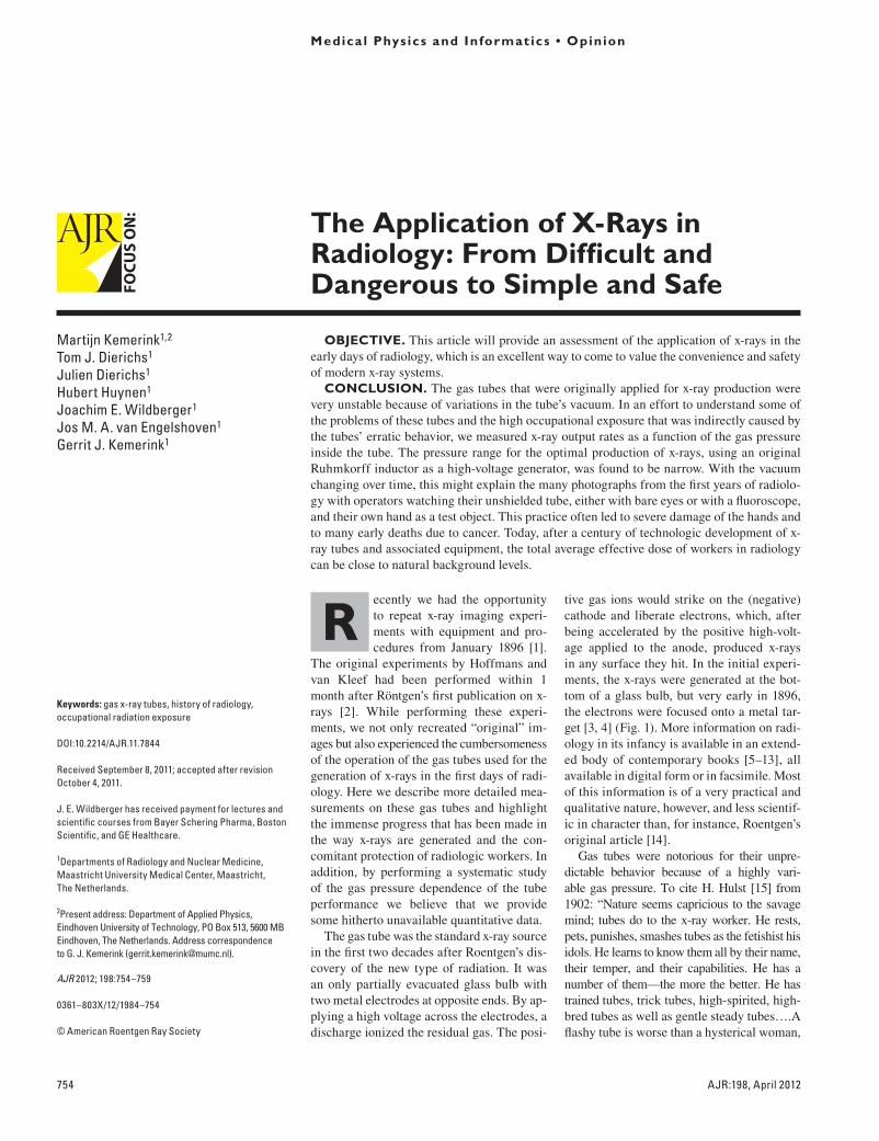
tive gas ions would strike on the (negative) cathode and liberate electrons, which, after being accelerated by the positive high-volt-age applied to the anode, produced x-rays in any surface they hit. In the initial experi-ments, the x-rays were generated at the bot-tom of a glass bulb, but very early in 1896, the electrons were focused onto a metal tar-get [3, 4] (Fig. 1). More information on radi-ology in its infancy is available in an extend-ed body of contemporary books [5–13], all available in digital form or in facsimile. Most of this information is of a very practical and qualitative nature, however, and less scientif-ic in character than, for instance, Roentgen’s original article [14].
Gas tubes were notorious for their unpre-dictable behavior because of a highly vari-able gas pressure. To cite H. Hulst [15] from 1902: “Nature seems capricious to the savage mind; tubes do to the x-ray worker. He rests, pets, punishes, smashes tubes as the fetishist his idols. He learns to know them all by their name, their temper, and their capabilities. He has a number of them—the more the better. He has trained tubes, trick tubes, high-spirited, high-bred tubes as well as gentle steady tubes….A flashy tube is worse than a hysterical woman,
The Application of X-Rays in Radiology: From Difficult and Dangerous to Simple and Safe
Martijn Kemerink1,2
Tom J. Dierichs1 Julien Dierichs1 Hubert Huynen1 Joachim E. Wildberger1 Jos M. A. van Engelshoven1 Gerrit J. Kemerink1
Kemerink M, Dierichs TJ, Dierichs J, et al.
1Departments of Radiology and Nuclear Medicine, Maastricht University Medical Center, Maastricht, The Netherlands.
2Present address: Department of Applied Physics, Eindhoven University of Technology, PO Box 513, 5600 MB Eindhoven, The Netherlands. Address correspondence to G. J. Kemerink ([email protected]).
Medica l Phys ics and Informat ics • Opinion
AJR 2012; 198:754–759
0361–803X/12/1984–754
© American Roentgen Ray Society
Recently we had the opportunity to repeat x-ray imaging experi-ments with equipment and pro-cedures from January 1896 [1].
The original experiments by Hoffmans and van Kleef had been performed within 1 month after Röntgen’s first publication on x-rays [2]. While performing these experi-ments, we not only recreated “original” im-ages but also experienced the cumber someness of the operation of the gas tubes used for the generation of x-rays in the first days of radi-ology. Here we describe more detailed mea-surements on these gas tubes and highlight the immense progress that has been made in the way x-rays are generated and the con-comitant protection of radiologic workers. In addition, by performing a systematic study of the gas pressure dependence of the tube performance we believe that we provide some hitherto unavailable quantitative data.
The gas tube was the standard x-ray source in the first two decades after Roentgen’s dis-covery of the new type of radiation. It was an only partially evacuated glass bulb with two metal electrodes at opposite ends. By ap-plying a high voltage across the electrodes, a discharge ionized the residual gas. The posi-
Keywords: gas x-ray tubes, history of radiology, occupational radiation exposure
DOI:10.2214/AJR.11.7844
Received September 8, 2011; accepted after revision October 4, 2011.
J. E. Wildberger has received payment for lectures and scientific courses from Bayer Schering Pharma, Boston Scientific, and GE Healthcare.
FOCU
S O
N:
OBJECTIVE. This article will provide an assessment of the application of x-rays in the early days of radiology, which is an excellent way to come to value the convenience and safety of modern x-ray systems.
CONCLUSION. The gas tubes that were originally applied for x-ray production were very unstable because of variations in the tube’s vacuum. In an effort to understand some of the problems of these tubes and the high occupational exposure that was indirectly caused by the tubes’ erratic behavior, we measured x-ray output rates as a function of the gas pressure inside the tube. The pressure range for the optimal production of x-rays, using an original Ruhmkorff inductor as a high-voltage generator, was found to be narrow. With the vacuum changing over time, this might explain the many photographs from the first years of radiolo-gy with operators watching their unshielded tube, either with bare eyes or with a fluoroscope, and their own hand as a test object. This practice often led to severe damage of the hands and to many early deaths due to cancer. Today, after a century of technologic development of x-ray tubes and associated equipment, the total average effective dose of workers in radiology can be close to natural background levels.
Kemerink et al.X-Rays in Radiology
Medical Physics and InformaticsOpinion
AJR:198, April 2012 755
X-Rays in Radiology
it is incurably useless.” A more moderate eval-uation of gas tubes, with essentially the same conclusion, is given by Coolidge [16].
The problems caused by the varying gas pressure are related to a few basic facts. First, when the vacuum was too high for a given high voltage to cause a discharge, no x-rays were generated. Second, when the vacuum was low, the discharge current could be so strong that it loaded the (unstabilized) pow-er supply so heavily that the high voltage dropped to a substantial degree. In the lat-ter case, the electrons were also likely to lose part of their kinetic energy in collisions with the relatively abundant residual gas. Volt-age drop and electron collisions resulted in a lowering of the energy of the electrons, and the x-ray radiation hardness intended might not be obtainable. These considerations il-lustrate fundamental limitations of the gas tube: Any radiation quality required a rather unique vacuum, and, for a given tube, the x-ray output was generally not independently adjustable from the radiation hardness.
The problematic behavior of gas tubes had unfortunate side effects. Users of these tubes would often want to check how well their tube was functioning and make electrical adjust-ments when possible. The functioning could partly be judged from the visual aspects of
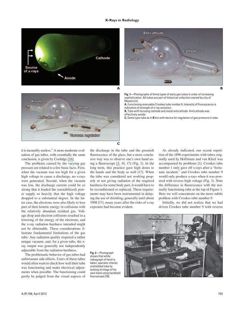
the discharge in the tube and the greenish fluorescence of the glass, but a more conclu-sive way was to observe one’s own hand us-ing a fluoroscope [3, 10, 17] (Fig. 2). In the long term, this practice gave high doses to the hands and the body as well [17]. When the tube was considered not working prop-erly or not giving radiation of the required hardness for some body part, it would have to be reconditioned or replaced. These require-ments may have been instrumental in delay-ing the use of shielding, generally until about 1908 [17], many years after the risks of x-ray exposure had become evident.
As already indicated, our recent repeti-tion of the 1896 experiments with tubes orig-inally used by Hoffmans and van Kleef was accompanied by problems [1]. Crookes tube number 1 only gave off x-rays after a “fortu-nate incident,” and Crookes tube number 9 would only produce x-rays when it was pow-ered with reverse high voltage (Fig. 3). Note the difference in fluorescence with the nor-mally functioning tube at the top of Figure 1. Here we will concentrate on the more subtle problem with Crookes tube number 9.
Initially, we did not realize that we had driven Crookes tube number 9 with reverse
A
C
Fig. 1—Photographs of three types of early gas tubes in order of increasing sophistication. All tubes are part of historical collection owned by city of Maastricht.A, Functioning evacuable Crookes tube number 9. Intensity of fluorescence is indication of strength of x-ray emission.B, Tube with focusing cathode and metal anticathode. Anticathode was effectively anode.C, Same type tube as in B but with device for regulation of gas pressure in tube.
B
Fig. 2—Photograph shows that while radiograph of hand is taken, operator checks unshielded tube by looking at image of his own hand using handheld fluoroscope [10].
756 AJR:198, April 2012
Kemerink et al.
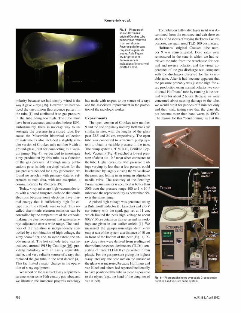
polarity because we had simply wired it the way it gave x-rays [18]. However, we had no-ticed the uncommon fluorescence pattern in the tube [1] and attributed it to gas pressure in the tube being too high. The tube must have been evacuated and sealed before 1896. Unfortunately, there is no easy way to in-vestigate the pressure in a closed tube. Be-cause the Maastricht historical collection of instruments also included a slightly sim-pler version of Crookes tube number 9 with a ground-glass joint for connecting to a vacu-um pump (Fig. 4), we decided to investigate x-ray production by this tube as a function of the gas pressure. Although many publi-cations gave (widely varying) values for the gas pressure needed for x-ray generation, we found no articles with primary data or ref-erences to such data, with one exception, a communication by Röntgen [19].
Today, x-ray tubes are high-vacuum devic-es with a heated tungsten cathode that emits electrons because some electrons have ther-mal energy that is sufficiently high for es-cape from the cathode wire or foil. This so-called thermionic electron emission can be controlled by the temperature of the cathode, making the electron current that generates x-rays adjustable over a wide range. The hard-ness of the radiation is independently con-trolled by a combination of high voltage, the x-ray beam filter, and, to some extent, the an-ode material. The hot cathode tube was in-troduced around 1913 by Coolidge [16], pro-viding radiology with an easily adjustable, stable, and very reliable source of x-rays that replaced the gas tube in the next decade [4]. This facilitated a major change in the opera-tion of x-ray equipment.
We report on the results of x-ray output mea-surements on some 19th-century gas tubes, and we illustrate the immense progress radiology
has made with respect to the source of x-rays and the associated improvement in the protec-tion of the radiologic worker.
ExperimentsThe open version of Crookes tube number
9 and the one originally used by Hoffmans are similar in size, with the lengths of the glass pear 22.5 and 24 cm, respectively. The open tube was connected to a vacuum pump sys-tem to obtain a variable pressure in the tube. The pump system (PT 50 KIT, Oerlikon Ley-bold Vacuum) (Fig. 4) reached a lowest pres-sure of about 4 × 10⁻⁶ mbar when connected to the tube. Higher pressures, with pressure read-ings varying by less than a few percent, could be obtained by largely closing the valve above the pump and letting in air using an adjustable needle valve. The accuracy of the Penning/ Pirani vacuum meter is specified as better than 30% over the pressure range 100 to 1 × 10⁻⁸ mbar and the reproducibility as better than 5% over the same range.
A pulsed high voltage was generated using a Ruhmkorff inductor (F. Ernecke) and a 6-V car battery with the spark gap set at 11 cm, which limited the peak high voltage to about 80 kV. More details on this setup and its work-ings are given in our earlier article [1]. We measured the gas-pressure-dependent x-ray output rate of the system at a distance of 10 cm in front of the bottom of the pear (Fig. 1). X-ray dose rates were derived from readings of thermoluminescence dosimeters (TLDs) con-sisting of three TLD-100 chips sealed in thin plastic. For the gas pressure giving the highest x-ray intensity, the dose rate on the surface of the glass was measured because Hoffmans and van Kleef and others had reported incidentally to have positioned the tube as close as possible to the object (e.g., the hand of the daughter of van Kleef).
The radiation half-value layer in Al was de-termined from the entrance and exit dose on stacks of Al sheets of varying thickness. For this purpose, we again used TLD-100 dosimeters.
Hoffmans’ original Crookes tube num-ber 9 was reinvestigated. Dose rates were remeasured in the state in which we had re-trieved the tube from the warehouse for nor-mal and reverse polarity, and the visual ap-pearance of the gas discharge was compared with the discharges observed for the evacu-able tube. After it had become apparent that the pressure probably was just too high for x-ray production using normal polarity, we con-ditioned Hoffmans’ tube by running it the nor-mal way for about 2 hours. Because we were concerned about causing damage to the tube, we would run it for periods of 5 minutes only and then wait, taking care that the glass did not become more than hand-warm (≤ 40°C). The reason for this “conditioning” is that the
Fig. 3—Photograph shows Hoffmans’ original Crookes tube number 9 as retrieved from warehouse. Reverse polarity was required to generate x-rays. As in Figure 1A, brightness of fluorescence is indication of intensity of emitted x-rays.
Fig. 4—Photograph shows evacuable Crookes tube number 9 and vacuum pump system.
AJR:198, April 2012 757
X-Rays in Radiology
vacuum in a gas tube is known to improve on prolonged normal use with an electron current that is not too high, even to the extent that x-ray production will finally stop [10, 11, 16]. One important mechanism of this evacuation is the implantation of gas ions into the cathode and the glass wall (e.g., for 50 keV nitrogen ions, the projected range in soda lime glass is about 138 nm; the projected range straggle is 45 nm [20]). Another mechanism is gettering by sputtered metal from the electrodes [4]. To increase the gas pressure again after prolonged use, the tube might be baked in an oven be-cause, using this procedure, gas is again driven out of the glass and the Al cathode [3, 10, 11]. Very soon, vacuum regulators came into use [3, 4] (Fig. 1), but these could not prevent the tube’s function from deteriorating over time.
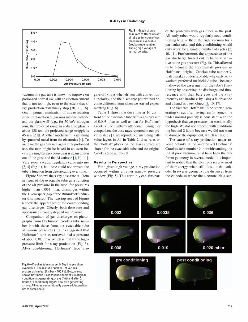
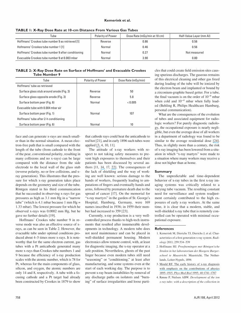
Figure 5 shows the x-ray dose rate at 10 cm in front of the evacuable tube as a function of the air pressure in the tube; for pressures higher than 0.004 mbar, discharges within the 11-cm spark gap of the Ruhmkorff induc-tor disappeared. The two top rows of Figure 6 show the appearance of the corresponding gas discharges. Clearly, both dose rate and appearance strongly depend on pressure.
Comparison of gas discharges on photo-graphs from Hoffmans’ Crookes tube num-ber 9 with those from the evacuable tube at various pressures (Fig. 6) suggested that Hoffmans’ tube as retrieved had a pressure of about 0.01 mbar, which is just at the high-pressure limit for x-ray production (Fig. 5). After conditioning, Hoffmans’ tube also
gave off x-rays when driven with convention-al polarity, and the discharge pattern had be-come different from when we started experi-menting (Fig. 6).
Table 1 shows the dose rate at 10 cm in front of the evacuable tube with a gas pressure of 0.003 mbar as well as that for Hoffmans’ Crookes tube number 9 after conditioning. For comparison, the dose rates reported in our pre-vious study [1] are reproduced, including half-value layers in Al. In Table 2, dose rates on the “hottest” places on the glass surface are shown for the evacuable tube and the original Crookes tube number 9.
Results in PerspectiveFor a given high voltage, x-ray production
occurred within a rather narrow pressure window (Fig. 5). This certainly explains part
of the problems with gas tubes in the past. All early tubes would regularly need condi-tioning to give them the right vacuum for a particular task, and this conditioning would only work for a limited number of cycles [3, 10, 11]. Furthermore, the appearance of the gas discharge turned out to be very sensi-tive to the gas pressure (Fig. 6). This allowed us to estimate the approximate pressure in Hoffmans’ original Crookes tube number 9. It also makes understandable why early x-ray workers preferred unshielded tubes, because it allowed the assessment of the tube’s func-tioning by observing the discharge and fluo-rescence with their bare eyes and the x-ray intensity and hardness by using a fluoroscope and a hand as a test object [3, 10, 17].
The fact that Hoffmans’ tube started gen-erating x-rays after having run for some time under normal polarity is consistent with the hypothesis that gas pressure that was initially too high. We did not proceed with condition-ing beyond 2 hours because we did not want to damage the equipment, which is fragile.
The cause of x-ray production under re-verse polarity in the as-retrieved Hoffmans’ Crookes tube number 9, notwithstanding the initial poor vacuum, must have been the dif-ferent geometry in reverse mode. It is impor-tant to notice that the electrons receive most of their energy when still close to the cath-ode. In reverse geometry, the distances from the cathode to where the electrons hit a sur-
Air Pressure (mbar)
Do
se R
ate
(mG
y/m
in)
0.002 0.004 0.006 0.008 0.0100.0
1.0
5.0
2.0
3.0
4.0
0.00
Fig. 5—Graph shows dose rate at 10 cm in front of tube as function of gas pressure in evacuable Crookes tube number 9 using high voltage of normal polarity.
Fig. 6—Crookes tube number 9. Top images show evacuable Crookes tube number 9 at various pressures in mbar (1 mbar = 100 Pa). Bottom row shows Hoffmans’ Crookes tube number 9 in original condition not generating x-rays (left) and after 2 hours of conditioning (right), now also generating x-rays. All tubes conventionally powered. Intensities not to same scale.
758 AJR:198, April 2012
Kemerink et al.
face and can generate x-rays are much small-er than in the normal situation. A mean elec-tron-free path that is small compared with the length of the tube (from cathode to the front of the pear, conventional polarity, resulting in many collisions and no x-rays) can be large compared with the distance from the side electrode to the local wall of the glass stub (reverse polarity, no or few collisions, and x-ray generation). This illustrates that the pres-sure for which x-ray generation takes place depends on the geometry and size of the tube. Röntgen stated in his third communication that he succeeded in observing x-rays for gas pressures as high as 3.1 mm Hg in a “narrow tube” (which is 4.1 mbar because 1 mm Hg = 1.33 mbar). The lowest pressure for which he observed x-rays was 0.0002 mm Hg, but he gave no further details [19].
Hoffmans’ Crookes tube number 9 in re-verse mode was also an effective source of x-rays, as can be seen in Table 2. However, the evacuable tube under optimal conditions pro-duced about 4–5 times more x-rays. It is note-worthy that for the same electron current, gas tubes with a Pt anticathode generated many more x-rays than Crookes tube numbers 1 and 9 because the efficiency of x-ray production scales with the atomic number, which is 78 for Pt, whereas for the main components of glass, silicon, and oxygen, the atomic numbers are only 14 and 8, respectively. A tube with a fo-cusing cathode and a Pt target had already been constructed by Crookes in 1879 to show
that cathode rays could heat the anticathode to red hot [21], and in early 1896 such tubes were applied [3, 4, 10, 11].
The attitude of x-ray workers with re-spect to not taking safety measures to pre-vent high exposures to themselves and their patients has been discussed by several au-thors [11, 14, 17, 22]. The consequences of the lack of shielding and the way of work-ing are well known: serious damage to the hands of workers, frequently leading to am-putations of fingers and eventually hands and arms, followed by premature death due to the spread of cancer [17]. On the memorial for “x-ray martyrs” in the garden of St. George’s Hospital, Hamburg, Germany, were 169 names inscribed in 1936; in 1959 their num-ber had increased to 359 [23].
Currently, x-ray production is a very well-controlled process thanks to high-tech instru-ments that resulted after innumerable devel-opments in technology. A modern tube does not need maintenance and can be placed in well-shielded permanent housing. Modern electronics allow remote control, with, at least for diagnostic imaging, the x-ray operator at a safe position. Nevertheless, ghosts of the past linger because even modern tubes still need “seasoning” or “conditioning,” at least after manufacturing, and some systems even at the start of each working day. The purpose is to prevent x-ray beam instabilities by removal of any discharge paths on isolators and “burn-ing” of surface irregularities and loose parti-
cles that could create field emission sites caus-ing spurious discharges. The gaseous remains of this electrical cleaning and other gas freed during loading of the tube will be ionized by the electron beam and implanted or bound by a zirconium-graphite based getter. For a tube, the final vacuum is on the order of 10−9 mbar when cold and 10−4 mbar when fully load-ed (Behling R, Philips Healthcare Hamburg, personal communication).
What are the consequences of the evolution of tubes and associated equipment for radio-logic workers? For purely diagnostic radiolo-gy, the occupational exposure is nearly negli-gible, but even the average dose of all workers in a department of radiology was found to be similar to the average residential dose [24]. Thus, in slightly more than a century, the risk of x-ray imaging has been lowered from a situ-ation in which “x-ray martyrs” were made to a situation where many workers may receive a dose not higher than at home.
SummaryThe unpredictable and time-dependent
behavior of x-ray tubes in the first x-ray im-aging systems was critically related to a varying tube vacuum. The resulting constant need for surveillance and system readjust-ment certainly contributed to the high ex-posures of early x-ray workers. At the same time, it is clear that a modern, stable, and well-shielded x-ray tube that is remotely con-trolled can be operated with minimal occu-pational exposure.
References 1. Kemerink M, Dierichs TJ, Dierichs J, et al. Char-
acteristics of a first generation x-ray system. Radi-
ology 2011; 259:534–539
2. Hoffmans HJ. Proefnemingen met Röntgen’sche
Stralen in het laboratorium der Hoogere Burger-
school te Maastricht. Maastricht, The Nether-
lands, Leiter-Nypels, 1896
3. Mould RF. The early history of x-ray diagnosis
with emphasis on the contributions of physics
1895–1915. Phys Med Biol 1995; 40:1741–1787
4. Rønne P, Nielsen ABW. Development of the ion
x-ray tube: with a description of the collection in
TABLE 2: X-Ray Dose Rate on Surface of Hoffmans’ and Evacuable Crookes Tube Number 9
Tube Polarity of Power Dose Rate (mGy/min)
Hoffmans’ tube as retrieved
Surface glass stub around anode (Fig. 3) Reverse 50
Surface glass opposite anode (Fig. 3) Reverse 5.8
Surface bottom pear (Fig. 6) Normal < 0.005
Evacuable tube with 0.004 mbar air
Surface bottom pear (Fig. 1) Normal 107
Hoffmans’ tube after 2-h conditioning
Surface bottom pear (Fig. 6) Normal 10
TABLE 1: X-Ray Dose Rate at 10-cm Distance From Various Gas Tubes
Tube Polarity of Power Dose Rate (mGy/min at 10 cm) Half-Value Layer (mm Al)
Hoffmans’ Crookes tube number 9 as retrieved [1] Reverse 0.86 0.56
Hofmanns’ Crookes tube number 1 [1] Normal 0.46 0.56
Hoffmans’ Crookes tube number 9 after conditioning Normal 0.27 Not measured
Evacuable Crookes tube number 9 at 0.003 mbar Normal 3.90 0.80
AJR:198, April 2012 759
X-Rays in Radiology
the Medical Historical Museum, University of
Copenhagen (Acta Historica Scientiarum Natu-
ralium Et Medicinalium, vol. 35). Copenhagen,
Denmark: CA Reitzel Publishers, 1986
5. Addyman FT. Practical x ray work. London,
United Kingdom: Scott, Greenwood & Co, 1901
6. Albers-Schönberg HE. Die Röntgentechnik. Ham-
burg, Germany: Lucas Gräfe & Sillem, 1903
7. Kassabian MK. Röntgen rays and electro-thera-
peutics with chapters on radium and phototherapy.
Philadelphia, PA: JB Lippincott Company, 1907
8. Kaye CWC. An introduction to the study of rönt-
gen rays. London, United Kingdom: Longman,
Green and Co, 1914
9. Meadowcraft WMH. The ABC of the x rays. New
York, NY: The American Technical Book Co,
1896
10. Morton WJ, Hammer EW. The x-ray. New York,
NY: American Technical Book Co, 1896
11. Rollins W. Notes on x-light. Cambridge, United
Kingdom: University Press, 1904
12. Snowden Ward H. Practical radiography. Lon-
don, United Kingdom: Dawbarn & Ward, 1896
13. Thompson EP. Roentgen rays and phenomena of
the anode and the cathode. New York, NY: D. Van
Nostrand Company, 1896
14. Serwer DP. The rise of radiation protection: science,
medicine and technology in society. BNL 22279
Informal Report Upton, NY: Brookhaven National
Laboratory Associated Universities, 1976:chapter 1
15. Hulst H. Joys and sorrows of an x-ray worker.
Phys Surg 1902; 24:492–498
16. Coolidge WD. A powerful Röntgen ray tube with a
pure electron discharge. Phys Rev 1913; 2:409–430
17. Meggitt G. Taming the rays: a history of radiation
and protection. Raleigh, NC: Lulu.com, 2008:
chapter 1
18. Kemerink M, Dierichs TJ, Dierichs J, et al. First-gen-
eration x-ray system. Radiology 2011; 260: 611–612
19. Röntgen WC. Weitere Beobachtungen über die
Eigenschaften der X-Strahlen. Sitzungsberichte
der königlich preußischen Akademie der Wissen-
schaften zu Berlin. 1897; 26:576–592
20. James F. Ziegler Website. SRIM: the stopping and
range of ions in matter. www.srim.org. Accessed
June 27, 2011
21. Crookes W. Radiant matter. Lecture delivered be-
fore the British Association for the Advancement
of Science at Sheffield. Friday, August 22, 1879
22. Herzig R. Suffering, sacrifice, and the formation of
American roentgenology. Am Q 2001; 53:563–589
23. Vogel H. Das Ehrenmal der Radiologie in Ham-
burg. Ein Beitrag zur Geschichte der Röntgen-
strahlen. Fortschr Röntgenstr 2006; 178:753–756
24. Kemerink GJ, Frantzen MJ, de Jong P, Wildberger
JE. Less radiation in a radiology department than
at home. Insights Imaging 2011; 2:275–280
F O R Y O U R I N F O R M A T I O N
Mark your calendar for the following ARRS annual meetings:April 29–May 4, 2012—Vancouver Convention Center, Vancouver, BC, CanadaApril 14–19, 2013—Marriott Wardman Park Hotel, Washington, DCMay 4–9, 2014—Manchester Grand Hyatt San Diego, San Diego, CAApril 19–24, 2015—Toronto Convention Centre, Toronto, ON, Canada