Direct control for AC/DC/AC converter-fed induction motor with active filtering function
Upload
khangminh22Category
view
4download
0
Operating instructions
EN
Control
T4.04 - Tetrix AC/DC Smart 2.0 T4.10 - Tetrix AC/DC Smart 2.0
099-00T404-EW501 Observe additional system documents! 02.07.2020
General instructions
WARNING
Read the operating instructions!
The operating instructions provide an introduction to the safe use of the products.
• Read and observe the operating instructions for all system components, especially the sa-
fety instructions and warning notices!
• Observe the accident prevention regulations and any regional regulations!
• The operating instructions must be kept at the location where the machine is operated.
• Safety and warning labels on the machine indicate any possible risks.
Keep these labels clean and legible at all times.
• The machine has been constructed to state-of-the-art standards in line with any applicable
regulations and industrial standards. Only trained personnel may operate, service and re-
pair the machine.
• Technical changes due to further development in machine technology may lead to a dif-
fering welding behaviour.
In the event of queries on installation, commissioning, operation or special conditions at the
installation site, or on usage, please contact your sales partner or our customer service
department on +49 2680 181-0.
A list of authorised sales partners can be found at www.ewm-group.com/en/specialist-dealers.
Liability relating to the operation of this equipment is restricted solely to the function of the equipment. No
other form of liability, regardless of type, shall be accepted. This exclusion of liability shall be deemed ac-
cepted by the user on commissioning the equipment.
The manufacturer is unable to monitor whether or not these instructions or the conditions and methods
are observed during installation, operation, usage and maintenance of the equipment.
An incorrectly performed installation can result in material damage and injure persons as a result. For this
reason, we do not accept any responsibility or liability for losses, damages or costs arising from incorrect
installation, improper operation or incorrect usage and maintenance or any actions connected to this in
any way.
© EWM AG
Dr. Günter-Henle-Strasse 8
56271 Mündersbach Germany
Tel.: +49 2680 181-0, Fax: -244
Email: [email protected]
www.ewm-group.com
The copyright to this document remains the property of the manufacturer.
Copying, including extracts, only permitted with written approval.
The content of this document has been prepared and reviewed with all reasonable care. The information
provided is subject to change; errors excepted.
Contents Notes on using these operating instructions
099-00T404-EW501 02.07.2020 3
1 Contents 1 Contents .................................................................................................................................................. 3
2 For your safety ....................................................................................................................................... 5 2.1 Notes on using these operating instructions .................................................................................. 5 2.2 Explanation of icons ....................................................................................................................... 5 2.3 Part of the complete documentation .............................................................................................. 7
3 Intended use ........................................................................................................................................... 8 3.1 Use and operation solely with the following machines .................................................................. 8 3.2 Documents which also apply ......................................................................................................... 8 3.3 Software version ............................................................................................................................ 8
4 Machine control – Operating elements ................................................................................................ 9 4.1 Overview of control sections .......................................................................................................... 9
4.1.1 Control section A .......................................................................................................... 10 4.1.2 Control section B .......................................................................................................... 11
4.2 Machine display ........................................................................................................................... 12 4.2.1 Setting the welding current (absolute/percentage) ....................................................... 12
4.3 Operating the machine control ..................................................................................................... 12 4.3.1 Main screen .................................................................................................................. 12 4.3.2 Welding power setting .................................................................................................. 12 4.3.3 Welding parameter setting in the operation sequence ................................................. 13 4.3.4 Setting advanced welding parameters (Expert menu) ................................................. 13 4.3.5 Changing basic settings (machine configuration menu) .............................................. 13
5 Functional characteristics ................................................................................................................... 14 5.1 TIG welding .................................................................................................................................. 14
5.1.1 Setting the shielding gas volume (gas test)/rinse hose package ................................. 14 5.1.1.1 Automatic gas post-flow ................................................................................ 14
5.1.2 Welding task selection .................................................................................................. 15 5.1.3 AC welding ................................................................................................................... 16
5.1.3.1 AC balance (optimise cleaning effect and penetration characteristics) ........ 16 5.1.3.2 AC commutation optimisation ....................................................................... 16 5.1.3.3 Alternating current waveforms ...................................................................... 17
5.1.4 Arc ignition .................................................................................................................... 18 5.1.4.1 HF ignition ..................................................................................................... 18 5.1.4.2 Liftarc ............................................................................................................ 18 5.1.4.3 Automatic cut-out .......................................................................................... 18
5.1.5 Operating modes (functional sequences) .................................................................... 19 5.1.5.1 Explanation of symbols ................................................................................. 19 5.1.5.2 Non-latched mode ......................................................................................... 20 5.1.5.3 Latched mode ............................................................................................... 21 5.1.5.4 spotArc .......................................................................................................... 22 5.1.5.5 spotmatic ....................................................................................................... 24 5.1.5.6 Non-latched operation, version C ................................................................. 25
5.1.6 Average value pulse welding ........................................................................................ 26 5.1.6.1 Pulsed welding in the upslope and downslope phases ................................ 27 5.1.6.2 Automated pulses ......................................................................................... 27
5.1.7 TIG activArc welding..................................................................................................... 28 5.1.8 TIG antistick .................................................................................................................. 28 5.1.9 Welding torch (operating variants) ............................................................................... 28
5.1.9.1 Tapping function (tap torch trigger) ............................................................... 28 5.1.9.2 Torch mode setting ....................................................................................... 29 5.1.9.3 Up/down speed ............................................................................................. 29 5.1.9.4 Current jump ................................................................................................. 29 5.1.9.5 Standard TIG torch (5-pole) .......................................................................... 30 5.1.9.6 TIG up/down torch (8-pole) ........................................................................... 32 5.1.9.7 Potentiometer torch (8-pole) ......................................................................... 34 5.1.9.8 Configuring the TIG potentiometer torch connection .................................... 35
5.1.10 RTF 1 foot-operated remote control ............................................................................. 36 5.1.10.1 RTF start ramp .............................................................................................. 36 5.1.10.2 RTF response ............................................................................................... 37
Contents Notes on using these operating instructions
4 099-00T404-EW501 02.07.2020
5.1.11 Expert menu (TIG) ........................................................................................................ 38 5.1.12 Aligning the cable resistance ........................................................................................ 39
5.2 MMA welding ................................................................................................................................ 40 5.2.1 Welding task selection .................................................................................................. 40 5.2.2 Hotstart ......................................................................................................................... 41 5.2.3 Arcforce......................................................................................................................... 41 5.2.4 Antistick......................................................................................................................... 41 5.2.5 Average value pulse welding ........................................................................................ 42 5.2.6 Expert menu (MMA) ...................................................................................................... 43
5.3 Power-saving mode (Standby) ..................................................................................................... 44 5.4 Access control .............................................................................................................................. 44 5.5 Voltage reducing device ............................................................................................................... 44 5.6 Machine configuration menu ........................................................................................................ 45
5.6.1 Selecting, changing and saving parameters................................................................. 45
6 Rectifying faults.................................................................................................................................... 49 6.1 Warnings ...................................................................................................................................... 49 6.2 Error messages ............................................................................................................................ 50 6.3 Resetting welding parameters to the factory settings .................................................................. 51 6.4 Display machine control software version .................................................................................... 51
7 Appendix ............................................................................................................................................... 52 7.1 Parameter overview – setting ranges .......................................................................................... 52
7.1.1 TIG welding ................................................................................................................... 52 7.1.2 MMA welding ................................................................................................................ 53
7.2 Searching for a dealer .................................................................................................................. 54
For your safety Notes on using these operating instructions
099-00T404-EW501 02.07.2020 5
2 For your safety
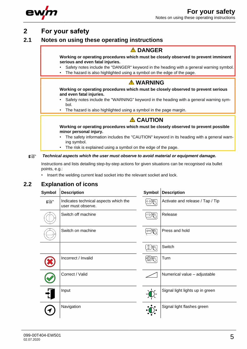
2.1 Notes on using these operating instructions
DANGER Working or operating procedures which must be closely observed to prevent imminent
serious and even fatal injuries.
• Safety notes include the "DANGER" keyword in the heading with a general warning symbol.
• The hazard is also highlighted using a symbol on the edge of the page.
WARNING Working or operating procedures which must be closely observed to prevent serious
and even fatal injuries.
• Safety notes include the "WARNING" keyword in the heading with a general warning sym-
bol.
• The hazard is also highlighted using a symbol in the page margin.
CAUTION Working or operating procedures which must be closely observed to prevent possible
minor personal injury.
• The safety information includes the "CAUTION" keyword in its heading with a general warn-
ing symbol.
• The risk is explained using a symbol on the edge of the page.
Technical aspects which the user must observe to avoid material or equipment damage.
Instructions and lists detailing step-by-step actions for given situations can be recognised via bullet
points, e.g.:
• Insert the welding current lead socket into the relevant socket and lock.
2.2 Explanation of icons
Symbol Description Symbol Description
Indicates technical aspects which the
user must observe.
Activate and release / Tap / Tip
Switch off machine
Release
Switch on machine
Press and hold
Switch
Incorrect / Invalid
Turn
Correct / Valid Numerical value – adjustable
Input
Signal light lights up in green
Navigation
Signal light flashes green
For your safety Part of the complete documentation
6 099-00T404-EW501 02.07.2020
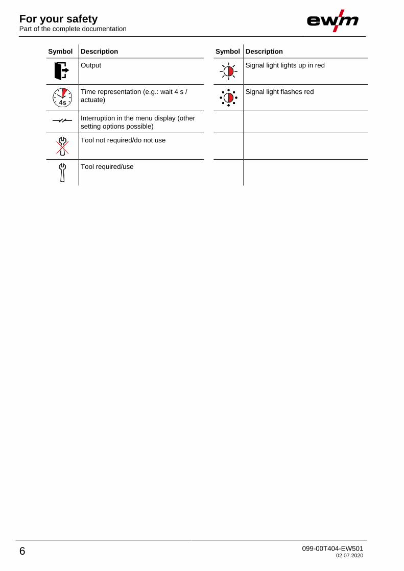
Symbol Description Symbol Description
Output
Signal light lights up in red
Time representation (e.g.: wait 4 s /
actuate)
Signal light flashes red
Interruption in the menu display (other
setting options possible)
Tool not required/do not use
Tool required/use
For your safety Part of the complete documentation
099-00T404-EW501 02.07.2020 7
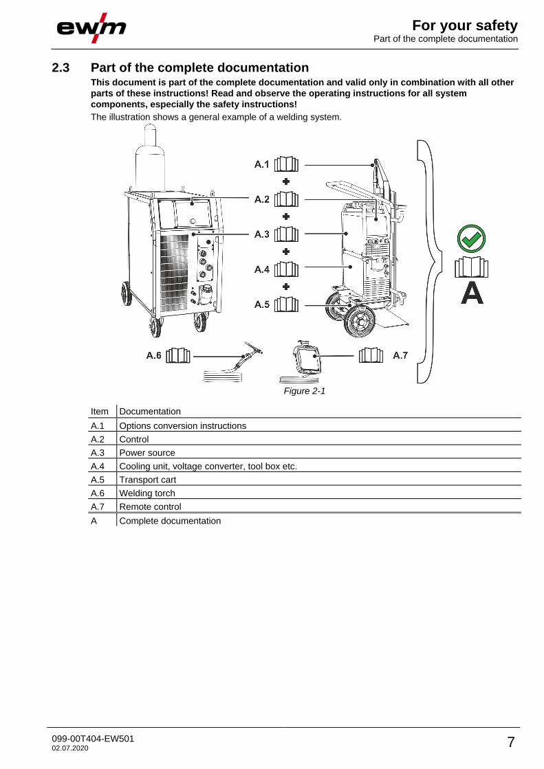
2.3 Part of the complete documentation This document is part of the complete documentation and valid only in combination with all other
parts of these instructions! Read and observe the operating instructions for all system
components, especially the safety instructions!
The illustration shows a general example of a welding system.
Figure 2-1
Item Documentation
A.1 Options conversion instructions
A.2 Control
A.3 Power source
A.4 Cooling unit, voltage converter, tool box etc.
A.5 Transport cart
A.6 Welding torch
A.7 Remote control
A Complete documentation
Intended use Use and operation solely with the following machines
8 099-00T404-EW501 02.07.2020
3 Intended use
WARNING
Hazards due to improper usage!
The machine has been constructed to the state of the art and any regulations and
standards applicable for use in industry and trade. It may only be used for the welding
procedures indicated at the rating plate. Hazards may arise for persons, animals and
material objects if the equipment is not used correctly. No liability is accepted for any
damages arising from improper usage!
• The equipment must only be used in line with its designated purpose and by trained or
expert personnel!
• Do not improperly modify or convert the equipment!
3.1 Use and operation solely with the following machines • Tetrix 300 AC/DC Smart 2.0 (T4.04)
• Tetrix 351-551 AC/DC Smart 2.0 (T4.10)
3.2 Documents which also apply • Operating instructions for the connected welding machines
• Documents of the optional expansions
3.3 Software version These instructions apply to the following software version:
07.03F0
The software version of the machine control can be displayed in the machine configuration menu
(menu Srv) > see 5.6 chapter.
Machine control – Operating elements Overview of control sections
099-00T404-EW501 02.07.2020 9
4 Machine control – Operating elements
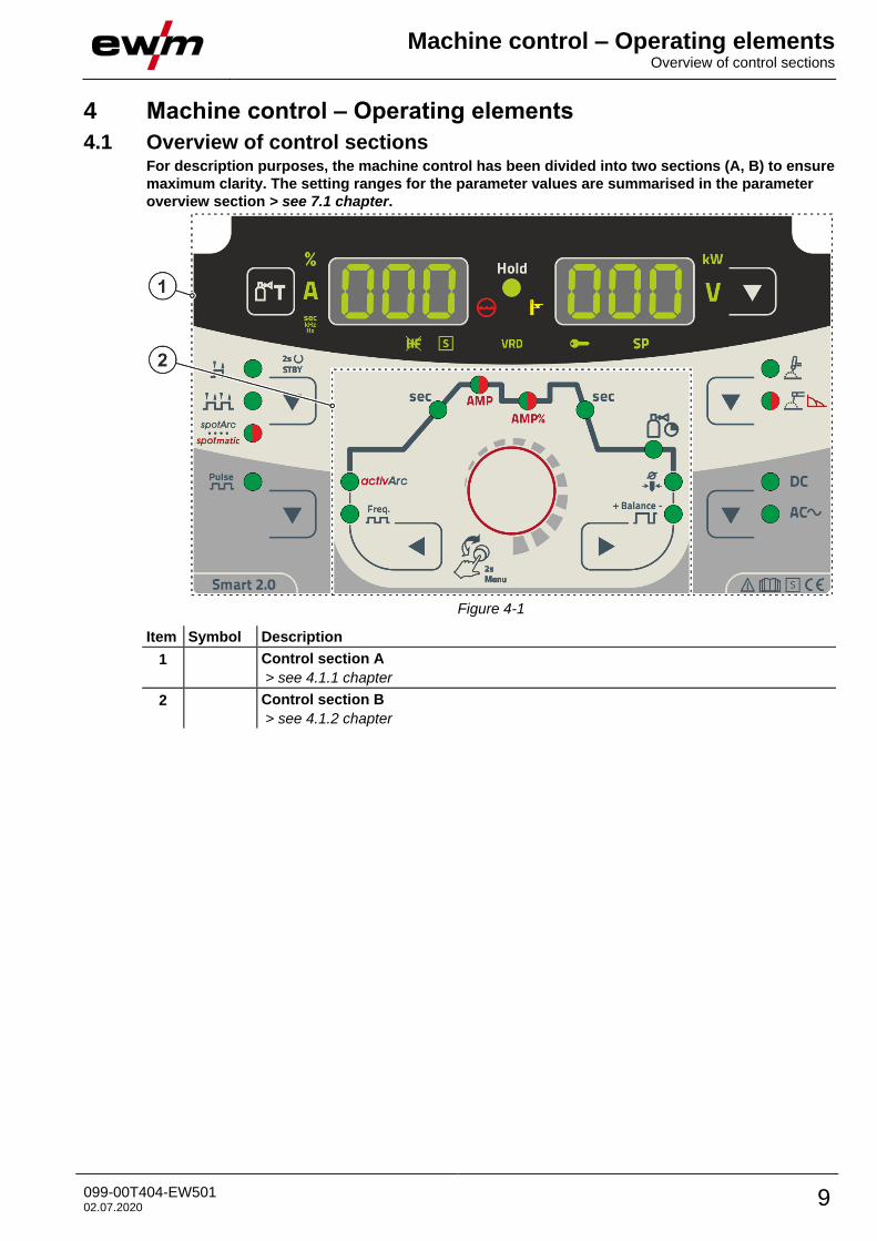
4.1 Overview of control sections For description purposes, the machine control has been divided into two sections (A, B) to ensure
maximum clarity. The setting ranges for the parameter values are summarised in the parameter
overview section > see 7.1 chapter.
Figure 4-1
Item Symbol Description 0
1 Control section A
> see 4.1.1 chapter
2 Control section B
> see 4.1.2 chapter
Machine control – Operating elements Overview of control sections
10 099-00T404-EW501 02.07.2020
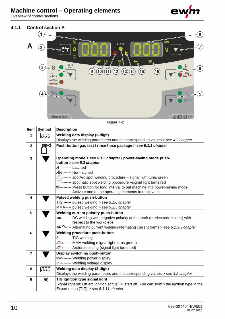
4.1.1 Control section A
Figure 4-2
Item Symbol Description 0
1
Welding data display (3-digit)
Displays the welding parameters and the corresponding values > see 4.2 chapter
2
Push-button gas test / rinse hose package > see 5.1.1 chapter
3
Operating mode > see 5.1.5 chapter / power-saving mode push-
button > see 5.3 chapter
--------- Latched
------- Non-latched
------- spotArc spot welding procedure – signal light turns green
------- spotmatic spot welding procedure –signal light turns red
--------- Press button for long interval to put machine into power-saving mode.
Activate one of the operating elements to reactivate.
4
Pulsed welding push-button
TIG ------ pulsed welding > see 5.1.6 chapter
MMA ---- pulsed welding > see 5.2.5 chapter
5
Welding current polarity push-button
-------- DC welding with negative polarity at the torch (or electrode holder) with
respect to the workpiece.
-- Alternating current welding/alternating current forms > see 5.1.3.3 chapter
6
Welding procedure push-button
--------- TIG welding
----- MMA welding (signal light turns green)
----- Arcforce setting (signal light turns red)
7
Display switching push-button
kW ------- Welding power display
V --------- Welding voltage display
8
Welding data display (3-digit)
Displays the welding parameters and the corresponding values > see 4.2 chapter
9 TIG ignition type signal light
Signal light on: Lift arc ignition active/HF start off. You can switch the ignition type in the
Expert menu (TIG) > see 5.1.11 chapter.
Machine control – Operating elements Overview of control sections
099-00T404-EW501 02.07.2020 11
Item Symbol Description 0
10
Character function signal light
Indicates that it is possible to weld in an environment with major electric hazards, such
as in boilers. Service must be informed if this signal light is not on.
11
Coolant fault signal light
Signals pressure loss or low coolant level in the coolant circuit.
12 VRD Voltage reduction device (VRD) signal light > see 5.5 chapter
13 Hold Signal light Status display
After each completed welding task, the last values used in the welding process for the
welding current and welding voltage are shown on the displays, and the signal light will
be on
14
Excess temperature signal light
In case of excess temperature, temperature monitors de-activate the power unit, and
the excess temperature control lamp comes on. Once the machine has cooled down,
welding can continue without any further measures.
15 Access control active signal light
Signal light is on when access control is active on the machine con-
trol > see 5.4 chapter.
16 Without function in this machine version.
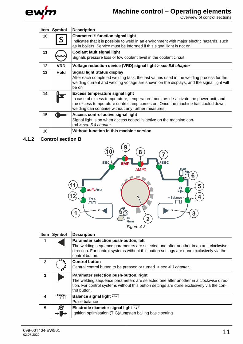
4.1.2 Control section B
Figure 4-3
Item Symbol Description 0
1
Parameter selection push-button, left
The welding sequence parameters are selected one after another in an anti-clockwise
direction. For control systems without this button settings are done exclusively via the
control button.
2
Control button
Central control button to be pressed or turned > see 4.3 chapter.
3
Parameter selection push-button, right
The welding sequence parameters are selected one after another in a clockwise direc-
tion. For control systems without this button settings are done exclusively via the con-
trol button.
4 Balance signal light
Pulse balance
5
Electrode diameter signal light
Ignition optimisation (TIG)/tungsten balling basic setting
Machine control – Operating elements Machine display
12 099-00T404-EW501 02.07.2020
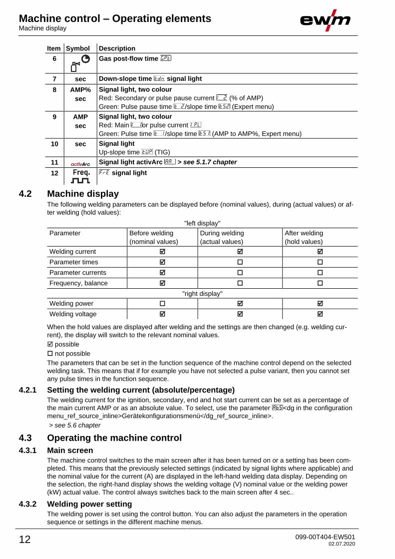
Item Symbol Description 0
6
Gas post-flow time
7 sec Down-slope time signal light
8 AMP%
sec
Signal light, two colour
Red: Secondary or pulse pause current (% of AMP)
Green: Pulse pause time /slope time (Expert menu)
9 AMP
sec
Signal light, two colour
Red: Main or pulse current
Green: Pulse time /slope time (AMP to AMP%, Expert menu)
10 sec Signal light
Up-slope time (TIG)
11 Signal light activArc > see 5.1.7 chapter
12
signal light
4.2 Machine display The following welding parameters can be displayed before (nominal values), during (actual values) or af-
ter welding (hold values):
"left display"
Parameter Before welding
(nominal values)
During welding
(actual values)
After welding
(hold values)
Welding current
Parameter times
Parameter currents
Frequency, balance
"right display"
Welding power
Welding voltage
When the hold values are displayed after welding and the settings are then changed (e.g. welding cur-
rent), the display will switch to the relevant nominal values.
possible
not possible
The parameters that can be set in the function sequence of the machine control depend on the selected
welding task. This means that if for example you have not selected a pulse variant, then you cannot set
any pulse times in the function sequence.
4.2.1 Setting the welding current (absolute/percentage)
The welding current for the ignition, secondary, end and hot start current can be set as a percentage of
the main current AMP or as an absolute value. To select, use the parameter <dg in the configuration
menu_ref_source_inline>Gerätekonfigurationsmenü</dg_ref_source_inline>.
> see 5.6 chapter
4.3 Operating the machine control
4.3.1 Main screen
The machine control switches to the main screen after it has been turned on or a setting has been com-
pleted. This means that the previously selected settings (indicated by signal lights where applicable) and
the nominal value for the current (A) are displayed in the left-hand welding data display. Depending on
the selection, the right-hand display shows the welding voltage (V) nominal value or the welding power
(kW) actual value. The control always switches back to the main screen after 4 sec..
4.3.2 Welding power setting
The welding power is set using the control button. You can also adjust the parameters in the operation
sequence or settings in the different machine menus.
Machine control – Operating elements Operating the machine control
099-00T404-EW501 02.07.2020 13
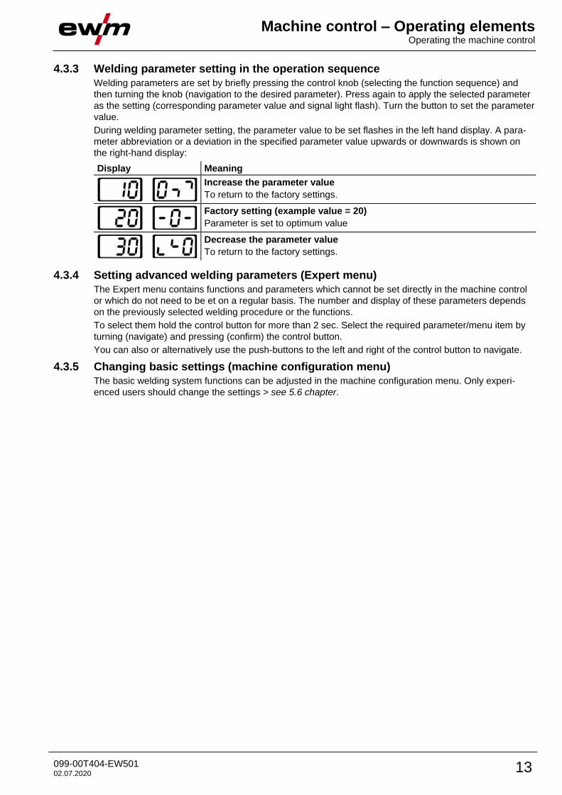
4.3.3 Welding parameter setting in the operation sequence
Welding parameters are set by briefly pressing the control knob (selecting the function sequence) and
then turning the knob (navigation to the desired parameter). Press again to apply the selected parameter
as the setting (corresponding parameter value and signal light flash). Turn the button to set the parameter
value.
During welding parameter setting, the parameter value to be set flashes in the left hand display. A para-
meter abbreviation or a deviation in the specified parameter value upwards or downwards is shown on
the right-hand display:
Display Meaning
Increase the parameter value
To return to the factory settings.
Factory setting (example value = 20)
Parameter is set to optimum value
Decrease the parameter value
To return to the factory settings.
4.3.4 Setting advanced welding parameters (Expert menu)
The Expert menu contains functions and parameters which cannot be set directly in the machine control
or which do not need to be et on a regular basis. The number and display of these parameters depends
on the previously selected welding procedure or the functions.
To select them hold the control button for more than 2 sec. Select the required parameter/menu item by
turning (navigate) and pressing (confirm) the control button.
You can also or alternatively use the push-buttons to the left and right of the control button to navigate.
4.3.5 Changing basic settings (machine configuration menu)
The basic welding system functions can be adjusted in the machine configuration menu. Only experi-
enced users should change the settings > see 5.6 chapter.
Functional characteristics TIG welding
14 099-00T404-EW501 02.07.2020
5 Functional characteristics
5.1 TIG welding
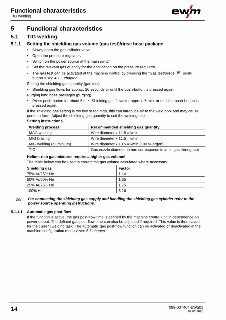
5.1.1 Setting the shielding gas volume (gas test)/rinse hose package
• Slowly open the gas cylinder valve.
• Open the pressure regulator.
• Switch on the power source at the main switch.
• Set the relevant gas quantity for the application on the pressure regulator.
• The gas test can be activated at the machine control by pressing the "Gas test/purge " push-
button > see 4.1.1 chapter.
Setting the shielding gas quantity (gas test)
• Shielding gas flows for approx. 20 seconds or until the push-button is pressed again.
Purging long hose packages (purging)
• Press push-button for about 5 s. • Shielding gas flows for approx. 5 min. or until the push-button is
pressed again.
If the shielding gas setting is too low or too high, this can introduce air to the weld pool and may cause
pores to form. Adjust the shielding gas quantity to suit the welding task!
Setting instructions
Welding process Recommended shielding gas quantity
MAG welding Wire diameter x 11.5 = l/min
MIG brazing Wire diameter x 11.5 = l/min
MIG welding (aluminium) Wire diameter x 13.5 = l/min (100 % argon)
TIG Gas nozzle diameter in mm corresponds to l/min gas throughput
Helium-rich gas mixtures require a higher gas volume!
The table below can be used to correct the gas volume calculated where necessary:
Shielding gas Factor
75% Ar/25% He 1.14
50% Ar/50% He 1.35
25% Ar/75% He 1.75
100% He 3.16
For connecting the shielding gas supply and handling the shielding gas cylinder refer to the power source operating instructions.
5.1.1.1 Automatic gas post-flow
If the function is active, the gas post-flow time is defined by the machine control unit in dependence on
power output. The defined gas post-flow time can also be adjusted if required. This value is then saved
for the current welding task. The automatic gas post-flow function can be activated or deactivated in the
machine configuration menu > see 5.6 chapter.
Functional characteristics TIG welding
099-00T404-EW501 02.07.2020 15
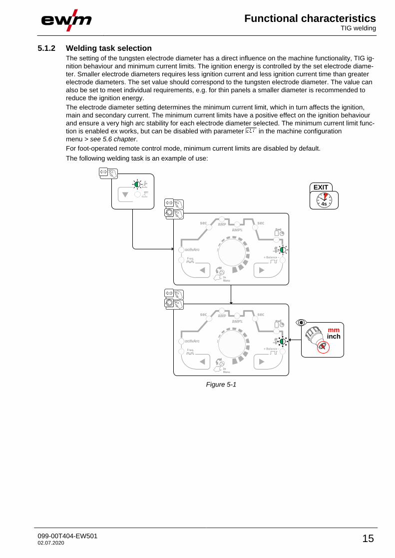
5.1.2 Welding task selection
The setting of the tungsten electrode diameter has a direct influence on the machine functionality, TIG ig-
nition behaviour and minimum current limits. The ignition energy is controlled by the set electrode diame-
ter. Smaller electrode diameters requires less ignition current and less ignition current time than greater
electrode diameters. The set value should correspond to the tungsten electrode diameter. The value can
also be set to meet individual requirements, e.g. for thin panels a smaller diameter is recommended to
reduce the ignition energy.
The electrode diameter setting determines the minimum current limit, which in turn affects the ignition,
main and secondary current. The minimum current limits have a positive effect on the ignition behaviour
and ensure a very high arc stability for each electrode diameter selected. The minimum current limit func-
tion is enabled ex works, but can be disabled with parameter in the machine configuration
menu > see 5.6 chapter.
For foot-operated remote control mode, minimum current limits are disabled by default.
The following welding task is an example of use:
EXIT
4s
mminch
Figure 5-1
Functional characteristics TIG welding
16 099-00T404-EW501 02.07.2020
5.1.3 AC welding
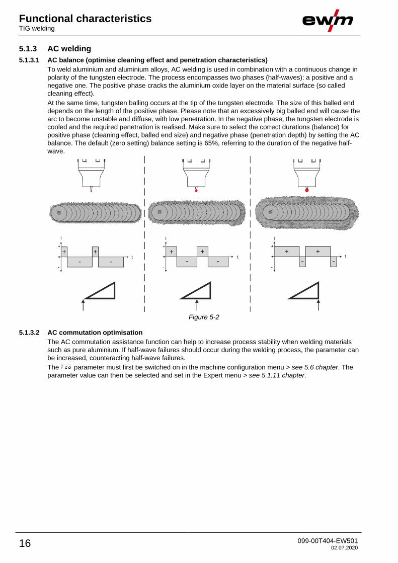
5.1.3.1 AC balance (optimise cleaning effect and penetration characteristics)
To weld aluminium and aluminium alloys, AC welding is used in combination with a continuous change in
polarity of the tungsten electrode. The process encompasses two phases (half-waves): a positive and a
negative one. The positive phase cracks the aluminium oxide layer on the material surface (so called
cleaning effect).
At the same time, tungsten balling occurs at the tip of the tungsten electrode. The size of this balled end
depends on the length of the positive phase. Please note that an excessively big balled end will cause the
arc to become unstable and diffuse, with low penetration. In the negative phase, the tungsten electrode is
cooled and the required penetration is realised. Make sure to select the correct durations (balance) for
positive phase (cleaning effect, balled end size) and negative phase (penetration depth) by setting the AC
balance. The default (zero setting) balance setting is 65%, referring to the duration of the negative half-
wave.
Figure 5-2
5.1.3.2 AC commutation optimisation
The AC commutation assistance function can help to increase process stability when welding materials
such as pure aluminium. If half-wave failures should occur during the welding process, the parameter can
be increased, counteracting half-wave failures.
The parameter must first be switched on in the machine configuration menu > see 5.6 chapter. The
parameter value can then be selected and set in the Expert menu > see 5.1.11 chapter.
Functional characteristics TIG welding
099-00T404-EW501 02.07.2020 17
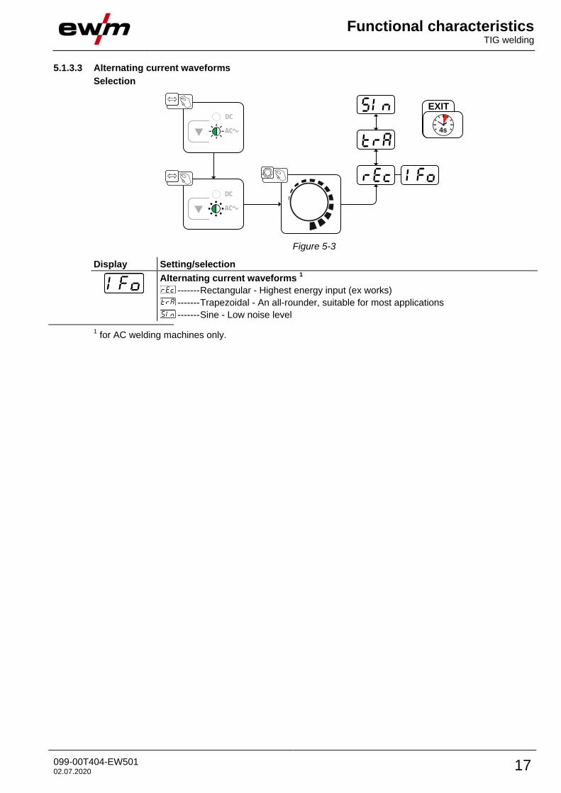
5.1.3.3 Alternating current waveforms
Selection
EXIT
4s
Figure 5-3
Display Setting/selection
Alternating current waveforms 1
------- Rectangular - Highest energy input (ex works)
------- Trapezoidal - An all-rounder, suitable for most applications
------- Sine - Low noise level
1 for AC welding machines only.
Functional characteristics TIG welding
18 099-00T404-EW501 02.07.2020
5.1.4 Arc ignition
To change the ignition type, use parameter to switch between HF start ( ) and lift arc ( ) in the
Expert menu > see 5.1.11 chapter.
5.1.4.1 HF ignition
Figure 5-4
The arc is started without contact from high-voltage ignition pulses.
a) Position the welding torch in welding position over the workpiece (distance between the electrode tip
and workpiece should be approx. 2-3mm).
b) Press the torch trigger (high voltage ignition pulses ignite the arc).
c) Ignition current flows, and the welding process is continued depending on the operating mode select-
ed.
End the welding process: Release or press the torch trigger depending on the operating mode
selected.
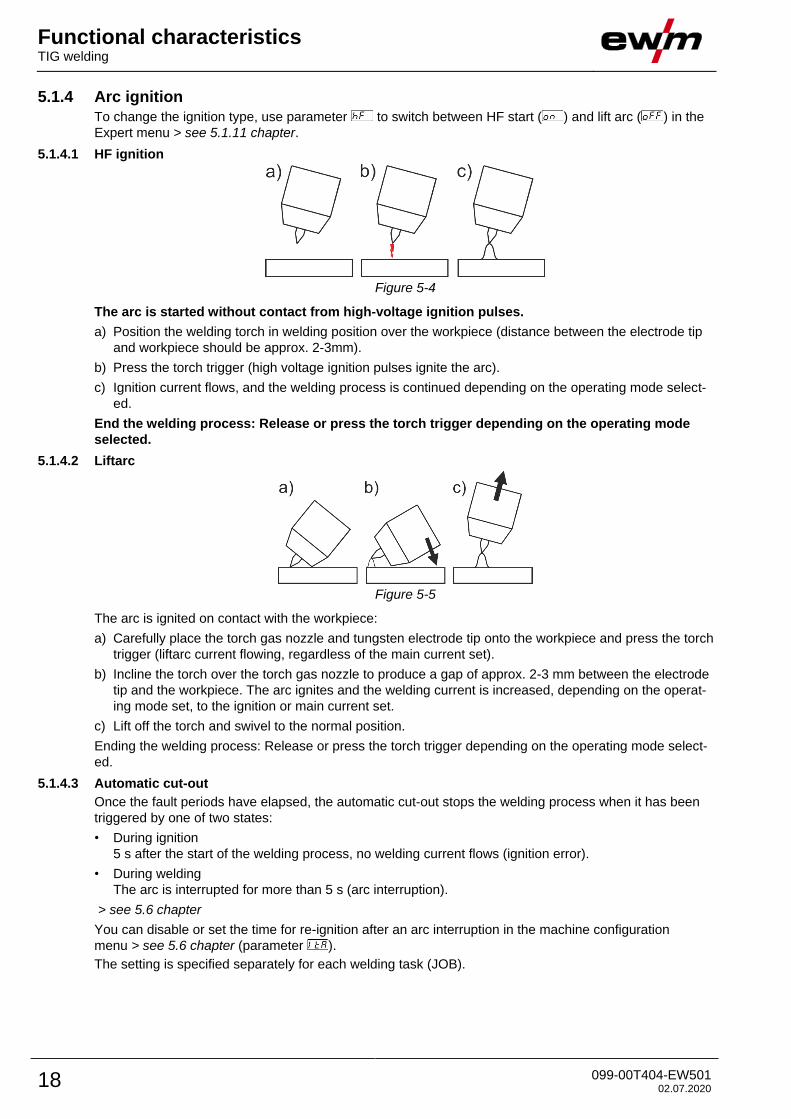
5.1.4.2 Liftarc
Figure 5-5
The arc is ignited on contact with the workpiece:
a) Carefully place the torch gas nozzle and tungsten electrode tip onto the workpiece and press the torch
trigger (liftarc current flowing, regardless of the main current set).
b) Incline the torch over the torch gas nozzle to produce a gap of approx. 2-3 mm between the electrode
tip and the workpiece. The arc ignites and the welding current is increased, depending on the operat-
ing mode set, to the ignition or main current set.
c) Lift off the torch and swivel to the normal position.
Ending the welding process: Release or press the torch trigger depending on the operating mode select-
ed.
5.1.4.3 Automatic cut-out
Once the fault periods have elapsed, the automatic cut-out stops the welding process when it has been
triggered by one of two states:
• During ignition
5 s after the start of the welding process, no welding current flows (ignition error).
• During welding
The arc is interrupted for more than 5 s (arc interruption).
> see 5.6 chapter
You can disable or set the time for re-ignition after an arc interruption in the machine configuration
menu > see 5.6 chapter (parameter ).
The setting is specified separately for each welding task (JOB).
Functional characteristics TIG welding
099-00T404-EW501 02.07.2020 19
5.1.5 Operating modes (functional sequences)
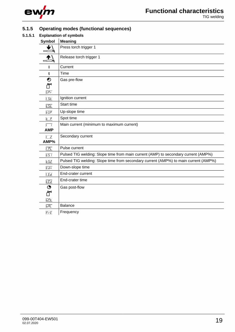
5.1.5.1 Explanation of symbols
Symbol Meaning
Press torch trigger 1
Release torch trigger 1
I Current
t Time
Gas pre-flow
Ignition current
Start time
Up-slope time
Spot time
AMP
Main current (minimum to maximum current)
AMP%
Secondary current
Pulse current
Pulsed TIG welding: Slope time from main current (AMP) to secondary current (AMP%)
Pulsed TIG welding: Slope time from secondary current (AMP%) to main current (AMP%)
Down-slope time
End-crater current
End-crater time
Gas post-flow
Balance
Frequency
Functional characteristics TIG welding
20 099-00T404-EW501 02.07.2020
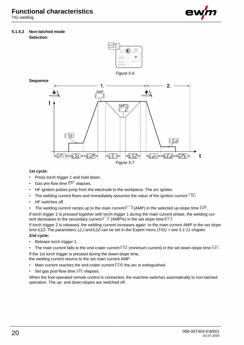
5.1.5.2 Non-latched mode
Selection
Figure 5-6
Sequence
Figure 5-7
1st cycle:
• Press torch trigger 1 and hold down.
• Gas pre-flow time elapses.
• HF ignition pulses jump from the electrode to the workpiece. The arc ignites.
• The welding current flows and immediately assumes the value of the ignition current .
• HF switches off.
• The welding current ramps up to the main current (AMP) in the selected up-slope time .
If torch trigger 2 is pressed together with torch trigger 1 during the main current phase, the welding cur-
rent decreases to the secondary current (AMP%) in the set slope time .
If torch trigger 2 is released, the welding current increases again to the main current AMP in the set slope
time . The parameters and can be set in the Expert menu (TIG) > see 5.1.11 chapter.
2nd cycle:
• Release torch trigger 1.
• The main current falls to the end-crater current (minimum current) in the set down-slope time .
If the 1st torch trigger is pressed during the down-slope time,
the welding current returns to the set main current AMP
• Main current reaches the end-crater current ; the arc is extinguished.
• Set gas post-flow time elapses.
When the foot-operated remote control is connected, the machine switches automatically to non-latched
operation. The up- and down-slopes are switched off.
Functional characteristics TIG welding
099-00T404-EW501 02.07.2020 21
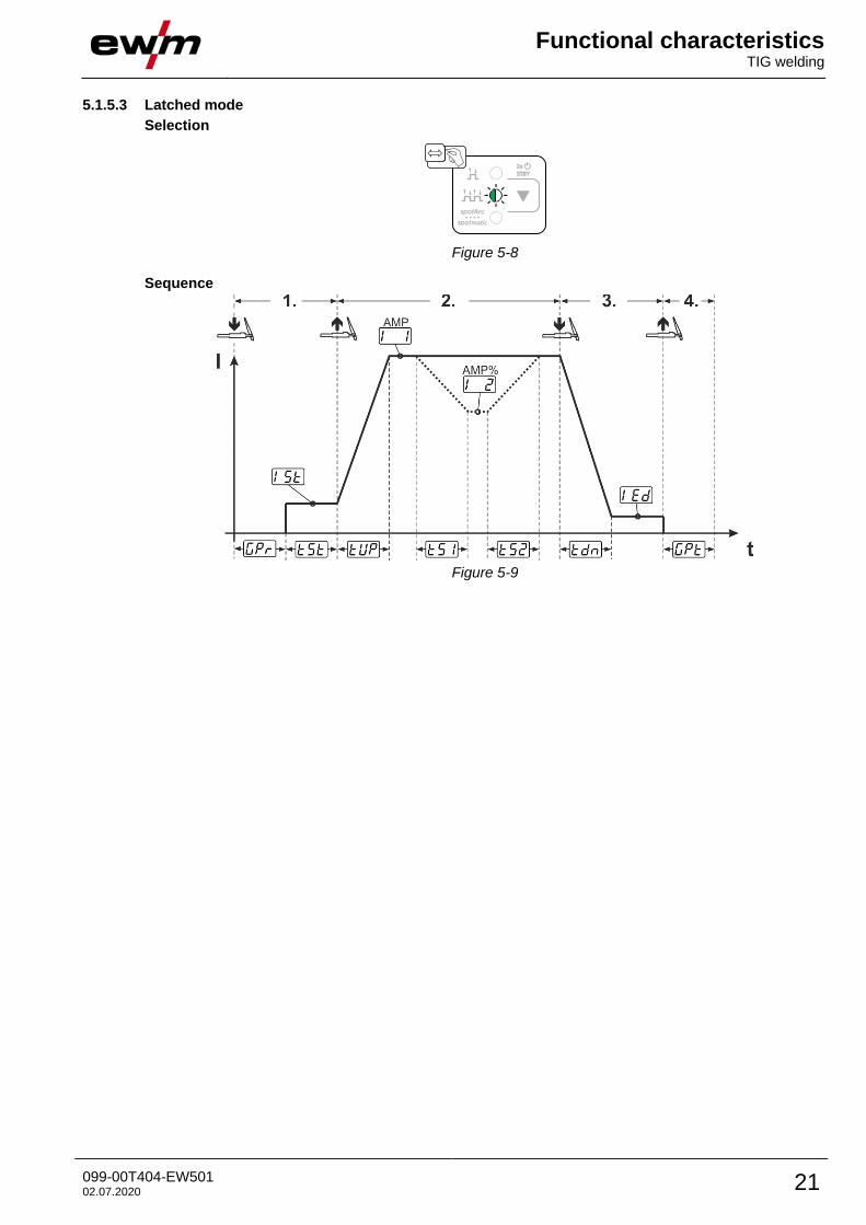
5.1.5.3 Latched mode
Selection
Figure 5-8
Sequence
Figure 5-9
Functional characteristics TIG welding
22 099-00T404-EW501 02.07.2020
1st cycle
• Press torch trigger 1 , the gas pre-flow time elapses.
• HF start pulses jump from the electrode to the workpiece. The arc ignites.
• Welding current flows and immediately assumes the set ignition current (search arc at minimum
setting). HF switches off.
• Ignition current flows at least for the start time or as long as the torch trigger is held.
2nd cycle
• Release torch trigger 1.
• The welding current ramps up to the main current (AMP) in the selected upslope time .
Switching from the main current AMP to secondary current (AMP%):
• Press torch trigger 2 or
• Tap torch trigger 1 (torch modes 1–6).
If torch trigger 2 is pressed together with torch trigger 1 during the main current phase, the welding cur-
rent decreases to the secondary current (AMP%) in the set slope time .
Once torch trigger 2 is released, the welding current increases again to the main current AMP in the set
slope time . The parameters and can be set in the Expert menu (TIG) > see 5.1.11 chapter.
3rd cycle
• Press torch trigger 1.
• The main current decreases to the end-crater current within the set down-slope time .
Once the main current phase AMP has been reached, you can shorten the welding sequence by tap-
ping torch trigger 1 (third cycle will be omitted).
4th cycle
• Release torch trigger 1; arc is extinguished.
• Set gas post-flow time runs.
When the foot-operated remote control is connected, the machine switches automatically to non-latched
operation. The up- and down-slopes are switched off.
Alternative welding start (tapping start):
For the alternative welding start, the durations of the first and second cycle are defined by the set process
times only (tapping the torch trigger in the gas pre-low phase ).
To activate this function, set a two-digit torch mode (11-1x) at the machine control. This function can also
be deactivated completely when required (welding stop by tapping remains active). To do so, the pa-
rameter must be switched to in the machine configuration menu > see 5.6 chapter.
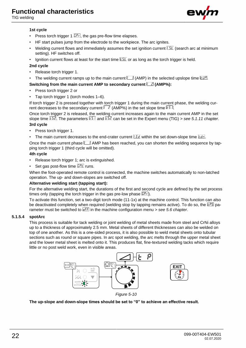
5.1.5.4 spotArc
This process is suitable for tack welding or joint welding of metal sheets made from steel and CrNi alloys
up to a thickness of approximately 2.5 mm. Metal sheets of different thicknesses can also be welded on
top of one another. As this is a one-sided process, it is also possible to weld metal sheets onto tubular
sections such as round or square pipes. In arc spot welding, the arc melts through the upper metal sheet
and the lower metal sheet is melted onto it. This produces flat, fine-textured welding tacks which require
little or no post weld work, even in visible areas.
EXIT
4s
Figure 5-10
The up-slope and down-slope times should be set to “0” to achieve an effective result.
Functional characteristics TIG welding
099-00T404-EW501 02.07.2020 23
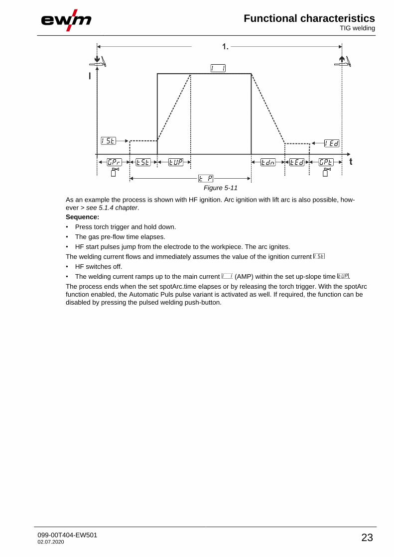
Figure 5-11
As an example the process is shown with HF ignition. Arc ignition with lift arc is also possible, how-
ever > see 5.1.4 chapter.
Sequence:
• Press torch trigger and hold down.
• The gas pre-flow time elapses.
• HF start pulses jump from the electrode to the workpiece. The arc ignites.
The welding current flows and immediately assumes the value of the ignition current
• HF switches off.
• The welding current ramps up to the main current (AMP) within the set up-slope time .
The process ends when the set spotArc.time elapses or by releasing the torch trigger. With the spotArc
function enabled, the Automatic Puls pulse variant is activated as well. If required, the function can be
disabled by pressing the pulsed welding push-button.
Functional characteristics TIG welding
24 099-00T404-EW501 02.07.2020
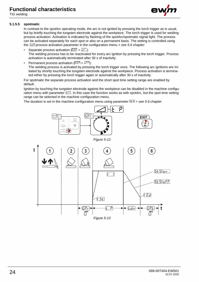
5.1.5.5 spotmatic
In contrast to the spotArc operating mode, the arc is not ignited by pressing the torch trigger as is usual,
but by briefly touching the tungsten electrode against the workpiece. The torch trigger is used for welding
process activation. Activation is indicated by flashing of the spotArc/spotmatic signal light. The process
can be activated separately for each spot or also on a permanent basis. The setting is controlled using
the process activation parameter in the configuration menu > see 5.6 chapter:
• Separate process activation ( > ):
The welding process has to be reactivated for every arc ignition by pressing the torch trigger. Process
activation is automatically terminated after 30 s of inactivity.
• Permanent process activation ( > ):
The welding process is activated by pressing the torch trigger once. The following arc ignitions are ini-
tiated by shortly touching the tungsten electrode against the workpiece. Process activation is termina-
ted either by pressing the torch trigger again or automatically after 30 s of inactivity.
For spotmatic the separate process activation and the short spot time setting range are enabled by
default.
Ignition by touching the tungsten electrode against the workpiece can be disabled in the machine configu-
ration menu with parameter . In this case the function works as with spotArc, but the spot time setting
range can be selected in the machine configuration menu.
The duration is set in the machine configuration menu using parameter > see 5.6 chapter
EXIT
4s
Figure 5-12
Figure 5-13
Functional characteristics TIG welding
099-00T404-EW501 02.07.2020 25
As an example the process is shown with HF ignition. Arc ignition with lift arc is also possible, how-
ever > see 5.1.4 chapter.
Selecting the process activation type for the welding process > see 5.6 chapter.
Up-slope and down-slope times possible for long spot time setting range (0.01–20.0 s) only.
Press and release torch trigger (tap) to activate the welding process.
Touch the torch gas nozzle and tungsten electrode tip carefully against the workpiece.
Incline the welding torch over the torch gas nozzle until there is a gap of approx. 2–3 mm between the
electrode tip and the workpiece. Shielding gas flows during the set gas pre-flow time . The arc igni-
tes and the previously set ignition current flows.
The main current phase ends when the set spot time elapses.
For long-time spot welding only (parameter = ):
The welding current decreases to the end-crater current within the set down-slope time .
The gas post-flow time elapses and the welding process ends.
Press and release the torch trigger (tap) to reactivate the welding process (only for separate
process activation). Touching the welding torch with the tungsten electrode tip against the
workpiece again will initiate the next welding processes.
5.1.5.6 Non-latched operation, version C
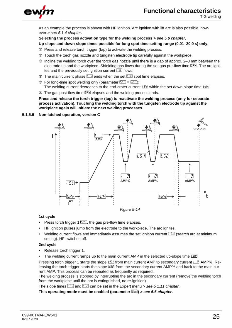
Figure 5-14
1st cycle
• Press torch trigger 1 , the gas pre-flow time elapses.
• HF ignition pulses jump from the electrode to the workpiece. The arc ignites.
• Welding current flows and immediately assumes the set ignition current (search arc at minimum
setting). HF switches off.
2nd cycle
• Release torch trigger 1.
• The welding current ramps up to the main current AMP in the selected up-slope time .
Pressing torch trigger 1 starts the slope from main current AMP to secondary current AMP%. Re-
leasing the torch trigger starts the slope from the secondary current AMP% and back to the main cur-
rent AMP. This process can be repeated as frequently as required.
The welding process is stopped by interrupting the arc in the secondary current (remove the welding torch
from the workpiece until the arc is extinguished, no re-ignition).
The slope times and can be set in the Expert menu > see 5.1.11 chapter.
This operating mode must be enabled (parameter ) > see 5.6 chapter.
Functional characteristics TIG welding
26 099-00T404-EW501 02.07.2020
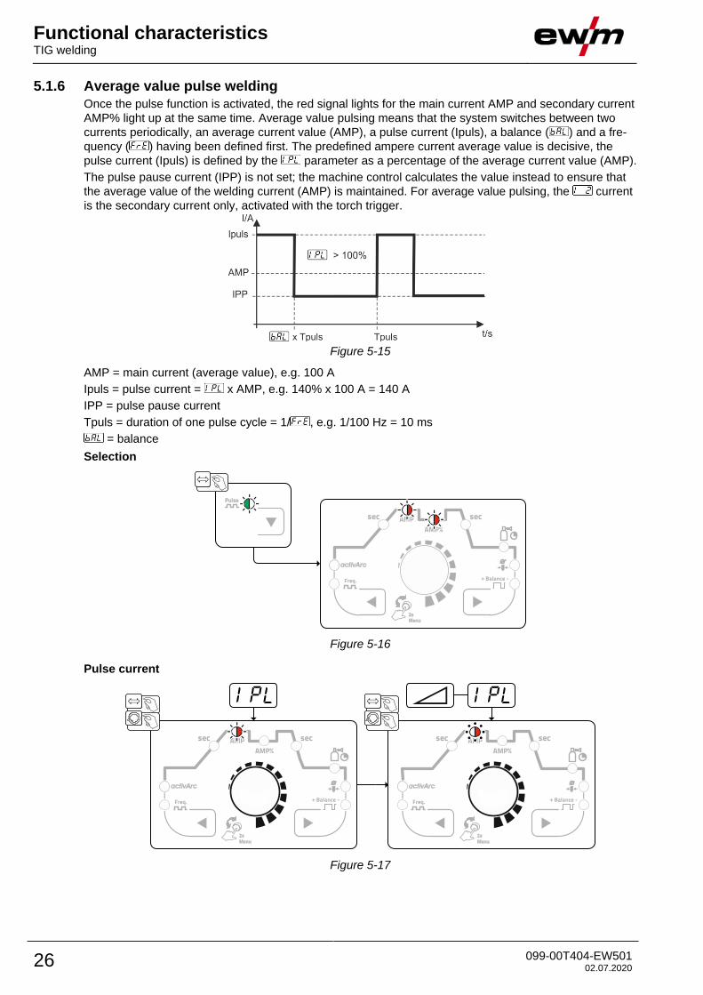
5.1.6 Average value pulse welding
Once the pulse function is activated, the red signal lights for the main current AMP and secondary current
AMP% light up at the same time. Average value pulsing means that the system switches between two
currents periodically, an average current value (AMP), a pulse current (Ipuls), a balance ( ) and a fre-
quency ( ) having been defined first. The predefined ampere current average value is decisive, the
pulse current (Ipuls) is defined by the parameter as a percentage of the average current value (AMP).
The pulse pause current (IPP) is not set; the machine control calculates the value instead to ensure that
the average value of the welding current (AMP) is maintained. For average value pulsing, the current
is the secondary current only, activated with the torch trigger.
Figure 5-15
AMP = main current (average value), e.g. 100 A
Ipuls = pulse current = x AMP, e.g. 140% x 100 A = 140 A
IPP = pulse pause current
Tpuls = duration of one pulse cycle = 1/ , e.g. 1/100 Hz = 10 ms
= balance
Selection
Figure 5-16
Pulse current
Figure 5-17
Functional characteristics TIG welding
099-00T404-EW501 02.07.2020 27
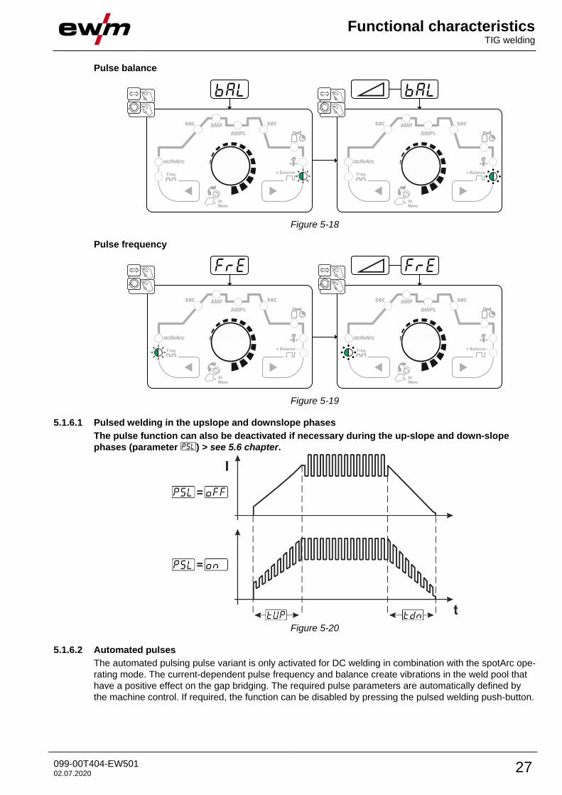
Pulse balance
Figure 5-18
Pulse frequency
Figure 5-19
5.1.6.1 Pulsed welding in the upslope and downslope phases
The pulse function can also be deactivated if necessary during the up-slope and down-slope
phases (parameter ) > see 5.6 chapter.
Figure 5-20
5.1.6.2 Automated pulses
The automated pulsing pulse variant is only activated for DC welding in combination with the spotArc ope-
rating mode. The current-dependent pulse frequency and balance create vibrations in the weld pool that
have a positive effect on the gap bridging. The required pulse parameters are automatically defined by
the machine control. If required, the function can be disabled by pressing the pulsed welding push-button.
Functional characteristics TIG welding
28 099-00T404-EW501 02.07.2020
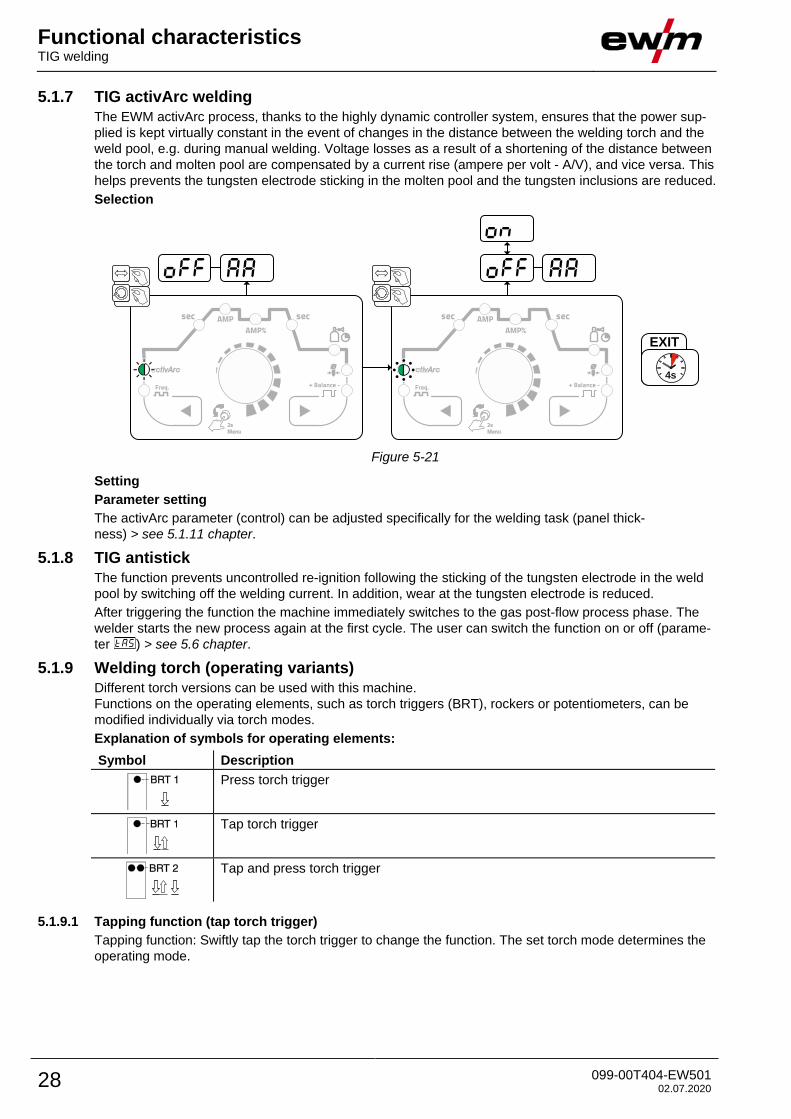
5.1.7 TIG activArc welding
The EWM activArc process, thanks to the highly dynamic controller system, ensures that the power sup-
plied is kept virtually constant in the event of changes in the distance between the welding torch and the
weld pool, e.g. during manual welding. Voltage losses as a result of a shortening of the distance between
the torch and molten pool are compensated by a current rise (ampere per volt - A/V), and vice versa. This
helps prevents the tungsten electrode sticking in the molten pool and the tungsten inclusions are reduced.
Selection
EXIT
4s
Figure 5-21
Setting
Parameter setting
The activArc parameter (control) can be adjusted specifically for the welding task (panel thick-
ness) > see 5.1.11 chapter.
5.1.8 TIG antistick
The function prevents uncontrolled re-ignition following the sticking of the tungsten electrode in the weld
pool by switching off the welding current. In addition, wear at the tungsten electrode is reduced.
After triggering the function the machine immediately switches to the gas post-flow process phase. The
welder starts the new process again at the first cycle. The user can switch the function on or off (parame-
ter ) > see 5.6 chapter.
5.1.9 Welding torch (operating variants)
Different torch versions can be used with this machine.
Functions on the operating elements, such as torch triggers (BRT), rockers or potentiometers, can be
modified individually via torch modes.
Explanation of symbols for operating elements:
Symbol Description
Press torch trigger
Tap torch trigger
Tap and press torch trigger
5.1.9.1 Tapping function (tap torch trigger)
Tapping function: Swiftly tap the torch trigger to change the function. The set torch mode determines the
operating mode.
Functional characteristics TIG welding
099-00T404-EW501 02.07.2020 29
5.1.9.2 Torch mode setting
Modes 1 to 6 and 11 to 16 are available to the user. Modes 11 to 16 feature the same functionality as 1 to
6, but without the tapping function > see 5.1.9.1 chapter for the secondary current.
The functionality of the individual modes can be found in the corresponding torch type tables.
The torch modes are set using the torch configuration parameters " " in the machine configuration
menu > torch mode " " > see 5.6 chapter.
Only the modes listed are suitable for the corresponding torch types.
5.1.9.3 Up/down speed
Functionality
Press and hold the up push-button:
Increase current up to the maximum value (main current) set in the power source.
Press and hold the down push-button:
Decrease current to the minimum value.
Use the machine configuration menu > see 5.6 chapter to set the up/down speed parameter which
determines the speed with which a current change becomes effective.
5.1.9.4 Current jump
By tapping the corresponding torch trigger the welding current can be determined in an adjustable jump
range. Each tap will cause the welding current to jump up or down by the defined value.
The “current jump” parameter is set in the machine configuration menu > see 5.6 chapter.
Functional characteristics TIG welding
30 099-00T404-EW501 02.07.2020
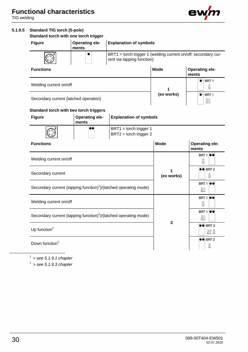
5.1.9.5 Standard TIG torch (5-pole)
Standard torch with one torch trigger
Figure Operating ele-
ments
Explanation of symbols
BRT1 = torch trigger 1 (welding current on/off; secondary cur-
rent via tapping function)
Functions Mode Operating ele-
ments
Welding current on/off 1
(ex works)
Secondary current (latched operation)
Standard torch with two torch triggers
Figure Operating ele-
ments
Explanation of symbols
BRT1 = torch trigger 1
BRT2 = torch trigger 2
Functions Mode Operating ele-
ments
Welding current on/off
1
(ex works)
Secondary current
Secondary current (tapping function)1)/(latched operating mode)
Welding current on/off
3
Secondary current (tapping function)1)/(latched operating mode)
Up function2
Down function2
1 > see 5.1.9.1 chapter
2 > see 5.1.9.3 chapter
Functional characteristics TIG welding
099-00T404-EW501 02.07.2020 31
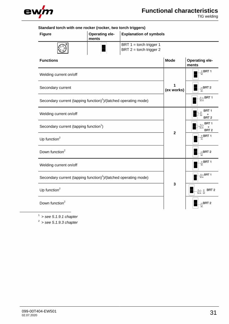
Standard torch with one rocker (rocker, two torch triggers)
Figure Operating ele-
ments
Explanation of symbols
BRT 1 = torch trigger 1
BRT 2 = torch trigger 2
Functions Mode Operating ele-
ments
Welding current on/off
1
(ex works)
Secondary current
Secondary current (tapping function)1)/(latched operating mode)
Welding current on/off
2
Secondary current (tapping function1)
Up function2
Down function2
Welding current on/off
3
Secondary current (tapping function)1)/(latched operating mode)
Up function2
Down function2
1 > see 5.1.9.1 chapter
2 > see 5.1.9.3 chapter
Functional characteristics TIG welding
32 099-00T404-EW501 02.07.2020
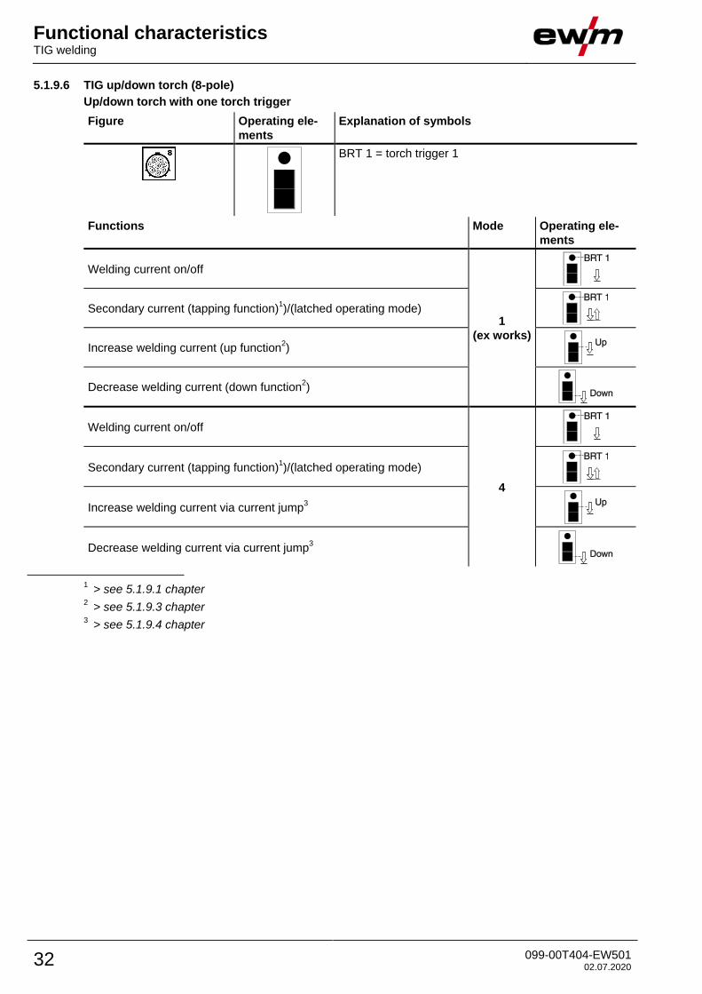
5.1.9.6 TIG up/down torch (8-pole)
Up/down torch with one torch trigger
Figure Operating ele-
ments
Explanation of symbols
BRT 1 = torch trigger 1
Functions Mode Operating ele-
ments
Welding current on/off
1
(ex works)
Secondary current (tapping function)1)/(latched operating mode)
Increase welding current (up function2)
Decrease welding current (down function2)
Welding current on/off
4
Secondary current (tapping function)1)/(latched operating mode)
Increase welding current via current jump3
Decrease welding current via current jump3
1 > see 5.1.9.1 chapter
2 > see 5.1.9.3 chapter
3 > see 5.1.9.4 chapter
Functional characteristics TIG welding
099-00T404-EW501 02.07.2020 33
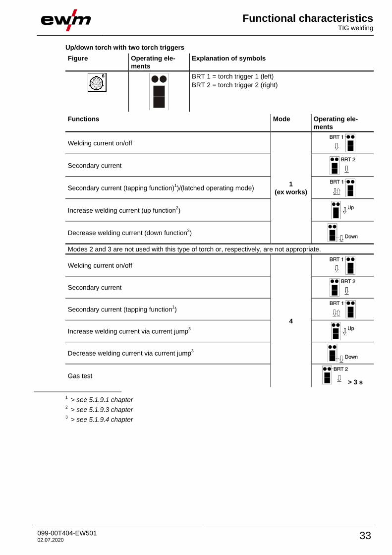
Up/down torch with two torch triggers
Figure Operating ele-
ments
Explanation of symbols
BRT 1 = torch trigger 1 (left)
BRT 2 = torch trigger 2 (right)
Functions Mode Operating ele-
ments
Welding current on/off
1
(ex works)
Secondary current
Secondary current (tapping function)1)/(latched operating mode)
Increase welding current (up function2)
Decrease welding current (down function2)
Modes 2 and 3 are not used with this type of torch or, respectively, are not appropriate.
Welding current on/off
4
Secondary current
Secondary current (tapping function1)
Increase welding current via current jump3
Decrease welding current via current jump3
Gas test > 3 s
1 > see 5.1.9.1 chapter
2 > see 5.1.9.3 chapter
3 > see 5.1.9.4 chapter
Functional characteristics TIG welding
34 099-00T404-EW501 02.07.2020
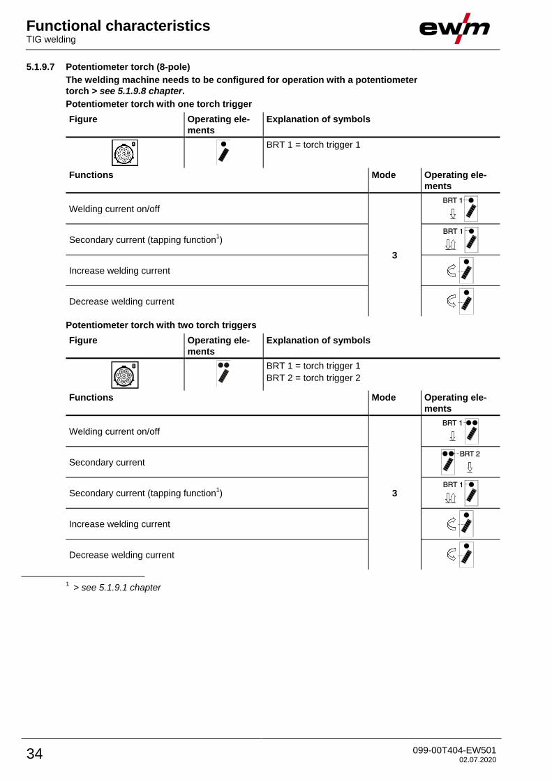
5.1.9.7 Potentiometer torch (8-pole)
The welding machine needs to be configured for operation with a potentiometer
torch > see 5.1.9.8 chapter.
Potentiometer torch with one torch trigger
Figure Operating ele-
ments
Explanation of symbols
BRT 1 = torch trigger 1
Functions Mode Operating ele-
ments
Welding current on/off
3
Secondary current (tapping function1)
Increase welding current
Decrease welding current
Potentiometer torch with two torch triggers
Figure Operating ele-
ments
Explanation of symbols
BRT 1 = torch trigger 1
BRT 2 = torch trigger 2
Functions Mode Operating ele-
ments
Welding current on/off
3
Secondary current
Secondary current (tapping function1)
Increase welding current
Decrease welding current
1 > see 5.1.9.1 chapter
Functional characteristics TIG welding
099-00T404-EW501 02.07.2020 35
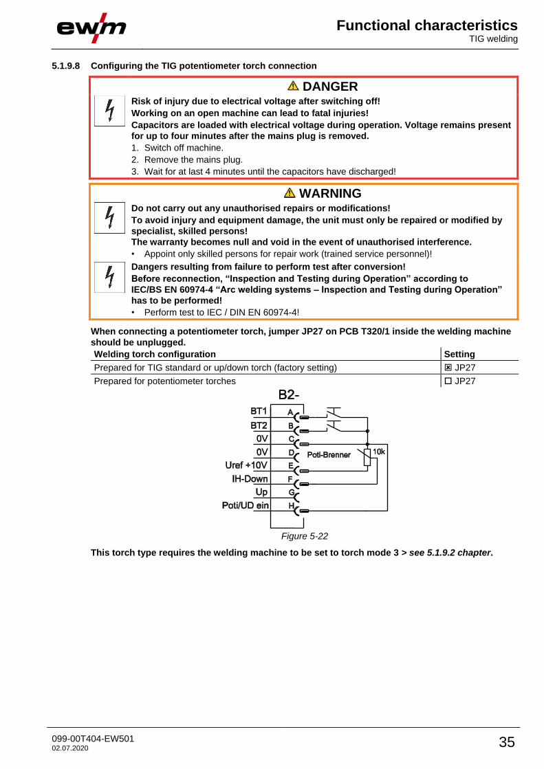
5.1.9.8 Configuring the TIG potentiometer torch connection
DANGER
Risk of injury due to electrical voltage after switching off!
Working on an open machine can lead to fatal injuries!
Capacitors are loaded with electrical voltage during operation. Voltage remains present
for up to four minutes after the mains plug is removed.
1. Switch off machine.
2. Remove the mains plug.
3. Wait for at last 4 minutes until the capacitors have discharged!
WARNING
Do not carry out any unauthorised repairs or modifications!
To avoid injury and equipment damage, the unit must only be repaired or modified by
specialist, skilled persons!
The warranty becomes null and void in the event of unauthorised interference.
• Appoint only skilled persons for repair work (trained service personnel)!
Dangers resulting from failure to perform test after conversion!
Before reconnection, “Inspection and Testing during Operation” according to
IEC/BS EN 60974-4 “Arc welding systems – Inspection and Testing during Operation”
has to be performed!
• Perform test to IEC / DIN EN 60974-4!
When connecting a potentiometer torch, jumper JP27 on PCB T320/1 inside the welding machine
should be unplugged.
Welding torch configuration Setting
Prepared for TIG standard or up/down torch (factory setting) JP27
Prepared for potentiometer torches JP27
Figure 5-22
This torch type requires the welding machine to be set to torch mode 3 > see 5.1.9.2 chapter.
Functional characteristics TIG welding
36 099-00T404-EW501 02.07.2020
5.1.10 RTF 1 foot-operated remote control
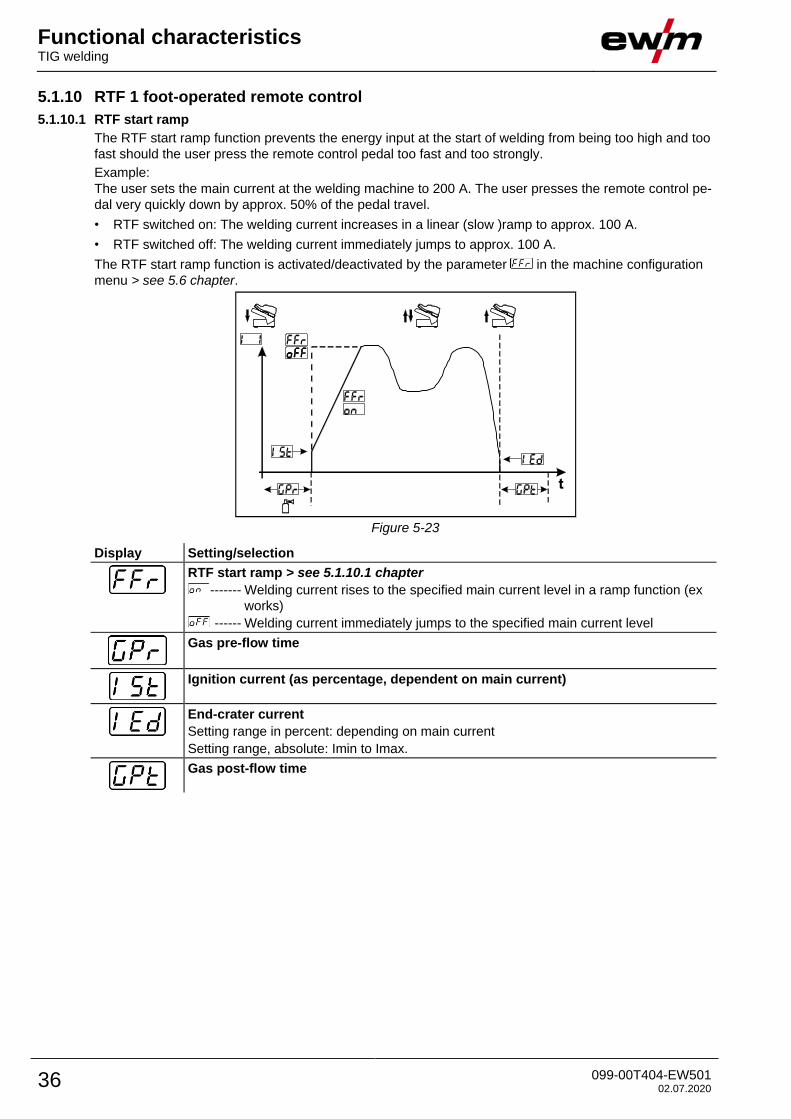
5.1.10.1 RTF start ramp
The RTF start ramp function prevents the energy input at the start of welding from being too high and too
fast should the user press the remote control pedal too fast and too strongly.
Example:
The user sets the main current at the welding machine to 200 A. The user presses the remote control pe-
dal very quickly down by approx. 50% of the pedal travel.
• RTF switched on: The welding current increases in a linear (slow )ramp to approx. 100 A.
• RTF switched off: The welding current immediately jumps to approx. 100 A.
The RTF start ramp function is activated/deactivated by the parameter in the machine configuration
menu > see 5.6 chapter.
Figure 5-23
Display Setting/selection
RTF start ramp > see 5.1.10.1 chapter
------- Welding current rises to the specified main current level in a ramp function (ex
works)
------ Welding current immediately jumps to the specified main current level
Gas pre-flow time
Ignition current (as percentage, dependent on main current)
End-crater current
Setting range in percent: depending on main current
Setting range, absolute: Imin to Imax.
Gas post-flow time
Functional characteristics TIG welding
099-00T404-EW501 02.07.2020 37
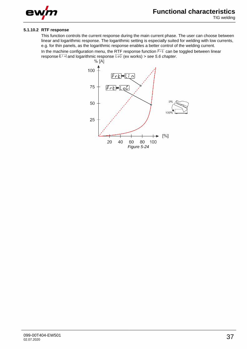
5.1.10.2 RTF response
This function controls the current response during the main current phase. The user can choose between
linear and logarithmic response. The logarithmic setting is especially suited for welding with low currents,
e.g. for thin panels, as the logarithmic response enables a better control of the welding current.
In the machine configuration menu, the RTF response function can be toggled between linear
response and logarithmic response (ex works) > see 5.6 chapter.
Figure 5-24
Functional characteristics TIG welding
38 099-00T404-EW501 02.07.2020
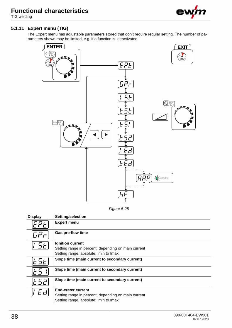
5.1.11 Expert menu (TIG)
The Expert menu has adjustable parameters stored that don’t require regular setting. The number of pa-
rameters shown may be limited, e.g. if a function is deactivated.
ENTER EXIT
Figure 5-25
Display Setting/selection
Expert menu
Gas pre-flow time
Ignition current
Setting range in percent: depending on main current
Setting range, absolute: Imin to Imax.
Slope time (main current to secondary current)
Slope time (main current to secondary current)
Slope time (main current to secondary current)
End-crater current
Setting range in percent: depending on main current
Setting range, absolute: Imin to Imax.
Functional characteristics TIG welding
099-00T404-EW501 02.07.2020 39
Display Setting/selection
Slope time (main current to secondary current)
activArc parameter
Parameter also adjustable after TIG activArc welding is activated.
Ignition type (TIG)
------- HF start active (ex works)
------- Lift arc ignition active
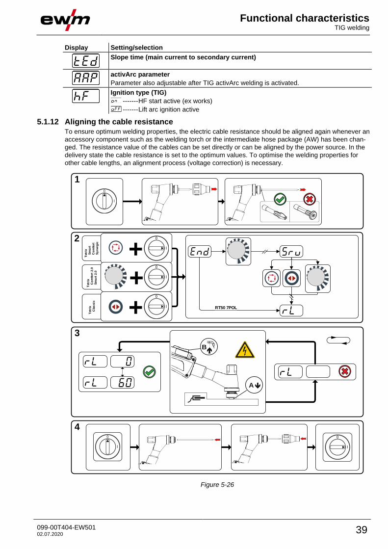
5.1.12 Aligning the cable resistance
To ensure optimum welding properties, the electric cable resistance should be aligned again whenever an
accessory component such as the welding torch or the intermediate hose package (AW) has been chan-
ged. The resistance value of the cables can be set directly or can be aligned by the power source. In the
delivery state the cable resistance is set to the optimum values. To optimise the welding properties for
other cable lengths, an alignment process (voltage correction) is necessary.
1
2
3
4
l
0
l
0
+
+Tetr
ix
C
las
sic
Tetr
ix
S
ma
rt
C
om
fort
S
yn
erg
ic
B
A
+Tetr
ix
C
om
fort
2.0
S
ma
rt 2
.0
RT50 7POL
Figure 5-26
Functional characteristics MMA welding
40 099-00T404-EW501 02.07.2020
1 Preparation
• Switch off the welding machine.
• Unscrew the gas nozzle from the welding torch.
• Unfasten the tungsten electrode and extract.
2 Configuration
• Activate the rotary knob while switching on the welding machine at the same time.
• Release rotary knob.
• You can now use the rotary knob (rotate and press) to select the parameter > see 5.6 chapter.
3 Alignment/measurement
• Applying slight pressure, press the welding torch with the collet against a clean, purged location on the
workpiece and then press the torch trigger for approx. 2 seconds. A short-circuit current will flow brief-
ly, which is used to determine and display the cable resistance. The value can be between 0 mΩ and
60 mΩ. The new value is immediately saved without requiring further confirmation. If no value is
shown on the right-hand display, then measurement failed. The measurement must be repeated.
4 Restoring welding standby mode
• Switch off the welding machine.
• Lock the tungsten electrode in the collet again.
• Screw the gas nozzle onto the welding torch.
• Switch on the welding machine.
5.2 MMA welding
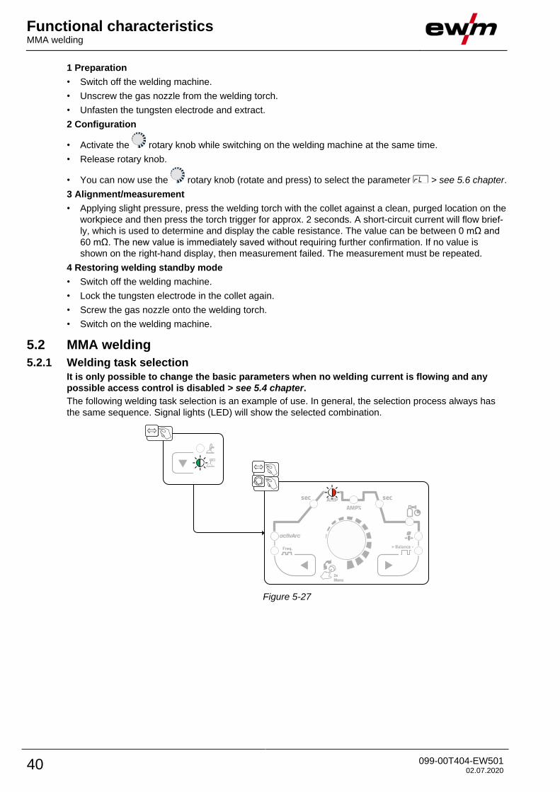
5.2.1 Welding task selection
It is only possible to change the basic parameters when no welding current is flowing and any
possible access control is disabled > see 5.4 chapter.
The following welding task selection is an example of use. In general, the selection process always has
the same sequence. Signal lights (LED) will show the selected combination.
Figure 5-27
Functional characteristics MMA welding
099-00T404-EW501 02.07.2020 41
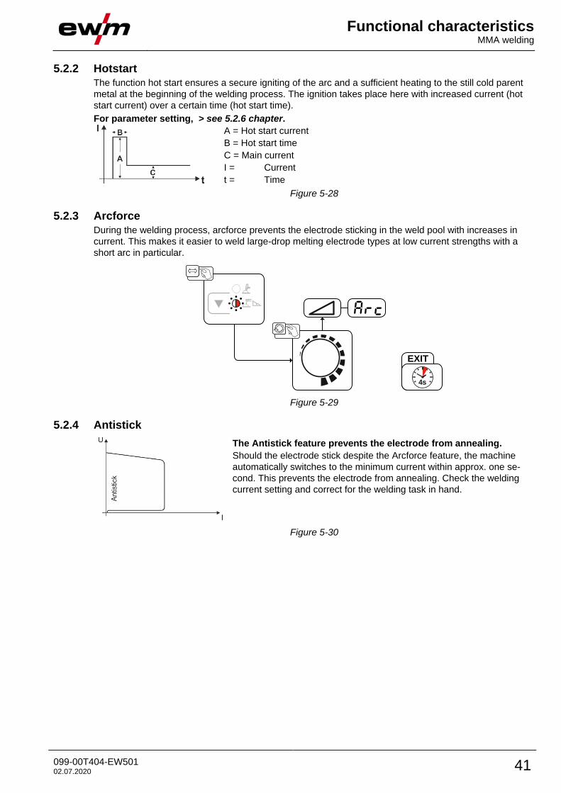
5.2.2 Hotstart
The function hot start ensures a secure igniting of the arc and a sufficient heating to the still cold parent
metal at the beginning of the welding process. The ignition takes place here with increased current (hot
start current) over a certain time (hot start time).
For parameter setting, > see 5.2.6 chapter.
A = Hot start current
B = Hot start time
C = Main current
I = Current
t = Time
Figure 5-28
5.2.3 Arcforce
During the welding process, arcforce prevents the electrode sticking in the weld pool with increases in
current. This makes it easier to weld large-drop melting electrode types at low current strengths with a
short arc in particular.
EXIT
4s
Figure 5-29
5.2.4 Antistick
The Antistick feature prevents the electrode from annealing.
Should the electrode stick despite the Arcforce feature, the machine
automatically switches to the minimum current within approx. one se-
cond. This prevents the electrode from annealing. Check the welding
current setting and correct for the welding task in hand.
Figure 5-30
Functional characteristics MMA welding
42 099-00T404-EW501 02.07.2020
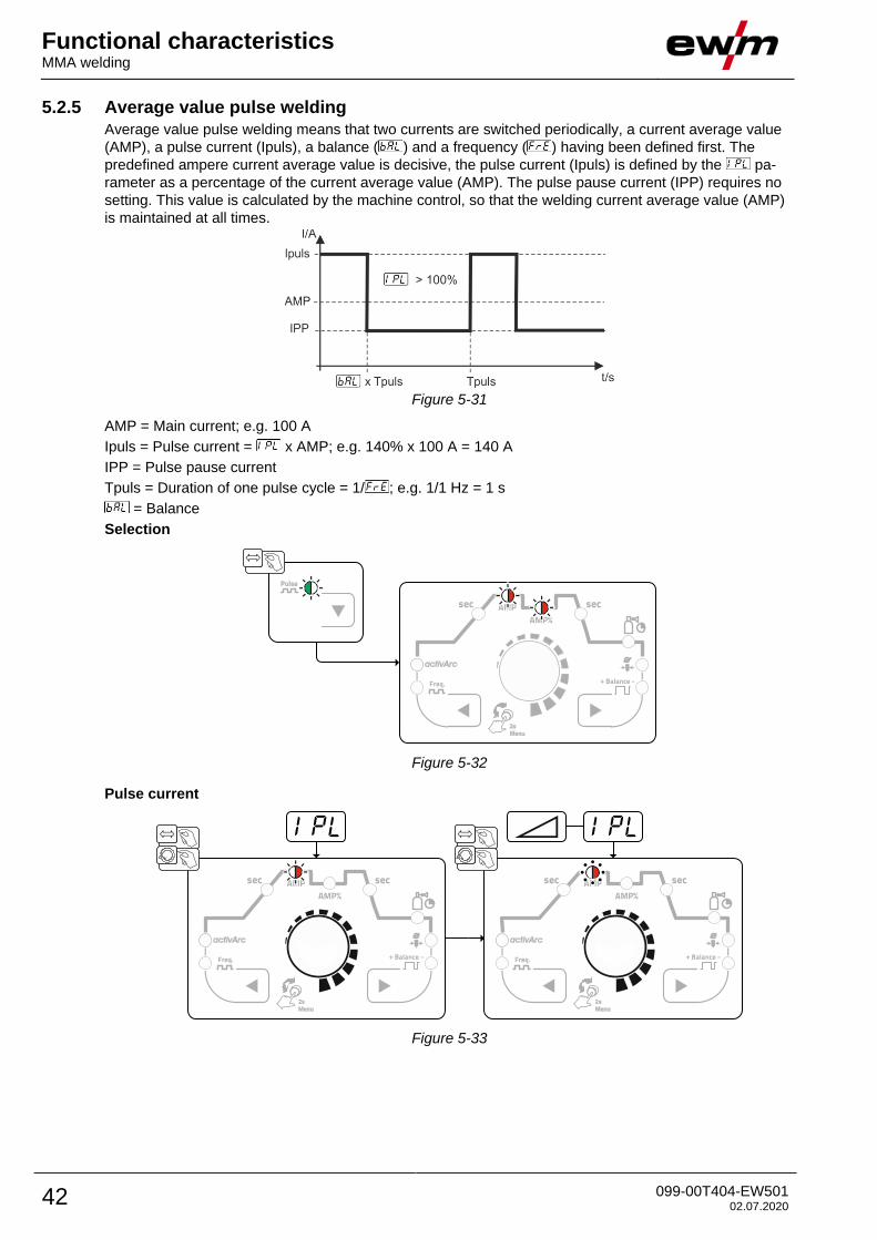
5.2.5 Average value pulse welding
Average value pulse welding means that two currents are switched periodically, a current average value
(AMP), a pulse current (Ipuls), a balance ( ) and a frequency ( ) having been defined first. The
predefined ampere current average value is decisive, the pulse current (Ipuls) is defined by the pa-
rameter as a percentage of the current average value (AMP). The pulse pause current (IPP) requires no
setting. This value is calculated by the machine control, so that the welding current average value (AMP)
is maintained at all times.
Figure 5-31
AMP = Main current; e.g. 100 A
Ipuls = Pulse current = x AMP; e.g. 140% x 100 A = 140 A
IPP = Pulse pause current
Tpuls = Duration of one pulse cycle = 1/ ; e.g. 1/1 Hz = 1 s
= Balance
Selection
Figure 5-32
Pulse current
Figure 5-33
Functional characteristics MMA welding
099-00T404-EW501 02.07.2020 43
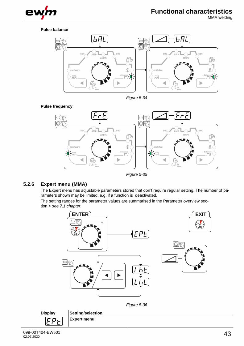
Pulse balance
Figure 5-34
Pulse frequency
Figure 5-35
5.2.6 Expert menu (MMA)
The Expert menu has adjustable parameters stored that don’t require regular setting. The number of pa-
rameters shown may be limited, e.g. if a function is deactivated.
The setting ranges for the parameter values are summarised in the Parameter overview sec-
tion > see 7.1 chapter.
ENTER EXIT
Figure 5-36
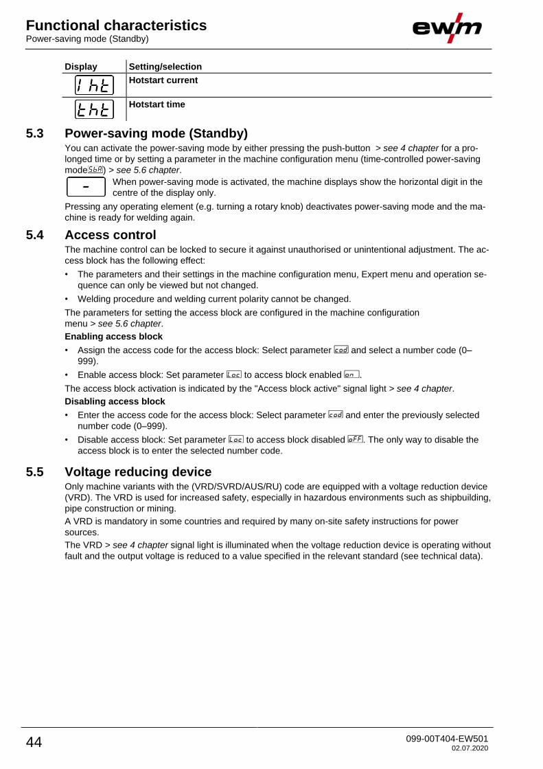
Display Setting/selection
Expert menu
Functional characteristics Power-saving mode (Standby)
44 099-00T404-EW501 02.07.2020
Display Setting/selection
Hotstart current
Hotstart time
5.3 Power-saving mode (Standby) You can activate the power-saving mode by either pressing the push-button > see 4 chapter for a pro-
longed time or by setting a parameter in the machine configuration menu (time-controlled power-saving
mode ) > see 5.6 chapter.
When power-saving mode is activated, the machine displays show the horizontal digit in the
centre of the display only.
Pressing any operating element (e.g. turning a rotary knob) deactivates power-saving mode and the ma-
chine is ready for welding again.
5.4 Access control The machine control can be locked to secure it against unauthorised or unintentional adjustment. The ac-
cess block has the following effect:
• The parameters and their settings in the machine configuration menu, Expert menu and operation se-
quence can only be viewed but not changed.
• Welding procedure and welding current polarity cannot be changed.
The parameters for setting the access block are configured in the machine configuration
menu > see 5.6 chapter.
Enabling access block
• Assign the access code for the access block: Select parameter and select a number code (0–
999).
• Enable access block: Set parameter to access block enabled .
The access block activation is indicated by the "Access block active" signal light > see 4 chapter.
Disabling access block
• Enter the access code for the access block: Select parameter and enter the previously selected
number code (0–999).
• Disable access block: Set parameter to access block disabled . The only way to disable the
access block is to enter the selected number code.
5.5 Voltage reducing device Only machine variants with the (VRD/SVRD/AUS/RU) code are equipped with a voltage reduction device
(VRD). The VRD is used for increased safety, especially in hazardous environments such as shipbuilding,
pipe construction or mining.
A VRD is mandatory in some countries and required by many on-site safety instructions for power
sources.
The VRD > see 4 chapter signal light is illuminated when the voltage reduction device is operating without
fault and the output voltage is reduced to a value specified in the relevant standard (see technical data).
Functional characteristics Machine configuration menu
099-00T404-EW501 02.07.2020 45
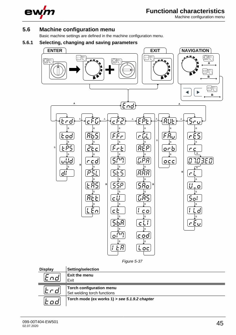
5.6 Machine configuration menu Basic machine settings are defined in the machine configuration menu.
5.6.1 Selecting, changing and saving parameters
ENTER
+l
0
A
A
B
A A A
A
EXIT NAVIGATION
A
B
B
B
B
B
B
B
B
BB
B
B
B
B
A
B B B
B B
B
B
B
B
B
B
B
B
B
B
B
B
B
B
B
B
B
B
B
B
B
B
B
B
BB
B
BB
B
Figure 5-37
Display Setting/selection
Exit the menu
Exit
Torch configuration menu
Set welding torch functions
Torch mode (ex works 1) > see 5.1.9.2 chapter
Functional characteristics Machine configuration menu
46 099-00T404-EW501 02.07.2020
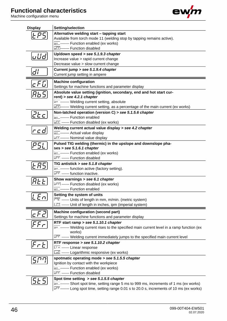
Display Setting/selection
Alternative welding start – tapping start
Available from torch mode 11 (welding stop by tapping remains active).
------- Function enabled (ex works)
------- Function disabled
Up/down speed > see 5.1.9.3 chapter
Increase value > rapid current change
Decrease value > slow current change
Current jump > see 5.1.9.4 chapter
Current jump setting in ampere
Machine configuration
Settings for machine functions and parameter display
Absolute value setting (ignition, secondary, end and hot start cur-
rent) > see 4.2.1 chapter
------- Welding current setting, absolute
------- Welding current setting, as a percentage of the main current (ex works)
Non-latched operation (version C) > see 5.1.5.6 chapter
------- Function enabled
------ Function disabled (ex works)
Welding current actual value display > see 4.2 chapter
------- Actual value display
------- Nominal value display
Pulsed TIG welding (thermic) in the upslope and downslope pha-
ses > see 5.1.6.1 chapter
------- Function enabled (ex works)
------ Function disabled
TIG antistick > see 5.1.8 chapter
------- function active (factory setting).
------ function inactive.
Show warnings > see 6.1 chapter
------ Function disabled (ex works)
------- Function enabled
Setting the system of units
------ Units of length in mm, m/min. (metric system)
------ Unit of length in inches, ipm (imperial system)
Machine configuration (second part)
Settings for machine functions and parameter display
RTF start ramp > see 5.1.10.1 chapter
------- Welding current rises to the specified main current level in a ramp function (ex
works)
------ Welding current immediately jumps to the specified main current level
RTF response > see 5.1.10.2 chapter
------ Linear response
------ Logarithmic responsive (ex works)
spotmatic operating mode > see 5.1.5.5 chapter
Ignition by contact with the workpiece
------- Function enabled (ex works)
------ Function disabled
Spot time setting > see 5.1.5.5 chapter
------- Short spot time, setting range 5 ms to 999 ms, increments of 1 ms (ex works)
------- Long spot time, setting range 0.01 s to 20.0 s, increments of 10 ms (ex works)
Functional characteristics Machine configuration menu
099-00T404-EW501 02.07.2020 47
Display Setting/selection
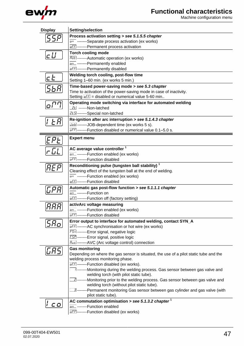
Process activation setting > see 5.1.5.5 chapter
------- Separate process activation (ex works)
------- Permanent process activation
Torch cooling mode
------- Automatic operation (ex works)
------- Permanently enabled
------- Permanently disabled
Welding torch cooling, post-flow time
Setting 1–60 min. (ex works 5 min.)
Time-based power-saving mode > see 5.3 chapter
Time to activation of the power-saving mode in case of inactivity.
Setting = disabled or numerical value 5-60 min..
Operating mode switching via interface for automated welding
------ Non-latched
------- Special non-latched
Re-ignition after arc interruption > see 5.1.4.3 chapter
------- JOB-dependent time (ex works 5 s).
------- Function disabled or numerical value 0.1–5.0 s.
Expert menu
AC average value controller 1
------- Function enabled (ex works)
------- Function disabled
Reconditioning pulse (tungsten ball stability) 1
Cleaning effect of the tungsten ball at the end of welding.
------- Function enabled (ex works)
------- Function disabled
Automatic gas post-flow function > see 5.1.1.1 chapter
------- Function on
------- Function off (factory setting)
activArc voltage measuring
------- Function enabled (ex works)
------- Function disabled
Error output to interface for automated welding, contact SYN_A
------- AC synchronisation or hot wire (ex works)
------- Error signal, negative logic
------- Error signal, positive logic
------- AVC (Arc voltage control) connection
Gas monitoring
Depending on where the gas sensor is situated, the use of a pilot static tube and the
welding process monitoring phase.
------- Function disabled (ex works).
------- Monitoring during the welding process. Gas sensor between gas valve and
welding torch (with pilot static tube).
------- Monitoring prior to the welding process. Gas sensor between gas valve and
welding torch (without pilot static tube).
------- Permanent monitoring Gas sensor between gas cylinder and gas valve (with
pilot static tube).
AC commutation optimisation > see 5.1.3.2 chapter 1
------- Function enabled
------- Function disabled (ex works)
Functional characteristics Machine configuration menu
48 099-00T404-EW501 02.07.2020
Display Setting/selection
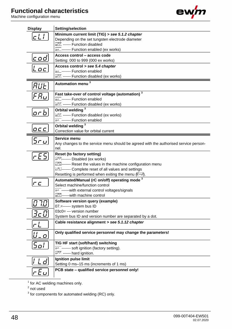
Minimum current limit (TIG) > see 5.1.2 chapter
Depending on the set tungsten electrode diameter
------ Function disabled
------- Function enabled (ex works)
Access control – access code
Setting: 000 to 999 (000 ex works)
Access control > see 5.4 chapter
------- Function enabled
------ Function disabled (ex works)
Automation menu 3
Fast take-over of control voltage (automation) 3
------- Function enabled
------ Function disabled (ex works)
Orbital welding 3
------ Function disabled (ex works)
------- Function enabled
Orbital welding 3
Correction value for orbital current
Service menu
Any changes to the service menu should be agreed with the authorised service person-
nel.
Reset (to factory setting)
------- Disabled (ex works)
------- Reset the values in the machine configuration menu
------- Complete reset of all values and settings
Resetting is performed when exiting the menu ( ).
Automated/Manual (rC on/off) operating mode 3
Select machine/function control
------with external control voltages/signals
------with machine control
Software version query (example)
07.= ------ system bus ID
03c0= --- version number
System bus ID and version number are separated by a dot.
Cable resistance alignment > see 5.1.12 chapter
Only qualified service personnel may change the parameters!
TIG HF start (soft/hard) switching
------- soft ignition (factory setting).
------ hard ignition.
Ignition pulse limit
Setting 0 ms–15 ms (increments of 1 ms)
PCB state – qualified service personnel only!
1 for AC welding machines only. 2 not used
3 for components for automated welding (RC) only.
Rectifying faults Warnings
099-00T404-EW501 02.07.2020 49
6 Rectifying faults All products are subject to rigorous production checks and final checks. If, despite this, something fails to
work at any time, please check the product using the following flowchart. If none of the fault rectification
procedures described leads to the correct functioning of the product, please inform your authorised dea-
ler.
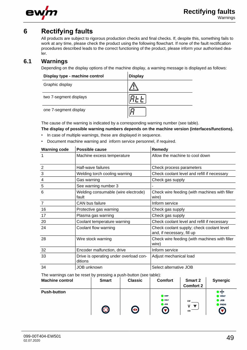
6.1 Warnings Depending on the display options of the machine display, a warning message is displayed as follows:
Display type - machine control Display
Graphic display
two 7-segment displays
one 7-segment display
The cause of the warning is indicated by a corresponding warning number (see table).
The display of possible warning numbers depends on the machine version (interfaces/functions).
• In case of multiple warnings, these are displayed in sequence.
• Document machine warning and inform service personnel, if required.
Warning code Possible cause Remedy
1 Machine excess temperature Allow the machine to cool down
2 Half-wave failures Check process parameters
3 Welding torch cooling warning Check coolant level and refill if necessary
4 Gas warning Check gas supply
5 See warning number 3 -
6 Welding consumable (wire electrode)
fault
Check wire feeding (with machines with filler
wire)
7 CAN bus failure Inform service
16 Protective gas warning Check gas supply
17 Plasma gas warning Check gas supply
20 Coolant temperature warning Check coolant level and refill if necessary
24 Coolant flow warning Check coolant supply; check coolant level
and, if necessary, fill up
28 Wire stock warning Check wire feeding (with machines with filler
wire)
32 Encoder malfunction, drive Inform service
33 Drive is operating under overload con-
ditions
Adjust mechanical load
34 JOB unknown Select alternative JOB
The warnings can be reset by pressing a push-button (see table):
Machine control Smart Classic Comfort Smart 2
Comfort 2
Synergic
Push-button
Rectifying faults Error messages
50 099-00T404-EW501 02.07.2020
6.2 Error messages Depending on the options of the machine display, a fault is shown as follows:
Display type - machine control Display
Graphic display
two 7-segment displays
one 7-segment display
The possible cause of the fault is signalled by a corresponding fault number (see table). In the case of an
error, the power unit shuts down.
The display of possible error numbers depends on the machine version (interfaces/functions).
• If multiple errors occur, these are displayed in succession.
• Document machine errors and inform service staff as necessary.
Error Possible cause Remedy
3 Tacho error Check wire guide / hose package.
Wire feeder is not connected Switch off cold wire mode in the machine configuration
menu (off status). Connect the wire feeder.
4 Temperature error Allow the machine to cool down.
Error in the emergency stop circuit
(interface for automated welding)
Check the external shutdown devices. Check the jum-
per JP 1 on PCB T320/1.
5 Overvoltage Switch off the machine and check the mains voltage.
6 Undervoltage
7 Coolant error (with connected coo-
ling unit only).
Check coolant level and top up if necessary.
8 Gas error Check the gas supply.
9 Secondary overvoltage Switch the machine off and on. If the error persists,
notify the service department. 10 PE error
11 FastStop position Slope “Acknowledge error” signal (0 to 1) using the
robot interface (if present).
12 VRD error Switch the machine off and on. If the error persists,
notify the service department.
16 Pilot arc current Check welding torch.
17 Filler wire error
Excess current or deviation of the
actual value from the wire target
value.
Check the wire feed system (drives, hose packages,
welding torches, process wire feed speed and robot
travel speed) and correct if necessary.
18 Plasma gas error
Target value specification deviates
significantly from the actual value.
Check plasma gas supply (leak tightness, kinks, guide,
connections, closure).
19 Shielding gas error
Target value specification deviates
significantly from the actual value
Check plasma gas supply (leak tightness, kinks, guide,
connections, closure).
20 Coolant flow
Coolant flow rate too low
Check cooling circuit (coolant level, leak tightness,
kinks, guide, connections, closure).
22 Excess temperature in cooling circuit Check cooling circuit (coolant level, temperature target
value).
23 Excess temperature of the HF choke Allow the machine to cool down. Adjust processing
cycle times if necessary.
24 Pilot arc ignition error Check the wear parts of the plasma torch.
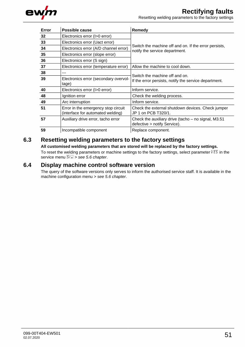
Rectifying faults Resetting welding parameters to the factory settings
099-00T404-EW501 02.07.2020 51
Error Possible cause Remedy
32 Electronics error (I>0 error)
Switch the machine off and on. If the error persists,
notify the service department.
33 Electronics error (Uact error)
34 Electronics error (A/D channel error)
35 Electronics error (slope error)
36 Electronics error (S sign)
37 Electronics error (temperature error) Allow the machine to cool down.
38 --- Switch the machine off and on.
If the error persists, notify the service department. 39 Electronics error (secondary overvol-
tage)
40 Electronics error (I>0 error) Inform service.
48 Ignition error Check the welding process.
49 Arc interruption Inform service.
51 Error in the emergency stop circuit
(interface for automated welding)
Check the external shutdown devices. Check jumper
JP 1 on PCB T320/1.
57 Auxiliary drive error, tacho error Check the auxiliary drive (tacho – no signal, M3.51
defective > notify Service).
59 Incompatible component Replace component.
6.3 Resetting welding parameters to the factory settings All customised welding parameters that are stored will be replaced by the factory settings.
To reset the welding parameters or machine settings to the factory settings, select parameter in the
service menu > see 5.6 chapter.
6.4 Display machine control software version The query of the software versions only serves to inform the authorised service staff. It is available in the
machine configuration menu > see 5.6 chapter.
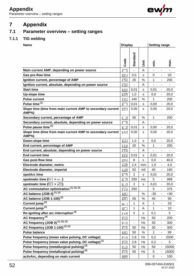
Appendix Parameter overview – setting ranges
52 099-00T404-EW501 02.07.2020
7 Appendix
7.1 Parameter overview – setting ranges
7.1.1 TIG welding
Name Display Setting range
Co
de
Sta
nd
ard
Un
it
min
.
ma
x.
Main current AMP, depending on power source
- A - - -
Gas pre-flow time
0,5 s 0 - 20
Ignition current, percentage of AMP
20 % 1 - 200
Ignition current, absolute, depending on power source
- A - - -
Start time
0,01 s 0,01 - 20,0
Up-slope time
1,0 s 0,0 - 20,0
Pulse current
140 % 1 200
Pulse time [1]
0,01 s 0,00 - 20,0
Slope time (time from main current AMP to secondary current
AMP%)
0,00 s 0,00 - 20,0
Secondary current, percentage of AMP
50 % 1 200
Secondary current, absolute, depending on power source
- A - -
Pulse pause time [1]
0,01 s 0,00 - 20,0
Slope time (time from main current AMP to secondary current
AMP%)
0,00 s 0,00 - 20,0
Down-slope time
1,0 s 0,0 - 20,0
End current, percentage of AMP
20 % 1 - 200
End current, absolute, depending on power source
- A - - -
End current time
0,01 s 0,01 - 20,0
Gas post-flow time
8 s 0,0 - 40,0
Electrode diameter, metric
2,4 mm 1,0 - 4,0
Electrode diameter, imperial
92 mil 40 - 160
spotArc time
2 s 0,01 - 20,0
spotmatic time ( > )
200 ms 5 - 999
spotmatic time ( > )
2 s 0,01 - 20,0
AC commutation optimisation [1], [2], [3]
250 5 - 375
AC balance (JOB 0) [1], [2]
% -30 - +30
AC balance (JOB 1-100) [2]
65 % 40 - 90
Current jump [3]
1 A 1 - 20
Current jump [4]
1 A 1 - 10
Re-igniting after arc interruption [3]
5 s 0,1 5
AC frequency [4]
- Hz 50 - 200
AC frequency (JOB 0) [1], [2], [3]
- Hz 30 - 300
AC frequency (JOB 1-100) [1], [2]
50 Hz 30 - 300
Pulse balance
50 % 1 - 99
Pulse frequency (mean value pulsing, DC voltage)
2,8 Hz 0,2 - 2000
Pulse frequency (mean value pulsing, DC voltage) [1]
2,8 Hz 0,2 - 5
Pulse frequency (metallurgical pulsing) [3]
50 Hz 50 - 15000
Pulse frequency (metallurgical pulsing) [4]
50 Hz 5 - 15000
activArc, depending on main current
0 - 100
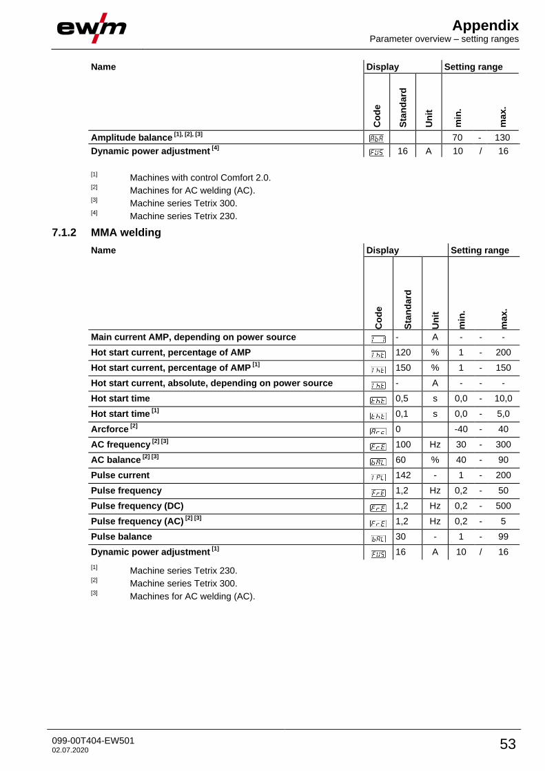
Appendix Parameter overview – setting ranges
099-00T404-EW501 02.07.2020 53
Name Display Setting range
Co
de
Sta
nd
ard
Un
it
min
.
ma
x.
Amplitude balance [1], [2], [3]
70 - 130
Dynamic power adjustment [4]
16 A 10 / 16
[1]
Machines with control Comfort 2.0. [2]
Machines for AC welding (AC). [3]
Machine series Tetrix 300. [4]
Machine series Tetrix 230.
7.1.2 MMA welding
Name Display Setting range
Co
de
Sta
nd
ard
Un
it
min
.
ma
x.
Main current AMP, depending on power source - A - - -
Hot start current, percentage of AMP 120 % 1 - 200
Hot start current, percentage of AMP [1]
150 % 1 - 150
Hot start current, absolute, depending on power source - A - - -
Hot start time 0,5 s 0,0 - 10,0
Hot start time [1]
0,1 s 0,0 - 5,0
Arcforce [2]
0 -40 - 40
AC frequency [2] [3]
100 Hz 30 - 300
AC balance [2] [3]
60 % 40 - 90
Pulse current 142 - 1 - 200
Pulse frequency 1,2 Hz 0,2 - 50
Pulse frequency (DC) 1,2 Hz 0,2 - 500
Pulse frequency (AC) [2] [3]
1,2 Hz 0,2 - 5
Pulse balance 30 - 1 - 99
Dynamic power adjustment [1]
16 A 10 / 16
[1] Machine series Tetrix 230.
[2] Machine series Tetrix 300.
[3] Machines for AC welding (AC).

Appendix Searching for a dealer
54 099-00T404-EW501 02.07.2020
7.2 Searching for a dealer Sales & service partners
www.ewm-group.com/en/specialist-dealers
"More than 400 EWM sales partners worldwide"
Copyright © 2022 FDOKUMEN