Template synthesis, characterization and magnetic property of Fe nanowires-filled amorphous carbon...
7
This content has been downloaded from IOPscience. Please scroll down to see the full text. Download details: IP Address: 194.210.237.200 This content was downloaded on 13/11/2013 at 18:22 Please note that terms and conditions apply. Template synthesis, characterization and magnetic property of Fe nanowires-filled amorphous carbon nanotubes array View the table of contents for this issue, or go to the journal homepage for more 2006 J. Phys. D: Appl. Phys. 39 3939 (http://iopscience.iop.org/0022-3727/39/18/003) Home Search Collections Journals About Contact us My IOPscience
Transcript of Template synthesis, characterization and magnetic property of Fe nanowires-filled amorphous carbon...

This content has been downloaded from IOPscience. Please scroll down to see the full text.
Download details:
IP Address: 194.210.237.200
This content was downloaded on 13/11/2013 at 18:22
Please note that terms and conditions apply.
Template synthesis, characterization and magnetic property of Fe nanowires-filled amorphous
carbon nanotubes array
View the table of contents for this issue, or go to the journal homepage for more
2006 J. Phys. D: Appl. Phys. 39 3939
(http://iopscience.iop.org/0022-3727/39/18/003)
Home Search Collections Journals About Contact us My IOPscience

INSTITUTE OF PHYSICS PUBLISHING JOURNAL OF PHYSICS D: APPLIED PHYSICS
J. Phys. D: Appl. Phys. 39 (2006) 3939–3944 doi:10.1088/0022-3727/39/18/003
Template synthesis, characterization andmagnetic property of Fe nanowires-filledamorphous carbon nanotubes arrayLifeng Liu1,2, Shicheng Mu3, Sishen Xie1, Weiya Zhou1,Li Song1,2, Dongfang Liu1,2, Shudong Luo1,2, Yanjuan Xiang1,2,Zengxing Zhang1,2, Xiaowei Zhao1,2, Wenjun Ma1,2, Jun Shen1,2,Chaoying Wang1 and Gang Wang1
1 Beijing National Laboratory for Condensed Matter Physics and Institute of Physics,Chinese Academy of Sciences, Beijing 100080, People’s Republic of China2 The Graduate University of Chinese Academy of Sciences, Beijing 100049, People’sRepublic of China3 Nanotechnology Industrialization Base of China, TEDA, Tianjin 300457, People’s Republicof China
E-mail: [email protected] (S.S. Xie)
Received 24 April 2006, in final form 28 July 2006Published 1 September 2006Online at stacks.iop.org/JPhysD/39/3939
AbstractA Fe nanowires-filled amorphous carbon nanotubes (FeNW-filled a-CNTs)array was synthesized by sequential growth of electrodeposited Fenanowires and subsequent chemical vapour deposition of amorphous CNTsin the nanochannels of alumina template. Structural characterizations ofas-prepared FeNW-filled a-CNTs were carried out via field emissionscanning electron microscope (FE-SEM), x-ray diffraction (XRD),elemental mapping, high-resolution transmission electron microscope(HRTEM) and Raman scattering. The formation mechanism of such Fe/Cnanoheterostructure was proposed according to the detailed HRTEManalyses. Furthermore, the room temperature magnetic property of theas-prepared FeNW-filled a-CNTs array was also investigated, and obviousanisotropic behaviour in magnetization was observed.
(Some figures in this article are in colour only in the electronic version)
1. Introduction
Since the discovery in 1991, CNTs have attracted a largeamount of scientific and technological interests due totheir novel physical and chemical properties [1–6]. Thehollow structure of CNTs provides room for introductionof various metals and alloys [7–9], chemical groups [10]and bio-molecules [11, 12], which can significantly altertheir electrical, magnetic, mechanical and surface chemicalproperties. Among them, magnetic metals filled CNTs areespecially attractive because the CNTs coating layer plays animportant role to protect the nanosized magnetic metals frombeing oxidized so that the magnetism can sustain in the openair for a long time, which makes this kind of nanostructureto have widespread applications in perpendicular recordingmedia [13], biomedicine [14], the probes of magnetic force
microscope [15] and spintronics [16]. To date, variousmethods have been developed to prepare metal-filled CNTs,such as arc-discharging [17, 18], catalyzed thermolysis [15,19, 20], capillary suction [21], a wet chemical technique [22]and template-assisted synthesis [23, 24]. However, mostencapsulations of metals or alloys in CNTs exist in the formof nanoparticles or short, discontinuous nanowire segments.Furthermore, only a few reports are about the synthesis andproperties of an ordered array of magnetic metals filled CNTs[19, 23, 24].
In this paper, a Fe nanowires-filled amorphous carbonnanotubes (FeNW-filled a-CNTs) array was synthesized viaa two-step template-assisted growth process by employingporous anodic alumina (PAA) membrane as the template.Compared with the template synthesis method reportedpreviously [23, 24], which grows CNTs first and then
0022-3727/06/183939+06$30.00 © 2006 IOP Publishing Ltd Printed in the UK 3939
L Liu et al
electrodeposits nanowires into the CNTs-contained PAAtemplate, we reversed the order of the synthesis, that is, Fenanowires were first obtained through electrodeposition, thenthe Fe nanowires embedded in PAA template were used as the‘second-order template’ to grow CNTs via chemical vapourdeposition. The advantages of this reversed approach are that,on one hand, it can avoid the discontinuous deposition of themetal ions within the CNTs due to the roughness or poorwettability of the inner wall of the CNTs; on the other hand, itcan form amorphous-CNTs-encapsulated Fe nanowires (aCE-FeNWs)/a-CNTs axial heterojunction other than Fe/C radialheterojunction.
2. Experimental section
The PAA template was prepared via a two-step anodizationmethod developed by Masuda and Satoh [25]. The schematicdiagram of the detailed preparation process is shown infigures 4(a)–(e). Briefly speaking, a polished high purityaluminium foil (99.999%) with thickness of 0.5 mm and a pieceof lead plate were placed in 0.3 M oxalic acid, acting as anodeand cathode, respectively. The first anodization was carried outunder a voltage of 40 V at 1◦C for 10 h. Then the aluminiumfoil was soaked in 1.8 wt% CrO3 and 6 wt% H3PO4 for 10 h at60◦C to etch away the oxidized layer. The second anodizationwas performed for 20 h under the condition identified withthe first anodization. After that, the alumina layer waspeeled off by submerging the oxidized aluminium foil intosaturated HgCl2 solution. Next, the alumina membrane wasput into 5 wt% H3PO4 to remove the barrier layer to obtainthe through-hole structure. As-prepared PAA membrane hasthe pore diameter of about 70 ± 5 nm and thickness of 50 µm,respectively.
Fe nanowires were first electrodeposited into thenanopores of the PAA template. Before the electrodeposition,a layer of Au was sputtered on one side of the PAA membranethrough an ion sputtering system (Hitachi E1030, 20 mA,1000 s). The deposition was carried out in a traditionaltwo-electrodes cell. The Au-coated PAA and a piece ofgraphite plate were employed as working electrode andcounter-electrode, respectively. The electrolyte consisted of120 g l−1 FeSO4, 45 g l−1 H3BO3 and 1.5 g l−1 ascorbic acid.The deposition was conducted at galvanostatic mode witha constant current density of 3 mA cm−2 for 2 h at roomtemperature.
Afterwards, the Fe-filled PAA membrane was used as‘second-order template’ to grow CNTs. The ‘second-ordertemplate’ was put into the quartz tube and then the quartz tubewas inserted into the tube furnace. The furnace was rampedat 15◦C min−1 to 680◦C under a flow of 100 sccm high purityN2. Then, 15 sccm C2H2 was purged into the quartz tube asthe precursor gas to grow CNTs. The growth duration wasmaintained for 1 h. After that, the C2H2 was turned off and thefurnace was cooled down to room temperature naturally withthe protection of N2 atmosphere.
The morphology and the microstructures of as-preparedFeNW-filled a-CNTs were determined by FE-SEM (HitachiS-5200), X-ray diffraction (XRD) (Rigaku D/MAX) andhigh-resolution transmission electron microscope (HRTEM)(JEOL JEM-2010F). To examine the distribution of elements,
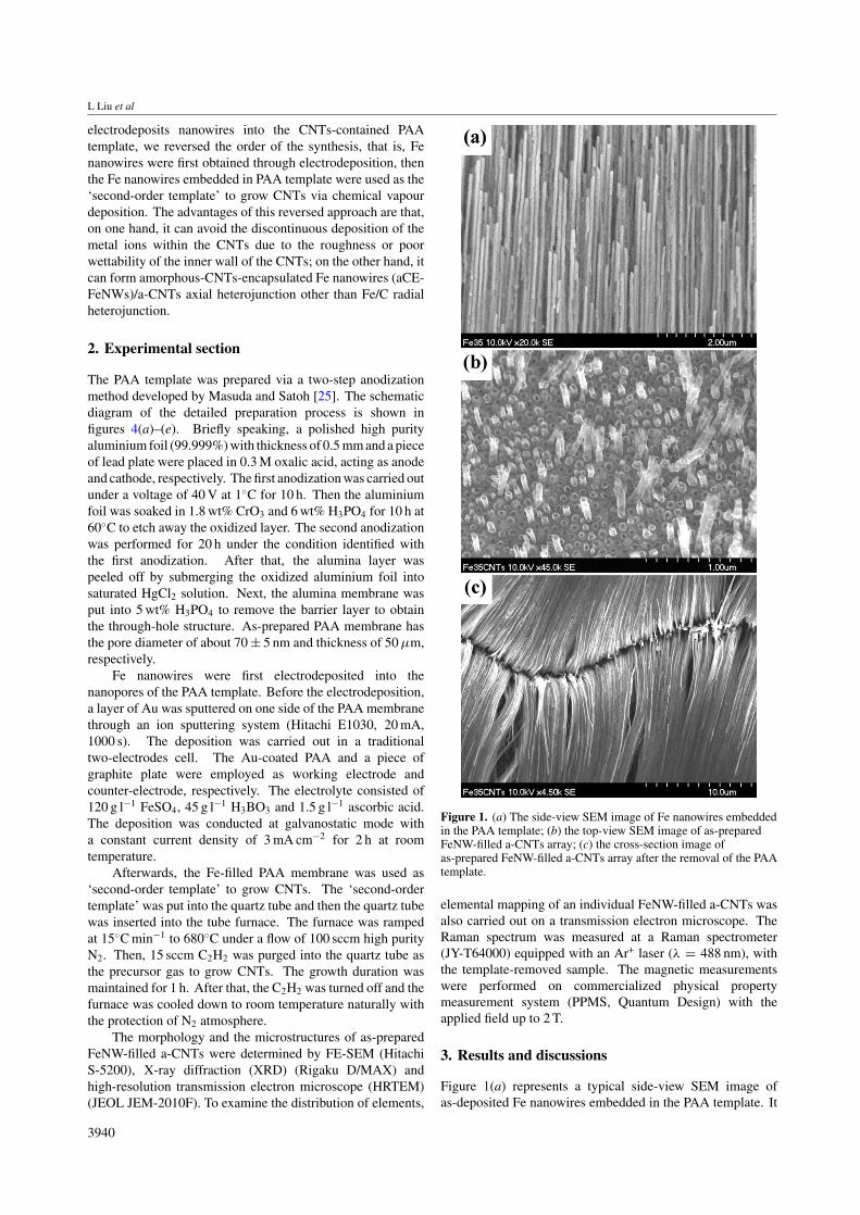
Figure 1. (a) The side-view SEM image of Fe nanowires embeddedin the PAA template; (b) the top-view SEM image of as-preparedFeNW-filled a-CNTs array; (c) the cross-section image ofas-prepared FeNW-filled a-CNTs array after the removal of the PAAtemplate.
elemental mapping of an individual FeNW-filled a-CNTs wasalso carried out on a transmission electron microscope. TheRaman spectrum was measured at a Raman spectrometer(JY-T64000) equipped with an Ar+ laser (λ = 488 nm), withthe template-removed sample. The magnetic measurementswere performed on commercialized physical propertymeasurement system (PPMS, Quantum Design) with theapplied field up to 2 T.
3. Results and discussions
Figure 1(a) represents a typical side-view SEM image ofas-deposited Fe nanowires embedded in the PAA template. It
3940
Fe nanowires-filled amorphous carbon nanotubes
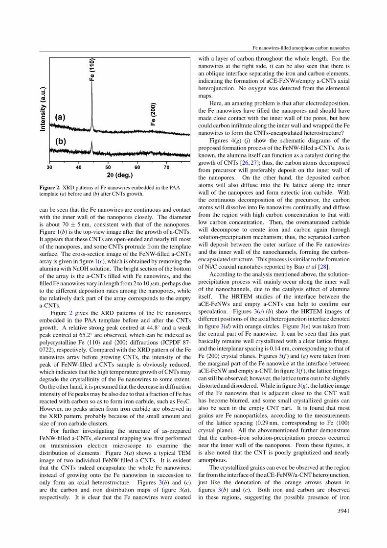
Figure 2. XRD patterns of Fe nanowires embedded in the PAAtemplate (a) before and (b) after CNTs growth.
can be seen that the Fe nanowires are continuous and contactwith the inner wall of the nanopores closely. The diameteris about 70 ± 5 nm, consistent with that of the nanopores.Figure 1(b) is the top-view image after the growth of a-CNTs.It appears that these CNTs are open-ended and nearly fill mostof the nanopores, and some CNTs protrude from the templatesurface. The cross-section image of the FeNW-filled a-CNTsarray is given in figure 1(c), which is obtained by removing thealumina with NaOH solution. The bright section of the bottomof the array is the a-CNTs filled with Fe nanowires, and thefilled Fe nanowires vary in length from 2 to 10 µm, perhaps dueto the different deposition rates among the nanopores, whilethe relatively dark part of the array corresponds to the emptya-CNTs.
Figure 2 gives the XRD patterns of the Fe nanowiresembedded in the PAA template before and after the CNTsgrowth. A relative strong peak centred at 44.8◦ and a weakpeak centred at 65.2◦ are observed, which can be indexed aspolycrystalline Fe 〈110〉 and 〈200〉 diffractions (JCPDF 87-0722), respectively. Compared with the XRD pattern of the Fenanowires array before growing CNTs, the intensity of thepeak of FeNW-filled a-CNTs sample is obviously reduced,which indicates that the high temperature growth of CNTs maydegrade the crystallinity of the Fe nanowires to some extent.On the other hand, it is presumed that the decrease in diffractionintensity of Fe peaks may be also due to that a fraction of Fe hasreacted with carbon so as to form iron carbide, such as Fe3C.However, no peaks arisen from iron carbide are observed inthe XRD pattern, probably because of the small amount andsize of iron carbide clusters.
For further investigating the structure of as-preparedFeNW-filled a-CNTs, elemental mapping was first performedon transmission electron microscope to examine thedistribution of elements. Figure 3(a) shows a typical TEMimage of two individual FeNW-filled a-CNTs. It is evidentthat the CNTs indeed encapsulate the whole Fe nanowires,instead of growing onto the Fe nanowires in succession toonly form an axial heterostructure. Figures 3(b) and (c)are the carbon and iron distribution maps of figure 3(a),respectively. It is clear that the Fe nanowires were coated
with a layer of carbon throughout the whole length. For thenanowires at the right side, it can be also seen that there isan oblique interface separating the iron and carbon elements,indicating the formation of aCE-FeNWs/empty a-CNTs axialheterojunction. No oxygen was detected from the elementalmaps.
Here, an amazing problem is that after electrodeposition,the Fe nanowires have filled the nanopores and should havemade close contact with the inner wall of the pores, but howcould carbon infiltrate along the inner wall and wrapped the Fenanowires to form the CNTs-encapsulated heterostructure?
Figures 4(g)–(j) show the schematic diagrams of theproposed formation process of the FeNW-filled a-CNTs. As isknown, the alumina itself can function as a catalyst during thegrowth of CNTs [26, 27]; thus, the carbon atoms decomposedfrom precursor will preferably deposit on the inner wall ofthe nanopores. On the other hand, the deposited carbonatoms will also diffuse into the Fe lattice along the innerwall of the nanopores and form eutectic iron carbide. Withthe continuous decomposition of the precursor, the carbonatoms will dissolve into Fe nanowires continually and diffusefrom the region with high carbon concentration to that withlow carbon concentration. Then, the oversaturated carbidewill decompose to create iron and carbon again throughsolution-precipitation mechanism; thus, the separated carbonwill deposit between the outer surface of the Fe nanowiresand the inner wall of the nanochannels, forming the carbon-encapsulated structure. This process is similar to the formationof Ni/C coaxial nanotubes reported by Bao et al [28].
According to the analysis mentioned above, the solution-precipitation process will mainly occur along the inner wallof the nanochannels, due to the catalysis effect of aluminaitself. The HRTEM studies of the interface between theaCE-FeNWs and empty a-CNTs can help to confirm ourspeculation. Figures 3(e)-(h) show the HRTEM images ofdifferent positions of the axial heterojunction interface denotedin figure 3(d) with orange circles. Figure 3(e) was taken fromthe central part of Fe nanowire. It can be seen that this partbasically remains well crystallized with a clear lattice fringe,and the interplanar spacing is 0.14 nm, corresponding to that ofFe 〈200〉 crystal planes. Figures 3(f ) and (g) were taken fromthe marginal part of the Fe nanowire at the interface betweenaCE-FeNW and empty a-CNT. In figure 3(f ), the lattice fringescan still be observed; however, the lattice turns out to be slightlydistorted and disordered. While in figure 3(g), the lattice imageof the Fe nanowire that is adjacent close to the CNT wallhas become blurred, and some small crystallized grains canalso be seen in the empty CNT part. It is found that mostgrains are Fe nanoparticles, according to the measurementsof the lattice spacing (0.29 nm, corresponding to Fe 〈100〉crystal plane). All the abovementioned further demonstratethat the carbon–iron solution-precipitation process occurrednear the inner wall of the nanopores. From these figures, itis also noted that the CNT is poorly graphitized and nearlyamorphous.
The crystallized grains can even be observed at the regionfar from the interface of the aCE-FeNW/a-CNT heterojunction,just like the denotation of the orange arrows shown infigures 3(b) and (c). Both iron and carbon are observedin these regions, suggesting the possible presence of iron
3941

L Liu et al
Figure 3. (a) The TEM image of individual FeNW-filled a-CNTs; (b) carbon and (c) iron maps of FeNW-filled a-CNTs shown in (a);(d) the magnified image of the interface between aCE-FeNW and a-CNT shown in (a); (e)–(h) the HRTEM images of different positionsdenoted in (d).
Figure 4. The schematic diagrams of the formation processes of (a)–(e) the PAA template and (f)–(j) the FeNW-filled a-CNTs.
carbide. A typical HRTEM image of such regions is revealed infigure 3(h). It is found that the spacing of lattice fringes of thesegrains is about 0.21 nm, approximately equal to that of Fe3C〈211〉 crystal planes (JCPDF 85-1317). This demonstratesthat besides the process of carbon infiltrating into iron, a
reversed process also existed, that is, at eutectic state ironwill diffuse from high concentration region (Fe nanowires)to low concentration region (CNTs) along the inner wall ofnanochannels as well and react with carbon to form ironcarbide. Thus, some iron carbide grains will be retained when
3942
Fe nanowires-filled amorphous carbon nanotubes
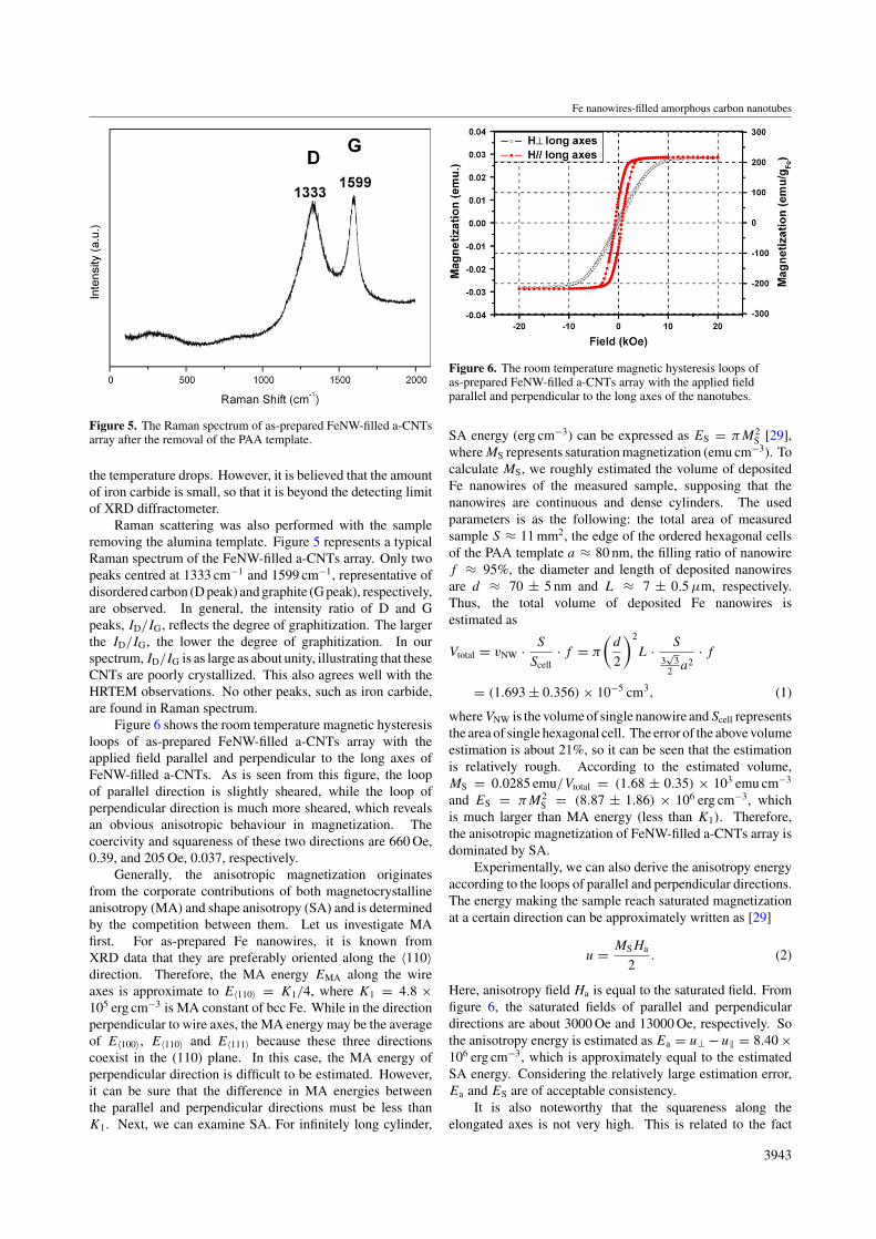
Figure 5. The Raman spectrum of as-prepared FeNW-filled a-CNTsarray after the removal of the PAA template.
the temperature drops. However, it is believed that the amountof iron carbide is small, so that it is beyond the detecting limitof XRD diffractometer.
Raman scattering was also performed with the sampleremoving the alumina template. Figure 5 represents a typicalRaman spectrum of the FeNW-filled a-CNTs array. Only twopeaks centred at 1333 cm−1 and 1599 cm−1, representative ofdisordered carbon (D peak) and graphite (G peak), respectively,are observed. In general, the intensity ratio of D and Gpeaks, ID/IG, reflects the degree of graphitization. The largerthe ID/IG, the lower the degree of graphitization. In ourspectrum, ID/IG is as large as about unity, illustrating that theseCNTs are poorly crystallized. This also agrees well with theHRTEM observations. No other peaks, such as iron carbide,are found in Raman spectrum.
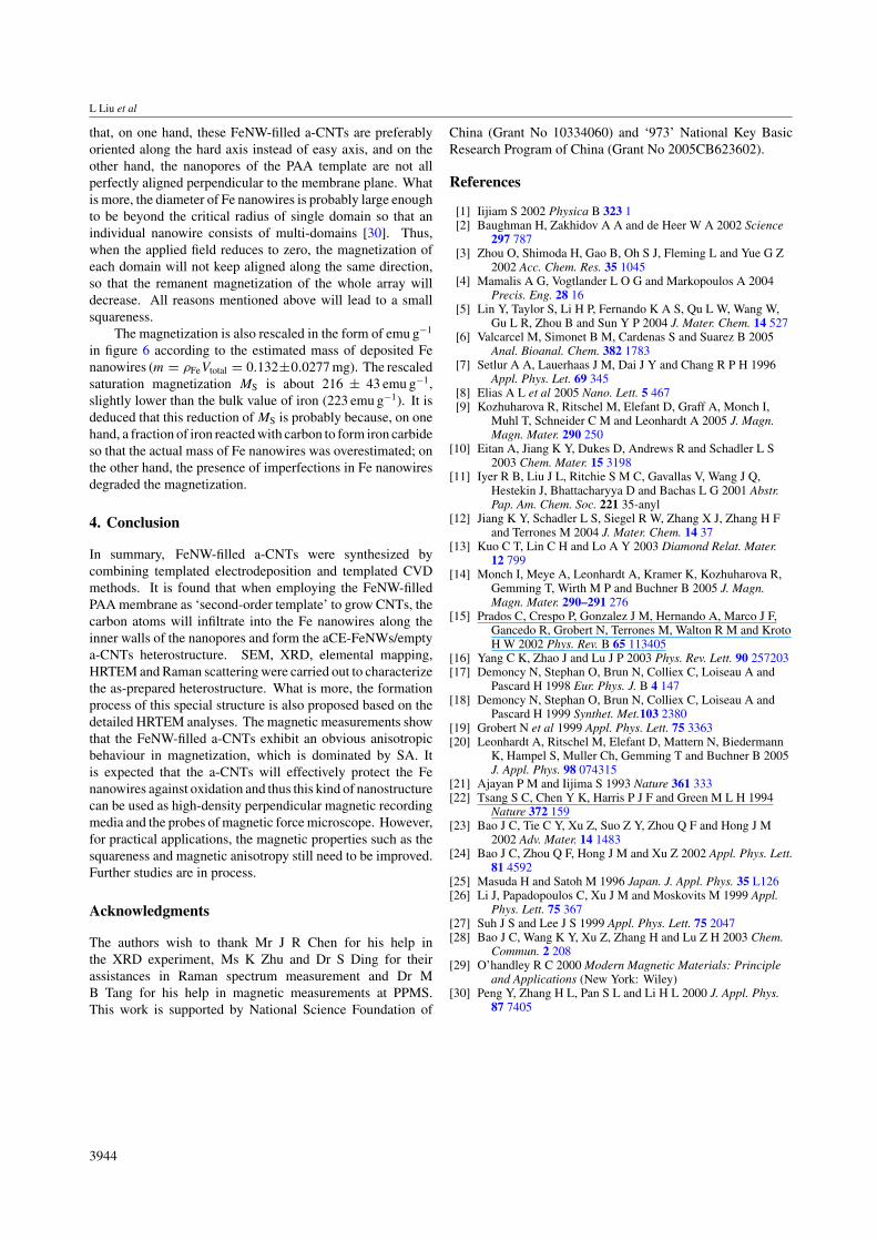
Figure 6 shows the room temperature magnetic hysteresisloops of as-prepared FeNW-filled a-CNTs array with theapplied field parallel and perpendicular to the long axes ofFeNW-filled a-CNTs. As is seen from this figure, the loopof parallel direction is slightly sheared, while the loop ofperpendicular direction is much more sheared, which revealsan obvious anisotropic behaviour in magnetization. Thecoercivity and squareness of these two directions are 660 Oe,0.39, and 205 Oe, 0.037, respectively.
Generally, the anisotropic magnetization originatesfrom the corporate contributions of both magnetocrystallineanisotropy (MA) and shape anisotropy (SA) and is determinedby the competition between them. Let us investigate MAfirst. For as-prepared Fe nanowires, it is known fromXRD data that they are preferably oriented along the 〈110〉direction. Therefore, the MA energy EMA along the wireaxes is approximate to E〈110〉 = K1/4, where K1 = 4.8 ×10⁵ erg cm−3 is MA constant of bcc Fe. While in the directionperpendicular to wire axes, the MA energy may be the averageof E〈100〉, E〈110〉 and E〈111〉 because these three directionscoexist in the (110) plane. In this case, the MA energy ofperpendicular direction is difficult to be estimated. However,it can be sure that the difference in MA energies betweenthe parallel and perpendicular directions must be less thanK1. Next, we can examine SA. For infinitely long cylinder,
Figure 6. The room temperature magnetic hysteresis loops ofas-prepared FeNW-filled a-CNTs array with the applied fieldparallel and perpendicular to the long axes of the nanotubes.
SA energy (erg cm−3) can be expressed as ES = πM2S [29],
where MS represents saturation magnetization (emu cm−3). Tocalculate MS, we roughly estimated the volume of depositedFe nanowires of the measured sample, supposing that thenanowires are continuous and dense cylinders. The usedparameters is as the following: the total area of measuredsample S ≈ 11 mm2, the edge of the ordered hexagonal cellsof the PAA template a ≈ 80 nm, the filling ratio of nanowiref ≈ 95%, the diameter and length of deposited nanowiresare d ≈ 70 ± 5 nm and L ≈ 7 ± 0.5 µm, respectively.Thus, the total volume of deposited Fe nanowires isestimated as
Vtotal = vNW · S
Scell· f = π
(d
2
)2
L · S
3√
32 a2
· f
= (1.693 ± 0.356) × 10−5 cm3, (1)
whereVNW is the volume of single nanowire andScell representsthe area of single hexagonal cell. The error of the above volumeestimation is about 21%, so it can be seen that the estimationis relatively rough. According to the estimated volume,MS = 0.0285 emu/Vtotal = (1.68 ± 0.35) × 103 emu cm−3
and ES = πM2S = (8.87 ± 1.86) × 106 erg cm−3, which
is much larger than MA energy (less than K1). Therefore,the anisotropic magnetization of FeNW-filled a-CNTs array isdominated by SA.
Experimentally, we can also derive the anisotropy energyaccording to the loops of parallel and perpendicular directions.The energy making the sample reach saturated magnetizationat a certain direction can be approximately written as [29]
u = MSHa
2. (2)
Here, anisotropy field Ha is equal to the saturated field. Fromfigure 6, the saturated fields of parallel and perpendiculardirections are about 3000 Oe and 13000 Oe, respectively. Sothe anisotropy energy is estimated as Ea = u⊥ − u‖ = 8.40 ×10⁶ erg cm−3, which is approximately equal to the estimatedSA energy. Considering the relatively large estimation error,Ea and ES are of acceptable consistency.
It is also noteworthy that the squareness along theelongated axes is not very high. This is related to the fact
3943
L Liu et al
that, on one hand, these FeNW-filled a-CNTs are preferablyoriented along the hard axis instead of easy axis, and on theother hand, the nanopores of the PAA template are not allperfectly aligned perpendicular to the membrane plane. Whatis more, the diameter of Fe nanowires is probably large enoughto be beyond the critical radius of single domain so that anindividual nanowire consists of multi-domains [30]. Thus,when the applied field reduces to zero, the magnetization ofeach domain will not keep aligned along the same direction,so that the remanent magnetization of the whole array willdecrease. All reasons mentioned above will lead to a smallsquareness.
The magnetization is also rescaled in the form of emu g−1
in figure 6 according to the estimated mass of deposited Fenanowires (m = ρFeVtotal = 0.132±0.0277 mg). The rescaledsaturation magnetization MS is about 216 ± 43 emu g−1,slightly lower than the bulk value of iron (223 emu g−1). It isdeduced that this reduction of MS is probably because, on onehand, a fraction of iron reacted with carbon to form iron carbideso that the actual mass of Fe nanowires was overestimated; onthe other hand, the presence of imperfections in Fe nanowiresdegraded the magnetization.
4. Conclusion
In summary, FeNW-filled a-CNTs were synthesized bycombining templated electrodeposition and templated CVDmethods. It is found that when employing the FeNW-filledPAA membrane as ‘second-order template’ to grow CNTs, thecarbon atoms will infiltrate into the Fe nanowires along theinner walls of the nanopores and form the aCE-FeNWs/emptya-CNTs heterostructure. SEM, XRD, elemental mapping,HRTEM and Raman scattering were carried out to characterizethe as-prepared heterostructure. What is more, the formationprocess of this special structure is also proposed based on thedetailed HRTEM analyses. The magnetic measurements showthat the FeNW-filled a-CNTs exhibit an obvious anisotropicbehaviour in magnetization, which is dominated by SA. Itis expected that the a-CNTs will effectively protect the Fenanowires against oxidation and thus this kind of nanostructurecan be used as high-density perpendicular magnetic recordingmedia and the probes of magnetic force microscope. However,for practical applications, the magnetic properties such as thesquareness and magnetic anisotropy still need to be improved.Further studies are in process.
Acknowledgments
The authors wish to thank Mr J R Chen for his help inthe XRD experiment, Ms K Zhu and Dr S Ding for theirassistances in Raman spectrum measurement and Dr MB Tang for his help in magnetic measurements at PPMS.This work is supported by National Science Foundation of
China (Grant No 10334060) and ‘973’ National Key BasicResearch Program of China (Grant No 2005CB623602).
References
[1] Iijiam S 2002 Physica B 323 1[2] Baughman H, Zakhidov A A and de Heer W A 2002 Science
297 787[3] Zhou O, Shimoda H, Gao B, Oh S J, Fleming L and Yue G Z
2002 Acc. Chem. Res. 35 1045[4] Mamalis A G, Vogtlander L O G and Markopoulos A 2004
Precis. Eng. 28 16[5] Lin Y, Taylor S, Li H P, Fernando K A S, Qu L W, Wang W,
Gu L R, Zhou B and Sun Y P 2004 J. Mater. Chem. 14 527[6] Valcarcel M, Simonet B M, Cardenas S and Suarez B 2005
Anal. Bioanal. Chem. 382 1783[7] Setlur A A, Lauerhaas J M, Dai J Y and Chang R P H 1996
Appl. Phys. Let. 69 345[8] Elias A L et al 2005 Nano. Lett. 5 467[9] Kozhuharova R, Ritschel M, Elefant D, Graff A, Monch I,
Muhl T, Schneider C M and Leonhardt A 2005 J. Magn.Magn. Mater. 290 250
[10] Eitan A, Jiang K Y, Dukes D, Andrews R and Schadler L S2003 Chem. Mater. 15 3198
[11] Iyer R B, Liu J L, Ritchie S M C, Gavallas V, Wang J Q,Hestekin J, Bhattacharyya D and Bachas L G 2001 Abstr.Pap. Am. Chem. Soc. 221 35-anyl
[12] Jiang K Y, Schadler L S, Siegel R W, Zhang X J, Zhang H Fand Terrones M 2004 J. Mater. Chem. 14 37
[13] Kuo C T, Lin C H and Lo A Y 2003 Diamond Relat. Mater.12 799
[14] Monch I, Meye A, Leonhardt A, Kramer K, Kozhuharova R,Gemming T, Wirth M P and Buchner B 2005 J. Magn.Magn. Mater. 290–291 276
[15] Prados C, Crespo P, Gonzalez J M, Hernando A, Marco J F,Gancedo R, Grobert N, Terrones M, Walton R M and KrotoH W 2002 Phys. Rev. B 65 113405
[16] Yang C K, Zhao J and Lu J P 2003 Phys. Rev. Lett. 90 257203[17] Demoncy N, Stephan O, Brun N, Colliex C, Loiseau A and
Pascard H 1998 Eur. Phys. J. B 4 147[18] Demoncy N, Stephan O, Brun N, Colliex C, Loiseau A and
Pascard H 1999 Synthet. Met.103 2380[19] Grobert N et al 1999 Appl. Phys. Lett. 75 3363[20] Leonhardt A, Ritschel M, Elefant D, Mattern N, Biedermann
K, Hampel S, Muller Ch, Gemming T and Buchner B 2005J. Appl. Phys. 98 074315
[21] Ajayan P M and Iijima S 1993 Nature 361 333[22] Tsang S C, Chen Y K, Harris P J F and Green M L H 1994
Nature 372 159[23] Bao J C, Tie C Y, Xu Z, Suo Z Y, Zhou Q F and Hong J M
2002 Adv. Mater. 14 1483[24] Bao J C, Zhou Q F, Hong J M and Xu Z 2002 Appl. Phys. Lett.
81 4592[25] Masuda H and Satoh M 1996 Japan. J. Appl. Phys. 35 L126[26] Li J, Papadopoulos C, Xu J M and Moskovits M 1999 Appl.
Phys. Lett. 75 367[27] Suh J S and Lee J S 1999 Appl. Phys. Lett. 75 2047[28] Bao J C, Wang K Y, Xu Z, Zhang H and Lu Z H 2003 Chem.
Commun. 2 208[29] O’handley R C 2000 Modern Magnetic Materials: Principle
and Applications (New York: Wiley)[30] Peng Y, Zhang H L, Pan S L and Li H L 2000 J. Appl. Phys.
87 7405
3944