Temperature Sensors & Instruments - AZPower - Industrial ...
134
Bulletin TS-103(A) © Minco Products Inc., July 2004 Temperature Sensors & Instruments Temperature Sensors & Instruments TEMPERATURE SENSORS & INSTRUMENTS © MINCO PRODUCTS INC Jl 2004 For continually updated information, please visit www.minco.com Resistance Temperature Detectors • Thermocouples Thermistors • Transmitters • Monitors • Controllers Precision Sensors Configured for Your Every Need! PRODUCTS, INC.
-
Upload
khangminh22 -
Category
Documents
-
view
0 -
download
0
Transcript of Temperature Sensors & Instruments - AZPower - Industrial ...

Bulletin TS-103(A)© Minco Products Inc., July 2004
Temperature Sensors & InstrumentsTemperature Sensors & Instruments
TE
MP
ER
AT
UR
ES
EN
SO
RS
&IN
ST
RU
ME
NT
S©
MIN
CO
PR
OD
UC
TS
INC
Jl
2004
For continually updated information, please visit www.minco.com
Resistance Temperature Detectors • ThermocouplesThermistors • Transmitters • Monitors • Controllers
Precision Sensors Configured for Your Every Need!
PRODUCTS, INC.

Page 1-2 Sales: 763-571-3121 � Fax: 763-571-0927 � www.minco.com Minco Bulletin TS-103(A)
About MincoAbout Minco
7300 Commerce Lane • Minneapolis, MN 55432-3177 U.S.A.PRODUCTS, INC.
Minco: Your Source For SensorsMinco has designed and manufacturedRTDs for more than 45 years. We havethe capabilities and experience to puttogether a proven sensing solution, at acost-effective price, for your application.
The right sensor
No sensor manufacturer offers morestyles and variations. From miniaturedetectors to 100 foot averaging thermo-meters, from flexible Thermal-Ribbons™to heavy duty probe assemblies, ourselection lets you choose the best modelfor your needs. We can supply platinum,nickel, nickel-iron, and copper RTDs withcurves to match any instrumentation. AndMinco also offers thermocouples andthermistors mechanically interchangeablewith RTD models to help you standardizeinstallations.
Single source manufacturing
Minco builds sensors from start to finish.We manufacture our own sensingelements, machine our own cases andfittings, and assemble finished parts. Thatgives us complete control over productquality, plus flexibility in adapting designsto customer requirements.
Custom design
Stock solutions aren’t always the bestsolutions. Minco has designed over 7000custom sensors, each with uniquefeatures for better performance at a lowerprice. Let our engineers suggestinnovative ideas to tailor a sensor to yourapplication.
Quality above all
Minco sensors have proven their reliabilityin the most critical areas. The SpaceShuttle uses our RTDs. So do nuclearplant safety systems, rocket motors,power generators, missiles, andcalibration labs. Quality comes first atMinco. Documented and auditedprocedures, continuous qualityimprovement goals, and employeeinvolvement programs set a highstandard throughout the company. Mincois certified to ISO 9001: 2000.
Credit cards
Minco accepts MasterCard, Visa, andAmerican Express.
Extensive stock for urgent needs
When you need it right now, this is theright place. Minco stocks more than 250different types of sensors. Cut-to-lengthprobes are one example. We can take aprobe from the shelf, trim it to the propersize, add fittings, connection head,transmitter, and thermowell, and ship it toyou overnight. Look for this symbol:
To order stock items:
Minco Order Desk:
Phone: 763-571-3123FAX: 763-571-0942
Saturday-Sunday emergency beeper:612-580-4659
For technical assistance andnon-standard items:
Minco Sales Department:
Phone: 763-571-3121FAX: 763-571-0927
Or visit www.minco.com to find your localsales representative’s phone number.
IN STOCK

Minco Bulletin TS-103(A) Order Desk: 763-571-3123 � Fax:
ContentsContents
Ass
emblies
Pro
bes
Acc
esso
ries
Inst
rum
ents
Sanit
ary
Sen
sors
Min
iatu
reS
enso
rsS
tato
rD
etec
tors
HV
AC
/RS
enso
rsTher
mal-
Rib
bon
snts
Section 1Introduction
Typical applications ...........................................................1-4 to 1-5Custom design...................................................................1-6 to 1-7Directions to Minco.......................................................................1-8
Section 2Temperature Sensor Assemblies
Tip-sensitive, spring-loaded...............................................2-2 to 2-3Direct immersion ................................................................2-4 to 2-5Tip-sensitive with thermowells...........................................2-6 to 2-7High temp. with thermowells .............................................2-8 to 2-9Flameproof/Explosionproof ...........................................2-10 to 2-17Eurostyle .....................................................................................2-18
Section 3RTD and Thermocouple Probes
Tip-sensitive RTDs.................................................................3-2, 3-6Tip-sensitive thermocouples.................................................3-3, 3-6Fast response RTDs...........................................................3-4 to 3-5Bayonet mount probes .........................................................3-6, 3-8Electrically Isolated probes ..........................................................3-7550°C RTDs, thermocouples........................................................3-8600°C, 850°C RTDs ......................................................................3-9Mineral-insulated RTDs ..............................................................3-10Cut-to-length probes .....................................3-2, 3-3, 3-4, 3-8, 3-11How to shorten cut-to-length probes.........................................3-11Specifying custom assemblies ..................................................3-12
Section 4Accessories
Connection heads..............................................................4-2 to 4-3Spring-loaded holders..................................................................4-4Fluid immersion fittings.......................................................4-5, 4-10Thermowells .......................................................................4-6 to 4-8Bayonet fittings.............................................................................4-9Extension fittings ..........................................................................4-9Metric accessories......................................................................4-10Feedthroughs and oil seals ...........................................4-11 to 4-13Extension wire ............................................................................4-14
Section 5Temperature Instruments
Temperature transmitters...................................................5-2 to 5-9Temperature range table ...............................................5-10 to 5-17Why use Temptrans? .................................................................5-18High accuracy calibration ..........................................................5-18Temptran wiring diagrams .........................................................5-19Mounting accessories ................................................................5-19Temperature controllers ................................................5-20 to 5-23Temperature monitors ...................................................5-24 to 5-25Temperature Indicators..................................................5-21 to 5-26
Section 6Sanitary Sensors
Probes...........................................................................................6-2Assemblies ...................................................................................6-3Installation and accessories.........................................................6-4
Section 7Miniature Sensors
RTDs .............................................................................................7-2Thermocouples.............................................................................7-3Bolt on sensors.............................................................................7-4Economy sensors.........................................................................7-5Installation and accessories.........................................................7-6
Section 8Stator Winding Detectors
Single element RTDs....................................................................8-2Dual element RTDs.......................................................................8-3Increased safety RTDs.......................................................8-4 to 8-5Accessories ..................................................................................8-6
Section 9HVAC/R Temperature Sensors
Room sensors ..............................................................................9-2Outside air ....................................................................................9-3Duct point .....................................................................................9-3Averaging sensors........................................................................9-4Fluid immersion ............................................................................9-5Surface mount Thermal-Ribbons™..............................................9-6Elements & probes.......................................................................9-7Refrigeration & freezer..................................................................9-8Thermal Vial™...............................................................................9-9Temptran™ transmitters .............................................................9-10
Section 10Thermal-Ribbons™
Miniature RTD Thermal-Ribbons................................................10-2Thin-film RTD Thermal-Ribbons.................................................10-2Waterproof RTD Thermal-Ribbons.............................................10-2Discoil™ Thermal-Ribbons.........................................................10-3Custom configurations ...............................................................10-3Strip sensing Thermal-Ribbons .................................................10-4Thermistor Thermal-Ribbons .....................................................10-5Thermocouple Thermal-Ribbons ...............................................10-5Installation and accessories.......................................................10-6
Section 11Ceramic Elements
550°C wire-wound elements ......................................................11-2150°C, 400°C, 600°C thin-film elements ....................................11-2850°C precision elements ..........................................................11-3Installation...................................................................................11-4Extension leads ..........................................................................11-4Custom elements .......................................................................11-4
Section 12Precision Reference Thermometers
Laboratory reference standards.................................................12-2Ruggedized standards...............................................................12-2Cryogenic capsule PRT..............................................................12-3Oil-filled PRTs .............................................................................12-4Powder-filled probes and elements...........................................12-5Calibration tables........................................................................12-6
RCRRSMSMR
PS
Section 13Technical Reference
763-571-0942 � www.minco.com Page 1-3
Ele
me
Ref
eren
ceP
RTs
Tec
hnic
al
Ref
eren
ce
TD, thermocouple, or thermistor? ...........................................13-2hoosing sensor elements ........................................................13-3TD connections: 2-wire, 3-wire, 4-wire? ..................................13-4/T and mV/T tables, element codes ............................13-5 to 13-6pecifications for temperature sensors.....................................13-7aterial selection guide .............................................................13-8ensor selection guide ..............................................................13-9iscellaneous specifications and codes...................................13-9elated literature ......................................................................13-10
Section 14Indexes
art number index ......................................................................14-1ubject index .................................................................14-2 to 14-3

Page 1-4 Sales: 763-571-3121 � Fax: 763-571-0927 � www.minco.com Minco Bulletin TS-103(A)
Typical ApplicationsTypical Applications
Industrial/Commercial Machinery
Restaurant fryer
A fast response RTD monitors oiltemperature for perfect cooking results.
Medical freezer
RTDs monitor temperatures as low as-269°C in freezers used to store biologicaland pharmaceutical materials. Closecontrol and sensor reliability are essential.
Humidity calibration
A wet bulb/dry bulb humidity standardcontains two gold-plated precisionplatinum thermometers.
Aerospace/Defense
Wing de-icing system
This flexible Thermal-Ribbon™ mounts onthe leading edge as part of a system tocontrol wing surface icing.
Hydraulic systems
Installed in hydraulic lines, this RTDmonitors oil temperatures to preventoverheating.
Military vehicles
This RTD contains an integral Wheatstonebridge. It monitors engine temperaturesfor computerized diagnostics.

Minco Bulletin TS-103(A) Order Desk: 763-571-3123 � Fax: 763-571-0942 � www.minco.com Page 1-5
Typical ApplicationsTypical Applications
Process Control and Energy Management
Centrifugal compressor
This assembly includes an RTD probe,thermowell, and 2-wire Temptran™transmitter. It monitors the air outletstream.
Room air sensing
Minco’s sensor/transmitter is speciallydesigned to reduce self-heating effectsfor accurate readings.
Pipe surface measurement
A flexible Thermal-Ribbon™, taped to apipe surface, eliminates the need forthermowell installation.
Motor/Machinery Protection
Bearings
Miniature detectors fit beneath the babbittsurface of bearing shoes to provide earlywarning of failure.
Stator windings
Flat “stick” RTDs track windingtemperatures to prevent motor burnout.
Temperature alarm
Minco’s programmable monitor tracks upto eight sensing points and automaticallyactivates relays and an audible alarm.

Page 1-6 Sales: 763-571-3121 � Fax: 763-571-0927 � www.minco.com Minco Bulletin TS-103(A)
Custom DesignCustom Design
Custom Design For Better PerformanceThis bulletin contains a wide array ofsensor styles to fit most applications. Butif you have special requirements — or willpurchase sensors in quantity for an OEMdesign — a custom sensor can improveaccuracy and reduce cost at the sametime. And no one offers more customdesign possibilities than Minco.
Elements to match any curve
We can supply sensors to work withnearly any type of instrument input:
• Platinum RTDs with TCRs from 0.00375to 0.003927
• Nickel, copper, and nickel-iron RTDelements
• Non-standard curves
• Base resistances up to thousands ofohms
• Thermistors or thermocouples
• Linearizing transmitters with 4 to20 mA, 1 to 5 VDC, or othervoltage/current outputs
Machining and materials
A sensor’s case construction determinesits thermal response and resistance tocorrosive media. Minco has an advancedmachine shop with CAD/CAM capabilityfor economic production of cases andfittings.
Select from a variety of materials:
• Stainless steel in various grades
• Brass
• Copper
• Monel
• Hastelloy
• Titanium
• Rubber, PTFE, plastics
We can plate with nickel, gold, and othermetals. Additional services includeelectropolishing, passivating, andpressure testing.
Leadwires
RTDs, thermocouples, and thermistorsmay be furnished with many differenttypes of leadwire and cables to meetapplication parameters:
• PTFE, silicone rubber, polyimide,mica/glass, and glass braid insulation
• Stainless steel overbraid or flexiblearmor
• UL recognized wire
• Integral feedthroughs
• Connectors assembled to probes orleadwires
• Flat ribbon leads or sensor/flex-circuithybrids
Lamination
Minco’s winding and laminationtechnology enables manufacture of flat,flexible sensors in any size or shape. Thecustom Thermal-Ribbon™ below has awire element to average temperaturesover its entire area.

Minco Bulletin TS-103(A) Order Desk: 763-571-3123 � Fax: 763-571-0942 � www.minco.com Page 1-7
Custom DesignCustom Design
Testing
Minco has complete in-house testing andmetrology equipment to meet stringentquality requirements:
• NIST traceable calibrations
• Hydrostatic testing of thermowells
• Helium leak testing for nuclearrequirements
• Automated resistance measurement
• Humidity testing
Critical point calibration
Here’s a simple idea to improve accuracywith little additional cost. Suppose youwant RTDs interchangeable within 0.5°Cat a critical control point of 200°C. Theinterchangeability for a typical RTD(EN60751, Class B) is ±0.3°C at 0°C,±1.3°C at 200°C. The tolerance bandlooks like this:
You could specify a tighter overallcalibration in order to get the desiredtolerance at 200°C, but that wouldincrease sensor cost. Instead, Minco cancalibrate the sensor to have its narrowesttolerance at the critical temperature:
You now have a sensor with ±0.3°Ctolerance at 200°C. And the cost is nomore than a standard sensor in volume.
Sensor/instrument systems
Minco manufactures transmitters,readouts, controllers, and alarms inaddition to sensors. Ordering sensorsand instruments in sets offers manybenefits:
• Transmitters can be calibrated toindividual sensors rather than nominalcurves. That way, overall accuracy isnot dependent on sensor tolerance.
• There are no worries about sensor andinstrument compatibility.
• Entire systems can be customdesigned with the best feature/pricepackage for the intended application.
• You can combine Thermofoil™ heaterswith sensors and controllers forready-to-use thermal systems.
Designing for accuracy
How accurate is a temperature sensor?To many, the answer to this question isthe sensor’s interchangeabilityspecification. For example, 100 �
platinum RTDs are typicallyinterchangeable within 0.1 � (0.3°C) at0°C.
But interchangeability only tells howclosely the electrical characteristics of asensor conform to its published tables.What you really want to know is howmuch the temperature seen at yourreadout or controller deviates from theactual temperature of the material you aresensing. Interchangeability is only one ofthe potential sources of error in thesystem, and it is usually not the largest.Following are some other error modesalong with suggested solutions.
Repeatability/stability: Repeatability tellshow well the sensor repeats subsequentreadings at the same temperature.Stability is the absence of long term drift.In many cases, the user is less concernedwith absolute accuracy than with theability of a sensor to maintain a processat the same point once properly set.
Solution: Platinum RTDs are the moststable sensor in common use and areused to interpolate over the standardtemperature scale from -260 to 962°C.Ordinary industrial models will drift lessthan 0.1°C per year in normal use.
Time lag: When temperatures changerapidly, sensors may not keep up.
Solution: Minco specializes in fastresponse RTDs. Most models in thiscatalog have a time constant of2 seconds or less. Certain customdesigned models are faster yet.
Time constant is defined as the time ittakes a sensor to reflect 63% of a steptemperature change:
Conduction errors: Heat conducted intosensors from ambient air alters thetemperature of the sensing tip.
Solution: Use smaller sensors ortip-sensitive probes, and be sure they aresufficiently immersed or embedded in thesensed medium.
Point sensing errors: In places wheretemperatures are stratified or gradientsare large, the temperature at a singlepoint may be unrepresentative ormisleading.
Solution: Use temperature averagingprobes or Thermal-Ribbons.
Leadwire resistance: Resistance in theleads between RTDs and control pointselevates apparent readings.
Solutions:
• Specify sensors with higherresistances.
• Use 3 or 4-wire compensating circuits(see page 13-4).
• Eliminate leadwire effects with a 4 to20 mA transmitter (Section 5).
Self-heating: The measuring currentthrough an RTD can raise its temperatureabove the true value.
Solution: As a general rule, limit currentto 5 mA for industrial applications. MostMinco RTDs, and especiallyThermal-Ribbons, have a large surfacearea to dissipate heat and reduceself-heating effects.
0°C-100 100 200 300
-2
-1
0°C
+1
+2
0°C-100 100200
300
-2
-1
0°C
+1
+2
63%
Time Constant
Time
Ste
pte
mp.
chan
ge

Page 1-8 Sales: 763-571-3121 � Fax: 763-571-0927 � www.minco.com Minco Bulletin TS-103(A)
Directions to MincoDirections to Minco
«
694
35W
394
694
694
35E
94
494
494
35E
494
494
494
694
55 5
73 AvrdCom
mer
ceLn
Uni
vers
ityA
v
Fron
tage
Rd
47MINNESOTA
65MINNESOTA
47MINNESOTA
MINNESOTA
100
MINNESOTA
100
Minneapolis
St. Paul
Airport
35W
94
62
MINNESOTA
MINNESOTA MINNESOTA
94
N
Directions to Minco
Located just 30 minutes from the Twin Cities International Airport, Minco welcomes customer visits.
From the airport, follow the signs to Hwy. 55 West.Follow Hwy. 55 to Hwy. 62 Crosstown West.Follow Hwy. 62 West to I-35W North.Follow I-35W to I-94 West around downtown Minneapolis.From I-94, take I-694 East across the Mississippi River.Exit University Ave. (Hwy. 47) North.Follow University Ave. to 73rd Ave.Turn left on 73rd Ave.Go two blocks to Commerce Lane, and you will see Minco on the right.
Welcome to Minco!
7300 Commerce Lane • Minneapolis, MN 55432-3177 U.S.A.PRODUCTS, INC.
Minco Bulletin TS-103(A) Order Desk: 763-571-3123 � Fax: 763-571-0942 � www.minco.com Page 2-1
Temperature Sensor AssembliesTemperature Sensor Assemblies
Ass
emblies
Section 2: Temperature Sensor Assemblies
• Standard, easy-to-order assemblies to fit a variety ofapplications
• RTDs, thermocouples, and transmitters
• Fittings, connection heads, and thermowellsincluded
• Tip-sensitive, high temperature, explosionproof, andflameproof versions
To specify custom assemblies see:Probes: Section 3Accessories: Section 4Transmitters: Section 5
Tip-sensitive, spring-loaded ......2-2 to 2-3Direct immersion........................2-4 to 2-5Tip-sensitive with thermowells...2-6 to 2-7High temp. with thermowells .....2-8 to 2-9Flameproof/Explosionproof ...2-10 to 2-13Flameproof.............................2-14 to 2-17Eurostyle ............................................2-18
Page 2-2 Sales: 763-571-3121 � Fax: 763-571-0927 � www.minco.com Minco Bulletin TS-103(A)
Temperature Sensor AssembliesTemperature Sensor Assemblies
Assem
blies
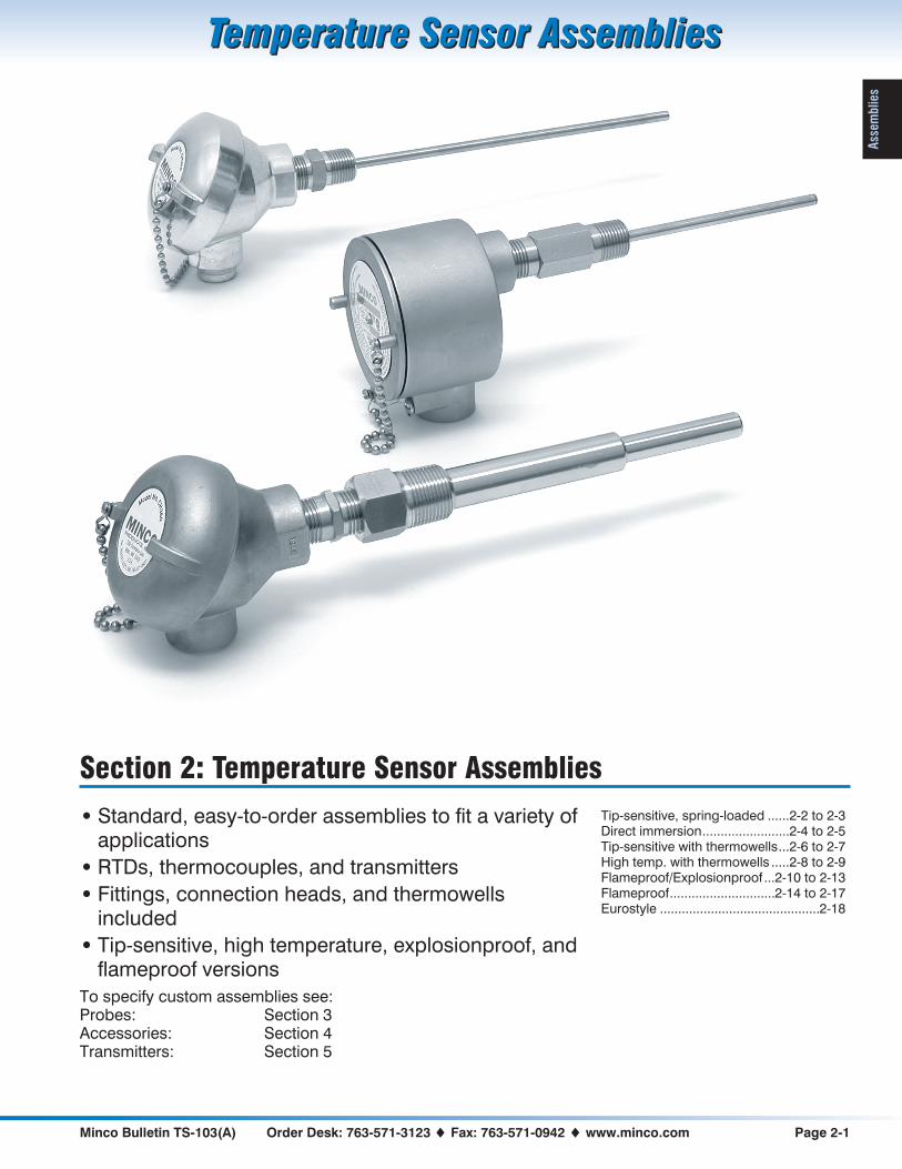
5.0" (127 mm) MAX. INSERTION DEPTH D
1.0" (25 mm) MINIMUM
CONDUIT THREAD
½ –14 NPT0.250" (6.4 mm)
DIAMETER
Tip-Sensitive Spring-Loaded RTDs• Tip-sensitive RTD probe for use to
260°C (500°F)
• Spring-loaded holder with fluid seal
• Cast iron, stainless steel, or aluminumconnection head
Get fast and accurate readings frombearings, blocks, and other solids.Minco’s spring-loaded holder ensuressolid contact in drilled holes and has abuilt-in oil seal. The sensing probefeatures a copper alloy tip for quickresponse to temperature changes.
Specifications
Temperature range:-50 to 260°C (-58 to 500°F).Material:Probe: Stainless steel with copper alloy tip.Holder: Stainless steel with Viton O-ring.Connection head: Cast iron, aluminum, or
stainless steel.Pressure rating: 50 psi (3.4 bar).Insulation resistance: 100 megohms min. at100 VDC, leads to case.Connection: Terminal block for wires toAWG 14.Time constant: Typical value in moving water:Single element: 2.0 seconds.Dual element: 3.0 seconds.
Sensing element Code
Platinum 392 100 � ±0.5% at 0°C PA
Platinum 385 100 � ±0.1% at 0°C(Meets EN60751, Class B)
PD
Platinum 385 100 � ±0.5% at 0°C PE
Copper 10 � ±0.2% at 25°C CA
(dual) 10 � ±0.5% at 25°C CC
Nickel 120 � ±0.5% at 0°C NA
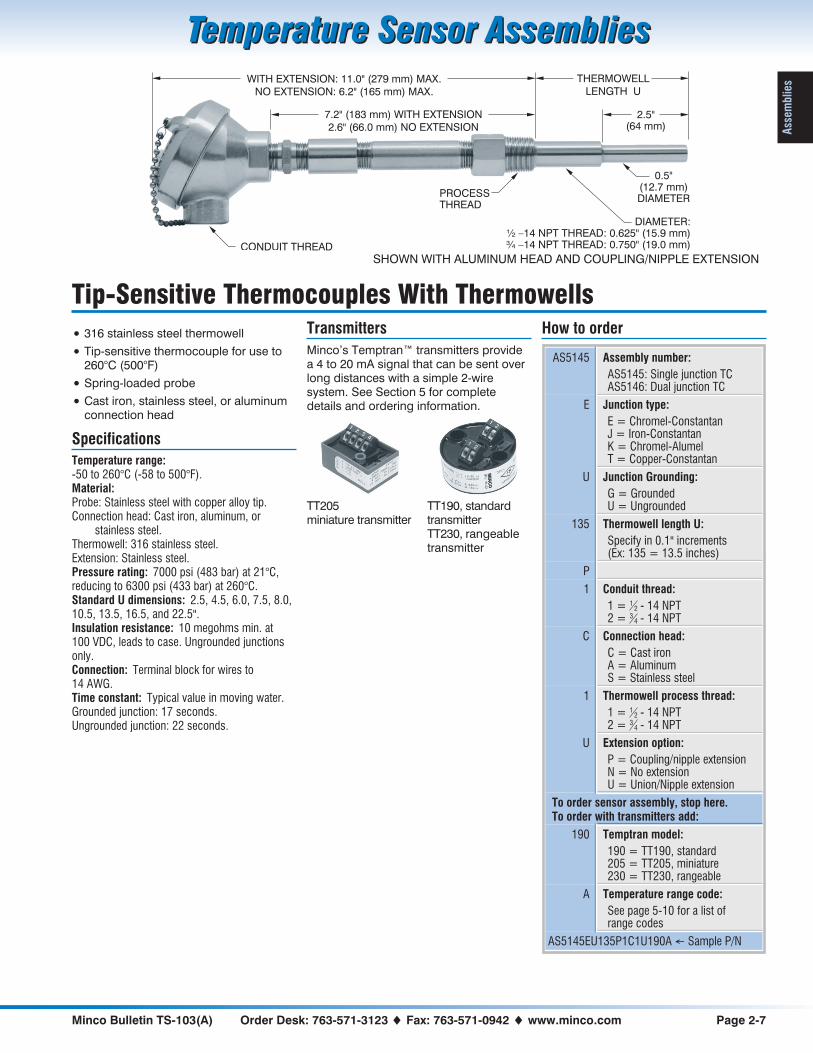
Transmitters
Minco’s Temptran™ transmitters providea 4 to 20 mA signal that can be sent overlong distances with a simple 2-wiresystem. Add any Minco model transmitter(except electrically isolated models). SeeSection 5 for complete details andordering information.
Special high-accuracy calibration
For guaranteed system accuracy of± 0.75% of temperature span, specifytransmitters with high-accuracycalibration as shown on page 5-18.Calibration data traceable to NIST willalso be provided.
How to order
AS5004 Assembly number:
AS5004: Single element RTDAS5005: Dual element RTD
PA Sensing element from table
67 Insertion depth D:
Specify in 0.1" increments(Ex: 67 = 6.7 inches)
Z Leads per sensing element:
Y = 2 leadsZ = 3 leads (required for
CA and CC copper elements)X = 4 leads (PD elements only)
2 Conduit thread:
1 = 12 - 14 NPT
2 = 34 - 14 NPT
C Connection head:
C = Cast ironA = AluminumS = Stainless steel
To order sensor assembly, stop here.To order with transmitters (singleplatinum element only, 2 or 3 leads) add:
211 Temptran model:
211 = TT211: 2-lead RTDs176 = TT176: 3-lead RTDs711 = TT711: 2-lead RTDs,
match calibrated676 = TT676: 3-lead RTDs,
match calibrated
A Temperature range code:
See page 5-10 for a list ofrange codes
AS5004PA67Z2C211A � Sample P/N
IN STOCK
Single element models (except PE)Contact Minco for currently available Temptranmodels and ranges
SHOWN WITH STAINLESS STEEL HEAD
TT176, TT676standard transmitter
TT211, TT711miniature transmitter

Minco Bulletin TS-103(A) Order Desk: 763-571-3123 � Fax: 763-571-0942 � www.minco.com Page 2-3
Temperature Sensor AssembliesTemperature Sensor Assemblies
Ass
emblies
5.0" (127 mm) MAX. INSERTION DEPTH D
1.0" (25mm) MINIMUM
CONDUIT THREAD
½ –14 NPT0.250" (6.4 mm)
DIAMETER
Tip-Sensitive Spring-Loaded Thermocouples
• Tip-sensitive Thermocouple for use to260°C (500°F)
• Spring-loaded holder with fluid seal
• Cast iron, stainless steel or aluminumconnection head
Get fast and accurate readings frombearings, blocks, and other solids.Minco’s spring-loaded holder ensuressolid contact in drilled holes and has abuilt-in oil seal. The sensing probefeatures a copper alloy tip for quickresponse to temperature changes.
Specifications
Temperature range:-50 to 260°C (-58 to 500°F).Material:Probe: Stainless steel with copper alloy tip.Holder: Stainless steel with Viton O-ring.Connection head: Cast iron, aluminum, or
stainless steel.Pressure rating: 50 psi (3.4 bar).Insulation resistance: 10 megohms min. at100 VDC, leads to case. Ungrounded junctionsonly.Connection: Terminal block for wires to14 AWG.Time constant: Typical value in moving water:Grounded junction: 1.5 seconds.Ungrounded junction: 7 seconds.
Transmitters
Minco’s Temptran™ transmitters providea 4 to 20 mA signal that can be sent overlong distances with a simple 2-wiresystem. See Section 5 for completedetails and ordering information.
How to order
AS5192 Assembly number:
AS5191: Single junctionAS5192: Dual junction
E Junction type:
E = Chromel-ConstantanJ = Iron-ConstantanK = Chromel-AlumelT = Copper-Constantan
U Junction grounding:
G = GroundedU = Ungrounded
133 Insertion depth D:
Specify in 0.1" increments(Ex: 133 = 13.3 inches)
P
1 Conduit thread:
1 = 12 - 14 NPT
2 = 34 - 14 NPT
C Connection head:
C = Cast ironA = AluminumS = Stainless steel
To order sensor assembly, stop here.To order with transmitter, add:
190 Temptran model:
190 = TT190, standard205 = TT205, miniature230 = TT230, rangeable
A Temperature range code:
See page 5-10 for a list ofrange codes
AS5192EU133P1C190A � Sample P/N
SHOWN WITH ALUMINUM HEAD
TT205miniature transmitter
TT190, standardtransmitterTT230, rangeabletransmitter

Page 2-4 Sales: 763-571-3121 � Fax: 763-571-0927 � www.minco.com Minco Bulletin TS-103(A)
Temperature Sensor AssembliesTemperature Sensor Assemblies
Assem
blies
Tip Sensitive Direct Immersion RTDs
• RTD probe for use to 260°C (500°F)
• Adjustable fluid seal fitting
• Cast iron, stainless steel, or aluminumconnection head
Mount sensors directly in fluid flow for fastresponse. Probes are rated to 100 psi (6.9bar). For non-corrosive fluids only.
Specifications
Temperature range:-50 to 260°C (-58 to 500°F).Material:Probe: Stainless steel with copper alloy tip.Fitting: Stainless steel, silicone rubber O-ring.Connection head: Cast iron, aluminum, or
stainless steel.Pressure rating: 100 psi (6.9 bar).Insulation resistance: 100 megohms min. at100 VDC, leads to case.Connection: Terminal block for wires to14 AWG.Time constant: Typical value in moving water:Single element: 2.0 seconds.Dual element: 3.0 seconds.
Sensing element Code
Platinum 392 100 � ±0.5% at 0°C PA
Platinum 385 100 � ±0.1% at 0°C(Meets EN60751, Class B)
PD
Platinum 385 100 � ±0.5% at 0°C PE
Copper 10 � ±0.2% at 25°C CA
(dual) 10 � ±0.5% at 25°C CC
Nickel 120 � ±0.5% at 0°C NA
Transmitters
Minco’s Temptran™ transmitters providea 4 to 20 mA signal that can be sent overlong distances with a simple 2-wiresystem. Add any Minco model transmitter(except electrically isolated models). SeeSection 5 for complete details andordering information.
Special high-accuracy calibration
For guaranteed system accuracy of± 0.75% of temperature span, specifytransmitters with high-accuracycalibration as shown on page 5-18.Calibration data traceable to NIST willalso be provided.
How to order
AS5200 Assembly number:
AS5200: Single elementAS5201: Dual element
PD Sensing element from table
100 Insertion depth D:
Specify in 0.1" increments(Ex: 100 = 10.0 inches)
Z Number of leads per sensingelement:
Y = 2 leadsZ = 3 leads (required for
CA and CC copper elements)X = 4 leads (PD elements only)
2 Conduit thread:
1 = 12 - 14 NPT
2 = 34 - 14 NPT
C Connection head:
C = Cast ironA = AluminumS = Stainless steel
To order sensor assembly, stop here.To order with transmitters (singleplatinum element only, 2 or 3 leads) add:
211 Temptran model:
211 = TT211: 2-lead RTDs176 = TT176: 3-lead RTDs711 = TT711: 2-lead RTDs,
match calibrated676 = TT676: 3-lead RTDs,
match calibrated
A Temperature range code:
See page 5-10 for a list ofrange codes
AS5200PD100Z2C211A � Sample P/N
5.0" (127 mm) MAX. INSERTION DEPTH D
CONDUIT THREAD
½ –14 NPT0.250" (6.4 mm)
DIAMETER
IN STOCK
Single element models (except PE)Contact Minco for currently available Temptranmodels and ranges
TT176, TT676standard transmitter
TT211, TT711miniature transmitter
SHOWN WITH CAST IRON HEAD

Minco Bulletin TS-103(A) Order Desk: 763-571-3123 � Fax: 763-571-0942 � www.minco.com Page 2-5
Temperature Sensor AssembliesTemperature Sensor Assemblies
Ass
emblies
Tip Sensitive Direct Immersion Thermocouples
• Thermocouple for use to 260°C (500°F)
• Adjustable fluid seal fitting
• Cast iron, stainless steel or aluminumconnection head
Mount sensors directly in fluid flow for fastresponse. Probes are rated to 100 psi(6.9 bar). For non-corrosive fluids only.
Specifications
Temperature range:-50 to 260°C (-58 to 500°F).Material:Probe: Stainless steel with copper alloy tip.Fitting: Stainless steel, silicone rubber O-ring.Connection head: Cast iron, aluminum, or
stainless steel.Pressure rating: 100 psi (6.9 bar).Insulation resistance: 10 megohms min. at100 VDC, leads to case. Ungrounded junctionsonly.Connection: Terminal block for wires to14 AWG.Time constant: Typical value in moving water:Grounded junction: 1.5 seconds.Ungrounded junction: 7 seconds.
Transmitters
Minco’s Temptran™ transmitters providea 4 to 20 mA signal that can be sent overlong distances with a simple 2-wiresystem. See Section 5 for completedetails and ordering information.
How to order
AS5206 Assembly number:
AS5205: Single junctionAS5206: Dual junction
E Junction type:
E = Chromel-ConstantanJ = Iron-ConstantanK = Chromel-AlumelT = Copper-Constantan
U Junction grounding:
G = GroundedU = Ungrounded
215 Insertion depth D:
Specify in 0.1" increments(Ex: 215 = 21.5 inches)
P
1 Conduit thread:
1 = 12 - 14 NPT
2 = 34 - 14 NPT
C Connection head:
C = Cast ironA = AluminumS = Stainless steel
To order sensor assembly, stop here.To order with transmitters add:
190 Temptran model:
190 = TT190, standard205 = TT205, miniature230 = TT230, rangeable
A Temperature range code:
See page 5-10 for a list ofrange codes
AS5206EU215P1C190A � Sample P/N
5.0" (127 mm) MAX. INSERTION DEPTH D
CONDUIT THREAD
½ –14 NPT0.250" (6.4 mm)
DIAMETER
SHOWN WITH ALUMINUM HEAD
TT190, standardtransmitterTT230, rangeabletransmitter
TT205miniature transmitter

Page 2-6 Sales: 763-571-3121 � Fax: 763-571-0927 � www.minco.com Minco Bulletin TS-103(A)
Temperature Sensor AssembliesTemperature Sensor Assemblies
Assem
blies
Tip-Sensitive RTDs With Thermowells
• 316 stainless steel thermowell
• Tip-sensitive RTD probe for use to260°C (500°F)
• Spring-loaded probe
• Cast iron, stainless steel, or aluminumconnection head
Thermowells protect sensors from theeffects of fluid flow and pressure. Theseassemblies are spring-loaded for positiveprobe contact against the bottom of thethermowell. The probe’s copper alloy tipprovides superior time response andreduces error from stem conduction.
Specifications
Temperature range:-50 to 260°C (-58 to 500°F).Material:Probe: Stainless steel with copper alloy tip.Connection head: Cast iron, aluminum, or
stainless steel.Thermowell: 316 stainless steel.Extension: Stainless steel.Pressure rating: 7000 psi (483 bar) at 21°C,reducing to 6300 psi (433 bar) at 260°C.Standard U dimensions: 2.5, 4.5, 6.0, 7.5, 8.0,10.5, 13.5, 16.5, and 22.5".Insulation resistance: 100 megohms min. at100 VDC, leads to case.Connection: Terminal block for wires to14 AWG.Time constant: 17 seconds typical in movingwater.
Sensing element Code
Platinum 392 100 � ±0.5% at 0°C PA
Platinum 385 100 � ±0.1% at 0°C(Meets EN60751, Class B)
PD
Platinum 385 100 � ±0.5% at 0°C PE
Copper 10 � ±0.2% at 25°C CA
(dual) 10 � ±0.5% at 25°C CC
Nickel 120 � ±0.5% at 0°C NA
Transmitters
Minco’s Temptran™ transmitters providea 4 to 20 mA signal that can be sent overlong distances with a simple 2-wiresystem. Add any Minco model transmitter(except electrically isolated models). SeeSection 5 for complete details andordering information.
Special high-accuracy calibration
For guaranteed system accuracy of± 0.75% of temperature span, specifytransmitters with high-accuracycalibration as shown on page 5-18.Calibration data traceable to NIST willalso be provided.
How to order
AS5140 Assembly number:
AS5140: Single element RTDAS5141: Dual element RTD
CA Sensing element from table
60 Thermowell length U:
Specify in 0.1" increments(Ex: 60 = 6.0 inches)
Z Leads per sensing element:
Y = 2 leadsZ = 3 leads (required for
CA and CC copper elements)X = 4 leads (PD elements only)
2 Conduit thread:
1 = 12 - 14 NPT
2 = 34 - 14 NPT
C Connection head:
C = Cast ironA = AluminumS = Stainless steel
1 Thermowell process thread:
1 = 12 - 14 NPT
2 = 34 - 14 NPT
U Extension option:
P = Coupling/nipple extensionN = No extensionU = Union/Nipple extension
To order sensor assembly, stop here.To order with transmitters (singleplatinum element only, 2 or 3 leads) add:
211 Temptran model:
211 = TT211: 2-lead RTDs176 = TT176: 3-lead RTDs711 = TT711: 2-lead RTDs,
match calibrated676 = TT676: 3-lead RTDs,
match calibrated
A Temperature range code:
See page 5-10 for a list ofrange codes
AS5140CA60Z2C1U211A � Sample P/N
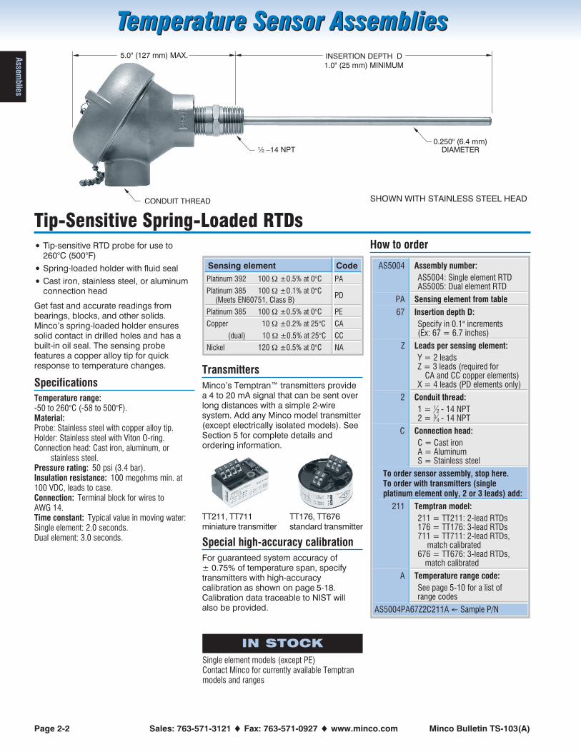
THERMOWELL
LENGTH U
CONDUIT THREAD
DIAMETER:½ –14 NPT THREAD: 0.625" (15.9 mm)¾ –14 NPT THREAD: 0.750" (19.0 mm)
PROCESSTHREAD
0.5"(12.7 mm)DIAMETER
2.5"(64 mm)
WITH EXTENSION: 11.0" (279 mm) MAX.
NO EXTENSION: 6.2" (165 mm) MAX.
7.2" (183 mm) WITH EXTENSION
2.6" (66.0 mm) NO EXTENSION
TT211, TT711miniature transmitter
TT176, TT676standard transmitter
IN STOCK
Standard thermowell lengths to 8.0"Single element models (except PE)Contact Minco for currently available Temptranmodels and ranges
SHOWN WITH STAINLESS STEEL HEAD AND UNION/NIPPLE EXTENSION
Minco Bulletin TS-103(A) Order Desk: 763-571-3123 � Fax: 763-571-0942 � www.minco.com Page 2-7
Temperature Sensor AssembliesTemperature Sensor Assemblies
Ass
emblies
Tip-Sensitive Thermocouples With Thermowells
• 316 stainless steel thermowell
• Tip-sensitive thermocouple for use to260°C (500°F)
• Spring-loaded probe
• Cast iron, stainless steel, or aluminumconnection head
Specifications
Temperature range:-50 to 260°C (-58 to 500°F).Material:Probe: Stainless steel with copper alloy tip.Connection head: Cast iron, aluminum, or
stainless steel.Thermowell: 316 stainless steel.Extension: Stainless steel.Pressure rating: 7000 psi (483 bar) at 21°C,reducing to 6300 psi (433 bar) at 260°C.Standard U dimensions: 2.5, 4.5, 6.0, 7.5, 8.0,10.5, 13.5, 16.5, and 22.5".Insulation resistance: 10 megohms min. at100 VDC, leads to case. Ungrounded junctionsonly.Connection: Terminal block for wires to14 AWG.Time constant: Typical value in moving water.Grounded junction: 17 seconds.Ungrounded junction: 22 seconds.
Transmitters
Minco’s Temptran™ transmitters providea 4 to 20 mA signal that can be sent overlong distances with a simple 2-wiresystem. See Section 5 for completedetails and ordering information.
How to order
AS5145 Assembly number:
AS5145: Single junction TCAS5146: Dual junction TC
E Junction type:
E = Chromel-ConstantanJ = Iron-ConstantanK = Chromel-AlumelT = Copper-Constantan
U Junction Grounding:
G = GroundedU = Ungrounded
135 Thermowell length U:
Specify in 0.1" increments(Ex: 135 = 13.5 inches)
P
1 Conduit thread:
1 = 12 - 14 NPT
2 = 34 - 14 NPT
C Connection head:
C = Cast ironA = AluminumS = Stainless steel
1 Thermowell process thread:
1 = 12 - 14 NPT
2 = 34 - 14 NPT
U Extension option:
P = Coupling/nipple extensionN = No extensionU = Union/Nipple extension
To order sensor assembly, stop here.To order with transmitters add:
190 Temptran model:
190 = TT190, standard205 = TT205, miniature230 = TT230, rangeable
A Temperature range code:
See page 5-10 for a list ofrange codes
AS5145EU135P1C1U190A � Sample P/N
WITH EXTENSION: 11.0" (279 mm) MAX.
NO EXTENSION: 6.2" (165 mm) MAX.
THERMOWELL
LENGTH U
CONDUIT THREAD
DIAMETER:½ –14 NPT THREAD: 0.625" (15.9 mm)¾ –14 NPT THREAD: 0.750" (19.0 mm)
PROCESSTHREAD
0.5"(12.7 mm)DIAMETER
2.5"(64 mm)
7.2" (183 mm) WITH EXTENSION
2.6" (66.0 mm) NO EXTENSION
SHOWN WITH ALUMINUM HEAD AND COUPLING/NIPPLE EXTENSION
TT205miniature transmitter
TT190, standardtransmitterTT230, rangeabletransmitter

Page 2-8 Sales: 763-571-3121 � Fax: 763-571-0927 � www.minco.com Minco Bulletin TS-103(A)
Temperature Sensor AssembliesTemperature Sensor Assemblies
Assem
blies
550°C RTDs With Thermowells
• 316 stainless steel thermowell
• RTD probe for use to 550°C (1022°F)
• Spring-loaded probe
• Cast iron, stainless steel, or aluminumconnection head
Sense temperature in high-pressure fluidsand gases. These assemblies arespring-loaded for positive probe contactagainst the bottom of the thermowell.
Note: For temperatures less than 260°C(500°F), assemblies using tip-sensitivesensors are recommended.
Specifications
Temperature range:Thermowell and sensor:
-100 to 550°C (-148 to 1022°F).Connection head:
Cast iron: 260°C (500°F) max.Aluminum: 316°C (600°F) max.Stainless steel: 121°C (250°F) max.
Material:Probe: 316 stainless steel.Connection head: Cast iron, aluminum, or
stainless steel.Thermowell: 316 stainless steel.Extension: Stainless steel.Pressure rating: 7000 psi (483 bar) at 21°C,reducing to 2500 psi (172 bar) at 550°C.Standard U dimensions: 2.5, 4.5, 6.0, 7.5, 8.0,10.5, 13.5, 16.5, and 22.5".Insulation resistance: 10 megohms min. at100 VDC, leads to case.Connection: Terminal block for wires to14 AWG.Time constant:23 seconds typical in moving water.
Sensing element Code
Platinum 391 100 � ±0.1% at 0°C PB
Platinum 385 100 � ±0.1% at 0°C(Meets EN60751, Class B)
PD
Transmitters
Minco’s Temptran™ transmitters providea 4 to 20 mA signal that can be sent overlong distances with a simple 2-wiresystem. Add any Minco model transmitter(except electrically isolated models). SeeSection 5 for complete details andordering information.
Special high-accuracy calibration
For guaranteed system accuracy of± 0.75% of temperature span, specifytransmitters with high-accuracycalibration as shown on page 5-18.Calibration data traceable to NIST willalso be provided.
How to order
AS5160 Assembly number: AS5160
PB Sensing element from table
105 Thermowell length U:
Specify in 0.1" increments(Ex: 105 =10.5 inches)
Z Number of leads:
Y = 2 leadsZ = 3 leadsX = 4 leads (PD elements only)
2 Conduit thread:
1 = 12 - 14 NPT
2 = 34 - 14 NPT
C Connection head:
C = Cast ironA = AluminumS = Stainless steel
1 Thermowell process thread:
1 = 12 - 14 NPT
2 = 34 - 14 NPT
U Extension option:
P = Coupling/nipple extensionN = No extensionU = Union/Nipple extension
To order sensor assembly, stop here.To order with transmitters (2 or 3 leads),add:
211 Temptran model:
211 = TT211: 2-lead RTDs176 = TT176: 3-lead RTDs711 = TT711: 2-lead RTDs,
match calibrated676 = TT676: 3-lead RTDs,
match calibrated
A Temperature range code:
See page 5-10 for a list ofrange codes
AS5160PB105Z2C1U211A � Sample P/N
THERMOWELL
LENGTH U
CONDUIT THREAD
DIAMETER:½ –14 NPT THREAD: 0.625" (15.9 mm)¾ –14 NPT THREAD: 0.750" (19.0 mm)
PROCESSTHREAD
0.5"(12.7 mm)DIAMETER
2.5"(64 mm)
WITH EXTENSION: 11.0" (279 mm) MAX.
NO EXTENSION: 6.2" (165 mm) MAX.
7.2" (183 mm) WITH EXTENSION
2.6" (66.0 mm) NO EXTENSION
IN STOCK
Standard thermowell dimensions 2.5, 4.5, 6.0,7.5, 8.0"Single element models (except PE)Contact Minco for currently available Temptranmodels and ranges
SHOWN WITH STAINLESS STEEL HEAD AND UNION/NIPPLE EXTENSION
TT176, TT676standard transmitter
TT211, TT711miniature transmitter

Minco Bulletin TS-103(A) Order Desk: 763-571-3123 � Fax: 763-571-0942 � www.minco.com Page 2-9
Temperature Sensor AssembliesTemperature Sensor Assemblies
Ass
emblies
550°C Thermocouples With Thermowells
• 316 stainless steel thermowell
• Thermocouple probe for use to 550°C(1022°F)
• Spring-loaded probe
• Cast iron, aluminum or stainless steelconnection head
Sense temperature in high-pressure fluidsand gases. These assemblies arespring-loaded for positive probe contactagainst the bottom of the thermowell.
Note: For temperatures less than 260°C(500°F), assemblies using tip-sensitivesensors are recommended.
Specifications
Temperature range:Thermowell and sensor:
-100 to 550°C (-148 to 1022°F).Connection head:
Cast iron: 260°C (500°F) max.Aluminum: 316°C (600°F) max.Stainless steel: 121°C (250°F) max.
Material:Probe: 316 stainless steel.Connection head: Cast iron, aluminum, or
stainless steel.Thermowell: 316 stainless steel.Extension: Stainless steel.Pressure rating: 7000 psi (483 bar) at 21°C,reducing to 2500 psi (172 bar) at 550°C.Standard U dimensions: 2.5, 4.5, 6.0, 7.5, 8.0,10.5, 13.5, 16.5, and 22.5".Insulation resistance: 10 megohms min. at100 VDC, leads to case. Ungrounded junctionsonly.Connection: Terminal block for wires to14 AWG.Time constant: 60 seconds typical in movingwater.
Transmitters
Minco’s Temptran™ transmitters providea 4 to 20 mA signal that can be sent overlong distances with a simple 2-wiresystem. See Section 5 for completedetails and ordering information.
How to order
AS5165 Assembly number: AS5165
K Junction type:
E = Chromel-ConstantanJ = Iron-ConstantanK = Chromel-Alumel
U Junction grounding:
G = GroundedU = Ungrounded
135 Thermowell length U:
Specify in 0.1" increments(Ex: 135 = 13.5 inches)
P
1 Conduit thread:
1 = 12 - 14 NPT
2 = 34 - 14 NPT
C Connection head:
C = Cast ironA = AluminumS = Stainless steel
1 Thermowell process thread:
1 = 12 - 14 NPT
2 = 34 - 14 NPT
U Extension option:
P = Coupling/nipple extensionN = No extensionU = Union/Nipple extension
To order sensor assembly, stop here.To order with transmitters add:
190 Temptran model:
190 = TT190, standard205 = TT205, miniature230 = TT230, rangeable
A Temperature range code:
See page 5-10 for a list ofrange codes
AS5165KU135P1C1U190A � Sample P/N
WITH EXTENSION: 11.0" (279 mm) MAX.
NO EXTENSION: 6.2" (165 mm) MAX.
THERMOWELL
LENGTH U
CONDUIT THREAD
DIAMETER:½ –14 NPT THREAD: 0.625" (15.9 mm)¾ –14 NPT THREAD: 0.750" (19.0 mm)
PROCESSTHREAD
0.5"(12.7 mm)DIAMETER
2.5"(64 mm)
7.2" (183 mm) WITH EXTENSION
2.6" (66.0 mm) NO EXTENSION
SHOWN WITH ALUMINUM HEAD AND COUPLING/NIPPLE EXTENSION
TT205miniature transmitter
TT190, standardtransmitterTT230, rangeabletransmitter

Page 2-10 Sales: 763-571-3121 � Fax: 763-571-0927 � www.minco.com Minco Bulletin TS-103(A)
Temperature Sensor AssembliesTemperature Sensor Assemblies
Assem
blies
Flameproof/Explosionproof Sensors
• Tip sensitive, all stainless or MgO filledprobes available
• RTD or thermocouple sensors
• Hazardous area rated
Specifications
Temperature range:-50 to 260°C (-58 to 500°F).Material:Probe: Stainless steel (tip sensitive models have
copper alloy tip).Holder: Stainless steel.Connection head:
Copper free aluminum alloy (CH104)316L stainless steel (CH106).
Pressure rating: See table on facing page.Insulation resistance: 10 megohms min. at100 VDC, leads to case. Ungrounded junctionsonly on thermocouples.Connection: Terminal block for wires to14 AWG.Time constant: Typical value in moving water.Tip sensitive: 3 seconds.All stainless and MgO filled: 10 seconds.Explosionproof and flameproof ratings:National and Canadian Electrical Code:
Class I, Divisions 1 and 2, Groups B, C, and D,Class II, Groups E, F, and G,T6 (Ta = 40°C),T2 (Ta = 260°C). Ta limited to 160°C for CSAClass II locations.
National Electrical Code (Article 505):Class I, Zones 1 and 2, AEx d IIC,T6 (Ta =40°C), T2 (Ta = 260°C).
Canadian Electrical Code (IEC 60079):Zones 1 and 2, Ex d IIC,T6 (Ta = 40°C), T2 (Ta = 260°C).
How to order RTDs
AS720 Assembly number:
(see table on facing page)
4 Connection head/fitting:
(see table on facing page)
PD Sensing element:
(see table on facing page)
100 Insertion depth D (in mm):
(43–1219 mm)
X Number of leads:
Y = 2 leads (n/a for copper)Z = 3 leadsX = 4 leads (n/a for dual models)
3 Conduit thread:
3 = 12 - 14 NPT
4 = 34 - 14 NPT
AS7204PD100X3 � Sample P/N
How to order thermocouples
AS706 Assembly number:
(see table on facing page)
4 Connection head/fitting:
(see table on facing page)
E Junction type:
(see table on facing page)
U Junction Grounding:
G = GroundedU = Ungrounded
100 Insertion depth D (in mm):
(27–3000 mm)
P
3 Conduit thread:
3 = 12 - 14 NPT
4 = 34 - 14 NPT
AS7064EU100P3 � Sample P/N
� Order thermocouple transmittersseparately. See section 5 to order.
Transmitters
Minco’s Temptran™ transmitters providea 4 to 20 mA signal that can be sent overlong distances with a simple 2-wiresystem. See Section 5 for completedetails and ordering information.
L REF. INSERTION DEPTH D
27 mm MINIMUM
CONDUIT THREAD
Ex d IIC
AEx d IIC
Hazardous Area Requirements
Request Application Aid #19 for information on how to classify a hazardousarea, methods of protection, and the various standards and agencies(including FM, CSA, CENELEC and ATEX).
TT205miniature transmitter
TT190, standardtransmitterTT230, rangeabletransmitter

Minco Bulletin TS-103(A) Order Desk: 763-571-3123 � Fax: 763-571-0942 � www.minco.com Page 2-11
Temperature Sensor AssembliesTemperature Sensor Assemblies
Ass
embliesFlameproof/Explosionproof Sensors
RTDs
Probe diameters 0.215" (5.5 mm) 0.236" (6.0 mm) 0.250" (6.4 mm)
Number of elements Single Dual Single Dual Single Dual
Tip-sensitive AS760 AS761 AS700 AS701 AS720 AS721
All stainless AS762 AS763 AS702 AS703 AS722 AS723
MgO filled (platinum only) AS704 AS724
Sensing element Code
Single Dual
Platinum 392 100 � ±0.5% at 0°C PA PAPA
Platinum 385 100 � ±0.1% at 0°C(Meets EN60751, Class B)
PD PDPD
Platinum 385 100 � ±0.5% at 0°C PE PEPE
Copper 10 � ±0.2% at 25°C CA
(dual) 10 � ±0.5% at 25°C CCCC
Nickel 672 120 � ±0.5% at 0°C NA NANA
Nickel 618 100 � ±0.22% at 0°C NB NBNB
Thermocouples
Probe diameters 0.215" (5.5 mm) 0.236" (6.0 mm) 0.250" (6.4 mm)
Number of elements Single Dual Single Dual Single Dual
Tip-sensitive AS766 AS767 AS706 AS707 AS726 AS727
MgO filled AS708 AS709 AS728 AS729
Thermocouple Junction Code
Single Dual
Chromel-Constantan E EE
Iron-Constantan J JJ
Chromel-Alumel K KK
Copper-Constantan T TT
Connection head and fitting options
CH104: Aluminum IP65, Type 3 and 4.CH106: 316L stainless steel IP66, Type 3, 4, and 4X.
Fitting Process thread Pressure Rating L REF. Head Code
Welded 12 - 14 NPT 200 psi (13.8 bar) 4.4" (112 mm) CH104 0*
Welded 12 - 14 NPT 200 psi (13.8 bar) 4.2" (106 mm) CH106 1*
Welded G12 200 psi (13.8 bar) 4.2" (107 mm) CH104 2*
Welded G12 200 psi (13.8 bar) 4.0" (101 mm) CH106 3*
Spring-loaded holder 12 - 14 NPT 50 psi (3.4 bar) 5.7" (144 mm) CH104 4
Spring-loaded holder 12 - 14 NPT 50 psi (3.4 bar) 5.4" (138 mm) CH106 5
Spring-loaded holder G12 50 psi (3.4 bar) 5.7" (144 mm) CH104 6
Spring-loaded holder G12 50 psi (3.4 bar) 5.4" (138 mm) CH106 7
* 0.250 diameter only for all stainless and MgO probes.
� Connection head dimensions are found on pages 4-2 to 4-3.

Page 2-12 Sales: 763-571-3121 � Fax: 763-571-0927 � www.minco.com Minco Bulletin TS-103(A)
Temperature Sensor AssembliesTemperature Sensor Assemblies
Assem
blies
L REF. INSERTION DEPTH D
27 mm MINIMUM
CONDUIT THREAD
Flameproof/Explosionproof RTDs With Transmitters
• Tip sensitive, all stainless or MgO filledRTD probe
• Temptran transmitter for long signalpath
• Hazardous area rated
Specifications
Temperature range:-50 to 260°C (-58 to 500°F).Material:Probe: Stainless steel (tip sensitive models have
copper alloy tip).Holder: Stainless steel.Connection head:
Copper free aluminum alloy (CH104)316L stainless steel (CH106).
Pressure rating: See table on facing page.Insulation resistance: 10 megohms min. at100 VDC, leads to case.Connection: Terminal block for wires to14 AWG.Time constant: Typical value in moving water.Tip sensitive: 3 seconds.All stainless and MgO filled: 10 seconds.Explosionproof and flameproof ratings:National and Canadian Electrical Code:
Class I, Divisions 1 and 2, Groups B, C, and D,Class II, Groups E, F, and G,T6 (Ta = 40°C),T2 (Ta = 260°C). Ta limited to 160°C for CSAClass II locations.
National Electrical Code (Article 505):Class I, Zones 1 and 2, AEx d IIC,T6 (Ta =40°C), T2 (Ta = 260°C).
Canadian Electrical Code (IEC 60079):Zones 1 and 2, Ex d IIC,T6 (Ta = 40°C), T2 (Ta = 260°C).
Transmitters
Output: 4 to 20 mA over specified range, linearwith temperature.Calibration accuracy: ±0.1% of span.Linearity: 0.1% of span.Adjustments: Zero and span, ±5% of span.Factory calibrated to nominal R/T curve.Ambient operating temperature:TT211, TT711: -25 to 85°C (-13 to 185°F).TT176, TT676: -40 to 85°C (-40 to 185°F).Supply voltage: 10 to 35 VDC.Maximum load resistance:
RV
loop max
supply�
� 10
0.020 amps
Leadwires:TT211, TT711: 2-lead RTD.TT176, TT676: 3-lead RTD for resistancecompensation.Physical: Epoxy potted for moisture resistance.Mounting: Transmitter mounts in connectionhead.
Special high-accuracy calibration
For guaranteed system accuracy of± 0.75% of temperature span, specifytransmitters with high-accuracycalibration as shown on page 5-18.Calibration data traceable to NIST willalso be provided.
How to order
AS710 Assembly number:
(see table on facing page)
4 Connection head/fitting:
(see table on facing page)
TT176 Temptran model number:
TT211: 2-lead RTDsTT176: 3-lead RTDsTT711: 2-lead RTDs,
match calibratedTT676: 3-lead RTDs,
match calibrated
N Code for temperature range:
(see table on facing page)
100 Insertion depth D (in mm):
(27 – 3000 mm)
PD Sensing element
3 Conduit thread:
3 = 12 - 14 NPT
4 = 34 - 14 NPT
AS7104TT176N100PD3 � Sample P/N
TT211, TT711miniature transmitter
TT176, TT676standard transmitter
Ex d IIC
AEx d IIC
Hazardous Area Requirements
Request Application Aid #19 for information on how to classify a hazardousarea, methods of protection, and the various standards and agencies(including FM, CSA, CENELEC and ATEX).

Minco Bulletin TS-103(A) Order Desk: 763-571-3123 � Fax: 763-571-0942 � www.minco.com Page 2-13
Temperature Sensor AssembliesTemperature Sensor Assemblies
Ass
embliesFlameproof/Explosionproof RTDs With Transmitters
RTD with Transmitter
Probe diameters 0.215" (5.5 mm) 0.236" (6.0 mm) 0.250" (6.4 mm)
Tip-sensitive AS770 AS710 AS730
All stainless AS772 AS712 AS732
MgO filled AS714 AS734
Transmitters:
Popular ranges:
Code Range
EO -50 to 100°C -58 to 212°F
BC -30 to 30°C -22 to 86°F
S -17.8 to 37.8°C 0 to 100°F
AC -17.8 to 93.3°C 0 to 200°F
AN -17.8 to 148.9°C 0 to 300°F
AG -17.8 to 260°C 0 to 500°F
AP -6.7 to 21.1°C 20 to 70°F
A -6.7 to 48.9°C 20 to 120°F
N 0 to 50°C 32 to 122°F
C 0 to 100°C 32 to 212°F
J 0 to 150°C 32 to 302°F
K 0 to 200°C 32 to 392°F
V 10 to 65.6°C 50 to 150°F
P 37.8 to 179.4°C 100 to 355°F
BH 50 to 150°C 122 to 302°F
� Complete range table is on page 5-10.
Connection head and fitting options
CH104: Aluminum IP65, Type 3 and 4.CH106: 316L stainless steel IP66, Type 3, 4, and 4X.
Fitting Process thread Pressure Rating L REF. Head Code
Welded 12 - 14 NPT 200 psi (13.8 bar) 4.4" (112 mm) CH104 0*
Welded 12 - 14 NPT 200 psi (13.8 bar) 4.2" (106 mm) CH106 1*
Welded G12 200 psi (13.8 bar) 4.2" (107 mm) CH104 2*
Welded G12 200 psi (13.8 bar) 4.0" (101 mm) CH106 3*
Spring-loaded holder 12 - 14 NPT 50 psi (3.4 bar) 5.7" (144 mm) CH104 4
Spring-loaded holder 12 - 14 NPT 50 psi (3.4 bar) 5.4" (138 mm) CH106 5
Spring-loaded holder G12 50 psi (3.4 bar) 5.7" (144 mm) CH104 6
Spring-loaded holder G12 50 psi (3.4 bar) 5.4" (138 mm) CH106 7
* 0.250 diameter only for all stainless and MgO probes.
� Connection head dimensions are found on pages 4-2 to 4-3.

Page 2-14 Sales: 763-571-3121 � Fax: 763-571-0927 � www.minco.com Minco Bulletin TS-103(A)
Temperature Sensor AssembliesTemperature Sensor Assemblies
Assem
blies
Flameproof Sensors; Metric-Dimensioned
• Approved for use in hazardouslocations defined by CENELECEN50014 and EN50018, ATEX directive94/9/EC (KEMA 03 ATEX 2389)
• Features tip-sensitive, all stainless orMgO filled RTD or thermocouple probefor fast response
• Spring-loaded holder ensures goodprobe contact
• U.S. or European threads
Flameproof sensors are designed tocontain an explosion, and prevent thetransmission of the explosion to thesurrounding atmosphere. These sensorsare suitable for use in Zone 1 or Zone 2.
Specifications
Temperature range:-50 to 260°C (-58 to 500°F).Material:Tip-sensitive probe: Stainless steel with copper
alloy tip.All stainless RTD: Stainless steel.MgO filled RTD: Inconel.MgO filled thermocouple: Stainless steel.Fittings: Stainless steel.Connection head:
CH357: Copper free aluminum alloy; IP65.CH358: Epoxy coated copper free; IP66.
Pressure rating: Spring-loaded holder: 50 psi(3.4 bar). Fluid seal fitting: 100 psi (6.9 bar).Insulation resistance: 100 megohms min. at100 VDC, leads to probe case. Ungroundedjunction models only on thermocouples.Connection: Terminal block for wires up toAWG 14.
How to order RTDs
MAS600 Assembly number:
(see table on facing page)
4 Connection head/fitting:
(see table on facing page)
CA Sensing element:
(see table on facing page)
100 Insertion depth D (in mm):
(75 – 1219 mm)
X Number of leads:
Y = 2 leads (n/a for copper)Z = 3 leadsX = 4 leads (n/a for dual models)
3 Conduit thread:
3 = 12 - 14 NPT
4 = 34 - 14 NPT
MAS6004CA100X3 � Sample P/N
How to order thermocouples
MAS607 Assembly number:
(see table on facing page)
5 Connection head/fitting:
(see table on facing page)
EE Junction type:
(see table on facing page)
U Junction Grounding:
G = GroundedU = Ungrounded
450 Insertion depth D (in mm):
(75 – 1219 mm)
P
3 Conduit thread:
3 = 12 - 14 NPT
4 = 34 - 14 NPT
MAS6075EEU450P3 � Sample P/N
� Order thermocouple transmittersseparately. See section 5 to order.
Transmitters
Minco’s Temptran™ transmitters providea 4 to 20 mA signal that can be sent overlong distances with a simple 2-wiresystem. See Section 5 for completedetails and ordering information.
L REF. INSERTION DEPTH D(75 mm MINIMUM)
PROBE ØPROCESS THREAD:
½ - 14 NPT (SHOWN) ORISO 228/1-G ½
CONDUIT THREAD
II 2 G EEx d IIC T6
0344
Hazardous Area Requirements
Request Application Aid #19 for information on how to classify a hazardousarea, methods of protection, and the various standards and agencies(including FM, CSA, CENELEC and ATEX).
TT205miniature transmitter
TT190, standardtransmitterTT230, rangeabletransmitter
ATEX

Minco Bulletin TS-103(A) Order Desk: 763-571-3123 � Fax: 763-571-0942 � www.minco.com Page 2-15
Temperature Sensor AssembliesTemperature Sensor Assemblies
Ass
embliesFlameproof Sensors
RTDs
Probe diameters 0.236" (6.0 mm) 0.250" (6.4 mm)
Number of elements Single Dual Single Dual
Tip-sensitive MAS600 MAS601 MAS620 MAS621
All stainless MAS602 MAS603 MAS622 MAS623
Platinum, MgO filled* MAS604 MAS624
*MAS604_ and MAS624_, not available with head/fittingoptions “8” or “9”.
Sensing element Code
Single Dual
Platinum 392 100 � ±0.5% at 0°C PA PAPA
Platinum 385 100 � ±0.1% at 0°C(Meets EN60751, Class B)
PD PDPD
Platinum 385 100 � ±0.5% at 0°C PE PEPE
Copper 10 � ±0.2% at 25°C CA
(dual) 10 � ±0.5% at 25°C CCCC
Nickel 672 120 � ±0.5% at 0°C NA NANA
Nickel 618 100 � ±0.22% at 0°C NB NBNB
Thermocouples
Probe diameters 0.236" (6.0 mm) 0.250" (6.4 mm)
Number of elements Single Dual Single Dual
Tip-sensitive MAS606 MAS607 MAS626 MAS627
MgO filled MAS608 MAS609 MAS628 MAS629
Thermocouple Junction Code
Single Dual
Chromel-Constantan E EE
Iron-Constantan J JJ
Chromel-Alumel K KK
Copper-Constantan T TT
Connection head and fitting options
CH357: Aluminum alloy; meets IP65.CH358: Epoxy coated; meets IP66.
Fitting Process thread L REF. Head Code
Fluid seal 12 - 14 NPT 4.6" (117 mm) CH357 0
Fluid seal 12 - 14 NPT 4.6" (117 mm) CH358 1
Fluid seal G12 4.4" (111 mm) CH357 2
Fluid seal G12 4.4" (111 mm) CH358 3
Set screw spring-loaded holder 12 - 14 NPT 5.6" (143 mm) CH357 4
Set screw spring-loaded holder 12 - 14 NPT 5.6" (143 mm) CH358 5
Set screw spring-loaded holder G12 5.4" (136 mm) CH357 6
Set screw spring-loaded holder G12 5.4" (136 mm) CH358 7
Release knob spring-loaded holder 12 - 14 NPT 5.7" (144 mm) CH357 8*
Release knob spring-loaded holder 12 - 14 NPT 5.7" (144 mm) CH358 9*
*MAS604_ and MAS624_, not available with head/fitting options “8” or “9”.
� Connection head dimensions are found on pages 4-2 to 4-3.

Page 2-16 Sales: 763-571-3121 � Fax: 763-571-0927 � www.minco.com Minco Bulletin TS-103(A)
Temperature Sensor AssembliesTemperature Sensor Assemblies
Assem
blies
L REF. INSERTION DEPTH D(75 mm MINIMUM)
PROBE ØPROCESS THREAD:
½ - 14 NPT (SHOWN) ORISO 228/1-G ½
CONDUIT THREAD
Flameproof RTDs With Transmitters; Metric-Dimensioned
• Approved for use in hazardouslocations defined by CENELECEN50014 and EN50018, ATEX directive94/4/EC (KEMA 03 ATEX 2389)
• Features tip-sensitive RTD probe forfast response
• Spring-loaded holder ensures goodprobe contact
• U.S. or European threads
• Temperature transmitters for 2-leadRTDs or 3-lead RTDs
Flameproof sensors are designed tocontain an explosion, and prevent thetransmission of the explosion to thesurrounding atmosphere. These sensorsare suitable for use in Zone 1 or Zone 2.
Specifications
Temperature range:-50 to 260°C (-58 to 500°F).Material:Tip-sensitive probe: Stainless steel with copper
alloy tip.All stainless RTD: Stainless steel.MgO filled RTD: Inconel.MgO filled thermocouple: Stainless steel.Fittings: Stainless steel.Connection head:
CH357: Aluminum alloy; meets IP65.CH358: Epoxy coated; meets IP66.
Pressure rating: Spring-loaded holder: 50 psi(3.4 bar). Fluid seal fitting: 100 psi (6.9 bar).Insulation resistance: 100 megohms min. at100 VDC, leads to probe case.Connection: Terminal block for wires up toAWG 14.
Transmitters
Output: 4 to 20 mA over specified range, linearwith temperature.Calibration accuracy: ±0.1% of span.Linearity: 0.1% of span.Adjustments: Zero and span, ±5% of span.Factory calibrated to nominal R/T curve.Ambient operating temperature:TT211, TT711: -25 to 85°C (-13 to 185°F).TT176, TT676: -40 to 85°C (-40 to 185°F).Supply voltage: 10 to 35 VDC.Maximum load resistance:
RV
loop max
supply�
� 10
0.020 amps
Leadwires:TT211, TT711: 2-lead RTD.TT176, TT676: 3-lead RTD for resistancecompensation.Physical: Epoxy potted for moisture resistance.Mounting: Transmitter mounts in connectionhead.
Special high-accuracy calibration
For guaranteed system accuracy of± 0.75% of temperature span, specifytransmitters with high-accuracycalibration as shown on page 5-18.Calibration data traceable to NIST willalso be provided.
How to order
MAS624 Assembly number:
(see table on facing page)
7 Connection head/fitting:
(see table on facing page)
TT676 Temptran model number:
TT211: 2-lead RTDsTT176: 3-lead RTDsTT711: 2-lead RTDs,
match calibratedTT676: 3-lead RTDs,
match calibrated
N Code for temperature range:
(see table on facing page)
500 Insertion depth D (in mm):
(75–1219 mm)
PD Sensing element:
(see table on facing page)
4 Conduit thread:
3 = 12 - 14 NPT
4 = 34 - 14 NPT
MAS6247TT676N500PD4 � Sample P/N
TT211, TT711miniature transmitter
TT176, TT676standard transmitter
II 2 G EEx d IIC T6
0344
Hazardous Area Requirements
Request Application Aid #19 for information on how to classify a hazardousarea, methods of protection, and the various standards and agencies(including FM, CSA, CENELEC and ATEX).
ATEX

Minco Bulletin TS-103(A) Order Desk: 763-571-3123 � Fax: 763-571-0942 � www.minco.com Page 2-17
Temperature Sensor AssembliesTemperature Sensor Assemblies
Ass
embliesFlameproof RTDs With Transmitters
RTDs
Probe diameters 0.236" (6.0 mm) 0.250" (6.4 mm)
Number of elements Single Single
Tip-sensitive MAS600 MAS620
All stainless MAS602 MAS622
Platinum, MgO filled* MAS604 MAS624
*MAS604_ and MAS624_, not available with head/fittingoptions “8” or “9”.
Sensing element Code
Platinum 392 100 � ±0.5% at 0°C PA
Platinum 385 100 � ±0.1% at 0°C(Meets EN60751, Class B)
PD
Platinum 385 100 � ±0.5% at 0°C PE
Transmitters:
Popular ranges:
Code Range
EO -50 to 100°C -58 to 212°F
BC -30 to 30°C -22 to 86°F
S -17.8 to 37.8°C 0 to 100°F
AC -17.8 to 93.3°C 0 to 200°F
AN -17.8 to 148.9°C 0 to 300°F
AG -17.8 to 260°C 0 to 500°F
AP -6.7 to 21.1°C 20 to 70°F
A -6.7 to 48.9°C 20 to 120°F
N 0 to 50°C 32 to 122°F
C 0 to 100°C 32 to 212°F
J 0 to 150°C 32 to 302°F
K 0 to 200°C 32 to 392°F
V 10 to 65.6°C 20 to 150°F
P 37.8 to 179.4°C 100 to 355°F
BH 50 to 150°C 122 to 302°F
� Complete range table is on page 5-10.
Connection head and fitting options
CH357: Aluminum alloy; meets IP65.CH358: Epoxy coated; meets IP66.
Fitting Process thread L REF. Head Code
Fluid seal 12 - 14 NPT 4.6" (117 mm) CH357 0
Fluid seal 12 - 14 NPT 4.6" (117 mm) CH358 1
Fluid seal G12 4.4" (111 mm) CH357 2
Fluid seal G12 4.4" (111 mm) CH358 3
Set screw spring-loaded holder 12 - 14 NPT 5.6" (143 mm) CH357 4
Set screw spring-loaded holder 12 - 14 NPT 5.6" (143 mm) CH358 5
Set screw spring-loaded holder G12 5.4" (136 mm) CH357 6
Set screw spring-loaded holder G12 5.4" (136 mm) CH358 7
Release knob spring-loaded holder 12 - 14 NPT 5.7" (144 mm) CH357 8*
Release knob spring-loaded holder 12 - 14 NPT 5.7" (144 mm) CH358 9*
*MAS604_ and MAS624_, not available with head/fitting options “8” or “9”.
� Connection head dimensions are found on pages 4-2 to 4-3.

Page 2-18 Sales: 763-571-3121 � Fax: 763-571-0927 � www.minco.com Minco Bulletin TS-103(A)
Temperature Sensor AssembliesTemperature Sensor Assemblies
Assem
blies
4.2" (107 mm) MAX. THERMOWELL LENGTH U
CABLE GLAND
PROCESSTHREAD
0.375" (9.5 mm)DIAMETER
Eurostyle Sensors
• Compact, economical RTD orthermocouple assembly
• Metric straight thread or U.S. taperedthread
• Tip-sensitive probe for use to 260°C(500°F)
• Optional European Form B connectionhead to DIN 43729
• Stainless steel thermowell
These low-priced assemblies comecomplete with thermowells, spring-loadedprobes, and connection heads. Theyprovide accurate sensing and quickresponse in liquid or air streams. SpecifyU.S. or metric thread for globalcompatibility.
Specifications
Temperature range:-50 to 260°C (-58 to 500°F).Material:Probe: Stainless steel with copper alloy tip.Connection head: Cast aluminum.Thermowell: 300 series stainless steel.Pressure rating: 2755 psi (190 bar) at 25°C,reducing to 493 psi (34 bar) at 600°C.Insulation resistance: 10 megohms min. at100 VDC, leads to case. Ungrounded junctionsonly on thermocouples.Connection: Terminal block for wires to14 AWG.Time constant: Typical in moving water:RTD: 35 seconds.Thermocouple: 27 seconds.
Transmitters
Minco’s Temptran™ transmitters providea 4 to 20 mA signal that can be sent overlong distances with a simple 2-wiresystem. See Section 5 for completedetails and ordering information.
For guaranteed system accuracy of± 0.75% of temperature span, specifytransmitters with high-accuracycalibration as shown on page 5-18.Calibration data traceable to NIST willalso be provided.
How to order RTDs
Sensing element Code
Platinum 392 100 � ±0.5% at 0°C PA
Platinum 385 100 � ±0.1% at 0°C(Meets EN60751, Class B)
PD
Platinum 385 100 � ±0.5% at 0°C PE
Copper 10 � ±0.2% at 25°C CA
(dual) 10 � ±0.5% at 25°C CC
Nickel 120 � ±0.5% at 0°C NA
AS5240 Assembly number:
AS5240: Single element RTDAS5241: Dual element RTD
PD Sensing element from table:
40 TW length U in 0.1" increments
[Ex: 40 = 4.0 inches (102 mm)]
Z Leads per sensing element:
Y = 2 leadsZ = 3 leads (required for CA/CC)X = 4 leads (single element only)
2 Conduit thread:
1 = 12 - 14 NPT
2 = 34 - 14 NPT
3 = PG cable gland (Eurostyle only)
A Connection head:
A = Standard aluminum headE = Eurostyle aluminum head
1 TW process thread:
1 = 12 - 14 NPT
2 = 34 - 14 NPT
3 = ISO 228/1 - G½
To order sensor assembly, stop here.To order with transmitters, add:
TT176 Temptran model:
TT176: 3-lead RTDsTT676: 3-lead RTDs,
match calibrated
A Temperature range code:
See page 5-10 for a list ofrange codes
AS5240PD40Z2A1TT176A � Sample P/N
How to order Thermocouples
AS5245 Assembly number:
AS5245: Single junction TCAS5246: Dual junction TC
E Junction type:
E = Chromel-ConstantanJ = Iron-ConstantanK = Chromel-AlumelT = Copper-Constantan
G Junction grounding:
G = GroundedU = Ungrounded
135 Thermowell length U:
Specify in 0.1" increments[Ex: 135 = 13.5 inches(343 mm)]
P
3 Conduit thread:
1 = 12 - 14 NPT
2 = 34 - 14 NPT
3 = PG cable gland(Eurostyle head only)
E Connection head:
A = Standard aluminum headE = Eurostyle aluminum head
3 Thermowell process thread:
1 = 12 - 14 NPT
2 = 34 - 14 NPT
3 = ISO 228/1 - G½
To order sensor assembly, stop here.To order with transmitters add:
190 Temptran model:
190 = TT190, standard230 = TT230, rangeable
A Temperature range code:
See page 5-10 for a list ofrange codes
AS5245EG135P3E3190A � Sample P/N
EUROSTYLE HEAD SHOWN.
Minco Bulletin TS-103(A) Order Desk: 763-571-3123 � Fax: 763-571-0942 � www.minco.com Page 3-1
RTD and Thermocouple ProbesRTD and Thermocouple Probes
Pro
bes
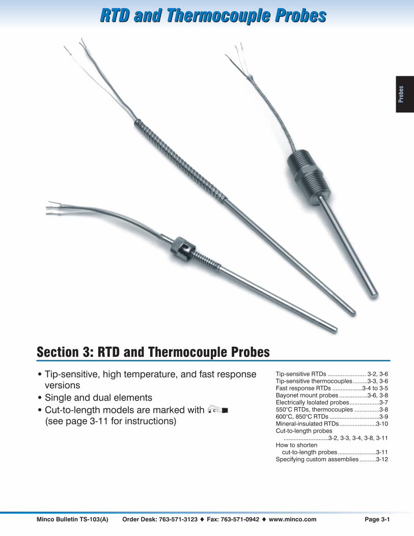
Section 3: RTD and Thermocouple Probes
• Tip-sensitive, high temperature, and fast responseversions
• Single and dual elements
• Cut-to-length models are marked with(see page 3-11 for instructions)
Tip-sensitive RTDs ....................... 3-2, 3-6Tip-sensitive thermocouples.........3-3, 3-6Fast response RTDs ..................3-4 to 3-5Bayonet mount probes .................3-6, 3-8Electrically Isolated probes..................3-7550°C RTDs, thermocouples ...............3-8600°C, 850°C RTDs ..............................3-9Mineral-insulated RTDs......................3-10Cut-to-length probes
...........................3-2, 3-3, 3-4, 3-8, 3-11How to shorten
cut-to-length probes.......................3-11Specifying custom assemblies ..........3-12

Page 3-2 Sales: 763-571-3121 � Fax: 763-571-0927 � www.minco.com Minco Bulletin TS-103(A)
RTD and Thermocouple ProbesRTD and Thermocouple Probes
Prob
es
Tip-Sensitive RTDs
• Copper alloy tip for fast response
• Accurate sensing to 260°C (500°F)
• Non armor models can beuser-shortened
The sensing tip of these probes isconstructed of copper alloy, twenty timesmore conductive than stainless steel.Sensors react more quickly to changesand indicate tip temperature instead ofstem temperature. The result: Betteraccuracy in thermowells, bearings, andother installations.
0.250" diameter is recommended for usein thermowells.
Specifications
Temperature range:-50 to 260°C (-58 to 500°F).Case: Stainless steel with copper alloy tip.Minimum case length:
Single element probes: 2.8" (71.1 mm).Dual element probes: 4.0" (101.6 mm).
Maximum case length:48" (1220 mm), longer on special order.
Leads: 2, 3, or 4 leadwires, stranded copperwith PTFE insulation. AWG 22, except 0.188"diameter dual probes AWG 24. For 2-lead RTDsadd 0.03 � per foot (0.05 � per foot for 0.188"diameter dual probes) of combined case andlead length to element tolerance. Copper (CA,CC) models must have 3 leads.Time constant: 2.0 seconds typical in movingwater. 3.0 seconds for dual element models.Pressure rating: 100 psi (6.9 bar).Insulation resistance:Single element probes: 1000 megohms min. at
500 VDC, leads to case.Dual element probes: 100 megohms min. at
100 VDC, between elements and leads to case.Vibration: Withstands 10 to 2000 Hz at 20 G’smin. per MIL-STD-202, Method 204, TestCondition D.Shock: Withstands 100 G’s min. sine waveshock of 8 milliseconds duration.
How to order
S56NA Model number from table
125 Case length:
Specify in 0.1" increments(Ex: 125 = 12.5 inches)
Y Number of leads per sensingelement:
Y = 2 leadsZ = 3 leadsX = 4 leads (PD only)
36 Lead length in inches
S56NA125Y36 � Sample P/N
Element TCR�/�/°C
Model number for probe diameter:
0.188"(4.8 mm)
0.215"(5.5 mm)
0.250"(6.4 mm)
Single element RTDs: No armor over leads
Platinum, 100 � ±0.5% at 0°C 0.00392 S54PA S51PA S53PA
Platinum, 100 � ±0.1% at 0°C(meets EN60751, Class B)
0.00385 S854PD S851PD S853PD
Platinum, 100 � ±0.5% at 0°C 0.00385 S884PE S881PE S883PE
Copper, 10 � ±0.2% at 25°C 0.00427 S54CA S51CA S53CA
Nickel, 120 � ±0.5% at 0°C 0.00672 S54NA S51NA S53NA
Single element RTDs with armor over leads
Add element code (Ex: S154NA, S153CA) S154__ S151__ S153__
Dual element RTDs: No armor over leads
Platinum, 100 � ±0.5% at 0°C 0.00392 S59PA S56PA S57PA
Platinum, 100 � ±0.1% at 0°C(meets EN60751, Class B)
0.00385 S859PD S856PD S857PD
Platinum, 100 � ±0.5% at 0°C 0.00385 S889PE S886PE S887PE
Copper, 10 � ±0.5% at 25°C 0.00427 N/A S56CC S57CC
Nickel, 120 � ±0.5% at 0°C 0.00672 S59NA S56NA S57NA
Dual element RTDs with armor over leads
Add element code (Ex: S159NA, S157CC) S159__ S156__ S157__
LEAD LENGTH CASE LENGTH
SLEEVE COPPER ALLOY TIP
4" (102 mm)LEAD LENGTH
ARMOR OPTION CASE LENGTH
COPPER ALLOY TIP
CUT-TO-LENGTH
IN STOCK
Single element models (except PE),lengths from 4" to 24", without armorDual models: S859 to 18", S857 to 24"

Minco Bulletin TS-103(A) Order Desk: 763-571-3123 � Fax: 763-571-0942 � www.minco.com Page 3-3
RTD and Thermocouple ProbesRTD and Thermocouple Probes
Pro
bes
Tip-Sensitive Thermocouples
• Copper alloy tip for fast response
• Accurate sensing to 260°C (500°F)
• Non armor models can beuser-shortened
The sensing tip of these probes isconstructed of copper alloy, twenty timesmore conductive than stainless steel.Sensors react more quickly to changesand indicate tip temperature instead ofstem temperature. The result: Betteraccuracy in thermowells, bearings, andother installations.
0.250" diameter is recommended for usein thermowells.
Specifications
Temperature range:-184 to 260°C (-300 to 500°F).Case: Stainless steel with copper alloy tip.Minimum case length: 2.5" (63.5 mm).Maximum case length: 48" (1220 mm), longer
on special order.Leads: Solid thermocouple wire, AWG 20(except AWG 24 on model TC355). Specify PTFEinsulation, stainless steel overbraid, or stainlesssteel armor.Time constant: Typical value in moving water:Grounded junction: 1.5 seconds.Ungrounded junction: 7 seconds.Pressure rating: 100 psi (6.9 bar).Insulation resistance: 10 megohms min. at100 VDC, leads to case, ungrounded junctionsonly.Vibration: Withstands 10 to 2000 Hz at 20 G’smin. per MIL-STD-202, Method 204, TestCondition D.Shock: Withstands 100 G’s min. sine waveshock of 8 milliseconds duration.
Thermocouple model numbers
Model
Ø 0.188"(4.8 mm)
Ø 0.215"(5.5 mm)
Ø 0.250"(6.4 mm)
Single junction TC354 TC356 TC358
Dual junction TC355 TC357 TC359
How to order
TC356 Model number from table
T Junction type:
E = Chromel-ConstantanJ = Iron-ConstantanK = Chromel-AlumelT = Copper-Constantan
G Junction grounding:
G = GroundedU = Ungrounded
200 Case length:
Specify in 0.1" increments:Ex: 200 = 20.0 inches
S Covering over leadwires:
T = PTFE onlyG = Glass braid onlyS = Stainless steel overbraidA = Stainless steel armor
24 Lead length in inches
TC356TG200S24 � Sample P/N
LEAD LENGTH CASE LENGTH
SLEEVE
4" (102 mm) LEAD LENGTH
ARMOR OPTION
CASE LENGTH
COPPER ALLOY TIP
COPPER ALLOY TIP
CUT-TO-LENGTH

Page 3-4 Sales: 763-571-3121 � Fax: 763-571-0927 � www.minco.com Minco Bulletin TS-103(A)
RTD and Thermocouple ProbesRTD and Thermocouple Probes
Prob
es
Fast Response RTDs
• All-stainless steel probes for use to260°C (500°F)
• Unique low mass element reactsquickly to temperature changes
These probes have rugged stainless steelcases for use in high pressures orcorrosive fluids. Yet their time constantsare comparable to copper-tipped probesat 2 to 4 seconds, compared to 8 to 10seconds for other all-stainless probes.
Specifications
Temperature range:-269 to 260°C (-452 to 500°F).Case material:S601, S603, S604: 316 stainless steel.S602, S614: 304/305 stainless steel.Case length:Minimum case length:
S602, S604: 2.0" (50.8 mm) with PTFEinsulated leads; 3.0" (76.2 mm) with SSbraid over leads.S601, S603: 3.0" (76.2 mm).
Maximum case length:48" (1220 mm), longer on special order.
Time constant: Typical in moving water:S602, S604, S614: 2 seconds.S601: 3 seconds.S603: 4 seconds.Pressure rating: 1500 psi (103 bar).Leads: 2, 3, or 4 leadwires, AWG 22, strandedcopper with PTFE insulation, stainless steelbraid, or stainless steel armor. For 2-lead RTDsadd 0.03 � per foot of combined case and leadlength to element tolerance (model S602 hasAWG 26; add 0.08 � per foot for 2-lead).Insulation resistance: 1000 megohms min. at500 VDC, leads to case.Vibration: Withstands 10 to 2000 Hz at 20 G’smin. per MIL-STD-202, Method 204, TestCondition D.Shock: Withstands 100 G’s min. sine waveshock of 8 milliseconds duration.
Sensing elements:
How to ordervariable length probes
Specify 0.125" or 0.188" for fastestresponse, 0.250" or 0.215" for greaterstrength and cut-to-length capability(PTFE and SS braid models).
S604 Model number:
S601: Ø 0.215" (5.5 mm)S602: Ø 0.125" (3.2 mm)S603: Ø 0.250" (6.4 mm)S604: Ø 0.188" (4.8 mm)
PD Sensing element from table
140 Case length:
Specify in 0.1" increments(Ex: 140 = 14.0 inches)
X Number of leadwires:
Y = 2 leadsZ = 3 leadsX = 4 leads (PD only)
36 Lead length in inches
T Covering over leadwires:
T = PTFE onlyS = Stainless steel braidA = Stainless steel armor(S, A not available on S602)
S604PD140X36T � Sample P/N
How to ordershort probes
This model has a case with fixed length of2.4" (61 mm). Use it as an all-purposesensing element.
S614 Model number: S614
PA Sensing element from table
Z Number of leadwires:
Y = 2 leadsZ = 3 leadsX = 4 leads (PD only)
12 Lead length in inches
S Covering over leadwires:
T = PTFE onlyS = Stainless steel braid
S614PAZ12S � Sample P/N
LEAD
LENGTH
CASE LENGTH
LEAD
LENGTH
2.4"
(61.0 mm)
0.188" (4.8 mm)
DIAMETER
VARIABLELENGTHPROBE
SHORT PROBE
CUT-TO-LENGTH
S601: 0.215" (5.5 mm) ØS602: 0.125" (3.2 mm) ØS603: 0.250" (6.4 mm) ØS604: 0.188" (4.8 mm) Ø
Element Code
Platinum 392, 100 � ±0.5% at 0°C PA
Platinum 385, 100 � ±0.1% at 0°C (Meets EN60751, Class B) PD
Platinum 385, 100 � ±0.5% at 0°C PE
Platinum 385, 1000 � ±0.1% at 0°C (N/A for model S602) PF
Copper, 10 � ±0.2% at 25°C CA
Nickel, 120 � ±0.5% at 0°C NA

Minco Bulletin TS-103(A) Order Desk: 763-571-3123 � Fax: 763-571-0942 � www.minco.com Page 3-5
RTD and Thermocouple ProbesRTD and Thermocouple Probes
Pro
bes
Fast Response Immersion RTDs
• Stainless steel probes for use to 260°C(500°F)
• Pressure rating 1500 psi (103 bar)
• Quick reaction to changing fluid andgas temperatures
• NPT (U.S.) or metric threads
You can mount these probes directly influid streams for accurate, reliablesensing. Time constant is just 2 seconds,compared to 10 seconds for an ordinarystainless probe or up to 50 seconds for athermowell. The result: More accuratemonitoring of dynamic processes.
Specifications
Temperature range:-269 to 260°C (-452 to 500°F).Case material:S623, S628: 316 stainless steel.S634, S639: 304/305 stainless steel.Case length:Minimum case length: 1.5" (38.1 mm).Maximum case length: 48" (1220 mm), longer
on special order.Time constant: Typical value in moving water:S623, S628: 4 seconds.S634, S639: 2 seconds.Pressure rating: 1500 psi (103 bar).Leads: 2, 3, or 4 leadwires, AWG 22, strandedcopper with PTFE insulation, stainless steelbraid, or stainless steel armor. For 2-lead RTDsadd 0.03 � per foot of combined case and leadlength to element tolerance.Insulation resistance: 1000 megohms min. at500 VDC, leads to case.Vibration: Withstands 10 to 2000 Hz at 20 G’smin. per MIL-STD-202, Method 204, TestCondition D.Shock: Withstands 100 G’s min. sine waveshock of 8 milliseconds duration.
Sensing elements:
How to orderimmersion probes
These probes have welded fittings tomount directly into fluid vessels. Add aconnection head for termination ofextension leads.
S623 Model number:
S623: ½ - 14 NPT thread [2]S628: ISO 228/1-G½process thread(½ - 14 NPT on leads end)
PF Sensing element from table
60 Case length:
Specify in 0.1" increments(Ex: 60 = 6.0 inches)
Y Number of leads:
Y = 2 leadsZ = 3 leadsX = 4 leads (PD only)
72 Lead length in inches
A Covering over leadwires:
T = PTFE onlyS = Stainless steel braidA = Stainless steel armor
S623PF60Y72A � Sample P/N
How to orderplug type sensors
Save space and get accurate readingswith this compact, easy-to-install probe.
S634 Model number:
S634: ½ - 14 NPT threadS639: ISO 228/1-G½ thread
NA Sensing element from table
Y Number of leads:
Y = 2 leadsZ = 3 leadsX = 4 leads (PD only)
24 Lead length in inches
T Covering over leadwires:
T = PTFE onlyS = Stainless steel braid
S634NAY24T � Sample P/N
Element Code
Platinum 392, 100 � ±0.5% at 0°C PA
Platinum 385, 100 � ±0.1% at 0°C (Meets EN60751, Class B) PD
Platinum 385, 100 � ±0.5% at 0°C PE
Platinum 385, 1000 � ±0.1% at 0°C (N/A for model S602) PF
Copper, 10 � ±0.2% at 25°C CA
Nickel, 120 � ±0.5% at 0°C NA
LEAD LENGTH CASE LENGTH
LEAD LENGTH 2.0"
(50.8 mm)
½ - 14 NPT ½ - 14 NPT
or G½
0.250" (6.4 mm)
DIAMETER
½ - 14 NPT or G½ 0.188" (4.8 mm)
DIAMETER
IMMERSIONPROBE
PLUG TYPESENSOR

Page 3-6 Sales: 763-571-3121 � Fax: 763-571-0927 � www.minco.com Minco Bulletin TS-103(A)
RTD and Thermocouple ProbesRTD and Thermocouple Probes
Prob
es
Bayonet Mount Tip-Sensitive Probes
• Lockcap and spring fortwist-and-release spring loading
• Accurate sensing to 260°C (500°F)
Bayonet mounting provides easy andinexpensive spring loaded installation ofprobes into solids. All models have acopper alloy tip for fast time responseand increased tip sensitivity.
See page 4-9 for bayonet fittings.
Specifications
Temperature range:-50 to 260°C (-58 to 500°F).Case: Stainless steel with copper alloy tip.Minimum case length: 3.0" (76.2 mm).Maximum case length: 48" (1220 mm), longer
on special order.Vibration: Withstands 10 to 2000 Hz at 20 G’smin. per MIL-STD-202, Method 204, TestCondition D.Shock: Withstands 100 G’s min. sine waveshock of 8 milliseconds duration.
� See compatible fittings on pages4-9 and 4-10.
RTDs
Element Model
Platinum 392, 100 � ±0.5% at 0°C S44PA
Platinum 385, 100 � ±0.1% at 0°C(Meets EN60751, Class B)
S844PD
Platinum 385, 100 � ±0.5% at 0°C S874PE
Copper, 10 � ±0.2% at 25°C S44CA
Nickel, 120 � ±0.5% at 0°C S44NA
Leads: 2, 3, or 4 leadwires, AWG 22, strandedcopper with PTFE insulation, stainless steelarmor, and ½" conduit connector. For 2-leadRTDs add 0.03 � per foot of combined case andlead length to element tolerance.Time constant: 2 seconds typical in movingwater.Insulation resistance: 1000 megohms min. at500 VDC, leads to case.
How to order
S874PE Model number from table
110 Case length:
Specify in 0.1" increments(Ex: 110 = 11.0 inches)
Y Number of leads:
Y = 2 leadsZ = 3 leadsX = 4 leads (PD only)
36 Lead length in inches
S874PE110Y36 � Sample P/N
Thermocouples
Leads: Solid thermocouple wire, AWG 20(single) or AWG 24 (dual). Specify PTFEinsulation, glass braid insulation, stainless steelbraid over glass braid, or stainless steel armorover PTFE.Time constant: Typical value in moving water:Grounded junction: 1.5 seconds.Ungrounded junction: 7 seconds.Insulation resistance: 10 megohms min. at100 VDC, leads to case, ungrounded junctionsonly.
How to order
TC360 Model number:
TC360 = Single junctionTC361 = Dual junction
E Junction type:
E = Chromel-ConstantanJ = Iron-ConstantanK = Chromel-AlumelT = Copper-Constantan
G Junction grounding:
G = GroundedU = Ungrounded
95 Case length:
Specify in 0.1" increments(Ex: 95 = 9.5 inches)
A Covering over leadwires:
T = PTFE onlyG = Glass braidA = Stainless steel armorS = Stainless steel overbraid
12 Lead length in inches
TC360EG95A12 � Sample P/N
RTD PROBE
LEAD LENGTH CASE LENGTHTHERMOCOUPLE
PROBE
LEAD LENGTH CASE LENGTH
0.188" (4.8 mm)
DIAMETER
4" (102 mm)
SPADE LUGS ½" CONDUIT
CONNECTOR
0.280" (7.1 mm)
DIAMETER
0.188" (4.8 mm)
DIAMETER
0.280" (7.1 mm)
DIAMETER
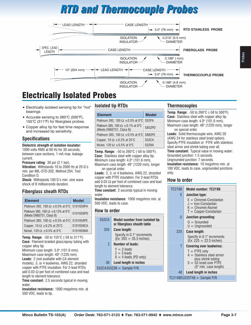
Minco Bulletin TS-103(A) Order Desk: 763-571-3123 � Fax: 763-571-0942 � www.minco.com Page 3-7
RTD and Thermocouple ProbesRTD and Thermocouple Probes
Pro
bes
Electrically Isolated Probes
• Electrically isolated sensing tip for “hot”bearings
• Accurate sensing to 260°C (500°F),155°C (311°F) for fiberglass probes.
• Copper alloy tip for fast time responseand increased tip sensitivity.
Specifications
Dielectric strength of isolation insulator:1000 volts RMS at 60 Hz for 30 seconds,between case sections, 1 mA max. leakagecurrent.Pressure rating: 30 psi (2.1 bar).Vibration: Withstands 10 to 2000 Hz at 20 G’smin. per MIL-STD-202, Method 204, TestCondition D.Shock: Withstands 100 G’s min. sine waveshock of 8 milliseconds duration.
Fiberglass sheath RTDs
Element Model
Platinum 392, 100 � ±0.5% at 0°C S101659PA
Platinum 385, 100 � ±0.12% at 0°C(Meets EN60751, Class B)
S101659PD
Platinum 385, 100 � ±0.5% at 0°C S101659PE
Copper, 10 � ±0.2% at 25°C S101659CA
Nickel, 120 � ±0.5% at 0°C S101659NA
Temp. Range: -50 to 155°C (-58 to 311°F).Case: Filament braided glass/epoxy tubing withcopper alloy tip.Minimum case length: 3.0" (101.6 mm).Maximum case length: 40" (1220 mm).Leads: 2 (not available with CA elementmodels), 3, or 4 leadwires, AWG 22, strandedcopper with PTFE insulation. For 2-lead RTDsadd 0.03 � per foot of combined case and leadlength to element tolerance.Time constant: 2.5 seconds typical in movingwater.Insulation resistance: 1000 megohms min. at500 VDC, leads to tip.
Isolated tip RTDs
Element Model
Platinum 392, 100 � ±0.5% at 0°C S52PA
Platinum 385, 100 � ±0.1% at 0°C(Meets EN60751, Class B)
S852PD
Platinum 385, 100 � ±0.5% at 0°C S882PE
Copper, 10 � ±0.2% at 25°C S52CA
Nickel, 120 � ±0.5% at 0°C S52NA
Temp. Range: -50 to 260°C (-58 to 500°F).Case: Stainless steel with copper alloy tip.Minimum case length: 4.0" (101.6 mm).Maximum case length: 48" (1220 mm), longer
on special order.Leads: 2, 3, or 4 leadwires, AWG 22, strandedcopper with PTFE insulation. For 2-lead RTDsadd 0.03 � per foot of combined case and leadlength to element tolerance.Time constant: 2 seconds typical in movingwater.Insulation resistance: 1000 megohms min. at500 VDC, leads to case.
How to order
S52CA Model number from isolated tipor fiberglass sheath table
355 Case length:
Specify in 0.1" increments(Ex: 355 = 35.5 inches)
Z Number of leads:
Y = 2 leadsZ = 3 leadsX = 4 leads (PD only)
36 Lead length in inches
S52CA355Z36 � Sample P/N
Thermocouples
Temp. Range: -50 to 260°C (-58 to 500°F).Case: Stainless steel with copper alloy tip.Minimum case length: 4.0" (101.6 mm).Maximum case length: 48" (1220 mm), longer
on special order.Leads: Solid thermocouple wire, AWG 20(AWG 24 for stainless steel braid option).Specify PTFE insulation or PTFE with stainlesssteel armor and shrink tubing over all.Time constant: Typical value in moving water:Grounded junction: 1.5 seconds.Ungrounded junction: 7 seconds.Insulation resistance: 10 megohms min. at100 VDC, leads to case, ungrounded junctionsonly.
How to order
TC2198 Model number: TC2198
E Junction type:
E = Chromel-ConstantanJ = Iron-ConstantanK = Chromel-AlumelT = Copper-Constantan
U Junction grounding:
G = GroundedU = Ungrounded
225 Case length:
Specify in 0.1" increments(Ex: 225 = 22.5 inches)
T Covering over leadwires:
T = PTFE onlyA = Stainless steel armor
plus shrink tubingS = SS braid over PTFE
(5" min. case length)
48 Lead length in inches
TC2198EU225T48 � Sample P/N
LEAD LENGTH CASE LENGTH
ISOLATION
INSULATOR
0.215" (5.5 mm)
DIAMETER
RTD STAINLESS PROBE3.0" (76 mm)
LEAD LENGTH CASE LENGTH
ISOLATION
INSULATOR
0.188" (4.8 mm)
DIAMETER
THERMOCOUPLE PROBE3.0" (76 mm)
10" (254 mm)
SPEC. LEADLENGTH
CASE LENGTH
ISOLATION
INSULATOR
0.188" ( mm)
DIAMETER
FIBERGLASS PROBE

Page 3-8 Sales: 763-571-3121 � Fax: 763-571-0927 � www.minco.com Minco Bulletin TS-103(A)
RTD and Thermocouple ProbesRTD and Thermocouple Probes
Prob
es
550°C RTD and Thermocouple Probes
• 0.250" diameter cut-to-length RTDs
• 0.188" diameter straight and bayonetRTDs and thermocouples.
Install these probes in steam lines,exhaust gases, wherever you needprecise readings of elevatedtemperatures. RTD probes feature hightemperature ceramic elements,assembled into stainless steel cases in aconfiguration that provides long-termreliable service.
Models S80 and S81 are usershortenable. You can stock standardlengths and cut them to the size requiredwith an ordinary tubing cutter.
Bayonet style probes have a lockcap andspring for spring-loaded installation. Seepage 4-9 for bayonet fittings.
Specifications
Temperature range:-100 to 550°C (-148 to 1022°F).Leadwires: 500°C (932°F) max.Case: 316 stainless steel.Minimum case length:
0.250" diameter: 4.0" (101.6 mm).0.188" diameter:
S71, S72: 2.0" (50.8 mm)S73, S74: 3.0" (76.2 mm).
Maximum case length: 48" (1220 mm), longeron special order.
Pressure rating: 1500 psi (103 bar).Vibration: Withstands 10 to 2000 Hz at 20 G’smin. per MIL-STD-202, Method 204, TestCondition D.Shock: Withstands 100 G’s min. sine waveshock of 8 milliseconds duration.
RTDs
Leads: 2 or 3 leadwires, AWG 22, strandedcopper with mica/glass insulation. For 2-leadRTDs add 0.04 � per foot of combined case andlead length to element tolerance.Time constant: 10 seconds typical in movingwater.Insulation resistance: 10 megohms min. at100 VDC, leads to case.
How to order
S74PD Model number from table
145 Case length:
Specify in 0.1" increments(Ex: 145 = 14.5 inches)
Z Number of leads:
Y = 2 leadsZ = 3 leads
6 Lead length in inches
S74PD145Z6 � Sample P/N
LEAD LENGTH CASE LENGTH
BRASS FERRULE
CUT-TO-LENGTHPROBE
CASE LENGTHLEAD LENGTH
0.280" (7.1 mm)
DIAMETER
BAYONET PROBE
0.188" (4.8 mm)
DIAMETER
CASE LENGTH STRAIGHT PROBELEAD LENGTH4" (102 mm)
ARMOR OPTION SHOWN(THERMOCOUPLES ONLY)
0.250" (6.4 mm)
DIAMETER
0.188" (4.8 mm)
DIAMETER
CUT-TO-LENGTHS80, S81
Element100 � ±0.1% at 0°C
Ø 0.188" (4.8 mm)Straight probe
Ø 0.188" (4.8 mm)Bayonet probe
Ø 0.250" (6.4 mm)Cut-to-length
Platinum 391 S71PB S73PB S80PB
Platinum 385,(Meets EN60751, Class B)
S72PD S74PD S81PD
Thermocouples
Leads: Solid thermocouple wire, AWG 20.Specify glass braid insulation, stainless steeloverbraid, or stainless steel armor.Time constant: 7 seconds typical in movingwater.Insulation resistance: 10 megohms min. at100 VDC, leads to case, ungrounded junctionsonly.
How to order
TC173 Model number:
TC173: Straight probeTC171: Bayonet mount
J Junction type:
E = Chromel-ConstantanJ = Iron-ConstantanK = Chromel-AlumelT = Copper-Constantan
U Junction grounding:
G = GroundedU = Ungrounded
45 Case length:
Specify in 0.1" increments(Ex: 45 = 4.5 inches)
G Covering over leadwires:
G = Glass braid onlyS = Stainless steel overbraidA = Stainless steel armor
24 Lead length in inches
TC173JU45G24 � Sample P/N
IN STOCK
S80 and S81, lengths from 4" to 24"

Minco Bulletin TS-103(A) Order Desk: 763-571-3123 � Fax: 763-571-0942 � www.minco.com Page 3-9
RTD and Thermocouple ProbesRTD and Thermocouple Probes
Pro
bes
600°C and 850°C RTDs
• Accurate sensing of extreme high andlow temperatures
• Platinum elements to EN60751, Class Aor B
• English and metric diameters
These RTDs cover the full temperaturescale of the international standardEN60751. Precision sensing elementsand nickel alloy sheaths are capable ofmeasurements from -200 to 850°C withtypical ice point drift less than ±0.05°C.
600°C models have stainless steelsheaths for reduced cost. They use thesame element structure as 850°C modelsfor excellent accuracy and stability.
Specifications
Element: Platinum, 100 � at 0°C,TCR = 0.00385 �/�/°C.Tolerance: EN60751 Class A or B.Class A: ± 0.06%Class B: ± 0.12%Repeatability: Meet IEC requirements. Typicalshift less than 0.05°C (0.02 �) at 0°C after tencycles over range.Stability: Meet IEC stability specifications after250 hours exposure to extremes of temperaturerange. Typical drift is less than 0.05°C (0.02 �)at 0°C.Vibration: Will withstand 10 to 5000 Hz at 2 G’sminimum per EN60751.Shock: Will withstand 250 mm drop onto 8 mmthick steel plate (approximately 1400 G’s for0.08 ms).Time constant: 10 seconds typical in movingwater.Pressure rating: 1000 psi (69 bar) at 25°C.Insulation resistance: 10 megohms min. at100 VDC, leads to case.
600°C probes
Probe diameter Model number
0.188" (4.8 mm) S914
0.236" (6.0 mm) S912
0.250" (6.4 mm) S913
Temperature range: -200 to 600°C (-328 to1112°F). Reduced temperature rating for leadsand last 2" (50 mm) of case; see leadwire chart.Case: 316 stainless steel.Minimum case length: 2.0" (50.8 mm).Maximum case length: 48.0" (1220 mm), longer
on special order.
850°C probes
Probe diameter Model number
0.157" (4.0 mm) S926
0.236" (6.0 mm) S922
0.250" (6.4 mm) S923
Temperature range: -200 to 850°C (-328 to1582°F). Reduced temperature rating for leadsand last 2" (50 mm) of case; see leadwire chart.Case: Nickel alloy.Minimum case length: 6.0" (150 mm).Maximum case length: 18.0" (460 mm), longer
on special order.
Leadwire options:
Code Description Max.temp*
GMica/glass insulatedstranded copper, AWG 22.
600°C1112°F
TPTFE insulated strandedcopper, AWG 22.
260°C500°F
C
AWG 24, PTFE insulated,stranded copper wires withsilver-plated copper braidand PTFE over all (4 leadsonly).
260°C500°F
* Temp. rating for leads and last 2" of case.
How to order
S914 Model number from table
PD 100 � Platinum, 0.00385 TCR
06 Tolerance at 0°C:
06 = ±0.06%, EN60751 Class A12 = ±0.12%, EN60751 Class B
G Leadwire code from table
120 Case length:
Specify in 0.1" increments(Ex: 120 = 12.0 inches)
X Number of leads:
Z = 3 leadsX = 4 leads
24 Lead length in inches
BS Probe termination:
BS = Boot and springB = Boot only
(Boot required on S926)N = No boot or spring
S914PD06G120X24BS � Sample P/N
LEAD LENGTH CASE LENGTH
CASE LENGTH
1.5" (38.1 mm)
LEAD LENGTH
0.375" (9.5 mm) leadwire transition boot;
recommended for best durability
4"
(100 mm)

Page 3-10 Sales: 763-571-3121 � Fax: 763-571-0927 � www.minco.com Minco Bulletin TS-103(A)
RTD and Thermocouple ProbesRTD and Thermocouple Probes
Prob
es
Mineral-Insulated RTDs
• Mineral MgO packing protects elementfrom shock and contamination
• Field bendable
• Inconel or stainless steel sheath
• High precision RTD elements for stable,repeatable measurements
• Dual sensing element model S953 isexcellent for redundancy and failureprotection
Mineral-insulated RTDs provide excellentperformance, even when exposed to highlevels of shock and vibration in toughindustrial environments. Typicalapplications include process control andsteam turbine efficiency measurement.
Probes can be bent around a mandreldiameter at least 3 times the probediameter without kinking.
Custom designed RTDs andthermocouples are available.
Specifications
Element: Platinum, 100 � at 0°C,TCR=0.00385 �/�/°C.Temperature range:Reduced to 260°C (500°F) for leadwires andpotting boot.S932, S933: -200 to 650°C (-328 to 1202°F).S942, S943, S944: -200 to 550°C
(-328 to 1022°F).S953: -200 to 260°C (-328 to 500°F).Tolerance: EN60751 Class B (±0.12 � =±0.3°C) or Class A (±0.06 � = ±0.15°C)Repeatability: Meets EN60751 requirements.Typical shift less than 0.05°C (0.1°F) whencycled over temperature range.Stability: Meets EN60751 specifications after250 hours exposure to extremes of temperaturerange. Typical drift of less than 0.05°C (0.1°F) at0°C.Vibration: Withstands 10 to 5000 Hz at 2 G’sper EN60751. Also withstands 50 to 250 Hz at50 G’s at 500°C.Shock: Withstands a 1 meter drop onto an 8 mmsteel plate (1 meter is 4 times the EN60751height requirement of 250 mm).Time constant: 10 seconds typical in movingwater.Pressure rating: 69 bar (1000 psi) at 25°C.Insulation resistance: 10 megohms min. at100 VDC.
How to order
S933 Model number from table
PD 100 � platinum, 0.00385 TCR
06 Tolerance at 0°C:
06 = ±0.06%, EN60751 Class A(NA for dual element S953)
12 = ±0.12%, EN60751 Class B
T Leadwire insulation:
T = PTFE leadwiresC = PTFE cable (4 lead only,
NA for dual element S953)
120 Case length:
Specify in 0.1" increments(Ex: 120 = 12.0 inches)
X Number of leadwires:
Y = 2 leads per elementZ = 3 leads per elementX = 4 leads per element
36 Lead length in inches
BS Lead exit configuration:
(B or BS option recommendedfor best lead exit strength)BS = Potting boot and strain
relief springB = Potting bootN = No potting boot or spring
S933PD06T120X36BS � Sample P/N
Probe diameter Max. temperature Case material Single elementmodel
0.236" (6.0 mm) 550°C (1022°F) 316 stainless steel S942
0.236" (6.0 mm) 650°C (1202°F) Inconel 600 S932
0.250" (6.4 mm) 550°C (1022°F) 316 stainless steel S943
0.250" (6.4 mm) 650°C (1202°F) Inconel 600 S933
0.188" (4.8 mm) 550°C (1022°F) 316 stainless steel S944
Probe diameter Max. temperature Case material Dual elementmodel
0.250" (6.4 mm) 260°C (500°F) 316 stainless steel S953
LEAD LENGTH
2.5"
(64 mm)
1.5"
(38 mm)
0.3" (7.6 mm)
DIA.
CASE LENGTH
PROBE DIA.
2.0"
(51 mm)BENDABLE
REGION2.0"
(51 mm)
0.38" (9.5 mm)
DIA.

Minco Bulletin TS-103(A) Order Desk: 763-571-3123 � Fax: 763-571-0942 � www.minco.com Page 3-11
RTD and Thermocouple ProbesRTD and Thermocouple Probes
Pro
bes
Cut-to-length probes
Many probe models in section 3 can becut to the required length using anordinary tubing cutter. Cut-to-lengthmodels are marked with
Benefits are:
• You can keep standard lengths ininventory, and shorten them as neededfor urgent requirements
• Stocking and shortening probes,instead of ordering a few pieces at atime, may let you take advantage ofquantity discounts
• Minco stocks most cut-to-lengthprobes and can trim and ship themwithin 24 hours of your call
How to shorten probes
Remove the PTFE or brass ferrule fromthe lead exit end of the probe. Mark theproper length, then cut, going slowly toavoid crimping the case or damaging theleads. Use a good quality tubing cutterthat is intended to cut stainless steeltubing or conduit. The cutter must have asharp blade to prevent “rolling in” duringcutting of the tubing. Suitable models areavailable from Imperial Eastman andSears Industrial.
After cutting, discard the hollow tubesection, carefully deburr the cut end, andreplace the ferrule. You can slit the PTFEferrule for easier installation.
If you use many cut-to-length probesconsider the AC101248 probe cuttingsystem. It includes an electric Dremel™tool (120 VAC @ 60 Hz), flexible shaft andaccessories to allow clean, precise cuts.The system includes a convenientcarrying case and comes with easy tofollow instructions.
Shorten probes easily with a tubing cutter. The AC101248 probe cutting system makes clean, precise cuts.
Protect probes from chemical attack
AC100375 PFA or FEPencapsulation tubing
The tube is sealed at one end and canbe easily shrunk onto any probe.Supplied separately.
Temperature range:PFA = -70 to 260°C (-94 tp 500°F).FEP = -70 to 200°C (-94 to 392°F).
How to order
AC100375 Model number
L60 Length in 0.1" increments
P Encapsulation type:
P = clear PFAF = clear FEP
188 Probe diameter:
125 = 0.125" (3.2 mm)188 = 0.188" (4.8 mm)215 = 0.215" (5.5 mm)250 = 0.250" (6.4 mm)
AC100375L60P188 � Sample P/N
IN STOCK
6" and 12" lengths
FEP: FluorinatedethylenepropyleneMaximum temperature 204°C (400°F)Excellent dielectric insulation properties,chemically resistant, unaffected by weather,extreme heat, or cold temperatures.
PFA: PerfluoroalkoxyMaximum temperature 260°C (500°F)Combines attributes of PTFE and FEP,chemically resistant to all common solvents,maintains mechanical strength at hightemperatures.

Page 3-12 Sales: 763-571-3121 � Fax: 763-571-0927 � www.minco.com Minco Bulletin TS-103(A)
RTD and Thermocouple ProbesRTD and Thermocouple Probes
Prob
es
Specifying Custom AssembliesThe standard assemblies in Section 2 will fit a wide variety of installations. For more versatility you can create new assembliesfrom the probes, accessories, and transmitters in the pages listed.
Follow these steps:
1. Choose a probe
Select an RTD or thermocouple fromSection 3. The section includestip-sensitive, high temperature, and fastresponse models. Some have integralfittings or bayonet lockcaps.
Factors to consider are:
• Temperature rating
• Compatibility with receiving instruments
• Probe style and diameter
• Accuracy vs. cost
2. Add a fitting
See Section 4 for probe mounting fittings.Adjustable fittings, combined withcut-to-length probes, allow instantfabrication of assemblies to any lengthrequired. Included are spring-loadedholders, pressure fittings, andbayonet-style fittings.
Factors to consider are:
• Temperature rating
• Probe diameter
• Correct NPT threads
• Pressure ratings
• Compatibility with environment
3. Select a thermowell
Thermowells protect sensors from theeffects of fluid flow and pressure. SeeSection 4 for a variety of well styles andmaterials.
Factors to consider are:
• Pressure rating
• Compatibility with fluid media
• Insertion depth
• Correct NPT thread
4. Attach a connection head
Finish off your assembly with aconnection head for termination toremote extension wires. See pages 4-2 to4-3.
Factors to consider are:
• Connection head size
• Temperature rating
• Correct pipe threads for fitting andconduit
• Number of terminals or wire nuts
• Hazardous area requirements
5. Install a transmitter
Transmitters convert sensor output to a4 to 20 mA current signal, immune toleadwire resistance. See Section 5 forRTD and thermocouple transmitters.
Factors to consider are:
• Transmitter accepts sensor input
• Transmitter fits connection head
• Ambient temperature range acceptable
6. How to calculate probe length
All fittings listed in this catalog have probelength adders to help you determine totalprobe length. Total length L is the insertiondepth D plus the adder A.
Thermowell drawings show an adder toconvert thermowell length U to insertiondepth D. Then use D plus the fitting adderA to find total probe length L.
PROBE CASE LENGTH L
ADDER A INSERTION DEPTH D
THERMOWELL LENGTH U
ADDER A
PROBE CASE LENGTH L
INSERTION DEPTH D

Minco Bulletin TS-103(A) Order Desk: 763-571-3123 � Fax: 763-571-0942 � www.minco.com Page 4-1
AccessoriesAccessories
Acc
esso
ries
Section 4: Accessories
• A wide selection of fittings and accessories adaptsensors to any installation
• Adjustable fittings combine with cut-to-length probesfor off-the-shelf versatility
• Choose from a variety of materials for severeenvironments
Connection heads......................4-2 to 4-3Spring-loaded holders .........................4-4Fluid immersion fittings...............4-5, 4-10Economy thermowells .........................4-6HVAC thermowells ...............................4-6Reduced tip thermowells .....................4-7Tapered thermowells ...........................4-7Flanged thermowells............................4-8Bayonet fittings.....................................4-9Extension fittings..................................4-9Metric accessories .............................4-10Feedthroughs.....................................4-11Oil seals..............................................4-12Elastomer rubber-filled cable.............4-13Extension wire ....................................4-14

Page 4-2 Sales: 763-571-3121 � Fax: 763-571-0927 � www.minco.com Minco Bulletin TS-103(A)
AccessoriesAccessories
Accessories
Connection Heads
Dimensions in inches (mm) Body/gasketmaterial
IP/NEMARating
Max.Temp.
Pipe threadcodes
Temptran™models
Approx.weight
Model
CH103
3.5 (89) H3.5 (89) L1.9 (48) D1.9 (48) T
Nickel-plated castironwith SS chain/silicone gasket
IP55Type 3 and 4
316°C(600°F)
P1, P2, P3, P4All modelsexcept isolated
2.0 lbs.(0.9 kg.)
CH103
CH366
3.0 (76) H3.7 (94) L1.37 (35) D1.9 (48) T
Whitepolypropylene(FDA approved)/neoprene gasket
IP55Type 3 and 4
110°C(230°F)
P3 onlyAll modelsexcept isolated
0.2 lbs.(0.1 kg.)
CH366
CH359
3.5 (89) H3.5 (89) L2.0 (51) D1.75 (44) T Aluminum/
silicone gasketIP55Type 3 and 4
316°C(600°F)
P1, P2, P3, P4All modelsexcept isolated
0.8 lbs.(0.4 kg.)
CH359
CH301
2.33 (59.2) H4.25 (108) L1.25 (31.8) D3.60 (91.4) T
CH302
2.60 (66.0) H5.20 (132) L1.50 (38.1) D4.25 (108) T
Aluminum/neoprene gasket
IP55Type 3 and 4
115°C(240°F)
CH301: P3 only
MiniatureTT110 andTT111 models
0.5 lbs.(0.2 kg.)
CH301
CH302: P2 only CH302
CH360
3.5 (89) H3.5 (89) L2.0 (51) D1.75 (44) T 316 SS with
silicone gasketIP56Type 3, 4 and 4X
316°C(600°F)
P1, P2, P3, P4All modelsexcept isolated
1.8 lbs.(0.8 kg.)
CH360
CH335/CH339
2.5 (64) Ø3.5 (89) H0.95 (20) D
300 series SS withBuna N O-ring
IP56Type 3, 4 and 4X
121°C(250°F)
P3 onlyAll modelsexcept isolated
2.6 lbs.(1.2 kg.)
CH335
300 series SS withBuna N O-ring andchain
IP56Type 3, 4 and 4X
121°C(250°F)
P3 onlyAll modelsexcept isolated
2.6 lbs.(1.2 kg.)
CH339
H
D
L
CONDUITTHREAD B
SENSORTHREAD
A
T
H
D
L
T
H
D
L
CONDUITTHREAD B
SENSORTHREAD
A
T
H
D
L
PIPETHREADS
(2)
T
H
D
L
CONDUITTHREAD B
SENSORTHREAD
A
T
H
D
Ø

Minco Bulletin TS-103(A) Order Desk: 763-571-3123 � Fax: 763-571-0942 � www.minco.com Page 4-3
AccessoriesAccessories
Acc
esso
ries
Explosionproof and flameproof connection heads
Dimensions in inches (mm) Body/gasketmaterial
Hazardouslocation rating
IP/NEMARating
Max.Temp.
Approx.weight
Model
Explosionproof/flameproof heads FM/CSA approved
CH104
4.60 (116.8) L3.50 (88.9) H1.63 (41.4) D3.35 (85.1) T
CH106
4.20 (106.7) L3.50 (88.9) H1.35 (34.3) D3.22 (81.8) T
Copper-free aluminum/Buna-N O-ringDivision 1;Class I, Groups B, C, D;Class II, Groups E, F, G;Class I, Zone 1, AEx d IIC;Zone 1, Ex d IIC;T6 (Ta = 40°C),T2 (Ta = 260°C)
IP65Type 3 and 4
121°C*(250°F)
1.5 lbs.(0.7 kg.)
CH104
Stainless steel/Buna-N O-ringIP66Type 4X
121°C*(250°F)
2.4 lbs.(1.1 kg.)
CH106
Explosionproof heads FM/CSA approved
CH405/CH407/CH342/CH343/CH330/CH328
4.60 (116.8) L3.60 (91.4) H1.63 (41.4) D3.70 (96.0) T
Copper-free aluminumDivision 1;Class I, Groups A, B, C, D;Class II, Groups E, F, G;Class III(FM approved only)
IP54,Type 3
260°C(500°F)
1.4 lbs.(0.6 kg.)
CH405
Copper-free aluminum/Buna-N O-ringIP65Type 3 and 4
121°C(250°F)
CH407
Copper-free aluminum, gray epoxycoat, no chain/ Buna-N O-ring Division 1;
Class I, Groups B, C, D;Class II, Groups E, F, G
IP66Type 4X
CH342
Copper-free aluminum, gray epoxy coat,with chain/Buna-N O-ring
CH343
Note: The following models have lower cost but no FM/CSA approval or label.
Aluminum/Buna-N O-ring Division 1;Class I, Groups B, C, D;Class II, Groups E, F, G;Class III
IP65Type 3 and 4 121°C
(250°F)1.4 lbs.(0.6 kg.)
CH330
Aluminum with FDA approved whiteepoxy coat, no chain/Buna-N O-ring
IP66Type 4X
CH328
Flameproof heads CENELEC/ATEX approved II 2G EEx d IIC
CH357/CH358
4.49 (114) L3.60 (91.4) H1.63 (41.4) D3.78 (96.0) T
Copper-free aluminum/Buna-N O-ring
Zone 1, Group IIC IP65
40°C(104°F)
1.4 lbs.(0.6 kg.)
CH357
Copper-free aluminum,epoxy coated/Buna-N O-ring
Zone 1, Group IIC IP66 CH358
*Maximum temperature increases to 500°F (260°C) if O-ring is removed. Environmental rating drops to Type 3, IP54.
� All Temptran™ models may be used with all models on this page.AC781 dual miniature Temptran™ mounting kit, pictured on 5-19, fits CH104, CH106 and CH330.
H
D
L
CONDUITTHREAD B
SENSORTHREAD
A
T
H
D
L
CONDUITTHREAD B
SENSORTHREAD
A
T
H
D
L
CONDUITTHREAD B
SENSORTHREAD
A
T
How to order connection heads
CH104 Model number: (See tables on pages 4-2 and 4-3)
P2 Pipe thread code: Thread A Thread B
P1 = ¾ - 14 ½ - 14P2 = ¾ - 14 ¾ - 14P3 = ½ - 14 ½ - 14P4 = ½ - 14 ¾ - 14
T Connection type:
T = Terminal board for wires AWG 14 or smallerW = Wire nuts for wires AWG 14 to 22
4 Number of terminal posts or wire nuts:
0, 4 or 6T0: transmitter mounting hardwareW0: empty enclosureT4: N/A on CH103, CH331, CH335, CH339, CH359, CH360
CH104P2T4 � Sample P/N
How to order replacement terminal boards
Model 4-positionboard
6-positionboard
CH103 AC102708
CH104 AC1048 AC1039
CH106 AC1048 AC1039
CH301 AC101377T4 AC101377T6
CH302 AC101377T4 AC101377T6
CH328 AC1048 AC1039
CH330 AC1048 AC1039
CH331 AC100427
CH335 AC100427
CH339 AC100427
CH342 AC1048 AC1039
CH343 AC1048 AC1039
Model 4-positionboard
6-positionboard
CH357 AC1048 AC1039
CH358 AC1048 AC1039
CH359 AC100427
CH360 AC100427
CH405 AC1048 AC1039
CH407 AC1048 AC1039
Photos of terminal boards can beseen at www.minco.com/support.
8 position terminal boards
These are available on somemodels. Contact Minco fordetails.

Page 4-4 Sales: 763-571-3121 � Fax: 763-571-0927 � www.minco.com Minco Bulletin TS-103(A)
AccessoriesAccessories
Accessories
Spring-Loaded HoldersSpring-loaded holders provide a quick and simple installation of probe sensors — pull out and twist the knob, insert the probe until itbottoms out, and release the knob. Spring pressure holds the probe tip in contact with the measuring surface for faster response andmore reliable measurements. Many models feature a rubber O-ring that doesn’t crimp the probe but prevents oil leakage to 50 psi(3.4 bar) at up to 260°C. High temperature models are usable to 450°C. Nylon versions provide electrical insulation.
Fluoroelastomer O-ring seal: 50 psi pressure rated fluid seal
Bodymaterial
Temperaturerange
Thread“CH”
Processthread
Hexsize
Adder “A”(Total length)
ProbeØ
Model
300 seriesstainless steel
-40 to 260°C(-40 to 500°F)
34 - 14 NPT 1
2 - 14 NPT 118" (29 mm) 3.6" (91 mm)
0.188" FG114-1
0.215" FG110-1
0.250" FG113-1
316stainless steel
-40 to 260°C(-40 to 500°F)
34 - 14 NPT 1
2 - 14 NPT 118" (29 mm) 3.6 (91 mm)
0.188" FG914
0.215" FG912
0.250" FG911
Nylon-40 to 120°C(-40 to 248°F)
34 - 14 NPT 1
2 - 14 NPT 1" (25 mm)wrench flats
3.6" (91 mm)
0.188" FG314
0.215" FG310
0.250" FG313
300 seriesstainless steel
-40 to 260°C(-40 to 500°F)
12 - 14 NPT 1
2 - 14 NPT 78" (22 mm) 2.6" (66 mm)
0.125" FG216
0.188" FG214
0.215" FG210
0.250" FG213
6.0 mm FG215
300 seriesstainless steel
-40 to 260°C(-40 to 500°F)
None 18 - 27 NPT 5
8" (16 mm)
2.8" (71 mm) 0.125" FG116
3.6" (91 mm)
0.188" FG112
0.215" FG111
0.250" FG117
300 seriesstainless steel
-40 to 260°C(-40 to 500°F)
None 14 - 18 NPT 5
8" (16 mm) 1.9" (48 mm)
0.188" FG101072
0.215" FG101078
0.250" FG101080
High temperature: No pressure rating or fluid seal
Bodymaterial
Temperaturerange
Thread“CH”
Processthread
Hexsize
Adder “A”(Total length)
ProbeØ
Model
300 seriesstainless steel
-40 to 450°C(-40 to 842°F)
12 - 14 NPT 1
2 - 14 NPT 78" (22 mm) 2.3" (58 mm)
0.188" FG801
0.215" FG802
0.250" FG810
IN STOCK
All fittings shownExclusive Minco user-friendly design!
Minco offers spring-loaded holders to provide a quick and simple installationand removal of probe sensors — pull out and twist the knob, insert theprobe until it bottoms out, and release the knob. To removeprobe, pull out and twist the knob.
OPEN RELEASE KNOBAS FOLLOWS:
PULL TWIST PUSH
REMOVE PROBE
(Set screw installation)

Minco Bulletin TS-103(A) Order Desk: 763-571-3123 � Fax: 763-571-0942 � www.minco.com Page 4-5
AccessoriesAccessories
Acc
esso
ries
Fluid Immersion FittingsInstall probes directly into fluid streams and pressure vessels. Simply position the fitting on the probe and tighten the sealing nut.
Fluid seal fittings are best for moderate temperatures and pressures. Pressure fittings, constructed of stainless steel, canwithstand corrosive media and greater extremes of pressure and temperature.
Be sure to check the pressure ratings of probes intended for direct immersion.
To determine the ideal probe length addthe insertion depth to the adder A for thefitting you will use.
Fluid seal fittings to 260°C (500°F)
Body material Thread “CH” Processthread
Adder “A”(Total length)
Probe Ø Model
Brass
None 18 -27 NPT
1.2" min.(31 mm)
0.188"FG143
None 14 -18 NPT FG140
None 18 -27 NPT
0.215"FG126
None 14 -18 NPT FG120
None 18 -27 NPT
0.250"FG151
None 14 -18 NPT FG130
Stainless steel 12 -14 NPT 1
2 -14 NPT 2.4"(61 mm)
0.188" FG142
0.215" FG122
0.250" FG132
� Fluid seal fittings are rated to 200 psi (17 bar) when using the repositionable silicone rubber O-ring. They are rated to 500 psi(34 bar) when using the non-repositionable compression ring. These fittings come with both the O-ring and the compression ring.
Pressure fittings to 871°C (1600°F)
Body material Thread “CH” Processthread
Adder “A”(Total length)
Probe Ø Model
316 stainless steel
None 18 -27 NPT
1.5"(39 mm)
0.188"
FG141T3P2
None 14 -18 NPT FG141T3P4
None 12 -14 NPT FG141T3P8
None 18 -27 NPT
0.250"
FG141T4P2
None 14 -18 NPT FG141T4P4
None 12 -14 NPT FG141T4P8
12 -14 NPT 1
2 -14 NPT 2.4"(61 mm)
0.250" FG145T4
� Pressure fittings are rated to 1500 psi (103 bar) at 25°C/77°F, reducing to 500 psi (34 bar) at 630°C/1166°F. The probe cannotbe repositioned after installation.
PROBE CASE LENGTH
ADDER A INSERTION DEPTH
PROCESS THREADTHREAD "CH"
IN STOCK
All fittings shown

Page 4-6 Sales: 763-571-3121 � Fax: 763-571-0927 � www.minco.com Minco Bulletin TS-103(A)
AccessoriesAccessories
Accessories
Economy ThermowellsThermowells protect probes from pressure, flow, and corrosion. The models on this page have integral fittings for probe andconnection head mounting.
Immerse the thermowell at least 2.5" (65 mm) for accurate readings. The well should extend beyond the center of the fluid streamwithout touching the opposite wall. Installation in an elbow or tee may be necessary for sufficient immersion in small pipes.
For fastest time response, Minco can furnish thermowells with heat sink compound in the tip. This eliminates the air gap betweenthe probe and inside wall of the well and can reduce time constant by as much as 50%. Order AC101750.
Economy thermowells
Use withtip-sensitiveprobes fromsection 3
Body material Templimit
Pressurerating
Thread“CH”
Processthread
Hexsize
Standard Udimension
ProbeØ
Model
300 series stainless steel
Nickel-plated brass sealingnut w/ brass compressionring
260°C(500°F)
1000 psi(69.9) bar
12 -14 NPT 1
2 -14 NPT7
8"(22 mm)
0.1" increments to48"
0.188" TW204
0.215" TW201
0.250" TW203
HVAC thermowells
Use withHVACprobes onpage 9-7
Body material Templimit
Pressurerating
Thread“CH”
Processthread
Hexsize
Standard Udimension
Model
316 stainless steel
Nickel-plated brass sealingnut w/silicone rubber O-ring
260°C(500°F)
1880 psi(129.7) bar
12 -14 NPT 1
2 -14 NPT7
8"(22 mm)
3.0, 6.0, 12.0, and 18.0".Other lengths are available.
TW488
How to order
TW203 Model number
U
60 Thermowell length U:
Specify in 0.1" increments(Ex: 60 = 6.0 inches)
TW203U60 � Sample P/N
1.90"(48.3mm)
0.55"(14mm)
0.34"(8.6mm)
THERMOWELL LENGTH U
0.375"
(9.5mm)
DIAMETER½ - 14 NPT [2]
PROCESS THREAD
TW201, TW203, TW204
TW488:
REDUCED I.D. AT TIP
PROBE CASE LENGTH = U + 2.7"
IN STOCK
TW488: 3.0, 6.0"

Minco Bulletin TS-103(A) Order Desk: 763-571-3123 � Fax: 763-571-0942 � www.minco.com Page 4-7
AccessoriesAccessories
Acc
esso
ries
Heavy Duty ThermowellsProtect probes from pressure, flow, and corrosive fluids. Thermowells on this page are machined from solid bar stock. Specifyreduced tip style for fast response, tapered style for maximum rigidity in high flow conditions.
Immerse the thermowell at least 2.5" (65 mm) for accurate readings. The well should extend beyond the center of the fluid streamwithout touching the opposite wall. Installation in an elbow or tee may be necessary for sufficient immersion in small pipes.
Spring-loaded probe installation is recommended, using either spring-loaded holders or bayonet mount probes. 0.250" diameterprobes provide the best fit.
For fastest time response, Minco can furnish thermowells with heat sink compound in the tip. This eliminates the air gap betweenthe probe and inside wall of the well and can reduce time constant by as much as 50%. Order AC101750.
Contact Minco for other well styles and materials.
Reduced tip thermowells
Temperature limit:Stainless steel: 900°C (1650°F).Monel: 538°C (1000°F).Standard U dimensions: 2.5, 4.5, 6.0, 7.5, 8.0,10.5, 13.5, 16.5, and 22.5". Other dimensionsavailable.
Material Process thread (NPT)
12 - 14 3
4 - 14 1 - 1112
304 SS TW239 TW228 TW238
316 SS TW222 TW248 TW234
Monel TW1204 TW447 TW1231
Dia. Q 0.625"(16 mm)
0.750"(19 mm)
0.875"(22 mm)
Hex 118"
(29 mm)13
8"(35 mm)
Tapered thermowells
Temperature limit:Stainless steel: 900°C (1650°F).Standard U dimensions: 2.5, 4.5, 6.0, 7.5, 8.0,10.5, 13.5, 16.5, and 22.5". Other dimensionsavailable.
Material Process thread (NPT)
34 - 14 1 - 111
2
304 SS TW477 TW252
316 SS TW1218 TW1237
Dia. Q 0.875"(22 mm)
1.06"(27 mm)
Hex 118"
(29 mm)13
8"(35 mm)
Pressure rating
Material Temperature
21°C70°F
538°C1000°F
650°C1200°F
304 SS7000 psi483 bar
4500 psi310 bar
1650 psi114 bar
316 SS7000 psi483 bar
5100 psi352 bar
2500 psi172 bar
Monel6500 psi448 bar
1500 psi103 bar
How to order
TW222 Model number from table
U
45 Thermowell length U:
Specify in 0.1" increments(Ex: 45 = 4.5 inches)
TW222U45 � Sample P/N
½ - 14 NPT THERMOWELL LENGTH U
DIA. Q 2.5 (63.5)
0.500(12.7)DIA.
0.260(6.6) I.D.
0.120 (3) WALLPROCESSTHREAD
PROBE INSERTIONDEPTH = U + 1.5"
0.25(6.4)
DIMENSIONS AREIN INCHES (MM)
½ - 14 NPT THERMOWELL LENGTH U
DIA. Q
PROCESS THREAD
0.260 (6.6) I.D.
Ø 0.625(16)
0.25(6.4)
PROBE INSERTIONDEPTH = U + 1.5"
REDUCED TIP TAPERED
IN STOCK
TW222: 2.5, 4.5, 6.0, 7.5, 8.0, 10.5"TW248: 2.5, 4.5, 6.0, 7.5, 8.0, 10.5"

Page 4-8 Sales: 763-571-3121 � Fax: 763-571-0927 � www.minco.com Minco Bulletin TS-103(A)
AccessoriesAccessories
Accessories
Flanged ThermowellsFlanged thermowells are available in three standard flange sizes: 1.0", 1.5", and 2.0" per ANSI B16.5. Specify U dimension andpressure rating.
Immerse the thermowell at least 2.5" (65 mm) for accurate readings. The well should extend beyond the center of the fluid streamwithout touching the opposite wall. Installation in an elbow or tee may be necessary for sufficient immersion in small pipes.
TW1219, TW1220 thermowells
Material: 316 stainless steel.Thread: 1
2 - 14 NPT internal thread.Temperature limit: 607°C (1125°F).Pressure limit: Specify flange pressure rating.Standard ratings: 150, 300, 400, 600, 900,1500, 2500 psi (1 bar = 14.5 psi).Standard U dimensions: 2.5, 4.5, 6.0, 7.5, 8.0,10.5, 13.5, 16.5, and 22.5". Other dimensionsavailable.
Pressure rating Dimension A
150-600 2.25"
900-2500 3.25"
How to order
TW1219 Model number:
TW1219 = StraightTW1220 = Tapered
U
105 Thermowell length U:
Specify in 0.1" increments(Ex: 105 = 10.5 inches)
S
10 Flange size:
10 = 1.0"15 = 1.5"20 = 2.0"
F
300 Pressure rating in poundsper square inch
RF Flange type:
RF = Raised faceRTJ = Ring type joint
TW1219U105S10F300RF � Sample P/N
DIM A THERMOWELL LENGTH U
Ø 0.260"(6.60 mm)
Ø 0.750"(19.0 mm)
SPECIFYFLANGE SIZEAND TYPE
PROBE INSERTION DEPTH = U = (A - 0.25")
Ø 1.25"(32.0 mm)
TW1219
½ - 14 NPT
DIM A THERMOWELL LENGTH U
SPECIFYFLANGE SIZEAND TYPE
Ø 0.875(22.23 mm)
Ø 0.750"(19.0 mm)
Ø 0.260(6.60 mm)
PROBE INSERTION DEPTH = U + A - 0.25")
Ø 1.125(32.0 mm)
½ - 14 NPT
TW1220

Minco Bulletin TS-103(A) Order Desk: 763-571-3123 � Fax: 763-571-0942 � www.minco.com Page 4-9
AccessoriesAccessories
Acc
esso
ries
Bayonet Fittings, ExtensionsBayonet fittings are for spring-loaded installation of probes equipped with springs and lockcaps. Insert the probe, hook thelockcap over the pin on the fitting, and release.
Extensions in assemblies serve to isolate connection heads from process connections in order to clear pipe insulation or limit heatconduction into the head. Choose from galvanized or stainless steel nipples, couplings, and unions.
Bayonet adapter style Bodymaterial
Thread“CH”
Processthread
Hexsize
Adder“A”
ProbeØ
Model
303 stainlesssteel
None 18 - 27 NPT None
1.2" min.(31 mm)
0.188"(4.8 mm)
FG180
316 stainlesssteel
12 - 14 NPT 1
2 - 14 NPT 78" (22 mm) 2.4"
(61 mm)0.188"(4.8 mm)
FG144T3
� Temperature limit: 871°C (1600°F)
Extension nipples, couplings, unions
Nipples are short lengths of pipe to extend connection heads away from processes. Couplings and unions have two ½ -14 NPTfemale threads to join nipples to other fittings. Unions allow installation without rotating the connection head.Note: FG709 does not provide a fluid seal.
Style Length Galvanized steelto 260°C (500°F)
Stainless steelto 871°C (1600°F)
Nipple
1.38" (35 mm) FG563 FG537
2.0" (51 mm) FG556L20 FG579L20
3.0" (76 mm) FG556L30 FG579L30
6.0" (152 mm) FG556L60 FG579L60
Coupling
1.7" (43 mm) FG602 FG854
Union
1.56" (40 mm)FG70913
8" (35 mm) hexFG71411
2" (38 mm) hex
� All threads are 12 -14 NPT [2].
FITTING
ADDER A
PROBE CASE LENGTH
INSERTION DEPTH
FITTINGADDER A
PROBE CASE LENGTH
NIPPLE LENGTH+ 0.9"
INSERTION DEPTH
IN STOCK
All models except FG579L60Other accessories listed atwww.minco.com/support

Page 4-10 Sales: 763-571-3121 � Fax: 763-571-0927 � www.minco.com Minco Bulletin TS-103(A)
AccessoriesAccessories
Accessories
Metric AccessoriesMetric fittings and thermowells help youdesign your equipment to meet globalstandards. Use these fittings to installMinco sensors in process lines, rotatingmachinery, and all types of industrialequipment destined for Europe and othercontinents.
Special threads and accessories areavailable. Also see the Eurostyleassemblies on page 2-18.
Spring-loaded holders provide fastinstallation and simple adjustment orremoval of probes. Minco's uniquedesigns work with straight probes andprovide sealing for the typical oilpressures found in rotating machines.Fluid seal fittings are a low cost solutionwhere a connection head is not required.Bayonet adapters work with Minco’sspring-loaded bayonet fitted probes onpages 3-6 and 3-8.
Adapter bushings allow fitting ½ - 14NPT fittings into metric threaded processconnections.Thermowells provide high pressureprotection and allow probe replacementwithout opening the system.
� 303 stainless steel per DIN 1.4300, AISI 303.G thread is defined by ISO 288/1 parallel.R thread is defined by ISO 7/1 tapered.
How to order Thermowells
MTW1208 Model number
U
100 Thermowell length U:
Specify in millimetersMinimum: 13 mmMaximum: 1200 mm
MTW1208U100 � Sample P/N
Bodymaterial
Temp.limit
Pressurerating
Thread“CH”
Processthread
Hexsize
ProbeØ
Model
Fluid seal spring-loaded holderProbe length adder A: 3.6" (91 mm)
303stainlesssteel
260°C(500°F)
3.4 bar(50 psi)
34 - 14 NPT G1
211
16"(27 mm)
0.188"(4.8 mm)
MFG812P477
0.215"(5.5 mm)
MFG812P546
0.250"(6.4 mm)
MFG812P635
Fluid seal fittingProbe length adder A: 1.1" min. (28 mm)
Brass260°C(500°F)
Silicone rubberO-ring: 17.2 bar(250 psi).Brasscompression ring:34.5 bar (500 psi).
None R14
916"
(14 mm)0.250"(6.4 mm)
MFG816
Bayonet adapterProbe length adder A: 1.2" (31 mm)
303stainlesssteel
871°C(1600°F)
No fluid seal None R18 None
0.188"(4.8 mm)
MFG817
Adapter bushingProbe length adder A: 1.2" (31 mm)
303stainlesssteel
871°C(1600°F)
No fluid seal1
2 - 14 NPT(Female)
G12
1 116"
(27 mm)All MFG811
ThermowellProbe length = U + 30 mm + fitting adder A(U= 13 mm min./1200 mm max.)
303stainlesssteel
871°C(1600°F)
190 bar (2755 psi)at 25°C, reducingto 34 bar (493 psi)at 600°C.
12 - 14 NPT
(Female)G1
211
16"(27 mm)
0.250"(6.4 mm)
MTW1208
IN STOCK
All metric fittings
U
Ø .375" (9.5 mm)

Minco Bulletin TS-103(A) Order Desk: 763-571-3123 � Fax: 763-571-0942 � www.minco.com Page 4-11
AccessoriesAccessories
Acc
esso
ries
FeedthroughsFeedthroughs provide an oil tight sealwhere a cable exits a machine housing.The stainless steel tube is epoxy filledand each wire is sealed to the individualconductor. This prevents wicking of oilinside the wires as well as leakagearound the wire insulation. The pressurerating to 25 psi (1.7 bar) is suitable formost oil and coolant pump systems.
They can be ordered as an accessory toany sensor in this catalog. When orderingfeedthroughs with case style B bearingsensors, the spring and retaining ring areautomatically included. Fluid seal fittingsallow easy installation of feedthroughsinto standard NPT threaded machinehousings. Use fluid seal fittings on page4-4, 4-5, 4-10 (metric), or FG1015 andFG3015 on page 4-12 for transitionsthrough housings.
Specifications
Material: Stainless steel with epoxy potting.Temperature limit: 149°C (300°F).Pressure limit: 25 psi (1.7 bar).
Sheath Ø Max. Cable Ø Model
0.188" (4.8 mm) 0.12" (3.0 mm) AC958
0.215" (5.5 mm) 0.14" (3.6 mm) AC717
0.250" (6.4 mm) 0.17" (4.3 mm) AC718
0.375" (9.5 mm) 0.26" (6.6 mm) AC961
How to order
AC717 Model number from table
B6 Lead length B or C in inches:
Specify one:B = Lead endC = Sensor end
D250 Feedthrough length D in 0.01"increments:
Min. length: 1.6" (40.6 mm)(Ex: 250 = 2.50")
AC717B6D250 � Sample P/N
SENSORSEE TABLE FOR Ø
FEETHROUGHLENGTH D
SENSOR LEAD LENGTH
B C

Page 4-12 Sales: 763-571-3121 � Fax: 763-571-0927 � www.minco.com Minco Bulletin TS-103(A)
AccessoriesAccessories
Accessories
Leadwire and cable sealStop oil seepage! The FG1015 andFG3015 seal RTD or thermocoupleleadwires where they exit oil-filled bearinghousings of rotating equipment.
Both versions include a grommet thatprovides the seal and allows adjustmentof the wire or cable position. With theFG1015 the wire or cable ends must bethreaded through the grommet holes. TheFG3015 features a split grommet so it canbe fitted over the wire or cable whereaccess to the wire ends isn’t practical.
Order the 6-hole version to seal aroundPTFE-insulated wires. Order the 2-, 3-, or4-hole version to allow multiplefeedthroughs or cables to exit to a singleconnection head.
� Viton plugs are provided for unusedholes on 6 hole and split grommets.
Specifications
Material: Stainless steel.Temperature: -40 to 150°C (-40 to 320°F).Pressure: 50 psi (3.4 bar) at 20°C.
Connectionthread
Processthread
Pipethreadcode
12 - 14 NPT 3
4 - 14 NPT P13
4 - 14 NPT 34 - 14 NPT P2
12 - 14 NPT 1
2 - 14 NPT P33
4 - 14 NPT 12 - 14 NPT P4
How to order
FG1015 Model number:
FG1015: Cable sealFG3015: Cable seal
with split grommet
P2 Thread code (table at left)
SS Fitting material:
SS = Stainless steel
2 Number of holes (table at left)
V Grommet material:
V = Viton
220 Hole diameter in 0.001"increments (table above)
(Ex: 220 = 0.220")
FG1015P2SS2V220 � Sample P/N
Replacement grommet/washer kits
For replacement grommet/washer kitsorder model AC1015 or AC3015 (splitgrommet). Specify the number of holesand hole diameter required from the tableabove.
3.25" (82.6 mm)
PROCESS
THREAD
CONNECTION
THREAD
1½ HEX [2]8
MACHINEHOUSING
CAP
SEALING GROMMET
BODY
FG1015
BULKHEADOR HOUSING
SPLITGROMMET
VITONPLUGS
DETAIL TO SHOW SLITSIN GROMMET HOLES
SEEDETAIL
FG3015
Seal around 2, 3, or 4 probes or feedthroughs… or up to 6 wires.
Numberof holes
FG3015splitgrommet
FG1015 Grommethole Ø
Cable/tube Ø range
1
• 0.130" (3.30 mm) 0.100" to 0.130" (2.54 to 3.30 mm)
• 0.160" (4.06 mm) 0.130" to 0.160" (3.30 to 4.06 mm)
• 0.220" (5.59 mm) 0.190" to 0.220" (4.83 to 5.59 mm)
2
• 0.130" (3.30 mm) 0.100" to 0.130" (2.54 to 3.30 mm)
• 0.160" (4.06 mm) 0.130" to 0.160" (3.30 to 4.06 mm)
• 0.190" (4.83 mm) 0.160" to 0.190" (4.06 to 4.83 mm)
• • 0.220" (5.59 mm) 0.190" to 0.220" (4.83 to 5.59 mm)
• 0.257" (6.53 mm) 0.227" to 0.257" (5.77 to 6.53 mm)
3
• 0.130" (3.30 mm) 0.100" to 0.130" (2.54 to 3.30 mm)
• 0.160" (4.06 mm) 0.130" to 0.160" (3.30 to 4.06 mm)
• • 0.190" (4.83 mm) 0.160" to 0.190" (4.06 to 4.83 mm)
4
• 0.100" (2.54 mm) 0.080" to 0.100" (2.03 to 2.54 mm)
• • 0.130" (3.30 mm) 0.100" to 0.130" (2.54 to 3.30 mm)
• • 0.160" (4.06 mm) 0.130" to 0.160" (3.30 to 4.06 mm)
6 • • 0.050" (1.27 mm) 0.035" to 0.050" (0.76 to 1.27 mm)
IN STOCK
FG1015 (most versions), AC1015FG3015 (most versions), AC3015
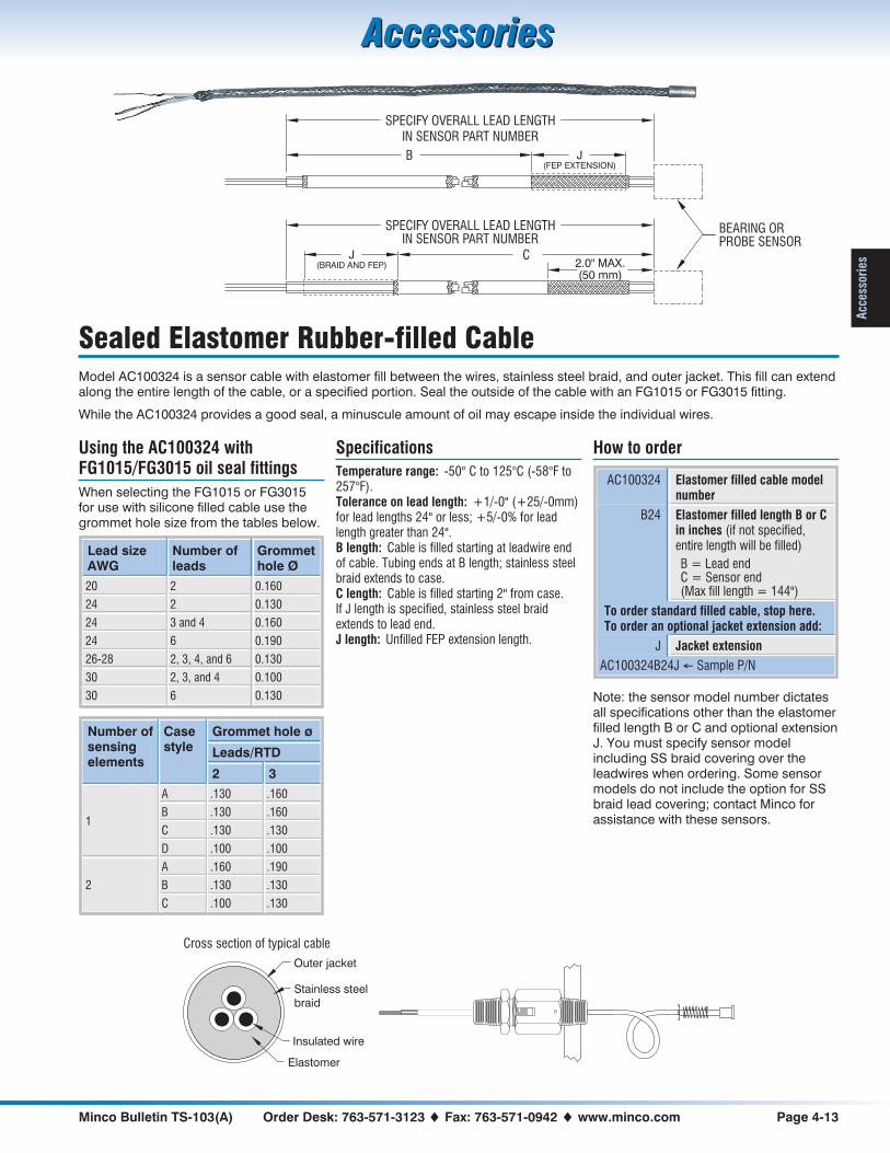
Minco Bulletin TS-103(A) Order Desk: 763-571-3123 � Fax: 763-571-0942 � www.minco.com Page 4-13
AccessoriesAccessories
Acc
esso
ries
Sealed Elastomer Rubber-filled CableModel AC100324 is a sensor cable with elastomer fill between the wires, stainless steel braid, and outer jacket. This fill can extendalong the entire length of the cable, or a specified portion. Seal the outside of the cable with an FG1015 or FG3015 fitting.
While the AC100324 provides a good seal, a minuscule amount of oil may escape inside the individual wires.
Using the AC100324 withFG1015/FG3015 oil seal fittings
When selecting the FG1015 or FG3015for use with silicone filled cable use thegrommet hole size from the tables below.
Lead sizeAWG
Number ofleads
Grommethole Ø
20 2 0.160
24 2 0.130
24 3 and 4 0.160
24 6 0.190
26-28 2, 3, 4, and 6 0.130
30 2, 3, and 4 0.100
30 6 0.130
Number ofsensingelements
Casestyle
Grommet hole ø
Leads/RTD
2 3
1
A .130 .160
B .130 .160
C .130 .130
D .100 .100
2
A .160 .190
B .130 .130
C .100 .130
Specifications
Temperature range: -50° C to 125°C (-58°F to257°F).Tolerance on lead length: +1/-0" (+25/-0mm)for lead lengths 24" or less; +5/-0% for leadlength greater than 24".B length: Cable is filled starting at leadwire endof cable. Tubing ends at B length; stainless steelbraid extends to case.C length: Cable is filled starting 2" from case.If J length is specified, stainless steel braidextends to lead end.J length: Unfilled FEP extension length.
How to order
AC100324 Elastomer filled cable modelnumber
B24 Elastomer filled length B or Cin inches (if not specified,entire length will be filled)
B = Lead endC = Sensor end(Max fill length = 144")
To order standard filled cable, stop here.To order an optional jacket extension add:
J Jacket extension
AC100324B24J � Sample P/N
Note: the sensor model number dictatesall specifications other than the elastomerfilled length B or C and optional extensionJ. You must specify sensor modelincluding SS braid covering over theleadwires when ordering. Some sensormodels do not include the option for SSbraid lead covering; contact Minco forassistance with these sensors.
Outer jacket
Stainless steel
braid
Insulated wire
Elastomer
Cross section of typical cable
B
SPECIFY OVERALL LEAD LENGTHIN SENSOR PART NUMBER
C
SPECIFY OVERALL LEAD LENGTHIN SENSOR PART NUMBER
2.0" MAX.(50 mm)
BEARING ORPROBE SENSOR
J(BRAID AND FEP)
J(FEP EXTENSION)

Page 4-14 Sales: 763-571-3121 � Fax: 763-571-0927 � www.minco.com Minco Bulletin TS-103(A)
AccessoriesAccessories
Accessories
Copper wire for RTDs
Choose single conductor copper wireor cable.
How to order
WS122R Model number from table
10 Length in feet
WS122R10 � Sample P/N
Description Temperaturelimit
Color Model number for AWG
22 26
Single conductor wire, stranded copper,PTFE insulation
260°C(500°F)
White WS122W WS126W
Red WS122R WS126R
Blue WS122B WS126B
Yellow WS122Y WS126Y
Single conductor wire, stranded,mica/glass insulation
550°C(1022°F)
White WS222W
Red tracer WS222R
3 conductor cable, PTFE insulation,stainless steel braid over all
260°C(500°F)
Red/White/White
WS322S WS326S
6 conductor cable, PTFE insulation,stainless steel braid over all
260°C(500°F)
Red/White/White/Blue/Yellow/ Yellow
WS426S
3 conductor cable, PTFE insulation,copper shield and PTFE jacket over all
260°C(500°F)
Red/White/White
WS522T
Thermocouple cable
All cable is single pair, solid wire, colorcoded per ANSI MC96.1-1982.
How to order
WT120S Model number from table
J Junction type:
E, J, K, or T
25 Length in feet
WT120SJ25 � Sample P/N
Description Temperature limit Model number for AWG
20 24
Single pair thermocouple cable, glass braidinsulation
482°C(900°F)
WT120G WT124G
Single pair thermocouple cable, PTFE insulation260°C(500°F)
WT120T WT124T
Single pair thermocouple cable, glass braidinsulation with stainless steel braid over all
482°C(900°F)
WT120S WT124S
Extension WireUse the wire and cable on this page toconnect sensor leadwires to remoteinstrumentation. Thermocouple wiremeets standard limits of error perANSI MC96.1-1982.
Unless Minco informs you otherwise,wire and cable will be supplied incontinuous lengths. Ends are notstripped.
IN STOCK
All wire shown, in moderate lengths

Minco Bulletin TS-103(A) Order Desk: 763-571-3123 � Fax: 763-571-0942 � www.minco.com Page 5-1
Temperature InstrumentsTemperature Instruments
Inst
rum
ents
Section 5: Temperature Instruments
• RTD and thermocouple Temptran™ transmitters giveaccurate signals over thousands of feet. Select fixedrange or field rangeable; miniature,“hockey puck,”and isolated versions
• Microprocessor based controllers with optional alarmfeatures
• Miniature DC temperature controller
RTD transmitters....................5-2, 5-3, 5-5, 5-7, 5-8, 5-18
Thermocouple transmitters....................................5-4, 5-6, 5-7, 5-9
Isolated transmitters .......5-5, 5-6, 5-8, 5-9Field rangeable transmitters......5-7 to 5-9Temp. range table..................5-10 to 5-17Why use Temptrans? .........................5-18High accuracy calibration ..................5-18Temptran wiring diagrams.................5-19Mounting accessories........................5-19CT325 miniature
DC temperature controller..............5-20CT15 controller/alarm ........................5-21CT16A temperature controller
............................................5-22 to 5-23CT124 8-channel monitor ......5-24 to 5-25TI196 head mounted indicator...........5-26TI350 Indicator ...................................5-26
www.minco.com
� Dozens of other instrument configura-tions are listed at www.minco.com.

Page 5-2 Sales: 763-571-3121 � Fax: 763-571-0927 � www.minco.com Minco Bulletin TS-103(A)
Temperature InstrumentsTemperature Instruments
Instruments
Miniature RTD Transmitters
• Small size, low cost
• Four models:TT110, TT111: UL recognizedcomponent for Canada and UnitedStates.TT210, TT211: Wider ambient rating;Factory Mutual (FM) approvedintrinsically safe and nonincendive
• Optional match calibration to MincoRTDs for improved accuracy,see page 5-18.
SpecificationsOutput: 4 to 20 mA over specified range, linearwith temperature.Calibration accuracy: ±0.1% of span.Linearity: Referenced to actual sensortemperature.Platinum RTD input: ±0.1% of span.Nickel and nickel-iron RTD input:
±0.25% of span for spans less than 100°C.±0.25% of span per 100°C of span for spans
greater than 100°C.Adjustments: Zero and span, ±5% of span.Factory set.Ambient temperature:TT110, TT111: 0 to 50°C (32 to 122°F).TT210, TT211: -25 to 85°C (-13 to 185°F).Storage: -55 to 100°C (-67 to 212°F).Ambient temperature effects:±0.013% of span per °C.±0.025% of span per °C for spans less than55°C.Warmup drift: ±0.1% of span max., withVsupply = 24 VDC and Rloop = 250 �.
Stable within 30 minutes.Supply voltage: 8.5 to 35 VDC. Voltage effect±0.001% of span per volt. Reverse polarityprotected.
Maximum load resistance: The maximumallowable resistance of the signal carrying loopis:
RV
loop max
supply�
� 8.5
0.020 amps
Example: With supply voltage 24 VDC, maximumloop resistance is 775 �.Minimum span: 27.8°C (50°F).Hazardous atmospheres: All models may beused with Minco flameproof/explosionproofconnection heads. Models TT210 and TT211 areFactory Mutual approved intrinsically safe forClass I, Division 1 areas (requires approvedbarrier) and nonincendive for use in Class I,Division 2 areas. Transmitter entity parameters:Vmax = 35 volts; Imax = 150 mA; Ci = 0 �F
and Li = 0 mH.
Connections:TT110, TT210: Four AWG 22 leads, 5" (127 mm).TT111, TT211: Terminal block for wires AWG 22
to AWG 14.Physical: Polycarbonate case, epoxy potted formoisture resistance.Weight: 1.1 oz. (30 g).
RTD input types2-wire resistance thermometer:
Element Code
Platinum 392, 100 � at 0°C PA
Platinum 391, 100 � at 0°C PB
Platinum 385, 100 � at 0°C PD, PE
Platinum 385, 1000 � at 0°C PF
Platinum 375, 1000 � at 0°C PW
Nickel-iron, 604 � at 0°C FA
Nickel-iron, 1000 � at 70°F FB
Nickel-iron, 2000 � at 70°F FC
Nickel, 120 � at 0°C NA
How to order
TT111 Model number: TT110, TT111,TT210, or TT211
PD RTD element code from table
1 Output: 4 to 20 mA DC
C Temperature range code fromtable on page 5-10[Ex: C = 0 to 100°C(32 to 212°F)]
TT111PD1C � Sample P/N
See page 5-18 for high-accuracy calibrationoption.
IN STOCK
Contact Minco for currently available transmitterranges and models
0.149 (3.8) I.D.THROUGH
1.5 (38.1)
1 2 3 4
0.25(6.4)
1.0(25.4)
ZERO
SPAN
0.08(2.0)MAX.
0.675 (17.1)
1.09 (27.1)
MOUNTING USE #6SCREW THROUGH OR#8 THREAD FORMING
SCREW
0.50(12.7)
DIMENSIONS IN INCHES (mm)SEE PAGE 5-19 FOR WIRING DIAGRAM
C USTT110, TT111 only TT210, TT211 only
TT110, TT210 TT111, TT211
Hazardous Area RequirementsRequest Application Aid #19 for information on how to classify a hazardousarea, methods of protection, and the various standards and agencies(including FM, CSA, CENELEC and ATEX).

Minco Bulletin TS-103(A) Order Desk: 763-571-3123 � Fax: 763-571-0942 � www.minco.com Page 5-3
Temperature InstrumentsTemperature Instruments
Inst
rum
entsTT176, TT246 RTD Transmitters
• “Hockey puck” style industrialtransmitters
• TT176: 4 to 20 mA current signalTT246: 1 to 5 VDC voltage signal
• 2 or 3-wire RTD input
• TT176: Factory Mutual (FM) approvedintrinsically safe, nonincendive forhazardous locations
• Ambient rated to 85°C (185°F)
• Fits DIN “B” style connection heads
• Optional match calibration to MincoRTDs for improved accuracy,see page 5-18
Specify these rugged, accuratetransmitters for process control and otherindustrial applications.
Model TT176 provides a linearized 4 to20 mA current signal for long distancetransmission. It has a built-in LEDindicator to monitor operation.
TT246 outputs 1 to 5 VDC proportional totemperature. It draws only 3 mA ofquiescent current, making it ideal for solaror battery powered systems.
SpecificationsOutput: Linear with temperature over specifiedrange.TT176: 4 to 20 mA.TT246: 1 to 5 VDC.Calibration accuracy: ±0.1% of span (0.2% ofspan for spans less than 10 �).Linearity: 0.1% of span, referenced to actualsensor temperature.Adjustments: Zero and span, ±5% of span,non-interacting. Factory set.Ambient temperature:Operating: -40 to 85°C (-40 to 185°F).Storage: -55 to 100°C (-67 to 212°F).Ambient temperature effects:±0.009% of span per °C.±0.014% of span per °C for spans less than10 �.
Warmup drift: ±0.1% of span max., withVsupply = 24 VDC and Rloop = 250 �.
Stable within 15 minutes.Supply voltage:TT176: 10 to 35 VDC.TT246: 7.5 to 35 VDC.Voltage effect ±0.001% of span per volt.Reverse polarity protected.Supply current (TT246): 3 mA max. with noload.Maximum load resistance (TT176): Themaximum allowable resistance of the signalcarrying loop is:
RV
loop max
supply�
� 10
0.020 amps
Example: With supply voltage 24 VDC, maximumloop resistance is 700 �.Minimum span: 10°C (18°F).Minimum output current: 2.2 mA (TT176).Maximum output current: 28 mA (TT176).Leadwire compensation: (3-wire RTD) ±0.05%of span per � up to 25 � in each leg.Hazardous atmospheres: Both models may beused with Minco explosionproof connectionheads. Model TT176 is Factory Mutual approvedintrinsically safe for Class I, Division 1 areas(requires approved barrier) and nonincendive foruse in Class I, Division 2 areas. Transmitterentity parameters: Vmax = 35 volts;
Imax = 150 mA; Ci = 0 �F and Li = 0 mH.
Connections: Terminal block for wires AWG 22to AWG 14.Physical: Polycarbonate case, epoxy potted formoisture resistance.Weight: 2.0 oz. (57 g).
RTD input types2 or 3-wire resistance thermometer:
Element Code
Platinum 392, 100 � at 0°C PA
Platinum 391, 100 � at 0°C PB
Platinum 385, 100 � at 0°C PD, PE
Platinum 385, 1000 � at 0°C PF
Platinum 375, 1000 � at 0°C PW
Copper, 10 � at 25°C CA
Nickel-iron, 604 � at 0°C FA
Nickel-iron, 1000 � at 70°F FB
Nickel-iron, 2000 � at 70°F FC
Nickel, 120 � at 0°C NA
How to order
TT176 Model number:TT176: 4 to 20 mATT246: 1 to 5 VDC
PB RTD element code from table
1
K Temperature range code fromtable on page 5-10[Ex: K = 0 to 200°C(32 to 392°F)]
TT176PB1K � Sample P/N
See page 5-18 for high-accuracy calibrationoption.
TT176 only
TT176 CURRENT OUTPUT
TT246 VOLTAGE OUTPUT
SPAN
SIGNAL(TT246 HAS
THREESIGNAL
TERMINALS)
AZEROSENSOR
1.30(33.0)
0.65(16.5)
A LED
1.725 (43.8)DIAMETER
0.188 (4.8) DIA. [2]
0.26 (6.6) DIA.
0.320 (8.1) DIA. [2]
12
3
12
12
3
1.10 (27.9)
SECTION A-A
0.725(18.42)
DIMENSIONS IN INCHES (mm)SEE PAGE 5-19 FOR WIRING DIAGRAM
IN STOCK
Contact Minco for currently available transmitterranges and models
Hazardous Area RequirementsRequest Application Aid #19 for information on how to classify a hazardousarea, methods of protection, and the various standards and agencies(including FM, CSA, CENELEC and ATEX).

Page 5-4 Sales: 763-571-3121 � Fax: 763-571-0927 � www.minco.com Minco Bulletin TS-103(A)
Temperature InstrumentsTemperature Instruments
Instruments
TT190, TT205 Thermocouple Transmitters
• TT190: “Hockey puck” style industrialtransmitterTT205: Miniature economy version
• Thermocouple input
• Intrinsically safe, nonincendive forhazardous locations
• Fits DIN “B” style connection heads
Model TT190 interfaces withthermocouples for use in process controland other industrial applications. It has abuilt-in LED indicator to help troubleshootsignal loops. A dark LED signals loss ofcurrent loop power or an openthermocouple.
Model TT205 offers performance andeconomy over a reduced ambienttemperature range. Its compact size takesup little space.
SpecificationsOutput: 4 to 20 mA over specified range.Accuracy: ±0.2% of span.Linearity: Voltage linear.Adjustments: Zero and span, ±5% of span,non-interacting. Factory set.Warmup drift: ±0.2% of span max., withVsupply = 24 VDC and Rloop = 250 �.
Stable within 15 minutes.Supply voltage:TT190: 10 to 35 VDC.TT205: 8.5 to 35 VDC.Voltage effect ±0.001% of span per volt.Reverse polarity protected.Maximum load resistance: The maximumallowable resistance of the signal carrying loop is:
RV V
loop max
supply min�
�
0.020 amps
Example: With a TT190 (Vmin = 10) operated at24 VDC, maximum loop resistance is 700 �.Minimum output current: 1.5 mA.Maximum output current: 28 mA.Burnout: Downscale burnout standard; upscaleoptional.
Hazardous atmospheres: Both models may beused with Minco explosionproof connectionheads. Model TT190 is Factory Mutual approvedintrinsically safe for Class I, Division 1 areas(requires approved barrier) and nonincendive foruse in Class I, Division 2 areas. Transmitterentity parameters: Vmax = 35 volts;
Imax = 150 mA; Ci = 0 �F and Li = 0 mH.
Connections: Terminal block for wires AWG 22to AWG 14.Physical: Polycarbonate case, epoxy potted formoisture resistance.Weight: 1.8 oz. (52 g).
TT190Ambient temperature:Operating: -40 to 85°C (-40 to 185°F).Storage: -55 to 100°C (-67 to 212°F).Ambient temperature effects:±0.018% of span per °C.Cold junction compensation drift:±0.03°C per °C, -25 to 70°C.±0.06°C per °C, -40 to -25°C and 70 to 85°C.Minimum span: 100°C (180°F).
TT205Ambient temperature:Operating: -10 to 60°C (14 to 140°F).Storage: -55 to 100°C (-67 to 212°F).Ambient temperature effects:±0.036% of span per °C.Cold junction compensation drift:±0.05°C per °C.Minimum span: 150°C (270°F).
How to order
TT190 Model number:TT190: RoundTT205: Rectangular
J TC junction type:E = Chromel-ConstantanJ = Iron-ConstantanK = Chromel-AlumelT = Copper-Constantan
U U = Ungrounded junction(required)
1 Output: 4 to 20 mA DC
GX Temperature range code fromtable on page 5-10[Ex: GX = 93.3 to 760°C(200 to 1400°F)]
TT190JU1GX � Sample P/N
TT190 only
4 TO 20mA LOOP
AZERO
SENSOR
1.30(33.0)
0.65(16.5)
A LED
1.725 (43.8)DIAMETER
0.188 (4.8) DIA. [2]
0.26 (6.6) DIA.
0.320 (8.1) DIA. [2]
12
12
1.10 (27.9)
SECTION A-A
0.725(18.42)
12
SPAN
DIMENSIONS IN INCHES (mm)SEE PAGE 5-19 FOR WIRING DIAGRAM
TT190
TT205
DIMENSIONS SAMEAS ON PAGE 5-2
Hazardous Area RequirementsRequest Application Aid #19 for information on how to classify a hazardousarea, methods of protection, and the various standards and agencies(including FM, CSA, CENELEC and ATEX).

Minco Bulletin TS-103(A) Order Desk: 763-571-3123 � Fax: 763-571-0942 � www.minco.com Page 5-5
Temperature InstrumentsTemperature Instruments
Inst
rum
entsTT220 Isolated RTD Transmitter
• 2 or 3-wire RTD input
• Input/output isolated to 600 VRMS
• Factory Mutual (FM) approvedintrinsically safe, nonincendive forhazardous locations
• Ambient rated to 85°C (185°F)
• Optional match calibration to MincoRTDs for improved accuracy,see page 5-18
Model TT220 is a rugged industrialtransmitter designed for process controland other applications. It provideselectrical isolation to 600 VRMS betweenthe input and output.
The TT220 has a built-in LED indicator tohelp troubleshoot signal loops. A verybright LED indicates an open sensor; adark LED signals a shorted sensor or lossof current loop power.
SpecificationsOutput: 4 to 20 mA over specified range, linearwith temperature.Calibration accuracy: ±0.1% of span (0.2% ofspan for spans less than 10 �).Linearity: 0.1% of span, referenced to actualsensor temperature.Adjustments: Zero and span, ±5% of span,non-interacting. Factory set.Ambient temperature:Operating: -40 to 85°C (-40 to185°F).Storage: -55 to 100°C (-67 to 212°F).Ambient temperature effects: ±0.018% ofspan per °C.Warmup drift: ±0.1% of span max., withVsupply = 24 VDC and Rloop = 250 �.
Stable within 15 minutes.Input/output isolation: 600 VRMS.Supply voltage: 13 to 45 VDC. Voltage effect±0.001% of span per volt. Reverse polarityprotected.
Maximum load resistance: The maximumallowable resistance of the signal carrying loop is:
RV
loop max
supply�
� 13
0.020 amps
Example: With supply voltage 24 VDC, maximumloop resistance is 550 �.Minimum span: 10°C (18°F).Minimum output current: 2.5 mA.Maximum output current: 28 mA.Leadwire compensation: (3-wire RTD) ±0.05%of span per � up to 25 � in each leg.Hazardous atmospheres: Model TT220 may beused with Minco explosionproof connectionheads. This model is Factory Mutual approvedintrinsically safe for Class I, Division 1 areas(requires approved barrier) and nonincendive foruse in Class I, Division 2 areas. Transmitterentity parameters: Vmax = 35 volts;
Imax = 150 mA; Ci = 0 �F and Li = 0 mH.
Connections: Terminal block for wires AWG 22to AWG 14.Physical: Polycarbonate case, epoxy potted formoisture resistance.Weight: 3.0 oz. (85 g).
RTD input types2 or 3-wire resistance thermometer:
Element Code
Platinum 392, 100 � at 0°C PA
Platinum 391, 100 � at 0°C PB
Platinum 385, 100 � at 0°C PD, PE
Platinum 385, 1000 � at 0°C PF
Platinum 375, 1000 � at 0°C PW
Copper, 10 � at 25°C CA
Nickel-iron, 604 � at 0°C FA
Nickel-iron, 1000 � at 70°F FB
Nickel-iron, 2000 � at 70°F FC
Nickel, 120 � at 0°C NA
How to order
TT220 Model number
PA RTD element code from table
1 Output: 4 to 20 mA DC
GH Temperature range code fromtable on page 5-10[Ex: GH = -40 to 100°C(-40 to 212°F)]
TT220PA1GH � Sample P/N
See page 5-18 for high-accuracy calibrationoption.
1.25(31.8)
1.55 (39.4)
0.65(16.5)
1.30(33.0)
SPAN
LED
ZERO
1.90 (48.3)DIAMETER
0.312 (7.9)I.D. [2]
0.188 (4.8) I.D.THROUGH [2]
1 2 3 4 5
DIMENSIONS IN INCHES (mm)SEE PAGE 5-19 FOR WIRING DIAGRAM
Hazardous Area RequirementsRequest Application Aid #19 for information on how to classify a hazardousarea, methods of protection, and the various standards and agencies(including FM, CSA, CENELEC and ATEX).

Page 5-6 Sales: 763-571-3121 � Fax: 763-571-0927 � www.minco.com Minco Bulletin TS-103(A)
Temperature InstrumentsTemperature Instruments
Instruments
TT221 Isolated Thermocouple Transmitter
• Thermocouple input
• Input/output isolated to 600 VRMS
• Factory Mutual (FM) approvedintrinsically safe, nonincendive forhazardous locations
• Ambient rated to 85°C (185°F)
Model TT221 is a rugged thermocoupletransmitter designed for process controland other applications. It provideselectrical isolation to 600 VRMS betweenthe input and output. You can usethermocouples with either grounded orungrounded junctions.
The TT221 has a built-in LED indicator tohelp troubleshoot signal loops. A darkLED signals loss of loop power or anopen sensor.
SpecificationsOutput: 4 to 20 mA over specified range.Accuracy: ±0.2% of span.Linearity: Voltage linear.Adjustments: Zero and span, ±5% of span,non-interacting. Factory set.Ambient temperature:Operating: -40 to 85°C (-40 to185°F).Storage: -55 to 100°C (-67 to 212°F).Ambient temperature effects:±0.036% of span per °C.Cold junction compensation drift:±0.03°C per °C, -25 to 70°C.±0.06°C per °C, -40 to -25°C and 70 to 85°C.Warmup drift: ±0.2% of span max., withVsupply = 24 VDC and Rloop = 250 �.
Stable within 15 minutes.Supply voltage: 13 to 45 VDC. Voltage effect±0.001% of span per volt. Reverse polarityprotected.
Maximum load resistance: The maximumallowable resistance of the signal carrying loop is:
RV
loop max
supply�
� 13
0.020 amps
Example: With supply voltage 24 VDC, maximumloop resistance is 550 �.Minimum span: 100°C (180°F).Minimum output current: 2.5 mA.Maximum output current: 28 mA.Burnout: Downscale burnout standard; upscaleoptional.Hazardous atmospheres: Model TT221 may beused with Minco explosionproof connectionheads. This model is Factory Mutual approvedintrinsically safe for Class I, Division 1 areas(requires approved barrier) and nonincendive foruse in Class I, Division 2 areas. Transmitterentity parameters: Vmax = 35 volts;
Imax = 150 mA; Ci = 0 �F and Li = 0 mH.
Connections: Terminal block for wires AWG 22to AWG 14Physical: Polycarbonate case, epoxy potted formoisture resistance.Weight: 3.0 oz. (85 g).
How to order
TT221 Model number
J TC junction type (may begrounded or ungrounded):E = Chromel-ConstantanJ = Iron-ConstantanK = Chromel-AlumelT = Copper-Constantan
1 Output: 4 to 20 mA DC
BW Temperature range code fromtable on page 5-10[Ex: BW = 0 to 250°C(32 to 482°F)]
TT221J1BW � Sample P/N
1.25(31.8)
1.55 (39.4)
0.65(16.5)
1.30(33.0)
SPAN
LED
ZERO
0.312 (7.9)I.D. [2]
0.188 (4.8) I.D.THROUGH [2]
1 2 3 4
1.90 (48.3)DIAMETER
DIMENSIONS IN INCHES (mm)SEE PAGE 5-19 FOR WIRING DIAGRAM
Hazardous Area RequirementsRequest Application Aid #19 for information on how to classify a hazardousarea, methods of protection, and the various standards and agencies(including FM, CSA, CENELEC and ATEX).

Minco Bulletin TS-103(A) Order Desk: 763-571-3123 � Fax: 763-571-0942 � www.minco.com Page 5-7
Temperature InstrumentsTemperature Instruments
Inst
rum
entsField Rangeable Transmitters
• Wide ranging zero and span adjust todesired temperature range
• LED indicates status of current loop
Rangeable transmitters let you stockstandard models, then calibrate to theexact range when a need arises. Thereare three broad range codes for platinumRTDs, one for copper RTDs, and two forthermocouples. Each range codecontains three intervals for temperaturespan. You select the desired interval bymaking a solder link between two pinsatop the transmitter. Zero and spanpotentiometers give fine adjustments.
SpecificationsOutput: 4 to 20 mA over specified range.Adjustments: See temperature range chart atright. Normally shipped uncalibrated; factorycalibration available.Ambient temperature:Operating: -40 to 85°C (-40 to 185°F).Storage: -55 to 100°C (-67 to 212°F).Supply voltage: 10 to 35 VDC. Voltage effect±0.001% of span per volt. Reverse polarityprotected.Maximum load resistance: The maximumallowable resistance of the signal carrying loop is:
RV
loop max
supply�
� 10
0.020 amps
Example: With supply voltage 24 VDC, maximumloop resistance is 700 �.Hazardous atmospheres: Factory Mutualapproved intrinsically safe for Class I, Division 1areas (requires approved barrier) andnonincendive for use in Class I, Division 2 areas.Transmitter entity parameters: Vmax = 35 volts;
Imax = 150 mA; Ci = 0 �F and Li = 0 mH.
Request Application Aid #19 for information onhazardous area classifications.Connections: Terminal block for wires AWG 22to AWG 14.Physical: Polycarbonate case, epoxy potted formoisture resistance.Weight: 2.0 oz. (57 g).
TT216 RTD transmitterCalibration accuracy: ±0.2% of span whenfactory calibrated.Linearity: 0.2% of span, referenced to actualsensor temperature.Ambient temperature effects: ±0.013% ofspan per °C.Warmup drift: ±0.1% of span max., withVsupply = 24 VDC and Rloop = 250 �.
Stable within 15 minutes.Minimum output current 2.2 mA.Maximum output current: 28 mA.Leadwire compensation: (3-wire RTD) ±0.05%of span per � up to 25 � in each leg.RTD input types:2 or 3-wire resistance thermometer:
Element Code
Platinum, 100 � at 0°C(Includes all TCRs)
PX
Copper, 10 � at 25°C CA
How to order
TT216 Model number
PX RTD element code from table
1 Output: 4 to 20 mA DC
RB Range code from table
TT216PX1RB � Sample P/N
TT230 thermocouple transmitterCalibration accuracy: ±0.3% of span whenfactory calibrated.Linearity: Voltage linear.Ambient temperature effects:±0.025% of span per °C.Cold junction compensation drift:±0.03°C per °C, -25 to 70°C.±0.06°C per °C, -40 to -25°C and 70 to 85°C.Minimum output current: 1.5 mA.Maximum output current: 28 mA.Burnout: Downscale burnout standard; upscaleoptional.
How to order
TT230 Model number
T TC junction type:E = Chromel-ConstantanJ = Iron-ConstantanK = Chromel-AlumelT = Copper-Constantan
U Ungrounded junction(required)
1 Output: 4 to 20 mA DC
RC Range code from table above
TT230TU1RC � Sample P/N
SPAN
4 TO 20mA LOOP
AZEROSENSOR
1.30(33.0)
0.65(16.5)
A LED
1.725 (43.8)DIAMETER
12
3
12
0.188 (4.8) DIA. [2]
0.26 (6.6) DIA.
0.320 (8.1) DIA. [2]
12
3
1.10 (27.9)
SECTION A-A
0.725(18.42)
DIMENSIONS IN INCHES (mm)SEE PAGE 5-19 FOR WIRING DIAGRAM
TT230
TT216
Temperature range: The range code determines which values of zero and span are available on thetransmitter you order. The actual values are chosen by shorting two pins on top the transmitter, thenadjusting the two potentiometers.
Zero (T4 mA) Span (T20mA - T4mA) RTDcode
Thermocoupleinput type
RangecodeMinimum Maximum Minimum Maximum
-25°C 25°C 25°C 100°C PX RA
-50°C 50°C 50°C 200°C PX RB
-100°C 200°C 150°C 600°C PX E, J, K, T RC
-100°C 100°C 100°C 300°C CA RD
-100°C 500°C 300°C 1200°C K RE

Page 5-8 Sales: 763-571-3121 � Fax: 763-571-0927 � www.minco.com Minco Bulletin TS-103(A)
Temperature InstrumentsTemperature Instruments
Instruments
TT273 RTD Temperature Transmitter
• Accurate, stable 4 to 20 mA signal
• Fits standard 35 mm DIN rail
• Field-calibrate to your temperaturerange
• Optional match calibration to MincoRTDs for improved accuracy,see page 5-18
• Optional Input/Output isolation to600 VRMS
The Model TT273 is a 2-wire temperaturetransmitter for 2 or 3-lead 100 � platinumRTDs. The transmitter converts the RTDstemperature into a linearized 4 to 20 mADC current signal. Because this currentsignal is immune to leadwire andelectrical noise, the TT273 lets you obtainaccurate temperature readings fromRTDs thousands of feet away. An ordinarytwisted pair of wires carries both thetemperature signal and power for thetransmitter’s electronics.
An LED conveniently indicates the statusof the control loop. The brightness isdirectly proportional to the loop current. Avery bright LED indicates an open RTD; adark LED signals a shorted RTD or loss ofcurrent loop power.
SpecificationsOutput: 4 to 20 mA DC over specified range.Calibration accuracy: ±0.2% of span.Linearity: ±0.2% of span, reference to actualsensor temperature.Adjustments:Zero: -50 to 150°C (-58 to 302°F).Span: 50 to 600°C (90 to 1080°F).Ambient temperature:Operating: -40 to 85°C (-40 to 185°F).Storage: -55 to 100°C (-67 to 212°F).Ambient temperature effects:±0.018% of span/°C (±0.01% of span/°F).Warmup drift: ±0.1% of span max., assumingVsupply = 24 VDC and Rloop = 250 �.
Stable within 15 minutes.Input/output isolation (optional):600 VRMS, 1 minute.Supply voltage:Non-Isolated: 10 to 45 volts DC with no load.Isolated: 13 to 45 volts DC with no load.Reverse polarity protected.Voltage effect: ±0.001% of span per volt.Lead wire compensation: (3-wire RTD)±0.05% of span per �, up to 25 � in each leg.Maximum load resistance: The maximumallowable resistance of the signal-carrying loop isgiven by this formula:
Non-Isolated: RV
loop max
supply�
� 10
0.020 amps
Isolated: RV
loop max
supply�
� 13
0.020 amps
Maximum output current: 28 mA.Connections: Terminal block accepts wires fromAWG 22 to AWG 14.Physical: Polycarbonate, DIN rail enclosure.Weight: 4.2 oz. (119 grams).
RTD input types2 or 3-wire 100 � platinum RTD.
Element Code
Platinum 392, 100 � at 0°C PA
Platinum 391, 100 � at 0°C PB
Platinum 385, 100 � at 0°C PD, PE
How to order:
TT273 Model number
PD RTD element code from table
1 Output: 4 to 20 mA DC
N Input/Output:N = Non-isolatedI = Isolated
(-25/50) Factory preset temp. range:(4 mA/20 mA temperature)Range is user adjustable.Refer to the Zero and Spanspecifications at left.
C Temperature scale:F = FahrenheitC = Celsius
TT273PD1N(-25/50)C � Sample P/N
See page 5-18 for high-accuracy calibrationoption.
PWR
ZERO
SPAN
2.95(74.9)
0.886(22.5)
3.875(98.4)
SLIDINGCATCH
DIP SWITCHRANGE SELECTION
35 mm DINRAIL MOUNT
DIMENSIONS IN INCHES (mm)
SEE PAGE 5-19 FOR WIRING DIAGRAMS

Minco Bulletin TS-103(A) Order Desk: 763-571-3123 � Fax: 763-571-0942 � www.minco.com Page 5-9
Temperature InstrumentsTemperature Instruments
Inst
rum
entsTT274 Thermocouple Temperature Transmitter
• Accurate, stable 4 to 20 mA signal
• Fits standard 35 mm DIN rail
• Field-calibrate to your thermocoupletype and temperature range
• Optional Input/Output isolation to600 VRMS
The Model TT274 is a 2-wire temperaturetransmitter for types J and Kthermocouples. The transmitter convertsthe thermocouple’s millivolt signal to a4 to 20 mA DC current signal. Becausethis current signal is immune to leadwireand electrical noise, the TT274 lets youobtain accurate temperature readingsfrom thermocouples thousands of feetaway. An ordinary twisted pair of wirescarries both the temperature signal andpower for the transmitter’s electronics.
With the isolation option, the mV inputsignal from the thermocouple iselectrically isolated from the 4 to 20 mAoutput, allowing use of groundedthermocouples with multiple TT274soperating from the same power supply.
An LED conveniently indicates the statusof the control loop. The brightness isdirectly proportional to the loop current. Adark LED signals an open sensor or lossof current loop power.
The output signal of the TT274 is voltagelinear (not temperature linear) and isintended for use with instruments whichcompensate for the nonlinear signaloutput of the thermocouple sensor.
SpecificationsInput: Type J or K thermocouple.Output: 4 to 20 mA DC over specified range.Accuracy: ±0.2% of span.Linearity: Voltage linear.Adjustments:Zero: -50°C to 150°C (-58°F to 302°F)Span: Type J: 125 to 850°C (225 to 1530°F)
Type K: 150 to 1200°C (270 to 2160°F)Ambient temperature:Operating: -40 to 85°C (-40 to 185°F).Storage: -55 to 100°C (-67 to 212°F).Ambient temperature effects: ±0.036% ofspan/°C (±0.02% of span/°F).Cold junction compensation drift: ±0.03°C/°Cfor -25 to 70°C ambients. ±0.06°C/°C for -40 to-25°C and 70 to 85°C ambients.Warmup drift: ±0.1% of span max., assumingVsupply = 24 VDC and Rloop = 250 �.
Stable within 15 minutes.Input/output isolation (optional):600 VRMS, 1 minute.Supply voltage:Non-Isolated: 10 to 45 volts DC with no load.Isolated: 13 to 45 volts DC with no load.Reverse polarity protected.Voltage effect: ±0.001% of span per volt.Maximum load resistance: The maximumallowable resistance of the signal-carrying loop isgiven by this formula:
Non-Isolated: RV
loop max
supply�
� 10
0.020 amps
Isolated: RV
loop max
supply�
� 13
0.020 amps
Maximum output current: 28 mA.Connections: Terminal block accepts wires fromAWG 22 to AWG 14.Physical: Polycarbonate, DIN rail enclosure.Weight: 4.2 oz. (119 grams).
How to order:
TT274 Model number
K T/C element code:J = Type J thermocoupleK = Type K thermocouple
1 Output: 4-20 mA DC
N Input/Output:N = Non-isolatedI = Isolated
(-25/200) Factory preset temp. range:(4 mA/20 mA temperature)Range is user adjustable.Refer to the Zero and Spanspecifications at left.
C Temperature scale:F = FahrenheitC = Celsius
TT274K1N(-25/200)C � Sample P/N
PWR
ZERO
SPAN
2.95(74.9)
0.886(22.5)
3.875(98.4)
SLIDINGCATCH
DIP SWITCHRANGE SELECTION
35 mm DINRAIL MOUNT
DIMENSIONS IN INCHES (mm)
SEE PAGE 5-19 FOR WIRING DIAGRAMS

Page 5-10 Sales: 763-571-3121 � Fax: 763-571-0927 � www.minco.com Minco Bulletin TS-103(A)
Temperature InstrumentsTemperature Instruments
Instruments
� Additional ranges are available. Call Minco for details.
Temperature InstrumentsTemperature Instruments
Temptran™ Temperature RangesThe endpoints of the temperature range correspond to the Temptran’s 4 and 20 mA signals. Choose the smallest possible spanfor best accuracy. Be sure to check the temperature limits of the sensor you specify.
New ranges are available for a small setup charge.
Minco sets the range for each Temptran using high-quality fixed resistors, then finely calibrates them with high resolutionmulti-turn zero and span potentiometers. Because the potentiometers represent only 5% of span, Minco Temptrans are much lesssusceptible than other transmitters to drift caused by vibration and temperature change.
RangeCode
°F TemperatureRange
°C TemperatureRange
TT110, TT111, TT115, TT210, TT211,TT829
TT176, TT246, TT220 TT190,TT221
TT205
4 mA 20 mA 4 mA 20 mA Platinum elements Other elements Elements T/CTypes T/CTypes
DC -328 -238 -200.0 -150.0 PA PB PD PE
YL -328 -202 -200.0 -130.0 PA PB PD PE
MH -328 -148 -200.0 -100.0 PA PB PD PE
YR -328 -148 -200.0 -100.0 PA PB PD PE
LC -328 -58 -200.0 -50.0 T
TN -328 32 -200.0 0.0 PA PB PD PE
UH -328 122 -200.0 50.0
MC -328 149 -200.0 65.0 PF PW PA PB PD PE
DH -328 212 -200.0 100.0 PA PB PD PE PA PB PD PE
GD -328 392 -200.0 200.0 PA PB PD PE
HG -325 100 -198.3 37.8 PA PB PD PE PF PW JT
XW -310 1,832 -190.0 1,000.0 K
KE -301 -139 -185.0 -95.0 PA PB PD PE
QS -300 150 -184.4 65.6 PA PB PD PE
JY -300 300 -184.4 148.9 PA PB PD PE
SM -280 -180 -173.3 -117.8 PA PB PD PE
TM -274 -202 -170.0 -130.0 PF PW
TG -256 -184 -160.0 -120.0 PA PB PD PE
JN -250 0 -156.7 -17.8 PA PB PD PE
UT -238 -58 -150.0 -50.0 PA PB PD PE
GY -211 32 -135.0 0.0 PA PB PD PE
WM -211 95 -135.0 35.0
MB -202 149 -130.0 65.0 PA PB PD PE T
JQ -200 -50 -128.9 -45.6
KD -185 -95 -120.6 -70.6 PA PB PD PE
QM -184 95 -120.0 35.0 PA PB PD PE
LY -180 0 -117.8 -17.8 T
SZ -150 -50 -101.1 -45.6 PA PB PD PE
YN -150 0 -101.1 -17.8 PA PB PD PE
WP -150 50 -101.1 10.0 PA PB PD PE
TF -148 -76 -100.0 -60.0 PA PB PD PE
AT -148 -40 -100.0 -40.0 PA PB PD PE PF PW
EZ -148 32 -100.0 0.0 PA PB PD PE PF PW PA PB PD PE
SE -148 95 -100.0 35.0 PF PW
TK -148 122 -100.0 50.0 PA PB PD PE PF PW
LN -148 212 -100.0 100.0 PA PB PD PE
UZ -148 257 -100.0 125.0 K
QT -148 500 -100.0 260.0 PA PB PD PE NA
MV -148 572 -100.0 300.0 J
SA -140 100 -95.6 37.8 PA PB PD PE
XT -121 32 -85.0 0.0
QU -120 -40 -84.4 -40.0 PF PW
EB -120 60 -84.4 15.6 PA PB PD PE
SC -120 100 -84.4 37.8 PA PB PD PE FA J
HP -110 200 -78.9 93.3 PA PB PD PE PA PB PD PE
GG -103 122 -75.0 50.0 PA PB PD PE PA PB PD PE
UL -103 752 -75.0 400.0 K
SK -100 0 -73.3 -17.8 PA PB PD PE

Minco Bulletin TS-103(A) Order Desk: 763-571-3123 � Fax: 763-571-0942 � www.minco.com Page 5-11
Temperature InstrumentsTemperature Instruments
Inst
rum
ents
Temperature InstrumentsTemperature Instruments
� Additional ranges are available. Call Minco for details.
RangeCode
°F TemperatureRange
°C TemperatureRange
TT110, TT111, TT115, TT210, TT211,TT829
TT176, TT246, TT220 TT190,TT221
TT205
4 mA 20 mA 4 mA 20 mA Platinum elements Other elements Elements T/CTypes T/CTypes
SB -100 100 -73.3 37.8 PA PB PD PE J
LP -100 250 -73.3 121.1 PA PB PD PE K
QF -100 400 -73.3 204.4 K
TH -100 600 -73.3 315.6 PA PB PD PE
JB -99 1 -72.8 -17.2 PA PB PD PE
TR -94 158 -70.0 70.0 PA PB PD PE
LD -90 90 -67.8 32.2 PA PB PD PE PA PB PD PE J
WS -90 600 -67.8 315.6
ET -85 32 -65.0 0.0 PA PB PD PE PF PW
WF -79 392 -62.0 200.0 PA PB PD PE
XA -75 100 -59.4 37.8 PA PB PD PE
XG -67 392 -55.0 200.0 K
XF -67 662 -55.0 350.0 K
XE -67 2,192 -55.0 1,200.0 K
AR -60 10 -51.1 -12.2 PA PB PD PE FB PA PB PD PE
UM -60 60 -51.1 15.6 PA PB PD PE
WR -60 100 -51.1 37.8
BO -60 120 -51.1 48.9 PA PB PD PE PA PB PD PE
SS -60 210 -51.1 98.9 J
XU -58 32 -50.0 0.0
MZ -58 77 -50.0 25.0 PA PB PD PE
M -58 122 -50.0 50.0 PA PB PD PE PF PW PA PB PD PE
EO -58 212 -50.0 100.0 PA PB PD PE NA PA PB PD PE T ET
JD -58 302 -50.0 150.0 PA PB PD PE PA PB PD PE J
TE -58 392 -50.0 200.0 PA PB PD PE
MR -58 500 -50.0 260.0 PA PB PD PE CA NA
Y -50 50 -45.6 10.0 PA PB PD PE PF PW FB FC PA PB PD PE
SD -50 100 -45.6 37.8 PA PB PD PE
MI -50 150 -45.6 65.6 PA PB PD PE PA PB PD PE T
QY -50 250 -45.6 121.1 PA PB PD PE ND ND
AI -50 275 -45.6 135.0 PA PB PD PE PF PW FB FC FL NA PA PB PD PE
MS -50 650 -45.6 343.3 PA PB PD PE PA PB PD PE
TL -40 32 -40.0 0.0 PF PW
WT -40 50 -40.0 10.0 PA PB PD PE
DG -40 85 -40.0 29.4 PA PB PD PE FB FC PA PB PD PE
MU -40 86 -40.0 30.0 PA PB PD PE
SI -40 104 -40.0 40.0 PA PB PD PE
AD -40 120 -40.0 48.9 PA PB PD PE FB FC PA PB PD PE
UJ -40 130 -40.0 54.4 PA PB PD PE
AK -40 140 -40.0 60.0 PA PB PD PE PU PA PB PD PE
BE -40 160 -40.0 71.1 PA PB PD PE FB PA PB PD PE
UC -40 176 -40.0 80.0 PA PB PD PE
WU -40 200 -40.0 93.3
GH -40 212 -40.0 100.0 PA PB PD PE PA PB PD PE
WJ -40 240 -40.0 115.6 PF PW
TY -40 248 -40.0 120.0 PA PB PD PE PF PW
WB -40 257 -40.0 125.0 PF PW
UE -40 302 -40.0 150.0 PA PB PD PE
EX -40 482 -40.0 250.0 PA PB PD PE PF PW
UP -40 500 -40.0 260.0 K
EP -32 122 -35.6 50.0 PA PB PD PE PF PW
JR -32 150 -35.6 65.6 PA PB PD PE
XK -32 160 -35.6 71.1 PF
QA -30 50 -34.4 10.0 PA PB PD PE PF PW NA PA PB PD PE
EQ -30 60 -34.4 15.6
EL -30 80 -34.4 26.7
L -30 120 -34.4 48.9 PA PB PD PE PF PW FB FC
AS -30 130 -34.4 54.4 PA PB PD PE PF PW FB PA PB PD PE

Page 5-12 Sales: 763-571-3121 � Fax: 763-571-0927 � www.minco.com Minco Bulletin TS-103(A)
Temperature InstrumentsTemperature Instruments
Instruments
Temperature InstrumentsTemperature Instruments
RangeCode
°F TemperatureRange
°C TemperatureRange
TT110, TT111, TT115, TT210, TT211,TT829
TT176, TT246, TT220 TT190,TT221
TT205
4 mA 20 mA 4 mA 20 mA Platinum elements Other elements Elements T/CTypes T/CTypes
R -30 150 -34.4 65.6 PA PB PD PE FB FC PA PB PD PE
DR -30 212 -34.4 100.0 PA PB PD PE FC
QD -30 220 -34.4 104.4 PA PB PD PE
LJ -30 240 -34.4 115.6 PA PB PD PE FC T
YW -30 250 -34.4 121.1
BG -30 500 -34.4 260.0 PA PB PD PE PF PW
WV -25 80 -31.7 26.7 PA PB PD PE
MT -25 125 -31.7 51.7 PA PB PD PE PA PB PD PE
TT -25 130 -31.7 54.4 PA PB PD PE
YH -22 32 -30.0 0.0 PA PB PD PE
TD -22 68 -30.0 20.0 PA PB PD PE
BC -22 86 -30.0 30.0 PA PB PD PE PA PB PD PE
YS -22 104 -30.0 40.0 PA PB PD PE
DN -22 122 -30.0 50.0 PA PB PD PE PA PB PD PE
UN -22 130 -30.0 54.4 PA PB PD PE
TQ -22 158 -30.0 70.0 PA PB PD PE
ES -22 212 -30.0 100.0 PA PB PD PE PA PB PD PE
EE -22 302 -30.0 150.0 PA PB PD PE PA PB PD PE
ER -22 320 -30.0 160.0 PA PB PD PE
YC -20 35 -28.9 1.7
XD -20 75 -28.9 23.9 PA PB PD PE
DO -20 120 -28.9 48.9 PA PB PD PE PF PW ND PA PB PD PE
TA -20 130 -28.9 54.4 PA PB PD PE
EN -20 140 -28.9 60.0 PA PB PD PE PF PW FB PA PB PD PE
B -20 180 -28.9 82.2 PA PB PD PE FB FC NA PA PB PD PE CA
GC -20 200 -28.9 93.3
TU -20 250 -28.9 121.1 K
WN -20 320 -28.9 160.0 PA PB PD PE
UB -20 350 -28.9 176.7 T
GI -13 32 -25.0 0.0 PA PB PD PE
GO -13 122 -25.0 50.0 PA PB PD PE PA PB PD PE
G -10 40 -23.3 4.4 PA PB PD PE PF PW PA PB PD PE
I -10 90 -23.3 32.2 PA PB PD PE PF PW FB
WK -10 130 -23.3 54.4 PA PB PD PE
JX -10 250 -23.3 121.1 PA PB PD PE K
SW -5 130 -20.6 54.4 PA PB PD PE
MA -4 68 -20.0 20.0 PA PB PD PE
BP -4 104 -20.0 40.0 PA PB PD PE FC PA PB PD PE
SH -4 122 -20.0 50.0 PA PB PD PE
DB -4 212 -20.0 100.0 PA PB PD PE PA PB PD PE
YZ -4 248 -20 120 PA PB PD PE
XY -4 320 -20.0 160.0 PA PB PD PE
MN 0 50 -17.8 10.0 PA PB PD PE PF PW
JZ 0 65 -17.8 18.3 PA PB PD PE PA PB PD PE
KV 0 70 -17.8 21.1
QX 0 80 -17.8 26.7 PA PB PD PE
S 0 100 -17.8 37.8 PA PB PD PE PF PG PW FB PA PB PD PE PW
JH 0 120 -17.8 48.9 PA PB PD PE PF PW FC PA PB PD PE
HD 0 130 -17.8 54.4 PA PB PD PE PF PW PA PB PD PE
DV 0 150 -17.8 65.6 PA PB PD PE FB PA PB PD PE
EI 0 160 -17.8 71.1 PA PB PD PE
AC 0 200 -17.8 93.3 PA PB PD PE PF PW FB NA PA PB PD PE CA EJKT T
KJ 0 240 -17.8 115.6 PA PB PD PE PF PW PA PB PD PE CA
EY 0 250 -17.8 121.1 PA PB PD PE PF PW NA PA PB PD PE JK JKT
KA 0 255 -17.8 123.9 PA PB PD PE
WA 0 275 -17.8 135.0 PA PB PD PE
LG 0 280 -17.8 137.8 PA PB PD PE J
AN 0 300 -17.8 148.9 PA PB PD PE PF PW FB FC NA PA PB PD PE CA NA EJKT K
� Additional ranges are available. Call Minco for details.

Minco Bulletin TS-103(A) Order Desk: 763-571-3123 � Fax: 763-571-0942 � www.minco.com Page 5-13
Temperature InstrumentsTemperature Instruments
Inst
rum
ents
RangeCode
°F TemperatureRange
°C TemperatureRange
TT110, TT111, TT115, TT210, TT211,TT829
TT176, TT246, TT220 TT190,TT221
TT205
4 mA 20 mA 4 mA 20 mA Platinum elements Other elements Elements T/CTypes T/CTypes
JA 0 350 -17.8 176.7 PA PB PD PE PA PB PD PE KJ
DS 0 400 -17.8 204.4 PA PB PD PE NA PA PB PD PE CA NA JK
US 0 410 -17.8 210.0 PA PB PD PE
AG 0 500 -17.8 260.0 PA PB PD PE PF PW NA PA PB PD PE CA EJT JKT
QN 0 550 -17.8 287.8 PA PB PD PE PA PB PD PE
AB 0 600 -17.8 315.6 PA PB PD PE PF PW NA PA PB PD PE EJK J
QI 0 700 -17.8 371.1 PA PB PD PE PA PB PD PE
AA 0 800 -17.8 426.7 PA PB PD PE PF PW PA PB PD PE J JK
BZ 0 1,000 -17.8 537.8 PA PB PD PE PA PB PD PE JK EJ
KX 0 1,200 -17.8 648.9 PA PB PD PE PA PB PD PE
HU 0 1,300 -17.8 704.4 K
JT 0 1,400 -17.8 760.0 JK J
JC 0 1,500 -17.8 815.6 PA PB PD PE PA PB PD PE K
LW 0 1,600 -17.8 871.1
WQ 0 1,652 -17.8 900.0 K
KC 0 1,750 -17.8 954.4 K K
UQ 0 1,850 -17.8 1,010.0 K
KZ 0 2,000 -17.8 1,093.3 K
LV 0 2,400 -17.8 1,315.6 K
KS 5 275 -15.0 135.0 PA PB PD PE
KR 5 302 -15.0 150.0 PA PB PD PE PA PB PD PE
XM 10 35 -12.2 1.7 PA PB PD PE
BM 10 60 -12.2 15.6 PA PB PD PE PA PB PD PE
HB 10 70 -12.2 21.1 PA PB PD PE PF PW PA PB PD PE
LH 10 90 -12.2 32.2 PA PB PD PE
TS 10 130 -12.2 54.4 PA PB PD PE
HO 10 190 -12.2 87.8 PA PB PD PE J
YT 14 68 -10.0 20.0 PF PW
YJ 14 86 -10.0 30.0 PA PB PD PE
BY 14 104 -10.0 40.0 PA PB PD PE PA PB PD PE
AJ 14 122 -10.0 50.0 PA PB PD PE PA PB PD PE
UD 14 212 -10.0 100.0 PA PB PD PE
GL 14 230 -10.0 110.0 PA PB PD PE
EA 15 65 -9.4 18.3 PA PB PD PE PF PW
GB 15 85 -9.4 29.4 PA PB PD PE PF PW
TV 15 130 -9.4 54.4 PA PB PD PE
TB 17 130 -8.3 54.4 PA PB PD PE
XN 20 45 -6.7 7.2 PA PB PD PE
GT 20 50 -6.7 10.0 PA PB PD PE
AP 20 70 -6.7 21.1 PA PB PD PE PF PW PA PB PD PE
KW 20 80 -6.7 26.7 PA PB PD PE PA PB PD PE
GV 20 100 -6.7 37.8 PA PB PD PE PF PW PA PB PD PE
A 20 120 -6.7 48.9 PA PB PD PE PF PW FA FB FC NA PA PB PD PE PF
UG 20 130 -6.7 54.44 PA PB PD PE
SN 20 140 -6.7 60.0 PA PB PD PE
ST 20 170 -6.7 76.7 PA PB PD PE
HE 20 240 -6.7 115.6 PA PB PD PE
AF 20 320 -6.7 160.0 PA PB PD PE FA FB
GR 21 120 -6.1 48.9 PF PW
QE 22 122 -5.6 50.0 PA PB PD PE
QK 22 212 -5.6 100.0 PA PB PD PE
XL 23 59 -5.0 15.0 PA PB PD PE
GJ 23 68 -5.0 20.0
XV 23 95 -5.0 35.0
GW 23 131 -5.0 55.0 PA PB PD PE
MO 25 75 -3.9 23.9 PA PB PD PE PF PW
DY 25 100 -3.9 37.8 PA PB PD PE PA PB PD PE
SU 25 140 -3.9 60.0 PA PB PD PE
� Additional ranges are available. Call Minco for details.
Temperature InstrumentsTemperature Instruments

Page 5-14 Sales: 763-571-3121 � Fax: 763-571-0927 � www.minco.com Minco Bulletin TS-103(A)
Temperature InstrumentsTemperature Instruments
Instruments
RangeCode
°F TemperatureRange
°C TemperatureRange
TT110, TT111, TT115, TT210, TT211,TT829
TT176, TT246, TT220 TT190,TT221
TT205
4 mA 20 mA 4 mA 20 mA Platinum elements Other elements Elements T/CTypes T/CTypes
SY 26 130 -3.3 54.4 PA PB PD PE
SF 30 50 -1.1 10.0 PA PB PD PE
U 30 80 -1.1 26.7 PA PB PD PE PF PW FB FC PA PB PD PE
DA 30 90 -1.1 32.2 PA PB PD PE PF PW FC PA PB PD PE
DP 30 100 -1.1 37.8 PA PB PD PE PF PW
EK 30 110 -1.1 43.3 PA PB PD PE PF PW
HC 30 120 -1.1 48.9 PA PB PD PE PF PW
BI 30 130 -1.1 54.4 PA PB PD PE PF PW PA PB PD PE PF PW
DQ 30 150 -1.1 65.6 PA PB PD PE FB PA PB PD PE
KK 30 180 -1.1 82.2 PA PB PD PE
EV 30 230 -1.1 110.0 PA PB PD PE PA PB PD PE
BN 30 240 -1.1 115.6 PA PB PD PE PF PW FB PA PB PD PE
BJ 30 250 -1.1 121.1 PA PB PD PE PF PW NA PA PB PD PE FA
GP 30 260 -1.1 126.7
LR 30 300 -1.1 148.9 PA PB PD PE
GN 30 350 -1.1 176.7
JI 32 50 0.0 10.0 PA PB PD PE
LS 32 68 0.0 20.0 PA PB PD PE
YG 32 75 0.0 23.9 PA PB PD PE
SJ 32 77 0.0 25.0 PA PB PD PE
WE 32 86 0.0 30.0 PF PW
GQ 32 100 0.0 37.8 PA PB PD PE PF PW PA PB PD PE
EG 32 104 0.0 40.0 PA PB PD PE PF PW PA PB PD PE
N 32 122 0.0 50.0 PA PB PD PE PF PW FB FC PA PB PD PE
YQ 32 130 0.0 54.4 PA PB PD PE
HL 32 167 0.0 75.0 PA PB PD PE PA PB PD PE
YD 32 176 0.0 80.0
XR 32 176 0.0 80.0 PA PB PD PE
ML 32 182 0.0 83.3
MD 32 200 0.0 93.3 NA
C 32 212 0.0 100.0 PA PB PD PE PF PW FB FC NA PA PB PD PE CA NA JT
MQ 32 248 0.0 120.0 PA PB PD PE
QR 32 257 0.0 125.0 PA PB PD PE
DL 32 280 0.0 137.8 PA PB PD PE PA PB PD PE
J 32 302 0.0 150.0 PA PB PD PE PF PU PW FC NA PA PB PD PE CA J J
TZ 32 320 0.0 160.0
LK 32 350 0.0 176.7 K
UA 32 356 0.0 180.0
K 32 392 0.0 200.0 PA PB PD PE PU NA PA PB PD PE CA JK J
LX 32 400 0.0 204.4 PA PB PD PE
BW 32 482 0.0 250.0 PA PB PD PE NA PA PB PD PE EJKT J
UK 32 550 0.0 287.8 PW
LF 32 572 0.0 300.0 PA PB PD PE PA PB PD PE JT
EU 32 662 0.0 350.0 PA PB PD PE PA PB PD PE J
GE 32 752 0.0 400.0 PA PB PD PE PF PW PA PB PD PE JK
JW 32 932 0.0 500.0 PA PB PD PE PA PB PD PE JK K
HA 32 1,112 0.0 600.0 PA PB PD PE PF PW K
JM 32 1,400 0.0 760.0 J
GF 32 1,472 0.0 800.0 PA PB PD PE PA PB PD PE K K
HR 32 1,652 0.0 900.0 K K
QC 32 1,832 0.0 1,000.0 K
MW 32 2,012 0.0 1,100.0
MG 32 2,100 0.0 1,148.9 K
JF 32 2,192 0.0 1,200.0
JG 32 2,912 0.0 1,600.0
SG 33.8 123.8 1.0 51.0 PA PB PD PE
WC 34 80 1.1 26.7
XC 34 140 1.1 60.0 PA PB PD PE
� Additional ranges are available. Call Minco for details.
Temperature InstrumentsTemperature Instruments

Minco Bulletin TS-103(A) Order Desk: 763-571-3123 � Fax: 763-571-0942 � www.minco.com Page 5-15
Temperature InstrumentsTemperature Instruments
Inst
rum
ents
RangeCode
°F TemperatureRange
°C TemperatureRange
TT110, TT111, TT115, TT210, TT211,TT829
TT176, TT246, TT220 TT190,TT221
TT205
4 mA 20 mA 4 mA 20 mA Platinum elements Other elements Elements T/CTypes T/CTypes
HJ 35 65 1.7 18.3 PA PB PD PE
KU 35 80 1.7 26.7
JL 35 100 1.7 37.8 PA PB PD PE
MF 35 120 1.7 48.9 PA PB PD PE
XS 35 130 1.7 54.4 PA PB PD PE
DD 35 140 1.7 60.0 PA PB PD PE PA PB PD PE
HM 35 700 1.7 371.1 J
JK 40 60 4.4 15.6 PA PB PD PE
ME 40 85 4.4 29.4
H 40 90 4.4 32.2 PA PB PD PE PF PW FB PA PB PD PE
BU 40 100 4.4 37.8 PA PB PD PE PF PW
KN 40 110 4.4 43.3 PA PB PD PE
QL 40 120 4.4 48.9 PF PW FC
XH 40 130 4.4 54.4 PA PB PD PE
BK 40 140 4.4 60.0 PA PB PD PE PF PW FB PA PB PD PE
KG 40 150 4.4 65.6 PA PB PD PE
MX 40 200 4.4 93.3 FB
LT 40 210 4.4 98.9 PA PB PD PE PA PB PD PE
KL 40 220 4.4 104.4 PA PB PD PE
KH 40 240 4.4 115.6 PA PB PD PE PF PW PA PB PD PE
XZ 40 250 4.4 121.1
QO 41 113 5.0 45.0 PD
KP 42 92 5.6 33.3 PA PB PD PE
XP 45 70 7.2 21.1 PA PB PD PE
DU 45 95 7.2 35.0 PA PB PD PE PA PB PD PE
UF 45 130 7.2 54.4 PA PB PD PE
JE 48 194 8.9 90.0 PA PB PD PE
WY 50 70 10.0 21.1 PA PB PD PE
TW 50 85 10.0 29.4 PA PB PD PE
TP 50 86 10.0 30.0
GS 50 95 10.0 35.0
DX 50 100 10.0 37.8 PA PB PD PE PF PW PA PB PD PE
XB 50 104 10.0 40.0 PA PB PD PE
AH 50 110 10.0 43.3 PA PB PD PE FB PA PB PD PE
ED 50 120 10.0 48.9 PA PB PD PE PF PW FB
UR 50 130 10.0 54.4 PA PB PD PE
V 50 150 10.0 65.6 PA PB PD PE PF PW FA FB NA PA PB PD PE
UW 50 180 10.0 82.2 PG
KQ 50 200 10.0 93.3 PA PB PD PE PA PB PD PE
AV 50 230 10.0 110.0 PA PB PD PE PF PW PA PB PD PE J
BF 50 250 10.0 121.1 PA PB PD PE PF PW PA PB PD PE PF PW ET
AO 50 300 10.0 148.9 PA PB PD PE PA PB PD PE CA FA
KM 50 350 10.0 176.7 PA PB PD PE PF PW PA PB PD PE
KF 50 400 10.0 204.4 PA PB PD PE PA PB PD PE
QP 50 450 10.0 232.2 PA PB PD PE FX
DW 50 550 10.0 287.8 PA PB PD PE PA PB PD PE K
GU 50 750 10.0 398.9 PA PB PD PE
EH 50 1,200 10.0 648.9 J
YY 55 80 12.8 26.7 PA PB PD PE
AU 55 105 12.8 40.6 PA PB PD PE
YA 57 87 13.9 30.6
KY 57.8 78.2 14.3 25.7 PA PB PD PE
SL 59 77 15.0 25.0
GK 59 104 15.0 40.0
WZ 60 80 15.6 26.7 PA PB PD PE
GM 60 100 15.6 37.8
KO 60 110 15.6 43.3 PA PB PD PE PA PB PD PE
YP 60 300 15.6 148.9 PF PW PA PB PD PE
� Additional ranges are available. Call Minco for details.
Temperature InstrumentsTemperature Instruments

Page 5-16 Sales: 763-571-3121 � Fax: 763-571-0927 � www.minco.com Minco Bulletin TS-103(A)
Temperature InstrumentsTemperature Instruments
Instruments
RangeCode
°F TemperatureRange
°C TemperatureRange
TT110, TT111, TT115, TT210, TT211,TT829
TT176, TT246, TT220 TT190,TT221
TT205
4 mA 20 mA 4 mA 20 mA Platinum elements Other elements Elements T/CTypes T/CTypes
WG 60 400 15.6 204.4
SP 60.8 78.8 16.0 26.0
GZ 64.4 82.4 18.0 28.0 PA PB PD PE
UI 65 190 18.3 87.8 PA PB PD PE
SV 68 104 20.0 40.0
WX 68 176 20.0 80.0 PA PB PD PE
TC 68 203 20.0 95.0
EJ 68 212 20.0 100.0
QJ 69 85 20.6 29.4 PA PB PD PE
DZ 70 120 21.1 48.9 PA PB PD PE
DM 70 130 21.1 54.4 PA PB PD PE PA PB PD PE
D 70 220 21.1 104.4 PA PB PD PE PF PW FB FC PA PB PD PE
YV 70 320 21.1 160.0 PD
YE 70 450 21.1 232.2
AM 70 550 21.1 287.8 FB PA PB PD PE
LO 75 125 23.9 51.7 PA PB PD PE
MJ 75 175 23.9 79.4 PA PB PD PE
MK 75 200 23.9 93.3 PA PB PD PE
SR 77 95 25.0 35.0 PA PB PD PE
XJ 77 167 25.0 75.0 PA PB PD PE
LQ 77 302 25.0 150.0 CA
HQ 80 160 26.7 71.1 PA PB PD PE
EC 80 180 26.7 82.2 FB
BV 80 200 26.7 93.3 PA PB PD PE PA PB PD PE
LE 80 380 26.7 193.3 FB
YK 80 400 26.7 204.4 PA PB PD PE
QG 85 125 29.4 51.7 PA PB PD PE
EW 86 122 30.0 50.0
HK 90 190 32.2 87.8 PA PB PD PE
Q 90 270 32.2 132.2 PA PB PD PE FC PA PB PD PE
MY 100 130 37.8 54.4 PA PB PD PE
JU 100 150 37.8 65.6 PA PB PD PE PA PB PD PE
W 100 200 37.8 93.3 PA PB PD PE PA PB PD PE
KT 100 240 37.8 115.6 PA PB PD PE
Z 100 250 37.8 121.1 PA PB PD PE PF PW FB PA PB PD PE
LL 100 300 37.8 148.9 PA PB PD PE PA PB PD PE
P 100 355 37.8 179.4 PA PB PD PE PF PW PA PB PD PE
JO 100 400 37.8 204.4 PA PB PD PE PA PB PD PE
E 100 500 37.8 260.0 PA PB PD PE PF PW PA PB PD PE
DE 100 550 37.8 287.8 PA PB PD PE J
JJ 100 1,000 37.8 537.8 PA PB PD PE K
YF 113 212 45.0 100.0
WD 120 210 48.9 98.9 PA PB PD PE
QZ 122 212 50.0 100.0 PA PB PD PE
BH 122 302 50.0 150.0 PA PB PD PE PA PB PD PE T
WH 122 392 50.0 200.0
AQ 125 275 51.7 135.0 PA PB PD PE PF PW PA PB PD PE
MP 150 230 65.6 110.0 PA PB PD PE
BR 150 250 65.6 121.1 PA PB PD PE PA PB PD PE
EM 150 300 65.6 148.9 PA PB PD PE
YM 150 350 65.6 176.7 PA PB PD PE
HN 160 380 71.1 193.3 PA PB PD PE
DF 165.2 215.6 74.0 102.0 PA PB PD PE PF PW
BX 200 300 93.3 148.9 PA PB PD PE PF PW
DI 200 350 93.3 176.7 FC
BS 200 400 93.3 204.4 PA PB PD PE PA PB PD PE
T 200 425 93.3 218.3 PA PB PD PE
WL 200 470 93.3 243.3
� Additional ranges are available. Call Minco for details.
Temperature InstrumentsTemperature Instruments
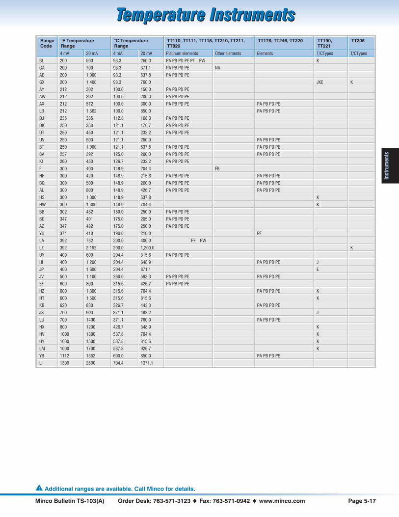
Minco Bulletin TS-103(A) Order Desk: 763-571-3123 � Fax: 763-571-0942 � www.minco.com Page 5-17
Temperature InstrumentsTemperature Instruments
Inst
rum
ents
RangeCode
°F TemperatureRange
°C TemperatureRange
TT110, TT111, TT115, TT210, TT211,TT829
TT176, TT246, TT220 TT190,TT221
TT205
4 mA 20 mA 4 mA 20 mA Platinum elements Other elements Elements T/CTypes T/CTypes
BL 200 500 93.3 260.0 PA PB PD PE PF PW K
GA 200 700 93.3 371.1 PA PB PD PE NA
AE 200 1,000 93.3 537.8 PA PB PD PE
GX 200 1,400 93.3 760.0 JKE K
AY 212 302 100.0 150.0 PA PB PD PE
AW 212 392 100.0 200.0 PA PB PD PE
AX 212 572 100.0 300.0 PA PB PD PE PA PB PD PE
LB 212 1,562 100.0 850.0 PA PB PD PE
DJ 235 335 112.8 168.3 PA PB PD PE
DK 250 350 121.1 176.7 PA PB PD PE
DT 250 450 121.1 232.2 PA PB PD PE
UV 250 500 121.1 260.0 PA PB PD PE
BT 250 1,000 121.1 537.8 PA PB PD PE PA PB PD PE
BA 257 392 125.0 200.0 PA PB PD PE PA PB PD PE
KI 260 450 126.7 232.2 PA PB PD PE
F 300 400 148.9 204.4 FB
HF 300 420 148.9 215.6 PA PB PD PE PA PB PD PE
BQ 300 500 148.9 260.0 PA PB PD PE PA PB PD PE
AL 300 800 148.9 426.7 PA PB PD PE PA PB PD PE
HS 300 1,000 148.9 537.8 K
HW 300 1,300 148.9 704.4 K
BB 302 482 150.0 250.0 PA PB PD PE
BD 347 401 175.0 205.0 PA PB PD PE
AZ 347 482 175.0 250.0 PA PB PD PE
YU 374 410 190.0 210.0 PF
LA 392 752 200.0 400.0 PF PW
LZ 392 2,192 200.0 1,200.0 K
UY 400 600 204.4 315.6 PA PB PD PE
HI 400 1,200 204.4 648.9 PA PB PD PE J
JP 400 1,600 204.4 871.1 E
JV 500 1,100 260.0 593.3 PA PB PD PE PA PB PD PE
EF 600 800 315.6 426.7 PA PB PD PE
HZ 600 1,300 315.6 704.4 PA PB PD PE K
HT 600 1,500 315.6 815.6 K
KB 620 830 326.7 443.3 PA PB PD PE
JS 700 900 371.1 482.2 J
LU 700 1400 371.1 760.0 PA PB PD PE
HX 800 1200 426.7 348.9 K
HV 1000 1300 537.8 704.4 K
HY 1000 1500 537.8 815.6 K
LM 1000 1700 537.8 926.7 K
YB 1112 1562 600.0 850.0 PA PB PD PE
LI 1300 2500 704.4 1371.1
� Additional ranges are available. Call Minco for details.
Temperature InstrumentsTemperature Instruments

Page 5-18 Sales: 763-571-3121 � Fax: 763-571-0927 � www.minco.com Minco Bulletin TS-103(A)
Temperature InstrumentsTemperature Instruments
Instruments
Why Use Temptrans?
Long distance accuracyTemptran transmitters amplify thelow-level signals from RTDs orthermocouples to an industry-standard4 to 20 mA current signal proportional totemperature. Unlike resistance or voltage,current signals are immune to resistancein extension wires and stray electricalnoise. This lets you receive accuratesignals from a sensor located thousandsof feet away.
The 4 to 20 mA output signal and DCpower share the same wire pair. Youdon’t need to run power wires to everysensor location.
RTD transmitters also linearize the signalto temperature, making them excellentlow cost signal conditioners.
Engineered for reliabilityOver 500,000 Minco transmitters arecurrently giving trouble-free service ininstallations around the world. Twofactors behind Temptrans’ exceptionalstability and longevity are:
• Minco encapsulates all electronics inepoxy to exclude contaminants andprotect components.
• Standard fixed-range transmittersfeature ±5% adjustability using 20 turntrimpots. Because a complete rotationof the trimpot represents only 0.25% ofthe span, slight movements frommechanical shock cause onlynegligible output change. In contrast,many competitive transmitters havewide ranging zero and span. Someeven use single-turn potentiometers.With zero and span far more sensitiveto potentiometer shifts, a minor bumpcan void the transmitter’s calibration.
Easy to installCompact Temptrans fit nearly anywhere.You can install most models in standardelectrical utility boxes and elbows. OrMinco offers a complete selection ofcomplementary connection heads (pages4-2 and 4-3).
For DIN rail mounting inside instrumentcabinets, see the mounting accessorieson page 5-19.
Intrinsic safetyMost Temptrans are rated intrinsicallysafe by Factory Mutual (FM), arecognized testing authority for safety inhazardous areas. Installations mustinclude a suitable barrier. Contact Mincofor a list of barriers FM approved underthe system concept for use withTemptrans.
Request Application Aid #19 to learnmore about the use of sensors inhazardous areas.
Special High-Accuracy CalibrationStandard transmitters are calibrated tothe nominal resistance values of the RTDat the zero and span points. Total systemerror includes the tolerance of both thetransmitter and the RTD sensor.
If you order Minco Temptrans calibratedto the actual resistance of the RTD(traceable to NIST), this effectivelysubtracts the sensor tolerance fromsystem accuracy specifications.
For example, consider a transmitter with arange of 0 to 500°C. The transmitter itselfis accurate to ±1.0°C (±0.2% of span,including calibration accuracy andlinearity). The RTD interchangeabilitycontributes an additional error of ±0.3°Cat 0°C and ±2.8°C at 500°C. Total systemerror would be ±1.3°C at 0°C and ±3.8°Cat 500°C. Calibration of the sensor andtransmitter as a set cancels the sensorerror, reducing system error to ±1.0°Cover the full range — all for a nominalextra cost.
NIST traceability at no costWith each matched sensor/transmitterset, Minco sends you calibration datatraceable to the National Institute ofStandards & Technology. This helps yourprocess comply with ISO 9000 and otherquality standards.
How to order special calibrationTo order a Temptran with specialcalibration, replace the standard model(eg. TT110) with the special calibrationmodel (eg. TT150). Specifications forspecial calibration models are identical totheir standard model counterparts.
Standard model Special calibration
TT110 TT150
TT111 TT151
TT115 TT155
TT176 TT676
TT210 TT710
TT211 TT711
TT220 TT720
TT246 TT746
TT273 TT773
RecalibrationMinco prints RTD resistance values righton the Temptran label to simplifyrecalibration. You simply connect aresistance decade box or “RTD simulator”in place of the RTD, dial in the correctvalues, and adjust zero and span.
Because Minco platinum RTDs areextremely stable in typical installations(0.1°C or better), you can trust the printedvalues for many years withoutrecalibration of the sensor.
MODEL TT211PD1AD/C: 9614100 OHM PLATINUM RTD4mA= 20.0°F= -6.7°C= 97.932
20mA= 120.0°F= 48.9°C= 118.969
��
TEMPTRAN™
MP
LS
,M
NU
SA
RTD resistances are printed on Temptranlabels for easy recalibration of zero and span.
A standard Temptran shows nominal values.
MODEL TT711PD1AD/C: 9614 S/N: 103100 OHM PLATINUM RTD4mA= 20.0°F= -6.7°C= 97.427
20mA= 120.0°F= 48.9°C= 118.988
��
TEMPTRAN™
MP
LS
,M
NU
SA
A specially calibrated Temptran showsresistance of the serialized, connected RTD.
actual

Minco Bulletin TS-103(A) Order Desk: 763-571-3123 � Fax: 763-571-0942 � www.minco.com Page 5-19
Temperature InstrumentsTemperature Instruments
Inst
rum
ents
Temptran Wiring DiagramsShown below are schematics of thetransmitter signal loop. R1 is a fixed loadresistor, typically part of the inputinstrument, to convert the current signal
to voltage. Total resistance of R1, signalwires, and any stray resistances such ascontacts, must be less than the maximumallowable resistance for the transmitter.
An R1 value of 250 � will produce avoltage drop of 1 to 5 VDC from4 to 20 mA.
DIN rail mountingFor easy installation in instrument cabinets. Adapters fit all Temptran models. Specifylength when ordering rails.
Model Description
AC805 DIN EN50022 Rail
AC807 Adapter for EN50022
AC781 dual mounting kitThe AC781 mounting kit fitsconnection head models CH104,CH106, and CH330 on page 4-3. Itholds two miniature Temptrans in asingle head for use with dual RTDs.
LINEPOWER
DCSUPPLY
R1
CONTROLLERAND/OR INDICATOR
CONTROL ROOM
COPPER LEADS,TWISTED PAIR
4 TO 20mA LOOP
RESISTANCETHERMOMETER
RED
BROWN
BLACK
ORNG
TT110, TT111,
TT210, TT211
THERMOCOUPLE
TT205
1
2
3
4
1
2
3
4
RESISTANCETHERMOMETER
THERMOCOUPLE
TT273TT274
Intrinsically safe installations
require the addition of a safety
barrier to the signal loop.
See Application Aid #19
for more information.
TB1 TB2
RESISTANCE THERMOMETER
1 TO 5 VDCCONTROLLERAND/OR INDICATOR
DCSUPPLY
LINE POWER
TT246 CONTROL ROOM
AC807ADAPTER
AC805 RAILTemptrans mounted to DIN rail.
www.minco.com/support
Note: Wiring diagrams, literature and application aidsare available at www.minco.com/support
TB1 TB2
4 TO 20mA LOOP
RESISTANCE THERMOMETER
TT176TT216
TB1TB2
4 TO 20mA LOOP
THERMOCOUPLE RESISTANCE THERMOMETER THERMOCOUPLE
TT190TT230 TT220 TT221
4 TO 20mA LOOP
4 TO 20mA LOOP

Page 5-20 Sales: 763-571-3121 � Fax: 763-571-0927 � www.minco.com Minco Bulletin TS-103(A)
Temperature InstrumentsTemperature Instruments
Instruments
.69(17.5)
(27.7)
DIMENSIONS IN INCHES (mm)
1 2 3 4 5 6 7
Setpoint Adjust
Test PointsVtemp
GND
Vsetpoint
Heat Indicator
0.149 (3.8)I.D. THRU
1.50(38.1)
1.00(25.4)
CT325 Miniature DC Temperature Controller
• Tight control with ±0.1°C (0.2°F)deadband!
• Miniature package 1 × 1 × 1.5"
• Solid state on/off control withadjustable setpoint
• Uses standard 100 � or 1000 �platinum RTD or 50 k� thermistorsensor input
• Single DC power source providespower to the controller and heater up to240 watts
• Simple setup with voltage output pinsfor process and setpoint temperatures
• 3-wire RTD connection cancels leadresistance
The CT325 Miniature DC TemperatureController is designed for use with MincoThermofoil™ heaters and RTD orthermistor sensors. It offers inexpensiveon/off temperature control of yourprocess or equipment with accuracymany times better than bimetalthermostats.
You can control temperatures up to 200°C(RTD sensor) or 75°C (thermistor). Easilyread and adjust the set point temperatureusing your voltmeter, then monitor theactual signal temperature at the otherend.
Operating from your 4.75 to 60 volt DCpower supply, the controller can switchup to 4 amps power to the heater. Abright LED indicates when power isapplied to the heater.
The entire unit is epoxy filled for moistureresistance, with a through-hole for amounting bolt. A terminal block providesthe power input, sensor input and heateroutput connections.
Custom design optionsMinco can customize the design of theCT325 for special applications. Specifictemperature ranges, other sensoroptions, and special packaging arepossible for volume OEM applications.
SpecificationsInput: 100 � or 1000 � platinum RTD,0.00385 �/�/°C, 2 or 3-leads, or 50 k� NTCthermistor, 2-lead.Setpoint range: 2 to 200°C (36 to 392°F) forplatinum RTD input. 25 to 75°C (77 to 167°F) forthermistor input. Consult factory for otherranges.Setpoint stability: ±0.02% of span/°C.Vtemp signal: 0.010 V/°C over specified range.
Platinum RTD sensor2°C 0.02 V
50°C 0.50 V100°C 1.00 V200°C 2.00 V
Accuracy: ±1% of spanLinearity: ±0.1% of span
Thermistor sensor25°C 0.25 V50°C 0.50 V75°C 0.75 V
Accuracy: ±2% of spanLinearity: ±2% of span
Deadband: 0.1°C.Input power: 4.75 to 60 VDC.Output: Open drain, 4 amps max. DC.Leadwire compensation: (3-wire RTD)±0.06°C/� for 100 � or 1000 � platinum up to25 � per leg.Fault protection: Heater disabled on RTD shortor thermistor open. No heater protection; externalfuse is recommended.
Operating ambient temperature range:-40 to 70°C (-40 to 158°F).Relative humidity: 0 to 95% non-condensing.Physical: Polycarbonate case, epoxy sealed formoisture resistance.Weight: 1 oz. (28g).Connections: Terminal block for wires AWG 22to AWG 14.Mounting: Mounting hole for #6 screw throughor #8 thread forming screw.
Code Sensor type
PD 100 � platinum RTD
PF 1000 � platinum RTD
TF 50 k� thermistor
How to order:
CT325 Model number
PD Sensor type from table
1 Power supply:1 = 4.75 to 10 VDC2 = 7.5 to 60 VDC
C Temperature range:A = 25 to 75°C (thermistor only)C = 2 to 200°C (RTD only)
1 Dead band:1 = 0.1°C
CT325PD1C1 � Sample P/N
� 50k� thermistor sensor TS665TF isavailable on page 10-5.

Minco Bulletin TS-103(A) Order Desk: 763-571-3123 � Fax: 763-571-0942 � www.minco.com Page 5-21
Temperature InstrumentsTemperature Instruments
Inst
rum
entsCT15 Temperature Controller & Alarm
An easy to use controller withsophisticated PID control. It can also be asingle or 2-stage alarm (using alarmfeature plus control relay): monitormotors and generators for overheating.
Features
• RTD or thermocouple input
• Control modes: Self-Tune, pre-set orprogrammable PID, or On/Off
• Bright red LED display
• Ramp to setpoint
• Digital sensor input correction
• Digital input filter adjustable for noisy orjittery processes
• 4 security levels
• Setpoint limits
• Non-volatile memory needs no batterybackup
• Input fault timer
• Alarms at one or two temperatures
• Alarm Relay option is programmablefor high, low, absolute, or deviation,can be reset manually or automatically,and it controls a singleelectromechanical relay withvoltage-free contacts
SpecificationsSelectable inputs:RTD: 2 or 3-wire, Minco types PD or PE
(100 � EN60751 platinum).Thermocouple: Type J (factory default), K, T
(selectable).Input impedance:Thermocouple: 3 megohms minimum.RTD current: 200 �A maximum.Sensor break or short protection: De-energizescontrol outputs to protect system.Loop break protection: Error message isinitiated and output is turned off in case ofshorted sensor or open heater circuit. Break timeadjustable from OFF to 99 minutes.Cycle rate: 1 to 80 seconds.Setpoint range: Selectable from -212 to 1371°C(-350 to 2500°F), input dependent.Display: One: 4 digit, 7 segment 0.3" high LEDs.Display shows the measured temperature, unlessa control key is pressed, then it will display theitem value.Control action: Reverse (usually heating) orDirect (usually cooling), selectable.Ramp/Soak: One ramp, 0 to 100 hours.Accuracy: ±0.25% of span ±1 count.Resolution: 1° or 0.1°, selectable.Line voltage stability: ±0.05% over supplyvoltage range.Temperature stability: 4 �V/°C (2.3 �V/°F)typical, 8 �V/°C (4.5 �V/°F) max. (100 ppm/°Ctypical, 200 ppm/°C max.).Isolation: Relay and SSR outputs are isolated.Pulsed voltage output must not share a commonground with the input.Supply voltage: 100 to 240 VAC nom.,+10/-15%, 50 to 400 Hz, single phase; 132 to240 VDC, nom., +10/-20%. 5 VA maximum.Note: Do not confuse controller power withheater power. The controller does not supplypower to the heater, but only acts as a switch.For example, the controller could be powered by115 VAC, but controlling 12 VDC to the heater.Operating temperature range:-10 to 55°C (14 to 131°F).Memory backup: Non-volatile memory (nobatteries required).
Control output ratings:AC SSR (SPST): 3.5 A @ 250 VAC @ 25°C
(77°F); derates to 1.25 A @ 55°C (130°F).An SSR is recommended for longer life thana mechanical relay.
Mechanical relay, SPST Form A (Normally Open):3 A resistive, 1.5 A inductive @ 250 VAC;pilot duty: 250 VA; 2 A @ 125 VAC or
1 A @ 250 VAC.Switched voltage (non-isolated):
5 VDC @ 25 mA.Alarm relay, SPST Form A (Normally Open):
3 A resistive, 1.5 A inductive @ 250 VAC;pilot duty: 250 VA; 2 A @ 125 VAC or
1 A @ 250 VAC.Weight: 227 g (8 oz.).Agency approvals: UL & CSA.Front panel rating: Type 4X (IP66).
How to order
CT15 Model number
1 Alarm:0 = No1 = Yes
2 Input:1 = J, K, or T thermocouple2 = 100 � platinum RTD, typePD or PE
1 Output:1 = Built-in AC SSR2 = Pulsed voltage (5 VDC)3 = Mechanical relay
CT15121 � Sample P/N
Compact 1/16 DIN size
1.76(44.7)
0.45 (12)
1.89(48)
1.89(48)
PANEL CUTOUT: 1.775" × 1.775" (45 mm × 45 mm)
MAXIMUM PANEL THICKNESS: 0.25" (6.35 mm)
DIMENSIONS IN INCHES (mm)
5.04 (128)
IN STOCK
Contact Minco for currently available models
R

Page 5-22 Sales: 763-571-3121 � Fax: 763-571-0927 � www.minco.com Minco Bulletin TS-103(A)
Temperature InstrumentsTemperature Instruments
Instruments
CT16A Temperature ControllerThis economical controller packssophisticated PID control into a compact1/16 DIN enclosure. A wide range ofcontrol modes, sensor input types, andrelay or SSR outputs give versatile controlof Thermofoil™ heaters and lets youeasily connect to other electronics.
Features
• Dual displays continuously show theset point and the actual temperaturereading in resolutions of 1°, 0.1°, orengineering units
• Universal Input fits any sensor: Selectfrom 10 thermocouple types, 4 RTDtypes, voltage, and current signals
• Isolated Outputs for safe, easy wiring
• Loop Break protection handles sensoror heater failure
• Peak / Valley records the maximumand minimum temperatures
• Front panel is waterproof andcorrosion-resistant, making it ideal forsanitary applications. Illuminatedkeypad for easy operation
• Limit the temperatures which theoperator can set via fourpassword-protected Security Levels
• Controller can Self-Tune for best PIDcontrol
• Control modes: Self-Tune, pre-set oradjustable PID values, simple On/Offcontrol, and open loop
• Fuzzy Logic provides better responsetime and reduces overshoot inprocesses with unpredictable inputs
• Alarms at one or two temperatures
• Alarm Relay option is programmablefor high, low, absolute, or deviation,can be reset manually or automatically,and it controls a singleelectromechanical relay withvoltage-free contacts
• Ramp & Soak option handles complexheating profiles of 16 segments withfront-panel activation and a selectabletime base (CT16A3)
• Auto / Manual option easily switches tomanual control for set up orexperiments (CT16A3)
• RS-232 or RS-485 SerialCommunications access thetemperature readings and all controlparameters (optional)
• Retransmit either the sensedtemperature or the set point as avoltage or current signal to a computeror recorder (optional)
• Vary the Set Point using apotentiometer, a voltage, or a currentsignal (optional)
• 4-Stage Set Point to quickly switchfrom one temperature to the next(optional)
SpecificationsSelectable inputs:RTD: 2 or 3-wire, Minco types
PD or PE (100 � EN60751 platinum),PA (100 � NIST platinum),PF (1000 � EN60751 platinum), orNA (120 � Nickel).
Thermocouple: Type J (factory default), K, T, L,E, R, S, B, C, or N.
DC current: 0-20 mA or 4-20 mA (use withTemptran™ transmitters).
DC voltage: 0-10 or 2-10 VDC,-10 to 10 mVDC, scalable.
Input impedance:Voltage: 5000 �.Thermocouple: 3 megohms minimum.Current: 10 �.RTD current: 200 �A.Sensor break or short protection:Selectable output: disabled, average output
before fault, or preprogrammed output.Adjustable delay: 0.0 to 540.0 minutes.
Loop break protection: Error message isinitiated and output is turned off in case ofshorted sensor or open heater circuit. Break timeadjustable from OFF to 9999 seconds.Cycle rate: 1 to 80 seconds.Setpoint range: Selectable from -212 to 2320°C(-350 to 4208°F), input dependent.Displays: Two 4 digit, 7 segment 0.3" highLEDs. Process Value red, Setpoint Value green.°C or °F.Control action: Reverse (usually heating) orDirect (usually cooling), selectable.Ramp/soak: (CT16A3 only) 16 separate rampand soak times are adjustable in minutes orseconds from 0 to 9999. When the program hasended, you may choose to repeat, hold, revert tolocal setpoint, or turn the outputs off.Accuracy: ±0.25% of span ±1 count.Resolution: 1° or 0.1°, selectable.Line voltage stability: ±0.05% over supplyvoltage range.Temperature stability: 4 �V/°C (2.3 �V/°F)typical, 8 �V/°C (4.5 �V/°F) max. (100 ppm/°Ctypical, 200 ppm/°C max.).Isolation:Relay and SSR: 1500 VAC to all other inputs
and outputs.SP1 and SP2 current and voltage: 500 VAC to all
other inputs and outputs, but not isolatedfrom each other.
Process output (options 934, 936): 500 VAC to allother inputs and outputs.
Supply voltage: 100 to 240 VAC nom.,+10/-15%, 50 to 400 Hz, single phase; 132 to240 VDC, nom., +10/-20%. 5 VA maximum. 12& 24 volt AC/DC optional.Note: Do not confuse controller power withheater power. The controller does not supplypower to the heater, but only acts as a switch.For example, the controller could be powered by115 VAC, but controlling 12 VDC to the heater.Operating temperature range:-10 to 55°C (14 to 131°F).
1.76(44.7)
0.45 (12)
1.89(48)
1.89(48)
PANEL CUTOUT: 1.775" × 1.775" (45 mm × 45 mm)
MAXIMUM PANEL THICKNESS: 0.25" (6.35 mm)
DIMENSIONS IN INCHES (mm)
5.24 (133)
Compact 1/16 DIN size
R

Minco Bulletin TS-103(A) Order Desk: 763-571-3123 � Fax: 763-571-0942 � www.minco.com Page 5-23
Temperature InstrumentsTemperature Instruments
Inst
rum
ents
Memory backup: Non-volatile memory (nobatteries required).Control output ratings:AC SSR (SPST): 2.0 A combined outputs
A & B @ 240 VAC @ 25°C (77°F);derates to 1.0 A @ 55°C (130°F).An SSR is recommended for longer life thana mechanical relay.
Mechanical relay, SPST Form A (Normally Open)or Form B (Normally Closed):
3 A resistive, 1.5 A inductive @ 240 VAC;pilot duty: 240 VA; 2 A @ 120 VAC or
1 A @ 240 VAC.Switched voltage (isolated): 15 VDC @ 20 mA.Proportional current (isolated):
0 to 20 mA, 600 � max.DC SSR: 1.75 A @ 32 VDC max.Alarm relay, SPST Form A (Normally Open):
3 A @ 240 VAC resistive;1/10 HP @ 120 VAC.
Weight: 227 g (8 oz.).Agency approvals: UL & CE.Front panel rating: Type 4X (IP66).
Additional options for CT16A (board level)924: Analog remote setpoint: (0 to 10 VDC)Vary the setpoint using a voltage signal.926: Analog remote setpoint: (4 to 20 mADC)Vary the setpoint using a current signal.928: Analog remote setpoint: (0 to10,000 �)Vary the setpoint using a potentiometer.934: Analog retransmission of ProcessVariable or Set Variable: (4 to 20 mADC) Foruse as recorder, transmitter or computer A/Dinput. Linearized 4 to 20 mA DC signal followsthe Process or Set variable. Scaleable.936: Analog retransmission of ProcessVariable or Set Variable: (0 to 10 VDC) Similarto option 934, but output signal is linearized 0 to10 VDC.948: 4-Stage setpoint. Four preset setpointsmay be selected by external contacts. Each setpoint has its own set of PID values givingcontroller 4 distinct “recipes” for differentprocess situations.
992: RS-485 Computer communication link:Allows remote computer to read and write allcontrol parameters.993: RS-232 Computer communication link:Allows remote computer to read and write allcontrol parameters.9502: 12 to 24 VDC / VAC power option:Controller is powered by low voltage instead ofline voltage.Note: Only option 9502 can be combined withanother board level option.
How to order CT16A
CT16A Model number
2 Feature set:2 = Standard3 = Enhanced (ramp & soak, Auto/manual)
1 Alarm relay:0 = No1 = Yes
1 Output A:1 = Built-in AC SSR2 = Pulsed voltage (15 VDC) for external SSR3 = Mechanical relay, SPST (normally open)4 = Mechanical relay, SPST (normally closed)5 = Current8 = DC SSR
0 Output B:0 = None1 = Built-in AC SSR2 = Pulsed voltage (15 VDC) for external SSR3 = Mechanical relay, SPST (normally open)4 = Mechanical relay, SPST (normally closed)5 = Current8 = DC SSR
-948 Options (leave blank for none)
CT16A2110-948 � Sample P/N
AccessoriesAC744: 1-10 A, 24 to 280 VAC SSRAC745: 1-25 A, 24 to 280 VAC SSRAC746: 1-50 A, 24 to 280 VAC SSRAC1009: 1-20 A, 0 to 100 VDC SSRAC743: SSR heatsink for high current or ambient temperatureAC996 R/C Snubber: Highly recommended to prolong relay contact life, ifusing the mechanical relay or SSR output to drive a relay or solenoid. Also,for the CT16A AC SSR output, make sure that the coil HOLDING current isgreater than 100 mA and voltage is minimum 48 VDC.AC1001: Steel 1/16 to ¼ DIN adapter plate. 127×127 mm gray steel with45×45 mm centered hole.
AC743
AC1001
AC996
IN STOCK
AC743, AC744, AC745, AC746, AC1009Call Minco for CT16A models in stock

Page 5-24 Sales: 763-571-3121 � Fax: 763-571-0927 � www.minco.com Minco Bulletin TS-103(A)
Temperature InstrumentsTemperature Instruments
Instruments
CT124 8-channel Temperature Monitor
• Protect motors, generators, transformers, other equipment
• Monitor 1 to 8 resistance temperature detectors (RTDs)
• 4 internal relays and audible alarm with independent trippoints
• Overtemperature or undertemperature protection
• Microprocessor based; fully programmable
• Large, bright LED display shows °F or °C
• Stores high and low temperature peaks
• Trip points, programs, peaks stored in non-volatile memory
• Programmable silence button
• Versatile override switch permits manual relay toggling
• Rugged enclosure with sealed front panel
The CT124 8-channel Temperature Monitor offers flexibleprotection and control of temperature-critical equipment andprocesses. It scans up to eight RTDs and activates four relaysplus a built-in audible alarm.
In a typical application, the CT124 provides early warning ofpossible large machine failure by monitoring the temperature ofbearings, stators, transformer coils, and oil outlets. You canconfigure the CT124 to many other situations such as on/offcontrol or undertemperature alarms. The CT124 can evenmonitor and control several loops at one time since you cangroup input zones with output relays in any combination.
OperationThe CT124 continuously scans all RTD inputs. The displaynormally shows the highest, lowest, or any other zonetemperature according to your instructions. Press up and downarrows to display other zones, Peak Temp to recall high and lowpeaks, and Trip Temp to indicate trip temperatures.
Each relay has its own trip temperature, either high or low, andmay be programmed to react to any or all scanned input zones.Relays may control cooling fans, remote alarms, contactors, orprogrammable controller inputs. You can set the audible alarm tosound when certain relays trip, and also at its own setpoint. Thesilence button quiets the alarm for a programmed length of time.
ProgrammingIn the CT124’s program mode you simply step through theincluded setup worksheet, change each parameter with the upand down arrows, and press Done to proceed. The CT124retains all program data and setpoints with power off.
InstallationThe CT124 fits in a standard ¾ DIN panel cutout. Plug-interminal blocks at the rear let you remove the unit withoutdisconnecting wires. Front panel keys and indicators are sealedagainst dust and moisture.
Special featuresOverride: The programmable Override button manually togglesa selected set of relays on and off. With it you can bypassautomatic functions to assume direct control. For example, youcould turn on fans or shut a machine down at temperaturesbelow the trip point.
Sensor failure protection: If any scanned RTD circuit shorts oropens the CT124 sounds its alarm and locks out that zone.Other zones continue to scan normally. The Error light stays onuntil the faulty input is repaired and the self-test run.
Self-test: Press the Test button to test all panel lights and inputs.You can also program the Test button to trip relays connectedto external alarms, fans, etc.

Minco Bulletin TS-103(A) Order Desk: 763-571-3123 � Fax: 763-571-0942 � www.minco.com Page 5-25
Temperature InstrumentsTemperature Instruments
Inst
rum
ents
SpecificationsRange: Platinum input: -40 to 530°C or -40 to 986°FCopper or nickel input: -40 to 250°C or -40 to 500°F.Input: 1 to 8 RTDs (Resistance Temperature Detectors), 2 or 3 wire.
Code Element TCR (�/�/°C)
PA Platinum, 100 � at 0°C 0.00392
PB Platinum, 100 � at 0°C 0.00391
PD Platinum, 100 � at 0°C 0.00385
PF Platinum, 1000 � at 0°C 0.00385
CA Copper, 10 � at 25°C 0.00427
NA Nickel, 120 � at 0°C 0.00672
Input scan rate: 8 readings per second.Input fault detection: Open or shorted circuit sounds alarm and locks outfaulty zone. Other zones unaffected.Input protection: ±30 VDC continuous, any input to ground.Output: 5 independent trip points: 4 relays and one audible alarm. Alarmmay be programmed to sound when selected relays trip.Relays: Form C, SPDT, 10 Amps at 250 VAC resistive load,¼ HP at 120 VAC.Trip point hysteresis (deadband): Programmable from 2 to 20°C or °F.Display: 0.56" (14 mm) LED, 1°C or 1°F resolution. 16 LED indicators.Accuracy: ±2°C (3°F) at 10 to 30°C (50 to 86°F) ambient. ±3°C (5°F) at0 to 55°C (32 to 131°F) ambient.Zone and relay labels: Replaceable from rear for custom labeling.Supply power: 115 or 230 VAC ±10%, 50/60 Hz. 15 W max. Selectionswitch inside enclosure. 24 VDC factory option.Power loss protection: Trip points, peaks, and program parameters storedin non-volatile memory. Normal operation resumes when power isrestored.Keyboard: 10 membrane type keys with audible feedback.
Programming: Programmable from front panel. Access to program moderequires special key sequence.Program fault protection: Watchdog circuit resets microprocessor if itfails to perform program sequence.Enclosure: ABS case, water and dust resistant front panel.Ambient temperature rating: 0 to 55°C (32 to 131°F).Connections: Plug-in terminal boards at rear accept wires to 14 AWG.Mounting: ¾ DIN (DIN 43700). Panel-mounted in 5.51" × 7.32" (140 ×186 mm) opening. Extends behind panel 5.1" (130 mm) max.Instructions: Instruction manual and setup worksheets furnished witheach unit.Weight: 4 lb. (1.8 kg).
How to order:
CT124 Model number CT124
PA RTD type:CA = 10 � copperNA = 120 � nickelPA = 100 � platinum, TCR = 0.00392PB = 100 � platinum, TCR = 0.00391PD = 100 � platinum, TCR = 0.00385PF = 1000 � platinum, TCR = 0.00385
1 Supply power:1 = 115/230 VAC2 = 24 VDC
CT124PA1 � Sample part number
SIDE
7.6(193)
5.1 (130) MAX. 1.6(41)
POWER/RELAYCONNECTOR BOARD
RTD CONNECTOR BOARD
EMI FILTER(115/230
VAC ONLY)
87654321
87654321
87654321
87654321
REAR
5.67 (144)5.43 (138)
7.24(184)
7.56(192)
DIMENSIONS IN INCHES (mm)
TOP
PANEL CUTOUT
5.51 (140)
7.32(186)

Page 5-26 Sales: 763-571-3121 � Fax: 763-571-0927 � www.minco.com Minco Bulletin TS-103(A)
Temperature InstrumentsTemperature Instruments
Instruments
2" pipe mountkit AC102765 for
use with TI196 and TI350.TI196 TI350
Loop-powered IndicatorsRange is field programmable via coarse dip switches and two fine adjustment potentiometers. Wiring is easy. Simply connect theindicator in series with the 4 to 20 mA loop. Forward voltage drop is only 2.8 VDC.
TI196 Head-mounted IndicatorThe TI196 includes an explosion-proof connection head anddigital indicator for local indication of temperature. Sensors andtransmitters are specified separately. Temptran model TT111,TT211, TT176, TT205, or TT190 will fit inside the connectionhead along with the meter (optional).
SpecificationsInput: 4 to 20 mA DC series connection.Range: User adjustable.
Zero: -500 to +1000 counts.Span: 10 to 2000 counts.
Accuracy: ±(0.1% reading + 1 count).Forward voltage drop: 2.8 VDC max.Decimal: User selectable to 1 position or absent (i.e. 1XX.X, or 1XXXX).Ambient temperature range:
Operating: 0 to 50°C (32 to 122°F).Storage: -20 to 65°C (-4 to 149°F).
Weight: 43 oz. (1220 g.)Enclosure: Aluminum, polyester-coated, explosion-proof.Dimensions (connection head):4.5" W × 4.5" H ×3.4" D (144 mm W × 114 mm H × 87 mm D).
How to order
TI196 Model number
P3 Pipe thread size:P2 = 3
4 - 14 NPT (sensor and conduit)P3 = 1
2 - 14 NPT (sensor and conduit)
(0/100) Temperature range:(4 mA temp./20 mA temp.), user adjustable
C Display:C = CelsiusF = Fahrenheit
TI196P3(0/100)C � Sample P/N
AC102765 Pipe mounting hardwareFor mounting TI196 or TI350 meters to vertical or horizontalpipe. Kit includes plate, stainless U-bolts, nuts and washers for2" schedule 40 pipe (Ø 2.375").
Order model number AC102765.
TI350 IndicatorThe TI350 features a washdown compatible digital readout forlocal indication of temperature. Sensors and transmitters arespecified separately.
• NEMA 4X enclosure
• Cable glands are installed for 0.118" to 0.256" cable
SpecificationsInput: 4-20 mA DC series connection to current loopRange: User adjustable.
Zero: -500 to +1000 counts.Span: 10 to 2000 counts.
Accuracy: ± (0.1% reading + 1 count).Temperature Coefficient:
Zero: ± 0.075 counts/°C typ.
Span: ± 0.005% of span/°C typ.
Linearity: ± (0.1% of span + 1 count).Forward Voltage Drop: 2.8 volts DC maximum.Display: 0.59 high, 3-1/2 digit LCD, with °C/°F descriptor.Display Update: 3 times per second.Underrange Indication: -1 in MSD (Most Significant Digit).Overrange Indication: 1 in MSD.Connections: Terminal Block, PluggableDecimal: User programmable to 1 position or absent (i.e. 1XX.X or 1XXX).Ambient Temperature Range:
Operating: 0 to 50°C (32 to 122°F).Storage: -20 to 65°C (-4 to 149°F).
Weight: 7 oz. (200 g).Enclosure: Polycarbonate, NEMA 4X.Dimensions (box only):2.6" W × 4.5" L × 2.2" D (65 mm W × 115 mm H × 56 mm D).
How to order
TI350 Model number
(0/100) Temperature Range:(4 mA temp./20 mA temp.), user adjustable
C Display:C = CelsiusF = Fahrenheit
TI350(0/100)C � Sample P/N

Minco Bulletin TS-103(B) Order Desk: 763-571-3123 � Fax: 763-571-0942 � www.minco.com Page 6-1
Sanitary SensorsSanitary Sensors
Sanit
ary
Sen
sors
Section 6: Sanitary Sensors
• Authorized to carry 3-A symbol for sanitaryapplications
• Food, beverage, pharmaceutical processing
• Fast response design
• 100 � platinum elements, single or dual
• Three styles: Probe, connection head assembly,thermowell assembly
Probes ..................................................6-2Assemblies ...........................................6-3Installation guidelines
and accessories ...............................6-4

Page 6-2 Sales: 763-571-3121 � Fax: 763-571-0927 � www.minco.com Minco Bulletin TS-103(B)
Sanitary SensorsSanitary Sensors
Sanita
ryS
ensors
Sanitary RTD ProbesInstall directly into process lines for fastresponse. Cases, made of polished 316stainless steel, are free of cracks andcrevices that might shelter bacteria.External cables will withstand washdown;optional stainless steel armor preventsabrasion wear.
Tri-clamp® caps are standard. ContactMinco for other styles. Note that clampand gasket are not part of the assembly.
Specifications
Sensing element: Platinum RTD, 100 � ±0.1%at 0°C, TCR = 0.00385 �/�/°C (MeetsEN60751, Class B).Temperature range:Probe: -100 to 200°C (-148 to 392°F).External leadwires: -100 to 121°C
(-148 to 250°F).Material: 316 stainless steel.Finish:Standard: #4 finish per 3-A standard 74-02,
32 microinches max.Pharmaceutical (optional): Polished to mirror
finish and passivated. 10 microinchestypical.
Pressure rating: 500 psi (34.5 bar).Leadwires: AWG 22, polyimide insulation;optional stainless steel armor. Polyolefin shrinktubing wrap standard over either option.Time constant: 2 seconds.Self-heating: 50 mW/°C typical in moving water.Insulation resistance:Single element probes: 1000 megohms min. at
500 VDC, leads to case.Dual element probes: 100 megohms min. at
100 VDC, between elements and leadsto case.
How to order
S5020PD Model number:
S5020PD: Single elementS5022PD: Dual element
Z Number of leads per sensingelement:
Y = 2 leadsZ = 3 leads
30 Case length in 0.1"increments:
Standard lengths:30 = 3.0"40 = 4.0"50 = 5.0"
A Lead covering:
T = TubingA = Armor
60 Lead length in inches
TC Sanitary cap style:
TC = Tri-clamp®
20 Nominal diameter:
10 = 1.0"15 = 1.5"20 = 2.0"
P Case finish:
S = Standard finishP = Pharmaceutical finish
S5020PDZ30A60TC20P � Sample P/N
CASE LENGTH
0.125" (3.2 mm)RADIUS
0.25" (6.4 mm)DIAMETER

Minco Bulletin TS-103(B) Order Desk: 763-571-3123 � Fax: 763-571-0942 � www.minco.com Page 6-3
Sanitary SensorsSanitary Sensors
Sanit
ary
Sen
sorsSanitary RTD Assemblies
These assemblies include a connectionhead for terminating RTD leads toexternal wiring. The fast-responsethermowell assembly lets you remove theRTD probe without breaking into processlines. Cases and thermowells, made ofpolished 316 stainless steel, are free ofcracks and crevices that might shelterbacteria.
Connection head options includestainless steel, cast iron, FDA approvedwhite polypropylene, and aluminum withFDA approvable epoxy coating.
Tri-Clamp® caps are standard. ContactMinco for other styles.
Note that clamp and gasket are not partof the assembly.
Transmitters
Minco’s Temptran™ transmitters providea 4 to 20 mA signal that can be sent overlong distances with a simple 2-wiresystem. Add any Minco model transmitter(except electrically isolated models). SeeSection 5 for complete details andordering information.
Specifications
Sensing element: Platinum RTD, 100 � ±0.1%at 0°C, TCR = 0.00385 �/�/°C (MeetsEN60751, Class B).Temperature range:-100 to 200°C (-148 to 392°F).Material:Probe: 316 stainless steel.Spring-loaded holder on thermowell version:
300 series stainless steel.Finish:Standard: #4 finish per 3-A standard 74-02,
32 microinches max.Pharmaceutical (optional): Polished to mirror
finish and passivated. 10 microinchestypical.
Pressure rating: 500 psi (34.5 bar).Leadwires: Polyimide insulated leads,4" (102 mm) long.Time constant:Probe assembly: 2 seconds.Thermowell assembly: 4 seconds.Self-heating: Typical value in moving water.Probe assembly: 50 mW/°CThermowell assembly: 25 mW/°C.Insulation resistance:Single element probes: 1000 megohms min.
at 500 VDC, leads to case.Dual element probes: 100 megohms min.
at 100 VDC, between elements and leadsto case.
How to order
AS5000PD Model number:
Probe assembly:AS5010PD: Single elementAS5012PD: Dual elementThermowell assembly:AS5000PD: Single elementAS5002PD: Dual element
Z Number of leads per element:
Y = 2 leadsZ = 3 leads
50 Probe or thermowell lengthin 0.1" increments:
Standard lengths: 30 (3.0"),40 (4.0"), 50 (5.0")
TC Sanitary cap style:
TC = Tri-Clamp®
15 Nominal diameter:
10 = 1.0"15 = 1.5"20 = 2.0"
E Connection head:
C = Cast ironE = Epoxy coated alum.N = White polypropyleneS = Stainless steel (CH335)SL = Stainless steel (CH306)SS = Stainless steel (CH360)
3 Conduit thread:
3 = 12 - 14 NPT
4 = 34 - 14 NPT (N/A with
N or S connection heads)
S Case finish:
S = Standard finishP = Pharmaceutical finish
AS5000PDZ50TC15E3S � Sample P/N
2.5"(64 mm)
1.5"(38 mm)
0.375" (9.5 mm)DIAMETER
0.25" (6.4 mm)RADIUS
THERMOWELLLENGTH
THERMOWELL ASSEMBLY
0.23" (5.8 mm)DIAMETER
3.6" (91 mm) 3.6" (91 mm)1.4"(36 mm)
PROBELENGTH
0.25"(6.4 mm)RADIUS
4.6"(117 mm)
4.6"(117 mm)
CONDUITTHREAD
CONDUITTHREAD
1.6"(41 mm)
1.6"(41 mm)
0.25" (6.4 mm)DIAMETER
PROBE ASSEMBLY
TT176, TT676standard transmitter
TT211, TT711miniature transmitter
CH328 EPOXY-COATED ALUMINUM HEAD SHOWN. SEE PAGES 4-2, 4-3 FOR OTHER MODELS.CAST IRON: MODEL CH103; POLYPROPYLENE: MODEL CH366; STAINLESS STEEL: MODEL CH306, CH335, CH360

Page 6-4 Sales: 763-571-3121 � Fax: 763-571-0927 � www.minco.com Minco Bulletin TS-103(B)
Sanitary SensorsSanitary Sensors
Sanita
ryS
ensors
Installation
Accessories
Tri-Clamp® fittings consist of two identical pipe faces with agasket between them. A hinged clamp holds the two flangestogether.
Standard probe lengths for installation in Tri-Clamp® tee fittingsare for reference only; you can order Minco RTDs in any caselength desired.
Nominal diameter Standard case length Clamp part #
1.5" 3.0" AC101656
2.0" 4.0" AC101657
Tri-Clamp® is a registered trademark of Alfa Laval.
SPRING-LOADED HOLDER
PROVIDES SURE CONTACT BETWEEN
PROBES AND THERMOWELLS
OPTIONAL 2-WIRE TRANSMITTER
TRI-CLAMP
SANITARY CAP
®
CLAMP
REDUCED TIP FOR
FAST RESPONSE
RADIUSED CORNER
ELIMINATES CREVICES
FLOW
FLOW
CLAMP FOR SANITARY FITTING

Minco Bulletin TS-103(A) Order Desk: 763-571-3123 � Fax: 763-571-0942 � www.minco.com Page 7-1
Miniature SensorsMiniature Sensors
Min
iatu
reSe
nsor
s
Section 7: Miniature Sensors
• Small, rugged RTDs and thermocouples
• Install in bearings for early warning of overheating
• Bolt-on designs for easy installation
• Single or dual elements
• Wide variety of leadwire options
RTDs.....................................................7-2Thermocouples ....................................7-3Bolt-on sensors ....................................7-4Economy sensors ................................7-5Installation and accessories.................7-6

Page 7-2 Sales: 763-571-3121 � Fax: 763-571-0927 � www.minco.com Minco Bulletin TS-103(A)
Miniature SensorsMiniature Sensors
Miniature
Sensors
Embedment RTDs
Element TCR�/�/°C
Case style A
Case L: 0.250" (6.4 mm)Case Ø: 0.275" (7.0 mm)
Case style BCase L: 0.250" (6.4 mm)Case Ø: 0.188" (4.8 mm)Flange Ø: 0.250" (6.4 mm)
Case style C
Case L: 0.300" (7.6 mm)Case Ø: 0.125" (3.2 mm)
Case style D
Case L: 0.300" (7.6 mm)Case Ø: 0.080" (2.0 mm)
Single Dual Single Dual Single Dual Single Dual
Platinum, 100 � ±0.36% at 0°C .00392S325PAS11636PA*
S4026PA S331PA S7792PA S341PA S14320PA S12414PA
Platinum, 100 � ±0.12% at 0°C(Meets EN60751, Class B)
.00385 S304PD S309PD S306PD S14405PD S308PD S14455PD S13282PD
Platinum, 100 � ±0.36% at 0°C .00385 S7304PE S305PE S7746PE S307PE S7908PE S14456PE S13282PE
Platinum, 1000 � ±0.12% at 0°C .00385 S101907PF S101911PF S101908PF S101912PF S101909PF S101913PF S101910PF
Copper, 10 � ±0.2% at 25°C .00427 S324CA S4026CA S332CA S342CA
Nickel, 120 � ±0.5% at 0°C .00672S326NAS11636NA*
S4026NA S330NA S7792NA S340NA
*MIL-T-24388C qualified models.
Install miniature sensors in or beneath thebabbitt layer of bearing shoes. Theymonitor metal temperature — the mostreliable indicator of bearing condition —to give early warning of oil filmbreakdown. Machines can then be shutdown and the problem corrected beforecatastrophic failure occurs.
While no larger than many bare ceramicelements, these RTDs have metal casesand insulated leads to withstand roughhandling and harsh environments.They’re easy to install in drilled holes forgeneral purpose sensing.
SpecificationsTemperature range:-50 to 260°C (-58 to 500°F).Case: Tin plated copper alloy. Models S12414,S13282 and S101910: Stainless steel.Babbitt tip: Factory applied babbitt tip, availableon case style A or B, reduces the danger ofoverheating the sensor when installed in babbittlayer.Leads: Stranded copper with PTFE insulation;stainless steel overbraid optional (one sleevecovers all leads). Polyimide insulation onS11636.Leadwire size (AWG):
Casestyle
Number of leads
2 3 4 6
A 24 24 24 24
B 24 24 28 28
C 24 26 30 30
D 30 30 34
Time constant: 3.0 seconds (case style A) to1.5 seconds (case style D), typical value inmoving water.Insulation resistance: 10 megohms min. at100 VDC, leads to case.MIL-T-24388C qualified models:PRT-EM-E2: Order S11636PA3K36B1.NRT-EM-E1: Order S11636NA3K36B1.
How to order
S325PA Model number from table
3 Number of leads per sensingelement (2 or 3):CA or PD elements must have3 leads per element
S Covering over leadwires:T = PTFE onlyK = Polyimide;
available only on S331,S340, S101913, S11636,S13282 and S14455
S = Stainless steel overbraid
36 Lead length in inches
(Stop here for case style Cor D; no babbitt option)
B0 Optional babbitt tip:B0 = No babbitt metalB1 = Babbitt metal applied
S325PA3S36B0 � Sample P/N
IN STOCK
Most models on this page are stocked
Non-sparking bearing RTDs
• Embedment sensors formonitoring the temperature ofthrust bearings
• Four case styles offer a varietyof installation options
• Certified for use in Zone 2,Group IIC hazardous areas
Call Minco for more information.
II 3 G EEx nA IIC x u
ATEX

Minco Bulletin TS-103(A) Order Desk: 763-571-3123 � Fax: 763-571-0942 � www.minco.com Page 7-3
Miniature SensorsMiniature Sensors
Min
iatu
reSe
nsor
s
Embedment Thermocouples
Leadwire
Case style A
Case L: 0.250" (6.4 mm)Case Ø: 0.275" (7.0 mm)
Case style BCase L: 0.250" (6.4 mm)Case Ø: 0.188" (4.8 mm)Flange Ø: 0.250" (6.4 mm)
Case style C
Case L: 0.300" (7.6 mm)Case Ø: 0.125" (3.2 mm)
Case style D
Case L: 0.300" (7.6 mm)Case Ø: 0.080" (2.0 mm)
Single Dual Single Dual Single Dual Single Dual
AWG 20 stranded TC311 TC312 TC333
AWG 24 stranded TC2162 TC2303 TC2084 TC2096 TC344 TC2623
AWG 24 stranded with single SSbraid over both wire pairs
TC2698 TC2520 TC2837
AWG 30 solid TC2741
Install miniature thermocouples in orbeneath the babbitt layer of bearing shoes.They monitor metal temperature — themost reliable indicator of bearing cond-ition — to give early warning of oil filmbreakdown. Machines can then be shutdown and the problem corrected beforecatastrophic failure occurs.
These thermocouples are mechanicallyinterchangeable with the RTDs on theprevious page.
SpecificationsTemperature range:-184 to 260°C (-300 to 500°F).Copper-Constantan (Type T):
AWG 24: 200°C (392°F) maximum,AWG 30: 150°C (302°F) maximum.
Time constant: Typical value in moving water:Grounded junction: 0.3 seconds.Ungrounded junction: 6 seconds (case style A)
to 1 second (case style C).Insulation resistance: 10 megohms min. at100 VDC, leads to case, ungrounded junctionsonly.Case: Tin plated copper alloy.Babbitt tip: Factory applied babbitt tip, availableon case styles A and B, reduces the danger ofoverheating the sensor when installed in babbittlayer.Leads: Thermocouple wire; see table for sizesand options. Dual element models with AWG 24stranded leadwires are available with a singlestainless steel braid over all four wires. Thisoption is recommended for use with integralfeedthroughs. See inset below for details.
How to order
TC311 Model number from table
E Junction type:E = Chromel-ConstantanJ = Iron-ConstantanK = Chromel-AlumelT = Copper-Constantan
U Junction grounding:G = GroundedU = Ungrounded
24 Lead length in inches
T Covering over leadwires:T = PTFE onlyS = Stainless steel overbraid
(Stop here for case style Cor D; no babbitt option)
B0 Optional babbitt tip:B0 = No babbitt metalB1 = Babbitt metal applied
TC311EU24TB0 � Sample P/N
� Single SS braid over both wire pairsis preferred with integral feedthroughs.
Stop Oil Seepage!Feedthroughs provide an oil tight seal where a cable exits a machine housing. The stainless steel tube is epoxy filled andeach wire is sealed to the individual conductor. This prevents wicking of oil inside the wires as well as leakage around thewire insulation. Pressure rating to 25 psi (1.7 bar.) See page 4-11 for details.
Leadwire and cable seal models FG1015 and FG3015 seal RTD or thermocouple leadwires where they exit oil-filledbearing housings of rotating equipment. Both versions include a grommet that provides the seal and allows adjustment ofthe wire or cable position. See page 4-12 for details.
Elastomer rubber filled cable model AC100324 is a sensor cable with elastomer fill between the wires, stainless steelbraid, and outer jacket. This fill can extend along the entire length of the cable, or a specified portion. The outside of thecable can be sealed with an FG1015 or FG3015 fitting. See page 4-13 for details.
Request Application Aid #27 for discussion on the problems of oil seepage and various solutions.

Page 7-4 Sales: 763-571-3121 � Fax: 763-571-0927 � www.minco.com Minco Bulletin TS-103(A)
Miniature SensorsMiniature Sensors
Miniature
Sensors
Bolt-On Temperature Sensors
DimensionsW × L × T (max.)
Temperaturerange
Elementoptions
Casematerial
Leadwire Model
0.50 × 1.00 × 0.188"(12.7 × 25.4 × 4.8 mm) with0.161" (4.1 mm) diameter hole
-70 to 500°C(-94 to 932°F)
PD, PF,PW
Stainlesssteel
AWG 22,Mica-glassinsulated
S101730
0.29 × 1.25 × 0.188"(7.4 × 31.8 × 4.8 mm)with 0.161" (4.1 mm) hole
-70 to 500°C(-94 to 932°F)
PD, PF,PW
Stainlesssteel
AWG 22,Mica-glassinsulated
S101731
0.265" (6.7 mm) ID ring lug-50 to 260°C(-58 to 500°F)
PD, PE, PF,NB
Nickel platedcopper
2 lead: AWG 24,3 lead: AWG 26,PTFE insulated
S101732
0.50 x 0.375 x 0.188"(12.7 × 9.5 × 4.8 mm)with 0.166" (4.2 mm) hole
-50 to 260°C(-58 to 500°F)
PD, PE, PF,NB
Stainlesssteel 2 lead: AWG 24,
3 lead: AWG 26,PTFE insulatedwith SS braidcover
S101733
14 - 20 × 3
8" long thread with7
16" hex head -50 to 260°C(-58 to 500°F)
PD, PE, PF,NB
Stainlesssteel
S101734
M6 × 1 thread, 10 mm long,with 10 mm hex
S101797
0.51 × 1.97 × 0.079"(13 × 50 × 2 mm) withØ 0.130" (3.3 mm) holesspaced 1.47" (37.3 mm) apart
-50 to 180°C(-58 to 356°F)
PD, PF, PW,PS, NB, NA,NJ
Hightemperatureepoxy glass
AWG 22, PTFEinsulated, SSbraid option
S100722
• Removable and reusable
• Wide temperature range
• Configurations to fit most applications
• Standard 100 � platinum, 1000 � platinum and 100 � nickelelements
Bolt-on temperature sensors are designed for easy installationin industrial and commercial environments. The sensors can bemounted on machines, against process pipes, or embeddeddirectly into a machined part. Threaded fasteners install inseconds and can be easily removed for installation at anotherlocation.
These sensors are ideal for process control measurements, testand verification of existing systems, and retrofitting existingmachines. Standard designs allow prototyping without highsetup costs, while significant discounts are available for OEMquantities.
Standard platinum and nickel RTD elements provide stable andreliable output compatible with most control and monitoringsystems. Physically interchangeable designs allow you to easilycustomize your installation to different instrumentation. Mincocan also provide custom RTD, thermistor or thermocoupleelements in these packages, or specialized case designs tomeet your application needs.
SpecificationsTime constant: Less than 10 seconds in moving water.Insulation resistance: 10 megohms minimum at 100 VDC, leads to case.Vibration: Withstands 10 to 2000 Hz at 20 G’s minimum perMIL-STD-202. Method 204, test condition D.
Sensing element specifications* Code
Platinum 385, 100 � ±0.12% at 0°C (EN60751, Class B) PD
Platinum 385, 100 � ±0.36% at 0°C PE
Platinum 385, 1000 � ±0.12% at 0°C PF
Platinum 375, 1000 � ±0.12% at 0°C PW
Platinum 385, 10,000 � ±0.12% at 0°C PS
Nickel 618, 100 � ±0.22% at 0°C (DIN43760 NI100, Class B) NB
Nickel 672, 120 � ±0.50% at 0°C NA
Nickel 618, 1,000 � ±0.22% at 0°C NJ
* See table at top for element options on each model.
How to order
S101732 Model number from table at top
PD RTD element code from table at top
3 Number of leads:2 or 3: 2 leads not recommended for PD models
S Leadwire covering:G = Mica-glass (S101730 and S101731)T = PTFE (S100722, S101732, S101733,
S101734, and S101797)S = Stainless steel braid over PTFE insulated leads
(S100722, S101732, S101733, S101734, andS101797)
40 Leadwire length in inches:40" (1000 mm) standard
S101732PD3S40 � Sample P/N

Minco Bulletin TS-103(A) Order Desk: 763-571-3123 � Fax: 763-571-0942 � www.minco.com Page 7-5
Miniature SensorsMiniature Sensors
Min
iatu
reSe
nsor
s
Economy Sensors
Dimensions Temp.range
Elementoptions
Casematerial
Leadwire Model
.050" × 0.065"(1.3 × 1.7 mm) Thin-Filmwith insulated leads
-50 to 150°C(-58 to 302°F)
PD, PF Ceramic2-lead AWG 32,3-lead AWG 34,solid enamel insulated
S102404
Ø .125" × .90"(Ø 3.2 × 22.9 mm)
-50 to 260°C(-58 to 500°F)
PD, PF,PW Stainless
steel
AWG 24, PTFEinsulated
S102409
-50 to 155°C(-58 to 311°F)
PD, PFAWG 30, PTFEinsulated
S102737
Ø .140" × .40"(Ø 3.6 × 10.2 mm)
-70 to 500°C(-94 to 932°F)
PD, PF,PW
CeramicAWG 27, solid glassinsulated nickel
S102410
Ø .188" × .90"(Ø 4.8 × 22.9 mm)
-50 to 150°C(-58 to 302°F)
PD, PF,PW
Siliconerubber
AWG 24, siliconerubber insulated
S102406
Ø .188" × 1.25"(Ø 4.8 × 31.8 mm)
-50 to 230°C(-58 to 446°F)
PD, PF,PW
PTFEAWG 24, PTFE withPTFE jacket
S102405
Ø .188" × 1.25"(Ø 4.8 × 31.8 mm)
-50 to 260°C(-58 to 500°F)
PD, PF,PW, NA
AluminumAWG 22, PTFEinsulated
S102407
Ø .188" × 2.38"(Ø 4.8 × 60.5 mm)
-70 to 550°C(-94 to 1022°F)
PD, PF,PW
Stainlesssteel
AWG 22, glass braidinsulated
S102408
• Insulated leads of variable length, installed and strain relieved
• Wide temperature range
• Configurations to fit most applications
• Standard 100 � platinum, 1000 � platinum and 120 � nickelelements
Economy sensors are designed to be a component of your finalassembly. With insulated leads preattached and strain relieved,final construction is easy and reliable.
SpecificationsInsulation resistance: 10 megohms minimum at 100 VDC, leads to case.Vibration: Withstands 10 to 2000 Hz at 20 G’s minimum perMIL-STD-202. Method 204, test condition D.
Sensing element specifications* Code
Platinum 385, 100 � ±0.12% at 0°C (EN60751, Class B) PD
Platinum 385, 1000 � ±0.12% at 0°C PF
Platinum 375, 1000 � ±0.12% at 0°C PW
Nickel 672, 120 � ±0.50% at 0°C NA
* See table at top for element options on each model.
How to order
S102408 Model number from table at top
PD RTD element code from table at top
3 Number of leads:2 leads (not recommended for PD models) or3 leads (only option for S102410PD)
G Leadwire covering:E = Enamel (S102404)G = Glass (S102408 and S102410)R = Silicone rubber (S102406)T = PTFE (S102405, S102407, S102409, S102737)
40 Leadwire length in inches:40" (1000 mm) standard
S102408PD3G40 � Sample P/N

Page 7-6 Sales: 763-571-3121 � Fax: 763-571-0927 � www.minco.com Minco Bulletin TS-103(A)
Miniature SensorsMiniature Sensors
Miniature
Sensors
Installation and Accessories
Case style AInstall case style A sensor justbelow the babbitt layer, thenpuddle the babbitt metal over thesensor tip and smooth. RequestEngineering Instructions #164and #167 for complete details.Case styles C and D can bebonded with epoxy near thebabbitt face for best readings.Request Engineering Instruction #184.
Case style BThe “top hat” flange shapeallows spring loading withthe AC171 spring andAC172 or AC915 retainingring (order separately).Choose the economicalAC172 style for lowestcost. The AC915 style allows removal and reinstallation. Slidethe spring and ring over the leads, insert the sensor tip into amilled hole, and push down on the retaining ring to compressthe spring and secure the sensor. Request EngineeringInstructions #180 and #181.
Case styles C and DPot with epoxy inside small bearingshoes. Locate near the babbitt facefor best readings. RequestEngineering Instruction #184.
AC171 spring for case style BStainless steel. Outside diameter 0.240" (6.1 mm). Compressedlength 0.22" (5.6 mm). To be used in conjunction with AC172 orAC915 for spring loading case style B.
AC172 and AC915 retaining ring for case style B
Model “A” diameter Hole I.D.
AC172 sized to fit leadwires 0.312" (7.92 mm)
AC172-3 0.175" (4.45 mm) 0.375" (9.53 mm)
AC915-2 0.213" (5.4 mm) 0.312" (7.92 mm)
AC190 terminal blockTwo tin-plated brass terminals.PTFE body. Meets MIL-T-17600.Request Engineering Instruction#107 for instructions.
AC191 terminal blockTwo tin-plated brass terminals. PTFEbody. Meets MIL-T-17600. RequestEngineering Instruction #121 forinstructions.
AC192 terminal blockThree tin-plated brass terminals.Glass-filled PTFE body.
AC195 terminal blockSame as AC192 except polyamide-imide body for radiationresistance to 109 rads.
AC197 terminal blockThree tin-plated brass terminals.Glass-filled PTFE body.
AC196 terminal blockSame as AC197 except polyamide-imide body for radiationresistance to 109 rads.
www.minco.com/support
Note: Engineering Instructions (E.I.’s) are available for download atwww.minco.com/support .
A
0.010" REF (0.25 mm)
AC172: Spring steel
.310"
A
0.125"
AC915: Beryllium copper
1.00" (25.4 mm)DIAMETER
0.62" (15.7 mm)DIAMETER
0.53" (13.5 mm)DIAMETER
0.75" (19.0 mm)DIAMETER
0.278/0.281"(7.1 mm) Ø BORE
BABBITLAYER
SENSOR
BEARINGSHOE
LEADWIRE0.188"(4.8 mm)
AC171SPRING
SENSOR
BABBITLAYER
AC172 RING
BEARINGSHOE
LEADWIRE
0.312±0.001"(7.92±0.02 mm)
Ø BORE
SENSORBABBIT LAYER
SENSOR Ø+0.005"
(0.01 mm)
LEADWIRE
BEARINGSHOE
FeedthroughsFeedthroughs provide an oil tight seal where a cableexits a machine housing. The stainless steel tube isepoxy filled and each wire is sealed to the individualconductor. This prevents wicking of oil inside the wiresas well as leakage around the wire insulation. Pressurerating to 25 psi (1.7 bar). See page 4-11 for details.

Minco Bulletin TS-103(A) Order Desk: 763-571-3123 � Fax: 763-571-0942 � www.minco.com Page 8-1
Stator DetectorsStator Detectors
Stat
orD
etec
tors
Section 8: Stator Winding Detectors
• Install between stator windings for continuousprotection of motors and generators
• Single and dual element RTDs
• Class F or Class H
• Dimensions to fit any machine
• Extensive stock inventory for urgent requirements
• Models certified for use in hazardous areas
Single element RTDs ...........................8-2Dual element RTDs ..............................8-3Increased Safety RTDs ..............8-4 to 8-5Accessories..........................................8-6

Page 8-2 Sales: 763-571-3121 � Fax: 763-571-0927 � www.minco.com Minco Bulletin TS-103(A)
Stator DetectorsStator Detectors
StatorD
etectors
Single Element Stator Winding RTDs
Flat, laminated “stick” RTDs fit in slotsbetween stator windings to monitortemperature rise and prevent overheating.The National Electrical ManufacturersAssociation (NEMA) recognizesembedded detectors as a standardprotection for motor and generatorinsulation. Unlike on-off devices, RTDsprovide continuous sensing for earlierwarning without unnecessary tripouts.
The sensing elements of stator RTDsextend through most of the body lengthto provide an average temperaturereading. This eliminates the danger of apoint-type sensor missing a localized hotspot. Six sensors are recommended foreach motor, two per phase. Locatesensors near the hottest point of thewindings for best performance.
Minco stator RTDs meet the specificationsof ANSI C50.10-1990, generalrequirements for synchronous motors.
SpecificationsTemperature limit:Class F: 155°C (311°F).Class H: 180°C (356°F).Body material: Class F: Epoxy glass.Class H: High temperature epoxy glass.Standard sizes (others available):
Thickness(inches)
0.030 0.050 0.078 0.125
Length(inches)
6.0 10.0 11.0 12.0
Standardbodywidth(inches)
0.219 0.260 0.305 0.3150.344 0.406 0.455 0.5000.563 0.656 0.750 0.8751.000
� Custom order any width from 0.219"to 2.500"
Leadwires: 2, 3, or 4, stranded copper withPTFE or polyimide insulation. Other leadwirecoverings available.
0.125" thick: AWG 18.0.078" thick: AWG 22.0.050" thick: AWG 26.0.030" thick: AWG 30 (no lead bulge);
AWG 18 (0.110" lead bulge);Cable (0.110" lead bulge).
Dielectric strength: 3200 VRMS at 60 Hz,tested between the leads and external flat bodysurface for 1 to 5 seconds.
How to order
S3CA Model number from table
110 Body length:Specify in 0.1" increments(Example: 110 = 11.0 inches)
T Leadwire insulation:T = PTFEK = Polyimide
344 Body width:Specify in 0.001" increments(Example: 344 = 0.344 inches)Minimum body widths:S8015, 2 or 3-lead: 320S8015, 4-lead: 420S8016, 2 or 3-lead: 320S8016, 4-lead: 420S100305: 310S100415: 310All other 4-lead models: 320
Z Number of leads:Y = 2 leads (PA, PE, NA only)Z = 3 leadsX = 4 leads
36 Lead length in inches
S3CA110T344Z36 � Sample P/N
Element TCR�/�/°C
Class F (155°C) RTDs Class H (180°C) RTDs
0.030" thick 0.050" thick 0.078" thick 0.125" thick 0.030" thick 0.050" thick 0.078" thick 0.125" thick
Platinum, 100 � ±0.5% at 0°C .00392 S1320PA1 S7682PA S11PA S8015PA S1420PA1 S7401PA S13PA S8016PA
Platinum, 100 � ±0.12% at 0°C(Meets EN60751, Class B)
.00385 S8009PD1 S8013PD S8011PD S8015PDS8010PD1
S100305PD2
S100415PD3
S8014PD S11016PD S8016PD
Platinum, 100 � ±0.5% at 0°C .00385 S8009PE1 S8013PE S8011PE S8015PE S8010PE1 S8014PE S8012PE S8016PE
Copper, 10 � ±0.2% at 25°C .00427 S1120CA1 S23CA S3CA S8015CA S1220CA1 S7401CA S18CA S8016CA
Nickel, 120 � ±0.5% at 0°C .00672 S1140NA1 S24NA S4NA S8015NA S1240NA1 S7401NA S15NA S8016NA
1 Leadwires: AWG 30; lead bulge: 0.045" thick, extending into the body a maximum of 0.62".2 Leadwires: AWG 18; lead bulge: 0.110" thick, extending into the body a maximum of 1.75".3 Leadwires: AWG 30 with PTFE jacket overall; lead bulge: 0.110" thick, extending into the body a maximum of 1.75".
LEAD LENGTH BODY LENGTH
BODY WIDTH
IN STOCK
Most models available from stock in a variety ofsizes

Minco Bulletin TS-103(A) Order Desk: 763-571-3123 � Fax: 763-571-0942 � www.minco.com Page 8-3
Stator DetectorsStator Detectors
Stat
orD
etec
tors
Dual Element Stator Winding RTDsDual element stator winding RTDsprovide extra protection for motors andgenerators. The second element can be aback up in case of damage, or use oneelement for input to a temperature displayat the machine and the other for controlroom monitoring.
Standard models are available withthickness options of 0.030 to 0.125", withsensing elements to match mostinstrumentation.
Custom designsMinco designs and builds custom modelsfor many applications. Because wecontrol all steps of the production fromelement to finished product we haveunmatched capabilities. Examples ofspecial options we can make include:
• Thermocouple elements
• Thermistor elements (PTC or NTC)
• Dual sensors with different elements(for example, one copper and oneplatinum element)
• EEx rated sensors for equipment inhazardous areas. See pages 8-4 to 8-5for more information on these sensors.
• Electrically conductive coating
• Special leadwire or cable
Call Minco for the exact solution to yoursensing problem.
SpecificationsTemperature limit: 180°C (356°F), class H.Body material: High temperature epoxy glass.Standard sizes:
Thickness(inches)
0.030 0.050 0.078 0.125
Length(inches)
2.0 to 35.0" (51 to 899 mm)
Bodywidth(inches)
Models S9078 and S9125:0.425 to 2.500 (10.8 to 63.5 mm)
Models S9030 and S9050:0.425 to 1.065 (10.8 to 27.0 mm)
Leadwires: 2 or 3 (per element) strandedcopper with PTFE or polyimide insulation. Otherleadwire coverings available.
0.125" thick: AWG 18.0.078" thick: AWG 22.0.050" thick: AWG 26.0.030" thick: AWG 30.
Dielectric strength: 3200 VRMS at 60 Hz,tested between the leads and external flat bodysurface for 1 to 5 seconds.
How to order
S9078PAPA Model number from table
120 Body length:Specify in 0.1" increments(Example: 120 = 12.0")
T Leadwire insulation:T = PTFEK = Polyimide
500 Body width:Specify in 0.001" increments(Example: 500= 0.500")
Z Number of leads per element:Y = 2 leads (PA, PE, NA only)Z = 3 leads
36 Lead length in inches
S9078PAPA120T500Z36 � Sample P/N
Element TCR�/�/°C
Class H (180°C) RTDs
0.030" thick* 0.050" thick 0.078" thick 0.125" thick
Platinum,100 � ±0.5% at 0°C
.00392 S9030PAPA S9050PAPA S9078PAPA S9125PAPA
Platinum,100 � ±0.12% at 0°C(Meets EN60751, Class B)
.00385 S9030PDPD S9050PDPD S9078PDPD S9125PDPD
Platinum,100 � ±0.5% at 0°C
.00385 S9030PEPE S9050PEPE S9078PEPE S9125PEPE
Copper,10 � ±0.2% at 25°C
.00427 S9030CACA S9050CACA S9078CACA S9125CACA
Nickel,120 � ±0.5% at 0°C
.00672 S9030NANA S9050NANA S9078NANA S9125NANA
*Model has a lead bulge 0.045" thick, extending into the body a maximum of 0.62".
LEADLENGTH BODY LENGTH
BODY WIDTH

Page 8-4 Sales: 763-571-3121 � Fax: 763-571-0927 � www.minco.com Minco Bulletin TS-103(A)
Stator DetectorsStator Detectors
StatorD
etectors
Increased Safety Stator Winding RTDs
• Pt100, Ni100, or U.S. curves
• CENELEC EEx e II certified
• Tested and certified by N.V. KEMA
• EC-Type Examination CertificateKEMA 03ATEX2240 U
• Complies with European standards forelectrical apparatus for potentiallyexplosive atmospheres:ATEX Directive 94/9/ECEN 50 014: 1997, General requirementsEN 50 019: 2000, Increased safety
Insert these thin, laminated ResistanceTemperature Detectors (RTDs) in windingslots to detect high temperatures beforeinsulation damage occurs. RTDtemperature sensors continuouslymonitor conditions and provide the longterm trend data that is necessary formaking adjustments before unexpectedalarms occur.
These models are designed for use inhazardous areas, where there may be apresence of flammable gas under normaloperating conditions. Strict constructionguidelines prevent arcing. Certified as"increased safety" devices, these RTDshave component approval for Zone 1,Groups IIA, IIB, and IIC.
Wire-wound element constructionWire-wound Resistance TemperatureDetectors (RTDs), embedded in statorslots, are the most common method formeasuring winding temperature in largemotors. The wire-wound element extendsthrough most of the body length andmeasures the average temperature of thewinding.
Thin-film element constructionThin-film RTDs use a much smallersensing element. Because the thin-filmelement is small, approximately0.08" × 0.09" (2.0 mm × 2.3 mm), itsenses the temperature in only one smallspot of the winding. Thin-film elementsare best suited for shorter length statorsensors.
SpecificationsTemperature limit: 180°C (356°F), class H.Body material: High temperature epoxy glass.Leadwires: 2, 3, or 4, stranded copper, AWG 22(0.35 mm²) with PTFE or polyimide insulation.Dielectric strength: 3200 VRMS at 60 Hz,tested between the leads and external flat bodysurface for 1 to 5 seconds.
LEAD LENGTH BODY LENGTH
BODY WIDTH
II 2 G EEx e II
Non-sparking bearing RTDs
• Embedment sensors formonitoring the temperature ofthrust bearings
• Four case styles offer a varietyof installation options
• Certified for use in Zone 2,Group IIC hazardous areas
Call Minco for more information.
Explosionproof sensors
• RTDs or thermocouples
• Tip-sensitive, all stainless steel,or MgO-filled probes
• Certified for use in Zone 1,Group IIC; or Class I and II,Division 1, Groups A, B, C, D, E,F, and G
See Section 2 for details.
Intrinsically safe transmitters
• Temperature transmitters forRTDs or thermocouples
• Eliminates error due to remotesensing over long distances
• Certified for use in Class 1,Division 1, Groups A, B, C,and D
See Section 5 for details.
II 3 G EEx nA IIC x u II 2 G EEx d IIC
ATEX ATEX
ATEX

Minco Bulletin TS-103(A) Order Desk: 763-571-3123 � Fax: 763-571-0942 � www.minco.com Page 8-5
Stator DetectorsStator Detectors
Stat
orD
etec
tors
Wire-wound RTD elements
Element TCR���/°C
Thickness
0.079" (2.0 mm) 0.098" (2.5 mm) 0.118" (3.0 mm) 0.138" (3.5 mm) 0.157" (4.0 mm) 0.177" (4.5 mm)
Pt100, 100 � ±0.12% at 0°C(Meets EN60751, Class B)
0.00385 S100050PD S100051PD S100052PD S100053PD S100054PD S100055PD
Pt100, 100 � ±0.5% at 0°C 0.00385 S100050PE S100051PE S100052PE S100053PE S100054PE S100055PE
Ni100, 100 � ±0.2% at 0°C(Meets DIN 43760)
0.00618 S100050NB S100051NB S100052NB S100053NB S100054NB S100055NB
Platinum, 100 � ±0.5% at 0°C 0.00392 S100050PA S100051PA S100052PA S100053PA S100054PA S100055PA
Thin-film RTD elements
Element TCR���/°C
Thickness
0.079" (2.0 mm) 0.098" (2.5 mm) 0.118" (3.0 mm) 0.138" (3.5 mm) 0.157" (4.0 mm) 0.177" (4.5 mm)
Pt100, 100 � ±0.12% at 0°C(Meets EN60751, Class B)
0.00385 S200050PD S200051PD S200052PD S200053PD S200054PD S200055PD
Pt100, 100 � ±0.5% at 0°C 0.00385 S200050PE S200051PE S200052PE S200053PE S200054PE S200055PE
Ni100, 100 � ±0.2% at 0°C(Meets DIN 43760)
0.00618 S200050NB S200051NB S200052NB S200053NB S200054NB S200055NB
Platinum, 100 � ±0.5% at 0°C 0.00392 S200050PA S200051PA S200052PA S200053PA S200054PA S200055PA
How to order
S100050PD
Model number from tables above
79 RTD length in 0.1" increments:Example: 79 = 7.9" (200 mm)Minimum length = 20 (2.0" [51 mm])Maximum length= 232 (23.2" [590 mm])
T Lead insulation:T = TFEK = Polyimide film
394 RTD width in 0.001" increments:Example: 394 = 0.394" (10 mm)Minimum width = 0.219" (5,6 mm) for 2 or 3 leads;
0.285" (7,25 mm) for 4 leadsMaximum width = 1.000" (25,4 mm)
Z Number of leads:Y = 2 leadsZ = 3 leadsX = 4 leads
15 Lead length in inches
F Lead configuration:T = Twisted leadsF = Flat leads
N Lead covering:N = No jacketS = FEP jacket overall (available onlywith twisted lead configuration option “T”)
S100050PD79T394Z15FN � Sample part number
Hazardous Area RequirementsRequest Application Aid #19 for information on how toclassify a hazardous area, methods of protection, and thevarious standards and agencies (including FM, CSA,CENELEC, and ATEX).

Page 8-6 Sales: 763-571-3121 � Fax: 763-571-0927 � www.minco.com Minco Bulletin TS-103(A)
Stator DetectorsStator Detectors
StatorD
etectors
CT124 8-channel temperature alarm
• Monitor 1 to 8platinum, nickel, orcopper RTDs
• 4 internal relaysand audible alarmwith independenttrip points
• Microprocessorbased, fullyprogrammable
• Large, bright LEDshows °C or °F
• Stores high and low temperature peaks
• Programs and parameters stored in non-volatilememory
• Rugged enclosure with sealed front panel
The CT124 alarm offers flexible and reliable protectionof large rotating equipment. It scans up to eight pointsin stators and bearings. Independently programmabletrip points let you configure your system for fan control,audible alarms, and shutdown. The CT124 is the perfectcompanion to Minco sensors for safeguarding ofvaluable equipment.
CT15 temperature alarm
• Alarm shuts downmotor on over-temperature topreventcatastrophicfailure
• Monitors single100 � platinumRTD (PD or PE)
• 1 or 2 relays withindependent trippoints for warning and shutdown
• Microprocessor-based
• Front panel programmable with four security levels
• 100 to 240 VAC supply power
• Compact DIN case with water resistant front panel
Anti-condensation space heaters
• Flexible silicone rubber insulation
• Mount on windings or housings to prevent moisturebuildup
• 2.5 to 10 watts per square inch at 120 or 240 volts
• Variety of sizes to 60" (1.5 m)
• UL component recognition
• Available from stock
End turn RTDModel S3238 Thermal-Ribbon is designed to sensestator temperatures in motors and generators. With analternative installation method to the “stick-type”sensors in this section, S3238 is used on the end turnsof stator windings and provides an easy way to addovertemperature protection when the stator is not beingrewound.
See page 10-4 for details.
See page 5-24 for details. See page 5-21 for details.
Request Bulletin HS-202 for more information.

Minco Bulletin TS-103(A) Order Desk: 763-571-3123 � Fax: 763-571-0942 � www.minco.com Page 9-1
HVAC/R SensorsHVAC/R Sensors
HVA
C/R
Sens
ors
Section 9: HVAC/R Temperature Sensors
• Complete range of sensors for Building AutomationSystems
• RTDs, thermistors, and transmitters
• Accurate and stable sensing ensures maximumenergy efficiency
• Optional high accuracy calibration of transmittersand sensors
• 3-day shipment for most items
Room air...............................................9-2Explosionproof .....................................9-2Flush mount .........................................9-2Outside air ............................................9-3Duct point.............................................9-3Rigid averaging ....................................9-4Bendable averaging.............................9-4Sump sensors ......................................9-4Fluid immersion....................................9-5Surface mount Thermal-Ribbons™......9-6Elements & probes ..............................9-7Refrigeration & freezer .........................9-8Thermal Vial™ ......................................9-9Temptran™ transmitters.....................9-10

Page 9-2 Sales: 763-571-3121 � Fax: 763-571-0927 � www.minco.com Minco Bulletin TS-103(A)
HVAC/R SensorsHVAC/R Sensors
HVAC/R
Sensors
Room Air Temperature SensorsRoom air sensors are designed for wallmounting. Choose from two plasticenclosure styles with brushed aluminumfaceplates or a flushmount stainless steelmodel.
The full-size enclosure and flushmount fitover standard junction boxes. The full sizeenclosure has optional knockouts forWiremold raceway surface wiring. Justremove knockouts with pliers.
The compact room air sensor mountsdirectly on drywall.
See page 9-10 for available 4 to 20 mAtransmitters.
The explosionproof sensor is UL listedand CSA approved for Class I, Groups Cand D; Class II, Groups E, F, and G; andClass III. Request Application Aid #19 formore hazardous area information and thevarious standards and agencies(including FM, CSA, CENELEC andATEX).
SpecificationsTemperature range:-45.5 to 100°C (-50 to 212°F).Leadwires:Full size and compact: AWG 22,
PTFE insulated, 4" (100 mm) long.Explosionproof and flush mount: AWG 26,
PTFE insulated, 6" (150 mm) inside cover.Moisture resistance: Meets MIL-STD-202,Method 104, Test Condition B.
How to order room air sensors
S472PB Model number from table
Y Number of leads:Y = 2 leadsZ = 3 leads (RTD only)
4 Lead length in inches:(stocked only in 4")
K0 Knockouts (full size only):K0 = No knockoutsK1 = Knockouts for
Wiremold raceway
S472PBY4K0 � Sample P/N
For replacement cover only, order part AC692KOor AC692K1 for full size, AC551 for compact.
Element TCR�/�/°C
Compactroom airsensors
Full sizeroom airsensors
Explosion-proofwall-mountsensors
Flushmountroom airsensors
RTDs
Platinum, 100 � ±0.1% at 0°C 0.00391 S405PB S472PB
Platinum, 100 � ±0.1% at 0°C(Meets EN60751, Class B)
0.00385 S448PD S473PD S100147PD S101456PD
Platinum, 1000 � ±0.1% at 0°C 0.00385 S449PF S474PF S100148PF S101456PF
Platinum, 1000 � ±0.1% at 0°C 0.00375 S483PW S489PW S101608PW S101456PW
Nickel-iron, 1000 � ±0.12% at 70°F 0.00527 S403FB S470FB
Nickel-iron, 2000 � ±0.12% at 70°F 0.00527 S404FC S471FC
HW, 3000 � at -30.2°C 0.00262 S100064PX S100063PX
Thermistors RR
25125
Thermistor, 2,252 � ±1% at 25°C 29.2 TS426TA TS424TA TS100149TA TS101769TA
Thermistor, 10,000 � ±1% at 25°C 23.5 TS427TB TS425TB TS100150TB TS101769TB
How to order explosionproofwall-mount sensors and flushwall-mount sensors
S100147PD Model number from table
Y Number of leads:Y = 2 leadsZ = 3 leads (RTD only)
S100147PDY � Sample P/N
� Transmitters must be installed in aseparate enclosure.
COMPACT WALL-MOUNTSENSOR
FULL SIZEWALL-MOUNTSENSOR
DIMENSIONS:3.12" (79 mm) W2.09" (54 mm) H1.80" (46 mm) D
DIMENSIONS:2.75" (70 mm) W4.50" (114 mm) H1.56" (40 mm) D
EXPLOSIONPROOFWALL-MOUNTSENSOR
DIMENSIONS:1.60" (41 mm) W5.55" (141 mm) H2.05 (52 mm) D
FLUSH WALL-MOUNTSENSOR
DIMENSIONS:2.75" (70 mm) W4.50" (114 mm) H0.18" (5 mm) D
IN STOCK
Three day shipment standard for RTDs(Room air sensors stocked only with4" lead length)
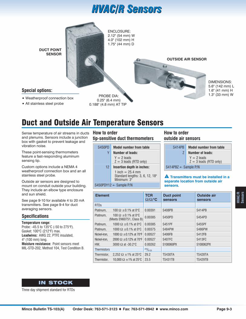
Minco Bulletin TS-103(A) Order Desk: 763-571-3123 � Fax: 763-571-0942 � www.minco.com Page 9-3
HVAC/R SensorsHVAC/R Sensors
HVA
C/R
Sens
ors
Duct and Outside Air Temperature SensorsSense temperature of air streams in ductsand plenums. Sensors include a junctionbox with gasket to prevent leakage andvibration noise.
These point-sensing thermometersfeature a fast-responding aluminumsensing tip.
Custom options include a NEMA 4weatherproof connection box and an allstainless steel probe.
Outside air sensors are designed tomount on conduit outside your building.They include an elbow type enclosureand sun shield.
See page 9-10 for available 4 to 20 mAtransmitters. See page 9-4 for ductaveraging sensors.
SpecificationsTemperature range:Probe: -45.5 to 135°C (-50 to 275°F).Gasket: 100°C (212°F) max.Leadwires: AWG 22, PTFE insulated,4" (100 mm) long.Moisture resistance: Point sensors meetMIL-STD-202, Method 104, Test Condition B.
How to ordertip-sensitive duct thermometers
S450PD Model number from table
Y Number of leads:Y = 2 leadsZ = 3 leads (RTD only)
12 Insertion depth in inches:1 inch = 25.4 mmStandard lengths: 3, 6, 12, 18"Minimum: 3"
S450PDY12 � Sample P/N
Element TCR�/�/°C
Duct pointsensors
Outside airsensors
RTDs
Platinum, 100 � ±0.1% at 0°C 0.00391 S408PB S414PB
Platinum, 100 � ±0.1% at 0°C(Meets EN60751, Class B)
0.00385 S450PD S454PD
Platinum, 1000 � ±0.1% at 0°C 0.00385 S451PF S455PF
Platinum, 1000 � ±0.1% at 0°C 0.00375 S484PW S486PW
Nickel-iron, 1000 � ±0.12% at 70°F 0.00527 S406FB S412FB
Nickel-iron, 2000 � ±0.12% at 70°F 0.00527 S407FC S413FC
HW, 3000 � at -30.2°C 0.00262 S100060PX S100062PX
Thermistors RR
25125
Thermistor, 2,252 � ±1% at 25°C 29.2 TS430TA TS428TA
Thermistor, 10,000 � ±1% at 25°C 23.5 TS431TB TS429TB
How to orderoutside air sensors
S414PB Model number from table
Z Number of leads:Y = 2 leadsZ = 3 leads (RTD only)
S414PBZ � Sample P/N
ENCLOSURE:2.12" (54 mm) W4.0" (102 mm) H1.75" (44 mm) D
Special options:
• Weatherproof connection box
• All stainless steel probe
PROBE DIA:0.25" (6.4 mm)
0.188" (4.8 mm) AT TIP
OUTSIDE AIR SENSOR
DIMENSIONS:5.6" (142 mm) L1.6" (41 mm) H1.3" (33 mm) W
DUCT POINTSENSOR
IN STOCK
Three day shipment standard for RTDs
� Transmitters must be installed in aseparate location from outside airsensors.

Page 9-4 Sales: 763-571-3121 � Fax: 763-571-0927 � www.minco.com Minco Bulletin TS-103(A)
HVAC/R SensorsHVAC/R Sensors
HVAC/R
Sensors
Averaging Temperature SensorsTrue continuous elements
Sense temperature of air streams in ductsand plenums. Sensors include a junction boxwith gasket to prevent leakage and vibrationnoise.
These sensors have a continuouselement to sense true averagetemperature along their entire length.They provide accurate compositereadings in locations where air may bestratified into hot and cold layers.
Rigid averaging sensors have a brasscase. Bendable models have aluminumsheaths (copper on special order),formable to a radius of 4". Bendablesensors can criss-cross ducts to averagetemperatures in two dimensions.
SpecificationsTemperature range:Probe: -45.5 to 135°C (-50 to 275°F).Gasket: 100°C (212°F) max.Leadwires: AWG 22, PTFE insulated,8" (200 mm) long.Moisture resistance: Meet MIL-STD-202,Method 104, Test Condition B.
Special options:
• Weatherproof connection box
• Sensor only, no box
• Lengths to 100 feet (30 m)
• Thermistor averaging sensors
*These averaging sensors do not actuallycontain platinum. They use a proprietarysensing element that closely matches theplatinum curve over the specified range,at a much lower cost.
How to orderrigid averaging sensors
S456PE Model number from table
Y Number of leads:Y = 2 leadsZ = 3 leads
12 Insertion depth in inches:1 inch = 25.4 mmStandard lengths:12, 18, 24, 36, 48, 60, 72"
S456PEY12 � Sample P/N
RTDs(Tolerance: ±0.25% at 70°F)
TCR�/�/°C
Rigid averagingsensors
Bendableaveraging sensors
*Platinum, 100 � at 0°C 0.00391 S423PB S447PB
*Platinum, 100 � at 0°C 0.00385 S456PE S457PE
*Platinum, 1000 � at 0°C 0.00385 S493PF S475PF
*Platinum, 1000 � at 0°C 0.00375 S492PW S488PW
Nickel-iron, 1000 � at 70°F 0.00527 S421FB S445FB
Nickel-iron, 2000 � at 70°F 0.00527 S422FC S446FC
*HW, 3000 � at -30.2°C 0.00262 S20080PX S15215PX
How to orderbendable averaging sensors
S457PE Model number from table
Z Number of leads:Y = 2 leadsZ = 3 leads
24 Insertion length in feet:1 foot = 0.3 mStandard lengths:6, 12, 24 feet
S457PEZ24 � Sample P/N
RIGIDAVERAGINGSENSOR
BENDABLEAVERAGING
SENSOR
SHEATH DIAMETER:0.188" (4.8 mm)
SHEATHDIAMETER:0.188" (4.8 mm)
ENCLOSURE:2.12" (54 mm) W4.0" (102 mm) H1.75" (44 mm) D
Sump sensorsA sump averaging sensor (S100479) lets youdefine the temperature sensitive zone to matchtank fluid levels (see drawing at right).
For more information, call Minco and requestbulletin RT-13 or go towww.minco.com/support
Temperature sensitive zone

Minco Bulletin TS-103(A) Order Desk: 763-571-3123 � Fax: 763-571-0942 � www.minco.com Page 9-5
HVAC/R SensorsHVAC/R Sensors
HVA
C/R
Sens
ors
Fluid Immersion Temperature SensorsSense temperature of heated/chilledwater or other fluids in pipes or tanks.
Immersion sensors include stainless steelthermowells for insertion directly into fluidstreams. The sensing probe may beremoved without breaking the fluid seal.Brass thermowells are also available.
See page 9-10 for available 4 to 20 mAtransmitters.
SpecificationsTemperature range:-45.5 to 260°C (-50 to 500°F).Leadwires: AWG 22, PTFE insulated, 4"(100 mm) long.Thermowell pressure rating:1880 psi (130 bar).Moisture resistance: Meets MIL-STD-202,Method 104, Test Condition B.
How to order
S479PD Model number from table
Y Number of leads:Y = 2 leadsZ = 3 leads
60 Thermowell length U:Specify in 0.1" increments(Ex: 60 = 6.0 inches)Standard thermowell lengthsare 3" and 6", contact factoryfor other lengths
S479PDY60 � Sample P/N
Element TCR �/�/°C Model number
Platinum, 100 � ±0.1% at 0°C 0.00391 S478PB
Platinum, 100 � ±0.1% at 0°C (Meets EN60751, Class B) 0.00385 S479PD
Platinum, 1000 � ±0.1% at 0°C 0.00385 S480PF
Platinum, 1000 � ±0.1% at 0°C 0.00375 S490PW*
Nickel-iron, 1000 � ±0.12% at 70°F 0.00527 S476FB*
Nickel-iron, 2000 � ±0.12% at 70°F 0.00527 S477FC*
HW, 3000 � at -30.2°C 0.00262 S100061PX*
* Maximum temperature is 130°C (266°F).
How to order replacement stainlesssteel thermowells
TW488 Model number
U
60 Thermowell length U:Specify in 0.1" increments(Ex: 60 = 6.0 inches)Standard thermowell lengthsare 3" and 6", contact factoryfor other lengths
TW488U60 � Sample P/N
5.8" (147 mm) THERMOWELL LENGTH U
0.375" (9.5 mm) DIAMETER½ - 14 NPT
½ - 14 NPT
OPTIONALTRANSMITTER
CONNECTIONHEAD
THERMOWELL ALUMINUMPROBE TIP
IN STOCK
Three day shipment for standard lengthsof 3" or 6"

Page 9-6 Sales: 763-571-3121 � Fax: 763-571-0927 � www.minco.com Minco Bulletin TS-103(A)
HVAC/R SensorsHVAC/R Sensors
HVAC/R
Sensors
Flexible Thermal-Ribbon™ Pipe SensorsFlexible Thermal-Ribbon™ sensors mounton the pipe surface — saving time andmoney during installation. There’s noexpense of a pipefitter to drain, drill, andtap the pipe for a thermowell becausethere is no thermowell! When properlyinstalled and insulated, the accuracy andresponse of a Thermal-Ribbon equals animmersed thermowell assembly.
Options include stainless steel braid overleadwires to prevent abrasion damage,and pressure-sensitive adhesive for easiermounting (flat surfaces only).
See page 9-10 for available 4 to 20 mAtransmitters.
SpecificationsBody material: Silicone rubber with polyimidebacking.Temperature range:RTD: -62 to 200°C (-80 to 392°F).Thermistor: -45.5 to 135°C (-50 to 275°F).Leadwires: AWG 24, silicone rubber.Moisture resistance: Meets MIL-STD-202,Method 104, Test Condition B.
How to order Thermal-Ribbons
S467PD Model number from table
Z Number of leads:Y = 2 leadsZ = 3 leads (RTD only)YS = 2 leads, stainless steel
braidZS = 3 leads, stainless steel
braid (RTD only)
36 Lead length in inches
A Adhesive backing:A = No adhesiveB = Pressure-sensitive
adhesive
S467PDZ36A � Sample P/N
Element TCR �/�/°C Model number
RTDs
Platinum, 100 � ±0.1% at 0°C 0.00391 S464PB
Platinum, 100 � ±0.1% at 0°C (Meets EN60751, Class B) 0.00385 S467PD
Platinum, 1000 � ±0.1% at 0°C 0.00385 S468PF
Nickel-iron, 1000 � ±0.12% at 70°F 0.00527 S462FB
Nickel-iron, 2000 � ±0.12% at 70°F 0.00527 S463FC
HW, 3000 � at -30.2°C 0.00262 S100001PX
Thermistors RR
25125
Thermistor, 2,252 � ±1% at 25°C 29.2 TS436TA
Thermistor, 10,000 � ±1% at 25°C 23.5 TS437TB
Mounting accessories:AC766 mounting kitSee drawing above. Provides apipe-mounted enclosure for transmittersand connections. Kit includes junctionbox, 5 ft. nylon strap, buckle, 4 wire nuts,and 6 ft. of #20 stretch tape.
#20 stretch tapeHigh temperature self-fusing siliconerubber tape for mountingThermal-Ribbons to pipes. 1" wide rolls, 6or 36 foot lengths.
#6 RTV adhesiveRoom temperature vulcanizing adhesivefor attaching Thermal-Ribbons tosurfaces. 3 oz. (89 ml) tube.
PIPE INSULATION
STRAP
BUCKLE
STRETCH TAPE
THERMAL-RIBBON
TRANSMITTER(OPTIONAL)
JUNCTIONBOX
CONDUIT
FIELDWIRES
WIRENUTS
A Thermal-Ribbon accurately senses fluidthrough pipe walls. No draining, welding, drilling,
or tapping — just tape the Thermal-Ribbon inplace beneath a layer of insulation.
Shown with AC766 Mounting Kit.
LEAD LENGTH 1.5"*(38.1 mm)
0.5" (12.7 mm)
THICKNESS: 0.045" (1.2 mm) over element*MODEL S468PF IS 3.0" (76.2 mm) LONG
IN STOCK
S462, S463, S464, S467

Minco Bulletin TS-103(A) Order Desk: 763-571-3123 � Fax: 763-571-0942 � www.minco.com Page 9-7
HVAC/R SensorsHVAC/R Sensors
HVA
C/R
Sens
ors
Elements & ProbesElements feature fast-responding RTD orthermistor elements in aluminum cases(except stainless steel on S482PW), withPTFE insulated leadwires. They can beassembled into probes or usedseparately as all-purpose sensors.
Probes consist of elements assembledinto stainless steel extension tubes. Theyare not suitable for direct fluid immersionbut may be used with the thermowells onpage 4-6.
See page 9-10 for available 4 to 20 mAtransmitters.
SpecificationsTemperature range:-45.5 to 135°C (-50 to 275°F).Leadwires: AWG 22, PTFE insulated. Standardlengths are 4", 12" and 18".Moisture resistance: Meets MIL-STD-202,Method 104, Test Condition B.Insulation resistance: 1000 megohms min. at500 VDC, leads to case.
How to order elements
S458PD Model number from table
Z Number of leads:Y = 2 leadsZ = 3 leads (platinum only)
4 Lead length in inches
S458PDZ4 � Sample P/N
Element TCR�/�/°C
Elements Probes
RTDs
Platinum, 100 � ±0.1% at 0°C 0.00391 S402PB S411PB
Platinum, 100 � ±0.1% at 0°C(Meets EN60751, Class B)
0.00385 S458PD S460PD
Platinum, 1000 � ±0.1% at 0°C 0.00385 S459PF S461PF
Platinum, 1000 � ±0.1% at 0°C 0.00375 S482PW S485PW
Nickel-iron, 1000 � ±0.12% at 70°F 0.00527 S400FB S409FB
Nickel-iron, 2000 � ±0.12% at 70°F 0.00527 S401FC S410FC
HW, 3000 � at -30.2°C 0.00262 S100057PX S100837PX
Thermistors RR
25125
Thermistor, 2,252 � ±1% at 25°C 29.2 TS438TA TS440TA
Thermistor, 10,000 � ±1% at 25°C 23.5 TS439TB TS441TB
How to order probes
S411PB Model number from table
60 Case length:Specify in 0.1" increments(Ex: 60 = 6.0 inches)Minimum length is 3"
Z Number of leads:Y = 2 leadsZ = 3 leads (platinum only)
4 Lead length in inches
S411PB60Z4 � Sample P/N
LEAD LENGTH CASE LENGTH
0.250" (6.4 mm) DIAMETER 0.188" (4.8 mm) DIAMETER
1.0" (25.4 mm)SENSING TIP
LEAD LENGTH 2.00"*(50.8 mm)
0.188" (4.8 mm) DIAMETER
*MODEL S482PW IS 2.4" (60.3 mm) LONG
IN STOCK
Three day shipment standard for RTDs
ELEMENT
PROBE
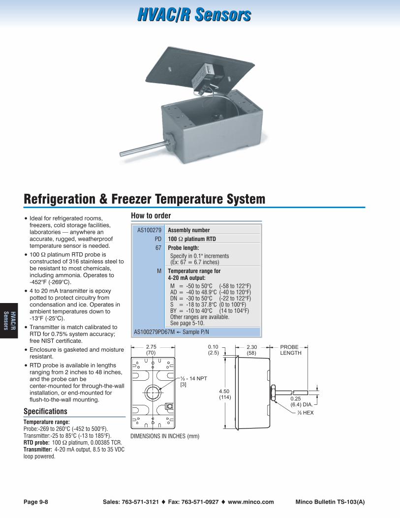
Page 9-8 Sales: 763-571-3121 � Fax: 763-571-0927 � www.minco.com Minco Bulletin TS-103(A)
HVAC/R SensorsHVAC/R Sensors
HVAC/R
Sensors
Refrigeration & Freezer Temperature System
• Ideal for refrigerated rooms,freezers, cold storage facilities,laboratories — anywhere anaccurate, rugged, weatherprooftemperature sensor is needed.
• 100 � platinum RTD probe isconstructed of 316 stainless steel tobe resistant to most chemicals,including ammonia. Operates to-452°F (-269°C).
• 4 to 20 mA transmitter is epoxypotted to protect circuitry fromcondensation and ice. Operates inambient temperatures down to-13°F (-25°C).
• Transmitter is match calibrated toRTD for 0.75% system accuracy;free NIST certificate.
• Enclosure is gasketed and moistureresistant.
• RTD probe is available in lengthsranging from 2 inches to 48 inches,and the probe can becenter-mounted for through-the-wallinstallation, or end-mounted forflush-to-the-wall mounting.
SpecificationsTemperature range:Probe:-269 to 260°C (-452 to 500°F).Transmitter:-25 to 85°C (-13 to 185°F).RTD probe: 100 � platinum, 0.00385 TCR.Transmitter: 4-20 mA output, 8.5 to 35 VDCloop powered.
How to order
AS100279 Assembly number
PD 100 � platinum RTD
67 Probe length:Specify in 0.1" increments(Ex: 67 = 6.7 inches)
M Temperature range for4-20 mA output:M = -50 to 50°C (-58 to 122°F)AD = -40 to 48.9°C (-40 to 120°F)DN = -30 to 50°C (-22 to 122°F)S = -18 to 37.8°C (0 to 100°F)BY = -10 to 40°C (14 to 104°F)Other ranges are available.See page 5-10.
AS100279PD67M � Sample P/N
2.75(70)
½ - 14 NPT[3]
4.50(114) 0.25
(6.4) DIA.
2.30(58)
PROBELENGTH
0.10(2.5)
87
DIMENSIONS IN INCHES (mm)

Minco Bulletin TS-103(A) Order Desk: 763-571-3123 � Fax: 763-571-0942 � www.minco.com Page 9-9
HVAC/R SensorsHVAC/R Sensors
HVA
C/R
Sens
ors
Thermal Vial™ Temperature Sensing System
• Ideal for ultralow freezers,laboratories, blood banks, walk-infreezers and refrigerators, evenincubators — anywhere accuratesensing of the contents instead ofthe air is a vital concern.
• Sealed polyethylene Thermal Vial™virtually eliminates spillage andcontamination. Simply fill with fluidsuch as ethylene glycol, alcohol,water, or a cryopreservative toaccurately emulate the materialbeing stored or processed.
• Large (50 mm × 50 mm) footprintprovides stability on a shelf or rack.Holds 175 ml (6 oz) of fluid.
• 100 � Platinum RTD probe isconstructed of 316 Stainless Steeland operates to -269°C (-452°F).
• Cable is reinforced with stainlesssteel braid for ruggedness.
• 4 to 20 mA transmitter is matchcalibrated to the RTD for ±0.75% ofspan system accuracy.
• NIST certificate and calibration datasupplied at no additional cost.
SpecificationsTemperature range:Probe and vial: -269 to 120°C (-452 to 248°F).Transmitter: -25 to 85°C (-13 to 185°F).RTD probe: 100 � Platinum;TCR = 0.00385.Transmitter: 4 to 20 mA output;8.5 to 35 VDC loop powered.
How to order
AS101436 Assembly number:AS101436: Standard constructionAS102437: Washdown compatible
PD 100 � platinum RTD
72 Cable length in inches
M Temperature range for4-20 mA output:AT = -100 to 40°C (-148 to -40°F)EZ = -100 to 0°C (-148 to 32°F)LN = -100 to 100°C (-148 to 212°F)M = -50 to 50°C ( -58 to 122°F)BC = -10 to 30°C ( -22 to 86°F)N = 0 to 50°C ( 32 to 122°F)Other ranges are available.See page 5-10.
AS101436PD72M � Sample P/N
4.5(115)
2.6(65.0)
4.5(114)
2.75(70)
4.0(102)
2.0 SQ.(51)
STANDARD WASHDOWN
DIMENSIONS IN INCHES (mm) BOX DEPTH APPROXIMATELY 2.2 (55.9)
WASHDOWNCOMPATIBLE
Washdown compatibilityThe washdown compatibleThermal Vial includes apolycarbonate housing andPTFE sensor cable forcompatibility with thechemicals commonly used.
Note: Washdowncompatible indicator
TI350 is alsoavailable. See page
5-26 for moreinformation.
TI350
STANDARDCONSTRUCTION

Page 9-10 Sales: 763-571-3121 � Fax: 763-571-0927 � www.minco.com Minco Bulletin TS-103(A)
HVAC/R SensorsHVAC/R Sensors
HVAC/R
Sensors
Temptran™ 4 to 20 mA TransmittersAll HVAC RTDs are available withcompanion 4 to 20 mA transmitters. Seepage 5-2 for suitable models. (Room airthermometers use model TT115, whichhas the same specifications as TT111).Temptrans convert low-level RTD outputto a standard current signal, immune tolead resistance and electrical noise. Youcan get accurate readings from pointsthousands of feet away.
How to order transmittersTo order HVAC/R sensors with integraltransmitters, specify both the RTD andthe Temptran part numbers.Example: S450PDY12 / TT111PD1A =Platinum duct RTD and 20 to 120°Ftransmitter.
Special calibrationStandard transmitters are calibrated tothe nominal resistance values of the RTDat the zero and span points. Total systemerror includes the tolerance of both thetransmitter and the RTD sensor.
If you order Minco Temptrans calibratedto the actual resistance of the RTD (asmeasured in Minco’s metrology lab), thiseffectively subtracts the sensor tolerancefrom system accuracy specifications.
For example, consider a transmitter with arange of 0 to 500°C. The transmitter itselfis accurate to ±1.0°C (±0.2% of span,including calibration accuracy andlinearity). The RTD interchangeabilitycontributes an additional error of ±0.3°Cat 0°C and ±2.8°C at 500°C. Total systemerror would be ±1.3°C at 0°C and ±3.8°Cat 500°C. When you calibrate the sensorand transmitter as a set, the sensor errordisappears, reducing system error to±1.0°C over the full range — all for anominal extra cost.
0.75% guaranteed accuracyMinco guarantees a system accuracy(current signal vs temperature) of 0.75%of span when you order speciallycalibrated Temptrans with any RTD in thissection. (An RTD with standardtransmitter will deviate about 1-2% ofspan.) Tighter accuracies are available onspecial order.
Standard model Special calibration
TT110 TT150
TT111 TT151
TT115 TT155
TT210 TT710
TT211 TT711
Free NIST traceabilityWith each matched sensor/transmitterset, Minco sends you calibration datatraceable to the National Institute ofStandards & Technology. This helps youcomply with ISO 9001 and other qualitystandards.
RecalibrationMinco prints RTD resistance values righton the Temptran label to simplifyrecalibration. You simply connect aresistance decade box or “RTD simulator”in place of the RTD, dial in the correctvalues, and adjust zero and span.Because Minco RTDs shift less than0.05°F per year in a typical HVACinstallation, the printed values remainvalid for many years.
Full size wall mount thermometers use theTT115 circuit-board style Temptran. Theenclosure is thermally designed tominimize heating of the sensor bytransmitter electronics.
Outside air thermometers and Thermal-Ribbons: Transmitters are furnished separately. Install in anenclosure near the sensor, but away from excessive ambient temperatures.
Transmitters are mounted in the junction box on duct sensors, or in the connection head of fluidimmersion sensors.
MODEL TT211PD1AD/C: 9614100 OHM PLATINUM RTD4mA= 20.0°F= -6.7°C= 97.932
20mA= 120.0°F= 48.9°C= 118.969
��
TEMPTRAN™
MP
LS
,M
NU
SA
RTD resistances are printed on Temptranlabels for easy recalibration of zero and span.
A standard Temptran shows nominal values.
MODEL TT711PD1AD/C: 9614 S/N: 103100 OHM PLATINUM RTD4mA= 20.0°F= -6.7°C= 97.427
20mA= 120.0°F= 48.9°C= 118.988
��
TEMPTRAN™
MP
LS
,M
NU
SA
A specially calibrated Temptran showsresistance of the serialized, connected RTD.
actual

Minco Bulletin TS-103(A) Order Desk: 763-571-3123 � Fax: 763-571-0942 � www.minco.com Page 10-1
Thermal-RibbonsThermal-Ribbons
Ther
mal
-R
ibbo
ns
Section 10: Thermal-Ribbons™
• Thin, flexible RTDs and thermocouples
• Fast response surface sensing in aerospace,medical, and industrial devices
• Rugged laminated construction
• Kapton™, silicone rubber, Mylar™ insulation
• All models available from stock
• See page 9-6 for Thermal-Ribbons designed for pipemounting.
Miniature RTD Thermal-Ribbons .......10-2Thin-film RTD Thermal-Ribbons.........10-2Waterproof RTD Thermal-Ribbons ....10-2Discoil™ Thermal-Ribbons.................10-3Custom configurations.......................10-3Strip sensing Thermal-Ribbons .........10-4Thermistor Thermal-Ribbons .............10-5Thermocouple Thermal-Ribbons.......10-5Installation and accessories...............10-6

Page 10-2 Sales: 763-571-3121 � Fax: 763-571-0927 � www.minco.com Minco Bulletin TS-103(A)
Thermal-RibbonsThermal-Ribbons
Thermal-
Ribbons
Thermal-Ribbons and Thermal-TabsInstall these compact sensors anywhere for accurate point sensing and fast response. All Thermal-Ribbon models conform toEN60751 Class B tolerance when ordered with a PD platinum element. Thermal-Tab models use a thin-film RTD element.
DimensionsW × L × T (max.)
Elementoptions
Insulation Temp.range
Leadwires Timeconstant*
Features Model
Thermal-Ribbons
0.20 × 1.50 × 0.030"(5.1 × 38.1 × 0.8 mm) FA Kapton
-200 to 200°C-328 to 392°F
AWG 34,PTFE insulated
0.15 sec.Wire-wound nickel-ironfor high resistance insmall package
S38
0.30 × 0.30 × 0.025"(7.6 × 7.6 × 0.7 mm) PD
Kapton with foilbacking
-200 to 200°C-328 to 392°F
AWG 28,PTFE insulated
0.15 sec. Wire-wound element S651
0.75 × 0.75 × 0.04"(19 × 19 × 1.0 mm)
FA Mylar-200 to 150°C-328 to 302°F
AWG 30,PTFE insulated
0.3 sec.Wire-wound nickel-ironflat element for highresistance
S25
Thermal-Tabs
0.20 × 0.50 × 0.08"(5 × 12 × 2 mm) PD, PF, PW
Kapton withelastomer cover coat
-50 to 155°C-58 to 311°F
AWG 26,PTFE insulated
0.8 sec.Stocked for immediateshipment
S665
0.20 × 0.60 × 0.08"(5 × 15 × 2 mm)
PD, PF, PW, PS,NB, NA, NJ
Kapton-50 to 200°C-58 to 392°F
AWG 26, PTFE orPolyimide insulated
1.0 sec. Platinum models in stock S17624
0.20 × 0.60 × 0.08"(5 × 15 × 2 mm) PD, PF, PW, PS Polyimide film
-50 to 260°C-58 to 500°F
AWG 26, PTFE orPolyimide insulated
0.4 sec.Highest temperaturecapability
S100820
0.20 × 0.60 × 0.12"(5 × 15 × 3 mm) PD, PF, PW
Silicone rubber withelastomer cover andfoil backing
-50 to 155°C-58 to 311°F
AWG 24,Silicone insulated
1.3 sec.Waterproof; suitable forcontinuous immersion
S667
0.20 × 0.60 × 0.07"(5 × 15 × 1.7 mm) PD, PF, PW Polyimide film
-50 to 200°C-58 to 392°F
AWG 26, PTFE orPolyimide insulated
0.6 sec. Thinnest profile S100725
0.30 × 0.60 × 0.10"(7 × 15 × 2.5 mm) PD, PF, PW, PS,
NB, NA, NJPolyimide film
-50 to 200°C-58 to 392°F
AWG 22, PTFE orPolyimide insulated
1.2 sec.Heavier leadwire forapplications requiringruggedized design
S100724
0.40 × 0.80 × 0.08"(10 × 20 × 2 mm) PD, PF, PW, PS,
NB, NA, NJPolyimide film
-50 to 200°C-58 to 392°F
AWG 26, PTFE orPolyimide insulated
0.9 sec.Larger surface area foreasier handling and max.adhesive bond
S100723
0.40 × 0.80 × 0.08"(10 × 20 × 2 mm) PD, PF, PW, PS,
NB, NA, NJSilicone rubber
-50 to 220°C-58 to 428°F
AWG 26, PTFE orPolyimide insulated
1.5 sec.High temperature rating,available with wide rangeof element options
S100721
* In water at 1 m/sec.
� T (max.) is over the lead bulge.
IN STOCK
All models in the following lead lengths:24": S65136": S38, S2540" PD or PF only: S100723, S100724, S100725, S100820, S1762440" with 60" max. PD or PF only: S665, S667
See next page for information on how to order.���������������������
Waterproof modelModel S667 is waterproof andsuitable for continous immersion.Use it to monitor the temperatureof water in a tank or container, oron equipment that must withstandwash-down or immersion.
Check with Minco for suitability inother liquids.
Leadwire insulation codes
S25, S38, S651, S665, S667 Leave blank
A17624, S100721, S100723, S100724,S100725, S100820
T = PTFE insulated wiresK = Polyimide insulated wires

Minco Bulletin TS-103(A) Order Desk: 763-571-3123 � Fax: 763-571-0942 � www.minco.com Page 10-3
Thermal-RibbonsThermal-Ribbons
Ther
mal
-R
ibbo
ns
Discoil™ Thermal-RibbonsDiscoil RTD elements are wound in a single plane for faster time response.
DimensionsW × L × T (max.)
Elementoptions
Insulation Temp.range
Leadwires Timeconstant*
Features Model
0.79 × 1.87 × 0.055"(20 × 47.5 × 1.4 mm)solder pad version shown
PD, PE
Kapton(Clearpolyesteravailable)
-73 to 200°C-100 to 392°F
(Optional) AWG 24,PTFE insulated
0.10 sec.Only 0.010" thick over element,fast time response, platinum PDaccuracy available
S17422
1.00 × 1.25 × 0.090"(25.4 × 31.8 × 2.3 mm) PB11, PB22 Silicone
rubber withKaptonbacking
-62 to 220°C-80 to 428°F
AWG 24, siliconerubber insulated
0.2 sec.High temperature rating,platinum PD accuracy available
S32
PD12, PE22 S385
1.00 × 1.25 × 0.065"(25.4 × 31.8 × 1.7 mm)
FA Kapton-200 to 200°C-328 to 392°F
AWG 26,PTFE insulated
0.15 sec.High resistance nickel-ironelement
S39
* In water at 1 m/sec.
Sensing element specifications** Code
Platinum 391, 100 � ±0.11% at 0°C PB11
Platinum 391, 100 � ±0.22% at 0°C PB22
Platinum 385, 100 �±0.12% at 0°C (EN60751, Class B) PD, PD12
Platinum 385, 100 � ±0.36% at 0°C PE
Platinum 385, 100 � ±0.22% at 0°C PE22
Platinum 385, 1000 � ±0.12% at 0°C PF
Platinum 375, 1000 � ±0.12% at 0°C PW
Platinum 385, 10,000 � ±0.12% at 0°C PS
Nickel-iron 518, 604 � ±0.26% at 0°C FA
Nickel 618, 100 �±0.22% at 0°C (DIN43760 NI100, Class B) NB
Nickel 672, 120 �±0.50% at 0°C NA
Nickel 618, 1,000 �±0.22% at 0°C (DIN43760 NI1000, Class B) NJ
** See tables for element options on each model.
How to order Thermal-Ribbons and Thermal-Tabs
S17624 Model number from table on previous page
PD Sensing element from table on previous page
Z Number of leads:Y = 2 leadsZ = 3 leads (N/A on S25, S38 or S667)X = 4 leads (N/A on S25, S38 or S665/S667)
T Leadwire insulation code from table on previous page
24 Lead length in inches:S665/S667: 60" max.
A Adhesive backing:A = No adhesiveB = Pressure-sensitive adhesive (PSA)
S17624PDZT24A � Sample P/N
� PSA reduces temperature range to -20 to 177°C(-4 to 350°F) and adds 0.005" (0.1 mm) to thickness.
How to order Discoil Thermal-Ribbons
S32 Model number from table above
PB22 Sensing element from table above
Z Number of leads:Y = 2 leadsZ = 3 leads (Platinum only)X = 4 leads (PD only)W = Solder pads (S17422 only)
36 Lead length in inches(Specify 0 for solder pads, optional on S17422 only)
A Adhesive backing:A = No adhesiveB = Pressure-sensitive adhesive (PSA)
S32PB22Z36A � Sample P/N
IN STOCK
All models in the following lead lengths:36": S32, S39, S38540": S17422
Custom Thermal-Ribbon designsMinco can custom-wind elements in virtually any shapeand size. One Thermal-Ribbon model measures 2 feetsquare and averages temperature readings over itsentire surface. We can even profile elements to givemore weight to temperature readings in selected zones.Look to Minco for custom design solutions to uniquetemperature sensing problems.

Page 10-4 Sales: 763-571-3121 � Fax: 763-571-0927 � www.minco.com Minco Bulletin TS-103(A)
Thermal-RibbonsThermal-Ribbons
Thermal-
Ribbons
Strip Sensing Thermal-RibbonsThese models average temperatures along their length to eliminate point measurement errors. Wrap them around cylinders oradhere them to flat surfaces.
DimensionsW × L × T (max.)
Elementoptions
Insulation Temp.range
Leadwires Timeconstant*
Features Model
0.375 × 4.00 × 0.075"(9.5 × 101.6 × 1.9 mm)
PB22Siliconerubber withKaptonbacking
-62 to 220°C-80 to 428°F
AWG 26,PTFE insulated
0.6 sec.Platinum PDaccuracy
S34
PD12, PE22 S386
0.375 × 4.00 × 0.065"(9.5 × 101.6 × 1.7 mm)
FA Kapton-200 to 200°C-328 to 392°F
0.2 sec.
Wire-woundnickel-iron forhigh resistance,thin element
S35
FA Mylar-100 to 150°C-148 to 302°F
0.3 sec.Wire-woundnickel-iron,low cost
S2
0.50 × 1.25 × 0.050"(12.7 × 31.8 × 1.3 mm PA, PE,
CA, NAKapton
-73 to 200°C-100 to 392°F
0.17 sec.Easy motorinstallations
S3238
* In water at 1 m/sec.
Sensing element specifications** Code
Platinum 392, 100 � ±0.5% at 0°C PA
Platinum 391, 100 � ±0.22% at 0°C PB22
Platinum 385, 100 � ±0.12% at 0°C (EN60751, Class B) PD12
Platinum 385, 100 � ±0.5% at 0°C PE
Platinum 385, 100 � ±0.22% at 0°C PE22
Nickel-iron 518, 604 � ±0.26% at 0°C FA
Copper 427, 10 � ±0.20% at 25°C CA
Nickel 672, 120 � ±0.3% at 0°C NA
** See table for element options on each model.
How to order
S34 Model number from table (except S3238)
PB22 Sensing element from table at top
Y Number of leads:Y = 2 leadsZ = 3 leads (required on CA)X = 4 leads (PD only)
36 Lead length in inches:36" stocked (42" on S2)
A Adhesive backing:A = No adhesiveB = Pressure-sensitive adhesive (PSA)
S34PB22Y36A � Sample P/N
Model S3238Model S3238 is specially designed to sense stator temperaturesin motors and generators. An alternative to the “stick” sensorsin Section 8, the S3238 mounts on the end turns of statorwindings and provides an easy way to add overtemperatureprotection when the stator is not being rewound.
How to order
S3238 Model number S3238
PA Sensing element from table above
Y Number of leads:Y = 2 leadsZ = 3 leads (required on CA)X = 4 leads
T Lead insulation:T = PTFEK = polyimideTS = SS braid over PTFE
36 Lead length in inches36" stocked
U Lead configuration:T = TwistedU = Untwisted
A Adhesive backing:A = No adhesiveB = Pressure-sensitive adhesive (PSA)
S3238PAYT36UA � Sample P/N
� PSA reduces temperature range to -20 to 177°C (-4 to 350°F) and adds 0.005" (0.1 mm) to thickness.
IN STOCK
All models in stock with 36" leads,except 42" leads on S2FA

Minco Bulletin TS-103(A) Order Desk: 763-571-3123 � Fax: 763-571-0942 � www.minco.com Page 10-5
Thermal-RibbonsThermal-Ribbons
Ther
mal
-R
ibbo
ns
Thermistor and Thermocouple Thermal-Ribbons
Thermistor Thermal-Ribbon
DimensionsW × L × T (max.)
Elementoptions
Insulation Temp.range
Leadwires Timeconstant*
Features Model
0.20 × 0.47 × 0.079"(5.0 × 12.0 × 2.0 mm)
TF, TK
Kapton with elastomercover coat
-50 to 125°C(-58 to 257°F)
AWG 26,PTFE insulated
0.8 sec. Small, low-cost TS665
0.20 × 0.60 × 0.118"(5.0 × 15.2× 3.0 mm)
Silicone rubber withelastomer cover andfoil backing
AWG 24,Silicone insulated
1.3 sec.Waterproof, suitable forcontinous immersion
TS667
* In water at 1 m/sec.
Thermocouple Thermal-Ribbon
DimensionsW × L × T (max.)
Junctiontype
Insulation Temp.range
Leadwires Timeconstant*
Features Model
0.75 × 0.75 × 0.065"(19.1 × 19.1 × 1.7 mm)
E, J, K, or T Kapton-200 to 200°C(-328 to 392°F)
AWG 24, solidPTFE insulated
0.6 sec. Surface mounting TC40
* In water at 1 m/sec.
Thermistor TS665, TS667Model TS665 and TS667 offer extremely sensitive NTCthermistors for applications with small temperature changes.Model TS667 also features waterproof construction, making itsuitable for continous immersion.
Sensing element specifications** Code
NTC thermistor, 50k � ±1% at 25°C TF
NTC thermistor, 10k � ±1% at 25°C TK
** See table for element options.
How to order
TS665 Model number from table
TF Element from table
Y Number of leads:Y = 2 leads
40 Lead length in inches:40" stocked, 60" maximum
A Adhesive backing:A = No adhesiveB = Pressure-sensitive adhesive (PSA)
TS665TFY40A � Sample P/N
Thermocouple TC40TC40 is a patch-style thermocouple that adheres to all types ofsurfaces for quick and easy mounting.
How to order
TC40 Model number
J Junction type:E, J, K, or T
T Covering over leadwires:T = PTFE onlyS = Stainless steel braid
36 Lead length in inches:36" stocked for type J, K, T
A Adhesive backing:A = No adhesiveB = Pressure-sensitive adhesive (PSA)
TC40JT36A � Sample P/N
� PSA reduces temperature range to -20 to 177°C (-4 to 350°F) and adds 0.005" (0.1 mm) to thickness.
IN STOCK
TS665 stocked in 40" lead lengthTC40 types J, K, T stocked in 36" lead length

Page 10-6 Sales: 763-571-3121 � Fax: 763-571-0927 � www.minco.com Minco Bulletin TS-103(A)
Thermal-RibbonsThermal-Ribbons
Thermal-
Ribbons
Installation and AccessoriesThermal-Ribbons lend themselves to a variety of installation methods. You should avoid repeated bending during the installationprocess, and Thermal-Ribbons should not flex in use unless they are specifically designed to do so. Take care to secure leadwiresso they do not pull against sensor bodies. Leadwires should be routed along the sensed surface a short distance so that they donot sink heat away from the sensing element.
Listed below are some standard installation methods.
Pressure sensitive adhesivePSA (option B in part number) is thesimplest mounting method, but it isrestricted to flat surfaces andtemperatures below 177°C (350°F). PSAis usually factory applied to the mountingsurface of the Thermal-Ribbon. To install,just remove the backing paper and pressin place.
#20 stretch tapeHigh temperature silicone rubber tape formounting Thermal-Ribbons to pipes orother cylinders as shown below. It comesin 1" wide rolls, 6 or 36 feet long.
#6 RTV cementRoom temperature vulcanizing cement formounting silicone rubberThermal-Ribbons to flat or curvedsurfaces. It is available in 3 oz. (89 ml)tubes. Contact Minco for other adhesivesusable with Kapton™ or Mylar™Thermal-Ribbons.
Shrink bandsMinco shrink bands are pre-stretchedplastic strips with adhesive at both ends.Use them to mount Thermal-Ribbons tocylinders. Simply wrap the band aroundthe sensor and cylinder, secure the ends,and heat to shrink in place. To order,specify band width and cylinder diameter.
#21 Polyimide tapeHigh temperature tape with siliconebased adhesive. Useful for quickmounting of Thermal-Ribbon orThermal-Tab sensors to flat surfaces.Makes a strong but removable bond tomost smooth and clean surfaces.Maximum operating temperature is150°C. 0.5 inch wide × 108 ft. long roll.
Thermal-Ribbons for fluid sensingNeed to monitor temperature of liquids in pipes or tanks?Thermal-Ribbons make a practical, economical alternative totraditional immersed sensors. They mount directly on pipesurfaces, so there’s no need to drain systems and installthermowells. And tests show that Thermal-Ribbons respond asquickly and as accurately as invasive sensors. Request MincoApplication Aid #16 for a comparison of Thermal-Ribbons versusthermowells.
See page 9-6 to order Thermal-Ribbon models designedspecifically for pipe mounting.
Thermofoil™ heater-sensorsMinco manufactures flexible etched-foil heaters forprecision temperature control of aerospace,medical, and industrial devices. We can buildcombination heater-sensors containingThermal-Ribbons integral to the heating element.We can also etch Thermal-Ribbon RTDs fromresistive foil.
Request Bulletin HS-202 for complete heater andheater-sensor information.

Minco Bulletin TS-103(A) Order Desk: 763-571-3123 � Fax: 763-571-0942 � www.minco.com Page 11-1
ElementsElements
Elem
ents
Section 11: Ceramic Elements
• Low cost thin-film elements
• Wire wound elements
• Accurate sensing from -200 to 850°C(-328 to 1582°F)
• Wide choice of sizes and styles for applicationversatility
• Available from stock
550°C wire-wound elements ..............11-2150°C, 400°C, 600°CThin-film elements..............................11-2850°C precision elements ..................11-3Installation ..........................................11-4Extension leads..................................11-4Custom elements ...............................11-4

Page 11-2 Sales: 763-571-3121 � Fax: 763-571-0927 � www.minco.com Minco Bulletin TS-103(A)
ElementsElements
Elements
Wire-Wound and Thin-Film Elements
Dimensions in inches (mm) R (0°C) Temperaturerange
Leads Model
550°C wire-wound elements
0.040 ø(1.020) 0.45 (11.4) 0.75 (19)
100 �
-20 to 550°C(-4 to 1022°F)
0.006" (0.15 mm) øPlatinum
S200PD
0.058 ø(1.47) 0.40 (10.2) 0.75 (19)
-100 to 550°C(-148 to 1022°F)
0.010" (0.25 mm) øPlatinum alloy
S201PD
0.077 ø(1.96) 0.30 (7.6) 0.75 (19) S202PD
0.100 ø(2.54) 0.40 (10.2) 0.75 (19)
0.014" (0.35 mm) øPlatinum alloy
S203PD
0.135 ø(3.43) 0.40 (10.2) 0.75 (19)
0.014" (0.35 mm) øPlatinum
S204PD
0.077 ø(1.96) 1.00 (25.4) 0.75 (19)
500 �
0.010" (0.25 mm) øPlatinum alloy
S212PG
0.135 ø(3.43) 1.20 (30.5) 0.75 (19)
0.014" (0.35 mm) øPlatinum
S214PG
400°C and 600°C thin-film elements
0.05 (1.3) 0.025 (0.7) THICK0.07 (1.7) Lead length: 0.4 (10)
100 � -50 to 400°C(-58 to 752°F)
0.010" (0.25 mm) ø Ag.0004 �/mm/lead
S100144PD12
1,000 � S101503PF12
0.08 (2.0) 0.055 (1.4) THICK0.09 (2.3) Lead length
S245: 0.6 (15)S249: 0.4 (10)
100 �
-70 to 400°C(-94 to 752°F)
0.010" (0.25 mm) ø Ag.0004 �/mm/lead
S245PD12
-70 to 600°C(-94 to 1112°F)
0.008" (0.20 mm) ø Pt/Ni0.003 �/mm/lead
S249PD12
0.08 (2.0) 0.055 (1.4) THICK0.20 (5.0) Lead length
S247: 0.6 (15)S251: 0.4 (10)
1,000 �
-70 to 400°C(-94 to 752°F)
0.010" (0.25 mm) ø Ag.0004 �/mm/lead
S247PF12
-70 to 600°C(-94 to 1112°F)
0.008" (0.20 mm) ø Pt/Ni0.003 �/mm/lead
S251PF12
0.10 (2.5) 0.050 (1.3) THICK0.20 (5.0) Lead length: 0.6 (15) 10,000 �
-50 to 400°C(-58 to 752°F)
0.010" (0.25 mm) ø Ag.0004 �/mm/lead
S19827PS12
150°C surface mount technology (SMT) thin-film elements
0.063 (1.6) 0.016 (.41) THICK
0.126 (3.2) Tin solder contacts: 0.020 (.51)
100 � -50 to 150°C(-58 to 302°F)
Tin plated solderingcontacts
S101162PD
1,000 � S101163PF
550°C wire-wound elementsUse these elements for general purposesensing in probes or equipment. PDmodels meet EN60751, Class B.Temperature range: See table above. Someelements may be used down to -269°C in certainapplications. Contact factory for advice oncryogenic use.Material: Glass-coated ceramic.
Tolerance: ±0.1% at 0°C.TCR: 0.00385 �/�/°C. Models with 0.00391TCR, the U.S. industrial standard, are: S201PB,S202PB, S203PB, S204PB, S212PP, S214PP.All 0.00391 TCR models use 0.010" (0.25 mm)diameter 0.5" (13mm) long platinum leads.Diameter tolerance: ±0.005" (0.13 mm).Length tolerance: ±0.06" (1.5 mm).
Repeatability: ±0.1°C or better.Stability: Drift less than 0.1°C/year (normal use).Vibration: Withstands 20 G’s minimum at 10 to2,000 Hz.Shock: Withstands 100 G’s minimum sine waveshock of 8 milliseconds duration.
Thin-film elementsThin film elements offer low cost andresistances to 10k �. SMT modelsavailable: S101162PD and S101163PF.See page 10-2 for the S17624 thin-filmThermal-Ribbon™.Tolerance: ±0.12% (EN60751 Class B) Toorder optional ±0.06% tolerance (EN60751Class A), change 12 to 06 for ±0.06%(EN60751 Class A). Not available with ,S101162PD, S101163PF, or S19827PS.Material: Aluminum oxide substrate with fusedglass cover.
Dimensional tolerance:400, 600°C elements: ±0.02" (0.5 mm).SMT models: Length×Width ±0.008 (0.2 mm),
Thickness ±0.004 (0.1 mm).TCR: 0.00385 �/�/°C.Repeatability: ±0.1°C or better.Stability: Drift less than 0.1°C/year in normal use.Vibration: Withstands 20 G’s minimum at 10 to2,000 Hz.Shock: Withstands 100 G’s minimum sine waveshock of 8 milliseconds duration.
Contact Minco for other standard andcustom thin-film models.
How to order wire-wound orthin-film elements
S201PD Model number from table
S201PD � Sample P/N
IN STOCK
All 0.00385 TCR models

Minco Bulletin TS-103(A) Order Desk: 763-571-3123 � Fax: 763-571-0942 � www.minco.com Page 11-3
ElementsElements
Elem
ents
850°C Precision Elements
Dimensions in inches (mm) Leads Response time in seconds Self-HeatingWater, 1 m/s°C/mW
Model
Water, 0.4 m/s Air, 1.5 m/s
50% 90% 50% 90%
0.047 ø(1.2) 0.59 (15) 0.4 (10)
0.006" (0.15 mm) øPlatinum
Resistance:0.0055 �/mm/lead
0.06 0.15 3.5 12.5 0.100 S270*
0.98 (25) 0.6 (15)0.07 0.20 6.0 20.0 0.040 S271*
0.062 ø(1.6) 0.59 (15) 0.4 (10)
0.010" (0.25 mm) øPlatinum
Resistance:0.002 �/mm/lead
0.07 0.30 6.6 25.4 0.029 S272
0.98 (25) 0.6 (15)0.08 0.35 7.0 25.0 0.020 S273
0.079 ø(2.0) 0.59 (15) 0.4 (10) 0.08 0.35 7.0 24.0 0.012 S274
0.98 (25) 0.6 (15)0.09 0.45 7.5 25.3 0.008 S275
0.110 ø(2.8) 0.59 (15) 0.4 (10) 0.13 0.55 9.3 30.0 0.014 S276
0.98 (25) 0.6 (15)0.16 0.70 10.5 34.1 0.011 S277
0.155 ø(3.9) 0.59 (15) 0.4 (10)
0.014" (0.36 mm) øPlatinum
Resistance:0.001 �/mm/lead
0.29 1.24 14.3 43.3 0.011 S278
0.98 (25) 0.6 (15)0.35 1.55 16.0 48.0 0.010 S279
0.177 ø(4.5) 0.59 (15) 0.4 (10)
0.31 1.50 17.0 51.0 0.012 S280
0.98 (25) 0.6 (15)0.41 1.60 18.0 54.0 0.008 S281
0.188 ø(4.8) 0.59 (15) 0.4 (10)
0.32 1.58 17.3 52.1 0.012 S282
0.98 (25) 0.6 (15)0.43 1.65 18.4 54.8 0.008 S283
*Not available with factory installed extension leads AC887/AC888/AC889/AC101828
Obtain accurate measurements over awide temperature range. A proprietary fillmaterial supports the element wirewithout straining it, giving exceptionalresistance to shock, vibration, andtemperature-induced hysteresis.
SpecificationsElement: Platinum, 100 � at 0°C,TCR = 0.00385 �/�/°C.Tolerance: EN60751 Class A (± 0.06%) orClass B (± 0.12%). Calibrated 1 mm from endsof leads.Temperature range: -200 to 850°C (-328 to1562°F).Diameter tolerance: ±0.005" (0.13 mm).Length tolerance: ±0.06" (1.5 mm).Repeatability: Meet IEC requirements. Typicalshift less than 0.05°C (0.02 �) at 0°C after tencycles from -200 to 850°C.Stability: Meet IEC stability specifications after250 hours exposure to extremes of temperaturerange. Typical drift is less than 0.05°C (0.02 �)at 0°C.
Vibration: Will withstand 10 to 5000 Hz at 2 G’s.minimum.Shock: Will withstand 250 mm drop onto 8 mmthick steel plate (approximately 1400 G’s for0.08 ms).Immersion: Elements are not hermetically sealed.
How to Order 850°C Elements
S276 Model number from table
PD 100 � Platinum, 0.00385 TCR
12 Tolerance at 0°C:06 = ±0.06%, EN60751 Class A12 = ±0.12%, EN60751 Class B
Other tolerances are available
S276PD12 � Sample P/N
IN STOCK
All models

Page 11-4 Sales: 763-571-3121 � Fax: 763-571-0927 � www.minco.com Minco Bulletin TS-103(A)
ElementsElements
Elements
Installation and AccessoriesCeramic elements can be assembled intoprobes or potted inside holes in heatsinks and platens. Ceramic cement isrecommended for high temperaturepotting. Epoxy is recommended forintermediate temperatures.
Round elements will provide the best timeresponse in round sheaths and holes. Flatthin film elements can be bonded tosurfaces.
Elements are calibrated at the end of theirleads. The leads have resistances rangingfrom 0.6 to 2.4 � per foot, so you should
connect extension leads as close aspossible to the end of the element leadsto maintain tolerance.
Minco can supply elements withextension leadwires welded onto thesensor leads. Use the standard modelsbelow or contact us for a quote on yourcustom design.
One final note: Ceramic elements arefragile and can suffer damage or loss ofaccuracy from improper installations. Inmany cases, the best alternative is to buya complete encased probe assembly
from Minco. Take advantage of ourexpertise and equipment for best overallperformance and value.
#8 high temperature cement#8 comes as a powder in 1 oz.packages. Just add water to form apotting compound rated to 850°C(1562°F).
Extension leadsAll elements are available with factory-welded extension leads insulated with PTFE,polyimide, or mica/glass.
Insulation Max.temp.
LeadAWG
Max. diameter over lead bundlein inches (mm)
Model
2 leads 3 leads 4 leads
PTFE, PTFE tubing overconnections
200°C(392°F)
22 0.136 (3.45) 0.143 (3.63) 0.157 (3.99)
AC887
24 0.122 (3.10) 0.124 (3.15) 0.147 (3.73)
26 0.113 (2.87) 0.119 (3.02) 0.123 (3.12)
28 0.110 (2.79) 0.116 (2.95) 0.118 (3.00)
30 0.100 (2.54) 0.101 (2.57) 0.103 (2.62)
Mica/glass, glass braidover connections
550°C(1022°F)
22 0.157 (3.99) 0.192 (4.88) 0.195 (4.95) AC888
Polyimide, PTFE tubingover connections
200°C(392°F)
22 0.123 (3.12) 0.141 (3.58) 0.148 (3.76)
AC88926 0.116 (2.95) 0.131 (3.33) 0.132 (3.35)
30 0.095 (2.41) 0.102 (2.59) 0.107 (2.72)
Glass braid, glass braidover connections
550°C(1022°F)
27 solidleads
0.100 (2.54) 0.117 (2.97) 0.130 (3.30) AC101828
How to order extension leads
AC887 Model Number
Z Number of leads:Y = 2 leadsZ = 3 leadsX = 4 leads
26 Lead gauge (AWG)
L
48 Lead length in inches
AC887Z26L48 � Sample P/N
Custom elementsShown below are examples of custom design:
• A dual ceramic sensor used for air flow sensing
• Two resistor-style RTDs

Minco Bulletin TS-103(A) Order Desk: 763-571-3123 � Fax: 763-571-0942 � www.minco.com Page 12-1
Reference ThermometersReference Thermometers
Ref
eren
cePR
Ts
Section 12: Precision Reference Thermometers
• Laboratory accuracy from -260 to 660°C (-436 to1220°F)
• True strain-free elements
• Reference grade accuracy at affordable prices
• Traceable to NIST (National Institute of Standardsand Technology)
Laboratory reference standards ........12-2Ruggedized standards.......................12-2Cryogenic capsule PRT .....................12-3Oil-filled PRTs.....................................12-4Powder-filled probes and elements...12-5Calibration tables ...............................12-6

Page 12-2 Sales: 763-571-3121 � Fax: 763-571-0927 � www.minco.com Minco Bulletin TS-103(A)
Reference ThermometersReference Thermometers
ReferencePR
Ts
Reference standards
• Air filled strain-free element
• S7928, S7929: 0.005°C stability from-189 to 500°C (-308 to 932°F)
• S7932: Reduced range for lower cost
Maintain an NIST-traceable secondarytemperature reference in your calibrationlab. These PRTs offer precisionapproaching that of primary standards ata fraction of the cost.
Thermometers are shipped in paddedcarrying cases. Like all temperaturestandards, they must be handled withextreme caution to avoid calibration shifts.
Ruggedized standards
• Powder-filled strain-free element
• S9762: 0.01°C stability to 600°C
• S7933: Reduced range for low cost
Ruggedized PRTs have a powder-filledelement to better withstand roughhandling, at the cost of slightly reducedstability. They make excellent workingstandards for transferring calibrations inproduction environments. Model S9762features an Inconel sheath for hightemperature use.
Platinum element options
Code R(0°C) TCR (�/�/°C)
PA 100 � 0.003925 min.
PD 100 � 0.003850
PJ 25.5 � 0.003925 min.
How to order
S7928PJ Model number from table
1 1 = ±0.1% at 0°C
L
180 Case length:Specify in 0.1" increments(Ex:180 = 18.0")18" min. required for customcalibration
S Leadwire termination:S = 5 spade lugsG = 5 gold plated banana plugsC = 5-pin DIN connector
S7928PJ1L180S � Sample P/N
See page 12-6 for calibration.
0.375" (9.5 mm) DIAMETER
1.75"(45 mm)
0.188" (4.8 mm) DIAMETER S7932
S7933
CASE LENGTH
0.75" (19 mm) DIAMETER
18" (457 mm)4" (101 mm)
S7928
S7929
S9762
0.156" (4.0 mm) DIAMETERS9762: 0.219" (5.6 mm) DIAMETER
Leads: Shielded cable, 4 wires plus ground, 6 ft. (1.8 m) long
Laboratory Standards
Stability Repeatabilityafter cycling
Temperaturerange
Sheath Maximumtemperatureat leads
Insulationresistance(100 VDC)
Timeresponse(water;3 ft/sec)
Self-heating(water;3 ft/sec)
Model
Reference standards (air-filled element)
0.005°C/yr. 0.005°C-189 to 500°C(-308 to 932°F)
SS 60°C (140°F) 1000 M � 10 sec. 12.5 mW/°CS7929PAS7928PJ
0.010°C/yr. 0.010°C-50 to 250°C
(-58 to 482°F)SS 60°C (140°F) 100 M � 10 sec. 12.5 mW/°C
S7932PAS7932PJ
Ruggedized standards (powder-filled element)
0.050°C/yr. 0.025°C-189 to 660°C(-308 t0 1220°F)
Inconel 150°C (302°F) 1000 M � 9 sec. 80 mW/°CS9762PAS9762PJ
0.030°C/yr. 0.020°C-50 to 250°C
(-58 to 482°F)SS 60°C (140°F) 100 M � 8 sec. 80 mW/°C
S7933PAS7933PD

Minco Bulletin TS-103(A) Order Desk: 763-571-3123 � Fax: 763-571-0942 � www.minco.com Page 12-3
Reference ThermometersReference Thermometers
Ref
eren
cePR
Ts
Cryogenic Capsule PRT
• Helium filled strain-free element
• 0.0025°C stability
• -260 to 260°C (13 to 533K)
Model S1059 is a miniature thermometerdesigned to cover a wide temperaturerange. It provides reference gradeprecision for cryogenics, calibration, andcalorimetry.
Construction features include a strain-freeelement, gold-plated copper case,all-platinum internal components, dryhelium backfill, and a platinum-to-glassinternal seal. All materials arenon-magnetic.
Select ice point resistance of 25.5 or100 �. The higher resistance isrecommended to reduce heat dissipationinto cryostats.
Specifications
Element Model
Platinum, 25.5 � at 0°C S1059PJ
Platinum, 100 � at 0°C S1059PA
Temperature coefficient:0.003925 �/�/°C min.Case: Gold-plated copper, helium filled,hermetically sealed. External lead connectionsepoxy potted.Leadwires: True 4-wire lead construction. FourAWG 30 leads, polyimide insulation. 6"(150 mm) standard.Time constant:4 seconds typical in water moving at 3 ft/sec.Self-heating: Measuring power of10 microwatts or less recommended to limittemperature rise to less than 0.6 mK.Repeatability: ±0.0005°C typical after 20cycles down to 4K.Stability: ±0.0025°C/year at 0°C typical.Residual resistance:R
R4 10 typical
4.2K
273.15K
4� � �
Insulation resistance: 1000 megohms min. at100 VDC, leads to case, at 25°C.
How to order
S1059PA Model number from table
5 5 = ±0.5% at 0°C
X X = 4 leads
6 Lead length in inches:6" is standard
S1059PA5X6 � Sample P/N
See page 12-6 for calibration.
0.38" (9.7 mm)
0.125" (3.2 mm) DIAMETER
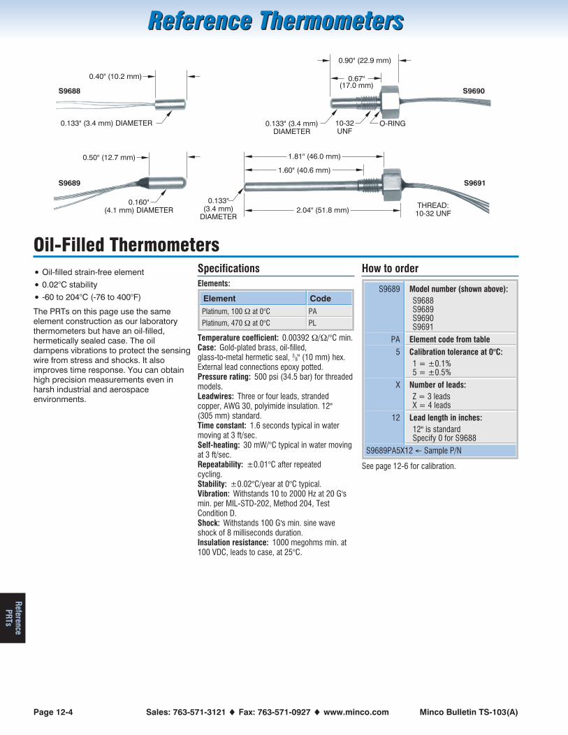
Page 12-4 Sales: 763-571-3121 � Fax: 763-571-0927 � www.minco.com Minco Bulletin TS-103(A)
Reference ThermometersReference Thermometers
ReferencePR
Ts
Oil-Filled Thermometers
• Oil-filled strain-free element
• 0.02°C stability
• -60 to 204°C (-76 to 400°F)
The PRTs on this page use the sameelement construction as our laboratorythermometers but have an oil-filled,hermetically sealed case. The oildampens vibrations to protect the sensingwire from stress and shocks. It alsoimproves time response. You can obtainhigh precision measurements even inharsh industrial and aerospaceenvironments.
SpecificationsElements:
Element Code
Platinum, 100 � at 0°C PA
Platinum, 470 � at 0°C PL
Temperature coefficient: 0.00392 �/�/°C min.Case: Gold-plated brass, oil-filled,glass-to-metal hermetic seal, 3
8" (10 mm) hex.External lead connections epoxy potted.Pressure rating: 500 psi (34.5 bar) for threadedmodels.Leadwires: Three or four leads, strandedcopper, AWG 30, polyimide insulation. 12"(305 mm) standard.Time constant: 1.6 seconds typical in watermoving at 3 ft/sec.Self-heating: 30 mW/°C typical in water movingat 3 ft/sec.Repeatability: ±0.01°C after repeatedcycling.Stability: ±0.02°C/year at 0°C typical.Vibration: Withstands 10 to 2000 Hz at 20 G'smin. per MIL-STD-202, Method 204, TestCondition D.Shock: Withstands 100 G's min. sine waveshock of 8 milliseconds duration.Insulation resistance: 1000 megohms min. at100 VDC, leads to case, at 25°C.
How to order
S9689 Model number (shown above):S9688S9689S9690S9691
PA Element code from table
5 Calibration tolerance at 0°C:1 = ±0.1%5 = ±0.5%
X Number of leads:Z = 3 leadsX = 4 leads
12 Lead length in inches:12" is standardSpecify 0 for S9688
S9689PA5X12 � Sample P/N
See page 12-6 for calibration.
0.133" (3.4 mm) DIAMETER
0.40" (10.2 mm)
S9688
0.160"(4.1 mm) DIAMETER
0.50" (12.7 mm)
S9689
0.67"(17.0 mm)
0.90" (22.9 mm)
S9690
0.133" (3.4 mm)DIAMETER
10-32UNF
O-RING
S9691
1.60" (40.6 mm)
1.81" (46.0 mm)
0.133"(3.4 mm)
DIAMETER2.04" (51.8 mm)
THREAD:10-32 UNF

2.2"(55.9 mm)
0.250" (6.4 mm) DIAMETERS7924
CASE LENGTH
Minco Bulletin TS-103(A) Order Desk: 763-571-3123 � Fax: 763-571-0942 � www.minco.com Page 12-5
Reference ThermometersReference Thermometers
Ref
eren
cePR
Ts
Powder-Filled Probes & Elements
• Powder-filled strain-free element
• 0.05°C stability
Models S7924 and S7925 probes offerlaboratory precision in rugged industrialenvironments. Use them for in situ
process checks, calibration, and criticalprocess control.
Model S7924 has a miniature connectionhead for termination of extension wires orcables. S7925 has built-in leadwires.
Field tests of the S7924 have shownperformance superior to othercommercially available thermometers.When used for side-by-side calibration ofthermocouples in power plant equipment,the S7924 typically maintained stabilitywithin 0.01 to 0.03°C at 0°C, even aftersimultaneous exposure to hightemperature and vibration.
Specify S215PA and S220PHpowder-filled elements for 0.05°C stabilityat temperatures ranging from -250 to650°C. Also see the 850°C elements onpage 11-3.
Calibration options for these PRTs are onpage 12-6.
S7924, S7925 probes
Element Model
Platinum, 100 � ±0.1% at 0°C S7924PD
Platinum, 100 � ±0.1% at 0°C S7925PD
Temperature coefficient: 0.00385 �/�/°C.Temperature range:-189 to 540°C (-308 to 1004°F).Case: 316 stainless steel, hermetically sealed.4" minimum immersion recommended for bestaccuracy.Pressure rating: 1000 psi (69 bar) at 20°C.Leadwire terminations:True 4-wire lead construction.S7924: Steel terminal head with 4 screw posts
for wires to AWG 14. Neoprene grommetand O-ring seal.
S7925: 36" (914 mm) AWG 26 leadwires,polyimide insulated.
Time constant: 9 seconds typical in watermoving at 3 ft/sec.Self-heating: 80 mW/°C typical in water movingat 3 ft/sec.Repeatability: ±0.025°C after repeated cycling.Stability: ±0.05°C/year at 0°C typical.Vibration: Withstands 10 to 2000 Hz at 20 G'smin. per MIL-STD-202, Method 204, TestCondition D.Shock: Withstands 100 G's min. sine waveshock of 8 milliseconds duration.Insulation resistance: 200 megohms min. at25°C, 2 megohms min. at 500°C, 500 VDC,leads to case.
How to order
S7924PD Model number
120 Case length:60 = 6.0" 120 = 12.0"
180 = 18.0" 240 = 24.0"18" min. required for customcalibration
S7924PD120 � Sample P/N
S215PA, S220PH elements
Element Model
Platinum, 100 � ±0.1% at 0°C S215PA
Platinum, 500 � ±0.1% at 0°C S220PH
Temperature coefficient: 0.00392 �/�/°C.Temperature range:-250 to 650°C (-418 to 1202°F).Body material: Ceramic.Leads: 0.010" (0.25 mm) diameter platinum(S215) or platinum alloy (S220), 1" (25 mm)long.Repeatability: ±0.05°C typical.Stability: Drift less than 0.05°C/year in normaluse.
Dimensions ininches (mm)
Model
Length Diameter
0.40 (10.2) 0.140 (3.56) S215PA
0.90 (22.9) 0.140 (3.56) S220PH
S215
S220
0.313" (8.0 mm) DIAMETER
1.5"(38.1 mm)
0.250" (6.4 mm) DIAMETER S7925
CASE LENGTH

Page 12-6 Sales: 763-571-3121 � Fax: 763-571-0927 � www.minco.com Minco Bulletin TS-103(A)
Reference ThermometersReference Thermometers
ReferencePR
Ts
CalibrationMinco's fully equipped standards lab cancalibrate and furnish individual tables forany thermometer in this bulletin. Alltemperatures are based on ITS-90. Thereare two types of calibration:
Fixed point calibrationsThese calibrations use measurementstaken at points derived from physicalconstants, such as the triple point ofwater or the freezing point of tin. Theobserved values are used to calculatecoefficients for the interpolating equationsof ITS-90. In addition to the completeR vs T table, Minco furnishes the actualfixed point values and the resultingcoefficients.
Comparison calibrationsUsed for oil-filled thermometers,comparison calibrations match thethermometer to be measured against anNIST traceable standard, rather than fixedpoints.
Absolute vs ratio tablesTables may list either absolute resistancevalues (RT vs T) or resistance ratios (RT/R0
vs T) indexed to 1. For example, if theabsolute values of a thermometer are177.47 � at 200°C and 100.08 � at 0°C,the ratio table reads 1.77328 at 200°C. Aratio like this tends to remain more stableover time than an absolute resistance.You can periodically recheck R0°C in anice bath and use the latest value for ratiocalculation.
RTD calculationsMinco offers “SensorCalc”, an on-line toolfor creating, printing and saving RTDtables available atwww.minco.com/support.
Thermometer model (accuracy specifications may vary for other models)
S7928 S7929 S9762 S1059 S9688-S9691S7932-S7933
S7924,S79253
Type of calibration Fixed point Fixed point Fixed point Fixed point Comparison Fixed point
Temperature range -189 to 500°C -189 to 500°C -189 to 660°C -269 to 260°C -189 to 260°C -100 to 200°C -189 to 540°C
Ordering number for tables
RT vs T, 1°C increments RT05 RT05 RT16 RT01 RT09 RT12
RT/R0 vs T, 1°C increments RT06 RT06 RT17 RT02 RT10 RT13
RT vs T, 0.1°C increments RT07 RT18 RT111 RT03 RT14
RT/R0 vs T, 0.1°C increments RT08 RT19 RT04 RT15
Table accuracy ±0.025°C ±0.025°C ±0.025°C ±0.025°C ±0.025°C ±0.035°C ±0.025°C
Data points supplied
-268.95°C (4.2K): BP helium •
-189.34°C : TP of argon2 • • • • •
-50°C, -25°C, 175°C2 •
-38.83°C : TP of mercury2 • • • •
0.01°C : Triple Point of water • • • • • •
100°C: BP water2 • •
231.928°C : FP tin • • • • •
419.527°C : FP zinc • • • •
660.323°C : FP aluminum2 (±0.05°C)
1 Cryogenic calibrations available on special order.2 Comparison calibration measurement.3 S7924, S7925 calibrations based on EN60751, not ITS-90
The Minco strain-free elementMinco precision thermometers rely on aunique element design for superiorprecision. It consists of a helical coil ofplatinum wire, spiraled onto a groovedceramic bobbin. This construction givesmore support to the coils than “birdcage”
designs, but does not stress the elementduring thermal expansion. The result isstable and repeatable measurementsunder a variety of conditions.

Minco Bulletin TS-103(A) Order Desk: 763-571-3123 � Fax: 763-571-0942 � www.minco.com Page 13-1
Technical ReferenceTechnical Reference
Tech
nica
lR
efer
ence
Section 13: Technical Reference
• Which sensor is best for you?
• Resistance versus temperature tables
• Connection (wiring) options and their consequences
• Material/chemical compatibility
RTD, thermocouple, or thermistor? ...13-2Choosing sensor elements................13-3RTD connections:
2-wire, 3-wire, 4-wire?.....................13-4R/T and mV/T tables, element codes
............................................13-5 to 13-6Specifications for temperature sensors
........................................................13-7What is Temperature Coefficient ofResistance (TCR)? .............................13-7Material selection guide.....................13-8Sensor selection guide ......................13-9Miscellaneous specifications and codes
........................................................13-9Related literature ..............................13-10

Page 13-2 Sales: 763-571-3121 � Fax: 763-571-0927 � www.minco.com Minco Bulletin TS-103(A)
Technical ReferenceTechnical Reference
TechnicalR
eference
RTD, Thermocouple, or Thermistor?
Resistance temperature detectors(RTDs)An RTD sensing element consists of awire coil or deposited film of pure metal.The element’s resistance increases withtemperature in a known and repeatablemanner. RTDs exhibit excellent accuracyover a wide temperature range andrepresent the fastest growing segmentamong industrial temperature sensors.Their advantages include:
• Temperature range: Models in thisbulletin cover temperatures from -260to 850°C (-436 to 1582°F).
• Repeatability and stability: Theplatinum resistance thermometer is theprimary interpolation instrument usedby the National Institute of Standardsand Technology from -260 to 962°C.Minco offers laboratory models stablewithin 0.0025°C per year. Even ordinaryindustrial RTDs typically drift less than0.1°C/year.
• Sensitivity: The voltage drop across anRTD provides a much larger outputthan a thermocouple.
• Linearity: Platinum and copper RTDsproduce a more linear response thanthermocouples or thermistors. RTDnon-linearities can be correctedthrough proper design of resistivebridge networks.
• Low system cost: RTDs use ordinarycopper extension leads and require nocold junction compensation.
• Standardization: Manufacturers offerRTDs to industry standard curves, mostcommonly 100 � platinum to EN60751(Minco element code PD or PE).
ThermocouplesA thermocouple consists of two wires ofdissimilar metals welded together into ajunction. At the other end of the signalwires, usually as part of the inputinstrument, is another junction called thereference junction. Heating the sensingjunction generates a thermoelectricpotential (emf) proportional to thetemperature difference between the twojunctions. This millivolt-level emf, whencompensated for the known temperatureof the reference junction, indicates thetemperature at the sensing tip. Publishedmillivolt tables assume the referencejunction is at 0°C.
Thermocouples are simple and familiar.Designing them into systems, however, iscomplicated by the need for specialextension wires and reference junctioncompensation. Thermocoupleadvantages include:
• Extremely high temperature capability:Thermocouples with precious metaljunctions may be rated as high as1800°C (3272°F).
• Ruggedness: The inherent simplicity ofthermocouples makes them resistant toshock and vibration.
• Small size/fast response: A fine-wirethermocouple junction takes up littlespace and has low mass, making itsuitable for point sensing and fastresponse. Note, however, that manyMinco RTDs have time constants fasterthan equivalent thermocouples.
ThermistorsA thermistor is a resistive devicecomposed of metal oxides formed into abead and encapsulated in epoxy or glass.A typical thermistor shows a largenegative temperature coefficient.Resistance drops dramatically andnon-linearly with temperature. Sensitivityis many times that of RTDs but usefultemperature range is limited. Somemanufacturers offer thermistors withpositive coefficients. Linearized modelsare also available.
There are wide variations of performanceand price between thermistors fromdifferent sources. Typical benefits are:
• Low sensor cost: Basic thermistors arequite inexpensive. However, modelswith tighter interchangeability orextended temperature ranges oftencost more than RTDs.
• High sensitivity: A thermistor maychange resistance by tens of ohms perdegree temperature change, versus afraction of an ohm for RTDs.
• Point sensing: A thermistor bead canbe made the size of a pin head forsmall area sensing.
Sensortype
Temperaturerange
Sensorcost
Systemcost
Stability Sensitivity Linearity Specifyfor:
RTD-260 to 850°C(-436 to 1562°F)
Moderate Moderate Best Moderate Best•General purpose sensing•Highest accuracy•Temperature averaging
Thermocouple-270 to 1800°C(-454 to 3272°F)
Low High Low Low Moderate •Highest temperatures
Thermistor-80 to 150°C
(-112 to 302°F)(typical)
Low Moderate Moderate Best Poor•Best sensitivity•Narrow ranges (e.g. medical)•Point sensing

Minco Bulletin TS-103(A) Order Desk: 763-571-3123 � Fax: 763-571-0942 � www.minco.com Page 13-3
Technical ReferenceTechnical Reference
Tech
nica
lR
efer
ence
Choosing Sensor Elements
RTD element typesPlatinum is the most widely specified RTD element type, due to its wide temperature range, stability, and standardization betweenmanufacturers. Copper, nickel, and nickel-iron can offer comparable accuracy at lower cost in many applications.
Elementmaterial
Temperaturerange
Resistivity(� per circular milfoot at 20°C)
Benefits Typical baseresistance
Sensitivity(Avg. �/°C, 0 to100°C)
TCR�/�/°C
Platinum-260 to 850°C(-436 to 1562°F)
63.8•Greatest range•Best stability•Good linearity
100 � at 0°C1000 � at 0°C
0.393.90
0.00375 to0.003927
Copper-100 to 260°C(-148 to 500°F)
10.7 •Best linearity 10 � at 25°C 0.04 0.00427
Nickel-100 to 260°C(-148 to 500°F)
41.5•Low cost•High sensitivity
120 � at 0°C 0.81 0.00672
Nickel-iron-100 to 204°C(-148 to 400°F)
120.0•Low cost•Highest sensitivity
604 � at 0°C1000 � at 70°F2000 � at 70°F
3.134.799.58
0.00518 to0.00527
RTD and thermistor interchangeabilityThe tables below show temperature tolerance — the allowable deviation from nominal curves — for RTDs and thermistors in thiscatalog. Minco can supply sensors with tighter overall tolerance, or with the narrowest tolerance at a point other than 0°C.
Temperature°C
Interchangeability
Platinum RTD
0.06% at 0°C 0.1% at 0°C 0.22% at 0°C 0.36% at 0°C 0.5% at 0°C 0.1% at 70°F 0.24% at 70°F
-200 ±0.55°C ±1.3°C ±2.1°C
-100 ±0.35°C ±0.8°C ±1.3°C ±1.7°C
0 ±0.15°C ±0.3°C ±0.5°C ±0.9°C ±1.3°C ±0.3°C ±0.7°C
20 ±0.19°C ±0.4°C ±0.7°C ±1.3°C ±1.6°C ±0.3°C ±0.6°C
100 ±0.35°C ±0.8°C ±1.8°C ±2.3°C ±2.9°C ±0.7°C ±1.1°C
200 ±0.55°C ±1.3°C ±3.1°C ±3.7°C ±4.4°C ±1.3°C ±1.8°C
260 ±0.67°C ±1.6°C ±3.7°C ±4.6°C ±5.5°C
300 ±0.75°C ±1.8°C
400 ±0.95°C ±2.3°C
500 ±1.15°C ±2.8°C
600 ±1.35°C ±3.3°C
700 ±3.8°C
800 ±4.3°C
850 ±4.6°C
Temperature°C
Interchangeability
Copper RTD Nickel RTD Nickel-iron RTD Thermistor
±0.2%at 25°C
±0.5%at 25°C
±0.3%at 25°C
±0.5%at 0°C
±0.26%at 0°C
±0.5%at 0°C
±0.5%at 25°C
±0.12%at 70°F
±0.25%at 70°F
±0.1%at 0°C
-100 ±1.5°C ±2.2°C ±2.5°C ±2.9°C
0 ±0.7°C ±1.5°C ±0.5°C ±0.8°C ±0.6°C ±1.1°C ±1.4°C ±0.5°C ±1.4°C ±0.2°C
20 ±0.5°C ±1.3°C ±0.8°C ±1.2°C ±0.8°C ±1.4°C ±1.2°C ±0.3°C ±0.7°C ±0.2°C
100 ±1.5°C ±2.5°C ±1.8°C ±2.2°C ±1.7°C ±2.4°C ±2.2°C ±1.1°C ±2.0°C ±0.3°C
150 ±2.2°C ±3.3°C ±2.5°C ±3.0°C ±2.3°C ±3.1°C ±2.9°C ±1.6°C ±2.9°C ±1.0°C
200 ±2.8°C ±4.1°C ±3.1°C ±3.7°C ±2.9°C ±3.8°C ±3.6°C ±2.1°C ±3.8°C
260 ±3.6°C ±5.1°C ±3.4°C ±4.0°C
Thermocouple limits of error per ANSI-MC96.1-1982
Junction type: E (Chromel-Constantan) J (Iron-Constantan) K (Chromel-Alumel) T (Copper-Constantan)
Limits oferror:
±1.7°C or ±0.5%0 to 900°C
±2.2°C or ±0.75%0 to 750°C
±2.2°C or ±0.75%0 to 1250°C
±1.0°C or ±0.75%0 to 350°C

Page 13-4 Sales: 763-571-3121 � Fax: 763-571-0927 � www.minco.com Minco Bulletin TS-103(A)
Technical ReferenceTechnical Reference
TechnicalR
eference
RTD Connections: 2-Wire, 3-Wire, 4-Wire?Because an RTD is a resistance typesensor, resistance introduced byconnecting extension wires betweenthe RTD and control instrument willadd to readings. Furthermore, thisadditional resistance is not constantbut increases with ambienttemperature. To estimate leadwireerror in 2-wire circuits, multiply thetotal length of the extension leadstimes the resistance per foot in thetable below. Then divide by thesensitivity of the RTD, given in the nexttwo pages, to obtain an error figure in°C. For example, assume you haveconnected 100 feet of AWG 22 wiresto a 100 � platinum RTD (PDelement). Lead resistance is:
R 200 ft. 0.0165 / ft. 3.3� � �� �
Approximate error is:
E3.3
0.385 / C8.6 C�
�� �
�
�
Leadwire AWG Ohms/ft. at 25°C
12 0.0016
14 0.0026
16 0.0041
18 0.0065
20 0.0103
22 0.0165
24 0.0262
26 0.0418
28 0.0666
30 0.1058
You can reduce leadwire error by:
• Using larger gauge extension wires.
• Specifying an RTD with greatersensitivity; 1000 � instead of 100 �,for example.
• Employing a 3 or 4-wire resistancecanceling circuit as shown at right.Common leads, connected to thesame end of the sensing element,are the same color.
• Using a 2-wire current transmitter.Its linearized signal is immune toelectrical noise as well as resistanceand can maintain accuracy overruns of several thousand feet. SeeSection 5 for transmitters.
2-wire circuitShown above is a 2-wire RTD connected to a typical Wheatstone bridge circuit. ES is thesupply voltage; EO is the output voltage; R1, R2, and R3 are fixed resistors; and RT is theRTD. In this uncompensated circuit, lead resistances L1 and L2 add directly to RT.
3-wire circuitIn this circuit there are three leads coming from the RTD instead of two. L1 and L3 carrythe measuring current while L2 acts only as a potential lead. No current flows through itwhile the bridge is in balance. Since L1 and L3 are in separate arms of the bridge,resistance is canceled. This circuit assumes high impedance at EO and close matching ofresistance between wires L1 and L3. Minco matches RTD leads within 5%.
4-wire circuit4-wire RTD circuits not only cancel leadwires but remove the effects of mismatchedresistances such as contact points. A common version is the constant current circuitshown above. IS drives a precise measuring current through L1 and L4. L2 and L3 measurethe voltage drop across the RTD element. EO must have high impedance to preventcurrent flow in the potential leads. 4-wire circuits may be usable over longer distancesthan 3-wire, but you should consider using a transmitter in electrically noisyenvironments.
If necessary you can connect a 2-wire RTD to a 3-wire circuit or 4-wire circuit, as shownabove. As long as the junctions are near the RTD, as in a connection head, errors arenegligible.
ES
R1
R2 R3
EO
L1
L2
RT
ES
R1
R2 R3
EO
L1
L3
RTL2
IS EO
L1
L3
RT
L2
L4
RT
RTExtension leads
Extension leads
RTD leads
RTD leads

Minco Bulletin TS-103(A) Order Desk: 763-571-3123 � Fax: 763-571-0942 � www.minco.com Page 13-5
Technical ReferenceTechnical Reference
Tech
nica
lR
efer
ence
Resistance/Temperature TablesComplete tables in 1°C or 1°F increments are available from Minco at www.minco.com/sensorcalc.
Platinum elements
Element code PJ PA PB PD, PE PN PL PH PP PG PF PW PS
Resistance at 0°C 25.5 � 100 � 100 � 100 � 200 � 470 � 500 � 500 � 500 � 1000 � 1000 � 10k �
TCR (�/�/°C) .00392 .00392 .00391 .00385 .00385 .00392 .00392 .00391 .00385 .00385 .00375 .00385
Sensitivity (Average �/°C) 0.100 0.392 0.391 0.385 0.770 1.845 1.963 1.955 1.925 3.850 3.750 38.50
Temperature (°C) Resistance (ohms)
-200 4.33 17.00 17.26 18.52 37.04 79.88 84.98 86.30 92.60 185.20 1,852
-180 6.56 25.72 25.97 27.10 54.19 120.88 128.59 129.84 135.48 270.96 2,710
-160 8.75 34.31 34.54 35.54 71.09 161.28 171.57 172.72 177.72 355.43 3,554
-140 10.91 42.80 43.01 43.88 87.75 201.15 213.99 215.03 219.38 438.76 4,388
-120 13.05 51.19 51.37 52.11 104.22 240.57 255.93 256.83 260.55 521.10 5,211
-100 15.17 59.49 59.64 60.26 120.51 279.58 297.43 298.19 301.28 602.56 6,026
-80 17.27 67.71 67.83 68.33 136.65 318.23 338.55 339.17 341.63 683.25 6,833
-60 19.35 75.87 75.96 76.33 152.66 356.57 379.53 379.80 381.64 763.28 7,633
-40 21.41 83.96 84.03 84.27 168.54 394.63 419.82 420.13 421.35 842.71 846.57 8,427
-20 23.46 92.01 92.04 92.16 184.32 432.43 460.03 460.19 460.80 921.60 923.55 9,216
0 25.50 100.00 100.00 100.00 200.00 470.00 500.00 500.00 500.00 1000.00 1000.00 10,000
20 27.53 107.95 107.92 107.79 215.59 507.35 539.73 539.58 538.96 1077.94 1075.96 10,779
40 29.54 115.85 115.78 115.54 231.08 544.47 579.23 578.92 577.70 1155.41 1151.44 11,554
60 31.54 123.70 123.60 123.24 246.48 581.38 618.49 618.02 616.21 1232.42 1226.44 12,324
80 33.53 131.50 131.38 130.90 261.79 618.06 657.51 656.90 654.48 1308.97 1300.96 13,090
100 35.51 139.26 139.11 138.51 277.01 654.53 696.31 695.54 692.53 1385.06 1375.00 13,851
120 37.48 146.97 146.79 146.07 292.14 690.77 734.86 733.94 730.34 1460.68 1448.56 14,607
140 39.43 154.64 154.42 153.58 307.17 726.79 773.18 772.11 767.92 1535.84 1521.63 15,358
160 41.37 162.25 162.01 161.05 322.11 762.59 811.27 810.05 805.27 1610.54 1594.22 16,105
180 43.31 169.82 169.55 168.48 336.96 798.18 849.12 847.75 842.39 1684.78 1666.33 16,848
200 45.22 177.35 177.04 175.86 351.71 833.54 886.74 885.22 879.28 1758.56 1737.96 17,586
220 47.13 184.82 184.49 183.19 366.38 868.68 924.12 922.46 915.94 1831.88 1809.11 18,319
240 49.02 192.25 191.89 190.47 380.95 903.59 961.27 959.46 952.36 1904.73 1879.78 19,047
260 50.91 199.64 199.24 197.71 395.42 938.29 998.18 996.22 988.56 1977.12 1949.96 19,771
280 52.78 206.97 206.55 204.91 409.81 972.77 1034.86 1032.76 1024.52 2049.05 2019.67 20,490
300 54.64 214.26 213.81 212.05 424.10 1007.03 1071.31 1069.06 1060.26 2120.52 2088.89 21,205
320 56.48 221.50 221.02 219.15 438.30 1041.06 1107.51 1105.12 1095.76 2191.52 2157.63 21,915
340 58.32 228.70 228.19 226.21 452.41 1074.88 1143.49 1140.95 1131.03 2262.06 2225.89 22,621
360 60.14 235.85 235.31 233.21 466.43 1108.47 1179.23 1176.55 1166.07 2332.14 2293.67 23,321
380 61.95 242.95 242.38 240.18 480.35 1141.85 1214.73 1211.91 1200.88 2401.76 2360.96 24,018
400 63.75 250.00 249.41 247.09 494.18 1175.00 1250.00 1247.04 1235.46 2470.92 2427.78 24,709
420 65.54 257.01 256.39 253.96 507.92 1207.93 1285.03 1281.94 1269.81 2539.62 2494.11 25,396
440 67.31 263.97 263.32 260.79 521.57 1240.64 1319.83 1316.60 1303.92 2607.85 2559.96 26,078
460 69.07 270.88 270.21 267.56 535.12 1273.14 1354.40 1351.03 1337.81 2674.62 2625.33 26,756
480 70.83 277.75 277.04 274.29 548.59 1305.41 1388.73 1385.22 1371.46 2742.93 2690.22 27,429
500 72.56 284.57 283.84 280.98 561.96 1337.46 1422.83 1419.18 1404.89 2808.78 2754.63 28,098
520 74.29 291.34 290.58 287.62 575.23 1369.28 1456.69 1452.91 1438.08 2876.16 28,762
540 76.01 298.06 297.28 294.21 588.42 1400.89 1490.31 1486.40 1471.04 2942.08 29,421
560 77.71 304.74 303.93 300.75 601.51 1432.28 1523.70 1519.66 1503.77 3007.54 30,075
580 79.40 311.37 310.54 307.25 614.51 1463.45 1556.86 1552.68 1536.27 3072.54 30,725
600 81.08 317.96 317.09 313.71 627.42 1494.39 1589.78 1585.47 1568.54 3137.08 31,371
620 82.75 324.49 323.60 320.12 640.23 1525.12 1622.47 1618.02 1600.58 3201.16
640 84.40 330.98 330.07 326.48 1555.62 1654.92 1650.35
660 86.04 337.43 336.49 332.79 1585.91 1687.14 1682.43
680 87.67 343.82 342.86 339.06 1615.97 1719.12 1714.29
700 89.29 350.17 349.18 345.28 1645.81 175 0.87 1745.91
720 351.46
740 357.59
760 363.67
780 369.71
800 375.70
820 381.65
840 387.55
850 390.48

Page 13-6 Sales: 763-571-3121 � Fax: 763-571-0927 � www.minco.com Minco Bulletin TS-103(A)
Technical ReferenceTechnical Reference
TechnicalR
eference
Copper Nickel Nickel-iron Thermistors*
Element code CA NA FA FB FC TA TB
Base resistance10 � at25°C
120 � at0°C
604 � at0°C
1000 � at70°F
2000 � at70°F
2252 � at25°C
10k � at25°C
TCR (�/�/°C) .00427 .00672 .00518 .00527 .00527R
R
25
125
29 2� .R
R
25
125
23 5� .
Sensitivity(Average �/°C)
0.039 0.806 3.133 4.788 9.576 -72 -287
Temperature (°C) Resistance (ohms)
-100 5.128 372.79
-80 5.923 66.60 410.73 1660 K 3558 K
-60 6.712 79.62 452.82 316.5 K 845.9 K
-40 7.490 92.76 499.06 75.79 K 239.8 K
-20 8.263 106.15 549.46 826.90 1653.81 21.87 K 78.91 K
0 9.035 120.00 604.00 908.40 1816.81 7355 29.49 K
20 9.807 134.52 660.97 995.04 1990.09 2814 12.26 K
40 10.580 149.79 720.79 1086.49 2172.99 1200 5592
60 11.352 165.90 783.45 1182.50 2365.01 560.3 2760
80 12.124 182.84 848.97 1282.83 2565.66 282.7 1458
100 12.897 200.64 917.33 1387.21 2774.44 152.8 816.8
120 13.669 219.29 988.54 1495.42 2990.84 87.7 481.8
140 14.442 238.85 1062.60 1607.18 3214.37 53.0 297.2
160 15.217 259.30 1139.50 1722.26 3444.54
180 15.996 280.77 1219.26 1840.41 3680.84
200 16.776 303.46 1301.86 1961.38 3922.77
220 17.555 327.53
240 18.335 353.14
260 19.116 380.31
*See www.minco.com/support for additional thermistor resistance tables.
Resistance/temperaturecalculationsMost RTD tables follow theCallendar-Van Dusen equation orsome variation thereof:
� R R 1 At Bt Ctt 0
2 3� � � �
where Rt is the resistance attemperature t, R0 is the ice pointresistance, and A, B, and C arecoefficients describing a giventhermometer.
Request Application Aid #18 for acomplete set of equations andcoefficients for numerical calculationof resistance vs temperature.
SensorCalc programRTD and thermocouple tables areavailable on-line atwww.minco.com/sensorcalc. You cancreate and store tables in a variety offormats. You can also enterresistances and coefficients forcustom tables, using Callendar-VanDusen or ITS-90 equations.
Thermocouples
Junction type: EChromel-Constantan
Purple Red
JIron-Constantan
White Red
KChromel-Alumel
Yellow Red
TCopper-Constantan
Blue Red
Sensitivity (mV/°C): 0.063 0.053 0.041 0.043
Temperature (°C) Millivolts
-200 -8.824 -7.890 -5.891 -5.603
-150 -7.279 -6.499 -4.912 -4.648
-100 -5.237 -4.632 -3.553 -3.378
-50 -2.787 -2.431 -1.889 -1.819
0 0.000 0.000 0.000 0.000
50 3.047 2.585 2.022 2.035
100 6.317 5.268 4.095 4.277
150 9.787 8.008 6.137 6.702
200 13.419 10.777 8.137 9.286
250 17.178 13.553 10.151 12.011
300 21.033 16.325 12.207 14.860
350 24.961 19.089 14.292 17.816
400 28.943 21.846 16.395 20.869
450 32.960 24.607 18.513
500 36.999 27.388 20.640
550 41.045 30.210 22.772
+ _ + _ + _ + _

Minco Bulletin TS-103(A) Order Desk: 763-571-3123 � Fax: 763-571-0942 � www.minco.com Page 13-7
Technical ReferenceTechnical Reference
Tech
nica
lR
efer
ence
Specifications for Temperature SensorsListed below are national and international specifications for RTDs and thermocouples.
ANSI-MC96.1-1982Issued by: Instrument Society of AmericaDate: 1982Sets general standards for thermocouples,including millivolt tables, limits of error, andwire color codes. All Minco thermocouplesconform to this specification.
CENELEC EN50014, EN50019:Issued by: European Committee forElectrotechnical StandardizationDate: 2003Minco has qualified specific models ofsensors and accessories used inpotentially hazardous areas to theseinternational requirements.
CSAIssued by: Canadian Standards Assn.Date: 2002CSA Standards are met throughrecognized testing labs, such asUnderwriters Labs, whose testing coversboth the U.S. and Canada (see UL).
DIN 43760Issued by: Deutsches Institut fürNormung (Germany)Date: 1987Specifies resistance curves and tolerancefor nickel RTDs. Platinum curves are nowcovered under EN60751.
FMIssued by: Factory MutualDate: 1989Selected temperature sensor andTemptran™ models are certified compliantto FM specifications and requirements foruse in hazardous areas, for the purposesof safety and property loss prevention.
IEC EN60751 (IEC 751)Issued by: International ElectrotechnicalCommissionDate: 1983IEC 751 has the widest internationalscope of any RTD standard. It calls forplatinum RTDs, 100 � at 0°C, TCR0.00385 �/�/°C, in one of two toleranceclasses:Class A: ±0.06% at 0°C.Class B: ±0.12% at 0°C.All Minco RTDs with PD element codemeet Class B. Selected models haveClass A as an option.
ISO 9001: 2000 certified by TÜVManagement ServicesMinco’s Quality Assurance system hasbeen audited and certified to thisinternationally recognized standard.
Additional Quality system standardsMinco also has the capability of meetingMIL-Q-9858, MIL-I-45208, FDA-GMP, and10CFR50 and -21.
ITS-90Issued by: Comité International desPoids et MesuresDate: 1990ITS-90 defines temperature itself. It specifiesthe temperature in Kelvins of various physi-cal constants, such as the triple point of wa-ter. ITS-90 also names the interpolatinginstruments to be used between the fixedpoints. Minco laboratory thermometers inSection 12 are suitable for use as second-ary transfer standards, but do not have thestability required for primary standards.
JIS C 1604-1989Issued by: Japanese Standards Assn.Date: 1989Specifies 100 � 0.00385 platinum thermo-meters in accordance with EN60751, butalso makes provision for 0.003916 TCR.Minco can supply RTDs to either curve.
MIL-T-24388C(SH)Issued by: U.S. Naval Sea SystemsCommandDate: 1990RTDs and thermocouples for shipboarduse. Included are platinum RTDs with0.00392 TCR and nickel models with0.00672 TCR. See Section 7 for bearingembedment RTDs qualified to this specifi-cation. Minco does not currently offer probeor thermowell models to MIL-T-24388.
SAMA RC21-4-1966Issued by: Scientific Apparatus MakersAssociationDate: 1966Specifies various curves for platinum,nickel, and copper RTDs. The platinumcurve, available from Minco, has aresistance of 98.129 � at 0°C and TCR of0.003923. Placing a fixed resistor of1.871 � in series with this element makesit fit the EN60751 curve.
ULIssued by: Underwriters LaboratoriesDate: 1995Selected Minco temperature controllersand temperature transmitters areUL-Listed, and/or UL RecognizedComponents (see catalog listings fordetails).
What is Temperature Coefficient of Resistance (TCR)?TCR differentiates RTDs by theirresistance/temperature curves.Sometimes called alpha ( � ), it isspecified in various ways by differentmanufacturers.
In this bulletin TCR is the RTD’sresistance change from 0 to 100°C,divided by the resistance at 0°C, dividedby 100°C:
TCR / / CR R
R 100 C
100 C 0 C
0 C
� � � ��
� �� �
�
For example, a platinum thermometermeasuring 100 � at 0°C and 139.11 � at100°C has TCR 0.00391 �/�/°C:
TCR139.11 100
100 100 C0.003911�
�
� ��
� �
�
For a copper RTD, 10 � at 25°C, TCR is:
TCR12.897 9.035
9.035 100 C0.00427�
�
� ��
� �
�
Stated another way, TCR is the averageresistance increase per degree of ahypothetical RTD measuring 1 � at 0°C.
The most common use of TCR is todistinguish between curves for platinum,
which is available with TCRs ranging from0.00375 to 0.003927. The highest TCRindicates the highest purity platinum, andis mandated by ITS-90 for standardplatinum thermometers.
There are no technical advantages of oneTCR versus another in practical industrialapplications. 0.00385 platinum is themost popular worldwide standard and isavailable in both wire-wound and thin-filmelements.
In most cases, all you need to knowabout TCR is that it must be properlymatched when replacing RTDs orconnecting them to instruments.

Page 13-8 Sales: 763-571-3121 � Fax: 763-571-0927 � www.minco.com Minco Bulletin TS-103(A)
Technical ReferenceTechnical Reference
TechnicalR
eference
Material Selection GuideThis guide lists the least expensive materials compatible with various corrosive media. The user should also consider unusualtemperatures or levels of concentration. Consult Minco for assistance.
Medium (°F) Material
Acetic acid 212 Monel
Acetic anhydride 300 Nickel
Acetone 212 304 SS
Acetylene 400 304 SS
Alcohols 212 304 SS
Alum. (Potassium or sodium) 300 Hastelloy C
Aluminum chloride 212 Hastelloy B
Aluminum sulfate 212 316 SS
Ammonia, dry 212 316 SS
Ammonium hydroxide 212 316 SS
Ammonium chloride 50% 300 Monel
Ammonium nitrate 300 304 SS
Ammonium sulfate 212 316 SS
Amyl acetate 300 304 SS
Aniline 25 Monel
Asphalt 250 304 SS
Atmosphere(industrial and marine)
304 SS
Barium compounds See calcium
Beer 70 304 SS
Benzene 212 Steel
Benzoic acid 212 316 SS
Bleaching powder 15% 70 Monel
Borax 212 Brass
Bordeaux mixture 200 304 SS
Boric acid 400 316 SS
Bromine, dry 125 Monel
Butane 400 Steel
Butyric acid 212 Hastelloy C
Calcium bisulphite 75 Hastelloy C
Calcium chloride 212 Hastelloy C
Calcium hydroxide 20% 300 Hastelloy C
Calcium hypochlorite See bleachingpowder
Carbolic acid See phenol
Carbon dioxide, dry 800 Brass
Carbonated water 212 304 SS
Carbonated beverages 212 304 SS
Carbon disulfide 200 304 SS
Carbon tetrachloride 125 Monel
Chlorine, dry 100 Monel
Chlorine, moist 100 Monel
Chloracetic acid 212 Monel
Chloroform, dry 212 Monel
Chromic acid 300 Hastelloy C
Cider 300 304 SS
Citric acid 212 Hastelloy C
Copper (10) chloride 212 Hastelloy C
Copper (10) nitrate 300 316 SS
Copper (10) sulfate 300 316 SS
Copper plating solution (cyanide) 180 304 SS
Medium (°F) Material
Copper plating solution (acid) 75 304 SS
Corn oil 200 304 SS
Creosote 200 304 SS
Crude oil 300 Monel
Ethyl acetate See lacquerthinner
Ethyl chloride, dry 500 Steel
Ethylene glycol(uninhibited)
212 304 SS
Ethylene oxide 75 Steel
Fatty acids 500 316 SS
Ferric chloride 75 Hastelloy C
Ferric sulphate 300 304 SS
Formaldehyde 40% 212 316 SS
Formic acid 300 316 SS
Freon 300 Steel
Fluorine, anhydrous 100 304 SS
Furfural 450 316 SS
Gasoline 300 Steel
Glucose 300 304 SS
Glue, pH 6-8 300 304 SS
Glycerine 212 Brass
Hydrobromic acid 212 Hastelloy C
Hydrochloric acid 37-38% 225 Hastelloy B
Hydrogen chloride, dry 500 304 SS
Hydrocyanic acid 212 304 SS
Hydrofluoric acid 60% 212 Monel
Hydrogen fluoride, dry 175 Steel
Hydrofluogilicic acid 40% 212 Monel
Hydrogen peroxide 10-100% 125 304 SS
Kerosene 300 Steel
Lacquers & thinners 300 304 SS
Lactic acid 300 316 SS
Lime 212 316 SS
Linseed oil 75 Steel
Magnesium chloride 50% 212 Nickel
Magnesium hydroxide (or oxide) 75 304 SS
Magnesium sulphate 40% 212 304 SS
Mercuric chloride 10% 75 Hastelloy C
Mercury 100% 700 Steel
Methylene chloride 212 304 SS
Methyl chloride, dry 75 Steel
Milk, fresh or sour 180 304 SS
Molasses See glucose
Natural gas 70 304 SS
Nitric acid 75 304 SS
Nitric acid 300 316 SS
Oxygen 75 Steel
Oleic acid See fatty acids
Oxalic acid 212 Monel
Photographic bleaching 100 304 SS
Medium (°F) Material
Palmitic acid See fatty acids
Phosphoric acid 212 316 SS
Phenol 212 316 SS
Potassium compounds See sodiumcompounds
Propane 300 Steel
Rosin 100% 700 316 SS
Sea water 75 Monel
Soap & detergents 212 304 SS
Sodium bicarbonate 20% 212 316 SS
Sodium bisulphite 20% 212 304 SS
Sodium bisulphate 20% 212 304 SS
Sodium carbinate 40% 212 316 SS
Sodium chloride 30% 300 Monel
Sodium chromate 212 316 SS
Salt or brine See sodiumchloride
Sodium cyanide 212 304 SS
Sodium hydroxide 30% 212 316 SS
Sodium hypochlorite 10% 75 Hastelloy C
Sodium nitrate 40% 212 304 SS
Sodium nitrite 20% 75 316 SS
Sodium phosphate 10% 212 Steel
Sodium silicate 10% 212 Steel
Sodium sulfide 30% 212 316 SS
Sodium sulfite 10% 212 316 SS
Sodium sulfate 30% 212 304 SS
Sodium thiosulfate 212 304 SS
Steam 304 SS
Stearic acid See fatty acids
Sugar solution See glucose
Sulfur 500 304 SS
Sulfur chloride, dry 75 316 SS
Sulfur dioxide, dry 500 316 SS
Sulfur trioxide, dry 500 316 SS
Sulfuric acid 10% 212 316 SS
Sulfuric acid 10-90% 212 Hastelloy B
Sulfuric acid 90-100% 212 316 SS
Sulfuric acid, fuming 175 Hastelloy C
Sulfurous acid 20% 75 316 SS
Titanium tetrachloride 75 316 SS
Tannic acid 40% 75 Hastelloy B
Toluene 75 Steel
Trichloracetic acid 75 Hastelloy B
Trichloroethylene, dry 300 Monel
Turpentine 75 316 SS
Varnish 150 Steel
Zinc chloride 212 Hastelloy B
Zinc sulfate 212 316 SS

Minco Bulletin TS-103(A) Order Desk: 763-571-3123 � Fax: 763-571-0942 � www.minco.com Page 13-9
Technical ReferenceTechnical Reference
Tech
nica
lR
efer
ence
Miscellaneous specifications and codes
Thread specifications
Thread Applicable specifications
G12
•ISO 228/1•DIN 259•BS 2779•JIS B0202
R14
R18
•ISO 7/1•DIN 2999•BS 21•JIS B0203
Wire gauge conversion
Wire GaugeNumber AWG
Cross Sectional Area mm2 Resistance�/ft. at 25°CStranded Solid
30 0.057 0.051 0.1058
28 0.089 0.080 0.0666
26 0.141 0.128 0.0418
24 0.227 0.205 0.0262
22 0.355 0.324 0.0165
20 0.563 0.519 0.0103
18 0.897 0.823 0.0065
Ingress Protection (IP) Codes
First Number
Protection against solid bodies
Second Number
Protection against liquid
0 No protection No protection
1 Objects > 50 mm Vertically dripping water
2 Objects > 12 mm 75° to 90° dripping water
3 Objects > 2.5 mm Sprayed water
4 Objects > 1 mm Splashed water
5 Dust-protected Water jets
6 Dust-tight Heavy seas
7 Effects of immersion
8 Indefinite immersion
Approximate US Enclosure Type Equivalent to IPXX
Type IP Type IP Type IP
1 10 3S 54 6 & 6P 67
2 11 4 & 4X 55 12 & 12K 52
3 54 5 52 13 54
3R 14
Sensor Selection Guide
Sensor Type Description TemperatureRange*
RTD Element ThermocoupleJunction
Th
erm
isto
rs
Pla
tinum
Cop
per
Nic
kel
Nic
kel-
Iron
E J K T
AssembliesProbes supplied complete with fittings,connection heads, thermowells, and optionaltransmitters
-269 to 550°C(-452 to 1022°F) • • • • • • •
ProbesIndustrial probe type sensors: tip-sensitive, fastresponse, and high temperature models
-269 to 850°C(-452 to 1562°F) • • • • • • •
Sanitary RTDs 3-A certified for clean-in-place installations-100 to 200°C(-148 to 392°F) •
Bearing Detectors &Miniature RTDs
Miniature encased sensing elements-184 to 260°C(-300 to 500°F) • • • • • • •
Stator WindingDetectors
Flat, laminated “stick” sensors180°C(356°F) max. • • • • • • •
HVAC ThermometersSensors and transmitters designed for HVACsystems
-45.5 to 135°C(-50 to 275°F) • • •
Thermal-Ribbons™ Flat, flexible sensors for surface mounting-200 to 200°C(-328 to 428°F) • • • • • • • • •
Ceramic Elements Wire-wound and thin-film elements-200 to 850°C(-328 to 1582°F) •
Precision LaboratoryThermometers
Reference grade platinum thermometers-260 to 660°C(-436 to 1220°F) •
* Temperature range of individual models may vary.

Page 13-10 Sales: 763-571-3121 � Fax: 763-571-0927 � www.minco.com Minco Bulletin TS-103(A)
Technical ReferenceTechnical Reference
TechnicalR
eference
Related Literature
Temperature instrumentsBulletin CT124The CT124 8-channel alarm, aprogrammable monitor for protection oflarge machinery. 4 pages.
Thermofoil heatersBulletin HS-202“Thermofoil™ Heaters” describes flexible,etched-foil and wire-wound precisionheating elements, as well as controllersand accessories. Includes listing ofstandard models and specifications, plusa custom design guide. 60 pages.
Bulletin HR-1“Electric Motor Anti-condensationHeaters” describes wire-wound heatersfor anti-condensation. 2 pages.
Application Aid #21“Estimating Power Requirements ofThermofoil™ Heaters”Procedure for calculating requiredwattage. 12 pages.
Application Aid #22“Recommended Adhesives for ThermofoilHeater Installation” describes manyalternatives for mounting MincoThermofoil heaters to optimize the heattransfer, life and efficiency of the heatingsystem. 4 pages.
Application Aid #25“Prototyping Techniques for Thermofoil™Heaters”Methods and tools for thermal design. 4pages.
Application Aid #29“Designing Heated Chucks forSemiconductor Processing Equipment”Descussion of design considerations forchucks used to process wafers. 4 pages.
Application Aid #30“Comparison of Thin-film andWire-element Heaters fot TransparentApplications”Benefits and drawbaxks of thin-film andwire-element transparent heaterconstruction. 4 pages.
Flex-CircuitsBulletin FC-302“Flex-Circuit Design Guide”Assists in the design of reliable,producible flexible circuits. 28 pages.
Bulletin FC-1“Flex Coils” describes Minco’s uniquelaminated coils for high reliabilitytelemetry in implantable medical devices,guidance systems and other applications.4 pages.
Temperature sensorsApplication Aid #16“Use of Thermal-Ribbons for Pipe FluidTemperature Sensing”Compares surface-mountedThermal-Ribbons to traditional thermowellassemblies. 4 pages.
Application Aid #18“Resistance Thermometry”Discusses theory and application of RTDsand thermistors. Includes information on3 and 4-wire circuits, plus equations forcalculating resistance from temperature.16 pages.
Application Aid #19“Use of Temperature Sensors InHazardous Areas”Classification of hazardous atmospheresand specification of Minco sensors forexplosion-proof, intrinsically safe, andnon-incendive installations. 8 pages.
Application Aid #20“Installation Guidelines: ResistanceThermometers and Temptran™Thermometers for Building AutomationSystems”Installation drawings and procedures forHVAC sensors. 8 pages.
Application Aid #27“Sealing Sensor Leads Against OilLeakage”Discusses the problems of oil seepageand various solutions. 2 pages.
Bulletin RT-13“Sump Temperature Sensor”Measure overall tank temperature with asingle sensor. 1 page.
Bulletin STD-5“Increased Safety Stator WindingTemperature Sensors”CENELEC/ATEX approved stator sensorsfor use in hazardous areas. 2 pages.
SensorCalc program“SensorCalc” is Minco’s on-line programfor calculating, printing and savingresistance vs. temperature or millivolt vs.temperature tables. It provides standardRTD and thermocouple choices, with theoption of customizing the table to meetyour specific needs. Print the tabledirectly or convert it to an Adobe Acrobat.pdf file for storage or sending by e-mail.Go to www.minco.com/sensorcalc.
www.minco.com
� Most literature is immediately down-loadable at www.minco.com/support.

Minco Bulletin TS-103(A) Order Desk: 763-571-3123 � Fax: 763-571-0942 � www.minco.com Page 14-1
Accessories#6 RTV adhesive.................9-6, 10-6#8 high temperaturecement .............11-4#20 stretch tape.................9-6, 10-6#21 Polyimide tape.........................10-6AC171 ................7-6AC172 ................7-6AC190 ................7-6AC191 ................7-6AC192 ................7-6AC195 ................7-6AC196 ................7-6AC197 ................7-6AC717 ..............4-11AC718 ..............4-11AC743 ..............5-23AC744 ..............5-23AC745 ..............5-23AC746 ..............5-23AC766 ................9-6AC781 ..............5-19AC805 ..............5-19AC807 ..............5-19AC887 ..............11-4AC888 ..............11-4AC889 ..............11-4AC915 ................7-6AC958 ..............4-11AC961 ..............4-11AC996 ..............5-23AC1001 ............5-23AC1009 ............5-23AC1015 ............4-12AC1039 ..............4-3AC1048 ..............4-3AC3015 ............4-12AC100324 ........4-13AC100375 ........3-11AC100427 ..........4-3AC101248 ........3-11AC101377 ..........4-3AC101656 ..........6-4AC101657 ..........6-4AC101750 ...4-6, 4-7AC101828 ........11-4AC102708 ..........4-3AC102765 ........5-26
AssembliesAS5000...............6-3AS5002...............6-3AS5004...............2-2AS5005...............2-2AS5010...............6-3AS5012...............6-3AS5140...............2-6AS5141...............2-6AS5145...............2-7AS5146...............2-7AS5160...............2-8AS5165...............2-9AS5191...............2-3AS5192...............2-3AS5200...............2-4AS5201...............2-4AS5205...............2-5AS5206...............2-5AS5240.............2-18AS5241.............2-18AS5245.............2-18AS5246.............2-18AS7000 – AS7727............2-10 to 2-13AS100279...........9-8AS101436...........9-9AS102437...........9-9MAS6000 – MAS6599.............2-14 to 2-17
CalibrationRT01 – RT15 .....12-6
Connection HeadsCH103 ................4-2CH104 ................4-3CH106 ................4-3CH301 ................4-2CH302 ................4-2CH328 ................4-3CH330 ................4-3CH335 ................4-2CH339 ................4-2CH342 ................4-3CH343 ................4-3CH357 ................4-3CH358 ................4-3CH359 ................4-2CH360 ................4-2CH366 ................4-2CH405 ................4-3CH407 ................4-3
ControllersCT15..........5-21, 8-6CT16A ..5-22 to 5-23CT124.......5-24 to 5-26, 8-6CT325...............5-20
FittingsFG110-1 .............4-4FG111.................4-4FG112.................4-4FG113-1 .............4-4FG114-1 .............4-4FG116.................4-4FG117.................4-4FG120.................4-5FG122.................4-5FG126.................4-5FG130.................4-5FG132.................4-5FG140.................4-5FG141.................4-5FG142.................4-5FG143.................4-5FG144.................4-9FG145.................4-5FG151.................4-5FG180.................4-9FG210.................4-4FG213.................4-4FG214.................4-4FG215.................4-4FG216.................4-4FG310.................4-4FG313.................4-4FG314.................4-4FG537.................4-9FG556.................4-9FG563.................4-9FG579.................4-9FG602.................4-9FG709.................4-9FG714.................4-9FG801.................4-4FG802.................4-4FG810.................4-4FG854.................4-9FG911.................4-4FG912.................4-4FG914.................4-4FG1015.............4-12FG3015.............4-12FG101072...........4-4FG101078...........4-4FG101080...........4-4MFG811............4-10MFG812............4-10MFG816............4-10MFG817............4-10MTW1208 .........4-10
IndicatorsTI196 ................5-26TI350 ................5-26
RTDsS2.....................10-4S3.......................8-2S4.......................8-2S11.....................8-2S13.....................8-2S15.....................8-2S18.....................8-2S23.....................8-2S24.....................8-2S25...................10-2S32...................10-3S34...................10-4S35...................10-4S38...................10-2S39...................10-3S44.....................3-6S51.....................3-2S52.....................3-7S53.....................3-2S54.....................3-2S56.....................3-2S57.....................3-2S59.....................3-2S71.....................3-8S72.....................3-8S73.....................3-8S74.....................3-8S80.....................3-8S81.....................3-8S151...................3-2S153...................3-2S154...................3-2S156...................3-2S157...................3-2S159...................3-2S200.................11-2S201.................11-2S202.................11-2S203.................11-2S204.................11-2S212.................11-2S214.................11-2S215.................12-5S220.................12-5S245.................11-2S247.................11-2S249.................11-2S251.................11-2S270.................11-3S271.................11-3S272.................11-3S273.................11-3S274.................11-3S275.................11-3S276.................11-3S277.................11-3S278.................11-3S279.................11-3S280.................11-3S281.................11-3S282.................11-3S283.................11-3S304...................7-2S305...................7-2S306...................7-2S307...................7-2S308...................7-2S309...................7-2S324...................7-2S325...................7-2S326...................7-2S330...................7-2S331...................7-2S332...................7-2S340...................7-2S341...................7-2S342...................7-2S385.................10-3
RTDs cont.S386.................10-4S400...................9-7S401...................9-7S402...................9-7S403...................9-2S404...................9-2S405...................9-2S406...................9-3S407...................9-3S408...................9-3S409...................9-7S410...................9-7S411...................9-7S412...................9-3S413...................9-3S414...................9-3S421...................9-4S422...................9-4S423...................9-4S445...................9-4S446...................9-4S447...................9-4S448...................9-2S449...................9-2S450...................9-3S451...................9-3S454...................9-3S455...................9-3S456...................9-4S457...................9-4S458...................9-7S459...................9-7S460...................9-7S461...................9-7S462...................9-6S463...................9-6S464...................9-6S467...................9-6S468...................9-6S470...................9-2S471...................9-2S472...................9-2S473...................9-2S474...................9-2S475...................9-4S476...................9-5S477...................9-5S478...................9-5S479...................9-5S480...................9-5S482...................9-7S483...................9-2S484...................9-3S485...................9-7S486...................9-3S488...................9-4S489...................9-2S490...................9-5S492...................9-4S493...................9-4S601...................3-4S602...................3-4S603...................3-4S604...................3-4S614...................3-4S623...................3-5S628...................3-5S634...................3-5S639...................3-5S651.................10-2S665.................10-2S667.................10-2S844...................3-6S851...................3-2S852...................3-7S853...................3-2S854...................3-2S856...................3-2S857...................3-2S859...................3-2S874...................3-6
RTDs cont.S881...................3-2S882...................3-7S883...................3-2S884...................3-2S886...................3-2S887...................3-2S889...................3-2S912...................3-9S913...................3-9S914...................3-9S922...................3-9S923...................3-9S926...................3-9S932.................3-10S933.................3-10S942.................3-10S943.................3-10S944.................3-10S1059...............12-3S1120.................8-2S1140.................8-2S1220.................8-2S1240.................8-2S1320.................8-2S1420.................8-2S3238 .......8-6, 10-4S4026.................7-2S5020.................6-2S5022.................6-2S7304.................7-2S7401.................8-2S7682.................8-2S7746.................7-2S7792.................7-2S7908.................7-2S7924...............12-5S7925...............12-5S7928...............12-2S7929...............12-2S7932...............12-2S7933...............12-2S8009.................8-2S8010.................8-2S8011.................8-2S8012.................8-2S8013.................8-2S8014.................8-2S8015.................8-2S8016.................8-2S9030.................8-3S9050.................8-3S9078.................8-3S9125.................8-3S9688...............12-4S9689...............12-4S9690...............12-4S9691...............12-4S9762...............12-2S100305.............8-2S100415.............8-2S102737.............7-5S11016...............8-2S11636...............7-2S12414...............7-2S13282...............7-2S14320...............7-2S14405...............7-2S14455...............7-2S14456...............7-2S15215...............9-4S17422.............10-3S17624.............10-2S19827.............11-2S20080...............9-4S100001.............9-6S100050.............8-5S100051.............8-5S100052.............8-5S100053.............8-5S100054.............8-5S100055.............8-5
RTDs cont.S100057.............9-7S100060.............9-3S100061.............9-5S100062.............9-3S100063.............9-2S100064.............9-2S100144...........11-2S100147.............9-2S100148.............9-2S100479.............9-4S100721...........10-2S100722.............7-4S100723...........10-2S100724...........10-2S100725...........10-2S100820...........10-2S100837.............9-7S101162...........11-2S101163...........11-2S101456.............9-2S101503...........11-2S101608.............9-2S101659.............3-7S101730.............7-4S101731.............7-4S101732.............7-4S101733.............7-4S101734.............7-4S101797.............7-4S101907.............7-2S101908.............7-2S101909.............7-2S101910.............7-2S101911.............7-2S101912.............7-2S101913.............7-2S102404.............7-5S102405.............7-5S102406.............7-5S102407.............7-5S102408.............7-5S102409.............7-5S102410.............7-5S200050.............8-5S200051.............8-5S200052.............8-5S200053.............8-5S200054.............8-5S200055.............8-5
ThermistorsTS424 .................9-2TS425 .................9-2TS426 .................9-2TS427 .................9-2TS428 .................9-3TS429 .................9-3TS430 .................9-3TS431 .................9-3TS436 .................9-6TS437 .................9-6TS438 .................9-7TS439 .................9-7TS440 .................9-7TS441 .................9-7TS665 ...............10-5TS667 ...............10-5TS100149 ...........9-2TS100150 ...........9-2TS101769 ...........9-2
ThermocouplesTC40.................10-5TC171.................3-8TC173.................3-8TC311.................7-3TC312.................7-3TC333.................7-3TC344.................7-3TC354.................3-3TC355.................3-3TC356.................3-3TC357.................3-3
Thermocouples cont.TC358.................3-3TC359.................3-3TC360.................3-6TC361.................3-6TC2084...............7-3TC2096...............7-3TC2162...............7-3TC2198...............3-7TC2303...............7-3TC2520...............7-3TC2623...............7-3TC2698...............7-3TC2741...............7-3TC2837...............7-3
ThermowellsTW201................4-6TW203................4-6TW204................4-6TW222................4-7TW228................4-7TW234................4-7TW238................4-7TW239................4-7TW248................4-7TW252................4-7TW447................4-7TW477................4-7TW488.........4-6, 9-5TW1204..............4-7TW1218..............4-7TW1219..............4-8TW1220..............4-8TW1231..............4-7TW1237..............4-7
TransmittersTT110 ........5-2, 9-10TT111 ........5-2, 9-10TT115................9-10TT150 ......5-18, 9-10TT151 ......5-18, 9-10TT155 ......5-18, 9-10TT176..................5-3TT190..................5-4TT205..................5-4TT210 ........5-2, 9-10TT211 ........5-2, 9-10TT216..................5-7TT220..................5-5TT221..................5-6TT230..................5-7TT246..................5-3TT273..................5-8TT274..................5-9TT676................5-18TT710 ......5-18, 9-10TT711 ......5-18, 9-10TT720................5-18TT746................5-18TT773................5-18
Wire/CableWS122B ...........4-14WS122R ...........4-14WS122W ..........4-14WS122Y............4-14WS126B ...........4-14WS126R ...........4-14WS126W ..........4-14WS126Y............4-14WS222R ...........4-14WS222W ..........4-14WS322S ...........4-14WS326S ...........4-14WS426S ...........4-14WS522T............4-14WT120G............4-14WT120S............4-14WT120T ............4-14WT124G............4-14WT124S............4-14WT124T ............4-14
Part Number IndexPart Number Index

Page 14-2 Sales: 763-571-3121 � Fax: 763-571-0927 � www.minco.com Minco Bulletin TS-103(A)
3-A sensors ..............................See sanitary sensors
4 to 20mA transmitters ............................5-2 to 5-19
Adhesive.....................................................9-6, 10-6
Armor.................................................1-6, 3-2 to 3-8
Accessories ................................................Section 4Extension wire/leads ............................4-14, 11-4For controllers...............................................5-23For loop-powered indicators..........................5-26For miniature sensors......................................7-6For probes.................................4-2 to 4-10, 4-14For sanitary sensors ........................................6-4For Temptrans ...............................................5-19For Thermal-Ribbons..............................9-6, 10-6Seals ................................................4-11 to 4-13
Accuracy, designing for .......................................1-7
Alarms, temperature ..............................5-21 to 5-25
Alpha ...........................................................See TCR
Assemblies .................................................Section 2Adding extensions ...........................................4-9Custom .........................................................3-12European style...............................................2-18Explosionproof/flameproof ................2-10 to 2-13Flameproof........................................2-14 to 2-17High temperature ..................................2-8 to 2-9Immersion, direct .................................2-4 to 2-5Sanitary...........................................................6-3Spring-loaded, tip sensitive ...................2-2 to 2-3Thermowell ...........................................2-6 to 2-9Transmitter ...................2-2 to 2-10, 2-12 to 2-14,
2-16 to 2-18, 6-3, 9-8 to 9-10
ATEX .....................2-14 to 2-17, 4-3, 7-2, 8-4 to 8-5
Averaging RTDs ...................................................9-4
Babbitted sensors..................................7-2, 7-3, 7-6
Bayonet fittings........................................4-9 to 4-10
Bayonet mount probes..................................3-6, 3-8
Bearing sensors ....................................7-2, 7-3, 7-6
Bendable RTDs...........................................3-10, 9-4
Bolt-on sensors....................................................7-4
Building automation................................See HVAC/R
Cable, elastomer rubber-filled.............................4-13
Cable, extension.................................................4-14
Cable seal ..........................................................4-12
Calibration................................1-7, 5-18, 9-10, 12-6
Callendar-Van Dusen equation............................13-6
Cement.....................................................10-6, 11-4
CENELEC .....2-14 to 2-17, 4-3, 7-2, 8-4 to 8-5, 5-26
Ceramic elements .................................See elements
Chemical compatibility table...............................13-8
Chemical protection tubing.................................3-11
Class A sensors..............3-9, 3-10, 11-2, 11-3, 13-7
Class F sensors ...................................................8-2
Class H sensors.........................................8-2 to 8-3
Connection heads ......................................4-2 to 4-3
Controllers .............................................5-20 to 5-23
Couplings.............................................................4-9
Credit card orders ................................................1-2
Cryogenic sensors................................9-8, 9-9,12-3
Custom design ..........1-6, 1-7, 3-12, 8-3, 10-3, 11-4
Cut-to-length probes.............3-2, 3-3, 3-4, 3-8, 3-11
Directions to Minco ..............................................1-8
Discoil................................................................10-3
Dual sensorsRTDs ....2-2, 2-4, 2-6, 2-10 to 2-11, 2-14 to 2-15,
2-18, 3-2, 6-2 to 6-3, 7-2, 8-3, 11-4Thermocouples ..........2-3, 2-5, 2-7, 2-10 to 2-11,
2-14 to 2-15, 2-18, 3-3, 3-6, 7-3Transmitter mount .........................................5-19
Duct sensors .............................................9-3 to 9-4
Economy sensors ................................................7-5
Elastomer filled cable .........................................4-13
Electrically isolated probes ...................................3-7
Electrically isolated transmitters .................5-5 to 5-6
Element comparison ..................13-2, 13-3 and 13-9
Elements .........................................Section 11, 12-5
Embedment sensors ..................See bearing sensors
EMCS sensors .......................................See HVAC/R
EN60751 ...........................................................13-7
End-turn sensor ..........................................8-6, 10-4
European style sensors ......................................2-18
Explosionproof connection heads .........................4-3
Explosionproof sensors ..................2-10 to 2-13, 9-2
Extension wire ..........................................4-14, 11-4
Extension fittings..................................................4-9
Fast response, probes ...........................3-4, 3-5, 9-7
Feedthroughs .....................................................4-11
Field cut off, probes ..............3-2, 3-3, 3-4, 3-8, 3-11
FittingsBayonet ..............................................4-9 to 4-10Fluid seal ......................................4-4, 4-10, 4-12Pressure................................4-4, 4-5, 4-10, 4-12Spring-loaded ........................................4-4, 4-10
Flameproof connection heads...............................4-3
Flameproof sensors ...............................2-14 to 2-17
Fluid immersion fittings...............................4-5, 4-10
Fluid immersion sensors........See immersion sensors
Freezer sensors .........................................9-8 to 9-9
Hazardous Area ...........2-10 to 2-14, 4-3, 5-2 to 5-7,
5-26, 7-2, 8-4 to 8-5, 9-2
HeatersAnti-condensation ...........................................8-6Thermofoil™ ................................10-6, rear cover
High temperature elements ..............11-2, 11-3, 12-5
High temperature probes..........................3-8 to 3-10
Higher accuracy..............1-7, 5-18, 9-10, Section 12
HVAC/R sensors .........................................Section 9
IEC 751................................................See EN60751
Immersion sensors ..................2-4 to 2-9, 2-18, 3-5,
6-2 to 6-3, 9-4 to 9-6, 10-2
Increased safety sensors ...........................8-4 to 8-5
Indicators, temperature ..........................5-21 to 5-26
Ingress protection codes ....................................13-9
InstallationBearing sensors ..............................................7-6Sanitary sensors..............................................6-4Thermal-Ribbons....................................9-6, 10-6Ceramic elements .........................................11-4
Interchangeability tolerance ................................13-3
Isolated tip probes................................................3-7
Isolated transmitters ..................................5-5 to 5-9
ISO 9001 ....................................................1-2, 13-7
ITS-90 ......................................................12-6, 13-7
Laboratory grade RTDs .............................Section 12
Leadwire seal.....................................................4-12
Leadwires2, 3 or 4 wire systems...................................13-4AWG/mm2 conversion ...................................13-9Custom ...........................................................1-6Extension .............................................4-14, 11-4Resistive effects of.................................1-7, 13-4
Limits of error, thermocouples ...........................13-3
Literature, related .............................................13-10
Loop-powered indicator .....................................5-26
Map .....................................................................1-8
Materials ..............................................................1-6Selection guide .............................................13-8
Meter, temperature ................................5-21 to 5-26
Metric accessories.............................................4-10
Metric RTDs............................2-14 to 2-18, 3-5, 7-4
Miniature sensors .......................................Section 7Accessories ....................................................7-6Bearing embedment .........................7-2, 7-3, 7-6Bolt-On............................................................7-4Economy .........................................................7-5Installation.......................................................7-6
MIL-T-24388C(SH).....................................7-2, 13-7
Nipples ................................................................4-9
NIST traceability .......................1-7, 5-18, 9-10, 12-6
Oil seals and feedthroughs .....................4-11 to 4-13
Pipe mounting hardware.....................................5-26
Pipe sensors .........................See immersion sensors
Pressure fittings .........................4-4, 4-5, 4-10, 4-12
Probes ................................Section 3, 6-2, 9-7, 12-5Calculating length ........................3-12, 4-5 to 4-9Cut-to-length ...................3-2, 3-3, 3-4, 3-8, 3-11
Quality standards ........................................1-2, 13-7
Reference thermometers ...........................Section 12
Refrigeration systems ................................9-8 to 9-9
Repeatability (definition).......................................1-7
Resistance/temperature tables......12-6, 13-5 to 13-6
Room air sensors.................................................9-2
RS-232 interface................................................5-23
RS-485 interface................................................5-23
RTDsAveraging ........................................................9-4Bayonet ...................................................3-6, 3-8Bendable................................................3-10, 9-4Bearing, miniature ...........................................7-2Ceramic ...............................................Section 11Compared to other sensors ........13-2, 13-3, 13-9Cryogenic ....................................9-8 to 9-9, 12-3Custom elements ..........................................11-4Cut-to-length kit ............................................3-11Duct......................................................9-3 to 9-4Element type comparison ...........13-2, 13-3, 13-9Explosionproof...........................2-10 to 2-13, 9-2Extension wire......................................4-14, 11-4Fast response, probes ...................3-4 to 3-5, 9-7Fiberglass sheath ............................................3-7Flameproof........................................2-12 to 2-17Flexible .........................................9-6, Section 10Fluid sensing..........................2-4 to 2-9, 2-18, 3-5,
6-2 to 6-3, 9-4 to 9-6, 10-2High temp. .............2-8, 3-8 to 3-10, 11-2 to 11-3Immersion .............................................2-4, 10-2Increased safety....................................8-4 to 8-5Industry specifications...................................13-7Interchangeability ..........................................13-3Isolated tip probes...........................................3-7Laboratory .....................................................12-2Leadwire resistance ...............................1-7, 13-4Mineral-insulated...........................................3-10Motor.....................................................Section 8Oil-filled Thermometers .................................12-4Outside air.......................................................9-3Powder-filled probes and elements................12-5Probes ...........................Section 3, 6-2, 9-7, 12-5Resistance vs temperature ................13-5 to 13-6Room air .........................................................9-2Sanitary..................................................Section 6Stator winding........................................Section 8Terminal boards...............................................4-3Tip-sensitive ...........................2-2 to 2-7, 3-2, 3-6Vibration resistant ........3-2, 3-4 to 3-10, 7-4, 7-5,
11-2, 11-3, 12-4, 12-5
Rubber-filled cable .............................................4-13
Sanitary sensors .........................................Section 6
Selection guide .........................................Section 13
Self-heating..........................................................1-7
SensorCalc....................................12-6, 13-6, 13-10
Sensor comparison...................................Section 13
Shrink bands......................................................10-6
Subject IndexSubject Index

Minco Bulletin TS-103(A) Order Desk: 763-571-3123 � Fax: 763-571-0942 � www.minco.com Page 14-3
Subject IndexSubject Index
Shortening probes..............................................3-11
Sleeves (PFA, FEP for probes)............................3-11
Specifications for temperature sensors...............13-7
Spring-loaded holders.................................4-4, 4-10
SPRT ........................................................Section 12
Stability (definition) ..............................................1-7
Stainless steel armor ..........................1-6, 3-2 to 3-8
Stator winding detectors ....................Section 8, 10-4
Stock program .....................................................1-2
Sump sensors......................................................9-4
Tables, temperature......................12-6, 13-5 to 13-6
TCR (Temperature Coefficient of
Resistance), definition ...................................13-7
Tape, high temperature ...............................9-6, 10-6
Temperature controllers .........................5-20 to 5-23
Temptrans........................................See transmitters
Terminal blocks ............................................4-3, 7-6
Testing.................................................................1-7
Thermal Vial .........................................................9-9
Thermal-Ribbons........................8-6, 9-6, Section 10Custom configuration ....................................10-3Installation .............................................9-6, 10-6Pipe mount......................................................9-6
Thermal-Tabs.....................................................10-2
Thermistors...................8-3, 9-2, 9-3, 9-6, 9-7, 10-5Compared to other sensors ........13-2, 13-3, 13-9Interchangeability ..........................................13-3Resistance vs temperature ............................13-6
ThermocouplesBayonet...........................................................3-6Bearing, miniature ...........................................7-3Compared to other sensors ........13-2, 13-3, 13-9Explosionproof .....................................2-10, 2-11Extension wire ...............................................4-14Flameproof........................2-10, 2-11, 2-14, 2-15Flexible Thermal-Ribbons...............................10-5Flush-mount ....................................................9-2High temperature.............................................3-8Immersion.......................................................2-5Isolated tip probes...........................................3-7Limits of error................................................13-3Millivolt vs. temperature table ........................13-6Probes ...................................................Section 3Tip-sensitive ...........................2-2 to 2-7, 3-3, 3-6Vibration resistant ................3-3, 3-6 to 3-8, 3-10
Thermowells ............................ 4-6 to 4-8, 4-10, 9-5
Thin-film sensors......................................10-2, 11-2
Thread specifications .........................................13-9
Time constant, defined .........................................1-7
Tip-sensitive sensors ..................2-2 to 2-7, 3-2, 3-3
Tolerance, RTDs and thermistors .......................13-3
Transmitters...................Section 5, 9-8 to 9-10, 13-4Assemblies with .................Section 2, 9-8 to 9-10Connection head compatibility ........4-2, 4-3, 5-19CSA ...........................2-10, 2-12, 4-3, 5-21, 13-7Current output .............................5-2 to 5-9, 9-10Factory Mutual (FM)....................2-10, 2-12, 4-3,
5-2 to 5-7, 13-7Field rangeable......................................5-7 to 5-9Hazardous area .....................................5-2 to 5-7Installation ........................................5-18 to 5-19Intrinsically safe ....................................5-2 to 5-7Isolated .....................................5-5, 5-6, 5-8, 5-9NEMA............................................................5-26Nonincendive ........................................5-2 to 5-7RTD ..........................5-2, 5-3, 5-5, 5-7, 5-8, 5-18Special calibration................................5-18, 9-10Temperature ranges ..........................5-10 to 5-17Thermocouple ...........................5-4, 5-6, 5-7, 5-9UL recognized component .....................5-2, 5-18Voltage output .................................................5-3Wiring diagrams ............................................5-19
Tri-clamp .............................................................6-4
Tubing, chemical-resistant .................................3-11
Underwriters Laboratories (UL).........5-2, 5-21, 5-22,
13-7, rear cover
Unions .................................................................4-9
User-shortenable probes .....See Cut-to-length probes
Vibration resistantRTDs............................3-2, 3-4 to 3-10, 7-4, 7-5,
11-2, 11-3, 12-4, 12-5Thermocouples.....................3-3, 3-6 to 3-8, 3-10
Wheatstone bridge .............................................13-4
Wires ...................................................See leadwires

Other Minco ProductsOther Minco Products
Minco Products, Inc.7300 Commerce LaneMinneapolis, MN 55432 U.S.A.Tel: 763-571-3121Fax: 763-571-0927www.minco.com
Tel: 763-571-3123Fax: [email protected]
Customer Service/Order Desk:Hirzenstrasse 2CH-9244 NiederuzwilSwitzerlandTel: (41) 71 952 79 89Fax: (41) 71 952 79 90
Minco ECUsine et ServiceCommercial, Z.I.09310 Aston, FranceTel: (33) 5 61 03 24 01Fax: (33) 5 61 03 24 09
Minco S.A.
ISO 9001: 2000
20030711-1 July 2004 © Minco Products Inc., July 2004 Specifications subject to change without notice.
A history of meeting needs
Minco was established in 1956 as anengineering firm manufacturingelectromechanical instruments. In 1958the company began to develop precisionwire-wound temperature sensors foraerospace guidance systems, followed bythe world’s first etched-foil heatingelements in 1960. Minco soon expandedfrom aerospace into industrial marketsand gained a large customer base. The1970’s saw the introduction offlex-circuits, first used in medical devices,and temperature instruments for use withsensors and heaters.
Minco today
Minco now has more than 700 employeesserving 5000 customers worldwide, while50 sales representative offices in the U.S.provide field assistance. Annual salesexceed $70 million. Facilities includethree plants in Minnesota totaling 280,000square feet plus a manufacturing centerin France and a technical support office inSwitzerland.
Minco is the nation’s leading producer ofsuch diverse products as temperaturesensors for machinery protection,transmitters for energy management,heaters for avionics, and flex-circuits formedical implants.
People make the difference
Minco’s most important asset is aninformed and involved work force.Personnel turnover is low, and thecompany sponsors both in-plant andoutside training programs to fosterpersonal growth and job knowledge.Incentive programs and opencommunications encourage efficiencyand continuous improvement of productquality. You’ll find that all Mincoemployees — in customer service,production, engineering, and qualityassurance — have the knowledge anddesire to serve your needs.
Thermofoil™ heaters• Electric motor anti-condensation heaters
• Flexible etched-foil heating elements
• Polyimide, polyester, silicone rubber, mica insulation
• Precise heat, uniform or profiled
• UL, NASA qualified models
• Complete subassemblies to simplify installation
Temperature instruments• PID, proportional, and on/off controllers
• Handheld and panel mount readouts
• Programmable temperature alarms
• Custom instruments for OEM’s
• Loop-powered indicators
Flex-circuits• Single, double, multilayer, and rigid-flex
• MIL-P-50884C qualified, Types 1 through 5
• High density: 0.003" lines and spaces
• Stiffeners, integral wire wound coils