Temperature distribution in spacecraft mounting plates with discrete heat generation sources due to...
11
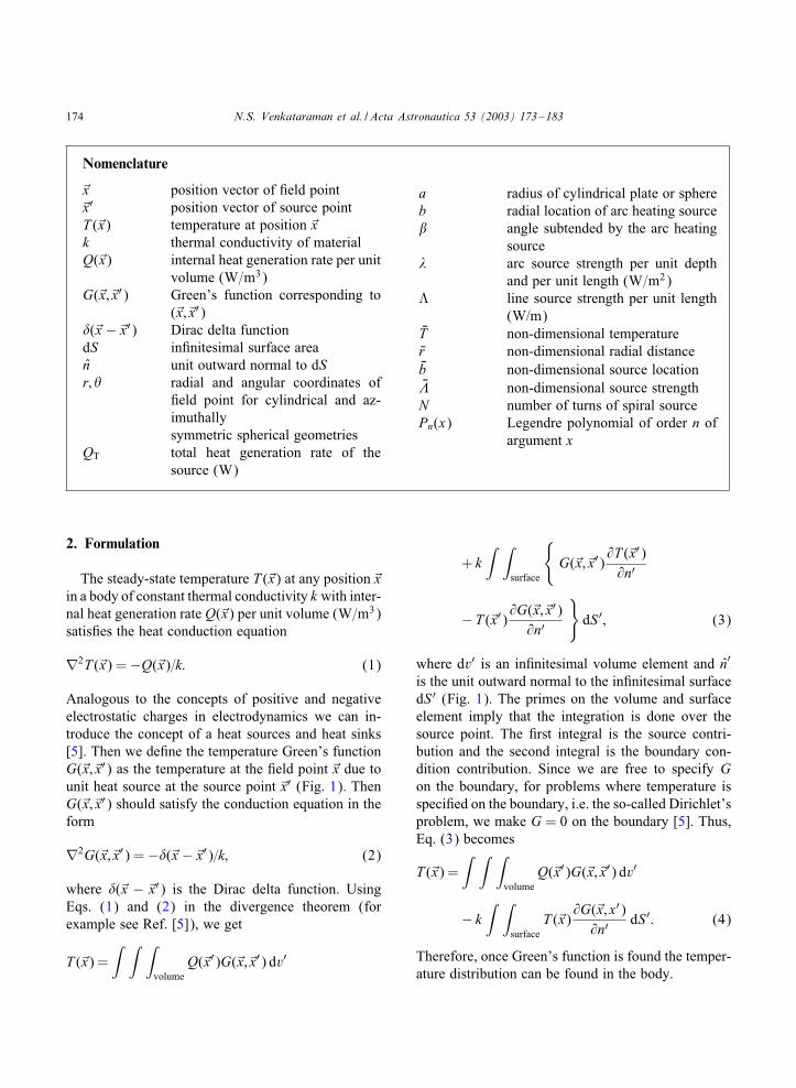
Available online at www.sciencedirect.com Acta Astronautica 53 (2003) 173 – 183 www.elsevier.com/locate/actaastro Temperature distribution in spacecraft mounting plates with discrete heat generation sources due to conductive heat transfer Nellore S. Venkataraman ∗ , Eduardo G. P erez, Iv an Delgado-Vel azquez 1 Department of Mechanical Engineering, University of Puerto Rico, Mayag uez, PR 00680, USA Received 4 May 2001; received in revised form 11 March 2002 Abstract The steady-state temperature distribution in spacecraft mounting plates and components with discrete internal heat generation sources in the form of a thin current carrying wire due to conductive heat transfer has been determined. The heat sources are embedded in a circular plate in the form of a thin circular arc or a spiral and in the case of a sphere as a thin wire running along a diameter. An integral technique using Green’s function is used. It is shown that in these cases an elegant closed-form analytical solution or an “almost analytical solution” can be obtained. The behavior of the non-dimensional temperature on the source strength, location and the geometry is discussed. c 2002 Elsevier Science Ltd. All rights reserved. 1. Introduction When a spacecraft is in the shadow of the earth many of its components and mounting plates are heated by electrical heaters in the form of thin current carrying conductors [1,2]. In this work, we consider the problem of nding the temperature distribution due to heat conduction in a thin circular plate or an innitely long cylinder and a solid sphere whose boundaries are kept at a constant temperature. The circular plate is heated by a thin current carrying wire in the form of a circular arc or a spiral. In the case of the sphere, the heating source is a thin straight wire running along diameter. The physical situa- tion is similar to what is encountered in spacecrafts. The temperature distribution and thermal resistance ∗ Corresponding author. 1 Present address: Xerox Corporation, PSG/PEDU, 800 Phillips Road, Bldg 207-02z, Webster, NY 14580, USA. in satellite mounting plates have been studied by Venkataraman et al. [3] and Venkataraman and Egalon [4] where additional references are cited. While the methods used in these works are adequate for nite sources, they are not suitable for innites- imally thin sources. An integral approach using Green’s function is adopted as this is ideally suited for discrete sources. Green’s function approach has been traditionally used in electrodynamics [5], po- tential theory, uid mechanics and elasticity and to a lesser extent in conduction heat transfer. Beck et al. [6] have summarized the use of Green’s function ap- proach to problems in heat conduction basically using eigenfunction expansion techniques. Here, we use a physical approach to determine the Green’s function analogous to the techniques used in electrostatics and uid mechanics. For the applications considered here we show that this method yields the results in a closed form or in the form an integral which for elegance and the ease and accuracy of computation is far superior to numerical methods such as nite dierence methods. 0094-5765/03/$ - see front matter c 2002 Elsevier Science Ltd. All rights reserved. PII:S0094-5765(02)00201-1
-
Upload
cincinnatstate -
Category
Documents
-
view
1 -
download
0
Transcript of Temperature distribution in spacecraft mounting plates with discrete heat generation sources due to...
Available online at www.sciencedirect.com
Acta Astronautica 53 (2003) 173–183www.elsevier.com/locate/actaastro
Temperature distribution in spacecraft mounting plates withdiscrete heat generation sources due to conductive heat transfer
Nellore S. Venkataraman∗, Eduardo G. P+erez, Iv+an Delgado-Vel+azquez1
Department of Mechanical Engineering, University of Puerto Rico, Mayag�uez, PR 00680, USA
Received 4 May 2001; received in revised form 11 March 2002
Abstract
The steady-state temperature distribution in spacecraft mounting plates and components with discrete internal heat generationsources in the form of a thin current carrying wire due to conductive heat transfer has been determined. The heat sources areembedded in a circular plate in the form of a thin circular arc or a spiral and in the case of a sphere as a thin wire runningalong a diameter. An integral technique using Green’s function is used. It is shown that in these cases an elegant closed-formanalytical solution or an “almost analytical solution” can be obtained. The behavior of the non-dimensional temperature onthe source strength, location and the geometry is discussed.c© 2002 Elsevier Science Ltd. All rights reserved.
1. Introduction
When a spacecraft is in the shadow of the earthmany of its components and mounting plates areheated by electrical heaters in the form of thin currentcarrying conductors [1,2]. In this work, we considerthe problem of =nding the temperature distributiondue to heat conduction in a thin circular plate oran in=nitely long cylinder and a solid sphere whoseboundaries are kept at a constant temperature. Thecircular plate is heated by a thin current carrying wirein the form of a circular arc or a spiral. In the caseof the sphere, the heating source is a thin straightwire running along diameter. The physical situa-tion is similar to what is encountered in spacecrafts.The temperature distribution and thermal resistance
∗ Corresponding author.1 Present address: Xerox Corporation, PSG/PEDU, 800 Phillips
Road, Bldg 207-02z, Webster, NY 14580, USA.
in satellite mounting plates have been studied byVenkataraman et al. [3] and Venkataraman andEgalon [4] where additional references are cited.While the methods used in these works are adequatefor =nite sources, they are not suitable for in=nites-imally thin sources. An integral approach usingGreen’s function is adopted as this is ideally suitedfor discrete sources. Green’s function approach hasbeen traditionally used in electrodynamics [5], po-tential theory, Euid mechanics and elasticity and to alesser extent in conduction heat transfer. Beck et al.[6] have summarized the use of Green’s function ap-proach to problems in heat conduction basically usingeigenfunction expansion techniques. Here, we use aphysical approach to determine the Green’s functionanalogous to the techniques used in electrostatics andEuid mechanics. For the applications considered herewe show that this method yields the results in a closedform or in the form an integral which for elegance andthe ease and accuracy of computation is far superior tonumerical methods such as =nite diIerence methods.
0094-5765/03/$ - see front matter c© 2002 Elsevier Science Ltd. All rights reserved.PII: S0094 -5765(02)00201 -1
174 N.S. Venkataraman et al. / Acta Astronautica 53 (2003) 173–183
Nomenclature
x̃ position vector of =eld pointx̃′ position vector of source pointT (̃x) temperature at position x̃k thermal conductivity of materialQ(̃x) internal heat generation rate per unit
volume (W=m3)G(̃x; x̃′) Green’s function corresponding to
(̃x; x̃′)(̃x − x̃′) Dirac delta functiondS in=nitesimal surface arean̂ unit outward normal to dSr; radial and angular coordinates of
=eld point for cylindrical and az-imuthallysymmetric spherical geometries
QT total heat generation rate of thesource (W)
a radius of cylindrical plate or sphereb radial location of arc heating source� angle subtended by the arc heating
source� arc source strength per unit depth
and per unit length (W=m2)M line source strength per unit length
(W/m)NT non-dimensional temperatureNr non-dimensional radial distanceNb non-dimensional source locationN� non-dimensional source strengthN number of turns of spiral sourcePn(x) Legendre polynomial of order n of
argument x
2. Formulation
The steady-state temperature T (̃x) at any position x̃in a body of constant thermal conductivity k with inter-nal heat generation rate Q(̃x) per unit volume (W=m3)satis=es the heat conduction equation
∇2T (̃x) = −Q(̃x)=k: (1)
Analogous to the concepts of positive and negativeelectrostatic charges in electrodynamics we can in-troduce the concept of a heat sources and heat sinks[5]. Then we de=ne the temperature Green’s functionG(̃x; x̃′) as the temperature at the =eld point x̃ due tounit heat source at the source point x̃′ (Fig. 1). ThenG(̃x; x̃′) should satisfy the conduction equation in theform
∇2G(̃x; x̃′) = −(̃x − x̃′)=k; (2)
where (̃x − x̃′) is the Dirac delta function. UsingEqs. (1) and (2) in the divergence theorem (forexample see Ref. [5]), we get
T (̃x) =∫ ∫ ∫
volumeQ(̃x′)G(̃x; x̃′) dv′
+ k∫ ∫
surface
{G(̃x; x̃′)
@T (̃x′)@n′
−T (̃x′)@G(̃x; x̃′)
@n′
}dS ′; (3)
where dv′ is an in=nitesimal volume element and n̂′
is the unit outward normal to the in=nitesimal surfacedS ′ (Fig. 1). The primes on the volume and surfaceelement imply that the integration is done over thesource point. The =rst integral is the source contri-bution and the second integral is the boundary con-dition contribution. Since we are free to specify Gon the boundary, for problems where temperature isspeci=ed on the boundary, i.e. the so-called Dirichlet’sproblem, we make G = 0 on the boundary [5]. Thus,Eq. (3) becomes
T (̃x) =∫ ∫ ∫
volumeQ(̃x′)G(̃x; x̃′) dv′
− k∫ ∫
surfaceT (̃x)
@G(̃x; x′)@n′
dS ′: (4)
Therefore, once Green’s function is found the temper-ature distribution can be found in the body.

N.S. Venkataraman et al. / Acta Astronautica 53 (2003) 173–183 175
.
n̂
dS′dV′
x′
x
k
Sourcepoint
Field point
Fig. 1. Body of thermal conductivity k.
3. Thin circular plate or in�nitely long cylinder
Green’s function for a thin circular plate or atwo-dimensional (in=nitely long) circular cylindercan be found by the method of images that is com-monly used in electrostatics and potential theory [5]and Euid mechanics [7]. A unit heat source is placedat the source point and a heat sink of unknownstrength is placed at the corresponding inverse point.The strength of the unknown sink is found by thecondition G(̃x; x̃′) = 0 on the boundary. The detailscan be found in Ref. [5]. Green’s function for thecircular plate shown in Fig. 2 is
G(r; ; r′; ′) =1
4�k‘
×ln
{a2 + (r2r′2=a2) − 2rr′ cos( − ′)
r2 + r′2 − 2rr′ cos( − ′)
}; (5)
where ‘ is the depth of the plate. Note that G = 0on the boundary of the plate. G also satis=es reci-procity, i.e., G remains unaltered when the sourcepoint (r′; ′) and the =eld point (r; ) are inter-changed.
4. Spherical conductor
Green’s function for the interior of a sphericalregion with thermal conductivity k can be againfound by the method of images [5]. Green’s function
θ′θ
a
k r
Field point
Source point
r′
Fig. 2. Geometric con=guration of circular plate of thermal con-ductivity k—source and =eld points.
θ
θ′
γ
a
k
Field point
Source point
r
r′
φ
φ′
Fig. 3. Geometric con=guration for sphere of thermal conductivityk—source and =eld points.
for a sphere of radius a and thermal conductivity k asshown in Fig. 3 is
G(r; ; r′; ′) =1
4�k
1√
r2 + r′2 − 2rr′ cos �
− 1√(r2r′2=a2) + a2 − 2rr′ cos �
; (6)
176 N.S. Venkataraman et al. / Acta Astronautica 53 (2003) 173–183
β/2
β/2
θ
a Arc heating
source
b
r
Temperature TB
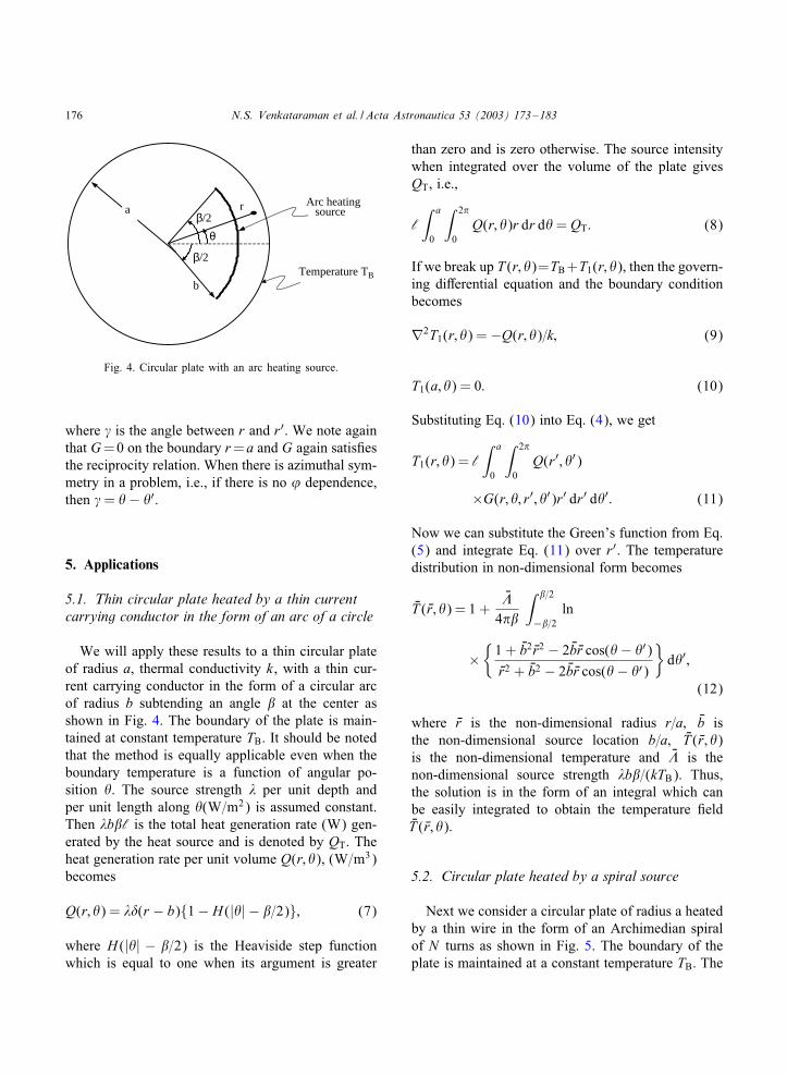
Fig. 4. Circular plate with an arc heating source.
where � is the angle between r and r′. We note againthat G=0 on the boundary r =a and G again satis=esthe reciprocity relation. When there is azimuthal sym-metry in a problem, i.e., if there is no ’ dependence,then � = − ′.
5. Applications
5.1. Thin circular plate heated by a thin currentcarrying conductor in the form of an arc of a circle
We will apply these results to a thin circular plateof radius a, thermal conductivity k, with a thin cur-rent carrying conductor in the form of a circular arcof radius b subtending an angle � at the center asshown in Fig. 4. The boundary of the plate is main-tained at constant temperature TB. It should be notedthat the method is equally applicable even when theboundary temperature is a function of angular po-sition . The source strength � per unit depth andper unit length along (W=m2) is assumed constant.Then �b�‘ is the total heat generation rate (W) gen-erated by the heat source and is denoted by QT. Theheat generation rate per unit volume Q(r; ), (W=m3)becomes
Q(r; ) = �(r − b){1 − H (| | − �=2)}; (7)
where H (| | − �=2) is the Heaviside step functionwhich is equal to one when its argument is greater
than zero and is zero otherwise. The source intensitywhen integrated over the volume of the plate givesQT, i.e.,
‘∫ a
0
∫ 2�
0Q(r; )r dr d = QT: (8)
If we break up T (r; )=TB+T1(r; ), then the govern-ing diIerential equation and the boundary conditionbecomes
∇2T1(r; ) = −Q(r; )=k; (9)
T1(a; ) = 0: (10)
Substituting Eq. (10) into Eq. (4), we get
T1(r; ) = ‘∫ a
0
∫ 2�
0Q(r′; ′)
×G(r; ; r′; ′)r′ dr′ d ′: (11)
Now we can substitute the Green’s function from Eq.(5) and integrate Eq. (11) over r′. The temperaturedistribution in non-dimensional form becomes
NT ( Nr; ) = 1 +N�
4��
∫ �=2
−�=2ln
×{
1 + Nb2 Nr2 − 2 Nb Nr cos( − ′)Nr2 + Nb2 − 2 Nb Nr cos( − ′)
}d ′;
(12)
where Nr is the non-dimensional radius r=a; Nb isthe non-dimensional source location b=a; NT ( Nr; )is the non-dimensional temperature and N� is thenon-dimensional source strength �b�=(kTB). Thus,the solution is in the form of an integral which canbe easily integrated to obtain the temperature =eldNT ( Nr; ).
5.2. Circular plate heated by a spiral source
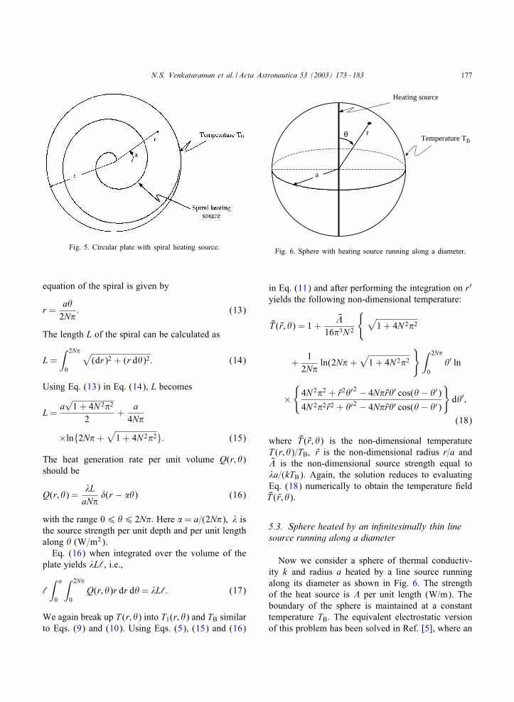
Next we consider a circular plate of radius a heatedby a thin wire in the form of an Archimedian spiralof N turns as shown in Fig. 5. The boundary of theplate is maintained at a constant temperature TB. The
N.S. Venkataraman et al. / Acta Astronautica 53 (2003) 173–183 177
Fig. 5. Circular plate with spiral heating source.
equation of the spiral is given by
r =a
2N�: (13)
The length L of the spiral can be calculated as
L =∫ 2N�
0
√(dr)2 + (r d )2: (14)
Using Eq. (13) in Eq. (14), L becomes
L =a√
1 + 4N 2�2
2+
a4N�
×ln{2N� +√
1 + 4N 2�2}: (15)
The heat generation rate per unit volume Q(r; )should be
Q(r; ) =�LaN�
(r − � ) (16)
with the range 06 6 2N�. Here � = a=(2N�); � isthe source strength per unit depth and per unit lengthalong (W=m2).
Eq. (16) when integrated over the volume of theplate yields �L‘, i.e.,
‘∫ a
0
∫ 2N�
0Q(r; )r dr d = �L‘: (17)
We again break up T (r; ) into T1(r; ) and TB similarto Eqs. (9) and (10). Using Eqs. (5), (15) and (16)
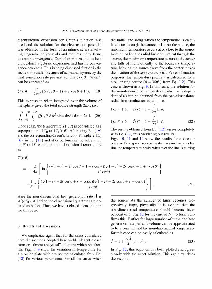
θ r
Heating source
a
Temperature TB
Fig. 6. Sphere with heating source running along a diameter.
in Eq. (11) and after performing the integration on r′
yields the following non-dimensional temperature:
NT ( Nr; ) = 1 +N�
16�3N 2
{ √1 + 4N 2�2
+1
2N�ln(2N� +
√1 + 4N 2�2
}∫ 2N�
0 ′ ln
×{
4N 2�2 + Nr2 ′2 − 4N� Nr ′ cos( − ′)4N 2�2 Nr2 + ′2 − 4N� Nr ′ cos( − ′)
}d ′;
(18)
where NT ( Nr; ) is the non-dimensional temperatureT (r; )=TB; Nr is the non-dimensional radius r=a andN� is the non-dimensional source strength equal to�a=(kTB). Again, the solution reduces to evaluatingEq. (18) numerically to obtain the temperature =eldNT ( Nr; ).
5.3. Sphere heated by an in2nitesimally thin linesource running along a diameter
Now we consider a sphere of thermal conductiv-ity k and radius a heated by a line source runningalong its diameter as shown in Fig. 6. The strengthof the heat source is � per unit length (W/m). Theboundary of the sphere is maintained at a constanttemperature TB. The equivalent electrostatic versionof this problem has been solved in Ref. [5], where an
178 N.S. Venkataraman et al. / Acta Astronautica 53 (2003) 173–183
eigenfunction expansion for Green’s function wasused and the solution for the electrostatic potentialwas obtained in the form of an in=nite series involv-ing Legendre polynomials and requires many termsto obtain convergence. Our solution turns out to be aclosed-form algebraic expression and has no conver-gence problems. This is being discussed further in thesection on results. Because of azimuthal symmetry theheat generation rate per unit volume Q(r; ) (W=m3)can be expressed as
Q(r; ) =�
2�r2 {(cos − 1) + (cos + 1)}: (19)
This expression when integrated over the volume ofthe sphere gives the total source strength 2a�, i.e.,∫ a
0
∫ �
0
∫ 2�
0Q(r; ; �)r2 sin dr d d� = 2a�: (20)
Once again, the temperature T (r; ) is considered as asuperposition of TB and T1(r; ). After using Eq. (19)and the corresponding Green’s function for sphere, Eq.(6), in Eq. (11) and after performing the integrationon ′ and Nr′ we get the non-dimensional temperatureas
NT (r; )
=1 +N�
4�
[ln
{(√
1 + Nr2 − 2 Nr cos + 1 − Nr cos )(√
1 + Nr2 + 2 Nr cos + 1 + Nr cos )
Nr2 sin2
}
−1Nrln
{(√
1 + Nr2 − 2 Nr cos + Nr − cos )(√
1 + Nr2 + 2 Nr cos + Nr + cos )
sin2
} ]: (21)
Here the non-dimensional heat generation rate N� is�=(kTB). All other non-dimensional quantities are de-=ned as before. Thus, we have a closed-form solutionfor this case.
6. Results and discussions
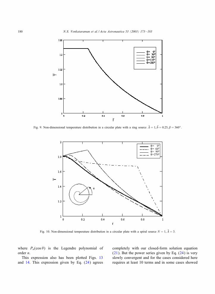
We emphasize again that for the cases consideredhere the methods adopted here yields elegant closedform or “almost analytical” solutions which we cher-ish. Figs. 7–9 show the variation in temperature fora circular plate with arc source calculated from Eq.(12) for various parameters. For all the cases, when
the radial line along which the temperature is calcu-lated cuts through the source or is near the source, themaximum temperature occurs at or close to the sourcelocation. When the radial line does not cut through thesource, the maximum temperature occurs at the centerand falls of monotonically to the boundary tempera-ture. Moving the source away from the center movesthe location of the temperature peak. For con=rmationpurposes, the temperature pro=le was calculated for acircular ring source (� = 360◦) from Eq. (12). Thiscase is shown in Fig. 9. In this case, the solution forthe non-dimensional temperature (which is indepen-dent of ) can be obtained from the one-dimensionalradial heat conduction equation as
For Nr6 b; NT ( Nr) = 1 −N�
2�ln Nb;
For Nr¿ b; NT ( Nr) = 1 −N�
2�ln Nr: (22)
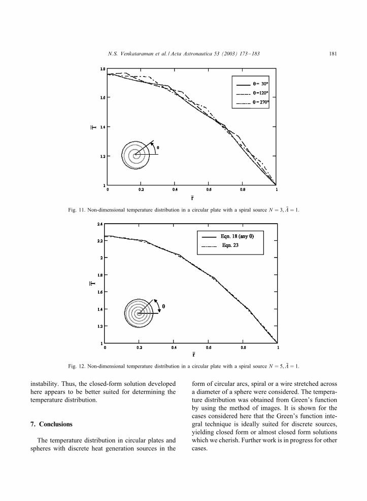
The results obtained from Eq. (12) agrees completelywith Eq. (22) thus validating our results.Figs. 10, 11 and 12 show the results for a circularplate with a spiral source heater. Again for a radialline the temperature peaks whenever the line is cutting
the source. As the number of turns becomes pro-gressively large, physically it is evident that thenon-dimensional temperature should become inde-pendent of . Fig. 12 for the case of N = 5 turns con-=rms this. Further for large number of turns, the heatgeneration rate per unit volume can be approximatedto be a constant and the non-dimensional temperaturefor this case can be easily calculated as
NT = 1 +N N�4
(1 − Nr2): (23)
In Fig. 12, this equation has been plotted and agreesclosely with the exact solution. This again validatesthe method.
N.S. Venkataraman et al. / Acta Astronautica 53 (2003) 173–183 179
Fig. 7. Non-dimensional temperature distribution in a circular plate with arc source N� = 3; Nb = 0:25; � = 60◦.
Fig. 8. Non-dimensional temperature distribution in a circular plate with arc source N� = 1; Nb = 0:75; � = 20◦.
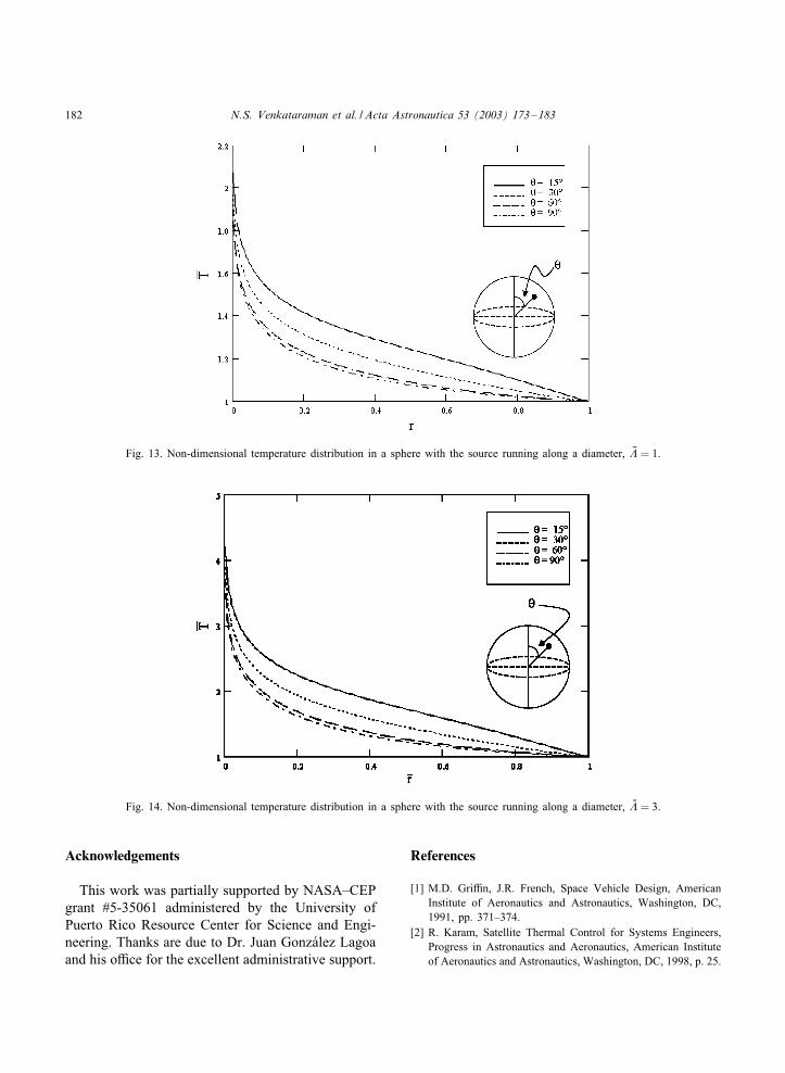
Figs. 13 and 14 show the results for a spherewith a line heat generation source stretching acrossa diameter (Fig. 6). These have been calculatedfrom the closed-form solutions equation (21). Asmentioned before, the electrostatic version of thisproblem has been solved in [5], using an eigen-function expansion for Green’s function and the
results are
NT ( Nr; ) = 1 +( N�
2�
)[ln(1= Nr) +
∞∑j=1
(4j + 1)2j(2j + 1)
×{1 − Nr2j}P2j(cos )
]; (24)
180 N.S. Venkataraman et al. / Acta Astronautica 53 (2003) 173–183
Fig. 9. Non-dimensional temperature distribution in a circular plate with a ring source N� = 1; Nb = 0:25; � = 360◦.
Fig. 10. Non-dimensional temperature distribution in a circular plate with a spiral source N = 1; N� = 3.
where Pn(cos ) is the Legendre polynomial oforder n.
This expression also has been plotted Figs. 13and 14. This expression given by Eq. (24) agrees
completely with our closed-form solution equation(21). But the power series given by Eq. (24) is veryslowly convergent and for the cases considered hererequires at least 10 terms and in some cases showed
N.S. Venkataraman et al. / Acta Astronautica 53 (2003) 173–183 181
Fig. 11. Non-dimensional temperature distribution in a circular plate with a spiral source N = 3; N� = 1.
Fig. 12. Non-dimensional temperature distribution in a circular plate with a spiral source N = 5; N� = 1.
instability. Thus, the closed-form solution developedhere appears to be better suited for determining thetemperature distribution.
7. Conclusions
The temperature distribution in circular plates andspheres with discrete heat generation sources in the
form of circular arcs, spiral or a wire stretched acrossa diameter of a sphere were considered. The tempera-ture distribution was obtained from Green’s functionby using the method of images. It is shown for thecases considered here that the Green’s function inte-gral technique is ideally suited for discrete sources,yielding closed form or almost closed form solutionswhich we cherish. Further work is in progress for othercases.
182 N.S. Venkataraman et al. / Acta Astronautica 53 (2003) 173–183
Fig. 13. Non-dimensional temperature distribution in a sphere with the source running along a diameter, N� = 1.
Fig. 14. Non-dimensional temperature distribution in a sphere with the source running along a diameter, N� = 3.
Acknowledgements
This work was partially supported by NASA–CEPgrant #5-35061 administered by the University ofPuerto Rico Resource Center for Science and Engi-neering. Thanks are due to Dr. Juan Gonz+alez Lagoaand his oUce for the excellent administrative support.
References
[1] M.D. GriUn, J.R. French, Space Vehicle Design, AmericanInstitute of Aeronautics and Astronautics, Washington, DC,1991, pp. 371–374.
[2] R. Karam, Satellite Thermal Control for Systems Engineers,Progress in Astronautics and Aeronautics, American Instituteof Aeronautics and Astronautics, Washington, DC, 1998, p. 25.

N.S. Venkataraman et al. / Acta Astronautica 53 (2003) 173–183 183
[3] N.S. Venkataraman, H.P. Cardoso, O.B.de. Oliveira Filho,Thermal resistance of convectively cooled plates with appliedEux and internal heat generation, Acta Astronautica 9 (1982)613–620.
[4] N.S. Venkataraman, C.O. Egalon, Temperature distribution insatellite mounting plates due to conductive heat transfer, ActaAstronautica 17 (1988) 1127–1135.
[5] J.D. Jackson, Classical Electrodynamics, 3rd Edition, Wiley,New York, 1999 (Chapters 1–3).
[6] J.V. Beck, K.D. Cole, A. Haji-Sheikh, B. Litkouhi, HeatConduction Using Green’s Functions, 1st Edition, HemispherePublishing Corporation, Washington, DC, 1992 (Chapter 1).
[7] Z.U.A. Warsi, Fluid Dynamics—Theoretical andComputational Approaches, 2nd Edition, CRC Press,Washington, DC, 1999, p. 665.