Temperature dependence of macrobending loss in all-fiber bend loss edge filter
20
Dublin Institute of Technology ARROW@DIT Articles School of Electronic and Communications Engineering 1-1-2008 Temperature dependence of macrobending loss in all-fiber bend loss edge filter Pengfei Wang Dublin Institute of Technology, [email protected] Yuliya Semenova Dublin Institute of Technology Gerald Farrell Dublin Institute of Technology This Article is brought to you for free and open access by the School of Electronic and Communications Engineering at ARROW@DIT. It has been accepted for inclusion in Articles by an authorized administrator of ARROW@DIT. For more information, please contact [email protected]. Recommended Citation Wang, Pengfei and Semenova, Yuliya and Farrell, Gerald: Temperature dependence of macrobending loss in all-fiber bend loss edge filter. Optics Communications, Vol. 281, pp. 4312-4316 , 2008.
Transcript of Temperature dependence of macrobending loss in all-fiber bend loss edge filter

Dublin Institute of TechnologyARROW@DIT
Articles School of Electronic and CommunicationsEngineering
1-1-2008
Temperature dependence of macrobending loss inall-fiber bend loss edge filterPengfei WangDublin Institute of Technology, [email protected]
Yuliya SemenovaDublin Institute of Technology
Gerald FarrellDublin Institute of Technology
This Article is brought to you for free and open access by the School ofElectronic and Communications Engineering at ARROW@DIT. It hasbeen accepted for inclusion in Articles by an authorized administrator ofARROW@DIT. For more information, please [email protected].
Recommended CitationWang, Pengfei and Semenova, Yuliya and Farrell, Gerald: Temperature dependence of macrobending loss in all-fiber bend loss edgefilter. Optics Communications, Vol. 281, pp. 4312-4316 , 2008.

Temperature dependence of macrobending
loss in all-fiber bend loss edge filter
Pengfei Wang, Yuliya Semenova, Gerald Farrell
Applied Optoelectronics Center, School of Electronic and Communications Engineering, Dublin
Institute of Technology, Kevin Street, Dublin 8, Ireland
E-mail: [email protected]
Abstract: A theoretical model for macrobending-induced temperature dependent loss
(TDL) for a standard singlemode fiber (SMF28) with dual coating layers is presented,
with good agreement demonstrated between theoretical calculations and experimental
results. The impact of temperature on two examples of an all-fiber based edge filter is
also investigated theoretically and experimentally and using the developed model, it is
shown that it is possible to predict the impact of temperature variations on an all-fiber
based edge filter.
Keyword: Temperature dependent loss, macrobending loss, singlemode fiber, SMF28,
edge filter
1. Introduction
It is well known that temperature change causes significant temperature
dependent loss at a bend in a singlemode fiber. Temperature dependence for fiber
macrobending loss has been presented in several published papers both theoretically
and experimentally [1-4]. The fibers employed in most of the previous published
works had a structure that consisted of a fiber core, cladding and a single coating
layer.
The influence on bend loss of whispering gallery modes (WGMs) is an important
issue considered by many authors, with some publications considering the practical
application of WGMs in developing an interferometric sensor [3, 4]. WGMs in bent
optical fibers are excited when the radiating rays are reflected at interfaces such as the
coating–air boundary or cladding–coating boundary. Such WGMs can recouple to the
propagating mode in the fiber core and can result in wavelength dependent

interference effects.
Most existing commercial standard singlemode fibers (such as SMF28) have two
coating layers, which offer protection and stability to the fiber core and cladding.
SMF28 fiber has been widely employed for optical communication and sensing.
However, previously published investigations of the temperature dependent loss of
bending fiber have been focused on the prediction of phase shift in the core modes
induced by interference and no existing formulas have been presented for the
modeling of theoretical temperature dependent loss of standard singlemode fiber with
multiple coating layers. In this paper, the theoretical prediction of temperature
dependent loss for an SMF28 fiber based on perturbation theory is presented for the
first time.
One justification for the investigation is that recently macrobending singlemode
fiber with an absorbing layer (such as SMF28 or 1060XP) has been investigated and
optimized for use in a bend loss based edge filter for a rapid wavelength measurement
system [5-7]. Changes in macrobending loss with temperature will alter the spectral
responses of the fiber edge filter leading to inaccuracy in the measurement of
wavelength.
For the bent SMF28 singlemode fiber employed in this paper, the existence of the
coating layers produces WGMs for the bent fiber because of reflections at the
interfaces at the boundaries of the cladding–coating, the inner and outer coating layers
and the coating–air layers. However, for a macrobending fiber based edge filter
application, in order to maintain a quasi-linear filter transmission response with
wavelength [5], an absorbing layer is required on the surface of the outer coating layer
to absorb the radiated light in the outer coating and thus suppress the formation of
WGMs at the coating–air interface. In the model the absorption layer is taken account
of by assuming an infinite outer coating thickness.
In this paper, we report on both a theoretical and an experimental investigation of
the bending induced temperature dependent loss of standard SMF28 singlemode fiber.
The operating temperature is controlled within the range 0oC to 70
oC, as the SMF28
polymer coatings would suffer degradation if the temperature is higher than 70oC. The
corresponding experimental results show a good agreement with the results of the
theoretical modeling. Both the theoretical and experimental results suggest that both
the thermal expansion coefficient (TEC) and thermo-optic coefficient (TOC) of the
fiber materials have a significant influence on macrobending loss.
2. Modeling for temperature dependent loss of singlemode fiber with dual
coating layers
As is well known, the refractive index of an optical material depends on
temperature and wavelength. For silica material, the refractive index varies with the
temperature as a result of lattice deformations in the silica matrix structure. For a fiber
polymer coating material, the variation of the refractive index is induced by the
amplitude of vibrations of polymer molecules and results in the translation and

distortion of the cross-linked network within the polymer long molecule structure.
A series of theoretical formulations have been developed [8-12] for the prediction
of the macrobending loss of singlemode fibers. For example, the theoretical modeling
of fiber bending loss based on weak perturbance of the guide field for a multi-coating
structure (such as SMF28) has been presented in Ref. [12], along with comparisons
with the modeling of fiber macrobending loss which were presented in previous
publications [8-11]. Based on the satisfactory agreement between the calculated and
experimental results for SMF28 fiber in Ref. [12], the model presented in Ref. [12] is
employed in this paper to predict the temperature dependent loss of bending SMF28
singlemode fiber.
Fig. 1 gives the schematic cross-section of a bending fiber with multiple cladding
or coating layers. The bending radius is denoted by R. For the q-th (q is a positive
integer, q=1, 2, 3…) layer of fiber, its refractive index is nq and the thickness is xq-xq-1.
q=1 represents the core and q=2 represents the cladding layer.
As a starting point, the analysis in Ref. [10] is used, In Ref. [10], the fiber was
assumed to consist of a core, cladding (q=2) and an infinite coating (q=3). When the
fiber is bent, the Fourier transform scalar field in the cladding and infinite coating
regions (q=2, 3) in the y-direction can be expressed as:
2 2 2 2 2
0
2( , ) (1 ) ( , ) 0t q q q
xx k n x
Rψ ζ β ζ ψ ζ ∇ + + − − =
(1)
where ( , )q
xψ ζ is the Fourier transform along the y-direction of the transverse field
component in region q; ζ is the conjugate variable for the Fourier transform in
y-direction; q
n is the refractive index in region q; k is the well know wavenumber in
vacuum at the wavelength λ , it can be expressed as 2k πλ= ;
21
x
R
+
is the
correction factor for 2
qn to take account of the change induced by the stress-optic
effect; and 0β is the complex propagation constant, the imaginary part of which is
the bend loss coefficient. Following solution by an inverse Fourier transform of the
y-field, equation (1) can be treated as [11]:
1
( , ) ( ) ( ) ( ) ( ) exp( )2
q q i q q i qx y D B X H A X i y dψ ζ ζ ζ ζ
π
+∞
−∞
= + ⋅ − ∫ (2)
where
+−+
= )
21(
2),( 2222
32
22 R
xnk
nk
RxX q
q
ζβζ , and iB and iA are Airy
functions, respectively. Both ( )qD ζ and ( )qH ζ are the Fourier spectra which were

previously defined in Ref. [10]. For the outermost infinite layer, the relation between
( )qD ζ and ( )qH ζ can be defined as ( ) ( )q qH iDζ ζ= − . Thus by extending the
model, for any two adjacent layers in the fiber structure, given the continuous
boundary conditions of the field, the adjacent fields are given by [12]:
1 1 1 1
' ' ' '
1 1 1 1
( ) [ ( , )] [ ( , )] ( ) [ ( , )] [ ( , )]
( ) [ ( , )] [ ( , )] ( ) [ ( , )] [ ( , )]
q i q q q i q q q i q q q i q q
q i q q q i q q q i q q q i q q
D B X x H A X x D B X x H A X x
D B X x H A X x D B X x H A X x
ζ ζ ζ ζ ζ ζζ ζ ζ ζ ζ ζ
+ + + +
+ + + +
+ = + + = +
(3)
which has the form of ( )( )
( )( )
=
+
+
ζζ
ζζ
1
1
2221
1211
j
j
j
j
H
D
MM
MM
H
D. Considering the core and
cladding layer, the relationship between ( )ζ1D and ( )ζ1H is obtained as the
following
( ) ( ) ( )11 121 1 1
21 22
M i MD H GH
M i Mζ ζ ζ
+= =
+ (4)
Given the boundary condition at the interface between the core layer and cladding
layer, then:
( ) [ ] ( ) [ ] ( )2 2
1 2 1 1 2 12 2
( , ) ( , ) expi iD B X x H A X x aπ
ζ ζ ζ ζ γ ζγ ζ
+ = − ++
(5)
Therefore, ( )( )
[ ] [ ]),(),(
exp
1111
22
22
1 ζζ
ζγζγ
π
ζxXAxXGB
a
Hii +
+−+
= and finally according to
perturbation theory the bend loss factor can be expressed as:
( ) [ ]2
1 22 2
1
2 2 Im (0, )2 ( )
iH A X dV K a
κα ζ ζ ζ
πβ γ
∞
−∞
= −
∫ (6)
This factor can be used for the calculation of bend loss for a fiber with one or more
coating layers, and the above formulas are used in the investigation which follows of
the temperature dependence of bending loss for SMF28 fiber.
In most previously published papers [9-11], the effective bend radius (a
wavelength dependent correction factor) was employed to take account of stress
induced refractive index changes in order to achieve a good agreement between the
modeled results and the experimental results. However in our previously published
work [12], the good agreement between the theoretical model and experimental
results for Corning standard singlemode fiber-SMF28 showed that for this particular
fiber, the so-called “effective bending radius” used to take account of macrobending
stress, was not required. SMF28 is the fiber type employed in the investigations of

temperature dependent loss in this paper. For the theoretical model employed in this
paper, to maintain generality, the stress-optic effect is included in the model and all
formulas, but in applying the model for SMF28 fiber, the value of the correction
factor is set equal to 1.
For the fiber used in this paper the key parameters at 20oC are shown in Table 1:
While most of the parameter values are published by the manufacturer of SMF28,
some TEC and TOC values were extracted from Ref. [13].
With the parameters of TEC and TOC listed in the Table 1, the corresponding
temperature dependent thickness and refractive index of each fiber layer at a
temperature T can be expressed as:
( )1T q q qx x x Tα−= − ⋅ ⋅∆ (7)
T q q
n n Tβ= ⋅ ⋅∆ (8)
where q
x is the distance from the fiber core center to the q-th fiber layer boundary as
shown in Figure 1; q
α is the TEC of the q-th layer of fiber material, q
β is the TOC
of the q-th layer of fiber material and T∆ is the difference in temperature with
respect to 20oC.
A bending singlemode SMF28 fiber with dual coating layers and an absorbing
layer can be treated as core-cladding-primary coating-infinite coating structure. In the
previous publications [8-12], it was found that radiation, which is launched from the
fiber core at the bend enters the coating region(s) of the fiber and thus it is important
in principle to consider the effect of absorption within the coating in modeling the
behavior of a bent fiber. However in the theoretical model in this case, we assume an
infinite outer coating thickness, which suppresses the evolution of strong WGMs that
otherwise could arise at the coating-air interface, where the refractive index difference
is 0.5294. Experimentally an absorbing layer is applied to the surface of the outer
fiber coating to achieve the same effect. WGMs also evolve at the interface between
the coatings, where there is a small refractive index change (0.0508). However the
actual absorption coefficient of the coating layers is in any event very low. Given that
the coating layers are 62.5 microns thick, the coating absorption loss is less than 0.02
dB at a wavelength of 1550 nm and is thus not considered significant enough for
inclusion in the model.
In Figure 2 (a), the calculated bend losses are shown for two different
temperatures 0oC and 70
oC. From this figure one can see that the bend loss at either
temperature does not increase monotonically as the bending radius decreases. For
example, bend losses for a bending radius of 9 mm are larger than those for a bending
radius of 8.5 mm. This is due to the coherent coupling between the fundamental
propagation mode and the reflected radiation from two interfaces: the cladding-inner
coating interface and the inner coating-outer coating interface. These so-called
whispering-gallery modes have a significant effect on the bend loss characteristics.
The temperature dependent parameters TOC and TEC have a significant impact on
the interference process and thus there are a significant changes in bend loss with
temperature, which are also sensitive to the bend radius value, in particular below 9.5
mm. Overall a consequence of the fact that bend loss is not a monotonic function of
bend radius is that when the temperature changes from 0oC and 70
oC, the TDL at
different bent radii (shown in Figure 2 (b)) displays significant variations in value and
also changes sign.
Figure 2 (b) shows the calculated difference in macrobending loss for two
temperatures, 0oC and 70
oC, as a function of different bend radius ranging from 8 to
12.5 mm, where the bending fiber length is 10 turns and the wavelength is 1550 nm.
The calculation was carried out by applying the corresponding TEC and TOC
parameters of SMF28 fiber into the theoretical model described above. In Fig. 2 (b),
one can also see that the calculated macrobending loss difference between 0oC and
70oC is very sensitive to the bend radius when the bend radius ranges from 8 to 9.5
mm due to the significant difference of bend losses between 0oC and 70
oC presented
in Fig. 2 (a). The maximal bend loss difference in Fig. 2 (b) is -32.67 dB for a bend
radius of 9 mm.
3. Experimental results and discussion
Fig. 3 shows the experimental setup used for the measurement of temperature
dependent loss; the SMF28 singlemode fiber is wrapped to form bend loops around a
series of precisely dimensioned metal mandrels, with each mandrel providing a
different usable diameter. The beginning and end of the bending fiber is fixed by a
two-part epoxy to improve mechanical stability. The bending fiber was connected to a
tunable laser and an optical spectrum analyser. The tunable laser has an output power
range from +7 dBm to -7 dBm. Both the bending fiber with an outer absorbing layer
and mandrel were attached to a thermoelectric Peltier cooler, which is controlled by a
digital Temperature Controller (ITC 510, Thorlabs), while a digital resistance
thermometer sensor probe is attached to the mandrel to accurately measure the
temperature.
As presented in Ref. [1-3, 14], a bending singlemode fiber without an outer
absorbing layer is attractive for applications such as thermo-optic interferometric
sensing using the so-called whispering gallery mode, as fiber bends have a significant
influence on the whispering gallery mode. However, a bending SMF28 fiber which
does have an absorbing layer is needed in an all-fiber ratiometric wavelength
measurement application [6, 12]. Thus the temperature dependent measurements of
bending fiber are carried out with an absorbing layer to suppress the whispering
gallery mode.
In order to better characterize the temperature dependent loss, the temperature
dependent loss value is defined as the difference in bend loss between 0oC and 70
oC
thus:
70 0o oC C
TDL BL BL= − (9)

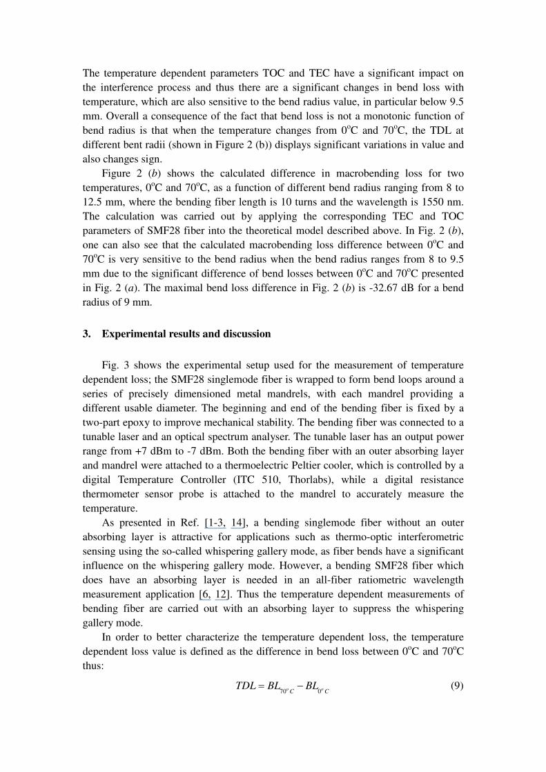
Using this formula, the measurements of bend loss of the SMF28 are carried out
for discrete bending radii ranging from 8 to 12 mm at a wavelength of 1550 nm at
temperatures of 0oC and 70
oC. In practice, because of the finite diameter of SMF28
fiber, the radius of the fiber should be treated as a part of bend radius, thus 0.125mm,
the radius of SMF28 fiber, is added to each mandrel radius. In Fig. 4, both the
theoretical modeling (solid line) and experimental temperature dependent loss results
(star points) as a function of different bending radii are presented, from which one can
see that the theoretical modeling of temperature dependent loss shows a reasonable
agreement with the experimental results. The discrepancy between the calculated
temperature dependent loss and measured results could be induced by the limited
physical accuracy of each bend radius and the scalar approximation modeling of
bending loss.
The primary concern in this work is to study the impact of temperature on an
all-fiber based edge filter. Using the model above, it is possible to predict the impact
of temperature variations on an all-fiber based edge filter. We investigate this
temperature dependence by measuring the bend loss for two different edge filters over
the range 0oC and 70
oC, in 5
oC increments. Both of the edge filters have bending
radii equal to those which have been investigated in our previous publication [15].
The two cases of fiber edge filters are, case 1) a bending length of 10 turns (is 667.59
mm) for the bending radius of 10.5+0.125 mm and case 2) a bending length of 20
turns (is 1272.35 mm) for a bending radius of 10+0.125 mm,
In the measured bend loss results, both the transition loss which exists in the
section between the bent section and the straight fiber, and the insertion loss which
includes the interconnection loss and splicing loss, are deducted from the total
transmission loss to obtain the “pure” bend loss within the bent section.
In Figure 5 (a) and 5 (b), the variation in the edge filter loss with temperature at
1550 nm is presented for two different bend radii/bend length combinations. The
Figures show both experimental and modeled results for both single and dual coating
layer models. The calculated TDLs using a dual coating layer model are in reasonable
overall agreement with the experimental results. It is clear also that the single layer
model, while it may be accurate at predicting loss at a fixed temperature of 20oC, is
not adequate for predicting the variation of loss with temperature. Also from Fig. 5 (a)
and (b), one can see that wave-like variations exist in both modeled and measured
temperature dependent loss results.
A physical interpretation of these results is as follows. In the theoretical model
with single-coating layer, the fiber coating is assumed to be infinitely thick and hence
the radiation entering the coating layer from the cladding propagates away from the
fiber without any subsequent reflection. This explanation is consistent with the
monotonic behaviour of the dashed-dot curves in Fig.5 (a) and (b). In the theoretical
model with dual-coating layer, the primary coating layer has a finite thickness and the
secondary coating layer is assumed to be infinitely thick. Hence radiation entering the
primary coating from the cladding is partially reflected at the first interface of the
cladding-primary coating layer, and again at the second interface of the
primary-secondary coating layer. The finite thickness of the primary coating layer

combined with the index differences on either side form in effect a simple Fabry-Perot
interferometer. Therefore as both the refractive index and thickness of the primary
coating varies with changes in temperature, at a fixed wavelength, the fraction of
incident radiation in the primary coating that is reflected back into the cladding
toward the core will vary periodically. This would account for the oscillations in the
solid curves in the Fig.5 (a) and (b).
In Figure 5 (a) and 5 (b), the discrepancy between the calculated TDLs and
measured results could be caused by: 1) the approximations made in the calculation.
The scalar approximation theory is built on a base of perturbation theory, and the
interface of between the fiber cladding and infinite coating layer was treated as an
infinite plane and the light field within the core is approximated by the unperturbed
field of the straight fiber with an infinite cladding as mentioned in Section 2; 2)
Temperature induced mechanical stress, for example asymmetric expansion between
the primary and secondary coating layer as temperature changes. In table 1, one can
see that the TEC values for the primary and secondary coatings are significantly
different. This means that as temperature changes, varying stress forces will be
induced between the coatings, increasing overall stress and perturbing the loss
measurements. The theoretical and experimental work is ongoing on these issues.
4. Conclusion
In this paper, macrobending induced temperature dependent losses for a standard
singlemode fiber (SMF28) have been investigated both theoretically and
experimentally. The calculations of temperature dependent loss of bending SMF28
fiber are also presented based on perturbation theory and it shown that the
developed model can be utilized to successfully predict the temperature dependence
of an all-fiber bend loss edge filter, where the fiber has a dual coating.
Reference
1. R. Morgan, J. S. Barton, P. G. Harper and J. D. C. Jones, “Temperature dependence of
bending loss in monomode optical fibres,” Electron. Lett. Vol. 26 No. 13, pp. 937-939
(1990).
2. F. M. Haran, J. S. Barton and J. D. C. Jones, “Bend loss in buffered over-moded optical fibre:
LP11mode and 'whispering gallery' mode interaction,” Electron. Lett. Vol. 30 No. 17, pp.
1433-1434 (1994).
3. F. M. Haran, J. S. Barton, S. R. Kidd and J. D. C. Jones, “Optical fibre interferometric
sensors using buffer guided light,” Meas. Sci. Technol. Vol. 5, pp. 526-530 (1994).
4. Y.-G. Han, J. H. Lee and S. B. Lee, “Discrimination of bending and temperature sensitivities
with phase-shifted long-period fiber gratings depending on initial coupling strength,” Opt.
Exp. Vol. 12 No. 14, pp. 3204-3208 (2004).
5. Q. Wang, G. Farrell, T. Freir, G. Rajan, and P. Wang, “Low-cost wavelength measurement
based on a macrobending single-mode fiber,” Opt. Lett., Vol. 31, No. 12, pp. 1785-1787
(2006).

6. Q. Wang, G. Farrell and T. Freir, "Study of transmission response of edge filters employed in
wavelength measurements," Appl. Opt., Vol. 44, No.36, pp. 7789-7792 (2005).
7. P. Wang, G. Farrell, Q. Wang and G. Rajan, “An optimized macrobending-fiber-based edge
filter”, IEEE Photon. Technol. Lett., Vol. 19, No. 15, pp. 1136-1138 (2007).
8. C. Vassallo, “Perturbation of a LP mode of an optical fibre by a quasi-degenerate field: a
simple formula,” Opt. & Quantum Electron. Vol. 17, No. 3, pp. 201-205 (1985).
9. I. Valiente and C. Vassallo, “New formalism for bending losses in coated single-mode optical
fibres,” Electron. Lett., Vol. 25, No. 22, pp. 1544-1545 (1989).
10. H. Renner, “Bending losses of coated single-mode fibers: a simple approach,” J. Lightwave
Technol., Vol. 10, No. 5, pp. 544-551 (1992).
11. L. Faustini and G. Martini, “Bend loss in single-mode fibers,” J. Lightwave Technol., Vol. 15,
No.4, pp. 671-679 (1997).
12. Q. Wang, G. Farrell, and T. Freir, “Theoretical and experimental investigations of macro-bend
losses for standard single mode fibers,” Opt. Exp., Vol. 13, No. 12, pp. 4476-4484 (2005).
13. C.-C. Lai, W.-Y. Lee and W.-S. Wang, “Gamma radiation effect on the fiber Fabry–Pérot
interference sensor,” IEEE Photon. Technol. Lett., Vol. 15, No. 8, 1132-1134 (2003).
14. S. H. Nam and S. Yin, “High-temperature sensing using whispering gallery mode resonance
in bent optical fibers,” IEEE Photon. Technol. Lett., Vol. 17, No. 11, pp. 2391-2393 (2005).
15. Q. Wang, G. Rajan, P. Wang, and G. Farrell, “Polarization dependence of bend loss for a
standard singlemode fiber,” Opt. Express, Vol. 15, No. 8, pp. 4909-4920 (2007).

Figure captions
Fig. 1 Cross-section of a bending fiber with multiple coating layers.
Fig. 2 (a) Calculated macrobending loss for SMF28 fiber at the temperature of 0oC
and 70oC, respectively; (b) Calculated result of difference of macrobending loss for
SMF28 fiber between 0oC and 70
oC at the wavelength of 1550 nm, the bending length
is 10 turns.
Fig. 3 Experimental setup for measuring temperature dependent loss of macrobending
fiber.
Fig. 4 Calculated and measured bend loss of SMF28 as a function of bend radius at
wavelength 1550 nm with a bending length of 10 turns.
Fig. 5 Modeled and measured macrobending loss results for temperature ranging from
0 to 70oC at a wavelength of 1550 nm, the bending radius is a) 10.5+0.125 mm with a
bending length of 10 turns; b) 10+0.125 mm with a bending length of 20 turns.

Table caption
Table 1 Parameters of the standard Corning SMF28 CPC6 dual coating singlemode
fiber; (the refractive index values are defined at a wavelength of 1550 nm at the room
temperature, about 20oC)

Fig. 1
Core: n1
n2 n3 nq
x1 x2 xq-1
R nq-1
xq-2 0
y

Fig. 2 (a)
8 8.5 9 9.5 10 10.5 11 11.5 12 12.50
10
20
30
40
50
60
70
Bend radius (mm)
Bend loss (
dB
)
Calculated bend loss at 70oC
Calculated bend loss at 0oC

Fig. 2 (b)
8 8.5 9 9.5 10 10.5 11 11.5 12 12.5-35
-30
-25
-20
-15
-10
-5
0
5
10
15
Bend radius (mm)
∆B
end loss (
dB
)
Modeling results

Fig. 3
Semiconductor
thermo-electric Peltier cooler
Optical Spectrum Analyzer Tunable Laser
Temperature Combi Controller
Temperature Sensor
Mandrel
Resistance temperature probe
Fig. 4
8 8.5 9 9.5 10 10.5 11 11.5 12 12.5-35
-30
-25
-20
-15
-10
-5
0
5
10
15
Bend radius (mm)
∆B
end loss (
dB
)
Modeling result
Experimental data

Fig. 5a
0 10 20 30 40 50 60 709
9.5
10
10.5
11
11.5
12
12.5
13
Temperature (oC)
Bend loss (
dB
)
Calculated TDL results with dual coating model
Calculated TDL results with single coating model
Measured results

Fig. 5b
0 10 20 30 40 50 60 709
9.5
10
10.5
11
11.5
12
12.5
Temperature (oC)
Bend loss (
dB
)
Calculated TDL results with dual coating model
Calculated TDL results with single coating model
Measured results

Table 1
SMF28 fiber Core Cladding Primary coating Secondary coating
Refractive index 1.4504 1.4447 1.4786 1.5294
Radius (µm) 4.15 62.5 95 125
TEC α (K-1
) 5.5×10⁻⁷
5.5×10⁻⁷
800×10-7
<100×10-7
TOC β (K-1
) ≈1×10⁻⁵
≈1×10⁻⁵
-2.9×10⁻⁴
—