Influence of fiber manufacturing tolerances on the spectral response of a bend loss based all-fiber...
22
Dublin Institute of Technology ARROW@DIT Articles School of Electronic and Communications Engineering 2008-01-01 Influence of fiber manufacturing tolerances on the spectral response of a bend loss based all-fiber edge filter Pengfei Wang Dublin Institute of Technology, [email protected] Gerald Farrell Dublin Institute of Technology, [email protected] Yulia Semenova Dublin Institute of Technology, [email protected] Ginu Rajan Dublin Institute of Technology This Article is brought to you for free and open access by the School of Electronic and Communications Engineering at ARROW@DIT. It has been accepted for inclusion in Articles by an authorized administrator of ARROW@DIT. For more information, please contact [email protected], [email protected]. Recommended Citation Wang, Pengfei et al: Influence of fiber manufacturing tolerances on the spectral response of a bend loss based all-fiber edge filter. Applied Optics, Vol.47, 16, 2008, pp.2921-2925.
Transcript of Influence of fiber manufacturing tolerances on the spectral response of a bend loss based all-fiber...
Dublin Institute of TechnologyARROW@DIT
Articles School of Electronic and CommunicationsEngineering
2008-01-01
Influence of fiber manufacturing tolerances on thespectral response of a bend loss based all-fiber edgefilterPengfei WangDublin Institute of Technology, [email protected]
Gerald FarrellDublin Institute of Technology, [email protected]
Yulia SemenovaDublin Institute of Technology, [email protected]
Ginu RajanDublin Institute of Technology
This Article is brought to you for free and open access by the School ofElectronic and Communications Engineering at ARROW@DIT. It hasbeen accepted for inclusion in Articles by an authorized administrator ofARROW@DIT. For more information, please [email protected], [email protected].
Recommended CitationWang, Pengfei et al: Influence of fiber manufacturing tolerances on the spectral response of a bend loss based all-fiber edge filter.Applied Optics, Vol.47, 16, 2008, pp.2921-2925.
Influence of fiber manufacturing tolerances on the
spectral response of a bend loss based all-fiber edge
filter
Pengfei Wang, Gerald Farrell, Yuliya Semenova, Ginu Rajan
Applied Optoelectronics Center, School of Electronics and Communication
Engineering, Dublin Institute of Technology, Kevin Street, Dublin 8, Ireland
*Corresponding author: [email protected]
Abstract: It is shown that manufacturing tolerances of the fiber parameters bend
radius and NA significantly influence the fiber bend loss performance and spectral
response of a fiber-based edge filter. A theoretical model, validated by experimental
results, is used to determine the changes in key spectral parameters for an edge filter,
resulting from changes within their manufacturing tolerance range, for both the bend
radius and NA. Finally is shown that bend-radius tuning during fabrication of such
filters is a means of mitigating the effect of manufacturing variations.
Keywords: Singlemode fiber, manufacturing tolerance, bend loss, edge filter
OCIS codes: 120.4820, 120.4570, 060.2310
1. Introduction
Fiber bend loss has been previously investigated for application in areas such as
fiber-optic sensing and communications [1-3]. Recently, it was shown that fiber bend
loss could be used as the basis of an edge filter for an all-fiber ratiometric wavelength
measurement system [4-7]. Based on the previously published work for fiber bend
loss [8-10], both theoretical and experimental results have shown that both the bend
radius and fiber length have a significant influence on the fiber bend loss [6, 7].
In addition, in practice, the fiber bend loss will be sensitive to the fiber’s own
parameters, such as fiber core radius, refractive index and so on. Given the
manufacturing tolerances for singlemode fiber, small variations in fiber parameters
are unavoidable. All of these parameter tolerances resulting from the manufacturing
process may significantly affect the resulting ratio response of a fiber based
ratiometric wavelength measurement system. Therefore, it is highly desirable to
investigate the influence of these fiber parameter variations on the response of fiber
bend loss based edge filters.
In past work, both fiber bend loss theoretical modeling and experiments were
carried out on SMF28 fiber with a multi-turn structure and 1060XP fiber with a
compact single-turn structure, e.g., bend radius of 11 mm with 22 turns in Ref. [6],
and bend radius in 10.5 mm with single turn in Ref. [7]. In order to evaluate the fiber
bend loss performance of a fiber edge filter employed in a wavelength measurement
system, two important parameters, baseline loss and discrimination range have been
also defined [6, 7].
In this paper, the dependences of fiber bend loss on parameter tolerances are
presented for the fiber core radius and the numerical aperture (NA) value. Through
examination of the dependence of bend loss behavior on the parameters of bend loss
sensitive singlemode fiber-1060XP, it is found that these small variations in these
parameters have a significant impact on the spectral response of the fiber bend loss
edge filter. We also show that bend-radius tuning during fabrication of such filters is a
means of mitigating the effect of manufacturing variations.
2. Design of a 1060XP based fiber edge filter
Fig. 1 (a) shows a fiber edge filter used within a ratiometric wavelength measurement
system. The input signal is split into two equal signals. One passes through the fiber
bend loss edge filter (upper arm) and the other passes through a reference arm (lower
arm). Photodiodes are placed at the ends of both arms. By measuring the ratio of the
electrical outputs of the two photodiodes, we can determine the wavelength of the
input signal assuming a suitable calibration has taken place. The fiber bend loss edge
filter, for a measurable wavelength range from λ1 to λ2, provides a strong
monotonically increasing wavelength dependent attenuation (discrimination range),
from a given lower start wavelength (baseline loss, λ1) to an end wavelength λ2 [see
Fig. 1(b)].
In our previously published work on wavelength ratiometric measurements [4, 5],
it was found that with higher slope values for the transmission response of the edge
filters for a given measurable wavelength range, the output ratio R, which was
measured by a dual channel power meter, diverged from the actual transmission
response of the edge filters at the upper end of the wavelength range due to the limited
Signal-to-Noise Ratio (SNR) of real optical sources. To take account of this fact the
slope of the transmission response of edge filters must be limited, effectively placing
an upper limit on the useable discrimination. In regard to baseline loss, there are
inevitable transmission losses, splicing losses, and insertion losses in such a system
and these losses increase the baseline loss as well, reducing the overall signal power
available for Optical-to-Electrical (OE) conversion and thus degrading accuracy due
to noise. Ideally, the baseline loss should be lower than 5 dB and the discrimination
range should be lower than 20 dB and larger than 15 dB for wavelength measurement.
For the 1060XP fiber, the essential parameters are shown in Table 1:
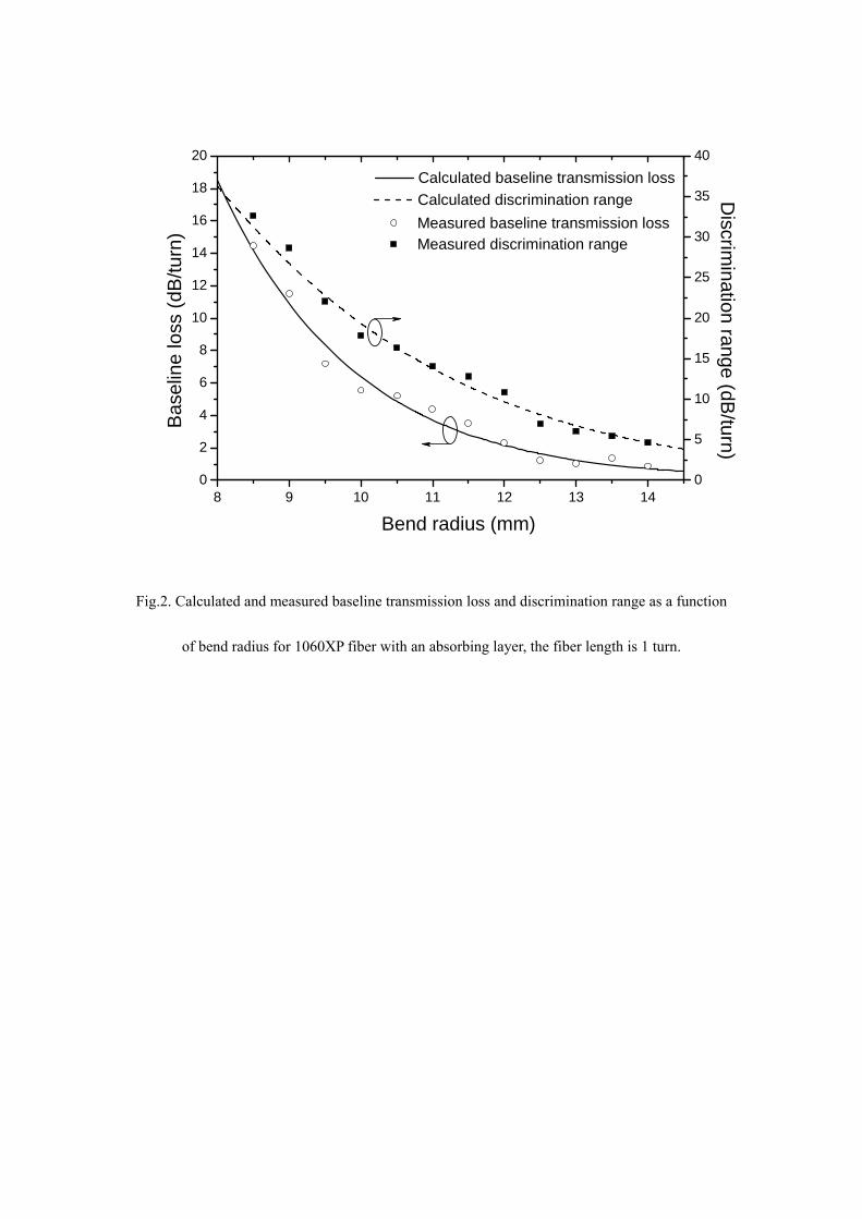
Fig. 2 shows that the calculated baseline loss (solid line), discrimination range
(dashed line), measured baseline loss (hollow circles), discrimination range (solid
squares) as a function of bend radius for the bend loss sensitive singlemode
fiber-1060XP, with an applied absorbing layer and a fiber bend of 1 turn. A so-called
effective bend radius (correction factor, 1.308@1500nm; 1.336@1600nm) is also
employed in the theoretical modeling, as presented in Ref. [7]. In the experiments, a
tunable laser is employed as a power source, which has an output power of 0 dBm
with a wavelength tuning range from 1500 to 1600 nm. To experimentally determine
the baseline loss and discrimination range, the bend losses of bare 1060XP fiber with
an absorbing layer (to remove the reflection occurring at the interface between the
cladding layer and air) were measured at 1500 nm and at 1600 nm. The measurements
were taken at 0.5 mm intervals over a bending radius range from 8.5 to 14 mm.
In Fig.2, the theoretical modeling shows a reasonable agreement with the
experimental results overall, and the divergence between the experimental and
theoretical results is most likely caused by: 1) measurement error of the bending loss
and errors due to temperature induced fluctuations of the bend loss; 2) the
experimental inaccuracy of the bend radius (both baseline loss and discrimination
range are sensitive to the bend radius as shown in Fig. 2; 3) the limitations of the
absorbing layer material coated on the bare fiber cladding surface leading to partial
reflections from the fiber cladding-air boundary so that radiation launched from fiber
core will re-couple with the fundamental propagation mode in the fiber core, resulting
in a perceptible quasi-periodic behaviour for the measured results in Fig. 2. Finally
the calculation of the bend loss itself has some minor limitations: 1) the
approximations made in the calculation from D. Marcuse [8] and 2) the calculation of
bend loss is based on a scalar approximation to enable reasonable processing times
with limited processing power and memory.
From Fig. 2, one can also see that both the baseline loss and discrimination range
are highly sensitive to the bend radius. When the bend radius is less than 8 mm, as in
our previous experiments [11], it is found that when the bare fiber is bent, it is more
susceptible to breakage. Furthermore, to reduce the fiber bend induced mechanical
stress and improve the reliability of the fiber filter, it is suggested that a bend radius is
larger than 8 mm is employed for fiber edge filter applications. Thus in this paper a
bend radius of 10.5 mm is chosen to characterize the influence of bend loss due to the
manufacturing tolerance of fiber parameters.
3. Influence of the manufacturing tolerance of key fiber parameters on the
performance of a fiber-based edge filter
For a 1060XP fiber based edge filter, the influence of manufacturing variations in key
fiber parameters needs to be considered in the design process. In the first instance the
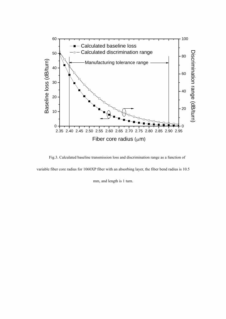
influence of variations in the fiber core radius (nominal value 2.65 µm) was modeled
for a range of core radii from 2.35 to 2.95 µm. The results are shown in Fig. 3 in
which the calculated baseline loss (solid square line) is shown along with the
discrimination range (hollow square line) as a function of fiber core radius for
1060XP fiber with an absorbing layer. The fiber bend radius is 10.5 mm, and bend
length is 1 turn.
It is clear that both the baseline loss and discrimination range, decrease rapidly
with an increase in fiber core radius. In practice the manufacturing tolerance for the
fiber core radius is ± 0.25 µm, so from Fig. 3, one can see that a large variation in the
baseline loss and discrimination range will occur within this manufacturing tolerance
range. The worst case variation for either the baseline loss value or the discrimination
range value is the difference between the highest value, calculated for the lowest
possible core radius (2.4 µm) and the lowest value calculated for the highest possible
core radius (2.9 µm). For the baseline loss the worst case variation is 34.6 dB, and for
the discrimination range it is 65.3 dB.
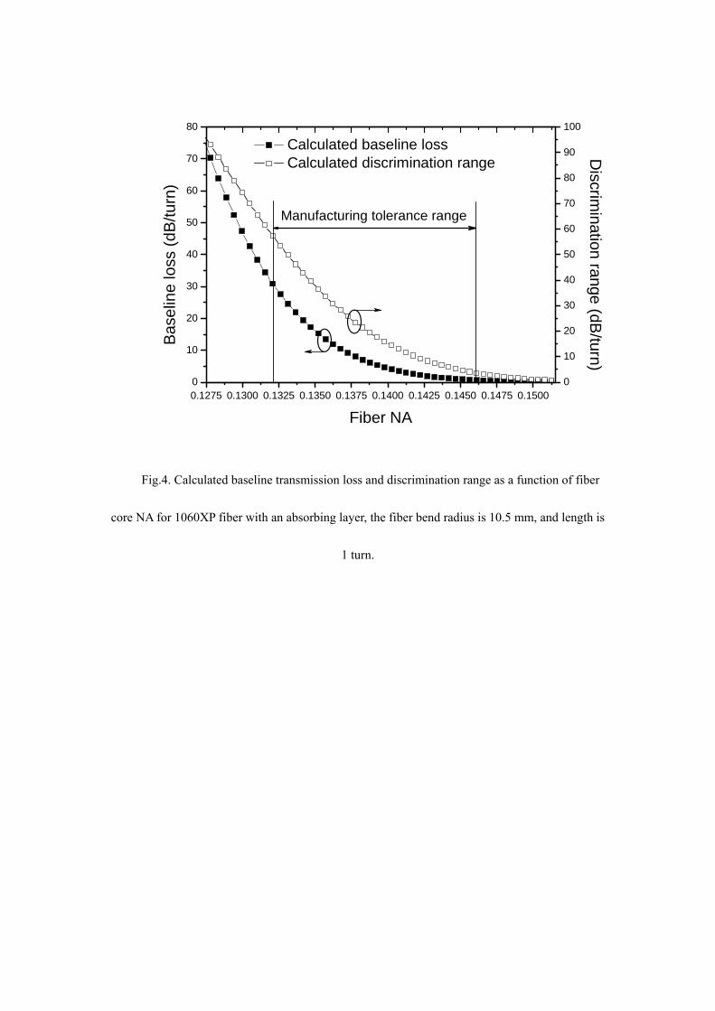
Next, the influence of manufacturing tolerance for fiber NA value was modelled.
During the fiber manufacturing process, the tolerance of refractive index difference
between fiber core and cladding can be controlled below ± 10%, and the
corresponding calculated core NA tolerance (nominal value 0.1393) of the 1060XP
fiber is thus within the range from 0.1321 to 0.1461. The results of the modeling are
shown in Fig. 4, for a range of NA value from 0.1275 to 0.1515.
The baseline loss and discrimination range vary with the fiber NA, and for a fiber
with lower NA value the result is a larger baseline loss and discrimination range.
Within the manufacturing tolerance range for the NA, the worst case variation for the
baseline loss is 27.6 dB, and for the discrimination range is 52.3 dB.
4. Discussion
Even allowing for worst case nature of manufacturing tolerances, for the fiber
parameters core radius and NA it is clear from Figures 3 and 4 that such variations
have a profound effect on the discrimination range and baseline loss of a fiber bend
loss edge filter. In manufacturing such filters in significant quantities such variations
in discrimination range and baseline loss would result in unacceptably low production
yields. However in practice there are mitigating issues which can reduce or even
eliminate the impact of manufacturing tolerances.
The first issue is the statistical nature of manufacturing tolerances. It is known for
example that the core radius variations of a fiber normally conform to a Gaussian
statistical distribution, which has been demonstrated in the Ref. [12]. To determine
the standard deviation it can be assumed that the worst case variations about the
nominal value of the core radius correspond to approximately ± 3 standard deviations
about the nominal value. Based on Gaussian statistics one could assume the while the
worst case variation is indeed ± 0.25 µm, in practice in 95% of cases the actual fiber
tolerance will be within ± 2 standard deviations or ± 0.166 µm. The corresponding
variation of the discrimination range is reduced from 65.32 dB worst case to 39.55 dB
for ± two standard deviations, reducing the impact of manufacturing variations.
The second mitigating issue is that fiber bend loss filters can be fabricated to
allow the discrimination range and baseline loss to be set and fixed at the point of
manufacture. This means that a preset mandrel around which the fiber is fixed cannot
be used but instead a freespace fiber bend loop is fabricated and the radius of the loop
is “tuned” manually to give the correct discrimination at a given wavelength. The
fiber loop is then fixed using an epoxy droplet at the crossover point of the fibers. To
verify if this is possible the model described earlier is used to determine the fiber bend
radius that would need to be set to ensure that the discrimination range is equal to the
design example value of 16.32 dB (achieved with a nominal core radius (2.65 µm) for
a bend radius of 10.5 mm) where the actual core radius can vary by ± 0.166 µm (± 2
standard deviations). The results are presented in Table 2. As expected for low values
of core radius, a larger bend radius is needed, up to 14.55 mm. For high values of core
radius a smaller bend radius is needed, down to 8 mm, which is acceptable in terms of
the minimum radius needed to avoid fiber failure.
Variations in the fiber NA from nominal can be also be dealt with using bend
radius tuning during fabrication. The nominal NA is 0.1393. Again assuming
Gaussian statistics, the worst case value of NA variation is equal to approximately
three standard deviations. For 95% of fibers the variation will be within ± two
standard deviations or ± 0.004887. If bend radius tuning is employed to ensure that
even with NA variations the discrimination range is still 16.32 dB, then the bend
radius range needed to compensate NA variations is shown in Table 3.
The bend radius needed to compensate for NA variations has a minimum value of
7.25 µm, which is acceptable in terms of fiber reliability. Bend radius “tuning” during
fabrication of the fiber filter is thus a feasible approach to reducing the effect of
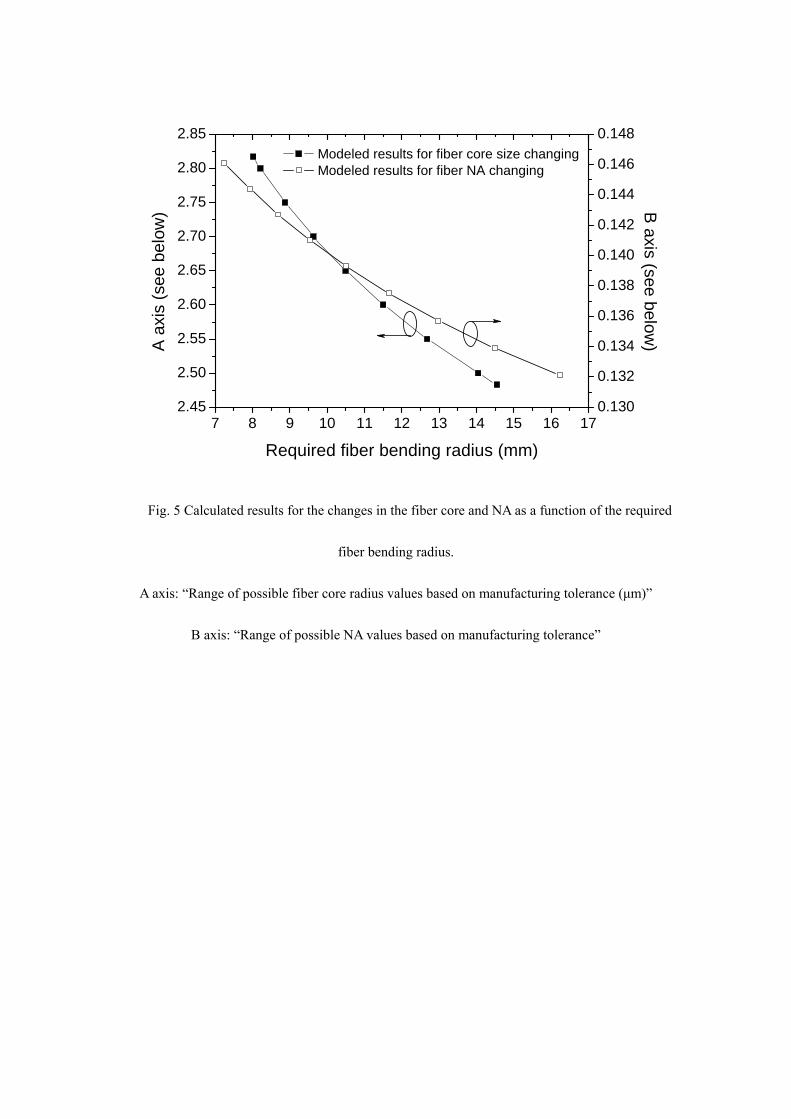
manufacturing tolerances. To confirm this, for a design bend radius of 10.5 mm, we
calculated the tuned bend radius required to meet the edge filter specifications over
the range of possible fiber core radii and NA values. The results are shown in Fig. 5
which shows in a graphical form that is possible to compensate for manufacturing
variations in the fiber core size and fiber NA changes, by tuning the actual bend radius
used.
In practice the need to “tune” the bend radius to meet a given discrimination
range should not be an onerous task. The fiber to be used for a batch of fiber bend loss
filters will most likely come from the same drawn length of fiber, so similar “tuned”
bend radii can be expected for a given batch of filters. Finally it is also true that for
many applications of such fiber bend loss filters (such as wavelength measurement as
discussed earlier), there is no need to achieve a precise discrimination through radius
tuning as in any event the overall system calibration will take account of variations in
the discrimination range.
Finally it is recognised that parameter variations during manufacture will not
occur in just one parameter at a time, but rather variations in several parameters will
occur. We have not considered such combined variations in this paper. However we
have shown that in the fabrication of bend-loss based fiber edge filters, bend radius
tuning can be employed to mitigate the effects of parameter variations. Where the
fiber used displays variations from a nominal value for several parameters, bend
radius tuning will still offer a means of achieving the correct filter response, albeit
with a lower yield, depending on the magnitude of the parameter variations.
5. Conclusions
The design of a 1060XP singlemode fiber based edge filter has been examined in the
context of variations in fiber parameters. We have shown that two such parameters,
core radius and NA, influence the fiber bend loss spectral response performance
significantly, and two analytical models have been presented for calculating the
influence of the manufacturing tolerance of the fiber parameters on fiber bend loss.
Finally we have shown that bend-radius tuning during the fabrication of such filters is
a viable way to mitigate the effect of manufacturing variations.
References
1. M. T. Wlodarczyk, “Wavelength referencing in single-mode microbend sensors,” Opt.
Lett., 12, 741-743 (1987)
2. S. H. Nam, and S. Yin, “High-temperature sensing using whispering gallery mode
resonance in bent optical fibers,” IEEE Photon. Technol. Lett., 17, 2391-2393 (2005).
3. M. D. Nielsen, N. A. Mortensen, M. Albertsen, J. R. Folkenberg, A. Bjarklev, and D.
Bonacinni, “Predicting macrobending loss for large-mode area photonic crystal fibers,”
Opt. Express, 12, 1775-1779 (2004).
4. Q. Wang, G. Farrell and T. Freir, “Study of transmission response of edge filters
employed in wavelength measurements,” Appl. Opt., 44, 7789-7792 (2005).
5. Q. Wang, G. Rajan, P. Wang and G. Farrell, “Resolution investigation of ratiometric
wavelength measurement system,” Appl. Opt., 46, 6362-6367 (2007).
6. Q. Wang, G. Farrell, T. Freir, G. Rajan and P. Wang, “Low-cost wavelength measurement
based on a macrobending single-mode fiber,” Opt. Lett., 31, 1785-1787 (2006).
7. P. Wang, G. Farrell, Q. Wang and G. Rajan, “An optimized macrobending-fiber-based
edge filter,” IEEE Photon. Technol. Lett., 19, 1136-1138 (2007).
8. D. Marcuse, “Curvature loss formula for optical fibers,” J. Opt. Soc. Am., 66, 216-220,
(1976).
9. H. Renner, “Bending losses of coated single-mode fibers: a simple approach,” J.
Lightwave Technol., 10, 544-551 (1992).
10. L. Faustini and G. Martini, “Bend loss in single-mode fibers,” J. Lightwave Technol., 15,
671-679 (1997).
11. P. Wang, Q. Wang, G. Farrell, G. Rajan, T. Freir and J. Cassidy, “Investigation of
macrobending losses of standard single mode fiber with small bend radii,” Microw. Opt.
Techn. Lett. , 49, 2133-2138 (2007).
12. P. H. Krawarik and L. S. Watkins, “Fiber geometry specifications and its relation to
measured fiber statistics,” Appl. Opt., 17, 3984-3989 (1978).
Figure captions
Fig.1. (a) Schematic configuration of the ratiometric wavelength measurement system with the
fiber edge filter; (b) desired spectral response of the fiber edge filter.
Fig.2. Calculated and measured baseline transmission loss and discrimination range as a function
of bend radius for 1060XP fiber with an absorbing layer, the fiber length is 1 turn.
Fig.3. Calculated baseline transmission loss and discrimination range as a function of variable
fiber core radius for 1060XP fiber with an absorbing layer, the fiber bend radius is 10.5 mm, and
length is 1 turn.
Fig.4. Calculated baseline transmission loss and discrimination range as a function of fiber core
NA for 1060XP fiber with an absorbing layer, the fiber bend radius is 10.5 mm, and length is 1
turn.
Fig. 5 Calculated results for the changes in the fiber core and NA as a function of the required
fiber bending radius.
A axis: “Range of possible fiber core radius values based on manufacturing tolerance (μm)”
B axis: “Range of possible NA values based on manufacturing tolerance”
Tables
Table 1. Parameters of the 1060XP singlemode fiber; (the refractive index values are defined at a
wavelength of 1550 nm).
Table 2. Fiber bend radius range needed to compensate for two-standard deviation variations in the
fiber core radius.
Table 3. Fiber bend radius range needed to compensate for two-standard deviation variations in the
fiber NA.
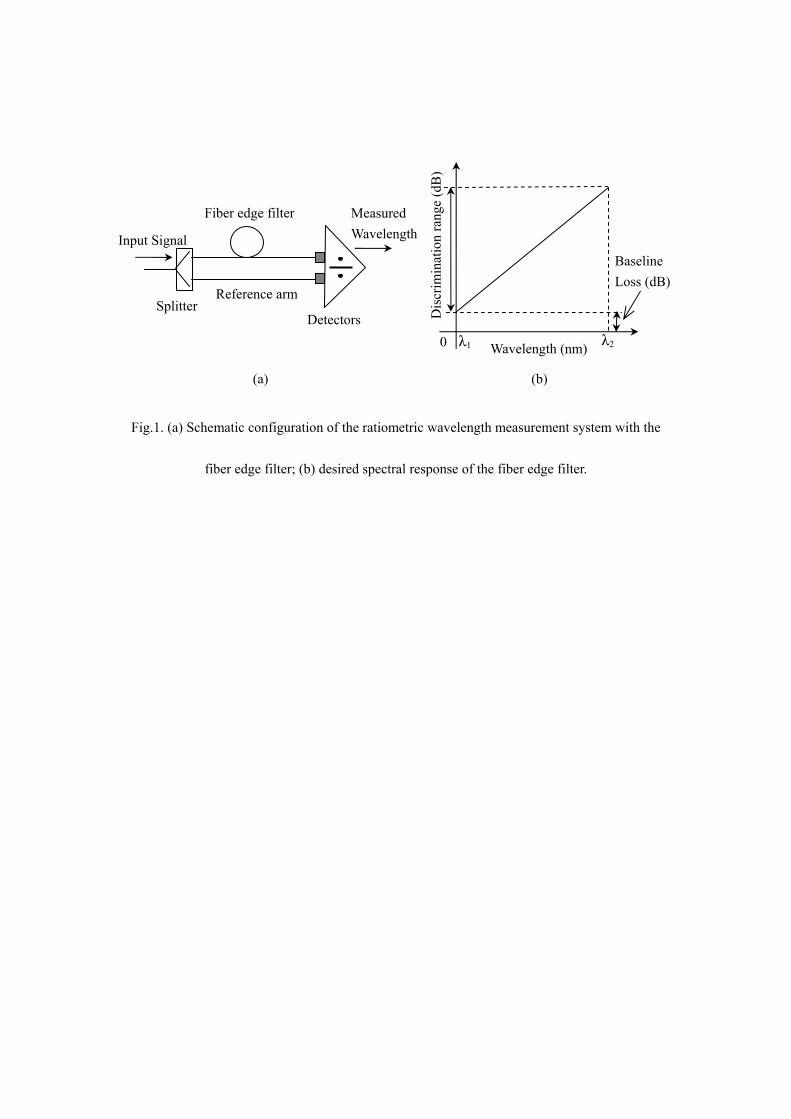
Fig.1. (a) Schematic configuration of the ratiometric wavelength measurement system with the
fiber edge filter; (b) desired spectral response of the fiber edge filter.
Splitter
Fiber edge filter
Reference arm
Detectors
Measured Wavelength
Dis
crim
inat
ion
rang
e (d
B)
(a)
Wavelength (nm) 0 λ1 λ2
(b)
Baseline Loss (dB)
Input Signal
0
2
4
6
8
10
12
14
16
18
20 Calculated baseline transmission loss
0
5
10
15
20
25
30
35
40
Calculated discrimination range Discrim
ination range (dB/turn)
8 9 10 11 12 13 14
Measured baseline transmission loss
Bend radius (mm)
Bas
elin
e lo
ss (d
B/tu
rn) Measured discrimination range
Fig.2. Calculated and measured baseline transmission loss and discrimination range as a function
of bend radius for 1060XP fiber with an absorbing layer, the fiber length is 1 turn.
2.35 2.40 2.45 2.50 2.55 2.60 2.65 2.70 2.75 2.80 2.85 2.90 2.950
10
20
30
40
50
60
Fiber core radius (μm)
Base
line
loss
(dB
/turn
)
0
20
40
60
80
100D
iscrimination range (dB
/turn)
Calculated baseline loss Calculated discrimination range
Manufacturing tolerance range
Fig.3. Calculated baseline transmission loss and discrimination range as a function of
variable fiber core radius for 1060XP fiber with an absorbing layer, the fiber bend radius is 10.5
mm, and length is 1 turn.
0.1275 0.1300 0.1325 0.1350 0.1375 0.1400 0.1425 0.1450 0.1475 0.15000
10
20
30
40
50
60
70
80
Calculated baseline loss Calculated discrimination range
Fiber NA
Base
line
loss
(dB/
turn
)
Manufacturing tolerance range
0
10
20
30
40
50
60
70
80
90
100D
iscrimination range (dB
/turn)
Fig.4. Calculated baseline transmission loss and discrimination range as a function of fiber
core NA for 1060XP fiber with an absorbing layer, the fiber bend radius is 10.5 mm, and length is
1 turn.
7 8 9 10 11 12 13 14 15 16 172.45
2.50
2.55
2.60
2.65
2.70
2.75
2.80
2.85 Modeled results for fiber core size changing Modeled results for fiber NA changing
Required fiber bending radius (mm)
A a
xis
(see
bel
ow)
0.130
0.132
0.134
0.136
0.138
0.140
0.142
0.144
0.146
0.148B
axis (see below)
Fig. 5 Calculated results for the changes in the fiber core and NA as a function of the required
fiber bending radius.
A axis: “Range of possible fiber core radius values based on manufacturing tolerance (μm)”
B axis: “Range of possible NA values based on manufacturing tolerance”
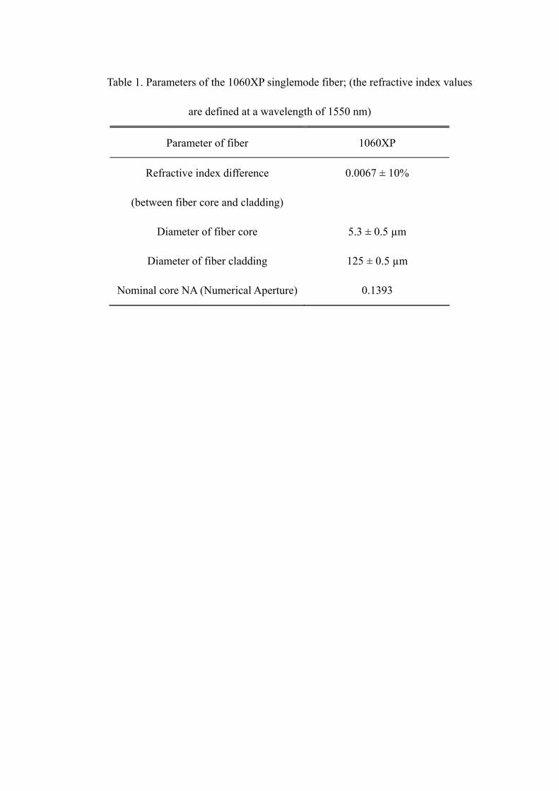
Table 1. Parameters of the 1060XP singlemode fiber; (the refractive index values
are defined at a wavelength of 1550 nm)
Parameter of fiber 1060XP
Refractive index difference
(between fiber core and cladding)
0.0067 ± 10%
Diameter of fiber core 5.3 ± 0.5 µm
Diameter of fiber cladding 125 ± 0.5 µm
Nominal core NA (Numerical Aperture) 0.1393

Table 2. Fiber bend radius range needed to compensate for two-standard deviation
variations in the fiber core radius
Fiber core radius R (µm) ∆R (µm) Bend radius needed (mm)
2.483 (lowest) -0.166 14.55
2.65 (nominal) 0 10.50
2.817 (highest) +0.166 8.02
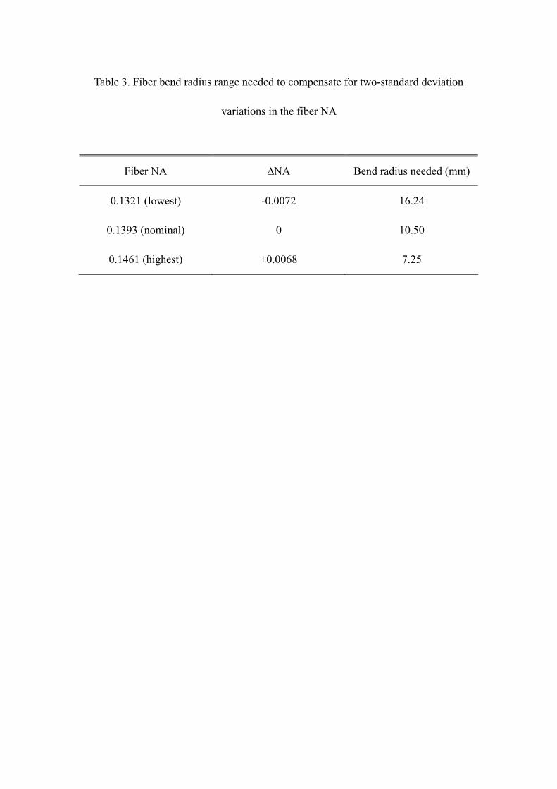
Table 3. Fiber bend radius range needed to compensate for two-standard deviation
variations in the fiber NA
Fiber NA ∆NA Bend radius needed (mm)
0.1321 (lowest) -0.0072 16.24
0.1393 (nominal) 0 10.50
0.1461 (highest) +0.0068 7.25