Tekla Structures 2019 - Create models
968
Tekla Structures 2019 Create models March 2019 ©2019 Trimble Solutions Corporation
-
Upload
khangminh22 -
Category
Documents
-
view
1 -
download
0
Transcript of Tekla Structures 2019 - Create models

Tekla Structures 2019Create models
March 2019
©2019 Trimble Solutions Corporation

Contents
1 Get to know Tekla Structures basic working methods........... 171.1 Set up the workspace..................................................................................... 17
Change units and decimals.................................................................................................. 18Work with grids...................................................................................................................... 18
Create, modify, or delete a grid...................................................................................... 21Add a single grid line........................................................................................................26Modify a single grid line...................................................................................................26Delete a single grid line................................................................................................... 29
Work with views..................................................................................................................... 29Move the view plane........................................................................................................ 31Create model views.......................................................................................................... 31Open, save, modify, or delete a view............................................................................. 41Switch between views...................................................................................................... 43Update and refresh views............................................................................................... 43View properties.................................................................................................................44Grid view properties.........................................................................................................45
Define the work area.............................................................................................................46Fit work area to entire model..........................................................................................47Fit work area to selected parts....................................................................................... 47Fit work area using two points........................................................................................47Hide the work area box................................................................................................... 47
If you cannot see all objects................................................................................................. 48Coordinate system.................................................................................................................48
Right-hand rule................................................................................................................. 50Show or hide the work plane grid.................................................................................. 50Shift the work plane......................................................................................................... 51Base points........................................................................................................................53Select the work plane.......................................................................................................63
Change the color settings..................................................................................................... 64Find RGB values for colors.............................................................................................. 64Change the model background color ........................................................................... 64Change the color of dimensions, part labels, and bolts.............................................. 66
Change the rendering of the model.................................................................................... 671.2 Zoom and rotate the model........................................................................... 75
Zoom in and out.................................................................................................................... 75Rotate the model................................................................................................................... 76Pan the model........................................................................................................................77
1.3 Snap to positions.............................................................................................77Snapping toolbar................................................................................................................... 78
Snap zone..........................................................................................................................79Snap priority......................................................................................................................79Snap depth........................................................................................................................ 79Snapping in drawings.......................................................................................................79
Snap switches and symbols..................................................................................................80Snap in orthogonal directions..............................................................................................82
2

Snap to orthogonal points.............................................................................................. 82Snap in orthogonal direction relative to previously picked points.............................83
Snap to lines........................................................................................................................... 85Snap to a line.................................................................................................................... 85Snap to extension lines....................................................................................................85
Snap to points using exact distance or coordinates - numeric snapping.......................87Enter a distance or coordinates......................................................................................87Snapping example: Track along a line towards a snap point......................................88Options for coordinates...................................................................................................90Change the snapping mode............................................................................................91
Snapping aids.........................................................................................................................92Create a temporary reference point.............................................................................. 92Lock X, Y, or Z coordinate on a line.................................................................................94Align objects using a snap grid....................................................................................... 94
Snap settings.......................................................................................................................... 941.4 Work with model objects in Tekla Structures..............................................95
Create model objects and modify model object properties by using property pane... 96Create or delete a model object..................................................................................... 97Modify model object properties by using property pane............................................97Modify the common properties of different object types by using property pane....
100Resize and reshape model objects....................................................................................103Copy properties from another object............................................................................... 109
Copy model object properties using the property pane........................................... 109Copy object properties using the contextual toolbar................................................ 111
Save and load object properties........................................................................................ 111Save and load properties in the property pane......................................................... 111Save and load properties in a dialog box.................................................................... 113Remove existing properties.......................................................................................... 114
Undo modeling and drawing changes ............................................................................. 1141.5 Select objects................................................................................................. 116
Select single objects............................................................................................................ 116Select multiple objects using area selection.................................................................... 117Select all objects.................................................................................................................. 117Select previous objects....................................................................................................... 118Select objects by identifier..................................................................................................118Select handles...................................................................................................................... 120Modify the selection............................................................................................................122 Selecting toolbar.................................................................................................................122Select assemblies, cast units, and nested objects........................................................... 127
Select assemblies and cast units..................................................................................127Select nested objects..................................................................................................... 127
Select reference models, reference model objects and assemblies............................. 128Select an entire reference model................................................................................. 128Select a reference model object................................................................................... 129Select a reference model assembly............................................................................. 129
Tips for selecting objects.................................................................................................... 129Switch rollover highlight on or off................................................................................129Select on right-click........................................................................................................ 130If you cannot select objects...........................................................................................130Interrupt object selection..............................................................................................131
1.6 Copy and move objects.................................................................................131Copy objects......................................................................................................................... 133
Copy by picking two points........................................................................................... 133
3
Copy linearly................................................................................................................... 134Copy by specifying a distance from origin.................................................................. 135Copy using drag-and-drop............................................................................................ 135Copy objects to another object.................................................................................... 136Copy all content to another object...............................................................................137Copy to another plane................................................................................................... 137Copy from another model.............................................................................................138Copy objects using linear array tool.............................................................................138Copy objects using radial array tool.............................................................................141 Copy objects using Array of objects (29) component .............................................. 143
Move objects........................................................................................................................ 144Move by picking two points...........................................................................................145Move linearly...................................................................................................................146Move by specifying a distance from origin..................................................................147Move using drag-and-drop............................................................................................147Move to another plane.................................................................................................. 149Move objects to another object....................................................................................149
Rotate objects...................................................................................................................... 150Rotate around a line...................................................................................................... 150Rotate around the z axis................................................................................................151Rotate drawing objects..................................................................................................153Rotation settings............................................................................................................ 154
Mirror objects.......................................................................................................................154Mirror model objects..................................................................................................... 154Mirror drawing objects.................................................................................................. 155
1.7 Filter objects.................................................................................................. 155Use existing filters............................................................................................................... 156
How to use a view filter................................................................................................. 156How to use a selection filter..........................................................................................158
Create new filters.................................................................................................................159Create a view filter..........................................................................................................159Create a selection filter..................................................................................................161Create a drawing filter................................................................................................... 161Create a drawing view filter.......................................................................................... 164Create a drawing selection filter...................................................................................166
Filtering techniques.............................................................................................................166Object properties in filtering.............................................................................................. 169 Template attributes in filtering......................................................................................... 185 Wildcards ............................................................................................................................ 186Examples of filters............................................................................................................... 186
Filter parts based on their name..................................................................................186Filter main parts............................................................................................................. 187Filter bolts based on their size......................................................................................188Filter parts based on their assembly type...................................................................188Filter sub-assemblies..................................................................................................... 190Filter reference model objects......................................................................................190Filter parts within component...................................................................................... 191Filter reinforcement in pour units based on pour object type................................. 191Filter all contents of a pour unit................................................................................... 192
Copy and remove filters......................................................................................................193Copy a filter to another model..................................................................................... 193Remove a filter................................................................................................................194
Select values from the model.............................................................................................1941.8 Customize the basic user interface elements .......................................... 194
Customize the keyboard shortcuts....................................................................................195
4
Define new keyboard shortcuts....................................................................................195Clear and reset shortcuts.............................................................................................. 197Export keyboard shortcuts............................................................................................197Import keyboard shortcuts........................................................................................... 197
Customize the ribbon..........................................................................................................198Add a button to the ribbon........................................................................................... 199Move a button................................................................................................................ 205Resize a button............................................................................................................... 205Change the appearance of a button............................................................................ 206Create a user-defined command with Command editor.......................................... 208Add a separator bar....................................................................................................... 210Remove a button............................................................................................................ 210Add, hide, and edit tabs.................................................................................................210Save the ribbon ............................................................................................................. 211Check the changes......................................................................................................... 212Back up and restore ribbons........................................................................................ 213
Customize the property pane layout................................................................................ 213Add a property or a property group............................................................................ 215Change the name of a property or a property group................................................217Copy properties from one object type to another object type ................................218Remove a customization............................................................................................... 219Save the changes............................................................................................................219User-defined attributes (UDAs) in the customized property pane.......................... 219Example: How to add IFC related user-defined attributes to the property pane
layout and copy them to another object type............................................................................ 220Customize the Selecting, Snapping, and Snap override toolbars .................................225Customize the contextual toolbar..................................................................................... 226
Customize contextual toolbar...................................................................................... 226Create user profiles for contextual toolbars...............................................................228Back up and share contextual toolbars.......................................................................228
1.9 Tips for large models.................................................................................... 2291.10 Create model templates...............................................................................231
Create a new model template............................................................................................231Modify an existing model template...................................................................................232Download model templates...............................................................................................233Model template options..................................................................................................... 233
2 Create parts, reinforcement, and construction objects....... 2342.1 Create parts and modify part properties................................................... 235
Create a steel column......................................................................................................... 237Modify steel column properties................................................................................... 237Steel column properties................................................................................................ 238
Create a steel beam............................................................................................................ 239Modify steel beam properties...................................................................................... 240Steel beam properties................................................................................................... 240
Create a steel polybeam..................................................................................................... 242Modify steel polybeam properties............................................................................... 242Steel beam properties................................................................................................... 242
Create a curved beam.........................................................................................................244Modify curved beam properties...................................................................................245Steel beam properties................................................................................................... 245
Create a twin profile............................................................................................................ 246Modify twin profile properties...................................................................................... 247Twin profile properties.................................................................................................. 247
5

Create an orthogonal beam............................................................................................... 249Modify orthogonal beam properties........................................................................... 249Orthogonal beam properties........................................................................................249
Create a steel spiral beam.................................................................................................. 251Basic concepts related to spiral beams....................................................................... 251Create a spiral beam......................................................................................................251Limitations.......................................................................................................................253
Create a contour plate........................................................................................................ 253Create a round contour plate....................................................................................... 254Modify contour plate properties.................................................................................. 255Contour plate properties...............................................................................................255
Create a conical or a cylindrical bent plate...................................................................... 256Create a cylindrical bent plate...................................................................................... 257Create a conical bent plate........................................................................................... 260Modify the bend radius................................................................................................. 263Modify the shape of a bent plate................................................................................. 265Remove curved sections................................................................................................269Examples......................................................................................................................... 270
Create a stand-alone bent plate........................................................................................ 271Modify the shape of a stand-alone bent plate........................................................... 274
Create a concrete column.................................................................................................. 277Modify concrete column properties............................................................................ 278Concrete column properties......................................................................................... 278
Create a concrete beam......................................................................................................279Modify concrete beam properties................................................................................280Concrete beam properties............................................................................................ 280
Create a concrete polybeam.............................................................................................. 282Modify concrete polybeam properties........................................................................ 283Concrete beam properties............................................................................................ 283
Create a concrete spiral beam........................................................................................... 285Basic concepts related to spiral beams....................................................................... 285Create a spiral beam......................................................................................................286Limitations.......................................................................................................................287
Create a concrete panel or wall......................................................................................... 288Modify concrete panel or wall properties................................................................... 289Concrete panel or wall properties................................................................................289
Create a concrete slab........................................................................................................ 290Create a round concrete slab........................................................................................291Modify concrete slab properties.................................................................................. 292Concrete slab properties............................................................................................... 292
Create a pad footing............................................................................................................293Modify pad footing properties......................................................................................294Pad footing properties...................................................................................................294
Create a strip footing.......................................................................................................... 295Modify strip footing properties.................................................................................... 296Strip footing properties................................................................................................. 296
Create items......................................................................................................................... 298Create an item or a concrete item............................................................................... 299Modify item or concrete item properties.................................................................... 300Change the shape of an item........................................................................................301Item and concrete item properties.............................................................................. 301
2.2 Adjust part position and show part information...................................... 303Show part handles and part reference lines in a model view........................................303
Show part handles......................................................................................................... 303Show part reference lines in a model view................................................................. 306
6
Modify the position of a part............................................................................................. 306 Part position on the work plane..................................................................................308Part rotation....................................................................................................................309Part position depth........................................................................................................ 310Part vertical position...................................................................................................... 312Part horizontal position.................................................................................................313Part end offsets.............................................................................................................. 315
Select and change the profile or material of a part........................................................ 316Select and change the profile of a part....................................................................... 316Select and change the material of a part.................................................................... 318
Examples of user-defined attributes (UDAs) for parts....................................................319Show part information by using part labels.....................................................................320Create curved parts.............................................................................................................321Create horizontal parts....................................................................................................... 322Create beams close to each other.....................................................................................323Position columns, pad footings, and orthogonal beams................................................323 How to model identical areas........................................................................................... 324
2.3 Modify parts...................................................................................................325Modify the adaptivity of reinforcement, surface treatment, or edge chamfersin parts.................................................................................................................................. 325
Define default adaptivity settings................................................................................ 325Modify the adaptivity of an individual model object................................................. 326
Split parts..............................................................................................................................326Split a straight or curved part or polybeam................................................................326Split a plate or slab using a polygon............................................................................ 326
Combine parts..................................................................................................................... 327Attach parts to each other..................................................................................................327
Attach a part to another part........................................................................................328Detach an attached part................................................................................................328Explode attached parts..................................................................................................329
Warp a part...........................................................................................................................329Warp a beam or a column using deformation angles............................................... 329Warp a concrete slab by moving chamfers................................................................. 330Warp a Floor Bay (66) slab.............................................................................................330
Camber a part...................................................................................................................... 3312.4 Add details to parts.......................................................................................332
Create bolts.......................................................................................................................... 332Create a bolt group........................................................................................................ 332Create a single bolt........................................................................................................ 333Create bolts using the Auto bolt component............................................................. 333Create a bolt group by exploding a component.........................................................336Change or add bolted parts.......................................................................................... 337Bolt group shape............................................................................................................ 337Bolt properties................................................................................................................338
Create studs......................................................................................................................... 342Create holes......................................................................................................................... 343
Create round holes........................................................................................................ 343Create oversized holes.................................................................................................. 344Create slotted holes....................................................................................................... 345
Create welds.........................................................................................................................346Create a weld between parts........................................................................................ 346Create a weld to a part.................................................................................................. 347Create a polygon weld................................................................................................... 348Weld properties.............................................................................................................. 349List of weld types............................................................................................................354
7
Welds in components.................................................................................................... 356Weld preparation............................................................................................................357Set the visibility and appearance of welds..................................................................358Change a weld to a polygon weld................................................................................ 359Split a polygon weld....................................................................................................... 360Create user-defined cross sections for welds.............................................................360
Create fittings.......................................................................................................................361Create cuts............................................................................................................................362
Cut parts with a line....................................................................................................... 362Cut parts with a polygon............................................................................................... 363Cut parts with another part.......................................................................................... 364Hide cut lines in a model view...................................................................................... 365Tips on how to cut efficiently........................................................................................ 366Polygon cut properties.................................................................................................. 366Part cut properties......................................................................................................... 367
Create part chamfers.......................................................................................................... 368Chamfer part corners.................................................................................................... 368Chamfer part edges....................................................................................................... 369Corner chamfer properties........................................................................................... 370Edge chamfer properties...............................................................................................372
Add surface treatment to parts......................................................................................... 373Add surface treatment to an entire part face.............................................................374Add surface treatment to a selected area on a part face..........................................374Add surface treatment to all faces of a part............................................................... 375Add surface treatment to cut faces..............................................................................375Surface treatment on chamfered parts.......................................................................375Surface treatment on parts with openings and recesses..........................................376Modify surface treatment properties.......................................................................... 376Surface treatment properties....................................................................................... 377Define new surface treatment subtypes..................................................................... 378Tiled surface treatment................................................................................................. 379Create an unpainted area using the No paint area component.............................. 383
Add surfaces to part faces and pour object faces........................................................... 385Add a surface to a face.................................................................................................. 386Modify surface properties.............................................................................................386
2.5 Create assemblies......................................................................................... 386Create an assembly............................................................................................................. 387
Create a sub-assembly.................................................................................................. 387Use bolts to create assemblies.....................................................................................388Bolt sub-assemblies to an existing assembly............................................................. 388Use welds to create assemblies................................................................................... 389Weld sub-assemblies to an existing assembly........................................................... 389
Add objects to assemblies..................................................................................................390Assembly hierarchy........................................................................................................390Add parts to an assembly..............................................................................................391Create a nested assembly............................................................................................. 392Join assemblies............................................................................................................... 392
Change the assembly main part........................................................................................392Change the main assembly................................................................................................ 393Remove objects from an assembly................................................................................... 393Check and highlight objects in an assembly.................................................................... 393Explode an assembly.......................................................................................................... 394Assembly examples.............................................................................................................394
2.6 Create cast units........................................................................................... 396Define the cast unit type of a part.....................................................................................396
8
Create a cast unit.................................................................................................................397Add objects to a cast unit................................................................................................... 397Change the cast unit main part......................................................................................... 398Remove objects from a cast unit....................................................................................... 398Check and highlight objects in a cast unit........................................................................ 398Explode a cast unit.............................................................................................................. 399Casting direction..................................................................................................................399
Define the casting direction of a part.......................................................................... 400Show the top-in-form face............................................................................................ 401
2.7 Manage pours................................................................................................ 402Enable pour management..................................................................................................402
Disable pour management temporarily......................................................................403View cast-in-place concrete structures............................................................................. 404
Set the appearance of cast-in-place concrete structures..........................................404Part view vs. pour view.................................................................................................. 406
Define the pour phase of a part........................................................................................ 407Pour objects......................................................................................................................... 408
Change the color and transparency of pour objects................................................. 409Modify the properties of a pour object....................................................................... 410
Pour units............................................................................................................................. 410Calculate pour units.......................................................................................................411Check and inquire objects in a pour unit.................................................................... 411Add objects to a pour unit.............................................................................................412Remove objects from a pour unit................................................................................ 413Reset pour unit relations...............................................................................................413Modify the properties of a pour unit........................................................................... 414How Tekla Structures automatically adds objects to pour units.............................. 414
Pour breaks.......................................................................................................................... 415Pour break adaptivity.....................................................................................................417Set the visibility of pour breaks.................................................................................... 417Create a pour break....................................................................................................... 418Select a pour break........................................................................................................ 420Copy a pour break..........................................................................................................420Move a pour break......................................................................................................... 420Modify a pour break...................................................................................................... 421Remove a pour break.................................................................................................... 422
Troubleshoot pours.............................................................................................................422Example: Create concrete geometry and work with pours............................................425
2.8 Create reinforcement................................................................................... 427Create a rebar set................................................................................................................ 428
Basic concepts related to rebar sets............................................................................428Create longitudinal rebars............................................................................................ 430Create crossing rebars...................................................................................................432Create planar rebars...................................................................................................... 435Create rebars by point input.........................................................................................437Rebar set properties...................................................................................................... 438Limitations.......................................................................................................................438Create a rebar set using Rebar shape placing tool.................................................... 438Examples: Rebar sets in curved structures.................................................................445
Create a single reinforcing bar...........................................................................................451Create a reinforcing bar group...........................................................................................452
Create a reinforcing bar group using Rebar shape catalog...................................... 454Create a curved reinforcing bar group........................................................................ 461Create a circular reinforcing bar group....................................................................... 463Create a tapered or spiral reinforcing bar group....................................................... 465
9

Create a reinforcement mesh............................................................................................ 467Create a rectangular reinforcement mesh..................................................................468Create a polygonal reinforcement mesh.....................................................................469Create a bent reinforcement mesh..............................................................................471Create a customized reinforcement mesh..................................................................473
Create a reinforcement strand pattern.............................................................................473Debond reinforcement strands....................................................................................475
Create a reinforcement splice............................................................................................4762.9 Modify reinforcement...................................................................................477
Modify a rebar set............................................................................................................... 478Modify the properties of a rebar set............................................................................478Change the layer order of a rebar set..........................................................................479Modify a rebar set using guidelines.............................................................................479Modify a rebar set using leg faces................................................................................480Modify a rebar set locally using modifiers.................................................................. 486How to cut rebar sets.....................................................................................................493Distribute bars in a rebar set........................................................................................494
Modify a single reinforcing bar, bar group, or mesh.......................................................496Distribute bars in a reinforcing bar group.................................................................. 500Delete bars from a reinforcing bar group................................................................... 502Ungroup a reinforcement............................................................................................. 503Group reinforcement.....................................................................................................504Combine two reinforcing bars or reinforcing bar groups into one..........................505Split a reinforcing bar group ........................................................................................ 506Use handles to modify a reinforcement......................................................................507
Add hooks to reinforcing bars............................................................................................508Define the reinforcement cover thickness....................................................................... 510Use adaptivity to modify a reinforcement........................................................................512Attach a reinforcement to a concrete part....................................................................... 514Check the validity of reinforcement geometry................................................................ 514Split and splice a reinforcement........................................................................................ 515Assign running numbers to reinforcement......................................................................517Classify reinforcement to layers........................................................................................ 517How to calculate the reinforcing bar length.....................................................................518How to calculate the reinforcing bar leg length...............................................................521Reinforcement shape recognition..................................................................................... 523
Rebar shape manager in reinforcement shape recognition.....................................524Hard-coded bending type identifiers in reinforcement shape recognition............ 535Reinforcement in templates......................................................................................... 559
2.10 Create construction objects and points..................................................... 561Create a construction line.................................................................................................. 562Create a construction plane............................................................................................... 563Create a construction circle................................................................................................563Create a construction arc................................................................................................... 564Create a construction polycurve........................................................................................565Copy a construction object with offset............................................................................. 566Modify a construction object............................................................................................. 567 Create points.......................................................................................................................570
Create points on a line...................................................................................................571Create points on a plane............................................................................................... 571Create points parallel to two points.............................................................................572Create points along the extension line of two points................................................573Create projected points on a line................................................................................. 574Create points along an arc using center and arc points............................................574Create points along an arc using three arc points..................................................... 575
10
Create points tangent to a circle.................................................................................. 575Create points at any position........................................................................................576Create bolt points...........................................................................................................576Create points at the intersection of two lines.............................................................577Create points at the intersection of a plane and a line............................................. 577Create points at the intersection of a part and a line................................................577Create points at the intersection of a circle and a line.............................................. 577Create points at the intersection of two part axes.....................................................578Import points.................................................................................................................. 578Point properties..............................................................................................................579
3 Change how model objects are displayed ............................. 5813.1 Show and hide model objects...................................................................... 581
Set the visibility and appearance of model objects.........................................................582Show parts with exact lines...........................................................................................583Show parts with high accuracy..................................................................................... 583
Change the rendering of parts and components............................................................ 584Hide model objects............................................................................................................. 588Show only selected model objects.................................................................................... 588Temporarily display assembly and component objects................................................. 589Display detailing of a part...................................................................................................590Show parts in a selected view angle..................................................................................591
3.2 Create object groups.....................................................................................591Create an object group....................................................................................................... 592Copy an object group to another model.......................................................................... 592Delete an object group....................................................................................................... 593
3.3 Change the color and transparency of model objects..............................593Change the color of a model object.................................................................................. 594Change the color of an object group.................................................................................595
Define your own colors for object groups...................................................................595Define color and transparency settings............................................................................597Copy color and transparency settings to another model...............................................598Delete color and transparency settings............................................................................598
4 Check the model........................................................................ 5994.1 Inquire object properties............................................................................. 599
Object property report templates..................................................................................... 601Custom inquiry.................................................................................................................... 602
Use the Custom Inquiry tool.........................................................................................602Define what information is shown by Custom Inquiry tool...................................... 602Modify the default attributes in InquiryTool.config file............................................. 604
4.2 Measure objects............................................................................................ 605Measure distances...............................................................................................................605Measure angles....................................................................................................................606Measure arcs........................................................................................................................606Measure bolt spacing..........................................................................................................607
4.3 Compare parts or assemblies...................................................................... 6074.4 Create a clip plane.........................................................................................6084.5 Fly through the model.................................................................................. 6094.6 Detect clashes................................................................................................610
Find clashes in a model.......................................................................................................611
11
Manage clash check results................................................................................................612Symbols used in clash checking................................................................................... 612About clash types........................................................................................................... 613Manage the list of clashes.............................................................................................616Search for clashes.......................................................................................................... 617Change the status of clashes........................................................................................ 617Change the priority of clashes......................................................................................617
Group and ungroup clashes...............................................................................................618View the details of a clash.................................................................................................. 618Add comments to a clash................................................................................................... 619
Modify a clash comment............................................................................................... 619Remove a clash comment............................................................................................. 619
View the history of a clash..................................................................................................620Print a list of clashes........................................................................................................... 620
Preview a list of clashes before printing......................................................................620Set the paper size, margins and page orientation..................................................... 621
Open and save clash check sessions................................................................................ 622Define a clash check clearance area for bolts..................................................................623
4.7 View solid errors............................................................................................6234.8 Diagnose and repair the model................................................................... 6244.9 Find distant objects...................................................................................... 626
5 Number the model.................................................................... 6275.1 What is numbering and how to plan it....................................................... 627
Numbering series................................................................................................................ 628 Plan your numbering series.........................................................................................629Assign a numbering series to a part............................................................................ 630Assign a numbering series to an assembly.................................................................630Overlapping numbering series.....................................................................................631
Identical parts...................................................................................................................... 632Identical reinforcement...................................................................................................... 632Define what affects numbering......................................................................................... 633User-defined attributes in numbering..............................................................................634Family numbers................................................................................................................... 634
Assign family numbers.................................................................................................. 635Change the family number of an object......................................................................636
5.2 Adjust the numbering settings....................................................................6365.3 Number parts................................................................................................ 637
Number a series of parts....................................................................................................638Number assemblies and cast units................................................................................... 638Number reinforcement.......................................................................................................639Number welds......................................................................................................................640Save preliminary numbers................................................................................................. 640
5.4 Change existing numbers.............................................................................6405.5 Clear existing numbers.................................................................................6415.6 Check the numbering................................................................................... 6425.7 View the numbering history........................................................................ 6445.8 Repair numbering errors..............................................................................6455.9 Renumber the model....................................................................................6465.10 Control numbers........................................................................................... 646
12

Assign control numbers to parts....................................................................................... 647Control number order.........................................................................................................648Display control numbers in the model............................................................................. 649Remove control numbers................................................................................................... 650Lock or unlock control numbers........................................................................................651Example: Use control numbers to indicate the erection order .................................... 651
5.11 Number parts by design group....................................................................6535.12 Numbering examples................................................................................... 656
Example: Number identical beams................................................................................... 656Example: Use family numbers........................................................................................... 657Example: Number selected part types..............................................................................658Example: Number parts in selected phases.....................................................................659
5.13 Tips for numbering........................................................................................661Numbering settings during a project................................................................................ 661Create a standard-part model............................................................................................662
6 Applications................................................................................6646.1 Working with applications........................................................................... 6666.2 Import a .tsep extension to the Applications & components catalog.... 6706.3 Publish a group in the Applications & components catalog.................... 671
7 Components............................................................................... 6747.1 Component properties................................................................................. 6757.2 Add a component to a model.......................................................................6777.3 View a component in a model..................................................................... 6797.4 Component tips............................................................................................. 6807.5 How to use the Applications & components catalog................................ 681
Groups in the catalog..........................................................................................................681Search for a component in the catalog.............................................................................682Change the view in the catalog.......................................................................................... 683Show selected components in the catalog.......................................................................683View and modify component information in the catalog...............................................684Add a thumbnail image for a component in the catalog................................................684Publish a component in the catalog..................................................................................685Create and modify groups in the catalog......................................................................... 685Change the order of groups in the catalog...................................................................... 686Hide groups and components in the catalog...................................................................687Show the catalog message log...........................................................................................687Catalog definitions...............................................................................................................688
7.6 Converting a conceptual or a detailed component.................................. 6887.7 Automate connection creation .................................................................. 689
AutoConnection................................................................................................................... 689Define AutoConnection settings and rules................................................................. 690Create a connection using AutoConnection............................................................... 693
AutoDefaults........................................................................................................................ 694Define AutoDefaults settings and rules.......................................................................695Modify a connection using AutoDefaults.................................................................... 699
AutoConnection and AutoDefaults rules..........................................................................699Combining and iterating properties for AutoDefaults...............................................702AutoDefaults example: Using iteration with connection check................................704
13

Using reaction forces and UDLs in AutoDefaults and AutoConnection.................. 7067.8 Advanced component settings ................................................................... 707
Define connection properties in the joints.def file..........................................................708How to use the joints.def file........................................................................................ 708Example: How Tekla Structures uses the joints.def file.............................................710General defaults in the joints.def file...........................................................................711Bolt diameter and number of bolts in the joints.def file...........................................712Bolt and part properties in the joints.def file............................................................. 714
Excel spreadsheets in connection design.........................................................................720Files used in Excel spreadsheet connection design................................................... 721Example of an Excel spreadsheet in connection design........................................... 722Example of visualizing the Excel connection design process....................................726Showing connection status in Excel connection design............................................ 730
General tab...........................................................................................................................730Design and Design type tabs..............................................................................................731Analysis tab.......................................................................................................................... 734
8 Custom components................................................................. 7368.1 Custom parts................................................................................................. 7388.2 Custom connections..................................................................................... 7408.3 Custom details...............................................................................................7428.4 Custom seams............................................................................................... 7448.5 Create a custom component........................................................................747
Explode a component......................................................................................................... 750Create a nested custom component.................................................................................750Create a thumbnail image of a custom component....................................................... 753Example: Create a custom end plate component........................................................... 754Example: Create a nested connection with stiffeners.................................................... 757
8.6 Modify a custom component....................................................................... 761Protect a custom component with a password............................................................... 762
8.7 Add variables to a custom component ......................................................763Bind component objects to a plane.................................................................................. 764
Bind objects automatically............................................................................................764Bind objects manually................................................................................................... 766Test a binding..................................................................................................................769Delete a binding............................................................................................................. 769Example: Bind an end plate to a plane........................................................................770
Bind component objects using magnetic construction planes or lines........................772Bind handles using a magnetic construction plane...................................................772Bind handles using a magnetic construction line...................................................... 774
Add a distance between component objects...................................................................774Set object properties using parametric variables............................................................777Copy properties and property references from another object....................................780Create a variable formula................................................................................................... 782
Functions in variable formulas..................................................................................... 784How to avoid cyclic dependencies in formulas.......................................................... 796
Examples of parametric variables and variable formulas..............................................797Example: Set the end plate material............................................................................798Example: Create new component objects...................................................................799Example: Replace sub-components.............................................................................801Example: Modify a sub-component by using a component attribute file...............802Example: Define the stiffener position using construction planes.......................... 803
14

Example: Determine the bolt size and bolt standard................................................ 806Example: Calculate the bolt group distance............................................................... 807Example: Calculate the number of bolt rows..............................................................809Example: Link variables to user-defined attributes................................................... 811Example: Calculate the number of handrail posts using a template attribute...... 813Example: Link an Excel spreadsheet to a custom component................................. 815Examples: Rebar set modifiers in custom components............................................816
8.8 Save a custom component........................................................................... 8238.9 Modify the dialog box of a custom component.........................................824
Custom component input files......................................................................................... 827Modify custom component input files manually.............................................................827
Add new tabs.................................................................................................................. 827Add text boxes................................................................................................................ 828Add images..................................................................................................................... 829 Change the order of boxes...........................................................................................829 Change the location of boxes...................................................................................... 830
Lock or unlock the custom component input file............................................................831Example: Create a toggle group.........................................................................................831Example: Modify the dialog box of a stiffener detail...................................................... 835
Example: Create a custom stiffener detail with variables.........................................836Example: Add a list with images................................................................................... 847Example: Arrange text boxes and labels..................................................................... 852Example: Dim unavailable options...............................................................................854
Dialog editor settings......................................................................................................... 8578.10 Add a custom component to a model.........................................................8598.11 Add or move a custom part in the model...................................................8608.12 Import and export custom components.................................................... 862
Export custom components...............................................................................................862Import custom components.............................................................................................. 863
8.13 Custom component settings........................................................................864Custom component properties......................................................................................... 864
Type/Notes tab properties............................................................................................ 864Position tab properties.................................................................................................. 865Advanced tab properties............................................................................................... 866
Default properties of a custom component.....................................................................867Default properties of custom parts............................................................................. 868Default properties of custom connections, details, and seams............................... 870
Plane types........................................................................................................................... 872 Examples of component planes.................................................................................. 873
Variable properties ............................................................................................................ 8758.14 Hints and tips for using custom components............................................881
Tips for creating custom components.............................................................................. 881Tips for sharing custom components............................................................................... 882Tips for updating custom components to a new version...............................................883
9 Predefined parametric profiles available in TeklaStructures................................................................................... 884
9.1 I profiles..........................................................................................................8849.2 I beams (steel)............................................................................................... 8859.3 L profiles.........................................................................................................8859.4 Z profiles.........................................................................................................886
15
9.5 U profiles........................................................................................................ 8879.6 C profiles.........................................................................................................8879.7 T profiles.........................................................................................................8889.8 Welded box profiles.......................................................................................8889.9 Welded beam profiles................................................................................... 8889.10 Box profiles.................................................................................................... 8919.11 WQ profiles.....................................................................................................8929.12 Rectangular sections.................................................................................... 8929.13 Circular sections............................................................................................8939.14 Rectangular hollow sections........................................................................8939.15 Circular hollow sections............................................................................... 8949.16 Cold rolled profiles........................................................................................ 8949.17 Folded plates..................................................................................................8979.18 Hat profiles.................................................................................................... 9049.19 I beams (concrete).........................................................................................9059.20 Ledger beams (concrete).............................................................................. 9059.21 T profiles (concrete)...................................................................................... 9069.22 Irregular beams (concrete).......................................................................... 9089.23 Panels............................................................................................................. 9119.24 Variable cross sections................................................................................. 9149.25 Others.............................................................................................................916
10 Modeling settings...................................................................... 91810.1 View and representation settings............................................................... 918
Display settings....................................................................................................................918Color settings for object groups........................................................................................ 921Transparency settings for object groups.......................................................................... 922
10.2 Part position settings................................................................................... 92310.3 Numbering settings...................................................................................... 923
General numbering settings...............................................................................................923Weld numbering settings................................................................................................... 925Control number settings.....................................................................................................926
10.4 Reinforcement settings................................................................................ 927Reinforcing bar and bar group properties....................................................................... 927Reinforcement mesh properties........................................................................................930
Custom reinforcement mesh properties.....................................................................931Rebar set properties............................................................................................................933
Secondary guideline properties................................................................................... 936Leg face properties........................................................................................................ 938Property modifier properties........................................................................................938End detail modifier properties......................................................................................941Splitter properties.......................................................................................................... 943
Reinforcement strand properties...................................................................................... 946
11 Disclaimer...................................................................................949
16
1 Get to know Tekla Structuresbasic working methods
Before starting to create models and drawings, get to know some basicworking methods that you will need to work efficiently both in the TeklaStructures models and in the drawings.
We recommend you to familiarize yourself how to
• work with grids (page 18) and views
• define the work area and coordinates (page 48) that affect your work
• zoom and rotate the model
• create (page 96), select and move objects
• position objects by using snapping (page 77)
• filter objects (page 155) both in the modeling mode and in the drawingmode.
See also
Create parts and modify part properties (page 235)
1.1 Set up the workspaceBefore starting to model, check that your Tekla Structures workspace is set upcorrectly.
1. Define the units and decimals you will use. (page 18)
2. Modify the grid to suit your needs. (page 18) Create a modular grid ifneeded.
3. Create some views (page 29) to examine the model from different anglesand elevations.
4. Resize the work area to suit your project. (page 46)
Get to know Tekla Structures basic workingmethods
17 Set up the workspace
5. Get familiar with the coordinate system (page 48). If you are modelingsloped structures, shift the work plane accordingly. (page 51)
Change units and decimalsYou can define which units and how many decimals Tekla Structures uses. Thesettings are model-specific. Note that these settings do not have any effect ondrawings or reports, or on the Inquire and Measure tools.
1. On the File menu, click Settings --> Options, and go to the Units anddecimals settings.
2. Modify the units and decimals to suit your needs.
The number located to the right of each option indicates the number ofdecimals. The number of decimals affects the input and storage accuracy.Always use a sufficient number of decimals.
• The settings on the Modeling tab affect the data that is used when youare modeling, for example copying, moving, creating grids, creatingpoints, and so on.
• The settings on the Catalogs tab affect the data stored in the profileand material catalogs.
• The settings on the Analysis results tab affect the output data.
3. Click OK to save the changes.
Work with gridsA grid represents a three-dimensional complex of horizontal and verticalplanes. The grid is shown on the view plane using dash-and-dot lines. You cancreate both rectangular and radial grids. Use grids as an aid in locating objectsin a model. You can make rectangular grids and grid lines act magnetically sothat the objects on the grid lines of a rectangular grid follow if you move thegrid line.
• Create, modify, or delete a grid (page 21)
• Add a single grid line (page 26)
• Modify a single grid line (page 26)
Get to know Tekla Structures basic workingmethods
18 Set up the workspace

Grid terminology
(1) Grid origin is the point where the zero points of each coordinate axisintersect
(2) Grid line extensions define how far the grid lines extend in each direction
(3) Grid labels are the names of the grid lines shown in views
Several grids in one model
You can have more than one grid in a model. You can create a large-scale gridfor the entire structure, and smaller grids for some detailed sections. Create asmany grids as needed, so that you can easily place objects in your model.
Get to know Tekla Structures basic workingmethods
19 Set up the workspace
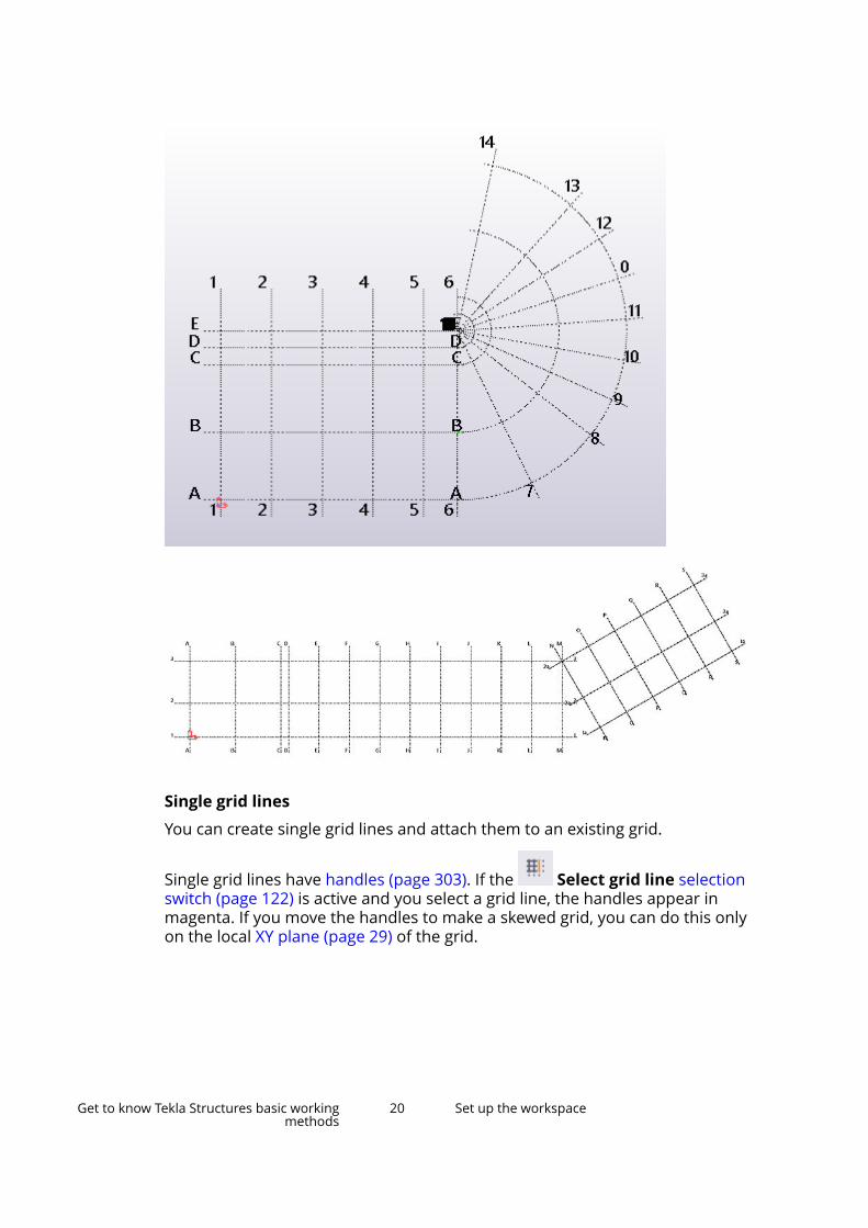
Single grid lines
You can create single grid lines and attach them to an existing grid.
Single grid lines have handles (page 303). If the Select grid line selectionswitch (page 122) is active and you select a grid line, the handles appear inmagenta. If you move the handles to make a skewed grid, you can do this onlyon the local XY plane (page 29) of the grid.
Get to know Tekla Structures basic workingmethods
20 Set up the workspace
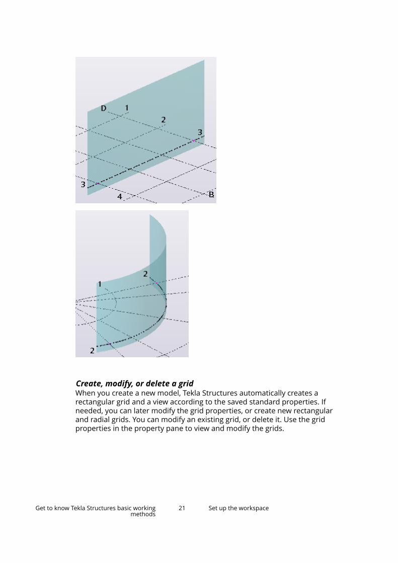
Create, modify, or delete a gridWhen you create a new model, Tekla Structures automatically creates arectangular grid and a view according to the saved standard properties. Ifneeded, you can later modify the grid properties, or create new rectangularand radial grids. You can modify an existing grid, or delete it. Use the gridproperties in the property pane to view and modify the grids.
Get to know Tekla Structures basic workingmethods
21 Set up the workspace
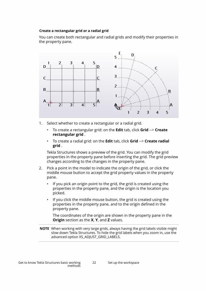
Create a rectangular grid or a radial grid
You can create both rectangular and radial grids and modify their properties inthe property pane.
1. Select whether to create a rectangular or a radial grid.
• To create a rectangular grid: on the Edit tab, click Grid --> Createrectangular grid .
• To create a radial grid: on the Edit tab, click Grid --> Create radialgrid .
Tekla Structures shows a preview of the grid. You can modify the gridproperties in the property pane before inserting the grid. The grid previewchanges according to the changes in the property pane.
2. Pick a point in the model to indicate the origin of the grid, or click themiddle mouse button to accept the grid property values in the propertypane.
• If you pick an origin point to the grid, the grid is created using theproperties in the property pane, and the origin is the location youpicked.
• If you click the middle mouse button, the grid is created using theproperties in the property pane, and to the origin defined in theproperty pane.
The coordinates of the origin are shown in the property pane in theOrigin section as the X, Y, and Z values.
NOTE When working with very large grids, always having the grid labels visible mightslow down Tekla Structures. To hide the grid labels when you zoom in, use theadvanced option XS_ADJUST_GRID_LABELS.
Get to know Tekla Structures basic workingmethods
22 Set up the workspace
Create a radial grid (alternative method)
This is an alternative method to create a radial grid. You can create a radialgrid using a component called Radial Grid. Note that the curved grid linescreated by the Radial Grid component are not truly curved but straight.
1. Click the Applications & components button in the side pane toopen the Applications & components catalog.
2. Start typing radial grid in the search box.
3. Double-click Radial Grid to open the properties dialog box.
4. Modify the grid properties.
In the coordinate properties
• X defines the location of the curved grid lines and the distancebetween the grid lines.
The first value is the radius of the innermost curved grid line.
• Y (degrees) defines the location of the straight grid lines and thedistance between the grid lines in degrees.
The first value defines how the grid is rotated. The grid is rotatedcounter-clockwise from the x axis in the current work plane.
5. Click OK.
6. Pick a point to indicate the origin of the grid.
The grid is created automatically.
Modify a gridDouble-click an existing grid to modify it.
1. Ensure that the Select grid selection switch (page 122) is active.
2. Double-click a grid line.
Depending on the type of the grid, the Rectangular grid or the Radialgrid properties open in the property pane.
3. Change the grid properties.
4. Click Modify to apply the changes.
Delete a gridWhen you delete an entire grid, ensure that you do not have any other objectsselected. Otherwise Tekla Structures only deletes the objects, not the grid.
1. Ensure that only the Select grid selection switch (page 122) is active.
2. Select the grid.
Get to know Tekla Structures basic workingmethods
23 Set up the workspace

3. Press Delete.
4. Confirm that you want to delete the grid.
Grid propertiesUse the Rectangular grid or the Radial grid properties in the property paneto view and modify the properties of a grid. To open the properties, double-click the grid. The file name extension of a rectangular grid property file is*.grd. The file name extension of a radial grid property file is *.rgrd.
If you have customized the property pane layout, the list of properties may bedifferent.
Setting DescriptionCoordinates In the Rectangular grid properties:
Coordinates of the grid in the x, y, and z directions.
X: grid lines vertical to the work plane
Y: grid lines horizontal to the work plane
Z: elevations in the structure
You can enter a maximum of 1024 characters. Use azero at the start to represent a grid on the 0,0coordinate and spaces as separators forcoordinates.
The x and y coordinates are relative, which meansthat the entries for X and Y are always relative tothe previous entry. The Z coordinates are absolute,which means that entries for z are absolutedistances from the work plane origin.
You can either define the coordinates individually,or you can define several grid lines with equalspacing. Both of the following coordinate entriescreate three grid lines with the spacing of 4000:
0 4000 40000 2*4000In the Radial grid properties:
Radial and angular values of the grid lines.Elevations is the value of the grid in z direction.
Radial: curved grid lines. If you enter only one valuefor radius, it must be >0.
Angular: straight grid lines. You can enter negativeangle values, if needed.
Elevations: elevations in the structure
Get to know Tekla Structures basic workingmethods
24 Set up the workspace

Setting DescriptionUse a zero at the start to represent a grid on the 0,0coordinate and spaces as separators forcoordinates.
The Radial and Angular coordinates are relative,which means that the entries are always relative tothe previous entry. The Elevations are absolute,which means that entries are absolute distancesfrom the work plane origin.
You can either define the coordinates individually,or you can define several grid lines with equalspacing. Both of the following coordinate entriescreate three grid lines with the spacing of 4000:
0 4000 40000 2*4000
Labels In the Rectangular grid properties:
Names of the grid lines shown in views.
Names in the X box are associated with the gridlines parallel to the y axis and vice versa. The Z boxis for the names of levels parallel to the work plane.
If you wish, you can leave the label boxes empty.In the Radial grid properties:
Names of the grid lines shown in views.
Names in the Radial box are associated with thecurved grid lines.
Names in the Angular box are associated with thestraight grid lines.
The Elevations box is for the names of levelsparallel to the work plane.
If you wish, you can leave the label boxes empty.Line extensions In the Rectangular grid properties:
Define how far the grid lines extend in the directionsLeft/Below and Right/Above.In the Radial grid properties:
Define how far the grid lines extend in the directionsStart and End.
Origin Coordinates of the grid origin in the x, y, and zdirections. These values offset the grid from thework plane origin, not from the global model origin.
Get to know Tekla Structures basic workingmethods
25 Set up the workspace
Setting DescriptionMagnetic grid plane In the Rectangular grid properties:
Select whether objects are bind to grid lines(page 26). If you bind the objects to grid lines, theobjects follow if you move the grid line.
Grid color Use the color picker to pick the grid color.Label font size andcolor
Define the label font size.
Use the color picker to pick the label color.Custom properties Click the More button to open the user-defined
attributes (UDAs) of the grid.
Add a single grid lineYou can add new grid lines either between existing grid lines or between twofreely chosen points that you define in the model.
Add a grid line between existing grid linesYou can add new grid lines between existing grid lines.
1. Ensure that the Direct modification switch is active.
2. Ensure that the Select grid selection switch (page 122) is active.
3. Select an existing grid to attach the grid line to.
4. Click the symbol between two existing grid lines or outside the grid.
Tekla Structures creates the grid line and gives it a label using the labels ofthe adjacent grid lines. For example, a new grid line between the grid lines1 and 2 receives the label 12*.
Add a grid line between two pointsYou can add new grid lines between two picked points.
1. On the Edit tab, click Grid --> Add grid line .
2. Select an existing grid to attach the grid line to.
3. Pick the start point of the grid line.
4. Pick the end point of the grid line.
Tekla Structures creates the grid line.
Modify a single grid lineYou can modify single grid line properties. You can also move grid lines orchange the grid line labels.
Get to know Tekla Structures basic workingmethods
26 Set up the workspace
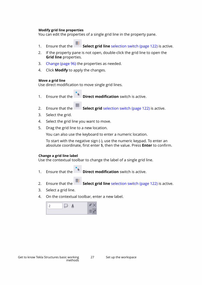
Modify grid line propertiesYou can edit the properties of a single grid line in the property pane.
1. Ensure that the Select grid line selection switch (page 122) is active.
2. If the property pane is not open, double-click the grid line to open theGrid line properties.
3. Change (page 96) the properties as needed.
4. Click Modify to apply the changes.
Move a grid lineUse direct modification to move single grid lines.
1. Ensure that the Direct modification switch is active.
2. Ensure that the Select grid selection switch (page 122) is active.
3. Select the grid.
4. Select the grid line you want to move.
5. Drag the grid line to a new location.
You can also use the keyboard to enter a numeric location.
To start with the negative sign (-), use the numeric keypad. To enter anabsolute coordinate, first enter $, then the value. Press Enter to confirm.
Change a grid line labelUse the contextual toolbar to change the label of a single grid line.
1. Ensure that the Direct modification switch is active.
2. Ensure that the Select grid line selection switch (page 122) is active.
3. Select a grid line.
4. On the contextual toolbar, enter a new label.
Get to know Tekla Structures basic workingmethods
27 Set up the workspace

Stretch, shrink, or incline a grid lineUse direct modification to stretch, shrink, or incline single grid lines inrectangular grids.
Note that this works only for the single grid lines that you have added inrectangular grids by using the Add grid line command.
1. Ensure that the Direct modification switch is active.
2. Ensure that the Select grid selection switch (page 122) is active.
3. Select the rectangular grid.
4. Select the grid line.
5. Drag a grid line handle to a new location.
Turn grid line stretching offIf you move the outermost grid lines in rectangular grids using the linehandles, Tekla Structures stretches or shrinks the perpendicular, crossing gridlines accordingly by default. You can switch this off temporarily.
1. Ensure that the Direct modification switch is active.
2. Ensure that the Select grid selection switch (page 122) is active.
3. Select the grid line.
4. On the contextual toolbar, click the Turn grid line stretching offbutton.
Grid line propertiesUse the Grid line properties in the property pane to view and modify theproperties of a single grid line. To open the properties, double-click a singlegrid line. The file name extension of a grid line property file is .grdp.
The units depend on the settings in File menu --> Settings --> Options -->Units and decimals .
Setting DescriptionLabel Name of the grid line.Depth in view plane Height of the grid plane
perpendicular to the view plane.Line extension Left/Below Define how far the grid lines extend in
the directions Left/Below and Right/Above.
Line extension Right/Above
Get to know Tekla Structures basic workingmethods
28 Set up the workspace

Setting DescriptionMagnetic Select whether objects are bind to
straight the grid lines. If you bind theobjects to grid lines, the objects followif you move the grid line.
Visible in drawing Select whether grid lines are madevisible in drawings.
Grid line automatic dimensioning Select whether single grid lines areused in grid dimensioning.
More Click the More button to open theuser-defined attributes (UDAs) of thegrid line.
Delete a single grid lineYou can delete grid lines in two different ways. The easiest way is by usingdirect modification.
Delete a grid line using direct modificationUse direct modification to quickly delete single grid lines.
1. Ensure that the Direct modification switch is active.
2. Select the grid line you want to delete.
3. Press Delete.
Delete a grid line (alternative method)This is the alternative way of deleting single grid lines.
1. Ensure that the Select grid line selection switch (page 122) is active.
2. Select the grid line you want to delete.
3. Ensure that you do not have any other objects selected.
If you also have other objects selected, Tekla Structures only deletes theobjects, not the grid line.
4. Right-click and select Delete from the pop-up menu.
5. Confirm that you want to delete the grid line.
Work with viewsA view is a representation of a model from a specific location. Each view isrepresented in its own window within Tekla Structures. Selecting a part in aview highlights the part in all open views.
Get to know Tekla Structures basic workingmethods
29 Set up the workspace
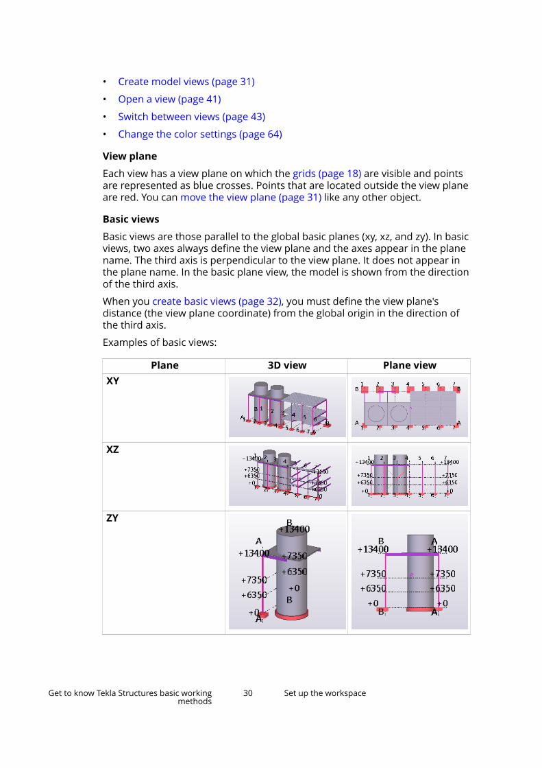
• Create model views (page 31)
• Open a view (page 41)
• Switch between views (page 43)
• Change the color settings (page 64)
View plane
Each view has a view plane on which the grids (page 18) are visible and pointsare represented as blue crosses. Points that are located outside the view planeare red. You can move the view plane (page 31) like any other object.
Basic views
Basic views are those parallel to the global basic planes (xy, xz, and zy). In basicviews, two axes always define the view plane and the axes appear in the planename. The third axis is perpendicular to the view plane. It does not appear inthe plane name. In the basic plane view, the model is shown from the directionof the third axis.
When you create basic views (page 32), you must define the view plane'sdistance (the view plane coordinate) from the global origin in the direction ofthe third axis.
Examples of basic views:
Plane 3D view Plane viewXY
XZ
ZY
Get to know Tekla Structures basic workingmethods
30 Set up the workspace
Other views
For other view types, you either define the view plane and coordinate bypicking points, or the points are defined automatically, depending on thecreation method.
Should I model in a 3D or plane view?
Views can be 3D or plane views. 3D, plane, and also elevation views providedifferent type of information, which is useful for different tasks.
One common technique is to open several views:
• A 3D view to see a real-life version of the model
• A plane view, where you can add and connect parts
• An elevation view to check the level
If you are working with several screens, maximize your work area by puttingthe different views on different screens.
You can easily switch between the 3D and plane view by using the keyboardshortcut Ctrl+P.
Move the view planeYou can move the view plane like any other object. When you move it, TeklaStructures only uses the vector that is perpendicular to the view plane.
1. Click the view.
2. Right-click and select Move --> Linear.
3. Pick the start point of the translation vector, or enter its coordinates.
4. Pick the end point of the translation vector, or enter its coordinates.
5. Click Move to move the view plane.
Create model viewsYou can create model views in several ways in Tekla Structures.
For example, you can create views
• of the entire model (3D view) (page 32)
• of selected parts (page 37)
• of selected components (page 38)
• along grid lines (axis views) (page 33)
• to the surface of an object (page 38)
Each view has properties which define its appearance. You can change theappearance of a view after you have created it. To view and modify the
Get to know Tekla Structures basic workingmethods
31 Set up the workspace
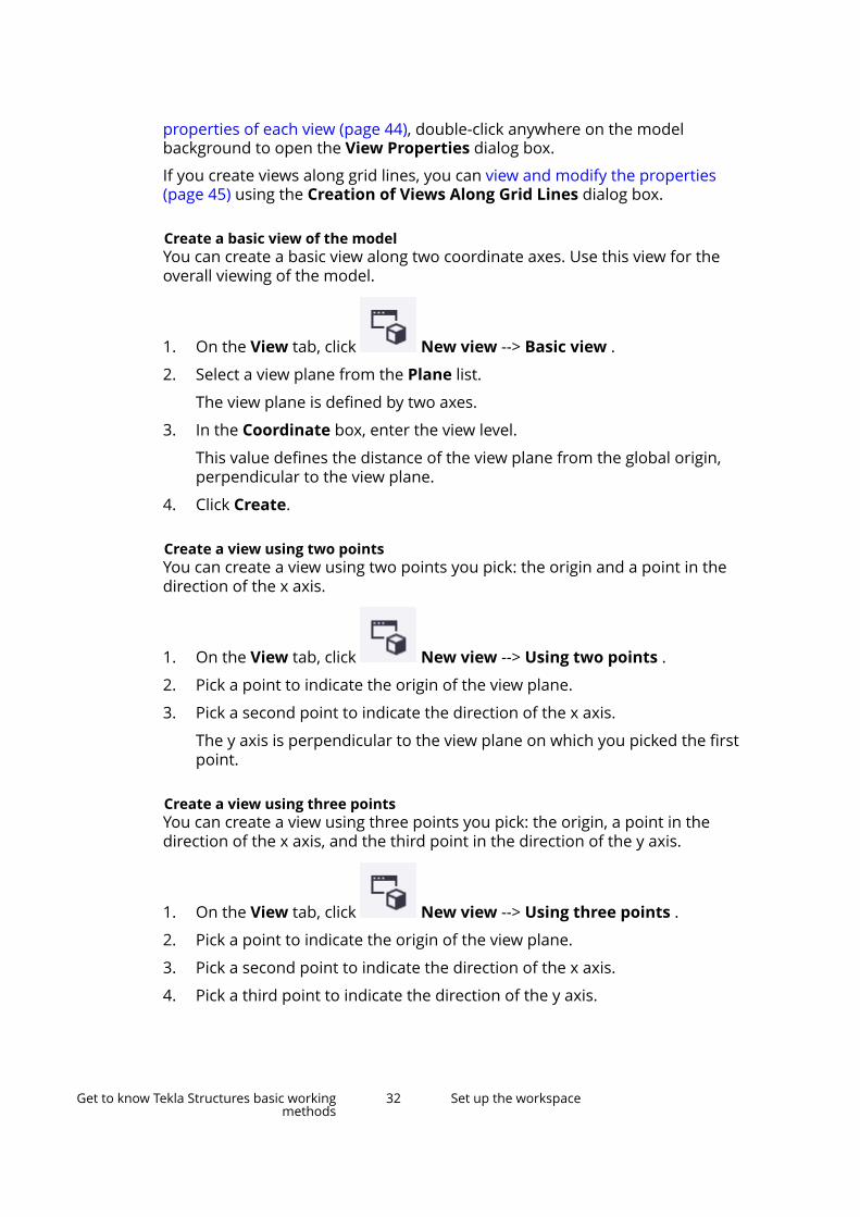
properties of each view (page 44), double-click anywhere on the modelbackground to open the View Properties dialog box.
If you create views along grid lines, you can view and modify the properties(page 45) using the Creation of Views Along Grid Lines dialog box.
Create a basic view of the modelYou can create a basic view along two coordinate axes. Use this view for theoverall viewing of the model.
1. On the View tab, click New view --> Basic view .
2. Select a view plane from the Plane list.
The view plane is defined by two axes.
3. In the Coordinate box, enter the view level.
This value defines the distance of the view plane from the global origin,perpendicular to the view plane.
4. Click Create.
Create a view using two pointsYou can create a view using two points you pick: the origin and a point in thedirection of the x axis.
1. On the View tab, click New view --> Using two points .
2. Pick a point to indicate the origin of the view plane.
3. Pick a second point to indicate the direction of the x axis.
The y axis is perpendicular to the view plane on which you picked the firstpoint.
Create a view using three pointsYou can create a view using three points you pick: the origin, a point in thedirection of the x axis, and the third point in the direction of the y axis.
1. On the View tab, click New view --> Using three points .
2. Pick a point to indicate the origin of the view plane.
3. Pick a second point to indicate the direction of the x axis.
4. Pick a third point to indicate the direction of the y axis.
Get to know Tekla Structures basic workingmethods
32 Set up the workspace

Create a view of the work planeYou can create a view of the work plane using the current view properties.
• On the View tab, click New view --> On work plane .
Create grid viewsYou can create views along the grid lines you select.
Before you start, create a view that contains a grid, and check the gridproperties. Note that with radial grid you can create the grid views only on thestraight grid lines, not on the arched grid lines.
If the grid properties are incorrect in some way, Tekla Structures may cut theviews at the wrong elevations or they may be named incorrectly. If you changethe grid labels or the elevation or grids later on, the views will not beautomatically renamed.
1. Select the grid.
2. On the View tab, click New view --> Along grid lines .
3. Modify the grid view properties if needed.
a. In the Number of views list, select how many views you want tocreate.
b. In the View name prefix box, enter a prefix.
c. In the View properties list, define which view properties (applied orsaved) you want to use.
4. Click Create.
The Views dialog box opens.
5. Click the arrow buttons to move views from the Named views list to theVisible views list.
The views will not be visible until you move them to the Visible views list.
Example
This example shows how to create vertical views of the grid lines 1–7 on thefollowing model:
Get to know Tekla Structures basic workingmethods
33 Set up the workspace
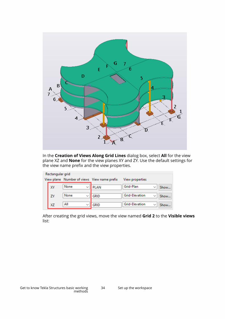
In the Creation of Views Along Grid Lines dialog box, select All for the viewplane XZ and None for the view planes XY and ZY. Use the default settings forthe view name prefix and the view properties.
After creating the grid views, move the view named Grid 2 to the Visible viewslist:
Get to know Tekla Structures basic workingmethods
34 Set up the workspace
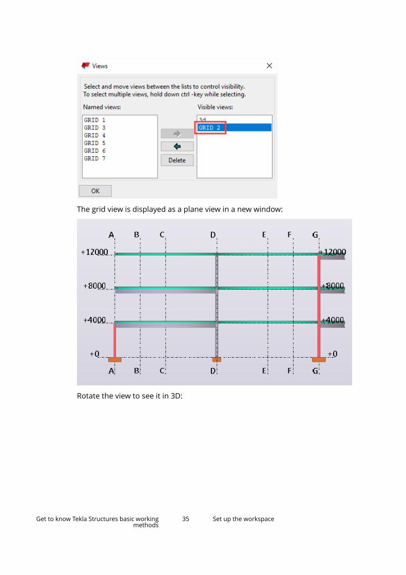
The grid view is displayed as a plane view in a new window:
Rotate the view to see it in 3D:
Get to know Tekla Structures basic workingmethods
35 Set up the workspace
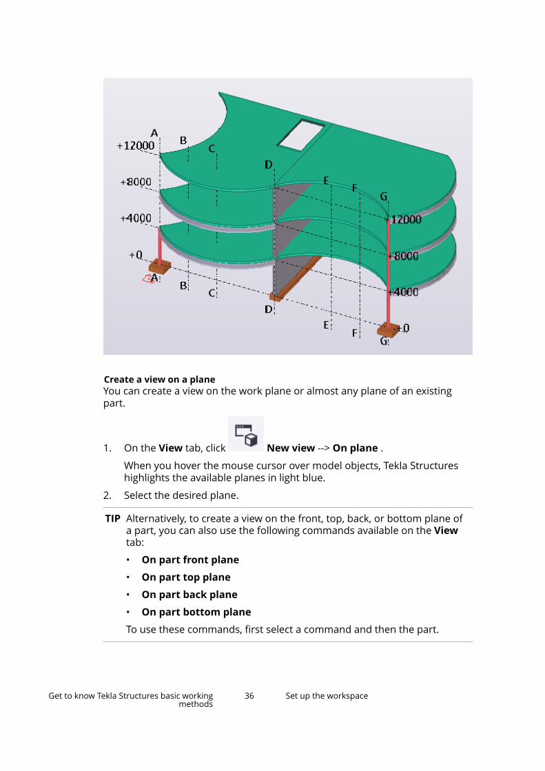
Create a view on a planeYou can create a view on the work plane or almost any plane of an existingpart.
1. On the View tab, click New view --> On plane .
When you hover the mouse cursor over model objects, Tekla Structureshighlights the available planes in light blue.
2. Select the desired plane.
TIP Alternatively, to create a view on the front, top, back, or bottom plane ofa part, you can also use the following commands available on the Viewtab:
• On part front plane
• On part top plane
• On part back plane
• On part bottom plane
To use these commands, first select a command and then the part.
Get to know Tekla Structures basic workingmethods
36 Set up the workspace
Create a 3D view of a partWhen you need to see a specific part clearly, create a 3D view of the part. Thepart is placed in the center of the view.
1. On the View tab, click New view --> 3D view of part .
2. Select the part.
Tekla Structures creates the view using the properties defined in thepart_basic_view property file. The view plane y axis is the global z axisof the model. The x axis is the projection of the part's local x axis onto theglobal xy plane.
Tekla Structures fits the work area to include the selected part.
If you want Tekla Structures to rotate the view once whenever you create anew 3D view, select the Basic view auto rotation setting in the File menu.
Create default part viewsYou can create four views of a part: front, top, end, and 3D view. TeklaStructures creates these views all at once with the same command. The front,top, and end views are plane views by default.
1. On the View tab, click New view --> Default part views .
2. Select the part.
Tekla Structures creates the four default views all at once, using theproperties defined in part_front_view, part_top_view,part_end_view, and part_persp_view property files.
Create an undeformed part viewYou can create a view that shows a deformed part in undeformed form. Thisworks only for beams and columns.
1. On the View tab, click New view --> Undeformed part view .
2. Select the part.
For example, select a warped beam. Tekla Structures displays the beam ina separate view in undeformed form.
Create a 3D view of a componentWhen you need to see a specific component clearly, create a 3D view of thecomponent. The component is placed in the center of the view.
Get to know Tekla Structures basic workingmethods
37 Set up the workspace
1. On the View tab, click New view --> 3D view of component .
2. Select the component.
Tekla Structures creates the view, using the properties defined in thecomponent_basic_view property file. The view plane y axis is the globalz axis of the model. The x axis is the projection of the first secondary partlocal x axis onto the global xy plane. Work area depth is 1 m in alldirections.
The component you select automatically defines the work area.
If you want Tekla Structures to rotate the view once whenever you create anew 3D view, select the Basic view auto rotation setting in the File menu.
Create default component viewsYou can create four views of a component: front, top, end, and 3D view. TeklaStructures creates these views all at once with the same command. The front,top, and end views are plane views by default.
1. On the View tab, click New view --> Default views ofcomponent .
2. Select the component.
Tekla Structures creates the four default views all at once, using theproperties defined in the component_front_view,component_top_view, component_end_view, andcomponent_persp_view property files.
Create a surface viewUse the Create surface view macro to create an automatically aligned surfaceview. This can be useful when modeling bolt groups, stiffener plates, and holepenetrations on complex geometry.
To be able to select the surface of a part, ensure that you are using a modelview that shows part faces. On the View tab, click Rendering, and select eitherthe Parts grayscale or the Parts rendered option.
1. Click the Applications & components button in the side pane toopen the Applications & components catalog.
2. Click the arrow next to Applications to open the applications list.
3. Double-click Create surface view to start the macro.
4. Select the surface of the part.
Get to know Tekla Structures basic workingmethods
38 Set up the workspace
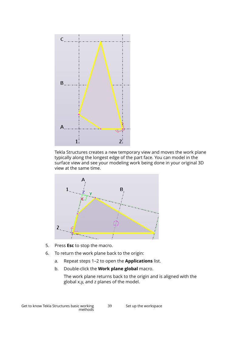
Tekla Structures creates a new temporary view and moves the work planetypically along the longest edge of the part face. You can model in thesurface view and see your modeling work being done in your original 3Dview at the same time.
5. Press Esc to stop the macro.
6. To return the work plane back to the origin:
a. Repeat steps 1–2 to open the Applications list.
b. Double-click the Work plane global macro.
The work plane returns back to the origin and is aligned with theglobal x,y, and z planes of the model.
Get to know Tekla Structures basic workingmethods
39 Set up the workspace
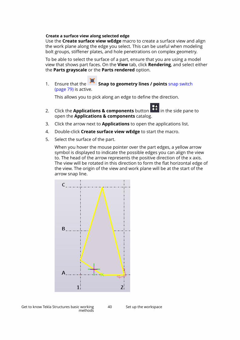
Create a surface view along selected edgeUse the Create surface view wEdge macro to create a surface view and alignthe work plane along the edge you select. This can be useful when modelingbolt groups, stiffener plates, and hole penetrations on complex geometry.
To be able to select the surface of a part, ensure that you are using a modelview that shows part faces. On the View tab, click Rendering, and select eitherthe Parts grayscale or the Parts rendered option.
1. Ensure that the Snap to geometry lines / points snap switch(page 79) is active.
This allows you to pick along an edge to define the direction.
2. Click the Applications & components button in the side pane toopen the Applications & components catalog.
3. Click the arrow next to Applications to open the applications list.
4. Double-click Create surface view wEdge to start the macro.
5. Select the surface of the part.
When you hover the mouse pointer over the part edges, a yellow arrowsymbol is displayed to indicate the possible edges you can align the viewto. The head of the arrow represents the positive direction of the x axis.The view will be rotated in this direction to form the flat horizontal edge ofthe view. The origin of the view and work plane will be at the start of thearrow snap line.
Get to know Tekla Structures basic workingmethods
40 Set up the workspace
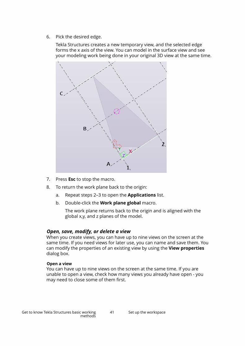
6. Pick the desired edge.
Tekla Structures creates a new temporary view, and the selected edgeforms the x axis of the view. You can model in the surface view and seeyour modeling work being done in your original 3D view at the same time.
7. Press Esc to stop the macro.
8. To return the work plane back to the origin:
a. Repeat steps 2–3 to open the Applications list.
b. Double-click the Work plane global macro.
The work plane returns back to the origin and is aligned with theglobal x,y, and z planes of the model.
Open, save, modify, or delete a viewWhen you create views, you can have up to nine views on the screen at thesame time. If you need views for later use, you can name and save them. Youcan modify the properties of an existing view by using the View propertiesdialog box.
Open a viewYou can have up to nine views on the screen at the same time. If you areunable to open a view, check how many views you already have open - youmay need to close some of them first.
Get to know Tekla Structures basic workingmethods
41 Set up the workspace
1. On the View tab, click View list to open the Views dialog box.
Tekla Structures lists all invisible named views on the left, and all visibleviews on the right.
2. Select a view from the Named views list and click the right arrow to moveit to the Visible views list.
You can also double-click a view to open it. If the view does not appear,check how many views you already have open.
3. To open multiple views, use the Shift and Ctrl keys when you select viewsfrom the list.
Save a viewIf you need to re-open views later on, give each view a unique name. Whenyou exit the model, Tekla Structures only saves the named views. Temporaryviews disappear when you close them.
Before you start, create one or more views (page 31) in the model.
1. Double-click the view to open the View Properties dialog box.
2. Enter a unique name in the Name box.
Temporary views have a default name in parentheses. Do not useparentheses when naming a view, or the view will not be saved for lateruse.
NOTE In multi-user mode, it is very important to give views uniquenames. If several users have different views with the same name,the view settings of one user may accidentally override thesettings of another user.
3. Click Modify.
Tekla Structures will automatically save all named views when you closethe model.
Modify a viewYou can modify a view simply by double-clicking it.
1. Double-click the view to open the View Properties dialog box.
2. Modify the view properties (page 44).
3. Click Modify.
Delete a viewYou can permanently delete named views.
Get to know Tekla Structures basic workingmethods
42 Set up the workspace
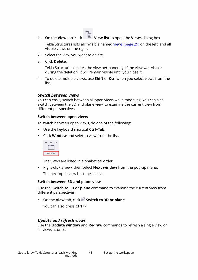
1. On the View tab, click View list to open the Views dialog box.
Tekla Structures lists all invisible named views (page 29) on the left, and allvisible views on the right.
2. Select the view you want to delete.
3. Click Delete.
Tekla Structures deletes the view permanently. If the view was visibleduring the deletion, it will remain visible until you close it.
4. To delete multiple views, use Shift or Ctrl when you select views from thelist.
Switch between viewsYou can easily switch between all open views while modeling. You can alsoswitch between the 3D and plane view, to examine the current view fromdifferent perspectives.
Switch between open views
To switch between open views, do one of the following:
• Use the keyboard shortcut Ctrl+Tab.
• Click Window and select a view from the list.
The views are listed in alphabetical order.
• Right-click a view, then select Next window from the pop-up menu.
The next open view becomes active.
Switch between 3D and plane view
Use the Switch to 3D or plane command to examine the current view fromdifferent perspectives.
• On the View tab, click Switch to 3D or plane.
You can also press Ctrl+P.
Update and refresh viewsUse the Update window and Redraw commands to refresh a single view orall views at once.
Get to know Tekla Structures basic workingmethods
43 Set up the workspace
• Update: Removes temporary graphics (such as measured distances) butdoes not redraw the view. Faster than redrawing.
• Redraw: Redraws the view completely and shows all previously hiddenobjects.
To Do thisUpdate the current view Right-click the view and select Update window.Update all of the views On the View tab, click Redraw --> Erase
temporary graphics.
Redraw the current view Right-click the view and select Redraw View.Redraw all of the views
On the View tab, click .
See also
Switch between views (page 43)
View propertiesUse the View Properties dialog box to view and modify the model viewproperties.
Option DescriptionName The name of the view.Angle Whether the view angle is Plane or
3D.Projection The projection type of views.
Orthogonal: All objects are of equalsize (no perspective). When youzoom, text and point size remains thesame. In addition, the zoom remainson object faces.
Perspective: Distant objects appearsmaller than close ones, as do textand points. You can zoom, rotate, orfly through the model.
Get to know Tekla Structures basic workingmethods
44 Set up the workspace

Option DescriptionRotation How the view is rotated around the z
and x axes. Rotation is view-specific.
The units depend on the settings inFile menu --> Settings --> Options --> Units and decimals .
Color and transparency in all views The color and transparency settingthat is used in all views (according tothe status of the objects in themodel).
Representation... Opens the Object Representationdialog box for defining color andtransparency settings.
View depth The thickness of the displayed slice ofmodel. You can define the depthseparately upwards and downwardsfrom the view plane. Only objectspositioned within the view depth arevisible in the model.
The units depend on the settings inFile menu --> Settings --> Options --> Units and decimals .
Display... Opens the Display dialog box fordefining which objects are displayed(page 918) in the view and how.
Visible object group Which object group is displayed in theview.
Object group... Opens the Object Group - ViewFilter dialog box for creating andmodifying object groups.
See also
Open, save, modify, or delete a view (page 41)
Grid view propertiesUse the Creation of Views Along Grid Lines dialog box to view and modifythe properties of grid views.
Option DescriptionView plane The plane of the view defined by two axes similarly to the
default view.Number of views Defines which grid lines the views will be created of.
None does not create any views.
Get to know Tekla Structures basic workingmethods
45 Set up the workspace
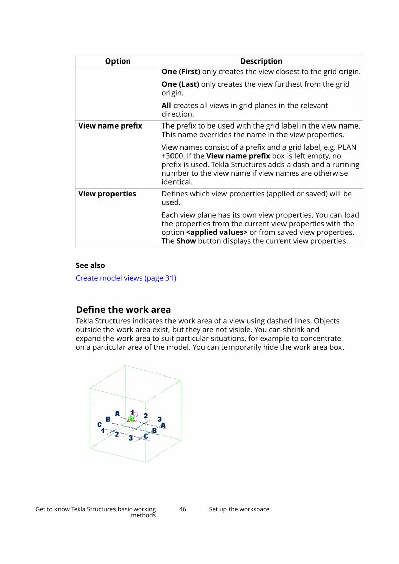
Option DescriptionOne (First) only creates the view closest to the grid origin.
One (Last) only creates the view furthest from the gridorigin.
All creates all views in grid planes in the relevantdirection.
View name prefix The prefix to be used with the grid label in the view name.This name overrides the name in the view properties.
View names consist of a prefix and a grid label, e.g. PLAN+3000. If the View name prefix box is left empty, noprefix is used. Tekla Structures adds a dash and a runningnumber to the view name if view names are otherwiseidentical.
View properties Defines which view properties (applied or saved) will beused.
Each view plane has its own view properties. You can loadthe properties from the current view properties with theoption <applied values> or from saved view properties.The Show button displays the current view properties.
See also
Create model views (page 31)
Define the work areaTekla Structures indicates the work area of a view using dashed lines. Objectsoutside the work area exist, but they are not visible. You can shrink andexpand the work area to suit particular situations, for example to concentrateon a particular area of the model. You can temporarily hide the work area box.
Get to know Tekla Structures basic workingmethods
46 Set up the workspace

Fit work area to entire modelYou can resize the work area to include all model objects, either in all views orin selected views only.
1. On the View tab, click Work area and select one of the following:
• To entire model in all views
Fits the work area to include all model objects in all visible views.
• To entire model in selected views
Fits the work area to include all model objects in the selected views.
Fit work area to selected partsYou can resize the work area to include only selected parts, either in all viewsor in selected views only.
1. Select the objects you want to include.
2. On the View tab, click Work area and select one of the following:
• To selected parts in all views
Fits the work area to include the selected model objects in all views.
• To selected parts in selected views
Fits the work area to include the selected model objects in the selectedviews.
Fit work area using two pointsYou can resize the work area based on two corner points you pick on the viewplane. The depth of the work area is the same as the view depth.
1. On the View tab, click Work area and select Using two points.
2. Pick the first point.
3. Pick the second point.
Hide the work area boxYou can temporarily hide the work area box in a view. This can be useful, forexample, when creating screenshots for presentations.
1. Hold down the Ctrl and Shift keys simultaneously.
2. On the View tab, click Redraw --> Redraw all views.
Get to know Tekla Structures basic workingmethods
47 Set up the workspace

3. To make the box visible again, click Redraw --> Redraw all views again.
TIP Alternatively, use the advanced option XS_HIDE_WORKAREA.
If you cannot see all objectsThe visibility of objects in a view depends on a number of different settings. Ifyou cannot see all the desired objects in a model view, check the followingsettings:
• work area
• view depth
• view filter
• view and representation settings
• color and transparency settings
Note that work area and view depth are like two virtual boxes. Objects thathave their handles partially or totally inside both boxes are visible. Newlycreated objects are also visible outside the view depth but never outside thework area. When you redraw a view, only the objects inside the view depth aredisplayed.
See also
Show and hide model objects (page 581)
View properties (page 44)
Define the work area (page 46)
Filter objects (page 155)
Coordinate systemTekla Structures uses two coordinate systems: the global and the localcoordinate system. The local coordinate system is also known as the workplane.
Global coordinate system
The green cube symbol represents the global coordinate system and lies at theglobal point of origin (x=0, y=0, z=0). The global coordinate system is static andit cannot be changed.
Get to know Tekla Structures basic workingmethods
48 Set up the workspace
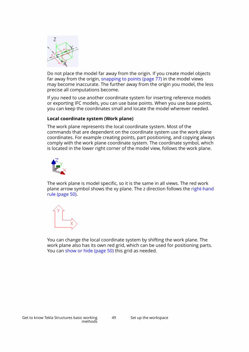
Do not place the model far away from the origin. If you create model objectsfar away from the origin, snapping to points (page 77) in the model viewsmay become inaccurate. The further away from the origin you model, the lessprecise all computations become.
If you need to use another coordinate system for inserting reference modelsor exporting IFC models, you can use base points. When you use base points,you can keep the coordinates small and locate the model wherever needed.
Local coordinate system (Work plane)
The work plane represents the local coordinate system. Most of thecommands that are dependent on the coordinate system use the work planecoordinates. For example creating points, part positioning, and copying alwayscomply with the work plane coordinate system. The coordinate symbol, whichis located in the lower right corner of the model view, follows the work plane.
The work plane is model specific, so it is the same in all views. The red workplane arrow symbol shows the xy plane. The z direction follows the right-handrule (page 50).
You can change the local coordinate system by shifting the work plane. Thework plane also has its own red grid, which can be used for positioning parts.You can show or hide (page 50) this grid as needed.
Get to know Tekla Structures basic workingmethods
49 Set up the workspace
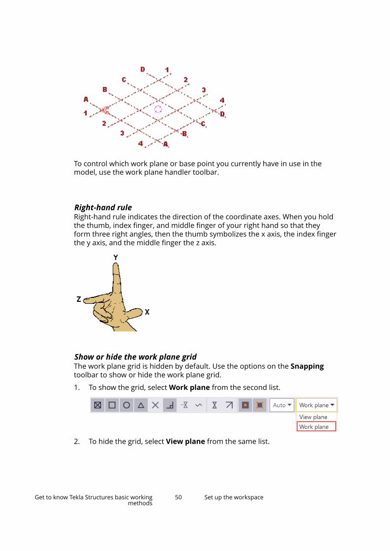
To control which work plane or base point you currently have in use in themodel, use the work plane handler toolbar.
Right-hand ruleRight-hand rule indicates the direction of the coordinate axes. When you holdthe thumb, index finger, and middle finger of your right hand so that theyform three right angles, then the thumb symbolizes the x axis, the index fingerthe y axis, and the middle finger the z axis.
Show or hide the work plane gridThe work plane grid is hidden by default. Use the options on the Snappingtoolbar to show or hide the work plane grid.
1. To show the grid, select Work plane from the second list.
2. To hide the grid, select View plane from the same list.
Get to know Tekla Structures basic workingmethods
50 Set up the workspace
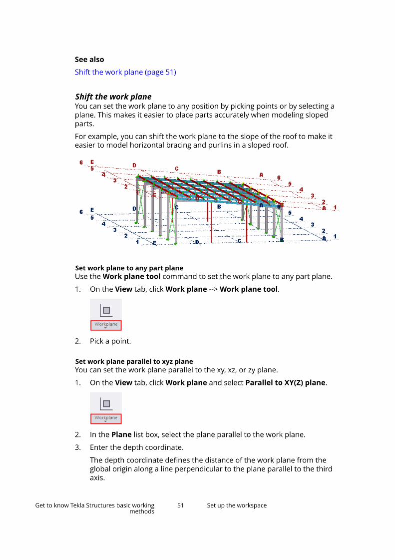
See also
Shift the work plane (page 51)
Shift the work planeYou can set the work plane to any position by picking points or by selecting aplane. This makes it easier to place parts accurately when modeling slopedparts.
For example, you can shift the work plane to the slope of the roof to make iteasier to model horizontal bracing and purlins in a sloped roof.
Set work plane to any part planeUse the Work plane tool command to set the work plane to any part plane.
1. On the View tab, click Work plane --> Work plane tool.
2. Pick a point.
Set work plane parallel to xyz planeYou can set the work plane parallel to the xy, xz, or zy plane.
1. On the View tab, click Work plane and select Parallel to XY(Z) plane.
2. In the Plane list box, select the plane parallel to the work plane.
3. Enter the depth coordinate.
The depth coordinate defines the distance of the work plane from theglobal origin along a line perpendicular to the plane parallel to the thirdaxis.
Get to know Tekla Structures basic workingmethods
51 Set up the workspace

4. Click Change.
Set work plane using one pointYou can set the work plane using one picked point. The work plane staysparallel to the current work plane, but moves it to a new position. The x and ydirections are unchanged.
1. On the View tab, click Work plane and select Using one point.
2. Pick the new position of the work plane.
Set work plane using two pointsYou can set the work plane using two picked points. The first point you pick isthe origin, the second defines the x direction of the work plane. The y directionremains the same as the previous work plane.
1. On the View tab, click Work plane and select Using two points.
2. Pick the origin of the work plane.
3. Pick a point in the work plane, in the positive x direction.
Set work plane using three pointsYou can set the work plane using three picked points. The first point you pick isthe origin, the second defines the x direction, and the third defines the ydirection of the work plane. Tekla Structures fixes the z direction according tothe right-hand rule.
1. On the View tab, click Work plane and select Using three points.
2. Pick the origin for the work plane.
3. Pick a point in the positive x direction.
4. Pick a point in the positive y direction.
Set work plane parallel to view planeYou can set the work plane to be the same as the view plane of a selectedview.
Get to know Tekla Structures basic workingmethods
52 Set up the workspace

1. On the View tab, click Work plane and select Parallel to view plane.
2. Select the view.
Restore the default work planeRemember to change back to the default work plane when you have finishedmodeling sloped structures.
1. On the View tab, click Work plane --> Parallel to XY(Z) plane.
2. In the Plane list, select XY.
3. In the Depth coordinate box, enter 0.
4. Click Change.
Base pointsThe base points (control points) allow you to use a coordinate system basedon the civil origin or other coordinate system for interoperability andcollaboration. For example, you can use base points when inserting referencemodels, exporting IFC models, in drawings, in Layout manager, and in reportsand templates.
Civil origin is the datum point or fundamental benchmark point of the nationalland survey network.
When you use base points, you can keep the coordinates small and locate themodel wherever needed. You can create as many base points as you need, andselect one of those to be the project base point.
Note the following:
• Reference model should not have any additional lines to the origin.
• Reference models should not include objects that are very far from eachother because otherwise using the model may get difficult.
• Tekla Structures native objects including reference models should not beinserted very far from the Tekla Structures model origin.
Define a base point
You can define base points in Project properties. In case you need to importor export a reference model, you need to know the coordinates of the
Get to know Tekla Structures basic workingmethods
53 Set up the workspace
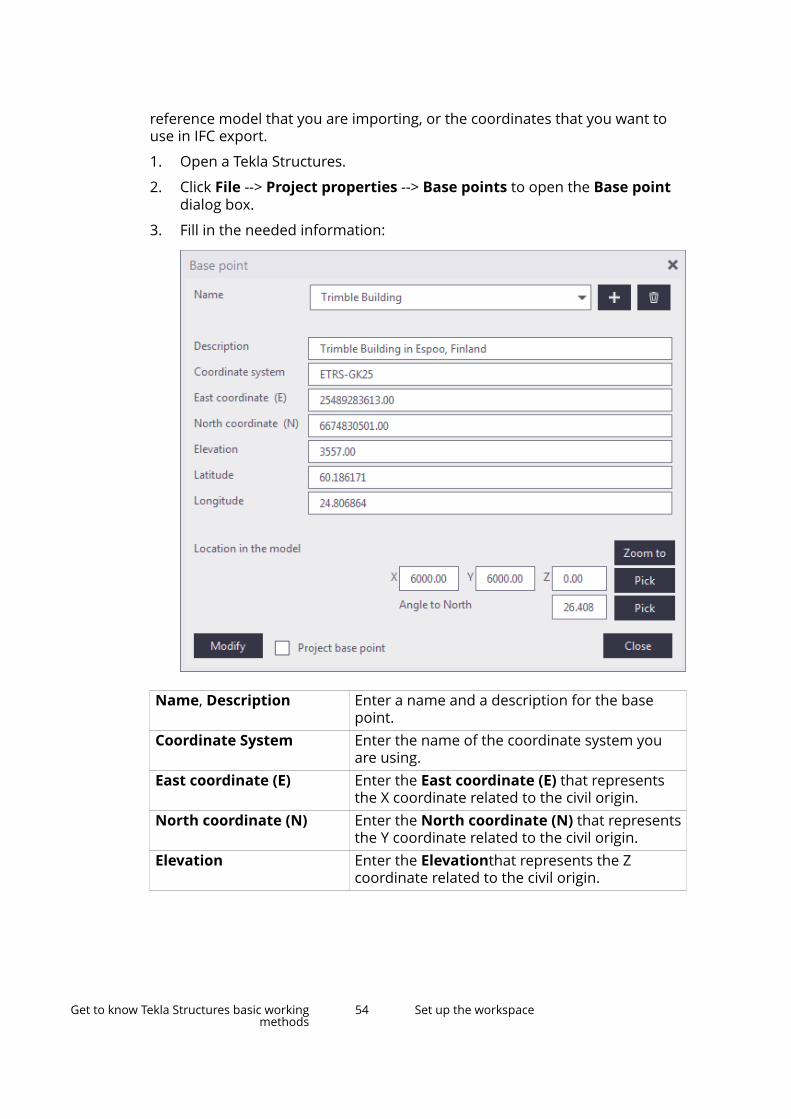
reference model that you are importing, or the coordinates that you want touse in IFC export.
1. Open a Tekla Structures.
2. Click File --> Project properties --> Base points to open the Base pointdialog box.
3. Fill in the needed information:
Name, Description Enter a name and a description for the basepoint.
Coordinate System Enter the name of the coordinate system youare using.
East coordinate (E) Enter the East coordinate (E) that representsthe X coordinate related to the civil origin.
North coordinate (N) Enter the North coordinate (N) that representsthe Y coordinate related to the civil origin.
Elevation Enter the Elevationthat represents the Zcoordinate related to the civil origin.
Get to know Tekla Structures basic workingmethods
54 Set up the workspace

Latitude,Longitude Enter the Latitude and Longitude of the basepoint to be used in the IFC export.
Latitude and Longitude is additionalinformation, which some software can use. Inthe IFC file, this is written to IFCSITEinformation.
If the total number of digits in Longitude ismore than 15, the value is rounded up to thenearest if it is > 99.999999999999999999.
To convert Latitude and Longitude informationbetween decimal format and degree/minute/second (DMS) format, see Convert Latitude/Longitude to decimal.
Location in the model Pick or enter a location for the base point in theTekla Structures model. The distance ismeasured from the model origin. The locationneeds to be near the model origin, preferablyless than 1000 m from the origin.
Angle to North Pick or enter the Angle to North, which is theangle between Y and North directions. Themaximum number of decimals for the angle is13.
Project base point If you want to set a coordinate system as theproject base point, select a base point from thelist at the top and then select the Project basepoint check box.
4. Click Modify to save the base point.
A blue symbol is added in the model.
If you later on make changes to the base point, the base point location inthe model changes according to the location or rotation changes youmake in the Base point dialog box when you press Enter or click anotherinput field, and there is no need to click Modify.
Get to know Tekla Structures basic workingmethods
55 Set up the workspace
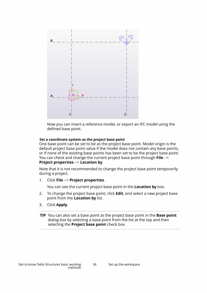
Now you can insert a reference model, or export an IFC model using thedefined base point.
Set a coordinate system as the project base pointOne base point can be set to be as the project base point. Model origin is thedefault project base point value if the model does not contain any base points,or if none of the existing base points has been set to be the project base point.You can check and change the current project base point through File -->Project properties --> Location by.
Note that it is not recommended to change the project base point temporarilyduring a project.
1. Click File --> Project properties.
You can see the current project base point in the Location by box.
2. To change the project base point, click Edit, and select a new project basepoint from the Location by list.
3. Click Apply.
TIP You can also set a base point as the project base point in the Base pointdialog box by selecting a base point from the list at the top and thenselecting the Project base point check box.
Get to know Tekla Structures basic workingmethods
56 Set up the workspace
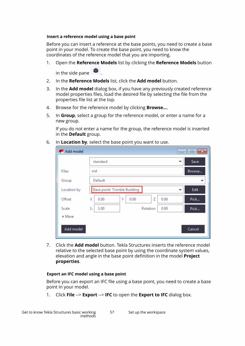
Insert a reference model using a base point
Before you can insert a reference at the base points, you need to create a basepoint in your model. To create the base point, you need to know thecoordinates of the reference model that you are importing.
1. Open the Reference Models list by clicking the Reference Models button
in the side pane .
2. In the Reference Models list, click the Add model button.
3. In the Add model dialog box, if you have any previously created referencemodel properties files, load the desired file by selecting the file from theproperties file list at the top.
4. Browse for the reference model by clicking Browse....
5. In Group, select a group for the reference model, or enter a name for anew group.
If you do not enter a name for the group, the reference model is insertedin the Default group.
6. In Location by, select the base point you want to use.
7. Click the Add model button. Tekla Structures inserts the reference modelrelative to the selected base point by using the coordinate system values,elevation and angle in the base point definition in the model Projectproperties.
Export an IFC model using a base point
Before you can export an IFC file using a base point, you need to create a basepoint in your model.
1. Click File --> Export --> IFC to open the Export to IFC dialog box.
Get to know Tekla Structures basic workingmethods
57 Set up the workspace

2. In Location by, select a base point that you have created.
3. Fill in other necessary IFC export information.
4. Click Export. The base point option exports the IFC model relative to thebase point using the coordinate system values, elevation, latitude,longitude and angle in the base point definition in the model Projectproperties.
Base points in drawingsIt is possible to use base-point-defined coordinate system values in drawings.If you change the project base point Z or the elevation value, the level valuewill change accordingly when a drawing is opened.
• Base point data can be used in drawing and view level to set the coordinatesystem. The base point can be used instead of datum offset.
• When the base point is set, level attributes and template attributes inmarks provide values in the specific base-point-defined coordinate system.
• This setting affects level marks and attributes that end with _BASEPOINT.
• When the base point is set at the drawing level, the _BASEPOINT templateattributes can be used in drawing templates.
You can set Location by in drawing view properties to use model origin,project base point or any base point defined coordinate system. Location byuses the project base point as the default value.
The datum level only affects the attributes TOP_LEVEL and TOP_LEVEL_UNFORMATTED when Location by is set to Model origin or to theproject base point that is in the model origin.
To change the Location by value:
1. In an open drawing, double-click the drawing view frame to open the ViewProperties dialog box.
2. On the Attributes 2 tab, set Location by to a new base point, or to themodel origin.
3. Click Modify.
Example of base point usage in a drawing
In the following example, do the following:
1. Create a slab with a thickness of 200 mm with the slab's top at the level 0in the model.
Get to know Tekla Structures basic workingmethods
58 Set up the workspace
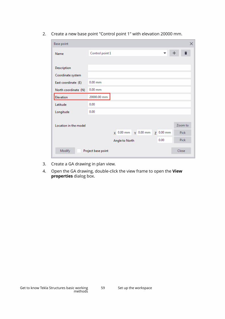
2. Create a new base point "Control point 1" with elevation 20000 mm.
3. Create a GA drawing in plan view.
4. Open the GA drawing, double-click the view frame to open the Viewproperties dialog box.
Get to know Tekla Structures basic workingmethods
59 Set up the workspace
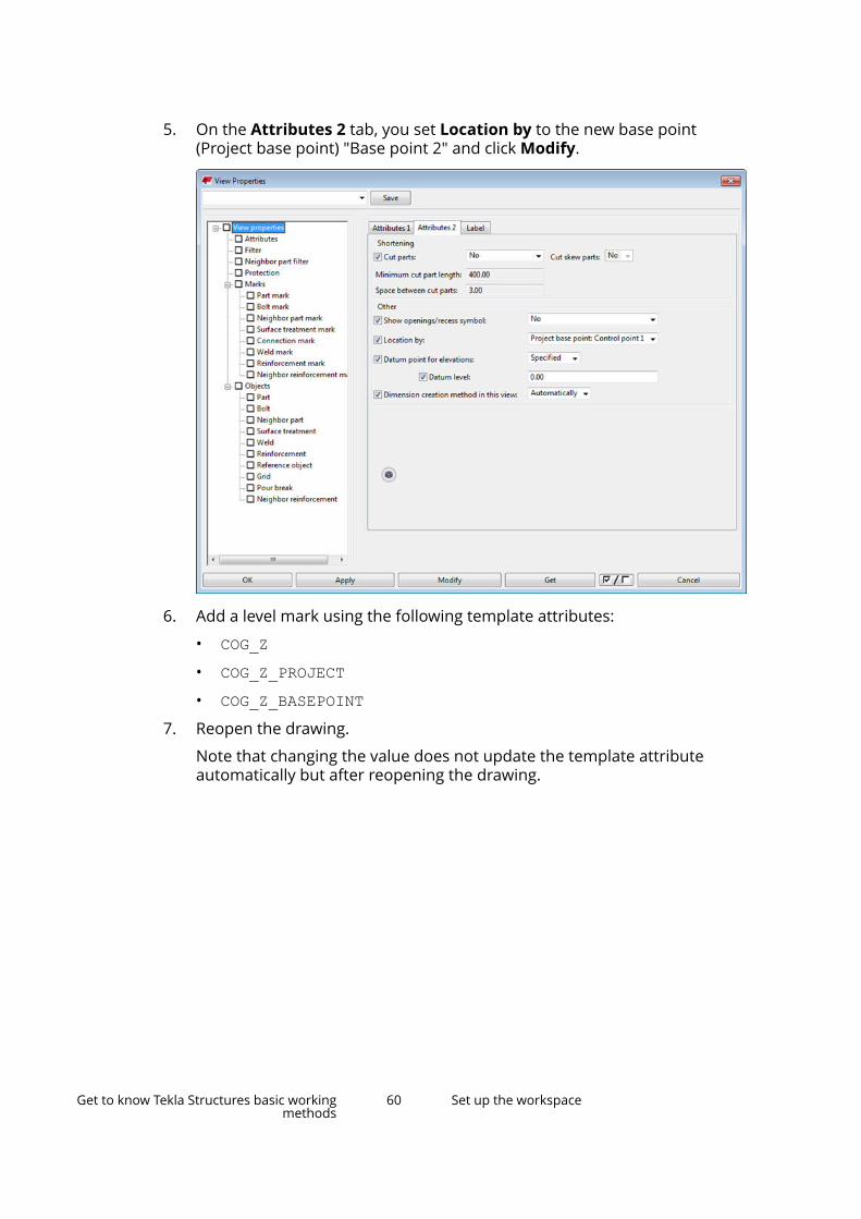
5. On the Attributes 2 tab, you set Location by to the new base point(Project base point) "Base point 2" and click Modify.
6. Add a level mark using the following template attributes:
• COG_Z• COG_Z_PROJECT• COG_Z_BASEPOINT
7. Reopen the drawing.
Note that changing the value does not update the template attributeautomatically but after reopening the drawing.
Get to know Tekla Structures basic workingmethods
60 Set up the workspace

Base points in Layout managerYou can use base points in Layout manager when defining the location oflayout points.
• You can use base points as location coordinates when exporting andimporting layout points.
• When you add, modify or delete base points, you need to reopen or refreshLayout manager to make the changed base point data available in Layoutmanager.
Base point in reports and templatesYou can inquire project base point and current base point value in reports andtemplates.
The following table lists the template attributes where you can use _PROJECTand _BASEPOINT at the end, for example, ASSEMBLY_BOTTOM_LEVEL_PROJECT or ASSEMBLY_BOTTOM_LEVEL_BASEPOINT. Note that _BASEPOINT uses thecurrent base point in the same way as the workplane uses the currentworkplane. If there is no current base point defined, _BASEPOINT providesvalues relative to model origin (Global).
Content type AttributesASSEMBLY, CAST_UNITand PART
ASSEMBLY_BOTTOM_LEVELASSEMBLY_BOTTOM_LEVEL_UNFORMATTEDASSEMBLY_TOP_LEVELASSEMBLY_TOP_LEVEL_UNFORMATTED
Get to know Tekla Structures basic workingmethods
61 Set up the workspace
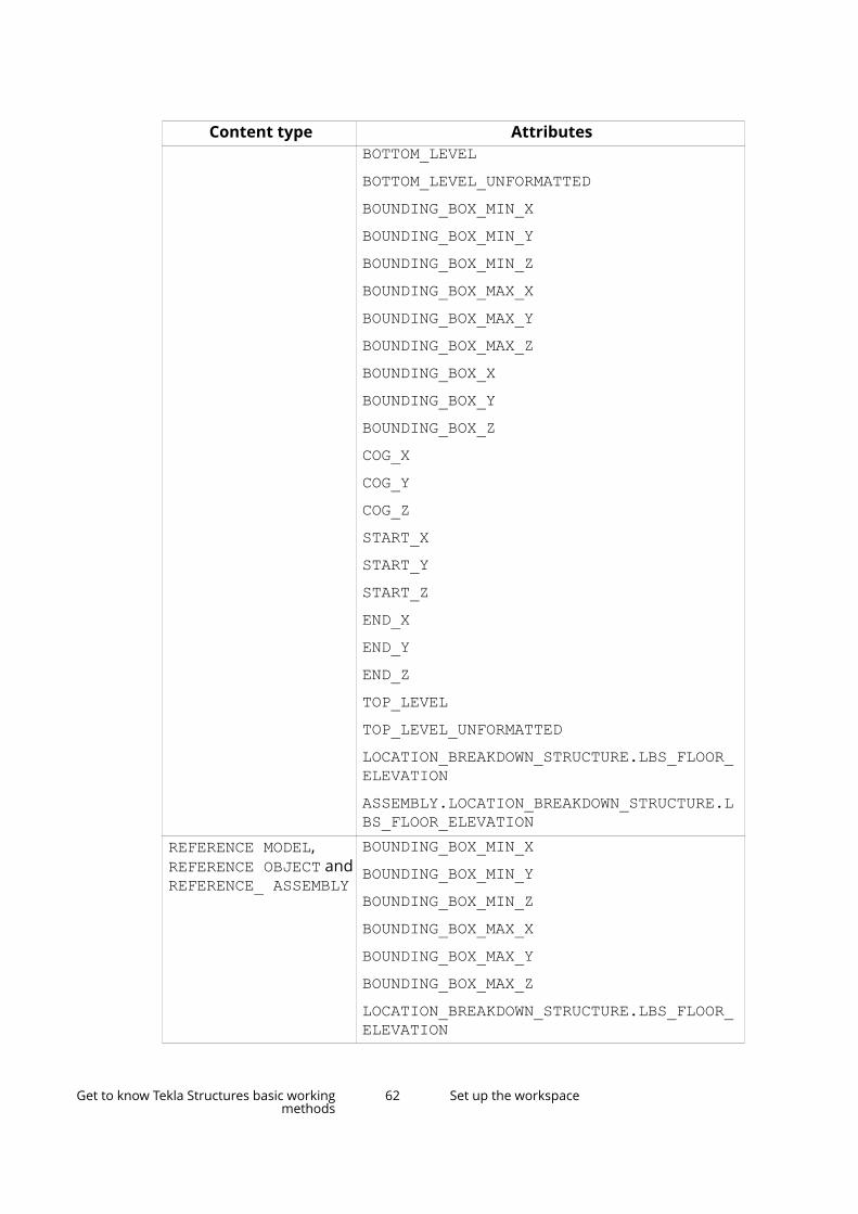
Content type AttributesBOTTOM_LEVELBOTTOM_LEVEL_UNFORMATTEDBOUNDING_BOX_MIN_XBOUNDING_BOX_MIN_YBOUNDING_BOX_MIN_ZBOUNDING_BOX_MAX_XBOUNDING_BOX_MAX_YBOUNDING_BOX_MAX_ZBOUNDING_BOX_XBOUNDING_BOX_YBOUNDING_BOX_ZCOG_XCOG_YCOG_ZSTART_XSTART_YSTART_ZEND_XEND_YEND_ZTOP_LEVELTOP_LEVEL_UNFORMATTEDLOCATION_BREAKDOWN_STRUCTURE.LBS_FLOOR_ELEVATIONASSEMBLY.LOCATION_BREAKDOWN_STRUCTURE.LBS_FLOOR_ELEVATION
REFERENCE MODEL, REFERENCE OBJECT and REFERENCE_ ASSEMBLY
BOUNDING_BOX_MIN_XBOUNDING_BOX_MIN_YBOUNDING_BOX_MIN_ZBOUNDING_BOX_MAX_XBOUNDING_BOX_MAX_YBOUNDING_BOX_MAX_ZLOCATION_BREAKDOWN_STRUCTURE.LBS_FLOOR_ELEVATION
Get to know Tekla Structures basic workingmethods
62 Set up the workspace
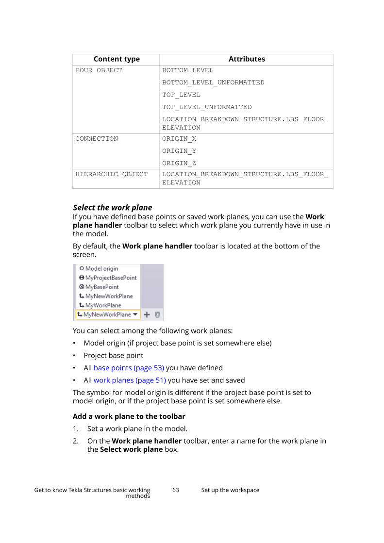
Content type AttributesPOUR OBJECT BOTTOM_LEVEL
BOTTOM_LEVEL_UNFORMATTEDTOP_LEVELTOP_LEVEL_UNFORMATTEDLOCATION_BREAKDOWN_STRUCTURE.LBS_FLOOR_ELEVATION
CONNECTION ORIGIN_XORIGIN_YORIGIN_Z
HIERARCHIC OBJECT LOCATION_BREAKDOWN_STRUCTURE.LBS_FLOOR_ELEVATION
Select the work planeIf you have defined base points or saved work planes, you can use the Workplane handler toolbar to select which work plane you currently have in use inthe model.
By default, the Work plane handler toolbar is located at the bottom of thescreen.
You can select among the following work planes:
• Model origin (if project base point is set somewhere else)
• Project base point
• All base points (page 53) you have defined
• All work planes (page 51) you have set and saved
The symbol for model origin is different if the project base point is set tomodel origin, or if the project base point is set somewhere else.
Add a work plane to the toolbar
1. Set a work plane in the model.
2. On the Work plane handler toolbar, enter a name for the work plane inthe Select work plane box.
Get to know Tekla Structures basic workingmethods
63 Set up the workspace
3. Click the button to add the new work plane to the list.
If needed, you can rename your work plane by double-clicking it andentering a new name.
4. To remove a work plane from the list, click the button.
By default, the Work plane handler toolbar is located at the bottom of thescreen. If you are unable to find the toolbar, click File --> Settings, and in theToolbars list ensure that the Work plane handler toolbar is selected.
See also
Coordinate system (page 48)
Change the color settingsYou can define which color you want to use for dimensions, labels, andbackground in the model. For example, if you set the background color toblack, you may need to adjust the other color settings as well to ensure thatthe text and dimensions will be visible.
Change the color settings in the Advanced Options dialog box by using RGBvalues on a scale of 0.0 to 1.0. Separate the values with spaces. For example,the color code for yellow is 1.0 1.0 0.0.
TIP Alternatively, if you wish to change the color settings at one go without using theadvanced options, you can use the Background Color Tool, which is available inTekla Warehouse.
Find RGB values for colorsTo find the right RGB values for colors, use, for example, the following tools:
• Background Color Selector tool, which is available in Tekla Warehouse
• Color picker for Tekla Structures tool, which is available in Tekla UserAssistance
Change the model background colorSet the background color using a combination of four different advancedoptions. You can control the color of each corner of the backgroundseparately.
1. On the File menu, click Settings --> Advanced Options , and go to theModel View category.
2. Set the background color using the following advanced options:
• XS_BACKGROUND_COLOR1
Get to know Tekla Structures basic workingmethods
64 Set up the workspace

• XS_BACKGROUND_COLOR2
• XS_BACKGROUND_COLOR3
• XS_BACKGROUND_COLOR4
To use a single-colored background, set the same color code for all fourcorners of the background. To use the default background color, leave theboxes empty.
3. Click OK to save the changes.
4. Close and reopen the view to see the changes.
Examples
Below are some examples of possible background colors that you can define.The first RGB value refers to the advanced option XS_BACKGROUND_COLOR1,the second value to the advanced option XS_BACKGROUND_COLOR2, and soon.
RGB values Result1.0 1.0 1.01.0 1.0 1.01.0 1.0 1.01.0 1.0 1.0
0.98 0.98 0.990.99 0.99 0.990.00 0.37 0.990.21 0.46 0.88
Get to know Tekla Structures basic workingmethods
65 Set up the workspace

RGB values Result0.6 0.8 0.90.6 0.8 0.91.0 1.0 1.01.0 1.0 1.0
0.6 0.8 0.90.6 0.8 0.90.5 0.2 0.00.5 0.2 0.0
0.1 0.6 0.60.5 0.9 0.50.1 0.6 0.60.5 0.9 0.5
Change the color of dimensions, part labels, and boltsYou can define which color you want to use for dimensions, part labels, andbolts that are using the representation option Fast in the model.
Get to know Tekla Structures basic workingmethods
66 Set up the workspace

1. On the File menu, click Settings --> Advanced Options .
2. Search for the color setting you want to change.
Color setting Advanced optionDimension lines XS_VIEW_DIM_LINE_COLORDimension text XS_VIEW_DIM_TEXT_COLORPart labels XS_VIEW_PART_LABEL_COLORWork plane grid XS_GRID_COLOR_FOR_WORK_PLANEBolts using the representation optionFast
XS_VIEW_FAST_BOLT_COLOR
TIP To quickly find all color related advanced options, type color in theSearch box and press Enter. Make sure the In all categories checkbox is selected.
3. Define the color using RGB color codes.
4. Click OK to save the changes. You may be required to restart TeklaStructures.
5. Close and reopen the view to see the changes.
Change the rendering of the modelYou can set Tekla Structures to use the DirectX rendering engine instead of thedefault OpenGL-based rendering engine. Compared to the OpenGL rendering,the DirectX rendering improves the rendering quality and adds a subtle
Get to know Tekla Structures basic workingmethods
67 Set up the workspace

shading effect to Tekla Structures objects, making the 3D visualizations clearerand more defined.
The DirectX graphics performance is better on the recommended NVIDIAGeforce GTX graphics cards than with graphics cards that have a lower end orno graphics processing unit (GPU). For more information on the recommendedgraphics cards, see Tekla Structures 2019 Hardware Recommendations.
You can switch the DirectX rendering on or off in File --> Settings --> Switches.The rendering setting is view specific, meaning that you can use the DirectXrendering or the OpenGL rendering in different views. If you switch betweenthe rendering, you need to reopen the view to activate the rendering.
NOTE If you use Tekla Structures via remote connections, the DirectX rendering maynot work as expected: parts that you have created may not show in themodel, or the model is working slowly. If you experience such problems,switch the DirectX rendering off.
Use the following advanced options to fine-tune the DirectX rendering:
• XS_SHOW_SHADOW_FOR_ORTHO_IN_DX
• XS_SHOW_SHADOW_FOR_PERSPECTIVE_IN_DX
• XS_USE_ANTI_ALIASING_IN_DX
• XS_HATCH_OVERLAPPING_FACES_IN_DX
DirectX rendering examples
Visualization of distance
The visualization of the distances in the DirectX rendering uses subtle shadowsand ambient occlusion. This gives a better understanding of the structure anddistances.
DirectX OpenGL
Depth accuracy
The accuracy in depth buffer is improved in the DirectX rendering so that whenthe model is zoomed, parts are not shown through other parts' faces as oftenas previously.
Get to know Tekla Structures basic workingmethods
68 Set up the workspace
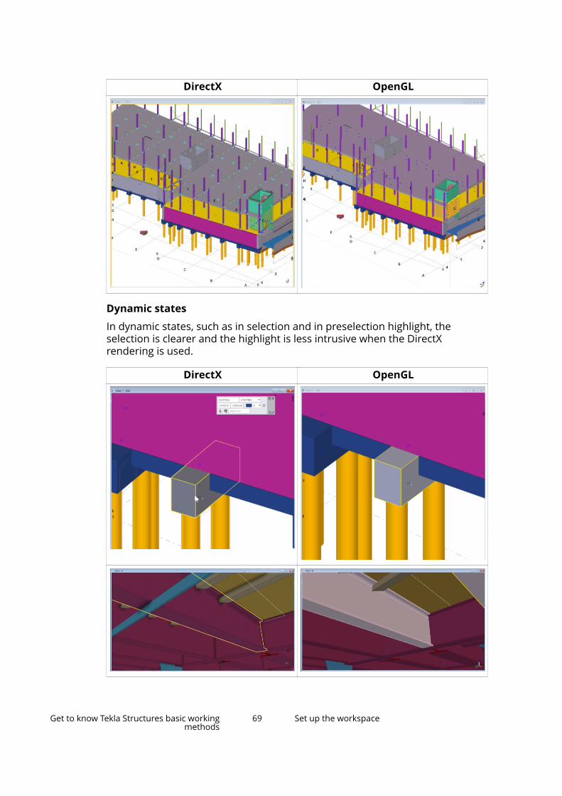
DirectX OpenGL
Dynamic states
In dynamic states, such as in selection and in preselection highlight, theselection is clearer and the highlight is less intrusive when the DirectXrendering is used.
DirectX OpenGL
Get to know Tekla Structures basic workingmethods
69 Set up the workspace
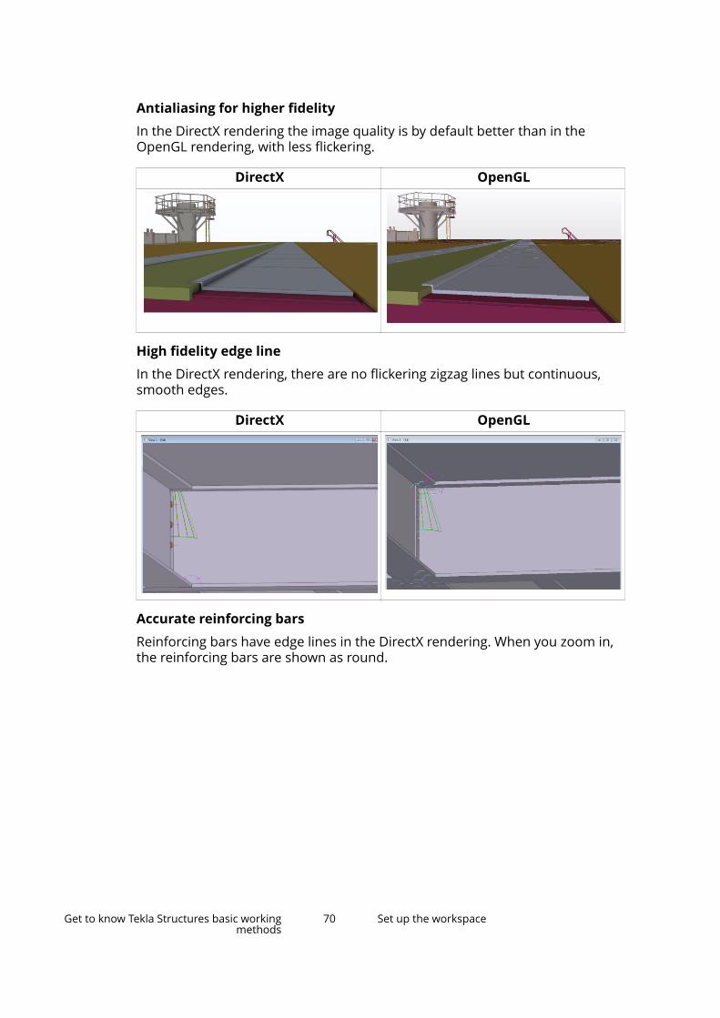
Antialiasing for higher fidelity
In the DirectX rendering the image quality is by default better than in theOpenGL rendering, with less flickering.
DirectX OpenGL
High fidelity edge line
In the DirectX rendering, there are no flickering zigzag lines but continuous,smooth edges.
DirectX OpenGL
Accurate reinforcing bars
Reinforcing bars have edge lines in the DirectX rendering. When you zoom in,the reinforcing bars are shown as round.
Get to know Tekla Structures basic workingmethods
70 Set up the workspace

DirectX OpenGL
Automatic edge lines for intersecting material in transparent view
In the DirectX rendering, you can see where there are intersecting materials inthe model.
DirectX OpenGL
Get to know Tekla Structures basic workingmethods
71 Set up the workspace

Accuracy and clarity on details
DirectX OpenGL
Get to know Tekla Structures basic workingmethods
72 Set up the workspace

DirectX OpenGL
Automatic hatching for overlapping surfaces on same plane
You can detect duplicate objects or any overlapping parts in the DirectXrendering.
Get to know Tekla Structures basic workingmethods
73 Set up the workspace
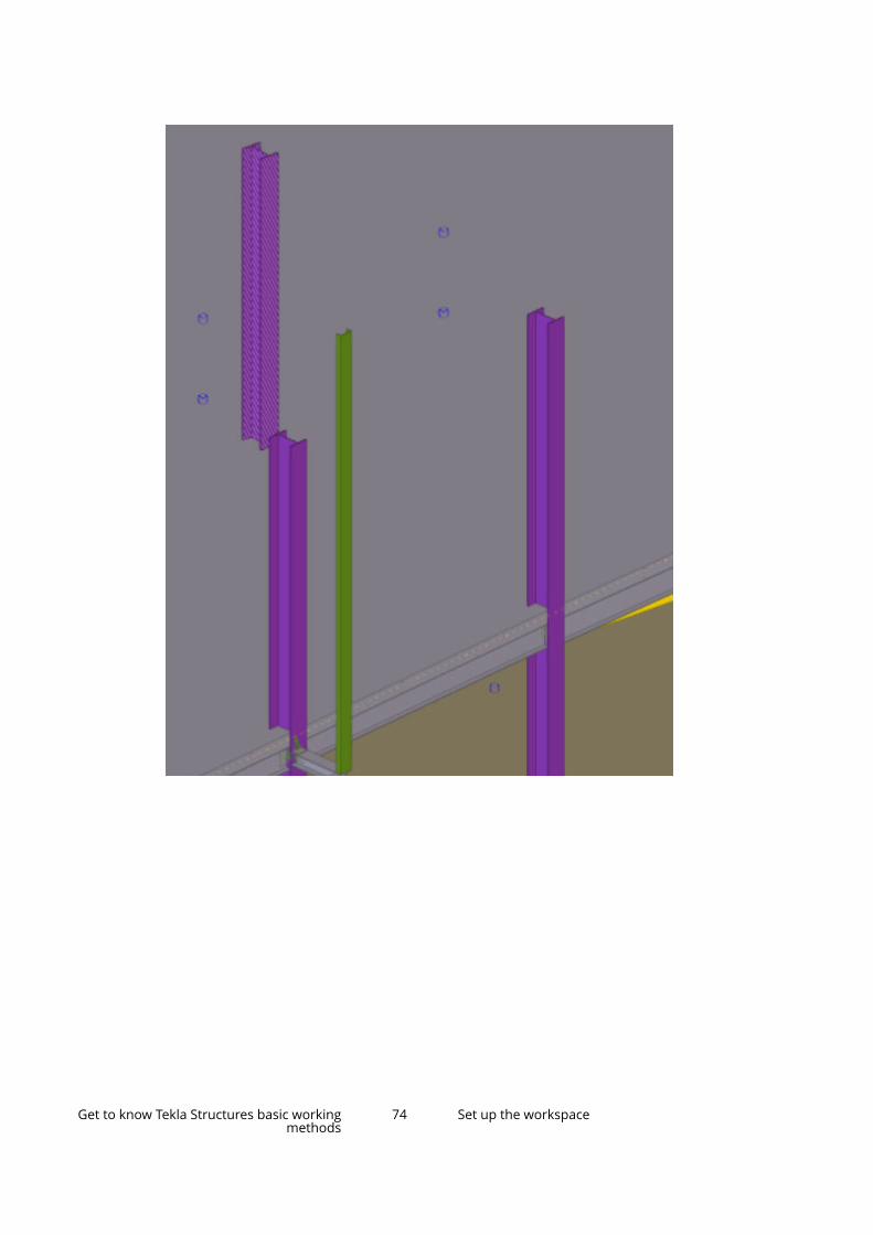
Get to know Tekla Structures basic workingmethods
74 Set up the workspace
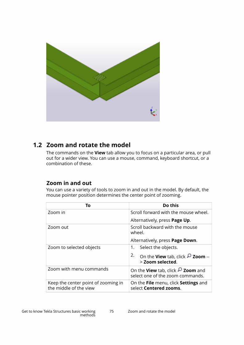
1.2 Zoom and rotate the modelThe commands on the View tab allow you to focus on a particular area, or pullout for a wider view. You can use a mouse, command, keyboard shortcut, or acombination of these.
Zoom in and outYou can use a variety of tools to zoom in and out in the model. By default, themouse pointer position determines the center point of zooming.
To Do thisZoom in Scroll forward with the mouse wheel.
Alternatively, press Page Up.Zoom out Scroll backward with the mouse
wheel.
Alternatively, press Page Down.Zoom to selected objects 1. Select the objects.
2. On the View tab, click Zoom --> Zoom selected.
Zoom with menu commands On the View tab, click Zoom andselect one of the zoom commands.
Keep the center point of zooming inthe middle of the view
On the File menu, click Settings andselect Centered zooms.
Get to know Tekla Structures basic workingmethods
75 Zoom and rotate the model
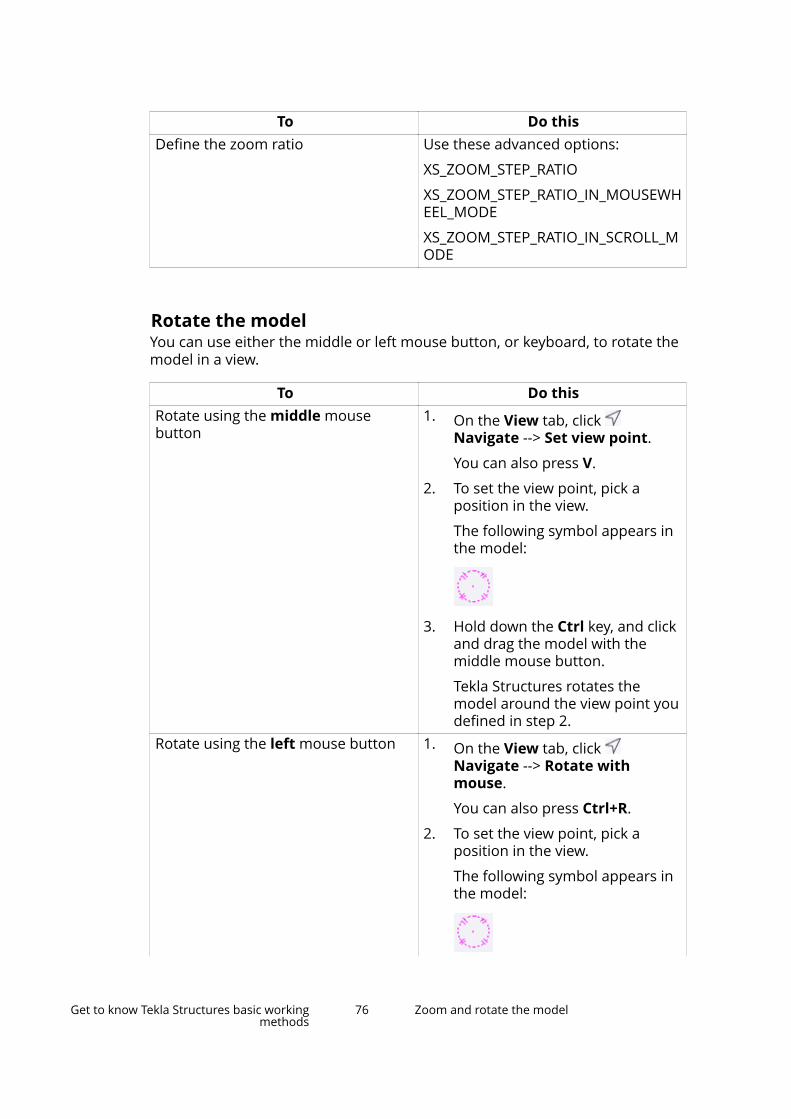
To Do thisDefine the zoom ratio Use these advanced options:
XS_ZOOM_STEP_RATIO
XS_ZOOM_STEP_RATIO_IN_MOUSEWHEEL_MODE
XS_ZOOM_STEP_RATIO_IN_SCROLL_MODE
Rotate the modelYou can use either the middle or left mouse button, or keyboard, to rotate themodel in a view.
To Do thisRotate using the middle mousebutton
1. On the View tab, click Navigate --> Set view point.
You can also press V.
2. To set the view point, pick aposition in the view.
The following symbol appears inthe model:
3. Hold down the Ctrl key, and clickand drag the model with themiddle mouse button.
Tekla Structures rotates themodel around the view point youdefined in step 2.
Rotate using the left mouse button 1. On the View tab, click Navigate --> Rotate withmouse.
You can also press Ctrl+R.
2. To set the view point, pick aposition in the view.
The following symbol appears inthe model:
Get to know Tekla Structures basic workingmethods
76 Zoom and rotate the model

To Do this3. Click and drag the model with the
left mouse button.
Tekla Structures rotates themodel around the view point youdefined in step 2.
Rotate using keyboard Use the keyboard shortcuts Ctrl+arrow keys and Shift+arrow keys.
Ctrl+arrow keys rotates the model in15 degree increments.
Shift+arrow keys rotates the modelin 5 degree increments.
Pan the modelYou can use either the middle or left mouse button to pan the model in a view.
To Do thisMove the model using the middlemouse button
1. On the File menu, click Settingsand check that the Middlebutton pan check box isselected.
2. Hold down the middle mousebutton and drag the model.
Move the model using the left mousebutton
1. To activate dynamic panning, goto the View tab and click Navigate --> Pan.
You can also press P.
The mouse pointer changes to a
hand:
2. Hold down the left mouse buttonand drag the model.
3. To stop panning, press Esc.
1.3 Snap to positionsMost commands ask you to pick points to place objects in the model ordrawing. This is called snapping. When you are creating a new object, TeklaStructures displays snap symbols for the available snap points and displays agreen line between the snap point and the last point picked.
Get to know Tekla Structures basic workingmethods
77 Snap to positions
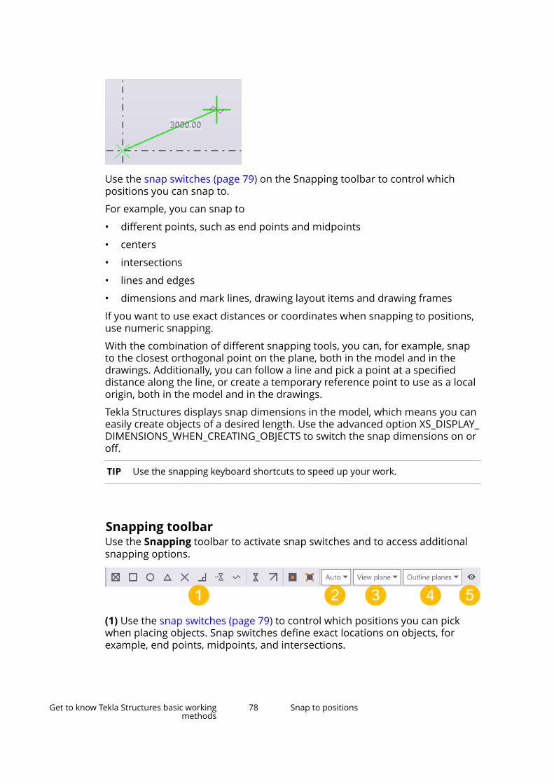
Use the snap switches (page 79) on the Snapping toolbar to control whichpositions you can snap to.
For example, you can snap to
• different points, such as end points and midpoints
• centers
• intersections
• lines and edges
• dimensions and mark lines, drawing layout items and drawing frames
If you want to use exact distances or coordinates when snapping to positions,use numeric snapping.
With the combination of different snapping tools, you can, for example, snapto the closest orthogonal point on the plane, both in the model and in thedrawings. Additionally, you can follow a line and pick a point at a specifieddistance along the line, or create a temporary reference point to use as a localorigin, both in the model and in the drawings.
Tekla Structures displays snap dimensions in the model, which means you caneasily create objects of a desired length. Use the advanced option XS_DISPLAY_DIMENSIONS_WHEN_CREATING_OBJECTS to switch the snap dimensions on oroff.
TIP Use the snapping keyboard shortcuts to speed up your work.
Snapping toolbarUse the Snapping toolbar to activate snap switches and to access additionalsnapping options.
(1) Use the snap switches (page 79) to control which positions you can pickwhen placing objects. Snap switches define exact locations on objects, forexample, end points, midpoints, and intersections.
Get to know Tekla Structures basic workingmethods
78 Snap to positions
(2) Use the first list to define the snap depth. For more information, see theseparate instructions further along on this page.
(3) Use the second list to switch between the view plane and work plane(page 50).
(4) Use the third list to set the plane type. The plane type defines what planesyou can select in the model.
(5) You can hide (page 225) selected switches from the toolbar.
By default, the Snapping toolbar is located at the bottom of the screen. If youare unable to find the toolbar, click File --> Settings , and in the Toolbars listensure that the Snapping toolbar is selected.
Snap zoneEach object has a snap zone. It defines how close you need to pick to hit aposition. When you pick within the snap zone of an object, Tekla Structuresautomatically snaps to the closest pickable point on that object.
You can set the snap zone using the advanced option XS_PIXEL_TOLERANCE.
Snap priorityIf you pick and hit several positions simultaneously, Tekla Structuresautomatically snaps to the point with the highest snap priority. To controlwhich positions you can pick, use snap switches. Snap switches define thesnap priority of positions.
Snap depthThe first list on the Snapping toolbar defines the depth of each position youpick. You have the following options:
• Plane: You can snap to positions either on the view plane (page 29) or thework plane (page 48), depending on what you have selected in the secondlist on the Snapping toolbar.
• Auto: In perspective views, this option works like the 3D option. In non-perspective views, it works like the Plane option.
• 3D: You can snap to positions in the entire 3D space.
Snapping in drawingsSee Snapping in drawings.
Get to know Tekla Structures basic workingmethods
79 Snap to positions
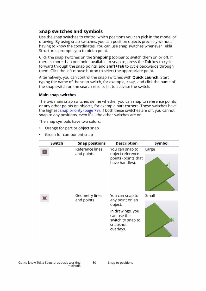
Snap switches and symbolsUse the snap switches to control which positions you can pick in the model ordrawing. By using snap switches, you can position objects precisely withouthaving to know the coordinates. You can use snap switches whenever TeklaStructures prompts you to pick a point.
Click the snap switches on the Snapping toolbar to switch them on or off. Ifthere is more than one point available to snap to, press the Tab key to cycleforward through the snap points, and Shift+Tab to cycle backwards throughthem. Click the left mouse button to select the appropriate point.
Alternatively, you can control the snap switches with Quick Launch. Starttyping the name of the snap switch, for example, snap, and click the name ofthe snap switch on the search results list to activate the switch.
Main snap switches
The two main snap switches define whether you can snap to reference pointsor any other points on objects, for example part corners. These switches havethe highest snap priority (page 79). If both these switches are off, you cannotsnap to any positions, even if all the other switches are on.
The snap symbols have two colors:
• Orange for part or object snap
• Green for component snap
Switch Snap positions Description SymbolReference linesand points
You can snap toobject referencepoints (points thathave handles).
Large
Geometry linesand points
You can snap toany point on anobject.
In drawings, youcan use thisswitch to snap tosnapshotoverlays.
Small
Get to know Tekla Structures basic workingmethods
80 Snap to positions
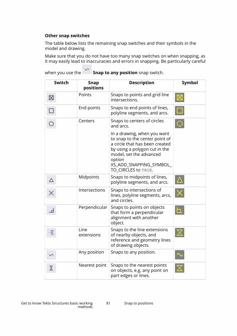
Other snap switches
The table below lists the remaining snap switches and their symbols in themodel and drawing.
Make sure that you do not have too many snap switches on when snapping, asit may easily lead to inaccuracies and errors in snapping. Be particularly careful
when you use the Snap to any position snap switch.
Switch Snappositions
Description Symbol
Points Snaps to points and grid lineintersections.
End points Snaps to end points of lines,polyline segments, and arcs.
Centers Snaps to centers of circlesand arcs.
In a drawing, when you wantto snap to the center point ofa circle that has been createdby using a polygon cut in themodel, set the advancedoptionXS_ADD_SNAPPING_SYMBOL_TO_CIRCLES to TRUE.
Midpoints Snaps to midpoints of lines,polyline segments, and arcs.
Intersections Snaps to intersections oflines, polyline segments, arcs,and circles.
Perpendicular Snaps to points on objectsthat form a perpendicularalignment with anotherobject.
Lineextensions
Snaps to the line extensionsof nearby objects, andreference and geometry linesof drawing objects.
Any position Snaps to any position.
Nearest point Snaps to the nearest pointson objects, e.g. any point onpart edges or lines.
Get to know Tekla Structures basic workingmethods
81 Snap to positions
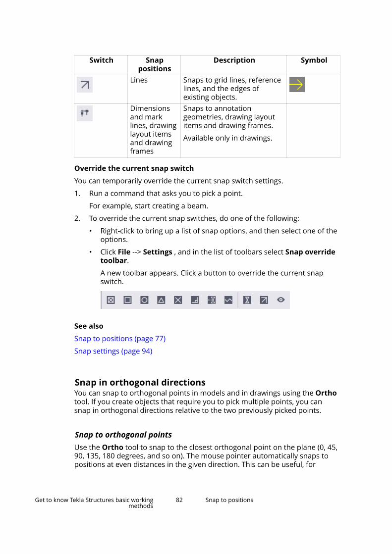
Switch Snappositions
Description Symbol
Lines Snaps to grid lines, referencelines, and the edges ofexisting objects.
Dimensionsand marklines, drawinglayout itemsand drawingframes
Snaps to annotationgeometries, drawing layoutitems and drawing frames.
Available only in drawings.
Override the current snap switch
You can temporarily override the current snap switch settings.
1. Run a command that asks you to pick a point.
For example, start creating a beam.
2. To override the current snap switches, do one of the following:
• Right-click to bring up a list of snap options, and then select one of theoptions.
• Click File --> Settings , and in the list of toolbars select Snap overridetoolbar.
A new toolbar appears. Click a button to override the current snapswitch.
See also
Snap to positions (page 77)
Snap settings (page 94)
Snap in orthogonal directionsYou can snap to orthogonal points in models and in drawings using the Orthotool. If you create objects that require you to pick multiple points, you cansnap in orthogonal directions relative to the two previously picked points.
Snap to orthogonal pointsUse the Ortho tool to snap to the closest orthogonal point on the plane (0, 45,90, 135, 180 degrees, and so on). The mouse pointer automatically snaps topositions at even distances in the given direction. This can be useful, for
Get to know Tekla Structures basic workingmethods
82 Snap to positions
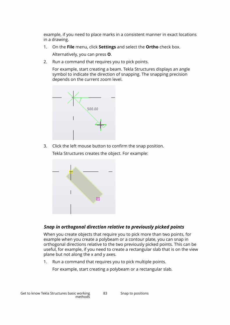
example, if you need to place marks in a consistent manner in exact locationsin a drawing.
1. On the File menu, click Settings and select the Ortho check box.
Alternatively, you can press O.
2. Run a command that requires you to pick points.
For example, start creating a beam. Tekla Structures displays an anglesymbol to indicate the direction of snapping. The snapping precisiondepends on the current zoom level.
3. Click the left mouse button to confirm the snap position.
Tekla Structures creates the object. For example:
Snap in orthogonal direction relative to previously picked pointsWhen you create objects that require you to pick more than two points, forexample when you create a polybeam or a contour plate, you can snap inorthogonal directions relative to the two previously picked points. This can beuseful, for example, if you need to create a rectangular slab that is on the viewplane but not along the x and y axes.
1. Run a command that requires you to pick multiple points.
For example, start creating a polybeam or a rectangular slab.
Get to know Tekla Structures basic workingmethods
83 Snap to positions
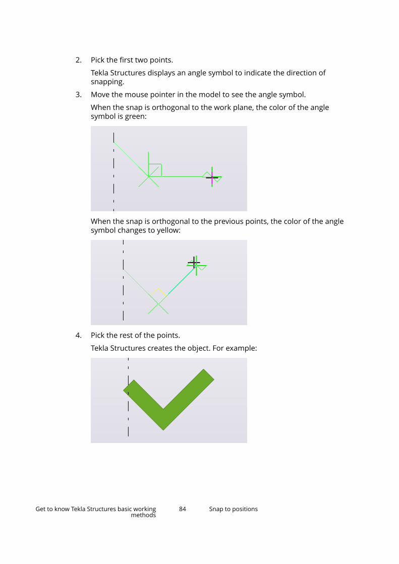
2. Pick the first two points.
Tekla Structures displays an angle symbol to indicate the direction ofsnapping.
3. Move the mouse pointer in the model to see the angle symbol.
When the snap is orthogonal to the work plane, the color of the anglesymbol is green:
When the snap is orthogonal to the previous points, the color of the anglesymbol changes to yellow:
4. Pick the rest of the points.
Tekla Structures creates the object. For example:
Get to know Tekla Structures basic workingmethods
84 Snap to positions
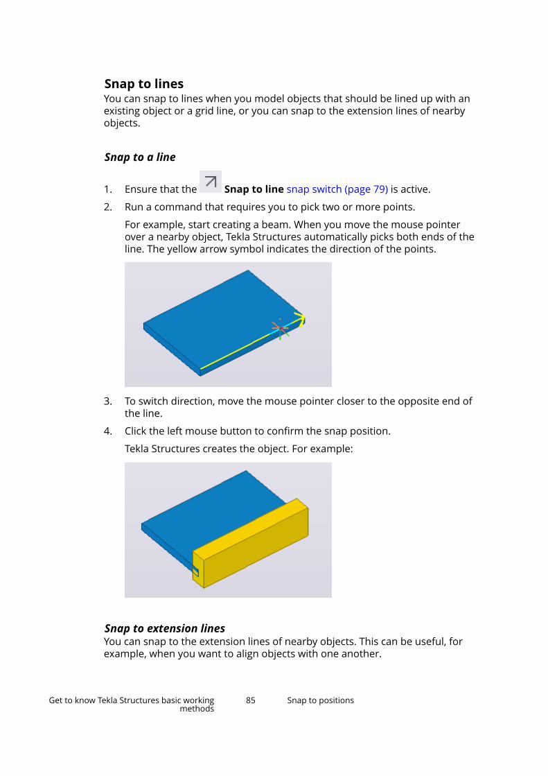
Snap to linesYou can snap to lines when you model objects that should be lined up with anexisting object or a grid line, or you can snap to the extension lines of nearbyobjects.
Snap to a line
1. Ensure that the Snap to line snap switch (page 79) is active.
2. Run a command that requires you to pick two or more points.
For example, start creating a beam. When you move the mouse pointerover a nearby object, Tekla Structures automatically picks both ends of theline. The yellow arrow symbol indicates the direction of the points.
3. To switch direction, move the mouse pointer closer to the opposite end ofthe line.
4. Click the left mouse button to confirm the snap position.
Tekla Structures creates the object. For example:
Snap to extension linesYou can snap to the extension lines of nearby objects. This can be useful, forexample, when you want to align objects with one another.
Get to know Tekla Structures basic workingmethods
85 Snap to positions
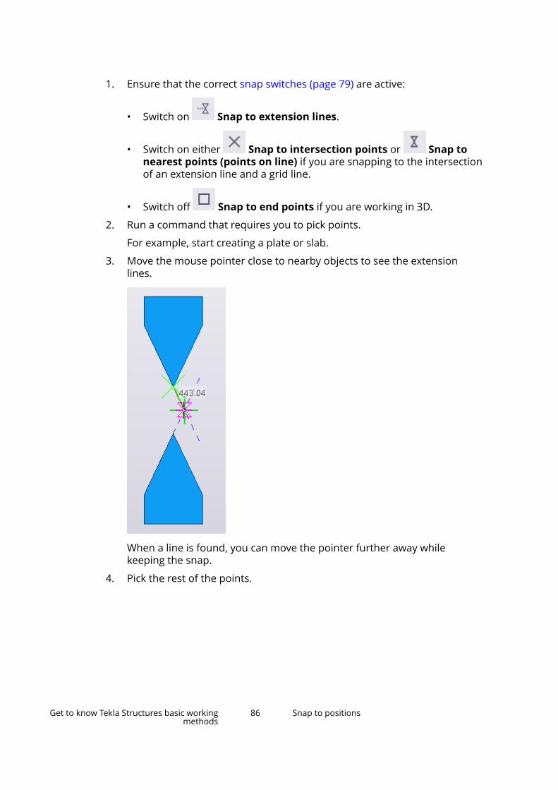
1. Ensure that the correct snap switches (page 79) are active:
• Switch on Snap to extension lines.
• Switch on either Snap to intersection points or Snap tonearest points (points on line) if you are snapping to the intersectionof an extension line and a grid line.
• Switch off Snap to end points if you are working in 3D.
2. Run a command that requires you to pick points.
For example, start creating a plate or slab.
3. Move the mouse pointer close to nearby objects to see the extensionlines.
When a line is found, you can move the pointer further away whilekeeping the snap.
4. Pick the rest of the points.
Get to know Tekla Structures basic workingmethods
86 Snap to positions

Tekla Structures creates the object:
Snap to points using exact distance or coordinates -numeric snappingYou can enter exact distances and coordinates when snapping to a position.This is called numeric snapping.
Enter a distance or coordinatesUse the Enter a Numeric Location dialog box to specify the distance orcoordinates to a position you want to snap to.
1. Run a command that requires you to pick points.
For example, start creating a beam.
2. Enter a distance or coordinates by using the keyboard.
Get to know Tekla Structures basic workingmethods
87 Snap to positions

For example, type 1000 as the distance from the last point picked. Whenyou start typing, Tekla Structures displays the Enter a Numeric Locationdialog box automatically.
3. After entering the distance or coordinates, click OK or press Enter to snapto the position.
Snapping example: Track along a line towards a snap pointTracking means that you follow a line and pick a point at a specified distancealong the line. You usually use tracking in combination with numericcoordinates and other snapping tools, such as snap switches and orthogonalsnapping. This example shows how to pick a point at a specified distance alonga line. Use the Enter a Numeric Location dialog box to specify the distancefrom the last point picked.
1. Create two beams and place them as shown below:
2. Activate the beam command, to create one more beam.
3. Pick the first point.
4. Move the mouse pointer over the grid line midpoint, so that it locks ontothe snap point, but do not click the mouse button.
Get to know Tekla Structures basic workingmethods
88 Snap to positions

5. Type 1000.
When you start typing, Tekla Structures displays the Enter a NumericLocation dialog box.
6. Click OK to confirm the distance.
Tekla Structures creates a beam, which is 1000 units long and positionedbetween the points you defined:
You can also:
• Track beyond the snap point, for example 4000 units from the first point:
Get to know Tekla Structures basic workingmethods
89 Snap to positions

• Track in the opposite direction by entering a negative value, for example-1000:
For an example of how to use numeric snapping in drawings, see Place asketch object at a specified distance.
Options for coordinatesThe table below explains the types of information you can enter in the Enter aNumeric Location dialog box.
Note that Tekla Structures has three snapping modes: relative, absolute, andglobal. You can temporarily override the default snapping mode by using aspecial character in front of the coordinates in the Enter a Numeric Locationdialog box.
You can enter Description Special characterOne coordinate A distance to an indicated direction.
Get to know Tekla Structures basic workingmethods
90 Snap to positions
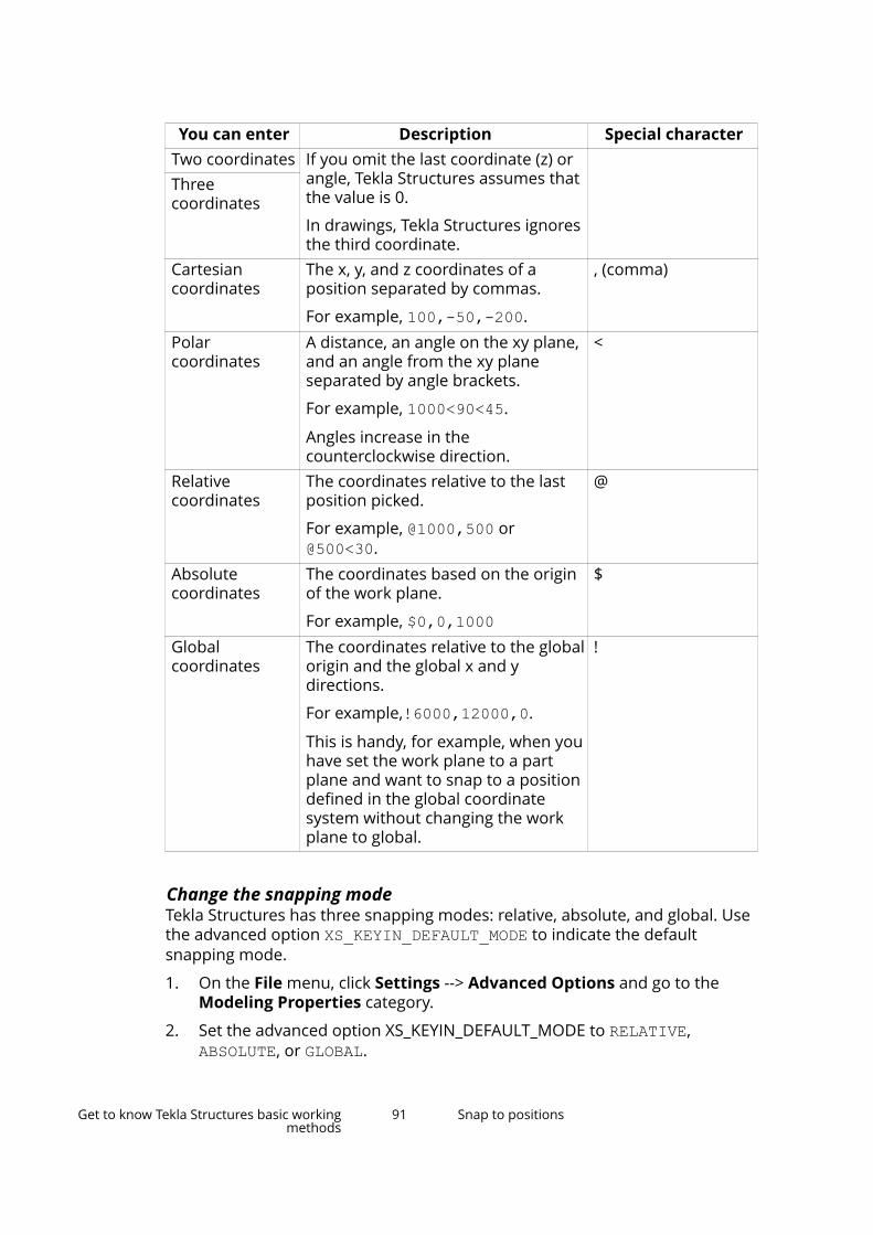
You can enter Description Special characterTwo coordinates If you omit the last coordinate (z) or
angle, Tekla Structures assumes thatthe value is 0.
In drawings, Tekla Structures ignoresthe third coordinate.
Threecoordinates
Cartesiancoordinates
The x, y, and z coordinates of aposition separated by commas.
For example, 100,-50,-200.
, (comma)
Polarcoordinates
A distance, an angle on the xy plane,and an angle from the xy planeseparated by angle brackets.
For example, 1000<90<45.
Angles increase in thecounterclockwise direction.
<
Relativecoordinates
The coordinates relative to the lastposition picked.
For example, @1000,500 or@500<30.
@
Absolutecoordinates
The coordinates based on the originof the work plane.
For example, $0,0,1000
$
Globalcoordinates
The coordinates relative to the globalorigin and the global x and ydirections.
For example,!6000,12000,0.
This is handy, for example, when youhave set the work plane to a partplane and want to snap to a positiondefined in the global coordinatesystem without changing the workplane to global.
!
Change the snapping modeTekla Structures has three snapping modes: relative, absolute, and global. Usethe advanced option XS_KEYIN_DEFAULT_MODE to indicate the defaultsnapping mode.
1. On the File menu, click Settings --> Advanced Options and go to theModeling Properties category.
2. Set the advanced option XS_KEYIN_DEFAULT_MODE to RELATIVE, ABSOLUTE, or GLOBAL.
Get to know Tekla Structures basic workingmethods
91 Snap to positions

• In the relative snapping mode, the coordinates you enter in the Entera Numeric Location dialog box as such without any prefix are relativeto the last position picked.
• In the absolute snapping mode, the coordinates are based on theorigin of the work plane.
• In the global snapping mode, the coordinates are based on the globalorigin and the global x and y directions.
3. Click OK to save the changes.
4. If you want to temporarily override the default snapping mode, enter aspecial character in front of the coordinates when entering a numericlocation.
By default, the special characters are:
• @ for relative coordinates
• $ for absolute coordinates
• ! for global coordinates
NOTE If you want to change the special character for any of the threesnapping modes, use the advanced options XS_KEYIN_RELATIVE_PREFIX, XS_KEYIN_ABSOLUTE_PREFIX, and XS_KEYIN_GLOBAL_PREFIX.
Snapping aidsIn addition to the snap switches and the numeric snapping, you can use someadditional methods that help you to pick the correct positions when snapping.
Create a temporary reference pointYou can create a temporary reference point to be used as a local origin whensnapping in models and drawings. Temporary reference points can be used incombination with other snapping tools, such as snap switches (page 79) andorthogonal snapping (page 82).
1. Run a command that requires you to pick points.
For example, start creating a beam.
2. Pick the start point.
Get to know Tekla Structures basic workingmethods
92 Snap to positions
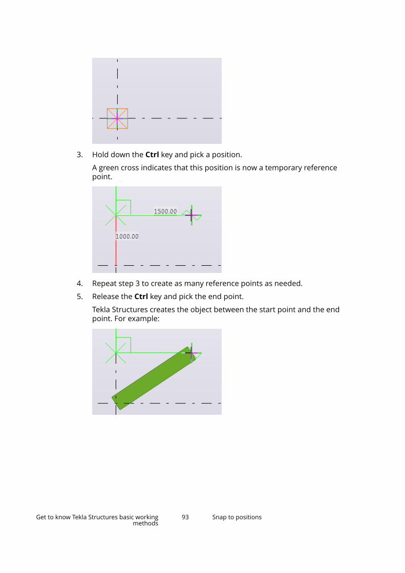
3. Hold down the Ctrl key and pick a position.
A green cross indicates that this position is now a temporary referencepoint.
4. Repeat step 3 to create as many reference points as needed.
5. Release the Ctrl key and pick the end point.
Tekla Structures creates the object between the start point and the endpoint. For example:
Get to know Tekla Structures basic workingmethods
93 Snap to positions
Lock X, Y, or Z coordinate on a lineYou can lock the x, y, and z coordinates on a line. This is useful when you needto determine a point to pick and the needed point does not exist on the line.When a coordinate is locked, you can only snap to points in that direction.
1. Run a command that requires you to pick positions.
For example, start creating a beam.
2. Lock a coordinate:
• To lock the x coordinate, press X.
• To lock the y coordinate, press Y.
• To lock the z coordinate, press Z.
Now you can only snap to points in the chosen direction.
3. To unlock the coordinate, press the same letter (X, Y, or Z) again.
Align objects using a snap gridA snap grid makes it easier to align objects in a model, because it allows you tosnap to positions only at set intervals (page 94). Use a snap grid when you
pick points using the Snap to any positionsnap switch (page 79).
1. On the File menu, click Settings --> Snap settings.
2. Define the grid spacing intervals in the Spacing boxes.
For example, if the spacing of the x coordinate is 500, you are able to snapto positions at intervals of 500 units in the x direction.
3. If needed, define offsets for the snap grid origin in the Origin boxes.
4. To activate the snap grid, select the Active (when free snap is on) checkbox.
5. Click OK.
Now when you pick points using the Snap to any position snapswitch, you can only snap to positions at set intervals. The snap grid itselfis invisible in the model.
Snap settingsUse the Model snap settings dialog box to view and modify the snap settingsin the model. The Drawing snap settings dialog box has the same options fordrawings. These settings are user specific.
Get to know Tekla Structures basic workingmethods
94 Snap to positions

Option DescriptionSymbol Show or hide the snap symbols.
Select the check box to show the snapsymbols, and clear the check box tohide them.
Active (when free snap is on) Select the check box to activate thesnap grid (page 94).
Spacing Define grid spacing intervals for thesnap grid origin. For example, if thespacing of the x coordinate is 500,you are able to snap to positions atintervals of 500 units in the xdirection.
Origin Define offsets for the snap grid origin.Angle interval Set the angle interval for the Ortho
tool. This setting is used when yousnap to orthogonal points (page 82).
For example, if you set the interval to10, the Ortho tool will snap to anglesat intervals of 10 degrees in themodel or drawing.
Custom angles Define custom angles for the Orthotool. This setting is used when yousnap to orthogonal points (page 82).
Separate the values with emptyspaces. For example, if you enter12.5 60, the Ortho tool will snap tothe angles 12.5 and 60 in the modelor drawing.
See also
Snapping toolbar (page 78)
Snap switches and symbols (page 79)
1.4 Work with model objects in Tekla StructuresWhen you model in Tekla Structures, you create and work with different typesof model objects. In most cases, a model object represents a building objectthat will exist in the real building or structure, or that will be closely related toit. A model object can also be a modeling aid that represents information thatis only relevant when you are creating the model. Model objects are eithercreated in the model or imported to it.
Get to know Tekla Structures basic workingmethods
95 Work with model objects in Tekla Structures
Examples of model objects include:
• Parts (page 235) and items
• Bolts and welds (page 346)
• Reinforcement (page 427) and embeds
• Surface treatment (page 373) and surfaces (page 386)
• Cuts, fittings (page 361), holes, and chamfers
• Pour breaks (page 415)
• Loads
Model objects may also be created by components.
You can modify the properties of many model objects by using the propertypane (page 97). To resize and reshape model objects, use the directmodification (page 103) handles.
The following modeling aids in can be used in the model:
• Grids (page 21) and grid lines (page 26)
• Construction objects (page 561) and points
• Reference models
You can combine model objects to bigger entities by creating assemblies(page 386), cast units (page 396), and pour units (page 410).
You can manage model objects by using object groups (page 591), Organizer,and other planning tools.
See also
Copy properties from another object (page 109)
Save and load object properties (page 111)
Undo modeling and drawing changes (page 114)
Create model objects and modify model object propertiesby using property paneThere are several ways to create and modify model objects in Tekla Structures.
You can create different types of model objects (page 95), such as parts anditems, bolts, reinforcement, and cuts, by using the commands on the ribbon.
Some ribbon commands have a keyboard shortcut that speed up yourmodeling work. You can customize the keyboard shortcuts and assign yourown shortcuts for the most used commands.
Get to know Tekla Structures basic workingmethods
96 Work with model objects in Tekla Structures
Alternatively, you can start many of the commands that create model objectsby using Quick Launch, or in the property pane.
After you have created the model objects, you can view and modify the modelobject properties by using the property pane.
Create or delete a model object1. Run a command that creates a model object, such as a part.
• On the ribbon: click a command. For example, click to create asteel beam.
• By using Quick Launch: enter a search term. For example, type steelbeam to find the Create steel beam command.
• In the property pane: ensure that you have nothing selected in the
model. Click the Object type list button and select from the listthe object you want to create.
2. Pick points (page 77) to place the model object in the model.
Tekla Structures creates the model object using the current properties ofthe object type.
3. Follow the status bar messages to get instructions on how to proceed.
4. To create more model objects with the same properties, pick more points.
The command runs until you end it or start another command.
5. If you want to delete a model object, select the object and press Delete.
Modify model object properties by using property paneTekla Structures shows the properties of model objects in the property pane,which is a side pane window. Note that you can have only one property sidepane window open at a time. This means that you can view the properties ofonly one object type at a time.
Use the property pane to view and modify the properties of
• parts (page 235), such as columns and beams
• items
• bolts
• welds (page 346)
• reinforcement (page 427)
• rebar sets
• pour objects (page 408), pour units and pour breaks (page 415)
Get to know Tekla Structures basic workingmethods
97 Work with model objects in Tekla Structures
• chamfers
• grids (page 21)
• polygon cuts (page 363) and part cuts (page 364)
• construction objects (page 561) and points
• assemblies (page 386) and cast units (page 396)
• surface treatment
• surfaces
To open the model object properties:
• If the property pane is closed: double-click a model object, or click the
Properties button in the side pane.
• If the property pane is open: select a model object.
Alternatively, hold down Shift and click a command on the ribbon to openthe properties in the property pane.
TIP You can customize the property pane. You can select separately for eachobject type which properties you wish to see in the property pane. Forexample, you can organize the settings as you wish, or remove thesettings you do not need. You can also add your most needed user-defined attributes (UDAs) directly to the property pane.
1. To start modifying the properties, double-click a model object.
The property pane opens and shows the current properties of the object.
For example:
Get to know Tekla Structures basic workingmethods
98 Work with model objects in Tekla Structures

2. Modify the properties as needed.
Tekla Structures highlights the modified properties in yellow in theproperty pane.
3. If you want to discard some of the changes, click the check marks next toeach setting to remove them.
Get to know Tekla Structures basic workingmethods
99 Work with model objects in Tekla Structures

You can clear the check marks one by one, or select a whole section andall its properties.
You can use the Select All and Select None switches at the bottom of theproperty pane to select all the changes or to clear all the changes.
4. When you are ready with the modifications, click Modify to apply thechanges.
Tekla Structures uses the properties the next time you create an object ofthe same type.
If you want to create an object using the standard values instead of thevalues you just applied, load the standard file first.
Note that if you use contextual toolbar or direct modification (page 103) tomodify a model object, the current properties do not change and are notautomatically applied when you create the next object of the same type.
Modify the common properties of different object types by usingproperty paneWhen you select several similar objects in the model, the property pane showsthe properties that are common for all the selected objects. The settings whichhave several options have the text Varies in the property pane, and the values
Get to know Tekla Structures basic workingmethods
100 Work with model objects in Tekla Structures
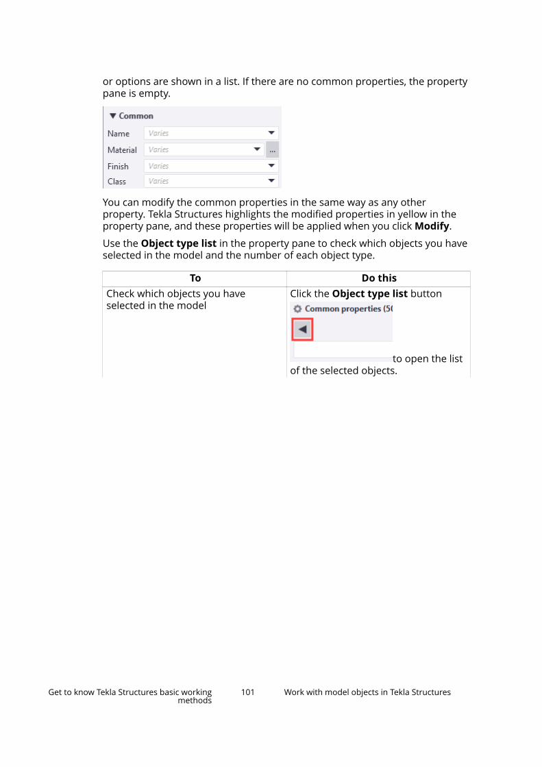
or options are shown in a list. If there are no common properties, the propertypane is empty.
You can modify the common properties in the same way as any otherproperty. Tekla Structures highlights the modified properties in yellow in theproperty pane, and these properties will be applied when you click Modify.
Use the Object type list in the property pane to check which objects you haveselected in the model and the number of each object type.
To Do thisCheck which objects you haveselected in the model
Click the Object type list button
to open the listof the selected objects.
Get to know Tekla Structures basic workingmethods
101 Work with model objects in Tekla Structures

To Do this
The list shows how many objects youhave selected for each object type.
The list also shows how manycomponents you have selected. If youselect Component in the list, theproperty pane shows the names andnumbers of the components that youhave selected in the model.
Modify the object selection in theObject type list
Hold down Ctrl and click the objecttypes in the list that you want toexclude or include in the selection.
The content of the property pane canchange according to your selection.
Select all the objects in the Objecttype list
Click the Select all button.
Get to know Tekla Structures basic workingmethods
102 Work with model objects in Tekla Structures

Resize and reshape model objectsYou can resize, reshape, and move model objects by using direct modificationhandles. When you select an object, Tekla Structures displays the handles anddimensions that are specific for that model object.
Direct modification can be used with the following object types:
• Parts
• Construction objects
• Grids and grid lines
• Line cuts and polygon cuts
• Reinforcement
• Rebar set guidelines, modifiers, and leg faces
• Pour breaks
• Custom parts
• Loads
1. Ensure that Direct modification is switched on.
To switch direct modification on or off, click or press D.
2. Click the object to select it.
Tekla Structures displays the handles that you can use to modify theobject.
The relevant dimensions are shown when you move the mouse pointerslowly over the object's edges. The dimension colors follow the colors ofthe work plane coordinate axes: red in the X direction, green in the Ydirection, and blue in the Z direction. Diagonal dimensions are magenta.
3. To reshape the object, drag any of the handles.
Get to know Tekla Structures basic workingmethods
103 Work with model objects in Tekla Structures

Here are some examples of direct modification handles:
Handle Description
Reference point handle
Midpoint handle
End point handle (for reinforcing barsonly)
Plane handle
Line handle
Get to know Tekla Structures basic workingmethods
104 Work with model objects in Tekla Structures
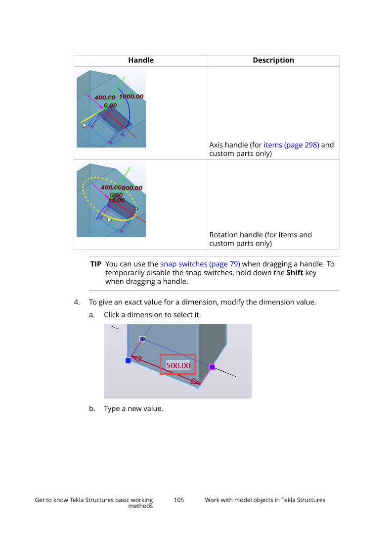
Handle Description
Axis handle (for items (page 298) andcustom parts only)
Rotation handle (for items andcustom parts only)
TIP You can use the snap switches (page 79) when dragging a handle. Totemporarily disable the snap switches, hold down the Shift keywhen dragging a handle.
4. To give an exact value for a dimension, modify the dimension value.
a. Click a dimension to select it.
b. Type a new value.
Get to know Tekla Structures basic workingmethods
105 Work with model objects in Tekla Structures

The yellow arrow defines the direction in which the object is extendedor shortened. You can change the direction by clicking the arrows.
c. Press Enter to confirm the new value.
5. To change a dimension only from one end, move the dimensionarrowheads.
You can either drag an arrowhead to a new location, or you can type anexact distance or coordinates.
a. Select the dimension arrowhead you want to move. For example:
To change a dimension at both ends, select both arrowheads.
b. Type the distance or coordinates.
When you start typing, Tekla Structures displays the Enter a NumericLocation dialog box. Click OK to confirm the dimension.
6. To add a new object corner, drag a midpoint handle . For example:
Get to know Tekla Structures basic workingmethods
106 Work with model objects in Tekla Structures
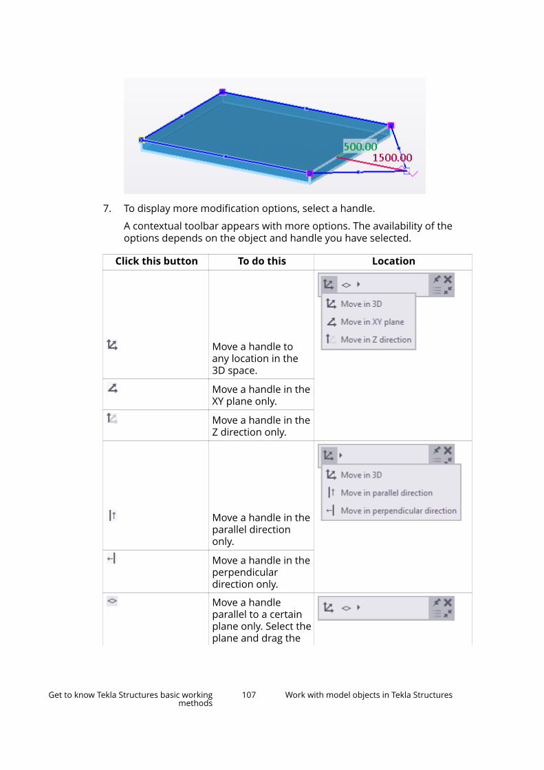
7. To display more modification options, select a handle.
A contextual toolbar appears with more options. The availability of theoptions depends on the object and handle you have selected.
Click this button To do this Location
Move a handle toany location in the3D space.
Move a handle in theXY plane only.
Move a handle in theZ direction only.
Move a handle in theparallel directiononly.
Move a handle in theperpendiculardirection only.
Move a handleparallel to a certainplane only. Select theplane and drag the
Get to know Tekla Structures basic workingmethods
107 Work with model objects in Tekla Structures

Click this button To do this Locationhandle to a newlocation.
This option can beuseful when workingwith a sloped roof,for example.
Control the visibilityof directmodificationdimensions. Click theeye symbol to showor hide dimensions.
• X, Y, Zdimensions: Allorthogonaldimensions in thework planedirections X, Y,and Z aredisplayed.
• Totaldimensions:Only the totallength isdisplayed.
Show or hidemidpoint handles.
Add a new point atthe end of an object.
Only available forobjects that passthrough multiplepoints, such aspolybeams, panels,strip footings, andrebar set modifiers.
Get to know Tekla Structures basic workingmethods
108 Work with model objects in Tekla Structures

NOTE Some of these options are located in an expandable section onthe contextual toolbar. Click the small triangle symbol on thecontextual toolbar to show or hide the options:
8. To delete a handle, select it and press Delete.
See also
Modify a construction object (page 567)
Modify a single grid line (page 26)
Modify a single reinforcing bar, bar group, or mesh (page 496)
Modify a rebar set (page 478)
Modify a pour break (page 421)
Add or move a custom part in the model (page 860)
Copy properties from another object
Use the Copy properties command in the property pane to copy modelobject properties from one model object to another. Alternatively, you can usethe contextual toolbar if you want to quickly copy properties to a few objectsonly.
Copy model object properties using the property paneYou can use the property pane to copy properties between any objects as longas both of the objects have the same property available. Use this methodwhen you need to copy properties to a large number of objects.
Get to know Tekla Structures basic workingmethods
109 Work with model objects in Tekla Structures
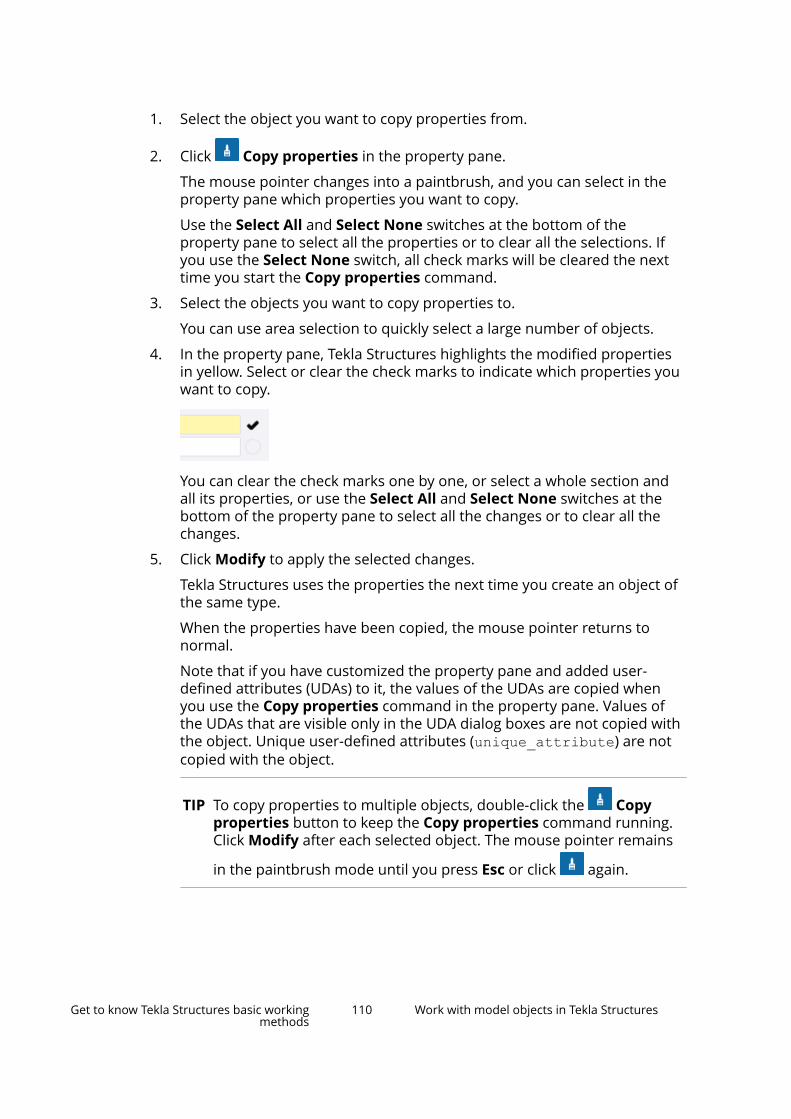
1. Select the object you want to copy properties from.
2. Click Copy properties in the property pane.
The mouse pointer changes into a paintbrush, and you can select in theproperty pane which properties you want to copy.
Use the Select All and Select None switches at the bottom of theproperty pane to select all the properties or to clear all the selections. Ifyou use the Select None switch, all check marks will be cleared the nexttime you start the Copy properties command.
3. Select the objects you want to copy properties to.
You can use area selection to quickly select a large number of objects.
4. In the property pane, Tekla Structures highlights the modified propertiesin yellow. Select or clear the check marks to indicate which properties youwant to copy.
You can clear the check marks one by one, or select a whole section andall its properties, or use the Select All and Select None switches at thebottom of the property pane to select all the changes or to clear all thechanges.
5. Click Modify to apply the selected changes.
Tekla Structures uses the properties the next time you create an object ofthe same type.
When the properties have been copied, the mouse pointer returns tonormal.
Note that if you have customized the property pane and added user-defined attributes (UDAs) to it, the values of the UDAs are copied whenyou use the Copy properties command in the property pane. Values ofthe UDAs that are visible only in the UDA dialog boxes are not copied withthe object. Unique user-defined attributes (unique_attribute) are notcopied with the object.
TIP To copy properties to multiple objects, double-click the Copyproperties button to keep the Copy properties command running.Click Modify after each selected object. The mouse pointer remains
in the paintbrush mode until you press Esc or click again.
Get to know Tekla Structures basic workingmethods
110 Work with model objects in Tekla Structures
Copy object properties using the contextual toolbarUse this method when you want to quickly copy properties to a few objectsonly.
1. Select the object you want to copy properties from.
A contextual toolbar appears.
2. Click Copy properties on the contextual toolbar.
The mouse pointer changes into a paintbrush.
3. Select the object you want to copy properties to.
When the properties have been copied, the mouse pointer returns tonormal.
Note that user-defined attributes (UDAs) are not copied with the object,even if you have customized the contextual toolbar and added UDAs to it.
4. To copy properties to multiple objects, double-click the Copyproperties button.
Now you can copy properties to multiple objects. The pointer remains inthe paintbrush mode until you press Esc or start another command.
Save and load object propertiesThe property pane and many dialog boxes have the possibility to save theproperty information in property files. You can load these saved propertieslater on when you create new objects.
For example, you can define the properties for each object type you plan tocreate before you start modeling, and then use these user-defined propertyfiles when you are creating new objects. Tekla Structures stores the user-defined property files, including the properties of sub-dialog boxes, in thecurrent model’s \attributes folder.
You can save and load object properties either in the property pane or in adialog box, depending on the object type.
Save and load properties in the property paneUse the property pane to save and load the properties of
• parts (page 235), such as columns and beams
• items
• bolts
• welds (page 346)
Get to know Tekla Structures basic workingmethods
111 Work with model objects in Tekla Structures
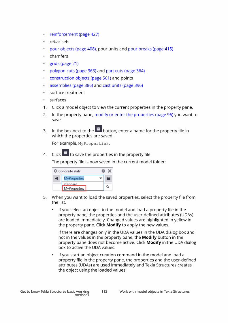
• reinforcement (page 427)
• rebar sets
• pour objects (page 408), pour units and pour breaks (page 415)
• chamfers
• grids (page 21)
• polygon cuts (page 363) and part cuts (page 364)
• construction objects (page 561) and points
• assemblies (page 386) and cast units (page 396)
• surface treatment
• surfaces
1. Click a model object to view the current properties in the property pane.
2. In the property pane, modify or enter the properties (page 96) you want tosave.
3. In the box next to the button, enter a name for the property file inwhich the properties are saved.
For example, MyProperties.
4. Click to save the properties in the property file.
The property file is now saved in the current model folder:
5. When you want to load the saved properties, select the property file fromthe list.
• If you select an object in the model and load a property file in theproperty pane, the properties and the user-defined attributes (UDAs)are loaded immediately. Changed values are highlighted in yellow inthe property pane. Click Modify to apply the new values.
If there are changes only in the UDA values in the UDA dialog box andnot in the values in the property pane, the Modify button in theproperty pane does not become active. Click Modify in the UDA dialogbox to active the UDA values.
• If you start an object creation command in the model and load aproperty file in the property pane, the properties and the user-definedattributes (UDAs) are used immediately and Tekla Structures createsthe object using the loaded values.
Get to know Tekla Structures basic workingmethods
112 Work with model objects in Tekla Structures
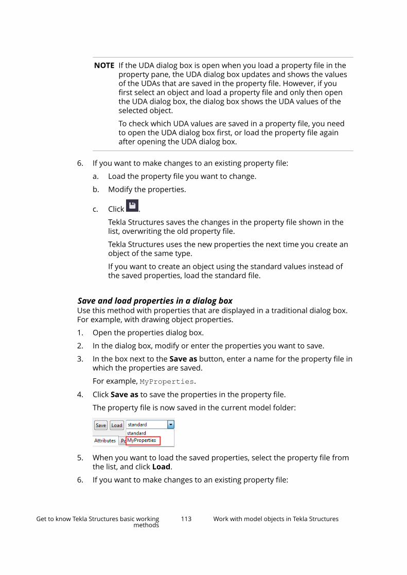
NOTE If the UDA dialog box is open when you load a property file in theproperty pane, the UDA dialog box updates and shows the valuesof the UDAs that are saved in the property file. However, if youfirst select an object and load a property file and only then openthe UDA dialog box, the dialog box shows the UDA values of theselected object.
To check which UDA values are saved in a property file, you needto open the UDA dialog box first, or load the property file againafter opening the UDA dialog box.
6. If you want to make changes to an existing property file:
a. Load the property file you want to change.
b. Modify the properties.
c. Click .
Tekla Structures saves the changes in the property file shown in thelist, overwriting the old property file.
Tekla Structures uses the new properties the next time you create anobject of the same type.
If you want to create an object using the standard values instead ofthe saved properties, load the standard file.
Save and load properties in a dialog boxUse this method with properties that are displayed in a traditional dialog box.For example, with drawing object properties.
1. Open the properties dialog box.
2. In the dialog box, modify or enter the properties you want to save.
3. In the box next to the Save as button, enter a name for the property file inwhich the properties are saved.
For example, MyProperties.
4. Click Save as to save the properties in the property file.
The property file is now saved in the current model folder:
5. When you want to load the saved properties, select the property file fromthe list, and click Load.
6. If you want to make changes to an existing property file:
Get to know Tekla Structures basic workingmethods
113 Work with model objects in Tekla Structures

a. Load the property file you want to change.
b. Modify the properties.
c. Click Save.
Tekla Structures saves the changes in the property file shown in thelist, overwriting the old property file.
Remove existing propertiesYou can remove user-defined property files manually by removing them fromthe model's \attributes folder.
1. Remove the selected property file from the model's \attributes folder.
The property files may have different file name extensions, depending ontheir type. For more information, see Model folder files and file nameextensions.
2. Restart Tekla Structures.
Undo modeling and drawing changesThe Undo history list helps you to check which commands and modificationsyou have done and undone, and to keep track of the changes. By selecting acommand or an action in the Undo history dialog box, you can undo or redoseveral commands at one go, and thus go back and forth in the model history.Undo history is available both in the modeling and in the drawing mode.
How to use Undo history
To open the Undo history dialog box, click the button on the Quick AccessToolbar, next to the Undo and Redo buttons. Alternatively, use Quick Launchto open the dialog box.
To Do thisUndo commands Click any row on the list.
If the undo operation takes a longtime, Tekla Structures highlights theclicked row to show what wasselected.
All the modifications you have doneafter the selected command areundone. The modifications you haveundone have a dark gray backgroundcolor in the list.
Get to know Tekla Structures basic workingmethods
114 Work with model objects in Tekla Structures

To Do thisRedo previously undone commands Click any row with a dark gray
background color in the list.
All the modifications you have donebefore the selected command areredone.
Add a bookmark Move your mouse pointer over any
row. A bookmark icon is shown.Click the bookmark icon to markcertain commands.
Use the bookmarks to markimportant commands or actions. Youcan later return to these commandsor actions if the changes in the modelare not satisfactory.
To remove a bookmark, click the
bookmark icon again.
The Undo history dialog box
• lists the commands you have run and modifications you have done,starting from the top of the list. The latest commands and modificationsare at the bottom of the list.
• updates constantly according to the changes you make in the model or inthe drawing.
• creates a hierarchy for some of the used commands. The hierarchy iscreated when you first run a command, then you undo some commands toa certain point in the list, and run another command.
The hierarchy is marked with an arrow in the list. You can undo or redocommands at any point in the hierarchy, making it possible to undocommands that you have previously redone.
This means that after you have undone a command, you can continueworking with the model, and you still have the option to go back to thecommands you have used first.
The Undo history list is cleared when you
• save a model
• open or close a drawing
• synchronize Organizer with the model
• read in or write out model changes using Tekla Model Sharing
• use CIS/2 or SDNF import commands.
Get to know Tekla Structures basic workingmethods
115 Work with model objects in Tekla Structures
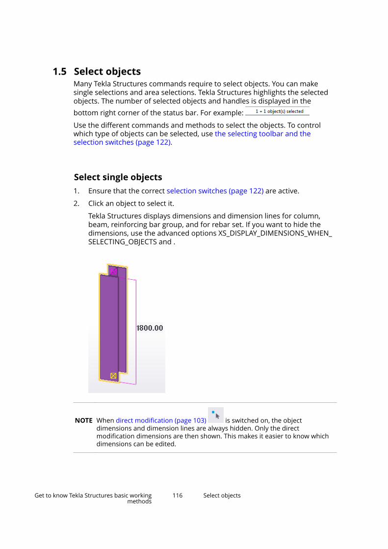
1.5 Select objectsMany Tekla Structures commands require to select objects. You can makesingle selections and area selections. Tekla Structures highlights the selectedobjects. The number of selected objects and handles is displayed in thebottom right corner of the status bar. For example:
Use the different commands and methods to select the objects. To controlwhich type of objects can be selected, use the selecting toolbar and theselection switches (page 122).
Select single objects1. Ensure that the correct selection switches (page 122) are active.
2. Click an object to select it.
Tekla Structures displays dimensions and dimension lines for column,beam, reinforcing bar group, and for rebar set. If you want to hide thedimensions, use the advanced options XS_DISPLAY_DIMENSIONS_WHEN_SELECTING_OBJECTS and .
NOTE When direct modification (page 103) is switched on, the objectdimensions and dimension lines are always hidden. Only the directmodification dimensions are then shown. This makes it easier to know whichdimensions can be edited.
Get to know Tekla Structures basic workingmethods
116 Select objects
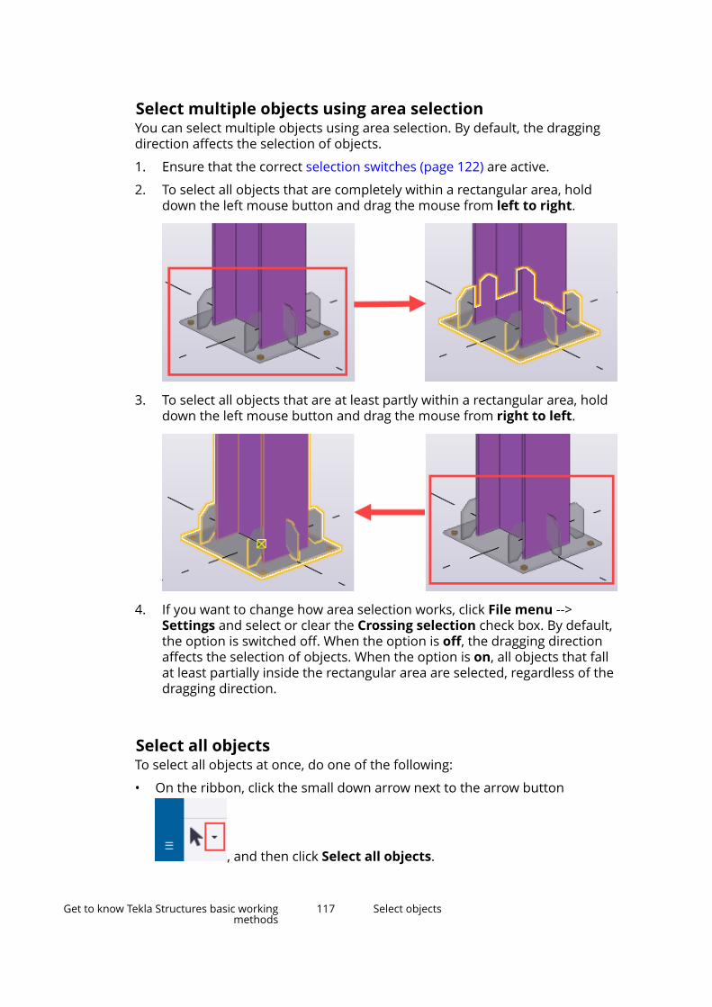
Select multiple objects using area selectionYou can select multiple objects using area selection. By default, the draggingdirection affects the selection of objects.
1. Ensure that the correct selection switches (page 122) are active.
2. To select all objects that are completely within a rectangular area, holddown the left mouse button and drag the mouse from left to right.
3. To select all objects that are at least partly within a rectangular area, holddown the left mouse button and drag the mouse from right to left.
4. If you want to change how area selection works, click File menu -->Settings and select or clear the Crossing selection check box. By default,the option is switched off. When the option is off, the dragging directionaffects the selection of objects. When the option is on, all objects that fallat least partially inside the rectangular area are selected, regardless of thedragging direction.
Select all objectsTo select all objects at once, do one of the following:
• On the ribbon, click the small down arrow next to the arrow button
, and then click Select all objects.
Get to know Tekla Structures basic workingmethods
117 Select objects
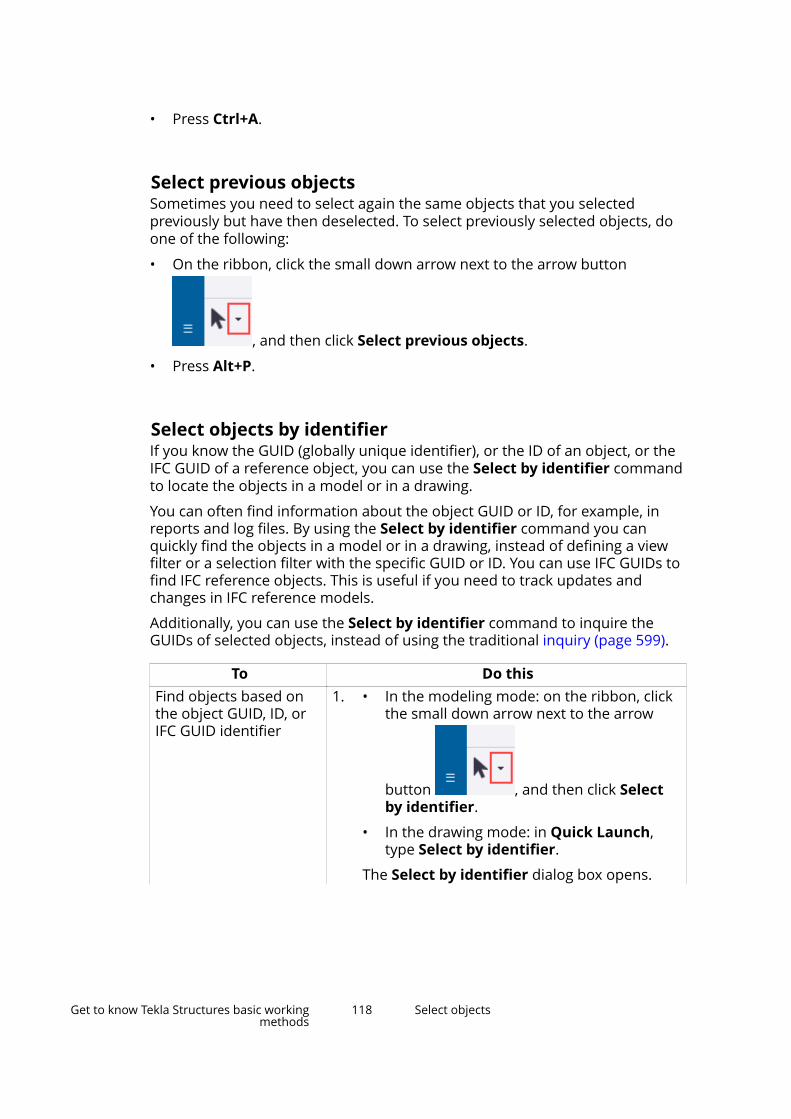
• Press Ctrl+A.
Select previous objectsSometimes you need to select again the same objects that you selectedpreviously but have then deselected. To select previously selected objects, doone of the following:
• On the ribbon, click the small down arrow next to the arrow button
, and then click Select previous objects.
• Press Alt+P.
Select objects by identifierIf you know the GUID (globally unique identifier), or the ID of an object, or theIFC GUID of a reference object, you can use the Select by identifier commandto locate the objects in a model or in a drawing.
You can often find information about the object GUID or ID, for example, inreports and log files. By using the Select by identifier command you canquickly find the objects in a model or in a drawing, instead of defining a viewfilter or a selection filter with the specific GUID or ID. You can use IFC GUIDs tofind IFC reference objects. This is useful if you need to track updates andchanges in IFC reference models.
Additionally, you can use the Select by identifier command to inquire theGUIDs of selected objects, instead of using the traditional inquiry (page 599).
To Do thisFind objects based onthe object GUID, ID, orIFC GUID identifier
1. • In the modeling mode: on the ribbon, clickthe small down arrow next to the arrow
button , and then click Selectby identifier.
• In the drawing mode: in Quick Launch,type Select by identifier.
The Select by identifier dialog box opens.
Get to know Tekla Structures basic workingmethods
118 Select objects

To Do this2. Copy the object identifier, for example from a
log file, to the dialog box.
You can enter multiple identifiers in the dialogbox. Either enter each identifier on its ownrow, or separate them with semicolon ;.
3. To define the search, select the needed checkboxes.
• Reference objects: Tekla Structures selectsIFC objects based on their GUID or IFCGUID.
• Keep selection: Tekla Structures keeps thecurrently selected object and appends itwith new selection.
• Zoom to selected: Tekla Structures selectsthe object and zooms to it.
4. Click Select.
Tekla Structures selects the objects based onthe GUID in the model or in the drawing.
If there are identifiers that are not found in themodel or in the drawing, they are listed in thestatus bar as identifier?.
Find a model object in adrawing
You can select an object in a model, get itsidentifier, and then find it in a drawing based onthe identifier.
1. In the modeling mode: on the ribbon, click thesmall down arrow next to the arrow button
, and then click Select byidentifier.
The Select by identifier dialog box opens.
2. Select an object or objects in the model.
3. Click Get.
The Select by identifier dialog box lists theidentifiers of the selected objects.
If you want to get IFC GUIDs, ensure that theReference objects check box is selected.
4. Keep the dialog box open.
5. Open a drawing.
Get to know Tekla Structures basic workingmethods
119 Select objects
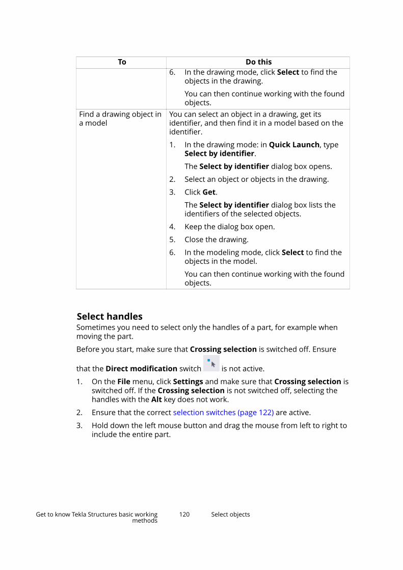
To Do this6. In the drawing mode, click Select to find the
objects in the drawing.
You can then continue working with the foundobjects.
Find a drawing object ina model
You can select an object in a drawing, get itsidentifier, and then find it in a model based on theidentifier.
1. In the drawing mode: in Quick Launch, typeSelect by identifier.
The Select by identifier dialog box opens.
2. Select an object or objects in the drawing.
3. Click Get.
The Select by identifier dialog box lists theidentifiers of the selected objects.
4. Keep the dialog box open.
5. Close the drawing.
6. In the modeling mode, click Select to find theobjects in the model.
You can then continue working with the foundobjects.
Select handlesSometimes you need to select only the handles of a part, for example whenmoving the part.
Before you start, make sure that Crossing selection is switched off. Ensure
that the Direct modification switch is not active.
1. On the File menu, click Settings and make sure that Crossing selection isswitched off. If the Crossing selection is not switched off, selecting thehandles with the Alt key does not work.
2. Ensure that the correct selection switches (page 122) are active.
3. Hold down the left mouse button and drag the mouse from left to right toinclude the entire part.
Get to know Tekla Structures basic workingmethods
120 Select objects
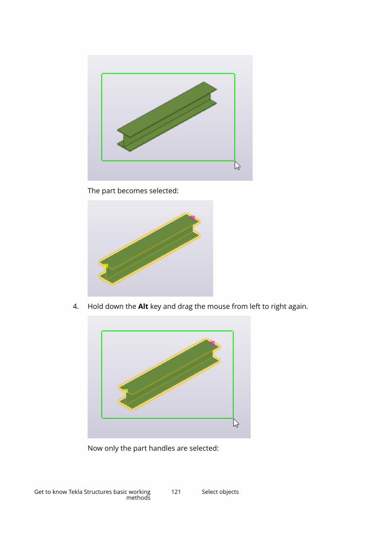
The part becomes selected:
4. Hold down the Alt key and drag the mouse from left to right again.
Now only the part handles are selected:
Get to know Tekla Structures basic workingmethods
121 Select objects
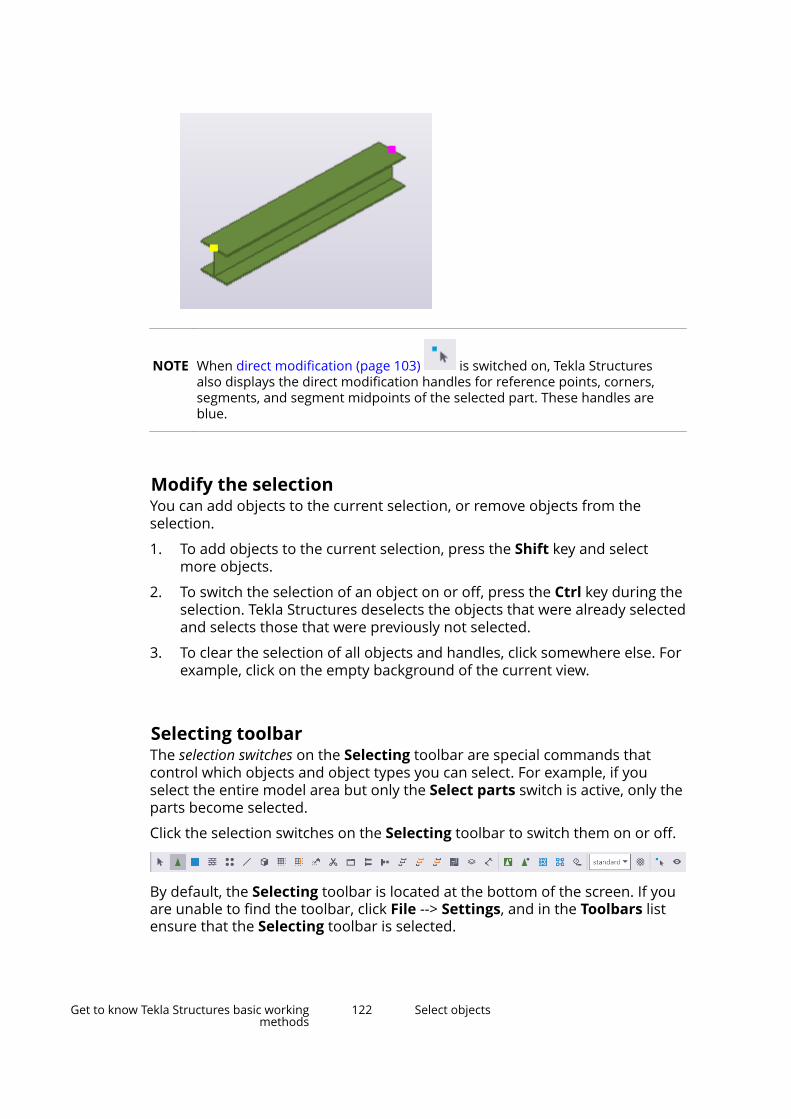
NOTE When direct modification (page 103) is switched on, Tekla Structuresalso displays the direct modification handles for reference points, corners,segments, and segment midpoints of the selected part. These handles areblue.
Modify the selectionYou can add objects to the current selection, or remove objects from theselection.
1. To add objects to the current selection, press the Shift key and selectmore objects.
2. To switch the selection of an object on or off, press the Ctrl key during theselection. Tekla Structures deselects the objects that were already selectedand selects those that were previously not selected.
3. To clear the selection of all objects and handles, click somewhere else. Forexample, click on the empty background of the current view.
Selecting toolbarThe selection switches on the Selecting toolbar are special commands thatcontrol which objects and object types you can select. For example, if youselect the entire model area but only the Select parts switch is active, only theparts become selected.
Click the selection switches on the Selecting toolbar to switch them on or off.
By default, the Selecting toolbar is located at the bottom of the screen. If youare unable to find the toolbar, click File --> Settings, and in the Toolbars listensure that the Selecting toolbar is selected.
Get to know Tekla Structures basic workingmethods
122 Select objects

Main selection switches
The main selection switches control whether you can select components andassemblies, or objects included in them. These switches have the highestpriority.
Switch Selectable objects DescriptionComponents When you click any
object belonging to acomponent, TeklaStructures selects thecomponent symbol andhighlights (but does notselect) all componentobjects.
Component objects Objects createdautomatically by acomponent can beselected.
Assemblies and castunits
When you click anyobject in an assembly ora cast unit, TeklaStructures selects theassembly or cast unitand highlights all objectsin the same assembly orcast unit.
Objects in assembliesand cast units
You can select singleobjects in assembliesand cast units.
Other selection switches
The table below lists the remaining selection switches. Use these switches tocontrol which object types you want to select.
Switch Selectable objects DescriptionAny objects Turns all switches on.
You can select all objecttypes, except for singlebolts.
Components You can selectcomponent symbols.
Parts You can select parts,such as columns, beams,or plates.
Get to know Tekla Structures basic workingmethods
123 Select objects
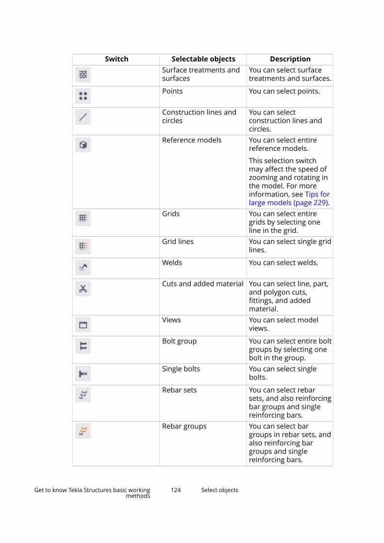
Switch Selectable objects DescriptionSurface treatments andsurfaces
You can select surfacetreatments and surfaces.
Points You can select points.
Construction lines andcircles
You can selectconstruction lines andcircles.
Reference models You can select entirereference models.
This selection switchmay affect the speed ofzooming and rotating inthe model. For moreinformation, see Tips forlarge models (page 229).
Grids You can select entiregrids by selecting oneline in the grid.
Grid lines You can select single gridlines.
Welds You can select welds.
Cuts and added material You can select line, part,and polygon cuts,fittings, and addedmaterial.
Views You can select modelviews.
Bolt group You can select entire boltgroups by selecting onebolt in the group.
Single bolts You can select singlebolts.
Rebar sets You can select rebarsets, and also reinforcingbar groups and singlereinforcing bars.
Rebar groups You can select bargroups in rebar sets, andalso reinforcing bargroups and singlereinforcing bars.
Get to know Tekla Structures basic workingmethods
124 Select objects
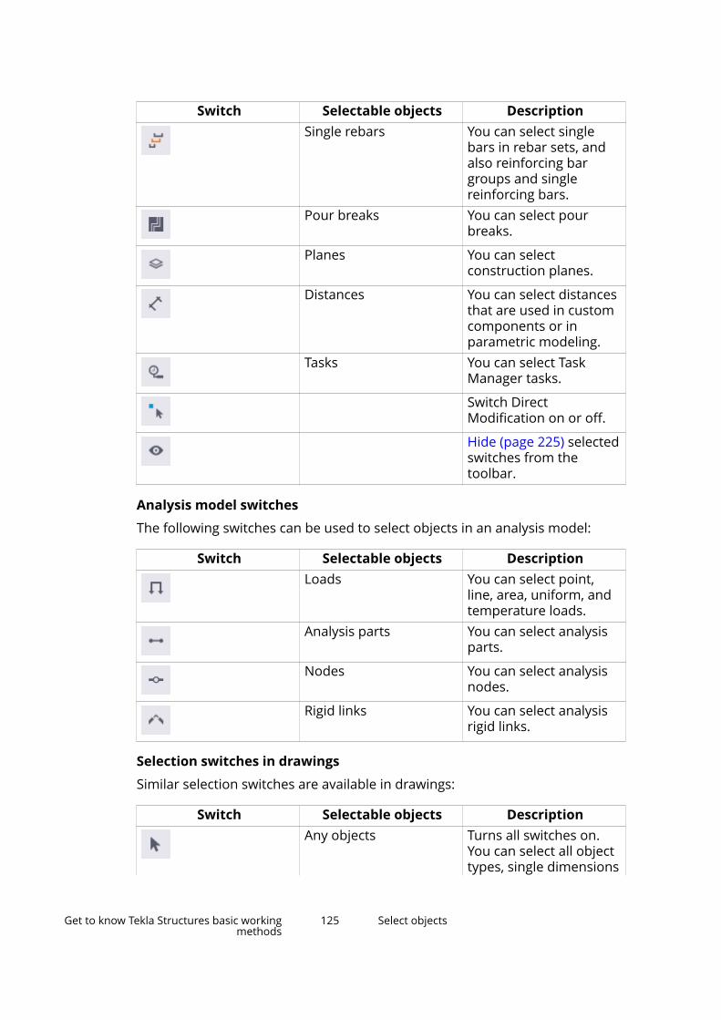
Switch Selectable objects DescriptionSingle rebars You can select single
bars in rebar sets, andalso reinforcing bargroups and singlereinforcing bars.
Pour breaks You can select pourbreaks.
Planes You can selectconstruction planes.
Distances You can select distancesthat are used in customcomponents or inparametric modeling.
Tasks You can select TaskManager tasks.
Switch DirectModification on or off.
Hide (page 225) selectedswitches from thetoolbar.
Analysis model switches
The following switches can be used to select objects in an analysis model:
Switch Selectable objects DescriptionLoads You can select point,
line, area, uniform, andtemperature loads.
Analysis parts You can select analysisparts.
Nodes You can select analysisnodes.
Rigid links You can select analysisrigid links.
Selection switches in drawings
Similar selection switches are available in drawings:
Switch Selectable objects DescriptionAny objects Turns all switches on.
You can select all objecttypes, single dimensions
Get to know Tekla Structures basic workingmethods
125 Select objects
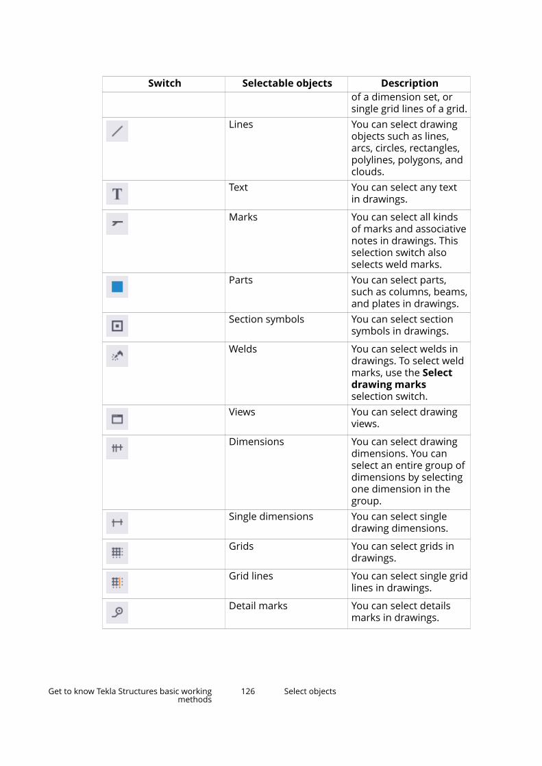
Switch Selectable objects Descriptionof a dimension set, orsingle grid lines of a grid.
Lines You can select drawingobjects such as lines,arcs, circles, rectangles,polylines, polygons, andclouds.
Text You can select any textin drawings.
Marks You can select all kindsof marks and associativenotes in drawings. Thisselection switch alsoselects weld marks.
Parts You can select parts,such as columns, beams,and plates in drawings.
Section symbols You can select sectionsymbols in drawings.
Welds You can select welds indrawings. To select weldmarks, use the Selectdrawing marksselection switch.
Views You can select drawingviews.
Dimensions You can select drawingdimensions. You canselect an entire group ofdimensions by selectingone dimension in thegroup.
Single dimensions You can select singledrawing dimensions.
Grids You can select grids indrawings.
Grid lines You can select single gridlines in drawings.
Detail marks You can select detailsmarks in drawings.
Get to know Tekla Structures basic workingmethods
126 Select objects
Switch Selectable objects DescriptionPlugins You can select custom
plugins in drawings.
Alternatively, you can control the selection switches with Quick Launch. Starttyping the name of the selection switch, for example, select, and click thename of the selection switch on the search results list to activate the switch.
See also
Tips for selecting objects (page 129)
Select assemblies, cast units, and nested objectsYou can select either assemblies or cast units, or single objects in nestedassemblies or nested components.
Select assemblies and cast unitsUse the Select assemblies selection switch to select assemblies (page 386)and cast units (page 396).
1. Ensure that the Select assemblies selection switch (page 122) isactive.
2. Select a part.
Tekla Structures selects the entire cast unit or assembly that contains theselected part.
Select nested objectsYou can select nested assemblies and components. The active selection switchdefines on which level you start and toward which direction you move in thecomponent or assembly hierarchy (page 390). The status bar shows the stepsyou take in the hierarchy.
1. Ensure that the correct selection switch (page 122) is active.
• : to start from the assemblies on the highest level, move to theirsub-assemblies, and finally select single parts, bolts, and so on
• : to start from single objects and move to bigger and biggernested assemblies
Get to know Tekla Structures basic workingmethods
127 Select objects
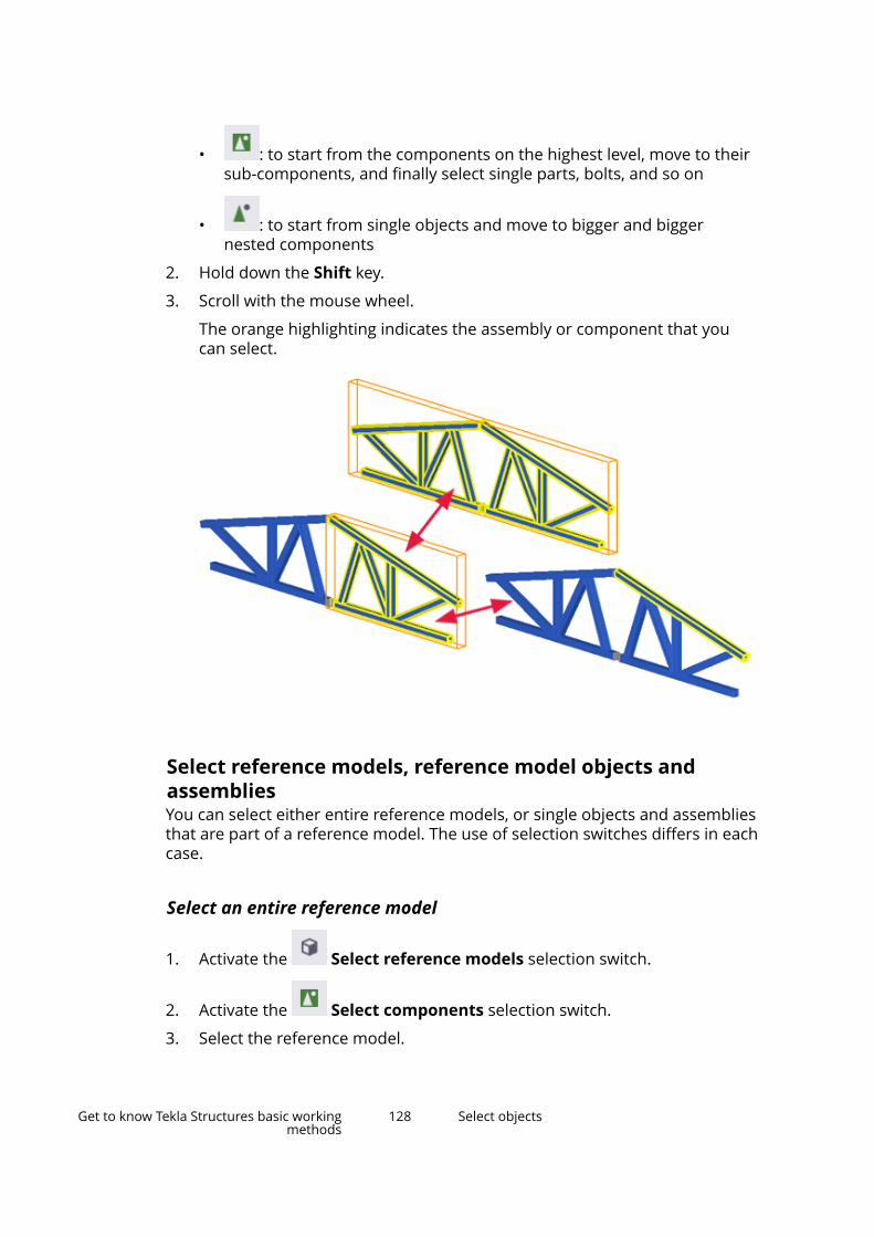
• : to start from the components on the highest level, move to theirsub-components, and finally select single parts, bolts, and so on
• : to start from single objects and move to bigger and biggernested components
2. Hold down the Shift key.
3. Scroll with the mouse wheel.
The orange highlighting indicates the assembly or component that youcan select.
Select reference models, reference model objects andassembliesYou can select either entire reference models, or single objects and assembliesthat are part of a reference model. The use of selection switches differs in eachcase.
Select an entire reference model
1. Activate the Select reference models selection switch.
2. Activate the Select components selection switch.
3. Select the reference model.
Get to know Tekla Structures basic workingmethods
128 Select objects

Select a reference model object
1. Activate the Select reference models selection switch.
2. Activate the Select objects in components selection switch.
3. Select the desired object in the reference model.
Select a reference model assembly
1. Activate the Select reference models selection switch.
2. Activate the Select assemblies selection switch.
3. Select the desired assembly in the reference model.
Tips for selecting objectsHere are listed some tips that can help when you are selecting objects.
Switch rollover highlight on or offBy default, Tekla Structures highlights the objects that you can select. You canswitch the highlighting on or off.
To switch the rollover highlight on or off, on the File menu, click Settings andselect or clear the Rollover highlight check box. Alternatively, you can pressH.
Depending on the rendering engine (page 67) you are using, OpenGL orDirectX, Tekla Structures highlights the objects differently when rolloverhighlight is on.
In the example below, the rendering of parts (page 584) is set to Parts shadedwireframe.
DirectX OpenGLTekla Structures highlights the objectsby showing them with darker objectcolor.
For example:
Tekla Structures highlights the objectsby showing them with light edge linecolor.
For example:
Get to know Tekla Structures basic workingmethods
129 Select objects

DirectX OpenGL
Select on right-clickYou can change the settings so that you can select objects also with the rightmouse button.
1. On the File menu, click Settings and select the following check boxes:
• Select on right-click
• Rollover highlight
2. Right-click an object to select it. Tekla Structures highlights the object andshows the related shortcut menu.
If you cannot select objectsIf you cannot select desired objects in the model, check the selection switchesand the filter settings.
• Check that you have switched on all the needed selection switches(page 122).
Get to know Tekla Structures basic workingmethods
130 Select objects
• If you still cannot select the objects, check the selection filter settings. Youcan select a different filter or modify the current filter.
Interrupt object selectionYou can have Tekla Structures interrupt the object selection process if theselection takes over a defined period of time. For example, if you are workingon a large model and you accidentally select all or part of the model, you caninterrupt the selection if it takes over 5000 milliseconds (5 seconds) tocomplete.
1. Define the time after which Tekla Structures asks if you want to interruptobject selection.
a. On the File menu, click Settings --> Advanced Options and go to theModeling Properties category.
b. Modify the advanced option XS_OBJECT_SELECTION_CONFIRMATION.
The default value is 5000 milliseconds.
c. Click OK.
2. Select (page 116) all or part of the model.
3. When Tekla Structures asks if you want to interrupt object selection, clickCancel.
1.6 Copy and move objectsThe basic functionality of copying and moving objects is the same in modelsand drawings. You can copy and move objects linearly, with rotation, and withmirroring.
• Copy objects (page 133)
• Move objects (page 144)
• Rotate objects (page 150)
• Mirror objects (page 154)
Duplicate objects
Two objects are considered duplicates if they have the same properties andlocation. Tekla Structures checks for duplicate objects when you copy andmove objects or create new objects in the same location as an existing object.If duplicates are found, you can choose whether to keep or delete them.
Use the advanced option XS_DUPLICATE_CHECK_LIMIT_FOR_COPY_AND_MOVEto define the maximum number of objects that can be counted as duplicateswhile copying or moving objects.
Get to know Tekla Structures basic workingmethods
131 Copy and move objects
NOTE Tekla Structures does not check for duplicates when you copy objectsusing a modeling tool, such as the Array of objects (29) component.
Connected objects
When you copy objects that are connected to another part (such asconnections and bolts), Tekla Structures tries to find suitable new main partsfor these copied objects. If none are found, some of the connected objectsmay not be copied at all. After copying, check that all of the objects have beencopied correctly.
Assemblies and cast units
If you copy or move objects from an assembly or cast unit, Tekla Structurescopies the assembly structure if possible. For example, sub-assemblies arecopied as sub-assemblies if a parent object is found.
Reinforcement and surface treatment
If you copy or move reinforcement or surface treatments, and want them toadapt to the part they are copied or moved to:
• The reinforcement handle or surface treatment handles must be in partcorners.
• The parts between which you copy or move must have the same numberof cross section corners.
• Circular parts must have the same cross section dimensions.
Drawing objects
You can copy and move drawing objects between drawing views that havedifferent scales.
Copy and move efficiently
You can keep the Move and Copy dialog boxes open if you are going to usethem often.
After you have run the Copy - Linear, Copy - Mirror, Copy - Rotate, or theMove - Linear, Move - Mirror or Move - Rotate command, interrupt thecommand and leave the dialog box open. When you want to continue copyingor moving, click the dialog box to activate it and continue to copy or moveobjects.
Show or hide "Do not show this message again"
Tekla Structures displays warning messages when necessary, for example,when you are about to copy or move objects outside the work area. However,you have the option to hide future warnings of the same type. You can haveTekla Structures show these warnings again.
Get to know Tekla Structures basic workingmethods
132 Copy and move objects
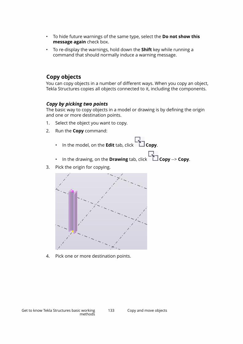
• To hide future warnings of the same type, select the Do not show thismessage again check box.
• To re-display the warnings, hold down the Shift key while running acommand that should normally induce a warning message.
Copy objectsYou can copy objects in a number of different ways. When you copy an object,Tekla Structures copies all objects connected to it, including the components.
Copy by picking two pointsThe basic way to copy objects in a model or drawing is by defining the originand one or more destination points.
1. Select the object you want to copy.
2. Run the Copy command:
• In the model, on the Edit tab, click Copy.
• In the drawing, on the Drawing tab, click Copy --> Copy.
3. Pick the origin for copying.
4. Pick one or more destination points.
Get to know Tekla Structures basic workingmethods
133 Copy and move objects
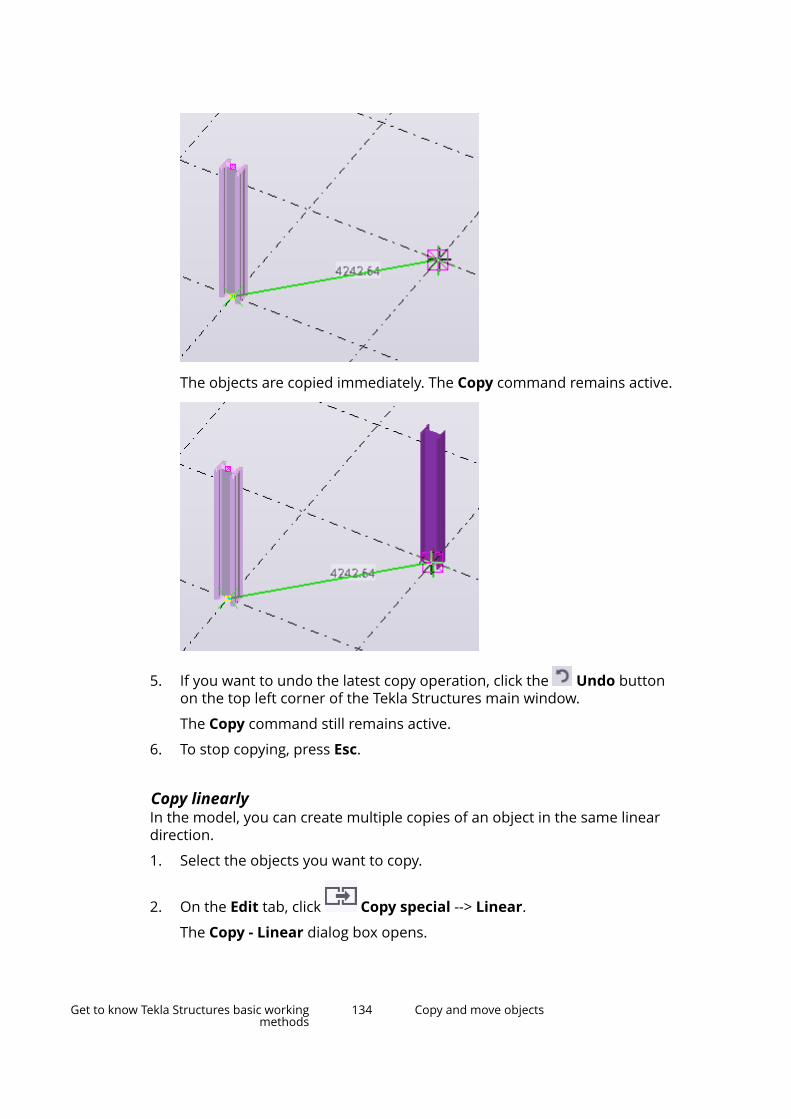
The objects are copied immediately. The Copy command remains active.
5. If you want to undo the latest copy operation, click the Undo buttonon the top left corner of the Tekla Structures main window.
The Copy command still remains active.
6. To stop copying, press Esc.
Copy linearlyIn the model, you can create multiple copies of an object in the same lineardirection.
1. Select the objects you want to copy.
2. On the Edit tab, click Copy special --> Linear.
The Copy - Linear dialog box opens.
Get to know Tekla Structures basic workingmethods
134 Copy and move objects

3. Pick two points, or enter the coordinates in the dX, dY, and dZ boxes.
You can also use a formula to calculate the x, y, and z displacements. Forexample:
4. Enter the number of copies.
5. Click Copy.
6. To stop copying, press Esc.
TIP If the dialog box is open but the command is no longer active, clickthe Pick... button to re-activate the command.
Copy by specifying a distance from originYou can copy objects to a new position in the model or drawing by specifying adistance from the origin. Use the Enter a Numeric Location dialog box tospecify the distance.
1. Select the objects you want to copy.
2. Run the Copy command:
• In the model, on the Edit tab, click Copy.
• In the drawing, on the Drawing tab, click Copy --> Copy.
3. Pick the origin for copying.
4. Move the cursor in the direction you want to copy the objects, but do notpick the point.
5. Type the distance.
When you start typing, Tekla Structures displays the Enter a NumericLocation dialog box automatically.
6. Click OK.
Copy using drag-and-dropYou can copy objects by using drag-and-drop.
1. On the File menu, click Settings and select the Drag & drop check box toactivate the command.
2. Select the objects you want to copy.
Get to know Tekla Structures basic workingmethods
135 Copy and move objects

3. Hold down the Ctrl key and drag the objects to a new location.
The point you start dragging from (center, corner, or middle point) affectsthe object's alignment in the new location.
Tekla Structures copies the objects:
NOTE To copy grid labels in a drawing, first select the grid label and then either
activate the Select grid line selection switch (page 122) or select the gridlabel handle.
Copy objects to another objectIn the model, you can copy objects from an object to other similar objects. Thisis useful, for example, when you detail previously modeled parts. The objects
Get to know Tekla Structures basic workingmethods
136 Copy and move objects

that you can copy between can have different dimensions, length, androtation.
1. Select the objects you want to copy.
2. On the Edit tab, click Copy special --> To another object.
3. Select the object to copy from (source object).
4. Select the objects to copy to (target object).
Copy all content to another objectIn the model, you can copy objects from an assembly or cast unit to othersimilar assemblies or cast units without individually selecting each object tocopy. This is useful, for example, when you have detailed an assembly andwant to copy all details to another similar assembly.
1. Ensure that the Select assemblies selection switch (page 122) isactive.
2. Select the assembly or cast unit to copy from (source object).
3. On the Edit tab, click Copy special --> All content to anotherobject.
4. Select the assemblies or cast units to copy to (target objects).
As a result, Tekla Structures copies the following objects:
• Secondary parts
• Reinforcement, bolts, and welds
• Cuts, fittings, and edge chamfers
• Sub-assemblies
• Components
NOTE Tekla Structures does not copy pour breaks, or secondary partscreated by a component that has also created the assembly main part.If some of the objects to be copied already exist in the assembly orcast unit to copy to, Tekla Structures may create duplicate objects.Tekla Structures warns you about duplicate secondary parts,reinforcement, and sub-assemblies, but not about duplicate bolts,welds, cuts, or components.
Copy to another planeIn the model, you can copy objects from the first plane you specify to thesecond (and third, etc.) plane you specify. The position of the copied objects
Get to know Tekla Structures basic workingmethods
137 Copy and move objects

relative to the second (and third, etc.) plane remains the same as the positionof the original objects relative to the first plane.
1. Select the objects you want to copy.
2. On the Edit tab, click Copy special --> To another plane.
3. Pick the point of origin of the first plane.
4. Pick a point on the first plane in the positive x direction.
5. Pick a point on the first plane in the positive y direction.
6. Repeat steps 3–5 for all destination planes.
Copy from another modelYou can copy objects from another model based on phase numbers. Note thatTekla Structures copies secondary parts from the model only if they belong tothe same phase as their main part. This also applies to component objects.
1. On the Edit tab, click Copy special --> From another model.
The Copy from Model dialog box opens.
2. In the Model directories list, select the model to copy from.
This is the source model. Note that the target model must have beencreated using the same or newer version of Tekla Structures as the sourcemodel. You cannot copy from a newer version to an older version.
3. In the Phase numbers box, enter the numbers of the phases from whichto copy objects, separated by spaces.
For example, 2 7.
4. Click Copy.
5. Close the dialog box.
NOTE If you copy pour breaks from another model, the copied pour breaksautomatically adapt to the target model. Always check that the copiedpour breaks have adapted correctly.
Copy objects using linear array toolUse Linear array tool to copy selected objects linearly along multipledirections at defined intervals or spacing. Tekla Structures does not check forduplicates when you copy objects using this method.
Get to know Tekla Structures basic workingmethods
138 Copy and move objects
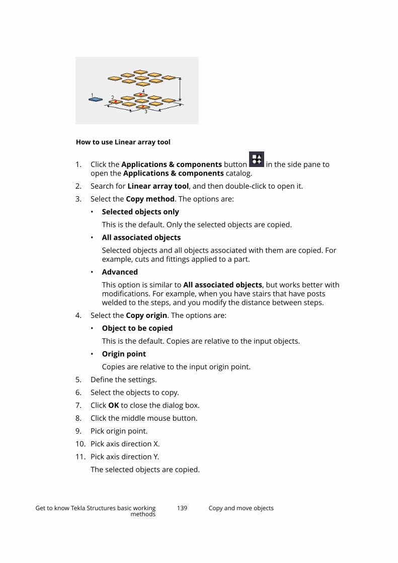
How to use Linear array tool
1. Click the Applications & components button in the side pane toopen the Applications & components catalog.
2. Search for Linear array tool, and then double-click to open it.
3. Select the Copy method. The options are:
• Selected objects only
This is the default. Only the selected objects are copied.
• All associated objects
Selected objects and all objects associated with them are copied. Forexample, cuts and fittings applied to a part.
• Advanced
This option is similar to All associated objects, but works better withmodifications. For example, when you have stairs that have postswelded to the steps, and you modify the distance between steps.
4. Select the Copy origin. The options are:
• Object to be copied
This is the default. Copies are relative to the input objects.
• Origin point
Copies are relative to the input origin point.
5. Define the settings.
6. Select the objects to copy.
7. Click OK to close the dialog box.
8. Click the middle mouse button.
9. Pick origin point.
10. Pick axis direction X.
11. Pick axis direction Y.
The selected objects are copied.
Get to know Tekla Structures basic workingmethods
139 Copy and move objects
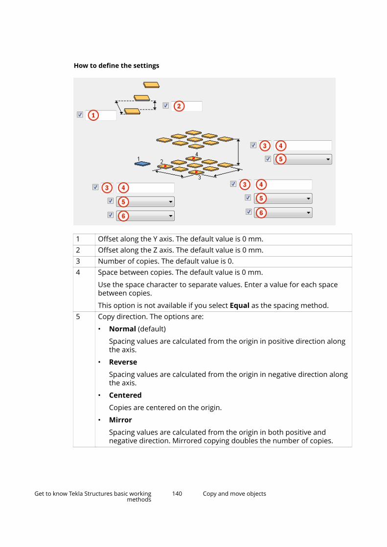
How to define the settings
1 Offset along the Y axis. The default value is 0 mm.2 Offset along the Z axis. The default value is 0 mm.3 Number of copies. The default value is 0.4 Space between copies. The default value is 0 mm.
Use the space character to separate values. Enter a value for each spacebetween copies.
This option is not available if you select Equal as the spacing method.5 Copy direction. The options are:
• Normal (default)
Spacing values are calculated from the origin in positive direction alongthe axis.
• Reverse
Spacing values are calculated from the origin in negative direction alongthe axis.
• Centered
Copies are centered on the origin.
• Mirror
Spacing values are calculated from the origin in both positive andnegative direction. Mirrored copying doubles the number of copies.
Get to know Tekla Structures basic workingmethods
140 Copy and move objects

6 Spacing method. The options are:
• Equal (default)
Copies are equally spaced based on the length of the X or Y axis.
• Specified
Copies are spaced according to the number and spacing values given.
Copy objects using radial array toolUse Radial array tool to copy selected objects radially along multipledirections at defined intervals or spacing. Tekla Structures does not check forduplicates when you copy objects using this method.
How to use Radial array tool
1. Click the Applications & components button in the side pane toopen the Applications & components catalog.
2. Search for Radial array tool, and then double-click to open it.
3. Select the Copy method. The options are:
• Selected objects only
This is the default. Only the selected objects are copied.
• All associated objects
Selected objects and all objects associated with them are copied. Forexample, cuts, welds, and bolts.
• Advanced
This option is similar to All associated objects, but works better withmodifications. For example, when you have stairs that have postswelded to the steps, and you modify the distance between steps.
4. Select the Rotate copies option.
The default is Yes.
5. Define the rotation axis.
The default is X.
6. Define the settings.
Get to know Tekla Structures basic workingmethods
141 Copy and move objects

7. Select the objects to copy.
8. Click OK to close the dialog box.
9. Click the middle mouse button.
10. Pick origin point.
11. Pick axis direction X.
12. Pick axis direction Y.
The selected objects are copied.
How to define the settings
1 Distance between copies. The default value is 0.2 Rotation. The options are:
• Angle (default)
The copies are rotated by angle.
• Distance
The copies are rotated by distance.3 Number of angles or distances. The default value is 0.4 Space between copies.
Use the space character to separate values. Enter a value for eachspace between copies.
Get to know Tekla Structures basic workingmethods
142 Copy and move objects

5 Copy direction. The options are:
• Normal (default)
Spacing values are calculated from the origin in positive directionalong the axis.
• Reverse
Spacing values are calculated from the origin in negativedirection along the axis.
• Centered
Copies are centered on the origin.
• Mirror
Spacing values are calculated from the origin in both positiveand negative direction. Mirrored copying doubles the number ofcopies.
6 Radial distance.
The radial distance should be equivalent to the distance you pickedwhen applying the component.
If the radial distance is smaller or greater than the picked distance,the spacing between the copied objects is not the same as given inthe Space between copies box (4).
Tekla Structures calculates the rotation angle according to the dialogbox values (spacing and radial distance), and the rotation angleoverrides the spacing given in the dialog box.
Copy objects using Array of objects (29) componentUse the Array of objects (29) component to copy model objects along a line. Ifyou modify the original object, Tekla Structures also changes the copiedobjects.
1. Click the Applications & components button in the side pane toopen the Applications & components catalog.
2. Search for the Array of objects (29) component, and then double-click toopen it.
3. Define the settings:
• Number of copies: Enter the number of copies you want to create.
• Spacing values: Define the spacing of the objects.
• Copy to the opposite direction: Select Yes if you want to copy in thedirection opposite to the points you pick.
• Start point for copying: Choose either the object to be copied or thefirst input point.
Get to know Tekla Structures basic workingmethods
143 Copy and move objects
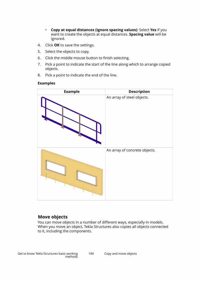
• Copy at equal distances (Ignore spacing values): Select Yes if youwant to create the objects at equal distances. Spacing value will beignored.
4. Click OK to save the settings.
5. Select the objects to copy.
6. Click the middle mouse button to finish selecting.
7. Pick a point to indicate the start of the line along which to arrange copiedobjects.
8. Pick a point to indicate the end of the line.
Examples
Example DescriptionAn array of steel objects.
An array of concrete objects.
Move objectsYou can move objects in a number of different ways, especially in models.When you move an object, Tekla Structures also copies all objects connectedto it, including the components.
Get to know Tekla Structures basic workingmethods
144 Copy and move objects

Move by picking two pointsThe basic way to move objects in a model or drawing is by defining the originand one or more destination points.
1. Select the object you want to move.
2. Run the Move command:
• In the model, on the Edit tab, click Move.
• In the drawing, on the Drawing tab, click Move --> Move
3. Pick the origin for moving.
4. Pick the destination point.
Get to know Tekla Structures basic workingmethods
145 Copy and move objects

The object is moved immediately. The Move command does not remainactive.
Move linearlyYou can move objects linearly to a new position in the model.
1. Select the objects you want to move.
2. On the Edit tab, click Move special --> Linear.
The Move - Linear dialog box opens.
3. Pick two points in the model, or enter the coordinates in the dX, dY, anddZ boxes.
You can also use a formula to calculate the x, y, and z displacements. Forexample:
4. Click Move.
Get to know Tekla Structures basic workingmethods
146 Copy and move objects
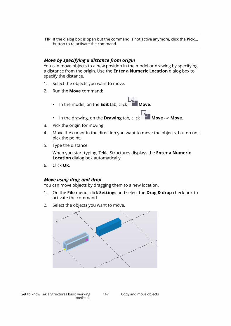
TIP If the dialog box is open but the command is not active anymore, click the Pick...button to re-activate the command.
Move by specifying a distance from originYou can move objects to a new position in the model or drawing by specifyinga distance from the origin. Use the Enter a Numeric Location dialog box tospecify the distance.
1. Select the objects you want to move.
2. Run the Move command:
• In the model, on the Edit tab, click Move.
• In the drawing, on the Drawing tab, click Move --> Move.
3. Pick the origin for moving.
4. Move the cursor in the direction you want to move the objects, but do notpick the point.
5. Type the distance.
When you start typing, Tekla Structures displays the Enter a NumericLocation dialog box automatically.
6. Click OK.
Move using drag-and-dropYou can move objects by dragging them to a new location.
1. On the File menu, click Settings and select the Drag & drop check box toactivate the command.
2. Select the objects you want to move.
Get to know Tekla Structures basic workingmethods
147 Copy and move objects

3. Drag the objects to a new location.
The point you start dragging from (center, corner, or middle point) affectsthe object's alignment in the new location.
The objects are moved immediately.
4. To move an end point using drag-and-drop:
a. Select the handle.
b. Hold down the left mouse button, and drag the handle to a newlocation.
The end point is moved accordingly:
Get to know Tekla Structures basic workingmethods
148 Copy and move objects

NOTE For some objects, you may need to switch on Smart select todrag from handles without selecting them first. To switch it on,click File --> Settings and select the Smart select check box.
NOTE To move grid labels in a drawing, first select the grid label and
then either activate the Select grid line selection switch(page 122) or select the grid label handle.
Move to another planeIn a model, you can move objects from the first plane you specify to anotherplane, which you specify by picking three points. The moved objects remain inthe same position on the second plane as the original objects on the firstplane.
1. Select the objects you want to move.
2. On the Edit tab, click Move special --> To another plane.
3. Pick the point of origin of the first plane.
4. Pick a point on the first plane in the positive x direction.
5. Pick a point on the first plane in the positive y direction.
6. Repeat steps 3–5 for the destination plane.
Move objects to another objectIn a model, you can move objects from an object to other, similar objects. Thisis useful, for example, when you detail previously modeled parts. The objectsthat you move between can have different dimensions, length, and rotation.
1. Select the objects you want to move.
2. On the Edit tab, click Move special --> To another object.
3. Select the object to move from (source object).
Get to know Tekla Structures basic workingmethods
149 Copy and move objects
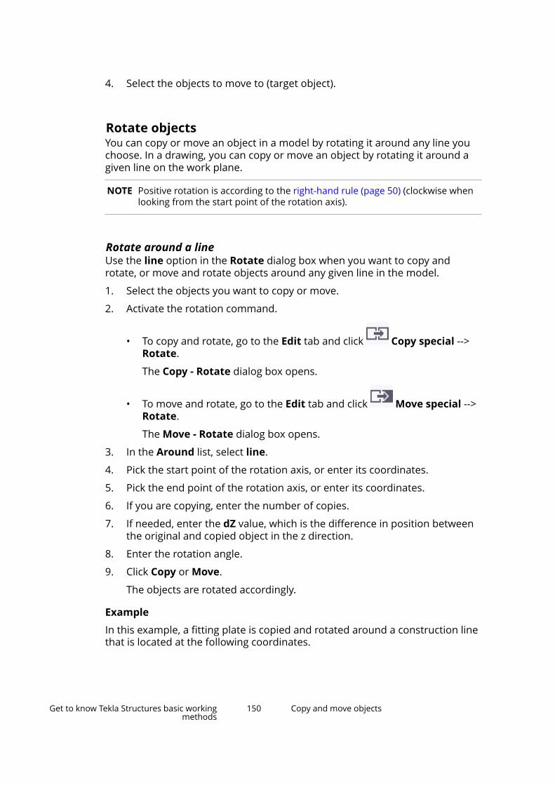
4. Select the objects to move to (target object).
Rotate objectsYou can copy or move an object in a model by rotating it around any line youchoose. In a drawing, you can copy or move an object by rotating it around agiven line on the work plane.
NOTE Positive rotation is according to the right-hand rule (page 50) (clockwise whenlooking from the start point of the rotation axis).
Rotate around a lineUse the line option in the Rotate dialog box when you want to copy androtate, or move and rotate objects around any given line in the model.
1. Select the objects you want to copy or move.
2. Activate the rotation command.
• To copy and rotate, go to the Edit tab and click Copy special -->Rotate.
The Copy - Rotate dialog box opens.
• To move and rotate, go to the Edit tab and click Move special -->Rotate.
The Move - Rotate dialog box opens.
3. In the Around list, select line.
4. Pick the start point of the rotation axis, or enter its coordinates.
5. Pick the end point of the rotation axis, or enter its coordinates.
6. If you are copying, enter the number of copies.
7. If needed, enter the dZ value, which is the difference in position betweenthe original and copied object in the z direction.
8. Enter the rotation angle.
9. Click Copy or Move.
The objects are rotated accordingly.
Example
In this example, a fitting plate is copied and rotated around a construction linethat is located at the following coordinates.
Get to know Tekla Structures basic workingmethods
150 Copy and move objects

As a result, the copied fitting plates follow the curve of the concrete panel.
Rotate around the z axisUse the Z option in the Rotate dialog box when you want to copy and rotate,or move and rotate objects around the z axis in the model.
1. Select the objects you want to copy or move. For example:
Get to know Tekla Structures basic workingmethods
151 Copy and move objects
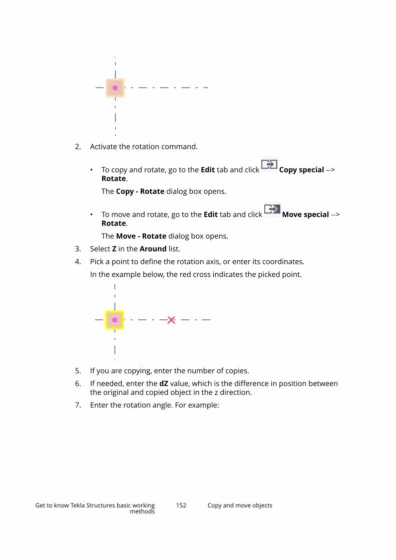
2. Activate the rotation command.
• To copy and rotate, go to the Edit tab and click Copy special -->Rotate.
The Copy - Rotate dialog box opens.
• To move and rotate, go to the Edit tab and click Move special -->Rotate.
The Move - Rotate dialog box opens.
3. Select Z in the Around list.
4. Pick a point to define the rotation axis, or enter its coordinates.
In the example below, the red cross indicates the picked point.
5. If you are copying, enter the number of copies.
6. If needed, enter the dZ value, which is the difference in position betweenthe original and copied object in the z direction.
7. Enter the rotation angle. For example:
Get to know Tekla Structures basic workingmethods
152 Copy and move objects
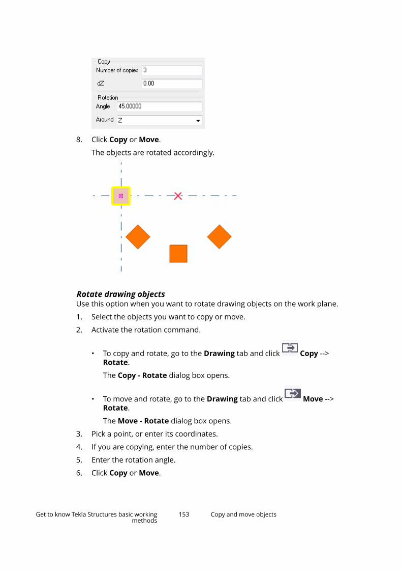
8. Click Copy or Move.
The objects are rotated accordingly.
Rotate drawing objectsUse this option when you want to rotate drawing objects on the work plane.
1. Select the objects you want to copy or move.
2. Activate the rotation command.
• To copy and rotate, go to the Drawing tab and click Copy -->Rotate.
The Copy - Rotate dialog box opens.
• To move and rotate, go to the Drawing tab and click Move -->Rotate.
The Move - Rotate dialog box opens.
3. Pick a point, or enter its coordinates.
4. If you are copying, enter the number of copies.
5. Enter the rotation angle.
6. Click Copy or Move.
Get to know Tekla Structures basic workingmethods
153 Copy and move objects
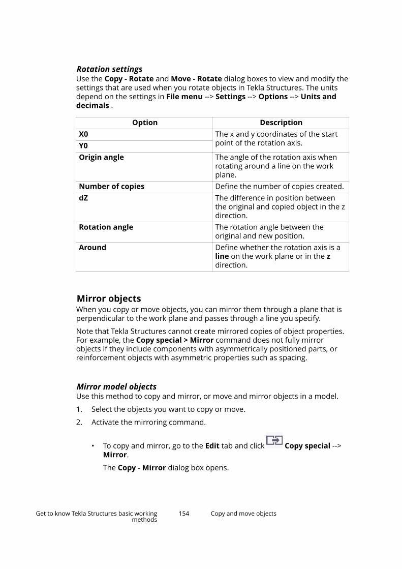
Rotation settingsUse the Copy - Rotate and Move - Rotate dialog boxes to view and modify thesettings that are used when you rotate objects in Tekla Structures. The unitsdepend on the settings in File menu --> Settings --> Options --> Units anddecimals .
Option DescriptionX0 The x and y coordinates of the start
point of the rotation axis.Y0Origin angle The angle of the rotation axis when
rotating around a line on the workplane.
Number of copies Define the number of copies created.dZ The difference in position between
the original and copied object in the zdirection.
Rotation angle The rotation angle between theoriginal and new position.
Around Define whether the rotation axis is aline on the work plane or in the zdirection.
Mirror objectsWhen you copy or move objects, you can mirror them through a plane that isperpendicular to the work plane and passes through a line you specify.
Note that Tekla Structures cannot create mirrored copies of object properties.For example, the Copy special > Mirror command does not fully mirrorobjects if they include components with asymmetrically positioned parts, orreinforcement objects with asymmetric properties such as spacing.
Mirror model objectsUse this method to copy and mirror, or move and mirror objects in a model.
1. Select the objects you want to copy or move.
2. Activate the mirroring command.
• To copy and mirror, go to the Edit tab and click Copy special -->Mirror.
The Copy - Mirror dialog box opens.
Get to know Tekla Structures basic workingmethods
154 Copy and move objects
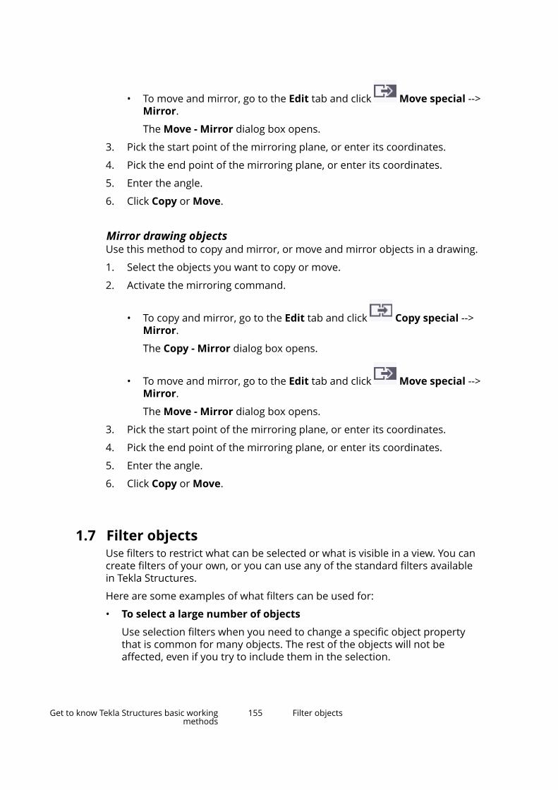
• To move and mirror, go to the Edit tab and click Move special -->Mirror.
The Move - Mirror dialog box opens.
3. Pick the start point of the mirroring plane, or enter its coordinates.
4. Pick the end point of the mirroring plane, or enter its coordinates.
5. Enter the angle.
6. Click Copy or Move.
Mirror drawing objectsUse this method to copy and mirror, or move and mirror objects in a drawing.
1. Select the objects you want to copy or move.
2. Activate the mirroring command.
• To copy and mirror, go to the Edit tab and click Copy special -->Mirror.
The Copy - Mirror dialog box opens.
• To move and mirror, go to the Edit tab and click Move special -->Mirror.
The Move - Mirror dialog box opens.
3. Pick the start point of the mirroring plane, or enter its coordinates.
4. Pick the end point of the mirroring plane, or enter its coordinates.
5. Enter the angle.
6. Click Copy or Move.
1.7 Filter objectsUse filters to restrict what can be selected or what is visible in a view. You cancreate filters of your own, or you can use any of the standard filters availablein Tekla Structures.
Here are some examples of what filters can be used for:
• To select a large number of objects
Use selection filters when you need to change a specific object propertythat is common for many objects. The rest of the objects will not beaffected, even if you try to include them in the selection.
Get to know Tekla Structures basic workingmethods
155 Filter objects
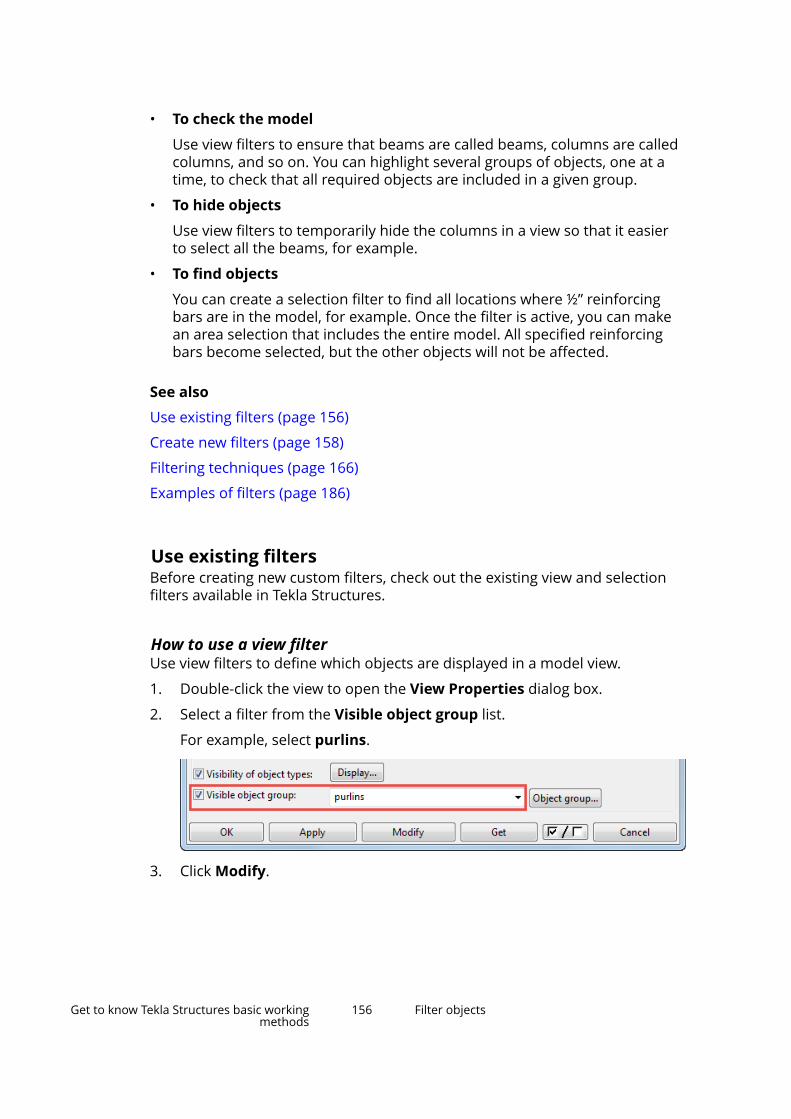
• To check the model
Use view filters to ensure that beams are called beams, columns are calledcolumns, and so on. You can highlight several groups of objects, one at atime, to check that all required objects are included in a given group.
• To hide objects
Use view filters to temporarily hide the columns in a view so that it easierto select all the beams, for example.
• To find objects
You can create a selection filter to find all locations where ½” reinforcingbars are in the model, for example. Once the filter is active, you can makean area selection that includes the entire model. All specified reinforcingbars become selected, but the other objects will not be affected.
See also
Use existing filters (page 156)
Create new filters (page 158)
Filtering techniques (page 166)
Examples of filters (page 186)
Use existing filtersBefore creating new custom filters, check out the existing view and selectionfilters available in Tekla Structures.
How to use a view filterUse view filters to define which objects are displayed in a model view.
1. Double-click the view to open the View Properties dialog box.
2. Select a filter from the Visible object group list.
For example, select purlins.
3. Click Modify.
Get to know Tekla Structures basic workingmethods
156 Filter objects
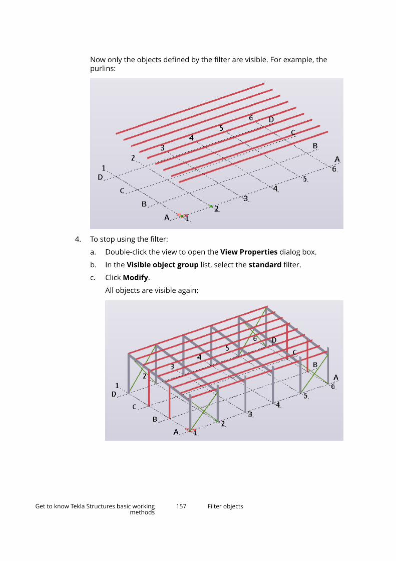
Now only the objects defined by the filter are visible. For example, thepurlins:
4. To stop using the filter:
a. Double-click the view to open the View Properties dialog box.
b. In the Visible object group list, select the standard filter.
c. Click Modify.
All objects are visible again:
Get to know Tekla Structures basic workingmethods
157 Filter objects

NOTE If you cannot see all desired objects (page 48), note that thework area, view depth, view setup, and object representationsettings also affect the visibility of objects.
How to use a selection filterUse selection filters to define which objects can be selected in the model. Notethat an object must be visible in the model to be selectable.
1. On the Selecting toolbar, select a filter from the list.
The list is by default located at the bottom of the Tekla Structures mainwindow.
For example, select the Name - Footing filter.
2. Select the desired objects in the model.
You can select multiple objects or even the entire model at once. Now thatthe filter is active, only objects defined by the filter become selected. Forexample, if the Name - Footing filter is active, only footings are selectableand the rest of the objects stay intact:
3. If you cannot select all objects defined by the selection filter, check yourview filter settings and ensure that you have switched on all the neededselection switches (page 122).
4. To stop using the filter, go to the Selecting toolbar and select thestandard filter.
All objects are selectable again.
Get to know Tekla Structures basic workingmethods
158 Filter objects
Create new filtersYou can create custom filters to define which objects are visible and selectablein the model and drawings. Add new filter rules, one on each row, to definewhich objects should be included or excluded.
Create a view filterYou can create your own custom filters to define which objects are visible in amodel.
1. Double-click the view to open the View Properties dialog box.
2. Click Object group.
The Object Group - View Filter dialog box opens, showing the currentlyactive filter.
3. Click New filter to create a new filter from scratch.
4. Click Add row to add a new filter rule.
5. In the Category list, select an object category.
You have the following options:
• Part
• Component
• Bolt
• Weld
• Reinforcing bar
• Surface
• Assembly
• Construction object
• Load
• Template
• Reference assembly
• Reference object
• Location breakdown structure
• Pour object
• Pour break
• Pour unit
• Task
• Object
Get to know Tekla Structures basic workingmethods
159 Filter objects
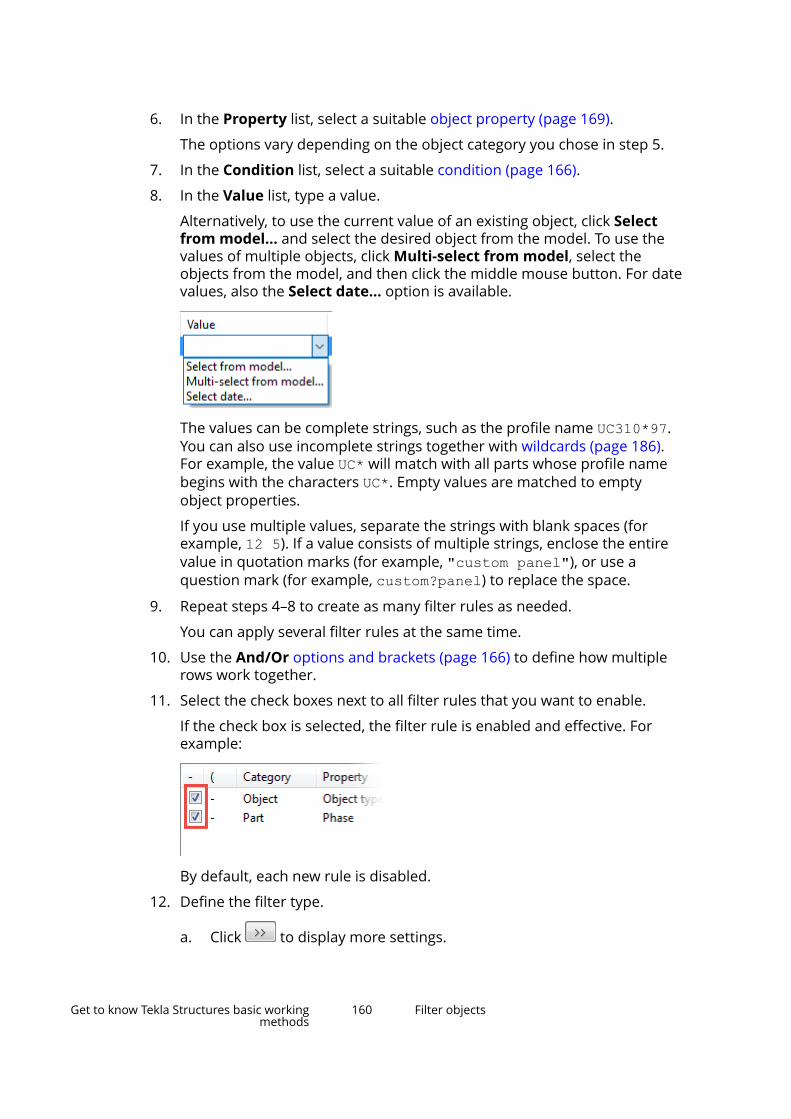
6. In the Property list, select a suitable object property (page 169).
The options vary depending on the object category you chose in step 5.
7. In the Condition list, select a suitable condition (page 166).
8. In the Value list, type a value.
Alternatively, to use the current value of an existing object, click Selectfrom model... and select the desired object from the model. To use thevalues of multiple objects, click Multi-select from model, select theobjects from the model, and then click the middle mouse button. For datevalues, also the Select date... option is available.
The values can be complete strings, such as the profile name UC310*97.You can also use incomplete strings together with wildcards (page 186).For example, the value UC* will match with all parts whose profile namebegins with the characters UC*. Empty values are matched to emptyobject properties.
If you use multiple values, separate the strings with blank spaces (forexample, 12 5). If a value consists of multiple strings, enclose the entirevalue in quotation marks (for example, "custom panel"), or use aquestion mark (for example, custom?panel) to replace the space.
9. Repeat steps 4–8 to create as many filter rules as needed.
You can apply several filter rules at the same time.
10. Use the And/Or options and brackets (page 166) to define how multiplerows work together.
11. Select the check boxes next to all filter rules that you want to enable.
If the check box is selected, the filter rule is enabled and effective. Forexample:
By default, each new rule is disabled.
12. Define the filter type.
a. Click to display more settings.
Get to know Tekla Structures basic workingmethods
160 Filter objects
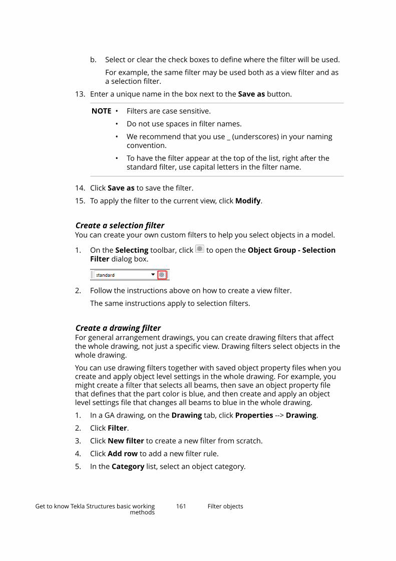
b. Select or clear the check boxes to define where the filter will be used.
For example, the same filter may be used both as a view filter and asa selection filter.
13. Enter a unique name in the box next to the Save as button.
NOTE • Filters are case sensitive.
• Do not use spaces in filter names.
• We recommend that you use _ (underscores) in your namingconvention.
• To have the filter appear at the top of the list, right after thestandard filter, use capital letters in the filter name.
14. Click Save as to save the filter.
15. To apply the filter to the current view, click Modify.
Create a selection filterYou can create your own custom filters to help you select objects in a model.
1. On the Selecting toolbar, click to open the Object Group - SelectionFilter dialog box.
2. Follow the instructions above on how to create a view filter.
The same instructions apply to selection filters.
Create a drawing filterFor general arrangement drawings, you can create drawing filters that affectthe whole drawing, not just a specific view. Drawing filters select objects in thewhole drawing.
You can use drawing filters together with saved object property files when youcreate and apply object level settings in the whole drawing. For example, youmight create a filter that selects all beams, then save an object property filethat defines that the part color is blue, and then create and apply an objectlevel settings file that changes all beams to blue in the whole drawing.
1. In a GA drawing, on the Drawing tab, click Properties --> Drawing.
2. Click Filter.
3. Click New filter to create a new filter from scratch.
4. Click Add row to add a new filter rule.
5. In the Category list, select an object category.
Get to know Tekla Structures basic workingmethods
161 Filter objects

You have the following options:
• Part
• Component
• Bolt
• Weld
• Reinforcing bar
• Surface
• Assembly
• Construction object
• Template
• Reference assembly
• Reference object
• Location breakdown structure
• Pour object
• Pour break
• Pour unit
• Task
• Object
6. In the Property list, select a suitable object property (page 169).
The options vary depending on the object category you chose in step 5.
7. In the Condition list, select a suitable condition (page 166).
8. In the Value list, type a value.
Alternatively, to use the current value of an existing object, click Selectfrom drawing and select the desired object from the drawing. To use thevalues of multiple objects, click Multi-select from drawing, select theobjects from the drawing, and then click the middle mouse button. Fordate values, also the Select date... option is available.
The values can be complete strings, such as the profile name UC310*97.You can also use incomplete strings together with wildcards (page 186).For example, the value UC* will match with all parts whose profile name
Get to know Tekla Structures basic workingmethods
162 Filter objects

begins with the characters UC*. Empty values are matched to emptyobject properties.
If you use multiple values, separate the strings with blank spaces (forexample, 12 5). If a value consists of multiple strings, enclose the entirevalue in quotation marks (for example, "custom panel"), or use aquestion mark (for example, custom?panel) to replace the space.
9. Repeat steps 4–8 to create as many filter rules as needed.
You can apply several filter rules at the same time.
10. Use the And/Or options and brackets (page 166) to define how multiplerows work together.
11. Select the check boxes next to all filter rules that you want to enable.
If the check box is selected, the filter rule is enabled and effective. Forexample:
By default, each new rule is disabled.
12. Define the filter type.
a. Click to display more settings.
b. Select or clear the check boxes to define where the filter will be used.
For example, the same drawing filter may be used both as a modelview filter and as a model selection filter, and also as an Organizerfilter.
13. Enter a unique name in the box next to the Save as button.
NOTE • Filters are case sensitive.
• Do not use spaces in filter names.
• We recommend that you use _ (underscores) in your namingconvention.
• To have the filter appear at the top of the list, right after thestandard filter, use capital letters in the filter name.
14. Click Save as to save the filter.
15. When you are done, click Cancel to close the filter properties dialog box.
Get to know Tekla Structures basic workingmethods
163 Filter objects
Create a drawing view filterYou can create your own custom view filters to help you select a specific groupof view objects in a drawing view.
You can use drawing view filters for changing the appearance of a certainobject group, or for selecting which objects are hidden in a drawing view.
You can also use drawing view filters together with saved object property fileswhen you create and apply object level settings in the selected view. Forexample, you might create a view filter that selects all columns in a view, thensave an object property file that defines that the part color is red, and thencreate and apply an object level settings file that changes all columns to red inthe selected view.
1. Open a drawing.
2. Double-click a drawing view frame.
3. Click Filter.
4. Click New filter to create a new filter from scratch.
5. Click Add row to add a new filter rule.
6. In the Category list, select an object category.
You have the following options:
• Part
• Component
• Bolt
• Weld
• Reinforcing bar
• Surface
• Assembly
• Construction object
• Template
• Reference assembly
• Reference object
• Location breakdown structure
• Pour object
• Pour break
• Pour unit
• Task
• Object
Get to know Tekla Structures basic workingmethods
164 Filter objects
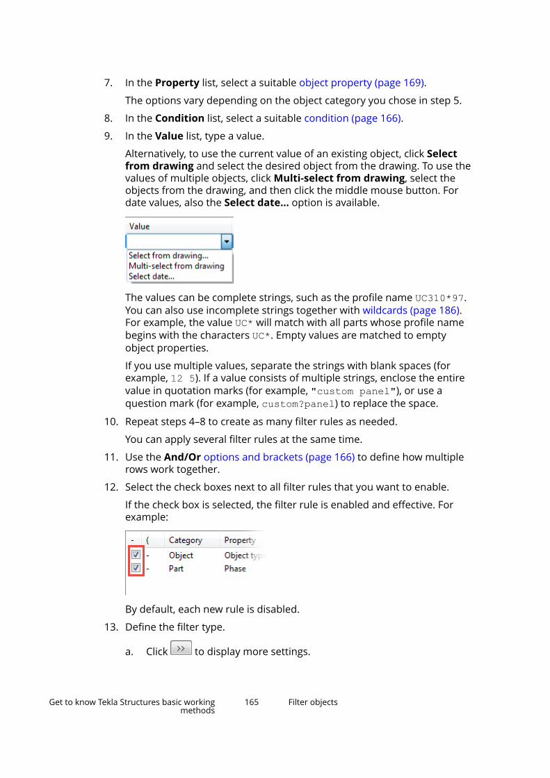
7. In the Property list, select a suitable object property (page 169).
The options vary depending on the object category you chose in step 5.
8. In the Condition list, select a suitable condition (page 166).
9. In the Value list, type a value.
Alternatively, to use the current value of an existing object, click Selectfrom drawing and select the desired object from the drawing. To use thevalues of multiple objects, click Multi-select from drawing, select theobjects from the drawing, and then click the middle mouse button. Fordate values, also the Select date... option is available.
The values can be complete strings, such as the profile name UC310*97.You can also use incomplete strings together with wildcards (page 186).For example, the value UC* will match with all parts whose profile namebegins with the characters UC*. Empty values are matched to emptyobject properties.
If you use multiple values, separate the strings with blank spaces (forexample, 12 5). If a value consists of multiple strings, enclose the entirevalue in quotation marks (for example, "custom panel"), or use aquestion mark (for example, custom?panel) to replace the space.
10. Repeat steps 4–8 to create as many filter rules as needed.
You can apply several filter rules at the same time.
11. Use the And/Or options and brackets (page 166) to define how multiplerows work together.
12. Select the check boxes next to all filter rules that you want to enable.
If the check box is selected, the filter rule is enabled and effective. Forexample:
By default, each new rule is disabled.
13. Define the filter type.
a. Click to display more settings.
Get to know Tekla Structures basic workingmethods
165 Filter objects
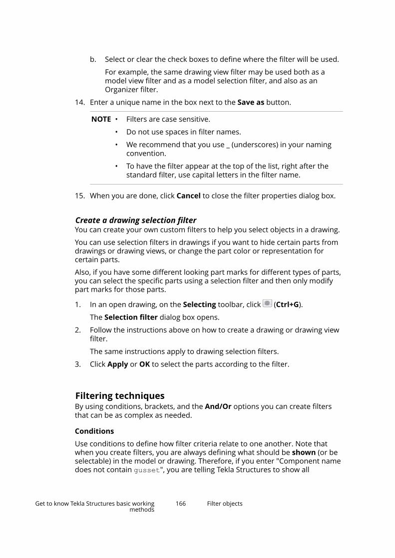
b. Select or clear the check boxes to define where the filter will be used.
For example, the same drawing view filter may be used both as amodel view filter and as a model selection filter, and also as anOrganizer filter.
14. Enter a unique name in the box next to the Save as button.
NOTE • Filters are case sensitive.
• Do not use spaces in filter names.
• We recommend that you use _ (underscores) in your namingconvention.
• To have the filter appear at the top of the list, right after thestandard filter, use capital letters in the filter name.
15. When you are done, click Cancel to close the filter properties dialog box.
Create a drawing selection filterYou can create your own custom filters to help you select objects in a drawing.
You can use selection filters in drawings if you want to hide certain parts fromdrawings or drawing views, or change the part color or representation forcertain parts.
Also, if you have some different looking part marks for different types of parts,you can select the specific parts using a selection filter and then only modifypart marks for those parts.
1. In an open drawing, on the Selecting toolbar, click (Ctrl+G).
The Selection filter dialog box opens.
2. Follow the instructions above on how to create a drawing or drawing viewfilter.
The same instructions apply to drawing selection filters.
3. Click Apply or OK to select the parts according to the filter.
Filtering techniquesBy using conditions, brackets, and the And/Or options you can create filtersthat can be as complex as needed.
Conditions
Use conditions to define how filter criteria relate to one another. Note thatwhen you create filters, you are always defining what should be shown (or beselectable) in the model or drawing. Therefore, if you enter "Component namedoes not contain gusset", you are telling Tekla Structures to show all
Get to know Tekla Structures basic workingmethods
166 Filter objects
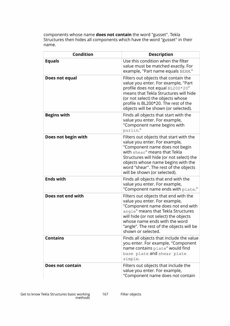
components whose name does not contain the word "gusset". TeklaStructures then hides all components which have the word "gusset" in theirname.
Condition DescriptionEquals Use this condition when the filter
value must be matched exactly. Forexample, "Part name equals BEAM."
Does not equal Filters out objects that contain thevalue you enter. For example, "Partprofile does not equal BL200*20"means that Tekla Structures will hide(or not select) the objects whoseprofile is BL200*20. The rest of theobjects will be shown (or selected).
Begins with Finds all objects that start with thevalue you enter. For example,"Component name begins withpurlin."
Does not begin with Filters out objects that start with thevalue you enter. For example,"Component name does not beginwith shear" means that TeklaStructures will hide (or not select) theobjects whose name begins with theword "shear". The rest of the objectswill be shown (or selected).
Ends with Finds all objects that end with thevalue you enter. For example,"Component name ends with plate."
Does not end with Filters out objects that end with thevalue you enter. For example,"Component name does not end withangle" means that Tekla Structureswill hide (or not select) the objectswhose name ends with the word"angle". The rest of the objects will beshown or selected.
Contains Finds all objects that include the valueyou enter. For example, "Componentname contains plate" would findbase plate and shear platesimple.
Does not contain Filters out objects that include thevalue you enter. For example,"Component name does not contain
Get to know Tekla Structures basic workingmethods
167 Filter objects

Condition Descriptiongusset" means that Tekla Structureswill hide (or not select) the objectswhose name contains the word"gusset". The rest of the objects willbe shown or selected.
Greater than Finds all objects that exceed the valueyou enter. For example, "Templateattribute LENGTH is greater than5000."
This property can only be used withnumerical data, such as the part startnumber, class, phase, or LENGTH.
Greater or equal Finds all objects that match or exceedthe value you enter.
This property can only be used withnumerical data, such as the part startnumber, class, phase, or LENGTH.
Less than Finds all objects that are less than thevalue you enter.
This property can only be used withnumerical data, such as the part startnumber, class, phase, or LENGTH.
Less or equal Finds all objects that match or areless than the value you enter.
This property can only be used withnumerical data, such as the part startnumber, class, phase, or LENGTH.
Later than Available for dates only. The datemust be later than the one you havedefined. For example, "Object'sapproval date later than 4/10/2017."
Later than or equal Available for dates only. The datemust be later than or equal to the oneyou have defined.
Earlier than Available for dates only. The datemust be earlier than the one you havedefined. For example, "Object'sapproval date earlier than2/18/2017."
Earlier than or equal Available for dates only. The datemust be earlier than or equal to theone you have defined.
Get to know Tekla Structures basic workingmethods
168 Filter objects
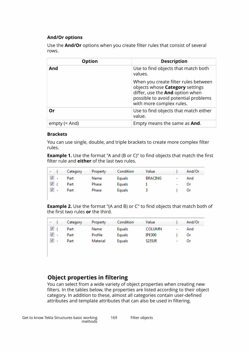
And/Or options
Use the And/Or options when you create filter rules that consist of severalrows.
Option DescriptionAnd Use to find objects that match both
values.
When you create filter rules betweenobjects whose Category settingsdiffer, use the And option whenpossible to avoid potential problemswith more complex rules.
Or Use to find objects that match eithervalue.
empty (= And) Empty means the same as And.
Brackets
You can use single, double, and triple brackets to create more complex filterrules.
Example 1. Use the format "A and (B or C)" to find objects that match the firstfilter rule and either of the last two rules.
Example 2. Use the format "(A and B) or C" to find objects that match both ofthe first two rules or the third.
Object properties in filteringYou can select from a wide variety of object properties when creating newfilters. In the tables below, the properties are listed according to their objectcategory. In addition to these, almost all categories contain user-definedattributes and template attributes that can also be used in filtering.
Get to know Tekla Structures basic workingmethods
169 Filter objects

Category: Object
Use the Object category to filter objects based on their object level properties.
Property DescriptionGUID To filter objects based on their
globally unique identifier (GUID). Forexample, "Object GUID begins withID7554C9EB-C8B4."
Phase To filter objects based on their phasenumber. For example, "Object phasedoes not equal 3."
Object type To filter objects based on their type.Select an object type from the Valuelist, or use the Select from model...or Multi-select from model option.
NOTE: We recommend that youinclude one filter rule for the Objecttype property in each filter youcreate. This ensures that only objectsof this type are filtered in. If you leavethe object type out, the filteringoutcome will be different, and objectsthat do not match the category infurther filter rules may be filtered in.
The following object types can beselected from the list:
• Assembly
• Bolt group
• Connection
• Part
• Pour break
• Pour object
• Pour unit
• Reference object
• Reinforcing bar
• Surface
• Surface treatment
• Weld
The following object types are shownas numeric values only:
Get to know Tekla Structures basic workingmethods
170 Filter objects

Property Description• 1 = point
• 9 = fitting
• 11 = polygon cut
• 12 = line cut
• 24 = construction line
• 30 = construction plane
• 38 = added material
• 42 = construction circle
• 48 = reference model
• 70 = edge chamfer
• 76 = analysis partIs component To filter objects based on whether or
not they are components. The optionsare Yes and No. For example, "Objectis component equals Yes."
Some object types are not visible directly, but only when the objects that makethem up are visible. For example, assemblies are visible when parts are visible,and pour units are visible when pour objects are visible. Therefore, using theobject type Assembly or Pour unit alone in a view filter in the model or indrawings does not show anything. However, selection filters are able to selectobject types like assemblies and pour units.
Category: Part
Use the Part category to filter parts (page 235) based on their commonproperties.
Property DescriptionName To filter objects based on their name.
For example, "Part name equalsSLAB."
Profile To filter objects based on their profile.For example, "Part profile does notequal L20*2."
Material To filter objects based on theirmaterial grade. For example, "Partmaterial equals C25/30."
Finish To filter objects based on how thepart surface has been treated. Forexample, "Part finish equals "FP -Fire proofing"."
Get to know Tekla Structures basic workingmethods
171 Filter objects

Property DescriptionPrefix To filter objects based on their
numbering prefix. For example, "Partprefix equals P."
Start number To filter objects based on their startnumber. For example, "Part startnumber greater than 100."
Numbering series To filter objects based on theirnumbering series information. Forexample, "Part numbering seriesequals TP/1."
Note that position number separatorcan be a dot (.), comma (,), slash (/), orhyphen (-), depending on what youhave defined in File menu -->Settings --> Options --> Numbering.
Position number To filter objects based on theirposition number. For example, "Partposition number does not equal P/5."
Note that position number separatorcan be a dot (.), comma (,), slash (/), orhyphen (-), depending on what youhave defined in File menu -->Settings --> Options --> Numbering.
Class To filter objects based on their classnumber. For example, "Part classequals 210."
Phase To filter objects based on their phasenumber. For example, "Part phaseequals 1 2."
Lot To filter objects based on their lotnumber. For example, "Part lotgreater than 1."
Primary part To filter objects based on whetherthey are main or secondary parts inan assembly or cast unit. 1 = primarypart, 0 = secondary part. For example,"Part primary part equals 1."
Pour phase To filter parts based on their pourphase. For example, "Pour phasedoes not equal 0."
Get to know Tekla Structures basic workingmethods
172 Filter objects

Category: Component
Use the Component category to filter components based on their commonproperties.
Property DescriptionName To filter components based on their
name. For example, "Componentname equals "shear platesimple"."
Connection code To filter components based on theirconnection code, which can be eithera text string or a number. Forexample, "Component connectioncode equals 200_2."
Running number To filter components based on theirunique running number. For example,"Component running number lessthan 150."
Phase To filter components based on theirphase number. For example,"Component phase equals 2."
Is conceptual To filter components based on theirtype. Components can be eitherdetailed or conceptual. Yes =conceptual, No = detailed. Forexample, "Component is conceptualequals Yes."
Category: Bolt
Use the Bolt category to filter bolts based on their common properties.
Property DescriptionSize To filter bolts based on their
diameter. For example, "Bolt size lessthan 20.00."
Standard To filter bolts based on their boltassembly standard/grade. Forexample, "Bolt standard equals7990."
Site/Workshop To filter bolts based on their assemblytype. Site = 0, Workshop = 1. Forexample, "Bolt Site/Workshop equals1."
Get to know Tekla Structures basic workingmethods
173 Filter objects
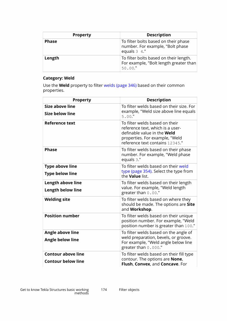
Property DescriptionPhase To filter bolts based on their phase
number. For example, "Bolt phaseequals 3 4."
Length To filter bolts based on their length.For example, "Bolt length greater than50.00."
Category: Weld
Use the Weld property to filter welds (page 346) based on their commonproperties.
Property DescriptionSize above line
Size below line
To filter welds based on their size. Forexample, "Weld size above line equals5.00."
Reference text To filter welds based on theirreference text, which is a user-definable value in the Weldproperties. For example, "Weldreference text contains 12345."
Phase To filter welds based on their phasenumber. For example, "Weld phaseequals 3."
Type above line
Type below line
To filter welds based on their weldtype (page 354). Select the type fromthe Value list.
Length above line
Length below line
To filter welds based on their lengthvalue. For example, "Weld lengthgreater than 0.00."
Welding site To filter welds based on where theyshould be made. The options are Siteand Workshop.
Position number To filter welds based on their uniqueposition number. For example, "Weldposition number is greater than 100."
Angle above line
Angle below line
To filter welds based on the angle ofweld preparation, bevels, or groove.For example, "Weld angle below linegreater than 0.000."
Contour above line
Contour below line
To filter welds based on their fill typecontour. The options are None,Flush, Convex, and Concave. For
Get to know Tekla Structures basic workingmethods
174 Filter objects

Property Descriptionexample, "Weld contour above linedoes not equal None."
Effective throat above line
Effective throat below line
To filter welds based on their weldsize used in weld strength calculation.For example, "Weld effective throatabove line equals 0.500."
Finish above line
Finish below line
To filter welds based on how theyhave been treated. The options areNone, Grind, Machine, Chip,Finished weld, and Smoothtransition.
Increment amount above line
Increment amount below line
To filter welds based on their amountof increments. For example, "Weldincrement amount above line greaterthan 0."
Intermittent type To filter welds based on their shape.The options are Continuous,Intermittent, and Staggeredintermittent.
Pitch above line
Pitch below line
To filter welds based on their spacingof weld increments.
Root face thickness above line
Root face thickness below line
To filter welds based on their rootface thickness, in other words, theheight of the narrowest part insidethe root opening.
Root opening above line
Root opening below line
To filter welds based on the spacefound between the welded parts.
Size prefix above line
Size prefix below line
To filter welds based on their weldsize prefix. For example, "Weld sizeprefix above line equals a."
The standard ISO 2553 prefixes are a(Design throat thickness), s(Penetration throat thickness), and z(Leg length).
User defined cross-section To filter welds based on whether ornot they contain user-defined cross-sections. The options are Yes and No.
Electrode classification To filter welds based on their weldelectrode classification. The optionsare (empty), 35, 52, 50, E60XX, E70XX,E80XX, and E90XX.
Electrode strength To filter welds based on theirelectrode strength. For example,
Get to know Tekla Structures basic workingmethods
175 Filter objects
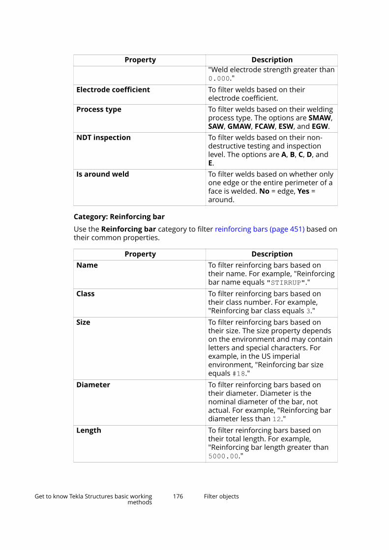
Property Description"Weld electrode strength greater than0.000."
Electrode coefficient To filter welds based on theirelectrode coefficient.
Process type To filter welds based on their weldingprocess type. The options are SMAW,SAW, GMAW, FCAW, ESW, and EGW.
NDT inspection To filter welds based on their non-destructive testing and inspectionlevel. The options are A, B, C, D, andE.
Is around weld To filter welds based on whether onlyone edge or the entire perimeter of aface is welded. No = edge, Yes =around.
Category: Reinforcing bar
Use the Reinforcing bar category to filter reinforcing bars (page 451) based ontheir common properties.
Property DescriptionName To filter reinforcing bars based on
their name. For example, "Reinforcingbar name equals "STIRRUP"."
Class To filter reinforcing bars based ontheir class number. For example,"Reinforcing bar class equals 3."
Size To filter reinforcing bars based ontheir size. The size property dependson the environment and may containletters and special characters. Forexample, in the US imperialenvironment, "Reinforcing bar sizeequals #18."
Diameter To filter reinforcing bars based ontheir diameter. Diameter is thenominal diameter of the bar, notactual. For example, "Reinforcing bardiameter less than 12."
Length To filter reinforcing bars based ontheir total length. For example,"Reinforcing bar length greater than5000.00."
Get to know Tekla Structures basic workingmethods
176 Filter objects
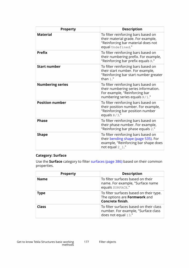
Property DescriptionMaterial To filter reinforcing bars based on
their material grade. For example,"Reinforcing bar material does notequal Undefined."
Prefix To filter reinforcing bars based ontheir numbering prefix. For example,"Reinforcing bar prefix equals R."
Start number To filter reinforcing bars based ontheir start number. For example,"Reinforcing bar start number greaterthan 1."
Numbering series To filter reinforcing bars based ontheir numbering series information.For example, "Reinforcing barnumbering series equals R/1."
Position number To filter reinforcing bars based ontheir position number. For example,"Reinforcing bar position numberequals R/3."
Phase To filter reinforcing bars based ontheir phase number. For example,"Reinforcing bar phase equals 2."
Shape To filter reinforcing bars based ontheir bending shape (page 535). Forexample, "Reinforcing bar shape doesnot equal 2_1."
Category: Surface
Use the Surface category to filter surfaces (page 386) based on their commonproperties.
Property DescriptionName To filter surfaces based on their
name. For example, "Surface nameequals SURFACE."
Type To filter surfaces based on their type.The options are Formwork andConcrete finish.
Class To filter surfaces based on their classnumber. For example, "Surface classdoes not equal 13."
Get to know Tekla Structures basic workingmethods
177 Filter objects
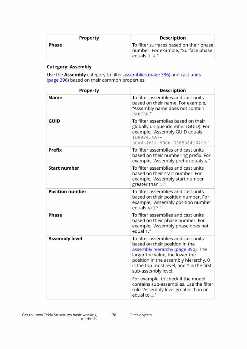
Property DescriptionPhase To filter surfaces based on their phase
number. For example, "Surface phaseequals 3 4."
Category: Assembly
Use the Assembly category to filter assemblies (page 386) and cast units(page 396) based on their common properties.
Property DescriptionName To filter assemblies and cast units
based on their name. For example,"Assembly name does not containRAFTER."
GUID To filter assemblies based on theirglobally unique identifier (GUID). Forexample, "Assembly GUID equalsID89F414A7-ECA6-4B14-99CB-6985B84E64CB."
Prefix To filter assemblies and cast unitsbased on their numbering prefix. Forexample, "Assembly prefix equals A."
Start number To filter assemblies and cast unitsbased on their start number. Forexample, "Assembly start numbergreater than 1."
Position number To filter assemblies and cast unitsbased on their position number. Forexample, "Assembly position numberequals A/13."
Phase To filter assemblies and cast unitsbased on their phase number. Forexample, "Assembly phase does notequal 1."
Assembly level To filter assemblies and cast unitsbased on their position in theassembly hierarchy (page 390). Thelarger the value, the lower theposition in the assembly hierarchy. 0is the top-most level, and 1 is the firstsub-assembly level.
For example, to check if the modelcontains sub-assemblies, use the filterrule "Assembly level greater than orequal to 1."
Get to know Tekla Structures basic workingmethods
178 Filter objects
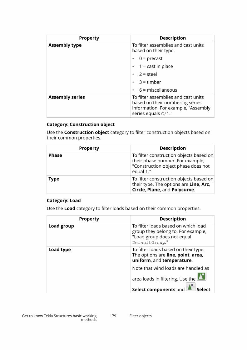
Property DescriptionAssembly type To filter assemblies and cast units
based on their type.
• 0 = precast
• 1 = cast in place
• 2 = steel
• 3 = timber
• 6 = miscellaneousAssembly series To filter assemblies and cast units
based on their numbering seriesinformation. For example, "Assemblyseries equals C/1."
Category: Construction object
Use the Construction object category to filter construction objects based ontheir common properties.
Property DescriptionPhase To filter construction objects based on
their phase number. For example,"Construction object phase does notequal 1."
Type To filter construction objects based ontheir type. The options are Line, Arc,Circle, Plane, and Polycurve.
Category: Load
Use the Load category to filter loads based on their common properties.
Property DescriptionLoad group To filter loads based on which load
group they belong to. For example,"Load group does not equalDefaultGroup."
Load type To filter loads based on their type.The options are line, point, area,uniform, and temperature.
Note that wind loads are handled as
area loads in filtering. Use the
Select components and Select
Get to know Tekla Structures basic workingmethods
179 Filter objects

Property Descriptionobjects in components selectionswitches to select wind loads.
Phase To filter loads based on their phasenumber. For example, "Load phasedoes not equal 1."
Category: Template
Use the Template category to filter parts and other objects by using templateattributes.
With this category, you can type the name of any template attribute or user-defined attribute directly in the Property box, even if it is not on the list. Usethe ASSEMBLY., CAST_UNIT., or POUR_UNIT. prefix in front of the propertyname to access higher hierarchy level attributes, and the USERDEFINED.prefix to access user-defined attributes.
For example, to filter objects that are one hierarchy level below the cast-unitwith the user-defined attribute User field 1, typeCAST_UNIT.USERDEFINED.USER_FIELD_1 in the Property box.
In some cases, you can filter objects based on properties of other objects fromlower hierarchy levels. This is possible when there is only one lower levelobject to be accessed. For example, there is only one main part in eachassembly or cast unit, so you can access the main part properties from theassembly or cast unit level using the MAINPART prefix. Similarly, there can onlybe one pour object in each pour unit, so you can access the pour objectproperties from the pour unit level using the POUR_OBJECT prefix.
For example, to filter objects in assemblies whose main part has a certainname, type ASSEMBLY.MAINPART.NAME in the Property box.
For example, to filter all reinforcing bars belonging to pour units with a certainpour object type, type POUR_UNIT.POUR_OBJECT.POUR_TYPE in the Propertybox.
Category: Reference assembly
Use the Reference assembly category to filter reference model assembliesbased on their common properties.
Property DescriptionCreation GUID To filter reference model assemblies
based on their globally uniqueidentifier (GUID). For example,"Reference assembly GUID equalsIDA51E6BFF-DAB9-4A56-970C-7486EF17B7B7."
Get to know Tekla Structures basic workingmethods
180 Filter objects

Property DescriptionPhase To filter reference model assemblies
based on their phase number. Forexample, "Reference assembly phaseequals 2."
Lot To filter reference model assembliesbased on their lot number. Forexample, "Reference assembly lotgreater than 1."
Description To filter reference model assembliesbased on their description, which is auser-definable value in the Referenceobject dialog box. For example,"Reference assembly descriptioncontains "architect model"."
Info text To filter reference model assembliesbased on their info text, which is auser-definable value in the Referenceobject dialog box. For example,"Reference assembly info textcontains revised."
Locked To filter reference model assembliesbased on whether or not they arelocked. 0 = No, 1 = Yes, 2 =Organization.
Logical name To filter reference model assembliesbased on their logical name, which isa user-definable value in theReference object dialog box. Forexample, "Reference assembly logicalname equals "MEP heatingsystem"."
Category: Reference object
Use the Reference object category to filter reference model objects based ontheir common properties.
Property DescriptionCreation GUID To filter reference model objects
based on their globally uniqueidentifier (GUID).
Phase To filter reference model objectsbased on their phase number. For
Get to know Tekla Structures basic workingmethods
181 Filter objects
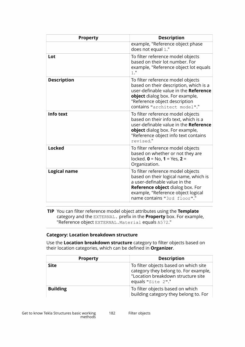
Property Descriptionexample, "Reference object phasedoes not equal 1."
Lot To filter reference model objectsbased on their lot number. Forexample, "Reference object lot equals1."
Description To filter reference model objectsbased on their description, which is auser-definable value in the Referenceobject dialog box. For example,"Reference object descriptioncontains "architect model"."
Info text To filter reference model objectsbased on their info text, which is auser-definable value in the Referenceobject dialog box. For example,"Reference object info text containsrevised."
Locked To filter reference model objectsbased on whether or not they arelocked. 0 = No, 1 = Yes, 2 =Organization.
Logical name To filter reference model objectsbased on their logical name, which isa user-definable value in theReference object dialog box. Forexample, "Reference object logicalname contains "3rd floor"."
TIP You can filter reference model object attributes using the Templatecategory and the EXTERNAL. prefix in the Property box. For example,"Reference object EXTERNAL.Material equals A572."
Category: Location breakdown structure
Use the Location breakdown structure category to filter objects based ontheir location categories, which can be defined in Organizer.
Property DescriptionSite To filter objects based on which site
category they belong to. For example,"Location breakdown structure siteequals "Site 2"."
Building To filter objects based on whichbuilding category they belong to. For
Get to know Tekla Structures basic workingmethods
182 Filter objects

Property Descriptionexample, "Location breakdownstructure building does not equal"Building A"."
Section To filter objects based on whichsection category they belong to. Forexample, "Location breakdownstructure section equals Ramp."
Floor To filter objects based on which floorthey are located on. For example,"Location breakdown structure floorequals "Floor 4"."
Category: Pour object
Use the Pour object category to filter pour objects (page 408) based on theircommon properties.
Property DescriptionPour number To filter pour objects based on their
pour number. For example, "Pournumber equals 5."
Pour type To filter pour objects based on theirtype. For example, "Pour type equalsWALL."
Concrete mixture To filter pour objects based on theproperties of their concrete mix, forexample, maximum grain size ofaggregate, and/or plasticity of freshconcrete.
Material To filter pour objects based on theirmaterial grade. For example,"Material equals C35/45 ."
Pour phase To filter pour objects based on theirpour phase. For example, "Pourphase does not equal 0."
Category: Pour break
Use the Pour break category to filter pour breaks (page 415) based on theircommon properties.
Property DescriptionCreationID number To filter pour breaks based on their ID
number. For example, "ID numberequals 25237."
Get to know Tekla Structures basic workingmethods
183 Filter objects
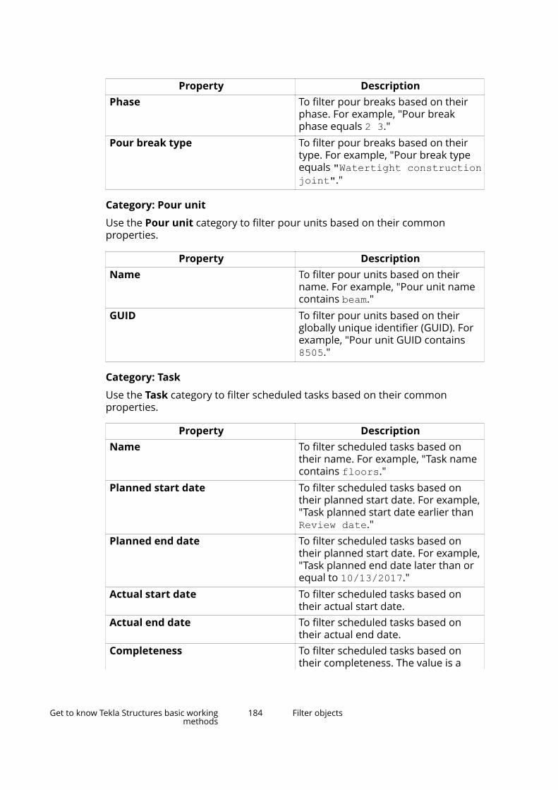
Property DescriptionPhase To filter pour breaks based on their
phase. For example, "Pour breakphase equals 2 3."
Pour break type To filter pour breaks based on theirtype. For example, "Pour break typeequals "Watertight constructionjoint"."
Category: Pour unit
Use the Pour unit category to filter pour units based on their commonproperties.
Property DescriptionName To filter pour units based on their
name. For example, "Pour unit namecontains beam."
GUID To filter pour units based on theirglobally unique identifier (GUID). Forexample, "Pour unit GUID contains8505."
Category: Task
Use the Task category to filter scheduled tasks based on their commonproperties.
Property DescriptionName To filter scheduled tasks based on
their name. For example, "Task namecontains floors."
Planned start date To filter scheduled tasks based ontheir planned start date. For example,"Task planned start date earlier thanReview date."
Planned end date To filter scheduled tasks based ontheir planned start date. For example,"Task planned end date later than orequal to 10/13/2017."
Actual start date To filter scheduled tasks based ontheir actual start date.
Actual end date To filter scheduled tasks based ontheir actual end date.
Completeness To filter scheduled tasks based ontheir completeness. The value is a
Get to know Tekla Structures basic workingmethods
184 Filter objects
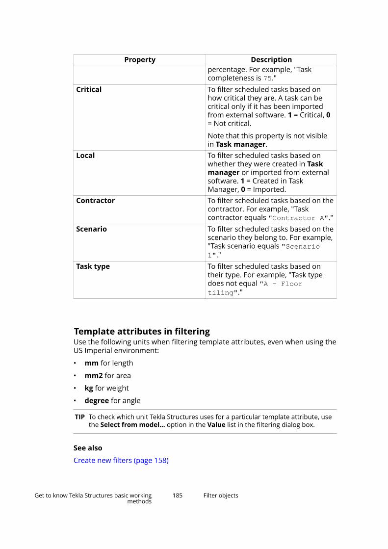
Property Descriptionpercentage. For example, "Taskcompleteness is 75."
Critical To filter scheduled tasks based onhow critical they are. A task can becritical only if it has been importedfrom external software. 1 = Critical, 0= Not critical.
Note that this property is not visiblein Task manager.
Local To filter scheduled tasks based onwhether they were created in Taskmanager or imported from externalsoftware. 1 = Created in TaskManager, 0 = Imported.
Contractor To filter scheduled tasks based on thecontractor. For example, "Taskcontractor equals "Contractor A"."
Scenario To filter scheduled tasks based on thescenario they belong to. For example,"Task scenario equals "Scenario1"."
Task type To filter scheduled tasks based ontheir type. For example, "Task typedoes not equal "A - Floortiling"."
Template attributes in filteringUse the following units when filtering template attributes, even when using theUS Imperial environment:
• mm for length
• mm2 for area
• kg for weight
• degree for angle
TIP To check which unit Tekla Structures uses for a particular template attribute, usethe Select from model... option in the Value list in the filtering dialog box.
See also
Create new filters (page 158)
Get to know Tekla Structures basic workingmethods
185 Filter objects
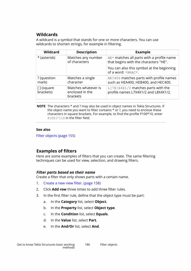
WildcardsA wildcard is a symbol that stands for one or more characters. You can usewildcards to shorten strings, for example in filtering.
Wildcard Description Example* (asterisk) Matches any number
of charactersHE* matches all parts with a profile namethat begins with the characters "HE".
You can also this symbol at the beginningof a word: *BRAC*.
? (questionmark)
Matches a singlecharacter
HE?400 matches parts with profile namessuch as HEA400, HEB400, and HEC400.
[ ] (squarebrackets)
Matches whatever isenclosed in thebrackets
L[78]X4X1/2 matches parts with theprofile names L7X4X1/2 and L8X4X1/2.
NOTE The characters * and ? may also be used in object names in Tekla Structures. Ifthe object name you want to filter contains * or ?, you need to enclose thesecharacters in square brackets. For example, to find the profile P100*10, enter P100[*]10 in the filter field.
See also
Filter objects (page 155)
Examples of filtersHere are some examples of filters that you can create. The same filteringtechniques can be used for view, selection, and drawing filters.
Filter parts based on their nameCreate a filter that only shows parts with a certain name.
1. Create a new view filter. (page 158)
2. Click Add row three times to add three filter rules.
3. In the first filter rule, define that the object type must be part:
a. In the Category list, select Object.
b. In the Property list, select Object type.
c. In the Condition list, select Equals.
d. In the Value list, select Part.
e. In the And/Or list, select And.
Get to know Tekla Structures basic workingmethods
186 Filter objects
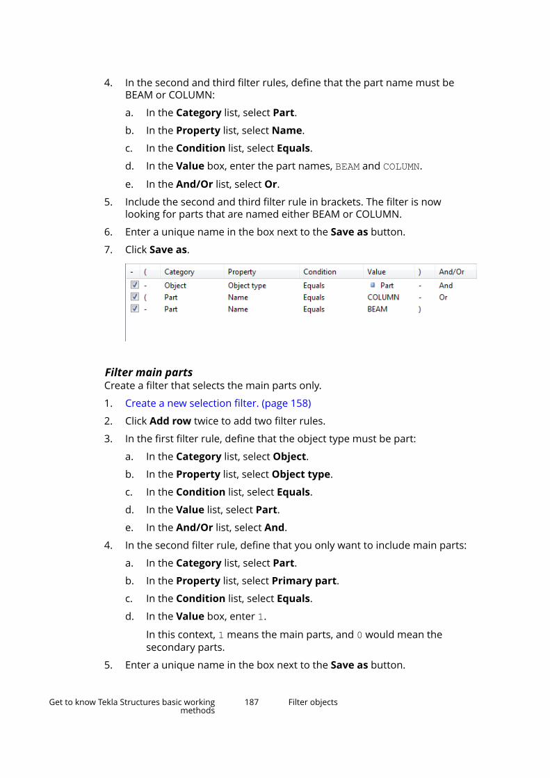
4. In the second and third filter rules, define that the part name must beBEAM or COLUMN:
a. In the Category list, select Part.
b. In the Property list, select Name.
c. In the Condition list, select Equals.
d. In the Value box, enter the part names, BEAM and COLUMN.
e. In the And/Or list, select Or.
5. Include the second and third filter rule in brackets. The filter is nowlooking for parts that are named either BEAM or COLUMN.
6. Enter a unique name in the box next to the Save as button.
7. Click Save as.
Filter main partsCreate a filter that selects the main parts only.
1. Create a new selection filter. (page 158)
2. Click Add row twice to add two filter rules.
3. In the first filter rule, define that the object type must be part:
a. In the Category list, select Object.
b. In the Property list, select Object type.
c. In the Condition list, select Equals.
d. In the Value list, select Part.
e. In the And/Or list, select And.
4. In the second filter rule, define that you only want to include main parts:
a. In the Category list, select Part.
b. In the Property list, select Primary part.
c. In the Condition list, select Equals.
d. In the Value box, enter 1.
In this context, 1 means the main parts, and 0 would mean thesecondary parts.
5. Enter a unique name in the box next to the Save as button.
Get to know Tekla Structures basic workingmethods
187 Filter objects

6. Click Save as.
Filter bolts based on their sizeCreate a filter that only shows bolts of certain sizes.
1. Create a new view filter. (page 158)
2. Click Add row twice to add two filter rules.
3. In the first filter rule, define that the object type must be bolt:
a. In the Category list, select Object.
b. In the Property list, select Object type.
c. In the Condition list, select Equals.
d. In the Value list, select Bolt group.
e. In the And/Or list, select And.
4. In the second filter rule, define that the bolt size must be 12.00 or 16.00:
a. In the Category list, select Bolt.
b. In the Property list, select Size.
c. In the Condition list, select Equals.
d. In the Value box, enter the bolt sizes, 12.00 and 16.00.
Separate the strings with a blank space.
5. Enter a unique name in the box next to the Save as button.
6. Click Save as.
Filter parts based on their assembly typeCreate a filter based on assembly types. For example, you can create a filterthat only shows cast-in-place and precast columns. Steel columns and anyother columns or parts are hidden. The same filtering technique can be usedfor steel, concrete, timber, and miscellaneous parts.
Get to know Tekla Structures basic workingmethods
188 Filter objects
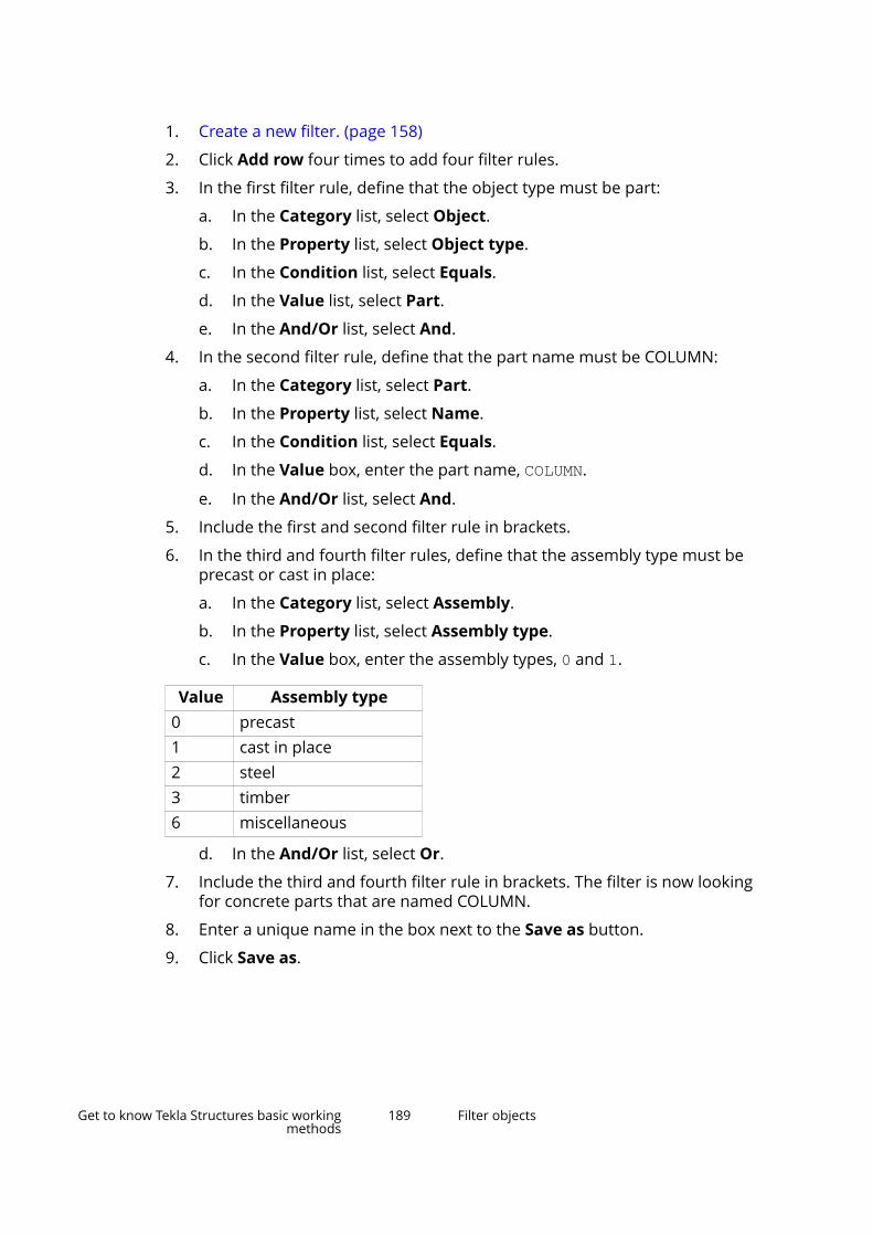
1. Create a new filter. (page 158)
2. Click Add row four times to add four filter rules.
3. In the first filter rule, define that the object type must be part:
a. In the Category list, select Object.
b. In the Property list, select Object type.
c. In the Condition list, select Equals.
d. In the Value list, select Part.
e. In the And/Or list, select And.
4. In the second filter rule, define that the part name must be COLUMN:
a. In the Category list, select Part.
b. In the Property list, select Name.
c. In the Condition list, select Equals.
d. In the Value box, enter the part name, COLUMN.
e. In the And/Or list, select And.
5. Include the first and second filter rule in brackets.
6. In the third and fourth filter rules, define that the assembly type must beprecast or cast in place:
a. In the Category list, select Assembly.
b. In the Property list, select Assembly type.
c. In the Value box, enter the assembly types, 0 and 1.
Value Assembly type0 precast1 cast in place2 steel3 timber6 miscellaneous
d. In the And/Or list, select Or.
7. Include the third and fourth filter rule in brackets. The filter is now lookingfor concrete parts that are named COLUMN.
8. Enter a unique name in the box next to the Save as button.
9. Click Save as.
Get to know Tekla Structures basic workingmethods
189 Filter objects

Filter sub-assembliesCreate a filter that only selects parts that belong to a sub-assembly.
1. Create a selection filter. (page 158)
2. Click Add row to add a new filter rule.
3. In the Category list, select Template.
4. In the Property list, select ASSEMBLY.HIERARCHY_LEVEL.
5. In the Condition list, select Does not equal.
6. In the Value box, enter 0.
In this context, 0 means that the part does not belong to any sub-assembly, and 1 would mean that the part does. The filter will show onlythose parts whose value is not 0.
7. Enter a unique name in the box next to the Save as button.
8. Click Save as.
Filter reference model objectsCreate a filter based on reference model object properties.
1. Create an empty view or selection filter. (page 158)
2. Click Add row to add a new filter rule.
3. In the Category list, select Template.
4. In the Property list, select the desired template attribute or enter one ofyour own (page 169).
TIP To find the attribute name used by the reference model, select areference model object, right-click and select one of the Inquirecommands. Find the property name in the Inquire object dialog boxand copy it.
Get to know Tekla Structures basic workingmethods
190 Filter objects
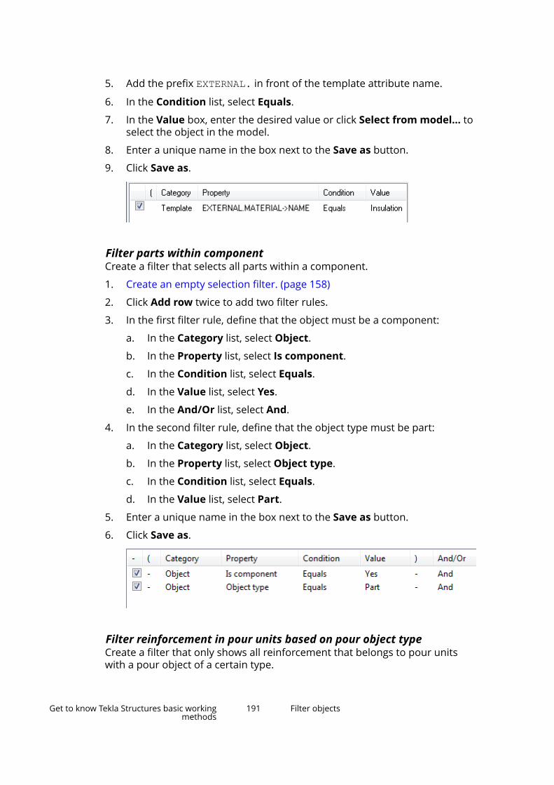
5. Add the prefix EXTERNAL. in front of the template attribute name.
6. In the Condition list, select Equals.
7. In the Value box, enter the desired value or click Select from model... toselect the object in the model.
8. Enter a unique name in the box next to the Save as button.
9. Click Save as.
Filter parts within componentCreate a filter that selects all parts within a component.
1. Create an empty selection filter. (page 158)
2. Click Add row twice to add two filter rules.
3. In the first filter rule, define that the object must be a component:
a. In the Category list, select Object.
b. In the Property list, select Is component.
c. In the Condition list, select Equals.
d. In the Value list, select Yes.
e. In the And/Or list, select And.
4. In the second filter rule, define that the object type must be part:
a. In the Category list, select Object.
b. In the Property list, select Object type.
c. In the Condition list, select Equals.
d. In the Value list, select Part.
5. Enter a unique name in the box next to the Save as button.
6. Click Save as.
Filter reinforcement in pour units based on pour object typeCreate a filter that only shows all reinforcement that belongs to pour unitswith a pour object of a certain type.
Get to know Tekla Structures basic workingmethods
191 Filter objects
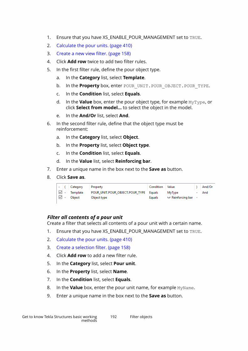
1. Ensure that you have XS_ENABLE_POUR_MANAGEMENT set to TRUE.
2. Calculate the pour units. (page 410)
3. Create a new view filter. (page 158)
4. Click Add row twice to add two filter rules.
5. In the first filter rule, define the pour object type.
a. In the Category list, select Template.
b. In the Property box, enter POUR_UNIT.POUR_OBJECT.POUR_TYPE.
c. In the Condition list, select Equals.
d. In the Value box, enter the pour object type, for example MyType, orclick Select from model... to select the object in the model.
e. In the And/Or list, select And.
6. In the second filter rule, define that the object type must bereinforcement:
a. In the Category list, select Object.
b. In the Property list, select Object type.
c. In the Condition list, select Equals.
d. In the Value list, select Reinforcing bar.
7. Enter a unique name in the box next to the Save as button.
8. Click Save as.
Filter all contents of a pour unitCreate a filter that selects all contents of a pour unit with a certain name.
1. Ensure that you have XS_ENABLE_POUR_MANAGEMENT set to TRUE.
2. Calculate the pour units. (page 410)
3. Create a selection filter. (page 158)
4. Click Add row to add a new filter rule.
5. In the Category list, select Pour unit.
6. In the Property list, select Name.
7. In the Condition list, select Equals.
8. In the Value box, enter the pour unit name, for example MyName.
9. Enter a unique name in the box next to the Save as button.
Get to know Tekla Structures basic workingmethods
192 Filter objects

10. Click Save as.
Copy and remove filtersYou can copy custom filters to another model by manually copying filter files tothe attributes folder under the desired model folder. You can also manuallyremove unneeded filters from the same folder. If you want to make a filteravailable in all models, copy the file to your company's project or firm folder.
Copy a filter to another model1. Select the filter you want to copy.
The filters you have created are located in the attributes folder underthe current model folder. You can recognize different filter types based ontheir file name extension:
File name extension Filter type.VObjGrp Model view filter.SObjGrp Model selection filter.PObjGrp Object group filter.vf Drawing view filter.vnf Drawing view level neighbor part filter.wdf Single-part drawing filter.wdnf Single-part drawing neighbor part
filter.adf Assembly drawing filter.adnf Assembly drawing neighbor part filter.cuf Cast unit drawing filter.cunf Cast unit drawing neighbor part filter.gdf General arrangement drawing filter.gdnf General arrangement drawing
neighbor part filter.dsf Drawing selection filter
2. To make the filter available in another model, copy the file to theattributes folder of the destination model folder.
Get to know Tekla Structures basic workingmethods
193 Filter objects
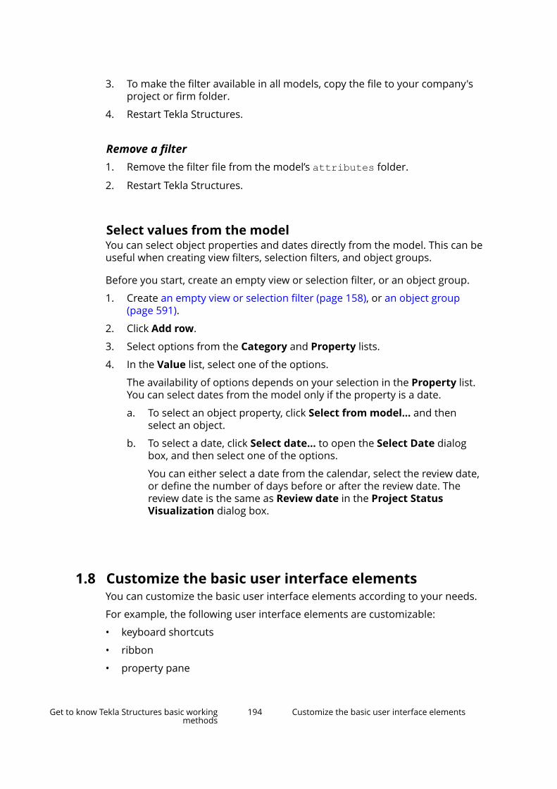
3. To make the filter available in all models, copy the file to your company'sproject or firm folder.
4. Restart Tekla Structures.
Remove a filter1. Remove the filter file from the model’s attributes folder.
2. Restart Tekla Structures.
Select values from the modelYou can select object properties and dates directly from the model. This can beuseful when creating view filters, selection filters, and object groups.
Before you start, create an empty view or selection filter, or an object group.
1. Create an empty view or selection filter (page 158), or an object group(page 591).
2. Click Add row.
3. Select options from the Category and Property lists.
4. In the Value list, select one of the options.
The availability of options depends on your selection in the Property list.You can select dates from the model only if the property is a date.
a. To select an object property, click Select from model... and thenselect an object.
b. To select a date, click Select date... to open the Select Date dialogbox, and then select one of the options.
You can either select a date from the calendar, select the review date,or define the number of days before or after the review date. Thereview date is the same as Review date in the Project StatusVisualization dialog box.
1.8 Customize the basic user interface elementsYou can customize the basic user interface elements according to your needs.
For example, the following user interface elements are customizable:
• keyboard shortcuts
• ribbon
• property pane
Get to know Tekla Structures basic workingmethods
194 Customize the basic user interface elements
• toolbars (page 225)
• contextual toolbar
The customizations can be distributed to other users in the company.
Customize the keyboard shortcutsIn the Keyboard shortcuts dialog box, you can view a list of all shortcutsavailable in Tekla Structures. You can define new keyboard shortcuts andremove existing ones. After customization, you can export the keyboardshortcuts and share them with your co-workers.
Define new keyboard shortcutsYou can assign keyboard shortcuts to any command, macro, or component.You can even change the default keyboard shortcuts, if needed.
1. On the File menu, click Settings --> Keyboard shortcuts.
Get to know Tekla Structures basic workingmethods
195 Customize the basic user interface elements

The Keyboard shortcuts dialog box opens.
2. In the Group list, select the shortcut group you want to modify.
A list of commands and shortcuts appears.
3. If you want to search for a particular command or keyboard shortcut,enter some text in the Filter box.
For example:
• Type grid to only see the commands whose name contains the word"grid".
• Type "+" to get a list of shortcuts that consist of two parts (such as Ctrl+S).
Get to know Tekla Structures basic workingmethods
196 Customize the basic user interface elements
• Type "," to get a list of shortcuts that consist of two consecutive keys(such as M, N).
4. Select a command from the list.
5. Click Enter shortcut.
6. On the keyboard, enter the combination of keys you would like to use asthe shortcut.
7. Check the Conflicts box to see if the keyboard shortcut is alreadyassigned to another command.
If the shortcut is already in use, enter a different combination of keys.
NOTE If you reassign a keyboard shortcut that is already used, it will nolonger be associated with the command it was originally assignedto.
8. Click Assign to save the keyboard shortcut.
Clear and reset shortcutsYou can remove any existing shortcut. You can also reset all shortcuts back tothe defaults.
1. On the File menu, click Settings --> Keyboard shortcuts.
2. To remove a keyboard shortcut, select the command from the list and clickClear.
3. To reset all the keyboard shortcuts to the defaults, click the Restorebutton.
Export keyboard shortcutsYou can export your customized keyboard shortcuts and share them with yourco-workers.
1. On the File menu, click Settings --> Keyboard shortcuts.
2. Click Export.
3. Enter a file name and location.
4. Click Save to export the keyboard shortcuts.
5. To share your keyboard shortcuts with other users, send them theexported file.
Import keyboard shortcutsYou can import keyboard shortcuts from a file. Use this method to importkeyboard shortcuts from Tekla Structures 2016 or newer.
1. On the File menu, click Settings --> Keyboard shortcuts.
Get to know Tekla Structures basic workingmethods
197 Customize the basic user interface elements
2. Click Import.
3. Browse for the shortcuts file you want to import. For example, ..\Users\<user>\AppData\Local\Trimble\Tekla Structures\<version>\Settings\KeyboardShortcuts_4.xml.
4. Click Open to import the keyboard shortcuts.
Customize the ribbonWith Ribbon editor you can customize the ribbon according to your needs.You can change the size and shape of any button, for example. You can createuser-defined commands, and bring your favorite components and extensionsto the ribbon for an easy access.
To open Ribbon editor, click File menu --> Settings --> Customize -->Ribbon .
With Ribbon editor, you can
• add new buttons to the ribbon
• move existing buttons on the ribbon
• resize the buttons on the ribbon
• change the icons and texts of the buttons
• remove buttons you do not need
• create new commands and add buttons for them
• add separator bars to the ribbon
• add new tabs
NOTE If you want to customize the modeling ribbon, open Ribbon editor inthe modeling mode.
If you want to customize the drawing ribbon, open Ribbon editor inthe drawing mode.
You can only customize the ribbons that are available in yourconfiguration.
Get to know Tekla Structures basic workingmethods
198 Customize the basic user interface elements
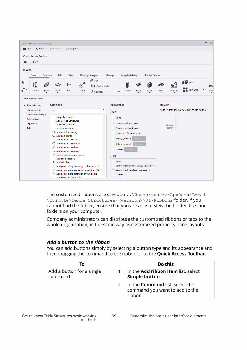
The customized ribbons are saved to ..\Users\<user>\AppData\Local\Trimble\Tekla Structures\<version>\UI\Ribbons folder. If youcannot find the folder, ensure that you are able to view the hidden files andfolders on your computer.
Company administrators can distribute the customized ribbons or tabs to thewhole organization, in the same way as customized property pane layouts.
Add a button to the ribbonYou can add buttons simply by selecting a button type and its appearance andthen dragging the command to the ribbon or to the Quick Access Toolbar.
To Do thisAdd a button for a singlecommand
1. In the Add ribbon item list, selectSimple button.
2. In the Command list, select thecommand you want to add to theribbon.
Get to know Tekla Structures basic workingmethods
199 Customize the basic user interface elements
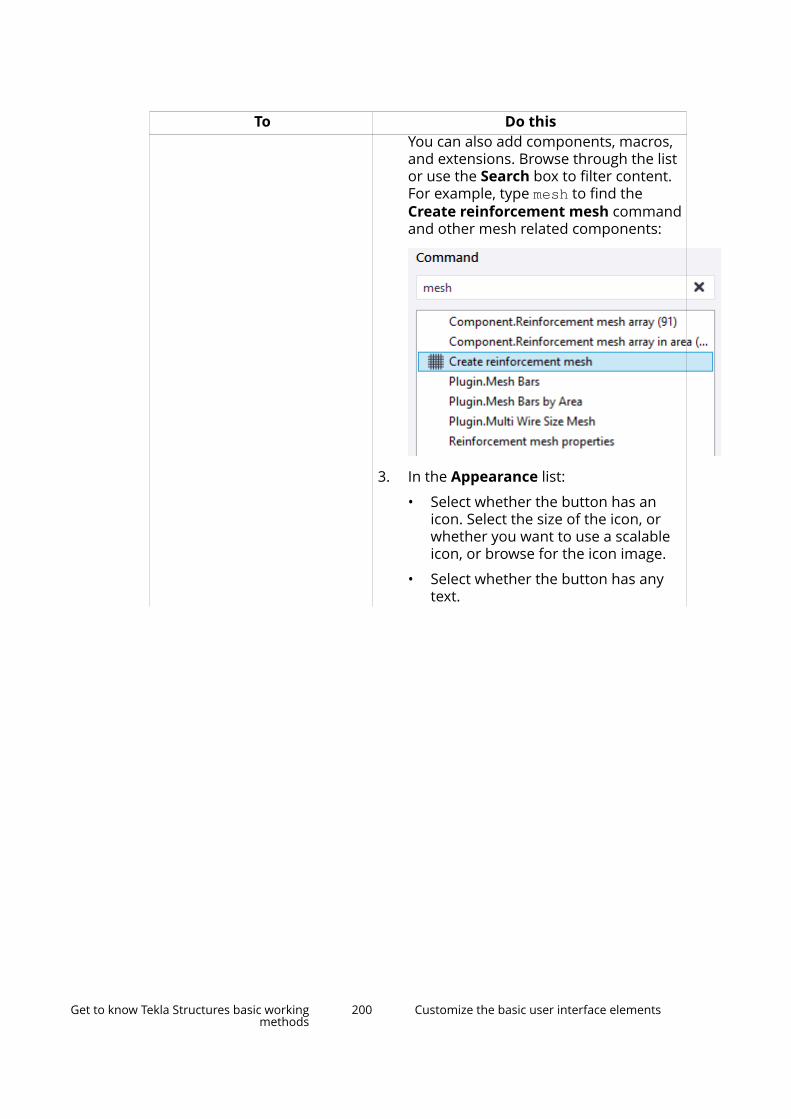
To Do thisYou can also add components, macros,and extensions. Browse through the listor use the Search box to filter content.For example, type mesh to find theCreate reinforcement mesh commandand other mesh related components:
3. In the Appearance list:
• Select whether the button has anicon. Select the size of the icon, orwhether you want to use a scalableicon, or browse for the icon image.
• Select whether the button has anytext.
Get to know Tekla Structures basic workingmethods
200 Customize the basic user interface elements
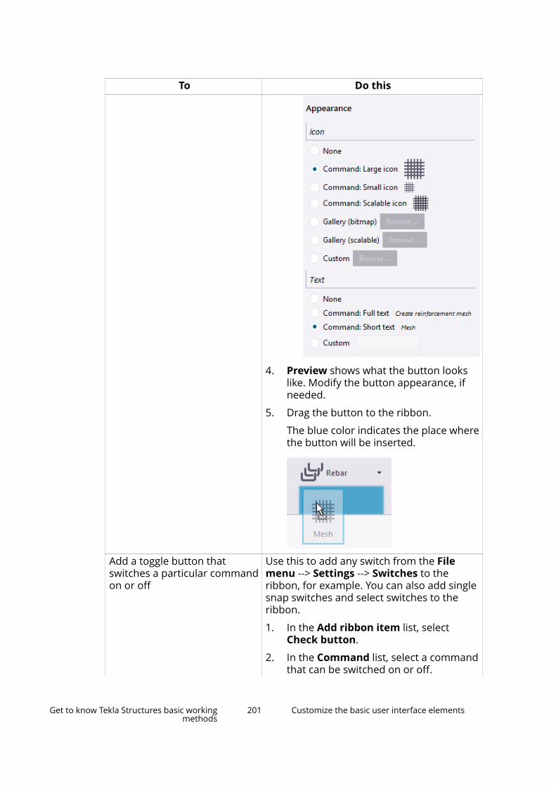
To Do this
4. Preview shows what the button lookslike. Modify the button appearance, ifneeded.
5. Drag the button to the ribbon.
The blue color indicates the place wherethe button will be inserted.
Add a toggle button thatswitches a particular commandon or off
Use this to add any switch from the Filemenu --> Settings --> Switches to theribbon, for example. You can also add singlesnap switches and select switches to theribbon.
1. In the Add ribbon item list, selectCheck button.
2. In the Command list, select a commandthat can be switched on or off.
Get to know Tekla Structures basic workingmethods
201 Customize the basic user interface elements
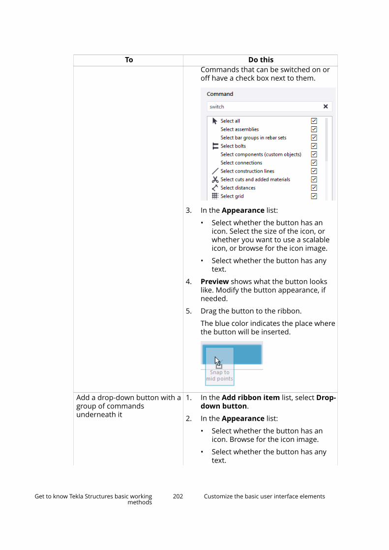
To Do thisCommands that can be switched on oroff have a check box next to them.
3. In the Appearance list:
• Select whether the button has anicon. Select the size of the icon, orwhether you want to use a scalableicon, or browse for the icon image.
• Select whether the button has anytext.
4. Preview shows what the button lookslike. Modify the button appearance, ifneeded.
5. Drag the button to the ribbon.
The blue color indicates the place wherethe button will be inserted.
Add a drop-down button with agroup of commandsunderneath it
1. In the Add ribbon item list, select Drop-down button.
2. In the Appearance list:
• Select whether the button has anicon. Browse for the icon image.
• Select whether the button has anytext.
Get to know Tekla Structures basic workingmethods
202 Customize the basic user interface elements

To Do this3. Preview shows what the button looks
like. Modify the button appearance, ifneeded.
4. Drag the button to the ribbon.
The button is now an empty placeholderfor single commands. You need to addcommands to the drop-down button tomake it work.
a. In the Add ribbon item list, selectSimple button.
b. In the Command list, select thecommand you want to add to thedrop-down list.
c. In the Appearance list, set theappearance of the button.
d. Drag the button to the drop-downlist.
The blue color indicates the placewhere the button will be inserted. Ifyou hover over a down arrow, a listwill open and you can dragcommands to the list. The list willremain open until you click thedown arrow again.
e. Add as many commands as neededto the drop-down button.
Add a button for a singlecommand, plus a drop-downbutton with a group ofcommands underneath it
1. In the Add ribbon item list, select Splitbutton.
2. In the Command list, select thecommand you want to add to theribbon as the main button for the wholesplit button.
3. In the Appearance list:
Get to know Tekla Structures basic workingmethods
203 Customize the basic user interface elements

To Do this• Select whether the button has an
icon. Select the size of the icon, orwhether you want to use a scalableicon, or browse for the icon image.
• Select whether the button has anytext.
4. Preview shows what the button lookslike. Modify the button appearance, ifneeded.
5. Drag the button to the ribbon.
The button now has a single command.You need to add commands to thedrop-down list.
a. In the Add ribbon item list, selectSimple button.
b. In the Command list, select thecommand you want to add to thedrop-down list.
c. In the Appearance list, set theappearance of the button.
d. Drag the button to the drop-downlist.
The blue color indicates the placewhere the button will be inserted. Ifyou hover over a down arrow, a listwill open and you can dragcommands to the list. The list willremain open until you click thedown arrow again.
e. Add as many commands as neededto the drop-down button.
You can also drag commands to the Quick Access Toolbar, which is locatedabove the ribbon, or to the fixed container on the left side of the ribbon:
Get to know Tekla Structures basic workingmethods
204 Customize the basic user interface elements
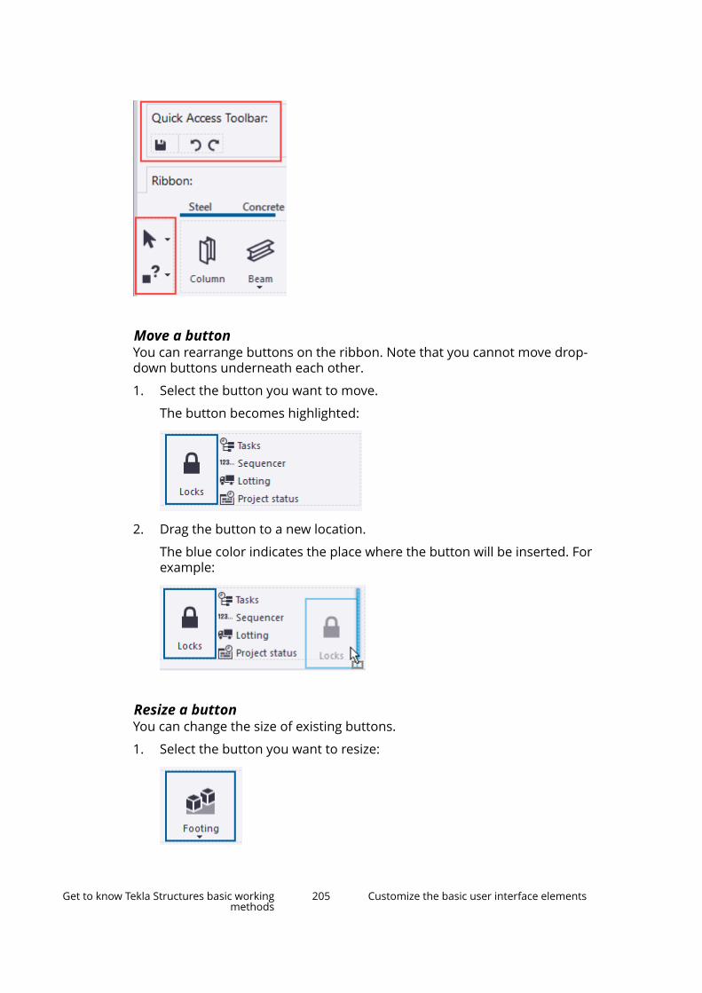
Move a buttonYou can rearrange buttons on the ribbon. Note that you cannot move drop-down buttons underneath each other.
1. Select the button you want to move.
The button becomes highlighted:
2. Drag the button to a new location.
The blue color indicates the place where the button will be inserted. Forexample:
Resize a buttonYou can change the size of existing buttons.
1. Select the button you want to resize:
Get to know Tekla Structures basic workingmethods
205 Customize the basic user interface elements

2. Move the mouse pointer over any side or corner of the button to display awhite arrow symbol:
3. Drag with the arrow to define a new size:
The size of the button changes accordingly. The other buttons areautomatically moved forward on the ribbon, if needed.
4. Double-click the button to expand it.
The button now fully occupies the empty space around it:
Change the appearance of a buttonYou can change the appearance of any button.
1. Select the button you want to modify.
• If you are adding a new button: select the command in the Commandlist.
The current properties of the button are shown in the Appearance list.
Get to know Tekla Structures basic workingmethods
206 Customize the basic user interface elements
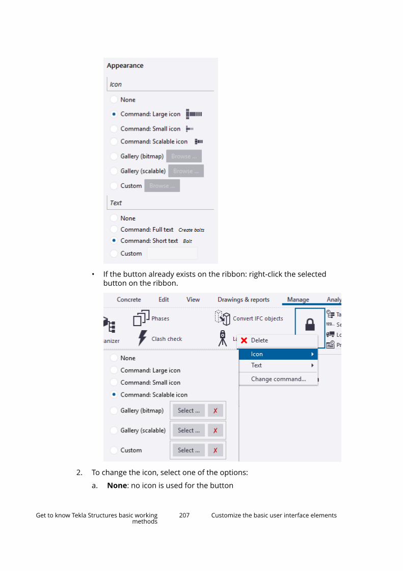
• If the button already exists on the ribbon: right-click the selectedbutton on the ribbon.
2. To change the icon, select one of the options:
a. None: no icon is used for the button
Get to know Tekla Structures basic workingmethods
207 Customize the basic user interface elements
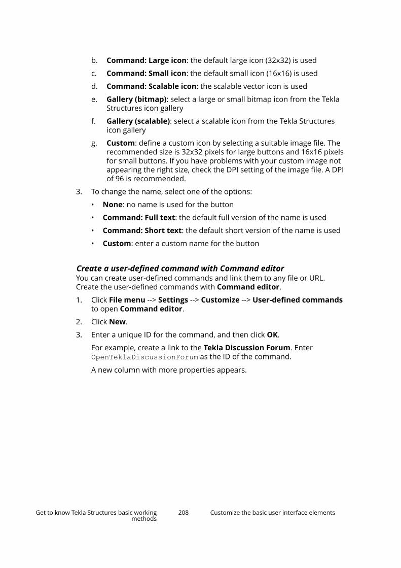
b. Command: Large icon: the default large icon (32x32) is used
c. Command: Small icon: the default small icon (16x16) is used
d. Command: Scalable icon: the scalable vector icon is used
e. Gallery (bitmap): select a large or small bitmap icon from the TeklaStructures icon gallery
f. Gallery (scalable): select a scalable icon from the Tekla Structuresicon gallery
g. Custom: define a custom icon by selecting a suitable image file. Therecommended size is 32x32 pixels for large buttons and 16x16 pixelsfor small buttons. If you have problems with your custom image notappearing the right size, check the DPI setting of the image file. A DPIof 96 is recommended.
3. To change the name, select one of the options:
• None: no name is used for the button
• Command: Full text: the default full version of the name is used
• Command: Short text: the default short version of the name is used
• Custom: enter a custom name for the button
Create a user-defined command with Command editorYou can create user-defined commands and link them to any file or URL.Create the user-defined commands with Command editor.
1. Click File menu --> Settings --> Customize --> User-defined commandsto open Command editor.
2. Click New.
3. Enter a unique ID for the command, and then click OK.
For example, create a link to the Tekla Discussion Forum. EnterOpenTeklaDiscussionForum as the ID of the command.
A new column with more properties appears.
Get to know Tekla Structures basic workingmethods
208 Customize the basic user interface elements
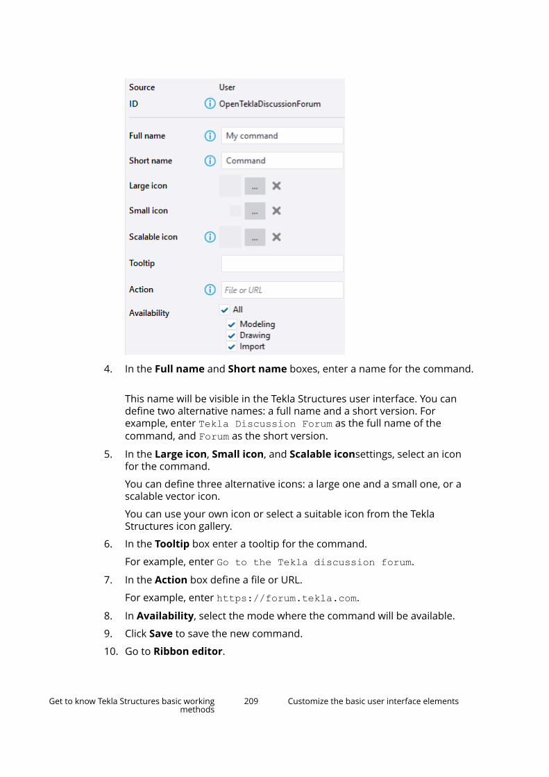
4. In the Full name and Short name boxes, enter a name for the command.
This name will be visible in the Tekla Structures user interface. You candefine two alternative names: a full name and a short version. Forexample, enter Tekla Discussion Forum as the full name of thecommand, and Forum as the short version.
5. In the Large icon, Small icon, and Scalable iconsettings, select an iconfor the command.
You can define three alternative icons: a large one and a small one, or ascalable vector icon.
You can use your own icon or select a suitable icon from the TeklaStructures icon gallery.
6. In the Tooltip box enter a tooltip for the command.
For example, enter Go to the Tekla discussion forum.
7. In the Action box define a file or URL.
For example, enter https://forum.tekla.com.
8. In Availability, select the mode where the command will be available.
9. Click Save to save the new command.
10. Go to Ribbon editor.
Get to know Tekla Structures basic workingmethods
209 Customize the basic user interface elements

11. Select the button type.
12. In the Command list, search for the new command you created.
13. In the Appearance list, modify the appearance of the button, if needed.
14. Drag the new button to the ribbon.
15. To modify a user-defined command, right-click the command on theribbon and edit the command properties just like for any other command.
Add a separator barYou can add vertical and horizontal separator bars to divide buttons intosmaller groups on the ribbon.
1. In the Add ribbon item list, select Separator.
2. In the Appearance list, select whether to add a horizontal or a verticalbar, and the thickness of the bar.
Preview shows what the separator bar looks like.
3. Drag the preview item to the ribbon.
4. To modify the orientation or the line thickness of the bar, right-click thebar on the tab and select Orientation or Thickness.
5. To delete the bar, select the bar on the ribbon and press Delete on yourkeyboard.
Alternatively, right-click the bar on the ribbon and select Delete.
Remove a button1. Select the button on the ribbon.
2. Press Delete on your keyboard.
Alternatively, right-click the button on the ribbon and select Delete.
Add, hide, and edit tabsYou can add, move and rename ribbon tabs, choose how they are aligned, andhide some tabs if you do not need them in your current project. For example,if you are only modeling steel parts, you can temporarily hide the Concretetab.
To Do thisAdd a new tab 1. In the Add ribbon item list, select Tab.
Get to know Tekla Structures basic workingmethods
210 Customize the basic user interface elements
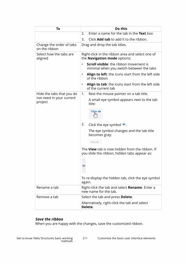
To Do this2. Enter a name for the tab in the Text box.
3. Click Add tab to add it to the ribbon.Change the order of tabson the ribbon
Drag and drop the tab titles.
Select how the tabs arealigned
Right-click in the ribbon area and select one ofthe Navigation mode options:
• Scroll visible: the ribbon movement isminimal when you switch between the tabs
• Align to left: the icons start from the left sideof the ribbon
• Align to tab: the icons start from the left sideof the current tab
Hide the tabs that you donot need in your currentproject
1. Rest the mouse pointer on a tab title.
A small eye symbol appears next to the tabtitle:
2. Click the eye symbol .
The eye symbol changes and the tab titlebecomes gray:
The View tab is now hidden from the ribbon. Ifyou slide the ribbon, hidden tabs appear as:
To re-display the hidden tab, click the eye symbolagain.
Rename a tab Right-click the tab and select Rename. Enter anew name for the tab.
Remove a tab Select the tab and press Delete.
Alternatively, right-click the tab and selectDelete.
Save the ribbonWhen you are happy with the changes, save the customized ribbon.
Get to know Tekla Structures basic workingmethods
211 Customize the basic user interface elements
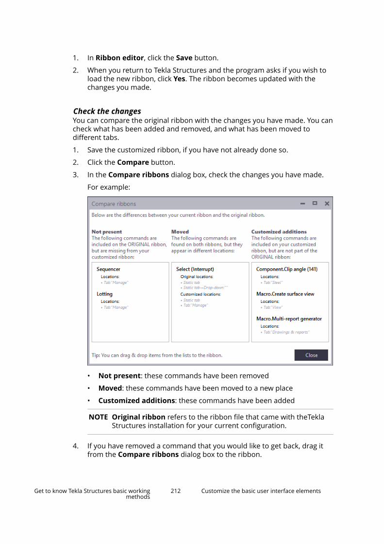
1. In Ribbon editor, click the Save button.
2. When you return to Tekla Structures and the program asks if you wish toload the new ribbon, click Yes. The ribbon becomes updated with thechanges you made.
Check the changesYou can compare the original ribbon with the changes you have made. You cancheck what has been added and removed, and what has been moved todifferent tabs.
1. Save the customized ribbon, if you have not already done so.
2. Click the Compare button.
3. In the Compare ribbons dialog box, check the changes you have made.
For example:
• Not present: these commands have been removed
• Moved: these commands have been moved to a new place
• Customized additions: these commands have been added
NOTE Original ribbon refers to the ribbon file that came with theTeklaStructures installation for your current configuration.
4. If you have removed a command that you would like to get back, drag itfrom the Compare ribbons dialog box to the ribbon.
Get to know Tekla Structures basic workingmethods
212 Customize the basic user interface elements

5. When you are finished, click Close.
Back up and restore ribbonsYou can restore the default Tekla Structures ribbons at any time. Beforerestoring the default settings, make sure to save a backup copy of yourcustomized ribbon, because the customizations will be permanently deleted.You can use the backup file to take your customized ribbon back into use, tocopy the ribbon settings to another computer, or to share the customizedribbon with your co-workers.
1. To save a backup copy of the customized ribbon:
a. In Ribbon editor, click the Save button.
b. Go to the ..\Users\<user>\AppData\Local\Trimble\TeklaStructures\<version>\UI\Ribbons folder.
c. Make a copy of the desired ribbon file and save it in another folder.
The ribbons are named according to the Tekla Structuresconfigurations. For example, in the Full configuration, the name ofthe Modeling ribbon file is albl_up_Full--main_menu.xml.
2. Click the Restore button to restore the default Tekla Structures modelingor drawing ribbon.
3. To take the customized ribbon back into use:
a. Copy the backup file back to the ..\Users\<user>\AppData\Local\Trimble\Tekla Structures\<version>\UI\Ribbonsfolder.
b. When you return to Tekla Structures and the program asks if you wishto load the new ribbon, click Yes. The ribbon becomes updated withthe changes you made.
Customize the property pane layoutTekla Structures shows the properties of most model objects in the propertypane. You can customize the property pane to better suit your needs. You canselect separately for each object type which properties you wish to see in theproperty pane. With Property pane editor you can show, hide and organizethe settings in the property pane. You can also add your most needed user-defined attributes (UDAs) directly to the property pane.
To open Property pane editor, click File menu --> Settings --> Customize -->Property pane .
With Property pane editor, you can
• organize properties to a suitable order or to suitable groups
• remove properties you do not use or need
Get to know Tekla Structures basic workingmethods
213 Customize the basic user interface elements

• create your own groups for properties that you find relevant, includinguser-defined attributes (UDAs)
• add properties, including user-defined attributes (UDAs), to an existinggroup
• create nested property groups
• rename properties or groups
• save the customized property pane layouts
The customized property pane layouts are saved to thePropertyTemplates.xml file in the ..Users\<user>\AppData\Local\Trimble\TeklaStructures\<version>\UI\PropertyTemplates\folder. If you cannot find the folder, ensure that you are able to view thehidden files and folders on your computer.
Company administrators can distribute the customized property pane layoutsto the whole organization, in the same way as customized ribbons orcustomized tabs.
Get to know Tekla Structures basic workingmethods
214 Customize the basic user interface elements
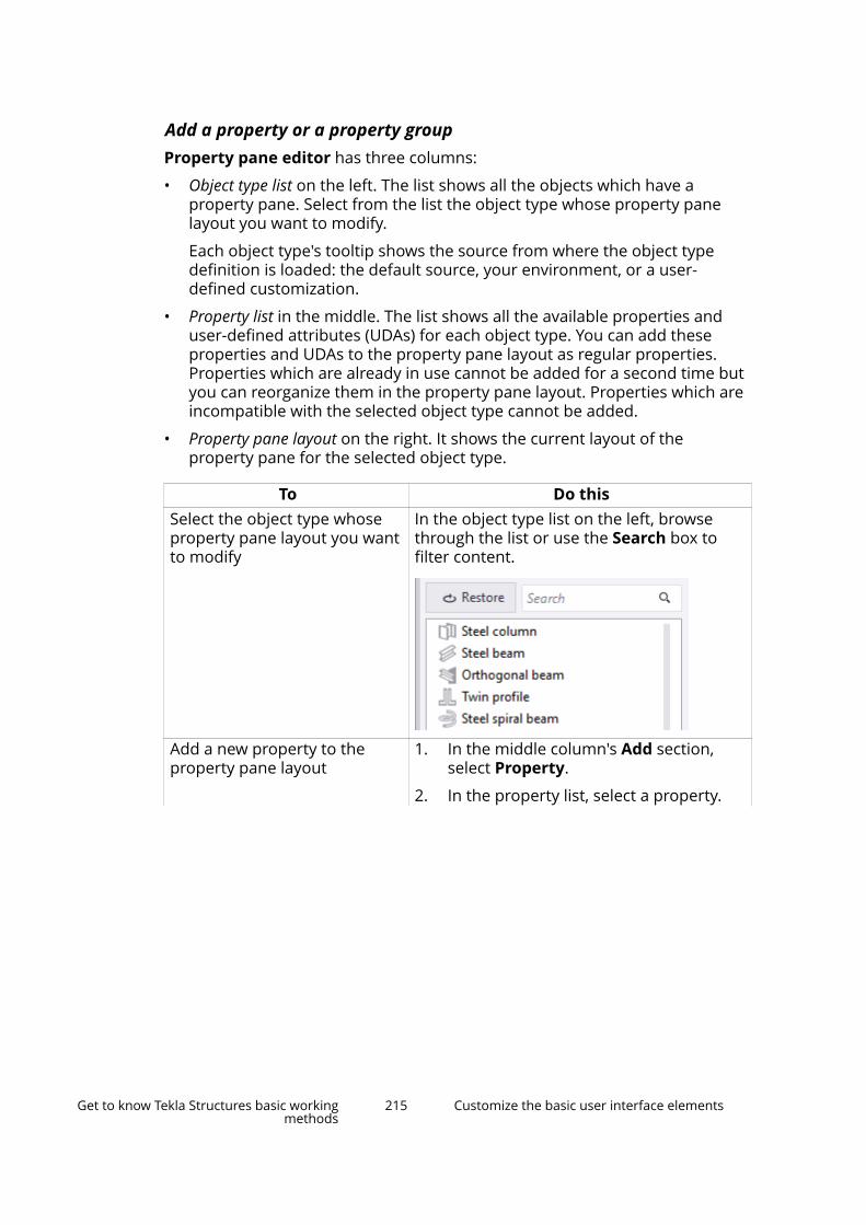
Add a property or a property groupProperty pane editor has three columns:
• Object type list on the left. The list shows all the objects which have aproperty pane. Select from the list the object type whose property panelayout you want to modify.
Each object type's tooltip shows the source from where the object typedefinition is loaded: the default source, your environment, or a user-defined customization.
• Property list in the middle. The list shows all the available properties anduser-defined attributes (UDAs) for each object type. You can add theseproperties and UDAs to the property pane layout as regular properties.Properties which are already in use cannot be added for a second time butyou can reorganize them in the property pane layout. Properties which areincompatible with the selected object type cannot be added.
• Property pane layout on the right. It shows the current layout of theproperty pane for the selected object type.
To Do thisSelect the object type whoseproperty pane layout you wantto modify
In the object type list on the left, browsethrough the list or use the Search box tofilter content.
Add a new property to theproperty pane layout
1. In the middle column's Add section,select Property.
2. In the property list, select a property.
Get to know Tekla Structures basic workingmethods
215 Customize the basic user interface elements
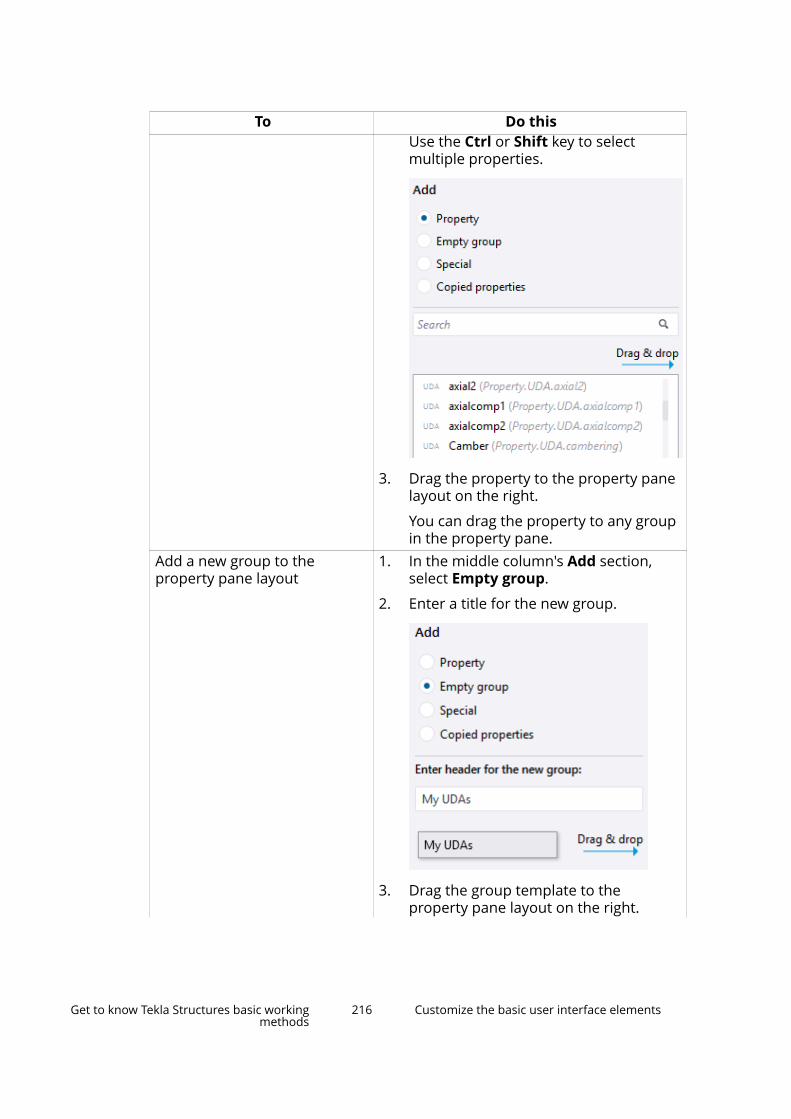
To Do thisUse the Ctrl or Shift key to selectmultiple properties.
3. Drag the property to the property panelayout on the right.
You can drag the property to any groupin the property pane.
Add a new group to theproperty pane layout
1. In the middle column's Add section,select Empty group.
2. Enter a title for the new group.
3. Drag the group template to theproperty pane layout on the right.
Get to know Tekla Structures basic workingmethods
216 Customize the basic user interface elements
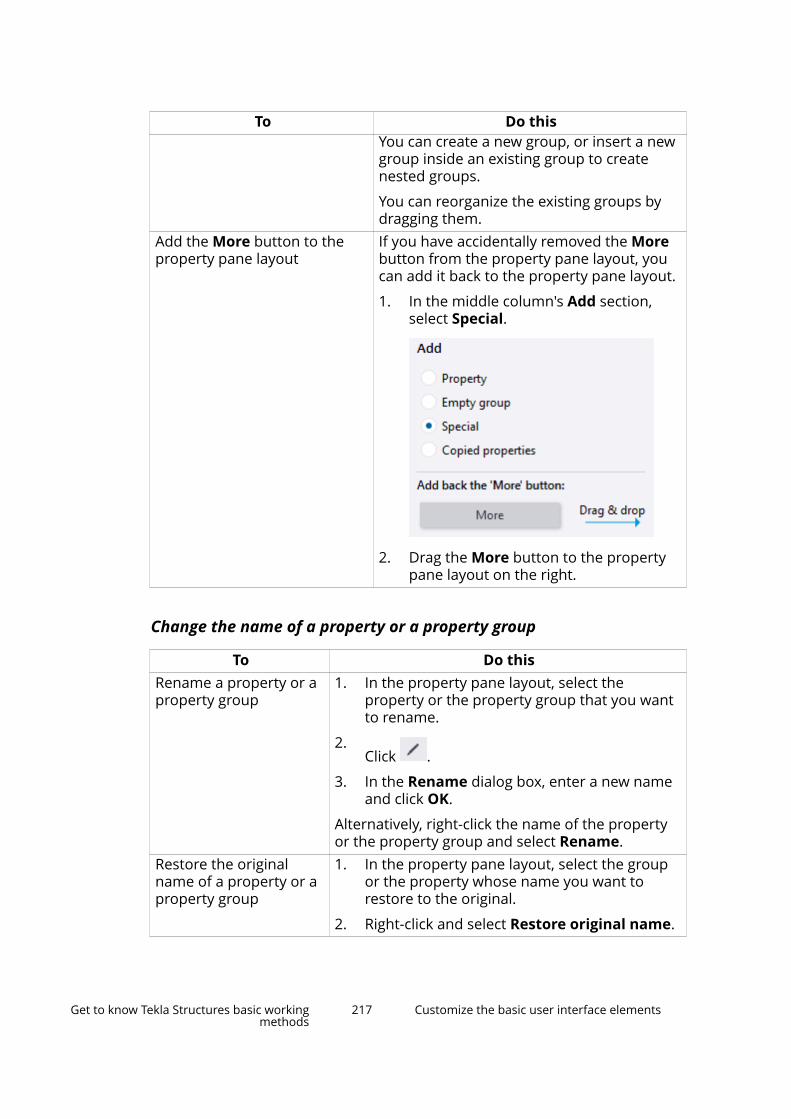
To Do thisYou can create a new group, or insert a newgroup inside an existing group to createnested groups.
You can reorganize the existing groups bydragging them.
Add the More button to theproperty pane layout
If you have accidentally removed the Morebutton from the property pane layout, youcan add it back to the property pane layout.
1. In the middle column's Add section,select Special.
2. Drag the More button to the propertypane layout on the right.
Change the name of a property or a property group
To Do thisRename a property or aproperty group
1. In the property pane layout, select theproperty or the property group that you wantto rename.
2.Click .
3. In the Rename dialog box, enter a new nameand click OK.
Alternatively, right-click the name of the propertyor the property group and select Rename.
Restore the originalname of a property or aproperty group
1. In the property pane layout, select the groupor the property whose name you want torestore to the original.
2. Right-click and select Restore original name.
Get to know Tekla Structures basic workingmethods
217 Customize the basic user interface elements
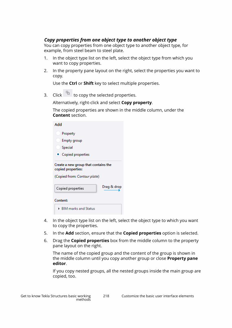
Copy properties from one object type to another object typeYou can copy properties from one object type to another object type, forexample, from steel beam to steel plate.
1. In the object type list on the left, select the object type from which youwant to copy properties.
2. In the property pane layout on the right, select the properties you want tocopy.
Use the Ctrl or Shift key to select multiple properties.
3. Click to copy the selected properties.
Alternatively, right-click and select Copy property.
The copied properties are shown in the middle column, under theContent section.
4. In the object type list on the left, select the object type to which you wantto copy the properties.
5. In the Add section, ensure that the Copied properties option is selected.
6. Drag the Copied properties box from the middle column to the propertypane layout on the right.
The name of the copied group and the content of the group is shown inthe middle column until you copy another group or close Property paneeditor.
If you copy nested groups, all the nested groups inside the main group arecopied, too.
Get to know Tekla Structures basic workingmethods
218 Customize the basic user interface elements

NOTE Properties that are already in use cannot be added for a secondtime. If you copy properties that are already in use, the copiedproperties have the text In use in the Content section.
Properties that cannot be added to the selected object type havethe text Incompatible in the Content section.
Remove a customization
To Do thisDelete a property or a propertygroup
1. Select the property or the propertygroup to be deleted.
Use the Ctrl or Shift key to selectmultiple properties.
2.Click .
Alternatively, right-click a property or aproperty group, and select Delete.
Discard changes Click the Revert all button to discardchanges and to revert to the previous save.
Remove a single customization Click the Restore button to remove thecustomization of a selected object type'sproperty pane.
Alternatively, right-click the selected objecttype and select Restore to default.
Remove all customizations Click the Restore all button to remove thecustomization of all property pane layouts.
Save the changesWhen you are happy with the changes, save the customized property panelayout.
1. Click the Save all button.
2. When you return to Tekla Structures, Tekla Structures asks if you wish toreload the changed property pane templates. Click Yes to take thecustomized property pane layout in use.
User-defined attributes (UDAs) in the customized property pane
In the property pane, the More button in the Custom properties sectionopens the user-defined attributes (UDAs) dialog box. If you customize the
Get to know Tekla Structures basic workingmethods
219 Customize the basic user interface elements

property pane, you can add your most important UDAs directly to the propertypane, so that you do not need to open separate UDA dialog boxes.
When you create or modify model objects, UDAs are automatically appliedtogether with all the other object properties. UDAs are automatically appliedregardless of them being in the property pane or in the UDA dialog boxes.
UDAs with the following unit types are supported and work correctly if they areadded in the property pane: Option, String, Integer, Float, Date, Distance, Weight, Force, Moment, Angle, Factor, and Area. UDAs withother unit types need to be used through the UDA dialog boxes.
Example: How to add IFC related user-defined attributes to theproperty pane layout and copy them to another object typeThis example shows how to add a group of IFC related user-defined attributes(UDAs) to the steel column property pane layout, and copy the group to thesteel beam property pane layout.
1. In the object type list, select Steel column.
2. In the Add section, select Empty group. Enter IFC as the title for the newgroup.
Get to know Tekla Structures basic workingmethods
220 Customize the basic user interface elements
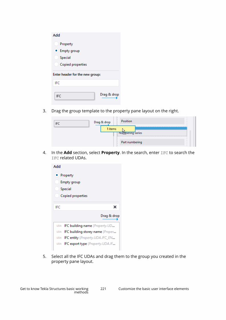
3. Drag the group template to the property pane layout on the right.
4. In the Add section, select Property. In the search, enter IFC to search theIFC related UDAs.
5. Select all the IFC UDAs and drag them to the group you created in theproperty pane layout.
Get to know Tekla Structures basic workingmethods
221 Customize the basic user interface elements
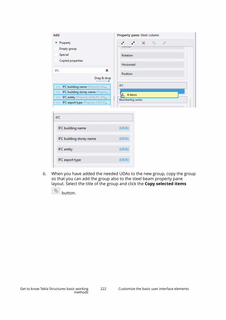
6. When you have added the needed UDAs to the new group, copy the groupso that you can add the group also to the steel beam property panelayout. Select the title of the group and click the Copy selected items
button.
Get to know Tekla Structures basic workingmethods
222 Customize the basic user interface elements
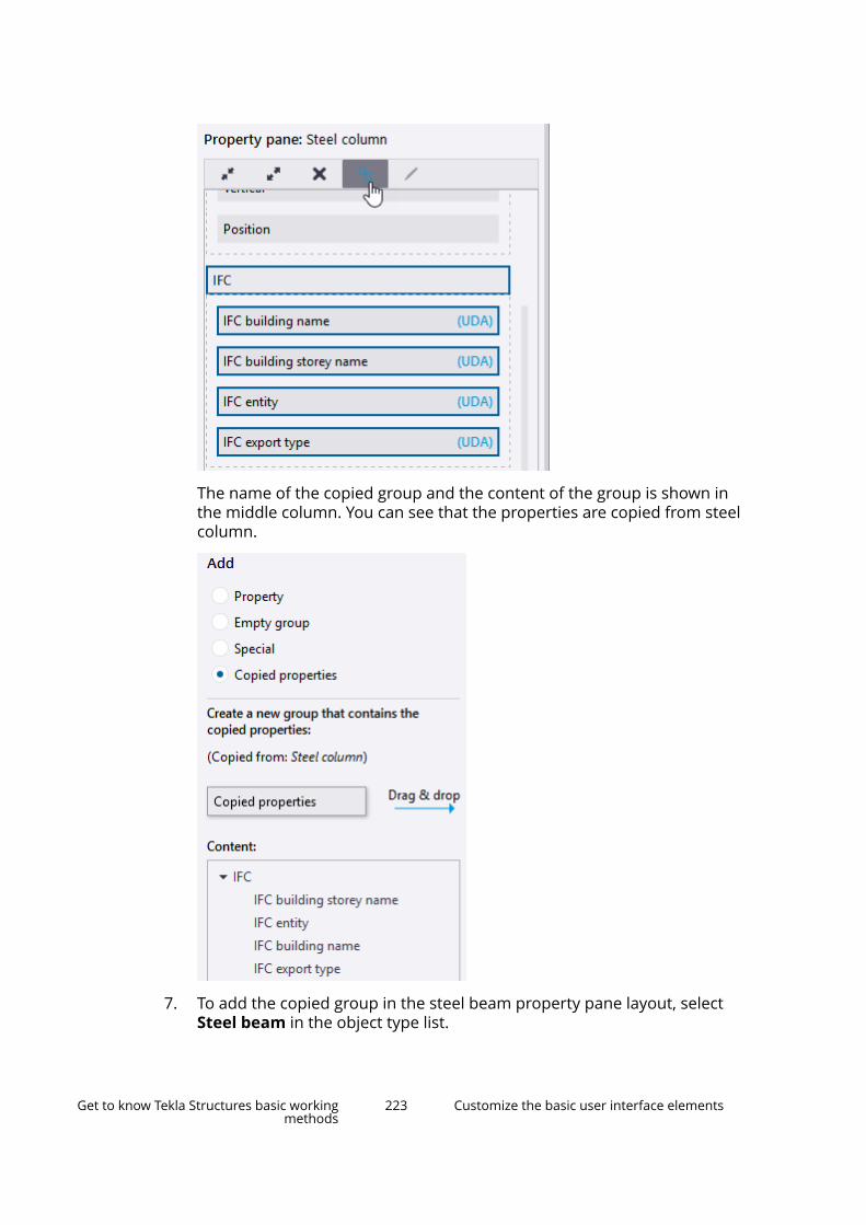
The name of the copied group and the content of the group is shown inthe middle column. You can see that the properties are copied from steelcolumn.
7. To add the copied group in the steel beam property pane layout, selectSteel beam in the object type list.
Get to know Tekla Structures basic workingmethods
223 Customize the basic user interface elements
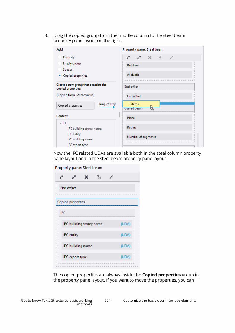
8. Drag the copied group from the middle column to the steel beamproperty pane layout on the right.
Now the IFC related UDAs are available both in the steel column propertypane layout and in the steel beam property pane layout.
The copied properties are always inside the Copied properties group inthe property pane layout. If you want to move the properties, you can
Get to know Tekla Structures basic workingmethods
224 Customize the basic user interface elements
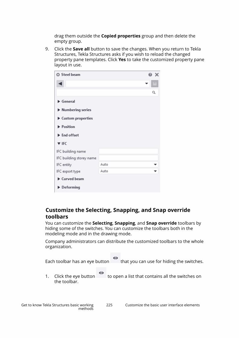
drag them outside the Copied properties group and then delete theempty group.
9. Click the Save all button to save the changes. When you return to TeklaStructures, Tekla Structures asks if you wish to reload the changedproperty pane templates. Click Yes to take the customized property panelayout in use.
Customize the Selecting, Snapping, and Snap overridetoolbarsYou can customize the Selecting, Snapping, and Snap override toolbars byhiding some of the switches. You can customize the toolbars both in themodeling mode and in the drawing mode.
Company administrators can distribute the customized toolbars to the wholeorganization.
Each toolbar has an eye button that you can use for hiding the switches.
1. Click the eye button to open a list that contains all the switches onthe toolbar.
Get to know Tekla Structures basic workingmethods
225 Customize the basic user interface elements

Alternatively, right-click on the toolbar to open the list.
2. To hide a switch, click the name of the switch in the list.
The selected switch becomes hidden on the toolbar and the eye button
changes in the list: .
3. To make the switch visible again, click the hidden switch in the list.
See also
Snapping toolbar (page 78)
Selecting toolbar (page 122)
Customize the contextual toolbarYou can customize the contextual toolbar by selecting which toolbar elementsare visible. You can also adjust the width of the elements, and add icons andadditional titles to the elements.
Customize contextual toolbar
1. On the contextual toolbar, click .
Get to know Tekla Structures basic workingmethods
226 Customize the basic user interface elements
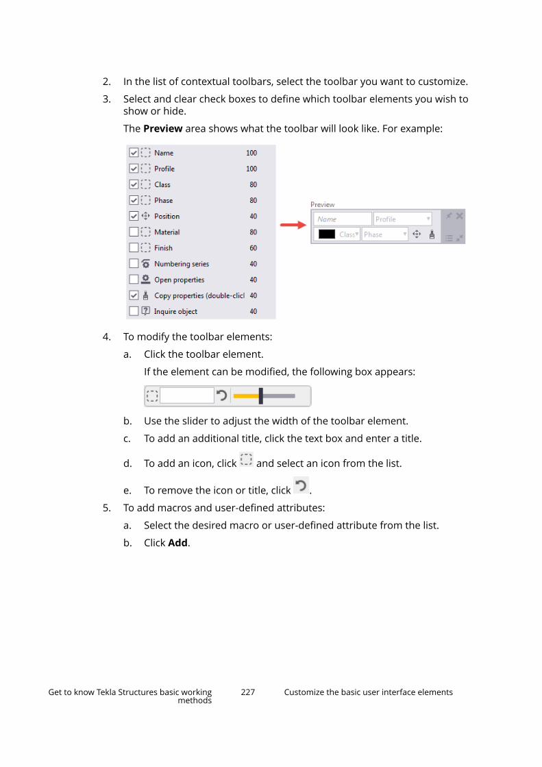
2. In the list of contextual toolbars, select the toolbar you want to customize.
3. Select and clear check boxes to define which toolbar elements you wish toshow or hide.
The Preview area shows what the toolbar will look like. For example:
4. To modify the toolbar elements:
a. Click the toolbar element.
If the element can be modified, the following box appears:
b. Use the slider to adjust the width of the toolbar element.
c. To add an additional title, click the text box and enter a title.
d. To add an icon, click and select an icon from the list.
e. To remove the icon or title, click .
5. To add macros and user-defined attributes:
a. Select the desired macro or user-defined attribute from the list.
b. Click Add.
Get to know Tekla Structures basic workingmethods
227 Customize the basic user interface elements

Tekla Structures adds the macro or user-defined attribute to the listof toolbar elements and to the Preview image. For example:
c. To hide the macro or user-defined attribute, clear the correspondingcheck box as described in step 2.
6. Click OK to save the changes.
Create user profiles for contextual toolbarsYou can create multiple profiles for contextual toolbars. Each profile containsthe same contextual toolbars, but with different settings.
1. On the contextual toolbar, click .
2. In the Set profiles box, enter a name for the profile.
3. Click to save the new profile.
4. Customize the selected contextual toolbar.
For example, remove some elements from the contextual toolbar.
5. Click OK to save the changes.
The user profile is now active with the settings you defined.
6. To switch to another profile:
a. In the Set profiles list, select another profile from the list.
b. Modify the settings.
c. Click OK.
This user profile is now active.
Back up and share contextual toolbarsWe advice you to save a backup copy of your customized contextual toolbars.You can use the backup file to copy settings to another computer or to sharethe customizations with your co-workers.
1. Save the contextual toolbar under a user profile, with a name that you caneasily recognize. For example, MyContextualToolbar.
2. Go to the ..\Users\<user>\AppData\Local\Trimble\TeklaStructures\<version>\ContextualToolbar\Profilesfolder.
Get to know Tekla Structures basic workingmethods
228 Customize the basic user interface elements
3. Make a copy of your customized contextual toolbar and save it in thecorresponding folder on another computer.
4. To open a customized contextual toolbar on another computer:
a. On the contextual toolbar, click .
b. In the Set profiles list, select the correct profile from the list. Forexample, MyContextualToolbar, if that is the name you used instep 1.
c. Click OK. The customizations are now active.
NOTE Alternatively, you can place the entire ContextualToolbar folder inyour company's firm folder or in the system folder.
1.9 Tips for large models
Modeling item TipsCoordinate system (page 48) • Do not place the model far away
from the origin. The further awayfrom the origin you model, theless precise all the computationsbecome.
• Mark global coordinates as labelsinstead of actually using themduring modeling.
• If you need to use building sitecoordinates, drop the first digits ifthey are always the same. Forexample, instead of coordinate758 375 6800, use 375 6800.
• Base points allow you to useanother coordinate systemneeded for interoperability andcollaboration. You can use anothercoordinate system for insertingreference models and exportingIFC models. When you use basepoints, you can keep thecoordinates small and locate themodel wherever needed. You cancreate as many base points as youneed, and select one of those tobe the project base point. For
Get to know Tekla Structures basic workingmethods
229 Tips for large models
Modeling item Tipsmore information, see Base points(page 53).
Work area (page 46) and visibility • Keep the work area as small aspossible.
• Show only the required parts inviews.
• Use view filters to control thevisibility of parts.
Views (page 29) • Close unnecessary views.
• Close all views when you savelarge models.
Selection switches (page 122) • Switch on the Select referencemodels selection switch onlywhen necessary. The speed ofzooming and rotating may beaffected by this switch especially inlarge and complicated models thatcontain reference models.
Round objects • Create holes with the Create boltscommand instead of using partcuts with round beams.
• Use studs to model small straightround objects instead of smallround beams.
• Model lifting hooks and otherembeds with reinforcement barsinstead of round polybeams.
Hollow core profiles • Use simple fixed (non-parametric)profiles.
• Use chamfers for curved corners.Custom components • Do not create overly complex
custom components. When usedin great numbers they consume alot of memory.
Numbering (page 627) • Do not number the whole modelin one go. Numbering all objects inlarge models may take aconsiderable amount of time.
Model database • If your model file is getting large,repairing the model database canhelp to reduce the file size
Get to know Tekla Structures basic workingmethods
230 Tips for large models

Modeling item Tipsconsiderably and therefore helpwith memory problems.
Firm and Project folders • Save Firm and Project folderslocally on the hard drive of yourcomputer instead of a networkdrive. This saves time if networkspeed is slow.
When working in the multi-usermode, ensure that the folders aresynchronized on all users’ harddrives so that important data isnot lost or changed.
1.10 Create model templatesModel templates allow you to start a model with predefined companytemplates and settings. This can be especially useful for sub-contractors.
Only single-user models can be created with model templates. If you wish tocreate a multi-user model using a model template, create the model in single-user mode and then switch to multi-user mode.
By default, the model template folder is saved in your environment folder. Usethe advanced option XS_MODEL_TEMPLATE_DIRECTORY to define a differentlocation.
Create a new model templateYou can create your own model templates and use them for creating newmodels. You can select which catalogs, custom components, model subfolders,drawing templates, and report templates from the model are included in themodel template.
1. Create a new model.
Always start by creating a new empty model. This is because old modelsthat have been used in live projects cannot be completely cleaned. Theymay contain excess information that increases the size of the model evenif you delete all objects and drawings from the model.
2. Add the desired part properties, drawing properties, profiles, materials,custom components, sketches, and so on, in the model.
You can copy the needed attribute files from another model, for example.
Get to know Tekla Structures basic workingmethods
231 Create model templates
3. On the File menu, click Save as --> Save .
You need to save the model to include custom components in thexslib.db1 file. If you do not save the model, custom components will notbe included in the model template.
4. On the File menu, click Save as --> Save as model template .
5. Enter a name for the model template.
6. Select which catalogs, drawing templates, report templates, and modelsubfolders to include in the model template.
For more information, see Model template options (page 233).
You can only select files and folders that are available in the model folder.Catalogs are typically located in an environment folder and they areincluded in the model folder only if they have been modified.
7. If you want to open the destination folder after creating the modeltemplate, select the check box.
8. Click OK.
You can now use the model template for creating new models.
9. When you create new models in File --> New , you can mark theimportant model templates as favorites, or hide the templates that you donot need.
a. Select a model template in the list.
b. Right-click and select Favorite or Hidden.
If you marked a template as Favorite, it is placed on top of thetemplate list. Alternatively, use the star icon on the template to markit as Favorite, or to remove the marking.
If you marked a template as Hidden, it is removed from the templatelist. Select the Show hidden items check box to show it again.
Modify an existing model templateTo modify an existing template, save the model as a new template.Alternatively, you can modify the template by copying new or updated filesdirectly to the model template folder.
1. Create a model using the existing model template.
2. Make the needed changes.
3. Save it as a new model template.
Get to know Tekla Structures basic workingmethods
232 Create model templates

Download model templatesYou can download, share, and store model templates using Tekla Warehouse.
Model template optionsUse the Save as model template dialog box to define which files and foldersare included in the model template.
Setting Files and folders includedProfiles profdb.bin
profitab.inpMaterials matdb.binComponents and sketches ComponentCatalog.txt
ComponentCatalogTreeView.txtxslib.db1thumbnail_bitmap.arc*.dat files
CustomComponentDialogFilesfolder
Attribute definitions Includes all attribute definitions of thecurrent model.
Bolts and bolt assemblies screwdb.dbassdb.db
Reinforcement rebar_database.inpRebarShapeRules.xmlrebardatabase_config.inprebardatabase_schedule_config.inp
Meshes mesh_database.inpOptions Includes all options of the current
model.Drawing templates *.tpl filesReport templates *.rpt filesInclude model subfolders Lists all subfolders found in the
model folder. The selected folders areincluded in the model template.
The attributes folder, whichcontains part and drawing properties,is included by default.
Get to know Tekla Structures basic workingmethods
233 Create model templates

2 Create parts, reinforcement,and construction objects
When you know the basic principles of how to create and modify differenttypes of model objects in Tekla Structures, you can start working on moredetailed level with your model.
First, to get your model started, you need to create some parts (page 235).Parts are the building blocks of the physical model. You can continue workingwith the parts by, for example, deforming their shape (page 324), or by addingsome details to the parts (page 331), such as bolts, welds, or cuts or fittings.
When you use a workshop weld or bolt to join parts together, you will learnhow to work with assemblies of steel parts (page 386).
For concrete parts, each concrete part is considered a separate cast unit(page 396). For construction purposes, you may need to merge severalconcrete parts into one cast unit. If you model cast-in-place concretestructures, you may need to check how to work with pours (page 402). Andonce you have created a model of concrete parts, you will need to reinforcethe parts (page 427) to gain higher strength for the parts.
Additionally, you may need to use points or construction objects (page 561) asmodeling aids. Points and construction objects help you to place other objectsin the model.
See also
Create model objects and modify model object properties by using propertypane (page 96)
Change how model objects are displayed (page 581)
Show and hide model objects (page 581)
Change the color and transparency of model objects (page 593)
Check the model (page 599)
Number the model (page 627)
Create parts, reinforcement, and constructionobjects
234 Create model templates

2.1 Create parts and modify part propertiesIn Tekla Structures, the term part refers to the basic building objects that canbe modeled and detailed further. Parts are the building blocks of the physicalmodel.
You can create steel parts and concrete parts. A special type of parts are items.Use them to model objects that would be difficult to model using basic TeklaStructures parts and commands, such as cutting.
Create steel parts by using the commands on Steel tab on the ribbon. Createconcrete parts by using the commands on the Concrete tab on the ribbon.
Every part has properties that define it, such as material, profile, and location(page 306). Also, parts have user-defined attributes (UDAs) (page 319) that youcan use to provide additional information about a part. You can use partproperties in view filters (page 159) and selection filters (page 161) to, forexample, select, modify, and hide parts. You can also include part propertiesand UDAs in drawing and report templates.
To view and modify the part properties (page 96), use the property pane. Youcan view and modify the properties of a one part type at a time, or thecommon properties of several, similar part types. If needed, you can copy
properties (page 109) from one part to another part by using the Copyproperties button in the property pane.
Create parts, reinforcement, and constructionobjects
235 Create parts and modify part properties
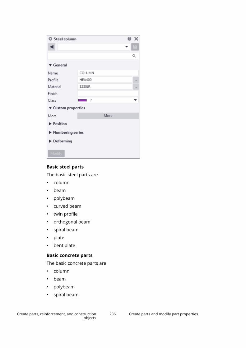
Basic steel parts
The basic steel parts are
• column
• beam
• polybeam
• curved beam
• twin profile
• orthogonal beam
• spiral beam
• plate
• bent plate
Basic concrete parts
The basic concrete parts are
• column
• beam
• polybeam
• spiral beam
Create parts, reinforcement, and constructionobjects
236 Create parts and modify part properties
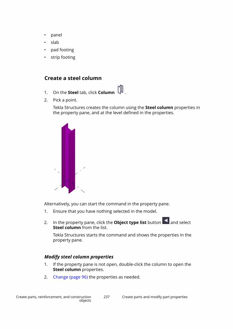
• panel
• slab
• pad footing
• strip footing
Create a steel column
1. On the Steel tab, click Column .
2. Pick a point.
Tekla Structures creates the column using the Steel column properties inthe property pane, and at the level defined in the properties.
Alternatively, you can start the command in the property pane.
1. Ensure that you have nothing selected in the model.
2. In the property pane, click the Object type list button and selectSteel column from the list.
Tekla Structures starts the command and shows the properties in theproperty pane.
Modify steel column properties1. If the property pane is not open, double-click the column to open the
Steel column properties.
2. Change (page 96) the properties as needed.
Create parts, reinforcement, and constructionobjects
237 Create parts and modify part properties
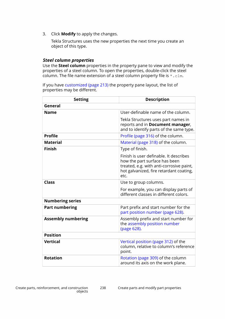
3. Click Modify to apply the changes.
Tekla Structures uses the new properties the next time you create anobject of this type.
Steel column propertiesUse the Steel column properties in the property pane to view and modify theproperties of a steel column. To open the properties, double-click the steelcolumn. The file name extension of a steel column property file is *.clm.
If you have customized (page 213) the property pane layout, the list ofproperties may be different.
Setting DescriptionGeneralName User-definable name of the column.
Tekla Structures uses part names inreports and in Document manager,and to identify parts of the same type.
Profile Profile (page 316) of the column.Material Material (page 318) of the column.Finish Type of finish.
Finish is user definable. It describeshow the part surface has beentreated, e.g. with anti-corrosive paint,hot galvanized, fire retardant coating,etc.
Class Use to group columns.
For example, you can display parts ofdifferent classes in different colors.
Numbering seriesPart numbering Part prefix and start number for the
part position number (page 628).Assembly numbering Assembly prefix and start number for
the assembly position number(page 628).
PositionVertical Vertical position (page 312) of the
column, relative to column's referencepoint.
Rotation Rotation (page 309) of the columnaround its axis on the work plane.
Create parts, reinforcement, and constructionobjects
238 Create parts and modify part properties
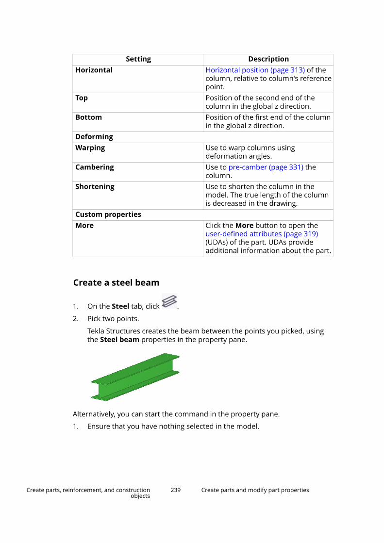
Setting DescriptionHorizontal Horizontal position (page 313) of the
column, relative to column's referencepoint.
Top Position of the second end of thecolumn in the global z direction.
Bottom Position of the first end of the columnin the global z direction.
DeformingWarping Use to warp columns using
deformation angles.Cambering Use to pre-camber (page 331) the
column.Shortening Use to shorten the column in the
model. The true length of the columnis decreased in the drawing.
Custom propertiesMore Click the More button to open the
user-defined attributes (page 319)(UDAs) of the part. UDAs provideadditional information about the part.
Create a steel beam
1. On the Steel tab, click .
2. Pick two points.
Tekla Structures creates the beam between the points you picked, usingthe Steel beam properties in the property pane.
Alternatively, you can start the command in the property pane.
1. Ensure that you have nothing selected in the model.
Create parts, reinforcement, and constructionobjects
239 Create parts and modify part properties

2. In the property pane, click the Object type list button and selectSteel beam from the list.
Tekla Structures starts the command and shows the properties in theproperty pane.
Modify steel beam properties1. If the property pane is not open, double-click the beam to open the Steel
beam properties.
2. Change (page 96) the properties as needed.
3. Click Modify to apply the changes.
Tekla Structures uses the new properties the next time you create anobject of this type.
Steel beam propertiesUse the Steel beam properties in the property pane to view and modify theproperties of a steel beam, steel polybeam, or curved beam. To open theproperties, double-click the steel beam. The file name extension of a beamproperty file is *.prt.
If you have customized (page 213) the property pane layout, the list ofproperties may be different.
Setting DescriptionGeneralName User-definable name of a beam.
Tekla Structures uses part names inreports and in Document manager,and to identify parts of the same type.
Profile Profile (page 316) of the beam.Material Material (page 318) of the beam.Finish Type of finish.
Finish is user definable. It describeshow the part surface has beentreated, e.g. with anti-corrosive paint,hot galvanized, fire retardant coating,etc.
Class Use to group beams.
For example, you can display parts ofdifferent classes in different colors.
Numbering series
Create parts, reinforcement, and constructionobjects
240 Create parts and modify part properties
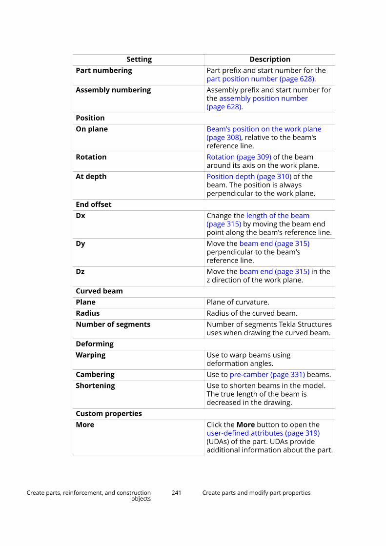
Setting DescriptionPart numbering Part prefix and start number for the
part position number (page 628).Assembly numbering Assembly prefix and start number for
the assembly position number(page 628).
PositionOn plane Beam's position on the work plane
(page 308), relative to the beam'sreference line.
Rotation Rotation (page 309) of the beamaround its axis on the work plane.
At depth Position depth (page 310) of thebeam. The position is alwaysperpendicular to the work plane.
End offsetDx Change the length of the beam
(page 315) by moving the beam endpoint along the beam's reference line.
Dy Move the beam end (page 315)perpendicular to the beam'sreference line.
Dz Move the beam end (page 315) in thez direction of the work plane.
Curved beamPlane Plane of curvature.Radius Radius of the curved beam.Number of segments Number of segments Tekla Structures
uses when drawing the curved beam.DeformingWarping Use to warp beams using
deformation angles.Cambering Use to pre-camber (page 331) beams.Shortening Use to shorten beams in the model.
The true length of the beam isdecreased in the drawing.
Custom propertiesMore Click the More button to open the
user-defined attributes (page 319)(UDAs) of the part. UDAs provideadditional information about the part.
Create parts, reinforcement, and constructionobjects
241 Create parts and modify part properties

Create a steel polybeamA polybeam can contain straight and curved segments.
1. On the Steel tab, click Beam --> Polybeam.
2. Pick the points you want the beam to go through.
3. Click the middle mouse button.
Tekla Structures creates the polybeam between the points you picked,using the Steel beam properties in the property pane.
4. If you want to create curved segments, chamfer the corners of thepolybeam.
For example:
Modify steel polybeam properties1. If the property pane is not open, double-click the polybeam to open the
Steel beam properties.
2. Change (page 96) the properties as needed.
3. Click Modify to apply the changes.
Tekla Structures uses the new properties the next time you create anobject of this type.
Steel beam propertiesUse the Steel beam properties in the property pane to view and modify theproperties of a steel beam, steel polybeam, or curved beam. To open theproperties, double-click the steel beam. The file name extension of a beamproperty file is *.prt.
Create parts, reinforcement, and constructionobjects
242 Create parts and modify part properties
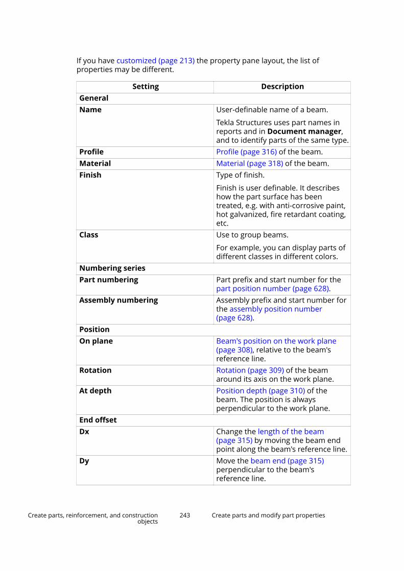
If you have customized (page 213) the property pane layout, the list ofproperties may be different.
Setting DescriptionGeneralName User-definable name of a beam.
Tekla Structures uses part names inreports and in Document manager,and to identify parts of the same type.
Profile Profile (page 316) of the beam.Material Material (page 318) of the beam.Finish Type of finish.
Finish is user definable. It describeshow the part surface has beentreated, e.g. with anti-corrosive paint,hot galvanized, fire retardant coating,etc.
Class Use to group beams.
For example, you can display parts ofdifferent classes in different colors.
Numbering seriesPart numbering Part prefix and start number for the
part position number (page 628).Assembly numbering Assembly prefix and start number for
the assembly position number(page 628).
PositionOn plane Beam's position on the work plane
(page 308), relative to the beam'sreference line.
Rotation Rotation (page 309) of the beamaround its axis on the work plane.
At depth Position depth (page 310) of thebeam. The position is alwaysperpendicular to the work plane.
End offsetDx Change the length of the beam
(page 315) by moving the beam endpoint along the beam's reference line.
Dy Move the beam end (page 315)perpendicular to the beam'sreference line.
Create parts, reinforcement, and constructionobjects
243 Create parts and modify part properties
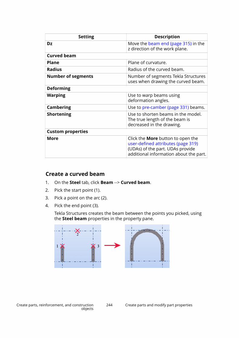
Setting DescriptionDz Move the beam end (page 315) in the
z direction of the work plane.Curved beamPlane Plane of curvature.Radius Radius of the curved beam.Number of segments Number of segments Tekla Structures
uses when drawing the curved beam.DeformingWarping Use to warp beams using
deformation angles.Cambering Use to pre-camber (page 331) beams.Shortening Use to shorten beams in the model.
The true length of the beam isdecreased in the drawing.
Custom propertiesMore Click the More button to open the
user-defined attributes (page 319)(UDAs) of the part. UDAs provideadditional information about the part.
Create a curved beam1. On the Steel tab, click Beam --> Curved beam.
2. Pick the start point (1).
3. Pick a point on the arc (2).
4. Pick the end point (3).
Tekla Structures creates the beam between the points you picked, usingthe Steel beam properties in the property pane.
Create parts, reinforcement, and constructionobjects
244 Create parts and modify part properties

Modify curved beam properties1. If the property pane is not open, double-click the curved beam to open
the Steel beam properties.
2. Change (page 96) the properties as needed.
3. Click Modify to apply the changes.
Tekla Structures uses the new properties the next time you create anobject of this type.
Steel beam propertiesUse the Steel beam properties in the property pane to view and modify theproperties of a steel beam, steel polybeam, or curved beam. To open theproperties, double-click the steel beam. The file name extension of a beamproperty file is *.prt.
If you have customized (page 213) the property pane layout, the list ofproperties may be different.
Setting DescriptionGeneralName User-definable name of a beam.
Tekla Structures uses part names inreports and in Document manager,and to identify parts of the same type.
Profile Profile (page 316) of the beam.Material Material (page 318) of the beam.Finish Type of finish.
Finish is user definable. It describeshow the part surface has beentreated, e.g. with anti-corrosive paint,hot galvanized, fire retardant coating,etc.
Class Use to group beams.
For example, you can display parts ofdifferent classes in different colors.
Numbering seriesPart numbering Part prefix and start number for the
part position number (page 628).Assembly numbering Assembly prefix and start number for
the assembly position number(page 628).
Position
Create parts, reinforcement, and constructionobjects
245 Create parts and modify part properties

Setting DescriptionOn plane Beam's position on the work plane
(page 308), relative to the beam'sreference line.
Rotation Rotation (page 309) of the beamaround its axis on the work plane.
At depth Position depth (page 310) of thebeam. The position is alwaysperpendicular to the work plane.
End offsetDx Change the length of the beam
(page 315) by moving the beam endpoint along the beam's reference line.
Dy Move the beam end (page 315)perpendicular to the beam'sreference line.
Dz Move the beam end (page 315) in thez direction of the work plane.
Curved beamPlane Plane of curvature.Radius Radius of the curved beam.Number of segments Number of segments Tekla Structures
uses when drawing the curved beam.DeformingWarping Use to warp beams using
deformation angles.Cambering Use to pre-camber (page 331) beams.Shortening Use to shorten beams in the model.
The true length of the beam isdecreased in the drawing.
Custom propertiesMore Click the More button to open the
user-defined attributes (page 319)(UDAs) of the part. UDAs provideadditional information about the part.
Create a twin profileA twin profile consists of two parallel and identical beams. You define thepositions of both beams by selecting the twin profile type and setting theclearance between the beams in two directions.
1. On the Steel tab, click Beam --> Twin profile.
Create parts, reinforcement, and constructionobjects
246 Create parts and modify part properties

2. Pick two points.
Tekla Structures creates the twin profile between the points you picked,using the Twin profile properties in the property pane.
Alternatively, you can start the command in the property pane.
1. Ensure that you have nothing selected in the model.
2. In the property pane, click the Object type list button and selectTwin profile from the list.
Tekla Structures starts the command and shows the properties in theproperty pane.
Modify twin profile properties1. If the property pane is not open, double-click either of the beams to open
the Steel beam properties.
2. Change (page 96) the properties as needed.
3. Click Modify to apply the changes.
Twin profile propertiesUse the Twin profile properties in the property pane to view and modify theproperties of a twin steel profile. The file name extension of a twin profileproperty file is *.dia.
If you have customized (page 213) the property pane layout, the list ofproperties may be different.
Setting DescriptionGeneralName User-definable name of a twin profile.
Tekla Structures uses part names inreports and in Document manager,and to identify parts of the same type.
Profile The profile of both the beams in thetwin profile.
Material Material (page 318) of the beams.
Create parts, reinforcement, and constructionobjects
247 Create parts and modify part properties

Setting DescriptionFinish Type of finish.
Finish is user definable. It describeshow the part surface has beentreated, e.g. with anti-corrosive paint,hot galvanized, fire retardant coating,etc.
Class Use to group twin profiles.
For example, you can display parts ofdifferent classes in different colors.
Twin profile type Define how the profiles arecombined.
Numbering seriesPart numbering Part prefix and start number for the
part position number (page 628).Assembly numbering Assembly prefix and start number the
assembly position number (page 628).PositionOn plane Twin profile's position on the work
plane (page 308), relative to the twinprofile's reference line.
Rotation Rotation (page 309) of the twin profilearound its axis on the work plane.
At depth Position depth (page 310) of the twinprofile. The position is alwaysperpendicular to the work plane.
End offsetDx Change the length of the twin profile
(page 315) by moving the twin profileend point along the twin profile'sreference line.
Clearance between membersHorizontal The horizontal clearance between the
profiles.Vertical The vertical clearance between the
profiles.Custom propertiesMore Click the More button to open the
user-defined attributes (page 319)(UDAs) of the part. UDAs provideadditional information about the part.
Create parts, reinforcement, and constructionobjects
248 Create parts and modify part properties

Create an orthogonal beamUse the Orthogonal beam command when you want to create a steel partthat is perpendicular to the current work plane. After you have created anorthogonal beam, you can modify it as if it were beam or column.
1. On the Steel tab, click Beam --> Orthogonal beam.
2. Pick a point.
Tekla Structures creates the beam using the Orthogonal beam propertiesin the property pane, and at the level (page 323) defined in the properties.
Alternatively, you can start the command in the property pane.
1. Ensure that you have nothing selected in the model.
2. In the property pane, click the Object type list button and selectOrthogonal beam from the list.
Tekla Structures starts the command and shows the properties in theproperty pane.
Modify orthogonal beam properties1. If the property pane is not open, double-click the orthogonal beam to
open the properties.
2. Change (page 96) the properties as needed.
3. Click Modify to apply the changes.
Orthogonal beam propertiesUse the Orthogonal beam properties in the property pane to view and modifythe properties of an orthogonal steel beam. The file name extension of anorthogonal beam property file is *.crs.
Create parts, reinforcement, and constructionobjects
249 Create parts and modify part properties
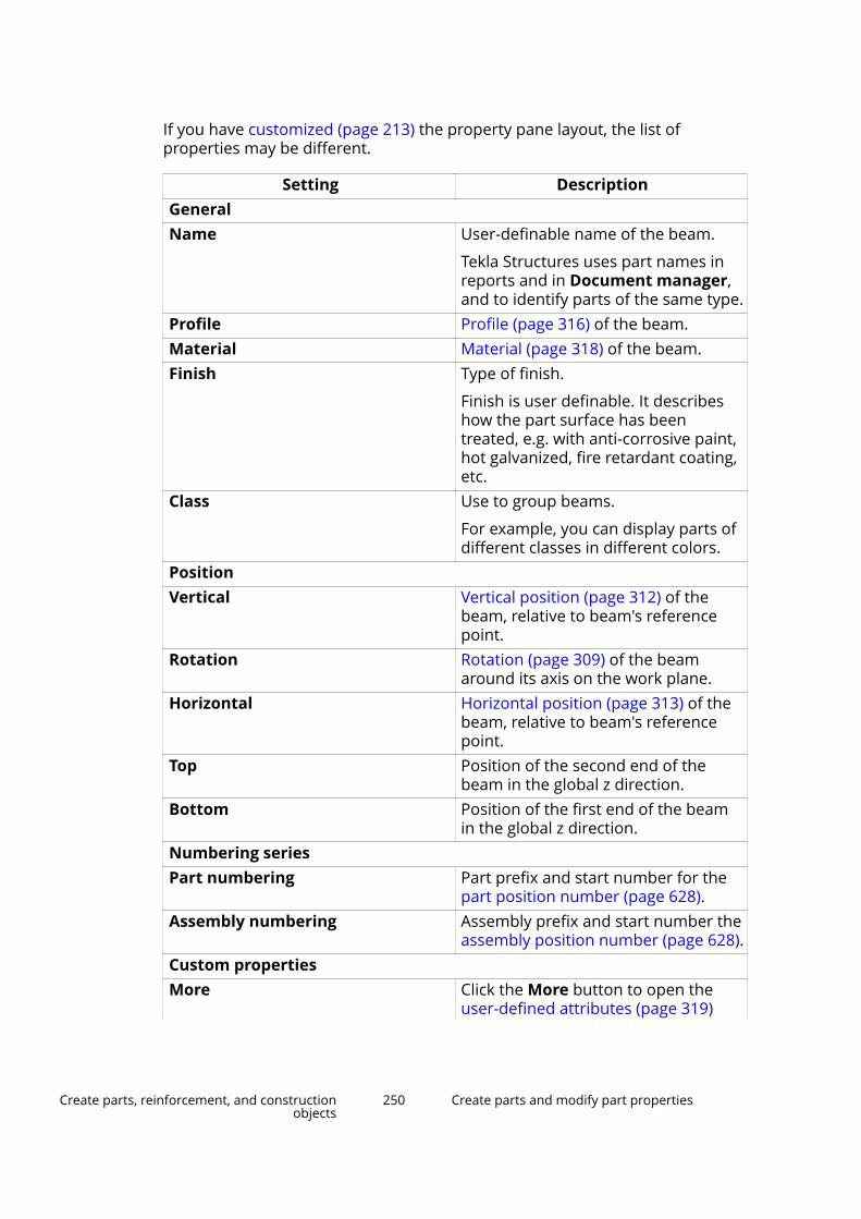
If you have customized (page 213) the property pane layout, the list ofproperties may be different.
Setting DescriptionGeneralName User-definable name of the beam.
Tekla Structures uses part names inreports and in Document manager,and to identify parts of the same type.
Profile Profile (page 316) of the beam.Material Material (page 318) of the beam.Finish Type of finish.
Finish is user definable. It describeshow the part surface has beentreated, e.g. with anti-corrosive paint,hot galvanized, fire retardant coating,etc.
Class Use to group beams.
For example, you can display parts ofdifferent classes in different colors.
PositionVertical Vertical position (page 312) of the
beam, relative to beam's referencepoint.
Rotation Rotation (page 309) of the beamaround its axis on the work plane.
Horizontal Horizontal position (page 313) of thebeam, relative to beam's referencepoint.
Top Position of the second end of thebeam in the global z direction.
Bottom Position of the first end of the beamin the global z direction.
Numbering seriesPart numbering Part prefix and start number for the
part position number (page 628).Assembly numbering Assembly prefix and start number the
assembly position number (page 628).Custom propertiesMore Click the More button to open the
user-defined attributes (page 319)
Create parts, reinforcement, and constructionobjects
250 Create parts and modify part properties
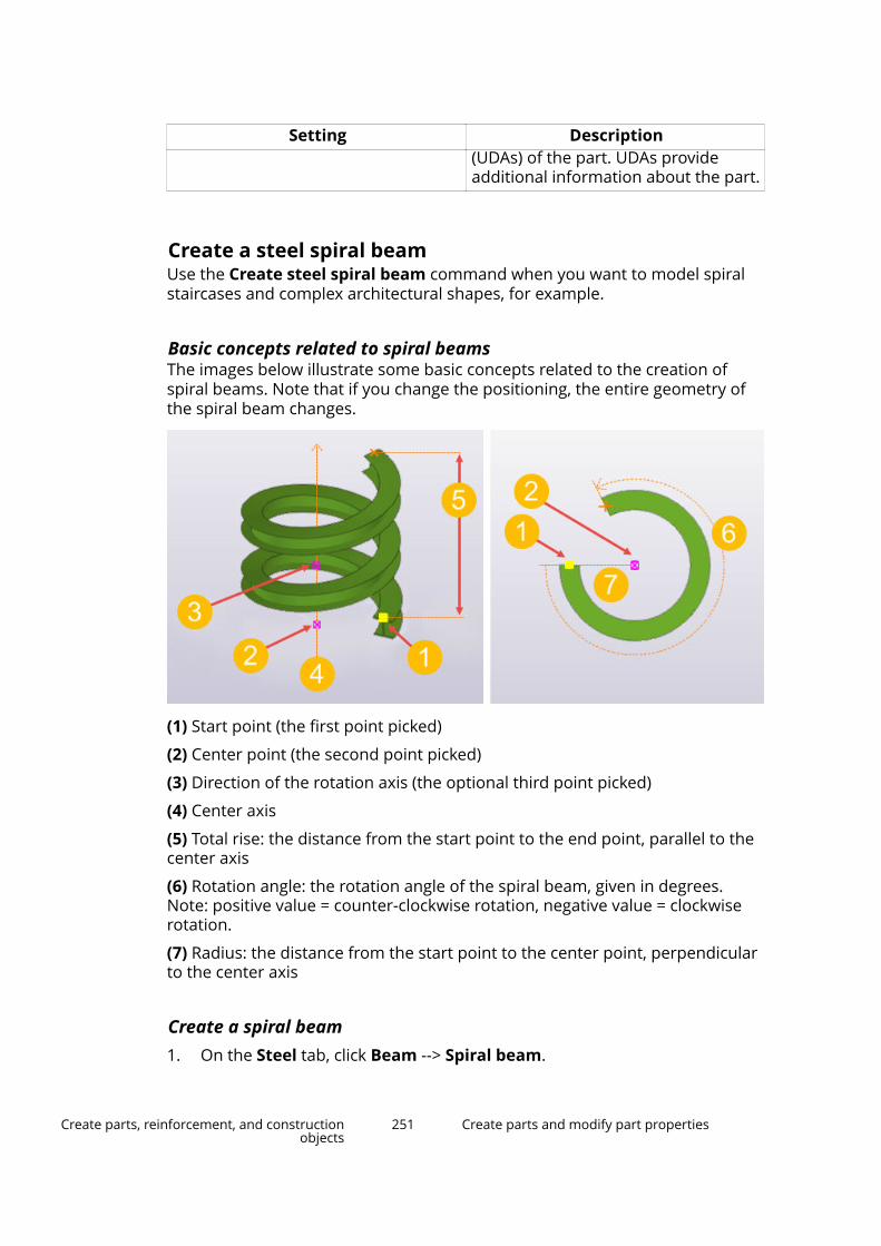
Setting Description(UDAs) of the part. UDAs provideadditional information about the part.
Create a steel spiral beamUse the Create steel spiral beam command when you want to model spiralstaircases and complex architectural shapes, for example.
Basic concepts related to spiral beamsThe images below illustrate some basic concepts related to the creation ofspiral beams. Note that if you change the positioning, the entire geometry ofthe spiral beam changes.
(1) Start point (the first point picked)
(2) Center point (the second point picked)
(3) Direction of the rotation axis (the optional third point picked)
(4) Center axis
(5) Total rise: the distance from the start point to the end point, parallel to thecenter axis
(6) Rotation angle: the rotation angle of the spiral beam, given in degrees.Note: positive value = counter-clockwise rotation, negative value = clockwiserotation.
(7) Radius: the distance from the start point to the center point, perpendicularto the center axis
Create a spiral beam1. On the Steel tab, click Beam --> Spiral beam.
Create parts, reinforcement, and constructionobjects
251 Create parts and modify part properties
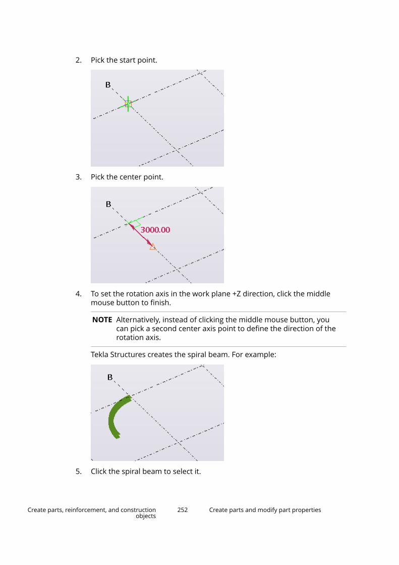
2. Pick the start point.
3. Pick the center point.
4. To set the rotation axis in the work plane +Z direction, click the middlemouse button to finish.
NOTE Alternatively, instead of clicking the middle mouse button, youcan pick a second center axis point to define the direction of therotation axis.
Tekla Structures creates the spiral beam. For example:
5. Click the spiral beam to select it.
Create parts, reinforcement, and constructionobjects
252 Create parts and modify part properties

The contextual toolbar appears with the following options:
(1) Rotation angle
(2) Total rise
(3) Twist angle at start
(4) Twist angle at end
6. To add more rotation, enter a bigger value in the Rotation angle box.
7. To make the spiral more loose, enter a bigger value in the Total rise box.
8. To change the radius, move the start point or center point.
Limitations• Spiral beam has a single, constant radius.
• Unfolding of spiral beams whose total rise is larger than 0.00 does notproduce completely straight results in drawings. The amount of deviation inthe part profile outlines and part length depends on several factors: thetype, size, and length of the profile; the amount of total rise; and theamount of rotation angle and detailing used.
• Spiral beams are not always untwisted in unfolding. If unequal twisting isapplied to the start end and end end, the unfolded drawing shows anunfolded but twisted part as a result.
• Connections and details may not work as expected with spiral beams.
• DSTV export of spiral beams may not produce a correct result.
• You cannot export spiral beams as parts in IFC export. If you are modelingcast-in-place structures with spiral beam, you can export the geometry toIFC as pour objects.
Create a contour plateWhen you create a contour plate, the profile you select defines the thicknessof the plate and the points you pick define the shape. The corners of thecontour plate can be chamfered.
1. On the Steel tab, click .
Create parts, reinforcement, and constructionobjects
253 Create parts and modify part properties

2. Pick the corner points of the contour plate.
3. Click the middle mouse button.
Tekla Structures creates the plate using the Contour plate properties inthe property pane.
Alternatively, you can start the command in the property pane.
1. Ensure that you have nothing selected in the model.
2. In the property pane, click the Object type list button and selectContour plate from the list.
Tekla Structures starts the command and shows the properties in theproperty pane.
Create a round contour plate1. Create a square contour plate with four equal sides.
2. Select the plate.
3. Select the handles of the plate.
TIP To select all the handles at once, hold down the Alt key and drag themouse from left to right, covering all the handles.
4. Press Alt + Enter to display the Chamfer Properties dialog box.
5. Select the round chamfer symbol from the list.
6. Enter the chamfer radius in the x box. The radius must be equal to half ofthe side of the square.
7. Click Modify.
Create parts, reinforcement, and constructionobjects
254 Create parts and modify part properties
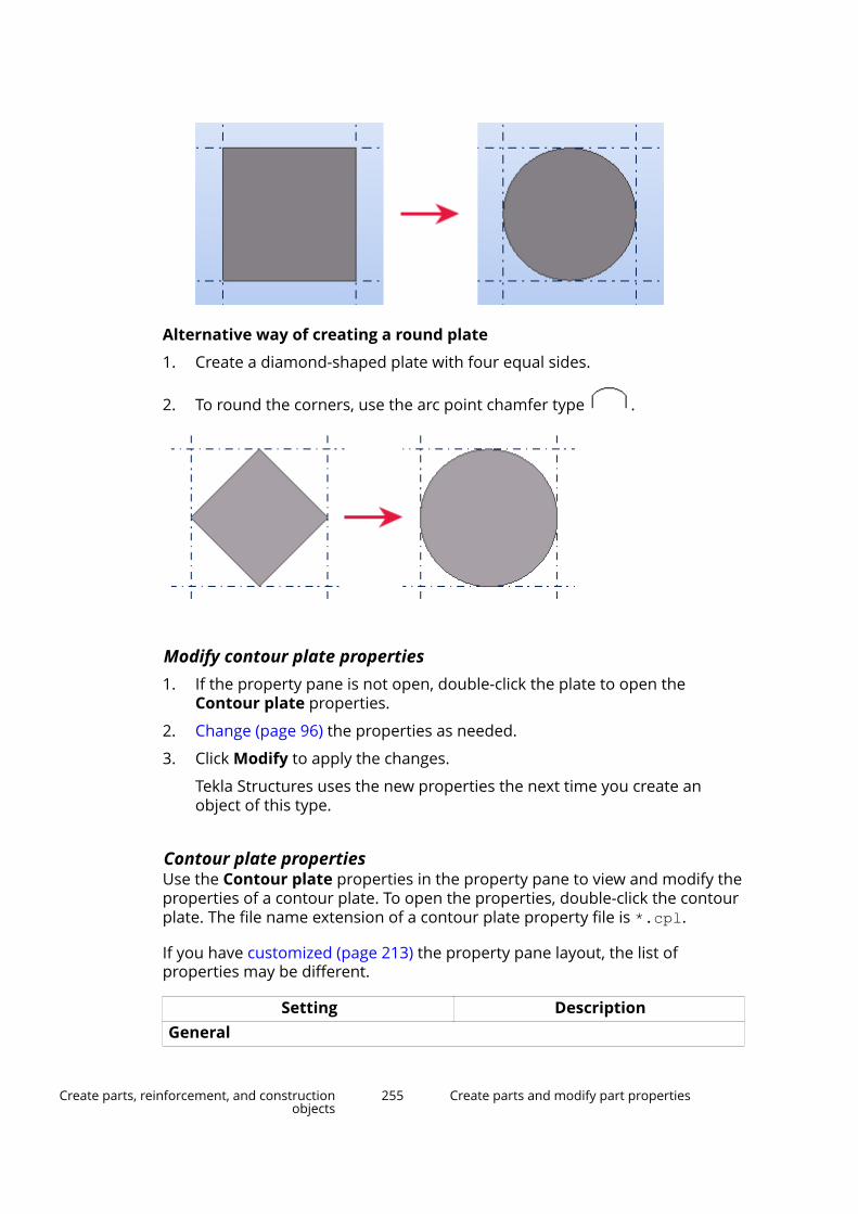
Alternative way of creating a round plate
1. Create a diamond-shaped plate with four equal sides.
2. To round the corners, use the arc point chamfer type .
Modify contour plate properties1. If the property pane is not open, double-click the plate to open the
Contour plate properties.
2. Change (page 96) the properties as needed.
3. Click Modify to apply the changes.
Tekla Structures uses the new properties the next time you create anobject of this type.
Contour plate propertiesUse the Contour plate properties in the property pane to view and modify theproperties of a contour plate. To open the properties, double-click the contourplate. The file name extension of a contour plate property file is *.cpl.
If you have customized (page 213) the property pane layout, the list ofproperties may be different.
Setting DescriptionGeneral
Create parts, reinforcement, and constructionobjects
255 Create parts and modify part properties

Setting DescriptionName User-definable name of the contour
plate.
Tekla Structures uses part names inreports and in Document manager,and to identify parts of the same type.
Profile Profile (page 316) of the contourplate.
Material Material (page 318) of the contourplate.
Finish Type of finish.
Finish is user definable. It describeshow the part surface has beentreated, e.g. with anti-corrosive paint,hot galvanized, fire retardant coating,etc.
Class Use to group contour plates.
For example, you can display parts ofdifferent classes in different colors.
Numbering seriesPart numbering Part prefix and start number for the
part position number (page 628).Assembly numbering Assembly prefix and start number the
assembly position number (page 628).PositionAt depth Position depth (page 310) of the
contour plate. The position is alwaysperpendicular to the work plane.
Custom propertiesMore Click the More button to open the
user-defined attributes (page 319)(UDAs) of the part. UDAs provideadditional information about the part.
Create a conical or a cylindrical bent plateYou can create cylindrical or conical bent steel plates either by selecting twoparts or two part faces. The parts that you use for creating a bent plate mustbe contour plates, or beams whose profile is a plate (for example, PL200*20).Position the parts so that there is some room on both sides, so that TeklaStructures can create a curved section between them.
Create parts, reinforcement, and constructionobjects
256 Create parts and modify part properties

After creating a cylindrical or conical bent plate, the individual parts no longerexist in the model. The bent plate gets its properties and coordinates from thefirst part that you selected when creating the bent plate. The first part is themain section of the bent plate. You can later change the main section, ifneeded.
Limitations
• Only the side faces of the part can be used for creating a bent plate.
• Chamfered or cut faces cannot be used for creating a bent plate.
• Curved beams and deformed parts cannot be used for creating a bentplate.
• Details (such as bolts, welds, cuts, chamfers, and preparations) in simplecases are supported on the curved section of the bent plate.
In addition to the cylindrical and conical bent plates you can also create stand-alone bent plates (page 271), which do not require any input parts.
Create a cylindrical bent plateYou can create a cylindrical bent plate by selecting two steel parts or two partfaces. Cylindrical bent plate has a radius that you can modify. The bent plateproperties, such as the ID, thickness, class, and material of the plate, aredetermined by the first part you select.
You can create cylindrical bent plates also when the selected parts areintersecting.
1. On the Steel tab, click Plate --> Create cylindrical bent plate .
2. On the bent plate toolbar, select whether you want to create the bentplate by selecting parts or by selecting part faces.
Additionally, you can enter the radius of the cylindrical bent plate. If noradius is entered, Tekla Structures creates the bent plate using the defaultradius.
• If you selected By parts:
a. Select the first part.
Create parts, reinforcement, and constructionobjects
257 Create parts and modify part properties

b. Select the second part.
Tekla Structures creates the cylindrical bent plate.
Create parts, reinforcement, and constructionobjects
258 Create parts and modify part properties
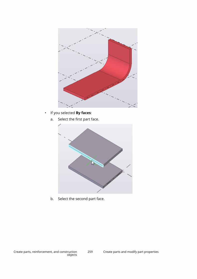
• If you selected By faces:
a. Select the first part face.
b. Select the second part face.
Create parts, reinforcement, and constructionobjects
259 Create parts and modify part properties

Tekla Structures creates the cylindrical bent plate.
Create a conical bent plateYou can create a conical bent plate by selecting two steel parts or two partfaces. Conical bent plate has two radiuses that you can modify. The bent plateproperties, such as the ID, thickness, class, and material of the plate, aredetermined by the first part you select.
To be able to create conical bent plates, the selected parts or part faces needto be of a shape that creating a conical bent plate is possible. If the selectedparts or part faces are such that creating a cylindrical bent plate is possible, a
Create parts, reinforcement, and constructionobjects
260 Create parts and modify part properties
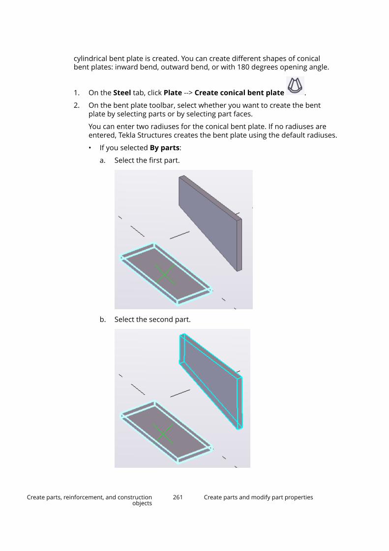
cylindrical bent plate is created. You can create different shapes of conicalbent plates: inward bend, outward bend, or with 180 degrees opening angle.
1. On the Steel tab, click Plate --> Create conical bent plate .
2. On the bent plate toolbar, select whether you want to create the bentplate by selecting parts or by selecting part faces.
You can enter two radiuses for the conical bent plate. If no radiuses areentered, Tekla Structures creates the bent plate using the default radiuses.
• If you selected By parts:
a. Select the first part.
b. Select the second part.
Create parts, reinforcement, and constructionobjects
261 Create parts and modify part properties
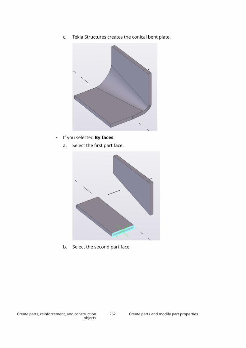
c. Tekla Structures creates the conical bent plate.
• If you selected By faces:
a. Select the first part face.
b. Select the second part face.
Create parts, reinforcement, and constructionobjects
262 Create parts and modify part properties
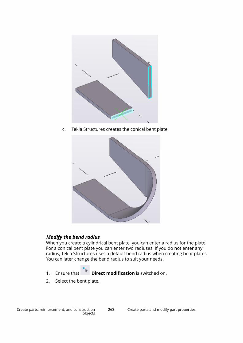
c. Tekla Structures creates the conical bent plate.
Modify the bend radiusWhen you create a cylindrical bent plate, you can enter a radius for the plate.For a conical bent plate you can enter two radiuses. If you do not enter anyradius, Tekla Structures uses a default bend radius when creating bent plates.You can later change the bend radius to suit your needs.
1. Ensure that Direct modification is switched on.
2. Select the bent plate.
Create parts, reinforcement, and constructionobjects
263 Create parts and modify part properties
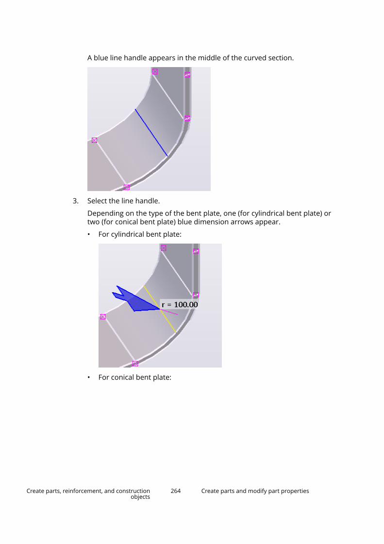
A blue line handle appears in the middle of the curved section.
3. Select the line handle.
Depending on the type of the bent plate, one (for cylindrical bent plate) ortwo (for conical bent plate) blue dimension arrows appear.
• For cylindrical bent plate:
• For conical bent plate:
Create parts, reinforcement, and constructionobjects
264 Create parts and modify part properties
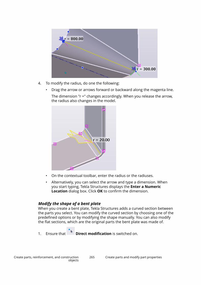
4. To modify the radius, do one the following:
• Drag the arrow or arrows forward or backward along the magenta line.
The dimension "r =" changes accordingly. When you release the arrow,the radius also changes in the model.
• On the contextual toolbar, enter the radius or the radiuses.
• Alternatively, you can select the arrow and type a dimension. Whenyou start typing, Tekla Structures displays the Enter a NumericLocation dialog box. Click OK to confirm the dimension.
Modify the shape of a bent plateWhen you create a bent plate, Tekla Structures adds a curved section betweenthe parts you select. You can modify the curved section by choosing one of thepredefined options or by modifying the shape manually. You can also modifythe flat sections, which are the original parts the bent plate was made of.
1. Ensure that Direct modification is switched on.
Create parts, reinforcement, and constructionobjects
265 Create parts and modify part properties
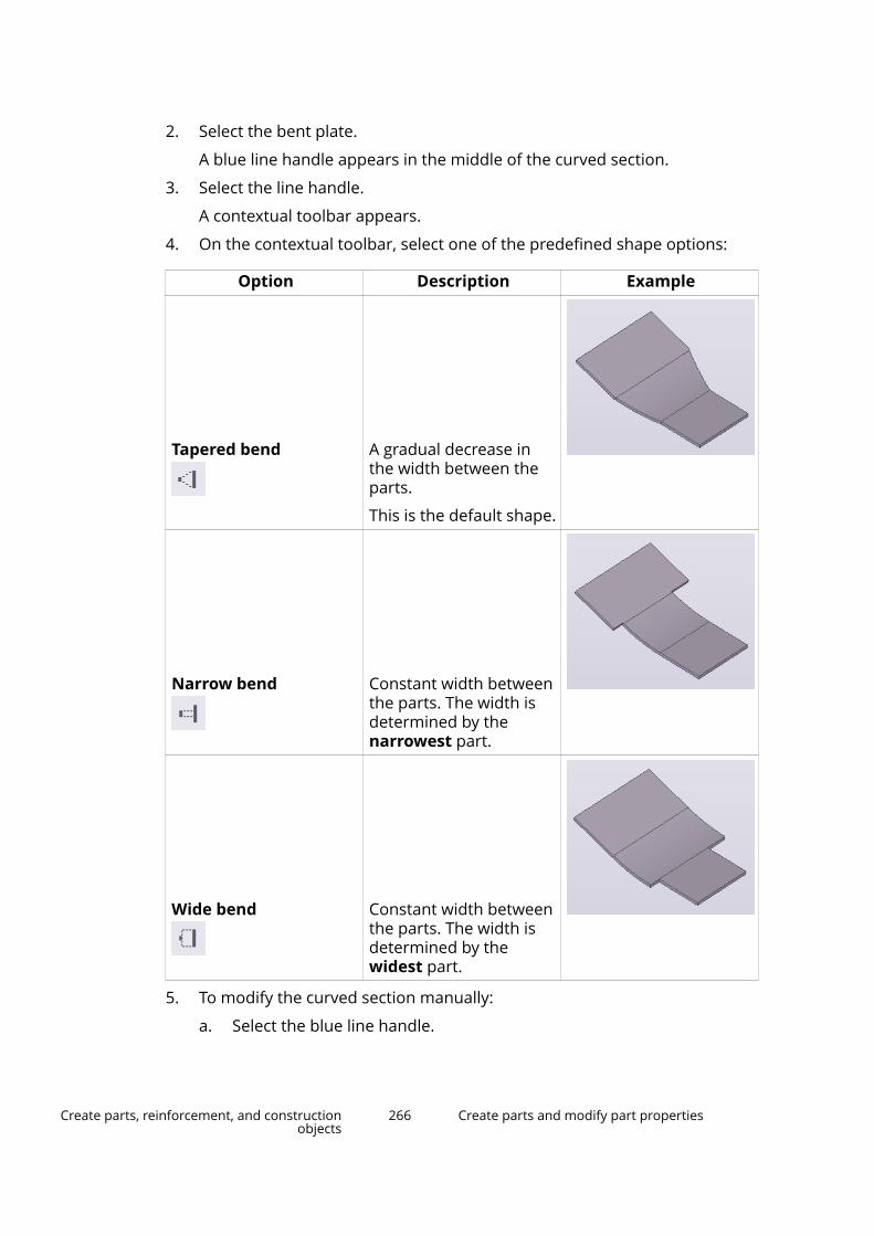
2. Select the bent plate.
A blue line handle appears in the middle of the curved section.
3. Select the line handle.
A contextual toolbar appears.
4. On the contextual toolbar, select one of the predefined shape options:
Option Description Example
Tapered bend A gradual decrease inthe width between theparts.
This is the default shape.
Narrow bend Constant width betweenthe parts. The width isdetermined by thenarrowest part.
Wide bend Constant width betweenthe parts. The width isdetermined by thewidest part.
5. To modify the curved section manually:
a. Select the blue line handle.
Create parts, reinforcement, and constructionobjects
266 Create parts and modify part properties

You can modify the side boundaries or the lateral boundaries of thebends both in the cylindrical and in the conical bent plate. TeklaStructures displays the boundary handles in blue:
b. Drag the handles to change the shape of the curved section.
For example:
6. To modify the flat sections:
Create parts, reinforcement, and constructionobjects
267 Create parts and modify part properties

a. Select the bent plate.
Tekla Structures displays a green selection handle in the middle ofeach flat section:
b. Click the selection handle of the section you want to modify.
The direct modification handles of the selected section becomevisible:
c. Use the direct modification handles to change the shape of the flatsection.
7. To modify the angle of the bent plate:
a. Click the green selection handle in the middle of the flat sectionwhose angle you want to modify.
b. Select the line handle.
A contextual toolbar appears.
c. On the contextual toolbar, click Enable angle manipulator.
Create parts, reinforcement, and constructionobjects
268 Create parts and modify part properties

The angle manipulator wheel appears in the model.
d. Modify the angle using the wheel.
If you want to modify the angle of another flat section, click the othergreen selection handle.
8. To change the main section of the bent plate:
a. Click the green selection handle of the section that you want to set asthe main section.
A contextual toolbar appears.
b. On the contextual toolbar, click Set main section.
The direct modification handles become active in the new mainsection. The main section and the coordinate system of the bent platechange accordingly, changing the bent plate orientation in anunfolded drawing.
Remove curved sectionsYou can return bent plates into individual objects, and then edit and use themas any other model object. If the bent plate consists of several curved sectionsthat are all joined to the same part, you can either remove each curved sectionseparately or explode the entire bent plate all at once.
To Do thisTo remove individual curved sections 1.
Ensure that Directmodification is switched on.
2. Select the curved section youwant to remove.
A blue line handle appears.
3. Select the line handle.
A contextual toolbar appears.
4. On the contextual toolbar, click
Remove bend.
Create parts, reinforcement, and constructionobjects
269 Create parts and modify part properties
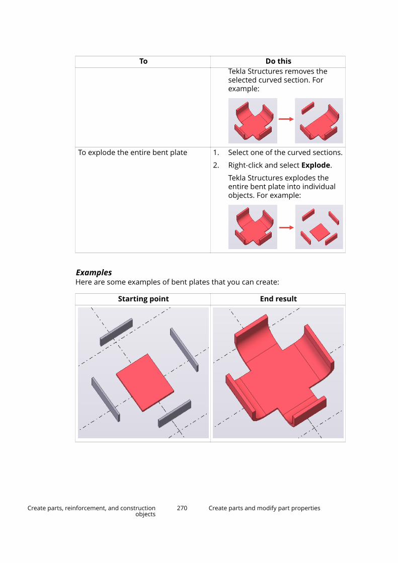
To Do thisTekla Structures removes theselected curved section. Forexample:
To explode the entire bent plate 1. Select one of the curved sections.
2. Right-click and select Explode.
Tekla Structures explodes theentire bent plate into individualobjects. For example:
ExamplesHere are some examples of bent plates that you can create:
Starting point End result
Create parts, reinforcement, and constructionobjects
270 Create parts and modify part properties

Starting point End result
Create a stand-alone bent plateYou can create stand-alone bent plates which do not require any input parts tobe selected. Use stand-alone bent plates to model cylindrical and conical parts,such as hoods, hoppers, cones, and so on.
Limitations
• Tekla Structures does not support full 360 degree stand-alone bent plates.However, you can create 359 degree plates instead.
• Use the local coordinate system in drawing creation.
• Unfolded drawings of less than 180 degree conical bent plates workcorrectly. However, with more than 180 degree conical bent plates theremight be some unexpected results in the drawing creation.
In addition to the stand-alone bent plates, you can also create cylindrical andconical bent plates (page 256) either by selecting two parts or two part faces.The parts that you use for creating a bent plate must be contour plates, orbeams whose profile is a plate.
1. Ensure that Direct modification is switched on.
2. On the Steel tab, click Plate --> Create stand-alone bent plate .
3. Define the first radius of the bend:
a. Pick the center point.
b. Pick the start point for the arc.
c. Pick the end point for the arc.
The picking order defines the up direction. For example, if you create anarc on the xy plane in the counterclockwise direction, the up directionpoints to the positive z axis, according to the right-hand rule (page 50).
Create parts, reinforcement, and constructionobjects
271 Create parts and modify part properties
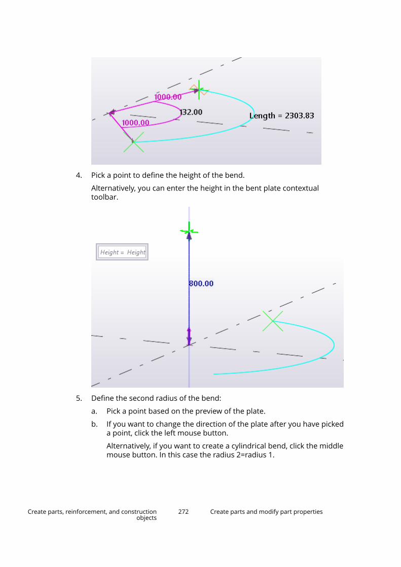
4. Pick a point to define the height of the bend.
Alternatively, you can enter the height in the bent plate contextualtoolbar.
5. Define the second radius of the bend:
a. Pick a point based on the preview of the plate.
b. If you want to change the direction of the plate after you have pickeda point, click the left mouse button.
Alternatively, if you want to create a cylindrical bend, click the middlemouse button. In this case the radius 2=radius 1.
Create parts, reinforcement, and constructionobjects
272 Create parts and modify part properties
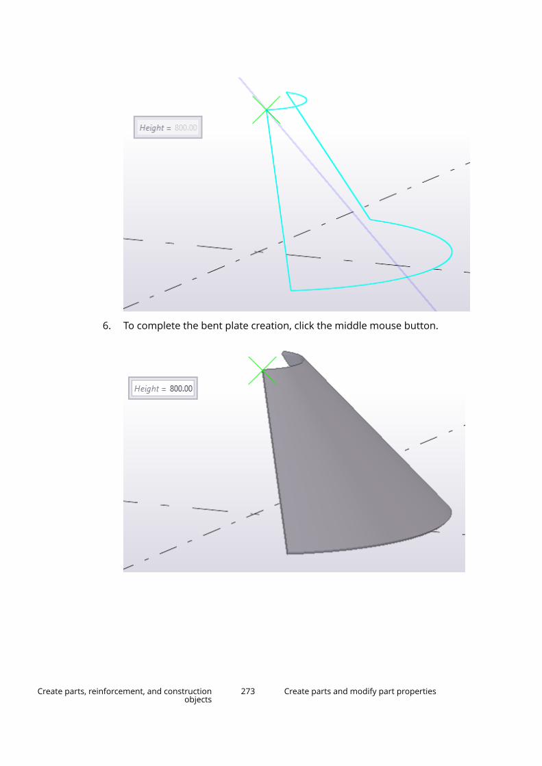
6. To complete the bent plate creation, click the middle mouse button.
Create parts, reinforcement, and constructionobjects
273 Create parts and modify part properties

Modify the shape of a stand-alone bent plateUse direct modification dimension values and handles to modify the bentplate shape.
• You can change the angle, radiuses and height of the bend by entering newdimension values.
Create parts, reinforcement, and constructionobjects
274 Create parts and modify part properties
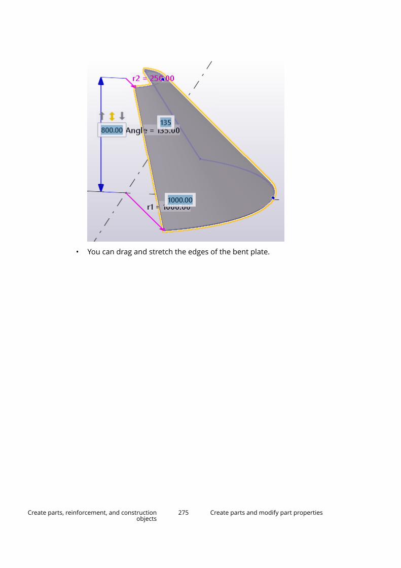
• You can drag and stretch the edges of the bent plate.
Create parts, reinforcement, and constructionobjects
275 Create parts and modify part properties
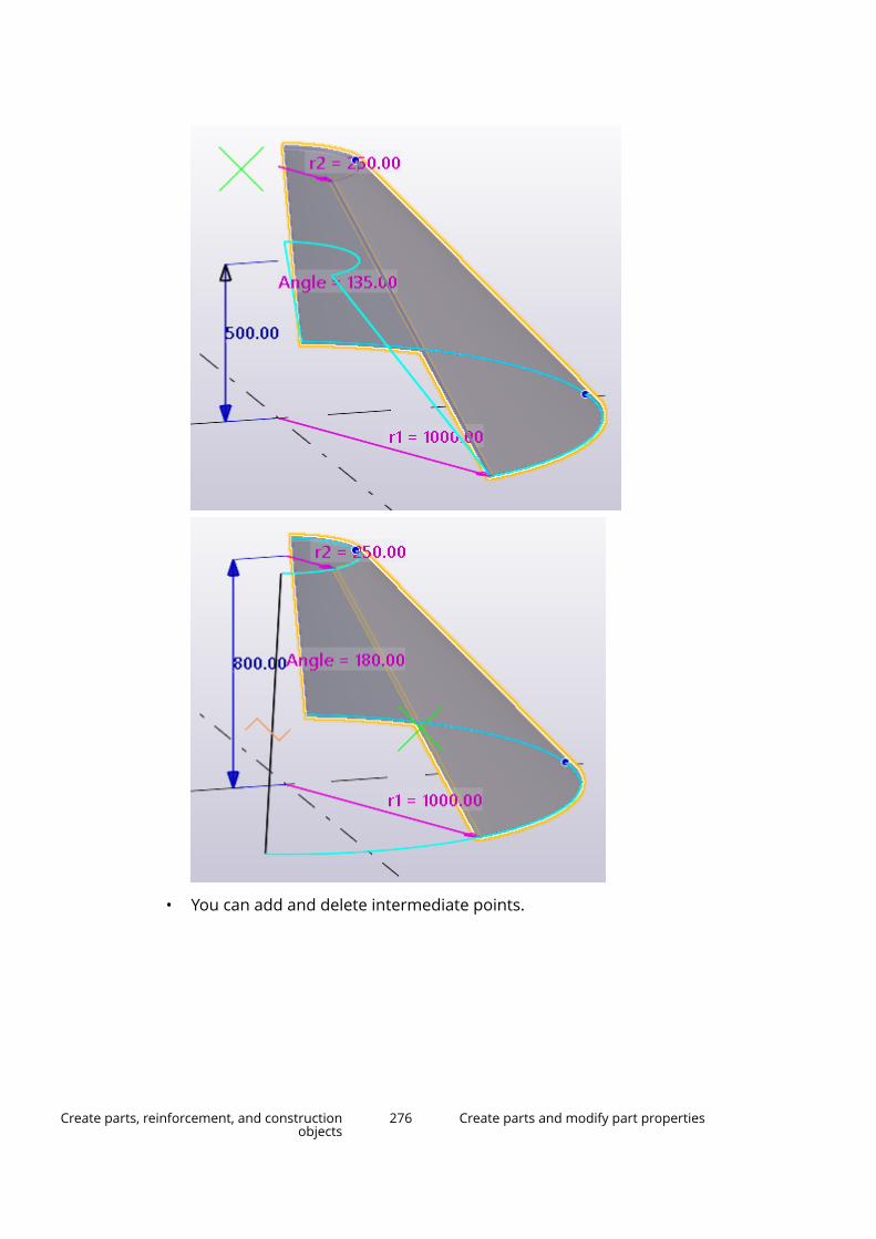
• You can add and delete intermediate points.
Create parts, reinforcement, and constructionobjects
276 Create parts and modify part properties
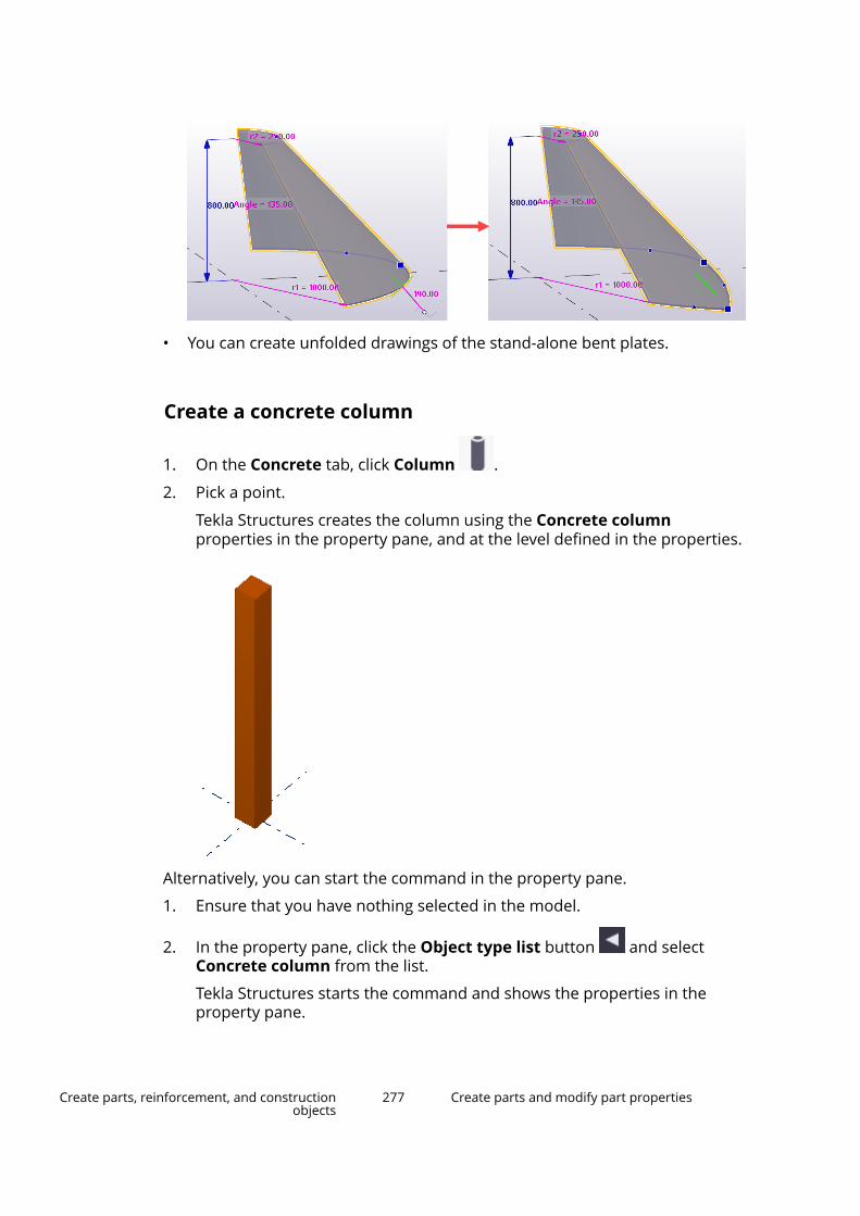
• You can create unfolded drawings of the stand-alone bent plates.
Create a concrete column
1. On the Concrete tab, click Column .
2. Pick a point.
Tekla Structures creates the column using the Concrete columnproperties in the property pane, and at the level defined in the properties.
Alternatively, you can start the command in the property pane.
1. Ensure that you have nothing selected in the model.
2. In the property pane, click the Object type list button and selectConcrete column from the list.
Tekla Structures starts the command and shows the properties in theproperty pane.
Create parts, reinforcement, and constructionobjects
277 Create parts and modify part properties
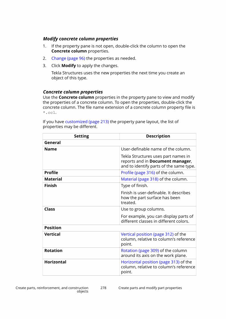
Modify concrete column properties1. If the property pane is not open, double-click the column to open the
Concrete column properties.
2. Change (page 96) the properties as needed.
3. Click Modify to apply the changes.
Tekla Structures uses the new properties the next time you create anobject of this type.
Concrete column propertiesUse the Concrete column properties in the property pane to view and modifythe properties of a concrete column. To open the properties, double-click theconcrete column. The file name extension of a concrete column property file is*.ccl.
If you have customized (page 213) the property pane layout, the list ofproperties may be different.
Setting DescriptionGeneralName User-definable name of the column.
Tekla Structures uses part names inreports and in Document manager,and to identify parts of the same type.
Profile Profile (page 316) of the column.Material Material (page 318) of the column.Finish Type of finish.
Finish is user-definable. It describeshow the part surface has beentreated.
Class Use to group columns.
For example, you can display parts ofdifferent classes in different colors.
PositionVertical Vertical position (page 312) of the
column, relative to column's referencepoint.
Rotation Rotation (page 309) of the columnaround its axis on the work plane.
Horizontal Horizontal position (page 313) of thecolumn, relative to column's referencepoint.
Create parts, reinforcement, and constructionobjects
278 Create parts and modify part properties

Setting DescriptionTop Position of the second end of the
column in the global z direction.Bottom Position of the first end of the column
in the global z direction.Cast unitCast unit numbering Part prefix and start number for the
part position number (page 628).Cast unit Indicate whether the column is
precast or cast-in-place.Pour phase Pour phase (page 407) of the cast-in-
place parts. Use to separate pourobjects from one another.
DeformingWarping Use to warp columns using
deformation angles.Cambering Use to pre-camber (page 331) the
column.Shortening Use to shorten the column in the
model. The true length of the columnis decreased in the drawing.
Custom propertiesMore Click the More button to open the
user-defined attributes (page 319)(UDAs) of the part. UDAs provideadditional information about the part.
Create a concrete beam
1. On the Concrete tab, click .
Create parts, reinforcement, and constructionobjects
279 Create parts and modify part properties
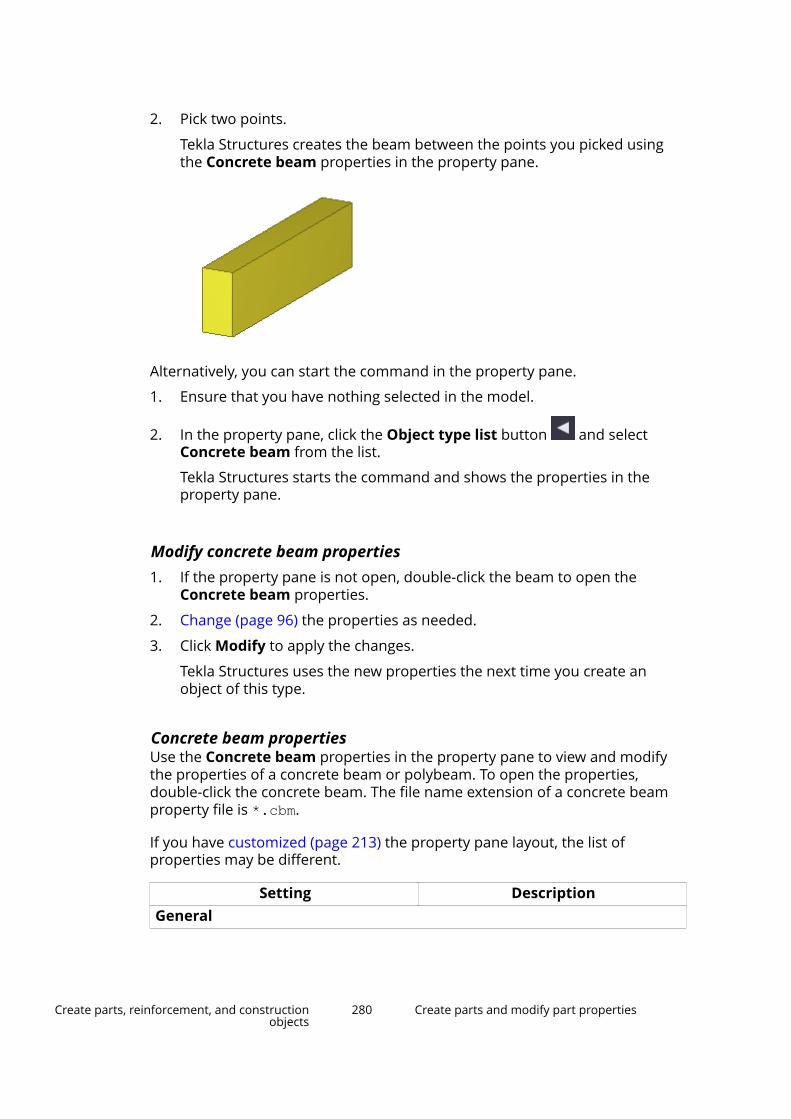
2. Pick two points.
Tekla Structures creates the beam between the points you picked usingthe Concrete beam properties in the property pane.
Alternatively, you can start the command in the property pane.
1. Ensure that you have nothing selected in the model.
2. In the property pane, click the Object type list button and selectConcrete beam from the list.
Tekla Structures starts the command and shows the properties in theproperty pane.
Modify concrete beam properties1. If the property pane is not open, double-click the beam to open the
Concrete beam properties.
2. Change (page 96) the properties as needed.
3. Click Modify to apply the changes.
Tekla Structures uses the new properties the next time you create anobject of this type.
Concrete beam propertiesUse the Concrete beam properties in the property pane to view and modifythe properties of a concrete beam or polybeam. To open the properties,double-click the concrete beam. The file name extension of a concrete beamproperty file is *.cbm.
If you have customized (page 213) the property pane layout, the list ofproperties may be different.
Setting DescriptionGeneral
Create parts, reinforcement, and constructionobjects
280 Create parts and modify part properties

Setting DescriptionName User-definable name of a beam.
Tekla Structures uses part names inreports and in Document manager,and to identify parts of the same type.
Profile Profile (page 316) of the beam.Material Material (page 318) of the beam.Finish Type of finish.
Finish is user-definable. It describeshow the part surface has beentreated.
Class Use to group beams.
For example, you can display parts ofdifferent classes in different colors.
PositionOn plane Beam's position on the work plane
(page 308), relative to the beam'sreference line.
Rotation Rotation (page 309) of the beamaround its axis on the work plane.
At depth Position depth (page 310) of thebeam. The position is alwaysperpendicular to the work plane.
End offsetDx Change the length of the beam
(page 315) by moving the beam endpoint along the beam's reference line.
Dy Move the beam end (page 315)perpendicular to the beam'sreference line.
Dz Move the beam end (page 315) in thez direction of the work plane.
Curved beamPlane Plane of curvature.Radius Radius of the curved beam.Number of segments Number of segments Tekla Structures
uses when drawing the curved beam.Cast unitCast unit numbering Part prefix and start number for the
part position number (page 628).
Create parts, reinforcement, and constructionobjects
281 Create parts and modify part properties
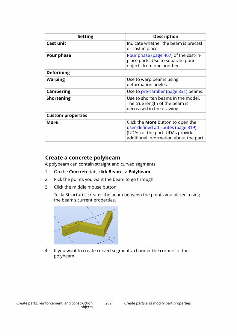
Setting DescriptionCast unit Indicate whether the beam is precast
or cast in place.Pour phase Pour phase (page 407) of the cast-in-
place parts. Use to separate pourobjects from one another.
DeformingWarping Use to warp beams using
deformation angles.Cambering Use to pre-camber (page 331) beams.Shortening Use to shorten beams in the model.
The true length of the beam isdecreased in the drawing.
Custom propertiesMore Click the More button to open the
user-defined attributes (page 319)(UDAs) of the part. UDAs provideadditional information about the part.
Create a concrete polybeamA polybeam can contain straight and curved segments.
1. On the Concrete tab, click Beam --> Polybeam.
2. Pick the points you want the beam to go through.
3. Click the middle mouse button.
Tekla Structures creates the beam between the points you picked, usingthe beam's current properties.
4. If you want to create curved segments, chamfer the corners of thepolybeam.
Create parts, reinforcement, and constructionobjects
282 Create parts and modify part properties

For example:
Modify concrete polybeam properties1. If the property pane is not open, double-click the polybeam to open the
Concrete beam properties.
2. Change (page 96) the properties as needed.
3. Click Modify to apply the changes.
Tekla Structures uses the new properties the next time you create anobject of this type.
Concrete beam propertiesUse the Concrete beam properties in the property pane to view and modifythe properties of a concrete beam or polybeam. To open the properties,double-click the polybeam. The file name extension of a concrete beamproperty file is *.cbm.
If you have customized (page 213) the property pane layout, the list ofproperties may be different.
Setting DescriptionGeneralName User-definable name of a beam.
Tekla Structures uses part names inreports and in Document manager,and to identify parts of the same type.
Profile Profile (page 316) of the beam.Material Material (page 318) of the beam.Finish Type of finish.
Finish is user-definable. It describeshow the part surface has beentreated.
Create parts, reinforcement, and constructionobjects
283 Create parts and modify part properties
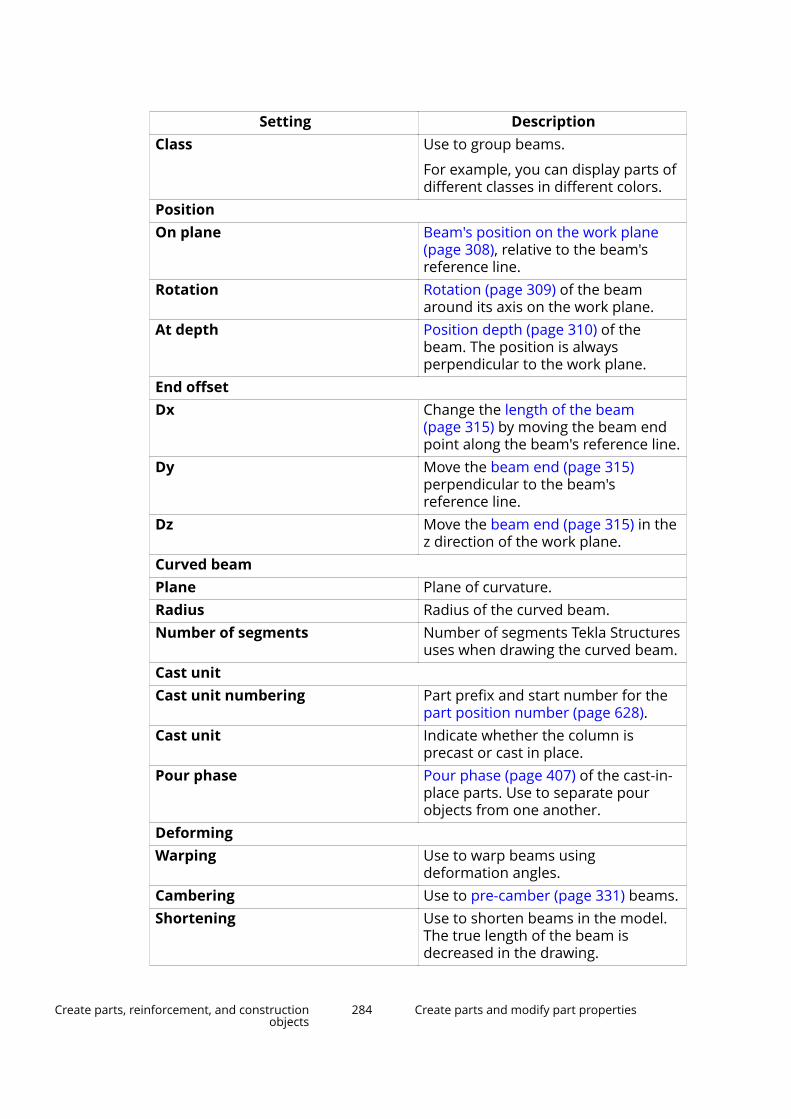
Setting DescriptionClass Use to group beams.
For example, you can display parts ofdifferent classes in different colors.
PositionOn plane Beam's position on the work plane
(page 308), relative to the beam'sreference line.
Rotation Rotation (page 309) of the beamaround its axis on the work plane.
At depth Position depth (page 310) of thebeam. The position is alwaysperpendicular to the work plane.
End offsetDx Change the length of the beam
(page 315) by moving the beam endpoint along the beam's reference line.
Dy Move the beam end (page 315)perpendicular to the beam'sreference line.
Dz Move the beam end (page 315) in thez direction of the work plane.
Curved beamPlane Plane of curvature.Radius Radius of the curved beam.Number of segments Number of segments Tekla Structures
uses when drawing the curved beam.Cast unitCast unit numbering Part prefix and start number for the
part position number (page 628).Cast unit Indicate whether the column is
precast or cast in place.Pour phase Pour phase (page 407) of the cast-in-
place parts. Use to separate pourobjects from one another.
DeformingWarping Use to warp beams using
deformation angles.Cambering Use to pre-camber (page 331) beams.Shortening Use to shorten beams in the model.
The true length of the beam isdecreased in the drawing.
Create parts, reinforcement, and constructionobjects
284 Create parts and modify part properties
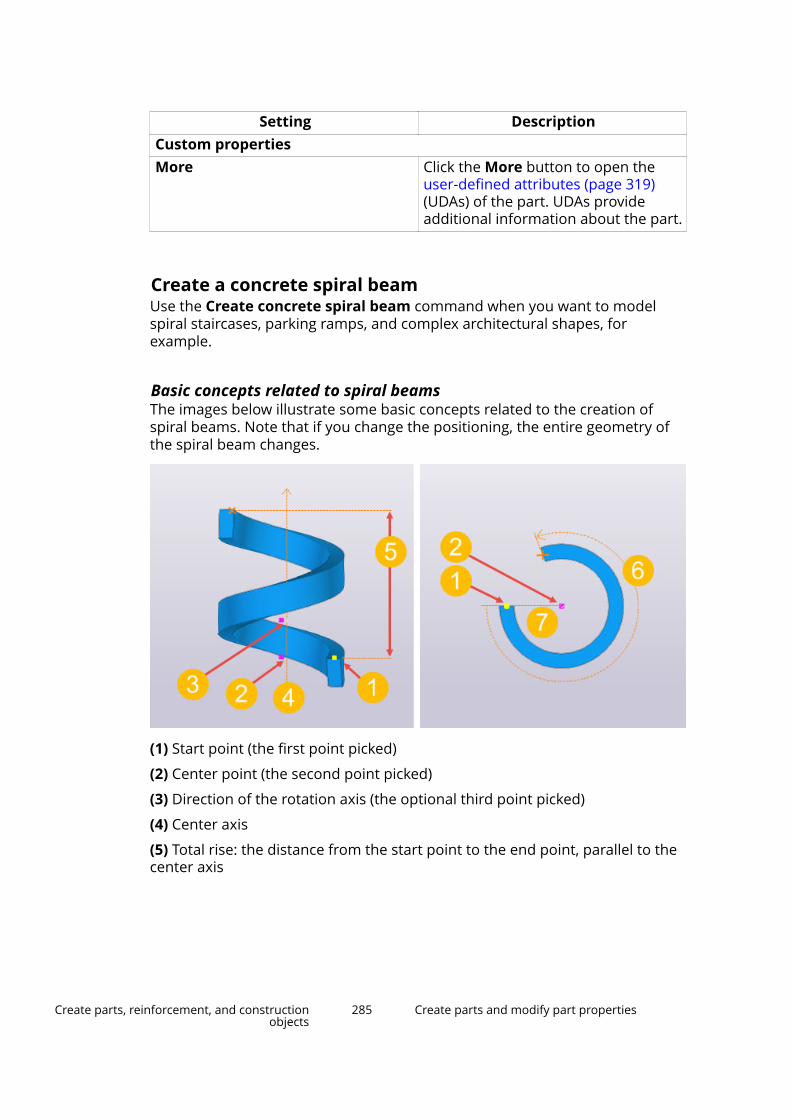
Setting DescriptionCustom propertiesMore Click the More button to open the
user-defined attributes (page 319)(UDAs) of the part. UDAs provideadditional information about the part.
Create a concrete spiral beamUse the Create concrete spiral beam command when you want to modelspiral staircases, parking ramps, and complex architectural shapes, forexample.
Basic concepts related to spiral beamsThe images below illustrate some basic concepts related to the creation ofspiral beams. Note that if you change the positioning, the entire geometry ofthe spiral beam changes.
(1) Start point (the first point picked)
(2) Center point (the second point picked)
(3) Direction of the rotation axis (the optional third point picked)
(4) Center axis
(5) Total rise: the distance from the start point to the end point, parallel to thecenter axis
Create parts, reinforcement, and constructionobjects
285 Create parts and modify part properties

(6) Rotation angle: the rotation angle of the spiral beam, given in degrees.Note: positive value = counter-clockwise rotation, negative value = clockwiserotation.
(7) Radius: the distance from the start point to the center point, perpendicularto the center axis
Create a spiral beam1. On the Concrete tab, click Beam --> Spiral beam.
2. Pick the start point.
3. Pick the center point.
4. To set the rotation axis in the work plane +Z direction, click the middlemouse button to finish.
NOTE Alternatively, instead of clicking the middle mouse button, youcan pick a second center axis point to define the direction of therotation axis.
Tekla Structures creates the spiral beam. For example:
Create parts, reinforcement, and constructionobjects
286 Create parts and modify part properties
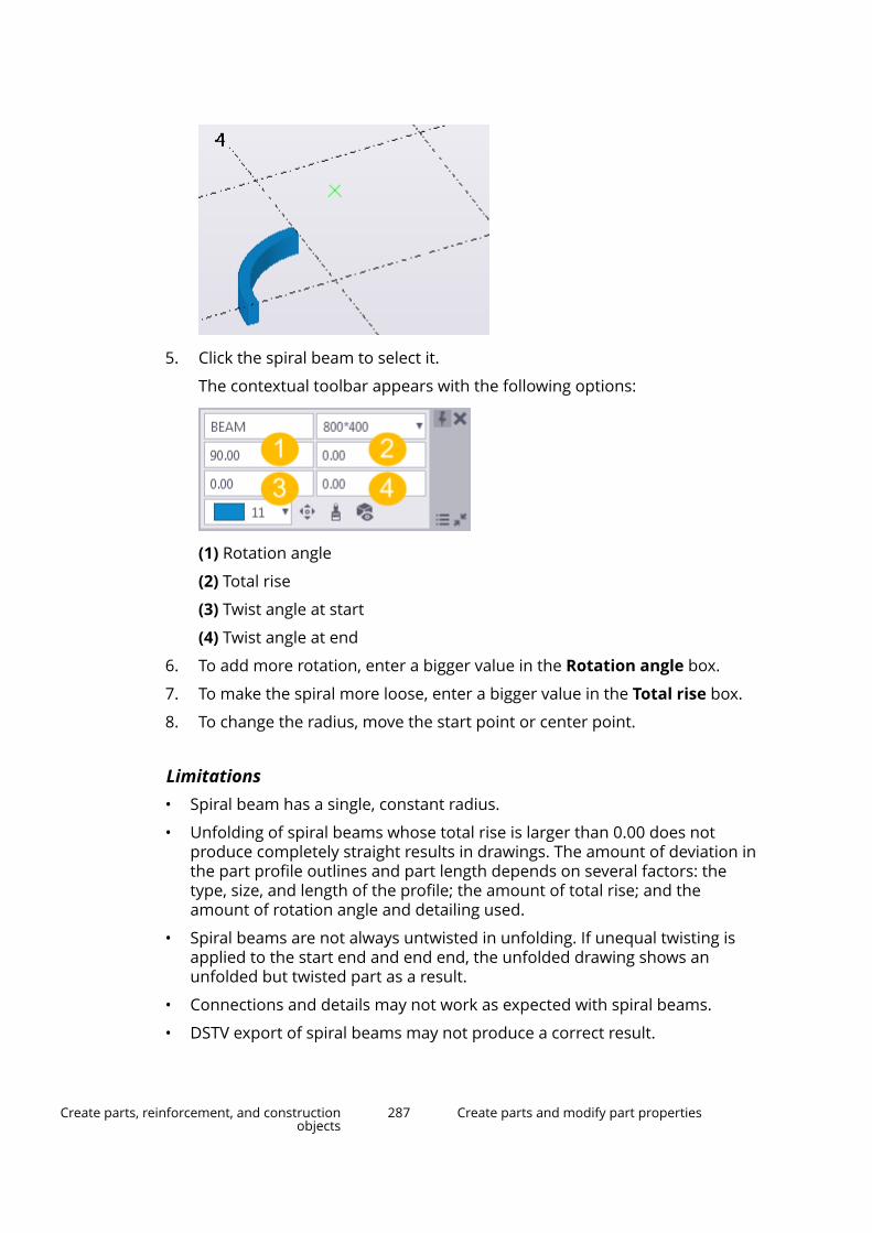
5. Click the spiral beam to select it.
The contextual toolbar appears with the following options:
(1) Rotation angle
(2) Total rise
(3) Twist angle at start
(4) Twist angle at end
6. To add more rotation, enter a bigger value in the Rotation angle box.
7. To make the spiral more loose, enter a bigger value in the Total rise box.
8. To change the radius, move the start point or center point.
Limitations• Spiral beam has a single, constant radius.
• Unfolding of spiral beams whose total rise is larger than 0.00 does notproduce completely straight results in drawings. The amount of deviation inthe part profile outlines and part length depends on several factors: thetype, size, and length of the profile; the amount of total rise; and theamount of rotation angle and detailing used.
• Spiral beams are not always untwisted in unfolding. If unequal twisting isapplied to the start end and end end, the unfolded drawing shows anunfolded but twisted part as a result.
• Connections and details may not work as expected with spiral beams.
• DSTV export of spiral beams may not produce a correct result.
Create parts, reinforcement, and constructionobjects
287 Create parts and modify part properties

• You cannot export spiral beams as parts in IFC export. If you are modelingcast-in-place structures with spiral beam, you can export the geometry toIFC as pour objects.
Create a concrete panel or wallYou can create a concrete panel or wall that passes through the points youpick.
1. On the Concrete tab, click Panel .
2. Pick the points you want the panel or wall to go through.
3. Click the middle mouse button.
Tekla Structures creates the panel or wall using the Concrete panelproperties in the property pane
4. If you want to create curved segments, chamfer the corners of the panelor wall.
For example:
Alternatively, you can start the command in the property pane.
1. Ensure that you have nothing selected in the model.
2. In the property pane, click the Object type list button and selectConcrete panel from the list.
Tekla Structures starts the command and shows the properties in theproperty pane.
Create parts, reinforcement, and constructionobjects
288 Create parts and modify part properties

Modify concrete panel or wall properties1. If the property pane is not open, double-click the panel or the wall to open
the Concrete panel properties.
2. Change (page 96) the properties as needed.
3. Click Modify to apply the changes.
Tekla Structures uses the new properties the next time you create anobject of this type.
Concrete panel or wall propertiesUse the Concrete panel properties in the property pane to view and modifythe properties of a concrete panel or a wall. To open the properties, double-click the panel or the wall. The file name extension of a concrete panelproperty file is *.cpn.
If you have customized (page 213) the property pane layout, the list ofproperties may be different.
Setting DescriptionGeneralName User-definable name of the panel.
Tekla Structures uses part names inreports and in Document manager,and to identify parts of the same type.
Profile Profile (page 316) of the panel(thickness × height of the wall).
Material Material (page 318) of the panel.Finish Type of finish.
Finish is user-definable. It describeshow the part surface has beentreated.
Class Use to group panels.
For example, you can display parts ofdifferent classes in different colors.
PositionOn plane Panel's position on the work plane
(page 308), relative to the panel'sreference line.
Rotation Rotation (page 309) of the panelaround its axis on the work plane.
At depth Position depth (page 310) of thepanel. The position is alwaysperpendicular to the work plane.
Create parts, reinforcement, and constructionobjects
289 Create parts and modify part properties
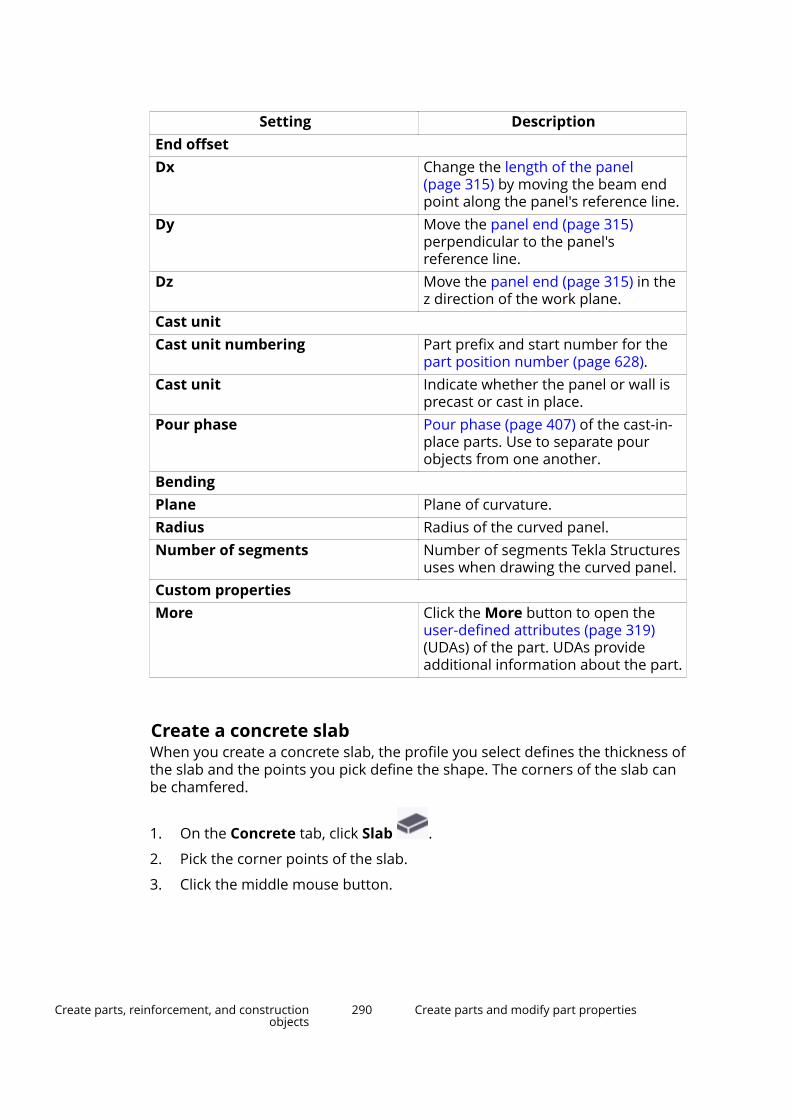
Setting DescriptionEnd offsetDx Change the length of the panel
(page 315) by moving the beam endpoint along the panel's reference line.
Dy Move the panel end (page 315)perpendicular to the panel'sreference line.
Dz Move the panel end (page 315) in thez direction of the work plane.
Cast unitCast unit numbering Part prefix and start number for the
part position number (page 628).Cast unit Indicate whether the panel or wall is
precast or cast in place.Pour phase Pour phase (page 407) of the cast-in-
place parts. Use to separate pourobjects from one another.
BendingPlane Plane of curvature.Radius Radius of the curved panel.Number of segments Number of segments Tekla Structures
uses when drawing the curved panel.Custom propertiesMore Click the More button to open the
user-defined attributes (page 319)(UDAs) of the part. UDAs provideadditional information about the part.
Create a concrete slabWhen you create a concrete slab, the profile you select defines the thickness ofthe slab and the points you pick define the shape. The corners of the slab canbe chamfered.
1. On the Concrete tab, click Slab .
2. Pick the corner points of the slab.
3. Click the middle mouse button.
Create parts, reinforcement, and constructionobjects
290 Create parts and modify part properties

Tekla Structures creates the slab, using the Concrete slab properties inthe property pane.
Alternatively, you can start the command in the property pane.
1. Ensure that you have nothing selected in the model.
2. In the property pane, click the Object type list button and selectConcrete slab from the list.
Tekla Structures starts the command and shows the properties in theproperty pane.
Create a round concrete slab1. Create a square slab with four equal sides.
2. Select the slab.
3. Select the handles of the slab.
TIP To select all the handles at once, hold down the Alt key and drag themouse from left to right, covering all the handles.
4. Press Alt + Enter to display the Chamfer Properties dialog box.
5. Select the round chamfer symbol from the list.
6. Enter the chamfer radius in the x box. The radius must be equal to half ofthe side of the square.
7. Click Modify.
Create parts, reinforcement, and constructionobjects
291 Create parts and modify part properties

Alternative way of creating a round slab
1. Create a diamond-shaped slab with four equal sides.
2. To round the corners, use the arc point chamfer type .
Modify concrete slab properties1. If the property pane is not open, double-click the slab to open the
Concrete slab properties.
2. Change (page 96) the properties as needed.
3. Click Modify to apply the changes.
Tekla Structures uses the new properties the next time you create anobject of this type.
Concrete slab propertiesUse the Concrete slab properties in the property pane to view and modify theproperties of a concrete slab. To open the properties, double-click the concreteslab. The file name extension of a concrete slab property file is *.csl.
If you have customized (page 213) the property pane layout, the list ofproperties may be different.
Setting DescriptionGeneralName User-definable name of the slab.
Tekla Structures uses part names inreports and in Document manager,and to identify parts of the same type.
Thickness Thickness of the slab.Material Material (page 318) of the slab.
Create parts, reinforcement, and constructionobjects
292 Create parts and modify part properties
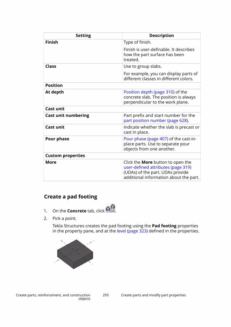
Setting DescriptionFinish Type of finish.
Finish is user-definable. It describeshow the part surface has beentreated.
Class Use to group slabs.
For example, you can display parts ofdifferent classes in different colors.
PositionAt depth Position depth (page 310) of the
concrete slab. The position is alwaysperpendicular to the work plane.
Cast unitCast unit numbering Part prefix and start number for the
part position number (page 628).Cast unit Indicate whether the slab is precast or
cast in place.Pour phase Pour phase (page 407) of the cast-in-
place parts. Use to separate pourobjects from one another.
Custom propertiesMore Click the More button to open the
user-defined attributes (page 319)(UDAs) of the part. UDAs provideadditional information about the part.
Create a pad footing
1. On the Concrete tab, click .
2. Pick a point.
Tekla Structures creates the pad footing using the Pad footing propertiesin the property pane, and at the level (page 323) defined in the properties.
Create parts, reinforcement, and constructionobjects
293 Create parts and modify part properties

Alternatively, you can start the command in the property pane.
1. Ensure that you have nothing selected in the model.
2. In the property pane, click the Object type list button and select Padfooting from the list.
Tekla Structures starts the command and shows the properties in theproperty pane.
Modify pad footing properties1. If the property pane is not open, double-click the pad footing to open the
Pad footing properties.
2. Change (page 96) the properties as needed.
For example, to create a circular pad footing, select a circular section forProfile.
3. Click Modify to apply the changes.
Tekla Structures uses the new properties the next time you create anobject of this type.
Pad footing propertiesUse the Pad footing properties in the property pane to view and modify theproperties of a pad footing. To open the properties, double-click the padfooting. The file name extension of a pad footing property file is *.cpf.
If you have customized (page 213) the property pane layout, the list ofproperties may be different.
Setting DescriptionGeneralName User-definable name of the pad
footing.
Tekla Structures uses part names inreports and in Document manager,and to identify parts of the same type.
Profile Profile (page 316) of the pad footing.Material Material (page 318) of the pad
footing.Finish Type of finish.
Finish is user-definable. It describeshow the part surface has beentreated.
Create parts, reinforcement, and constructionobjects
294 Create parts and modify part properties
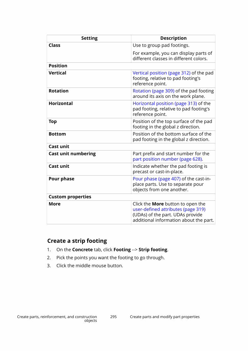
Setting DescriptionClass Use to group pad footings.
For example, you can display parts ofdifferent classes in different colors.
PositionVertical Vertical position (page 312) of the pad
footing, relative to pad footing'sreference point.
Rotation Rotation (page 309) of the pad footingaround its axis on the work plane.
Horizontal Horizontal position (page 313) of thepad footing, relative to pad footing'sreference point.
Top Position of the top surface of the padfooting in the global z direction.
Bottom Position of the bottom surface of thepad footing in the global z direction.
Cast unitCast unit numbering Part prefix and start number for the
part position number (page 628).Cast unit Indicate whether the pad footing is
precast or cast-in-place.Pour phase Pour phase (page 407) of the cast-in-
place parts. Use to separate pourobjects from one another.
Custom propertiesMore Click the More button to open the
user-defined attributes (page 319)(UDAs) of the part. UDAs provideadditional information about the part.
Create a strip footing1. On the Concrete tab, click Footing --> Strip footing.
2. Pick the points you want the footing to go through.
3. Click the middle mouse button.
Create parts, reinforcement, and constructionobjects
295 Create parts and modify part properties

Tekla Structures creates the strip footing between the points you pickedusing the Strip footing properties in the property pane.
4. If you want to create curved segments, chamfer the corners of the footing.
For example:
Alternatively, you can start the command in the property pane.
1. Ensure that you have nothing selected in the model.
2. In the property pane, click the Object type list button and selectStrip footing from the list.
Tekla Structures starts the command and shows the properties in theproperty pane.
Modify strip footing properties1. If the property pane is not open, double-click the strip footing to open the
Strip footing properties.
2. Change (page 96) the properties as needed.
3. Click Modify to apply the changes.
Tekla Structures uses the new properties the next time you create anobject of this type.
Strip footing propertiesUse the Strip footing properties in the property pane to view and modify theproperties of a strip footing. To open the properties, double-click the stripfooting. The file name extension of a strip footing property file is *.csf.
Create parts, reinforcement, and constructionobjects
296 Create parts and modify part properties
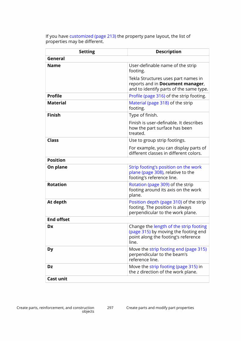
If you have customized (page 213) the property pane layout, the list ofproperties may be different.
Setting DescriptionGeneralName User-definable name of the strip
footing.
Tekla Structures uses part names inreports and in Document manager,and to identify parts of the same type.
Profile Profile (page 316) of the strip footing.Material Material (page 318) of the strip
footing.Finish Type of finish.
Finish is user-definable. It describeshow the part surface has beentreated.
Class Use to group strip footings.
For example, you can display parts ofdifferent classes in different colors.
PositionOn plane Strip footing's position on the work
plane (page 308), relative to thefooting's reference line.
Rotation Rotation (page 309) of the stripfooting around its axis on the workplane.
At depth Position depth (page 310) of the stripfooting. The position is alwaysperpendicular to the work plane.
End offsetDx Change the length of the strip footing
(page 315) by moving the footing endpoint along the footing's referenceline.
Dy Move the strip footing end (page 315)perpendicular to the beam'sreference line.
Dz Move the strip footing (page 315) inthe z direction of the work plane.
Cast unit
Create parts, reinforcement, and constructionobjects
297 Create parts and modify part properties

Setting DescriptionCast unit numbering Part prefix and start number for the
part position number (page 628).Cast unit Indicate whether the strip footing is
precast or cast-in-place.Pour phase Pour phase (page 407) of the cast-in-
place parts. Use to separate pourobjects from one another.
BendingPlane Plane of curvature.Radius Radius of the curved strip footing.Number of segments Number of segments Tekla Structures
uses when drawing the curved stripfooting.
Custom propertiesMore Click the More button to open the
user-defined attributes (page 319)(UDAs) of the part. UDAs provideadditional information about the part.
Create itemsIn Tekla Structures, the term item refers to the parts that have a 3D shape.Shapes are created in an external modeling software, or in Tekla Structures,and they are available in the Tekla Structures shape catalog.
Items are similar to other parts (page 235), such as beams and columns. Themain difference between items and other types of parts is that a 3D shapedefines the geometry of an item, whereas a part has a 2D profile that isextruded to create the length of the part.
You can use items to model objects that would be difficult to model usingbasic Tekla Structures parts and commands, such as cutting. You can also useitems to model objects that use shapes modeled in an external software or bya manufacturer.
Every item has properties that define it, such as shape, material, and location.If you want to use item properties in view and selection filters or in drawingand report templates, you need to use the template attributes of parts andprofiles. If you want to separate items from parts, use the IS_ITEM templateattribute.
Limitations to items
• Items have a fixed geometry according to their shape, so items cannot bescaled, stretched, or fitted.
• Items cannot be mirrored.
Create parts, reinforcement, and constructionobjects
298 Create parts and modify part properties
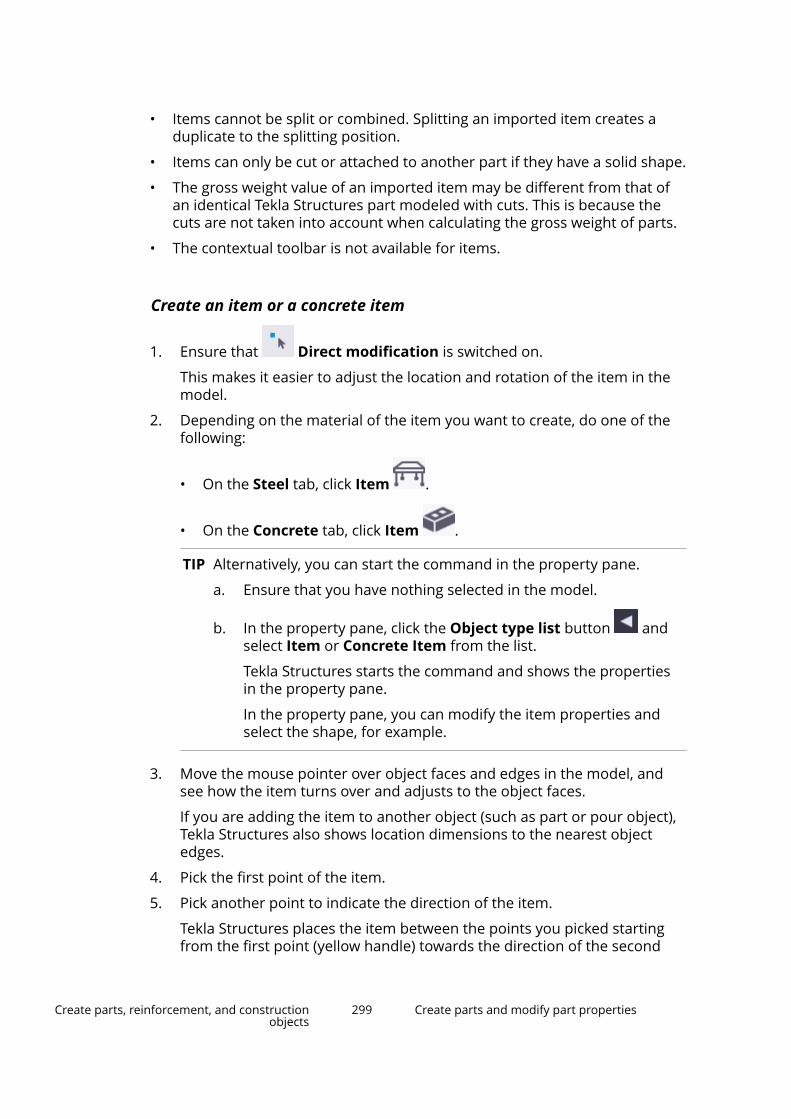
• Items cannot be split or combined. Splitting an imported item creates aduplicate to the splitting position.
• Items can only be cut or attached to another part if they have a solid shape.
• The gross weight value of an imported item may be different from that ofan identical Tekla Structures part modeled with cuts. This is because thecuts are not taken into account when calculating the gross weight of parts.
• The contextual toolbar is not available for items.
Create an item or a concrete item
1. Ensure that Direct modification is switched on.
This makes it easier to adjust the location and rotation of the item in themodel.
2. Depending on the material of the item you want to create, do one of thefollowing:
• On the Steel tab, click Item .
• On the Concrete tab, click Item .
TIP Alternatively, you can start the command in the property pane.
a. Ensure that you have nothing selected in the model.
b. In the property pane, click the Object type list button andselect Item or Concrete Item from the list.
Tekla Structures starts the command and shows the propertiesin the property pane.
In the property pane, you can modify the item properties andselect the shape, for example.
3. Move the mouse pointer over object faces and edges in the model, andsee how the item turns over and adjusts to the object faces.
If you are adding the item to another object (such as part or pour object),Tekla Structures also shows location dimensions to the nearest objectedges.
4. Pick the first point of the item.
5. Pick another point to indicate the direction of the item.
Tekla Structures places the item between the points you picked startingfrom the first point (yellow handle) towards the direction of the second
Create parts, reinforcement, and constructionobjects
299 Create parts and modify part properties

point (magenta handle), using the Item or Concrete Item properties inthe property pane.
Tekla Structures shows the coordinate axes, rotation handles, and locationdimensions that you can use to fine-tune the location and rotation of theitem. The handles are red, green, and blue, according to the localcoordinate system of the item.
6. To move the item along any of its coordinate axes, drag the relevant axishandle to a new location.
7. To rotate the item around any of its coordinate axes, drag the relevantrotation handle to a new location.
Press Tab to rotate the item in 90-degree steps in the direction of theselected rotation handle.
8. To move or rotate the item by specifying a distance or angle:
a. Select an axis handle, a rotation handle, or a dimension arrowhead.
b. Type the value by which you want the dimension to change.
When you start typing, Tekla Structures displays the Enter a NumericLocation dialog box.
c. Click OK to confirm the new dimension.
9. If you want to add more items to the model, click the middle mousebutton and repeat steps 3–8.
10. To stop adding and modifying items, press Esc.
Modify item or concrete item properties1. If the property pane is not open, double-click the item or the concrete
item to open the Item or the Concrete Item properties.
2. Change (page 96) the properties as needed.
Create parts, reinforcement, and constructionobjects
300 Create parts and modify part properties

3. Click Modify to apply the changes.
Tekla Structures uses the new properties the next time you create anobject of this type.
Change the shape of an itemWhen you create or modify an item, you can select the shape from the list thatcontains all the shapes available in the shape catalog.
Before you start, ensure that you have the required shape imported to theshape catalog.
1. Double-click an item to open the item properties in the property pane.
2. Click the ... button next to the Shape box to open the Shape Catalogdialog box.
3. If needed, use the Filter box to search for a shape.
4. Select a shape from the list.
5. Click OK to close the Shape Catalog dialog box.
6. Click Modify to apply the changes.
Item and concrete item propertiesUse the Item and the Concrete Item properties in the property pane todefine, view, and modify the properties of an item. To open the properties,double-click the item or the concrete item.
The file name extension of an item property file is *.ips.
The file name extension of a concrete item property file is *.ipc.
If you have customized (page 213) the property pane layout, the list ofproperties may be different.
Setting DescriptionGeneralName User-definable name of an item.
Tekla Structures uses part names inreports and in Document manager,and to identify parts of the same type.
Shape Shape of an item.
To select a shape from the shapecatalog, click the ... button next to theShape box.
To show the item shape in reportsand drawing tables, use the PROFILEtemplate attribute.
Create parts, reinforcement, and constructionobjects
301 Create parts and modify part properties
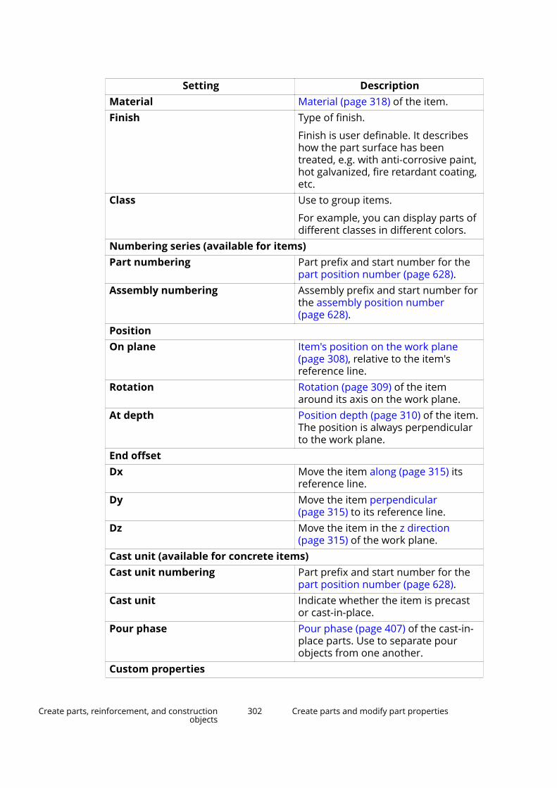
Setting DescriptionMaterial Material (page 318) of the item.Finish Type of finish.
Finish is user definable. It describeshow the part surface has beentreated, e.g. with anti-corrosive paint,hot galvanized, fire retardant coating,etc.
Class Use to group items.
For example, you can display parts ofdifferent classes in different colors.
Numbering series (available for items)Part numbering Part prefix and start number for the
part position number (page 628).Assembly numbering Assembly prefix and start number for
the assembly position number(page 628).
PositionOn plane Item's position on the work plane
(page 308), relative to the item'sreference line.
Rotation Rotation (page 309) of the itemaround its axis on the work plane.
At depth Position depth (page 310) of the item.The position is always perpendicularto the work plane.
End offsetDx Move the item along (page 315) its
reference line.Dy Move the item perpendicular
(page 315) to its reference line.Dz Move the item in the z direction
(page 315) of the work plane.Cast unit (available for concrete items)Cast unit numbering Part prefix and start number for the
part position number (page 628).Cast unit Indicate whether the item is precast
or cast-in-place.Pour phase Pour phase (page 407) of the cast-in-
place parts. Use to separate pourobjects from one another.
Custom properties
Create parts, reinforcement, and constructionobjects
302 Create parts and modify part properties
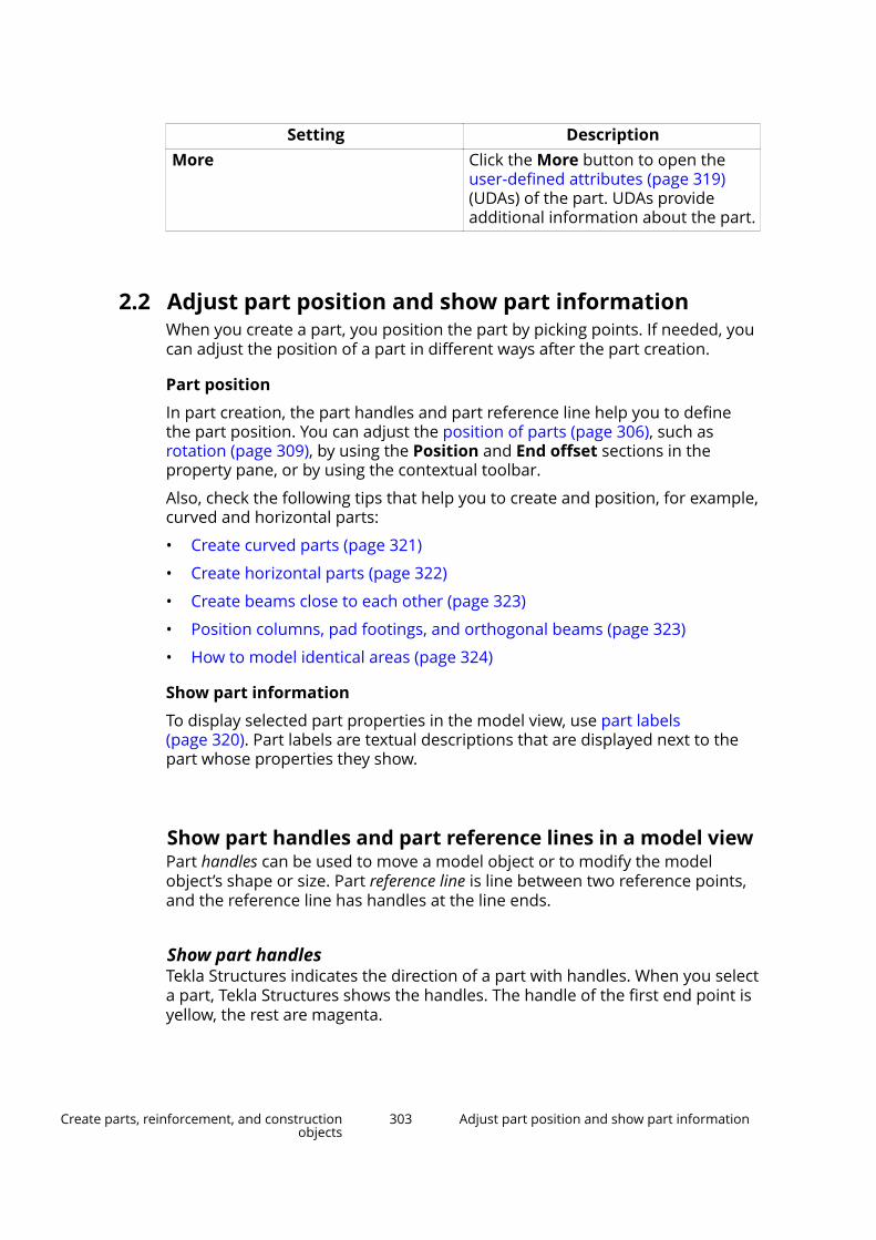
Setting DescriptionMore Click the More button to open the
user-defined attributes (page 319)(UDAs) of the part. UDAs provideadditional information about the part.
2.2 Adjust part position and show part informationWhen you create a part, you position the part by picking points. If needed, youcan adjust the position of a part in different ways after the part creation.
Part position
In part creation, the part handles and part reference line help you to definethe part position. You can adjust the position of parts (page 306), such asrotation (page 309), by using the Position and End offset sections in theproperty pane, or by using the contextual toolbar.
Also, check the following tips that help you to create and position, for example,curved and horizontal parts:
• Create curved parts (page 321)
• Create horizontal parts (page 322)
• Create beams close to each other (page 323)
• Position columns, pad footings, and orthogonal beams (page 323)
• How to model identical areas (page 324)
Show part information
To display selected part properties in the model view, use part labels(page 320). Part labels are textual descriptions that are displayed next to thepart whose properties they show.
Show part handles and part reference lines in a model viewPart handles can be used to move a model object or to modify the modelobject’s shape or size. Part reference line is line between two reference points,and the reference line has handles at the line ends.
Show part handlesTekla Structures indicates the direction of a part with handles. When you selecta part, Tekla Structures shows the handles. The handle of the first end point isyellow, the rest are magenta.
Create parts, reinforcement, and constructionobjects
303 Adjust part position and show part information
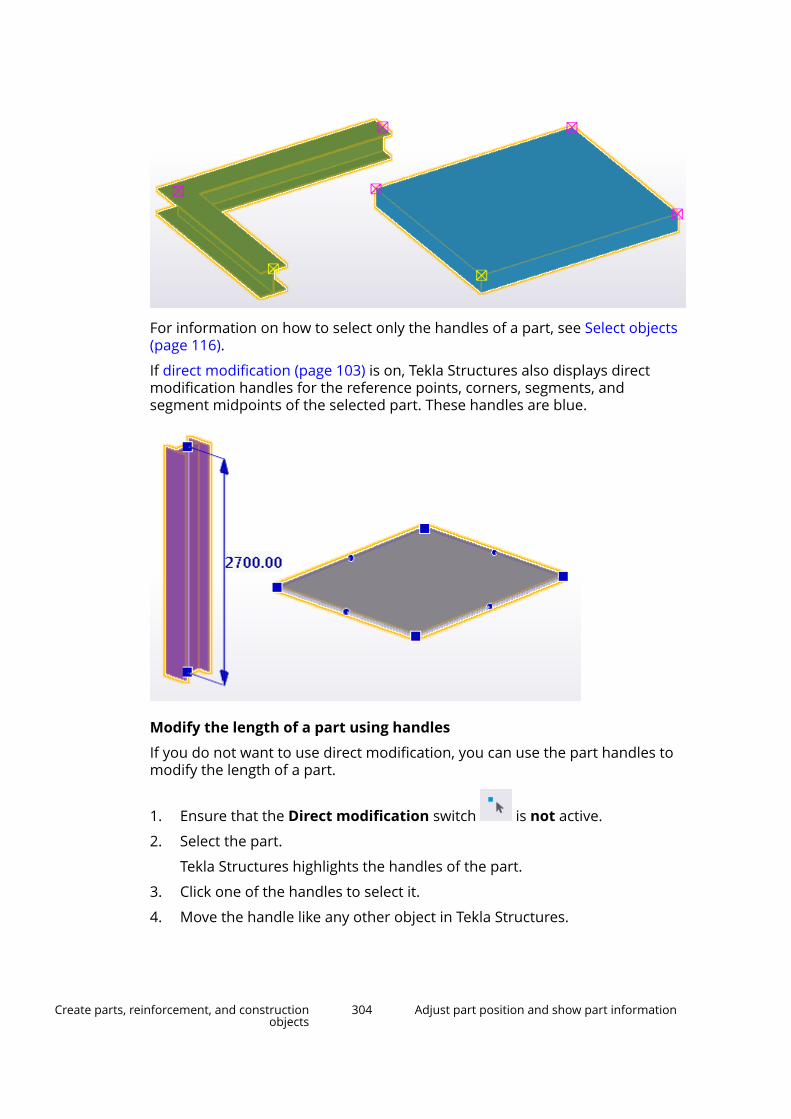
For information on how to select only the handles of a part, see Select objects(page 116).
If direct modification (page 103) is on, Tekla Structures also displays directmodification handles for the reference points, corners, segments, andsegment midpoints of the selected part. These handles are blue.
Modify the length of a part using handles
If you do not want to use direct modification, you can use the part handles tomodify the length of a part.
1. Ensure that the Direct modification switch is not active.
2. Select the part.
Tekla Structures highlights the handles of the part.
3. Click one of the handles to select it.
4. Move the handle like any other object in Tekla Structures.
Create parts, reinforcement, and constructionobjects
304 Adjust part position and show part information
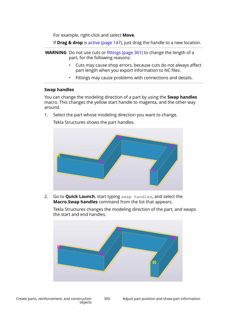
For example, right-click and select Move.
If Drag & drop is active (page 147), just drag the handle to a new location.
WARNING Do not use cuts or fittings (page 361) to change the length of apart, for the following reasons:
• Cuts may cause shop errors, because cuts do not always affectpart length when you export information to NC files.
• Fittings may cause problems with connections and details.
Swap handles
You can change the modeling direction of a part by using the Swap handlesmacro. This changes the yellow start handle to magenta, and the other wayaround.
1. Select the part whose modeling direction you want to change.
Tekla Structures shows the part handles.
2. Go to Quick Launch, start typing swap handles, and select theMacro.Swap handles command from the list that appears.
Tekla Structures changes the modeling direction of the part, and swapsthe start and end handles.
Create parts, reinforcement, and constructionobjects
305 Adjust part position and show part information

Show part reference lines in a model viewWhen you create a part, you position the part by picking points (page 77).These points are the part reference points. If you pick two points to position apart, the points form a part reference line, and handles appear at the lineends. By default, the part reference line is invisible in the model. It may beuseful to display it when snapping to the middle points of parts, for example.
1. Double-click the view to open the View Properties dialog box.
2. Click Display... to open the Display dialog box.
3. On the Advanced tab, select the Part reference line check box.
4. Click Modify.
The part reference lines are displayed.
Modify the position of a partUse the property pane and its Position and End offset sections to modify thepart position. Alternatively, you can use the contextual toolbar to modify thepart position.
To modify the position of a part, do one of the following:
To Do thisModify part position using theproperty pane (page 96)
1. Double-click a part to open thepart properties in the propertypane.
2. In the Position or in the Endoffset section, modify thedesired position settings, such as
Create parts, reinforcement, and constructionobjects
306 Adjust part position and show part information

To Do thispart rotation (page 309) or partvertical position (page 312).
For example, you can define thepart to be positioned 200 unitsabove its handles.
3. Click Modify.Modify part position using thecontextual toolbar
1.Click in the contextualtoolbar.
2. Modify the settings. The objectmoves in the model accordingly.
• To change the overall positionof a beam, column, panel, orfooting, use the roundselection dial. Click a sector inthe dial to select a position.
• To change the rotation angle,click and drag the greenrotation angle knob.
• To change the Angle, Planeoffset, or Depth offset, entera value in the correspondingbox.
• To change the position of aplate or slab, select an optionand enter a value in theDepth offset box.
TIP The rotation angle knob snaps to every 5 degrees. Hold down Shift tooverride this.
Create parts, reinforcement, and constructionobjects
307 Adjust part position and show part information
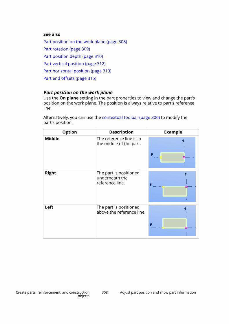
See also
Part position on the work plane (page 308)
Part rotation (page 309)
Part position depth (page 310)
Part vertical position (page 312)
Part horizontal position (page 313)
Part end offsets (page 315)
Part position on the work planeUse the On plane setting in the part properties to view and change the part’sposition on the work plane. The position is always relative to part's referenceline.
Alternatively, you can use the contextual toolbar (page 306) to modify thepart's position.
Option Description ExampleMiddle The reference line is in
the middle of the part.
Right The part is positionedunderneath thereference line.
Left The part is positionedabove the reference line.
Create parts, reinforcement, and constructionobjects
308 Adjust part position and show part information
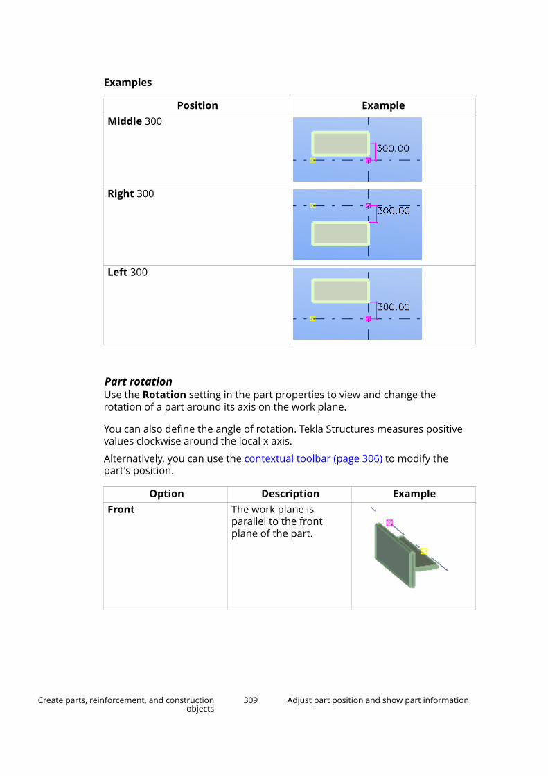
Examples
Position ExampleMiddle 300
Right 300
Left 300
Part rotationUse the Rotation setting in the part properties to view and change therotation of a part around its axis on the work plane.
You can also define the angle of rotation. Tekla Structures measures positivevalues clockwise around the local x axis.
Alternatively, you can use the contextual toolbar (page 306) to modify thepart's position.
Option Description ExampleFront The work plane is
parallel to the frontplane of the part.
Create parts, reinforcement, and constructionobjects
309 Adjust part position and show part information
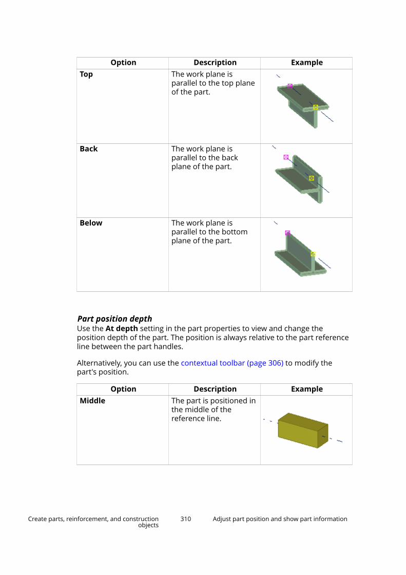
Option Description ExampleTop The work plane is
parallel to the top planeof the part.
Back The work plane isparallel to the backplane of the part.
Below The work plane isparallel to the bottomplane of the part.
Part position depthUse the At depth setting in the part properties to view and change theposition depth of the part. The position is always relative to the part referenceline between the part handles.
Alternatively, you can use the contextual toolbar (page 306) to modify thepart's position.
Option Description ExampleMiddle The part is positioned in
the middle of thereference line.
Create parts, reinforcement, and constructionobjects
310 Adjust part position and show part information

Option Description ExampleFront The part is positioned
above the reference line.
Behind The part is positionedunderneath thereference line.
Examples
Position ExampleMiddle 400
Front 400
Behind 400
Create parts, reinforcement, and constructionobjects
311 Adjust part position and show part information
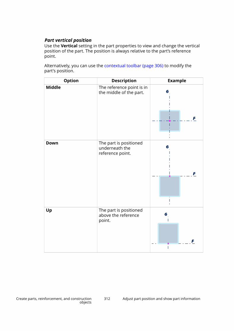
Part vertical positionUse the Vertical setting in the part properties to view and change the verticalposition of the part. The position is always relative to the part’s referencepoint.
Alternatively, you can use the contextual toolbar (page 306) to modify thepart's position.
Option Description ExampleMiddle The reference point is in
the middle of the part.
Down The part is positionedunderneath thereference point.
Up The part is positionedabove the referencepoint.
Create parts, reinforcement, and constructionobjects
312 Adjust part position and show part information

Examples
Position ExampleMiddle 200
Down 200
Up 200
Part horizontal positionUse the Horizontal setting in the part properties to view and change thehorizontal position of the part. The position is always relative to the part’sreference point.
Alternatively, you can use the contextual toolbar (page 306) to modify thepart's position.
Option Description ExampleMiddle The reference point is in
the middle of the part.
Create parts, reinforcement, and constructionobjects
313 Adjust part position and show part information

Option Description ExampleLeft The part is positioned on
the left side of thereference point.
Right The part is positioned onthe right side of thereference point.
Examples
Position ExampleMiddle 150
Left 150
Create parts, reinforcement, and constructionobjects
314 Adjust part position and show part information

Position ExampleRight 150
Part end offsetsUse the Dx, Dy and Dz settings in the part properties to move the ends of apart, relative to its reference line. You can enter positive and negative values.
Alternatively, you can use the contextual toolbar (page 306) to modify thepart's position.
Option DescriptionDx Changes the length of the part by
moving the part end point along thereference line.
Dy Moves the part end perpendicular tothe reference line.
Dz Moves the part end in the z directionof the work plane.
Examples
Position ExampleDx
End point: 200
Dx
End point: -200
Dy
End point: 300
Create parts, reinforcement, and constructionobjects
315 Adjust part position and show part information
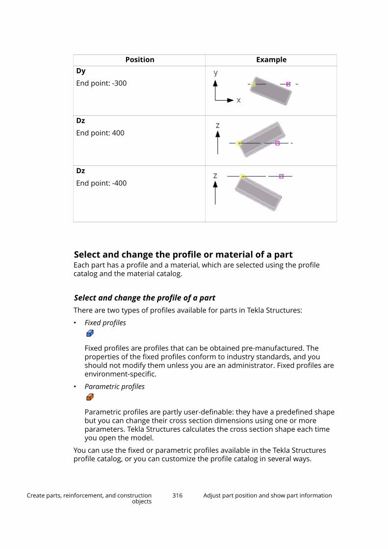
Position ExampleDy
End point: -300
Dz
End point: 400
Dz
End point: -400
Select and change the profile or material of a partEach part has a profile and a material, which are selected using the profilecatalog and the material catalog.
Select and change the profile of a partThere are two types of profiles available for parts in Tekla Structures:
• Fixed profiles
Fixed profiles are profiles that can be obtained pre-manufactured. Theproperties of the fixed profiles conform to industry standards, and youshould not modify them unless you are an administrator. Fixed profiles areenvironment-specific.
• Parametric profiles
Parametric profiles are partly user-definable: they have a predefined shapebut you can change their cross section dimensions using one or moreparameters. Tekla Structures calculates the cross section shape each timeyou open the model.
You can use the fixed or parametric profiles available in the Tekla Structuresprofile catalog, or you can customize the profile catalog in several ways.
Create parts, reinforcement, and constructionobjects
316 Adjust part position and show part information

Change the profile of a part
When you create or modify a part (page 235), you can select the profile of apart from a list that contains all the profiles available in the profile catalog.
1. Double-click a part to open the part properties in the property pane.
2. Click the ... button next to the Profile box.
The Select Profile dialog box appears.
By default, only the profile types that are relevant to the material of thepart are shown. For example, if you are changing the profile of a steelpart, only the profile types that are associated with steel are shown.
3. If needed, define what profile information you want to see.
• To display all the profiles of the profile catalog in the list, regardless ofthe material the profile types are associated with, select the Show allprofiles check box.
• To see all the properties of profiles, select the Show details check box.
4. Select a profile from the list.
5. If the profile is parametric, define its dimensions on the General tab.
(1) Click the Value box and replace the existing value with a new one.
6. Click OK to close the Select Profile dialog box.
7. Click Modify in the property pane.
Alternatively, if you know the name of the profile, you can enter it directly inthe Profile box in the property pane or in the contextual toolbar.
Use standardized values for profile dimensions
You can use standardized values for the dimensions of parametric profiles.
1. Double-click a part to open the part properties in the property pane.
2. Click the ... button next to the Profile box.
The Select Profile dialog box appears.
3. Select a parametric profile.
Create parts, reinforcement, and constructionobjects
317 Adjust part position and show part information

If standardized values have been defined for this profile, the Use industrystandardized values only check box appears on the General tab underthe profile properties:
4. Select the Use industry standardized values only check box.
5. Select the profile dimensions from a list in the Value column.
Select and change the material of a partWhen you create or modify a part (page 235), you can select the material andgrade of a part from a list that contains all the materials available in thematerial catalog.
1. Double-click a part to open the part properties in the property pane.
2. Click the ... button next to the Material box.
The Select Material dialog box appears.
3. If needed, define what material information you want to see.
• To include aliases for material grades in the list, select the Showaliases check box.
Aliases are alternative names. For example, they can be former names,or names used in different countries or standards. Tekla Structures
Create parts, reinforcement, and constructionobjects
318 Adjust part position and show part information

automatically changes aliases into the standard name when you selecta material grade.
• To see all the properties of materials, select the Show details checkbox.
4. Select a material from the list.
5. Click OK to close the Select Material dialog box.
6. Click Modify in the property pane.
Alternatively, if you know the name of the profile, you can enter it directly inthe Profile box in the property pane or in the contextual toolbar.
TIP If needed, you can customize the material catalog.
Examples of user-defined attributes (UDAs) for parts
User-defined attributes (UDAs) provide additional information about a part.UDAs can consist of numbers, text, or lists. If needed, you can define new user-defined attributes.
The following table gives some examples of what you can use part UDAs for:
Attribute Can be used...Comment In part and weld marks in Tekla Structures
drawings, or in projects.Shorten When drawings of the parts are created, Tekla
Structures decreases the true length of the part bythis value. This is useful when creating assemblydrawings of bracing bars that should always beunder tension.
Camber In part marks in Tekla Structures drawings.Preliminary mark To obtain preliminary numbers for parts in reports.Locked To protect objects from being accidentally
changed.Shear, Tension, andMoment
To save reaction forces for AutoDefaults. You canenter forces separately for each end of a part.
User field 1...4 User-defined fields. You can change the names ofthese fields and add new user-defined fields.
Connection code When importing information on connection typesinto Tekla Structures. You can then use theconnection codes as rules in AutoConnection andAutoDefaults. Each end of a part can have adifferent connection code.
Create parts, reinforcement, and constructionobjects
319 Adjust part position and show part information

Attribute Can be used...Moment connection For selecting whether to show moment connection
symbols in drawings or not.
Show part information by using part labelsYou can display selected part properties, user-defined attributes and templateattributes in a model view by using part labels.
Part labels are textual descriptions that are displayed next to the part theyrepresent. You can define what information to display in the labels, such as thename, profile, and position number of the part.
1. Double-click the view to open the View Properties dialog box.
2. Click Display... to open the Display dialog box.
3. Go to the Advanced tab.
4. Next to the Part label, in the Properties list, select a property.
5. Click Add > to add the property to the Part label list. The Part label checkbox is automatically selected when you add properties.
Create parts, reinforcement, and constructionobjects
320 Adjust part position and show part information
6. To remove a property from the Part label list, select a property and clickRemove. The Part label check box is automatically cleared if you removeall the properties.
7. If needed, define which user-defined attribute or template attribute youwant to display in part labels.
a. Select User-defined attribute in the Properties list.
b. Click Add >. The Part label dialog box appears.
c. Enter the user-defined attribute name exactly as it appears in theobjects.inp file, or the template attribute name. For example,PRELIM_MARK.
d. Click OK.
8. In the Show for list, select for which parts you want to show the partlabels.
• All: Part labels are shown for all parts in the view.
• Selected: Part labels are only shown for the parts you select.
• Main part for selected: Part labels are only shown for the main partsof the assemblies you select.
• Main part for all: Part labels are shown for all main parts of allassemblies.
Note that if you select the Selected or the Main part for selected option,you need to first apply the changes to the view when the view is selected.Then continue to select the objects for which you want to show the partlabels.
9. Click Modify.
Create curved partsYou can create curved parts by defining a radius and the number of segmentsfor a part. The number of segments determines how realistic the curved partlooks: the more segments, the less angular the part appears.
1. Create a part that can be bent: a beam, panel, or strip footing.
2. Double-click the part to open the part properties.
3. Go to the Curved beam or Bending settings area, depending on the parttype.
4. In the Radius box, enter the radius.
5. In the Number of segments box, enter the number of segments youwant to use.
Create parts, reinforcement, and constructionobjects
321 Adjust part position and show part information

6. If needed, define the plane of curvature, which is relative to the currentwork plane.
7. Click Modify to bend the part.
Examples
Number of segments: 2
Number of segments: 5
Number of segments: 15
See also
Modify the position of a part (page 306)
Create horizontal partsWhen creating horizontal parts, such as beams, always pick points in the samedirection. For example, pick positions from left to right, and from bottom totop (in positive x, y directions). This ensures that Tekla Structures places and
Create parts, reinforcement, and constructionobjects
322 Adjust part position and show part information
dimensions the parts in the same way in drawings, and that part marksautomatically appear at the same part end.
To ensure that beam rotation is correct in drawings, set part Rotation to Topin the part properties.
Create beams close to each otherWhen you create beams so that they are located very close to each other,Tekla Structures may consider them as a twin profile. To prevent this fromhappening, use the user attribute MAX_TWIN_SEARCH_DIST in the profilecatalog.
1. On the File menu, click Catalogs --> Profile catalog to open the ModifyProfile Catalog dialog box.
2. Select the desired profile in the profile tree.
3. Go to the User attributes tab and set the property Twin profiledetection distance to a larger value than 0, for example to 0.1.
4. Click OK.
5. Create the beams using the profile.
See also
Create a steel beam (page 239)
Create a twin profile (page 246)
Position columns, pad footings, and orthogonal beamsFor parts that you create by picking only one point (such as columns), you candefine the top and bottom level of the part in the global z direction. The part iscreated at the defined level, not at the level you picked in the model. This canbe useful when creating multi-story structures, as you can define exact levelsfor each part you create.
To define the top and bottom levels of a part:
1. Create a part that requires you to pick only one point.
For example, a column.
2. Double-click the part to open the part properties.
3. Go to the Position settings area.
4. Modify the top and bottom levels of the part.
• Top: Use to define the top level of the part.
• Bottom: Use to define the bottom level of the part.
Create parts, reinforcement, and constructionobjects
323 Adjust part position and show part information

5. Click Modify.
Example
In this example, the concrete columns form a two-story structure. To positionthe upper columns correctly, you must modify their bottom level position.
(1) Top level = 1000, Bottom level = 0
(2) Top level = 1700, Bottom level = 1200
(3) Slab thickness = 200
See also
Modify the position of a part (page 306)
How to model identical areasMost structures contain identical areas, from simple frames to entire floors.Save time by modeling these areas once, then copying them throughout themodel. For example, create a column with a base plate and cap plate, thencopy the column to all the locations where it occurs in the model.
You can use this technique to create and reproduce any identical area.Depending on the project, you may even be able to add connections beforecopying the area of the building.
TIP For a project that has several identical floors, try modeling an entire floor, thencopying it to several levels.
See also
Copy and move objects (page 131)
Create parts, reinforcement, and constructionobjects
324 Modify parts
2.3 Modify partsThis section explains how to modify different part properties, such as shape,position and length of a part. It also explains how to split and combine parts,and how to use the deforming options to warp and camber parts.
Click the links below to find out more:
Modify the adaptivity of reinforcement, surface treatment, or edge chamfers inparts (page 325)
Split parts (page 326)
Combine parts (page 327)
Attach parts to each other (page 327)
Warp a part (page 329)
Camber a part (page 331)
Modify the adaptivity of reinforcement, surface treatment,or edge chamfers in partsReinforcement, surface treatment and edge chamfers adapt to the parts theyare linked to. For example, reinforcement, surface treatment and edgechamfers automatically adapt to changes in part geometry and size. You canmodify the adaptivity settings either for the entire model or for each modelobject separately. If you modify the adaptivity of individual model objects,these modifications override the default settings that you may have definedfor the entire model.
The options are:
• Off: adaptivity is not defined
• Relative: handles retain their relative distances to the nearest part faces inrelation to the part's overall size
• Fixed: handles retain their absolute distances to the nearest part faces
Define default adaptivity settingsYou can define default adaptivity settings that affect the entire model.
1. On the File menu, click Settings --> Options , and go to the Generalsettings.
2. Under Default adaptivity, select one of the options.
3. Click OK to save the changes.
Create parts, reinforcement, and constructionobjects
325 Modify parts
Modify the adaptivity of an individual model objectYou can modify the adaptivity settings for each reinforcement or surfacetreatment separately. These modifications override the default settings thatyou may have defined for the entire model.
1. In the model, select the reinforcement (page 512) or surface treatment(page 373) whose adaptivity settings you want to change.
2. Right-click, select Adaptivity, and then select one of the options.
Split partsUse splitting to split a part into two. You can use splitting with straight parts,polybeams and curved beams without offsets, and normal and taperedreinforcing bar groups. You can also split plates and slabs by using a polygon.
Split a straight or curved part or polybeam1. On the Edit tab, click Split.
2. Select the part you want to split.
3. Pick a point for the dividing line.
4. If you split a polybeam, check that the following are correct:
• The position and orientation settings of the split polybeams
• The components related to the split polybeams
Split a plate or slab using a polygon1. Ensure that the Z axis is perpendicular to the plate or slab you want to
split.
2. On the Edit tab, click Split.
3. Select the part you want to split.
4. Pick positions to outline the polygon to be used for splitting.
5. Click the middle mouse button to close the polygon and to split the part.
NOTE When you pick the corner points of the polygon to be used for splitting, makesure the starting and end points are:
• outside of the part, and
• on the same side of the part.
NOTE If you split contour plates that have bolts, welds or surface treatments, checkthe result after splitting.
Create parts, reinforcement, and constructionobjects
326 Modify parts
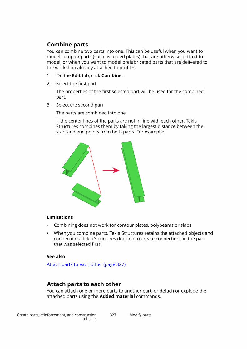
Combine partsYou can combine two parts into one. This can be useful when you want tomodel complex parts (such as folded plates) that are otherwise difficult tomodel, or when you want to model prefabricated parts that are delivered tothe workshop already attached to profiles.
1. On the Edit tab, click Combine.
2. Select the first part.
The properties of the first selected part will be used for the combinedpart.
3. Select the second part.
The parts are combined into one.
If the center lines of the parts are not in line with each other, TeklaStructures combines them by taking the largest distance between thestart and end points from both parts. For example:
Limitations
• Combining does not work for contour plates, polybeams or slabs.
• When you combine parts, Tekla Structures retains the attached objects andconnections. Tekla Structures does not recreate connections in the partthat was selected first.
See also
Attach parts to each other (page 327)
Attach parts to each otherYou can attach one or more parts to another part, or detach or explode theattached parts using the Added material commands.
Create parts, reinforcement, and constructionobjects
327 Modify parts
When you modify the properties of attached parts, note that some of the partproperties are taken from the main part. These properties are not shown inthe properties of the attached part. You can inquire the properties of thewhole part and the properties of each attached part separately. The attachedparts are taken into account when calculating area, volume, and weight:
• Weight (Gross) compares the weight with fittings and without fittings, andshows the biggest weight result without cuts and with attached parts.
• Weight (Net) shows the weight with cuts and attached parts based on thegeometry volume of the modeled part.
• Weight shows the net weight.
Limitations
• Connections must be added to the part to which other parts have beenattached. You cannot add connections to an attached part.
• All reinforcement components may not work correctly with parts that havebeen attached to each other using the Added material commands. Thegeometry of the parts is not always kept suitable for adding a component.For example, the reference points of the attached part may be lost andtherefore the orientation information needed for adding the reinforcementis not known anymore.
Attach a part to another part1. Double-click the view to open the view properties, click the Display...
button, and ensure that the Cuts and added material option is selectedin the display settings.
2. On the Edit tab, click Added material --> Attach to part .
3. Select the part to attach to.
4. Select the part you want to attach.
You can attach more than one part at a time.
5. Click the middle mouse button to attach the part.
Detach an attached part1. Double-click the view to open the view properties, click the Display...
button, and ensure that the Cuts and added material option is selectedin the display settings.
2. On the Edit tab, click Added material --> Detach from part .
3. Select the attached part you want to detach.
You can detach more than one part from several different parts at a time.Select the parts either by clicking them or by using area selection.
Create parts, reinforcement, and constructionobjects
328 Modify parts
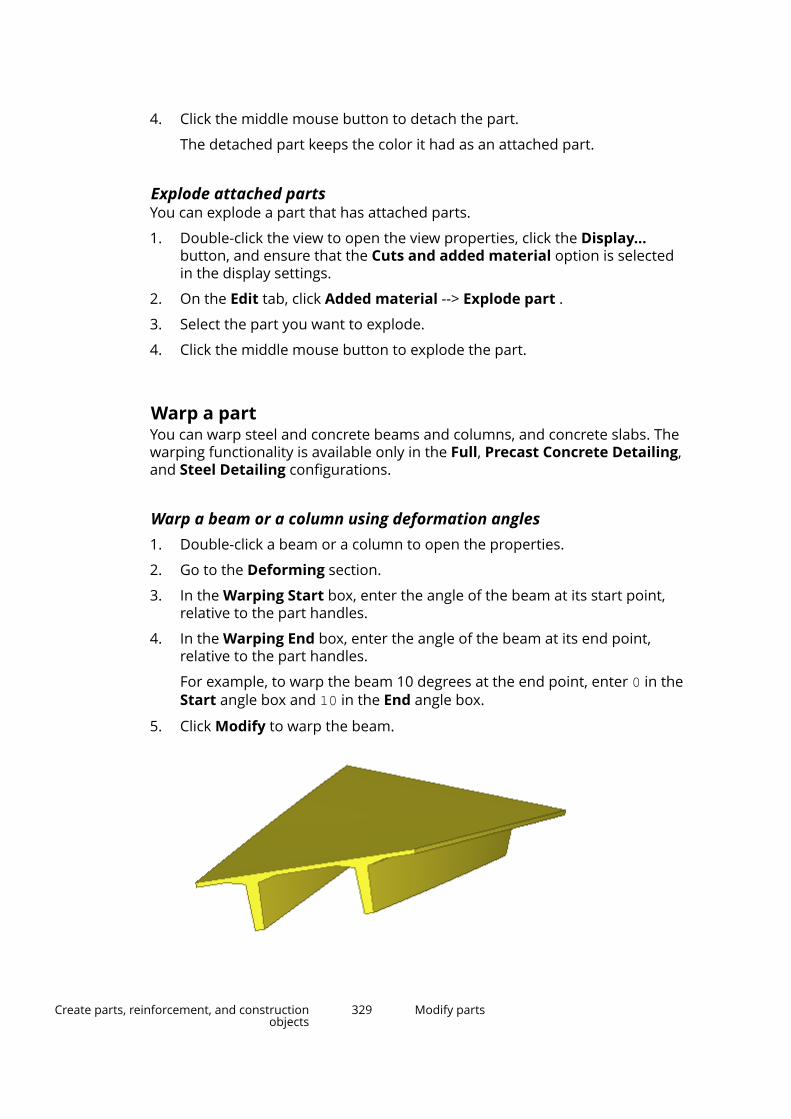
4. Click the middle mouse button to detach the part.
The detached part keeps the color it had as an attached part.
Explode attached partsYou can explode a part that has attached parts.
1. Double-click the view to open the view properties, click the Display...button, and ensure that the Cuts and added material option is selectedin the display settings.
2. On the Edit tab, click Added material --> Explode part .
3. Select the part you want to explode.
4. Click the middle mouse button to explode the part.
Warp a partYou can warp steel and concrete beams and columns, and concrete slabs. Thewarping functionality is available only in the Full, Precast Concrete Detailing,and Steel Detailing configurations.
Warp a beam or a column using deformation angles1. Double-click a beam or a column to open the properties.
2. Go to the Deforming section.
3. In the Warping Start box, enter the angle of the beam at its start point,relative to the part handles.
4. In the Warping End box, enter the angle of the beam at its end point,relative to the part handles.
For example, to warp the beam 10 degrees at the end point, enter 0 in theStart angle box and 10 in the End angle box.
5. Click Modify to warp the beam.
Create parts, reinforcement, and constructionobjects
329 Modify parts
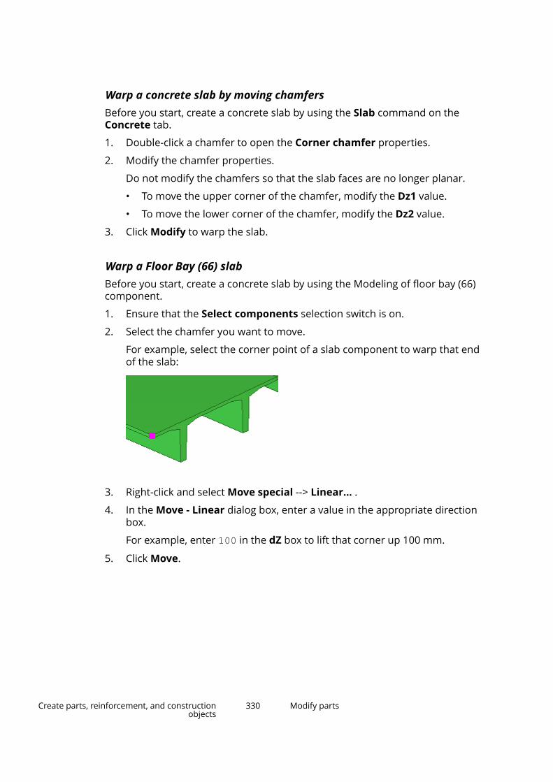
Warp a concrete slab by moving chamfersBefore you start, create a concrete slab by using the Slab command on theConcrete tab.
1. Double-click a chamfer to open the Corner chamfer properties.
2. Modify the chamfer properties.
Do not modify the chamfers so that the slab faces are no longer planar.
• To move the upper corner of the chamfer, modify the Dz1 value.
• To move the lower corner of the chamfer, modify the Dz2 value.
3. Click Modify to warp the slab.
Warp a Floor Bay (66) slabBefore you start, create a concrete slab by using the Modeling of floor bay (66)component.
1. Ensure that the Select components selection switch is on.
2. Select the chamfer you want to move.
For example, select the corner point of a slab component to warp that endof the slab:
3. Right-click and select Move special --> Linear... .
4. In the Move - Linear dialog box, enter a value in the appropriate directionbox.
For example, enter 100 in the dZ box to lift that corner up 100 mm.
5. Click Move.
Create parts, reinforcement, and constructionobjects
330 Modify parts

Tekla Structures moves the point in the direction you selected, whichwarps the slabs.
6. Right-click and select Interrupt.
7. Ensure that the Select objects in components selection switch is on.
8. To see the warping angle of a single slab, double-click a slab to open theConcrete beam properties, and go to the Deforming section.
The Warping start and end values show the warping angle at the startpoint and at the end point of the part.
Camber a partYou can use cambering to pre-camber parts, in other words, to curve longheavy sections that will settle on site and become flat. Use cambering to showthe natural camber of a prestressed part in a model. Cambering affects theposition of cuts, skews, and embeds in the model.
1. Double-click the part to open the part properties.
2. Go to the Deforming section.
3. In the Cambering box, define the degree of camber.
4. Click Modify.
Tekla Structures cambers the part in the local z direction.
Create parts, reinforcement, and constructionobjects
331 Add details to parts
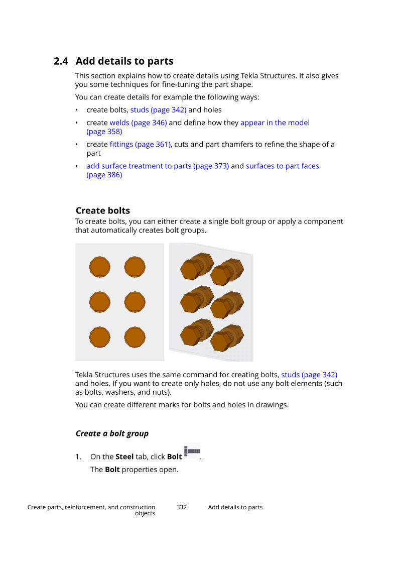
2.4 Add details to partsThis section explains how to create details using Tekla Structures. It also givesyou some techniques for fine-tuning the part shape.
You can create details for example the following ways:
• create bolts, studs (page 342) and holes
• create welds (page 346) and define how they appear in the model(page 358)
• create fittings (page 361), cuts and part chamfers to refine the shape of apart
• add surface treatment to parts (page 373) and surfaces to part faces(page 386)
Create boltsTo create bolts, you can either create a single bolt group or apply a componentthat automatically creates bolt groups.
Tekla Structures uses the same command for creating bolts, studs (page 342)and holes. If you want to create only holes, do not use any bolt elements (suchas bolts, washers, and nuts).
You can create different marks for bolts and holes in drawings.
Create a bolt group
1. On the Steel tab, click Bolt .
The Bolt properties open.
Create parts, reinforcement, and constructionobjects
332 Add details to parts
2. Modify the Bolt properties, if needed.
For example, the Bolt group settings affect the end result.
3. Select the main part, to which the secondary parts will be bolted.
4. Select the secondary parts.
5. Click the middle mouse button to finish selecting parts.
6. Pick a point to indicate the bolt group origin.
7. Pick a second point to indicate the direction of the bolt group x axis.
NOTE Tekla Structures determines the location of the bolt group usingthe following values: the bolt group x axis and the work plane.Dimensions are relative to the bolt group origin, which is the firstpoint picked. Tekla Structures sets the x direction of the boltgroup using the second point picked. It is important that thepoints you pick to create the bolt group are close enough to theparts you want to connect.
Create a single bolt
1. On the Steel tab, hold down Shift and click Bolt to open the Boltproperties.
2. Under Bolt group, select Array from the Shape list.
3. In the Bolt dist X and Bolt dist Y boxes, enter 0.
4. Create the bolt the same way you would create a bolt group:
a. Select the main part, to which the secondary parts will be bolted.
b. Select the secondary parts.
c. Click the middle mouse button to finish selecting parts.
d. Pick a point to indicate the bolt origin.
e. Pick a second point to indicate the direction of the x axis.
Create bolts using the Auto bolt componentUse the Auto bolt component to bolt parts and nearby parts, shim plates,splice plates, or other plates. Auto bolt follows the part rotation and finds thebest rotation so that you do not need to set the work plane. With Auto boltone bolt group can span many parts, for example, manage a splice as a singlegroup
1. Click the Applications & components button in the side pane toopen the Applications & components catalog.
Create parts, reinforcement, and constructionobjects
333 Add details to parts
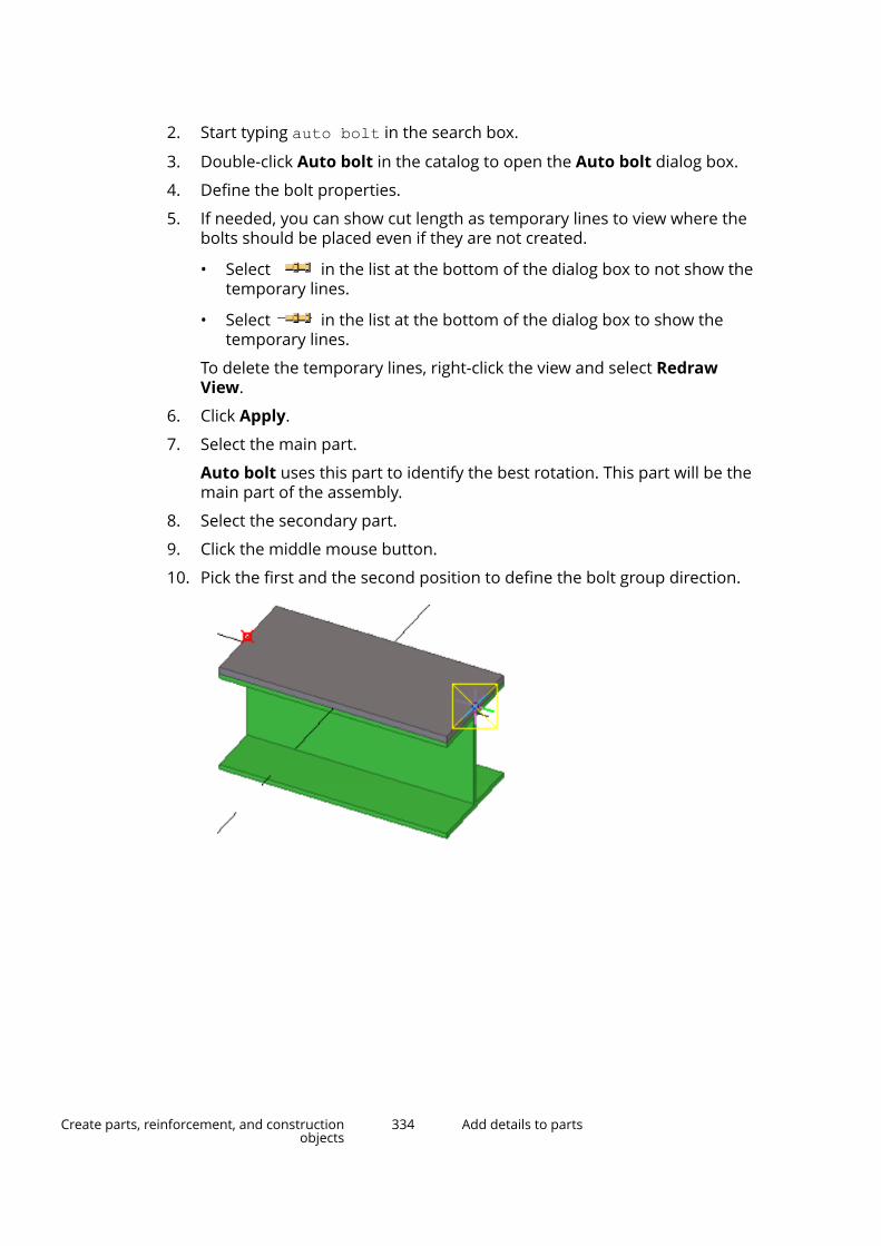
2. Start typing auto bolt in the search box.
3. Double-click Auto bolt in the catalog to open the Auto bolt dialog box.
4. Define the bolt properties.
5. If needed, you can show cut length as temporary lines to view where thebolts should be placed even if they are not created.
• Select in the list at the bottom of the dialog box to not show thetemporary lines.
• Select in the list at the bottom of the dialog box to show thetemporary lines.
To delete the temporary lines, right-click the view and select RedrawView.
6. Click Apply.
7. Select the main part.
Auto bolt uses this part to identify the best rotation. This part will be themain part of the assembly.
8. Select the secondary part.
9. Click the middle mouse button.
10. Pick the first and the second position to define the bolt group direction.
Create parts, reinforcement, and constructionobjects
334 Add details to parts
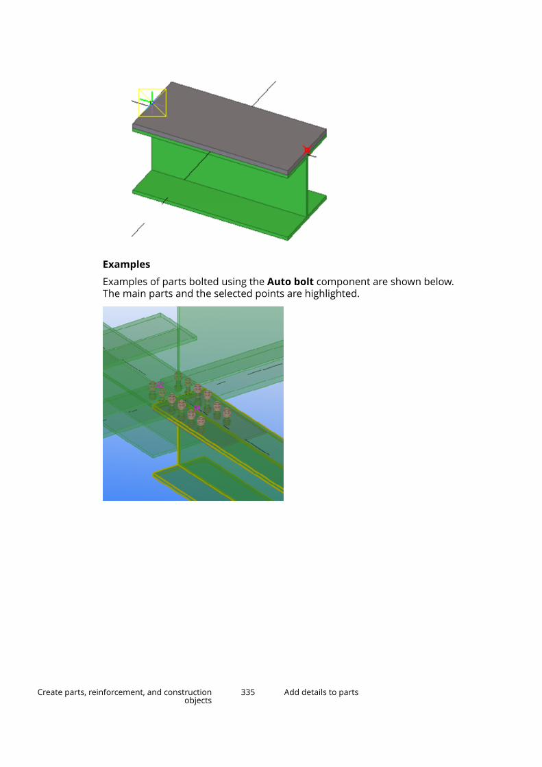
Examples
Examples of parts bolted using the Auto bolt component are shown below.The main parts and the selected points are highlighted.
Create parts, reinforcement, and constructionobjects
335 Add details to parts

Create a bolt group by exploding a componentAn alternative way to create bolts is to first apply a component that includesbolt groups, and then explode the component.
1. Apply a component that includes bolt groups.
For example, connect two beams, or a beam to a column, using a boltedend plate.
2. Explode (page 750) the component.
a. Select the component to explode.
Create parts, reinforcement, and constructionobjects
336 Add details to parts

b. Right-click and select Explode Component.
Tekla Structures separates the objects in the component.
3. Modify the bolt group.
a. Select the bolt group and double-click it to open the properties.
b. Modify the properties.
c. Click Modify.
Change or add bolted partsYou can change the parts a bolt group connects to.
1. On the Steel tab, click Bolted parts.
2. Select the bolt group.
3. Reselect the main and secondary parts.
4. Click the middle mouse button to finish selecting the parts.
Bolt group shapeTekla Structures uses the values of the Bolt dist X and Bolt dist Y boxes in theBolt properties to determine how many bolts the bolt group contains, asshown in the table below:
Shape Bolt dist X Bolt dist YArray Spacing between bolts,
in the x direction of thebolt group.
Spacing between bolts,in the y direction of thebolt group.
Circle Number of bolts. Diameter of the boltgroup.
List x coordinate of eachbolt, from the bolt grouppoint of origin.
y coordinate of eachbolt, from the bolt grouppoint of origin.
Examples
Bolt group shape Dimensions ResultArray Bolt dist X: 150
Bolt dist Y: 100
Create parts, reinforcement, and constructionobjects
337 Add details to parts
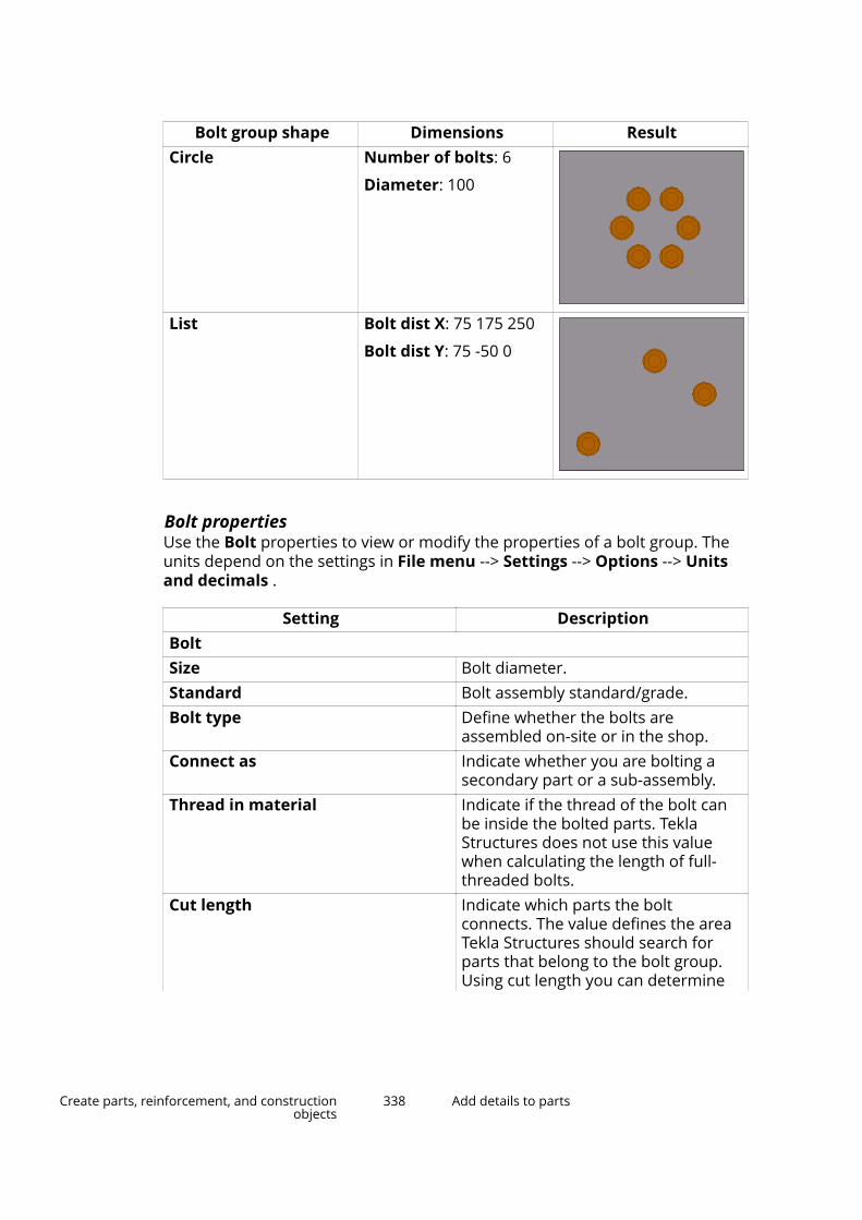
Bolt group shape Dimensions ResultCircle Number of bolts: 6
Diameter: 100
List Bolt dist X: 75 175 250
Bolt dist Y: 75 -50 0
Bolt propertiesUse the Bolt properties to view or modify the properties of a bolt group. Theunits depend on the settings in File menu --> Settings --> Options --> Unitsand decimals .
Setting DescriptionBoltSize Bolt diameter.Standard Bolt assembly standard/grade.Bolt type Define whether the bolts are
assembled on-site or in the shop.Connect as Indicate whether you are bolting a
secondary part or a sub-assembly.Thread in material Indicate if the thread of the bolt can
be inside the bolted parts. TeklaStructures does not use this valuewhen calculating the length of full-threaded bolts.
Cut length Indicate which parts the boltconnects. The value defines the areaTekla Structures should search forparts that belong to the bolt group.Using cut length you can determine
Create parts, reinforcement, and constructionobjects
338 Add details to parts

Setting Descriptionwhether the bolt will go through oneflange or two.
Tekla Structures searches for partsusing half the cut length value, inboth directions from the bolt groupplane. In the illustration below, A isthe cut length and B is the bolt origin.Tekla Structures calculates the searcharea as A/2 in both directions frompoint B.
Tekla Structures warns you if the cutlength is too small (i.e. the bolt groupcontains no parts) and makes the boltlength 100 mm.
If there are large gaps between theconnected parts, the gap is added tothe length of the bolt. Tekla Structurescalculates bolt length using the totaldistance between the first and lastsurfaces.
NOTE: If you want to force a bolt tobe a certain length, enter a negativevalue for cut length (e.g. -150).
Extra length Additional bolt length.
Increases the material thickness thatTekla Structures uses whencalculating bolt length. For example,you might need extra bolt length toallow for painting. You can also build
Create parts, reinforcement, and constructionobjects
339 Add details to parts
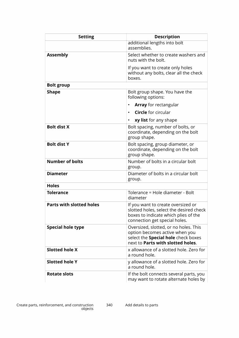
Setting Descriptionadditional lengths into boltassemblies.
Assembly Select whether to create washers andnuts with the bolt.
If you want to create only holeswithout any bolts, clear all the checkboxes.
Bolt groupShape Bolt group shape. You have the
following options:
• Array for rectangular
• Circle for circular
• xy list for any shapeBolt dist X Bolt spacing, number of bolts, or
coordinate, depending on the boltgroup shape.
Bolt dist Y Bolt spacing, group diameter, orcoordinate, depending on the boltgroup shape.
Number of bolts Number of bolts in a circular boltgroup.
Diameter Diameter of bolts in a circular boltgroup.
HolesTolerance Tolerance = Hole diameter - Bolt
diameterParts with slotted holes If you want to create oversized or
slotted holes, select the desired checkboxes to indicate which plies of theconnection get special holes.
Special hole type Oversized, slotted, or no holes. Thisoption becomes active when youselect the Special hole check boxesnext to Parts with slotted holes.
Slotted hole X x allowance of a slotted hole. Zero fora round hole.
Slotted hole Y y allowance of a slotted hole. Zero fora round hole.
Rotate slots If the bolt connects several parts, youmay want to rotate alternate holes by
Create parts, reinforcement, and constructionobjects
340 Add details to parts

Setting Description90 degrees. This allows the bolt tomove in different directions.
Oversized Allowance of an oversized hole.PositionOn plane Move the bolt group perpendicular to
the bolt group x axis.
Rotation Define how far the bolt group isrotated around the x axis, relative tothe current work plane.
For example, you can use this box toindicate on which side of theconnected parts you want the bolthead to be.
At depth Move the bolt group perpendicular tothe current work plane.
Offset fromDx, Dy, Dz Offsets that move the bolt group by
moving the bolt group x axis. Use tochange the position of the bolt group.
The start point values Dx, Dy and Dzmove the first end of the bolt group,relative to the bolt group x axis. Theend point values move the secondend of the bolt group.
• A positive Dx value moves thestart point towards the end point.
• Dy moves the end pointperpendicular to the bolt group xaxis on the current work plane.
• Dz moves the end pointperpendicular to the current workplane.
An example bolt group with the Dxstart point set to 75:
Create parts, reinforcement, and constructionobjects
341 Add details to parts
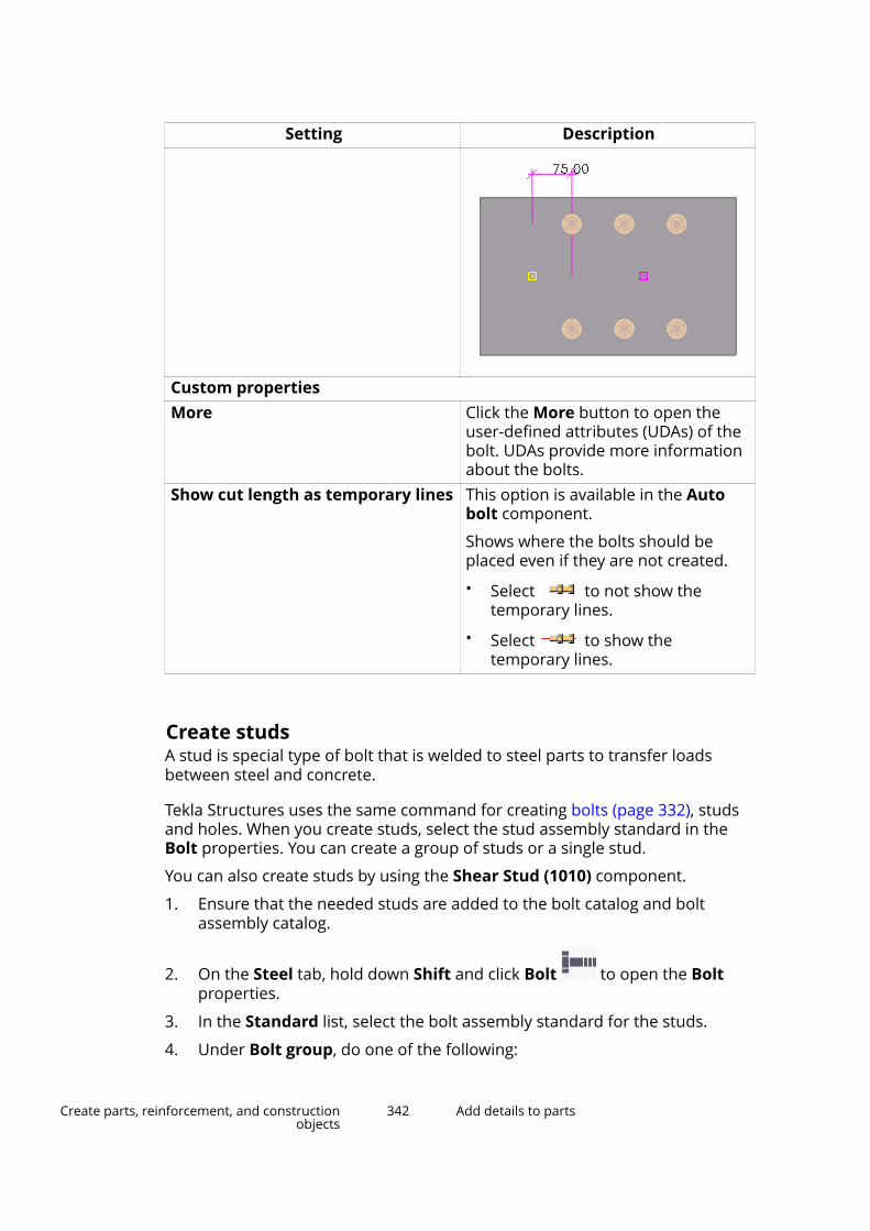
Setting Description
Custom propertiesMore Click the More button to open the
user-defined attributes (UDAs) of thebolt. UDAs provide more informationabout the bolts.
Show cut length as temporary lines This option is available in the Autobolt component.
Shows where the bolts should beplaced even if they are not created.
• Select to not show thetemporary lines.
• Select to show thetemporary lines.
Create studsA stud is special type of bolt that is welded to steel parts to transfer loadsbetween steel and concrete.
Tekla Structures uses the same command for creating bolts (page 332), studsand holes. When you create studs, select the stud assembly standard in theBolt properties. You can create a group of studs or a single stud.
You can also create studs by using the Shear Stud (1010) component.
1. Ensure that the needed studs are added to the bolt catalog and boltassembly catalog.
2. On the Steel tab, hold down Shift and click Bolt to open the Boltproperties.
3. In the Standard list, select the bolt assembly standard for the studs.
4. Under Bolt group, do one of the following:
Create parts, reinforcement, and constructionobjects
342 Add details to parts

• To create a group of studs, define Shape and the related properties asdesired.
• To create a single stud, select Array from the Shape list and type 0 inthe Bolt dist X and Bolt dist Y boxes.
5. Modify the other properties as desired.
6. Select the main part.
7. Click the middle mouse button to finish selecting parts.
8. Pick a point to indicate the origin of the stud or stud group.
9. Pick a second point to indicate the direction of the stud group x axis.
Create holesTekla Structures uses the same command for creating bolts, studs and holes.Before creating holes, you need to change some of the properties in the Boltproperties. If you want to create only holes, do not use any bolt elements(such as bolts, washers, and nuts).
You can create the following types of holes:
• Round
• Oversized
• Slotted
• Tapped
Create round holesYou can create a group of round holes, or a single round hole. Tekla Structurescalculates the diameter of a round hole as the sum of Size and Tolerance.
1. On the Steel tab, hold down Shift and click Bolt to open the Boltproperties.
2. If you do not want to create any bolts, clear all the Assembly check boxes.
Create parts, reinforcement, and constructionobjects
343 Add details to parts

3. If needed, modify the hole properties.
4. Create the holes the same way you would create a bolt group (page 332):
a. Select the main part, to which the secondary parts will be bolted.
b. Select the secondary parts.
c. Click the middle mouse button to finish selecting parts.
d. Pick a point to indicate the hole group origin.
e. Pick a second point to indicate the direction of the hole group x axis.
Create oversized holesYou can create a group of oversized holes.
1. On the Steel tab, hold down Shift and click Bolt to open the Boltproperties.
2. Next to Parts with slotted holes, indicate which plies of the connectionget oversized holes by selecting the desired Special hole check boxes.
For example:
3. If you do not want to create any bolts, clear all the Assembly check boxes.
4. In the Special hole type list, select Oversized.
5. In the Oversized box, enter the allowance for the oversized hole.
You can also use a negative value to create smaller (tapped) holes.
6. Create the holes the same way you would create a bolt group (page 332):
a. Select the main part, to which the secondary parts will be bolted.
Create parts, reinforcement, and constructionobjects
344 Add details to parts
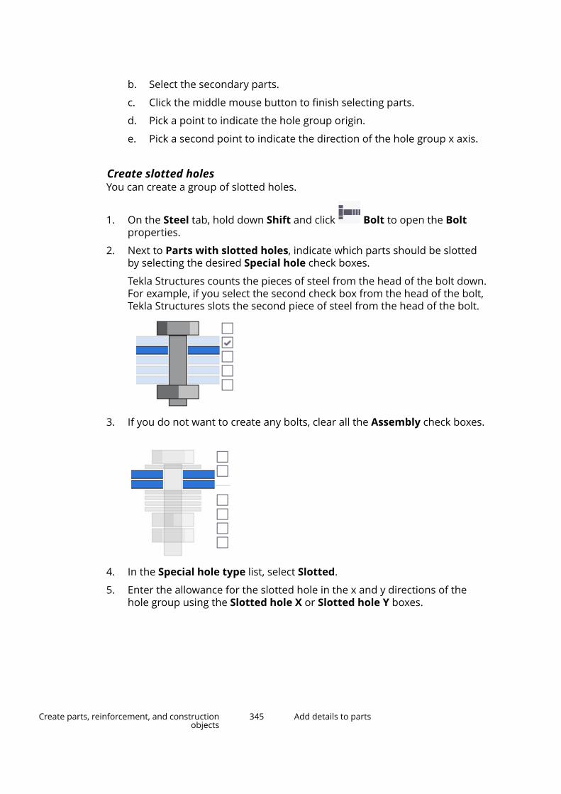
b. Select the secondary parts.
c. Click the middle mouse button to finish selecting parts.
d. Pick a point to indicate the hole group origin.
e. Pick a second point to indicate the direction of the hole group x axis.
Create slotted holesYou can create a group of slotted holes.
1. On the Steel tab, hold down Shift and click Bolt to open the Boltproperties.
2. Next to Parts with slotted holes, indicate which parts should be slottedby selecting the desired Special hole check boxes.
Tekla Structures counts the pieces of steel from the head of the bolt down.For example, if you select the second check box from the head of the bolt,Tekla Structures slots the second piece of steel from the head of the bolt.
3. If you do not want to create any bolts, clear all the Assembly check boxes.
4. In the Special hole type list, select Slotted.
5. Enter the allowance for the slotted hole in the x and y directions of thehole group using the Slotted hole X or Slotted hole Y boxes.
Create parts, reinforcement, and constructionobjects
345 Add details to parts
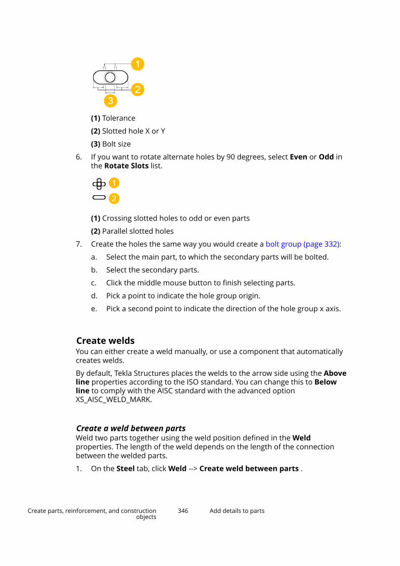
(1) Tolerance
(2) Slotted hole X or Y
(3) Bolt size
6. If you want to rotate alternate holes by 90 degrees, select Even or Odd inthe Rotate Slots list.
(1) Crossing slotted holes to odd or even parts
(2) Parallel slotted holes
7. Create the holes the same way you would create a bolt group (page 332):
a. Select the main part, to which the secondary parts will be bolted.
b. Select the secondary parts.
c. Click the middle mouse button to finish selecting parts.
d. Pick a point to indicate the hole group origin.
e. Pick a second point to indicate the direction of the hole group x axis.
Create weldsYou can either create a weld manually, or use a component that automaticallycreates welds.
By default, Tekla Structures places the welds to the arrow side using the Aboveline properties according to the ISO standard. You can change this to Belowline to comply with the AISC standard with the advanced optionXS_AISC_WELD_MARK.
Create a weld between partsWeld two parts together using the weld position defined in the Weldproperties. The length of the weld depends on the length of the connectionbetween the welded parts.
1. On the Steel tab, click Weld --> Create weld between parts .
Create parts, reinforcement, and constructionobjects
346 Add details to parts

2. Select the part to weld to.
If you are creating a workshop weld, this is the main part of the assembly.
3. Select the part to be welded.
If you are creating a workshop weld, this is the secondary part of theassembly.
(1) Main part
(2) Secondary part
Create a weld to a partYou can create a weld to a single part, without connecting any other parts.
1. On the Steel tab, click Weld --> Create weld to part .
2. Select the part that you want to weld.
3. Pick the starting and end point, or alternatively, pick the points you wantthe weld to go through.
4. Click the middle mouse button to create the weld.
Example
Use the Create weld to part command to weld seams in tubular sections:
TIP To model tubular sections with visible seams, use the SPD profile.
Create parts, reinforcement, and constructionobjects
347 Add details to parts

Create a polygon weldCreate polygon welds when you want to define the exact position of the weldby picking the points you want the weld to traverse.
If you want to create double-sided polygon welds, define both the Above lineand Below line properties.
1. On the Steel tab, click Weld --> Create polygon weld .
2. Select the part to weld to.
If you are creating a workshop weld, this is the main part of the assembly.
3. Select the part to be welded.
If you are creating a workshop weld, this is the secondary part of theassembly.
4. Pick the starting and end point, or alternatively, pick the points you wantthe weld to go through.
To create a double-sided polygon weld, pick the polygon points on oneside of the part to be welded. Tekla Structures automatically searches forthe corresponding points on the other side of the part.
5. Click the middle mouse button to create the weld.
6. If needed, modify the weld by dragging the handles.
Example
This example shows a double-sided polygon weld along three (outer andinner) edges of a rectangular hollow profile:
Create parts, reinforcement, and constructionobjects
348 Add details to parts
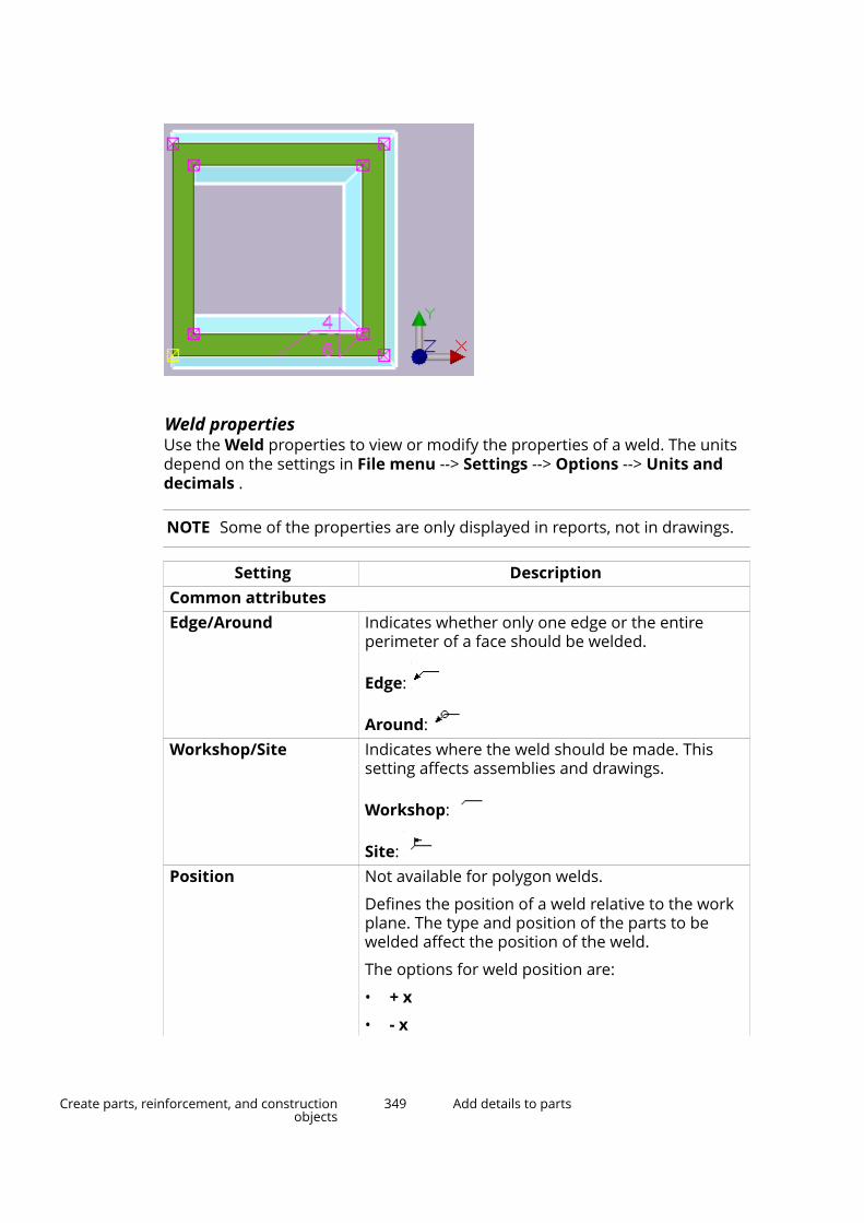
Weld propertiesUse the Weld properties to view or modify the properties of a weld. The unitsdepend on the settings in File menu --> Settings --> Options --> Units anddecimals .
NOTE Some of the properties are only displayed in reports, not in drawings.
Setting DescriptionCommon attributesEdge/Around Indicates whether only one edge or the entire
perimeter of a face should be welded.
Edge:
Around: Workshop/Site Indicates where the weld should be made. This
setting affects assemblies and drawings.
Workshop:
Site: Position Not available for polygon welds.
Defines the position of a weld relative to the workplane. The type and position of the parts to bewelded affect the position of the weld.
The options for weld position are:
• + x
• - x
Create parts, reinforcement, and constructionobjects
349 Add details to parts
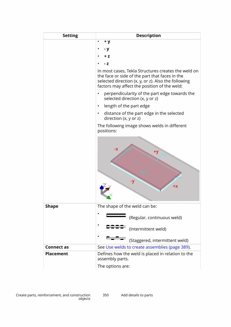
Setting Description• + y
• - y
• + z
• - z
In most cases, Tekla Structures creates the weld onthe face or side of the part that faces in theselected direction (x, y, or z). Also the followingfactors may affect the position of the weld:
• perpendicularity of the part edge towards theselected direction (x, y or z)
• length of the part edge
• distance of the part edge in the selecteddirection (x, y or z)
The following image shows welds in differentpositions:
Shape The shape of the weld can be:
• (Regular, continuous weld)
• (Intermittent weld)
• (Staggered, intermittent weld)
Connect as See Use welds to create assemblies (page 389).Placement Defines how the weld is placed in relation to the
assembly parts.
The options are:
Create parts, reinforcement, and constructionobjects
350 Add details to parts
Setting Description• Auto
The weld placement adapts to the typicalsituation of the weld type.
Square-, V-, and U-groove welds are located inthe middle of the main and secondary parts.Single-bevel and J-groove welds are located onthe secondary part side.
This is the default option.
• Main part
The weld is located fully on the main part side.
Does not affect V- or U-groove welds.
• Secondary part
The weld is located fully on the secondary partside.
Does not affect V- or U-groove welds.Preparation Defines which assembly parts, if any, are
automatically prepared for welding.
The options are:
• None
Parts are not prepared for welding.
This is the default option.
• Auto
Parts are prepared for welding according to theweld type.
• Main part
The main part is prepared for welding.
• Secondary part
The secondary part is prepared for welding.WeldPrefix The weld size prefix. Shown in drawings, but only if
the weld size is also defined.
The standard ISO 2553 prefixes are:
• a - Design throat thickness
• s - Penetration throat thickness
• z - Leg length
Create parts, reinforcement, and constructionobjects
351 Add details to parts
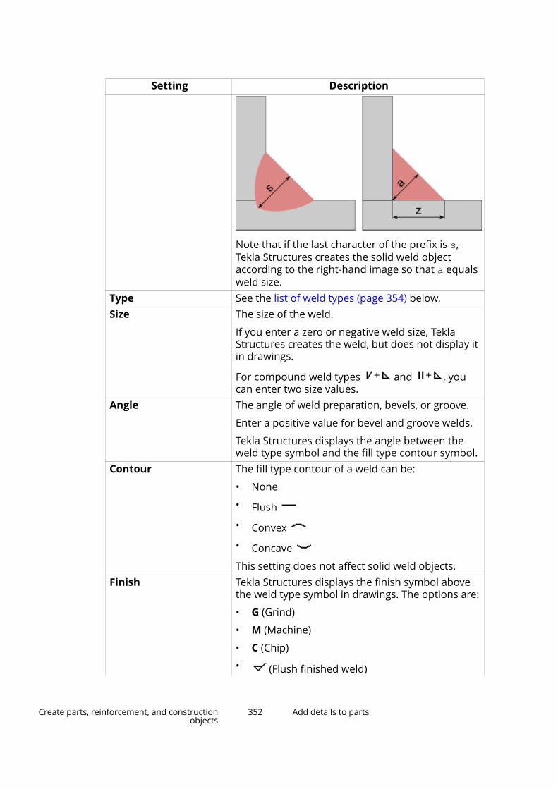
Setting Description
Note that if the last character of the prefix is s,Tekla Structures creates the solid weld objectaccording to the right-hand image so that a equalsweld size.
Type See the list of weld types (page 354) below.Size The size of the weld.
If you enter a zero or negative weld size, TeklaStructures creates the weld, but does not display itin drawings.
For compound weld types and , youcan enter two size values.
Angle The angle of weld preparation, bevels, or groove.
Enter a positive value for bevel and groove welds.
Tekla Structures displays the angle between theweld type symbol and the fill type contour symbol.
Contour The fill type contour of a weld can be:
• None
• Flush
• Convex
• Concave
This setting does not affect solid weld objects.Finish Tekla Structures displays the finish symbol above
the weld type symbol in drawings. The options are:
• G (Grind)
• M (Machine)
• C (Chip)
• (Flush finished weld)
Create parts, reinforcement, and constructionobjects
352 Add details to parts
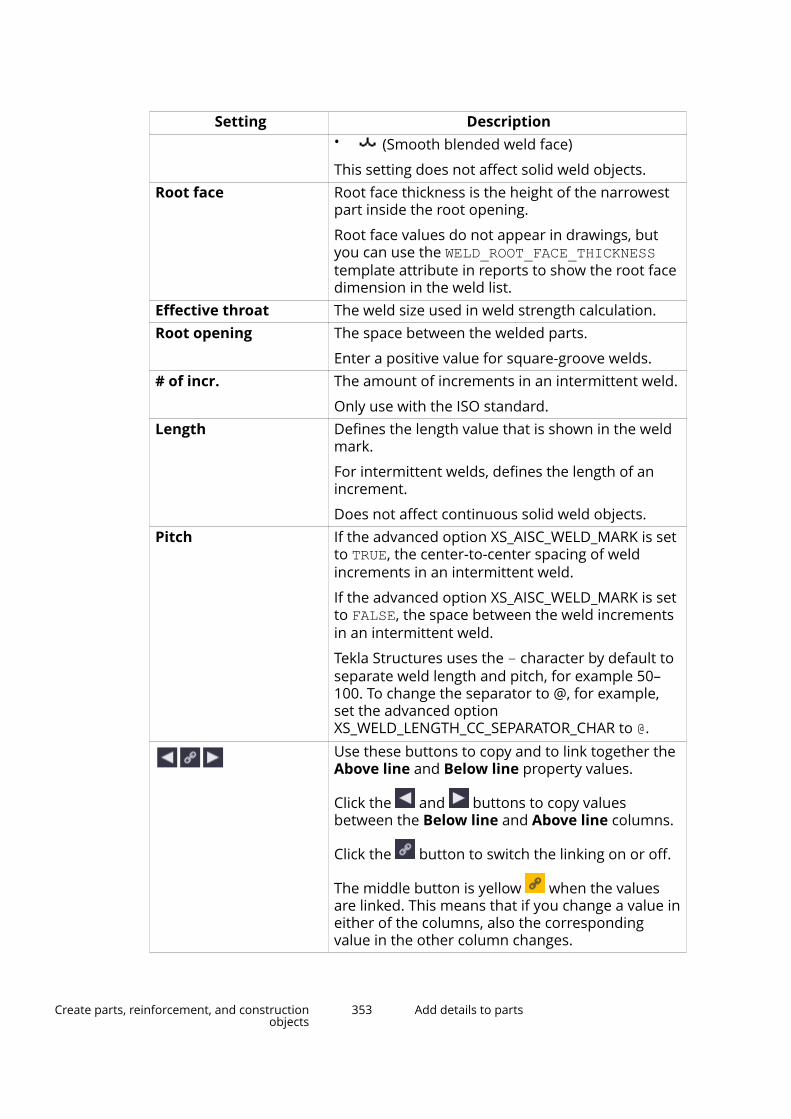
Setting Description• (Smooth blended weld face)
This setting does not affect solid weld objects.Root face Root face thickness is the height of the narrowest
part inside the root opening.
Root face values do not appear in drawings, butyou can use the WELD_ROOT_FACE_THICKNESStemplate attribute in reports to show the root facedimension in the weld list.
Effective throat The weld size used in weld strength calculation.Root opening The space between the welded parts.
Enter a positive value for square-groove welds.# of incr. The amount of increments in an intermittent weld.
Only use with the ISO standard.Length Defines the length value that is shown in the weld
mark.
For intermittent welds, defines the length of anincrement.
Does not affect continuous solid weld objects.Pitch If the advanced option XS_AISC_WELD_MARK is set
to TRUE, the center-to-center spacing of weldincrements in an intermittent weld.
If the advanced option XS_AISC_WELD_MARK is setto FALSE, the space between the weld incrementsin an intermittent weld.
Tekla Structures uses the – character by default toseparate weld length and pitch, for example 50–100. To change the separator to @, for example,set the advanced optionXS_WELD_LENGTH_CC_SEPARATOR_CHAR to @.Use these buttons to copy and to link together theAbove line and Below line property values.
Click the and buttons to copy valuesbetween the Below line and Above line columns.
Click the button to switch the linking on or off.
The middle button is yellow when the valuesare linked. This means that if you change a value ineither of the columns, also the correspondingvalue in the other column changes.
Create parts, reinforcement, and constructionobjects
353 Add details to parts
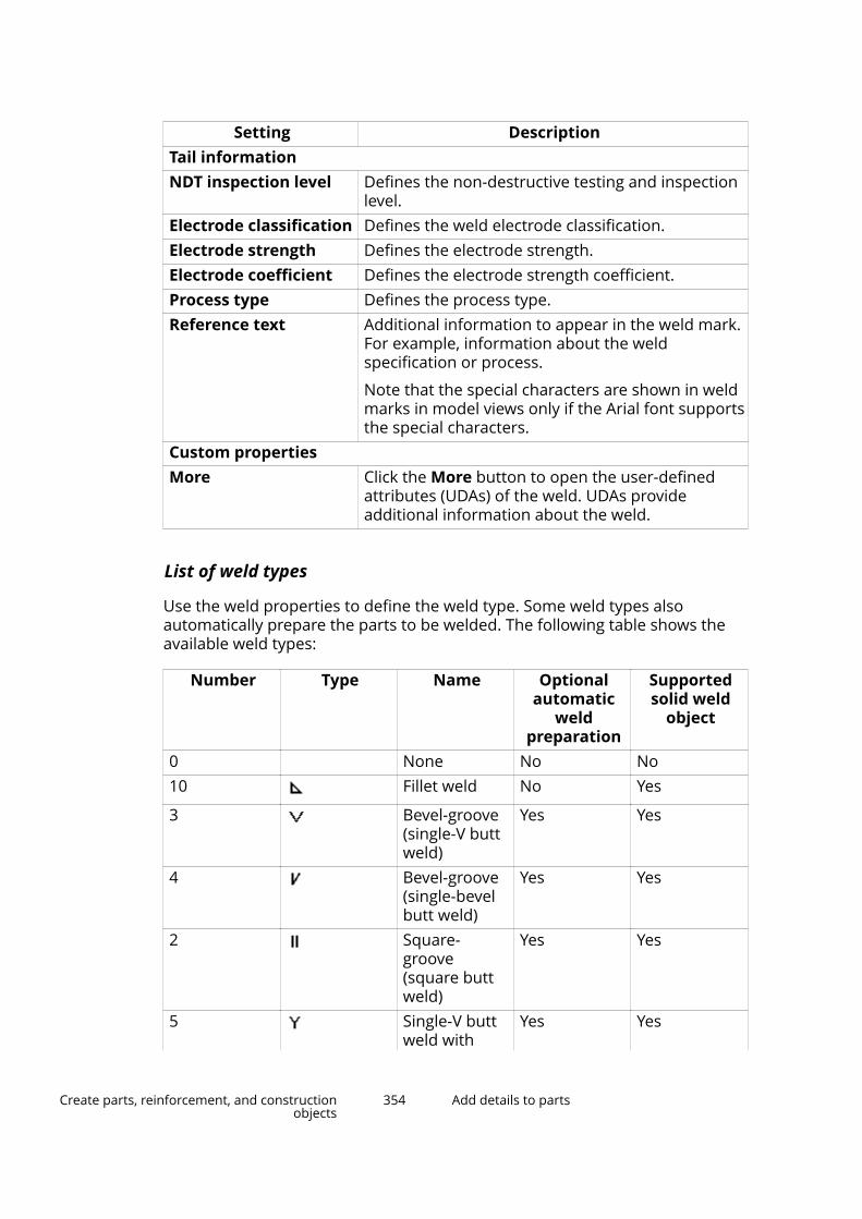
Setting DescriptionTail informationNDT inspection level Defines the non-destructive testing and inspection
level.Electrode classification Defines the weld electrode classification.Electrode strength Defines the electrode strength.Electrode coefficient Defines the electrode strength coefficient.Process type Defines the process type.Reference text Additional information to appear in the weld mark.
For example, information about the weldspecification or process.
Note that the special characters are shown in weldmarks in model views only if the Arial font supportsthe special characters.
Custom propertiesMore Click the More button to open the user-defined
attributes (UDAs) of the weld. UDAs provideadditional information about the weld.
List of weld types
Use the weld properties to define the weld type. Some weld types alsoautomatically prepare the parts to be welded. The following table shows theavailable weld types:
Number Type Name Optionalautomatic
weldpreparation
Supportedsolid weld
object
0 None No No10 Fillet weld No Yes
3 Bevel-groove(single-V buttweld)
Yes Yes
4 Bevel-groove(single-bevelbutt weld)
Yes Yes
2 Square-groove(square buttweld)
Yes Yes
5 Single-V buttweld with
Yes Yes
Create parts, reinforcement, and constructionobjects
354 Add details to parts
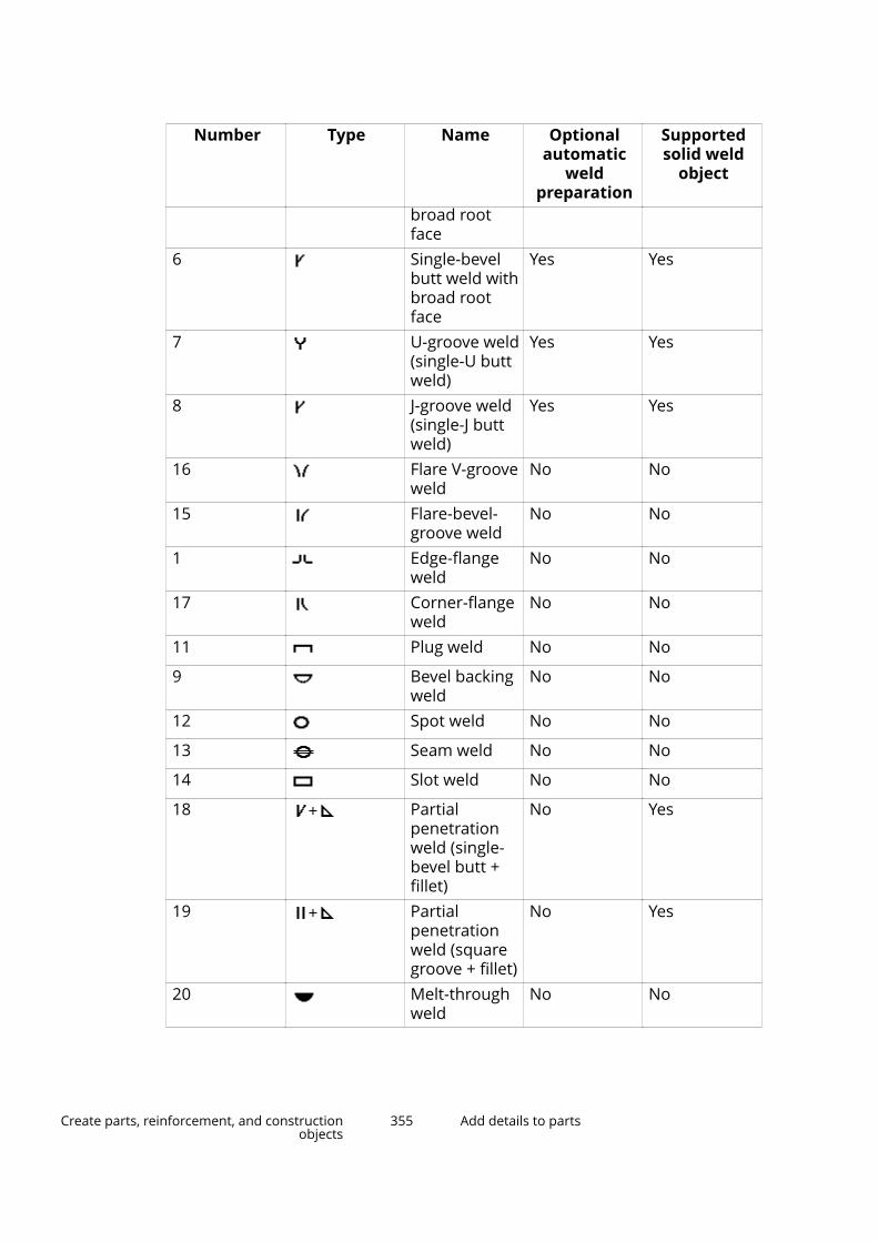
Number Type Name Optionalautomatic
weldpreparation
Supportedsolid weld
object
broad rootface
6 Single-bevelbutt weld withbroad rootface
Yes Yes
7 U-groove weld(single-U buttweld)
Yes Yes
8 J-groove weld(single-J buttweld)
Yes Yes
16 Flare V-grooveweld
No No
15 Flare-bevel-groove weld
No No
1 Edge-flangeweld
No No
17 Corner-flangeweld
No No
11 Plug weld No No
9 Bevel backingweld
No No
12 Spot weld No No
13 Seam weld No No
14 Slot weld No No
18 Partialpenetrationweld (single-bevel butt +fillet)
No Yes
19 Partialpenetrationweld (squaregroove + fillet)
No Yes
20 Melt-throughweld
No No
Create parts, reinforcement, and constructionobjects
355 Add details to parts
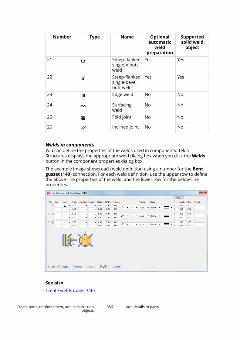
Number Type Name Optionalautomatic
weldpreparation
Supportedsolid weld
object
21 Steep-flankedsingle-V buttweld
Yes Yes
22 Steep-flankedsingle-bevelbutt weld
Yes Yes
23 Edge weld No No
24 Surfacingweld
No No
25 Fold joint No No
26 Inclined joint No No
Welds in componentsYou can define the properties of the welds used in components. TeklaStructures displays the appropriate weld dialog box when you click the Weldsbutton in the component properties dialog box.
The example image shows each weld definition using a number for the Bentgusset (140) connection. For each weld definition, use the upper row to definethe above-line properties of the weld, and the lower row for the below-lineproperties.
See also
Create welds (page 346)
Create parts, reinforcement, and constructionobjects
356 Add details to parts

Weld preparationWhen parts are prepared for welding, their edges can be beveled to produce agroove for the weld. You can define the angle of bevels and grooves.
You can either prepare a part for welding manually, or apply a component thatdoes it automatically, or you can use the Preparation options in the Weldproperties or in the component weld properties.
NOTE When you use components' weld preparation options, the supported weldtypes (page 354) are placed correctly in the model. If you use cuts forpreparing the part edges, the welds may not be placed correctly.
Prepare a part for welding with a polygonYou can manually prepare a part for welding by cutting it with a polygonalshape.
Before you start, ensure that the work plane (page 51) is on the plane you arecutting on.
1. On the Steel tab, click Weld --> Prepare part for welding with polygon .
2. Select the part that you want to cut.
3. Pick positions to outline the polygon to be used for cutting.
Extend the polygon outside the part, so that it is clear that the part edgeshould be cut away.
4. Click the middle mouse button to close the polygon and to cut the part.
(1) The part to be cut
(2) Cuts are displayed using dash-and-dot lines
Prepare a part for welding with another partYou can manually prepare a part for welding by cutting it with another part.The cutting part will subsequently be deleted.
Before you start, create a cutting part and position it through the part youwant to cut.
1. On the Steel tab, click Weld --> Prepare part for welding with anotherpart .
Create parts, reinforcement, and constructionobjects
357 Add details to parts

2. Select the part that you want to cut.
3. Select the cutting part.
(1) The part to be cut
(2) The cutting part
(3) Cuts are displayed using dash-and-dot lines
Set the visibility and appearance of weldsModify the display settings to define how welds appear in the model.
1. Double-click the view to open the View Properties dialog box.
2. Click Display... to open the Display dialog box.
3. Ensure that the Welds check box is selected.
4. Select a representation option for welds:
• Fast
Use this option to show the weld symbols only.
• Exact
Use this option to show welds as solid objects with weld symbols, andto display weld marks when you select welds.
Create parts, reinforcement, and constructionobjects
358 Add details to parts
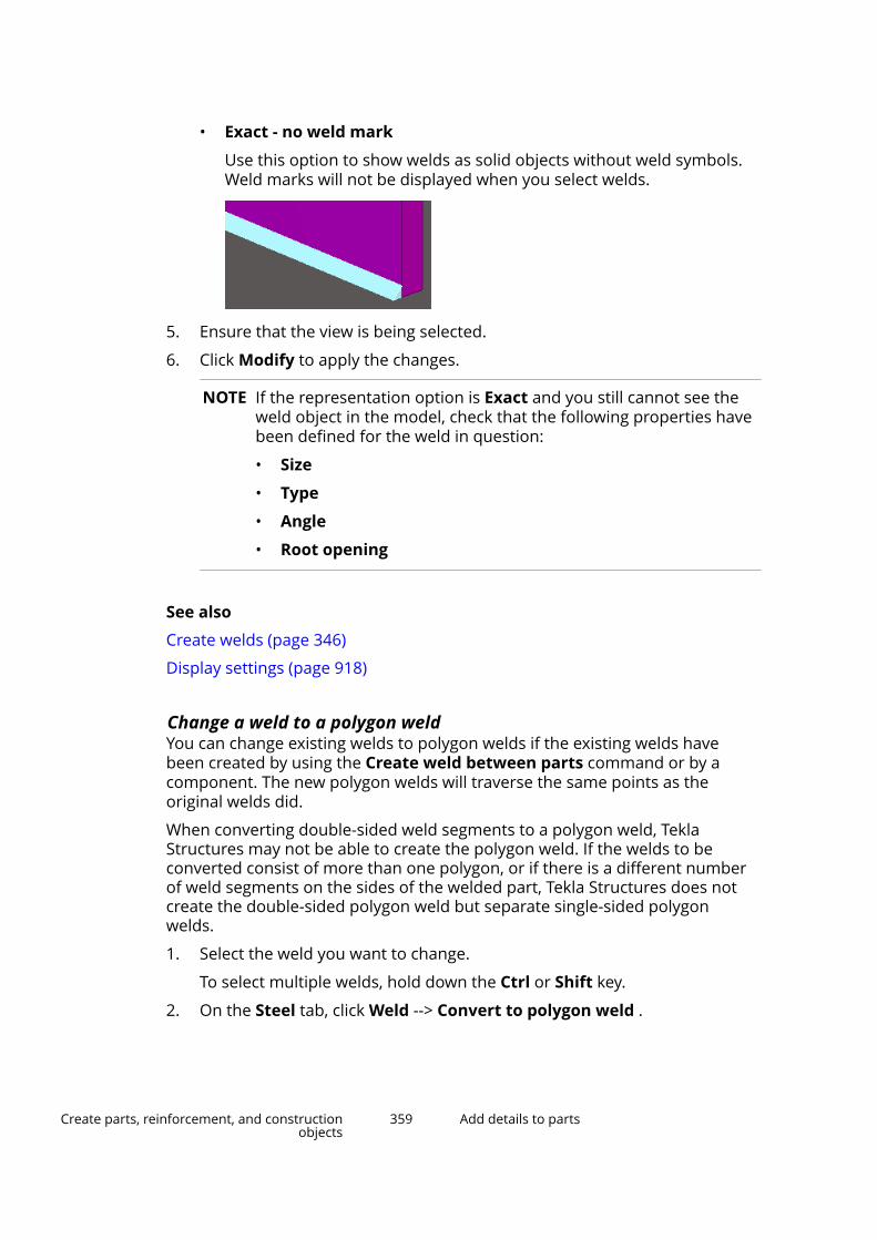
• Exact - no weld mark
Use this option to show welds as solid objects without weld symbols.Weld marks will not be displayed when you select welds.
5. Ensure that the view is being selected.
6. Click Modify to apply the changes.
NOTE If the representation option is Exact and you still cannot see theweld object in the model, check that the following properties havebeen defined for the weld in question:
• Size
• Type
• Angle
• Root opening
See also
Create welds (page 346)
Display settings (page 918)
Change a weld to a polygon weldYou can change existing welds to polygon welds if the existing welds havebeen created by using the Create weld between parts command or by acomponent. The new polygon welds will traverse the same points as theoriginal welds did.
When converting double-sided weld segments to a polygon weld, TeklaStructures may not be able to create the polygon weld. If the welds to beconverted consist of more than one polygon, or if there is a different numberof weld segments on the sides of the welded part, Tekla Structures does notcreate the double-sided polygon weld but separate single-sided polygonwelds.
1. Select the weld you want to change.
To select multiple welds, hold down the Ctrl or Shift key.
2. On the Steel tab, click Weld --> Convert to polygon weld .
Create parts, reinforcement, and constructionobjects
359 Add details to parts
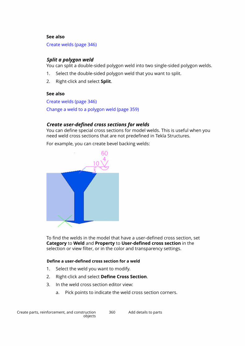
See also
Create welds (page 346)
Split a polygon weldYou can split a double-sided polygon weld into two single-sided polygon welds.
1. Select the double-sided polygon weld that you want to split.
2. Right-click and select Split.
See also
Create welds (page 346)
Change a weld to a polygon weld (page 359)
Create user-defined cross sections for weldsYou can define special cross sections for model welds. This is useful when youneed weld cross sections that are not predefined in Tekla Structures.
For example, you can create bevel backing welds:
To find the welds in the model that have a user-defined cross section, setCategory to Weld and Property to User-defined cross section in theselection or view filter, or in the color and transparency settings.
Define a user-defined cross section for a weld
1. Select the weld you want to modify.
2. Right-click and select Define Cross Section.
3. In the weld cross section editor view:
a. Pick points to indicate the weld cross section corners.
Create parts, reinforcement, and constructionobjects
360 Add details to parts
b. Click the middle mouse button to finish picking.
Remove a user-defined cross section from a weldYou can remove user-defined cross sections from model welds and revert tothe previous standard cross sections.
1. Select a weld that has a user-defined cross section.
2. Right-click and select Remove Cross Section.
Tekla Structures removes the user-defined cross section and uses theprevious standard cross section and properties for the weld.
Limitations
• User-defined weld cross sections are reported using only the above-lineproperties.
• User-defined weld cross sections do not create automatic weldpreparation.
Create fittingsYou can fit the end of a part by creating a straight cutting line between twopoints you pick. Use fittings to shorten beams. Do not use fittings for makingconsiderable beam extensions.
When you create fittings, Tekla Structures fits the part end to the cutting lineand automatically deletes the shortest side of the part. Use plane view(page 29) when you create fittings.
TIP Ensure that the Snap to nearest points (point on line) snap switch isactive when you create fittings.
Limitations:
• Fittings cannot be used on contour plates.
• If you apply a second fitting on the same part end, Tekla Structures willignore the first fitting. This happens if you use the Fit part end commandfor cutting and try to make two cuts on the same part end. In situations likethis, use, for example, the Line cut command instead.
1. On the Edit tab, click Fit part end.
2. Select the part you want to cut with a fitting.
3. Pick the first point of the cutting line.
4. Pick the second point of the cutting line.
Tekla Structures creates a fitting between the two points you picked. Thefitting adjusts the end of a beam on a plane, perpendicular to the viewplane.
Create parts, reinforcement, and constructionobjects
361 Add details to parts

(1) Fitting symbol
See also
Show part handles and part reference lines in a model view (page 303)
Create cutsYou can use cuts to shape a part. Do not use cuts to otherwise change thelength of a part in the model.
Cut parts with a lineUse line cuts to shape the end of a beam or column. A line cut cuts the end ofa beam on a plane that passes through the points you pick. Tekla Structuresdisplays the cut line using dash-and-dot lines.
1. On the Edit tab, click Line cut.
2. Select the part you want to cut.
3. Pick the first point of the cutting line.
4. Pick the second point of the cutting line.
5. Pick the side you want to remove.
6. If you want to modify the cut, use direct modification (page 103).
Create parts, reinforcement, and constructionobjects
362 Add details to parts
(1) Cuts are displayed using dash-and-dot lines
(2) Cut lines can be hidden
Cut parts with a polygonA polygon cut cuts a part using a polygonal shape. Tekla Structures displaysthe cut using dash-and-dot lines.
1. Press Ctrl+P to switch to the plane view (page 29).
2. Ensure that the work plane (page 51) is on the plane you are cutting on.
For example, if you are creating a polygonal cut on the yz plane, youshould temporarily set your work plane to the yz plane as well.
3. On the Edit tab, click Polygon cut.
4. Select the part you want to cut.
5. Pick positions to outline the polygon to be used for cutting.
Define the polygon so that there is some tolerance between the edges. Ifthe edge of a cutting polygon is in exactly the same position as the edge ofthe part to be cut, it can be unclear whether the edge should be cut away.
6. Click the middle mouse button to close the polygon and to cut the part.
7. To modify the cut shape, use direct modification (page 103).
8. If needed, you can modify the cut properties.
a. Double-click the cut to open the Polygon cut properties.
b. Change (page 96) the properties as needed.
c. Click Modify to apply the changes.
Create parts, reinforcement, and constructionobjects
363 Add details to parts

(1) Polygon-shaped cut
(2) Cut lines can be hidden
NOTE Tekla Structures uses the parametric profile BL to create polygonal cuts.
If you are unable to create polygonal cuts, ensure that the BL profile is definedin the profitab.inp file in ..\ProgramData\Trimble\TeklaStructures\<version>\environments\<environment>\profil asfollows:
BL ! PL ! -1 ! ! 1 ! 2 ! ! !
Cut parts with another partYou can cut a part using another part. Tekla Structures displays the cut usingdash-and-dot lines. Note that you can cut parts that already have cuts. Thatcan be useful, for example, when you want to create more sophisticated cutshapes.
1. Create a cutting part and position it through the part you want to cut.
2. On the Edit tab, click Part cut.
Create parts, reinforcement, and constructionobjects
364 Add details to parts
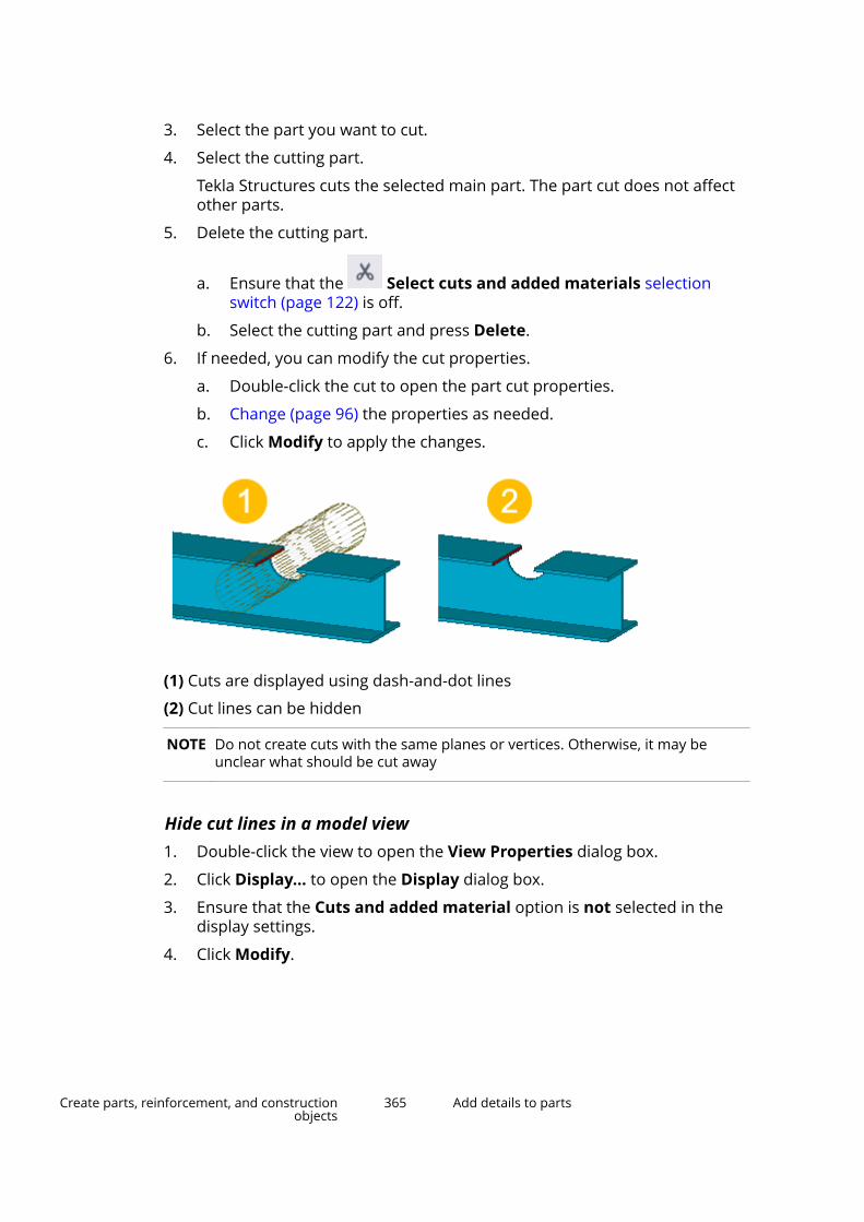
3. Select the part you want to cut.
4. Select the cutting part.
Tekla Structures cuts the selected main part. The part cut does not affectother parts.
5. Delete the cutting part.
a. Ensure that the Select cuts and added materials selectionswitch (page 122) is off.
b. Select the cutting part and press Delete.
6. If needed, you can modify the cut properties.
a. Double-click the cut to open the part cut properties.
b. Change (page 96) the properties as needed.
c. Click Modify to apply the changes.
(1) Cuts are displayed using dash-and-dot lines
(2) Cut lines can be hidden
NOTE Do not create cuts with the same planes or vertices. Otherwise, it may beunclear what should be cut away
Hide cut lines in a model view1. Double-click the view to open the View Properties dialog box.
2. Click Display... to open the Display dialog box.
3. Ensure that the Cuts and added material option is not selected in thedisplay settings.
4. Click Modify.
Create parts, reinforcement, and constructionobjects
365 Add details to parts
Tips on how to cut efficiently• Avoid part faces
Avoid creating cuts that are exactly on the part planes or go throughvertices. Try to position the cut at least 0.3 mm outside of the part planes.
• Use polygon cuts
Whenever possible, use polygon cuts. The Polygon cut commandautomatically extends the cut slightly outside of the part face. Note thatafter creating the polygon, you may have to adjust the position of thehandles manually.
• Use edge chamfers
Whenever possible, use edge chamfers (page 369) instead of small cuts,especially in components.
• Tips for flange cuts
When cutting a flange, if the cutting part cuts very slightly the web as well(at least 0.3 mm), the cut is more likely to succeed. For example, if you arecutting a beam that has roundings, it may be useful to cut even furtheronto the web than just the flange thickness.
• Tips for round tube cuts
Use the Round tube (23) component for round tube cuts. The componentautomatically rotates the cutting part until a successful cut position isfound. If the component fails, rotate the cutting part slightly until you find asuccessful cut position.
NOTE If a cut fails, Tekla Structures displays the cutting part using dash-and-dotlines. An error notification is printed in the session history log stating whichpart and which cut caused the failure.
To locate the failure in the model, click a row that contains an ID number inthe session history log. Tekla Structures selects the corresponding part andcut in the model.
Polygon cut propertiesUse the Polygon cut properties in the property pane to view and modify theproperties of a polygon cut.
Note that the polygon cut properties are available in the property pane onlyafter a polygon cut has been created and selected. You cannot access ormodify the cut properties before the cut is created.
If you have customized (page 213) the property pane layout, the list ofproperties may be different.
Setting DescriptionGeneral
Create parts, reinforcement, and constructionobjects
366 Add details to parts
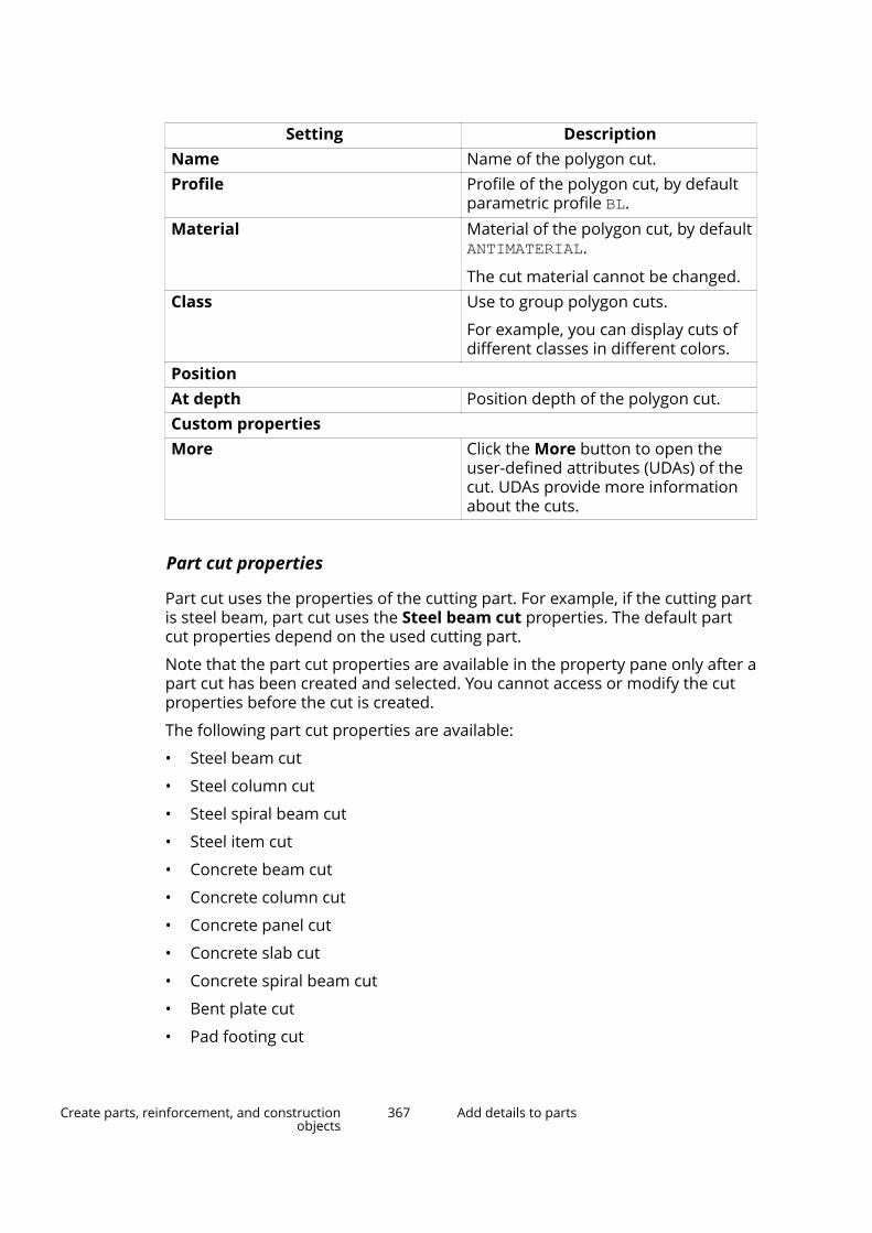
Setting DescriptionName Name of the polygon cut.Profile Profile of the polygon cut, by default
parametric profile BL.Material Material of the polygon cut, by default
ANTIMATERIAL.
The cut material cannot be changed.Class Use to group polygon cuts.
For example, you can display cuts ofdifferent classes in different colors.
PositionAt depth Position depth of the polygon cut.Custom propertiesMore Click the More button to open the
user-defined attributes (UDAs) of thecut. UDAs provide more informationabout the cuts.
Part cut properties
Part cut uses the properties of the cutting part. For example, if the cutting partis steel beam, part cut uses the Steel beam cut properties. The default partcut properties depend on the used cutting part.
Note that the part cut properties are available in the property pane only after apart cut has been created and selected. You cannot access or modify the cutproperties before the cut is created.
The following part cut properties are available:
• Steel beam cut
• Steel column cut
• Steel spiral beam cut
• Steel item cut
• Concrete beam cut
• Concrete column cut
• Concrete panel cut
• Concrete slab cut
• Concrete spiral beam cut
• Bent plate cut
• Pad footing cut
Create parts, reinforcement, and constructionobjects
367 Add details to parts
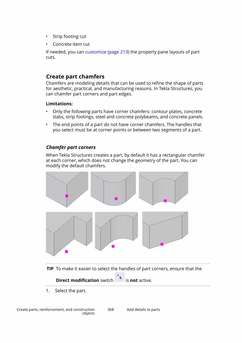
• Strip footing cut
• Concrete item cut
If needed, you can customize (page 213) the property pane layouts of partcuts.
Create part chamfersChamfers are modeling details that can be used to refine the shape of partsfor aesthetic, practical, and manufacturing reasons. In Tekla Structures, youcan chamfer part corners and part edges.
Limitations:
• Only the following parts have corner chamfers: contour plates, concreteslabs, strip footings, steel and concrete polybeams, and concrete panels.
• The end points of a part do not have corner chamfers. The handles thatyou select must be at corner points or between two segments of a part.
Chamfer part cornersWhen Tekla Structures creates a part, by default it has a rectangular chamferat each corner, which does not change the geometry of the part. You canmodify the default chamfers.
TIP To make it easier to select the handles of part corners, ensure that the
Direct modification switch is not active.
1. Select the part.
Create parts, reinforcement, and constructionobjects
368 Add details to parts
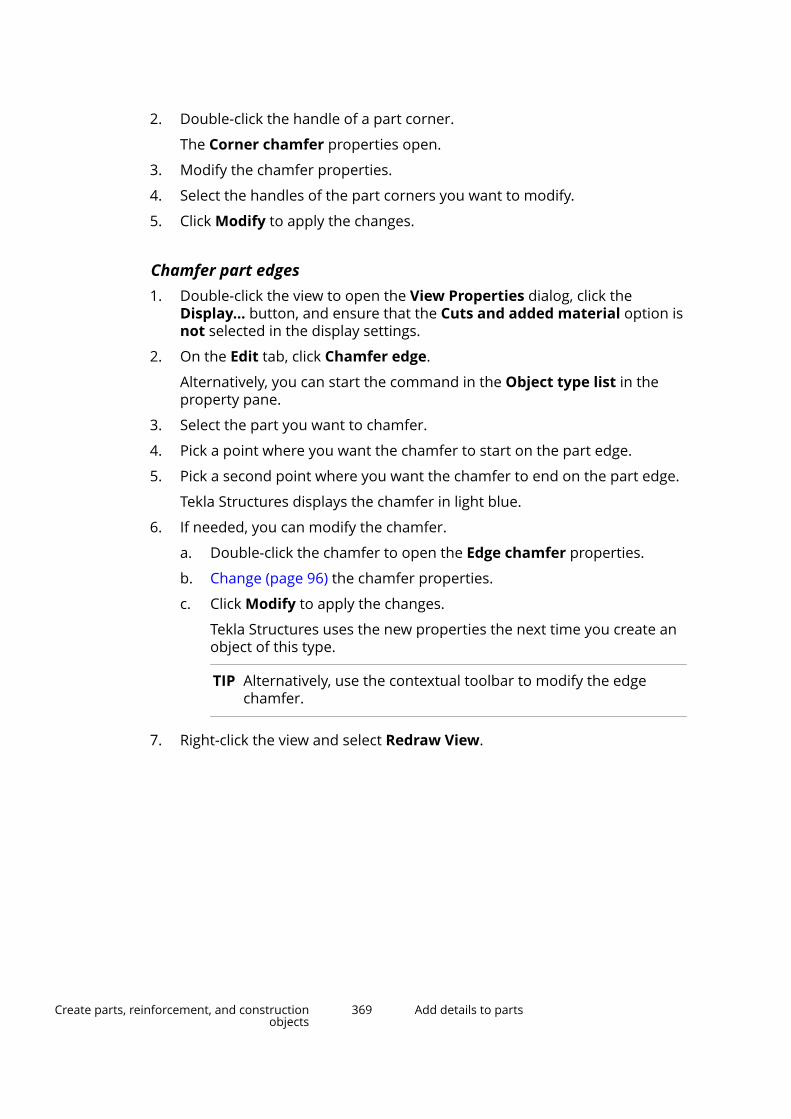
2. Double-click the handle of a part corner.
The Corner chamfer properties open.
3. Modify the chamfer properties.
4. Select the handles of the part corners you want to modify.
5. Click Modify to apply the changes.
Chamfer part edges1. Double-click the view to open the View Properties dialog, click the
Display... button, and ensure that the Cuts and added material option isnot selected in the display settings.
2. On the Edit tab, click Chamfer edge.
Alternatively, you can start the command in the Object type list in theproperty pane.
3. Select the part you want to chamfer.
4. Pick a point where you want the chamfer to start on the part edge.
5. Pick a second point where you want the chamfer to end on the part edge.
Tekla Structures displays the chamfer in light blue.
6. If needed, you can modify the chamfer.
a. Double-click the chamfer to open the Edge chamfer properties.
b. Change (page 96) the chamfer properties.
c. Click Modify to apply the changes.
Tekla Structures uses the new properties the next time you create anobject of this type.
TIP Alternatively, use the contextual toolbar to modify the edgechamfer.
7. Right-click the view and select Redraw View.
Create parts, reinforcement, and constructionobjects
369 Add details to parts
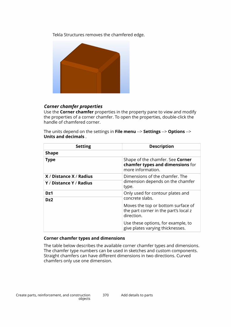
Tekla Structures removes the chamfered edge.
Corner chamfer propertiesUse the Corner chamfer properties in the property pane to view and modifythe properties of a corner chamfer. To open the properties, double-click thehandle of chamfered corner.
The units depend on the settings in File menu --> Settings --> Options -->Units and decimals .
Setting DescriptionShapeType Shape of the chamfer. See Corner
chamfer types and dimensions formore information.
X / Distance X / Radius Dimensions of the chamfer. Thedimension depends on the chamfertype.
Y / Distance Y / Radius
Dz1 Only used for contour plates andconcrete slabs.
Moves the top or bottom surface ofthe part corner in the part’s local zdirection.
Use these options, for example, togive plates varying thicknesses.
Dz2
Corner chamfer types and dimensions
The table below describes the available corner chamfer types and dimensions.The chamfer type numbers can be used in sketches and custom components.Straight chamfers can have different dimensions in two directions. Curvedchamfers only use one dimension.
Create parts, reinforcement, and constructionobjects
370 Add details to parts
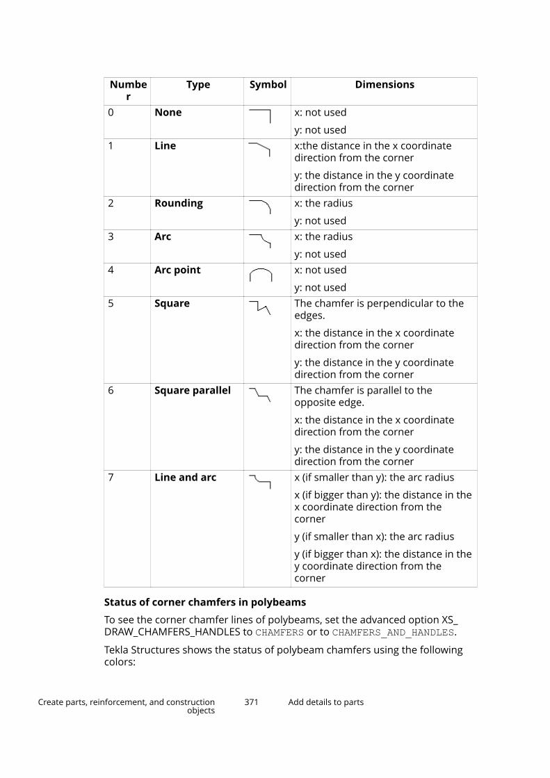
Number
Type Symbol Dimensions
0 None x: not used
y: not used1 Line x:the distance in the x coordinate
direction from the corner
y: the distance in the y coordinatedirection from the corner
2 Rounding x: the radius
y: not used3 Arc x: the radius
y: not used4 Arc point x: not used
y: not used5 Square The chamfer is perpendicular to the
edges.
x: the distance in the x coordinatedirection from the corner
y: the distance in the y coordinatedirection from the corner
6 Square parallel The chamfer is parallel to theopposite edge.
x: the distance in the x coordinatedirection from the corner
y: the distance in the y coordinatedirection from the corner
7 Line and arc x (if smaller than y): the arc radius
x (if bigger than y): the distance in thex coordinate direction from thecorner
y (if smaller than x): the arc radius
y (if bigger than x): the distance in they coordinate direction from thecorner
Status of corner chamfers in polybeams
To see the corner chamfer lines of polybeams, set the advanced option XS_DRAW_CHAMFERS_HANDLES to CHAMFERS or to CHAMFERS_AND_HANDLES.
Tekla Structures shows the status of polybeam chamfers using the followingcolors:
Create parts, reinforcement, and constructionobjects
371 Add details to parts

Color Description ExampleMagenta Correct chamfer
Yellow Correct chamfer thatcannot be unfolded
Red Incorrect chamfer
Edge chamfer propertiesUse the Edge chamfer properties in the property pane to view and modify theproperties of an edge chamfer. To open the properties, double-click the edgechamfer when the chamfer if visible in the model. The file name extension ofan edge chamfer property file is *.cha.
The units depend on the settings in File menu --> Settings --> Options -->Units and decimals .
Setting Description More informationShape on edgeType Shape of the chamfer. Distance X Defines how far away
from the chamfered
Create parts, reinforcement, and constructionobjects
372 Add details to parts
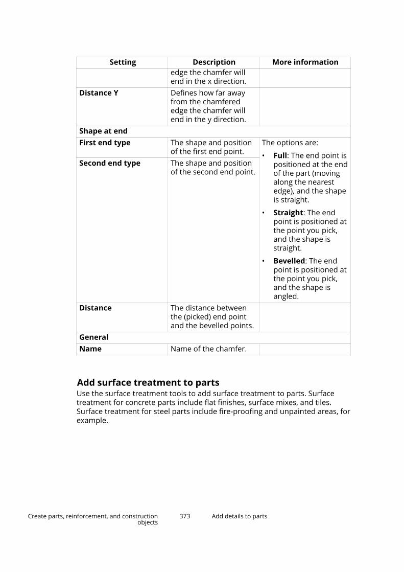
Setting Description More informationedge the chamfer willend in the x direction.
Distance Y Defines how far awayfrom the chamferededge the chamfer willend in the y direction.
Shape at endFirst end type The shape and position
of the first end point.The options are:
• Full: The end point ispositioned at the endof the part (movingalong the nearestedge), and the shapeis straight.
• Straight: The endpoint is positioned atthe point you pick,and the shape isstraight.
• Bevelled: The endpoint is positioned atthe point you pick,and the shape isangled.
Second end type The shape and positionof the second end point.
Distance The distance betweenthe (picked) end pointand the bevelled points.
GeneralName Name of the chamfer.
Add surface treatment to partsUse the surface treatment tools to add surface treatment to parts. Surfacetreatment for concrete parts include flat finishes, surface mixes, and tiles.Surface treatment for steel parts include fire-proofing and unpainted areas, forexample.
Create parts, reinforcement, and constructionobjects
373 Add details to parts

When you modify the shape or size of a part, Tekla Structures automaticallymodifies the surface treatment to fit the part (page 325).
When you create overlapping surface treatments, the smaller surfacetreatment overrides the larger one. The overlapping area is recognized inreports: only the topmost (visible) surface treatment is calculated.
Add surface treatment to an entire part face1. On the Edit tab, click Surfaces --> Surface treatment to part face .
2. Pick the origin of the surface treatment.
3. Pick a point to indicate the direction of the surface treatment.
4. Select the part to apply the surface treatment to.
a. Move the mouse cursor over a part. Tekla Structures highlights thefaces that you can select.
b. Select the part face.
Add surface treatment to a selected area on a part face1. On the Edit tab, click Surfaces --> Surface treatment to selected area .
2. Pick the origin of the surface treatment.
3. Pick a point to indicate the direction of the surface treatment.
Create parts, reinforcement, and constructionobjects
374 Add details to parts

4. Select an area of the part face to apply the surface treatment to.
a. Move the mouse pointer over a part. Tekla Structures highlights thefaces that you can select.
b. Select the part face.
c. Pick three or more points on the part face to define a polygonal area.
Add surface treatment to all faces of a part1. On the Edit tab, click Surfaces --> Surface treatment to all faces of
part .
2. Select the part to apply the surface treatment to.
Add surface treatment to cut faces1. On the Edit tab, click Surfaces and then either Surface treatment to
part face or Surface treatment to selected area.
2. Pick the origin of the surface treatment.
3. Pick the direction.
4. Select the cut face to apply the surface treatment to:
5. If you are using the Surface treatment to selected area command, pickthe points to define the area of the surface treatment.
Surface treatment on chamfered partsTake these things into account when adding surface treatment to chamferedparts:
• Surface treatment does not work on sketched profiles with chamfers.
Create parts, reinforcement, and constructionobjects
375 Add details to parts
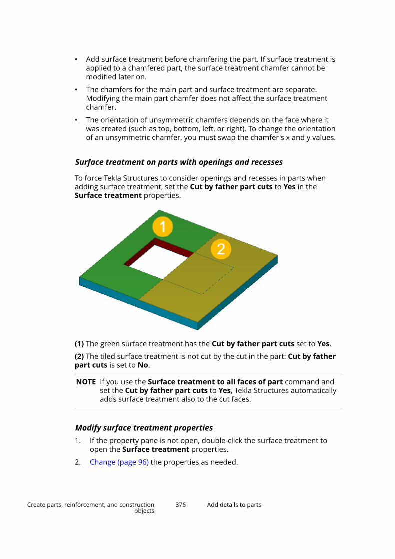
• Add surface treatment before chamfering the part. If surface treatment isapplied to a chamfered part, the surface treatment chamfer cannot bemodified later on.
• The chamfers for the main part and surface treatment are separate.Modifying the main part chamfer does not affect the surface treatmentchamfer.
• The orientation of unsymmetric chamfers depends on the face where itwas created (such as top, bottom, left, or right). To change the orientationof an unsymmetric chamfer, you must swap the chamfer's x and y values.
Surface treatment on parts with openings and recesses
To force Tekla Structures to consider openings and recesses in parts whenadding surface treatment, set the Cut by father part cuts to Yes in theSurface treatment properties.
(1) The green surface treatment has the Cut by father part cuts set to Yes.
(2) The tiled surface treatment is not cut by the cut in the part: Cut by fatherpart cuts is set to No.
NOTE If you use the Surface treatment to all faces of part command andset the Cut by father part cuts to Yes, Tekla Structures automaticallyadds surface treatment also to the cut faces.
Modify surface treatment properties1. If the property pane is not open, double-click the surface treatment to
open the Surface treatment properties.
2. Change (page 96) the properties as needed.
Create parts, reinforcement, and constructionobjects
376 Add details to parts

3. Click Modify to apply the changes.
Tekla Structures uses the new properties the next time you create anobject of the same type.
Note that if you modify the Pattern properties, you need to first click Modifyin the property pane and then redraw the view to make the changes visible.
Surface treatment propertiesUse the Surface treatment properties in the property pane to view andmodify the properties of a surface treatment. To open the properties, double-click the surface treatment. The file name extension of a surface treatmentproperty file is *.srf.
If you have customized (page 213) the property pane layout, the list ofproperties may be different.
Setting DescriptionGeneralName User-definable name of the surface
treatment.Type Select the type of surface treatment.Subtype Select the subtype of a specific
surface treatment.Material Depending on the type of the surface
treatment, select the material of thesurface treatment.
Color Depending on the type of the surfacetreatment, set the color of the surfacetreatment.
Thickness Depending on the type of the surfacetreatment, enter the thickness of thesurface treatment.
Cut by father part cuts To force Tekla Structures to consideropenings and recesses in parts whenadding surface treatment, set this toYes.
PositionIn depth Select the location of the surface
treatment, and set the Depth offsetvalue.
Pattern (for tiled surface treatment)Pattern If you have set Tile surface as the
Type of the surface treatment, select
Create parts, reinforcement, and constructionobjects
377 Add details to parts

Setting Descriptionthe pattern of the tiled surfacetreatment.
Tile width
Tile height
Define the tile width and height.
Mortar height
Mortar width
Define the mortar height and width.
Tile color
Mortar color
If needed, use the color picker to pickthe tile and the mortar color.
Custom propertiesMore Click the More button to open the
user-defined attributes (UDAs) of thesurface treatment. UDAs provideadditional information about thesurface treatment.
Define new surface treatment subtypesYou can add new options to the Subtype list in the Surface treatmentproperties by editing the product_finishes.dat file.
NOTE This section is for advanced users.
1. Copy the product_finishes.dat file to your firm, project, or modelfolder. The file is located under the \ProgramData\Trimble\TeklaStructures\<version>\environments folder. The exact file locationmay vary depending on the folder structure of your environment files.
2. Open the copied file using any text editor.
The first section of the file explains the available types of surfacetreatment. The surface treatment types are hard-coded, so do not modifythis section:
3. Go to the sections that define the options for each type of surfacetreatment:
Create parts, reinforcement, and constructionobjects
378 Add details to parts

4. Add rows to define new options.
a. Define the surface treatment type. For example, 1 for concrete finish.
b. Define a code for the surface treatment option. For example, MF forMagnesium Float.
c. Define the full name of the surface treatment option. For example, Magnesium Float. Remember to enclose the name in doublequotes " ".
5. Save the file.
See also
Add surface treatment to parts (page 373)
Tiled surface treatmentTekla Structures includes complex tile and brick surface treatment options,such as basketweave and herringbone patterns. Tiled surface treatmentoptions are based on repeating tile patterns that are stored in XML format.
The tile pattern surface treatment are available in Surface treatmentproperties if you have set the Type to Tile surface.
NOTE This section is for advanced users.
Define a new tile pattern
1. Copy the TilePatternCatalog.xml file to your firm, project, or modelfolder. The file is located under the \ProgramData\Trimble\TeklaStructures\<version>\environments folder. The exact file locationmay vary depending on the folder structure of your environment files.
2. Open the copied file using any text editor.
3. Add a new <TilePattern> element to the file.
Create parts, reinforcement, and constructionobjects
379 Add details to parts
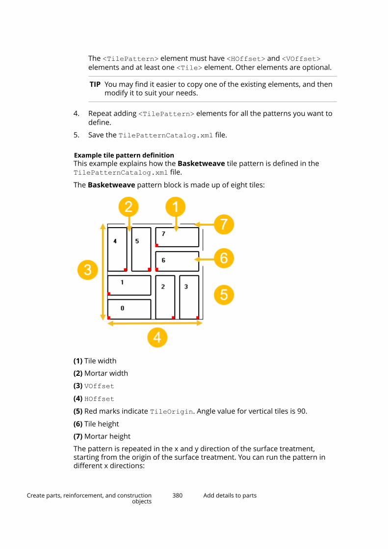
The <TilePattern> element must have <HOffset> and <VOffset>elements and at least one <Tile> element. Other elements are optional.
TIP You may find it easier to copy one of the existing elements, and thenmodify it to suit your needs.
4. Repeat adding <TilePattern> elements for all the patterns you want todefine.
5. Save the TilePatternCatalog.xml file.
Example tile pattern definitionThis example explains how the Basketweave tile pattern is defined in theTilePatternCatalog.xml file.
The Basketweave pattern block is made up of eight tiles:
(1) Tile width
(2) Mortar width
(3) VOffset(4) HOffset(5) Red marks indicate TileOrigin. Angle value for vertical tiles is 90.
(6) Tile height
(7) Mortar height
The pattern is repeated in the x and y direction of the surface treatment,starting from the origin of the surface treatment. You can run the pattern indifferent x directions:
Create parts, reinforcement, and constructionobjects
380 Add details to parts
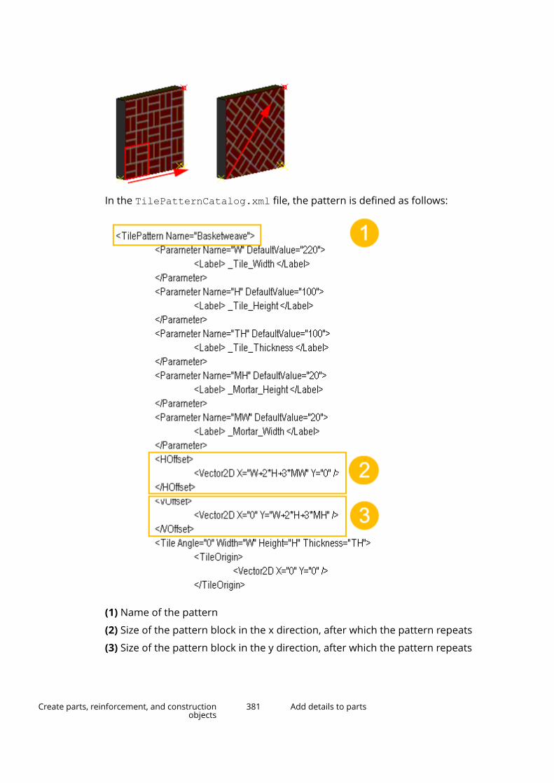
In the TilePatternCatalog.xml file, the pattern is defined as follows:
(1) Name of the pattern
(2) Size of the pattern block in the x direction, after which the pattern repeats
(3) Size of the pattern block in the y direction, after which the pattern repeats
Create parts, reinforcement, and constructionobjects
381 Add details to parts
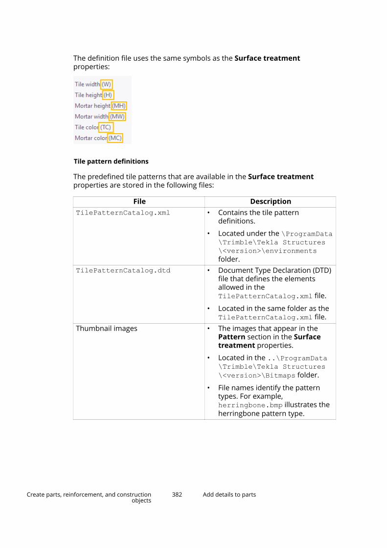
The definition file uses the same symbols as the Surface treatmentproperties:
Tile pattern definitions
The predefined tile patterns that are available in the Surface treatmentproperties are stored in the following files:
File DescriptionTilePatternCatalog.xml • Contains the tile pattern
definitions.
• Located under the \ProgramData\Trimble\Tekla Structures\<version>\environmentsfolder.
TilePatternCatalog.dtd • Document Type Declaration (DTD)file that defines the elementsallowed in theTilePatternCatalog.xml file.
• Located in the same folder as theTilePatternCatalog.xml file.
Thumbnail images • The images that appear in thePattern section in the Surfacetreatment properties.
• Located in the ..\ProgramData\Trimble\Tekla Structures\<version>\Bitmaps folder.
• File names identify the patterntypes. For example,herringbone.bmp illustrates theherringbone pattern type.
Create parts, reinforcement, and constructionobjects
382 Add details to parts

Tile pattern elements
The TilePatternCatalog.xml file can contain the following elements:
Element DescriptionTilePatternCatalog The container for tile patterns.
Required.TilePattern Tile pattern element. Required. This
element can contain the followingelements listed in this table.
HOffset Horizontal offset of the tile pattern.Required.
VOffset Vertical offset of the tile pattern.Required.
Tile The individual tiles used in a tilepattern. At least one required.
Color Color of the tile or mortar, defined bythe RGB values (0–255). Optional.
Parameter Creates an attribute for any elementin the TilePattern. Optional.
Label The label that identifies a parameterin the Surface treatment properties.Optional.
TileOrigin The origin of an individual tile,defined from the origin of thepattern. Optional.
Create an unpainted area using the No paint area componentYou can create an unpainted area between bolted steel parts using the Nopaint area component.
1. Click the Applications & components button in the side pane toopen the Applications & components catalog.
2. Search for No paint area.
3. On the General tab:
a. Click the Load bolt standards button to display the available boltstandards, and select the relevant standards.
b. Select the clearance location from the Create for list.
Create parts, reinforcement, and constructionobjects
383 Add details to parts
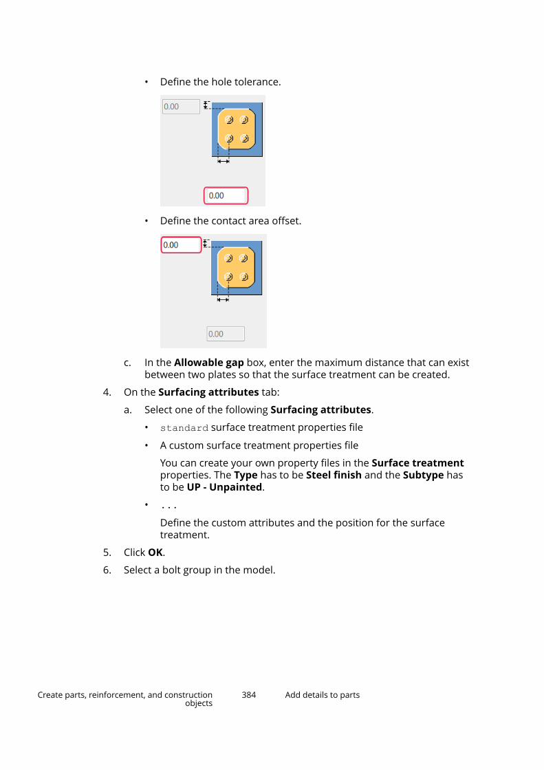
• Define the hole tolerance.
• Define the contact area offset.
c. In the Allowable gap box, enter the maximum distance that can existbetween two plates so that the surface treatment can be created.
4. On the Surfacing attributes tab:
a. Select one of the following Surfacing attributes.
• standard surface treatment properties file
• A custom surface treatment properties file
You can create your own property files in the Surface treatmentproperties. The Type has to be Steel finish and the Subtype hasto be UP - Unpainted.
• ...Define the custom attributes and the position for the surfacetreatment.
5. Click OK.
6. Select a bolt group in the model.
Create parts, reinforcement, and constructionobjects
384 Add details to parts

The unpainted area is created between the bolted parts.
See also
Add surface treatment to parts (page 373)
Add surfaces to part faces and pour object facesYou can add surfaces to the faces of parts and pour objects in the model. Youcan add surfaces to any face geometry, for example curved faces. You can usesurfaces for calculating surface areas, such as formwork areas.
Surfaces are associated with the objects they are attached to. Surfaces cannotexist as standalone objects. A surface can be associated either with a cast-in-place part or a pour object, but not with both. Surfaces associated with partsor pours can be shown in reports as belonging to those objects.
If you modify the geometry of the associated part, the surface will adapt to thechanges. If you delete or move the associated part, the surface will follow. Ifyou copy an object that has a surface, the surface will not be copied. If asurface is added to a pour object, it will not automatically adapt to changesthat only affect the pour object, such as inserting pour breaks.
Limitations:
Create parts, reinforcement, and constructionobjects
385 Add details to parts

• Surfaces do not recognize faces created by displaying objects with highaccuracy, such as curved profile fillets.
• Surfaces do not have handles, so their geometry cannot be modifiedseparately from the associated object.
• Surfaces cannot be copied.
• Surfaces cannot be moved or rotated without the associated object.
• Surfaces are not shown in drawings.
Add a surface to a face1. On the Edit tab, click Surfaces --> Add surface to face.
2. Depending on whether you want to create the surface on a part or on apour object, use a part view or a pour view (page 404).
To switch between part and pour views, click Pour view on the Concretetab.
3. Select the part face or pour object face to which you want to add thesurface.
Tekla Structures adds the surface using the Surface properties in theproperty pane.
If you modify the properties, Tekla Structures uses the new properties thenext time you create an object of the same type.
Modify surface properties1. If the property pane is not open, double-click the surface to open the
Surface properties.
2. Change (page 96) the properties as needed.
For example, you can define the surface type and whether you want thesurface to be cut by the holes in the part or pour object.
3. Click Modify to apply the changes.
Tekla Structures uses the properties the next time you create an object ofthe same type.
2.5 Create assembliesThis section explains how to turn steel parts into assemblies.
Tekla Structures creates assemblies of steel parts when you use a workshopweld or bolt to join parts together. Assemblies and their main parts are
Create parts, reinforcement, and constructionobjects
386 Create assemblies

automatically defined when you create single workshop welds or bolts, orwhen you apply automatic connections that create workshop welds or bolts.
Click the links below to find out more:
Create an assembly (page 387)
Add objects to assemblies (page 390)
Change the assembly main part (page 392)
Change the main assembly (page 393)
Remove objects from an assembly (page 393)
Check and highlight objects in an assembly (page 393)
Explode an assembly (page 394)
Assembly examples (page 394)
Create an assembly
1. Ensure that the Select assemblies selection switch (page 122) isactive.
2. Select the parts and/or assemblies that you want to join together.
3. Right-click and select Assembly --> Make into Assembly .
See also
Create assemblies (page 386)
Create a sub-assembly (page 387)
Use bolts to create assemblies (page 388)
Use welds to create assemblies (page 389)
Create a sub-assemblyYou can create a sub-assembly of parts that are already in an assembly.
1. Ensure that the Select objects in assemblies selection switch(page 122) is active.
2. Select the parts you want to include in the sub-assembly.
3. Right-click and select Make into Sub-Assembly.
See also
Create an assembly (page 387)
Create parts, reinforcement, and constructionobjects
387 Create assemblies

Use bolts to create assembliesYou can use bolts to create and connect assemblies. You can create nestedassemblies by connecting sub-assemblies to an existing assembly, or you canjust connect more parts to assemblies using bolts.
To control how Tekla Structures creates assemblies, use the Connect as andBolt type lists in the Bolt properties. The order in which you select parts whencreating the connection determines the main and secondary parts of theassembly or the assembly hierarchy.
Connect as Bolt type ResultAs sub-assembly Workshop or Site Nested assembly with the assembly
you are bolting as a sub-assembly.
The first part you pick determines theassembly to which you are bolting.
As secondarypart
Workshop Basic assembly with the part you arebolting as a secondary part.
The first part you pick usuallybecomes the main part in theassembly.
As secondarypart
Site No assembly created.
See also
Create assemblies (page 386)
Bolt sub-assemblies to an existing assembly (page 388)
Bolt sub-assemblies to an existing assembly
1. On the Steel tab, hold down Shift and click Bolt to open the Boltproperties.
2. In the Connect as list, select As sub-assembly.
3. Select a part in the assembly to bolt to.
4. Select a part in the sub-assembly to be bolted.
5. Pick the bolt group origin.
6. Pick a point to indicate the bolt group x direction.
See also
Use bolts to create assemblies (page 388)
Create parts, reinforcement, and constructionobjects
388 Create assemblies
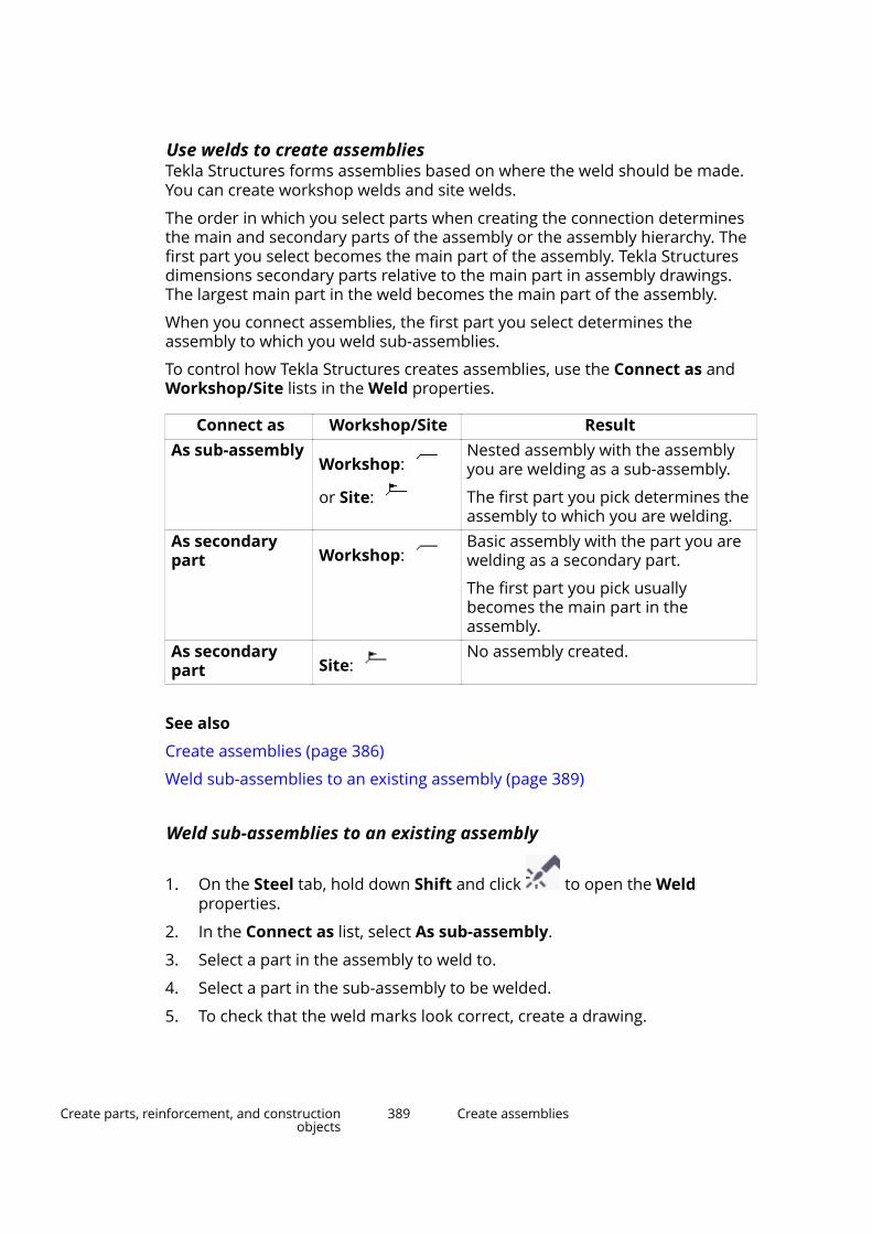
Use welds to create assembliesTekla Structures forms assemblies based on where the weld should be made.You can create workshop welds and site welds.
The order in which you select parts when creating the connection determinesthe main and secondary parts of the assembly or the assembly hierarchy. Thefirst part you select becomes the main part of the assembly. Tekla Structuresdimensions secondary parts relative to the main part in assembly drawings.The largest main part in the weld becomes the main part of the assembly.
When you connect assemblies, the first part you select determines theassembly to which you weld sub-assemblies.
To control how Tekla Structures creates assemblies, use the Connect as andWorkshop/Site lists in the Weld properties.
Connect as Workshop/Site ResultAs sub-assembly
Workshop:
or Site:
Nested assembly with the assemblyyou are welding as a sub-assembly.
The first part you pick determines theassembly to which you are welding.
As secondarypart Workshop:
Basic assembly with the part you arewelding as a secondary part.
The first part you pick usuallybecomes the main part in theassembly.
As secondarypart Site:
No assembly created.
See also
Create assemblies (page 386)
Weld sub-assemblies to an existing assembly (page 389)
Weld sub-assemblies to an existing assembly
1. On the Steel tab, hold down Shift and click to open the Weldproperties.
2. In the Connect as list, select As sub-assembly.
3. Select a part in the assembly to weld to.
4. Select a part in the sub-assembly to be welded.
5. To check that the weld marks look correct, create a drawing.
Create parts, reinforcement, and constructionobjects
389 Create assemblies
See also
Use welds to create assemblies (page 389)
Add objects to assemblies
You can add objects to assemblies in the following ways:
To Do one of the followingCreate a basic assembly • Add parts to an existing assembly
as secondary parts.
• Bolt or weld parts to an existingassembly as secondary parts.
Create a nested assembly • Add parts to an existing assemblyas secondary parts.
• Bolt or weld assemblies to anexisting assembly as sub-assemblies.
• Add assemblies to an existingassembly as sub-assemblies.
• Join existing assemblies togetherwithout adding any loose parts.
NOTE Sub-assemblies in a nested assembly retain their own assemblyinformation and main part. You can also define properties separatelyfor the sub-assemblies and the nested assembly in the partproperties.
See also
Create assemblies (page 386)
Assembly hierarchy (page 390)
Add parts to an assembly (page 391)
Create a nested assembly (page 392)
Join assemblies (page 392)
Assembly hierarchy
You can work on any level of a nested assembly, from single parts and bolts,through the basic and sub-assemblies, up to the highest level of the nestedassembly. Hold down the Shift key and scroll with the mouse wheel to select
Create parts, reinforcement, and constructionobjects
390 Create assemblies
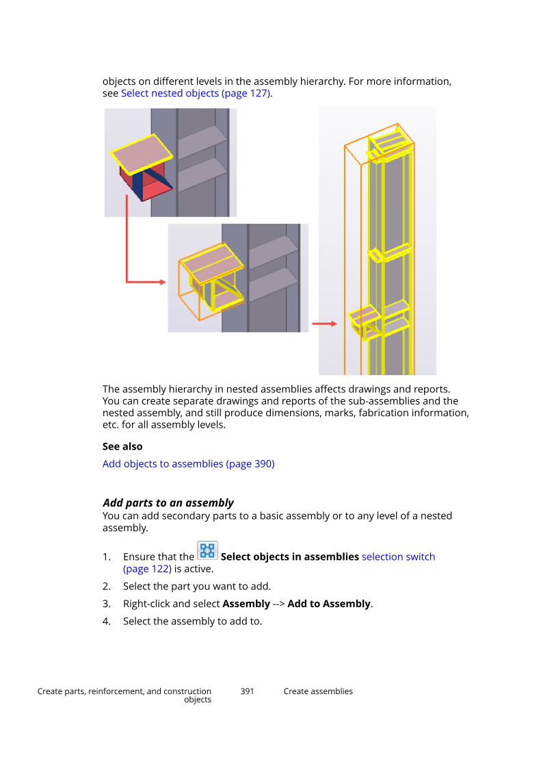
objects on different levels in the assembly hierarchy. For more information,see Select nested objects (page 127).
The assembly hierarchy in nested assemblies affects drawings and reports.You can create separate drawings and reports of the sub-assemblies and thenested assembly, and still produce dimensions, marks, fabrication information,etc. for all assembly levels.
See also
Add objects to assemblies (page 390)
Add parts to an assemblyYou can add secondary parts to a basic assembly or to any level of a nestedassembly.
1. Ensure that the Select objects in assemblies selection switch(page 122) is active.
2. Select the part you want to add.
3. Right-click and select Assembly --> Add to Assembly.
4. Select the assembly to add to.
Create parts, reinforcement, and constructionobjects
391 Create assemblies
See also
Add objects to assemblies (page 390)
Create a nested assembly
1. Ensure that the Select assemblies selection switch (page 122) isactive.
2. Select the assemblies you want to add to another assembly. They willbecome sub-assemblies in the nested assembly.
3. Right-click and select Assembly --> Add as Sub-Assembly.
4. Select the assembly to add to.
See also
Add objects to assemblies (page 390)
Join assembliesYou can join existing assemblies without adding any loose parts.
1. Ensure that the Select assemblies selection switch (page 122) isactive.
2. Select the assemblies you want to join.
3. Right-click and select Assembly --> Make into Assembly.
The assembly with the largest volume becomes the main assembly.
See also
Change the main assembly (page 393)
Add objects to assemblies (page 390)
Change the assembly main partThe main part in a steel assembly has other parts welded or bolted to it. Bydefault, the main part is not welded or bolted to any other parts. You canchange the main part in an assembly.
1. If needed, check (page 393) what is currently the main part of theassembly.
2. Ensure that the Select objects in assemblies selection switch(page 122) is active.
3. On the Steel tab, click Assembly --> Set as main object.
Create parts, reinforcement, and constructionobjects
392 Create assemblies
4. Select the new main part.
Tekla Structures changes the main part.
See also
Add objects to assemblies (page 390)
Change the main assemblyWhen you join two or more assemblies together, the assembly with the largestvolume becomes the main assembly. You can change the main assembly in anested assembly at any time.
1. Select the new main assembly.
2. Right-click and select Assembly --> Set as New Main Sub-Assembly .
See also
Add objects to assemblies (page 390)
Remove objects from an assembly1. Select the part or sub-assembly you want to remove.
2. Right-click and select Assembly --> Remove from Assembly.
See also
Create assemblies (page 386)
Check and highlight objects in an assemblyUse the Inquire tool to check which objects belong to a particular assembly.
1. On the ribbon, click the down arrow next to , and then selectAssembly objects.
2. Select a part that belongs to an assembly.
Tekla Structures highlights the other parts that belong to the sameassembly. The following colors are used:
Object type Highlight colorConcrete - main part magentaConcrete - secondary part cyanReinforcement blue
Create parts, reinforcement, and constructionobjects
393 Create assemblies
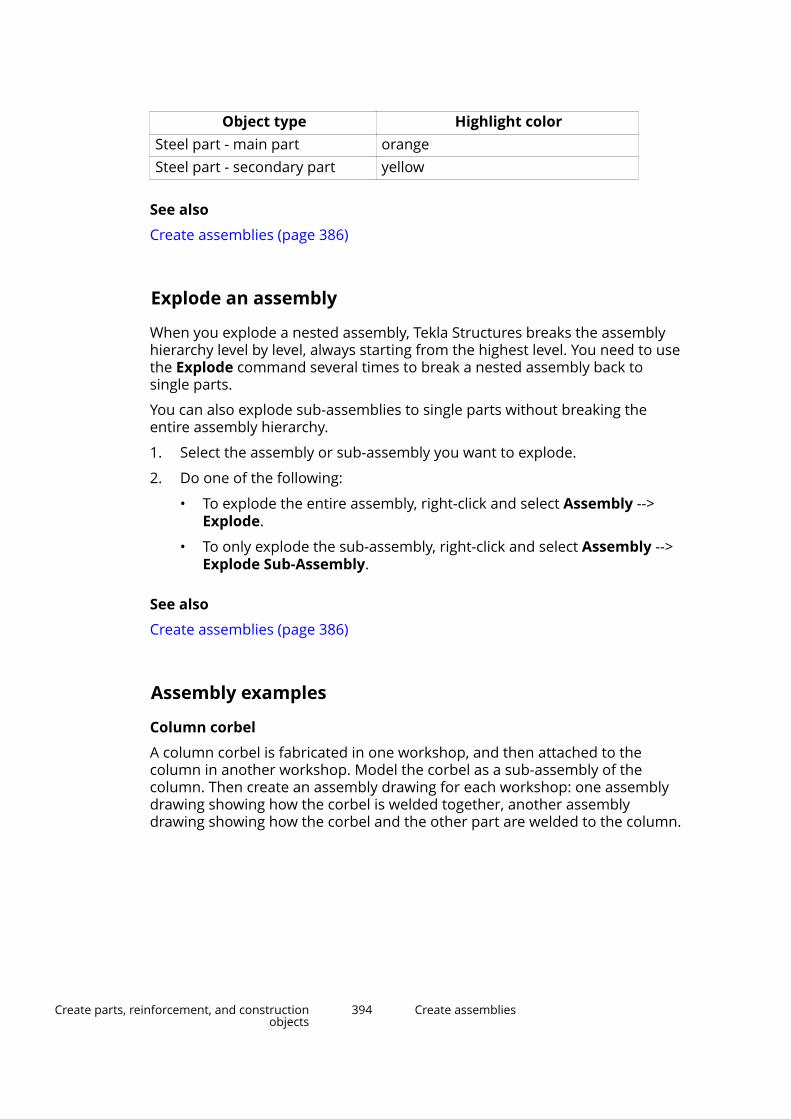
Object type Highlight colorSteel part - main part orangeSteel part - secondary part yellow
See also
Create assemblies (page 386)
Explode an assembly
When you explode a nested assembly, Tekla Structures breaks the assemblyhierarchy level by level, always starting from the highest level. You need to usethe Explode command several times to break a nested assembly back tosingle parts.
You can also explode sub-assemblies to single parts without breaking theentire assembly hierarchy.
1. Select the assembly or sub-assembly you want to explode.
2. Do one of the following:
• To explode the entire assembly, right-click and select Assembly -->Explode.
• To only explode the sub-assembly, right-click and select Assembly -->Explode Sub-Assembly.
See also
Create assemblies (page 386)
Assembly examples
Column corbel
A column corbel is fabricated in one workshop, and then attached to thecolumn in another workshop. Model the corbel as a sub-assembly of thecolumn. Then create an assembly drawing for each workshop: one assemblydrawing showing how the corbel is welded together, another assemblydrawing showing how the corbel and the other part are welded to the column.
Create parts, reinforcement, and constructionobjects
394 Create assemblies

Drawing 2, Workshop 2
Drawing 1, Workshop 1
Complex truss
Model the halves of a complex truss as assemblies. Create assembly drawingsfor the workshop to fabricate the truss halves. Then create another assemblydrawing showing how the halves should be joined on site.
Built-up profile
In a frame of built-up columns and beams, each built-up profile can be a sub-assembly. You can create an assembly drawing showing the entire frame, andseparate drawings showing how the columns and beams are constructed.
See also
Create assemblies (page 386)
Create parts, reinforcement, and constructionobjects
395 Create assemblies
2.6 Create cast unitsThis section explains how to create cast units.
By default, each concrete part is considered a separate cast unit. Forconstruction purposes, you may need to merge several concrete parts into onecast unit. For example, a single cast unit could consist of a column withcorbels.
Click the links below to find out more:
Define the cast unit type of a part (page 396)
Create a cast unit (page 397)
Add objects to a cast unit (page 397)
Change the cast unit main part (page 398)
Remove objects from a cast unit (page 398)
Check and highlight objects in a cast unit (page 398)
Explode a cast unit (page 399)
Casting direction (page 399)
Define the cast unit type of a partYou must define the cast unit type of concrete parts. Tekla Structures checksthe cast unit type of the main part each time you create or modify a cast unit.Precast and cast-in-place parts cannot be mixed within a cast unit.
1. Double-click a concrete part to open the part properties in the propertypane.
2. Go to the Cast unit section.
3. In the Cast unit list, select one of the following:
• Cast in place
Cast units that are constructed fully in their final location.
• Precast
Cast units that are built at another location and transported to theirfinal location for placement in the full structure.
4. Click Modify to save the changes.
NOTE It is important to use the correct cast unit type, because some functionalities,for example numbering, are based on the cast unit type.
Create parts, reinforcement, and constructionobjects
396 Create cast units
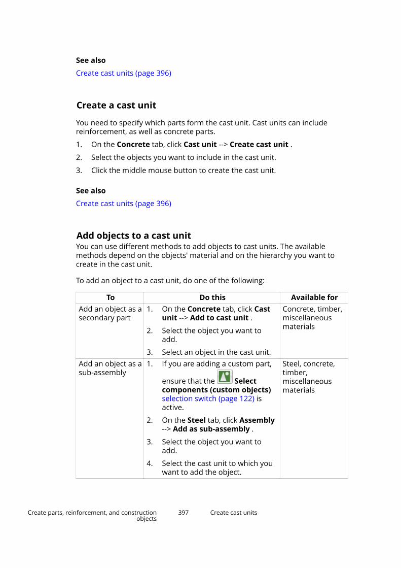
See also
Create cast units (page 396)
Create a cast unit
You need to specify which parts form the cast unit. Cast units can includereinforcement, as well as concrete parts.
1. On the Concrete tab, click Cast unit --> Create cast unit .
2. Select the objects you want to include in the cast unit.
3. Click the middle mouse button to create the cast unit.
See also
Create cast units (page 396)
Add objects to a cast unitYou can use different methods to add objects to cast units. The availablemethods depend on the objects' material and on the hierarchy you want tocreate in the cast unit.
To add an object to a cast unit, do one of the following:
To Do this Available forAdd an object as asecondary part
1. On the Concrete tab, click Castunit --> Add to cast unit .
2. Select the object you want toadd.
3. Select an object in the cast unit.
Concrete, timber,miscellaneousmaterials
Add an object as asub-assembly
1. If you are adding a custom part,
ensure that the Selectcomponents (custom objects)selection switch (page 122) isactive.
2. On the Steel tab, click Assembly--> Add as sub-assembly .
3. Select the object you want toadd.
4. Select the cast unit to which youwant to add the object.
Steel, concrete,timber,miscellaneousmaterials
Create parts, reinforcement, and constructionobjects
397 Create cast units
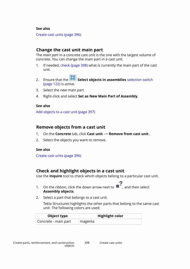
See also
Create cast units (page 396)
Change the cast unit main partThe main part in a concrete cast unit is the one with the largest volume ofconcrete. You can change the main part in a cast unit.
1. If needed, check (page 398) what is currently the main part of the castunit.
2. Ensure that the Select objects in assemblies selection switch(page 122) is active.
3. Select the new main part.
4. Right-click and select Set as New Main Part of Assembly.
See also
Add objects to a cast unit (page 397)
Remove objects from a cast unit1. On the Concrete tab, click Cast unit --> Remove from cast unit .
2. Select the objects you want to remove.
See also
Create cast units (page 396)
Check and highlight objects in a cast unitUse the Inquire tool to check which objects belong to a particular cast unit.
1. On the ribbon, click the down arrow next to , and then selectAssembly objects.
2. Select a part that belongs to a cast unit.
Tekla Structures highlights the other parts that belong to the same castunit. The following colors are used:
Object type Highlight colorConcrete - main part magenta
Create parts, reinforcement, and constructionobjects
398 Create cast units
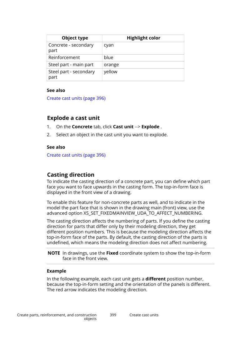
Object type Highlight colorConcrete - secondarypart
cyan
Reinforcement blueSteel part - main part orangeSteel part - secondarypart
yellow
See also
Create cast units (page 396)
Explode a cast unit1. On the Concrete tab, click Cast unit --> Explode .
2. Select an object in the cast unit you want to explode.
See also
Create cast units (page 396)
Casting directionTo indicate the casting direction of a concrete part, you can define which partface you want to face upwards in the casting form. The top-in-form face isdisplayed in the front view of a drawing.
To enable this feature for non-concrete parts as well, and to indicate in themodel the part face that is shown in the drawing main (front) view, use theadvanced option XS_SET_FIXEDMAINVIEW_UDA_TO_AFFECT_NUMBERING.
The casting direction affects the numbering of parts. If you define the castingdirection for parts that differ only by their modeling direction, they getdifferent position numbers. This is because the modeling direction affects thetop-in-form face of the parts. By default, the casting direction of the parts isundefined, which means the modeling direction does not affect numbering.
NOTE In drawings, use the Fixed coordinate system to show the top-in-formface in the front view.
Example
In the following example, each cast unit gets a different position number,because the top-in-form setting and the orientation of the panels is different.The red arrow indicates the modeling direction.
Create parts, reinforcement, and constructionobjects
399 Create cast units
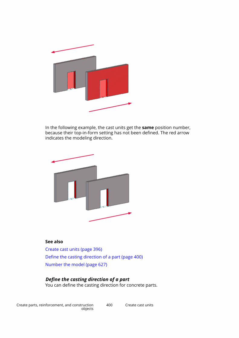
In the following example, the cast units get the same position number,because their top-in-form setting has not been defined. The red arrowindicates the modeling direction.
See also
Create cast units (page 396)
Define the casting direction of a part (page 400)
Number the model (page 627)
Define the casting direction of a partYou can define the casting direction for concrete parts.
Create parts, reinforcement, and constructionobjects
400 Create cast units
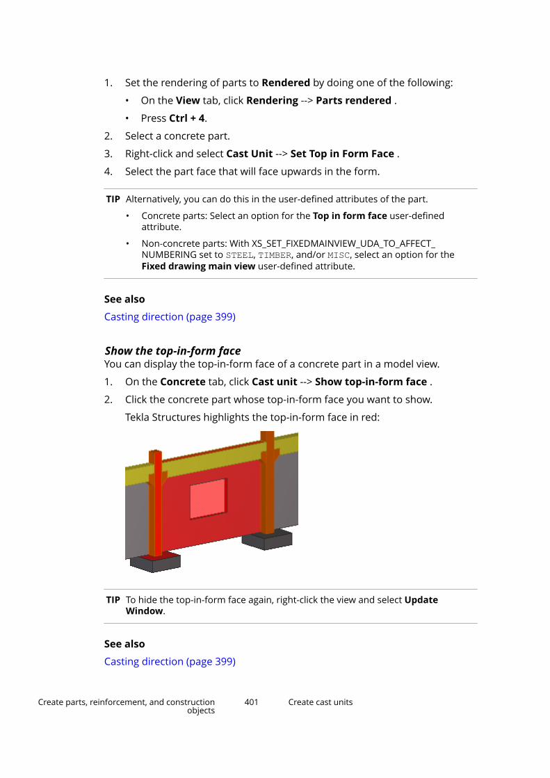
1. Set the rendering of parts to Rendered by doing one of the following:
• On the View tab, click Rendering --> Parts rendered .
• Press Ctrl + 4.
2. Select a concrete part.
3. Right-click and select Cast Unit --> Set Top in Form Face .
4. Select the part face that will face upwards in the form.
TIP Alternatively, you can do this in the user-defined attributes of the part.
• Concrete parts: Select an option for the Top in form face user-definedattribute.
• Non-concrete parts: With XS_SET_FIXEDMAINVIEW_UDA_TO_AFFECT_NUMBERING set to STEEL, TIMBER, and/or MISC, select an option for theFixed drawing main view user-defined attribute.
See also
Casting direction (page 399)
Show the top-in-form faceYou can display the top-in-form face of a concrete part in a model view.
1. On the Concrete tab, click Cast unit --> Show top-in-form face .
2. Click the concrete part whose top-in-form face you want to show.
Tekla Structures highlights the top-in-form face in red:
TIP To hide the top-in-form face again, right-click the view and select UpdateWindow.
See also
Casting direction (page 399)
Create parts, reinforcement, and constructionobjects
401 Create cast units

2.7 Manage poursWith the pour management functionality of Tekla Structures, you can view thegeometry of cast-in-place concrete structures, show them as parts or as pourobjects, plan pours and pour breaks, and report pour information, such asconcrete volumes and formwork areas. You can define pours, pour units, pourobjects, and pour breaks for concrete parts whose cast unit type is Cast inplace.
In Tekla Structures, a pour object is a building object that consists of one ormore cast-in-place concrete parts, or parts of them. The cast-in-place concreteparts are merged into one pour object if they have the same material gradeand they touch each other. They also need be in the same pour phase to bemerged. Pour objects are visible in pour views.
A pour unit is an entity for cast-in-place concrete and it consists of a pourobject and all related reinforcement, embeds, and other objects that need tobe in place before concrete can be poured on the building site.
A pour is a group of pour objects that is poured at one go.
With a pour break you can split a pour object into smaller pour objects.
NOTE Pour management is mainly targeted at contractors for quantity take-off, planning, and on-site activities. By default, pour management isdisabled in new models in most roles. You can enable pourmanagement (page 402) in the current model using the advancedoption XS_ENABLE_POUR_MANAGEMENT.
See also
Enable pour management (page 402)
View cast-in-place concrete structures (page 404)
Define the pour phase of a part (page 407)
Pour objects (page 408)
Pour units (page 410)
Pour breaks (page 415)
Troubleshoot pours (page 422)
Example: Create concrete geometry and work with pours (page 425)
Enable pour managementBy default, pour management is disabled in new models in most roles. You canenable pour management in the current model in the Advanced Optionsdialog box.
Create parts, reinforcement, and constructionobjects
402 Manage pours

WARNING If pour management is enabled in the model, do not disable itusing XS_ENABLE_POUR_MANAGEMENT, especially in the middle ofthe project. This may cause problems if you have drawingscontaining pour objects, and if you are sharing your model. Thepour objects and pour breaks in the model and in the drawingsmay get invalid, and you may lose all pour-related modeling work.
1. On the File menu, click Settings --> Advanced options to open theAdvanced Options dialog box.
2. Under Concrete Detailing, set XS_ENABLE_POUR_MANAGEMENT to TRUE.
3. Click OK.
4. Save and re-open the model for the change to take effect.
The commands that show and create pour objects and pour breaks arenow available in the model and in drawings.
See also
Disable pour management temporarily (page 403)
Disable pour management temporarilyYou can temporarily disable pour management. This may be needed if pourmanagement seems to significantly slow down your model, for example, whenthe pours and pour objects are very large and require splitting into smallerones.
When pour management is temporarily disabled, the existing pour objects andpour breaks are still present in the model, but any modifications to the modelgeometry that would normally update pour objects and pour breaksautomatically will not do that. Any information related to pours will beoutdated and inaccurate, for example, in reports, and the pour breaks will notbe adaptive. They will be updated automatically when you re-enable pourmanagement.
To disable or re-enable pour management:
1. Go to Quick Launch, start typing pours and pour breaks, and selectthe Toggle pours and pour breaks command from the list that appears.
2. Click Yes in the confirmation dialog box.
NOTE If you are working in a Tekla Model Sharing model, remember to re-enablepour management before you write out. Similarly, if you are working in themulti-user mode, re-enable pour management before you save the model. Inthis way, information related to pours stays up to date for all users of themodel.
Create parts, reinforcement, and constructionobjects
403 Manage pours
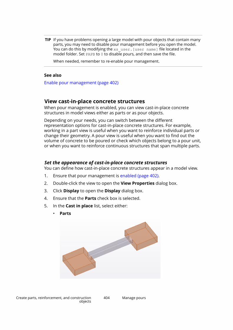
TIP If you have problems opening a large model with pour objects that contain manyparts, you may need to disable pour management before you open the model.You can do this by modifying the xs_user.[user name] file located in themodel folder. Set PAPB to 0 to disable pours, and then save the file.
When needed, remember to re-enable pour management.
See also
Enable pour management (page 402)
View cast-in-place concrete structuresWhen pour management is enabled, you can view cast-in-place concretestructures in model views either as parts or as pour objects.
Depending on your needs, you can switch between the differentrepresentation options for cast-in-place concrete structures. For example,working in a part view is useful when you want to reinforce individual parts orchange their geometry. A pour view is useful when you want to find out thevolume of concrete to be poured or check which objects belong to a pour unit,or when you want to reinforce continuous structures that span multiple parts.
Set the appearance of cast-in-place concrete structuresYou can define how cast-in-place concrete structures appear in a model view.
1. Ensure that pour management is enabled (page 402).
2. Double-click the view to open the View Properties dialog box.
3. Click Display to open the Display dialog box.
4. Ensure that the Parts check box is selected.
5. In the Cast in place list, select either:
• Parts
Create parts, reinforcement, and constructionobjects
404 Manage pours

• Pours
6. If you selected Parts for the cast-in-place concrete structures, in the Castin place parts list, select either:
• Merged
Tekla Structures shows concrete parts as merged in the model if theircast unit type is Cast in place, if they have the same material gradeand pour phase (page 407) number, and if they touch or overlap oneanother. When these criteria are met, Tekla Structures removes theoutlines of the individual parts within each continuous concretestructure.
• Separated
Tekla Structures shows concrete parts as individual parts andseparated by their outlines.
Create parts, reinforcement, and constructionobjects
405 Manage pours
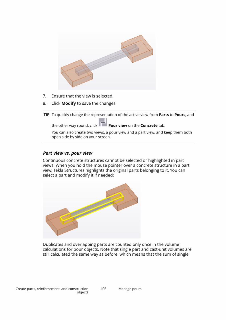
7. Ensure that the view is selected.
8. Click Modify to save the changes.
TIP To quickly change the representation of the active view from Parts to Pours, and
the other way round, click Pour view on the Concrete tab.
You can also create two views, a pour view and a part view, and keep them bothopen side by side on your screen.
Part view vs. pour viewContinuous concrete structures cannot be selected or highlighted in partviews. When you hold the mouse pointer over a concrete structure in a partview, Tekla Structures highlights the original parts belonging to it. You canselect a part and modify it if needed:
Duplicates and overlapping parts are counted only once in the volumecalculations for pour objects. Note that single part and cast-unit volumes arestill calculated the same way as before, which means that the sum of single
Create parts, reinforcement, and constructionobjects
406 Manage pours
part and cast-unit volumes may be higher than the volume of pour objectsthat are defined from exactly the same part geometry.
When you reinforce a concrete structure, you need to reinforce the individualconcrete parts within it in part views, or you can reinforce pour objects byusing Reinforcing Bar Shape Catalog or rebar sets in pour views. Therefore,you can reinforce a part of a continuous concrete structure independentlyfrom the whole continuous concrete structure. All reinforcement are visibleboth in part views and in pour views.
Define the pour phase of a partUse the pour phase property to separate pour objects from one another. Bydefining pour phases, you can prevent cast-in-place concrete parts frommerging even if they have the same material grade and they touch or overlapone another.
NOTE Pay attention to pour phases when you create cast-in-place concreteparts. For example, use pour phase 0 for horizontal structures, likebeams and slabs, and pour phase 1 for vertical structures, likecolumns and walls, to separate them to different pour objects. In thisway you can make sure that the number of parts included in eachsingle pour object is reasonable, and that your models do not slowdown due to too large pour objects.
To modify the pour phase of a part:
1. Double-click a concrete part to open the part properties in the propertypane.
2. Under Cast unit:
a. In the Cast unit type list, ensure that the cast unit type is set to Castin place.
b. In the Pour phase box, enter a pour phase.
By default, the pour phase is 0. If you are unable to change the value, thecast unit type that you set in step 2a is incorrect.
3. Click Modify.
NOTE When you define pour phases, make sure that parts in different pour phasesdo not overlap. If you use parts (not pour objects) to report geometricinformation, overlapping volumes of different pour phases are not mergedbut counted twice in calculations, and you may end up with incorrect volume,area, or weight information.
See also
View cast-in-place concrete structures (page 404)
Create parts, reinforcement, and constructionobjects
407 Manage pours

Pour objects
When pour management is enabled (page 402), each concrete part whose castunit type is Cast in place automatically forms a pour object.
Tekla Structures automatically merges multiple cast-in-place concrete parts toa pour object if they have the same material grade and pour phase (page 407)number, and if they touch or overlap one another.
By creating pour breaks (page 415) you can split pour objects into smaller pourobjects.
NOTE Make sure that the number of parts included in each single pourobject is reasonable. Too large number of parts and part surfaces in apour object slows down the model.
Pour objects are visible in pour views (page 404). All pour objects are displayedusing the same color, regardless of the individual parts’ color within a concretestructure. You can change the default color by using the advanced option XS_POUR_OBJECT_COLOR in File --> Settings --> Advanced options --> ConcreteDetailing .
You can also use different color and transparency settings (page 409) to showpour object groups, for example, by pour number.
Create parts, reinforcement, and constructionobjects
408 Manage pours

TIP You can group pour objects using Organizer or Task manager.
Limitations
The following commands are not available for pour objects: Copy, Move,Delete, Split, and Combine. This is because pour object geometry is definedby parts. If you want to change the geometry of pour objects, you have tomodify the parts instead of pour objects, or you can create pour breaks.
See also
Modify the properties of a pour object (page 410)
Reinforce pour objects using Rebar shape catalog (page 459)
Create a rebar set (page 428)
Change the color and transparency of pour objectsBy default, all pour objects are displayed using the same color in pour views,regardless of the individual parts’ color. You can customize the pour objectcolor and transparency in model views by defining object groups and thenselecting specific color and transparency settings for each group.
TIP To change the default color of pour objects, use the advanced option XS_POUR_OBJECT_COLOR in File --> Settings --> Advanced options -->Concrete Detailing .
1. On the View tab, click Representation.
The Object Representation dialog box is displayed.
2. Create a new object group for the pour objects whose color andtransparency you wish to change.
a. In the Object Representation dialog box, click Object group....
b. In the Object Group - Representation dialog box, click Add row.
c. To direct the settings to pour objects instead of parts, select thefollowing options for the row:
• Category = Object
• Property = Object type
• Condition = Equals
• Value = Pour object
d. If needed, add any additional filtering criteria.
For example, to filter pour objects by a certain user-defined attribute,add a row with Pour object as Category, and define the Property,Condition, and Value as desired.
Create parts, reinforcement, and constructionobjects
409 Manage pours

e. Enter a unique name in the box next to the Save as button.
f. Click Save as to save the object group.
g. Click Close.
3. Repeat step 2 if you wish to create more object groups.
4. In the Object Representation dialog box, select an object group from theObject group list.
5. In the Color list, choose a color for the object group.
6. In the Transparency list, set the transparency of the object group.
7. Click Modify.
The object group’s color and transparency changes in the model.
See also
Define color and transparency settings (page 597)
Define your own colors for object groups (page 595)
Modify the properties of a pour objectPour objects have properties and user-defined attributes which you can view,define, and modify.
For example, you can enter a Pour number that you can use to define thesequence of pours, and a Pour type that you can use to describe each pourobject.
1. Ensure that you are using a pour view. If not, click Pour view on theConcrete tab to show the pour objects.
2. Ensure that the Select objects in assemblies selection switch(page 122) is active.
3. Double-click the pour object whose properties you want to modify.
4. In the property pane, enter or modify the pour object properties.
5. Click Modify.
See also
Pour objects (page 408)
Pour unitsWhen pour management is enabled, you can create pour units that combinetogether pour objects and other objects. A pour unit is an entity for cast-in-place concrete and it consists of a pour object and all related reinforcement,
Create parts, reinforcement, and constructionobjects
410 Manage pours
embeds, and other objects that need to be in place before concrete can bepoured on the building site.
For each pour object (page 408) in the model, there is a corresponding pourunit to which the pour object belongs. You can automatically add other objectsto pour units by using the Calculate pour units command. You can alsomodify the pour units manually.
The following model objects can be added to pour units:
• Reinforcement, such as single reinforcing bars, bar groups, reinforcementmeshes and strands
• Assemblies (for example, embeds)
• Sub-assemblies (for example, embeds in cast-in-place cast units)
• Bolts (for example, anchor bolts and shear studs)
• Precast cast units
• Surfaces added to the pour object
Note that some model objects such as parts and welds cannot be directlyadded to a pour unit. Instead, these objects are indirectly linked to the pourunit through the assemblies and cast units they belong to.
One model object can be included in only one pour unit at a time.
Calculate pour unitsYou can have Tekla Structures detect which objects form pour units andautomatically add the objects to pour units.
1. Ensure that pour management is enabled (page 402).
2. On the Concrete tab, click Calculate pour units.
Tekla Structures adds the objects (page 414) to pour units.
You can check the pour units in a pour view, or using the Inquire tool,Organizer, or reports.
If you want to modify the pour units, you can manually add and removeobjects. The manual additions will be kept even if you use the Calculate pourunits command again, but the objects you manually remove from pour unitswill be added again.
Check and inquire objects in a pour unitYou can visually check which objects are included in a pour unit. You can alsouse the Inquire tool to get information about the pour unit and the objects init.
1. Ensure that you are using a pour view (page 404). If not, on the Concretetab, click Pour view to show the pour objects.
Create parts, reinforcement, and constructionobjects
411 Manage pours
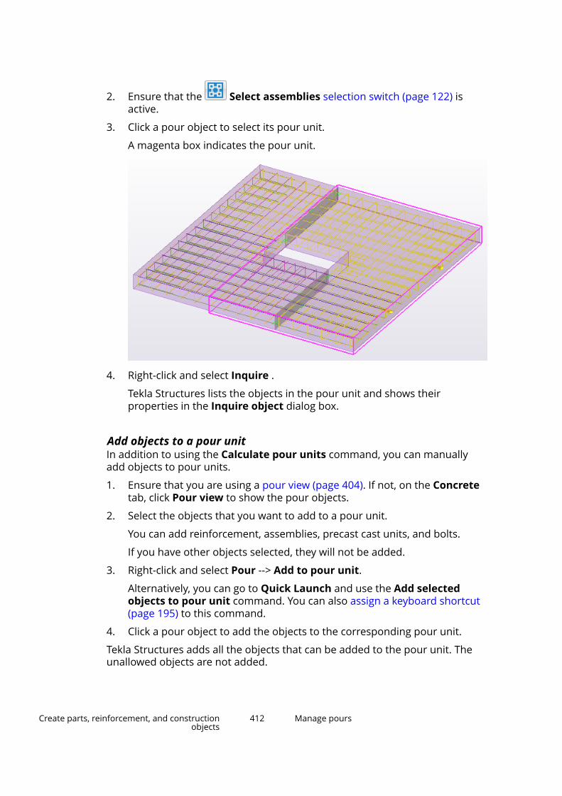
2. Ensure that the Select assemblies selection switch (page 122) isactive.
3. Click a pour object to select its pour unit.
A magenta box indicates the pour unit.
4. Right-click and select Inquire .
Tekla Structures lists the objects in the pour unit and shows theirproperties in the Inquire object dialog box.
Add objects to a pour unitIn addition to using the Calculate pour units command, you can manuallyadd objects to pour units.
1. Ensure that you are using a pour view (page 404). If not, on the Concretetab, click Pour view to show the pour objects.
2. Select the objects that you want to add to a pour unit.
You can add reinforcement, assemblies, precast cast units, and bolts.
If you have other objects selected, they will not be added.
3. Right-click and select Pour --> Add to pour unit.
Alternatively, you can go to Quick Launch and use the Add selectedobjects to pour unit command. You can also assign a keyboard shortcut(page 195) to this command.
4. Click a pour object to add the objects to the corresponding pour unit.
Tekla Structures adds all the objects that can be added to the pour unit. Theunallowed objects are not added.
Create parts, reinforcement, and constructionobjects
412 Manage pours
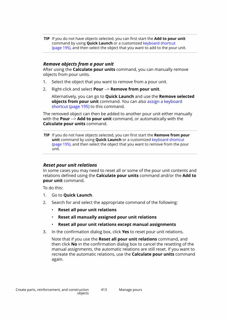
TIP If you do not have objects selected, you can first start the Add to pour unitcommand by using Quick Launch or a customized keyboard shortcut(page 195), and then select the object that you want to add to the pour unit.
Remove objects from a pour unitAfter using the Calculate pour units command, you can manually removeobjects from pour units.
1. Select the object that you want to remove from a pour unit.
2. Right-click and select Pour --> Remove from pour unit.
Alternatively, you can go to Quick Launch and use the Remove selectedobjects from pour unit command. You can also assign a keyboardshortcut (page 195) to this command.
The removed object can then be added to another pour unit either manuallywith the Pour --> Add to pour unit command, or automatically with theCalculate pour units command.
TIP If you do not have objects selected, you can first start the Remove from pourunit command by using Quick Launch or a customized keyboard shortcut(page 195), and then select the object that you want to remove from the pourunit.
Reset pour unit relationsIn some cases you may need to reset all or some of the pour unit contents andrelations defined using the Calculate pour units command and/or the Add topour unit command.
To do this:
1. Go to Quick Launch.
2. Search for and select the appropriate command of the following:
• Reset all pour unit relations
• Reset all manually assigned pour unit relations
• Reset all pour unit relations except manual assignments
3. In the confirmation dialog box, click Yes to reset pour unit relations.
Note that if you use the Reset all pour unit relations command, andthen click No in the confirmation dialog box to cancel the resetting of themanual assignments, the automatic relations are still reset. If you want torecreate the automatic relations, use the Calculate pour units commandagain.
Create parts, reinforcement, and constructionobjects
413 Manage pours

Modify the properties of a pour unitYou can modify the pour unit properties in the same way as pour objectproperties, but using a different selection switch.
1. Ensure that you are using a pour view (page 404). If not, click Pour viewon the Concrete tab to show the pour objects.
2. Ensure that the Select assemblies selection switch (page 122) isactive.
3. Double-click the pour unit whose properties you want to modify.
4. In the property pane, enter or modify the pour unit properties.
For example, you can define the pour unit name and user-definedattributes.
5. Click Modify.
How Tekla Structures automatically adds objects to pour unitsWhen you use the Calculate pour units command, Tekla Structuresautomatically adds objects to pour units.
Each object that collides with a pour object, meaning that the object at leastpartly overlaps the pour object, is added to the same pour unit to which thepour object belongs.
If any object in an assembly or precast cast unit collides with a pour object, theentire assembly or cast unit is added to the pour unit.
Only reinforcement objects that belong to cast-in-place parts are added topour units.
If any object in a reinforcing bar group or strand group collides with a pourobject, the entire group is added to the pour unit. On the other hand,individual reinforcing bars in a rebar set can be added to different pour units.
Objects colliding with more than one pour object
If an object collides with more than one pour object, the object will beassociated with the pour object whose bounding box has the lowest global zcoordinate.
For example, the reinforcing bars colliding with a footing pour object and acolumn pour object are associated with the footing pour object because itsbottom face has a lower global z coordinate than the column pour object.
Create parts, reinforcement, and constructionobjects
414 Manage pours

If the lowest global z coordinates of the pour object bounding boxes are thesame or differ less than 100 mm, the object will be associated with one of thepour objects according to these rules:
1. If the object's center of gravity is within only one of the colliding pourobject bounding boxes, the object will be associated with that pour object.
2. If the object's center of gravity is within more than one pour objectbounding box, or completely outside any pour object bounding box, theobject will be associated with the pour object whose center of gravity isclosest to the object's center of gravity.
If there are changes in pour units
Whenever there are changes in a pour object or pour unit, all associations tothat pour unit are reset. Similarly, if there are changes in an object associatedwith the pour unit, this association is reset. The next time you use theCalculate pour units command, only the unresolved associations arecalculated.
See also
Pour units (page 410)
Pour breaksWhen pour management is enabled, you can use pour breaks to split pourobjects into smaller pour objects.
Create parts, reinforcement, and constructionobjects
415 Manage pours

Pour breaks are visible and you can work with them both in pour views and inpart views (page 404). Pour breaks are displayed as a thin plane or line,depending on the part rendering option (page 584) you use.
WARNING If you move or copy a part, pour breaks do not follow the part.Pour breaks remain at their original locations, and adapt to anycast-in-place concrete parts (page 417) they still touch.
If a pour break does not split a pour object completely into two, the pourbreak is displayed in red by default. This means that it is invalid and needs tobe remodeled.
See also
Set the visibility of pour breaks (page 417)
Create a pour break (page 418)
Select a pour break (page 420)
Copy a pour break (page 420)
Move a pour break (page 420)
Modify a pour break (page 421)
Remove a pour break (page 422)
Create parts, reinforcement, and constructionobjects
416 Manage pours
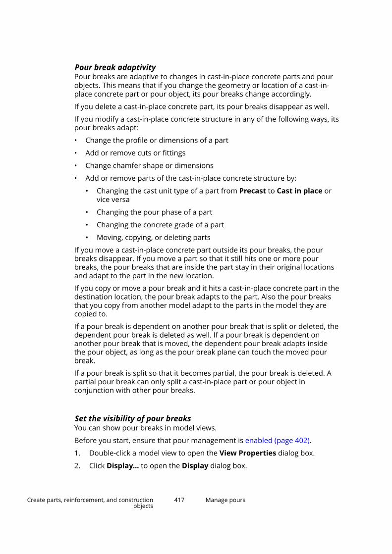
Pour break adaptivityPour breaks are adaptive to changes in cast-in-place concrete parts and pourobjects. This means that if you change the geometry or location of a cast-in-place concrete part or pour object, its pour breaks change accordingly.
If you delete a cast-in-place concrete part, its pour breaks disappear as well.
If you modify a cast-in-place concrete structure in any of the following ways, itspour breaks adapt:
• Change the profile or dimensions of a part
• Add or remove cuts or fittings
• Change chamfer shape or dimensions
• Add or remove parts of the cast-in-place concrete structure by:
• Changing the cast unit type of a part from Precast to Cast in place orvice versa
• Changing the pour phase of a part
• Changing the concrete grade of a part
• Moving, copying, or deleting parts
If you move a cast-in-place concrete part outside its pour breaks, the pourbreaks disappear. If you move a part so that it still hits one or more pourbreaks, the pour breaks that are inside the part stay in their original locationsand adapt to the part in the new location.
If you copy or move a pour break and it hits a cast-in-place concrete part in thedestination location, the pour break adapts to the part. Also the pour breaksthat you copy from another model adapt to the parts in the model they arecopied to.
If a pour break is dependent on another pour break that is split or deleted, thedependent pour break is deleted as well. If a pour break is dependent onanother pour break that is moved, the dependent pour break adapts insidethe pour object, as long as the pour break plane can touch the moved pourbreak.
If a pour break is split so that it becomes partial, the pour break is deleted. Apartial pour break can only split a cast-in-place part or pour object inconjunction with other pour breaks.
Set the visibility of pour breaksYou can show pour breaks in model views.
Before you start, ensure that pour management is enabled (page 402).
1. Double-click a model view to open the View Properties dialog box.
2. Click Display... to open the Display dialog box.
Create parts, reinforcement, and constructionobjects
417 Manage pours
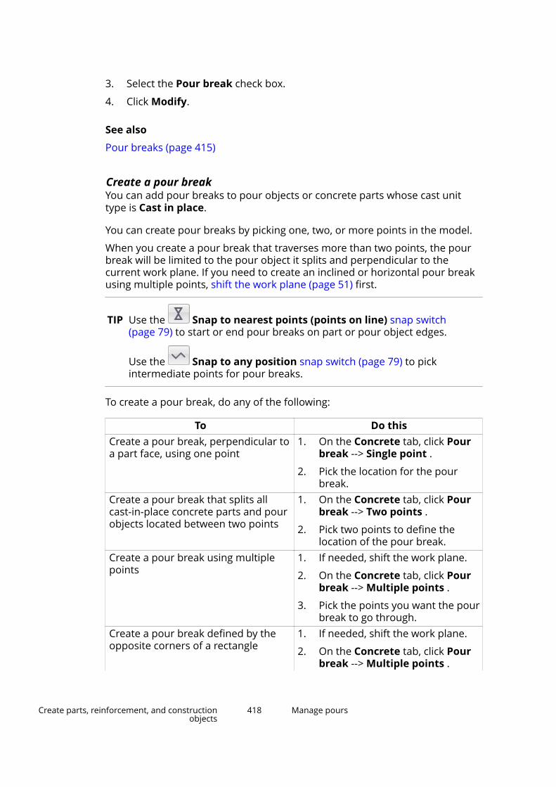
3. Select the Pour break check box.
4. Click Modify.
See also
Pour breaks (page 415)
Create a pour breakYou can add pour breaks to pour objects or concrete parts whose cast unittype is Cast in place.
You can create pour breaks by picking one, two, or more points in the model.
When you create a pour break that traverses more than two points, the pourbreak will be limited to the pour object it splits and perpendicular to thecurrent work plane. If you need to create an inclined or horizontal pour breakusing multiple points, shift the work plane (page 51) first.
TIP Use the Snap to nearest points (points on line) snap switch(page 79) to start or end pour breaks on part or pour object edges.
Use the Snap to any position snap switch (page 79) to pickintermediate points for pour breaks.
To create a pour break, do any of the following:
To Do thisCreate a pour break, perpendicular toa part face, using one point
1. On the Concrete tab, click Pourbreak --> Single point .
2. Pick the location for the pourbreak.
Create a pour break that splits allcast-in-place concrete parts and pourobjects located between two points
1. On the Concrete tab, click Pourbreak --> Two points .
2. Pick two points to define thelocation of the pour break.
Create a pour break using multiplepoints
1. If needed, shift the work plane.
2. On the Concrete tab, click Pourbreak --> Multiple points .
3. Pick the points you want the pourbreak to go through.
Create a pour break defined by theopposite corners of a rectangle
1. If needed, shift the work plane.
2. On the Concrete tab, click Pourbreak --> Multiple points .
Create parts, reinforcement, and constructionobjects
418 Manage pours

To Do this3.
Hover over , and then click
on the toolbar that appears.
4. Pick two opposite corner pointsof the pour break.
Create a pour break defined by thecenter and one corner of a rectangle
1. If needed, shift the work plane.
2. On the Concrete tab, click Pourbreak --> Multiple points .
3.Hover over , and then click
on the toolbar that appears.
4. Pick the center point of the pourbreak.
5. Pick one corner point of the pourbreak.
Create a pour break defined by threecorners of a rectangle
1. If needed, shift the work plane.
2. On the Concrete tab, click Pourbreak --> Multiple points .
3.Hover over , and then click
on the toolbar that appears.
4. Pick three corner points of thepour break.
Create a pour break defined by oneside midpoint and two corners of arectangle
1. If needed, shift the work plane.
2. On the Concrete tab, click Pourbreak --> Multiple points .
3.Hover over , and then click
on the toolbar that appears.
4. Pick one side midpoint of thepour break.
5. Pick two corner points of thepour break.
If the pour break you are creating does not split a pour object or cast-in-placepart completely into two, Tekla Structures does not add the pour break to themodel. You may need to use another Pour break command to create a validpour break, for example Multiple points instead of Single point.
Create parts, reinforcement, and constructionobjects
419 Manage pours
See also
Select a pour break (page 420)
Copy a pour break (page 420)
Move a pour break (page 420)
Modify a pour break (page 421)
Select a pour break
1. Ensure that the Select pour breaks selection switch (page 122) isactive.
2. Select the pour break.
See also
Pour breaks (page 415)
Copy a pour break
1. Ensure that the Select pour breaks selection switch (page 122) isactive.
2. Select the pour break.
3. Copy (page 133) the pour break like any other object in Tekla Structures.
For example, right-click and select Copy.
See also
Pour breaks (page 415)
Move a pour breakYou can move existing pour breaks. This may be needed, for example, if youhave moved the part, because the pour break does not follow the part.
1. Ensure that the Select pour breaks selection switch (page 122) isactive.
2. Select the pour break.
3. Move (page 144) the pour break like any other object in Tekla Structures.
For example, right-click and select Move.
Create parts, reinforcement, and constructionobjects
420 Manage pours
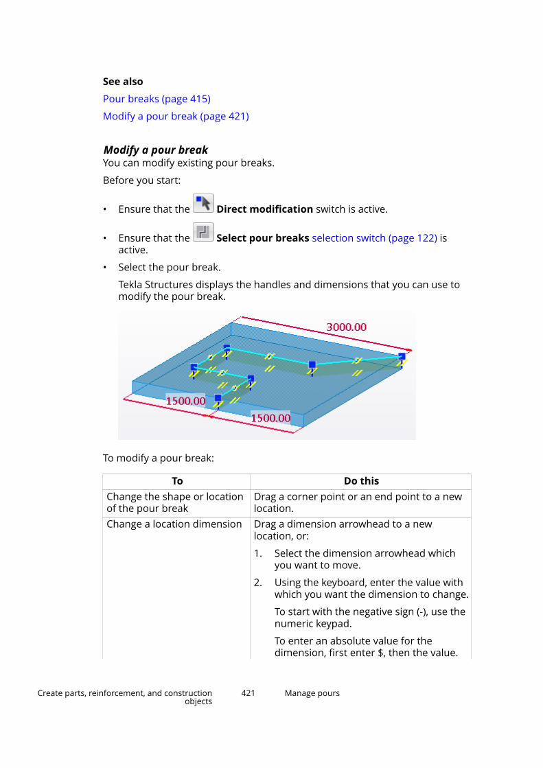
See also
Pour breaks (page 415)
Modify a pour break (page 421)
Modify a pour breakYou can modify existing pour breaks.
Before you start:
• Ensure that the Direct modification switch is active.
• Ensure that the Select pour breaks selection switch (page 122) isactive.
• Select the pour break.
Tekla Structures displays the handles and dimensions that you can use tomodify the pour break.
To modify a pour break:
To Do thisChange the shape or locationof the pour break
Drag a corner point or an end point to a newlocation.
Change a location dimension Drag a dimension arrowhead to a newlocation, or:
1. Select the dimension arrowhead whichyou want to move.
2. Using the keyboard, enter the value withwhich you want the dimension to change.
To start with the negative sign (-), use thenumeric keypad.
To enter an absolute value for thedimension, first enter $, then the value.
Create parts, reinforcement, and constructionobjects
421 Manage pours
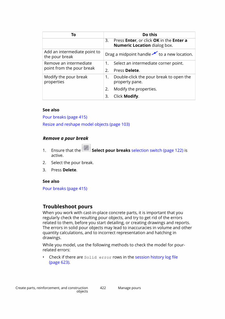
To Do this3. Press Enter, or click OK in the Enter a
Numeric Location dialog box.Add an intermediate point tothe pour break Drag a midpoint handle to a new location.
Remove an intermediatepoint from the pour break
1. Select an intermediate corner point.
2. Press Delete.Modify the pour breakproperties
1. Double-click the pour break to open theproperty pane.
2. Modify the properties.
3. Click Modify.
See also
Pour breaks (page 415)
Resize and reshape model objects (page 103)
Remove a pour break
1. Ensure that the Select pour breaks selection switch (page 122) isactive.
2. Select the pour break.
3. Press Delete.
See also
Pour breaks (page 415)
Troubleshoot poursWhen you work with cast-in-place concrete parts, it is important that youregularly check the resulting pour objects, and try to get rid of the errorsrelated to them, before you start detailing, or creating drawings and reports.The errors in solid pour objects may lead to inaccuracies in volume and otherquantity calculations, and to incorrect representation and hatching indrawings.
While you model, use the following methods to check the model for pour-related errors:
• Check if there are Solid error rows in the session history log file(page 623).
Create parts, reinforcement, and constructionobjects
422 Manage pours
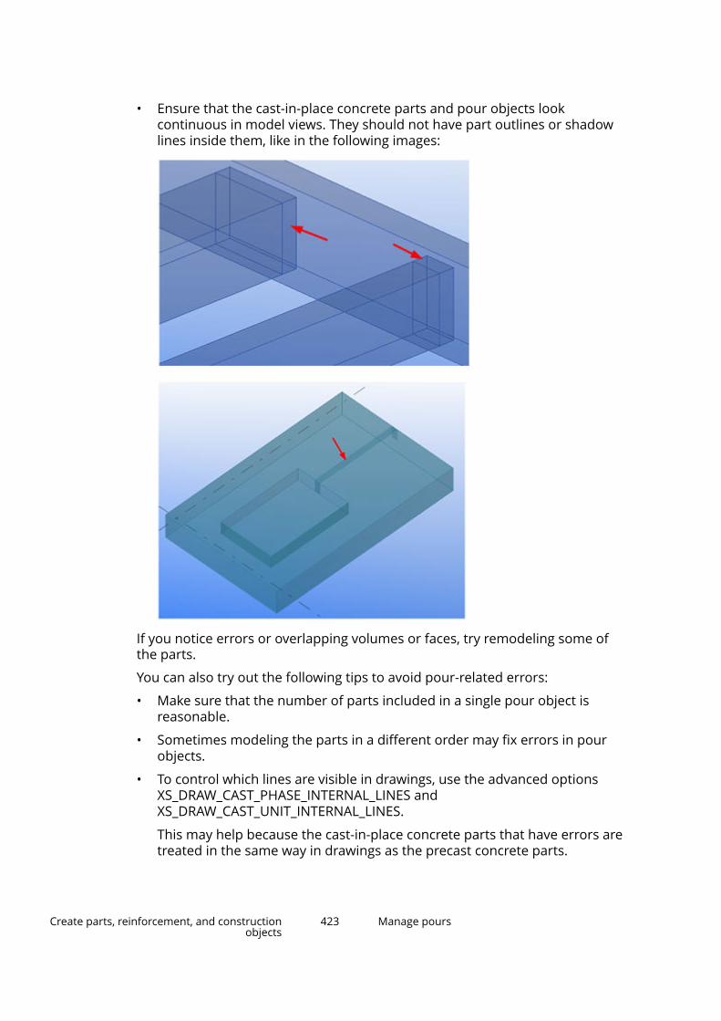
• Ensure that the cast-in-place concrete parts and pour objects lookcontinuous in model views. They should not have part outlines or shadowlines inside them, like in the following images:
If you notice errors or overlapping volumes or faces, try remodeling some ofthe parts.
You can also try out the following tips to avoid pour-related errors:
• Make sure that the number of parts included in a single pour object isreasonable.
• Sometimes modeling the parts in a different order may fix errors in pourobjects.
• To control which lines are visible in drawings, use the advanced optionsXS_DRAW_CAST_PHASE_INTERNAL_LINES andXS_DRAW_CAST_UNIT_INTERNAL_LINES.
This may help because the cast-in-place concrete parts that have errors aretreated in the same way in drawings as the precast concrete parts.
Create parts, reinforcement, and constructionobjects
423 Manage pours
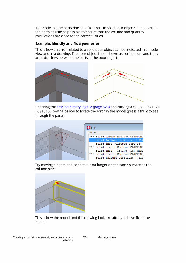
If remodeling the parts does not fix errors in solid pour objects, then overlapthe parts as little as possible to ensure that the volume and quantitycalculations are close to the correct values.
Example: Identify and fix a pour error
This is how an error related to a solid pour object can be indicated in a modelview and in a drawing. The pour object is not shown as continuous, and thereare extra lines between the parts in the pour object:
Checking the session history log file (page 623) and clicking a Solid failureposition row helps you to locate the error in the model (press Ctrl+2 to seethrough the parts):
Try moving a beam end so that it is no longer on the same surface as thecolumn side:
This is how the model and the drawing look like after you have fixed themodel:
Create parts, reinforcement, and constructionobjects
424 Manage pours
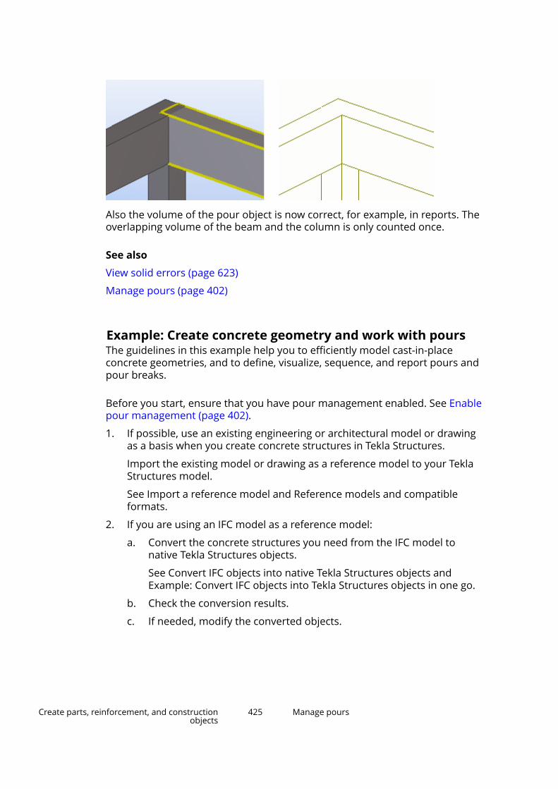
Also the volume of the pour object is now correct, for example, in reports. Theoverlapping volume of the beam and the column is only counted once.
See also
View solid errors (page 623)
Manage pours (page 402)
Example: Create concrete geometry and work with poursThe guidelines in this example help you to efficiently model cast-in-placeconcrete geometries, and to define, visualize, sequence, and report pours andpour breaks.
Before you start, ensure that you have pour management enabled. See Enablepour management (page 402).
1. If possible, use an existing engineering or architectural model or drawingas a basis when you create concrete structures in Tekla Structures.
Import the existing model or drawing as a reference model to your TeklaStructures model.
See Import a reference model and Reference models and compatibleformats.
2. If you are using an IFC model as a reference model:
a. Convert the concrete structures you need from the IFC model tonative Tekla Structures objects.
See Convert IFC objects into native Tekla Structures objects andExample: Convert IFC objects into Tekla Structures objects in one go.
b. Check the conversion results.
c. If needed, modify the converted objects.
Create parts, reinforcement, and constructionobjects
425 Manage pours

For example, you may need to change the profile, material, or castunit type of the converted objects.
TIP Use Organizer for checking and selecting objects.
3. If you are using a different reference model type, or if there are structuresthat cannot be converted from an IFC model, model the needed concretestructures as cast-in-place concrete parts in Tekla Structures.
You can model by tracing over the reference model.
See Create parts and modify part properties (page 235).
4. For each cast-in-place concrete part, define a pour phase number todivide your Tekla Structures model into pour objects.
For example, use the default pour phase 0 for horizontal structures, likebeams and slabs, and the default pour phase 1 for vertical structures, likecolumns and walls, to separate them to different pour objects.
See Define the pour phase of a part (page 407).
TIP Use selection filters or Organizer to efficiently select multiple partsand to modify them all at the same time.
5. View and check the pour objects in a pour view.
See View cast-in-place concrete structures (page 404) and Pour objects(page 408).
6. If needed, modify the pour phases or create pour breaks to fine-tune thepour objects.
For example, create pour breaks to split large slabs into smaller pourobjects.
See Create a pour break (page 418) and Pour breaks (page 415).
7. Once you are ready with the concrete geometry and pour objects, you candefine pour sequences by entering pour numbers for pour objects, or byusing the Organizer categories.
See Modify the properties of a pour object (page 410) and Categories inOrganizer.
8. Calculate the pour units, and modify them by adding and removingobjects if needed.
See Pour units (page 410).
9. You can also define other properties for pour objects and pour units, forexample, concrete mixtures, or dates or status of workflow.
See Modify the properties of a pour unit (page 413) and Categories inOrganizer.
Create parts, reinforcement, and constructionobjects
426 Manage pours
10. Use Organizer to categorize pours. Then you can select them by theirsequence and report pour-specific information, such as pour volumes andformwork areas.
See View object properties in Organizer and Example: Organize the modelinto location and custom categories, and view quantities.
11. If you wish, use Task manager to include pour objects and pour units intasks and to schedule pours. You can then visualize pour statusinformation based on planned and actual dates by using Project statusvisualization.
See Create a task in Task manager and Project status visualization.
12. Create general arrangement drawings for pour units.
Select a pour unit using the Select assemblies switch, create a 3Dview of the pour unit, and then create a GA drawing using the 3D view.
This way you can automatically include in the drawing all reinforcement,embeds, and other objects that need to be shown with the pour object.
See Pours in drawings.
2.8 Create reinforcementOnce you have created a model of concrete parts, you will need to reinforcethe parts to gain higher strength for the parts.
In Tekla Structures, you can use different methods to create reinforcement. Inmany cases, you may need to use a combination of several reinforcementtools to get the desired results.
The most automated method is to use the various reinforcement componentsTekla Structures contains. We recommend that you use reinforcementcomponents to create reinforcement whenever possible. The components areadaptive, attached to a concrete part, and updated automatically if thedimensions of the reinforced part change.
Rebar sets are another flexible and versatile method to create reinforcement.Also the rebar sets are adaptive to concrete geometry, and easy to modifyusing direct modification.
In addition to these methods, you can manually create:
• single reinforcing bars (page 451)
• reinforcing bar groups (page 452)
For more automated reinforcing bar group creation you can use Rebarshape catalog (page 454), which contains predefined reinforcement shapes.
• reinforcement meshes
Create parts, reinforcement, and constructionobjects
427 Create reinforcement
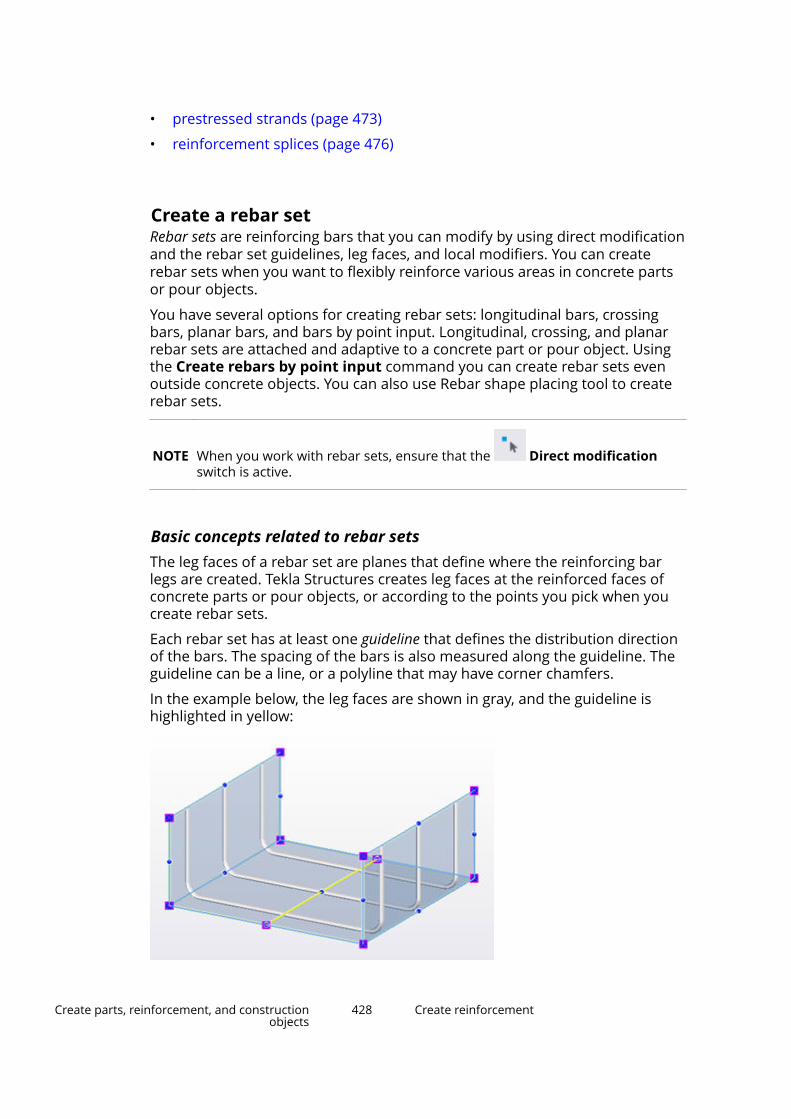
• prestressed strands (page 473)
• reinforcement splices (page 476)
Create a rebar setRebar sets are reinforcing bars that you can modify by using direct modificationand the rebar set guidelines, leg faces, and local modifiers. You can createrebar sets when you want to flexibly reinforce various areas in concrete partsor pour objects.
You have several options for creating rebar sets: longitudinal bars, crossingbars, planar bars, and bars by point input. Longitudinal, crossing, and planarrebar sets are attached and adaptive to a concrete part or pour object. Usingthe Create rebars by point input command you can create rebar sets evenoutside concrete objects. You can also use Rebar shape placing tool to createrebar sets.
NOTE When you work with rebar sets, ensure that the Direct modificationswitch is active.
Basic concepts related to rebar setsThe leg faces of a rebar set are planes that define where the reinforcing barlegs are created. Tekla Structures creates leg faces at the reinforced faces ofconcrete parts or pour objects, or according to the points you pick when youcreate rebar sets.
Each rebar set has at least one guideline that defines the distribution directionof the bars. The spacing of the bars is also measured along the guideline. Theguideline can be a line, or a polyline that may have corner chamfers.
In the example below, the leg faces are shown in gray, and the guideline ishighlighted in yellow:
Create parts, reinforcement, and constructionobjects
428 Create reinforcement
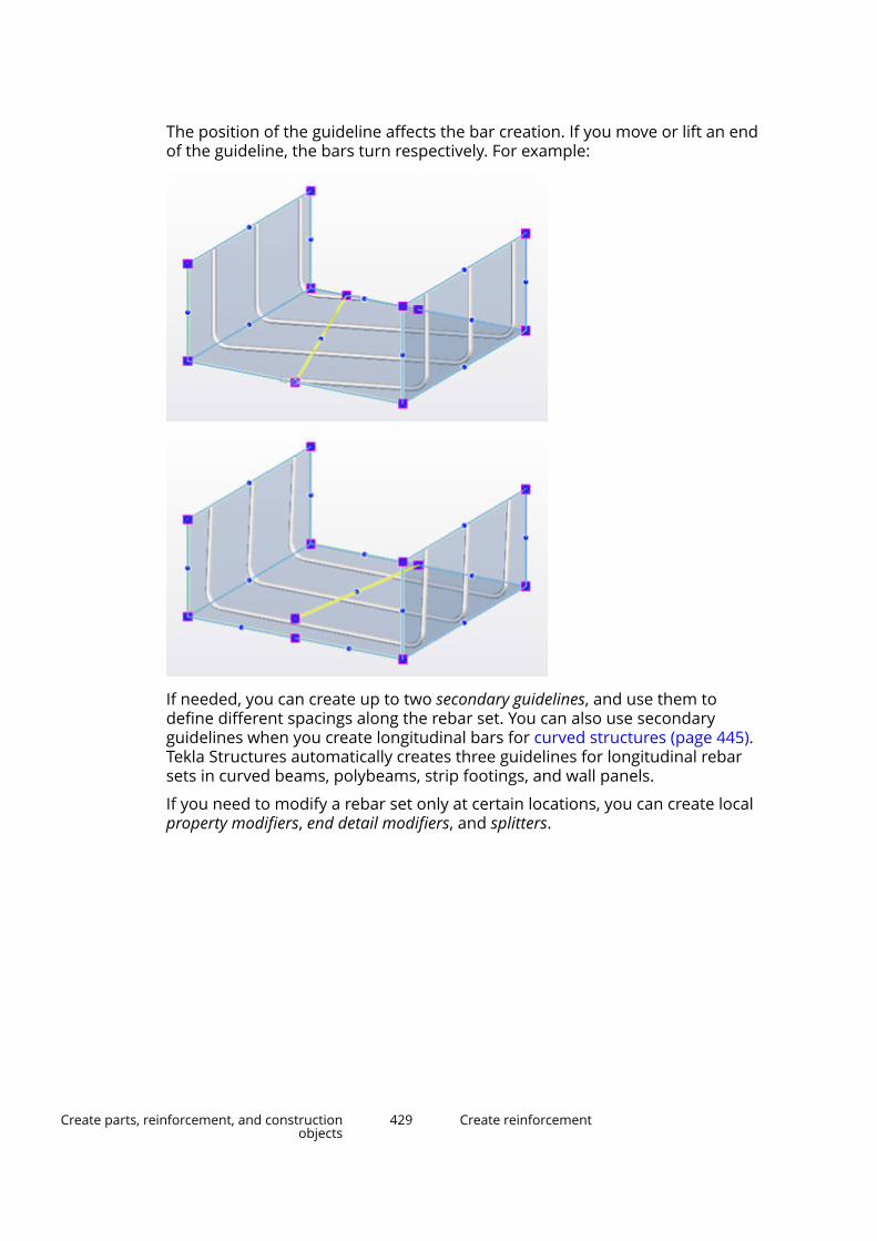
The position of the guideline affects the bar creation. If you move or lift an endof the guideline, the bars turn respectively. For example:
If needed, you can create up to two secondary guidelines, and use them todefine different spacings along the rebar set. You can also use secondaryguidelines when you create longitudinal bars for curved structures (page 445).Tekla Structures automatically creates three guidelines for longitudinal rebarsets in curved beams, polybeams, strip footings, and wall panels.
If you need to modify a rebar set only at certain locations, you can create localproperty modifiers, end detail modifiers, and splitters.
Create parts, reinforcement, and constructionobjects
429 Create reinforcement

Create longitudinal rebarsYou can create a rebar set that consists of longitudinal reinforcing bars in aconcrete part or pour object.
1. Depending on the concrete object you want to reinforce, use a part viewor a pour view (page 404).
2. On the Concrete tab, click Rebar set --> Create longitudinal rebars.
3. Move the mouse pointer over the edges of a concrete part or pour object.
Create parts, reinforcement, and constructionobjects
430 Create reinforcement

Tekla Structures highlights the cross sections that you can select.
4. Select the cross section that you want to reinforce.
5. If needed, modify the cross section size or shape for the bars.
To do this, click on the contextual toolbar, and then drag the crosssection handles.
6. In the selected cross section, select the faces that you want to reinforce.
Create parts, reinforcement, and constructionobjects
431 Create reinforcement

By default, only one of the faces is selected. To select multiple faces, holddown Shift or Ctrl.
Tekla Structures highlights the selected faces in yellow.
7. To extend or shorten individual faces, click on the contextual toolbar.Then drag the yellow and magenta end handles.
8. To finish, click the middle mouse button, or click Create the rebar seton the contextual toolbar.
Tekla Structures creates a rebar set at each selected face, and the barsperpendicular to the selected cross section.
Create crossing rebarsYou can create a rebar set that consists of crossing reinforcing bars in aconcrete part or pour object.
1. Depending on the concrete object you want to reinforce, use a part viewor a pour view (page 404).
2. On the Concrete tab, click Rebar set --> Create crossing rebars.
Create parts, reinforcement, and constructionobjects
432 Create reinforcement
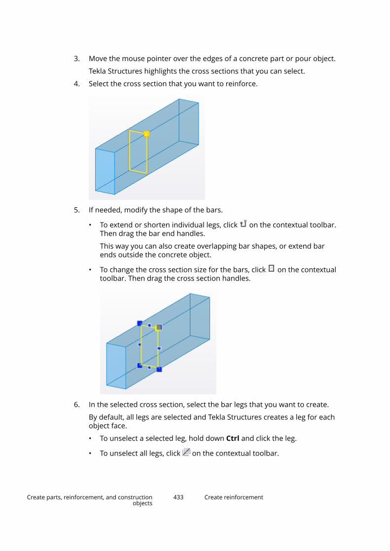
3. Move the mouse pointer over the edges of a concrete part or pour object.
Tekla Structures highlights the cross sections that you can select.
4. Select the cross section that you want to reinforce.
5. If needed, modify the shape of the bars.
• To extend or shorten individual legs, click on the contextual toolbar.Then drag the bar end handles.
This way you can also create overlapping bar shapes, or extend barends outside the concrete object.
• To change the cross section size for the bars, click on the contextualtoolbar. Then drag the cross section handles.
6. In the selected cross section, select the bar legs that you want to create.
By default, all legs are selected and Tekla Structures creates a leg for eachobject face.
• To unselect a selected leg, hold down Ctrl and click the leg.
• To unselect all legs, click on the contextual toolbar.
Create parts, reinforcement, and constructionobjects
433 Create reinforcement
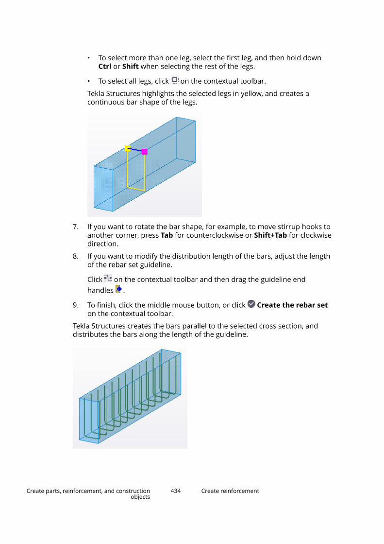
• To select more than one leg, select the first leg, and then hold downCtrl or Shift when selecting the rest of the legs.
• To select all legs, click on the contextual toolbar.
Tekla Structures highlights the selected legs in yellow, and creates acontinuous bar shape of the legs.
7. If you want to rotate the bar shape, for example, to move stirrup hooks toanother corner, press Tab for counterclockwise or Shift+Tab for clockwisedirection.
8. If you want to modify the distribution length of the bars, adjust the lengthof the rebar set guideline.
Click on the contextual toolbar and then drag the guideline endhandles .
9. To finish, click the middle mouse button, or click Create the rebar seton the contextual toolbar.
Tekla Structures creates the bars parallel to the selected cross section, anddistributes the bars along the length of the guideline.
Create parts, reinforcement, and constructionobjects
434 Create reinforcement

Create planar rebarsYou can create a rebar set that consists of planar reinforcing bars in a concretepart or pour object.
1. Depending on the concrete object you want to reinforce, use a part viewor a pour view (page 404).
2. On the Concrete tab, click Rebar set --> Create planar rebars.
3. Define the faces and areas of a concrete object you want to reinforce, andthe direction of the bars using the following options on the contextualtoolbar:
Click this button To do this
Create bars at the near face of the concrete object.
Create bars at the far face of the concrete object.
Create bars parallel to the longest object face edge.
Create bars perpendicular to the longest object faceedge.
Create bars in two directions: one set of bars parallel tothe longest object face edge, and the other set of barsperpendicular to it.
Create bars for an entire object face.
Create bars for a rectangular area on an object face.
Create bars for a polygonal area on an object face.
4. Depending on the area you selected to reinforce, do one of the following:
• To reinforce an entire object face:
a. Move the mouse pointer over the faces of a concrete part or pourobject.
Create parts, reinforcement, and constructionobjects
435 Create reinforcement

Tekla Structures shows the object face dimensions, and a symbolthat indicates the direction of the bars.
b. Select the object face.
• To reinforce a rectangular area, pick two opposite corners of the area.
• To reinforce a polygonal area, pick the polygon corners.
Create parts, reinforcement, and constructionobjects
436 Create reinforcement
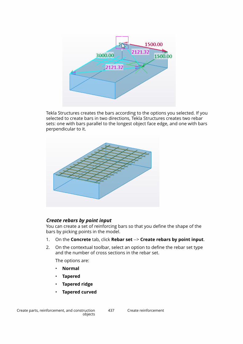
Tekla Structures creates the bars according to the options you selected. If youselected to create bars in two directions, Tekla Structures creates two rebarsets: one with bars parallel to the longest object face edge, and one with barsperpendicular to it.
Create rebars by point inputYou can create a set of reinforcing bars so that you define the shape of thebars by picking points in the model.
1. On the Concrete tab, click Rebar set --> Create rebars by point input.
2. On the contextual toolbar, select an option to define the rebar set typeand the number of cross sections in the rebar set.
The options are:
• Normal
• Tapered
• Tapered ridge
• Tapered curved
Create parts, reinforcement, and constructionobjects
437 Create reinforcement

• Tapered N
If you select the Tapered N option, enter the number of cross sections.
3. Pick points to define the shape of the bar at the first cross section.
You can use different snapping (page 77) methods, such as Ortho andtemporary reference points.
4. Click the middle mouse button to finish picking.
5. For the second and subsequent cross sections, pick points to define theshape of the bar, and then click the middle mouse button to finish pickingat each cross section.
Tekla Structures creates a rebar set with leg faces between each cross section.
Rebar set propertiesUse the contextual toolbar or the property pane to view and modify theproperties of rebar sets. The file name extension of the properties file is .rst.
See also Rebar set properties (page 933) and Modify a rebar set (page 478).
Limitations• Roundings in bent bar corners are not taken into account in automatic
clash avoidance when Tekla Structures creates rebar sets and arrangesthem to layers.
• You cannot create rebar sets in deformed parts.
Create a rebar set using Rebar shape placing toolYou can create a rebar set by selecting a predefined bar shape from Rebarshape placing tool. The predefined shapes in Rebar shape placing tool are
Create parts, reinforcement, and constructionobjects
438 Create reinforcement
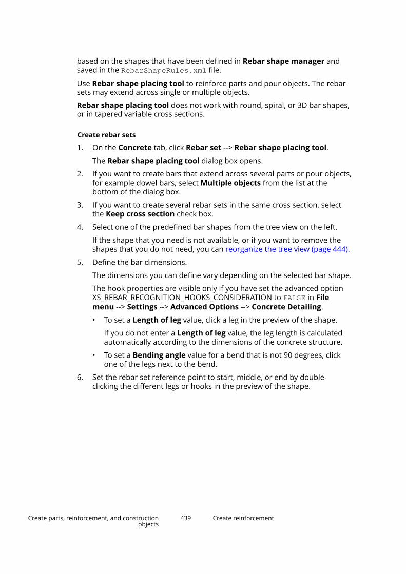
based on the shapes that have been defined in Rebar shape manager andsaved in the RebarShapeRules.xml file.
Use Rebar shape placing tool to reinforce parts and pour objects. The rebarsets may extend across single or multiple objects.
Rebar shape placing tool does not work with round, spiral, or 3D bar shapes,or in tapered variable cross sections.
Create rebar sets
1. On the Concrete tab, click Rebar set --> Rebar shape placing tool.
The Rebar shape placing tool dialog box opens.
2. If you want to create bars that extend across several parts or pour objects,for example dowel bars, select Multiple objects from the list at thebottom of the dialog box.
3. If you want to create several rebar sets in the same cross section, selectthe Keep cross section check box.
4. Select one of the predefined bar shapes from the tree view on the left.
If the shape that you need is not available, or if you want to remove theshapes that you do not need, you can reorganize the tree view (page 444).
5. Define the bar dimensions.
The dimensions you can define vary depending on the selected bar shape.
The hook properties are visible only if you have set the advanced optionXS_REBAR_RECOGNITION_HOOKS_CONSIDERATION to FALSE in Filemenu --> Settings --> Advanced Options --> Concrete Detailing.
• To set a Length of leg value, click a leg in the preview of the shape.
If you do not enter a Length of leg value, the leg length is calculatedautomatically according to the dimensions of the concrete structure.
• To set a Bending angle value for a bend that is not 90 degrees, clickone of the legs next to the bend.
6. Set the rebar set reference point to start, middle, or end by double-clicking the different legs or hooks in the preview of the shape.
Create parts, reinforcement, and constructionobjects
439 Create reinforcement

When you are placing the rebar set in the model, you can move the rebarset preview to a new location by dragging the reference point.
7. Modify the other bar properties as needed.
For example, you can use Layer order number to arrange bars to layerswhen two or more rebar sets overlap.
8. On the Spacing tab, define the spacing properties of the rebar set.
9. To place the rebar set in the model, move the mouse pointer over theedges and faces of a concrete structure.
Depending on the concrete structure you want to reinforce, use a partview or a pour view (page 404).
Tekla Structures highlights the cross sections and faces that you canselect. For example:
Create parts, reinforcement, and constructionobjects
440 Create reinforcement
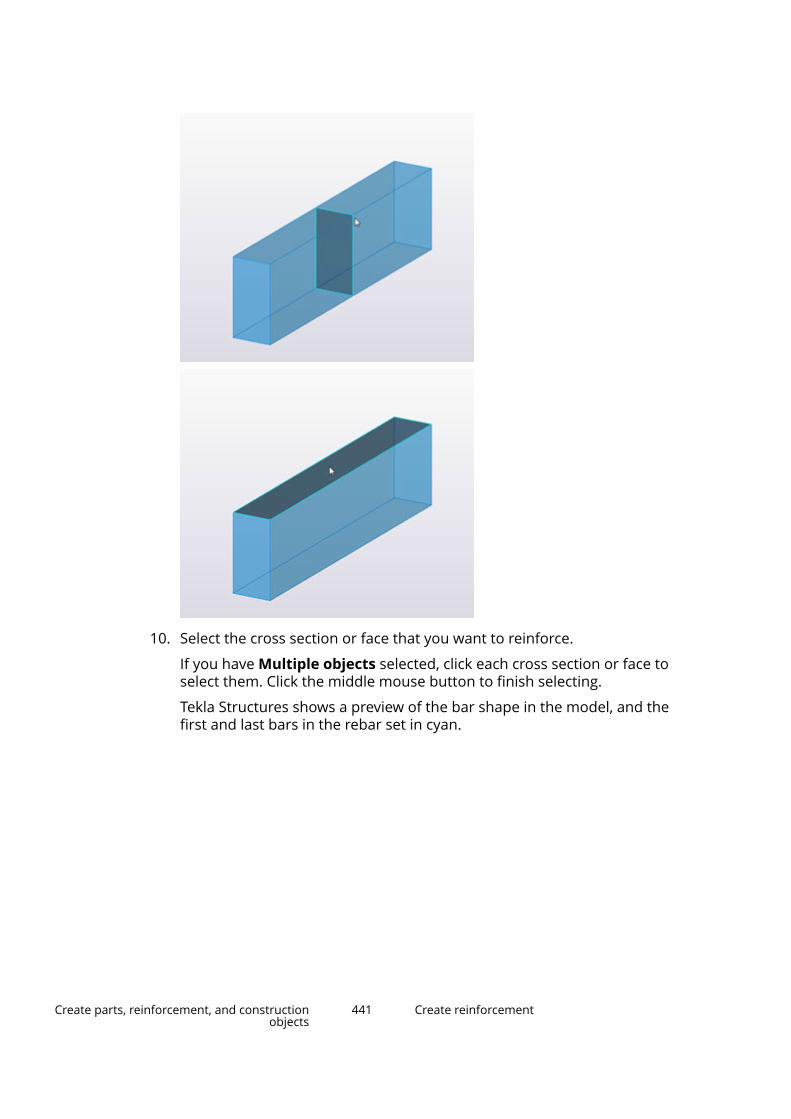
10. Select the cross section or face that you want to reinforce.
If you have Multiple objects selected, click each cross section or face toselect them. Click the middle mouse button to finish selecting.
Tekla Structures shows a preview of the bar shape in the model, and thefirst and last bars in the rebar set in cyan.
Create parts, reinforcement, and constructionobjects
441 Create reinforcement
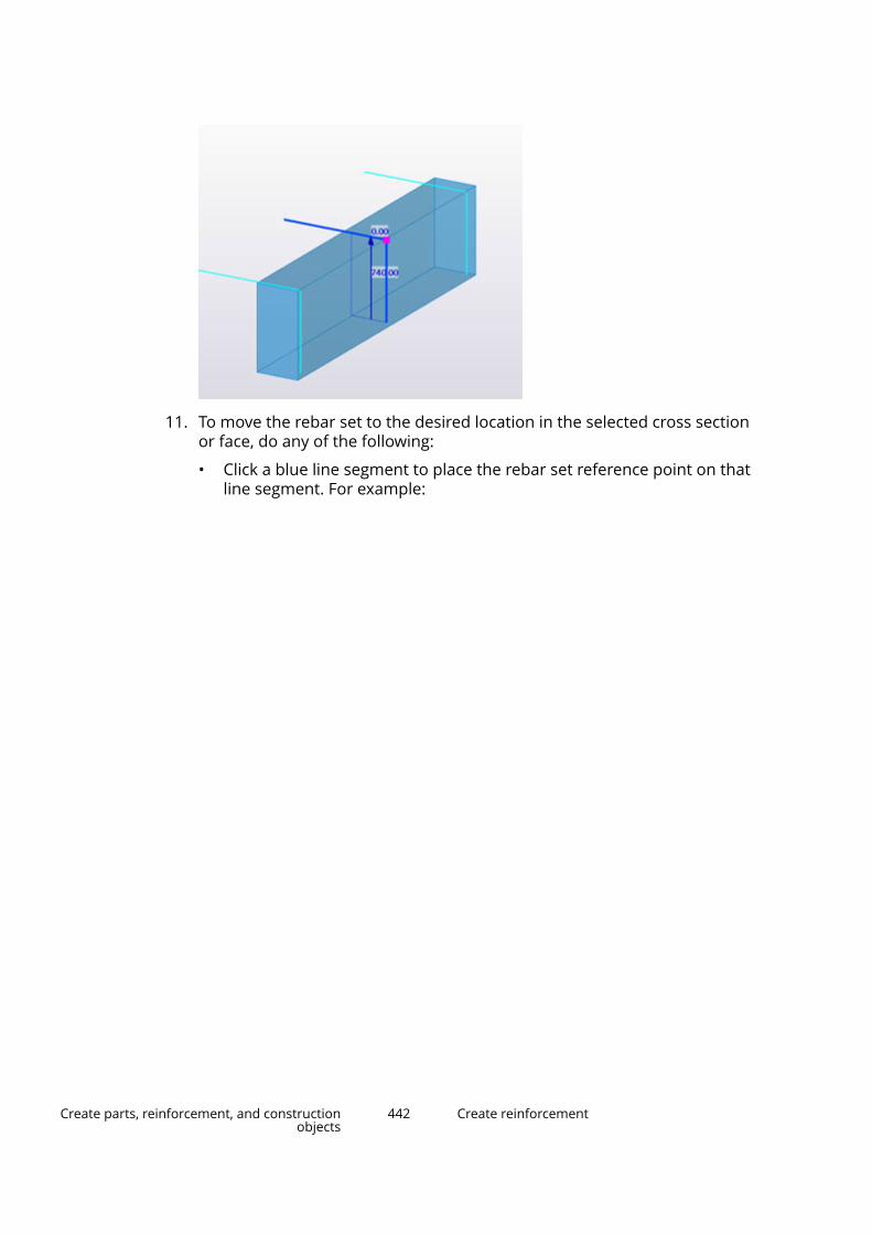
11. To move the rebar set to the desired location in the selected cross sectionor face, do any of the following:
• Click a blue line segment to place the rebar set reference point on thatline segment. For example:
Create parts, reinforcement, and constructionobjects
442 Create reinforcement

If needed, you can still change the reference point location in theRebar shape placing tool dialog box by double-clicking the desiredlocation in the preview.
• Drag the magenta reference point handle to a new location on theblue line.
• To turn the bar shape, click on the contextual toolbar.
Create parts, reinforcement, and constructionobjects
443 Create reinforcement

12. Click the middle mouse button to create the rebar set.
13. If you have the Keep cross section check box selected, repeat steps 4–12to create more rebar sets in the same cross section.
TIP If the Rebar shape placing tool dialog box is already open but the command isnot active, click the Select cross section button to start creating rebar setsagain.
Add and remove rebar shapesYou can modify the tree view in Rebar shape placing tool by addingfrequently used bar shapes to the tree, or removing the bar shapes that youdo not need.
1. On the Concrete tab, click Rebar set --> Rebar shape placing tool.
The Rebar shape placing tool dialog box opens.
2. Click Organize catalog.
Create parts, reinforcement, and constructionobjects
444 Create reinforcement
3. To create a new category folder, click .
4. Drag and drop the selected shapes to the folder.
If multiple shapes have the same shape code and you drag them to thecategories, the shape codes get a suffix (1), (2), and so on. You canrename the shapes by clicking the name twice and entering a new nameor suffix, for example, (a), (b).
When the shapes are listed in a report, they all get the same shape code.
5. Change the name of the folder in a similar way, if needed.
6. To remove a shape from a category, select the shape and click .
7. Click OK.
Examples: Rebar sets in curved structuresYou can reinforce curved concrete structures using rebar sets.
The curved concrete structures can include curved beams (page 279),polybeams (page 282) that have Arc point chamfers, and flat spiral beams(page 285) whose total rise is zero. You can also reinforce strip footings andwall panels the same way as you reinforce beams and polybeams.
For more information about creating rebar sets, see also Create a rebar set(page 428).
Create longitudinal bars for a curved beamIn this example, we will create longitudinal bottom bars for a curved concretebeam.
1. Create a curved concrete beam.
a. On the Concrete tab, click Beam.
b. Pick two points.
c. Double-click the beam to modify its properties.
d. Set the radius and number of segments, and then click Modify.
2. Create longitudinal bars at the bottom face of the beam.
a. On the Concrete tab, click Rebar set --> Create longitudinal rebars.
b. Move the mouse pointer over the edges of the beam, and select thecross section that you want to reinforce.
c. Click the middle mouse button to create the rebar set.
Create parts, reinforcement, and constructionobjects
445 Create reinforcement

Tekla Structures creates the curved longitudinal bars according to thebeam geometry. For example:
The rebar set has three guidelines: one at each end of the beam andone in the midpoint of the beam.
Create crossing bars for a curved polybeamIn this example, we will create crossing U-shaped stirrups for a curvedconcrete polybeam.
1. Create a concrete polybeam with curved segments.
a. On the Concrete tab, click Beam --> Polybeam.
b. Pick at least three points you want the beam to go through, and thenclick the middle mouse button.
c. Select the polybeam.
d. Select the handle in a polybeam corner, and then select the Arcpoint chamfer type on the contextual toolbar.
2. Create crossing bars that follow the bottom and side faces of the beam.
a. On the Concrete tab, click Rebar set --> Create crossing rebars.
b. Move the mouse pointer over the edges of the beam, and select thecross section that you want to reinforce.
c. In the selected cross section, hold down Ctrl and click the top bar legto unselect it.
d. Click the middle mouse button to create the rebar set.
Create parts, reinforcement, and constructionobjects
446 Create reinforcement
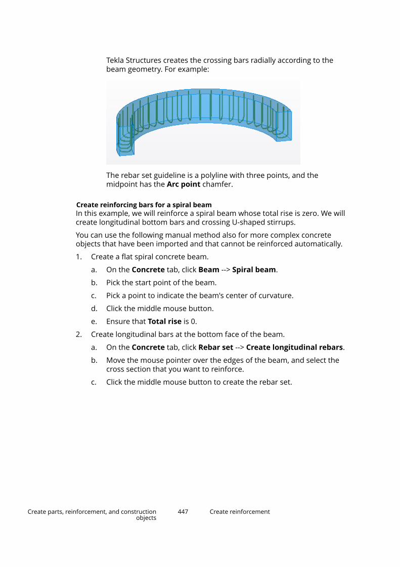
Tekla Structures creates the crossing bars radially according to thebeam geometry. For example:
The rebar set guideline is a polyline with three points, and themidpoint has the Arc point chamfer.
Create reinforcing bars for a spiral beamIn this example, we will reinforce a spiral beam whose total rise is zero. We willcreate longitudinal bottom bars and crossing U-shaped stirrups.
You can use the following manual method also for more complex concreteobjects that have been imported and that cannot be reinforced automatically.
1. Create a flat spiral concrete beam.
a. On the Concrete tab, click Beam --> Spiral beam.
b. Pick the start point of the beam.
c. Pick a point to indicate the beam's center of curvature.
d. Click the middle mouse button.
e. Ensure that Total rise is 0.
2. Create longitudinal bars at the bottom face of the beam.
a. On the Concrete tab, click Rebar set --> Create longitudinal rebars.
b. Move the mouse pointer over the edges of the beam, and select thecross section that you want to reinforce.
c. Click the middle mouse button to create the rebar set.
Create parts, reinforcement, and constructionobjects
447 Create reinforcement
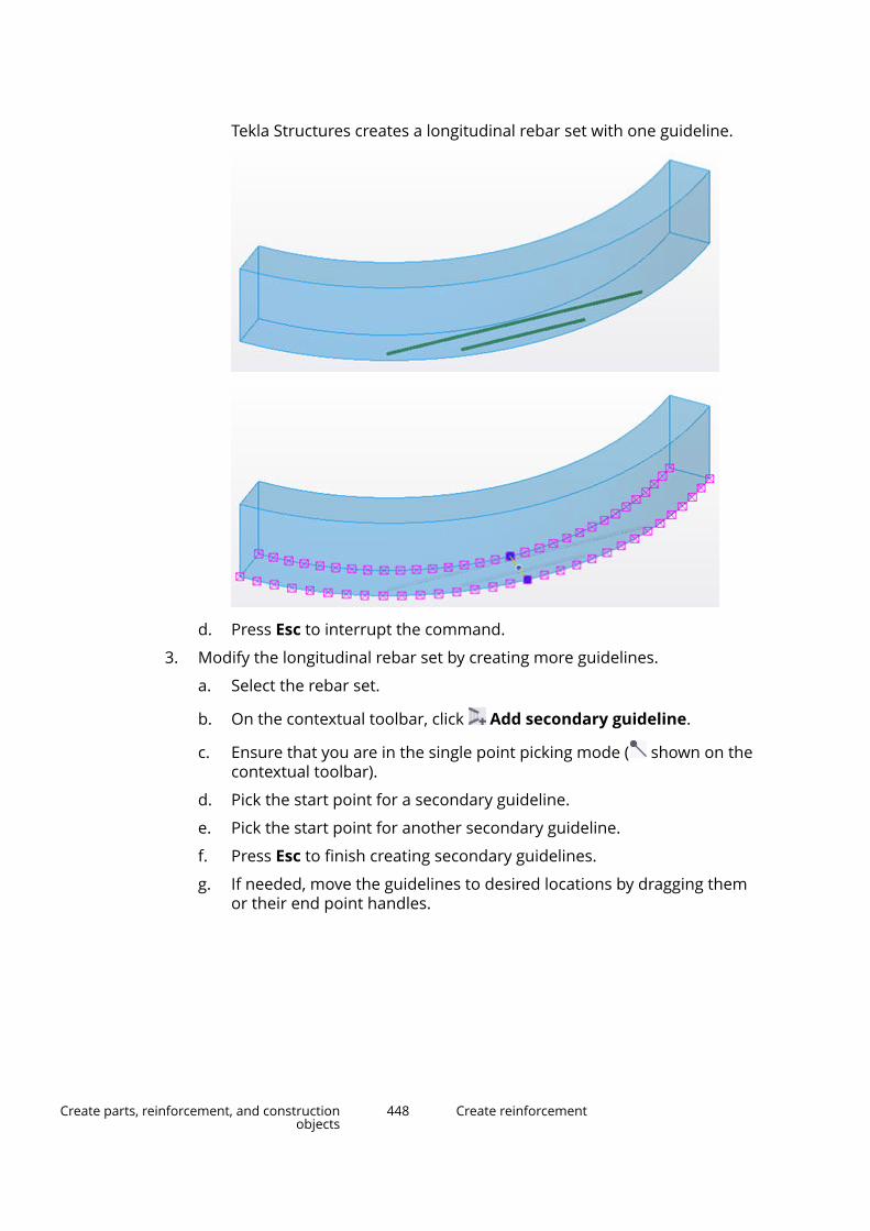
Tekla Structures creates a longitudinal rebar set with one guideline.
d. Press Esc to interrupt the command.
3. Modify the longitudinal rebar set by creating more guidelines.
a. Select the rebar set.
b. On the contextual toolbar, click Add secondary guideline.
c. Ensure that you are in the single point picking mode ( shown on thecontextual toolbar).
d. Pick the start point for a secondary guideline.
e. Pick the start point for another secondary guideline.
f. Press Esc to finish creating secondary guidelines.
g. If needed, move the guidelines to desired locations by dragging themor their end point handles.
Create parts, reinforcement, and constructionobjects
448 Create reinforcement
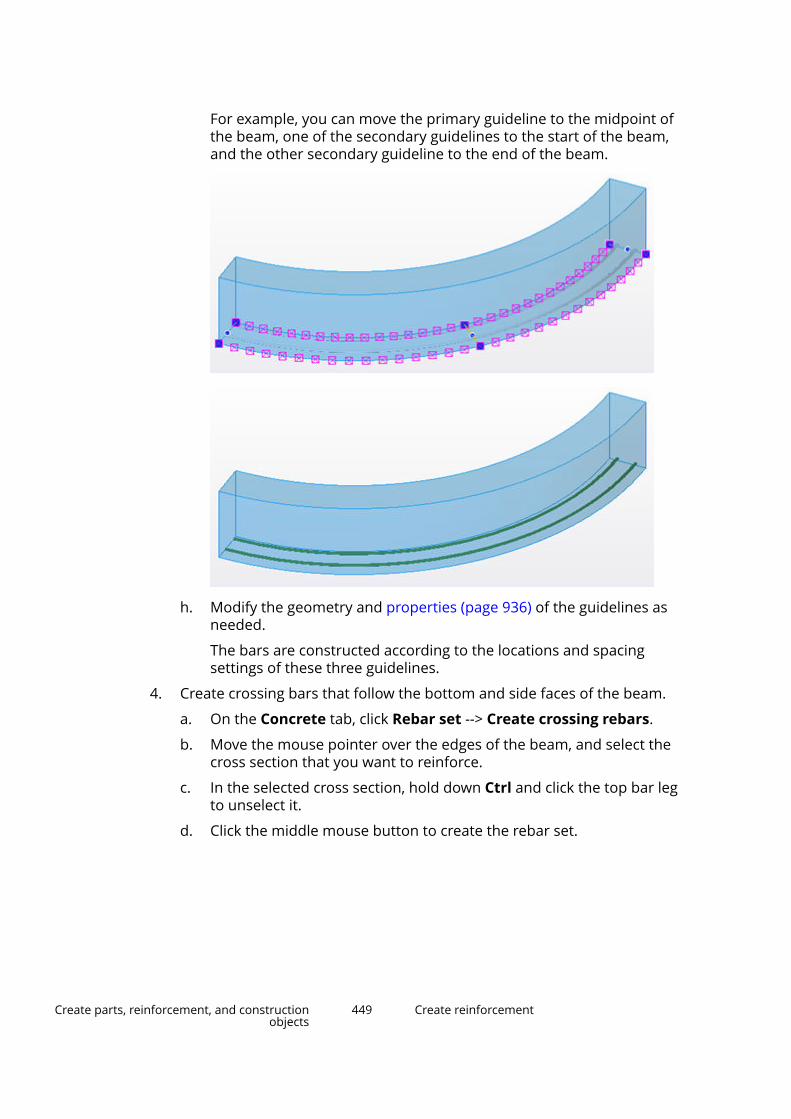
For example, you can move the primary guideline to the midpoint ofthe beam, one of the secondary guidelines to the start of the beam,and the other secondary guideline to the end of the beam.
h. Modify the geometry and properties (page 936) of the guidelines asneeded.
The bars are constructed according to the locations and spacingsettings of these three guidelines.
4. Create crossing bars that follow the bottom and side faces of the beam.
a. On the Concrete tab, click Rebar set --> Create crossing rebars.
b. Move the mouse pointer over the edges of the beam, and select thecross section that you want to reinforce.
c. In the selected cross section, hold down Ctrl and click the top bar legto unselect it.
d. Click the middle mouse button to create the rebar set.
Create parts, reinforcement, and constructionobjects
449 Create reinforcement

Tekla Structures creates a crossing rebar set with one guideline.
e. Press Esc to interrupt the command.
5. Modify the crossing rebar set by modifying the guideline.
a. Select the rebar set to highlight the guideline.
b. Drag the guideline end points to the beam ends.
c. Drag the guideline midpoint to the beam midpoint.
Create parts, reinforcement, and constructionobjects
450 Create reinforcement
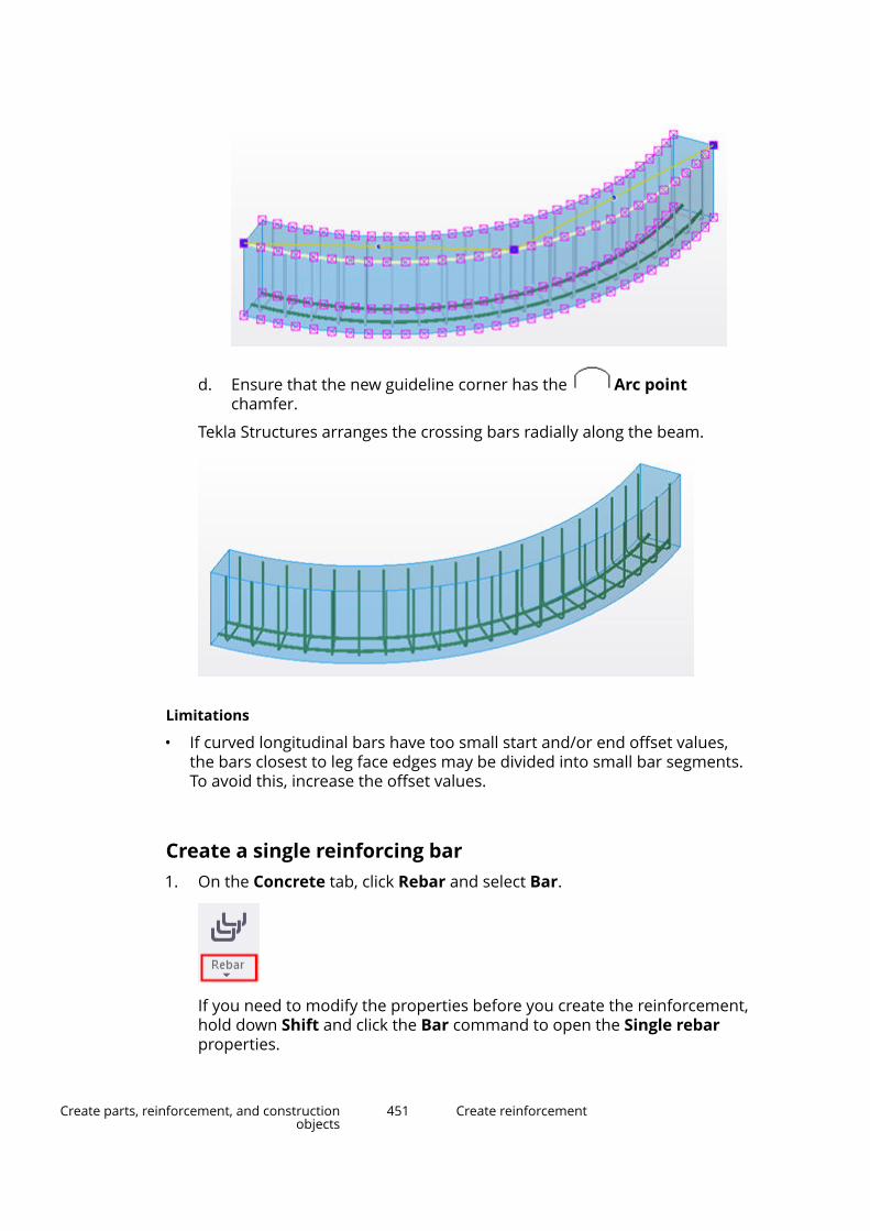
d. Ensure that the new guideline corner has the Arc pointchamfer.
Tekla Structures arranges the crossing bars radially along the beam.
Limitations
• If curved longitudinal bars have too small start and/or end offset values,the bars closest to leg face edges may be divided into small bar segments.To avoid this, increase the offset values.
Create a single reinforcing bar1. On the Concrete tab, click Rebar and select Bar.
If you need to modify the properties before you create the reinforcement,hold down Shift and click the Bar command to open the Single rebarproperties.
Create parts, reinforcement, and constructionobjects
451 Create reinforcement

2. Select the part to reinforce.
3. Pick the bar start point.
4. Pick the other bar reference points to set the bar shape.
5. Click the middle mouse button to finish picking.
Tekla Structures attaches the bar to this part.
6. If you want to modify the reinforcement, do one of the following:
• Use direct modification (page 496). Ensure that the Directmodification switch is active.
• Double-click the reinforcement to open the Single rebar propertiesand modify the properties (page 927).
See also
Create a reinforcing bar group using Rebar shape catalog (page 454)
Create a reinforcing bar group (page 452)
Create a reinforcing bar groupA reinforcing bar group includes several identical, or very similar, reinforcingbars. Tekla Structures always treats these bars as a group, modifies them inthe same way, deletes them all at the same time, and so on. You first definethe shape of a single bar, then the direction in which Tekla Structuresdistributes the bars.
NOTE If you do not want to manually define the bar shape, use Rebar shapecatalog (page 454) and its predefined reinforcement shapes instead.
1. On the Concrete tab, click:
Create parts, reinforcement, and constructionobjects
452 Create reinforcement
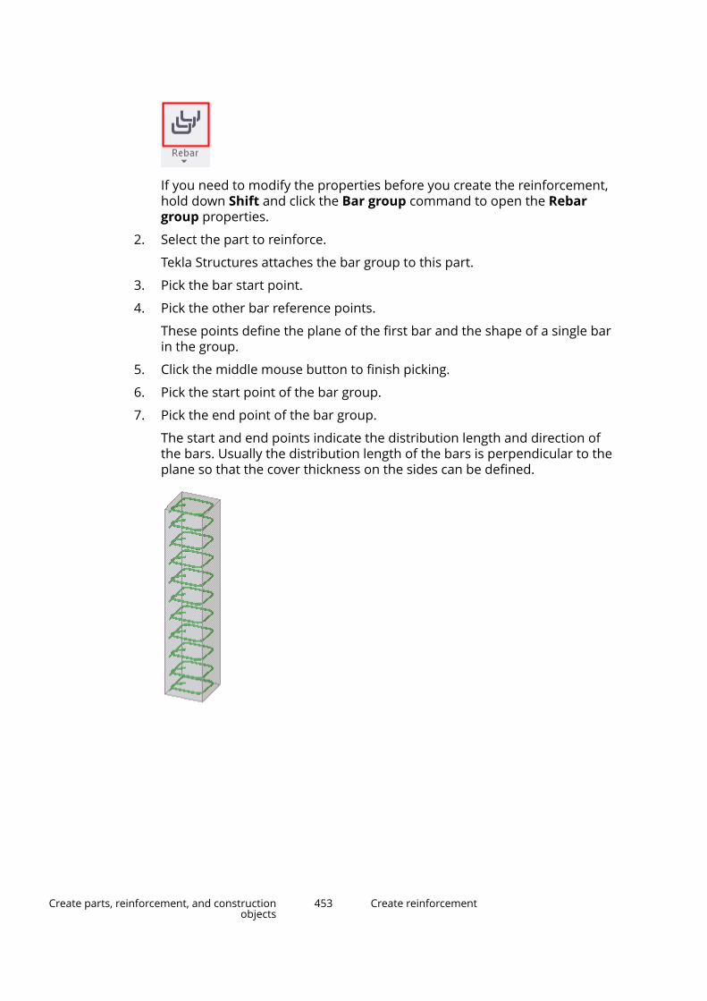
If you need to modify the properties before you create the reinforcement,hold down Shift and click the Bar group command to open the Rebargroup properties.
2. Select the part to reinforce.
Tekla Structures attaches the bar group to this part.
3. Pick the bar start point.
4. Pick the other bar reference points.
These points define the plane of the first bar and the shape of a single barin the group.
5. Click the middle mouse button to finish picking.
6. Pick the start point of the bar group.
7. Pick the end point of the bar group.
The start and end points indicate the distribution length and direction ofthe bars. Usually the distribution length of the bars is perpendicular to theplane so that the cover thickness on the sides can be defined.
Create parts, reinforcement, and constructionobjects
453 Create reinforcement
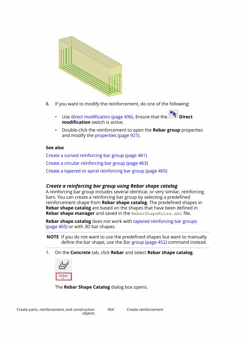
8. If you want to modify the reinforcement, do one of the following:
• Use direct modification (page 496). Ensure that the Directmodification switch is active.
• Double-click the reinforcement to open the Rebar group propertiesand modify the properties (page 927).
See also
Create a curved reinforcing bar group (page 461)
Create a circular reinforcing bar group (page 463)
Create a tapered or spiral reinforcing bar group (page 465)
Create a reinforcing bar group using Rebar shape catalogA reinforcing bar group includes several identical, or very similar, reinforcingbars. You can create a reinforcing bar group by selecting a predefinedreinforcement shape from Rebar shape catalog. The predefined shapes inRebar shape catalog are based on the shapes that have been defined inRebar shape manager and saved in the RebarShapeRules.xml file.
Rebar shape catalog does not work with tapered reinforcing bar groups(page 465) or with 3D bar shapes.
NOTE If you do not want to use the predefined shapes but want to manuallydefine the bar shape, use the Bar group (page 452) command instead.
1. On the Concrete tab, click Rebar and select Rebar shape catalog.
The Rebar Shape Catalog dialog box opens.
Create parts, reinforcement, and constructionobjects
454 Create reinforcement

2. Select one of the predefined shapes from the tree view on the left.
You can add frequently used shapes to the tree view (page 456), or deletethe shapes that you do not need.
If you select an existing reinforcement in the model and click the Getbutton, the properties of that reinforcement are displayed in the RebarShape Catalog dialog box.
3. If needed, modify the bar properties.
• To set a Length of leg value, click a leg in the preview of the shape.
If you do not enter a Length of leg value, the leg length is calculatedautomatically according to the dimensions of the concrete part.
• To set a Bending angle value for a bend that is not 90 degrees, clickone of the legs next to the bend.
• For circular, polygonal and spiral reinforcement, you can enter Circlediameter and Overlap distance values.
The hook properties are visible only if you have set the advanced optionXS_REBAR_RECOGNITION_HOOKS_CONSIDERATION to FALSE in Filemenu --> Settings --> Advanced Options --> Concrete Detailing.
4. If needed, set the reference point of the reinforcement (page 457) to start,middle, or end by double-clicking the different legs or hooks in thepreview of the shape.
5. Click OK.
6. In the model, place the mouse pointer over a part face or edge.
A preview showing the placing and dimensions of the reinforcement isdisplayed.
Create parts, reinforcement, and constructionobjects
455 Create reinforcement

7. Based on the preview, select a placing for the reinforcing bar group andclick the left mouse button.
Tekla Structures creates the reinforcement.
8. If you want to modify the reinforcement, do one of the following:
• Use direct modification (page 496). Ensure that the Directmodification switch is active.
• Double-click the reinforcement to open the reinforcing bar groupproperties, and modify the properties (page 927).
See also
Create a reinforcing bar group (page 452)
Create a rebar set using Rebar shape placing tool (page 438)
Add more reinforcement shapes to the tree view in Rebar shape catalogYou can modify the tree view in Rebar shape catalog by adding frequentlyused shapes to the tree, or deleting the shapes that you do not need.
1. On the Concrete tab, click Rebar and select Rebar shape catalog.
Create parts, reinforcement, and constructionobjects
456 Create reinforcement
The Rebar Shape Catalog dialog box opens.
2. Click Organize catalog.
3. Create a new category folder by clicking .
4. Drag and drop the selected shapes to the folder.
If multiple shapes have the same shape code and you drag them to thecategories, the shape codes get a suffix (1), (2), and so on. You canrename the shapes as you wish by clicking the name twice and entering anew name or suffix, for example, (a), (b).
When the shapes are listed in a report, they all get the same shape code.
5. Change the name of the folder in a similar way, if needed.
6. To remove a shape from a category, select the shape and click .
7. Click OK.
See also
Create a reinforcing bar group using Rebar shape catalog (page 454)
Set the reinforcement reference point in Rebar shape catalogWhen you use Rebar shape catalog and select a shape, you can set thereference point to the start, middle or end of the reinforcing bar leg. When youcreate the reinforcement in the model, you can move the reinforcement to anew location by dragging the reference point. This is useful, for example, whenthe reinforcing bar legs are of certain length and you want to aim thereference point, for example, to the middle of a part edge. You can also movethe reference point of circular reinforcement shapes.
1. On the Concrete tab, click Rebar and select Rebar shape catalog.
The Rebar Shape Catalog dialog box opens.
2. Select a reinforcement shape.
3. Set the reference point to the desired location (start, middle, end) bydouble-clicking the position in the preview of the shape.
Create parts, reinforcement, and constructionobjects
457 Create reinforcement
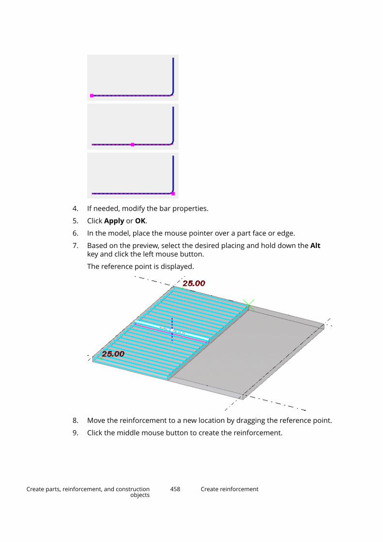
4. If needed, modify the bar properties.
5. Click Apply or OK.
6. In the model, place the mouse pointer over a part face or edge.
7. Based on the preview, select the desired placing and hold down the Altkey and click the left mouse button.
The reference point is displayed.
8. Move the reinforcement to a new location by dragging the reference point.
9. Click the middle mouse button to create the reinforcement.
Create parts, reinforcement, and constructionobjects
458 Create reinforcement
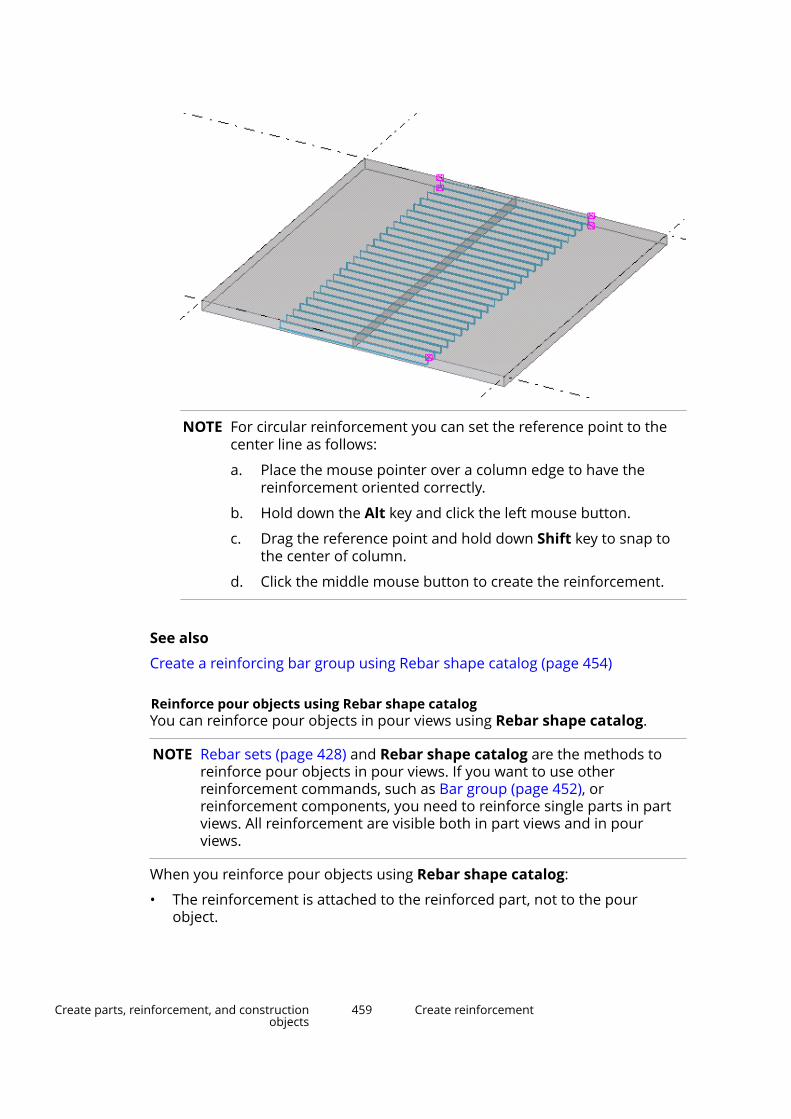
NOTE For circular reinforcement you can set the reference point to thecenter line as follows:
a. Place the mouse pointer over a column edge to have thereinforcement oriented correctly.
b. Hold down the Alt key and click the left mouse button.
c. Drag the reference point and hold down Shift key to snap tothe center of column.
d. Click the middle mouse button to create the reinforcement.
See also
Create a reinforcing bar group using Rebar shape catalog (page 454)
Reinforce pour objects using Rebar shape catalogYou can reinforce pour objects in pour views using Rebar shape catalog.
NOTE Rebar sets (page 428) and Rebar shape catalog are the methods toreinforce pour objects in pour views. If you want to use otherreinforcement commands, such as Bar group (page 452), orreinforcement components, you need to reinforce single parts in partviews. All reinforcement are visible both in part views and in pourviews.
When you reinforce pour objects using Rebar shape catalog:
• The reinforcement is attached to the reinforced part, not to the pourobject.
Create parts, reinforcement, and constructionobjects
459 Create reinforcement
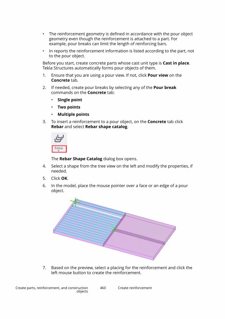
• The reinforcement geometry is defined in accordance with the pour objectgeometry even though the reinforcement is attached to a part. Forexample, pour breaks can limit the length of reinforcing bars.
• In reports the reinforcement information is listed according to the part, notto the pour object.
Before you start, create concrete parts whose cast unit type is Cast in place.Tekla Structures automatically forms pour objects of them.
1. Ensure that you are using a pour view. If not, click Pour view on theConcrete tab.
2. If needed, create pour breaks by selecting any of the Pour breakcommands on the Concrete tab:
• Single point
• Two points
• Multiple points
3. To insert a reinforcement to a pour object, on the Concrete tab clickRebar and select Rebar shape catalog.
The Rebar Shape Catalog dialog box opens.
4. Select a shape from the tree view on the left and modify the properties, ifneeded.
5. Click OK.
6. In the model, place the mouse pointer over a face or an edge of a pourobject.
7. Based on the preview, select a placing for the reinforcement and click theleft mouse button to create the reinforcement.
Create parts, reinforcement, and constructionobjects
460 Create reinforcement

See also
Create a reinforcing bar group using Rebar shape catalog (page 454)
Manage pours (page 402)
Create a curved reinforcing bar groupYou can reinforce curved segments in a concrete beam or a curved wall.
1. On the Concrete tab, click Rebar and select Curved bar group.
If you need to modify the properties before you create the reinforcement,hold down Shift and click the Curved bar group command to open theCurved bar properties.
2. Select the part to reinforce.
Tekla Structures attaches the bar group to this part.
3. Pick three points on an arc to define the curve.
Create parts, reinforcement, and constructionobjects
461 Create reinforcement
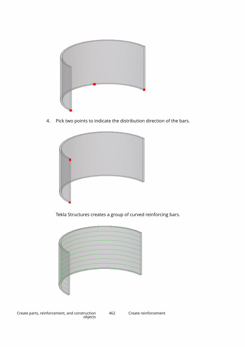
4. Pick two points to indicate the distribution direction of the bars.
Tekla Structures creates a group of curved reinforcing bars.
Create parts, reinforcement, and constructionobjects
462 Create reinforcement

5. If you want to change the curved reinforcing bar group properties:
a. Double-click the curved reinforcing bar group to open the Curved barproperties.
b. Modify the properties (page 927).
c. Click Modify.
See also
Create a reinforcing bar group using Rebar shape catalog (page 454)
Create a reinforcing bar group (page 452)
Create a circular reinforcing bar group (page 463)
Create a tapered or spiral reinforcing bar group (page 465)
Modify reinforcement (page 477)
Create a circular reinforcing bar groupYou can reinforce round circular columns.
1. On the Concrete tab, click Rebar and select Circular bar group.
If you need to modify the properties before you create the reinforcement,hold down Shift and click the Circular bar group command to open theCircular rebar properties.
2. Select the part to reinforce.
Tekla Structures attaches the bar group to this part.
3. Pick three points on the outer contour of the concrete part to define thecircular bars.
Create parts, reinforcement, and constructionobjects
463 Create reinforcement
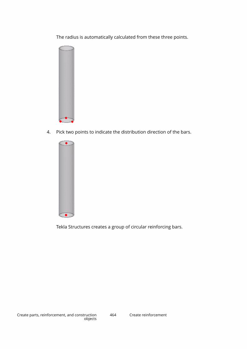
The radius is automatically calculated from these three points.
4. Pick two points to indicate the distribution direction of the bars.
Tekla Structures creates a group of circular reinforcing bars.
Create parts, reinforcement, and constructionobjects
464 Create reinforcement

NOTE If you want to modify the splice length of the round stirrups, enternegative values in the Start and End boxes in the Circular rebarproperties.
5. If you want to change the circular reinforcing bar group properties:
a. Double-click the circular reinforcing bar group to open the Circularrebar properties.
b. Modify the properties (page 927).
c. Click Modify.
See also
Create a reinforcing bar group using Rebar shape catalog (page 454)
Create a reinforcing bar group (page 452)
Create a curved reinforcing bar group (page 461)
Create a tapered or spiral reinforcing bar group (page 465)
Modify reinforcement (page 477)
Create a tapered or spiral reinforcing bar groupFor rectangular concrete parts it is sufficient to pick two points to define thedistribution area of the reinforcing bar group. If the part shape is notrectangular, an alternative shape can be selected.
Use the Rebar group type list on the Group tab in the Reinforcing BarProperties dialog box to select and modify the reinforcing group types.
1. On the Concrete tab, hold down Shift and click:
Create parts, reinforcement, and constructionobjects
465 Create reinforcement

The Reinforcing Bar Properties dialog box opens.
2. If needed, enter or modify the bar properties.
3. On the Group tab, select a tapered or spiral option from the Bar grouptype list.
4. Click OK.
5. Select the part to reinforce.
Tekla Structures attaches the bar group to the part.
6. Pick points to define the shape of the bar at the first cross section.
7. Click the middle mouse button to finish picking.
8. For the second and subsequent cross sections, pick points to define theshape of the bar.
9. Click the middle mouse button to finish picking.
Tekla Structures creates the reinforcement.
Reinforcing bar group types
Option Description Example
Normal
Not tapered.
Pick two points to define the distributionarea of the bar group.
Tapered
One bar dimension changes linearly inthe group.
Tapered ridge
One bar dimension changes linearly inthe group. The dimension is longest inthe middle of the group.
Create parts, reinforcement, and constructionobjects
466 Create reinforcement
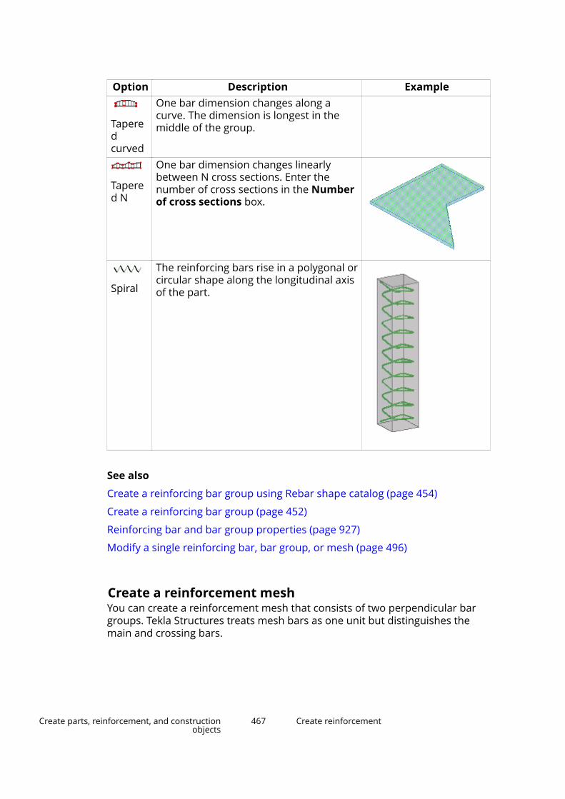
Option Description Example
Taperedcurved
One bar dimension changes along acurve. The dimension is longest in themiddle of the group.
Tapered N
One bar dimension changes linearlybetween N cross sections. Enter thenumber of cross sections in the Numberof cross sections box.
Spiral
The reinforcing bars rise in a polygonal orcircular shape along the longitudinal axisof the part.
See also
Create a reinforcing bar group using Rebar shape catalog (page 454)
Create a reinforcing bar group (page 452)
Reinforcing bar and bar group properties (page 927)
Modify a single reinforcing bar, bar group, or mesh (page 496)
Create a reinforcement meshYou can create a reinforcement mesh that consists of two perpendicular bargroups. Tekla Structures treats mesh bars as one unit but distinguishes themain and crossing bars.
Create parts, reinforcement, and constructionobjects
467 Create reinforcement

The reinforcement mesh can be rectangular, polygonal, or bent. You can alsocreate a customized reinforcement mesh.
NOTE You cannot change the mesh type once the mesh has been created.
Create a rectangular reinforcement mesh1. On the Concrete tab, hold down Shift and click Rebar --> Mesh.
The Rebar mesh properties open in the property pane.
2. In the Mesh type list, select Rectangle.
NOTE You cannot change the mesh type once the mesh has beencreated.
3. Select the part to reinforce.
Tekla Structures attaches the mesh to this part.
4. Pick the start point of the mesh.
5. Pick a point to indicate the direction of the longitudinal bars.
6. Click the middle mouse button to finish picking.
Tekla Structures creates the mesh parallel to the work plane, to the left ofthe points you picked.
7. If you want to modify the reinforcement mesh, do one of the following:
Create parts, reinforcement, and constructionobjects
468 Create reinforcement
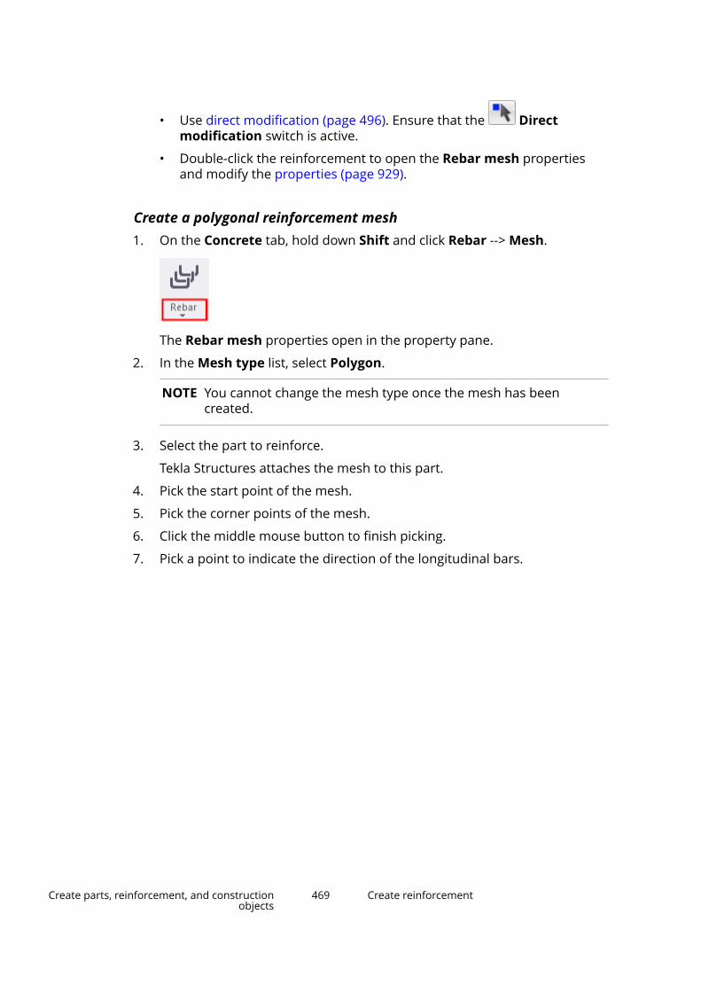
• Use direct modification (page 496). Ensure that the Directmodification switch is active.
• Double-click the reinforcement to open the Rebar mesh propertiesand modify the properties (page 929).
Create a polygonal reinforcement mesh1. On the Concrete tab, hold down Shift and click Rebar --> Mesh.
The Rebar mesh properties open in the property pane.
2. In the Mesh type list, select Polygon.
NOTE You cannot change the mesh type once the mesh has beencreated.
3. Select the part to reinforce.
Tekla Structures attaches the mesh to this part.
4. Pick the start point of the mesh.
5. Pick the corner points of the mesh.
6. Click the middle mouse button to finish picking.
7. Pick a point to indicate the direction of the longitudinal bars.
Create parts, reinforcement, and constructionobjects
469 Create reinforcement

Tekla Structures creates the mesh.
8. If you want to modify the reinforcement, do one of the following:
• Use direct modification (page 496). Ensure that the Directmodification switch is active.
• Double-click the reinforcement to open the Rebar mesh propertiesand modify the properties (page 929).
Reinforcement mesh with holes
If you want to reinforce a part that has holes, you need to pick the cornerpoints of holes when you create the reinforcement.
1. Select the part to reinforce.
2. Pick the start point of the mesh.
3. Pick the corner points of the mesh.
4. Pick the corner points of the hole.
Note that you need to pick the corner points of the hole in the oppositedirection than the corner points in the mesh.
Create parts, reinforcement, and constructionobjects
470 Create reinforcement
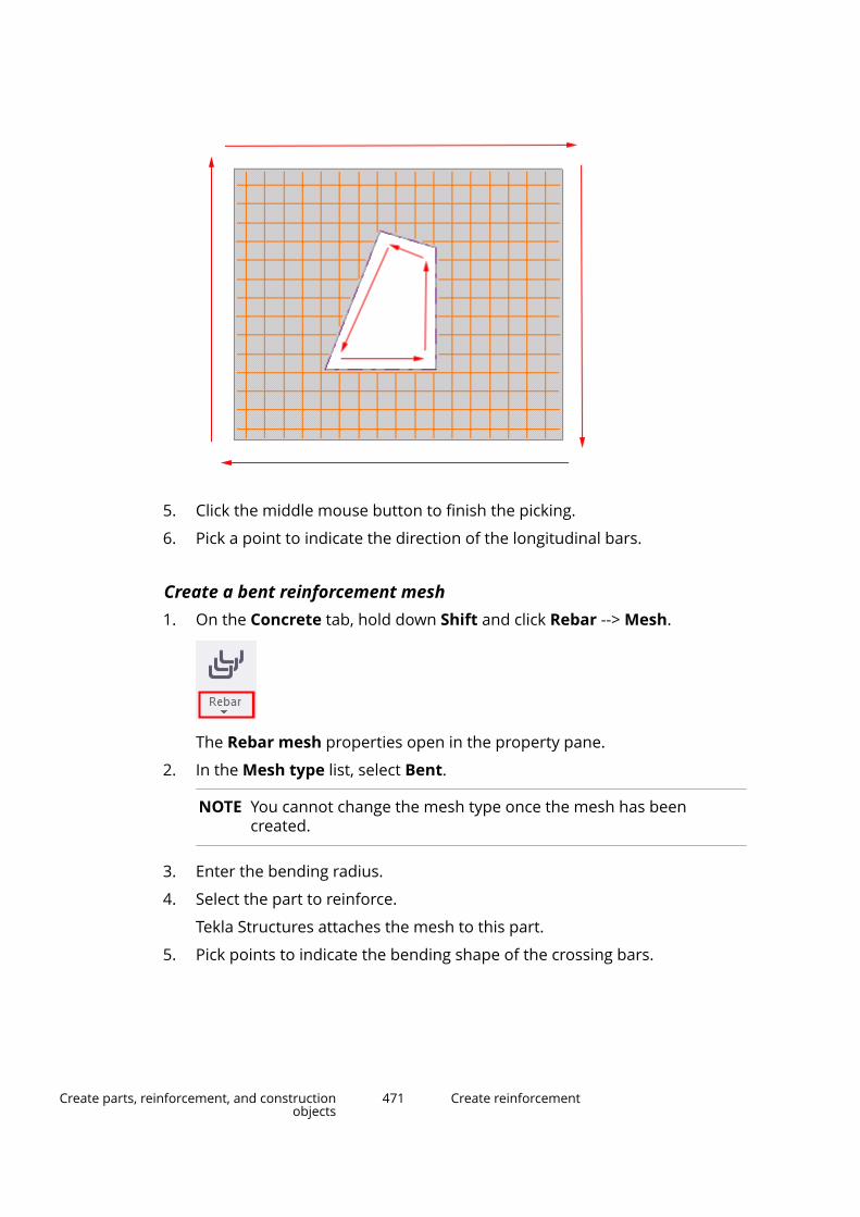
5. Click the middle mouse button to finish the picking.
6. Pick a point to indicate the direction of the longitudinal bars.
Create a bent reinforcement mesh1. On the Concrete tab, hold down Shift and click Rebar --> Mesh.
The Rebar mesh properties open in the property pane.
2. In the Mesh type list, select Bent.
NOTE You cannot change the mesh type once the mesh has beencreated.
3. Enter the bending radius.
4. Select the part to reinforce.
Tekla Structures attaches the mesh to this part.
5. Pick points to indicate the bending shape of the crossing bars.
Create parts, reinforcement, and constructionobjects
471 Create reinforcement
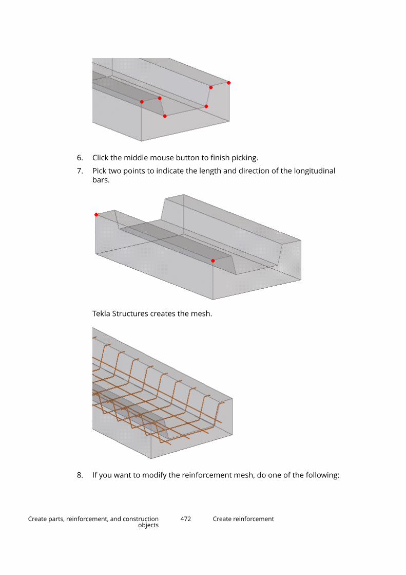
6. Click the middle mouse button to finish picking.
7. Pick two points to indicate the length and direction of the longitudinalbars.
Tekla Structures creates the mesh.
8. If you want to modify the reinforcement mesh, do one of the following:
Create parts, reinforcement, and constructionobjects
472 Create reinforcement
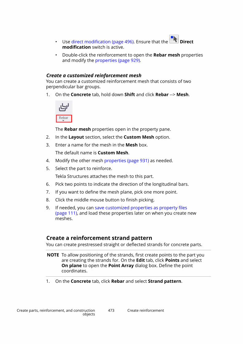
• Use direct modification (page 496). Ensure that the Directmodification switch is active.
• Double-click the reinforcement to open the Rebar mesh propertiesand modify the properties (page 929).
Create a customized reinforcement meshYou can create a customized reinforcement mesh that consists of twoperpendicular bar groups.
1. On the Concrete tab, hold down Shift and click Rebar --> Mesh.
The Rebar mesh properties open in the property pane.
2. In the Layout section, select the Custom Mesh option.
3. Enter a name for the mesh in the Mesh box.
The default name is Custom Mesh.
4. Modify the other mesh properties (page 931) as needed.
5. Select the part to reinforce.
Tekla Structures attaches the mesh to this part.
6. Pick two points to indicate the direction of the longitudinal bars.
7. If you want to define the mesh plane, pick one more point.
8. Click the middle mouse button to finish picking.
9. If needed, you can save customized properties as property files(page 111), and load these properties later on when you create newmeshes.
Create a reinforcement strand patternYou can create prestressed straight or deflected strands for concrete parts.
NOTE To allow positioning of the strands, first create points to the part youare creating the strands for. On the Edit tab, click Points and selectOn plane to open the Point Array dialog box. Define the pointcoordinates.
1. On the Concrete tab, click Rebar and select Strand pattern.
Create parts, reinforcement, and constructionobjects
473 Create reinforcement

If you need to modify the properties before you create the reinforcement,hold down Shift and click the Strand pattern command to open theStrand pattern properties.
2. Select the part you are creating strands for.
3. Pick each of the points that you are using to position the strands (forexample, at the end of a part).
The points you pick define the first cross section.
4. Click the middle mouse button to finish picking.
5. Pick points to position the strands.
• If you create a single cross section, pick two points to define the lengthof the strands.
• If you create two or more cross sections, for each cross section, pickpoints to indicate the strand positions. Pick the strand positions in thesame order as for the first cross section.
6. Click the middle mouse button to finish picking.
Tekla Structures creates the strands.
7. If you want to change the strand properties:
a. Double-click the strand pattern to open the Strand patternproperties.
b. Modify the properties (page 946).
c. Click Modify.
Create parts, reinforcement, and constructionobjects
474 Create reinforcement
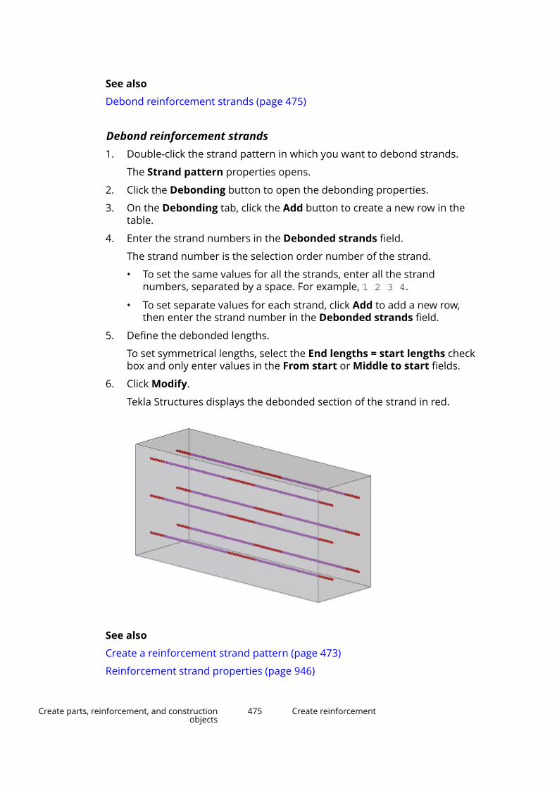
See also
Debond reinforcement strands (page 475)
Debond reinforcement strands1. Double-click the strand pattern in which you want to debond strands.
The Strand pattern properties opens.
2. Click the Debonding button to open the debonding properties.
3. On the Debonding tab, click the Add button to create a new row in thetable.
4. Enter the strand numbers in the Debonded strands field.
The strand number is the selection order number of the strand.
• To set the same values for all the strands, enter all the strandnumbers, separated by a space. For example, 1 2 3 4.
• To set separate values for each strand, click Add to add a new row,then enter the strand number in the Debonded strands field.
5. Define the debonded lengths.
To set symmetrical lengths, select the End lengths = start lengths checkbox and only enter values in the From start or Middle to start fields.
6. Click Modify.
Tekla Structures displays the debonded section of the strand in red.
See also
Create a reinforcement strand pattern (page 473)
Reinforcement strand properties (page 946)
Create parts, reinforcement, and constructionobjects
475 Create reinforcement
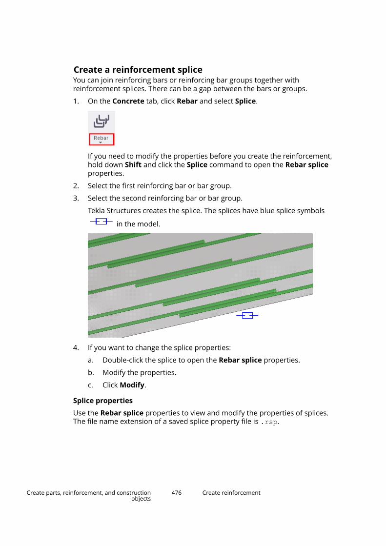
Create a reinforcement spliceYou can join reinforcing bars or reinforcing bar groups together withreinforcement splices. There can be a gap between the bars or groups.
1. On the Concrete tab, click Rebar and select Splice.
If you need to modify the properties before you create the reinforcement,hold down Shift and click the Splice command to open the Rebar spliceproperties.
2. Select the first reinforcing bar or bar group.
3. Select the second reinforcing bar or bar group.
Tekla Structures creates the splice. The splices have blue splice symbols
in the model.
4. If you want to change the splice properties:
a. Double-click the splice to open the Rebar splice properties.
b. Modify the properties.
c. Click Modify.
Splice properties
Use the Rebar splice properties to view and modify the properties of splices.The file name extension of a saved splice property file is .rsp.
Create parts, reinforcement, and constructionobjects
476 Create reinforcement
Option DescriptionJoint type Splice type.
Lap left creates the lap to the direction of the firstreinforcing bar or bar group selected, Lap right to thedirection of the second.
Lap both centers the lap between the bars or bar groups.Lap length Length of the lap joint.Offset Offset of the splice center point from the point where the
bars originally met.Bar positions Select whether the lapping bars are on top of each other
or parallel to each other.
See also
Create a reinforcing bar group using Rebar shape catalog (page 454)
Create a reinforcing bar group (page 452)
Split and splice a reinforcement (page 515)
2.9 Modify reinforcementOnce you have added reinforcement to your model, you can modify the shapeof the reinforcement, for example. Tekla Structures includes several methodsfor the modification.
Rebar sets
When you modify rebar sets, you can use direct modification on the rebar setguidelines, leg faces, and modifiers.
Single reinforcing bars, bar groups, and meshes
When you modify single reinforcing bars, bar groups, or meshes, you can use:
• direct modification (page 496)
• handles (page 506)
• grouping (page 504)
• combining (page 505)
• splitting (page 506)
See also
Use adaptivity to modify a reinforcement (page 512)
Attach a reinforcement to a concrete part (page 514)
Create parts, reinforcement, and constructionobjects
477 Modify reinforcement
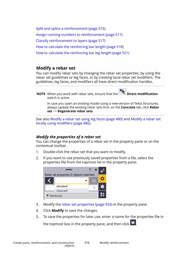
Split and splice a reinforcement (page 515)
Assign running numbers to reinforcement (page 517)
Classify reinforcement to layers (page 517)
How to calculate the reinforcing bar length (page 518)
How to calculate the reinforcing bar leg length (page 521)
Modify a rebar setYou can modify rebar sets by changing the rebar set properties, by using therebar set guidelines or leg faces, or by creating local rebar set modifiers. Theguidelines, leg faces, and modifiers all have direct modification handles.
NOTE When you work with rebar sets, ensure that the Direct modificationswitch is active.
In case you open an existing model using a new version of Tekla Structures,always update the existing rebar sets first: on the Concrete tab, click Rebarset --> Regenerate rebar sets.
See also Modify a rebar set using leg faces (page 480) and Modify a rebar setlocally using modifiers (page 486).
Modify the properties of a rebar setYou can change the properties of a rebar set in the property pane or on thecontextual toolbar.
1. Double-click the rebar set that you want to modify.
2. If you want to use previously saved properties from a file, select theproperties file from the topmost list in the property pane:
3. Modify the rebar set properties (page 933) in the property pane.
4. Click Modify to save the changes.
5. To save the properties for later use, enter a name for the properties file in
the topmost box in the property pane, and then click .
Create parts, reinforcement, and constructionobjects
478 Modify reinforcement

TIP Alternatively, you can modify the rebar set properties on the contextual toolbar.
Change the layer order of a rebar setYou can adjust the order of the bar layers when two or more rebar setsoverlap.
By default, the layer order is based on the creation order of the rebar sets.Tekla Structures automatically places the bars that are created first closest tothe concrete surface, and the bars created last will be the furthest.
1. Select a rebar set.
2. On the contextual toolbar, adjust the layer order number by using the
arrow buttons .
Alternatively, you can enter a number or use the arrow buttons in theproperty pane, and then click Modify to save the changes.
The smaller the layer order number, the closer to the concrete surface thebar layer is. You can use both positive and negative numbers.
If you set the same layer order number for several rebar sets, the bars willbe placed on the same layer, and the bars may collide.
3. If needed, fine-tune the layer order at any individual leg face (page 480)separately.
These modifications override the default settings and the layer ordersettings of the entire rebar set.
Modify a rebar set using guidelinesThe guidelines of a rebar set define the distribution direction of the bars. Thespacing of the bars is also measured along the guidelines. You can modify therebar set guidelines by using direct modification.
See also Resize and reshape model objects (page 103), Distribute bars in arebar set (page 494), and Create a secondary guideline (page 490).
To modify a guideline, select a rebar set and do any of the following:
• To move a guideline, drag the line handle.
• To move a guideline point, drag the point handle .
• To add a new point to the start or end of a guideline:
1. Select the start or end point of the guideline .
2. Click Add new point on the contextual toolbar.
3. Pick a location for the new start or end point.
Create parts, reinforcement, and constructionobjects
479 Modify reinforcement
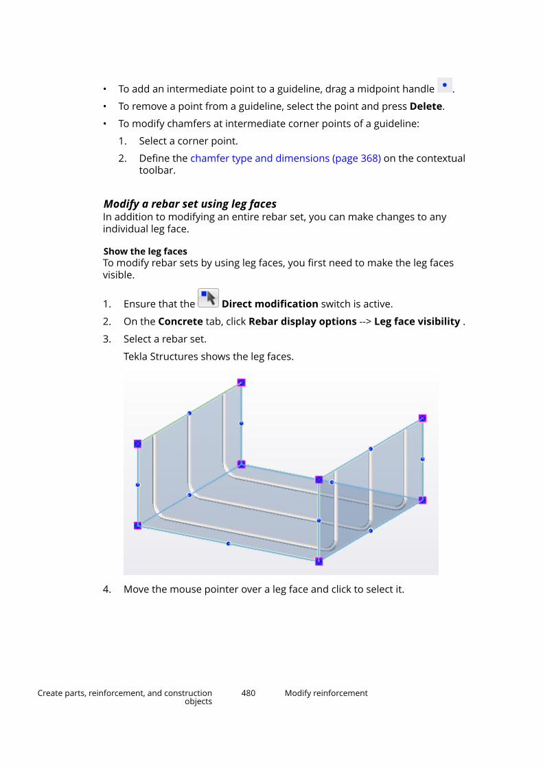
• To add an intermediate point to a guideline, drag a midpoint handle .
• To remove a point from a guideline, select the point and press Delete.
• To modify chamfers at intermediate corner points of a guideline:
1. Select a corner point.
2. Define the chamfer type and dimensions (page 368) on the contextualtoolbar.
Modify a rebar set using leg facesIn addition to modifying an entire rebar set, you can make changes to anyindividual leg face.
Show the leg facesTo modify rebar sets by using leg faces, you first need to make the leg facesvisible.
1. Ensure that the Direct modification switch is active.
2. On the Concrete tab, click Rebar display options --> Leg face visibility .
3. Select a rebar set.
Tekla Structures shows the leg faces.
4. Move the mouse pointer over a leg face and click to select it.
Create parts, reinforcement, and constructionobjects
480 Modify reinforcement
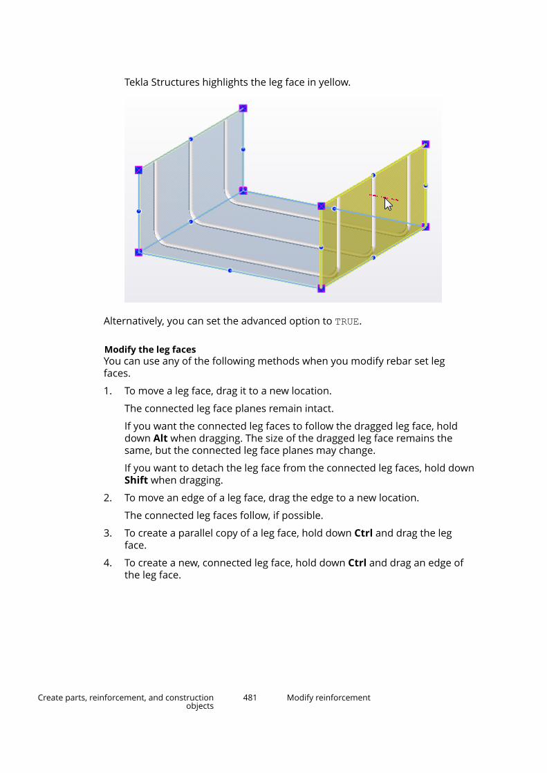
Tekla Structures highlights the leg face in yellow.
Alternatively, you can set the advanced option to TRUE.
Modify the leg facesYou can use any of the following methods when you modify rebar set legfaces.
1. To move a leg face, drag it to a new location.
The connected leg face planes remain intact.
If you want the connected leg faces to follow the dragged leg face, holddown Alt when dragging. The size of the dragged leg face remains thesame, but the connected leg face planes may change.
If you want to detach the leg face from the connected leg faces, hold downShift when dragging.
2. To move an edge of a leg face, drag the edge to a new location.
The connected leg faces follow, if possible.
3. To create a parallel copy of a leg face, hold down Ctrl and drag the legface.
4. To create a new, connected leg face, hold down Ctrl and drag an edge ofthe leg face.
Create parts, reinforcement, and constructionobjects
481 Modify reinforcement
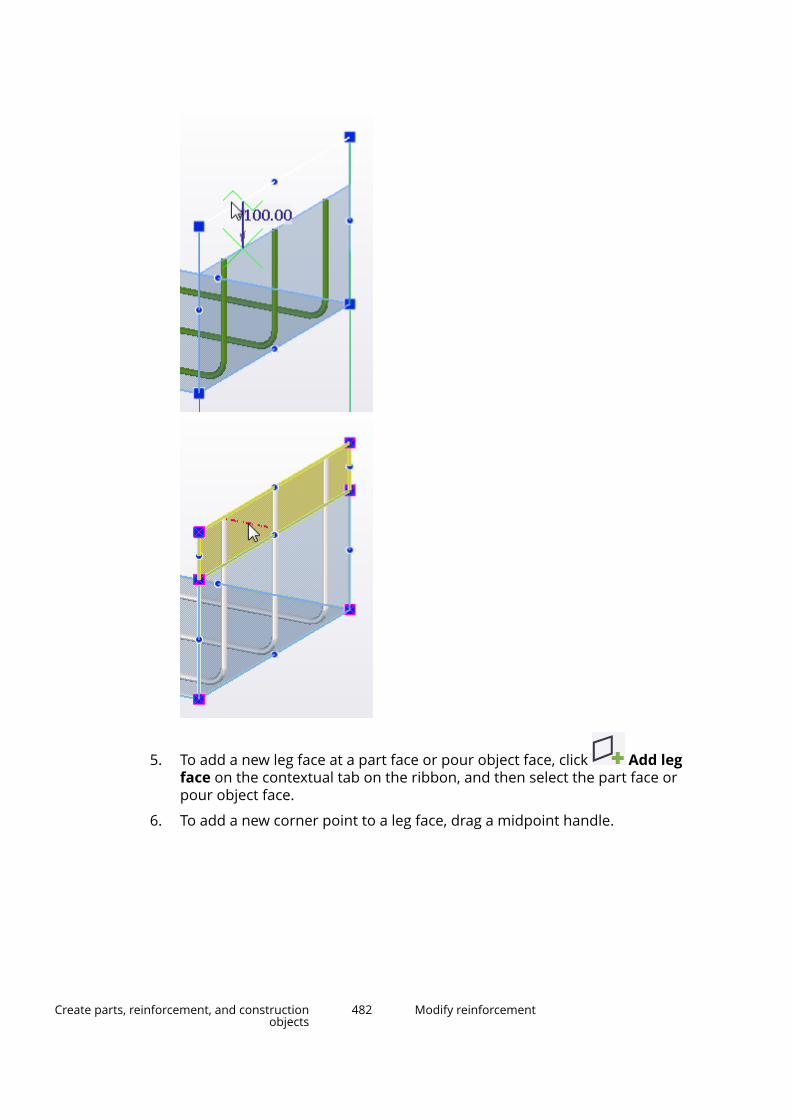
5. To add a new leg face at a part face or pour object face, click Add legface on the contextual tab on the ribbon, and then select the part face orpour object face.
6. To add a new corner point to a leg face, drag a midpoint handle.
Create parts, reinforcement, and constructionobjects
482 Modify reinforcement

7. To remove a corner point from a leg face, select the point and pressDelete.
8. To modify a corner chamfer of a leg face, select the corner point, and thenselect the chamfer type (page 368) and enter the chamfer dimensions onthe contextual toolbar.
Create parts, reinforcement, and constructionobjects
483 Modify reinforcement
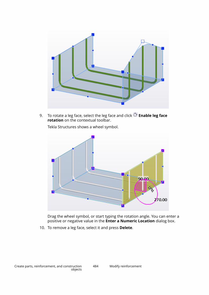
9. To rotate a leg face, select the leg face and click Enable leg facerotation on the contextual toolbar.
Tekla Structures shows a wheel symbol.
Drag the wheel symbol, or start typing the rotation angle. You can enter apositive or negative value in the Enter a Numeric Location dialog box.
10. To remove a leg face, select it and press Delete.
Create parts, reinforcement, and constructionobjects
484 Modify reinforcement
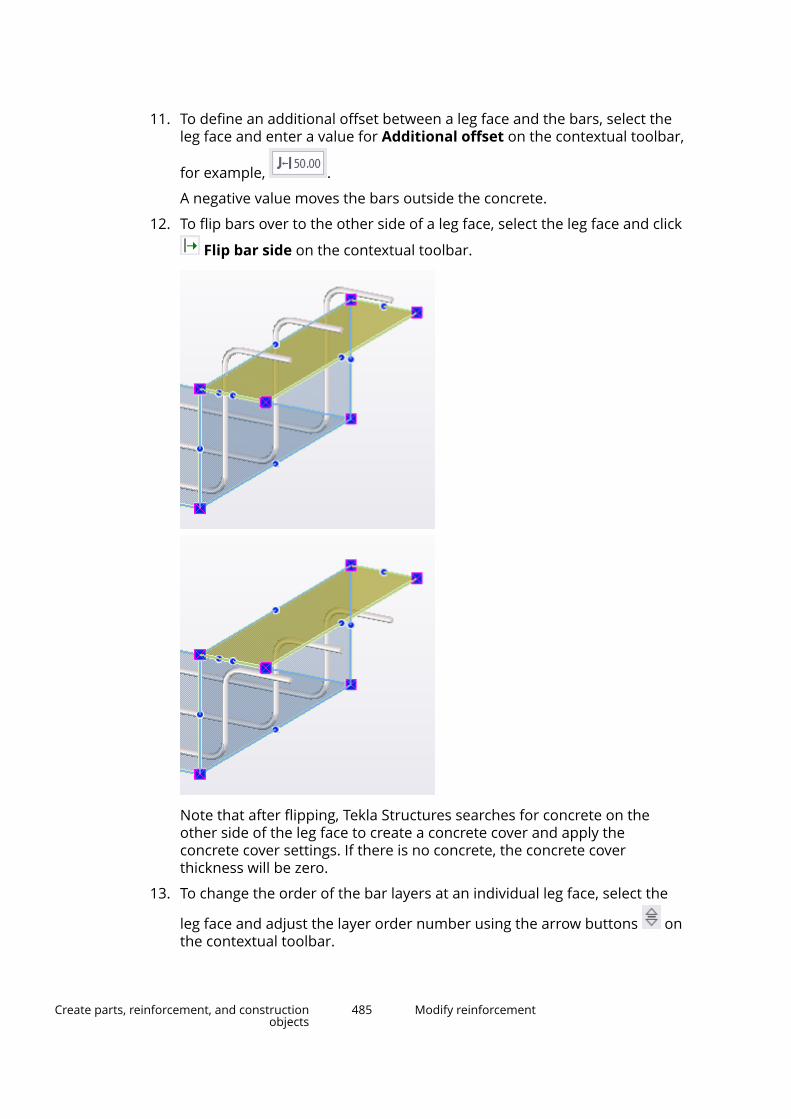
11. To define an additional offset between a leg face and the bars, select theleg face and enter a value for Additional offset on the contextual toolbar,
for example, .
A negative value moves the bars outside the concrete.
12. To flip bars over to the other side of a leg face, select the leg face and click
Flip bar side on the contextual toolbar.
Note that after flipping, Tekla Structures searches for concrete on theother side of the leg face to create a concrete cover and apply theconcrete cover settings. If there is no concrete, the concrete coverthickness will be zero.
13. To change the order of the bar layers at an individual leg face, select the
leg face and adjust the layer order number using the arrow buttons onthe contextual toolbar.
Create parts, reinforcement, and constructionobjects
485 Modify reinforcement

The smaller the layer order number, the closer to the concrete surface thebar layer is. You can use both positive and negative numbers.
These modifications override the layer order settings of the entire rebarset (page 478).
TIP You can modify leg face properties (page 938) also in the property pane.
Modify a rebar set locally using modifiersYou can use modifiers to modify a rebar set at certain locations only.
For example, you can create a local property modifier to only change theproperties of certain bars in a rebar set, or you can create hooks or threadingby adding an end detail modifier, or you can split rebar set bars with a splitter.
You can also create secondary guidelines for the rebar set. With a secondaryguideline you can define a different spacing at the start and end of the rebarset bars, for example.
Modifiers are lines, or polylines that may have corner chamfers. Modifiers areprojected to rebar set leg faces. Each modifier then only affects the rebar setbars that its projection touches.
NOTE When you work with rebar sets, ensure that the Direct modificationswitch is active.
To select entire rebar sets, or bar groups or individual bars within rebar sets in
the model, you can use the three reinforcement selection switches .Tekla Structures then shows the existing modifiers that affect the selectedrebar set bars, and the direct modification handles of the modifiers. Differentmodifiers have different colors as follows:
Create parts, reinforcement, and constructionobjects
486 Modify reinforcement
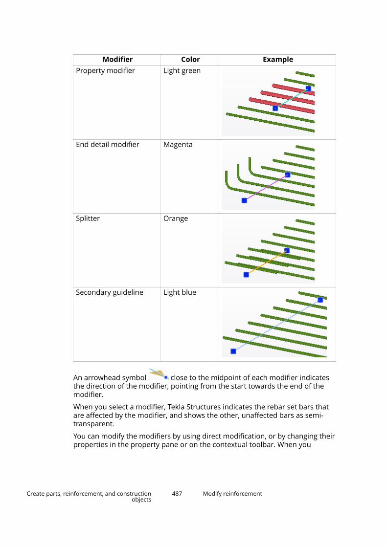
Modifier Color ExampleProperty modifier Light green
End detail modifier Magenta
Splitter Orange
Secondary guideline Light blue
An arrowhead symbol close to the midpoint of each modifier indicatesthe direction of the modifier, pointing from the start towards the end of themodifier.
When you select a modifier, Tekla Structures indicates the rebar set bars thatare affected by the modifier, and shows the other, unaffected bars as semi-transparent.
You can modify the modifiers by using direct modification, or by changing theirproperties in the property pane or on the contextual toolbar. When you
Create parts, reinforcement, and constructionobjects
487 Modify reinforcement
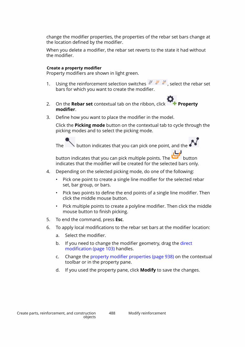
change the modifier properties, the properties of the rebar set bars change atthe location defined by the modifier.
When you delete a modifier, the rebar set reverts to the state it had withoutthe modifier.
Create a property modifierProperty modifiers are shown in light green.
1. Using the reinforcement selection switches , select the rebar setbars for which you want to create the modifier.
2. On the Rebar set contextual tab on the ribbon, click Propertymodifier.
3. Define how you want to place the modifier in the model.
Click the Picking mode button on the contextual tab to cycle through thepicking modes and to select the picking mode.
The button indicates that you can pick one point, and the
button indicates that you can pick multiple points. The buttonindicates that the modifier will be created for the selected bars only.
4. Depending on the selected picking mode, do one of the following:
• Pick one point to create a single line modifier for the selected rebarset, bar group, or bars.
• Pick two points to define the end points of a single line modifier. Thenclick the middle mouse button.
• Pick multiple points to create a polyline modifier. Then click the middlemouse button to finish picking.
5. To end the command, press Esc.
6. To apply local modifications to the rebar set bars at the modifier location:
a. Select the modifier.
b. If you need to change the modifier geometry, drag the directmodification (page 103) handles.
c. Change the property modifier properties (page 938) on the contextualtoolbar or in the property pane.
d. If you used the property pane, click Modify to save the changes.
Create parts, reinforcement, and constructionobjects
488 Modify reinforcement

Create an end detail modifierEnd detail modifiers affect the nearest end of the bar, so by moving themodifier you can change the bar end that it affects. End detail modifiers areshown in magenta.
Tekla Structures displays the threaded bar ends in dark red.
1. Using the reinforcement selection switches , select the rebar setbars for which you want to create the modifier.
2. On the Rebar set contextual tab on the ribbon, click End detail.
3. Define how you want to place the modifier in the model.
Click the Picking mode button on the contextual tab to cycle through thepicking modes and to select the picking mode.
The button indicates that you can pick one point, and the
button indicates that you can pick multiple points. The buttonindicates that the modifier will be created for the selected bars only.
4. Depending on the selected picking mode, do one of the following:
• Pick one point to create a single line modifier for the selected rebarset, bar group, or bars.
• Pick two points to define the end points of a single line modifier. Thenclick the middle mouse button.
• Pick multiple points to create a polyline modifier. Then click the middlemouse button to finish picking.
5. To end the command, press Esc.
6. To apply local modifications to the rebar set bars at the modifier location:
a. Select the modifier.
b. If you need to change the modifier geometry, drag the directmodification (page 103) handles.
c. Change the end detail modifier properties (page 941) on thecontextual toolbar or in the property pane.
Create parts, reinforcement, and constructionobjects
489 Modify reinforcement

d. If you used the property pane, click Modify to save the changes.
Create a splitterSplitters split bars and create lap or crank splices. Splitters are shown inorange.
1. Using the reinforcement selection switches , select the rebar setbars for which you want to create the modifier.
2. On the Rebar set contextual tab on the ribbon, click Splitter.
3. Define how you want to place the splitter in the model.
Click the Picking mode button on the contextual tab to cycle through thepicking modes and to select the picking mode.
The button indicates that you can pick one point, and the
button indicates that you can pick multiple points. The buttonindicates that the splitter will be created for the selected bars only.
4. Depending on the selected picking mode, do one of the following:
• Pick one point to create a single line splitter for the selected rebar set,bar group, or bars.
• Pick two points to define the end points of a single line splitter. Thenclick the middle mouse button.
• Pick multiple points to create a polyline splitter. Then click the middlemouse button to finish picking.
TIP If you want to create the splitter at a rounded distance from a barend, and the dimension shown is measured from the other bar end,hold down Shift when you are placing the splitter in the model toswitch the measuring point to the other bar end.
5. To end the command, press Esc.
6. To apply local modifications to the rebar set bars at the splitter location:
a. Select the splitter.
b. If you need to change the splitter geometry, drag the directmodification (page 103) handles.
c. Change the splitter properties (page 943) on the contextual toolbar orin the property pane.
d. If you used the property pane, click Modify to save the changes.
Create parts, reinforcement, and constructionobjects
490 Modify reinforcement
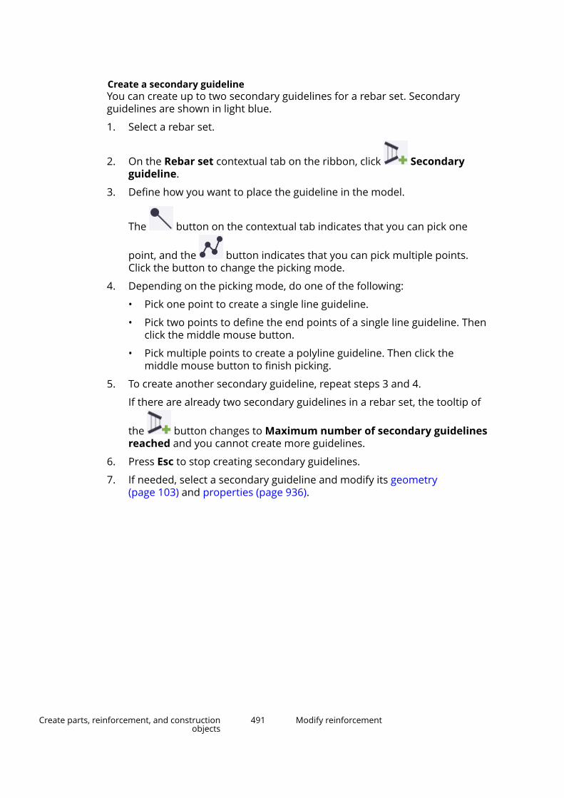
Create a secondary guidelineYou can create up to two secondary guidelines for a rebar set. Secondaryguidelines are shown in light blue.
1. Select a rebar set.
2. On the Rebar set contextual tab on the ribbon, click Secondaryguideline.
3. Define how you want to place the guideline in the model.
The button on the contextual tab indicates that you can pick one
point, and the button indicates that you can pick multiple points.Click the button to change the picking mode.
4. Depending on the picking mode, do one of the following:
• Pick one point to create a single line guideline.
• Pick two points to define the end points of a single line guideline. Thenclick the middle mouse button.
• Pick multiple points to create a polyline guideline. Then click themiddle mouse button to finish picking.
5. To create another secondary guideline, repeat steps 3 and 4.
If there are already two secondary guidelines in a rebar set, the tooltip of
the button changes to Maximum number of secondary guidelinesreached and you cannot create more guidelines.
6. Press Esc to stop creating secondary guidelines.
7. If needed, select a secondary guideline and modify its geometry(page 103) and properties (page 936).
Create parts, reinforcement, and constructionobjects
491 Modify reinforcement
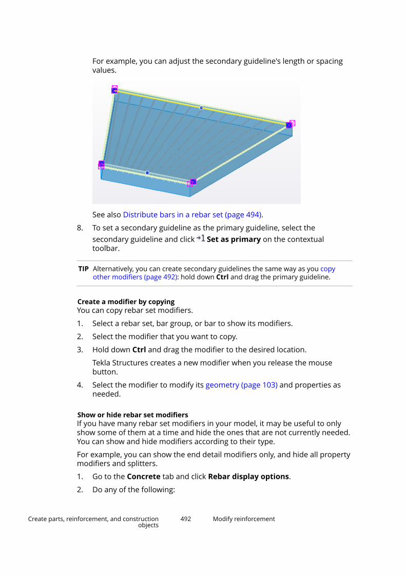
For example, you can adjust the secondary guideline's length or spacingvalues.
See also Distribute bars in a rebar set (page 494).
8. To set a secondary guideline as the primary guideline, select thesecondary guideline and click Set as primary on the contextualtoolbar.
TIP Alternatively, you can create secondary guidelines the same way as you copyother modifiers (page 492): hold down Ctrl and drag the primary guideline.
Create a modifier by copyingYou can copy rebar set modifiers.
1. Select a rebar set, bar group, or bar to show its modifiers.
2. Select the modifier that you want to copy.
3. Hold down Ctrl and drag the modifier to the desired location.
Tekla Structures creates a new modifier when you release the mousebutton.
4. Select the modifier to modify its geometry (page 103) and properties asneeded.
Show or hide rebar set modifiersIf you have many rebar set modifiers in your model, it may be useful to onlyshow some of them at a time and hide the ones that are not currently needed.You can show and hide modifiers according to their type.
For example, you can show the end detail modifiers only, and hide all propertymodifiers and splitters.
1. Go to the Concrete tab and click Rebar display options.
2. Do any of the following:
Create parts, reinforcement, and constructionobjects
492 Modify reinforcement
• Click Property modifier visibility to switch the property modifiers onor off.
• Click End detail modifier visibility to switch the end detail modifierson or off.
• Click Splitter visibility to switch the splitters on or off.
Alternatively, you can use the following advanced options:
•
•
•
How to cut rebar setsYou can cut rebar sets automatically by the existing cuts in the concrete partsor manually by using the cutting commands on the Edit tab. You can modifycuts in rebar sets the same way as you modify cuts in parts in the model, byusing direct modification.
You can use the following commands to create cuts:
• Line cut (page 362)
• Polygon cut (page 363)
• Part cut (page 364)
Concrete cover settings are also applied to cuts, even on cut edges that areparallel to reinforcing bars.
Cut a rebar set using a cut in a concrete partWhen you create rebar sets for concrete parts using the Create longitudinalrebars, Create crossing rebars, and Create planar rebars commands, TeklaStructures automatically cuts the new rebar sets using the existing cuts in theconcrete parts. If you add a new cut to a concrete part with a rebar set, therebar set is not automatically cut. If you want to cut the rebar set as well, usethe Part cut command, and use the new cut as the cutting part.
1. On the Edit tab, click Part cut.
2. Select the rebar set you want to cut.
3. Select the cut in the concrete part.
Tekla Structures cuts the rebar set.
Modify a cut in a rebar setYou can modify cuts in rebar sets using direct modification. For example, youcan make a cut in a rebar set of a different size or shape from a cut in aconcrete part.
Create parts, reinforcement, and constructionobjects
493 Modify reinforcement

1. Ensure that the Direct modification switch is active.
2. Select the cut in the rebar set.
3. Modify the cut using direct modification (page 103).
Distribute bars in a rebar setRebar sets may have zones with different spacing values between the bars.The spacing of the bars is measured along the rebar set guideline. You canmodify the spacing settings in the spacing mode.
NOTE When you work with rebar sets, ensure that the Direct modificationswitch is active.
Switch to the spacing modeTo define the spacing of bars in a rebar set, switch to the spacing mode. Whenthe spacing mode is active, you cannot modify the geometry of the rebar setguideline.
1. Select a rebar set.
2. On the contextual toolbar, click Edit spacing properties.
Tekla Structures shows the spacing zone dimensions in the model, and thespacing zone properties in the property pane, and on the contextual toolbar.
Add, move, and delete spacing zonesBy default, there is always one spacing zone in each rebar set. You can add anynumber of spacing zones, and move and delete spacing zones.
To Do thisAdd a spacing zone 1.
In the spacing mode, click in the middle ofa spacing zone on the rebar set guideline.
Tekla Structures splits the spacing zone in two.
Create parts, reinforcement, and constructionobjects
494 Modify reinforcement

To Do this
2. To modify the spacing zone properties(page 933), select a spacing zone and modifyits properties in the property pane or on thecontextual toolbar.
Move, lengthen, orshorten a spacing zone
1. In the spacing mode, drag a spacing zonehandle to a new location.
Delete a spacing zone 1. In the spacing mode, select a spacing zone inthe model.
2. Press Delete.
Modify the properties of a spacing zoneFor each spacing zone within a rebar set, you can modify the length, numberof spaces, and spacing value. You can also define offsets for the first and lastspacing zone of a rebar set.
You can modify the spacing zone properties in the property pane or on thecontextual toolbar.
On the contextual toolbar, the start offset is shown together with the firstspacing zone, and the end offset with the last spacing zone. If there is only onespacing zone in a rebar set, both the start and end offsets are shown.
1. While in the spacing mode, select a spacing zone.
2. Modify the properties (page 933) in the property pane or on thecontextual toolbar.
3. If you used the property pane, click Modify to save the changes.
Add, move, and delete single barsWhen you add, move, or delete single bars within a rebar set, it also affects thespacing zones.
Create parts, reinforcement, and constructionobjects
495 Modify reinforcement

1. Select a rebar set.
2. On the contextual toolbar, click Edit spacing properties.
The spacing mode is activated.
3. On the contextual toolbar, click Enable add/move/delete bars.
Tekla Structures displays a line handle for each bar on the rebar setguideline.
4. Do any of the following:
• To add a bar between two existing bars, click .
• To move a bar, select the line handle of the bar and drag it to a newlocation.
You can also use the keyboard to enter a numeric location (page 87).
To start with the negative sign (-), use the numeric keypad. To enter anabsolute coordinate, first enter $, then the value. Press Enter toconfirm.
Note that you cannot move the bar more than the spacing value,beyond the adjacent bars.
• To delete a bar, select the line handle of the bar and press Delete.
Modify a single reinforcing bar, bar group, or meshYou can modify a reinforcement by using direct modification. You can eithermodify the reinforcement simply by dragging handles, or select a commandfrom the contextual toolbar.
NOTE Direct modification does not work for the following reinforcementtypes:
• circular (page 463) and curved (page 461) reinforcing bars
• reinforcement strand patterns (page 473)
• detached reinforcing bars (page 514).
Create parts, reinforcement, and constructionobjects
496 Modify reinforcement
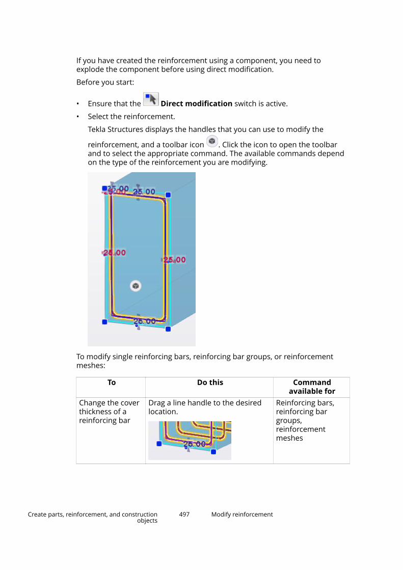
If you have created the reinforcement using a component, you need toexplode the component before using direct modification.
Before you start:
• Ensure that the Direct modification switch is active.
• Select the reinforcement.
Tekla Structures displays the handles that you can use to modify the
reinforcement, and a toolbar icon . Click the icon to open the toolbarand to select the appropriate command. The available commands dependon the type of the reinforcement you are modifying.
To modify single reinforcing bars, reinforcing bar groups, or reinforcementmeshes:
To Do this Commandavailable for
Change the coverthickness of areinforcing bar
Drag a line handle to the desiredlocation.
Reinforcing bars,reinforcing bargroups,reinforcementmeshes
Create parts, reinforcement, and constructionobjects
497 Modify reinforcement
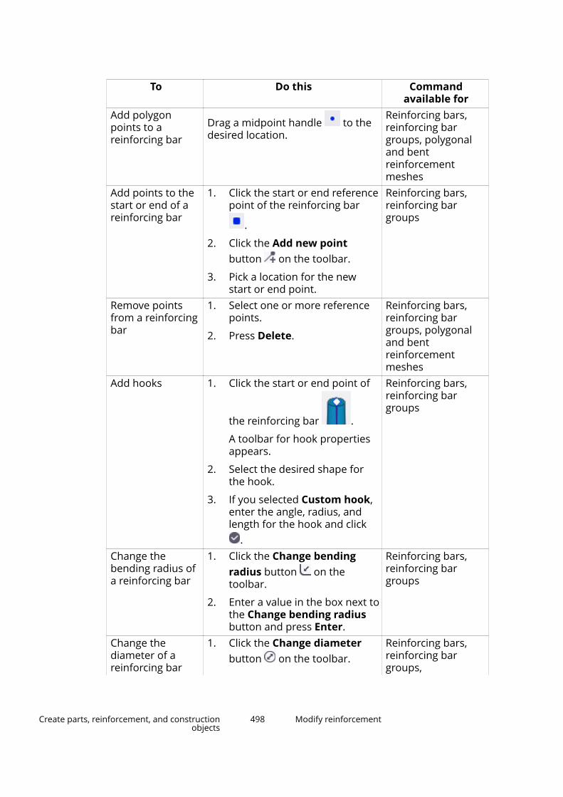
To Do this Commandavailable for
Add polygonpoints to areinforcing bar
Drag a midpoint handle to thedesired location.
Reinforcing bars,reinforcing bargroups, polygonaland bentreinforcementmeshes
Add points to thestart or end of areinforcing bar
1. Click the start or end referencepoint of the reinforcing bar
.
2. Click the Add new pointbutton on the toolbar.
3. Pick a location for the newstart or end point.
Reinforcing bars,reinforcing bargroups
Remove pointsfrom a reinforcingbar
1. Select one or more referencepoints.
2. Press Delete.
Reinforcing bars,reinforcing bargroups, polygonaland bentreinforcementmeshes
Add hooks 1. Click the start or end point of
the reinforcing bar .
A toolbar for hook propertiesappears.
2. Select the desired shape forthe hook.
3. If you selected Custom hook,enter the angle, radius, andlength for the hook and click
.
Reinforcing bars,reinforcing bargroups
Change thebending radius ofa reinforcing bar
1. Click the Change bendingradius button on thetoolbar.
2. Enter a value in the box next tothe Change bending radiusbutton and press Enter.
Reinforcing bars,reinforcing bargroups
Change thediameter of areinforcing bar
1. Click the Change diameterbutton on the toolbar.
Reinforcing bars,reinforcing bargroups,
Create parts, reinforcement, and constructionobjects
498 Modify reinforcement
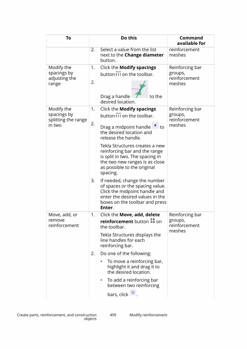
To Do this Commandavailable for
2. Select a value from the listnext to the Change diameterbutton.
reinforcementmeshes
Modify thespacings byadjusting therange
1. Click the Modify spacingsbutton on the toolbar.
2.
Drag a handle to thedesired location.
Reinforcing bargroups,reinforcementmeshes
Modify thespacings bysplitting the rangein two
1. Click the Modify spacingsbutton on the toolbar.
2.Drag a midpoint handle tothe desired location andrelease the handle.
Tekla Structures creates a newreinforcing bar and the rangeis split in two. The spacing inthe two new ranges is as closeas possible to the originalspacing.
3. If needed, change the numberof spaces or the spacing value.Click the midpoint handle andenter the desired values in theboxes on the toolbar and pressEnter.
Reinforcing bargroups,reinforcementmeshes
Move, add, orremovereinforcement
1. Click the Move, add, deletereinforcement button onthe toolbar.
Tekla Structures displays theline handles for eachreinforcing bar.
2. Do one of the following:
• To move a reinforcing bar,highlight it and drag it tothe desired location.
• To add a reinforcing barbetween two reinforcing
bars, click .
Reinforcing bargroups,reinforcementmeshes
Create parts, reinforcement, and constructionobjects
499 Modify reinforcement

To Do this Commandavailable for
• To delete reinforcing bars,select them and pressDelete.
See also
Use handles to modify a reinforcement (page 506)
Use adaptivity to modify a reinforcement (page 512)
Check the validity of reinforcement geometry (page 514)
Distribute bars in a reinforcing bar groupYou can select how reinforcing bars are distributed in a bar group by modifyingthe bar spacings.
To modify the spacings of bars in a reinforcing bar group, do one of thefollowing:
To Do thisModify the spacingsusing directmodification(page 496)
1.Ensure that the Direct modification switch is active.
2. Select a reinforcing bar group.
3. On the contextual toolbar, click the Modify thespacings button .
4.
Drag a handle to the desired location.Modify the spacingsusing the Rebargroup properties
1. Select a reinforcing bar group.
2. Double-click the reinforcement to open theRebar group properties.
3. In the Distribution section, select a spacingoption from the Creation method list.
4. Enter the required values.
5. Click Modify.
Spacing options in the Creation method list:
Create parts, reinforcement, and constructionobjects
500 Modify reinforcement
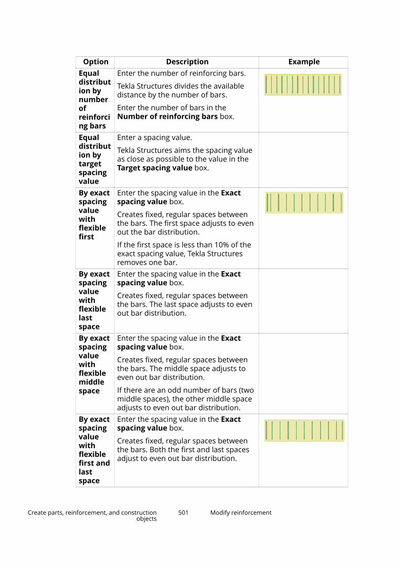
Option Description ExampleEqualdistribution bynumberofreinforcing bars
Enter the number of reinforcing bars.
Tekla Structures divides the availabledistance by the number of bars.
Enter the number of bars in theNumber of reinforcing bars box.
Equaldistribution bytargetspacingvalue
Enter a spacing value.
Tekla Structures aims the spacing valueas close as possible to the value in theTarget spacing value box.
By exactspacingvaluewithflexiblefirst
Enter the spacing value in the Exactspacing value box.
Creates fixed, regular spaces betweenthe bars. The first space adjusts to evenout the bar distribution.
If the first space is less than 10% of theexact spacing value, Tekla Structuresremoves one bar.
By exactspacingvaluewithflexiblelastspace
Enter the spacing value in the Exactspacing value box.
Creates fixed, regular spaces betweenthe bars. The last space adjusts to evenout bar distribution.
By exactspacingvaluewithflexiblemiddlespace
Enter the spacing value in the Exactspacing value box.
Creates fixed, regular spaces betweenthe bars. The middle space adjusts toeven out bar distribution.
If there are an odd number of bars (twomiddle spaces), the other middle spaceadjusts to even out bar distribution.
By exactspacingvaluewithflexiblefirst andlastspace
Enter the spacing value in the Exactspacing value box.
Creates fixed, regular spaces betweenthe bars. Both the first and last spacesadjust to even out bar distribution.
Create parts, reinforcement, and constructionobjects
501 Modify reinforcement
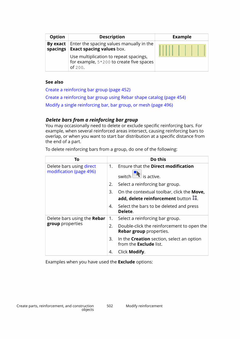
Option Description ExampleBy exactspacings
Enter the spacing values manually in theExact spacing values box.
Use multiplication to repeat spacings,for example, 5*200 to create five spacesof 200.
See also
Create a reinforcing bar group (page 452)
Create a reinforcing bar group using Rebar shape catalog (page 454)
Modify a single reinforcing bar, bar group, or mesh (page 496)
Delete bars from a reinforcing bar groupYou may occasionally need to delete or exclude specific reinforcing bars. Forexample, when several reinforced areas intersect, causing reinforcing bars tooverlap, or when you want to start bar distribution at a specific distance fromthe end of a part.
To delete reinforcing bars from a group, do one of the following:
To Do thisDelete bars using directmodification (page 496)
1. Ensure that the Direct modification
switch is active.
2. Select a reinforcing bar group.
3. On the contextual toolbar, click the Move,add, delete reinforcement button .
4. Select the bars to be deleted and pressDelete.
Delete bars using the Rebargroup properties
1. Select a reinforcing bar group.
2. Double-click the reinforcement to open theRebar group properties.
3. In the Creation section, select an optionfrom the Exclude list.
4. Click Modify.
Examples when you have used the Exclude options:
Create parts, reinforcement, and constructionobjects
502 Modify reinforcement

Before excluding bars After excluding barsTwo reinforcing bar groups have beenadded to a concrete beam:
• one bar group with flexible lastspace
• one bar group with flexible firstspace
Two reinforcing bar groups withoutthe excluded bars:
• one bar group with the last barexcluded
• one bar group with the first barexcluded
See also
Create a reinforcing bar group (page 452)
Create a reinforcing bar group using Rebar shape catalog (page 454)
Modify a single reinforcing bar, bar group, or mesh (page 496)
Ungroup a reinforcementYou can ungroup reinforcing bar groups and reinforcement meshes. Onlyreinforcement where each reinforcing bar is in one plane can be ungrouped.
NOTE You cannot ungroup circular (page 463) or curved (page 461)reinforcing bar groups.
1. On the Concrete tab, click Rebar and select Ungroup.
2. Select one of the reinforcing bars in a reinforcing bar group or in areinforcement mesh.
The reinforcing bar group is replaced with single reinforcing bars. Thesingle bars get the same properties and offsets as the group.
If you ungroup a reinforcement mesh, the offsets for single bars are zero.
Create parts, reinforcement, and constructionobjects
503 Modify reinforcement

Before ungrouping After ungrouping
See also
Modify reinforcement (page 477)
Create a reinforcing bar group using Rebar shape catalog (page 454)
Create a reinforcing bar group (page 452)
Create a reinforcement mesh (page 467)
Group reinforcementYou can group single reinforcing bars and reinforcing bar groups. Onlyreinforcement where each reinforcing bar is in one plane can be grouped. Allgroups are created with exact spacings. Single reinforcing bars need to havethe same bending shape.
NOTE You cannot create circular (page 463) or curved (page 461) reinforcingbar groups by grouping.
1. On the Concrete tab, click Rebar and select Group.
2. Select all the reinforcing bars or reinforcing bar groups that you want togroup.
3. Click the middle mouse button.
4. Select one reinforcing bar or reinforcing bar group to copy the propertiesfrom.
Create parts, reinforcement, and constructionobjects
504 Modify reinforcement
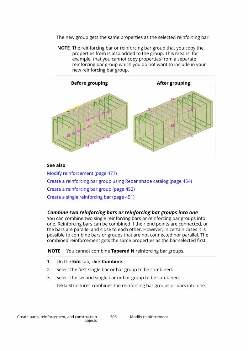
The new group gets the same properties as the selected reinforcing bar.
NOTE The reinforcing bar or reinforcing bar group that you copy theproperties from is also added to the group. This means, forexample, that you cannot copy properties from a separatereinforcing bar group which you do not want to include in yournew reinforcing bar group.
Before grouping After grouping
See also
Modify reinforcement (page 477)
Create a reinforcing bar group using Rebar shape catalog (page 454)
Create a reinforcing bar group (page 452)
Create a single reinforcing bar (page 451)
Combine two reinforcing bars or reinforcing bar groups into oneYou can combine two single reinforcing bars or reinforcing bar groups intoone. Reinforcing bars can be combined if their end points are connected, orthe bars are parallel and close to each other. However, in certain cases it ispossible to combine bars or groups that are not connected nor parallel. Thecombined reinforcement gets the same properties as the bar selected first.
NOTE You cannot combine Tapered N reinforcing bar groups.
1. On the Edit tab, click Combine.
2. Select the first single bar or bar group to be combined.
3. Select the second single bar or bar group to be combined.
Tekla Structures combines the reinforcing bar groups or bars into one.
Create parts, reinforcement, and constructionobjects
505 Modify reinforcement
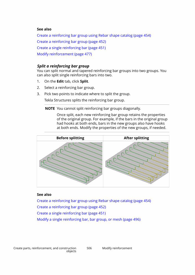
See also
Create a reinforcing bar group using Rebar shape catalog (page 454)
Create a reinforcing bar group (page 452)
Create a single reinforcing bar (page 451)
Modify reinforcement (page 477)
Split a reinforcing bar groupYou can split normal and tapered reinforcing bar groups into two groups. Youcan also split single reinforcing bars into two.
1. On the Edit tab, click Split.
2. Select a reinforcing bar group.
3. Pick two points to indicate where to split the group.
Tekla Structures splits the reinforcing bar group.
NOTE You cannot split reinforcing bar groups diagonally.
Once split, each new reinforcing bar group retains the propertiesof the original group. For example, if the bars in the original grouphad hooks at both ends, bars in the new groups also have hooksat both ends. Modify the properties of the new groups, if needed.
Before splitting After splitting
See also
Create a reinforcing bar group using Rebar shape catalog (page 454)
Create a reinforcing bar group (page 452)
Create a single reinforcing bar (page 451)
Modify a single reinforcing bar, bar group, or mesh (page 496)
Create parts, reinforcement, and constructionobjects
506 Modify reinforcement

Use handles to modify a reinforcementIf you do not want to use direct modification to modify a reinforcement, youcan use, for example, the reinforcement handles to modify the reinforcement.
Tekla Structures uses handles to indicate:
• The ends and corners of a reinforcing bar.
• The distribution length of a bar group.
• The corners and main bar direction of a mesh.
When you select a reinforcement, Tekla Structures highlights the handles. Thehandle of the first end point is yellow, the rest are magenta.
1. Select the reinforcement.
Tekla Structures highlights the handles.
2. Click one of the handles to select it.
3. Move the handle like any other object in Tekla Structures.
For example, if Drag and drop is active, just drag the handle to a newposition.
NOTE If you want to use the reinforcement handles, ensure that the
Direct modification switch is not active. If the switch isactive and direct modification (page 496) is on, Tekla Structuresdisplays direct modification handles for the reference points,
Create parts, reinforcement, and constructionobjects
507 Modify reinforcement

ends, legs, and leg midpoints of the selected reinforcement. Thesehandles are blue.
See also
Check the validity of reinforcement geometry (page 514)
Add hooks to reinforcing barsYou can add hooks to the ends of reinforcing bars for anchoring purposes.
NOTE Hooks are intended to be used only for anchoring purposes. Do notuse hooks as a method to model other reinforcing bar geometry,because it may cause problems with visibility in drawings, inadaptivity, and in bar bending shape recognition.
To add hooks to reinforcing bars, do one of the following:
To Do thisAdd hooks using directmodification (page 496)
1.Ensure that the Direct modificationswitch is active.
2. Select a single reinforcing bar or areinforcing bar group.
3. Click the start or end point of the
reinforcing bar .
A toolbar for hook properties appears.
4. Select the desired shape for the hook.
5. If you select Custom hook, enter theangle, radius, and length for the hook. Click
.Add hooks using the Singlerebar or Rebar groupproperties
1. Select a single reinforcing bar or areinforcing bar group.
2. Double-click the reinforcement to open itsproperties.
3. In the Hooks section, select a hook typefor the bar start and/or end from the Hooktype list.
4. If you select Custom hook, enter theangle, radius and length for the hook.
Create parts, reinforcement, and constructionobjects
508 Modify reinforcement
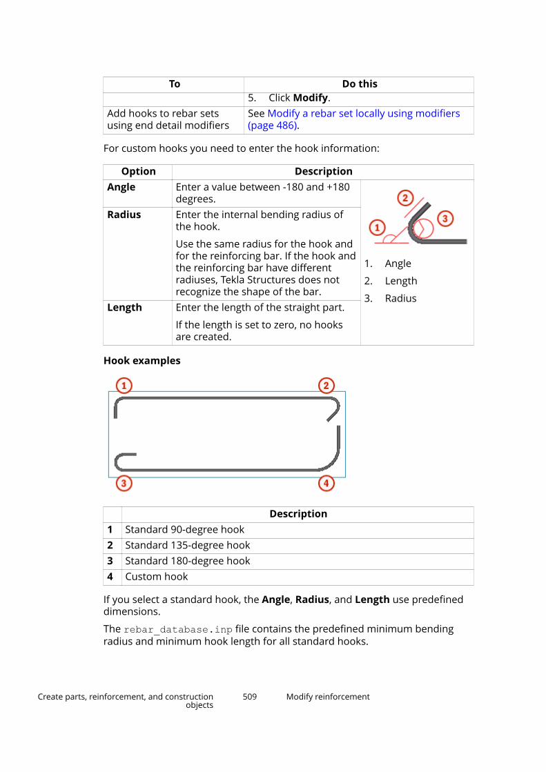
To Do this5. Click Modify.
Add hooks to rebar setsusing end detail modifiers
See Modify a rebar set locally using modifiers(page 486).
For custom hooks you need to enter the hook information:
Option DescriptionAngle Enter a value between -180 and +180
degrees.
1. Angle
2. Length
3. Radius
Radius Enter the internal bending radius ofthe hook.
Use the same radius for the hook andfor the reinforcing bar. If the hook andthe reinforcing bar have differentradiuses, Tekla Structures does notrecognize the shape of the bar.
Length Enter the length of the straight part.
If the length is set to zero, no hooksare created.
Hook examples
Description1 Standard 90-degree hook2 Standard 135-degree hook3 Standard 180-degree hook4 Custom hook
If you select a standard hook, the Angle, Radius, and Length use predefineddimensions.
The rebar_database.inp file contains the predefined minimum bendingradius and minimum hook length for all standard hooks.
Create parts, reinforcement, and constructionobjects
509 Modify reinforcement
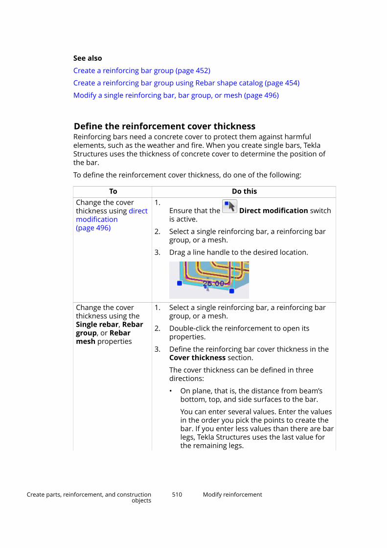
See also
Create a reinforcing bar group (page 452)
Create a reinforcing bar group using Rebar shape catalog (page 454)
Modify a single reinforcing bar, bar group, or mesh (page 496)
Define the reinforcement cover thicknessReinforcing bars need a concrete cover to protect them against harmfulelements, such as the weather and fire. When you create single bars, TeklaStructures uses the thickness of concrete cover to determine the position ofthe bar.
To define the reinforcement cover thickness, do one of the following:
To Do thisChange the coverthickness using directmodification(page 496)
1.Ensure that the Direct modification switchis active.
2. Select a single reinforcing bar, a reinforcing bargroup, or a mesh.
3. Drag a line handle to the desired location.
Change the coverthickness using theSingle rebar, Rebargroup, or Rebarmesh properties
1. Select a single reinforcing bar, a reinforcing bargroup, or a mesh.
2. Double-click the reinforcement to open itsproperties.
3. Define the reinforcing bar cover thickness in theCover thickness section.
The cover thickness can be defined in threedirections:
• On plane, that is, the distance from beam’sbottom, top, and side surfaces to the bar.
You can enter several values. Enter the valuesin the order you pick the points to create thebar. If you enter less values than there are barlegs, Tekla Structures uses the last value forthe remaining legs.
Create parts, reinforcement, and constructionobjects
510 Modify reinforcement
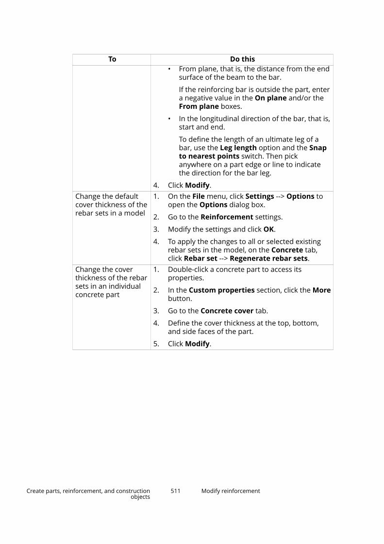
To Do this• From plane, that is, the distance from the end
surface of the beam to the bar.
If the reinforcing bar is outside the part, entera negative value in the On plane and/or theFrom plane boxes.
• In the longitudinal direction of the bar, that is,start and end.
To define the length of an ultimate leg of abar, use the Leg length option and the Snapto nearest points switch. Then pickanywhere on a part edge or line to indicatethe direction for the bar leg.
4. Click Modify.Change the defaultcover thickness of therebar sets in a model
1. On the File menu, click Settings --> Options toopen the Options dialog box.
2. Go to the Reinforcement settings.
3. Modify the settings and click OK.
4. To apply the changes to all or selected existingrebar sets in the model, on the Concrete tab,click Rebar set --> Regenerate rebar sets.
Change the coverthickness of the rebarsets in an individualconcrete part
1. Double-click a concrete part to access itsproperties.
2. In the Custom properties section, click the Morebutton.
3. Go to the Concrete cover tab.
4. Define the cover thickness at the top, bottom,and side faces of the part.
5. Click Modify.
Create parts, reinforcement, and constructionobjects
511 Modify reinforcement
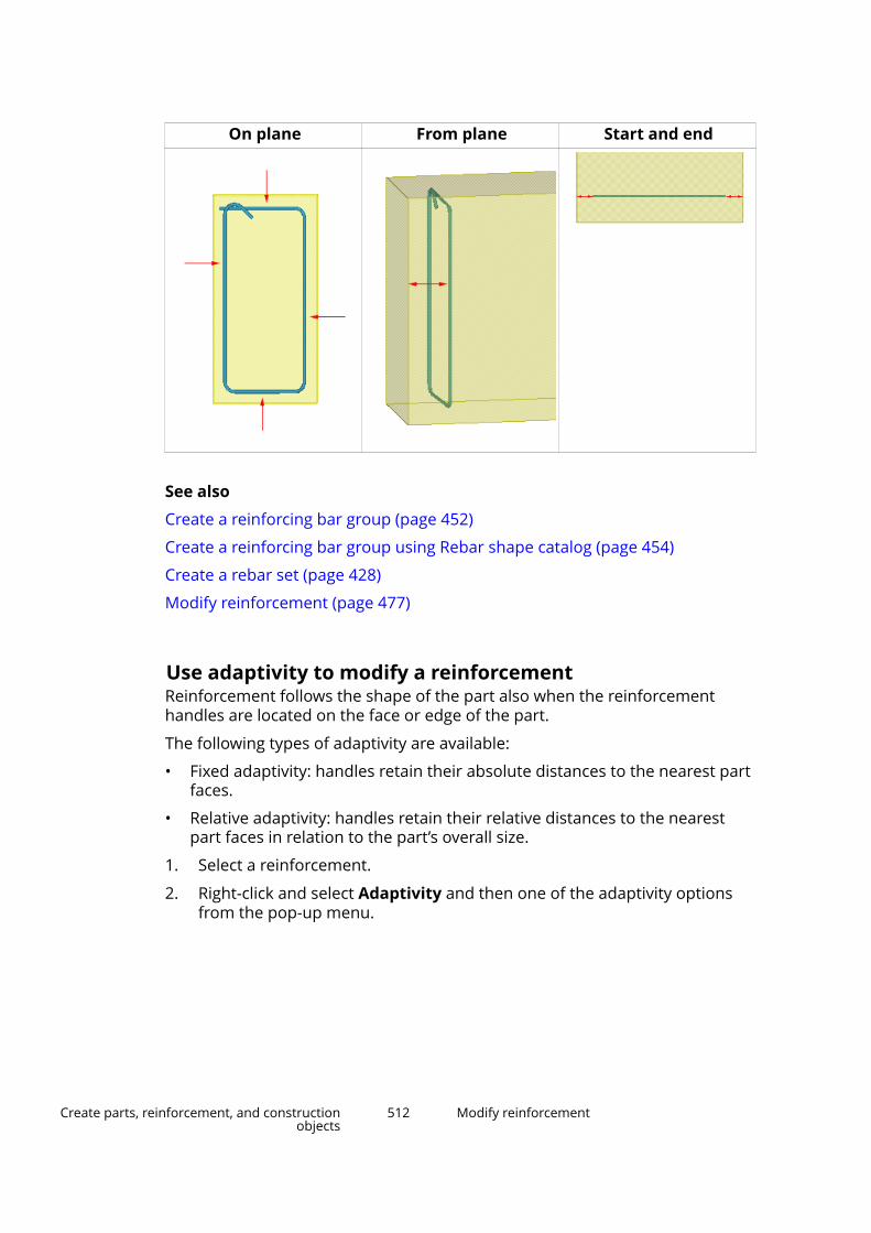
On plane From plane Start and end
See also
Create a reinforcing bar group (page 452)
Create a reinforcing bar group using Rebar shape catalog (page 454)
Create a rebar set (page 428)
Modify reinforcement (page 477)
Use adaptivity to modify a reinforcementReinforcement follows the shape of the part also when the reinforcementhandles are located on the face or edge of the part.
The following types of adaptivity are available:
• Fixed adaptivity: handles retain their absolute distances to the nearest partfaces.
• Relative adaptivity: handles retain their relative distances to the nearestpart faces in relation to the part’s overall size.
1. Select a reinforcement.
2. Right-click and select Adaptivity and then one of the adaptivity optionsfrom the pop-up menu.
Create parts, reinforcement, and constructionobjects
512 Modify reinforcement

When a part is modified, Tekla Structures handles the reinforcementaccording to the adaptivity selection.
TIP To modify the general adaptivity settings, click File menu -->Settings --> Options --> General.
You can also modify the adaptivity settings for each part separately.These modifications override the general settings in the Optionsdialog box.
Adaptivity examples
Reinforcing barsin their originalposition
Fixed adaptivity
Relativeadaptivity
See also
Check the validity of reinforcement geometry (page 514)
Modify a single reinforcing bar, bar group, or mesh (page 496)
Create parts, reinforcement, and constructionobjects
513 Modify reinforcement

Attach a reinforcement to a concrete partWhen you create a reinforcement, Tekla Structures automatically attaches thereinforcement to the part for which you are creating the reinforcement. Ifneeded, you can attach a reinforcement to a concrete part also manually. Theattached reinforcing bars follow the part or cast unit when it is moved, copied,or deleted.
NOTE You must attach reinforcement to a part to have Tekla Structuresmerge automatic reinforcing bar marks in drawings.
1. On the Concrete tab, click Rebar and select Attach to part.
2. Select the reinforcement that you want to attach.
3. Select the part to which you want to attach the reinforcement.
The reinforcement is attached to the part.
Detach a reinforcement from a concrete part
If needed, you can detach a reinforcement from a concrete part.
1. On the Concrete tab, click Rebar and select Detach from part.
2. Select the reinforcement that you want to detach.
The reinforcement is detached from the part.
TIP Alternatively, you can use the pop-up menu. This is how you attach and detachrebar sets, or bars in rebar sets, for example.
1. Select the reinforcement that you want to attach or detach.
2. Right-click and select Attach to Part or Detach from Part.
3. If you are attaching the reinforcement, select the part to which you want toattach the reinforcement.
See also
Modify reinforcement (page 477)
Check the validity of reinforcement geometryReinforcement creation or modification can result in invalid reinforcementgeometry. For example, too big bending radius can cause invalidreinforcement geometry. If a model contains a reinforcement with invalid
Create parts, reinforcement, and constructionobjects
514 Modify reinforcement

geometry, the reinforcement is not shown in the drawings. The reinforcementbecomes visible and the drawings are updated when the geometry iscorrected.
NOTE Reinforcement geometry validity check does not work with circular(page 463) or curved (page 461) reinforcing bar groups.
1. On the File menu, click Diagnose & Repair and in the Model area, clickDiagnose.
2. Check the results.
If there are inconsistencies in the geometry, Tekla Structures displays awarning message, and draws a thin line between the reinforcementhandles to show the invalid geometry.
You can correct the reinforcement geometry by selecting the line andmodifying the reinforcement properties.
See also
Modify a single reinforcing bar, bar group, or mesh (page 496)
Split and splice a reinforcementYou can split long reinforcing bars and bar groups that exceed the stocklength, and create splices in split locations.
Use the Automatic splicing tool macro to split and splice reinforcement thatexceeds the stock length. You can first check the length of the reinforcing barsin the model according to the manufacturer. You can then define the portionof the reinforcement to be split and spliced in the same cross section, and thelocation, symmetry, type, and length of the splices.
1. Click the Applications & components button in the side pane toopen the Applications & components catalog.
2. Click the arrow next to Applications to open the applications list.
3. Double-click Automatic splicing tool to start the macro.
4. In the Automatic Splicing Tool dialog box:
a. Select the manufacturer of the reinforcement.
The maximum bar lengths and lap lengths are then listed by thegrade and size of the bar.
If needed, you can define the length information in theAutomaticSplicingTool_Manufacturers.dat file. You can copythe default file from ..\ProgramData\Trimble\Tekla
Create parts, reinforcement, and constructionobjects
515 Modify reinforcement

Structures\<version>\environments\common\system , edit it,and save it to your project or firm folder.
b. For the bar grades and sizes that are not listed in theAutomaticSplicingTool_Manufacturers.dat file, use theMaximum length for unspecified stock box to define the maximumreinforcing bar length after which the bars are split and spliced.
c. To check if the length of the reinforcing bars exceeds the maximumlength, click one of the buttons next to Perform check to:
• To check all reinforcement in the model, click All.
• To check specific reinforcement, select the reinforcement in the
model using the Select objects in components switch , andthen click Selected.
Tekla Structures lists the reinforcing bars that are longer than themaximum length under Longer rebars on the right side of the dialogbox.
When you select a row in the Longer rebars list, Tekla Structureshighlights the corresponding reinforcement in the model.
d. Define which proportion of the reinforcement can be spliced in thesame cross section.
e. Define the symmetry that is applied when the reinforcing bars arespliced.
f. Define the offset of the splice center point.
g. Define the minimum longitudinal distance between two parallel barsplices.
h. Select the splice type.
You can create lap splices, coupler splices, or welded splices.
i. For lap splices, define the default lap length in relation to the nominalbar diameter.
This value will be used if there is no lap length defined for a bar gradeand size in the AutomaticSplicingTool_Manufacturers.dat file.
j. For lap slices, define whether the lapping bars are on top of eachother or parallel to each other.
k. To split and splice reinforcement, click one of the buttons next toPerform split and splice to:
• To splice all reinforcement in the model, click All.
• To splice specific reinforcement, select the reinforcement in theLonger rebars list, or in the model using the Select objects in
components switch , and then click Selected.
Create parts, reinforcement, and constructionobjects
516 Modify reinforcement
See also
Create a reinforcement splice (page 476)
Assign running numbers to reinforcementYou can assign running numbers to reinforcement in cast units. You can thenuse the running numbers in addition to or instead of the position numbers inreinforcement marks and tables in drawings, and in reports.
Use the Rebar sequence numbering macro to assign cast unit specificrunning numbers (1, 2, 3...) to the reinforcement in the model. Runningnumbers are unique inside each cast unit. The macro does the following:
• Updates the position numbers of the modified model objects using theNumber modified objects command in Drawings & reports --> Performnumbering .
• Assigns running numbers to the reinforcing bars, reinforcing bar groups,and reinforcement meshes in the model.
• Saves a running number as the user-defined attribute Rebar sequencenumber (REBAR_SEQ_NO) of each bar, group, or mesh.
1. Click the Applications & components button in the side pane toopen the Applications & components catalog.
2. Click the arrow next to Applications to open the applications list.
3. Double-click Rebar sequence numbering to start the macro.
4. To show the running numbers in drawings and reports, use the user-defined attribute REBAR_SEQ_NO.
See also
Number reinforcement (page 639)
Classify reinforcement to layersTo be able to show in drawings what is the order of different reinforcementlayers near a surface of a concrete part, you need to classify reinforcement inthe model. You can do this by using the Rebar classification macro.
Rebar classification classifies the reinforcing bars and reinforcement meshesby their order of depth in concrete slabs and panels. The reinforcing bars and
Create parts, reinforcement, and constructionobjects
517 Modify reinforcement

meshes get an attribute indicating the layer where they are placed inside theconcrete part.
1. Click the Applications & components button in the side pane toopen the Applications & components catalog.
2. Click the arrow next to Applications to open the applications list.
3. Double-click Rebar classification to start the macro.
4. In the Rebar classification dialog box:
a. Enter the prefixes that you want to use for the reinforcement layersnear the top, bottom, front, and back surfaces of the concrete parts.
b. Select whether you want to classify All objects or Selected objects.
If you select Selected objects, select the reinforcement or theconcrete parts containing the reinforcement that you want to classify.
c. Click Preview to view the properties of the reinforcement in eachlayer.
The layers are named using the relevant surface prefix and numberedstarting from the surface.
d. If you do not want to classify a reinforcement, select it from the listand click Delete item.
e. To save the classification attributes of the reinforcement, do one ofthe following:
• Click Modify to also keep the Rebar classification dialog boxopen.
• Click OK to also close the Rebar classification dialog box.
5. In a drawing, run the Rebar layering marker macro to create layer-specific markers for reinforcement.
How to calculate the reinforcing bar lengthYou have three options how to calculate the reinforcing bar length in TeklaStructures:
• Along center line, which is the default method
• As a sum of leg lengths
• Using a formula
Create parts, reinforcement, and constructionobjects
518 Modify reinforcement
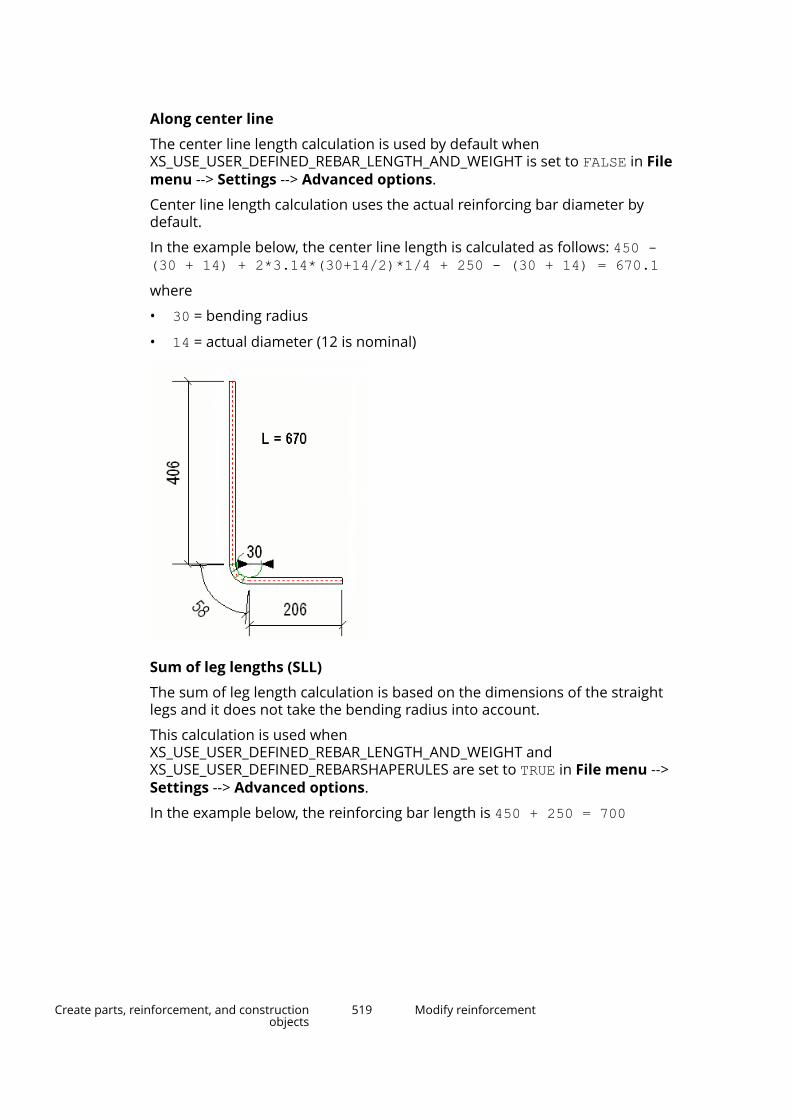
Along center line
The center line length calculation is used by default whenXS_USE_USER_DEFINED_REBAR_LENGTH_AND_WEIGHT is set to FALSE in Filemenu --> Settings --> Advanced options.
Center line length calculation uses the actual reinforcing bar diameter bydefault.
In the example below, the center line length is calculated as follows: 450 -(30 + 14) + 2*3.14*(30+14/2)*1/4 + 250 - (30 + 14) = 670.1where
• 30 = bending radius
• 14 = actual diameter (12 is nominal)
Sum of leg lengths (SLL)
The sum of leg length calculation is based on the dimensions of the straightlegs and it does not take the bending radius into account.
This calculation is used whenXS_USE_USER_DEFINED_REBAR_LENGTH_AND_WEIGHT andXS_USE_USER_DEFINED_REBARSHAPERULES are set to TRUE in File menu -->Settings --> Advanced options.
In the example below, the reinforcing bar length is 450 + 250 = 700
Create parts, reinforcement, and constructionobjects
519 Modify reinforcement

If the length value is shown as zero in reports and inquiries, you need to definethe length in Rebar Shape Manager for each shape.
To define the length in Rebar Shape Manager:
1. In Bending schedule fields, right-click in the L cell and select SLL (Sum ofleg lengths) from the pop-up menu.
2. Click Update.
3. Click Save.
Using a formula
You can also use a formula in Rebar Shape Manager to calculate thereinforcing bar total length.
You need to set XS_USE_USER_DEFINED_REBAR_LENGTH_AND_WEIGHT andXS_USE_USER_DEFINED_REBARSHAPERULES to TRUE File menu --> Settings --> Advanced options.
For example, to take the bending radius into account and to calculate thelength along the reinforcing bar outer surface, do the following:
1. In Bending schedule fields, right-click in the L cell and select (formula)from the pop-up menu.
2. Enter the following formula for the length calculation: S1 + S2+ 2*3.14*(RS + DIA)*1/4
where
• S1 = straight leg length 1 (406)
• S2 = straight leg length 2 (206)
• RS = rounding radius (30)
• DIA = actual diameter (14)
Create parts, reinforcement, and constructionobjects
520 Modify reinforcement
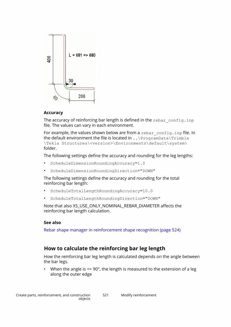
Accuracy
The accuracy of reinforcing bar length is defined in the rebar_config.inpfile. The values can vary in each environment.
For example, the values shown below are from a rebar_config.inp file. Inthe default environment the file is located in ..\ProgramData\Trimble\Tekla Structures\<version>\Environments\default\system\folder.
The following settings define the accuracy and rounding for the leg lengths:
• ScheduleDimensionRoundingAccuracy=1.0• ScheduleDimensionRoundingDirection="DOWN"The following settings define the accuracy and rounding for the totalreinforcing bar length:
• ScheduleTotalLengthRoundingAccuracy=10.0• ScheduleTotalLengthRoundingDirection="DOWN"Note that also XS_USE_ONLY_NOMINAL_REBAR_DIAMETER affects thereinforcing bar length calculation.
See also
Rebar shape manager in reinforcement shape recognition (page 524)
How to calculate the reinforcing bar leg lengthHow the reinforcing bar leg length is calculated depends on the angle betweenthe bar legs.
• When the angle is <= 90°, the length is measured to the extension of a legalong the outer edge
Create parts, reinforcement, and constructionobjects
521 Modify reinforcement

• When the angle is > 90 ° and <= 180 °, the tangential length is used
The leg lengths are calculated using Rebar Shape Manager, where
Create parts, reinforcement, and constructionobjects
522 Modify reinforcement
• S1 = straight portion of a bar for the first segment
• S2 = straight portion of a bar for the second segment
• A1 = bending angle measured between the extension of the first leg andthe second leg. The angle is 0° if the second segment continues to thesame direction as the first segment (the bar is straight)
• L1 = leg length for the first reinforcing bar segment
• L2 = leg length for the second reinforcing bar segment
• RS = bending radius
• DIA = actual diameter of the reinforcing bar
See also
Rebar shape manager in reinforcement shape recognition (page 524)
Reinforcing bar and bar group properties (page 927)
Reinforcement shape recognitionTekla Structures recognizes different reinforcing bar bending shapes andassigns shape codes to them. Tekla Structures then uses the shape anddimension information in bending schedules, pull-out pictures, templates andreports.
Tekla Structures includes two methods for shape recognition.
User-defined bending shapedefinitions.
These definitions are created withRebar shape manager (page 524)and saved in theRebarShapeRules.xml file.
The file is located in ..\ProgramData\Trimble\TeklaStructures\<version>\environments\<environment>\system folder.
Tekla Structures internal, hard-codedbending type definitions.
These internal bending types(page 535) of reinforcing bars aremapped to area-specific reinforcingbar bending type codes in therebar_schedule_config.inp file.
The file is located in ..\ProgramData\Trimble\TeklaStructures\<version>\environments\common\systemfolder.
Create parts, reinforcement, and constructionobjects
523 Modify reinforcement
See also
Reinforcement in templates (page 559)
Rebar shape manager in reinforcement shape recognitionYou can define your own bar bending shapes and assign shape codes withRebar shape manager, and thus increase the amount of recognized barshapes. User-defined bending shapes are useful when Tekla Structures doesnot recognize the bending shape and assigns the UNKNOWN bending type to theshape.
Rebar shape manager is meant for users who need to customize the bendingshapes according to company or project requirements.
With Rebar shape manager you can:
• Customize the existing bending shapes and create new bending shapes(page 524).
• Establish your own rules (page 527) for defining the bending shapes.
• Customize your own dimension mappings that are used in templates andreports (page 533).
• Import and export user-defined bending shapes.
• Use user-defined bending shapes in bending schedules and pull-outpictures.
NOTE Rebar shape manager is a tool for recognizing reinforcing bar shapes. Youcannot control the reinforcing bar creation properties, such as coverthickness, reinforcing bar grade, or size, with this tool.
See also
Tips for reinforcement shape recognition in Rebar shape manager (page 534)
Define reinforcing bar bending shapes in Rebar shape managerWith Rebar shape manager you can establish your own rules for defining thebending shapes. When you define your own reinforcing bar bending shapesand shape codes, an .xml file called RebarShapeRules.xml is created in thecurrent model folder.
In addition, Tekla Structures installation contains by default another .xml filecalled RebarShapeRules.xml. This file contains the most typical bendingshapes in your environment, and it is located in the ..\ProgramData\Trimble\Tekla Structures\<version>\environments\<environment>\system folder.
When you define new shapes, the shapes in the defaultRebarShapeRules.xml rule file can be appended to your own shapes. TeklaStructures reads valid RebarShapeRules.xml rule files in the model, project,firm, and system folders in that order. When the shape codes and report field
Create parts, reinforcement, and constructionobjects
524 Modify reinforcement
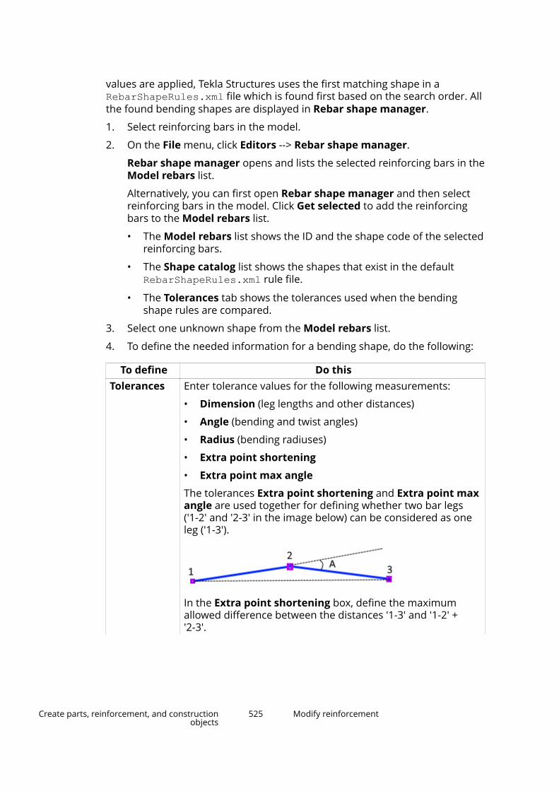
values are applied, Tekla Structures uses the first matching shape in aRebarShapeRules.xml file which is found first based on the search order. Allthe found bending shapes are displayed in Rebar shape manager.
1. Select reinforcing bars in the model.
2. On the File menu, click Editors --> Rebar shape manager.
Rebar shape manager opens and lists the selected reinforcing bars in theModel rebars list.
Alternatively, you can first open Rebar shape manager and then selectreinforcing bars in the model. Click Get selected to add the reinforcingbars to the Model rebars list.
• The Model rebars list shows the ID and the shape code of the selectedreinforcing bars.
• The Shape catalog list shows the shapes that exist in the defaultRebarShapeRules.xml rule file.
• The Tolerances tab shows the tolerances used when the bendingshape rules are compared.
3. Select one unknown shape from the Model rebars list.
4. To define the needed information for a bending shape, do the following:
To define Do thisTolerances Enter tolerance values for the following measurements:
• Dimension (leg lengths and other distances)
• Angle (bending and twist angles)
• Radius (bending radiuses)
• Extra point shortening
• Extra point max angle
The tolerances Extra point shortening and Extra point maxangle are used together for defining whether two bar legs('1-2' and '2-3' in the image below) can be considered as oneleg ('1-3').
In the Extra point shortening box, define the maximumallowed difference between the distances '1-3' and '1-2' +'2-3'.
Create parts, reinforcement, and constructionobjects
525 Modify reinforcement

To define Do thisIn the Extra point max angle box, define the maximumallowed angle ('A' in the image) between the two bar legs.
Note that the tolerance values are stored along with the rulefile RebarShapeRules.xml, and thus the tolerances arespecific to each rule file.
Shape code Enter a shape code for an unknown shape.
Note that multiple reinforcement shapes that are variants ofthe same shape can have the same Shape code but differentBending shape rules.
Bendingshape rules
If the bending shape rules that Rebar shape managerdefines automatically are not sufficient to distinguish certainbending shapes, you can manually add (page 527) newbending shape rules.
Add or delete a bending shape rule by clicking the Add andDelete buttons on the right.
Use the Reset button to restore the original values.Check hooks Select the check box if you want to define different shape
codes or bending schedule fields for two bars that otherwisehave exactly the same geometry, but one bar has hooks andthe other one does not.
If you select the check box, hooks are considered as hooks. Ifyou clear the check box, hooks are considered as normal legs.
Note that the Check hooks option works independently fromthe advanced optionXS_REBAR_RECOGNITION_HOOKS_CONSIDERATION, and itallows bars that have different hooks to have different shapecode or schedule fields regardless of the value of theadvanced option.
Update Update the existing shape code definition of the selectedreinforcing bar.
You can update the definition if you have modified the shapecode, bending shape rules or the contents of bendingschedule fields.
Bendingschedulefields
Define the content (page 533) for a bending schedule. Right-click a field to select a bending shape property or to enter aformula.
The names of the Bending schedule fields (A, B, and so on)are used in templates and reports. To make sure that oldreports also work correctly, we recommend that you use thesame DIM_XX fields as in the rebar_schedule_config.inpfile.
Create parts, reinforcement, and constructionobjects
526 Modify reinforcement
To define Do thisSchedulefields...
Click the Schedule fields button to add, remove or changethe order of the available schedule fields. If needed, you canreset the schedule fields to original defaults.
If you change the set of available schedule fields and updatean existing shape, the old schedule fields which do not existanymore will be cleared. Therefore we recommend that youdo not to remove any of the default schedule fields unlessyou are sure they have not been used in any of the existingshapes.
You can change the names of the existing schedule fields or, ifyou add new fields, give names to them. To use the fields intemplates and reports, use the DIM_XX or ANG_xx fields, andreplace xx with the schedule field name.
5. When you have finished defining the new shape, click Add to add thebending shape definition to the RebarShapeRules.xml file.
To enable the Add button you need to change the bending shape rule,enter a shape code or select the Check hooks check box.
6. Click Save to save the RebarShapeRules.xml file.
By default, the file is located in the current model folder.
When you create, for example, a bending schedule, Tekla Structures usesthe updated bending shape information, recognizes the added bendingshape and assigns a correct shape code to it.
NOTE Rebar shape manager is able to recognize bending shapesregardless of the modeling direction of the bars. This means thatthe modeling direction has no effect on the shape definition andthe shape code.
When defining the bending shapes, the start or the end ofmodeling direction is always sorted based first on bending angles,then on twist angles, and finally on leg lengths. However, bendingradius is not taken into account in the sorting. This means thatradius 1 may not always be less than radius 2 or vice versa.
See also
Rebar shape manager in reinforcement shape recognition (page 524)
Add new bending shape rules manually in Rebar shape managerIn some cases, the bending shape rules that are defined in Rebar shapemanager are not sufficient to distinguish certain bending shapes. If needed,you can manually add new bending shape rules for reinforcing bars in Rebarshape manager.
Create parts, reinforcement, and constructionobjects
527 Modify reinforcement
1. In Rebar shape manager, click Add next to the Bending shape rules list.
2. In the New bending rule dialog box, select the options from the lists todefine the new rule.
The content of the lists depends on the shape and the bending of thereinforcing bar.
3. Click OK to add the new rule to the Bending shape rules list.
The OK button is enabled only when the rule is valid.
Bending shape rule settings
All the rule options are available in the New bending rule dialog box, eventhough only certain selections are valid, depending on the type of theconditions used. The left and right condition of a rule need to be of the sametype. The values in the parentheses are the values that were used to create thebar shape.
Use the New bending rule dialog box in Rebar shape manager to manuallydefine rules for reinforcing bar bending shapes.
Option DescriptionAngle (A) Bending angle between the legs.
Bending angle is always between 0 and +180 degrees. Theangle cannot be negative.
Twist angle (T) Rotation angle of a plane that has been created by twobars of consecutive lengths. The plane is rotated aroundthe axis of the last bar creating the plane.
For bars where all the legs lie in the same plane, the twistangle is either 0 degrees or +180 degrees.
If the bar twists out of the plane, i.e. the bar is in 3D, thetwist angle is between -180 and +180 degrees.
Create parts, reinforcement, and constructionobjects
528 Modify reinforcement

Option Description
1. Leg1
2. Leg 2
3. Leg 3
4. Twist angle direction
5. Plane created by legs 1 and 2Twist angleexample
The twist angle between two planes is +90 degrees. Theplanes are created by legs 1 and 2, and legs 2 and 3.
1. Twist angle: +90 degrees
Create parts, reinforcement, and constructionobjects
529 Modify reinforcement
Option DescriptionRadius (R), (RX) Bending radius of the bending.
(RX) Radius * is the value of the bending radius whenall the bendings have equal radius. Otherwise the value iszero (0). Radius * = Radius 1 ensures that all thebendings have been created using the same radius.
Bending length(BL)
Center line length of the bending.
Straight length(S)
Straight length between the start and the end of adjacentbendings.
The rule is generated only when there is no straight part,for example, Straight length 2 = 0.
Leg length (L) Length of the leg.Leg (V) Leg direction as a vector value.Bar diameter(DIA), (DIAX)
Diameter of the reinforcing bar.
Nominaldiameter (NDIA),(NDIAX)
Nominal diameter of the reinforcing bar.
Center linelength (CLL)
Leg length according to the center line.
Sum of leglengths (SLL)
Sum of all leg lengths.
Reversed Reversed reinforcing bar.
You can use Reversed to have additional bending shaperules and/or formulas for the schedule fields.
When used in a rule, you can have separate definitions inshape code and/or schedule fields for reinforcing barsthat have different modeling order of the points.
When used as a part of a formula, you can eliminate theautomatic normalization of the modeling order of thepoints. For example, a formula if (REVERSED) thenL2 else L3 endif forces the content of the field toshow the desired leg length depending on the order ofthe points or legs.
Arc inner radius(RI)
Inner radius of the arc.
Arc outer radius(RO)
Outer radius of the arc.
Arc angle (AA) Angle of the arc.Arc length (AL) Length of the arc.
Create parts, reinforcement, and constructionobjects
530 Modify reinforcement
Option DescriptionCurve width(CW)
Extreme width of the curved bar.
Curved height(CH)
Extreme height of the curved bar.
RFACTOR Relative radius.LFACTOR Relative length.Spiral rounds(SR)
Rounds of the spiral bar.
Spiral pitch (SP) Pitch of the spiral bar.Spiral length (SL) Distance between the reference points of the spiral bar.Spiral totallength (STL)
Total length of the spiral bar when the bar is installed onsite.
Standard radius(RS)
Standard minimum bending radius.
The bending radius depends on the size and the grade ofthe bar.
Weight perlength (WPL)
Weight per leg length.
Leg distancefrom leg (D)
Similar to Point/arc distance off from leg (H). Thedifference is that Point/arc distance off from leg (H)considers the bending radius, whereas Leg distancefrom leg (D) is measured from the sharp corner.
When the legs are parallel, both Leg distance from leg(D) and Point/arc distance off from leg (H) give thesame result.
Point/arcdistance alongleg (K)
Distance parallel to a leg from outer edge to outer edge,or tangential to the bending.
The distances are positive or negative depending on theleg direction.
Example:
Create parts, reinforcement, and constructionobjects
531 Modify reinforcement
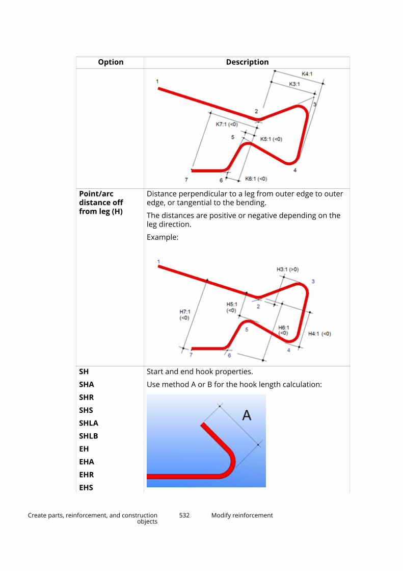
Option Description
Point/arcdistance offfrom leg (H)
Distance perpendicular to a leg from outer edge to outeredge, or tangential to the bending.
The distances are positive or negative depending on theleg direction.
Example:
SH
SHA
SHR
SHS
SHLA
SHLB
EH
EHA
EHR
EHS
Start and end hook properties.
Use method A or B for the hook length calculation:
Create parts, reinforcement, and constructionobjects
532 Modify reinforcement
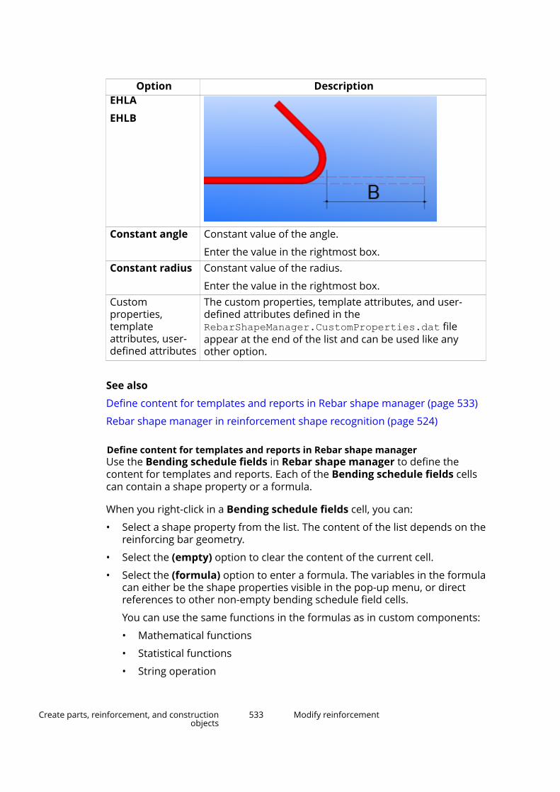
Option DescriptionEHLA
EHLB
Constant angle Constant value of the angle.
Enter the value in the rightmost box.Constant radius Constant value of the radius.
Enter the value in the rightmost box.Customproperties,templateattributes, user-defined attributes
The custom properties, template attributes, and user-defined attributes defined in theRebarShapeManager.CustomProperties.dat fileappear at the end of the list and can be used like anyother option.
See also
Define content for templates and reports in Rebar shape manager (page 533)
Rebar shape manager in reinforcement shape recognition (page 524)
Define content for templates and reports in Rebar shape managerUse the Bending schedule fields in Rebar shape manager to define thecontent for templates and reports. Each of the Bending schedule fields cellscan contain a shape property or a formula.
When you right-click in a Bending schedule fields cell, you can:
• Select a shape property from the list. The content of the list depends on thereinforcing bar geometry.
• Select the (empty) option to clear the content of the current cell.
• Select the (formula) option to enter a formula. The variables in the formulacan either be the shape properties visible in the pop-up menu, or directreferences to other non-empty bending schedule field cells.
You can use the same functions in the formulas as in custom components:
• Mathematical functions
• Statistical functions
• String operation
Create parts, reinforcement, and constructionobjects
533 Modify reinforcement

• Trigonometric functions
When you map angles and trigonometric functions in the Schedulefield formula dialog box, enter the functions (sin, cos, tan) in smallletters, for example sin(A1). Capital letters are not recognized, and ablank space will appear in reports.
If you have angles in a formula, the formula needs to be in radians. Forexample, if you want to subtract 180 degrees from angle A1, enter A1-PI incapital letters. If you enter A1-180 or A1-pi, the formula does not work.
Bending schedule fields cell shows the result of a valid formula. If theformula is not valid, a question mark and text describing the error is shown.
NOTE Use the fields S, T, U or V to report angles. If you do not use thesefields, you need to override the default unit settings in the TemplateEditor.
Example
Formula is L1+L3+L5-2*DIA• L1, L3 and L5 are the leg lengths measured from outer edge to outer edge
• H1 is the total width
• to achieve H1: L1+L3+L5 minus 2*bar diameter
See also
Add new bending shape rules manually in Rebar shape manager (page 527)
Rebar shape manager in reinforcement shape recognition (page 524)
Tips for reinforcement shape recognition in Rebar shape manager
The reinforcing bar shape recognition is based on each shape’s bending shaperules. The shapes and their rules are listed in the RebarShapeRules.xml file,located in the ..\ProgramData\Trimble\Tekla Structures\<version>\environments\<environment>\system folder by default. Sometimes ashape matches the rules of two shapes, and Tekla Structures does notrecognize the reinforcing bar shape as expected.
NOTE The most convenient way to ensure that a shape is recognizedcorrectly is to modify the shape definition by adding more rules(page 527) to the shape in Rebar shape manager.
However, if necessary, you can manually modify the RebarShapeRules.xmlfile and thus affect the shape recognition. When Tekla Structures recognizesthe shape, the order of the shapes in the RebarShapeRules.xml isimportant:
Create parts, reinforcement, and constructionobjects
534 Modify reinforcement

• The first shape that matches the rules is the one that Tekla Structuresrecognizes as the shape. If you need to change the order of the shapes tochange how Tekla Structures recognizes the shape, you can do it bymanually modifying the RebarShapeRules.xml file. If you modify the fileand change the order of the shapes, make sure that the structure of the filestays valid.
• You can divide the shape definitions in several RebarShapeRules.xmlfiles and different folders. Tekla Structures searches theRebarShapeRules.xml file in the model, project, firm, and system foldersin that order. Tekla Structures uses the first matching shape in the firstRebarShapeRules.xml file which is found based on the search order.
See also
Rebar shape manager in reinforcement shape recognition (page 524)
Hard-coded bending type identifiers in reinforcement shaperecognitionTekla Structures recognizes different reinforcing bar bending shapes andassigns bending type identifiers to them.
The bending type identifiers in the table below are internal, hard-coded typesof Tekla Structures. The leg dimensions (D1, D2, and so on) and bending angles(A1, A2, and so on) of reinforcing bars are Tekla Structures internal dimensionsand angles. You can map the Tekla Structures internal bending types, forexample, to country- or project-specific bending types, and the TeklaStructures internal dimensions and angles to specific template attributes. Youcan do this in the rebar_schedule_config.inp file.
Reinforcing bar bending dimensions are calculated so that the leg dimensions(D1, D2, and so on) follow the outer edge, or the edge extension, of thereinforcing bar. The total length is calculated according to the center line of thereinforcing bar.
If Tekla Structures does not recognize the shape of a reinforcing bar, it assignsthe UNKNOWN bending type to it.
The magenta points in the images in the table below represent the points youpick in the model when you create reinforcing bars.
NOTE If you want to customize the hard-coded bending shapes or definenew bending shapes, use Rebar shape manager (page 524).
Bendingtype
identifier
Bending shape
1
Create parts, reinforcement, and constructionobjects
535 Modify reinforcement
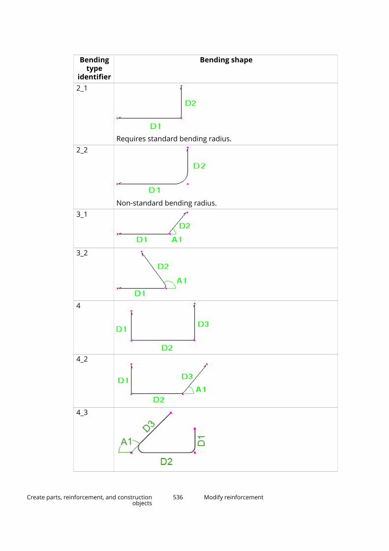
Bendingtype
identifier
Bending shape
2_1
Requires standard bending radius.2_2
Non-standard bending radius.3_1
3_2
4
4_2
4_3
Create parts, reinforcement, and constructionobjects
536 Modify reinforcement
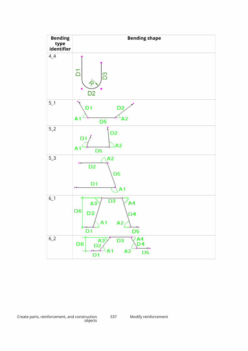
Bendingtype
identifier
Bending shape
4_4
5_1
5_2
5_3
6_1
6_2
Create parts, reinforcement, and constructionobjects
537 Modify reinforcement
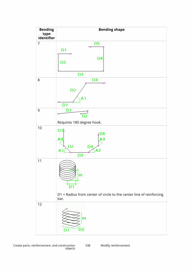
Bendingtype
identifier
Bending shape
7
8
9
Requires 180 degree hook.10
11
D1 = Radius from center of circle to the center line of reinforcingbar.
12
Create parts, reinforcement, and constructionobjects
538 Modify reinforcement

Bendingtype
identifier
Bending shape
13
Can also be modeled using hooks at both ends (i.e. model D1 andD5 using 90 degree hooks).
14
Requires 90 degree hooks at both ends.14_2
14_3
Create parts, reinforcement, and constructionobjects
539 Modify reinforcement
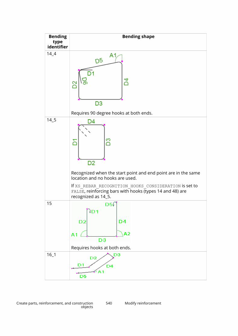
Bendingtype
identifier
Bending shape
14_4
Requires 90 degree hooks at both ends.14_5
Recognized when the start point and end point are in the samelocation and no hooks are used.
If XS_REBAR_RECOGNITION_HOOKS_CONSIDERATION is set to FALSE, reinforcing bars with hooks (types 14 and 48) arerecognized as 14_5.
15
Requires hooks at both ends.16_1
Create parts, reinforcement, and constructionobjects
540 Modify reinforcement
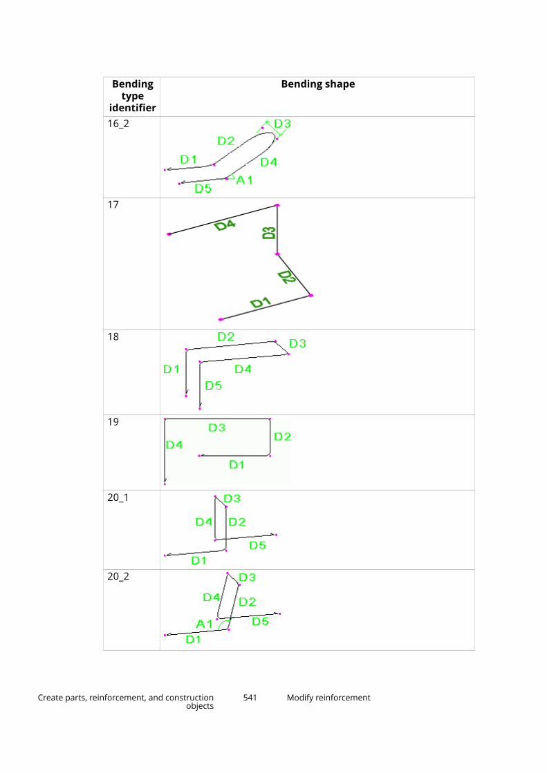
Bendingtype
identifier
Bending shape
16_2
17
18
19
20_1
20_2
Create parts, reinforcement, and constructionobjects
541 Modify reinforcement
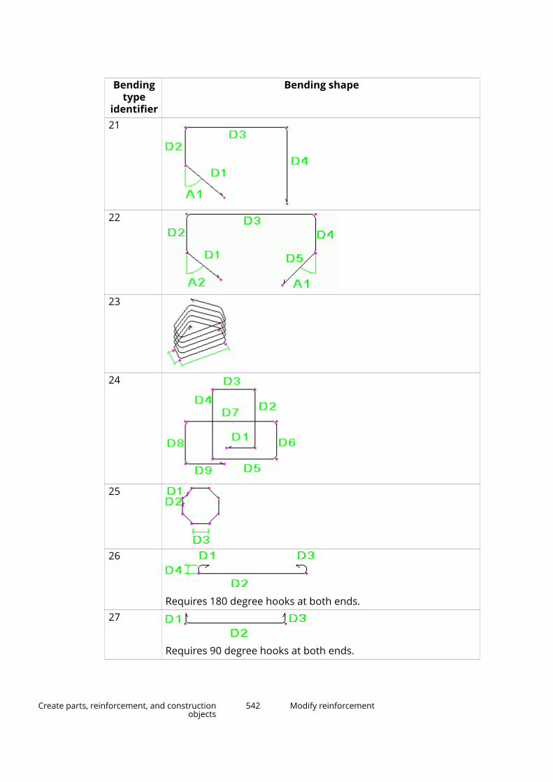
Bendingtype
identifier
Bending shape
21
22
23
24
25
26
Requires 180 degree hooks at both ends.27
Requires 90 degree hooks at both ends.
Create parts, reinforcement, and constructionobjects
542 Modify reinforcement
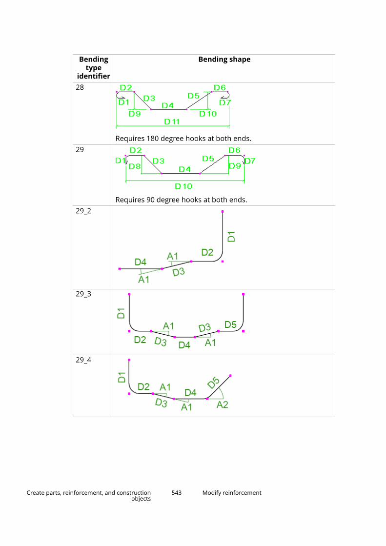
Bendingtype
identifier
Bending shape
28
Requires 180 degree hooks at both ends.29
Requires 90 degree hooks at both ends.29_2
29_3
29_4
Create parts, reinforcement, and constructionobjects
543 Modify reinforcement

Bendingtype
identifier
Bending shape
29_5
30
Requires 180 degree hooks at both ends.31
Requires 90 degree hooks at both ends.32
Requires 180 degree hooks at both ends.32_2
Create parts, reinforcement, and constructionobjects
544 Modify reinforcement
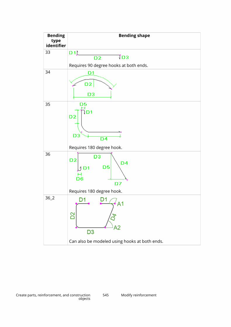
Bendingtype
identifier
Bending shape
33
Requires 90 degree hooks at both ends.34
35
Requires 180 degree hook.36
Requires 180 degree hook.36_2
Can also be modeled using hooks at both ends.
Create parts, reinforcement, and constructionobjects
545 Modify reinforcement
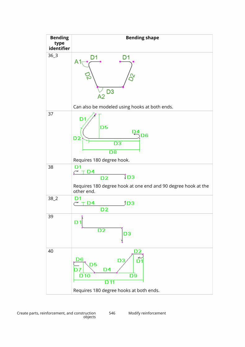
Bendingtype
identifier
Bending shape
36_3
Can also be modeled using hooks at both ends.37
Requires 180 degree hook.38
Requires 180 degree hook at one end and 90 degree hook at theother end.
38_2
39
40
Requires 180 degree hooks at both ends.
Create parts, reinforcement, and constructionobjects
546 Modify reinforcement

Bendingtype
identifier
Bending shape
41
Requires 90 degree hooks at both ends.42
Requires 180 degree hooks at both ends.43
43_2
44
Requires hooks at both ends.
Create parts, reinforcement, and constructionobjects
547 Modify reinforcement

Bendingtype
identifier
Bending shape
44_2
Requires 180 degree hooks at both ends.45
Requires hooks at both ends.45_2
Requires 180 hooks at both ends.46
Requires hooks at both ends.47
Requires 90 degree hooks at both ends.
Create parts, reinforcement, and constructionobjects
548 Modify reinforcement
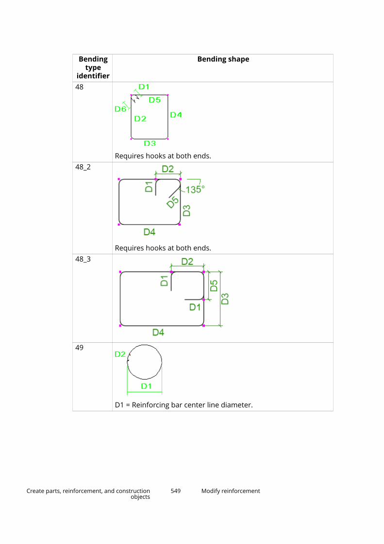
Bendingtype
identifier
Bending shape
48
Requires hooks at both ends.48_2
Requires hooks at both ends.48_3
49
D1 = Reinforcing bar center line diameter.
Create parts, reinforcement, and constructionobjects
549 Modify reinforcement
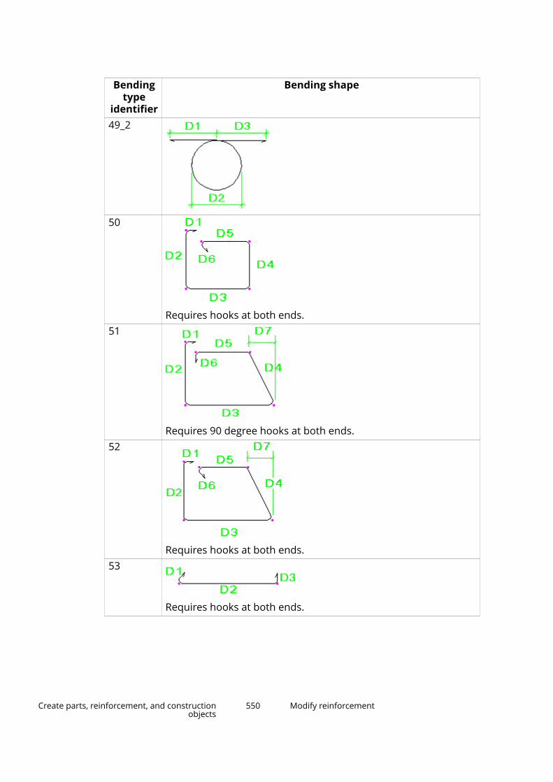
Bendingtype
identifier
Bending shape
49_2
50
Requires hooks at both ends.51
Requires 90 degree hooks at both ends.52
Requires hooks at both ends.53
Requires hooks at both ends.
Create parts, reinforcement, and constructionobjects
550 Modify reinforcement

Bendingtype
identifier
Bending shape
54
Requires hooks at both ends.55
56
57
58
59
Create parts, reinforcement, and constructionobjects
551 Modify reinforcement
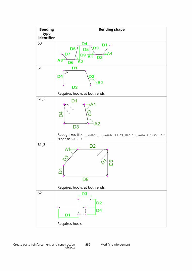
Bendingtype
identifier
Bending shape
60
61
Requires hooks at both ends.61_2
Recognized if XS_REBAR_RECOGNITION_HOOKS_CONSIDERATIONis set to FALSE.
61_3
Requires hooks at both ends.62
Requires hook.
Create parts, reinforcement, and constructionobjects
552 Modify reinforcement

Bendingtype
identifier
Bending shape
63
Requires hook.64
Requires hooks at both ends.64_2
Recognized if XS_REBAR_RECOGNITION_HOOKS_CONSIDERATIONis set to FALSE.
65
Requires hooks at both ends.
Create parts, reinforcement, and constructionobjects
553 Modify reinforcement
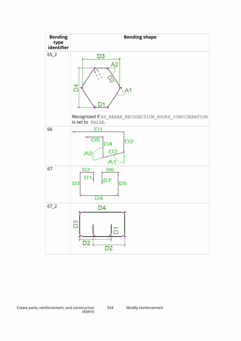
Bendingtype
identifier
Bending shape
65_2
Recognized if XS_REBAR_RECOGNITION_HOOKS_CONSIDERATIONis set to FALSE.
66
67
67_2
Create parts, reinforcement, and constructionobjects
554 Modify reinforcement
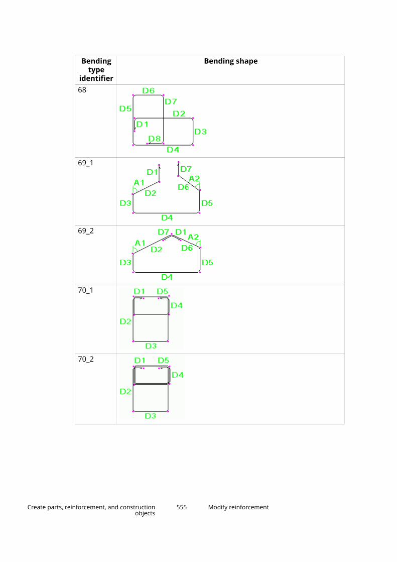
Bendingtype
identifier
Bending shape
68
69_1
69_2
70_1
70_2
Create parts, reinforcement, and constructionobjects
555 Modify reinforcement

Bendingtype
identifier
Bending shape
71
72
73_1
73_2
73_3
Create parts, reinforcement, and constructionobjects
556 Modify reinforcement

Bendingtype
identifier
Bending shape
74
75_1
75_2
76
77
Create parts, reinforcement, and constructionobjects
557 Modify reinforcement

Bendingtype
identifier
Bending shape
78
79_1
79_2
80
UNKNOWN For example:
Create parts, reinforcement, and constructionobjects
558 Modify reinforcement
See also
Reinforcement in templates (page 559)
Reinforcement shape recognition (page 523)
Reinforcement in templatesSometimes you need to localize reinforcing bar bending types or to createtemplates for reinforcing bar bending schedules.
NOTE If you want to customize the hard-coded bending shapes or definenew bending shapes, use Rebar shape catalog. See Definereinforcing bar bending shapes in Rebar shape manager (page 524).
Reinforcement templates
You can show dimensions, bending angles, and bending types of reinforcingbars in drawings and reports by including reinforcement-specific attributes,such as DIM_A, ANG_S, SHAPE, and SHAPE_INTERNAL, in template fields. Formore information on creating templates, see the Template Editor (TplEd) help.
Mapping dimensions
Use the rebar_schedule_config.inp file in the ..\ProgramData\Trimble\Tekla Structures\<version>\environments\<environment>\system folder to map
• Tekla Structures internal reinforcing bar dimensions and angles withspecific template attributes
• Tekla Structures internal reinforcing bar bending types with specificbending types
These mappings are environment-specific by default. You can modify them tosuit your company or project needs.
You can use equations, functions, and if statements to calculate thedimensions and angles you need to show.
Use any standard text editor (for example, Microsoft Notepad) to edit therebar_schedule_config.inp file.
Examples
The following example of the rebar_schedule_config.inp file maps theinternal bending type 5_1 to the bending type identifier E, and the legdimensions and bending angles to specific template attributes.
Create parts, reinforcement, and constructionobjects
559 Modify reinforcement

rebar_schedule_config.inp
With this mapping, the internal bending type 6_2 becomes XY, and thetemplate attributes DIM_B and DIM_C will show the horizontal and verticaldimensions of the second leg D2, and DIM_E and DIM_F the horizontal andvertical dimensions of the fourth leg D4.
rebar_schedule_config.inp
The following example maps the internal bending type 4 to the bending typeidentifier A if the dimensions D1 and D3 are the same. Otherwise it maps 4 to B.
rebar_schedule_config.inp
If Tekla Structures does not recognize a reinforcing bar bending shape, it usesthe internal bending type UNKNOWN for it. In therebar_schedule_config.inp file you can also define how unknownbending types appear in drawings and reports. For example, you may justwant to use the bending type identifier ???, and list all leg dimensions andbending angles.
Create parts, reinforcement, and constructionobjects
560 Modify reinforcement
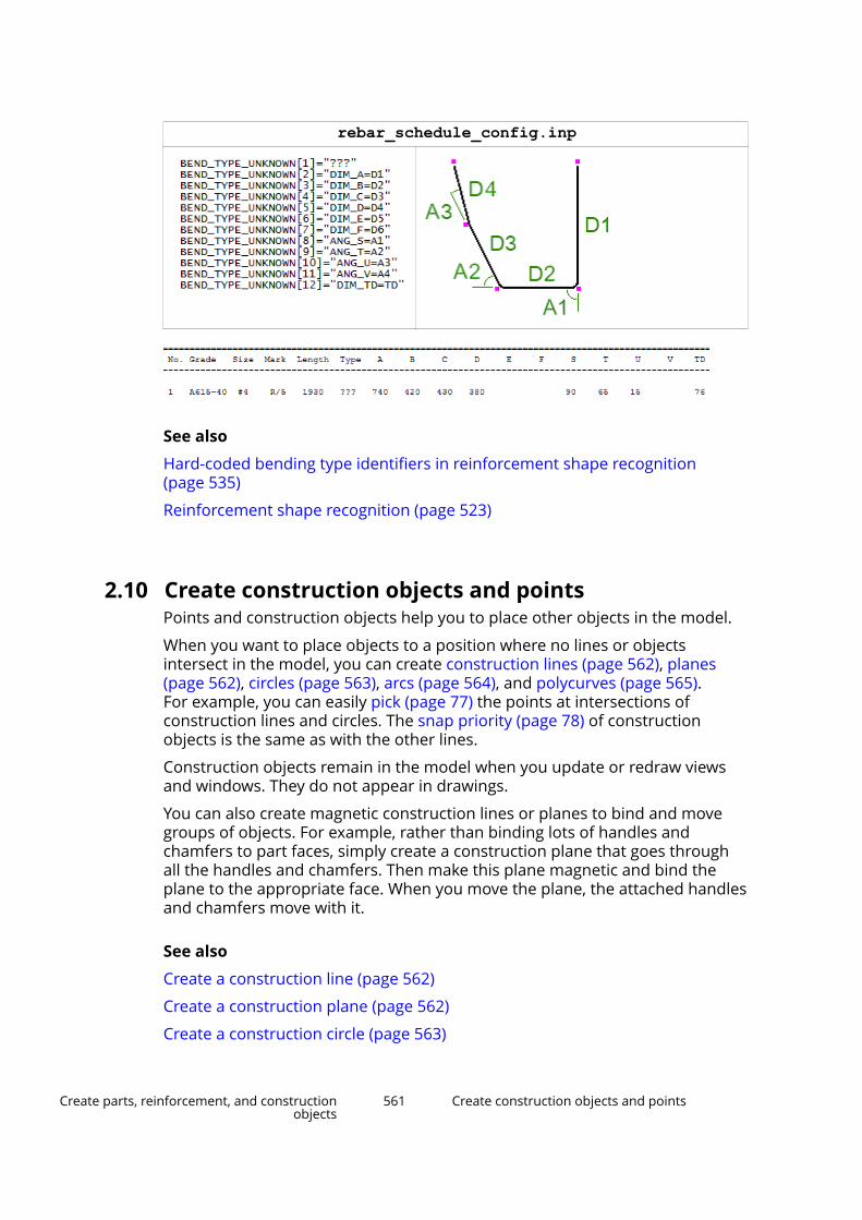
rebar_schedule_config.inp
See also
Hard-coded bending type identifiers in reinforcement shape recognition(page 535)
Reinforcement shape recognition (page 523)
2.10 Create construction objects and pointsPoints and construction objects help you to place other objects in the model.
When you want to place objects to a position where no lines or objectsintersect in the model, you can create construction lines (page 562), planes(page 562), circles (page 563), arcs (page 564), and polycurves (page 565).For example, you can easily pick (page 77) the points at intersections ofconstruction lines and circles. The snap priority (page 78) of constructionobjects is the same as with the other lines.
Construction objects remain in the model when you update or redraw viewsand windows. They do not appear in drawings.
You can also create magnetic construction lines or planes to bind and movegroups of objects. For example, rather than binding lots of handles andchamfers to part faces, simply create a construction plane that goes throughall the handles and chamfers. Then make this plane magnetic and bind theplane to the appropriate face. When you move the plane, the attached handlesand chamfers move with it.
See also
Create a construction line (page 562)
Create a construction plane (page 562)
Create a construction circle (page 563)
Create parts, reinforcement, and constructionobjects
561 Create construction objects and points

Create a construction arc (page 564)
Create a construction polycurve (page 565)
Copy a construction object with offset (page 566)
Modify a construction object (page 567)
Create points (page 570)
Create a construction line1. On the Edit tab, click Construction object --> Line .
2. Pick the start point of the construction line.
3. Pick the end point of the construction line.
4. To end the command, press Esc.
5. To modify the construction line properties, double-click the line in themodel.
The line properties are shown in the property pane.
a. If you want to make the line magnetic, select Yes in the Magnetic list.
b. Select a color for the line.
c. Define how far the line extends beyond the picked points.
d. Select a line type for the line.
e. Click Modify to apply the changes.
Tekla Structures uses the new properties the next time you create anobject of this type.
See also
Create construction objects and points (page 561)
Copy a construction object with offset (page 566)
Modify a construction object (page 567)
Create parts, reinforcement, and constructionobjects
562 Create construction objects and points

Create a construction plane1. On the Edit tab, click Construction object --> Plane .
2. Pick three points.
3. Click the middle mouse button.
Tekla Structures draws the plane.
4. To end the command, press Esc.
5. To modify the construction plane properties, double-click the plane in themodel.
The plane properties are shown in the property pane.
a. Enter a name for the plane.
b. If you want to make the construction plane magnetic, select Yes in theMagnetic list.
c. Click Modify.
See also
Create construction objects and points (page 561)
Modify a construction object (page 567)
Create a construction circleYou can create construction circles by picking three points in the 3D space inthe model.
1. On the Edit tab, click Construction object --> Circle .
2. On the contextual toolbar that appears, click a button to specify which setof points you want to pick.
• Click , and then pick three points: the center point, a point to definethe radius, and a point to define the plane of the circle.
Create parts, reinforcement, and constructionobjects
563 Create construction objects and points
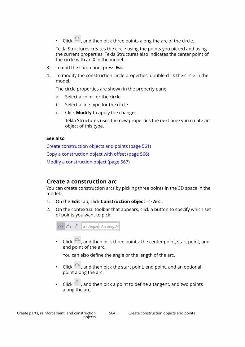
• Click , and then pick three points along the arc of the circle.
Tekla Structures creates the circle using the points you picked and usingthe current properties. Tekla Structures also indicates the center point ofthe circle with an X in the model.
3. To end the command, press Esc.
4. To modify the construction circle properties, double-click the circle in themodel.
The circle properties are shown in the property pane.
a. Select a color for the circle.
b. Select a line type for the circle.
c. Click Modify to apply the changes.
Tekla Structures uses the new properties the next time you create anobject of this type.
See also
Create construction objects and points (page 561)
Copy a construction object with offset (page 566)
Modify a construction object (page 567)
Create a construction arcYou can create construction arcs by picking three points in the 3D space in themodel.
1. On the Edit tab, click Construction object --> Arc .
2. On the contextual toolbar that appears, click a button to specify which setof points you want to pick:
• Click , and then pick three points: the center point, start point, andend point of the arc.
You can also define the angle or the length of the arc.
• Click , and then pick the start point, end point, and an optionalpoint along the arc.
• Click , and then pick a point to define a tangent, and two pointsalong the arc.
Create parts, reinforcement, and constructionobjects
564 Create construction objects and points
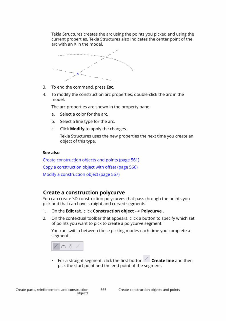
Tekla Structures creates the arc using the points you picked and using thecurrent properties. Tekla Structures also indicates the center point of thearc with an X in the model.
3. To end the command, press Esc.
4. To modify the construction arc properties, double-click the arc in themodel.
The arc properties are shown in the property pane.
a. Select a color for the arc.
b. Select a line type for the arc.
c. Click Modify to apply the changes.
Tekla Structures uses the new properties the next time you create anobject of this type.
See also
Create construction objects and points (page 561)
Copy a construction object with offset (page 566)
Modify a construction object (page 567)
Create a construction polycurveYou can create 3D construction polycurves that pass through the points youpick and that can have straight and curved segments.
1. On the Edit tab, click Construction object --> Polycurve .
2. On the contextual toolbar that appears, click a button to specify which setof points you want to pick to create a polycurve segment.
You can switch between these picking modes each time you complete asegment.
• For a straight segment, click the first button Create line and thenpick the start point and the end point of the segment.
Create parts, reinforcement, and constructionobjects
565 Create construction objects and points
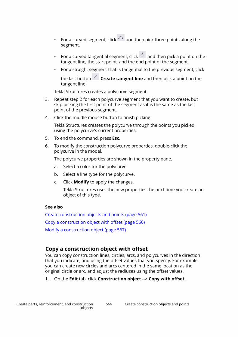
• For a curved segment, click and then pick three points along thesegment.
• For a curved tangential segment, click and then pick a point on thetangent line, the start point, and the end point of the segment.
• For a straight segment that is tangential to the previous segment, click
the last button Create tangent line and then pick a point on thetangent line.
Tekla Structures creates a polycurve segment.
3. Repeat step 2 for each polycurve segment that you want to create, butskip picking the first point of the segment as it is the same as the lastpoint of the previous segment.
4. Click the middle mouse button to finish picking.
Tekla Structures creates the polycurve through the points you picked,using the polycurve's current properties.
5. To end the command, press Esc.
6. To modify the construction polycurve properties, double-click thepolycurve in the model.
The polycurve properties are shown in the property pane.
a. Select a color for the polycurve.
b. Select a line type for the polycurve.
c. Click Modify to apply the changes.
Tekla Structures uses the new properties the next time you create anobject of this type.
See also
Create construction objects and points (page 561)
Copy a construction object with offset (page 566)
Modify a construction object (page 567)
Copy a construction object with offsetYou can copy construction lines, circles, arcs, and polycurves in the directionthat you indicate, and using the offset values that you specify. For example,you can create new circles and arcs centered in the same location as theoriginal circle or arc, and adjust the radiuses using the offset values.
1. On the Edit tab, click Construction object --> Copy with offset .
Create parts, reinforcement, and constructionobjects
566 Create construction objects and points
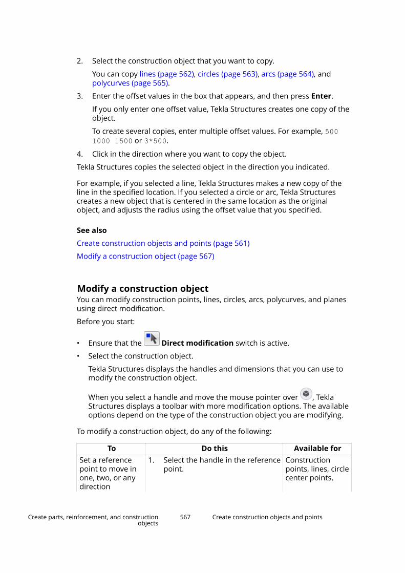
2. Select the construction object that you want to copy.
You can copy lines (page 562), circles (page 563), arcs (page 564), andpolycurves (page 565).
3. Enter the offset values in the box that appears, and then press Enter.
If you only enter one offset value, Tekla Structures creates one copy of theobject.
To create several copies, enter multiple offset values. For example, 5001000 1500 or 3*500.
4. Click in the direction where you want to copy the object.
Tekla Structures copies the selected object in the direction you indicated.
For example, if you selected a line, Tekla Structures makes a new copy of theline in the specified location. If you selected a circle or arc, Tekla Structurescreates a new object that is centered in the same location as the originalobject, and adjusts the radius using the offset value that you specified.
See also
Create construction objects and points (page 561)
Modify a construction object (page 567)
Modify a construction objectYou can modify construction points, lines, circles, arcs, polycurves, and planesusing direct modification.
Before you start:
• Ensure that the Direct modification switch is active.
• Select the construction object.
Tekla Structures displays the handles and dimensions that you can use tomodify the construction object.
When you select a handle and move the mouse pointer over , TeklaStructures displays a toolbar with more modification options. The availableoptions depend on the type of the construction object you are modifying.
To modify a construction object, do any of the following:
To Do this Available forSet a referencepoint to move inone, two, or anydirection
1. Select the handle in the referencepoint.
Constructionpoints, lines, circlecenter points,
Create parts, reinforcement, and constructionobjects
567 Create construction objects and points
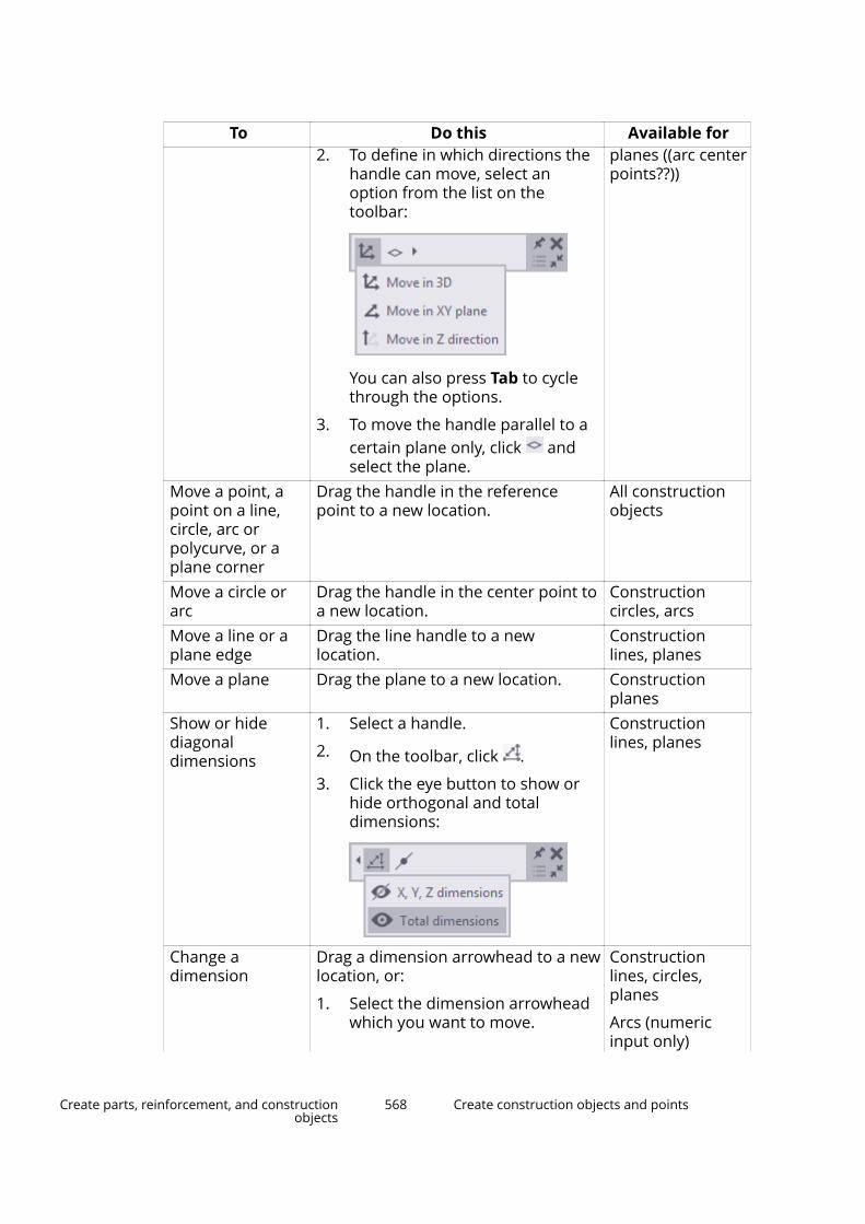
To Do this Available for2. To define in which directions the
handle can move, select anoption from the list on thetoolbar:
You can also press Tab to cyclethrough the options.
3. To move the handle parallel to acertain plane only, click andselect the plane.
planes ((arc centerpoints??))
Move a point, apoint on a line,circle, arc orpolycurve, or aplane corner
Drag the handle in the referencepoint to a new location.
All constructionobjects
Move a circle orarc
Drag the handle in the center point toa new location.
Constructioncircles, arcs
Move a line or aplane edge
Drag the line handle to a newlocation.
Constructionlines, planes
Move a plane Drag the plane to a new location. Constructionplanes
Show or hidediagonaldimensions
1. Select a handle.
2. On the toolbar, click .
3. Click the eye button to show orhide orthogonal and totaldimensions:
Constructionlines, planes
Change adimension
Drag a dimension arrowhead to a newlocation, or:
1. Select the dimension arrowheadwhich you want to move.
Constructionlines, circles,planes
Arcs (numericinput only)
Create parts, reinforcement, and constructionobjects
568 Create construction objects and points

To Do this Available forTo change the dimension at bothends, select both arrowheads.
To change the radius of a circle orarc, select the outer arrowhead.
2. Using the keyboard, enter thevalue with which you want thedimension to change.
To start with the negative sign (-),use the numeric keypad.
To enter an absolute value for thedimension, first enter $, then thevalue.
3. Press Enter, or click OK in theEnter a Numeric Locationdialog box.
Chamfer apolycurve corner
1. Select a corner handle.
2. On the toolbar:
•Click to create arounded chamfer, and thenenter the chamfer radius.
•Click to create a straightchamfer, and then enter thechamfer dimensions X and Y.
3. Press Enter to confirm thechamfer dimensions.
Polycurves
Change an arc toa line
Make a curvedsegment straight
Select the arc or segment midpoint
handle (with an arc symbol) andpress Delete.
Arcs, curvedpolycurvesegments
Change a line toan arc
Make a straightsegment curved
Drag the arc symbol at themidpoint of the line or segment.
Lines, straightpolycurvesegments
Add a cornerpoint and anintermediatesegment to apolycurve
Drag a segment midpoint handle to anew location.
Polycurves
Remove a cornerpoint and the two
Select the corner point handle andpress Delete.
Polycurves
Create parts, reinforcement, and constructionobjects
569 Create construction objects and points
To Do this Available forconnectedsegmentsRemove the lastpolycurvesegment
Select the end point handle and pressDelete.
Polycurves
Change the radiusof an arc and keepthe end pointlocations
Click the radius dimension, enter anew value, and press Enter.
Arcs
Change the radiusof a polycurvesegment and keepthe end pointlocations
Drag the arc symbol at thesegment midpoint handle.
Curved polycurvesegments
Change the angleor length of an arc
Drag the start or end point to a newlocation.
Arcs
Copy aconstructionobject using offset
See Copy a construction object withoffset (page 566).
Lines, circles, arcs,polycurves
See also
Create construction objects and points (page 561)
Create points (page 570)
Resize and reshape model objects (page 103)
Create pointsYou can create points to make it easier to place model objects at positionswhere no lines or objects intersect.
There are many ways to create points in Tekla Structures. Which method is themost convenient at each time depends on what you have already created inthe model and which locations you can easily pick.
When you create points, Tekla Structures always places them according to thework plane coordinate system. Points located on the view plane are by defaultblue and points outside the view plane are by default red. You can change thecolor of points in the point properties.
Create parts, reinforcement, and constructionobjects
570 Create construction objects and points
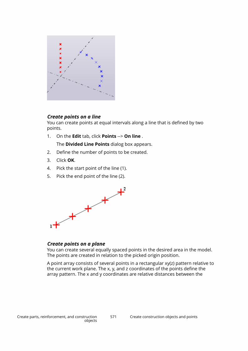
Create points on a lineYou can create points at equal intervals along a line that is defined by twopoints.
1. On the Edit tab, click Points --> On line .
The Divided Line Points dialog box appears.
2. Define the number of points to be created.
3. Click OK.
4. Pick the start point of the line (1).
5. Pick the end point of the line (2).
Create points on a planeYou can create several equally spaced points in the desired area in the model.The points are created in relation to the picked origin position.
A point array consists of several points in a rectangular xy(z) pattern relative tothe current work plane. The x, y, and z coordinates of the points define thearray pattern. The x and y coordinates are relative distances between the
Create parts, reinforcement, and constructionobjects
571 Create construction objects and points
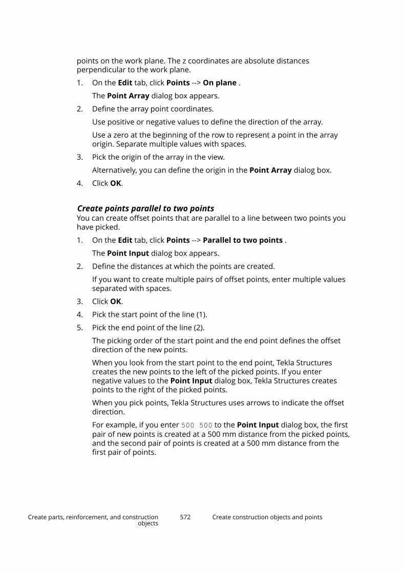
points on the work plane. The z coordinates are absolute distancesperpendicular to the work plane.
1. On the Edit tab, click Points --> On plane .
The Point Array dialog box appears.
2. Define the array point coordinates.
Use positive or negative values to define the direction of the array.
Use a zero at the beginning of the row to represent a point in the arrayorigin. Separate multiple values with spaces.
3. Pick the origin of the array in the view.
Alternatively, you can define the origin in the Point Array dialog box.
4. Click OK.
Create points parallel to two pointsYou can create offset points that are parallel to a line between two points youhave picked.
1. On the Edit tab, click Points --> Parallel to two points .
The Point Input dialog box appears.
2. Define the distances at which the points are created.
If you want to create multiple pairs of offset points, enter multiple valuesseparated with spaces.
3. Click OK.
4. Pick the start point of the line (1).
5. Pick the end point of the line (2).
The picking order of the start point and the end point defines the offsetdirection of the new points.
When you look from the start point to the end point, Tekla Structurescreates the new points to the left of the picked points. If you enternegative values to the Point Input dialog box, Tekla Structures createspoints to the right of the picked points.
When you pick points, Tekla Structures uses arrows to indicate the offsetdirection.
For example, if you enter 500 500 to the Point Input dialog box, the firstpair of new points is created at a 500 mm distance from the picked points,and the second pair of points is created at a 500 mm distance from thefirst pair of points.
Create parts, reinforcement, and constructionobjects
572 Create construction objects and points
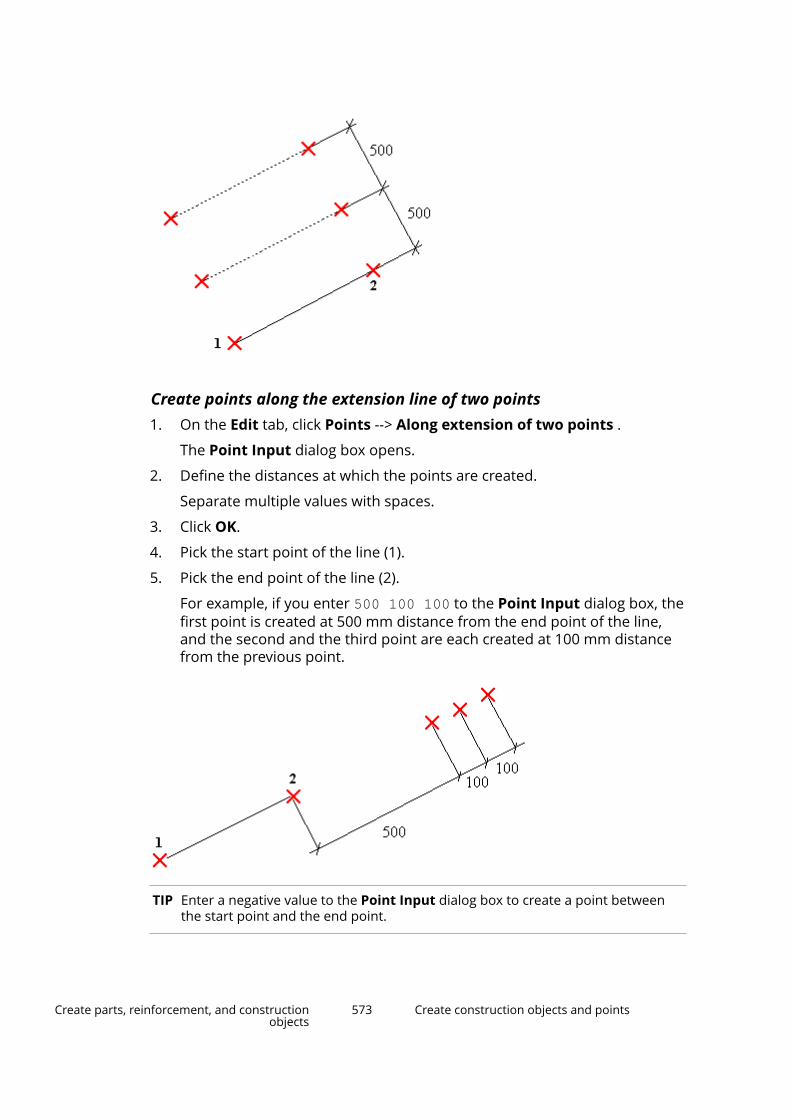
Create points along the extension line of two points1. On the Edit tab, click Points --> Along extension of two points .
The Point Input dialog box opens.
2. Define the distances at which the points are created.
Separate multiple values with spaces.
3. Click OK.
4. Pick the start point of the line (1).
5. Pick the end point of the line (2).
For example, if you enter 500 100 100 to the Point Input dialog box, thefirst point is created at 500 mm distance from the end point of the line,and the second and the third point are each created at 100 mm distancefrom the previous point.
TIP Enter a negative value to the Point Input dialog box to create a point betweenthe start point and the end point.
Create parts, reinforcement, and constructionobjects
573 Create construction objects and points

Create projected points on a lineYou can project a point onto a selected line or its extension.
1. On the Edit tab, click Points --> Projected points on line .
2. Pick the first point on the line (1).
3. Pick the second point on the line (2).
4. Pick the point to be projected (3).
Create points along an arc using center and arc pointsYou can create points along an arc.
1. On the Edit tab, click Points --> Along arc using center and arc points .
The Arc Points dialog box appears.
2. Select either Angles or Distances and enter the angles or distancesbetween the points along the arc.
Give the angle values in degrees.
Separate multiple angle and distance values with spaces.
3. Click OK.
4. Pick the center point.
5. Pick the start point of the arc.
Tekla Structures creates the arc points counterclockwise from the startpoint.
Create parts, reinforcement, and constructionobjects
574 Create construction objects and points
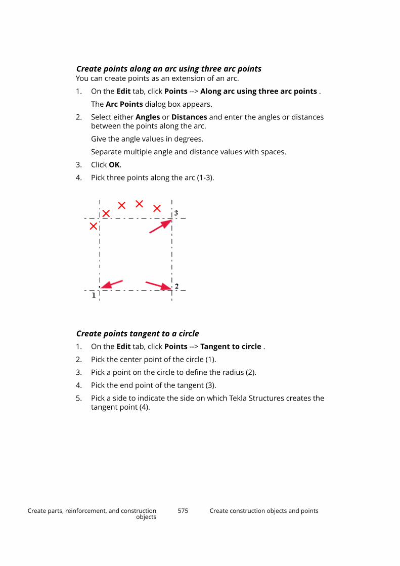
Create points along an arc using three arc pointsYou can create points as an extension of an arc.
1. On the Edit tab, click Points --> Along arc using three arc points .
The Arc Points dialog box appears.
2. Select either Angles or Distances and enter the angles or distancesbetween the points along the arc.
Give the angle values in degrees.
Separate multiple angle and distance values with spaces.
3. Click OK.
4. Pick three points along the arc (1-3).
Create points tangent to a circle1. On the Edit tab, click Points --> Tangent to circle .
2. Pick the center point of the circle (1).
3. Pick a point on the circle to define the radius (2).
4. Pick the end point of the tangent (3).
5. Pick a side to indicate the side on which Tekla Structures creates thetangent point (4).
Create parts, reinforcement, and constructionobjects
575 Create construction objects and points

Tangentpoint
Create points at any position
NOTE Snap switches (page 79) determine the positions you can pick.
You can also use temporary reference points and numeric snapping to create apoint, for example, to a certain distance from an existing corner or a point.
1. On the Edit tab, click Points --> At any position .
2. Pick the intersection of two part edges (1), or the corner of a part (2).
Create bolt pointsYou can create points on the view plane at the center points of single bolts andbolt group bolts.
1. On the Edit tab, click Points --> Bolt points.
2. Select a bolt or a bolt group.
Create parts, reinforcement, and constructionobjects
576 Create construction objects and points

Create points at the intersection of two lines1. On the Edit tab, click Points --> At intersection of two lines .
2. Pick the start point of the first line (1).
3. Pick the end point of the first line (2).
4. Pick the start point of the second line (3).
5. Pick the end point of the second line (4).
Create points at the intersection of a plane and a line1. On the Edit tab, click Points --> At intersection of plane and line .
2. Pick three points to define the plane.
3. Pick the first point of the line.
4. Pick the second point of the line.
Create points at the intersection of a part and a lineYou can create points where a line intersects with the surface of a part.
1. On the Edit tab, click Points --> At intersection of part and line .
2. Select the part.
3. Pick the first point of the line.
4. Pick the second point of the line.
Create points at the intersection of a circle and a line1. On the Edit tab, click Points --> At intersection of circle and line .
2. Pick the center point of the circle (1).
3. Pick a point on the circle to define the radius (2).
4. Pick the first point on the line (3).
5. Pick the second point on the line (4).
Create parts, reinforcement, and constructionobjects
577 Create construction objects and points
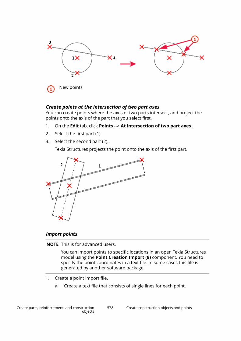
New points
Create points at the intersection of two part axesYou can create points where the axes of two parts intersect, and project thepoints onto the axis of the part that you select first.
1. On the Edit tab, click Points --> At intersection of two part axes .
2. Select the first part (1).
3. Select the second part (2).
Tekla Structures projects the point onto the axis of the first part.
Import points
NOTE This is for advanced users.
You can import points to specific locations in an open Tekla Structuresmodel using the Point Creation Import (8) component. You need tospecify the point coordinates in a text file. In some cases this file isgenerated by another software package.
1. Create a point import file.
a. Create a text file that consists of single lines for each point.
Create parts, reinforcement, and constructionobjects
578 Create construction objects and points
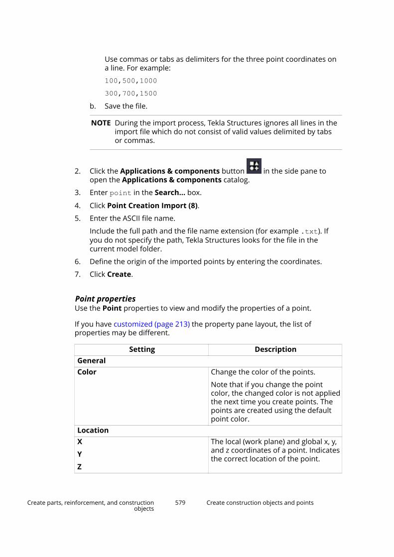
Use commas or tabs as delimiters for the three point coordinates ona line. For example:
100,500,1000300,700,1500
b. Save the file.
NOTE During the import process, Tekla Structures ignores all lines in theimport file which do not consist of valid values delimited by tabsor commas.
2. Click the Applications & components button in the side pane toopen the Applications & components catalog.
3. Enter point in the Search... box.
4. Click Point Creation Import (8).
5. Enter the ASCII file name.
Include the full path and the file name extension (for example .txt). Ifyou do not specify the path, Tekla Structures looks for the file in thecurrent model folder.
6. Define the origin of the imported points by entering the coordinates.
7. Click Create.
Point propertiesUse the Point properties to view and modify the properties of a point.
If you have customized (page 213) the property pane layout, the list ofproperties may be different.
Setting DescriptionGeneralColor Change the color of the points.
Note that if you change the pointcolor, the changed color is not appliedthe next time you create points. Thepoints are created using the defaultpoint color.
LocationX
Y
Z
The local (work plane) and global x, y,and z coordinates of a point. Indicatesthe correct location of the point.
Create parts, reinforcement, and constructionobjects
579 Create construction objects and points

TIP You can change the point size in Display settings (page 918).
Create parts, reinforcement, and constructionobjects
580 Create construction objects and points

3 Change how model objects aredisplayed
To change the display of model objects:
• You can change the general display settings to Set the visibility andappearance of model objects (page 582) and Change the rendering ofparts and components (page 584).
• You can temporarily hide selected objects as explained in Hide modelobjects (page 587) or do the opposite and show only the selected objectsas explained in Show only selected model objects (page 588).
• You can temporarily show hidden assembly and component objects asexplained in Temporarily display assembly and component objects(page 589).
• To show all the detailing that belongs to a part, see Display detailing of apart (page 590).
• To show a part in a selected view angle, see Show parts in a selected viewangle (page 591).
• You can group model objects using various criteria (for example, profile) tohandle them as a single unit when you define display settings, see Createobject groups (page 591).
• Detailed instructions for changing model object color and transparency canbe found in the section Change the color and transparency of modelobjects (page 593).
3.1 Show and hide model objectsThis section explains how to control the visibility and appearance of parts andother model objects.
Click the links below to find out more:
Change how model objects are displayed 581 Show and hide model objects

Set the visibility and appearance of model objects (page 582)
Change the rendering of parts and components (page 584)
Hide model objects (page 587)
Show only selected model objects (page 588)
Temporarily display assembly and component objects (page 589)
Display detailing of a part (page 590)
Show parts in a selected view angle (page 591)
Set the visibility and appearance of model objectsModify the display settings to define how parts and other model objectsappear in a model view.
1. Double-click the view to open the View Properties dialog box.
2. Click Display... to open the Display dialog box.
3. Select or clear check boxes to specify which objects are visible in the view.
4. Select a representation option for parts, bolts, holes, welds, constructionplanes and reinforcing bars.
You have the following options:
• Fast
• Exact
• Reference line (only for parts)
• Exact slotted holes (only for holes)
• Exact - no weld mark (only for welds)
5. If you are working with cast-in-place (page 404) concrete structures, andthe pour management functionality is enabled (page 402):
a. In the Cast in place list, select whether you want to show thestructures as Parts or as Pours.
b. If you selected Parts for the cast-in-place concrete structures, selectwhether you want to show the parts as Merged or as Separated.
6. Ensure that the view is selected.
7. Click Modify to apply the changes.
See also
Display settings (page 918)
Show parts with exact lines (page 583)
Show parts with high accuracy (page 583)
Change how model objects are displayed 582 Show and hide model objects

Show part handles and part reference lines in a model view (page 303)
Set the visibility and appearance of welds (page 358)
Set the visibility of pour breaks (page 417)
Change the rendering of parts and components (page 584)
Change the color and transparency of model objects (page 593)
Show parts with exact linesUse the Show part with exact lines command to temporarily display a partwith exact lines even if you are using the Fast representation option for parts.
1. Select the part.
2. Go to Quick Launch, start typing show part with exact lines, andselect the Show part with exact lines command from the list thatappears.
3. Click the view in which you want to display exact lines.
4. To clear the exact lines effect, on the View tab, click .
See also
Show and hide model objects (page 581)
Show parts with high accuracyYou can temporarily display parts with the highest possible level of accuracy.This can be useful, for example, when checking a large model, because theentire model can still be displayed in the Fast or Exact representation modebut the individual part can be shown in more detail.
1. Select the parts.
2. Right-click, and then hold down the Shift key while selecting Show withExact Lines.
Tekla Structures displays the selected parts with the highest possible levelof accuracy.
3. To clear the high accuracy effect, right-click and select Show with ExactLines.
Change how model objects are displayed 583 Show and hide model objects
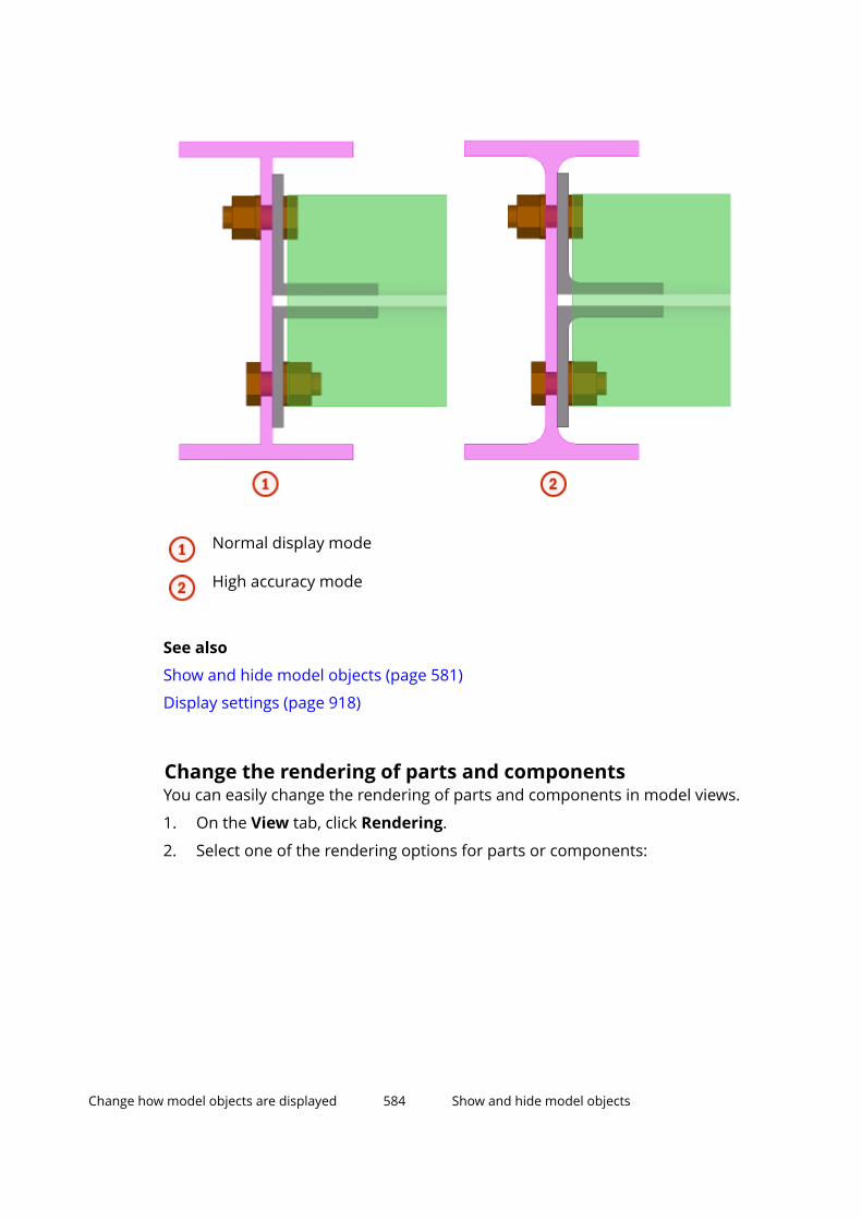
Normal display mode
High accuracy mode
See also
Show and hide model objects (page 581)
Display settings (page 918)
Change the rendering of parts and componentsYou can easily change the rendering of parts and components in model views.
1. On the View tab, click Rendering.
2. Select one of the rendering options for parts or components:
Change how model objects are displayed 584 Show and hide model objects

Option Description Example
Partswireframe/Componentswireframe
Object outlines are displayed,surfaces are not. Objects aretransparent. In this wireframe example,
component objects aredisplayed as rendered.
Parts shadedwireframe/Componentsshadedwireframe
Object outlines are displayed.Objects are transparent, andtheir surfaces are rendered.
If you use the DirectXrendering and have set XS_HATCH_OVERLAPPING_FACES_IN_DX to TRUE, theoverlapping surfaces arevisualized in renderedwireframe views.
In this rendered wireframeexample, component objectsare displayed as rendered.
In this DirectX renderingexample, the overlappingsurfaces are visualized.
Change how model objects are displayed 585 Show and hide model objects

Option Description Example
Partsgrayscale/Componentsgrayscale
Objects are shown ingrayscale.
If you use the DirectXrendering and have set XS_HATCH_OVERLAPPING_FACES_IN_DX to TRUE, theoverlapping surfaces arevisualized in grayscale views.
In this DirectX renderingexample, the overlappingsurfaces are visualized.
Partsrendered/Componentsrendered
Object surfaces are displayed.Objects are not transparent.
If you use the DirectXrendering and have set XS_HATCH_OVERLAPPING_FACES_IN_DX to TRUE, theoverlapping surfaces arevisualized with a hatch.
Change how model objects are displayed 586 Show and hide model objects

Option Description Example
In this DirectX renderingexample, the overlappingsurfaces are visualized with ahatch.
Show onlyselectedpart/Showonly selectedcomponent
Selected objects aredisplayed. Other objects arealmost completelytransparent.
This option is useful, forexample, when viewing clashcheck results in a large model.
TIP Alternatively, you can use the keyboard shortcuts Ctrl+1...5 for parts and Shift+1...5 for components to switch between the rendering options.
See also
Set the visibility and appearance of model objects (page 582)
Change the rendering of the model (page 67)
Change how model objects are displayed 587 Show and hide model objects

Hide model objectsYou can quickly hide selected parts or other objects in a model view. This canbe useful, for example, when you want to temporarily hide parts to see theparts behind them.
1. Select the objects you want to hide.
2. Right-click and select Hide.
The selected objects become invisible.
3. To make the objects visible again, click on the View tab.
See also
Show only selected model objects (page 588)
Show only selected model objectsAs an alternative to hiding single objects in a model view, you can define whichobjects you want to keep visible. All of the other, unselected objects will behidden.
Change how model objects are displayed 588 Show and hide model objects

1. Select the objects that you want to keep visible.
2. Right-click and select Show Only Selected.
The unselected objects become almost transparent.
TIP To completely hide the unselected objects, hold down the Shift keywhen selecting the command.
To show the unselected parts as sticks, hold down the Ctrl key whenselecting the command.
3. To make the objects visible again, click on the View tab.
See also
Hide model objects (page 587)
Temporarily display assembly and component objectsYou can temporarily show the contents of an assembly or a component even ifsome of the assembly or component objects are not visible in a model view.
Change how model objects are displayed 589 Show and hide model objects
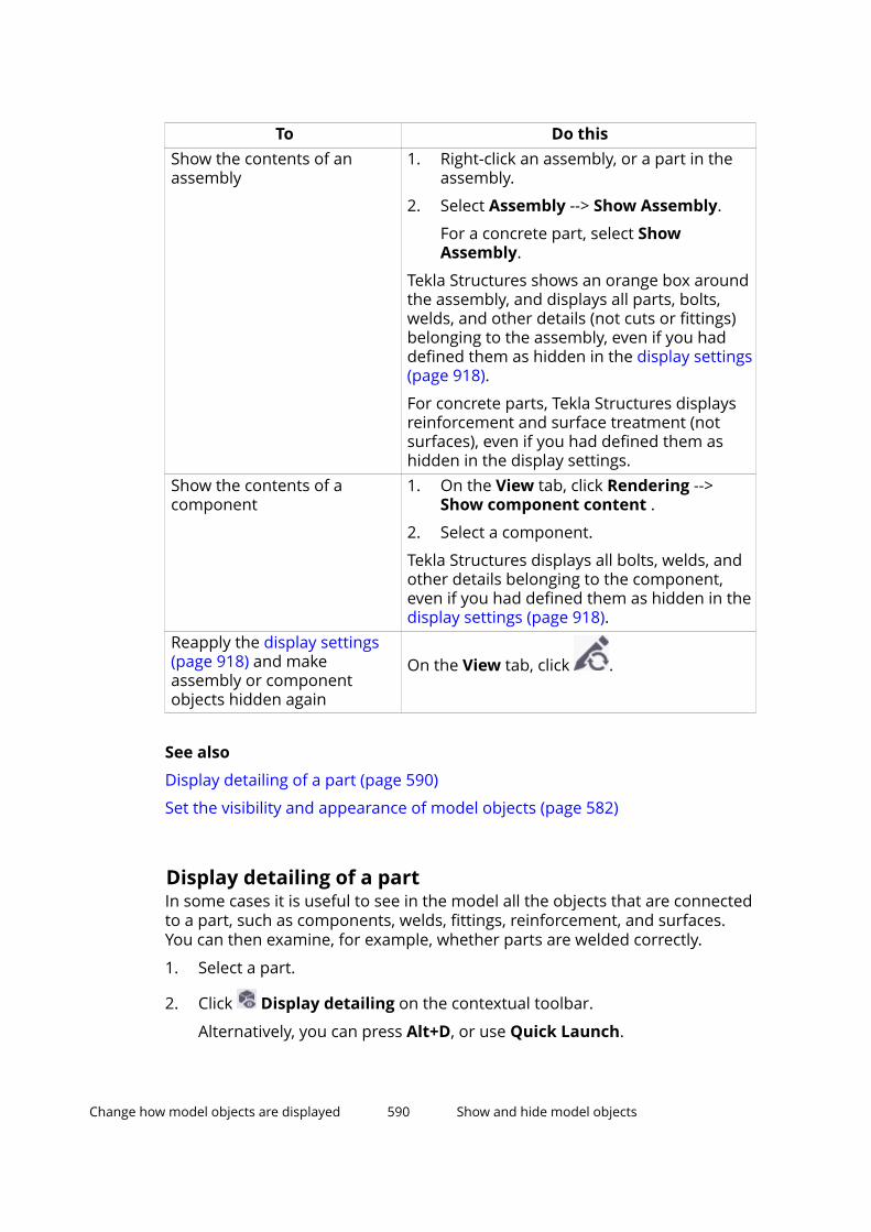
To Do thisShow the contents of anassembly
1. Right-click an assembly, or a part in theassembly.
2. Select Assembly --> Show Assembly.
For a concrete part, select ShowAssembly.
Tekla Structures shows an orange box aroundthe assembly, and displays all parts, bolts,welds, and other details (not cuts or fittings)belonging to the assembly, even if you haddefined them as hidden in the display settings(page 918).
For concrete parts, Tekla Structures displaysreinforcement and surface treatment (notsurfaces), even if you had defined them ashidden in the display settings.
Show the contents of acomponent
1. On the View tab, click Rendering -->Show component content .
2. Select a component.
Tekla Structures displays all bolts, welds, andother details belonging to the component,even if you had defined them as hidden in thedisplay settings (page 918).
Reapply the display settings(page 918) and makeassembly or componentobjects hidden again
On the View tab, click .
See also
Display detailing of a part (page 590)
Set the visibility and appearance of model objects (page 582)
Display detailing of a partIn some cases it is useful to see in the model all the objects that are connectedto a part, such as components, welds, fittings, reinforcement, and surfaces.You can then examine, for example, whether parts are welded correctly.
1. Select a part.
2. Click Display detailing on the contextual toolbar.
Alternatively, you can press Alt+D, or use Quick Launch.
Change how model objects are displayed 590 Show and hide model objects

Tekla Structures displays all bolts, welds, cuts, fittings, and other detailsbelonging to the part, even if you had defined them as hidden in the displaysettings (page 918). For concrete parts, Tekla Structures displays alsoreinforcement, surface treatment, and surfaces.
See also
Temporarily display assembly and component objects (page 589)
Set the visibility and appearance of model objects (page 582)
Show parts in a selected view angleIn some cases it is useful to examine parts in a selected view angle. Forexample, when you reinforce concrete elements, you can easily check thedistances between the reinforcing bars.
1. Select a part.
2. Click View angle on the contextual toolbar.
3. Select a top, back, right, bottom, front, or left view.
Tekla Structures displays the part in the selected view angle. The viewangle is based on the selected part's coordinate system so that the topview is looking to the negative z-direction. For example, if you select thetop view, Tekla Structures sets the current view angle from up to down inthe coordinate system.
4. To return to the original 3D view, click the button in the middle of the viewangle options.
NOTE Tekla Structures shows the part in the current view, which is the viewwhere your mouse has last been. If the contextual toolbar is located,for example, on top of two views, the part is shown in the view whereyour mouse has last been and not in the view where the part wasselected.
See also
Show and hide model objects (page 581)
3.2 Create object groupsYou can group parts and other objects based on their properties. Use objectgroups to control the color and transparency of parts in the model. Objectgroups are also needed in model view filters, selection filters, Organizer filters,and with the Project Status Visualization tool.
Change how model objects are displayed 591 Create object groups

Create an object group1. On the View tab, click Representation to open the Object
Representation dialog box.
2. Click Object group... to open the Object Group - Representation dialogbox.
3. Select an existing Object Group from the Save/Load list to create amodified version or click New filter to start without existing settings.
4. Click Add row or continue to modify the settings on an existing row.
5. Select options from the Category, Property, and Condition lists.
You can use the same object properties (page 169) and techniques(page 166) as in filtering.
6. In the Value list, enter a value or select one from the model.
The values can be complete strings, such as the profile name UC310*97.You can also use incomplete strings together with wildcards (page 186).For example, the value UC* will match with all parts whose profile namebegins with the characters UC*. Empty values are matched to emptyobject properties.
If you use multiple values, separate the strings with blank spaces (forexample, 12 5). If a value consists of multiple strings, enclose the entirevalue in quotation marks (for example, "custom panel"), or use aquestion mark (for example, custom?panel) to replace the space.
7. Use the And/Or options and brackets (page 166) to define how multiplerows work together.
8. To temporarily disable rules without deleting them, you can deselect thecheck boxes in the first column of the row. Select the check box to re-enable the rule.
9. Enter a unique name in the box next to the Save as button.
10. Click Save as to save the object group.
Copy an object group to another model1. Select the object group you want to copy.
The object groups you have created are located in the model’s\attributes folder, and they have the file name extension .PObjGrp.
2. Select where you want to copy the object group.
• To make an object group available in another model, copy the file tothe \attributes folder of the destination model.
Change how model objects are displayed 592 Create object groups

• To make an object group available in all models, copy the file to theproject or firm folder, defined by the advanced option XS_PROJECT orXS_FIRM.
3. Restart Tekla Structures.
Delete an object group1. Delete the object group file located in the model’s \attributes folder.
Object groups have the file name extension *.PObjGrp.
2. Restart Tekla Structures.
3.3 Change the color and transparency of model objectsYou can modify the color and transparency of model objects and createcustomized presentations of the model. The following images show the samemodel with different transparency settings:
1. Standard color and transparency settings
2. Only parts whose profile name starts with IPE* or HEA* are visible
3. Parts whose user-defined attribute Planned erection date is set to acertain date are displayed in blue, while all other parts are 90%transparent
Click the links below to find out more:
Change how model objects are displayed 593 Change the color and transparency of modelobjects

Change the color of a model object (page 594)
Change the color of an object group (page 595)
Define color and transparency settings (page 597)
Copy color and transparency settings to another model (page 598)
Delete color and transparency settings (page 598)
Change the color of a model objectYou can change the color of individual objects in a model by modifying theirclass. Alternatively, you can use the object representation settings to specifycolors for entire object groups.
The possible class numbers range between 0 and 14, and result in differentcolors as follows:
Class numbers above 14 produce the same colors as 1...14. For example, classnumbers 2, 16, 30, 44, and so on, all result in red.
You can also use class numbers to define the default color of pour objects andpour breaks.
To change the color and class of a part or reinforcement:
To Do thisChange object color on the contextualtoolbar
1. Select a model object.
2. On the contextual toolbar, selecta new class.
Change object color in the objectproperties
1. Double-click a model object toopen its properties.
Change how model objects are displayed 594 Change the color and transparency of modelobjects
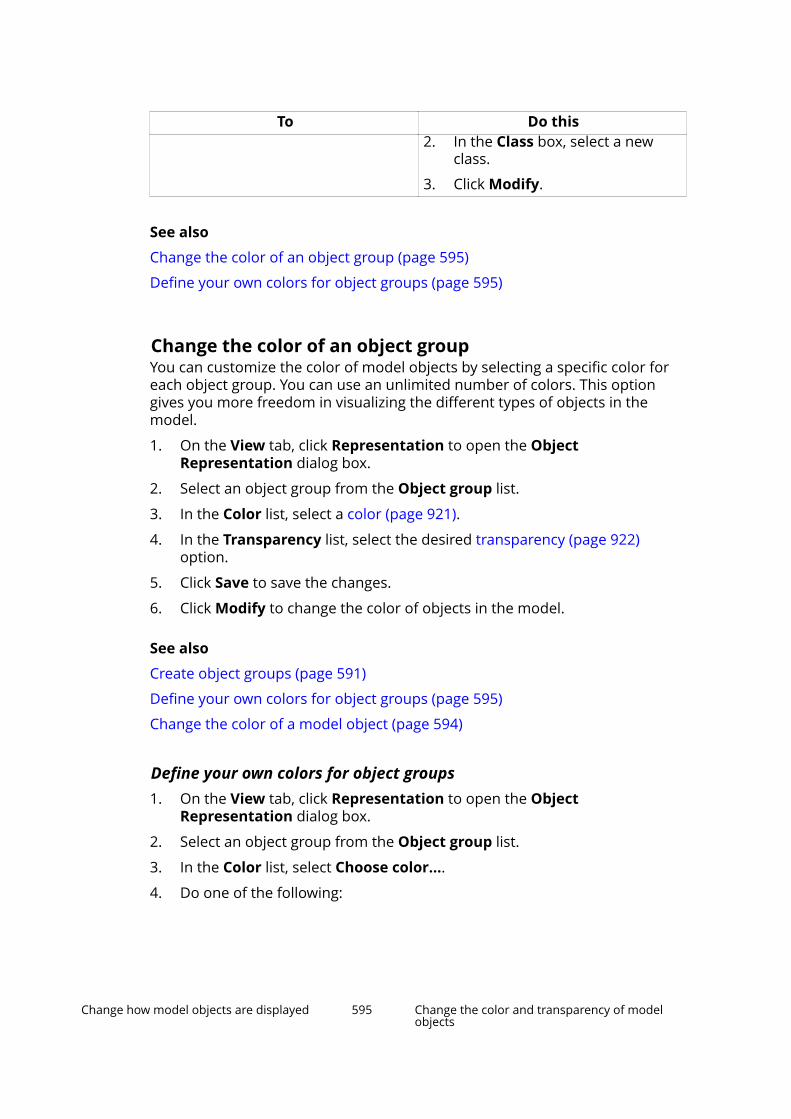
To Do this2. In the Class box, select a new
class.
3. Click Modify.
See also
Change the color of an object group (page 595)
Define your own colors for object groups (page 595)
Change the color of an object groupYou can customize the color of model objects by selecting a specific color foreach object group. You can use an unlimited number of colors. This optiongives you more freedom in visualizing the different types of objects in themodel.
1. On the View tab, click Representation to open the ObjectRepresentation dialog box.
2. Select an object group from the Object group list.
3. In the Color list, select a color (page 921).
4. In the Transparency list, select the desired transparency (page 922)option.
5. Click Save to save the changes.
6. Click Modify to change the color of objects in the model.
See also
Create object groups (page 591)
Define your own colors for object groups (page 595)
Change the color of a model object (page 594)
Define your own colors for object groups1. On the View tab, click Representation to open the Object
Representation dialog box.
2. Select an object group from the Object group list.
3. In the Color list, select Choose color....
4. Do one of the following:
Change how model objects are displayed 595 Change the color and transparency of modelobjects
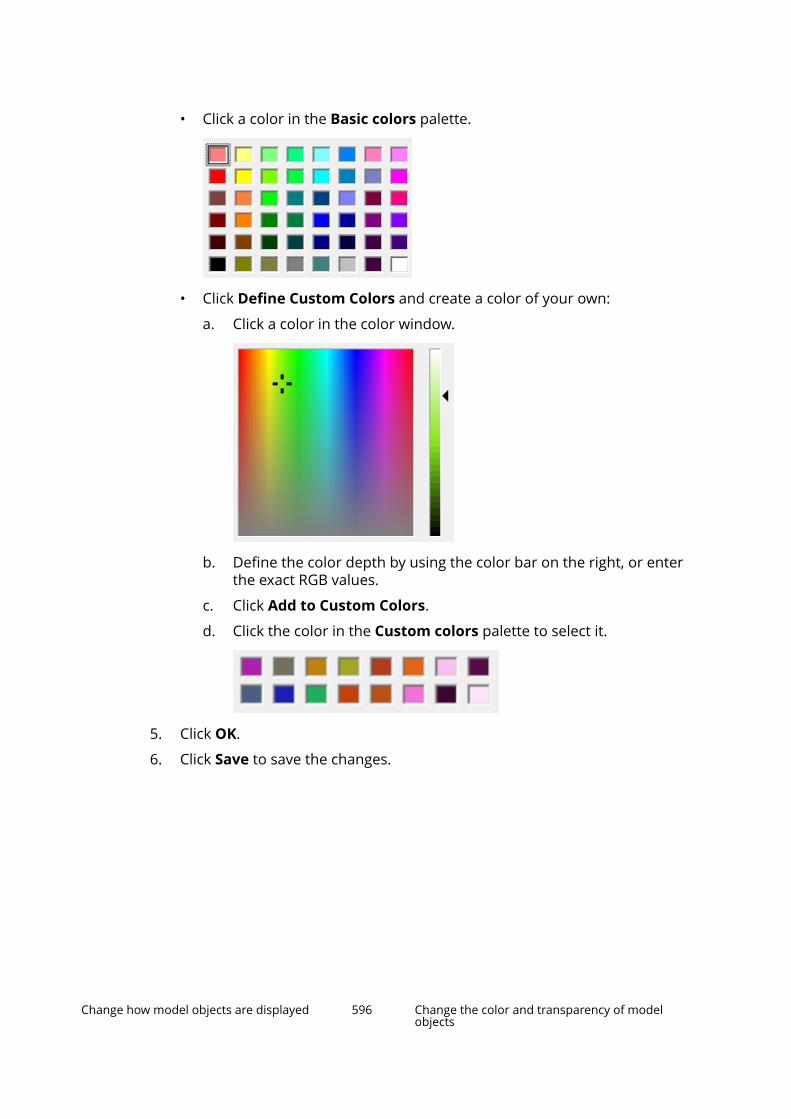
• Click a color in the Basic colors palette.
• Click Define Custom Colors and create a color of your own:
a. Click a color in the color window.
b. Define the color depth by using the color bar on the right, or enterthe exact RGB values.
c. Click Add to Custom Colors.
d. Click the color in the Custom colors palette to select it.
5. Click OK.
6. Click Save to save the changes.
Change how model objects are displayed 596 Change the color and transparency of modelobjects

When you open the Object Representation dialog box the next time, theColor list shows a maximum of 10 colors that you last defined. Customizedcolors are shown above the dashed line:
Information about the colors that you define for the object groups is stored inthe used_custom_colors.clr file, which is located in the \attributesfolder under the model folder. Information about the colors that you add inthe Custom colors palette is stored in the xs_user.xxx file in the modelfolder (xxx is your user name).
See also
Change the color of an object group (page 595)
Define color and transparency settingsYou can define color and transparency settings for parts and other modelobjects.
1. On the View tab, click Representation to open the ObjectRepresentation dialog box.
2. Click Add row.
3. Select an object group from the Object group list.
4. Use the Color list to define the color of the objects.
5. Use the Transparency list to define the transparency of the objects.
6. Repeat steps 3–5 for each row you add.
Change how model objects are displayed 597 Change the color and transparency of modelobjects

7. Use the Move up and Move down buttons to change the order of therows.
If an object belongs to several object groups, the color and transparencysetting defined on the top row is applied to that object.
8. Enter a unique name in the box next to the Save as button.
9. Click Save as to save the settings.
NOTE If your setting does not contain the group All, Tekla Structures adds that rowto the bottom of the list when you click Modify, Apply or OK.
See also
Change the color and transparency of model objects (page 593)
Color settings for object groups (page 921)
Transparency settings for object groups (page 922)
Define your own colors for object groups (page 595)
Copy color and transparency settings to another model1. Select the settings you want to copy.
The settings you have created are located in the model’s \attributesfolder, and they have the file name extension .rep.
2. Select where you want to copy the settings.
• To make the settings available in another model, copy them to the\attributes folder of the destination model.
• To make the settings available in all models, copy them to the projector firm folder, defined by the advanced option XS_PROJECT or XS_FIRM.
3. Restart Tekla Structures.
See also
Change the color and transparency of model objects (page 593)
Delete color and transparency settings1. Delete the .rep file located in the model’s \attributes folder.
2. Restart Tekla Structures.
See also
Change the color and transparency of model objects (page 593)
Change how model objects are displayed 598 Change the color and transparency of modelobjects
4 Check the model
This section describes a variety of tools you can use to ensure the model doesnot contain errors.
Click the links below to find out more:
Inquire object properties (page 599)
Measure objects (page 605)
Compare parts or assemblies (page 607)
Create a clip plane (page 608)
Fly through the model (page 609)
Detect clashes (page 610)
View solid errors (page 623)
Diagnose and repair the model (page 624)
Find distant objects (page 626)
4.1 Inquire object propertiesUse the Inquire commands to get information about a particular object, or agroup of objects, within the model.
Do any of the following:
To inquire Do thisObject properties 1.
On the ribbon, click Object.
2. Select an object.
Tekla Structures displays the object propertiesin a separate window.
Check the model 599 Inquire object properties
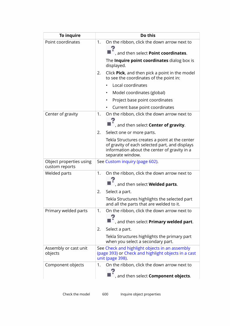
To inquire Do thisPoint coordinates 1. On the ribbon, click the down arrow next to
, and then select Point coordinates.
The Inquire point coordinates dialog box isdisplayed.
2. Click Pick, and then pick a point in the modelto see the coordinates of the point in:
• Local coordinates
• Model coordinates (global)
• Project base point coordinates
• Current base point coordinatesCenter of gravity 1. On the ribbon, click the down arrow next to
, and then select Center of gravity.
2. Select one or more parts.
Tekla Structures creates a point at the centerof gravity of each selected part, and displaysinformation about the center of gravity in aseparate window.
Object properties usingcustom reports
See Custom inquiry (page 602).
Welded parts 1. On the ribbon, click the down arrow next to
, and then select Welded parts.
2. Select a part.
Tekla Structures highlights the selected partand all the parts that are welded to it.
Primary welded parts 1. On the ribbon, click the down arrow next to
, and then select Primary welded part.
2. Select a part.
Tekla Structures highlights the primary partwhen you select a secondary part.
Assembly or cast unitobjects
See Check and highlight objects in an assembly(page 393) or Check and highlight objects in a castunit (page 398).
Component objects 1. On the ribbon, click the down arrow next to
, and then select Component objects.
Check the model 600 Inquire object properties
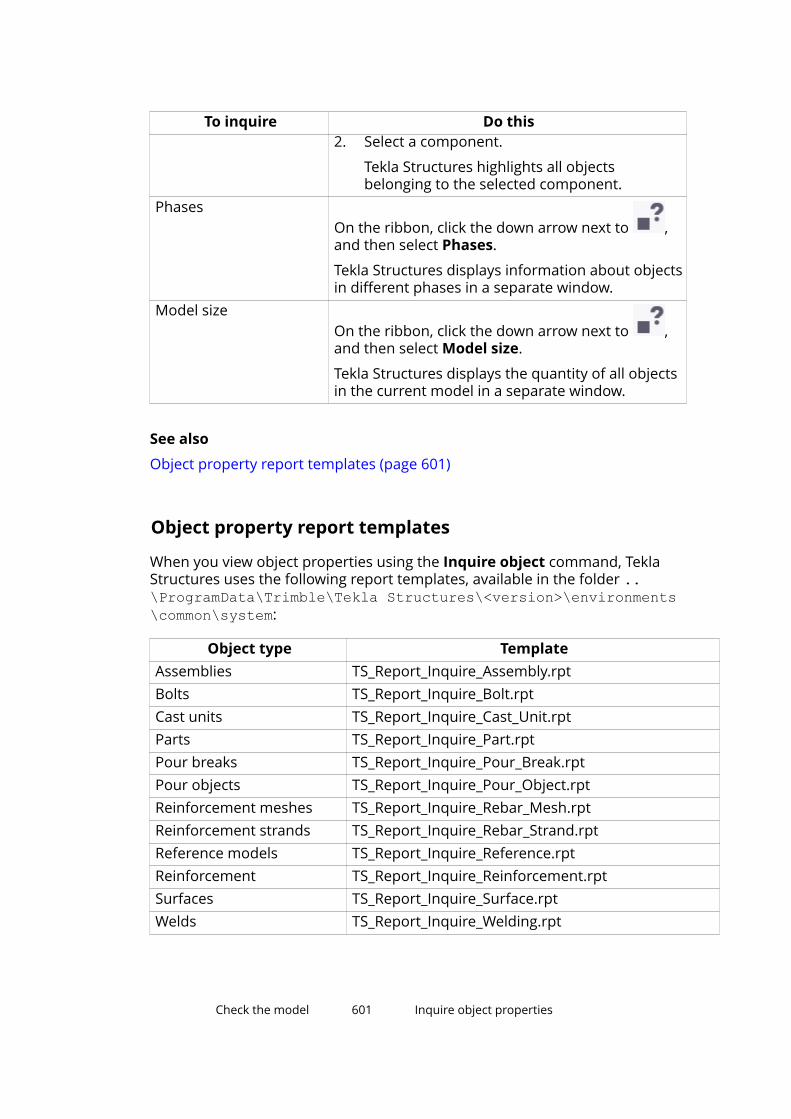
To inquire Do this2. Select a component.
Tekla Structures highlights all objectsbelonging to the selected component.
PhasesOn the ribbon, click the down arrow next to ,and then select Phases.
Tekla Structures displays information about objectsin different phases in a separate window.
Model sizeOn the ribbon, click the down arrow next to ,and then select Model size.
Tekla Structures displays the quantity of all objectsin the current model in a separate window.
See also
Object property report templates (page 601)
Object property report templates
When you view object properties using the Inquire object command, TeklaStructures uses the following report templates, available in the folder ..\ProgramData\Trimble\Tekla Structures\<version>\environments\common\system:
Object type TemplateAssemblies TS_Report_Inquire_Assembly.rptBolts TS_Report_Inquire_Bolt.rptCast units TS_Report_Inquire_Cast_Unit.rptParts TS_Report_Inquire_Part.rptPour breaks TS_Report_Inquire_Pour_Break.rptPour objects TS_Report_Inquire_Pour_Object.rptReinforcement meshes TS_Report_Inquire_Rebar_Mesh.rptReinforcement strands TS_Report_Inquire_Rebar_Strand.rptReference models TS_Report_Inquire_Reference.rptReinforcement TS_Report_Inquire_Reinforcement.rptSurfaces TS_Report_Inquire_Surface.rptWelds TS_Report_Inquire_Welding.rpt
Check the model 601 Inquire object properties
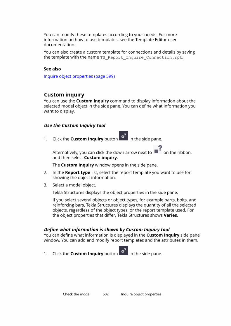
You can modify these templates according to your needs. For moreinformation on how to use templates, see the Template Editor userdocumentation.
You can also create a custom template for connections and details by savingthe template with the name TS_Report_Inquire_Connection.rpt.
See also
Inquire object properties (page 599)
Custom inquiryYou can use the Custom inquiry command to display information about theselected model object in the side pane. You can define what information youwant to display.
Use the Custom Inquiry tool
1. Click the Custom Inquiry button in the side pane.
Alternatively, you can click the down arrow next to on the ribbon,and then select Custom inquiry.
The Custom Inquiry window opens in the side pane.
2. In the Report type list, select the report template you want to use forshowing the object information.
3. Select a model object.
Tekla Structures displays the object properties in the side pane.
If you select several objects or object types, for example parts, bolts, andreinforcing bars, Tekla Structures displays the quantity of all the selectedobjects, regardless of the object types, or the report template used. Forthe object properties that differ, Tekla Structures shows Varies.
Define what information is shown by Custom Inquiry toolYou can define what information is displayed in the Custom Inquiry side panewindow. You can add and modify report templates and the attributes in them.
1. Click the Custom Inquiry button in the side pane.
Check the model 602 Inquire object properties

Alternatively, you can click the down arrow next to on the ribbon,and then select Custom inquiry.
The Custom Inquiry window opens in the side pane.
2. Click the button.
The Manage contents dialog box appears.
The Attributes list contains the attributes that are available by default. Inthe Calculated attributes area you can create your own attributeformulas. The Contents of Custom Inquiry list contains the attributeswhose values will be displayed in the side pane.
3. Define which report templates and attributes are available.
• To modify an existing report template, select it from the top left-handlist in the Manage contents dialog box.
• To create a new report template, enter a name in the box next to the
button, and then click .
• To modify the default attributes, edit the InquiryTool.config file.
• To create or modify a calculated attribute, double-click a cell in theCalculated attributes area. In the first cell, type the name of the
Check the model 603 Inquire object properties

attribute. In the second cell, use attribute names and standardmathematical symbols (+, -, *, and /) to form equations.
4. Define which attributes are shown in the Custom Inquiry side panewindow.
• To add more attributes to the side pane, select an attribute in the
Attributes list and then click the button.
• To remove attributes from the side pane, select an attribute in the
Contents of Custom Inquiry list and then click the button.
• To change the order of the attributes, use the buttons.
• To change the formula of an attribute, click the down arrow and selecta different formula (Sum, Average, Max, or Min) from the list.
5. Click to save the changes.
Modify the default attributes in InquiryTool.config fileUse the InquiryTool.config file to control which attributes are shown asdefault attributes in the Manage contents dialog box in the Custom Inquirytool.
NOTE This section is for advanced users.
Tekla Structures searches for the InquiryTool.config file in the followingfolders in the following order:
1. \attributes folder in the model folder
2. \CustomInquiry subfolder in the folder defined by XS_PROJECT
3. \CustomInquiry subfolder in the folder defined by XS_FIRM
4. \CustomInquiry subfolder in the folder defined by XS_SYSTEM
If you specify several folders that have \CustomInquiry as a subfolder, TeklaStructures uses the first folder it finds.
To add new attributes to the InquiryTool.config file:
1. Open the InquiryTool.config file in any standard text editor.
2. Copy the entire contents of [ATTR_CONTENT_??] to the end of the file.
3. Change the position number of the new attribute.
For example, change [ATTR_CONTENT_??] to [ATTR_CONTENT_66].
4. Modify the NAME, DISPLAY_NAME, DATATYPE, UNIT, and DECIMAL valuesof the new attribute. Use the attribute names and definitions that are
Check the model 604 Inquire object properties
included in the contentattributes_global.lst orcontentattributes_userdefined.lst file.
5. Change the TOTAL_ATTR_CONTENT value to reflect the total number ofattributes in the file.
For example, change TOTAL_ATTR_CONTENT=65 to TOTAL_ATTR_CONTENT=66.
6. Save the file.
4.2 Measure objectsUse the Measure commands to measure angles, arcs, the distance betweentwo points and between bolts in the model.
All measurements are temporary. The measurements appear in the modelview window until you update or redraw (page 43) the window.
The units depend on the settings in File menu --> Settings --> Options -->Units and decimals .
Measure distancesYou can measure horizontal, vertical and user-defined distances in the model.
1. Press Ctrl+P to switch to the plane view.
2. On the Edit tab, click Measure and select one of the following commands:
• Distance
This command measures the distance between any two points. Usethis command to measure inclined or aligned distances. By default, theresults contain the distance and the coordinates.
• Horizontal distance
This command measures the distance between two points in thedirection of the view plane x axis.
• Vertical distance
This command measures the distance between two points in thedirection of the view plane y axis.
3. Pick the start point.
4. Pick the end point.
Check the model 605 Measure objects
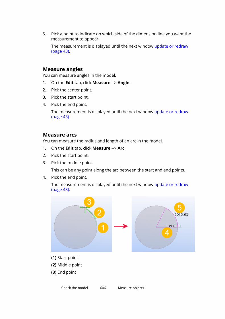
5. Pick a point to indicate on which side of the dimension line you want themeasurement to appear.
The measurement is displayed until the next window update or redraw(page 43).
Measure anglesYou can measure angles in the model.
1. On the Edit tab, click Measure --> Angle .
2. Pick the center point.
3. Pick the start point.
4. Pick the end point.
The measurement is displayed until the next window update or redraw(page 43).
Measure arcsYou can measure the radius and length of an arc in the model.
1. On the Edit tab, click Measure --> Arc .
2. Pick the start point.
3. Pick the middle point.
This can be any point along the arc between the start and end points.
4. Pick the end point.
The measurement is displayed until the next window update or redraw(page 43).
(1) Start point
(2) Middle point
(3) End point
Check the model 606 Measure objects
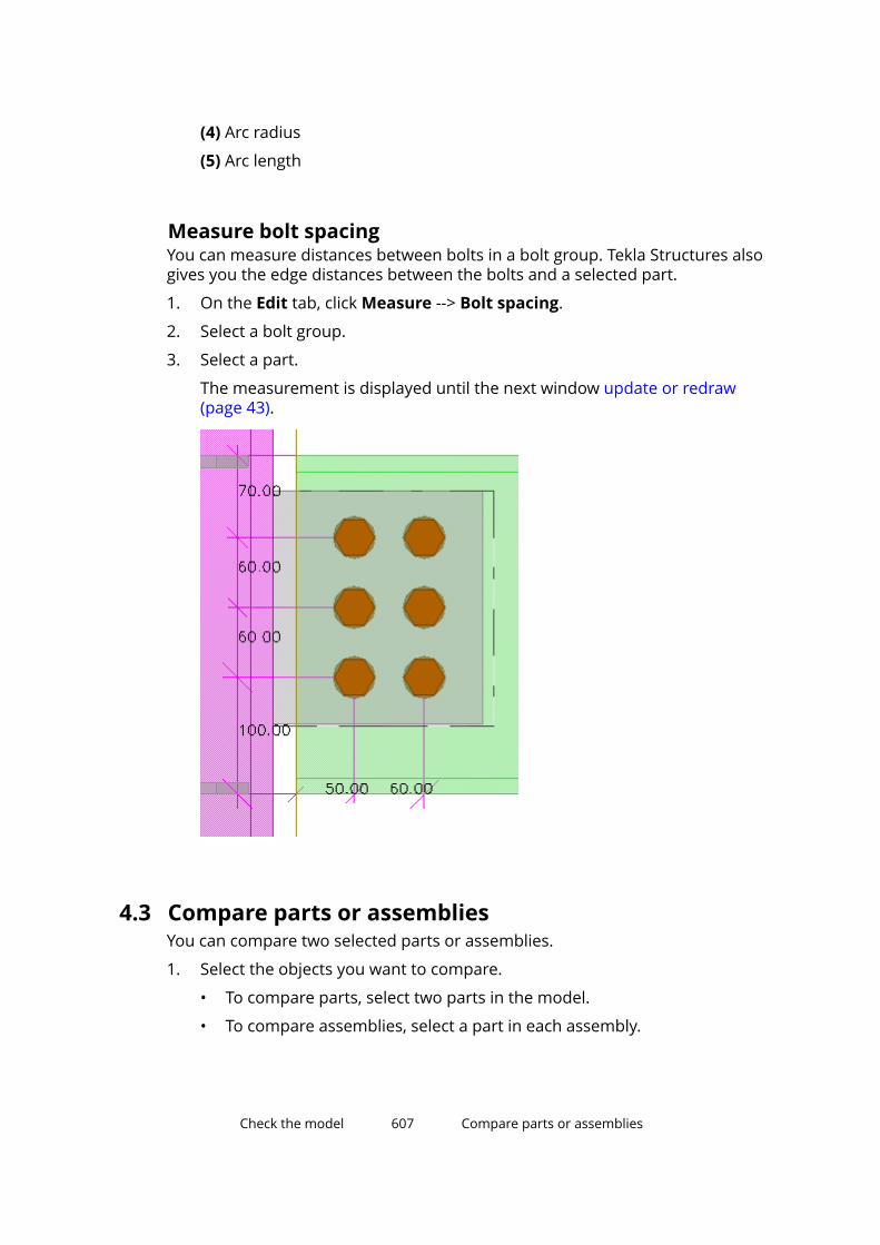
(4) Arc radius
(5) Arc length
Measure bolt spacingYou can measure distances between bolts in a bolt group. Tekla Structures alsogives you the edge distances between the bolts and a selected part.
1. On the Edit tab, click Measure --> Bolt spacing.
2. Select a bolt group.
3. Select a part.
The measurement is displayed until the next window update or redraw(page 43).
4.3 Compare parts or assembliesYou can compare two selected parts or assemblies.
1. Select the objects you want to compare.
• To compare parts, select two parts in the model.
• To compare assemblies, select a part in each assembly.
Check the model 607 Compare parts or assemblies

2. On the Edit tab, click Compare, and then select either Compare parts orCompare assemblies.
Tekla Structures displays the results on the status bar.
See also
Check the model (page 599)
4.4 Create a clip planeClip planes enable you to focus on the required detail in the model. You cancreate up to six clip planes in any model view that shows the object faces.
1. When you create clip planes, ensure that you are using a model view thatshows object faces.
On the View tab, click Rendering, and use any of the following options:
• Parts grayscale (Ctrl+3)
• Parts rendered (Ctrl+4)
• Components grayscale (Shift+3)
• Components rendered (Shift+3)
2. On the View tab, click Clip plane .
3. Move the mouse pointer over the model objects.
A green symbol indicates the object faces that you can select and align theclip plane with. The green line indicates the side that will be clipped out.For example:
Note that the snap depth (page 78) setting on the Snapping toolbaraffects the object faces you can select. Set snap depth to 3D or Auto toselect object faces in the entire 3D space.
4. Select an object face.
The clip plane symbol appears in the model:
Check the model 608 Create a clip plane
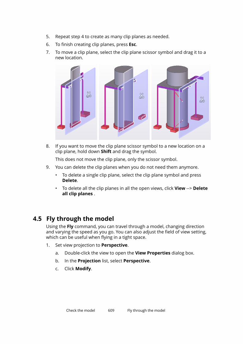
5. Repeat step 4 to create as many clip planes as needed.
6. To finish creating clip planes, press Esc.
7. To move a clip plane, select the clip plane scissor symbol and drag it to anew location.
8. If you want to move the clip plane scissor symbol to a new location on aclip plane, hold down Shift and drag the symbol.
This does not move the clip plane, only the scissor symbol.
9. You can delete the clip planes when you do not need them anymore.
• To delete a single clip plane, select the clip plane symbol and pressDelete.
• To delete all the clip planes in all the open views, click View --> Deleteall clip planes .
4.5 Fly through the modelUsing the Fly command, you can travel through a model, changing directionand varying the speed as you go. You can also adjust the field of view setting,which can be useful when flying in a tight space.
1. Set view projection to Perspective.
a. Double-click the view to open the View Properties dialog box.
b. In the Projection list, select Perspective.
c. Click Modify.
Check the model 609 Fly through the model
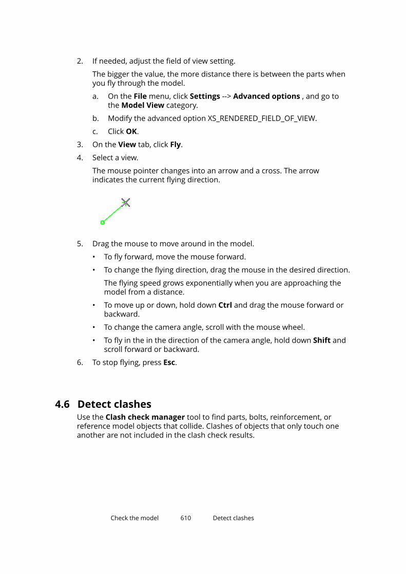
2. If needed, adjust the field of view setting.
The bigger the value, the more distance there is between the parts whenyou fly through the model.
a. On the File menu, click Settings --> Advanced options , and go tothe Model View category.
b. Modify the advanced option XS_RENDERED_FIELD_OF_VIEW.
c. Click OK.
3. On the View tab, click Fly.
4. Select a view.
The mouse pointer changes into an arrow and a cross. The arrowindicates the current flying direction.
5. Drag the mouse to move around in the model.
• To fly forward, move the mouse forward.
• To change the flying direction, drag the mouse in the desired direction.
The flying speed grows exponentially when you are approaching themodel from a distance.
• To move up or down, hold down Ctrl and drag the mouse forward orbackward.
• To change the camera angle, scroll with the mouse wheel.
• To fly in the in the direction of the camera angle, hold down Shift andscroll forward or backward.
6. To stop flying, press Esc.
4.6 Detect clashesUse the Clash check manager tool to find parts, bolts, reinforcement, orreference model objects that collide. Clashes of objects that only touch oneanother are not included in the clash check results.
Check the model 610 Detect clashes
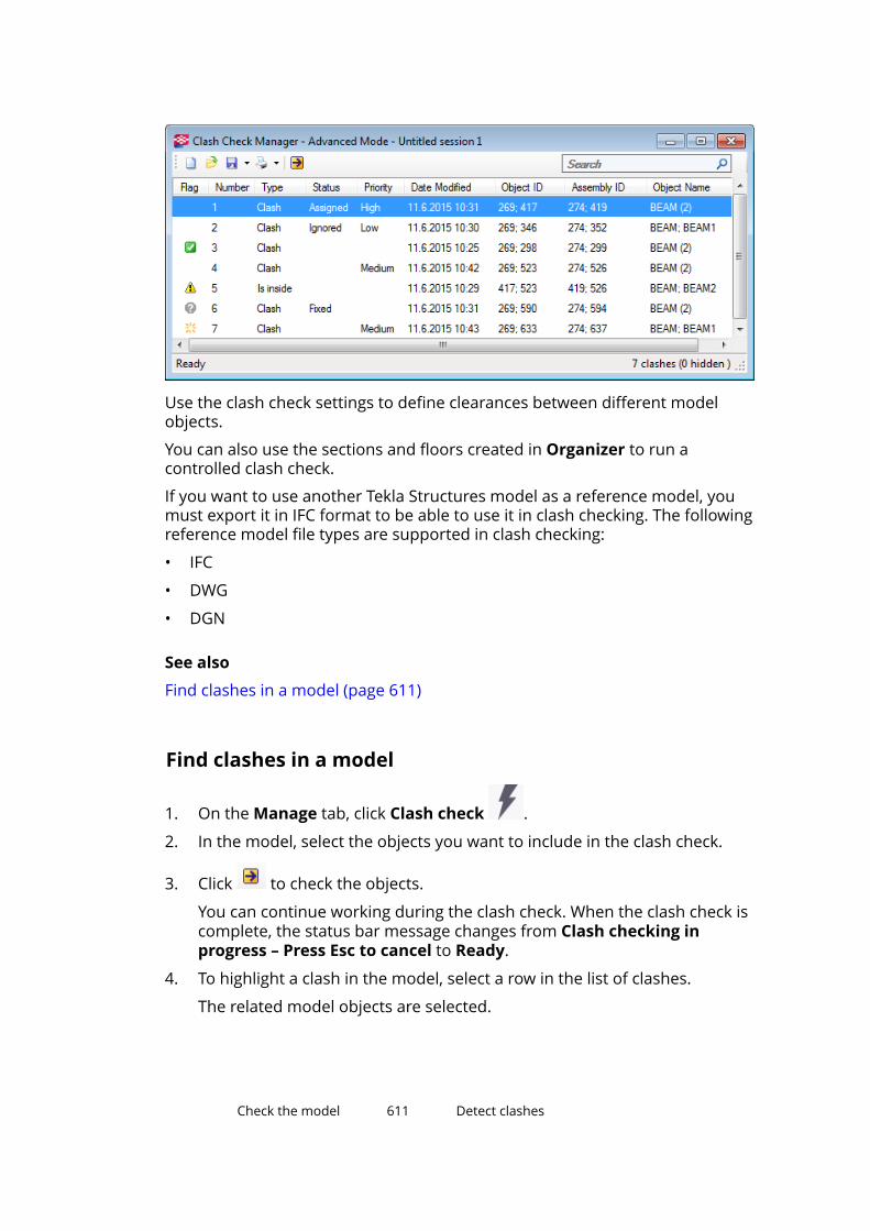
Use the clash check settings to define clearances between different modelobjects.
You can also use the sections and floors created in Organizer to run acontrolled clash check.
If you want to use another Tekla Structures model as a reference model, youmust export it in IFC format to be able to use it in clash checking. The followingreference model file types are supported in clash checking:
• IFC
• DWG
• DGN
See also
Find clashes in a model (page 611)
Find clashes in a model
1. On the Manage tab, click Clash check .
2. In the model, select the objects you want to include in the clash check.
3. Click to check the objects.
You can continue working during the clash check. When the clash check iscomplete, the status bar message changes from Clash checking inprogress – Press Esc to cancel to Ready.
4. To highlight a clash in the model, select a row in the list of clashes.
The related model objects are selected.
Check the model 611 Detect clashes
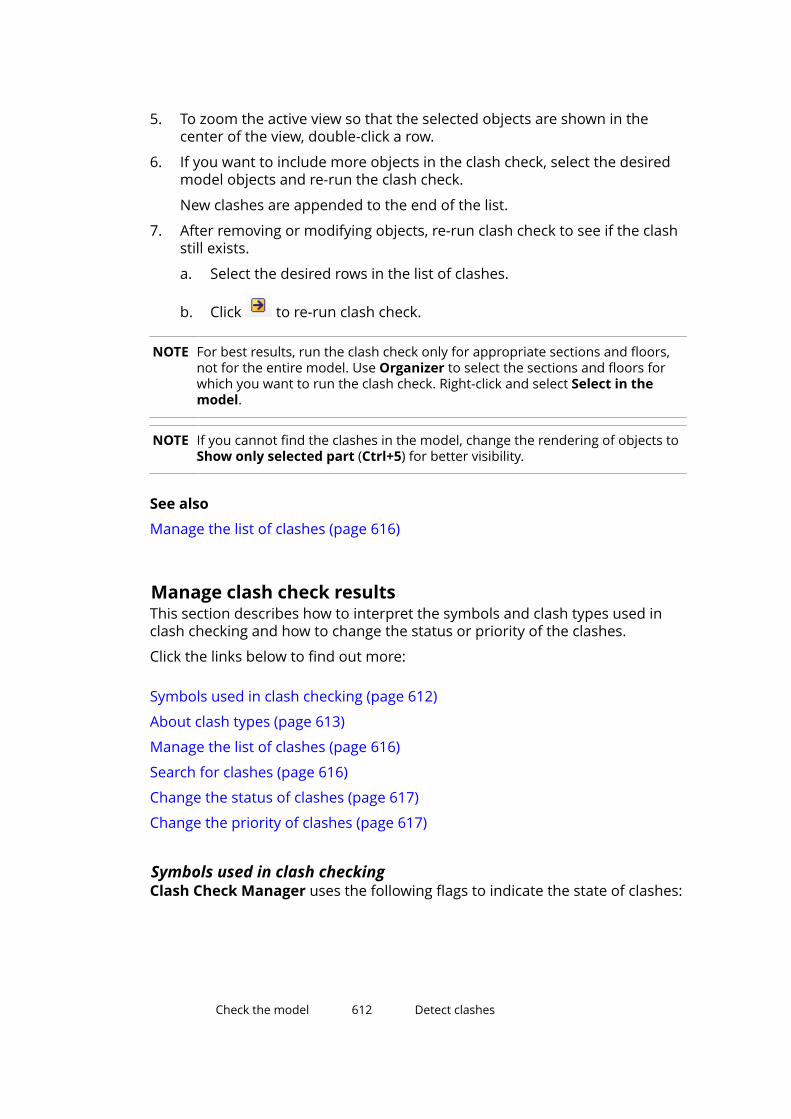
5. To zoom the active view so that the selected objects are shown in thecenter of the view, double-click a row.
6. If you want to include more objects in the clash check, select the desiredmodel objects and re-run the clash check.
New clashes are appended to the end of the list.
7. After removing or modifying objects, re-run clash check to see if the clashstill exists.
a. Select the desired rows in the list of clashes.
b. Click to re-run clash check.
NOTE For best results, run the clash check only for appropriate sections and floors,not for the entire model. Use Organizer to select the sections and floors forwhich you want to run the clash check. Right-click and select Select in themodel.
NOTE If you cannot find the clashes in the model, change the rendering of objects toShow only selected part (Ctrl+5) for better visibility.
See also
Manage the list of clashes (page 616)
Manage clash check resultsThis section describes how to interpret the symbols and clash types used inclash checking and how to change the status or priority of the clashes.
Click the links below to find out more:
Symbols used in clash checking (page 612)
About clash types (page 613)
Manage the list of clashes (page 616)
Search for clashes (page 616)
Change the status of clashes (page 617)
Change the priority of clashes (page 617)
Symbols used in clash checkingClash Check Manager uses the following flags to indicate the state of clashes:
Check the model 612 Detect clashes
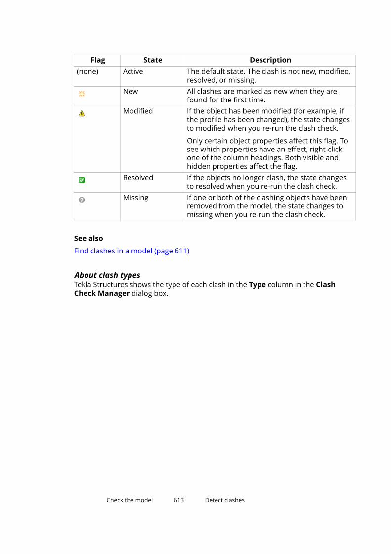
Flag State Description(none) Active The default state. The clash is not new, modified,
resolved, or missing.New All clashes are marked as new when they are
found for the first time.Modified If the object has been modified (for example, if
the profile has been changed), the state changesto modified when you re-run the clash check.
Only certain object properties affect this flag. Tosee which properties have an effect, right-clickone of the column headings. Both visible andhidden properties affect the flag.
Resolved If the objects no longer clash, the state changesto resolved when you re-run the clash check.
Missing If one or both of the clashing objects have beenremoved from the model, the state changes tomissing when you re-run the clash check.
See also
Find clashes in a model (page 611)
About clash typesTekla Structures shows the type of each clash in the Type column in the ClashCheck Manager dialog box.
Check the model 613 Detect clashes
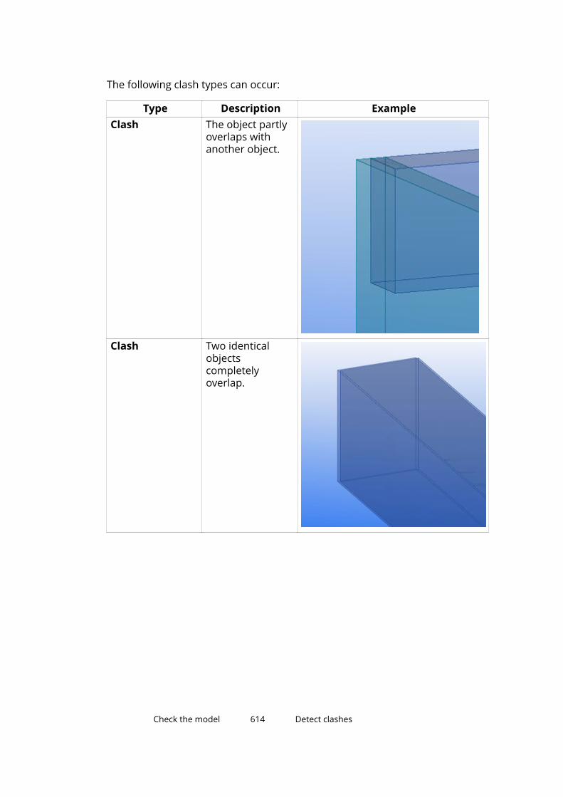
The following clash types can occur:
Type Description ExampleClash The object partly
overlaps withanother object.
Clash Two identicalobjectscompletelyoverlap.
Check the model 614 Detect clashes

Type Description ExampleClash Objects intersect
with each other inseveral locations.
Clash The object cutsthrough anotherobject.
Check the model 615 Detect clashes

Type Description ExampleIs inside The object is
inside anotherobject.
See also
Find clashes in a model (page 611)
Manage clash check results (page 612)
Manage the list of clashes
To manage the list of clashes in Clash Check Manager:
To Do thisChange the sort order of clashresults
Click the heading of the desired column toalternate between the ascending and descendingsort order.
Select multiple rows in the listof clashes
Hold down Ctrl or Shift while selecting rows.
Show or hide a column 1. Right-click one of the column headings toopen a menu.
2. Click any of the list items to show or hidethem.
A check mark in front of the item indicatesthat it is visible.
See also
Find clashes in a model (page 611)
Check the model 616 Detect clashes
Search for clashesUse the Search box to find clashes based on search terms. The more searchterms you enter, the more refined your search will be. For example, if youenter column 8112, only the clashes that match both of these terms aredisplayed.
1. Open the clash check session you want to find clashes from.
2. In the Search box, enter the words to search for.
The search results are displayed as you type.
3. To narrow your search, enter more characters.
4. To display all the clashes again, click next to the Search box.
See also
Find clashes in a model (page 611)
Change the status of clashes1. In Clash Check Manager, select the clashes whose status you want to
change.
2. Right-click one of the selected rows.
3. Select Status and then one of the status options:
• Assign
• Fix
• Approve
• Ignore
• Re-open
See also
Find clashes in a model (page 611)
Change the priority of clashes1. In Clash Check Manager, select the clashes whose priority you want to
change.
2. Right-click one of the selected rows.
3. Select Priority and then one of the status options:
• High
• Medium
• Low
Check the model 617 Detect clashes
See also
Find clashes in a model (page 611)
Group and ungroup clashesYou can combine several clashes into a group so that the clashes are treatedas a single unit.
1. In Clash Check Manager, select the clashes you want to group.
2. Right-click and select Group --> Group .
3. If you want to add clashes to an already existing group, select the clashesand the group, and then repeat step 2.
NOTE You cannot create nested groups of clashes.
4. If you want to ungroup clashes:
a. Select the clash group to ungroup.
b. Right-click and select Group --> Ungroup .
See also
Detect clashes (page 610)
View the details of a clashUse the Clash Information dialog box to view more detailed informationabout a clash.
For example, you can view the profile, material and class of the objects thatcollide. This can be useful especially when you view clash groups (page 618)that contain more than two objects.
1. Select the clash or clash group whose details you want to view.
2. Right-click and select Clash Information.
NOTE You can view information on one clash or clash group at a time. Ifyou select more than one clash or clash group, the ClashInformation option is disabled.
See also
Add comments to a clash (page 619)
View the history of a clash (page 620)
Check the model 618 Detect clashes

Add comments to a clashYou can add comments to clashes and clash groups. For example, you mightuse comments as reminders to yourself and other users.
1. Select the clash or clash group you want to comment on.
2. Right-click and select Clash Information.
3. Go to the Comments tab.
4. Click to open the Add comment dialog box.
5. Enter your comment in the Comment box.
6. Modify the author name and the date if needed.
7. Click OK.
See also
Modify a clash comment (page 619)
Remove a clash comment (page 619)
Modify a clash comment1. Select the clash or clash group (page 618) whose comment you want to
modify.
2. Right-click and select Clash Information.
3. Go to the Comments tab.
4. Select the comment you want to modify.
5. Click to open the Edit comment dialog box.
6. Modify the comment.
7. Click OK.
See also
Add comments to a clash (page 619)
Remove a clash comment (page 619)
Remove a clash comment1. Select the clash or clash group (page 618) whose comment you want to
remove.
2. Right-click and select Clash Information.
3. Go to the Comments tab.
Check the model 619 Detect clashes

4. Select the comment you want to remove.
5. Click .
See also
Add comments to a clash (page 619)
Modify a clash comment (page 619)
View the history of a clashYou can view the history of a particular clash. For example, you can see whenand by whom the clash was detected.
1. Select a clash or a clash group (page 618).
2. Right-click and select Clash Information.
3. Go to the History tab.
The history information of the clash is displayed.
See also
View the details of a clash (page 618)
Print a list of clashesYou can print lists of clashes. You can control the print settings the same wayas in any standard Windows application.
1. Open the clash check session you want to print.
2. Click Print...
3. If needed, modify the print settings.
4. Click Print....
See also
Preview a list of clashes before printing (page 620)
Set the paper size, margins and page orientation (page 621)
Preview a list of clashes before printingUse the options in the Print preview dialog box to see what a list of clasheswill look like when it is printed.
Check the model 620 Detect clashes

To preview a list of clashes:
To Do thisOpen the Print preview...dialog box
In Clash Check Manager, click the down arrow
next to and select Print preview....Select how many pages toview at a time
Click one of the Page Layout buttons:
If the list of clashes is very long, it might be spreadout on several pages.
Zoom the page in or out Click the down arrow next to and select anoption from the menu.
Print the current page Click .Close the Print preview...dialog box.
Click Close.
See also
Print a list of clashes (page 620)
Set the paper size, margins and page orientation (page 621)
Set the paper size, margins and page orientationBefore printing a list of clashes, you can set the paper size, margins, and pageorientation in the Page Setup dialog box.
NOTE The options for paper size and paper source are printer-dependent.To use different paper options, select another printer in the Printdialog box and click Apply.
1. Click the arrow next to the button and select Page setup.
2. In the Size box, select the paper size you want to use.
3. In the Source box, select the correct paper source.
4. Under Orientation, select one of the page orientation options.
• Portrait: vertical page orientation
• Landscape: horizontal page orientation
5. Under Margins, enter values for the Left, Right, Top, and Bottommargins.
6. Click OK to save the changes.
Check the model 621 Detect clashes

See also
Print a list of clashes (page 620)
Preview a list of clashes before printing (page 620)
Open and save clash check sessionsClash check sessions are saved as XML files in the ..\TeklaStructuresModels\<model>\Clashes folder. Tekla Structurescreates the folder automatically when you open Clash Check Manager for thefirst time.
To open or save sessions in Clash Check Manager, do any of the following:
To Do thisOpen a session 1.
Click .
2. In the Open dialog box, select a session.
3. Click Open.Start a new session
Click .
Clash Check Manager clears the list of clasheswithout running clash check.
Save the current sessionClick .
Save the current session with aanother name or in anotherlocation
1.Click the arrow next to the button. Amenu appears.
2.Click Save as .
3. In the Save as dialog box, browse to thefolder where you want to save the session.
4. In the File name box, enter a new name.
5. Click Save.Save only selected clashes 1. In the list of clashes, select the clashes you
want to save.
2.Click the arrow next to the button. Amenu appears.
3.Click Save selected .
See also
Detect clashes (page 610)
Check the model 622 Detect clashes
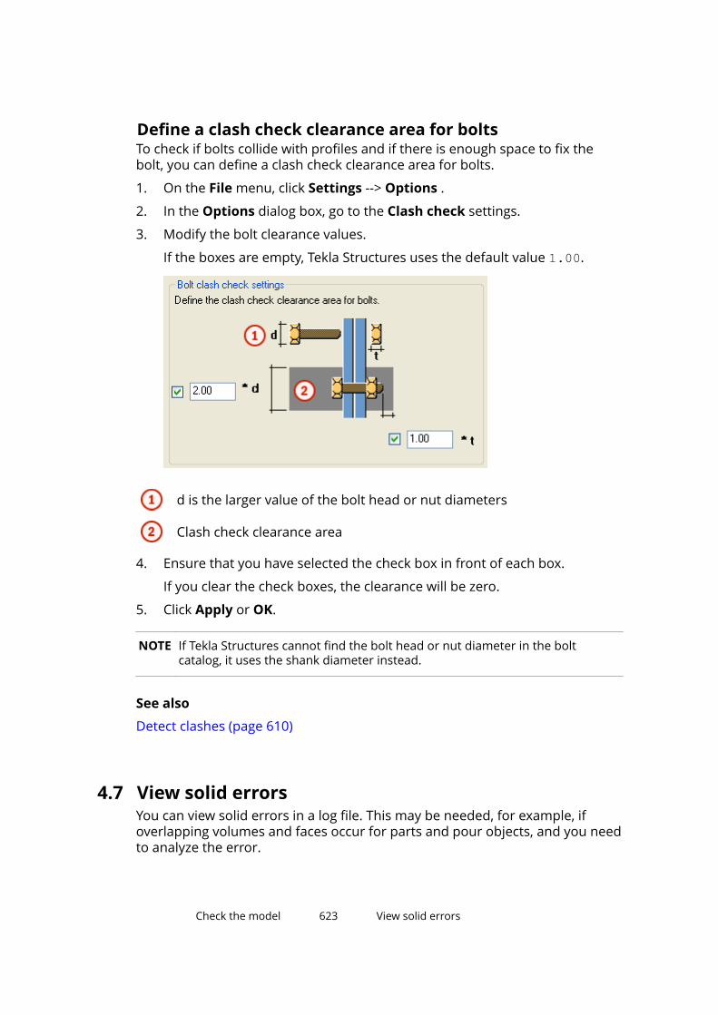
Define a clash check clearance area for boltsTo check if bolts collide with profiles and if there is enough space to fix thebolt, you can define a clash check clearance area for bolts.
1. On the File menu, click Settings --> Options .
2. In the Options dialog box, go to the Clash check settings.
3. Modify the bolt clearance values.
If the boxes are empty, Tekla Structures uses the default value 1.00.
d is the larger value of the bolt head or nut diameters
Clash check clearance area
4. Ensure that you have selected the check box in front of each box.
If you clear the check boxes, the clearance will be zero.
5. Click Apply or OK.
NOTE If Tekla Structures cannot find the bolt head or nut diameter in the boltcatalog, it uses the shank diameter instead.
See also
Detect clashes (page 610)
4.7 View solid errorsYou can view solid errors in a log file. This may be needed, for example, ifoverlapping volumes and faces occur for parts and pour objects, and you needto analyze the error.
Check the model 623 View solid errors
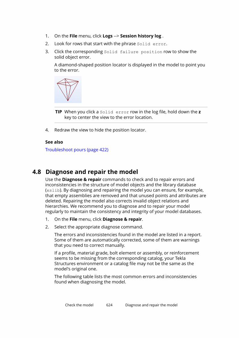
1. On the File menu, click Logs --> Session history log .
2. Look for rows that start with the phrase Solid error.
3. Click the corresponding Solid failure position row to show thesolid object error.
A diamond-shaped position locator is displayed in the model to point youto the error.
TIP When you click a Solid error row in the log file, hold down the zkey to center the view to the error location.
4. Redraw the view to hide the position locator.
See also
Troubleshoot pours (page 422)
4.8 Diagnose and repair the modelUse the Diagnose & repair commands to check and to repair errors andinconsistencies in the structure of model objects and the library database(xslib). By diagnosing and repairing the model you can ensure, for example,that empty assemblies are removed and that unused points and attributes aredeleted. Repairing the model also corrects invalid object relations andhierarchies. We recommend you to diagnose and to repair your modelregularly to maintain the consistency and integrity of your model databases.
1. On the File menu, click Diagnose & repair.
2. Select the appropriate diagnose command.
The errors and inconsistencies found in the model are listed in a report.Some of them are automatically corrected, some of them are warningsthat you need to correct manually.
If a profile, material grade, bolt element or assembly, or reinforcementseems to be missing from the corresponding catalog, your TeklaStructures environment or a catalog file may not be the same as themodel's original one.
The following table lists the most common errors and inconsistenciesfound when diagnosing the model.
Check the model 624 Diagnose and repair the model
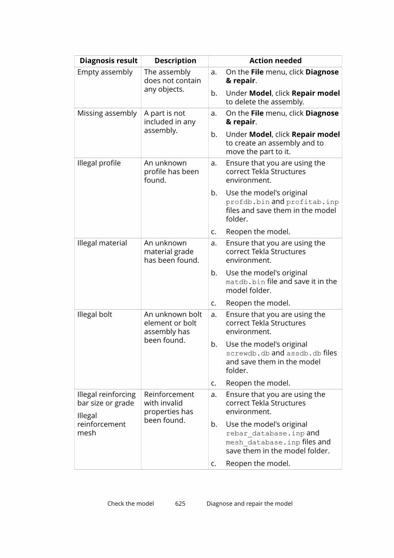
Diagnosis result Description Action neededEmpty assembly The assembly
does not containany objects.
a. On the File menu, click Diagnose& repair.
b. Under Model, click Repair modelto delete the assembly.
Missing assembly A part is notincluded in anyassembly.
a. On the File menu, click Diagnose& repair.
b. Under Model, click Repair modelto create an assembly and tomove the part to it.
Illegal profile An unknownprofile has beenfound.
a. Ensure that you are using thecorrect Tekla Structuresenvironment.
b. Use the model's originalprofdb.bin and profitab.inpfiles and save them in the modelfolder.
c. Reopen the model.Illegal material An unknown
material gradehas been found.
a. Ensure that you are using thecorrect Tekla Structuresenvironment.
b. Use the model's originalmatdb.bin file and save it in themodel folder.
c. Reopen the model.Illegal bolt An unknown bolt
element or boltassembly hasbeen found.
a. Ensure that you are using thecorrect Tekla Structuresenvironment.
b. Use the model's originalscrewdb.db and assdb.db filesand save them in the modelfolder.
c. Reopen the model.Illegal reinforcingbar size or grade
Illegalreinforcementmesh
Reinforcementwith invalidproperties hasbeen found.
a. Ensure that you are using thecorrect Tekla Structuresenvironment.
b. Use the model's originalrebar_database.inp andmesh_database.inp files andsave them in the model folder.
c. Reopen the model.
Check the model 625 Diagnose and repair the model

Diagnosis result Description Action neededInvalid rebargeometry
Reinforcementwith undefinedgeometry hasbeen found.
See Check the validity ofreinforcement geometry (page 514).
If the model does not contain any errors or inconsistencies, a message isdisplayed on the status bar.
See also
Check the model (page 599)
4.9 Find distant objectsWhen the work area is huge, the model may contain some distant objects thatare not easy to find. Use the Find distant objects command to find theseobjects.
1. On the File menu, click Diagnose & repair.
2. Under Utilities, click Find distant objects.
Tekla Structures displays a list of object GUIDs. At the end of the list, TeklaStructures displays additional six objects that have the biggest andsmallest x, y, or z coordinates.
3. Select an object in the list.
4. Right-click and select a command.
You can, for example, inquire or delete the object.
See also
Check the model (page 599)
Check the model 626 Find distant objects

5 Number the model
This section explains how to change numbering settings and apply numberingin Tekla Structures.
Click the links below to find out more:
What is numbering and how to plan it (page 627)
Adjust the numbering settings (page 636)
Number parts (page 637)
Change existing numbers (page 640)
Clear existing numbers (page 641)
Check the numbering (page 642)
View the numbering history (page 644)
Repair numbering errors (page 645)
Renumber the model (page 645)
Control numbers (page 646)
Number parts by design group (page 653)
Numbering examples (page 656)
5.1 What is numbering and how to plan itBefore you can create drawings or accurate reports, you need to number allparts in the model. You do not need to number the model before you creategeneral arrangement drawings.
Numbering is the key to the production output, for example, drawings, reports,and NC files. Numbers are also needed when you export models. Partnumbers are vital in the fabrication, shipping, and erection stages ofconstruction. Tekla Structures assigns a mark to each part and assembly/castunit in a model. The mark includes part or assembly prefix and position
Number the model 627 What is numbering and how to plan it
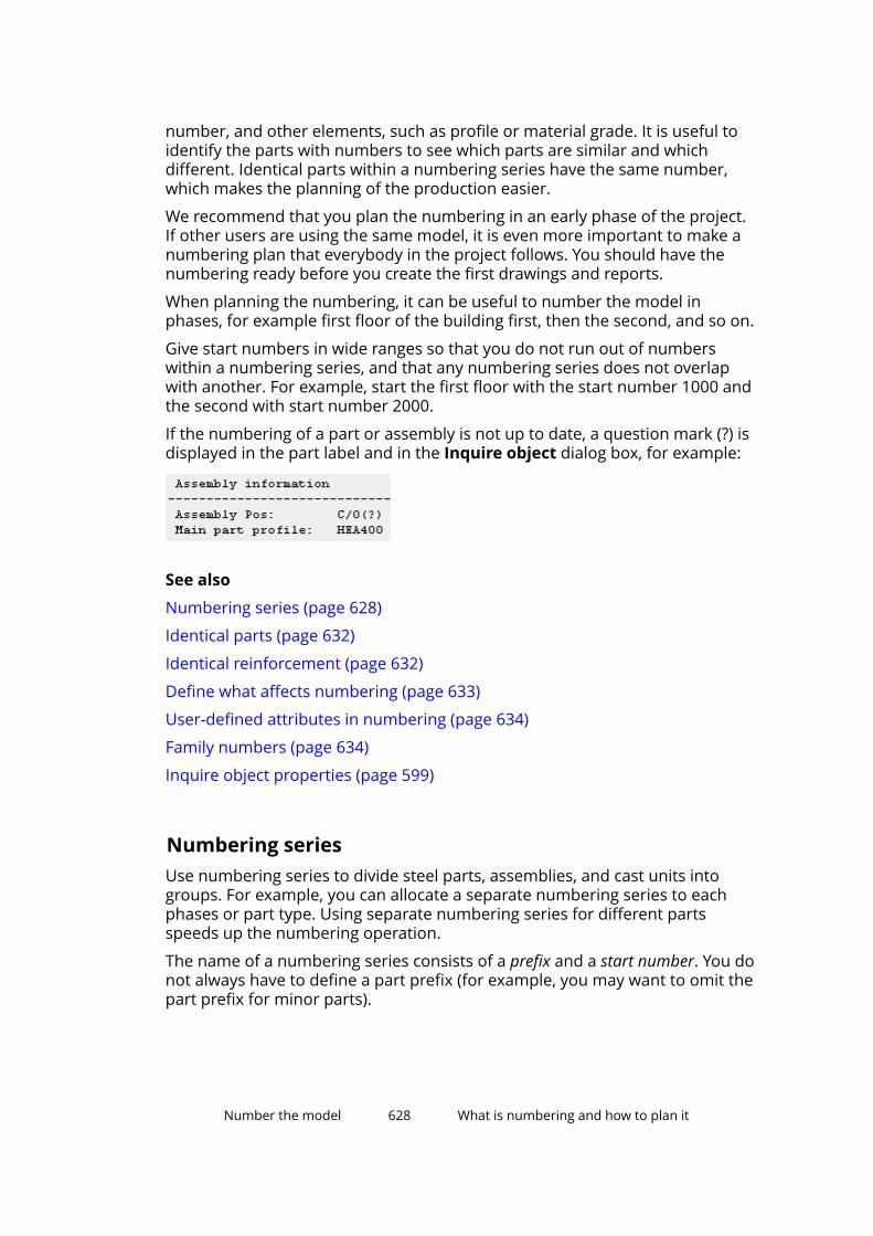
number, and other elements, such as profile or material grade. It is useful toidentify the parts with numbers to see which parts are similar and whichdifferent. Identical parts within a numbering series have the same number,which makes the planning of the production easier.
We recommend that you plan the numbering in an early phase of the project.If other users are using the same model, it is even more important to make anumbering plan that everybody in the project follows. You should have thenumbering ready before you create the first drawings and reports.
When planning the numbering, it can be useful to number the model inphases, for example first floor of the building first, then the second, and so on.
Give start numbers in wide ranges so that you do not run out of numberswithin a numbering series, and that any numbering series does not overlapwith another. For example, start the first floor with the start number 1000 andthe second with start number 2000.
If the numbering of a part or assembly is not up to date, a question mark (?) isdisplayed in the part label and in the Inquire object dialog box, for example:
See also
Numbering series (page 628)
Identical parts (page 632)
Identical reinforcement (page 632)
Define what affects numbering (page 633)
User-defined attributes in numbering (page 634)
Family numbers (page 634)
Inquire object properties (page 599)
Numbering seriesUse numbering series to divide steel parts, assemblies, and cast units intogroups. For example, you can allocate a separate numbering series to eachphases or part type. Using separate numbering series for different partsspeeds up the numbering operation.
The name of a numbering series consists of a prefix and a start number. You donot always have to define a part prefix (for example, you may want to omit thepart prefix for minor parts).
Number the model 628 What is numbering and how to plan it
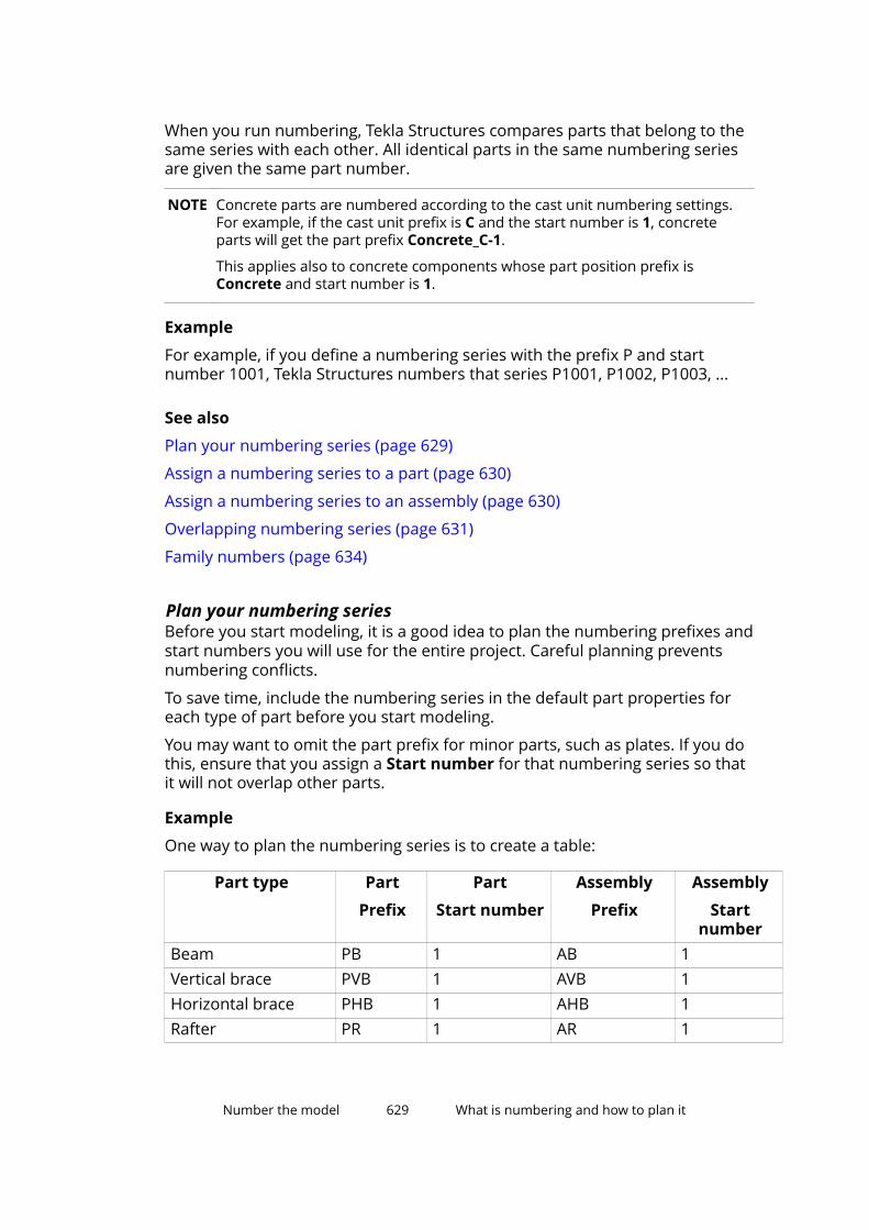
When you run numbering, Tekla Structures compares parts that belong to thesame series with each other. All identical parts in the same numbering seriesare given the same part number.
NOTE Concrete parts are numbered according to the cast unit numbering settings.For example, if the cast unit prefix is C and the start number is 1, concreteparts will get the part prefix Concrete_C-1.
This applies also to concrete components whose part position prefix isConcrete and start number is 1.
Example
For example, if you define a numbering series with the prefix P and startnumber 1001, Tekla Structures numbers that series P1001, P1002, P1003, ...
See also
Plan your numbering series (page 629)
Assign a numbering series to a part (page 630)
Assign a numbering series to an assembly (page 630)
Overlapping numbering series (page 631)
Family numbers (page 634)
Plan your numbering seriesBefore you start modeling, it is a good idea to plan the numbering prefixes andstart numbers you will use for the entire project. Careful planning preventsnumbering conflicts.
To save time, include the numbering series in the default part properties foreach type of part before you start modeling.
You may want to omit the part prefix for minor parts, such as plates. If you dothis, ensure that you assign a Start number for that numbering series so thatit will not overlap other parts.
Example
One way to plan the numbering series is to create a table:
Part type Part
Prefix
Part
Start number
Assembly
Prefix
Assembly
Startnumber
Beam PB 1 AB 1Vertical brace PVB 1 AVB 1Horizontal brace PHB 1 AHB 1Rafter PR 1 AR 1
Number the model 629 What is numbering and how to plan it
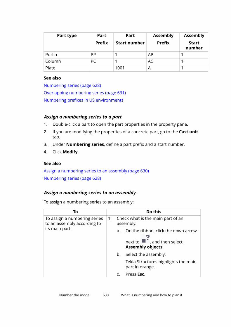
Part type Part
Prefix
Part
Start number
Assembly
Prefix
Assembly
Startnumber
Purlin PP 1 AP 1Column PC 1 AC 1Plate 1001 A 1
See also
Numbering series (page 628)
Overlapping numbering series (page 631)
Numbering prefixes in US environments
Assign a numbering series to a part1. Double-click a part to open the part properties in the property pane.
2. If you are modifying the properties of a concrete part, go to the Cast unittab.
3. Under Numbering series, define a part prefix and a start number.
4. Click Modify.
See also
Assign a numbering series to an assembly (page 630)
Numbering series (page 628)
Assign a numbering series to an assembly
To assign a numbering series to an assembly:
To Do thisTo assign a numbering seriesto an assembly according toits main part
1. Check what is the main part of anassembly.
a. On the ribbon, click the down arrow
next to , and then selectAssembly objects.
b. Select the assembly.
Tekla Structures highlights the mainpart in orange.
c. Press Esc.
Number the model 630 What is numbering and how to plan it
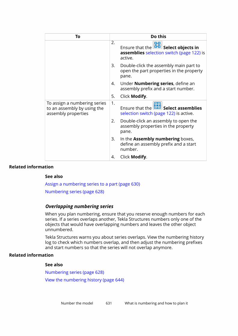
To Do this2.
Ensure that the Select objects inassemblies selection switch (page 122) isactive.
3. Double-click the assembly main part toopen the part properties in the propertypane.
4. Under Numbering series, define anassembly prefix and a start number.
5. Click Modify.To assign a numbering seriesto an assembly by using theassembly properties
1.Ensure that the Select assembliesselection switch (page 122) is active.
2. Double-click an assembly to open theassembly properties in the propertypane.
3. In the Assembly numbering boxes,define an assembly prefix and a startnumber.
4. Click Modify.
Related information
See also
Assign a numbering series to a part (page 630)
Numbering series (page 628)
Overlapping numbering seriesWhen you plan numbering, ensure that you reserve enough numbers for eachseries. If a series overlaps another, Tekla Structures numbers only one of theobjects that would have overlapping numbers and leaves the other objectunnumbered.
Tekla Structures warns you about series overlaps. View the numbering historylog to check which numbers overlap, and then adjust the numbering prefixesand start numbers so that the series will not overlap anymore.
Related information
See also
Numbering series (page 628)
View the numbering history (page 644)
Number the model 631 What is numbering and how to plan it
Identical partsTekla Structures gives parts the same number if the parts are identical in thefabrication or casting. If a part is deformed after fabrication or casting (forexample if the part is cambered, shortened, or warped), the final geometry onsite and in the model may be different.
Tekla Structures treats parts as identical and gives them the same number ifthe following basic part properties are the same:
• Part geometry
• Casting direction
• Numbering series
• Profile
• Material
• Finish
• Shortening
You can set the degree of tolerance for part geometry in the NumberingSetup dialog box. If the geometry of parts differs within this degree oftolerance, Tekla Structures treats the parts as identical for numberingpurposes.
Class does not affect numbering. Tekla Structures gives the same number toidentical parts that belong to different classes.
If you have created NC files, pop marks and contour marking affectnumbering.
See also
Casting direction (page 399)
Define what affects numbering (page 633)
User-defined attributes in numbering (page 634)
Identical reinforcementTekla Structures treats reinforcing bars as identical, and gives them the samenumber, if the following properties are the same:
• Bar geometry
• Numbering series
• Size
• Grade
Number the model 632 What is numbering and how to plan it
• Bending radius
Class does not affect numbering. Tekla Structures gives the same number toidentical reinforcing bars that belong to different classes.
The modeling direction of tapered reinforcing bar groups affects numbering.This means that identical bar groups with different modeling directions receivedifferent numbers.
The bar length rounding, step tapering, and some other rebar set settingsaffect bar geometry and thus the numbering of rebar set bars. The roundingsettings that are defined in the rebar_config.inp file for drawings andreports do not affect numbering.
See also
Create reinforcement (page 427)
Define what affects numberingTo define which properties affect numbering in your model, modify thesettings in the Numbering Setup dialog box.
You can have Tekla Structures compare the following properties:
• Holes (if created with the Bolt command)
• Part name
• Beam orientation
• Column orientation
• Assembly name
• Assembly phase (XS_ENABLE_PHASE_OPTION_IN_NUMBERING set to TRUE)
• Reinforcement
• Embedded objects (affect only cast units)
• Surface treatment (affects only assemblies)
• Welds (affect only assemblies)
If these properties differ, Tekla Structures treats objects as different, andtherefore numbers them differently.
For example, if two otherwise identical parts have different names and youselect the Part name check box, Tekla Structures gives the parts differentnumbers.
By default, a part retains its number, as long as only one part has thatparticular number, regardless of the settings in the Numbering Setup dialogbox.
Number the model 633 What is numbering and how to plan it
See also
Adjust the numbering settings (page 636)
What is numbering and how to plan it (page 627)
Identical parts (page 632)
Identical reinforcement (page 632)
User-defined attributes in numbering (page 634)
General numbering settings (page 923)
User-defined attributes in numberingYou can set in the objects.inp file whether a user-defined attribute affectsnumbering or not. Tekla Structures treats parts and reinforcing bars asdifferent, and therefore numbers them differently, if the values of the user-defined attribute differ.
NOTE Only user-defined attributes of parts and reinforcement can affectnumbering. User-defined attributes of other objects, such as phases, projectsand drawings do not affect numbering.
If you want Tekla Structures to consider a user-defined attribute whennumbering, set the special_flag option of the attribute to yes in the Partattributes section of objects.inp. For reinforcement, you need to set special_flag to yes also in the Reinforcing bar attributes section.Tekla Structures assigns different numbers to parts or reinforcement that areotherwise identical but have different values for this user-defined attribute.
If you want Tekla Structures to ignore a user-defined attribute whennumbering, set the special_flag option to no in objects.inp.
Related information
See also
Examples of user-defined attributes (UDAs) for parts (page 319)
Select and change the profile or material of a part (page 316)
Define what affects numbering (page 633)
Family numbersWith family numbering you can group objects within the same numberingseries into different “families”. This can be used, for example, to find similarcast units that can be cast in the same bed.
Number the model 634 What is numbering and how to plan it

When you use family numbering, the cast unit position numbers consist of afamily number and a qualifier. For example:
1. Family number
2. Qualifier
Assemblies and cast units that match the comparison criteria you define in theNumbering Setup dialog box get the same family number. However, if theyhave the same family number but different part geometry or materials, theyget unique qualifier numbers.
See also
Numbering series (page 628)
Assign family numbers (page 635)
Change the family number of an object (page 636)
Example: Use family numbers (page 656)
Assign family numbers1. On the Drawings & reports tab, click Numbering settings -->
Numbering settings to open the Numbering Setup dialog box.
2. Go to the Family numbering tab.
3. Define which numbering series to assign family numbers to.
a. Click Add series to open the Add series dialog box.
Tekla Structures displays all the assembly and cast unit numberingseries in the model.
b. Select a numbering series from the list, and then click Add.
The numbering series appears in the family numbering list.
4. Under Compare, select the properties that need to be identical for themembers of the same family.
Define comparison criteria for each numbering series separately.
Select at least one check box, but not all of them. If you select all the checkboxes, the family number will be the same as the normal assemblyposition, and the qualifier number will be 1 for all. If you do not select anycheck boxes, only one family number per series is assigned.
Number the model 635 What is numbering and how to plan it
5. Click Apply.
Tekla Structures stores the settings in the numbering database file(<model_name>.db2) in the current model folder the next time you savethe model.
6. If you are assigning family numbers to parts that have already beennumbered, clear the existing numbers.
7. Update numbering in the model.
Tekla Structures assigns a family number to all objects in the numberingseries.
See also
Family numbers (page 634)
Clear existing numbers (page 641)
Change the family number of an objectYou can change the family number and/or family qualifier of an object.
1. Select the objects whose family numbers you want to change.
2. On the Drawings & reports tab, click Change number --> Change familynumber .
3. In the Assign Family Number dialog box, enter the desired values in theFamily number and Family qualifier boxes.
4. Click Assign.
See also
Family numbers (page 634)
5.2 Adjust the numbering settingsYou can adjust the numbering settings to better suit your needs. This shouldbe done early in the project, before creating any drawings or reports. Do notchange your numbering conventions in the middle of a project.
1. On the Drawings & reports tab, click Numbering settings -->Numbering settings to open the Numbering Setup dialog box.
2. Modify the settings if necessary.
For example, you can define which part properties affect numbering inyour model. Using the default settings is effective in most cases.
3. Click Apply or OK.
Number the model 636 Adjust the numbering settings
NOTE Always check and repair numbering after you have changed thenumbering settings.
See also
Define what affects numbering (page 633)
Numbering settings during a project (page 661)
Repair numbering errors (page 645)
5.3 Number partsUse the Number modified objects command to number all parts that havebeen created or modified since the last numbering. If this is the first time yourun numbering for this model, all parts in the model are new and will thereforebe numbered.
If the model has changed since the last numbering so that a modified partbecomes identical to an unmodified part, Tekla Structures updates the partnumbers in the following way when you run numbering:
• If both or none of the parts have drawings, the unmodified part will keepits number.
• If one of the parts has a drawing and the other one does not, the numberof the part that has a drawing will stay the same, and the number of thepart that does not have a drawing will change.
To number new and modified parts:
• On the Drawings & reports tab, click Perform numbering --> Numbermodified objects .
Tekla Structures numbers the parts.
See also
Number a series of parts (page 637)
Number assemblies and cast units (page 638)
Number reinforcement (page 639)
Number welds (page 640)
Save preliminary numbers (page 640)
Number parts by design group (page 653)
Number the model 637 Number parts
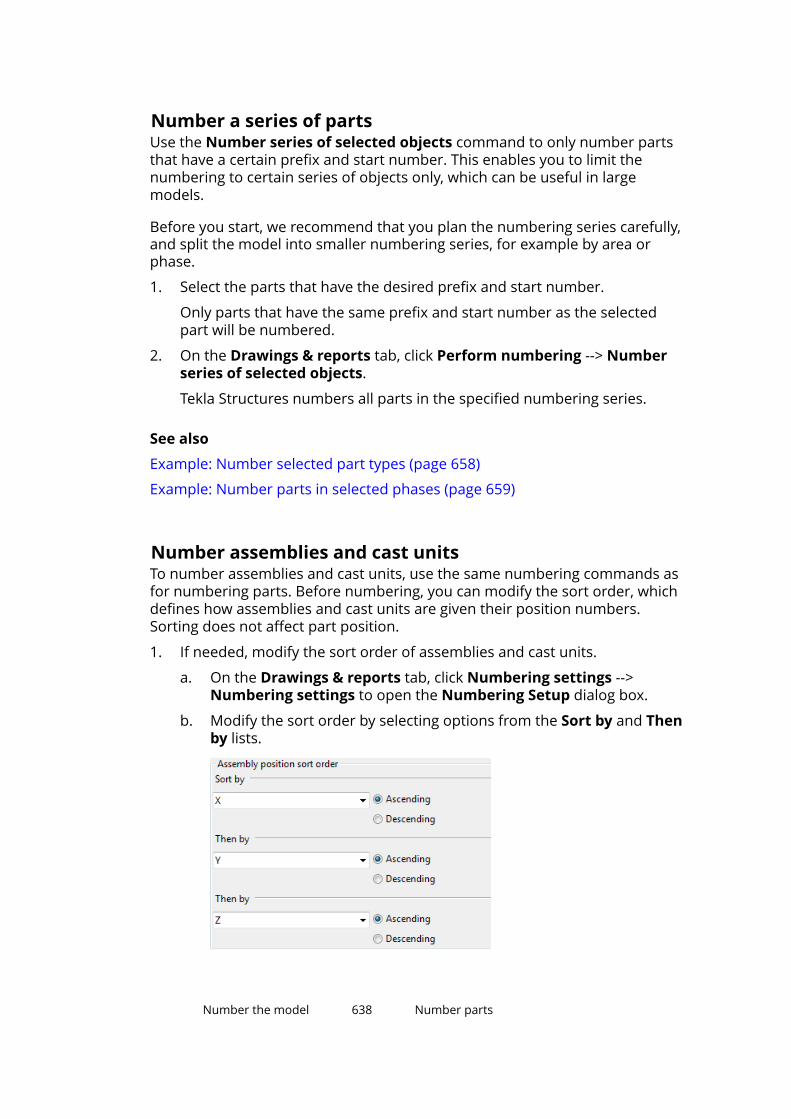
Number a series of partsUse the Number series of selected objects command to only number partsthat have a certain prefix and start number. This enables you to limit thenumbering to certain series of objects only, which can be useful in largemodels.
Before you start, we recommend that you plan the numbering series carefully,and split the model into smaller numbering series, for example by area orphase.
1. Select the parts that have the desired prefix and start number.
Only parts that have the same prefix and start number as the selectedpart will be numbered.
2. On the Drawings & reports tab, click Perform numbering --> Numberseries of selected objects.
Tekla Structures numbers all parts in the specified numbering series.
See also
Example: Number selected part types (page 658)
Example: Number parts in selected phases (page 659)
Number assemblies and cast unitsTo number assemblies and cast units, use the same numbering commands asfor numbering parts. Before numbering, you can modify the sort order, whichdefines how assemblies and cast units are given their position numbers.Sorting does not affect part position.
1. If needed, modify the sort order of assemblies and cast units.
a. On the Drawings & reports tab, click Numbering settings -->Numbering settings to open the Numbering Setup dialog box.
b. Modify the sort order by selecting options from the Sort by and Thenby lists.
Number the model 638 Number parts

The default sort order is XYZ. You have the following options:
• The x, y or z coordinates of the main part of the assembly or castunit
The sorting is based on the center of gravity (COG) location of theassembly or cast unit. Tekla Structures finds the center of gravityfor each assembly and cast unit and compares them in the orderyou defined.
• The user-defined attribute of an assembly or the main part
If your sorting is based on user-defined attributes, TeklaStructures displays a list that includes all the available user-defined attributes.
c. Click Apply or OK to save the changes.
2. If needed, modify the other numbering settings.
3. On the Drawings & reports tab, click Perform numbering --> Numbermodified objects to number the model.
NOTE If you add new parts in the model, parts that have already been numbered arenot renumbered to suit the sorting order. In this case you should check andrepair the numbering of those parts.
See also
Repair numbering errors (page 645)
Number reinforcementTo number reinforcement, use the same numbering commands as fornumbering parts.
Note that reinforcement may affect the numbering of parts and cast units. Toforce Tekla Structures to give otherwise identical concrete parts and cast unitsdifferent numbers if they have different reinforcement, select the Reinforcingbars check box in the Numbering Setup dialog box.
Part numbering and cast unit numbering do not affect the numbering ofreinforcement.
See also
Number parts (page 637)
Identical reinforcement (page 632)
Define what affects numbering (page 633)
User-defined attributes in numbering (page 634)
Assign running numbers to reinforcement (page 517)
Number the model 639 Number parts

Number weldsUse the Number welds command to assign numbers to welds. Weld numbersare displayed in drawings and reports.
1. On the Drawings & reports tab, click Perform numbering --> Numberwelds to open the Weld Numbering dialog box.
2. If needed, modify the weld numbering settings (page 925).
For example, you can define whether to assign numbers for All welds orSelected welds.
3. If you selected to assign numbers to certain welds only, select the welds.
4. Click Assign numbers to start numbering welds.
See also
Number parts (page 637)
Save preliminary numbersPreliminary mark is a user-defined attribute that defines the part positionnumber. You can save the current part position numbers as preliminarynumbers for selected parts. The previous preliminary numbers are overridden.
1. Select the parts.
2. On the Drawings & reports tab, click Numbering settings --> Savepreliminary numbers .
See also
Number parts (page 637)
5.4 Change existing numbersUse the Change number commands to change the existing part, assembly,multi-position, or family numbers into something you have defined yourself.These commands do not change the numbering series of parts. To preventdrawing, modeling, and fabrication errors, Tekla Structures does not allow youto use identical numbers for two different assemblies or parts.
1. On the Drawings & reports tab, click Change number and select one ofthe following commands:
• Change part number
• Change assembly number
• Change part multinumber
Number the model 640 Change existing numbers

• Change assembly multinumber
• Change family number
The corresponding dialog box appears.
2. Select a part in the model.
3. Click Get to view the current numbering properties of the part.
4. Enter the numbering properties you want to use for this part.
Note that the position numbers you enter here are not absolute numbers.For example, if the start number of the series is 100, the positionnumbers refer to numbers in that series. Therefore, position number 1 isactually 100, position number 2 is 101, position number 3 is 102, and soon.
5. If you are changing the assembly number of selected parts, ensure thatthe Assign to option is set to Selected objects only.
Otherwise, all parts with the same original number will be renumbered.
6. Click Assign to change the number.
If the number you specified is already in use, Tekla Structures displays awarning and keeps the original number.
Tekla Structures also displays a warning if the position number is higherthan the highest current number. This is for information only and thenumber is still changed.
See also
Number parts (page 637)
5.5 Clear existing numbersUse the Clear commands to permanently remove the current positionnumbers of parts. Next time you run numbering, Tekla Structures assigns newnumbers to these parts, irrespective of what their previous numbers were.
1. Select the parts whose numbers you want to clear.
2. On the Drawings & reports tab, click Change number and select one ofthe following commands:
• Clear part and assembly numbers
• Clear part numbers
• Clear assembly numbers
• Clear reinforcing bar numbers
Tekla Structures removes the position numbers of the selected parts.
Number the model 641 Clear existing numbers
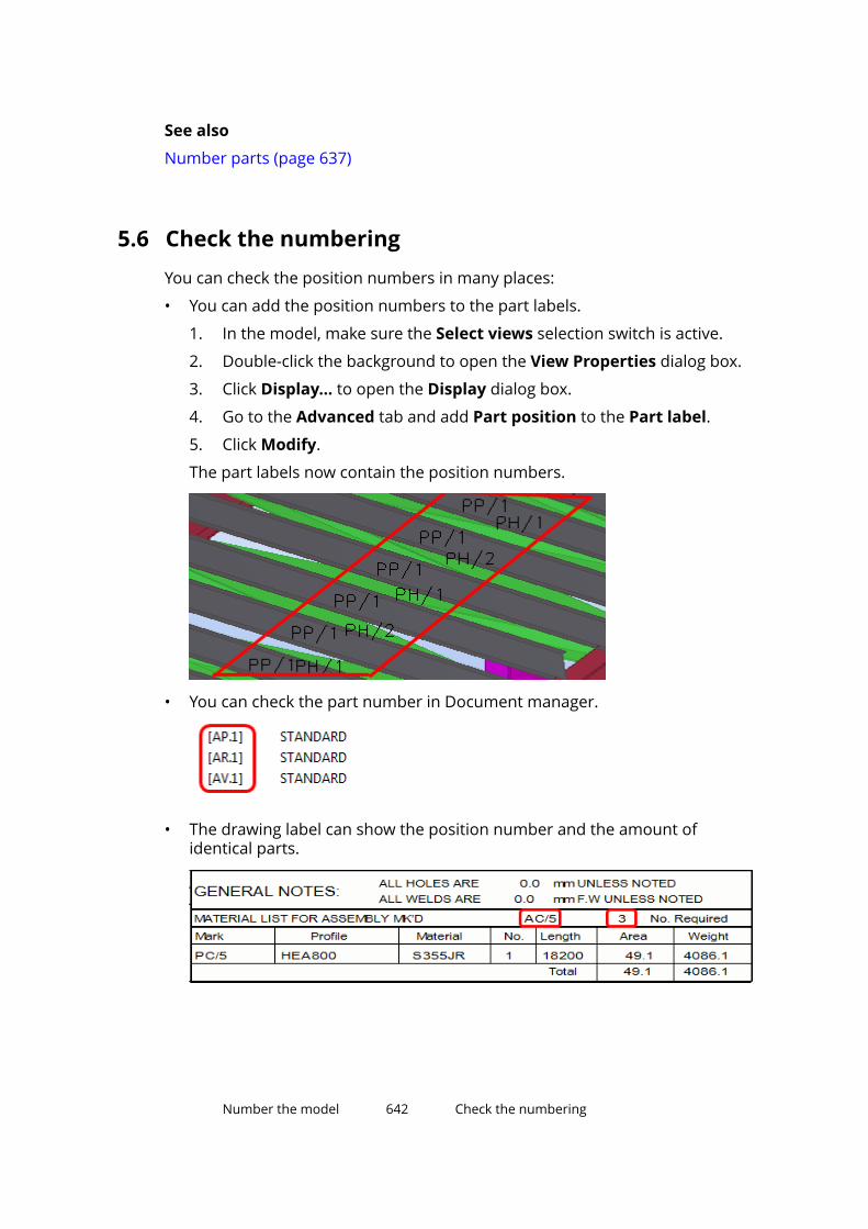
See also
Number parts (page 637)
5.6 Check the numberingYou can check the position numbers in many places:
• You can add the position numbers to the part labels.
1. In the model, make sure the Select views selection switch is active.
2. Double-click the background to open the View Properties dialog box.
3. Click Display... to open the Display dialog box.
4. Go to the Advanced tab and add Part position to the Part label.
5. Click Modify.
The part labels now contain the position numbers.
• You can check the part number in Document manager.
• The drawing label can show the position number and the amount ofidentical parts.
Number the model 642 Check the numbering

• You can use the Inquire commands.
Number the model 643 Check the numbering
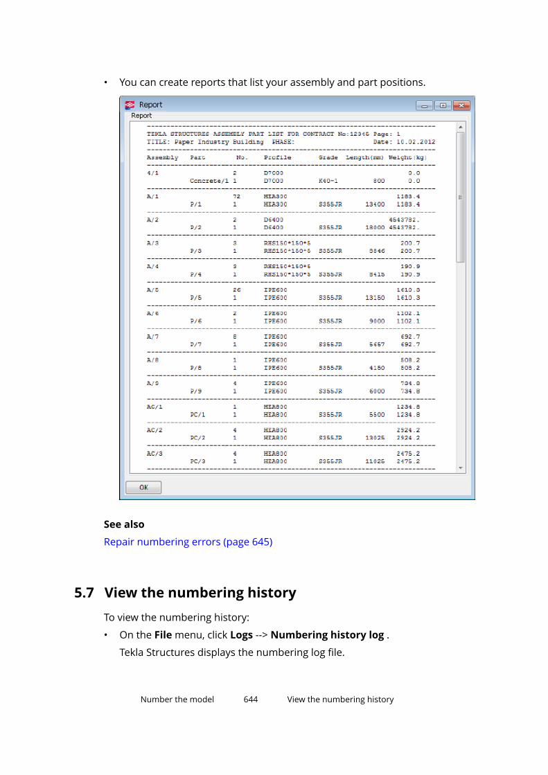
• You can create reports that list your assembly and part positions.
See also
Repair numbering errors (page 645)
5.7 View the numbering historyTo view the numbering history:
• On the File menu, click Logs --> Numbering history log .
Tekla Structures displays the numbering log file.
Number the model 644 View the numbering history

5.8 Repair numbering errorsWe recommend that you check and repair numbering in the model every nowand then, especially before producing drawings or reports.
NOTE If you work in the multi-user mode, it is very important that you repairnumbering regularly.
1. On the Drawings & reports tab, click Numbering settings -->Numbering settings to open the Numbering Setup dialog box.
2. Ensure that the option Compare to old is selected for New parts.
3. Ensure that one of the following options is selected for Modified parts:
• Compare to old
• Keep number if possible
4. Click OK to save the changes.
5. Unless you want to repair the entire model, select the objects whosenumbering you want to repair.
6. On the File menu, click Diagnose & repair and select one of the followingcommands under Numbering:
• Diagnose and repair numbering: all
This command numbers all parts and assemblies, even the unmodifiedones.
• Diagnose and repair numbering: series of selected objects
This command numbers all parts and assemblies that have the sameprefix and start number as the selected part.
Note that Tekla Structures assigns the position number of the oldestpart or assembly to all identical parts, even if a newer part or assemblyhas a smaller position number.
TIP To manually assign a certain position number on a part orassembly, use the Change number command after repairingnumbering in the model.
See also
Change existing numbers (page 640)
Number the model 645 Repair numbering errors
5.9 Renumber the modelUse the Renumber all option when the numbering needs to be started over.This option permanently removes the existing position numbers and resetsthem with new ones. Any existing drawings will also be removed.
1. On the Drawings & reports tab, click Numbering settings -->Numbering settings to open the Numbering Setup dialog box.
2. Select the Renumber all check box.
3. Click Apply or OK.
4. On the Drawings & reports tab, click Perform numbering --> Numbermodified objects .
5. When you are asked to confirm the renumbering of the model, click Yes.
Tekla Structures renumbers the entire model.
See also
Change existing numbers (page 640)
Clear existing numbers (page 641)
5.10 Control numbersControl numbers are additional numbers that can be used to identify parts ina model. Use control numbers if you need to give additional, unique numbersto assemblies or cast units, regardless of their position numbers.
Control numbers can be useful, for example, when delivering a large numberof similar wall elements to the site. To successfully pack and unpack the load,you need to plan the order of the wall elements already when the order isshipped. Although all of the wall elements may have the same cast unitposition number, you can assign a unique control number to each individualwall element.
See also
Assign control numbers to parts (page 646)
Control number order (page 647)
Display control numbers in the model (page 649)
Remove control numbers (page 650)
Lock or unlock control numbers (page 651)
Example: Use control numbers to indicate the erection order (page 651)
Number the model 646 Control numbers
Assign control numbers to parts1. On the Drawings & reports tab, click Numbering settings --> Assign
control numbers to open the Create control numbers dialog box.
2. Indicate which parts to assign control numbers to.
• To number the entire model, do not select any parts.
• To only number specific parts, select the parts you want to number.
3. If you want to assign control numbers only to parts in a specificnumbering series:
a. In the Numbering list, select By numbering serie.
b. Enter the Prefix and Start number in the corresponding boxes.
4. Define the control numbers to be used.
a. In the Start number of control numbers box, enter the first controlnumber to be used.
b. In the Step value box, define the control number interval.
For example, to assign the control numbers 2, 5, 8, 11, and so on,enter 2 in the Start number of control numbers box and 3 in theStep value box.
5. Use the Renumber list to specify how to treat parts that already havecontrol numbers.
• Select No to keep the existing control numbers.
• Select Yes to replace the existing control numbers with new ones.
6. Use the First direction, Second direction, and Third direction lists todefine the order of control numbers.
7. In the Write UDA to list, select where to save the control numbers. Thecontrol number will appear on the Parameters tab in the user-definedattributes dialog box either for:
• Assembly
• Main part
8. Click Apply to save the changes.
9. Click Create to number the parts.
See also
Control number order (page 647)
Control number settings (page 925)
Number the model 647 Control numbers
Control number orderWhen you assign control numbers, you must define in what order to assignthem. The order is based on the location of each part on the global coordinatesystem.
The options are:
• None
• X
• Y
• Z
• -X
• -Y
• -Z
With positive directions (X, Y, and Z), the parts with the lowest coordinate valueare numbered first. With negative directions (-X, -Y, and -Z), the parts with thehighest coordinate value are numbered first.
For example, if the first direction is X, the second direction is Y, and the thirddirection is Z, numbering starts from the parts that have the lowest xcoordinate value. If multiple parts have the same x coordinate, also their ycoordinates are compared. If multiple parts have the same x and ycoordinates, also their z coordinates are compared.
Example
In the following example, the first direction is X and the second direction is Y.The numbers 1–8 indicate the control numbers.
Number the model 648 Control numbers

See also
Assign control numbers to parts (page 646)
Display control numbers in the modelIf the control numbers are not displayed in the model, you can set them visibleusing the display settings.
1. Double-click the view to open the View Properties dialog box.
2. Click Display... and go to the Advanced tab.
3. Select the Part label check box.
4. In the Properties list, select User-defined attributes, and then click Add>.
The Part label dialog box is displayed.
5. Enter ACN and click OK.
The property is moved to the Part label list.
6. Click Modify.
The control numbers are displayed in the model, right after the partposition numbers.
Number the model 649 Control numbers
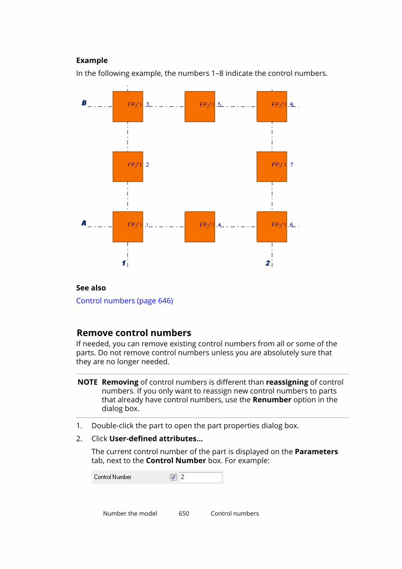
Example
In the following example, the numbers 1–8 indicate the control numbers.
See also
Control numbers (page 646)
Remove control numbersIf needed, you can remove existing control numbers from all or some of theparts. Do not remove control numbers unless you are absolutely sure thatthey are no longer needed.
NOTE Removing of control numbers is different than reassigning of controlnumbers. If you only want to reassign new control numbers to partsthat already have control numbers, use the Renumber option in the dialog box.
1. Double-click the part to open the part properties dialog box.
2. Click User-defined attributes...
The current control number of the part is displayed on the Parameterstab, next to the Control Number box. For example:
Number the model 650 Control numbers
3. Remove the existing control number from the box.
4. Click Modify to apply the change.
See also
Control numbers (page 646)
Lock or unlock control numbersTo prevent other users from changing the control numbers of some or all ofthe parts in the model, use the Lock/unlock control numbers command.Later on, if the control numbers need to be changed, you can use the samecommand for unlocking the numbers.
1. On the Drawings & reports tab, click Numbering settings --> Lock/unlock control numbers to open the Lock/Unlock control numbersdialog box.
2. Define which parts’ control numbers to lock or unlock.
• To lock or unlock the control numbers of all parts, do not select anyparts in the model.
• To lock or unlock the control numbers of specific parts only, select theparts in the model.
3. In the Status list, select Lock or Unlock.
4. Click Apply to save the changes.
5. Click Create to lock or unlock the numbers.
See also
Control numbers (page 646)
Example: Use control numbers to indicate the erectionorderThis example shows how to assign control numbers to six concrete walls. Asfour of these walls have the same cast unit position, you cannot make a cleardistinction between the cast units based on their position number. That is whyeach wall will get a unique identifier that indicates their erection order at thesite. The erection order also affects the order of shipping. For example, thewall number 1 needs to be shipped on top of the delivery, because it will beerected first on the site; the wall number 2 should be the second on thebundle, because it will be erected next; and so on.
Number the model 651 Control numbers

The following image represents the desired end result.
Erected as 1st
Erected as 2nd
Erected as 3rd
Erected as 4th
Erected as 5th
Erected as 6th
To assign control numbers to the concrete walls:
1. On the Drawings & reports tab, click Numbering settings --> Assigncontrol numbers to open the Create control numbers dialog box.
2. Select the six concrete walls.
3. Define that you want to assign control numbers only to parts in thenumbering series S with the start number 1.
a. In the Numbering list, select By numbering serie.
b. In the Prefix box, enter S.
c. In the Start number box, enter 1.
Number the model 652 Control numbers
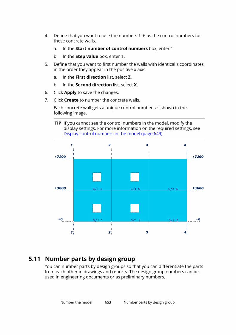
4. Define that you want to use the numbers 1–6 as the control numbers forthese concrete walls.
a. In the Start number of control numbers box, enter 1.
b. In the Step value box, enter 1.
5. Define that you want to first number the walls with identical z coordinatesin the order they appear in the positive x axis.
a. In the First direction list, select Z.
b. In the Second direction list, select X.
6. Click Apply to save the changes.
7. Click Create to number the concrete walls.
Each concrete wall gets a unique control number, as shown in thefollowing image.
TIP If you cannot see the control numbers in the model, modify thedisplay settings. For more information on the required settings, seeDisplay control numbers in the model (page 649).
5.11 Number parts by design groupYou can number parts by design groups so that you can differentiate the partsfrom each other in drawings and reports. The design group numbers can beused in engineering documents or as preliminary numbers.
Number the model 653 Number parts by design group
Design group numbers consist of a prefix, a separator, and a number or aletter.
Use the Design group numbering application to assign prefixes and numbersor letters to parts on the basis of design groups. The Design groupnumbering application groups parts that match a selection filter into a designgroup, numbers them, and optionally compares the part lengths. Theapplication also compares the user-defined attributes of parts that are set toaffect numbering.
NOTE The Design group numbering application only numbers parts thathave a profile extruded to create the length of the part, such asbeams, columns, panels, and footings. Contour plates, slabs, or itemsare not numbered.
Before you start:
• Create the needed selection filters that define the design groups.
• If you want to use certain letters in design group numbering, list theallowed letters using the advanced option XS_VALID_CHARS_FOR_ASSEMBLY_POSITION_NUMBERS. By default, letters A–Z are allowed.
• In multi-user or Tekla Model Sharing models, make sure that only one ofthe users runs the Design group numbering application.
To number parts by their design group:
1. In the model, Click the Applications & components button in theside pane to open the Applications & components catalog.
2. Click the arrow next to Applications to open the applications list.
3. Double-click Design group numbering to start the application.
4. In the Design group numbering dialog box:
a. Click Add group to create design group numbering settings for partsmatching a selection filter.
• Select the filter in the Group filter column.
The selection filters are read from specific folders in the standardfolder search order.
• Enter the design group prefix and start number or start letter youwant to use for the parts in this group.
• In the Compare length column, define whether the part lengthsare compared or not.
b. Repeat step 4a for all part groups that you want to number by designgroup.
Number the model 654 Number parts by design group

c. If needed, change the order of the groups by using the Move up andMove down buttons.
If a part belongs to several groups, the last group filter in the listoverrides the previous ones.
d. If you want to compare part lengths, define the length tolerance.
For example, if you enter 0, parts must be exactly the same length toreceive the same design group number (or letter). If you enter 2, partlengths can differ 2 mm from each other.
The default tolerance is 0.05 mm.
e. Enter a number separator that is used to separate the design groupprefix and number or letter in drawing marks and in reports. Forexample, enter - .
We recommend that you do not change the separator during theproject.
f. To reuse old, unneeded numbers or letters, select the Reuse oldnumbers check box.
g. In Number using letters, select whether to use letters or not.
h. In Renumber all, select whether to renumber all parts or not.
i. To number the parts by design group, click Perform numbering.
A design group number is saved as the user-defined attribute DESIGN_GROUP_MARK of each part.
By default, the user-defined attribute DESIGN_GROUP_MARK isavailable in the objects.inp file in the Engineering configuration inthe default and US environments.
j. To create a report to show the numbering results, select whether tocreate a report of all or the selected parts, and then click Createreport.
Tekla Structures shows the report in the List dialog box and alsosaves the report. The report is saved as dgnReport.txt in the folderdefined by the advanced option XS_REPORT_OUTPUT_DIRECTORY. Inthe Default environment, the report is saved in the \Reports folderunder the current model folder.
When you select a row in the List dialog box, Tekla Structureshighlights and selects the corresponding part in the model.
If the numbering of a part is not up to date, meaning that the part hasbeen modified after numbering, a question mark (?) is added after thedesign group number.
5. To show the design group numbers in drawing marks or in reports, usethe user-defined attribute DESIGN_GROUP_MARK.
Number the model 655 Number parts by design group
See also
Create new filters (page 158)
5.12 Numbering examplesThis section gives some examples of numbering the model.
Click the links below to find out more:
Example: Number identical beams (page 656)
Example: Use family numbers (page 656)
Example: Number selected part types (page 658)
Example: Number parts in selected phases (page 659)
Example: Number identical beamsThis example explains how different numbering settings result in different partnumbers when you modify a part.
To number identical beams:
1. Create three identical beams with the numbering series prefix P and startnumber 1.
2. Number the model. All the beams have the part position number P1.
3. Modify one of the beams.
4. Number the model. You should now have two beams P1 and one P2.
5. Change beam P2 to be identical to the others.
6. Number the model.
Depending on the numbering settings in the Numbering Setup dialogbox, Tekla Structures assigns one of the following part position numbersto the modified part:
• Compare to old: P1
• Keep number if possible: P2
• Take new number: P3
See also
Number parts (page 637)
Number the model 656 Numbering examples
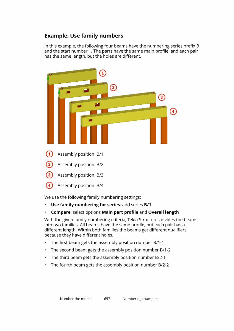
Example: Use family numbers
In this example, the following four beams have the numbering series prefix Band the start number 1. The parts have the same main profile, and each pairhas the same length, but the holes are different.
Assembly position: B/1
Assembly position: B/2
Assembly position: B/3
Assembly position: B/4
We use the following family numbering settings:
• Use family numbering for series: add series B/1
• Compare: select options Main part profile and Overall length
With the given family numbering criteria, Tekla Structures divides the beamsinto two families. All beams have the same profile, but each pair has adifferent length. Within both families the beams get different qualifiersbecause they have different holes.
• The first beam gets the assembly position number B/1-1
• The second beam gets the assembly position number B/1-2
• The third beam gets the assembly position number B/2-1
• The fourth beam gets the assembly position number B/2-2
Number the model 657 Numbering examples
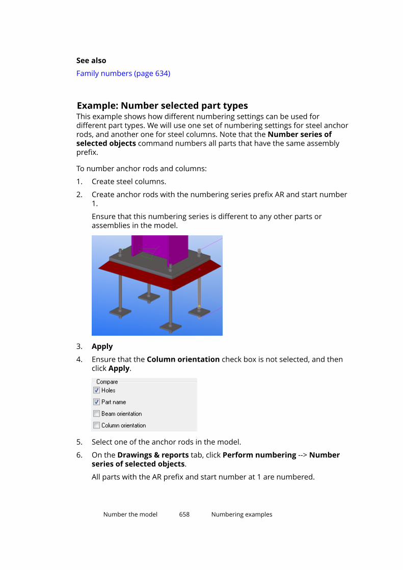
See also
Family numbers (page 634)
Example: Number selected part typesThis example shows how different numbering settings can be used fordifferent part types. We will use one set of numbering settings for steel anchorrods, and another one for steel columns. Note that the Number series ofselected objects command numbers all parts that have the same assemblyprefix.
To number anchor rods and columns:
1. Create steel columns.
2. Create anchor rods with the numbering series prefix AR and start number1.
Ensure that this numbering series is different to any other parts orassemblies in the model.
3. Apply
4. Ensure that the Column orientation check box is not selected, and thenclick Apply.
5. Select one of the anchor rods in the model.
6. On the Drawings & reports tab, click Perform numbering --> Numberseries of selected objects.
All parts with the AR prefix and start number at 1 are numbered.
Number the model 658 Numbering examples
7. Wait until the anchor rod numbering is complete.
8. On the Drawings & reports tab, click Numbering settings -->Numbering settings to open the Numbering Setup dialog box.
9. Select the Column orientation check box, and then click Apply.
10. Select one of the steel columns in the model.
11. On the Drawings & reports tab, click Perform numbering --> Numberseries of selected objects.
All columns belonging to the same numbering series as the selectedcolumn are numbered.
See also
Number a series of parts (page 637)
Example: Number parts in selected phasesThis example shows how to number a model that consists of multiple phases,each phase having a different detailing and submittal schedule. This enablesyou to release drawings for a particular phase at any time.
Before you start, divide the model into phases.
To number parts in selected phases:
1. Apply a specific numbering series prefix and start number for parts ineach phase.
For example:
• The beams in phase 1 get the numbering series prefix B and startnumber 1000.
• The beams in phase 2 get the numbering series prefix B and startnumber 2000.
Number the model 659 Numbering examples
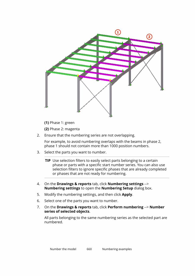
(1) Phase 1: green
(2) Phase 2: magenta
2. Ensure that the numbering series are not overlapping.
For example, to avoid numbering overlaps with the beams in phase 2,phase 1 should not contain more than 1000 position numbers.
3. Select the parts you want to number.
TIP Use selection filters to easily select parts belonging to a certainphase or parts with a specific start number series. You can also useselection filters to ignore specific phases that are already completedor phases that are not ready for numbering.
4. On the Drawings & reports tab, click Numbering settings -->Numbering settings to open the Numbering Setup dialog box.
5. Modify the numbering settings, and then click Apply.
6. Select one of the parts you want to number.
7. On the Drawings & reports tab, click Perform numbering --> Numberseries of selected objects.
All parts belonging to the same numbering series as the selected part arenumbered.
Number the model 660 Numbering examples

See also
Number a series of parts (page 637)
Numbering settings during a project (page 661)
5.13 Tips for numbering• It is a good idea to have some kind of a routine in numbering. For example,
number the model when you start your working day or when you finish forthe day.
• To save time, include the numbering series in the default part propertiesfor each type of part before you start modeling.
• Numbering is not just another way of classifying parts. To classify, useOrganizer, user-defined attributes, or colors.
• If you have overlapping position numbers, Tekla Structures will warn youabout it.
You can have a closer look at the overlapping position numbers in thenumbering history log. To display the log, click File menu --> Logs -->Numbering history log.
See also
Numbering settings during a project (page 661)
Numbering examples (page 656)
Create a standard-part model (page 662)
Numbering settings during a projectYou can use different numbering settings at different times in a project.
For example:
• Before releasing a phase of the project for fabrication, you might use theRe-use old numbers option for numbering the entire model.
• If a phase has already been released for fabrication in a project, you mightuse the Take new number option for new and modified parts.
• If you are numbering other phases of the project at earlier stages ofdetailing, you might use the Compare to old option and try to combine asmany position numbers as possible.
See also
Example: Number parts in selected phases (page 659)
Number the model 661 Tips for numbering

General numbering settings (page 923)
Create a standard-part modelA standard-part model contains only standard parts with specific part prefixes.You can use these prefixes when numbering parts in another model. Theprefixes that you define will be used as actual part position numbers in theother model.
The standard-part model is only used for comparing parts when you numberparts in a project model. It cannot be used for creating parts in the projectmodel.
NOTE This functionality only applies to steel parts. Assemblies are notaffected.
1. Create a new model and give it a descriptive name.
For example, StandardParts.
2. Create the objects you want to use as standard parts.
3. Explode all components.
You can explode the components if you plan to delete the unnecessaryparts such as duplicate angles and main parts.
4. Delete all unnecessary items.
5. Give the objects part prefixes that are not used elsewhere (for example,STD1, STD2, and so on).
Ensure that the standard-part model does not contain duplicate partprefixes. You do not need to define the assembly prefix or the part orassembly start numbers.
6. Save the standard-part model.
To use the standard-part model with Tekla Model Sharing, save thestandard-part model in a separate folder under the current model folder.
To use the standard-part model with a multi-user model, save thestandard-part model so that all users have access to it.
7. Open a project model that you wish to number.
8. On the File menu, click Settings --> Advanced options --> Numbering .
9. Check that the advanced option XS_STD_PART_MODEL points to thecorrect standard-part model.
For example:
XS_STD_PART_MODEL=C:\TeklaStructuresModels\StandardParts\10. On the Drawings & reports tab, click Numbering settings -->
Numbering settings to display the Numbering Setup dialog box.
Number the model 662 Tips for numbering

11. If you have selected the Part name check box, ensure that the projectmodel has the same part names as the standard-part model.
12. Select the Check for standard parts check box.
13. Click Apply to save the changes.
14. On the Drawings & reports tab, click Perform numbering --> Numbermodified objects to number the project model.
As the parts are being numbered, Tekla Structures compares all parts inthe project model to the standard-part model. Any part prefixes found inthe standard-part model are applied to all identical parts found in theproject model. The numbering series of the oldest numbered standardpart in the project model is applied to all identical parts found in theproject model.
See also
Number parts (page 637)
Number the model 663 Tips for numbering

6 Applications
All available applications, macros, and drawing plugins are located in thesection Applications of the Applications & components catalog. You can alsorecord macros of your own and show them on the list.
Macros
Macros (page 666) are saved as .cs files in the \drawings or \modelingfolder under the folders that have been defined with the advanced option . Bydefault, this advanced option is set to ..\ProgramData\Trimble\TeklaStructures\<version>\environments\common\macros.
In addition to this global folder, you can define a local folder and store localmacros there, for example, environment macros or firm macros. Specify thelocal macro folder for the advanced option XS_MACRO_DIRECTORY in additionto the global folder. Define the global folder first and then the local folder.When you create a macro you need to set it as global or local, and the macrowill be placed in the global or local folder according to your selection. Themacros in the global folder are read first.
Example of the definition for XS_MACRO_DIRECTORY containing a global folderand a local folder:
%XSDATADIR%environments\common\macros;%XSDATADIR%environments\uk\General\user-macros
Macros in the modeling mode
Macro DescriptionAutoConnectSelectedParts(page 693)
Use to automatically createconnections without opening theAutoConnection dialog box.
AutomaticSplicingTool (page 515) Use to split long reinforcing bars andbar groups that exceed the stocklength, and create splices in splitlocations.
ContinuousBeamReinforcement Use to reinforce a continuous beam.The macro creates main top and
Applications 664 Tips for numbering

Macro Descriptionbottom bars, stirrups, fittings, andadditional top and bottom bars usingsystem components.
Convert_DSTV2DXF Use to create NC files in DXF formatby converting DSTV files to DXF files.
CreateSurfaceView (page 31) Use to create an automatically alignedsurface view.
CreateSurfaceView_wEdge (page 31) Use to create a surface view and alignthe work plane along the edge youselect.
DesignGroupNumbering (page 653) Use to number parts by designgroups so that you can differentiatethe parts from each other in drawingsand reports.
DirectoryBrowser Use to to find and modify the locationof the various Tekla Structures filesand folders, and customize usersettings.
RebarClassificator (page 517) Use to classify the reinforcing barsand reinforcement meshes by theirorder of depth in concrete slabs andpanels.
RebarSeqNumbering (page 517) Use to assign cast unit specificrunning numbers (1, 2, 3...) to thereinforcement in the model.
RebarSplitAndCoupler Use to split a reinforcing bar groupand add couplers in relation to thedirection of the picked points.
UpdateRebarAttributes Use to manage the user-definedattributes (UDAs) of the couplers andthe end anchor parts created byRebar Coupler and Anchor Tools.
Macros in the drawing mode
Macro DescriptionAdd surfacing symbols Use to add surface treatment symbols
in cast unit drawings.Copy with offsets (Drawing tools) Use to copy lines, circles, polylines,
polygons and rectangles with offsets.Create fillets (Drawing tools) Use to connect two intersecting lines
by extending the two selected lines totheir intersection point.
Applications 665 Tips for numbering
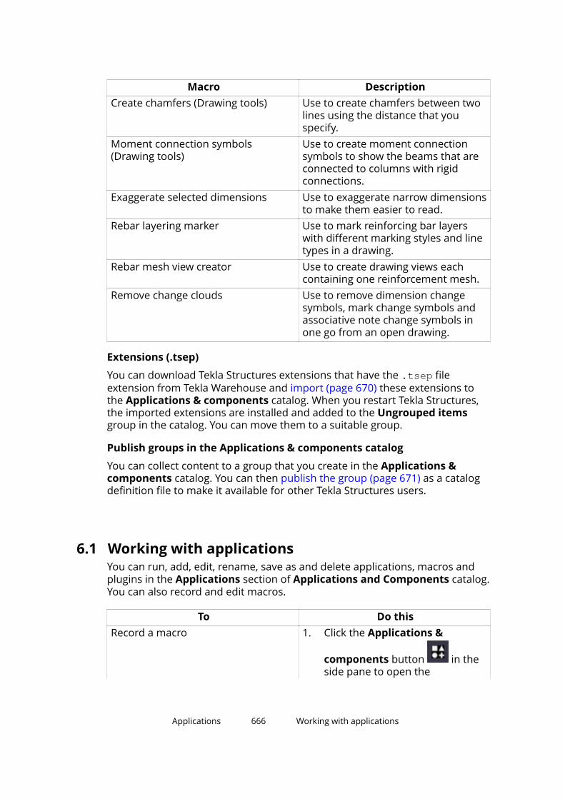
Macro DescriptionCreate chamfers (Drawing tools) Use to create chamfers between two
lines using the distance that youspecify.
Moment connection symbols(Drawing tools)
Use to create moment connectionsymbols to show the beams that areconnected to columns with rigidconnections.
Exaggerate selected dimensions Use to exaggerate narrow dimensionsto make them easier to read.
Rebar layering marker Use to mark reinforcing bar layerswith different marking styles and linetypes in a drawing.
Rebar mesh view creator Use to create drawing views eachcontaining one reinforcement mesh.
Remove change clouds Use to remove dimension changesymbols, mark change symbols andassociative note change symbols inone go from an open drawing.
Extensions (.tsep)
You can download Tekla Structures extensions that have the .tsep fileextension from Tekla Warehouse and import (page 670) these extensions tothe Applications & components catalog. When you restart Tekla Structures,the imported extensions are installed and added to the Ungrouped itemsgroup in the catalog. You can move them to a suitable group.
Publish groups in the Applications & components catalog
You can collect content to a group that you create in the Applications &components catalog. You can then publish the group (page 671) as a catalogdefinition file to make it available for other Tekla Structures users.
6.1 Working with applicationsYou can run, add, edit, rename, save as and delete applications, macros andplugins in the Applications section of Applications and Components catalog.You can also record and edit macros.
To Do thisRecord a macro 1. Click the Applications &
components button in theside pane to open the
Applications 666 Working with applications
To Do thisApplications & componentscatalog.
2. Click the Access advanced
features button and thenclick Record macro > Global orLocal depending on whether youwant to save the macro in theglobal or local macros folder.
The Local command is onlyavailable if you have defined alocation for the local macrosusing the advanced option XS_MACRO_DIRECTORY.
3. Enter a name for the macro inthe Macro name box.
4. Click OK and perform the actionsyou want to record.
5. Click Stop recoding to stoprecording.
The recorded macro is savedunder global or local macros inthe macros\drawings ormacros\modeling folderdepending on the mode (drawingor modeling) you were usingwhile you were recording themacro.
Create a macro file and add contentslater
1. Click the Applications &
components button in theside pane to open theApplications & componentscatalog.
2. Click the Access advanced
features button and thenclick New macro > Global orLocal depending on whether youwant to save the macro in theglobal or local macros folder.
The Local command is onlyavailable if you have defined alocation for the local macros
Applications 667 Working with applications

To Do thisusing the advanced option XS_MACRO_DIRECTORY.
3. Enter a name for the macro inthe Macro name box.
4. Click OK.
This creates an empty macro filethat is displayed in theApplications list.
5. Right-click the empty macro fileand select Edit.
6. Add the macro content, forexample, by copying commandsfrom other macro files and savethe file.
View or edit a macro 1. Click the Applications &
components button in theside pane to open theApplications & componentscatalog.
2. Click the arrow next toApplications to open theapplications list.
3. Right-click the macro you want toedit and click Edit.
The macro can be opened in anytext editor.
4. If needed, edit the macro andsave the macro file.
Run an application 1. Click the Applications &
components button in theside pane to open theApplications & componentscatalog.
2. Click the arrow next toApplications to open theapplications list.
3. Double-click the application youwant to run.
Applications 668 Working with applications
To Do thisSave an application with anothername
1. Click the Applications &
components button in theside pane to open theApplications & componentscatalog.
2. Click the arrow next toApplications to open theapplications list.
3. Right-click the application thatyou want to save with anothername and click Save as.
4. Enter a new name for theapplication and click OK.
The application will be added inthe list.
Rename an application 1. Click the Applications &
components button in theside pane to open theApplications & componentscatalog.
2. Click the arrow next toApplications to open theapplications list.
3. Right-click the application youwant to rename and clickRename.
4. Enter a new name for theapplication and click OK.
The name of the applicationchanges.
Delete an application 1. Click the Applications &
components button in theside pane to open theApplications & componentscatalog.
2. Click the arrow next toApplications to open theapplications list.
Applications 669 Working with applications
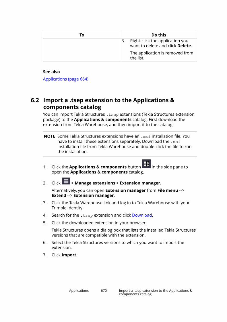
To Do this3. Right-click the application you
want to delete and click Delete.
The application is removed fromthe list.
See also
Applications (page 664)
6.2 Import a .tsep extension to the Applications &components catalogYou can import Tekla Structures .tsep extensions (Tekla Structures extensionpackage) to the Applications & components catalog. First download theextension from Tekla Warehouse, and then import it to the catalog.
NOTE Some Tekla Structures extensions have an .msi installation file. Youhave to install these extensions separately. Download the .msiinstallation file from Tekla Warehouse and double-click the file to runthe installation.
1. Click the Applications & components button in the side pane toopen the Applications & components catalog.
2. Click > Manage extensions > Extension manager.
Alternatively, you can open Extension manager from File menu -->Extend --> Extension manager.
3. Click the Tekla Warehouse link and log in to Tekla Warehouse with yourTrimble Identity.
4. Search for the .tsep extension and click Download.
5. Click the downloaded extension in your browser.
Tekla Structures opens a dialog box that lists the installed Tekla Structuresversions that are compatible with the extension.
6. Select the Tekla Structures versions to which you want to import theextension.
7. Click Import.
Applications 670 Import a .tsep extension to the Applications &components catalog
The extension is shown in Extension manager in all the Tekla Structuresversions that you selected.
Alternatively, if you want to import the extension to the current TeklaStructures version only, you can do the import in Extension managerafter downloading the extension. In Extension manager, click Importand then double-click the .tsep file.
You can still remove the extension from Extension manager beforeinstalling it. Select the extension and click Cancel.
8. If needed, repeat steps 4 - 7 to import more Tekla Structures extensions.
9. Restart Tekla Structures to install the imported extension.
10. Open the Applications & components catalog.
The extension is shown in the Ungrouped items group in the catalog. Youcan move the extension to a more suitable group, or create a new group.
You can uninstall installed extensions in Extension manager. Select one orseveral extensions (use Ctrl or Shift) and click Remove. The selectedextensions are removed when you restart Tekla Structures. Installing anduninstalling extensions creates a log file to \Tekla Structures\<version>\Extensions\TSEP Logs.
System administrators can copy multiple .tsep extension files to a TeklaStructures user's computer to the \Tekla Structures\<version>\Extensions\To be installed folder. The extensions are installed thenext time the user restarts Tekla Structures.
Copy .tsep extensions to a new Tekla Structures version
When starting to use a new Tekla Structures version, you can use the MigrationWizard tool to copy the installed .tsep extensions to the new version. You canopen Migration Wizard either from the Applications & components catalog,
click > Manage extensions > Migrate extensions, or from File menu -->Extend --> Migrate extensions. Once copied, the extensions are listed inExtension manager in the new Tekla Structures version. Restart TeklaStructures to install the copied extensions.
See also
How to use the Applications & components catalog (page 681)
6.3 Publish a group in the Applications & componentscatalogYou can collect content, such as macros, extensions, and system and customcomponents to a group that you create in the Applications & componentscatalog. You can then publish the group as a catalog definition file to make it
Applications 671 Publish a group in the Applications & componentscatalog
available for other Tekla Structures users. For the published content to workcorrectly in another Tekla Structures installation, the content must also exist inthat installation.
1. Click the Applications & components button in the side pane toopen the Applications & components catalog.
2. Create a new group:
a. Right-click in the catalog and select New group.
b. Enter a name for the group.
c. Select the group and click the small arrow on the right to add adescription to the group.
d. Add content to the group.
Some content in the Applications & components catalog may behidden. To publish the hidden content, select the Show hidden itemscheck box at the bottom of the catalog.
Note that the model-specific items you add to the group are visible inthe modeling mode and the drawing-specific items in the drawingmode.
e. Add the needed information to the items in the group: description,tags, and additional thumbnail images.
Use a thumbnail image from the \Tekla Structures\<version>\Bitmaps folder to ensure that the image is available for other TeklaStructures users.
3. Right-click the group and select Publish group to create a catalogdefinition file.
The file contains the following information:
• Name and description of the published group
• Names and descriptions of the subgroups
• References to the items that you have added to the group
The file does not contain the actual items. When other users use thegroup, they must ensure that the referenced items exist in their TeklaStructures installation and model.
• Descriptions, tags and thumbnail references of the items in the group
The file does not contain the actual thumbnail image files.
4. Add a unique prefix to the filename in the Publish group dialog box.
The filename format must be <prefix>_ComponentCatalog.ac.xml.
5. Click Save.
The file is by default saved to the model folder.
Applications 672 Publish a group in the Applications & componentscatalog

6. Make the group available for other Tekla Structures users by placing the<prefix>_ComponentCatalog.ac.xml catalog definition file to anappropriate folder:
• Project, firm or system folder defined in XS_PROJECT, XS_FIRM, or XS_SYSTEM.
• \attributes folder under the current model folder
• Extensions folder in \Tekla Structures\<version>\environments\common\extensions, or to any of the foldersdefined in XS_EXTENSION_DIRECTORY.
The Applications & components catalog also searches the subfoldersof these folders. We recommend that you use the extension folders ifyou have created your own extensions and have included them in thegroup.
7. Check that the catalog definition file works correctly:
a. Delete the published group from your Applications & componentscatalog.
b. Click > Catalog managementReload catalog to load and viewthe published group.
When you have checked the group, other users can start using it:
• If the group content is already included in other users' Tekla Structuresinstallation, they can use the group immediately after reloading the catalog
by clicking > Catalog management > Reload catalog.
• If the group content, for example extensions, is not included in other users'Tekla Structures installation, they have to download the missing extensionsfrom Tekla Warehouse first, and then re-open the model where they aregoing to use the group.
Applications 673 Publish a group in the Applications & componentscatalog

7 Components
Components are tools that you can use to connect parts in the model.Components automate tasks and group objects so that Tekla Structures treatsthem as a single unit. You can save the properties of a component and usethem in other projects.
Components adapt to changes in the model, which means that TeklaStructures automatically modifies a component if you modify the parts itconnects. When you copy or move objects, Tekla Structures automaticallycopies or moves all the associated components with the objects.
All components are stored in the Applications & components catalog. Click the
Applications & components button in the side pane to open theApplications & components catalog.
System components
Tekla Structures contains a wide range of predefined system components bydefault. There are three types of system components:
• Connection components connect two or more parts, and create all therequired objects such as cuts, fittings, parts, bolts, and welds.
For example, end plates, clip angles, and bolted gussets are connections.
In the Applications & components catalog, the connection symbol is .
• Detail components add a detail or a reinforcement to the main part. Adetail is only connected to one part.
For example, stiffeners, base plates, and lifting hooks are steel details, andbeam reinforcement and pad footing reinforcement are concrete details.
In the Applications & components catalog, the detail symbol is .
• Detailing components automatically create and assemble the parts tobuild a structure, but do not connect the structure to existing parts.
For example, stairs, frames, and towers are detailing components.
Components 674 Publish a group in the Applications & componentscatalog
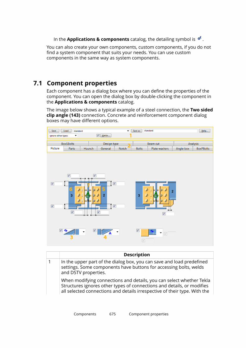
In the Applications & components catalog, the detailing symbol is .
You can also create your own components, custom components, if you do notfind a system component that suits your needs. You can use customcomponents in the same way as system components.
7.1 Component propertiesEach component has a dialog box where you can define the properties of thecomponent. You can open the dialog box by double-clicking the component inthe Applications & components catalog.
The image below shows a typical example of a steel connection, the Two sidedclip angle (143) connection. Concrete and reinforcement component dialogboxes may have different options.
Description1 In the upper part of the dialog box, you can save and load predefined
settings. Some components have buttons for accessing bolts, weldsand DSTV properties.
When modifying connections and details, you can select whether TeklaStructures ignores other types of connections and details, or modifiesall selected connections and details irrespective of their type. With the
Components 675 Component properties

Descriptionmodify option, the type of the selected components is changed tomatch the type of the component you are currently modifying.
For more information, see Save and load object properties (page 111).2 On the tabs, you can define the properties of the parts and bolts that
the component creates. You can enter values manually, use systemdefault values, AutoDefaults values, automatic values, or for some steelconnections, the values in the joints.def file.
Manually entered values, AutoDefaults, automatic values and theproperties defined in the joints.def file all override the systemdefaults. System default values are used if you do not manually enter avalue or select any other type of property value. You cannot change thesystem default values.
For more information on joints.def, see Define connectionproperties in the joints.def file (page 708).
3 If you select an AutoDefaults option, Tekla Structures uses theproperty defined in the AutoDefaults rules.
The image in the AutoDefaults option is an example and does notnecessarily match the outcome in the model.
For more information on AutoDefaults, see AutoDefaults (page 694).4
If you select an automatic option, Tekla Structures automaticallydetermines which option to use for a property.
For example, when you use the automatic option for the stiffener inEnd plate (144), the connection automatically adds the stiffener to abeam-to-column connection, but does not add it to a beam-to-beamconnection.
For more information on AutoConnection, see AutoConnection(page 689).
5 The parts that are yellow in the component dialog box are created bythe component.
6 The parts that are blue in the component dialog box should alreadyexist in the model before you create the component.
7 Up direction indicates how the connection is rotated around the
secondary part, relative to the current work plane. The symbol onthe Picture tab of the component dialog box indicates the correct updirection.
If there are no secondary parts, Tekla Structures rotates the connectionaround the main part. The options are: +x, -x, +y, -y, +z, -z.
You can change the default up direction on the General tab of thecomponent dialog box. Try changing the positive directions first.
Components 676 Component properties
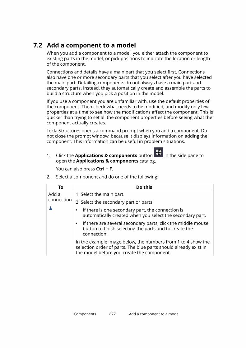
7.2 Add a component to a modelWhen you add a component to a model, you either attach the component toexisting parts in the model, or pick positions to indicate the location or lengthof the component.
Connections and details have a main part that you select first. Connectionsalso have one or more secondary parts that you select after you have selectedthe main part. Detailing components do not always have a main part andsecondary parts. Instead, they automatically create and assemble the parts tobuild a structure when you pick a position in the model.
If you use a component you are unfamiliar with, use the default properties ofthe component. Then check what needs to be modified, and modify only fewproperties at a time to see how the modifications affect the component. This isquicker than trying to set all the component properties before seeing what thecomponent actually creates.
Tekla Structures opens a command prompt when you add a component. Donot close the prompt window, because it displays information on adding thecomponent. This information can be useful in problem situations.
1. Click the Applications & components button in the side pane toopen the Applications & components catalog.
You can also press Ctrl + F.
2. Select a component and do one of the following:
To Do thisAdd aconnection
1. Select the main part.
2. Select the secondary part or parts.
• If there is one secondary part, the connection isautomatically created when you select the secondary part.
• If there are several secondary parts, click the middle mousebutton to finish selecting the parts and to create theconnection.
In the example image below, the numbers from 1 to 4 show theselection order of parts. The blue parts should already exist inthe model before you create the component.
Components 677 Add a component to a model
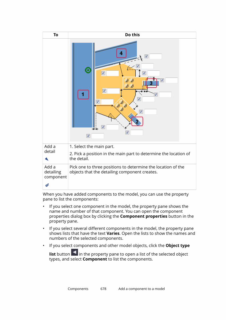
To Do this
Add adetail
1. Select the main part.
2. Pick a position in the main part to determine the location ofthe detail.
Add adetailingcomponent
Pick one to three positions to determine the location of theobjects that the detailing component creates.
When you have added components to the model, you can use the propertypane to list the components:
• If you select one component in the model, the property pane shows thename and number of that component. You can open the componentproperties dialog box by clicking the Component properties button in theproperty pane.
• If you select several different components in the model, the property paneshows lists that have the text Varies. Open the lists to show the names andnumbers of the selected components.
• If you select components and other model objects, click the Object type
list button in the property pane to open a list of the selected objecttypes, and select Component to list the components.
Components 678 Add a component to a model
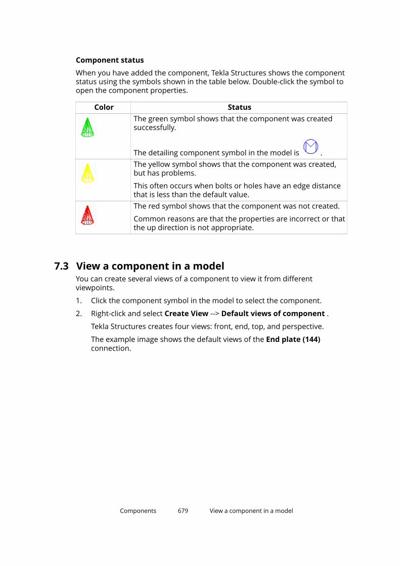
Component status
When you have added the component, Tekla Structures shows the componentstatus using the symbols shown in the table below. Double-click the symbol toopen the component properties.
Color StatusThe green symbol shows that the component was createdsuccessfully.
The detailing component symbol in the model is .The yellow symbol shows that the component was created,but has problems.
This often occurs when bolts or holes have an edge distancethat is less than the default value.The red symbol shows that the component was not created.
Common reasons are that the properties are incorrect or thatthe up direction is not appropriate.
7.3 View a component in a modelYou can create several views of a component to view it from differentviewpoints.
1. Click the component symbol in the model to select the component.
2. Right-click and select Create View --> Default views of component .
Tekla Structures creates four views: front, end, top, and perspective.
The example image shows the default views of the End plate (144)connection.
Components 679 View a component in a model
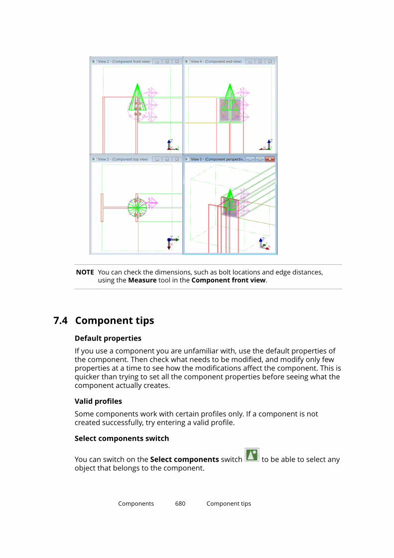
NOTE You can check the dimensions, such as bolt locations and edge distances,using the Measure tool in the Component front view.
7.4 Component tipsDefault properties
If you use a component you are unfamiliar with, use the default properties ofthe component. Then check what needs to be modified, and modify only fewproperties at a time to see how the modifications affect the component. This isquicker than trying to set all the component properties before seeing what thecomponent actually creates.
Valid profiles
Some components work with certain profiles only. If a component is notcreated successfully, try entering a valid profile.
Select components switch
You can switch on the Select components switch to be able to select anyobject that belongs to the component.
Components 680 Component tips
Component is not added to the model
If the component is not added to the model, check the status bar. Forexample, you may need to click the middle mouse button to stop selectingparts before Tekla Structures creates the component.
Using thickness to create needed parts
If a component does not by default create the parts that you need, look foroptions to create them. If there are no options, try entering a thickness valuefor the parts.
If a component creates parts that you do not need, look for options to removethem. If there are no options, enter a zero (0) as the thickness of the parts.
Many secondary parts are found
If you are using a connection that only allows one secondary part, you may seethe message Many parts found on the status bar. This means that TeklaStructures cannot determine which parts to connect. You may have severalparts in the same location, or the view may be set too deep.
7.5 How to use the Applications & components catalogComponents are stored in the Applications & components catalog andorganized into two different types of groups: default groups are automaticallyavailable and predefined groups depend on your environment.
Click the Applications & components button in the side pane to openthe Applications & components catalog. You can also press Ctrl + F.
To use a component (page 674), select it in the catalog and follow theinstructions on the status bar to add the component to the model. Double-click the component in the catalog to open the component properties dialogbox.
Groups in the catalogDefault groups and predefined groups are shown against different backgroundcolor in the catalog.
Default groups are automatically available:
• Recent contains the 12 components and applications that you have mostrecently used in the model.
Components 681 How to use the Applications & componentscatalog

• Ungrouped items contains the components and applications that are notin any predefined group.
Ungrouped items can be, for example, imported components that have notbeen moved to any other group yet.
• Applications contains applications (page 664), macros and drawingplugins.
If you create your own macros, you can add them to this group.
• Connections contains connections and seams.
• Detailing contains detailing components.
• Details contains details.
• Parts contains custom parts.
• Legacy catalog shows the folder structure of the Component Catalogused in previous Tekla Structures versions if the catalog definition files arefound in the standard folder search paths.
Depending on your environment, the catalog may also contain predefinedgroups for specific usage, such as Steel --> Beam to beam connections. Youcan create your own groups according to your needs, for example, for yourown favorite connections. This way you can find these connections quickly andeasily. You can also hide the groups that you are not using so that only thegroups you use are visible in the catalog.
Model-specific components are shown in the modeling mode and drawing-specific components are shown in the drawing mode.
Search for a component in the catalogTo search for a component in the catalog, enter the search term in the searchbox. The search is case-insensitive.
Note that the search does not find catalog content that has been hidden.Select the Show hidden items check box to show the hidden content.
The search uses the following rules:
• Non-numeric search terms find partial matches, for example, bolt showsboth bolt and bolted in the search result.
If you have more than one word in the search term, for example boltplate, the words are automatically combined so that the search resultshows the components that contain both bolt and plate in their name,description, or tags.
Components 682 How to use the Applications & componentscatalog
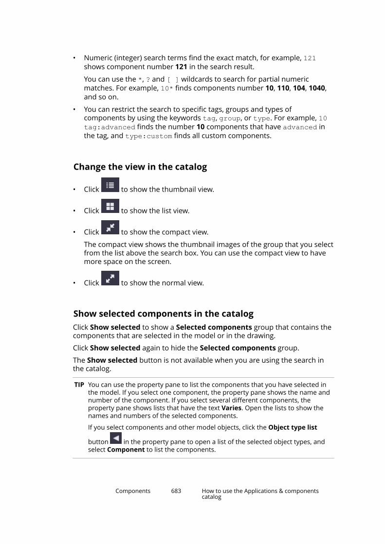
• Numeric (integer) search terms find the exact match, for example, 121shows component number 121 in the search result.
You can use the *, ? and [ ] wildcards to search for partial numericmatches. For example, 10* finds components number 10, 110, 104, 1040,and so on.
• You can restrict the search to specific tags, groups and types ofcomponents by using the keywords tag, group, or type. For example, 10tag:advanced finds the number 10 components that have advanced inthe tag, and type:custom finds all custom components.
Change the view in the catalog
• Click to show the thumbnail view.
• Click to show the list view.
• Click to show the compact view.
The compact view shows the thumbnail images of the group that you selectfrom the list above the search box. You can use the compact view to havemore space on the screen.
• Click to show the normal view.
Show selected components in the catalogClick Show selected to show a Selected components group that contains thecomponents that are selected in the model or in the drawing.
Click Show selected again to hide the Selected components group.
The Show selected button is not available when you are using the search inthe catalog.
TIP You can use the property pane to list the components that you have selected inthe model. If you select one component, the property pane shows the name andnumber of the component. If you select several different components, theproperty pane shows lists that have the text Varies. Open the lists to show thenames and numbers of the selected components.
If you select components and other model objects, click the Object type list
button in the property pane to open a list of the selected object types, andselect Component to list the components.
Components 683 How to use the Applications & componentscatalog

View and modify component information in the catalogEach component has an information box that shows the type of thecomponent and the groups the component belongs to. You can add adescription for the component and tags that can be used in the search.
1. Select a component in the catalog and click the small arrow on the right toopen the component information box.
2. Type a description in the Description box.
3. Click to add a tag and enter a tag in the box.
4. If needed, click again to add more tags. You can also remove tags.
5. Click outside the information box to close it.
The descriptions and tags that you add are by default saved in theComponentCatalog.xml file in the model folder.
Add a thumbnail image for a component in the catalogComponents have a default thumbnail image that shows a typical situationwhere the component can be used. You can add several thumbnails for acomponent and select which thumbnail is shown in the thumbnail view in theApplications & components catalog.
1. Select a component in the catalog.
2. Right-click and selectThumbnails.
3. Click Add thumbnail.
4. Select an image and click Open. You can use any standard image format,for example, .png, .jpeg, .gif, .tiff, and .bmp.
5. Select the check boxes of the thumbnails that you want to show in thecomponent information box. You can also remove thumbnails, except forthe default thumbnail.
6. Click Close.
The thumbnail information that you add is by default saved in theComponentCatalog.xml file in the model folder.
Components 684 How to use the Applications & componentscatalog
Publish a component in the catalogYou may need to use the same component with different settings in differentsituations. To easily use the component, you can define the settings for eachsituation and publish the component in the catalog.
For example, you may need End plate (144) in three different situations. AddEnd plate (144) once to each situation in the model. Define the settingsneeded and then publish each End plate (144) in the catalog. You will thenhave End plate (144) saved in the catalog as three separate components, eachwith different settings. You can use these components from the catalog in thesame way as other components.
1. Add a component once to all needed situations in the model.
2. Define the desired settings for each situation.
3. Select one of the components you added in the model, right-click andselect Publish in Catalog....
4. Enter a descriptive name for the component and click OK.
5. Repeat steps 3-4 for each component you added.
The components are first placed in the Ungrouped items group in the catalog.They have the name you entered and the thumbnail image of the originalcomponent.
You can move the components to a more appropriate group in the catalog andchange the thumbnail image. For example, you can create a basic componentview in each situation, and use an image of the view as the thumbnail.
Create and modify groups in the catalogYou can create groups and subgroups, and move groups to different locationsin the predefined groups section in the catalog. You can add and removecomponents from the groups, rename the groups, and add descriptions forthe groups.
To Do thisCreate agroup
Right-click in the catalog and select New group.... Drag thegroup to the desired location.
Create asubgroup
Right-click a group in the catalog and select New group....
Name agroup
Right-click a group, select Rename... and type the name.
Addcomponentsto the group
• Select components in the catalog and drag them to anothergroup.
• Select components in the catalog, right-click and select Addto group. Then select the group to which the componentsare added.
Components 685 How to use the Applications & componentscatalog

To Do this• Right-click a group, select Add all to group and select the
group to which all the components in the group are added.
Note that the components are copied, not moved, to theother groups.
Remove agroup
Right-click a group and select Remove from group.
The groups that you create are by default saved in theComponentCatalog.xml file in the model folder.
NOTE You cannot add or remove groups in the default groups, and you cannotmodify the content of the default groups. However, you can hide the defaultgroups and the individual items in the groups.
Change the order of groups in the catalogYou can change the order of the predefined groups in the Applications &components catalog. Predefined groups depend on your environment, forexample, Steel and Concrete can be such groups. Note that you cannotchange the order of the default groups, for example, Applications,Connections, and Detailing.
You can control the order with a sort index. The Sort index option is availablein the group information of each predefined group in the Applications &components catalog. Sort indexes are saved in the catalog definition files.
You can change the sort index by entering either a negative or a positiveinteger number, or 0, in the Sort index option box. A negative sort index
Components 686 How to use the Applications & componentscatalog

moves a group towards the top and a positive sort index moves a grouptowards the bottom in the predefined groups section. Enter 0 or clear thevalue to revert to the default order. By default, the groups are in alphabeticalorder.
The sort index changes you make are model specific and they are saved in theComponentCatalog.xml file in the \model folder. Administrators can definethe order of groups for an environment or a project using the catalogdefinition files in the environment, firm and project folders. Do not edit thesefiles if you are not an administrator.
Note that even if administrators have defined the order, you can still makemodel-specific changes to the order of the groups by entering a different sortindex value for a group. If you need to revert to the default order, enter 0 asthe sort index.
To change the order:
1. Select a predefined group.
2. Click the small arrow on the right to open the group information box.
3. Enter a number in the Sort index box.
The group is immediately moved.
4. Save the model to keep the order.
Hide groups and components in the catalog1. Select a group or a component in the catalog.
2. Right-click and select Hide / Unhide to hide the group or the component.
3. To view the hidden group or component again, select the Show hiddenitems check box at the bottom of the catalog. The hidden group orcomponent is shown as dimmed.
4. To show the hidden group or component normally, right-click it and selectHide / Unhide.
Show the catalog message logIf there are errors or warnings, for example, in the catalog definition files, theMessage Log button is shown in the lower right corner in the catalog. Thebutton is not shown if there are no errors or warnings.
To view the error log, click the Message Log button.
Errors and warnings are also written to the ComponentCatalog_<user>.logfile in the \logs folder under the model folder.
Components 687 How to use the Applications & componentscatalog
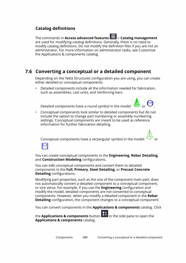
Catalog definitions
The commands in Access advanced features > Catalog managementare used for modifying catalog definitions. Generally, there is no need tomodify catalog definitions. Do not modify the definition files if you are not anadministrator. For more information on administrator tasks, see Customizethe Applications & components catalog.
7.6 Converting a conceptual or a detailed componentDepending on the Tekla Structures configuration you are using, you can createeither detailed or conceptual components.
• Detailed components include all the information needed for fabrication,such as assemblies, cast units, and reinforcing bars.
Detailed components have a round symbol in the model: or .
• Conceptual components look similar to detailed components but do notinclude the option to change part numbering or assembly numberingsettings. Conceptual components are meant to be used as referenceinformation for further fabrication detailing.
Conceptual components have a rectangular symbol in the model: or
.
You can create conceptual components in the Engineering, Rebar Detailing,and Construction Modeling configurations.
You can edit conceptual components and convert them to detailedcomponents in the Full, Primary, Steel Detailing, or Precast ConcreteDetailing configurations.
Modifying part properties, such as the size of the component main part, doesnot automatically convert a detailed component to a conceptual component,or vice versa. For example, if you use the Engineering configuration andmodify the model, detailed components are not converted to conceptualcomponents. However, when you modify a detailed component in the RebarDetailing configuration, the component changes to a conceptual component.
You can convert components in the Applications & components catalog. Click
the Applications & components button in the side pane to open theApplications & components catalog.
Components 688 Converting a conceptual or a detailed component
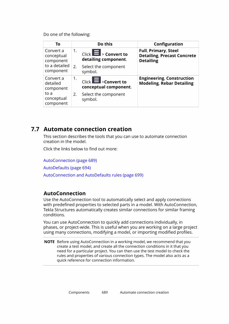
Do one of the following:
To Do this ConfigurationConvert aconceptualcomponentto a detailedcomponent
1.Click > Convert todetailing component.
2. Select the componentsymbol.
Full, Primary, SteelDetailing, Precast ConcreteDetailing
Convert adetailedcomponentto aconceptualcomponent
1.Click >Convert toconceptual component.
2. Select the componentsymbol.
Engineering, ConstructionModeling, Rebar Detailing
7.7 Automate connection creationThis section describes the tools that you can use to automate connectioncreation in the model.
Click the links below to find out more:
AutoConnection (page 689)
AutoDefaults (page 694)
AutoConnection and AutoDefaults rules (page 699)
AutoConnectionUse the AutoConnection tool to automatically select and apply connectionswith predefined properties to selected parts in a model. With AutoConnection,Tekla Structures automatically creates similar connections for similar framingconditions.
You can use AutoConnection to quickly add connections individually, inphases, or project-wide. This is useful when you are working on a large projectusing many connections, modifying a model, or importing modified profiles.
NOTE Before using AutoConnection in a working model, we recommend that youcreate a test model, and create all the connection conditions in it that youneed for a particular project. You can then use the test model to check therules and properties of various connection types. The model also acts as aquick reference for connection information.
Components 689 Automate connection creation

See also
Define AutoConnection settings and rules (page 690)
Create a connection using AutoConnection (page 693)
AutoConnection and AutoDefaults rules (page 699)
Define AutoConnection settings and rulesWith AutoConnection you can define groups of rules which Tekla Structuresautomatically applies when creating connections in a model. By using a rulegroup to select connections and connection properties you do not have toselect each connection and define its properties separately. For example, youcan create separate rules for different standards, projects, manufacturers, andeven individual models.
AutoConnection settings
To open the AutoConnection Setup dialog box, on the File menu, clickCatalogs --> AutoConnection settings.
Icon Setup level DescriptionRule group You can use rule groups to organize
connections and connection propertiesaccording to different standards,
Components 690 Automate connection creation
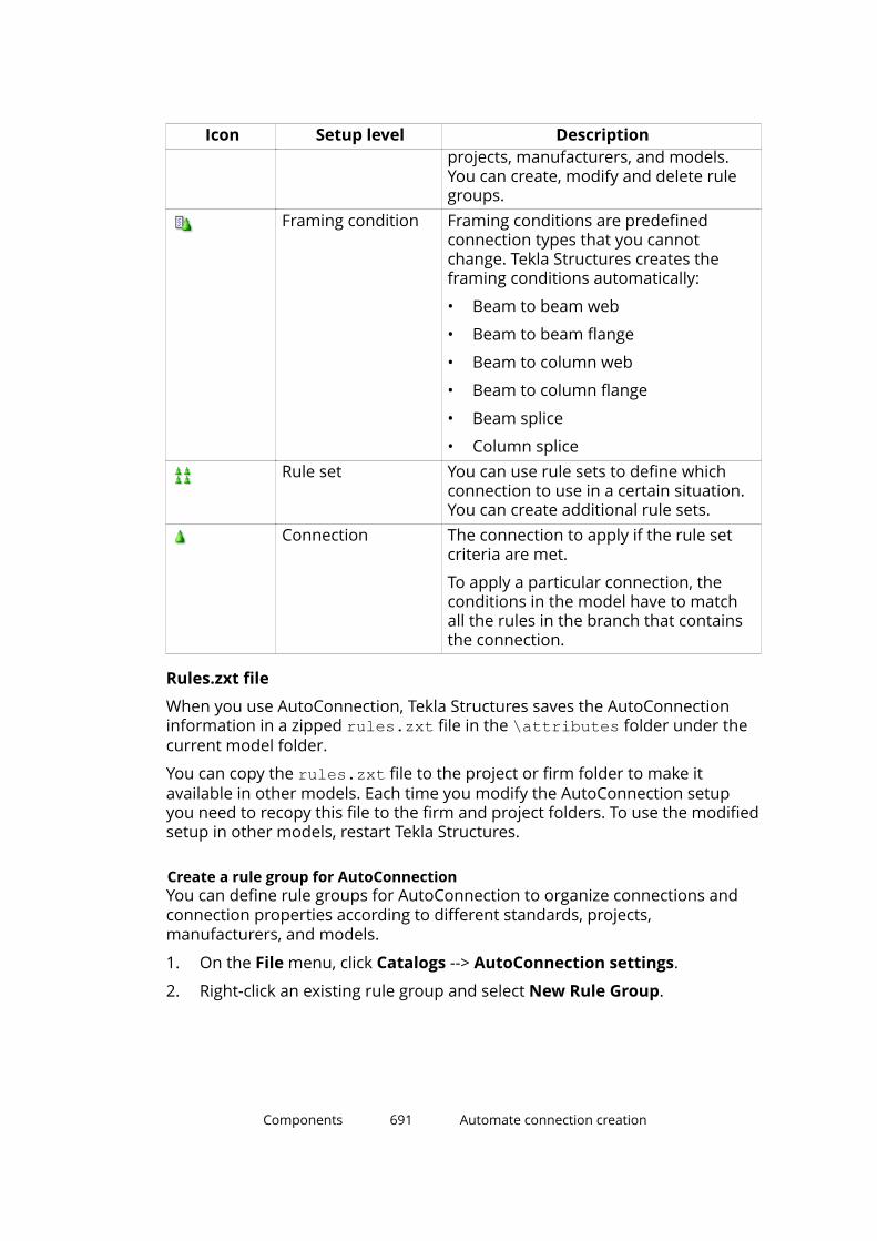
Icon Setup level Descriptionprojects, manufacturers, and models.You can create, modify and delete rulegroups.
Framing condition Framing conditions are predefinedconnection types that you cannotchange. Tekla Structures creates theframing conditions automatically:
• Beam to beam web
• Beam to beam flange
• Beam to column web
• Beam to column flange
• Beam splice
• Column spliceRule set You can use rule sets to define which
connection to use in a certain situation.You can create additional rule sets.
Connection The connection to apply if the rule setcriteria are met.
To apply a particular connection, theconditions in the model have to matchall the rules in the branch that containsthe connection.
Rules.zxt file
When you use AutoConnection, Tekla Structures saves the AutoConnectioninformation in a zipped rules.zxt file in the \attributes folder under thecurrent model folder.
You can copy the rules.zxt file to the project or firm folder to make itavailable in other models. Each time you modify the AutoConnection setupyou need to recopy this file to the firm and project folders. To use the modifiedsetup in other models, restart Tekla Structures.
Create a rule group for AutoConnectionYou can define rule groups for AutoConnection to organize connections andconnection properties according to different standards, projects,manufacturers, and models.
1. On the File menu, click Catalogs --> AutoConnection settings.
2. Right-click an existing rule group and select New Rule Group.
Components 691 Automate connection creation
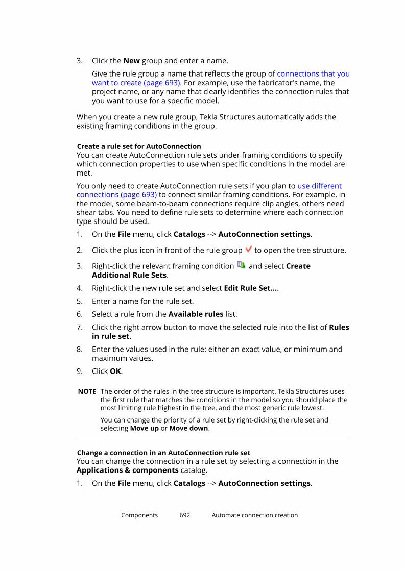
3. Click the New group and enter a name.
Give the rule group a name that reflects the group of connections that youwant to create (page 693). For example, use the fabricator's name, theproject name, or any name that clearly identifies the connection rules thatyou want to use for a specific model.
When you create a new rule group, Tekla Structures automatically adds theexisting framing conditions in the group.
Create a rule set for AutoConnectionYou can create AutoConnection rule sets under framing conditions to specifywhich connection properties to use when specific conditions in the model aremet.
You only need to create AutoConnection rule sets if you plan to use differentconnections (page 693) to connect similar framing conditions. For example, inthe model, some beam-to-beam connections require clip angles, others needshear tabs. You need to define rule sets to determine where each connectiontype should be used.
1. On the File menu, click Catalogs --> AutoConnection settings.
2. Click the plus icon in front of the rule group to open the tree structure.
3. Right-click the relevant framing condition and select CreateAdditional Rule Sets.
4. Right-click the new rule set and select Edit Rule Set....
5. Enter a name for the rule set.
6. Select a rule from the Available rules list.
7. Click the right arrow button to move the selected rule into the list of Rulesin rule set.
8. Enter the values used in the rule: either an exact value, or minimum andmaximum values.
9. Click OK.
NOTE The order of the rules in the tree structure is important. Tekla Structures usesthe first rule that matches the conditions in the model so you should place themost limiting rule highest in the tree, and the most generic rule lowest.
You can change the priority of a rule set by right-clicking the rule set andselecting Move up or Move down.
Change a connection in an AutoConnection rule setYou can change the connection in a rule set by selecting a connection in theApplications & components catalog.
1. On the File menu, click Catalogs --> AutoConnection settings.
Components 692 Automate connection creation

2. Click the plus icon in front of the relevant framing condition and rule
set to find the connection that you want to change.
3. Right-click the connection and select Select Connection Type....
4. Double-click a connection in the Select component dialog box.
5. Click OK in the AutoConnection Setup dialog box.
Create a connection using AutoConnectionUse AutoConnection to have Tekla Structures automatically create connectionsusing the properties of predefined rules. When you use AutoConnection, TeklaStructures ignores the properties in the connection dialog boxes. TeklaStructures does not modify the existing connections.
1. In the model, select the parts to connect.
2. On the Edit tab, click Components --> Create AutoConnections.
3. Select the rule groups from the lists on the Rule groups tab.
1 Rule group for AutoConnection2 Rule group for AutoDefaults
4. If needed, go to the Advanced tab to change the rules used in the framingconditions:
a. Select the connection in the Connection selection option:
• AutoConnection applies the connection defined in the rule groupthat you have selected in the first list on the Rule groups tab.
• None does not create a connection.
Components 693 Automate connection creation

• Click Select... to select a connection from the Applications &components catalog. Tekla Structures creates the connectionusing the default properties.
b. Select the connection properties in the Parameters selection option:
• Autodefaults applies the properties of the rule group that youhave selected in the first list on the Rule groups tab.
• No autodefaults applies the default connection properties.
5. Click Create connections.
TIP You can also use the Auto connect selected parts macro to automaticallycreate connections using the current properties without opening theAutoConnection dialog box.
Macros are located in the Applications group in the Applications &components catalog.
See also
Define AutoConnection settings and rules (page 690)
AutoDefaultsUse AutoDefaults to set up properties for existing connections. AutoDefaultsallows you to modify the default connection properties and save them for usein specific circumstances. When you use AutoDefaults, Tekla Structuresautomatically creates the connections with the predefined AutoDefaultsproperties. You can also use AutoDefaults for a single connection.
For example, you can use AutoDefaults to automatically adjust the thickness ofeach base plate you create, according to the main part profile. If the main partprofile changes, Tekla Structures automatically adjusts the thickness of thebase plate.
NOTE Before using AutoDefaults in a working model, we recommend that youcreate a test model, and create all the connection conditions in it that youneed for a particular project. You can then use this test model to check therules and properties of various connection types. It also acts as a quickreference for connection information.
See also
Define AutoDefaults settings and rules (page 695)
Modify a connection using AutoDefaults (page 699)
AutoConnection and AutoDefaults rules (page 699)
Components 694 Automate connection creation
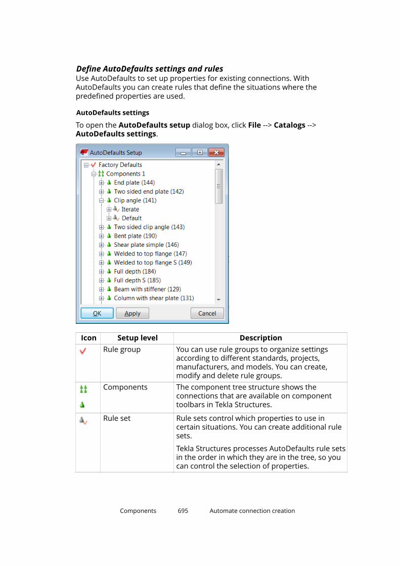
Define AutoDefaults settings and rulesUse AutoDefaults to set up properties for existing connections. WithAutoDefaults you can create rules that define the situations where thepredefined properties are used.
AutoDefaults settings
To open the AutoDefaults setup dialog box, click File --> Catalogs -->AutoDefaults settings.
Icon Setup level DescriptionRule group You can use rule groups to organize settings
according to different standards, projects,manufacturers, and models. You can create,modify and delete rule groups.
Components The component tree structure shows theconnections that are available on componenttoolbars in Tekla Structures.
Rule set Rule sets control which properties to use incertain situations. You can create additional rulesets.
Tekla Structures processes AutoDefaults rule setsin the order in which they are in the tree, so youcan control the selection of properties.
Components 695 Automate connection creation
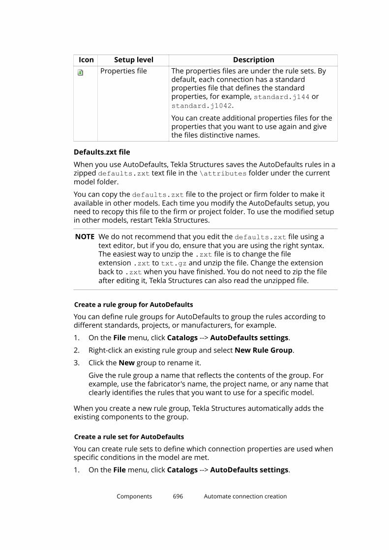
Icon Setup level DescriptionProperties file The properties files are under the rule sets. By
default, each connection has a standardproperties file that defines the standardproperties, for example, standard.j144 orstandard.j1042.
You can create additional properties files for theproperties that you want to use again and givethe files distinctive names.
Defaults.zxt file
When you use AutoDefaults, Tekla Structures saves the AutoDefaults rules in azipped defaults.zxt text file in the \attributes folder under the currentmodel folder.
You can copy the defaults.zxt file to the project or firm folder to make itavailable in other models. Each time you modify the AutoDefaults setup, youneed to recopy this file to the firm or project folder. To use the modified setupin other models, restart Tekla Structures.
NOTE We do not recommend that you edit the defaults.zxt file using atext editor, but if you do, ensure that you are using the right syntax.The easiest way to unzip the .zxt file is to change the fileextension .zxt to txt.gz and unzip the file. Change the extensionback to .zxt when you have finished. You do not need to zip the fileafter editing it, Tekla Structures can also read the unzipped file.
Create a rule group for AutoDefaults
You can define rule groups for AutoDefaults to group the rules according todifferent standards, projects, or manufacturers, for example.
1. On the File menu, click Catalogs --> AutoDefaults settings.
2. Right-click an existing rule group and select New Rule Group.
3. Click the New group to rename it.
Give the rule group a name that reflects the contents of the group. Forexample, use the fabricator's name, the project name, or any name thatclearly identifies the rules that you want to use for a specific model.
When you create a new rule group, Tekla Structures automatically adds theexisting components to the group.
Create a rule set for AutoDefaults
You can create rule sets to define which connection properties are used whenspecific conditions in the model are met.
1. On the File menu, click Catalogs --> AutoDefaults settings.
Components 696 Automate connection creation
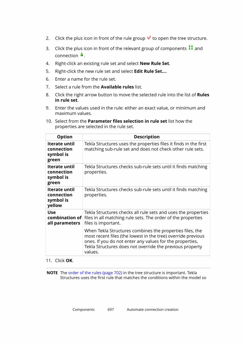
2. Click the plus icon in front of the rule group to open the tree structure.
3. Click the plus icon in front of the relevant group of components andconnection .
4. Right-click an existing rule set and select New Rule Set.
5. Right-click the new rule set and select Edit Rule Set....
6. Enter a name for the rule set.
7. Select a rule from the Available rules list.
8. Click the right arrow button to move the selected rule into the list of Rulesin rule set.
9. Enter the values used in the rule: either an exact value, or minimum andmaximum values.
10. Select from the Parameter files selection in rule set list how theproperties are selected in the rule set.
Option DescriptionIterate untilconnectionsymbol isgreen
Tekla Structures uses the properties files it finds in the firstmatching sub-rule set and does not check other rule sets.
Iterate untilconnectionsymbol isgreen
Tekla Structures checks sub-rule sets until it finds matchingproperties.
Iterate untilconnectionsymbol isyellow
Tekla Structures checks sub-rule sets until it finds matchingproperties.
Usecombination ofall parameters
Tekla Structures checks all rule sets and uses the propertiesfiles in all matching rule sets. The order of the propertiesfiles is important.
When Tekla Structures combines the properties files, themost recent files (the lowest in the tree) override previousones. If you do not enter any values for the properties,Tekla Structures does not override the previous propertyvalues.
11. Click OK.
NOTE The order of the rules (page 702) in the tree structure is important. TeklaStructures uses the first rule that matches the conditions within the model so
Components 697 Automate connection creation
you should place the most limiting rule highest in the tree, and the mostgeneric rule lowest.
You can change the priority of a rule set by right-clicking the rule set andselecting Move up or Move down.
Modify connection properties for AutoDefaults
Each connection has a default standard property file that defines theproperties for the connection. You can modify the properties that the standardfile uses. Save the connection properties that you want to use and set thestandard file to use these properties (page 699) in the AutoDefaults settings.
1. On the File menu, click Catalogs --> AutoDefaults settings.
2. Click the plus icon in front of the rule group to open the tree structure.
3. Click the plus icon in front of the relevant group of components andconnection .
4. Right-click the standard.j connection file that you want to modify, forexample, standard.j144 and select Edit Connection Parameters....
5. In the connection dialog box, set the properties that you want to save.
Such properties could be, for example, bolt properties, profiles, andmaterials.
6. Enter a descriptive name for the properties in the box next to the Save asbutton.
7. Copy this name in the Connection code option on the General tab.
Using the same name allows you to check which properties TeklaStructures used in specific situations. Tekla Structures does notautomatically show the AutoDefaults values in the connection dialog box.
8. Click Save as.
Tekla Structures saves the properties file in the \attributes folderunder the current model folder. The filename consists of the name youentered in Save as and the file extension .jXXX, where XXX is theconnection number, for example, sec_0-190.j144.
9. Click Cancel to close the connection dialog box and return to theAutoDefaults setup dialog box.
If you click OK to close the connection dialog box, you need to load thedefault properties the next time you use the connection. Using the defaultproperties ensures that AutoDefaults can modify the properties.
Components 698 Automate connection creation

10. Right-click the standard.j file again and select Select ConnectionParameters....
The Attribute File List dialog box that opens contains the properties thathave been set and saved in the connection dialog box.
11. Select a file in the Attribute File List dialog box.
12. Click OK.
Modify a connection using AutoDefaultsWhen you use a connection that you are unfamiliar with, first use the defaultproperties. Then use AutoDefaults to modify the properties.
1. Double-click a connection symbol in the model to open the connectiondialog box.
2. On the General tab, select a rule group from the AutoDefaults rulegroup list.
3. On all tabs, select the AutoDefaults options marked with the arrow symbol for the properties in which you want to use AutoDefaults.
4. Click Apply.
If you manually modify the properties after using AutoDefaults, TeklaStructures uses the manually modified properties.
For example, you have manually set the base plate thickness of a connectionto 20 mm. AutoDefaults is active and sets the plate thickness according to themain part profile. If you modify the main part profile, Tekla Structures does notupdate the base plate thickness. It remains at 20 mm.
NOTE You can view which AutoDefault rules and properties are used:
• To view AutoDefaults rules, select the connection symbol in the model,right-click and select Inquire .
Tekla Structures shows the rule group, rule sets and properties files used.
• To view the AutoDefaults properties, double-click the connection symbol inthe model, select <AutoDefaults> in the list box next to the Load buttonand click Load.
See also
Define AutoDefaults settings and rules (page 695)
AutoConnection and AutoDefaults rulesYou can create your own AutoConnection and AutoDefaults rules for projectand company defaults. By defining rules you can accurately select connectionsand connection properties when using AutoConnection and AutoDefaults.
Components 699 Automate connection creation
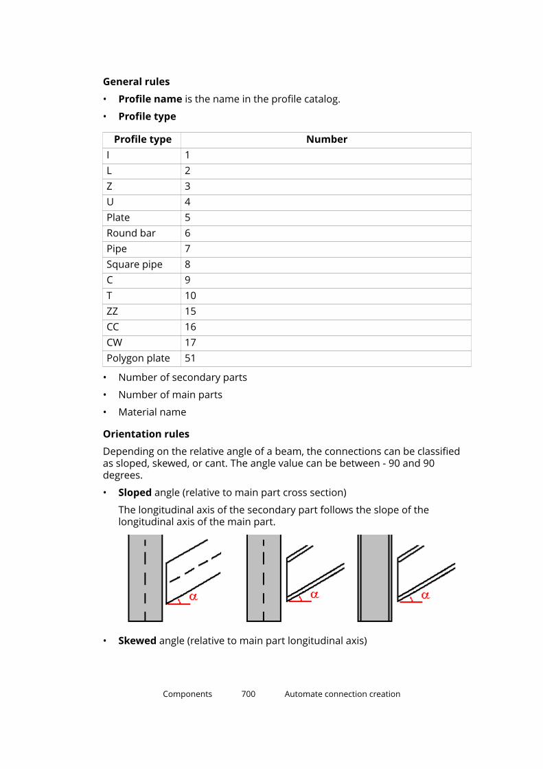
General rules
• Profile name is the name in the profile catalog.
• Profile type
Profile type NumberI 1L 2Z 3U 4Plate 5Round bar 6Pipe 7Square pipe 8C 9T 10ZZ 15CC 16CW 17Polygon plate 51
• Number of secondary parts
• Number of main parts
• Material name
Orientation rules
Depending on the relative angle of a beam, the connections can be classifiedas sloped, skewed, or cant. The angle value can be between - 90 and 90degrees.
• Sloped angle (relative to main part cross section)
The longitudinal axis of the secondary part follows the slope of thelongitudinal axis of the main part.
• Skewed angle (relative to main part longitudinal axis)
Components 700 Automate connection creation
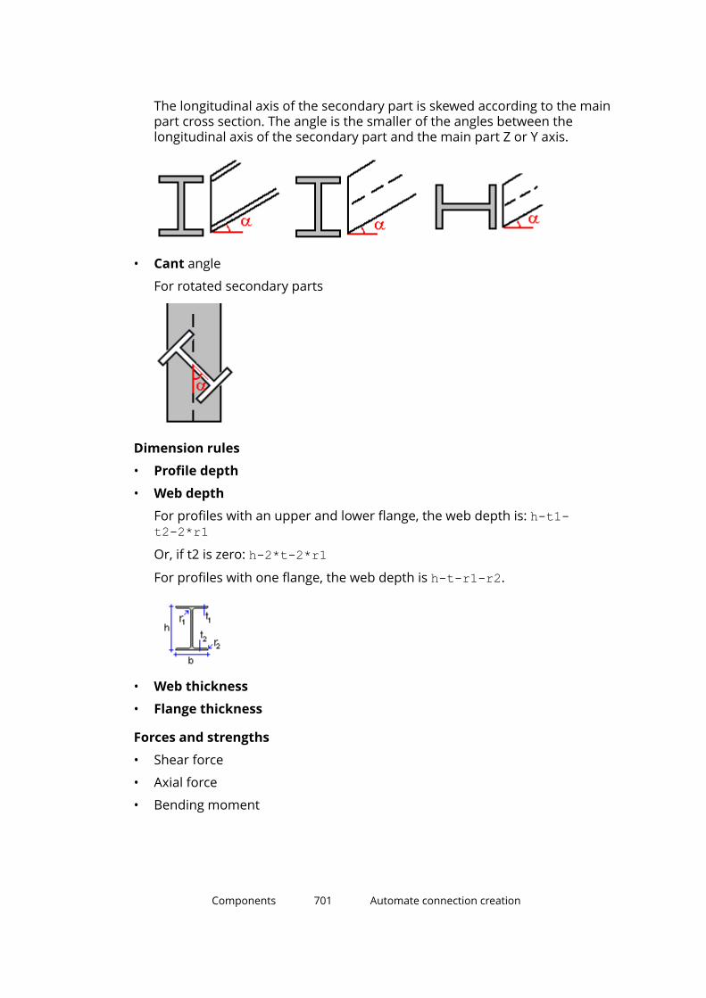
The longitudinal axis of the secondary part is skewed according to the mainpart cross section. The angle is the smaller of the angles between thelongitudinal axis of the secondary part and the main part Z or Y axis.
• Cant angle
For rotated secondary parts
Dimension rules
• Profile depth
• Web depth
For profiles with an upper and lower flange, the web depth is: h-t1-t2-2*r1Or, if t2 is zero: h-2*t-2*r1For profiles with one flange, the web depth is h-t-r1-r2.
• Web thickness
• Flange thickness
Forces and strengths
• Shear force
• Axial force
• Bending moment
Components 701 Automate connection creation

See also
Combining and iterating properties for AutoDefaults (page 702)
AutoDefaults example: Using iteration with connection check (page 704)
Using reaction forces and UDLs in AutoDefaults and AutoConnection(page 706)
Combining and iterating properties for AutoDefaults
Combining properties
You can save properties files that cover different groups of properties and usethese files to define many rules. For example, you can have one file for boltproperties and another for profile properties. AutoDefaults combines theseparate files into one file. This means that you can define fewer files becauseyou can use one file for several rules. If the files contain different values forthe same property, Tekla Structures uses the last property it finds, see theexample image below.
Components 702 Automate connection creation

Iterating properties
Tekla Structures tests the properties until the connection symbol is yellow orgreen. Iteration changes the properties automatically if the connection is notcreated successfully, even if the rules match. If connection check is active, theiteration results in properties that have passed the check.
Components 703 Automate connection creation
Limitations
• Tekla Structures cannot iterate property files directly. Use a single iterationrule set with sub-rule sets.
• You cannot have many parallel iteration rule sets. Use a single iteration ruleset and place it just before the default rule set.
• Place the combination rule sets above the iteration rule set in theAutoDefaults tree structure.
• Combination rule sets can only be one level deep.
• Tekla Structures disregards empty rule sets, so include at least one rule ineach rule set.
See also
Define AutoDefaults settings and rules (page 695)
AutoDefaults example: Using iteration with connection checkYou can use the connection check result when using AutoDefaults withiteration. If an iteration rule matches, but the connection does not pass theconnection check and the connection symbol remains red, AutoDefaultscontinues testing other rules and properties until the connection symbol isgreen.
In this example, you will create iteration rules to set the number of boltsaccording to the result of the connection check. After this, you will use the
Components 704 Automate connection creation
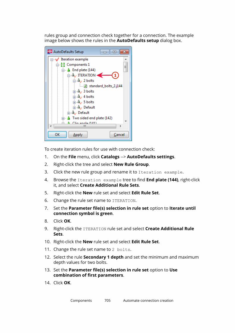
rules group and connection check together for a connection. The exampleimage below shows the rules in the AutoDefaults setup dialog box.
To create iteration rules for use with connection check:
1. On the File menu, click Catalogs --> AutoDefaults settings.
2. Right-click the tree and select New Rule Group.
3. Click the new rule group and rename it to Iteration example.
4. Browse the Iteration example tree to find End plate (144), right-clickit, and select Create Additional Rule Sets.
5. Right-click the New rule set and select Edit Rule Set.
6. Change the rule set name to ITERATION.
7. Set the Parameter file(s) selection in rule set option to Iterate untilconnection symbol is green.
8. Click OK.
9. Right-click the ITERATION rule set and select Create Additional RuleSets.
10. Right-click the New rule set and select Edit Rule Set.
11. Change the rule set name to 2 bolts.
12. Select the rule Secondary 1 depth and set the minimum and maximumdepth values for two bolts.
13. Set the Parameter file(s) selection in rule set option to Usecombination of first parameters.
14. Click OK.
Components 705 Automate connection creation
15. Right-click the connection properties file standard.j144 under 2 boltsand select Select Connection Parameters.
16. Select a properties file for two bolts in the Attribute File List and clickOK.
TIP If there is no suitable properties file, you can create a new file. Right-click the standard.j144 file and select Edit ConnectionParameters. Save the needed properties and click Cancel to closethe dialog box. The saved properties are now available in theAttribute File List.
17. Click Apply to have the changes available in the connection dialog box.
18. Repeat steps 9 to 16 for other rule sets.
19. Open the End plate (144) dialog box.
20. Select <Defaults> from the list next to the Load button and click Load.
21. On the General tab, set the AutoDefaults rule group option to theIteration example you created.
22. On the Design type tab, set the Check connection option to Yes.
23. Enter the load from secondary members in the Shear, Tension, andMoment options.
24. Click OK.
See also
Define AutoDefaults settings and rules (page 695)
Combining and iterating properties for AutoDefaults (page 702)
Using reaction forces and UDLs in AutoDefaults and AutoConnectionYou can set reaction forces for AutoConnection and AutoDefaults in the user-defined attributes of a part, and for AutoDefaults also on the Design tab in theconnection dialog box.
Reaction forces
When you use reaction forces in a rule and AutoDefaults is activated, TeklaStructures first searches for reaction forces in the corresponding connection’sproperties. If the properties do not contain reaction forces, Tekla Structuressearches the user-defined attributes of the secondary part of the connection.If Tekla Structures does not find forces there, you cannot use reaction forcerules.
Shear force calculation
If you have not given any reaction force values, shear force is calculated usingthe UDL (uniformly distributed load) shear force routine. The UDL calculation
Components 706 Automate connection creation
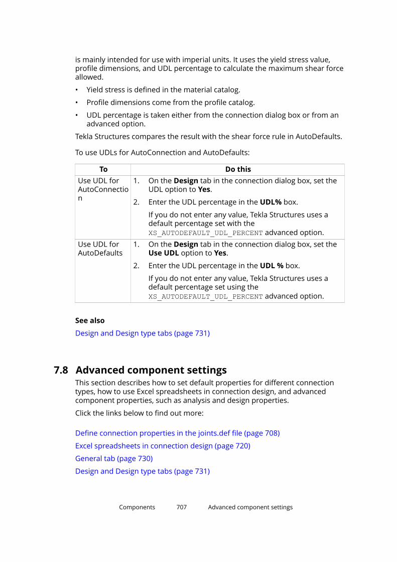
is mainly intended for use with imperial units. It uses the yield stress value,profile dimensions, and UDL percentage to calculate the maximum shear forceallowed.
• Yield stress is defined in the material catalog.
• Profile dimensions come from the profile catalog.
• UDL percentage is taken either from the connection dialog box or from anadvanced option.
Tekla Structures compares the result with the shear force rule in AutoDefaults.
To use UDLs for AutoConnection and AutoDefaults:
To Do thisUse UDL forAutoConnection
1. On the Design tab in the connection dialog box, set theUDL option to Yes.
2. Enter the UDL percentage in the UDL% box.
If you do not enter any value, Tekla Structures uses adefault percentage set with the XS_AUTODEFAULT_UDL_PERCENT advanced option.
Use UDL forAutoDefaults
1. On the Design tab in the connection dialog box, set theUse UDL option to Yes.
2. Enter the UDL percentage in the UDL % box.
If you do not enter any value, Tekla Structures uses adefault percentage set using the XS_AUTODEFAULT_UDL_PERCENT advanced option.
See also
Design and Design type tabs (page 731)
7.8 Advanced component settingsThis section describes how to set default properties for different connectiontypes, how to use Excel spreadsheets in connection design, and advancedcomponent properties, such as analysis and design properties.
Click the links below to find out more:
Define connection properties in the joints.def file (page 708)
Excel spreadsheets in connection design (page 720)
General tab (page 730)
Design and Design type tabs (page 731)
Components 707 Advanced component settings

Analysis tab (page 734)
Define connection properties in the joints.def fileThe joints.def file contains general connection settings and connection-specific settings for different connection types. You can use the joints.deffile to set the default properties for different connection types. Joints.def isa text file that you can open and edit in any standard text editor.
Tekla Structures uses the values defined in the joints.def file for theproperties that do not have values in the connection dialog boxes. If youmanually enter values in the connection dialog boxes, the manually enteredvalues are used instead of the values in the joints.def file. AutoDefaultsalso override the values defined in the joints.def file.
Tekla Structures stores the joints.def file in the system folder. TeklaStructures searches for the joints.def file in the standard search order:model, project, firm, and system folder.
How to use the joints.def fileThe joints.def file contains general connection settings and connection-specific settings for different connection types in separate sections. You canmodify the joints.def file using any standard text editor.
When you modify the file:
• Enter absolute values or names.
• Do not use feet and inch symbols.
• Ensure that the profiles exist in the profile catalog.
• Ensure that the bolts exist in the bolt catalog.
• You can set the measurement units at the beginning of the file.
• You can define in the JOINTDEFAULT line whether Tekla Structures usesthe default values in the joints.def file or the system default values, forexample, as follows:
• Value 1 means that the default values defined in the joints.def fileare used.
• Value 0 means that the system default values are used.
• The // characters at the beginning of a line mean that the line is acomment line. Tekla Structures does not use the information on theselines.
Components 708 Advanced component settings
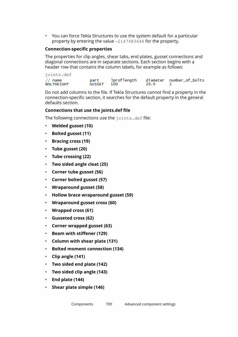
• You can force Tekla Structures to use the system default for a particularproperty by entering the value -2147483648 for the property.
Connection-specific properties
The properties for clip angles, shear tabs, end plates, gusset connections anddiagonal connections are in separate sections. Each section begins with aheader row that contains the column labels, for example as follows:
joints.def
Do not add columns to the file. If Tekla Structures cannot find a property in theconnection-specific section, it searches for the default property in the generaldefaults section.
Connections that use the joints.def file
The following connections use the joints.def file:
• Welded gusset (10)
• Bolted gusset (11)
• Bracing cross (19)
• Tube gusset (20)
• Tube crossing (22)
• Two sided angle cleat (25)
• Corner tube gusset (56)
• Corner bolted gusset (57)
• Wraparound gusset (58)
• Hollow brace wraparound gusset (59)
• Wraparound gusset cross (60)
• Wrapped cross (61)
• Gusseted cross (62)
• Corner wrapped gusset (63)
• Beam with stiffener (129)
• Column with shear plate (131)
• Bolted moment connection (134)
• Clip angle (141)
• Two sided end plate (142)
• Two sided clip angle (143)
• End plate (144)
• Shear plate simple (146)
Components 709 Advanced component settings
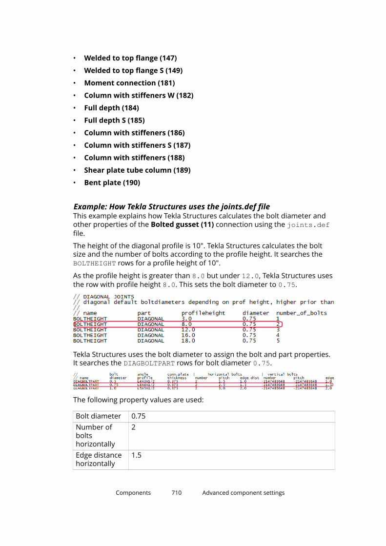
• Welded to top flange (147)
• Welded to top flange S (149)
• Moment connection (181)
• Column with stiffeners W (182)
• Full depth (184)
• Full depth S (185)
• Column with stiffeners (186)
• Column with stiffeners S (187)
• Column with stiffeners (188)
• Shear plate tube column (189)
• Bent plate (190)
Example: How Tekla Structures uses the joints.def fileThis example explains how Tekla Structures calculates the bolt diameter andother properties of the Bolted gusset (11) connection using the joints.deffile.
The height of the diagonal profile is 10". Tekla Structures calculates the boltsize and the number of bolts according to the profile height. It searches the BOLTHEIGHT rows for a profile height of 10".
As the profile height is greater than 8.0 but under 12.0, Tekla Structures usesthe row with profile height 8.0. This sets the bolt diameter to 0.75.
Tekla Structures uses the bolt diameter to assign the bolt and part properties.It searches the DIAGBOLTPART rows for bolt diameter 0.75.
The following property values are used:
Bolt diameter 0.75Number ofboltshorizontally
2
Edge distancehorizontally
1.5
Components 710 Advanced component settings
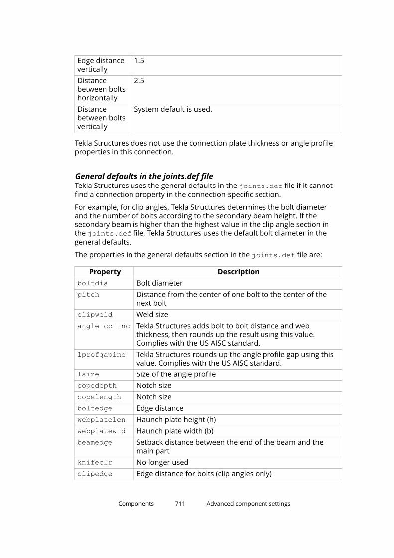
Edge distancevertically
1.5
Distancebetween boltshorizontally
2.5
Distancebetween boltsvertically
System default is used.
Tekla Structures does not use the connection plate thickness or angle profileproperties in this connection.
General defaults in the joints.def fileTekla Structures uses the general defaults in the joints.def file if it cannotfind a connection property in the connection-specific section.
For example, for clip angles, Tekla Structures determines the bolt diameterand the number of bolts according to the secondary beam height. If thesecondary beam is higher than the highest value in the clip angle section inthe joints.def file, Tekla Structures uses the default bolt diameter in thegeneral defaults.
The properties in the general defaults section in the joints.def file are:
Property Descriptionboltdia Bolt diameterpitch Distance from the center of one bolt to the center of the
next boltclipweld Weld sizeangle-cc-inc Tekla Structures adds bolt to bolt distance and web
thickness, then rounds up the result using this value.Complies with the US AISC standard.
lprofgapinc Tekla Structures rounds up the angle profile gap using thisvalue. Complies with the US AISC standard.
lsize Size of the angle profilecopedepth Notch sizecopelength Notch sizeboltedge Edge distancewebplatelen Haunch plate height (h)webplatewid Haunch plate width (b)beamedge Setback distance between the end of the beam and the
main partknifeclr No longer usedclipedge Edge distance for bolts (clip angles only)
Components 711 Advanced component settings

Property Descriptiongap No longer usedshearplatethk
Shear tab thickness
endplatethk End plate thicknessshearweld Size of weldcliplsize Size of angle profile (clip angles only)flangecutclear
Flange cut clearance
slotsize Size of slotted holeclipslots Part with slotted holes:
• 1 = beam
• 2 = angle profiles
• 3 = both
This property is the Slots in option on the Bolts tab.clip_attac Clip angle attached to the main part and secondary parts:
• 1 = both parts bolted
• 2 = main part bolted/secondary part welded
• 3 = main part not welded
• 4 = main part welded/secondary part bolted
• 5 = both parts welded
• 6 = main part not bolted
• 7 = secondary part not welded
• 8 = secondary part not bolted
• 9 = both parts bolted/welded
This property is the bolt attachment option on the Bolts tabwhere the location of bolts is defined.
copedepth_inc
Tekla Structures rounds up notch depth using this value.
copelength_inc
Tekla Structures rounds up notch length using this value.
Bolt diameter and number of bolts in the joints.def fileIn the joints.def file, the BOLTHEIGHT rows in each connection-specificsection show the default bolt diameter and default number of bolt rows forthe connection type.
Components 712 Advanced component settings

Tekla Structures determines the bolt diameter and the number of boltsaccording to the connection type based on the following properties:
For According toClip angles Secondary beam heightShear tabs Secondary beam heightEnd plates Secondary beam heightGussetconnections
Angle profile length
Diagonalconnections
Profile height
Clip angle, shear tab, and end plate connections
Tekla Structures calculates the default bolt diameter and the number of boltrows vertically according to the height of the secondary beam. You can enterthe following properties:
Property Descriptionname BOLTHEIGHTpart ANGLECLIPsec.beam.height Maximum height of the secondary beam for a certain
number of boltsdiameter Bolt diameter. The diameter must exist in the bolt
catalog.number_of_bolts Number of bolts vertically
Gusset connections
Tekla Structures calculates the default bolt diameter and the number of boltrows horizontally according to the length of the angle profile. You can enterthe following properties:
Property Descriptionname BOLTHEIGHTpart GUSSETlproflength or angleproflength
Length of the angle profile
diameter Bolt diameter. The diameter must exist in the boltcatalog.
number_of_bolts Number of bolts horizontally
Components 713 Advanced component settings
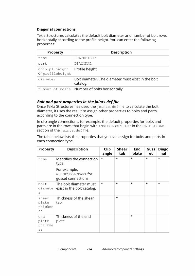
Diagonal connections
Tekla Structures calculates the default bolt diameter and number of bolt rowshorizontally according to the profile height. You can enter the followingproperties:
Property Descriptionname BOLTHEIGHTpart DIAGONALconn.pl.heightor profileheight
Profile height
diameter Bolt diameter. The diameter must exist in the boltcatalog.
number_of_bolts Number of bolts horizontally
Bolt and part properties in the joints.def fileOnce Tekla Structures has used the joints.def file to calculate the boltdiameter, it uses the result to assign other properties to bolts and parts,according to the connection type.
In clip angle connections, for example, the default properties for bolts andparts are in the rows that begin with ANGLECLBOLTPART in the CLIP ANGLEsection of the joints.def file.
The table below lists the properties that you can assign for bolts and parts ineach connection type.
Property Description Clipangle
Sheartab
Endplate
Gusset
Diagonal
name Identifies the connectiontype.
For example, GUSSETBOLTPART forgusset connections.
* * * * *
boltdiameter
The bolt diameter mustexist in the bolt catalog.
* * * * *
shearplatethickness
Thickness of the sheartab
*
endplatethickness
Thickness of the endplate
*
Components 714 Advanced component settings
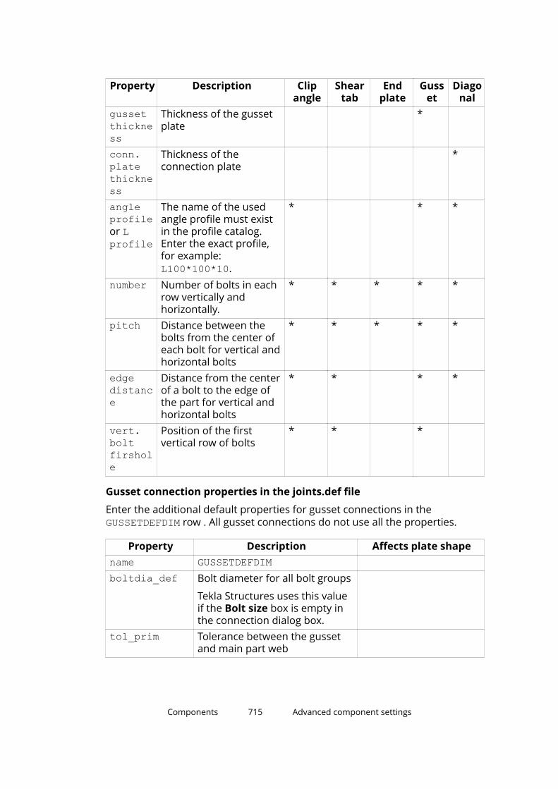
Property Description Clipangle
Sheartab
Endplate
Gusset
Diagonal
gussetthickness
Thickness of the gussetplate
*
conn.platethickness
Thickness of theconnection plate
*
angleprofileor Lprofile
The name of the usedangle profile must existin the profile catalog.Enter the exact profile,for example: L100*100*10.
* * *
number Number of bolts in eachrow vertically andhorizontally.
* * * * *
pitch Distance between thebolts from the center ofeach bolt for vertical andhorizontal bolts
* * * * *
edgedistance
Distance from the centerof a bolt to the edge ofthe part for vertical andhorizontal bolts
* * * *
vert.boltfirshole
Position of the firstvertical row of bolts
* * *
Gusset connection properties in the joints.def file
Enter the additional default properties for gusset connections in the GUSSETDEFDIM row . All gusset connections do not use all the properties.
Property Description Affects plate shapename GUSSETDEFDIM boltdia_def Bolt diameter for all bolt groups
Tekla Structures uses this valueif the Bolt size box is empty inthe connection dialog box.
tol_prim Tolerance between the gussetand main part web
Components 715 Advanced component settings
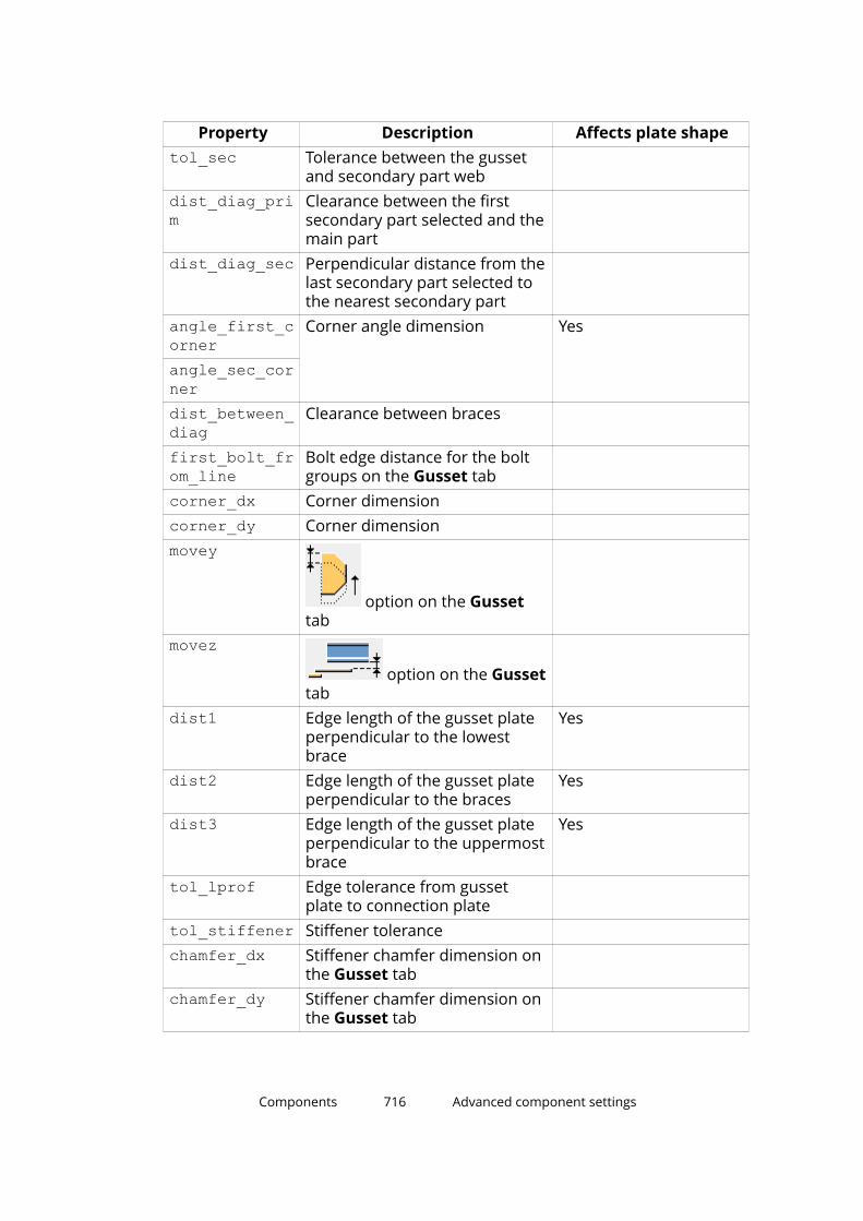
Property Description Affects plate shapetol_sec Tolerance between the gusset
and secondary part web
dist_diag_prim
Clearance between the firstsecondary part selected and themain part
dist_diag_sec Perpendicular distance from thelast secondary part selected tothe nearest secondary part
angle_first_corner
Corner angle dimension Yes
angle_sec_cornerdist_between_diag
Clearance between braces
first_bolt_from_line
Bolt edge distance for the boltgroups on the Gusset tab
corner_dx Corner dimension corner_dy Corner dimension movey
option on the Gussettab
movez option on the Gusset
tab
dist1 Edge length of the gusset plateperpendicular to the lowestbrace
Yes
dist2 Edge length of the gusset plateperpendicular to the braces
Yes
dist3 Edge length of the gusset plateperpendicular to the uppermostbrace
Yes
tol_lprof Edge tolerance from gussetplate to connection plate
tol_stiffener Stiffener tolerance chamfer_dx Stiffener chamfer dimension on
the Gusset tab
chamfer_dy Stiffener chamfer dimension onthe Gusset tab
Components 716 Advanced component settings

Property Description Affects plate shapechamfer_corner_dx
chamfer_corner_dy
side_length Side length diafit_length Fit length in the Bracing cross
(19) connection.
Tekla Structures uses this valueif the option on the Parameterstab is empty.
The example image below shows the properties of the Wraparound gusset(58) connection on the Picture tab.
1. tol_lprof2. corner_dy3. corner_dx
Components 717 Advanced component settings

4. dist_diag_sec5. tol_sec6. angle_sec_corner7. dist38. dist_between_diag9. dist210. dist111. dist_diag_prim12. tol_prim
Diagonal connection properties in the joints.def file
Enter the additional default properties for bolts and parts in the DIAGDEFDIMrow. All diagonal connections do not use all the properties.
Property Descriptionname DIAGDEFDIMboltdia_def Bolt diameter for all bolt groups
Tekla Structures uses this value if the Bolt size box isempty in the connection dialog box.
dist_gus_diag Gap between the gusset plate and the brace
If the tube profiles are closed with end plates, dist_gus_diag is the gap between the gusset plate andthe end plate.
See the Tube crossing (22) image below.dist_in Cut depth in the brace. Enter a negative value to prevent
the connection plate from being inside the tube brace.
See the Tube crossing (22) image below.dist_dv Brace edge distance to the edge of the connection plate.
This dimension changes the width of the connection plate.
See the Tube crossing (22) image below.sec_cut_tol On the Brace conn tab:slot_length_tol
tube_cut_tol On the Brace conn tab:
Components 718 Advanced component settings

Property Descriptionconn_cut_dx On the Brace conn tab:conn_cut_dy
round_plate_tol
On the Brace conn tab:
flanges_cut_angle
On the Brace conn tab:
dist_flanges_cutdist_skew_cutend_plate_thk End plate thickness
The example image below shows the properties of the Tube crossing (22)connection on the Picture tab:
1. dist_dv2. dist_in3. dist_gus_diag
Profile dependent bolt dimensions in the joints.def file
For some connections, such as Clip angle (141) and Two sided clip angle(143), Tekla Structures calculates the bolt size according to the profile size.
For these connections, Tekla Structures takes the bolt size from the PROFILEBOLTDIM rows of the PROFILE TYPE-DEPENDENT BOLT
Components 719 Advanced component settings
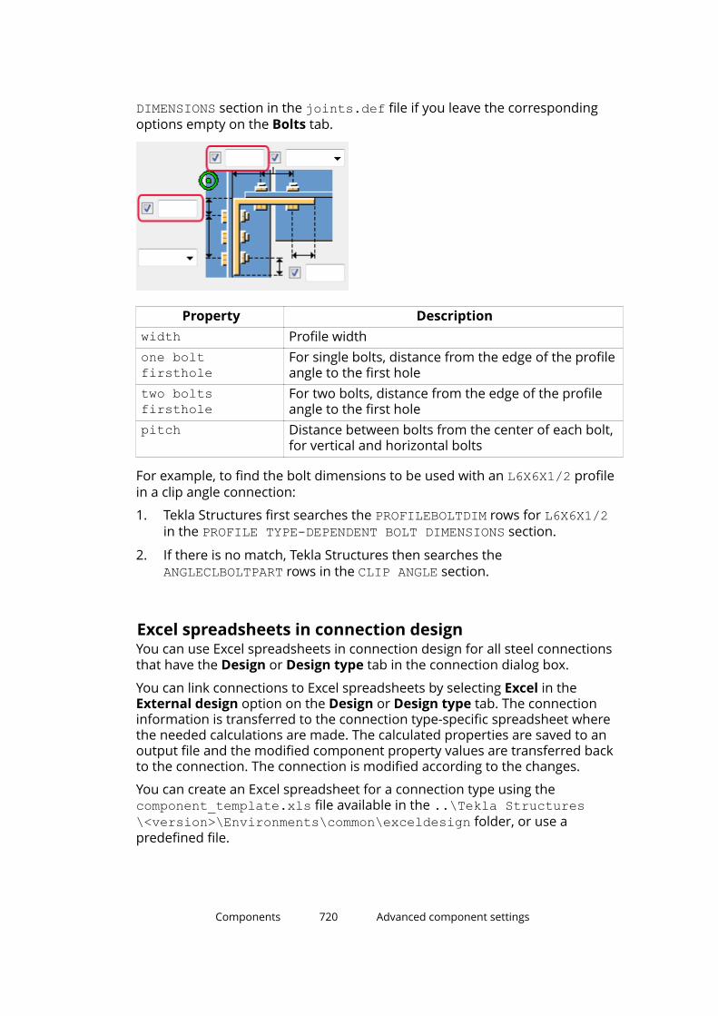
DIMENSIONS section in the joints.def file if you leave the correspondingoptions empty on the Bolts tab.
Property Descriptionwidth Profile widthone boltfirsthole
For single bolts, distance from the edge of the profileangle to the first hole
two boltsfirsthole
For two bolts, distance from the edge of the profileangle to the first hole
pitch Distance between bolts from the center of each bolt,for vertical and horizontal bolts
For example, to find the bolt dimensions to be used with an L6X6X1/2 profilein a clip angle connection:
1. Tekla Structures first searches the PROFILEBOLTDIM rows for L6X6X1/2in the PROFILE TYPE-DEPENDENT BOLT DIMENSIONS section.
2. If there is no match, Tekla Structures then searches the ANGLECLBOLTPART rows in the CLIP ANGLE section.
Excel spreadsheets in connection designYou can use Excel spreadsheets in connection design for all steel connectionsthat have the Design or Design type tab in the connection dialog box.
You can link connections to Excel spreadsheets by selecting Excel in theExternal design option on the Design or Design type tab. The connectioninformation is transferred to the connection type-specific spreadsheet wherethe needed calculations are made. The calculated properties are saved to anoutput file and the modified component property values are transferred backto the connection. The connection is modified according to the changes.
You can create an Excel spreadsheet for a connection type using thecomponent_template.xls file available in the ..\Tekla Structures\<version>\Environments\common\exceldesign folder, or use apredefined file.
Components 720 Advanced component settings
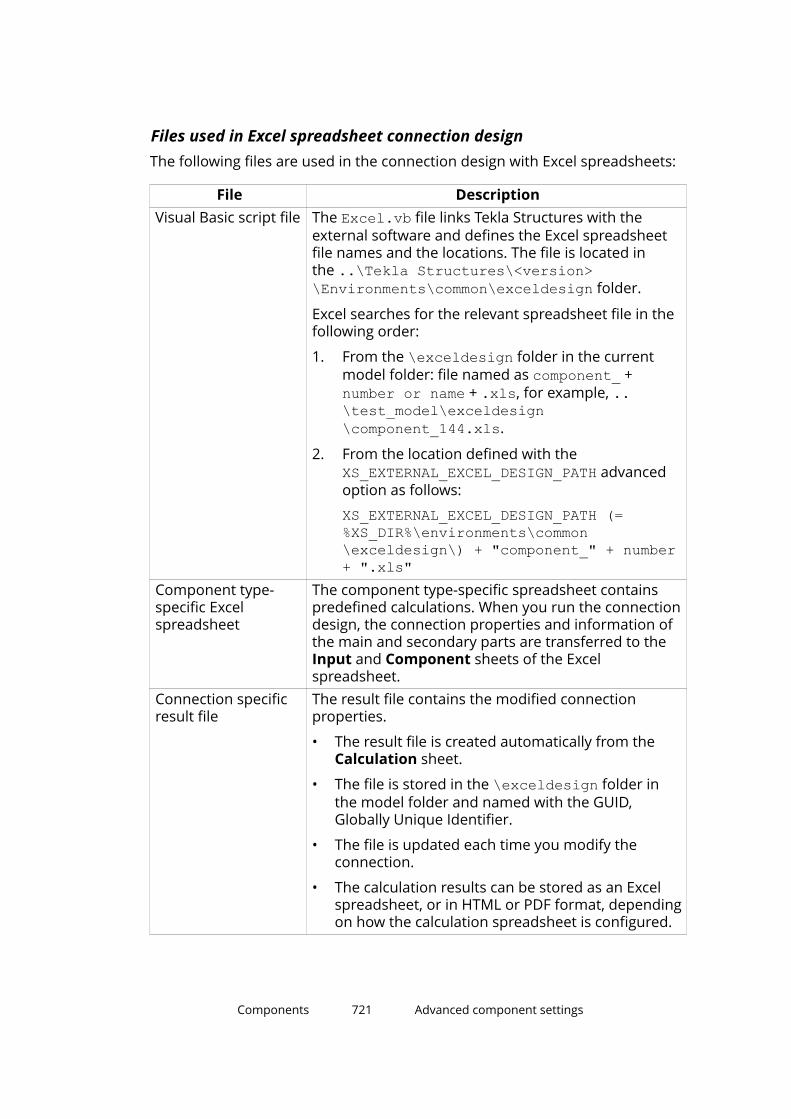
Files used in Excel spreadsheet connection designThe following files are used in the connection design with Excel spreadsheets:
File DescriptionVisual Basic script file The Excel.vb file links Tekla Structures with the
external software and defines the Excel spreadsheetfile names and the locations. The file is located inthe ..\Tekla Structures\<version>\Environments\common\exceldesign folder.
Excel searches for the relevant spreadsheet file in thefollowing order:
1. From the \exceldesign folder in the currentmodel folder: file named as component_ + number or name + .xls, for example, ..\test_model\exceldesign\component_144.xls.
2. From the location defined with the XS_EXTERNAL_EXCEL_DESIGN_PATH advancedoption as follows:
XS_EXTERNAL_EXCEL_DESIGN_PATH (=%XS_DIR%\environments\common\exceldesign\) + "component_" + number+ ".xls"
Component type-specific Excelspreadsheet
The component type-specific spreadsheet containspredefined calculations. When you run the connectiondesign, the connection properties and information ofthe main and secondary parts are transferred to theInput and Component sheets of the Excelspreadsheet.
Connection specificresult file
The result file contains the modified connectionproperties.
• The result file is created automatically from theCalculation sheet.
• The file is stored in the \exceldesign folder inthe model folder and named with the GUID,Globally Unique Identifier.
• The file is updated each time you modify theconnection.
• The calculation results can be stored as an Excelspreadsheet, or in HTML or PDF format, dependingon how the calculation spreadsheet is configured.
Components 721 Advanced component settings
File DescriptionTemplatespreadsheet
The ..\Tekla Structures\<version>\Environments\common\exceldesign foldercontains a component_template.xls spreadsheetyou should use to create your own spreadsheetapplications to use with Tekla Structures components.
Example of an Excel spreadsheet in connection designThe images in this example show the Excel spreadsheet that is used for theEnd plate (144) connection.
The sample spreadsheet has the following sheets:
The Calculation sheet contains a report of the calculations.
Components 722 Advanced component settings

The Inputs sheet contains the properties of the connection from theconnection dialog box.
Components 723 Advanced component settings
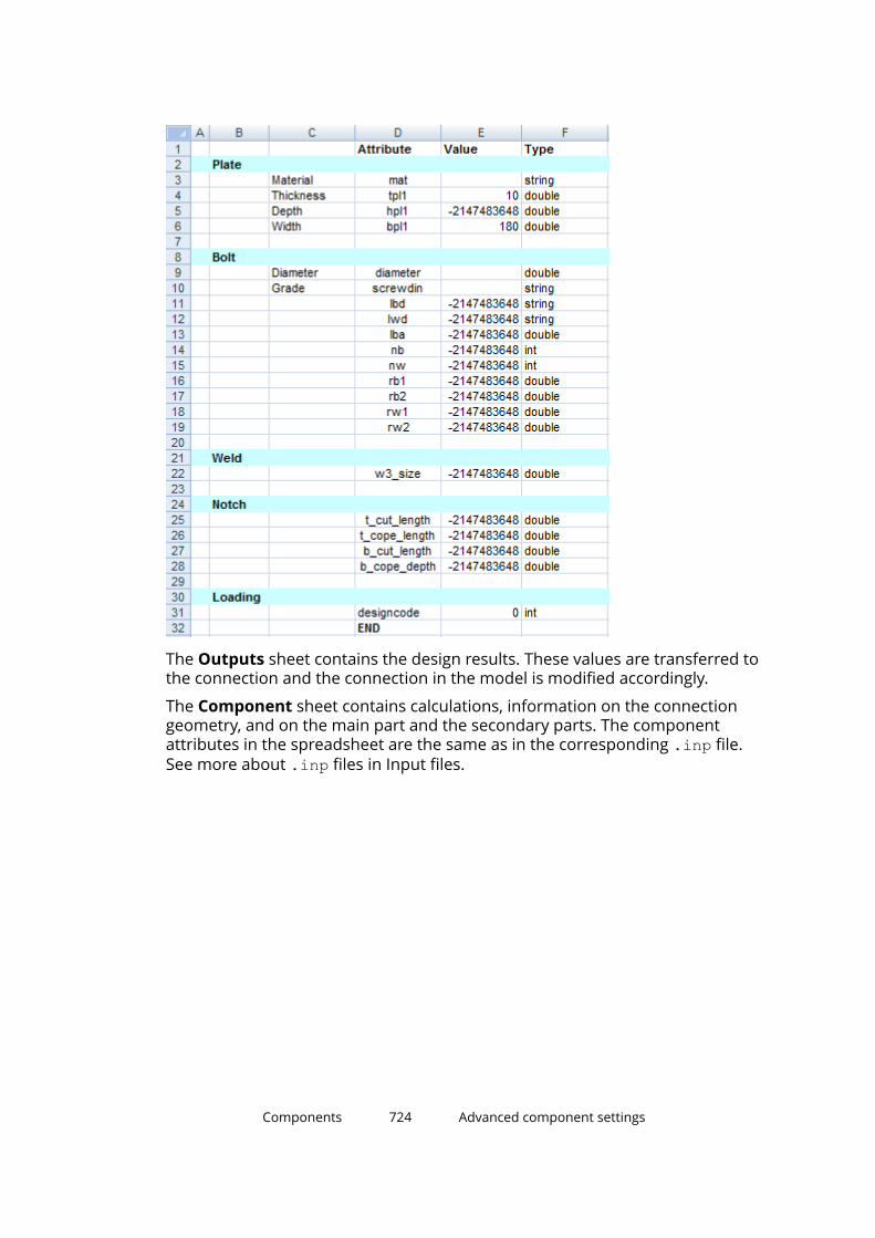
The Outputs sheet contains the design results. These values are transferred tothe connection and the connection in the model is modified accordingly.
The Component sheet contains calculations, information on the connectiongeometry, and on the main part and the secondary parts. The componentattributes in the spreadsheet are the same as in the corresponding .inp file.See more about .inp files in Input files.
Components 724 Advanced component settings

The following sheets are also included:
• Data shows catalog information.
• Norm shows the code selection and references to codes.
• Language shows translations.
Components 725 Advanced component settings
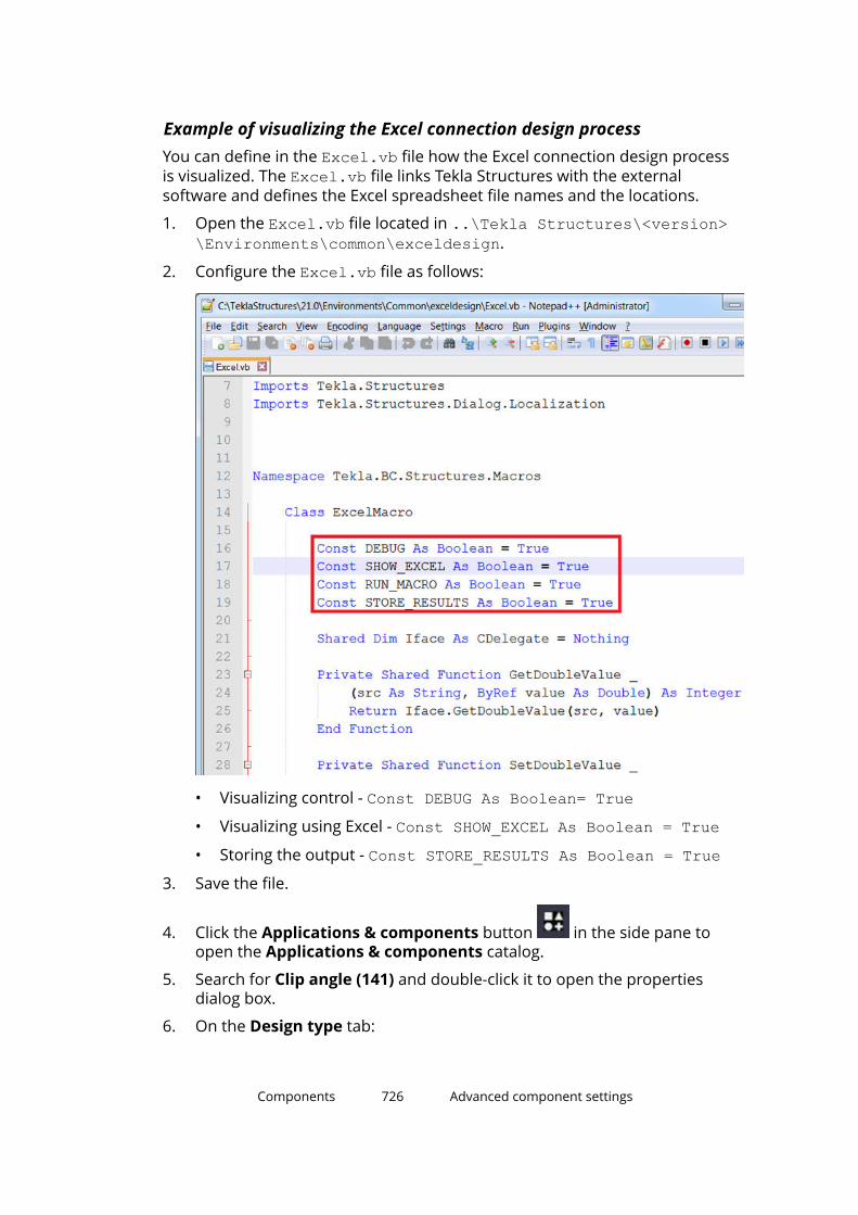
Example of visualizing the Excel connection design processYou can define in the Excel.vb file how the Excel connection design processis visualized. The Excel.vb file links Tekla Structures with the externalsoftware and defines the Excel spreadsheet file names and the locations.
1. Open the Excel.vb file located in ..\Tekla Structures\<version>\Environments\common\exceldesign.
2. Configure the Excel.vb file as follows:
• Visualizing control - Const DEBUG As Boolean= True• Visualizing using Excel - Const SHOW_EXCEL As Boolean = True• Storing the output - Const STORE_RESULTS As Boolean = True
3. Save the file.
4. Click the Applications & components button in the side pane toopen the Applications & components catalog.
5. Search for Clip angle (141) and double-click it to open the propertiesdialog box.
6. On the Design type tab:
Components 726 Advanced component settings

a. Select Excel in the External design option.
b. Enter the load values.
7. Click Modify.
Components 727 Advanced component settings
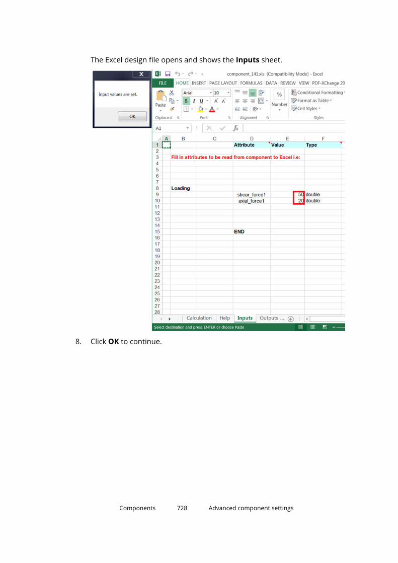
The Excel design file opens and shows the Inputs sheet.
8. Click OK to continue.
Components 728 Advanced component settings

The Excel design process now calculates the data that is shown on theComponent sheet, and then opens the Component sheet.
9. Click OK to continue.
The Excel design process now calculates the result output values and thenopens the Outputs sheet. The calculated results values are transferred tothe connection.
Components 729 Advanced component settings

10. Save the file in the model folder.
11. When you click OK, the design process is completed and the Excel designfile is closed.
Showing connection status in Excel connection designWhen you use Excel spreadsheets in connection design, you can have TeklaStructures use different colors in component symbols to show the status of acomponent in the model.
You can do this by including an error attribute on the Outputs sheet of thecomponent's Excel spreadsheet. The type of the attribute is int.
The possible values are:
Value
Color
Status
1 Green
Bolt edge distances are sufficient.
The connection passes the connection design check using the UKand US design codes embedded in the system.
2 Yellow
Bolt edge distances are insufficient according to the valuedefined in the Components settings in File --> Settings -->Options.
3 Red Tekla Structures cannot calculate the component properties. Thepossible reasons are:
• The connection direction is not correct.
• The work plane is not correct.
• The selected connection is not appropriate for the situation.
• The connection design check was carried out using theembedded UK and US design codes and the connectioncannot support the loading you have defined.
NOTE The component symbol color can only be controlled for system components,not for custom components.
General tabThe General tab is available in steel connections and steel details.
Components 730 Advanced component settings
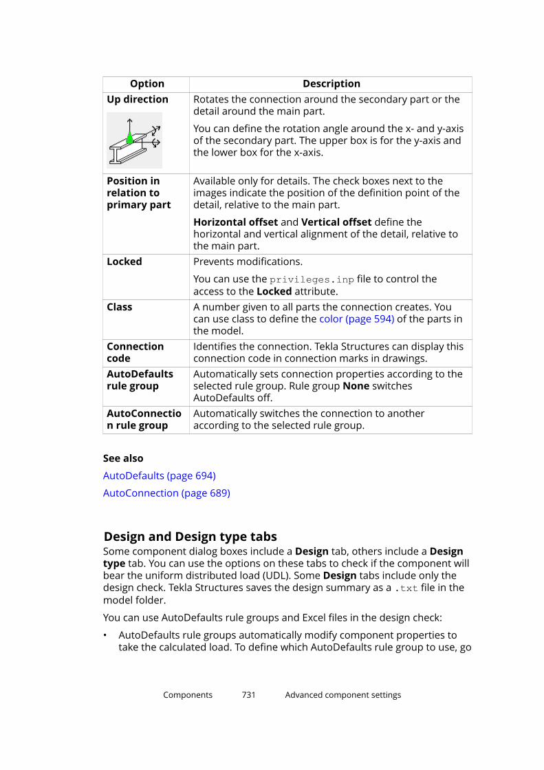
Option DescriptionUp direction Rotates the connection around the secondary part or the
detail around the main part.
You can define the rotation angle around the x- and y-axisof the secondary part. The upper box is for the y-axis andthe lower box for the x-axis.
Position inrelation toprimary part
Available only for details. The check boxes next to theimages indicate the position of the definition point of thedetail, relative to the main part.
Horizontal offset and Vertical offset define thehorizontal and vertical alignment of the detail, relative tothe main part.
Locked Prevents modifications.
You can use the privileges.inp file to control theaccess to the Locked attribute.
Class A number given to all parts the connection creates. Youcan use class to define the color (page 594) of the parts inthe model.
Connectioncode
Identifies the connection. Tekla Structures can display thisconnection code in connection marks in drawings.
AutoDefaultsrule group
Automatically sets connection properties according to theselected rule group. Rule group None switchesAutoDefaults off.
AutoConnection rule group
Automatically switches the connection to anotheraccording to the selected rule group.
See also
AutoDefaults (page 694)
AutoConnection (page 689)
Design and Design type tabsSome component dialog boxes include a Design tab, others include a Designtype tab. You can use the options on these tabs to check if the component willbear the uniform distributed load (UDL). Some Design tabs include only thedesign check. Tekla Structures saves the design summary as a .txt file in themodel folder.
You can use AutoDefaults rule groups and Excel files in the design check:
• AutoDefaults rule groups automatically modify component properties totake the calculated load. To define which AutoDefaults rule group to use, go
Components 731 Advanced component settings
to the General tab and select the rule in the AutoDefaults rule group listbox.
For more information, see Using reaction forces and UDLs in AutoDefaultsand AutoConnection (page 706).
• The information in an Excel file checks the connection design andautomatically updates component properties to bear the UDL. This isuseful when you want to check connection design according to otherdesign codes. See Excel spreadsheets in connection design (page 720).
Design tab
This design check is intended to be used with imperial units.
To check the design:
1. Go to the Design tab and select Yes in the Use UDL list.
2. To use information in an Excel spreadsheet in the UDL calculation, selectExcel in the External design list.
3. Enter the information you want to use in the calculation.
4. Select the connection in the model and click Modify.
Tekla Structures checks the component. A green component symbolindicates that the connection will bear the UDL, red indicates that it willnot.
5. To view the results of the check, right-click the component symbol andselect Inquire from the pop-up menu.
The Inquire object dialog box shows the summary of the design checkand related information.
See also Excel spreadsheets in connection design (page 720).
Design type tab
This design check is intended to be used with imperial units.
To check the design:
1. Go to the Design type tab and select Yes in the Check connection list.
Tekla Structures checks the connection each time it is used or changed inthe model.
2. Enter the information you want to use in the calculation.
3. Select the connection in the model and click Modify.
Tekla Structures checks the component. A green component symbolindicates that the connection will bear the UDL, red indicates that it willnot.
Components 732 Advanced component settings

4. To view the results of the check, right-click the component symbol andselect Inquire from the pop-up menu.
The Inquire object dialog box shows the summary of the design check:the part checked, the name of the check, the applied and allowed forceand how much capacity has been used, the results and possible solutions.
Design tab for check design only
The design is based on the British standard BS5950.
The design has the following limitations:
• Design only works in the UK environment.
• Design is available only if the main part and the secondary parts areperpendicular.
• Design is available only with two bolts horizontally.
• Design is available only when vertical bolts are defined from the top.
• Design is valid for I profiles only.
To check the design:
1. Go to the Design tab and select On in the Design list.
2. Enter the Tie Force in kilo Newtons (kN).
Tie force is required if the design check is turned on and the framing typeof the connection is beam-to-column. If there is no tie force, enter 0.
3. Enter the Shear Force in kN.
If the design check is turned on, enter a positive value. If there is no shearforce, enter 0.
4. Select the connection in the model and click Modify.
The connection symbol shows the design check status:
• Green means that the design check was successful.
• Yellow means that a warning occurred in the design check.
• Red means that a fatal error occurred in the design check.
5. To view the results of the check, right-click the connection symbol andselect Inquire from the pop-up menu.
The Inquire object dialog box shows the summary of the design checkand related information.
NOTE If the message Numbering not up to date is shown in the Inquireobject dialog box, the marks will not be correct. You need torenumber the model to ensure that the marks are up-to-date. Afterthat use the Inquire command again to get the correct marks to thedesign check summary.
Components 733 Advanced component settings
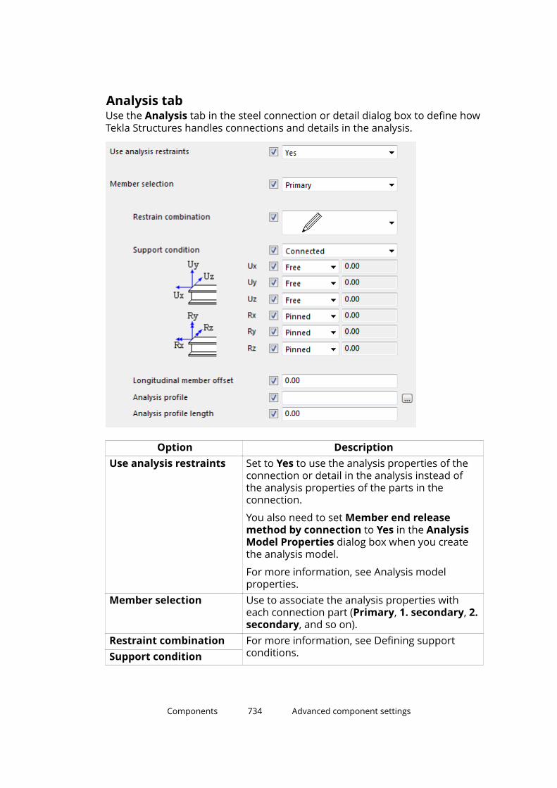
Analysis tabUse the Analysis tab in the steel connection or detail dialog box to define howTekla Structures handles connections and details in the analysis.
Option DescriptionUse analysis restraints Set to Yes to use the analysis properties of the
connection or detail in the analysis instead ofthe analysis properties of the parts in theconnection.
You also need to set Member end releasemethod by connection to Yes in the AnalysisModel Properties dialog box when you createthe analysis model.
For more information, see Analysis modelproperties.
Member selection Use to associate the analysis properties witheach connection part (Primary, 1. secondary, 2.secondary, and so on).
Restraint combination For more information, see Defining supportconditions.Support condition
Components 734 Advanced component settings
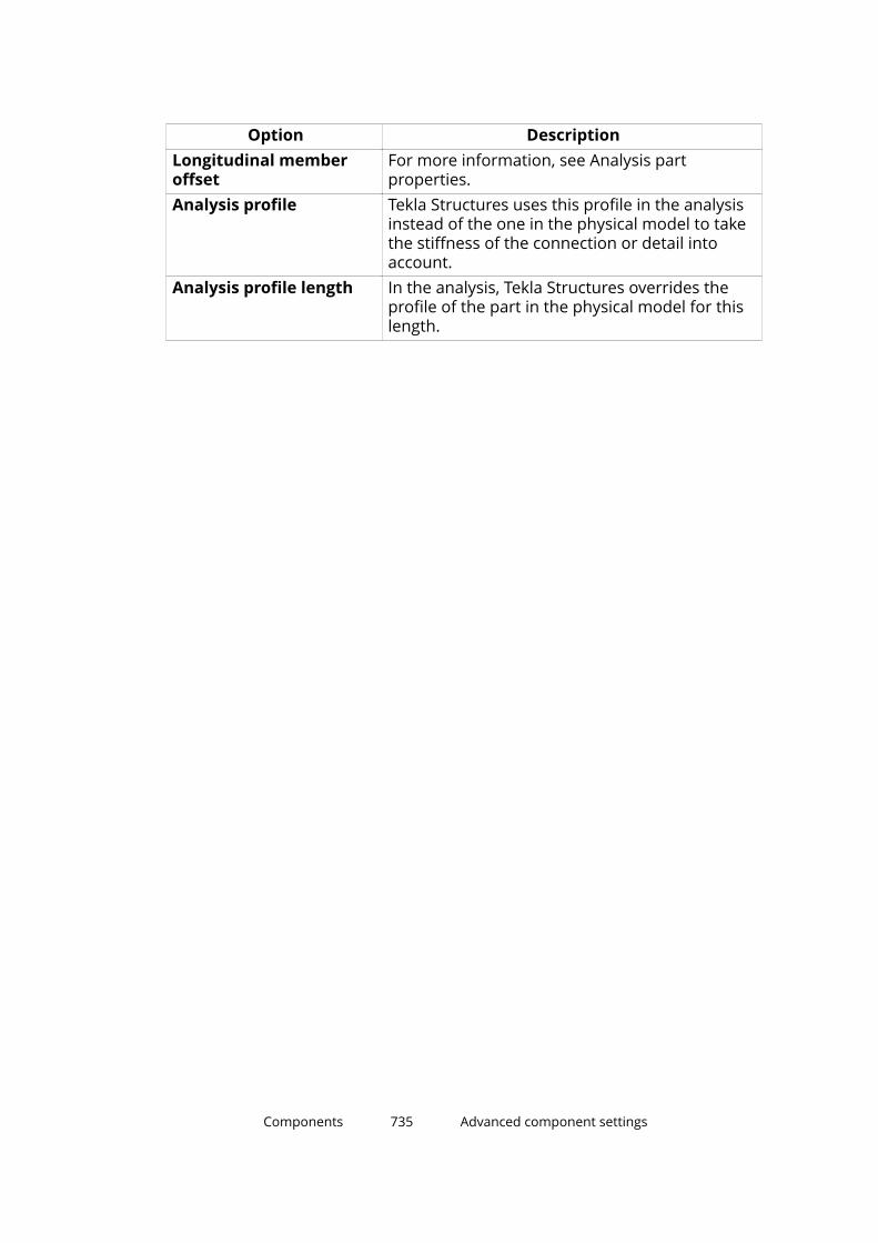
Option DescriptionLongitudinal memberoffset
For more information, see Analysis partproperties.
Analysis profile Tekla Structures uses this profile in the analysisinstead of the one in the physical model to takethe stiffness of the connection or detail intoaccount.
Analysis profile length In the analysis, Tekla Structures overrides theprofile of the part in the physical model for thislength.
Components 735 Advanced component settings
8 Custom components
You can create customized connections, parts, seams, and details for yourproject. These are called custom components. You can use custom componentsin the same way as any Tekla Structures system component. You can evencreate intelligent custom components that automatically adjust to changes inthe model.
When to use
Create a custom component if you cannot find a predefined systemcomponent (page 674) that meets all your needs. Especially if you need tocreate a large number of complex model objects and copy them across severalprojects.
Benefits
Once you store a custom component in the Applications & componentscatalog, you can easily access it from the catalog and use it in another locationin the same model. If you must modify the custom component, you only needto make the changes once. When you save the changes, they will beautomatically applied to all copies of that custom component in the model.You can also import and export custom components as .uel files betweenmodels and share the custom components with your colleagues.
Custom component types
You can create four types of custom components:
Custom components 736 Advanced component settings

Type Description ExampleCustom part(page 738)
Creates a group ofobjects that maycontainconnections anddetails.
Note: Unlikeother customcomponents,custom parts arenot marked witha component
symbol inthe model.Custom partshave the samepositionproperties asbeams have.
Customconnection(page 740)
Createsconnectionobjects andconnects thesecondary partsto the main part.The main partmay becontinuous at theconnection point.
Custom components 737 Advanced component settings
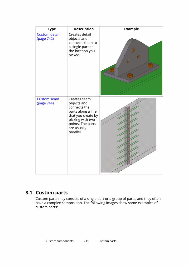
Type Description ExampleCustom detail(page 742)
Creates detailobjects andconnects them toa single part atthe location youpicked.
Custom seam(page 744)
Creates seamobjects andconnects theparts along a linethat you create bypicking with twopoints. The partsare usuallyparallel.
8.1 Custom partsCustom parts may consists of a single part or a group of parts, and they oftenhave a complex composition. The following images show some examples ofcustom parts:
Custom components 738 Custom parts
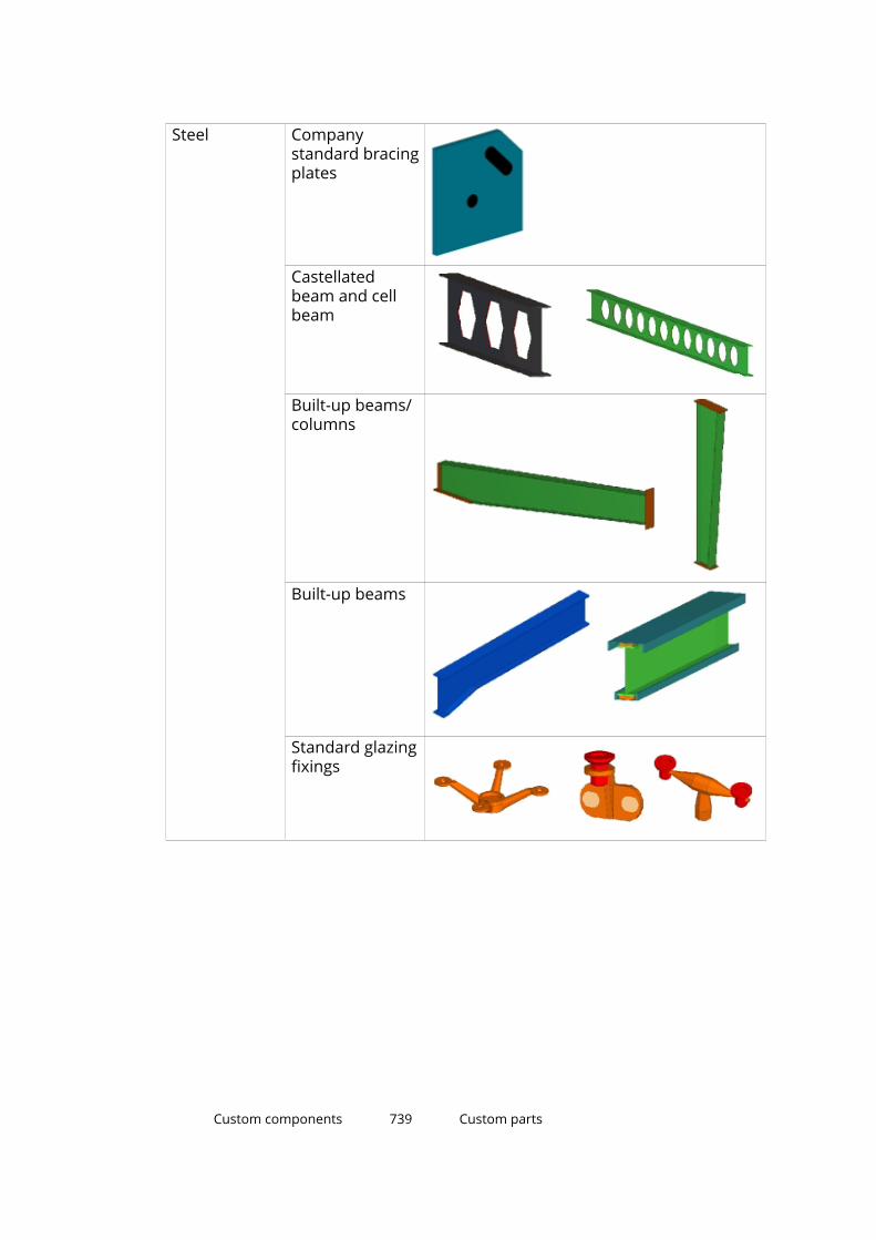
Steel Companystandard bracingplates
Castellatedbeam and cellbeam
Built-up beams/columns
Built-up beams
Standard glazingfixings
Custom components 739 Custom parts
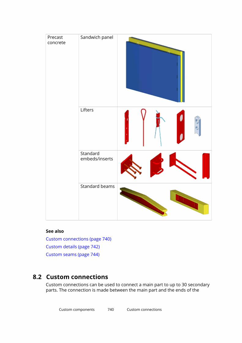
Precastconcrete
Sandwich panel
Lifters
Standardembeds/inserts
Standard beams
See also
Custom connections (page 740)
Custom details (page 742)
Custom seams (page 744)
8.2 Custom connectionsCustom connections can be used to connect a main part to up to 30 secondaryparts. The connection is made between the main part and the ends of the
Custom components 740 Custom connections

secondary parts. The following images show some examples of customconnections:
Steel Built-up plateseat
Shear plate
Typical japanesepost connections
Precastconcrete
Base detail
Double tee to Lprofile
Custom components 741 Custom connections
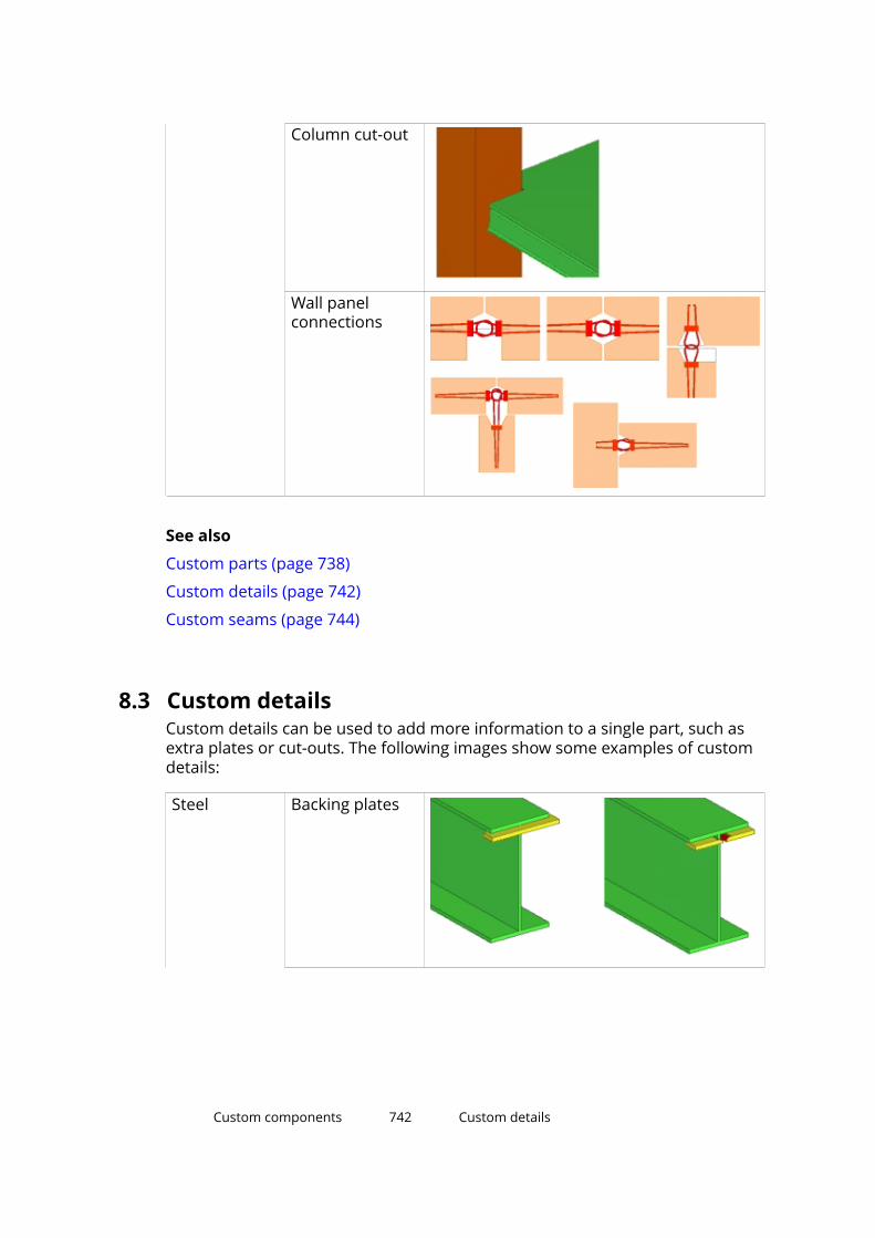
Column cut-out
Wall panelconnections
See also
Custom parts (page 738)
Custom details (page 742)
Custom seams (page 744)
8.3 Custom detailsCustom details can be used to add more information to a single part, such asextra plates or cut-outs. The following images show some examples of customdetails:
Steel Backing plates
Custom components 742 Custom details

Cast base
Timber base
Out rigger(stiffeners) andout rigger plate(stiffeners)
Precastconcrete
Door andwindow
Column patterns
Custom components 743 Custom details
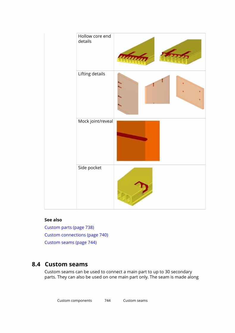
Hollow core enddetails
Lifting details
Mock joint/reveal
Side pocket
See also
Custom parts (page 738)
Custom connections (page 740)
Custom seams (page 744)
8.4 Custom seamsCustom seams can be used to connect a main part to up to 30 secondaryparts. They can also be used on one main part only. The seam is made along
Custom components 744 Custom seams
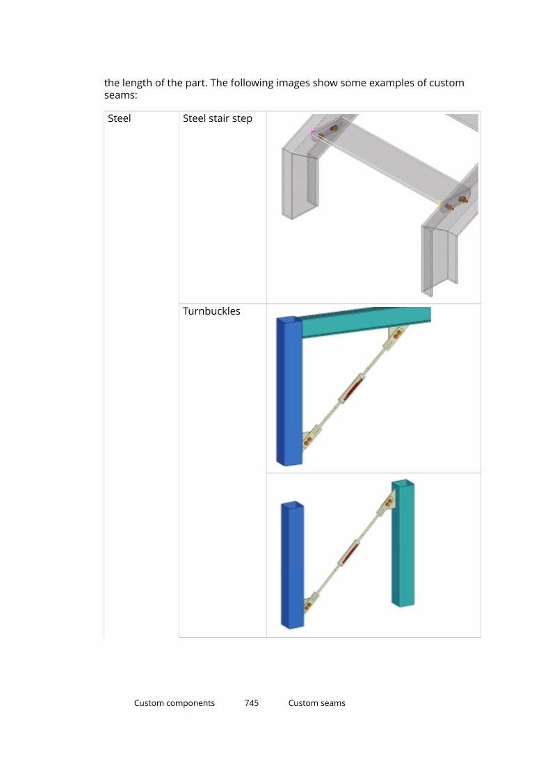
the length of the part. The following images show some examples of customseams:
Steel Steel stair step
Turnbuckles
Custom components 745 Custom seams

Handrail
Precastconcrete
Double teeconnection
Panel to panelgrout tubeconnection
See also
Custom parts (page 738)
Custom connections (page 740)
Custom details (page 742)
Custom components 746 Custom seams
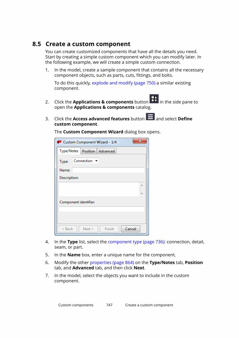
8.5 Create a custom componentYou can create customized components that have all the details you need.Start by creating a simple custom component which you can modify later. Inthe following example, we will create a simple custom connection.
1. In the model, create a sample component that contains all the necessarycomponent objects, such as parts, cuts, fittings, and bolts.
To do this quickly, explode and modify (page 750) a similar existingcomponent.
2. Click the Applications & components button in the side pane toopen the Applications & components catalog.
3. Click the Access advanced features button and select Definecustom component.
The Custom Component Wizard dialog box opens.
4. In the Type list, select the component type (page 736): connection, detail,seam, or part.
5. In the Name box, enter a unique name for the component.
6. Modify the other properties (page 864) on the Type/Notes tab, Positiontab, and Advanced tab, and then click Next.
7. In the model, select the objects you want to include in the customcomponent.
Custom components 747 Create a custom component
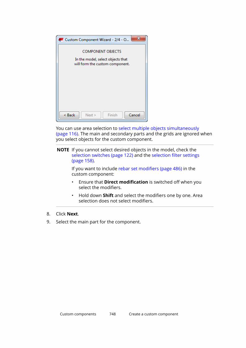
You can use area selection to select multiple objects simultaneously(page 116). The main and secondary parts and the grids are ignored whenyou select objects for the custom component.
NOTE If you cannot select desired objects in the model, check theselection switches (page 122) and the selection filter settings(page 158).
If you want to include rebar set modifiers (page 486) in thecustom component:
• Ensure that Direct modification is switched off when youselect the modifiers.
• Hold down Shift and select the modifiers one by one. Areaselection does not select modifiers.
8. Click Next.
9. Select the main part for the component.
Custom components 748 Create a custom component

10. Click Next.
11. Select the secondary parts for the component.
To select multiple secondary parts, hold down Shift when you selectthem. The maximum number of secondary parts in a custom componentis 30.
NOTE Pay attention to the order in which you select secondary parts.Tekla Structures will use the same picking order when you use thecustom component in a model.
12. Define any other properties required for this custom component, such asdetail or seam position. The properties depend on the component typethat you selected in step 4.
Custom components 749 Create a custom component
13. If you want to adjust any of the settings at this stage, click Back to returnto the previous page of the Custom Component Wizard.
14. When you are happy with the settings, click Finish to create the customcomponent.
The custom component is added in the model and in the Applications &components catalog.
15. If you want to change these settings afterwards:
a. On the custom component editor toolbar (page 761), click the
Modify custom component settings button .
b. Change the settings.
c. Click OK.
See also
Create a nested custom component (page 750)
Example: Create a custom end plate component (page 754)
Tips for creating custom components (page 881)
Explode a componentExploding means that you ungroup the objects of an existing component. Thiscan be useful when you want to create custom components more quickly.Once the objects are detached, you can modify them to suit your needs andthen create new custom components using these objects.
1. Select the component you want to explode.
2. Right-click and select Explode Component.
Tekla Structures separates the component objects. You can modify theobjects and use them to create new custom components (page 747).
Create a nested custom componentYou can create more complex custom components by joining two or morecomponents together as a nested component. The original componentsbecome sub-components in the nested component.
1. In the model, create the components and other model objects that youwant to include in the nested component.
2. Click the Applications & components button in the side pane toopen the Applications & components catalog.
Custom components 750 Create a custom component

3. Click the Access advanced features button and select Definecustom component.
The Custom Component Wizard dialog box opens.
4. In the Type list, select the type of the nested custom component.
5. In the Name box, enter a unique name for the nested component.
6. Modify the other properties on the Type/Notes tab, Position tab, andAdvanced tab, and then click Next.
7. Select the components and any other objects you want to include in thenested component, and then click Next.
8. Follow the instructions in the Custom Component Wizard to continue.
You will be asked to select the main and secondary parts for the nestedcomponent. Depending on the component type that you selected in step3, you may also have to define other properties, such as detail or seamposition.
9. When you are happy with the settings, click Finish to create the nestedcomponent.
Custom components 751 Create a custom component
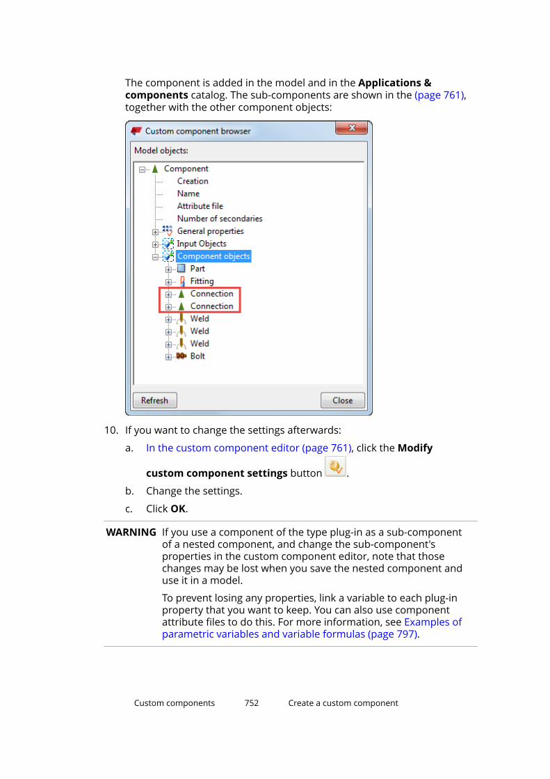
The component is added in the model and in the Applications &components catalog. The sub-components are shown in the (page 761),together with the other component objects:
10. If you want to change the settings afterwards:
a. In the custom component editor (page 761), click the Modify
custom component settings button .
b. Change the settings.
c. Click OK.
WARNING If you use a component of the type plug-in as a sub-componentof a nested component, and change the sub-component'sproperties in the custom component editor, note that thosechanges may be lost when you save the nested component anduse it in a model.
To prevent losing any properties, link a variable to each plug-inproperty that you want to keep. You can also use componentattribute files to do this. For more information, see Examples ofparametric variables and variable formulas (page 797).
Custom components 752 Create a custom component
Create a thumbnail image of a custom componentCreate a thumbnail image for each custom component to make it easier tofind a suitable component when modeling.
1. In the model, select the custom component.
2. Right-click and select Edit Custom Component.
3. Adjust the view and hide unnecessary objects to have a clear view of thecustom component.
4. Take a screenshot of the custom component.
a. On the View tab, click Screenshot --> Screenshot to open theScreenshot dialog box.
b. Click Pick view and select the view you want to take a screenshot of.
c. Click Options to open the Screenshot Options dialog box.
d. Select Print to file.
e. Select White background and click OK.
f. In the Screenshot dialog box, click Capture.
g. Click Close to close the dialog box.
h. On the File menu, click Open the model folder.
i. Browse to the \screenshots folder under the model folder.
j. Open the screenshot file in a graphics editor.
k. Crop the image, if needed.
5. Save the thumbnail image in the \screenshots folder under the modelfolder.
6. Click the Applications & components button in the side pane toopen the Applications & components catalog.
7. Right-click the custom component and select Thumbnails.
The Thumbnails dialog box opens.
8. Click Add thumbnail.
9. Browse to the \screenshots folder under the model folder.
10. Select the thumbnail image and click Open.
11. In the Thumbnails dialog box, select the check box next to the image youwant to use and clear the other check boxes.
12. Click Close.
Custom components 753 Create a custom component
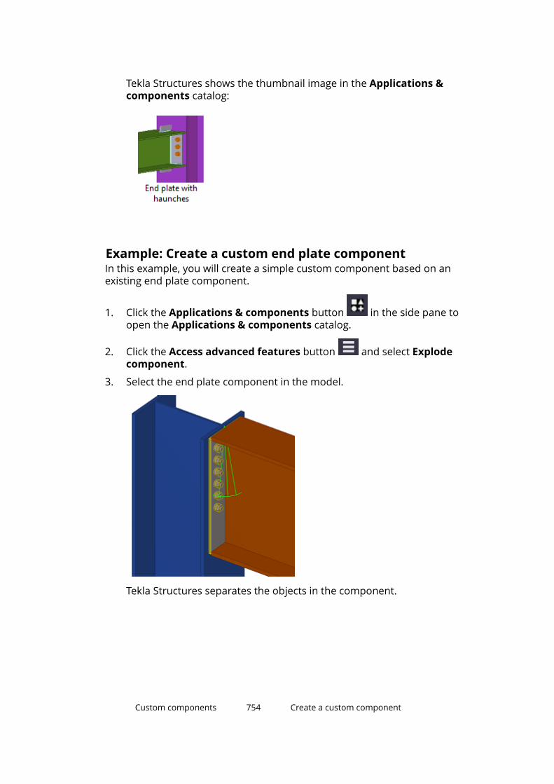
Tekla Structures shows the thumbnail image in the Applications &components catalog:
Example: Create a custom end plate componentIn this example, you will create a simple custom component based on anexisting end plate component.
1. Click the Applications & components button in the side pane toopen the Applications & components catalog.
2. Click the Access advanced features button and select Explodecomponent.
3. Select the end plate component in the model.
Tekla Structures separates the objects in the component.
Custom components 754 Create a custom component

4. Click the Access advanced features button and select Definecustom component.
5. In the Type list, select Connection.
6. In the Name box, enter a unique name for the custom component.
7. Click Next.
8. Select the objects you want to use in the custom component, and thenclick Next.
Custom components 755 Create a custom component
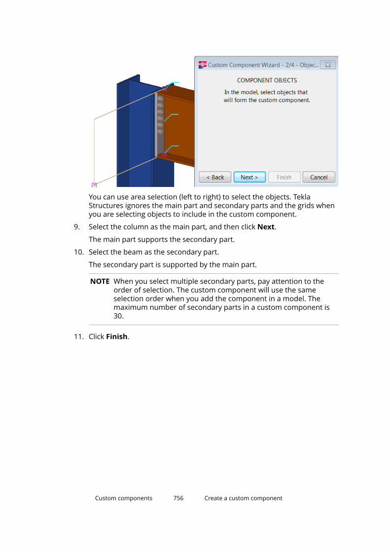
You can use area selection (left to right) to select the objects. TeklaStructures ignores the main part and secondary parts and the grids whenyou are selecting objects to include in the custom component.
9. Select the column as the main part, and then click Next.
The main part supports the secondary part.
10. Select the beam as the secondary part.
The secondary part is supported by the main part.
NOTE When you select multiple secondary parts, pay attention to theorder of selection. The custom component will use the sameselection order when you add the component in a model. Themaximum number of secondary parts in a custom component is30.
11. Click Finish.
Custom components 756 Create a custom component

Tekla Structures displays a component symbol for the new component.
You have now defined a simple custom component, which you can use inlocations similar to where it was originally created. This component is notintelligent and Tekla Structures does not adjust dimensions to suit anychanges in the model. To make the custom component intelligent, youneed to modify (page 761) it in the custom component editor.
Example: Create a nested connection with stiffenersIn this example, you will create a nested custom connection that consists ofand end plate, a bolt group, welds, and two Stiffeners (1003) components.The stiffeners are optional, which means that you can choose whether or notto create them when using the component in a model.
1. Add an End plate (144) component.
2. Explode (page 750) the end plate component.
Custom components 757 Create a custom component
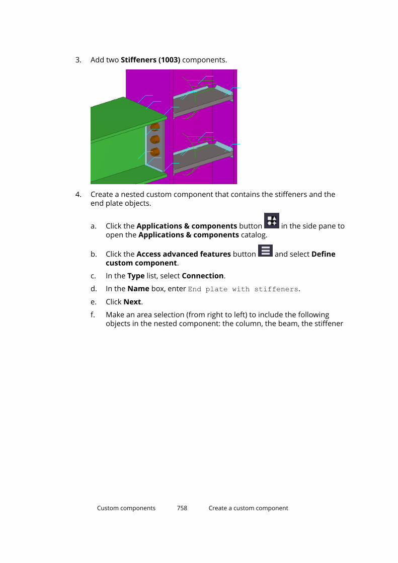
3. Add two Stiffeners (1003) components.
4. Create a nested custom component that contains the stiffeners and theend plate objects.
a. Click the Applications & components button in the side pane toopen the Applications & components catalog.
b. Click the Access advanced features button and select Definecustom component.
c. In the Type list, select Connection.
d. In the Name box, enter End plate with stiffeners.
e. Click Next.
f. Make an area selection (from right to left) to include the followingobjects in the nested component: the column, the beam, the stiffener
Custom components 758 Create a custom component

components, and all the end plate objects.
g. Click Next.
h. Choose the column as the main part of the nested component, andthen click Next.
i. Choose the beam as the secondary part of the nested component,and then click Finish. Tekla Structures creates the nested component.
5. Select the nested component you just created.
6. Right-click and select Edit Custom Component.
7. In the custom component editor, click the Display variables button .
The Variables dialog box opens.
Custom components 759 Create a custom component

8. Create the following parametric variables:
a. Click Add to create a new parametric variable P1.
b. In the Value type list, select Yes/No.
c. In the Label in dialog box box, enter Create Stiffener 1.
d. Click Add to create a new parametric variable P2.
e. In the Value type list, select Yes/No.
f. In the Label in dialog box box, enter Create Stiffener 2.
9. Link the variables to the Creation property of the two stiffeners:
a. In the Custom component browser, browse for the uppermostConnection.
b. Right-click Creation and select Add Equation.
c. Enter P1 after the equal sign, and then press Enter.
d. Browse for the second Connection.
e. Right-click Creation and select Add Equation.
f. Enter P2 after the equal sign, and then press Enter.
10. Save and close (page 823) the nested component.
Custom components 760 Create a custom component

You now have the following options in the nested component's dialog box:
8.6 Modify a custom componentUse the custom component editor to fine-tune existing custom components.When you modify a custom component, Tekla Structures updates all instancesof that component throughout the model with the changes you have made.
1. In the model, select the custom component by clicking the greencomponent symbol.
NOTE Custom parts do not have a component symbol in the model. To
select custom parts, ensure that the Select components selection switch is active.
2. Right-click and select Edit Custom Component.
The custom component editor opens. It consists of the following parts:
• The Custom component browser
• The Custom component editor toolbar
Custom components 761 Modify a custom component

• Four different views of the custom component
3. Modify the custom component in one of the four custom componentviews. You can, for example:
• Add or remove component objects
For example, add extra bolts or stiffeners to the component. Onlycomponent objects, not the main or secondary parts, can be modifiedin the custom component editor.
• Bind component objects to a plane (page 764)
• Add a distance between component objects (page 774)
• Set object properties using parametric variables (page 777)
4. Save the custom component (page 823). Click Yes when prompted toreplace all occurrences of the custom component in the model. Allinstances of the custom component are now updated with the changesyou made.
See also
Protect a custom component with a password (page 762)
Protect a custom component with a passwordYou can set a password to prevent others from modifying a customcomponent. Password-protected custom components can still be added tomodels as usual.
1. In the model, select a custom component.
Custom components 762 Modify a custom component

2. Right-click the custom component symbol and select Edit CustomComponent.
3. In the custom component editor, click the Display variables button .
The Variables dialog box opens.
4. Click Add to create a new variable.
5. In the Name box, enter Password.
6. In the Formula box, enter the desired password.
7. Save the custom component. (page 823)
The next time someone tries to edit this custom component, they will be askedfor the password.
8.7 Add variables to a custom componentVariables are the properties of a custom component. You can create variablesin the custom component editor and use them to adapt custom componentsto changes in the model. Some of the variables appear in the customcomponent's dialog box, while others are hidden and are only used incalculations.
Variable types
There are two types of variables:
• Distance variable: The distance between two planes, or between a pointand a plane. A distance variable binds parts together, or works as areference distance.
• Parametric variable: Controls all the other properties in a customcomponent, such as name, material grade, and bolt size. Parametricvariables are also used in calculations.
Distance variables
Use distance variables to bind custom component objects to a plane, so thatthe component objects stay at a fixed distance even if the surrounding objectschange. You can create distance variables manually or automatically.
You can bind the following objects to a plane:
• construction planes
• reference points of parts (only custom component objects)
• reference points of bolt groups
• chamfers
• part and polygon cut handles
Custom components 763 Add variables to a custom component

• line cuts
• reference points of reinforcing bars
• reference points of reinforcement meshes and strands
• fittings
You can decide which distance variables are shown in the custom component'sdialog box. Show the variables if you want to edit their values in the dialog box.Hide the variables if you only use them to bind objects to a plane.
Parametric variables
Use parametric variables to to set properties for any object the customcomponent creates (page 777). After creating the variable, you will be able tochange the value directly in the custom component's dialog box.
You can also create formulas to calculate values. For example, you cancalculate the position of a stiffener relative to the beam length.
You can decide which parametric variables are shown in the customcomponent's dialog box. Show the variables if you want to edit their values inthe dialog box. Hide the variables if you only use them in calculations.
Bind component objects to a planeUse distance variables to bind component objects to a plane. Binding keeps thecustom component at a fixed distance from the plane even if the surroundingobjects change. Distance variables automatically get the prefix D (distance),which is shown in the Variables dialog box.
Bind objects automaticallyYou can bind objects automatically to the main and secondary parts of aconnection or detail. The selected objects, or their handles, are bound toexisting planes if the objects (or handles) are located exactly on the plane.
NOTE You cannot bind custom parts (page 738) automatically, because theydo not have a main part.
1. In the custom component editor, click the Create distances variables
automatically button .
2. Select an object that has handles (page 303).
Custom components 764 Add variables to a custom component

3. Click the middle mouse button to bind the object.
Tekla Structures binds the object from a maximum of three directions tothe existing planes.
Tekla Structures displays a distance symbol for each binding. Select theobject to see the bindings.
Custom components 765 Add variables to a custom component
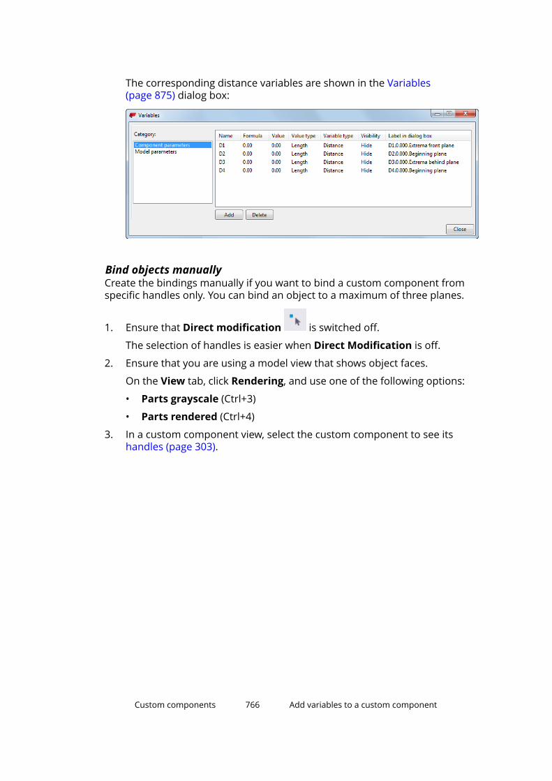
The corresponding distance variables are shown in the Variables(page 875) dialog box:
Bind objects manuallyCreate the bindings manually if you want to bind a custom component fromspecific handles only. You can bind an object to a maximum of three planes.
1. Ensure that Direct modification is switched off.
The selection of handles is easier when Direct Modification is off.
2. Ensure that you are using a model view that shows object faces.
On the View tab, click Rendering, and use one of the following options:
• Parts grayscale (Ctrl+3)
• Parts rendered (Ctrl+4)
3. In a custom component view, select the custom component to see itshandles (page 303).
Custom components 766 Add variables to a custom component
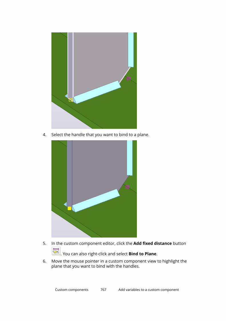
4. Select the handle that you want to bind to a plane.
5. In the custom component editor, click the Add fixed distance button
. You can also right-click and select Bind to Plane.
6. Move the mouse pointer in a custom component view to highlight theplane that you want to bind with the handles.
Custom components 767 Add variables to a custom component
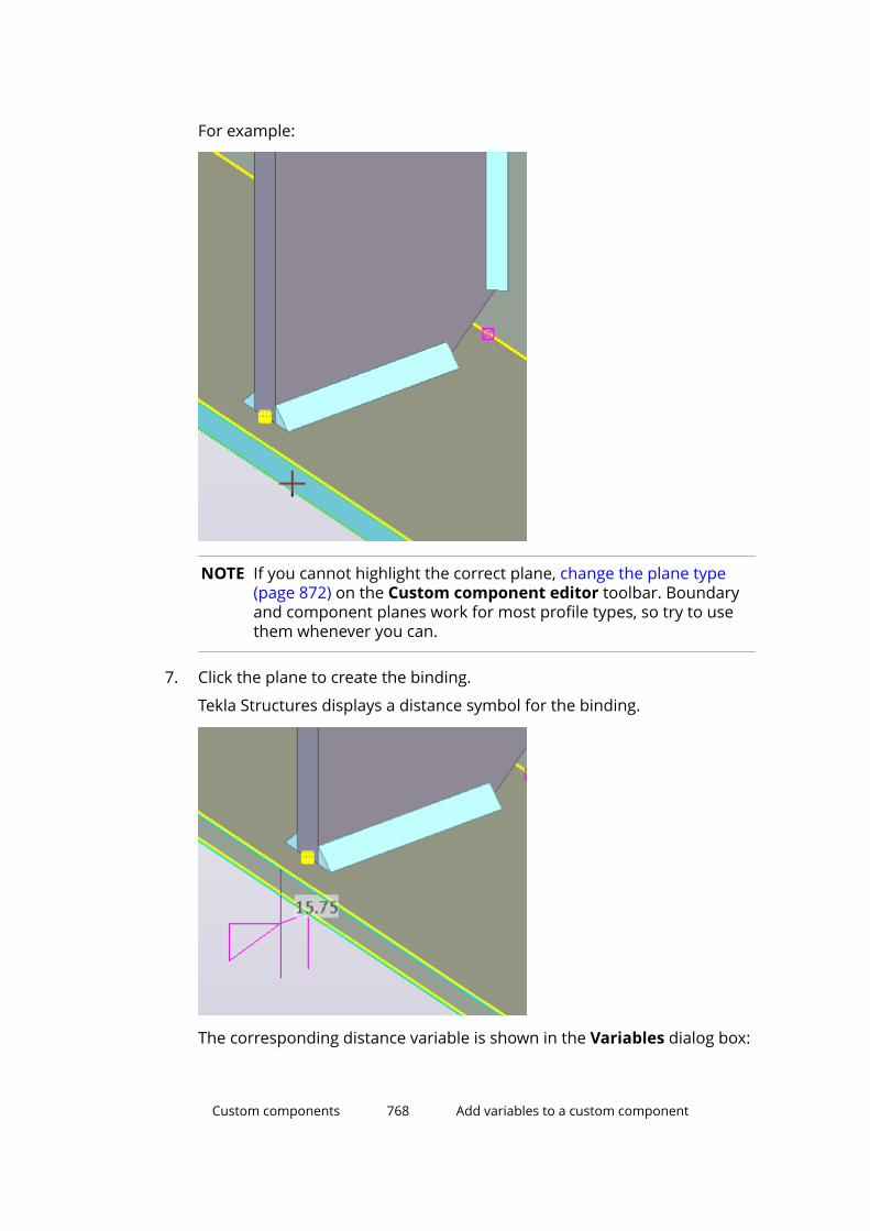
For example:
NOTE If you cannot highlight the correct plane, change the plane type(page 872) on the Custom component editor toolbar. Boundaryand component planes work for most profile types, so try to usethem whenever you can.
7. Click the plane to create the binding.
Tekla Structures displays a distance symbol for the binding.
The corresponding distance variable is shown in the Variables dialog box:
Custom components 768 Add variables to a custom component

Test a bindingTest all bindings to see that they work correctly.
1. Double-click the binding symbol in a custom component view.
The Distance Properties dialog box opens.
2. In the Value box, enter a new value.
3. Click Modify.
You should see the binding change in the model.
TIP Alternatively, you can test the binding in the Variables (page 875)dialog box:
a. Enter a new value in the Formula box.
b. Press Enter.
You should see the binding change in the model.
Delete a bindingBindings cannot be modified, but you can delete the existing bindings andthen create new ones to rebind the objects.
1. Select the binding in a custom component view.
2. Press Delete.
You can also select the binding in the Variables (page 875) dialog box andthen click the Delete button.
Custom components 769 Add variables to a custom component

Example: Bind an end plate to a planeIn this example, you will bind the end plate top to the upper side of the beam.
1. Ensure that Direct modification is switched off. The selection of endplate handles is easier when Direct Modification is off.
2. In a custom component view, select the end plate to see the end platehandles.
3. Select the top handle of the end plate.
4. Right-click the top handle and select Bind to Plane.
5. Move the pointer over the upper side of the beam flange to highlight it.
Custom components 770 Add variables to a custom component
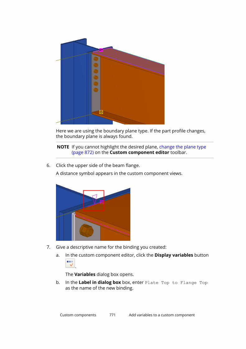
Here we are using the boundary plane type. If the part profile changes,the boundary plane is always found.
NOTE If you cannot highlight the desired plane, change the plane type(page 872) on the Custom component editor toolbar.
6. Click the upper side of the beam flange.
A distance symbol appears in the custom component views.
7. Give a descriptive name for the binding you created:
a. In the custom component editor, click the Display variables button
.
The Variables dialog box opens.
b. In the Label in dialog box box, enter Plate Top to Flange Topas the name of the new binding.
Custom components 771 Add variables to a custom component

Bind component objects using magnetic constructionplanes or linesInstead of binding each component object handle to a plane separately, youcan use magnetic construction planes and lines. The objects that are directlyon a magnetic construction plane (or line) will move with the plane (or line),which means you only need to create one distance variable instead of 8, forexample.
Bind handles using a magnetic construction plane
1. In the custom component editor, click Add construction plane.
2. Pick four points to define the shape of the construction plane.
For example, create a plane that goes through all the handles andchamfers of the custom component.
3. Click the middle mouse button.
Tekla Structures creates a construction plane. For example:
4. Double-click the plane. The plane properties are shown in the propertypane.
5. Enter a name for the plane.
6. In the Magnetic list, select Yes.
7. Click Modify.
Custom components 772 Add variables to a custom component
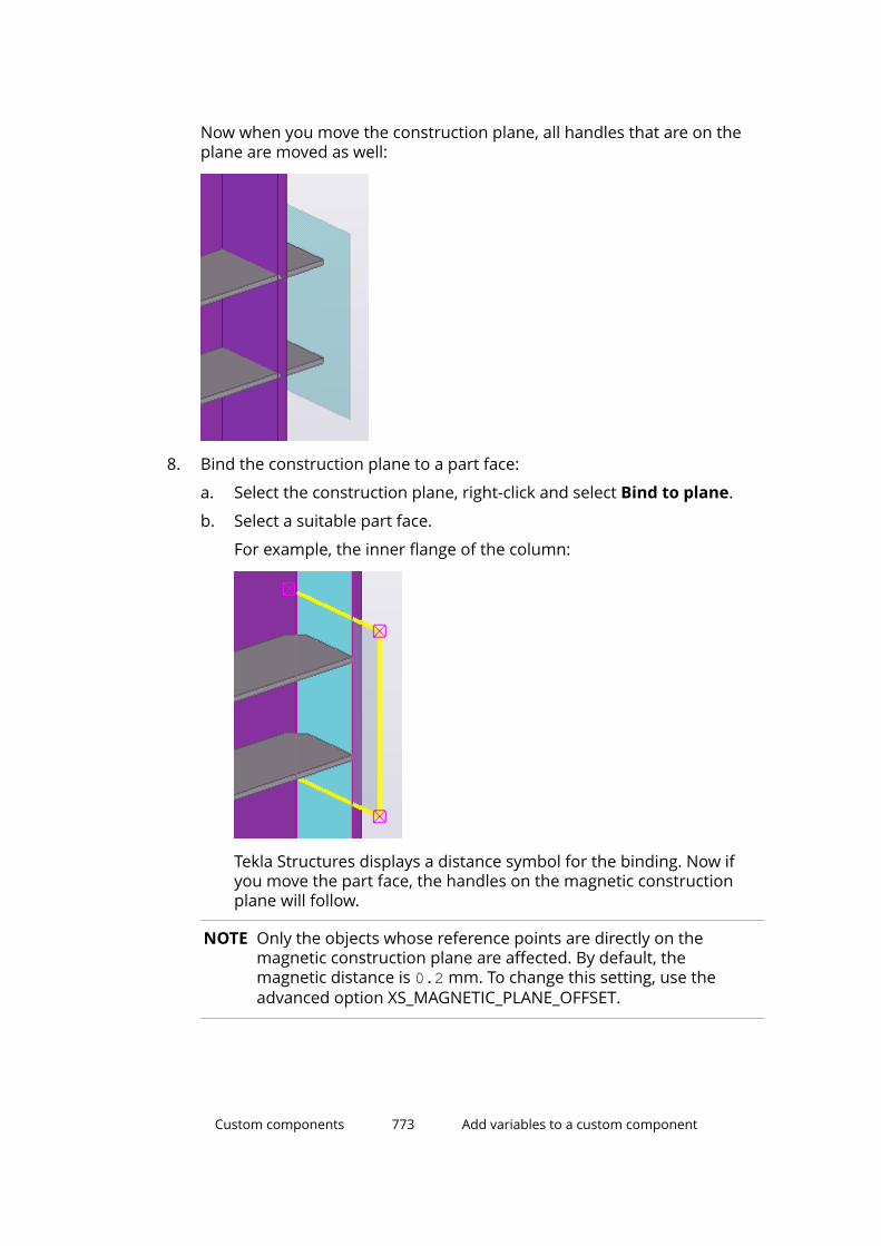
Now when you move the construction plane, all handles that are on theplane are moved as well:
8. Bind the construction plane to a part face:
a. Select the construction plane, right-click and select Bind to plane.
b. Select a suitable part face.
For example, the inner flange of the column:
Tekla Structures displays a distance symbol for the binding. Now ifyou move the part face, the handles on the magnetic constructionplane will follow.
NOTE Only the objects whose reference points are directly on themagnetic construction plane are affected. By default, themagnetic distance is 0.2 mm. To change this setting, use theadvanced option XS_MAGNETIC_PLANE_OFFSET.
Custom components 773 Add variables to a custom component
Bind handles using a magnetic construction line
1. In the custom component editor, click Add construction line.
2. Pick the starting point of the construction line.
3. Pick the end point of the construction line.
Tekla Structures creates a construction line.
4. Double-click the line. The line properties are shown in the property pane.
5. Enter a name for the line.
6. In the Magnetic list, select Yes.
7. Click Modify.
Now when you move the construction line, all handles that are on the lineare moved as well.
8. Bind the construction line to a part face:
a. Select the construction line, right-click and select Bind to plane.
b. Select a suitable part face.
Tekla Structures displays a distance symbol for the binding. Now ifyou move the part face, the handles on the magnetic constructionline will follow.
Add a distance between component objectsUse reference distance variables to add a distance between two points or apoint and a plane. The reference distance changes as you move the objects itrefers to. You can use reference distances in calculations, for example, todetermine the spacing of rungs on a ladder. Reference distance variablesautomatically get the prefix D (distance), which is shown in the Variablesdialog box.
1. In a custom component view, select a handle (page 303).
Custom components 774 Add variables to a custom component
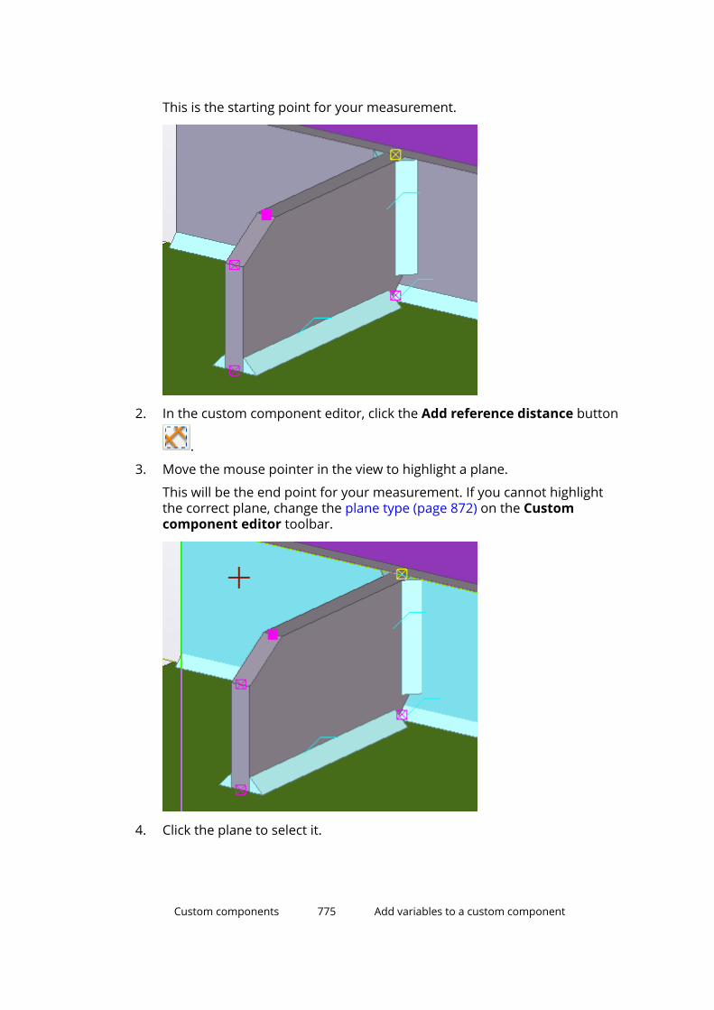
This is the starting point for your measurement.
2. In the custom component editor, click the Add reference distance button
.
3. Move the mouse pointer in the view to highlight a plane.
This will be the end point for your measurement. If you cannot highlightthe correct plane, change the plane type (page 872) on the Customcomponent editor toolbar.
4. Click the plane to select it.
Custom components 775 Add variables to a custom component

Tekla Structures displays the distance.
The corresponding reference distance variable is shown in the Variablesdialog box:
Note that the Add reference distance command remains active. You canclick more planes if you want to measure other distances.
5. To stop measuring, press Esc.
6. To check that the reference distance works correctly, move the handle.
Custom components 776 Add variables to a custom component
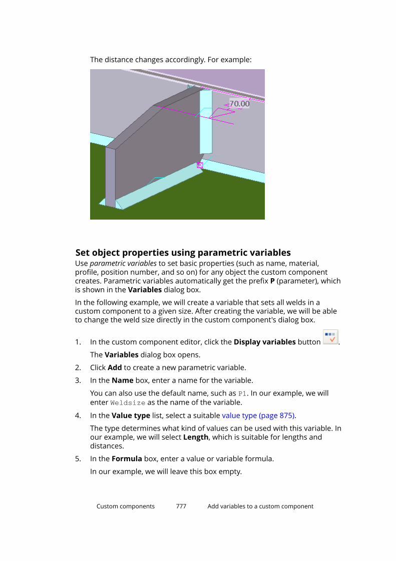
The distance changes accordingly. For example:
Set object properties using parametric variablesUse parametric variables to set basic properties (such as name, material,profile, position number, and so on) for any object the custom componentcreates. Parametric variables automatically get the prefix P (parameter), whichis shown in the Variables dialog box.
In the following example, we will create a variable that sets all welds in acustom component to a given size. After creating the variable, we will be ableto change the weld size directly in the custom component's dialog box.
1. In the custom component editor, click the Display variables button .
The Variables dialog box opens.
2. Click Add to create a new parametric variable.
3. In the Name box, enter a name for the variable.
You can also use the default name, such as P1. In our example, we willenter Weldsize as the name of the variable.
4. In the Value type list, select a suitable value type (page 875).
The type determines what kind of values can be used with this variable. Inour example, we will select Length, which is suitable for lengths anddistances.
5. In the Formula box, enter a value or variable formula.
In our example, we will leave this box empty.
Custom components 777 Add variables to a custom component

6. In the Label in dialog box box, enter a descriptive name for theparametric variable.
This label will be shown in the custom component's dialog box. In ourexample, we will enter Weld size as the label.
7. In the Visibility list, define whether the variable will be visible in thecustom component's dialog box.
Hide the variable if you only use it in calculations. Show the variable if youwant to be able to edit the value in the custom component's dialog box. Inour example, we will select Show.
8. Click Close.
In our example, we have now created a parametric variable with thefollowing settings:
9. In the Custom component browser, link the variable to the desiredobject property.
a. Select the property.
In our example, we will select the Size above line property of theuppermost weld.
b. Right-click the property and select Add Equation.
Custom components 778 Add variables to a custom component
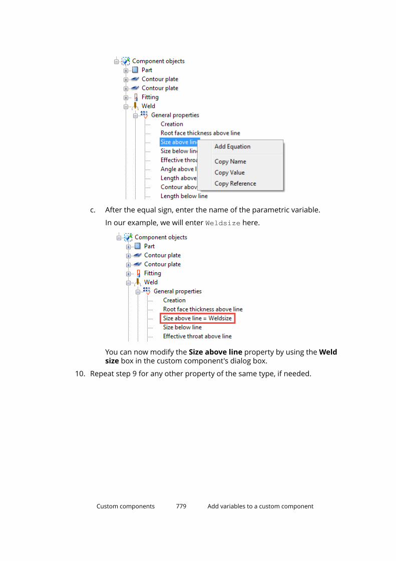
c. After the equal sign, enter the name of the parametric variable.
In our example, we will enter Weldsize here.
You can now modify the Size above line property by using the Weldsize box in the custom component's dialog box.
10. Repeat step 9 for any other property of the same type, if needed.
Custom components 779 Add variables to a custom component
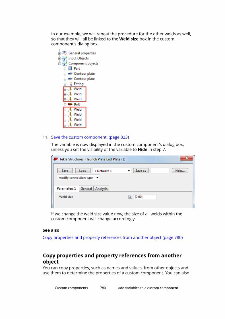
In our example, we will repeat the procedure for the other welds as well,so that they will all be linked to the Weld size box in the customcomponent's dialog box.
11. Save the custom component. (page 823)
The variable is now displayed in the custom component's dialog box,unless you set the visibility of the variable to Hide in step 7.
If we change the weld size value now, the size of all welds within thecustom component will change accordingly.
See also
Copy properties and property references from another object (page 780)
Copy properties and property references from anotherobjectYou can copy properties, such as names and values, from other objects anduse them to determine the properties of a custom component. You can also
Custom components 780 Add variables to a custom component
copy property references. The link is dynamic, so when the property changes,the reference reflects the change. For example, you can use a beam lengthreference in variable formulas. Even if the length changes, the correct value isalways used in calculations.
1. In the Custom component browser, browse for the object property youwant to copy.
To find the required component object more easily, select it in a customcomponent view. Tekla Structures highlights the selected object in theCustom component browser.
2. Right-click the property and select one of the following:
• Copy Name
Copies the name of the object. For example, Material.
• Copy Value
Copies the value the object currently has. For example, S235JR.
• Copy Reference
Copies the link to the property. For example, fP(Material,"ID57720EEE-0000-000E-3134-363730393237").
Custom components 781 Add variables to a custom component
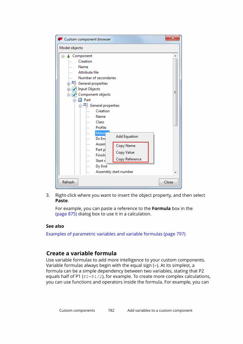
3. Right-click where you want to insert the object property, and then selectPaste.
For example, you can paste a reference to the Formula box in the(page 875) dialog box to use it in a calculation.
See also
Examples of parametric variables and variable formulas (page 797)
Create a variable formulaUse variable formulas to add more intelligence to your custom components.Variable formulas always begin with the equal sign (=). At its simplest, aformula can be a simple dependency between two variables, stating that P2equals half of P1 (P2=P1/2), for example. To create more complex calculations,you can use functions and operators inside the formula. For example, you can
Custom components 782 Add variables to a custom component
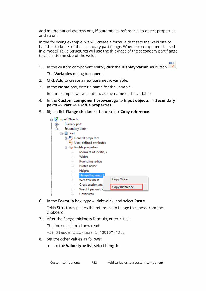
add mathematical expressions, if statements, references to object properties,and so on.
In the following example, we will create a formula that sets the weld size tohalf the thickness of the secondary part flange. When the component is usedin a model, Tekla Structures will use the thickness of the secondary part flangeto calculate the size of the weld.
1. In the custom component editor, click the Display variables button .
The Variables dialog box opens.
2. Click Add to create a new parametric variable.
3. In the Name box, enter a name for the variable.
In our example, we will enter w as the name of the variable.
4. In the Custom component browser, go to Input objects --> Secondaryparts --> Part --> Profile properties.
5. Right-click Flange thickness 1 and select Copy reference.
6. In the Formula box, type =, right-click, and select Paste.
Tekla Structures pastes the reference to flange thickness from theclipboard.
7. After the flange thickness formula, enter *0.5.
The formula should now read:
=fP(Flange thickness 1,"GUID")*0.58. Set the other values as follows:
a. In the Value type list, select Length.
Custom components 783 Add variables to a custom component

b. In the Visibility list, select Hide.
9. In the Custom component browser, go to Component objects --> Weld--> General properties.
10. Right-click Size above line, select Add equation and type = w.
Functions in variable formulasYou can use functions to calculate values for parametric variables. Variableformulas always begin with the equal sign (=).
For more information, see Set object properties using parametric variables(page 777).
Arithmetic operatorsUse arithmetic operators to combine expressions that return numeric values.You can use the following arithmetic operators:
Operator Description Notes+ addition Use also to create strings of
parameters.- subtraction * multiplication Multiplication is faster than division.
=D1*0.5 is faster than =D1/2/ division
Logical and comparison operatorsUse logical and comparison operators inside if statements. You can use if-then-else statements to test a condition and to set the value according to theresult.
Custom components 784 Add variables to a custom component

For example:
=if (D1>200) then 20 else 10 endifYou can use the following operators inside if statements:
Operator Description Example== both sides are equal!= sides are not equal< left side is smaller<= left side is smaller or
equal> right side is smaller>= right side is smaller or
equal&& logical AND
both conditions mustbe true
=if (D1==200 && D2<40) then 6 else 0 endif
If D1 is 200 and D2 smaller than 40,the result is 6, otherwise 0.
|| logical OR
only one conditionmust be true
=if (D1==200 || D2<40) then 6 else 0 endif
If D1 is 200 or D2 is smaller than 40,the result is 6, otherwise 0.
Reference functionsUse reference functions to refer to the property of another object, such as theplate thickness of a secondary part. Tekla Structures refers to the object on thesystem level, so if the object property changes, so does the reference functionvalue.
You can use the following reference functions:
Function Description ExamplefTpl("templateattribute","object GUID")
Returns thetemplate attributevalue of an objectthat has a givenobject GUID.
=fTpl("WEIGHT","ID50B8559A-0000-010B-3133-353432373038")returns the weight of an objectwhose GUID isID50B8559A-0000-010B-3133-353432373038.
Custom components 785 Add variables to a custom component
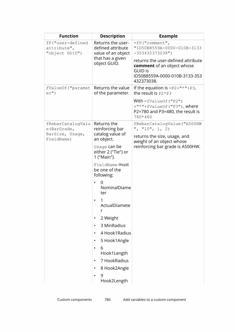
Function Description ExamplefP("user-definedattribute","object GUID")
Returns the user-defined attributevalue of an objectthat has a givenobject GUID.
=fP("comment","ID50B8559A-0000-010B-3133-353432373038")returns the user-defined attributecomment of an object whoseGUID isID50B8559A-0000-010B-3133-353432373038.
fValueOf("parameter")
Returns the valueof the parameter.
If the equation is =P2+"*"+P3,the result is P2*P3With =fValueOf("P2")+"*"+fValueOf("P3"), whereP2=780 and P3=480, the result is 780*480
fRebarCatalogValue(BarGrade,BarSize, Usage,FieldName)
Returns thereinforcing barcatalog value ofan object.
Usage can beeither 2 ("Tie") or1 ("Main").
FieldName mustbe one of thefollowing:
• 0NominalDiameter
• 1ActualDiameter
• 2 Weight
• 3 MinRadius
• 4 Hook1Radius
• 5 Hook1Angle
• 6Hook1Length
• 7 HookRadius
• 8 Hook2Angle
• 9Hook2Length
fRebarCatalogValue("A500HW", "10", 1, 2)returns the size, usage, andweight of an object whosereinforcing bar grade is A500HW.
Custom components 786 Add variables to a custom component

Function Description Example• 10
Hook3Radius
• 11 Hook3Angl
• 12Hook3Length
• 13 Area
ASCII file as a reference functionYou can refer to ASCII files to get data. Tekla Structures searches for the files inthe following order:
1. model
2. ..\TeklaStructuresModels\<model>\CustomComponentDialogFiles\
3. project (set with advanced option XS_PROJECT)
4. firm (set with advanced option XS_FIRM)
5. system (set with advanced option XS_SYSTEM)
The format for reading files is the following:
fVF("filename", "key_value_of_row", column_number)• Key value of row is a unique text value.
• Column number is an index starting from 1.
NOTE Enter a space at the end of each row in the ASCII file. Otherwise theinformation is not read correctly.
Example
The =fVF("Overlap.dat", "MET-202Z25", 5) function is in the Formulabox in the Variables dialog box. The function gets the value 16.0 for theprofile MET-202Z25, from the Overlap.dat file.
Custom components 787 Add variables to a custom component
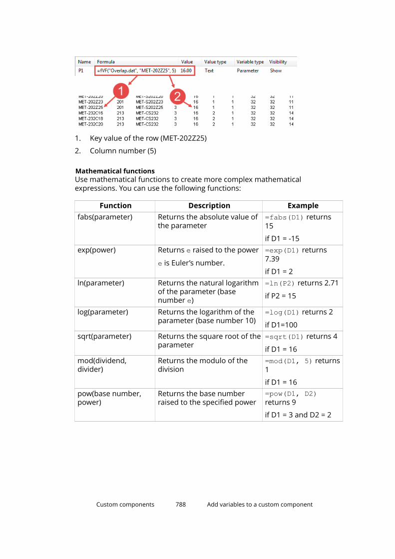
1. Key value of the row (MET-202Z25)
2. Column number (5)
Mathematical functionsUse mathematical functions to create more complex mathematicalexpressions. You can use the following functions:
Function Description Examplefabs(parameter) Returns the absolute value of
the parameter=fabs(D1) returns15
if D1 = -15exp(power) Returns e raised to the power
e is Euler’s number.
=exp(D1) returns7.39
if D1 = 2ln(parameter) Returns the natural logarithm
of the parameter (basenumber e)
=ln(P2) returns 2.71
if P2 = 15
log(parameter) Returns the logarithm of theparameter (base number 10)
=log(D1) returns 2
if D1=100sqrt(parameter) Returns the square root of the
parameter=sqrt(D1) returns 4
if D1 = 16mod(dividend,divider)
Returns the modulo of thedivision
=mod(D1, 5) returns1
if D1 = 16pow(base number,power)
Returns the base numberraised to the specified power
=pow(D1, D2)returns 9
if D1 = 3 and D2 = 2
Custom components 788 Add variables to a custom component
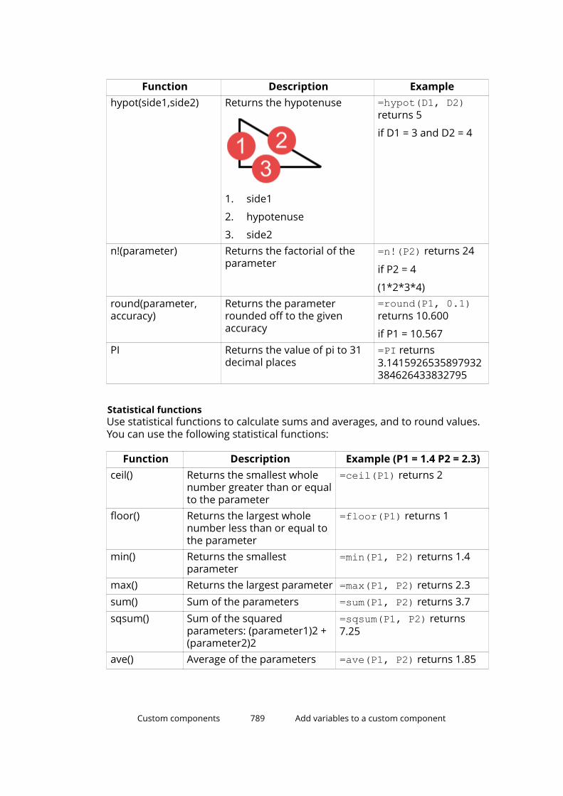
Function Description Examplehypot(side1,side2) Returns the hypotenuse
1. side1
2. hypotenuse
3. side2
=hypot(D1, D2)returns 5
if D1 = 3 and D2 = 4
n!(parameter) Returns the factorial of theparameter
=n!(P2) returns 24
if P2 = 4
(1*2*3*4)round(parameter,accuracy)
Returns the parameterrounded off to the givenaccuracy
=round(P1, 0.1)returns 10.600
if P1 = 10.567PI Returns the value of pi to 31
decimal places=PI returns3.1415926535897932384626433832795
Statistical functionsUse statistical functions to calculate sums and averages, and to round values.You can use the following statistical functions:
Function Description Example (P1 = 1.4 P2 = 2.3)ceil() Returns the smallest whole
number greater than or equalto the parameter
=ceil(P1) returns 2
floor() Returns the largest wholenumber less than or equal tothe parameter
=floor(P1) returns 1
min() Returns the smallestparameter
=min(P1, P2) returns 1.4
max() Returns the largest parameter =max(P1, P2) returns 2.3sum() Sum of the parameters =sum(P1, P2) returns 3.7sqsum() Sum of the squared
parameters: (parameter1)2 +(parameter2)2
=sqsum(P1, P2) returns7.25
ave() Average of the parameters =ave(P1, P2) returns 1.85
Custom components 789 Add variables to a custom component

Function Description Example (P1 = 1.4 P2 = 2.3)sqave() Average of the squared
parameters=sqave(P1, P2) returns3.625
Example: Ceil and floor statistical functions
In this example, you have the following parametric variables:
• Beam length: P1 = 3500
• Post spacing: P2 = 450
P1 / P2 = 7.7778
You can use the ceil and floor statistical functions to round the value andthen use the rounded value as the number of beam posts:
• =ceil(P1/P2) returns 8
• =floor(P1/P2) returns 7
Data type conversion functionsUse data type conversion functions to convert values into another data type.You can use the following data type conversion functions:
Function Description Exampleint() Converts data to integer Useful especially for calculating
profile dimensions:
=int(100.0132222000) returns100, if decimals are set to 0 in theOptions dialog box
double() Converts data to a doublestring() Converts data to stringimp() Converts imperial units
Use this function incalculations instead ofimperial units. You cannotuse imperial units directlyin calculations.
For the following examples,length unit is set to mm anddecimals are set to 2 in theOptions dialog box.
=imp(1,1,1,2) meaning 1 foot1 1/2 inch returns 342.90 mm
=imp(1,1,2) meaning 1 1/2inches returns 38.10 mm
=imp(1,2) meaning 1/2 inchesreturns 12.70 mm
=imp(1) meaning 1 inch returns25.40 mm
=3’/3" is not possible, but =imp(36)/imp(3) is ok
Custom components 790 Add variables to a custom component

Function Description Examplevwu(value,unit)
Converts the lengthvalues and angle values.The available units are:
• "ft" ("feet", "foot")
• "in" ("inch", "inches")
• "m"
• "cm"
• "mm"
• "rad"
• "deg"
=vwu(4.0,"in") returns 101.60mm, if length unit is set to mmand decimals are set to 2 in theOptions dialog box
=vwu(2.0,"rad") returns114.59 degrees, if angle is set todegrees and decimals are set to 2in the Options dialog box
NOTE The units depend on the settings in File menu --> Settings -->Options --> Units and decimals .
String operationsUse string operations to manipulate character strings. Strings must be insidequotation marks in variable formulas.
You can use the following string operations:
Operation Description Example (P1 = "PL100*10")match(parameter1,parameter2)
Returns 1 if parametersare equal and 0 ifdifferent.
You can also usewildcards *, ?, and [ ]with the match function.
=match(P1, "PL100*10")returns 1
Accept all profiles starting withPFC: =match(P4, "PFC*")Accept profiles starting with PFC,and height starts with 2,3,4 or 5: =match(P4, "PFC[2345]*")Accept profiles starting with PFC,heights are 200,300,400 or 500and width starts with 7: =match(P4, "PFC[2345]00?7")
length(parameter)
Returns the number ofcharacters in theparameter.
=length(P1) returns 8
find(parameter, string)
Returns the order number(starting at zero) of thespecified string and -1 ifthe specified string is not
=find(P1, "*") returns 5
Custom components 791 Add variables to a custom component
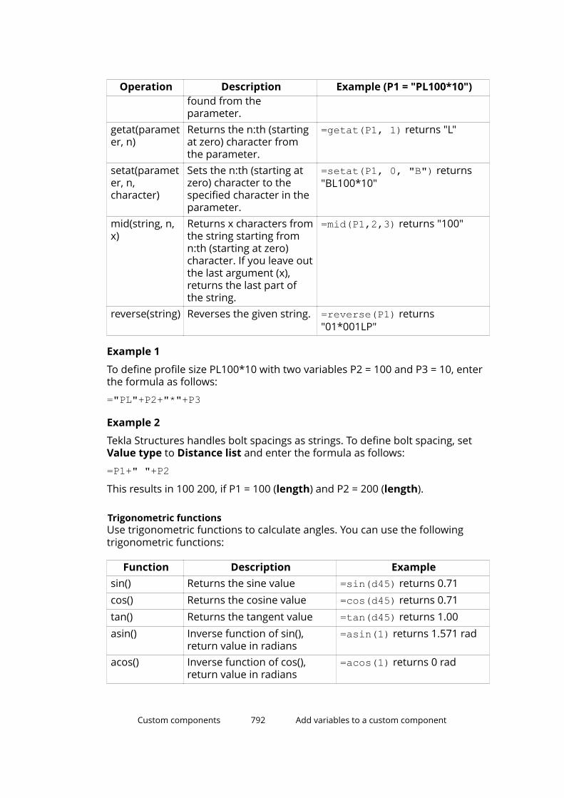
Operation Description Example (P1 = "PL100*10")found from theparameter.
getat(parameter, n)
Returns the n:th (startingat zero) character fromthe parameter.
=getat(P1, 1) returns "L"
setat(parameter, n,character)
Sets the n:th (starting atzero) character to thespecified character in theparameter.
=setat(P1, 0, "B") returns"BL100*10"
mid(string, n,x)
Returns x characters fromthe string starting fromn:th (starting at zero)character. If you leave outthe last argument (x),returns the last part ofthe string.
=mid(P1,2,3) returns "100"
reverse(string) Reverses the given string. =reverse(P1) returns"01*001LP"
Example 1
To define profile size PL100*10 with two variables P2 = 100 and P3 = 10, enterthe formula as follows:
="PL"+P2+"*"+P3
Example 2
Tekla Structures handles bolt spacings as strings. To define bolt spacing, setValue type to Distance list and enter the formula as follows:
=P1+" "+P2This results in 100 200, if P1 = 100 (length) and P2 = 200 (length).
Trigonometric functionsUse trigonometric functions to calculate angles. You can use the followingtrigonometric functions:
Function Description Examplesin() Returns the sine value =sin(d45) returns 0.71cos() Returns the cosine value =cos(d45) returns 0.71tan() Returns the tangent value =tan(d45) returns 1.00asin() Inverse function of sin(),
return value in radians=asin(1) returns 1.571 rad
acos() Inverse function of cos(),return value in radians
=acos(1) returns 0 rad
Custom components 792 Add variables to a custom component
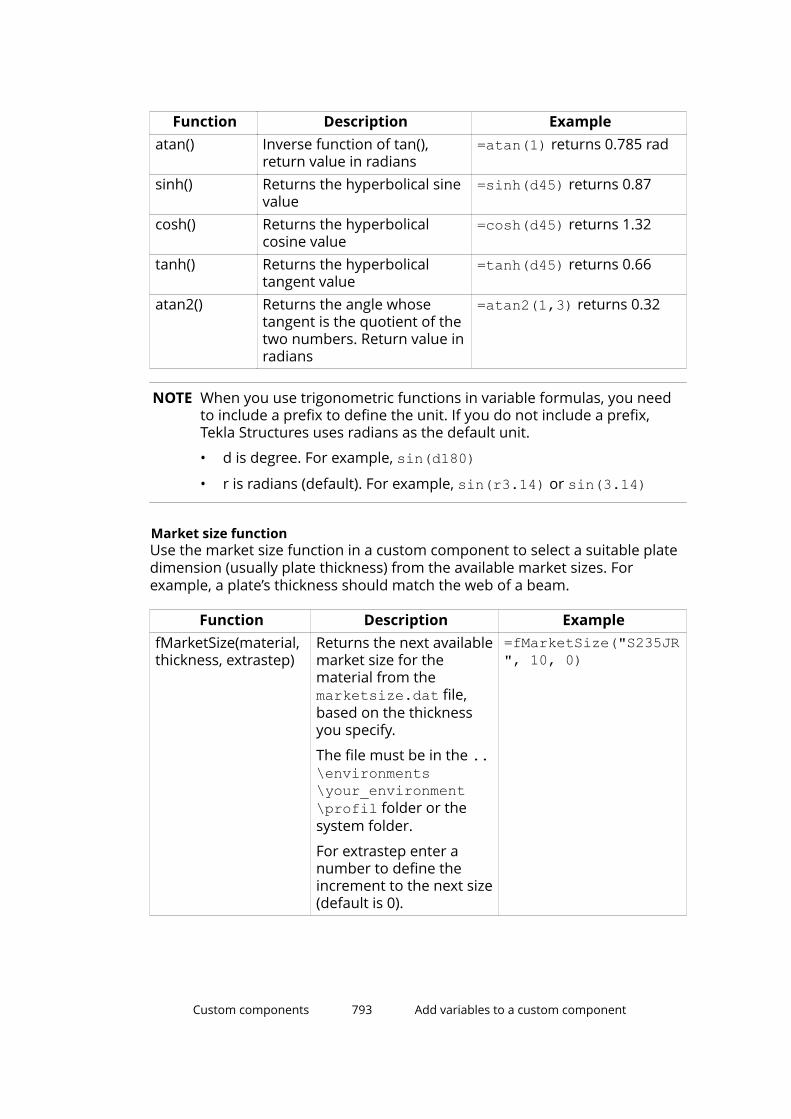
Function Description Exampleatan() Inverse function of tan(),
return value in radians=atan(1) returns 0.785 rad
sinh() Returns the hyperbolical sinevalue
=sinh(d45) returns 0.87
cosh() Returns the hyperbolicalcosine value
=cosh(d45) returns 1.32
tanh() Returns the hyperbolicaltangent value
=tanh(d45) returns 0.66
atan2() Returns the angle whosetangent is the quotient of thetwo numbers. Return value inradians
=atan2(1,3) returns 0.32
NOTE When you use trigonometric functions in variable formulas, you needto include a prefix to define the unit. If you do not include a prefix,Tekla Structures uses radians as the default unit.
• d is degree. For example, sin(d180)• r is radians (default). For example, sin(r3.14) or sin(3.14)
Market size functionUse the market size function in a custom component to select a suitable platedimension (usually plate thickness) from the available market sizes. Forexample, a plate’s thickness should match the web of a beam.
Function Description ExamplefMarketSize(material,thickness, extrastep)
Returns the next availablemarket size for thematerial from themarketsize.dat file,based on the thicknessyou specify.
The file must be in the ..\environments\your_environment\profil folder or thesystem folder.
For extrastep enter anumber to define theincrement to the next size(default is 0).
=fMarketSize("S235JR", 10, 0)
Custom components 793 Add variables to a custom component
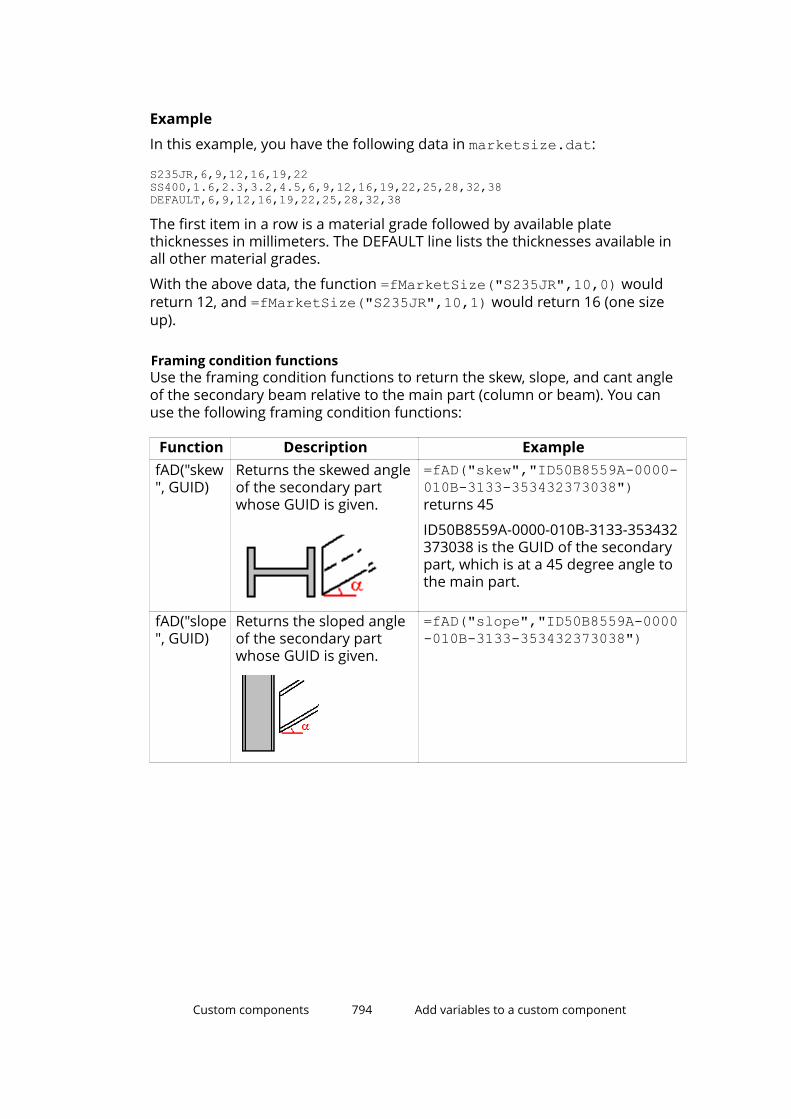
Example
In this example, you have the following data in marketsize.dat:
S235JR,6,9,12,16,19,22SS400,1.6,2.3,3.2,4.5,6,9,12,16,19,22,25,28,32,38DEFAULT,6,9,12,16,19,22,25,28,32,38
The first item in a row is a material grade followed by available platethicknesses in millimeters. The DEFAULT line lists the thicknesses available inall other material grades.
With the above data, the function =fMarketSize("S235JR",10,0) wouldreturn 12, and =fMarketSize("S235JR",10,1) would return 16 (one sizeup).
Framing condition functionsUse the framing condition functions to return the skew, slope, and cant angleof the secondary beam relative to the main part (column or beam). You canuse the following framing condition functions:
Function Description ExamplefAD("skew", GUID)
Returns the skewed angleof the secondary partwhose GUID is given.
=fAD("skew","ID50B8559A-0000-010B-3133-353432373038")returns 45
ID50B8559A-0000-010B-3133-353432373038 is the GUID of the secondarypart, which is at a 45 degree angle tothe main part.
fAD("slope", GUID)
Returns the sloped angleof the secondary partwhose GUID is given.
=fAD("slope","ID50B8559A-0000-010B-3133-353432373038")
Custom components 794 Add variables to a custom component
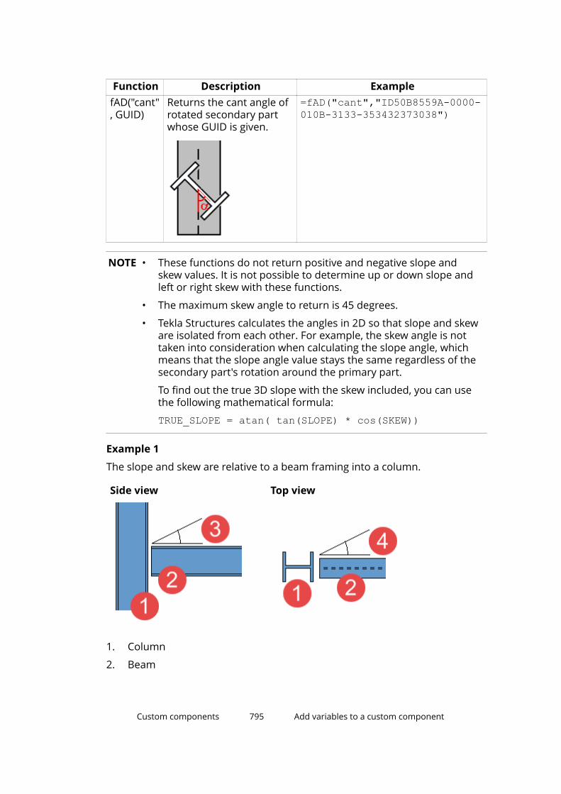
Function Description ExamplefAD("cant", GUID)
Returns the cant angle ofrotated secondary partwhose GUID is given.
=fAD("cant","ID50B8559A-0000-010B-3133-353432373038")
NOTE • These functions do not return positive and negative slope andskew values. It is not possible to determine up or down slope andleft or right skew with these functions.
• The maximum skew angle to return is 45 degrees.
• Tekla Structures calculates the angles in 2D so that slope and skeware isolated from each other. For example, the skew angle is nottaken into consideration when calculating the slope angle, whichmeans that the slope angle value stays the same regardless of thesecondary part's rotation around the primary part.
To find out the true 3D slope with the skew included, you can usethe following mathematical formula:
TRUE_SLOPE = atan( tan(SLOPE) * cos(SKEW))
Example 1
The slope and skew are relative to a beam framing into a column.
Side view Top view
1. Column
2. Beam
Custom components 795 Add variables to a custom component
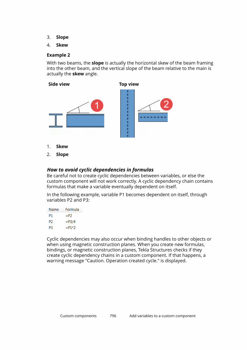
3. Slope
4. Skew
Example 2
With two beams, the slope is actually the horizontal skew of the beam framinginto the other beam, and the vertical slope of the beam relative to the main isactually the skew angle.
Side view Top view
1. Skew
2. Slope
How to avoid cyclic dependencies in formulasBe careful not to create cyclic dependencies between variables, or else thecustom component will not work correctly. A cyclic dependency chain containsformulas that make a variable eventually dependent on itself.
In the following example, variable P1 becomes dependent on itself, throughvariables P2 and P3:
Cyclic dependencies may also occur when binding handles to other objects orwhen using magnetic construction planes. When you create new formulas,bindings, or magnetic construction planes, Tekla Structures checks if theycreate cyclic dependency chains in a custom component. If that happens, awarning message "Caution. Operation created cycle." is displayed.
Custom components 796 Add variables to a custom component
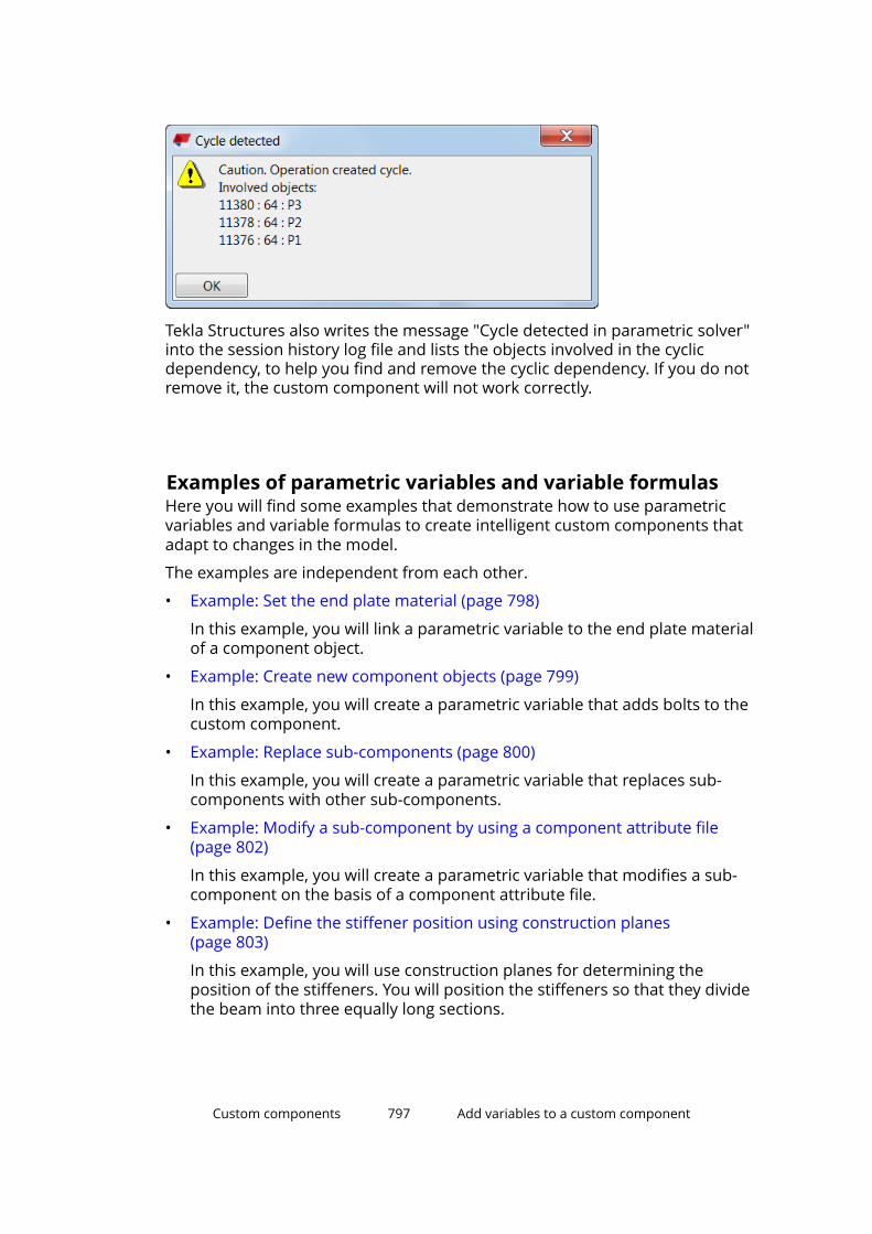
Tekla Structures also writes the message "Cycle detected in parametric solver"into the session history log file and lists the objects involved in the cyclicdependency, to help you find and remove the cyclic dependency. If you do notremove it, the custom component will not work correctly.
Examples of parametric variables and variable formulasHere you will find some examples that demonstrate how to use parametricvariables and variable formulas to create intelligent custom components thatadapt to changes in the model.
The examples are independent from each other.
• Example: Set the end plate material (page 798)
In this example, you will link a parametric variable to the end plate materialof a component object.
• Example: Create new component objects (page 799)
In this example, you will create a parametric variable that adds bolts to thecustom component.
• Example: Replace sub-components (page 800)
In this example, you will create a parametric variable that replaces sub-components with other sub-components.
• Example: Modify a sub-component by using a component attribute file(page 802)
In this example, you will create a parametric variable that modifies a sub-component on the basis of a component attribute file.
• Example: Define the stiffener position using construction planes(page 803)
In this example, you will use construction planes for determining theposition of the stiffeners. You will position the stiffeners so that they dividethe beam into three equally long sections.
Custom components 797 Add variables to a custom component

• Example: Determine the bolt size and bolt standard (page 806)
In this example, you will create two parametric variables that determine thebolt size and bolt standard.
• Example: Calculate the bolt group distance (page 807)
In this example, you will create a variable formula that calculates the boltgroup distance from the beam flange.
• Example: Calculate the number of bolt rows (page 809)
In this example, you will create a variable formula that calculates thenumber of bolt rows based on the beam height. You will use if statementsin the calculations.
• Example: Link variables to user-defined attributes (page 811)
In this example, you will link parametric variables to the user-definedattributes of panels. You can then use the user-defined attributes in viewfilters to show or hide the panels.
• Example: Calculate the number of handrail posts using a template attribute(page 813)
In this example, you will create a variable formula that calculates thenumber of handrail posts based on the length template attribute of thebeam. The handrail posts were created at both ends of the beam and oneof them was copied with the Array of objects (29) component.
• Example: Link an Excel spreadsheet to a custom component (page 815)
In this example, you will link a parametric variable to an Excel spreadsheet.For example, you can use Excel spreadsheets to check connections.
• Examples: Rebar set modifiers in custom components (page 816)
In these examples, you will use rebar set modifiers for defining theproperties and hooks of rebar set bars in custom components.
Example: Set the end plate materialIn this example, you will link a parametric variable to the end plate material ofa component object.
1. In the custom component editor, click the Display variables button .
The Variables dialog box opens.
2. Click the Add button.
A new parametric variable appears.
3. In the Value type list, change the variable's value type to Material.
4. In the Label in dialog box box, enter End Plate Material.
Custom components 798 Add variables to a custom component

5. In the Custom component browser, browse for the end plate material.
6. Right-click Material and select Add Equation.
7. Enter P1 after the equal sign, and then press Enter.
8. Save the custom component.
9. Close the custom component editor.
You can now change the end plate material in the custom component's dialogbox.
Example: Create new component objectsIn this example, you will create a parametric variable that adds bolts to thecustom component.
Custom components 799 Add variables to a custom component
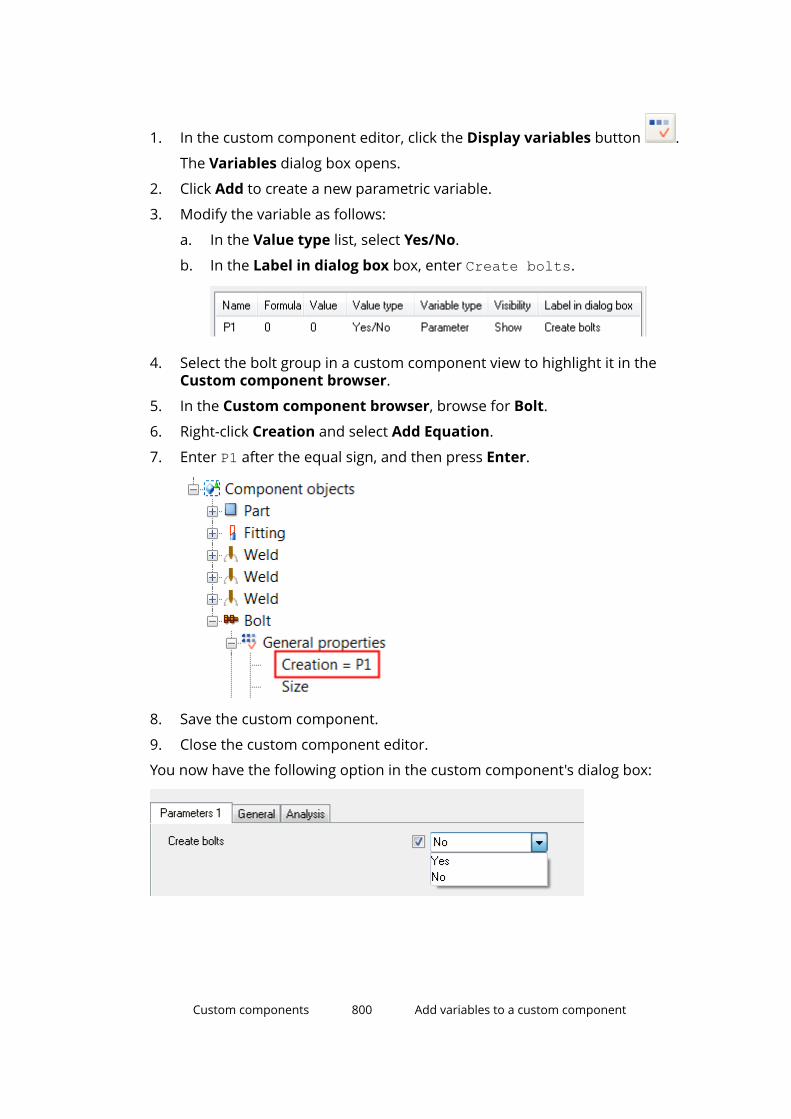
1. In the custom component editor, click the Display variables button .
The Variables dialog box opens.
2. Click Add to create a new parametric variable.
3. Modify the variable as follows:
a. In the Value type list, select Yes/No.
b. In the Label in dialog box box, enter Create bolts.
4. Select the bolt group in a custom component view to highlight it in theCustom component browser.
5. In the Custom component browser, browse for Bolt.
6. Right-click Creation and select Add Equation.
7. Enter P1 after the equal sign, and then press Enter.
8. Save the custom component.
9. Close the custom component editor.
You now have the following option in the custom component's dialog box:
Custom components 800 Add variables to a custom component

Example: Replace sub-componentsIn this example, you will create a parametric variable that replaces sub-components with other sub-components.
1. In the custom component editor, click the Display variables button .
The Variables dialog box opens.
2. Click Add to create a new parametric variable.
3. Modify the variable as follows:
a. In the Value type list, select Component name.
Tekla Structures automatically adds the suffix _name in the variablename. Do not delete the suffix.
b. In the Formula box, enter the name of the sub-component.
c. In the Label in dialog box box, enter Cast-in plate.
4. Link the variable to the Name property of both sub-components:
a. In the Custom component browser, browse for the Name attributeof the first sub-component.
b. Right-click Name and select Add Equation.
c. Enter P1_name after the equals sign.
d. Repeat steps 4b–4c for the other sub-component.
Custom components 801 Add variables to a custom component
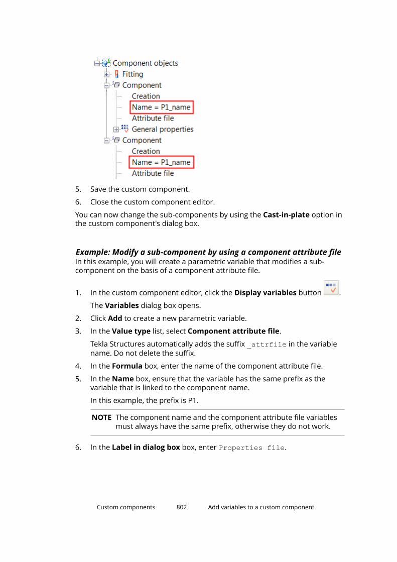
5. Save the custom component.
6. Close the custom component editor.
You can now change the sub-components by using the Cast-in-plate option inthe custom component's dialog box.
Example: Modify a sub-component by using a component attribute fileIn this example, you will create a parametric variable that modifies a sub-component on the basis of a component attribute file.
1. In the custom component editor, click the Display variables button .
The Variables dialog box opens.
2. Click Add to create a new parametric variable.
3. In the Value type list, select Component attribute file.
Tekla Structures automatically adds the suffix _attrfile in the variablename. Do not delete the suffix.
4. In the Formula box, enter the name of the component attribute file.
5. In the Name box, ensure that the variable has the same prefix as thevariable that is linked to the component name.
In this example, the prefix is P1.
NOTE The component name and the component attribute file variablesmust always have the same prefix, otherwise they do not work.
6. In the Label in dialog box box, enter Properties file.
Custom components 802 Add variables to a custom component
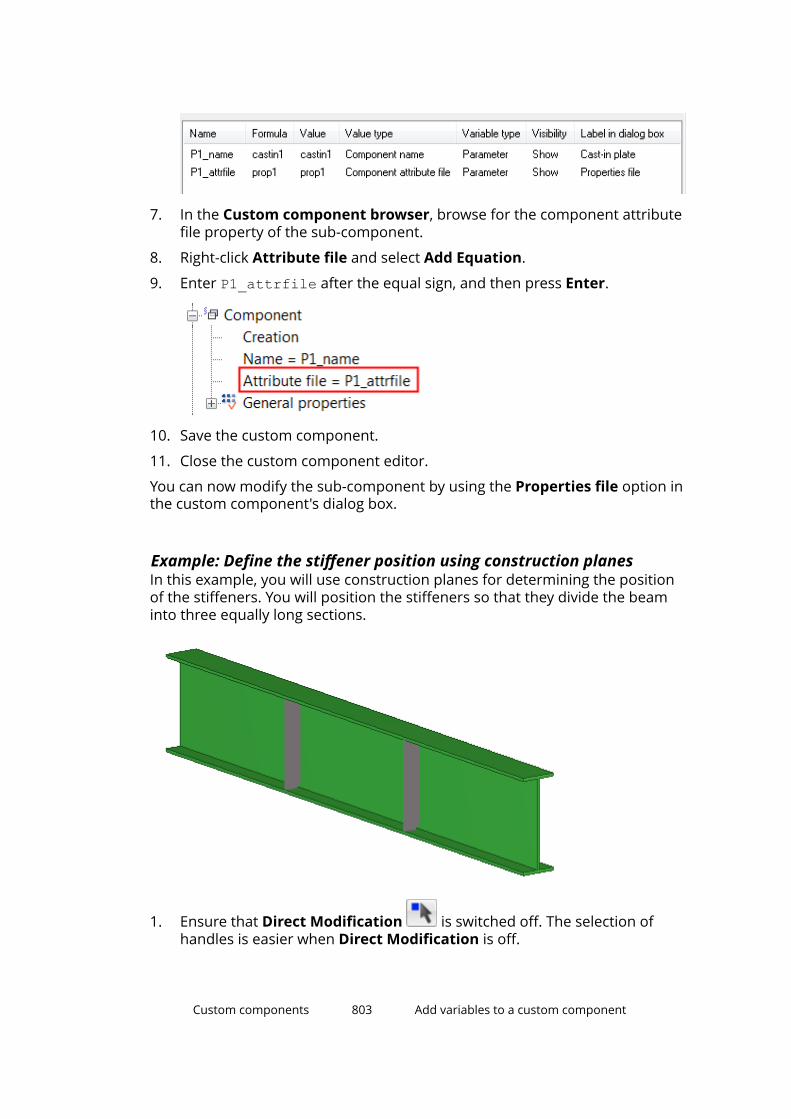
7. In the Custom component browser, browse for the component attributefile property of the sub-component.
8. Right-click Attribute file and select Add Equation.
9. Enter P1_attrfile after the equal sign, and then press Enter.
10. Save the custom component.
11. Close the custom component editor.
You can now modify the sub-component by using the Properties file option inthe custom component's dialog box.
Example: Define the stiffener position using construction planesIn this example, you will use construction planes for determining the positionof the stiffeners. You will position the stiffeners so that they divide the beaminto three equally long sections.
1. Ensure that Direct Modification is switched off. The selection ofhandles is easier when Direct Modification is off.
Custom components 803 Add variables to a custom component
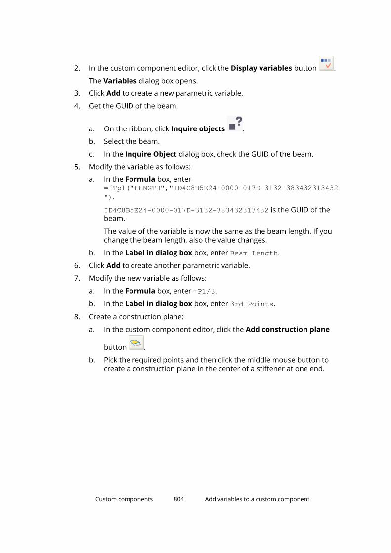
2. In the custom component editor, click the Display variables button .
The Variables dialog box opens.
3. Click Add to create a new parametric variable.
4. Get the GUID of the beam.
a. On the ribbon, click Inquire objects .
b. Select the beam.
c. In the Inquire Object dialog box, check the GUID of the beam.
5. Modify the variable as follows:
a. In the Formula box, enter=fTpl("LENGTH","ID4C8B5E24-0000-017D-3132-383432313432").
ID4C8B5E24-0000-017D-3132-383432313432 is the GUID of thebeam.
The value of the variable is now the same as the beam length. If youchange the beam length, also the value changes.
b. In the Label in dialog box box, enter Beam Length.
6. Click Add to create another parametric variable.
7. Modify the new variable as follows:
a. In the Formula box, enter =P1/3.
b. In the Label in dialog box box, enter 3rd Points.
8. Create a construction plane:
a. In the custom component editor, click the Add construction plane
button .
b. Pick the required points and then click the middle mouse button tocreate a construction plane in the center of a stiffener at one end.
Custom components 804 Add variables to a custom component

9. Bind the stiffener to the construction plane:
a. Select the stiffener.
b. Hold down Alt and use area selection (from left to right) to select allstiffener handles.
c. Right-click and select Bind to plane.
d. Bind the stiffener handles to the construction plane.
10. Bind the construction plane to the beam end:
a. Select the construction plane.
b. Right-click and select Bind to plane.
c. Bind the construction plane to the beam end.
Custom components 805 Add variables to a custom component
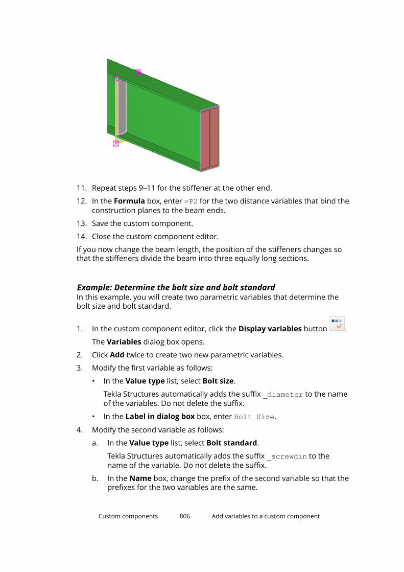
11. Repeat steps 9–11 for the stiffener at the other end.
12. In the Formula box, enter =P2 for the two distance variables that bind theconstruction planes to the beam ends.
13. Save the custom component.
14. Close the custom component editor.
If you now change the beam length, the position of the stiffeners changes sothat the stiffeners divide the beam into three equally long sections.
Example: Determine the bolt size and bolt standardIn this example, you will create two parametric variables that determine thebolt size and bolt standard.
1. In the custom component editor, click the Display variables button .
The Variables dialog box opens.
2. Click Add twice to create two new parametric variables.
3. Modify the first variable as follows:
• In the Value type list, select Bolt size.
Tekla Structures automatically adds the suffix _diameter to the nameof the variables. Do not delete the suffix.
• In the Label in dialog box box, enter Bolt Size.
4. Modify the second variable as follows:
a. In the Value type list, select Bolt standard.
Tekla Structures automatically adds the suffix _screwdin to thename of the variable. Do not delete the suffix.
b. In the Name box, change the prefix of the second variable so that theprefixes for the two variables are the same.
Custom components 806 Add variables to a custom component
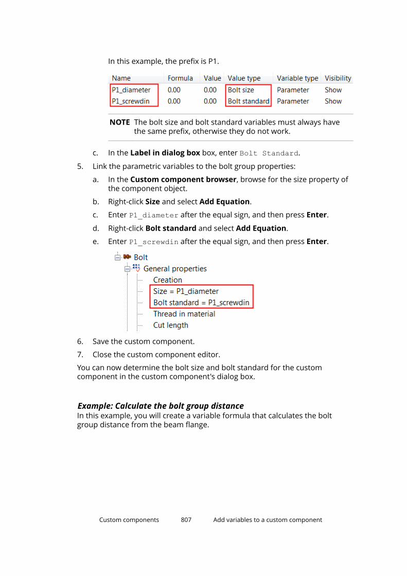
In this example, the prefix is P1.
NOTE The bolt size and bolt standard variables must always havethe same prefix, otherwise they do not work.
c. In the Label in dialog box box, enter Bolt Standard.
5. Link the parametric variables to the bolt group properties:
a. In the Custom component browser, browse for the size property ofthe component object.
b. Right-click Size and select Add Equation.
c. Enter P1_diameter after the equal sign, and then press Enter.
d. Right-click Bolt standard and select Add Equation.
e. Enter P1_screwdin after the equal sign, and then press Enter.
6. Save the custom component.
7. Close the custom component editor.
You can now determine the bolt size and bolt standard for the customcomponent in the custom component's dialog box.
Example: Calculate the bolt group distanceIn this example, you will create a variable formula that calculates the boltgroup distance from the beam flange.
Custom components 807 Add variables to a custom component

1. Modify the bolt group properties as follows:
a. In the custom component editor, double-click the bolt group.
The Bolt properties open.
b. Clear all values that are in the Offset from section.
c. Click Modify.
The bolt group moves to the same level with the start point handle ofthe bolt group.
2. Bind the bolt group to the beam flange:
a. In the custom component editor, select the bolt group.
b. Select the yellow top handle.
c. Right-click the handle and select Bind to plane.
d. Select the top flange of the beam.
Custom components 808 Add variables to a custom component
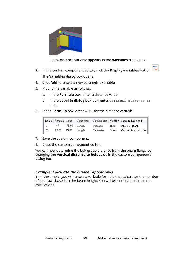
A new distance variable appears in the Variables dialog box.
3. In the custom component editor, click the Display variables button .
The Variables dialog box opens.
4. Click Add to create a new parametric variable.
5. Modify the variable as follows:
a. In the Formula box, enter a distance value.
b. In the Label in dialog box box, enter Vertical distance tobolt.
6. In the Formula box, enter =-P1 for the distance variable.
7. Save the custom component.
8. Close the custom component editor.
You can now determine the bolt group distance from the beam flange bychanging the Vertical distance to bolt value in the custom component'sdialog box.
Example: Calculate the number of bolt rowsIn this example, you will create a variable formula that calculates the numberof bolt rows based on the beam height. You will use if statements in thecalculations.
Custom components 809 Add variables to a custom component
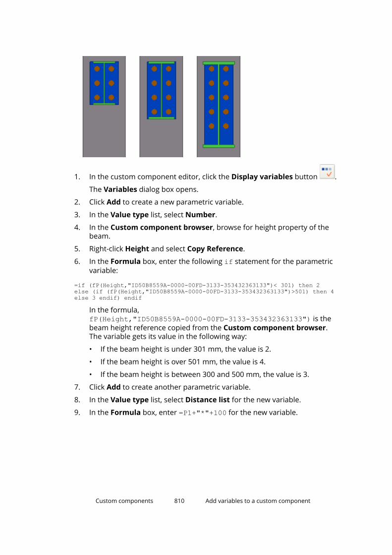
1. In the custom component editor, click the Display variables button .
The Variables dialog box opens.
2. Click Add to create a new parametric variable.
3. In the Value type list, select Number.
4. In the Custom component browser, browse for height property of thebeam.
5. Right-click Height and select Copy Reference.
6. In the Formula box, enter the following if statement for the parametricvariable:
=if (fP(Height,"ID50B8559A-0000-00FD-3133-353432363133")< 301) then 2 else (if (fP(Height,"ID50B8559A-0000-00FD-3133-353432363133")>501) then 4 else 3 endif) endif
In the formula,fP(Height,"ID50B8559A-0000-00FD-3133-353432363133") is thebeam height reference copied from the Custom component browser.The variable gets its value in the following way:
• If the beam height is under 301 mm, the value is 2.
• If the beam height is over 501 mm, the value is 4.
• If the beam height is between 300 and 500 mm, the value is 3.
7. Click Add to create another parametric variable.
8. In the Value type list, select Distance list for the new variable.
9. In the Formula box, enter =P1+"*"+100 for the new variable.
Custom components 810 Add variables to a custom component

In the formula, 100 is the bolt spacing and the P1 value is the number ofbolt rows.
10. In the Custom component browser, browse for Bolt group distance x.
11. Right-click Bolt group distance x and select Add Equation.
12. Enter P2 after the equal sign, and then press Enter.
13. Save the custom component.
14. Close the custom component editor.
When you now change the beam height, the number of bolt rows changes aswell.
Example: Link variables to user-defined attributesIn this example, you will link parametric variables to the user-definedattributes of panels. You can then use the user-defined attributes in viewfilters to show or hide the panels in the model.
1. In the custom component editor, click the Display variables button .
The Variables dialog box opens.
2. Click Add to create a new parametric variable.
3. Modify the variable as follows:
a. In the Value type list, select Text.
Custom components 811 Add variables to a custom component

b. In the Formula box, enter Type1.
c. In the Label in dialog box box, enter Panel1.
4. In the Custom component browser, browse for the user-definedattributes of the first panel.
You will link the P1 variable to the USER_FIELD_1 attribute. However, theattribute is not visible in the Custom component browser.
5. Make the user-defined attribute visible in the Custom componentbrowser:
a. Double-click the first panel.
The panel properties open in the property pane.
b. Click More.
The dialog box for user-defined attributes opens.
c. Go to the Parameters tab.
d. Enter text in the User field 1 box.
e. Click Modify.
6. In the Custom component browser, click Refresh.
USER_FIELD_1 appears under User-defined attributes in the Customcomponent browser.
7. Link P1 to USER_FIELD_1.
a. Right-click USER_FIELD_1 and select Add Equation.
b. Enter P1 after the equal sign, and then press Enter.
8. Create two new parametric variables and link them to the user-definedattributes of the other two panels.
9. Save the custom component.
10. Close the custom component editor.
You can now create a view filter (page 158) in the model to hide or showpanels using the User field 1 attribute and the Formula values you enteredfor the parametric variables in the filter.
Custom components 812 Add variables to a custom component
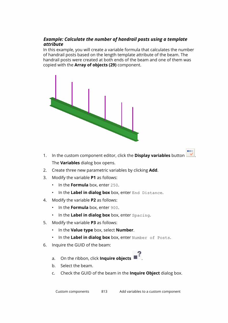
Example: Calculate the number of handrail posts using a templateattributeIn this example, you will create a variable formula that calculates the numberof handrail posts based on the length template attribute of the beam. Thehandrail posts were created at both ends of the beam and one of them wascopied with the Array of objects (29) component.
1. In the custom component editor, click the Display variables button .
The Variables dialog box opens.
2. Create three new parametric variables by clicking Add.
3. Modify the variable P1 as follows:
• In the Formula box, enter 250.
• In the Label in dialog box box, enter End Distance.
4. Modify the variable P2 as follows:
• In the Formula box, enter 900.
• In the Label in dialog box box, enter Spacing.
5. Modify the variable P3 as follows:
• In the Value type box, select Number.
• In the Label in dialog box box, enter Number of Posts.
6. Inquire the GUID of the beam:
a. On the ribbon, click Inquire objects .
b. Select the beam.
c. Check the GUID of the beam in the Inquire Object dialog box.
Custom components 813 Add variables to a custom component
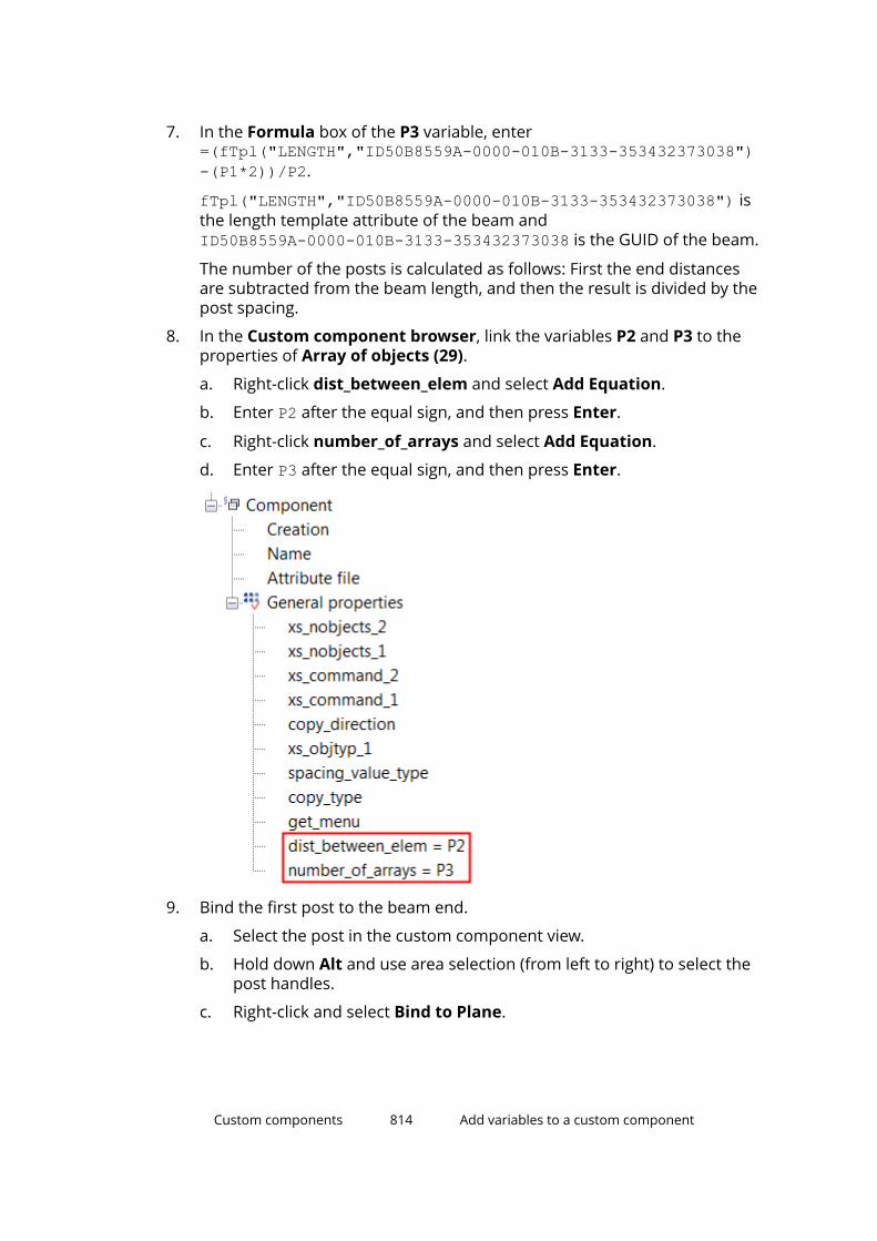
7. In the Formula box of the P3 variable, enter=(fTpl("LENGTH","ID50B8559A-0000-010B-3133-353432373038")-(P1*2))/P2.
fTpl("LENGTH","ID50B8559A-0000-010B-3133-353432373038") isthe length template attribute of the beam andID50B8559A-0000-010B-3133-353432373038 is the GUID of the beam.
The number of the posts is calculated as follows: First the end distancesare subtracted from the beam length, and then the result is divided by thepost spacing.
8. In the Custom component browser, link the variables P2 and P3 to theproperties of Array of objects (29).
a. Right-click dist_between_elem and select Add Equation.
b. Enter P2 after the equal sign, and then press Enter.
c. Right-click number_of_arrays and select Add Equation.
d. Enter P3 after the equal sign, and then press Enter.
9. Bind the first post to the beam end.
a. Select the post in the custom component view.
b. Hold down Alt and use area selection (from left to right) to select thepost handles.
c. Right-click and select Bind to Plane.
Custom components 814 Add variables to a custom component
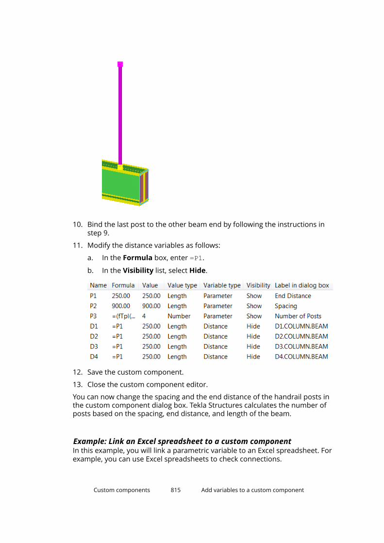
10. Bind the last post to the other beam end by following the instructions instep 9.
11. Modify the distance variables as follows:
a. In the Formula box, enter =P1.
b. In the Visibility list, select Hide.
12. Save the custom component.
13. Close the custom component editor.
You can now change the spacing and the end distance of the handrail posts inthe custom component dialog box. Tekla Structures calculates the number ofposts based on the spacing, end distance, and length of the beam.
Example: Link an Excel spreadsheet to a custom componentIn this example, you will link a parametric variable to an Excel spreadsheet. Forexample, you can use Excel spreadsheets to check connections.
Custom components 815 Add variables to a custom component
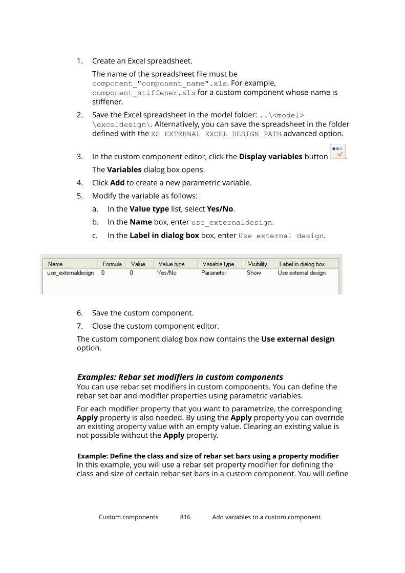
1. Create an Excel spreadsheet.
The name of the spreadsheet file must becomponent_"component_name".xls. For example,component_stiffener.xls for a custom component whose name isstiffener.
2. Save the Excel spreadsheet in the model folder: ..\<model>\exceldesign\. Alternatively, you can save the spreadsheet in the folderdefined with the XS_EXTERNAL_EXCEL_DESIGN_PATH advanced option.
3. In the custom component editor, click the Display variables button .
The Variables dialog box opens.
4. Click Add to create a new parametric variable.
5. Modify the variable as follows:
a. In the Value type list, select Yes/No.
b. In the Name box, enter use_externaldesign.
c. In the Label in dialog box box, enter Use external design.
6. Save the custom component.
7. Close the custom component editor.
The custom component dialog box now contains the Use external designoption.
Examples: Rebar set modifiers in custom componentsYou can use rebar set modifiers in custom components. You can define therebar set bar and modifier properties using parametric variables.
For each modifier property that you want to parametrize, the correspondingApply property is also needed. By using the Apply property you can overridean existing property value with an empty value. Clearing an existing value isnot possible without the Apply property.
Example: Define the class and size of rebar set bars using a property modifierIn this example, you will use a rebar set property modifier for defining theclass and size of certain rebar set bars in a custom component. You will define
Custom components 816 Add variables to a custom component
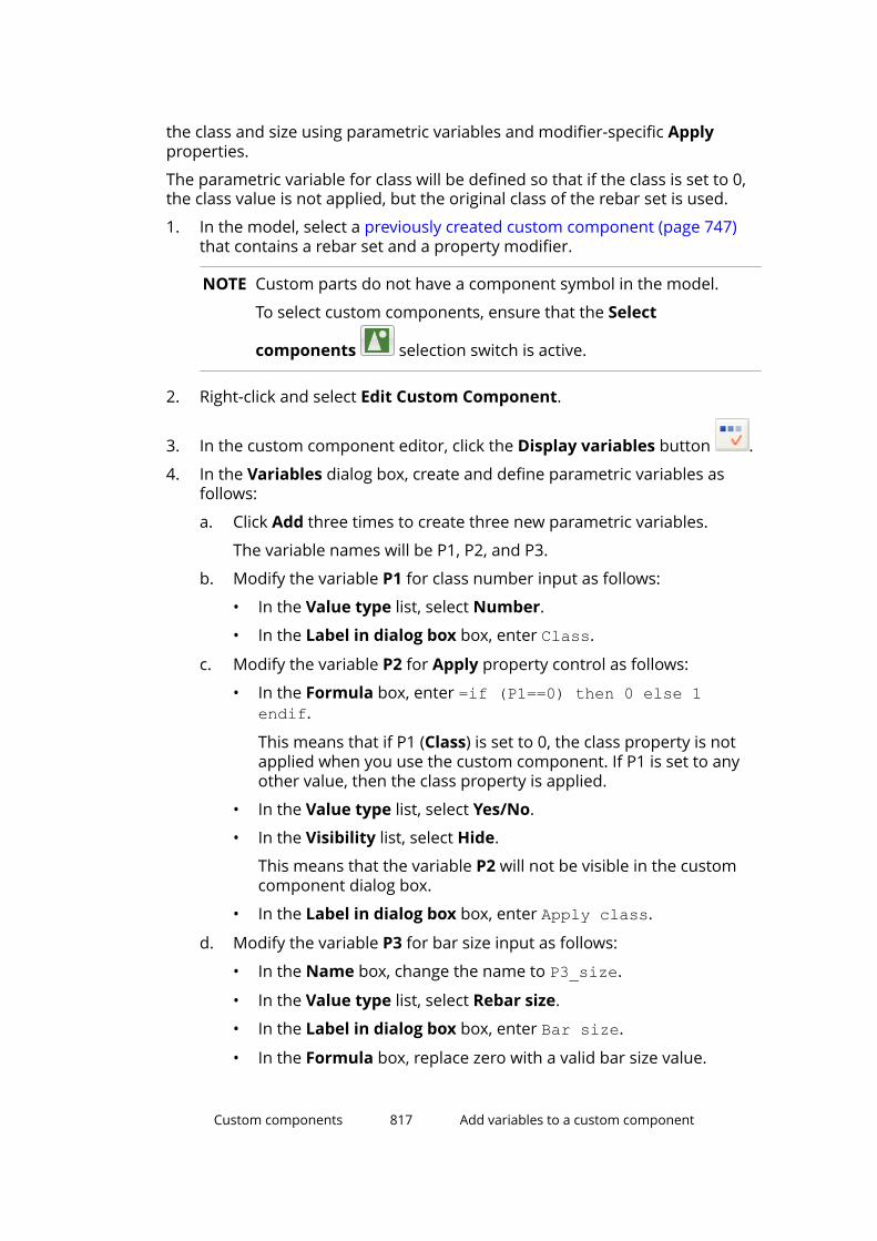
the class and size using parametric variables and modifier-specific Applyproperties.
The parametric variable for class will be defined so that if the class is set to 0,the class value is not applied, but the original class of the rebar set is used.
1. In the model, select a previously created custom component (page 747)that contains a rebar set and a property modifier.
NOTE Custom parts do not have a component symbol in the model.
To select custom components, ensure that the Select
components selection switch is active.
2. Right-click and select Edit Custom Component.
3. In the custom component editor, click the Display variables button .
4. In the Variables dialog box, create and define parametric variables asfollows:
a. Click Add three times to create three new parametric variables.
The variable names will be P1, P2, and P3.
b. Modify the variable P1 for class number input as follows:
• In the Value type list, select Number.
• In the Label in dialog box box, enter Class.
c. Modify the variable P2 for Apply property control as follows:
• In the Formula box, enter =if (P1==0) then 0 else 1endif.
This means that if P1 (Class) is set to 0, the class property is notapplied when you use the custom component. If P1 is set to anyother value, then the class property is applied.
• In the Value type list, select Yes/No.
• In the Visibility list, select Hide.
This means that the variable P2 will not be visible in the customcomponent dialog box.
• In the Label in dialog box box, enter Apply class.
d. Modify the variable P3 for bar size input as follows:
• In the Name box, change the name to P3_size.
• In the Value type list, select Rebar size.
• In the Label in dialog box box, enter Bar size.
• In the Formula box, replace zero with a valid bar size value.
Custom components 817 Add variables to a custom component

5. In the Custom component browser, link the parametric variables to theproperty modifier properties:
a. Browse for Component objects --> Rebar property modifier -->General properties.
b. Right-click Class, select Add Equation, enter P1 after the equal sign(=), and then press Enter.
Similarly, link the other variables and properties as follows:
• Apply class property = P2• Size = P3_size• Apply size property = 1
Custom components 818 Add variables to a custom component
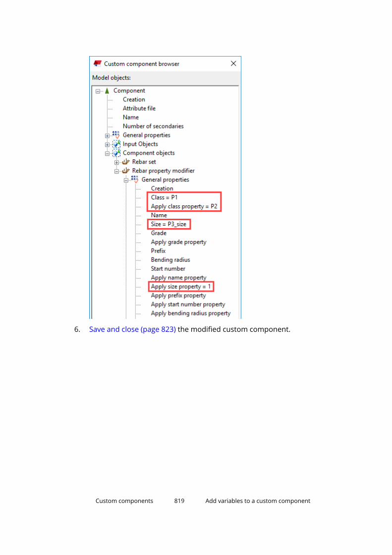
6. Save and close (page 823) the modified custom component.
Custom components 819 Add variables to a custom component
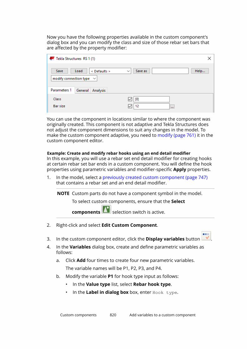
Now you have the following properties available in the custom component'sdialog box and you can modify the class and size of those rebar set bars thatare affected by the property modifier:
You can use the component in locations similar to where the component wasoriginally created. This component is not adaptive and Tekla Structures doesnot adjust the component dimensions to suit any changes in the model. Tomake the custom component adaptive, you need to modify (page 761) it in thecustom component editor.
Example: Create and modify rebar hooks using an end detail modifierIn this example, you will use a rebar set end detail modifier for creating hooksat certain rebar set bar ends in a custom component. You will define the hookproperties using parametric variables and modifier-specific Apply properties.
1. In the model, select a previously created custom component (page 747)that contains a rebar set and an end detail modifier.
NOTE Custom parts do not have a component symbol in the model.
To select custom components, ensure that the Select
components selection switch is active.
2. Right-click and select Edit Custom Component.
3. In the custom component editor, click the Display variables button .
4. In the Variables dialog box, create and define parametric variables asfollows:
a. Click Add four times to create four new parametric variables.
The variable names will be P1, P2, P3, and P4.
b. Modify the variable P1 for hook type input as follows:
• In the Value type list, select Rebar hook type.
• In the Label in dialog box box, enter Hook type.
Custom components 820 Add variables to a custom component
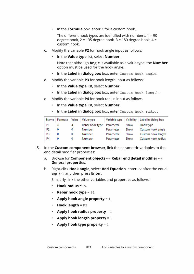
• In the Formula box, enter 4 for a custom hook.
The different hook types are identified with numbers: 1 = 90degree hook, 2 = 135 degree hook, 3 = 180 degree hook, 4 =custom hook.
c. Modify the variable P2 for hook angle input as follows:
• In the Value type list, select Number.
Note that although Angle is available as a value type, the Numberoption must be used for the hook angle.
• In the Label in dialog box box, enter Custom hook angle.
d. Modify the variable P3 for hook length input as follows:
• In the Value type list, select Number.
• In the Label in dialog box box, enter Custom hook length.
e. Modify the variable P4 for hook radius input as follows:
• In the Value type list, select Number.
• In the Label in dialog box box, enter Custom hook radius.
5. In the Custom component browser, link the parametric variables to theend detail modifier properties:
a. Browse for Component objects --> Rebar end detail modifier -->General properties.
b. Right-click Hook angle, select Add Equation, enter P2 after the equalsign (=), and then press Enter.
Similarly, link the other variables and properties as follows:
• Hook radius = P4• Rebar hook type = P1• Apply hook angle property = 1• Hook length = P3• Apply hook radius property = 1• Apply hook length property = 1• Apply hook type property = 1
Custom components 821 Add variables to a custom component

6. Save and close (page 823) the modified custom component.
Custom components 822 Add variables to a custom component
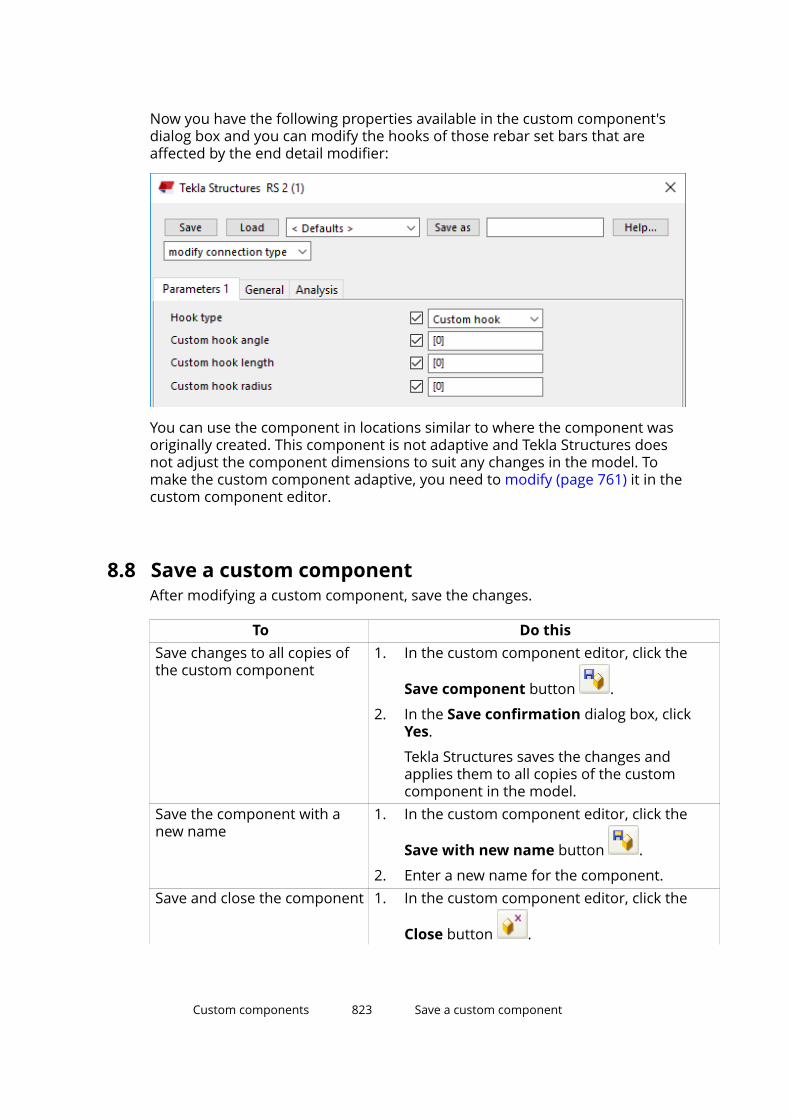
Now you have the following properties available in the custom component'sdialog box and you can modify the hooks of those rebar set bars that areaffected by the end detail modifier:
You can use the component in locations similar to where the component wasoriginally created. This component is not adaptive and Tekla Structures doesnot adjust the component dimensions to suit any changes in the model. Tomake the custom component adaptive, you need to modify (page 761) it in thecustom component editor.
8.8 Save a custom componentAfter modifying a custom component, save the changes.
To Do thisSave changes to all copies ofthe custom component
1. In the custom component editor, click the
Save component button .
2. In the Save confirmation dialog box, clickYes.
Tekla Structures saves the changes andapplies them to all copies of the customcomponent in the model.
Save the component with anew name
1. In the custom component editor, click the
Save with new name button .
2. Enter a new name for the component.Save and close the component 1. In the custom component editor, click the
Close button .
Custom components 823 Save a custom component

To Do this2. In the Close custom component editor
message, click Yes.
If you click No, the custom component editorcloses without saving the changes.
See also
Tips for sharing custom components (page 882)
8.9 Modify the dialog box of a custom componentTekla Structures automatically creates a dialog box for each customcomponent you define. You can customize the dialog box by using the CustomComponent Dialog Editor tool.
To open the dialog editor, select a custom component in the model, right-click,and select Edit Custom Component Dialog Box.
To Do thisView and edit object properties 1. Select a dialog box element. For
example, a text box.
2. Click Modify --> Properties.
Now you can view and edit thecurrent properties of the dialogbox element. For example, youcan check that you have the
Custom components 824 Modify the dialog box of a custom component
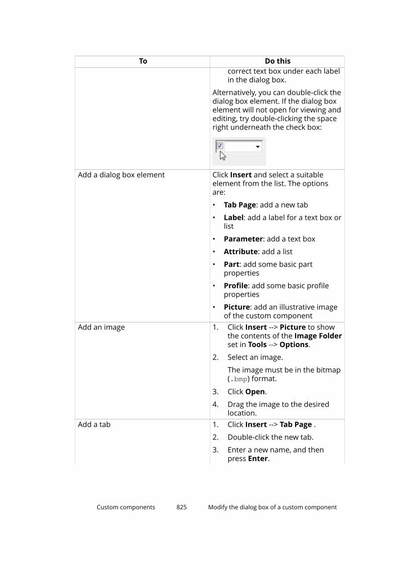
To Do thiscorrect text box under each labelin the dialog box.
Alternatively, you can double-click thedialog box element. If the dialog boxelement will not open for viewing andediting, try double-clicking the spaceright underneath the check box:
Add a dialog box element Click Insert and select a suitableelement from the list. The optionsare:
• Tab Page: add a new tab
• Label: add a label for a text box orlist
• Parameter: add a text box
• Attribute: add a list
• Part: add some basic partproperties
• Profile: add some basic profileproperties
• Picture: add an illustrative imageof the custom component
Add an image 1. Click Insert --> Picture to showthe contents of the Image Folderset in Tools --> Options.
2. Select an image.
The image must be in the bitmap(.bmp) format.
3. Click Open.
4. Drag the image to the desiredlocation.
Add a tab 1. Click Insert --> Tab Page .
2. Double-click the new tab.
3. Enter a new name, and thenpress Enter.
Custom components 825 Modify the dialog box of a custom component
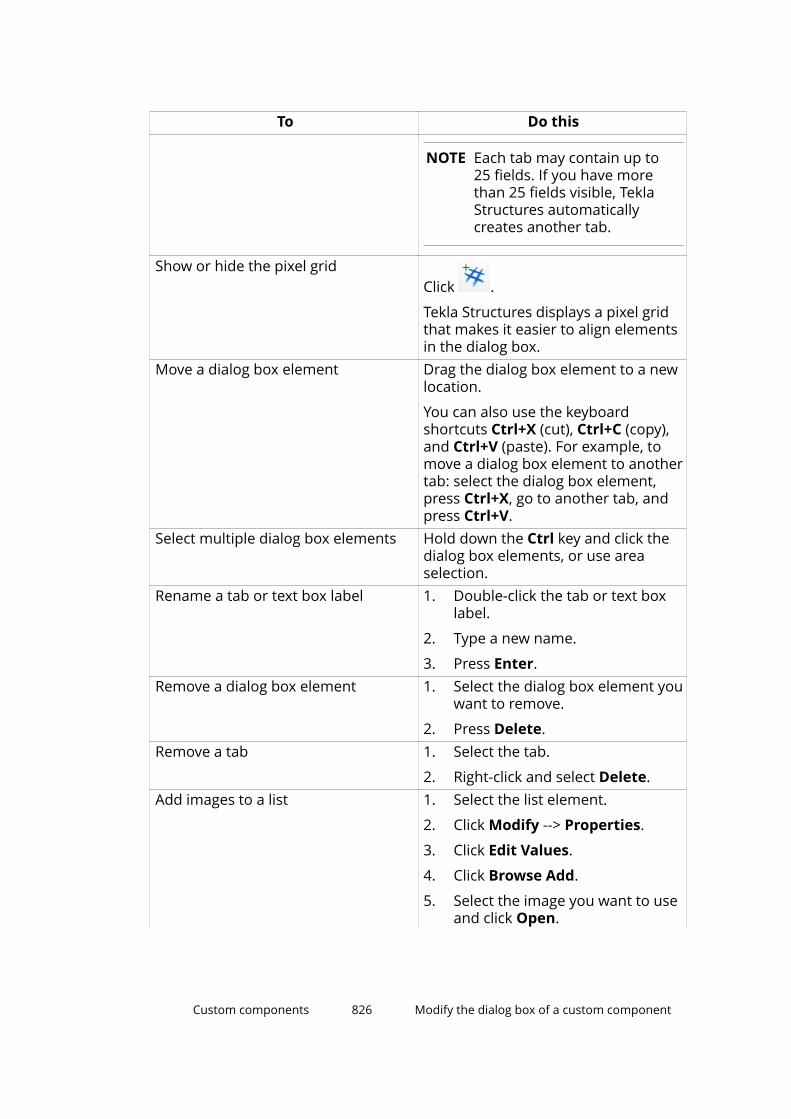
To Do this
NOTE Each tab may contain up to25 fields. If you have morethan 25 fields visible, TeklaStructures automaticallycreates another tab.
Show or hide the pixel gridClick .
Tekla Structures displays a pixel gridthat makes it easier to align elementsin the dialog box.
Move a dialog box element Drag the dialog box element to a newlocation.
You can also use the keyboardshortcuts Ctrl+X (cut), Ctrl+C (copy),and Ctrl+V (paste). For example, tomove a dialog box element to anothertab: select the dialog box element,press Ctrl+X, go to another tab, andpress Ctrl+V.
Select multiple dialog box elements Hold down the Ctrl key and click thedialog box elements, or use areaselection.
Rename a tab or text box label 1. Double-click the tab or text boxlabel.
2. Type a new name.
3. Press Enter.Remove a dialog box element 1. Select the dialog box element you
want to remove.
2. Press Delete.Remove a tab 1. Select the tab.
2. Right-click and select Delete.Add images to a list 1. Select the list element.
2. Click Modify --> Properties.
3. Click Edit Values.
4. Click Browse Add.
5. Select the image you want to useand click Open.
Custom components 826 Modify the dialog box of a custom component
To Do this6. Repeat steps 4–5 for any other
images you want to use.
7. Click OK to save the changes.Save the changes Click File --> Save.
See also
Dialog editor settings (page 857)
Modify custom component input files manually (page 827)
Example: Modify the dialog box of a stiffener detail (page 835)
Custom component input filesEach custom component has an input file that defines the contents of thecustom component's dialog box.
When you create a new custom component, Tekla Structures automaticallycreates an input file for the component. The input file is located in the\CustomComponentDialogFiles folder under the model folder. The inputfile has the same name as the custom component, and the file nameextension is .inp.
When you modify a custom component (page 761), you will lose any changesyou have made to the input file. However, when you modify the customcomponent, Tekla Structures automatically creates a backup copy of the inputfile. The backup copy has the file name extension .inp_bak, and it is locatedin the \CustomComponentDialogFiles folder under the model folder. TeklaStructures displays a notification when the backup file is created.
See also
Lock or unlock the custom component input file (page 830)
Modify custom component input files manuallyIf you are an advanced user, you can modify the dialog box input (.inp) filesmanually in a text editor. Be careful when modifying an input file, as errorsmay cause the dialog box to disappear.
Note that the General tab is reserved for predefined general properties. Youcannot rename the General tab or add more parameters to it.
Add new tabs1. Open the .inp file in a text editor.
Custom components 827 Modify the dialog box of a custom component
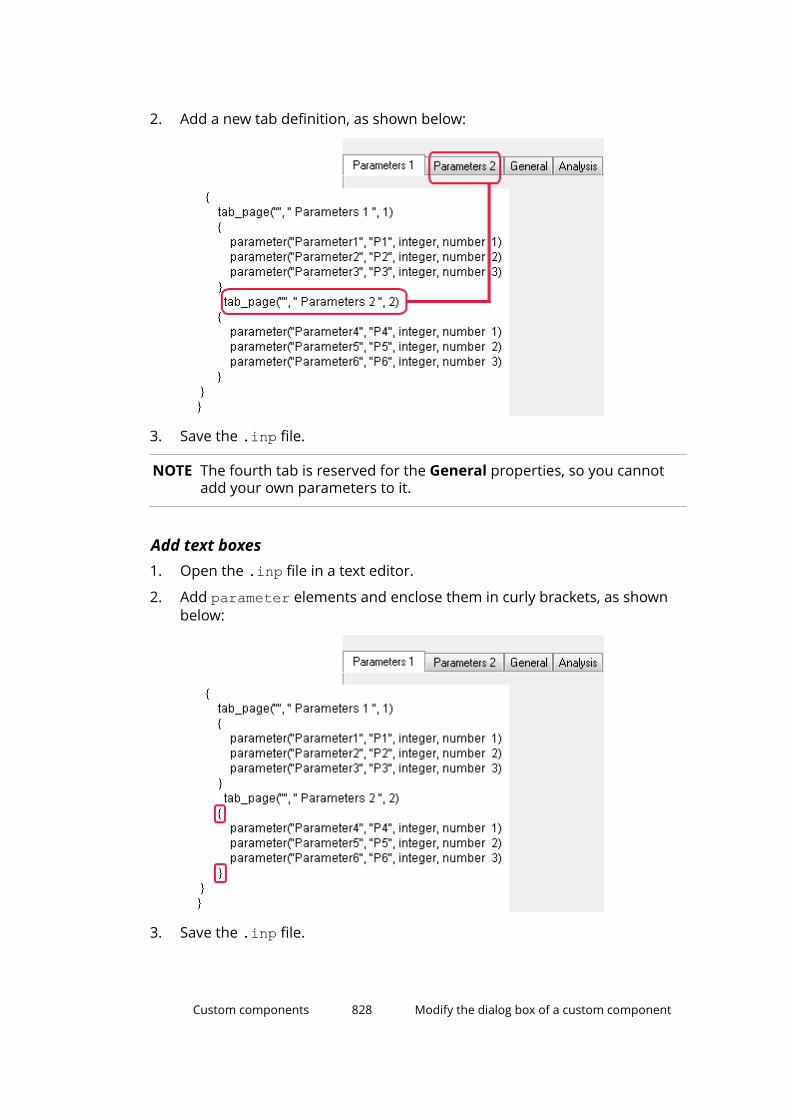
2. Add a new tab definition, as shown below:
3. Save the .inp file.
NOTE The fourth tab is reserved for the General properties, so you cannotadd your own parameters to it.
Add text boxes1. Open the .inp file in a text editor.
2. Add parameter elements and enclose them in curly brackets, as shownbelow:
3. Save the .inp file.
Custom components 828 Modify the dialog box of a custom component

Add images1. Create an image and save it in bitmap (.bmp) format in the ..\Tekla
Structures\<version>\nt\bitmaps folder.
2. Open the .inp file in a text editor.
3. Add an image definition, as shown below:
(1) y = 100
(2) x = 50
(3) height = 75
(4) width = 100
4. Save the .inp file.
Change the order of boxes1. Open the .inp file in a text editor.
2. Change the last number in the parameter definition.
Custom components 829 Modify the dialog box of a custom component
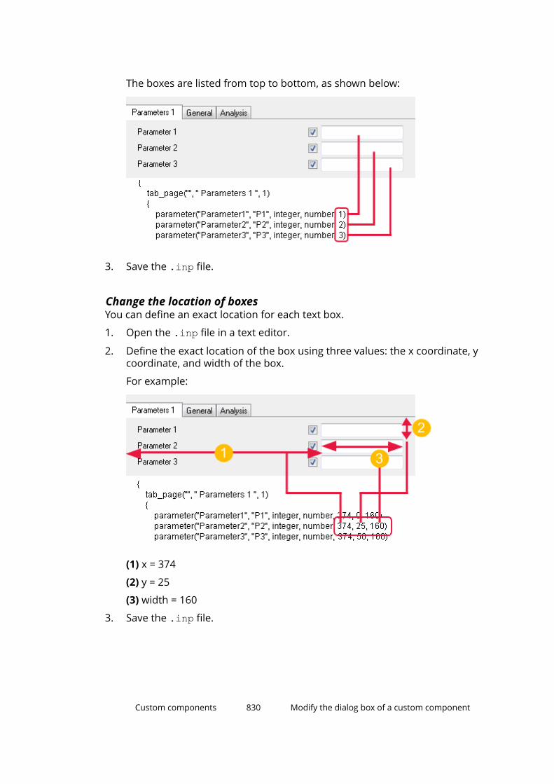
The boxes are listed from top to bottom, as shown below:
3. Save the .inp file.
Change the location of boxesYou can define an exact location for each text box.
1. Open the .inp file in a text editor.
2. Define the exact location of the box using three values: the x coordinate, ycoordinate, and width of the box.
For example:
(1) x = 374
(2) y = 25
(3) width = 160
3. Save the .inp file.
Custom components 830 Modify the dialog box of a custom component
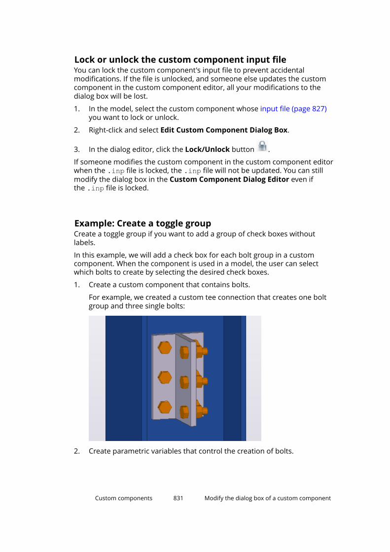
Lock or unlock the custom component input fileYou can lock the custom component's input file to prevent accidentalmodifications. If the file is unlocked, and someone else updates the customcomponent in the custom component editor, all your modifications to thedialog box will be lost.
1. In the model, select the custom component whose input file (page 827)you want to lock or unlock.
2. Right-click and select Edit Custom Component Dialog Box.
3. In the dialog editor, click the Lock/Unlock button .
If someone modifies the custom component in the custom component editorwhen the .inp file is locked, the .inp file will not be updated. You can stillmodify the dialog box in the Custom Component Dialog Editor even ifthe .inp file is locked.
Example: Create a toggle groupCreate a toggle group if you want to add a group of check boxes withoutlabels.
In this example, we will add a check box for each bolt group in a customcomponent. When the component is used in a model, the user can selectwhich bolts to create by selecting the desired check boxes.
1. Create a custom component that contains bolts.
For example, we created a custom tee connection that creates one boltgroup and three single bolts:
2. Create parametric variables that control the creation of bolts.
Custom components 831 Modify the dialog box of a custom component
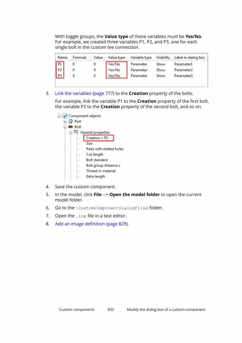
With toggle groups, the Value type of these variables must be Yes/No.For example, we created three variables P1, P2, and P3, one for eachsingle bolt in the custom tee connection.
3. Link the variables (page 777) to the Creation property of the bolts.
For example, link the variable P1 to the Creation property of the first bolt,the variable P2 to the Creation property of the second bolt, and so on.
4. Save the custom component.
5. In the model, click File --> Open the model folder to open the currentmodel folder.
6. Go to the \CustomComponentDialogFiles folder.
7. Open the .inp file in a text editor.
8. Add an image definition (page 829).
Custom components 832 Modify the dialog box of a custom component
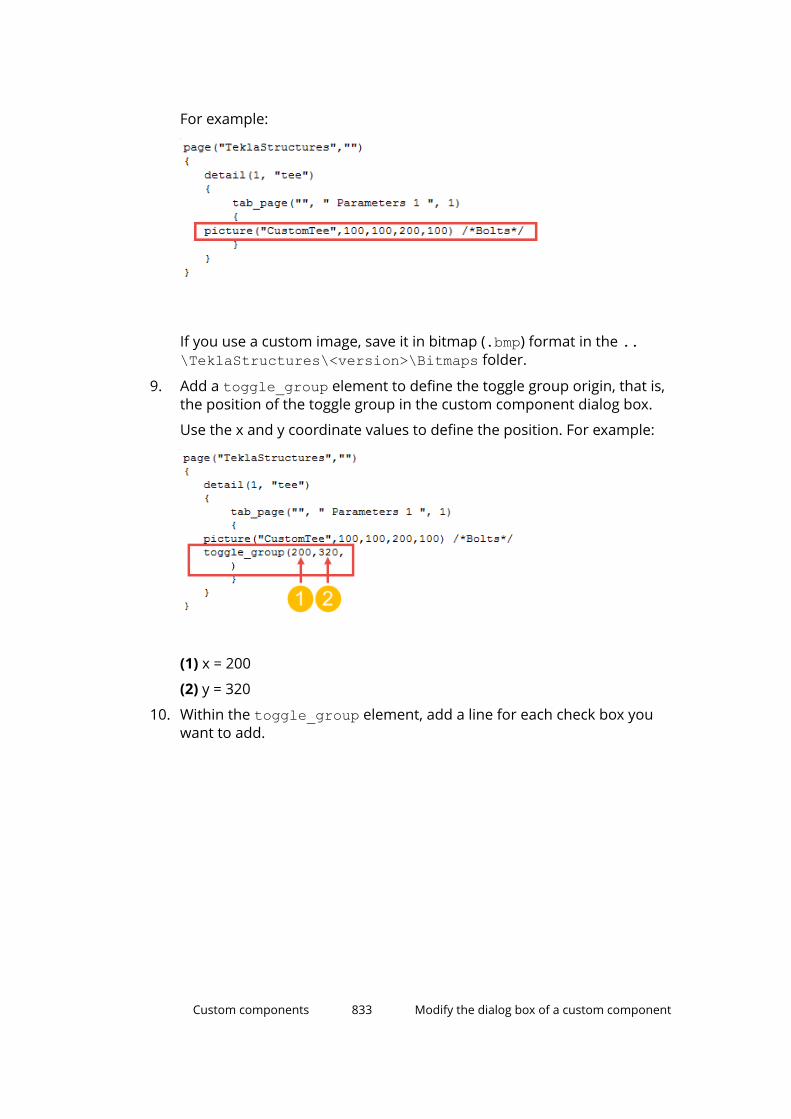
For example:
If you use a custom image, save it in bitmap (.bmp) format in the ..\TeklaStructures\<version>\Bitmaps folder.
9. Add a toggle_group element to define the toggle group origin, that is,the position of the toggle group in the custom component dialog box.
Use the x and y coordinate values to define the position. For example:
(1) x = 200
(2) y = 320
10. Within the toggle_group element, add a line for each check box youwant to add.
Custom components 833 Modify the dialog box of a custom component
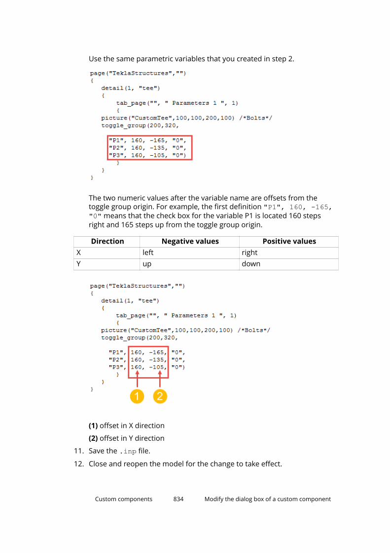
Use the same parametric variables that you created in step 2.
The two numeric values after the variable name are offsets from thetoggle group origin. For example, the first definition "P1", 160, -165,"0" means that the check box for the variable P1 is located 160 stepsright and 165 steps up from the toggle group origin.
Direction Negative values Positive valuesX left rightY up down
(1) offset in X direction
(2) offset in Y direction
11. Save the .inp file.
12. Close and reopen the model for the change to take effect.
Custom components 834 Modify the dialog box of a custom component

Now when you select and clear check boxes in the dialog box, the numberof bolts changes accordingly in the model. For example:
NOTE Tekla Structures automatically adds the Effect in modify labeland check box for each toggle group you create.
Example: Modify the dialog box of a stiffener detailIn this example, we will edit the dialog box of a custom stiffener detail to makeit easier to adjust the settings later on.
When we begin, the dialog box looks like the following:
Do this
Custom components 835 Modify the dialog box of a custom component

1. Create a custom stiffener detail with all the needed variables that controlthe creation of stiffener plates.
2. Add a list with images.
3. Arrange text boxes and labels.
4. Dim unavailable options.
Example: Create a custom stiffener detail with variablesIn this example, we will create a stiffener detail with variables that control theshape and position of the stiffeners.
Create a basic stiffener detailIn this example, we will create a basic stiffener detail.
1. Create a beam with two stiffeners.
TIP To create the stiffeners, you can use the Stiffeners (1003)component and then explode the component.
2. Click the Applications & components button in the side pane toopen the Applications & components catalog.
3. Click the Access advanced features button and select Definecustom component.
The Custom Component Wizard dialog box opens.
4. In the Type list, select Detail.
5. In the Name box, type Stiffeners.
Custom components 836 Modify the dialog box of a custom component

6. Click Next.
7. Select the stiffeners and the beam as the objects that form the customcomponent.
8. Click Next.
9. Select the beam as the main part.
10. Click Next.
11. Select the middle point of the beam as the reference point.
TIP Switch to the plane view (page 43) to select the middle point moreeasily.
Custom components 837 Modify the dialog box of a custom component
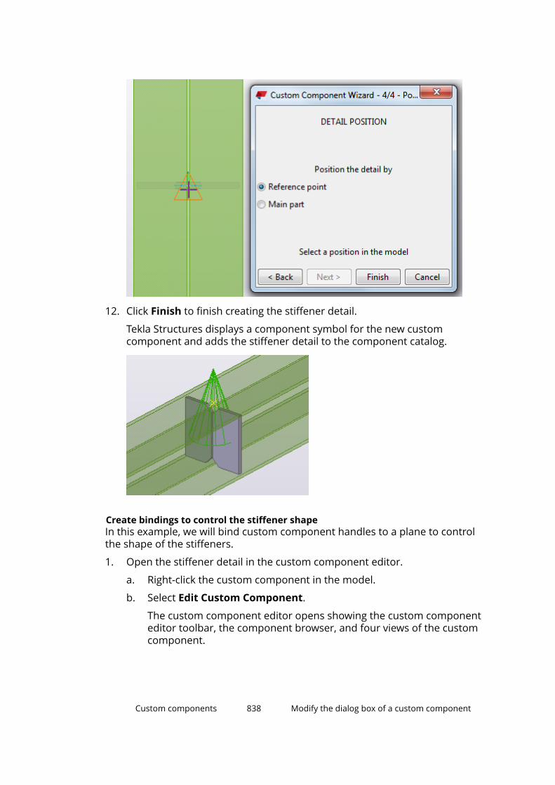
12. Click Finish to finish creating the stiffener detail.
Tekla Structures displays a component symbol for the new customcomponent and adds the stiffener detail to the component catalog.
Create bindings to control the stiffener shapeIn this example, we will bind custom component handles to a plane to controlthe shape of the stiffeners.
1. Open the stiffener detail in the custom component editor.
a. Right-click the custom component in the model.
b. Select Edit Custom Component.
The custom component editor opens showing the custom componenteditor toolbar, the component browser, and four views of the customcomponent.
Custom components 838 Modify the dialog box of a custom component
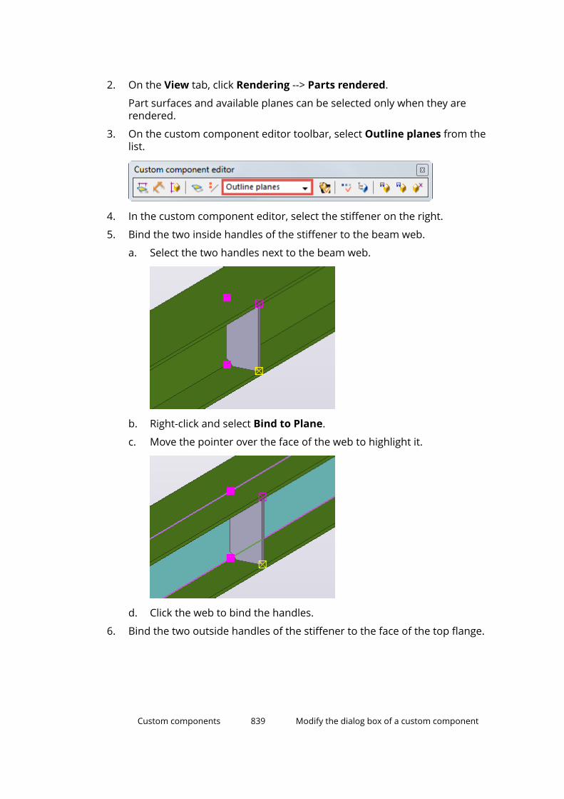
2. On the View tab, click Rendering --> Parts rendered.
Part surfaces and available planes can be selected only when they arerendered.
3. On the custom component editor toolbar, select Outline planes from thelist.
4. In the custom component editor, select the stiffener on the right.
5. Bind the two inside handles of the stiffener to the beam web.
a. Select the two handles next to the beam web.
b. Right-click and select Bind to Plane.
c. Move the pointer over the face of the web to highlight it.
d. Click the web to bind the handles.
6. Bind the two outside handles of the stiffener to the face of the top flange.
Custom components 839 Modify the dialog box of a custom component
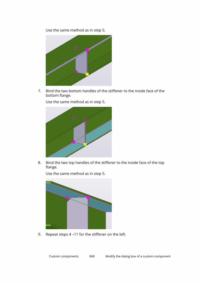
Use the same method as in step 5.
7. Bind the two bottom handles of the stiffener to the inside face of thebottom flange.
Use the same method as in step 5.
8. Bind the two top handles of the stiffener to the inside face of the topflange.
Use the same method as in step 5.
9. Repeat steps 4 –11 for the stiffener on the left.
Custom components 840 Modify the dialog box of a custom component

10. In the custom component editor, click the Display variables button .
The Variables dialog box opens.
11. Click Add to create a new parametric variable P1.
12. Modify the variable P1 as follows:
a. In the Formula box, enter 10.
b. In the Label in dialog box box, enter Stiffener set back.
13. In the Formula box, enter =P1 for all variables that got values during thebinding of the handles.
For example:
The variable P1 now controls the distances of these variables.
14. In the Visibility list, set the variable P1 to Show and the other variables toHide.
We have now created distance variables that control the stiffener shape.
Create bindings to control the stiffener positionIn this example, we will bind custom component handles to a plane to controlthe position of the stiffeners.
Custom components 841 Modify the dialog box of a custom component

1. Open the stiffener detail in the custom component editor.
a. Right-click the custom component in the model.
b. Select Edit Custom Component.
The custom component editor opens showing the custom componenteditor toolbar, the component browser, and four views of the customcomponent.
2. On the custom component editor toolbar, select Component planes fromthe list.
3. Select all the handles of both stiffeners.
4. Right-click and select Bind to Plane.
5. Bind the handles to the vertical component plane.
Custom components 842 Modify the dialog box of a custom component

We have now created distance variables that control the position of thestiffeners.
Create variables to control the stiffener thicknessIn this example, we will control the stiffener thickness so that it is one and ahalf times the web thickness rounded up to the nearest available platethickness. The available thickness values are 10, 12, and 16 mm.
1. Open the stiffener detail in the custom component editor.
a. Right-click the custom component in the model.
b. Select Edit Custom Component.
The custom component editor opens showing the custom componenteditor toolbar, the component browser, and four views of the customcomponent.
2. In the custom component editor, click the Display variables button .
The Variables dialog box opens.
3. Click Add to create a new parametric variable P2.
4. Modify the variable P2 as follows:
a. In the Formula box, enter =1.5*.
b. In the Visibility list, select Hide.
c. In the Label in dialog box box, enter Plate calculation.
5. Select the beam in the custom component editor to highlight the beam(primary part) in the custom component browser.
6. In the Custom component browser, select Web thickness of theprimary part.
Custom components 843 Modify the dialog box of a custom component
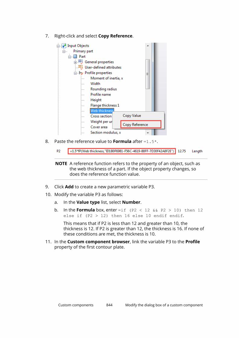
7. Right-click and select Copy Reference.
8. Paste the reference value to Formula after =1.5*.
NOTE A reference function refers to the property of an object, such asthe web thickness of a part. If the object property changes, sodoes the reference function value.
9. Click Add to create a new parametric variable P3.
10. Modify the variable P3 as follows:
a. In the Value type list, select Number.
b. In the Formula box, enter =if (P2 < 12 && P2 > 10) then 12else if (P2 > 12) then 16 else 10 endif endif.
This means that if P2 is less than 12 and greater than 10, thethickness is 12. If P2 is greater than 12, the thickness is 16. If none ofthese conditions are met, the thickness is 10.
11. In the Custom component browser, link the variable P3 to the Profileproperty of the first contour plate.
Custom components 844 Modify the dialog box of a custom component
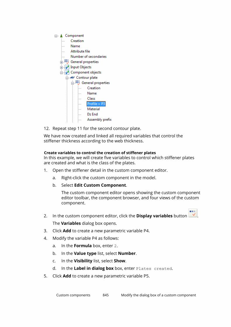
12. Repeat step 11 for the second contour plate.
We have now created and linked all required variables that control thestiffener thickness according to the web thickness.
Create variables to control the creation of stiffener platesIn this example, we will create five variables to control which stiffener platesare created and what is the class of the plates.
1. Open the stiffener detail in the custom component editor.
a. Right-click the custom component in the model.
b. Select Edit Custom Component.
The custom component editor opens showing the custom componenteditor toolbar, the component browser, and four views of the customcomponent.
2. In the custom component editor, click the Display variables button .
The Variables dialog box opens.
3. Click Add to create a new parametric variable P4.
4. Modify the variable P4 as follows:
a. In the Formula box, enter 2.
b. In the Value type list, select Number.
c. In the Visibility list, select Show.
d. In the Label in dialog box box, enter Plates created.
5. Click Add to create a new parametric variable P5.
Custom components 845 Modify the dialog box of a custom component
6. Modify the variable P5 as follows:
a. In the Formula box, enter =if P4==0 then 0 else 1 endif.
b. In the Value type list, select Yes/No.
c. In the Visibility list, select Hide.
d. In the Label in dialog box box, enter Do not create right.
7. Click Add to create a new parametric variable P6.
8. Modify the variable P6 as follows:
a. In the Formula box, enter =if P4==1 then 0 else 1 endif.
b. In the Value type list, select Yes/No.
c. In the Visibility list, select Hide.
d. In the Label in dialog box box, enter Do not create left.
9. Click Add to create a new parametric variable P7.
10. Modify the variable P7 as follows:
a. Rename P7 as LeftC.
b. In the Formula box, enter 4.
c. In the Value type list, select Number.
d. In the Visibility list, select Show.
e. In the Label in dialog box box, enter Left plate class.
11. Click Add to create a new parametric variable P8.
12. Modify the variable P8 as follows:
a. Rename P8 as RightC.
b. In the Formula box, enter 5.
c. In the Value type list, select Number.
d. In the Visibility list, select Show.
e. In the Label in dialog box box, enter Right plate class.
13. In the Custom component browser, link the variables P5 and RightC tothe right stiffener plate.
Custom components 846 Modify the dialog box of a custom component

14. Link the variables P6 and LeftC to the left stiffener plate.
Example: Add a list with imagesIn this example, we will add an illustrative list in the stiffener dialog box. Youcan do this either in the custom component dialog editor or by editing theinput (.inp) file manually.
When we begin, the dialog box has the text box shown below, and the userneeds to know the values (0 is left, 1 is right, and 2 is both plates) that controlthe creation of stiffener plates.
We will replace the text box with a list that is easier to use:
Custom components 847 Modify the dialog box of a custom component

Add a list by using the dialog editor
1. Create a custom stiffener detail (page 836) with all the needed variablesthat control which stiffener plates are created.
In our example, the variable is called Plates created.
2. Open the stiffener dialog box for editing.
a. In the model, select the custom stiffener detail.
b. Right-click and select Edit Custom Component Dialog Box.
3. Check the name of the parametric variable that controls the platecreation.
a. In the dialog editor, double-click the Plates created box.
The Object Properties dialog box opens.
b. Check the name of the parametric variable.
Custom components 848 Modify the dialog box of a custom component
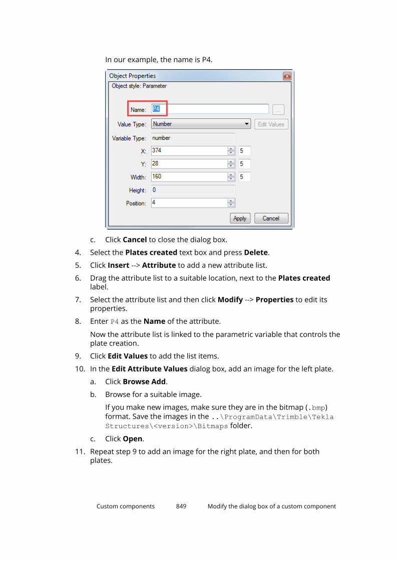
In our example, the name is P4.
c. Click Cancel to close the dialog box.
4. Select the Plates created text box and press Delete.
5. Click Insert --> Attribute to add a new attribute list.
6. Drag the attribute list to a suitable location, next to the Plates createdlabel.
7. Select the attribute list and then click Modify --> Properties to edit itsproperties.
8. Enter P4 as the Name of the attribute.
Now the attribute list is linked to the parametric variable that controls theplate creation.
9. Click Edit Values to add the list items.
10. In the Edit Attribute Values dialog box, add an image for the left plate.
a. Click Browse Add.
b. Browse for a suitable image.
If you make new images, make sure they are in the bitmap (.bmp)format. Save the images in the ..\ProgramData\Trimble\TeklaStructures\<version>\Bitmaps folder.
c. Click Open.
11. Repeat step 9 to add an image for the right plate, and then for bothplates.
Custom components 849 Modify the dialog box of a custom component
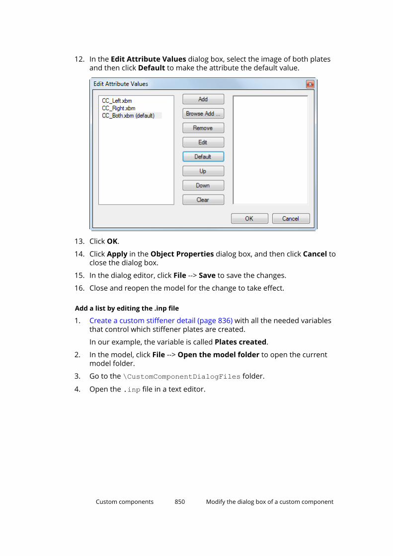
12. In the Edit Attribute Values dialog box, select the image of both platesand then click Default to make the attribute the default value.
13. Click OK.
14. Click Apply in the Object Properties dialog box, and then click Cancel toclose the dialog box.
15. In the dialog editor, click File --> Save to save the changes.
16. Close and reopen the model for the change to take effect.
Add a list by editing the .inp file
1. Create a custom stiffener detail (page 836) with all the needed variablesthat control which stiffener plates are created.
In our example, the variable is called Plates created.
2. In the model, click File --> Open the model folder to open the currentmodel folder.
3. Go to the \CustomComponentDialogFiles folder.
4. Open the .inp file in a text editor.
Custom components 850 Modify the dialog box of a custom component

5. Remove the following line:
parameter("Plates created", "P4", integer, number, 2)6. Add a new Plates created attribute with the following settings:
7. Add a new P4 attribute with the following settings:
The list now contains three options, and Both is the default value. The listoptions are linked to the variable P4 that controls the creation of thestiffener plates.
Custom components 851 Modify the dialog box of a custom component
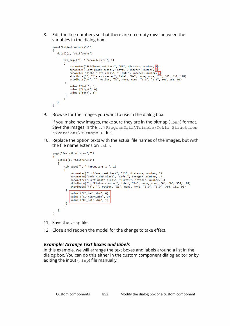
8. Edit the line numbers so that there are no empty rows between thevariables in the dialog box.
9. Browse for the images you want to use in the dialog box.
If you make new images, make sure they are in the bitmap (.bmp) format.Save the images in the ..\ProgramData\Trimble\Tekla Structures\<version>\Bitmaps folder.
10. Replace the option texts with the actual file names of the images, but withthe file name extension .xbm.
11. Save the .inp file.
12. Close and reopen the model for the change to take effect.
Example: Arrange text boxes and labelsIn this example, we will arrange the text boxes and labels around a list in thedialog box. You can do this either in the custom component dialog editor or byediting the input (.inp) file manually.
Custom components 852 Modify the dialog box of a custom component
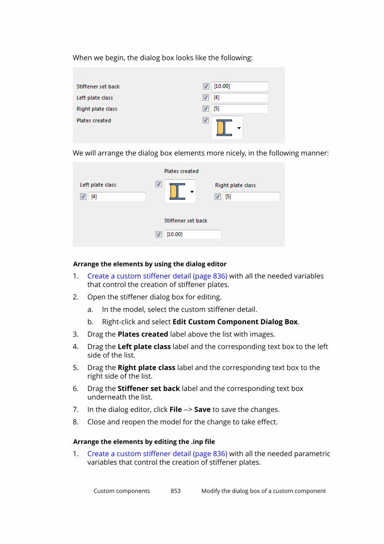
When we begin, the dialog box looks like the following:
We will arrange the dialog box elements more nicely, in the following manner:
Arrange the elements by using the dialog editor
1. Create a custom stiffener detail (page 836) with all the needed variablesthat control the creation of stiffener plates.
2. Open the stiffener dialog box for editing.
a. In the model, select the custom stiffener detail.
b. Right-click and select Edit Custom Component Dialog Box.
3. Drag the Plates created label above the list with images.
4. Drag the Left plate class label and the corresponding text box to the leftside of the list.
5. Drag the Right plate class label and the corresponding text box to theright side of the list.
6. Drag the Stiffener set back label and the corresponding text boxunderneath the list.
7. In the dialog editor, click File --> Save to save the changes.
8. Close and reopen the model for the change to take effect.
Arrange the elements by editing the .inp file
1. Create a custom stiffener detail (page 836) with all the needed parametricvariables that control the creation of stiffener plates.
Custom components 853 Modify the dialog box of a custom component
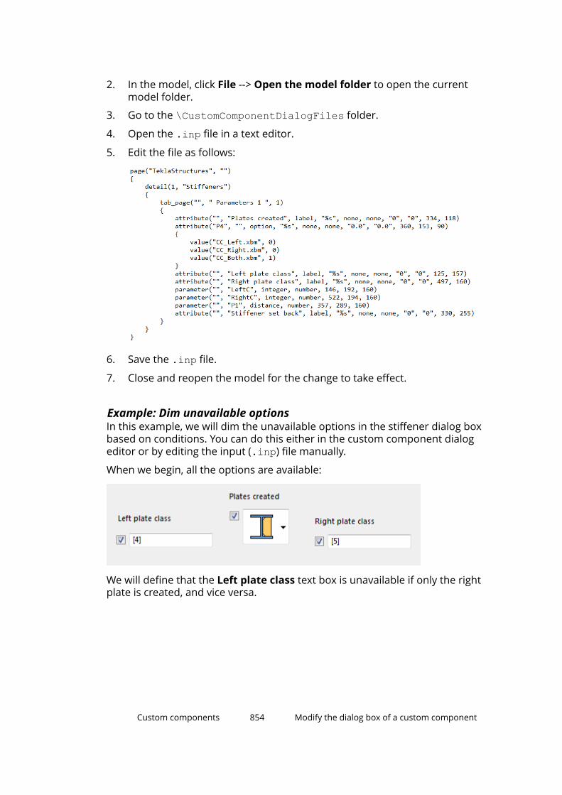
2. In the model, click File --> Open the model folder to open the currentmodel folder.
3. Go to the \CustomComponentDialogFiles folder.
4. Open the .inp file in a text editor.
5. Edit the file as follows:
6. Save the .inp file.
7. Close and reopen the model for the change to take effect.
Example: Dim unavailable optionsIn this example, we will dim the unavailable options in the stiffener dialog boxbased on conditions. You can do this either in the custom component dialogeditor or by editing the input (.inp) file manually.
When we begin, all the options are available:
We will define that the Left plate class text box is unavailable if only the rightplate is created, and vice versa.
Custom components 854 Modify the dialog box of a custom component

Dim unavailable options by using the dialog editor
1. Create a custom stiffener detail (page 836) with all the needed parametricvariables that control the creation of stiffener plates.
2. Open the stiffener dialog box for editing.
a. In the model, select the custom stiffener detail.
b. Right-click and select Edit Custom Component Dialog Box.
3. Define that the Left plate class text box must be dimmed if only the rightstiffener plate is created.
a. In the Plates created list, select the image for the right plate class.
Note that a blue selection border must be displayed for the image:
b. Hold down the Ctrl key and click the Left plate class text box.
c. Click the Toggle visibility button.
The Left plate class text box is now dimmed:
Custom components 855 Modify the dialog box of a custom component
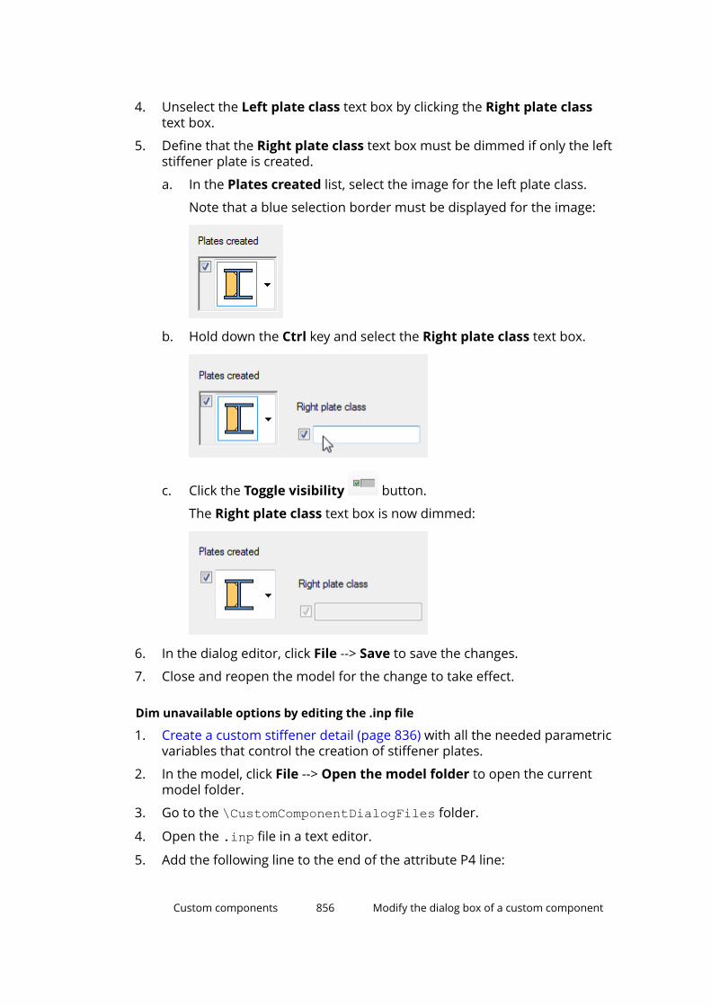
4. Unselect the Left plate class text box by clicking the Right plate classtext box.
5. Define that the Right plate class text box must be dimmed if only the leftstiffener plate is created.
a. In the Plates created list, select the image for the left plate class.
Note that a blue selection border must be displayed for the image:
b. Hold down the Ctrl key and select the Right plate class text box.
c. Click the Toggle visibility button.
The Right plate class text box is now dimmed:
6. In the dialog editor, click File --> Save to save the changes.
7. Close and reopen the model for the change to take effect.
Dim unavailable options by editing the .inp file
1. Create a custom stiffener detail (page 836) with all the needed parametricvariables that control the creation of stiffener plates.
2. In the model, click File --> Open the model folder to open the currentmodel folder.
3. Go to the \CustomComponentDialogFiles folder.
4. Open the .inp file in a text editor.
5. Add the following line to the end of the attribute P4 line:
Custom components 856 Modify the dialog box of a custom component
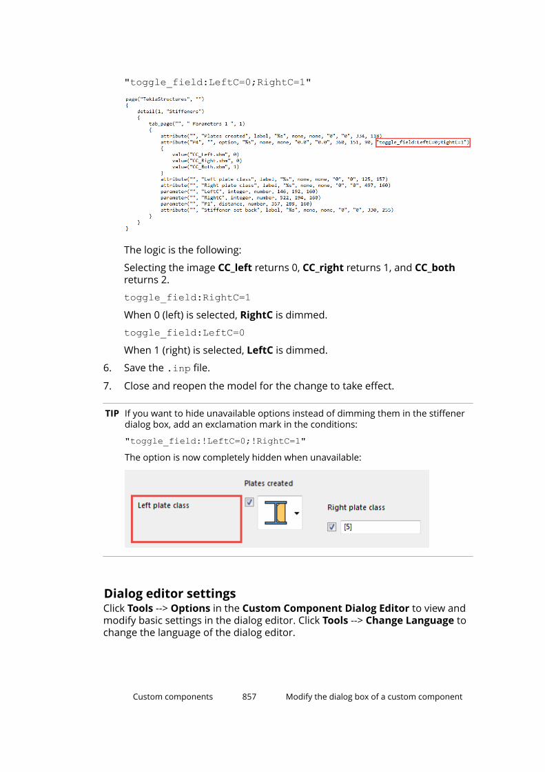
"toggle_field:LeftC=0;RightC=1"
The logic is the following:
Selecting the image CC_left returns 0, CC_right returns 1, and CC_bothreturns 2.
toggle_field:RightC=1When 0 (left) is selected, RightC is dimmed.
toggle_field:LeftC=0When 1 (right) is selected, LeftC is dimmed.
6. Save the .inp file.
7. Close and reopen the model for the change to take effect.
TIP If you want to hide unavailable options instead of dimming them in the stiffenerdialog box, add an exclamation mark in the conditions:
"toggle_field:!LeftC=0;!RightC=1"The option is now completely hidden when unavailable:
Dialog editor settingsClick Tools --> Options in the Custom Component Dialog Editor to view andmodify basic settings in the dialog editor. Click Tools --> Change Language tochange the language of the dialog editor.
Custom components 857 Modify the dialog box of a custom component
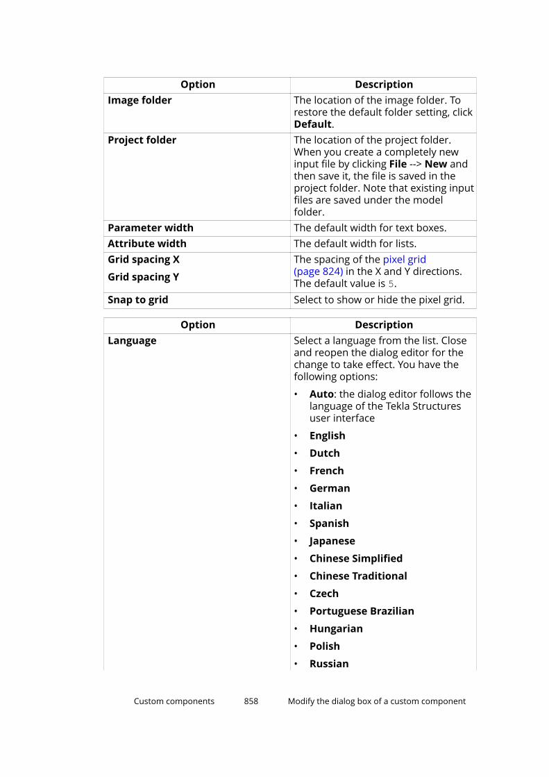
Option DescriptionImage folder The location of the image folder. To
restore the default folder setting, clickDefault.
Project folder The location of the project folder.When you create a completely newinput file by clicking File --> New andthen save it, the file is saved in theproject folder. Note that existing inputfiles are saved under the modelfolder.
Parameter width The default width for text boxes.Attribute width The default width for lists.Grid spacing X
Grid spacing Y
The spacing of the pixel grid(page 824) in the X and Y directions.The default value is 5.
Snap to grid Select to show or hide the pixel grid.
Option DescriptionLanguage Select a language from the list. Close
and reopen the dialog editor for thechange to take effect. You have thefollowing options:
• Auto: the dialog editor follows thelanguage of the Tekla Structuresuser interface
• English
• Dutch
• French
• German
• Italian
• Spanish
• Japanese
• Chinese Simplified
• Chinese Traditional
• Czech
• Portuguese Brazilian
• Hungarian
• Polish
• Russian
Custom components 858 Modify the dialog box of a custom component
Option Description• Korean
See also
Modify the dialog box of a custom component (page 824)
8.10 Add a custom component to a modelUse the Applications & components catalog to add your custom componentto a model.
1. Click the Applications & components button in the side pane toopen the Applications & components catalog.
2. To search for a component, browse the catalog or enter a search term inthe search box. Custom components have the following symbols in thecatalog:
Type Symbol
Custom part
Custom connection or seam
Custom detail
3. Select the custom component you want to add.
4. Follow the instructions on the status bar to add the custom component inthe model.
5. To modify the properties, double-click the custom component in themodel.
Example: Add a custom connection to a model
In this example, you will add a previously created custom end plate connectionto a model. Because you have not modified the custom component to adapt todifferent situations in the model, you need to add it to a similar location whereit was created. Otherwise the custom component may not work as required.
1. Click the Applications & components button in the side pane toopen the Applications & components catalog.
2. In the catalog, select the custom end plate connection you want to add.
Tekla Structures displays instructions on the status bar.
3. Select the column as the main part.
Custom components 859 Add a custom component to a model
4. Select the beam as the secondary part.
Tekla Structures adds the end plate connection to the model.
See also
Add or move a custom part in the model (page 860)
8.11 Add or move a custom part in the modelUse the direct modification handles and dimensions when you add or movecustom parts. If you are unable to select custom parts in the model, ensure
that the Select components selection switch is active.
NOTE This method cannot be used when adding custom parts to faces thathave cuts or edge chamfers. You need to hide the cutting parts andedge chamfer objects from the view before you add custom parts oncut or chamfered faces using direct modification.
We do not recommend using this method with custom parts that areparametric, and in which the input points define the dimensions of thecustom part. The preview is simplified, based on the default custompart dimensions, and snapping has a different focus than usually.
1. Ensure that Direct modification is switched on.
2. Click the Applications & components button in the side pane toopen the Applications & components catalog.
3. In the catalog, select the custom part you want to add.
4. Move the mouse pointer over part faces and edges in the model, and seehow the custom part turns over and adjusts to the part faces.
If you are adding the custom part to another object, Tekla Structuresshows location dimensions to the nearest object edges.
If you are adding a custom part that has only one input point, press Tab torotate it in 90-degree steps around the work plane Y axis.
5. Depending on the number of custom part input points, pick one or twopoints to place the custom part in the model.
Tekla Structures shows the coordinate axes, rotation handles, and locationdimensions that you can use to fine-tune the location and rotation of the
Custom components 860 Add or move a custom part in the model
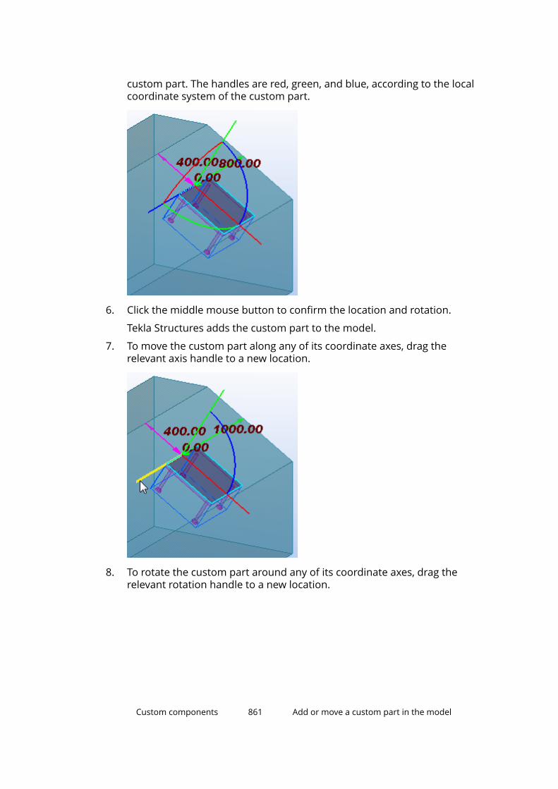
custom part. The handles are red, green, and blue, according to the localcoordinate system of the custom part.
6. Click the middle mouse button to confirm the location and rotation.
Tekla Structures adds the custom part to the model.
7. To move the custom part along any of its coordinate axes, drag therelevant axis handle to a new location.
8. To rotate the custom part around any of its coordinate axes, drag therelevant rotation handle to a new location.
Custom components 861 Add or move a custom part in the model
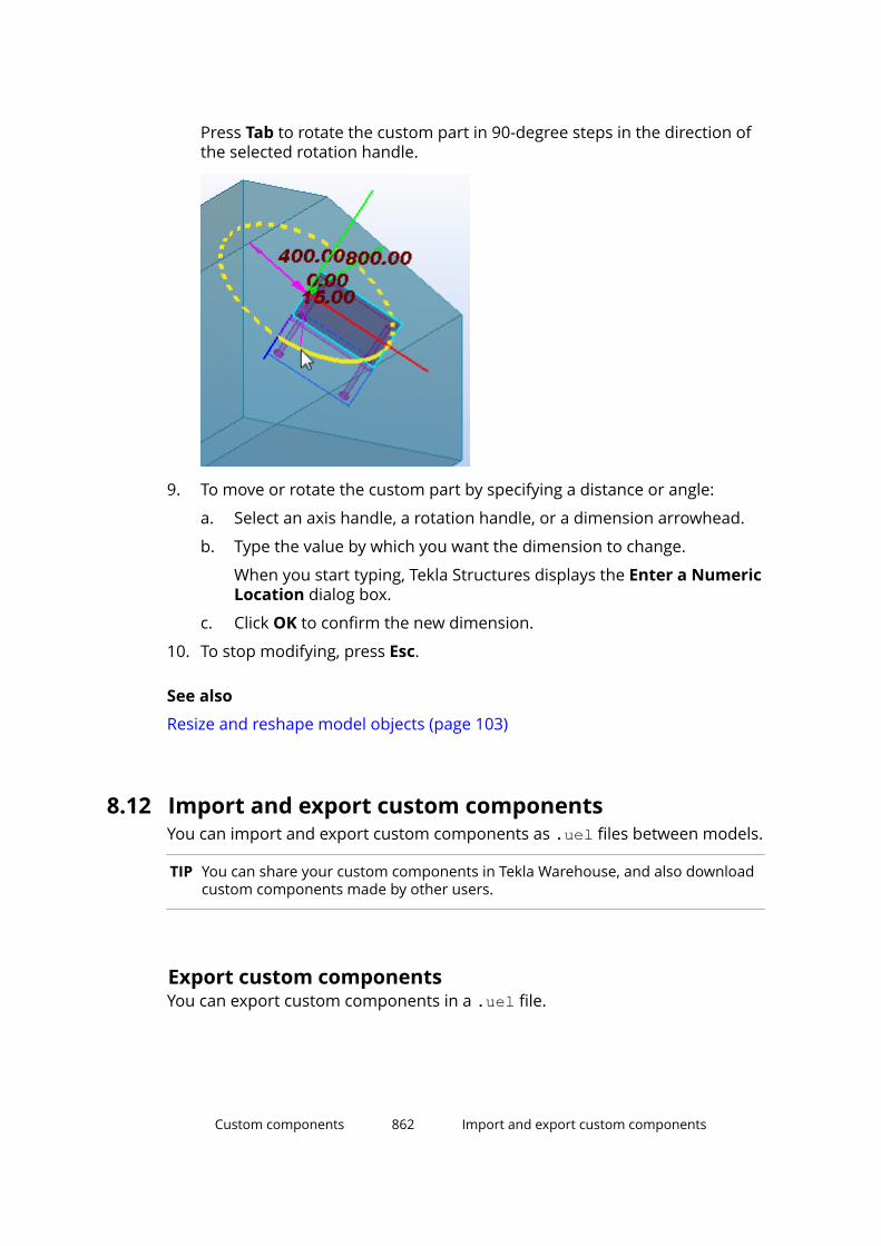
Press Tab to rotate the custom part in 90-degree steps in the direction ofthe selected rotation handle.
9. To move or rotate the custom part by specifying a distance or angle:
a. Select an axis handle, a rotation handle, or a dimension arrowhead.
b. Type the value by which you want the dimension to change.
When you start typing, Tekla Structures displays the Enter a NumericLocation dialog box.
c. Click OK to confirm the new dimension.
10. To stop modifying, press Esc.
See also
Resize and reshape model objects (page 103)
8.12 Import and export custom componentsYou can import and export custom components as .uel files between models.
TIP You can share your custom components in Tekla Warehouse, and also downloadcustom components made by other users.
Export custom componentsYou can export custom components in a .uel file.
Custom components 862 Import and export custom components
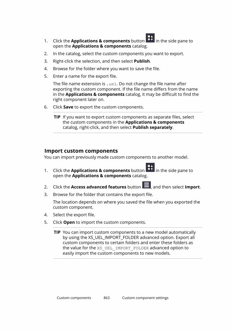
1. Click the Applications & components button in the side pane toopen the Applications & components catalog.
2. In the catalog, select the custom components you want to export.
3. Right-click the selection, and then select Publish.
4. Browse for the folder where you want to save the file.
5. Enter a name for the export file.
The file name extension is .uel. Do not change the file name afterexporting the custom component. If the file name differs from the namein the Applications & components catalog, it may be difficult to find theright component later on.
6. Click Save to export the custom components.
TIP If you want to export custom components as separate files, selectthe custom components in the Applications & componentscatalog, right-click, and then select Publish separately.
Import custom componentsYou can import previously made custom components to another model.
1. Click the Applications & components button in the side pane toopen the Applications & components catalog.
2. Click the Access advanced features button , and then select Import.
3. Browse for the folder that contains the export file.
The location depends on where you saved the file when you exported thecustom component.
4. Select the export file.
5. Click Open to import the custom components.
TIP You can import custom components to a new model automaticallyby using the XS_UEL_IMPORT_FOLDER advanced option. Export allcustom components to certain folders and enter these folders asthe value for the XS_UEL_IMPORT_FOLDER advanced option toeasily import the custom components to new models.
Custom components 863 Custom component settings

8.13 Custom component settingsHere you will find more information about the various custom componentproperties and plane types.
• Custom component properties (page 864)
You must define these properties when you create new customcomponents. You can change some of these properties when you modifyan existing custom component.
• Default properties of a custom component (page 867)
Each custom component has a dialog box that you can modify. By default,the dialog box has a Position tab for custom parts and a General tab forcustom connections, details, and seams.
• Plane types (page 872)
When you create distance variables for a custom component, you mustselect a plane type. The plane type defines what planes you can select.
• Variable properties (page 875)
Use the Variables dialog box to define properties for distance andparametric variables.
Custom component propertiesYou must define these properties when you create new custom componentswith the Custom Component Wizard. You can change some of theseproperties when you modify an existing custom component.
For more information, see Create a custom component (page 747) and Modifya custom component (page 761).
Type/Notes tab propertiesOn the Type/Notes tab, you have the following options:
Option DescriptionType Select the type of the custom component.
Type affects how you insert the custom componentin the model. Type also defines if the customcomponent connects to existing parts.
Name Enter a unique name for the custom component.Description Enter a short description for the custom
component. Tekla Structures shows the descriptionin the Applications & components catalog.
Custom components 864 Custom component settings

Option DescriptionComponent identifier Enter an additional name or reference for the
component, for example a design code reference.This can be shown in general arrangement andassembly drawings, and in lists.
To show this in drawings, include Code in theConnection Mark Properties dialog box.
Position tab propertiesOn the Position tab, you have the following options:
Option Description NoteUp direction Sets the default up
direction.Not available for parts.
Position type The position (or origin)of the component,relative to the main part.
Not available for detailsand parts.
You can define the position for custom connections and seams. You have thefollowing options:
Option Description ExampleMiddle Where the center lines
of the main andsecondary partsintersect.
Box plane Where the main partbounding box and thecenter line of thesecondary part intersect.
Collision plane Where the main partand the center line ofthe secondary partintersect.
Custom components 865 Custom component settings

Option Description ExampleEndend plane Where the center line of
the secondary part hitsthe end of the main part.
Gusset plane Where the center linesof the main part and thefirst secondary partintersect. The x directionis perpendicular to thecenter line of the mainpart.
Advanced tab propertiesOn the Advanced tab, you have the following options:
Option Description NoteDetail type Determines on which
side of the main part thecomponent is located.The options are:
• Intermediate detail
Tekla Structurescreates allcomponents on thesame side of themain part
• End detail
Tekla Structurescreates allcomponents on theside of the main partclosest to the details
Only affects asymmetriccomponents.
Only available for detailsand seams
Custom components 866 Custom component settings
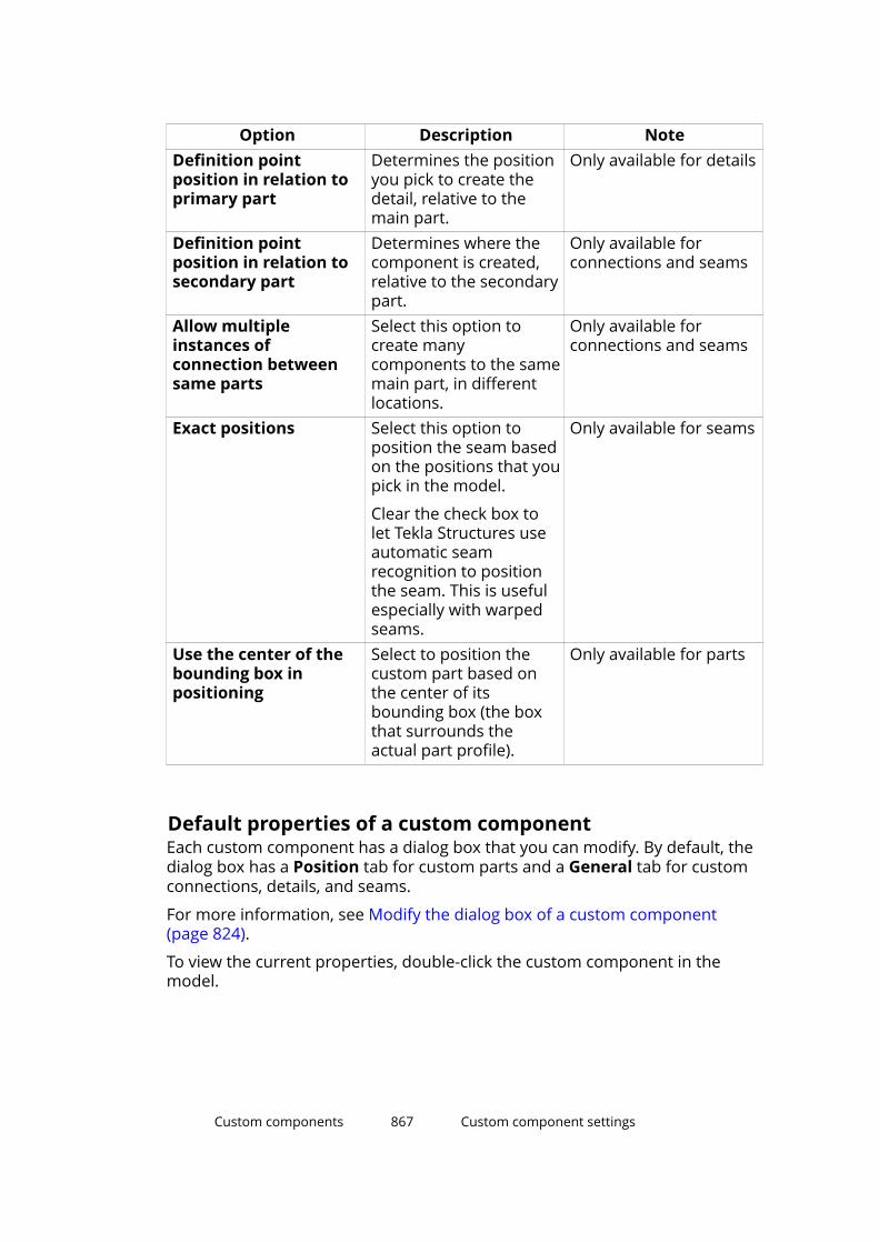
Option Description NoteDefinition pointposition in relation toprimary part
Determines the positionyou pick to create thedetail, relative to themain part.
Only available for details
Definition pointposition in relation tosecondary part
Determines where thecomponent is created,relative to the secondarypart.
Only available forconnections and seams
Allow multipleinstances ofconnection betweensame parts
Select this option tocreate manycomponents to the samemain part, in differentlocations.
Only available forconnections and seams
Exact positions Select this option toposition the seam basedon the positions that youpick in the model.
Clear the check box tolet Tekla Structures useautomatic seamrecognition to positionthe seam. This is usefulespecially with warpedseams.
Only available for seams
Use the center of thebounding box inpositioning
Select to position thecustom part based onthe center of itsbounding box (the boxthat surrounds theactual part profile).
Only available for parts
Default properties of a custom componentEach custom component has a dialog box that you can modify. By default, thedialog box has a Position tab for custom parts and a General tab for customconnections, details, and seams.
For more information, see Modify the dialog box of a custom component(page 824).
To view the current properties, double-click the custom component in themodel.
Custom components 867 Custom component settings

Default properties of custom partsBy default, the dialog box of a custom part has the following options:
Option Description ExampleOn plane Changes part location on the work
plane.Middle
Right
Left
Rotation Rotates the part in steps of 90degrees.
Top and Below
Front and Back
Custom components 868 Custom component settings
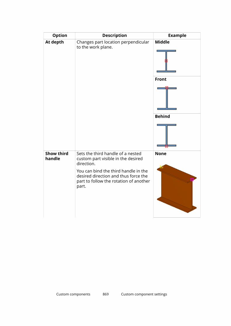
Option Description ExampleAt depth Changes part location perpendicular
to the work plane.Middle
Front
Behind
Show thirdhandle
Sets the third handle of a nestedcustom part visible in the desireddirection.
You can bind the third handle in thedesired direction and thus force thepart to follow the rotation of anotherpart.
None
Custom components 869 Custom component settings

Option Description ExampleAbove
On the left
Default properties of custom connections, details, and seamsBy default, the dialog box of a custom connection, detail, or seam has thefollowing options:
Option Description NoteUp direction Indicates how the component
is rotated around thesecondary part, relative to thecurrent work plane. If thereare no secondary parts, TeklaStructures rotates theconnection around the mainpart.
Position in relationto primary part
The creation point of thecomponent, relative to themain part.
Only available fordetails.
Custom components 870 Custom component settings

Option Description NotePosition in relationto secondary part
Tekla Structures automaticallyplaces the componentaccording to the selectedoption.
By default, onlyavailable for seams.
If you want to use thisproperty inconnections, selectthe Allow multipleinstances ofconnection betweensame parts checkbox on the Advancedtab when you createthe component.
Place to pickedpositions
Select this option to place theseam at the points you pick.
Only available forseams.
Detail type Determines on which side ofthe main part the componentis located. The options are:
• Intermediate detail
Tekla Structures creates allcomponents on the sameside of the main part.
• End detail
Tekla Structures creates allcomponents on the sidethat is closest to thedetails.
Only affects asymmetriccomponents.
Only available fordetails.
Locked Select Yes to prevent otherusers from modifying theproperties.
Class The class of the parts that thecustom component creates.
Connection code Identifies the component. Youcan display this connectioncode in connection marks indrawings.
AutoDefaults rulegroup
The rule group used forsetting the connectionproperties.
Custom components 871 Custom component settings

Option Description NoteAutoConnection rulegroup
The rule group TeklaStructures uses to select theconnection.
Plane typesWhen you add distance variables to a custom component, you must select aplane type. The plane type defines what planes you can select.
You have the following options:
Plane type Description ExampleBoundary planes You can select the edges of a
bounding box that surroundsthe profile.
Center planes You can select the centerplanes of a profile.
Custom components 872 Custom component settings
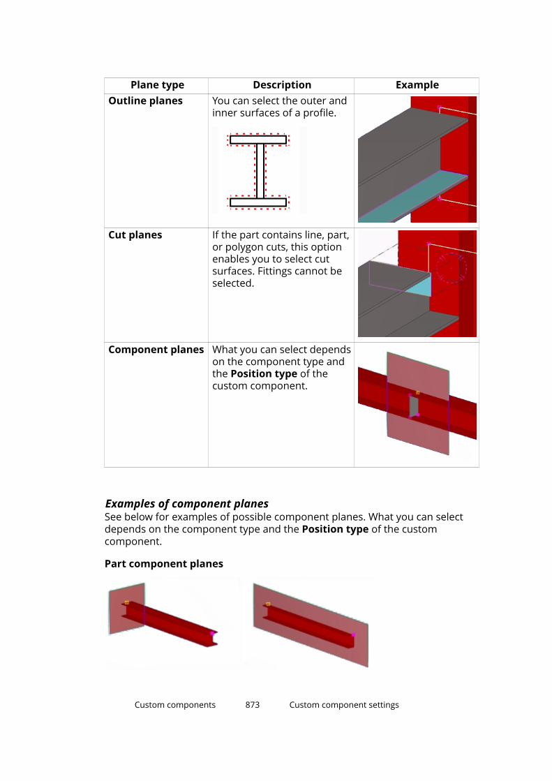
Plane type Description ExampleOutline planes You can select the outer and
inner surfaces of a profile.
Cut planes If the part contains line, part,or polygon cuts, this optionenables you to select cutsurfaces. Fittings cannot beselected.
Component planes What you can select dependson the component type andthe Position type of thecustom component.
Examples of component planesSee below for examples of possible component planes. What you can selectdepends on the component type and the Position type of the customcomponent.
Part component planes
Custom components 873 Custom component settings

Connection component planes
Custom components 874 Custom component settings
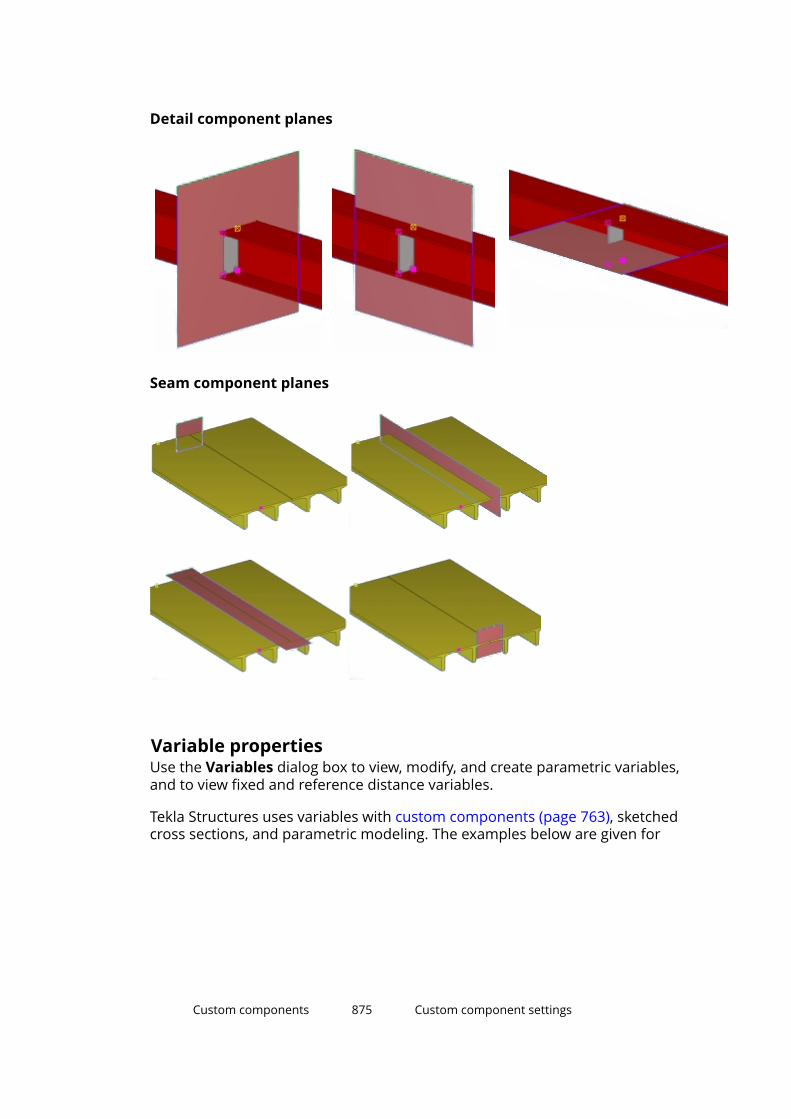
Detail component planes
Seam component planes
Variable propertiesUse the Variables dialog box to view, modify, and create parametric variables,and to view fixed and reference distance variables.
Tekla Structures uses variables with custom components (page 763), sketchedcross sections, and parametric modeling. The examples below are given for
Custom components 875 Custom component settings
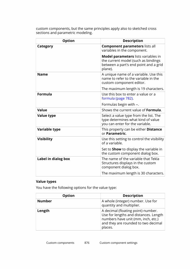
custom components, but the same principles apply also to sketched crosssections and parametric modeling.
Option DescriptionCategory Component parameters lists all
variables in the component.
Model parameters lists variables inthe current model (such as bindingsbetween a part's end point and a gridplane).
Name A unique name of a variable. Use thisname to refer to the variable in thecustom component editor.
The maximum length is 19 characters.Formula Use this box to enter a value or a
formula (page 782).
Formulas begin with =.Value Shows the current value of Formula.Value type Select a value type from the list. The
type determines what kind of valueyou can enter for the variable.
Variable type This property can be either Distanceor Parametric.
Visibility Use this setting to control the visibilityof a variable.
Set to Show to display the variable inthe custom component dialog box.
Label in dialog box The name of the variable that TeklaStructures displays in the customcomponent dialog box.
The maximum length is 30 characters.
Value types
You have the following options for the value type:
Option DescriptionNumber A whole (integer) number. Use for
quantity and multiplier.Length A decimal (floating point) number.
Use for lengths and distances. Lengthnumbers have unit (mm, inch, etc.)and they are rounded to two decimalplaces.
Custom components 876 Custom component settings

Option DescriptionText A text (ASCII) string.Factor A decimal value without a unit. You
can set the number of decimals forthe value type in File menu -->Settings --> Options --> Units anddecimals .
Angle A decimal number type for storingangles, stored to one decimal place, inradians.
Material A data type associated with thematerial catalog. Use to select amaterial from the standard materialdialog.
Profile A data type associated with the profilecatalog. Use to select a profile fromthe standard profile dialog.
Bolt size
Bolt standard
Data types linked to the bolt catalog.Bolt size works with Bolt standard.They have a fixed naming format:Px_diameter and Px_screwdin. Donot change the fixed name.
To show values for these in thecomponent’s dialog box, x must bethe same for both, for example,P1_diameter and P1_screwdin.
Bolt type For determining the bolt type (site/workshop) in the custom componentdialog box. Linked to the Bolt typeproperty of bolts in the Customcomponent browser.
Stud size
Stud standard
Stud length
Data types linked to the bolt catalog.Stud size, Stud standard and Studlength work together. They have afixed naming format: Px_size,
Custom components 877 Custom component settings
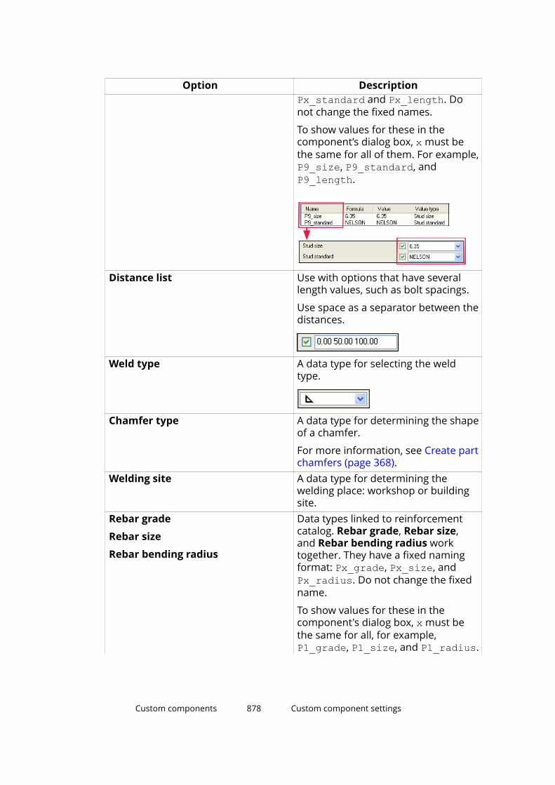
Option DescriptionPx_standard and Px_length. Donot change the fixed names.
To show values for these in thecomponent’s dialog box, x must bethe same for all of them. For example,P9_size, P9_standard, andP9_length.
Distance list Use with options that have severallength values, such as bolt spacings.
Use space as a separator between thedistances.
Weld type A data type for selecting the weldtype.
Chamfer type A data type for determining the shapeof a chamfer.
For more information, see Create partchamfers (page 368).
Welding site A data type for determining thewelding place: workshop or buildingsite.
Rebar grade
Rebar size
Rebar bending radius
Data types linked to reinforcementcatalog. Rebar grade, Rebar size,and Rebar bending radius worktogether. They have a fixed namingformat: Px_grade, Px_size, andPx_radius. Do not change the fixedname.
To show values for these in thecomponent's dialog box, x must bethe same for all, for example,P1_grade, P1_size, and P1_radius.
Custom components 878 Custom component settings

Option Description
Rebar hook type Used for rebar set end detailmodifiers, to specify the hook type.
Rebars to split Used for rebar set splitters, to specifyhow the bars are to be split (1/1, 1/2,and so on).
Rebar stagger type Used for rebar set splitters, to specifythe stagger type (left/right/middle).
Rebar lap side Used for rebar set splitters, to specifythe side of the overlap (left/right/middle).
Rebar lap placement Used for rebar set splitters, todetermine whether the lapping barsare parallel to each other or on top ofeach other.
Rebar lap type Used for rebar set splitters, todetermine whether the reinforcingbars are kept straight at lap splices byoffsetting entire bars, or placedslanted by offsetting bar ends.
Reinforcement mesh For determining meshes in customcomponents. Linked to the Catalogname property of reinforcementmeshes in the Custom componentbrowser.
Cross bar location Used for rebar meshes, to determinewhether the crossing bars are locatedabove or below the longitudinal bars.
Component name
Component attribute file
Use Component name for replacinga sub-component inside a customcomponent with another sub-component. Linked to the Nameproperty of objects in the Customcomponent browser.
Use Component attribute file forsetting the properties of a sub-
Custom components 879 Custom component settings
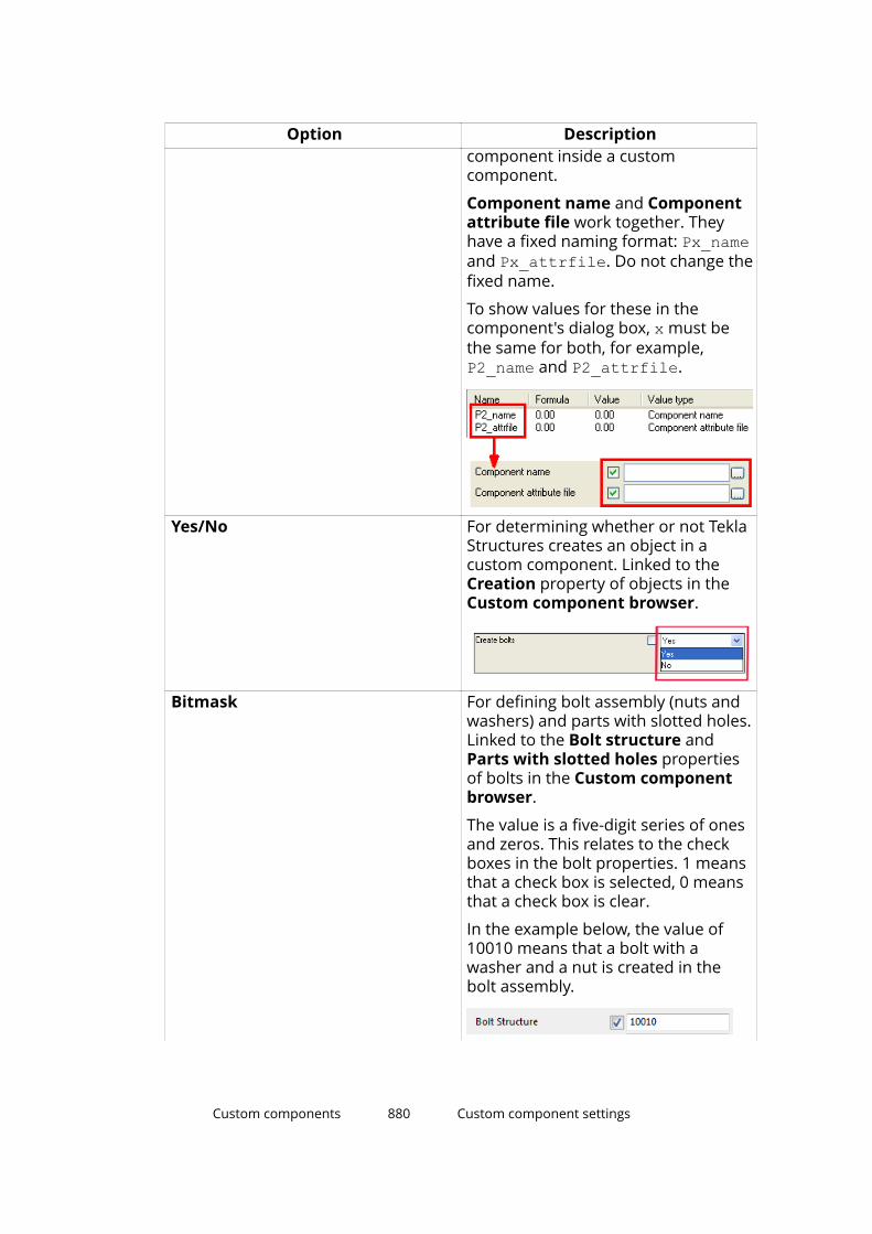
Option Descriptioncomponent inside a customcomponent.
Component name and Componentattribute file work together. Theyhave a fixed naming format: Px_nameand Px_attrfile. Do not change thefixed name.
To show values for these in thecomponent's dialog box, x must bethe same for both, for example,P2_name and P2_attrfile.
Yes/No For determining whether or not TeklaStructures creates an object in acustom component. Linked to theCreation property of objects in theCustom component browser.
Bitmask For defining bolt assembly (nuts andwashers) and parts with slotted holes.Linked to the Bolt structure andParts with slotted holes propertiesof bolts in the Custom componentbrowser.
The value is a five-digit series of onesand zeros. This relates to the checkboxes in the bolt properties. 1 meansthat a check box is selected, 0 meansthat a check box is clear.
In the example below, the value of10010 means that a bolt with awasher and a nut is created in thebolt assembly.
Custom components 880 Custom component settings
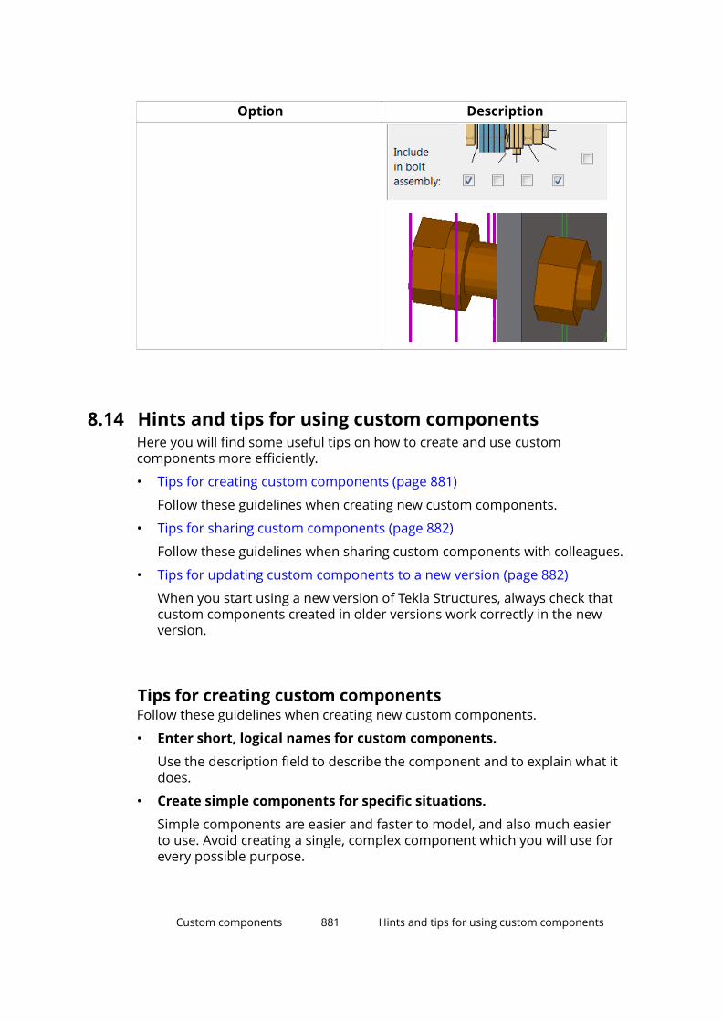
Option Description
8.14 Hints and tips for using custom componentsHere you will find some useful tips on how to create and use customcomponents more efficiently.
• Tips for creating custom components (page 881)
Follow these guidelines when creating new custom components.
• Tips for sharing custom components (page 882)
Follow these guidelines when sharing custom components with colleagues.
• Tips for updating custom components to a new version (page 882)
When you start using a new version of Tekla Structures, always check thatcustom components created in older versions work correctly in the newversion.
Tips for creating custom componentsFollow these guidelines when creating new custom components.
• Enter short, logical names for custom components.
Use the description field to describe the component and to explain what itdoes.
• Create simple components for specific situations.
Simple components are easier and faster to model, and also much easierto use. Avoid creating a single, complex component which you will use forevery possible purpose.
Custom components 881 Hints and tips for using custom components

• Consider creating a separate component model.
Use that model when you create and test custom components.
• Use the simplest part you can.
For example, if all you need is a rectangular shape, use a rectangular plate,not a contour plate. Rectangular plates only have two handles, so you onlyneed to create a few bindings to manipulate them. Contour plates requiremore bindings because they have four handles.
1. Rectangular plate
2. Contour plate
• Model parts only as accurately as you need.
If the only part information required is a part mark in a generalarrangement drawing, plus a quantity on a materials list, create a simplebar or plate. If you need to include the part in a detailed view later on,simply re-model the part more accurately at that point.
• Model embeds as custom parts and include them in components.
Tips for sharing custom componentsFollow these guidelines when sharing custom components with colleagues.
• Use Tekla Warehouse to share and store custom components.
• Provide essential information.
If you distribute your component to other users, remember to list theprofiles it works with.
• Use fixed profiles (page 316) whenever possible.
• If your custom component contains user-defined profile crosssections, remember to include them when you copy the customcomponent to a new location.
Custom components 882 Hints and tips for using custom components
Tips for updating custom components to a new versionWhen you start using a new version of Tekla Structures, always check thatcustom components created in older versions work correctly in the newversion.
When you edit custom components created with an older version of TeklaStructures, and the new version contains improvements that require anupdate, Tekla Structures asks whether you want to update the component. Ifyou do not update the component, it works in the same manner as in theversion where it was originally created, but you do not gain the benefits of thenew improvements.
If you choose to update the component, you need to check and sometimesrecreate dimensions depending on the improvements. When you delete adimension and create a new one (even with the same name), the equationsthat contain the dimension also need to be modified, because the dependencycreated by the equation is lost when a dimension is deleted. You can recreatedimensions and modify equations in the custom component editor.
Custom components 883 Hints and tips for using custom components
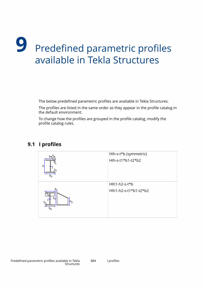
9 Predefined parametric profilesavailable in Tekla Structures
The below predefined parametric profiles are available in Tekla Structures.
The profiles are listed in the same order as they appear in the profile catalog inthe default environment.
To change how the profiles are grouped in the profile catalog, modify theprofile catalog rules.
9.1 I profiles
HIh-s-t*b (symmetric)
HIh-s-t1*b1-t2*b2
HIh1-h2-s-t*b
HIh1-h2-s-t1*b1-t2*b2
Predefined parametric profiles available in TeklaStructures
884 I profiles
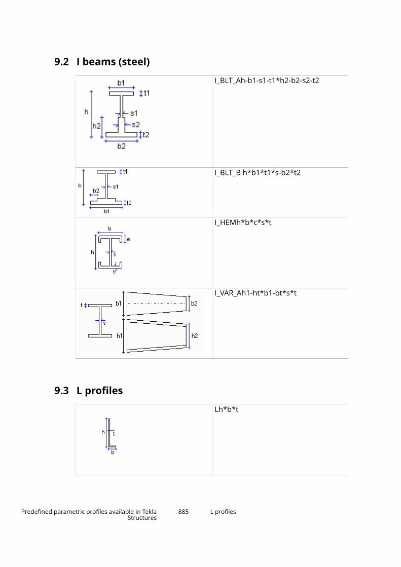
9.2 I beams (steel)
I_BLT_Ah-b1-s1-t1*h2-b2-s2-t2
I_BLT_B h*b1*t1*s-b2*t2
I_HEMh*b*c*s*t
I_VAR_Ah1-ht*b1-bt*s*t
9.3 L profiles
Lh*b*t
Predefined parametric profiles available in TeklaStructures
885 L profiles
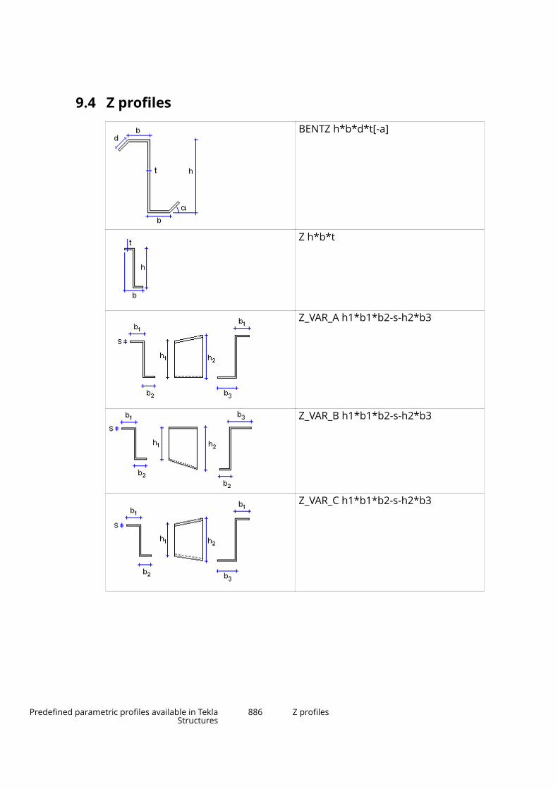
9.4 Z profiles
BENTZ h*b*d*t[-a]
Z h*b*t
Z_VAR_A h1*b1*b2-s-h2*b3
Z_VAR_B h1*b1*b2-s-h2*b3
Z_VAR_C h1*b1*b2-s-h2*b3
Predefined parametric profiles available in TeklaStructures
886 Z profiles
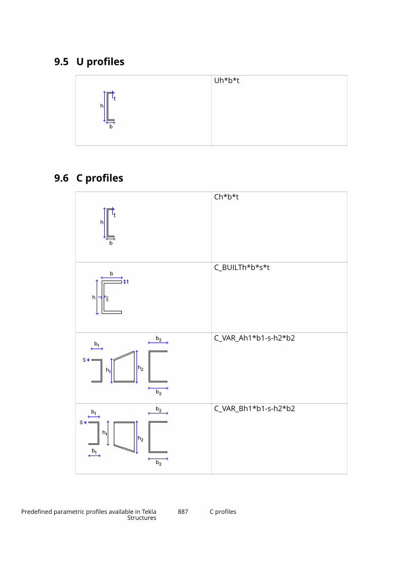
9.5 U profiles
Uh*b*t
9.6 C profiles
Ch*b*t
C_BUILTh*b*s*t
C_VAR_Ah1*b1-s-h2*b2
C_VAR_Bh1*b1-s-h2*b2
Predefined parametric profiles available in TeklaStructures
887 C profiles

C_VAR_Ch1*b1-s-h2*b2
C_VAR_Dh-b-d-c-s
9.7 T profiles
Th-s-t-b
9.8 Welded box profiles
HK h-s-t*b-c
HKh-s-t1*b1-t2*b2-c
9.9 Welded beam profiles
B_WLD_A h*b*s*t
Predefined parametric profiles available in TeklaStructures
888 T profiles
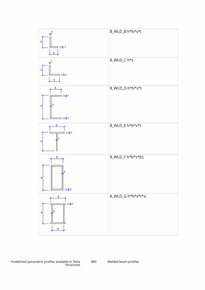
B_WLD_B h*b*s*t
B_WLD_C h*s
B_WLD_D h*b*s*t
B_WLD_E h*b*s*t
B_WLD_F h*b*s*[t]
B_WLD_G h*b*s*t*a
Predefined parametric profiles available in TeklaStructures
889 Welded beam profiles
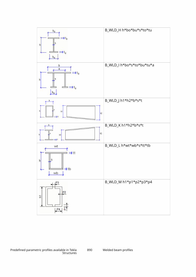
B_WLD_H h*bo*bu*s*to*tu
B_WLD_I h*bo*s*to*bu*tu*a
B_WLD_J h1*h2*b*s*t
B_WLD_K h1*h2*b*s*t
B_WLD_L h*wt*wb*s*tt*tb
B_WLD_M h1*p1*p2*p3*p4
Predefined parametric profiles available in TeklaStructures
890 Welded beam profiles

B_WLD_Np1*p2*p3*p4*p5*p6*p7*p8*p9
B_WLD_Ob1*h1*b4*h5*b7*h6*P1*P2
B_WLD_PW*H*FT*WT*TPT*TPW*BPT*BPW
9.10 Box profiles
B_BUILTh*b*s*t
Predefined parametric profiles available in TeklaStructures
891 Box profiles
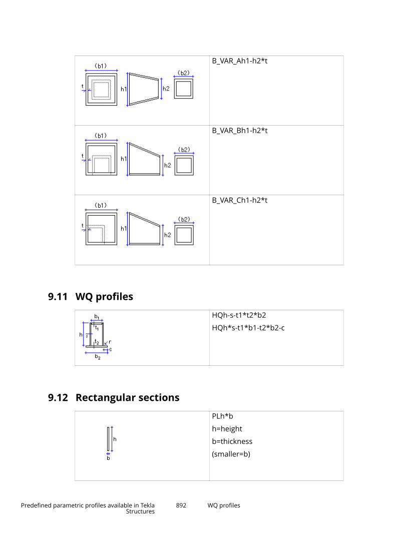
B_VAR_Ah1-h2*t
B_VAR_Bh1-h2*t
B_VAR_Ch1-h2*t
9.11 WQ profiles
HQh-s-t1*t2*b2
HQh*s-t1*b1-t2*b2-c
9.12 Rectangular sections
PLh*b
h=height
b=thickness
(smaller=b)
Predefined parametric profiles available in TeklaStructures
892 WQ profiles

9.13 Circular sections
Dd
ELDd1*r1*d2*r2
9.14 Rectangular hollow sections
Ph*t (symmetric)
Ph*b*t
Ph1*b1-h2*b2*t
Predefined parametric profiles available in TeklaStructures
893 Circular sections

9.15 Circular hollow sections
PDd
PDd1*d2*t
EPDd1*r1*d2*r2*t
9.16 Cold rolled profiles
ZZh-t-e-b (symmetric)
ZZh-t-e1-b1-e2-b2
CCh-t-e-b (symmetric)
CCh-t-e1-b1-e2-b2
Predefined parametric profiles available in TeklaStructures
894 Cold rolled profiles
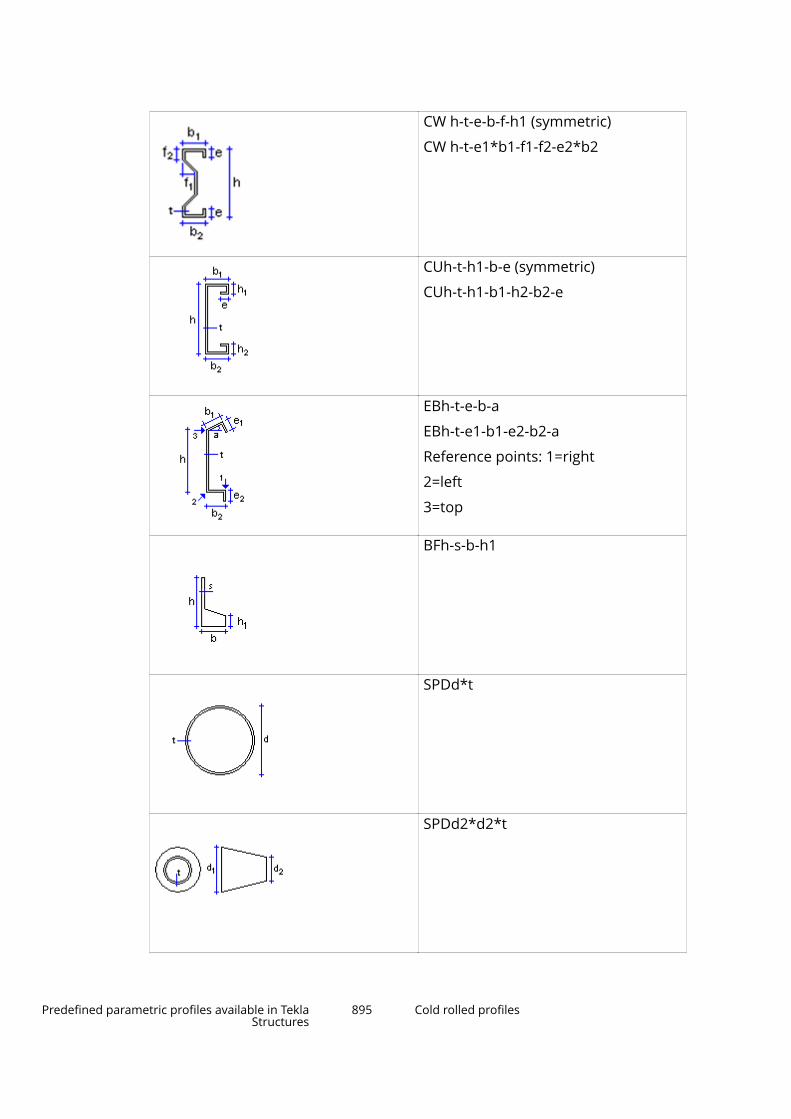
CW h-t-e-b-f-h1 (symmetric)
CW h-t-e1*b1-f1-f2-e2*b2
CUh-t-h1-b-e (symmetric)
CUh-t-h1-b1-h2-b2-e
EBh-t-e-b-a
EBh-t-e1-b1-e2-b2-a
Reference points: 1=right
2=left
3=top
BFh-s-b-h1
SPDd*t
SPDd2*d2*t
Predefined parametric profiles available in TeklaStructures
895 Cold rolled profiles

ESPD d1-d2*t
ECh-t-e-b-a
ECh-t-e1-b1-e2-b2-a
EDh-t-b-e-h1-h2-f1-f2-a
EEh-t-e-b-f1-f3-h1-f2-a
EFh-t-e-b1-b2-f1-f2/h1-a
Predefined parametric profiles available in TeklaStructures
896 Cold rolled profiles

EZh-t-e-b-f1-f3-h1-f2-a
EWh-t-e-b1-b2-f1-f2-h2-h1-a
9.17 Folded plates
FFLAa-b-t
FPANBh-b-t
FPANB_-b-t
FPANBAh-b-t
FPANBA_h-b-t
FPANBBh-c-d-t
Predefined parametric profiles available in TeklaStructures
897 Folded plates

FPANCVb-c-d-t
FPANGh-b-c-t
FPANGAh-b-c-t
FPANJa-b-c-t
FPANJa-b-c-t
FPAN a-b-c-t-g
FPANVVa-b-c-t-g
Predefined parametric profiles available in TeklaStructures
898 Folded plates
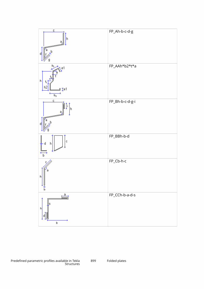
FP_Ah-b-c-d-g
FP_AAh*b2*t*a
FP_Bh-b-c-d-g-i
FP_BBh-b-d
FP_Cb-h-c
FP_CCh-b-a-d-s
Predefined parametric profiles available in TeklaStructures
899 Folded plates
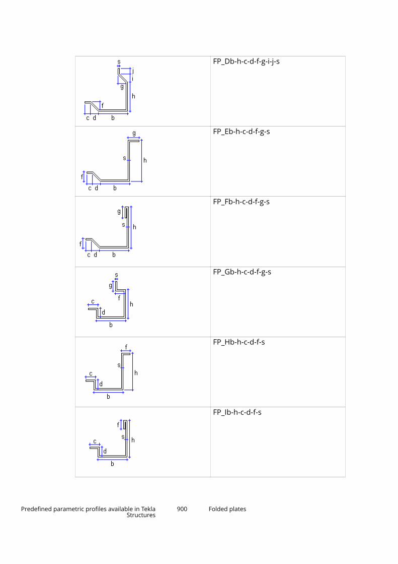
FP_Db-h-c-d-f-g-i-j-s
FP_Eb-h-c-d-f-g-s
FP_Fb-h-c-d-f-g-s
FP_Gb-h-c-d-f-g-s
FP_Hb-h-c-d-f-s
FP_Ib-h-c-d-f-s
Predefined parametric profiles available in TeklaStructures
900 Folded plates
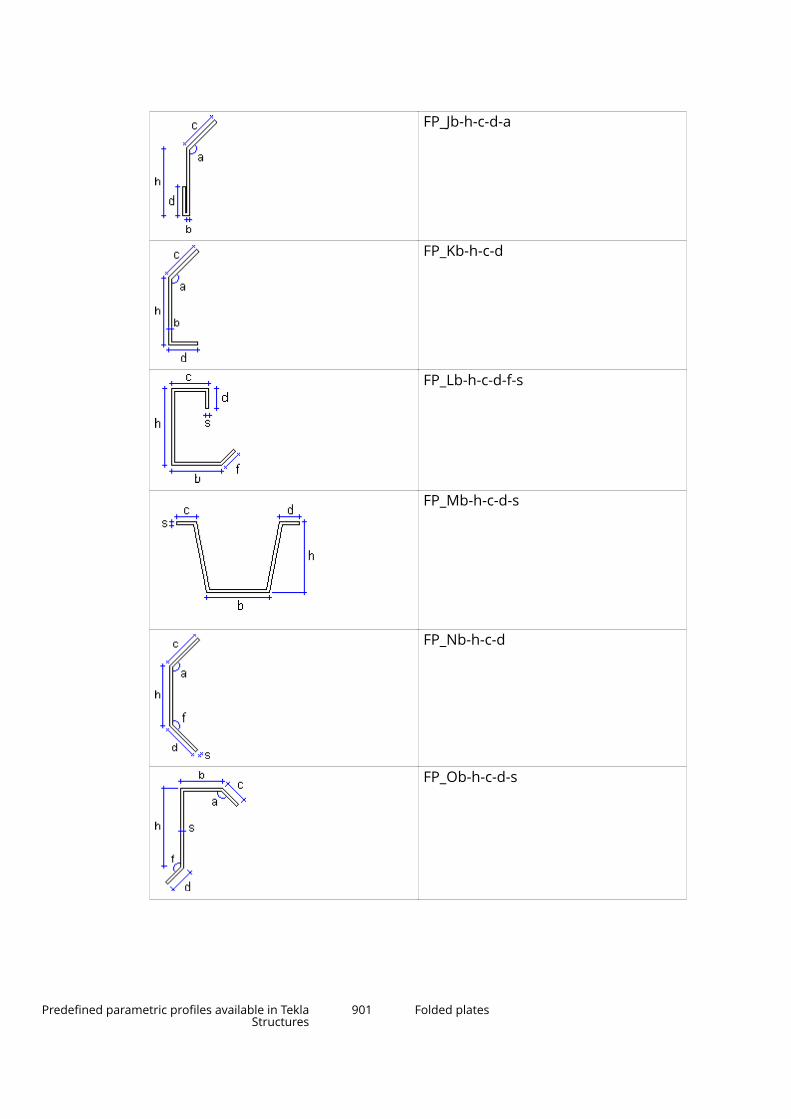
FP_Jb-h-c-d-a
FP_Kb-h-c-d
FP_Lb-h-c-d-f-s
FP_Mb-h-c-d-s
FP_Nb-h-c-d
FP_Ob-h-c-d-s
Predefined parametric profiles available in TeklaStructures
901 Folded plates
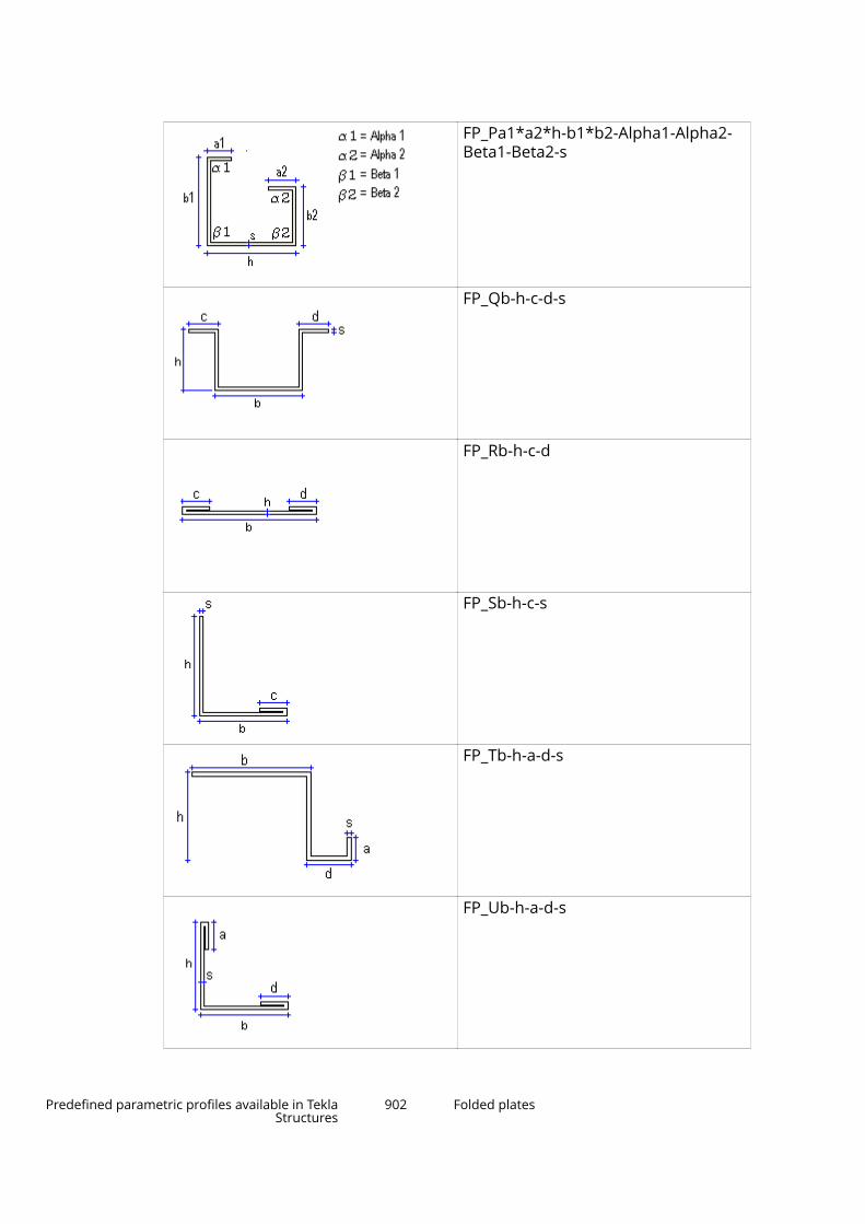
FP_Pa1*a2*h-b1*b2-Alpha1-Alpha2-Beta1-Beta2-s
FP_Qb-h-c-d-s
FP_Rb-h-c-d
FP_Sb-h-c-s
FP_Tb-h-a-d-s
FP_Ub-h-a-d-s
Predefined parametric profiles available in TeklaStructures
902 Folded plates

FP_Vb-h-s-c
FP_Wb-h-a-d-s
FP_WWh-b-a-c-s
FP_Yh-b-c-d
FP_Zd-h-b-s-a-f
Predefined parametric profiles available in TeklaStructures
903 Hat profiles

9.18 Hat profiles
HAT h*a*c*t
HATCa-b-c-b1-h-b3-b4-b5-s
HATAb1*h1*h2*h3*h4*h5*h6*b2*t*f*a*h*b
HATBb*b1*b2*h*h1*h2*h3*h4*t*f*a
Predefined parametric profiles available in TeklaStructures
904 I beams (concrete)

9.19 I beams (concrete)
HIIh1*b1*t1-h2-s-b2*t2[-sft[-sfb]]
IIh*b1*t1-s-b2*t2[-sft[-sfb]]
SIIh1*b1*t1-h2-s-b2*t2[-sft[-sfb]]
9.20 Ledger beams (concrete)
RCLs*h-b*t
Predefined parametric profiles available in TeklaStructures
905 Ledger beams (concrete)
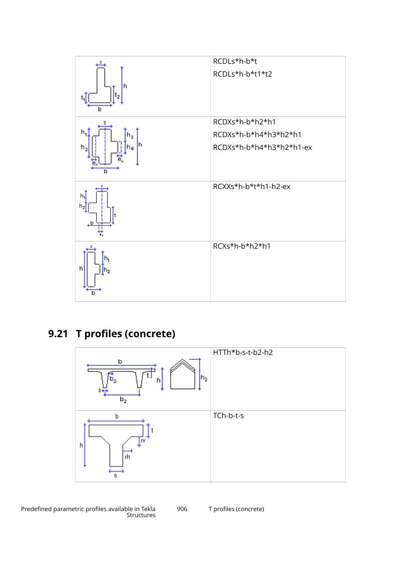
RCDLs*h-b*t
RCDLs*h-b*t1*t2
RCDXs*h-b*h2*h1
RCDXs*h-b*h4*h3*h2*h1
RCDXs*h-b*h4*h3*h2*h1-ex
RCXXs*h-b*t*h1-h2-ex
RCXs*h-b*h2*h1
9.21 T profiles (concrete)
HTTh*b-s-t-b2-h2
TCh-b-t-s
Predefined parametric profiles available in TeklaStructures
906 T profiles (concrete)

TRIh*b-b2*t1-h3-t2
TTh*b-s-t-b2
TTTh*b-bl-br-hw-bwmin-bwmax
T_VAR_Ah1*h2*s*b1*t1-sft
T_VAR_Bh-b-c-d
Predefined parametric profiles available in TeklaStructures
907 Irregular beams (concrete)
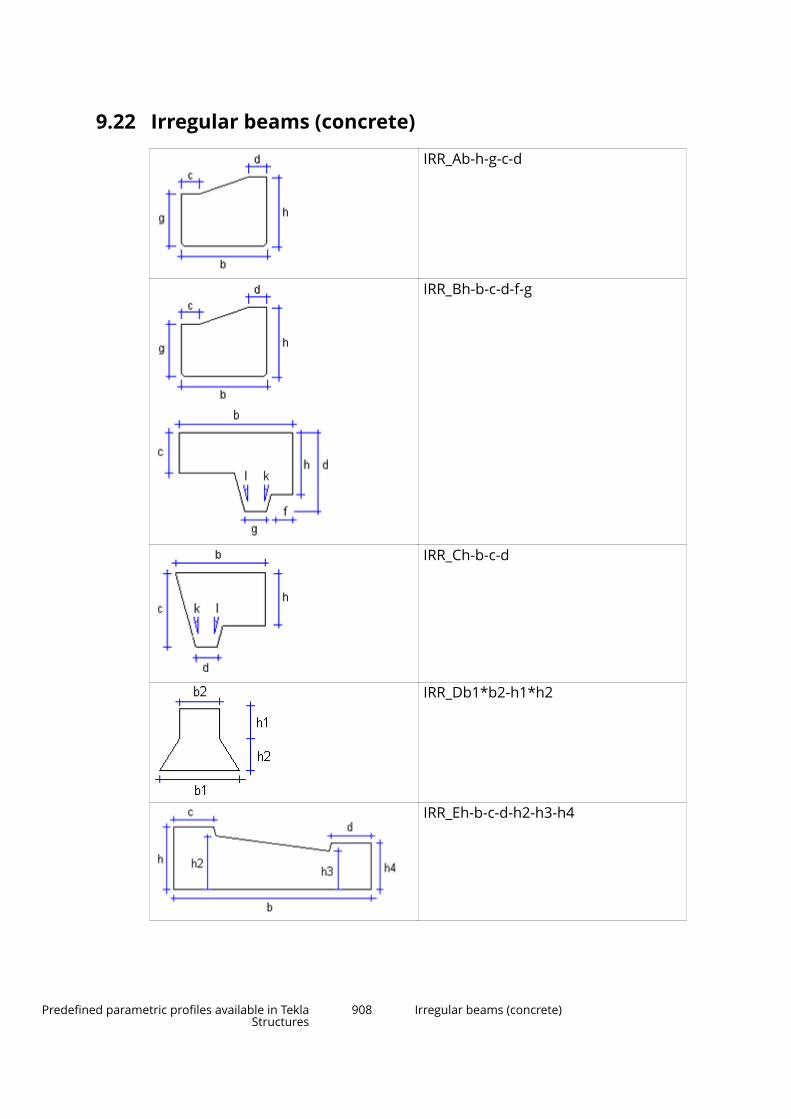
9.22 Irregular beams (concrete)
IRR_Ab-h-g-c-d
IRR_Bh-b-c-d-f-g
IRR_Ch-b-c-d
IRR_Db1*b2-h1*h2
IRR_Eh-b-c-d-h2-h3-h4
Predefined parametric profiles available in TeklaStructures
908 Irregular beams (concrete)
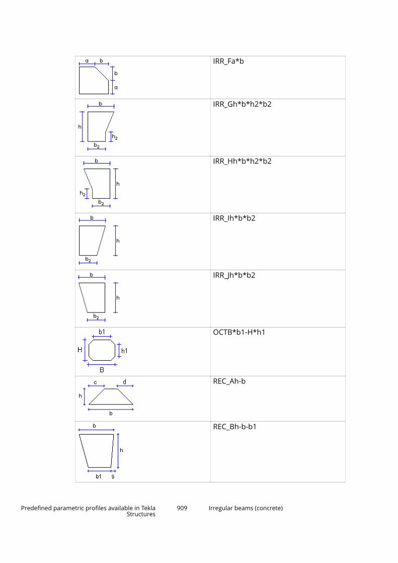
IRR_Fa*b
IRR_Gh*b*h2*b2
IRR_Hh*b*h2*b2
IRR_Ih*b*b2
IRR_Jh*b*b2
OCTB*b1-H*h1
REC_Ah-b
REC_Bh-b-b1
Predefined parametric profiles available in TeklaStructures
909 Irregular beams (concrete)

REC_Ch-b-b1
REC_Dh-b-b2
REC_Eh-b
REC_Fh-b
REC_Gh-b
REC_Hh-b
REC_I a-b*h
TRI_Ah-b
Predefined parametric profiles available in TeklaStructures
910 Irregular beams (concrete)

TRI_Ba1
TRI_Cb-h
TRI_Dh*b
TRI_Eb*h*h2*b2
9.23 Panels
PNL_Ah*b
PNL_Bh*b
Predefined parametric profiles available in TeklaStructures
911 Panels
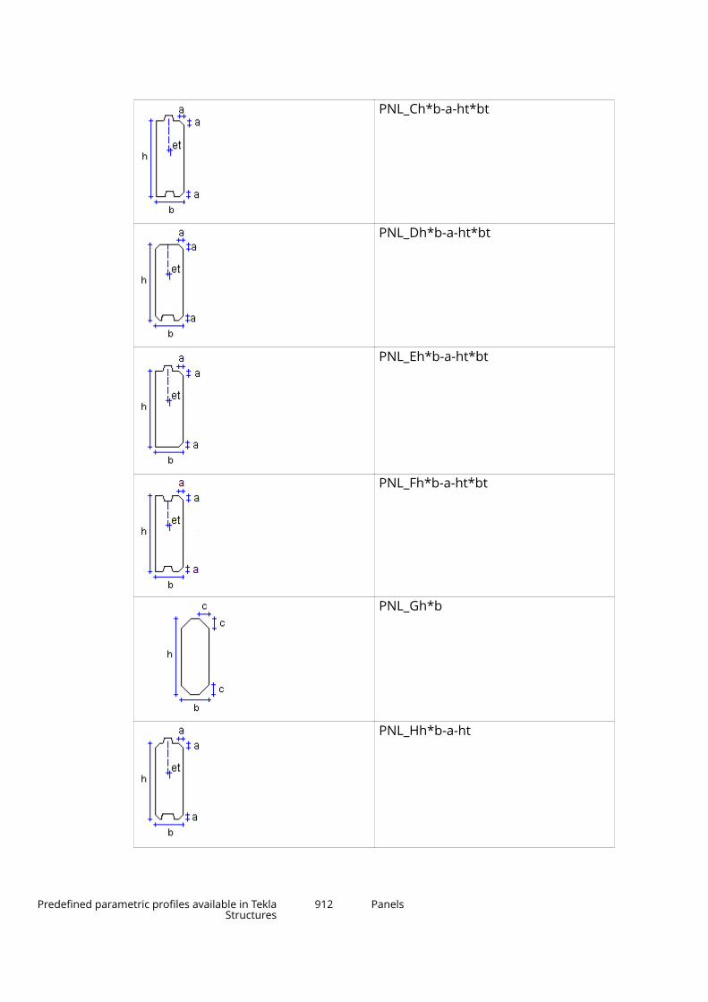
PNL_Ch*b-a-ht*bt
PNL_Dh*b-a-ht*bt
PNL_Eh*b-a-ht*bt
PNL_Fh*b-a-ht*bt
PNL_Gh*b
PNL_Hh*b-a-ht
Predefined parametric profiles available in TeklaStructures
912 Panels
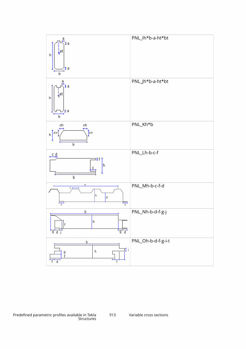
PNL_Ih*b-a-ht*bt
PNL_Jh*b-a-ht*bt
PNL_Kh*b
PNL_Lh-b-c-f
PNL_Mh-b-c-f-d
PNL_Nh-b-d-f-g-j
PNL_Oh-b-d-f-g-i-t
Predefined parametric profiles available in TeklaStructures
913 Variable cross sections
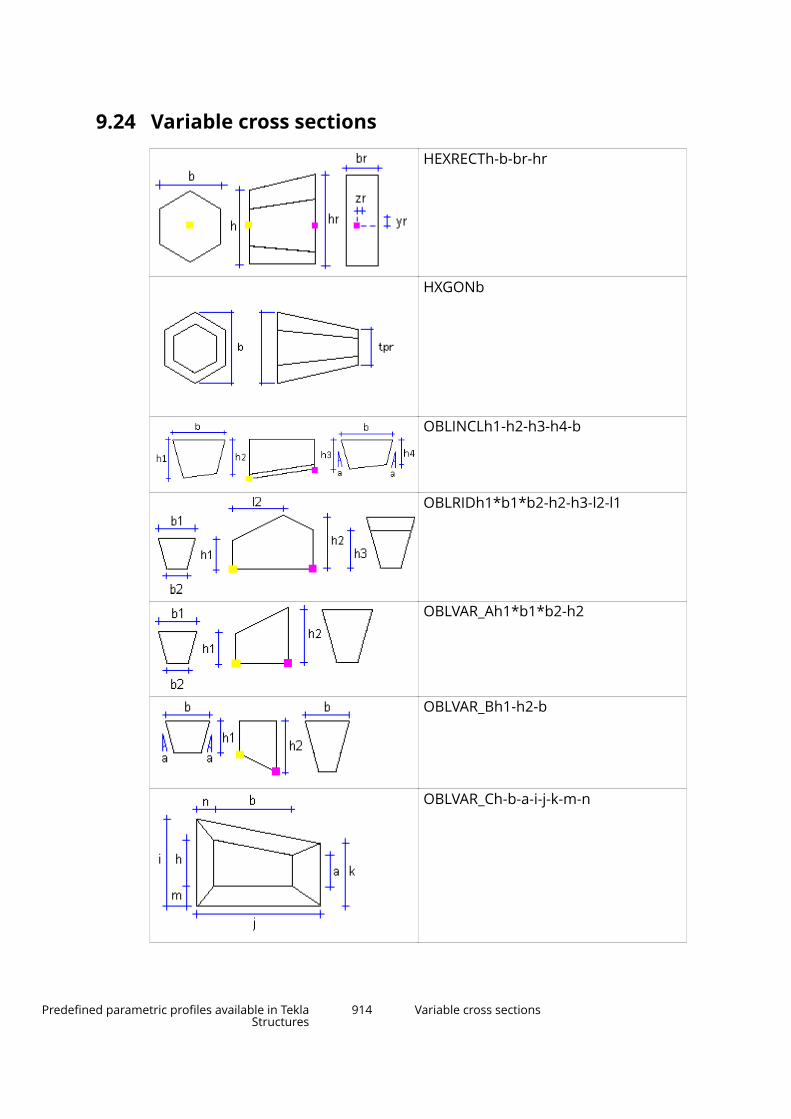
9.24 Variable cross sections
HEXRECTh-b-br-hr
HXGONb
OBLINCLh1-h2-h3-h4-b
OBLRIDh1*b1*b2-h2-h3-l2-l1
OBLVAR_Ah1*b1*b2-h2
OBLVAR_Bh1-h2-b
OBLVAR_Ch-b-a-i-j-k-m-n
Predefined parametric profiles available in TeklaStructures
914 Variable cross sections
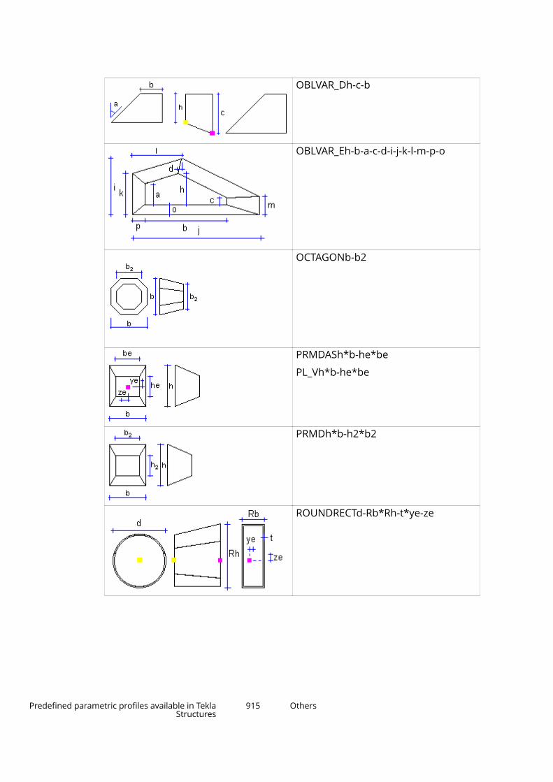
OBLVAR_Dh-c-b
OBLVAR_Eh-b-a-c-d-i-j-k-l-m-p-o
OCTAGONb-b2
PRMDASh*b-he*be
PL_Vh*b-he*be
PRMDh*b-h2*b2
ROUNDRECTd-Rb*Rh-t*ye-ze
Predefined parametric profiles available in TeklaStructures
915 Others
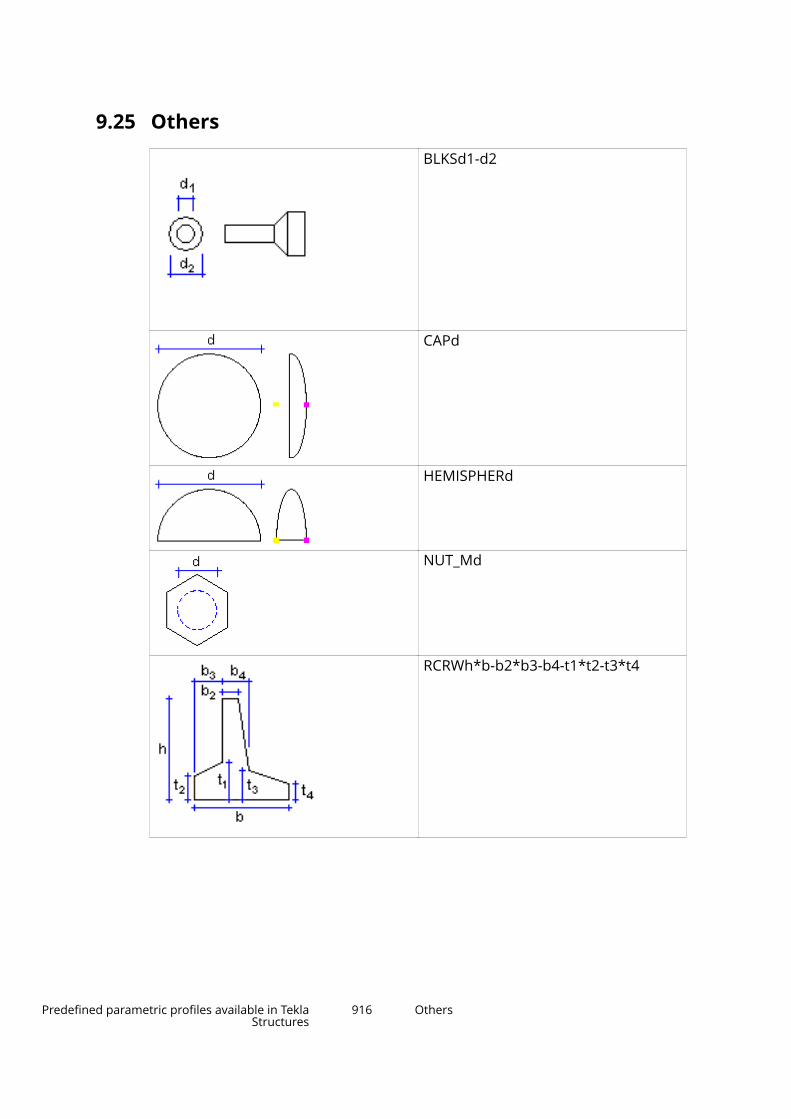
9.25 Others
BLKSd1-d2
CAPd
HEMISPHERd
NUT_Md
RCRWh*b-b2*b3-b4-t1*t2-t3*t4
Predefined parametric profiles available in TeklaStructures
916 Others
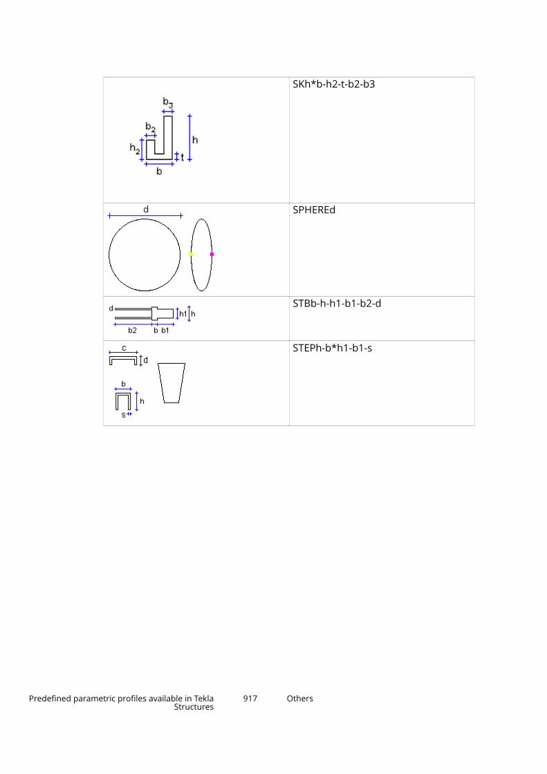
SKh*b-h2-t-b2-b3
SPHEREd
STBb-h-h1-b1-b2-d
STEPh-b*h1-b1-s
Predefined parametric profiles available in TeklaStructures
917 Others
10Modeling settings
This section provides more information about the various settings you canmodify in Tekla Structures.
Click the links below to find out more:
• View and representation settings (page 918)
• Part position settings (page 923)
• Numbering settings (page 923)
• Reinforcement settings (page 927)
10.1 View and representation settingsThis section provides more information about specific view and representationsettings.
Click the links below to find out more:
View properties (page 44)
Grid view properties (page 45)
Display settings (page 918)
Color settings for object groups (page 921)
Transparency settings for object groups (page 922)
Display settingsUse the Display dialog box to define which object types Tekla Structuresdisplays and how they appear in the model. Some of these settings may affectsystem performance.
Modeling settings 918 View and representation settings
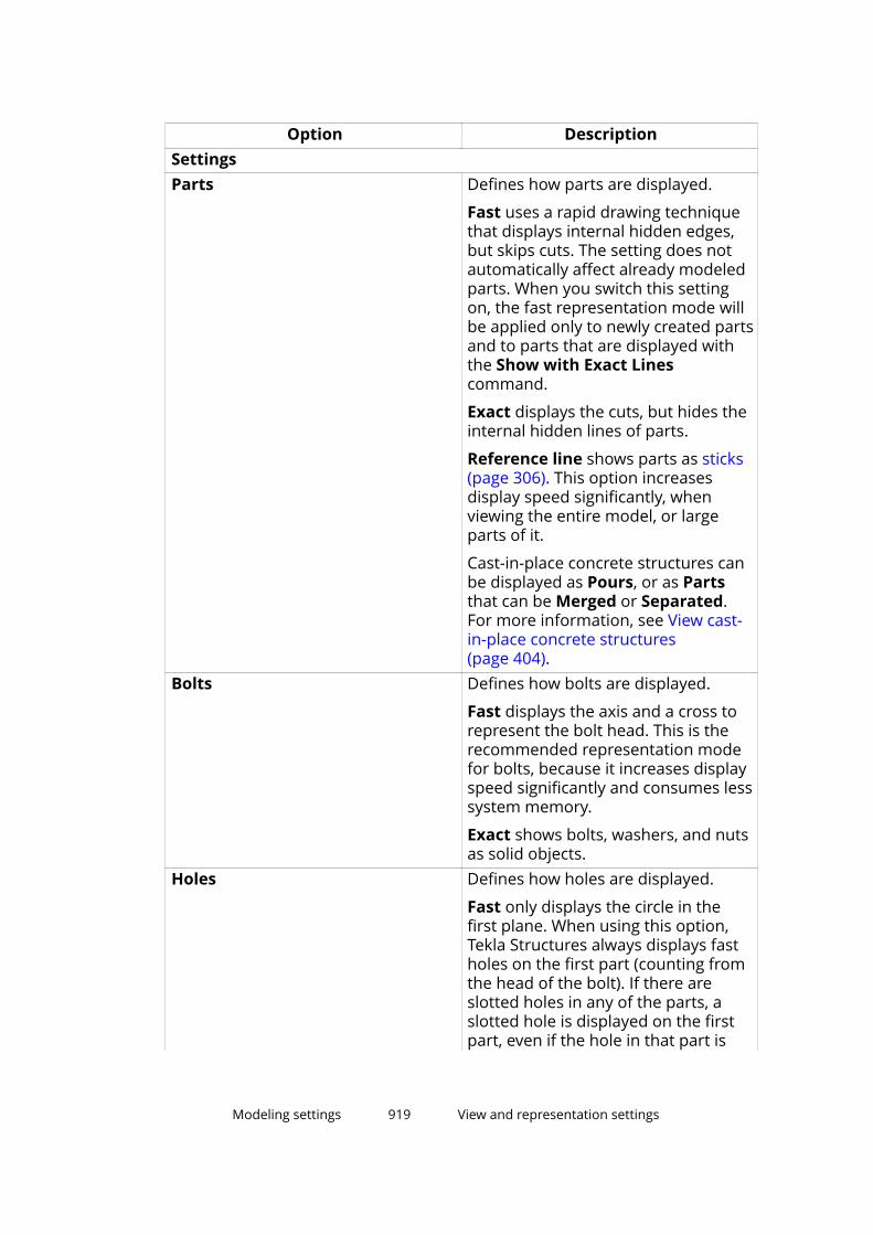
Option DescriptionSettingsParts Defines how parts are displayed.
Fast uses a rapid drawing techniquethat displays internal hidden edges,but skips cuts. The setting does notautomatically affect already modeledparts. When you switch this settingon, the fast representation mode willbe applied only to newly created partsand to parts that are displayed withthe Show with Exact Linescommand.
Exact displays the cuts, but hides theinternal hidden lines of parts.
Reference line shows parts as sticks(page 306). This option increasesdisplay speed significantly, whenviewing the entire model, or largeparts of it.
Cast-in-place concrete structures canbe displayed as Pours, or as Partsthat can be Merged or Separated.For more information, see View cast-in-place concrete structures(page 404).
Bolts Defines how bolts are displayed.
Fast displays the axis and a cross torepresent the bolt head. This is therecommended representation modefor bolts, because it increases displayspeed significantly and consumes lesssystem memory.
Exact shows bolts, washers, and nutsas solid objects.
Holes Defines how holes are displayed.
Fast only displays the circle in thefirst plane. When using this option,Tekla Structures always displays fastholes on the first part (counting fromthe head of the bolt). If there areslotted holes in any of the parts, aslotted hole is displayed on the firstpart, even if the hole in that part is
Modeling settings 919 View and representation settings
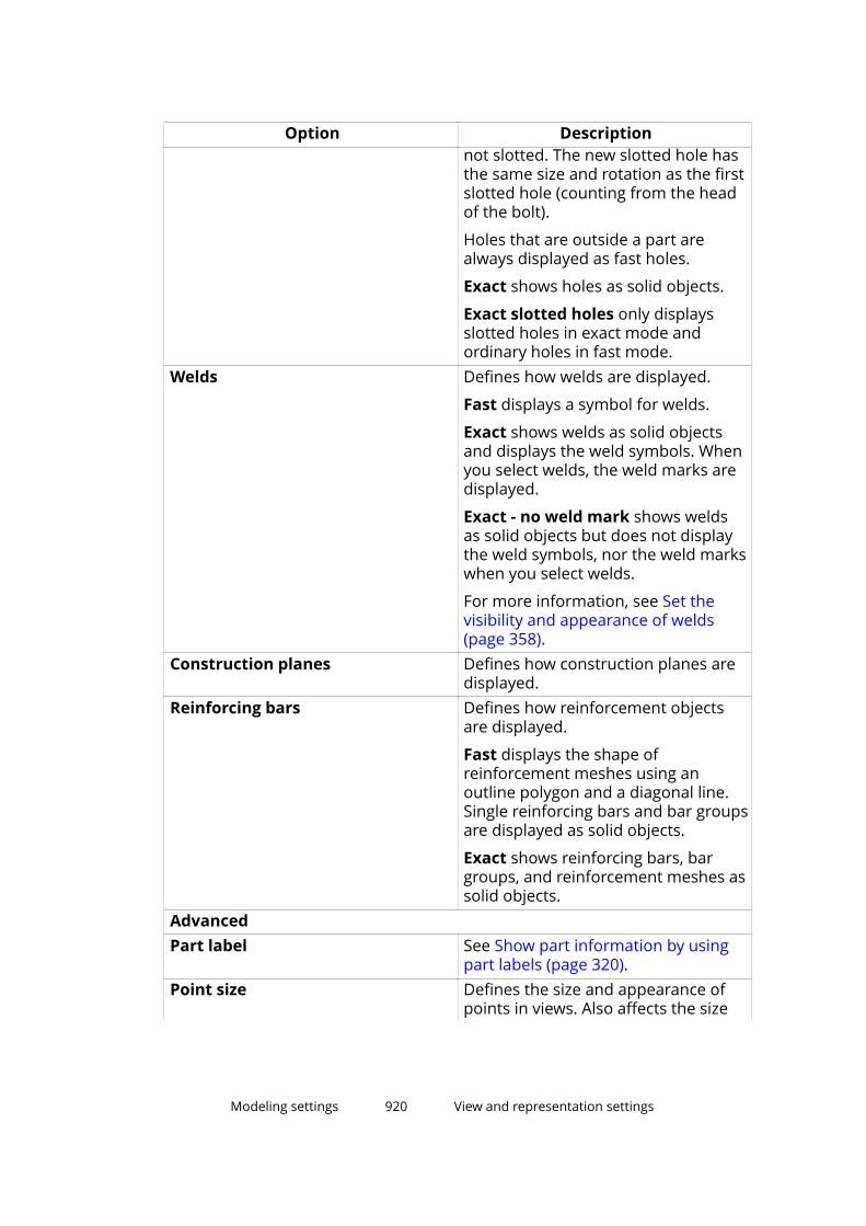
Option Descriptionnot slotted. The new slotted hole hasthe same size and rotation as the firstslotted hole (counting from the headof the bolt).
Holes that are outside a part arealways displayed as fast holes.
Exact shows holes as solid objects.
Exact slotted holes only displaysslotted holes in exact mode andordinary holes in fast mode.
Welds Defines how welds are displayed.
Fast displays a symbol for welds.
Exact shows welds as solid objectsand displays the weld symbols. Whenyou select welds, the weld marks aredisplayed.
Exact - no weld mark shows weldsas solid objects but does not displaythe weld symbols, nor the weld markswhen you select welds.
For more information, see Set thevisibility and appearance of welds(page 358).
Construction planes Defines how construction planes aredisplayed.
Reinforcing bars Defines how reinforcement objectsare displayed.
Fast displays the shape ofreinforcement meshes using anoutline polygon and a diagonal line.Single reinforcing bars and bar groupsare displayed as solid objects.
Exact shows reinforcing bars, bargroups, and reinforcement meshes assolid objects.
AdvancedPart label See Show part information by using
part labels (page 320).Point size Defines the size and appearance of
points in views. Also affects the size
Modeling settings 920 View and representation settings

Option Descriptionand appearance of the handles,together with XS_HANDLE_SCALE.
In model increases the point size onthe screen when you zoom in. Showspoints and handles as 3D cubes:
In view does not increase the pointsize. Shows points and handles as flat2D objects:
See also
Set the visibility and appearance of model objects (page 582)
Change the rendering of parts and components (page 584)
Set the visibility of pour breaks (page 417)
Color settings for object groupsUse the Object Representation dialog box to define the color of objectgroups.
Option DescriptionAs is The current color is used.
If the object belongs to one of the object groups definedin the following rows, its color is defined by the settingsthat the object group in question has on that row.
Colors Select color from the list.Color by class All parts are colored according to their Class property. See
Change the color of a model object (page 594).
Modeling settings 921 View and representation settings

Option DescriptionColor by lot Parts belonging to different lots or phases get different
colors according to the lot or phase number:Color by phase
Color by analysistype
Displays parts according to the member analysis class.
Color by analysisutility check
Displays parts according to the utilization ratio in analysis.
Color by attribute Displays parts in different colors according to the valuesof a user-defined attribute.
See also
Change the color and transparency of model objects (page 593)
Transparency settings for object groupsUse the Object Representation dialog box to define the transparency ofobject groups.
Option DescriptionAs is The current visibility.
If the object belongs to any object group whose visibilityand color settings have been defined, the settings will beread from that object group.
Visible Object is shown in the views.50% transparent Object is transparent in the views.70% transparent90% transparentHidden Object is not shown in the views.
Modeling settings 922 View and representation settings
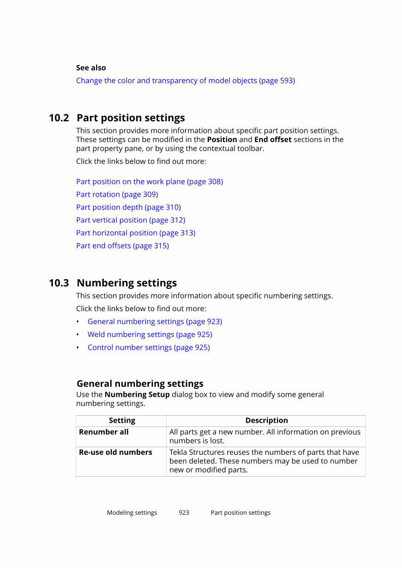
See also
Change the color and transparency of model objects (page 593)
10.2 Part position settingsThis section provides more information about specific part position settings.These settings can be modified in the Position and End offset sections in thepart property pane, or by using the contextual toolbar.
Click the links below to find out more:
Part position on the work plane (page 308)
Part rotation (page 309)
Part position depth (page 310)
Part vertical position (page 312)
Part horizontal position (page 313)
Part end offsets (page 315)
10.3 Numbering settingsThis section provides more information about specific numbering settings.
Click the links below to find out more:
• General numbering settings (page 923)
• Weld numbering settings (page 925)
• Control number settings (page 925)
General numbering settingsUse the Numbering Setup dialog box to view and modify some generalnumbering settings.
Setting DescriptionRenumber all All parts get a new number. All information on previous
numbers is lost.Re-use old numbers Tekla Structures reuses the numbers of parts that have
been deleted. These numbers may be used to numbernew or modified parts.
Modeling settings 923 Part position settings
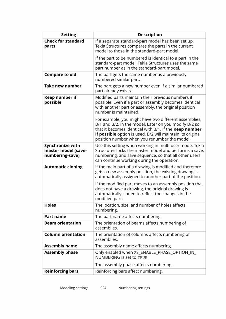
Setting DescriptionCheck for standardparts
If a separate standard-part model has been set up,Tekla Structures compares the parts in the currentmodel to those in the standard-part model.
If the part to be numbered is identical to a part in thestandard-part model, Tekla Structures uses the samepart number as in the standard-part model.
Compare to old The part gets the same number as a previouslynumbered similar part.
Take new number The part gets a new number even if a similar numberedpart already exists.
Keep number ifpossible
Modified parts maintain their previous numbers ifpossible. Even if a part or assembly becomes identicalwith another part or assembly, the original positionnumber is maintained.
For example, you might have two different assemblies,B/1 and B/2, in the model. Later on you modify B/2 sothat it becomes identical with B/1. If the Keep numberif possible option is used, B/2 will maintain its originalposition number when you renumber the model.
Synchronize withmaster model (save-numbering-save)
Use this setting when working in multi-user mode. TeklaStructures locks the master model and performs a save,numbering, and save sequence, so that all other userscan continue working during the operation.
Automatic cloning If the main part of a drawing is modified and thereforegets a new assembly position, the existing drawing isautomatically assigned to another part of the position.
If the modified part moves to an assembly position thatdoes not have a drawing, the original drawing isautomatically cloned to reflect the changes in themodified part.
Holes The location, size, and number of holes affectsnumbering.
Part name The part name affects numbering.Beam orientation The orientation of beams affects numbering of
assemblies.Column orientation The orientation of columns affects numbering of
assemblies.Assembly name The assembly name affects numbering.Assembly phase Only enabled when XS_ENABLE_PHASE_OPTION_IN_
NUMBERING is set to TRUE.
The assembly phase affects numbering.Reinforcing bars Reinforcing bars affect numbering.
Modeling settings 924 Numbering settings
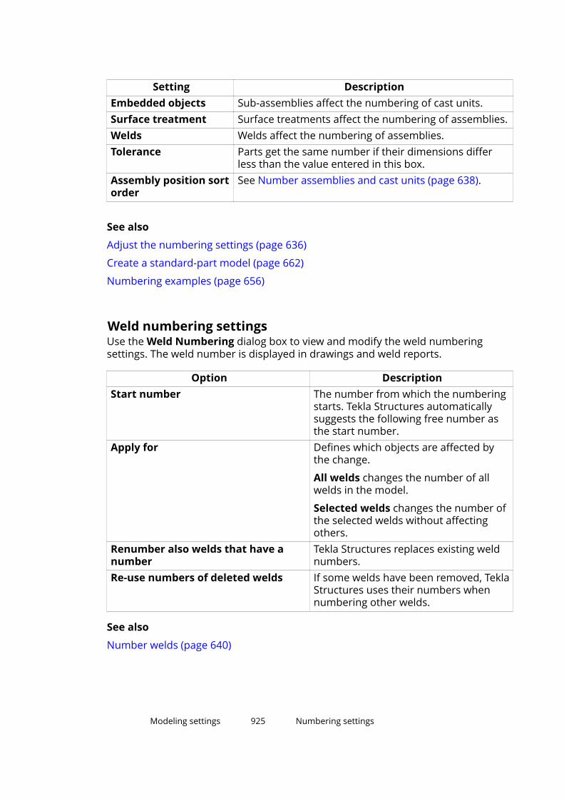
Setting DescriptionEmbedded objects Sub-assemblies affect the numbering of cast units.Surface treatment Surface treatments affect the numbering of assemblies.Welds Welds affect the numbering of assemblies.Tolerance Parts get the same number if their dimensions differ
less than the value entered in this box.Assembly position sortorder
See Number assemblies and cast units (page 638).
See also
Adjust the numbering settings (page 636)
Create a standard-part model (page 662)
Numbering examples (page 656)
Weld numbering settingsUse the Weld Numbering dialog box to view and modify the weld numberingsettings. The weld number is displayed in drawings and weld reports.
Option DescriptionStart number The number from which the numbering
starts. Tekla Structures automaticallysuggests the following free number asthe start number.
Apply for Defines which objects are affected bythe change.
All welds changes the number of allwelds in the model.
Selected welds changes the number ofthe selected welds without affectingothers.
Renumber also welds that have anumber
Tekla Structures replaces existing weldnumbers.
Re-use numbers of deleted welds If some welds have been removed, TeklaStructures uses their numbers whennumbering other welds.
See also
Number welds (page 640)
Modeling settings 925 Numbering settings
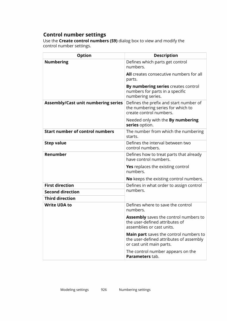
Control number settingsUse the Create control numbers (S9) dialog box to view and modify thecontrol number settings.
Option DescriptionNumbering Defines which parts get control
numbers.
All creates consecutive numbers for allparts.
By numbering series creates controlnumbers for parts in a specificnumbering series.
Assembly/Cast unit numbering series Defines the prefix and start number ofthe numbering series for which tocreate control numbers.
Needed only with the By numberingseries option.
Start number of control numbers The number from which the numberingstarts.
Step value Defines the interval between twocontrol numbers.
Renumber Defines how to treat parts that alreadyhave control numbers.
Yes replaces the existing controlnumbers.
No keeps the existing control numbers.First direction Defines in what order to assign control
numbers.Second directionThird directionWrite UDA to Defines where to save the control
numbers.
Assembly saves the control numbers tothe user-defined attributes ofassemblies or cast units.
Main part saves the control numbers tothe user-defined attributes of assemblyor cast unit main parts.
The control number appears on theParameters tab.
Modeling settings 926 Numbering settings

See also
Control numbers (page 646)
10.4 Reinforcement settingsThis section provides more information about the various reinforcementsettings you can modify in Tekla Structures.
Click the links below to find out more:
Reinforcing bar and bar group properties (page 927)
Reinforcement mesh properties (page 929)
Rebar set properties (page 933)
Reinforcement strand properties (page 946)
Reinforcing bar and bar group properties
Use the Single rebar and Rebar group properties to view and modify theproperties of reinforcing bars and reinforcing bar groups. The file nameextension of the properties file is:
• .rbr for bars (page 451)
• .rbg for groups (page 454)
• .rci for circular groups (page 463)
• .rcu for curved groups (page 461)
General, Hooks, Cover thickness, Custom properties
The following properties are available for single reinforcing bars andreinforcing bar groups:
Option DescriptionName User-definable name of the bar.
Tekla Structures uses bar names in reports and drawinglists, and to identify bars of the same type.
Grade Steel grade of the bar. Size-grade-radiuscombinations arepredefined in thereinforcing bar catalog.Click the ... button toopen the SelectReinforcing Bar dialogbox. The dialog box
Size Diameter of the bar.
Depending on theenvironment, the nominaldiameter of the bar, or a markthat defines the diameter.
Modeling settings 927 Reinforcement settings
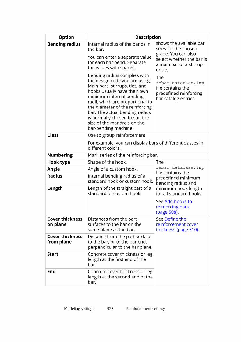
Option DescriptionBending radius shows the available bar
sizes for the chosengrade. You can alsoselect whether the bar isa main bar or a stirrupor tie.
Therebar_database.inpfile contains thepredefined reinforcingbar catalog entries.
Internal radius of the bends inthe bar.
You can enter a separate valuefor each bar bend. Separatethe values with spaces.
Bending radius complies withthe design code you are using.Main bars, stirrups, ties, andhooks usually have their ownminimum internal bendingradii, which are proportional tothe diameter of the reinforcingbar. The actual bending radiusis normally chosen to suit thesize of the mandrels on thebar-bending machine.
Class Use to group reinforcement.
For example, you can display bars of different classes indifferent colors.
Numbering Mark series of the reinforcing bar.Hook type Shape of the hook. The
rebar_database.inpfile contains thepredefined minimumbending radius andminimum hook lengthfor all standard hooks.
See Add hooks toreinforcing bars(page 508).
Angle Angle of a custom hook.Radius Internal bending radius of a
standard hook or custom hook.Length Length of the straight part of a
standard or custom hook.
Cover thicknesson plane
Distances from the partsurfaces to the bar on thesame plane as the bar.
See Define thereinforcement coverthickness (page 510).
Cover thicknessfrom plane
Distance from the part surfaceto the bar, or to the bar end,perpendicular to the bar plane.
Start Concrete cover thickness or leglength at the first end of thebar.
End Concrete cover thickness or leglength at the second end of thebar.
Modeling settings 928 Reinforcement settings

Option DescriptionCustomproperties
You can create user-defined attributes to add informationabout reinforcement. Attributes can consist of numbers,text, or lists.
You can use the values of user-defined attributes inreports and drawings.
You can also change the name of the fields, and add newones, by editing the objects.inp file. See Customizinguser-defined attributes.
Rebar group type, Distribution, Creation
The following properties are available for:
• reinforcing bar groups, including tapered (page 465) groups
• curved reinforcing bar groups
• circular reinforcing bar groups
Option Description Rebar grouptype
What is the type of thegroup.
See Create a tapered or spiralreinforcing bar group(page 465).Number of
cross sectionsCreationmethod
How the bars are spaced. See Distribute bars in areinforcing bar group(page 500).Number of
reinforcing barsTarget spacingvalueExact spacingvalueExact spacingvaluesExclude Which bars are omitted
from the group.See Delete bars from areinforcing bar group(page 502).
Modeling settings 929 Reinforcement settings
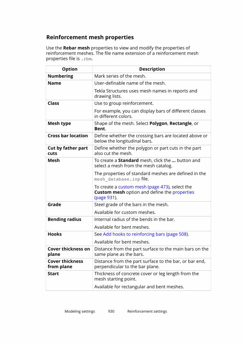
Reinforcement mesh properties
Use the Rebar mesh properties to view and modify the properties ofreinforcement meshes. The file name extension of a reinforcement meshproperties file is .rbm.
Option DescriptionNumbering Mark series of the mesh.Name User-definable name of the mesh.
Tekla Structures uses mesh names in reports anddrawing lists.
Class Use to group reinforcement.
For example, you can display bars of different classesin different colors.
Mesh type Shape of the mesh. Select Polygon, Rectangle, orBent.
Cross bar location Define whether the crossing bars are located above orbelow the longitudinal bars.
Cut by father partcuts
Define whether the polygon or part cuts in the partalso cut the mesh.
Mesh To create a Standard mesh, click the ... button andselect a mesh from the mesh catalog.
The properties of standard meshes are defined in themesh_database.inp file.
To create a custom mesh (page 473), select theCustom mesh option and define the properties(page 931).
Grade Steel grade of the bars in the mesh.
Available for custom meshes.Bending radius Internal radius of the bends in the bar.
Available for bent meshes.Hooks See Add hooks to reinforcing bars (page 508).
Available for bent meshes.Cover thickness onplane
Distance from the part surface to the main bars on thesame plane as the bars.
Cover thicknessfrom plane
Distance from the part surface to the bar, or bar end,perpendicular to the bar plane.
Start Thickness of concrete cover or leg length from themesh starting point.
Available for rectangular and bent meshes.
Modeling settings 930 Reinforcement settings
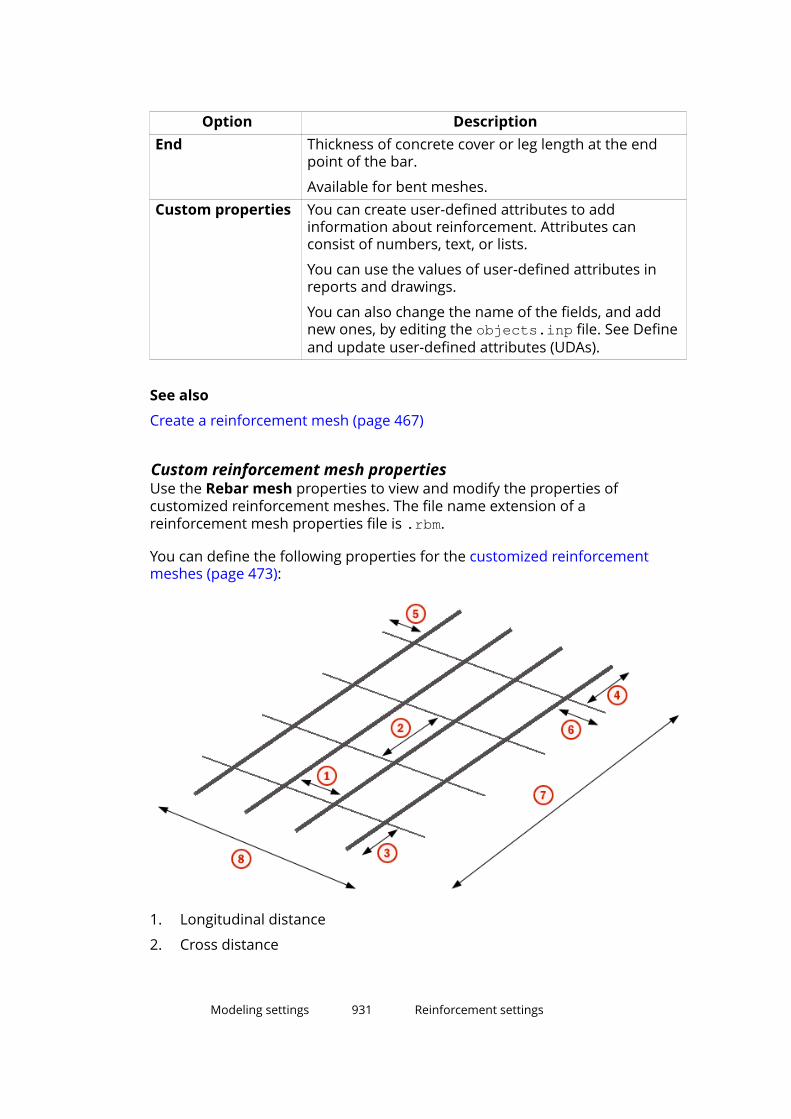
Option DescriptionEnd Thickness of concrete cover or leg length at the end
point of the bar.
Available for bent meshes.Custom properties You can create user-defined attributes to add
information about reinforcement. Attributes canconsist of numbers, text, or lists.
You can use the values of user-defined attributes inreports and drawings.
You can also change the name of the fields, and addnew ones, by editing the objects.inp file. See Defineand update user-defined attributes (UDAs).
See also
Create a reinforcement mesh (page 467)
Custom reinforcement mesh propertiesUse the Rebar mesh properties to view and modify the properties ofcustomized reinforcement meshes. The file name extension of areinforcement mesh properties file is .rbm.
You can define the following properties for the customized reinforcementmeshes (page 473):
1. Longitudinal distance
2. Cross distance
Modeling settings 931 Reinforcement settings
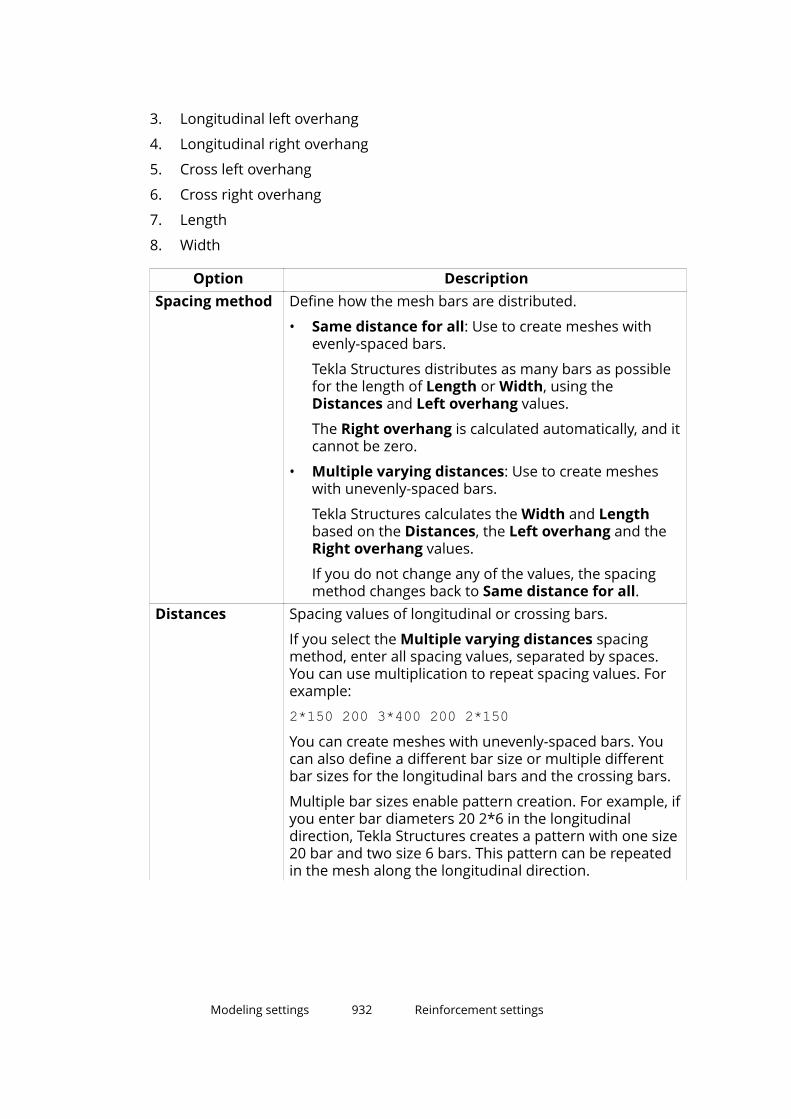
3. Longitudinal left overhang
4. Longitudinal right overhang
5. Cross left overhang
6. Cross right overhang
7. Length
8. Width
Option DescriptionSpacing method Define how the mesh bars are distributed.
• Same distance for all: Use to create meshes withevenly-spaced bars.
Tekla Structures distributes as many bars as possiblefor the length of Length or Width, using theDistances and Left overhang values.
The Right overhang is calculated automatically, and itcannot be zero.
• Multiple varying distances: Use to create mesheswith unevenly-spaced bars.
Tekla Structures calculates the Width and Lengthbased on the Distances, the Left overhang and theRight overhang values.
If you do not change any of the values, the spacingmethod changes back to Same distance for all.
Distances Spacing values of longitudinal or crossing bars.
If you select the Multiple varying distances spacingmethod, enter all spacing values, separated by spaces.You can use multiplication to repeat spacing values. Forexample:
2*150 200 3*400 200 2*150You can create meshes with unevenly-spaced bars. Youcan also define a different bar size or multiple differentbar sizes for the longitudinal bars and the crossing bars.
Multiple bar sizes enable pattern creation. For example, ifyou enter bar diameters 20 2*6 in the longitudinaldirection, Tekla Structures creates a pattern with one size20 bar and two size 6 bars. This pattern can be repeatedin the mesh along the longitudinal direction.
Modeling settings 932 Reinforcement settings

Option Description
Left overhang Extensions of crossing bars over the outermostlongitudinal bars.
Extensions of longitudinal bars over the outermostcrossing bars.
Right overhang
Diameters Diameter or size of the longitudinal or crossing bars.
You can define multiple diameters for the bars in bothdirections. Enter all the diameter values, separated byspaces. You can use multiplication to repeat diametervalues. For example, 12 2*6 in longitudinal direction and6 20 2*12 in crossing direction.
Width Length of crossing bars.Length Length of longitudinal bars.Grade Steel grade of the bars in the mesh.
See also
Create a reinforcement mesh (page 467)
Reinforcement mesh properties (page 929)
Rebar set propertiesUse the property pane or the contextual toolbar to view and modify theproperties of the rebar sets. The file name extension of the properties fileis .rst.
Attributes
Option DescriptionNumbering Numbering series of the bars.Name User-definable name of the bars.
Tekla Structures uses bar names in reports and drawing lists,and to identify bars of the same type.
Modeling settings 933 Reinforcement settings
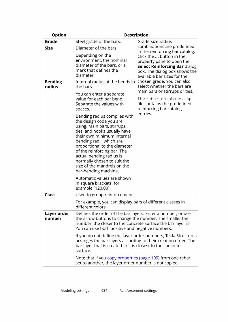
Option DescriptionGrade Steel grade of the bars. Grade-size-radius
combinations are predefinedin the reinforcing bar catalog.Click the ... button in theproperty pane to open theSelect Reinforcing Bar dialogbox. The dialog box shows theavailable bar sizes for thechosen grade. You can alsoselect whether the bars aremain bars or stirrups or ties.
The rebar_database.inpfile contains the predefinedreinforcing bar catalogentries.
Size Diameter of the bars.
Depending on theenvironment, the nominaldiameter of the bars, or amark that defines thediameter.
Bendingradius
Internal radius of the bends inthe bars.
You can enter a separatevalue for each bar bend.Separate the values withspaces.
Bending radius complies withthe design code you areusing. Main bars, stirrups,ties, and hooks usually havetheir own minimum internalbending radii, which areproportional to the diameterof the reinforcing bar. Theactual bending radius isnormally chosen to suit thesize of the mandrels on thebar-bending machine.
Automatic values are shownin square brackets, forexample [120.00].
Class Used to group reinforcement.
For example, you can display bars of different classes indifferent colors.
Layer ordernumber
Defines the order of the bar layers. Enter a number, or usethe arrow buttons to change the number. The smaller thenumber, the closer to the concrete surface the bar layer is.You can use both positive and negative numbers.
If you do not define the layer order numbers, Tekla Structuresarranges the bar layers according to their creation order. Thebar layer that is created first is closest to the concretesurface.
Note that if you copy properties (page 109) from one rebarset to another, the layer order number is not copied.
Modeling settings 934 Reinforcement settings
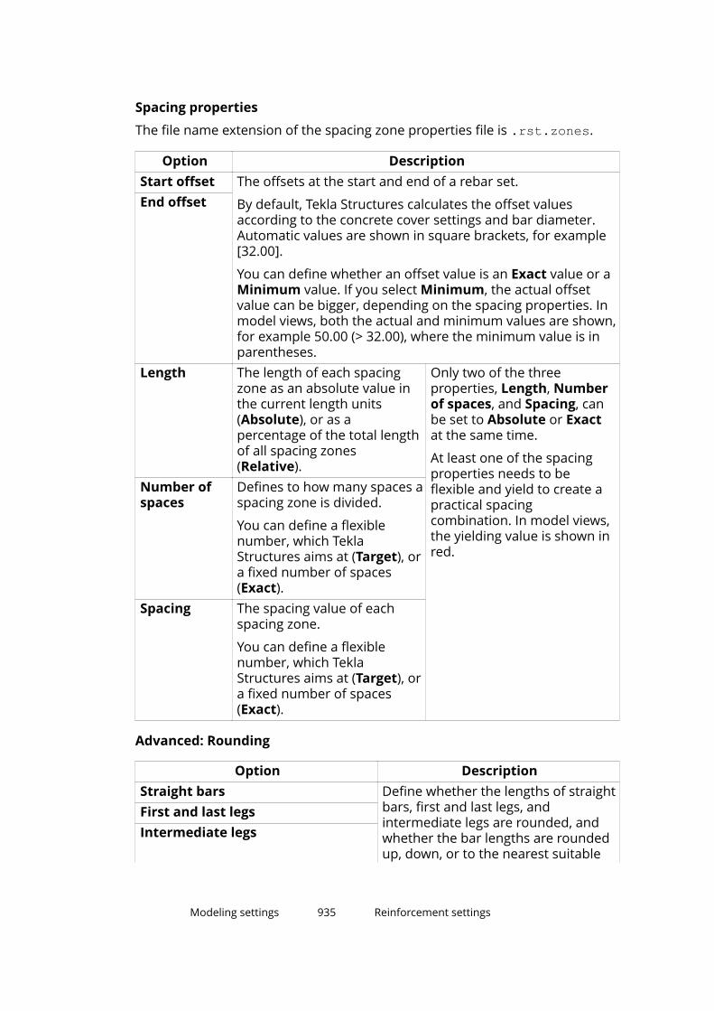
Spacing properties
The file name extension of the spacing zone properties file is .rst.zones.
Option DescriptionStart offset The offsets at the start and end of a rebar set.
By default, Tekla Structures calculates the offset valuesaccording to the concrete cover settings and bar diameter.Automatic values are shown in square brackets, for example[32.00].
You can define whether an offset value is an Exact value or aMinimum value. If you select Minimum, the actual offsetvalue can be bigger, depending on the spacing properties. Inmodel views, both the actual and minimum values are shown,for example 50.00 (> 32.00), where the minimum value is inparentheses.
End offset
Length The length of each spacingzone as an absolute value inthe current length units(Absolute), or as apercentage of the total lengthof all spacing zones(Relative).
Only two of the threeproperties, Length, Numberof spaces, and Spacing, canbe set to Absolute or Exactat the same time.
At least one of the spacingproperties needs to beflexible and yield to create apractical spacingcombination. In model views,the yielding value is shown inred.
Number ofspaces
Defines to how many spaces aspacing zone is divided.
You can define a flexiblenumber, which TeklaStructures aims at (Target), ora fixed number of spaces(Exact).
Spacing The spacing value of eachspacing zone.
You can define a flexiblenumber, which TeklaStructures aims at (Target), ora fixed number of spaces(Exact).
Advanced: Rounding
Option DescriptionStraight bars Define whether the lengths of straight
bars, first and last legs, andintermediate legs are rounded, andwhether the bar lengths are roundedup, down, or to the nearest suitable
First and last legsIntermediate legs
Modeling settings 935 Reinforcement settings

Option Descriptionnumber according to the roundingaccuracy.
Rounding up at splitters At splitter locations, define how muchthe bar lengths can be rounded up.
Advanced: Step tapering
Option DescriptionType Define whether the bars are step
tapered, and how the tapering stepsare created.
The options are None, Distance, andNumber of bars.If you select the Number of barsoption, enter the number of bars inone tapering step.
Straight bars If you select the Distance option,enter the tapering step values forstraight bars, first and last legs, andintermediate legs.
First and last legsIntermediate legs
Custom properties
Click the More button to open the user-defined attributes dialog box. The filename extension of the user-defined attributes file is .rst.more.
See also
Create a rebar set (page 428)
Modify a rebar set (page 478)
Secondary guideline properties (page 936)
Leg face properties (page 938)
Property modifier properties (page 938)
End detail modifier properties (page 941)
Splitter properties (page 943)
Secondary guideline propertiesUse the property pane or the contextual toolbar to view and modify theproperties of the rebar set secondary guidelines.
Modeling settings 936 Reinforcement settings

Spacing properties
If you want a secondary guideline to have the same spacing properties as theprimary guideline, select Yes from the Inherit from primary list in theproperty pane.
If you want to define the secondary guideline spacing propertiesindependently from the primary guideline, select No from the Inherit fromprimary list, and then modify the following spacing properties as needed:
Option DescriptionStart offset The offsets at the start and end of a rebar set.
By default, Tekla Structures calculates the offset valuesaccording to the concrete cover settings and bar diameter.Automatic values are shown in square brackets, for example[32.00].
You can define whether an offset value is an Exact value or aMinimum value. If you select Minimum, the actual offsetvalue can be bigger, depending on the spacing properties. Inmodel views, both the actual and minimum values are shown,for example 50.00 (> 32.00), where the minimum value is inparentheses.
End offset
Length The length of each spacingzone as an absolute value inthe current length units(Absolute), or as apercentage of the total lengthof all spacing zones(Relative).
Only two of the threeproperties, Length, Numberof spaces, and Spacing, canbe set to Absolute or Exactat the same time.
At least one of the spacingproperties needs to beflexible and yield to create apractical spacingcombination. In model views,the yielding value is shown inred.
Number ofspaces
Defines to how many spaces aspacing zone is divided.
You can define a flexiblenumber, which TeklaStructures aims at (Target), ora fixed number of spaces(Exact).
Spacing The spacing value of eachspacing zone.
You can define a flexiblenumber, which TeklaStructures aims at (Target), ora fixed number of spaces(Exact).
See also
Modify a rebar set locally using modifiers (page 486)
Modeling settings 937 Reinforcement settings
Rebar set properties (page 933)
Leg face propertiesUse the property pane or the contextual toolbar to view and modify theproperties of the rebar set leg faces.
Attributes
Option DescriptionAdditional offset Distance between the leg face and the bars.
A negative value moves the bars outside theconcrete.
Flip bar side Shows if the bars are flipped over to the other sideof the leg face (Yes) or not (No). The default valueis No.
Layer order number Defines the order of the bar layers. Enter anumber, or use the arrow buttons to change thenumber. The smaller the number, the closer to theconcrete surface the bar layer is. You can use bothpositive and negative values.
If you do not define the layer order numbers, TeklaStructures arranges the bar layers according totheir creation order. The bar layer that is createdfirst is closest to the concrete surface.
Note that if you copy properties (page 109) fromone leg face to another, the layer order number isnot copied.
See also
Modify a rebar set using leg faces (page 480)
Rebar set properties (page 933)
Property modifier propertiesUse the property pane or the contextual toolbar to view and modify theproperties of the rebar set property modifiers. The file name extension of theproperties file is .rst_pm.
Modeling settings 938 Reinforcement settings

General
Option DescriptionBars affected Select how many bars can be modified in the same
location:
• 1/1 = all bars are modified in the same crosssection.
• 1/2 = every second bar is modified in the samecross section.
• 1/3 = every third bar is modified in the samecross section.
• 1/4 = every fourth bar is modified in the samecross section.
First affected bar Define which is the first bar to be modified,starting from the first end of the modifier.
Enter a positive number, or use the arrow buttonsto change the number.
Attributes
Option DescriptionNumbering Numbering series of the bars.Name User-definable name of the bars.
Tekla Structures uses bar names in reports and drawing lists,and to identify bars of the same type.
Grade Steel grade of the bars. Grade-size-radiuscombinations are predefinedin the reinforcing bar catalog.Click the ... button in theproperty pane to open theSelect Reinforcing Bar dialogbox. The dialog box shows theavailable bar sizes for thechosen grade. You can alsoselect whether the bars aremain bars or stirrups or ties.
The rebar_database.inpfile contains the predefinedreinforcing bar catalogentries.
Size Diameter of the bars.
Depending on theenvironment, the nominaldiameter of the bars, or amark that defines thediameter.
Bendingradius
Internal radius of the bends inthe bars.
You can enter a separatevalue for each bar bend.Separate the values withspaces.
Bending radius complies withthe design code you areusing. Main bars, stirrups,ties, and hooks usually havetheir own minimum internal
Modeling settings 939 Reinforcement settings
Option Descriptionbending radii, which areproportional to the diameterof the reinforcing bar. Theactual bending radius isnormally chosen to suit thesize of the mandrels on thebar-bending machine.
Automatic values are shownin square brackets, forexample [120.00].
Class Used to group reinforcement.
For example, you can display bars of different classes indifferent colors.
Advanced: Rounding
Option DescriptionStraight bars Define whether the lengths of straight
bars, first and last legs, andintermediate legs are rounded, andwhether the bar lengths are roundedup, down, or to the nearest suitablenumber according to the roundingaccuracy.
First and last legsIntermediate legs
Rounding up at splitters At splitter locations, define how muchthe bar lengths can be rounded up.
Advanced: Step tapering
Option DescriptionType Define whether the bars are step
tapered, and how the tapering stepsare created.
The options are None, Distance, andNumber of bars.If you select the Number of barsoption, enter the number of bars inone tapering step.
Straight bars If you select the Distance option,enter the tapering step values forstraight bars, first and last legs, andintermediate legs.
First and last legsIntermediate legs
Modeling settings 940 Reinforcement settings
Custom properties
Click the More button to open the user-defined attributes dialog box. The filename extension of the user-defined attributes file is .rst_pm.more.
See also
Modify a rebar set locally using modifiers (page 486)
Rebar set properties (page 933)
End detail modifier propertiesUse the property pane or the contextual toolbar to view and modify theproperties of the rebar set end detail modifiers. The file name extension of theproperty file is .rst_edm.
General
Option DescriptionBars affected Select how many bars can be modified in the same
location:
• 1/1 = all bars are modified in the same crosssection.
• 1/2 = every second bar is modified in the samecross section.
• 1/3 = every third bar is modified in the samecross section.
• 1/4 = every fourth bar is modified in the samecross section.
First affected bar Define which is the first bar to be modified,starting from the first end of the modifier.
Enter a positive number, or use the arrow buttonsto change the number.
Hook
Option DescriptionHook type Shape of the hook. The rebar_database.inp
file contains the predefinedminimum bending radius andminimum hook length for allstandard hooks.
See Add hooks to reinforcingbars (page 508).
Angle Angle of a custom hook.Radius Internal bending radius of a
standard hook or customhook.
Length Length of the straight part ofa standard or custom hook.
Modeling settings 941 Reinforcement settings

Option DescriptionHookrotation
Rotation angle of a hook outof the bar plane. Use to create3D bars.
For example:
Length adjustment
Option DescriptionAdjustment type Select whether and how the bar length is adjusted
(extended or shortened).
• No adjustment: Bar length is not adjusted.
• End offset: Bar length is adjusted according tothe specified end offset.
Use this option to keep the leg faces on theconcrete faces and adaptive to the concretefaces, but still to extend or shorten the barends.
• Leg length: Bar length is adjusted according tothe specified leg length.
Length Depending on the adjustment type, the length ofthe end offset or leg.
With end offset, enter a positive value to extendthe bars, or a negative value to shorten the bars.
With leg length, enter a positive value to set the leglength.
End preparations
Option DescriptionMethod Select the end method of the bars. The options
are:
• Coupler
• Coupler female
• Coupler male
• Threaded
• AnchorType Select the end method type. The options are:
• Standard
Modeling settings 942 Reinforcement settings
Option Description• Position
• Bridging
• Transition
• Bolt
• WeldableProduct Product name of the end detail. Can be shown in
reports.Code Product code of the end detail. Can be shown in
reports.Thread type Enter the type of the threading.Threaded length Length of the threading from the bar end.Extra fabricationlength
Additional length needed with some threadingmethods. Can be shown in reports, but does notaffect the total length of the bar.
Custom properties
Click the More button to open the user-defined attributes of the rebar set enddetail modifiers. The file name extension of the user-defined attribute fileis .rst_edm.more.
See also
Modify a rebar set locally using modifiers (page 486)
Rebar set properties (page 933)
Splitter propertiesUse the property pane or the contextual toolbar to view and modify theproperties of the rebar set splitters. The file name extension of the propertiesfile is .rst_sm.
Some of the following settings depend on the splitter direction. An arrowhead
symbol close to the midpoint of each splitter indicates the direction andthe left and right sides of the splitter. The arrow points from the start towardsthe end of the splitter.
Modeling settings 943 Reinforcement settings
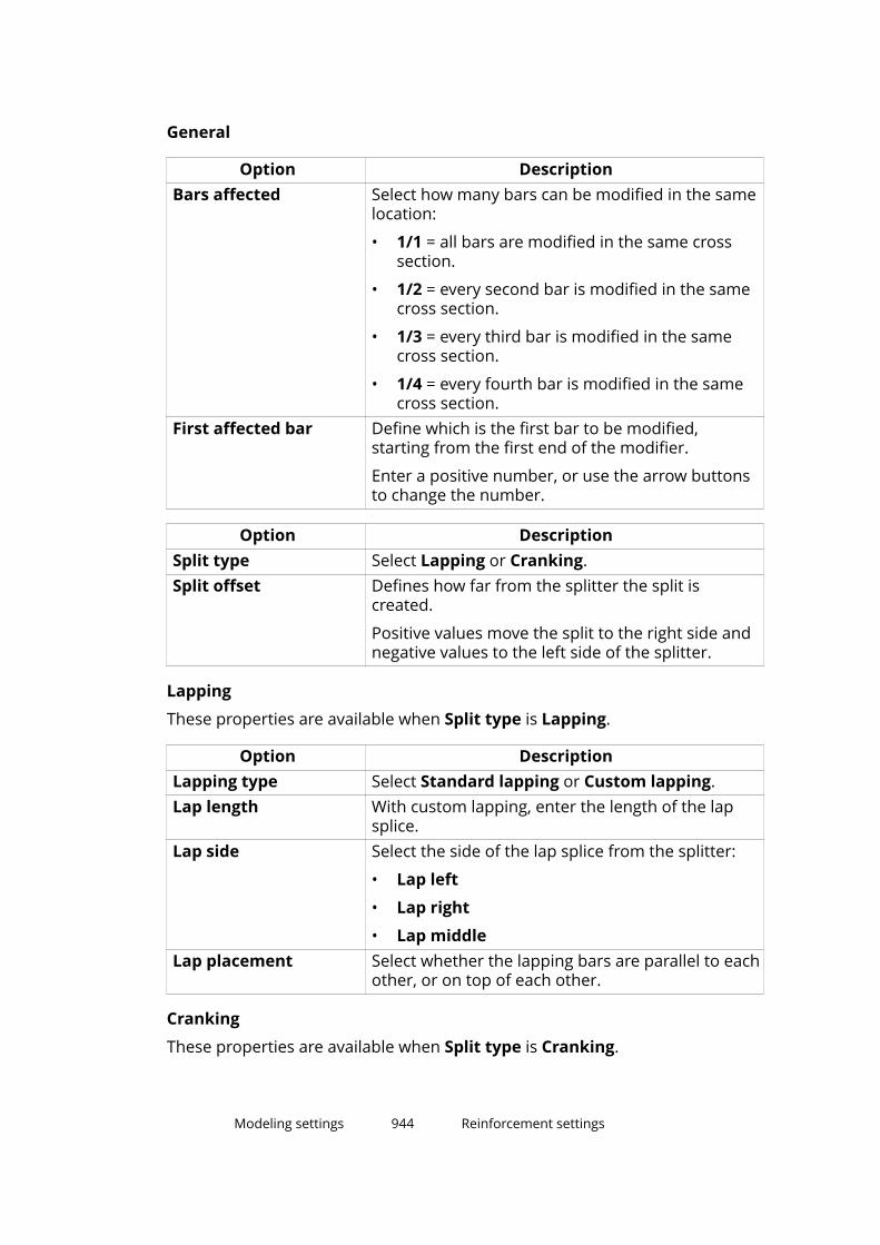
General
Option DescriptionBars affected Select how many bars can be modified in the same
location:
• 1/1 = all bars are modified in the same crosssection.
• 1/2 = every second bar is modified in the samecross section.
• 1/3 = every third bar is modified in the samecross section.
• 1/4 = every fourth bar is modified in the samecross section.
First affected bar Define which is the first bar to be modified,starting from the first end of the modifier.
Enter a positive number, or use the arrow buttonsto change the number.
Option DescriptionSplit type Select Lapping or Cranking.Split offset Defines how far from the splitter the split is
created.
Positive values move the split to the right side andnegative values to the left side of the splitter.
Lapping
These properties are available when Split type is Lapping.
Option DescriptionLapping type Select Standard lapping or Custom lapping.Lap length With custom lapping, enter the length of the lap
splice.Lap side Select the side of the lap splice from the splitter:
• Lap left
• Lap right
• Lap middleLap placement Select whether the lapping bars are parallel to each
other, or on top of each other.
Cranking
These properties are available when Split type is Cranking.
Modeling settings 944 Reinforcement settings

(1) = Location of the splitter
Option DescriptionCranking type Select Standard cranking or Custom cranking.Crank straight length With custom cranking, enter the length of the
straight segment of the crank.
This is (2) in the image above.Cranked length With custom cranking, select how the length of the
cranked segment is defined, and enter the neededdistance or multiplier value. The options are:
• Diagonal ratio: Multiplier of the bar diameterin diagonal direction
• Diagonal distance: Total length of the crankedsegment in diagonal direction
This is (4) in the image above.
• Horizontal ratio: Multiplier of the bar diameterin horizontal direction
• Horizontal distance: Total length of thecranked segment in horizontal direction
This is (3) in the image above.Cranked offset With custom cranking, enter the offset distance of
the straight segment of the crank.
This is (5) in the image above.
The default value is 2 * actual bar diameter.Crank side Select to which side of the splitter the crank is
created, Left or Right.Crank rotation Defines to which angle the crank is rotated.
Staggering
Option DescriptionStagger type Select whether and to which direction the splices
are staggered. The options are:
• No stagger
Modeling settings 945 Reinforcement settings

Option Description• Stagger left
• Stagger right
• Stagger middleStagger offset The offset of the adjacent bars if they are
staggered.
See also
Modify a rebar set locally using modifiers (page 486)
Rebar set properties (page 933)
Reinforcement strand properties
Use the Strand pattern properties to view and modify the properties ofstrands. The file name extension of the properties file is .rbs.
Option DescriptionGeneralNumbering Mark series of the strand.Name User-definable name of the strand.
Tekla Structures uses strand names in reports anddrawing lists, and to identify strands of the sametype.
Grade Steel grade of the strand.Size Diameter of the strand.
Depending on the environment, the nominaldiameter of the strand, or a mark that defines thediameter.
Bending radius Internal radius of the bends in the strand.
You can enter a separate value for each bend.Separate the values with spaces.
Class Use to group reinforcement.
For example, you can display strands of differentclasses in different colors.
Pull per strand Pre-stress load per strand (kN).Number of crosssections
Number of cross sections of the strand pattern.
For example:
Modeling settings 946 Reinforcement settings
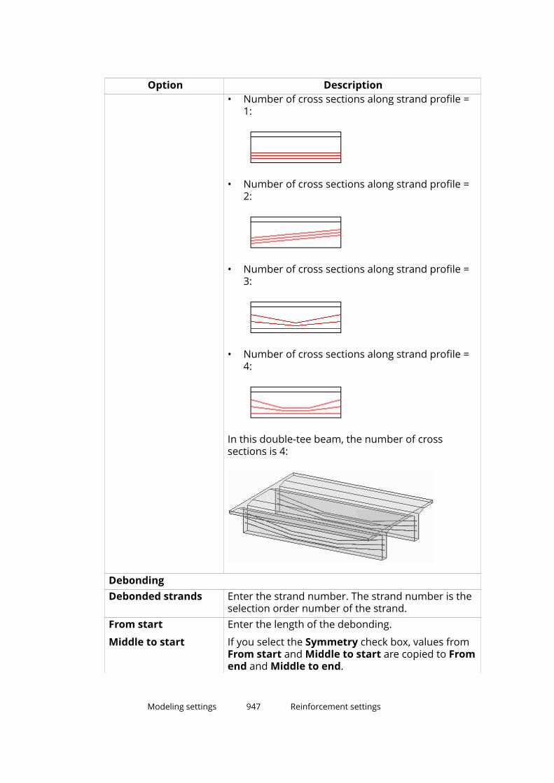
Option Description• Number of cross sections along strand profile =
1:
• Number of cross sections along strand profile =2:
• Number of cross sections along strand profile =3:
• Number of cross sections along strand profile =4:
In this double-tee beam, the number of crosssections is 4:
DebondingDebonded strands Enter the strand number. The strand number is the
selection order number of the strand.From start
Middle to start
Enter the length of the debonding.
If you select the Symmetry check box, values fromFrom start and Middle to start are copied to Fromend and Middle to end.
Modeling settings 947 Reinforcement settings

Option DescriptionMiddle to end
From endSymmetry Define whether the end and start lengths are
symmetrical.Custom propertiesMore You can create user-defined attributes to add
information about reinforcement. Attributes canconsist of numbers, text, or lists.
You can use the values of user-defined attributes inreports and drawings.
To set values for user-defined attributes, click theMore button.
You can also change the name of the fields, and addnew ones, by editing the objects.inp file. SeeDefine and update user-defined attributes (UDAs).
See also
Create a reinforcement strand pattern (page 473)
Debond reinforcement strands (page 475)
Modeling settings 948 Reinforcement settings
11Disclaimer
© 2019 Trimble Solutions Corporation and its licensors. All rights reserved.
This Software Manual has been developed for use with the referencedSoftware. Use of the Software, and use of this Software Manual are governedby a License Agreement. Among other provisions, the License Agreement setscertain warranties for the Software and this Manual, disclaims otherwarranties, limits recoverable damages, defines permitted uses of theSoftware, and determines whether you are an authorized user of the Software.All information set forth in this manual is provided with the warranty set forthin the License Agreement. Please refer to the License Agreement for importantobligations and applicable limitations and restrictions on your rights. Trimbledoes not guarantee that the text is free of technical inaccuracies ortypographical errors. Trimble reserves the right to make changes andadditions to this manual due to changes in the software or otherwise.
In addition, this Software Manual is protected by copyright law and byinternational treaties. Unauthorized reproduction, display, modification, ordistribution of this Manual, or any portion of it, may result in severe civil andcriminal penalties, and will be prosecuted to the full extent permitted by law.
Tekla, Tekla Structures, Tekla BIMsight, BIMsight, Tekla Civil, Tedds, Solve,Fastrak and Orion are either registered trademarks or trademarks of TrimbleSolutions Corporation in the European Union, the United States, and/or othercountries. More about Trimble Solutions trademarks: http://www.tekla.com/tekla-trademarks. Trimble is a registered trademark or trademark of TrimbleInc. in the European Union, in the United States and/or other countries. Moreabout Trimble trademarks: http://www.trimble.com/trademarks.aspx. Otherproduct and company names mentioned in this Manual are or may betrademarks of their respective owners. By referring to a third-party product orbrand, Trimble does not intend to suggest an affiliation with or endorsementby such third party and disclaims any such affiliation or endorsement, exceptwhere otherwise expressly stated.
Portions of this software:
D-Cubed 2D DCM © 2010 Siemens Industry Software Limited. All rightsreserved.
Disclaimer 949 Reinforcement settings

EPM toolkit © 1995-2006 Jotne EPM Technology a.s., Oslo, Norway. All rightsreserved.
Open Cascade Express Mesh © 2015 OPEN CASCADE S.A.S. All rights reserved.
PolyBoolean C++ Library © 2001-2012 Complex A5 Co. Ltd. All rights reserved.
FLY SDK - CAD SDK © 2012 VisualIntegrity™. All rights reserved.
Teigha © 2002-2016 Open Design Alliance. All rights reserved.
CADhatch.com © 2017. All rights reserved.
FlexNet Publisher © 2014 Flexera Software LLC. All rights reserved.
This product contains proprietary and confidential technology, informationand creative works owned by Flexera Software LLC and its licensors, if any. Anyuse, copying, publication, distribution, display, modification, or transmission ofsuch technology in whole or in part in any form or by any means without theprior express written permission of Flexera Software LLC is strictly prohibited.Except where expressly provided by Flexera Software LLC in writing,possession of this technology shall not be construed to confer any license orrights under any Flexera Software LLC intellectual property rights, whether byestoppel, implication, or otherwise.
To see the third party open source software licenses, go to Tekla Structures,click File menu --> Help --> About Tekla Structures and then click the 3rdparty licenses option.
The elements of the software described in this Manual are protected byseveral patents and possibly pending patent applications in the United Statesand/or other countries. For more information go to page http://www.tekla.com/tekla-patents.
Disclaimer 950 Reinforcement settings

Index
** character................................................... 186
33D
in snapping...............................................78views......................................................... 43
?? character................................................... 186
Aaccuracy, see high accuracy.......................583accuracy
in modeling............................................ 583of parts................................................... 583
adaptivitydefault settings......................................325of individual model objects..................325of reinforcement................................... 512
addingbuttons................................................... 198grid lines...................................................26
aligningobjects...................................................... 92
Analysis tab..................................................707anchoring hooks......................................... 508angles........................................................... 605Applications & components...................... 736
exporting custom components........... 862importing custom components...........862
applications in Applications andComponents catalog ................................. 664arcs
measuring.............................................. 605
arithmetic operators...................................784Array of objects (29)....................................143assemblies................................................... 386
adding objects................................390,391changing the main assembly...............393changing the main part........................ 392comparing..............................................607creating...................................................387examples................................................ 394exploding................................................394highlighting............................................ 393joining.....................................................392nested assemblies..................127,390,392numbering...................................... 630,638removing objects...................................393selecting................................................. 127showing invisible objects..................... 589sub-assemblies......................................387using bolts to create assemblies.........388using welds to create assemblies....... 389
asterisk......................................................... 186attaching parts............................................ 327attaching
reinforcement to part...........................514auto bolt
creating bolts......................................... 332AutoConnection.......................................... 689
rules.................................................690,699settings................................................... 690using....................................................... 693
AutoDefaults........................................ 689,694combining properties........................... 702connection check.................................. 704iterating properties............................... 702rules........................................................ 699using....................................................... 699using reaction forces............................ 706using UDLs............................................. 706
Autoin snapping...............................................78
automatic splicing tool............................... 515
951
AutomaticSplicingTool................................515
Bbackground color
changing................................................... 64examples.................................................. 64
backing upribbons................................................... 198
base points.................................................... 53basepoints..................................................... 53beams
cambering.............................................. 331concrete beams.....................................279concrete polybeams............................. 282curved beams........................................ 244orthogonal beams.................................249spiral beams................................... 251,285steel beams............................................239steel polybeams.................................... 242warping...................................................329
bending........................................................ 321bending shapes
in rebar shape manager............... 527,534of reinforcement............................523,524rules........................................................ 527
bent plates...................................................256bent plates...................................................271bent mesh....................................................467binding objects
plane types.............................................872to a plane............................................... 764
bolt points....................................................570bolted parts................................................. 332bolts.......................................................332,388
bolt group shape...................................332bolt spacing............................................605bolting sub-assemblies.........................388clash checking........................................623creating...................................................332holes....................................................... 343modifying............................................... 332studs....................................................... 342
boundary planes......................................... 872box profiles.................................................. 884brackets........................................................186
Cc profiles.......................................................884calculations..................................................782cambering....................................................331cambering parts..........................................331cast units......................................................396
adding objects....................................... 397cast unit type......................................... 396casting direction..................... 399,400,401changing the main part........................ 398creating...................................................397exploding................................................399highlighting............................................ 398numbering............................................. 638removing objects...................................398selecting................................................. 127top-in-form face.................................... 401
cast-in-place.................................................396continuous concrete structures.......... 404pour breaks.......415,417,418,420,421,422pour objects...........................................408pours......................... 402,403,407,409,623viewing parts..........................................404viewing pour objects.............................404
categoriesin filtering............................................... 169
center planes...............................................872chamfering
corner chamfers....................................368corner chamfer dimensions................ 368edge chamfers.......................................368polybeams..............................................368
chamfersin warping.............................................. 329
changingwelds to polygon welds........................ 359
checking the model.................................... 599circular hollow sections..............................884circular reinforcing bar group................... 463circular sections.......................................... 884Clash Check Manager.................................611clash checking...................................... 610,611
bolts........................................................ 623changing priority................................... 617changing status..................................... 617clash types............................................. 613comments.............................................. 619
952
grouping clashes................................... 618history.....................................................620list of clashes......................................... 616managing results...................................616previewing before printing...................620printing lists of clashes................. 620,621results..................................................... 612saving clashes........................................622searching................................................616sessions..................................................622symbols.................................................. 612ungrouping clashes...............................618
class.............................................................. 594clip planes.................................................... 608closing
custom component editor................... 823cold rolled profiles...................................... 884colliding objects.......................................... 610colors
changing color settings...........................64changing the background color.............64color settings for object groups.......... 921customizing............................................595finding RGB values.................................. 64for object groups...................................595for parts..................................................594for pour objects.....................................409settings............................................597,598
columnsconcrete columns..................................277positioning............................................. 323steel columns.........................................237
combiningparts........................................................327reinforcing bar groups..........................505
command editor......................................... 198commands
customizing............................................198user-defined.......................................... 198
commentsin clash checking................................... 619
comparing parts or assemblies.................607comparing
ribbons................................................... 198component analysis properties................ 734component catalog.....................................681component planes.............................. 872,873component symbol.....................................736
componentsconceptual............................................. 688converting.............................................. 688
components in Applications & components.......................................................................681components
catalog.................................................... 681connections........................................... 674detailing..................................................674details..................................................... 674exploding................................................750nested components..............................750properties...............................................674selecting................................................. 127showing invisible objects..................... 589sub-components................................... 750views....................................................... 674
concrete beam properties......................... 279concrete beams...........................................279concrete column properties...................... 277concrete cover
of reinforcement................................... 510concrete item properties........................... 298concrete items.............................................298concrete panel properties..........................288concrete panels...........................................288concrete parts............................................. 235
beams.....................................................279cast units................................................ 396casting direction.................................... 400columns..................................................277items....................................................... 298pad footings...........................................293panels..................................................... 288polybeams..............................................282showing as continuous.........................404slabs........................................................290strip footings..........................................295walls........................................................ 288
concrete partsspiral beams.......................................... 285
concrete polybeam properties..................282concrete slab properties............................ 290concrete walls..............................................288conical bent plate........................................256conical bent plate........................................271connection analysis properties................. 734connection design
953
Excel........................................................720connection weld properties.......................356connections
custom connections...................... 736,740construction arcs........................................ 561construction circles.....................................561construction lines................................ 561,772construction objects................................... 561
construction polycurves.......................565construction arcs...................................564construction circles...............................563construction lines..................................562construction planes.............................. 562copying with offset................................566modifying location................................ 567
construction planes.............................561,772construction polycurves.............................561contextual toolbar
customizing............................................226modifying part position........................306
continuous concrete structures................ 404contour plate properties............................253contour plates............................................. 253control numbers......................................... 646
assigning to parts..................................646directions............................................... 647displaying in model...............................649example..................................................651locking.................................................... 651order....................................................... 647removing................................................ 650settings................................................... 925unlocking................................................651
control points................................................ 53converting
welds to polygon welds........................ 359coordinate system........................................ 48coordinates.................................................... 21copying
construction objects with offset..........566contextual toolbar.................................109filters.......................................................193object groups.........................................591objects.............................................131,133parts........................................................235pour breaks............................................420properties...............................................109property pane........................................109
property references.............................. 780Radial array tool.................................... 141with Array of objects (29) component 143
corner chamfersproperties...............................................368types and dimensions.......................... 368
createassemblies............................................. 234cast units................................................ 234construction circles...............................234construction lines..................................234construction planes.............................. 234parts........................................................234points......................................................234pours.......................................................234reinforcement........................................234
creating boltsauto bolt.................................................332
creating surface treatmentunpainted area...................................... 383
creatingassemblies............................................. 387beams close to each other...................323bolts........................................................ 332cast units................................................ 397clip planes.............................................. 608concrete beams.....................................279concrete columns..................................277concrete items.......................................298concrete panels..................................... 288concrete polybeams............................. 282concrete slabs........................................290concrete walls........................................288construction arcs...................................564construction circles...............................563construction lines..................................562construction planes.............................. 562construction polycurves.......................565contour plates....................................... 253curved beams........................................ 244custom components.............................747fittings.....................................................361grids.......................................................... 21holes....................................................... 343model templates................................... 231nested assemblies................................ 392object groups.........................................591objects...................................................... 96
954
orthogonal beams.................................249pad footings...........................................293parts.................................................. 96,235pour breaks............................................418spiral beams................................... 251,285standard-part models...........................662steel beams............................................239steel columns.........................................237steel items..............................................298steel polybeams.................................... 242strip footings..........................................295studs....................................................... 342sub-assemblies......................................387tile patterns............................................379twin profiles........................................... 246view filters
selection filters................................ 158views......................................................... 31welds.......................................................346
curved parts......................................... 244,321curved reinforcing bar group.................... 461Custom component browser............. 761,780Custom component dialog editor.............824
changing the language......................... 857setting options.......................................857
custom component editor.........................761closing.....................................................823saving......................................................823
custom component view............................761Custom component wizard....................... 747
properties...............................................864custom components
about custom components..................736adding to model.................................... 859arithmetic operators.............................784binding objects...............................764,772construction planes and lines............. 772copying property references................780creating...................................................747default properties................................. 867dialog box files.......................................827exporting................................................ 862importing................................................862inp files................................................... 827locking.................................................... 830modifying............................................... 761modifying the dialog box..................... 824nested components..............................750
plane types.............................................872preventing modifications..................... 830protecting with passwords...................762seams..................................................... 744settings................................................... 863sub-components................................... 750thumbnail images................................. 753toggle groups.........................................831types....................................................... 736variables................................................. 763
custom connections................................... 740custom details............................................. 742custom hooks.............................................. 508custom inquiry
modifying default attributes................602custom parts................................................738
adding to model.................................... 860custom seams............................................. 744customized mesh........................................467customizing
commands............................................. 198contextual toolbar.................................194contextual toolbar.................................226Custom Inquiry tool attributes............ 602keyboard shortcuts............................... 194keyboard shortcuts............................... 195property pane........................................194property pane........................................213ribbon..................................................... 194ribbons................................................... 198tabs......................................................... 198toolbars...........................................194,225
cut planes.....................................................872cuts
hints and tips......................................... 362in rebar sets........................................... 493line cuts.................................................. 362part cuts................................................. 362polygon cuts.......................................... 362
cyclic dependencies ...................................796cylindrical bent plate.................................. 256cylindrical bent plate.................................. 271
Ddefault adaptivity........................................ 325default connection properties...................708default connection settings....................... 708
955
defining unpainted areasurface treatment................................. 383
definingweld cross sections............................... 360
deletingclip planes.............................................. 608objects...................................................... 96parts..........................................................96views......................................................... 41
dependenciesin variable formulas..............................796
design check................................................ 731design group numbering........................... 653Design tab.............................................707,731detaching parts........................................... 327detail analysis properties...........................734detailing parts
detaching............................................... 327exploding................................................327
detailscustom details................................736,742
diagnosing model....................................... 624dialog boxes
loading properties.................................111modifying............................................... 824saving properties...................................111
dialog editor................................................ 824direct modification
modifying............................................... 103display detailing.......................................... 590display settings............................................918displaying
control numbers....................................649distance variables................................763,764distance
reference distance................................ 774distances
measuring.............................................. 605drawing objects
moving....................................................144rotating...................................................150
Eedge chamfers
properties...............................................368editing
custom components.............................761
editorsCustom component dialog editor.......824
end detail modifiers................................... 486end offsets................................................... 315exact lines.................................................... 583examples
adding option to create object in customcomponent.............................................799assemblies............................................. 394background colors.................................. 64component planes................................ 873creating custom connection................ 754creating parametric variable................798determining bolt group distance frombeam flange...........................................807determining bolt size and bolt standard.................................................................806determining number of bolt rows incustom component...............................809drawing filters........................................186exploding components.........................754modifying custom component dialog box.................................................................835modifying dialog box of stiffener detail....835nested components..............................757numbering....................... 651,656,658,659rebar set modifiers in customcomponents...........................................816replacing sub-components in customcomponent.............................................800snapping in model.................................. 87sub-components................................... 757tile pattern definition............................379using construction planes in customcomponent.............................................803using Excel spreadsheets with customcomponents...........................................815using properties file in customcomponent.............................................802using template attributes in customcomponents...........................................813using user-defined attributes in customcomponents...........................................811view and selection filters......................186
excel design................................................. 707Excel
connection design.................................720
956
using with custom components..........815exploding
assemblies............................................. 394cast units................................................ 399components...........................................750parts........................................................327
exportingcustom components.............................862keyboard shortcuts............................... 195
extensions in Applications and componentscatalog.......................................................... 664extensions
importing................................................670
Ffamily numbers....................................634,635
example..................................................656modifying............................................... 636
filteringAnd/Or....................................................166categories...............................................169conditions.............................................. 166copying filters........................................ 193object properties...................................169objects.................................................... 155parentheses........................................... 166removing filters..................................... 193template attributes........................166,185use for.................................................... 155view filters
selection filters................................ 158wildcards................................................ 186
filtersexamples................................................ 186selection................................................. 122
finding distant objects................................626finding
clashes....................................................611fit part end................................................... 361fittings...........................................................361fixed profiles................................................316flying through model.................................. 609folded plates................................................884footings.................................................293,295formulas
arithmetic operators.............................784in custom components.........................782
in rebar shape manager.......................533functions...................................................... 782
GGeneral tab...........................................707,730geometry
of reinforcement................................... 514global coordinate system.............................48global point of origin.................................... 48grid lines
adding.......................................................26deleting.....................................................29modifying................................................. 26properties.................................................26
grid planes................................................... 872grid views
properties.................................................45grids
coordinates......................................... 18,21creating................................................18,21deleting................................................18,21labels................................................... 18,21line extensions.........................................18modifying............................................ 18,21origin.........................................................18properties........................................... 18,21radial....................................................18,21rectangular..........................................18,21
gridwork plane grid........................................50
groupingclashes....................................................618reinforcement........................................504
Hhandles.........................................................303
in pour breaks....................................... 421of reinforcement................................... 506
hat profiles...................................................884hatching
DX............................................................584hiding
cut lines.................................................. 362dimensions............................................ 116part labels.............................................. 320
957

rebar set modifiers............................... 486reference lines.......................................303selected parts........................................ 587top-in-form face.................................... 401unselected parts....................................588work area................................................. 46
high accuracy...............................................583highlighting
assemblies............................................. 393cast units................................................ 398objects.................................................... 129
historyof clashes............................................... 620
holes............................................................. 343horizontal position......................................313
Ii beams (concrete)...................................... 884i beams (steel)............................................. 884i profiles....................................................... 884identical
areas....................................................... 324parts........................................................632reinforcement........................................632
if you cannot select objects....................... 129import items................................................ 298importing
custom components.............................862keyboard shortcuts............................... 195points......................................................570
inp filesin custom components................. 824,827
inquiringobject properties...................................599
interruptingobject selection..................................... 129
irregular beams (concrete)........................ 884items..................................................... 235,298
changing the shape...............................298limitations.............................................. 298
Jjoining assemblies...................................... 392joints. def..................................................... 708joints.def...................................................... 707
Kkeyboard shortcuts.....................................195
Ll profiles....................................................... 884label color
changing................................................... 64labels
part labels.............................................. 320ledger beams (concrete)............................ 884leg faces....................................................... 480levels.............................................................323line cuts........................................................ 362linear array tool...........................................138lines
exact........................................................583linking
parametric variables to object properties.................................................................777
loadingsaved properties................................... 111
local coordinate system............................... 48locking and unlocking
custom components.............................830log files
pour errors.............................................623solid errors.............................................623
Mmacros
adding.....................................................666editing.....................................................666global...............................................664,666local................................................. 664,666macro folder.......................................... 664recording................................................ 666running...................................................666
magnetic construction planes and lines.. 772measuring objects...................................... 605
angles..................................................... 605arcs..........................................................605bolt spacing............................................605distances................................................ 605
mesh
958
bent.........................................................467customized.............................................467handles...................................................506modifying............................................... 496polygonal................................................467rectangular.............................................467ungrouping............................................ 503
model templatescreating...................................................231modifying
options..............................................231model objects................................................ 95
showing and hiding...............................581model views..............................................29,31
rendering options................................. 584representation options.........................584
modeling direction......................................322Modeling of floor bay (66)..........................329modeling
identical areas....................................... 324more accurately.....................................583
modelschecking for errors................................599flying through model............................ 609moving...................................................... 75numbering............................................. 627rotating..................................................... 75zooming....................................................75
modifiersin custom components.........................816showing or hiding..................................486visibility...................................................486
modifyingparts........................................................235
modifyingconcrete beams.....................................279concrete columns..................................277concrete items.......................................298concrete panels..................................... 288concrete polybeams............................. 282concrete slabs........................................290concrete walls........................................288construction objects............................. 567contour plates....................................... 253curved beams........................................ 244custom components..................... 747,761items....................................................... 298model templates................................... 231
objects.................................................... 103orthogonal beams.................................249pad footings...........................................293parts........................................................324pour breaks............................................421pour object properties......................... 410rebar sets............................................... 478reinforcement................................ 478,496steel beams............................................239steel columns.........................................237steel polybeams.................................... 242strip footings..........................................295twin profiles........................................... 246
movingbuttons................................................... 198drawing objects..................................... 144models in a view......................................75objects.............................. 103,131,133,144pour breaks............................................420
multi-story structures.................................323
Nnested assemblies....................... 127,390,392nested
components................................... 750,757no paint area............................................... 383numbering............................................627,637
about numbering.................................. 627assemblies............................................. 638cast units................................................ 638checking and repairing......................... 645clearing...................................................641control numbers...... 646,647,649,650,651examples................................. 656,658,659family numbers............... 634,635,636,656history.....................................................644identical parts........................................632manually.................................................640modifying............................................... 640numbering series.................................. 630parts................................................ 637,645preliminary numbers............................640reinforcement................................ 632,639renumbering..........................................645series........................................628,629,631settings.............................636,661,923,925standard-part model............................ 662
959
user-defined attributes........................ 634welds.......................................................640what affects........................................... 633
numberingdesign group numbering..................... 653
numbering settings.....................................923numeric snapping......................................... 87
Oobject groups...............................................591
changing the color................................ 595color settings......................................... 921copying to another model....................591creating...................................................591deleting...................................................591transparency settings........................... 922
object propertiesin filtering............................................... 169
object property report templates............. 601object representation settings....593,597,598objects
clash checking........................................610copying............................................131,133creating.....................................................96defining visibility....................................582deleting.....................................................96filtering................................................... 155finding distant objects.......................... 626inquiring properties..............................599measuring.............................................. 605moving..................................... 131,133,144numbering............................................. 637placing objects in model...................... 561rotating...................................................150selecting................................................. 116showing and hiding.................................48
offsets...........................................................315operators..................................................... 782origin...............................................................48orthogonal beam properties..................... 249orthogonal beams
positioning............................................. 323orthogonal
snapping...................................................82others........................................................... 884outline planes..............................................872overlapping
numbering series.................................. 631oversized holes........................................... 343
Ppad footing properties............................... 293pad footings.................................................293
positioning............................................. 323properties...............................................293
page margins...............................................621page orientation..........................................621paintbrush icon........................................... 109panels....................................................288,884panning.......................................................... 75paper size.....................................................621parametric profiles..................................... 316
available in Tekla Structures................ 884predefined............................................. 884
parametric variables...................................763creating...................................................777linking..................................................... 777
part add, see attaching parts.................... 327part cuts....................................................... 362part labels
showing and hiding...............................320part position................................................ 303
on the work plane................................. 308part properties.............................................. 96part reference lines.................................... 303part view angle ........................................... 591part
handles...................................................303position...................................................303reference lines.......................................303
partsadding to assembly...............................391assemblies............................................. 386bending.................................................. 321cambering.............................................. 331changing the color................................ 594changing the material...........................316changing the profile..............................316combining.............................................. 327comparing..............................................607concrete parts........................................235copying................................................... 235creating...................................................235curved parts...........................................321
960
custom parts.................................. 736,738cutting with another part..................... 362handles...................................................303hiding......................................................587horizontal parts.....................................322identical parts........................................632items....................................................... 298labels.......................................................320location...................................................306modifying........................................235,324modifying part shape........................... 103numbering...............................630,637,645position........................................... 303,306position settings....................................923properties...............................................235showing and hiding...............................581showing only selected parts................ 588showing with exact lines...................... 583showing with high accuracy.................583splitting...................................................326steel parts.............................................. 235user-defined attributes........................ 319
passwordsprotecting custom components..........762
performancemodeling tips.........................................229
phasesin numbering......................................... 659pour phase.............................................407
plane of curvature...................................... 321plane types.................................................. 872plane views.................................................... 43Plane
in snapping...............................................78plates
bent plates............................................. 256bent plates............................................. 271
points.................................................... 561,570along arc using center and arc points 570along extension of two points............. 570at any position.......................................570at the intersection of a circle and a line....570at the intersection of a part and a line....570at the intersection of a plane and a line.................................................................570at the intersection of two lines............570
at the intersection of two part axes....570importing................................................570on line.....................................................570on plane................................................. 570parallel to two points............................570projected points on line....................... 570properties...............................................570tangent to circle.....................................570
polybeams............................................242,282chamfers................................................ 368
polygon cuts................................................ 362polygon mesh..............................................467polygon welds............................................. 346
converting.............................................. 359splitting double-sided to single-sided 360
positiondepth...................................................... 310end offsets............................................. 315horizontal...............................................313part position settings............................923rotation...................................................309vertical.................................................... 312
pour breaks................................................. 415adaptivity................................................417copying................................................... 420creating...................................................418handles...................................................421modifying............................................... 421moving....................................................420removing................................................ 422selecting................................................. 420visibility...................................................417
pour objects.................................................408changing color and transparency....... 409modifying properties............................ 410reinforcing..............................................459user-defined attributes........................ 410viewing....................................................404
pour units.................................................... 410adding objects automatically...............414
pourschanging color and transparency....... 409errors...............................................422,623example workflow.................................425introduction........................................... 402pour breaks............................................415pour objects...........................................408pour phase.............................................407
961
pour representation............................. 404reinforcing..............................................459switching on/off............................. 402,403viewing....................................................404working with.......................................... 425
preliminary numbers..................................640preparing parts for welding.......................357prestressed strands
debonding..............................................475previewing
lists of clashes........................................620printing
lists of clashes........................................620priority
in clash checking................................... 617profiles
fixed........................................................ 316parametric...................................... 316,884predefined............................................. 884profile names.........................................186standardized values..............................316twin profiles........................................... 246
propertiescopying................................................... 109Custom Component Wizard................ 864custom components.............................867grid lines...................................................26grids.......................................................... 21twin profile.............................................246variable properties................................875
property files............................................... 111property modifiers......................................486property pane................................................96
customizing............................................213loading properties.................................111saving properties...................................111
publishing groups in Applications &components catalog................................... 671
Qquestion mark............................................. 186quick access toolbar
undo history.......................................... 114
Rradial array tool...........................................141radial grid....................................................... 21radius............................................................321rebar classificator....................................... 517rebar groups................................................452
circular....................................................463curved.....................................................461spiral....................................................... 465tapered................................................... 465
rebar sequence numbering.......................517rebar set modifiers..................................... 486rebar sets..................................................... 428
cutting.....................................................493in curved structures..............................445leg faces..................................................480modifiers................................................ 486modifiers in custom components.......816modifying........................................478,486rebar shape placing tool...................... 438showing or hiding modifiers................486spacing................................................... 494
rebar shape manager.................................523bending shapes..............................524,534formulas................................................. 533rules.................................................527,534
rebar shape placing tool............................ 438RebarClassificator....................................... 517rebars
adaptivity................................................512bar leg length.........................................521bending types........................................ 535combining.............................................. 505concrete cover....................................... 510creating........................................... 428,451geometry................................................514grouping................................................. 504handles...................................................506hooks...................................................... 508length......................................................518modifying........................................478,496shape catalog..........................454,456,457splitting...................................................506ungrouping............................................ 503
RebarSeqNumbering..................................517recording
macros....................................................666
962

rectangular grid.............................................21rectangular hollow sections.......................884rectangular mesh........................................467rectangular sections................................... 884redrawing views............................................ 43reference distance variables.............. 763,774reference lines.............................................303reference models
clash checking........................................610refreshing views............................................ 43reinforcement
adaptivity................................................512attaching to part....................................514bar groups..............................................452bar leg length.........................................521bar length...............................................518bending shapes..................................... 524bending types........................................ 535circular bar groups................................463classifying...............................................517combining.............................................. 505concrete cover....................................... 510curved bar groups.................................461customized mesh..................................467debonding strands................................475for pour objects.....................................459geometry................................................514grouping................................................. 504handles...................................................506hooks...................................................... 508identical..................................................632in templates........................................... 559layer information.................................. 517mesh....................................................... 467modifying................................ 477,478,496numbering...................................... 632,639omitting bars......................................... 502prestressed strands.............................. 473rebar sets............................................... 428running numbers.................................. 517sequential numbers..............................517shape catalog..........................454,456,457shape codes...........................................524shape recognition................................. 523single bars..............................................451spiral bar group.....................................465splice.......................................................476splicing....................................................515
splitting...................................................506strands....................................................473tapered bar group.................................465ungrouping............................................ 503
reinforcing bar groups................................452adaptivity................................................512bar leg length.........................................521bar length...............................................518circular....................................................463combining.............................................. 505curved.....................................................461excluding bars....................................... 502geometry................................................514grouping................................................. 504handles...................................................506modifying............................................... 496omitting bars......................................... 502pours.......................................................459shape catalog..........................454,456,457spiral....................................................... 465splitting...................................................506tapered................................................... 465ungrouping............................................ 503
reinforcing bars...........................................451bending types........................................ 535combining.............................................. 505geometry................................................514handles...................................................506hooks...................................................... 508leg length................................................521length......................................................518modifying............................................... 496pours.......................................................459shape catalog..........................454,456,457spacing................................................... 500
reinforcing pour objects.............................459removing
filters.......................................................193pour breaks............................................422weld cross sections............................... 360
renderingDirectX...................................................... 67OpenGL.....................................................67
renderingof parts and components.....................584
renumbering................................................645repairing model...........................................624repairing
963

numbering errors..................................645report templates
for inquiring object properties............ 601reports
on reinforcement...........................533,559representation
of cast-in-place concrete structures... 404of parts and components.....................584
reshapingobjects.................................................... 103
resizingbuttons................................................... 198
RGB values..................................................... 64ribbon editor........................................ 198,213ribbons
backing up..............................................198customizing............................................198restoring.................................................198
right-clickselecting................................................. 129
right-hand rule.............................................. 50rollover highlight......................................... 129rotating
drawing objects..................................... 150objects.................................................... 150parts........................................................309settings................................................... 150
rotation angle knob.................................... 306rotation settings..........................................150round
holes....................................................... 343plates...................................................... 253slabs........................................................290
rulesin bending shapes.................................527in rebar shape manager............... 527,534
runningmacros....................................................666
Ssaving
clashes....................................................622custom component...............................823dialog box properties............................111property pane properties.....................111views......................................................... 41
seams
custom seams................................ 736,744searching
clashes....................................................616secondary guidelines..................................486select work plane.......................................... 63selecting toolbar.................................. 122,225selecting
all objects............................................... 116assemblies............................................. 127by id........................................................ 116cast units................................................ 127dates from model..................................194handles...................................................116interrupting object selection............... 129multiple objects.....................................116nested assemblies................................ 127objects..................................... 116,122,129objects in components......................... 127on right-click.......................................... 129pour breaks............................................420previous objects.................................... 116unable to select objects........................129values from model................................ 194
selection dial................................................306selection filters.....................................122,158selection switches....................................... 122setting up
grid............................................................ 17views......................................................... 17work area................................................. 17work plane............................................... 17workspace................................................ 17
settingsadaptivity................................................325bolt properties.......................................332color settings...........................597,598,921concrete beam properties................... 279concrete column properties................ 277concrete item properties......................298concrete panel properties....................288concrete slab properties...................... 290contour plate properties...................... 253corner chamfer properties.................. 368custom components.............................863dialog editor settings............................ 857display settings......................................918edge chamfer properties..................... 368grid line properties..................................26
964
grid properties.........................................21grid view properties................................ 45model templates................................... 231numbering............................................. 661numbering settings................ 636,923,925orthogonal beam properties............... 249pad footing properties......................... 293part position settings............................923point properties.................................... 570reinforcement properties.....................927rotation settings.................................... 150snapping...................................................94steel beam properties.......................... 242steel beam properties...................239,244steel column properties....................... 237steel item properties............................ 298strip footing properties........................ 295transparency settings............ 597,598,922twin profile properties..........................246units and decimals.................................. 18view properties........................................44view settings.......................................... 918weld properties..................................... 346
shape codesof reinforcement.....................523,524,527
shapemodifying part shape........................... 103
shapesof items...................................................298
shifting the work plane.................................51shortcuts, see keyboard shortcuts............195showing and hiding
model objects........................................ 581parts........................................................581rebar set modifiers............................... 486
showing part reference lines..................... 303showing
cast-in-place concrete structures........404cut lines.................................................. 362dimensions............................................ 116invisible assembly objects....................589invisible component objects................589part labels.............................................. 320parts with exact lines............................583parts with high accuracy...................... 583rebar set modifiers............................... 486reference lines.......................................303top-in-form face.................................... 401
views......................................................... 41welds.......................................................358work area................................................. 46
single bolts...................................................332single-part welds.........................................346slabs..............................................................290
warping...................................................329slotted holes................................................ 343snap grid........................................................ 92snap override toolbar.................................225snap settings..................................................94snap switches........................................... 77,79snap symbols.................................................79snapping.............................................. 77,82,84
example....................................................87extension line...........................................84line.............................................................84lock coordinates...................................... 92orthogonal directions............................. 82settings..................................................... 94snap depth............................................... 78snap zone................................................. 78snap priority.............................................78snap switches.......................................... 79snap symbols...........................................79temporary reference lines......................92to middle points.................................... 303to numeric coordinates.......................... 87using coordinates....................................87
snapping modeabsolute....................................................87global........................................................ 87relative...................................................... 87
snapping toolbar.............................. 77,78,225spacing in rebar sets...................................494spacing reinforcing bars.............................500special characters....................................... 186spiral beams.........................................251,285splice.............................................................476splicing
reinforcement........................................515splitters........................................................ 486splitting
parts........................................................326reinforcing bar group............................506
stand-alone bent plate............................... 256stand-alone bent plate............................... 271standard-part models................................ 662
965
standardized values for parametric profiles.......................................................................316status
in clash checking................................... 617steel beam properties................................ 239steel column properties............................. 237steel connection properties........ 356,730,731steel curved beam properties................... 244steel detail properties................................ 730steel item properties.................................. 298steel items....................................................298steel parts.................................................... 235
assemblies............................................. 386beams.....................................................239bent plates............................................. 256bent plates............................................. 271columns..................................................237contour plates....................................... 253curved beams........................................ 244items....................................................... 298orthogonal beams.................................249polybeams..............................................242spiral beams.......................................... 251twin profiles........................................... 246
steel polybeam properties.........................242storys
creating multi-story structures............323strand pattern
of reinforcement................................... 473strip footing properties.............................. 295strip footings............................................... 295studs............................................................. 342sub-assemblies............................................387
bolting to existing assembly................ 388welding to existing assembly...............389
sub-components.........................................750examples................................................ 757
surface treatmentadd new subtype...................................378adding.....................................................373modifying............................................... 373on all faces of part................................ 373on chamfered parts.............................. 373on cut faces............................................373on part face............................................373on parts with openings and recesses.373on selected areas.................................. 373tiled surface treatment.........................373
surfaces........................................................385Swap Handles..............................................303switching between
views......................................................... 43switching on/off
pour management.........................402,403system components................................... 674
Tt profiles....................................................... 884t profiles (concrete).....................................884tabs............................................................... 198tail information........................................... 346template attributes
in filtering............................................... 185templates
model templates................................... 231thumbnail image
of custom component.......................... 753tiled surface treatment
creating new tile patterns.................... 379pattern definition example.................. 379pattern definitions................................ 379pattern elements...................................379
tipscreating beams close to each other....323creating curved parts............................321creating custom components..............881creating horizontal parts......................322custom components in new TeklaStructures version.................................882finding RGB values for colors.................64hiding cut lines...................................... 362modeling identical areas...................... 324modeling large models.........................229numbering settings...............................661positioning columns, pad footings andorthogonal beams.................................323right-hand rule.........................................50sharing custom components...............882
toggle_group................................................831toolbar
selection switches................................. 122toolbars
customizing............................................225snapping toolbar..................................... 78
top-in-form face.......................................... 401
966
trackingalong line..................................................87
transparency settings................................. 922transparency
of pour objects...................................... 409settings............................................597,598
twin profiles.................................................246
Uu profiles...................................................... 884UDL............................................................... 731undo history................................................ 114ungrouping
clashes....................................................618reinforcement........................................503
uniform distributed load............................731units and decimals........................................18up direction................................................. 730updating views.............................................. 43user-defined attributes
for parts..................................................319in numbering......................................... 634
user-defined weld cross sections..............360user-defined
commands............................................. 198
Vvalue types...................................................875values
selecting from model............................194variable cross sections............................... 884variable formulas........................................782variables
creating dependencies......................... 777dependencies........................................ 796distance variables................................. 764in custom components.........................763parametric variables.............................777value types............................................. 875variable properties................................875
vertical position...........................................312view depth......................................................48view filters....................................................158view plane...................................................... 50view planes
moving...................................................... 31view settings................................................ 918viewing
cast-in-place concrete parts.................404models....................................................608numbering history................................ 644pour objects...........................................404
views............................................................... 29creating.....................................................31deleting.....................................................41modifying................................................. 41naming......................................................41opening.....................................................41properties.................................................44refreshing................................................. 43saving........................................................41switching between views........................43
visibility of objects................................. 48,582visibility
of parts................................................... 581of pour breaks....................................... 417
Wwalls..............................................................288warping........................................................ 329
beams.....................................................329concrete slabs........................................329
weld cross sectionsdefining.................................................. 360removing................................................ 360
weld preparation.........................................357welded beam profiles.................................884welded box profiles.................................... 884Welds in components.................................707welds............................................................ 356
between parts........................................346creating...................................................346defining cross sections......................... 360numbering...................................... 640,925polygon welds........................................346properties...............................................346removing cross sections.......................360showing.................................................. 358single-part welds................................... 346user-defined cross sections................. 360visibility in model.................................. 358weld preparation...................................357
967
weld types.............................................. 346welding sub-assemblies....................... 389
wildcards...................................................... 186work area.................................................. 46,48
hiding........................................................ 46work plane handler toolbar
base points...............................................63project base points................................. 63work plane............................................... 63
work planeshifting......................................................51show or hide............................................ 50toolbar...................................................... 63
wq profiles................................................... 884
Zz profiles.......................................................884zooming in or out..........................................75
968