Working with HDF and Working with HDF and netCDF Data in ...
Upload
khangminh22Category
view
1download
0
Tekla Structures 2022Share models and files
March 2022
©2022 Trimble Solutions Corporation

Contents
1 Working collaboratively within a Tekla Structures model.......91.1 What is Tekla Model Sharing..........................................................................10
Prerequisites for Tekla Model Sharing................................................................................12Tekla Model Sharing licenses............................................................................................... 12How Tekla Model Sharing uses the sharing service.......................................................... 13
1.2 Work with Tekla Model Sharing ....................................................................14How does Tekla Model Sharing work?................................................................................ 15Who can use the shared model?......................................................................................... 17Install the Cache service for Tekla Model Sharing.............................................................18
Troubleshooting the Cache service installation........................................................... 21Setting the Log On account for the Cache Windows service...................................... 21
Share a model in Tekla Model Sharing............................................................................... 21Join a shared model in Tekla Model Sharing......................................................................23
Join a shared model......................................................................................................... 23Information on shared models in Tekla Model Sharing..............................................25
Update the model with other users' changes in Tekla Model Sharing (read in)............26Share your model changes in Tekla Model Sharing.......................................................... 27
Write out............................................................................................................................28Reserve the next write out.............................................................................................. 29Share your model changes automatically..................................................................... 29
Manage users in Tekla Model Sharing................................................................................ 31Invite new users to a shared model...............................................................................31View information on users and sharing action.............................................................31Modify user roles in Tekla Model Sharing..................................................................... 32Remove users from a shared model..............................................................................34Export and import users..................................................................................................35Send email notifications.................................................................................................. 36
Detect sharing changes and view the sharing history in Tekla Model Sharing..............36Detect changes................................................................................................................. 37View the sharing history.................................................................................................. 40
Set object locks, drawing locks, and privileges in Tekla Model Sharing.........................41Set object locks................................................................................................................. 41Set drawing locks..............................................................................................................43Set privileges..................................................................................................................... 43
Create a baseline for a model in Tekla Model Sharing..................................................... 44Collect model history in Tekla Model Sharing....................................................................45
Collect model history in Tekla Model Sharing.............................................................. 45Clear model history in Tekla Model Sharing................................................................. 46
Use XS_FIRM and XS_PROJECT folders with Tekla Model Sharing................................... 47Tekla Model Sharing settings............................................................................................... 50Exclude a model from the sharing service in Tekla Model Sharing.................................53Convert a shared model to a multi-user model in Tekla Model Sharing........................54
1.3 What is shared in Tekla Model Sharing........................................................ 55How data is shared................................................................................................................56Exclude files and folders from Tekla Model Sharing.........................................................60
2

How to share catalog updates............................................................................................. 61How to share Organizer data............................................................................................... 62How different object types work in shared models.......................................................... 62How property files in the XS_FIRM and the XS_PROJECT folders are shared................. 65
1.4 Best practices in Tekla Model Sharing..........................................................67Use GUIDs correctly in shared models............................................................................... 67Save local versions of shared models on your computer................................................ 67Create baselines regularly.................................................................................................... 68Back up shared models.........................................................................................................68Number model objects in Tekla Model Sharing.................................................................68
1.5 Repair Tekla Model Sharing issues................................................................69Restore shared models......................................................................................................... 69Rejoin the model if the model is not saved after write out..............................................70Start a new Tekla Model Sharing session after timeout................................................... 71React to Tekla Model Sharing error messages...................................................................71 Get support for sharing issues............................................................................................88
1.6 Multi-user mode ............................................................................................. 89 Multi-user system................................................................................................................. 90
Tekla Structures multi-user server as a service...........................................................90Install Tekla Structures multi-user server as a service................................................ 91Restart the multi-user server service.............................................................................91Install a new instance of the multi-user server service............................................... 92Uninstall an instance of the multi-user server service................................................ 93Change the server of a multi-user model......................................................................94Convert a multi-user model to a single-user model.................................................... 94Convert a single-user model to a multi-user model.................................................... 95
How multi-user works.......................................................................................................... 96Locks for models in multi-user mode............................................................................ 97 Saving in multi-user mode ............................................................................................ 97 Autosaving in multi-user mode..................................................................................... 98Model history in multi-user mode..................................................................................99 Shutting down the model in multi-user mode ......................................................... 100 Copy multi-user models............................................................................................... 100Display active multi-users............................................................................................. 101Error messages in multi-user mode ........................................................................... 101 Remove inconsistencies from a multi-user database...............................................102
Modeling in multi-user mode ...........................................................................................103 Numbering setup in multi-user mode .......................................................................107 Synchronize numbering with the master model.......................................................108
Drawings in multi-user mode.............................................................................................108 Guidelines for multi-user drawings............................................................................ 109Locks for drawings in multi-user mode.......................................................................110Delete unnecessary drawing files in multi-user mode.............................................. 110
Access rights in multi-user mode .................................................................................... 112Change access rights in the privileges.inp file............................................................ 113 Options in the privileges.inp file..................................................................................114User-defined attribute Locked......................................................................................115Control access to lock and unlock objects in a multi-user model............................116Control access to numbering in a multi-user model................................................. 116Control access to save standard files in a multi-user model.................................... 117Control access to remove users from a multi-user model....................................... 117
1.7 Trimble Connector........................................................................................ 118Launch Trimble Connector.................................................................................................118Launch Trimble Connect from Tekla Structures..............................................................119
3

Link a Tekla Structures model to a Trimble Connect project.........................................120Unlink a Tekla Structures model from the Trimble Connect projectLink a Tekla
Structures model to a Trimble Connect project......................................................................... 120Upload the Tekla Structures model to Trimble Connect................................................ 121Manage reference models in Trimble Connector............................................................125
Upload reference models or reference model updates............................................125Download reference models or reference model updates...................................... 126Create new folders for reference models................................................................... 127Export Tekla Structures model objects as an .ifc reference model to a Trimble
Connect project.............................................................................................................................. 127Manage overlay models in Trimble Connector................................................................129
Manage the visibility of overlay models...................................................................... 130Add overlay models....................................................................................................... 131Create sub-folders for overlay models........................................................................132Adjust the scale and position of overlay models........................................................132Inquire overlay model objects...................................................................................... 132Remove an overlay model from currently used models...........................................133Should I use reference models or overlay models?...................................................133Manage overlay model versions.................................................................................. 134
Work with ToDos in Trimble Connector........................................................................... 139Open and view the ToDo list.........................................................................................140Create ToDo notes......................................................................................................... 140View and modify ToDo notes........................................................................................142Add comments to ToDo notes......................................................................................142Create markups for ToDo notes...................................................................................143Assign ToDo notes..........................................................................................................145Adjust the ToDo view settings...................................................................................... 146Synchronize ToDo notes................................................................................................147
Match views and selections between Tekla Structures and Trimble Connectfor Windows......................................................................................................................... 147
Match the camera position, zoom level, and projection of model views................147Select the same objects.................................................................................................148
2 Get started with import and export formats ........................1492.1 Industry standards........................................................................................1492.2 Compatible file formats and software with Tekla Structures.................150
Compatible file formats...................................................................................................... 150Compatible Trimble software............................................................................................ 154Compatible software with direct links.............................................................................. 155Compatible software...........................................................................................................158
3 Import to and export from Tekla Structures......................... 1703.1 Conversion files............................................................................................. 171
Create conversion files....................................................................................................... 172Twin profile conversion files.............................................................................................. 174
3.2 Reference models and compatible formats...............................................175Insert a reference model.................................................................................................... 177View reference models....................................................................................................... 180Modify reference model details.........................................................................................184Lock reference models........................................................................................................185Detect changes between reference model versions.......................................................186Define a comparison set for reference model change detection..................................192
Create a new comparison set....................................................................................... 192
4

Properties in comparison set........................................................................................194Define property comparison tolerances..................................................................... 196
Export reference model change detection results to Excel........................................... 197Add UDAs in reference models..........................................................................................199Inquire reference model contents.....................................................................................201Reference model objects.................................................................................................... 202Examine reference model hierarchy.................................................................................203Reference model assemblies............................................................................................. 205
3.3 IFC....................................................................................................................205IFC interoperability concepts............................................................................................. 206Insert IFC models as reference models............................................................................ 208Convert IFC objects into native Tekla Structures objects............................................... 209
Check and change the IFC object conversion settings.............................................. 210Convert selected IFC objects at one go....................................................................... 213Convert IFC objects using conversion change management - first conversion .....215Convert IFC objects using conversion change management - update conversion ....
217Macro for selecting converted IFC objects.................................................................. 218Class values.....................................................................................................................218Example: Convert IFC objects into Tekla Structures objects at one go................... 220 Profile conversion logic in IFC object conversion ..................................................... 223Limitations in IFC object conversion............................................................................ 224
IFC export............................................................................................................................. 224Define additional property sets for IFC export...........................................................225Export in IFC format.......................................................................................................231Check the exported IFC model..................................................................................... 243IFC base quantities in exported IFC model................................................................. 244Property set configuration files used in IFC export................................................... 244
3.4 DWG and DXF................................................................................................. 248Import 2D or 3D DWG or DXF files.................................................................................... 249Export in 3D DWG or DXF format...................................................................................... 250
Export 3D DWG files.......................................................................................................250Export 3D DWG or DXF files (old export).....................................................................252
Export a drawing in 2D DWG or DXF format ................................................................... 254Start DWG/DXF export .................................................................................................. 254Define export settings and export DWG or DXF files.................................................256Layer rule example........................................................................................................ 262Tips...................................................................................................................................264To use old DWG and DXF export.................................................................................. 264
Export a drawing in 2D DWG or DXF format (old export)...............................................264Export a drawing in 2D DWG or DXF format...............................................................265Create layers in DWG/DXF files for export.................................................................. 266Assign objects to layers in export................................................................................ 267Example: Create a rule for exporting beam marks to their own layer in drawing
export.............................................................................................................................. 269Copying export layer settings to another project ..................................................... 269Define customized line type mappings in drawing export....................................... 270Default line types in drawings...................................................................................... 273Example: Set up layers and export in DWG format (old export).............................. 273
3.5 DGN................................................................................................................. 280Insert DGN files....................................................................................................................280Export in 3D DGN format................................................................................................... 283
Export in 3D DGN v8 format......................................................................................... 283Export in 3D DGN v7 format......................................................................................... 285
5

Control tubular parts in 3D DGN export..................................................................... 2853.6 LandXML.........................................................................................................2863.7 PDF.................................................................................................................. 2883.8 SketchUp........................................................................................................ 2883.9 Point clouds................................................................................................... 289
Attach a point cloud to the model ....................................................................................291Modify point cloud properties and visualization settings.............................................. 293Detach a point cloud from a model.................................................................................. 296Set the default maximum point count in a view .............................................................297Clip point clouds and reference models only.................................................................. 297Point cloud example............................................................................................................297Share point clouds with other users................................................................................. 301
3.10 Layout manager............................................................................................ 304Set up groups in Layout manager..................................................................................... 305
Base points in Layout manager....................................................................................305Define a default coordinate system for groups......................................................... 307Define numbering settings for groups........................................................................ 307Create a group in Layout manager.............................................................................. 308
Create a layout point...........................................................................................................310Create a layout line..............................................................................................................311Export layout data from Layout manager........................................................................ 312
Export layout data..........................................................................................................312Define default export settings...................................................................................... 314Define the drawing scale...............................................................................................314
Import layout data to Layout manager.............................................................................315Import layout data......................................................................................................... 316Define point file columns.............................................................................................. 317Measured points in Layout manager...........................................................................318
Example: Base point use in Layout manager...................................................................3203.11 Analysis and design systems....................................................................... 324
Analysis and design direct links......................................................................................... 324Tekla Structural Designer................................................................................................... 325
Example workflow of integration between Tekla Structures and Tekla Structural Designer.......................................................................................................................... 326
Import from Tekla Structural Designer....................................................................... 327Re-import from Tekla Structural Designer..................................................................330Export to Tekla Structural Designer.............................................................................332
Robot.....................................................................................................................................334SAP2000................................................................................................................................ 335STAAD.Pro.............................................................................................................................335ISM.........................................................................................................................................336S-Frame.................................................................................................................................336FEM........................................................................................................................................337
Import FEM......................................................................................................................338Export FEM...................................................................................................................... 341Supported DSTV entities............................................................................................... 342STAAD table type specifications................................................................................... 343
3.12 Steel fabrication............................................................................................ 344NC files.................................................................................................................................. 344
Create NC files in DSTV format.....................................................................................345NC file settings................................................................................................................347Create pop-marks in NC files........................................................................................ 359Create contour marking in NC files..............................................................................363
6

Fittings and line cuts in NC files....................................................................................365DSTV file description...................................................................................................... 366Create NC files in DXF format using Convert DSTV files to DXF macro................... 367Create NC files in DXF format using tekla_dstv2dxf.exe........................................... 368 tekla_dstv2dxf_<env>.def file description ................................................................. 369Create round tube NC files .......................................................................................... 379
MIS lists................................................................................................................................. 379CIS/2...................................................................................................................................... 380FabTrol XML files..................................................................................................................381PDMS/E3D ........................................................................................................................... 382ASCII files.............................................................................................................................. 382
Import a model in ASCII format....................................................................................382Export a model in ASCII format.................................................................................... 382ASCII file description...................................................................................................... 383
Tekla PowerFab....................................................................................................................385Export model to Tekla PowerFab................................................................................. 385Export settings for Tekla PowerFab............................................................................. 386Customize user-defined attributes for export............................................................391
3.13 Automated precast fabrication...................................................................392Unitechnik............................................................................................................................ 394
Limitations in Unitechnik export.................................................................................. 395Export in Unitechnik format..........................................................................................396Unitechnik export: Main tab......................................................................................... 400Unitechnik export: TS configuration tab..................................................................... 405Unitechnik export: Embeds tab....................................................................................417Unitechnik export: Reinforcement tab........................................................................ 424Unitechnik export: Validation tab.................................................................................435Unitechnik export: Reinforcement data tab............................................................... 438Unitechnik export: HEADER block data tab.................................................................440 Unitechnik export: SLABDATE block data tab............................................................442Unitechnik export: MOUNPART block data tab.......................................................... 446Unitechnik export: Line attributes tab.........................................................................447Unitechnik export: Pallet tab........................................................................................ 451Unitechnik export: Symbols tab................................................................................... 452Unitechnik export: Log files tab....................................................................................457Best practices in modeling, validating and exporting for Unitechnik......................457
BVBS...................................................................................................................................... 473Export in BVBS format................................................................................................... 474BVBS export settings......................................................................................................475BVBS export file description (.abs)............................................................................... 485Reinforcing bar length calculation in BVBS export.................................................... 487Best practices in BVBS export.......................................................................................487
ELiPLAN.................................................................................................................................488Export an ELiPLAN data file...........................................................................................489ELiPLAN export settings................................................................................................ 490ELiPLAN data conversion file........................................................................................ 504ELiPLAN export file (.eli).................................................................................................505Import an ELiPLAN status data file...............................................................................506ELiPLAN user-defined attributes.................................................................................. 507Examples of ELiPLAN files............................................................................................. 509Best practices in ELiPLAN export................................................................................. 509
HMS....................................................................................................................................... 511Export in HMS format.................................................................................................... 511HMS Export settings.......................................................................................................511
3.14 CAD..................................................................................................................517
7

CAD import and export formats........................................................................................ 517Import a CAD model............................................................................................................518Settings of the CAD import.................................................................................................519Settings of the FEM import.................................................................................................521Re-import a CAD model...................................................................................................... 523Export a CAD model............................................................................................................ 525CAD model export settings.................................................................................................525
4 Tekla Warehouse....................................................................... 528
5 Disclaimer...................................................................................530
8

1 Working collaboratively withina Tekla Structures model
To work collaboratively within a Tekla Structures model, you can select out ofthe following different methods:
Tekla ModelSharing(page 10)
With Tekla Model Sharing a global team can workefficiently within one model regardless of the teamlocation and time zones. The team members can workboth simultaneously and at different times. Each user hasa local version of the model on their computer. The modeldata is shared and synchronized over the Internet, andstored to a cloud-based Tekla Model Sharing service.
It is possible to work also offline. The Internet connectionis needed only when you want to share your modelchanges.
Tekla Model Sharing requires a license.Multi-user mode(page 89)
Multi-user mode also allows several users to access thesame model simultaneously. Multi-user mode is suitablefor local teams with projects where the team members donot necessarily have an Internet connection.
In the multi-user mode a server computer runs the multi-user server, a file server computer contains the multi-usermaster model and client computers run Tekla Structures.The multi-user model consists of a single master model onthe file server computer and local views to the mastermodel, called working models, on each users' computer.The model synchronization is done by saving the workingmodel to the master model.
TrimbleConnector(page 117)
The Trimble Connector adds automatic filesynchronization to the Trimble Connect cloud. You can useit to exchange files and information, such as referencemodels and comments. Trimble Connector works with
Working collaboratively within a Tekla Structuresmodel
9

various different products and file formats, so it allowssmooth collaboration within the whole project.
If you do not need to work simultaneously with otherusers on the same model, or you only need to give othersviewing access to the model, you can also synchronize theTekla Structures model (or parts of it) to Trimble Connect.This method is not suitable for different people makingchanges in the same Tekla Structures modelsimultaneously, because users can easily overwrite eachothers' changes.
NOTE Tekla Model Sharing and the multi-user mode do not work together. Whenyou want to work collaboratively, you need to select which one of themethods to use.
If your company takes part in external projects, or if more than one userworks with the same model at different locations, we recommend that youuse Tekla Model Sharing. With Tekla Model Sharing, the users in yourcompany can work with the same shared model, offline and with highperformance, and synchronize the changes with other team members even ina low-speed network.
If you work in a local team and prefer not to use Internet while working onyour models, you can use the multi-user mode.
1.1 What is Tekla Model SharingTekla Model Sharing enables efficient global collaborative modeling within oneTekla Structures model. Tekla Model Sharing gives users the freedom to workwith the same model at the same time in different locations and time zones.
Working collaboratively within a Tekla Structuresmodel
10 What is Tekla Model Sharing

With Tekla Model Sharing you can work locally and share the model changesglobally. For example, one Tekla Model Sharing team of users can work in NewYork, one in London and one in Bangkok. They all contribute to the samemodel, working around the globe during their office hours in different timezones while the model keeps building up all the time.
In Tekla Model Sharing each user has a local version of the model on theircomputer or on a network drive, and the model data is shared andsynchronized over the Internet using a Microsoft Azure cloud sharing service.When a model is shared, it is connected to the cloud-based sharing service.You can check the status of the service at any time.
To easily share your model changes, write out them to the sharing service.When you want to update your model with the changes made by other users,read in the changes from the sharing service.
Even though the changes are shared over the Internet, you do not need to beconnected to the sharing service all the time. You need to be online only whenyou want to write out or read in the changes. This enables offline work if yourInternet connection is not always available.
NOTE Tekla Model Sharing requires a single-user model.
A model cannot be simultaneously shared and used in multi-user mode(page 96). If you want to start using multi-user mode as a means to shareyour model instead of Tekla Model Sharing, you need to first exclude yourlocal version of the model from the sharing service and then convert(page 54) it to a multi-user model.
The excluded model has no connection to the original shared model in thesharing service. This means that if you exclude your local version of the modelfrom the sharing service and start to use the model in multi-user mode, youcannot later merge the original shared model and the multi-user model.
Working collaboratively within a Tekla Structuresmodel
11 What is Tekla Model Sharing

Prerequisites for Tekla Model SharingBefore you can start using Tekla Model Sharing and share your models, thefollowing prerequisites need to be met:
• Internet connection
You need to establish a connection to the Tekla Model Sharing service toperform any model sharing actions.
• TCP port 443 (the default HTTPS) outbound must be open.
If an HTTP proxy is used, it must support HTTP 1.1.
• Trimble Identity
All sharing actions require authentication, and the authentication is donewith Trimble Identity username and password.
If you do not have a Trimble Identity, go to Tekla Online services and clickLog in.
• License
All sharing actions require a valid Tekla Model Sharing license. Tekla ModelSharing licenses are tied to users' Trimble Identities. The organization'sadministrator assigns and manages the licenses in the Tekla Online AdminTool.
• Tekla Structures
The users of the same shared model need to have the same TeklaStructures version, and use the same latest service pack.
Tekla Model Sharing licensesTekla Model Sharing requires a valid Tekla Model Sharing license.
Tekla Model Sharing licenses are assigned and managed in the Tekla OnlineAdmin Tool. To obtain a Tekla Model Sharing license, contact yourorganization's administrator. For details about model sharing licenses, seeManage user accounts for Tekla products.
Tekla Model Sharing uses enterprise-type licenses that are purchased as ayearly subscription. The license use is limited to a maximum number ofconcurrent users.
A license is reserved when a user starts read in or write out in a shared model.Note that users can work on a shared model offline without reserving alicense. Licenses can be temporarily assigned outside of your organization toany users. Having several shared models open on the same computer onlyreserves one license.
If a user does not perform any operations that use the Tekla Model Sharingservice (such as write out your changes or read in changes made by other
Working collaboratively within a Tekla Structuresmodel
12 What is Tekla Model Sharing

users), their session closes in eight hours, and Tekla Structures releases theTekla Model Sharing license within three hours. We recommend that each usershuts down Tekla Structures at the end of the day to close the session andrelease the Tekla Model Sharing license sooner.
The configuration, type, and maintenance status of your Tekla Structureslicense has no effect on your Tekla Model Sharing license. Keep track of thenumber of licenses and users as well as your license expiration dates toensure continued service.
How Tekla Model Sharing uses the sharing serviceWhen you start to share a model using Tekla Model Sharing, the model isconnected to the cloud-based sharing service.
• To send model changes to the sharing service, you need to write out(page 27).
• To fetch other users' model changes from the sharing service, you need toread in (page 27).
When you read in other users' changes, the updates to your local version ofthe shared model are delivered to you as incremental packets. This meansthat when you read in, the data that is fetched from the sharing service ismerged with the data on your computer. You need to read in all sharedchanges before you can write out your own changes to the sharing service.
Note that there is no central model in the sharing service as such, only amodel instance that consists of a model baseline and incremental updates.You cannot open the model in the sharing service or access any files.
The image below shows how the model data is stored to the sharing service.Each user fetches the model data from the sharing service to their localversions of the model when they read in. User authentication is based onTrimble Identity.
Working collaboratively within a Tekla Structuresmodel
13 What is Tekla Model Sharing

NOTE You can install a separate Tekla Model Sharing Cache service(page 67) that downloads and caches the model changes on behalf ofthe Tekla Structures client workstations. The cache service speeds upthe workflow as users can fetch the changes to their local versions ofthe model from the LAN instead of the Tekla Model Sharing sharingservice. The cache service is useful especially when there are at leasttwo Tekla Model Sharing users in the same office, and in regionswhere the download speed may be limited.
1.2 Work with Tekla Model SharingThis section explains the basic workflow in Tekla Model Sharing.
Tekla Model Sharing is available in all configurations of Tekla Structures. Youcan find all the Tekla Model Sharing commands in File --> Sharing .
To start using Tekla Model Sharing, you need to have:
• Tekla Structures installed
• A personal Trimble Identity that is connected to an organization
Working collaboratively within a Tekla Structuresmodel
14 Work with Tekla Model Sharing

• An internet connection to share and download changes
• A valid Tekla Model Sharing license
Tekla Model Sharing uses enterprise-type licenses that are purchased as ayearly subscription. The company administrator assigns Tekla ModelSharing licenses to the users with the Tekla Online Admin Tool.
How does Tekla Model Sharing work?In short, the workflow in Tekla Model Sharing has the following phases:
1. Downloading the cache service
If needed, the person who plans to share a model downloads the TeklaModel Sharing Cache service from Tekla Downloads.
The Tekla Model Sharing cache service downloads and caches the modelchanges on behalf of the Tekla Structures client workstations.Downloading the cache service speeds up working, as users can fetch thechanges to their local versions of the model from the LAN instead of theTekla Model Sharing sharing service.
2. Sharing the model to other users
The model owner shares a single-user model and invites users to join themodel.
To share a model, open the single-user model that you want to share, orcreate a new single-user model.
Before you can start sharing your models in Tekla Model Sharing, youneed to be logged in with your Trimble Identity in Tekla Structures. If youare not logged in, the Trimble Identity sign in dialog box opens.
To start sharing the model, go to File --> Sharing --> Start sharing toopen the Start sharing dialog box. You can invite other users to join themodel and send an email invitation to them, or you can add users later.When you start sharing, you become the Owner of the model.
When you start sharing the model, a model baseline is uploaded to thesharing service. The baseline is a snapshot of the current state of themodel. A new baseline is typically created once a week. Joining thebaseline is beneficial for users who join the model when many changeshave already been made.
When a model is shared (page 10), it is connected to a cloud-basedsharing service. Each user of the model has a local version of the modelon their computer or on a network drive.
3. Joining the model
The invited users accept the invitations they have received.
Working collaboratively within a Tekla Structuresmodel
15 Work with Tekla Model Sharing

You can either join a model someone has shared with you, or you canstart sharing your own model. The shared model has an Owner who caninvite other users to the model. The Owner can send an email notificationto the invited users.
You can also join a model you have been invited to without the emailnotification. You will find all the shared models in which you are a user inFile --> Sharing --> Browse shared models . Just select the model fromthe list, and click Join. The model is downloaded, and you can startworking with it.
4. Working on the model
The invited users can start working on the model offline.
You do not need to log in with your Trimble Identity every time you wantto work on a shared model. When you have joined the model, you canwork offline, provided that you are using the same Windows account asyou did when you joined the model.
5. Sharing and downloading changes
You need an internet connection to download other people's changes tothe model and share your own changes.
a. Downloading changes made by other users
To keep your model up to date, you need to read in the changesother users have made to the model (page 26) from the sharingservice. Only the changed data is read in to the model.
To read in, you can either go to File --> Sharing --> Read in, or click
on the Quick Access Toolbar.
The Read in icon shows the number of packets that are availableto be read in. Each packet contains one or more changes made byanother user. After reading in all the packets, the changes are listedin a table at the bottom of the screen.
The changes are color-coded:
• Red for deleted objects
• Yellow for modified objects
• Green for new objects
b. Sharing your changes to other users
When you have made changes to your local model, you can shareyour changes to other users of the model by writing out the changesto the sharing service.
Before you write out, you always need to read in (page 26) anychanges made by other users first. This is done to solve anyconflicting changes made by other users.
Working collaboratively within a Tekla Structuresmodel
16 Work with Tekla Model Sharing

After you have read in, you will see a green arrow on the Write out
icon . You can now write out your changes.
When you write out, only the changes that you have made are sent tothe sharing service. These changes are then available for other usersto read in.
Typically, you want to read in other users' changes and write out yourchanges a couple of times a day to keep everyone updated. Modelchanges are collected to packets that are very fast to download andupload.
6. Track the progress of the project
Users with the Owner role can create new starting points, or baselines,(page 44) for the model. Baselines make the model faster and easier tojoin for new users, and allow tracking the progress in the model.
Who can use the shared model?With Tekla Model Sharing, you can add new users to your shared modelwithout limitations. Tekla Model Sharing has four roles that define what a usercan do in the shared model.
• When you share your model, you automatically get the Owner role. Youcan invite more users and assign appropriate roles for them. In a typicalsituation you may have one or two owners who can control everything inthe shared model. The users of a model and their roles are listed in File -->Sharing --> Users . The Owner can change the roles if needed.
• Editor can perform all modeling and drawing tasks.
• Viewer role is targeted for those who just want to follow-up on the project.
• Project viewer is for those who use the model information and need toupdate the fabrication status, for example.
The permissions of each role are shown in the table below:
Owner Editor Viewer Projectviewer
Read in Yes Yes Yes YesWrite out Yes Yes No YesModifyobjects anddrawings
Yes Yes No No
Modify UDAs Yes Yes No YesInvite/removeusers, changeroles,
Yes No No No
Working collaboratively within a Tekla Structuresmodel
17 Work with Tekla Model Sharing

Owner Editor Viewer Projectviewer
baseline,exclude fromsharing
Owner has all permissions, Editor has all permissions except modeladministration, Viewer can only read in changes, and Project viewer can readin and write out, but cannot modify objects or drawings, only the UDAs that donot affect numbering.
In addition to the Owner, the company administrator can list all the sharedmodels of the organization and the users and their roles in the web-basedManagement Console for Tekla Model Sharing. The administrator can changethe roles in Management Console without opening Tekla Structures.
Install the Cache service for Tekla Model SharingTekla Model Sharing Cache service downloads model data from the TeklaModel Sharing service and caches the data in the file system inside a LAN.Using the cache service reduces the use of the Internet, resulting in fasterdownload times when the same data is requested more than once. Note thatthe cache is not used for packets that are written out.
The cache service needs an Internet connection to download model data fromthe sharing service. The first time a user fetches a packet it will be loaded tothe cache service. Any following requests to the same packet will then beserved fast from the cache service inside the LAN.
The cache service is useful even if there is only one Tekla Model Sharing userin the same office. For example, rejoining a model is faster as the model datais available in the cache service. In addition, the model data is always loadedas small data blocks. This is useful if the downloading is interrupted for somereason, because the cache service can just download the missing blocks later.
Note that data is not automatically cleared from the Cache service. To clearunnecessary data, you can simply delete old files from the Cache service.
If there are several Tekla Model Sharing users in the same office, we highlyrecommend you to install the Tekla Model Sharing Cache service. The Cacheservice is recommended especially in regions where the download speed maybe limited.
The image below shows how the model data is stored to the sharing serviceand used with the Tekla Model Sharing Cache service.
Working collaboratively within a Tekla Structuresmodel
18 Work with Tekla Model Sharing

NOTE If the Cache service cannot be reached for any reason, TeklaStructures will use the cloud storage for model changes directly. Thiscan also happen when a download operation is on-going, if theconnection to Cache service times out.
You can see whether the Cache service is in use by checking theClientLog_cat.txtClientLog_dog.txt log files in the \Users\<user>\AppData\Local\Tekla DataSharing folder.
Software and system requirements for a cache installation:
• Windows Server 2008 R2, or later
• .NET Framework 4.5.1
Install a cache service in the following way:
1. Ensure that you have an active Windows computer or a server withenough disk space to store the cached model data.
2. Download the Tekla Model Sharing Cache service installation file fromTekla Downloads.
3. Run the installation file and follow the steps in the installation wizard tocomplete the installation.
Working collaboratively within a Tekla Structuresmodel
19 Work with Tekla Model Sharing

• The default cache folder is C:\TeklaModelSharingCache. If needed,you can change the folder destination.
Ensure that the destination folder has enough disk space for theestimated usage of the service. The required disk space can vary froma few gigabytes to terabytes, depending on the amount of Tekla ModelSharing users and the size of the models.
• The default TCP/IP port number for the cache service is 9998.
Use this port number when you configure Tekla Structures clientworkstations to use the cache. This port is the main communicationand control channel to the cache service.
• The default TCP/IP port number for internal communication is 9001.
This port is automatically fetched from the cache service, and it is usedfor the actual data transfer.
Network access
You need to allow inbound traffic for TCP/IP ports (defaults 9001 and9998) for the cache service host.
If the ports cause conflicts or other problems because of other services ora firewall, you can change the ports to some other ports.
The cache service needs an Internet connection to download modelchanges from the sharing service.
NOTE If you later need to modify the installation, re-run theTeklaModelSharingCacheService.exe installation file andselect Repair. You can then change the previously set cachefolder or port numbers. To use content from the previous cachefolder, copy or move the needed content to the new folder.
4. Check that the Tekla Model Sharing Cache service has started.
• Locate Tekla Model Sharing Cache from the Windows services byusing, for example, the Computer Management console compmgmt.msc or the Services management console services.msc.
• Use Windows Event Viewer to verify that there are no errors from theservice and that there are Information messages showing that theservice has started.
5. Configure Tekla Structures client workstations to use the cache.
In Tekla Structures, on the File menu, click Sharing --> Sharing settings .
In the Sharing settings dialog box:
• Name is the name of the computer on which the cache is installed. Tocheck the computer name, click Windows Control Panel --> Systemand Security --> System .
Working collaboratively within a Tekla Structuresmodel
20 Work with Tekla Model Sharing

• Port is the cache service port number that you have set when youinstalled the cache service. The default value is 9998.
Troubleshooting the Cache service installation
Problem Possible solutionsCannot connect to the Cache servicefrom Tekla Structures
• Ensure that the Tekla ModelSharing Windows Service isrunning.
• Ensure sure that the firewalls donot block TCP/IP ports configuredto Tekla Structures, for example 9001 or 9998 when you use thedefault ports.
Canche service does not start Check the Windows Event Viewer'sApplication Log for errors.
Setting the Log On account for the Cache Windows service
In case the Cache service needs to access some special resources, such asshared network drives, you need to ensure that the Log On account for theCache Windows service has permissions to access those resources. Note thatthe Log On account also needs to have reading and writing permissions to theC:\ProgramData\Tekla\ModelSharingCache folder. We recommend thatyou use the same account both for installing the Cache service and, if needed,as the Log On account for the Cache Windows service.
By default, the Log On account for the Cache Windows service is LocalSystem Account, so you may need to change the account:
1. Right-click the Cache Windows Service in the Services dialog box.
2. Select Properties.
3. On the Log On tab, select This Account and type the account name andpassword.
4. Click OK.
Share a model in Tekla Model SharingWhen you start sharing your model in Tekla Model Sharing, you need to belogged in with your Trimble Identity in Tekla Structures. If you are not loggedin, the Trimble Identity log in dialog box opens. You can invite other users tothe models that you share.
Working collaboratively within a Tekla Structuresmodel
21 Work with Tekla Model Sharing

When you start sharing a model in Tekla Model Sharing, you become theOwner of the model.
Note that to start sharing a model, you need to belong to an organization asan employee. If you have an external license, you cannot have modelownership, so you cannot start sharing a model. For more information aboutemployees and external license users, see Manage Trimble Identities andTekla Online licenses.
1. Open a single-user model that you want to share.
2. On the File menu, click Sharing --> Start sharing.
The Start sharing dialog box opens.
3. Select the service from the Service list.
When you use Tekla Model Sharing for the first time and the on-premisessharing service is enabled, you need to select the service from the Servicelist. You can set up and use an on-premises service connection, or you canuse the Tekla service. Tekla Model Sharing on-premises server requires aseparate license and installation.
4. If needed, enter a Code and a Description for the model.
• Code can be a site number, a project number, or an accountingnumber, for example.
• Type a description according to your company conventions.
5. Invite other users to share your model by typing their email addresses tothe Invite users box and set their user role to either Editor, Owner,Project viewer, or Viewer.
You can add several users at one go. Separate the email addresses withsemicolons. Do not use spaces between the email addresses. If you addseveral users at one go, they all get the same user role. The role can bechanged later.
6. Click the Add button to add the users to the model.
7. Select the Send email notification to user. check box to send anotification email to the invited users, and write a message to the users.
8. Click the Start button to start sharing your model.
The model is saved and written out to the sharing service (page 10).
When you open the model the next time, you have two options:
• In the Tekla Structures start screen when you open Tekla Structures:
1. Go to the Shared models tab and log in with yourTrimble Identity.
2. Click Continue to open the Shared models dialog box.
3. Select the Show shared models on this computer check box to listthe models.
Working collaboratively within a Tekla Structuresmodel
22 Work with Tekla Model Sharing

4. Click Join.
You can also open shared models on the Recent or All models tabs. Log inwith your Trimble Identity to read in and write out.
• In File --> Open --> Browse shared models .
Join a shared model in Tekla Model SharingWhen someone using Tekla Model Sharing has invited you to join a sharedTekla Structures model, you may receive an invitation email.
The email contains information about the model, the used environment, andyour user role. The user role defines your permissions in the model. You canjoin a model at any stage of sharing, and as many times as you need.
Join a shared model1. On the File menu, click Sharing --> Browse shared models.
2. In the Shared models dialog box, select the service from the Service list.
When you use Tekla Model Sharing for the first time and the on-premisessharing service is enabled, you need to select the service from the Servicelist. You can set up and use an on-premises service connection, or you canuse the Tekla service. Tekla Model Sharing on-premises server requires aseparate license and installation.
3. In Save in, browse for the location where you want to save your localversion of the model.
If you later want to join the same model again, you need to save a newlocal version of the model on your computer. If you use the same name
Working collaboratively within a Tekla Structuresmodel
23 Work with Tekla Model Sharing

for the model, the local versions of the model need to be saved indifferent locations on your computer, because you cannot have two ormore models with the same name in the same folder.
4. From the Shared models list, select the model you have been invited to.
You can find the name of the model in the invitation email, if you receivedone. Otherwise, you can ask the model owner.
5. Click the Join button.
When you join the model:
• Tekla Structures checks that the local version of the model does notalready exist in the selected folder. A warning message is displayed ifthe selected folder already contains the model. In that case, you needto browse for a different folder where to save the model.
• Tekla Structures checks the environment you are using and displays amessage if you are using a different environment than the sharedmodel. We recommend that all users within the same shared modeluse the same environment.
The Available updates list opens.
6. From the list of available updates, select an update or a baseline(page 44) that you want to join.
You can join any baseline (a snapshot of the model state on a certaindate) or update, not only the latest. Selecting a baseline is beneficial if youjoin the model when there many changes have already been made.Joining a baseline instead of an update is also faster.
By joining an earlier baseline or update, you can go back in the modelhistory, and, for example, check the model state on a certain date.
7. Click OK.
8. Start working with the model and share your model changes (page 27).
When you read in, only incremental update packets are fetched from thesharing service.
Working collaboratively within a Tekla Structuresmodel
24 Work with Tekla Model Sharing
NOTE If you use pours and have issues with joining a model, ask anothermodel user to set the XS_CALCULATE_POUR_UNITS_ON_SHARINGadvanced option to FALSE.
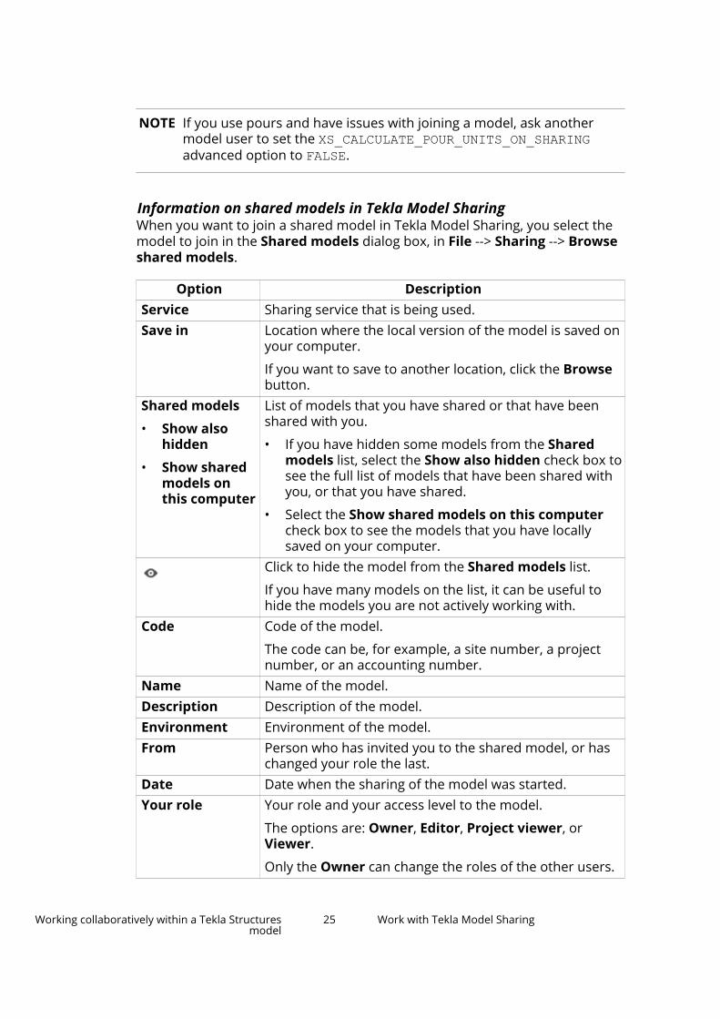
Information on shared models in Tekla Model SharingWhen you want to join a shared model in Tekla Model Sharing, you select themodel to join in the Shared models dialog box, in File --> Sharing --> Browseshared models.
Option DescriptionService Sharing service that is being used.Save in Location where the local version of the model is saved on
your computer.
If you want to save to another location, click the Browsebutton.
Shared models
• Show alsohidden
• Show sharedmodels onthis computer
List of models that you have shared or that have beenshared with you.
• If you have hidden some models from the Sharedmodels list, select the Show also hidden check box tosee the full list of models that have been shared withyou, or that you have shared.
• Select the Show shared models on this computercheck box to see the models that you have locallysaved on your computer.
Click to hide the model from the Shared models list.
If you have many models on the list, it can be useful tohide the models you are not actively working with.
Code Code of the model.
The code can be, for example, a site number, a projectnumber, or an accounting number.
Name Name of the model.Description Description of the model.Environment Environment of the model.From Person who has invited you to the shared model, or has
changed your role the last.Date Date when the sharing of the model was started.Your role Your role and your access level to the model.
The options are: Owner, Editor, Project viewer, orViewer.
Only the Owner can change the roles of the other users.
Working collaboratively within a Tekla Structuresmodel
25 Work with Tekla Model Sharing

Option DescriptionIf you are the Owner, you can edit the Code and theDescription of the model.If you are the Owner, you can invite new users to themodel, or remove existing users.
If you are the Editor, you can see which users have beeninvited or have joined the shared model.If you are the Owner, you can remove the model fromthe sharing service.
This discontinues the sharing, and the users who havebeen working with the shared model cannot sharechanges anymore.
Local copies ofselected modelon this computer
• Edited
• Model
•
•
When you select a model from the Shared models list,the model information is displayed here.
• The date when the local version of the model hasbeen edited.
• The location of the local version of the model on yourcomputer.
• Click to open the selected local version of themodel.
• Click to remove the selected local version of themodel from your computer.
Update the model with other users' changes in Tekla ModelSharing (read in)To update your model with the changes made by other users, fetch thechanges from the sharing service by reading them in. You always need to readin the most current changes to a model before you can write out your ownchanges.
You can also use the Sharing automation tool to automate read in(page 27), so that you can keep the model updated with changes made byother users of the model.
1. On the File menu, click Sharing --> Read in , or click on the QuickAccess Toolbar.
If there are available packets to read in, the Read in icon shows a greenarrow and the number of packets .
NOTE If you have been idle for over 6 hours, the number of packets maynot be shown in the Read in icon. That is why we recommend
Working collaboratively within a Tekla Structuresmodel
26 Work with Tekla Model Sharing

that after a long time of idling, you click the Read in icon toensure if any packets are available to read in.
If one of the users who shares the model has selected the Show availableupdates when reading in the changes option in the Sharing settings(page 50) dialog box, the Available updates list opens after you haveclicked the Read in icon.
The dialog box lists all the available packets. You can read in the changespacket-by-packet, if you want to check the model changes in phases. Ifyou want to receive all the updates at once, you can select the latestpacket and all the previous packets are read in as well.
When you read in, the updates to the shared model are delivered asincremental packets that only include the changed data. You need to readin all shared changes before you can write out your own changes to thesharing service again.
If you have selected the Show changes after read in option in theSharing settings (page 50) dialog box, a list of sharing changes opens atthe bottom pane after the selected packets are read in. The list shows thechanges according to how they affect the model. For more information onsharing changes, see Detect sharing changes and view the sharing historyin Tekla Model Sharing (page 36).
2. Continue working with the model.
NOTE If you have issues in read-in, ensure that the XS_CALCULATE_POUR_UNITS_ON_SHARING advanced option is set to FALSE.
NOTE If you encounter problems with sharing, check the sharing related log files inthe current model folder and in ..\Users\<user>\AppData\Local\TeklaDataSharing for troubleshooting.
If Tekla Model Sharing detects changes that should not appear in the localversion of the model after read in, Tekla Structures displays a message andthe changes are recorded in the modelsharing.log. We recommend thatyou contact your local support to solve the issue.
See also
Share your model changes in Tekla Model Sharing (page 27)
Detect sharing changes and view the sharing history in Tekla Model Sharing(page 36)
Share your model changes in Tekla Model SharingAfter you have modified your local version of the shared model, you can shareyour changes with other users who are working with the model. To share your
Working collaboratively within a Tekla Structuresmodel
27 Work with Tekla Model Sharing

changes with other users, send your changes to the sharing service by writingthem out. To ensure that other users will not write out while you are makingchanges in the model, you can reserve the next write out. You can also use theSharing automation tool to automate sharing your changes.
Write outBefore you write out your changes, you need to:
• Read in (page 26) the most current changes made to the model.
• Save the changes you have made into the model.
1. On the File menu, click Sharing --> Write out, or click on the QuickAccess Toolbar.
The Write out icon shows a green arrow when there are no packetsthat need to be read in before you can write out. You can write outchanges immediately.
The Write out icon shows a gray arrow when there are packets thatneed to be read in before you can write out changes.
When you write out, Tekla Structures saves the model, creates a packet ofthe model changes, writes out the changes to the sharing service andsaves the model again.
Only new or changed data is written out. If you attempt to write out yourchanges, but some other user has shared some changes earlier and youhave not yet read in all the available updates, you are asked to read infirst. If there is no new data to be read in, Tekla Structures writes out yourchanges to the sharing service immediately.
If one of the users who shares the model has selected the Enable writeout revision comment option in the Sharing settings (page 50) dialogbox, you can enter a code or a comment for the update that you arewriting out.
If you delete objects and share the deletion to the sharing service, thedeletion is shared with other users, and the deleted objects cannot berecovered.
2. Continue working with the model.
Note that if several users modify the same objects at the same time, themodel will contain the changes by the user who first wrote out thechanges.
Working collaboratively within a Tekla Structuresmodel
28 Work with Tekla Model Sharing

Reserve the next write out1. On the File menu, click Sharing --> Reserve next write out.
2. In the Reserve next write out dialog box, write a comment about whyyou are reserving the next write out.
3. Click Reserve.
When you have reserved the next write out, the Write out icon on the
Quick Access Toolbar shows a yellow arrow for all users of the model.Placing the mouse pointer on top of the icon shows who has reserved thenext write out and the comment written in the Reserve next write outdialog box.
Other users cannot write out while you have the next write out reserved.If another user has started writing out when you reserve the next writeout, the write out of the other user is canceled only if data transfer hasnot started yet. The other user will get a notification if the write out iscanceled.
4. To write out the changes you have made, on the File menu, click Sharing--> Write out.
Note that you may need to read in (page 26) before you can write out.
5. In the Reserve next write out dialog box, enter a comment about thechanges that you have made.
6. Click Release.
When you have written out, the arrow in the Write out icon on the Quick
Access Toolbar changes to green again . Other users can now writeout normally.
You can also release your write out reservation without writing out. To do this,on the File menu, click Sharing --> Release reservation without write out.
Note that if you do not write out or release the write out reservation within 1hour, Tekla Structures will automatically release the reservation. Anadministrator can also release the write out reservation in ManagementConsole for Tekla Model Sharing at any time.
Share your model changes automaticallyIf you want to automate sharing your model changes, you can use the Sharingautomation tool from the Applications & components catalog.
The Sharing automation tool first reads in and then tries to write out thechanges until it succeeds. The tool is useful if there are many packets to read
Working collaboratively within a Tekla Structuresmodel
29 Work with Tekla Model Sharing

in (page 26) and you want to make sure you get the write out done, or if youwant to have the packets read in when you arrive at the office.
You can also use the tool just to automate read in (page 26) to keep your localmodel updated with changes made by other users of the model. You canselect the date and set the time for the read in.
1. Click the Applications & components button in the side pane toopen the Applications & components catalog.
2. Define the settings that you want to use:
Option DescriptionWrite out now untilsuccessful
Select this option to write out your changesimmediately. Note that before writing out, the toolreads in other users' changes.
Create baseline If you are the Owner of the shared model, you canselect this option to create a baseline (page 44)when writing out.
Close Tekla Structuresafter successful writeout
Select to close Tekla Structures after write out.
Closing Tekla Structures releases licenses and mayhelp with license management.
Code Enter the code of the model, for example.Comment Enter a comment, if needed.Delayed read in at Select the date and set the time at which you want
to read in. If you have not selected Write out nowuntil successful, the tool only reads in.
If you have selected Write out now untilsuccessful, the tool first reads in and writes out,and then starts waiting to read in at the set dateand time.
Using the tool to only read in can be useful if yourlocal model has changes that you do not wish toshare but you want to get changes from others.
3. Click OK to start to tool.
See also
What is shared in Tekla Model Sharing (page 55)
Detect sharing changes and view the sharing history in Tekla Model Sharing(page 36)
Best practices in Tekla Model Sharing (page 67)
Working collaboratively within a Tekla Structuresmodel
30 Work with Tekla Model Sharing

Manage users in Tekla Model SharingUsers with the Owner role in a shared model can manage the users in thatmodel in several ways. Among other options, owners can invite new users,change user roles and permissions, send email notifications, and removeusers.
Invite new users to a shared model1. Open the shared model to which you want to invite new users.
2. On the File menu, click Sharing --> Users .
3. In the Users dialog box, type the email addresses of new users in theInvite users box, and set their user roles to either Editor, Owner, Projectviewer, or Viewer.
You can add several users at one go. Separate the email addresses withsemicolons. Do not use spaces between the email addresses.
If you add several users at one go, they all get the same user role. Theroles can be changed later.
4. Click the Add button to add the new users to the model.
5. If necessary, modify the user roles of the new users.
6. Select the Send email notification to user. check box to send anotification email to the invited users, and write a message to the users.
7. Click Save changes to invite the users.
View information on users and sharing actionWhen you want to check the Tekla Model Sharing users and the basic sharingactions on the model, or invite new users to the shared model, open the Usersdialog box in File --> Sharing --> Users.
Option DescriptionName Name of the user.Email Email address of the user.Role Role of the user: Owner, Editor, Project viewer, or Viewer.
When you start to share a model, you become the Owner ofthe model and you can set other users' roles. The roles canbe changed later, if needed.
Use the different roles to control the permissions of usersregarding the shared model.
Note that there can be more than one Owner within onemodel.
Joined Indicates whether the invited user has joined the model.
Working collaboratively within a Tekla Structuresmodel
31 Work with Tekla Model Sharing

Option DescriptionDate Date when the user has joined the model.By Person who invited the user or changed the user role the
last.Last read in Date when the user last read in.↓ Number with the arrow down indicates the total number of
update packets available in the sharing service.
The number next to the arrow indicates how many of thepackets the user has read in.
Last writeout
Date when the user last wrote out.
↑ Number with the arrow up indicates the total number ofupdate packets available in the sharing service.
The number next to the arrow indicates the number of thelast packet that the user has written out.Remove the selected user's permissions to the model.
Only users with the Owner role can remove other users fromthe sharing service.
Modify user roles in Tekla Model SharingUser roles define a user's permissions to view and modify the shared model.There are four different user roles in Tekla Model Sharing: Owner, Editor,Project viewer, and Viewer. When you start sharing your model in TeklaModel Sharing, you become the Owner of the model. The Owner can inviteother users to join in the model and give them one of the four roles.
The permissions of the four different user roles are described in the tablebelow:
Role PermissionsOwner Users with the Owner role can:
• Read in (page 27) other users' changes andwrite out (page 27) their own changes to thesharing service
• Invite new users
• List other users and change their roles
• Remove users from the model
• Remove the model instance and all the modelrelated data from the sharing service
Working collaboratively within a Tekla Structuresmodel
32 Work with Tekla Model Sharing

Role Permissions• Change the model code and description
properties
Several users can have the Owner role within onemodel. The Owner who has started to share themodel can give the Owner role to any selecteduser.
Editor Users with the Editor role can:
• Read in other users' changes and write outtheir own changes to the sharing service
• Edit the model
• List other usersProject viewer Users with the Project viewer role can:
• Read in other users' changes and write outtheir own changes to the sharing service
• View the model, but they cannot modify themodel objects
• List other users
Users with the Project viewer role cannot:
• Modify user-defined attributes that affectnumbering
• Insert and modify grids
• Import and update models that would createbeams and other objects
Note that when you open the model in theProject viewer role, restarting Tekla Structures isrequired.
The permissions of the Project viewer role in ashared model correspond with the set offunctionalities available in the Project Viewerconfiguration.
Viewer Users with the Viewer role can:
• Read in other users' changes
• View the model
Users with the Viewer role cannot:
• Write out any changes to the sharing service
• Modify the model objects
Working collaboratively within a Tekla Structuresmodel
33 Work with Tekla Model Sharing

Role Permissions• Use the export commands
Note that when you open the model in the Viewerrole, restarting Tekla Structures is required.
Note that your permission to access the shared model is removed when youdetach the model from the sharing using one the following methods:
• Exclude the model from the sharing (page 53) using the Exclude fromsharing command
• Upgrade to the next Tekla Structures version
• Use the Save as command to save the model
A user with the Owner role can change the role of a user as follows:
1. Open the shared model whose user roles you want to modify.
2. On the File menu, click Sharing --> Users .
3. In the Users dialog box, select the user whose role you want to modify.
4. Click the arrow in the Role column, and select a new role for the user inthe list.
5. If you want to send an email notification to the user whose role has beenchanged, select the Send email notification to user. check box.
6. If needed, type a short message that you want to attach to the emailnotification.
If you include a message, all the invited users and the user whose role hasbeen changed receive the same message.
7. Click Save changes.
Remove users from a shared modelUsers with the Owner role can remove unnecessary users from a sharedmodel.
1. On the File menu, click Sharing --> Users .
2. In the Users dialog box, select the user that you want to delete.
3. Click the button to remove the user's permissions to access andmodify the model.
If you clicked the button accidentally, you can click the button againto cancel removing the user's permissions.
4. Repeat steps 2 and 3 for all users that you want to remove from themodel.
5. Click Save changes to remove the users from the model.
Working collaboratively within a Tekla Structuresmodel
34 Work with Tekla Model Sharing

Export and import usersUsers with the Owner role can export the list of users in the current sharedmodel to make changes to users' roles and permissions, or to add the sameusers into another shared model.
1. On the File menu, click Sharing --> Users .
2. At the bottom of the Users dialog box, click Export users.
The list of users is saved in the users.csv file in the \ModelSharingsub-folder under the model folder. The format of the list is <emailaddress>;<role>.
3. According to your needs, do any of the following:
To Do thisChange users' roles and permissionsin the current model
a. Open the users.csv file.
b. Change user roles according toyour needs, or remove users'permissions by setting their rolesto NONE.
c. Save and close the users.csvfile.
d. Go back to the shared model.
e. To apply the changes, at thebottom of the Users dialog box,click Import users.
f. Select the users.csv file.
g. Click Open.
The changes made in the users.csv are now updated tothe current list of users.
h. To save the user changes to thecurrent model, click Savechanges.
Copy users to another shared model a. Close the current model, andopen another shared model.
b. On the File menu, click Sharing --> Users .
c. At the bottom of the Users dialogbox, click Import users.
Working collaboratively within a Tekla Structuresmodel
35 Work with Tekla Model Sharing

To Do thisd. Find and select the previous
model's users.csv file.
By default, the users.csv file issaved in the \ModelSharingsub-folder under the modelfolder.
e. Click Open.
The users in the users.csv fileare added to the current modelwith the roles defined in that file.
f. To save the user changes, clickSave changes.
Send email notificationsUsers with the Owner role can send messages to other model users via emailat any point.
1. On the File menu, click Sharing --> Users .
2. In the Users dialog box, select the Send email notification to user.check box.
3. In the message box below the Send email notification to user. checkbox, type the notification text.
4. According to your needs, do any of the following:
• To send the notification to particular users, select the users in the listof model users.
You can hold down Shift to select a range of users, or Control toselect multiple users.
• To send the message to all users, ensure that no users are selected inthe list of model users.
5. Click Send.
Detect sharing changes and view the sharing history inTekla Model SharingTo see how the model has been changing and who has shared their modelchanges, use the sharing change detection and sharing history to see whatkind of changes the model includes.
Working collaboratively within a Tekla Structuresmodel
36 Work with Tekla Model Sharing

Detect changesAfter you have either read in (page 27) the model changes from the sharingservice (page 10) or made changes in the local model, you can view thechanges that have been made in more detail. A list of changes is shown at thebottom of the screen. The changes are visualized with colors both in theChanges list and in the model.
To Do thisOpen the changeslist
Do one of the following:
• On the Quick Access Toolbar, click the Show read in
changes icon .
• Click File --> Sharing --> Show read in changes.
• To automatically show the list after each read in,select the Show changes after read in option in File--> Sharing --> Sharing settings .
View changes inthe list
• Click the separate tabs to see the changes accordingto how they affect the model.
The changes are divided to the following tabs: Physicalobjects, Other objects, Drawings, Options, Attributedefinitions, Model folder files, and UDA changes.
The changes are visualized with colors in the list.
Deleted objects are listed in the Changes list but theydo not have any information available in the Namecolumn.
The UDA changes tab includes user-defined attributesthat have a definition included in the environment.dbfile. Reference objects are detected as changed if thereare physical or material changes.
Tabs do not exist if there are no items on the tab. If thetab content becomes empty because of filtering, the tabis no longer shown.
View changes inthe model
• Select the Select objects in the model check boxand a row in the list to highlight the changed objectsin the model.
The changes are visualized with colors in the model.Deleted objects are not visualized in the model.
• Added objects = green
• Modified objects = yellow
• Conflicting objects = orange
Working collaboratively within a Tekla Structuresmodel
37 Work with Tekla Model Sharing

To Do this• Existing objects that have not been modified by
another user = gray
View changes indrawings
You can list the different versions of the same drawing inconflict situations, show their snapshots, and change thecurrent drawing version. You can also view a modifieddrawing and its snapshot, or clone drawings from othermodels.
When users modify the same drawing in their localversion of the model and one user writes out, theChanges list will show a conflict in other users' localversion of the model when they read in.
To view the versions of a drawing, do the following:
1. Select the changed drawing on the Changes list.
2. Right-click the drawing.
3. On the context menu, select Open versions.
The Drawing versions dialog box opens.
In the Drawing versions dialog box, you can select adrawing version, right-click and open the selectedversion. You can save the drawing version and write outto make the selected drawing version the currentversion for all users.
Working collaboratively within a Tekla Structuresmodel
38 Work with Tekla Model Sharing

To Do thisFilter changes inthe list
On each tab, you can filter the changes in every column.
1. Hover the mouse pointer over the column.
2.Click the filter icon next to the column name.
3. Select how you want to filter the changes.
The name of the selected filter is shown at the bottomleft corner of the list.
If you right-click the filter icon , you can, for example,sort the columns.
Edit the filter 1.Right-click the filter icon .
2. In the context menu, select Filter Editor....
The Filter editor dialog box opens. You can edit theselected filter as needed, or create a new filter.
Zoom to changedobjects in themodel
• Select the Zoom to selected check box, and click arow in the list to zoom to the changed object in themodel.
Search for specificchanges
• Type a search word to the search box on the bottomright corner of the list.
Move the Changeslist somewhereelse on the screen
You can:
• move the list around the screen
• drag the list to a second screen
• dock the list to the side pane or to the bottom of thescreen
The list has a button, , in the side pane. If you dragthe list to a second screen, click the button to return thelist to the main screen.
Add new columnsto the Changes listor bring backhidden columns
1. Right-click the column title.
2. On the context menu, select the column that youwant to add to the Changes list.
3. Hold down the left mouse button and drag thecolumn to the desired location.
4. Release the left mouse button.
Working collaboratively within a Tekla Structuresmodel
39 Work with Tekla Model Sharing

View the sharing historyAfter you have read in and written out (page 27) model changes, you can checkthe sharing history of the model. The Sharing history dialog box shows:
• All your read in and write out events
• The packets included in each read-in and write out event
• The changes that you have made to the model locally and have not yetshared
You can check the sharing history event-by-event, and see how the model hasevolved by the changes made by other users.
To Do thisOpen the sharinghistory
• On the File menu, click Sharing --> Sharing history .
Check the read inand write outevents
• To see all your read in or write out events and theirdate and time, click the Collapse all button.
Check the packetinformation
• To see all the packets in each read in or write outevent, click the Expand all button.
The packet information shows:
• The packet number
• The user who wrote out the packet
• The packet upload date and time
• The code and comment of the update that isincluded in the packet
If the comment is too long, it is not shown entirely.View the modelchanges includedin a single event
• Select the event and click the Show changes button.
A list of model changes is displayed at the bottom paneof Tekla Structures.
View the localmodel changes
To view the changes that you have made to the modelbut have not yet written out:
• Select Local non-shared changes and click theShow changes button.
A list of local model changes is displayed in the bottompane of Tekla Structures.
The Undo history dialog box lists all the commands that you have run andthe modifications that you have done in your local version of the model. TheUndo history list is cleared when you read in or write out.
Working collaboratively within a Tekla Structuresmodel
40 Work with Tekla Model Sharing

See also
What is shared in Tekla Model Sharing (page 55)
Best practices in Tekla Model Sharing (page 67)
Set object locks, drawing locks, and privileges in TeklaModel SharingYou can use object locks, drawing locks, and privileges to prevent other usersfrom accidentally modifying the shared model objects and the shareddrawings, and to control other users' access to particular attributes, files, andsettings.
Set object locksYou can lock assemblies and cast units, and model objects to preventaccidental modification and numbering of objects. This is useful when thereare multiple organizations working with the same shared model, and theorganizations want to prevent changes to the assemblies, cast units, andmodel objects that they have created.
Organization lock means that assemblies, cast units and model objects arelocked so that users who are not employees of a particular organizationcannot modify them. The assemblies, cast units and model objects are markedas locked For others in the Object locks dialog box (Manage > Locks). Werecommend that you use the Assemblies option for locking as this alsoprevents the editing of objects in the assembly.
NOTE The organization information is based on the Windows user account, not onthe Trimble Identity.
We recommend that you use the XS_OBJECTLOCK_DEFAULT advanced optionto set the default lock status to ORGANIZATION so that assemblies, cast unitsand model objects are automatically locked For others when they are created.
Set the default organization lock status
You can automatically set the default lock status for all new assemblies andcast units when they are created. Use the XS_OBJECTLOCK_DEFAULT advancedoption to set the default lock status. The default lock status can be ORGANIZATION or NO. When you start to share the model, the default lockstatus is set for all assemblies and cast units that do not have any lock statusyet.
To set the default organization lock status:
1. On the File menu, click Settings --> Advanced options --> ModelingProperties.
2. Set the XS_OBJECTLOCK_DEFAULT advanced option to ORGANIZATION.
Working collaboratively within a Tekla Structuresmodel
41 Work with Tekla Model Sharing

3. Click OK.
All new assemblies and cast units are locked for your organization, andtheir lock status in the Object locks dialog box is For others. The users inyour organization can modify the objects in the assemblies and cast units.Note that users who are not in your organization see the locked status asFor us.
Change the lock statuses
To change the lock statuses:
1. On the Manage tab, click Locks.
The Object locks dialog box opens.
2. Select the objects in the model.
You can select the objects on the assembly and cast unit level, or on themodel object level. Use the Assemblies and All object types options, andthe Sub-objects check box to define the level of selection.
3. Click the Add objects button to add the assemblies, cast units, orthe objects to the list.
Once the objects are on the list, you can check their Object type, Nameand Locked status.
4. To change the status of the locks, select the assemblies or objects in thelist or in the model, and a new lock value from the list at the bottom of thedialog box, and click Set.
The lock status is changed.
How the object locks are set What is lockedAssembly is set to Organization (theLocked status is For others) and theobjects in the assembly are set to No.
Assembly and the objects in theassembly are locked for yourorganization, and users in yourorganization can modify the assemblyor the objects in the assembly.
Users in other organizations cannotmodify the assembly or the objects inthe assembly. Assembly and theobjects in the assembly are green inthe model.
Assembly is set to Yes and the objectsin the assembly are set to No.
Assembly and the objects in theassembly are locked for all users, noone can modify the object.
Assembly and the objects in theassembly are red in the model. It isnot possible to delete, modify ornumber the assembly or the object.
Working collaboratively within a Tekla Structuresmodel
42 Work with Tekla Model Sharing

How the object locks are set What is lockedAssembly is set to No and the objectsin the assembly are set to No.
Assembly or the objects in theassembly do not have any locks,anyone can modify the objects.
Assembly and the objects in theassembly are green in the model.
If you want to clear the list, click the Reset data button .
You can use the following template fields in report templates to report thelock statuses: ASSEMBLY.OBJECT_LOCKED, ASSEMBLY.OWNER_ORGANIZATIONand ASSEMBLY.LOCK_PERMISSION.
In addition, you can use the object representation to visualize the locks. Whenyou share the object representations, other members in the project canvisually check the lock statuses.
Set drawing locksYou can lock drawings to prevent accidental modifications and to reservedrawings for editing. If a drawing is locked and the lock is shared, use asnapshot instead.
1. Read in (page 26) all the model changes.
2. Open Document manager, enable direct editing , and click the Lockcolumn next to the drawing.
The Locked by column in the Document manager shows the user whohas locked the drawing.
3. Write out (page 27) to share the drawing lock information.
4. To edit the drawing, open the drawing locks.
5. Edit the drawing as needed.
6. Write out to share the updated drawings.
The drawing can also be unlocked, unless unlocking drawings has been limitedto only particular users in the privileges.inp file. If the drawing is unlockedand a user writes out the changes they made, the changes made by theoriginal lock owner are overridden.
Set privilegesThe user who has created the model, or anyone in the same organization, cancontrol certain access rights to the model using privileges (page 112). Inpractice, the privileges of the model are controlled via the privileges.inp
Working collaboratively within a Tekla Structuresmodel
43 Work with Tekla Model Sharing

file. All users can change the status of locks unless the access rights are limitedin the privileges.inp.
By modifying the privileges.inp file, you can control the access to:
• modify user-defined attributes (page 112)
• modify numbering settings (page 112)
• save standard files (page 112)
To change the access rights:
1. Close the model.
2. Open the privileges.inp file in any text editor.
The privileges.inp file is usually found under the ..\ProgramData\Trimble\Tekla Structures\<version>\environments\<environment>\ folder. The exact file location may vary depending onthe folder structure of your environment files.
3. Change the desired settings and save the privileges.inp file to yourmodel folder.
4. Re-open the model.
5. Write out (page 27) to share the privileges information.
See also
Share a model in Tekla Model Sharing (page 21)
Create a baseline for a model in Tekla Model SharingIf you are the Owner of a model in Tekla Model Sharing, and you want to keepa record of the current progress in the model or you want to make the modelfaster to join for a new user, you can create a new starting point for the modelin the sharing service. This new starting point is a baseline. Baseline is asnapshot of the current state of the model. When you create a baseline, a fullmodel is created and uploaded to the sharing service. We recommend that theOwner creates a new baseline when a new user has been invited to themodel. Existing users do not need to re-join the model after a new baselinehas been created.
1. On the File menu, click Sharing --> Create baseline .
2. Enter a code or a comment, if entering revision comments has beenenabled in the Sharing settings (page 50) dialog box.
Working collaboratively within a Tekla Structuresmodel
44 Work with Tekla Model Sharing

A full model is written out (page 27) to the sharing service. Files andfolders that have been excluded from the sharing are not included in thebaseline.
If you need to read in while you are creating the baseline, you need torepeat the Create baseline command after you have read in other users'changes.
If you make changes in the model before creating the baseline, anincremental update packet is created before the baseline. This ensuresthat no model data is lost and that the users of the shared model do notneed to join the model again.
3. If needed: Invite someone to join (page 23) the model.
When the new user joins the model, the Available updates list opens.
The user can then select a baseline or an update to join. The Availableupdates list shows all the baselines and the updates after the latestbaseline. You can select any baseline or update to join, not only the latest.By joining an earlier baseline or update you can go back in the modelhistory, and, for example, check the model state on a certain date.
Joining a baseline is beneficial for users who join the model when therealready are many changes made. Joining a baseline instead of an updateis also faster.
After joining a model, only incremental update packets are read in fromthe sharing service (page 10).
TIP You can also create a baseline using the Sharing automation tool(page 29) from the Applications & components catalog.
See also
Share a model in Tekla Model Sharing (page 21)
Collect model history in Tekla Model SharingIn Tekla Model Sharing, you can collect model history information on theactions made in a model. The model history of a shared model shows whenthe model has been changed, how the model has changed, and who has madethe changes.
Collect model history in Tekla Model SharingTo start collecting model history, do the following:
1. On the File menu, click Settings --> Advanced options --> Speed andAccuracy .
Working collaboratively within a Tekla Structuresmodel
45 Work with Tekla Model Sharing

2. Ensure that XS_COLLECT_MODEL_HISTORY is set to TRUE.
Tekla Structures automatically sets XS_COLLECT_MODEL_HISTORY to TRUEwhen a model is shared.
3. Set XS_CLEAR_MODEL_HISTORY to FALSE.
4. Click OK.
5. To view model history, do one of the following:
• On the ribbon, click and select an object in the model.
The model history is shown in the Inquire object dialog box.
If the Enable write out revision comment option has been selectedin the Sharing settings dialog box, the revision comments aredisplayed as well.
• Create a model history report.
a. On the Drawings & reports tab, click Reports.
b. Select a report template that shows the model history.
The name of the report template may vary in differentenvironments. In the Default environment, the report template iscalled Q_Model_History_Report.
c. Click Create from all to create a report on all the objects in themodel, or select one or more objects in the model and clickCreate from selected to create a report from the selectedobjects.
Offline usage history is stored according to the Windows domain user account.Note that in Tekla Model Sharing models, when you write out your changes tothe sharing service, the changes are stored using your Trimble Identity.
Clear model history in Tekla Model SharingClearing the model history of a shared model can improve the performance ofa large shared model in Tekla Model Sharing and save disc space. Note that ifyou clear the model history, the model history information can no longer beused in the Tekla Structures user interface, reports, or Tekla Open API.
Before you clear model history, ensure that:
• The information stored in the model history is no longer needed.
• All users in the shared model have written out all their changes.
• You are the only user currently working on the shared model. Werecommend that you delete the model history at a quiet time, such asduring the weekend.
Working collaboratively within a Tekla Structuresmodel
46 Work with Tekla Model Sharing

NOTE Do not delete the history.db file in order to clear the history of ashared model. The history.db file is incrementally shared, anddeleting the file can cause errors in the shared model.
1. Open the shared model whose history you want to delete.
2. On the File menu, click Sharing --> Reserve next write out .
3. In the Reserve next write out dialog box, write a comment about whyyou are reserving the next write out.
4. Click Reserve.
5. On the File menu, click Settings --> Advanced options --> Speed andAccuracy .
6. In the Advanced Options dialog box, set the XS_CLEAR_MODEL_HISTORYoption to TRUE.
7. Click OK.
8. Save the model.
9. Restart Tekla Structures.
10. Open the model folder and ensure that the size of the history.db filehas been reduced.
11. Write out (page 27) the baseline.
Other users should now join the new baseline (page 23) you have written out.
Use XS_FIRM and XS_PROJECT folders with Tekla ModelSharingUsing project folders and firm folders in shared models is the easiest whenyou use a sub-folder in a Trimble Connect project as the project or firm folder.
The project and firm folder information is only updated from the TrimbleConnect project to local versions of the shared models, not vice versa. Inpractice, this means that Tekla Structures downloads new files from theproject or film folder to the local model and updates any changed files. If alocal file is not stored in the Trimble Connect project sub-folder, the file isremoved from the local model.
When Tekla Structures detects a change between the local model data and thedata in the Trimble Connect project or firm folder, you get the followingnotification:
Working collaboratively within a Tekla Structuresmodel
47 Work with Tekla Model Sharing

If you click Yes, the model is saved and closed. Then, the local model data isupdated and re-opened.
Note that files that are generated when macros are compiled (cs.dlland .cs.pdb) are ignored from the folder sync operation. Thus, addition ofthese two files in the local folder will not trigger an update.
To set a folder in a Trimble Connect project as the XS_FIRM or the XS_PROJECT folder:
1. On the File menu, go to Settings --> Advanced options.
2. Depending on the option, do one of the following:
To set a TrimbleConnect project sub-
folder as
Do this
The XS_PROJECT folder a. In the Advanced Options dialog box, find theXS_PROJECT option.
b. Set the value of XS_PROJECT to%CONNECT_FOLDER_SYNC%.
%CONNECT_FOLDER_SYNC% points to :\Users\<user>\AppData\Local\Trimble\Teklafolder sync\<folder>
NOTE If you use the same Trimble Connectproject as the XS_PROJECT folder andfor collaboration, you need to use asub-folder that is separated from theTrimble Connect collaborationinformation as the XS_PROJECTfolder. In this case, the sub-folder isset to %CONNECT_FOLDER_SYNC%\<folder>\<sub-folder of thefolder>.
For example, you could save theproject folder under the Project
Working collaboratively within a Tekla Structuresmodel
48 Work with Tekla Model Sharing

To set a TrimbleConnect project sub-
folder as
Do this
settings folder with the nameProject. In this case, the valueshould be set to%CONNECT_FOLDER_SYNC%\ProjectSettings\Project. You can alsouser lower level sub-folders.
The XS_FIRM folder a. In the Advanced Options dialog box, find theXS_FIRM option.
b. Set the value of XS_FIRM to%CONNECT_FOLDER_SYNC%\<ProjectID><region>.
Note that no separator is needed between theproject ID and the region.
You can see the project ID in Trimble Connectfor Browser:
The region is the same as the project serverlocation setting. The options are:
• asia
• europe
• northAmerica
So, for example, the value could be%CONNECT_FOLDER_SYNC%\m1G-M21Ca_onorthAmerica.
NOTE If you use the same Trimble Connectproject as the XS_FIRM folder and forcollaboration, you need to use a sub-folder that is separated from theTrimble Connect collaborationinformation as the XS_FIRM folder. Inthis case, the sub-folder is set to%CONNECT_FOLDER_SYNC%
Working collaboratively within a Tekla Structuresmodel
49 Work with Tekla Model Sharing

To set a TrimbleConnect project sub-
folder as
Do this
\<ProjectID><region>\<folder>\<sub-folder of the folder>.
For example, you could save theproject folder under the Projectsettings folder with the nameProject. In this case, the valueshould be set to%CONNECT_FOLDER_SYNC%\m1G-M21Ca_onorthAmerica\ProjectSettings\Project. You can alsouser lower level sub-folders.
3. Click OK to save the project or firm folder.
4. Close and re-open the model to take the new firm or project folder intouse.
Tekla Model Sharing settingsTo modify the basic Tekla Model Sharing settings, use the options in theSharing settings dialog box in File --> Sharing --> Sharing settings.
Option DescriptionModel folder filesharing
Click the Exclude button to define files or foldersthat you do not want to share (page 55).
• Tekla Model Sharingcache
• Name and Port
You can set up a separate Tekla Model SharingCache service (page 67) to be used with the TeklaModel Sharing service. With the Tekla ModelSharing Cache service, the model data is stored tothe sharing service and then cached inside a LAN.This set-up is useful especially if there are severalTekla Model Sharing users in the same location, ora narrow bandwidth to the Internet. Using a cachereduces the download effort.
The first user who reads in a packet from thesharing service loads it to the cache, and the nextuser gets the data faster from the cache inside theLAN than from the sharing service through theInternet. The cache is not used for packets thatare written out.
Working collaboratively within a Tekla Structuresmodel
50 Work with Tekla Model Sharing

Option Description• Name is the name of the computer on which
the cache is installed.
To check the computer name, click WindowsControl Panel --> System and Security -->System .
• Port is the cache service port number that youhave set when you installed the cache service.
The default value is 9998.
• Click the Set button to connect to the cache.
• Alternatively, you can set the advanced optionXS_CLOUD_SHARING_PROXY to ”name of theserver”;”port” in a .ini file. This advancedoption is user-specific.
To reset the cache settings in the dialog box tothe ones defined in the .ini file, click theReset button. If any .ini file has the advancedoption defined, the settings appear in thedialog box.
Show available updateswhen joining the model
Select the check box to enable a list that shows allthe available baselines and updates (page 44)when you join the model.
The Available updates list shows all the baselinesand the updates after the latest baseline. You canselect any of the available baselines or updates tojoin, not only the latest. By joining an earlierbaseline or update you can go back in the modelhistory, and, for example, check the model stateon a certain date.
Alternatively, you can set the advanced option XS_SHARING_JOIN_SHOW_AVAILABLE_UPDATES to TRUE in a .ini file to enable the showing ofupdates. This advanced option is user-specific.
Show available updateswhen reading in thechanges
Select the check box to enable a list that shows allthe available updates (page 27) when you read inthe model changes.
The Available updates list shows all the availableupdates. You can select any of the availableupdates to be read in, not only the latest. Byreading in an earlier update you can go back in the
Working collaboratively within a Tekla Structuresmodel
51 Work with Tekla Model Sharing

Option Descriptionmodel history, and, for example, check the modelstate on a certain date.
Alternatively, you can set the advanced option XS_SHARING_READIN_SHOW_AVAILABLE_VERSIONS to TRUE in a .ini file to enable the showing ofupdates. This advanced option is user-specific.
• Show changes afterread in
• Only when conflictsexist
Select the check box to enable a list that shows themodel changes (page 27) after you have read in. Ifyou select the Only when conflicts exist option,the list is shown only when there are conflicts inthe model after read in.
Alternatively, you can set the advanced optionsXS_SHARING_READIN_SHOW_CHANGEMANAGERand XS_SHARING_READIN_SHOW_CHANGEMANAGER_CONFLICTSONLY to TRUE ina .ini file to enable the showing of modelchanges. These advanced options are user-specific.
Enable write outrevision comment
Select the check box to enable the entering ofrevision comments.
When you write out, you can enter a revisioncomment and code in the comment dialog box. Ifyou enable the revision comments, the commentdialog box is displayed for all the model users.
Alternatively, you can set the advanced option XS_SAVE_WITH_COMMENT to TRUE in .ini files toenable the revision comment. This advancedoption is model-specific.
• Copy project folderfiles to model folder
• Copy firm folderfiles to model folder
• Overwrite modelfolder files
If you have stored files, such as property files,report templates (.rpt), or graphical templates(.tpl) in a project folder or a firm folder, or theirdesignated sub-folders, you can copy the files tothe model folder. Files that are placed to themodel folder are synchronized by Tekla ModelSharing. This means that by having copies of thefiles in the model folder, you can ensure that thefiles are shared and synchronized appropriately.
Select whether the project or the firm folder filesare copied to the model folder that you are goingto share. Select the check boxes and click theCopy files button. We recommend that you copyfiles from the project and firm folders.
Working collaboratively within a Tekla Structuresmodel
52 Work with Tekla Model Sharing

Option DescriptionYou can also select whether the copied project orfirm folder files replace the existing files of thesame name in the model folder.
Individual files can be copied to the model folderat any time. The next time you write out, the filesare shared to all model users.
See also
Best practices in Tekla Model Sharing (page 67)
Exclude a model from the sharing service in Tekla ModelSharingIf needed, you can exclude yourself and your local version of the model fromthe sharing service.
When you exclude a model, your local version of the model is no longerconnected to the sharing service and you cannot share your changesanymore. However, the model instance still exists in the sharing service andother users can continue working with the model normally.
NOTE After you have excluded your local version of the model from thesharing service, you cannot merge the excluded model back to theoriginal shared model. The excluded model is completely new and ithas no connection to the model in the sharing service.
All users, regardless of their user role (page 21) (Owner, Editor, Projectviewer, Viewer), can exclude their local version of the model from the sharingservice.
1. On the File menu, click Sharing --> Exclude from sharing .
A confirmation message is displayed.
2. Click Continue.
Your local version of the model is disconnected from the sharing service,and you cannot write out or read in (page 27) changes anymore.
The model automatically becomes a single-user model.
After you have excluded your local version of the model from the sharingservice you can
• continue working with the model in single-user mode.
• start working with the model in multi-user mode (page 54).
• start working with the model again in Tekla Model Sharing.
Working collaboratively within a Tekla Structuresmodel
53 Work with Tekla Model Sharing

If you would like to start working again with the excluded model in TeklaModel Sharing, you can either
• start sharing (page 21) the model and invite other users to join the model.
If you start to share the model, the model is completely new and it has noconnection to the previous model in the sharing service, even though themodel retains its old name.
• join (page 23) the same model again in the Shared models dialog box inFile --> Sharing --> Browse shared models.
When you join the model, you can select a baseline or an update (page 44)to join.
If you join the model again, you need to save a new local version of themodel on your computer. If you do not change the name of the model, youmay have several models that have the same name in the Shared modelsdialog box. All these local versions of the model need to be saved indifferent locations on your computer, because you cannot have two ormore models of the same name in the same folder.
Convert a shared model to a multi-user model in TeklaModel SharingIf needed, you can stop working with a shared model in Tekla Model Sharingand convert your local version of the model to a multi-user model.
A model cannot be simultaneously shared and used in multi-user mode(page 96). If you want to start using multi-user mode as a means to shareyour model instead of Tekla Model Sharing, you need to first exclude yourlocal version of the model from the sharing service and then convert it to amulti-user model.
NOTE The excluded model has no connection to the original shared modelin the sharing service. This means that if you exclude your localversion of the model from the sharing service and start to use themodel in multi-user mode, you cannot later merge the original sharedmodel and the multi-user model.
1. Exclude your local version of the shared model from the sharing service tomake it a single-user model:
a. Open the shared model that you want to convert to a multi-usermodel.
b. On the File menu, click Sharing --> Exclude from sharing .
A confirmation message is displayed.
c. Click Continue.
Working collaboratively within a Tekla Structuresmodel
54 Work with Tekla Model Sharing

The model automatically becomes a single-user model.
Your local version of the model is disconnected from the sharingservice, and you cannot write out or read in changes anymore.However, the model instance still exists in the sharing service andother users can continue working with the model normally.
2. Convert the current single-user model to a multi-user model:
a. On the File menu, click Sharing --> Convert to a multi-user model.
b. Enter the multi-user server name or select the name from the list inthe Convert to multi-user model dialog box.
c. Click Convert.
The current model is converted to a multi-user model and you canstart using the model in multi-user mode.
See also
Share a model in Tekla Model Sharing (page 21)
1.3 What is shared in Tekla Model SharingBy default, all the model data is shared when you share a model in TeklaModel Sharing.
How data is shared in Tekla Model Sharing depends on the type of the shareddata.
• Some data is shared incrementally.
This means that only the new and changed data is shared. When you readin, the data that is fetched from the sharing service is merged to the dataon your computer.
NOTE You cannot remove or replace incrementally shared databases.The compatibility of incrementally shared databases is checkedwhen the model is opened.
• Some data is shared, but it cannot be updated incrementally.
When you read in, the data that is fetched from the sharing serviceoverwrites the data on your computer.
• Some data is not shared.
• Empty folders under the model folder are not shared.
• By default, Organizer data is not shared.
However, you can use the Organizer import and export with TeklaModel Sharing to share Organizer changes.
Working collaboratively within a Tekla Structuresmodel
55 What is shared in Tekla Model Sharing

• Backup copies of the model database, or .bak files, are not shared.
NOTE Some of the catalog files that are located in the environment folders(rebar_database.inp, assdb.db, screwdb.db, matdb.bin, profdb.bin)are copied to the model folder when the sharing is started.
How data is sharedIf you want to check the files that have been overwritten when you read in,click File --> Sharing --> Open file backup folder to open the\ModelSharing\BackUpEnv folder under the model folder. The foldercontains overwritten files from the three latest read ins. You can then, forexample, copy the files back to your model or check the files for changedetection.
NOTE We recommend that you do not remove or replace any databases. If youremove or replace a database, you must create a new baseline of the model.All other users must then join this new baseline, and then continue reading inpackets.
Databases
DescriptionModel database Model database .db1 is shared incrementally.Numberingdatabase
Numbering database .db2 is shared, but it cannot beupdated incrementally.
If you have modified the family numbering settings andyou read in, you lose the changes if another user haschanged the family numbering settings and has writtenout.
NOTE We recommend that one user updates andshares the numbering settings with other usersby writing them out. In case the user needs toread in before writing out the numberingupdates, it is important to check that thesettings are as they were before starting toshare them.
We recommend you to use the Number seriesof selected objects command on theDrawings & reports tab when numbering.
Create your model output, such as drawings, reports,NC files and IFC files, after a successful write out.
Working collaboratively within a Tekla Structuresmodel
56 What is shared in Tekla Model Sharing

DescriptionModel historydatabase
Model history database history.db is sharedincrementally.
Plan database Plan databases .db3 are shared, but they cannot beupdated incrementally.
If you have imported a CIS/2 or a SDNF model and youread in, you lose the plan database changes if anotheruser has imported the same CIS/2 or SDNF model andhas written out.
Analysis modeldatabase
Analysis model database .db6 and analysis resultsmodel database .db5 are shared, but they cannot beupdated incrementally.
If you have modified an analysis model and you read in,you lose the analysis model changes if another userhas changed the same analysis model and has writtenout.
Customcomponents andsketched profiles
Custom components and sketched profiles databasexslib.db1 is shared incrementally.
Standard-partmodel database
Standard-part model .db1 is shared when you save thestandard-part model in a separate folder under themodel folder.
Ensure that XS_STD_PART_MODEL is set relative to themodel folder and that it points to the correct standard-part model, for example, XS_STD_PART_MODEL=.\StandardParts\.
Catalogs
DescriptionProfile catalog Shared model contains the profile catalog file
profdb.bin.
When you add and use a new profile definition in theshared model, the definition is shared the next timeyou write out. When another user reads in this newdefinition, the profdb.bin file in the user's modelfolder is updated to include the added definition.
You can also update (page 61) the profile catalog withnew definitions without creating any new objects orchange the existing profile definitions of a profile thatis already used in the model. For more information, seethe 'How to share catalog updates' section below.
Working collaboratively within a Tekla Structuresmodel
57 What is shared in Tekla Model Sharing

DescriptionRebar catalog Shared model contains the rebar catalog file
rebar_database.inp.
When you add and use a new rebar definition in theshared model, the definition is shared the next timeyou write out. When another user reads in this newdefinition, the rebar_database.inp file in the user'smodel folder is updated to include the addeddefinition.
You can also update the rebar catalog with newdefinitions without creating any new objects. For moreinformation, see the 'How to share catalog updates'section below.
Bolt catalog
Bolt assemblycatalog
Shared model contains the bolt catalog filescrewdb.db and the bolt assembly catalog fileassdb.db.
When you add and use a new bolt definition or boltassembly definition in the shared model, the definitionis shared the next time you write out. When anotheruser reads in this new definition, the screwdb.db andassdb.db files in the user's model folder are updatedto include the added definition.
You can also update the bolt catalog and bolt assemblycatalog with new definitions without creating any newobjects. For more information, see the 'How to sharecatalog updates' section below.
Material catalog Shared model contains the material catalog filematdb.bin.
When you add and use a new material definition in theshared model, the definition is shared the next timeyou write out. When another user reads in this newdefinition, the matdb.bin file in the user's modelfolder is updated to include the added definition.
You can also update the material catalog with newdefinitions without creating any new objects. For moreinformation, see the 'How to share catalog updates'section below.
UDAs, options, views, pour units
DesriptionUser-definedattribute (UDA)definitions
When a model is created, the user-defined attributedefinitions are read from the objects.inp files andthe definitions are stored to the environment.db
Working collaboratively within a Tekla Structuresmodel
58 What is shared in Tekla Model Sharing

Desriptiondatabase. Modified and added new attributedefinitions are shared incrementally.
New attribute definitions are added to the databaseautomatically when the model is opened. If the currentobjects.inp file has a different definition than theenvironment.db, it is possible to take changes to useby clicking File --> Diagnose & repair --> Diagnoseand change attribute definitions .
If the objects.inp file is in the model folder, it isshared as a file and it overrides the local objects.inpfile when you read in.
Options When a model is created, the options are read fromthe options.ini files and the model-specific optionsare stored to options_model.db andoptions_drawings.db databases.
Model-specific options can be modified using theOptions and Advanced Options dialog boxes.Modifications to model-specific options are sharedincrementally.
• Some of the options are of the type SYSTEM(ROLE).These options are read from the .ini files and arenot shared. It is possible to change SYSTEM(ROLE)model option to MODEL(ROLE) option and thedrawing option to DRAWINGS(ROLE) option. Theoptions are then stored to the options_model.dbor options_drawings.db databases in the modelfolder, and the value is shared incrementally.
• Some of the options are of the type USER. Theseoptions are user-specific and they are not shared.
• Some of the options are of the type SYSTEM. Theseoptions are user-specific and they are not shared. Itis possible to change a SYSTEM option to aMODEL(SYSTEM) option. If you change a SYSTEMoption to MODEL(SYSTEM), the changed value onlyworks for the current model. These options are notshared.
Other importantfiles in the modelfolder
The database ID range mapper file db.idrm and thelibrary database ID range mapper file xslib.idrm arerelated to the handling of IDs. These files are needed,for example, to open drawings that have been createdin single-user or multi-user modes.
The plotdev.bin file contains the print devicedefinitions that you create in Printer Catalog (old
Working collaboratively within a Tekla Structuresmodel
59 What is shared in Tekla Model Sharing

Desriptionprinting). The file is shared when located in the modelfolder.
NOTE If your project has users that work in differentoffices and with different printers, you shouldnot save any local changes to theplotdev.bin file in the model folder. Save thelocal changes in the XS FIRM folder instead.
View sharing By default, views are not shared. Views are shared ifthey have a name, and the Share option in the ViewProperties dialog box is set to Shared.
Note that when you join a model, you get all the modelviews but changes to the views are not shared if theShare option is set to Not shared.
Pour unitinformation
Automatic assignments of objects to pour units are notshared. The Calculate pour units command has to berun in the local versions of the shared model to updatethe pour units.
When XS_CALCULATE_POUR_UNITS_ON_SHARING is setto FALSE (which is the default value), each user has torun the Calculate pour units command in their localversion of the shared model to update the pour units.
If XS_CALCULATE_POUR_UNITS_ON_SHARING is set to TRUE, Tekla Structures automatically calculates andupdates the pour units during writing out and readingin.
Manual assignments created by using the Add to pourunit and Remove from pour unit commands areshared.
Exclude files and folders from Tekla Model SharingBy default, files and sub-folders in the model folder, and in firm and projectfolders, are shared when you share a model in Tekla Model Sharing. If you donot want to share all of the files or sub-folders, you can select to exclude someof them from sharing.
NOTE Tekla Model Sharing works only if the model is the same for all users.Tekla Structures takes care of model-specific data sharing. You canonly exclude files that do not have an effect on the model. You cannot
Working collaboratively within a Tekla Structuresmodel
60 What is shared in Tekla Model Sharing

exclude any of the databases that are in the model folder, xslib.db1,for example.
Empty sub-folders under the model folder and some files areexcluded automatically.
1. On the File menu, click Sharing --> Sharing settings .
The Sharing settings dialog box opens.
2. Click the Exclude button to see which files and folders are excluded fromsharing, and to exclude more files or folders.
Some files and folders are excluded automatically from sharing. Thesefiles and folders appear on the Excluded model folder files anddirectories list, and they cannot be removed from the list.
a. If you want to exclude more folders or files, click the Directory or theFile button.
b. Select the folder or the file to be excluded.
The excluded folders and files are added to the Excluded modelfolder files and directories list.
If you exclude a folder, all its sub-folders and sub-files are alsoexcluded from Tekla Model Sharing.
You can exclude files in several ways. For example, if you have a filecalled TeklaStructures.bbb, and you use the following settings toexclude the files:
Option Description(x.x) TeklaStructures.bbb is excluded from sharing.(x.*) All the files with TeklaStructures. are excluded from sharing.(*.x) All the files with .bbb are excluded from sharing.(*.*) All the files from that folder, but not from its sub-folders, are
excluded from sharing.
c. If you want to remove the added folders or files from the list ofexcluded files, click Remove.
You cannot remove a folder or a file that has been excludedautomatically.
3. Click OK when you have finished selecting the excluded files.
How to share catalog updatesSometimes you may need to update catalogs with new definitions, such asnew profiles, and share the changes without creating any objects with the newdefinitions.
Working collaboratively within a Tekla Structuresmodel
61 What is shared in Tekla Model Sharing

1. Ensure that all users on the shared model write out (page 27) theirchanges.
2. Read in (page 27) all the model changes.
3. Update the needed catalogs.
4. Create a new baseline (page 44).
5. Ensure that all users join (page 23) the created baseline.
After users have joined the baseline:
a. Ensure that users check that their settings for excluded files andfolders are up-to-date in File --> Sharing --> Sharing settings -->Exclude, or that they copy the FileSharing.ini file from theprevious local version of the model in ..\TeklaStructuresModels\<model>\ModelSharing\Settings.
b. Ensure that users remove their previous local versions of the model.
How to share Organizer dataBy default, Organizer data is not shared. However, you can use the Organizerimport and export with Tekla Model Sharing to share Organizer changes.
1. Select a user who is responsible for the Organizer data. This is User A.
2. User A creates the Organizer data and exports the data to a modelsubfolder.
Note that the selected folder cannot be the default ProjectOrganizerfolder.
3. User A writes out (page 27).
4. User B reads in (page 27) and notices that there is new data available.
5. User B opens Organizer and imports the data that User A has exported.
6. User B removes the old Organizer data and saves the model.
7. User A updates the Organizer data, exports the update and writes out.
8. User B reads in and imports the updated data to Organizer.
The data appears as new in Organizer. User B removes the old data.
How different object types work in shared modelsWhen several users modify the model at the same time in Tekla ModelSharing, conflicts may occur.
In general, all object types work similarly in Tekla Model Sharing. When youread in, the changes in the incoming packet override your local changes to the
Working collaboratively within a Tekla Structuresmodel
62 What is shared in Tekla Model Sharing

same object. In other words, if several users modify the same object, the userwho first writes out the changes to the sharing service wins in conflicts.
Before you start to share models, agree on common ways of working. Forexample, you can agree that users work on different areas of the model.
Object / Property DescriptionModel objects A shared modification to an object property
overrides any other object property modification.
For example, one user modifies a beam profile andwrites out. Another user has modified the materialof the same beam and reads in. The user whomodified the beam material loses the changes,because the shared changes override the localchanges to the same object.
Family numbering Check the family numbering settings.
Family numbering settings are shared but cannot beincrementally updated. We recommend that oneuser first reads in all the packets, makes the updatesand then shares the settings by writing them out. Ifthe user needs to read in before writing out, it isimportant to check that the settings are as they werebefore starting to share them.
Give start numbers in wide ranges so that you do notrun out of numbers within a numbering series, andthat any numbering series does not overlap withanother.
We recommend you to use the Number series ofselected objects command on the Drawings &reports tab when numbering.
Grids If there is a conflict in sharing grids, grids arerecreated using the original values that have beenset in the grid properties. Any manually added gridlines are lost.
For example, when two users modify a grid byadding extra grid lines and write out, the added gridlines disappear from the model when they read in.
Catalogs Check the catalogs so that they include all theneeded definitions.
Starting from Tekla Structures 2018, the shapegeometry files that are in .xml format areautomatically converted to .tez format in sharedmodels.
Working collaboratively within a Tekla Structuresmodel
63 What is shared in Tekla Model Sharing

Object / Property DescriptionUser-definedattributes (UDAs)
A shared change to a user-defined attribute (UDA)overrides changes to the same UDA only.
For example, a change in the Comment UDAoverrides a change to the Comment UDA but not tothe Shorten UDA.
A shared change to a part does not override UDAchanges and vice versa.
Part and the relatedcomponent
A shared change to a part does not overridecomponent changes and vice versa.
Custom components If a user deletes a custom component from theApplications & components catalog in the localversion of the shared model, reading in causes aninstance of the custom component to appear in themodel even if the component was not used in themodel.
You cannot edit the component instance in themodel. If you need to edit the component, explode itfirst.
Drawings There can be duplicate drawings from the same part.
For example, two users create drawings from thesame part when they are working on their localversions of the shared model. When both users writeout their changes, two drawings appear inDocument manager. Tekla Structures does notdelete either of the drawings, and it does not mergethe changes from the drawings. You need to visuallycheck the drawings and decide which drawing todelete, or to use drawing locks (page 41) to preventother users modifying the drawings.
Pours Agree whether pour management will be used in themodel and set XS_ENABLE_POUR_MANAGEMENTaccordingly.
If pour management is enabled in the model, do notdisable it using XS_ENABLE_POUR_MANAGEMENT,especially in the middle of the project. This maycause problems if you have drawings containingpour objects, and if you are sharing your model. Thepour objects and pour breaks in the model and inthe drawings may get invalid, and you may lose allpour-related modeling work.
Automatic assignments of objects to pour units arenot shared. The Calculate pour units command hasto be run to update the pour units.
Working collaboratively within a Tekla Structuresmodel
64 What is shared in Tekla Model Sharing

Object / Property Description• If XS_CALCULATE_POUR_UNITS_ON_SHARING is
set to FALSE (which is the default value), eachuser has to run the Calculate pour unitscommand in their local version of the sharedmodel when they need up-to-date pour unitinformation.
For example, user 1 moves a reinforcing bar sothat it touches a pour object, runs the Calculatepour units command to add the bar to the pourunit, and writes out. When user 2 reads in, user 2sees that the reinforcing bar has been moved,but the bar has not been added to the pour unit.
• If XS_CALCULATE_POUR_UNITS_ON_SHARING isset to TRUE, Tekla Structures automaticallycalculates and updates the pour units duringwriting out and reading in.
Manual assignments, and other modifications topour objects and to the objects attached to the pourobjects (such as changes to geometry or location),are shared. A shared manual change in pour unitassignment overrides a local change.
For example, user 1 adds an embed to a pour unit byusing the Add to pour unit command, and writesout. User 2 has added the same embed to anotherpour unit by using the Add to pour unit command.When user 2 reads in, user 2 sees that the embedhas been added to the pour unit user 1 added it to.
Standard files fornumbering setup
Standard files for numbering setup are not loadedautomatically when you read in. If you want to takethem in to use, you need to reload them afterreading in.
WARNING If an object deletion has been written out to the sharing service, theobject will be deleted in your model when you read in. This happensregardless of whether you have modified the object before reading in.Deleted objects remain deleted if the deletion has been shared.
Deleted objects are not visualized when you read in.
How property files in the XS_FIRM and the XS_PROJECTfolders are sharedYou can store property files in user-defined sub-folders under the firm orproject folders. The property files are copied and shared in Tekla Model
Working collaboratively within a Tekla Structuresmodel
65 What is shared in Tekla Model Sharing

Sharing in two situations: when you start sharing a model, or when you have ashared model open and click the Copy files button in the Sharing settingsdialog box.
Property files are copied and shared from the following folders:
1. The \attributes folder under the model folder.
2. The user-defined sub-folders under the XS_PROJECT folder.
If the XS_PROJECT folder is empty, Tekla Structures skips it when copyingfiles.
3. The user-defined sub-folders under the XS_FIRM folder.
If the XS_FIRM folder is empty, Tekla Structures skips it when copyingfiles.
4. The sub-folders of the environment folder.
The folders are searched in the order they are listed above. When TeklaStructures finds the first corresponding file, that file is selected. Othercorresponding files are ignored, and the file names are stored in the error log.
Note that if the following folders are immediate sub-folders of project or firmfolders, Tekla Structures does not read property files from the folders:
• ProjectOrganizerData• ProjectOrganizerData\DefaultCategoryTrees• ProjectOrganizerData\PropertyTemplates• ProjectOrganizerData\ExcelTemplates
• AdditionalPSets• macros
• macros\drawings• macros\modeling
• Drawing Details• CustomInquiry• PropertyRepository\Templates• symbols• template
• template\mark• template\settings• template\tooltips
• profil• profil\ShapeGeometries
Working collaboratively within a Tekla Structuresmodel
66 What is shared in Tekla Model Sharing

• profil\Shapes
1.4 Best practices in Tekla Model SharingTo keep your shared models in good shape and to share your changessuccessfully, follow the Tekla Model Sharing best practices below.
NOTE The users of the same shared model need to have the same TeklaStructures version, and use the same latest service pack.
For general Tekla Model Sharing troubleshooting instructions, seeTroubleshooting Tekla Model Sharing.
Use GUIDs correctly in shared modelsTekla Structures objects have an identifier that is shown as an object GUID,Globally Unique Identifier, that is also used in Tekla Model Sharing.
This means that features that do not use GUIDs need to be changed to useGUIDs:
• Interoperability import/export actions:
• FabTrol XML
• ASCII
• All other applications, macros and report processes that rely on static IDs.
Save local versions of shared models on your computerWe recommend that you save the local versions of shared models on yourcomputer instead of a network drive for two main reasons:
• The performance of shared models is better when the local models aresaved on your own computer. This means that the models open faster, forexample.
• Saving shared models on your own computer prevents other users fromaccessing them and accidentally blocking important files.
If you still want to save local models on a network drive, use a private networkdrive that other users cannot access.
Working collaboratively within a Tekla Structuresmodel
67 Best practices in Tekla Model Sharing

Create baselines regularlyThe Owner of a model should create baselines of the model regularly. Forexample, you can create a baseline once a week.
We recommend creating a new baseline each time a new user has beeninvited to the model. This way, joining the shared model is faster.
Back up shared modelsWe recommend you to back up the models used in Tekla Model Sharing. Incase there are problems with a shared model, it is possible to select any user'slocal version of the model, or a model that has been backed up, and continueworking using that model. Make sure that you have the complete backed upmodel in use and that the model folder includes, for example, drawings anddifferent databases. This ensures that the model functions properly and youdo not lose any data. If the backed up version of the model is old, reading in allthe changes may take some time.
Back up your models according to your company conventions, for example, byusing Windows Backup. You can also use the File --> Save as --> Save andcreate backup copy command to create a backup copy of the model. Thebackup copy will have the same GUIDs as the original model.
Note that the Save as command cannot be used for backing up the model. Ifyou use Save as, the model gets new IDs and it has no relation to the originalmodel. If you use the Save as command, the model history is not copied withthe saved model.
Number model objects in Tekla Model SharingNumbering a shared model has three main phases: reading in the changesmade by other users, numbering a series of objects, and writing out thenumbering changes. Always use the Number series of selected objectscommand when you number parts in a shared model. To avoid unnecessarywork and conflicts, do not use the Number modified objects command.
Before you start numbering objects in a shared model, you should plan thenumbering carefully. We recommend that you divide the model into phases,and each user only numbers objects within the phase they are working on.This way, you can avoid numbering conflicts in your shared models.
To number a phase, do the following:
1. Finish the changes you are making in the phase that you are working on.
2. Save the model.
3. Read in (page 26) the changes made by other users.
4. Review the changes and save the model.
Working collaboratively within a Tekla Structuresmodel
68 Best practices in Tekla Model Sharing

5. Select the parts in a numbering series that have been modified.
You can create selection filters to select objects in a specific numberingseries. For example, you can create a selection filter that allows you toselect objects with the same assembly start number.
6. On the Drawings & reports tab, select Perform numbering --> Numberseries of selected objects .
Repeat steps 5 to 6 for different numbering series, if needed.
7. When numbering has been performed successfully, save the model.
8. Write out (page 27) your changes immediately.
1.5 Repair Tekla Model Sharing issues
Restore shared modelsIf a shared model has problems that may cause loss of working time, acompany administrator can delete the model versions that have problemsusing Management Console for Tekla Model Sharing. It is also possible that auser of a shared model restores a previous version of the model in TeklaStructures, and that model is used in Tekla Model Sharing.
Management Console for Tekla Model Sharing provides a web-based accessfor administrators to manage all shared models of an organization. Anadministrator can lock a model and name one user as the lock owner who caninvestigate the model in Tekla Structures. Once the lock owner finds theproblem, the administrator can delete the model versions that are causing theproblem, and then unlock the model so that it can be used normally again.
While the model is locked, the sharing commands in Tekla Structures areavailable as follows:
• The Read in and Write out icons have yellow arrows . Onlythe lock owner can use these commands.
• On the File menu, the Read in, Write out, Create baseline and Userscommands are available for the lock owner.
• In the Shared models dialog box, the Edit model, Manage users, and
Remove model from cloud commands , and joining a particularmodel are available for the lock owner.
For other users the sharing commands are not available.
If a user of the shared model has already read in or written out any of themodel versions that the administrator has deleted, Tekla Structures shows the
Working collaboratively within a Tekla Structuresmodel
69 Repair Tekla Model Sharing issues

Write out and Read in icons with red arrows for this user. Thesharing commands on the File menu are not available. The user needs torejoin the model.
If a user is not using any of the deleted versions, the user does not need torejoin.
Note that it is also possible to revert to an earlier version of the model withoutfurther investigating it. The administrator can lock the model in ManagementConsole for Tekla Model Sharing, delete the versions that are not needed orthat contain errors, and then unlock the model. After this, the users need torejoin the valid version of the model.
Note that when model versions are deleted, the changes that have been madein those versions are lost from the model. The changes that should beincluded in the model need to be made again and read in.
Another option to take a previous version of the model into use is that a userof the shared model performs the following steps:
1. Join (page 23) the model again.
2. Read in (page 26) the packets until you have reached the preferred level inthe model history.
3. Exclude (page 53) the model from sharing.
4. Start sharing (page 21) and invite other users again to the model.
Ensure that all the users within the model start to use the restoredversion of the model.
Rejoin the model if the model is not saved after write outIf there are errors in writing out changes to the sharing service, you may needto rejoin the model. Tekla Structures will show you an error message if theerrors in the write out could cause database inconsistencies and corruptmodel data.
When you write out, Tekla Model Sharing does the following:
1. Saves the model.
2. Prepares the incremental packet. The data in the model folder is notchanged yet.
3. Uploads the incremental packet to the sharing service.
4. Saves the model again if the incremental packet is uploaded successfully.Local model data is updated with the needed information.
Tekla Structures will not show you an error message if there are errors at anystep before step 4. The sharing service has not received the model update yet.You can try to write out again as the model folder does not contain any data
Working collaboratively within a Tekla Structuresmodel
70 Repair Tekla Model Sharing issues

that would prevent the write out. If there are new updates available for themodel, first read in the updates and then try to write out again.
If there are errors at step 4, Tekla Structures shows you an error messageadvising you to rejoin the model. After joining, you can check from the sharinghistory (page 36) that your write out was uploaded to the sharing service.
Errors at step 4 mean that the model may not have been saved correctly, andmodel data may be corrupted or lost. The model has several different TeklaStructures databases each of them with their own baseline. If there are errors,the Tekla Structures model does not have all the needed information of whathas been shared.
Start a new Tekla Model Sharing session after timeoutTekla Model Sharing sessions time out if you do not read in or write outchanges for 6 hours. This means that you are disconnected from the TeklaModel Sharing service and the on-premises server, so that your Tekla ModelSharing license can be released to other users.
In these cases, the Read in icon on the Quick Access Toolbar does notshow the number of available packets. However, packets may still be availableto read in.
To start a new Tekla Model Sharing session and re-connect to the Tekla ModelSharing service:
• Click the Read in icon on the Quick Access Toolbar.
React to Tekla Model Sharing error messages
Message Description Do thisFailed to open model. This message appears
when the selected modelcannot be opened.
This can happen if amodel is corrupted, or ifanother program isreserving files that areimportant for openingthe model.
1. Look for errors inthe following logfiles:
• In the \logsfolder under themodel folder:
• modelsharing.log
Licensing,sign-in, and
openingerrors
Working collaboratively within a Tekla Structuresmodel
71 Repair Tekla Model Sharing issues

Message Description Do this• error_<use
r>_<YYYYMMDD>_<HHMMSS>.log
• sharingfacade.log
• In the\TeklaStructuresModelsfolder:
• TeklaStructures_<user>.log
• In the \Users\<user>\AppData\Local\TeklaDataSharingfolder:
• ClientLog_cat.txt
• ClientLog_dog.txt
2. Proceed as the errormessages require.
For example, ifanother applicationis blocking a file,close thatapplication.
3. If you do not knowhow to proceed orthe issues persist,contact TeklaStructures support.
Invalid database fileshave been detected:[invalid files]
When you open a sharedmodel, certain databasefiles are checked.
This message appears ifthere are issues in thedatabase files that arechecked. The invalid files
1. Look for errors inthe following logfiles:
• In the \logsfolder under themodel folder:
Working collaboratively within a Tekla Structuresmodel
72 Repair Tekla Model Sharing issues

Message Description Do thisare listed at the end ofthe error message.
• modelsharing.log
• error_<user>_<YYYYMMDD>_<HHMMSS>.log
• sharingfacade.log
• In the\TeklaStructuresModelsfolder:
• TeklaStructures_<user>.log
• In the \Users\<user>\AppData\Local\TeklaDataSharingfolder:
• ClientLog_cat.txt
• ClientLog_dog.txt
2. Proceed as the errormessages require.
For example, ifanother applicationis blocking a file,close thatapplication.
3. If the model iscurrently open,diagnose and repairthe model.
4. If the problempersists, try to takea backup copy inuse by replacingall .db files in the
Working collaboratively within a Tekla Structuresmodel
73 Repair Tekla Model Sharing issues

Message Description Do thismodel folderwith .db.bak files.
Login failed Signing in to the TeklaModel Sharing sharingservice has failed.
1. Open InternetExplorer and clearthe browsercookies.
2. Optionally, sign outfrom all TeklaOnline services andensure the servicesdo not automaticallyremember yoursign-in information.
3. Try signing in again.
4. If the issues persist,contact TeklaStructures support.
Model does not exist. The model that you aretrying to open has beendeleted from the TeklaModel Sharing Service.
• If you need to accessthe deleted model,contact TeklaStructures support.
Model requiresenvironment:[Environment name]
The model has beenshared with a particularenvironment, but youare trying to join themodel using anotherenvironment.
We recommend that youuse the originalenvironment, if possible.Using anotherenvironment mightcause problems whenyou are working with themodel.
1. According to yoursituation, do eitherof the following:
• To join themodel withanotherenvironment,click OK.
• To use theoriginalenvironment,click Cancel andswitch to theoriginalenvironment.
The command could notbe completed, TeklaStructures must close.After restarting TeklaStructures run diagnose& repair command andtry again.
Tekla Structures cannotperform the selectedcommand right nowbecause of errors andinconsistencies in modelobjects or the librarydatabase (xslib).
1. Restart TeklaStructures.
2. Open the sharedmodel that youwere working withwhen TeklaStructures wasclosed.
Working collaboratively within a Tekla Structuresmodel
74 Repair Tekla Model Sharing issues

Message Description Do this3. On the File menu,
click Diagnose &repair, and selectan appropriatecommand.
4. Try to perform theselected commandagain.
The command could notbe completed, TeklaStructures must close.Try again after restartingTekla Structures.
Tekla Structures cannotperform the selectedcommand right now.
For example, this mighthappen because of adatabase issue or acanceled operation.
1. Restart TeklaStructures.
2. Open the sharedmodel that youwere working withwhen TeklaStructures wasclosed.
3. Try to perform theselected commandagain.
4. If the issues persist,contact TeklaStructures support.
You do not havepermissions to removemodel from service.
For safety reasons, onlyTekla Model Sharingusers with the Ownerrole can exclude modelsfrom the Tekla ModelSharing sharing service.
This message appears ifyou are trying to excludea model from the TeklaModel Sharing sharingservice, but your role(Editor, Viewer, orProject viewer) doesnot allow doing that.
• Do either of thefollowing:
• Ask a user withthe Owner role tochange your role.
• Ask a user withthe Owner role toexclude themodel from theTekla ModelSharing sharingservice.
Your Tekla ModelSharing licensesubscription expires in[X] days.
Your Tekla ModelSharing licensesubscription is about toexpire.
• Contact yourorganization's licenseadministrator andask them to renewyour licensesubscription.
Working collaboratively within a Tekla Structuresmodel
75 Repair Tekla Model Sharing issues

Message Description Do thisRemoving model fromthe service failed.
Tekla Structures cannotexclude the model fromthe Tekla Model Sharingsharing service.
1. Try again.
2. If the issues persist,contact TeklaStructures support.
Removing model fromthe computer failed.
You cannot delete theselected model fromyour computer.
1. Ensure that themodel still exists onyour computer.
2. Ensure that themodel or any of itsfiles are not open inTekla Structures orin anotherapplication.
3. Try again.Removing model fromthe computer failed.Model is in use.
You cannot delete theselected model fromyour computer becausethe model is currentlyopen.
1. Close the model.
2. Try deleting themodel again.
The Tekla Cloud servicecannot be removed fromlist of known services.
Users cannot delete the Tekla Cloud service.
Message Description Do thisYour permission levelhas been modified. Youno longer havepermissions to manageusers for this sharedmodel. You maycontinue to use themodel otherwise.Contact the modelowner if you needpermissions.
A Tekla Model Sharinguser with the Ownerrole has changed yourrole in the sharedmodel, so that you canno longer manage theusers of the model in theUsers dialog box.
• Do either of thefollowing:
• Ask a user withthe Owner role tochange your roleto Owner. Then,try again.
• Ask a user withthe Owner role tomanage the usersas necessary.
File removalerrors
Role andpermission
errors
Working collaboratively within a Tekla Structuresmodel
76 Repair Tekla Model Sharing issues

Message Description Do thisCheck the port number. The port number is
incorrect.1. Find out the
correct portnumber.
2. Type the correctport number,and try again.
Check the server name. The server name isincorrect.
1. Find out thecorrect servername.
2. Type the correctserver name,and try again.
Connecting to modelsharing service failed asthe email is already in usein another organization.
Please check the modelsharing log, and contactTekla Structures support ifthe problem persists.
You cannot connect to theTekla Model Sharingservice because the emailaddress that you are usinghas been added to anotherorganization.
A user can only be addedto one organization at atime.
• According to yourneeds, do one ofthe following:
• Ask yourorganization'slicenseadministratorto move youback to theoriginalorganizationand add youto the neworganizationas an externaluser.
This way, youcan work onexistingmodels. Notethat as anexternal user,you cannotstart sharingnew models.
• Create a newemail addressin the neworganization,and then,
Sharing andconnection
errors
Working collaboratively within a Tekla Structuresmodel
77 Repair Tekla Model Sharing issues

Message Description Do thiscreate a newTrimbleIdentity usingthe newaccount.
• If you needfull access tothe models ofbothorganizations,contact TeklaStructuressupport.
Connection to proxyserver failed.
Tekla Model Sharingcannot connect to theproxy server.
1. Ensure that youhave access tothe proxyserver.
2. Ensure that theproxy server isrunning.
Even when TeklaModel Sharingcannot connect tothe proxy server,Tekla Model Sharingcan retrieveinformation usingthe sharing service.
Different Tekla Structuresversions cannot be usedin the same model sharingproject.
You can save the modeland start sharing again tocreate a new project, orclose the model withoutsaving and continue withthe original version[version number].
All users need to use thesame Tekla Structuresversion when working on ashared model.
This message appears ifyou try to open a sharedmodel with a differentTekla Structures version.
• Do either of thefollowing:
• Save themodel in theTeklaStructuresversion thatyou are using,and startsharing thenewly savedmodel.
• Close themodel withoutsaving it andopen themodel using
Working collaboratively within a Tekla Structuresmodel
78 Repair Tekla Model Sharing issues

Message Description Do thisthe TeklaStructuresversion withwhich themodel wasoriginallyshared.
Exclude from sharingfailed
Tekla Structures cannotexclude the model fromthe Tekla Model Sharingsharing service.
1. Look for errorsin the followinglog files:
• In the \logsfolder underthe modelfolder:
• modelsharing.log
• error_<user>_<YYYYMMDD>_<HHMMSS>.log
• sharingfacade.log
• In the\TeklaStructuresModels folder:
• TeklaStructures_<user>.log
• In the\Users\<user>\AppData\Local\TeklaDataSharing folder:
Working collaboratively within a Tekla Structuresmodel
79 Repair Tekla Model Sharing issues

Message Description Do this• ClientL
og_cat.txt
• ClientLog_dog.txt
2. Proceed as theerror messagesrequire.
For example, ifanotherapplication isblocking a file,close thatapplication.
3. If you do notknow how toproceed or theissues persist,contact TeklaStructuressupport.
Failed to write out modelchanges. Reason: Failed tocreate the data. Path istoo long. maximum lengthis 125.
The shared model islocated on a network drivewhose path is too long.
1.
Fatal database integrityerror discovered duringthe operation. Use theDiagnose Modelcommand to findproblematic objects.
Some of the databasesthat the model uses havebeen corrupted. TeklaStructures needs todiagnose the model to findout how the model can berepaired.
1. Go to File menuand selectDiagnose &repair -->Diagnosemodel .
The errors andinconsistenciesfound in themodel are listedin a report.Some of themareautomaticallycorrected, someof them arewarnings thatyou need to
Working collaboratively within a Tekla Structuresmodel
80 Repair Tekla Model Sharing issues

Message Description Do thiscorrectmanually.
2. If you do notknow how toproceed or theissues persist,contact TeklaStructuressupport.
Not enough memory A change managementoperation has failedbecause of insufficientsystem memory.
1. To releasememory, closesome openapplications.
2. Try again.Operation is not allowedfor shared model.
This message appears when you are trying to fixID gaps in a shared model. Fixing ID gaps is onlyused to repair models that are not shared andthat have been saved in Tekla Structures 2016i orolder.
Sharing operation failed Tekla Model Sharingcannot find all necessaryinformation.
1. Ensure that youhave not usedcharacters thatTekla ModelSharing cannotrecognize, suchas semicolon (;).
2. Look for errorsin the followinglog files:
• In the \logsfolder underthe modelfolder:
• modelsharing.log
• error_<user>_<YYYYMMDD>_<HHMMSS>.log
Working collaboratively within a Tekla Structuresmodel
81 Repair Tekla Model Sharing issues

Message Description Do this• sharing
facade.log
• In the\TeklaStructuresModels folder:
• TeklaStructures_<user>.log
• In the\Users\<user>\AppData\Local\TeklaDataSharing folder:
• ClientLog_cat.txt
• ClientLog_dog.txt
3. Proceed as theerror messagesrequire.
For example, ifanotherapplication isblocking a file,close thatapplication.
4. If you do notknow how toproceed or theissues persist,contact TeklaStructuressupport.
Sharing operation failed.Please check the Internetconnection and Tekla
Tekla Model Sharingcannot retrieve allnecessary information.
1. Check that yourInternet
Working collaboratively within a Tekla Structuresmodel
82 Repair Tekla Model Sharing issues

Message Description Do thisModel Sharing Status inhttps://status.teklamodelsharing.com/.
connectionworks properly.
2. Go to https://status.teklamodelsharing.com/and check theTekla ModelSharing Status.
Sharing operation failed.Please check the modelsharing log, and contactTekla Structures support ifthe problem persists.
Tekla Model Sharingcannot retrieve allnecessary information.
1. Open the \logsfolder under themodel folder.
2. Look for errormessages in themodelsharing.log file.
3. Proceed as theerror messagesrequire.
4. If you do notknow how toproceed or theissues persist,contact TeklaStructuressupport.
Sharing operation failed.Service could not bereached - realm or serveraddress could be wrong.Please check the modelsharing log, and contactTekla Structures support ifthe problem persists.
Tekla Model Sharingcannot retrieve allnecessary information.
1. Open the \logsfolder under themodel folder.
2. Look for errormessages in themodelsharing.log file.
3. Proceed as theerror messagesrequire.
4. If you do notknow how toproceed or theissues persist,contact TeklaStructuressupport.
Working collaboratively within a Tekla Structuresmodel
83 Repair Tekla Model Sharing issues

Message Description Do thisInvalid database files havebeen detected: [invalidfiles]
The versions of thesedatabases do not match.To enable sharingoperations in this model,backup files will be used.
Some of the databases used in the shared modelhave been deleted or replaced with irrelevantdatabases. Instead, Tekla Structuresautomatically uses the available backup files. Youdo not need to react to this message.
Invalid database files havebeen detected: [invalidfiles]
The versions of thesedatabases do not match.To enable sharingoperations in this model,databases are neededfrom a model that has thecorrect version (packetnumber).
Some of the databasesused in the shared modelhave been deleted orreplaced with irrelevantdatabases. Because of this,Tekla Structures cannotopen the model.
1. In the sharedmodel, join(page 23) thepacket that ismentioned inthe errormessage.
2. Open FileExplorer andcopy thenecessarydatabase file tothe newerversion of themodel.
3. Try opening themodel again.
This model has beenshared in a previousversion. Sharingoperations cannot beused in this release. If yousave the model in thisversion, it will be excludedfrom sharing.
/
This model has beenshared in a previousversion. If you save it now,it will be excluded fromsharing.
The current model hasbeen shared in an earlierTekla Structures version,so you cannot share yourchanges or read in otherusers' changes with anewer Tekla Structuresversion.
Do either of thefollowing:
• Close the modelwithout saving,and open it withthe earlier TeklaStructuresversion withwhich it has beenshared.
• If you want to usethe currentversion of TeklaStructures, savethe model andstart sharing themodel again with
Working collaboratively within a Tekla Structuresmodel
84 Repair Tekla Model Sharing issues

Message Description Do thisthe newerversion.
Note that allother TeklaStructures usersin the project alsoneed to use thenewer version.
Message Description Do thisAnother user hasreserved the next writeout
This message appears ifanother user has alreadyreserved the next writeout.
You cannot reserve thenext write out if anotheruser has alreadyreserved it.
• Do any of thefollowing:
• Find out who theother user is andask them torelease the nextwrite out.(page 27)
• Wait for the otheruser to write outtheir changesbefore you writeout your changes.
• Wait for an hour.
If the other userdoes not write outtheir changes inthat time, thenext write out willbe released.
• Ask a user withadministratorrights to unlockthe model inManagementConsole for TeklaModel Sharing.
When anadministratorunlocks themodel, the next
Read-in andwrite out
errors
Working collaboratively within a Tekla Structuresmodel
85 Repair Tekla Model Sharing issues

Message Description Do thiswrite out isreleased.
Failed to populate thechanges list
This message appearswhen changemanagement fails toshow the list of latestchanges.
1. Look for errors inthe following logfiles:
• In the \logsfolder under themodel folder:
• modelsharing.log
• error_<user>_<YYYYMMDD>_<HHMMSS>.log
• sharingfacade.log
• In the\TeklaStructuresModelsfolder:
• TeklaStructures_<user>.log
• In the \Users\<user>\AppData\Local\TeklaDataSharingfolder:
• ClientLog_cat.txt
• ClientLog_dog.txt
2. Contact TeklaStructures support.
Failed to release nextwrite out.
This message appears ifyou cannot release thewrite out that youpreviously reserved.
This is usually anInternet connectionissue.
1. Check your Internetconnection.
2. Try again
OR
Wait one hour. Thewrite out is
Working collaboratively within a Tekla Structuresmodel
86 Repair Tekla Model Sharing issues

Message Description Do thisautomaticallyreleased after thattime.
Failed to reserve nextwrite out.
This message appears ifyou cannot reserve thenext write out.
1. Check your Internetconnection.
2. Try again
OR
Find out if anotheruser has reservedthe next write out. Ifyes, you can askthem to release thenext write out.
No new shared dataavailable.
You can only read in changes that other users haveshared.
This message appears in the status bar at thebottom of Tekla Structures when you try to read inother users' changes, but no new changes havebeen shared.
Please provide commentfor operation
A comment is requiredwhenever you reservethe next write out in ashared model.
This message appears ifyou have attempted toreserve the next writeout without typing acomment.
1. Click OK to close theerror message.
2. Type a commentthat describes whyyou want to reservethe next write out.
3. Click Reserve.
The following charactersare not allowed in Codeor Comment field: < & >
This message appears ifyou try to use thecharacters "<", "&", or">" when you type arevision code orcomment at write-out.
Note that you can onlytype revision codes orcomments if the Enablewrite out revisioncomment check box isselected in the Sharingsettings dialog box.
1. Remove theforbiddencharacters from therevision code orrevision comment.
2. Click Save to writeout your changes.
Working collaboratively within a Tekla Structuresmodel
87 Repair Tekla Model Sharing issues

Message Description Do thisThe revision codeexceeds maximumlength ([X] out of [Y]characters used).
The revision code thatyou have typed is toolong.
• Type a shorterrevision code.
The revision commentexceeds maximumlength ([X] out of [Y]characters used.)
The revision commentthat you have typed istoo long.
• Type a shorterrevision comment.
Write Out is not allowedbecause the model isnot up to date. Use ReadIn to update the model.
You cannot write outyour changes before youhave read in the changesthat other users havemade before you.
1. On the File menu,click Sharing -->Read in , or click
on the QuickAccess Toolbar.
2. View the changesmade by otherusers.
3. To share yourchanges, on the Filemenu, click Sharing--> Write out , or
click on theQuick AccessToolbar.
Get support for sharing issuesYou can contact Tekla Structures support to solve Tekla Model Sharing issues.
When you deliver your model to your local support for investigation, ensurethat you include the following:
• The model. Zip the model but do not save it anymore before delivering it.
• Give Viewer permissions to your local support by inviting their emailaddress to the model.
If the issues persist, prepare to also invite the Tekla Structures globalhelpdesk ([email protected]) to the model.
Remember to remove any support email addresses from the user list afterthe model has been investigated.
• A detailed description of the problem.
Include steps to reproduce the problem if possible.
Working collaboratively within a Tekla Structuresmodel
88 Repair Tekla Model Sharing issues

• Images and screenshots.
• Which Tekla Structures version you are using.
• Which environment and role you are using.
1.6 Multi-user modeYou can work on Tekla Structures models in either single-user or multi-usermode. Multi-user mode allows several users to access the same model at thesame time. Several users can work on the same project and be aware of theothers’ progress. This eliminates the need for copying and merging models.
Advantages
• No duplicate models to control, track or store
• Using only one model reduces on site errors
• Erection plans based on a single master model
• Bolt and material lists generated from a single master model
• Ability to share the workload of large projects among many users
• Ability to collect model history (see XS_COLLECT_MODEL_HISTORY)
Other issues to consider
As with all projects, you need to plan your multi-user project carefully. Someissues to consider are:
• Only one user can save to the master model at a time
• Use a numbering plan. When working with multi-user models, always usethe option Synchronize with master model (save-numbering-save) inthe Numbering setup dialog box to prevent saving conflicts.
• Schedule numbering sessions appropriately (it can take some time tonumber larger models)
• If possible, assign distinct areas of the model to each user to avoid conflictsthat may happen when several users are working in the same area.
• You should never use a mix of single-user and multi-user setups on oneproject. Saving a multi-user model in single-user mode deletes changes byother users working on the model, and can also corrupt the model. SeeSaving in multi-user mode (page 97) to find out how saving works in multi-user mode.
NOTE Tekla Structures multi-user mode only runs on TCP/IP-basednetworks.
Working collaboratively within a Tekla Structuresmodel
89 Multi-user mode
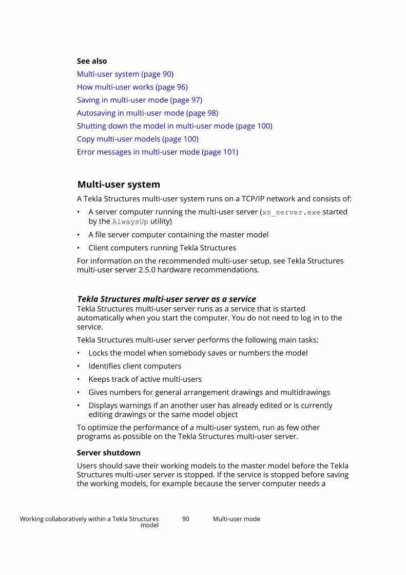
See also
Multi-user system (page 90)
How multi-user works (page 96)
Saving in multi-user mode (page 97)
Autosaving in multi-user mode (page 98)
Shutting down the model in multi-user mode (page 100)
Copy multi-user models (page 100)
Error messages in multi-user mode (page 101)
Multi-user systemA Tekla Structures multi-user system runs on a TCP/IP network and consists of:
• A server computer running the multi-user server (xs_server.exe startedby the AlwaysUp utility)
• A file server computer containing the master model
• Client computers running Tekla Structures
For information on the recommended multi-user setup, see Tekla Structuresmulti-user server 2.5.0 hardware recommendations.
Tekla Structures multi-user server as a serviceTekla Structures multi-user server runs as a service that is startedautomatically when you start the computer. You do not need to log in to theservice.
Tekla Structures multi-user server performs the following main tasks:
• Locks the model when somebody saves or numbers the model
• Identifies client computers
• Keeps track of active multi-users
• Gives numbers for general arrangement drawings and multidrawings
• Displays warnings if an another user has already edited or is currentlyediting drawings or the same model object
To optimize the performance of a multi-user system, run as few otherprograms as possible on the Tekla Structures multi-user server.
Server shutdown
Users should save their working models to the master model before the TeklaStructures multi-user server is stopped. If the service is stopped before savingthe working models, for example because the server computer needs a
Working collaboratively within a Tekla Structuresmodel
90 Multi-user mode

restart, simply restart the service and have users save their working models tothe master model.
Install Tekla Structures multi-user server as a serviceThe Tekla Structures multi-user server installer installs the multi-user server asa service. When you have installed the server, the service is always availableand it is automatically started when the server computer is started. There is noneed to log in and no need to start the server manually every time you startyour computer. Tekla Structures multi-user server allows many users to workon the same model simultaneously.
We recommend that you use the latest multi-user server version availableregardless of the Tekla Structures version that you use.
1. Download the multi-user server software installation file from TeklaDownloads.
2. Double-click the installation file to run the installation.
3. Follow the steps in the installation wizard to complete the installation.
The server is by default installed to:
c:\Program Files (x86)\Tekla Structures Multiuser ServerYou cannot change the installation path during the installation.
If you install the multi-user server on your own computer, the servername is the name of your computer.
The multi-user server uses TCP/IP port 1238.
The installation log is written to the xs_server.log file that is available inc:\ProgramData\TeklaStructuresServer.
Restart the multi-user server serviceIf you receive an error message saying that the model is locked, it might beuseful to restart the Tekla Structures multi-user server service. You can restartthe multi-user server service without restarting the server computer.
1. Ensure that all users of the Tekla Structures multi-user server have beenlogged out of Tekla Structures.
2. Find and open the server computer that hosts the Tekla Structures multi-user server service.
The name of the server computer is the same as the server name that youtype when you log into the multi-user model.
3. On the server computer, go to ..\ProgramData\TeklaStructuresServer.
Working collaboratively within a Tekla Structuresmodel
91 Multi-user mode
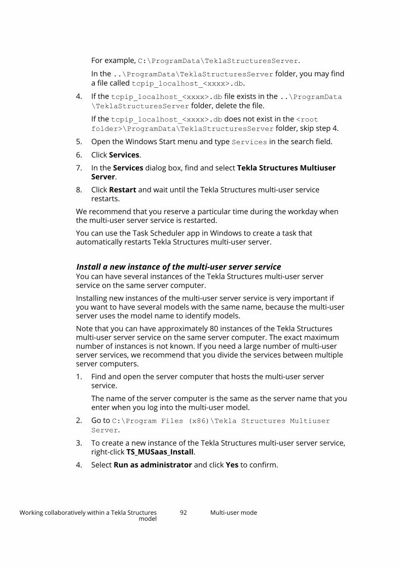
For example, C:\ProgramData\TeklaStructuresServer.
In the ..\ProgramData\TeklaStructuresServer folder, you may finda file called tcpip_localhost_<xxxx>.db.
4. If the tcpip_localhost_<xxxx>.db file exists in the ..\ProgramData\TeklaStructuresServer folder, delete the file.
If the tcpip_localhost_<xxxx>.db does not exist in the <rootfolder>\ProgramData\TeklaStructuresServer folder, skip step 4.
5. Open the Windows Start menu and type Services in the search field.
6. Click Services.
7. In the Services dialog box, find and select Tekla Structures MultiuserServer.
8. Click Restart and wait until the Tekla Structures multi-user servicerestarts.
We recommend that you reserve a particular time during the workday whenthe multi-user server service is restarted.
You can use the Task Scheduler app in Windows to create a task thatautomatically restarts Tekla Structures multi-user server.
Install a new instance of the multi-user server serviceYou can have several instances of the Tekla Structures multi-user serverservice on the same server computer.
Installing new instances of the multi-user server service is very important ifyou want to have several models with the same name, because the multi-userserver uses the model name to identify models.
Note that you can have approximately 80 instances of the Tekla Structuresmulti-user server service on the same server computer. The exact maximumnumber of instances is not known. If you need a large number of multi-userserver services, we recommend that you divide the services between multipleserver computers.
1. Find and open the server computer that hosts the multi-user serverservice.
The name of the server computer is the same as the server name that youenter when you log into the multi-user model.
2. Go to C:\Program Files (x86)\Tekla Structures MultiuserServer.
3. To create a new instance of the Tekla Structures multi-user server service,right-click TS_MUSaas_Install.
4. Select Run as administrator and click Yes to confirm.
Working collaboratively within a Tekla Structuresmodel
92 Multi-user mode

The related Command Prompt window opens. You can see the defaultservice name, port number and destination for the new instance. The lastcharacter of the service name is the identifier of the instance.
The default identifier is 2, whereas the default port number is 1239.
5. If necessary, change the identifier or port number of the new instance.
To Do thisChange the identifier a. Press I on the keyboard.
b. Press Enter.
c. Type the new identifier.
d. Press Enter to change theidentifier.
Change the port number a. Press P on the keyboard.
b. Press Enter.
c. Type the new port number.
d. Press Enter to change the portnumber.
6. When you are ready, press any key on the keyboard except for I, P, or Q.
A new instance of the Tekla Structures multi-user server is installed andstarted.
7. Press any key on the keyboard to close the Command Prompt window.
Uninstall an instance of the multi-user server serviceIf you need to uninstall an instance of the Tekla Structures multi-user serverservice, do the following:
1. Find and open the server computer that hosts the multi-user serverservice.
The name of the server computer is the same as the server name that youenter when you log into the multi-user model.
2. Go to C:\Program Files (x86)\Tekla Structures MultiuserServer.
3. To create a new instance of the Tekla Structures multi-user server service,right-click TS_MUSaas_Uninstall.
4. Select Run as administrator and click Yes to confirm.
The related Command Prompt window opens.
Working collaboratively within a Tekla Structuresmodel
93 Multi-user mode

5. Type the identifier of the instance that you want to uninstall, and pressEnter.
The identifier is the last character of the instance name. For example, ifthe instance name is Tekla Structures Multiuser Server 2, theidentifier is 2.
6. Type Y to confirm uninstalling the instance, and press Enter.
The selected instance of the Tekla Structures multi-user server service isstopped and uninstalled. All files stored in the associated multi-userserver folder are deleted.
7. Press any key on the keyboard to close the Command Prompt window.
Change the server of a multi-user modelYou can change the Tekla Structures server of a multi-user model.
1. On the File menu, click Sharing --> Change multi-user server .
2. Enter the new server name or select it from the list.
3. Click Change.
If the connection to the new server cannot be established, the oldconnection is restored.
NOTE The file .This_is_multiuser_model located in the model folder defineswhether the model is a multi-user or a single-user model. The file includesalso the name of the server. You can open the file using any standard texteditor.
See also
Convert a multi-user model to a single-user model (page 94)
Convert a single-user model to a multi-user model (page 95)
Convert a multi-user model to a single-user modelYou can convert a multi-user model to a single-user model and open it in thesingle-user mode.
To Do thisConvert a current, open model On the File menu, click Sharing -->
Convert to a single-user model .
The current model is converted to asingle-user model.
Convert some other than the currentmodel
1. On the File menu, click Open -->All models .
Working collaboratively within a Tekla Structuresmodel
94 Multi-user mode

To Do this2. Select the multi-user model to be
converted from the list of modelsand click Convert to single-usermodel.
3. Click Convert in the Convert tosingle-user model dialog box.
See also
Convert a single-user model to a multi-user model (page 95)
Convert a single-user model to a multi-user modelYou can convert a single-user model to a multi-user model and open it in themulti-user mode.
To Do thisConvert a current, open model 1. On the File menu, click Sharing --
> Convert to a multi-usermodel .
2. Enter the multi-user server nameor select the name from the list inthe Convert to multi-usermodel dialog box.
3. Click Convert.
The current model is convertedto a multi-user model.
Convert some other than the currentmodel
1. On the File menu, click Open -->All models .
2. Select the single-user model tobe converted from the list ofmodels, and click Convert tomulti-user model.
3. Enter the multi-user server nameor select the name from the list inthe Convert to multi-usermodel dialog box.
4. Click Convert.
See also
Convert a multi-user model to a single-user model (page 94)
Working collaboratively within a Tekla Structuresmodel
95 Multi-user mode

How multi-user works
The multi-user model consists of a single master model. Each user can accessthis model and open their own local view of the model. This local view is calleda working model. The above image shows one possible configuration of themulti-user system.
Any changes a user makes to his working model are local and are not visible toother users until he saves the working model to the master model.
The multi-user system can contain several client computers, where users workon their working models. The master model can be located anywhere on thenetwork, including any of the client computers.
When you open a multi-user model on a client computer, Tekla Structuresmakes a copy of the master model to the memory of the client computer (aworking model).
When you click Save to save your working model back to the master model,Tekla Structures:
1. Takes a new copy of the master model and compares your working modelwith it.
2. Saves the changes in your working model to the copy of the master model(locally).
Working collaboratively within a Tekla Structuresmodel
96 Multi-user mode

3. Saves this copy back to the master model. (When other users save theirworking models, they can now see your changes.)
4. Takes a new copy of the master model and saves it locally as your workingmodel. (You can see your own changes and those uploaded by otherusers.)
The multi-user model is locked during opening, saving and numbering. Whenone of the users performs any of these operations, other users cannotperform them during that time.
Locks for models in multi-user modeTo preserve the integrity of the multi-user model, Tekla Structures locks themaster model when a user:
• Opens the multi-user model
• Saves a working model to the master model
• Runs numbering
When you try to save the model that is locked, Tekla Structures gives you anoption to queue for saving until the model is unlocked. Tekla Structures keepson retrying saving every 15 seconds until the operation is completed or untilyou cancel the operation.
See also
Saving in multi-user mode (page 97)
Saving in multi-user modeTekla Structures preserves the integrity of the model, even if more than oneuser modifies the same model objects. If two users modify the same object,then save to the master model, the master model will only contain thechanges of the user who most recently saved their working model to themaster model.
TIP To avoid potential save conflicts, have users work on different areas of themodel.
Tekla Structures creates connections to the right parts, even if the part ismoved by another user.
Note that if you use the Save as command to save the model, the modelhistory is not copied with the saved model.
Speeding up the saving process
The following advice may help in speeding up the saving process:
Working collaboratively within a Tekla Structuresmodel
97 Multi-user mode

• Check your network connection speed, because it can slow down thesaving process significantly.
• Close down all the views of the model before saving.
• Set the advanced options XS_PROJECT and XS_FIRM so that they point to alocal drive and move most of the system files there. If there are manysystem files in the network drive, saving may become slower than whenusing system files located on your own hard drive. Each user should usethe same files to ensure similar outcome.
• Delete any hidden reference models which you do not need anymore.
See also
How multi-user works (page 96)
Autosaving in multi-user modeAutosave only saves the working model, not the master model. Other users donot see the modifications you make after an Autosave. In multi-user mode,this makes Autosave much faster than the Save command. Save updates themaster model.
By default, Tekla Structures saves the Autosave files in the master modelfolder with the filename <model>.db1_<user>. If several people are usingthe same username, conflicts will occur.
To avoid conflicts and problems caused by the network traffic, store theAutosave files locally, not in the model folder that is located on a networkdrive. Set the advanced option XS_AUTOSAVE_DIRECTORY, for example, to XS_AUTOSAVE_DIRECTORY=C:\TeklaStructuresModels\autosave. Bysaving autosave files locally you make sure that if there are problems in thenetwork traffic, you are still able to save your own work.
1. On the File menu, click Settings --> Options, and in the General settingsdefine the Autosave intervals for operations performed in the drawingand the model.
2. Periodically autosave the model manually.
To do so, create a shortcut for the Autosave command. Click File menu --> Settings and in the Customize area select Keyboard shortcuts.
NOTE Remember to save regularly to the master model by clicking Save.
See also
Error messages in multi-user mode (page 101)
Copy multi-user models (page 100)
How multi-user works (page 96)
Working collaboratively within a Tekla Structuresmodel
98 Multi-user mode

Model history in multi-user modeTekla Structures collects model history on the actions that have taken place inthe a model. In a multi-user model, the model history shows when the modelhas been changed, how the model has changed, who has made the changes,and the model revision comments.
Collect model history in multi-user mode
1. On the File menu, click Settings --> Advanced options.
2. Go to the Speed and Accuracy tab.
3. Set XS_COLLECT_MODEL_HISTORY to TRUE.
4. Set XS_CLEAR_MODEL_HISTORY to FALSE.
5. Optional: Go to the Multi-user tab.
Set XS_SAVE_WITH_COMMENT to TRUE.
This enables the saving of model revision comments.
View model history in multi-user mode
To view model history, do one of the following:
• On the ribbon, click and select an object in the model.
The model history is shown in the Inquire object dialog box.
• Create a model history report.
1. On the Drawings & reports tab, click Reports.
2. Select a report template that shows model history from the list. Thename of the report template may vary in different environments.
In the Default environment, the report template is calledQ_Model_History_Report.
3. Click Create from all to create a report on all the objects in a model,or select one or more objects in the model and click Create fromselected to create a report from the selected objects.
Save model revision comments in multi-user modeYou can save model revision comments when working with multi-user models.This means that all objects which have been changed during the last saveinterval include the revision information in them. You can use this informationin filtering and reports. You can also use it to examine which users havemodified the objects.
• The Owner is the user, who has added the object into the model.
• History shows when the model has been changed, how the model haschanged, who has made the changes, and the model revision comments.
Working collaboratively within a Tekla Structuresmodel
99 Multi-user mode

Before you can save model revision comments, check the following:
• Set the advanced option XS_SAVE_WITH_COMMENT to TRUE in File -->Settings --> Advanced options --> Multi-user.
• Set the advanced option XS_COLLECT_MODEL_HISTORY to TRUE in File -->Settings --> Advanced options --> Speed and Accuracy.
1. When you have set the advanced options mentioned above to TRUE, TeklaStructures displays the Model revision comments dialog box when youare saving the model. Enter the desired revision comment and code in theModel revision comment and Model revision code boxes.
2. Click OK.
Tekla Structures applies the values of this dialog box to parts that werechanged after the last save. When you inquire objects, you can see the modelrevision information in the Inquire object dialog box. You can use thisinformation also for selection and view filtering.
Shutting down the model in multi-user modeDo not shut down the computer containing the master model while otherusers are working on their working models. They will not be able to save theirchanges to the master model.
If this does happen, to avoid losing any changes, follow the steps below:
1. Keep the working models open on the client computers.
2. Restart the computer containing the master model.
3. Open the master model on the computer containing it and autosave themodel.
4. Click Save on the client computers to save the working models to themaster model.
See also
Saving in multi-user mode (page 97)
Autosaving in multi-user mode (page 98)
Copy multi-user models1. Have all users save and close their working models.
2. On the File menu, click Open --> All models .
3. From the list of models, select the multi-user model and click Convert tosingle-user model --> Convert .
4. Use Save as to make a copy of the model.
Working collaboratively within a Tekla Structuresmodel
100 Multi-user mode

5. Exit Tekla Structures and re-open the model in multi-user mode tocontinue working on it.
Display active multi-usersYou can display information on users working on the same server.
To display active multi-users, click File menu --> Sharing --> Active multi-users.
The Active Multi-Users dialog box displays the following information:
Option DescriptionLocked The time when the model was locked.Model name The name of the model.User Users that are currently working on
models on the server.Latest login The time when the users have logged
in.Latest access to server The time when the users have last
accessed the server.Editing drawings The drawings that are currently being
edited.Edited drawings The drawings that have been edited
and saved to the server.
TIP The Active Multi-Users dialog box is refreshed every 30 seconds. You canrefresh it immediately by clicking Refresh.
Error messages in multi-user mode
Error message Problem SolutionDatabase writeconflicts detected
More than one user haschanged an object.
Check theconflict.log. It liststhe GUID numbers ofthe objects that morethan one user haschanged. This is notusually a criticalproblem. No need to usethe Check databasetool. See also Saving inmulti-user mode(page 97)
Working collaboratively within a Tekla Structuresmodel
101 Multi-user mode

Error message Problem SolutionCould not save model.Possible reasons are:
- disk is full or writeprotected
- locked .tmp -file(s)exists in the modeldirectory
You tried to save a multi-user model to acomputer or folder thatyou could not access.
• Check that you havepermission to writeto the model folder.
• Check that there isenough disk space tosave the model.
• Restart the computerwhere you want tosave the model. Tryto save the modelagain.
• Delete the .tmp filesfrom the modeldirectory.
Database lockedcannot open model
Computer stoppedresponding while savingthe model, which locksthe model.
To unlock the model, theuser whose operatingsystem stoppedresponding should openthe model in multi-usermode and save it.
Cannot read autosavedmodel as a normalmodel in the multi-usemode
The opening of a multi-user Autosave file hasbeen prevented insingle-user mode toprevent the reading ofwrong file types.
Do not rename or moveAutosave files. Do notopen the Autosave file ofa single-user model inmulti-user mode or viceversa.
Remove inconsistencies from a multi-user databaseTo preserve the integrity of your multi-user model, you need to remove anyinconsistencies from the multi-user database at regular intervals, for exampleonce a day. This may also fix assemblies with no main part and drawings ofunknown (U) type.
We recommend you to check the multi-user database in single-user mode.
1. Have all other users exit the multi-user model.
2. Save your model to receive the modifications of other users.
3. Exit the model.
4. Open the model in single-user mode.
5. Exit the model without saving.
6. Re-open the model.
Working collaboratively within a Tekla Structuresmodel
102 Multi-user mode
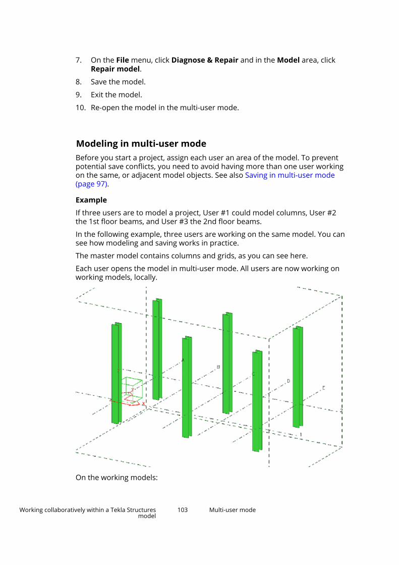
7. On the File menu, click Diagnose & Repair and in the Model area, clickRepair model.
8. Save the model.
9. Exit the model.
10. Re-open the model in the multi-user mode.
Modeling in multi-user modeBefore you start a project, assign each user an area of the model. To preventpotential save conflicts, you need to avoid having more than one user workingon the same, or adjacent model objects. See also Saving in multi-user mode(page 97).
Example
If three users are to model a project, User #1 could model columns, User #2the 1st floor beams, and User #3 the 2nd floor beams.
In the following example, three users are working on the same model. You cansee how modeling and saving works in practice.
The master model contains columns and grids, as you can see here.
Each user opens the model in multi-user mode. All users are now working onworking models, locally.
On the working models:
Working collaboratively within a Tekla Structuresmodel
103 Multi-user mode

User #1 adds base plates to the columns:
User #2 adds and connects the 1st floor steel beams:
User #3 adds and connects the 2nd floor steel beams:
Working collaboratively within a Tekla Structuresmodel
104 Multi-user mode

User #1 clicks Save to save to the master model. His working model nowshows the base plates he added and looks like this:
User #2 clicks Save to save to the master model. His working model nowshows his 1st floor framing and User #1’s base plates:
Working collaboratively within a Tekla Structuresmodel
105 Multi-user mode

User #3 clicks Save to save to the master model. His working model nowshows all three users’s work:
To see the updated master model, Users #1 and #2 need to save to the mastermodel again to update their working models.
Working collaboratively within a Tekla Structuresmodel
106 Multi-user mode

See also
Numbering setup in multi-user mode (page 107)
Synchronize numbering with the master model (page 108)
Numbering setup in multi-user modeDefine the numbering settings as follows:
1. On the Drawings & reports tab, click Numbering settings -->Numbering settings.
2. In the Numbering setup dialog box, select the Synchronize with mastermodel (save-numbering-save) check box.
When you select this check box, you can cancel the numbering before thelast save is made. This is useful, for example, if you want to check thenumbering results and you find something that you still want to change.
NOTE When working with multi-user models, use this option always toprevent saving conflicts.
3. Modify the other properties as required.
4. Click OK.
Tekla Structures will now save the model before and after you number allparts or modified parts.
When you click Perform numbering --> Number modified objects on theDrawings & reports tab to run numbering, Tekla Structures displays a list thatshows the numbering progress. When the numbering is finished, the changednumbering results are highlighted in the list. When you select an item on thelist, Tekla Structures highlights the corresponding object(s) in the model. If youkeep the F key pressed when you select the item, Tekla Structures fits the workarea of the current view around the objects.
If the numbering results are correct, click Save numbers to make the secondsave. To cancel the numbering before the second save, click Cancel. If youcancel the numbering, the model is returned to the state before numberingand standard files are read to all dialogs.
To review the numbering results further, click Stop timer.
To change the time frame in which Tekla Structures makes the second save,use the advanced option XS_NUMBERING_RESULTS_DIALOG_DISPLAY_TIME.
NOTE We recommend that you run the Diagnose & Repair Numbering: Allcommand in File --> Diagnose & repair to remove any numberinginconsistencies from the multi-user database at regular intervals, for exampleonce a day.
Working collaboratively within a Tekla Structuresmodel
107 Multi-user mode

See also
Access rights in multi-user mode (page 112)
Synchronize numbering with the master modelIf you need to include numbering information from areas in the model thathave been modeled by other users:
1. Ask all users to save their working models. This updates the mastermodel.
2. Number the model. Make sure that the Synchronize with master model(save-numbering-save) check box is selected in the Numbering setupdialog box (see Numbering setup in multi-user mode (page 107)). Thisupdates your working model to the master model, numbers the mastermodel, and then saves the numbered master model for all users toaccess.
NOTE If you create drawings and/or reports after numbering, you need to save themaster model again to make them visible to other users.
Drawings in multi-user modeThe multi-user environment is very useful when several users aresimultaneously editing drawings.
Tekla Structures saves each drawing in a unique file. These drawing files arelocated in the drawing folder in the master model folder.
The file is in the format D0000123456.dg. The dg files are part of the model,so you can only open them using Tekla Structures.
dg files contain the locations of views, details of any editing done to thedrawing, and the positions of dimensions, part marks, and text. The dgfilename does not contain any reference to assembly, part, or multidrawingnumbers.
If two users open and save the same drawing in their working models, thensave their changes to the master model, one set of changes will be lost. Themaster model will only contain the changes of the user who most recentlysaved their working model to the master model. See Saving in multi-usermode (page 97).
The Tekla Structures multi-user server assigns the general arrangementdrawing numbers automatically. This means that each drawing gets the first
Working collaboratively within a Tekla Structuresmodel
108 Multi-user mode

free number available. If users A and B both create a general arrangementdrawing at the same time, they are automatically assigned different numbers.The same applies to multidrawing numbers.
See also
Guidelines for multi-user drawings (page 109)
Locks for drawings in multi-user mode (page 110)
Guidelines for multi-user drawingsYou may find the following guidelines useful when you edit or check drawings:
Action RecommendationSaving drawings Periodically save your working model
to the master model (every 5–10drawings).
Editing drawings • Assign each user a different rangeof drawings to edit.
• Lock finalized drawings.
• If Tekla Structures displays themessage Database writeconflicts detected and a drawingID number, two or more usershave opened and saved the samedrawing. See Drawings in multi-user mode (page 108).
Checking drawings Only check locked drawings.Printing drawings Make sure that no-one else is working
with the same drawing. If you print adrawing while someone else is editingit and then save the model, the otheruser’s changes will be lost, eventhough you have not opened,modified, or saved the drawing.
You can disable the print date byusing the advanced optionXS_DISABLE_DRAWING_PLOT_DATE.
Creating general arrangementdrawings
Create a set of empty generalarrangement drawings in thebeginning of the project, and assign aa certain range of these ready-createdempty drawings to each user (forexample, GA1 to GA10 to User A,GA11-GA20 to User B and so on). Thisprevents overlapping general
Working collaboratively within a Tekla Structuresmodel
109 Multi-user mode

Action Recommendationarrangement drawing numbers in theproject.
See also
Delete unnecessary drawing files in multi-user mode (page 110)
Locks for drawings in multi-user mode
When you are about to open a drawing, Tekla Structures displays a notificationon the status of the drawing. The options are:
• Someone is already editing it.
• Someone has already edited it (drawing has been saved to their computer,but not yet to the server).
• The drawing has already been saved and there is a newer version availableon the server.
NOTE Locks for drawings are only used when a drawing is edited manually,not for example when drawings are automatically edited throughcloning.
Note that to lock edited drawings, the XS_COLLECT_MODEL_HISTORYadvanced option must be set to TRUE.
Delete unnecessary drawing files in multi-user modeEvery time you update a drawing, Tekla Structures creates a new drawing(.dg) file in the drawings sub-folder of the model. After that, the previousdrawing file is not used and might become unnecessary. To delete theunnecessary drawing files in multi-user mode, see the following instructions.
NOTE The drawing files that are not used are not always unnecessary. If you closethe model without saving, or if Tekla Structures crashes and you cannot savethe model, the drawing files that are not used can become necessary again. Inthese situations, you need the drawing files that were valid when you lastsaved the model and the drawing files that were valid when the last autosavewas performed.
Having different versions of drawings allows you to revert to the previousversions of drawings. This is especially useful if two users have edited thesame drawing.
Working collaboratively within a Tekla Structuresmodel
110 Multi-user mode

Delete drawing files automatically in a multi-user model
In multi-user models, you can use the XS_DELETE_UNNECESSARY_DG_FILESand XS_DELETE_UNNECESSARY_DG_FILES_SAFETY_PERIOD advancedoptions to keep the number of drawing files reasonable.
The XS_DELETE_UNNECESSARY_DG_FILES advanced option defines if thedrawing files are automatically deleted or not. To automatically delete thedrawing files that are no longer used, ensure thatXS_DELETE_UNNECESSARY_DG_FILES is set to TRUE. The drawing files aredeleted when the last user exits the model and saves the model.
The XS_DELETE_UNNECESSARY_DG_FILES_SAFETY_PERIOD advanced optiondefines how long the drawing files are kept before they are saved. The defaultsafety period is 7 days. This means that after 7 days, the drawing files that arenot used are deleted when the XS_DELETE_UNNECESSARY_DG_FILESadvanced option is set to TRUE. You can define a different safety periodaccording to your needs.
Note that in models shared with Tekla Model Sharing, unnecessary drawingfiles are removed automatically each time when a user writes out theirchanges.
Delete unnecessary drawing files manually in a multi-user model
The Remove unnecessary drawing files command deletes all drawing filesthat do not have a corresponding drawing in the current version of the model,regardless of the safety period. Note that also the drawing files that have acorresponding version in the last saved or autosaved version of the model aredeleted, if there is no corresponding drawing in the current version of themodel.
We recommend that you use the Remove unnecessary drawing filescommand when you want to archive the model or give the model to anotheruser.
Note that the Remove unnecessary drawing files command does not workin models shared with Tekla Model Sharing.
NOTE To avoid deleting drawing files that are still needed, we recommendthat you only use the Remove unnecessary drawing files commandif you are an experienced Tekla Structures user.
Before you use the Remove unnecessary drawing files command, ensurethat:
• You are the only user that has the multi-user model open.
• You have full privileges (page 112) in the multi-user model. If you do nothave full privileges in the model, you cannot delete the unnecessarydrawing files manually.
To delete the unnecessary drawing files manually:
Working collaboratively within a Tekla Structuresmodel
111 Multi-user mode

1. Save the model.
Saving the model ensures that any drawings that are still needed are notaccidentally deleted.
2. Convert the model to a single-user model. (page 94)
3. Search for the Remove unnecessary drawing files command in QuickLaunch.
4. When Tekla Structures finds the command, select it and press Enter.
Tekla Structures deletes all drawings that do not have a correspondingdrawing in the current version of the model.
5. Convert the model back to a multi-user model. (page 95)
Access rights in multi-user modeYou can use privileges to control access rights. The person who has createdthe model, or anyone from the same organization, can control access rights tothe model using privileges. In practice, the privileges of the model arecontrolled via the privileges.inp file.
By modifying the privileges.inp file, you can control:
• access to modify user-defined attributes.
• access to modify object properties. This is done by locking and unlockingobjects.
• access to modify numbering settings.
• access to remove users on multi-user server.
• access to save standard files.
You can prevent your model and drawings being accidentally modified byusing the Locked user-defined attribute (UDA) or drawing locks, or locks inPhase manager. Using the Locked UDA and privileges together you can evenrestrict some users or organizations from modifying your model.
For example, you can limit access to the model so that a checker can onlychange status attributes. Or you could prevent certain users from changingthe user-defined attributes used for approval or manufacturing and erectionstatus.
The privileges.inp file is also used in Tekla Model Sharing to control whichusers are allowed to modify the user-defined attributes or numbering settingsof a shared model and save standard files.
Working collaboratively within a Tekla Structuresmodel
112 Multi-user mode

Change access rights in the privileges.inp fileHow the privileges work:
• The privileges.inp file serves as a user interface for updating theprivileges in a model.
• The privileges are loaded from the privileges.inp file and stored in themodel.
• The privileges are loaded from the privileges.inp file only if the currentuser is allowed to do so.
• If there is no privileges.inp file or if it cannot be loaded, then theprivileges that are already stored in the model (if any) are used.
• If you do not set any privileges, all users have full rights.
• Tekla Structures checks the privilege defaults in the privileges.inp filewhen you create a model, and each time you open a model.
• Tekla Structures searches for the file first in the current model folder, thenin the folder defined for the advanced option XS_INP.
NOTE Only the person who created the model, or anyone from the sameorganization, can modify the privileges of the model via the privileges.inpfile.
To change the access rights:
1. Close the model.
2. Open the privileges.inp file, located in ..\ProgramData\Trimble\Tekla Structures\<version>\environments\common\inp folder,in any text editor.
3. Change the desired settings and save the file.
4. Re-open the model.
Example
Below is an example of the privileges.inp file. The slash (/) or backslash (\)separates the user name from the organization (<organization>/<user>). Ifno user name is entered, it means anyone in the company. Each row containsthree columns, separated by tabs.
If you want to give the privileges only to one user or only to some users, youfirst have to exclude everyone and then include the users who you want togive the privileges.
Note that the organization and the user names are case sensitive. Forexample, COMPANYA is not the same as companyA.
Working collaboratively within a Tekla Structuresmodel
113 Multi-user mode

Options in the privileges.inp fileThe following commands are available in the privileges.inp file:
• access to modify any user-defined attribute (UDA) - attribute:UDA_NAME• access to modify object properties - attribute:OBJECT_LOCKED• access to modify numbering settings - action:PartnumbersOptions• access to perform numbering - action:PerformNumbering• access to remove users in multi-user model -
action:AllowMultiuserKick• access to save standard files - action:SaveStandard• access to add watermarks to printed drawings -
action:DrawingWatermarkWhen you want to give the right only to one user or some users, you have tofirst exclude everyone and then include the users.
Column Option Descriptionprotected user-defined attribute
attribute: name Affects the protected user-definedattribute "name". Check the exactspelling of the name in theobjects.inp.
ORaction action: name Affects the action "name". The
available actions:
• PartnumbersOptions: Controlsaccess to numbering settings.
Limitation: only full/none
• PerformNumbering: Controlsaccess to performing numbering.
• AllowMultiuserKick: Controlsaccess to removing users from amulti-user model.
Limitation: only full/none
Working collaboratively within a Tekla Structuresmodel
114 Multi-user mode

Column Option Description• SaveStandard: Controls access to
saving standard files.
Limitations: only standard
• DrawingWatermark: Controlsaccess to adding watermarks forprinted drawings.
user everyone All usersdomain/ Affects all users within the network
domain "domain".domain/nn Affects the user "nn" in the network
domain "domain".nn Affects the user "nn".
rights full User can change the user-definedattribute.
view User can view the user-definedattribute, but not change it. Thisoption appears dimmed to the user.
none The user-defined attribute is hiddenfrom the user.
User-defined attribute LockedTo protect objects from being accidentally modified, you can use the Lockeduser-defined attribute (UDA).
You can use it for
• parts (separately for beams, columns, etc.)
• bolts
• welds
• specific drawing types
• project properties
• phase properties
The Locked user-defined attribute (UDA) has three values, Yes, No andOrganization. When set to Yes, the object is locked and you cannot modify itsproperties. You can only change the object’s user-defined attributes that donot affect numbering. If you try to modify a locked object, Tekla Structuresdisplays the following warning message:
"There are locked objects, see report. The operation could not be performed."
Working collaboratively within a Tekla Structuresmodel
115 Multi-user mode

The OBJECT_LOCKED attribute in the objects.inp file defines whether theLocked user-defined attribute (UDA) is visible in the Tekla Structures userinterface.
NOTE Make sure that numbering is up-to-date before you lock objects.
Control access to lock and unlock objects in a multi-user modelUse the OBJECT_LOCKED attribute in the privileges.inp file to set users'access to the user-defined attribute (UDA) Locked and thus prevent usersfrom locking and unlocking objects.
Example
Only users man and man2 have full rights to lock and unlock objects. Theattribute is hidden from everybody else:
NOTE To protect other user-defined attributes, you need to list them in theprivileges.inp file.
Control access to numbering in a multi-user modelUse the PartnumbersOptions in the privileges.inp file to restrict users'access to the numbering properties and thus prevent unauthorized users frommodifying the numbering settings.
NOTE Users can still run numbering even if they have no privilege to modify thenumbering settings.
If a user who has no privilege to modify properties in the Numbering Setupdialog box tries to access the dialog box, Tekla Structures displays a warningmessage which states that the user does not have the required privilege.
Example
Only admin can modify the properties in the Numbering Setup dialog box:
Working collaboratively within a Tekla Structuresmodel
116 Multi-user mode

Control access to save standard files in a multi-user modelUse the SaveStandard action in the privileges.inp file to control users'access to save standard files.
Example
Only admin has rights to save standard files in network domain ORGANIZATION:
Control access to remove users from a multi-user modelUse the AllowMultiuserKick action in the privileges.inp to restrictpermissions to remove users from a multi-user model.
You can define that undesired active multi-users can be removed from theuser list in the Active multi-users dialog box. This is useful, for example, if anapplication error has occurred on the user’s computer, and the locks on lockedobjects need to be cleared by removing the user.
Define the AllowMultiuserKick action in the privileges.inp file and givefull permissions to the user who you want to be able to remove other usersfrom the model.
Example
Only user jsmith has full permissions to remove users:
To remove a user:
1. On the File menu, click Sharing --> Active multi-users.
2. Right-click a user who you want to remove and select Clear locks.
3. Click Refresh to remove the user.
All the locks that the user has on objects and the user are removed.
Working collaboratively within a Tekla Structuresmodel
117 Trimble Connector

1.7 Trimble ConnectorTrimble Connector enables the connection between Tekla Structures andTrimble Connect for Windows or Trimble Connect for Browser for sharingmodels and ToDo notes, matching views and selected objects.
With Trimble Connector, you can:
• link a model to a project (page 120)
• create a new Trimble Connect project
• download a reference model (page 125) from a Trimble Connect project toa Tekla Structures model
• upload a model (page 129) to a Trimble Connect project as a .tekla file
• export model objects as reference models (page 125) to Trimble Connectprojects
• create, modify, assign, and comment on ToDo notes
• select the same objects in both and (page 147)
• match the camera position, zoom level, and projection of model views inand in (page 147)
All operations between Tekla Structures and Trimble Connect use the projectbase point. This means that, for example, reference models from TeklaStructures are placed in relation to the project base point in Trimble Connect.If you have not defined a project base point, the model origin is used.
NOTE You need to have a Trimble Identity before you can start using TrimbleConnector.
NOTE Trimble Connect related metadata and all reference models arelocated in the ..\TeklaStructuresModels\<model>\TConnectfolder. Exported reference model settings are stored tothe ..\TeklaStructuresModels\<model>\Links folder. TrimbleConnector does not work correctly if you manually modify the files inthese folders.
Launch Trimble ConnectorYou can launch Trimble Connector in multiple ways:
• Through the ribbon:
• To open the model list, on the Trimble Connect tab, click Models.
For more information on managing reference models, see Managereference models in Trimble Connector (page 125).
Working collaboratively within a Tekla Structuresmodel
118 Trimble Connector

• To open the list of ToDo notes, on the Trimble Connect tab, clickToDos.
For more information on managing ToDo notes, see Work with ToDos inTrimble Connector (page 139).
• Through the file menu:
• To download a reference model from any Trimble Connect project to aTekla Structures model, click File --> Import --> .
• To publish an IFC reference model of the open Tekla Structures modelto any Trimble Connect project, click File --> Export --> .
Trimble Connector opens. You can link your job to a Trimble Connect project ifyou have not done that earlier. You can also create a new project.
To start working with Trimble Connector, you need to sign in to TeklaStructures using your Trimble Identity.
Launch Trimble Connect from Tekla StructuresYou can launch Trimble Connect in multiple ways:
• Through the ribbon:
To launch Trimble Connect for Windows or Trimble Connect for Browser,click one of these buttons on the Trimble Connect ribbon tab:
• Trimble Connect for Browser:
If you have linked the model to a Trimble Connect project, the projectactivity page opens in Trimble Connect for Browser.
If you have not linked the model to a project, the Select project dialog
box opens whenever you click Trimble Connect for Browser orany of the menu options underneath it. To link the model to a project,see Link a Tekla Structures model to a Trimble Connect project(page 120).
• Trimble Connect for Browser --> Project explorer:
The project explorer page opens in Trimble Connect for Browser.
• Trimble Connect for Browser --> 3D view:
The 3D model view opens in Trimble Connect for Browser.
• Trimble Connect for Browser --> Team:
The team page opens in Trimble Connect for Browser.
Working collaboratively within a Tekla Structuresmodel
119 Trimble Connector
• Trimble Connect for Windows:
If you have attached a project, the project detail view opens in TrimbleConnect for Windows.
If you have not attached a project, the projects view opens in TrimbleConnect for Windows.
If you have not installed Trimble Connect for Windows, the web page todownload Trimble Connect for Windows opens: https://app.connect.trimble.com/tc/app#/store.
Link a Tekla Structures model to a Trimble Connect projectTo start collaboration between Tekla Structures and Trimble Connect, youneed to link your Tekla Structures model to a Trimble Connect project.
1. To start linking your model to a Trimble Connect project, do either of thefollowing:
a. To link a new model, select the Start Trimble Connect collaborationcheck box while creating the model,
b. To link an open model, go to the File menu and select --> Startcollaboration.
2. According to your needs, do either of the following:
• To link the model to a new Trimble Connect project, type a name forthe project in the field at the top of the Select project dialog box.
• To link the model to an existing Trimble Connect project, select theproject from the list at the top of the Select project dialog box.
3. Select the geographical location of the project from the Project ServerLocation list.
4. Select your Trimble Connect license from the License list.
5. Click Create or OK.
The model is linked to the selected Trimble Connect project. You can now startworking and, for example, download or upload reference models, add Connectmodels as overlays on top of the model, or add ToDo notes.
Unlink a Tekla Structures model from the Trimble Connect project1. On the File menu, click --> Exclude from collaboration.
2. To confirm unlinking the model from the linked Trimble Connect project,click OK.
Working collaboratively within a Tekla Structuresmodel
120 Trimble Connector

Link a Tekla Structures model to a Trimble Connect projectTo start collaboration between Tekla Structures and Trimble Connect, youneed to link your Tekla Structures model to a Trimble Connect project.
1. To start linking your model to a Trimble Connect project, do either of thefollowing:
a. To link a new model, select the Start Trimble Connect collaborationcheck box while creating the model,
b. To link an open model, go to the File menu and select --> Startcollaboration.
2. According to your needs, do either of the following:
• To link the model to a new Trimble Connect project, type a name forthe project in the field at the top of the Select project dialog box.
• To link the model to an existing Trimble Connect project, select theproject from the list at the top of the Select project dialog box.
3. Select the geographical location of the project from the Project ServerLocation list.
4. Select your Trimble Connect license from the License list.
5. Click Create or OK.
The model is linked to the selected Trimble Connect project. You can now startworking and, for example, download or upload reference models, add Connectmodels as overlays on top of the model, or add ToDo notes.
Upload the Tekla Structures model to Trimble ConnectYou can upload the current Tekla Structures model to a Trimble Connectproject folder as a read-only .tekla file. The .tekla file can then be used asa lightweight reference model with Tekla Structures or any Trimble Connectproduct. The .tekla reference models list and visualize model objects, parts,rebars, bolts, assemblies, and grids.
Before you upload your model to Trimble Connect, note that:
• Welds and surface treatments are not included in the .tekla referencemodel.
• Profiles are exported with normal solid accuracy, so corner roundings arenot included.
• Layers are available in .tekla models. Tekla Structures objects aregrouped to different layers according to a template attribute or UDA. Youcan include layers in .tekla upload.
• Object colors in the .tekla reference model might be different than in theTekla Structures model.
Working collaboratively within a Tekla Structuresmodel
121 Trimble Connector

• To include pours and pour units in the .tekla reference model instead ofcast units and cast unit parts, you need to enable pour management.
To disable pours and include cast units and cast unit parts:
1. Go to ...\Environments\common\system\UploadToConnect\.
2. Copy the conf.json file to the \attributes sub- folder under themodel folder.
3. Open the conf.json file in a text editor.
4. Change "pours" : "model" to "pours" : "false".
5. Save the conf.json file.
In the following image, the connection on the right has been exported as anIFC reference model using Trimble Connector. The connection looks the sameas in the Tekla Structures model.
The connection on the left has been uploaded to Trimble Connect as a .teklareference model. The colors are different, and the radiuses of profiles andwelds are missing.
Working collaboratively within a Tekla Structuresmodel
122 Trimble Connector

To upload the Tekla Structures model to Trimble Connect:
1. On the File menu, go to Settings --> Advanced options.
2. In the Advanced Options dialog box, find theXS_CONNECT_UPLOAD_MODEL_FOLDER option.
3. Type or paste a file path to the Trimble Connect folder where you want toupload the Tekla Structures model.
The default file path is Structural\Tekla models.
4. Click OK to save the folder path.
5. If necessary, define which template attributes and user-defined attributesare uploaded with the model:
Working collaboratively within a Tekla Structuresmodel
123 Trimble Connector

a. Copy the part.epr file from the \TeklaStructures\<version>\Environments\common\system\UploadToConnect folder to the\attributes folder under the current model folder.
b. Open the part.epr file in a text editor, such as Microsoft Notepad.
c. For each supported object type, define the template and user-definedattributes using the following syntax. Note that to include layers, youneed to add a line for the layers in the following format: "layer":["TEMPLATE_FIELD"].
{"part": ["PART_POS", "NAME", "USERDEFINED.USER_FIELD_1" ],"assembly": ["ASSEMBLY_POS", "USERDEFINED.PRELIM_ASSEM_MARK" ],"bolt": ["NAME","BOLT_STANDARD", "DIAMETER" ],"rebar": ["REBAR_POS", "NAME", "GRADE", "SIZE", "LENGTH", "WEIGHT" ]"layer": ["ASSEMBLY_POS"] }
Note that you cannot change the units that are used for attributes.
d. Save the part.epr file.
6. Go to the Trimble Connect ribbon tab, and click Upload model.
7. To confirm saving the model and uploading the entire model folder to theattached Trimble Connect project, click Save and upload.
The Tekla Structures model is uploaded as a .tekla file to the TrimbleConnect project folder that you defined.
An error message is displayed if the model upload to Trimble Connect fails. Incase of upload errors, see the PublishToTrimbleConnect.log file, whichyou can find in the /logs sub-folder under the model folder.
If needed, you can later attach the file to your model as a Connect overlaymodel. (page 129)
Note that if you want to move the model to another folder after uploading it,you need to do so manually in Trimble Connect.
NOTE The Upload model button does not upload shared models toTrimble Connect. Instead, you can use theXS_UPLOAD_SHARED_MODEL_TO_CONNECT advanced option to selectif and when a shared model is uploaded to a Trimble Connect projectfolder.
In the Advanced Options dialog box, set the value ofXS_UPLOAD_SHARED_MODEL_TO_CONNECT to one of the following:
Working collaboratively within a Tekla Structuresmodel
124 Trimble Connector

• BASELINE = The shared model is automatically uploaded to the setTrimble Connect project folder each time a user creates a newbaseline.
• WRITEOUT = The shared model is automatically uploaded to the setTrimble Connect project folder after each successful write out.
If you do not want to upload the model to a Trimble Connect projectfolder, clear the Value field.
See also
Trimble Connector (page 117)
Manage overlay models in Trimble Connector (page 129)
Manage reference models in Trimble ConnectorReference models are part of the Tekla Structures model, and they can bedownloaded from, or exported to Trimble Connect projects.
• To start managing reference models, on the Trimble Connect ribbon tab,
click Models.
The Trimble Connect - Models dialog box opens. You can manage referencemodels on the Reference models tab, and overlay models on the Overlaymodels tab.
For more information about differences between reference models andoverlay models, see Should I use reference models or overlay models?(page 133).
Upload reference models or reference model updatesYou can upload both new Tekla Structures reference models or updatedversions of Tekla Structures reference models to attached Trimble Connectprojects.
New and updated reference models are marked in different ways:
Icon or label MeaningThe Tekla Structures reference model has not beenuploaded to a Trimble Connect project.The newest version of the Tekla Structuresreference model has not been uploaded to aTrimble Connect project.The reference model has the same version in TeklaStructures and in Trimble Connect.
Working collaboratively within a Tekla Structuresmodel
125 Trimble Connector

1. Open the Reference models tab in the Trimble Connect - Models dialogbox.
2. To upload a new reference model or a new version of the reference
model to the Trimble Connect project, click the icon.
Download reference models or reference model updatesYou can download and insert either new or updated reference models from aTrimble Connect project to a Tekla Structures model.
The reference models and their versions are marked with different iconsdepending on whether they are up-to-date:
Icon MeaningThe reference model has been updated in theTrimble Connect project after the last time that ithas been downloaded to Tekla Structures.
•Click to download the latest version of themodel.
The updated version of the reference model hasnot been downloaded to Tekla Structures.
•Click to insert the version in the TeklaStructures model.
The reference model version exists in the TeklaStructures model sub-folder but has not beeninserted in the Tekla Structures model.
•Click to insert the version in the TeklaStructures model.
The reference model has the same version in TeklaStructures and in Trimble Connect.
1. On the Reference models tab in the Trimble Connect - Models dialogbox, double-click a folder.
A list of reference models in that folder is shown.
2. To show the versions of an reference model, click the arrow on the leftside of the reference model name.
3. Do either of the following:
• Select the reference model that you want to download and click .
Working collaboratively within a Tekla Structuresmodel
126 Trimble Connector

• Select the updated reference model version that you want to
download and click .
The new reference model or the updated reference model version isdownloaded to a Tekla Structures model sub-folder and inserted to the TeklaStructures model.
Create new folders for reference models1. On the Reference models tab in the Trimble Connect - Models dialog
box, click .
2. In the Select folders dialog box, double-click the project to see the foldersinside the project.
If a folder has sub-folders, you can view them by double-clicking thefolder.
3. Select one or more folders where you want to link the reference modeland click OK.
You can also create a new folder by typing a name for the folder andclicking Create, or remove an existing folder from the list by hovering
over the folder and clicking .
The selected folders are added to the Folders list on the Reference modelstab in the Trimble Connect - Models dialog box.
Export Tekla Structures model objects as an .ifc reference model to aTrimble Connect projectYou can create an .ifc coordination view 2.0 file from Tekla Structures modelobjects and export it to a Trimble Connect project. You can create the file fromselected model objects, or from all model objects.
1. Do one of the following:
To Do thisSelect to which Trimble Connectproject and folder the .ifc referencemodel is exported
a. On the File menu, select Export--> --> .
The Trimble Connect - ExportIFC to Trimble Connect dialogbox opens.
b. In the list at the top of the dialogbox, select the Trimble Connectproject.
Working collaboratively within a Tekla Structuresmodel
127 Trimble Connector

To Do thisc. In the Folder list, select a folder
in the selected Trimble Connectproject.
Export the .ifc reference model tothe linked Trimble Connect project
a. On the ribbon tab, click Models.
b. On the Reference models tab inthe Trimble Connect - Modelsdialog box, double-click thefolder where you want to savethe exported reference model.
c. To start the export, click .
The Trimble Connect - Export IFC toTrimble Connect dialog box opens.
2. In the Name box, type a name for the exported model or model objects.
The name of the export needs to be unique within the project.
3. Select which model objects you want to export:
To export Do thisAll model objects • In the Export list, select All.Selected model objects a. In the Export list, select
Selected.
b. Select the objects in the modelview.
To select the desired objects,ensure that you have the rightselection switches activated.
Filtered model objects a. In the Export list, select Filter.
b. Do any of the following:
• In the Filter list, select anexisting filter.
• To create a new filter, click next to Filter list.
4. Select which IFC settings you want to use:
To Do thisUse existing IFC export settings • In the IFC export settings list,
select the settings file.
The settings file needs to belocated in the model\attributes folder, so that you
Working collaboratively within a Tekla Structuresmodel
128 Trimble Connector

To Do thiscan select it in the IFC exportsettings list.
Create and use new IFC exportsettings
• Click next to the IFC exportsettings list.
The .ifc file does not include assembly information, which means thatyou can only export main parts. You can add additional property sets bysaving a property set through File --> Export --> IFC. Use the file nameifc.xml.
If you do not select a settings file in the IFC export settings list, TeklaStructures will not know which object types you want to export, so onlysurface geometry is exported.
5. Click OK.
When the .ifc model has been exported, you can download the referencemodel to the Tekla Structures model. Select the reference model in the
Trimble Connect - Models dialog box, and click . After a successful
export, the model is marked with .
If the Tekla Structures model has an updated version of the exported
reference model, click to export the updated version of the referencemodel.
If you have not defined where the .ifc model is positioned in the Export toIFC dialog box, the exported IFC model is placed in relation to the project basepoint in the Trimble Connect 3D view. If a project base point has not beendefined, the model is placed in relation to the model origin.
Manage overlay models in Trimble ConnectorOverlay models are lightweight reference models that are stored in theattached Trimble Connect project. Overlay models can be quickly attached tothe Tekla Structures model to show model objects on top of the TeklaStructures model. You can manage overlay models in many ways: for example,add new overlay models, adjust the scale and position of the overlay models,and inquire the properties of the overlay model objects.
Because overlay models are saved in the Trimble Connect project, you cannotuse them in a Tekla Structures model unless the Tekla Structures model hasbeen linked to a Trimble Connect project. Before you can start working withoverlay models, link your .
To start managing overlay models:
Working collaboratively within a Tekla Structuresmodel
129 Trimble Connector

1. On the Trimble Connect ribbon tab, click Models.
The Trimble Connect - Models dialog box opens. You can manageoverlay models on the Overlay models tab, and regular reference modelson the Reference models tab,
2. In the Trimbel Connect - Models dialog box, open the Overlay modelstab.
Manage the visibility of overlay models• Do any of the following:
To Do thisOnly show overlay model objectswithin the current work area
• Select the Show inside work areaonly check box.
Show a list of all folders and overlaymodels in the Trimble Connectproject
• In the list at the top, selectEverything in project.
Show a list containing only the foldersand overlay models that you cancurrently show or hide in this model
• In the list at the top, select Used inthis model.
Hide or show overlay models • To hide an overlay model, click on the left side of the model.
• To show an overlay model, click
on the left side of the model.
• To hide all overlay models in afolder, click on the left side ofthe folder.
• To show all overlay models in a
folder, click .
If a folder or its sub-folders do nothave any overlay models that canbe shown in Tekla Structures, thearrow symbol is not shown next tothe eye icon.
If a model cannot be converted to theright format and therefore, cannot beshown, a warning icon ( ) is shownon the left side of the model.
Working collaboratively within a Tekla Structuresmodel
130 Trimble Connector

To Do thisZoom to an overlay model 1. In the list of overlay models,
select the model to which youwant zoom in.
2. Click .
3. Select Zoom to model.
4. Select the model view in whichyou want to zoom.
5. Click Yes to confirm zooming tothe selected model view.
Add overlay models1. Select the folder in which you want to add a new overlay model.
2. Click .
3. Select Attach model.
4. In the Attach model dialog box, click Browse..., and browse to find theoverlay model.
5. Select the overlay model, and click Open.
6. In Location by, select one of the following options:
Model origin inserts the model relative to 0,0,0.
Work plane inserts the model relative to the current work planecoordinate system.
Base point:<name of base point> inserts the model relative to thebase point by using coordinate system values East coordinate, Northcoordinate, Elevation, and Angle to North from the base pointdefinition in Project properties.
7. Select where you want to place the overlay model. You can entercoordinates in the Offset boxes, or pick a position for the overlay modelorigin.
8. Set the Scale of the overlay model if it is different from the one in theTekla Structures model.
Note that you need to set the scale for a DWG or a file already in AutoCAD.When you define the measurement unit for a DWG or a DXF file and savethe file in AutoCAD, the unit is recognized in Tekla Structures, and theoverlay model is scaled correctly.
9. You can rotate the model around model Z axis by picking a location in themodel or entering the desired value in the Rotation box.
The maximum number of decimals for the rotation value is 7.
Working collaboratively within a Tekla Structuresmodel
131 Trimble Connector

10. Click Attach model.
The model version is added to the selected folder.
11. To show the new overlay model in the model view, click next to theoverlay model.
Create sub-folders for overlay modelsYou can create sub-folders within the Trimble Connect project to categorizeyour overlay models. For example, you can create different sub-folders foroverlay models according to their file format, their type, or their position in theproject.
1. Select the folder under which you want to add a sub-folder.
2. Click on the right side of the folder.
3. Select Create new folder.
4. Name the sub-folder and click Create.
Adjust the scale and position of overlay modelsA change in the model position or scale is applied to both Tekla Structures andTrimble Connect.
1. Select the overlay model whose position you want to adjust.
2. To show the model properties, click Properties at the bottom of theTrimble Connect - Models dialog box.
Note that the properties are relative to the project base point.
3. Type new values for the scale, position, or rotation of the model.
4. To apply the changes to the Tekla Structures model view, click Modify.
To return to the initial scale and position of the model, click Reset.
Inquire overlay model objectsYou can view the properties of objects and assemblies in overlay models byusing the Inquire command.
1. Select an object or assembly in an overlay model.
2. Right-click the object or assembly.
3. Select Inquire.
The Inquire object dialog box shows the properties of the selected object orassembly. The shown properties can differ depending on the overlay modeland the model format.
Working collaboratively within a Tekla Structuresmodel
132 Trimble Connector

Remove an overlay model from currently used models1. Ensure that you have the Used in the model list open.
2. Select the overlay model that you want to remove.
3. Click .
4. Select Remove from used model tree.
The overlay model is removed from the Used in the model list.
If you want to show the overlay model again, switch to the Everything in
project list and click . The overlay model appears in the Used in the modellist again.
Should I use reference models or overlay models?In the following tables, see the pros and cons of reference models and overlaymodels, and the operations that you can perform in these model types.
Reference models Overlay models+ Parts of the Tekla Structures model,so more operations are available
- Increase the size of the .db1 files
+ Fast to load and display
+ Allow each user to view the modelversions that they need
+ Do not affect the size of the .db1files
- All operations are not available
Operation Can you do it withreference models?
Can you do it withoverlay models?
View the model on topof a model (page 179)
Yes Yes
View the model in adrawing
Yes No
Inquire objects in themodel
Yes Yes
Filter objects in themodel
Yes No
Manage changesbetween model versions(page 129)
No Yes
Detect clashes Yes NoConvert objects to nativeobjects (page 209)
Yes No
Add user-definedattributes (page 199)
Yes No
Working collaboratively within a Tekla Structuresmodel
133 Trimble Connector
Operation Can you do it withreference models?
Can you do it withoverlay models?
Use layers (page 179) Yes NoCreate tasks Yes NoCreate views fromobjects
Yes No
Fit work area Yes NoHide objects Yes NoHide all objects from theview with displaysettings
Yes No
Manage categories in Yes No
Manage overlay model versionsYou can have several versions of the same overlay models in your TrimbleConnect projects, and view the differences between these versions in yourTekla Structures models. This way, you can see the progress of the project.
NOTE You need to save the new model versions with the same name and in thesame folder as previous model versions.
Create overlay model versions
1. Create a new version of the overlay model.
You can use external software to create overlay model versions, such as ArchiCad or Autodesk Revit, to create IFC model versions, or uploadthe Tekla Structures model to the Trimble Connect project as a .teklafile.
2. Do any of the following:
To upload Do thisA new model version in the .ifcformat
Do any of the following:
• In the Trimble Connect - Modelsdialog box, open the folder wherethe previous model version isstored, and click next to theprevious model version.
• In Trimble Connect for Browser,open the folder where the originalmodel is stored, and drag anddrop the new version of the modelto the folder.
Working collaboratively within a Tekla Structuresmodel
134 Trimble Connector

To upload Do thisA new model version in anotherformat
a. In the Trimble Connect - Modelsdialog box, select the folderwhere the original model versionwas saved.
b. Click and select Attach model.
c. Browse to the folder where yousaved the new model version,and select the model version.
The model version is added to theselected folder.
3. To see the overlay model versions, select the overlay model, and clickVersions to expand the Versions section.
4. Select which version of the model you want to show:
To show Do thisThe newest version ofthe model
Whenever the latest version of an overlay model is
not shown, the symbol appears. The symbol is shown next to models whose oldversions are shown, and folders in which you havesaved the models whose old versions are shown.
• Click next to the model or the folder inwhich the model is saved.
An older version of themodel • Click next to the version that you want to
see.
Compare the differences between .tekla or .ifc overlay model versions
1. In the overlay model list, select an overlay model that has at least twoversions in the attached Trimble Connect project.
2. At the bottom of the Overlay models tab, click Versions.
3. In the Versions section, do any of the following according to your needs:
To Do thisDefine the properties tobe compared
a. Click ... in the Versions section.
Working collaboratively within a Tekla Structuresmodel
135 Trimble Connector

To Do thisb. In the Comparison sets dialog box that
opens, select check boxes next to theproperties that you want to compare.
Only the selected properties will be used forcomparing the model objects in the Changeslist.
c. To add new properties, click + and type theproperty name.
d. To delete properties, click next to theproperties.
e. To save the currently selected properties as acomparison set for future use, select a settingsfile in the list at the top of the Comparisonsets dialog box, or create a new settings file bytyping a new name.
f. Click .
g. Close the Comparison sets dialog box.Define how preciselyproperties are compared a. Click in the Versions section.
b. In the Property Set Comparison Tolerancesdialog box, set the minimum units and valueswhich will be considered as changes inproperties.
c. To save the current tolerances for future use,select a settings file in the list at the top of theComparison sets dialog box, or create a newsettings file by typing a new name.
d. Click .
e. Close the Property Set ComparisonTolerances dialog box.
4. In the Versions section, show two versions of the model by clicking next to the model versions.
Note that you can compare only two versions of an overlay model at atime. If you set a third model version visible, the oldest visible version is
Working collaboratively within a Tekla Structuresmodel
136 Trimble Connector

hidden automatically, and the comparison is updated to show thedifferences between the two visible versions.
The changes between the versions are shown with the following colors inthe model:
• Added objects = green
• Modified objects = yellow
• Deleted objects = red
• Existing objects that have not been modified = gray
5. To show which properties of modified objects have changed, click thecorresponding row in the Changes list.
The changed properties are shown in the Property details side pane.Note that the side pane may not show changes in object rotation orlocation.
Compare the differences between overlay model versions in other formatsWhen you compare overlay model versions in formats such as .dgn or .dwg,the changes are shown by color-coding the objects in the overlay model.
1. In the overlay model list, select an overlay model that has at least twoversions in the attached Trimble Connect project.
2. At the bottom of the Overlay models tab, click Versions.
3. In the Versions section, show two versions of the model by clicking next to the model versions.
Note that you can compare only two versions of an overlay model at atime. If you set a third model version visible, the oldest visible version is
Working collaboratively within a Tekla Structuresmodel
137 Trimble Connector
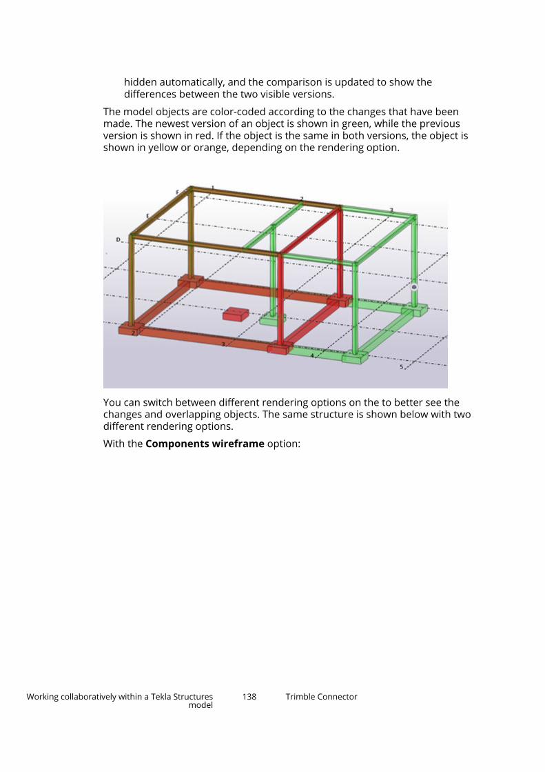
hidden automatically, and the comparison is updated to show thedifferences between the two visible versions.
The model objects are color-coded according to the changes that have beenmade. The newest version of an object is shown in green, while the previousversion is shown in red. If the object is the same in both versions, the object isshown in yellow or orange, depending on the rendering option.
You can switch between different rendering options on the to better see thechanges and overlapping objects. The same structure is shown below with twodifferent rendering options.
With the Components wireframe option:
Working collaboratively within a Tekla Structuresmodel
138 Trimble Connector

With the Components rendered option:
Work with ToDos in Trimble ConnectorThe ToDo list in Trimble Connector displays the ToDo notes added to theproject. You can add ToDo notes and reply to notes of other project members.
Working collaboratively within a Tekla Structuresmodel
139 Trimble Connector

The ToDo notes are shared to all project members by default, but you canselect a user or a user group to whom you want to assign the ToDo with a duedate when it needs to be resolved.
Open and view the ToDo listYou need to have a project linked to the current model to open to view orcreate ToDo notes.
1. On the Trimble Connect ribbon tab, click ToDos.
2. In the Trimble Connect - ToDos dialog box, do any of the following:
• To sort the ToDo list according to different criteria, click one of theavailable columns.
You can sort ToDo notes by Author, Assignee, Due date, Status, orPriority.
• To search for specific ToDo notes, start typing a search word in theSearch... field.
Trimble Connector shows the ToDo notes that match you search.
• To group ToDo notes, select the grouping option in the Group by list.
The options are Author, Status, Priority, Type, Tag, Creation date,and Last modified date
3. To close the ToDo list, click the Close button.
Create ToDo notes1. If you want to create a ToDo with a view and a snapshot, select the native
Tekla Structures objects in the model view.
When you create a ToDo with a view and a snapshot, note that:
• The coordinate system follows what has been set in the Work planehandler toolbar.
• We do not recommend creating a view of many objects at a time,because if you do so, creating the ToDo may take a long time.
When you create a view, an IFC file of the selected native objects iscreated and uploaded to the project root\TeklaStructures-ToDosfolder.
You can also create ToDo notes without a view and a snapshot. To do so,do not select any objects in the Tekla Structures model view.
2. In the Trimble Connect - ToDos dialog box, click the Create ToDobutton.
Working collaboratively within a Tekla Structuresmodel
140 Trimble Connector

3. Type a Title and a Description for the ToDo note.
TheTitle and the Description are mandatory. You cannot save a ToDonote without a title and a description.
4. To assign the ToDo note to a user or a user group, click Select next toAssignee and select a project member or a user group.
To filter the options that are shown, start typing the name of the user orthe user group.
ToDo notes can be assigned to other users when the project has beenshared.
5. If needed, do one or more of the following:
• To add tags, type a tag in the Tags box and press Enter to save the tag.
You can add several tags.
• Select a priority for the ToDo note from the Priority list.
• To set a due date for the ToDo note, type the due date in the DueDate box, or click to select the due date from the calendar.
• To define the type of the ToDo, select an option from the Type list.
• To define the status of the ToDo note, select an option from the Statuslist.
• Type the completion percentage of the ToDo note in the Completion% box.
6. To add an attachment, click Add attachment, and do one or both ofthe following:
• Click and to browse for a file on your computer and add thefile to the selected folder. Then, click OK.
• Click to browse for a file on your computer and click Add frommy computer. Then, attach the file to the current ToDo note and clickOK.
You can open an attachment by double-clicking it.
The attachment opens the file if Windows has a file association for thefilename extension. Model files are not opened.
You can also delete attachments. To do so, click X on the right side of theattachment.
7. To save the ToDo note, click Save.
Working collaboratively within a Tekla Structuresmodel
141 Trimble Connector

The saved ToDo note is immediately synchronized to Trimble Connect. Afterthe ToDo note has been uploaded to Trimble Connect, it receives a uniquename consisting of the abbreviated project name and a running number.
In Trimble Connect, you can see the ToDo note on the ToDo and Activity tabs.
View and modify ToDo notes1. In the Trimble Connect - ToDos dialog box, double-click the ToDo note
that you want to view.
2. Click Edit.
3. Adjust the ToDo information according to your needs.
For example, you can change the assignee, status, or completionpercentage.
4. To save the changes, click Save.
You can close the ToDo property pane by clicking the Close button.
Add comments to ToDo notesAny user in the project can comment on any ToDo.
1. In the Trimble Connect - ToDos dialog box, double-click the ToDo notethat you want to comment.
2. Scroll down until you see the Comments box.
3. Type any comments about the ToDo note.
4. If necessary, add an attachment by clicking and do one or both of thefollowing:
• Click and to browse for a file on your computer and add thefile to the selected folder. Then, click OK.
• Click to browse for a file on your computer and click Add frommy computer. Then, attach the file to the current ToDo note and clickOK.
5. To save your comment, click Add comment.
Project administrators and ToDo creators can also delete comments by
clicking Delete next to the Comments box.
You can close the ToDo property pane by clicking the Close button.
Working collaboratively within a Tekla Structuresmodel
142 Trimble Connector
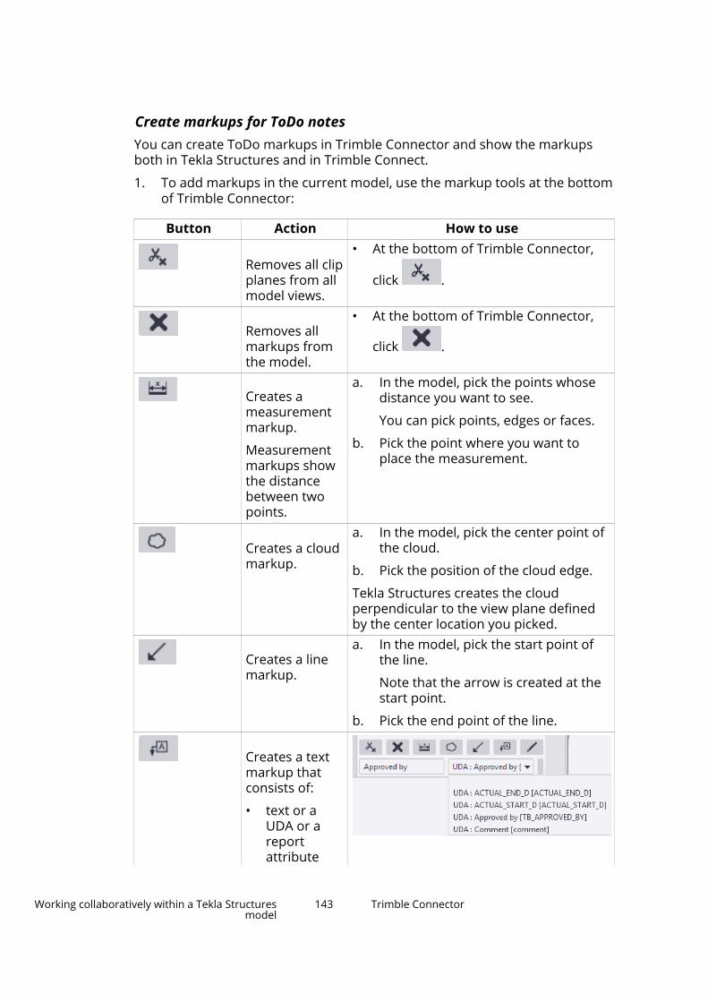
Create markups for ToDo notesYou can create ToDo markups in Trimble Connector and show the markupsboth in Tekla Structures and in Trimble Connect.
1. To add markups in the current model, use the markup tools at the bottomof Trimble Connector:
Button Action How to use
Removes all clipplanes from allmodel views.
• At the bottom of Trimble Connector,
click .
Removes allmarkups fromthe model.
• At the bottom of Trimble Connector,
click .
Creates ameasurementmarkup.
Measurementmarkups showthe distancebetween twopoints.
a. In the model, pick the points whosedistance you want to see.
You can pick points, edges or faces.
b. Pick the point where you want toplace the measurement.
Creates a cloudmarkup.
a. In the model, pick the center point ofthe cloud.
b. Pick the position of the cloud edge.
Tekla Structures creates the cloudperpendicular to the view plane definedby the center location you picked.
Creates a linemarkup.
a. In the model, pick the start point ofthe line.
Note that the arrow is created at thestart point.
b. Pick the end point of the line.
Creates a textmarkup thatconsists of:
• text or aUDA or areportattribute
Working collaboratively within a Tekla Structuresmodel
143 Trimble Connector

Button Action How to use• a leader line a. Type the text or prefix in the text box
under the markup commands.
b. Select a UDA or a report attributefrom the list under the markupcommands.
In the image above, Approved byhas been entered as text and UDA:Approved by has been selected fromthe list of available attributes.
c. Pick the start point of the leader line.
d. Pick the point where you want to addthe text.
TIP To add more UDAs or reportattributes in the list of availableattributes, or to add new attributesto the Text markup attributeoptions list so that they would beavailable for selection, click theMaintain text markup attributeoptions button in the bottom-rightcorner.
The Text markup attributeoptions dialog box opens:
Here, you can:
• Select the UDAs or reportattributes that you want to add inthe list of available attributes-
Working collaboratively within a Tekla Structuresmodel
144 Trimble Connector

Button Action How to use
• Add new attributes using theoptions at the top. You need to:
a. Select if the attribute is UDAor Report.
b. Select the attribute type(Integer, Double or String).
c. Type a name for theattribute.
d. To add an assemblyattribute, select theAssembly check box.
e. Click + to add the newattribute to the list.
Creates a pencilmarkup, or afreehandmarkup.
a. In the model, pick a start point for themarkup.
b. Move the mouse pointer to draw theshape that you want.
Do not hold down the left mousebutton.
c. Pick the end point of the markup.
Tekla Structures creates the markupperpendicular to the view plane definedby the start point you picked.
2. Select the necessary model objects in the Tekla Structures model.
3. Click the Create ToDo button.
4. Enter the ToDo information.
You need to enter at least a title and a description for the ToDo.
5. Ensure that the ToDo is synchronized with Trimble Connect.
You can click the Refresh the list button to manually upload the ToDoto Trimble Connect.
Assign ToDo notesOnce a project has been shared, ToDos can be assigned to other users. Youcan assign the ToDo only if you are the administrator of the project, or if you
Working collaboratively within a Tekla Structuresmodel
145 Trimble Connector

have created the ToDo. You can only assign ToDos created in TrimbleConnector.
1. Set the priority, type and the status of the ToDo, if needed.
2. Click the Save button to save changes.
1. In the Trimble Connect - ToDos dialog box, double-click the ToDo notethat you want to assign.
2. Click Edit.
3. Click Select next to Assignee and select a project member or a usergroup.
To filter the options that are shown, start typing the name of the user orthe user group.
4. To set a due date for the ToDo note, type the due date in the Due Datebox, or click to select the due date from the calendar.
5. If necessary, do any of the following:
• Select a priority for the ToDo note from the Priority list.
• To define the type of the ToDo, select an option from the Type list.
• To define the status of the ToDo note, select an option from the Statuslist.
6. To save the changes, click Save.
You can close the ToDo property pane by clicking the Close button.
Adjust the ToDo view settings
1. In the Trimble Connect - ToDos dialog box, click the Settings button.
2. Select the Double-click the ToDo view settings to use:
• Adjusts camera and view projection: This option is needed if you donot want the snapshot view to change because of coordinate systemdifference, for example, to keep the current view untouched. If youselect this option, the view projection will also change if the TeklaStructures view projection differs from the ToDo note snapshot viewprojection.
• Removes and adds clip planes: Clip planes in the Tekla Structuresview are removed, and clip planes in the ToDo view are added to theTekla Structures view. This option can only be used available if theAdjusts camera and view projection option is selected.
• Selects objects: This option selects the Tekla Structures native objectif the corresponding object has been selected in the ToDo view. If the
Working collaboratively within a Tekla Structuresmodel
146 Trimble Connector

coordinate systems differ, it is possible to select objects and zoom tothe selected objects.
These settings affect the snapshot view in ToDo notes.
3. To close the settings pane, click the Close button.
Synchronize ToDo notesIf another project member creates or comments on ToDo notes, the ToDos areautomatically synchronized. Alternatively, you can upload ToDo changesmanually:
• In the Trimble Connect - ToDos dialog box, click the Refresh the listbutton.
Match views and selections between Tekla Structures andTrimble Connect for WindowsIf you are working in Tekla Structures and Trimble Connect for Windows at thesame time, you can collaborate with the two applications. In practice, thismeans that you can match the zoom and projection of the 3D model views,and select the same objects in both applications.
Before collaborating, you need to do the following:
• Have a project open in Trimble Connect for Windows and a model open inTekla Structures.
• Export the Tekla Structures model to Trimble Connect in the IFC format.
For more information, see Manage reference models in Trimble Connector(page 125).
• Download and show the model in Trimble Connect for Windows.
Match the camera position, zoom level, and projection of model viewsYou can adjust the model views in Tekla Structures and in Trimble Connect forWindows to match each other as well as possible. When you do so, the cameraposition, zoom level, and view projection of the views are synchronized. Youcan select which model view is the principal model view to which you want tomatch the other model view.
• Do either of the following:
To Do thisAdjust the TeklaStructures model view tomatch the Trimble
• On the Trimble Connect tab, click Matchwith Trimble Connect for Windows view.
Working collaboratively within a Tekla Structuresmodel
147 Trimble Connector

To Do thisConnect for WindowsviewAdjust the TrimbleConnect for Windowsmodel view to match theTekla Structures view
• On the Trimble Connect tab, click Matchwith Tekla Structures view.
Select the same objects• Do either of the following:
To Do thisSelect the currentlyselected TrimbleConnect objects also inthe Tekla Structuresmodel
• On the Trimble Connect tab, click Selectin Trimble Connect for Windows.
Select the currentlyselected Tekla Structuresmodel objects also inTrimble Connect forWindows
• On the Trimble Connect tab, click Selectin Tekla Structures.
Working collaboratively within a Tekla Structuresmodel
148 Trimble Connector

2 Get started with import andexport formats
Tekla Structures is highly interoperable. If you need to exchange modelinformation with users of other software or systems, you can import andexport information in many standard file formats or even establish a directlink with several other products.
• In most cases, the format used for the exchange is a general industrystandard format (page 149) supported by many different tools.
• Formats may be supported for import, export or both. See Compatible fileformats and software with Tekla Structures (page 150) for a listing. Thereyou can also find tables of supported software listing the options you havefor sharing data with many commonly used tools.
• When you are ready to exchange data, see Import to and export from TeklaStructures (page 170)
• You can install new capabilities such as new import and export formats ordirect links to other software from the (page 528).
• If your organization has a capable programmer, you can even add yourown customized import and export formats or direct links to othersoftware and systems using Tekla Open API.
2.1 Industry standardsThere are many industry standard file transfer formats. The principle onessupported by Tekla Structures are IFC, DSTV, SDNF, DGN, DXF, DWG, IGES, andSTEP. Older formats are also included. For a tighter integration, you can link toTekla Structures using the Tekla Open API technology.
The file name extension normally informs the user which format it is basedupon. If you do not know what format it is, or the file does not import, thenyou will need to open the file in a text editor to look at the header information,
Get started with import and export formats 149 Industry standards

where the file type and the authoring application is usually noted. With CIS/2files the authoring application and version number is sometimes written at theend of the file.
See also
Compatible file formats and software with Tekla Structures (page 150)
2.2 Compatible file formats and software with TeklaStructuresThe following tables list the interoperability possibilities of Tekla Structures.
The Compatible file formats list includes the possible file formats for importand export in Tekla Structures.
The Compatible Trimble software, Compatible software with direct links,and Compatible software lists include software that are compatible withTekla Structures.
Some of the listed software have a direct link with Tekla Structures. Manydirect links are available in Tekla Warehouse. When you have a direct link to anapplication, and you export the model from Tekla Structures using thatparticular application, the model is opened in the application. Tekla Structuresand the particular application need to be installed on the same computer.
Compatible file formats
You can import and export several formats in Tekla Structures.
The following table lists many of the different formats you can use in TeklaStructures to import and export data (page 170).
To use some of the formats, you need to download an extension from TeklaWarehouse.
Format Import Export3D image (.obj) X aSa (.TEK) Rebar quantities and
production geometry forcut & bend
Autodesk 3DS Maxformat (.3ds)
X
Autodesk (.dwg) 3D geometry, 2Dgeometry
3D geometry, 2Dgeometry, drawings
Get started with import and export formats 150 Compatible file formats and software with TeklaStructures

Format Import ExportAutodesk (.dxf) 3D geometry, 2D
geometry3D geometry, 2Dgeometry, drawings
Bentley ISM X XBIM Collaborationformat (.bcf)
X X
Blender files (.blend) X BricsCAD (.ifc) X XBVBS (.abs) Rebar quantities and
production geometry forcut & bend, mesh, latticegirder
CIS/2 LPM5/LPM6analytical(.stp,.p21,.step)
3D geometry 3D geometry
CIS/2 LPM5/LPM6 design(.stp,.p21,.step)
3D geometry, attributes 3D geometry, attributes
CIS/2 LPM6manufacturing(.stp,.p21,.step)
3D geometry, attributes
CPIxml Quantities, materialdata, status data
COLLADA (.dae) X .csv Part and assembly
geometry formanufacture, attributes
DSTV (.nc,.stp,.mis) 3D analytical geometry Part data formanufacture
EJE XElematic ELiPLAN,ELiPOS (.eli)
Production status anddates
Element and materialquantitites, productiongeometry for casting,plotting and cutting,design status and notes
EPC XFabsuite (.xml) X XFabTrol Kiss (.kss) Model data, attributesFabTrol MIS Xml (.xml) X XFilmbox (.fbx) X GL Transmission Format(.glft)
X
Get started with import and export formats 151 Compatible file formats and software with TeklaStructures
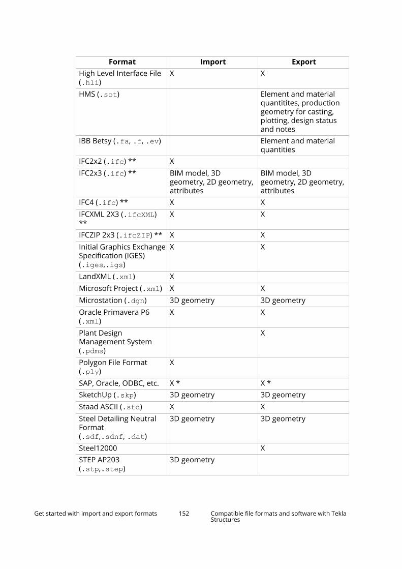
Format Import ExportHigh Level Interface File(.hli)
X X
HMS (.sot) Element and materialquantitites, productiongeometry for casting,plotting, design statusand notes
IBB Betsy (.fa, .f, .ev) Element and materialquantities
IFC2x2 (.ifc) ** X IFC2x3 (.ifc) ** BIM model, 3D
geometry, 2D geometry,attributes
BIM model, 3Dgeometry, 2D geometry,attributes
IFC4 (.ifc) ** X XIFCXML 2X3 (.ifcXML)**
X X
IFCZIP 2x3 (.ifcZIP) ** X XInitial Graphics ExchangeSpecification (IGES)(.iges,.igs)
X X
LandXML (.xml) X Microsoft Project (.xml) X XMicrostation (.dgn) 3D geometry 3D geometryOracle Primavera P6(.xml)
X X
Plant DesignManagement System(.pdms)
X
Polygon File Format(.ply)
X
SAP, Oracle, ODBC, etc. X * X *SketchUp (.skp) 3D geometry 3D geometryStaad ASCII (.std) X XSteel Detailing NeutralFormat(.sdf,.sdnf, .dat)
3D geometry 3D geometry
Steel12000 XSTEP AP203(.stp,.step)
3D geometry
Get started with import and export formats 152 Compatible file formats and software with TeklaStructures

Format Import ExportSTEP AP214(.stp,.step)
3D geometry 3D geometry
StruM.I.S X 3D geometry, 2Dgeometry, drawings
Tekla Collaboration(.tczip)
X X
Tekla EPM (e.g. Fabsuite) Model data, attributes,drawings, NC files
Tekla-FabTrol Report(.xsr)
X
Tekla StructuralDesigner model (.tsmd)
Analysis & Design model Analysis & Design model
Tekla StructuralDesigner neutral (.cxl)
Analysis & Design model Analysis & Design model
Tekla Structures shape(.tsc)
X X
Trimble Field Link (.tfl) X XTrimble LM80(.txt,.cnx)
X X
TubeNC (.xml) Part geometry formanufacture
Unitechnik (.uni, .cam) Element and materialquantities, processinformation, productiongeometry for precastformwork, plotting,mesh-welding
* Tekla OpenAPI used
**For a list of IFC applications certified by buildingSMART international, seeCertified Software.
Get started with import and export formats 153 Compatible file formats and software with TeklaStructures

Compatible Trimble software
The following table lists the Trimble software that is compatible with TeklaStructures.
Trimble product Import to TeklaStructures
Export from TeklaStructures
3D+ Autodesk (.dwg)
Autodesk (.dxf)
Steel Detailing NeutralFormat (.sdf, .sdnf)
Autodesk (.dwg)
Autodesk (.dxf)
DuctDesigner 3D Autodesk (.dwg)
Autodesk (.dxf)
IFC2X3 (.ifc)
Autodesk (.dwg)
Autodesk (.dxf)
IFC2X3 (.ifc)PipeDesigner 3D Autodesk (.dwg)
Autodesk (.dxf)
IFC2X3 (.ifc)
Autodesk (.dwg)
Autodesk (.dxf)
IFC2X3 (.ifc)Plancal IFC2X3 (.ifc)
Autodesk (.dwg)
Autodesk (.dxf)
IFC2X3 (.ifc)
Autodesk (.dwg)
Autodesk (.dxf)SketchUp Make SketchUp (.skp) SketchUp (.skp)SketchUp Pro SketchUp (.skp)
Autodesk (.dwg)
Autodesk (.dxf)
SketchUp (.skp)Autodesk (.dwg)
Autodesk (.dxf)Tekla Field3D IFC2X3 (.ifc)Tekla Civil Direct Link
LandXML (.xml)
Direct Link
IFC2X3 (.ifc)Tekla Collaboration Tekla Collaboration files
(.tczip)Tekla Collaboration files(.tczip)
Tekla StructuralDesigner
Direct link (.tsmd)
Neutral XML (.cxl)
Direct link (.tsmd)
Neutral XML (.cxl)Trimble Business Centre LandXML (.xml) Trimble Connect Direct Link
IFC2X3 (.ifc)
Direct Link
IFC2X3 (.ifc)Trimble Field Link Trimble Field Link (.tfl) Trimble Field Link (.tfl)Vico Office Direct Link Autodesk (.dwg)
Get started with import and export formats 154 Compatible file formats and software with TeklaStructures

Trimble product Import to TeklaStructures
Export from TeklaStructures
Autodesk (.dxf) IFC2X3 (.ifc) IfcXML 2X3 (.xml) IfcXML 2X3 (.xml) Microstation (.dgn) Excel Spreadsheet
(.xls)Excel Spreadsheet(.xls)
Vico Schedule Planner Direct Link.xml
Direct Link.xml
Compatible software with direct links
The following table lists the software that have a direct link with TeklaStructures to import and export data (page 170).
Many direct links are available in Tekla Warehouse.
The table also lists the file formats that can be used in case the direct link isnot possible.
Product Company Import to TeklaStructures
Export from TeklaStructures
ADConX ADConX Direct LinkAxisVM Inter-CAD Kft. Direct Link Direct Link
IFC2X3 (.ifc)BeamMaster AGT Direct LinkBentleyArchitecture
Bentley Direct Link (ISM) Direct Link (ISM)
Autodesk (.dwg) Autodesk (.dwg) Autodesk (.dxf) Autodesk (.dxf) IFC2X3 (.ifc) IFC2X3 (.ifc) Microstation (.dgn) Microstation (.dgn) STEP AP203/AP214
(.stp, .step)STEP AP214(.stp, .step)
BentleyStructural
Bentley Direct Link (ISM) Direct Link (ISM)
Autodesk (.dwg) Autodesk (.dwg) Autodesk (.dxf) Autodesk (.dxf) CIS/2 LPM6 design
(.stp, .p21, .step)IFC2X3 (.ifc)
Get started with import and export formats 155 Compatible file formats and software with TeklaStructures

Product Company Import to TeklaStructures
Export from TeklaStructures
IFC2X3 (.ifc) Microstation (.dgn) Microstation (.dgn) Steel Detailing
Neutral Format(.sdf, .sdnf)
STEP AP203/AP214(.stp, .step)
STEP AP214(.stp, .step)
BricsCAD Bricsys .ifc .ifcCYPECAD Cype Direct LinkDiamonds Buildsoft Direct Link Direct LinkFabsuite Fabsuite Direct Link
KISS (.kss)
Direct Link
KISS (.kss)FEM Design StruSoft Direct Link
IFC2X3 (.ifc)
Direct Link
IFC2X3 (.ifc)IDEA StatiCa IDEA StatiCa Direct LinkJoints ForTekla
ProgettoArchimede
Direct Link
Lantek Lantek Direct Link Direct LinkLIRA-SAPR LIRA SAPR Direct Link (Default,
Russia)Direct Link(Default, Russia)
LIRA 10 LIRA SOFT Direct Link (Russia) Direct Link (Russia)MeridianProlog
Trimble Direct Link
Midas Gen MIDAS Direct Link Direct LinkModeSt Tecnisoft Direct Link Direct LinkPEMAWeldControl
Pemamek Direct Link
Pipelabo Maruhide Direct LinkPowerConnect
Buildsoft Direct Link Direct Link
PowerFrame Buildsoft Direct Link Direct LinkProCAM HGG Direct Link Direct LinkPro-Fit Zeman Direct LinkQnect Qnect Direct LinkRaptor Peddinghaus Direct Link
Get started with import and export formats 156 Compatible file formats and software with TeklaStructures

Product Company Import to TeklaStructures
Export from TeklaStructures
RFEM Dlubal Direct Link
CIS/2 LPM6 analytical(.stp, .p21, .step)
IFC2X3 (.ifc)
Direct Link
CIS/2 LPM6analytical(.stp, .p21, .step)
IFC2X3 (.ifc)RISA 3D(Suite)
Risa Technology Direct Link (USmarket)
Direct Link (USmarket)
Autodesk (.dxf) Autodesk (.dxf) CIS/2 LPM6 analytical
(.stp, .p21, .step)CIS/2 LPM6analytical(.stp, .p21, .step)
CIS/2 LPM6 design(.stp, .p21, .step)
CIS/2 LPM6 design(.stp, .p21, .step)
Steel DetailingNeutral Format(.sdf, .sdnf)
RisaConnection
Risa Technology Direct Link (US, UK,Germany, Sweden,Norway, China, India,Australia)
Direct Link (US, UK,Germany, Sweden,Norway, China,India, Australia)
RobotMillenium
Autodesk Direct Link
CIS/2 LPM6 analytical(.stp, .p21, .step)
CIS/2 LPM6 design(.stp, .p21, .step)
Direct Link
CIS/2 LPM6analytical(.stp, .p21, .step)
CIS/2 LPM6 design(.stp, .p21, .step)
RSTAB Dlubal Direct Link
CIS/2 LPM6 analytical(.stp, .p21, .step)
IFC2X3 (.ifc)
Direct Link
CIS/2 LPM6analytical(.stp, .p21, .step)
IFC2X3 (.ifc)SAP2000 Computers &
Structures, Inc.Direct Link Direct Link
Direct Link (ISM) Direct Link (ISM) Autodesk (.dwg) Autodesk (.dwg) Autodesk (.dxf) Autodesk (.dxf) CIS/2 LPM6 analytical
(.stp, .p21, .step)CIS/2 LPM6analytical(.stp, .p21, .step)
Get started with import and export formats 157 Compatible file formats and software with TeklaStructures
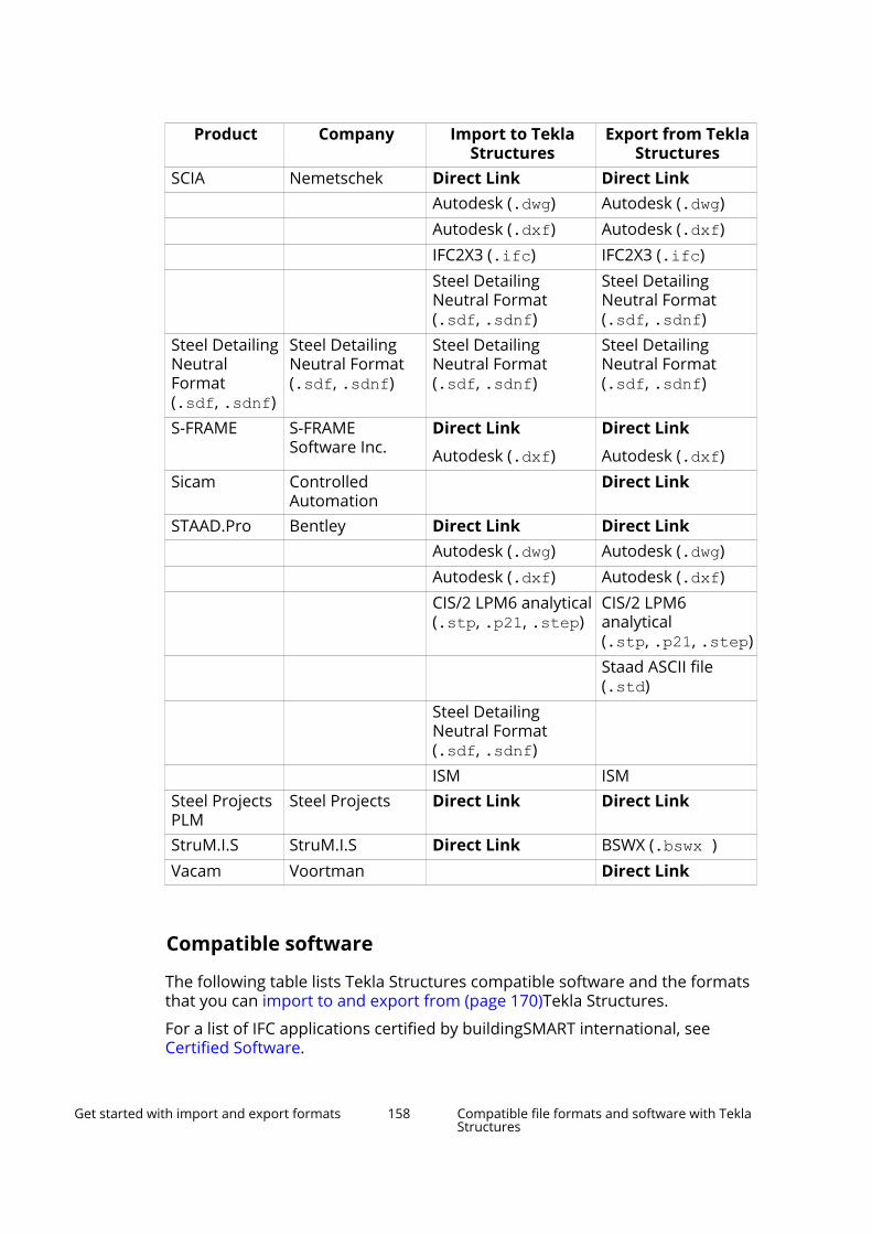
Product Company Import to TeklaStructures
Export from TeklaStructures
SCIA Nemetschek Direct Link Direct Link Autodesk (.dwg) Autodesk (.dwg) Autodesk (.dxf) Autodesk (.dxf) IFC2X3 (.ifc) IFC2X3 (.ifc) Steel Detailing
Neutral Format(.sdf, .sdnf)
Steel DetailingNeutral Format(.sdf, .sdnf)
Steel DetailingNeutralFormat(.sdf, .sdnf)
Steel DetailingNeutral Format(.sdf, .sdnf)
Steel DetailingNeutral Format(.sdf, .sdnf)
Steel DetailingNeutral Format(.sdf, .sdnf)
S-FRAME S-FRAMESoftware Inc.
Direct Link
Autodesk (.dxf)
Direct Link
Autodesk (.dxf)Sicam Controlled
Automation Direct Link
STAAD.Pro Bentley Direct Link Direct Link Autodesk (.dwg) Autodesk (.dwg) Autodesk (.dxf) Autodesk (.dxf) CIS/2 LPM6 analytical
(.stp, .p21, .step)CIS/2 LPM6analytical(.stp, .p21, .step)
Staad ASCII file(.std)
Steel DetailingNeutral Format(.sdf, .sdnf)
ISM ISMSteel ProjectsPLM
Steel Projects Direct Link Direct Link
StruM.I.S StruM.I.S Direct Link BSWX (.bswx )Vacam Voortman Direct Link
Compatible software
The following table lists Tekla Structures compatible software and the formatsthat you can import to and export from (page 170)Tekla Structures.
For a list of IFC applications certified by buildingSMART international, seeCertified Software.
Get started with import and export formats 158 Compatible file formats and software with TeklaStructures

To find out more about the various import and export tools, see Import to andexport from Tekla Structures (page 170).
Product Company Import to TeklaStructures
Export from TeklaStructures
3ds Max Autodesk Autodesk (.dwg)
Autodesk (.dxf)
IGES (.iges, .igs)
Autodesk (.dwg)
Autodesk (.dxf)
3ds MaxDesign/VIZ
Autodesk Autodesk (.dwg)
Autodesk (.dxf)
IGES (.iges, .igs)
Autodesk (.dwg)
Autodesk (.dxf)
A+ Software ArmaPlus BVBS (.abs)
Soulé (.xml)
aSa (.TEK)Adapt Adapt
Corporation
Autodesk (.dwg)
Autodesk (.dxf)
Autodesk (.dwg)
Autodesk (.dxf)
AdvancedSteel,AdvancedDesign/Engineering
Autodesk CIS/2 LPM5 analytical(.stp, .p21, .step)
IFC2X3 (.ifc)
Steel Detailing NeutralFormat (.sdf, .sdnf)
CIS/2 LPM5 analytical(.stp, .p21, .step)
IFC2X3 (.ifc)
Steel Detailing NeutralFormat (.sdf, .sdnf)
Allplan/Planbar
Nemetschek
Autodesk (.dwg) Autodesk (.dwg)Autodesk (.dxf) Autodesk (.dxf)IFC2X3 (.ifc) IFC2X3 (.ifc)Microstation (.dgn) Microstation (.dgn)
ANSYS ANSYS IGES (.iges, .igs) IGES (.iges, .igs)ArchiCAD Graphisoft
/Nemetschek
Autodesk (.dwg) Autodesk (.dwg)Autodesk (.dxf) Autodesk (.dxf)IFC2X3 (.ifc) IFC2X3 (.ifc)IFCXML 2X3 (.xml) IFCXML 2X3 (.xml)IFCZIP (.ifczip) IFCZIP (.ifczip)Coordinated view v1 Coordinated view v1
ArchonCAD ArchonCAD Ltd.
Autodesk (.dwg)
Autodesk (.dxf)
IGES (.iges, .igs)
Autodesk (.dwg)
Autodesk (.dxf)
Armaor Ariadis BVBS (.abs)
Get started with import and export formats 159 Compatible file formats and software with TeklaStructures

Product Company Import to TeklaStructures
Export from TeklaStructures
Artube Adige STEP (.stp, .step)
IGES (.iges, .igs)
IFC (.ifc)aSa Rebar Applied
SystemsAssociatesInc
aSa Rebar file (.TEK)
ASI AppliedScienceInternational LLC
Staad ASCII file (.std)
AutoCAD Autodesk Autodesk (.dwg)
Autodesk (.dxf)
Autodesk (.dwg)
Autodesk (.dxf)AutoCADArchitecture
Autodesk Autodesk (.dwg) Autodesk (.dwg)Autodesk (.dxf) Autodesk (.dxf)IFC2X3 (.ifc) IFC2X3 (.ifc)IGES (.iges, .igs) Microstation (.dgn)
AutoCAD Civil3D
Autodesk Autodesk (.dwg) Autodesk (.dwg)Autodesk (.dxf) Autodesk (.dxf)Microstation (.dgn) LandXML files (.xml)
AutoCAD MEP Autodesk Autodesk (.dwg) Autodesk (.dwg)Autodesk (.dxf) Autodesk (.dxf)IFC2X3 (.ifc) IFC2X3 (.ifc) Microstation (.dgn)
AutoPLANT Bentley Autodesk (.dwg)
Autodesk (.dxf)
Autodesk (.dwg)
Autodesk (.dxf)AutoVue Oracle Autodesk (.dwg)
Autodesk (.dxf)
IFC2X3 (.ifc)
STEP AP214(.stp, .step)
Get started with import and export formats 160 Compatible file formats and software with TeklaStructures

Product Company Import to TeklaStructures
Export from TeklaStructures
Aveva E3D AVEVA Microstation (.dgn)
Steel Detailing NeutralFormat(.sdf, .sdnf, .dat)
.ifc based TeklaCollaboration files(.tczip)
Microstation (.dgn)
Steel Detailing NeutralFormat(.sdf, .sdnf, .dat)
.ifc based TeklaCollaboration files(.tczip)
AviCAD Progress/EBAWE
Unitechnik (.cam),BVBS (.abs)
BentleyBuildingElectricalSystems
Bentley Autodesk (.dwg) Autodesk (.dwg)Autodesk (.dxf) Autodesk (.dxf)IFC2X3 (.ifc) IFC2X3 (.ifc)Microstation (.dgn) Microstation (.dgn)STEP AP203/AP214(.stp, .step)
STEP AP214(.stp, .step)
BentleyBuildingMechanicalSystems
Bentley Autodesk (.dwg) Autodesk (.dwg)Autodesk (.dxf) Autodesk (.dxf)IFC2X3 (.ifc) IFC2X3 (.ifc)Microstation (.dgn) Microstation (.dgn)STEP AP203/AP214(.stp, .step)
STEP AP214(.stp, .step)
BentleyInroads
Bentley LandXML files (.xml)
Betsy IBB –Consultants &Engineers
Betsy (.fa), Betsy (.f),Betsy (.ev)
Cadmatic Cadmatic Autodesk (.dwg)
Autodesk (.dxf)
IFC2X3 (.ifc)
Autodesk (.dwg)
Autodesk (.dxf)
IFC2X3 (.ifc)CADmep+ MAP
Software /Autodesk
Autodesk (.dwg) Autodesk (.dwg)Autodesk (.dxf) Autodesk (.dxf)IFC2X3 (.ifc) IFC2X3 (.ifc)IFCXML 2X3 (.xml) IFCXML 2X3 (.xml)IFCZip (.ifczip) IFCZip (.ifczip)
Get started with import and export formats 161 Compatible file formats and software with TeklaStructures

Product Company Import to TeklaStructures
Export from TeklaStructures
CADPipe AECDesignGroup
Autodesk (.dwg)
Autodesk (.dxf)
Autodesk (.dwg)
Autodesk (.dxf)
CADWorx Plant Intergraph/ Hexagon
Autodesk (.dwg) Autodesk (.dwg)Autodesk (.dxf) Autodesk (.dxf)CIS/2 LPM6 analytical(.stp,.p21,.step)
CIS/2 LPM6 analytical(.stp,.p21,.step)
CIS/2 LPM6 design(.stp,.p21,.step)
CIS/2 LPM6 design(.stp,.p21,.step)
CAESAR II Intergraph/ Hexagon
Autodesk (.dwg) Autodesk (.dwg)
CATIA Dassault Autodesk (.dwg) Autodesk (.dxf) IGES (.iges, .igs) Steel Detailing NeutralFormat (.sdf, .sdnf)
Steel Detailing NeutralFormat (.sdf, .sdnf)
STEP AP203/AP214(.stp, .step)
STEP AP214(.stp, .step)
Concrete Pro LAP LaserGmbH
Autodesk (.dwg)
Autodesk (.dxf)
Unitechnik (.cam)ConSteel ConSteel
SolutionsLimited
ASCII
Corobs MüllerOpladen
TubeNC (.xml)
DaystarSoftware
DaystarSoftwareInc.
Autodesk (.dxf)
Steel Detailing NeutralFormat (.sdf, .sdnf)
Autodesk (.dxf)
Steel Detailing NeutralFormat (.sdf, .sdnf)
DDS-CAD DDS IFC2X3 (.ifc) IFC2X3 (.ifc)Digital Project Gehry
Technologies
Autodesk (.dwg) Autodesk (.dwg)Autodesk (.dxf) Autodesk (.dxf)IGES (.iges, .igs) Steel Detailing NeutralFormat (.sdf, .sdnf)
Steel Detailing NeutralFormat (.sdf, .sdnf)
STEP AP203/AP214(.stp, .step)
STEP AP214(.stp, .step)
Get started with import and export formats 162 Compatible file formats and software with TeklaStructures

Product Company Import to TeklaStructures
Export from TeklaStructures
ebos Progress/EBAWE
Unitechnik (.cam)
elcoCAD HannappelSOFTWARE GmbH
Autodesk (.dwg)
Autodesk (.dxf)
Autodesk (.dwg)
Autodesk (.dxf)
ELiPLAN Elematic ELiPLAN (.eli) ELiPLAN (.eli)ELiPOS Elematic ELiPLAN (.eli)EliteCAD Messerli
InformatikIFC2X3 (.ifc)
Autodesk (.dxf)
IFC2X3 (.ifc)
Autodesk (.dxf)ETABS Computers
&Structures, Inc.
Autodesk (.dwg) Autodesk (.dwg)Autodesk (.dxf) Autodesk (.dxf)CIS/2 LPM6 analytical(.stp, .p21, .step)
CIS/2 LPM6 analytical(.stp, .p21, .step)
Steel Detailing NeutralFormat (.sdf, .sdnf)
Steel Detailing NeutralFormat (.sdf, .sdnf)
STEP AP214(.stp, .step)
FabPro Pipe UHPProcessPiping Inc.
Autodesk (.dwg)
Autodesk (.dxf)
Autodesk (.dwg)
Autodesk (.dxf)
FabTrol MRP FabTrol FabTrol MIS XML (.xml) FabTrol MIS XML (.xml)
FabTrol KISS File (.kss)
Tekla-FabTrol Report(.xsr)
FactoryCAD Siemens Autodesk (.dwg)
Autodesk (.dxf)
Autodesk (.dwg)
Autodesk (.dxf)FelixCAD SofTec Autodesk (.dwg)
Autodesk (.dxf)
Autodesk (.dwg)
Autodesk (.dxf)Floor Pro Adapt
Corporation
Autodesk (.dwg)
Autodesk (.dxf)
Autodesk (.dwg)
Autodesk (.dxf)
FormZ AutoDesSys, Inc.
Autodesk (.dwg) Autodesk (.dwg)Autodesk (.dxf) Autodesk (.dxf)IGES (.iges, .igs) STEP AP203/AP214(.stp, .step)
STEP AP214(.stp, .step)
Get started with import and export formats 163 Compatible file formats and software with TeklaStructures

Product Company Import to TeklaStructures
Export from TeklaStructures
FXTube Mazak STEP (.stp, .step)
IGES (.iges, .igs)
IFC (.ifc)GSA Oasys CIS/2 LPM6 analytical
(.stp, .p21, .step)CIS/2 LPM6 analytical(.stp, .p21, .step)
GT Strudl GT Strudl Autodesk (.dxf)
CIS/2 LPM6 analytical(.stp, .p21, .step)
Autodesk (.dxf)
HMS HMS HMS (.sot)HOOPS Tech Soft
3DAutodesk (.dwg)
Autodesk (.dxf)Inventor Autodesk Autodesk (.dwg) Autodesk (.dwg)
Autodesk (.dxf) Autodesk (.dxf)IGES (.iges, .igs) STEP AP203/AP214(.stp, .step)
STEP AP214(.stp, .step)
IronCAD IronCAD Autodesk (.dwg) Autodesk (.dwg)Autodesk (.dxf) Autodesk (.dxf)IGES (.iges, .igs) STEP AP203/AP214(.stp, .step)
STEP AP214(.stp, .step)
iTWO RIBSoftwareAG
CPIxml (.xml)
KeyCreator Kubotek Autodesk (.dwg) Autodesk (.dwg)Autodesk (.dxf) Autodesk (.dxf)IGES (.iges, .igs) STEP AP203/AP214(.stp, .step)
STEP AP214(.stp, .step)
LEIT2000 SAA Unitechnik (.cam)LP-System Lennerts &
PartnerBVBS (.abs)
MagiCAD Progman Autodesk (.dwg)
IFC2X3 (.ifc)
Autodesk (.dwg)
IFC2X3 (.ifc)MasterFrame MasterSeri
esDSTV96(.nc, .stp, .mis)
DSTV96(.nc, .stp, .mis)
Get started with import and export formats 164 Compatible file formats and software with TeklaStructures

Product Company Import to TeklaStructures
Export from TeklaStructures
Maxon Cinema4D
Nemetschek
Autodesk (.dwg)
Autodesk (.dxf)
Autodesk (.dwg)
Autodesk (.dxf)Maya Autodesk Autodesk (.dxf)
IGES (.iges, .igs)
STEP AP214(.stp, .step)
Autodesk MayaAutodesk (.dxf)
Mesh Welding EVG(Filzmoser)
Unitechnik (.cam)
BVBS (.abs)Mesh Welding A.W.M. Unitechnik (.cam)Mesh Welding Progress /
EBAWEUnitechnik (.cam)
MicrosoftOffice Project
Microsoft Project (.xml) Project (.xml)
Microstran Engineering SystemsPty Limited
Autodesk (.dxf) Autodesk (.dxf)
Microstation Bentley Autodesk (.dwg) Autodesk (.dwg)Autodesk (.dxf) Autodesk (.dxf)IGES (.iges, .igs) IGES (.iges, .igs)Microstation (.dgn) Microstation (.dgn)STEP AP203/AP214(.stp, .step)
STEP AP214(.stp, .step)
Multiframe DaystarSoftwareInc.
Autodesk (.dxf)
Steel Detailing NeutralFormat (.sdf, .sdnf)
Autodesk (.dxf)
Steel Detailing NeutralFormat (.sdf, .sdnf)
Nastran MSCSoftwareCorporation
Autodesk (.dwg)
IGES (.iges, .igs)
Autodesk (.dwg)
IGES (.iges, .igs)
NavisWorks Autodesk Autodesk (.dwg)
Autodesk (.dxf)
CIS/2 LPM6 analytical(.stp, .p21, .step)
IFC2X3 (.ifc)
Microstation (.dgn)NX (Unigraph) Siemens Autodesk (.dwg) Autodesk (.dwg)
Autodesk (.dxf) Autodesk (.dxf)
Get started with import and export formats 165 Compatible file formats and software with TeklaStructures

Product Company Import to TeklaStructures
Export from TeklaStructures
IGES (.iges, .igs) STEP AP203/AP214(.stp, .step)
STEP AP214(.stp, .step)
PDMS AVEVA Microstation (.dgn)
Steel Detailing NeutralFormat(.sdf, .sdnf, .dat)
Tekla Collaborationfiles (.tczip)
Microstation (.dgn)
Steel Detailing NeutralFormat(.sdf, .sdnf, .dat)
Tekla Collaborationfiles (.tczip)
PDS Intergraph/ Hexagon
Microstation (.dgn)
Steel Detailing NeutralFormat (.dat)
Microstation (.dgn)
Steel Detailing NeutralFormat (.dat)
PeikkoDesigner
PeikkoGroupCorporation
Plug-ins Plug-ins
PipeCAD Mc4Software
Autodesk (.dxf) Autodesk (.dxf)
Plant-4D CEATechnology
Autodesk (.dwg)
Autodesk (.dxf)
Microstation (.dgn)PRIAMOS GTSdata CPIxml (.xml)
Unitechnik (.cam)Primavera Oracle P6 (.xml) P6 (.xml)ProStructures Bentley Autodesk (.dwg)
Autodesk (.dxf) Microstation (.dgn)Steel Detailing NeutralFormat (.sdf, .sdnf)
Steel Detailing NeutralFormat (.sdf, .sdnf)
ISM ISMPro/Engineer PTC IGES (.iges, .igs)
STEP AP203/AP214(.stp, .step)
STEP AP214(.stp, .step)
ProFit Progress/EBAWE
BVBS (.abs)
Prokon Prokon CIS/2 LPM6 analytical(.stp, .p21, .step)
CIS/2 LPM6 analytical(.stp, .p21, .step)
Get started with import and export formats 166 Compatible file formats and software with TeklaStructures

Product Company Import to TeklaStructures
Export from TeklaStructures
PythonX LincolnElectric
DSTV
RAM (CADStudio)
Bentley Autodesk (.dwg) Autodesk (.dwg)Autodesk (.dxf) Autodesk (.dxf)CIS/2 LPM6 analytical(.stp, .p21, .step)
CIS/2 LPM6 analytical(.stp, .p21, .step)
CIS/2 LPM6 design(.stp, .p21, .step)
CIS/2 LPM6 design(.stp, .p21, .step)
ISM ISMRevitArchitecture/MEP
Autodesk Autodesk (.dwg) Autodesk (.dwg)Autodesk (.dxf) Autodesk (.dxf)IFC2X3 (.ifc) IFC2X3 (.ifc)Microstation (.dgn) Microstation (.dgn) Tekla Collaboration
files (.tczip)Revit Structure Autodesk Autodesk (.dwg) Autodesk (.dwg)
Autodesk (.dxf) Autodesk (.dxf)CIS/2 LPM6 design(.stp, .p21, .step)
CIS/2 LPM6 design(.stp, .p21, .step)
IFC2X3 (.ifc) IFC2X3 (.ifc)Microstation (.dgn) Microstation (.dgn) Tekla Collaboration
files (.tczip)Rhinoceros McNeel
NorthAmerica
Autodesk (.dwg) Autodesk (.dwg)Autodesk (.dxf) Autodesk (.dxf)IGES (.iges, .igs) Microstation (.dgn) Microstation (.dgn)STEP AP203/AP214(.stp, .step)
STEP AP214(.stp, .step)
Geometry Gym link Geometry Gym linkRinasWeld Kranendon
kIFC2X3 (.ifc)
SACS EngineeringDynamicsInc.
Autodesk (.dxf)
Steel Detailing NeutralFormat (.sdnf)
SAFE Computers&
Autodesk (.dwg) Autodesk (.dwg)
Get started with import and export formats 167 Compatible file formats and software with TeklaStructures

Product Company Import to TeklaStructures
Export from TeklaStructures
Structures,Inc.
Autodesk (.dxf) Autodesk (.dxf)CIS/2 LPM6 analytical(.stp, .p21, .step)
CIS/2 LPM6 analytical(.stp, .p21, .step)
IGES (.iges, .igs) SAM Bestech
LimitedAutodesk (.dxf) Autodesk (.dxf)
SchnellSoftware
SchnellSoftware
BVBS (.abs)
Unitechnik (rebar/mesh)
SDS/2 DesignData
Autodesk (.dwg) Autodesk (.dwg)Autodesk (.dxf) Autodesk (.dxf)CIS/2 LPM6 analytical(.stp, .p21, .step)
CIS/2 LPM6 analytical(.stp, .p21, .step)
CIS/2 LPM6 design(.stp, .p21, .step)
CIS/2 LPM6 design(.stp, .p21, .step)
CIS/2 LPM6manufacturing(.stp, .p21, .step)
Microstation (.dgn) Microstation (.dgn)Smart 3D(SmartPlant /SmartMarine)
Intergraph/ Hexagon
CIS/2 LPM6 analytical(.stp, .p21, .step)
CIS/2 LPM6 analytical(.stp, .p21, .step)
CIS/2 LPM6 design(.stp, .p21, .step)
CIS/2 LPM6 design(.stp, .p21, .step)
Microstation (.dgn) Microstation (.dgn)IFC2X3 (.ifc), withSmartPlant 3D
Solibri ModelChecker/ModelViewer
Solibri IFC2X3 (.ifc)
SolidEdge Siemens Autodesk (.dxf) Autodesk (.dxf)Microstation (.dgn) Microstation (.dgn)IGES (.iges, .igs) STEP AP203/AP214(.stp, .step)
STEP AP214(.stp, .step)
SolidWorks Dassault Autodesk (.dwg) Autodesk (.dwg)Autodesk (.dxf) Autodesk (.dxf)IGES (.iges, .igs) IFC2X3 (.ifc) IFC2X3 (.ifc)
Get started with import and export formats 168 Compatible file formats and software with TeklaStructures

Product Company Import to TeklaStructures
Export from TeklaStructures
STEP AP203/AP214(.stp, .step)
STEP AP214(.stp, .step)
Soulé SouléSoftwareInc.
.xmlBVBS (.abs)
SPACE GASS SPACEGASS
CIS/2 LPM6 analytical(.stp, .p21, .step)
CIS/2 LPM6 analytical(.stp, .p21, .step)
SpaceClaim SpaceClaim Co.
Autodesk (.dwg) Autodesk (.dwg)Autodesk (.dxf) Autodesk (.dxf)IGES (.iges, .igs) STEP AP203/AP214(.stp, .step)
STEP AP214(.stp, .step)
Steel SmartSystem
AppliedScienceInternational, LLC
Autodesk (.dwg)
Autodesk (.dxf)
Autodesk (.dwg)
Autodesk (.dxf)
StructureWorks
StructureWorks LLC.
Autodesk (.dwg) Autodesk (.dxf) IGES (.iges, .igs) STEP AP203/AP214(.stp, .step)
STEP AP214(.stp, .step)
TurboCAD IMSIDesign
Autodesk (.dwg) Autodesk (.dwg)Autodesk (.dxf) Autodesk (.dxf)Microstation (.dgn) Microstation (.dgn)STEP AP203/AP214(.stp, .step)
STEP AP214(.stp, .step)
UniCAM Unitechnik Unitechnik(.cam, .uni)
Unigraphics SiemensPLMSoftware
IGES (.iges, .igs)
Vernon LincolnElectric
TubeNC (.xml)
VectorWorks Nemetschek
IFC2X3 (.ifc)
IGES (.iges, .igs)
Autodesk (.dwg)
Autodesk (.dxf)
IFC2X3 (.ifc)Volo View Autodesk Autodesk (.dwg)
Autodesk (.dxf)
Autodesk (.dwg)
Autodesk (.dxf)
Get started with import and export formats 169 Compatible file formats and software with TeklaStructures

3 Import to and export fromTekla Structures
Tekla Structures has several tools you can use to import and export physicaland reference models and the information they contain.
For details about compatible software in import and export, see Compatiblefile formats and software with Tekla Structures (page 150).
NOTE The import and export functionality is not available in all Tekla Structuresconfigurations.
You can use import and export in Tekla Structures for several purposes:
• You can import reference models to Tekla Structures. For example, you canimport an architectural model, a plant design model, or a heating,ventilating and air-conditioning (HVAC) model as a reference model.Reference models can also be simple 2D drawings that are imported andthen used as a layout to directly build the model on.
• You can import 2D or 3D models created by other software, then detail ormodify the structural objects using Tekla Structures. Once the model iscomplete, you can export it, and return it to the architect or engineer forreview.
• You can create reports from the imported models from most of theformats.
• You can export Tekla Structures models for use in Analysis & Design(several formats). Then you can import the Analysis & Design results backto the Tekla Structures model.
• Various model transfers can be completed for the engineering andcontractor phase of the project.
• You can import shapes from many formats. Shapes are used in definingitems.
Import to and export from Tekla Structures 170

• You can export data for use in manufacturing information systems and inthe fabrication phase:
• You can export Computer Numerical Control (CNC) data for use byautomated cutting, drilling and welding CNC machinery.
• You can export Manufacturing Information Systems (MIS) data so thatfabricators can track project progress, for example.
Click the links below to find out more about the various types of import andexport:
Reference models and compatible formats (page 175)
Trimble Connector (page 117)
IFC (page 205)
DWG and DXF (page 248)
DGN (page 280)
LandXML (page 285)
PDF (page 287)
SketchUp (page 288)
Point clouds (page 289)
Layout manager (page 304)
Analysis and design systems (page 323)
Steel fabrication (page 344)
Automated precast fabrication (page 392)
CAD (page 517)
In addition to these built-in import and export tools, you have a variety of linksto other applications available in Tekla Warehouse that you can download.
3.1 Conversion filesConversion files (.cnv) map Tekla Structures profile, twin profile, and materialnames with names used in other software.
Conversion files are simple text files, containing the Tekla Structures name inthe first column, and the name used in the other software package in thesecond column. Columns are separated by a space. All parametric profilesmust be entered in the profile conversion file.
You can use the same conversion file both when importing and exportingmodels, and you can specify the location of conversion files in most of theimport and export tools.
Import to and export from Tekla Structures 171 Conversion files

If you enter a conversion file name without a path, Tekla Structures searchesfor the file in the current model folder. If you leave the box empty, TeklaStructures searches for the file indicated by the advanced option XS_PROFDBin File menu --> Settings --> Advanced options --> File Locations . This isalso the case, if the tool does not allow you to define the path and conversionfile.
Tekla Structures has several conversion files in the standard installation, andyou can also create your own. Standard conversion files are located in the \profil folder under the environment folder ...\ProgramData\Trimble\Tekla Structures\<version>\environments\ folder. The exact locationmay vary depending on your environment. All conversion files have the .cnvextension.
Create conversion filesYou can create your own conversion files if the ones that come with TeklaStructures installation do not suit your needs.
1. Open an existing conversion file using any standard text editor.
By default, conversion files are located in the \profil folder under theenvironment folder...\ProgramData\Trimble\Tekla Structures\<version>\environments\. The exact location may vary depending onyour environment.
2. Save the file with another name.
If the export/import tool allows you to define the path to the conversionfile, you can save the file where you like. If this is not the case, save the filein a location defined by the advanced option XS_PROFDB in File menu -->Settings --> Advanced options --> File Locations .
Import to and export from Tekla Structures 172 Conversion files
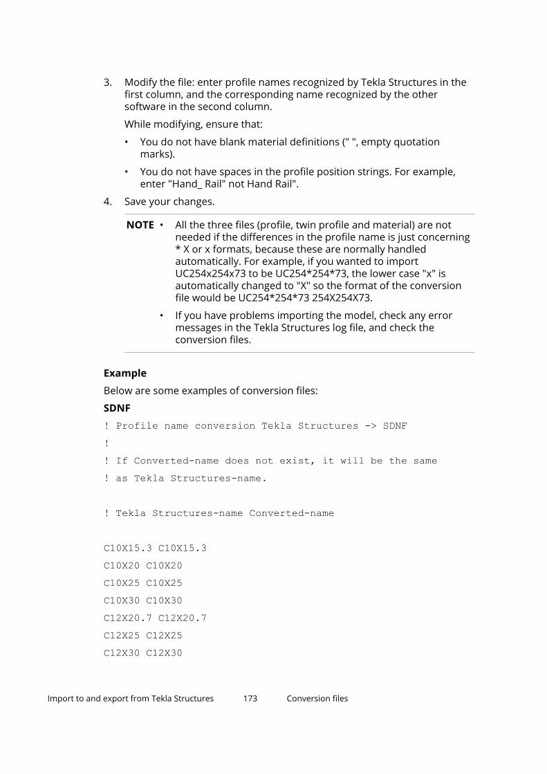
3. Modify the file: enter profile names recognized by Tekla Structures in thefirst column, and the corresponding name recognized by the othersoftware in the second column.
While modifying, ensure that:
• You do not have blank material definitions (" ", empty quotationmarks).
• You do not have spaces in the profile position strings. For example,enter "Hand_ Rail" not Hand Rail".
4. Save your changes.
NOTE • All the three files (profile, twin profile and material) are notneeded if the differences in the profile name is just concerning* X or x formats, because these are normally handledautomatically. For example, if you wanted to importUC254x254x73 to be UC254*254*73, the lower case "x" isautomatically changed to "X" so the format of the conversionfile would be UC254*254*73 254X254X73.
• If you have problems importing the model, check any errormessages in the Tekla Structures log file, and check theconversion files.
Example
Below are some examples of conversion files:
SDNF! Profile name conversion Tekla Structures -> SDNF!! If Converted-name does not exist, it will be the same! as Tekla Structures-name.
! Tekla Structures-name Converted-name
C10X15.3 C10X15.3C10X20 C10X20C10X25 C10X25C10X30 C10X30C12X20.7 C12X20.7C12X25 C12X25C12X30 C12X30
Import to and export from Tekla Structures 173 Conversion files

C15X33.9 C15X33.9C15X40 C15X40C15X50 C15X50C3X4.1 3X4.1DSTV! Profile name conversion Tekla Structures -> DSTV!! If Converted-name does not exist, it will be the same! as Tekla Structures-name.
! Tekla Structures-name Converted-name
C10X15.3 C10X15.3C10X20 C10X20C10X25 C10X25C10X30 C10X30C12X20.7 C12X20.7C12X25 C12X25Below there is first an example of an incorrect conversion file and then of acorrect one, errors are highlighted:
00100782 4 0 2 "brace" "Tread 4" 1 "TREAD4.5" "" 0.000000 0 0 0.000000 1.000000 0.000000 16.250000 13.154267 3.85714315.500000 13.154267 3.857143 0.000000 0.000000 0.0000000.000000 0.000000 0.000000 0.000000 0.000000 0.0000000.000000 0 0 0 0 0 0 0 0 0 0 0 000100782 4 0 2 "brace" "Tread_4" 1 "TREAD4.5" "A36" 0.0000000 0 0.000000 1.000000 0.000000 16.250000 13.154267 3.85714315.500000 13.154267 3.857143 0.000000 0.000000 0.0000000.000000 0.000000 0.000000 0.000000 0.000000 0.0000000.000000 0 0 0 0 0 0 0 0 0 0 0 0
Twin profile conversion filesTekla Structures contains separate conversion files for twin profiles, and itreads the twin profile conversion file before the profile conversion file, so youmust include the profiles from the original model in the import.
The twin profile conversion file is a text file containing the profile prefix(characters only) and the distance between the profiles in mm, separated by a
Import to and export from Tekla Structures 174 Conversion files

space. Tekla Structures converts all profiles with the specified prefix to twinprofiles.
The twin profile conversion file could be named twin_profiles.cnv and itcould contain lines such as the one below:
DL 20The distance between the profiles is the same for all profiles with the sameprofile prefix. For example, profiles with the prefix DL will always have thesame spacing. If you want different spacing values, then you need to use adifferent profile prefix.
You also need to add the twin profile to the profile conversion file to get theDL profile converted to L-profile:
L200*20 DL200/20-20
Limitations
• Twin profile conversion cannot be used for profiles that start with anumber. This means that you cannot define double angles as 2L. Instead,you need to use DL as the prefix for a twin profile, for example: DL200/20-20.
• Twin profile conversion does not work for FEM import. We recommendthat each angle is modeled separately rather than as twin profiles, as SP3Ddoes not control the gaps between members in the same way as TeklaStructures and there are, for example, various conversion and mappingdifficulties. Ii is easier to convert members that are modeled as twomembers.
3.2 Reference models and compatible formatsA reference model is a file that helps you to build a Tekla Structures model. Areference model may be created in Tekla Structures or another software ormodeling tool and then inserted to Tekla Structures.
For example, an architectural model, a plant design model, or a heating,ventilating and air-conditioning (HVAC) model can be used as a referencemodel. Reference models can also be simple 2D drawings that are insertedand then used as a layout to directly build the model on. You can snap toreference model geometry.
Reference models of different formats, such as IFC, IFC4, IFCzip, IFCxml, tcZIP,3DD, DXF, DWG, DGN, XML, LandXML, STP, IGS, SKP and PDF, are converted bythe TrimBimConverter to the TrimBIM (.trb) format at reference modelinsert. The .trb file is saved in the current model folder. The reference cacheis created in the cache folder based on the advanced option XS_REFERENCE_CACHE when the reference model is set visible, which happens automatically atinsert and update.
Import to and export from Tekla Structures 175 Reference models and compatible formats

Examples of supported file types:
• AutoCAD files .dxf• AutoCAD files .dwg (supported version ACAD2018 and earlier)
• IFC files .ifc, .ifczip, .ifcxml• IGES files .igs, .iges• LandXML files .xml• MicroStation files .dgn, .prp• PDF files .pdf• Tekla Collaboration files .tczip• SketchUp files .skp (supported version SketchUp 2021 and earlier)
• STEP files .stp, .STEP• Filmbox files .fbx• COLLADA files .dae• Autodesk 3DS Max format files .3ds• 3D image files .obj• Blender files .blend• GL Transmission Format files .glft• Polygon File Format files .ply• Tekla files (page 121) .tekla• TrimBIM files .trbThe Add model dialog box lists the extensions of all formats that are currentlysupported by Tekla Structures.
Some reference models are automatically subdivided or split into referencemodel objects.
TIP You can disable the roll-over highlight, which can speed up zooming.
Reference model plug-ins in Tekla Warehouse
Reference model plug-ins are available as .tsep plug-ins in Tekla Warehouse.Tekla Structures installation contains the plug-ins, but you can get newer onesfrom Tekla Warehouse. First download the needed package from TeklaWarehouse, and then import it to the Applications & components catalog.
Reference models in drawings
You can show reference models in drawings and adjust their visibility settings.
Import to and export from Tekla Structures 176 Reference models and compatible formats

See also
Insert a reference model (page 177)
Modify reference model details (page 184)
Lock reference models (page 185)
View reference models (page 179)
Detect changes between reference model versions (page 186)
Define a comparison set for reference model change detection (page 192)
Export reference model change detection results to Excel (page 196)
Reference model objects (page 202)
Inquire reference model contents (page 201)
Examine reference model hierarchy (page 203)
Insert a reference modelYou can insert reference models in a Tekla Structures model. You can use thereference models to overlay different discipline models with your own model.These disciplines can be architect, plant engineer, services engineer or otherstructural disciplines.
Note that all characters below 256 are allowed in a reference model file name:both ASCII (0 - 127) and extended ASCII (128 - 255). If the file name containsunsupported characters, you will get a warning message.
1. Open a Tekla Structures model where you want to insert a referencemodel.
2. To insert the reference model, go to the File menu, and select Import -->Insert reference model.
Selecting this command opens both the Reference Models pane and theAdd model dialog box.
You can also open the Reference Models pane first by clicking the
Reference Models button in the side pane , and then click the Addmodel button.
3. In the Add model dialog box, if you have any previously created referencemodel properties files, load the desired file by selecting the file from theproperties file list at the top.
4. In the Add model dialog box, browse for the reference model file byclicking Browse....
Import to and export from Tekla Structures 177 Reference models and compatible formats

You can also drag reference models from Windows Explorer, and insertseveral models at a time.
For a list of compatible formats, see Reference models and compatibleformats (page 175).
5. Select a group for the model or enter the name of a new group.
If you do not enter a name for the group, the reference model is insertedin the Default group.
You can also drag models to an existing group or create a new group lateron.
6. In Location by, select one of the following options:
Model origin inserts the model relative to 0,0,0.
Work plane inserts the model relative to the current work planecoordinate system.
Base point:<name of base point> inserts the model relative to thebase point by using coordinate system values East coordinate, Northcoordinate, Elevation, and Angle to North from the base pointdefinition in Project properties.
7. Select where you want to place the reference model. You can entercoordinates in the Offset boxes or pick a position for the reference modelorigin.
The maximum number of decimals for coordinates is 13.
8. Set the Scale of the reference model if it is different from the one in theTekla Structures model.
Note that you need to set the scale for a DWG or a DXF file already inAutoCAD. When you define the measurement unit for a DWG or a DXF fileand save the file in AutoCAD, the unit is recognized in Tekla Structures,and the reference model is scaled correctly.
The maximum number of decimals for scale is 13.
9. You can rotate the model around model Z axis by picking a location in themodel or entering the desired value in the Rotation box.
The maximum number of decimals for the rotation value is 7.
10. Click More to show more details and add the Code, Title, Phase andDescription of the reference model.
By default, the title is the same as the name of the inserted referencemodel. You may want to use the name of the discipline or the companyinstead, for example. The code could be a site number, project number, oraccounting number. Write the description according to the company
Import to and export from Tekla Structures 178 Reference models and compatible formats

conventions. The phase is the design phase of the reference model (notthe phase in the Tekla Structures model).
Below is an example of these details when you inquire the referencemodel.
You can also modify all the details after you have inserted the model.
11. Click Add model.
12. If the inserted reference model lies outside the work area and is not fullyor at all visible in the model view, Tekla Structures displays a warningmessage. Click Expand to extend the work area to see the referencemodel in the model view.
The reference model is inserted in the current phase of the TeklaStructures model.
Note that for IFC reference models the elevation offset value is not readfrom the inserted reference model.
When a reference model is inserted or updated, reference model data iscopied to Tekla Structures model internal data storage located in the<current model>\datastorage\ref folder. The reference model isvisible even if the original file is removed from its original location. Thereference model data in this folder should not be touched.
NOTE Do not insert the same reference model to the Tekla Structures model severaltimes. One person only should update the reference model (click Refresh) toavoid duplicate object data.
When you want to update the reference model, do not delete the oldreference model from an open Tekla Structures model and replace it with anew one, because then you would lose the work done on reference objects inthe old model. Use the change detection functionality instead.
TIP To only clip reference models and point clouds with the clip plane tool, set theadvanced option XS_DO_NOT_CLIP_NATIVE_OBJECTS_WITH_CLIP_PLANE to TRUE.If you do this, the native objects are not clipped.
See also
Modify reference model details (page 184)
Import to and export from Tekla Structures 179 Reference models and compatible formats

View reference modelsThere are many ways you can select what you want to show about thereference models and how.
For details about inserting reference models, see Insert a reference model(page 177).
To: Do this:Open theReference Modelslist
Do either of the following:
• Go to the File menu, and select Import --> Insert reference model.
•Click the Reference Models buttonin the side pane on the right side of theTekla Structures main window.
Hide and show referencemodels
•Click the eye button next to themodel you want to hide.
The button changes to and thereference model is hidden in the 3D view.
• Click the eye button again to show themodel.
Hide and show a group ofreference models
•Click the eye button next to thegroup you want to hide. The group eyebutton and the reference model eye
buttons all change to , and all thereference models included in the groupare hidden in the Tekla Structures model.
• Click the eye button again to show all themodels in the group.
• If a group contains both hidden andvisible models, the eye button for the
group looks like this .
• If there are no reference models in a
group, the eye button looks like this .Highlight the reference modelin the 3D view
• Click the reference model in theReference Models list.
Show reference model details • Double-click the reference model in theReference Models list.
Import to and export from Tekla Structures 180 Reference models and compatible formats

To: Do this:Show reference model objectdetails
1. Double-click the reference model in theReference Models list.
2.Ensure that the Select assemblies
selection switch (for assemblies) or Select objects in assemblies selectionswitch (for parts) is active.
3. Point the reference model in the modelview, hold down Shift and scroll to thehierarchy level where the desiredreference model object is located.
4. Point the object and double-click it toopen the reference model object details.
Rotate the reference modelaround model Z axis.
• In the reference model details, enter thedesired value in the Rotation box. Youcan also pick the rotation.
Hide and show referencemodel layers
1. Double-click the reference model in theReference Models list to open thedetails.
2. Click the small arrow on the Layers rowto show the list of layers.
3. You can show and hide individual layersor all layers:
• To hide all layers, click the eye button
on the Layers row.
• To hide individual layers, click the eye
buttons of the individual layers.
• To hide several layers, holding downCtrl, click the desired layers and thenclick the eye button of one of theselected layers.
• If the Layers list contains bothhidden and visible layers, the eyebutton for the Layers row looks like
this .
• If you hide all layers, the eye button
for the Layers row changes to .
Import to and export from Tekla Structures 181 Reference models and compatible formats

To: Do this:• If you hide individual layers, the eye
button for the hidden layers changes
to .
Note that layer visibilities do not affect modelvisibility, which means that the model eyeicon is visible even though all layers arehidden.
Detect changes betweendifferent versions of referencemodels
For details about change detection, seeDetect changes between reference modelversions (page 186).
For details about comparison sets, seeDefine a comparison set for reference modelchange detection (page 192).
Refresh all reference models • If the file name or path has not changed,open the Reference Models list and click
the Refresh button.
All models that are not up to date arereloaded. If a reference model is not
found, a warning sign is displayed.
• If the file name or path has not changed,open reference model details, browse forthe new file and click Modify.
You can also refresh locked referencemodels, if you have set the advanced option XS_REFRESH_ALSO_LOCKED_REFERENCE_MODELS to TRUE in File --> Settings -->Advanced options --> Import.
Refresh a single referencemodel
1. Double-click the reference model in theReference Models list to open thedetails.
2.Click the Refresh button.
If the original model path model isfound, and the model has changed, the
model is reloaded. A warning sign isdisplayed if the reference model is notfound and data needed to draw themodel is missing.
Import to and export from Tekla Structures 182 Reference models and compatible formats

To: Do this:Refresh the reference modelwhen settings have changed
•Hold down Ctrl and click the Refresh button.
You need to do this when you havechanged the LargeTessellationPerCircle settingin the TrimBimPlugin.config, forexample. The default value is 192, and ifyou have problems with the performance,you can decrease the value inTrimBimPlugin.config, which islocated in the .bin\plugins\referenceplugins\trimbim folder.Changing this setting affects all newinserted and updated reference models.
View user-defined attributes 1. Double-click the reference model in theReference Models list to open thedetails.
2. Click the small arrow on the User-defined attributes row to show the listof user-defined attributes.
3. The user-defined attributes that arespecified for reference models in theobjects.inp file are listed in the User-defined attributes list. Enter or select avalue from the list. By default, theobjects.inp is locatedin ..\ProgramData\Trimble\TeklaStructures\<version>\environments\common\inp. You mayalso have some objects.inp files thatyou modify and keep in firm or projectfolders. These files are read in certainorder.
Clip reference models onlywith clip plane tool
Set the advancedoptionXS_DO_NOT_CLIP_NATIVE_OBJECTS_WITH_CLIP_PLANE to TRUE to only clipreference models and point clouds with the
Import to and export from Tekla Structures 183 Reference models and compatible formats

To: Do this:clip plane tool. If you do this, the nativeobjects are not clipped.
Redraw the model views after changing thevalue.
This advanced option is located in the ModelView category in the Advanced Optionsdialog box.
See also
Modify reference model details (page 184)
Reference model objects (page 202)
Examine reference model hierarchy (page 203)
Lock reference models (page 185)
Modify reference model detailsAfter you have inserted a reference model, you can modify its details.
Limitation: Coordinates given in the Details section are always relative tomodel coordinates. You can modify the coordinate system only if modelcoordinate system is used in the reference model.
1. Click the Reference Models button in the side pane on the rightside of the Tekla Structures main window.
You can also go to the File menu, and select Import --> Insert referencemodel. Close the Add model dialog box.
2. In the Reference Models list, double-click the reference model that youwant to modify.
3. Click the arrow on the Details row, and change the desired details:
• Change Code, Title, Phase and Description of the reference model.
The code could be a site number, project number, or accountingnumber. By default, the title is the same as the name of the insertedreference model. You may want to use the name of the discipline orthe company instead, for example. Write the description according tothe company conventions. The phase is the design phase of thereference model (not the phase in the Tekla Structures model).
• You can insert another version of the reference model using the Filebox. For more information about version handling, see Detect changesbetween reference model versions (page 186).
• In the Group box, you can select a new group for the reference model.
Import to and export from Tekla Structures 184 Reference models and compatible formats

• You can also change the Location by selection.
By default, the Location by change does not keep the reference modellocation. When you click Modify, the model position changesaccording to East coordinate, North coordinate and Elevationsetting differences. If you want to calculate new offsets and keep thecurrent reference model location, select the check box next to theLocation by setting.
• You can change the Offset by entering new coordinates or by picking anew offset.
• You can change the Rotation by entering a new value or picking a newlocation.
There may be additional rotation boxes available for rotation around Xand Y axis. If the reference model already contains X or Y rotations, theadditional X and Y boxes are not active.
• Change the Scale, if necessary.
• Click the arrow on the User-defined attributes row, and enter valuesfor the user-defined attributes.
You may enter strings (texts), select dates or enter numericinformation depending on the type of the user-defined attribute. Thereference model user-defined attributes are defined in their ownsection in the objects.inp file. If you have several objects.inpfiles, they are read in a specific reading order.
4. Click Modify. The changes that you made are implemented in thereference model.
See also
Insert a reference model (page 177)
Lock reference modelsYou can prevent reference models from moving and from detail updates bylocking the reference models.
1. Click the Reference Models button in the side pane on the rightside of the Tekla Structures main window.
You can also go to the File menu, and select Import --> Insert referencemodel. Close the Add model dialog box.
2. Move your mouse over the desired reference model in the ReferenceModels list.
Import to and export from Tekla Structures 185 Reference models and compatible formats

The Lock/Unlock button is displayed.
3. Click the Lock/Unlock button.
Now the reference model is locked. You can only add values for user-defined attributes and work with layers, but you cannot modify the detailsin any other way or move the model.
To lock multiple reference models, select the models from the list and
click the Lock/Unlock button of one of the reference models.
To unlock the reference model, click the Lock/Unlock button again.
See also
Reference models and compatible formats (page 175)
Modify reference model details (page 184)
Detect changes between reference model versionsYou can check the changes between different IFC reference model versions inTekla Structures using change detection. You can use change detection todetect changes between reference models from different disciplines, such asengineer or detailer. Changes are detected on object level. You can alsocompare Tekla Structures models if you have exported a Tekla Structuresmodel into IFC format at least twice.
Tekla Structures stores versions of the reference models for change detection.Versioning is also needed for visualizing sharing changes and objectconversion change management.
Limitations
• Property comparison works only for IFC or IFC-based reference models.The following formats are supported:
• .ifc• .ifcxml• .ifczip• .tczip
• Deleted objects are not highlighted and cannot be selected.
Import to and export from Tekla Structures 186 Reference models and compatible formats

Change detection
You can show changes between two stored reference model versions orbetween stored version and browsed reference model file version. In both ofthese cases you need to activate change detection:
1. Click the Reference Models button in the side pane on the rightside of the Tekla Structures main window.
You can also go to the File menu, and select Import --> Insert referencemodel. Close the Add model dialog box.
2. Open a reference model by double-clicking the model in the ReferenceModels list.
3. Open the Change detection list by clicking the arrow on the Changedetection row.
Change detection between stored version and browsed model fileversion
The file path box has automatically the full file path to the current referencemodel original file. If a reference model file with the same name has changed,you can run the change detection and skip steps 1 and 3 below .
1. Click ... and browse for an earlier version of the reference model.
2. Select the This model is newer check box next to the file path if you wantto define that the file shown in the box is newer.
3. Ensure that you have both the original reference model and the browsed
reference model version visible by setting the eye buttons active inthe Change detection section.
4. To change the comparison set if needed, click the ... button and define theset you want to use. Then click Update view. The comparison set containsthe properties that you want to use in version comparison.
5. To change property set comparison tolerances, click the Property set
comparison tolerances button .
Import to and export from Tekla Structures 187 Reference models and compatible formats

You can do any of the following in the changes list and in the property detailslist:
• Export change detection results to Excel by clicking Export to Excel.The exported Excel file contains all or changed properties that are visible inthe changes list. The information is exported in the current language.
• Click a row in the changes list to open the related property details list in theside pane. The content of the property details list depends on thecomparison rules that you are using. The details list also indicates how theindividual properties have changed in the Old value and New valuecolumns.
Note that in the property details list, if you by accident remove one of thecolumns, you can bring it back by right-clicking the column title andselecting the column from the context menu. You can then drag thecolumn to the desired location.
• To show the object in the model, select the Select objects in the modelcheck box, and then click a row in the changes list. Note that you cannotselect deleted objects.
• The older state of an object is drawn to the model view when you select thecorresponding object in the changes list.
• To highlight the object in the changes list, select the Get selected objectsfrom model check box, and then click an object in the model.
Import to and export from Tekla Structures 188 Reference models and compatible formats

• To zoom to the selected object in the model, select the Zoom to selectedcheck box, and then click a row in the changes list. You can also zoom todeleted objects.
• The older state of a reference model object is drawn to the 3D view inorange color when you select the corresponding object.
• To show only changes in the property details list, select the Show onlychanges check box, and then click a row in the changes list.
• You can search for specific items using the search box at the bottom.
• If the changes list disappears, you can bring it back by clicking the Changes list button in the side pane. If the details list disappears, you can
bring it back by clicking the Property details button in the side pane.These two buttons are only visible when Change detection is active.
Update reference model and detect changes between versions
You can update a reference model with another version of the model, anddetect the changes between these two reference model versions.
1. Open another version of the reference model by browsing to it in the Filebox in reference model details and clicking Modify.
This updates the original reference model with the changed informationin the other reference model version.
You can open several versions, but you can only compare two versions ata time.
You do not need to copy the reference models to the model folder.
2. On the Change detection row, click the arrow on the row to open theChange detection list.
In the Change detection list, the current version is bolded. The newestversion is at the top and the oldest at the bottom.
3. Ensure that both models are visible by setting the eye buttons active in the Change detection list.
Comparison is active only when two eye buttons are active . Youcannot have more than two eye buttons active at the same time. If youactivate a third reference model in the list, the older version from
previously visible model is automatically set inactive , and thecomparison is done between the two models that have the active eye.
4. Set another version as the current version in the Change detection list byright-clicking the version in the list and selecting Set as current.
5. To change the comparison set, click the ... button and define the set youwant to use. Then click Update view. The comparison set contains theproperties that you want to use in version comparison.
Import to and export from Tekla Structures 189 Reference models and compatible formats

6. To delete a version, right-click the version in the Change detection list,and select Remove.
The current model version is modified, and this modification is shared inmultiuser mode or Tekla Model Sharing.
When you remove a version, you are asked if you want to set the model ascurrent and save changes.
You need to pay special attention to versioning and updating in a project.For example, if you remove a version, the current model is updated andyou may end up with conflicts.
7. Select any or all of the check boxes for the following options: Changed,Unchanged, Inserted and/or Deleted, and then click the Update viewbutton, which is displayed when you select an option.
For example, select Inserted to show with green color the objects thatwere inserted between the two versions.
The changes list and the property details list are displayed. The changeslist content is based on the IFC content and has all physical object types.The colors are the same as the ones in Change detection.
8. You can do any of the following in the changes list and in the details list:
• Click a row in the changes list to open the related property details listin the side pane. The property details list contains at least the name,location as origin and property set properties, basically the content isthe same as in the reference object inquiry report. The details list alsoindicates how the individual properties have changed in the Old valueand New value columns.
• To highlight the object in the model, select the Select objects in themodel check box, and then click a row in the changes list. Note thatyou cannot select deleted objects.
• To highlight the model object in the changes list, select the Getselected objects from model check box, and then click an object inthe model.
• To zoom to the selected object in the model, select the Zoom toselected check box, and then click a row in the changes list. You canalso zoom to deleted objects.
Import to and export from Tekla Structures 190 Reference models and compatible formats

• To show only changes in the property details list, select the Show onlychanges check box, and then click a row in the changes list.
• The older state of a reference model object is drawn to the 3D view inorange color when you select the corresponding object.
• You can search for specific items using the search box at the bottom.
• If the changes list disappears, you can bring it back by clicking the Changes list button in the side pane. If the details list disappears, you
can bring it back by clicking the Property details button in theside pane. These two buttons are only visible when Change detectionis active.
Change comparison order
• Select the This model is newer check box to define that the file shown inthe file path box is newer than the other compared file. If the file has beenupdated, it appears in the box automatically and the check box is selected.
• It is possible to compare as newer (default) or older.
Select the This model is newer check box next to the file path box if you wantto define that the file shown in the box is newer.
Macro for selecting Tekla Structures native objects
The Select Corresponding Objects Based On Ifc Objects Selection macro isuseful for cases where you exported native objects to IFC, inserted the IFCmodel back to the same native model, and then you want to select thecorresponding Tekla Structures objects. You may need to select thecorresponding objects when you want to add your own UDAs to all updatedand selected native objects, for example.
Remove old reference model versions automatically
You can remove old reference model versions automatically with theadvanced option XS_REFERENCE_MODEL_KEEP_VERSIONS_COUNT.
Import to and export from Tekla Structures 191 Reference models and compatible formats

See also
Insert a reference model (page 177)
Convert IFC objects into native Tekla Structures objects (page 209)
Define a comparison set for reference model changedetectionChange detection in Tekla Structures compares different versions of thereference model based on a comparison set, which tells you whether TeklaStructures considers a change in a property a change or not. You can use thestandard property comparison set, or define a comparison set of your own.
In the reference model, when change detection is active, the changes listshows all deleted, changed, new and not changed objects. The property detailslist only contains those properties that are defined by the current comparisonset rules to be compared.
When you save a comparison file, both the standard file and a customizedcomparison set file are saved to the \attributes folder under model folder.The standard file can only be removed from model folder if it exists inanother location. If saving or removing the standard file is not successful, youwill get an error message.
The property set comparison tolerance setting files (.rmct) and thecomparison set files (.rmcs) can be read from subfolders of the firm andproject folders defined for the advanced options XS_PROJECT and XS_FIRM.
Create a new comparison set1. Open two versions of the same reference model.
2. In Change detection, click the Comparison sets button ... to open theComparison sets dialog box.
3. Enter a name for the comparison set.
4. Add a new comparison rule by clicking the Add row button andtyping or copying and pasting the property name.
• You can copy and paste property names directly from the propertydetails list in change detection.
Import to and export from Tekla Structures 192 Reference models and compatible formats

• To include more properties within one rule, use asterisk (*), forexample:
X* (all that starts with X)
*X (all that ends with X)
• If you want to compare only one property set property, clear theProperty sets check box and create a separate rule for that property.If you want to compare all property sets but not one property, selectthe Property sets check box and create rule for that property andleave its check box empty.
• Note that comparison rules are case insensitive.
• All rules in comparison set affect the comparison if the referencemodel version has a corresponding property.
5. Add more rules in the same way as in step 2 and 3.
6. To delete a rule, select the rule and click the Delete row button . Youcannot delete fixed comparison rules, like Geometry, Location, Rotation,Materials, Profiles, Products, Common attributes or Property sets, butyou can exclude those from comparison by leaving the check boxes nextto them empty.
7. Ensure that you have the check box selected next to all the comparisonrules you want to include in the comparison set. If you do not want toinclude a rule, clear the check box.
TIP You can also exclude attributes already included in a property set byadding a separate row for that specific attribute and then ensuringthat you do not add a check mark in the check box next to thatspecific attribute.
8. Click the Save button .
Import to and export from Tekla Structures 193 Reference models and compatible formats

9. Close the comparison set dialog box by clicking the Close button . Ifyou have not saved your changes, you will be asked if you want to keepthe changes when you close the dialog box.
10. Click the Update view button.
Properties in comparison set
A comparison set may contain the following types of properties:
• Free property set properties, such as BaseQuantities.NetVolume
• Fixed properties that always exist in the comparison set file, but can beexcluded from the comparison
The fixed properties are listed below:
Property type DescriptionGeometry Object dimensionsLocation The coordinates of the object in the
modelRotation The rotation coordinates of the objectMaterial Material name and gradeProfile Profile nameProduct IfcProduct parameters that vary
object type by type. Some propertiesare optional.
Below examples of productproperties for IfcColumn:
Application full name
Application identifier
Change action
Creation date
Description
Family name
Given name
Is set last modified date
Last modified date
Middle names
Name
Object type
Organization description
Import to and export from Tekla Structures 194 Reference models and compatible formats

Property type DescriptionOrganization names
Organization roles
Roles
State
VersionCommon attributes Below examples of common
attributes for IfcColumn:
External Use
Fire Rating
Load bearing
Reference
COLUMNTYPE->GUID
GUIDProperty sets Whatever has been added to IFC
properties.
Below examples of property setproperties for IfcColumn:
BaseQuantities.Length [mm]
BaseQuantities.NetWeight [kg]
BaseQuantities.NetVolume [mm³]
BaseQuantities.OuterSurfaceArea[m²]
Tekla Common.Bottom elevation
Tekla Common.Class
Tekla Common.Phase
Tekla Common.Preliminary mark
Tekla Common.Top elevation
Tekla Quantity.Area per tons [m²]
Tekla Quantity.Gross footprint area[m²]
Tekla Quantity.Height [mm]
Tekla Quantity.Length [mm]
Tekla Quantity.Net surface area [m²]
Tekla Quantity.Weight [kg]
Import to and export from Tekla Structures 195 Reference models and compatible formats

Property type DescriptionTekla Quantity.Width [mm]
Tekla Quantity.Volume [mm³]
Define property comparison tolerancesIn reference model version comparison, you can modify the propertycomparison tolerance settings to get relevant changes more easily. You needtwo versions from the same IFC model.
The changed row appears as light yellow if the tolerance is bigger than thedifference.
1. Open two versions of the same reference model.
2. In the Reference Models pane, open the Change detection section andactivate the change detection.
3. Click the Property set comparison tolerances button .
4. Change the tolerances by modifying the values.
5. Apply the changes by closing the dialog box and clicking Update view.
The changed row appears as light yellow.
You can also save the tolerances in the Property set comparisontolerances dialog box.
Import to and export from Tekla Structures 196 Reference models and compatible formats

Export reference model change detection results to ExcelThe exported Excel file contains all or changed properties that are visible inthe reference model changes list. The information is exported in the currentlanguage.
Objects that are filtered out using comparison set (page 192) filtering are notexported.
Columns in export:
• Status
• Name
• Profile
• Material
• Type
• GUID
1. When the reference model change management (page 186) is active and
the changes list is displayed, click Export to Excel.
2. Filter which properties are shown in the property changes list andexported to the Excel file by using the comparison set (page 192) filtering.
3. In the Export to Excel dialog box, define the needed settings:
• Template: Select a new Excel template for the export.
• Export without column headers: If you do not want to show thecolumn headers in the Excel sheet, select this option.
• Export details: Exports all property details. Property details are showncollapsed by default. When you open the collapsed details by clickingthe plus (+) button, all details are listed under titles Name, Old valueand New value.
Import to and export from Tekla Structures 197 Reference models and compatible formats

• Changed details only : Only exports those property details that havechanged between reference model versions.
4. If you want to save the settings in a properties file to be loaded and usedin other exports, enter a name and click Save.
5. When you are ready, click Export.
The changes list is exported to an Excel spreadsheet.
If you want, you can save the Excel where ever you want.
Example of the exported Excel when the Export details option has not beenselected.
Example of the exported Excel when the Export details option has beenselected. If you include details in the export, all property details are listed, andthe detail rows are by default collapsed. You can open the details by clickingthe plus (+) button.
Import to and export from Tekla Structures 198 Reference models and compatible formats

Example of the exported Excel when the Export details and Changed detailsonly options have been selected.
Add UDAs in reference modelsIf you wish to use user-defined attributes in your reference models, you needto add the UDAs in the objects.inp file if your environment does not containthe necessary reference model UDAs.
Import to and export from Tekla Structures 199 Reference models and compatible formats

Note that you should not edit the original objects.inp file under theenvironments folder. To define new user-defined attributes, create your ownobjects.inp file in the model, project or firm folder.
Below is an example of the text you need to add to an objects.inp file tocreate the UDAs that will be shown in the image of the side pane.
/***************************************************************************//* Reference attributes *//***************************************************************************/reference(0,"j_Reference_model") { tab_page("","jd_Parameters",10) { attribute("VENDOR", "Ref. Model Vendor", string, "%s", no, none, "0.0", "0.0") { value("", 0) } attribute("DISCIPLINE", "Discipline", string, "%s", no, none, "0.0", "0.0") { value("", 0) } attribute("PERCENT_COMPLETE", "% Complete", integer, "%s", no, none, "0.0", "0.0") { value("", 0) } unique_attribute("USER_PHASE", "User Phase", string, "%s", yes, none, "0.0", "0.0") {
Import to and export from Tekla Structures 200 Reference models and compatible formats

value("", 0) }}modify(1)}
Inquire reference model contentsYou can inquire the contents of a reference model. This is something youmight want to do after importing a reference model into Tekla Structures.
1. On the ribbon, click Object.
2. In your Tekla Structures model, click the reference model you want toexamine.
The contents of the reference model are listed in the Inquire objectdialog box.
Import to and export from Tekla Structures 201 Reference models and compatible formats

See also
Insert a reference model (page 177)
Reference model objectsSome types of reference models are automatically subdivided into referencemodel objects, which is an individual part of an imported reference model. Youcan define user-defined attributes separately for each reference model objectand use them for reports and the view and selection filters. They can also be
Import to and export from Tekla Structures 202 Reference models and compatible formats

moved to a Tekla Structures model that is currently being worked on.Information included in a reference model object can be saved in the modeldatabase.
The reference model objects are read-only.
Whether the reference model supports splitting depends on the file formatand file structure. .ifc models are always automatically subdivided,and. .dwg files that include any of the following objects, are also automaticallysubdivided:
• block table
• polyface mesh
• polygon mesh
• proxy object (for example, ADT)
• ACIS objects (3DSolid, Body, Region)
The file formats .dgn, .prp, .skp, .step, and .iges are not subdivided.
TIP To report a needed reference object attribute you can inquire a reference objectin the model to see the property name and then in Template Editor, add thatproperty name to be reported in a Reference* row.
See also
Reference models and compatible formats (page 175)
Examine reference model hierarchyYou can view the reference model hierarchy and check the hierarchy level ofdifferent objects. You can also add user-defined attributes to the referencemodel objects. The added attributes can be used for filtering, for example.Additionally, you can view the native reference object attributes andproperties.
1. Ensure that the Select assemblies selection switch (for assemblies)
or Select objects in assemblies selection switch (for parts) is active.
2. Point the reference model, hold down Shift and scroll using the middlemouse button to the hierarchy level were the reference object is. Noticethat if the cursor is too close to a grid, the hierarchy is not scrolled.
3. Do any of the following:
• To inquire the native reference object properties and attributes, right-click the object and select Inquire .
• To view or modify the user-defined attributes of a reference object,double-click the object to open the reference model object details.
Import to and export from Tekla Structures 203 Reference models and compatible formats

TIP There are many more commands available for the selected referencemodel objects. Check rest of the commands on the context menu.
Below is an example of a reference model. When you want to scroll thehierarchy, the Select assemblies selection switch or the Select objects inassemblies selection switch must be active. The 0 level IfcProject in theexample is the upmost level.
In the image below you can see one of the reference objects on the third level,IfcBuildingStorey, of the same reference model.
As you can see, the level 4, Ifcwall, shows an individual part. In this case, it is awall.
In the example below, one of the reference objects on the lowest level hasbeen inquired.
Import to and export from Tekla Structures 204 Reference models and compatible formats

Reference model assembliesImported IFC reference models can contain assemblies. You can selectreference model assemblies in the model view and view assembly levelinformation in Tekla Structures.
• You can add user-defined attributes to reference model assemblies.
• You can use the Inquire command to view information on reference modelassemblies. For example, you can view GUIDs of child objects.
• You can create reports to view information on reference model assemblies.
3.3 IFCIFC stands for Industry Foundation Classes, the set of internationallystandardized object definitions for use in the construction industry. IFC isdeveloped as an open standard by buildingSMART.
IFC offers a high-level common language for the sharing of intelligent objects,such as building elements, between disciplines across the building life cycle.The principal benefit of IFC is the object description – not only does the IFCprotocol preserve the full geometric description in 3D, but it also knows itslocation and relationships, as well as all the properties (or parameters) of eachobject.
For a list of IFC applications certified by buildingSMART international, seeCertified software.
See also
IFC interoperability concepts (page 206)
Insert IFC models as reference models (page 208)
Import to and export from Tekla Structures 205 IFC

Insert a reference model (page 177)
Convert IFC objects into native Tekla Structures objects (page 209)
IFC export (page 224)
IFC interoperability conceptsSome common terms and concepts used in IFC import, export, and conversionare explained below.
B-rep
B-rep or boundary representation is a method for representing shapes using thelimits. A solid is represented as a collection of connected surface elements,showing the boundary between solid and non-solid.
CSG
CSG or Constructive Solid Geometry is a technique used in solid modeling. CSGallows a modeler to create a complex surface or object byusing Boolean operations to combine simpler objects.
Boolean operations on sets
Union:
Import to and export from Tekla Structures 206 IFC

Intersection:
Difference:
Import to and export from Tekla Structures 207 IFC

Extrusion
Sweeping is allowing a two-dimensional planar cross section to sweep throughspace.
Revolved extrusion
A revolved extrusion or a solid of revolution is a solid object that is obtained byrotating a plane cross section around a straight line (the axis) that lies on thesame plane.
Arbitrary profiles
In addition to parameterized profiles, there is a free profile shape type calledarbitrary profiles. These profiles are defined by an ifcCurve, which may havelinear and curved segments. Thin wall profiles can be defined by a centerlineand a thickness. Other profiles are defined by a closed shape. Closed profileshape may or may not have inner voids.
Parameterized profiles
There are several parameterized profiles available in the IFC specification.Those include standard hot-rolled steel I, L, T, U, and Z profiles, cold formed Cprofiles, and generic rectangle and circle profiles with or without a hollow.These profiles are defined with their parameters, such as width, height, webthickness and flange thickness.
Insert IFC models as reference modelsYou can insert IFC models as reference models to Tekla Structures, andoptionally convert the inserted IFC objects into native Tekla Structures objectsdirectly by using the direct conversion, or convert the selected IFC referenceobjects using conversion change management. You can use inserted IFCreference models, for example, in clash checking, reporting and scheduling.
Insert a reference model
1. Open a Tekla Structures model where you want to insert the IFC referencemodel.
2. Go to the File menu, and select Import --> Insert reference model.
This opens the Reference Models list and the Add model dialog box.
You can also open the Reference Models list by clicking the Reference
Models button in the side pane and the click the Add model button.
3. Click the following link and follow the instructions for inserting thereference model: Insert a reference model (page 177).
Import to and export from Tekla Structures 208 IFC

Supported IFC schemas and IFC applications
• Tekla Structures supports the following IFC schemas:
• IFC2X3 (recommended)
• IFC4
• For a list of applications/utilities that are purported, by their developers, toprovide IFC insert and/or export functionality, see List of all IFCapplications.
Certification
• The IFC insert IFC2X3 functionality has the IFC certification granted bybuildingSMART international. For a list of IFC-certified applications, seeCertified Software.
Supported entities
The IFC reference model insert in Tekla Structures supports all the sub-objectsof the IfcBuildingElement class and sub-objects of the IfcProduct classincluding:
• Architectural entities
• Structural entities
• Building services entities
Supported formats
• IFC (.ifc) and ifcXML (.ifcXML) formats are supported.
• You can use compressed (.ifcZIP) or uncompressed insert files.
• IFC4 does not support ifcXML.
See also
Convert IFC objects into native Tekla Structures objects (page 209)
Convert IFC objects into native Tekla Structures objectsYou can convert most linear IFC reference objects such as beams, columns,braces, plates, slabs, footings and walls into native Tekla Structures objects.Conversion also supports polybeams that have curved sections, and haveoriginally been exported from Tekla Structures, and string, int and double typeUDAs. The purpose of converting IFC objects in Tekla Structures is to help inthe creation of the structural model and to avoid rework in an early modelingphase.
In IFC object conversion, IFC objects are converted either as items or asextrusions. Conversion as item means that an IFC object is converted as aTekla Structures item, where the 3D shape defines the geometry of the item.Conversion as extrusion (page 206) means that an IFC object is converted as a
Import to and export from Tekla Structures 209 IFC

part (column, beam, plate, etc.) that has a profile extruded to create the lengthof the part.
In IFC object conversion you need to do the following:
1. Before converting, check that the profiles and units in the IFC referencemodel are compatible with your environment.
2. Check the object conversion settings in the IFC object conversionsettings dialog box and change them, if needed.
3. Convert the IFC objects to native Tekla Structures objects. There are twoalternative ways available in object conversion:
• Converting all selected reference model objects at one go using theConvert IFC objects command on the Manage tab.
• Converting using the IFC object conversion change management. Youcan also perform an update conversion with a new reference modelrevision using the change management.
For more information about the profile conversion logic, see section "Profileconversion logic" below. Limitations are listed in section "Limitations in IFCobject conversion" below.
Is object conversion always necessary?
In Tekla Structures, reference model objects can be used in a way similar tothe native objects, for example, in clash detection, reporting and scheduling.There is no need to have everything as native, because the reference modelobjects can also be used in many ways. For example, reference model objectscan be shown in drawings and they can be listed in reports.
The reference files have the benefit compared to the copied files that thecontent of the files is automatically updated by the designer of that designdiscipline.
Check and change the IFC object conversion settingsBefore you start converting, check the conversion settings and change them ifnecessary.
1. On the File menu, click Settings --> IFC object conversion settings .
2. In the IFC object conversion settings dialog box, check and change theconversion settings:
Create report afterconversion
Not used any longer. The changes list replaces thereport.
Import to and export from Tekla Structures 210 IFC

Set handles to topflange
Set the reference lines of beams to top flange.
If Set handles to top flange is not selected, thereference lines of beams are located in the middleof the beams.
This setting is not used for polybeams for betterconversion results.
Convert B-rep object Convert B-rep objects into Tekla Structures objects.
You can select conversion to item and conversionto extrusion separately for concrete material andother material, for example, steel. The selectedoptions are applied to direct conversion and inconversion change management.
B-rep objects are converted to items, and the itemsare added to the shape catalog. The items belongto class 996.
Primary profilemapping
Profile name Map profiles primarily by comparingthe profile names between the IFC model andTekla Structures profile catalog.
Dimensions: Map profiles primarily by comparingthe object dimensions.
If the IFC object converter cannot map profiles withthe method you select as primary, it applies thesecondary (unselected) method.
Tolerance Enter values for dimension comparison. The unit ofmeasurement is based on the environment.
The r value in Tolerance affects only rectangularhollow profiles. It is used to distinguish hot rolledprofiles from cold rolled profiles.
3. Copy properties from the IFC object property sets to be used as user-defined attributes of converted Tekla Structures objects:
a. Click Add to add a row and enter the name of the IFC property in theProperty box.
Write the IFC property as it is shown in the Inquire dialog box(without the prefix EXTERNAL.).
Dots (.), underscores (_), and spaces are allowed in the property setname.
b. Enter the name of the user-defined attribute in the UDA box.
The maximum length of the user-defined attribute name is 20characters. The user-defined attribute that you add here must also beincluded in the objects.inp file. Ensure that the attribute name isunique. Enter the original name of the user-defined attribute. For the
Import to and export from Tekla Structures 211 IFC

following, also the translated name is supported: Profile name,Description, Ifc type (type), Object type, Phase, Material, Finish,Profile, and Name.
Note that you can copy the Object type property to UDA withObjectType.
c. Click Type to select the format of the attribute.
The possible formats are string, integer or double. The type specifiesthe IFC property datatype, not the UDA datatype.
4. Before you convert IFC objects into native Tekla Structures objects, checkthe profiles and materials to ensure that the conversion will be successful,and map the profiles or material manually in the following way:
a. Click the Check button.
Tekla Structures displays any missing profiles or materials on theMissing Profiles and Missing Materials tabs in the MissingMapping dialog box.
b. Select an appropriate option in the Tekla Structures profile and TeklaStructures material lists to define a mapping for the missing profilesor materials.
An IFC part profile name can be mapped with a Tekla Structuresprofile. The mapping of profiles works for IFC data that has a profilename but does not include enough information for conversion. Youcan change your mappings later if needed. The maps are used inconversion only if the profiles are not found from Tekla Structurescatalogs. The profile conversion follows a certain logic describedbelow.
Material mapping works for both existing and not found materials.
Import to and export from Tekla Structures 212 IFC

c. Click Update Mapping Catalogs and Close.
You can also open and modify the catalog files in a text editor. To do this,click the Catalog button. When you are done, reopen the IFC objectconversion settings to take the new settings in use. The files are located inthe \attributes folder under the model folder:
TeklaStructuresCatalogMaterials.txt contains all materials
TeklaStructuresCatalogProfiles.txt contains all profiles
MappedMaterials-default.txt maps the materials
MappedProfiles-default.txt maps the profiles
5. Click OK in the IFC object conversion settings dialog box. Now you canconvert the IFC objects using one of the two available ways.
Convert selected IFC objects at one goYou can convert all imported IFC objects at one go using the current objectconversion settings. You need to have at least two or more revisions of thesame model.
1. Open the Reference Models list by clicking the Reference Models button
in the side pane.
2. Click the Add model button, browse for the model in the Add modeldialog box, and click Add model again.
3. In the model, select the objects that you want to convert.
4. Go to the ribbon, and on the Manage tab, click Convert IFC objects. Theselected objects are converted on the basis of IFC conversion settings.Conversion is done automatically for objects that have not beenconverted earlier. Converted IFC object are listed in the changes list at thebottom. Each object is on a row of its own, and cuts are listedhierarchically under the related object.
Import to and export from Tekla Structures 213 IFC

• To select objects in model, activate the Select objects in the modelcheck box, and then click an object row. This also selects the relatednative object.
• To highlight the object in the changes list and show its details, selectthe Get selected objects from model check boxes, and then click anobject in the model.
• To zoom to the selected object in the model, select the Zoom toselected check box, and then click a row in the changes list. The Zoomto selected check box is disabled if the Select objects in the model isnot selected.
• To show only changes in the property details list, select the Show onlychanges check box, and then click a row in the changes list.
Note that in the property details list, if you by accident remove one ofthe columns, you can bring it back by right-clicking the column title andselecting the column from the context menu. You can then drag thecolumn to the desired location.
• The status of an object may be New (green) Changed (yellow),Deleted (red), or Up-to-date (blue or gray, when the conversionchange management is reopened), or Error (lilac).
• The Conversion status column shows the resulting conversion status.
• The properties of a converted object are listed in the property detailslist that appears in the side pane when you click an object in thechanges list.
Import to and export from Tekla Structures 214 IFC

5. You can update an object in the list by changing its conversion status toConversion and clicking Apply changes.
6. If the lists disappear, click the following buttons that are only visible whenthe conversion changes list is active:
• The Changes list button brings back the changes list.
• The Property details button brings back the property details list.
Convert IFC objects using conversion change management - firstconversionObject conversion change management provides change detection andchange management on object level. Conversion change management isneeded in the initial data change management to reduce the challenges inconstruction projects. Objects are not converted automatically but you need toconvert the objects using the conversion changes list.
1. Open the Reference Models list by clicking the Reference Models button
.
2. Click Add model, browse for the model in the Add model dialog box, andclick Add model again.
3. Double-click the model in the Reference Models list to open it, and then
click the Start IFC object conversion change management button .
The current conversion status is displayed in the changes list andconversion management is activated. The status is based on referencemodel object physical changes and IFC conversion settings. The propertiesof a reference object are listed in the property details list that appearsseparately for each object when you click an object in the changes list.
Use the Select objects in the model, Get selected objects from model,and Zoom to selected check boxes to review the model and the changesand details lists.
Import to and export from Tekla Structures 215 IFC

The reference object status and conversion status logic and colors:
Status Conversion status ColorNew No conversion GreenChanged Conversion as item or
Conversion asextrusion
Yellow
Deleted Conversion as item orConversion asextrusion
Red
Up-to-date Conversion as item orConversion asextrusion
Blue (gray when theconversion changemanagement isreopened)
Error No conversion Lilac
4. Convert objects by selecting the desired object rows, selectingConversion in the Conversion status column and clicking Applychanges. The conversion is based on conversion settings. You can selectmultiple objects.
Import to and export from Tekla Structures 216 IFC

• After conversion, the conversion status is either Conversion as itemor Conversion as extrusion depending on the result of theconversion.
• B-reps (page 206) are shown as Surface geometry, parametric(page 206) profiles as Parametric and arbitrary (page 206) shapes asArbitrary. Assembly is also Arbitrary, and so are the referenceobjects that are selected with the Select objects in assemblies orSelect objects in components selection switches.
• If B-rep (Surface geometry in the Reference type column) conversionis selected, conversion is done as item, if not error.
• If object is extrusion (page 206) (Arbitrary or Parametric in theReference type column), it is converted as extrusion.
• You can force conversion to be item by selecting Conversion as item.In this case, an extrusion object is also converted as item. Theconversion does not check if same shape is already available, meaningnew shape will always be created.
• You can force conversion to be extrusion by selecting Conversion asextrusion. In this case, B-rep is also converted as extrusion, profile isby mapping, or by bounding box if there is no mapping. Thisconversion result is not always as preferred.
• If the conversion fails, the result is written to the Conversion statuscolumn, and the row color is lilac.
5. If the lists disappear, click the following buttons that are only visible whenthe conversion management is active:
• The Changes list button brings back the changes list.
• The Property details button brings back the property details list.
Convert IFC objects using conversion change management - updateconversionIf a previously converted reference object has changed in a newer referencemodel revision, you can compare the older and newer revisions of thereference model and update the conversion.
1. Open the Reference Models list by clicking the Reference Models button
in the side pane .
2. Open the older reference model revision by double-clicking it in theReference Models list.
3. Update the reference model with a new revision of the reference modelby selecting a new revision file in the File list in the Details section andclicking Modify.
Import to and export from Tekla Structures 217 IFC

4. Click the Start IFC object conversion change management button .
5. Go through the changes:
• Select the Select objects in the model and Zoom to selected checkboxes to see the changed objects clearly in the model.
• Click the changed row to see detailed changes in property details inthe side pane.
6. You can update previously converted objects partially by selecting theUpdate check box next to a certain property in the property details pane.For example, if you only want to update the profile information, onlyselect the Update check box next to the Profile row in the propertydetails pane.
7. To convert all objects with changed conversion status, select all rows,change the Conversion status to Conversion and click Apply changes.
• The objects that have a changed conversion status are converted onthe basis of the current IFC object conversion settings.
• You can update previously converted native model objects based onprevious conversion type and settings by selecting Conversion in theConversion status column. You cannot change the type fromextrusion to item, in this case you need to delete the native objectsand force conversion.
• If the reference object status is Deleted, select Conversion and clickApply changes. This removes the native object and the link to theremoved reference objects.
Macro for selecting converted IFC objectsThe Select Converted Objects BasedOn Ifc Objects Selection macro selectsthe objects that have been converted to native Tekla Structures objects. Youmay want to select the converted objects to check the properties of the nativeTekla Structures objects, for example. This macro is located in theApplications section of the Applications & components catalog.
Class valuesThe status of the converted object is reported in the changes list in the Classcolumn. Sometimes the input data in the IFC model is not adequate to
Import to and export from Tekla Structures 218 IFC

successfully create the converted object. The following table explains what theclass values mean.
Class value IFC object data Converted objectdescription
990 Parametric profile with aname
There is enough informationin the IFC model to convertthe object successfully.
991 Parametric profile without aname
Tekla Structures determinesthe name of the object basedon the objects profile.
992 Arbitrary profile with a name The profile of the convertedobject may be incorrectlyrotated because there is noparametrized profile data inthe IFC model.
993 Arbitrary profile without aname
The profile of the convertedobject may be incorrectlyrotated because there is noparametrized profile data inthe IFC model.
The profile name is set to UNKNOWN.
994 B-rep piece with a name The profile may be anextrema box due to the lackof profile data in the IFCmodel.
995 B-rep piece without a name The profile may be anextrema box due to the lackof profile data in the IFCmodel.
The profile name is set to UNKNOWN.
996 B-rep piece The object is converted usingthe Convert B-rep objectoption in converter settings.
The converted B-rep object iseither an item or a concreteitem and is added to theshape catalog.
Import to and export from Tekla Structures 219 IFC

Example: Convert IFC objects into Tekla Structures objects at one goIn this example, an IFC model is used as a basis for your structural model. Thebeams and columns are converted into native Tekla Structures objects.
1. Hide irrelevant IFC layers:
a. Click the Reference Models button in the side pane.
b. In the Reference Models list, double-click the reference model toopen the details.
c. Open the Layers list by clicking the down arrow on the right.
d. Hide the unnecessary layers by clicking the eye button next to thelayer.
Import to and export from Tekla Structures 220 IFC

2. Select all visible IFC objects.
3. On the Manage tab on the ribbon, click Convert IFC objects.
Tekla Structures converts the reference objects.
4. Check the profiles and materials of the IFC objects and map missingmaterial:
a. On the File menu, click Settings --> IFC object conversion settings .
b. Click Check.
Tekla Structures lists the missing profiles and materials.
c. View the Missing Profiles and Missing Materials tabs.
Tekla Structures lists a missing reference part material ConcreteBlock.
d. Select CONCRETE_UNDEFINED from the list.
e. Click Update Mapping Catalogs and Close.
f. Select the Create report after conversion check box.
g. Click OK in the IFC object conversion settings dialog box.
5. On the Manage tab, click Convert IFC objects again.
Import to and export from Tekla Structures 221 IFC

Tekla Structures converts the objects.
The Class for all the converted objects is 992. That means that the profileof the converted object may be incorrectly rotated because there is noparametrized profile data in the IFC model.
6. Check the conversion changes list:
• Select objects in the changes list to highlight them in the model: Usethe buttons Select objects in the model and Zoom to selected.
• Compare the converted objects with the IFC objects.
• Use the Inquire object button on the ribbon to view detailedinformation on objects.
Import to and export from Tekla Structures 222 IFC

Below is an image of converted beams and columns.
Profile conversion logic in IFC object conversionYou can map an IFC part profile name with a Tekla Structures profile. If aprofile is not mapped, Tekla Structures uses a certain logic in convertingprofiles in the IFC object conversion.
When a parametric profile (page 206) is used in the IFC model, the I, L, U,C, T, Z, Rectangle and Circular type profiles can be definedparametrically:
1. If the IFC file has been created with Tekla Structures, the original profilename is used.
2. If a profile with the same name is found from the Tekla Structures profilecatalog, that profile will be used.
3. Otherwise, Tekla Structures checks the parameter values to find acorresponding profile. If found, that will be used.
4. Otherwise, a default parametric profile is used.
When an arbitrary profile (page 206) used in the IFC model, the profileshape is defined with polygon:
1. If the IFC file has been created with Tekla Structures, the original profilename is used.
Import to and export from Tekla Structures 223 IFC

2. If the shape is detected and found from Tekla Structures profile catalog,that profile will be used. The shape detection supports the standard typesof hot rolled profiles.
3. Otherwise, a new profile is created based on the description of thearbitrary profile.
When B-rep (page 206) geometry used in the IFC model, the object isdefined with surfaces, and profile geometry information is not available:
1. If corresponding item exists in Tekla Structures model, it will be used.
2. Otherwise, a new item will be created and used.
If Conversion as item is used for extrusion (page 206) type of part, a new itemis always created.
Limitations in IFC object conversionTekla Structures converts most linear IFC objects to native Tekla Structuresobjects. However, there are some limitations in the conversion.
Tekla Structures is dependent on the quality of the IFC model, because it usesinformation available in the model when converting objects.
The following limitations exist in the IFC object conversion:
• The IFC4 and IFC4.1 formats are not supported in the IFC objectconversion.
• If the IFC model does not comply with the IFC standard, it might not beconverted as expected.
• Bolts, reinforcement and welds cannot be converted to native TeklaStructures objects.
• The following physical elements are currently supported: IfcBeam,ifcColumn, ifcMember, ifcPile, ifcFooting, ifcPlate, ifcDiscreteAccessory,ifcSlab, ifcWall, ifcWallStandardCase, ifcRailing and ifcBuildingElementPart.
• Only SweptSolid, Brep, CSG and Clipping representations are supported.
• Multiple representations for one object are not supported.
• Profile offset is not supported.
• Sometimes, chamfers may be converted incorrectly.
IFC exportYou can export Tekla Structures models as IFC models.
Import to and export from Tekla Structures 224 IFC

You can export all basic parts in the Tekla Structures model such as beams,columns, braces, slabs, panels, plates, reinforcing bars, pours, and bolts withnuts and washers.
Tekla Structures exports the model objects on the basis of the export settingsyou define, including the property sets.
The IFC export functionality in Tekla Structures supports the IFC2X3, IFC4 andIFC4.3 schemas. The IFC export functionality has the IFC certification grantedby buildingSMART international Certified Software.
Certified model view definitions:
• IFC2x3 Coordination view 2.0
• IFC4 Reference view
• IFC4.3 Bridge view
IFC (.ifc) and ifcXML (.ifcXML) formats are supported, ifcXML in IFC2x3 only.You can use compressed (.ifcZIP) or uncompressed import files.
To Click the link to find out moreDefine the resulting IFC entities forthe exported Tekla Structures modelobjects and the IFC export settings,and then export the Tekla Structuresmodel or a part of it into an IFC file
Export in IFC format (page 231)
Check what kind of base quantityinformation is included in theQuantity takeoff add-on view
IFC base quantities in exported IFCmodel (page 244)
Take a look at the property setconfiguration files
Property set configuration files usedin IFC export (page 244)
Create additional property sets out oftemplate attributes and user-definedattributes, define property definitionsfor the attributes, and bind theproperty sets to IFC entities to beused in IFC export
Define additional property sets for IFCexport (page 225)
Define additional property sets for IFC exportYou can create additional property sets out of template attributes and user-defined attributes, define properties for the attributes, and bind the TeklaStructures property sets to IFC entities for IFC export. Tekla Structures savesadditional property sets in configuration files. You can keep severalconfiguration files in several locations. When Tekla Structures exports an IFCfile, it reads the predefined property sets and the additional property sets.
Import to and export from Tekla Structures 225 IFC

NOTE If you have created additional property sets in a Tekla Structures versionearlier than Tekla Structures 2022, only the property sets corresponding tothe IFC objects types found in the Structural entity type category will beavailable in Tekla Structures 2022 or later. Property sets corresponding toobject types located in other entity type categories (such as IfcCovering inCommon) will need to be recreated.
Add a new IFC property set configuration file
1. On the File menu, click Export --> IFC or IFC4.
2. Select <new> in the Additional property sets list and click the edit
button . If you have copied one of the predefined configuration files(page 244) in the model folder, open that one instead.
3. In the Property Set Definitions dialog box, enter a name for the newconfiguration file in the Property set configuration file name box.
4. To add a new property set, under Property Set, click the add button .
If you are using an existing configuration file, you can also select one ofthe property sets in the Property Set list.
You can create several property sets in one configuration file. Forexample, you can add COGs, and start and end points on the part level,and scheduling information on the assembly level.
Note that you can also edit the property set name and description, or
delete an existing property set. To do that, click or respectively.
5. In the displayed dialog box, type a name and a description for theproperty set, and click Create. The property set name may contain anytext, including spaces. The maximum length of the property set name is255 characters. The name should not start with the "Pset_" prefix, becausethis prefix is reserved for the standard BuildingSMART property sets.
6. Select the desired entity type category in the Entities list. Structural isthe default category. When you select the category, the related IFC entitiesare displayed in the Select entity types list.
7. Select an entity type from the Select entity types list by selecting itscheck box.
When you do this, the Select attributes list shows the attributes that areavailable for the selected entity type.
8. Add the desired attributes from the Select attributes list by selecting thecheck boxes next to the attribute names.
Import to and export from Tekla Structures 226 IFC

The attribute is added to the List of all selected properties list on theright. This list shows which attributes are exported and in which format:
• You can add new attributes by entering an attribute name in theAttribute box in the Create/Modify property area and clicking theAdd button.
• You can modify and remove attributes on the list by selecting theattributes on the list and clicking Modify or Remove.
9. Under Create/Modify property, define the attribute properties:
• Select Property type for the selected attribute.
Here, always select Template attribute for those user-definedattributes whose name contains more than 19 characters. Forexample, select Template attribute for ASSEMBLY.USERDEFINED.PLANS_STATUS.
• Enter or modify the name of the selected attribute in the name boxName.
• Select the Type of the attribute. The Type can be one of the following:String (sequence of characters), Boolean(false or true), Integer(number without a fractional part), Measurement, Real (numbers thathave decimal representations), or Time stamp.
• If the type of the user-defined attribute is Measurement:
• You can select the Measurement type: Length, Area, Volume,Mass, Positive length or Count.
• You can select the Conversion factor and Accuracy.
User-definable accuracy allows better IFC file size optimization.
10. Click Save to save your modifications.
Import to and export from Tekla Structures 227 IFC

1) The entity groups where Tekla Structures attributes are written in theexported IFC file
2) The template attributes or user-defined attributes that you want to exportfor the selected entity
3) List showing the selected attributes
4) The properties that you can define for the attributes
TIP Be careful to select the correct Type when defining property sets from UDAs. Forexample, if the UDA properties are normal text, select String. If your UDAproperties are whole numbers, select Integer. If the wrong Type is selected, theproperty set export will fail. Note that you can get a string value for a user-
Import to and export from Tekla Structures 228 IFC

defined attribute so that you add the prefix USERDEFINED. to the user-definedattribute, change the Property type to Template attribute and the Type toString.
Example:
Tekla Structures model objects and corresponding IFC entities
Object IFCTekla Structures default objectsBeam IfcBeam, (IfcMember)Bolt hole IfcMechanicalFastener
IFC2x3 Steel fabrication view:IfcOpeningElement
Bolts, nuts, and washers IfcMechanicalFastenerBraces, haunches IfcBeam, IfcPlate, (IfcMember*)Column IfcColumn, (IfcMember), (IfcPile)Contour plate IfcPlateFootings IfcFootingPanel IfcWallPour object, pour break IfcBuildingElementProxyRebar end anchor and coupler IfcMechanicalFastener,
(IfcTendonAnchor)Reinforcing bar IfcReinforcingBarReinforcing mesh IfcReinforcingMeshSlab IfcSlabSteel assembly/cast unit/pour unit IfcElementAssemblySteel/concrete item IFC2x3: IfcBuildingElementProxy
IFC4: IfcDiscreteAccessorySurface treatment IfcCoveringWeld IfcFastenerCommon construction objects
Import to and export from Tekla Structures 229 IFC

Object IFCChimney IfcColumn, IfcBeam, IfcWall,
(IfcChimney*)Pile IfcColumn, IfcBeam, (IfcPile*)Purlin, rafter IfcBeam, IfcColumn, (IfcMember*)Railing IfcColumn, IfcBeam, (IfcRailing)Roof panel IfcBeam, (IfcRoof*)AssembliesTekla Structures assemblies IfcFacilityPart
(IfcBridgePartTypeEnum*)**Embedded tendon anchor assembly IfcElementAssembly,
(IfcTendonAnchor*)Floor assembly IfcElementAssembly, (IfcSlab*)Railing IfcElementAssembly, (IfcRailing*)Ramp IfcElementAssembly, (IfcRamp*)Roof IfcElementAssembly, (IfcRoof*)Stairs IfcElementAssembly, (IfcStair*)Wall assembly IfcElementAssembly, (IfcWall*)Rebar assembly IfcElementAssemblyAssembly sub-part (secondary part) Exported according to the entity
indicated for the corresponding sub-part in this table. To export asIfcDiscreteAccessory, set theadvanced option XS_IFC2X3_EXPORT_SECONDARY_AS_DISCRETEACCESSORY to TRUE inan .ini file, for example, inteklastructures.ini.
NOTE • If the entity is not in parenthesis in the table above, the object isautomatically exported as this entity type. If an entity is in parenthesis, theobject is not exported as this entity type automatically, but you can selectthe entity for the object in the IFC export section.
• * If an entity in parenthesis is marked with an asterisk (*), it isrecommended.
• **IfcBridgePartTypeEnum is called IfcBridgePart in the IFC entity list inthe property pane.
• The IfcBuildingElementPart and IfcBuildingElement entities can also beused. IfcBuildingElement matches beams, columns, etc, but notassemblies.
• Polybeams are always exported as B-rep (page 206).
Import to and export from Tekla Structures 230 IFC
Export in IFC formatYou can export Tekla Structures model or a part of the model in the IFCformat.
Before you start the export:
• Define the IFC entities for Tekla Structures model objects. See below forinstructions.
• Define the needed property sets (page 225).
• If you export the IFC file using the base point, define the base point.
• To have pour objects and pour units (from Tekla Structures 2018 onwards)in your model, set XS_ENABLE_POUR_MANAGEMENT to TRUE. In the IFC2x3export, to export pour objects instead of CIP concrete parts select the Pourobjects check box. In IFC4 export, to export pour objects and pour unitsinstead of cast-in-place parts and cast-in-place pcast units, select the Pourscheck box. Note that pour unit export is not supported in IFC2x3.
• IFC2x3 export: You can control how bars created by rebar sets areexported with the advanced option XS_EXPORT_IFC_REBARSET_INDIVIDUAL_BARS. If the advanced option isset to FALSE, bars are exported in groups. If the advanced option is set to TRUE, bars are exported as individual bars. The default value is FALSE.
NOTE In the IFC file 'Total number' always shows 1 for groups created byrebar sets, and 'Total weight' and 'Weight' show one bar weight.Use the NUMBER_OF_BARS_IN_GROUP and WEIGHT_TOTAL_IN_GROUP attributes to export the values of thegroup to the IFC file.
• IFC2x3 export: You can export B-rep objects as exact solids by setting theadvanced option XS_EXPORT_BREP_AS_EXACT_SOLID to TRUE. Thedefault value is FALSE.
Note that if you export B-reps as exact solids, the IFC file size increases,and the export takes more time.
To get smooth edges to the export, you may need to set the advancedoption XS_CS_CHAMFER_DIVIDE_ANGLE to 10.
• During the IFC export you can add classification information to assembliesby entering the name of the classification system in the user-definedattributes in Project properties. The classification system is written to theIFCCLASSIFICATION field in the export file. You can define the classificationvalues for the assemblies in Organizer or in the UDA dialog box of the
Import to and export from Tekla Structures 231 IFC

assemblies. Note that classification information is written to the assemblylevel only.
• You may want to check and modify the user-defined attributes of theexported parts related to IFC export and structural information.
Define IFC entities for Tekla Structures model objectsBefore you export Tekla Structures model objects to IFC, you can define theresulting IFC entities for the exported model objects in the object properties.
1. Double-click an object, for example a column, to open part properties,and click the User-defined attributes button.
2. On the Structural information tab, set Load bearing to Bearing, if youwant to define the user-defined attribute LOAD_BEARING for the exportedobject.
Set this option to No for all non-load bearing objects. Bearing is thedefault value.
3. Go to the IFC export tab, and in the IFC export type list, select Auto or B-rep:
• The Auto option will automatically select what kind of Swept Solid IFCobject a Tekla object becomes in the IFC.
• If Auto fails for some reason (such as with a deformation), the exportreverts to B-rep automatically, and creates a mesh-based IFC objectwith less intelligence. These objects are data heavy but stillgeometrically correct.
• B-rep will force the IFC object to be always mesh based.
Import to and export from Tekla Structures 232 IFC

4. Click Modify in the user-defined attributes dialog box.
5. In the IFC export section in the property pane, select an option in the IFCentity list to define the IFC entity for the exported model object.
Below is a list of entities available for a different types of objects:
Object IFCTekla Structures default objectsBeam IfcBeam, (IfcMember)Bolt hole IfcMechanicalFastener
IFC2x3 Steel fabrication view:IfcOpeningElement
Bolts, nuts, and washers IfcMechanicalFastenerBraces, haunches IfcBeam, IfcPlate, (IfcMember*)Column IfcColumn, (IfcMember), (IfcPile)Contour plate IfcPlateFootings IfcFootingPanel IfcWallPour object, pour break IfcBuildingElementProxyRebar end anchor and coupler IfcMechanicalFastener,
(IfcTendonAnchor)Reinforcing bar IfcReinforcingBarReinforcing mesh IfcReinforcingMeshSlab IfcSlabSteel assembly/cast unit/pour unit IfcElementAssemblySteel/concrete item IFC2x3: IfcBuildingElementProxy
IFC4: IfcDiscreteAccessorySurface treatment IfcCoveringWeld IfcFastenerCommon construction objectsChimney IfcColumn, IfcBeam, IfcWall,
(IfcChimney*)Pile IfcColumn, IfcBeam, (IfcPile*)Purlin, rafter IfcBeam, IfcColumn, (IfcMember*)Railing IfcColumn, IfcBeam, (IfcRailing)Roof panel IfcBeam, (IfcRoof*)AssembliesTekla Structures assemblies IfcFacilityPart
(IfcBridgePartTypeEnum*)**
Import to and export from Tekla Structures 233 IFC

Object IFCEmbedded tendon anchor assembly IfcElementAssembly,
(IfcTendonAnchor*)Floor assembly IfcElementAssembly, (IfcSlab*)Railing IfcElementAssembly, (IfcRailing*)Ramp IfcElementAssembly, (IfcRamp*)Roof IfcElementAssembly, (IfcRoof*)Stairs IfcElementAssembly, (IfcStair*)Wall assembly IfcElementAssembly, (IfcWall*)Rebar assembly IfcElementAssemblyAssembly sub-part (secondary part) Exported according to the entity
indicated for the corresponding sub-part in this table. To export asIfcDiscreteAccessory, set theadvanced option XS_IFC2X3_EXPORT_SECONDARY_AS_DISCRETEACCESSORY to TRUE inan .ini file, for example, inteklastructures.ini.
NOTE • If the entity is not in parenthesis in the table above, the objectis automatically exported as this entity type. If an entity is inparenthesis, the object is not exported as this entity typeautomatically, but you can select the entity for the object inthe IFC export section.
• * If an entity in parenthesis is marked with an asterisk (*), it isrecommended.
• **IfcBridgePartTypeEnum is called IfcBridgePart in the IFCentity list in the property pane.
• The IfcBuildingElementPart and IfcBuildingElement entitiescan also be used. IfcBuildingElement matches beams,columns, etc, but not assemblies.
• Polybeams are always exported as B-rep (page 206).
6. You can define the IFC entity more precisely by selecting an entity subtypeamong the predefined subtypes available in the Subtype (IFC4) list, orselect USERDEFINED and then type the desired type in free text in User-defined type (IFC4).
Import to and export from Tekla Structures 234 IFC

Note that the subtype and the user-defined type are only supported in theIFC4 export.
The available subtypes depend on the selected IFC entity.
For example, if you have a native assembly in your Tekla Structuresmodel, you can define that its entity type is IfcBridgePart, and select aSubtype among the predefined subtypes available, for example, PIER, orselect USERDEFINED and then type the desired type in free text, forexample, bridge part.
7. Click Modify in the property pane.
Export in IFC2x3 format
1. Select the model objects to export.
If you want to export all model objects, you do not have to selectanything.
2. On the File menu, click Export --> IFC.
3. Browse to the Output file location and replace the name out with thedesired file name.
IFC files are by default exported to the \IFC folder under the modelfolder. The length of the file path is limited to 247 characters. You do notneed to enter the file name extension, it will be automatically addedaccording to the selected File format.
4. Define the export settings:
Setting DescriptionParameters tabFile format The options are IFC, IFC XML, zipped
IFC, and zipped IFC XML.Export type Which export type to select?
• The certified Coordination view2.0 should be your default.
• If the model is used only forviewing purposes, or as areference model, Surfacegeometry is your choice.
• Coordination view 1.0 is forthose who need to exportopenings as separate objects.
• Steel fabrication view is for thefabrication workflow, and to beprovided for manufacturing.
Import to and export from Tekla Structures 235 IFC

Setting DescriptionSurface geometry is ideal when theneed is to view the model without anyneed for re-using or editing:
• Reinforcing bars are exported asB-rep (page 206).
• Export does not support CSG(page 206) (Constructive SolidGeometry).
• Curved elements are exported asB-rep.
• Bolts are exported as B-rep.
The certified Coordination view 2.0is recommended to be used when thegeometry needs to be edited andmodified in the receiving application:
• Reinforcing bars are exported asextrusions (page 206).
• Export uses CSG (ConstructiveSolid Geometry) for presentingcuts and voids.
• Curved elements are exported asextrusions.
• Bolts are exported as B-rep.
Steel fabrication view isrecommended for exporting detailedinformation on steel objects for steelfabrication:
• Exports assembly presentationand dedicated property sets.
• Bolt holes are exported as voids.
• Steel fabrication model viewconfiguration file for property setsand properties(IfcPropertySetConfigurations_AISC.xml) is included in theinstallation by default.
Coordination view 1.0 isrecommended to be used instead ofCoordination view 2.0 when youneed to have voids and openings
Import to and export from Tekla Structures 236 IFC

Setting Descriptionpresented by using openingelements:
• Reinforcing bars are exported asextrusions.
• Voids and openings are exportedas opening elements(ifcOpeningElements).
• Curved elements are exported asextrusions.
• Bolts are exported as B-rep.Additional property sets • To define a new property set
(page 225), select <new> and clickEdit.
• To use an additional property setcreated earlier, select the propertyset from the Additional propertysets list.
Location by Model origin exports the modelrelative to 0,0,0.
Work plane exports the modelElevation relative to the current workplane coordinate system.
Base point: <name of basepoint> exports the model relative tothe base point using coordinatesystem values East coordinate,North coordinate, Elevation, Angleto North, Latitude and Longitudefrom the base point definition. Thebase point latitude and longitudevalues have a microsecond accuracy.
Advanced tabObject types Select the object types to export.
To export pour objects instead of CIPconcrete parts select the Pourobjects check box.
If you select Assemblies, you canexclude single part assemblies byselecting Exclude single partassemblies in the Other area.
Note that edge chamfers are omittedfrom the exported IFC model. This is
Import to and export from Tekla Structures 237 IFC

Setting Descriptionto enable better interoperability withplant design systems. If the geometrywith edge chamfers is needed, youcan set the IFC export type to B-repseparately for those objects in theobjects' user-defined attributes dialogbox on the IFC export tab.
Property sets Selecting the option Base quantitiesadds in the exported IFC file aQuantity takeoff add-on viewcontaining additional information onthe entities in the exported IFCmodel.
For more information about the basequantities, see IFC base quantities inexported IFC model (page 244).
Select one of the following options forProperty sets:
• Default exports the default set ofproperties.
• Minimum exports the minimumset of properties required by thebuildingSMART IFC standard. Toview the property sets, click View.
• If you do not want to exportpredefined property sets, leavethe box empty. If you do this, theView button is not available.
Other Layer names as part names usespart names, such as COLUMN andBEAM, as layer names for exportedobjects. If this option is not selected,then layer name will be the object'sphase number followed by the phasename.
Export flat wide beams as platesexports flat and wide beams asplates. Select this option if you havemodeled plates as beams or columnswith flat profiles. For example, somesystem components use beams orcolumns instead of plates.
Use current view colors exports theobjects using the colors defined in
Import to and export from Tekla Structures 238 IFC

Setting Descriptionobject representation, not the classcolors. Note that exporting objecttransparency settings is notsupported.
Select Exclude single partassemblies when you exportassemblies.
Spatial hierarchy from Organizeruses the spatial hierarchy ( Building-Site-Section-Floors) created inOrganizer in export.
Do the following:
a. Select Spatial hierarchy fromOrganizer.
b. Create a project hierarchy inOrganizer.
c. In Organizer, right-click theproject, and select Use forreporting.
d. Before the IFC export,synchronize or write theOrganizer data in the TeklaStructures model by right-clickingthe project in Organizer, andselecting Write to the model forreporting.
If you do not select Spatialhierarchy from Organizer, theexport uses the IFC exporthierarchy defined in projectproperty UDAs.
5. Select either Selected objects or All objects to define the object selectionfor the export. If you selected Selected objects, you need to select theobjects.
6. Click Export.
Export in IFC4 formatYou can export a Tekla Structures model or a part of the model in the IFC4format.
1. Select the model objects to export.
If you want to export all model objects, you do not have to select anyobjects.
Import to and export from Tekla Structures 239 IFC

2. On the File menu, click Export --> IFC4.
3. In the File name box, enter the file name without a file name extension.
The extension will be automatically added according to the selectedFormat. The length is not limited.
4. Browse for the Folder location.
IFC files are by default exported to the \IFC folder under the currentmodel folder.
Both absolute and relative paths can be defined.
5. In Selection, select whether you want to export All objects or Selectedobjects. Note that if you choose Selected objects, you need to selectSpatial hierarchy from Organizer.
6. Define other export settings:
Setting DescriptionLocation by Model origin exports the model
relative to 0,0,0.
Work plane exports the modelrelative to the current work planecoordinate system.
Base point: <name of basepoint> exports the model relative tothe base point using coordinatesystem values East coordinate,North coordinate, Elevation, Angleto North, Latitude and Longitudefrom the base point definition.
Format The options are IFC and zipped IFC.Export type The Reference view option is
intended to support the referencingworkflow, and exported files can beused as reference files, and viewed ina viewer. The Reference view is notmeant to be used for conversion tonative objects.
The overall goal of the Referenceview is to provide workflows forvarious software applications that donot require modifying geometry. Suchapplications enable viewing,estimating, building, operating, andother downstream analysis.
Design transfer view is intended forthe handover workflow, meaning
Import to and export from Tekla Structures 240 IFC

Setting Descriptionimport for further editing. Thisrequires the conversion of the IFCentities into native objects. Oneexample is the takeover of thestructural engineering model (or partof it) into the basis of the structuraldetail modeling . The IFC objectconversion will be used to convert theIFC entities to Tekla Structures nativeobjects. Typically import andconversion are only needed a coupleof times, or even once only. The resultmay require some rework toaccomplish a proper model.
Bridge view: The main purpose ofthe Bridge view export is to extendTekla Structures to bridgeconstructions. The bridge IFC files arebased on the IFC4.3 schema.
IFC4precast view supports thefabrication data transfer workflow ofprecast elements. At this phase itcovers the fabrication of precast wallsand slabs including all the neededreinforcement and embeds.
For more information aboutIFC4precast, see IFC4precast.
Additional property sets • To define a new property set(page 225), select <new> and click
Edit.
• To use an additional property setcreated earlier, select the propertyset from the Additional propertysets list.
• The additional property sets arestored in the \AdditionalPSetfolder under the model folder.
Layer names as You can use phases, part names, ortemplate attributes as layer namesfor exported objects. Select Name or
Import to and export from Tekla Structures 241 IFC

Setting DescriptionPhase from the list, or type theattribute name in the box.
Note that you cannot use user-defined attributes as the layer name.
Object color Select whether you want to exportobjects using object class colors orobject group colors. If you selectobject group colors, the definedtransparency settings are alsoexported.
Export flat wide beams as plates Select this option if you want toexport flat and wide beams as plates.Select this option if you have modeledplates as beams or columns with flatprofiles. For example, some systemcomponents use beams or columnsinstead of plates.
Spatial hierarchy from Organizer Spatial hierarchy from Organizeruses the spatial hierarchy ( Building-Site-Section-Floors) created inOrganizer in export.
Do the following:
a. Select Spatial hierarchy fromOrganizer.
b. Create a project hierarchy inOrganizer.
c. In Organizer, right-click theproject, and select Use forreporting.
d. Before the IFC export,synchronize or write theOrganizer data in the TeklaStructures model by right-clickingthe project in Organizer, andselecting Write to the model forreporting.
Note that the selected objects areonly exported when Spatialhierarchy from Organizer has beenselected.
If you do not select Spatial hierarchyfrom Organizer, the export uses the
Import to and export from Tekla Structures 242 IFC

Setting DescriptionIFC export hierarchy defined inproject property UDAs.
Also note that in bridge models theexport always uses the hierarchydefined in project property UDAs.
Pours When you select the option Pours,pour objects and pour units areexported but cast-in-place concreteparts and cast-in-place cast units arenot exported. If you do not select thisoption, cast-in-place concrete partsand cast-in-place cast units areexported without pour objects orpour units.
Object types Select the object types to exportamong the listed types.
Note that edge chamfers are omittedfrom the exported IFC model. This isto enable better interoperability withplant design systems. If the geometrywith edge chamfers is needed, youcan set the IFC export type to B-repseparately for those objects in theobject user-defined attributes dialogbox on the IFC export tab.
7. Click Export.
After a successful export, a message box is displayed. In this message box youcan open the folder where the exported IFC model is stored, or view the logfile in a browser. The log file gives detailed information of the export process,exported entities and the errors occurred during the export.
Limitations in IFC4 export
• The IFC4 export always contains the full assembly. If the part IFC entity isset None in the part properties, the part and its bolts are not included inthe export.
• The user interface does not provide all the features included in the IFC2x3export user interface.
• The Reference view is intended to be used for design coordination and forreferencing workflow.
Check the exported IFC modelWe recommend that you test the reference model after creating it.
Import to and export from Tekla Structures 243 IFC

To check the exported IFC model (page 231), insert the model as referencemodel to the original Tekla Structures model.
Check the following things:
• Check the IFC model visually. Use different colors for the IFC model and theoriginal model. Use clip planes to check the model thoroughly.
• Compare the number of objects. If there are differences, check the exportlog.
• Check the modeling of unsuccessfully exported objects. For example,unnecessary cuts may result in unsuccessful export. Consider remodelingthe incorrect objects or set IFC export type to Brep for the objects.
TIP You can also use Trimble Connector (page 117) for viewing and checkingthe IFC model.
IFC base quantities in exported IFC modelBase quantities are quantity definitions that are independent of a particularmethod of measurement and therefore internationally applicable. Basequantities are defined as gross and net values and provided by measurementof the correct geometric shape representation of the element. AdditionalQuantity takeoff add-on view is included to the exported IFC model if youselect the Base quantities check box in the Export to IFC dialog box.
The Quantity takeoff add-on view contains the following base quantityinformation on the entities in the exported IFC model:
Beam Column Slab WallWidth X XHeight XLength X X XNet area XOuter surface area X XGross footprint area XNet volume X X X XNet weight X X X X
Property set configuration files used in IFC exportTekla Structures uses configuration files for defining which user-definedattributes and template attributes are exported as property sets into IFCmodels.
Import to and export from Tekla Structures 244 IFC

Predefined property set configuration files
The predefined configuration files are read-only and they are readfrom ..\ProgramData\Trimble\Tekla Structures\<version>\Environments\Common\inp. The location may vary depending on yourenvironment.
IFC2x3:
• IfcPropertySetConfigurations_CV2.xml (default property sets)/IfcPropertySetConfigurations_CV2_1.xml (property property sets)contains the property sets for Export type Coordination view 2.0.
• IfcPropertySetConfigurations_SG.xml (default property sets)/IfcPropertySetConfigurations_CV2_1.xml (minimum property sets)contains the property sets for Export type Surface geometry.
• IfcPropertySetConfigurations_AISC.xml (default property sets)/IfcPropertySetConfigurations_AISC_1.xml (minimum propertysets) contains the property sets for Export type Steel fabrication view.
The IfcPropertySetConfigurations_CV1.xsd file in the same folder is aschema file that describes the structure of the XML file and is used forvalidation of the XML file. This file is read when the software is started.
Additional property set configuration files
When you configure property sets for IFC export in XML format, you need twofiles:
• IfcPropertySetConfigurations.xsd is a schema file that describesthe structure of the XML file and is used for validation of the XML file. Thisfile is read when the software is started.
• IfcPropertySetConfigurations.xml is the actual property setconfiguration file.
We recommend you define the additional property sets (page 225) in theProperty Set Definitions dialog box to ensure that the XML configuration filesare valid. The additional property sets you create are saved to the\AdditionalPSets folder under the model folder by default. You can alsoread additional property sets from the following folders:
• XS_SYSTEM• XS_PROJECT• XS_FIRMIf you use the above mentioned folders, save the files in a folder called\AdditionalPSets under the system, project or firm folder.
Import to and export from Tekla Structures 245 IFC

Property set configuration file contents
• A configuration file includes the structure of property sets, and the datadefinitions for the properties inside the property sets:
• Template attribute or UDA name. Template attributes are read fromcontent_attributes_global.lst and the user-defined attributesfrom the environment database.
• Data type, such as String, Integer, Float, Timestamp, Boolean, Logical, orplaneanglemeasure.
• Unit type, such as length, area, volume, or mass.
• Unit value scaling of unitless UDA values. Conversion factor is added sothat unitless values can be converted to correspond to the global unitsused in the IFC files. Area and volume units need these factors.
• If you need the option type UDA value to be the same as in the userinterface, you can change the type from User defined attribute tostring type Template attribute in Property Set Definitions dialog box.
• Possibility to use default values.
• Possibility to ignore the set to export if template attribute or UDA doesnot have a value.
• A configuration file includes property set binding rules to IFC entities:
• Binding to IFC entity type hierarchy including support for not onlybuilding elements but also for bolts, reinforcing bars, and assemblies.
• Possibility to use limiting rules, such as Equal, NotEqual, LessThan,GreaterThan, LessThanOrEqual, and GreaterThanOrEqual for numbers,and Equal and NotEqual for texts.
You need to modify your additional property set configuration file usinga suitable editor, if you want to add these limiting rules.
Import to and export from Tekla Structures 246 IFC

• There can be any number of binding rules for any property set, but onlyone property set definition for each ReferenceId.
• You can bind different property sets to different IFC entity types. Forexample, a plate may have a different property set than a beam.
• If no value is found for a property in export, the export does not write theproperty set at all. To avoid this, add optional=true for that property inthe property set.
Below is an example of the contents of theIfcPropertySetConfigurations_CV2.xml file.
Below is an example of the contents of theIfcPropertySetConfigurations.xml file.
Import to and export from Tekla Structures 247 IFC

3.4 DWG and DXFDWG is the native file format of AutoCAD and the standard file format forAutodesk products. DWG is used for 2D and 3D CAD data that is supported byTekla Structures.
Drawing eXchange Format (DXF) was developed by Autodesk for enabling datainteroperability between AutoCAD and other programs. As the file format doesnot contain any form of part ID it is not possible to track changes betweendifferent physical objects contained within different versions of a file. Clashchecking is not possible with a DXF file in Tekla Structures.
The DWG and DXF files imported with the DWG/DXF tool do not show thesurfaces of the imported objects, only the construction lines or lines converted
Import to and export from Tekla Structures 248 DWG and DXF

to part profiles that can be used to create a model. If you want to showsurfaces of the objects, insert DWG and DXF files as reference models(page 177).
In DWG/DXF import, Tekla Structures supports ACAD2012 or earlier.
To determine the AutoCAD version of the DWG file, open the file in a texteditor. You will find the version code in the first six bytes:
AC1027 = 2013
AC1024 = 2010, 2011, 2012
AC1021 = 2007, 2008, 2009
AC1018 = 2004, 2005, 2006
AC1015 = 2002, 2000i, 2000
AC1014 = 14
AC1012 = 13
AC1009 = 12, 11
AC1006 = 10
AC1004 = 9
AC1002 = 2
Click the links below to find out more:
Import 2D or 3D DWG or DXF files (page 249)
Export in 3D DWG or DXF format (page 250)
Export a drawing in 2D DWG or DXF format (page 254)
Export a drawing to a 2D DWG or DXF file (old export) (page 264)
Link DWG or DXF files in drawings
You can also add links to DWG or DXF files in drawings through the 2D Libraryor by using the drawing ribbon command DWG/DXF.
Import 2D or 3D DWG or DXF filesIn DWG/DXF import, you can convert 2D and 3D objects as parts or referencelines (construction lines).
1. On the File menu, click Import --> DWG/DXF .
2. Enter the name of the import file.
Click Browse... to browse for the file.
3. Enter the offset from X, Y and Z.
4. Enter the scale.
Import to and export from Tekla Structures 249 DWG and DXF

5. Select how to show the imported parts:
• Reference lines displays parts in the model as construction lines.
• Parts displays the full profile of parts in the original model, based onthe profile sizes defined in the Plate profile and Beam profile boxes.You can only use metric profiles with this option.
6. Select Use 2D import to import a two-dimensional representation of theoriginal object.
This is useful when have selected the Reference lines option. Do notselect Use 2D import if you want to import the model in 3D.
7. Click Import.
Tekla Structures imports the file you specified. If you need to delete theimported parts or reference lines, select the parts or lines and press Delete.
Limitations
When importing DWG profiles, note the following:
• The profile must be the only object in the DWG file. The file should notinclude any titles, blocks or any other graphics.
• The profile must be a closed polyline.
• Generating the polylines from an ADSK 3D model requires a number ofsteps to clean the profile.
• The profile needs to be scaled up.
• The DWG/DXF files imported with the DWG/DXF tool do not show thesurfaces of the imported objects, only the construction lines or linesconverted to part profiles that can be used to create a model. If you wantto show surfaces of the objects, insert DWG and DXF files as referencemodels (page 177).
• The import functionality is not available in all Tekla Structuresconfigurations.
Export in 3D DWG or DXF formatYou can export selected parts or the whole model as 3D DWG or DXF. You canuse either the older export to export as 3D DWG or DXF, or the newer exportto export as 3D DWG.
Export 3D DWG files• 3D DWG export uses Teigha libraries.
• The surface presentation of the parts is exported. Bolt holes are notincluded in the export.
Import to and export from Tekla Structures 250 DWG and DXF

• You can export objects relative to the model origin, to the base point youdefine, or to the work plane.
• You can export in layers by name, phase or any template attribute or user-defined attribute.
• Colors can be exported by class or by stored object group representation.
• You can export all objects or selected objects. You can use the Selectobjects in assemblies and Select objects in components selectionswitches for selecting the objects to export. You can export selected partsin an assembly when you use the Select objects option and Select objectsin assemblies and Select objects in components when you select theparts. If you do not select a part but an assembly, the highest level ofassembly parts will be included in the export.
• Bolt holes are not exported.
• Grids are not exported.
Create object group color representations
If you want to use object group color representations in the export, you needto create the object groups first, set the colors for the object groups and savethe representation settings. Note that the transparency setting is also includedin the export.
Create base points
If you want to export objects relative to a base point, you need to create abase point in your model.
1. Open a Tekla Structures model.
2. On the File menu, click Export --> 3D DWG .
3. In the File name box, enter the name of the export file.
Import to and export from Tekla Structures 251 DWG and DXF

4. In the Folder box, enter the export folder path, or browse to the folder.
5. In Location by, select one of the following:
• Model origin exports the model relative to 0,0,0.
• Work plane exports the model relative to the current work planecoordinate system.
• Base point <name of base point> exports the model relative tothe base point using coordinate system values East coordinate,North coordinate, Elevation, Angle to North, Latitude andLongitude from the base point definition.
6. In the Selection list, select All objects, or Selected objects. If you want toexport selected objects, select the objects with the appropriate selectionswitches:
• If you activate the Select parts and Select objects in componentsselection switches, all the selected parts will be exported.
• If you activate the assembly or component selection, nothing will beexported.
7. In Object color, select whether you want to export objects using objectclass colors or object group colors.
8. In Layer names as, select Name or Phase from the list, or type thetemplate or user-defined attribute name in the box. You can use phases,part names, or template attributes or user-defined attributes as layernames for exported objects.
9. When you are done, click Export to export the objects according to thedefined settings.
Tekla Structures creates the <name>.dwg file in the specified folder.
Export 3D DWG or DXF files (old export)You can export the whole model or model parts as 3D DWG or 3D DXF files. Bydefault, Tekla Structures creates a model.dwg file in the current model folder.You can export parts, items and bolts as 3D DWG or DXF.
Limitations
The old 3D DWG and DXF export has the following limitations:
• Bolt holes are not exported.
• Curved beams and polybeams are exported as single, continuous beams.
• The number of segments in the curved beams is as defined for theparticular curved beam.
• Reinforcing bars are not exported.
• Grids are not exported.
Import to and export from Tekla Structures 252 DWG and DXF

TIP You can define the color settings for parts and other model objects. Thisway you can affect the color that the objects have in the exportedDWG/DXF files.
1. Open a Tekla Structures model.
2. On the File menu, click Export --> 3D DWG/DXF .
3. In the Export 3D DWG/DXF dialog box, accept the default export filename, or enter another one.
To replace an already existing export file, click the ... button and browsefor the file.
4. Select whether to export as DWG or DXF.
5. In Export as, select the representation for the exported objects:
• Faces exports parts as faces.
Exporting 3D DWG or DXF files as Faces uses more memory and maytake longer, but the end result is better.
• Lines exports parts as lines located in the center of the profile crosssections. This option suits well for exporting to analysis software.
• Center lines exports parts as part center lines.
• Reference lines exports parts as reference lines, drawn between thecreation points. This option suits well for exporting to analysissoftware.
If the model is large, or you have less memory to use, the Referencelines option is faster, and the resulting file size is smaller.
6. Select Part accuracy:
• The options are High and Normal. High also exports chamfers inprofile cross-sections.
7. Select Bolt accuracy:
• High exports entire bolt assemblies, including washers.
• Normal only exports the bolt and nut.
• No bolts exports no bolts.
8. Select whether to include Cuts in the export.
Yes exports cuts.
9. Select whether to include Inner contours
Yes includes the inner contours.
10. In the Export list, select what to export:
• All objects exports the whole model.
Import to and export from Tekla Structures 253 DWG and DXF

• Selected objects exports the parts selected from the model.
To only select parts that you want to include in the export, activate theSelect parts and Select objects in components selection switches. Youcan also create a selection filter that exports all the parts and objects thatyou want. Components cannot be imported as such, but you need toselect the objects in components to export the included parts.
11. Click Create.
Tekla Structures creates the export file in the current model folder. The ID ofeach part is exported as an attribute and written into the export file for eachpart.
Export a drawing in 2D DWG or DXF formatYou can export Tekla Structures drawings in 2D DWG and DXF format. You canexport several drawings at a time.
The DWG/DXF export is object based. For example, if you export a rectangularpart that is drawn using hidden line types, the result is a rectangular objectdrawn with a dashed line. In the old line-based DWG export, the result wouldbe many separate short straight lines. Hatches are also exported as hatchobjects in CAD and not separate lines.
In the DWG/DXF drawing export you can:
• easily set layers for different objects, and separate mark frames from marktext and leader lines, for example
• separate different parts from another by using filters
• use layers that have been predefined by standard CAD layer settings
• use base points and model coordinates
• embed images in the export file so that the images are no longer exportedas links
Start DWG/DXF export
1. Start the export in any of the following ways:
• On the File menu, click Export --> Drawings, and select the drawingsfrom the displayed Document manager list.
• Click Drawings & reports --> Document manager, select thedrawings that you want to export from the Document manager list,and on the File menu, click Export --> Drawings.
• Click Drawings & reports --> Document manager, select thedrawings that you want to export from the Document manager list,
right-click and select Export, or click the Export button at the
Import to and export from Tekla Structures 254 DWG and DXF

bottom. Note that this command is not available when you open theDocument manager in the drawing mode.
• In an open a drawing, on the File menu, click Export drawings.
2. Click Open preview to show the preview window, where you can alsochange the drawing if you have selected many drawings for export. To getthe preview visible for the first time, click Refresh preview. You canrefresh the preview again by clicking Refresh preview. The preview doesnot get refreshed automatically, because this could take a long time.
Import to and export from Tekla Structures 255 DWG and DXF

Define export settings and export DWG or DXF files1. In the Save list, load previously saved or predefined export settings. If you
want to save modified settings for future use with another name, enter aname for a new settings file and click Save.
2. In File location, define the location for the exported DWG files.
The default location for DWG/DXF files is the current model folder. Thedefault folder for the generated DWG/DXF files can also be controlled bythe XS_DRAWING_PLOT_FILE_DIRECTORY advanced option. You can userelative file location by using .\ in front of the output folder name. Thespecified output folder is saved in the settings. Open folder whenfinished opens the export folder after the export.
3. In the File type list, select DWG or DXF.
4. Select the DWG version to be used in export. There are several versions ofAutoCAD or DXF formats available. 2010 is the default.
5. Define other settings on the Options tab as necessary:
Model spacecoordinates
Select one of the following options:
• Local: Exports the drawing to the 0 point in theCAD coordinate system. This option uses theleft bottom corner of the 1st view frame to set
Import to and export from Tekla Structures 256 DWG and DXF

the local coordinates. If frame is expanded, thelocal will move.
• Model: Matches Tekla Structures 0 point withCAD 0 point and rotates the CAD coordinatesystem accordingly in X and Y coordinates. Notethat Z coordinates are not supported.
• Base point: <name_of_base_point>: Matchesthe selected base point with CAD 0 point, androtates the CAD coordinate system accordingly.The base points are defined in the TeklaStructures model through File --> Projectproperties --> Base points.
Note that Z coordinates are not supported.File prefix
File suffix
Enter a specific prefix or suffix to be used in the filename. The preview of the file name will changeaccordingly.
The DWG export supports the following drawing-specific advanced options, which you can use tomodify the name of the exported file:
XS_DRAWING_PLOT_FILE_NAME_AXS_DRAWING_PLOT_FILE_NAME_CXS_DRAWING_PLOT_FILE_NAME_GXS_DRAWING_PLOT_FILE_NAME_MXS_DRAWING_PLOT_FILE_NAME_W
Embed images insidethe file
Embed all images inside the export file. No extraimage files are created in the export.
Drawing as snapshotto CAD model space
Export all included objects to the model space andpaper space of a CAD file. Model and globalcoordinates and paper space switch in the layersettings will be ignored.
Note that if the drawing has linked or copied views,and you have not selected Drawing as snapshotto CAD model space, the drawing views may beplaced on top of each other, and the view limitsmay not be accurate in the resulting DWG file. Thisis because drawing views are not conceptually thesame as paper space viewports in the DWG format.
Also note that if you have shortened views in thedrawing, and the objects are placed in 1:1 scale,the ends will be stretched to match the actual sizeof the part. Select Drawing as snapshot to CADmodel space to avoid stretching of the shortened
Import to and export from Tekla Structures 257 DWG and DXF

view in a CAD model space. The drawing space in aCAD software will keep the view shortening.
Scale Define the scale for the exported DWG. This optionis only available if you have selected the Drawingas snapshot to CAD model space check box.
For example, if you have a drawing between thecoordinates 0,0 and 800, and you define a scalevalue 5, the resulting DWG is 5 times bigger, andthe DWG is located between the coordinates 0,0and 4000.
In another example, if you have set the drawingview scale in Tekla Structures to 1:50 and wish toexport the drawing in 1:1 scale, using exportoption scale value 50 will produce the desiredresult.
If you set the advanced option XS_EXPORT_DRAWING_TRY_TO_KEEP_LOCATIONto TRUE, Tekla Structures tries to keep the DWGorigin in the same position as the drawing vieworigin. This can only be done in plan views andelevation views. If the drawing has more than oneplan view or elevation view, Tekla Structures placesthe DWG origin in the bottom-left corner of thedrawing frame.
Ungroup objects inblocks
Exports graphical objects as individual objects,does not add the objects to blocks. For example, aline, hatch and rectangle will be a DWG object line,hatch and rectangle, rather than blocks. When thisoption is selected, the option Update TeklaStructures linework only is disabled.
Update TeklaStructures lineworkonly
Updates the Tekla Structures drawing content andkeeps other content that is created in a CADsoftware intact in the same file. Blocks (groups),created by Tekla Structures will be updated.
This setting is only shown if you have set theadvanced option XS_DWG_EXPORT_UPDATE_TS_LINEWORK_OPTIONto TRUE in the Export category in the AdvancedOptions dialog box.
Note that you need to have the same drawingexported already, and the layer setup and the layertemplate must be the same as during the previousexport. All CAD lines that were added previouslywill stay in the file and only Tekla Structurescontent will get updated, unless editing was donein CAD blocks editor.
Import to and export from Tekla Structures 258 DWG and DXF

Also note that if you edit the content of a block(CAD object), and then select the Update TeklaStructures linework only option, the whole blockwill be re-written, and the changes made in CADwill not be kept. To keep the changes in CAD, youneed to explode a block before editing it.
For example, you may want to use this setting ifyou have added drawing title blocks in the CAD fileafter the first export of the drawing from TeklaStructures, and want to keep these title blocks asthey are, and update only the objects thatexported from Tekla Structures.
6. On the Layer rules tab, you can define explicitly the layers wheredifferent model and drawing objects, or parts of objects are exported to.For example, you can separate outline from fills and hatches.
You can also define here whether the line color, style and weight will beused from Tekla Structures settings or from the target layer settingsspecified in a DWG or DXF file. Note that Tekla Structures line weight, styleand colors stay as you see them in the Tekla Structures drawing, andthere is no functionality to modify them just for the DWG export.
7. To use a DWG template, use the Target layers from DWG list to browsefor the template file. If specified, the template is used for layer definition.The DWG template should not contain any CAD objects, just layer settings,unless it contains objects that are intended to appear on drawingsexported using this template. For example, here you could use yourstandard DWG file with all the predefined layers.
You can enter .\ and then the file name, in which case Tekla Structuressearches for the file first in the model, project and firm folders, then in the
Import to and export from Tekla Structures 259 DWG and DXF

folder indicated by the advanced option XS_DRIVER, then in the systemfolder, and finally in the user settings folder.
The DWG file not found text is displayed next to the Browse... buttonuntil a DWG or a DXF file is found and loaded.
The target layer boxes are briefly colored in yellow when a new DWG file isloaded from the Target layers from DWG list. When there are no layersavailable in the DWG file, the boxes are colored in red.
8. Add the rules:
• You can create a new rule by clicking the Add button on the right, or bycopying the selected rule by clicking the Copy button. You can selectmultiple rules.
• You can move the rules upwards or downwards in the set by clickingthe Move up and Move down buttons. You can select multiple rules.
• If you wish to delete a rule, select it and click Delete. You can deletemultiple rules at a time.
9. Define the rule contents:
Objects Select the objects that you want toexport.
Note that some objects, like neighborpart marks, are currently undermarks and not listed separately. Tohave them separated in the export,you need to use Object filtering, andcreate several mark rules for partsand neighbor parts.
To include everything else that ismissing from the Objects list, add anAll object rule at the end of the ruleslist, because rules are read in theorder they are listed.
To export pours, you need enable thepours in the model using theadvanced option .
Presentation filtering Define which part of the objectsshould follow the rule. You can alsoselect All .
The Presentation filtering optionsare different for different objecttypes.
You cannot add more than one filterper rule. For example, to have markframes separated from mark text, you
Import to and export from Tekla Structures 260 DWG and DXF

need to create two rules for marks,and in the first one, set thePresentation filtering to Text, andin the other one to Frames. See thesection Layer rule example below foran example.
Object filtering Reads the selection filter attributefiles that have been defined in thecurrent model.
Note that these files are only readfrom the current model folder, notfrom firm or project folders.
Target layer If you have no DWG templates, orwant to create layers of your own,type a new layer name in the Targetlayer box, or select a previously usedlayer from the list.
Note that after you have added aDWG template, its layers will appearin the Target layer list.
The target layer boxes are brieflycolored in yellow when a new DWGfile is loaded from the Target layersfrom DWG list. When there are nolayers available in the DWG file, theboxes are colored in red.
Color
Line style
Line weight
Define whether the linework is takenfrom Tekla Structures settings or fromthe DWG template.
Paper space To draw drawing objects correctly inthe paper space in a DWG file (andnot through the view portal), selectthe Paper space check box.
If the check box is not selected, therewill only be a portal from the modelspace in the paper space.
Note that it is recommended to putdrawing annotations, such as marks,dimensions, and texts to the paperspace only. That way they will appearcorrectly, for example, when a part is
Import to and export from Tekla Structures 261 DWG and DXF

cut in a Tekla Structures drawingview.
Include To include a rule in the final DWG,select the Include check box next tothe rule. If you do not want to exportsome objects, just clear the Includecheck box.
10. Open the preview and click Refresh preview to preview the result beforeexporting.
11. Click Export.
The drawings are exported on the basis of the defined settings and rules.The rules are read in the order that they are listed. If you have selectedOpen folder when finished, the export folder will open.
The error message Drawing cannot be read is displayed if the exporteddrawing is missing, not up to date or has similar problems.
When you click the Export button, Tekla Structures first checks if the filescan be written to before the export starts, and asks you to close thenecessary applications. It also checks if the files already exist and asks ifyou want to overwrite the existing files.
Layer rule example
In the example below, three separate mark rules have been created that willbe exported on layers 1, 2, and 3. Lines are exported on the layer 1, texts onthe layer 2, and frames on the layer 3.
After exporting, you can show the marks in the CAD model in the followingthree ways depending on the layers displayed in the CAD viewer:
All layers are shown:
Layer 1 containing the lines is hidden:
Import to and export from Tekla Structures 262 DWG and DXF

Layer 2 containing the texts is hidden:
Layer 3 containing the frames is hidden:
Import to and export from Tekla Structures 263 DWG and DXF

Tips• If you use the Output file version 2013 in the export, a wipeout frame will
be visible on the layout side in the CAD model due to the limitations inCAD, see below:
To avoid this, either use a DWG file layer template created in AutoCAD, oruse the output file version 2010 (default) or earlier.
• Another reason for the visible wipeout frame is that you are using a DWGtemplate where wipeout frames have been set visible. Hide the wipeoutframes in the CAD template.
To use old DWG and DXF exportIf you want to use the old DWG and DXF export, set the advanced option XS_USE_OLD_DRAWING_EXPORT to TRUE in an .ini file. This advanced optionis by default set to FALSE. For instructions on using the old export, see Exporta drawing to a 2D DWG or DXF file (old export) (page 264).
Export a drawing in 2D DWG or DXF format (old export)You can also export drawings as 2D DWG or DXF using the old DWG/DXFdrawing export.
If you want to use the old DWG or DXF drawing export, set the advancedoption XS_USE_OLD_DRAWING_EXPORT to TRUE in an .ini file. This advancedoption is by default set to FALSE. For instructions on using the newer
Import to and export from Tekla Structures 264 DWG and DXF

DWG/DXF drawing export, see Export a drawing in 2D DWG or DXF format(page 254).
For an example of setting up the layers and exporting to 2D DWG or DXF, seeExample: Set up layers and export in DWG format (old export) (page 273)
Export a drawing in 2D DWG or DXF format1. On the Drawings & reports tab, click Document manager.
2. Select from the list the drawings that you want to export.
3. Right-click and select Export.
4. In the Export Drawings dialog box, on the Export file tab, enter theexport file name.
If you are exporting several drawings, leave the file name box empty.
The drawings are exported by default to the \PlotFiles folder underthe current model folder. If you want to use another folder, enter the fullpath.
Tekla Structures uses one of the following advanced options to define thenames for the export files. The advanced option that is used depends onthe drawing type:
XS_DRAWING_PLOT_FILE_NAME_AXS_DRAWING_PLOT_FILE_NAME_CXS_DRAWING_PLOT_FILE_NAME_GXS_DRAWING_PLOT_FILE_NAME_WXS_DRAWING_PLOT_FILE_NAME_M.
5. Select the file type: DXF or DWG.
6. If you want to include a revision mark in the file name, select Includerevision mark to file name.
7. Set the layer options on the Layer options tab:
• Select the layer rules file.
To add or modify layers, and to assign object groups to differentlayers, click Setup...
• If you want to use advanced conversion to convert the type, color andweight of lines and layers, select Use advanced line type and layerconversion.
Import to and export from Tekla Structures 265 DWG and DXF

• In the Conversion file box, enter the name of the file to be used in theconversion.
By default, Tekla Structures uses the LineTypeMapping.xml file inthe ..\Tekla Structures\<version>\environments\common\inp folder.
If you need to define your own line type mappings, you can use the fileLineTypeMapping.xml as a template when you create a conversionfile of your own.
• Select Include empty layers if you want to include empty layers in theexport.
• Select Object color by layer to have different colors on differentlayers.
8. Set the other drawing export options on the Options tab:
• Set Drawing scale and Line type scale.
• If you want to export the drawings so that the DWG/DXF content isgrouped by object, select Export objects as groups. When you do this,Tekla Structures makes a new group for each object (part, mark,dimension line, etc.).
• Select Cut lines with text if you do not want to display continuouslines in exported drawings, for example, to run the line through text ordrawing marks.
• Select Export custom lines as split lines to ensure that custom linetypes have the same appearance in the software you are exporting toand when printed. If Export custom lines as split lines is selected,custom line types are exported as solid lines that are split to severalshort lines. If Export custom lines as split lines is not selected,custom line types are exported as defined in TeklaStructures.lin.
• Select Use paper space to export to both model space and paperspace. The unscaled contents of the drawing views are exported intomodel space. The drawing layout is exported into paper space. Thelayout contains scaled viewports showing appropriate areas of themodel space.
When exporting to paper space, ensure that all objects in the view areinside the view frame. Objects that are partially outside the drawingview frame are not exported
9. Click Export.
Create layers in DWG/DXF files for exportYou need to define the layers that are included in the exported DWG and DXFfiles.
Import to and export from Tekla Structures 266 DWG and DXF

NOTE To keep track on the layers that you have, create all the layers that youneed for the final DWG/DXF drawings at the same time.
1. On the File menu, click Export --> Drawings .
2. In the Export Drawings dialog box, go to the Layer options tab and clickSetup next to the Layer rules box.
3. In the Drawing Export Layers dialog box, click Modify layers.
4. To add a layer, click Add.
You can add as many layers as you need.
5. Click the row of the new layer in the Name column and enter a name forthe layer.
6. Click the row of the new layer in the Color column and select a color forthe new layer.
7. Click OK.
Next you can assign objects to the new layer.
Assign objects to layers in exportYou need to define which objects to export to certain layers in the exportedDWG/DXF file. You can do this by using a selection filter for identifying thedesired objects among all objects, and by creating a rule to export theseobjects to a certain layer.
Before creating the rule, first create the selection filter.
1. Create a selection filter.
2. On the File menu, click Export --> Drawings .
3. In the Export Drawings dialog box, go to the Layer options tab, and clickSetup.
4. Open an object group by clicking the plus sign next to the group name.
For example, click the plus sign next to Model Object.
5. Right-click a rule in the list and select Add Next Level Rule.
Import to and export from Tekla Structures 267 DWG and DXF

For example, right-click Part.
6. Enter a name for the rule and select the selection filter that you created.
7. Click OK.
8. Double-click the row under the rule you just created and select thedesired layer for it in the Select Layer dialog box.
9. Click OK.
Tekla Structures maps the selected layer to the rule.
10. Save the created layer rule settings for later use by entering a name nextto the Save as button and clicking Save as.
NOTE The order of rules is important. Organize the rules by right-clicking the rule,and selecting Move up or Move down. The objects are exported to the firstmatching layer. If there is no matching layer, the objects are exported asOther object type.
Import to and export from Tekla Structures 268 DWG and DXF

Example: Create a rule for exporting beam marks to their own layer indrawing exportYou can export all kinds of drawing objects to layers of their own.
This example shows how you can do that for beam marks. All kinds of markscan be exported separately to their own layers: bolt marks, part marks,connection marks, neighbor part marks, reinforcement marks and componentmarks.
First you need to create a selection filter selecting the beams and then you candefine the layer rule. Name the beam selection filter Beams.
1. On the File menu, click Export --> Drawings .
2. Go to the Layer options tab of the Export Drawings dialog box and clickSetup next to the Layer rules box.
3. Under Mark in the Drawing Export Layers dialog box, select the layerrule of the mark you want to define to its own layer (part, bolt, connection,neighbor part, or reinforcement mark).
Select Part mark.
4. Right-click Part mark and select Add Next Level Rule from the pop-upmenu.
This opens the Layer manager rules dialog box.
5. Enter a rule name (for example, BeamMark) and select a filter that youhave created (Beam).
6. Click OK.
Tekla Structures creates a new rule BeamMark. Now you can connect thenew rule to a layer you have created for beam marks and use whenexporting drawings.
Copying export layer settings to another projectIf you want your layer settings to also be available in other projects, you cancopy them to a firm or project folder.
1. On the File menu, click Export --> Drawings.
2. Go to the Layer options tab and click Setup.
3. Define the required rule and layer settings.
Import to and export from Tekla Structures 269 DWG and DXF

4. Enter a name for the layer rule settings file next to the Save as button andclick Save as.
5. Copy the file <your_layer_rule>.ldb from the \attributes folderunder the current model folder to the firm or project folder.
Define customized line type mappings in drawing exportYou can use advanced conversion to convert the type, color and weight oflines and layers. This way you will get the line types that you want to use in thetarget software, for example, AutoCAD.
By default, Tekla Structures uses the file LineTypeMapping.xml in thefolder ..\Tekla Structures\<version>\environments\common\inp forthe conversion.
If you need to define your own line type mappings, you can use the fileLineTypeMapping.xml as a template.
NOTE When modifying the line type mappings file, use an editor that iscapable of validating XML in order to maintain a valid documentstructure.
To define your own line type mappings, do one of the following:
To Do thisMap according to line types only 1. Open the mapping file in an XML
editor.
2. Enter only the line typeinformation.
For example, all lines in all layerswith line type XKITLINE01 willbe exported to DASHED.
3. Save the mapping file to themodel folder.
Map according to line types andlayers
1. Open the mapping file in an XMLeditor.
2. Enter the line type and layername.
Define the layers that themapping will apply to in the LayerName attribute.
If you leave out the attribute LayerName, Tekla Structuresuses the line type mapping forany layer. If you include theattribute LayerName, Tekla
Import to and export from Tekla Structures 270 DWG and DXF

To Do thisStructures uses the line typemapping for that layer only.
For example, all lines on the layer BEAM with line type XKITLINE01will be exported to DASHED. TeklaStructures first searches forthese kinds of mappings bydefault.
3. Define the color of the line in the Color attribute. Enter the colorvalues in AutoCAD Color Index(ACI) codes (numbers from 0 to255).
4. Define the thickness of the line inthe Weight attribute. Enter thevalues in hundredths ofmillimeters.
5. Save the mapping file to themodel folder.
This is how the file LineTypeMapping.xml is composed:
Import to and export from Tekla Structures 271 DWG and DXF

(1) The first section consists of XML and document type definition. Do notchange or remove this section.
(2) The mappings that are available are defined here. You can use thesemappings as a template for your own mappings.
Examples:
In the first example, a new Mapping element is added, where XKITLINE00lines in the Beam layer are converted to BORDER line type, color is converted to 10 and weight to 1.00 mm:
Import to and export from Tekla Structures 272 DWG and DXF

In the second example, a new Mapping element is added, where XKITLINE02lines in the Part layer are converted to HIDDEN2 line type, the layer name isconverted to Part_Hidden, the color is converted to 8 and weight to 1.00mm.
You can use the LineTypeMapping.xml file for exporting hidden lines toseparate layers. The hidden lines must then be defined to their own layers(here Part_Hidden).
NOTE For the export to succeed, ensure that the layer (here Part_Hidden)exists on the list of available layers in the Modify Layers dialog box.
Default line types in drawingsDefault line types are available in Tekla Structures drawings. You can mapdefault line types to customized line types, which are defined inTeklaStructures.lin and further exported to DWG/DXF files.
The table below lists the default line types and shows what they look like.
Line type name Line type appearanceXKITLINE00XKITLINE01XKITLINE02XKITLINE03XKITLINE04XKITLINE05XKITLINE06
Example: Set up layers and export in DWG format (old export)This example shows how to define layers and export line types on a certainlayer to their own sublayers in the DWG export.
Example: Create a selection filter for DWG export
To create a selection filter:
1. In the model, click the Selection filter switch .
Import to and export from Tekla Structures 273 DWG and DXF

2. In the Object Group - Selection Filter dialog box, click New filter.
3. Add new filter rules.
a. Create a filter rule that select parts according to the name BEAM.
b. Create a filter rule that selects parts according to the material S* (asin steel).
4. Save the filter as steel-beam.
Example: Create layers for DWG export
After creating a selection filter, you can continue by creating layers that youwant to have in the exported DWG.
To create the layers you want to have in the exported DWG:
1. On the File menu, click Export --> Drawings.
2. Go to the Layer options tab.
3. Click Setup and then click Modify layers.
4. Click Add to add a new layer.
Create separate layers for solid lines (steel-beam-layer) and hiddenlines (steel-beam-layer-H) within steel beams.
5. Set the color for the layers.
Import to and export from Tekla Structures 274 DWG and DXF

Set the solid lines to red and hidden lines to blue.
6. Click OK to accept the changes.
Example: Create a rule for drawing DWG export and assign a layer to the rule
After creating layers, you can continue by creating a rule to export an objectgroup into a layer, and assign the layer to the created rule.
To create a rule to export an object group into a layer, and assign the layer tothe created rule:
1. Right-click a model object part rule and select Add Next Level Rule.
2. Enter a name for the rule (steel-beam-rule) and select the selectionfilter you created for steel beams (steel-beam).
3. Click OK.
4. To assign a layer to a rule, double-click the row under the steel-beam-rule and select a layer, in this case steel-beam-layer.
5. Click OK.
6. Save the layer rule settings with the name example1 using Save as.
7. Close the dialog box by clicking OK.
Import to and export from Tekla Structures 275 DWG and DXF

Example: Define a custom line type for DWG export
After creating a rule, you can continue by defining a custom line type forcontinuous lines in the exported DWG. In this example, you will add some linetype definitions.
To define a custom line type:
1. Open the TeklaStructures.lin file in a text editor ( ..\ProgramData\Trimble\Tekla Structures\<version>\environments\common\inp ).
2. Add the following line type definition in the file:
3. Save the file. Ensure that the file name extension does not change.
Example: Define line types and weights for layers in DWG export
After defining a custom line type, you can continue by modifying theLineTypeMapping.xml file and defining the line types and weights.
To define the line types and weights:
1. Open the LineTypeMapping.xml file ( ..\ProgramData\Trimble\Tekla Structures\<version>\environments\common\inp ) in atext editor.
2. Add the line type mappings for the layers as shown inside the lower blueframe in the image below. Do not touch the lines inside the upper redframe.
3. Save the file. Ensure that the file name extension does not change.
Import to and export from Tekla Structures 276 DWG and DXF

1. The lines are on the steel-beam-layer layer.
2. The lines are drawn with XKITLINE00 (solid lines).
3. The lines are exported to CONTINUOUS lines in DWG. The line color inDWG was already defined in the layer properties (red). The line weight inDWG is 35.
4. The lines are on the steel-beam-layer layer.
5. The lines are drawn with XKITLINE02 (hidden lines).
6. The lines are exported to DASHED lines into a separate layer called steel-beam-layer-H in DWG. The line color in DWG was already defined in thelayer properties (blue). The line weight in DWG is 35.
Import to and export from Tekla Structures 277 DWG and DXF

Example: Export the drawing to DWG
After you have defined all the layer settings, you can continue by exporting thedrawing. Before exporting the drawing to DWG, ensure that all the drawingproperties are as you wish.
To export the drawing:
1. Open the drawing that you want to export.
2. On the File menu, click Export drawings.
3. Enter a name for the export file.
4. Set the Type to DWG.
5. Go to the Layer options tab page and load the layer rule settings that yousaved earlier with the name example1.
6. Select the following check boxes: Use advanced line type and layerconversion, Include empty layers and Object color by layer.
7. Browse for the LineTypeMapping.xml file.
8. Go to the Options tab, set the scale for the export and select the Exportobjects as groups check box and, if you want to, Cut lines with text andExport custom lines as split lines.
9. Click Export.
Open the exported DWG with an applicable DWG viewer software. You can seethat the solid lines of the steel beam are on one layer and the hidden lines are
Import to and export from Tekla Structures 278 DWG and DXF

on another layer. You can also see that columns do not match with the layerrules you defined, so they are handled according to other rules.
See below for examples on how the selecting and not selecting Cut lines withtext affects the result.
In the following example, Cut lines with text is selected.
In the following example, Cut lines with text is not selected.
Import to and export from Tekla Structures 279 DWG and DXF

3.5 DGNThe DGN format has been used especially for data transfer between plantdesign programs. It was developed by MicroStation. It is similar to DWG in thatit is only a graphical data format. It contains unique part IDs in the givenmodel. It is possible to check for clashes between the Tekla Structures modeland a DGN reference model.
This format has the following limitations:
• GUID is not supported.
• DGN reference model import does not support change management orUDAs.
• 3D DGN export supports parts only.
See also
Reference models and compatible formats (page 175)
Insert DGN files (page 280)
Insert a reference model (page 177)
Export in 3D DGN format (page 282)
Insert DGN filesYou can insert DGN files as reference models to Tekla Structures.
You can view DGN reference model objects on different reference modellayers according to the level settings in the DGN file. You can use DGN modelsfor clash checking. Tekla Structures reference model insert supports V7 and V8DGN formats.
A DGN file may contain one or more DGN models. A DGN model can be one ofthe following three types: a design model, an extrusion model or a sheetmodel. Design models are most useful in Tekla Structures as they containappropriate structural data.
Import to and export from Tekla Structures 280 DGN

If there are many model types available in a DGN file, Tekla Structures selectsthe inserted model type in the following order:
1. Active model is inserted if it is a design model.
2. Default model is inserted if it is a design model.
3. If DGN file contains design models, the first one is inserted.
4. If there are no design models in the DGN file, the first model is inserted,regardless of the model type.
DGN reference model insert does not support UDAs or change management.
To insert a DGN file, open the Tekla Structures model where you want to insertthe DGN reference model, and click the Reference Models button in the side
pane .
To complete the insertion, follow the instructions in Insert a reference model(page 177).
DGN objects supported in reference models
Tekla Structures can display the following DGN objects in reference models:
Object Type no. DescriptionCell 2 A collection of grouped entities
with a common insertion point/origin, scale and orientation in2D/3D space.
Line 3Line string 4 A series of interconnected lines.Shape 6 Like a line string, but closed (first
point = last point).Text node 7 A multi-line paragraph/block of
text.Curve 11 A parametric spline curve.Complex chain 12 A chained collection of other
entities (lines, line strings, arcs,curves or b-spline curves).
Complex shape 14 Like a complex chain, but closed(first point = last point).
Ellipse 15Arc 16Text 17 Supports TrueType fonts and text
styles (bold, underline, italic, etc).3D surface 18 Like a 3D solid, but not capped on
the ends.
Import to and export from Tekla Structures 281 DGN

Object Type no. Description3D solid 19 The solid created by projecting or
rotating from a boundary entity(line, line string, curve, arc orellipse).
Cone 23 Actually a truncated conedescribed by two parallel circles;if the radius of both circles is thesame, a cylinder is produced.
B-spline surface 24 See description of b-splinecurves, which also applies here;additional data is provided bysurface boundary entities (type25).
B-spline curve 27 Can be rational/non-rational,uniform/non-uniform, open/closed; entity type 27 suppliesheader data and additional datais provided by pole entities (type21), knot entities (type 26) andweight factor entities (type 28).
Shared cell definition 34 Similar to a DWG block definition;basically defines a set of groupedentities.
Shared cell instance 35 Similar to a DWG block instance;given a particular cell 'definition',numerous cell 'instances' can becreated at differing locations,scales and orientations.
Multiline 36 A set of parallel lines, which canbe jointed (with or without visibleseams at the joints), and havevarious types of end caps(rounded, square, etc).
Mesh 105 Supports indexed face loops,quad list, quad grid, triangle gridand triangle list meshes.
Smart solid - Smart solids (solids created fromembedded Parasolid/ACIS data)can be imported into TeklaStructures as wireframe outlines.
Import to and export from Tekla Structures 282 DGN

Export in 3D DGN formatYou can export selected parts or the whole model in the 3D DGN format. Youcan use either the older v7.0 export or the newer v8.0 export.
Export in 3D DGN v8 format• 3D DGN export v8 uses Teigha libraries.
• The surface presentation of the parts is exported. Bolt holes are notincluded in the export.
• You can export objects relative to the model origin, to the base point youdefine, or relative to the work plane.
• You can export in layers by name, phase or any template attribute or user-defined attribute.
• Colors can be exported by class or by stored object group representation.
• You can export all objects or selected objects. You can use the Selectobjects in assemblies and Select objects in components selectionswitches for selecting the objects to export. You can export selected partsin an assembly when you use the Select objects option and Select objectsin assemblies and Select objects in components when you select theparts. If you do not select a part but an assembly, the highest level ofassembly parts will be included in the export.
Create object group color representations
If you want to use object group color representations in the export, you needto create the object groups first, set the colors for the object groups and savethe representation settings. Note that the transparency setting is not includedin the export.
Create base points
If you want to export objects relative to a base point, you need to create abase point in your model.
1. Open a Tekla Structures model.
2. On the File menu, click Export --> 3D DGN v8 .
Import to and export from Tekla Structures 283 DGN

3. In the File name box, enter the name of the export file.
4. In the Folder box, enter the export folder path, or browse to the folder.
5. In Location by, select one of the following:
• Model origin exports the model relative to 0,0,0.
• Work plane exports the model relative to the current work planecoordinate system.
• Base point <name of base point> exports the model relative tothe base point using coordinate system values East coordinate,North coordinate, Elevation, Angle to North, Latitude andLongitude from the base point definition.
6. In the Selection list, select All objects, or Selected objects. If you want toexport selected objects, select the objects with the appropriate selectionswitches:
• If you activate the Select parts and Select objects in componentsselection switches, all the selected parts will be exported.
• If you activate the assembly or component selection, nothing will beexported.
7. In Object color, select whether you want to export objects using objectclass colors or object group colors.
8. In Layer names as, select Name or Phase from the list, or type thetemplate or user-defined attribute name in the box. You can use phases,part names, or template attributes or user-defined attributes as layernames for exported objects.
9. When you are done, click Export to export the objects according to thedefined settings.
Tekla Structures creates the <name>.dgn file in the specified folder.
Import to and export from Tekla Structures 284 DGN

Export in 3D DGN v7 format• The 3D DGN v7 export supports parts only.
• In the 3D DGN v7 export, you can only use the model origin in the export.Changing the work plane has no effect to export.
1. Open a Tekla Structures model.
2. On the File menu, click Export --> 3D DGN .
The 3D DGN Export dialog box opens.
3. In the Output file box, enter the name of the export file.
If you want to replace an already existing file, click the ... button andbrowse for the file.
4. In the Export list, select All objects, or Selected objects and select theparts to export.
It might be a good idea to filter out minor secondary parts, for example,curved parts from railings, if you do not need them in the exported DGNmodel. This decreases the export file size.
5. Click Create.
Tekla Structures creates the <name>.dgn file in the current model folder.
You can use the following advanced options to control DGN exports:
XS_EXPORT_DGN_COORDINATE_SCALE
XS_EXPORT_DGN_FILENAME
XS_EXPORT_DGN_INCLUDE_CUTS
XS_EXPORT_DGN_INCLUDE_INNER_CONTOUR
XS_EXPORT_DGN_USE_CLASS_AS_COLOR
Control tubular parts in 3D DGN export
If you have tubular parts in your model, and you want to reduce the size of theDGN files, or affect the complex display in rendered views, you can use thefollowing advanced options:
XS_CHORD_TOLERANCE_FOR_SMALL_TUBE_SEGMENTS
XS_CHORD_TOLERANCE_FOR_TUBE_SEGMENTS
Import to and export from Tekla Structures 285 LandXML

3.6 LandXMLYou can insert LandXML reference models to Tekla Structures. The supportedcontents of LandXML files are terrain models, line alignments of roads andrailways, and rain water systems.
You can export files in .xml format from applications like Bentley InRoads,Autodesk Civil, and Trimble Business Center, and insert the .xml files in TeklaStructures as reference models. The LandXML format extends the capabilitiesof Tekla Structures to show merged models, including the infra models. TeklaStructures supports LandXML 1.2 schema and single-precision floating-pointformat.
A typical example of a building structure where LandXML can be used is thesurface of the bedrock to be utilized when pile lengths are to be considered.LandXML can also be used when estimating the need of excavation. TheLandXML format is important also for bridge and for civil structures designtasks.
An example of an imported LandXML reference model:
An example of layers in a LandXML reference model:
Import to and export from Tekla Structures 286 LandXML

Limitations
The LandXML feature does not support all the possible data in the format. Itsupports the subset of the primitives defined in LandXML 1.2 schema, such asalignments, terrain models and pipe networks.
• Surfaces are not shown correctly in drawings.
• Triangle type of surfaces are only supported.
• There is no warning if the LandXML file contains unsupported data.
See also
Insert a reference model (page 177)
Import to and export from Tekla Structures 287 PDF

3.7 PDFYou can insert a PDF file as a reference model to your Tekla Structures model.During import, Tekla Structures converts the PDF into the DXF format.
Insert a PDF file to a model
1. On the File menu, click Import --> Insert PDF .
The Insert PDF Reference Model dialog box opens.
2. Click Browse...
3. Browse for the PDF file and click Open.
4. Set the scale for the reference model.
5. Enter the number of the pages that you want to insert.
6. Click OK.
7. Pick a point to place the reference model.
Tekla Structures converts the PDF into the DXF format. The conversioncreates a DXF file for every inserted page. Tekla Structures saves the DXFfiles to the same folder where the PDF is.
Limitations
Only vector graphics are converted, not raster graphics.
WARNING WARNING: The PDF document could be subject to minor scalingadjustments during the print process to make it fit a standard page size.That means that it may not be 100% accurate in all directions once scaledto full size.
3.8 SketchUpYou can export a Tekla Structures model to SketchUp in the .skp format.
Trimble SketchUp is a modeling software used in, for example, architecture,construction, engineering and landscape architecture. 3D Warehouse containslots of SketchUp models that you can import as reference models to TeklaStructures.
You can insert Sketchup files as reference models to Tekla Structures. TeklaStructures supports Sketchup version 2019 and earlier in import. For moreinformation about inserting reference models, see Insert a reference model(page 177).
You can export Tekla Structures models as .skp files to be used in SketchUp.
Export a model to SketchUp
Import to and export from Tekla Structures 288 SketchUp

1. Select the model objects to export.
If you want to export all, you do not have to select anything. Werecommend exporting large models in portions.
2. On the File menu, click Export --> SketchUp .
3. Browse for the Output file location and enter the file name.
4. On the Advanced tab, select the objects that you want to export.
5. Click Create selected.
If you want to export everything, click Create all.
3.9 Point cloudsPoint clouds are groups of measured points on the surfaces of objects createdwith 3D laser scanners, for example, Trimble 3D laser scanners. Inconstruction, the point clouds are mainly used in renovation projects to definethe building or structure that is to be renovated. They can also be used to getthe exact position of existing machinery, pipework or landscape that need tobe taken into consideration on the site. You can also use them to checkexecution by importing them as build points into a model to be compared tothe design.
About point clouds in Tekla Structures
• When you attach a point cloud to a Tekla Structures model, you can place iteither by the model origin or a defined base point.
• The original point cloud file is processed and cache files are created in thePotree format. The point cloud conversion occurs as a background process,and you can continue working with Tekla Structures meanwhile.
• Point cloud data is stored in the folder defined by the advanced option XS_POINT_CLOUD_CACHE_FOLDER. By default, the folder is%LocalAppData%\Trimble\Tekla Structures\PointClouds, forexample, C:\Users\<user>\AppData\Local\Trimble\TeklaStructures\PointClouds. The XS_POINT_CLOUD_CACHE_FOLDERadvanced option is user-specific, and it is located in the File Locationscategory in the Advanced Options dialog box.
• If the point cloud file is in the Potree format already, then the original file isused without any conversion or copying to the ..\Pointclouds folder.
• If the same point cloud is used in several models, it will not be convertedagain or duplicated when you attach it. If point clouds are identical, theexisting converted file is used, otherwise the file is converted.
• It may be useful to use a network drive for the potree file in a project. Thefile will not be copied to the local computer.
Import to and export from Tekla Structures 289 Point clouds

• You can also use point clouds through internet. Point cloud web streamingcache is a common cache with Trimble Connect for Windows. You candefine the cache folder using the advanced option XS_POINT_CLOUDS_WEB_CACHE in the File Locations category in theAdvanced Options dialog box. By default, the folder is %LocalAppData%\Trimble\Trimble Connect\Import, for example, C:\Users\<user>\AppData\Local\Trimble\Trimble Connect\Import. The cacheusage improves the performance of the web streamed point clouds.
• In Tekla Structures, point clouds have colors if the original file formatsupports colors.
• Point clouds can be seen in both the OpenGL model view and in the DXmodel view. The DX model view with perspective projection may give bettervisual result. Performance with bigger amount of data and/or largernumber of views may make DX usage impossible.
Compatible file formats
ASCII (.asc, .xyz)
E57 (.e57)
LAS (.las)
LAZ (.laz)
PTS (.pts)
PTX (.ptx)
Potree (.js)
Trimble scan format (.tzf)
Trimble TDX format (.tdx)
Limitations
• Some basic Tekla Structures model handling functionalities are notavailable, such as select, undo, move, rotate, copy, and pop-up menu onright-click.
• Point clouds are not autosaved.
• You cannot delete a point cloud from the point clouds list using thekeyboard button Delete.
• Point clouds are not visible in drawings.
• Point clouds are not shared in Tekla Model Sharing or in multi-user mode.
• For the file formats ASCII, PTS: On each text line, the first three fields mustbe: x y z. For colored point data, the last three fields must be: r g b
Import to and export from Tekla Structures 290 Point clouds

Attach a point cloud to the model1. Click the Point clouds button in the side pane.
2. If you want to place the point cloud inside the work area, select the Showinside work area only check box.
3. Click Attach.
4. Browse for the point cloud file, or enter the URL address of the pointcloud.
Note that when you are using a URL, you need to create the HTTPdirectory structure potree that you can create with Point Cloud Manager.
Import to and export from Tekla Structures 291 Point clouds

5. Change the point cloud scale, if needed.
6. In Location by, select Model origin to place the point cloud in the modelorigin, or select a base point to place the point cloud in the real worldcoordinates.
NOTE If you do not know the coordinate system of the point cloud,select Auto-created base point to get the point cloud near themodel origin. Automatic base point with point cloud boundingbox min x, min y, and min z coordinates will be created in TeklaStructures origin.
7. Click Attach point cloud.
Import to and export from Tekla Structures 292 Point clouds

8. To show the point cloud in the model, select the model view where you
want to show it, and click the eye button next to the point cloud inthe list.
Note that when you select a model view, it has a yellow frame.
When the point cloud is set visible in the model view, you can see the minx, min y, and min z coordinates of the point cloud bounding box on thestatus bar.
To hide the point cloud, click .
When you are modeling, you can snap to points for modeling and measuringdistances. You can use clip planes in point clouds to exactly show what youwant, for example, clip off the roof and some of the floors so that you can seethe bottom floor of the building, and everything there that needs yourattention in the planning phase. You can also use the Clipper tool in TeklaWarehouse for handling several clip planes at a time, and split the model tosmaller pieces for visualization and modeling.
Modify point cloud properties and visualization settingsYou can modify the point cloud properties and visualization settings when youhave attached a point cloud, and DirectX rendering is active.
Note that the point cloud Visualization settings are view specific and settingsare enabled for one view only, the name of which can be seen at the top of thePoint clouds side pane (if you have not selected multiple views). TheProperties settings are enabled only if the point cloud is selected from the list.
1. When you have attached the point cloud, select it from the point cloudslist in the side pane, otherwise you cannot modify its properties.
Import to and export from Tekla Structures 293 Point clouds

2. In Display name, define the desired display name for the point cloud. Inaddition to the display name, the point cloud has the actual point cloudfile name, which you cannot change.
3. URL shows the point cloud URL address. You can change the URL ifnecessary.
4. File shows the folder path of the point cloud file. You can change the pathif necessary.
5. Adjust the point cloud location, scale and rotation.
Use the Reset button to return the values that we saved for the pointcloud the last time.
6. Click Modify.
7. In Visualization settings, use the EDL (Eye-dome lighting) effect toimprove the depth perception of the point cloud. Drag the sliders toincrease or decrease the outline thickness and strength of the point cloud.You can deactivate the EDL effect by clicking the EDL button.
Import to and export from Tekla Structures 294 Point clouds

8. In Visualization settings, adjust the size and density of the points bydragging the sliders.
9. In Visualization settings, change the point cloud colors. Normally, thedefault color values are in use. The visualization settings are view specificand therefore you can use different settings in different views.
• You can color the point cloud by elevation by dragging the sliders.
Import to and export from Tekla Structures 295 Point clouds

• If the point cloud contains classifications, you can change the color ofthe classification category points or hide them.
• Check clashes and deviations by using different colors for differenttolerances. You can detect points that are inside or within a distancefrom the selected parts and selected reference model objects basedon the settings you define.
Note that rendered objects coloring may cause confusing results. It isrecommended to use Ctrl+1 and Shift+1 visibility modes to getunambiguous results.
10. Save the properties and visualization settings for future needs.
Detach a point cloud from a model
• To detach a point cloud, click Detach next to the point cloud name inthe Point clouds list. Then reopen the model or save the model.
Import to and export from Tekla Structures 296 Point clouds

Note that you cannot detach the point cloud by pressing Delete on thekeyboard.
The point clouds are cached to the default location or to the locationspecified by the user. When a point cloud is no longer used in any TeklaStructures model, it is cleaned from cache.
Set the default maximum point count in a viewYou can use the advanced option XS_SET_MAX_POINT_CLOUD_POINT_COUNTto set the default maximum value for the points in a view. The default value is10 000 000 (10 million).
This advanced option is system specific, and it is located in the Model Viewcategory of the Advanced Options dialog box. Restart Tekla Structures if youchange the value.
Clip point clouds and reference models onlySet the user-specific advanced option XS_DO_NOT_CLIP_NATIVE_OBJECTS_WITH_CLIP_PLANE to TRUE to only clippoint clouds and reference models with the Clip plane command. Native TeklaStructures objects are not clipped. FALSE is the default value. This advancedoption is located in the Model View category in the Advanced Options dialogbox.
Redraw the model views after changing the value.
Point cloud exampleIn the first image below, a point cloud has been attached to a model in a plan
view. Remember to select a model view and click the eye button ,otherwise the point cloud will not be shown.
Import to and export from Tekla Structures 297 Point clouds

In the next image, the clip plane tool has been used to cut off floors and otherstructures:
Import to and export from Tekla Structures 298 Point clouds

In the next image, a section has been cut to be used in a section view:
Import to and export from Tekla Structures 299 Point clouds

The last image shows the section view:
Import to and export from Tekla Structures 300 Point clouds

Share point clouds with other usersPoint clouds are normally so large in file size that it is not sensible to share thepoint cloud as a part of the model data. Point cloud is not structural domaindata but project data that is not a part of the model, and therefore it is notdependent on the model save. However, there is need for multiple persons touse the same point cloud model efficiently. You can use the potree file forsharing the point cloud. The best practices in sharing the point cloud potreefile among model users are explained below. You first need to create thepotree file and copy the potree file to a shared location, and then other userscan attach it to their Tekla Structures model.
Create a potree file
Option 1: With Tekla Structures
1. Create a potree file by attaching a point cloud model to a Tekla Structuresmodel.
The potree file is created to the folder defined by the advanced option XS_POINT_CLOUD_CACHE_FOLDER. The potree file is named as<potree_name>.db, and it has a folder with the same name. Forexample:
Import to and export from Tekla Structures 301 Point clouds

2. Copy both the <potree_name>.db file and the related folder to a sharedlocation. You can rename the model if you want, in which case you alsoneed to rename the folder.
NOTE Do not replace existing potree data, especially if it is used byother users.
Option 2: With Point cloud manager
You can download Point cloud manager from Tekla Warehouse.
For detailed instructions about using Point cloud manager, see the Point
cloud manager help. You can open the help by clicking the help button .
To use the Point cloud manager:
1. Install the application, and start it from the start menu or start screen,depending on your Windows version.
2. Set the root folder for the project, for example C:\Trimble\PTRS.
3. Click the Add new project button to create a project with a given name.
This name will be the name of the potree database and potree folder.
Import to and export from Tekla Structures 302 Point clouds

4. Import one or more point cloud models by clicking Add file, andbrowsing for the point cloud file.
5. When the point cloud has been imported, create the potree by clicking
.
Import to and export from Tekla Structures 303 Point clouds

6. Copy the <potree_name>.db and the <potree_name> folder to a sharedlocation. Attaching a potree requires both the <potree_name>.db andthe <potree_name> folder.
NOTE Do not replace existing potree data, especially if it is used by otherusers.
Attach a potree from a shared location
1. Open Tekla Structures and the Point clouds pane from the side pane.
2. Browse to the point cloud folder (mypotree in the example above) andselect the point cloud .js file. Then follow the instructions above forattaching the point cloud.
3.10 Layout managerUse Layout manager to import and export layout data between TeklaStructures and a field layout device, such as Trimble® LM80. Layout managerenables you to use accurate model data on the construction site.
When you wish to import and export layout data, we recommend that you firstset up groups in Layout manager, then model the layout points and layoutlines, and organize them in the groups. The points and lines are used in alayout device on the construction site to position parts correctly.
Once you have defined and organized the layout data, you can export the datafrom Layout manager to a field layout device in three different exportformats: point file (.txt), job file (.cnx), and Trimble Field Link file (.tfl).
You can check and measure the positions of the exported layout points(design points) on the site using a field layout device. The layout device helpsyou to position the parts correctly on the site, because then the points alongthe part boundaries can be placed to the correct locations. To place the partboundaries correctly, measure the as-built positions of the parts on the siteand create measured points along the part boundaries.
When you have measured the as-built positions and created measured points,you can import the points to Tekla Structures. You can first preview the pointsin Layout manager. Finally, you can view the measured points in the model.
To import and export directly with a handheld mobile device, such asTrimble® LM80, you need to connect your computer to the device. Your
Import to and export from Tekla Structures 304 Layout manager

computer needs to have software that enables it to communicate with amobile device. For information on how to connect your computer to Trimblelayout devices, see the Trimble website.
See also
Set up groups in Layout manager (page 305)
Create a layout point (page 310)
Create a layout line (page 311)
Export layout data from Layout manager (page 312)
Import layout data to Layout manager (page 315)
Example: Base point use in Layout manager (page 320)
Set up groups in Layout managerYou can create groups in Layout manager to organize layout points andlayout lines suitably.
Base points in Layout managerYou can use base points in Layout manager when defining the location oflayout points. You can use the base points that have already been defined inthe model, and you can define new base points in File --> Project properties--> Base points. Layout manager uses the Location in the model
Import to and export from Tekla Structures 305 Layout manager

coordinates that you define for base points, and the East coordinate, Northcoordinate, and Elevation coordinates.
When you add, modify, or delete base points in File --> Project properties -->Base points, reopen or refresh Layout manager to ensure that the basepoint data is up to date in Layout manager.
• The base points that you add are shown in the Group local coordinatesystem list for the groups in Layout manager.
• If you delete a base point that is linked to a group in Layout manager,Tekla Structures recreates that base point so that it can still be used inLayout manager.
• If you modify a base point that is used in Layout manager, TeklaStructures shows a message about the base point use in Layout manager.You can either use the modified coordinates in Layout manager, or youcan select not to use them. If you select not to use them, the coordinates ofthe base point will then be different in Tekla Structures and in Layoutmanager.
When you open an existing model in a Tekla Structures version where Layoutmanager uses the base point functionality, Layout manager creates basepoints based on the group local coordinate systems that are not in the modelorigin [(0,0,0) & no rotation]. The created base points are added to the groups
Import to and export from Tekla Structures 306 Layout manager

in Layout manager and shown in the Group local coordinate system list.The base points are also shown in the list of base points in File --> Projectproperties --> Base points. The description text in the Base point dialog boxshows that the base point has been created by Layout manager.
Define a default coordinate system for groupsYou can define a default base point to set the default coordinate system for allthe new groups that you create in Layout manager. You can use the groupsin Layout manager to organize layout points and layout lines.
1. On the Manage tab, click Layout manager.
2. In Layout manager, select Layout Manager Object Group to show theavailable Group local coordinate system for new groups list.
3. Select from the list the base point that you want to use, the model origin,or the current work plane.
The base points that have been defined in the model are available in the list. Ifyou have added new base points to the model since you opened Layoutmanager, reopen or refresh Layout manager to make the new base pointsavailable in the list.
You can change the group default coordinate system at any time by selectinganother option from the list. Note that the default coordinate system onlyapplies to new groups. The existing groups are not changed.
Define numbering settings for groupsYou can define that all groups in Layout manager have the same numberingsettings. When you change the settings, the changed settings are used in allthe groups that you create after the change. The settings in the existinggroups are not changed.
1. On the Manage tab, click Layout manager.
2. Click to open the settings and then click Group.
3. Define the numbering settings.
a. Enter the prefix in the Prefix box.
You can also leave the prefix empty to create the layout point andlayout line names without a prefix.
Import to and export from Tekla Structures 307 Layout manager

b. Enter the starting number in the Starting number box.
c. Enter the maximum length of the number in the Number maxlength box.
d. Enter a delimiter to separate the prefix and the number in theDelimiter box: a hyphen or an empty space.
e. Select from the Fill leading space list whether the leading space infront of the number is filled with zeroes or not, for example, PFX00001 or PFX 1.
4. Click OK.
5. To apply the numbering settings to the points and lines in a group, right-click the group and select Auto Naming.
NOTE You can modify the numbering settings of an individual group if you do notwant to use the default settings. Select the group and change the settings. Torestore the default settings, click Reset.
Create a group in Layout manager1. On the Manage tab, click Layout manager.
2. Right-click Layout Manager Object Group and select Add Group.
You may want to set up several groups so that you can organize thepoints and lines into groups as they are modeled. You can have amaximum of 255 groups in Layout manager.
3. If needed, click the group to rename it.
A group name can have 18 characters.
4. Define the numbering settings for the group.
5. Select the Group local coordinate system.
The coordinates are immediately applied when selected.
If you do not want to use the default base point, you can select someother suitable base point, the model origin, or the current work plane.
Import to and export from Tekla Structures 308 Layout manager

When you have selected a coordinate system for the group and added layoutpoints to it, you can view the location coordinates of the points in Layoutmanager. Select the point in Layout manager to show the coordinates of thepoint in Layout manager.
• Location in the model shows the point location compared to the modelorigin.
• Location in the group shows the point location compared to the grouplocal coordinate system.
• East, North, Elevation shows the coordinates that represent thecorresponding X, Y and Z coordinates.
TIP Set XS_IMPERIAL to TRUE to display imperial units in Layout manager,otherwise metric units are used. You can modify the distance accuracy settingfor imperial units in Layout manager settings when XS_IMPERIAL is set to TRUE.
Import to and export from Tekla Structures 309 Layout manager

NOTE Layout manager may show an Unassigned group in the tree structure. TheUnassigned group shows layout points and layout lines that have inadequategroup information. Such points and lines have usually been created in anearlier Layout manager version.
Create a layout pointUse the Layout Point tool in the Applications & components catalog tocreate layout points. The layout points that you create in the model are designpoints that you can export to use in a layout device, such as Trimble® LM80.
Before you start, ensure that the Select components selection switch isactivated.
1. In the Applications & components catalog, double-click the LayoutPoint tool.
2. Define the layout point properties on the Parameters tab:
a. Enter a name and a description for the layout point.
You can use the following special characters in layout point names:_~ % ! @ # & . = + - and space.
Note that the maximum length of the name is 16 characters if youexport layout data to .cnx and .tfl formats. When exporting to atext file, there is no limitation in the number of characters in thename. The maximum length of the description is 24 characters.
If you do not enter a name, Layout manager adds a number as thename.
b. Enter the diameter of the layout point in the Size box.
Layout manager uses the XS_IMPERIAL advanced option todetermine the units. Set XS_IMPERIAL to TRUE to show imperialunits.
c. Select whether the layout point is a reference point or not.
A reference point is a mapping point to another coordinate system,such as a geo-spatial coordinate system or a municipal monument.
d. Select a color for the layout point.
e. Select a shape for the layout point.
f. Select a group from the list or create a new group by entering aname.
For imported points, Is Stakeout Point shows if the point is a measuredpoint as staked in the Trimble® LM80 device if it deviates from thecorresponding layout point created in the model. Is Field Point shows if a
Import to and export from Tekla Structures 310 Layout manager

point is a field point that has been measured on the construction site andimported to Tekla Structures.
3. Select a location for the layout point in the model.
The layout point is created when you select the location.
4. On the Manage tab, click Layout manager.
5. Click Refresh to show the added point.
TIP You can also add a layout point to a group in Layout manager. First select agroup, then select the point in the model. Right-click the group and select Add
Selected. Click Refresh to show the point.
TIP To zoom to a layout point in the model, right-click the point in Layout managerand select Zoom selected.
To highlight a layout point in Layout manager, click in Layout managerand select Highlight selected model point. Select Redraw to remove thehighlighting.
See also
Set up groups in Layout manager (page 305)
Create a layout lineUse the Layout Line tool in the Applications & components catalog to createlayout lines. Layout lines are created between layout points.
Before you start, ensure that the Select components selection switch isactivated. Create layout points in your model.
1. In the Applications & components catalog, double-click the Layout Linetool.
2. Define the properties of the layout line:
a. Enter a name and a description for the layout line.
If you do not enter a name, Layout manager adds a number as thename.
b. Enter the diameter of the layout line in the Size box.
Layout manager uses the XS_IMPERIAL advanced option todetermine the units. Set XS_IMPERIAL to TRUE to show imperialunits.
c. Select a color for the layout line.
Import to and export from Tekla Structures 311 Layout manager

d. Select a group from the list or create a new group by entering aname.
Is Field Line shows if a line is a field line that has been measured on theconstruction site and imported to Tekla Structures.
3. Pick the first layout point.
4. Pick the second layout point.
The start point and the end point cannot be in the same location.
The layout line is created.
5. On the Manage tab, click Layout manager.
6. Click Refresh to show the added line.
TIP You can also add a layout line to a group in Layout manager. First select agroup, then select the line in the model. Right-click the group and select Add
Selected. Click Refresh to show the line.
TIP To zoom to a layout line in the model, right-click the line in Layout manager andselect Zoom selected.
To highlight a layout line in Layout manager, click in Layout manager andselect Highlight selected model point. Select Redraw to remove thehighlighting.
See also
Set up groups in Layout manager (page 305)
Create a layout point (page 310)
Export layout data from Layout managerYou can use Layout manager to export layout data from your model to alayout device, such as Trimble® LM80.
Export layout dataYou have two options when exporting:
• Export the layout data from Layout manager to a file and move the filelater to a layout device.
• Export a file directly to a layout device. You can do this if you connect thelayout device to your computer using a USB, or a Bluetooth connection.
Before you export, you can define the default export settings in Layoutmanager settings .
Import to and export from Tekla Structures 312 Layout manager

1. On the Manage tab, click Layout manager.
2. Check from the settings that the default export settings are asintended.
3. Select the group (page 305) that you want to export.
The points in the group are exported according to the group localcoordinate system. The local coordinates of the points are shown in theexport dialog box.
4. Click and select the appropriate file type for the export.
• Export point file (.txt) to export layout points (page 310).
• Export job file (.cnx) to export all layout data in the model toTrimble® LM80.
• Export Field Link file (.tfl) to export all layout data in the model to aTrimble Field Link device.
Note that in addition to Trimble devices, other layout devices can alsoread in the .txt and .cnx file types.
NOTE The layout points that you create in the model are design pointsthat you can export to use in a layout device.
The maximum length of the layout point name is 16 characters ifyou export layout data to .cnx and .tfl formats. Whenexporting to a text file, there is no limitation in the number ofcharacters in the name. The maximum length of the description is24 characters.
5. Select the destination folder and enter a name for the export file.
6. Select the coordinate system for the export from the Export localcoordinate system list.
• If you are exporting one group, the Export local coordinate systemlist shows the base point of the group. You can change the coordinatesby selecting another option from the list.
• If you are exporting more than one group and the groups do not havethe same local coordinate system, the Export local coordinatesystem list shows the text: Local coordinate systems of groups. Ifyou use this option in the export, each group uses the base point thathas been defined for it.
You can also use one base point for all the groups in the export byselecting the coordinate system from the Export local coordinatesystem list.
Import to and export from Tekla Structures 313 Layout manager

7. If needed, select a drawing in Map file (.dxf).
You can attach a layout drawing when exporting a job file (.cnx) and aTrimble Field Link file (.tfl). You can use the layout drawing with thelayout point data in the layout device. To ensure that the drawing isexported correctly, you need to define the drawing scale.
8. Click Export to export.
Define default export settingsYou can define the default export settings for each export file type: point file(.txt), Trimble LM80 job file (.cnx), and Trimble Field Link (.tfl). The unitsdepend on the settings in File menu --> Settings --> Options --> Units anddecimals .
1. On the Manage tab, click Layout manager.
2. Click to open the settings.
3. Click Point File to define the export settings for point files (.txt):
a. Select the unit.
b. Select the delimiter.
c. Define the order of column headers in point files. Right-click a headerin the list and select Move Up or Move Down.
4. Click Trimble LM80 to define the export settings for Trimble® LM80 jobfiles (.cnx):
a. Select the Default directory.
b. Select the default Length unit.
You can select to export as meters, feet-inches, or survey feet.
c. Select the plane Angle unit.
The default angle unit is Degree.
d. Select the Version of the Trimble® LM80 device.
The default version is V4. Ensure that the setting matches the versionof your layout device.
5. Click Trimble Field Link to define the Trimble Field Link file defaultdirectory (.tfl).
6. Click OK.
Define the drawing scaleYou can include a drawing when exporting all layout data in a job file or a fieldlink file from Layout manager by adding the drawing to the Map file (.dxf)box in the export dialog box. The drawing is exported in the .dxf or .dwg
Import to and export from Tekla Structures 314 Layout manager

format. To ensure that the drawing is exported correctly, you need to definethe drawing scale.
1. Create a general arrangement (GA) drawing of your model.
We recommend that you make the drawing as simple as possible, onlyinclude parts and grids to show the drawing correctly in a layout device.You might want to create a drawing layout especially intended to be usedin Layout manager export.
2. Open the drawing that you are going to use as a drawing layout.
3. Double-click the drawing view frame to open View Properties.
4. Copy the drawing scale.
5. Close the drawing.
6. On the Manage tab in the model view, click Layout manager.
7. Click Drawing Scale Calculator .
8. Enter the drawing scale in the Scale Denominator (e.g. 48, 128) box.
9. Click Calculate.
The drawing scale is shown in the Scale box.
10. Copy the drawing scale from the Scale box and close the Drawing ScaleCalculator dialog box.
11. On the File menu, click Export --> Drawings .
Tekla Structures opens the Document manager dialog box and theExport drawings to DWG/DXF dialog box.
12. In the Document manager dialog box, select the drawing that you wantto export.
13. In the Export drawings to DWG/DXF, do the following:
a. In File location, select the export folder.
b. Select the Drawing as snapshot to CAD model space check box.
The Scale box is shown.
c. Enter the drawing scale in the Scale box.
14. Click Export.
Import layout data to Layout managerYou can use Layout manager to import layout data to your model from alayout device, such as Trimble® LM80, to verify the as-built conditions.
Import to and export from Tekla Structures 315 Layout manager

Import layout dataYou have two options when importing:
• Copy the file that contains the layout data from the layout device to yourcomputer and import the file later to Layout manager.
• Import the file directly to Layout manager. You can do this if you connectthe layout device to your computer using a USB, or a Bluetooth connection.
1. On the Manage tab, click Layout manager.
2. In Layout manager, click Import .
3. Select the appropriate import file option.
• Import point file (.txt) to import layout points (page 310).
Point files (.txt) are always imported to the Design Points tab,regardless of whether they have been measured on the site or not.
• Import job file (.cnx) to import all layout data in a Trimble® LM80 jobfile.
Job files (.cnx) are imported to the Measured Points tab.
• Import Field Link file (.tfl) to import all layout data in a Trimble FieldLink file.
Trimble Field Link files (.tfl) import both design points that havebeen exported from Tekla Structures originally and measured pointsthat have been measured on the site. In the import dialog box, adesign point is flagged if the point name and therefore, the pointalready exists. We recommend that you do not import an existingdesign point. Clear the check box next to the flag to exclude an existingpoint from the import .
4. Select the file to import.
When you select a file, a new group that is named with the file name iscreated. You can have a maximum of 255 groups in Layout manager.
5. Select the group (page 305) to which the layout data is imported, or clickNew to create a new group.
Job files (.cnx) and Trimble Field Link files (.tfl) may contain layout pointgroups. If there are groups in these files, the groups are shown in the listof groups that you can select in the Group list.
6. Check the group coordinate system.
The Group local coordinate system shows the group coordinate optionthat you have selected. You can change the coordinates by selectinganother option from the list.
If you select the group that has the import file name, the defaultcoordinate system for groups defined in Layout Manager Object Groupis used.
Import to and export from Tekla Structures 316 Layout manager

7. Click Show to show the contents of the import file.
8. If needed, define the point file columns in the Text File Import - ColumnHeaders Mapping dialog box, and save the changes.
9. Click OK to close the Text File Import - Column Headers Mapping dialogbox.
The points are now shown in the import dialog box.
10. Click Import.
The imported points are created in the model and displayed in the Layoutmanager dialog box in the group that you selected in the import dialogbox.
NOTE Design points are layout points that have been created in the Tekla Structuresmodel. Measured points are layout points that have been measured on theconstruction site.
Define point file columnsYou can import layout points to your model in a point file that lists the layoutpoint names and the point coordinates. If the point file does not have aheader, or if Layout manager does not recognize the header, the Text FileImport - Column Headers Mapping dialog box is displayed when you clickShow to show the file contents in the import dialog box.
Example of a point file without a header:
In the Text File Import - Column Headers Mapping dialog box, the contentof the point file is shown at the bottom and the column headings are shown atthe top.
1. Check that the point file content is shown under the correct columnheadings:
• Name Column shows the layout point name.
• X Column shows the x coordinates.
• Y Column shows the y coordinates.
• Z Column shows the z coordinates.
Import to and export from Tekla Structures 317 Layout manager

2. If needed, change the columns at the top of the dialog box by selectingthe correct column from the list.
3. Select a measuring unit.
4. Select in the Process first line setting whether the first line in the pointfile is a header row or not.
• Yes means that the first line has layout point data and that it is not aheader line.
• No means that the first line is a header line.
5. Click OK.
Measured points in Layout managerMeasured points are points that are measured on the construction site using alayout device and imported to Tekla Structures. You can view the properties of
Import to and export from Tekla Structures 318 Layout manager

measured points in Layout manager or in the Layout Point tool dialog box.In addition to the general point properties, such as name, diameter, andshape, the measured points have measured point properties that cannot bemodified in Tekla Structures.
To view the measured point properties, select the point in Layout manager ordouble-click the point in the model.
The measured point properties are as follows:
Property DescriptionIs Stakeout Point You can label a measured point as
staked in the Trimble® LM80 device ifit deviates from the correspondinglayout point created in the model.
The property is shown in the LayoutPoint tool dialog box.
Is Field Point A field point has been measured onthe construction site and imported toTekla Structures.
Is Field Line is the correspondingproperty for layout lines.
The property is shown in the LayoutPoint tool dialog box.
HR Height of rod is the height of theprism on the pole. It is used todetermine instrument height, andtherefore the actual elevation of themeasured point.
HA Horizontal angle is the angle that wasmeasured from the back sight, or 0angle.
VA Vertical angle is the difference inangle measurement from thehorizontal position of the instrumentscope.
SD Slope distance is the actual distanceregardless of elevation change.Horizontal angle is the distance alonga horizontal plane.
PPM Parts per million is a factor used todetermine measurements that takeinto account the air conditions andhow they affect the ability of light totravel through the air. This property is
Import to and export from Tekla Structures 319 Layout manager

Property Descriptionimportant in the measurementcalculation and accuracy.
Benchmark offset Benchmark offset is a measurementthat defines a benchmark thatelevation measurements arecalculated from.
Example: Base point use in Layout managerThis example shows different model views that contain a layout point, controlpoint, and civil origin in the model. The civil origin is the datum point, or thefundamental benchmark point of the national land survey network.
1. Create a control point in File --> Project properties --> Base points.
2. Create a layout point (page 310) by using the Layout Point tool, and addthe layout point to the model.
Import to and export from Tekla Structures 320 Layout manager

The image below shows the point locations in a 3D model view.
• The green point in the bottom-left corner is the civil origin.
Note that the East coordinate and North coordinate are not in scalehere.
• The blue point is the control point, that is, the base point that youcreated.
• The red cone is the layout point, in the image framed with a yellowsquare.
• The green box is the model origin at the grid intersection A-1.
3. In Layout manager, add the layout point to a group (page 305). Select thebase point that you created, Control point 1, to be used as the Grouplocal coordinate system of the group.
4. Check the coordinates of the layout point.
• Location in the model: the distance to the model origin.
• Location in the group: the distance to the base point selected for thelayout point group.
• East, North, Elevation: the distance to the civil origin.
Import to and export from Tekla Structures 321 Layout manager

The images below show different views and measurements of the pointsin the model.
Elevation view
Plan view
Import to and export from Tekla Structures 322 Layout manager

Plan view zoomed
5. Export the layout point (page 312).
The X, Y and Z coordinates in the export dialog box are the East, North,Elevation (X, Y, Z) coordinates that you can view in Layout managerpoint properties. These coordinates are exported.
Import to and export from Tekla Structures 323 Analysis and design systems

3.11 Analysis and design systemsAnalysis and design systems are used to design and analyze the frame orcomponents within a structure. These applications calculate the loading,stresses and strains on the elements. They also calculate the moments, shearsand deflections on objects under various loading conditions.
These types of applications make use of various forms of analysis from thetraditional first order static, second order p-delta, geometric non-linear orbuckling analysis. They can also make use of various forms of dynamic analysisfrom modal extraction to time history and response spectrum analysis alongwith the sizing of steel, concrete and timber elements to the relevant nationaland international design codes.
Some examples of these systems are Tekla Structural Designer, ETABS,STAAD.Pro, SAP2000, Robot, ISM, S-Frame, MIDAS, Dlubal, SCIA, Powerframe,GTStrudl, Strusoft, and AxisVM.
See also
Analysis and design direct links (page 324)
Tekla Structural Designer (page 325)
STAAD.Pro (page 335)
SAP2000 (page 334)
Robot (page 334)
ISM (page 335)
S-Frame (page 336)
FEM (page 337)
Analysis and design direct links
When you have a direct link to an analysis and design application, and youexport the analysis model from Tekla Structures using that particular analysisapplication, the model is opened in the application. Tekla Structures and theanalysis and design application need to be installed on the same computer.
The analysis and design direct links are created either using the Tekla OpenAPI or the older COM link (Common Object Model transfer technology). Anumber of direct links are available including AxisVM, Diamonds, Dlubal,ETABS, GTStrudl, ModeSt, MIDAS, NISA, Powerframe, ISM, Robot, SAP2000,SCIA, S-Frame, STAAD.Pro, STRUDS, and Strusoft.
Many of the direct links are available for downloading in Tekla Warehouse. Forthe applications that are not available in Tekla Warehouse, the links can bedownloaded from the vendor web sites or by contacting the vendor.
Import to and export from Tekla Structures 324 Analysis and design systems

Tekla Structural DesignerTekla Structural Designer is a software that allows you to design reinforcedconcrete buildings and steel buildings. It works with real physical objects suchas beams, columns and slabs. The information transferred is the physicalinformation such as geometry, section sizes and grade as well as attributeddata. In Tekla Structures, you can import from and export to Tekla StructuralDesigner.
Tekla Structural Designer is a code-based modeling tool, which enablesstructural engineers to establish a code compliance design of the structure,and perform calculations and schema design, for example. All the design/codedata is held within Tekla Structural Designer at all times.
Tekla Structural Designer will analyze and design structures to a range ofInternational codes of practice.
The initial model can be started in either Tekla Structures or Tekla StructuralDesigner, depending on the project needs. You can import and export manytimes, and make use of the effective change management functionality.
The integration process allows you to pass models between Tekla StructuralDesigner and Tekla Structures, allowing the updates in the model at bothends. As the model is integrated between software applications, the changesare updated, and modifications performed since the last integration operationare maintained within the model.
For the full integration process, including importing reinforcement, you needto have compatible versions of Tekla Structures and Tekla Structural Designerinstalled on the same computer and access to the original Tekla StructuresDesigner file (.tsmd). Otherwise Tekla Structural Designer and TeklaStructures accept and produce files in the .cxl neutral file format. The .cxlfile format is an XML based neutral file format that allows applications to linkTekla Structural Designer.
Tekla Structures supports files created in Tekla Structural Designer 2016 orlater.
This section only contains instructions regarding import (page 327) and re-import (page 330) from Tekla Structural Designer, and export (page 332) toTekla Structural Designer. For more information about Tekla StructuralDesigner and the integration between Tekla Structural Designer and TeklaStructures, see Guidance notes for Integration between Tekla StructuralDesigner and Tekla Structures. This page contains a link to "Integration withTekla Structures" guide in .pdf format.
Also take a look at other related information in Tekla User Assistance for TeklaStructural Designer:
Getting started with Tekla Structural Designer
First steps with Tekla Structural Designer
Import to and export from Tekla Structures 325 Analysis and design systems

Product guides
Videos
Example workflow of integration between Tekla Structures and TeklaStructural DesignerIntegration between Tekla Structures and Tekla Structural Designer has beendeveloped to ensure that the initial model can be started in either tool withoutany detriment to the design process. This added flexibility enables companiesto align their software solutions closely to their own workflows. (i.e. The initialmodel can be created in Tekla Structural Designer by the engineer or in TeklaStructures by the technician.)
It is recommended that Tekla Structures model is used as the "master model"for geometrical changes as this model also is linked to the BIMdocumentation. Alterations made to the model geometry are best handled byaltering the Tekla Structures model and transferring the changes through toTekla Structural Designer for redesign.
A typical workflow and the decision making process through the differentstages of a project could be as follows:
Initial scheme stage
• The initial model may be started in Tekla Structures or Tekla StructuralDesigner without any detriment to the process.
• A number of factors may determine which software is used for starting themodeling process, such as availability of staff, or deliverable requirements.
• Unless there are external drivers, Tekla Structures may prove to be thebest starting point for the model as it can provide most of the deliverableitems at the initial stage.
• The model does not need to cover the complete building, it might be atypical bay or floor, for example.
• The generated structure can be designed in Tekla Structural Designer forinitial section sizing at the initial stage and synchronized back to TeklaStructures for initial drawings or material list creation.
• Simple drawings can be created at this stage, this can be done in TeklaStructures or Tekla Structural Designer.
• Initial material lists for cost estimates can be generated at this stage.
Detailed design stage
• It is not always appropriate to carry models forward from the Initialscheme stage to the Detailed design stage as changes to the overallscheme may have been made, which will not be reflected in the initialscheme model. It is sometimes better to begin the model again.
Import to and export from Tekla Structures 326 Analysis and design systems

• Models can be started in Tekla Structures or Tekla Structural Designer tosuit the user. The models can then be transferred to the other modelingsystem.
• Importantly, the two models can be worked on at the same time, withsynchronization of the two models taking place to suit the workflow.
• Tekla Structural Designer can be used for a full gravity and lateral design ofthe structure.
• Within Tekla Structures, drawings can be generated to a tender stage leveland general arrangements submitted to building control for approval.
Construction stage
• Using the model from the Detailed design stage, much of theConstruction stage process will take place in Tekla Structures so that theintegration with other disciplines can be accounted for.
• The design is not revisited unless the client drives the requirement forchange.
• If a re-design of the structure is required, the same synchronization ofTekla Structures or Tekla Structural Designer models can be carried out tosuit the user.
• The model will be completed within Tekla Structures and fully detaileddrawings for parts can be created along with construction levelarrangement drawings of the structure.
• Detail integration checks with other disciplines (e.g. mechanical andelectrical engineers) can be carried out at this stage.
Import from Tekla Structural DesignerImport from Tekla Structural Designer creates Tekla Structures parts, such asbeams, columns, slabs, and shear walls based on the contents of the importedTekla Structural Designer file (.tsmd) or neutral file (.cxl). To import rebars,you need to have compatible versions of Tekla Structures and Tekla StructuralDesigner installed on the same computer and access to the original TeklaStructures Designer file (.tsmd).
1. Open the Tekla Structures model to which you want to import.
2. On the File menu, click Import --> Tekla Structural Designer.
3. In the Tekla Structural Designer Import dialog box, enter the path ofthe import .cxl file or the original .tsmd file in the Import file box, orclick the ... button next to the box to browse for the file.
Once you have selected a valid file, the import settings and the Importbutton will be enabled.
4. If updating the positions of objects is not required, select the Onlyconsider profile and material changes check box.
Import to and export from Tekla Structures 327 Analysis and design systems

5. Select among the following grid options:
• Import grids from import file: The grid lines from the import file willbe imported into the Tekla Structures model. A grid line pattern will becreated, and all the imported grid lines will be attached as individualgrid planes to this pattern.
• Delete existing Tekla Structures grids: Import will remove all gridlines/planes from the current Tekla Structures model.
6. If you want to remove slab and wall openings in the Tekla Structuresmodel that were previously imported from Tekla Structural Designer,select the Remove previously imported openings check box.
7. Open the Location section and define to which location you want toimport the model. Do one of the following:
• In the X, Y, and Z boxes, enter offsets for the imported model from theglobal origin of the Tekla Structures model.
• Click Pick and then pick a location for the import model datum point inthe Tekla Structures model.
You can also define a rotation.
8. In the Rebars section, define whether the reinforcing bars are imported,and how they are imported. Note that the Rebars section will becomeavailable only when you have selected a .tsmd file as the import file.
Option DescriptionImport rebars Enable or disable rebar import.Delete old rebars Delete any reinforcement previously
imported using Tekla StructuralDesigner import.
Create rebars as Native bars: Create the rebars asstandard Tekla Structures bars.
Rebar sets are created for loose barsin cast-in-place concrete pad footings,strip footings, beams, columns, andwalls. Meshes are not transferred.
Reference bars: Create the rebars asa reference model that will be savedin the model folder.
Creation options Simplify bars: The rebars will beimported without any hooks orcurtailments, and longitudinal bars inbeams will be cut off before theyenter the columns at the end points.
Once per design group: Rebars inparts belonging to the same design
Import to and export from Tekla Structures 328 Analysis and design systems

Option Descriptiongroup (for example, beam, column, orpad footing) will be added only to onepart in the group.
Import rebars for Select the objects for which you wantto import rebars: Beams, Columns,Walls, Slabs, or Foundations.
9. To read the import file and display all the proposed profile, materialgrade, and rebar grade conversions to be used, open the Conversionssection and click the preview buttons.
The import uses an internal conversion list containing the standardprofiles and grades. If the profile or grade of any object cannot beconverted using the internal conversion, the Tekla Structures name will bereplaced with the text –-- NO MATCH –-- in the Conversions tables.
10. If the text –-- NO MATCH –-- is displayed, you can convert the profiles,materials, and rebar grades manually in the following way:
a. Create a profile, material, and/or rebar grade conversion file in a texteditor using the file name extension .cnv.
The conversion files can also be used to override the standardconversion.
b. In the text file, enter the .cxl/.tsmd profile, material, or rebar gradename, for profiles the # symbol and the profile code, then the equalsign (=), and the corresponding Tekla Structures name.
You may need help from your local Tekla support with this.
In the rebar grade conversion file, list the size mappings for the gradeon the rows underneath the grade name in the same way, indentedby a tab.
Import to and export from Tekla Structures 329 Analysis and design systems

c. In the Profile conversion file, Material conversion file, and/orRebar conversion file boxes, specify the conversion files that youwant to use for mapping profiles and grades.
The Rebar conversion file box is only available if you have acompatible version of Tekla Structural Designer installed and a .tsmdimport file selected.
If the conversion files are not used, the members with profiles ormaterials that cannot be converted will still be created but they will usethe import file profile or material, which may be invalid in TeklaStructures. In this case, the members may be drawn as lines in the model,but can then be edited manually in Tekla Structures.
11. Click Import.
If none of the objects in the import file have previously been imported into thecurrent model, Tekla Structures imports the contents of the selected importfile and creates all the required objects in the Tekla Structures model. If theTekla Structures model is empty, the project properties from the import filewill be written into the model's project properties. If the model containsobjects, the .cxl/.tsmd model data will be ignored leaving existing projectproperties intact.
NOTE You can find more information on exporting models and objects fromTekla Structural Designer in the Tekla Structural Designer productguides.
Limitations
• For the best results, ensure that XS_ENABLE_POUR_MANAGEMENT inAdvanced Options --> Concrete Detailing is set to TRUE.
• Clashes are not resolved.
• Laps cannot be modeled.
• Mapping of sizes and grades only works for standard settings with UK andUSA models.
See also
Re-import from Tekla Structural Designer (page 330)
Re-import from Tekla Structural DesignerWhen you import from Tekla Structural Designer, you can control whichchanges will be made in the Tekla Structures model. If none of the objects inthe import file have been previously imported in Tekla Structures, the importwill complete after Tekla Structures has created the required objects. If objectsalready exist, then the new objects will be listed as new, but if no objects exist,then the import will just take place.
Import to and export from Tekla Structures 330 Analysis and design systems

1. Follow the steps in Import from Tekla Structural Designer (page 327). Inaddition, do the following in the Tekla Structural Designer Import dialogbox:
a. If updating the positions of objects is not required, select the Onlyconsider profile and material changes check box.
This will only update the object profiles and materials, and ignoreother changes.
b. Select the Show model comparison tool check box at the bottom ofthe dialog box.
This will display the Model Comparison Tool dialog box after youhave clicked Import.
2. In Model Comparison Tool, go to an appropriate tab: Added, Updated,Deleted, or Unchanged.
3. To display the properties of an object, select the object from the list onthe left.
If the selected object has been updated or deleted, or has not beenchanged, the object is also highlighted in the model.
4. To append the Tekla Structures object ID to the object name in thecomparison tool list, select the Display part IDs check box.
5. To import objects that do not exist in the Tekla Structures model:
a. On the Added tab, ensure that the check box after the object name isselected for each object (or object type) that you want to import.
b. At the bottom of the Model Comparison Tool dialog box, select theAdd new objects check box.
If you clear this check box, the objects that did not previously exist inthe Tekla Structures model but that are in the import file areexcluded from the import.
6. To update the properties of the previously imported objects, go to theUpdated tab and do the following:
a. Ensure that the check box after the object name is selected for eachobject (or object type) that you want to update.
b. To reduce the amount of information displayed about the objectsthat have been updated, select the Only display changed fieldscheck box.
Only the values that have been changed are displayed instead of allthe object properties.
c. For each object to update, select the object from the list on the left,and then in the list of properties, select the Apply updates check boxfor each object property whose value you want to update.
Import to and export from Tekla Structures 331 Analysis and design systems

7. To delete objects that currently exist in the Tekla Structures model butthat are not in the import file:
a. On the Deleted tab, ensure that the check box after the object nameis selected for each object (or object type) that you want to delete.
b. At the bottom of the Model Comparison Tool dialog box, select theDelete current objects check box.
If you clear this check box, no objects will be deleted.
8. Click Accept changes to use the current settings and complete theimport.
Export to Tekla Structural DesignerExport to Tekla Structural Designer allows you to export the entire TeklaStructures model or a selected subset of the model. The exported .cxl filecan be uploaded to Tekla Structural Designer to update the model, or to createa new Tekla Structural Designer model based on the Tekla Structures model.
If you have compatible versions of Tekla Structures and Tekla StructuralDesigner installed on your computer, also the corresponding Tekla StructuralDesigner model (.tsmd file) can be created or updated during the export, andit then automatically opens in Tekla Structural Designer.
NOTE To export to Tekla Structural Designer using a Tekla Structuresanalysis model, see Export an analysis model to Tekla StructuralDesigner.
1. Open the Tekla Structures model from which you want to export.
2. On the File menu, click Export --> Tekla Structural Designer.
3. In the Tekla Structural Designer export dialog box, either enter the pathof the export file in the Export file box or click the ... button at the end tobrowse to a folder and enter a name for the file.
If you have a compatible version of Tekla Structural Designer installed,the .tsmd file type is automatically selected.
Once you have selected a valid file, the Export button and theConversions section will be enabled.
4. In the Grids list, specify which of the Tekla Structures grids you want toexport: All, Selected, or None.
With Selected, select the grids in the model.
5. In the Model objects list, specify which objects you want to export.
Import to and export from Tekla Structures 332 Analysis and design systems

To only export certain objects, select Selected, and then select the objectsin the model.
The use of selection and view filters is recommended to ensure that onlythe structural part of the model or objects requiring design are exported.
6. To process the model and display all the proposed profile and materialgrade conversions to be used, open the Conversions section and click thepreview buttons.
The export uses an internal conversion list containing the standardprofiles and grades. If the profile or material of any object cannot beconverted using the internal conversion, the export name will be replacedwith the text –-- NO MATCH –-- in the Conversions tables.
7. If the text –-- NO MATCH –-- is displayed, you can convert the profilesand materials in the following way:
a. Create a profile and/or material conversion file in a text editor usingthe file name extension .cnv.
The conversion files can also be used to override the standardconversion.
b. In the text file, enter the .cxl/.tsmd profile or material name, forprofiles the # symbol and the profile code, then the equal sign (=),and the corresponding Tekla Structures name.
You may need help from your local Tekla support with this.
c. In the Tekla Structural Designer export dialog box, in the Profileconversion file and Material conversion file boxes, specify theconversion files that you want to use for mapping profiles andmaterial grades.
If the conversion files are not used, the objects with profiles or materialsthat cannot be converted will still be created but they will use the exportfile profile or material that may be invalid.
8. Click Export.
The Process log section will show you the result of the export.
A .cxl file is created in the folder you specified using the file name youspecified. Also with the .tsmd export file type, a .cxl file is created firstand a timestamp is added after the file name.
9. If you have a compatible version of Tekla Structural Designer installedand .tsmd selected as the export file type, the BIM Integration :Structural BIM Import wizard appears. Do the following:
a. Review and modify the settings in the wizard as needed, and thenclick Next in each step.
Import to and export from Tekla Structures 333 Analysis and design systems

For example, you can set the building code, and select whether this isa first-time transfer from Tekla Structures to Tekla StructuralDesigner, or an update to an existing model.
For more information about the options, see 'Import a project from aStructural BIM Import file' in the Tekla Structural Designer productguides.
b. When you are happy with the settings, click Finish in the final step ofthe wizard.
A Tekla Structural Designer model file (.tsmd) is created in the folderyou specified using the file name you specified.
Tekla Structural Designer will open, and you can start working withthe model in Tekla Structural Designer.
To import a .cxl file to Tekla Structural Designer on another computer, forexample, see 'Import a project from a Structural BIM Import file' in the TeklaStructural Designer product guides.
RobotThe Robot Millennium A&D application is owned by Autodesk Inc. Full productdetails can be found on the Robot Millennium web site.
• This application is suitable for basic interoperability, and it can export andimport cis/2 files.
• If you install Tekla Structures and Robot Millennium on the samecomputer, then a direct link can be used.
• Currently only the EC3, LRFD, CM66, E32 and ANS design codes areavailable in Robot when using the direct link.
• If you are upgrading to Robot 2012, you will need to uninstall Robot 2011along with the Autodesk Robot Structural Analysis link. Then install Robot2012 and the link again. This way you make Tekla Structures point to theRobot 2012 application.
To get more information and to download, go to Tekla Warehouse
See also
Linking Tekla Structures with Robot
Analysis and design direct links (page 324)
Import to and export from Tekla Structures 334 Analysis and design systems

SAP2000
The SAP2000 analysis & design application is written by Computers &Structures, Inc. Full product details can be found on their website.
• The SAP2000 analysis & design application can export and import cis/2 andifc files, and export SDNF files.
• If Tekla Structures and SAP2000 are installed on the same computer, then adirect link can be used.
• It is important that you run SAP2000 for the first time as a standaloneapplication before your load the link. Just start SAP2000 and create a newmodel, save it and close SAP2000. This will then update your registry whichis needed by the link.
To get more information and to download, go to Tekla Warehouse.
See also
Linking Tekla Structures with SAP2000
Analysis and design direct links (page 324)
STAAD.ProThe STAAD.Pro analysis and design application is owned by Bentley Systems,Incorporated. Full product details can be found on their website.
• STAAD.Pro can export and import CIS/2 files, along with their .std format.It has become a semi-industrial standard especially in the plant and heavyengineering segments.
• If Tekla Structures and STAAD.Pro are installed on the same computer,then a direct link can be used.
• Profile mapping for different installation environments is achieved bymapping the profiles used by Tekla Structures and Bentley in files calledProfileExportMapping.cnv and ProfileImportMapping.cnv locatedin the TeklaStructures\TS_STAAD folder. Currently these files are onlyused in import.
To get more information and to download, go to Tekla Warehouse.
See also
Linking Tekla Structures with STAAD.Pro
Analysis and design direct links (page 324)
Import to and export from Tekla Structures 335 Analysis and design systems

ISMBentley’s Integrated Structural Modeling (ISM) is a technology for sharingstructural engineering project information among structural modeling,analysis, design, drafting and detailing applications.
ISM is similar to Building Information Modeling (BIM), but focuses on theinformation that is important in the design, construction and modification ofthe load bearing components of buildings, bridges and other structures. Fullproduct details can be found on their website.
The ISM link is different form the other analysis and design links in that thephysical model is also transferred at the same time as the analysis and designmodel and the ISM model can be imported into an empty Tekla Structuresmodel. The round-trip of model information is also controlled by asynchronizer.
If Tekla Structures and an ISM enabled Analysis & Design application orBentley Viewer v8i are installed on the same computer then a direct link canbe used.
In order to use the link, the ISM Structural Synchronizer version 3.0 needs tobe loaded before the link.
For more information and to download, go to Tekla Warehouse.
See also
Linking Tekla Structures with an ISM enabled Analysis & Design application
Analysis and design direct links (page 324)
S-Frame
S-Frame Analysis is owned and developed by S-FRAME Software Inc. It is acomplete 4D structural modeling, analysis and design solution for steel,concrete, linear and non-linear structural models.
• The Tekla API link allows you to write code to connect to an open model inTekla and query or manipulate the model. The link was established byusing both the S-Frame and Tekla APIs. It uses a library database tomanage items between Tekla Structures and S-Frame.
• S-Frame can export and import .dxf files. If Tekla Structures and S-Frameare installed on the same computer, then a direct link can be used. A copyof the link and instructions on using the link can be requested fromhttps://s-frame.com. Descriptions regarding the link can be found here:Building information modeling (BIM) links.
• In some areas S-Frame used to be distributed by CSC, in which case theinstallation points to different folders. The model name must not includespaces as this currently is an issue as the analysis and design frame is notcreated if spaces are included.
Import to and export from Tekla Structures 336 Analysis and design systems

The whole process involves the following steps: importing to S-Frame,displaying imported items, and exporting from S-Frame. This process isdescribed below.
Importing objects to S-Frame and displaying the objects
1. The S-Frame software checks to see if there is an open model in TeklaStructures using the Tekla API.
2. If a connection can be established, the Tekla Structures model is queriedfor a list of model objects, such as modeled members or panels.
3. The returned objects are iterated through, recognized types areprocessed, and equivalent S-Frame objects are added or updated to alibrary database.
4. The IDs from Tekla Structures are stored so that items can be mappedback and forth between Tekla Structures and S-Frame.
5. Once the objects have been iterated through, the library database isqueried, and the updated or created objects referenced in the library aredisplayed in S-Frame display window.
Exporting from S-Frame
1. The S-Frame is queried for objects that are displayed in the S-Framedisplay window.
2. The library is iterated through for types of known objects (members andpanels) that can be mapped back and forth between Tekla Structures andS-Frame.
3. Using the unique IDs stored in the import, the Tekla Structures model isqueried to see if items exist. If they do not, they will need to be created,and the library will be updated.
4. Items can then be added or updated to Tekla Structures to match what isin S-Frame.
FEMTekla Structures FEM import and export tool support several formats andprovide several options for importing and exporting models.
FEM (Finite Element Method) is an analysis and calculation method used instructural engineering. In this element method, the target is divided intoappropriate finite elements interconnected at points called nodes.
You can import the following formats into Tekla Structures using the FEMimport tool.
Import to and export from Tekla Structures 337 Analysis and design systems

Option SoftwareDSTV DSTV format data (Deutsche Stahlbau-Verband).
Several different systems, for example, RSTAB staticsoftware and Masterseries Analysis & Design system.
DSTV manufacturing format is the standard formatused for manufacturing steel components onnumerically controlled (NC) machines. It also has anAnalysis & Design format that is used for transferringAnalysis & Design models to the physical 3D model.
Different programs produce different DSTV files. Forexample, the DSTV file produced by RSTAB staticsoftware only contains a static model. Tekla Structuresexports either the static model (CROSS_SECTION), orthe CAD model (MEMBER_LOCATION).
SACS SACS modeling and analysis softwareS-Frame Analysis software, for example, FASTSOLVEMonorail Monorail systemSTAAD STAAD format data (Structural Analysis And Design).
STAAD modeling and analysis system.
FEM import is an old way to import STAAD data. Werecommend that you use a direct link to ISM orSTAAD.Pro, which are available in Tekla Warehouse. IfTekla Structures and STAAD.Pro or ISM are loadedonto the same machine then direct links can be used.
To make a STAAD input file compatible with the TeklaStructures STAAD import, use the option Jointcoordinate format (Single) to save the input file inSTAAD. This creates a line for each coordinate in theinput file.
Stan 3d Stan 3d analysis softwareBus BUS 2.5 analysis software
Import FEM1. On the File menu, click Import --> FEM .
2. In the New Import Model dialog box, select Import FEM.
3. Select import model (default) from the list or enter a new name.
4. Click OK.
5. Click Properties... to open a dialog box where you can define the settingsfor the import file:
Import to and export from Tekla Structures 338 Analysis and design systems

Setting DescriptionConversion tabProfile conversion file
Material conversionfile
Twin profileconversion file
Define the conversion files you want to use. Themaximum conversion file path length is 255characters.
Conversion files map Tekla Structures profile andmaterial names with names used in othersoftware.
For more information about conversion files, seeConversion files (page 171).
Parts tabPart Pos_No
Assembly Pos_No
Enter a prefix and a start position number.
Parameters tabInput file The name of the file you want to import. You can
also browse for the file.
The maximum folder path length is 255 characters.Type Select the input file type: DSTV, SACS, Monorail,
Staad, Stan 3d, BusOrigin X, Origin Y,Origin Z
Define the origin coordinates to place the file in aspecific location.
Default yield stresslimit
Default material whenyield stress >= limit
Default material whenyield stress < limit
The Default material when yield stress < limitsetting is used for SACS import file. Define thematerial to use if yield stress is less than the limit.
The setting Default material when yield stress>= limit is used for SACS or DSTV import files. ForSACS, this field defines the material to use if yieldstress is greater than or equal to the limit. ForDSTV you can enter the material grade here, if it isnot included in the import file.
Combine members
Max length forcombining
To combine several elements in the FEM modelinto one part in Tekla Structures, set Combinemembers to Yes.
For example, if a beam in a file consist of morethan one element, and you select Yes, theelements are combined to form one beam in theTekla Structures model.
If you use the value No, Tekla Structures creates abeam for each element in the FEM model.
Max length for combining is only applied if youset Combine members to Yes. Use this setting todefine the maximum length for combining parts.
Import to and export from Tekla Structures 339 Analysis and design systems
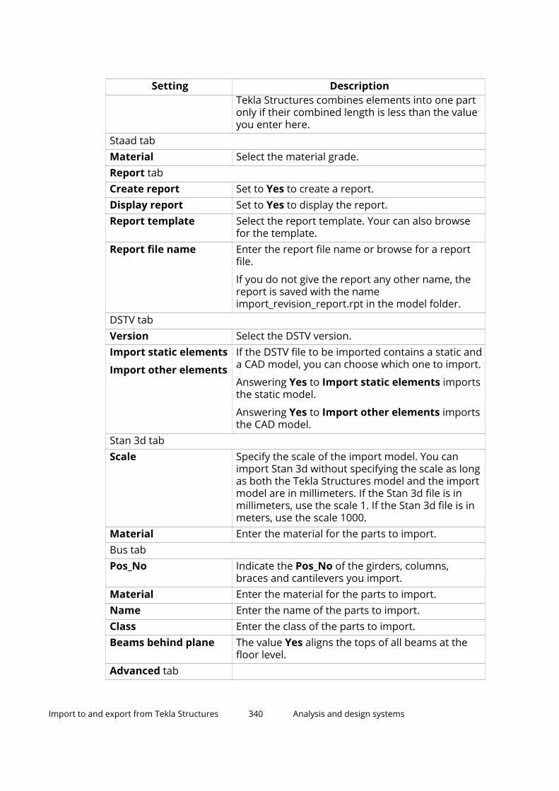
Setting DescriptionTekla Structures combines elements into one partonly if their combined length is less than the valueyou enter here.
Staad tabMaterial Select the material grade.Report tabCreate report Set to Yes to create a report.Display report Set to Yes to display the report.Report template Select the report template. Your can also browse
for the template.Report file name Enter the report file name or browse for a report
file.
If you do not give the report any other name, thereport is saved with the nameimport_revision_report.rpt in the model folder.
DSTV tabVersion Select the DSTV version.Import static elements
Import other elements
If the DSTV file to be imported contains a static anda CAD model, you can choose which one to import.
Answering Yes to Import static elements importsthe static model.
Answering Yes to Import other elements importsthe CAD model.
Stan 3d tabScale Specify the scale of the import model. You can
import Stan 3d without specifying the scale as longas both the Tekla Structures model and the importmodel are in millimeters. If the Stan 3d file is inmillimeters, use the scale 1. If the Stan 3d file is inmeters, use the scale 1000.
Material Enter the material for the parts to import.Bus tabPos_No Indicate the Pos_No of the girders, columns,
braces and cantilevers you import.Material Enter the material for the parts to import.Name Enter the name of the parts to import.Class Enter the class of the parts to import.Beams behind plane The value Yes aligns the tops of all beams at the
floor level.Advanced tab
Import to and export from Tekla Structures 340 Analysis and design systems

Setting DescriptionAction when objectsstatus is (compared to)
Previous plan lists the objects in your model,compared with the objects in the file to beimported. They can be New, Modified, Deleted, orSame.
Tekla Structures compares the state of importedobjects with those in your model. They can be Notin model, Different, or Same.
Use the options under Not in model, Different,and Same to specify the actions when importingchanged objects. The options are No action, Copy,Modify, or Delete.
Usually there is no need to change the defaults.
6. Click OK to go to the Import Models dialog box.
7. Select the model to import.
8. Click Import.
Tekla Structures displays the Import model info dialog box.
9. Select which version of parts to import.
10. Click Accept all.
If you have changed the model and want to re-import it, you can alsoreject all changes by clicking Reject all, or accept or reject individualchanges by clicking Select individual...
11. Tekla Structures displays the message Do you want to save the importmodel\nfor subsequent imports? Click Yes.
Tekla Structures displays the import model in a model view.
12. Right-click the model view and select Fit work area to entire model toensure that the imported model is completely visible.
13. If parts are missing, check the Depth up and Depth down values in theView Properties dialog box and change them if necessary.
Export FEM1. Open a Tekla Structures model.
2. On the File menu, click Export --> FEM .
The Export FEM dialog box opens.
3. Go to the Conversion tab and enter the names of the conversion files(page 171), or browse for the files.
4. Go to the Parameters tab, and enter the name of the output file, orbrowse for the file.
Import to and export from Tekla Structures 341 Analysis and design systems

5. Select the output file type: DSTV, MicroSAS or Staad.
6. Set Split members to Yes to split a part in the Tekla Structures model intoseveral elements in the exported model.
7. If you are exporting to MicroSAS, set Combine segmented members(MicroSAS) to Yes to combine multiple parts to form one part in theexported model.
For example, if you have divided a beam into several elements and selectthe Yes option, Tekla Structures combines the elements so that they formone beam in the exported model. With the option No every element of thebeam in the model forms individual beams.
8. If you are exporting to Staad, go to the Staad tab:
• Select an option from Profile table list.
• Use the setting Parametric shapes when possible to define howTekla Structures exports the profiles PL, P, D, PD, SPD to Staad. Yesexports the profiles as parametric shapes so that STAAD can identifythem correctly. No exports all profiles as standard STAAD shapes.
Example of a plate PL10*200 when exported as parametric shape(Yes):
13 PRI YD 200.000000 ZD 10.000000.
Example of the same plate exported as a standard shape (No):
13 TABLE ST PL10*200
9. If you are exporting to DSTV, go to the DSTV tab:
• Select the DSTV version from the version list.
• In Element reference with, select whether you want to export into astatic model (CROSS_SECTION), or into a CAD model(MEMBER_LOCATION).
10. Select the parts in the model to export.
11. Click Apply and Create.
Tekla Structures creates the export file in the current model folder.
Supported DSTV entities
The DSTV entities are listed below. Tekla Structures supports those markedwith an asterisk (*). See the DSTV standard "Stahlbau - Teil 1. März 2000" formore information.
Static data:
vertex (*)
polyline
substructure (*)
Import to and export from Tekla Structures 342 Analysis and design systems

node (*)
element (*)
element_eccentricity (*)
raster
boundary_condition
elastic_support
nodal_reaction
element_reaction
General data:
material (*)
cross_section (*)
CAD data:
member (*)
member_location (*)
construction-data
cutout
hole
STAAD table type specificationsTekla Structures supports the following STAAD table type specifications:
• ST (single section from the standard built-in tables)
• ST PIPE (parametric)
• ST TUBE (parametric)
• RA (single angle with reverse Y_Z axes)
• D (double channel)
• LD (long leg, double angle)
• SD (short leg, double angle)
• TC (beams with top cover plates)
• BC (beams with bottom cover plates)
• TB (beams with top and bottom cover plates)
You can import the types CM and T, user-provided steel table types (UPT), andother non-standard profiles, if you have defined them in the profile conversionfile. You must use the underscore character in the STAAD name, for example,UPT_1_W10X49. Tekla Structures automatically converts twin profiles in thisimport routine.
Import to and export from Tekla Structures 343 Analysis and design systems

3.12 Steel fabricationFabrication applies to the building of structures by cutting, shaping andassembling components made from steel. Steel fabrication shops generallyconcentrate on the preparation, welding and assembly aspect with a muchgreater use of the multi functioning machines.
Fabrication (cutting and drilling features) of structural steel elements hasalways been performed using manually operated techniques, and theseremain today as fabrication methods. The emergence of CNC (computernumerical control) technology brought automation and greater accuracy tothese techniques, resulting in families of special purpose machines dedicatedto performing individual fabrication tasks.
The following tools are included for steel fabrication purposes in TeklaStructures installation:
NC/DSTV (page 344)
MIS (page 379)
Fabtrol XML (page 381)
CIS/2 (page 380)
ASCII (page 382)
PDMS/E3D (page 381)
There are also some steel tools that you can download from Tekla Warehouse.
NC filesTekla Structures produces NC files in DSTV format. You can select theinformation to be included in NC files and NC file headers, and define thedesired pop-mark and contour mark settings. You can also produce MIS(Manufacturing Information System) list files according to the DSTV standard.
NC (Numerical Control) refers to a method where machine tool operations arecontrolled with a computer. The NC data controls the motion of CNC(computer numerical control) machine tools. During the manufacturingprocess a machine tool or machining center drills, cuts, punches or shapes thepiece of material.
After you have finished detailing a Tekla Structures model, you can export theNC data as NC files from Tekla Structures to be used by CNC machine tools.Tekla Structures transforms the part length, hole positions, bevels, notches,and cuts into sets of coordinates that the machine tools can use to create thepart in a shop. In addition to the CNC machine tools, the NC files can also beused by MIS and ERP software solutions.
Import to and export from Tekla Structures 344 Steel fabrication

The data for the NC files comes from the Tekla Structures model. Werecommend that you complete detailing and create drawings beforeproducing the NC files.
Tekla Structures produces NC files in DSTV format (Deutscher Stahlbau-Verband) in the current model folder. In most cases each part has its own NCfile. You can also produce NC files in DXF format by converting DSTV files toDXF files.
DSTV is a standard interface for geometrical description of steel structurepieces for the post-processors with numerical control. The essential aim of thisinterface is to be neutral, which means that with only one standard descriptionyou can manage several different NC machines. The interface standardizes thelink between a CAD-program or a graphical system via a CAM file for the NCmachines. The geometry of the piece is introduced completely neutrally, andafter knowing the parameters of the NC machine, the post-processor is able totranslate this neutral language to the NC machine language. For moreinformation, visit https://dstv.deutscherstahlbau.de/.
Notes and limitations:
• Duplicate bolts on a part (bolts in the same location as another bolt) are bydefault ignored in NC DSTV export. The tolerated distance for bolts to beconsidered duplicates can be adjusted with theXS_BOLT_DUPLICATE_TOLERANCE advanced option.
• The DSTV standard does not support curved beams, and therefore TeklaStructures does not create NC files for curved beams. Use polybeamsinstead of curved beams.
Create NC files in DSTV format1. On the File menu, click Export --> NC files .
2. If you have some predefined settings that you want to use, select thesettings from the settings file list at the top and click Load.
3. In the NC files dialog box, select the check box in the Create column nextto DSTV for plates and/or DSTV for profiles.
4. To modify the NC file settings, select an NC file settings row, and clickEdit...
In the NC file settings dialog box, modify the settings on the Files andpart selection, Holes and cuts, Hard stamp and Advanced Optionstabs. Click OK to save your NC file settings and to close the NC filesettings dialog box.
Hard stamps can be created for both the main part and the secondaryparts. By default, Tekla Structures creates hard stamps only for the mainpart. Set the advanced option XS_SECONDARY_PART_HARDSTAMP to TRUEto also create hard stamps for secondary parts.
Import to and export from Tekla Structures 345 Steel fabrication

You can select to create only DSTV files, MIS files, both, or DSTV filesembedded in MIS files.
If you want to add new NC file settings, click Add... This will add a new rowin the NC file settings list, and the NC file settings dialog box isdisplayed, where you can give the settings a new name.
You can enter a unique name for the settings using Save as. TeklaStructures saves the settings in the ..\attributes folder under thecurrent model folder.
For more information about the NC file settings, see the "NC file settings"section below.
5. You can customize the order in which information is displayed in an NCfile, and add additional information on individual parts in the NC fileheader. To select the information to be included in the NC file header,click Header..., modify the information, and click OK:
• In the NC File Header Information dialog box, include in the Selectedelements list the header information options that you want, andarrange the options in the desired order by selecting the option andusing the Move up and Move down buttons.
• If needed, add additional information on individual parts.
You can enter text in the Text info on piece 1 - Text info on piece 4boxes, and enter desired template attributes in double angle brackets,for example <<WEIGHT>> to display the weight of the part
• If you want to restore the default file header information, click theDefault button in the NC File Header Information dialog box.
Import to and export from Tekla Structures 346 Steel fabrication

6. To create pop-marks and modify the pop-mark settings, click Pop-marks...
For more information about creating pop-marks and about the pop-marksettings, see the section "Create pop-marks in NC files" below.
7. To create contour marks, and modify contour mark settings, click Contourmarking.
For more information about creating contour marking and about thecontour marking settings, see the section "Create contour marking in NCfiles" below.
For more information on contour marking, see the support article How tocreate contour marking for steel beams.
8. To save the settings that you have modified with another name for lateruse, click enter a new name next to Save as and click Save as.
9. In the NC files dialog box, use the All parts or Selected parts options toselect whether to create the NC files for all parts or only for the selectedparts.
If you use the Selected parts option, you need to select the parts in themodel.
10. Click Create.
Tekla Structures creates .nc1 files for the parts using the defined NC filesettings. By default, the NC files are created in the current model folder.The filename consists of a position number and the extension .nc1.
11. Click Show NC log to create and show the log file dstv_nc.log that liststhe exported parts and the parts that were not exported.
If all expected parts are not exported, check that the parts which were notexported pass all the profile type, size, hole and other limits set in the NCfile settings.
NC file settings
Files and part selection tab
Setting DescriptionFile format DSTV is the only available value.File location The default folder is \DSTV_Profiles or
DSTV_Plates under the current model folder.
You can define another destination folder for NCfiles in one of the following ways:
• You can enter the folder path in the Filelocation box. You can also browse for the path.
For example, enter C:\NC.
Import to and export from Tekla Structures 347 Steel fabrication

Setting Description• If you leave the field empty, the NC files will be
created in the current model folder.
• To create the NC file in a specific folder underthe current model folder,enter .\<folder_name>.
For example, enter .\MyNCFiles.
• You can use the model-specific advancedoption XS_MIS_FILE_DIRECTORY to define thedestination folder for NC and MIS files. Go tothe CNC category in the Advanced Optionsdialog box, and enter the desired folder pathfor the advanced option XS_MIS_FILE_DIRECTORY. The NC files will becreated in the specified folder under a folderthat has the name of the current model.
For example, if you define C:\NC, and the nameof the current model is MyModel, the NC fileswill be created in the folder C:\NC\MyModel.
File extension .nc1 is the default value.Include revision markto file name
Add a revision mark to the NC file name.
The file name then includes a number indicatingthe revision of the file,P176.nc1 becomesP176_1.nc1, for example.
Create what Select the type of files to create:
NC files creates only DSTV files.
Part list creates only a MIS list file ( .xsr ).
If you create an MIS list file, enter a name for thelist in the Part list file name box. Also, you needto click the Browse... button next to the Part listfile location box and browse for the locationwhere you want to save the list .
NC files and part list creates both the DSTV filesand an MIS list file.
Combined NC files and part list embeds DSTVfiles in an MIS list file ( .xsr ).
Maximum size The options define the maximum length, width,and height of the parts the machine tool canhandle. Larger parts are sent to other machines.
Import to and export from Tekla Structures 348 Steel fabrication

Setting DescriptionProfile type All profiles that are set to Yes in the Profile type
list can be handled by the machine tool. Profiletypes are named according to the DSTV standard.
I: I profiles
U: U and C profiles
L: L profiles
M: Rectangular tubes
R: Round bars and tubes
B: Plate profiles
CC: CC profiles
T: T profiles
SO: Z profiles and all the other types of profiles
By default, Tekla Structures unwraps round tubesas plate profiles and uses the plate profile type B inthe NC file header data. To change this, use theadvanced option XS_TUBE_UNWRAP_USE_PLATE_PROFILE_TYPE_IN_NC.
Maximum size of holes The Maximum size of holes options define howlarge holes the machine tool is able to drill. The NCfile is not created if a part contains larger holes orits material is thicker than the specified values. Thehole size is connected to material thickness orplate thickness.
Each row contains the maximum hole diameterand the material thickness. Both conditions have tobe met for the NC file to be created. For example, arow with the values 60 45 means that when thematerial thickness is 45 mm or smaller, and thehole diameter is 60 mm or smaller, the NC file iscreated. You can add as many rows as needed.
The following example shows how the Maximumsize of holes can be defined. In this example, wehave the following situation:
• Three plates of different thickness.
• Two bolt groups with equal sizes, and one boltgroup with a larger size.
Import to and export from Tekla Structures 349 Steel fabrication

Setting Description
Maximum size of holes are defined as follows:
Test1 creates a folder under the model folder forthe plates that meet the following criteria:
• Hole diameter: 22• Plate thickness: 10Test2 creates a folder under the model folder forthe plates that meet the following criteria:
• Hole diameter: 22• Plate thickness: 20When you create NC files for the plates, the folderTest1 includes the plate PL350*10 and the folderTest2 includes the plate PL350*20. The plate PL350*15 is not included in any folder, becausethe hole size criterion is not met.
The order in which you enter the criteria isimportant: enter the most exclusive criteria first. Ifyou define the criteria in a different order, theresults will also be different.
Holes and cuts tab
See also XS_DSTV_CREATE_NOTCH_ONLY_ON_BEAM_CORNERS.
Setting DescriptionInner corners shape The Inner corners shape option
defines the shape of, for example,
Import to and export from Tekla Structures 350 Steel fabrication

Setting Descriptionweb notches or flange cuts at thebeam end.
The Inner corners shape option alsoaffects cuts on the flange:
The Inner corners shape optiondoes not apply to rectangularopenings that are located in themiddle of a part:
The Inner corners shape optiondoes not apply to those innercontours that are already rounded inthe model. The model values remainintact.
The examples in the below show howthe different inner corner shapeoptions affect the part in the NC file.The original part in the model hasflanges cut entirely and the web isnotched.
Option 0: Radius
Import to and export from Tekla Structures 351 Steel fabrication

Setting Description
The inner corners are shaped likeholes with a given radius. A separate BO block is not written to the NC file.
Option 1: Tangential
The inner corner is roundedaccording to the value in the Radiusbox.
Option 2: Square
The corner is as it is in the model.
Option 3: Drilled hole
A drilled hole is added to the innercorner. The hole radius is the same as
Import to and export from Tekla Structures 352 Steel fabrication

Setting Descriptionthe value in the Radius box. Holes arewritten as a separate BO block to theNC file.
Option 4: Tangential drilled hole
A drilled hole is added tangentially tothe inner corner. The hole radius isthe same as the value in the Radiusbox. Holes are written as a separate BO block to the NC file.
Distance from flange within whichweb is not cut
The Distance from flange withinwhich web is not cut option definesthe height of the flange clearancearea. The clearance check only affectsthe I, U, C, and L DSTV profile types.
If a cut in a part is located closer tothe flange than the clearance in themodel, the cut points inside thatclearance are moved to the border ofthe clearance area when the NC file iswritten.
The part how it is modeled. The cutgoes closer to the top flange than thedefined flange clearance in the NC filesettings:
The part how it is written in the NCfiles. The dimension shows theclearance. The top of the original cutis moved so that the clearance area is
Import to and export from Tekla Structures 353 Steel fabrication

Setting Descriptionleft free. The bottom of the cut is notmoved.
Machine slots as The Machine slots as option defineshow slotted holes are created:
Ignore slots: Slotted holes are notcreated in the NC file.
A single hole in the center of theslot: Drills a single hole in the centerof the slotted hole.
Four small holes, one at eachcorner: Drills four smaller holes, oneat each corner.
Internal contours: Flame-cuts theslots as internal contours.
Slots: Leaves slots as they are.Maximum diameter for holes to bedrilled
The Maximum diameter for holesto be drilled option defines themaximum hole diameter. Holes andslotted holes that are larger than themaximum hole diameter aremanufactured as internal contours.
Maximum diameter for circularcuts to be drilled
Maximum diameter for circularcuts to be drilled defines themaximum circular part cuts. They arewritten as holes if the diameter of thecut is less than the value defined forthe setting. Smaller internal circularcuts are converted to holes.
Hard stamp tab
Setting DescriptionCreate hard stamp When selected, creates hard stamps.Hard stamp content The Elements list defines which
elements are included in hard stamps
Import to and export from Tekla Structures 354 Steel fabrication

Setting Descriptionand the order in which the elementsappear in the hard stamp. You canalso define the Text height and Case.
Project number: Adds the projectnumber to the hard stamp.
Lot number: Adds the lot number tothe hard stamp.
Phase: Adds the phase number to thehard stamp.
Part position: Prefix and positionnumber of the part.
Assembly position: Prefix andposition number of the assembly.
Material: The material of the part.
Finish: The type of finish.
User-defined attribute: Adds a user-defined attribute (user fields 1-4) tothe mark.
Text: Opens a dialog box where youcan add user-defined text to the hardstamp.
Including part position and/orassembly position in the hard stampaffects the NC filename:
• Part position: P1.nc1, P2.nc1• Assembly position: A1.nc1,
A2.nc1• Assembly and part position: A1-
P1.nc1, A2-P2.nc1The following example shows a hardstamp that contains the elementsPhase, Part position, Material, andText.
Hard stamp placing If you set the option By orientationmark to Yes, the default face ischanged from bottom (u) to top (o)
Import to and export from Tekla Structures 355 Steel fabrication
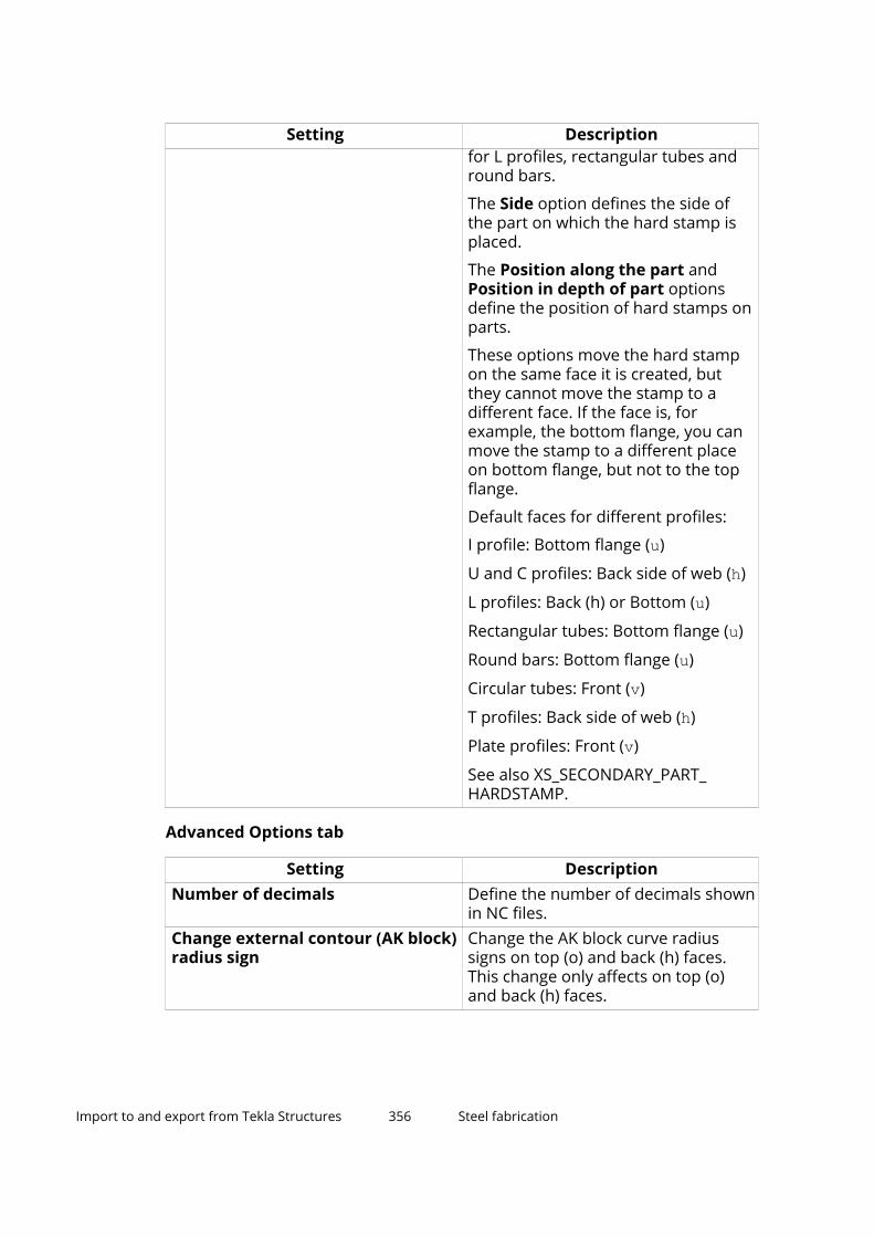
Setting Descriptionfor L profiles, rectangular tubes andround bars.
The Side option defines the side ofthe part on which the hard stamp isplaced.
The Position along the part andPosition in depth of part optionsdefine the position of hard stamps onparts.
These options move the hard stampon the same face it is created, butthey cannot move the stamp to adifferent face. If the face is, forexample, the bottom flange, you canmove the stamp to a different placeon bottom flange, but not to the topflange.
Default faces for different profiles:
I profile: Bottom flange (u)
U and C profiles: Back side of web (h)
L profiles: Back (h) or Bottom (u)
Rectangular tubes: Bottom flange (u)
Round bars: Bottom flange (u)
Circular tubes: Front (v)
T profiles: Back side of web (h)
Plate profiles: Front (v)
See also XS_SECONDARY_PART_HARDSTAMP.
Advanced Options tab
Setting DescriptionNumber of decimals Define the number of decimals shown
in NC files.Change external contour (AK block)radius sign
Change the AK block curve radiussigns on top (o) and back (h) faces.This change only affects on top (o)and back (h) faces.
Import to and export from Tekla Structures 356 Steel fabrication

Setting DescriptionBelow is an example, where the Change external contour (AK block) radiussign is not selected.
Below is an example, where the Change external contour (AK block) radiussign is selected.
Change internal contour (IK block)radius sign
Change the IK block curve radiussigns for top (o) and back (h) faces.This change only affects top (o) andback (h) faces.
Curve detection
Chord tolerance
Curve detection controls whetherthree points should be read as acurve instead of two straight lines.When Curve detection is set to Yes,Tekla Structures checks the edges of asolid against a virtual curve describedby the edges to see if the edges arecurved or straight based on theChord tolerance value. Enter theChord tolerance value in millimeters.Curve detection is on by default.
The image below describes the chordtolerance.
Import to and export from Tekla Structures 357 Steel fabrication

Setting Description
Convert I profile to T profile whenflange is missing
Select whether to convert I profiles toT profiles when a flange is missing.You can select either Yes or No.
Skip unnecessary points Select whether to keep or skip thepoints that are almost collinear.
If the creation points of a contourplate differ less than 0.3 mm from astraight line, they are skipped in theNC file when this setting is selected.When the setting is not selected,every creation point of a plate iswritten to the NC file.
Skip unnecessary points notselected:
Skip unnecessary points selected:
Import to and export from Tekla Structures 358 Steel fabrication

Setting Description
Create KA block for Select the following options to showbent line information for bent platesand polybeam plates in the NC file KAblock: Unfolded bent plates andUnfolded polybeam plates.
See also XS_DSTV_DO_NOT_UNFOLD_POLYBEAM_PLATES.
Create pop-marks in NC filesPop-marks are small holes that help the shop assemble individual parts toform an assembly. Tekla Structures is able to write the pop-mark informationin NC files to help position parts that will be manually welded to the assemblymain part. Pop-marks are usually made using a drilling machine that drills asmall hole in the surface of the material.
Limitation: Tekla Structures pop-marking does not work with polybeams.
Tekla Structures only creates pop-marks for parts for which you have definedpop-mark settings. You can save the pop-mark settings in a .ncp file, whichTekla Structures saves by default in the ..\attributes folder under thecurrent model folder.
NOTE Pop-marking affects numbering. For example, if two parts havedifferent pop-marks, or one part has pop-marks and the other onedoes not, Tekla Structures gives the parts different numbers.
1. In the NC files dialog box, select the parts for which you want to createthe pop-marks by selecting the corresponding check boxes in the Pop-marks column.
2. Click the Pop-marks... button.
3. In the Pop-Mark Settings, click Add to add a new row.
4. To define which parts are pop-marked and where the pop-marks arecreated, enter or select information for each item on a row.
Import to and export from Tekla Structures 359 Steel fabrication

The order of the rows in the Pop-Mark Settings dialog box is important.Enter the most limiting definition first, and the most generic one last.
First define the pop-mark settings on the Parts to pop-mark tab:
Setting DescriptionMain part profile type Select the main part profile type that
is pop-marked. The list containsprofiles according to the DSTVstandard.
Main part name Enter the names of the main partprofiles. You can enter several partnames separated by commas, forexample, COLUMN, BEAM.
You can use wildcards (* ? [ ] ). Forexample, HE* matches all parts with aprofile name that begins with thecharacters "HE".
Part name can contain more namesseparated by comma.
Sec part profile type Select the secondary part profile type.Secondary part name Enter the names of the secondary
part profiles. You can enter severalpart names separated by commas.
You can use wildcards (* ? [ ] ).
Part name can contain more namesseparated by comma
Pop-mark location Select how the secondary part isprojected onto the main part.
• Left side: The left side of thesecondary part is marked on themain part. The left side is the sideof the secondary part that isclosest to the start point of themain part.
• Right side: The right side of thesecondary part is marked on themain part.
• Both sides: Combines Left sideand Right side.
• Center: Center of the secondarypart.
• Left side holes: Marks the mainpart with the position of holes in
Import to and export from Tekla Structures 360 Steel fabrication

Setting Descriptionthe secondary part, on the leftside of the secondary part.
• Right side holes: Marks the mainpart with the position of holes inthe secondary part, on the rightside of the secondary part.
• Both side holes: Combines Leftside holes and Right side holes.
• Middle line: Marks two points onthe middle line of the secondarypart x axis.
Move to flange Select to which part of the main partflange the pop-marks are moved. Theoptions are None, Both flanges, Topflange, and Bottom flange.
Edge distance Enter the minimum distance from apop-mark to the edge of the mainpart. Tekla Structures does not createpop-marks inside this distance.
If a pop-mark is inside the definededge distance, Tekla Structuresmoves it, unless you have set Pop-mark location to Center.
Secondary pop-marks Select whether pop-marks arecreated to the secondary parts.
Add pop-mark to parts welded onsite
Select whether pop-marks arecreated for parts that are welded onsite.
Then define the pop-mark settings on the Pop-marking options tab:
Setting DescriptionPop-marks on the back Select one of the options:
Rotate part if pop-marks or otheritems only on the back
Rotate part and drill through pop-marks on the back if other items ormore pop-marks only on the back.Also set the Hole diameter.
Drill through pop-marks on theback if no other items on the back.Also set the Hole diameter.
Import to and export from Tekla Structures 361 Steel fabrication

Setting DescriptionNo pop-marks on overlapping holes Select if you do not want to have pop-
marks on overlapping holes.Add pop-marks to centers of studs Select to have pop-marks in the stud
centers.Show pop-marks in the model Select to show pop-marks in the
model.Consider zero diameter holes aspop-marks
Write zero diameter bolt holes as apop-marks.
5. Click OK.
6. Select the parts in the model and create the NC files.
Pop-marks are written in the BO block in the DSTV file as 0 mm diameter holes.
If needed, pop-marks can also be displayed in drawings. In drawings, selectthe Pop-marks: on/off check box in the part properties to display the pop-marks.
The default symbol for pop-marks is xsteel@0. You can change the symbolwith the advanced option XS_POP_MARK_SYMBOL .
Tekla Structures displays thick red lines for each pop-mark pair in the modelview which was last updated.
Examples
Import to and export from Tekla Structures 362 Steel fabrication

Tekla Structures marks the center point of all round secondary profiles on amain part, and does not create pop-marks closer than 10 mm to the main partedge.
Tekla Structures projects the hole location in the secondary plates onto a mainpart.
Create contour marking in NC filesTekla Structures is able to generate contour marking in NC files. This meansthat information on the layout and the parts that are welded together can beadded to the NC files and passed on to the machine tool.
Limitation: Tekla Structures contour marking on polybeams does not work inall cases. The visual placement of contour marking on polybeams has beenimproved.
Tekla Structures only creates contour markings for parts for which you havedefined contour marking settings. You can save the contour marking settingsin a .ncs file, which Tekla Structures saves by default in the ..\attributesfolder under the current model folder.
You can add contour marking to both the main and the secondary parts.
NOTE Contour marking affects numbering. For example, if two parts havedifferent contour markings, or one part has contour markings and theother one does not, Tekla Structures gives the parts differentnumbers.
1. In the NC files dialog box, select the parts for which you want to createthe contour marks by selecting the corresponding check boxes in theContour marking column.
2. Click the Contour marking... button in the NC files dialog box.
3. In the Contour marking settings dialog box, click Add to add a new row.
4. To define which parts are contour marked and how they are contourmarked, enter or select information for each item on a row:
Option DescriptionMain part profile type Select the main part profile type that
is contour marked. The list contains
Import to and export from Tekla Structures 363 Steel fabrication

Option Descriptionprofiles according to the DSTVstandard.
Main part name Enter the name for the main partprofiles. You can enter several partnames separated by commas, forexample, COLUMN, BEAM.
You can use wildcards (* ? [ ] ). Forexample, HE* matches all parts with aprofile name that begins with thecharacters "HE".
Part name can contain more namesseparated by comma.
Sec part profile type Select the secondary part profile type.The list contains profiles according tothe DSTV standard.
Secondary part name Enter the name for the secondarypart profiles. You can enter severalpart names separated by commas.
You can use wildcards (* ? [ ] ).
Part name can contain more namesseparated by comma.
Secondary contour marking Select whether the secondary partsare contour marked.
Punch or powder In the list, select how the part iscontour marked:
• Punch: The part is punched.
• Powder: The part is marked withpowder.
• Both: Both techniques are used.Hard stamp Select whether hard stamps are
created.Mark parts welded on site Select whether you want to mark
parts that are welded on site.Edge distance Define the minimum distance from a
contour mark to the edge of the mainpart. Tekla Structures not createcontour marks inside this distance.
5. Click OK and create the NC files.
Import to and export from Tekla Structures 364 Steel fabrication

Contour marking is written in the PU and KO blocks in the DSTV file.
Tekla Structures displays contour marking as thin magenta lines in the modelview.
Fittings and line cuts in NC filesWhen creating NC files in DSTV format, the method you use to cut the end ofthe beam affects the beam length in the NC file.
• Fittings affect the length of the beam in the NC file.
• Line cuts do not affect the length of the beam in the NC file.
When you cut the beam end, use the fitting method to make sure that thebeam length is correct in the NC file.
The overall length of a beam will be the fitted net length of the beam. Thismeans that Tekla Structures always takes the fitting into account whencalculating the beam length.
For lines, polygons, or part cuts, the cut does not affect beam length, but theoverall length in the NC file will be the gross (initially modeled) length of thebeam.
Import to and export from Tekla Structures 365 Steel fabrication

1. Fitting
2. Line cut
3. Polygon or line cut
4. Fitting
Shortest length
If you want to use the shortest possible length in an NC file, use the advancedoption XS_DSTV_NET_LENGTH.
Net and gross length
If you want to include both net and gross length into NC file header data, usethe advanced option XS_DSTV_PRINT_NET_AND_GROSS_LENGTH.
DSTV file descriptionTekla Structures produces NC files in DSTV format. DSTV format is anindustrial standard defined by the German Steel Construction Association(Deutsche Stahlbau-Verband). A DSTV file is a text file in ASCII format. In mostcases each part has its own DSTV file.
To learn more about the DTSV syntax, see Standard Description for SteelStructure Pieces for the Numerical Controls.
Blocks
The DSTV file is divided into blocks that describe the content of the file.
DSTV block DescriptionST Start of the fileEN End of the fileBO HoleSI Hardstamp
Import to and export from Tekla Structures 366 Steel fabrication

DSTV block DescriptionAK External contourIK Internal contourPU PowderKO MarkKA Bending
Profile types
Profile types are named according to the DSTV standard.
DSTV profile type DescriptionI I profilesU U and C profilesL L profilesM Rectangular tubesRO Round barsRU Round tubesB Plate profilesCC CC profilesT T profilesSO Z profiles and all the other types of
profile
Part faces
Single letters in the DSTV file describe the part faces.
Letter Part facev fronto topu bottomh behind
Create NC files in DXF format using Convert DSTV files to DXF macroYou can convert the created NC files in DXF format by using the Convert DSTVfiles to DXF macro
Limitation: The macro has been designed for simple plates. Therefore it maynot give correct conversion results for beams, columns and bent polybeams.
1. Create the NC files in the DSTV format.
Import to and export from Tekla Structures 367 Steel fabrication

2. Click the Applications & components button in the side pane toopen the Applications & components catalog.
3. Click the arrow next to Applications to open the applications list.
4. If Convert DSTV files to DXF is not visible in the Applications list, selectthe Show hidden items check box at the bottom of the Applications &components catalog.
5. Double-click Convert DSTV files to DXF to open the Convert DSTV filesto DXF dialog box.
6. Browse for the folder that contains the NC files you want to convert toDXF files.
7. Select the NC files and click Open.
Tekla Structures automatically creates an NC_dxf folder in the modelfolder and the DXF files are created there.
Create NC files in DXF format using tekla_dstv2dxf.exeYou can use a separate Tekla Structures program tekla_dstv2dxf.exe toconvert the DSTV files to DXF format. Only one side of a part (front, top, backor bottom) is written to the file, and therefore this export format is mostsuited to plates.
The program is located in the ..\Tekla Structures\<version>\bin\applications\Tekla\Tools\dstv2dxf folder.
1. Create a folder for the NC files, for example c:\dstv2dxf.
Do not use spaces is the folder path. You should not save the files, forexample, in the Tekla Structures folder under the \Program Filesfolder, because the folder path contains spaces.
2. Copy all files from ..\Tekla Structures\<version>\bin\applications\Tekla\Tools\dstv2dxf to the folder you created(C:\dstv2dxf).
3. Create DSTV files and save the files in the in the folder you created(C:\dstv2dxf).
4. Double-click a suitable dstv2dxf_conversion.bat file.
The program converts the files to DXF format in the same folder.
If you need to adjust the conversion settings, modify the settings in anappropriate tekla_dstv2dxf_<env>.def file and restart theconversion. For more information, see the tekla_dstv2dxf_<env>.deffile description below.
The conversion file description PDF files can be found in the same folderas the tekla_dstv2dxf.exe program.
Import to and export from Tekla Structures 368 Steel fabrication

tekla_dstv2dxf_<env>.def file descriptionThe tekla_dstv2dxf_<env>.def file is used when converting from the DSTVto the DXF format using the tekla_dstv2dxf.exe. It contains all thenecessary conversion settings. The .def file is located in the ..\TeklaStructures\<version>\bin\applications\Tekla\Tools\dstv2dxffolder.
The DSTV to DXF conversiong settings are described below.
Environment settings [ENVIRONMENT]
INCLUDE_SHOP_DATA_SECTION=FALSE
Specify whether to include a special data section in the DXF file to allow theDXF file to be better imported into CNC software written by Shop DataSystems. Including this special data section in the DXF file makes the DXF fileunreadable by AutoCAD.
Options: TRUE, FALSENO_INFILE_EXT_IN_OUTFILE=TRUE
Use to add the input file extension to the output file.
Options:
TRUE: p1001.dxf
FALSE: p1001.nc1.dxf
DRAW_CROSSHAIRS=HOLESDraw crosshair for holes and slotted holes.
Options: HOLES, LONG_HOLES, BOTH, NONEHOLES:
LONG_HOLES:
BOTH:
Import to and export from Tekla Structures 369 Steel fabrication

NONE:
SIDE_TO_CONVERT=FRONT
Define which side of the member to convert.
Options: FRONT, TOP, BACK, BELOWDefines which part face is shown in the DXF file. This setting is originallydesigned for plates.
FRONT is the most typical option. Sometimes you may need another rotationfor a plate, and then you can try if changing this setting to BACK would help. Inaddition to the SIDE_TO_CONVERT setting, it requires that the NC files arecreated with the advanced option XS_DSTV_WRITE_BEHIND_FACE_FOR_PLATE set to TRUE, which will includethe back side data of a plate in the NC file.
OUTPUT_CONTOURS_AS=POLYLINES
Convert contours as polylines or lines and arcs.
Options: POLYLINES, LINES_ARCS
NOTE If you set OUTPUT_CONTOURS_AS=LINES_ARCS:
• Slotted holes may sometimes have a gap/offset between a straightline and an arc.
• Sometimes a 3D DXF is produced instead of a 2D DXF.
If you set OUTPUT_CONTOURS_AS=POLYLINES, the DXF file may not becorrect if the NC is created with the Inner corner=0 setting.
CONTOUR_DIRECTION=REVERSE
Define the contour direction. This option changes the coordinates of thevertices, and the order they are written. You can see the difference if you openthe DXF file in a text editor: "reverse" is clockwise and "forward" is counter-clockwise.
Options: REVERSE, FORWARD
Import to and export from Tekla Structures 370 Steel fabrication

CONTOUR_DIRECTION only works if you have set OUTPUT_CONTOURS_AS=POLYLINES. If you have set it to use LINES_ARCS, theoutput is always FORWARD (counter-clockwise).
CONVERT_HOLES_TO_POLYLINES=TRUE
Convert holes to polylines.
Options: TRUE, FALSEMAX_HOLE_DIAMETER_TO_POINTS=10.0
Convert small holes to points in the DXF file.
When you set MAX_HOLE_DIAMETER_TO_POINTS to a value, the holes with adiameter smaller than this value will follow the HOLE_POINT_SIZE and HOLE_POINT_STYLE settings. With this kind of point visualization, the holesymbols will no longer show if a hole is bigger or smaller than the other one,but they will all have the same size.
HOLE_POINT_STYLE=33 and HOLE_POINT_SIZE=5
Point style and size for holes.
1 is a circle, but this setting is not in use
2 is +
3 is X
Import to and export from Tekla Structures 371 Steel fabrication

4 is short line
33 is circle
34 is a circle with +
35 is a circle with X
36 is a circle with short line
SCALE_DSTV_BY=0.03937
Use 0.03937 to scale to imperial units.
Use 1.0 to scale to metric units.
ADD_OUTER_CONTOUR_ROUNDINGS=FALSE
Add holes to roundings. This only affects the roundings that are created usingthe Inner corners shape: 1 setting in the NC file settings dialog box on theHoles and cuts tab. The hole size information is coming to the DSTV file fromthe Radius value in the NC file settings dialog box, and you cannot adjust thehole size in the dstv2dxf converter.
Options: TRUE, FALSEADD_OUTER_CONTOUR_ROUNDINGS=FALSE:
ADD_OUTER_CONTOUR_ROUNDINGS=TRUE:
MIN_MATL_BETWEEN_HOLES=2.0
Define how close the holes can be to each other in slotted hole conversion.
INPUT_FILE_DIR= and OUTPUT_FILE_DIR=
Import to and export from Tekla Structures 372 Steel fabrication

Folders for input and output files.
DEBUG=FALSE
Show data processing in the DOS window.
Options: TRUE or FALSE
Text specifications [TEXT_SPECS]
TEXT_OPTIONS=PQDG
Define the text options that you want to use in the DXF file:
S adds a side mark (Side: v)
P adds a part mark (Part: P/1)
B adds a part mark and side mark (Part: P/1 Side: v)
Q adds the quantity (Quantity: 5)
G adds the steel grade (Material: A36)
T adds the thickness (Thickness: 3)
D adds the profile description (Desc: FL5/8X7)
TEXT_POSITION_X=30.0 and TEXT_POSITION_Y=30.0
The X/Y location of lower-left corner of first line of text from the origin point<0,0> of the DXF file.
TEXT_HEIGHT=0.0
TEXT_HEIGHT is not used, the text height is always 10.0, also in text layers.
Text item prefixes
You can define several different prefixes for text items. The prefix is onlywritten in the file if the option CONCATENATE_TEXT is set to 0.
You can use the following prefix definitions:
PART_MARK_PREFIX=Part:SIDE_MARK_PREFIX=Side:STEEL_QUALITY_PREFIX=Material:QUANTITY_PREFIX=Quantity:THICKNESS_PREFIX=Thickness:DESCRIPTION_PREFIX=Desc:CONCATENATE_TEXT=1
Combine text items (part mark, quantity, profile, grade) into one or two lines.
Options:
0: Text lines are not combined. Prefixes work only with this option.
1: Part mark text on one line, other texts combined on another line.
Import to and export from Tekla Structures 373 Steel fabrication

2: All text on one line.
CONCATENATE_CHAR=+
Define a separator of max 19 characters for the text items.
Examples of different text specifications
The following settings are used the example below:
TEXT_OPTIONS=PQDGTEXT_POSITION_X=30.0TEXT_POSITION_Y=30.0TEXT_HEIGHT=0.0PART_MARK_PREFIX=Part:SIDE_MARK_PREFIX=Side:STEEL_QUALITY_PREFIX=Material:QUANTITY_PREFIX=Quantity:THICKNESS_PREFIX=Thickness:DESCRIPTION_PREFIX=Desc:CONCATENATE_TEXT=1CONCATENATE_CHAR=+
The following settings are used for the example below: TEXT_OPTIONS=B,CONCATENATE_TEXT=0:
Import to and export from Tekla Structures 374 Steel fabrication

Miscellaneous layers [MISC_LAYERS]
Entity Layer Name Color
Text Height Output as
TEXT TEXT 7 Not used,always thesame as thegeneral textheightdefinition 10.0.
OUTER_CONTOUR CUT 7 INNER_CONTOUR CUTOUT 4 PART_MARK SCRIBE 3 Do not set a
value for thisoption. If youset one, theDXF file will notbe created.
PHANTOM LAYOUT 4 NS_POP_PMARK NS_POP_MAR
K5 POP_CIRCLE
2.0(POP_CIRCLEor POP_POINTfollowed bysize)
FS_POP_PMARK FS_POP_MARK
6 1.0
This ‘1.0’ is thediameter of thehole used forfar side popmarks. It mustmatch thevalue in the“drill thru”option in themachinex.inifile
POP_CIRCLE2.0(POP_CIRCLEor POP_POINTfollowed bysize)
Color table
1 = red
2 = yellow
3 = green
4 = cyan
5 = blue
Import to and export from Tekla Structures 375 Steel fabrication

6 = magenta
7 = white
8 = dark grey
9 = light grey
Hole layers [HOLE_LAYERS]
Layer Name Min Diam Max Diam ColorP1 8.0 10.31 7P2 10.32 11.90 7P3 11.91 14.0 7
Slot layers [SLOT_LAYERS]
The type and color affect the symbol, but the color of the slot outline or arrow(phantom) is defined by the PHANTOM layer definition in the MISC_LAYERSdefinition.
LayerName
MinDiam
MaxDiam
Min‘b’
Max‘b’
Min‘h’
Max‘h’
Type
Color
Phantom
13_16x1 20.62
20.65
4.75 4.78 0.0 0.02 3 3 PHANTOM_OUTLINE
13_16x1-7_8
20.62
20.65
26.97
26.99
0.0 0.02 3 3 PHANTOM_OUTLINE
Below there are three examples with different phantom types. The othersettings used are Slot type=1, HOLE_POINT_STYLE=33 and HOLE_POINT_SIZE=1PHANTOM_ARROW:
PHANTOM_BOTH:
PHANTOM_OUTLINE:
Import to and export from Tekla Structures 376 Steel fabrication

PHANTOM_NONE:
For an explanation of the “b” and “h” dimensions, see the image below:
Examples of slot types
These example use different slot types, but the other setting are the same:
• Slot layer color is 3 (green).
• Hole layer color is 6 (magenta).
• Phantom layer color is 1 (red).
• Slot layer phantom type: PHANTOM_OUTLINE• Hole point settings: HOLE_POINT_STYLE=35, HOLE_POINT_SIZE=10
Slot type DescriptionSLOT_TYPE_1 One hole symbol to the center of slot. The hole symbol
follows the HOLE_POINT_STYLE and HOLE_POINT_SIZEsettings. The slot symbol is created according to theselected phantom setting (PHANTOM_OUTLINE in this
Import to and export from Tekla Structures 377 Steel fabrication

Slot type Descriptionexample). The circle color follows the slot layer color, andthe slot color follows the phantom layer color.
SLOT_TYPE_2 Two hole symbols to the slot. The hole symbol follows the HOLE_POINT_STYLE and HOLE_POINT_SIZE settings.The slot symbol is created according to the selectedphantom setting (PHANTOM_OUTLINE in this example).The hole symbol color follows the hole layer color, andthe slot color follows the phantom layer color.
SLOT_TYPE_3 One circle to the center of slot. The size of the circlecorresponds to the real hole size. The circle color followsthe slot layer color, and the slot color follows thephantom layer color. The slot symbol is created accordingto the selected phantom setting (PHANTOM_OUTLINE inthis example).
SLOT_TYPE_4 Two circles to the slot. The size of the circle correspondsto the real hole size. If the circles would be touching eachother, only one circle in the middle of slot is created. Theslot symbol is created according to the selected phantomsetting (PHANTOM_OUTLINE in this example). The circlecolor follows the hole layer color, and the slot colorfollows the phantom layer color.
SLOT_TYPE_5 Hole symbol to the first slot center point. The holesymbol follows the HOLE_POINT_STYLE and HOLE_POINT_SIZE settings. The slot symbol is createdaccording to the selected phantom setting(PHANTOM_OUTLINE in this example). The hole symbolcolor follows the hole layer color, and the slot symbolcolor follows the phantom layer.
SLOT_TYPE_6 One circle to the first slot center point. The slot symbol iscreated according to the selected phantom setting(PHANTOM_OUTLINE in this example). The circle colorfollows the hole layer color, and the slot symbol colorfollows the phantom layer color.
SLOT_TYPE_7 No hole symbol is created. The slot symbol is createdaccording to the selected phantom setting(PHANTOM_OUTLINE in this example). The slot colorfollows the slot layer color.
Import to and export from Tekla Structures 378 Steel fabrication

Create round tube NC filesYou can create NC files for tubular hollow sections. You first need to usespecific tube components to create the connections.
Create the following tube-to-tube and tube-to-plate connections:
• Tube-Chamfer
• Tube-CrossingSaddle
• Tube-MitreSaddle+Hole
• Tube-Saddle+Hole
• Tube-SlottedHole
After using the components, you can create an NC file for data export. Thetube NC file creation results in an XML file that contains the model data.
Limitations:
To get correct tube NC export results, note the following limitations:
• Line cuts and fittings created manually or by other components will beexported as simple chamfers.
• Holes created by bolts are not supported, and they will not be exported.
• Curved beams are not supported.
• For square or rectangular tubes, use File --> Export --> NC files to createDSTV files.
1. On the File menu, click Export --> Tube NC files .
2. In the Create Tube NC Files dialog box, enter a name for the export file,and browse for the location where you want to save the file.
By default, the file is saved in the model folder.
3. Select whether you want to create the file for selected parts or for allparts.
4. Click Create.
Tekla Structures creates an XML file and a log file in the location youdefined.
MIS listsYou can export an MIS list to a file.
You can export model data to use in Manufacturing Information Systems(MIS). The MIS export supports the following formats:
• DSTV - The exported file contains the MIS information written in the DSTVformat.
• KISS - We recommend using the FabTrol reports instead of the MIS exportfor exporting FabTrol data. The FabTrol reports are available for the Steel
Import to and export from Tekla Structures 379 Steel fabrication

Detailing role in the US environment. If you do not use a suitableenvironment you may also contact your local support for the FabTrol files.
Note that plates will not export in the KISS format correctly.
• EJE - US environment, Imperial role only. Structural Material Managerinternally stores all dimensions in sixteenths. Its External Data Interfacewrites all dimensions, such as widths and lengths, except for Beam andChannel descriptions, in sixteenths of an inch. As an example the length12'-8 7/8 is equivalent to 2446 sixteenths, which is calculated as (feet * 192)+ (inches * 16) + (eighths * 2) = (12 * 192 + 8 * 16 + 7 *2).
• EPC - The EPC (Estimating and Production Control) module of SDS/2requires multinumbering to be active.
• Steel 2000
Export a MIS list
1. On the File menu, click Export --> MIS.
The Export MIS dialog box opens.
2. Select the file type from the MIS type list.
3. If you selected KISS or Steel 2000, define the additional options:
• KISS
Enter the customer name in the Customer name box.
Select the Full material list check box to add labor-relatedinformation to the list (for example, holes, welds, cambers, preliminarymarks).
• Steel 2000
Select the Export only shop bolts check box to include only workshopbolts in the list file.
4. Enter a name for the list file in the MIS list file box.
By default, the list file is saved in the model folder.
You can select the folder where you want to save the list file by clickingBrowse....
5. Ensure that you have the selection switch Select objects in componentsselected. If you have the switch Select assemblies selected, TeklaStructures will create empty files.
6. Click Create all or Create selected to export the MIS list file.
CIS/2In order to use CIS/2 you need to download interoperability with Smart3D(S3D) fromTekla Warehouse.
Import to and export from Tekla Structures 380 Steel fabrication

You have the following S3D tool available for downloading in TeklaWarehouse:
Smart3D Interoperability
Tekla User Assistance contains the following article about S3D:
Smart3D Interoperability
FabTrol XML filesYou can import fabrication status information for parts to a Tekla Structuresmodel from an XML file written by FabTrol.
FabTrol is a Material Resource and Planning (MRP) system commonly used bysteel fabricators to manage estimating, inventory and production. Data can bewritten to FabTrol via a KISS format export or directly via the text basedreports from Tekla Structures for tracking of the assembly status through theproject lifecycle. The tracking information entered in FabTrol can then be re-imported back to Tekla Structures via the FabTrol XML import for colorizationof the model. This is performed by storing the data in a preset collection ofuser-defined attributes (UDAs). Import of the FabTrol XML is possible in allconfigurations of Tekla Structures (including Project Viewer) but data can onlybe saved into the UDAs in modeling or management configurations.
You need to have the XMLTrans.trn file in the system folder defined by theadvanced option XS_SYSTEM. This file maps the FabTrol XML names to TeklaStructures UDA names.
Import FabTrol XML
1. On the File menu, click Import --> FabTrol XML .
2. Click the ... button next to the Input file box to browse for the XML file.
3. Select an appropriate option from the Create log file list:
• Select Create to write a new log file and delete the previous log fileeach time you import the XML file.
• Select Append to add the log file information at the end of the existinglog file.
• If you do not need a log file, select No.
4. Select an appropriate option from the Display log file list:
• If you do not want to display the log file, select No.
• To display the log file, select On dialog.
5. Click Create to import the status information.
Import to and export from Tekla Structures 381 Steel fabrication

PDMS/E3DYou have the following tools available for download in Tekla Warehouse:
PDMS/E3D and Tekla Structures Interoperability: Export to PDMS/E3D
PDMS/E3D and Tekla Structures Interoperability: PDMS/E3D extension
BIM Publisher
Tekla User Assistance contains the following articles about PDMS/E3D:
PDMS/E3D and Tekla Structures Interoperability: Q&A, collected 7 th March2017
AVEVA PDMS/E3D and Tekla Structures Interoperability: PDMS/E3D extension
PDMS
ASCII filesASCII stands for American Standard Code for Information Interchange. Someplant design systems export ASCII files, for example, ModelDraft, PDS andPDMS.
You can import and export profiles and plates created as beams using theASCII format. Contour plates cannot be imported.
Import a model in ASCII format1. Create a new model in Tekla Structures.
2. Create a new 3D view.
3. Copy the ASCII file to the model folder.
4. Name the file import.asc.
5. On the File menu, click Import --> ASCII .
Tekla Structures displays the main parts created from the ASCII file in themodel.
Export a model in ASCII format1. Open the Tekla Structures model you want to export.
2. Select the parts in the model you want to export.
3. On the File menu, click Export --> ASCII .
Tekla Structures creates a model.asc file in the current model folder.
Import to and export from Tekla Structures 382 Steel fabrication

ASCII file description
In an import.asc file each part is described by 8 lines. These lines arerepeated for each part to be transferred. Units are always in millimeters,blanks are used as separators.
Below is an example of a beam part description:
Line DescriptionLine 1 4169 HEA300 1 = ID profile type
• ID 4169: Unique ID (integer).
• PROFILE HEA300: Profile name (string).
• TYPE 1: Profile type (integer)
The available profile types are:
0 = free cross section (can be used for special profiles which are not inthe database)
1 = I profiles
2 = Welded hollow core profiles (HK, HQ)
3 = U profiles
4 = L profiles
5 = Round bars
6 = Round tubes
7 = Rectangular hollow core sections (RHS, P)
8 = T profiles
9 = Rectangular bars (FL, PL)
10 = Z profiles
11 = C profiles
12 = Omega profiles
13 = Sigma profiles
Import to and export from Tekla Structures 383 Steel fabrication

Line Description14 = Rail profile
16 = Reinforcement bars (DH)Line 2 The contents of line 2 depend on the part profile.
• Polygon plates:
N_POINTS COORDINATES
N_POINTS: For profiles of type 0.
COORDINATES: Number of the corner points (integer).
The X and Y coordinates of the plate corners (floating). Rotationdirection is clockwise. Coordinates follow the global coordinatesystem. Z coordinates are taken from the center line in the platethickness direction.
Note that the line 2 can be divided into several rows in the file.
• Profiles:
For profile types 1-16, the line includes the physical dimensions ofthe cross section.
HEIGHT S W1 T1 W2 T2: 290.000000 8.500000 300.00000014.000000 300.000000 14.000000• HEIGHT 290.000000: Height of the cross section
• S 8.500000: Web thickness.
• W1 300.000000: Width of the upper flange.
• T1 14.000000: Thickness of the upper flange.
• W2 300.000000: Width of the lower flange.
• T2 14.000000: Thickness of the lower flange.Line 3 A/6 BEAM = mark name
• MARK A/6: Position mark of the part (string).
• NAME BEAM: Part name (string).Line 4 S235JR S235JR = material
Material of the part (string).Line 5 0.000000 = rotation
Rotation angle (in degrees) around the local x-axis of the beam.Line 6 16.500000 24000.000000 4855.000000 = X1 Y1 Z1
Coordinates of the beam start point. Z coordinates are center-linecoordinates.
Import to and export from Tekla Structures 384 Steel fabrication

Line DescriptionLine 7 6000.000000 24000.000000 4855.000000 = X2 Y2 Z2
Coordinates of the beam end point. Z-coordinates are center-linecoordinates.
Line 8 16.500000 24000.000000 5855.000000 = X3 Y3 Z3
Direction vector showing the direction of the local z-axis.
Tekla PowerFabYou can export your Tekla Structures model data to Tekla PowerFab as acompressed package in the .pfxt or .zip format . The package contains anXML file with drawing revisions, bills of materials, and user-defined attributes,as well as directories with CNC files and drawing files.
Export model to Tekla PowerFab1. In the File menu, select Export --> Tekla PowerFab. The Export to Tekla
PowerFab dialog box is displayed.
2. On the Export to Tekla PowerFab tab, to load predefined export settings,select the export settings from the list, and select Load.
3. On the Export to Tekla PowerFab tab, either select Auto-generate filename, or type the path and the name of the export file in the TeklaPowerFab file name box. Select the export file formet .pfxtor .zip. .pfxt is a Tekla PowerFab Exchange File format file.
4. In the Export settings section, select which information you want toinclude in the export file.
5. In the Drawing files section, select which drawing files are exported, andwhere different types of drawings are stored.
6. In the CNC files section, select if and how you want to export CNC files.
7. Click Export Tekla PowerFab. You can now save the modified exportsettings for future use by selecting Save, or save the modified exportsettings with another name by defining a new name and selecting Saveas.
If any files are out of date or not found in the export, you get warningmessages that notify you of these files.
8. Do any of the following in the message box:
• To continue despite the missing files, click Yes.
• To cancel the export, click No.
Import to and export from Tekla Structures 385 Steel fabrication

Any warnings and error messages are shown in the white text box at thebottom of the Export to Tekla PowerFab dialog box. When the export iscomplete, the path to the exported file is shown in this text box.
Next, the export file can be imported into Tekla PowerFab. For moreinformation, see instructions in the Tekla PowerFab product guide.
For details about importing Tekla PowerFab files into Tekla Structures, seesection "Import Tekla EPM XML into Tekla Structures" in Tekla Plug-in supportarticle.
For more information on the export settings, see the following table.
Export settings for Tekla PowerFab
Setting DescriptionTekla PowerFab file name When the Auto-generate file name
option is not selected, you can type afile name, select .pfxt or .zip, andclick ... to browse to and select thefolder where the file is saved.
Auto-generate file name When the Auto-generate file nameoption is selected, the export file issaved in the Tekla PowerFab folderunder the model folder. You canselect the file extension .pfxtor .zip.
The file name format is <projectnumber>_<number of theexport>. For example, if a model hasthe project number PROJ-NUM, thefirst export is saved to TeklaStructuresModels\PowerFab-01\Tekla PowerFab\PROJ-NUM_1.zip. The next exportwill have the same path except for thenumber, which will be 2.
Export assembly drawings Select which assembly drawinginformation you want to include inthe export:
• All exports information of allassembly drawings in the model.
• Selected from Drawing list onlyexports information of theassembly drawings that arecurrently selected in Documentmanager.
Import to and export from Tekla Structures 386 Steel fabrication

Setting Description• Selected from model only
exports information for assemblydrawings currently selected in themodel.
Drawing files are not included if youhave selected the Do not exportdrawing files option.
Include BOM When this option is selected, BOMinformation is included in the export.
Include single-part drawings When this option is selected, single-part drawing information is includedin the export. Drawing files are alsoincluded if you have not selected theDo not export drawing files option.
Include general arrangementdrawings
When this option is selected, generalarrangement drawing information isincluded in the export. Drawing filesare also included if you have notselected the Do not export drawingfiles option.
Include multidrawings When this option is selected, multi-drawing information is included in theexport. Drawing files are alsoincluded if you have not selected theDo not export drawing files option.
Include drawing UDAs When this option is selected, user-defined attributes for drawings areincluded in the export.
In the list on the right, select whichinformation is included:
• From report includes informationfrom your 450TeklaPowerFab_Drawing_UserDefined_v1.rpt report. Bydefault, the Drawn by, Checkedby, and Checked date values areincluded.
• From drawing (slow) includes alluser-defined attributes indrawings. Note that this mighttake some time.
• From both (slow) includesinformation from both the 450TeklaPowerFab_Part_UserDefi
Import to and export from Tekla Structures 387 Steel fabrication

Setting Descriptionned_v1.rpt report and thedrawing. Note that this might takesome time.
To customize the user-definedattributes in the export file, see theCustomize user-defined exportinformation instructions.
Include part UDAs When this option is selected, user-defined attributes for parts areincluded in the export.
In the list on the right, select whichinformation is included:
• From report includes informationfrom your 450TeklaPowerFab_Part_UserDefined_v1.rpt report. By default,user-defined fields 1-4 andcomment are included.
• From model generates partinformation directly from themodel.
• From both includes informationfrom both the 450TeklaPowerFab_Part_UserDefined_v1.rpt report and themodel.
To customize the user-definedattributes in the export file, see theCustomize user-defined exportinformation instructions.
Include bolts-nuts-washers When this option is selected, bolt, nut,and washer information is included inthe export.
Include bolt-nut-washer UDAs When this option is selected, user-defined attributes for bolts, nuts, andwashers are included in the export.
In the list on the right, select whichinformation is included:
• From report includes informationfrom your 450TeklaPowerFab_BoltNutWasher_UserDefined_v1.rpt report.By default, the GUID,
Import to and export from Tekla Structures 388 Steel fabrication

Setting DescriptionIsBoltNutWasher value, andcomment are included.
• From model generates nut, bolt,and washer information directlyfrom the model.
• From both includes informationfrom both the 450TeklaPowerFab_BoltNutWasher_UserDefined_v1.rpt reportand the model.
To customize the user-definedattributes in the export file, see theCustomize user-defined exportinformation instructions.
Include studs When this option is selected, studinformation is included in the export.
Include stud UDAs When this option is selected, user-defined attributes for studs areincluded in the export.
In the list on the right, select whichinformation is included:
• From report includes informationfrom your 450TeklaPowerFab_Stud_UserDefined_v1.rpt report. By default,the stud GUID and comment areincluded.
• From model generates studinformation directly from themodel.
• From both includes studinformation both from the 450TeklaPowerFab_Stud_UserDefined_v1.rpt report and themodel.
To customize the user-definedattributes in the export file, see theCustomize user-defined exportinformation instructions.
Do not export drawing files When this option is selected, nodrawing files are included in theexport.
Import to and export from Tekla Structures 389 Steel fabrication

Setting DescriptionUse drawing files from folder When this option is selected, drawing
files from the folder defined beloware included in the export.
To change the folder, click ... next tothe text box. Then, browse to andselect the folder.
Note that the drawing file namesmust match the drawing number,excluding the file extension. Forexample, the right file name fordrawing 200 would be 200.
Assembly drawing sub-folder
Single-part drawing sub-folder
GA drawing sub-folder
Multidrawing sub-folder
Saving drawing types in differentfolders is optional. We recommendthat you do so if you have drawings ofdifferent types with the same name.Having different drawing types indifferent folders also makes it easyfor Tekla PowerFab to place thedrawings in the right drawing logs.
To select the folders, click ... next toeach text box. Then, browse to andselect the folder where the currentdrawing type should be saved.
Do not export CNC files When this option is selected, CNC fileswill not be included in the export.
Generate CNC files - settings When this option is selected, TeklaStructures generates CNC files fromthe current model.
The exported CNC files are UTF-8encoded.
In the list below, select the CNCexport settings file that you want touse.
Use CNC files from folder When this option is selected, CNC filesfrom the folder set below areincluded in the export.
To change the folder, click ... andbrowse to and select the folder.
Note that the file names need tomatch the piece mark, excluding thefile extension. For example, the right
Import to and export from Tekla Structures 390 Steel fabrication

Setting DescriptionCNC file name for piece mark w104would be w104.
Customize user-defined attributes for exportThe user-defined attributes for the export comes from the following reports,which you can customize to adjust which information is included in the export:
• 450 TeklaPowerFab_Drawing_UserDefined_v1.rpt• 450 TeklaPowerFab_Part_UserDefined_v1.rpt• 450 TeklaPowerFab_Stud_UserDefined_v1.rpt• 450 TeklaPowerFab_BoltNutWasher_UserDefined_v1.rpt
NOTE • Do not customize any of the other reports related to the TeklaPowerFab Plug-in.
• Always keep extra copies of the customized reports in a separatefolder.
1. Open the environment folder where the reports are stored.
For example, C:\ProgramData\Trimble\Tekla Structures\2021.0Daily\Environments\Steel\reports.
2. Create a copy of the desired report and move it to another folder.
3. Open the copy in a text editor, such as Microsoft Notepad.
4. Customize the copy according to your needs.
Note that:
• Each field must be separated by a tab character.
• The report needs to have a single-line header containing the name ofeach field. These field names are included in the export file, so that theuser can decide to which Tekla PowerFab fields the information shouldbe mapped.
• Each field name can be used only once.
• Each field in the report needs to consist of a single line.
• In the 450 TeklaPowerFab_Part_UserDefined_v1.rpt report, thefirst field needs to be the part GUID, and the name in the reportheader for the first field needs to be GUID.
• In the 450 TeklaPowerFab_Drawing_UserDefined_v1.rpt report,the first field needs to be the drawing ID, and the name in the reportheader for the first field needs to be ID.
5. Save the copy.
Import to and export from Tekla Structures 391 Steel fabrication

6. Move the copy to the right folder, and overwrite the existing report.
3.13 Automated precast fabricationWith Tekla Structures you can efficiently deliver all types of precast concreteelements at the right time to the right place by integrating design and detailingwith manufacturing, project management and efficient information sharing.
For the precast fabricators, the target is to offer functionalities to help tooptimize the whole precast construction process from modeling to fabricationto site operations, minimize errors and waste in all stages and improvecollaboration between project parties in design, production and site.
The offering consist of several product listed below.
Unitechnik
Unitechnik (from the company Unitechnik) is the most common format forexporting precast and mesh geometry as well as production data. Unitechnikis for precast panels and slabs and other products that are manufactured in apallet circulation as well as for reinforcement meshes.
The Unitechnik format is not used only by UniCAM but also by other industrysolutions such as Leit2000.
Export to Unitechnik (page 394) versions 5.0c - 6.1 are available in TeklaStructures core installation in the most extensive precast-relatedconfigurations.
ELiPLAN
ELiPLAN is an ERP software from machinery provider Elematic. The fileformat .eli also contains production data and geometry for CAM-operatedhollow-core slab production.
Both EliPLAN export from and import to (page 488) Tekla Structures areavailable in the Tekla Structures installation in the most extensive precast-related configurations.
HMS
HMS is a CAM software for hollow-core production.
The export to HMS (page 511) software is included in the Tekla Structuresinstallation in the most extensive precast-related configurations.
BVBS
Reinforcement geometry can be exported to German BVBS(Bundesvereinigung Bausoftware) format. The result is a text file in ASCIIformat.
Import to and export from Tekla Structures 392 Automated precast fabrication

You can export cut and bent reinforcing bars, reinforcing bar groups andreinforcement meshes, which can be rectangular, polygonal, non-bent or bent,and may include cuts. The export of hooks is also supported.
The supported version of the BVBS format is 2.0 from year 2000.
BVBS export (page 473) is available in Tekla Structures installation in the mostextensive configurations.
UXML
UXML (from the company Unitechnik) is for precast panels and slabs and otherproducts that are manufactured in a pallet circulation as well as forreinforcement meshes.
Tekla Structures supports exporting both to Unitechnik and UXML formats.
Precast Production Export for UXML can be found as an extension in TeklaWarehouse. For instruction on how to use the export, see Precast ProductionExport.
PXML
The data format of progress XML also known as PXML has been developed byProgress Software Development, which is part of precast solution providerProgress Group. Data format is based on hierarchically structured XML for thegeneration of data and production control and scheduling at precast or rebarprefabrication factories. PXML contains both the product geometry to be usedin production and the attribute data for managing the related processes (ERPdata). In particular, there are two different areas of application:
• interface between systems of different manufacturers
• internal (proprietary) storage of data of CAD/CAM systems
PXML is the main data format to bring design geometry between detailer'sTekla Structures and factory's Progress software such as ebos, erpbos, ProFitand AviCAD.
Precast Production Export for PXML can be found as an extension in TeklaWarehouse. For instruction on how to use the export, see Precast ProductionExport.
Precast planning tools
There are some precast planning tools available in Tekla Warehouse, such as:
• Palletizer: Practical, easy-to-use and efficient workflow tool for arrangingdifferent types of precast elements on production pallets.
• Stacker: Interactive 3D-model-based truck-load planning application helpsyou to efficiently plan the transportation units for optimal deliveries withless crane time needed at the factory and site.
For other concrete tools in Tekla Warehouse, see Concrete.
Import to and export from Tekla Structures 393 Automated precast fabrication

UnitechnikYou can export the 3D geometry of the cast units in the Unitechnik format. Theresult is a text file in the ASCII format.
Supported versions of the Unitechnik format are:
• 6.1.0 17.9.2009
• 6.0.0 14.6.2005
• 5.2b 11.9.2000
• 5.0c 30.10.1997
The Unitechnik format is intended for the production of the geometry ofpallet- or table-produced precast elements such as solid, sandwich or doublewalls as well as panel slabs and half-slabs. You can export cast units consistingof concrete, steel and surface materials. Exporting of reinforcing bars (bentand not-bent), reinforcing bar groups and meshes with hooks is alsosupported.
Example
Exported cast unit:
(1) Hole
(2) Steel embed
Import to and export from Tekla Structures 394 Automated precast fabrication

(3) Reinforcing bars, cages also supported (UT version 6.1.0)
(4) Insulation plate (green)
For details about exporting in the UXML and PXML formats, see PrecastProduction Export. You can download Precast Production Export from TeklaWarehouse.
To ensure the best possible export result, see Best practices in modeling,validating and exporting for Unitechnik (page 457).
Limitations in Unitechnik exportThe Unitechnik format is for flat panels and slabs for production in palletcirculation plants. It is an open format used by many different productionsystem master computers, and therefore the specifications are quite strict,and field character lengths are limited, for example. The different mastercomputers from different solution providers also have differentinterpretations of the Unitechnik data. The original format is from early 2000's,and it is a bit outdated in many aspects. As a result, the Unitechnik format hascertain limitations:
• Cast units with cast unit type cast-in-place are not exported.
• All Unitechnik fields have a maximum character length, both for geometryand attribute information.
• While Tekla Structures supports input of longer strings, the data has tobe cut and simplified, or the export may be prevented completely. Thelog will notify if this happens.
• Negative values in certain geometry fields (negative pallet X, Y, and Zcoordinates, for example) will cause errors in production systems, eventhough the geometry comes correctly from the model.
• Also the number of fields per hierarchy object is limited, although eachhas also unspecified reserve fields for customer-specific cases.
• 3D shapes are not supported.
• 3D concrete shapes are not supported (except for edge shapes in lineattributes)
• 3D embed shapes are not supported
• 3D bent rebar shapes are not supported
• When using terminal hook flection forms, the rebars and meshes can bebent only in one direction (hooks up or hooks down, for example).
• One Unitechnik file may only have one HEADER block, but it may haveseveral SLABDATE blocks.
• Double wall elements are an exception. They should be exported in onefile, with each shell having its own HEADER information.
Import to and export from Tekla Structures 395 Automated precast fabrication

Export in Unitechnik format1. Go to the part properties of the parts that you plan to export, and edit the
user-defined attributes on the Unitechnik and Delivery tabs (orUnitechnik Mountpart tab for steel parts) as required. The user-definedattributes are environment specific, so you may not have all the settingsbelow available:
Unitechnic tab:Parts:Product type Product type is important for
identifying the object type in CAMsoftware. Undefined product type willresult in error notification whileimporting the production data file.You can define the product type byselecting one of the options, or bydefining a user-defined text.
Product type affects the file structureof the exported element. Certainproduct types, such as double walls,sandwich walls and thermo walls setcustom export logics to ensure thatthe panel production stages aretransferred correctly. With doublewalls and thermo walls, you can usethe user-defined product type settingfor the special logic with an alternateproduct type identifier.
User-defined product type Optional field for product type.Product group Optional field for product group. The
product group is used in theSLABDATE block.
Product addition This attribute is exported withUnitechnik export (79) to object'sSLABDATE block as a representativenumber 00-03. The available optionsare Standard element, Balcony,Roof, and Plastered element.
Storey Optional field used for planning thetransport and erection processes.
Surface smoothing Select whether to smooth thesurfaces or not. The default value isblank.
Import to and export from Tekla Structures 396 Automated precast fabrication

Concreting identification (LOTblock)
You can select No special treatmentor Shovel concrete, or leave the fieldempty.
Layer split thickness Manually define the layers withnames and thicknesses.
Layer not to export Specify the layer that you do not wantto export.
Mountpart data from UDA Select whether you want to exportmountpart data from the user-defined attributes.
Exlude from export Select whether you want to excludemountparts from export.
Identification of installation Select one of the following options:
Installed (0)
Only plotted (1)
Only installed (2)
Not installed, not plotted (3)
Installed in reinforcement (4)
Installed automatically (5)Type of mounting part Define the type of mounting part by
entering a user-defined attribute.Reference number Define the reference number of a
mounting part by entering a user-defined attribute.
Mountpart name Enter the mountpart name.Info 1 text (UT 6.0) Specify more information, if
necessary.Info 2 text (UT 6.0) Specify more information, if
necessary.Delivery tab:Unloading type Specify the unloading type.Transport type Pallets (00)
A-frame (01)
Inside loader (02)Transport unit number
Transport sequence number
Optional fields used for planning thetransport and erection processes.These can be defined in the exportsettings to be included as part ofSLABDATE block.
Import to and export from Tekla Structures 397 Automated precast fabrication

Transport pile number Optional field that specifies thetransport pile number.
Transport pile level number Optional field that specifies thetransport pile level number. If thereare elements in the stack that need tobe layered on the same level, then thepile level is used if the transportsequence number is the same for thepile. This can be defined in the exportsettings to be included as part ofSLABDATE block.
For example, you may have a pile of 6slabs, and they each have sequentialpile level numbers 1, 2, 3.. 6.
Surface objects:Use surface as pallet base Orient the object without changing
the top-in-form face or the rotation inexport settings.
Align pallet direction If you did not select to use the surfaceobject as the pallet base, you can useAlign pallet direction to rotate theelement in plane so that the selectedface is towards the pallet X axis, andaligns towards the X direction. Thissetting overrides all other rotationsettings.
Line type Select manual or predefined line type.Line attribute code If you selected manual line type, type
the line attribute code.
2. Check the settings on the Unitechnik tab in user-defined reinforcementattributes and change them as required. Ensure that rebars are notaccidentally grouped into mesh or cage.
Unitechnik reinforcement type Overrides the automatically assignedUnitechnik reinforcement type, whichis used to define the rebar/mesh wirelayer within the element or mesh.
Cage group number Used to group together specificrebars into a cage.
Cage type Unitechnik cage type data attributeCage shape Unitechnik cage shape data attributeMesh type Overrides the automatically assigned
Unitechnik mesh type.
Import to and export from Tekla Structures 398 Automated precast fabrication

3. We recommend that you define the top-in-form face. Do this beforecreating any drawings.
4. Update numbering.
Export Unitechnik reads and exports data from the numbering series ofparts. It is important that all exported parts are numbered correctly.Incorrectly numbered parts are not exported.
5. On the File menu, click Export --> Unitechnik .
The Export Unitechnik dialog box is displayed.
6. Define the Unitechnik export properties on the various tabs.
7. Select objects using Select assemblies (recommended) or Select objectsin assemblies depending on the option that you selected for Createfrom on the Main tab. You can also enter the cast unit positions to beexported manually.
8. Click Create.
By default, .uni output files are created in the \UT_Files folder underthe current model folder. The number of output files depends on theoptions selected from the Create from list on the Main tab, and on thetotal number of selected parts, cast units, or assemblies.
The export log is displayed. See the Log files tab for additional logoptions.
The maximum number of exported elements or layers is limited to 99. Ifthe limitation is exceeded, you will be notified by a console and log filemessage.
Import to and export from Tekla Structures 399 Automated precast fabrication

Unitechnik export: Main tab
NOTE When specifying object names: If names consist of several words,enclose those in quotation marks and use spaces between words, forexample, "WORD1 WORD2".
Option DescriptionUnitechnik version Select the Unitechnik version.Create from Select which parts or cast units are exported.
• Selected cast units
Only cast units that have one or more partsselected in the model are exported. Each castunit has one output file. Select By cast unit Idor By cast unit position.
• All parts
All cast units are exported. Each cast unit hasone output file. Select By cast unit Id or Bycast unit position.
• Selected parts (separately)
Only the selected concrete parts (also embedsand insulation parts belonging to the selectedpart) are exported. Each part has one outputfile.
• Selected parts (cast united)
Selected parts belonging to one cast unit aregrouped and exported together in one outputfile. Select By cast unit Id or By cast unitposition.
• Selected assemblies
This option is recommended in most cases. Allselected assemblies are exported. Oneassembly equals one cast unit and has oneoutput file. Selection of subassemblies is alsoallowed.
• Cast units in list
Select the cast units for export from the Castunit position list you enter.
• By cast unit Id
Each cast unit has its own output file.
Import to and export from Tekla Structures 400 Automated precast fabrication

Option Description• By cast unit position
Identical cast units share an output file.Export using filter Use a selection filter to select the parts for export.
You can use the selection filter for including theparts in or excluding the parts from the export.
Parts excluded fromexport (class or name)
If you do not want to export some parts, enter theclasses or names of these parts. You can also filterout rebars with this setting. Parts with classes inthis list will not be exported.
Directory path Define where the export files are saved. Thedefault folder is .\UT_Files under the currentmodel folder.
File name
Extension
Select the name of the output file from the listsand specify the file name extension.
You can use up to 5 strings to generate the exportfile names. Select options from the lists, definitionvalues or attributes, and an optional string lengthlimiter. You can leave the box empty if you do notneed all 5 strings. You can use the delimiter period( .), dash (-), or underscore (_) between the strings.
• Proj. nr is the number of the project.
• Proj. name is the name of the project.
• CU nr is the assembly position number of themain part of the cast unit.
• Phase is the current phase.
• CU pos is the assembly position of the mainpart of the cast unit.
• ACN is the assembly control number. Togenerate the assembly control numbers, go tothe Drawings & reports tab and clickNumbering --> Assign control numbers .
• Part ID is the ID number, which is 10 characterslong. If the ID number is not 10 characters long,zeros are added in front of the ID number to
Import to and export from Tekla Structures 401 Automated precast fabrication

Option Descriptionmake it 10 characters long. For example, idnumber 456999 will be 0000456999.
• Counter adds a running number at the end ofthe file name, if the name already exists.
• Other options are Date, Time, Date-Time,UDA, Text, Template, and Project UDA.
Date, Date-Time and Time use the formatyyyy-mm-dd-hh-mm.
Template means a template attribute. UDAand Template are always read from the mainpart.
Also define the file name extension. By default it isText and uni. You can select another option fromthe list.
File name mask The format (length) of the output file name and filename extension. Numbers represent the length ofthe output string. If the name is longer than theselected option, it is cut.
Open folder afterexport
Select whether the folder where the output file issaved is opened after the export.
Output file structure Structure of the exported file (slab date and layerpart).
In most cases, you do not need to use this setting.
• Multiple layers
One SLABDATE block with N layers. Each castunit has its own LAYER block. Embeds,reinforcement and insulations belong to oneconcrete part, and they are exported to therelated LAYER block.
If the layers are not defined correctly, it willresult in error.
Import to and export from Tekla Structures 402 Automated precast fabrication

Option Description
• Single layer, 1 slabdate, 1 part
Each cast unit has its own SLABDATE block, no LAYER blocks.
• Single layer, n slabdate, n parts
Cast units with equal geometry are collected inone SLABDATE block. No LAYER or LOT blocksare defined. Embeds, reinforcement andinsulation belonging to a cast unit with thesame geometry are collected and exported inone SLABDATE block.
• Single layer, 1 slabdate, n parts
All similar wall shells are defined within one SLABDATE block instead of being defined in aseparate SLABDATE block per wall shell. The
Import to and export from Tekla Structures 403 Automated precast fabrication

Option Descriptionoption is useful when exporting specialembeds.
• Combined, n slabdate, 1 part
Combined export that can contain more thanone cast unit. The exported cast units areplaced side by side according to the sequentiallogic defined on the Pallet tab.
• Single layer, 1 slabdate, n steelmats
Only exports the main part of the cast unit asslabdate and meshes and embeds from wholecast unit in one row in export X axis directionwith a 1 mm gap between them.
• 1 slabdate, scanned layers
Export element layers in the same order as theyare modeled in the model. Multiple parts on thesame depth level are recognized as one layer.
1st exported layer Select which part is exported in the first LAYER.This option allows to define which wall shell ispositioned on the pallet first.
The options are:
• Main part (of cast unit)
• Biggest part
• Heaviest partConsider layer splitthicknesses
Select how the layers of the cast unit are exported.These options are available when you have setOutput file structure to Multiple layers.
• No
The cast unit is exported as one volume.
• Yes
The manual layers set on the Unitechnik tab inthe user-defined attributes of a part are used,and the cast unit is exported in two or threelayers.
Blank symbol inexported file
Select the blank symbol to be used in the exportfile.
An example with "_" symbol:
Import to and export from Tekla Structures 404 Automated precast fabrication

Option Description
An example with " " symbol:
Unitechnik export: TS configuration tab
NOTE When specifying object names: If names consist of several words,enclose those in quotation marks and use spaces between words, forexample, "WORD1 WORD2".
Option DescriptionRotation Select the scanning direction, which defines which
main part face is towards the pallet base.Unitechnik export uses scanning layers to obtainthe geometry of all parts in a cast unit.
The scanning direction depends on the plane ofthe cast unit main part. A floor panel is scannedfrom bottom to top side. A wall panel and acolumn are scanned from one side to the otherside. The position and direction of a basic shape ofthe exported cast unit depends on the rotation.
Note that you can use the surface object user-defined attribute Use surface as pallet base toorient the object without changing the top-in-formface or the rotation in export settings.
You can also use the surface object Align palletdirection UDA, which rotates the element in planeso that the selected face is towards the pallet Y axis
Import to and export from Tekla Structures 405 Automated precast fabrication

Option Descriptionand aligns to the pallet X axis. This functionoverrides all other rotation settings.
The export also checks for the PALLET_ROTATIONUDA written by the Double wall details tool, androtates the element either 90 degrees left or rightrespectively.No
Floor: Bottom to top
Wall: Front to rear side (according to the modelingdirection)
Column: Side to side
180
Floor: Top to bottom
Wall: Rear to front side
Column: From one side to the opposite side
+90 around X
Floor: Left to right side
Wall: Top to bottom
Column: Side to side
Import to and export from Tekla Structures 406 Automated precast fabrication

Option Description
-90 around X
Floor: Right to left side
Wall: Bottom to top
Column: From one side to the opposite side
-90 around Y
Floor: Rear to front side
Wall: Right to left side
Column: Top to bottom
With the Top in form face option, the scanningdirection depends on the defined top-in-form face,so that the opposite face will be towards the pallet.
Import to and export from Tekla Structures 407 Automated precast fabrication

Option Description Examples of rotation:
• Wrong scanning plane (from the right side tothe left side):
Import to and export from Tekla Structures 408 Automated precast fabrication

Option Description• Correct scanning plane (from back to front
side):
Extra rotation Select the rotation around the z axis, and therebythe rotation of the pallet. The z axis has the samedirection, but the x and y directions are changed.
To show the actual coordinate system, set Drawpallet axis to Yes on the Pallet tab.
• No
No extra rotation.
• Swap X/Y
Swap x and y axis.
• X=max(X_dim,Y_dim) main part
X axis goes through the longer side of the mainpart.
• X=min(X_dim,Y_dim) main part
X axis goes through the shorter side of themain part.
Import to and export from Tekla Structures 409 Automated precast fabrication

Option Description• X=max(X_dim,Y_dim) cast unit
X axis goes through the longer side of the castunit.
• X=min(X_dim,Y_dim) cast unit
X axis goes through the shorter side of the castunit.
• +90 around Z
Rotates x and y axis around the z axis by 90degrees.
• - 90 around Z
Rotates x and y axis around the z axis by -90degrees.
• 180 around Z
Rotates x and y axis around the z axis by 180degrees.
The following example shows the coordinatesystem with no rotation and no extra rotationsettings. Panel 1 has the z axis set parallel to theshorter side. It is incorrect in the Unitechnikformat, so the coordinate system has to berotated. Panel 2 shows a rotation by 90 degreesaround the z axis.
Auto-rotate on pallet Select whether to auto-rotate the coordinatesystem for export +90° or -90° when the elementwidth exceeds the pallet width, or when theelement width exceeds the element length, or toauto-rotate the element on pallet.
With the Auto-rotate on pallet option, theelement is rotated based on a fixed set of rulesdefining that the longer edge with no cuts orprotruding embeds is at the bottom edge of the
Import to and export from Tekla Structures 410 Automated precast fabrication

Option Descriptionpallet. For the Auto-rotate on pallet option, youcan also select if the default rotation direction is Tolong even edge (clockwise) or To long even edge(counterclockwise).
Export CONTOUR Select how to export the element contour. Theoptions are Scanned, Bounding box, andSimplified.
The Scanned option inquires the modeled 3Dgeometry using 2D scanning planes, see the Scanposition setting description below.
The Bounding box option defines the contour as 4perpendicular lines between the minimum andmaximum values of (x, y) coordinates.
The Simplified option exports a simplified contourusing 4 x, y corner points of the element. Similarlyas the bounding box, but accounts for diagonallines at the edges.
Scan position The element contour, cutouts and line attributesare defined by scanning the cast unit in the scandirection defined by rotation settings above. Ascanning plane works like a section with no viewdepth. The export application uses 1 or 2 scanningplanes for each part included in the exported castunit (regardless of the output file structure setting).
The offset is towards the middle of panel from thescanning plane, but can be negative or positivevalue.
The number of the scanning layers depends on theselected scan position. Each object of the cast unitis scanned in one direction.
Select the position in which all parts are scanned.Each part is scanned separately. Scanning plane isparallel to the basic shape plane.
Import to and export from Tekla Structures 411 Automated precast fabrication

Option Description• Bottom and top
Two scanning planes at the top and bottom ofthe scanned part.
• Bottom only
One scanning plane at the bottom face.
• Top only
One scanning plane at the top face.
• Middle only
One scanning plane at the middle point of thescanned part.
Import to and export from Tekla Structures 412 Automated precast fabrication

Option Description• Top, bottom and middle
Three scanning planes: one at the top face, oneat the bottom face and one at the middle pointof the scanned part.
To move the position of the exact scanning plane,use the Scan position offset boxes below todefine start offset and end offset.
Merge CONTOURlayers
You can export one scanned layer only. With twoscanned layers, they have to be merged into onelayer.
• Intersection
Creates polygon intersection of two contourgeometries.
1. First scanned layer
2. Second scanned layer
3. Layer
• Union
Creates polygon union of two contourgeometries.
Import to and export from Tekla Structures 413 Automated precast fabrication

Option DescriptionExport CUTOUTs To prevent cutout export, select No.
Exclude selected excludes from the export themodeled cut parts that you define by class orname.
Selected only includes in the export the cut partsthat you define by class or name.
Merge CUTOUT layers The same as Contour export, but for holes only.Merge CUTOUTs Select how to merge overlapping cutouts. You can
select to export a big cutout which is created bysmaller cuts as separate cutouts. The options are:
1. Merged as one cutout
2. Unmerged, overlapping cutouts
3. Unmerged cutouts with no overlapping
Cuts as mountparts Recognize certain cuts as mountpartsautomatically. Select the cut type: Designatedonly, All, Recesses, Within contour, or Recesseswithin.
Any embed designated as Cutpart former willalways be a mountpart, unless excluded. Withincontour means any cut surrounded by theconcrete part at least from three sides.
Extend contour andadd formwork
Select whether to extend the contour according toprotruding reinforcement or embeds. This settingextends the contour and adds additional formworkmountparts to the extended area.
Formwork is not added if there already is anembed with the same geometry.
The contour is not extended for electric tubeembeds.
Name for additionalformwork (embed)
Define a name for the embed.
Import to and export from Tekla Structures 414 Automated precast fabrication

Option DescriptionGeometry export Select whether the geometry of the exported part
(concrete contour, cutout, mountpart) isrepresented as polygons or lines.
Polygons exported:
Import to and export from Tekla Structures 415 Automated precast fabrication

Option Description Lines exported:
Export rounded holesas circle (K)
Select whether you want to export rounded holesas circles (K) or polygons/lines.
Double wall turned Select whether the first shell of a double wall onthe pallet is turned. This requirement depends onthe receiving master computer system. Theoptions are:
No, one coordinate system: Exported as inmodel, shell1 is in front, shell2 in background.
Yes, turn shell1: The shell 1 is offset by the palletwidth in y direction (defined on the Validation tab)and flipped around x axis
Yes, turn shell1 - fixed edge up: This is meant forspecial machines.
No, shell-specific coordinate systems: Use toexport the second shell in the Z direction from thebottom of the pallet upwards.
Import to and export from Tekla Structures 416 Automated precast fabrication

Unitechnik export: Embeds tab
NOTE When specifying object names: If names consist of several words,enclose those in quotation marks and use spaces between words, forexample, "WORD1 WORD2".
Option DescriptionNormal embeds Select which parts are considered as embeds.
Embedded parts are exported in the MOUNPARTblock.
If the embed block consists of several parts, it isuseful to combine all embed parts into one sub-assembly block and then add as sub-assembly to acast unit or concrete shell sub-assembly. Singlepart embeds can be simply added to cast unit.
• Selected + steel
All classes listed in the Embeds classes box areconsidered as embeds. All steel parts are alsoconsidered as embeds, unless excluded fromexport.
• Selected
Classes listed in the Embeds classes box areonly considered as embeds.
• No export
Ignores the Embeds classes box and exportsall steel parts as standard parts.
• Selected (also reinforcement) + steel
All parts and reinforcing bars listed in theEmbed classes or names box are consideredas embeds and plotted as lines. Also boundingbox can be used. All steel parts are alsoconsidered as embeds.
Embed classes ornames
Enter the classes or names of the embeds.
Export assemblies Select how the 2D geometry of embeds and steelblocks are exported.
Import to and export from Tekla Structures 417 Automated precast fabrication

Option Description
Embeds are exported as parts. All embeddedwelds and assembly relations are ignored.
Welded embeds and the assembly block areexported as one part with the bounding boxgeometry of the complete sub-assembly.
Only the main part of the embedded block orembedded assembly is exported.
The main part of the embedded block extended inthe x direction to cover all the parts of theembedded block is exported.
Only the bounding box around the main part ofthe embedded block or embedded assembly isexported.
Import to and export from Tekla Structures 418 Automated precast fabrication

Option Description
Export the corner symbols of the embed sub-assembly bounding box.
Export the corner symbols of the main partbounding box.
Export all sub-assembly parts as one object withcontinuous geometry.
Export all sub-assembly parts as one object withdistinct geometry of each part.
Corner symbol width /height
Enter the width and height of the corner symbol.
Def export code Define how the insertion point and the directionfor embeds is calculated. Possible values are 0, 1,2, 3, 11, 12, 21, 22, 23, 31 and 32, 41, 42, 43.
In most cases, the insertion middle point refers tothe center of gravity of the embed sub-assembly ormain part depending on the Export assembliessetting.
0 = Ignores the symbol and uses the sub-assemblybounding box setting according to the insertionCOG setting (1 - 5), for example, PLATE 0 0 4.
1 = The insertion point is the middle point ofembed and the direction is parallel to the longest
Import to and export from Tekla Structures 419 Automated precast fabrication

Option Descriptionside of the exported mountpart geometry. 1 is thedefault.
2 = The insertion point is the middle point ofembed and the direction is parallel to the shortestside of the exported mountpart geometry.
3 = The insertion point is the middle point ofembed, and if the mainpart is symmetrical,calculate the direction of the mountpart along theline from mainpart COG to sub-assembly COG.
11 = The insertion point is the point of embed inthe middle of shorted side and the direction isalong the longest side.
12 = The insertion point is the point of embed inthe middle of longest side and the direction isalong the shortest side.
21 = The insertion point is in the contour's topedge point closest to the embed and the directionis parallel to the longest side of the exportedmountpart geometry.
22 = The insertion point is in the contour's topedge point closest to the embed and the directionis parallel to the shortest side of the exportedmountpart geometry.
23 = The insertion point is in the contour's topedge point closest to the embed and if themainpart is symmetrical, calculate the direction ofthe mountpart along the line from mainpart COGto sub-assembly COG.
31 = The insertion point is the point of the closestvertex on concrete part, between embeds andconcrete part side and the direction is along thelongest side.
32 = The insertion point is the point of the closestvertex on concrete part, between embeds andconcrete part side and the direction is along theshortest side.
41 = Insertion point embed assembly COG andorients towards the start to end point axis.
42 = Insertion point embed part start point andorients towards the end point.
43 = Insertion point embed assembly COG andorients towards the axis of the longest edge.
Import to and export from Tekla Structures 420 Automated precast fabrication

Option DescriptionCut outer assemblies Select how the embedded parts that are outside
the concrete element are exported.
All parts in the embed are exported.
Only the embedded parts that are inside of theconcrete element are exported. Embedded partsthat are outside the concrete element are ignored.If an embedded part is partly inside a concreteelement, the exported geometry of the embeddedpart is changed to cut.
Same as the previous option, but only embeddedparts with class defined in Cut outer only classesare taken into account.
Cut outer only classes Enter the classes of parts whose geometry ischanged to cut when you have selected the lastoption in the Cut outer assemblies list.
Embed Z position Select the embed z position. The options areMinimum to pallet, Start point and Z=0. Whenyou select Z=0, all exported mountparts will beplotted on the level of the pallet.
You can use the spec_assemblies_def.txt fileto set the position of the embeds, see above.
If unassigned, the setting chosen in the dialog boxis used by default.
For example:
On the first line of the example above you haveadditional options for positioning the embedsymbol:
Quicky is the name of the embed.
Import to and export from Tekla Structures 421 Automated precast fabrication

Option Description4 is the number of lines following.
1 is the embed installation type: 1 2 3 11 12 21 2223 31 32 (see above).
1 defines the geometry for which the center-of-gravity is calculated, choices being 1 - 5, see above.1 means that the symbol location is defined by theentire mountpart sub-assembly bounding boxcenter of gravity.
The special assembly symbol plotting for Z=0 is pallet, for Minimum to pallet bottom and forStart point middle.
Special embeds Class or name list
When defining special embeds as names, andobject names consist of several words, enclosethose in quotation marks and use spaces betweenwords, for example, "WORD1 WORD2".
Insulation Define the insulation classes or names. Thecorresponding parts will be exported as insulationparts. All parts considered insulation are exportedin the MOUNPART block. Default mountpart type forinsulation is 03 unless overwritten.
Electric tubes Define the electric tubes classes or names. Thecorresponding parts will be exported as MOUNPARTwith lines geometry. Default mountpart type forelectric installation is 07 unless overwritten.
Opening embed Define the opening embed classes or names. Thecorresponding parts will be exported as normalembeds in the MOUNPART block. The geometry willnot be considered in the CONTOUR and CUTOUTblocks of the concrete part.
Opening cutout Define the opening cutout classes or names. Thecorresponding parts will be exported only inregard to their geometry in the CUTOUT block ofthe concrete part. They will not be exported in the MOUNPART block.
Cutpart former Export cuts that have been specified with a class orname in the MOUNPART block. Default mountparttype for cutout box is 21 unless overwritten.
Thermal anchors Export thermal anchors for thermal walls byspecifying names or classes.
You need to set Export insulation to As embed(mounpart) with thermal anchor to activate the
Import to and export from Tekla Structures 422 Automated precast fabrication

Option Descriptionthermal anchors function and the Thermalanchors setting.
Export insulation Select how to export insulation:
• As embed (mounpart) exports insulation partsin the MOUNPART block as embeds.
• As concrete panel exports insulation parts inthe SLABDATE block as concrete panels
• As layers and embeds export insulation partsin the SLABDATE block as layers and in the MOUNPART block as embeds.
• To export thermal anchors as a part of theinsulation, select As embed (mounpart) withthermal anchor. The thermal anchors will berepresented as very small vertical lines withinthe insulation mountpart geometry.
Select if the insulation layer affects the contourusing the options Layer cut to contour andExtend contour. These options are only availableif the insulation is exported as a layer within theconcrete element, and you have set the Exportinsulation setting to As concrete panel or Aslayers and embeds. When Layer cut to contouris used, the shuttering is placed by the determinedconcrete edge, however any insulation mountpartis allowed to extend outside this contour.
Export surface Select whether surface treatment is exported inthe MOUNPART block as embeds or in the SLABDATEblock as concrete panels. You can also use theoption No, which does not export surfacetreatment.
Export cut edges Select how to export cut edges as MOUNPART block.The options are:
• Line cuts
• Chamfers
• Line cuts and chamfers
The geometry will be a simple line, and the MOUNPARTs have fixed names. Line cuts and fittingsare plotted along the cut edge. Chamfers areplotted at the inner line of the chamfered edge.
You can use this setting for representing sawingson standard slabs, for example.
Import to and export from Tekla Structures 423 Automated precast fabrication

Option DescriptionIdentification ofinstallation
Select the installation identification for the MOUNPART block.
The options are Installed (0), Only plotted (1),Only installed (2), Not installed, not plotted (3),Installed in reinforcement (4), Installedautomatically (5)
Unitechnik export: Reinforcement tab
You can export single reinforcing bars, groups of straight and bent reinforcingbars, and rectangular or polygonal or bent meshes. The reinforcing bar group,or rectangular or polygonal mesh is divided into several single reinforcingbars. All reinforcing bars are exported in the RODSTOCK block.
NOTE When specifying object names: If names consist of several words,enclose those in quotation marks and use spaces between words, forexample, "WORD1 WORD2".
Option DescriptionRebars export -Straight
Note that the hooked bars are controlled by theStraight setting, not by the Bent setting.
All including hooked - Straight reinforcing barsare exported. Hooks are supported.
All without hooks - Exports straight rebarswithout hooks only.
Collected - Uncollected reinforcement is excludedfrom the export.
Rebars export - Bent All - Bent reinforcing bars are exported.
Collected - Uncollected reinforcement is excludedfrom the export.
Meshes export When set to Yes, polygonal or rectangular meshesare exported. Hooks are supported. You can definethe setting separately for straight or bent meshes.
You can also select whether to unfold alonglongest line or parallel to pallet.
Bent mesh andreinforcement
When set to All as unfolded, bent reinforcement isexported as unfolded.
When set to Freely selectable forms, bentreinforcement is exported as freely selectableforms, which means that they will have thegeometry of each leg and bending represented inthe additional row.
Import to and export from Tekla Structures 424 Automated precast fabrication

Option DescriptionHooks are also supported for unfoldedreinforcement, and you can select Mesh withhook forms 0, 2 and 5 . Hook forms 0, 2 and 5 aredetected.
Mesh with hook forms 0-5 exports end hookshape L and two types of shapes S and U (flectionform 1, 2, 3, 4 and 5) as terminal hooks accordingto the Unitechnik specification. Other shapes areexported as unknown shape form 999.
Using the option Mesh as unfolded , you canexport bent meshes as unfolded, while other bentreinforcement is exported as bent.
Mesh forms 0-5 or free exports end hook shape Land two types of shapes S and U (flection form 1, 2,3, 4 and 5) as terminal hooks according to theUnitechnik specification. Other shapes areexported using freely selectable forms logic.
You can select between two reinforcement startingpoints: Origin in unfolded rebar or Origin instart rebar point. Origin in unfolded rebar usesthe first point of the main leg of rebar or meshwire depending on the rebar orientation in export.The option also affects the z level of thereinforcement in the resulting Unitechnik file. Thestart points are unaffected by unfolding options.
Export meshes as Set the rotation of the mesh plane in the exportfile. The options are:
Standard
Embeds: Exported as mountparts.
Turned to pallet: All meshes will be individuallyrotated in line with the pallet axes.
Braced girder classesor names
We recommend that you model braced girderswith braced girder components, which areautomatically recognized by the export, making theexport faster and consistently precise.
Enter the class or name of reinforcing bars, steelrods or profiles representing braced girders. Forexample, 15 17 5 means that parts with class 15,17, or 5 are considered braced girders.
You can export braced girders within theSTEELMAT block using the option Within theSTEELMAT block. You can also export bracedgirders Z coordinate as 0 using the option Without
Import to and export from Tekla Structures 425 Automated precast fabrication

Option Descriptionconcrete cover. By default, the braced girders areexported outside of the STEELMAT block.
Braced girders are represented as a single line,placed according to your selection:
• As braced girder top chord (default): Thegeometry of the main chord (top chord) with allinformation is included in the export.
• As braced girder bottom chords: The bracedgirder is exported as one object but with thequantity number 2 with the spacing included.
• As braced girder all chords: One object likeabove but with the quantity number 3.
• As top chord with end symbols: 2 mountpartsymbols are placed at the top chord end pointstowards the braced girder direction, line 20 mmlong. In addition, the above-mentionedBRGIRDER information.
You can adjust the symbol length on theSymbols tab, where you can also select ifbraced girders exported as mountparts shouldalso have width symbols.
• As bottom chords with end symbols: 4Mountpart symbols are placed at the bottomchord end points towards the braced girderdirection, line 20 mm long. In addition, theabove-mentioned BRGIRDER information.
• Only top chord end symbols: 2 Mountpartsymbols are placed at the top chord end pointstowards the braced girder direction, line 20 mmlong. No BRGIRDER.
• Only bottom chord end symbols: 4 Mountpartsymbols are placed at the bottom chord endpoints towards the braced girder direction, line20 mm long. No BRGIRDER.
Reinforcement exporttype
Define the structure of the exported file forreinforcement.Plant with lying robot only
All reinforcement including mesh objects will beexported as individual rodstocks within slabdate.
Import to and export from Tekla Structures 426 Automated precast fabrication

Option Description
Fabrication of welded rebars
If the export type is set to Fabrication of weldedrebars, bar groups are exported as individualrodstocks, mesh objects are exported as rodstockswithin STEELMAT blocks.
The structure of the output file (one SLABDATE isshown only):
Collect reinforcement
The structure of the output file is the same as forFabrication of welded rebars. This option allowsyou to collect mesh, single reinforcing bars andreinforcing bar groups into groups exported in one STEELMAT block. The groups are collected basedon the Collect based on field. You can also collectmeshes which belong to different cast units.
Import to and export from Tekla Structures 427 Automated precast fabrication

Option Description
1 (orange color): The mesh belongs to the bottompanel of the cast unit, mesh name is MESH1.
2 (blue color): Two single bars, the name is MESH1.
3 (green color): One reinforcing bar group belongsto the top panel, the name is MESH1.
If Reinforcement export type is set to Collectreinforcement and Collect based on is set toName, all three different reinforcement types arecollected into one mesh, which is exported in one STEELMAT block.
Other non-designated rebar groups are exportedas individual rodstocks. If the collected mesh hasonly one rebar, it is exported as an individualrodstock without a STEELMAT.
Designated welded bars
This option works in the same way as Fabricationof welded rebars, but you can use it with theCollect based on option to designate the rebarsthat will form main layers with reinforcement type1 or 2, while the rebars remain as RODSTOCKdepending on object type.
Import to and export from Tekla Structures 428 Automated precast fabrication

Option DescriptionCollect based on Select how meshes are collected. Meshes with one
bar are exported as a single reinforcing bar.
• Name
Meshes, single reinforcing bars and reinforcingbar groups with the same name are collectedinto meshes. Meshes, single reinforcing barsand reinforcing bar groups with the same nameequals one mesh in the exported file.
• Class
Meshes, single reinforcing bars and reinforcingbar groups with the same class number arecollected into meshes. Meshes, singlereinforcing bars and reinforcing bar groupswith one class number equal one mesh in theexported file.
• Grade
Meshes, single reinforcing bars and reinforcingbar groups with the same grade are collectedinto meshes.
• UDA
Meshes, single reinforcing bars and reinforcingbar groups with the same user-definedattribute are collected into meshes.
The value you enter in the box next to thisoption is the UDA value.
Collect if distance islower then
Define the maximum distance between the meshrebars to be collected together into one STEELMAT.
Rebar grouping Group similar rebars with equal spacing. Similarrebars are exported using one RODSTOCK rowwith correct quantity and spacing. The options areYes and No (default).
The rebar grouping is primarily intended to beused in the production of simple mesh andreinforcement.
Import to and export from Tekla Structures 429 Automated precast fabrication

Option DescriptionReinforcing bars length Select how the reinforcing bar length is calculated.
• Lines in the middle
Import to and export from Tekla Structures 430 Automated precast fabrication

Option Description• Lines at the edge (total length only)
• Lines at the edge (all leg lengths) calculatesthe lengths of the reinforcing bar legs at theedge of the bars.
Import to and export from Tekla Structures 431 Automated precast fabrication

Option Description• GetValue(Length) (total length only)
Reinforcing barsdiameter
Select how the reinforcing bar diameter isexported. The options are:
• Actual or nominal(XS_USE_ONLY_NOMINAL_REBAR_DIAMETER)
• Size
• Actual
• Nominal
This selection affects the results of the Rebarlength option.
Rebar direction anglelimit
Select whether the reinforcing bars startingdirection in XY plane is limited, as required in someproduction interfaces.
• No
The reinforcing bars exported as they'remodeled in Tekla Structures.
Import to and export from Tekla Structures 432 Automated precast fabrication

Option Description• From 0 to 180
The reinforcing bars are exported so that theyhave a start angle limit to be under 180degrees, and therefore always oriented to startin positive pallet y direction.
In this case the rebar start point will be alwaysbe the rebar end with smallest Y-coordinate
• From 0 to 180 ordered
Same as above but the reinforcing bars aresorted according to the direction angle of thereinforcing bar: the reinforcing bars with lowerangles are first.
• From 180 to 0 ordered
The reinforcing bars are sorted according to thedirection angle of the reinforcing bar: thereinforcing bars with higher angles are first.
First bending angle Allows setting the first bending angle of free-flection rodstock to be positive or negative (asrequired by certain interfaces). The options are:
• Always positive
• Allow positive or negative
Reinforcement types Select the reinforcing bar types in a mesh to beexported. UDA can also be specified for most ofthe options. The options are:
• Use 1, 2 and 4
• Use 1, 2, 4, 5, 6, 8 and UDA (default)
• Use 1, 2, 8 and UDA
• Use 1, 2, 4, 8 and UDA
• Use 1, 2 and UDA
1 and 2 are for the rods in the bottom facelongitudinal and cross bars. With the Use 1, 2 andUDA option, the lowest rebar layer, including allbars in the same direction, is exported with rebartype 1, and all other layers are exported as type 2.
5 and 6 are for the rods in the top face longitudinaland cross bars.
4 is for other rebars placed in the elementreinforcement.
Import to and export from Tekla Structures 433 Automated precast fabrication

Option Description8 is for loose bars welded into prefabricatedmeshes.
In addition, you can use the option Bottom rebar= type 1 to specify that the reinforcement type 1rebars will always be the lowest rebars of a meshregardless of the mesh orientation on the pallet.
The options Use 1, 2 and 4 and Use 1, 2, 4, 5, 6, 8and UDA calculate types 1 and 2 for the mainreinforcement according to the layer depthposition.
The options Use 1, 2, 8 and UDA and Use 1, 2, 4, 8and UDA are for specific interfaces. By default,they use a logic that has types 1 and 2 assigned bythe bar direction in pallet x-/y-axes, not by theirdepth in z-direction.
Classes for looserebars (type 8)
Enter the classes of loose reinforcing bars to becollected. The bars are a part of a mesh and areexported as reinforcing bar type 8.
Classes for non-automated rebars
Enter the classes of reinforcing bars to be taggedfor non-automated production.
Spacer type You can add spacer type information to the firstlayer of the reinforcement (Unitechnikreinforcement type 1). The spacer type is added tothe respective spacer type block in the rodstockwithin the Unitechnik file. The options are:
Automatic, rebar type 1: Calculates the spacertype automatically according to the coverthickness. When the reinforcement type is 1 andelement is thinner that 100 mm, the spacer type isexported.
Automatic, all rebar types: Spacer type is alwayscalculated for each rebar.
User defined spacer type: Enter the spacer typeto be input in all first layer rebars.
No: Leaves 0 as spacer type.Spacer start position Enter the first spacer start position from the start
point of the rebar, for example, 500 (mm).Spacer pitch Enter the spacer pitch information from start point
onwards, for example, 1000 (mm).
Import to and export from Tekla Structures 434 Automated precast fabrication

Option DescriptionMesh wire layer level Select how mesh wire levels are calculated. The
options are:
• Actual level: This is the relative wire level in themodel.
• By highest level: All wires in the layer aremoved to the level of the wire with the highest zposition.
• By wire size: The relative level of the 2nd layeris written according to the wire size.
• Manual: The 2nd layer wire level can bedefined manually.
Add mesh stabilizingwires
Select whether to extend reinforcement meshwires through openings to stabilize the mesh. Usefor meshes with large openings.
Stabilization wire maxspacing
Enter a value to define the maximum spacing ofthe wires that stabilize the reinforcement mesh. Asa result, the minimum amount of extra wires willbe extended within this spacing value from theclosest full wire near opening.
Meshes sort Select whether meshes are sorted.Meshes offset Select whether the mesh has an offset defined in
the STEELMAT block. If the option is set to Yes, thevalue for X and Y direction is set to zero. If theoption is set to No, the X and Y values are exportedaccording to modeled situation.
Unitechnik export: Validation tab
Option DescriptionDraw scannedgeometry
The exported geometry can be shown with Drawscanned geometry.
Select whether you want to check if the geometryof the exported parts is correct. It shows the linesrepresenting the exported rectangle of the basicshape, the exported geometry of parts, cuts,embeds, and reinforcement. Embeds are projectedto the plane of the basic shape. The reinforcementlines are positioned inside each reinforcing bar inbent or in unfolded state depending on the optionselected for the setting Bent reinf. as unfolded onthe Reinforcement tab.
Import to and export from Tekla Structures 435 Automated precast fabrication
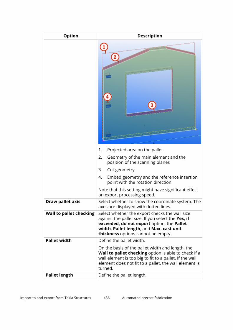
Option Description
1. Projected area on the pallet
2. Geometry of the main element and theposition of the scanning planes
3. Cut geometry
4. Embed geometry and the reference insertionpoint with the rotation direction
Note that this setting might have significant effecton export processing speed.
Draw pallet axis Select whether to show the coordinate system. Theaxes are displayed with dotted lines.
Wall to pallet checking Select whether the export checks the wall sizeagainst the pallet size. If you select the Yes, ifexceeded, do not export option, the Palletwidth, Pallet length, and Max. cast unitthickness options cannot be empty.
Pallet width Define the pallet width.
On the basis of the pallet width and length, theWall to pallet checking option is able to check if awall element is too big to fit to a pallet. If the wallelement does not fit to a pallet, the wall element isturned.
Pallet length Define the pallet length.
Import to and export from Tekla Structures 436 Automated precast fabrication

Option DescriptionMax. cast unitthickness
Define the maximum cast unit thickness.
To avoid collision with the drying chamber, themaximum thickness of a cast unit should besmaller than the maximum opening of the dryingchamber.
Rebar diameterlimitation
Minimum and maximum diameter for thereinforcing bars to be exported.
Rebar length limitation Minimum and maximum length for the reinforcingbars to be exported.
Rebar leg lengthlimitation
Minimum and maximum length for individual legsection within a bent rebar to be exported.
Mesh wire lengthlimitation (Long)
Minimum and maximum diameter for longitudinalreinforcing bars to be exported.
Mesh wire lengthlimitation (Cross)
Minimum and maximum length for crossreinforcing bars inside a mesh to be exported.
Mesh wire leg lengthlimitation
Minimum and maximum length for individual legsection within a bent mesh wire to be exported.
Mesh wire overhanglimitation
Minimum and maximum length for mesh wireoverhang section before the first cross-wirewelding point and after the last cross-wire weldingpoint to be exported.
Mesh wire spacinglimitation
Allowed spacing values for mesh wires separatedby blank space to be exported. If no value added,there is no limitation for spacing.
Export others These operations are intended for objects that failthe validation:
• Remove invalid mesh wires: Only excludeinvalid mesh wires and not the whole meshwhen some of the mesh wires fail thevalidation.
• Yes, as loose (type 4 or 8): Export invalidrebars as loose rebars of type 4 or 8.
• Yes, ignore limitation: The diameter andlength limitations are ignored.
• Yes, as non-automated: Export non-validrebars as non-automated.
• Prevent export
• Exclude all: Exclude the whole mesh from theexport if any of the wires fail the validation.
When a rebar fails the validation, you are notifiedby a log message.
Import to and export from Tekla Structures 437 Automated precast fabrication

Unitechnik export: Reinforcement data tab
In the column on the right, enter the custom or UDA string when applicable.On this tab, you can add data attributes only, no geometric attributes. Theinformation you add controls the reinforcement unit data (singlereinforcement, mesh, braced girder, or cage). The attributes are eitheroptional or obligatory. The length of some of the fields may be limited in theUT format, so keep the strings short.
Depending on the setting, the following attributes can be added: Name,Grade, Class, Rebar ID, Mesh ID, Mesh position,UDA, UDA (main part), UDA(rebar), Part UDA, Main part UDA, Phase, User-defined text, User-definedtext + class, Template, and Text[Template]#Counter.
Text[Template]#Counter:
• Text can be any text including punctuation marks.
• Write templates in brackets [].
• # adds a running number if the data content is the same in several entries.
• You can enter several templates and use text delimiters, for example,[ASSEMBLY_POS]-[REBAR_POS].
• If you start the Text[Template]#Counter with a template, add a space asthe first character before the bracket.
• Template attributes are read from the single reinforcement, mesh, bracedgirder, or cage.
• You can also use attributes that refer to another hierarchy level, forexample, the assembly UDA of the rebar.
• You can use <VALUE> to inquire a part UDA and {VALUE} to inquire anassembly UDA. This makes it possible to use a shorter string instead ofhaving to use a template property to designate UDAs.
• Data field and file name options with #Counter logic keep the counterseries separate from each other when necessary. Only objects with thesame object type and matching data string as a base are put into the samecounter series. For data fields other than HEADER block fields, thesecounter series are also distinct within each export file and data section.
Option DescriptionRebars: Article numberrebar
Select which property you want to export as areinforcing bar article number for rebars.
Rebars: Article numbermesh
Select which property you want to export as amesh article number for rebars.
Meshes: Articlenumber rebar
Select which property you want to export as areinforcing bar article number for meshes.
Meshes: Articlenumber mesh
Select which property you want to export as amesh article number for meshes.
Import to and export from Tekla Structures 438 Automated precast fabrication

Option DescriptionMeshes: Meshesdesignation
Select the information that you want to exportabout the meshes.
Meshes: Info 1 text (UT6.0)
Information field is filled with the selected data.
Meshes: Info 2 text (UT6.0)
Information field is filled with the selected data.
Welded leg designation Designate the welded leg in bent mesh bars ifthere is only one leg that is welded to cross-wires..When you select Yes, information about weldedleg designation is exported.
Strands (UT 6.0): Pullforce (KN)
You can now use main part UDA (UDA (main part))or rebar UDA (UDA (rebar)) to include strand pullforce information in the Unitechnik export.
Selecting Empty does not export the strand pullforce information.
This setting only works for rebars that are set totype 9 in the Unitechnik reinforcement type boxon the Unitechnik tab in the user-definedproperties of the rebars.
BRGIRDER block:Braced girder type
Select the string value of girder type field in the BRGIRDER block in the exported file.
• Empty
No string is exported.
• Name
The name of the braced girder type is exported.If the name of the top part of a braced girder isempty, the names of the rods are checked.
• UDA
You can export the user-defined attributevalues for a braced girder type (type), bracedgirder article number (art_number), or bracedgirder fabricator name (fabricator).
The UDAs can be added to the braced girder ifthe parts have been created using the systemcomponent Braced girder (88) or Bracedgirder (89) and you have entered the neededvalues on the dialog boxes of the components.
• User defined text
The value you enter in the box next to thisoption is exported.
Import to and export from Tekla Structures 439 Automated precast fabrication

Option DescriptionCAGE BLOCK: Cagedesignation
Select the information that you want to exportabout the the cage in the CAGE block (UT 6.1).
CAGE BLOCK: Base cageshape
Select the information that you want to show asbase cage shape.
CAGE BLOCK: Info 1text
Information field is filled with the selected data.
CAGE BLOCK: Info 2text
Information field is filled with the selected data.
Definition file Use an external definition file to overwrite typeand designation information, which is usuallydetermined automatically from model objects. Thedefinition file is a .csv file, with a fixed structure.The definition file can also be read from foldersdefined for XS_FIRM and XS_PROJECT.
Example of the definition file: UT_rebar_info.csv.
Unitechnik export: HEADER block data tab
In the column on the right, enter the custom or UDA string, when applicable.On this tab, you can add data attributes only, no geometric attributes. Theattributes are either optional or obligatory. The length of some of the fieldsmay be limited in the UT format, so keep the strings short.
Depending on the setting, the following attributes can be added: Projectnumber, Project name, Cast unit position, Cast unit positioncode,Assembly control number (ACN), Cast unit ID, Cast unit prefix (2digits), Cast unit drawing revision mark, Project properties - name,Project properties - address, File name with extension, File name withoutextension, Tekla Structures version, Main part ID, Project UDA, Main partUDA, Main part UDA (UT_product_code), Phase, User-defined text, Username, Main part template, Template and Text[Template]#Counter.
Text[Template]#Counter:
• Text can be any text including punctuation marks.
• Write templates in brackets [].
• # adds a running number if the data content is the same in several entries.
• You can enter several templates and use text delimiters.
• If you start the Text[Template]#Counter with a template, add a space asthe first character before the bracket.
• Template attributes are read from the main part.
• You can also use attributes that refer to another hierarchy level.
Import to and export from Tekla Structures 440 Automated precast fabrication

• You can use <VALUE> to inquire a part UDA and {VALUE} to inquire anassembly UDA. This makes it possible to use a shorter string instead ofhaving to use a template property to designate UDAs.
• Data field and file name options with #Counter logic keep the counterseries separate from each other when necessary. Only objects with thesame object type and matching data string as a base are put into the samecounter series. For data fields other than HEADER block fields, thesecounter series are also distinct within each export file and data section.
Option DescriptionName of order Order fields in the HEADER block are filled with the
selected data.
File name sections: Specify a string consisting ofnumbers referring to the 6 sections of theexported file name mask that are specified on theMain tab. You can type numbers 1 to 6, anddelimiters , . _ and - in the free input field to exportany combination of strings used in the file name, inany order. For example, 1-2-3, or 2_5_6.
Name of component Component fields in the HEADER block are filledwith the selected data.
Drawing number Drawing number fields in the HEADER block arefilled with the selected data.
File name sections: Specify a string consisting ofnumbers referring to the 6 sections of theexported file name mask that are specified on theMain tab. You can type numbers 1 to 6, anddelimiters , . _ and - in the free input field to exportany combination of strings used in the file name, inany order. For example, 1-2-3, or 2_5_6.
Drawing revision Drawing revision fields in the HEADER block arefilled with the selected data and drawing revisionmark is exported.
Product code Product code fields in the HEADER block are filledwith the selected data.
Project line1 text -Project line4 text
Project information fields (3rd line) in the HEADERblock are filled with the selected data.
File creator (UT 6.0) You can select to export the Tekla Structuresversion information, use name or user-defined textin the HEADER block.
Free field (UT 5.2) Only for Unitechnik 5.2. You can select to exportthe following information to theHEADER block: username, user-defined text, file name with extension,file name without extension, or model name.
Import to and export from Tekla Structures 441 Automated precast fabrication
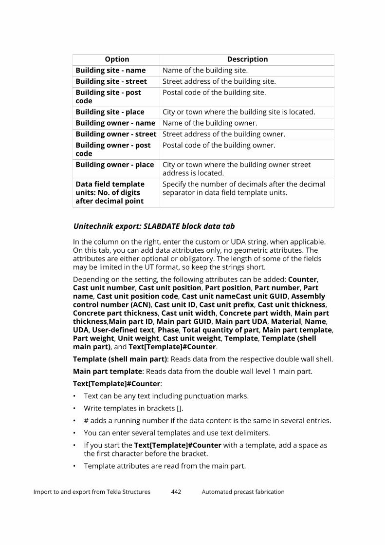
Option DescriptionBuilding site - name Name of the building site.Building site - street Street address of the building site.Building site - postcode
Postal code of the building site.
Building site - place City or town where the building site is located.Building owner - name Name of the building owner.Building owner - street Street address of the building owner.Building owner - postcode
Postal code of the building owner.
Building owner - place City or town where the building owner streetaddress is located.
Data field templateunits: No. of digitsafter decimal point
Specify the number of decimals after the decimalseparator in data field template units.
Unitechnik export: SLABDATE block data tab
In the column on the right, enter the custom or UDA string, when applicable.On this tab, you can add data attributes only, no geometric attributes. Theattributes are either optional or obligatory. The length of some of the fieldsmay be limited in the UT format, so keep the strings short.
Depending on the setting, the following attributes can be added: Counter,Cast unit number, Cast unit position, Part position, Part number, Partname, Cast unit position code, Cast unit nameCast unit GUID, Assemblycontrol number (ACN), Cast unit ID, Cast unit prefix, Cast unit thickness,Concrete part thickness, Cast unit width, Concrete part width, Main partthickness,Main part ID, Main part GUID, Main part UDA, Material, Name,UDA, User-defined text, Phase, Total quantity of part, Main part template,Part weight, Unit weight, Cast unit weight, Template, Template (shellmain part), and Text[Template]#Counter.
Template (shell main part): Reads data from the respective double wall shell.
Main part template: Reads data from the double wall level 1 main part.
Text[Template]#Counter:
• Text can be any text including punctuation marks.
• Write templates in brackets [].
• # adds a running number if the data content is the same in several entries.
• You can enter several templates and use text delimiters.
• If you start the Text[Template]#Counter with a template, add a space asthe first character before the bracket.
• Template attributes are read from the main part.
Import to and export from Tekla Structures 442 Automated precast fabrication
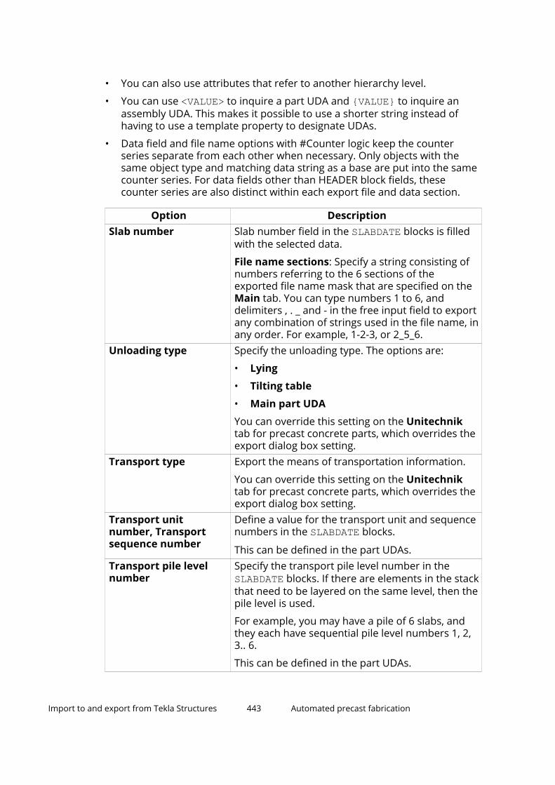
• You can also use attributes that refer to another hierarchy level.
• You can use <VALUE> to inquire a part UDA and {VALUE} to inquire anassembly UDA. This makes it possible to use a shorter string instead ofhaving to use a template property to designate UDAs.
• Data field and file name options with #Counter logic keep the counterseries separate from each other when necessary. Only objects with thesame object type and matching data string as a base are put into the samecounter series. For data fields other than HEADER block fields, thesecounter series are also distinct within each export file and data section.
Option DescriptionSlab number Slab number field in the SLABDATE blocks is filled
with the selected data.
File name sections: Specify a string consisting ofnumbers referring to the 6 sections of theexported file name mask that are specified on theMain tab. You can type numbers 1 to 6, anddelimiters , . _ and - in the free input field to exportany combination of strings used in the file name, inany order. For example, 1-2-3, or 2_5_6.
Unloading type Specify the unloading type. The options are:
• Lying
• Tilting table
• Main part UDA
You can override this setting on the Unitechniktab for precast concrete parts, which overrides theexport dialog box setting.
Transport type Export the means of transportation information.
You can override this setting on the Unitechniktab for precast concrete parts, which overrides theexport dialog box setting.
Transport unitnumber, Transportsequence number
Define a value for the transport unit and sequencenumbers in the SLABDATE blocks.
This can be defined in the part UDAs.Transport pile levelnumber
Specify the transport pile level number in the SLABDATE blocks. If there are elements in the stackthat need to be layered on the same level, then thepile level is used.
For example, you may have a pile of 6 slabs, andthey each have sequential pile level numbers 1, 2,3.. 6.
This can be defined in the part UDAs.
Import to and export from Tekla Structures 443 Automated precast fabrication

Option DescriptionExposure class Export exposition class. You can select to read
from part UDAs or use another option.Total thickness Select which value will be exported as total
thickness. The options are Cast unit thickness,Concrete part thickness, Main part thickness,Template, and Double wall width.
Double wall width is the same as the Cast unitthickness but it is always inquired from the maincast unit, regardless of how it is modeled. Then the2nd shell will also receive total cast unit width.
Production thickness Calculates the production thickness in SLABDATEblock based on cast unit width, concrete part widthor double wall width.
Double wall width is the same as the Cast unitwidth but it is always inquired from the main castunit, regardless of how it is modeled. Then the 2ndshell will also receive total cast unit width.
When you export double walls: With the optionCast unit width the cast unit thickness is exportedfor both shells.
Export shell gap width Controls or disables the export of the gap widthvalue. The options are:
• No: No gap is exported.
• Double walls only: The gap is exported onlyfor double walls. This is the default option, asthe value should only be used with double wallsin most control systems.
• Layered panels: The gap is exported for allpanels with multiple concrete layers, such asdouble walls and sandwich walls.
Production weight Set the type of the SLABDATE weight. The optionsare Part weight, Unit weight, Cast unit weight,and Template.
Concrete volume Set the type of the volume. You can select concretepart or specify a user-defined concrete volumetemplate property.
Maximum dimensions Specify how the SLABDATE maximum part lengthand width are exported. The options are:
• Main part bounding box (default): Checks themain part geometry
• Cast unit bounding box: Checks the entire castunit geometry, including all protruding embeds
Import to and export from Tekla Structures 444 Automated precast fabrication

Option Description• Scanned contour: Checks all contour polygons
• Scanned all parts: Checks all contour andembed polygons
Iron protection Export iron projection data. The values areautomatically determined from the reinforcementlength that extends outside the element.
Quality of layer Set the quality of the slabdate. The options arename, template, material and UDA.
Item designation Designate data about the exported element.Info 1 text (UT 6.0) -Info 4 text (UT 6.0)
Information fields (1 - 4) in the SLABDATE and MOUNPART blocks are filled with the selected data.
Export projectcoordinates
Select how you want to export project coordinates.
The options are:
No
Yes, model origin: Use model origin.
Yes, with swapped X-axis and Y-axis: Swap X-axisand Y-axis.
Yes, special variant A (version 5.2b): ExportUnitechnik files that are compatible with the IDATstacker software. This is only available for the 5.2bversion of Unitechnik.
Yes, project base point: Use project base point.
Yes, current base point: Use the base pointcurrently selected in the model.
Export quantity You can export element quantity in the SLABDATEblock. If the exported sets have multiple cast units,they will have their quantity marked in theSLABDATE reference number field. The export setsare defined by the file name definition or cast unitposition. The options are:
• No: 000 written in the field (default)
• Always 1: 001 written in the field regardless ifthe files names are unique or not
• From selection: If the cast units in the exportselection would have identical file names, theywill be exported with only 1 file, and the totalquantity of the set is written in the field
• From total in model: The total quantity of thecast units with identical position anywhere inthe model is written in the field
Import to and export from Tekla Structures 445 Automated precast fabrication

Unitechnik export: MOUNPART block data tab
On this tab, you can add data attributes only, no geometric attributes. Theattributes are either optional or obligatory. The length of some of the fieldsmay be limited in the UT format, so keep the strings short.
How to use Text[Template]#Counter:
• Text can be any text including punctuation marks.
• Write templates in brackets [].
• # adds a running number if the data content is the same in several entries.
• You can enter several templates and use text delimiters.
• If you start the Text[Template]#Counter with a template, add a space asthe first character before the bracket.
• Template attributes are read from the main part of the embed assembly.
• You can also use attributes that refer to another hierarchy level.
• You can use <VALUE> to inquire a part UDA and {VALUE} to inquire anassembly UDA. This makes it possible to use a shorter string instead ofhaving to use a template property to designate UDAs.
• Data field and file name options with #Counter logic keep the counterseries separate from each other when necessary. Only objects with thesame object type and matching data string as a base are put into the samecounter series. For data fields other than HEADER block fields, thesecounter series are also distinct within each export file and data section.
NOTE Steel parts have a tab Unitechnik Mountpart, where you can specifydata which then overwrites the settings defined on the MOUNPARTblock data tab.
When specifying object names: If names consist of several words,enclose those in quotation marks and use spaces between words, forexample, "WORD1 WORD2".
For several options, you need to specify the related value in theCustom UDA or string field.
Option DescriptionType of mounting part You can define the type of mounting
part in the MOUNTPART block by UDA,class or name.
Installation type Specify the installation type of theembed by defining a UDA, class,name or user-defined text.
Import to and export from Tekla Structures 446 Automated precast fabrication

Option DescriptionReference number You can define the reference number
of a mounting part in the MOUNTPARTblock by UDA.
Mountpart name Define the MOUNTPART name usingone of the available options.
Insulation name Specify a different mountpart namesource for the insulation.
Cut mountpart name Specify a different mountpart namesource for the cut part mountparts.
Info 1 text (UT 6.0) Information field is filled with theselected data.
Info 2 text (UT 6.0) Information field is filled with theselected data.
Unitechnik export: Line attributes tab
Line attributes are exported automatically according to the element andopening edge shape. If the factory does not use Unitechnik standard lineattribute codes, you can override these exported codes. Sometimes lineattribute values that are exported in the Unitechnik files are not suitable forthe particular situation. For example, to preserve lightness in the model orextensive product standardization, you might have fewer chamfers in themodel than there will be in the actual structure. For this reason, you mightwant to override some line attributes in the export so that the model remainslight, but the exported Unitechnik files are correct. You can do this by usingthe options on the Line attributes tab.
NOTE When specifying object names: If names consist of several words,enclose those in quotation marks and use spaces between words, forexample, "WORD1 WORD2".
Option DescriptionExport line attributesfor contour
Select whether the line attribute values are usedfor contours (Export line attributes for contour)or for holes (Export line attributes for cutouts) inthe export.
• None
Line attribute values are not used.
• All lines
Line attribute values are used for all lines.
Import to and export from Tekla Structures 447 Automated precast fabrication

Option Description• Outmost lines only
Line attribute values are used only for theoutermost lines in the part:
This option is available only for contours.Override scanned lineattributes
Limit the override to specific cases. The options areAll, Rotated, Not rotated, First shell and Secondshell. The first option affects the 3 overridesettings above, and the second option affects the 3settings below.
Rotated and Not rotated apply to all rotations inXY direction, manual and automatic.
Border line overriding You can enter up to six border line modifications inthe line attribute export.
No border lines are overridden.
Vertical outermost border lines at the start areoverridden.
Horizontal outermost border lines at the bottomare overridden.
Vertical outermost border lines at the end areoverridden.
Import to and export from Tekla Structures 448 Automated precast fabrication

Option Description
Horizontal outermost border lines at the top areoverridden.
Vertical outermost border lines are overridden.
Horizontal outermost border lines are overridden.
Horizontal and vertical outermost border lines areoverridden.
All inclined outermost border lines are overridden.
All outermost border lines are overridden.
All vertical border lines, except the outermostborder lines are overridden.
Import to and export from Tekla Structures 449 Automated precast fabrication

Option Description
All horizontal border lines, except the outermostborder lines are overridden.
All vertical and horizontal border lines except theoutermost border lines are overridden.
All border lines except outermost border lines areoverridden.
All border lines except the horizontal and verticaloutermost border lines are overridden.
All border lines are overridden.
Scanned CUTOUT line attributes are overridden.This affects window openings, for example.
Orig. attr. , New attr. Define the original attribute (Orig. attr.) and theattribute that will be used in the export (Newattr.).
In the example below the horizontal outermostborder line at the top would get a line attribute
Import to and export from Tekla Structures 450 Automated precast fabrication

Option Descriptionvalue 0033 originally, but the value will beoverridden, and the line attribute value in theUnitechnik file will be 0040.
Special formwork forobject (classes ornames)
Specify a special formwork object using a class or aname. The edge of the exported contour with thisspecified object will then be exported with code0002 by default.
This setting also works for reinforcement.
In Attribute code, you can specify a custom lineattribute code for special formwork for an object.
Export line attributesfor cutouts
Select whether all line attributes are exported foropenings.
Max, Min The width of the chamfer is max 30 mm and thedepth of the tongue and groove max 30 mm. If notwithin the tolerance, they are handled as specialformwork 0002.
Export angle of 1st andlast vertical border
Select whether you want to export the angle of cutat the first and last vertical border.
Unitechnik export: Pallet tab
Option DescriptionPlacing on pallet Define if the placing is checked from the start or
end of the pallet.X offset at start or end Define if the X offset at start or end of the pallet is
checked.Y offset fromalignment
Specify the Y offset of elements on the pallet.
Import to and export from Tekla Structures 451 Automated precast fabrication

Option DescriptionAlign in Y axis Align elements in Y direction. You can select
whether to align
• element upper edge to pallet upper edge
• element upper edge to pallet center line
• element center line to pallet center line
• element lower edge to pallet center line
• element lower edge to pallet lower edge
• element to the center of the pallet in Y directionClearance betweencast units
Define if the clearance between the cast units ischecked.
Same cast unitthickness needed
Define if the cast unit thickness is checked.
Sequence in pallet
Sequence order
When you have selected Combined, n slabdate, 1part as the output file structure on the Main tab,you can select the logic of sequencing panels onpallet using main part or cast unit ACN or number,main part UDA or main part template, orUnitechnik transport UDAs. You can set thesequence as Ascending or Descending.
Unitechnik export: Symbols tabConfigure the details of mountpart symbols and symbols for braced girdersused in the export.
Setting DescriptionSpecial assemblies export
Special export assembly file name
The options are No, Yes,(spec_assemblies_def.txt), and Yes,no rotation on pallet.
The options affect the exportedgeometry of the embeds. The realgeometry is replaced by the geometrydefined in text files. Each embed isdefined as a symbol consisting of aset of lines, a set of arcs, or a circle.The default name of the text file isspec_assemblies_def.txt, and issearched for in the model folder. UseSpecial export assembly file nameto define the name and the locationof the text file. The special exportassembly file name can also be read
Import to and export from Tekla Structures 452 Automated precast fabrication
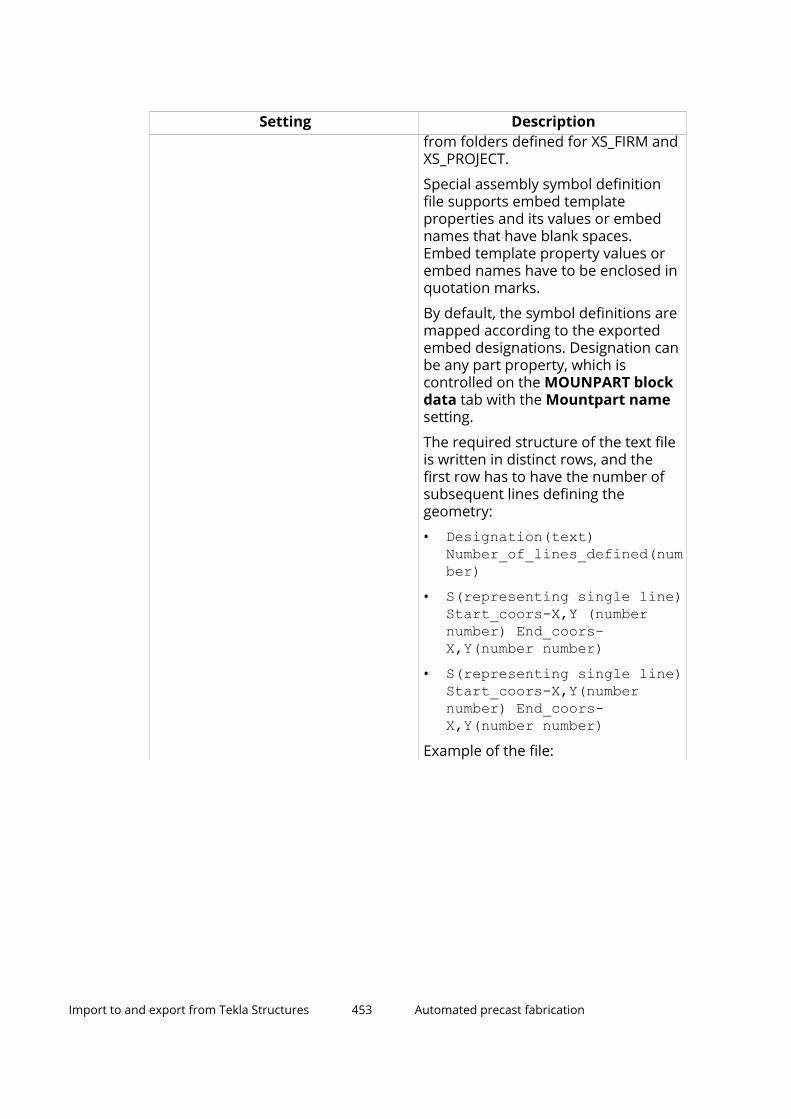
Setting Descriptionfrom folders defined for XS_FIRM andXS_PROJECT.
Special assembly symbol definitionfile supports embed templateproperties and its values or embednames that have blank spaces.Embed template property values orembed names have to be enclosed inquotation marks.
By default, the symbol definitions aremapped according to the exportedembed designations. Designation canbe any part property, which iscontrolled on the MOUNPART blockdata tab with the Mountpart namesetting.
The required structure of the text fileis written in distinct rows, and thefirst row has to have the number ofsubsequent lines defining thegeometry:
• Designation(text)Number_of_lines_defined(number)
• S(representing single line)Start_coors-X,Y (numbernumber) End_coors-X,Y(number number)
• S(representing single line)Start_coors-X,Y(numbernumber) End_coors-X,Y(number number)
Example of the file:
Import to and export from Tekla Structures 453 Automated precast fabrication

Setting Description
You can use S for a line, K for a circle,and B for an arc, and the coordinatesare related to the embed insertionpoint.
A line is defined with 4 coordinates,start (X,Y), end (X,Y). Example: S -50-50 50 50
A circle is defined with one radiusvalue around the insertioncoordinate. Example: K 100
An arc is defined with a radius valueand relative start and end angles, with0 angle pointing towards positive Xdirection, and increases counter-clockwise.
Embeds in special assembly symboldefinition file can also be designatedby template property and its value informat [TEMPLATE:VALUE] insteadof the exported embed designation.
Example of using template property:
Import to and export from Tekla Structures 454 Automated precast fabrication
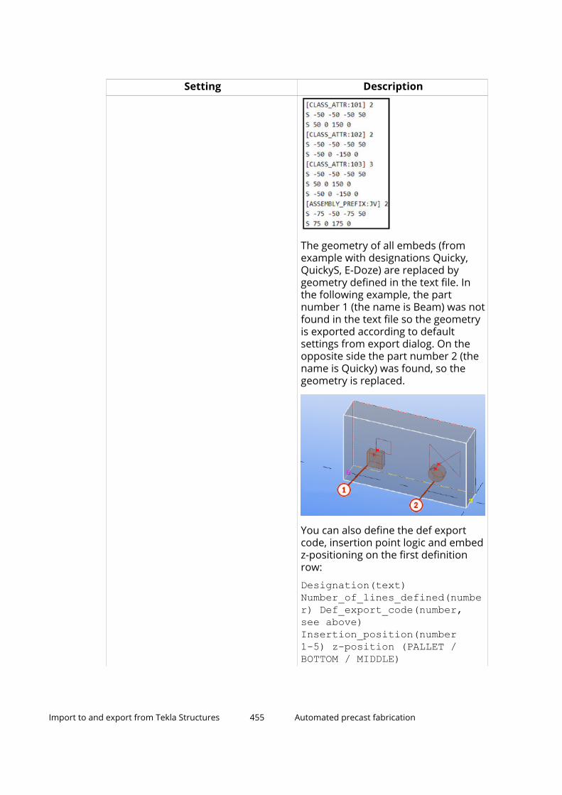
Setting Description
The geometry of all embeds (fromexample with designations Quicky,QuickyS, E-Doze) are replaced bygeometry defined in the text file. Inthe following example, the partnumber 1 (the name is Beam) was notfound in the text file so the geometryis exported according to defaultsettings from export dialog. On theopposite side the part number 2 (thename is Quicky) was found, so thegeometry is replaced.
You can also define the def exportcode, insertion point logic and embedz-positioning on the first definitionrow:
Designation(text)Number_of_lines_defined(number) Def_export_code(number,see above)Insertion_position(number1-5) z-position (PALLET /BOTTOM / MIDDLE)
Import to and export from Tekla Structures 455 Automated precast fabrication

Setting DescriptionTo specify the insertion point positionof embeds in using thespec_assemblies_def.txt file:
1 = Subassembly center of gravity
2 = Subassembly bounding boxcenter of gravity
3 = Main part center of gravity
4 = Extended main part center ofgravity
5 = Main part bounding box center ofgravity
If you select Yes, no rotation onpallet, the embed symbols are placedaccording to the panel rotation, butthe symbols themselves are notrotated.
Special embeds Class or name list
When defining special embeds asnames, and object names consist ofseveral words, enclose those inquotation marks and use spacesbetween words, for example,"WORD1 WORD2".
Opening with corner symbols Specify classes or names of parts orcut parts for openings that will beexported with corner symbols insteadof mountpart representation.
All cutouts as corner symbols Export rectangular cutouts as 4corner symbol mount parts bydefining the classes or names. Youcan define the size of the symbol inthe dialog box.
Draw girder width symbol Specify if the braced girders exportedwith end symbol mountpart shouldalso have a line representing thegirder width.
Draw girder in second shell Specify if the braced girders shouldbe exported in the second shell of thedouble wall. You can also specify thelength of the longitudinal line.
Import to and export from Tekla Structures 456 Automated precast fabrication

Unitechnik export: Log files tab
Option DescriptionLog file directory path Define the path for a log file. If the path is empty,
then the log file is saved in the same location asthe export files.
Create main Log file Select whether to create a one main log file.Create Log file for eachfile
Select whether a log file is created separately foreach export file.
Write history to log fileand UDA
Create a log file containing the history of theexported parts. You can also select to write theinformation to the UDA UT_export_history ofthe main part. The following data is gathered:export time, part information, export path and file,and who has performed the export.
Show error dialogboxes
Select whether an error message is shown, forexample, when exported parts are not numberedcorrectly or when the embedded parts have noparent part.
Write file name to UDA Select to write the full export file name (File namewith extension) or the export file name withoutthe file name extension (File name withoutextension) to hidden main part UDA UT_FILE_NAME.
Best practices in modeling, validating and exporting for UnitechnikThe following guidance helps you to ensure the best possible result from theBVBS export.
For exact instructions on the Unitechnik export, export settings, and on otherrelated topics, see Unitechnik (page 394).
Pre-research
Before you start modeling, find out the following:
• What are the fabrication requirements and constraints?
• What is the complexity level of the products?
• What information is desired from the model?
• Production geometry for reinforcement mesh, loose rebars, embeds
• Project and product attributes
• What Unitechnik versions does the CAM system support?
Before your first project:
• Model a test model with each of the typical products.
Import to and export from Tekla Structures 457 Automated precast fabrication

• Choose your modeling components and modeling settings.
• Test the Unitechnik export with each of the typical products and draftsuitable settings.
• Draft a company modeling guideline for collecting the information aboutmodeling, drawing creation, export and other practices in one place.
Modeling
General
Designers should aim to model with good precision taking into account thefabrication requirements of the products. The required level of accuracy variesfrom product to product, and some details need to have exactly correctgeometry whereas others can be included as attributes that will be sufficientfor production purposes.
As production only needs certain amount of information, some data needs tobe in drawings that will not be used within the export files and vice versa. Thegoal is to have an error free model, which is modeled in a disciplined andstructured fashion so that it will be easy to include or exclude information inboth drawing and export file creation. All information will be used byproduction, and therefore it is very important to have correct information,because also export might be prevented if data is missing (such as materialdata or other). Any mistakes are hard to notice until the actual productionstage.
Additional information can be brought to both the drawing and production fileusing user-defined attributes (UDAs), which can be within each object, or onthe project level. UDAs are defined on the HEADER block data specification,SLABDATE block data specification, Mounting part data specification andReinf. data specification tabs in the export dialog box. Some mandatoryfields have to filled as agreed, such as project number, product type anddrawing number, otherwise import is prevented. For more information aboutthe different tabs, see Unitechnik (page 394).
The best practice is to:
1. Finalize the detailing of a product.
2. Do a test export of the product with ready-made setting (for that producttype) and inspect the resulting file and make any adjustments ifnecessary.
3. Create the drawing and edit it.
4. Finalize the drawing and send the drawing and a production file to a teammember for approval.
5. Later on a designated person will send the production files in suitablesets.
6. Control the design status on object-level within the model to keep track ofdesign, approval and changes, as well as the export files sets.
Import to and export from Tekla Structures 458 Automated precast fabrication

Object geometry will be used for plotting and shuttering as well as fabricatingthe mesh, and cutting and bending the reinforcement. Each object type shouldhave a distinct NAME and CLASS setting, to later control the export content.
In the model objects are represented hierarchically. This means that the objectto be exported is a cast unit and within the cast unit there is the concrete mainpart. Other parts or reinforcement can be attached to the main part directly,or by first formulating a sub-assembly, which will have its own hierarchy andmain part.
Unitechnik geometric objects
The 3D Tekla Structures objects are translated to suit the Unitechnik format.
Import to and export from Tekla Structures 459 Automated precast fabrication

(1) Contour
(2) Cutout
(3) Mountpart (embed)
(4) Rodstock (rebar)
(5) Steelmat (mesh)
(6) BGrinder (braced girder)
Contour and openings
Each object should have unified contour. There may be openings through theelement.
More than one contour causes problems for plotting the contour and placingthe shuttering. Having more than one contour is usually unintended, andcaused by either having a concrete part that has not been designated as anembed, or the contour scanning resulting in two separate objects due to a cutor recess.
The orientation of the object and contour is controlled by the modelingdirection, using the top-in-form setting within the model and the varioussettings within the export dialog box. Setting the top-in-form in the model isimportant because that is how Tekla Structures understands how the object
Import to and export from Tekla Structures 460 Automated precast fabrication

will be produced, which affects both the export file and the drawings. As a ruleof thumb, slabs and panels should be laid out on their wide face, with noextending parts or rebars towards the pallet, and any embeds and gaps thatrequire additional filler pieces against the pallet. These filler embeds shouldhave 0 weight and should be excluded from drawings and volume calculations.
If the edge has a shape that needs to be identified for a shuttering robot, thisis indicated by using line attribute codes (for chamfers, recesses or teeth).These should be modeled using ready-made components, chamfers or cuts.These will always be in the geometrical object's contour and cutout. In export,they can be mapped automatically according to the Unitechnik standard, oryou can set an automatic override in the export.
In the usual case, CUTOUT represents a full-depth opening, while recesses inthe face are represented by embeds, MOUNPART.
For elements with standardized shape, such as pre-stressed slabs, the profilecan be included as attribute information.
Controlling the contour in the model is done by having an object profile, whichwill be extruded to create the main part geometry. This basic geometry canthen be adjusted by using cuts within the model. Each cut should have adistinct class or part set, so including and excluding them in export geometrycan be adjusted later. We recommend that you model any cuts or fillerembeds with systematic orientation, and for example, start and end handlesshould also be modeled in the panel length direction.
The initial cut parts are to be added to the cast unit, knowing that they will belisted on reports and shown on drawings. To exclude these purely productionrelated elements from reports and drawings use filters and rules.
In the example below the initial cut parts were kept and added to the cast unit.The cut part name is set to "FORMWORK", the class is 111 (orange), and thematerial name is Zero_weight.
Import to and export from Tekla Structures 461 Automated precast fabrication
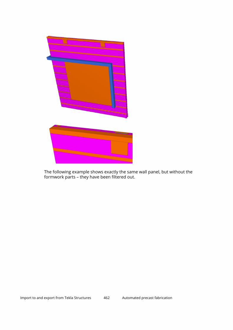
The following example shows exactly the same wall panel, but without theformwork parts – they have been filtered out.
Import to and export from Tekla Structures 462 Automated precast fabrication

Example chart of classes for modeling cuts (Cut included = as CUTOUT,mountpart included = as MOUNPART):
Type of cut Modeled ExportedWindow opening Cut with class 601
(component)Cut included
Door opening Cut with class 601(component)
Cut included
Other opening throughthe element
Cut with class 601(component)
Cut included
Rectangular recess inthe middle of element
Cut with class 602, fillerembed part with class
Cut excluded, fillermounpart included
Rectangular recess onthe contour
Cut with class 602, fillerembed part with class
Cut excluded, fillermounpart included
Non-rectangular recess Cut with class 602, fillerembed part with class
Cut excluded, fillermounpart included
Cuts around embedcomponents
Cut with class 602 Cut excluded
Chamfer on the edge Chamfer or cut withclass 603
As line attribute
Import to and export from Tekla Structures 463 Automated precast fabrication

Type of cut Modeled ExportedGroove or tongue shapeon the edge
Cut with class 603(component)
As line attribute
Embeds
Embeds are presented as mountparts. Steel plates for connections, liftingembeds, electric boxes or grout tubes are examples of mountparts. Eachembed should be added as a sub-assembly to the main cast unit. Embeds areusually modeled with ready-made components, and it is important to checkthat the tools have correct materials and attributes, and that the embedhierarchy is correct. Embeds should be classified by a distinct class(recommended 100 - 109 , other steel parts as 99). Steel parts can also berecognized automatically.
• There are various options available for presenting the embeds: exactgeometry, a bounding box or a symbol.
• Embeds modeled as rebars can be turned into mountparts.
• Small cuts within the embed modeling components should usually beexcluded, which can be done by separately identifying them with class.
• Insulation layers can be added as mountpart identified by class.
• Surface treatment can be exported as mountparts. Surface objects are notsupported.
• Additional attributes can be added to each mountpart.
Remember the following:
• Apply meaningful names or identification codes to embeds, such as thecomponent main part.
• Embed parts and sub-assemblies added to the cast unit must fully beadded to the cast unit of Tekla Structures. Embeds or other connectionentities not assigned to a cast unit of Tekla Structures will not be taken intoaccount when exporting to UT file.
• Use logical hierarchical structure, and select a sensible main part for anembed sub-assembly.
• Check sub-assembly hierarchies. Only 2 levels within the sub-assembly isrecommended.
• Check placing, classes, positioning, naming.
• Embed UDA tab settings for tailoring embed representation
Import to and export from Tekla Structures 464 Automated precast fabrication

• Keep a list of all embeds and reinforcement in the project including theirnames and classes.
Cut and bent reinforcement and reinforcement mesh
Cut and bent reinforcement can be modeled by using standard rebar modelingfunctionalities or components. Rebars should be correctly attached to correctmain parts, but this is rarely an issue if modeling carefully.
Usually the elements have a very high number of reinforcement but notnecessarily all have to be brought into the export file, only the ones that needto be produced according to correct geometry or need to be quantified. Insome cases, it is good idea to exclude the protruding rebars from cast units forbetter export. Bent rebar shapes will be presented as unfolded and in the xyplane in most of the viewers. 3D bent rebars are not supported by the format.
Reinforcement has automatically assigned reinforcement type to designate itin the production system. You can override this logic by manually addingreinforcement type in rebar UDAs for desired groups.
The mesh bars are automatically assigned to reinforcement types 1 and 2 or 5and 6. The types 1, 2, 5 and 6 represent the installation layer in the form. 1 and2 for mesh in bottom face, 5 and 6 on the top face.
Rebars can also be grouped and classified as cage objects by using rebarUDAs. It is very important to ensure that rebars are not accidentally groupedinto mesh or cage.
Additional attributes can be added to each bar group as well as to each bar.
Import to and export from Tekla Structures 465 Automated precast fabrication

Unitechnik supports both planar mesh and bent mesh. Mesh can be modeledas mesh objects or as crossing bar groups. If modeled as bar groups, the barsneed to be identified using class (recommended a double digit class, e.g. 13 -19) or name in the export dialog. If there are no bar groups to be designatedas mesh, it is important to not use this setting
The modeled cuts are also used for cutting meshes and bars within the TeklaStructures object.
Tekla Structures has several tools for creating mesh for precast objects, suchas Mesh Bars, Mesh Array and Wall Panel Reinforcement.
Additional attributes can be added to each mesh object as well as to each barwithin the mesh.
Remember the following:
• Model according to production constraints.
• Check placing, classes, positioning, naming.
• A mesh can be designed or created in the Tekla Structures model withmesh objects but also using bar groups. If mesh is bent in two directions, itcan only be modeled as bar groups. The UT file export has several optionsto influence the mesh creation towards the end result.
• A mesh in the Tekla Structures cast unit, consisting of longitudinal andcross wire, should be defined either by
• the same class (color)
• the same name
• Do a differentiation of name and class per mesh having for instancebottom and top mesh within one wall shell.
• Furthermore, it is a good practice to apply loose or additional rebar to adedicated class. Depending on the factory equipment and the processesinvolved it might be necessary to exclude certain rebars from a cast unitwhen exporting to the UT file. This can easily be achieved by excluding suchrebars by class in question from the export. Class can also be used todistinguish rebars for non-automated production.
• There are advanced functions to validate mesh, or to add additional wiresfor stabilizing if the mesh has openings. Check the dialog box settings onthe Reinforcement (page 394) tab.
In the example below the wall panel reinforcement rebar and mesh arecreated based on the suggested logic.
The mesh color has been set to red, class 79, its additional reinforcement toblue, class 88. Other reinforcement, also being added to the mesh manuallylater on in the production process, is set to yellow, class 6, and green, class 87.Reinforcement belonging to embeds are set to purple, class 7. With such astructure it is very easy to exclude rebar from automated mesh productionand declare the UT file content as per factory or MC requirement.
Import to and export from Tekla Structures 466 Automated precast fabrication

Braced girders
Braced girders for half-cast or layered structures are identified by having asub-assembly consisting of rebar groups and designating them with a specificclass that is defined in export dialog box (recommended class 105 ). The topchord should be the main part of the sub-assembly.
Girders modeled from steel parts or rebars are both supported but rebars arerecommended.
The best way to model braced girders is using modeling components such asthe Braced Girders tool from Tekla Warehouse.
Import to and export from Tekla Structures 467 Automated precast fabrication

Strands
Strands should be modeled as rebar groups. Strand rebar groups are typicallyreinforcement type 9. The best way to model strands is the Hollow CoreReinforcement Strands tool.
Strands should be quite standard so in the production file they canrepresented with an identifier within the main part such as a Strand Code andquantity of strands. With the Hollow Core Reinforcement Strands tool thisstrand code can be automatically included in the slabdate data, otherwise ithas to be manually controlled using UDAs.
Product information
Product information besides the geometry can be added as textual ornumerical information. This data can be on any level of the hierarchy, butmost important product information will be included in the HEADER andSLABDATE.
The following is automatically added:
• Names of the order and the element (but these have to be set in the exportdialog)
• Product maximum dimensions, length, width in slab-block and thickness inproduct-block
• Total weight in the slabdate block
• Product material in the slabdate block in the layer data. Many layers can beexported but in most cases using only 1 layer provides best results.
• Product coordinates within the project (model) in the header block
• Product type (this needs to be set within the main part UDA) in the headerblock
• Reinforcement type in the rodstock block
• Reinforcement cage group numbers
• Transport information
Other recommended manual information:
• The name of the modeler
• The design status
• Bar and mountpart labeling
• The quantity of the strands (if applicable)
• Erection sequence (if applicable)
Other optional manual information:
• Project information
• Mountpart special instructions
Import to and export from Tekla Structures 468 Automated precast fabrication

• Concreting special instructions
In addition, any UDA or manual text can be added to info fields.
Product type
As a mandatory setting, the UT product type must be set for each main part ofa cast unit.
The product type is not set by default. Select a product type for the elementselected from the model from the predefined list of option.
We recommend that you save the UT product type in modeling settings andcomponents.
The most commonly used types are:
• Solid wall
• Element slab
• Sandwich Element
• Double wall (1st stage)
• Double wall (2nd stage)
• Solid floor
Note that it is very important to define the double wall and sandwich wallcorrectly for both shells.
You can also define product types of your own in addition to the predefinedtypes.
We also recommend that you systematically gather information about theproduct and keep it up to date.
Company-specific modeling guidelines
• Use classes to control element geometry and part/rebar filtering.
• Included/excluded, automated/non-automated, mesh/loose bars
• Define UDA content to define the product
• Project UDAs
Import to and export from Tekla Structures 469 Automated precast fabrication

• Unitechnik product types, location, additional info
• What to do with different types of element openings and recesses
• Shuttered, plotted or excluded
• Use standard edge shuttering shapes
• Define standard meshes, rebars and embeds according to factoryrequirements
• Wire sizes, spacings, bendings, overhangs, maximum dimensions,cutting
• Define top-in-form face for pallet orientation
• Create export settings for each product, and tailor them for each project
Attribute information
Project attributes
To streamline and obtain best possible results it is highly recommended tohave the Tekla Structures cast units to be exported and processed by theUnitechnik file well structured. The modeling technique has a direct impact onthe outcome of the UT file.
The following instructions give a guideline on the mandatory and the mostneeded settings to be set in the Tekla Structures model.
The UT file contains a dedicated header block with general information aboutthe project where the cast unit to be manufactured belongs to.
Within the UT file export dialog box the content of the UT file header block canbe defined by using the project settings of the Tekla Structures Structuresmodel. All relevant information should be set in the beginning of the project inProject properties.
Import to and export from Tekla Structures 470 Automated precast fabrication

User-defined attributes (UDAs)
Each main part of a cast unit in Tekla Structures to be exported to an UT filerequires additional information to be stored in the model. You can use user-defined attributes (UDAs) for this purpose. The UDAs are defined in the TeklaStructures objects.inp file which is present for each configuration but itscontent can differ per Tekla Structures user role. In the Precast configurationthis file can be found in the ..\ProgramData\Tekla Structures\<version>\environments\common folder.
Import to and export from Tekla Structures 471 Automated precast fabrication

In UT file export the Unitechnik tab must be available for precast elements.
Element naming
The UT file contains geometric information of the cast unit to be manufacturedas well as its properties such as names and materials.
We recommend that you apply a meaningful naming to all elements of a castunit (main part, embed part, rebar), as this will improve the readability of a UTfile when being reviewed on the precast production control system. In mostsystems, the PDF drawing name should match the Unitechnik export filename.
Element numbering
Unique numbering is usually needed. ACN numbering is very handy formaking sure that the export separates each piece into its traceable own exportfile and PDF drawing, rebar positions can be included into bar objects using alogic that suits the production.
Element color coding
Tekla Structures elements, such as parts and reinforcements, can easily befiltered by its class.
Import to and export from Tekla Structures 472 Automated precast fabrication

Self-validating the export file
• Validate after the export.
• Go through the geometrical objects within the slab-blocks and visualizethem one by one.
• Investigate possible errors in notifications, logs and viewer.
• Check the date modified and naming of the files.
• Check the main attributes for HEADER and SLABDATE.
• Check orientation on pallet.
• Check contour and line attributes.
• Check the quantity of exported objects.
• Smoke test the rebar and mesh geometry. Check that the mesh productionconstraints have been taken into account, and translated correctly.
• Check the resulting embed plotting.
• If there are any issues, fix those in Tekla Structures, re-export and re-validate.
• Do not import to CAM unless you have checked the export files properly.
• Keep in separate folders (to be checked / faulty / checked and ready forimport).
BVBSYou can export reinforcement geometry in the BundesvereinigungBausoftware (BVBS) format. The result is a text file in the ASCII format with afile name extension .abs.
The supported version of the BVBS format is 2.0 from 2000.
Tekla Structures versions from 2021 onwards support BVBS 3.0 from 2018.The syntax of the BVBS 3.0 file format follows otherwise the BVBS 2.0 fileformat specification, but a support for coupler and thread data has beenadded.
You can export bent reinforcing bars, reinforcing bar groups andreinforcement meshes, which can be rectangular, polygonal, non-bent or bent,and may include cuts. The export of hooks is also supported.
Reinforcing bars that have bendings with two or more variable radius valuesare exported fully conforming with the BVBS specification so that radiuselement and leg elements are written separately. If this causes compatibilityissues within your own environment and other tools using the BVBS files, youcan still go back to the older way of exporting by setting the advanced option
Import to and export from Tekla Structures 473 Automated precast fabrication

XS_BVBS_EXPORT_ARC_COMPATIBLE_TO_OLDER_METHOD to TRUE in an .inifile, for example, in user.ini.
To ensure the best possible export result, see Best practices in BVBS export(page 487).
Export in BVBS format1. Ensure that numbering is up to date.
2. Go to the properties of the cast units and reinforcement that you plan toexport, and edit the user-defined attributes on the BVBS tab as required.The user-defined attributes are environment specific.
3. Select the cast units with the desired reinforcement content, or select thereinforcement.
4. On the File menu, click Export --> BVBS.
The BVBS Export dialog box is displayed.
5. Define the BVBS export settings:
a. On the Parameters tab:
• select which reinforcement to export
• define how and where to export the BVBS file or files, and includethe revision into the file name
• select which BVBS elements to export
• define class numbers for girders
You can use saved selection filters to exclude reinforcement bars ormeshes matching with the selected filter.
b. On the Data content tab:
• define how to export drawing data
• give the reinforcement position source
• give the project number
• select whether you want to export the private data block andselect the data items for this additional block
c. On the Advanced tab:
• round rebar lengths for 2D bent bars
• define which bending radius is used to calculate the arc length
• make meshes out of rebars, and give UDA name for grouping
• include detailed data of mesh bars in the export
• export tapered reinforcing bar groups as multiple separatereinforcing bar items
Import to and export from Tekla Structures 474 Automated precast fabrication

• define the order of the items in the output file
• define the export of reinforcement coupler data
• define whether to combine single rebars or rebar groups by theirposition number, with the total bar quantity, or handle each singlerebar or rebar group individually
BVBS export uses arc geometry in two cases:
• For circular rebars such as spirals or hoops.
• When bent rebar has more than 1 bending radius, the bends withthe larger radius are exported as arc sections.
d. On the Checking tab, select whether you want to run additionalchecks for the reinforcing bars.
e. On the UDAs tab, define the UDA fields to be used, and the contentto write into reinforcement, part, cast unit and pour object UDAs.
6. Click Export.
The BVBS file or files in the .abs format are exported to the folder specified inthe Output file area. You can check the export report by clicking the reportlink that appears at the bottom of the dialog box.
BVBS export settingsUse the BVBS Export dialog box to control the BVBS export settings.
Parameters tab
Option DescriptionModel objects to beexported
Select which reinforcing bars or meshes areexported.
• Reinforcement of all cast units in the model:Exports reinforcing bars or meshes in all castunits in the model. If there are cast units thatdo not have reinforcing bars or meshes, noempty files are created.
• Reinforcement of selected cast units: Exportsreinforcing bars or meshes in the cast units youhave selected in the model.
• Selected reinforcement only: Exports thereinforcing bars or meshes you have selected inthe model or in the drawing. This option alsoexports selected rebar assemblies. When youselect this option, you can export only to asingle file.
• Reinforcement of selected cast units (totalsby all positions): Exports reinforcing bars or
Import to and export from Tekla Structures 475 Automated precast fabrication

Option Descriptionmeshes in all the cast units that have the samecast unit position as any of the selected castunit positions.
For example, if a cast unit with the cast unitposition W-120 is selected, the reinforcing barsor meshes in all the cast units that haveposition W-120 are exported even though notall of them were selected.
• Reinforcement of selected pours: Exports aset of reinforcement in the selected pour.Select the pour in the pour view. Ensure thatyou have used the Calculate pour unitscommand to include the rebars in the pour.
Excludingreinforcement by filter
Exclude reinforcing bars or meshes by selectingany of the selection filters. Reinforcing bars ormeshes that match the filter are excluded.
Output file - Single file Export all BVBS information into one .abs file.Enter the file name in the box or click the ... buttonto browse for the file. If you do not enter a path,the file is saved in the model folder.
Output file - One fileper each cast unit
Export each cast unit reinforcement content to itsown file.
The files are created under the folder that youdefine in the Folder name box, or you can browsefor the folder using the ... button.
Use the File naming template list to select howthe created files are automatically named. You canuse multiple assembly template properties in thefile name. Type the template properties in the boxand separate them with spaces. The combinationwill be separated by underscores in the exportedfile name.
Include revision intofile name
Select to include revision into file name.
Select one of the following options to include it inthe output file name:
• Revision mark: REVISION.MARK, default value
• Revision number: REVISION.NUMBER• Rev<Revision mark>: same as Revision mark
but the text Rev comes first
• Rev<Revision number>: same as Revisionnumber but the text Rev comes first
Import to and export from Tekla Structures 476 Automated precast fabrication

Option DescriptionBVBS elements to beexported
Select which item types are exported. The optionsare:
• 2D reinforcement bars (BF2D)
• 3D reinforcement bars (BF3D)
• Spiral reinforcement coils (BFWE)
• Reinforcement meshes (BFMA)
• Lattice girders (BFGT)
If you select Lattice girders (BFGT), enter theclass numbers used in the model for the latticegirder bars in the Class numbers for girderbox. The lattice girder may contain two or threechord bars and one or two diagonal zig-zagbars. The lattice girder length and otherattributes are taken from the main chord(usually top chord).
Any such lattice girders should be modeled witha distinct class from other reinforcement toensure that other rebars will not be processedby the function.
Braced girders are recognized automatically bythe GIRDER_TOP_GUID UDA, added by theBraced Girder modeling components. If theLattice girders (BFGT) option is not enabled,braced girders are exported as normal rebars,unless excluded.
Class numbers forgirder
Enter the class attribute for recognizing latticegirders. The class should be same for all rebarswithin a girder.
Data content tab
Option DescriptionDrawing name source In BVBS file each row/rebar has a
data field for Drawing number ofthe respective drawing (drawingname) and Index of therespective drawing (drawingrevision). With the option Drawingname source you can control howthe values for these data fields will beset.
Cast unit position
Import to and export from Tekla Structures 477 Automated precast fabrication

Option DescriptionDrawing Name
Drawing Mark
Drawing Title1
Drawing Title2
Drawing Title3
Fixed text: If you select this, enterthe text in User-defined drawingname.
Reinforcement UDA
Reinforcement template
Cast unit template
Assembly template
By selecting the option Fixed textyou can enter the values in the dialogbox and same ("fixed") values will bewritten for every exported rebar.
If any of the other options is selected,the drawing name and revision willbe taken from the cast unit or castunit drawing of the rebar.
When you use the option Assemblytemplate and a rebar assemblyexists, the rebar assembly is alwaysread. Otherwise, the cast unit is read.
The option Assembly templatetakes data from the closest assemblyhierarchy level and Cast unittemplate from the top cast unit.
Note that it depends on the receivingsystem of the BVBS file howimportant and for what purpose thisdata will be used. From TeklaStructures perspective, using thisdata field is not obligatory.
User-defined drawing name Enter a text string to be used for thedrawing in the export.
This option is available only when youhave selected the Fixed text optionin Drawing name source.
Import to and export from Tekla Structures 478 Automated precast fabrication

Option DescriptionRev Drawing revision (index).
This option is available only when youhave selected the option Fixed textin Drawing name source.
Position source Define the source of the position. Theoptions are Reinforcement position,Reinforcement UDA,Reinforcement template and Fixedtext.
User-defined reinforcementposition
Define the reinforcement UDAposition number. Exported item withthe same position number butdifferent UDA position number willbe exported to different rows.
Project number Define the project number. Theoptions are:
Project Properties: The exportfetches the project numberinformation from the projectproperties set in Tekla Structures.
Project properties UDA: The exportuses the UDA name entered in theUser-defined project number box.
Fixed text: The export uses the textentered in theUser-defined projectnumber box.
User-defined project number Define the UDA project number or atext string to be used as the projectnumber.
Private data block With Private data block you cancontrol whether the private datablock is exported (Export privatedata block) and select the data itemsfor this additional block. Thefollowing data types are available:
- Reinforcement report property(integer, float or text)
- User-defined attribute (integer, floator text)
- Open API object property
- Assembly report property (integer,float or text)
Import to and export from Tekla Structures 479 Automated precast fabrication

Option DescriptionClick the New... button to add newpredefined private data fields to thelist. Enter information about the dataitem.
• Name in list
The text shown in the Privatedata block list.
• Field identifier (one lower caseletter)
The field code which separatesthe individual data fields in theprivate data block. It can be anylower case letter. Typically, it is agood practice to use a differentvalue for each data item but this isnot required. The receivingsystem may also be able to readonly certain data fields.
• Property or UDA name
The value defines which data willbe inquired from thereinforcement object. Note that anon-existing property will be notexported.
• Property data type
The value has to match the actualselected property. The optionsare:
• Reinforcement reportproperty Integer/Reinforcement reportproperty Float/Reinforcement reportproperty Text
• User defined attribute -Integer/User definedattribute - Float/Userdefined attribute - Text
• Open API object property
• Assembly report propertyInteger/Assembly report
Import to and export from Tekla Structures 480 Automated precast fabrication

Option Descriptionproperty Float/Assemblyreport property Text
You can also edit and remove datafields, and change their order.
Advanced tab
Option DescriptionRound
Round lengths to
Round leg lengths to
Round rebar lengths for 2D bent bars.Mesh and 3D rebars are not affected.
To round the lengths, first select anoption for the Round setting. Theoptions are:
Yes - Uses the nearest roundingvalue.
Up - Rounds the lengths up.
Down - Rounds the lengths down.
For the Round options Up and Down,there is a preliminary tolerance forsmall length differences up to 0.2 mmbefore performing the rounding. Thisensures that values very close toexact increment are not roundedwhen it is not necessary.
Round lengths to rounds the totalrebar lengths in the correspondingBVBS field in the header block, andthe available values are 1 (default), 5,10, and 25.
Round leg lengths to rounds the leglengths in the geometry block, andthe available values are 1 (default), 5,and 10.
Bent leg arc radius This setting defines which bendingradius is used to calculate the arclength: Bending radius to the rebarcenter line (Center line), which is thedefault for most interfaces, or to therebar inner edge (Inner edge). If youselect Inner edge, the bending radius
Import to and export from Tekla Structures 481 Automated precast fabrication

Option Descriptionis shortened with half of the rebarnominal diameter.
The BVBS export uses arc geometry intwo cases:
• For circular rebars such as spiralsor hoops.
• When bent rebar has more than 1bending radius, the bends with thelarger radius are exported as arcsections.
Try to make meshes of rebars Select whether the export tries toautomatically form meshes of a singlereinforcing bar or of a groupreinforcing bars and export them as amesh instead of separate 2D bars.The options are:
Yes, group rebars by class
Yes, group rebars by name
Yes, group rebars by grade
Yes, group rebars by UDA
Yes, group rebar assemblies
To form a mesh, the reinforcing barsneed to belong to the same part, bestraight, be on the same plane, andhave equal filtering attribute values.
All grouping methods can handlerebar assemblies.
UDA name for grouping If you selected the value Yes, grouprebars by UDA for Try to makemeshes of rebars, enter the UDAname for grouping.
Exporting of mesh bar data(@X..@Y..)
Use this setting to control whetherthe detailed data on mesh bars isincluded in the exported data of themesh. The appropriate optiondepends on the needs andcapabilities of the receiving system.The data is needed if it will be used,for example, for mesh fabrication.
• Custom and cut catalog meshesonly: Detailed bar data is includedonly for custom meshes and
Import to and export from Tekla Structures 482 Automated precast fabrication
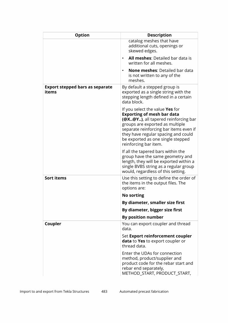
Option Descriptioncatalog meshes that haveadditional cuts, openings orskewed edges.
• All meshes: Detailed bar data iswritten for all meshes.
• None meshes: Detailed bar datais not written to any of themeshes.
Export stepped bars as separateitems
By default a stepped group isexported as a single string with thestepping length defined in a certaindata block.
If you select the value Yes forExporting of mesh bar data(@X..@Y..), all tapered reinforcing bargroups are exported as multipleseparate reinforcing bar items even ifthey have regular spacing and couldbe exported as one single steppedreinforcing bar item.
If all the tapered bars within thegroup have the same geometry andlength, they will be exported within asingle BVBS string as a regular groupwould, regardless of this setting.
Sort items Use this setting to define the order ofthe items in the output files. Theoptions are:
No sorting
By diameter, smaller size first
By diameter, bigger size first
By position numberCoupler You can export coupler and thread
data.
Set Export reinforcement couplerdata to Yes to export coupler orthread data.
Enter the UDAs for connectionmethod, product/supplier andproduct code for the rebar start andrebar end separately,METHOD_START, PRODUCT_START,
Import to and export from Tekla Structures 483 Automated precast fabrication

Option DescriptionCODE_START and METHOD_END,PRODUCT_END and CODE_END, forexample.
Note that the UDAs depend on thecreation tool and may differ from theexamples. The UDA representing themethod must be of type INTEGER,and the UDAs representing productand code must be of type STRING.
Single rebar and rebar groups Select either of the following options:
• Yes: Single rebars or rebar groupsare combined by their positionnumber, with the total barquantity. This is the default option.
• No: Each single rebar or rebargroup is handled individually andexported. This leads to a largerBVBS file, but the advantage is thateach single rebar and rebar groupcan be identified and handled byits own GUID, and the BVBS filewill reflect the model objects orIFC exported rebars.
Checking tab
Option DescriptionCheck reinforcement Select whether you want to run
additional checks for the following:
Reinforcement diameters(separated with spaces)
Minimum cutting length ofreinforcing bars
Maximum cutting length of thereinforcing bars
Minimum leg length for straightsections between the bends
Maximum weight of individual bars
When you select the Checkreinforcement check box, and thevalues of the exported reinforcing barare less than the minimum or greater
Import to and export from Tekla Structures 484 Automated precast fabrication

Option Descriptionthan the maximum, a warning iswritten to the export log file.
The log file entry contains the ID ofthe reinforcing bar. You can locate thereinforcing bar in the model byselecting the appropriate row in thelog file. Note that the reinforcing baris still exported normally and only theadditional warning is given.
Note that when the check is activated,the length of lattice girders is alsochecked. A warning is added in thelog when the check fails. The length ofthe main chord defines the exportedlength of the lattice girder.
UDAs tab
On this tab you can define the UDA fields to be used (UDA), and the content towrite into reinforcement, part, cast unit and pour object UDAs (UDA content).You can tag UDAs based on release code, release status, release date andreleased by information. You can also select whether existing UDAs arechecked and handled by using the setting Check existing UDAs. The optionsare No, Prevent export, Report to log, Report to log and overwrite, andOverwrite only.
BVBS export file description (.abs)
The content of the BVBS export file .abs is described below. The example datastructure represents a 2D bar, which is either straight, or bent on one plane atmost. Section H is the header section (identification and general information),and section G is the geometry section (production geometry).
For detailed BVBS interface description, see BVBS-Richtlinie Datenaustauschvon Bewehrungsdaten on the official site of the BVBS organization.
(1) BVBS element (product type)
(2) Project number
(3) Drawing number (in this example, cast unit position number)
Import to and export from Tekla Structures 485 Automated precast fabrication

(4) Drawing revision number (not in use in this example)
(5) Rebar position number
(6) Single rebar length
(7) Product quantity
(8) Single rebar weight
(9) Rebar diameter
(10) Material grade
(11) Bending diameter (a straight bar)
(12) Rebar layer (not in use the BVBS export)
(13) Step tapering for a tapered rebar series if grouping tapered enabled inexport settings (no tapering in this example)
(14) Leg length (only 1 leg in this example)
(15) Bending angle after the leg
(16) Checksum for correct data transfer. Checksum is a sum operation basedon the converted numerical values of the ASCII characters on a BVBS row.
Import to and export from Tekla Structures 486 Automated precast fabrication

Reinforcing bar length calculation in BVBS export
The length of the reinforcing bar is calculated according to the BVBSspecification. The length also depends on the bending angle. Lengths L1 andL2 are exported.
If you set the advanced optionXS_USE_USER_DEFINED_REBAR_LENGTH_AND_WEIGHT to TRUE, the user-defined length value is exported as the overall length for the reinforcing bar.
Note that the BVBS format specifications define that the overall length of thebar is ignored if the data contains actual geometry data. Some other softwareapplications may still use the overall length values in the BVBS file forcalculating quantities. The exported overall length in Tekla Structures is thesame length as shown in reports.
Best practices in BVBS exportThe following guidance helps you to ensure the best possible result from theBVBS export.
Import to and export from Tekla Structures 487 Automated precast fabrication

For exact instructions on the BVBS export, export settings, export filedescription, and the reinforcing bar length calculation in the BVBS export, seeBVBS (page 473).
• Export only those reinforcement types that the production control systemand machinery support.
• Ensure that the rebar sizes, bending roll sizes, leg lengths and angles,spacings, and overhangs are within the machinery constraints.
• Model your parts and reinforcement with systematic naming and classes.
• Create and maintain clear selection filters to exclude undesired rebarcontent.
• Use a file naming logic that results in unique file names, which can betraced back to the export set.
• Export in larger sets that can be systematically traced into a specificbuilding section or a drawing.
• Using the default option for cast unit position will export the totalamount of rebars in all relevant cast units to be combined into thesame file. There might be problems with the quantities if the amount ofcast units changes later on. Instead, you can use Assembly templateas the File naming template, and a unique identifier to ensure thatonly rebars from one cast unit are within one export file.
• Keep track of the export sets in the model using part/pour UDAs.
• After the first export, it is easy to lose track which rebars have beenexported already.
• Using rebar UDAs is heavier for the model database.
• Use private block to transfer extra information - Note that some importinterfaces do not support private block.
ELiPLANElematic ELiPLAN is a software for resource planning, scheduling, andmanagement for precast concrete fabricators. ELiPLAN import and exportautomate the data transfer between Tekla Structures and ELiPLAN.
The data transfer between Tekla Structures and ELiPLAN consists of four parts:
1. Exporting ELiPLAN data file from Tekla Structures.
2. Importing ELiPLAN data file into ELiPLAN.
3. Exporting ELiPLAN status data file from ELiPLAN.
4. Importing ELiPLAN status data file into Tekla Structures.
The import of an ELiPLAN data file into ELiPLAN supports the incrementalapproach, which means that ELiPLAN is able to create, update, and delete
Import to and export from Tekla Structures 488 Automated precast fabrication

parts in its database. This means that precast detailers can export the mostup-to-date data files whenever the Tekla Structures model has been changed.
Similar incremental support is included in the import of an ELiPLAN statusdata file to Tekla Structures. To keep the status and schedule data up to datein a Tekla Structures model, we recommend you update the status dataregularly.
In the EliPLAN export, the part geometry (profile, cuts, openings, and notches)is always automatically exported. You need to define the plotter data and thenecessary attributes. Every time you export, you need to export all the partsthat have been exported before to ensure proper change management inEliPLAN. Same applies to the import. The export is based on part GUIDs, andthe import is based on the project name/number and part GUIDs.
NOTE The format and contents of the ELiPLAN status data file imported to TeklaStructures differs from the data file that is exported from Tekla Structures toELiPLAN.
For more information about the best practices in EliPLAN export, see Bestpractices in ELiPLAN export (page 509).
Export an ELiPLAN data fileYou need to export everything that is ready. If you are using a shared model,first check the situation by checking the drawings, for example.
1. Add ELiPLAN information to ELiPLAN user-defined attributes of the parts.
This is optional, the product types and product codes are definedautomatically. There are numerous ways to alter these for the exportbesides the manual UDA handling. See later sections.
For more information about the UDAs, see ELiPLAN user-definedattributes in this same article.
2. On the File menu, click Export --> ELiPLAN .
The Export ELiPLAN file dialog box is displayed.
3. Define the ELiPLAN export properties on the Parameters, Plotter data,Weep holes, Data content Data settings, and EliX content tabs. Formore information about the export properties on different tabs, seefurther down in this same article.
4. On the Parameters tab, set Scope of export to All or Selected.
You should always bring every element that is ready to ELiPLAN with everyround to ensure that any design changes are taken into the system aswell. The model might have some non-relevant or not-ready cast units,which is why it is recommended to use Selected to control which ones arebeing exported. Conceptual cast units can be taken, but then you need tokeep track of these elements, for example, by using a UDA. You also needto ensure their GUID stays the same in the later export rounds.
Import to and export from Tekla Structures 489 Automated precast fabrication

5. Click Create.
By default, the export file eliplan.eli is created in the current modelfolder, in a .\EP_files subfolder. The export file is written with UTF-8encoding.
ELiPLAN export settingsUse the Export ELiPLAN file dialog box to control the ELiPLAN exportproperties.
Parameters tab
Setting DescriptionScope of export Select whether all parts or only
selected parts are exported. Becauseof the incremental import of ELiPLAN,you need to select the same parts,and some additional parts again, ifneeded, when exporting the nexttime, to make sure that any designchanges are taken in to the system aswell. Otherwise ELiPLAN assumes thatthe parts missing from thesubsequent file have been deleted inthe Tekla Structures model.
We recommend you to always use theAll option. Use the Selected optionwhen you are exporting parts for thefirst time, if you are exporting fromunfinished model or in special cases.Use the filtering option to control theproduct or phase scope.
Export using filter Specify a selection filter. The parts toexport are selected on the basis ofthe specified selection filter.
Numbering must be up to date toexport
Set this setting to Yes to preventexport when the numbering is not upto date. This prevents the export ofunfinished cast units.
Export version number The elements need to have a uniqueidentifier. The options are GUID, ID,ACN and FloorMES.
1.01 (ID) should only be used whenthe export is done only once, becauseof the changing IDs.
Import to and export from Tekla Structures 490 Automated precast fabrication

Setting DescriptionUse 2.00 (GUID), because IDs willchange when reopening the model,resulting in duplicates in export.
Select 2.00 (ACN) to export elementswith ACN.
The 3.0 (Plant Control) version fileformat is intended for interfacing withnewer Elematic FloorMES versions,and is also based on GUID. The fileformat has been extended withadditional data fields, and therefore itis not backwards compatible.
Version 3.0 of the export supports theexport of accessory code to plotterdata, and the export of accessorycode for openings. Furthermore, withthe export version 3.0, a plotterrecord of type BL is exported for thehollow core elements to define theside that has been cut. The borderline record is exported as a lineparallel with the longer side of thehollow core element.
Export version type Select the type of the export version.The options are Eli and EliX.
The Eli option only exports theproduction data file with the fileextension .eli.
The EliX option creates a packagewith a special file extension .elix.The package contains the productiondata file together with the related castunit drawing PDFs from the folderpath that has been specified on theEliX content tab.
Information about files included inthe EliX package are written in theexport log file.
The EliX option is applicable for therelease version number 3.0 andnewer only.
Output file name The name and location of the exportfile created. The default name iseliplan.eli. You can import this
Import to and export from Tekla Structures 491 Automated precast fabrication

Setting Descriptionfile into ELiPLAN. Use the … button toselect another location.
The eliplan.eli file includes,among other things, materialinformation. The accessory code,which is the material description, is inthe #Materials block.
The accessory code is based on thematerial type as follows:
• For concrete material the defaultaccessory code is same as thematerial name.
• For mesh, reinforcing bars, orstrands the default accessory codeis grade|size.
• For embedded material thedefault accessory code is name|size|material.
The export file is written with UTF-8encoding.
Data conversion file With this file you can convert theparametric profile names into theELiPLAN product codes, and thematerial descriptions into theELiPLAN accessory codes. You need tocreate the file yourself whennecessary.
The default file name iseliplan_export.dat, and this filecan be located in any folder. Use the… button to select another location.The data conversion file can also beread from folders defined for XS_FIRMand XS_PROJECT.
The data conversion fileeliplan_export.dat containsstring pairs separated with one ormore tabs. The string on the left sideis the profile name or TeklaStructures material description andthe string on the right side is thecorresponding ELiPLAN data.
Import to and export from Tekla Structures 492 Automated precast fabrication

Setting DescriptionData conversion supports caseinsensitive text, which means that itdoes not distinguish betweenuppercase and lowercase letterswhen looking for strings to bereplaced.
The data conversion file supports theuse of the wildcard asterisk (*) inregular expressions in the firstcolumn for finding strings from TeklaStructures objects. For example, youcan type L*FT to find LØFT or LIFT orLOFT.
Accessories, such as steel embedsand insulation blocks, can bequantified as piece count or withcustom measurement units.
Note that the ELiPLAN codes dependon the fabricator, and the codes thatare valid for one fabricator are likelyto be not valid for other fabricators.
You can disable/enable the usage ofthe data conversion file by clearingthe Enabled/Disabledcheck box nextto the Data conversion file setting.
For an example of data conversionfile contents, seeSample_for_Eliplan_Data_Conversion.dat.
Filter by part: Element data Enter a list of classes or to beexcluded from or included in theexport. This contains the class
Import to and export from Tekla Structures 493 Automated precast fabrication
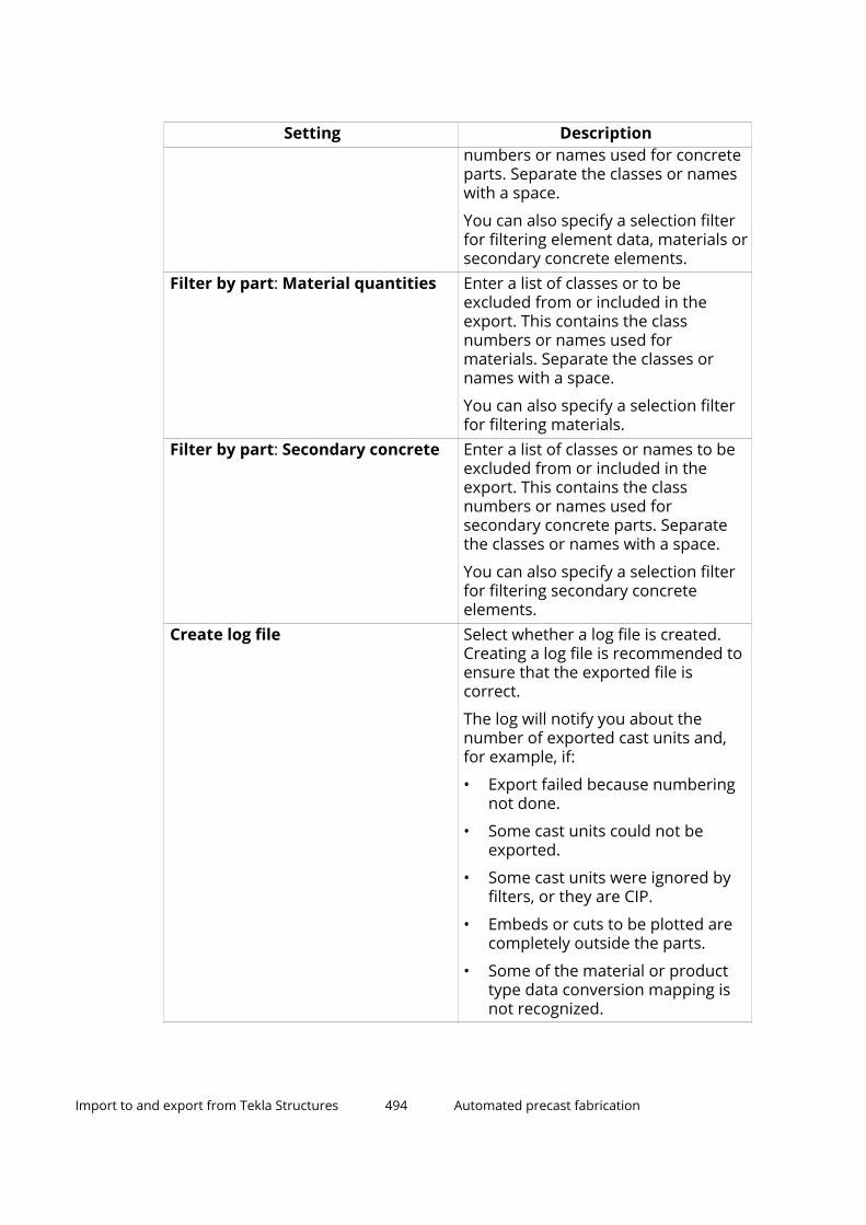
Setting Descriptionnumbers or names used for concreteparts. Separate the classes or nameswith a space.
You can also specify a selection filterfor filtering element data, materials orsecondary concrete elements.
Filter by part: Material quantities Enter a list of classes or to beexcluded from or included in theexport. This contains the classnumbers or names used formaterials. Separate the classes ornames with a space.
You can also specify a selection filterfor filtering materials.
Filter by part: Secondary concrete Enter a list of classes or names to beexcluded from or included in theexport. This contains the classnumbers or names used forsecondary concrete parts. Separatethe classes or names with a space.
You can also specify a selection filterfor filtering secondary concreteelements.
Create log file Select whether a log file is created.Creating a log file is recommended toensure that the exported file iscorrect.
The log will notify you about thenumber of exported cast units and,for example, if:
• Export failed because numberingnot done.
• Some cast units could not beexported.
• Some cast units were ignored byfilters, or they are CIP.
• Embeds or cuts to be plotted arecompletely outside the parts.
• Some of the material or producttype data conversion mapping isnot recognized.
Import to and export from Tekla Structures 494 Automated precast fabrication

Setting DescriptionLog file name The name and location of the created
log file. Use the … button to selectanother location.
Plotter data tab
Setting DescriptionHollowcore and slab productsExport of cutout data Select how to export cutout data. The
options are:
• All: Exports all data.
• Full depth cuts only: Exports dataonly on the cuts that go throughthe whole part. Does not exportrecess data.
• None: Does not export any cutoutdata.
It is recommended to use Full depthcuts only, because otherwise smallrecesses are included in the plottingon both faces.
Overlapping cutouts are combined inthe export file.
This setting exists for hollowcore andslab products, and for wall andsandwich wall products separately.
Export of embed data Select whether to export data ofembeds. The options are:
• Yes: Exports data on embeds.
• No: Does not export any data onembeds.
This setting exists for hollowcore andslab products, and for wall andsandwich wall products separately.
Export of filled cores Select whether to export thegeometry of filled slab cores. Theoptions are:
• Yes: Exports the geometry of filledslab cores.
Import to and export from Tekla Structures 495 Automated precast fabrication

Setting Description• No: Does not export the geometry
of filled slab cores.
Note that the position in Z is exportedfor filled cores. The export of the Zcoordinate for all items in thePLOTTER block is controlled theExport embed Z position on theData content tab.
Export of inner cores Select whether to export thegeometry of the inner cores of thehollow cores. The options are:
• Yes: Exports the geometry of theinner cores of the hollow cores.
• No: Does not export the geometryof inner cores of the hollow cores.
Wall and sandwich wall products: See the descriptions for Export ofcutout data and Export of embed data above.Plot additional reinforcement Plot additional reinforcement as
bounding box.
The options are:
• None
• Class
• Name
• GradePlot cutout/embed as lines Export cutouts and embeds as lines.
The options are:
• None
• Class
• Name
• Material/GradePlot irregular cutout/recess The As lines option exports as lines
the bounding box cutouts andrecesses that overlap a diagonal edge.By default, they are exported as box.
Note that we recommend you to usethe default setting if the factory usesan Elematic Modifier machine toensure correct data processing.
Import to and export from Tekla Structures 496 Automated precast fabrication

Setting DescriptionPlot lifters Specify how the lifter geometry
should be plotted - as outline or ascenter point.
Exclude cut parts by Use to exclude cut parts from exportbased on the cut part properties.
The options are:
• None
• Class
• Name
• Material
This setting is a handy filter forreducing amount of extra cuts inplotting.
Exclude embeds by Use to exclude embeds fromexported plotting data embeds by:
• None
• Class
• Name
• Material
You can define one or more valuesfor the selected property.
Exclude above z position Select whether to exclude fromexported plotting data embeds orcuts that are above the specified Zposition. The Z position is the depthof the element on the pallet, that ishow many millimeters the lowestpoint of the embed is above the palletsurface.
You can define one or more valuesfor the selected property.
The options are:
• None
• Embeds
• Cuts
• Embeds and cuts
Import to and export from Tekla Structures 497 Automated precast fabrication

Weep holes tab
Setting DescriptionExport of weep holes Select whether to export data of weep
holes. The options are:
• At end zones only: Provides weepholes at the slab end zones of thehollowcore only.
• At end zones and filled cores:Provides weep holes for the endzones of hollowcore and also addsweep holes on both sides of anyfilled cores. Filled core parts canbe specified by class or by name.
• At filled cores only: Providesweep holes around filled coresonly.
• No (default): Does not export anydata on weep.
Weep holes offset Export weep holes only at the middleof elements with a length less thanthe length specified for the setting Atmiddle only, length less than.
Weep holes at the start and at theend of the hollow core element arealways exported aligned in one line.Cuts smaller than 100 mm at the startand at the end are ignored, otherwisethe weep holes are offset respectivelyto the cut size.
Data content tab
Setting DescriptionProject name, Project number Use these settings to specify the
project number and project name inthe exported file. The options areProject UDA, Project template, andUser-defined text.
The maximum length of the projectnumber is 6 characters (usually digits),and the maximum length of theproject name 37 characters (string).
Note that the ELiPLAN file must have avalid project number that needs to
Import to and export from Tekla Structures 498 Automated precast fabrication

Setting Descriptionmatch the project number in theELiPLAN database, otherwise theELiPLAN file import will not succeed.
Comment 1 - 3 In the comment fields you can provideextra information to be included at thestart of the export file.
The options are:
No comment
Tekla Structures version
Model name
User name
User-defined text
The comments are only for viewing theexport file and will not be read in toELiPLAN.
Product code Select the default product codemapping, which then shouldcorrespond with any data conversionstrings.
Any content in the ELiPLAN ProductCode (EP_PRODUCT_CODE) UDA fieldalways overwrites the Product codestring determined by the exportsettings.
You can specify multiple UDAs byseparating them with a blank space. Inoutput, the content of UDAs will bewritten in the same order, separatedby blank spaces.
Accessory code Specify the accessory code forstandard embeds such as steel parts.This will be the code written to eachembed in the #Plotter (if applicable)and #Materials blocks, and the chosenoption should be used as a base forfurther data conversion mapping. Thedefault option is NAME|PROFILE-LENGTH|MATERIALGRADE.
You can specify multiple UDAs byseparating them with a blank space. Inoutput, the content of UDAs will be
Import to and export from Tekla Structures 499 Automated precast fabrication

Setting Descriptionwritten in the same order, separatedby blank spaces.
Material code Specify the material code for othermaterials besides accessories. This willbe the code written to each non-embed material in the #Materialsblock, and the chosen option shouldbe used as a base for further dataconversion mapping. The defaultoption sets a varying logic specific foreach material type, such as concreteor reinforcement.
You can specify multiple UDAs byseparating them with a blank space. Inoutput, the content of UDAs will bewritten in the same order, separatedby blank spaces.
Erection section Read the erection section from a user-defined attribute (UDA) or from acustom property (Template).
Erection sequence Read the erection sequence from auser-defined attribute (UDA) or from acustom property (Template).
Export material data Select whether to include or excludethe detailed material data (receipt) ofparts.
If you have no use for material data inELiPLAN (you have no materialhandling module in ELiPLAN), selectNo to exclude the data from the fileand to reduce the file size.
Note that once you have transferredthe file with the material data (Yes)you should never switch off (No) theexport of material data in subsequentexports. If you do this, the receipt isalso cleared in the ELiPLAN databaseand all modifications are lost.
Export rebar bending data Select whether to include or excludethe detailed rebar bendinginformation.
If you do not need this data inELiPLAN, select No to exclude the data
Import to and export from Tekla Structures 500 Automated precast fabrication

Setting Descriptionfrom the file and to reduce the filesize.
Note that once you have transferredthe file with the rebar bending data(Yes) you should never switch off (No)the export of rebar bending data insubsequent exports.
Export embed Z position Select whether to include or excludethe Z level of embeds.
Notes Use UDA or template attribute to addextra information to be viewed at thefactory, such as design status, changestatus or general comment.
Select what type of notes you want toexport: UDA, a template attribute oryour own text. Then enter the UDA,template attribute, or text.
Stack, Pile number, Pile level The export of stack results issupported starting from ELiPLANexport version 3.0. You can select ifthe UDA is read from the main part orfrom the cast unit.
The UDAs are pre-filled, but you canchange them manually.
Data settings tab
Setting DescriptionUDA for unit conversion Specify a UDA for unit conversion.
When a valid unit is specified in thisUDA, then the specified unit is usedfor the unit conversion instead of thedefault unit, or the unit defined in theconversion file.
Unit for element dimensions Select the unit to be used for theelement dimensions.
Unit for rebar length Select the unit for the length ofreinforcing bars.
No. of digits after decimal point Select the number of digits after thedecimal separator (0 - 3).
The default is 1 digit after the decimalseparator.
Import to and export from Tekla Structures 501 Automated precast fabrication

Setting DescriptionTag for lifters Use to identify lifting loops by their
name or class (default).
Also rebars can be specified as liftersusing a class or a name.
It is also possible to specify multipleclasses or names. If the nameconsists of multiple words then it hasto be enclosed in quotation marks.
Additionally, a user-defined attribute(UDA), or a template attribute(Template) can be specified to use aspecific property with a specific valueto recognize lifters.
When lifting loops are identified, theplotter instruction type is changedfrom WPL to LL.
Tag for filled cores You can enter either a single string(the name) or multiple strings. TeklaStructures will then use the enteredname or names as filter criteria todetermine filled cores from themodel. Depending on the selectedoption, the placement of the weepholes will be calculated and written tothe export file.
Prefix for ID Enter a prefix (letter) to use with theID number.
Position number type Select whether to export the cast unitposition number, assigned controlnumber (ACN), or cast unit positionnumber and ACN.
Remove numbering separator Select whether a position numberseparator is used in numbering. Thedefault is No.
Tag special elements Set this option to Yes to set a specialtag for elements that have notch cuts.This option marks hollow-cores withnotches with SK denominator (N foruncut slabs).
Strand code Specify a UDA or a template attributeto read the strand code. Defaultreads the value from the UDATS_STRAND_CODE. You can also
Import to and export from Tekla Structures 502 Automated precast fabrication

Setting Descriptionspecify a custom property using theoption Template.
Net area calculation Select Exclude all cuts to exclude allcuts, or Exclude full depth cuts onlyto exclude full depth cuts only fromthe net area calculation, or Grossarea to export gross area as net area.You can also specify a customproperty using the option Template.The whole assembly is checked.
You are now notified via log when thenet area calculation fails.
Weight calculation Select which weight will be exported.
The options are:
• Default: reports the weightdefined by the attribute CAST_UNIT.WEIGHT_NET.
• WEIGHT: reports the weightdefined by the attribute WEIGHT.
• WEIGHT NET: reports the weightdefined by the attribute WEIGHT_NET.
• CAST UNIT WEIGHT: reports theweight defined by the attribute CAST_UNIT.WEIGHT.
• MAIN PART WEIGHT: reports theweight defined by the attribute WEIGHT.
• Template: reports the weightdefined by a specified templateattribute or custom property.
• User-defined density: reports theresult of the user-defined densityvalue * object volume.
Decimal mark Set period (.) or comma (,) as thedecimal mark depending on ELiPLANsettings.
EliX content tab
Specify the folder path that you want to read for any cast unit drawing PDFs.The content of this folder will be included in the exported .elix zip file in EliXexport.
Import to and export from Tekla Structures 503 Automated precast fabrication

ELiPLAN data conversion file
The data conversion file contains string pairs separated with one or more tabs.The string on left side is the profile name or Tekla Structures materialdescription and the string on right side is the corresponding ELiPLAN data. Themapping can also contain the unit for quantity for material codes.
You can combine several mappings in one, because the product and materialcode conversion is based on tags separated with the pipe character ("|"). Amatching conversion is used when any tags are found in the source file.
Note that the ELiPLAN codes depend on the fabricator and the codes whichare valid for one fabricator are most probably not valid for other fabricators.
The product code and the material code can be defined separately: mappingsfollowing the line #PRODUCT CODES are used for product code conversionand mappings following the line #MATERIAL CODES are used for materialconversion.
Example of a data conversion file:
#PRODUCT CODES//// Hollow-core slabs//265X1200 HCS27320X1200 HCS32400X1200 HCS40//// Beams//BEAM|RCDL B_LP2PBEAM|RCL B_LPBEAM B_SK
#MATERIAL CODES//// reinforcement//A500HW|6 TW6 kgA500HW|8 TW8 kgA500HW|10 TW10 kgA500HW|12 TW12 kgA500HW|16 TW16 kgA500HW|20 TW20 kgA500HW|25 TW25 kgA500HW|32 TW32 kg//// Strands//1570/1770 1570/1770 m//// Meshes//B500K|8/8-200/200 B500K8-200 m2B500K|10/10-250/400 B500K10-250/400 m2//// Embeds//HPKM39|50*110-110 HPKM39 pcsNeoprene NEO_10 m2
Import to and export from Tekla Structures 504 Automated precast fabrication

//// Concrete materials//C35/45 C35 m3C40/50 C40 m3C45/55 C45 m3
You can combine several mappings in one, because the product and materialcode conversion is based on tags separated with the pipe character ("|"). Makesure that you use matching case.
ELiPLAN export file (.eli)The .eli file contents are described below.
Header data for file info
The geometry of the elements is reported in the #Pieces and #Plotter blocks:
#Pieces:
• Contains a unique data row for each slab.
• Has a unique data row for each slab.
• For hollowcore slabs, the outer measurements are reported in the #Piecesblock based on the min (x, y) and max (x, y) values of the slab. Thesemeasurements describe a rectangle, parallelogram or trapezium. Thethickness, profile and additional information of the slab is reported.
• In the #Pieces block you can separately flag slabs that have cuts in theedges.
#Plotter:
• Contains data for individual plotting operations by element, such asembeds, recesses, and through-cuts.
• The #Plotter block also contains geometrical data that is arranged by theslab position. The operations are performed on each slab on the basis ofthe position number.
• Each plotting operation is on its own row (formwork accessories, recesses,cross sections).
• In the export settings you can define the plotting data scope included inthe export.
• The shapes can be lines, rectangles or circles.
• The order of the rows is not important, they will be reorganized in ELiPLAN.
• If the geometry cannot be presented as a rectangle or a circle inside theslab boundaries, it will be presented as a line.
• Overlapping plotting with the outer boundaries defined by the #Piecesdata has been minimized, and crossing the edges is prevented.
#Materials:
Import to and export from Tekla Structures 505 Automated precast fabrication

• Contains data for material quantities by element.
#Bars:
• Contains data for rebar shapes by element.
Example of an export file:
2.00;1;;04.06.2019 11:49:15# Pieces56a109f8-562c-4aa5-882a-a45cc7be9b95;B_LP2P;B/1;7200.00;0.00;0.00;500.00;600.00;0.00;3628.80;1.51;4.32;1.08;;;PHASE 1;;N;0;3dbe09b6-1b35-44e7-a18f-0c492a71b6a6;HCS32;HC/1;6000.00;6000.00;0.00;700.00;0.00;320.00;1655.09;0.69;4.20;4.06;;;PHASE 1;;N;0;1d2c4018-daa3-4b5d-801a-4a1e491db41f;HCS32;HC/2;6000.00;6000.00;0.00;1200.00;0.00;320.00;2765.20;1.15;7.20;6.93;;;PHASE 1;;N;0;0b003ef7-2c79-4e4d-844f-51616ad0584d;HCS32;HC/3;6000.00;6000.00;0.00;1200.00;0.00;320.00;2747.86;1.14;7.20;6.89;;;PHASE 1;;N;0;e670a8ac-c034-4fa9-b5e3-0a17461502fb;HCS32;HC/4;5750.00;4875.00;0.00;1200.00;0.00;320.00;2446.78;1.02;6.89;6.13;;;PHASE 1;;N;0;868229bf-36ed-4b87-9d2e-e7c36962b181;HCS32;HC/5;4875.00;4000.00;0.00;1200.00;0.00;320.00;2044.57;0.85;5.85;5.12;;;PHASE 1;;N;0;# PlotterHCS32;HC/3;LI;LI;5750.00;1200.00;6000.00;850.00;0.00;0.00;# MaterialsB_LP2P;B/1;C35;1.51;HCS32;HC/1;C40;0.69;HCS32;HC/1;1570/1770;18.00;HCS32;HC/2;C40;1.15;HCS32;HC/2;1570/1770;36.00;HCS32;HC/3;C40;1.14;HCS32;HC/3;1570/1770;34.69;HCS32;HC/4;C40;1.02;HCS32;HC/4;1570/1770;29.45;HCS32;HC/5;C40;0.85;HCS32;HC/5;1570/1770;24.22;# Bars
Import an ELiPLAN status data fileIf you have a status data file that has been created in ELiPLAN, you can importthe status and scheduling information to your Tekla Structures model.
1. On the File menu, click Import --> ELiPLAN.
The Import ELiPLAN status data dialog box opens.
2. Click the ... button next to the Import file name box to browse for the fileto be imported.
3. Click Create.
Tekla Structures updates the status and schedule data for parts in theTekla Structures model. When the data is read, a log file is displayed.
The log file shows the parts whose data is updated correctly. It alsoprovides information on possible problems that may have occurred.
Import to and export from Tekla Structures 506 Automated precast fabrication

When you select a row in the log file, Tekla Structures automaticallyselects the corresponding part in the model. The overall statusinformation is shown at the end of the log file.
Tekla Structures stores the actual status data in the user-defined attributes ofthe parts. To view the data, open the part properties, click the User-definedattributes button and go to the ELiPLAN tab.
ELiPLAN user-defined attributesIn addition to normal model data, you can add additional information in theuser-defined attributes of the parts. The additional information can betransferred from Tekla Structures and used in ELiPLAN.
The product type and product code user-defined attributes override theautomatic product type and product code. Other user-defined attributes arereserved for ELiPLAN import.
Product type
The product type affects how ELiPLAN considers the part dimensions length,length2, deltaL, width, height, and thickness.
The product type user-defined attribute overrides the product type defined inthe ELiPLAN export dialog box.
To set the product type, select a suitable product type option from the list.Normally you should be able to use the default Auto, but in some cases youmay need to override the default.
If needed, you can override the product type value set in the dialog box in thefollowing way:
Import to and export from Tekla Structures 507 Automated precast fabrication

• You can enter a value for the user-defined attribute EP_TYPE in theobjects.inp file.
• You can enter a value for the user attribute EP_TYPE in the Profilecatalog.
In the Profile catalog, the attribute value is given as a number. The valuesare as follows:
• Slab = 1
• Beam = 2
• Column = 3
• Wall = 4
• Sandwich wall = 5
• Stair = 6
Product code
The product code user-defined attribute overrides the product code defined inthe ELiPLAN export dialog box.
You have alternative ways to give the product code. The ELiPLAN export triesto define the product code in the following order:
1. You can enter a value for the product code in the ELiPLAN user-definedattributes dialog box.
2. You can enter a value for the user-defined attribute EP_CODE of the castunit main part in the objects.inp file.
3. You can enter a value for user attribute EP_CODE in the Profile catalog.
4. You can use the data conversion file to convert parametric profile namesto a product code.
5. The main part name is exported as the main part name if none of theprevious methods succeeded.
Erection sequence
Precast parts are erected in a certain sequence. Use the sequence to help thescheduling of the production in ELiPLAN. You can give the estimated erectionsequence by giving the sequence number for parts.
Ready for production
Set this option to Yes when the designer or detailer has finished the part andthe part is ready for production. The default is No, which means that the datais transferred to ELiPLAN for preliminary planning only, and the part is notsent for production until the attribute is set to Yes and a new file is transferredto ELiPLAN.
Import to and export from Tekla Structures 508 Automated precast fabrication

ELiPLAN status data
The ELiPLAN status data is meant to be read-only information and used tovisualize the data in a Tekla Structures model.
Set up your UDAs in the model or profile catalog for mapping objecttypes, profiles and materials
For more information on how to set up your UDAs in the model or profilecatalog for mapping object types, profiles and materials to suit the ELiPLANexport, see EliPLAN/ELiPOS export guide.
Examples of ELiPLAN filesClick the links below to see examples of ELiPLAN files. You can open the fileswith a standard text editor.
• ELiPLAN data conversion file: Sample_for_Eliplan_Data_Conversion.dat.
• ELiPLAN export file: Sample_for_Export_Eliplan.eli
• ELiPLAN import file: Sample_for_Import_Eliplan.sql
Best practices in ELiPLAN exportThe following guidance helps you to ensure the best possible result from theELiPLAN export.
For exact instructions on the ELiPLAN export, export settings, and on otherrelated topics, see ELiPLAN (page 488).
Pre-research
Before you start, find out the following:
• Which elements are produced?
• What are the bed sizes and other fabrication requirements?
• What should be plotted?
• Are embed and rebar quantities desired?
• What kind of product and material codes are being used?
• What additional information is desired from the model?
• Is it needed to bring process information back to the model?
Before you start a project:
• Collect product codes and material article numbers.
• Create the data conversion file, include any necessary codes, and test withsample products that the data conversion table works as intended.
• Use automatic settings or choose the most suitable input method.
Import to and export from Tekla Structures 509 Automated precast fabrication

• Numbering logic:
• For ELiPLAN, every element should be unique and traceable.
• Data scope: Geometry, attribute, materials
• Which products and materials to include?
• Which plotter data to include?
• Draft a modeling guideline to categorize model objects with specificclass/name/other attribute
• Fabrication requirements: dimensions, profiles, maximum weight
• Document everything in the modeling guideline
Best practices in ELiPLAN exportThe following guidance helps you to ensure the best possible result from theELiPLAN export.
For exact instructions on the ELiPLAN export, export settings, and on otherrelated topics, see ELiPLAN (page 488).
Workflow
• Model according to modeling guideline, depending on fabricationrequirements.
• Model precast objects with their embedded content.
• If hollow-core geometry is used for plotting within ELiPOS, ensure thatrecesses and embed positions are accurate.
• Set up profile and material catalogs according to fabrication requirements.
• Adjust the profile catalog and modeling settings so that the mapping to theELiPLAN system is done correctly.
• Ensure that you use the materials and profiles that you have mapped.
• Define standard export settings in line with the modeling guideline.
• In newer Tekla Structures versions, always use GUID or ACN as the elementidentifier.
• Number the model. Use Tekla Structures numbering for creating drawings,and automatic control numbering (ACN) to track unique elements.
• Use automatic data conversion and product types.
• Add design status information to precast objects and import the status toELiPLAN using additional UDAs to communicate the design status. Alsomark the objects that have been sent to production.
• Always check the resulting file and the export log:
• Ensure that there is no strange mapping in the product or materialcodes.
Import to and export from Tekla Structures 510 Automated precast fabrication

• Validate the export files in the production software, as there is noviewer available.
HMSYou can export model data of hollow core slabs in the HMS format. The resultis a .sot file.
HMS stands for Hollowcore Manufacturing System and it is developed in theNetherlands. You can export data of hollow core slabs from Tekla Structuresto HMS. HMS uses the data in manufacturing processes.
Export in HMS format1. Select the model objects that you want to include in the export.
2. On the File menu, click Export --> HMS .
The HMS Export dialog box opens.
3. Define the export properties as required. For more information, see theHMS export settings section below.
4. Click the ... button to browse for the folder where you want to save thefile.
The \HMS folder under the model folder is the default.
5. Enter a name for the file.
The file name extension is .sot.
6. Click Save.
7. Select the Add revision to file name check box and select the revisionnumber if required.
The revision number is added to the HMS export file as follows:
hms_export_file<revision>.sot8. Select the Open log file after export check box if you want to see the log
after export.
HMS Export creates the log file in the file export folder.
9. Click Export to create the HMS export file.
HMS Export settingsYou can include project data, slab data, and steel part information in the HMSexport.
Import to and export from Tekla Structures 511 Automated precast fabrication

Project data tab
Option DescriptionCustomer Name
Customer Number
Contractor Name
Site Address
Site City
Section Name
Project Status
Remark 1
Remark 2
Remark 3
You can include project data, such ascustomer name and site address, inthe HMS export file.
The boxes have the following valuesavailable:
• Empty
The item is not included in theHMS export file.
• Text
Enter the text in the box next tothe item.
• Project UDA
The data comes from the project’suser-defined attributes.
• Project Object, Project Address,Project Info 1 - 2
The data comes from the projectinformation.
Export file Define a name and location for theexport file. The file name extensionis .sot. By default, the export filegoes to the \HMS folder under modelfolder.
Add revision to file name Add the revision number to the HMSexport file:hms_export_file<revision>.sot.
Open log file after export Open the log file after export. HMSExport creates the log file in the fileexport folder.
Slab data tab
Option DescriptionPosition Number Assigned Control Number (ACN) is
the only option.Slab Remarks
Element Type
End Label
The options are:
• Empty
The item is not included in theHMS export file.
Import to and export from Tekla Structures 512 Automated precast fabrication

Option Description• Text
Enter the text in the box next tothe item.
• UDA
The data comes from the project’suser-defined attributes
Slab Name The options are:
• Profile
Select to export the whole profilename.
• Thickness
Select to export only the profileheight.
Slab Mark The options are:
• Assembly position
Select to export the complete castunit position.
• Assembly serial number
Select to export the cast unit serialnumber only.
Bay number Select the default UDA or UDA of yourchoice. The value type of the defaultUDA is integer, and it must be typeinteger for any other chosen UDA aswell.
Slab Weight Units Select the weight unit.Live/dead load Enter the default live/dead load to be
exported.
For hollow core slab calculation, youcan define a default live load/ deadload (KN/m2) for slabs.
If you do not define this data here,you must enter the default values foreach slab in HMS software later.
Import to and export from Tekla Structures 513 Automated precast fabrication

Slab scope tab
Option DescriptionExclude parts Enter the class or the name of the
model object, text, UDA or a templateattribute to exclude the data.
Hook Points
Electric boxes
Weld plate
Solid fill
Filled area
Select the data that is exported.
• Empty
The item is not included in theHMS export file.
• Name
Select to include the name.
• Text
Enter the text in the box next tothe item to include the text.
• Class
Enter the class of the model objectin the box to include the class.
• UDA
The data comes from the user-defined attributes.
• Template
The data comes from a templateattribute.
Hook point name Select to include hook point name inexport.
• Name
Select to include the name.
• Text
Enter the text in the box next tothe item to include the text.
• UDA
The data comes from the user-defined attributes.
• Template
The data comes from a templateattribute.
Import to and export from Tekla Structures 514 Automated precast fabrication

Option DescriptionWeld plate name Select to include weld plate name in
export.
• Name
Select to include the name.
• Text
Enter the text in the box next tothe item to include the text.
• UDA
The data comes from the user-defined attributes.
• Template
The data comes from a templateattribute.
Reinforcement tab
Option DescriptionExport strand code Select to include strand code in
export.Export strand pull force Select to export pull force data.Custom top strands
Custom bottom strands
Enter the quantity, diameter, distanceand pull force for custom strands.
The custom strand settings are meantto be used if no strands are modeled.If there are modeled strands, thecustom strands will be included inaddition.
Additional strands Additional strands can be used todesignate any other specific rebarobject to be exported as strand, asonly strand objects are included inthe export by default.
• Name
Enter the strand name.
• Class
Enter the class in the box next tothe item to include the class.
Import to and export from Tekla Structures 515 Automated precast fabrication

Option Description• UDA
The data comes from the user-defined attributes. Enter the nameand value of the UDA.
• Template
The data comes from a templateattribute. Enter the templateattribute and the value.
Reinforcement Reinforcement can be included in theexport as cross bars by specifyingthem in the Reinforcement setting.
• Name
Enter the reinforcement name.
• Class
Enter the class in the box next tothe item to include the class.
• UDA
The data comes from the user-defined attributes. Enter the nameand value of the UDA.
• Template
The data comes from a templateattribute. Enter the templateattribute and the value.
Options tab
Option DescriptionBoundary line Export the boundary line Along cut
side of the slab or Along uncut sideof the slab.
Export Hook Box Select to include hook data.Export HP name Select to export hook point names. If
you do not select this option, only theXY coordinates are exported.
Export inner cores Select to include detailed informationon hollow cores in export.
Include full cut to contour Select to include in export full cut inthe contour block (CO). If not selected,
Import to and export from Tekla Structures 516 Automated precast fabrication

Option Descriptionthe full cut is written as an individualcut (SP).
Generate drain/weep holes Select to include drain holes andweep holes in export. You can alsospecify the offset.
3.14 CADThe CAD import and export tools support several formats to import andexport models. You can import a maximum of 10,000 parts. If the number ofparts exceeds this, Tekla Structures displays a warning message, and does notimport the model.
CAD import and export formatsThe table below lists the supported import and export file types.
Option Import Export Imports from/Exports toSDNF ✔ ✔ SDNF (Steel Detailing
Neutral File) is used inimporting to andexporting from severaldifferent CAD systems.
HLI ✔ ✔ HLI (High Level Interface).IEZ AG Speedikon software
Plantview ✔ Plantview design systemSDNF (PDMS) ✔ ✔ Plant Design Management
System. Aveva 3D plantdesign software.
Data is exported as PDMSvia SDNF link. TeklaStructures writes theinformation of finish fieldin the member classattribute, whereas in SDNFexport it omits the classinformation.
XML ✔ ✔ ArchiCAD modelingsystem.
There are some limitationsin the export:
Import to and export from Tekla Structures 517 CAD

Option Import Export Imports from/Exports to• Conversion files are
not used.
• Holes, bolts and weldsare not exported.
In addition to the CAD import tool, also FEM import is available in the NewImport Model dialog box. The steps for FEM import (page 337) are the sameas for the CAD import.
Import a CAD model1. On the File menu, click Import --> CAD .
The Import Models dialog box is displayed.
2. Select the import type Import CAD.
3. Click New and enter a new name for the import file in the New ImportModel dialog box.
4. In the New Import Model dialog box, click the Properties... button todefine the import settings, which depend on the selected import type.
For more information about the import-type-specific settings, see thesettings and their descriptions in sections below.
5. Click OK to apply the changed properties.
6. In the New Import Model dialog box, click OK.
7. Select the import model name from the list and click Import.
8. In the Import Models dialog box, select which version of parts to import.
9. Click Accept all.
The Accept all option is generally used if importing a new model over anexisting one. If you have changed the model and want to re-import it, youcan also reject all changes by clicking Reject all, or accept or rejectindividual changes by clicking Select individual....
10. Tekla Structures displays the message Do you want to save the importmodel\nfor subsequent imports? Click Yes.
Tekla Structures adds the import model in the model view.
11. Right-click the model view and select Fit work area to entire model toensure that the imported model is completely visible.
12. If parts are missing, check the Depth up and Depth down values in theView Properties dialog box and change them if necessary.
Import to and export from Tekla Structures 518 CAD

NOTE In SDNF import, if you want to import information that Tekla Structures partsdo not have, you can use the SDNF extension line in the SDNF file to beimported, and the REVISION_NUMBER user-defined attribute in TeklaStructures.
Settings of the CAD import
Setting DescriptionConversion tabProfile conversion file
Material conversionfile
Twin profileconversion file
Define the conversion files you want to use. Themaximum conversion file path length is 255characters.
Conversion files map Tekla Structures profile andmaterial names with names used in othersoftware.
For more information about conversion files, seeConversion files (page 171).
Parameters tabInput file The file that you want to import. You can also
browse for the file. The default value isimport.lis.
The maximum folder path length is 255 characters.Type Define the input file or model type:
SDNF, HLI, Plantview, SDNF (PDMS), XMLOrigin X, Origin Y,Origin Z
Define the origin coordinates to place the file in aspecific location.
SDNF tabPos_No Enter a prefix and a start position number for
parts.
This settings relates to the Position number typesetting.
SDNF version number Set the SDNF format type to 2.0 or 3.0.
SDNF 3.0 is generally the format to select.However, with StruCAD it is better to share SDNF2.0 files.
Apply cuts and fittings Set to Yes (default) to apply cuts and fittings in theimport.
These will only be included if contained within theSDNF file.
Import to and export from Tekla Structures 519 CAD

Setting DescriptionConsider offsets Set to Yes to create offsets. In most cases you
should select Yes. No (default) positions partcreation points at part end points.
In most cases you should select Yes. No (default)positions part creation points at part end points.
Create log file Select Create to write a new log file and delete theprevious log file each time you import the model.
If the import fails, examine the log file to find outwhy. Check the log file even if the import seems tohave succeeded.
Select Append (default) to add the log fileinformation is at the end of the existing log file.
If yo do not need a log file, select No.Display log file Select With external viewer to display the log file
in a text editor.
Select On dialog to create a separate list dialogbox in which the file can only be viewed.
If you do not want to display the file, select No.Log file name Enter the log file name or browse for an existing
log file.Position number type The SDNF file contains identifiers that can be
included in a part’s user-defined attributes, or usedas part position numbers.
Select Part position if you want the identifier tobecome the part’s position number. Do not use thePos_No option with this option.
Select Universal ID if you want the identifier tobecome a user-defined attribute for the part.
For file imports from PDS or PDMS then theUniversal ID option is the normal case.
To make user-defined attributes visible in thedialog boxes, you need to add them to theobjects.inp file.
Plantview tabMaterial Select the material grade.Report tabCreate report Set to Yes to create a report.Display report Set to Yes to display the report.Report template Select the report template.
Import to and export from Tekla Structures 520 CAD

Setting DescriptionReport file name Enter the report file name or browse for a report
file.
If you do not give the report any other name, thereport is saved with the nameimport_revision_report.rpt in the modelfolder.
Advanced tabAction when objectsstatus is (compared to)
Previous plan lists the objects in your model,compared with the objects in the file to beimported. They can be New, Modified, Deleted, orSame.
Tekla Structures compares the state of importedobjects with those in your model. They can be Notin model, Different, or Same.
Use the options under Not in model, Different,and Same to specify the actions when importingchanged objects. The options are No action, Copy,Modify, or Delete.
Usually there is no need to change the defaults.
Settings of the FEM import
Setting DescriptionConversion tabProfile conversion file
Material conversionfile
Twin profileconversion file
Define the conversion files you want to use.
Conversion files map Tekla Structures profile andmaterial names with names used in othersoftware.
For more information about conversion files, seeConversion files (page 171).
Parts tabPart Pos_No
Assembly Pos_No
Enter a prefix and a start position number.
Parameters tabInput file The name of the file you want to import. You can
also browse for the file.Type Select the input file type: DSTV, SACS, Monorail,
Staad, Stan 3d, Bus
Import to and export from Tekla Structures 521 CAD
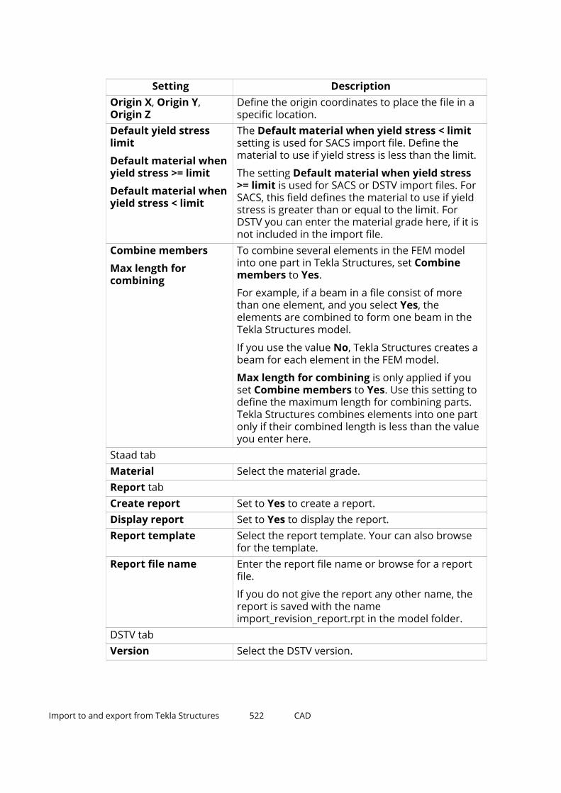
Setting DescriptionOrigin X, Origin Y,Origin Z
Define the origin coordinates to place the file in aspecific location.
Default yield stresslimit
Default material whenyield stress >= limit
Default material whenyield stress < limit
The Default material when yield stress < limitsetting is used for SACS import file. Define thematerial to use if yield stress is less than the limit.
The setting Default material when yield stress>= limit is used for SACS or DSTV import files. ForSACS, this field defines the material to use if yieldstress is greater than or equal to the limit. ForDSTV you can enter the material grade here, if it isnot included in the import file.
Combine members
Max length forcombining
To combine several elements in the FEM modelinto one part in Tekla Structures, set Combinemembers to Yes.
For example, if a beam in a file consist of morethan one element, and you select Yes, theelements are combined to form one beam in theTekla Structures model.
If you use the value No, Tekla Structures creates abeam for each element in the FEM model.
Max length for combining is only applied if youset Combine members to Yes. Use this setting todefine the maximum length for combining parts.Tekla Structures combines elements into one partonly if their combined length is less than the valueyou enter here.
Staad tabMaterial Select the material grade.Report tabCreate report Set to Yes to create a report.Display report Set to Yes to display the report.Report template Select the report template. Your can also browse
for the template.Report file name Enter the report file name or browse for a report
file.
If you do not give the report any other name, thereport is saved with the nameimport_revision_report.rpt in the model folder.
DSTV tabVersion Select the DSTV version.
Import to and export from Tekla Structures 522 CAD

Setting DescriptionImport static elements
Import other elements
If the DSTV file to be imported contains a static anda CAD model, you can choose which one to import.
Answering Yes to Import static elements importsthe static model.
Answering Yes to Import other elements importsthe CAD model.
Stan 3d tabScale Specify the scale of the import model. You can
import Stan 3d without specifying the scale as longas both the Tekla Structures model and the importmodel are in millimeters. If the Stan 3d file is inmillimeters, use the scale 1. If the Stan 3d file is inmeters, use the scale 1000.
Material Enter the material for the parts to import.Bus tabPos_No Indicate the Pos_No of the girders, columns,
braces and cantilevers you import.Material Enter the material for the parts to import.Name Enter the name of the parts to import.Class Enter the class of the parts to import.Beams behind plane The value Yes aligns the tops of all beams at the
floor level.Advanced tab Action when objectsstatus is (compared to)
Previous plan lists the objects in your model,compared with the objects in the file to beimported. They can be New, Modified, Deleted, orSame.
Tekla Structures compares the state of importedobjects with those in your model. They can be Notin model, Different, or Same.
Use the options under Not in model, Different,and Same to specify the actions when importingchanged objects. The options are No action, Copy,Modify, or Delete.
Usually there is no need to change the defaults.
Re-import a CAD modelSometimes you have already imported a model, but because of some changes,you need to re-import it.
Import to and export from Tekla Structures 523 CAD
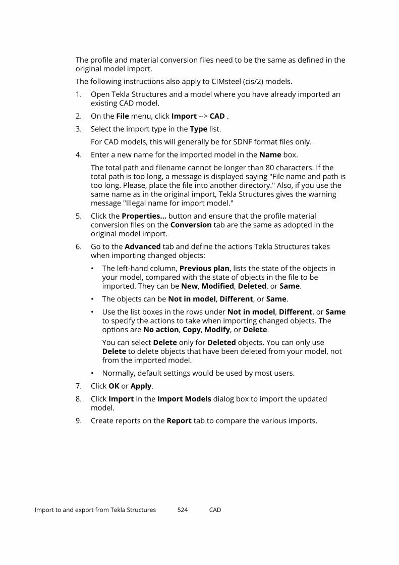
The profile and material conversion files need to be the same as defined in theoriginal model import.
The following instructions also apply to CIMsteel (cis/2) models.
1. Open Tekla Structures and a model where you have already imported anexisting CAD model.
2. On the File menu, click Import --> CAD .
3. Select the import type in the Type list.
For CAD models, this will generally be for SDNF format files only.
4. Enter a new name for the imported model in the Name box.
The total path and filename cannot be longer than 80 characters. If thetotal path is too long, a message is displayed saying "File name and path istoo long. Please, place the file into another directory." Also, if you use thesame name as in the original import, Tekla Structures gives the warningmessage "Illegal name for import model."
5. Click the Properties... button and ensure that the profile materialconversion files on the Conversion tab are the same as adopted in theoriginal model import.
6. Go to the Advanced tab and define the actions Tekla Structures takeswhen importing changed objects:
• The left-hand column, Previous plan, lists the state of the objects inyour model, compared with the state of objects in the file to beimported. They can be New, Modified, Deleted, or Same.
• The objects can be Not in model, Different, or Same.
• Use the list boxes in the rows under Not in model, Different, or Sameto specify the actions to take when importing changed objects. Theoptions are No action, Copy, Modify, or Delete.
You can select Delete only for Deleted objects. You can only useDelete to delete objects that have been deleted from your model, notfrom the imported model.
• Normally, default settings would be used by most users.
7. Click OK or Apply.
8. Click Import in the Import Models dialog box to import the updatedmodel.
9. Create reports on the Report tab to compare the various imports.
Import to and export from Tekla Structures 524 CAD

Export a CAD modelYou can export a CAD model in several formats.
NOTE Before you start an SDNF export, check that the advanced option hasnot been set in the Export category of the Advanced Options dialogbox.
1. Open a Tekla Structures model.
2. On the File menu, click Export --> CAD .
The Export CAD dialog box opens.
3. Enter the paths to the required conversion files on the Conversion tab,enter the parameters on the Parameters tab, and depending on theexport format, define the settings on the SDNF or XML tab.
For more information about the export settings, see the CAD exportsettings section below.
4. Select the parts in the model to export.
5. Click Apply and Create.
Tekla Structures creates the export file in your current model folder.
CAD model export settings
Setting DescriptionConversion tabProfile conversion file
Material conversionfile
Twin profileconversion file
Define the conversion files you want to use.
Conversion files map Tekla Structures profile andmaterial names with names used in othersoftware.
For more information about conversion files, seeConversion files (page 171).
Parameters tabOutput file The file name of the exported file. You can also
browse for the file.Type Select the export format: HLI, SCIA, SDNF, PDMS,
SDNF (PDMS), XMLOrigin X, Origin Y,Origin Z
Define the origin coordinates to place the exportedmodel in a specific location.
PML tab: this format is no longer supportedSDNF tab
Import to and export from Tekla Structures 525 CAD

Setting DescriptionSDNF version number Select the SDNF version to be used in the export.
With StruCAD, use SDNF version 2.0.Apply cuts and fittings Select Yes (default) applies cuts and fittings in the
export.Position number type The SDNF file contains identifiers, which can be
included in a part’s user-defined attributes, or asposition numbers. You have the following options:
• Part position
The identifier becomes the part’s positionnumber. Do not use the Part Pos_No fieldswith this option.
• Assembly position
The identifier becomes the assembly’s positionnumber.
• Universal ID
The identifier becomes a user-defined attributefor the part.
To make user-defined attributes visible, you needto add them to the objects.inp file.
Consider offsets To ignore the offset records during export, selectNo, and to take them into account, select Yes.
This setting does not affect the actual start andend point information, only the offset. TeklaStructures writes the start and end points basedon the actual solid object, not on the referenceline.
PDMS phase offset PDMS phase offset defines phase offset forexported parts. For example, if the first phase inTekla Structures model is 1 and you enter 10 forphase offset, Tekla Structures parts in anothersoftware get the phase from 11 and up.
Engineering Firm Enter the name of the engineering company.Client Enter the name of the client.Structure ID Enter a unique identification number for the
exported model.Project ID Enter a unique identification number for the
exported project.Revision Number Enter an optional revision number. Tekla
Structures takes the revision number from theuser-defined attributes (REVISION_NUMBER) of the
Import to and export from Tekla Structures 526 CAD

Setting Descriptionmodel. If this field is blank, Tekla Structures uses arevision number from the Export CADdialog box(Revision Number).
Issue Code Tekla Structures writes an issue code in the headersection of the output file. For PDMS, this valueshould always be "Tekla Structures".
Design Code Define the design code to be used in structuraldesign.
XML tabUnits Specify unit conversions (MM, M, IN, FT). For
example, for a Tekla Structures model createdusing millimeters, select IN to convert all partdimensions to inches in the output file.
XML structure ID Unique identification number for the exportedmodel. You must always enter the identification ID.Tekla Structures uses this value to identify themodel if you re-export it.
XML structure name Unique name of the exported model.
Import to and export from Tekla Structures 527 CAD

4 Tekla Warehouse
Tekla Warehouse is a service for collaboration, and for storing and sharingTekla Structures content.
Tekla Warehouse provides centralized access to a wide range of content thatyou can use in your Tekla Structures models.
With Tekla Warehouse you can:
• Publish your content online.
• Use your company network or a commercial file storage andsynchronization service to share content.
• Save content locally for private use.
In Tekla Warehouse, content is organized into collections.
Tekla Structures collections contain official Tekla Structures content that youcan use in your models. The content is grouped by geographical area. There isalso a global folder for content that is not location specific.
Tekla Warehouse has the following content categories:
• Applications
• Custom components
• 3D products
• Profiles
• Materials
• Bolts
• Reinforcement
• Model setup files
• Drawing setup files
• Report templates
Tekla Warehouse 528

Accessing Tekla Warehouse
To open Tekla Warehouse while using Tekla Structures, do one of thefollowing:
• On the File menu, click Extend --> Tekla Warehouse.
• Go to Quick Launch, and start typing Tekla Warehouse.
Tekla Warehouse Service
Tekla Warehouse consists of the Tekla Warehouse web site (https://warehouse.tekla.com/) and the Tekla Warehouse Service.
You need Tekla Warehouse Service to benefit from all the features TeklaWarehouse offers, for example, easy installation of content into a TeklaStructures model, or local and network collections.
See also
For more information on Tekla Warehouse, go to Tekla Warehouse and clickAbout, or see Getting started with Tekla Warehouse.
Tekla Warehouse 529

5 Disclaimer
© 2022 Trimble Solutions Corporation and its licensors. All rights reserved.
This Software Manual has been developed for use with the referencedSoftware. Use of the Software, and use of this Software Manual are governedby a License Agreement. Among other provisions, the License Agreement setscertain warranties for the Software and this Manual, disclaims otherwarranties, limits recoverable damages, defines permitted uses of theSoftware, and determines whether you are an authorized user of theSoftware. All information set forth in this manual is provided with the warrantyset forth in the License Agreement. Please refer to the License Agreement forimportant obligations and applicable limitations and restrictions on yourrights. Trimble does not guarantee that the text is free of technicalinaccuracies or typographical errors. Trimble reserves the right to makechanges and additions to this manual due to changes in the software orotherwise.
In addition, this Software Manual is protected by copyright law and byinternational treaties. Unauthorized reproduction, display, modification, ordistribution of this Manual, or any portion of it, may result in severe civil andcriminal penalties, and will be prosecuted to the full extent permitted by law.
Tekla Structures, Tekla Model Sharing, Tekla PowerFab, Tekla StructuralDesigner, Tekla Tedds, Tekla Civil, Tekla Campus, Tekla Downloads, Tekla UserAssistance, Tekla Discussion Forum, Tekla Warehouse and Tekla DeveloperCenter are either registered trademarks or trademarks of Trimble SolutionsCorporation in the European Union, the United States, and/or other countries.More about Trimble Solutions trademarks: http://www.tekla.com/tekla-trademarks. Trimble is a registered trademark or trademark of Trimble Inc. inthe European Union, in the United States and/or other countries. More aboutTrimble trademarks: http://www.trimble.com/trademarks.aspx. Other productand company names mentioned in this Manual are or may be trademarks oftheir respective owners. By referring to a third-party product or brand, Trimbledoes not intend to suggest an affiliation with or endorsement by such thirdparty and disclaims any such affiliation or endorsement, except whereotherwise expressly stated.
Portions of this software:
Disclaimer 530

EPM toolkit © 1995-2006 Jotne EPM Technology a.s., Oslo, Norway. All rightsreserved.
Portions of this software make use of Open CASCADE Technology software.Open Cascade Express Mesh Copyright © 2019 OPEN CASCADE S.A.S. All rightsreserved.
PolyBoolean C++ Library © 2001-2012 Complex A5 Co. Ltd. All rights reserved.
FLY SDK - CAD SDK © 2012 VisualIntegrity™. All rights reserved.
This application incorporates Open Design Alliance software pursuant to alicense agreement with Open Design Alliance. Open Design Alliance Copyright© 2002-2020 by Open Design Alliance. All rights reserved.
CADhatch.com © 2017. All rights reserved.
FlexNet Publisher © 2016 Flexera Software LLC. All rights reserved.
This product contains proprietary and confidential technology, informationand creative works owned by Flexera Software LLC and its licensors, if any. Anyuse, copying, publication, distribution, display, modification, or transmission ofsuch technology in whole or in part in any form or by any means without theprior express written permission of Flexera Software LLC is strictly prohibited.Except where expressly provided by Flexera Software LLC in writing,possession of this technology shall not be construed to confer any license orrights under any Flexera Software LLC intellectual property rights, whether byestoppel, implication, or otherwise.
To see the third party open source software licenses, go to Tekla Structures,click File menu --> Help --> About Tekla Structures and then click the 3rdparty licenses option.
The elements of the software described in this Manual are protected byseveral patents and possibly pending patent applications in the United Statesand/or other countries. For more information go to page http://www.tekla.com/tekla-patents.
Disclaimer 531

Index
.
.tekla modelsadjusting uploaded attributes............. 121limitations.............................................. 121pours.......................................................121uploading to Trimble Connect.............121
22D DWG or DXF files
defining customized line type mappings(old export)............................................ 264export settings (old export)................. 264exporting (old export)...........................264
2D DWG or DXF filesexport layers..........................................254export settings.......................................254exporting................................................254
33D DGN files
base points............................................ 282exporting................................................282exporting tubular parts........................ 282object group color representations....282v7 export................................................ 282v8 export................................................ 282
3D DWG or DXF filesbase points............................................ 250export settings.......................................250exporting................................................250object group color representation......250old export...............................................250
3DS filesreference models..................................175
AABS files
file description.......................................473analysis & design
direct links..............................................324Robot...................................................... 334SAP2000................................................. 334systems...................................................323
ASCII files......................................................344exporting................................................382file description.......................................382importing................................................382
assigning objects to export layersexporting as 2D DWG or DXF (old export).................................................................264
assigning objects to export layersexporting as 2D DWG or DXF...............254
Bbase quantities
IFC export...............................................244base points
3D DGN export...................................... 2823D DWG or DXF export.........................250reference models..................................177
BAT filescreating NC files in DXF format........... 344
BLEND filesreference models..................................175
BUS filesimporting................................................337
BVBS............................................................. 392best practices.........................................487calculating bar length........................... 473export settings.......................................473export file description.......................... 473exporting.........................................473,487
532

CCAD files
export settings.......................................517export file types.....................................517exporting................................................517import file types.................................... 517importing................................................517re-importing...........................................517
change detectioncomparing versions.............................. 192comparing versions.............................. 186defining comparison set...................... 192exporting changes................................ 186property comparison tolerances........ 192reference models...........................186,192updating changes..................................186
change managementcomparing versions.............................. 186exporting changes................................ 186reference models..................................186updating changes..................................186
checkingexported IFC model.............................. 243reference model contents....................201
CIMSteel2 files............................................. 380CIS/2 files
exporting................................................335importing................................................335
CIS/2 files..................................................... 380CIS/CIMSteel files........................................ 344class values
IFC object conversion........................... 209clipping
reference models..................................179CNC files
creating...................................................344CNV files
contents................................................. 171creating...................................................171
CNV filesSTAAD.Pro.............................................. 335
comparison setsdefining.................................................. 192included properties.............................. 192property comparison tolerances........ 192
compatible formats.................................... 150reference models..................................175
compatible software...................................150configuration files
contents in IFC property sets...............244IFC property sets................................... 244
contour markingcreating in NC files................................ 344NCS settings files...................................344
conversion filescontents................................................. 171creating...................................................171material conversion.............................. 171profile conversion................................. 171twin profile conversion.........................171
conversion filesFEM import and export........................ 337STAAD.Pro.............................................. 335
converting IFC objectsconversion example..............................209conversion settings...............................209conversion class values........................ 209converted objects..................................209different ways of converting................209object conversion limitations.............. 209profile conversion logic........................ 209selecting converted objects................. 209
Convert_DSTV2DXF.....................................344coordinates
reference models..................................177copying
multi-user models.................................100create layout line........................................ 311create layout point......................................310creating
contour marking in NC files................. 344NC files in DSTV format........................ 344NC files in DXF format.......................... 344pop-marks in NC files........................... 344tube NC files.......................................... 344
CXL files........................................................ 325
DDAE files
reference models..................................175DAT files
ELiPLAN export......................................488DEF files
creating NC files in DXF format........... 344
533

default line typesin drawings (old export)....................... 264
defining customized line type mappings (oldexport)..........................................................264detecting changes
exporting results to Excel.....................196reference models..................................179
detecting reference model changescomparing versions.............................. 186exporting changes................................ 186reference models..................................186updating changes..................................186
DGN filesexporting................................................280importing................................................280
DGN filesexporting 3D DGN.................................282importing................................................280inserting as reference model...............280objects supported in DGN insert........ 280reference models..................................175
direct linksISM.......................................................... 337STAAD.Pro.............................................. 337
direct links....................................................150direct links....................................................324
ISM.......................................................... 335drawing export............................................254drawing files
deleting unnecessary............................110drawings
exporting as 2D DWG or DXF...............254exporting as 2D DWG or DXF (old export).................................................................264in multi-user mode............................... 109
DSTV filesconverting to DXF..................................344creating from NC files...........................344DSTV file description.............................344exporting................................................337importing................................................337
DSTV formatMIS export..............................................379
dstv2dxf_conversion.bat............................344DWG files
base points............................................ 250exporting 3D.......................................... 250settings................................................... 250
DWG files......................................................248defining customized line type mappings(old export)............................................ 264drawing export layers (old export)......264export example (old export)................ 264export layers..........................................254export settings.......................................254exporting.........................................254,273exporting drawings...............................254exporting as 2D DWG or DXF (old export).................................................................264importing................................................249layer rules.............................................. 254objects in export layers........................ 254objects in export layers (old export)...264reference models..................................175
DXF filesbase points............................................ 250exporting 3D.......................................... 250settings................................................... 250
DXF files........................................................248creating from NC files...........................344defining customized line type mappings(old export)............................................ 264drawing export layers (old export)......264export example (old export)................ 264export layers..........................................254export settings.......................................254exporting.........................................254,273exporting drawings...............................254exporting as 2D DWG or DXF (old export).................................................................264importing................................................249layer rules.............................................. 254objects in export layers........................ 254objects in export layers (old export)...264PDF insert...............................................287reference models..................................175
EEJE format
MIS export..............................................379ELI files
ELiPLAN export......................................488ELI files......................................................... 392ELiPLAN........................................................ 392
best practices.........................................509
534

conversion files..................................... 488export files............................................. 488export settings.......................................488exporting.........................................488,509importing................................................488
eliplan.eli......................................................488eliplan_export.dat.......................................488ELIX files
ELiPLAN export......................................488entities
IFC export...............................................231EPC format
MIS export..............................................379error messages
in multi-user mode............................... 101examples
converting IFC objects.......................... 209setting up layers for DWG export (oldexport).............................................264,273
EXCEL filesreference model change detection.....196reference model change detection.....186
export layers2D DWG or DXF export)........................2542D DWG or DXF export (old export)....264copying to another project (old export)....264drawing export (old export).................264drawing export).....................................254
exporting2D DWG or DXF files............................. 2543D DGN files.......................................... 2823D DWG or DXF export settings.......... 2503D DWG or DXF files............................. 250ASCII files................................................382BVBS........................................................487BVBS files............................................... 473CAD models........................................... 517CAD export file types............................ 517CAD export settings.............................. 517checking exported IFC model.............. 243compatible software.............................150compatible formats.............................. 150drawings as 2D DWG or DXF(old export).................................................................264drawings as 2D DWG or DXF files....... 254drawings as 2D DWG or DXF files (oldexport).................................................... 273
DSTV files................................................337ELiPLAN.................................................. 509ELiPLAN files.......................................... 488export as DWG or DXF example (oldexport).................................................... 264export DWG/DXF example................... 273from Tekla Structures...........................170HLI files...................................................517HMS files................................................ 511IFC base quantities................................244IFC export settings................................ 231IFC2x3 files............................................. 231IFC4 files................................................. 231Layout Manager.................................... 304MICROSAS files...................................... 337MIS lists.................................................. 379old 3D DWG or DXF export.................. 250SDNF files............................................... 517setting up layers for DWG export (oldexport).................................................... 273SketchUp................................................ 288STAAD files............................................. 337supported types.................................... 170Unitechnik.............................................. 457Unitechnik files......................................394XML files................................................. 517
FFabTrol XML files
importing................................................381Fabtrol XML files..........................................344FBX files
reference models..................................175FEM files
importing................................................517FEM files
importing................................................337file formats.................................................. 149files
conversion files..................................... 171material conversion files......................171profile conversion files......................... 171twin profile conversion files.................171
firm foldersexporting drawings (old export)..........264
fittingsin NC files............................................... 344
535
GGLFT files
reference models..................................175
HHLI files
exporting................................................517importing................................................517
HMS.............................................................. 392exporting from Tekla Structures......... 511project data in export...........................511slab data in export................................ 511steel part data in export.......................511
IIFC files
checking exported IFC model.............. 243property set configuration...................244
IFC filesdefining property sets in export......... 225export..................................................... 224export settings.......................................231exported base quantities..................... 244exporting................................................231mapping IFC entities............................. 231reference models..................................175using Organizer spatial hierarchy inexport..................................................... 231
IFC2x3export settings.......................................231exporting................................................231
IFC4export settings.......................................231exporting................................................231
IFC................................................................. 205conversion class values........................ 209converted objects..................................209converting IFC objects.......................... 209importing................................................208inserting................................................. 208object converter.................................... 209object conversion settings................... 209object conversion limitations.............. 209profile conversion logic........................ 209
reference model assemblies............... 205supported schemas.............................. 208
IGES filesreference models..................................175
importingASCII files................................................382BUS files................................................. 337CAD import file types............................517CAD import settings..............................517CAD models........................................... 517compatible software.............................150compatible formats.............................. 150DGN files................................................ 280DSTV files................................................337DWG files................................................249DXF files..................................................249ELiPLAN files.......................................... 488fabrication status for parts.................. 381FabTrol XML files................................... 381FEM files................................................. 337from Tekla Structural Designer........... 327HLI files...................................................517IFC reference models............................208in Tekla Structures................................ 170Layout Manager.................................... 304MONORAIL files.....................................337Plantview files........................................517re-importing CAD files.......................... 517reference models..................................177SACS files................................................337SDNF files............................................... 517STAN 3D files......................................... 337supported types.................................... 170XML files................................................. 517XML files................................................. 517
industry standards......................................149INP files................................................. 184,199inquiring
reference model contents....................201inserting
DGN files................................................ 280IFC reference models............................208objects supported in DGN insert........ 280PDF to model......................................... 287reference models..................................175reference models..................................177
installingreference model plug-ins.....................175
536

interoperabilitycompatible software.............................150compatible formats.............................. 150
ISM direct link.......................................335,337
KKISS format
MIS export..............................................379
LLandXML files
inserting................................................. 285LandXML files
reference models..................................175layers
assigning objects in 2D DWG/DXF export.................................................................254assigning objects in 2D DWG or DXFexport (old export)................................ 264copying to another project (old export)....264exporting as 2D DWG or DXF...............254exporting as 2D DWG or DXF (old export).................................................................264
Layout Managerbase point.............................................. 320base points..................................... 305,312benchmark point...................................320control point.......................................... 320coordinates............................................ 305datum point........................................... 320drawing scale.........................................312example..................................................320export..................................................... 312exporting................................................304groups.................................................... 305import.....................................................315importing................................................304layout lines.............................................311layout points..........................................310
line cutsin NC files............................................... 344
line typescustomizing (old export).......................264
defining customized line type mappings(old export)............................................ 264exporting as 2D DWG or DXF (old export).................................................................264mapping (old export)............................ 264
linking modelsto Trimble Connect projects................ 120
locationreference models..................................177
lockingreference models..................................185
Mmapping line types
defining customized line type mappings(old export)............................................ 264exporting as 2D DWG or DXF (old export).................................................................264
master modelssaving......................................................103
material conversion files............................171MICROSAS files
exporting................................................337MIS lists........................................................ 344
exporting................................................379file types information........................... 379formats...................................................379
model historycollecting.................................................. 99model revision comments..................... 99viewing......................................................99
Model Sharingreading in................................................. 26updating................................................... 26
MONORAIL filesimporting................................................337
multi-user modelsmaster models.........................................96working models.......................................96
multi-user databaseschecking................................................. 102removing inconsistencies.....................102
multi-user modelsconverting................................................ 94copying................................................... 100repairing.................................................102saving........................................................97
537

shutting down........................................100switching between multi-user and single-user models............................................. 94
multi-user modeaccess rights.......................................... 112active multi-users..................................101advantages...............................................89autosaving................................................98deleting unnecessary drawing files.... 110drawing files.......................................... 108drawings.................................................109error messages......................................101locking models.........................................97locks for drawings.................................110numbering...................................... 107,108overview................................................... 89permissions........................................... 112privileges................................................ 112saving in................................................. 103
multi-user serveras a service...............................................90installing................................................... 90restarting..................................................90uninstalling...............................................90
NNC files
contour marking....................................344creating...................................................344creating in DXF format..........................344DSTV file description.............................344fittings.....................................................344line cuts.................................................. 344NC file headers...................................... 344pop-marks..............................................344tube NC files.......................................... 344
NC/DSTV files...............................................344NCP files
pop-mark settings.................................344NCS files
contour marking settings.....................344numbering
in multi-user mode........................ 107,108
OOBJ files
reference models..................................175object group color representation
3D DWG or DXF export.........................250object group color representations
3D DGN export...................................... 282objects.inp............................................ 184,199offset
reference models..................................177opening
reference models list............................179overlay models
adding.....................................................129adjusting scale and position................ 129inquiring................................................. 129removing................................................ 129showing and hiding...............................129versions.................................................. 134
overlay modelsbenefits...................................................133
PPalletizer...................................................... 392PDF files
inserting to model.................................287reference models..................................175
PDMS/E3D ...................................................381PFXF files
exporting................................................385Plantview files
importing................................................517PLY files
reference models..................................175point clouds
attaching................................................ 289detaching............................................... 289limitations.............................................. 289point count.............................................289storage....................................................289supported file formats......................... 289
pop-markscreating in NC files................................ 344NCP settings files...................................344
precast fabrication......................................392precast planning tools................................392
538

Precast Production Export.........................392privileges.inp
changing access rights..........................112controlling access to lock and unlockobjects.................................................... 112controlling access to numbering setup....112controlling access to save standard files.................................................................112options................................................... 112user-defined attribute Locked.............112
profile conversion files...............................171project folders
exporting drawings (old export)..........264property comparison tolerances.............. 192property sets
configuration files................................. 244defining in IFC export........................... 225IFC export...............................................244
PRP filesreference models..................................175
PXML files............................................. 392,394
Rreference models
base points............................................ 177clipping................................................... 179coordinates............................................ 177detecting changes................................. 179hiding and showing...............................179highlighting in model view................... 179importing................................................177inserting................................................. 177loading....................................................175location...................................................177offset.......................................................177opening reference models list.............179refreshing...............................................179rotating...................................................179rotation...................................................177scale........................................................ 177showing details......................................179showing layers.......................................179showing object details..........................179supported formats................................175updating................................................. 179user-defined attributes........................ 179
reference modelsattaching................................................ 125downloading.......................................... 125exporting................................................125removing................................................ 125updates.................................................. 125uploading............................................... 125versions.................................................. 125zooming to............................................. 125
reference model plug-insinstalling................................................. 175
reference modelslocking.................................................... 185
reference modelsadding user-defined attributes to objects.................................................................203adding UDAs.......................................... 199assemblies............................................. 205benefits...................................................133checking hierarchy................................203checking contents................................. 201defining comparison sets.....................192detecting changes................................. 186exporting changes................................ 186exporting change detection results toExcel........................................................196inquiring contents.................................201inquiring native reference objects...... 203LandXML files.........................................285modifying details...................................184property comparison tolerances........ 192reference model objects...................... 202updating changes..................................186
refreshingreference models..................................179
Robot............................................................ 334rotating
reference models..................................177reference models..................................179
SS-Frame
exporting................................................336importing................................................336
S3D................................................................380SACS files
importing................................................337
539

SAP2000....................................................... 334saving
in multi-user mode.......................... 97,103master models...................................... 103
scalereference models..................................177
SDNF filesexporting................................................517importing................................................517
settingsIFC object conversion........................... 209
showingreference model layers........................ 179
single-user modelsconverting................................................ 95switching between multi-user and single-user models............................................. 95
SketchUpexporting................................................288
SKP filesreference models..................................175
Smart3D....................................................... 380software....................................................... 150STAAD files
exporting................................................337importing................................................337
STAAD.Pro direct link..................................337STAAD.Pro
exporting................................................335importing................................................335
STAADtable type specifications.......................343
Stacker..........................................................392STAN 3D files
importing................................................337STD files
exporting................................................335importing................................................335
Steel 2000MIS export..............................................379
Steel fabrication.......................................... 344STEP files
reference models..................................175supported export types............................. 170supported formats......................................150supported import types............................. 170supported software.................................... 150
Ttable type specifications
STAAD..................................................... 343TCZIP files
reference models..................................175Tekla PowerFab
customizing UDAs for export...............385export settings.......................................385exporting Tekla Structures models.....385importing from Tekla PowerFab......... 385
TEKLA filesreference models..................................175
Tekla Model Sharingsharing changes...................................... 36sharing history.........................................36
Tekla Model Sharingcache service............................................18conflicts.................................................... 69editor........................................................ 30error messages........................................69exporting users........................................30firm folders.............................................. 47idle.............................................................69importing users....................................... 30inviting users............................................30model history...........................................45owner........................................................30project folders......................................... 47project viewer.......................................... 30sending emails to users..........................30session timeout....................................... 69timeout..................................................... 69troubleshooting.......................................69user roles................................................. 30viewer....................................................... 30write out errors....................................... 69
Tekla Model Sharingbacking up................................................67baselines............................................. 44,67best practices...........................................67browsing shared models........................23catalogs.................................................... 55conflicts.................................................... 55drawing locks...........................................41excluding model...................................... 53introduction............................................. 10joining model........................................... 23
540

licenses..................................................... 10multi-user model.....................................54numbering............................................... 67object locks.............................................. 41object IDs..................................................67object types..............................................55Organizer..................................................55prerequisites............................................10privileges.................................................. 41reserving write out..................................27settings..................................................... 50sharing automation tool.........................27sharing models........................................21sharing service.........................................10start using................................................ 14what is shared......................................... 55workflow...................................................14writing out................................................27
Tekla Structural Designer...........................325exporting to........................................... 332importing from...................................... 327re-importing from................................. 330
Tekla Warehouse........................................ 528Tekla Warehouse Service...........................528TeklaStructures.lin...................................... 264tekla_dstv2dxf.def ......................................344tekla_dstv2dxf.exe...................................... 344TRB files
reference models..................................175Trimble Connector
launching................................................117overview................................................. 117
Trimble Connectorlinking models to Trimble Connectprojects...................................................120matching views......................................147reference models..................................125reference model versions.................... 125reference model updates.....................125select same objects in Tekla Structuresand Trimble Connector........................ 147ToDos......................................................139unlinking models from Trimble Connectprojects...................................................120working with ToDos.............................. 139
Trimble Connectlaunching................................................117
Trimble Connector
overlay models...................................... 133overlay models...................................... 129reference models..................................133uploading model to Trimble Connect.121
TRN filesFabTrol XML import.............................. 381
TSEP filesreference models..................................175
TSMD files.................................................... 325tube NC files
creating...................................................344twin profile conversion files...................... 171
UUNI files........................................................394Unitechnik....................................................392
assemblies............................................. 394best practices.........................................457classes.................................................... 394embeds...................................................394export limitations..................................394export settings.......................................394exporting.........................................394,457files..........................................................394folder path............................................. 394insulation............................................... 394line attributes........................................ 394log files................................................... 394mounting parts......................................394pallet....................................................... 394reinforcement........................................394surface....................................................394symbols.................................................. 394validation................................................394version....................................................394
user-defined attributesadding in reference models.................199
UXML files.............................................392,394
XXML files
exporting................................................517importing................................................517
XML filesFabTrol XML import.............................. 381
541

IFC property set configuration............ 244reference models..................................285
XMLTrans.trn............................................... 381XSD files
IFC property set configuration............ 244XS_USE_OLD_DRAWING_EXPORT...... 254,264
ZZIP files
exporting................................................385
542
Copyright © 2022 FDOKUMEN