Manage Tekla Structures
414
Tekla Structures 2021 Manage Tekla Structures April 2021 ©2021 Trimble Solutions Corporation
-
Upload
khangminh22 -
Category
Documents
-
view
0 -
download
0
Transcript of Manage Tekla Structures

Tekla Structures 2021Manage Tekla Structures
April 2021
©2021 Trimble Solutions Corporation

Contents
1 Manage Tekla Structures .............................................................9
2 Tekla Structures installation for administrators.................... 102.1 Installation requirements..............................................................................102.2 Installing Tekla Structures.............................................................................112.3 Installation files...............................................................................................122.4 Standard installation......................................................................................132.5 Centralized installation.................................................................................. 132.6 Installation in a virtual environment........................................................... 132.7 Folder structure...............................................................................................132.8 Tekla Structures settings in the Windows registry.....................................142.9 Installing an on-premises license server......................................................152.10 Installing .tsep packages................................................................................ 152.11 Collaborative modeling.................................................................................. 182.12 Upgrading Tekla Structures........................................................................... 192.13 Create start-up shortcuts with customized initializations........................ 20
Create a start-up shortcut with customized initialization.................................................20Available parameters in shortcuts.......................................................................................21Example of an initialization file............................................................................................ 23
2.14 Using Tekla Structures with application and desktop virtualization.......23Prerequisites for using Tekla Structures in a virtual environment..................................24 Set up the virtual environment for Tekla Structures........................................................26
3 Manage Tekla Structures licenses ............................................ 283.1 Tekla Structures on-premises licensing....................................................... 29
Checklist of Trimble deliverables needed in on-premises licensing............................... 34Checklist of IT resources needed in on-premises licensing..............................................35Checklist for the on-premises license server administrator............................................ 36Rights needed for administrator tasks in on-premises licensing.................................... 37Distributing and managing on-premises licenses............................................................. 37Examples of different on-premises licensing setups........................................................ 39
3.2 Installing Tekla license server....................................................................... 44 Which license server version to use .................................................................................. 45Install Tekla license server - automatic installation...........................................................46Install Tekla license server - manual installation............................................................... 47Modify the license file tekla.lic manually............................................................................ 50Configure Tekla license server manually............................................................................ 52
3.3 Allowing Tekla license server to operate through Windows Firewall...... 53Allow exceptions in firewall for lmgrd.exe and tekla.exe................................................. 54Allow traffic in fixed TCP/IP ports........................................................................................ 55
2

3.4 Activate on-premises licenses....................................................................... 64How license activation works............................................................................................... 64Activate on-premises licenses using automatic server notification................................ 65Activate on-premises licenses using manual server notification.....................................67
3.5 Preconfigure license server settings for users............................................ 683.6 Deactivate on-premises licenses...................................................................69
Deactivate on-premises licenses......................................................................................... 703.7 Maintain Tekla licenses ................................................................................. 71
Monitor Tekla Structures license use.................................................................................. 72Modify on-premises license access rights (tekla.opt)........................................................73
Configuration codes and keywords used in access right definitions.........................75Move licenses between license servers.............................................................................. 78Repair an on-premises license.............................................................................................79 Troubleshoot Tekla licensing ..............................................................................................80
View and diagnose errors in Tekla Structures license activation, deactivation and borrowing.............................................................................................................................81
Problems in Tekla license server installation and connecting to the license server .............................................................................................................................................. 82
Problems in FlexNet.........................................................................................................84Problems in Tekla license activation.............................................................................. 85Problems in Tekla license deactivation..........................................................................89Problems in Tekla license borrowing.............................................................................89Problems in Tekla license trusted storage.................................................................... 90Problems using LMTOOLS in Tekla licensing................................................................ 91Problems in starting Tekla Structures............................................................................93Problems with options file tekla.opt.............................................................................. 95Problems in Tekla licensing: Error codes and their descriptions............................... 96
3.8 Set up on-premises license borrowing for offline use.............................. 103Provide offline users with a customized product ID file.................................................104Set up Tekla License Borrow Tool for Tekla Structures offline use...............................105Borrow a license from on-premises license server.........................................................107Return a borrowed on-premises license.......................................................................... 108
4 Implementation guide for administrators............................. 1104.1 Customizing Tekla Structures......................................................................1104.2 Overview of environments, roles and licenses......................................... 1124.3 Folder structure............................................................................................ 1134.4 Project and firm folders............................................................................... 1144.5 Folder search order.......................................................................................1154.6 Initialization files.......................................................................................... 1164.7 Setting advanced options in .ini files..........................................................1184.8 Creating shortcuts........................................................................................ 1194.9 Bypassing the login screen...........................................................................1204.10 User-defined attributes................................................................................121
5 Create and distribute customized settings, userinterface elements, and catalogs ........................................... 123
5.1 Environment, company, and project settings for administrators.......... 125Environment settings.......................................................................................................... 126
3

Company settings................................................................................................................126Project settings.................................................................................................................... 130
5.2 Distribute customized ribbons by using a firm or environment folder. 131Add ribbons to a firm or environment folder.................................................................. 132Loading order of custom ribbons......................................................................................132Naming convention for ribbon files.................................................................................. 133
5.3 Distribute customized tabs by using a firm or environment folder....... 1335.4 Distribute customized property pane layouts by using a project,
firm, or environment folder.........................................................................135Add a property pane layout file to a project, firm, or environment folder.................. 136Search order of the customized property pane layout files.......................................... 136
5.5 Distribute customized property pane settings by using a project,firm, or environment folder.........................................................................137
5.6 Distribute customized toolbars by using a project, firm, orenvironment folder.......................................................................................137
5.7 Customize the material catalog.................................................................. 138Important buttons in the material catalog.......................................................................139Add a material grade...........................................................................................................139Copy a material grade.........................................................................................................140Modify a material grade......................................................................................................141Delete a material grade...................................................................................................... 141Add user attributes to material grades.............................................................................142Create user-defined material definitions......................................................................... 143Import and export material grades...................................................................................144
Import a material catalog..............................................................................................144Export an entire material catalog.................................................................................145Export a part of the material catalog...........................................................................146
5.8 Customize the profile catalog......................................................................146Important buttons in the profile catalog.......................................................................... 147Group profiles together......................................................................................................148
Add a rule to the profile catalog...................................................................................148Modify a rule in the profile catalog.............................................................................. 149
Add user attributes to profiles...........................................................................................149Example: Add a user attribute to a profile and use it in a rule ................................150
Associate profile types with a certain material................................................................153Delete a profile from the profile catalog.......................................................................... 154Import and export profiles................................................................................................. 155
Import profile catalog items......................................................................................... 156Export an entire profile catalog....................................................................................157Export a part of the profile catalog.............................................................................. 157Example of profile export file....................................................................................... 158Units used in import and export.................................................................................. 160Import and export sketched profiles........................................................................... 161
Create your own profiles.................................................................................................... 162Create user-defined cross sections..............................................................................163Create fixed profiles.......................................................................................................169Create parametric profiles using .clb files...................................................................172Create parametric profiles by sketching..................................................................... 180Create parametric profiles with variable cross sections........................................... 205
Define standardized values for parametric profiles....................................................... 208Create an image of a profile...............................................................................................209
5.9 Customize the shape catalog.......................................................................210
4
Import shapes......................................................................................................................211Example: Import a shape from SketchUp Pro............................................................ 213Compress shape geometry files...................................................................................214Clean shape geometry files...........................................................................................215
Create shapes...................................................................................................................... 216Create a shape by using existing geometry in the model.........................................216Create a shape by converting a part to an item......................................................... 217
Work with shapes and groups in the shape catalog....................................................... 217Add a new group or sub-group.................................................................................... 219Modify a group or sub-group....................................................................................... 219Select shapes.................................................................................................................. 220Move or copy shapes between groups....................................................................... 220Modify shape properties............................................................................................... 221Delete a group or sub-group, or shapes..................................................................... 221
Export shapes...................................................................................................................... 222Organize the shape catalog view.......................................................................................223
Show or hide the catalog ribbon.................................................................................. 224Work with property columns in the catalog view.......................................................224Filter shapes....................................................................................................................225Add stars to shapes....................................................................................................... 225Add tags to shapes.........................................................................................................226
5.10 Customize the bolt catalog.......................................................................... 227How the bolt catalog and bolt assembly catalogs work together ................................ 227Manage bolts and bolt assemblies....................................................................................228
Add a bolt to the catalog............................................................................................... 228Add a stud bolt to the catalog.......................................................................................229Modify bolt information in the catalog........................................................................230Delete a bolt from the catalog......................................................................................231Add a bolt assembly to the catalog..............................................................................231Modify bolt assembly information in the catalog...................................................... 232Delete a bolt assembly from the catalog.................................................................... 232
Import and export bolts and bolt assemblies..................................................................233Import bolts to the catalog........................................................................................... 234Export bolts from the catalog....................................................................................... 234Import bolt assemblies to the catalog.........................................................................235Export bolt assemblies from the catalog.................................................................... 235Import a bolt catalog......................................................................................................236Import a part of the bolt catalog.................................................................................. 236Export an entire bolt catalog........................................................................................ 237
Bolt length calculation........................................................................................................ 238Bolt catalog properties........................................................................................................240Bolt assembly catalog properties...................................................................................... 242
5.11 Customize the rebar catalog........................................................................243Work with definitions in the rebar catalog....................................................................... 244
Add a new rebar definition........................................................................................... 244Add a new rebar definition by copying........................................................................244Select rebar definitions..................................................................................................245Modify a rebar definition...............................................................................................245Delete rebar definitions.................................................................................................246
Work with groups in the rebar catalog............................................................................. 246Add a new group to the catalog................................................................................... 247Modify a group in the catalog.......................................................................................248Delete a group from the catalog.................................................................................. 248
Import and export rebar definitions................................................................................. 248Import definitions to the rebar catalog....................................................................... 249
5

Export definitions from the rebar catalog...................................................................249Organize the rebar catalog view........................................................................................250
Show or hide the catalog ribbon.................................................................................. 250Change the grouping of rebar definitions...................................................................251Work with property columns in the catalog view.......................................................251Filter rebar definitions................................................................................................... 252Add stars to rebar definitions.......................................................................................253Add tags to rebar definitions........................................................................................ 253
5.12 Customize the Applications & components catalog................................. 254Edit the catalog.................................................................................................................... 255Maintain the catalog............................................................................................................260
5.13 Add instructor help for applications and components............................ 261
6 Files and folders in Tekla Structures.......................................2626.1 Create project and firm folders...................................................................263
Create a project or firm folder........................................................................................... 264Fixed sub-folders in project and firm folders...................................................................264
6.2 Initialization files (.ini files)......................................................................... 268Typical initialization files (.ini files) and their reading order...........................................269Global default environment settings - env_global_default.ini....................................... 273Local environment settings - env_<environment>.ini.....................................................274Role settings - role_<role>.ini.............................................................................................274Add an advanced option to the user.ini file..................................................................... 275
6.3 File storing options and advanced options................................................ 276Settings in the Options dialog box.................................................................................... 278
Clash check settings.......................................................................................................278Components settings.....................................................................................................280Drawing dimensions settings....................................................................................... 282Drawing objects settings............................................................................................... 283General settings............................................................................................................. 284Load modeling settings................................................................................................. 285Numbering settings....................................................................................................... 285Orientation mark settings............................................................................................. 285Rebar set settings...........................................................................................................287Units and decimals settings.......................................................................................... 289
Settings defined by advanced options..............................................................................296 Change the advanced option values in the Advanced Options dialog box.................298
6.4 Input files (.inp files)..................................................................................... 299Properties of the objects.inp file....................................................................................... 300Define and update user-defined attributes (UDAs).........................................................302
Update definitions of user-defined attributes (UDAs) in a model........................... 304Environment database file............................................................................................ 304Example: Create and update a user-defined attribute (UDA)...................................305
Show plates as flat bars in drawings and reports........................................................... 309Define flat bar sizes with the Fltprops.inp file................................................................. 309Define unfolding parameters in the unfold_corner_ratios.inp file................................310
6.5 Data files (.dat files)...................................................................................... 3126.6 Message files..................................................................................................313
Customize message files.................................................................................................... 3146.7 Property files................................................................................................. 3156.8 Standard files.................................................................................................316
6

6.9 Catalog files................................................................................................... 3186.10 Font files and font conversion files.............................................................3216.11 Symbol files....................................................................................................3226.12 Files related to templates, reports and drawings.....................................3226.13 Image files...................................................................................................... 3236.14 Log files...........................................................................................................324
View a log file....................................................................................................................... 328Change the name and location of session history log file..............................................329Numbering history log file..................................................................................................330Numbering series in the numbering history log file....................................................... 331
6.15 Model folder files and file name extensions..............................................333Files in the Tekla Structures model folder........................................................................333Files in the \Analysis folder.................................................................................................336Files in the \attributes folder..............................................................................................337Component properties files in the \attributes folder..................................................... 344Object level drawing settings, saved in \attributes folder..............................................344View level drawing settings, saved in \attributes folder................................................. 346Files related to single-part drawings, drawing level properties, saved in\attributes folder................................................................................................................. 347Files related to assembly drawings, drawing level properties, saved in\attributes folder................................................................................................................. 348Files related to cast unit drawings, drawing level properties, saved in\attributes folder................................................................................................................. 350Files related to general arrangement drawings, drawing level properties,saved in \attributes folder.................................................................................................. 351Files related to multidrawings, drawing level properties, saved in \attributes folder 354Files common to all drawings, and files in the \drawings folder................................... 354Files related to IFC export in \IFC folder........................................................................... 355Files related to NC in the \DSTV_Profiles folder...............................................................355Files in the \ModelSharing folder...................................................................................... 355Files in the \ProjectOrganizer folder................................................................................. 356Files related to reports in the \Reports folder................................................................. 356Files in the \SessionFileRepository folder.........................................................................356Files related to shapes in the \ShapeGeometries and \Shapes folders........................356Files in the \screenshots folder..........................................................................................357Files related to Unitechnik export in the \UT_files folder............................................... 357
6.16 Check and change Tekla Structures file and folder locations inDirectory browser......................................................................................... 357
6.17 Folder search order.......................................................................................3586.18 Location of certain hidden files and folders.............................................. 360
7 Templates................................................................................... 3627.1 Create a template......................................................................................... 3647.2 Template Editor User's Guide...................................................................... 3657.3 Create a template in HTML format............................................................. 3657.4 Create a .pdf report template......................................................................3677.5 Create a template for nested assemblies.................................................. 3697.6 Create a template for bending schedules or pull-out pictures .............. 373
Bending schedule attributes.............................................................................................. 376
7

7.7 Add images in a template............................................................................ 3787.8 Content types................................................................................................ 3807.9 Template attribute files (contentattributes.lst)....................................... 3837.10 User-defined template attributes...............................................................385
Add user-defined template attributes to Template Editor.............................................386Add comments to user-defined template attributes...................................................... 388Add hierarchy to user-defined template attributes........................................................ 388
7.11 Tips for templates ........................................................................................ 390Use text type attribute in calculations.............................................................................. 390Change value field content to use imperial units............................................................ 390Define customized date format.........................................................................................391Assembly or cast unit drawing sheet number................................................................. 391Use format functions in value fields................................................................................. 392
8 Tekla Model Sharing and multi-user for administrators...... 3958.1 Tekla Model Sharing..................................................................................... 3958.2 Multi-user models......................................................................................... 396
9 Import Tekla Structures model and drawings intoanother model........................................................................... 398
10 Import user-defined attribute values..................................... 400
11 Develop applications using Tekla Open API........................... 401
12 Disclaimer...................................................................................402
8
1 Manage Tekla Structures
Managing Tekla Structures means defining and maintaining the configurationsand settings you require to complete your work in different projects.
Basic configuration for your own use is generally explained in thedocumentation of each feature. The customizations can be copied betweendifferent models and for this it is good to have a basic understanding of thefile and folder structure (page 262).
If you manage Tekla Structures for other users, you are a Tekla Structuresadministrator, and you will need a deeper understanding and more managedapproach to maintaining the configurations, settings and servers that yourusers need in their work. To start customizing Tekla Structures for yourorganization, read more below.
Manage Tekla Structures 9

2 Tekla Structures installation foradministrators
You can install Tekla Structures on a workstation using the standardinstallation packages or by creating your own centralized installation using MSIpackages. You can also run Tekla Structures in a virtual environment.
If you have on-premises licenses, you also need to install a license server onyour own hardware.
2.1 Installation requirementsTrimble Identity
Tekla Online services, including online licensing, use Trimble Identity foridentification. You can use your Trimble Identity with other Trimble services,such as Trimble Connect and SketchUp 3D Warehouse.
Each organization has at least one account administrator, who is responsiblefor managing the Tekla Onlineorganization (group) used in Tekla Onlineservices. Several people in your company can be administrators. The first useris invited by a Trimble representative, and that person is then responsible foradding other users and administrators as necessary.
As an administrator, you:
• Invite or approve employees to your company's Tekla Online organizationto allow them unrestricted access in all Tekla Online services.
• Add external license users.
• Select who has access to your company's online licenses.
• Remove people from your company's employee group when they nolonger belong to your company.
For more information, see Create your Trimble Identity and Manage TrimbleIdentities and Tekla Online licenses.
Tekla Structures installation for administrators 10 Installation requirements

Tekla Structures installation prerequisites
Installing Tekla Structures requires one of the following operating systems:Windows 10 or Windows 8.1. If the operating system is not one of thesupported versions of Windows, the installation is cancelled.
The Tekla Structures installer is available as a 64-bit version.
For more information on recommended operating system and hardwarespecifications, see Tekla Structures 2021 hardware recommendations.
Tekla Structures needs the following redistributable packages that areautomatically installed during the Tekla Structures software installation if they,or newer versions of the packages, do not exist on your computer:
• Microsoft .NET Framework 4.7.2
• Microsoft Visual C++ 2010 Redistributable (x64) 10.0.40219
• Microsoft Visual C++ 2010 Redistributable (x86) 10.0.40219
• Microsoft Visual C++ 2013 Redistributable (x64) 12.0.40649
• Microsoft Visual C++ 2013 Redistributable (x86) 12.0.40649
• Microsoft Visual C++ 2015 Redistributable (x64) 14.0.23026
• Microsoft Visual C++ 2015 Redistributable (x86) 14.0.23026
If you create a customized installation package, make sure that the .NETFramework is installed on the client computers.
In addition, the following installers are automatically installed during the TeklaStructures software installation:
• Tsep File Dispatcher Launcher
• Tekla Warehouse Service
These installers are needed for Tekla Warehouse to work properly.
Tekla Warehouse offline content is available online. To find this content inTekla Warehouse, search for Catalogs and under Show, select Collections.
2.2 Installing Tekla StructuresYou can install Tekla Structures on each workstation running the standardinstaller separately on each workstation, or via a centralized installation withan MSI package and your preferred software deployment tool.
You can download Tekla Structures software and environments from TeklaDownloads. To have the latest software in use, we recommend that you installthe latest service pack of Tekla Structures. Service packs includeimprovements and fixes to the latest or to a previous main version or servicepack of Tekla Structures. Service packs are available for all users with a validmaintenance contract or subscription.
Tekla Structures installation for administrators 11 Installing Tekla Structures

NOTE You need to install Tekla Structures with administrator rights.
When you do a centralized installation, the end users do not needadministrator rights for the installation.
2.3 Installation filesTekla Structures installers are .msi installers. Environment .msi installersinclude sets of .tsep installers that contain the actual environment files andsettings. When installing a new version of Tekla Structures, install the softwarefirst and then the environments. The .msi installers are installed to yourcomputer before opening Tekla Structures.
When you run the environment .msi installer, the installer creates theenvironment folder and copies the .tsep installers to the..\TeklaStructures\<version>\Extensions\To be installed folder. Theinstaller also creates the RemoveEnv.bat and ToBeRemoved.txt files, andplaces them to the ..\Environments\<environment> folder. These files areused when uninstalling an environment.
When running the environment .msi installer, you can select in theinstallation wizard that the .tsep installers are run immediately when runningthe environment installer. If you do not select to do this, the .tsep installersare run when you open Tekla Structures for the first time after the installation.In this case, Tekla Structures opens a dialog box that shows the installationprogress of the .tsep installers.
You can cancel the installation of extension .tsep installers in the dialog boxand postpone them to the next Tekla Structures start-up. The queuedenvironment .tsep installers are not cancelled, they are installed even if youcancel. The .tsep packages contain information about the product type:environment or extension, which is used to determine which installers can becanceled.
Running the .tsep installers does not require administrator rights. The .tsepinstallers install the environment files to the ..\Tekla Structures\<version>\Environments\<environment> folder.
If you are installing several environments for the first time, we recommendthat you do not select to run the .tsep installers with the .msi installer. Someof the .tsep packages are used in more than one environment and the sameversion of a .tsep package is only installed once. Note that starting TeklaStructures for the first time after installation can take a long time particularly ifyou have installed several environments, as all the .tsep installers are run.
Tekla Structures installation for administrators 12 Installation files
2.4 Standard installationTekla Structures installation wizard has detailed instructions about theinstallation.
For more information, see also Install Tekla Structures.
2.5 Centralized installationInstalling Tekla Structures centrally across the company network saves time ina large company when there are many Tekla Structures users.
Centralized installation allows you to run the Tekla Structures installationsilently in the background so that the users do not see the installation wizarddialog boxes. For detailed information on centralized installation, seeCentralized distribution of Tekla Structures 2021.
2.6 Installation in a virtual environmentYou can also run Tekla Structures in a virtual environment. Application anddesktop virtualization allow users to run software from a server on thenetwork without locally-installed Tekla Structures on their workstation. UsingTekla Structures from the server ensures that all users in a project are usingthe same project environment set-up. For detailed information on virtualizedinstallation, see Using Tekla Structures with application and desktopvirtualization (page 23).
2.7 Folder structureThe default installation location is in Program Files. When Tekla Structuresis installed in this folder, configuration files are installed in the hiddenProgram Data folder. This may be the preferred location for reducing thelikelihood of end-user interference with the software installation andconfigurations.
If you install Tekla Structures in a normal file folder, all files are intalled in thatfolder. This may be preferred for users who need to easily access all files.
Folder structure on local computer
See Tekla Structures installation folders for information on how the folderstructure on the local computer is set up.
Tekla Structures installation for administrators 13 Centralized installation
Company folder structure
If you use Tekla Model Sharing, you can synchronize the project and firmfolders through the Trimble Connect cloud service included in your TeklaStructures subscription. .
If you have single-user or multi-user models, we recommend using a centralfile folder for storing the models and setup files for the company-specificsettings and the project-specific settings. Tekla Structures then reads thesettings from the central file server. When upgrading to a new Tekla Structuresversion, or updating the company logo, for example, the files only need to bereplaced in one place. This way taking backups and upgrading is easier.
For more information, see Create project and firm folders (page 263).
Backup
With all valuable information and work your company stores, it is important totake backups of the model folders, and firm and project settings. If yourcompany has a system for taking automatic scheduled backups, schedule yoursystem to take the backups at night time, outside working hours to preventany possible conflicts in the model.
If you use on-premises licenses, do not forget to also take a backup of thelicense entitlements and your active licenses.
Virus protection
Virus protection software has sometimes caused problems in saving modelsand drawings to the model folder. These problems may occur especially if youhave your model saved on a network drive. We strongly recommend that youadd Tekla Structures into the safe list of your antivirus system, and set up yourvirus protection in a way that actions in your model folder are not blocked orscanned.
2.8 Tekla Structures settings in the Windows registryWindows registry is a hierarchical database that stores configuration settingsand options in Microsoft Windows operating systems. Registry settings areused during a Tekla Structures session and during a Tekla Structuresinstallation.
WARNING Do not change the registry settings. Changing the settings cancause the operating system to fail. It is possible to view theregistry settings using the Registry Editor.
User settings
Some of the Tekla Structures user settings, for example, general options, anddialog box locations and sizes are stored in the registry. The settings are savedin a registry key named after the Tekla Structures version number in the
Tekla Structures installation for administrators 14 Tekla Structures settings in the Windows registry
registry branch HKEY_CURRENT_USER\Software\Trimble\TeklaStructures\<VERSION>.
Tekla Structures uses the hardcoded default settings when opened for the firsttime after the installation. If you change a setting during a Tekla Structuressession, Tekla Structures saves the change during the session, or when youexit Tekla Structures. When you open the same version of Tekla Structuresagain, the changed setting is used.
When upgrading to a newer Tekla Structures version, you can use theMigration Wizard tool to copy the settings you have changed.
Installation settings
The Tekla Structures installation saves information to the HKEY_LOCAL_MACHINE\SOFTWARE\Trimble\Tekla Structures\<VERSION> registry key.
2.9 Installing an on-premises license serverIf you have on-premises licenses, you need to install the license server on yourown hardware. If you only use one license of Tekla Structures, you can installthe license server on the same computer as Tekla Structures, making thelicense available on this one workstation. In an environment with multiplelicenses and users, you install the license server in your company network,which allows for more flexible and efficient use of your licenses according toneed.
Before users can start using Tekla Structures with on-premises licenses, youmust:
• Install and set up a license server on a computer.
• Save the entitlement certificate and activate the licenses.
• Connect each client computer with Tekla Structures to the license servereither manually, through a customized installation or by instructing theusers.
For more information, see Tekla Structures on-premises licensing (page 29).
If you have online licenses, Tekla Structures always connects to Trimble's cloudservice when the user needs to reserve an online license and you do not needto install your own license server.
2.10 Installing .tsep packagesTekla Structures extension packages, .tsep packages, are Tekla Structuresextensions or additional environment content installers. Extensions are not
Tekla Structures installation for administrators 15 Installing an on-premises license server

part of the Tekla Structures product release. .tsep packages are available fordownload in Tekla Warehouse.
You can install .tsep packages in three different ways.
Direct installation
1. Double-click the .tsep installer that you have downloaded.
2. The Tekla Structures extension manager dialog box opens with thename of the extension that is going to be installed.
By default .tsep installers are opened with Tekla Structures extensionmanager. Some .tsep installers are run directly from Tekla Warehousewith the Insert into model option.
3. Select the Tekla Structures versions to which you want to import and clickthe Import button. The next time you start Tekla Structures, the extensionis automatically installed, and it is shown in Tekla Structures extensionmanager.
NOTE If the .tsep installer is not set to open with Tekla Structuresextension manager by default, you can set it manually. Right-click onthe .tsep installer and select Properties. In Opens with, selectChange and browse to TsepFileDispatcherLauncher.
Installation in Tekla Structures extension manager
You can also install a .tsep installer from Tekla Structures extensionmanager in Tekla Structures.
1. In the Applications & components catalog, click > Manageextensions --> Extension manager to open Tekla Structures extensionmanager.
2. Click Import and browse to the .tsep installer that you want to install.
3. Click Open.
The imported .tsep is installed the next time you start Tekla Structures. Itis shown in Tekla Structures extension manager, and is ready for use inthe Applications & components catalog.
Uninstall .tsep packages
To uninstall .tsep packages, do one of the following:
• In Tekla Structures extension manager, select the .tsep packages thatyou want to uninstall (use Ctrl or Shift to select more than one), and clickRemove. The .tsep packages are removed when you restart TeklaStructures.
• Browse to ..\Program Files\Tekla Structures\<version\nt\bin\and double-click the TeklaExtensionPackage.Builder.exe to open the
Tekla Structures installation for administrators 16 Installing .tsep packages

Tekla Structures Extension Package (TSEP) builder and test runnerdialog box.
Go to the Uninstall TSEP based extensions tab, select the .tseppackages that you want to uninstall (use Ctrl or Shift to select more thanone), and click Uninstall selected. This will remove all the selected .tseppackages. You do not need to restart Tekla Structures.
Centralized installation
You can centrally install a batch of .tsep installers across companyworkstations. This method is meant for system administrators.
By default, the .tsep installers waiting for installation are stored in\ProgramData\Trimble\Tekla Structures\<version>\Extensions\Tobe installed. To install centrally, you need to copy the .tsep installers tothe %XSDATADIR%\Extensions\To be installed folder. Create the \Tobe installed folder if it does not exist yet.
When Tekla Structures starts, it checks the available .tsep installers from the\To be installed folder and installs them automatically. If there is an olderversion of the same extension package, it is uninstalled before installing thenew version. Installation is cancelled if the same or newer version has alreadybeen installed.
• The installed .tsep installers are stored in the %XSDATADIR%\Extensions\Installed folder.
• Invalid .tsep installers are uninstalled and moved to the %XSDATADIR%\Extensions\Invalid installations folder.
• Cancelled .tsep installers are stored in %XSDATADIR%\Extensions\Cancelled installations.
Copying .tsep installers
We recommend that you use ROBOCOPY from the command prompt(cmd.exe) to copy the .tsep installers. More information on ROBOCOPY can befound on the Microsoft website, for example.
The basic syntax for ROBOCOPY is: robocopy <Source> <Destination>[<File>[ ...]] [<Options>]For example, to copy .tsep installers in Tekla Structures 2021:
robocopy"\\Server1\prod\TeklaStructures\2021.0\Environments_TSEP""C:\ProgramData\Trimble\Tekla Structures\2021.0\Extensions\To be installed"*.tsep"C:\Program Files\Tekla Structures\2021.0\nt\bin\TeklaExtensionPackage.TepAutoInstaller.exe"2021.0 "C:\ProgramData\Trimble\Tekla Structures\2021.0" "2021"
This command will take all .tsep installers from the \Server1 networkdirectory and copy them to the local user's \To be installed folder. Aftercopying, TepAutoInstaller.exe installs all .tsep installers from the local
Tekla Structures installation for administrators 17 Installing .tsep packages

user's \To be installed folder. Installing the packages allows users to startTekla Structures without first waiting for the installations to complete.
Centralized uninstallation
You can uninstall .tsep packages in batches by creating an empty file withoutan extension, with the name RemoveExtensionOnStartup, in\ProgramData\Trimble\Tekla Structures\<version>\Extensions\Installed\[Extension_To_Be_Uninstalled]. The extensions areremoved the next time Tekla Structures is started.
2.11 Collaborative modelingSeveral people can simultanously work in the same Tekla Structures model.
If your company takes part in external projects, or if more than one user workswith the same model at different locations, we recommend that you use TeklaModel Sharing. With Tekla Model Sharing, the users in your company can workwith the same shared model, offline and with high performance, andsynchronize the changes with other team members even in a low-speednetwork.
If you work in a local team and prefer not to use Internet while working onyour models, you can use the multi-user mode.
For model coordination and exchange of other project files, we offer TrimbleConnect. To find out more and set up collaboration in your organization, seeTekla Model Sharing and multi-user for administrators (page 395) and Workingcollaboratively within a Tekla Structures model.
Using the multi-user server requires your company to have more than oneTekla Structures license.
Tekla Structures installation for administrators 18 Collaborative modeling

2.12 Upgrading Tekla StructuresYou can install service packs on top of the existing installation of TeklaStructures. You can update to new service packs without updating the existingon-premises licenses. A new Tekla Structures version installs as a separateinstance and can exist on the same workstation with other Tekla Structuresversions. An update to a new version requires that you also update your on-premises licenses, as the licenses have a highest allowed version. Onlinelicenses automatically allow you to use any Tekla Structures version that isreleased during your subscription period.
If you already have an older version of Tekla Structures installed on yourcomputer, you can use Migration Wizard to copy the personal settings to thenew version. With the Migration Wizard you can choose to copy any of thefollowing settings and values:
• user.ini file
• Registry values, such as:
• Toolbars
• Dialog boxes
• General options
Migration Wizard does not copy the environment .tsep files which areinstalled by the environment installers.
When you customize Tekla Structures, for example, add or change drawing orreport templates and catalog entries, we strongly recommend that you createproject and firm folders for the customized files. This is useful if you want tostore the files for future use, or if you want to retain them when you install anew release.
Tekla Structures does not replace files in the project and firm folders whenyou install a new release. You can retain your customized files without havingto copy and paste, or export and import from the previous versions. Thismakes upgrading faster and easier. If you have customized previous TeklaStructures versions without using firm or project folders, you will need totransfer the customized information to the next Tekla Structures version.
Before you start using a new Tekla Structures version, always test that the oldcompany settings work.
TIP If you want to copy the settings later, you can start Migration Wizard manuallyby double-clicking the MigrationWizard.exe in the \Tekla Structures\<version>\nt\bin\applications\Tekla\Migrations folder. You canselect the version from which the settings are copied and the version to whichthe settings are copied.
Tekla Structures installation for administrators 19 Create start-up shortcuts with customizedinitializations

2.13 Create start-up shortcuts with customizedinitializationsYou can use shortcuts to start teklastructures.exe with customizedinitializations. You can use this functionality to create shortcuts for differentpurposes, for example, to have customized setup files depending on the clientyou are working for in a project. The Tekla Structures installation automaticallycreates shortcuts for the selected environments.
NOTE We recommend that only administrators create the customization and thenecessary shortcuts. Otherwise, your settings may differ from the settingsdefined for your firm, or for the particular project you are working for.
Create a start-up shortcut with customized initialization1. Open the user.ini file using any standard text editor.
2. Save the file with a new name, for example, customer.ini orproject.ini.
3. Modify the file by adding the required settings.
4. Save the modified initialization file.
5. Open the Windows Start menu and select All Programs --> TeklaStructures <version> .
6. Right-click Tekla Structures <version> and select Copy.
7. Paste the shortcut to your desktop.
8. Select the shortcut, right-click and select Properties.
9. Modify the Target of the shortcut by adding the required projectinitialization information to it.
First enter the path to the current teklastructures.exe, then thedesired parameters.
Use the quotation marks (") in the path to avoid possible problems if thepath contains spaces. If you have installed Tekla Structures to a path thatdoes not contain spaces, there will be no problems even if you removethe quotations marks, for example, C:\TeklaStructures\. If you haveinstalled Tekla Structures to a path that contains spaces, the quotationmarks are needed, for example, C:\Program Files\TeklaStructures\.
Tekla Structures installation for administrators 20 Create start-up shortcuts with customizedinitializations

The maximum length of a shortcut is 256 characters. If you have problemswith the length, you can call all other necessary initialization files fromyour customized initialization file instead of adding them to the shortcut.
10. To override the settings defined in the shortcuts, use the parameter -i<initialization_file> in the user.ini and option.ini files.
Available parameters in shortcutsThe table below lists the parameters you can use in the start-up shortcuts.
The parameters can be used in combinations. You can set the parameters toautomatically bypass the Tekla Structures - Choose setup dialog box, open amodel and run a macro, for example.
Parameter Description-I<ini_file_path>
The given .ini file is loaded before theenvironment .ini files. This parameter can be specifiedmultiple times.
This parameter can be used to bypass the TeklaStructures - Choose setup dialog (the login dialog).
Example:
"C:\Program Files\Tekla Structures\<version>\nt\bin\TeklaStructures.exe" -I"C:\ProgramData\Trimble\Tekla Structures\<version>\Environments\uk\Bypass.ini"
Tekla Structures installation for administrators 21 Create start-up shortcuts with customizedinitializations

Parameter Description-i<ini_file_path>
The given .ini file is loaded after the role .ini files.This parameter can be specified multiple times.
Example:
"C:\Program Files\Tekla Structures\<version>\nt\bin\TeklaStructures.exe" -i"C:\TeklaStructures\MySettings.ini"
To open anexisting model
<model_path>
The given model is opened after start-up.
Example:
"C:\Program Files\Tekla Structures\<version>\nt\bin\TeklaStructures.exe""C:\TeklaStructuresModels\My model"
To open anexisting,autosaved model
<model_path> /autosaved
The given autosaved model is opened after start-up.
Example:
"C:\Program Files\Tekla Structures\<version>\nt\bin\TeklaStructures.exe""C:\TeklaStructuresModels\My model" /autosaved
To create a newmodel without amodel template
/create:<model_path>
A new model is created after start-up.
Example:
"C:\Program Files\Tekla Structures\<version>\nt\bin\TeklaStructures.exe"/create:"C:\TeklaStructuresModels\My model"
To create a newmodel using amodel template
/create:<model_path> /modelTemplate:<template_name>
A new model using a model template is created afterstart-up.
Example:
"C:\Program Files\Tekla Structures\<version>\nt\bin\TeklaStructures.exe"/create:"C:\TeklaStructuresModels\My model" /modelTemplate:"Cast-in-Place"
To create a newmulti-user model
/create:<model_path> /server:<server_name>
A new multi-user model is created after start-up.
Example:
"C:\Program Files\Tekla Structures\<version>\nt\bin\TeklaStructures.exe"/create:"C:\TeklaStructuresModels\My model" /server:"my-server:1234"
Tekla Structures installation for administrators 22 Create start-up shortcuts with customizedinitializations

Parameter DescriptionTo run a macroafter start-up
-m<macro_file_path>
The given macro is executed after start-up.
The example below opens Tekla Structures, sets theenvironment, role and configuration from theBypass.ini file, opens the model, and reads in andsaves the model by using the Example Macro: ModelSharing Read in and Save from the BIM Publisher toolthat is available in Tekla Warehouse.
"C:\Program Files\Tekla Structures\<version>\nt\bin\TeklaStructures.exe" -I"C:\ProgramData\Trimble\Tekla Structures\<version>\Environments\<environment>\Bypass.ini" "C:\TeklaStructuresModels\<model>" -m "C:\ReadInSave2016.cs"
Example of an initialization fileBelow is an example of a customized project initialization file that calls otherinitialization files.
MyProject.ini//The project is based on the default UK settingscall C:\ProgramData\Trimble\Tekla Structures\2019.0\Environments\uk\env_UK.ini//..but our company policy requires these changescall c:\CompanySettings\OurPolicy.ini//..and the fabricator requires somethingcall c:\Fabricators\Fabricator1.ini//..and then we let users to make some changes (color etc.)call c:\Users\user_%USERNAME%.ini
The project shortcut for this initialization file:
"C:\Program Files\Tekla Structures\<version>\nt\bin\TeklaStructures.exe" -i "\\MyServer\MyProject\MyProject.ini" "\\MyServer\MyProject\MyModel\"
2.14 Using Tekla Structures with application and desktopvirtualizationUsing Tekla Structures with the Citrix application and desktop virtualization isa flexible and safe way to quickly add users to Tekla Structures projectswithout locally installing Tekla Structures and copying project data to a user'scomputer. Citrix application and desktop virtualization products are productsof Citrix Systems, Inc.
Tekla Structures installation for administrators 23 Using Tekla Structures with application anddesktop virtualization

The image below shows the main concepts in Tekla Structures virtualization.
Data center
Citrix thin clientsrunning on variousoperating systems
Secure display dataconnection over the internet
Virtualization platform(hypervisor layer)
Virtual Tekla Structuresinstances running onMicrosoft Windows
Streaming applications from the server enables the use of Tekla Structures onclient computers, tablets and smartphones that have different hardware andsoftware configurations. Tekla Structures runs on Windows on the remoteserver and the virtualization solution allows client devices to be used fordisplay and user input.
Users connect through a secure connection to the data center located in yourpremises or in the cloud. The project data is protected as everything is storedonly on the server. Using Tekla Structures from a centralized location ensuresthat all users in the project are using the same project environment set-up.
Prerequisites for using Tekla Structures in a virtualenvironmentCitrix virtualization is set up either on a physical server or on a virtual server.Recommended hardware is described in Hardware recommendations forrunning Tekla Structures on Citrix and .
For detailed instructions on installing and setting up XenApp and XenDesktop,see the Citrix documentation.
The image below shows the main components in Tekla Structuresvirtualization.
Tekla Structures installation for administrators 24 Using Tekla Structures with application anddesktop virtualization

Data center
Citrix XenServer/VMware vSphere
License server
Citrix Receiver
File server
Virtual machinerunning Windows
1
2
Citrix XenApp/XenDesktop
3
1. Thin client application: users can access Tekla Structures with CitrixReceiver through Citrix XenApp client or Citrix XenDesktop desktop vieweron any supported operating system and hardware. Multiple concurrentclients may share one virtual machine instance.
A good internet connection is required. Recommended networkbandwidth is 1 Mbps or more.
2. Each TeklaStructures.exe running on the virtual machine needs avalid license.
Local, enterprise, or cloud Tekla license server can be used, and thelicense server can be hosted in or out of the data center.
3. Read/write project files from network-attached storage (NAS). Fast diskaccess is needed. Never use the local disk of the virtual server for savingmodel folders.
Accessing any files from the client's local file system requires uploadingthe files to the server, which may be very slow and should be avoided asmuch as possible. Project data including environments should be storedon another (server) machine in the data center or file system inside thecompany network.
The key components for using Tekla Structures with the Citrix application anddesktop virtualization are:
• High-end Windows server that can serve multiple concurrent users. Theserver is typically set up by the company's IT department.
• A file server that provides fast access to project files from the virtualizationserver.
Tekla Structures installation for administrators 25 Using Tekla Structures with application anddesktop virtualization

• Tekla Structures installed on the server or on the virtual machine runningon the server.
• A reliable connection from the virtual hosts to Tekla license server as eachTekla Structures user needs a valid Tekla Structures license
• Delivery groups (user groups) and access rights, which are defined on theserver with Citrix Studio.
• Delivery groups are set up by the administrator of the virtualizationenvironment.
• Access rights for delivery groups must be defined by the administratoron the server.
• Citrix Receiver installed on client computers. The Citrix Receiver is typicallydelivered through an Internet browser and installed by the end-user.
Set up the virtual environment for Tekla StructuresYou need to set up the server, define delivery groups, install the TeklaStructures software and environments on the server, and Tekla Structuresusers need to install the Citrix Receiver on their computers.
1. Set up the server.
The server must be a high-end computer with a fast graphics card, a fastprocessor, and enough main memory for each user depending on the sizeand level of detail of the projects they are working on. See Hardwarerecommendations for running Tekla Structures on Citrix for more detailedinformation.
For detailed instructions on installing and setting up XenApp andXenDesktop, see the Citrix documentation.
2. Install Tekla Structures software and the needed environments on theserver.
NOTE Storing models on the virtual computer local disk may causeaccess problems. Use a dedicated file server for models, andremember to select the correct network location for the modelfolder during the Tekla Structures installation.
Tekla Structures environment settings are the same for all usersthat use the same virtual computer. In the same manner as withnormal desktop installations, you still have to make sure that theenvironments on different virtual machines are the same ormatching.
We strongly recommend that you use standard Tekla Structuresenvironments and amend them with company or project-specific settings(on the network file server).
Tekla Structures installation for administrators 26 Using Tekla Structures with application anddesktop virtualization

3. Install the Citrix Receiver on the Tekla Structures client computer:
We recommend that you use the Citrix Receiver web user interface.
a. Open the Citrix Receiver web user interface in your web browser.
Use the https address provided by your company's administrators.
b. Install the Citrix Receiver client software by following the steps in theinstallation wizard. Do not create an account, or login in theinstallation wizard, but finish the installation and return to the webuser interface.
c. After the installation, return to the Citrix Receiver web user interfaceand log in with the credentials provided by your company'sadministrators.
d. Select the desired virtual desktop. If the virtual desktop does not startautomatically, run the downloaded Citrix (.ica) file.
You can now start using Tekla Structures on the virtual desktop, in thesame manner as if it was installed on your own computer.
• When you use the virtual desktop for the first time, you can give readand write access to your local files in the file access dialog box.
• Note that referencing local files from your computer directly in TeklaStructures is not recommended. If you need to access those files inTekla Structures, you should copy them to a shared network locationfirst.
• Note that model folders are not copied to the client computers.
The Citrix Receiver client is updated frequently. Always install the latestclient when the web user interface suggests you to do so.
Tekla Structures installation for administrators 27 Using Tekla Structures with application anddesktop virtualization

3 Manage Tekla Structureslicenses
There are two main types of licenses in Tekla Structures:
• Online licenses, which is the default option for new Tekla Structureslicenses and how the Tekla Model Sharing feature is licensed.
• On-premises licenses that you activate locally on a license server you installon your own hardware. Users connect to your local server to reserve alicense.
Working with online licenses
You activate online licenses for each user's Trimble Identity, after which theuser is able to choose a license when they log in to Tekla Structures.Administrator users can monitor the online license usage and contractmanager users can manage your subscription renewals in the Tekla OnlineAdmin Tool.
For online license instructions, see Manage Trimble Identities and Tekla Onlinelicenses.
Working with on-premises licenses
To get started with on-premises license administration:
1. Make sure you understand how licensing works, see Tekla Structures on-premises licensing (page 29).
2. Install the license server as explained in Installing Tekla license server(page 44).
3. Make sure the license server can connect to Trimble's activation serverand clients can connect to the license server, see Allowing Tekla licenseserver to operate through Windows Firewall (page 53).
4. Activate your licenses on the server as explained in Activate on-premiseslicenses (page 64).
5. Test that licensing works and connect the clients to the license server asexplained in Preconfigure license server settings for users (page 68).
Manage Tekla Structures licenses 28

Additionally, you can ensure that the correct types of on-premises licenses areavailable to the users who most need them by defining access rights for usingand borrowing licenses as explained in Modify on-premises license accessrights (tekla.opt) (page 73). This can prevent situations where there are nolicenses available for users that need them because someone else hasreserved or borrowed a license that they do not really need.
When you renew on-premises licenses and when you need to make hardwarechanges on the license server, you must deactivate your licenses as explainedin Deactivate on-premises licenses (page 69).
If your on-premises licenses have become untrusted or disabled, they cannotbe used and you need to repair them. For information about how to do this,see Repair an on-premises license (page 79).
See also
Troubleshoot Tekla licensing (page 80)
3.1 Tekla Structures on-premises licensingThe information on this page is not valid for online licenses.
On-premises licenses are an alternative to the default online licensing method.Whether the license is on-premises or online is determined when youpurchase a license, so you cannot switch your licenses between the twodistribution methods yourself. You activate on-premises licenses on a licenseserver that you install on your own computer hardware. Tekla Structuresinstallations for one or more users connect to the license server to reserve alicense.
On-premises licensing technology
With on-premises licensing, Tekla Structures uses FlexNet (FlexNet PublisherLicense Management) licensing system by Flexera Software. We provide ourown Tekla-specific tools for managing the licenses on top of the commonFlexNet platform, replacing some of the standard tools you may haveencountered when using other software products that use FlexNet forlicensing.
The license server software is compatible with several versions of TeklaStructures. To see which license server version to use with your current TeklaStructures version, see Hardware recommendations for Tekla 2020 licenseserver. The licenses are also compatible with older versions of Tekla Structuresin addition to the highest allowed version stated in the license. The license issent to you attached in an email as an entitlement certificate HTML file.
NOTE Keep backup copies of your license entitlements in a safe place.
Manage Tekla Structures licenses 29 Tekla Structures on-premises licensing

Local licensing on your workstation
If there are few users in your organization and you do not need to share thesame licenses between users, you will install a license server directly on theTekla Structures workstation. When you activate a license on the local licenseserver, Tekla Structures always uses that license and you can also start TeklaStructures offline without borrowing a license. If you want to use this type ofsetup, see .
For organizations with many users, it is not optimal to install and manage alicense server on each workstation because of the extra work involved, lack ofvisibility and inability to flexibly share licenses between users. In this situation,it is better to set up a central license server in your internal network.
License server in your local area network (floating licenses)
The illustration below shows how licensing works in a typical corporate setupwhere licenses are activated on a centrally-managed license server, and thereis a mix of on-premises and online licenses in use.
Main user / IT administratorLicense entitlement via email1
4Online licenses
Tekla license serverLicense administration tool
(FlexNet & LMTOOLS)23
4
Tekla Structures users
Tekla StructuresLicense borrow tool (optional)
1. An administrator (main user or IT administrator) receives entitlementcertificates for new and updated FlexNet licenses as email attachments.
2. The administrator activates and manages the FlexNet licenses in the TeklaLicense Administration Tool on the license server installed at yourorganization.
For successful activation, the system must be able to contact Trimble'sonline license activation service.
Manage Tekla Structures licenses 30 Tekla Structures on-premises licensing

3. The administrator adds users to your organization and allows access toyour purchased online licenses in the Tekla Online Admin tool.
Exception: users must get their free learning license themselves at theTekla Campus site.
4. Tekla Structures installations on the end-users' workstations reserve alicense on the license server or in the cloud when a user starts TeklaStructures or joins Tekla Model Sharing. When the user stops using TeklaStructures, the license reservation is revoked.
• You can optionally allow users to borrow licenses for a set period oftime, which allows the user to start Tekla Structures without networkaccess to the license server. To borrow a license, the user must havethe license borrow tool installed on their workstation.
• Online licenses cannot be borrowed; users must have internet accessto start Tekla Structures with an online license. For more informationabout online licenses, see Manage Trimble Identities and Tekla Onlinelicenses.
Tekla Structures holds licenses in trusted storage. This means that TeklaStructures does not support three-server redundancy, where licenses are heldin license files. However, you may have any number of license servers, and usesearch paths for defining and finding them.
Using multiple license servers in one company
You may want to spread your license pool on several servers in your company.You may have offices in many cities, each office with its own license server, oryou may simply want to divide the license pool to minimize disruption causedby server downtime.
Manage Tekla Structures licenses 31 Tekla Structures on-premises licensing

License entitlement - 20 seats
Office A - 10 licenses
Office B users
Office B - 10 licenses
Office A users Office C users
You do not have to activate all of the licenses on the same license server evenif they are on the same entitlement certificate. For example, you can divideyour total license entitlement on several servers simply by activating one halfof your licenses on one server and the other half of the licenses on anotherserver. Or, as another example, you can activate some of the licenses on acommon server and the rest locally on each user’s computer. You can easilychange the location of the licenses by deactivating them on one license serverand activating on another so you can adjust the number of licenses to changesin your user base over time.
In Tekla Structures, you can define two server addresses separated by asemicolon (;). This way, if there is a maintenance break on one of the servers,users can obtain the license from the other server.
Manage Tekla Structures licenses 32 Tekla Structures on-premises licensing

NOTE Defining several license servers may slow down the starting of TeklaStructures. Therefore, we do not recommend defining more than twoservers.
License server hardware
The Tekla license server does not need high performance hardware. However,it is important to ensure that the network connection and server hardware arereliable, and to maintain the server system carefully.
NOTE Deactivate your licenses before you make changes to the hardwareor perform a major operating system upgrade on the license servercomputer. Keep copies of your license entitlement certificate(s) in asafe place in case something goes wrong, so that you can easily andquickly activate the deactivated licenses on a different system. Youcan only activate the same licenses again if they have first beendeactivated on the previous system. If the license server systembecomes permanently inoperable with the licenses still activated,contact your local Tekla support for assistance.
See Tekla license server 2020 hardware recommendations for information onoperating systems and virtual machine platforms.
Configuration features for on-premises licenses
You have fine-grained control over the license use:
• You can control license use based on the license type (enterprise/domestic)or Tekla Structures configuration.
• You can define minimum and maximum numbers of licenses users/usergroups have available.
Manage Tekla Structures licenses 33 Tekla Structures on-premises licensing

• You can allow or prevent license borrowing from named users/usergroups.
The configurations can be done based on host addresses, individual usernames or by user groups. See Modify on-premises license access rights(tekla.opt) (page 73) for more information.
Checklists for on-premises licensing implementation
There are several prerequisites the administrator needs to take into accountbefore starting with FlexNet licensing. Take a look at the following listings:
• Checklist of Trimble deliverables needed in on-premises licensing(page 34)
• Checklist of IT resources needed in on-premises licensing (page 35)
• Checklist for the on-premises license server administrator (page 36)
• Rights needed for administrator tasks in on-premises licensing (page 37)
Additional information sources
In addition to Tekla Structures specific documentation, you can find usefulinformation on the FlexNet system in the documents provided with theinstallation and in Tekla Downloads. The following FlexNet LicenseAdministration Guides by Flexera Software are generic guides that contain,for example, instructions on how to create user groups and manage accessrights:
• C:\Tekla\License\Server\fnp_LicAdmin.pdf• C:\Tekla\License\Server\LicenseAdministration.pdf
See also
Distributing and managing on-premises licenses (page 37)
Examples of different on-premises licensing setups (page 39)
Installing Tekla license server (page 44)
Checklist of Trimble deliverables needed in on-premiseslicensing
The information on this page is not valid for online licenses.
To get started with the Tekla Structures on-premises FlexNet licensing, theadministrator needs to have the following items provided by Trimble:
• Entitlement certificate
Trimble has sent the license entitlement certificate in an e-mail to theperson in your organization who has made the license purchase, or tosomeone named as the contact person. The entitlement certificate lists all
Manage Tekla Structures licenses 34 Tekla Structures on-premises licensing

the Tekla Structures licenses you are entitled to use and includes theactivation IDs for entitled licenses.
For entitlement requests, contact your local Tekla representative.
• Tekla license server installation package
The Tekla license server installation package is available on TeklaDownloads product download service. The installation package containsthe license server files and Tekla License Administration Tool.
• License Administration Guide
This guide by Flexera Software is a general guide that contains, forexample, instructions on how to create user groups and manage accessrights. This guide is provided in the license server installation package andis installed in the folder where you install the license server in the .pdfformat.
Checklist of IT resources needed in on-premises licensing
The information on this page is not valid for online licenses.
In Tekla Structures on-premises licensing, you need to install the licensingtools on your own hardware, taking into account the following IT resourcerelated requirements:
• Supported operating system
The FlexNet licensing system for Tekla Structures runs in Windowsoperating system. The support for virtual servers is limited. For moreinformation, see Tekla Structures Hardware recommendations in TeklaUser Assistance.
• Windows user account with administrator rights
Your Windows login user name should not contain any special characters.
You need to have administrator rights to install and manage the licenseserver. For more information, see Rights needed for administrator tasks inon-premises licensing (page 37).
• TCP/IP port 27007 for license server
Tekla licensing service (lmgrd) is automatically run in the TCP/IP port27007. This port should be dedicated for Tekla licensing service only. Ifrequired, you can manually set a different TCP/IP port for the licensingservice, see Modify the license file tekla.lic manually (page 50).
• Local area network
The license server and the client computers need to be in the same localarea network. The clients need to be able to contact the license server. Ifthere is no local area network in your company, we recommend that you
Manage Tekla Structures licenses 35 Tekla Structures on-premises licensing
install the license server on each computer that has Tekla Structures andactivate one license on each computer.
• Internal firewall and direct communication
The internal firewall of your company (for example, Windows Firewall) mustallow the communication between the server computer and the computerswith Tekla Structures. You must allow the applications tekla.exe andlmgrd.exe to operate through the firewall. For more information, seeAllowing Tekla license server to operate through Windows Firewall(page 53).
Direct communication from the server computer to the Internet needs tobe allowed when the license server at your company contacts theactivation server at Trimble Solutions. The activation communication usesSOAP over HTTPS on the TCP/IP port 443.
Your firewall should not block any incoming or outgoing information duringthe activation. To allow the activation communication, use the activationserver address in your firewall settings:
https://activate.tekla.com:443/flexnet/services/ActivationService?wsdl
If direct communication from the server computer to the Internet is notallowed, contact your local Tekla Structures support for manual activation.
• System backup settings
If you have an automatic backup and restore system in your company,configure your system so that it does not overwrite your actual TrustedStorage with the backup copy. Trusted Storage is the place where thelicensing information is stored on the server computer, and it is located inC:\ProgramData\FLEXnet depending on the operating system.
Checklist for the on-premises license server administrator
The information on this page is not valid for online licenses.
Your company or organization should assign an administrator for the TeklaStructures on-premises license server. The license server administrator'sprimary responsibilities are:
• Install the Tekla license server: Installing Tekla license server (page 44)
• If automatic installation is not possible, manually install and configureTekla license server: Install Tekla license server - manual installation(page 47), Configure Tekla license server manually (page 51), Modify thelicense file tekla.lic manually (page 50)
• Save the entitlement certificate on the license server computer and activatelicenses on the server to make the licenses available for Tekla Structuresusers, or for yourself, if the license server is installed on your owncomputer: Activate on-premises licenses (page 64)
Manage Tekla Structures licenses 36 Tekla Structures on-premises licensing

• Inform users of the license server name and port number so that they canconnect Tekla Structures to the server: Preconfigure license server settingsfor users (page 68)
• If necessary, modify the firewall settings to allow licensing traffic: AllowingTekla license server to operate through Windows Firewall (page 53)
• If necessary, modify license access rights in the tekla.opt options file:Modify on-premises license access rights (tekla.opt) (page 73)
• Export a customized product ID files for license borrowing and deliverthem to offline users: Provide offline users with a customized product IDfile (page 104)
• Inform users of the license policy of the company and monitor license use.
Rights needed for administrator tasks in on-premiseslicensing
The information on this page is not valid for online licenses.
You need to have Windows administrator rights to install and manage theTekla Structures on-premises license server. Some applications also need tobe run as administrator separately. This depends on the Windows version youare using.
• In Windows 7, Windows 8/8.1 and Windows 10, you need to log in asadministrator. In some cases, you need to run applications asadministrator. To do this, go to the folder containing the application, right-click the application and select Run as administrator from the pop-upmenu.
• In Windows Server you need to log in as administrator. In some cases, youneed to run applications with unrestricted rights. To do this, right-click theapplication, select Run as, and clear the Run this program withrestricted access check box.
Distributing and managing on-premises licensesThe information on this page is not valid for online licenses.
The Tekla Structures FlexNet licensing system offers several options fordistributing licenses to users. The way you distribute the licenses depends onthe size of the company or organization, and the amount of Tekla Structuresusers.
There are two basic ways of distributing licenses to users:
• The licenses are available for multiple users on a common license server.
Manage Tekla Structures licenses 37 Tekla Structures on-premises licensing

• The licenses are activated on each user’s own computer.
You can also use a combination of license distribution methods. For example,you can activate one license on a separate computer and activate the rest ofyour licenses on a common license server.
You can also use online licenses together with on-premises licenses. Users canswitch between the two licensing methods when they start Tekla Structures.For example, users can use an on-premises license at the office, but switch toan online license when they are outside the office when they are mostly withinreach of the internet. Using an online license eliminates the need to borrowlicenses or connect to the office through VPN just to reserve a license.
The following table shows what is typical for managing the licenses that areactivated separately on each computer, and for licenses that are activated on acommon license server.
Licenses are activated on user'sown computer
Licenses are activated on acommon license server
No need for an assigned licenseserver administrator.
Each user manages the license serverthat is installed on the user's owncomputer.
Centralized maintaining andadministration of licenses is needed.
A license server administratormaintains the license server andmanages the license use.
Typically, there are a few TeklaStructures main users in a company.The main users are good candidatesfor license server administrators,because they are already familiar withTekla Structures. For moreinformation on the responsibilities ofthe license server administrator, seeChecklist for the on-premises licenseserver administrator (page 36)
No need to manage license accessrights.
Each user activates only the licensesthat are needed.
By default, all license configurationsactivated on the server are availablefor all Tekla Structures users.However, centralized access rightsmanagement is possible.
The license server administrator cangive different users access to differentconfigurations. The license serveradministrator needs to modify thetekla.opt options file to managethe license access rights. For moreinformation on managing licenseaccess rights, see Modify on-premises
Manage Tekla Structures licenses 38 Tekla Structures on-premises licensing
Licenses are activated on user'sown computer
Licenses are activated on acommon license server
license access rights (tekla.opt)(page 73).
Tekla Structures can be used out ofoffice.
If the user's license is activated on acomputer, license borrowing or a VPNconnection is not needed.
Tekla Structures can be used out ofoffice.
A user needs to borrow a license fromthe common license server or use aVPN connection to the license serverto use Tekla Structures out of office.
Licenses are used only by one person.
Users have access only to the licensesthat are activated on their owncomputer. If a user needs a licensethat is activated on anothercomputer, the user needs to use theother computer. Another option is todeactivate licenses on one computerand activate them on another, whichrequires effort.
Licenses are checked out frequentlyby several users.
When the licenses are activated on acommon server, they are available formultiple users. The licenses arechecked out from the license serveronly when they are needed. When auser does not need a license, the usercloses Tekla Structures and thelicense becomes available for anotheruser. Switching from using onelicense to another is simple.Rules of license usage
Tekla Structures users should acceptcommon rules or an internalcompany policy. The rules shouldcontain regulations of managing thelicenses, for example, who is allowedto borrow licenses. Usage of commonrules minimizes the amount ofconflicts in license management.
Examples of different on-premises licensing setups
The information on this page is not valid for online licenses.
The purpose of the following examples is to provide guidelines for TeklaStructures on-premises license management in companies or organizations ofdifferent sizes.
Example 1: One Tekla Structures user, all licenses activated on onecomputer
Only one user in the company uses Tekla Structures. The user installs TeklaStructures and the license server on the same computer.
Manage Tekla Structures licenses 39 Tekla Structures on-premises licensing

• Installing the license server is straightforward, and the default licenseserver settings can be used. The user does not need to modify the licenseserver settings, because the user runs the license server and TeklaStructures on the same computer.
• Because the user installs the license server on a computer, the user doesnot need to borrow a license or use a VPN connection to use TeklaStructures out of office.
Example 2: Three Tekla Structures users, necessary licenses activatedseparately on each computer
There are three Tekla Structures users in a company. Because the users usedifferent Tekla Structures configurations, each user installs a license serverseparately on the user's own computer and activates only the needed licenses.
• A license server administrator is not needed, the users maintain theirlicense servers.
• Because the users install the license servers on their computers, they donot need to borrow a license or use a VPN connection to use TeklaStructures out of office.
Manage Tekla Structures licenses 40 Tekla Structures on-premises licensing
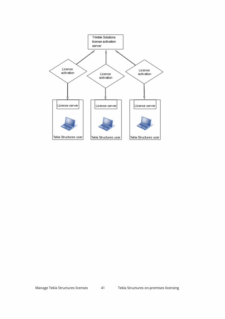
Manage Tekla Structures licenses 41 Tekla Structures on-premises licensing

Example 3: Ten Tekla Structures users, necessary licenses activated on acommon license server and one user's computer
There are ten Tekla Structures users in a compan
y.Because the users use different configurations, the company uses a commonlicense server.
• The company has an internal policy for license use containing regulationsfor managing the licenses.
• One of the main users is assigned as the license server administrator. Theadministrator installs the license server and informs the other users of thehostname and port number of the server. The license server administratoralso performs other server maintenance duties.
• One of the users travels a lot and needs Tekla Structures on the journeys. Alicense server is installed separately on the user’s computer, so the userdoes not need to borrow a license or use a VPN connection for offline useof Tekla Structures.
• Other users borrow licenses from the license server when they need to useTekla Structures offline.
Manage Tekla Structures licenses 42 Tekla Structures on-premises licensing

Example 4: Fifty Tekla Structures users in two offices, necessary licensesactivated on two separate servers
There are fifty Tekla Structures users in two separate offices. Both offices havetheir own license servers.
• Both offices have assigned license server administrators. The license serveradministrators install the license servers and perform license servermaintenance duties.
• The company has an internal policy for using licenses. The policy contains,for example, the rules that define who is allowed to borrow licenses.
• Because the amount of Tekla Structures users is large, the license serveradministrators create tekla.opt options files for controlling the accessrights for different licenses.
• Only a couple of users need to use Tekla Structures offline. The licenseserver administrators modify the option files to enable the licenseborrowing only for those users who need to borrow licenses.
• If one server fails, the users can connect to the license server at the otheroffice. If there are licenses available on the license server, the users can usethe licenses.
Manage Tekla Structures licenses 43 Tekla Structures on-premises licensing
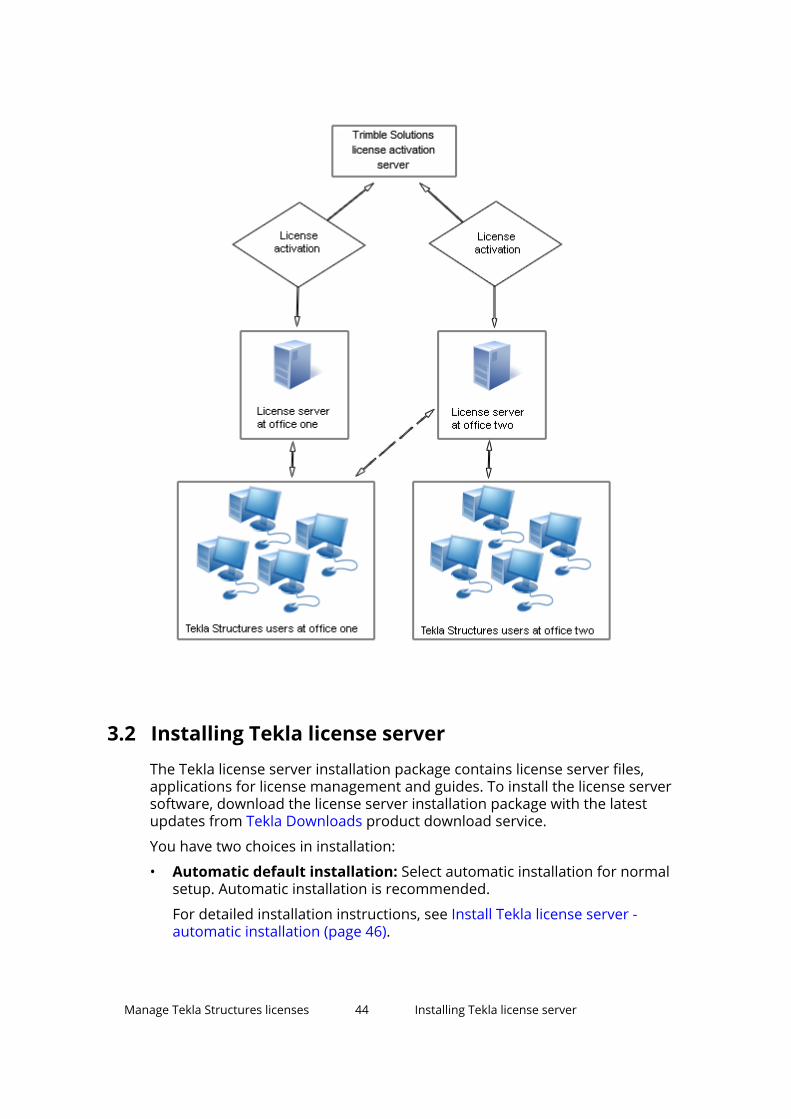
3.2 Installing Tekla license serverThe Tekla license server installation package contains license server files,applications for license management and guides. To install the license serversoftware, download the license server installation package with the latestupdates from Tekla Downloads product download service.
You have two choices in installation:
• Automatic default installation: Select automatic installation for normalsetup. Automatic installation is recommended.
For detailed installation instructions, see Install Tekla license server -automatic installation (page 46).
Manage Tekla Structures licenses 44 Installing Tekla license server

• Manual installation: Use manual installation if you need to separatelyinstall the license server, modify the license file, configure the licenseservice, and start the server software. This is needed if you want to useanother TCP/IP port than the one used in the automatic installation, forexample. Use manual installation only if you are an advanced user ofFlexNet or FlexIm licensing.
For detailed installation instructions, see Install Tekla license server -manual installation (page 47).
Before installing Tekla license server
• Install the license server using administrator's rights.
• Turn off the internal firewall and pause the antispyware/antivirusprotection.
• Ensure that you have access to the Internet. The Internet connection isneeded during the license activation process. An unreliable connectionspeed may cause errors.
• If you are using other FlexNet licensing services, you need to stop thembefore you install the Tekla license server. When you have completedinstalling the Tekla license server, you can restart the other licensingservices.
See also
Problems in Tekla license server installation and connecting to the licenseserver (page 82)
Activate on-premises licenses (page 64)
Allowing Tekla license server to operate through Windows Firewall (page 53)
Which license server version to use
Check the table below to see which license server version to use with yourcurrent Tekla Structures version. Also check if you need to upgrade to a newservice pack or progress release.
For information about updating the license server, see Update the Teklalicense server.
Tekla Structuresversion
License Server 2016SP1
License Server 2017 orlater
2018 or later
2017i - all versions
2017 - all versions
2016i - all versions
Manage Tekla Structures licenses 45 Installing Tekla license server

Tekla Structuresversion
License Server 2016SP1
License Server 2017 orlater
2016 SP5/PR5 or later
2016 up to SP4/PR4 Upgrade to 2016SP5/PR5 or later
21.1 SR7 or later
21.1 up to SR6 Upgrade to 21.1 SR7 orlater
21.1 all PV versions
21.0 or earlier
For instructions on how to install the license server, see .
Install Tekla license server - automatic installation
Before you start license server installation, stop FlexNet licensing services andother licensing services.
For more information about which license server version to use, see Hardwarerecommendations for Tekla 2020 license server.
To install the default setup of the Tekla license server to a computer that doesnot have a previous version of Tekla license server installed:
1. To download the license server installation package with the latestupdates, go to Tekla Downloads, select the Tekla Structures version, andclick All downloads. On the next page, select License server as the Filetype and click Apply filter. Then select the License server.
2. Select the installation language.
3. Select Automatic as the licensing service installation type to install thedefault setup.
4. Select the folder where you want to install the license server andcomplete the installation.
Tekla license server is installed.
In automatic license server installation, the license server address isautomatically set to 27007@your_hostname, where 27007 is the port andyour_hostname is the computer name/hostname. 27007@your_hostname isused as the license server address in every Tekla Structures installation.
When you have installed the license server, you need to do the following:
• Save the entitlement certificate and activate the licenses. For moreinformation, see Activate on-premises licenses (page 64).
Manage Tekla Structures licenses 46 Installing Tekla license server

• Connect Tekla Structures to the license server. For more information, seePreconfigure license server settings for users (page 68).
• You can also change the language of the user interface in Tekla LicenseAdministration Tool by opening the tool and clicking Language.
See also
Install Tekla license server - manual installation (page 47)
Problems in Tekla license server installation and connecting to the licenseserver (page 82)
Problems in Tekla licensing: Error codes and their descriptions (page 96)
Install Tekla license server - manual installationUse manual installation if you want to separately install the license server,modify the license file, configure the license server, and start the license serversoftware. In manual installation of Tekla license server, you also install twofiles: installanchorservice.exe and uninstallanchorservice.exe.You need these files when you manually install or uninstall FlexNet LicensingService.
For example, you need to install the license server manually if the defaultTCP/IP port 27007 is already in use by other services or applications, and youneed to define another port in the license file tekla.lic.
Before you start license server installation, stop other FlexNet licensingservices.
To install the license server manually:
1. To download the license server installation package with the latestupdates, go to Tekla Downloads, select the Tekla Structures version, andclick All downloads. On the next page, select License server as the Filetype and click Apply filter. Then select the License server.
2. Select the installation language.
3. Select Manual as the licensing server installation type and complete theinstallation.
4. Go to the Start menu or Start screen (depending on your Windowsoperating system) and open Command Prompt as administrator.
5. At the command prompt, enter the following commands:
a. cd /d %SYSTEMDRIVE%\Tekla\License\Serverb. installanchorservice.exe
Manage Tekla Structures licenses 47 Installing Tekla license server

The licensing server is installed.
6. Modify the license file to include the hostname or IP address of the server,and the correct TCP/IP port:
a. Open the ..\Tekla\License\Server folder on the servercomputer.
b. Open the tekla.lic (license file) file with a text editor.
c. Replace text localhost on the line SERVER localhost ANY withthe hostname (computer name) or IP address of the license server.
d. Enter the TCP/IP port number after text SERVER server_hostnameANY.
e. Save the changes and close the text editor.
7. Go to Tekla Licensing --> LMTOOLS through the Start menu or Startscreen, depending on your Windows operating system.
8. On the Service/License File tab, click Configuration using Services.
9. On the Config Services tab to configure the licensing service:
a. In the Service Name box, enter the name of the service exactly asfollows: Tekla Licensing Service.
b. Click the Browse buttons to locate the lmgrd.exe (license servermanager), tekla.lic and tekla_debug.log files.
By default, lmgrd.exe, tekla.lic and tekla_debug.log arelocated in the C:\Tekla\License\Server folder.
Note that if you set Path to the debug log file outside the"C:\ProgramData\..." folder, you get an error message:"Windows preferred path <SystemDrive>\ProgramData to storeservice data is not set." This error message can be ignored.
c. Select the Use Services check box to run the licensing service as aWindows service.
d. Select the Start Server at Power Up check box to start the licensingservice automatically after Windows startup.
e. Click Save Service to save the settings.
Manage Tekla Structures licenses 48 Installing Tekla license server

10. Go to the Start/Stop/Reread tab and click Start Server to start thelicense server.
11. Go to the Server Status tab and click Perform Status Enquiry.
In the status list, the line License server status shows the TCP/IPport and hostname of the license server.
Now you can activate the licenses and connect Tekla Structures to thelicense server.
You can also change the language of the user interface in Tekla LicenseAdministration Tool by opening the tool and clicking Language.
Manage Tekla Structures licenses 49 Installing Tekla license server

See also
Modify the license file tekla.lic manually (page 50)
Activate on-premises licenses (page 64)
Configure Tekla license server manually (page 51)
Problems using LMTOOLS in Tekla licensing (page 91)
Problems in Tekla licensing: Error codes and their descriptions (page 96)
Modify the license file tekla.lic manually
If you selected the Automatic installation option, the license server is set toyour hostname: 27007@server_hostname (port@hostname).
The licensing system automatically searches for an available TCP/IP port anduses the first available port detected. The Automatic installation sets the portto 27007.
You need to modify the tekla.lic license file if you:
• Select the Manual license server installation option
• Want to change the TCP/IP port of the licensing server
• Want to use the IP address of your computer instead of the hostname
To modify the license file tekla.lic manually:
1. Go to the ..\Tekla\License\Server folder on the server computer.
2. Open the tekla.lic file in a text editor.
3. Make the necessary changes:
• To use hostname or IP address: Replace text on the first line betweenwords SERVER and ANY with the hostname or IP address of yourlicense server.
Do not delete texts SERVER and ANY when you enter the hostname orIP address of the license server.
The following formats are valid:
Hostname:server_hostnameDomain name: server_hostname.mycompany.comIP address: 10.0.0.12
Manage Tekla Structures licenses 50 Installing Tekla license server

You can check the hostname of the license server in LMTOOLS on theSystem Settings tab. Go to Tekla Licensing --> LMTOOLS through theStart menu or Start screen, depending on your Windows operatingsystem.
• To set the TCP/IP port manually: Enter the TCP/IP port number aftertext SERVER server_hostname ANY.
The port number can be any free port in the range of 0 - 64000.
4. Save the changes and close the text editor.
5. Restart the Tekla Licensing Service in LMTOOLS or Windows Services forthe changes to take effect.
See also
Install Tekla license server - manual installation (page 47)
Manage Tekla Structures licenses 51 Installing Tekla license server
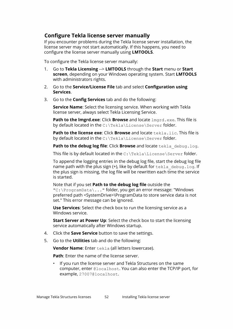
Configure Tekla license server manuallyIf you encounter problems during the Tekla license server installation, thelicense server may not start automatically. If this happens, you need toconfigure the license server manually using LMTOOLS.
To configure the Tekla license server manually:
1. Go to Tekla Licensing --> LMTOOLS through the Start menu or Startscreen, depending on your Windows operating system. Start LMTOOLSwith administrators rights.
2. Go to the Service/License File tab and select Configuration usingServices.
3. Go to the Config Services tab and do the following:
Service Name: Select the licensing service. When working with Teklalicense server, always select Tekla Licensing Service.
Path to the lmgrd.exe: Click Browse and locate lmgrd.exe. This file isby default located in the C:\Tekla\License\Server folder.
Path to the license exe: Click Browse and locate tekla.lic. This file isby default located in the C:\Tekla\License\Server folder.
Path to the debug log file: Click Browse and locate tekla_debug.log.
This file is by default located in the C:\Tekla\License\Server folder.
To append the logging entries in the debug log file, start the debug log filename path with the plus sign (+), like by default for tekla_debug.log. Ifthe plus sign is missing, the log file will be rewritten each time the serviceis started.
Note that if you set Path to the debug log file outside the"C:\ProgramData\..." folder, you get an error message: "Windowspreferred path <SystemDrive>\ProgramData to store service data is notset." This error message can be ignored.
Use Services: Select the check box to run the licensing service as aWindows service.
Start Server at Power Up: Select the check box to start the licensingservice automatically after Windows startup.
4. Click the Save Service button to save the settings.
5. Go to the Utilities tab and do the following:
Vendor Name: Enter tekla (all letters lowercase).
Path: Enter the name of the license server.
• If you run the license server and Tekla Structures on the samecomputer, enter @localhost. You can also enter the TCP/IP port, forexample, 27007@localhost.
Manage Tekla Structures licenses 52 Installing Tekla license server

• If you run the license server and Tekla Structures on separatecomputers, enter the hostname of the license server, for example,@server_hostname.
• You can also enter the TCP/IP port of the license server, for example,27007@server_hostname. You must define the port if you useanother port than the default port.
• You can also enter several license servers. Separate the server nameswith a semicolon. For example,27007@server_hostname;27007@localhost.
6. Click the Override Path button to replace the existing license serversdisplayed in the status list on the Server Status tab.
7. Go to the Start/Stop/Reread tab and start the license server by clickingStart Server.
The status bar should display a message telling that server start wassuccessful.
8. Go to the Server Status tab and enquire the license server status byclicking Perform Status Enquiry.
The status list displayes the TCP/IP port and hostname of the license server.The list should indicate that license server is up and vendor daemon tekla isup. The list also displays all the activated licenses on the server.
See also
Installing Tekla license server (page 44)
Problems in Tekla licensing: Error codes and their descriptions (page 96)
3.3 Allowing Tekla license server to operate throughWindows FirewallWhen you set up Tekla license server in your network, you may also need toconfigure the firewall and antivirus settings:
• You need to allow the applications tekla.exe and lmgrd.exe to operatethrough the firewall on the license servers and on the client computers.
Manage Tekla Structures licenses 53 Allowing Tekla license server to operate throughWindows Firewall

• The internal firewall at your company must allow the communicationbetween the license server computer and the computers with TeklaStructures.
• In addition to allowing the exceptions in your actual firewall, you may needto configure exceptions for Windows Firewall. Windows Firewall may be seton without you being aware of it, because some Windows updates mayautomatically turn on the Windows Firewall.
For instructions on how to modify the firewall settings so that the WindowsFirewall on the license server allows licensing traffic, see:
• Allow exceptions in firewall for lmgrd.exe and tekla.exe (page 54)
• Allow traffic in fixed TCP/IP ports (page 55)
In addition to Windows Firewall, the information given also applies to firewallsfrom other vendors.
Allow exceptions in firewall for lmgrd.exe and tekla.exeYou need to allow the applications tekla.exe and lmgrd.exe to operatethrough the firewall on the license server computer to enable licensing traffic.
To allow exceptions for lmgrd.exe and tekla.exe on the license servercomputer:
1. Press the Windows logo key + R on your keyboard to show the Rundialog box, then type firewall.cpl and press Enter.
2. In the left pane, click Allow a program or feature through WindowsFirewall or Allow an app or feature through Windows Firewall(depending on the operating system).
3. In Allowed programs or Allowed apps (depending on the operatingsystem), click Change settings.
Administrator permission is required. If you're prompted for anadministrator password or confirmation, enter the password or confirm.
4. Click Allow another program or Allow another app (depending on theoperating system).
5. Click Browse to browse for the \Server folder on the computer, selectlmgrd.exe and click Open.
By default, the path is ...\Tekla\License\Server.
6. Click Add to add lmgrd.exe to the Allowed programs or Allowed appsand features list (depending on the operating system).
7. Select both Home/Work (Private) or Private (depending on theoperating system) and Public check boxes next to lmgrd.exe.
8. Allow the exceptions also for tekla.exe by repeating the steps 4 – 7.
Manage Tekla Structures licenses 54 Allowing Tekla license server to operate throughWindows Firewall

9. Click OK to confirm the changes.
See also
Allowing Tekla license server to operate through Windows Firewall (page 53)
Allow traffic in fixed TCP/IP portsYou need to modify the firewall settings to allow traffic through fixed TCP/IPport.
To allow traffic in fixed TCP/IP ports in Windows on the license servercomputer:
1. Ensure that no other software or service is using the ports that you areabout to set fixed.
Use the command line command netstat -anp TCP to find out whichports are in use.
The numbers in the Local Address column after the colon (:) are the portnumbers that are in use.
2. Browse for tekla.lic, and open it using a text editor.
By default, the path is ..\Tekla\License\Server.
3. To set a fixed port for lmgrd.exe, enter the TCP/IP port number at theend of the SERVER row.
The Automatic installation option sets the port to 27007.
Manage Tekla Structures licenses 55 Allowing Tekla license server to operate throughWindows Firewall

4. Enter the text port=free_port at the end of the VENDOR row, forexample, port=1234.
Defining the TCP/IP port number on the VENDOR row may slow down therestart time of Tekla Licensing Service.
5. Save the changes and close tekla.lic.
6. Update your license server with the changes:
a. Go to Tekla Licensing --> LMTOOLS through the Start menu or Startscreen, depending on your Windows operating system.
b. On the Service/License File tab, ensure that Configuration usingservices and Tekla Licensing Service are selected.
Manage Tekla Structures licenses 56 Allowing Tekla license server to operate throughWindows Firewall
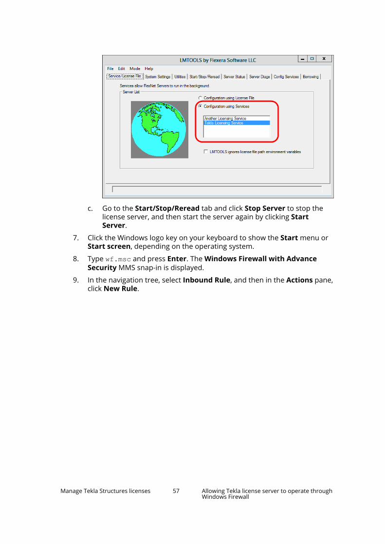
c. Go to the Start/Stop/Reread tab and click Stop Server to stop thelicense server, and then start the server again by clicking StartServer.
7. Click the Windows logo key on your keyboard to show the Start menu orStart screen, depending on the operating system.
8. Type wf.msc and press Enter. The Windows Firewall with AdvanceSecurity MMS snap-in is displayed.
9. In the navigation tree, select Inbound Rule, and then in the Actions pane,click New Rule.
Manage Tekla Structures licenses 57 Allowing Tekla license server to operate throughWindows Firewall
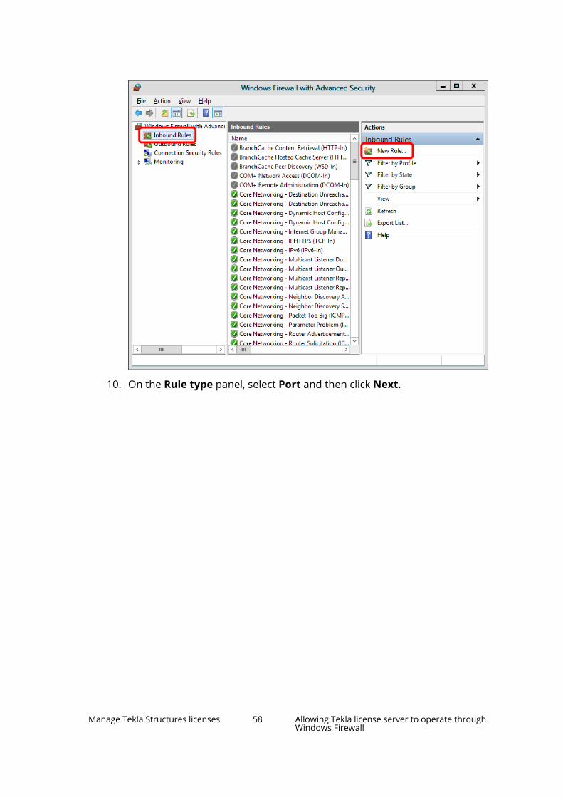
10. On the Rule type panel, select Port and then click Next.
Manage Tekla Structures licenses 58 Allowing Tekla license server to operate throughWindows Firewall
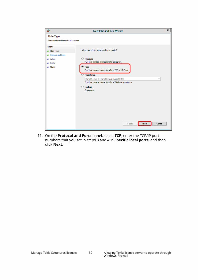
11. On the Protocol and Ports panel, select TCP, enter the TCP/IP portnumbers that you set in steps 3 and 4 in Specific local ports, and thenclick Next.
Manage Tekla Structures licenses 59 Allowing Tekla license server to operate throughWindows Firewall
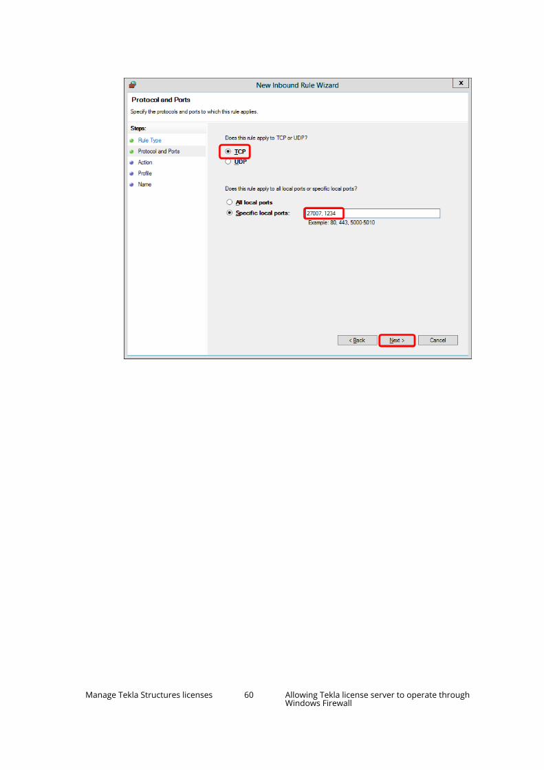
Manage Tekla Structures licenses 60 Allowing Tekla license server to operate throughWindows Firewall
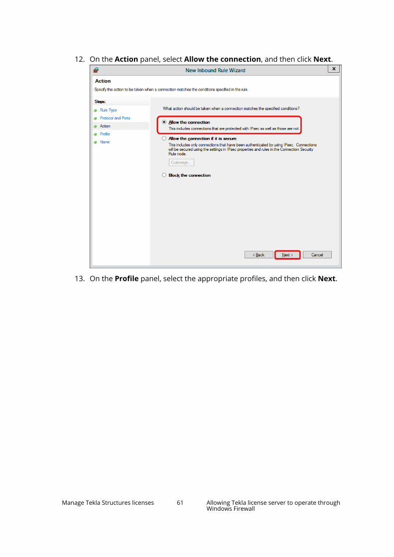
12. On the Action panel, select Allow the connection, and then click Next.
13. On the Profile panel, select the appropriate profiles, and then click Next.
Manage Tekla Structures licenses 61 Allowing Tekla license server to operate throughWindows Firewall

14. On the Name panel, enter the name of the rule, and then click Finish.
Manage Tekla Structures licenses 62 Allowing Tekla license server to operate throughWindows Firewall

The rule is created and automatically enabled.
Manage Tekla Structures licenses 63 Allowing Tekla license server to operate throughWindows Firewall

Tekla Structures
Allow exceptions in firewall for lmgrd.exe and tekla.exe (page 54)
Allowing Tekla license server to operate through Windows Firewall (page 53)
3.4 Activate on-premises licensesYou need to activate the on-premises licenses on the license server to be ableto use them. There is no activation for online licenses.
How license activation works
When you activate on-premises licenses, your license server contacts theactivation server at Trimble Solutions, and the license rights are transferred tothe license server in your company network or on your computer. You can
Manage Tekla Structures licenses 64 Activate on-premises licenses

activate licenses in Tekla License Administration Tool, which is installedtogether with the license server.
• Internet access is required in license activation because the license serverat your company needs to contact the activation server at TrimbleSolutions.
• The activation server at Trimble Solutions tracks the activation status ofyour licenses. You are not allowed to activate any version of the samelicense again without first deactivating it. Deactivate the licenses beforeyou make any major changes to the computer that runs the Tekla licenseserver.
• You do not need to activate all the licences at once. You can activate part ofthe licenses now and part of the licenses later on some other computer, forexample. Different configurations and different versions need to beselected for activation separately.
Activate licenses
To activate an on-premises license, you must have the corresponding licenseentitlement certificate file EntitlementCertificate.html. The entitlementcertificate is sent in an e-mail to the person in your organization who hasmade the license purchase, or to someone they have named as the contactperson. The entitlement certificate states the configurations, quantities andidentifiers of the licenses you are entitled to use.
• We recommend that you save the entitlement certificate fileEntitlementCertificate.html to the ..\Tekla\License\Serverfolder. You will need the file again if you later need to move the licenses toa different computer.
If you have licenses in several entitlement files, rename the files asnecessary to avoid overwriting.
• You can activate licenses using either manual or automatic servernotification. Do not use automatic notification if you are using some otherFlexNet license and license server administration tool, such as FlexNetManager. Otherwise, we recommend using automatic notification. You canfind the instructions for both procedures below.
Activate on-premises licenses using automatic servernotificationYou can activate Tekla Structures on-premises licenses in Tekla LicenseAdministration Tool, which is included in the license server installation. Toactivate the license, the license server at your company contacts the activationserver at Trimble Solutions through the internet. Online licenses do not needto be activated.
Manage Tekla Structures licenses 65 Activate on-premises licenses

NOTE Do not use automatic notification if you are using some other FlexNetlicense and license server administration tool, such as FlexNetManager. To notify the license server about license changes manually,see Activate on-premises licenses (page 64).
To activate the licenses and notify the license server automatically:
1. Go to Tekla Licensing --> Tekla License Administration Tool throughthe Start menu or Start screen, depending on your Windows operatingsystem.
2. Make sure the automatic license server notification is enabled. Check the
status on the Notify Server button in the toolbar and click thebutton if necessary.
3. Click Open and open the EntitlementCertificate.html file thatcontains the license. The license information is displayed in the EntitledLicenses area.
4. Click the Activate cell and select the number of licenses to activate.
5. Click the Activate button.
Your license server contacts the license activation server at TrimbleSolutions.
• The activated licenses are displayed in the Activated Licenses area.
• We recommend that you back up the trusted storage (..\ProgramData\FLEXnet\) in a safe place away from the computer running the licenseserver. Backups can help you restore your licenses on the same server ifactive licenses are accidentally erased.
• When you open Tekla License Administration Tool later on, it detectsexpired and broken licenses you may have and asks if you want todeactivate or repair them. If you select Yes, an automatic deactivation orrepair is run.
See also
Problems in Tekla license activation (page 85)
Problems in Tekla licensing: Error codes and their descriptions (page 96)
Manage Tekla Structures licenses 66 Activate on-premises licenses

Activate on-premises licenses using manual servernotificationYou have to use manual notification if you are using some other FlexNetlicense and license server administration tool, such as FlexNet Manager.
To activate the licenses and notify the server manually:
1. Go to Tekla Licensing --> Tekla License Administration Tool throughthe Start menu or Start screen, depending on your Windows operatingsystem.
2. Make sure the automatic license server notification is disabled. Check the
status on the Notify Server button in the toolbar and click the buttonif necessary.
3. Click Open and open the EntitlementCertificate.html file thatcontains the license. The license information is displayed in the EntitledLicenses area.
4. Click the Activate cell and select the number of licenses to activate.
5. Click the Activate button.
Your license server contacts the license activation server at TrimbleSolutions.
6. Next, you need to notify the server. This has to be done each time youactivate a license.
a. Go to Tekla Licensing --> LMTOOLS through the Start menu or Startscreen, depending on your Windows operating system.
b. On the Service/License File tab, ensure that Configuration usingservices and Tekla Licensing Service are selected.
c. In the LMTOOLS dialog box, go to the Start/Stop/Reread tab.
d. Click ReRead License File.
The license server reads the license information.
• The activated licenses are displayed in the Activated Licenses area.
• We recommend that you back up the trusted storage (..\ProgramData\FLEXnet\) in a safe place away from the computer running the license
Manage Tekla Structures licenses 67 Activate on-premises licenses
server. Backups can help you restore your licenses on the same server ifactive licenses are accidentally erased.
• When you open Tekla License Administration Tool, it detects expired andbroken licenses you may have and asks if you want to repair or deactivatethem. If you select Yes, an automatic deactivation or repair is run.
See also
Problems in Tekla license activation (page 85)
Problems in Tekla licensing: Error codes and their descriptions (page 96)
3.5 Preconfigure license server settings for usersWhen the license server is on a separate server in the network, TeklaStructures connects to the license server to fetch a license. To be able to dothis, the license server address must be defined on each computer. This canbe done by typing in the address when starting the software for the first timeor you can include the address in an intialization file that you distribute as partof your customized installation. You can also predefine the license,environment and role with a customized startup shortcut and intialization file.
By default, when Tekla Structures starts for the first time on a computer, thesystem asks for the address of your Tekla license server unless TeklaStructures can find a license server with an active license installed on the samecomputer. To avoid this manual process, you can include the Tekla licenseserver address in your customized configuration. Similarly, you can also selectthe license for the user, and if you also preset the environment and role, theuser does not need to make any selections when starting Tekla Structures. To
Manage Tekla Structures licenses 68 Preconfigure license server settings for users

set up this for your users, see the instructions in Implementation guide foradministrators (page 110).
See also
Modify the license file tekla.lic manually (page 50)
3.6 Deactivate on-premises licensesLicense deactivation releases license rights from a license server, which allowsyou to activate a new version of the same license or to activate the samelicense on different hardware. There is no deactivation for online licenses.
The activation server at Trimble Solutions tracks the activation status of youron-premises licenses. You are not allowed to activate any version of the samelicense again without first deactivating it.
When you deactivate licenses, your license server contacts the activationserver at Trimble Solutions, and the license rights are transferred away fromyour Tekla license server.
When you need to deactivate licenses
• Before you upgrade or reinstall the operating system or before you changethe hardware components of any computer that has a license serverinstallation with active licenses.
• Before you activate a replacement license, including licenses that entitleyou to run a new version of Tekla Structures and replacement licenses forany temporary licenses.
Manage Tekla Structures licenses 69 Deactivate on-premises licenses

• Before you activate the same license on a different license server, forexample, when you want to change from one license server computer toanother.
• Before you change the IP address on the license server computer.
• Before you format the hard drive of or decommission your servercomputer.
When you do not need to deactivate licenses
You do not need to deactivate licenses before uninstalling and reinstalling theTekla license server software.
Deactivate on-premises licensesThe information on this page is not valid for online licenses.
• Internet access is required in license deactivation.
• Deactivation must be done on the license server containing the activelicense. If your license server fails and cannot be recovered, contact yourlocal support for assistance.
To deactivate licenses:
1. Start the Tekla License Administration Tool app with administrator rights.This tool is installed together with the Tekla license server and you canfind it through the Windows Start menu on the computer that is hostingyour license server.
2. In the Tekla License Administration Tool dialog box, go to the Statistictab and ensure that no one is using the licenses.
NOTE Before you deactivate licenses, ensure that the licenses are not inuse or borrowed. The borrowed licenses must be returned beforethey can be deactivated.
3. If you have not activated the automatic server notifications (the NotifyServer option in Tekla License Administration Tool), you need to stopthe license server manually in LMTOOLS:
a. Go to Tekla Licensing --> LMTOOLS through the Start menu or Startscreen, depending on your Windows operating system. StartLMTOOLS with administrator rights.
Manage Tekla Structures licenses 70 Deactivate on-premises licenses
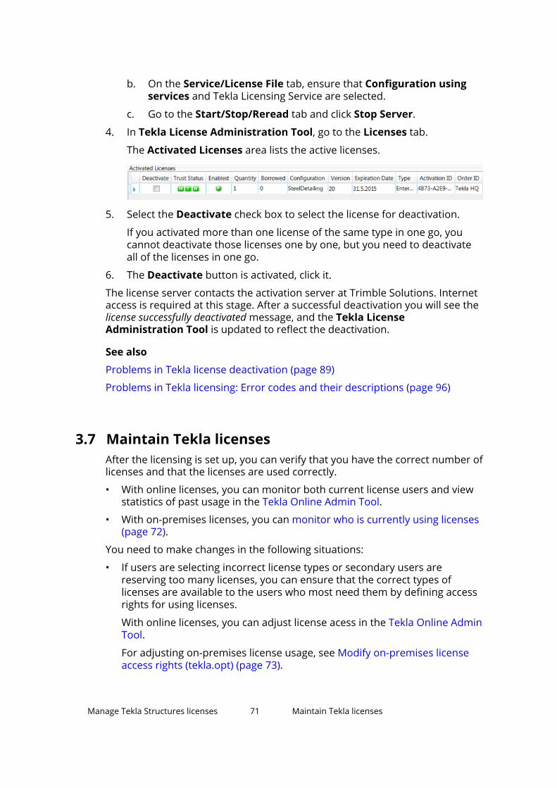
b. On the Service/License File tab, ensure that Configuration usingservices and Tekla Licensing Service are selected.
c. Go to the Start/Stop/Reread tab and click Stop Server.
4. In Tekla License Administration Tool, go to the Licenses tab.
The Activated Licenses area lists the active licenses.
5. Select the Deactivate check box to select the license for deactivation.
If you activated more than one license of the same type in one go, youcannot deactivate those licenses one by one, but you need to deactivateall of the licenses in one go.
6. The Deactivate button is activated, click it.
The license server contacts the activation server at Trimble Solutions. Internetaccess is required at this stage. After a successful deactivation you will see thelicense successfully deactivated message, and the Tekla LicenseAdministration Tool is updated to reflect the deactivation.
See also
Problems in Tekla license deactivation (page 89)
Problems in Tekla licensing: Error codes and their descriptions (page 96)
3.7 Maintain Tekla licensesAfter the licensing is set up, you can verify that you have the correct number oflicenses and that the licenses are used correctly.
• With online licenses, you can monitor both current license users and viewstatistics of past usage in the Tekla Online Admin Tool.
• With on-premises licenses, you can monitor who is currently using licenses(page 72).
You need to make changes in the following situations:
• If users are selecting incorrect license types or secondary users arereserving too many licenses, you can ensure that the correct types oflicenses are available to the users who most need them by defining accessrights for using licenses.
With online licenses, you can adjust license acess in the Tekla Online AdminTool.
For adjusting on-premises license usage, see Modify on-premises licenseaccess rights (tekla.opt) (page 73).
Manage Tekla Structures licenses 71 Maintain Tekla licenses
• If you have on-premises licenses, you need to deactivate your existinglicenses (page 69):
• When you start using a new version of Tekla Structures, which requiresactivating renewed licenses.
• Before you activate a changed version of the same license (for example,the number of concurrent users is changed).
• Before you make hardware changes that affect the license server.
• If you want to move the licenses to a different license server (page 78).
• If your on-premises licenses become untrusted or disabled, you can repairthem a limited number of times as explained in Repair an on-premiseslicense (page 79).
See also
Troubleshoot Tekla licensing (page 80)
Monitor Tekla Structures license useWith online licenses, you can monitor both current license users and viewstatistics of past usage in theTekla Online Admin Tool. For instructions onusing the Admin Tool, see Manage Trimble Identities and Tekla Onlinelicenses. With on-premises licenses, you can view current license usage asinstructed below.
The LMTOOLS application requires Windows administrator privileges to run.
With online licenses, you can monitor both current license users and viewstatistics of past usage in the Tekla Online Admin Tool. For instructions onusing the Admin Tool, see Manage Trimble Identities and Tekla Onlinelicenses.
You can get a report of how many Tekla Structures on-premises licenses arecurrently in use in your company with the LMTOOLS software that is deliveredwith the Tekla license server.
To view which licenses are currently in use:
1. Go to Tekla Licensing --> LMTOOLS through the Start menu or Startscreen, depending on your Windows operating system.
2. If the correct Tekla license server is not defined, switch to the Utilities taband add the license server path:
a. Type tekla in the Vendor Name box.
b. Type your license server address as port@host in the Path box.
c. Click Override Path.
Manage Tekla Structures licenses 72 Maintain Tekla licenses

3. On the Server Status tab, click Perform Status Enquiry. You will receivea listing of how many licenses and which configurations are activated onthe server, and how many of the licenses are in use at the moment ofenquiry.
The status enquiry uses abbreviations of Tekla Structures configurations,which are explained here (page 75). You can also find the description ofthe abbreviations in your entitlement certificate or in Tekla LicenseAdministration Tool.
For a comprehensive description of the status enquiry syntax, see .
Modify on-premises license access rights (tekla.opt)The Tekla Structures on-premises license server administrator may grantdifferent users and user groups different rights to use licenses by modifyingthe tekla.opt options file. This can prevent situations where there are nolicenses available for users that need them because someone else hasreserved or borrowed a license that they do not really need.
The information on this page is not valid for online licenses.
The licensing options file tekla.opt is located in the ..\Tekla\License\Server folder.
The most common configuration options include the following:
• You can define the access rights for specific usernames or hostnames/IPaddresses either individually or using groups that you define. You can usethe same username or hostname in several groups.
Manage Tekla Structures licenses 73 Maintain Tekla licenses
• You can reserve a number of licenses for a specific configuration (e.g.,Steel detailing) for exclusive use by a specific user or user group. Ifnecessary, the users in the group can reserve more licenses than thereserved quota. Other users can only use one of the remaining freelicenses outside the reserved quota.
• You can define a maximum (max) number of licenses that a user or groupcan simultaneously use. Users who are not included in this limitation canuse any free license.
• You can include (allow) a user or group in the exclusive use of all licensesfor a specific configuration. Other users are prevented from using theconfiguration.
• You can exclude (disallow) specific users from using any licenses for aspecific configuration. All other users are allowed to use the configuration.
• You can include and exclude users from borrowing licenses.
To modify access rights in the tekla.opt file:
1. Go to the ..\Tekla\License\Server folder.
2. Open the tekla.opt file in a text editor.
3. Enter your definitions for license access rights and restrictions.
The definition string consists of the following parts: [keyword] [TeklaStructures feature] [user type] [name]When you write the definition, follow the rules below.
• Note that the options file is case sensitive.
• If you need to define user groups and host groups, define them first.
Use Windows user names when defining user groups and hostnamesor IP addresses when defining host groups.
• Enter one definition per row. A definition consists of the followingthings:
• An options keyword that defines the actions.
• A feature, such as a configuration, that is affected by the keyword.
• The type that is affected by the keyword.
The options are: USER, GROUP, HOST, and HOST_GROUP.
• The name of the user, user group, host, or host group that isaffected by the keyword.
You can use the hostnames or IP addresses of the computers withthe HOST and HOST_GROUP keywords.
• To disable a row in the options file, enter # in the beginning of the row.
Examples of definitions:
Manage Tekla Structures licenses 74 Maintain Tekla licenses

INCLUDE PCD-C USER scarlett (Only the user scarlett is allowed touse the Precast Concrete Detailing configuration.)
RESERVE 1 RCD-C USER vera (One license of the Rebar Detailingconfiguration is reserved for the user vera.)
For details about the allowed keywords and configuration codes togetherwith more examples, Configuration codes and keywords used in accessright definitions (page 75).
4. Save the changes and close the text editor.
5. Go to Tekla Licensing --> LMTOOLS through the Start menu or Startscreen, depending on your Windows operating system.
6. In LMTOOLS, go to the Start/Stop/Reread tab and click the ReReadLicense File button to update the changes in the license file and in theoptions file.
Useful links
For more information about limiting certain Tekla Structures versions tocertain users, see the following Support Article in Tekla User Assistance: Howto limit certain Tekla Structures version to certain users
Configuration codes and keywords used in access right definitionsWhen you define access rights in tekla.opt, you need to use correctabbreviations (codes) for the configurations, otherwise the definitions do notwork. The access rights are defined using certain keywords.
Configuration codes
When you define access rights for different Tekla Structures configurations inthe tekla.opt options file, you need to add a proper code for eachconfiguration in the definition.
NOTE The configuration codes are backward compatible, and the codesused for licensing in older Tekla Structures versions still work.However, the commercial product name of the configuration maychange between versions. For example, the commercial product namefor STDL-C used to be Steel Detailing Limited, but now it is Primary.
The codes for the Tekla Structures configurations are listed below:
Configuration code ConfigurationCM-C Construction ModelingDEV-C DeveloperDFR-C DrafterEDU-C EducationalFUD-C Full
Manage Tekla Structures licenses 75 Maintain Tekla licenses

Configuration code ConfigurationPCD-C Precast Concrete DetailingRCD-C Rebar DetailingSDE-C EngineeringSTD-C Steel DetailingPPC-C Production Planner for ConcreteSTDL-C PrimaryVIE-C Project Viewer
Most common keywords
The most common keywords that are used for defining license access rightsand restrictions in the tekla.opt options file are listed and described below:
Keyword Description Usage informationEXCLUDE Prevent access to a Tekla
Structures configuration.Use with theabbreviation of theconfiguration.
EXCLUDE_ENTITLEMENT Prevent licenseborrowing.
Use with the activationID of the license.
EXCLUDEALL Prevent access to allTekla Structuresconfigurations.
GROUP Define a user group foruse with any options.
Use with Windows usernames (separated withspaces).
HOST_GROUP Define a host group foruse with any options.
Use with computerhostnames or IPaddresses (separatedwith spaces).
INCLUDE Allow a user to use aTekla Structuresconfiguration.
Use with theabbreviation of theconfiguration.
INCLUDE_ENTITLEMENT Allow a user to borrow alicense.
Use with the activationID of the license.
INCLUDEALL Allow a user to use allTekla Structuresconfigurations.
MAX Limit the usage of aconfiguration.
Use with the number oflicenses and theabbreviation of theconfiguration.
Manage Tekla Structures licenses 76 Maintain Tekla licenses

Keyword Description Usage informationRESERVE Reserve licenses for a
user/host or a group ofusers/hosts.
Use with the number oflicenses and theabbreviation of theconfiguration.
• When somebody is allowed to use a configuration with the INCLUDEkeyword, other users are automatically prevented from using theconfiguration.
• When somebody is denied to use a configuration with the EXCLUDEkeyword, other users are automatically allowed to use the configuration.
• If no rules exist, everybody is allowed to use the configuration.
Some examples of definitions in a tekla.opt options file are given below:
Options file definition DescriptionINCLUDE PCD-C USERscarlett
Only the user scarlett is allowed to use thePrecast Concrete Detailing configuration.
EXCLUDE FUD-C USER justin The user justin is not allowed to use theFull configuration. Other users are allowedto use the Full configuration.
GROUP tsusers jessica joeneilINCLUDEALL GROUP tsusers
The users jessica, joe and neil belong tothe group tsusers. Only the group tsusersis allowed to use all configurations.
EXCLUDEALL HOST pcrobert No configuration is allowed to be used onthe computer pcrobert.
INCLUDE_ENTITLEMENTqwer-1234-asdf-5678-zxUSER gwen
Only the user gwen is allowed to borrow alicense whose activation ID is qwer-1234-asdf-5678-zx.
EXCLUDE_ENTITLEMENTrtyu-9876-fghj-5432-cvUSER matt
The user matt is not allowed to borrow alicense whose activation ID is rtyu-9876-fghj-5432-cv.
GROUP students amy chloeandy deanMAX 3 EDU-C GROUPstudents
The users amy, chloe, andy, and deanbelong to the group students. The limit tothe usage of the Educational configurationfor the group students is three licenses.
RESERVE 1 RCD-C USER vera One license of the Rebar Detailingconfiguration is reserved for the user vera.
GROUP STUDENTS user1user2 user3RESERVE 3 VIE-C GROUPSTUDENTS
The users user1 user2 user3 belong to thegroup STUDENTS. 3 licenses of the ProjectViewer configuration are reserved for thegroup STUDENTS.
STUDENTS is a group name.
Manage Tekla Structures licenses 77 Maintain Tekla licenses

Options file definition Descriptionuser1 - user 3 are Windows user namesseparated with spaces.
The number 3 is the number of licenses toreserve.
VIE-C is the configuration code for theProject Viewer configuration.
Note that any licenses reserved for a groupare dedicated to that group. Even whenthat group is not actively using the licenses,the licenses are unavailable to other users.
INCLUDE VIE-C:VENDOR_STRING=Enterprise USER john
Only the user john is allowed to use theProject Viewer configuration which is oftype Enterprise.
Useful links
For more information about limiting certain Tekla Structures versions tocertain users, see the following Support Article in Tekla User Assistance: Howto limit certain Tekla Structures version to certain users
Move licenses between license serversYou can transfer an on-premises license from one license server to another.Moving licenses can be necessary, for example, if you are switching to newhardware or if you want to consolidate licenses from several workstations to acentral server.
The information on this page is not valid for online licenses.
1. Deactivate the licenses that you want to move (page 69) in the TeklaLicense Administration Tool on the computer that currently contains thelicenses.
2. If the license entitlement certificate file containing these licenses is notavailable on the other computer, find the EntitlementCertificate.html file that contains the license and copyit to the computer on which you want to activate the licenses.
• Entitlement certificate files are sent over email. In the installationinstructions, we recommend storing the entitlement files in the licenseserver installation folder (..\Tekla\License\Server\), from whereyou can copy it to the same folder on the other computer.
Manage Tekla Structures licenses 78 Maintain Tekla licenses

• Rename the files as necessary to avoid overwriting differententitlement certificate files with each other.
• There can be several licenses in one file, so you can activate differentlicenses on different computers using the same entitlement certificatefile.
3. Activate the licenses (page 64) in the Tekla License Administration Tool onthe other computer to complete the move.
We recommend that you back up the trusted storage (..\ProgramData\FLEXnet\) in a safe place away from the computer running the licenseserver. Backups can help you restore your licenses on the same server if activelicenses are accidentally erased.
See also
Installing Tekla license server (page 44)
Repair an on-premises licenseIf your on-premises licenses have become untrusted or disabled, they cannotbe used and you need to repair them.
The information on this page is not valid for online licenses.
The license trust status is indicated in the Activated Licenses area in TeklaLicense Administration Tool. If a trust status symbol is green, the informationis trusted, if red, the information is untrusted.
WARNING Because of technical and security reasons, you can repair anActivation ID only a limited number of times, which at themoment is two times a year. Therefore it is important that youinform your local Tekla Structures representative about thelicense repairs you have been performing, and keep count of therepairs.
The status can be one of the following:
• A red H (Host) indicates whether the server has been moved to anothercomputer, or whether the computer hardware has changed radically.
The Host trust status of your license is not trusted:
Manage Tekla Structures licenses 79 Maintain Tekla licenses

NOTE Licenses that have the Host trust status untrusted cannot berepaired.
• A red T (Time) indicates whether the system clock has been tampered with.
The Time trust status of your license is not trusted:
• A red R (Restore) indicates whether the license is obtained from a backupcopy.
The Restore trust status of your license is not trusted:
To repair a license:
1. Go to Tekla Licensing --> Tekla License Administration Tool throughthe Start menu or Start screen, depending on your Windows operatingsystem.
The Activated Licenses area displays the activated licenses.
2. Click Repair.
The license server contacts the activation server at Trimble Solutions.After successful repairing the trust status in Tekla License AdministrationTool dialog box is updated.
For more information about the status of the activated licenses in the trustedstorage, see instructions in the following Support Articles in Tekla UserAssistance:
Checking the status of the activated licenses in the trusted storage
Checking the status of the activated licenses in the trusted storage (includingborrowing info)
Troubleshoot Tekla licensingClick the links below for help in solving problems encountered in the followingareas:
• View and diagnose errors in Tekla Structures license activation,deactivation and borrowing (page 81)
• Problems in Tekla license server installation and connecting to the licenseserver (page 82)
• Problems in FlexNet (page 84)
Manage Tekla Structures licenses 80 Maintain Tekla licenses

• Problems in Tekla license activation (page 85)
• Problems in Tekla license deactivation (page 89)
• Problems in Tekla license borrowing (page 89)
• Problems in Tekla license trusted storage (page 90)
• Problems using LMTOOLS in Tekla licensing (page 91)
• Problems in starting Tekla Structures (page 93)
• Problems with options file tekla.opt (page 95)
For more information about error messages starting with an error code, seeProblems in Tekla licensing: Error codes and their descriptions (page 96).
View and diagnose errors in Tekla Structures license activation,deactivation and borrowingTekla License Administration Tool and Tekla License Borrow Tool both giveerror messages when errors occur. The tools automatically create packages ofall necessary files required for diagnosing the errors.
If you have a problem with activating or deactivating licenses, or borrowing orreturning licenses, Tekla License Administration Tool and Tekla License BorrowTool display an error message in the Activating Licenses(s), DeactivatingLicense(s), Borrowing License(s) or Returning Borrowed License(s) dialogboxes, depending on the subject of the error.
• You can view more detailed information about an error by clicking theView button in an error dialog box.
• Tekla License Administration Tool and Tekla License Borrow Toolautomatically create zip packages of all necessary files required fordiagnosing the errors in the C:\Tekla\License\Server\Reports folderand in the %TEMP%\Tekla License Borrow Tool\Reports folder. ClickBrowse in the error dialog box to browse for the folder containing theerror report package. You can send the package to your local support toget help.
The error report package contains the following files:
tekla_debug.log - Tekla license server debug log file
error.txt - error report, contains error information. The Tekla LicenseBorrow Tool zip package only contains this file.
tekla.opt - access rights options file
tekla.lic - Tekla license file
See also
Troubleshoot Tekla licensing (page 80)
Problems in Tekla licensing: Error codes and their descriptions (page 96)
Manage Tekla Structures licenses 81 Maintain Tekla licenses

Problems in Tekla license server installation and connecting to thelicense server
License server installation fails, and the following message is displayed:"A newer version of this application is already installed on this computer.If you wish to install this version, please uninstall the newer version first.Click OK to exit the wizard."
Reason: You have a newer version the license server installed.
Solution: You should not install an old version of the license server. Check thelatest available license server release on the Tekla Downloads productdownload page.
The license server version is not dependent on Tekla Structures. However, ifyou need to use an older version of the license server for some reason,uninstall the newer version on your computer before installing the olderversion.
License server installation does not finish (no error message)
Reason: Another software using the FlexNet licensing system is running onthe computer.
Solution: Stop all licensing services in LMTOOLS, then install the Tekla licenseserver and restart the licensing services you stopped earlier:
1. Go to Tekla Licensing --> LMTOOLS through the Start menu or Startscreen, depending on your Windows operating system.
2. On the Service/License File tab, ensure that Configuration usingservices is selected, select a license service from the services list, go tothe Start/Stop/Reread tab and click Stop Server.
Do the same for all the services you need to stop.
3. Install the Tekla license server.
4. In LMTOOLS, start the licensing services you stopped earlier.
Problem in license server connection. The following message is displayed:"Error when connecting to the license server. Contact your systemadministrator or try another server".
Reason: This problem is often related to firewall settings.
Solution: Check that your firewall allows the client to contact the licenseserver.
Manage Tekla Structures licenses 82 Maintain Tekla licenses

License library initialization failed with error: The licensing service is notinstalled.
Reason: The error occurs when you are starting Tekla License AdministrationTool, or when you are trying to run serveractutil.exe command line tool.
Solution: If you selected the Manual option for Tekla Licensing Serviceinstallation then you need to manually install FLEXnet licensing service:
1. If you have some other FlexNet licensing service running on the server,stop it before entering the commands.
2. Go to the Start menu or Start screen, depending on your Windowsoperating system, and open Command Prompt as an administrator.
3. At the command prompt, type the following commands:
cd /D full_path_to_installation_directoryFor example, if you install Tekla license server to the default folder, youneed to enter cd /D C:\Tekla\License\Server.
installanchorservice.exe
Cannot connect to the license server.
Solution: For the first time that you connect to the Tekla license server a clientcomputer that has a new version of Tekla Structures installed, you need to dothe following:
• Ensure that both (the client computer and the license server) are in thesame domain.
• Ensure that Local Area Network connection is established. The licenseserver and the client computers need to be in the same Local AreaNetwork.
• Turn off the firewall and pause the antispyware/antivirus protection of yourcomputer.
After the steps above do the following on your company's license server:
1. Make sure that no one is using Tekla Structures (ask all users to closeTekla Structures).
2. Go to C:\Tekla\License\Server and open the tekla.lic file in a texteditor.
3. Add a free TCP/IP port for the licensing service at the end of the first row,if it does not exist by default. Note that the automatic installation optionsets the port by default to 27007.
Example of the first row: SERVER MYSERVER ANY 27007, whereMYSERVER is the license server and 27007 is the port.
Manage Tekla Structures licenses 83 Maintain Tekla licenses
4. Save and close the file after changes.
5. Go to Tekla Licensing --> LMTOOLS through the Start menu or Startscreen, depending on your Windows operating system.
6. On the Service/License File tab, ensure that Configuration usingservices and Tekla Licensing Service are selected.
7. On the Start/Stop/Reread tab, click Stop Server. Wait couple of secondsand click on Start Server.
After defining the server and the port, do the following on your TeklaStructures workstations:
1. Start Tekla Structures.
2. When you are asked for a server, add the port to the front of the serverdefinition and click OK.
Example: 27007@MYSERVER
Cannot start the Tekla licensing service.
Reason: The tekla-debug.log file may be locked, thus preventing theservice from starting.
Solution: Delete the tekla-debug.log and restart the computer.
See also
Problems in Tekla licensing: Error codes and their descriptions (page 96)
Installing Tekla license server (page 44)
Allowing Tekla license server to operate through Windows Firewall (page 53)
Problems in FlexNet
An internal error occurred. FlexNet internal error.
Reason: There is a problem with the Tekla license server installation.
Solution: This error can often be fixed by performing the steps below:
1. Uninstall all existing Tekla license server installations.
2. Check that all the files are deleted from the Tekla license serverinstallation folder: .. \Tekla\License\Server.
3. Install the latest Tekla license server. Check for the latest version in TeklaDownloads.
Manage Tekla Structures licenses 84 Maintain Tekla licenses

See also
Installing Tekla license server (page 44)
Problems in Tekla licensing: Error codes and their descriptions (page 96)
Problems in Tekla license activation
The following message is displayed: "Error reading entitlement file".
Reason: The .NET Framework is not working for some reason.
Solution: Reinstall the existing .NET Framework, or install the latest .NETFramework version that is available for your operating system.
License activation fails, and the following message is displayed: "Unableto activate more licenses than you are entitled to".
Reason: There are a couple of possible reasons for the problem:
• You may have activated licenses on another computer. You cannot activatemore licenses than you are entitled to.
• You tried to activate a renewed temporary license or a permanent licensewithout deactivating the previous temporary license.
Solution: There are two possible solutions:
• Deactivate a license on another computer and then activate the license onyour computer.
• Deactivate the existing temporary license and then activate the succeedinglinked license.
For more information about deactivating licenses, see Deactivate on-premiseslicenses (page 69).
The amount of activated licenses in Tekla License Administration Tooland LMTOOLS does not match.
Manage Tekla Structures licenses 85 Maintain Tekla licenses
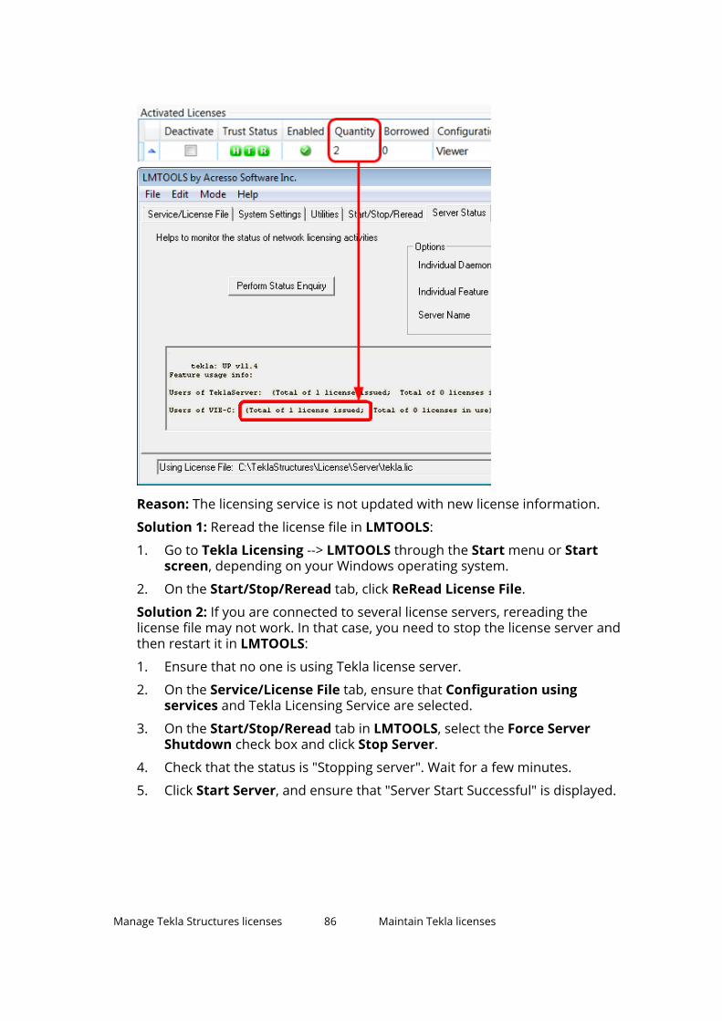
Reason: The licensing service is not updated with new license information.
Solution 1: Reread the license file in LMTOOLS:
1. Go to Tekla Licensing --> LMTOOLS through the Start menu or Startscreen, depending on your Windows operating system.
2. On the Start/Stop/Reread tab, click ReRead License File.
Solution 2: If you are connected to several license servers, rereading thelicense file may not work. In that case, you need to stop the license server andthen restart it in LMTOOLS:
1. Ensure that no one is using Tekla license server.
2. On the Service/License File tab, ensure that Configuration usingservices and Tekla Licensing Service are selected.
3. On the Start/Stop/Reread tab in LMTOOLS, select the Force ServerShutdown check box and click Stop Server.
4. Check that the status is "Stopping server". Wait for a few minutes.
5. Click Start Server, and ensure that "Server Start Successful" is displayed.
Manage Tekla Structures licenses 86 Maintain Tekla licenses

TIP To avoid the problem in the future, ensure that the license server isautomatically notified when you activate, deactivate, or repair licenses.
To enable the automatic notification functionality in Tekla LicenseAdministration Tool, click the Notify Server button.
For more information about starting and stopping server and rereadingthe license file, see .
For more information about activating licenses, see Activate on-premiseslicenses (page 64).
No warning is displayed, even though the temporary license will expirewithin one month.
Reason: The expiry warning message appears only when someone uses theexpiring license. Probably there are several permanent licenses (that havebeen activated first) and some temporary licenses that have been activatedafter the permanent ones.
When somebody starts Tekla Structures, the system uses licenses in the orderof activation. For example, if you have 10 permanent and 2 temporarylicenses, all 10 licenses must be in use before someone obtains the temporarylicense, and receives the warning about the expiring license.
When you try to open the entitlement certificate in Tekla LicenseAdministration Tool, nothing is shown.
Reason 1: You have not downloaded the attached entitlement certificate fromyour e-mail application, but opened the certificate in an Internet browser andsaved it as an .html file from the browser.
Solution: Open the e-mail containing the entitlement certificate attachmentEntitlementCertificate.html. Download the entitlement certificate tothe ..\Tekla\License\Server folder from e-mail. Then try to open it againin Tekla License Administration Tool by clicking Open.
For more information, see Activate on-premises licenses (page 64).
Reason 2: The virus protection system of your computer has removed theTrimble Solutions logo from the license entitlement certificate.
Solution: The sender of the entitlement certificate should zip the entitlementcertificate file. Unzip the entitlement certificate file on the computer where thelicenses are going to be activated.
License was activated successfully, but the following error message isdisplayed when you run the command line command ”serveractutil -view”: "Activation library initialization failed."
Manage Tekla Structures licenses 87 Maintain Tekla licenses

Reason: The license server installation was not successful.
Solution: Do the following:
1. Stop other FlexNet licensing services in LMTOOLS.
2. Run the installanchorservice.exe at the command prompt, restartthe license server.
After doing this you will be able to activate your licenses and use TeklaStructures.
If the above did not work, you need to uninstall the license server and reinstallthe recent version once again with administrator rights.
For more information about uninstalling and installing the license server, seeand Installing Tekla license server (page 44).
The automatic notification functionality in Tekla License AdministrationTool does not work: nothing happens when you click the Notify Serverbutton
Reason: One of the reasons why the Notify Server button does not work inTekla License Administration Tool might be that Tekla Licensing Service is notstarted on the computer.
Solution: To solve the issue, open Windows Control Panel --> AdministrativeTools --> Services . Ensure that the Tekla Licensing Service status is Running .The Startup Type of the service should be set either to Automatic or toAutomatic (Delayed Start).
Your licenses no longer appear as activated licenses, or old versionlicenses are activated, but they do not work.
Reason: Windows system restore may cause problems for licensing. For moreinformation, see Windows system restore might affect your model andlicensing.
Useful links
For more information about the status of the activated licenses in the trustedstorage, see instructions in the following Support Articles in Tekla UserAssistance:
Checking the status of the activated licenses in the trusted storage
Checking the status of the activated licenses in the trusted storage (includingborrowing info)
See also
Problems in Tekla licensing: Error codes and their descriptions (page 96)
Manage Tekla Structures licenses 88 Maintain Tekla licenses

Problems in Tekla license deactivation
Unable to select a license for deactivation.
Reason: You cannot select a license for deactivation if the license is stillborrowed.
Solution: Return the license and then deactivate the license.
See also
Problems in Tekla licensing: Error codes and their descriptions (page 96)
Deactivate on-premises licenses (page 69)
Problems in Tekla license borrowing
Unable to select a date from the calendar in the Borrow Until box.
Reason: The maximum borrowing period is one month.
Solution: In Tekla License Borrow Tool, select a date that is within one monthfrom the date of borrowing:
1. Go to Tekla License Borrow --> Tekla License Borrow Tool through theStart menu or Start screen, depending on your Windows operatingsystem.
2. In the Products area, click the Borrow Until box and select from thecalendar the expiration date that is within one month from the date ofborrowing.
Tekla Structures does not start up with the borrowed license.
Problem: You borrowed a license and disconnected from the network. Whenyou open Tekla Structures, the licensing dialog box is displayed, but TeklaStructures does not find the borrowed license.
Solution: If Tekla Structures does not start up with the borrowed license,please type only an asterisk character (*) into the server box in the licensingdialog box.
This will force Tekla Structures to search for all possible locations for thelicense. It might take some time until it finds the license.
Manage Tekla Structures licenses 89 Maintain Tekla licenses
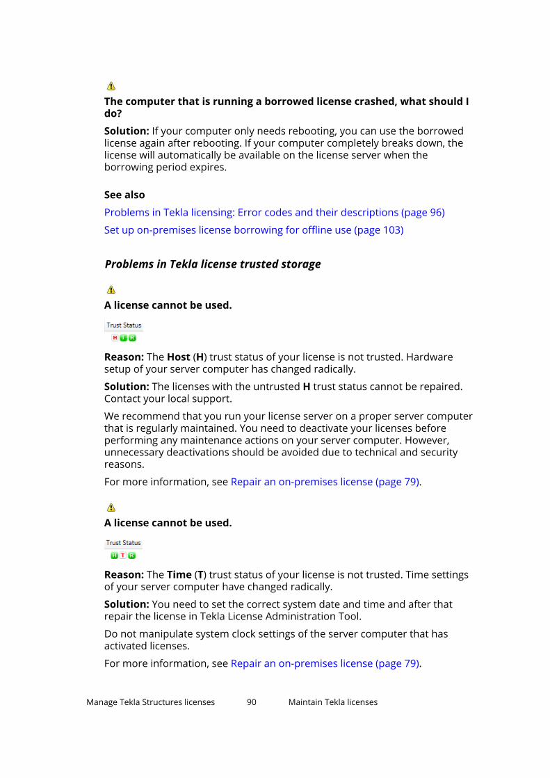
The computer that is running a borrowed license crashed, what should Ido?
Solution: If your computer only needs rebooting, you can use the borrowedlicense again after rebooting. If your computer completely breaks down, thelicense will automatically be available on the license server when theborrowing period expires.
See also
Problems in Tekla licensing: Error codes and their descriptions (page 96)
Set up on-premises license borrowing for offline use (page 103)
Problems in Tekla license trusted storage
A license cannot be used.
Reason: The Host (H) trust status of your license is not trusted. Hardwaresetup of your server computer has changed radically.
Solution: The licenses with the untrusted H trust status cannot be repaired.Contact your local support.
We recommend that you run your license server on a proper server computerthat is regularly maintained. You need to deactivate your licenses beforeperforming any maintenance actions on your server computer. However,unnecessary deactivations should be avoided due to technical and securityreasons.
For more information, see Repair an on-premises license (page 79).
A license cannot be used.
Reason: The Time (T) trust status of your license is not trusted. Time settingsof your server computer have changed radically.
Solution: You need to set the correct system date and time and after thatrepair the license in Tekla License Administration Tool.
Do not manipulate system clock settings of the server computer that hasactivated licenses.
For more information, see Repair an on-premises license (page 79).
Manage Tekla Structures licenses 90 Maintain Tekla licenses
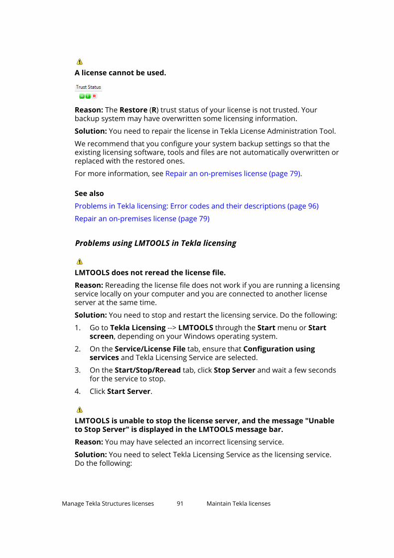
A license cannot be used.
Reason: The Restore (R) trust status of your license is not trusted. Yourbackup system may have overwritten some licensing information.
Solution: You need to repair the license in Tekla License Administration Tool.
We recommend that you configure your system backup settings so that theexisting licensing software, tools and files are not automatically overwritten orreplaced with the restored ones.
For more information, see Repair an on-premises license (page 79).
See also
Problems in Tekla licensing: Error codes and their descriptions (page 96)
Repair an on-premises license (page 79)
Problems using LMTOOLS in Tekla licensing
LMTOOLS does not reread the license file.
Reason: Rereading the license file does not work if you are running a licensingservice locally on your computer and you are connected to another licenseserver at the same time.
Solution: You need to stop and restart the licensing service. Do the following:
1. Go to Tekla Licensing --> LMTOOLS through the Start menu or Startscreen, depending on your Windows operating system.
2. On the Service/License File tab, ensure that Configuration usingservices and Tekla Licensing Service are selected.
3. On the Start/Stop/Reread tab, click Stop Server and wait a few secondsfor the service to stop.
4. Click Start Server.
LMTOOLS is unable to stop the license server, and the message "Unableto Stop Server" is displayed in the LMTOOLS message bar.
Reason: You may have selected an incorrect licensing service.
Solution: You need to select Tekla Licensing Service as the licensing service.Do the following:
Manage Tekla Structures licenses 91 Maintain Tekla licenses

1. Go to Tekla Licensing --> LMTOOLS through the Start menu or Startscreen, depending on your Windows operating system.
2. On the Service/License File tab, ensure that Configuration usingservices and Tekla Licensing Service are selected.
3. Go to the Start/Stop/Reread tab, and click Stop Server.
4. If this does not help, select the Force Server Shutdown check box andclick Stop Server again.
LMTOOLS is unable to stop the license server.
Reason: You did not run LMTOOLS with administrator rights.
Solution: Run LMTOOLS with administrator rights. For more information, seeRights needed for administrator tasks in on-premises licensing (page 37).
Starting or stopping the server or rereading the license file cannot beperformed, and the message "No Server Selected" is displayed.
Reason: You have not selected the licensing service.
Solution: You need to select Tekla Licensing Service as the licensing service.Do the following:
1. Go to Tekla Licensing --> LMTOOLS through the Start menu or Startscreen, depending on your Windows operating system.
2. On the Service/License File tab, ensure that Configuration usingservices and Tekla Licensing Service are selected.
3. Go to the Start/Stop/Reread tab and start or stop the server or rereadthe license file.
Starting or stopping the server or rereading the license file is notpossible.
The status list in LMTOOLS indicates that the license server manager (lmgrd)has not been started: "Error getting status: Cannot connect to license serversystem. The license server manager (lmgrd) has not been started yet, thewrong port@hostname or license file is being used, or the port or hostname inthe license file has been changed".
Reason: LMTOOLS points to the wrong lmgrd.exe.
Solution: You need to modify the settings in LMTOOLS. Do the following:
1. Go to Tekla Licensing --> LMTOOLS through the Start menu or Startscreen, depending on your Windows operating system.
2. On the Service/License File tab, ensure that Configuration usingservices and Tekla Licensing Service are selected.
Manage Tekla Structures licenses 92 Maintain Tekla licenses

3. Go to the Config Services tab, and click Browse to locate the lmgrd.exefile.
By default, the file is installed in the ..\Tekla\License\Server folder.
4. Click Save Service.
5. Go to the Start/Stop/Reread tab and click Stop Server.
6. Click Start Server to restart the server.
The changes are applied.
LMTOOLS does not show the licensing service status.
The status list on the Server status tab in LMTOOLS indicates that the licensefile cannot be found: "Error getting status: Cannot find license file. The licensefiles (or license server system network addresses) attempted are listed below.Use LM_LICENSE_FILE to use a different license file, or contact your softwareprovider for a license file".
Reason: You are trying to perform a status enquiry of a licensing service thatis not running.
Solution: You need to start Tekla Licensing Service. Do the following:
1. Go to Tekla Licensing --> LMTOOLS through the Start menu or Startscreen, depending on your Windows operating system.
2. On the Service/License File tab, ensure that Configuration usingservices and Tekla Licensing Service are selected.
3. Go to the Start/Stop/Reread tab and click Start Server.
4. Go to the Server Status tab and click Perform Status Enquiry again.
See also
Install Tekla license server - manual installation (page 47)
Configure Tekla license server manually (page 51)
Problems in Tekla licensing: Error codes and their descriptions (page 96)
Problems in starting Tekla Structures
Tekla Structures does not start. The following message is displayed:"Error when connecting to the license server. Contact your systemadministrator or try another server".
Reason: You are not connected to the license server.
Solution: Check the following:
• Check that your network connection is working.
Manage Tekla Structures licenses 93 Maintain Tekla licenses
• Check that you have entered the license server name correctly.
For more information, see Preconfigure license server settings for users(page 68).
• Check that license information in LMTOOLS is correct. If not, reread thelicense file in LMTOOLS and try to start Tekla Structures again.
For more information about LMTOOLS, see .
Tekla Structures does not start. The following message is displayed:"License server system does not support this feature".
Reason: Your license server may not be up to date.
Solution: Update the status of your license server. Do the following:
1. Go to Tekla Licensing --> LMTOOLS through the Start menu or Startscreen, depending on your Windows operating system. Start LMTOOLSusing administrator rights.
2. On the Service/License File tab, ensure that Configuration usingservices and Tekla Licensing Service are selected.
3. On the Start/Stop/Reread tab, click Stop Server and wait a couple ofseconds.
4. Click Start Server.
5. Start Tekla Structures.
If the problem still persists, contact your local Tekla Structures support. Thesupport will need a copy of the following files: tekla.lic, tekla.opt, andtekla_debug.log files.
Tekla Structures does not start occasionally.
The following message is displayed: "Cannot connect to license server system.The license server manager (lmgrd) has not been started, the wrongport@host or license file is being used, or the port and hostname in the licensefile has been changed".
Reason: There may be communication problems between your license serverand Tekla Structures client computers if the port of the license server is notdefined.
Solution: Define the port for the license server. Do the following:
1. Go to Tekla Licensing --> LMTOOLS through the Start menu or Startscreen, depending on your Windows operating system.
2. On the Service/License File tab, ensure that Configuration usingservices and Tekla Licensing Service are selected.
Manage Tekla Structures licenses 94 Maintain Tekla licenses

3. On the license server computer, define a free port for the license server inthe tekla.lic file. For more information, see Modify the license filetekla.lic manually (page 50).
4. Go to the Start/Stop/Reread tab and stop the license server by clickingStop Server.
5. Click Start Server.
6. Start Tekla Structures on a client computer.
7. In Tekla Structures, click Tools --> Change License Server . Define theport and hostname of the license server.
8. Close Tekla Structures.
9. Repeat steps 5 to 7 on all Tekla Structures client computers.
See also
Preconfigure license server settings for users (page 68)
Problems in Tekla licensing: Error codes and their descriptions (page 96)
Problems with options file tekla.opt
The tekla.opt file does not take effect.
Reason: The licensing service has not read the options file.
Solution: Do the following:
1. Go to Tekla Licensing --> LMTOOLS through the Start menu or Startscreen, depending on your Windows operating system.
2. On the Service/License File tab, ensure that Configuration usingservices and Tekla Licensing Service are selected.
3. On the Start/Stop/Reread tab, click ReRead License File.
4. Browse to the ..\Tekla\License\Server folder and open thetekla_debug.log file and the tekla.opt file with a text editor.
5. Check that the tekla_debug.log file contains the same keyword stringsas the tekla.opt file.
If this does not help, please contact your local support.
Manage Tekla Structures licenses 95 Maintain Tekla licenses

See also
Modify on-premises license access rights (tekla.opt) (page 73)
Problems in Tekla licensing: Error codes and their descriptions (page 96)
Problems in Tekla licensing: Error codes and their descriptions
Error 6
Problem: License library initialization failed with error: Activation LibraryInitialization error #6. Please, contact software vendor to resolve theproblem.
Reason: Tekla license server installation folder contains .dll files that arefrom the previous Tekla license server version.
Solution: To resolve the problem, do the following:
1. Close Tekla License Administration Tool and stop the Tekla license serverin LMTOOLS by clicking Stop Server on the Start/Stop/Reread tab.
2. Uninstall all existing Tekla license server installations.
3. If the Tekla license server installation folder contains any .dll files,remove the files manually.
4. Now you can install Tekla license server to the same folder where theuninstalled version was.
Manage Tekla Structures licenses 96 Maintain Tekla licenses

For more information about license server installation, see Installing Teklalicense server (page 44).
NOTE Deactivation is not needed in this case. Licenses are kept safe in aspecific Flexera Software location outside Tekla license serverinstallation directory.
Error 20
Problem: Error 20: The licensing service is not installed.
Reason: The error occurs when you are starting Tekla License AdministrationTool, or when you are trying to run serveractutil.exe command line tool.
Solution: If you selected the Manual option for Tekla Licensing Serviceinstallation then you need to manually install FLEXnet licensing service:
1. If you have some other FlexNet licensing service running on the server,stop it before entering the commands.
2. Go to the Start menu or Start screen, depending on your Windowsoperating system, and open Command Prompt as an administrator.
3. At the command prompt, type the following commands:
cd /D full_path_to_installation_directoryFor example, if you install Tekla license server to the default folder, youneed to enter cd /D C:\Tekla\License\Server.
installanchorservice.exe
Error 109
Problem: There are no activated licenses to return. Another programmay have modified the activated licenses rights concurrently. (109)Unable to return as there is no licenses in Trusted Storage.
Reason: The trusted storage has been modified, probably by some otherprogram.
The red Restore (R) trust status of your license is not trusted. Thelicense is broken, therefore it cannot be returned.
Solution: The license will become available on the server machineautomatically when the borrow period ends.
Error 123 or error 50030
Problem: Message 1: Row n: An error occurred but FLEXnet Licensing didnot return an error number. (123)
Message 2: Failed to load trusted storage or specified ASR. (50030)
Manage Tekla Structures licenses 97 Maintain Tekla licenses
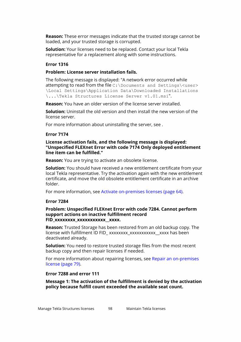
Reason: These error messages indicate that the trusted storage cannot beloaded, and your trusted storage is corrupted.
Solution: Your licenses need to be replaced. Contact your local Teklarepresentative for a replacement along with some instructions.
Error 1316
Problem: License server installation fails.
The following message is displayed: "A network error occurred whileattempting to read from the file C:\Documents and Settings\<user>\Local Settings\Application Data\Downloaded Installations\...\Tekla Structures License Server v1.01.msi".
Reason: You have an older version of the license server installed.
Solution: Uninstall the old version and then install the new version of thelicense server.
For more information about uninstalling the server, see .
Error 7174
License activation fails, and the following message is displayed:"Unspecified FLEXnet Error with code 7174 Only deployed entitlementline item can be fulfilled."
Reason: You are trying to activate an obsolete license.
Solution: You should have received a new entitlement certificate from yourlocal Tekla representative. Try the activation again with the new entitlementcertificate, and move the old obsolete entitlement certificate in an archivefolder.
For more information, see Activate on-premises licenses (page 64).
Error 7284
Problem: Unspecified FLEXnet Error with code 7284. Cannot performsupport actions on inactive fulfillment recordFID_xxxxxxxx_xxxxxxxxxxx__xxxx.
Reason: Trusted Storage has been restored from an old backup copy. Thelicense with fulfillment ID FID_ xxxxxxxx_xxxxxxxxxxx__xxxx has beendeactivated already.
Solution: You need to restore trusted storage files from the most recentbackup copy and then repair licenses if needed.
For more information about repairing licenses, see Repair an on-premiseslicense (page 79).
Error 7288 and error 111
Message 1: The activation of the fulfillment is denied by the activationpolicy because fulfill count exceeded the available seat count.
Manage Tekla Structures licenses 98 Maintain Tekla licenses

Message 2: The activation of the fulfillment is denied by the activationpolicy because number of copies left is zero.
Reason 1: You may be trying to activate some licenses that have beenactivated before on another server/computer.
Solution: Deactivate the licenses from the other computer, and then activatethe licenses on the new server/computer.
Reason 2: You may be trying to activate a renewed temporary license orpermanent licenses without deactivating the previous linked activatedlicenses.
Solution: Deactivate the existing temporary licenses first and then activate thesucceeding linked licenses.
For more information about deactivating licenses, see Deactivate on-premiseslicenses (page 69).
Error 7343
Problem: Unspecified FLEXnet Error with code 7343 Entitlement line itemhas expired on <date> <time>.
Reason: License has expired. It is not possible to activate or repair expiredlicenses.
Error 7466
Problem: License deactivation fails, and the following message isdisplayed: "The return of the fulfillment is denied by the return policybecause max return exceeded".
Reason: You have deactivated the license too many times in a 30 days period.
Solution: You can deactivate the license again when 30 days have passedsince the first deactivation of the license in the past 30 days. The number ofdeactivations of a license within a given time period is limited due to technicaland security reasons.
Error 7581
Problem: Unspecified FLEXnet Error with code 7581. Online Return/RepairRequest for the activationId XXXX-XXXX-XXXX-XXXX-XXXX-XX is notoriginated from the original client machine.
Reason and solution: The computer is not the same where the licenses wereoriginally activated, and you need to return/repair licenses from the originalcomputer. Another reason might be that the computer has changed so muchthat activation server at Trimble Solutions no longer recognizes it as the sameone, in which case you need to replace your licenses.
For more information about returning and repairing licenses, see Returning aborrowed license (page 108) and Repair an on-premises license (page 79).
Manage Tekla Structures licenses 99 Maintain Tekla licenses

Error 9999
Problem, reason and solution:: Licensing server at Trimble Solutions isdown. Wait for a while and retry.
Error 50005
Problem: Error (5005) License Activation failed - Initialization of APIFailed.
Problem: The activated licenses are not visible and it is not possible to activatenew licenses.
Reason: The installation package has failed to initialize or register some of thesoftware components.
Solution: Do the following:
1. Log in with administrator's rights.
2. Close Tekla License Administration Tool.
3. Stop Tekla license server and other license servers on the same computeron the LMTOOLS --> Start/Stop/Reread tab.
4. Go to ..\Tekla\License\Server folder.
5. Double-click installanchorservice.exe.
6. Start Tekla license server and other license servers on the same computeron the LMTOOLS --> Start/Stop/Reread tab.
7. Open Tekla License Administration Tool. The message should not bedisplayed anymore.
Error 50018
Problem: License borrowing fails.
Reason: Wrong product ID file is used.
Solution: Do one of the following:
• Export a product ID file in Tekla License Administration Tool and use thefile for borrowing.
Error 50033
Problem: License borrowing fails.
Reason 1: Your license server may not have up-to-date license information.
Solution: In LMTOOLS, stop and then restart the server.
Reason 2: The INCLUDE keyword in the options file prevents the borrowing ofthe configuration.
Solution: You need to add a dummy user "ACTIVATED LICENSE(S)" into thegroup of the included users to enable the borrowing. Do the following:
1. Open tekla.opt using a text editor.
Manage Tekla Structures licenses 100 Maintain Tekla licenses
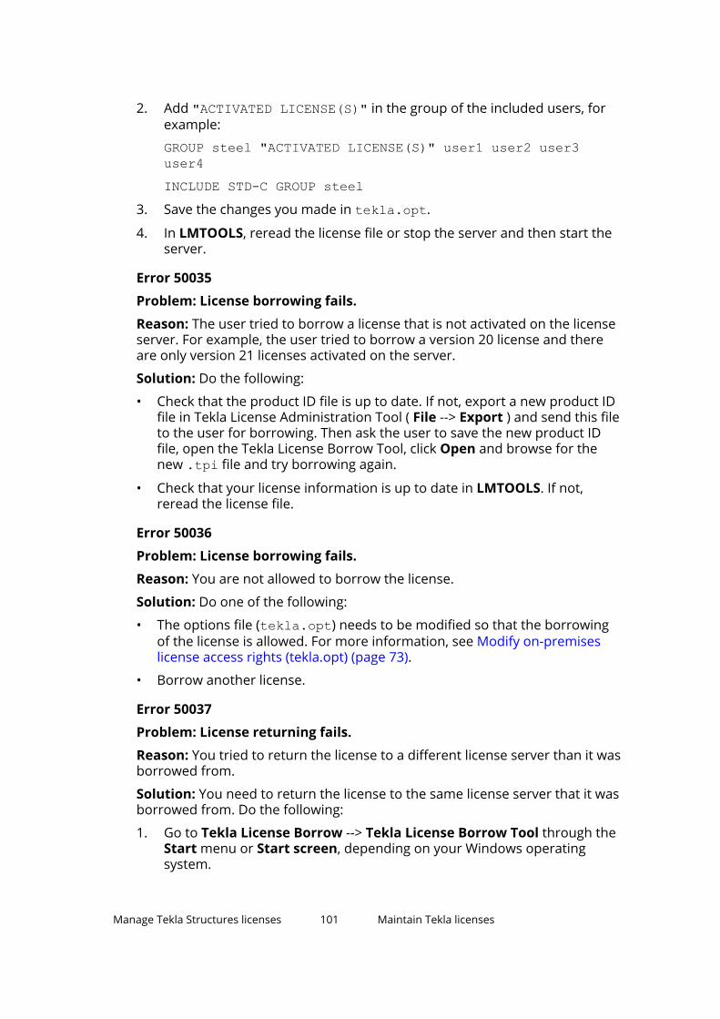
2. Add "ACTIVATED LICENSE(S)" in the group of the included users, forexample:
GROUP steel "ACTIVATED LICENSE(S)" user1 user2 user3user4INCLUDE STD-C GROUP steel
3. Save the changes you made in tekla.opt.
4. In LMTOOLS, reread the license file or stop the server and then start theserver.
Error 50035
Problem: License borrowing fails.
Reason: The user tried to borrow a license that is not activated on the licenseserver. For example, the user tried to borrow a version 20 license and thereare only version 21 licenses activated on the server.
Solution: Do the following:
• Check that the product ID file is up to date. If not, export a new product IDfile in Tekla License Administration Tool ( File --> Export ) and send this fileto the user for borrowing. Then ask the user to save the new product IDfile, open the Tekla License Borrow Tool, click Open and browse for thenew .tpi file and try borrowing again.
• Check that your license information is up to date in LMTOOLS. If not,reread the license file.
Error 50036
Problem: License borrowing fails.
Reason: You are not allowed to borrow the license.
Solution: Do one of the following:
• The options file (tekla.opt) needs to be modified so that the borrowingof the license is allowed. For more information, see Modify on-premiseslicense access rights (tekla.opt) (page 73).
• Borrow another license.
Error 50037
Problem: License returning fails.
Reason: You tried to return the license to a different license server than it wasborrowed from.
Solution: You need to return the license to the same license server that it wasborrowed from. Do the following:
1. Go to Tekla License Borrow --> Tekla License Borrow Tool through theStart menu or Start screen, depending on your Windows operatingsystem.
Manage Tekla Structures licenses 101 Maintain Tekla licenses

2. Click Setup and enter the name of the license server where you originallyborrowed the license from and click OK.
3. Select the Return check box in the Borrowed Licenses area to select thelicense for returning.
4. Click the Return button to return the license.
After successful returning of licenses, the Borrowed Licenses area isupdated.
Error 50040 or error 50041
Error 50040 or error 50041, problem 1: License activation, deactivation orrepairing fails
Reason: Your license server was not able to connect to activation server atTrimble Solutions correctly. Usually this is a temporary problem in onlineactivation.
Solution: Do the following:
• Check that your Internet connection is working. An Internet connection isneeded during license activation and deactivation. A low connection speedmay also cause errors.
• Close Tekla License Administration Tool and try to activate the license awhile later.
• Try to activate another license.
• Your firewall may block the activation communication. Check your firewallsettings. For more information, see Allowing Tekla license server to operatethrough Windows Firewall (page 53).
• Check that you have the latest Tekla license server version.
• This error could be caused by unfinalized Windows updates on the servercomputer. Reboot the server and try again.
• Your Windows login user name may contain special characters. Try to log inwith another user name, for example, administrator.
• Check that your Internet connection is working.
• Contact your local Tekla Structures support and ask for a manualactivation.
Error 50040 or error 50041, problem 2: License borrowing fails.
Reason: You are not connected to the license server.
Solution: Do the following:
• Check that your network connection is working.
• Start Tekla License Borrow Tool and check that you have entered thecorrect license server information.
Manage Tekla Structures licenses 102 Maintain Tekla licenses

See also
View and diagnose errors in Tekla Structures license activation, deactivationand borrowing (page 81)
Problems in Tekla license activation (page 85)
Problems in Tekla license borrowing (page 89)
Problems in Tekla license deactivation (page 89)
3.8 Set up on-premises license borrowing for offline useUsers who want to work in a location that does not have a reliable connectionto the on-premises license server can borrow an activated license from theTekla license server before leaving the office. The user receives a temporarylocal license file valid for a set time period.
The information on this page is not valid for online licenses.
Users can borrow Tekla Structures on-premises licenses for offline use in TeklaLicense Borrow Tool. Users need to have a network connection to the licenseserver to borrow and return a license.
Borrowed licenses are reserved for the duration of the borrowing even whenthey are not in use, so the borrowed license is not available for other users.
Configuration files
A product ID (.tpi) file is needed for borrowing licenses. If you use thelicensing options file (tekla.opt) for managing license access rights, youmust always provide a customized product ID file for users. The default filethat lists all configurations will technically work in other cases, butadministrators should still provide a customized product ID file. Thecustomized file makes it easier for the users to select a license, because itincludes just those licenses that you have actually activated on the server. Formore information, see Provide offline users with a customized product ID file(page 104).
You can define which licenses are available for which users in the licensingoptions file (tekla.opt) on the license server. For more information, seeModify on-premises license access rights (tekla.opt) (page 73).
How on-premises license borrowing works
License borrowing reserves and releases the on-premises licenses like this:
• The maximum license borrow period is one month. The user defines theborrow expiration date when borrowing the license. The borrowed licensesare unavailable to other users until they are returned or the license borrowperiod ends.
• The user can return a license before the license borrow period is overthrough the license borrow tool on the borrowing computer. Make sure
Manage Tekla Structures licenses 103 Set up on-premises license borrowing for offlineuse

your users return all borrowed licenses before a major operating systemupgrade, reinstallation or major hardware changes on their computer.
• Borrowed licenses must be returned before you deactivate those licenseson the license server, for example, to upgrade the licenses to a new versionor to move the license server to new hardware. You can see who hasborrowed which licenses by enquiring the license status in the LMTOOLSapplication on the license server.
NOTE If you do not follow the guidelines above, all users may lose the use ofthe borrowed licenses until the end of the license borrowing period,including the users who originally borrowed the licenses.
1. Install the Tekla License Borrow Tool on the users' computers withcustomized product ID file(s).
2. To borrow a license, users must open the Tekla License Borrow Toolinstalled on their computer when they are still online and can connect tothe Tekla license server.
The version of Tekla License Borrow Tool should be the same as theversion of Tekla license server.
3. After borrowing a license, users can go offline and freely work with, closeand reopen Tekla Structures within the license borrow period.
4. When the users are back online, they should return the borrowed licensesto the license server.
If a user does not return the license, it becomes available for other userson the license server after the license borrow time is over. However, thelicense is still listed in the license borrow tool for the user until the userreturns it.
For detailed instructions, see Set up Tekla License Borrow Tool for TeklaStructures offline use (page 105).
For end-user instructions, see Borrow a license from on-premises licenseserver (page 107) and Return a borrowed on-premises license (page 108).
See also
Problems in Tekla license borrowing (page 89)
Problems in Tekla licensing: Error codes and their descriptions (page 96)
Provide offline users with a customized product ID fileTekla License Borrow Tool for on-premises licenses needs the activation IDs ofthe licenses during borrowing. When you export a product ID file (.tpi) inTekla License Administration Tool, the activation IDs of the activated licensesare written in the file. Then you can send the file to offline users.
Manage Tekla Structures licenses 104 Set up on-premises license borrowing for offlineuse

The information on this page is not valid for online licenses.
When you install Tekla License Borrow Tool, the standard.tpi file isautomatically installed in the ..\Tekla\License\Borrow folder. This defaultproduct ID file lists all Tekla Structures configurations and their product IDs.However, users can only borrow the licenses that are activated on the licenseserver.
You can create a customized product ID file that only lists the activation IDs ofthe activated licenses available for borrowing. You need to export the productID file on the license server computer using Tekla License Administration Tooland save the file on the computers of the users who borrow licenses. Theactivation IDs are encrypted.
WARNING Product ID files are not updated automatically. If you deactivateborrowable licenses or activate new licenses for borrowing, youneed to export a new product ID file and send it to TeklaStructures offline users who borrow licenses.
To export the product ID file on the Tekla license server computer:
1. Go to Tekla Licensing --> Tekla License Administration Tool throughthe Start menu or Start screen, depending on your Windows operatingsystem.
2. Click Export.
3. In the Save Product ID file As dialog box, enter the name of the productID file or keep the default file name, select a folder where you want tosave the file and click Save.
4. Send the product ID file to the Tekla Structures users who need to borrowlicenses and inform the users about the usage of the file.
If the name of the file is standard.tpi and the file is saved inthe ..\Tekla\License\Borrow folder on the user’s computer, the file isopened automatically when the user starts Tekla License Borrow Tool.
See also
Set up Tekla License Borrow Tool for Tekla Structures offline use (page 105)
Set up Tekla License Borrow Tool for Tekla Structuresoffline useYou can use Tekla Structures on-premises licenses offline or off-site byborrowing Tekla licenses with Tekla License Borrow Tool.
The information on this page is not valid for online licenses.
For information on using online licenses offline, see .
Manage Tekla Structures licenses 105 Set up on-premises license borrowing for offlineuse

Before you start, download and install the latest Tekla License Borrow Toolfrom the Tekla Downloads product download page.
You can use the same Tekla License Borrow Tool for borrowing licenses fordifferent Tekla Structures versions. The version of Tekla License Borrow Toolshould be the same as the version of Tekla license server.
To set up Tekla License Borrow Tool for Tekla Structures offline use:
1. Go to Tekla License Borrow --> Tekla License Borrow Tool through theStart menu or Start screen, depending on your Windows operatingsystem.
2. In the Setup dialog box, enter the port number and the hostname(computer name) of the license server in the Server box in the format port@hostname, for example, 27007@server_hostname.
3. Still in the Setup dialog box, click Browse and select the product ID file.
4. Click OK.
The Products area in the Tekla License Borrow Tool is updated.
5. In the Tekla License Borrow Tool dialog box, click Language and changethe language of the Tekla License Borrow Tool user interface, if necessary.
NOTE When you start Tekla Structures, and if Tekla Structures does not start withthe borrowed license, enter an asterisk (*) in the server box of the licensing
Manage Tekla Structures licenses 106 Set up on-premises license borrowing for offlineuse
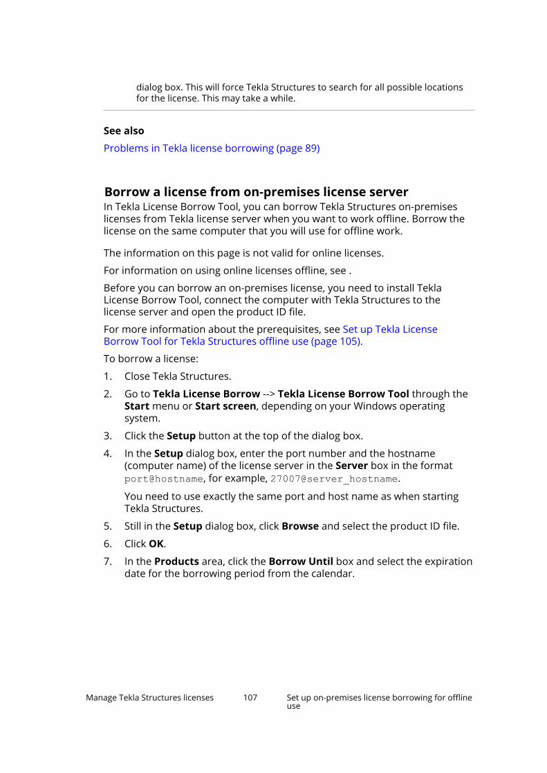
dialog box. This will force Tekla Structures to search for all possible locationsfor the license. This may take a while.
See also
Problems in Tekla license borrowing (page 89)
Borrow a license from on-premises license serverIn Tekla License Borrow Tool, you can borrow Tekla Structures on-premiseslicenses from Tekla license server when you want to work offline. Borrow thelicense on the same computer that you will use for offline work.
The information on this page is not valid for online licenses.
For information on using online licenses offline, see .
Before you can borrow an on-premises license, you need to install TeklaLicense Borrow Tool, connect the computer with Tekla Structures to thelicense server and open the product ID file.
For more information about the prerequisites, see Set up Tekla LicenseBorrow Tool for Tekla Structures offline use (page 105).
To borrow a license:
1. Close Tekla Structures.
2. Go to Tekla License Borrow --> Tekla License Borrow Tool through theStart menu or Start screen, depending on your Windows operatingsystem.
3. Click the Setup button at the top of the dialog box.
4. In the Setup dialog box, enter the port number and the hostname(computer name) of the license server in the Server box in the format port@hostname, for example, 27007@server_hostname.
You need to use exactly the same port and host name as when startingTekla Structures.
5. Still in the Setup dialog box, click Browse and select the product ID file.
6. Click OK.
7. In the Products area, click the Borrow Until box and select the expirationdate for the borrowing period from the calendar.
Manage Tekla Structures licenses 107 Set up on-premises license borrowing for offlineuse

The maximum borrowing period is one month. The exact maximumborrow period varies between 29 to 32 days depending on the borrowingdate.
8. Click the Borrow button to borrow the license.
The borrowing progress is displayed in the Borrowing License(s) dialogbox. After successful borrowing, the Borrowed Licenses area shows theborrowed license.
9. To ensure that the borrowing succeeded, disconnect your computer fromthe license server and start Tekla Structures with the borrowed license.
See also
Problems in Tekla license borrowing (page 89)
Problems in Tekla licensing: Error codes and their descriptions (page 96)
View and diagnose errors in Tekla Structures license activation, deactivationand borrowing (page 81)
Set up on-premises license borrowing for offline use (page 103)
Return a borrowed on-premises licenseYou can return a borrowed Tekla Structures on-premises license back to theTekla license server before the expiration date.
The information on this page is not valid for online licenses.
A borrowed license is automatically available on the license server on the dayfollowing the expiration date.
However, the Borrowed Licenses area in Tekla License Borrow Tool is notautomatically updated. The license should be returned to the server that hasthe same name as the name of the server from which the license wasborrowed. We recommend that you always return the expired licenses whenyou want to stop borrowing a license.
To return a borrowed Tekla license:
1. Ensure that you are connected to the license server.
2. Close Tekla Structures.
Manage Tekla Structures licenses 108 Set up on-premises license borrowing for offlineuse
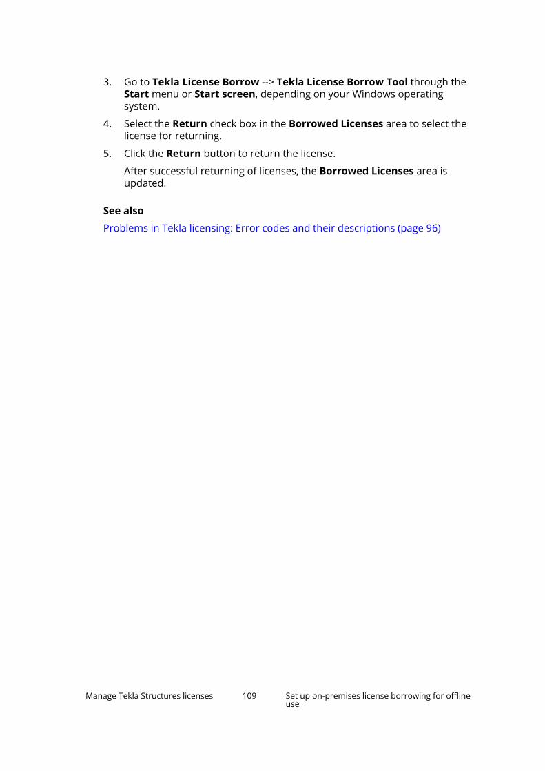
3. Go to Tekla License Borrow --> Tekla License Borrow Tool through theStart menu or Start screen, depending on your Windows operatingsystem.
4. Select the Return check box in the Borrowed Licenses area to select thelicense for returning.
5. Click the Return button to return the license.
After successful returning of licenses, the Borrowed Licenses area isupdated.
See also
Problems in Tekla licensing: Error codes and their descriptions (page 96)
Manage Tekla Structures licenses 109 Set up on-premises license borrowing for offlineuse

4 Implementation guide foradministrators
Tekla Structures administrator is the person responsible for ensuring that thecompany standards are used and set up in Tekla Structures. The followingsections explain how you can customize Tekla Structures.
4.1 Customizing Tekla StructuresEach new version of Tekla Structures introduces new features andfunctionalities to improve the overall process used for completing a project.Tekla Structures has multiple environments to suit the needs andrequirements of specific markets. Many features are localized in each TeklaStructures version. Most of the changes in versions are focused on making thedefault saved attributes more consistent, organized, simplified, and practical.
Your local technical team is dedicated to improving your knowledge andexperience of each new version. The team aims at enhancing your userexperience of Tekla Structures by performing tasks that have been identifiedas essential by the existing users, new users, and potential users.
Before you start customizing Tekla Structures to suit the needs of yourcompany and your projects, collect the needed information, such as drawingstandards, used profiles, grades and materials, company logos, and namingconventions.
The overall localization of Tekla Structures can be divided into four differentlayers:
• Tekla Structures environment
• Company-level settings
• Project-level settings
• Multi-user settings
The three last ones are mainly managed by company administrators.
Implementation guide for administrators 110 Customizing Tekla Structures

Setting up the standard that a company uses, and the standards that a specificproject needs will make the designing process much more efficient becausethe end user can concentrate on the design process.
Tekla Warehouse
Tekla Warehouse has a lot of additional content, such as application tools andenvironment content. You can download Tekla Warehouse offline content thatincludes the catalog content of environments, such as profiles, bolts,materials, and reinforcement.
The offline catalog content is under Tekla Structures collections in TeklaWarehouse. The content is in .tsep packages that are installed when openingTekla Structures.
You can also create a local collection for your company, and share it for yourorganization in your internal network. You can manage the access rights onthe folder and collection level in the collections.json file on each user'scomputer. Copy the file to the same location on each user's computer. The fileis located in C:\Users\Public\Public Documents\Trimble\TeklaWarehouse\collections.json.
The image below shows an example of the collection paths with four TeklaStructures collections:
In Tekla Warehouse the collections are found after mapping under Mycollections --> Local and network collections .
Implementation guide for administrators 111 Overview of environments, roles and licenses

4.2 Overview of environments, roles and licensesTekla Structures is one product that has many different configurations. Thelicenses you have determine which configurations you can use.
A Tekla Structures environment is set up for the materials, grades, profiles,drawing settings, component settings, .ini file settings that are used in aspecific market. There are over 30 different environments in Tekla Structures.By choosing a specific environment when starting Tekla Structures you will getthe settings for that market. You can install several environments, and addmissing environments later.
The blank project listed in the environments is an empty platform for yourown environment or project settings. It includes standard parametric profiles,undefined bolt, material and rebar grades, basic drawing layouts and so on,which you can complement from your own firm or project folders and TeklaWarehouse.
Some environments give you the opportunity to select a role when logging in.The role is independent from the licenses that are used. The purpose of theroles is to make the user interface and settings clearer, easier and faster forthe user's tasks.
In practice, this means that settings, filters, reports and the user interface isset up for the role the user has. For example, preloaded settings in objectproperties that are not relevant for the role are not shown, making the list ofoptions shorter and clearer.
Role selection is primarily meant to be configured by Trimble and resellerlocalization personnel, and be part of the Tekla Structures installation package.However, advanced users and Tekla Structures system administrators can alsocreate their own roles inside their company organization. Additional content isavailable in the Tekla Warehouse offline and online collections. Note that youneed to have a Trimble Identity for downloading or installing from the onlinecollections. For more information, see Trimble Identity for Tekla Onlineservices.
Implementation guide for administrators 112 Overview of environments, roles and licenses

Using roles for ribbon selection with the subscription licenseconfigurations
Note that the ribbon selection with the subscription license configurations isprimarily meant to be configured by Trimble and reseller localizationpersonnel.
With the subscription licenses, roles can be used for controlling which ribbonis shown for a certain role. The role-specific .ini files in the environments(page 274), for example, role_Steel_Detailer.ini orrole_Rebar_Detailer.ini, contain advanced options XS_RIBBON_CONFIGURATION_DIAMOND, XS_RIBBON_CONFIGURATION_GRAPHITE, and XS_RIBBON_CONFIGURATION_CARBON. The advanced options define theribbons for the specific role.
The advanced options need to point the configuration identifiers (page 132) ofthe ribbon files, either to the configuration identifiers of the legacy on-premises license configurations, or to the configuration identifiers of theonline license configurations. It is not possible to make up new configurationidentifiers.
If the advanced options are not set, Tekla Structures uses the default ribbonsfor each subscription license configuration.
Example:
For the users who select the Precast Concrete Detailing role, you could havethe following settings in the role_Precast_Detailer.ini file:
set XS_RIBBON_CONFIGURATION_CARBON=albl_up_Carbonset XS_RIBBON_CONFIGURATION_GRAPHITE=albl_up_PC_Detailingset XS_RIBBON_CONFIGURATION_DIAMOND=albl_up_PC_Detailing
For more examples, see your role_<role>.ini files used in yourenvironment.
TIP Administrators who have own environment and roles in use: for the ownrole, such as, for timber detailer, you can create a folder for the ribbonfiles in ..\<environment>\Timber\Detailing\Ribbons, forexample. Place the customized ribbon files in the folder, and include thefolder in the XS_SYSTEM path definition for that specific role.
4.3 Folder structureTekla Structures software and environments are separated into differentlocations due to the requirements for Windows certification. By default, thefiles are installed in the following folders:
• Software is installed under the \Program Files\Tekla Structuresfolder.
Implementation guide for administrators 113 Folder structure

• Environments and extensions are installed under the \ProgramData\Trimble\Tekla Structures folder.
• User settings are installed under the \Users\<username>\AppData\Local\Trimble\Tekla Structures folder.
4.4 Project and firm foldersProject and firm folders are meant for storing the customized files. For anycompany, we strongly recommend setting up firm and/or project folders on ashared file server accessible to all users. If multiple teams on different sitesare working on the same project, you can set up a project or firm folder in afolder in a .
Having the hierarchy of project and firm folders will make it much easier toupdate company settings, ensure that everyone uses the same settings in aproject, and upgrade to a newer version of Tekla Structures.
All the settings that are used on the company level (for example, companylogo and drawing standards) should be stored in a firm folder, and all thesettings used on a specific project should be stored in the correspondingproject folder. Property files are always saved in the \attributes folderunder the current model folder, like, \TeklaStructuresModels\<my_building>\attributes. These files should then be copied to theproject or firm folder, or to user-defined sub-folders under the project or firmfolder.
To use the saved settings in a firm and a project folder, set the path to thefolder by using the XS_PROJECT and XS_FIRM advanced options. Theseadvanced options should be put in the initialization, .ini, files. You can haveseveral different .ini files. You can define in the Tekla Structures shortcutwhich .ini files to run and which settings to apply.
One of the most important advantages of using firm and project folders is thatTekla Structures does not replace files in the project and firm folders whenyou install a new version. This means that you retain your customized fileswithout having to cut and paste, or export and import from previous versions.This makes upgrading to a newer version of Tekla Structures easier. When youstore files in one place, it is also easier to update the settings and ensure thateveryone in a project uses the same settings.
Example:
Implementation guide for administrators 114 Project and firm folders
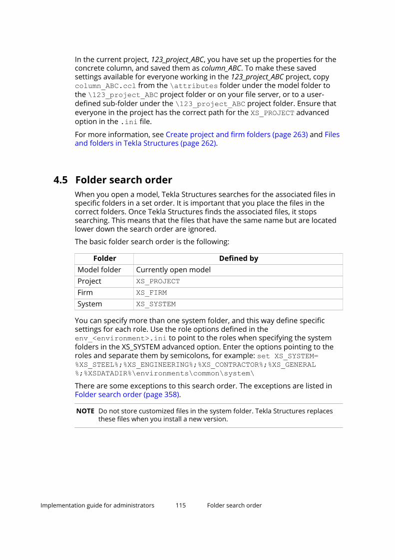
In the current project, 123_project_ABC, you have set up the properties for theconcrete column, and saved them as column_ABC. To make these savedsettings available for everyone working in the 123_project_ABC project, copycolumn_ABC.ccl from the \attributes folder under the model folder tothe \123_project_ABC project folder or on your file server, or to a user-defined sub-folder under the \123_project_ABC project folder. Ensure thateveryone in the project has the correct path for the XS_PROJECT advancedoption in the .ini file.
For more information, see Create project and firm folders (page 263) and Filesand folders in Tekla Structures (page 262).
4.5 Folder search orderWhen you open a model, Tekla Structures searches for the associated files inspecific folders in a set order. It is important that you place the files in thecorrect folders. Once Tekla Structures finds the associated files, it stopssearching. This means that the files that have the same name but are locatedlower down the search order are ignored.
The basic folder search order is the following:
Folder Defined byModel folder Currently open modelProject XS_PROJECTFirm XS_FIRMSystem XS_SYSTEM
You can specify more than one system folder, and this way define specificsettings for each role. Use the role options defined in theenv_<environment>.ini to point to the roles when specifying the systemfolders in the XS_SYSTEM advanced option. Enter the options pointing to theroles and separate them by semicolons, for example: set XS_SYSTEM=%XS_STEEL%;%XS_ENGINEERING%;%XS_CONTRACTOR%;%XS_GENERAL%;%XSDATADIR%\environments\common\system\There are some exceptions to this search order. The exceptions are listed inFolder search order (page 358).
NOTE Do not store customized files in the system folder. Tekla Structures replacesthese files when you install a new version.
Implementation guide for administrators 115 Folder search order

4.6 Initialization filesInitialization files (page 268) (.ini) are used for launching Tekla Structures.They can contain many advanced options that you can use to configure TeklaStructures for different standards and your own style of working. TeklaStructures automatically creates the necessary .ini files during installation.The number of .ini files it creates depends on how many country-specificenvironments you choose to install.
Why are .ini files needed?
There are numerous settings to be made when Tekla Structures starts.Advanced options are used to determine the appearance and the behavior ofTekla Structures, for example, the language used, behavior of part marks ondrawings, and the location of your model folder. Advanced options are setthrough the .ini files. The different .ini files and what they do, and howthey are related to each other are described below.
Different types of .ini files
The default reading order (page 269) of the .ini files is as shown in the imagebelow:
1. teklastructures.iniInitializes the settings needed for Tekla Structures to run.
The teklastructures.ini file in the \bin folder starts TeklaStructures. We recommend that you do not make any changes to this file.
Implementation guide for administrators 116 Initialization files
2. env_global_default.iniSets the global default settings.
The env_<your_environment>.ini file is located in the\Environments subfolder and it contains all the environment-specificsettings. These files are set by your area office or reseller.
3. environment.iniSets the environment-specific settings.
You can define specific settings for roles in your environment and storethese settings in role-specific folders. Organizing the folder structurebased on roles is useful for keeping the role content up to date. Note thatthe folder structure and content may vary depending on the environment.
In the env_<environment>.ini file, each role has an option where youcan add the paths that point to the folders in which you have stored therole settings. For example, XS_STEEL (\Steel), XS_CONCRETE(\Concrete), XS_ENGINEERING (\Engineering) and XS_PRECAST(\Precast) each point to the folders that contain settings specific to thatrole. An example for steel role could be as follows:
set XS_STEEL=%XSDATADIR%\environments\Steel\master_drawings\;%XSDATADIR%\environments\Steel\model_filters\;%XSDATADIR%\environments\Steel\model_settings\
XS_GENERAL points to the \General folder that has content common forall roles and settings that are specific to modeling and drawings, forexample.
When defining role settings in XS_SYSTEM, you use the role optionsdefined in the env_<environment>.ini to point to the role-specificsettings. Note that you do not need to add the folder paths in XS_SYSTEMas they are defined in the env_<environment>.ini.
4. role.iniSets the settings defined for a role.
The role_<role>.ini file is located in the \Environments subfolderand it contains the settings specific for a chosen role. For example, therole_Engineer.ini file in the \Environments\uk folder contains allthe settings for the Engineering role in the UK environment.
5. user.iniSets the settings specified by the user.
The user.ini file contains your personal settings. The advanced optionsin user.ini override those in other .ini files. For example, if you haveset the same advanced option in an .ini file, in a file in the environmentssubfolder and the user.ini file, Tekla Structures uses the value in theuser.ini file. The user.ini is located in the C:\Users\<user_name>
Implementation guide for administrators 117 Initialization files
\AppData\Local\Trimble\Tekla Structures\<version>\UserSettings folder.
6. options.iniSets the settings specified for the company/project/model.
If there are several settings for the same advanced option, the later setting inthe reading order overrules the previous one. This means that the settings inuser.ini overrule the settings in env_global_default.ini, and thesettings in user.in can be overruled by the settings in options.ini.
The lang_enu.ini is the initialization file for the English language settings.The file is located with the other installed languages in the \TeklaStructures\<version>\nt\bin folder.
We recommend that you make all your customizations in the options.inifile under the model folder, or in the user.ini file. This way thecustomizations are kept when you install the next version of Tekla Structures.
4.7 Setting advanced options in .ini filesTekla Structures contains three kinds of advanced options: user-specificadvanced options, system-specific advanced options, and model-specificadvanced options.
NOTE Changing an advanced option value in .ini files located outside the modelfolder does not affect the existing models. You can only update the advancedoptions in the Advanced options dialog box or in the options.ini filelocated in the model folder, not from an options.ini file located in foldersdefined for the XS_FIRM or XS_PROJECT advanced option. The .ini files arealso read when you open an existing model, but only new advanced optionsthat do not exist in options_model.db or options_drawings.db areinserted, for example, such options that are not yet in the Advanced Optionsdialog box, but have been added in the software.
User-specific advanced options set your personal preferences, for examplethe appearance of the Tekla Structures window. Tekla Structures saves user-specific advanced option settings in the options_<your_username>.inifile, located in the C:\Users\<user_name>\AppData\Local\Trimble\Tekla Structures\<version>\UserSettings folder.
The options.ini file contains the settings for model-specific advancedoptions. It is located in the current model folder. To share your settings withother people, copy the options.ini file to the system, project or firm folder.
The system-specific advanced options are stored in all other .ini files.
Setting advanced options
There are two methods for setting advanced options:
Implementation guide for administrators 118 Setting advanced options in .ini files
• The advanced options are grouped in different categories according totheir usage in the Advanced Options dialog box. To access the dialog box,click File --> Settings --> Advanced options. See more in Advanced optionsreference.
• The .ini files are plain text files that can be edited with a text editor, forexample Notepad. The settings will then be saved in the options.ini fileunder the model folder for the model that you have open. The settings canthen easily be copy-pasted into another .ini file. See more in File storingoptions and advanced options (page 276).
We recommend that you only use one of these methods to set advancedoptions. The settings in the Advanced Options dialog box override those inthe .ini files. Some advanced options need a Tekla Structures restart toactivate the new setting.
To set an advanced option in the user.ini file:
1. Locate the user.ini file in the C:\Users\<user_name>\AppData\Local\Trimble\Tekla Structures\<version>\UserSettingsfolder.
2. Select and right-click the user.ini file in Windows Explorer and clickOpen with. You can open the file in any standard text editor.
3. Check that the advanced option is set to the value you want. If it is, youcan stop here.
4. To change or add the advanced option, on a new line, type set, add aspace and the name of the advanced option followed by its value in asingle line.
Tekla Structures only reads lines in the initialization file that start with set,for example, set %XS_DIR%=C:\TeklaStructures\2019 .
5. Save the user.ini file.
4.8 Creating shortcutsTo use the correct .ini files for a specific project, the easiest way is to createa shortcut for the project on the desktop. Shortcuts are used to startteklastructures.exe with the defined initializations.
1. Make a copy of the default shortcut: In the Windows Start menu or Startscreen, find Tekla Structures <version>, then right-click the TeklaStructures <version>.
2. Select Copy from the pop-up menu.
3. Paste the shortcut to your desktop.
4. Select the shortcut and right-click.
5. Select Properties from the pop-up menu.
Implementation guide for administrators 119 Creating shortcuts

6. Modify the Target of the shortcut by adding the required projectinitializations to it.
For example, you can use the following parameters in shortcuts:
• -i InitializationFile: Initialization file to be read during startup, forexample: -i \\MyServer\MyProject\Project1.ini. You can repeatthis parameter as many times as you need.
• ModelToBeOpened: Full path to the model to be opened automatically.
• /create:ModelToBeCreated: Full path to model to be createdautomatically.
.ini files tell where things can be found and in which order, depending onthe folder structure that the company has set up. See more in Create start-upshortcuts with customized initializations (page 19).
4.9 Bypassing the login screenYou can bypass the login screen by using a separate .ini file where you setthe following advanced options:
• XS_LICENSE_SERVER_HOST to set the on-premises license server address.To use online licensing, set the value to https.
• XS_DEFAULT_LICENSE to set the default license for a user role.
• XS_DEFAULT_ENVIRONMENT points to the environment-specific .ini file,for example %XSDATADIR%\Environments\uk\env_UK.ini
• XS_DEFAULT_ROLE points to the role-specific .ini file, for example%XSDATADIR%\Environments\uk\role_Engineer.ini
Implementation guide for administrators 120 Bypassing the login screen

Define the startup shortcut using the parameter -I (capital i), for example, -I%XSDATADIR%\Environments\uk\Bypass.ini. When you do this, anadditional initialization file is read BEFORE the environment .ini.
The content of such a file could be, for example:
set XS_LICENSE_SERVER_HOST=httpsset XS_DEFAULT_LICENSE=DIAMONDset XS_DEFAULT_ENVIRONMENT=%XSDATADIR%\Environments\uk\env_UK.ini set XS_DEFAULT_ROLE=%XSDATADIR%\Environments\uk\role_Engineer.ini
See more in Create start-up shortcuts with customized initializations (page 19).
4.10 User-defined attributesUser-defined attributes are attributes set to an object in a model or a drawing.These user-defined attributes can be used for many purposes, such as infilters, drawings, reports, export, import, fabrication, erection, and revisionhandling.
You can create your own user-defined attributes (page 305) that you need inyour company, or for a specific project. The user-defined attributes can benumbers, text, lists, or dates. They can be set to be unique for an object orallowed to be copied; they can also be ignored by numbering or affectnumbering.
The user-defined attributes are defined in objects.inp files. These files arelocated in different folders following the Tekla Structures folder setup, andthey are merged together during startup. The objects.inp file reads the
Implementation guide for administrators 121 User-defined attributes
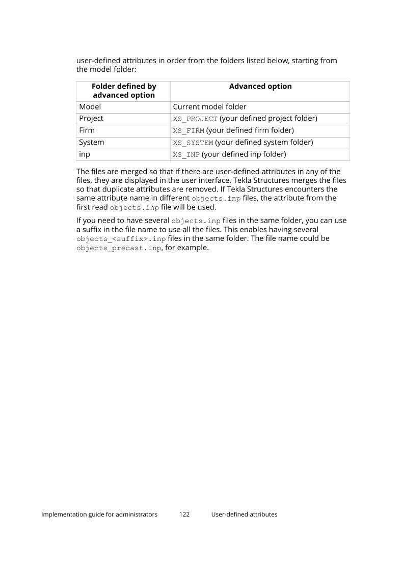
user-defined attributes in order from the folders listed below, starting fromthe model folder:
Folder defined byadvanced option
Advanced option
Model Current model folderProject XS_PROJECT (your defined project folder)Firm XS_FIRM (your defined firm folder)System XS_SYSTEM (your defined system folder)inp XS_INP (your defined inp folder)
The files are merged so that if there are user-defined attributes in any of thefiles, they are displayed in the user interface. Tekla Structures merges the filesso that duplicate attributes are removed. If Tekla Structures encounters thesame attribute name in different objects.inp files, the attribute from thefirst read objects.inp file will be used.
If you need to have several objects.inp files in the same folder, you can usea suffix in the file name to use all the files. This enables having severalobjects_<suffix>.inp files in the same folder. The file name could beobjects_precast.inp, for example.
Implementation guide for administrators 122 User-defined attributes

5 Create and distributecustomized settings, userinterface elements, andcatalogs
Tekla Structures settings are managed on several layers, and many of thesettings can be customized to meet the needs of your company and projects.
If you are not yet familiar with the different files and folder that are essentialto get Tekla Structures working as efficiently as possible, see Implementationguide for administrators (page 110) before you start customizing.
Customize modeling and drawing settings
In addition to Trimble's default settings, you can create your company'sgeneral settings and project-specific settings. See Environment, company, andproject settings for administrators (page 124).
Share customized user interface elements
Also, many user interface elements can be customized and distributed to allthe users in a company. You can distribute
• customized ribbons (page 131)
• customized tabs (page 133)
• customized property pane layouts (page 135) and
• customized toolbars (page 137).
Customize catalogs and databases
You can customize catalogs and databases for
• profiles (page 146)
• materials (page 138)
Create and distribute customized settings, userinterface elements, and catalogs
123

• shapes (page 209)
• bolts (page 226)
• rebars (page 243) and
• applications and components.
Check, for example, the profile and material needs for your project, and ifneeded, clean up the catalogs and databases so that they contain the relevantcontent for your project. This helps you to simplify your work and avoidmistakes. Always ensure that the catalog content is correct. Mistakes incatalogs may be hard to detect, but if left unnoticed, they may lead to seriousinconsistencies in quantity information, data transfer, or elsewhere. Forexample, wrong material density will lead to systematic errors in reportedweights.
If necessary, you can add new content to the catalogs from otherenvironments, from Tekla Warehouse, or you can import content created inother software solutions.
Create and distribute customized settings, userinterface elements, and catalogs
124 Environment, company, and project settings foradministrators

5.1 Environment, company, and project settings foradministratorsTekla Structures settings are managed on several layers. On the highest layerthere are hard-coded default settings which cannot be changed but which youcan override on the following layers.
common environment settings
Windows AppData folder
Tekla Structures hard-coded settings
regional environment settings
XS_FIRM
XS_PROJECT
model template
model folder
These settings are constantly active
Tekla Structures reads these settings when a model is created
Tekla Structures reads these settings when a model is opened
• Common environment settings that have preset values included in theinstallation. These can be modified or removed. The common environmentis usually always included in the installation.
• Regional environment settings with preset values that are suited forspecific regional areas.
If needed, you can clean up the common environment and the selectedregional environment of the files that you do not need.
• Advanced option XS_FIRM that defines a folder, typically on a networkdrive, that loads settings for all users within your company.
This folder is the main container of files for the company.
• Advanced option XS_PROJECT that defines a folder, typically on a networkdrive, that loads higher-ranking settings for all users within a specificproject.
Create and distribute customized settings, userinterface elements, and catalogs
125 Environment, company, and project settings foradministrators
• Model template that is loaded from the environment, or from the networkfolders. The model template is loaded only once when you start creating anew model.
• Model folder content that is saved locally when you add or edit settings.
Note that if you save content in the model folder, the presaved settings inother locations will override the same settings found in the model folder.
• Windows AppData folder for user-specific settings related to the TeklaStructures user interface.
Environment settings
Common settings
All settings and files that are the same in all environments are located in the\Tekla Structures\<version>\Environments\common folder. Files andsettings that are specific to an environment are located in separateenvironment folders.
The env_global_default.ini file is also located in the \common folder. Thefile determines the standard settings, and it is the first file that is read. Otherinitialization files (page 268) are read after this file, and if the other filescontain the same settings, they will override the previous settings.
Country-specific settings
The country-specific, or region-specific, settings are located in theenvironments folders, and they are localized by your local Trimble office/reseller. The folder structure of the environments can vary, but the same kindof settings exist. For example, the settings that are localized include profiledatabase, material database, reports, selection filters, view filters, componentsand custom components, macros, user-defined attributes, and drawingssettings.
Company settingsCompany-level settings are mainly settings that are used throughout thecompany for all projects. These settings are set using XS_SYSTEM and XS_FIRM.
For a larger company with subsidiaries, the settings could be used as follows:
• XS_SYSTEM may contain multiple paths, and it points to general settingsinside the company. These can be company logo, reports, printer settings,drawing settings, templates, for example. These are settings that veryseldom change, and are stored on a server available for all. For example, ifthe company logo is updated, it only has to be replaced in one place.
Create and distribute customized settings, userinterface elements, and catalogs
126 Environment, company, and project settings foradministrators

• XS_FIRM points to the firm folder set up by the company, or a subsidiary.The folder contains all the company settings used at the particular office.These can be logos, drawing settings, templates, reports, or printersettings, for example. The firm folder can also have user-defined sub-folders for storing property files.
• XS_PROJECT points to the project folder. The folder contains projectsettings, such as logos for contractors and fabricators, or drawing settings,for example. The project folder can also have user-defined sub-folders forstoring project-specific property files.
For more information on the folder search order, see Folder search order(page 358).
You can also use Tekla Warehouse company-specific collections online oroffline, in your own network. Use Trimble Identity for downloading or installingfrom the online collections. See also Trimble Identity for Tekla Online services.
The offline collection access is managed with folder rights in your network,and on the collection level in the collections.json file on each user'scomputer.
"collections" "\\\\server-A\\company\\Tekla Structures collection"
The collections.json file can be shared to selected persons by copying itto the C:\Users\Public\Documents\Tekla\Tekla Warehouse\ folder.
Model templates
You can save a model with the desired settings and use the model as atemplate when you create new models. This can be very useful if yourcompany has different kinds of projects, such as, parking garages, officebuildings, bridges, and industrial.
When you create a model template, always start by creating a new emptymodel. This is because old models that have been used in live projects cannotbe completely cleaned. They may contain excess information that increasesthe size of the model even if you delete all objects and drawings from themodel.
To create a model template:
1. Create a new model and give it a unique name.
2. Add in the model the desired profiles, custom components, and othernecessary items.
3. On the File menu, click Save as --> Save.
You need to save the model to include custom components in thexslib.db1 file. If you do not save the model, custom components will notbe included in the model template.
4. On the File menu, click Save as --> Save as model template.
Create and distribute customized settings, userinterface elements, and catalogs
127 Environment, company, and project settings foradministrators

5. Enter a name for the model template, and select which catalogs, drawingtemplates, report templates, and model subfolders you want to include inthe model template.
6. Click OK.
By default, the model template folder is saved in your environment folder,under ..ProgramData\Trimble\Tekla Structures\<version>\environments\<your environment>\. The exact folder location mayvary depending on your environment and role. Use the advanced optionXS_MODEL_TEMPLATE_DIRECTORY to define a different location.
You can download, share, and store model templates in Tekla Warehouse. Theimage below shows an example of a model template in Tekla Warehouse.
The Insert into model button in Tekla Warehouse installs the model templatedirectly in the folder pointed by XS_MODEL_TEMPLATE_DIRECTORY. You canimmediately use the template when creating a new model.
Model templates in Tekla Structures version update
We strongly recommend that you update your model templates in TeklaStructures version upgrade.
To update a model template:
1. Create a new model using an existing model template.
2. Give the model the same name as in the previous Tekla Structuresversion.
3. Open a 3D view.
Create and distribute customized settings, userinterface elements, and catalogs
128 Environment, company, and project settings foradministrators

4. On the File menu, click Diagnose and repair --> Diagnose model.
5. On the View tab, click Screenshot --> Project thumbnail to create aproject thumbnail, or add a custom image named thumbnail.png in themodel folder.
The preferred size of the image is 120 x 74 pixels.
6. On the File menu, click Save as --> Save.
If you do not do this, a message may appear warning about the modelbeing created with a previous version.
7. On the File menu, click Save as --> Save as model template.
8. Select which catalogs, drawing templates, report templates, and modelsubfolders you want to include in the model template.
9. Click OK.
10. Remove manually all *.db files (environment database, options databasefiles) from the model folder.
The *.bak, *.log and xs_user files are automatically removed from themodel folder.
Do not remove the .idrm files (db.idrm and xslib.idrm) as they arepart of the model.
The model template is saved in a location pointed by XS_MODEL_TEMPLATE_DIRECTORY.
You now have a sample image for your model template. The Applications& components catalog is now also in order and easy to use.
Customizing reports and drawings
If your company already has graphical templates in the DXF, DWG, or DGNformat, you can convert these templates to Tekla Structures templates. Fordetailed instructions on how to do this, see the information on AutoCAD andMicrostation files in the Template Editor Help.
For information on how to create your own templates and reports, see theTemplate Editor Help, and and Templates (page 362).
Cloning templates for drawings
You should consider cloning drawings when:
• There are several similar parts, assemblies, or cast units in the model.
• You need to produce single-part, assembly, or cast-unit drawings of similarparts, assemblies, or cast units.
• The drawings need a lot of manual editing.
For example, you can create a drawing for one truss, edit the drawing, andthen clone it for similar trusses. Then you only need to modify the cloneddrawings where the trusses differ.
Create and distribute customized settings, userinterface elements, and catalogs
129 Environment, company, and project settings foradministrators
The cloned drawing may contain more parts than the original drawing. Partproperties, marks, associative notes and related text objects are cloned from asimilar part in the original drawing.
Clone templates in Master Drawing Catalog
You can clone drawings by using the Master Drawing Catalog templates. Acloning template in the Master Drawing Catalog can also be used in othermodels. They can be used in projects that have the same kind of drawings.
To create cloning templates:
1. Select a drawing in Document manager.
2. Right-click and select Add to Master Drawing Catalog, and then fill in therequired properties.
The cloning template can be found under Cloning templates in the MasterDrawing Catalog. To use cloning templates in other models, open the Master
Drawing Catalog in the model, click the button on the toolbar, and addthe model where the templates are saved.
For more information on the Master Drawing Catalog and cloning templates,see .
Project settings
Create your own component folder
Usually, only a few different connections and components are used in aproject. To ensure that everyone in the project uses the same componentsand finds the components faster, we recommend that you create acomponent folder of your own.
1. Click the Applications & components button in the side pane toopen the Applications & components catalog.
2. Create a new group for the project: Right-click in the catalog and selectNew group.
3. Add components to the group: Select the components in the catalog,right-click and select Add to group. Then select the group to which thecomponents are added. You can also drag the selected components toanother group.
4. Hide the groups that you do not need: Select the group, right-click andselect Hide/Unhide.
TIP In the Applications & components catalog, use the commands in
Access advanced features > Catalog management to modifycatalog definitions. For more information, see Customize the
Create and distribute customized settings, userinterface elements, and catalogs
130 Environment, company, and project settings foradministrators

Applications & components catalog (page 254) and XS_COMPONENT_CATALOG_ALLOW_SYSTEM_EDIT.
For more information on the Applications & components catalog, see .
Define project properties
Project information is needed many times during a project. Define the projectinformation at the beginning of a project to make reports and drawingsdisplay the correct information automatically. You can also update the projectproperties during the project.
1. On the File menu, click Project properties.
2. Edit the project properties.
When you edit the properties, Tekla Structures highlights the modifiedproperties in yellow.
3. When you are ready with the modifications, click Modify to apply thechanges.
Create and modify templates and reports
You can modify existing reports and templates, or create your own templates(page 362) by using Template Editor. To open Template Editor, click File -->Editors --> Template editor, or double-click an existing table in an opendrawing to open the tool. For more information, see Template Editor User'sGuide.
Note that if your templates are located in a protected folder, the templates areread-only, and you cannot save a modified template in a protected folder. Inthis case, run Tekla Structures as an administrator.
Set up printers
Tekla Structures uses Windows drivers to write the print data directly to theWindows print device interface. You can print drawings as PDF files, save themas plot files (.plt) for printing with printer/plotter, or print them on a selectedprinter. To print to several paper sizes, you need to modify thedrawingsizes.dat file, see more in . You can also change the line width ofthe printed drawings, see more in and .
You can affect the way Tekla Structures automatically names the .pdf filesand plot files by using certain drawing-type-specific advanced options, seemore in .
5.2 Distribute customized ribbons by using a firm orenvironment folderCompany administrators can distribute the customized ribbon files to otherusers in the company by placing the ribbon files in a firm or environment
Create and distribute customized settings, userinterface elements, and catalogs
131 Distribute customized ribbons by using a firm orenvironment folder

folder (not in the project folder). For example, the administrator can createcompany ribbons and save them in the firm folder. These ribbons will bedisplayed in the Tekla Structures user interface for all users who use the samefirm folder.
Add ribbons to a firm or environment folder1. In the Ribbon editor, create the modeling and drawing ribbons that you
want to share.
The ribbons are saved in the ..\Users\<user>\AppData\Local\Trimble\Tekla Structures\<version>\UI\Ribbons folder.
If you cannot find the folder, ensure that you are able to view the hiddenfiles and folders (page 360) on your computer.
2. Copy the entire \Ribbons folder either to your company's firm folder orto the system folder.
3. If the ribbon contains user-defined commands, create a sub-folder named\Commands on the same level as the \Ribbons folder, and copy theUserDefined.xml file from the ..\Users\<user>\AppData\Local\Trimble\Tekla Structures\<version>\UI\Commands folder to the\Commands folder you just created.
4. Restart Tekla Structures.
Loading order of custom ribbonsTekla Structures loads the ribbons in the following order:
1. Tekla Structures default ribbon
2. Company ribbons in the environment folders
3. Company ribbons in the firm folder
4. User-defined ribbons under %localappdata%Note that the ribbons which are loaded later will override previously loadedribbons that have the same configuration + editing mode combination. Forexample, a ribbon defined in the firm folder will take precedence over theribbons in the environment folders.
If you have a customized ribbon in the ..\Users\<user>\AppData\Local\Trimble\Tekla Structures\<version>\UI\Ribbons folder, it will takeprecedence over company ribbons. To override this, open the Ribbon editorand click Restore. The ribbon in the environment or firm folder will now beused. Alternatively, you can remove or rename your own customized ribbons.
Create and distribute customized settings, userinterface elements, and catalogs
132 Distribute customized ribbons by using a firm orenvironment folder

Naming convention for ribbon filesThe customization tool saves the custom ribbons as .xml files. The namingconvention for these files is:
<Tekla-Structures-configuration_identifier>--<Tekla-Structures-editing-mode>.xmlThe name consists of an internal configuration name, a separator of two dashcharacters (--), an internal editing mode name, and the file nameextension .xml. For example, the Full license modeling ribbon is calledalbl_up_Full--main_menu.xml.
Configuration identifier Configuration namealbl_up_Diamond Tekla Structures Diamondalbl_up_Graphite Tekla Structures Graphitealbl_up_Carbon Tekla Structures Carbonalbl_up_Construction_Modeling Construction Modelingalbl_up_Developer Developeralbl_up_Drafter Drafteralbl_up_Educational Educationalalbl_up_Engineering Engineeringalbl_up_Full Fullalbl_up_PC_Detailing Precast Concrete Detailingalbl_up_Rebar_Detailing Rebar Detailingalbl_up_Steel_Detailing Steel Detailingalbl_up_Tekla_Structures_Primary
Primary
albl_up_Viewer Project Viewer
Editing mode Purposemain_menu Modeling ribbonedit_draw_menu Drawing ribbonplan_main_menu Importing ribbon
5.3 Distribute customized tabs by using a firm orenvironment folderAs an alternative to customized ribbon files, which override the existingribbon, you can distribute customized tabs to other users in the company byplacing the tab files in a firm or an environment folder (not in a project folder).The customized tabs are automatically appended to the end of the ribbon forall users who use the same firm or environment folder. This means that an
Create and distribute customized settings, userinterface elements, and catalogs
133 Distribute customized tabs by using a firm orenvironment folder
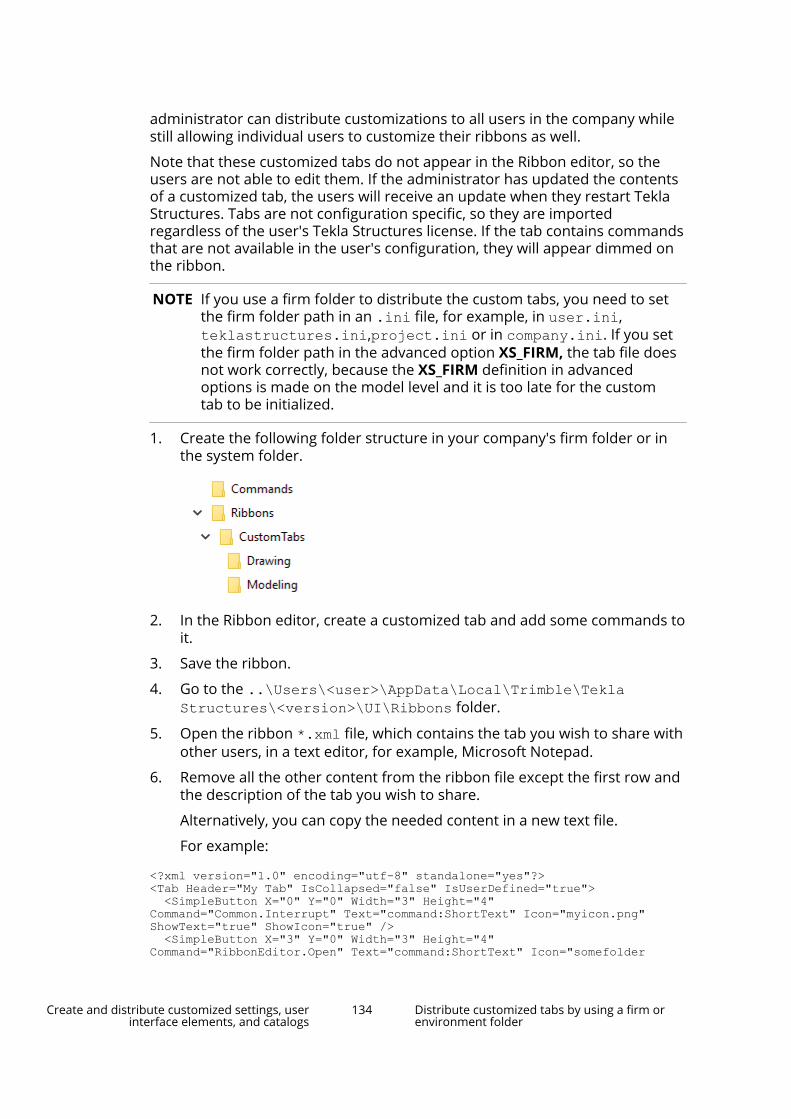
administrator can distribute customizations to all users in the company whilestill allowing individual users to customize their ribbons as well.
Note that these customized tabs do not appear in the Ribbon editor, so theusers are not able to edit them. If the administrator has updated the contentsof a customized tab, the users will receive an update when they restart TeklaStructures. Tabs are not configuration specific, so they are importedregardless of the user's Tekla Structures license. If the tab contains commandsthat are not available in the user's configuration, they will appear dimmed onthe ribbon.
NOTE If you use a firm folder to distribute the custom tabs, you need to setthe firm folder path in an .ini file, for example, in user.ini,teklastructures.ini,project.ini or in company.ini. If you setthe firm folder path in the advanced option XS_FIRM, the tab file doesnot work correctly, because the XS_FIRM definition in advancedoptions is made on the model level and it is too late for the customtab to be initialized.
1. Create the following folder structure in your company's firm folder or inthe system folder.
2. In the Ribbon editor, create a customized tab and add some commands toit.
3. Save the ribbon.
4. Go to the ..\Users\<user>\AppData\Local\Trimble\TeklaStructures\<version>\UI\Ribbons folder.
5. Open the ribbon *.xml file, which contains the tab you wish to share withother users, in a text editor, for example, Microsoft Notepad.
6. Remove all the other content from the ribbon file except the first row andthe description of the tab you wish to share.
Alternatively, you can copy the needed content in a new text file.
For example:
<?xml version="1.0" encoding="utf-8" standalone="yes"?><Tab Header="My Tab" IsCollapsed="false" IsUserDefined="true"> <SimpleButton X="0" Y="0" Width="3" Height="4" Command="Common.Interrupt" Text="command:ShortText" Icon="myicon.png" ShowText="true" ShowIcon="true" /> <SimpleButton X="3" Y="0" Width="3" Height="4" Command="RibbonEditor.Open" Text="command:ShortText" Icon="somefolder
Create and distribute customized settings, userinterface elements, and catalogs
134 Distribute customized tabs by using a firm orenvironment folder
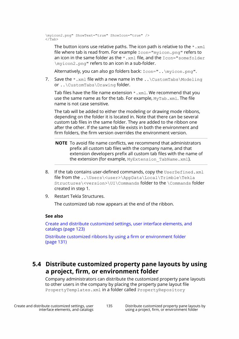
\myicon2.png" ShowText="true" ShowIcon="true" /></Tab>
The button icons use relative paths. The icon path is relative to the *.xmlfile where tab is read from. For example Icon="myicon.png" refers toan icon in the same folder as the *.xml file, and the Icon="somefolder\myicon2.png" refers to an icon in a sub-folder.
Alternatively, you can also go folders back: Icon="..\myicon.png".
7. Save the *.xml file with a new name in the ..\CustomTabs\Modelingor ..\CustomTabs\Drawing folder.
Tab files have the file name extension *.xml. We recommend that youuse the same name as for the tab. For example, MyTab.xml. The filename is not case sensitive.
The tab will be added to either the modeling or drawing mode ribbons,depending on the folder it is located in. Note that there can be severalcustom tab files in the same folder. They are added to the ribbon oneafter the other. If the same tab file exists in both the environment andfirm folders, the firm version overrides the environment version.
NOTE To avoid file name conflicts, we recommend that administratorsprefix all custom tab files with the company name, and thatextension developers prefix all custom tab files with the name ofthe extension (for example, MyExtension_TabName.xml).
8. If the tab contains user-defined commands, copy the UserDefined.xmlfile from the ..\Users\<user>\AppData\Local\Trimble\TeklaStructures\<version>\UI\Commands folder to the \Commands foldercreated in step 1.
9. Restart Tekla Structures.
The customized tab now appears at the end of the ribbon.
See also
Create and distribute customized settings, user interface elements, andcatalogs (page 123)
Distribute customized ribbons by using a firm or environment folder(page 131)
5.4 Distribute customized property pane layouts by usinga project, firm, or environment folderCompany administrators can distribute the customized property pane layoutsto other users in the company by placing the property pane layout filePropertyTemplates.xml in a folder called PropertyRepository
Create and distribute customized settings, userinterface elements, and catalogs
135 Distribute customized property pane layouts byusing a project, firm, or environment folder
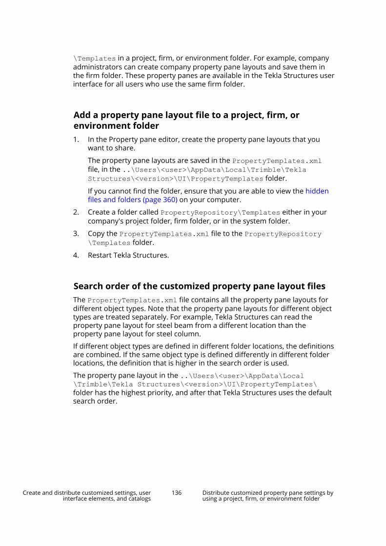
\Templates in a project, firm, or environment folder. For example, companyadministrators can create company property pane layouts and save them inthe firm folder. These property panes are available in the Tekla Structures userinterface for all users who use the same firm folder.
Add a property pane layout file to a project, firm, orenvironment folder1. In the Property pane editor, create the property pane layouts that you
want to share.
The property pane layouts are saved in the PropertyTemplates.xmlfile, in the ..\Users\<user>\AppData\Local\Trimble\TeklaStructures\<version>\UI\PropertyTemplates folder.
If you cannot find the folder, ensure that you are able to view the hiddenfiles and folders (page 360) on your computer.
2. Create a folder called PropertyRepository\Templates either in yourcompany's project folder, firm folder, or in the system folder.
3. Copy the PropertyTemplates.xml file to the PropertyRepository\Templates folder.
4. Restart Tekla Structures.
Search order of the customized property pane layout filesThe PropertyTemplates.xml file contains all the property pane layouts fordifferent object types. Note that the property pane layouts for different objecttypes are treated separately. For example, Tekla Structures can read theproperty pane layout for steel beam from a different location than theproperty pane layout for steel column.
If different object types are defined in different folder locations, the definitionsare combined. If the same object type is defined differently in different folderlocations, the definition that is higher in the search order is used.
The property pane layout in the ..\Users\<user>\AppData\Local\Trimble\Tekla Structures\<version>\UI\PropertyTemplates\folder has the highest priority, and after that Tekla Structures uses the defaultsearch order.
Create and distribute customized settings, userinterface elements, and catalogs
136 Distribute customized property pane settings byusing a project, firm, or environment folder

5.5 Distribute customized property pane settings byusing a project, firm, or environment folderCompany administrators can distribute the customized property pane settingsto other users in the company. Place the PropertyPaneSettings.xml file ina folder called \PropertyPane in a project, firm, or environment folder.
1. Customize the property pane settings that you want to share.
The property pane settings are saved in thePropertyPaneSettings.xml file, in the ..\Users\<user>\AppData\Local\Trimble\Tekla Structures\<version>\UI\PropertyPane\ folder.
If you cannot find the folder, ensure that you are able to view the hiddenfiles and folders (page 360) on your computer.
2. Create a folder called \PropertyPane either in your company's projectfolder, firm folder, or in the system folder.
3. Copy the PropertyPaneSettings.xml file to the \PropertyPanefolder.
4. Restart Tekla Structures.
The file in ..\Users\<user>\AppData\Local\Trimble\TeklaStructures\<version>\UI\PropertyPane\ has the highest priority inthe search order, and after that Tekla Structures uses the default searchorder.
If the PropertyPaneSettings.xml file is placed in several differentfolder locations, Tekla Structures reads the settings from different foldersand merges them.
See also
Create and distribute customized settings, user interface elements, andcatalogs (page 123)
5.6 Distribute customized toolbars by using a project,firm, or environment folderCompany administrators can distribute the customized Selecting, Snapping,and Snap override toolbars to other users in the company. Place the neededtoolbar .json files in a folder called \Toolbars in a project, firm, orenvironment folder. For example, company administrators can createcompany toolbars and save them in the firm folder. These toolbars areavailable in the Tekla Structures user interface for all users who use the samefirm folder.
1. Customize the toolbars that you want to share.
Create and distribute customized settings, userinterface elements, and catalogs
137 Distribute customized toolbars by using a project,firm, or environment folder

The toolbars are saved in corresponding .json files, in the ..\Users\<user>\AppData\Local\Trimble\Tekla Structures\<version>\Toolbars folder.
If you cannot find the folder, ensure that you are able to view the hiddenfiles and folders (page 360) on your computer.
2. Create a folder called \Toolbars either in your company's project folder,firm folder, or in the system folder.
3. Copy the needed .json files to the \Toolbars folder.
4. Restart Tekla Structures.
The files in ..\Users\<user>\AppData\Local\Trimble\TeklaStructures\<version>\Toolbars have the highest priority in thesearch order, and after that Tekla Structures uses the default searchorder.
See also
Create and distribute customized settings, user interface elements, andcatalogs (page 123)
5.7 Customize the material catalogThe material catalog contains information on material types and grades. In thematerial catalog, materials are displayed in a hierarchical tree groupedaccording to their types. Each material type has material grades listed underthem.
The following material types are available in Tekla Structures:
• Steel
• Concrete
• Reinforcing bar
• Timber
• Miscellaneous
By default, the material catalog contains standard, environment-specificmaterials. You can add, modify, and delete material grades.
Tekla Structures stores the material information in the matdb.bin file.
See also
Important buttons in the material catalog (page 139)
Add a material grade (page 139)
Copy a material grade (page 140)
Create and distribute customized settings, userinterface elements, and catalogs
138 Customize the material catalog

Modify a material grade (page 141)
Delete a material grade (page 141)
Add user attributes to material grades (page 142)
Create user-defined material definitions (page 143)
Import and export material grades (page 144)
Important buttons in the material catalogWhen you work with the material grades, note the usage of the followingbuttons in the Modify Material Catalog dialog box:
Button DescriptionSaves the changes of a single edited material grade to thecomputer’s memory until you click OK.Saves the changes in the model folder.
Tekla Structures saves the modified catalog on the hard disk whenyou click OK to close the dialog box and then click OK in the Saveconfirmation dialog box.Closes the Modify Material Catalog dialog box without saving thechanges.
Note that all changes made to the catalog will be lost even if youhave clicked Update, because the changes have not been saved onthe hard disk. The changes made to the catalog are visible duringone session, because the catalog is using the computer’s memory.When you start Tekla Structures the next time, the previous data isrestored from the hard disk.
Tekla Structures stores the material information in the matdb.bin file. Whenyou first open a model, Tekla Structures reads the data from the hard disk andstores it in the computer’s memory.
When you select a material, Tekla Structures reads the data from thecomputer’s memory and displays it in the Modify Material Catalog dialogbox. This is faster than accessing the data from the hard disk.
See also
Customize the material catalog (page 138)
Add a material grade1. On the File menu, click Catalogs --> Material catalog to open the Modify
Material Catalog dialog box.
Create and distribute customized settings, userinterface elements, and catalogs
139 Customize the material catalog

2. Select a material type, for example, steel.
3. Right-click and select Add Grade.
A new material grade is added under to the material type you selected.
4. Change the material grade name by clicking the grade and entering a newname for it.
5. Enter the material grade properties.
6. Click OK to save the material grade and close the Modify MaterialCatalog dialog box.
7. Click OK in the Save confirmation dialog box to save the changes.
See also
Copy a material grade (page 140)
Modify a material grade (page 141)
Delete a material grade (page 141)
Import and export material grades (page 144)
Copy a material gradeYou can add new material grades by modifying a copy of an existing, similarmaterial grade.
1. On the File menu, click Catalogs --> Material catalog to open the ModifyMaterial Catalog dialog box.
2. Select a material grade that is similar to the one you wish to create.
3. Right-click and select Copy Grade.
A copy of the material grade with the name COPY is added to the materialtree.
4. Change the material grade name by clicking the grade and entering a newname for it.
5. Modify the material grade properties.
6. Click OK to save the material grade and close the Modify MaterialCatalog dialog box.
7. Click OK in the Save confirmation dialog box to save the changes.
See also
Add a material grade (page 139)
Modify a material grade (page 141)
Delete a material grade (page 141)
Create and distribute customized settings, userinterface elements, and catalogs
140 Customize the material catalog

Modify a material gradeYou can modify existing material grades using the material catalog.
1. On the File menu, click Catalogs --> Material catalog to open the ModifyMaterial Catalog dialog box.
2. Select a material grade in the tree and modify its properties.
• Use the General tab for entering three alternative names for thematerial. The names are usually the material names used in differentcountries or standards. The tab also contains the profile and platedensity values.
• Use the Analysis tab for entering information on the properties usedin structural analysis.
• Use the Design tab for entering information on the design-specificproperties, such as strengths and partial safety factors.
• Use the User attributes tab for creating your own attributes formaterial grades.
For example, you can define a paint layer thickness, or the maximumgrain size of concrete using a user-defined attribute.
3. When you have finished modifying the material grade, click Update.
4. Click OK to close the Modify Material Catalog dialog box.
Tekla Structures asks if you want to save the changes to the model folder.
5. Click OK in the Save confirmation dialog box to save the changes.
The modified material catalog is saved in the current model folder and isavailable only for that model. To make the modified catalog available forall the other models, use export and import.
See also
Add a material grade (page 139)
Copy a material grade (page 140)
Delete a material grade (page 141)
Delete a material grade1. On the File menu, click Catalogs --> Material catalog to open the Modify
Material Catalog dialog box.
2. Select the material grade that you want to delete.
3. Right-click and select Delete Grade.
4. Click OK to close the Modify Material Catalog dialog box.
Create and distribute customized settings, userinterface elements, and catalogs
141 Customize the material catalog

5. Click OK in the Save confirmation dialog box to save the changes.
See also
Add a material grade (page 139)
Copy a material grade (page 140)
Modify a material grade (page 141)
Add user attributes to material gradesYou can add user attributes and their values to the material grades. The userattributes can then be used, for example, in filtering.
1. On the File menu, click Catalogs --> Material catalog to open the ModifyMaterial Catalog dialog box.
2. On the User attributes tab, click Definitions to open the ModifyMaterial Properties dialog box.
3. Click Add to add a new row.
4. To define a user attribute, click each item on a row.
a. In the Category list, select a material category to which the userattribute is applied.
b. In the Design code list, select a design code to which the attribute isadded.
c. In the Material type list, select a material type for the attribute.
d. In the Quantity type list, select the type of information that the userattribute contains, for example, weight, area, ratio, or string.
e. In the Order column, define the order in which the user attributes areshown in the dialog box. Smaller values are shown first.
f. In the Property name column, define a name for the property.
The name is saved in the catalog and can be used in reports andtemplates. When Property name is used in a template, MATERIAL.PROPERTY_NAME indicates where the property nameappears.
g. In the Label column, define a label for the attribute.
5. Click Update.
6. Click OK to close the Modify Material Properties dialog box.
See also
Modify a material grade (page 141)
Create and distribute customized settings, userinterface elements, and catalogs
142 Customize the material catalog

Create user-defined material definitionsYou can replace the existing material definitions with your own definitions anduse them, for example, in drawing part marks. Material definitions can containtext, numbers and symbols.
1. Save the symbol file user_material_symbols.sym in the symbol folder(usually the folder ..\ProgramData\Trimble\Tekla Structures\<version>\environments\common\symbols\).
2. Create a text file that contains your material definitions.
Create the file using a text editor, for example Microsoft Notepad.
Each row in the file defines a material. Use the following syntax: material_name symbol_file_name@n, where
• material_name is the name of the material used in the materialcatalog
• symbol_file_name is the symbol file name to be used
• n is the number of the symbol.
For example:
WARNING The order of material names in the definition file is relevantto the conversion. Materials with more specific names needto be listed before the ones with similar, but simpler names,for example, S235JRG1 must be listed before S235JR.Otherwise they both get the same symbol.
3. Save the file for example with the nameuser_material_definitions.txt.
All the named materials in the material catalog will be replaced with theones defined in this file.
4. Set the name of the file as a value for the advanced option XS_MATERIAL_SYMBOL_REPRESENTATION_FILE in File menu -->Settings --> Advanced options --> Drawing Properties as follows:
Create and distribute customized settings, userinterface elements, and catalogs
143 Customize the material catalog

setXS_MATERIAL_SYMBOL_REPRESENTATION_FILE=user_material_definitions.txtYou can also enter a full path to the material definition file. Without thepath Tekla Structures searches for the file in the model, firm, project, andsystem folders.
See also
Customize the material catalog (page 138)
Import and export material gradesUse importing and exporting for merging material catalogs. Material catalogsare imported and exported as .lis files.
Importing and exporting is useful when you:
• upgrade to a newer version of Tekla Structures and want to use acustomized material catalog from a previous version
• want to combine material catalogs that are stored in different locations
• want to share material catalog information with other users
• want to combine material catalogs across different environments.
TIP You can also download or share material grades using Tekla Warehouse.
See also
Import a material catalog (page 144)
Export an entire material catalog (page 145)
Export a part of the material catalog (page 146)
Units used in import and export (page 159)
Import a material catalogMaterial catalogs are imported to Tekla Structures models as .lis files. Youcan move an exported .lis file to any model folder and import it to anexisting material catalog.
1. Open the model to which you want to import a material catalog.
2. On the File menu, click Catalogs --> Material catalog to open the ModifyMaterial Catalog dialog box.
3. Click Import.
4. Browse for the folder that contains the import file, and select the file.
Create and distribute customized settings, userinterface elements, and catalogs
144 Customize the material catalog
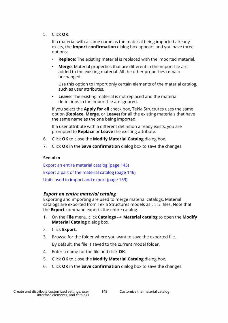
5. Click OK.
If a material with a same name as the material being imported alreadyexists, the Import confirmation dialog box appears and you have threeoptions:
• Replace: The existing material is replaced with the imported material.
• Merge: Material properties that are different in the import file areadded to the existing material. All the other properties remainunchanged.
Use this option to import only certain elements of the material catalog,such as user attributes.
• Leave: The existing material is not replaced and the materialdefinitions in the import file are ignored.
If you select the Apply for all check box, Tekla Structures uses the sameoption (Replace, Merge, or Leave) for all the existing materials that havethe same name as the one being imported.
If a user attribute with a different definition already exists, you areprompted to Replace or Leave the existing attribute.
6. Click OK to close the Modify Material Catalog dialog box.
7. Click OK in the Save confirmation dialog box to save the changes.
See also
Export an entire material catalog (page 145)
Export a part of the material catalog (page 146)
Units used in import and export (page 159)
Export an entire material catalogExporting and importing are used to merge material catalogs. Materialcatalogs are exported from Tekla Structures models as .lis files. Note thatthe Export command exports the entire catalog.
1. On the File menu, click Catalogs --> Material catalog to open the ModifyMaterial Catalog dialog box.
2. Click Export.
3. Browse for the folder where you want to save the exported file.
By default, the file is saved to the current model folder.
4. Enter a name for the file and click OK.
5. Click OK to close the Modify Material Catalog dialog box.
6. Click OK in the Save confirmation dialog box to save the changes.
Create and distribute customized settings, userinterface elements, and catalogs
145 Customize the material catalog

See also
Import a material catalog (page 144)
Units used in import and export (page 159)
Export a part of the material catalogIf you do not want to export the whole material catalog, you can export abranch of the material tree, meaning all the material grades grouped underone material type, or a single material grade. Material catalogs are exportedfrom Tekla Structures models as .lis files.
1. On the File menu, click Catalogs --> Material catalog to open the ModifyMaterial Catalog dialog box.
2. Select material grades to be exported.
• To export a branch of the material tree, right-click the branch andselect Export Grades.
• To export a single material grade, right-click the material grade andselect Export Grade.
3. Browse for the folder where you want to save the export files.
By default, the file is saved to the current model folder.
4. Enter a name for the file and click OK.
5. Click OK to close the Modify Material Catalog dialog box.
6. Click OK in the Save confirmation dialog box to save the changes.
See also
Export an entire material catalog (page 145)
Import a material catalog (page 144)
Units used in import and export (page 159)
5.8 Customize the profile catalogThe profile catalog contains information on profiles, their rules and types, andthe analysis and design properties of the profiles. Profiles are displayed in ahierarchical tree grouped according to rules.
By default, the profile catalog contains standard, environment-specific profilesand generic parametric profiles. You can add, modify, import, export, anddelete profiles.
You can define your own user-defined profiles, which can be either fixed orparametric. Use the profile catalog to create new fixed profiles, either from
Create and distribute customized settings, userinterface elements, and catalogs
146 Customize the profile catalog
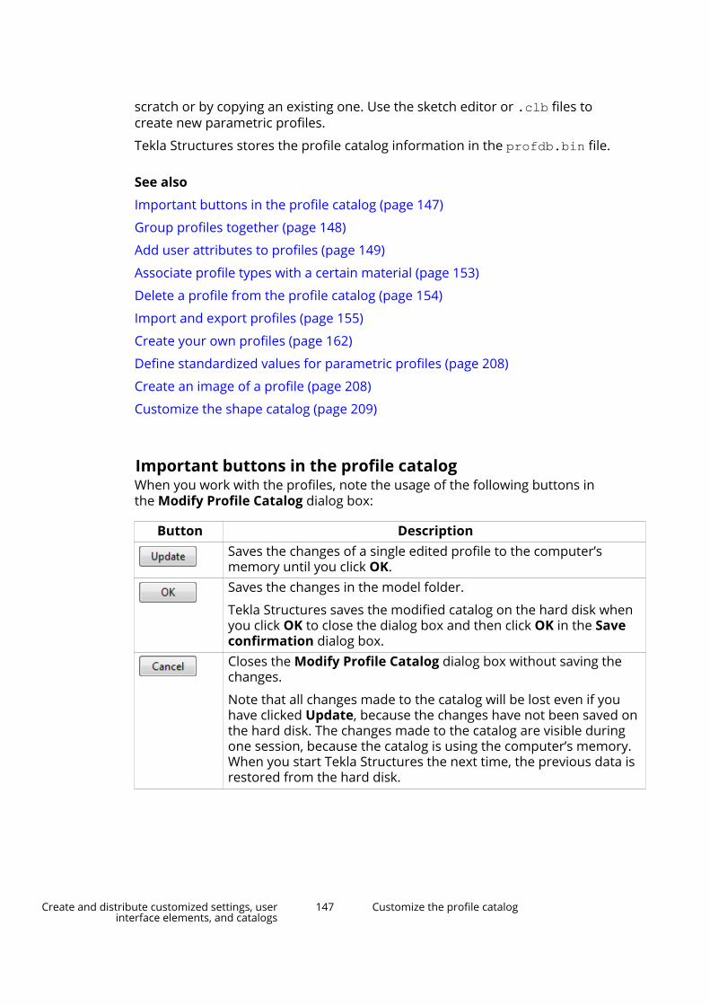
scratch or by copying an existing one. Use the sketch editor or .clb files tocreate new parametric profiles.
Tekla Structures stores the profile catalog information in the profdb.bin file.
See also
Important buttons in the profile catalog (page 147)
Group profiles together (page 148)
Add user attributes to profiles (page 149)
Associate profile types with a certain material (page 153)
Delete a profile from the profile catalog (page 154)
Import and export profiles (page 155)
Create your own profiles (page 162)
Define standardized values for parametric profiles (page 208)
Create an image of a profile (page 208)
Customize the shape catalog (page 209)
Important buttons in the profile catalogWhen you work with the profiles, note the usage of the following buttons inthe Modify Profile Catalog dialog box:
Button DescriptionSaves the changes of a single edited profile to the computer’smemory until you click OK.Saves the changes in the model folder.
Tekla Structures saves the modified catalog on the hard disk whenyou click OK to close the dialog box and then click OK in the Saveconfirmation dialog box.Closes the Modify Profile Catalog dialog box without saving thechanges.
Note that all changes made to the catalog will be lost even if youhave clicked Update, because the changes have not been saved onthe hard disk. The changes made to the catalog are visible duringone session, because the catalog is using the computer’s memory.When you start Tekla Structures the next time, the previous data isrestored from the hard disk.
Create and distribute customized settings, userinterface elements, and catalogs
147 Customize the profile catalog

Tekla Structures stores the information of fixed profiles in the profdb.binfile. When you first open a model, Tekla Structures reads the data from thehard disk and stores it in the computer’s memory.
When you select a profile, Tekla Structures reads the data from the computer’smemory and displays it in the Modify Profile Catalog dialog box. This is fasterthan accessing the data from the hard disk.
See also
Customize the profile catalog (page 146)
Group profiles togetherIn the profile catalog, the profiles are displayed in a hierarchical tree and theyare grouped according to rules , such as the profile type (for example, Iprofiles) and the profile subtype (for example, HEA). To change how theprofiles are grouped in the profile tree, you need to modify the rules.
The order in which you create the rules does not matter, only the location ofthe rules in the profile tree.
Tekla Structures reads the rules from top to bottom in the profile tree. Profilesare in the highest group where they meet the criteria defined in the rule. Forexample, a rule that collects All profiles overrides all rules that are below it inthe profile tree.
See also
Add a rule to the profile catalog (page 148)
Modify a rule in the profile catalog (page 149)
Add a rule to the profile catalog1. On the File menu, click Catalogs --> Profile catalog to open the Modify
Profile Catalog dialog box.
2. Right-click any existing rule and select Add Rule.
The Profile manager rules dialog box appears.
3. Define the rule properties.
a. Enter a rule name in the Rule name box.
b. Select the Profile type to which the rule is applied.
c. Enter the Name filter string that defines the new rule.
By default, the wildcard symbol (*) is entered, meaning “all entries”.
For example, to group all catalog entries with names beginning withA, enter A* in the Name filter string box, or to group all catalog
Create and distribute customized settings, userinterface elements, and catalogs
148 Customize the profile catalog

entries with names containing 100, enter *100*. Tekla Structuresgroups the catalog entries that meet your criteria under the new rule.
4. Click OK to close the Profile manager rules dialog box.
5. Click OK to close the Modify Profile Catalog dialog box.
6. Click OK in the Save confirmation dialog box to save the changes.
TIP You can add a next level rule that creates a subgroup under anexisting rule. Use the Add Next Level Rule command to add thenext level rule.
See also
Modify a rule in the profile catalog (page 149)
Modify a rule in the profile catalog1. On the File menu, click Catalogs --> Profile catalog to open the Modify
Profile Catalog dialog box.
2. Right-click any existing rule and select Edit Rule.
The Profile manager rules dialog box appears.
3. Modify the rule properties.
4. Click OK to close the Profile manager rules dialog box.
5. Click OK to close the Modify Profile Catalog dialog box.
6. Click OK in the Save confirmation dialog box to save the changes.
Profiles in the profile tree are listed in an alphabetical order, and rules arelisted in the order you specify. To change the order in which the rules appear,use the Move up and Move down commands.
TIP If you want to delete a rule, right-click an existing rule and select Delete Rule.
See also
Add a rule to the profile catalog (page 148)
Add user attributes to profilesYou can add your own attributes to profiles. For example, you can specifypaint layer thickness, define the maximum grain size of concrete, sort outdifferent profile types by material, or create profile aliases for convertingimperial profiles to metric and vice versa.
Create and distribute customized settings, userinterface elements, and catalogs
149 Customize the profile catalog

1. On the File menu, click Catalogs --> Profile catalog to open the ModifyProfile Catalog dialog box.
2. On the User attributes tab, click Definitions.
The Modify Profile Properties dialog box appears.
3. Click Add to add a new row.
4. To define a user attribute, click each item on a row.
a. In the Profile type list, select a profile type to which the userattribute is applied.
b. In the Quantity type list, select the type of information that the userattribute contains, for example, weight, area, ratio, or string.
c. In the Order list, define the order in which the user attributes areshown in the dialog box. Larger values are shown first.
d. In the Property name list, define a name for the property.
The name is saved in the catalog and can be used in reports andtemplates. When Property name is used in a template, PROFILE.PROPERTY_NAME indicates where the property nameappears. For example, PAINT_LAYER_THICKNESS.
e. In the Symbol column, define an abbreviation that can be used forthe property, such as Ix or ct.
f. In the Label column, define a label for the attribute.
5. Click Update.
6. Click OK to close the Modify Profile Properties dialog box.
See also
Example: Add a user attribute to a profile and use it in a rule (page 150)
Example: Add a user attribute to a profile and use it in a ruleYou can add your own attributes and their values to profiles. The userattributes can then be used, for example, in profile filtering.
In this example, you will add a user attribute for I profiles’ rule.
1. On the File menu, click Catalogs --> Profile catalog to open the ModifyProfile Catalog dialog box.
2. On the User attributes tab, click Definitions.
The Modify Profile Properties dialog box appears.
3. Click Add to add a new row.
4. Select the row that was created and modify the properties as follows:
• Set Profile type to I profiles.
Create and distribute customized settings, userinterface elements, and catalogs
150 Customize the profile catalog

• Set Quantity type to String.
• Set Property name to HISTORICAL_PROFILE.
• Set Symbol to Hist.
• Set Label to Historical profile.
5. Click Update and OK.
6. In the profile tree, select I profiles and then HEA.
7. Right-click and select Add Next Level Rule.
8. In the Profile manager rules dialog box, set the rule properties asfollows:
• Set Rule name to Historical profiles.
• In Profile type, clear the All profiles check box and select the Iprofiles check box.
• Enter HEA* in the Name filter string box.
Create and distribute customized settings, userinterface elements, and catalogs
151 Customize the profile catalog
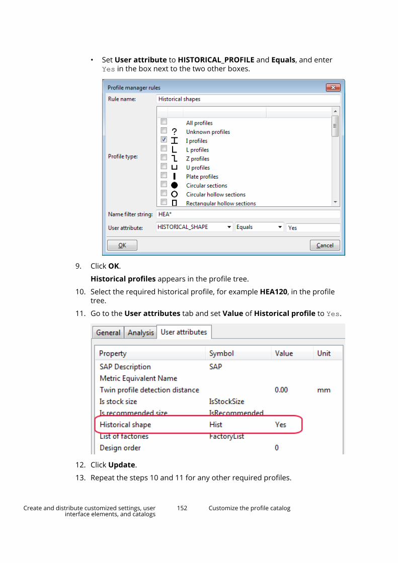
• Set User attribute to HISTORICAL_PROFILE and Equals, and enterYes in the box next to the two other boxes.
9. Click OK.
Historical profiles appears in the profile tree.
10. Select the required historical profile, for example HEA120, in the profiletree.
11. Go to the User attributes tab and set Value of Historical profile to Yes.
12. Click Update.
13. Repeat the steps 10 and 11 for any other required profiles.
Create and distribute customized settings, userinterface elements, and catalogs
152 Customize the profile catalog

14. Click OK to close the Modify Profile Catalog dialog box.
15. Click OK in the Save confirmation dialog box to save the changes.
Next time you open the profile catalog, the profiles appear under Historicalprofiles in the profile tree.
See also
Add user attributes to profiles (page 149)
Add a rule to the profile catalog (page 148)
Associate profile types with a certain materialYou can define which profiles are available for steel parts, concrete parts, orboth. This affects which profile types are shown in the Select Profile dialogbox when you change the material of a part.
To define the material of a profile type:
1. On the File menu, click Catalogs --> Profile catalog to open the ModifyProfile Catalog dialog box.
2. Select a profile type, for example, L profiles.
3. To associate the profiles with steel, right-click and select Material -->Steel .
Create and distribute customized settings, userinterface elements, and catalogs
153 Customize the profile catalog

A check mark next to Steel indicates that the profiles are available forsteel parts.
4. To make the selected profiles available also for concrete parts, right-clickand select Material --> Concrete .
If needed, you can remove the check mark by clicking the material again.
5. Click OK to close the Modify Profile Catalog dialog box.
6. Click OK in the Save confirmation dialog box to save the changes.
Delete a profile from the profile catalog1. On the File menu, click Catalogs --> Profile catalog to open the Modify
Profile Catalog dialog box.
2. Select the profile that you want to delete.
3. Right-click and select Delete Profile.
4. Click OK to close the Modify Profile Catalog dialog box.
5. Click OK in the Save confirmation dialog box to save the changes.
Tekla Structures will continue showing parts in model views using the deletedprofiles until you modify the parts or reopen the model. After that, the parts
Create and distribute customized settings, userinterface elements, and catalogs
154 Customize the profile catalog

having profiles that are not available in the profile catalog, are shown as stickswithout a profile.
If the deleted profile used a custom custom cross-section definition, delete itseparately to also remove the cross-section from your model.
See also
Customize the profile catalog (page 146)
Import and export profilesUse importing and exporting for merging profiles across profile catalogs.Profile catalogs are imported and exported as .lis files, sketched profilesas .uel files, and user-defined parametric profiles as .clb files.
When you export an entire profile catalog, Tekla Structures creates threeseparate files: profiles.clb, profiles.lis and rules.lis. The .clb filecontains parametric profile definitions, if they are used in the profiles in thecatalog, otherwise it is empty. The profiles.lis file includes the actualprofile definitions and the rules.lis file the branch rules. When you export abranch of a profile catalog, the branch name is attached as prefix to the filenames.
Importing and exporting is useful when you:
• upgrade to a newer version of Tekla Structures and want to use acustomized profile catalog from a previous version
• want to combine profile catalogs that are stored in different locations
• want to share profile catalog information with other users
• want to combine profile catalogs across different environments.
Limitations
• You cannot import or export hard-coded profiles such as PROFILE_ZZ,PROFILE_CC, and PROFILE_CW.
• You cannot import profiles that do not have a defined cross section.
• If you have used a sketched profile or a user-defined parametric profile asthe cross section for a fixed profile, you also need to import the sketchedprofile or the user-defined parametric profile to the new model.
TIP You can also download or share profiles using Tekla Warehouse.
See also
Export an entire profile catalog (page 157)
Export a part of the profile catalog (page 157)
Create and distribute customized settings, userinterface elements, and catalogs
155 Customize the profile catalog

Import profile catalog items (page 156)
Import and export sketched profiles (page 161)
Import profile catalog itemsTekla Structures has five types of profile catalog items: fixed profiles, hard-coded parametric profiles, sketched profiles, user-defined parametric profiles,and rule sets. Profiles and rule sets are imported to Tekla Structures modelsas .lis files, sketched profiles as .uel files, and user-defined parametricprofiles as .clb files.
If you are importing an entire profile catalog or a branch, we recommend thatyou save the related files in a separate folder. This makes the import processfaster.
1. Open the model to which you want to import profile catalog items.
2. On the File menu, click Catalogs --> Profile catalog to open the ModifyProfile Catalog dialog box.
3. Click Import to import a single file, or Import Directory to import thecontents of a file folder.
4. Select the import file or the import folder.
5. Click OK. Tekla Structures checks if there are duplicates in the profilenames in the import file compared to the profile catalog.
a. If the Review import items dialog box appears, there are duplicateprofile names and you must select each duplicate and assign theaction you want to perform with the following buttons:
• Leave: The existing profile item is not replaced and the profiledefinitions in the import file are ignored.
• Merge: Profile properties that are different in the import file areadded to the existing profile. All the other properties remainunchanged.
Use this option to import only certain elements of the profilecatalog, such as user attributes.
• Replace: The existing profile item is replaced with the importedprofile item.
• If you leave Unknown as the action for a profile item, it is notimported.
You can select more than one profile item at a time by using the Shiftand Ctrl keys and assign the same action to the entire selection.
NOTE Each cross section definition has a unique name and IDnumber. If during an import, a cross section with the samename but different properties is found in the existing profilecatalog, the cross section being imported is renamed by
Create and distribute customized settings, userinterface elements, and catalogs
156 Customize the profile catalog

adding an incremental number at the end of the existingname.
b. After you have selected the actions, click Continue to perform them.
6. Click OK to close the Modify Profile Catalog dialog box.
7. Click OK in the Save confirmation dialog box to save the changes.
See also
Import and export profiles (page 155)
Export an entire profile catalog (page 157)
Export a part of the profile catalog (page 157)
Import sketched profiles (page 161)
Units used in import and export (page 159)
Export an entire profile catalogProfile catalogs are exported from Tekla Structures models as .lis, .uel,and .clb files.
1. On the File menu, click Catalogs --> Profile catalog to open the ModifyProfile Catalog dialog box.
2. Click Export.
3. Browse for the folder where you want to save the export files.
By default, the files are saved to the current model folder. For fasterprofile catalog import, we recommend that you create a separatesubfolder for the catalog files.
4. Click OK to close the Modify Profile Catalog dialog box.
See also
Import and export profiles (page 155)
Export a part of the profile catalog (page 157)
Example of profile export file (page 158)
Import profile catalog items (page 156)
Units used in import and export (page 159)
Export a part of the profile catalogIf you do not want to export an entire profile catalog, you can export a branchof the profile tree, meaning all the profiles grouped under one rule, or a singleprofile. Profiles and rule sets are exported from Tekla Structures models
Create and distribute customized settings, userinterface elements, and catalogs
157 Customize the profile catalog
as .lis files, sketched profiles as .uel files, and user-defined parametricprofiles as .clb files.
1. On the File menu, click Catalogs --> Profile catalog to open the ModifyProfile Catalog dialog box.
2. Select profiles to be exported.
• To export a branch of the profile tree, right-click the branch and selectExport Profiles.
• To export a single profile, right-click the profile and select ExportProfile.
3. Browse for the folder where you want to save the export files.
By default, the files are saved to the current model folder.
If you are exporting a single profile, enter a name for the file.
4. Click OK.
5. Click OK to close the Modify Profile Catalog dialog box.
See also
Export an entire profile catalog (page 157)
Example of profile export file (page 158)
Import profile catalog items (page 156)
Units used in import and export (page 159)
Example of profile export file
The export .lis file is divided into specific sections.
The first row in the file is PROFILE CATALOG EXPORT VERSION = n, where nis the version number.
WARNING Do not delete this row. If the row does not appear in the file, theimport is canceled.
The next section defines the hierarchical tree structure that is used to displaythe contents of the catalog.
The next section contains the profiles.
Create and distribute customized settings, userinterface elements, and catalogs
158 Customize the profile catalog

Fixed profiles
Fixed user-defined profiles
Fixed user-defined profiles can have more than one cross section. The profiletype for fixed user-defined profiles is 998. SUB_TYPE refers to the name of thecross section definition. When importing fixed user-defined profiles, therelevant cross section definitions must be in the same import file as theprofile.
Cross section definitions
See also
Export an entire profile catalog (page 157)
Export a part of the profile catalog (page 157)
Create and distribute customized settings, userinterface elements, and catalogs
159 Customize the profile catalog

Units used in import and export
The table below lists the units Tekla Structures uses when importing andexporting profile catalogs and material catalogs.
Type Unit (if blank, no unit)Boolean Integer String Ratio Strain Angle degreeLength mmDeformation mmDimension mmRadius of inertia mmArea mm2
Reinforcement area mm2
Transverse reinforcement area mm2/mArea/unit length mm2/mVolume mm3
Section modulus mm3
Moment of inertia mm4
Torsion constant mm4
Warping constant mm6
Force NWeight kgDistributed load N/mSpring constant N/mMass/length kg/mSurface load N/m2
Strength N/m2
Stress N/m2
Modulus N/m2
Density kg/m3
Moment NmDistributed moment Nm/m
Create and distribute customized settings, userinterface elements, and catalogs
160 Customize the profile catalog

Type Unit (if blank, no unit)Rotation spring constant Nm/radTemperature K (oC)Thermal dilation coefficient 1/K (1/oC)Factor
See also
Import profile catalog items (page 156)
Import a material catalog (page 144)
Export an entire profile catalog (page 157)
Export an entire material catalog (page 145)
Import and export sketched profilesTo use a sketched profile in other Tekla Structures models, you have to exportthe profile to a file (*.uel), and then import the file into another TeklaStructures model.
We recommend that you use the profile catalog to import and export sketchedprofiles. You can also use the Applications & components catalog to importsketched profiles together with related custom components.
See also
Import sketched profiles (page 161)
Export sketched profiles (page 162)
Import sketched profilesAfter you have exported sketched profiles to a file, you can import them toanother Tekla Structures model.
1. Open the Tekla Structures model you want to import to.
2. On the File menu, click Catalogs --> Profile catalog to open the ModifyProfile Catalog dialog box.
3. Click Import.
4. In the Import Profile Catalog dialog box, select *.uel from the Filter list.
5. Select the file to import.
6. Click OK.
7. Click OK to close the Modify Profile Catalog dialog box.
8. Click OK in the Save confirmation dialog box to save the changes.
Create and distribute customized settings, userinterface elements, and catalogs
161 Customize the profile catalog

TIP To automatically import all *.uel files from a folder when creating a new model,use the advanced option XS_UEL_IMPORT_FOLDER.
See also
Export sketched profiles (page 162)
Export sketched profiles
1. Open the Tekla Structures model you want to export from.
2. On the File menu, click Catalogs --> Profile catalog to open the ModifyProfile Catalog dialog box.
3. Right-click the profile you want to export and select Export Profile.
4. In the Export Profile Catalog dialog box, enter a name for the export filein the Selection box.
5. If you want to save the export file to a specific location, browse for thefolder.
By default, Tekla Structures saves the export file in the current modelfolder.
6. Click OK.
See also
Import sketched profiles (page 161)
Create your own profilesYou can create your own profiles and save them in the profile catalog.
Use any of the following methods to create user-defined profiles in TeklaStructures:
Profile type Creation methodsFixed profile • Create user-defined cross sections
(page 163)
• Create a fixed profile (page 169)
• Create a fixed profile by copying(page 170)
• Create a fixed profile based on aparametric profile (page 171)
Parametric profile • Create parametric profilesusing .clb files (page 172)
Create and distribute customized settings, userinterface elements, and catalogs
162 Customize the profile catalog
Profile type Creation methods• Create parametric profiles by
sketching (page 180)Parametric profile with variable crosssections
• Create parametric profiles withvariable cross sections (page 205)
Create user-defined cross sectionsUser-defined cross sections can be used for creating fixed profiles. Define theneeded cross sections before creating the profile.
Use any of the following methods to define a cross section:
• Define a cross section using polygon.
Use this method to create a cross section with fixed dimensions.
• Define a cross section using a plate.
Use this method if you have a contour plate in the model.
• Define a cross section using a DWG file.
Use this method if you have a .dwg file of the profile you want to define.
Define a cross section using polygonDefine a cross section by picking the shape of the cross section.
1. On the File menu, click Catalogs --> Define profiles --> Define crosssection using polygon.
2. Define a cross section without or with inner contours.
• To create a cross section with no inner contours:
a. Pick the corner points of the cross section to define the shape.Start at the bottom-right corner and pick the points counterclockwise.
b. Pick the start point and click the middle mouse button to close theshape.
Create and distribute customized settings, userinterface elements, and catalogs
163 Customize the profile catalog

c. Pick the center point of the cross section.
TIP To make it easier to define the shape, insert a referencemodel of the cross section in the model, and use thereference model as a basis for picking the cross sectionshape.
Alternatively, you can create a few construction lines orpoints in the model and use them to define the cross sectionshape.
If you do not have any actual points to pick, picking thecenter point of the cross section becomes difficult. This isbecause the cross section shape disappears after you haveclicked the middle mouse button to close the shape.
• To create a cross section with inner contours:
a. Pick the corner points of the cross section to define the shape.
b. Pick the start point to close the shape.
c. Pick the corner points of the cross section inner contour.
d. Pick the start point to close the shape
e. Repeat until you have picked all inner contours.
f. Click the middle mouse button.
Create and distribute customized settings, userinterface elements, and catalogs
164 Customize the profile catalog

g. Pick the center point of the cross section.
3. When the User Profile Cross Section dialog box appears, enter a namefor the cross section.
4. Click OK to close the User Profile Cross Section dialog box.
5. Click OK in the Save confirmation dialog box to save the changes.
You can then use this cross section when you add a new profile to the profilecatalog. The Profile type will be User-defined, fixed.
Define a cross section using a plateYou can define a cross section using a contour plate.
1. Create a contour plate that includes all the chamfers.
2. On the File menu, click Catalogs --> Define profiles --> Define crosssection using plate.
The Profile Cross-Section from Plate (10) dialog box appears.
3. On the Parameters tab, enter a name in the Section name and Profilename boxes.
Other properties are optional.
4. Click OK.
5. Select the contour plate.
Tekla Structures creates the cross section with the shape of the contourplate.
You can then use this cross section when you add a new profile to theprofile catalog. The Profile type will be User-defined, fixed.
Properties: Profile cross-section from plate (10)
Use the Parameters tab to define the profile properties in the Profile cross-section from plate (10) component.
Create and distribute customized settings, userinterface elements, and catalogs
165 Customize the profile catalog

Option DescriptionSection name Name of the cross section shown in
the Modify Profile Catalog dialogbox.
If you leave this box empty, no profileis created.
Profile name Name of the profile shown in theBeam properties, and in the ModifyProfile Catalog dialog box.
If you leave this box empty, no profileis created.
Save to The location of the profile catalog.
Select one of the following options:
• Model directory: The currentmodel folder.
• Globaldirectory: ..\ProgramData\Trimble\Tekla Structures\<version>\environments\<environment>\profil
• Do not save: Does not save theprofile. This is useful for testing.
Min distance between points The minimum distance between thecorner points of the cross section.
To create simpler drawings ofcomplicated cross sections, increasethis value.
Center point offset The origin of the plate defines thelocation of the profile reference line.
Enter an offset value to move thereference line, relative to the crosssection.
Coordinate system Select one of the following options:
• Use local
• Use global xy-planeMirroring Select one of the following options:
• Do not mirror
• Mirror to x-direction
• Mirror to y-direction
• Mirror to x- and y-direction
Create and distribute customized settings, userinterface elements, and catalogs
166 Customize the profile catalog

Define a cross section using a DWG fileIf a cross section is available in DWG format, you can import the cross sectionand add it as a DWG profile to the profile catalog.
Tekla Structures supports DWG files that have been created using versionACAD2012 or earlier.
Before you start defining a cross section using a DWG file:
• Save the outline of the cross section as a DWG file. Ensure that the DWGfile only contains the outline of the profile.
• Make sure that the cross section is created as a closed polyline.
• Make sure that the outline consists of only one closed polyline. You cannot,for example, define holes to your cross section with this method. If youneed holes or openings, use the polygon or the plate creation method.
• Remove hatching and unnecessary lines from the DWG file. TeklaStructures imports all the lines it finds in the DWG file.
• If there are blocks in the DWG file, they must be exploded.
1. Open a model.
2. On the File menu, click Catalogs --> Define profiles --> Define crosssection using DWG file.
The DWG Profile to Library (6) dialog box appears.
3. On the Parameters tab, browse for the DWG file.
4. Define the cross section properties.
5. Click OK.
6. In the model, pick the start and the end points of the cross section to beimported.
Tekla Structures imports the cross section and places the profile referenceline at the origin of the DWG file.
You can then use this cross section when you add a new profile to theprofile catalog. The Profile type will be User-defined, fixed.
Properties: DWG Profile to Library (6)
Use the Parameters tab to define the profile properties in the DWG profile tolibrary (6) component.
Option DescriptionInput file Browse for the DWG file to be
imported.Section name Name of the cross section shown in
the Modify Profile Catalog dialogbox.
Create and distribute customized settings, userinterface elements, and catalogs
167 Customize the profile catalog
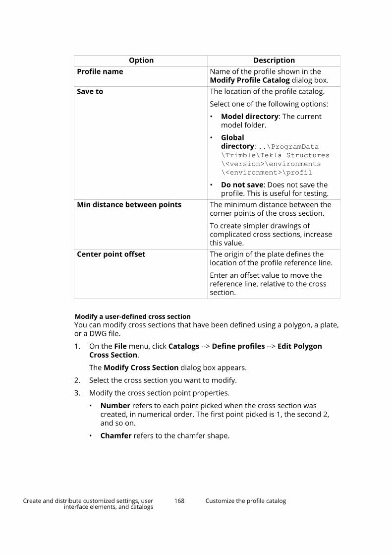
Option DescriptionProfile name Name of the profile shown in the
Modify Profile Catalog dialog box.Save to The location of the profile catalog.
Select one of the following options:
• Model directory: The currentmodel folder.
• Globaldirectory: ..\ProgramData\Trimble\Tekla Structures\<version>\environments\<environment>\profil
• Do not save: Does not save theprofile. This is useful for testing.
Min distance between points The minimum distance between thecorner points of the cross section.
To create simpler drawings ofcomplicated cross sections, increasethis value.
Center point offset The origin of the plate defines thelocation of the profile reference line.
Enter an offset value to move thereference line, relative to the crosssection.
Modify a user-defined cross sectionYou can modify cross sections that have been defined using a polygon, a plate,or a DWG file.
1. On the File menu, click Catalogs --> Define profiles --> Edit PolygonCross Section.
The Modify Cross Section dialog box appears.
2. Select the cross section you want to modify.
3. Modify the cross section point properties.
• Number refers to each point picked when the cross section wascreated, in numerical order. The first point picked is 1, the second 2,and so on.
• Chamfer refers to the chamfer shape.
Create and distribute customized settings, userinterface elements, and catalogs
168 Customize the profile catalog

• x: and y: apply to the chamfer type. For example, if you want thechamfer to be equal on both sides of the angle, only enter a value forx:.
For an uneven chamfer, enter values for x: and y:.
4. Click Update.
5. Click OK to close the Modify Cross Section dialog box.
6. Click OK in the Save confirmation dialog box to save the changes.
TIP If you want to delete a cross section, select the cross section and click Delete.
Create fixed profilesYou can create new fixed profiles either from scratch or by copying an existingone. You can also convert a parametric profile into a fixed one.
Create a fixed profileYou can create fixed profiles with a single cross section or with multiple crosssections. Note that cross sections affect the total weight of the profile.
WARNING If you create a profile with multiple cross sections, create thecross sections with the same number of corner points and in thesame order.
1. On the File menu, click Catalogs --> Profile catalog to open the ModifyProfile Catalog dialog box.
2. Right-click anywhere in the profile tree and select Add Profile.
A new fixed profile with the name PROFILE1 is created.
3. Change the profile name by entering a new name in the Profile namebox.
The profile name must be in upper case letters, with no spaces. TeklaStructures automatically converts lower case letters to upper case letters.
4. In the Profile type list, select User-defined, fixed.
5. In the Profile subtype list, select the cross section you want to use.
If you have created your own user-defined cross sections (page 163), youcan use one of them.
6. Under Equivalent type, select a profile type that matches the new crosssection as closely as possible. This is important because someconnections only work for certain types of profiles.
The equivalent type and the profile dimensions, such as height and width,affect which connections can be applied to the profile. An unsuitableequivalent type or missing dimension values may result in problems withconnections.
Create and distribute customized settings, userinterface elements, and catalogs
169 Customize the profile catalog

7. Click Update.
8. Modify the dimension values.
Always enter values for the dimensions Height h and Width b, as thesevalues affect how Tekla Structures displays the profiles. If the values are 0,the part is drawn as a line.
9. Under Cross section, define a relative location for each cross section:
a. In the Number list, select the number of the cross section.
b. In the Relative location box, enter the location of the cross section.
This value indicates the location of the cross section along the axis:0.0 for the start end and 1.0 for the second end. If you only have asingle cross section, select 1 for Number and enter 0.000 forRelative location.
c. Click Update after defining each cross section.
10. Click Add to add more cross sections, if needed.
11. If you want to use a different cross section in the profile, select a new onefrom the Profile subtype list.
12. If you want to remove a cross section, select the cross section from theNumber list and click Remove.
13. Click OK to close the Modify Profile Catalog dialog box.
14. Click OK in the Save confirmation dialog box to save the changes.
Example
For a pitched profile, you need two cross sections with the same center pointheight. The Relative location value is 0.0 for the first cross section, 0.5 forthe second cross section, and 1.0 for the third cross section.
Create and distribute customized settings, userinterface elements, and catalogs
170 Customize the profile catalog

Create a fixed profile by copyingYou can create new fixed profiles by modifying a copy of an existing, similarprofile.
1. On the File menu, click Catalogs --> Profile catalog to open the ModifyProfile Catalog dialog box.
2. Select a fixed profile that is similar to the one you wish to create.
3. Right-click and select Copy Profile.
A new profile with the name <existing_profile_name COPY> is created.
4. Change the profile name by entering a new name in the Profile namebox.
The profile name must be in upper case letters, with no spaces. TeklaStructures automatically converts lower case letters to upper case letters.
5. Modify the profile properties on the General, Analysis, and Userattributes tabs.
WARNING Under Equivalent type, select a profile type that matchesthe new cross section as closely as possible. This is importantbecause some connections only work for certain types ofprofiles.
Always enter values for the dimensions Height h and Widthb, as these values affect how Tekla Structures displays theprofiles. If the values are 0, the part is drawn as a line.
The equivalent type and the profile dimensions, such asheight and width, affect which connections can be applied tothe profile. An unsuitable equivalent type or missingdimension values may result in problems with connections.
6. Click Update.
7. Click OK to close the Modify Profile Catalog dialog box.
8. Click OK in the Save confirmation dialog box to save the changes.
Create a fixed profile based on a parametric profile
1. On the File menu, click Catalogs --> Profile catalog to open the ModifyProfile Catalog dialog box.
2. Select a parametric profile from the list.
3. Right-click and select Add Profile.
A new standard fixed profile is created, and it has the profile values of theparametric profile.
Create and distribute customized settings, userinterface elements, and catalogs
171 Customize the profile catalog

Modify a fixed profileIf necessary, you can modify existing fixed profiles using the profile catalog.Note that the fixed profiles conform to industry standards, and you should notmodify them unless you are an administrator.
1. On the File menu, click Catalogs --> Profile catalog to open the ModifyProfile Catalog dialog box.
2. Select a fixed profile in the tree and modify its properties.
• The General tab contains information on profile types anddimensions.
• The Analysis tab contains information on the properties used instructural analysis. The structure can be analyzed with differentanalysis software.
• The User attributes tab is for viewing or entering user attributes forprofiles.
3. When you have finished modifying the profile, click Update.
4. Click OK to close the Modify Profile Catalog dialog box.
Tekla Structures asks if you want to save the changes to the model folder.
5. Click OK in the Save confirmation dialog box to save the changes.
Create parametric profiles using .clb filesYou can create new parametric profiles using .clb files.
Follow the example workflow below to create a parametric profile with .clbfiles.
How the .clb, components.clb and profitab.inp files work together
When you create new parametric profiles using this method, you need thefollowing three files:
• .clb
This file contains the cross section definitions. Create a new .clb file inthe ..\ProgramData\Trimble\Tekla Structures\<version>\environments\common\inp folder for each parametric profile youdefine.
• components.clb
This file contains a list of all .clb files that contain cross sectiondefinitions. When you create a new .clb file, you need to add its file nameto the components.clb file located in the ..\ProgramData\Trimble\Tekla Structures\<version>\environments\common\inp folder.
• profitab.inp
Create and distribute customized settings, userinterface elements, and catalogs
172 Customize the profile catalog

This file is the link between the .clb files and the profile catalog. This filecontains a list of all parametric profiles available in Tekla Structures. Thefile controls how the parametric profiles are displayed in the ModifyProfile Catalog dialog box. When you want to take a new parametricprofile into use, you must add the needed profile definitions, such as theprofile type, prefix and the unit of measurement, to the profitab.inpfile. The profitab.inp file is located under the environment folderin ..\ProgramData\Trimble\Tekla Structures\<version>\environments\<environment>\. The exact file location may varydepending on the folder structure of your environment files .
Tekla Structures searches for the profitab.inp file in the standardsearch order and then from the folder indicated by the advanced option XS_PROFDB.
Define the shape and point coordinates of the profileStart by defining the shape and point coordinates of the new profile.
1. Design the profile on a paper.
a. Draw the cross section outline.
b. Add the needed corner points.
c. Add the needed dimensions.
d. Place the y-z coordinate axis center point to the middle of the crosssection.
2. Define the y and z coordinate directions. For example:
Create and distribute customized settings, userinterface elements, and catalogs
173 Customize the profile catalog

• positive y axis: up
• negative y axis: down
• positive z axis: on the right
• negative z axis: on the left
3. Define the y and z vectors. For example:
• y1, y2, y3
• z1, z2, z3
Create and distribute customized settings, userinterface elements, and catalogs
174 Customize the profile catalog
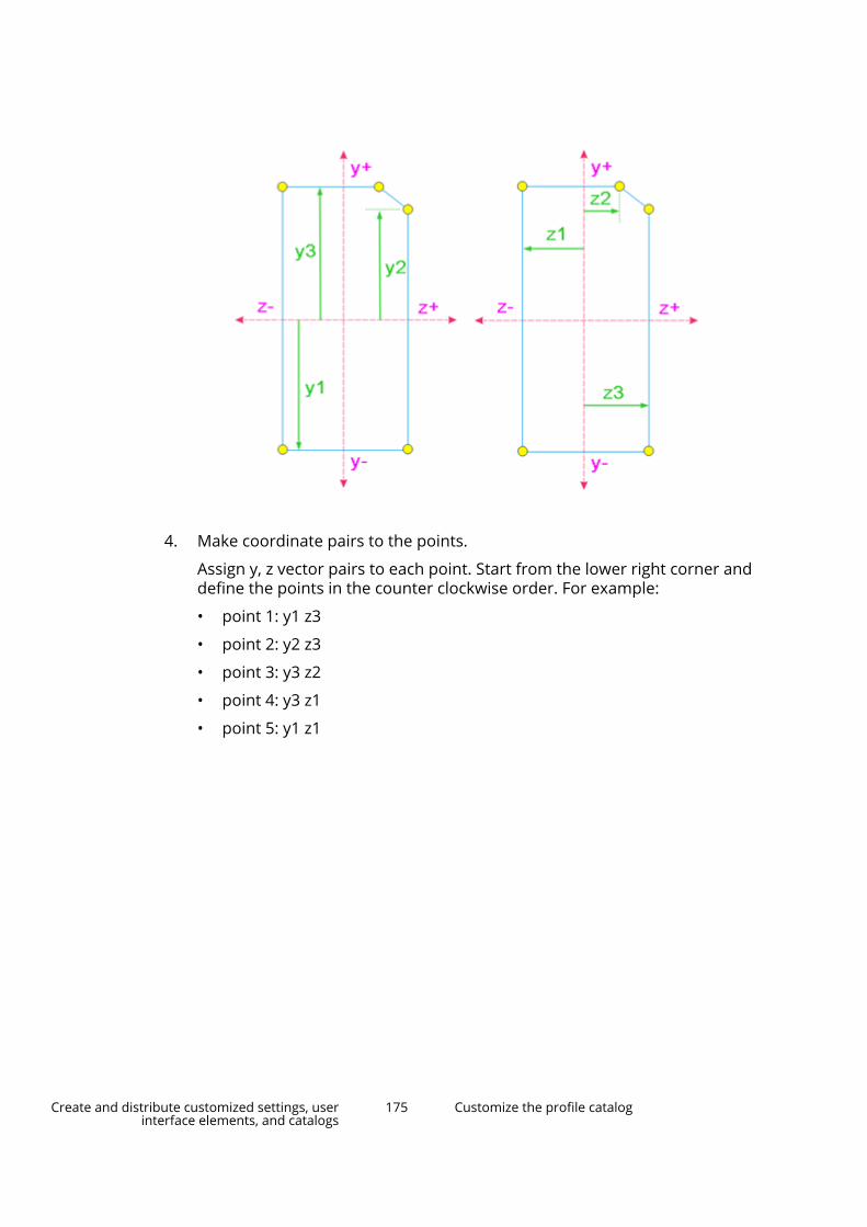
4. Make coordinate pairs to the points.
Assign y, z vector pairs to each point. Start from the lower right corner anddefine the points in the counter clockwise order. For example:
• point 1: y1 z3
• point 2: y2 z3
• point 3: y3 z2
• point 4: y3 z1
• point 5: y1 z1
Create and distribute customized settings, userinterface elements, and catalogs
175 Customize the profile catalog

Create the .clb fileAfter defining the shape and point coordinates of the profile, you can continueby creating the actual .clb file.
1. Create a new .clb file using any standard text editor, for exampleMicrosoft Notepad.
2. Define a library name that will be used in the profitab.inp file for thisprofile.
For example:
library_id "1Gen"3. Define a cross section name that will be used in the profitab.inp file
for this profile.
For example:
4. Define the dimensions of the cross section.
Create and distribute customized settings, userinterface elements, and catalogs
176 Customize the profile catalog

For example:
5. Define the coordinates of the profile.
The coordinates must be the same as the y and z vectors that you definedearlier. Define the default values. For example:
6. Define the geometry of one or several faces of the profile.
For example:
Create and distribute customized settings, userinterface elements, and catalogs
177 Customize the profile catalog

NOTE The index number refers to the point number: 0=start point ofthe beam, 1=end point of the beam.
7. Save the .clb file in the ..\ProgramData\Trimble\TeklaStructures\<version>\environments\common\inp folder.
8. Open the components.clb file.
9. Add your profile definition to the components.clb file by adding thefollowing line:
Include”new_file_name.clb” // give comment10. Save the components.clb file.
Add profile definitions to the profitab.inp fileBefore taking the new parametric profile into use, you must add the neededprofile definitions to the profitab.inp file.
1. Find the profitab.inp file, located under the environment folderin ..\ProgramData\Trimble\Tekla Structures\<version>\environments\<environment>\.
2. Copy the profitab.inp file to a model, project or firm folder.
3. Open the file in the new location using a standard text editor, such asMicrosoft Notepad.
4. Under a suitable category, add a new line for the profile definition.
Use the following syntax:
Prefix! Type ! SO ! Z ! MI ! MA ! G3-NAME ! Z3-NAME !5. Save the file.
The profile is now available in the profile catalog. You may have to restartTekla Structures for the change to take effect.
Example
An example of a profile definition:
PNL_A! USER ! 0 ! ! 2 ! 3 !1Gen.RectChamfer !h*b-[c]
Properties used in profitab.inpUse the following properties when you define new parametric profiles usingthe profitab.inp file:
Create and distribute customized settings, userinterface elements, and catalogs
178 Customize the profile catalog

Property DescriptionPrefix Prefix of the parametric profile. The
prefix is shown in the profile catalog.
For example, PNL_A.Type Type of the parametric profile.
The profile types are/include thefollowing:
I, L, Z, U, PL, D, PD, P, C, T, HK, HQ, ZZ,CC, CW, CU, EB, BF, SPD, EC, ED, EE,EF, EZ, EW, 102, 103, 104, 105, 106,USER
For example, in the defaultenvironment, parametric profiles withprefixes PD, EPD, CHS, CFCHS, O, Ø,and TUBE all group under the typePD, and appear under Circularhollow sections in the profilecatalog.
SO Sorting order. The options are:
• -1: Decreasing sorting order
• +1: Increasing sorting order
• 0: No sorting order
• -2: Name increasing, valuedecreasing
• +2: Value increasing, namedecreasing
For example, if your profile isPLT200*10 or PLT10*200 and thesorting order is +2, the result in theoutput (such as a report) for bothcases is PLT200*10. If the sortingorder is -2, the result for both casesis PLT10*200.
Z Unit of measurement. The optionsare:
• 0: millimeters
• 1: inches
• 2: feet
• 3: centimeters
• 4: meters
Create and distribute customized settings, userinterface elements, and catalogs
179 Customize the profile catalog

Property DescriptionMI Minimum number of parameters you
can use with the parametric profile.
For example, the rectangular hollowsection SHS has the following Profilesubtypes: h*t, h*b*t, h1*b1-h2*b2*t. If you define SHS with aminimum of two and a maximum oftwo parameters, you will only havethe option h*t available in the SelectProfile dialog box.
MA Maximum number of parameters youcan use with the parametric profile.
G3-NAME Refers to a cross section file (.clbfile).
Can be a combination of a library idand the name of a cross section,separated by a full stop. For example, 1Gen.RectChamfer.
Z3-NAME Defines how the profile parametersrelate to the parameters in the crosssection file.
Parameters in the order ofappearance in the .clb file, optionalparameters in square brackets. Forexample, h*b-[c].
Can also be the name of the detailingcomponent.
Create parametric profiles by sketchingYou can create parametric user-defined profiles by sketching. You can changethe dimensions of parametric profiles each time you use them in a model.
• Use the cross section sketch editor to create and modify sketched profiles.
• The Sketch Browser shows the objects of a sketched profile.
• Use the Variables dialog box to define the properties of a sketched profile.
Open the sketch editor
1. Open a Tekla Structures model.
2. On the File menu, click Editors --> Define cross section in sketch editor.
Create and distribute customized settings, userinterface elements, and catalogs
180 Customize the profile catalog

Tekla Structures opens the sketch editor, the Sketch Browser, and theVariables dialog box.
When you first open the sketch editor, the view is empty. The gridcoordinates and labels that you see in the sketch editor depend on thegrid properties of your actual Tekla Structures model.
Sketch BrowserThe Sketch Browser shows the objects (lines, arcs, circles, constraints,dimensions, and chamfers) of a sketched profile in a hierarchical, tree-likestructure. The Sketch Browser automatically opens when you open thesketch editor.
Create and distribute customized settings, userinterface elements, and catalogs
181 Customize the profile catalog

When you click an object in the sketch editor, Tekla Structures highlights theobject in the Sketch Browser, and vice versa.
The Sketch Browser displays the following information about a sketchedprofile:
• Extrusion type (0, 1, or 2) and thickness of the sketched profile
• Lines, arcs, and circles
• Constraints
• Distances and dimensions and their values
• Chamfers and their type (0=None, 1=Line ... 7=Line and arc) anddimensions.
Variables in sketched profilesUse the Variables dialog box to define the properties of a sketched profile.Variables can define fixed properties, or they can include formulas, so thatTekla Structures calculates the property value each time you use the profile ina model.
Create and distribute customized settings, userinterface elements, and catalogs
182 Customize the profile catalog

The Variables dialog box automatically opens when you open the sketcheditor.
NOTE The Variables dialog box functions the same way as thecorresponding dialog box in the custom component editor. For moreinformation on how to use variables, see .
Sketch the outline of a profileWhen you create a new sketched profile, start by sketching the outline and theholes of the profile using lines, arcs, and circles.
Ensure that you create a closed shape, unless you are creating a profile of aconsistent thickness, such as a cold-rolled profile.
Sketch a polylineYou can create line segments in the sketch editor by picking points. TeklaStructures automatically creates coincident constraints between the linesegments and displays a chamfer symbol where line segments meet.
1. Open the sketch editor. (page 180)
2. Click the Sketch polyline button: .
3. Pick points to create each line segment.
4. Click the middle mouse button to create the polyline.
Create and distribute customized settings, userinterface elements, and catalogs
183 Customize the profile catalog

Sketch an arcYou can create an arc in the sketch editor by picking three points.
1. Open the sketch editor. (page 180)
2. Click the Sketch arc button: .
3. Pick three points to define the arc.
TIP You can use the advanced option XS_CS_CHAMFER_DIVIDE_ANGLE todefine the smoothness of the arc.
Sketch a circleYou can create a circle in the sketch editor by picking two points.
1. Open the sketch editor. (page 180)
2. Click the Sketch circle button: .
3. Pick a point to indicate the center of the circle (1).
4. Pick a point to indicate the radius of the circle (2).
Create and distribute customized settings, userinterface elements, and catalogs
184 Customize the profile catalog

Refine the shape of a sketched profile by adding a constraintAfter you have sketched the outline of a profile, use constraints to refine yoursketch and lock the shape. For example, you can straighten lines, create 90degree angles, force lines to meet, close the shape, and add chamfers incorners.
To straighten the entire profile, use horizontal and vertical constraints inconjunction with other constraints. Although the shape is locked, you can stillrotate the profile in the model.
Add a parallel constraintYou can force two lines in a sketched profile to be parallel to each other.
Before you start, sketch the outline of the profile in the sketch editor.(page 183)
1. Click the Parallel constraint button: .
2. Select a line in the sketch (1).
3. Select another line in the sketch (2).
Create and distribute customized settings, userinterface elements, and catalogs
185 Customize the profile catalog

Add a perpendicular constraintYou can force a line in a sketched profile to be at a 90 degree angle to anotherline you select. The lines do not have to intersect.
Before you start, sketch the outline of the profile in the sketch editor.(page 183)
1. Click the Perpendicular constraint button: .
2. Select a line in the sketch (1).
3. Select another line in the sketch (2).
Add a coincident constraintYou can force two lines in a sketched profile to start or end at the same point,by extending or shortening one or both lines. The lines do not have tointersect.
NOTE Tekla Structures automatically creates coincident constraints
• where two lines meet.
• between line segments when you draw them with the Sketchpolyline tool.
• between the start of the first line segment and the end of the lastline segment in a shape, if they are within a certain distance ofeach other.
Before you start, sketch the outline of the profile in the sketch editor.(page 183)
1. Ensure that the Snap to end points snap switch is active.
2. Click the Coincident constraint button: .
3. Pick the end of the first line (1).
4. Pick the end of the second line (2).
Create and distribute customized settings, userinterface elements, and catalogs
186 Customize the profile catalog
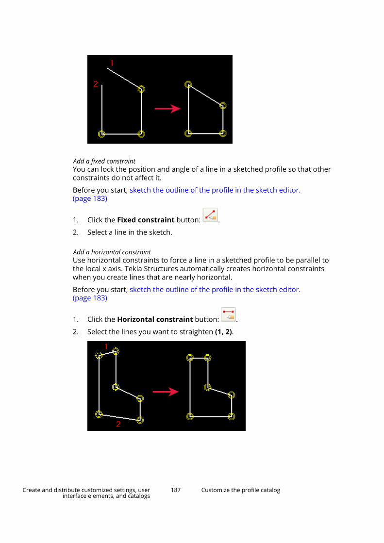
Add a fixed constraintYou can lock the position and angle of a line in a sketched profile so that otherconstraints do not affect it.
Before you start, sketch the outline of the profile in the sketch editor.(page 183)
1. Click the Fixed constraint button: .
2. Select a line in the sketch.
Add a horizontal constraintUse horizontal constraints to force a line in a sketched profile to be parallel tothe local x axis. Tekla Structures automatically creates horizontal constraintswhen you create lines that are nearly horizontal.
Before you start, sketch the outline of the profile in the sketch editor.(page 183)
1. Click the Horizontal constraint button: .
2. Select the lines you want to straighten (1, 2).
Create and distribute customized settings, userinterface elements, and catalogs
187 Customize the profile catalog

Add a vertical constraintUse vertical constraints to force a line in a sketched profile to be parallel to thelocal y axis. Tekla Structures automatically creates vertical constraints whenyou create lines that are nearly vertical.
Before you start, sketch the outline of the profile in the sketch editor.(page 183)
1. Click the Vertical constraint button:
2. Select the lines you want to straighten (1, 2).
Delete a constraintYou can delete constraints from sketched profiles.
1. Click to open the Sketch Browser.
2. Select the constraint you want to delete.
3. Right-click and select Delete.
4. Click Refresh.
Add dimensions to a sketched profileAfter you have sketched a profile, use dimensions to make different distancesin the profile parametric. You can use these dimensions to define the size ofthe profile when you use it in a model.
Tekla Structures also adds the dimensions you create to the list of variablesthat you can use in calculations.
NOTE Do not create too many dimensions in a sketch, or the dimensions will not beable to adjust when the values are changed.
In the following example, if you create the dimension marked in red, thedimension b1 will no longer work:
Create and distribute customized settings, userinterface elements, and catalogs
188 Customize the profile catalog

Add a radial dimension to a sketchYou can create a radial dimension for an arc or a circle in a sketched profile.
Before you start, sketch the outline of the profile in the sketch editor.(page 183)
1. Click the Sketch radial dimension button: .
2. Select the arc or circle.
Add an angle dimension to a sketchYou can create an angle dimension between two lines in a sketched profile.The angle is calculated counter clockwise from the first line you select.
Before you start, sketch the outline of the profile in the sketch editor.(page 183)
1. Click the Sketch angle dimension button: .
2. Select the first line (1).
3. Select the second line (2).
Create and distribute customized settings, userinterface elements, and catalogs
189 Customize the profile catalog

TIP If you are unable to see the angle symbol, scroll with the mousewheel to zoom in.
Add a dimension between two points in a sketchYou can add a dimension to a sketched profile, between two points you pick.
Before you start, sketch the outline of the profile in the sketch editor.(page 183)
1. Click the Sketch free dimension button:
2. Pick a point to indicate the start point of the dimension (1).
3. Pick a point to indicate the end point of the dimension (2).
4. Pick a point to indicate the location of the dimension lines and text.
Add a horizontal dimension to a sketchYou can add a horizontal dimension to a sketched profile, between two pointsyou pick.
Before you start, sketch the outline of the profile in the sketch editor.(page 183)
1. Click the Sketch horizontal dimension button: .
2. Pick a point to indicate the start point of the dimension (1).
Create and distribute customized settings, userinterface elements, and catalogs
190 Customize the profile catalog

3. Pick a point to indicate the end point of the dimension (2).
4. Pick a point to indicate the location of the dimension lines and text.
Add a vertical dimension to a sketchYou can add a vertical dimension to a sketched profile, between two pointsyou pick.
Before you start, sketch the outline of the profile in the sketch editor.(page 183)
1. Click the Sketch vertical dimension button: .
2. Pick a point to indicate the start point of the dimension (1).
3. Pick a point to indicate the end point of the dimension (2).
4. Pick a point to indicate the location of the dimension lines and text.
Delete a dimension from a sketchWhen you want to delete a dimension from a sketch, you can do it in thesketch editor view, in the Variables dialog box, or in the Sketch Browser.
1. Select the dimension you want to delete.
2. Do one of the following:
• In the sketch editor view or in the Sketch Browser, right-click andselect Delete.
Create and distribute customized settings, userinterface elements, and catalogs
191 Customize the profile catalog
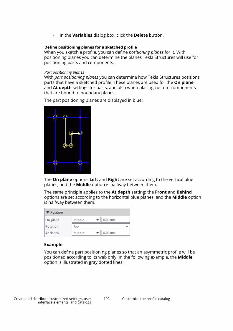
• In the Variables dialog box, click the Delete button.
Define positioning planes for a sketched profileWhen you sketch a profile, you can define positioning planes for it. Withpositioning planes you can determine the planes Tekla Structures will use forpositioning parts and components.
Part positioning planesWith part positioning planes you can determine how Tekla Structures positionsparts that have a sketched profile. These planes are used for the On planeand At depth settings for parts, and also when placing custom componentsthat are bound to boundary planes.
The part positioning planes are displayed in blue:
The On plane options Left and Right are set according to the vertical blueplanes, and the Middle option is halfway between them.
The same principle applies to the At depth setting: the Front and Behindoptions are set according to the horizontal blue planes, and the Middle optionis halfway between them.
Example
You can define part positioning planes so that an asymmetric profile will bepositioned according to its web only. In the following example, the Middleoption is illustrated in gray dotted lines:
Create and distribute customized settings, userinterface elements, and catalogs
192 Customize the profile catalog

(1) Middle option
Connection positioning planesWith connection positioning planes you can determine how Tekla Structurespositions components in relation to the component main part that has asketched profile.
The connection positioning planes are displayed in green:
Example
The following image shows the default connection positioning planes of adouble tee slab that was created as a sketched profile. The green lineillustrates the default connection positioning planes.
Create and distribute customized settings, userinterface elements, and catalogs
193 Customize the profile catalog

To place connections according to the location of the stems of the double tee,move the connection positioning planes as shown below.
Show and hide positioning planes
To show or hide the positioning planes, do one of the following:
To Do thisShow or hide part positioning planes
Click .Show or hide connection positioningplanes Click .
Move positioning planesYou can move the positioning planes by moving their handles. Note that if youmove the handles away from the outmost corners of the sketched profile, youmust bind them by adding a dimension to each handle. Otherwise thepositioning will not function correctly in the model.
1. Click the positioning plane to display the handles.
The handles are displayed in pink. By default, the handles are at theoutmost corners of the sketched profile. For example:
2. Click a handle to select it.
NOTE The same handle controls both the vertical and horizontal plane,so you can move them both at the same time.
Create and distribute customized settings, userinterface elements, and catalogs
194 Customize the profile catalog
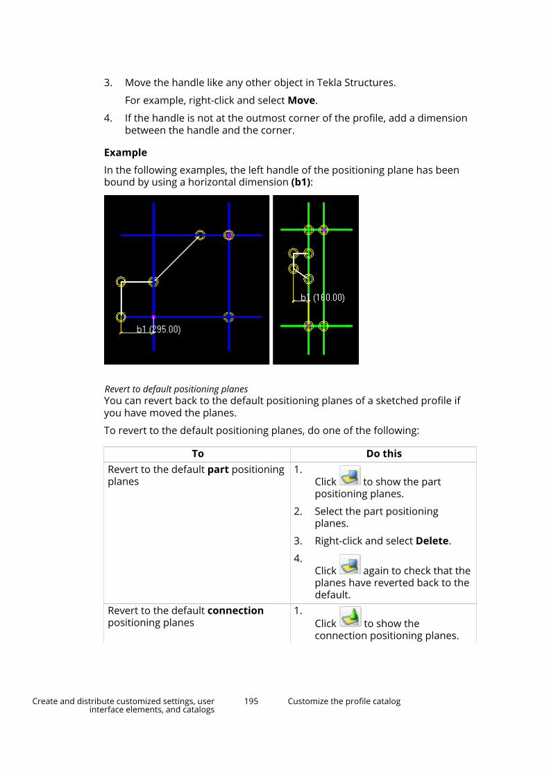
3. Move the handle like any other object in Tekla Structures.
For example, right-click and select Move.
4. If the handle is not at the outmost corner of the profile, add a dimensionbetween the handle and the corner.
Example
In the following examples, the left handle of the positioning plane has beenbound by using a horizontal dimension (b1):
Revert to default positioning planesYou can revert back to the default positioning planes of a sketched profile ifyou have moved the planes.
To revert to the default positioning planes, do one of the following:
To Do thisRevert to the default part positioningplanes
1.Click to show the partpositioning planes.
2. Select the part positioningplanes.
3. Right-click and select Delete.
4.Click again to check that theplanes have reverted back to thedefault.
Revert to the default connectionpositioning planes
1.Click to show theconnection positioning planes.
Create and distribute customized settings, userinterface elements, and catalogs
195 Customize the profile catalog

To Do this2. Select the connection positioning
planes.
3. Right-click and select Delete.
4.Click again to check that theplanes have reverted back to thedefault.
Check a sketched profileYou can check that the constraints and dimensions in a sketched profile workcorrectly.
1. Double-click a dimension line to open the Distance Properties dialogbox.
2. Change the Value box.
3. Click Modify.
Tekla Structures updates the profile in the sketch editor.
4. Check that the shape of the profile does not change and that thedimensions adjust correctly.
5. Click Cancel to close the Distance Properties dialog box.
See also
Use sketched profiles in a model (page 199)
Save a sketched profileTekla Structures saves the sketched profiles in the current model folder, in thexslib.db1 file, which is a library file containing custom components andsketches. Sketched profiles are available in the Others section in the profilecatalog.
NOTE Note the following limitations when naming sketched profiles:
• You cannot use the name of a fixed profile.
• You cannot include numbers, special characters, or blank spaces inthe profile name.
• Lower case letters are automatically converted into upper caseletters.
To save a sketched profile, do one of the following:
Create and distribute customized settings, userinterface elements, and catalogs
196 Customize the profile catalog

To Do thisSave a new profile 1.
Click Save sketch .
2. Enter a name in the Prefix box, and then clickOK.
Update an existing profile 1.Click Save sketch .
2. Click Yes when prompted to update theexisting cross section.
Save a copy of the profileunder a different name
1.Click Save sketch as .
2. Enter a new name in the Prefix box, and thenclick OK.
See also
Import and export sketched profiles (page 161)
Modify sketched profilesYou can modify existing sketched profiles, for example, by modifying chamfersor dimensions. You can also move corners or holes by moving the handles.The chamfers are moved automatically when you move the handles.
Modify a sketched cross section
NOTE • You cannot change dimensions that have been calculated usingformulas in the Variables dialog box.
• Constraints may also prevent you from changing dimensions.
1. On the File menu, click Catalogs --> Profile catalog to open the ModifyProfile Catalog dialog box.
2. Open the Others branch at the end of the profile tree.
3. Right-click a sketched profile, and then select Edit profile to open theprofile in the sketch editor.
4. Double-click a sketch object to modify its properties.
The sketch objects you can modify appear in yellow.
5. Modify the properties and then click Modify.
6. Close the sketch object properties dialog box.
7. Click the Save sketch as icon to save the changes.
Create and distribute customized settings, userinterface elements, and catalogs
197 Customize the profile catalog

Modify chamfers in a sketchYou can change the shape and dimensions of chamfers in a sketched profile.For example, you can create rounded profile corners.
1. Double-click a chamfer symbol in the sketch editor.
2. In the Chamfer Properties dialog box, change the shape and dimensionsof the chamfer.
3. Click Modify.
4. Click OK to close the dialog box.
5. Click the Save sketch as icon to save the changes.
Set the sketch thicknessIf you have sketched an open shape, such as a cold-rolled section, you mustdefine the extrusion type and thickness of the sketch in the Sketch Browser.The thickness can be either fixed or parametric.
1. In the sketch editor, sketch an open polyline (page 183).
2. Do one of the following:
• To set a fixed thickness:
a. In the Sketch Browser, right-click Thickness and select AddEquation.
b. Enter the value of the thickness after =.
• To define a parametric thickness:
a. In the Variables dialog box, add a new parameter variable forLength (for example, P1).
b. In the Formula column, define the default value for theparameter variable.
c. In the Sketch Browser, right-click Thickness and select AddEquation.
d. Enter the name of the parameter variable (for example, P1) after=.
3. To define the extrusion type:
Create and distribute customized settings, userinterface elements, and catalogs
198 Customize the profile catalog

a. In the Sketch Browser, right-click ExtrusionType and select AddEquation.
b. Enter the extrusion type number (0, 1, or 2) after =.
4. Click the Save sketch as icon to save the changes.
Extrusion typesThe extrusion type defines how a sketched profile of a consistent thickness isextruded. When you change the thickness, the profile grows inwards,outwards, or symmetrically in both directions, depending on the extrusiontype. You must define the extrusion type for sketches that consist of an openpolyline.
Type Description Image0 The sketch is extruded
symmetrically to theoutside and inside of thepolyline.
(Default)
1 The sketch is extrudedto the outside of thepolyline.
2 The sketch is extrudedto the inside of thepolyline.
Use sketched profiles in a modelOnce you have created a sketched profile and saved it, you are ready to use itin the model. If you have applied constraints correctly, the shape of the profilewill be maintained when you change its dimensions.
To use a sketched profile for a new part in a model:
1. Open the part properties in the property pane.
Create and distribute customized settings, userinterface elements, and catalogs
199 Customize the profile catalog
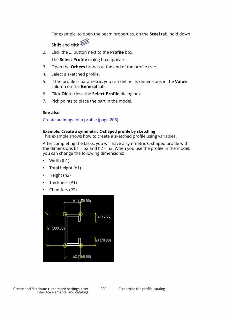
For example, to open the beam properties, on the Steel tab, hold down
Shift and click .
2. Click the ... button next to the Profile box.
The Select Profile dialog box appears.
3. Open the Others branch at the end of the profile tree.
4. Select a sketched profile.
5. If the profile is parametric, you can define its dimensions in the Valuecolumn on the General tab.
6. Click OK to close the Select Profile dialog box.
7. Pick points to place the part in the model.
See also
Create an image of a profile (page 208)
Example: Create a symmetric C-shaped profile by sketchingThis example shows how to create a sketched profile using variables.
After completing the tasks, you will have a symmetric C-shaped profile withthe dimensions b1 = b2 and h2 = h3. When you use the profile in the model,you can change the following dimensions:
• Width (b1)
• Total height (h1)
• Height (h2)
• Thickness (P1)
• Chamfers (P2)
Create and distribute customized settings, userinterface elements, and catalogs
200 Customize the profile catalog

Example: Sketch a C-shaped profile
Start by sketching the outline of the profile.
1. Open the sketch editor.
2. Use the Sketch polyline command to create a rough C-shaped profile.
At this stage, the profile does not have to be symmetric or have the rightdimensions.
3. Straighten the lines using the Add horizontal constraint and Add
vertical constraint commands.
4. Save the profile and name it CSHAPE.
Example: Add dimensions to the sketched profile
After sketching the outline of the profile, you can continue by addingdimensions.
1. Use the Sketch horizontal dimension command to create thedistances b1 and b2.
Create and distribute customized settings, userinterface elements, and catalogs
201 Customize the profile catalog

2. Use the Sketch vertical dimension command to create thedistances h1, h2, and h3.
3. In the Variables dialog box, enter the following values for the distances:
Name Formula Value Valuetype
Variabletype
Visibility Label indialog
boxb1 150.00 150.00 Length Distance Show Widthb2 =b1 150.00 Length Distance Hide Widthh1 300.00 300.00 Length Distance Show Heighth2 70.00 70.00 Length Distance Show Heighth3 =h2 70.00 Length Distance Hide Height
4. Ensure that Visibility is set to Show for the distances b1, h1, and h2.
5. Save the sketched profile.
Create and distribute customized settings, userinterface elements, and catalogs
202 Customize the profile catalog
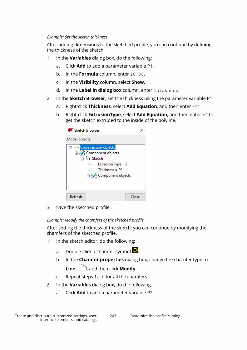
Example: Set the sketch thickness
After adding dimensions to the sketched profile, you can continue by definingthe thickness of the sketch.
1. In the Variables dialog box, do the following:
a. Click Add to add a parameter variable P1.
b. In the Formula column, enter 20.00.
c. In the Visibility column, select Show.
d. In the Label in dialog box column, enter Thickness.
2. In the Sketch Browser, set the thickness using the parameter variable P1.
a. Right-click Thickness, select Add Equation, and then enter =P1.
b. Right-click ExtrusionType, select Add Equation, and then enter =2 toget the sketch extruded to the inside of the polyline.
3. Save the sketched profile.
Example: Modify the chamfers of the sketched profile
After setting the thickness of the sketch, you can continue by modifying thechamfers of the sketched profile.
1. In the sketch editor, do the following:
a. Double-click a chamfer symbol .
b. In the Chamfer properties dialog box, change the chamfer type to
Line , and then click Modify.
c. Repeat steps 1a–b for all the chamfers.
2. In the Variables dialog box, do the following:
a. Click Add to add a parameter variable P2.
Create and distribute customized settings, userinterface elements, and catalogs
203 Customize the profile catalog

b. In the Formula box, enter 10.00.
c. In the Visibility box, select Show.
d. In the Label in dialog box box, enter Chamfer.
3. In the Sketch Browser, do the following:
a. Double-click Chamfer constraint to open the chamfer properties.
b. Right-click Chamfer X, select Add Equation, and then enter =P2.
c. Enter the same value for Chamfer Y.
d. Repeat steps 4a–c for all the chamfers.
4. Save the sketched profile.
Example: Use the sketched profile in a model
Your sketched profile is now completed and you can use it in a model.
1. Double-click a part to open the part properties in the property pane.
2. Click the ... button next to the Profile box.
The Select Profile dialog box appears.
3. Open the Others branch at the end of the profile tree, and select theCSHAPE profile.
4. If needed, modify the dimensions of the profile on the General tab.
5. Click OK to apply the changes.
6. Pick points to place the part in the model.
Create and distribute customized settings, userinterface elements, and catalogs
204 Customize the profile catalog

Create parametric profiles with variable cross sectionsYou can create parametric user-defined profiles with variable cross sectionsusing the Profile Editor. You can use a profile with variable cross sections likeany other parametric profile.
You can
• use a cross section with different dimensions at different locations in aprofile
• modify the variables of the cross sections and the profile
• save the profile and use it as a parametric profile through the profilecatalog
• import and export variable cross section profiles
NOTE When you use this method, only the dimensions of a variable crosssection can vary, not the actual shape of the cross section. If you wantto use several different cross section shapes in the profile, create afixed profile (page 169) with multiple cross sections instead.
Create a profile with variable cross sections
Before you start:
• Create a sketched profile (page 180) using the sketch editor.
Create and distribute customized settings, userinterface elements, and catalogs
205 Customize the profile catalog
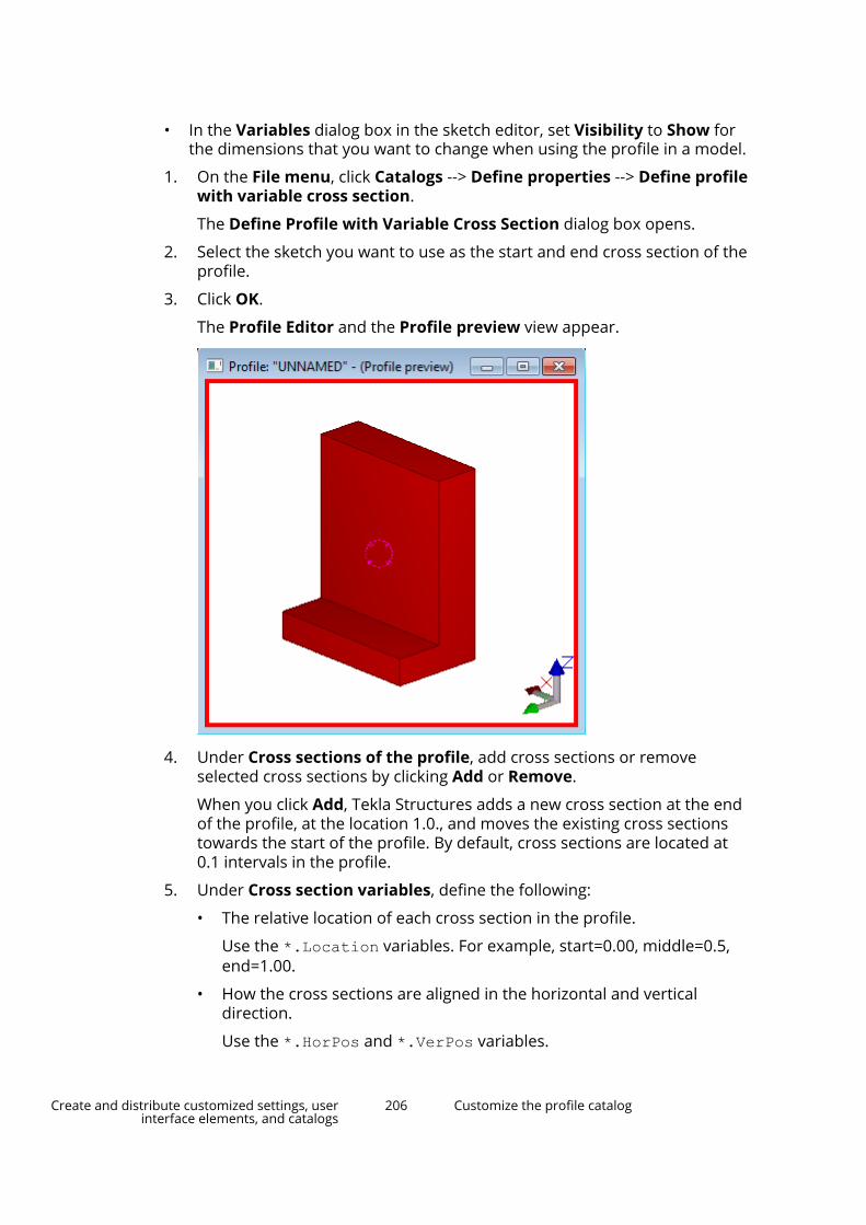
• In the Variables dialog box in the sketch editor, set Visibility to Show forthe dimensions that you want to change when using the profile in a model.
1. On the File menu, click Catalogs --> Define properties --> Define profilewith variable cross section.
The Define Profile with Variable Cross Section dialog box opens.
2. Select the sketch you want to use as the start and end cross section of theprofile.
3. Click OK.
The Profile Editor and the Profile preview view appear.
4. Under Cross sections of the profile, add cross sections or removeselected cross sections by clicking Add or Remove.
When you click Add, Tekla Structures adds a new cross section at the endof the profile, at the location 1.0., and moves the existing cross sectionstowards the start of the profile. By default, cross sections are located at0.1 intervals in the profile.
5. Under Cross section variables, define the following:
• The relative location of each cross section in the profile.
Use the *.Location variables. For example, start=0.00, middle=0.5,end=1.00.
• How the cross sections are aligned in the horizontal and verticaldirection.
Use the *.HorPos and *.VerPos variables.
Create and distribute customized settings, userinterface elements, and catalogs
206 Customize the profile catalog

• How much the cross sections are offset from the alignment.
Use the *.HorOffset and *.VerOffset variables.
6. If you have added new cross sections, check that they do not overlap anyexisting cross sections.
7. Set Visibility to Show for the dimensions that you want to change whenusing the profile in a model.
8. If you want to use parameter variables and equations to define the crosssection dimension, click Add variable and define the variable values.
9. Save the profile.
a. Click Save.
b. In the Save profile as dialog box, enter a unique name for the profile.
You cannot include numbers in the profile name, or use the name ofa standard profile.
c. Click OK.
Tekla Structures saves the profile in the current model folder.
Modify a profile with variable cross sections
1. On the File menu, click Catalogs --> Profile catalog to open the ModifyProfile Catalog dialog box.
2. Open the Others branch at the end of the profile tree.
3. Right-click a profile with variable cross sections, and then select Editprofile to open the profile in the Profile Editor.
4. Modify the profile properties.
5. Click Save.
Create and distribute customized settings, userinterface elements, and catalogs
207 Customize the profile catalog

Define standardized values for parametric profilesYou can define standardized values for the dimensions of parametric profiles.The standardized values are visible in the profile catalog where you can selectsuitable dimension values for the profiles.
1. Under ..\ProgramData\Trimble\Tekla Structures\<version>\environments\<environment> folder, locate theindustry_standard_profiles.inp file.
The exact file location may vary depending on the folder structure of yourenvironment files.
If there is no industry_standard_profiles.inp file in yourenvironment, you can use the file of the default environment.
2. Copy the industry_standard_profiles.inp file and place it in yourfirm, project, or model folder.
3. Open the copied industry_standard_profiles.inp file using anystandard text editor, for example, Microsoft Notepad.
4. Modify the file.
The file has the following format:
• profile and profile subtype
• parameters separated by spaces
• units for each parameter
• standardized values for each parameter.
Each dimension combination has its own row.
5. Save the file.
Example
For example, the standardized combinations of dimension values for a Cprofile are as follows:
Create and distribute customized settings, userinterface elements, and catalogs
208 Customize the profile catalog
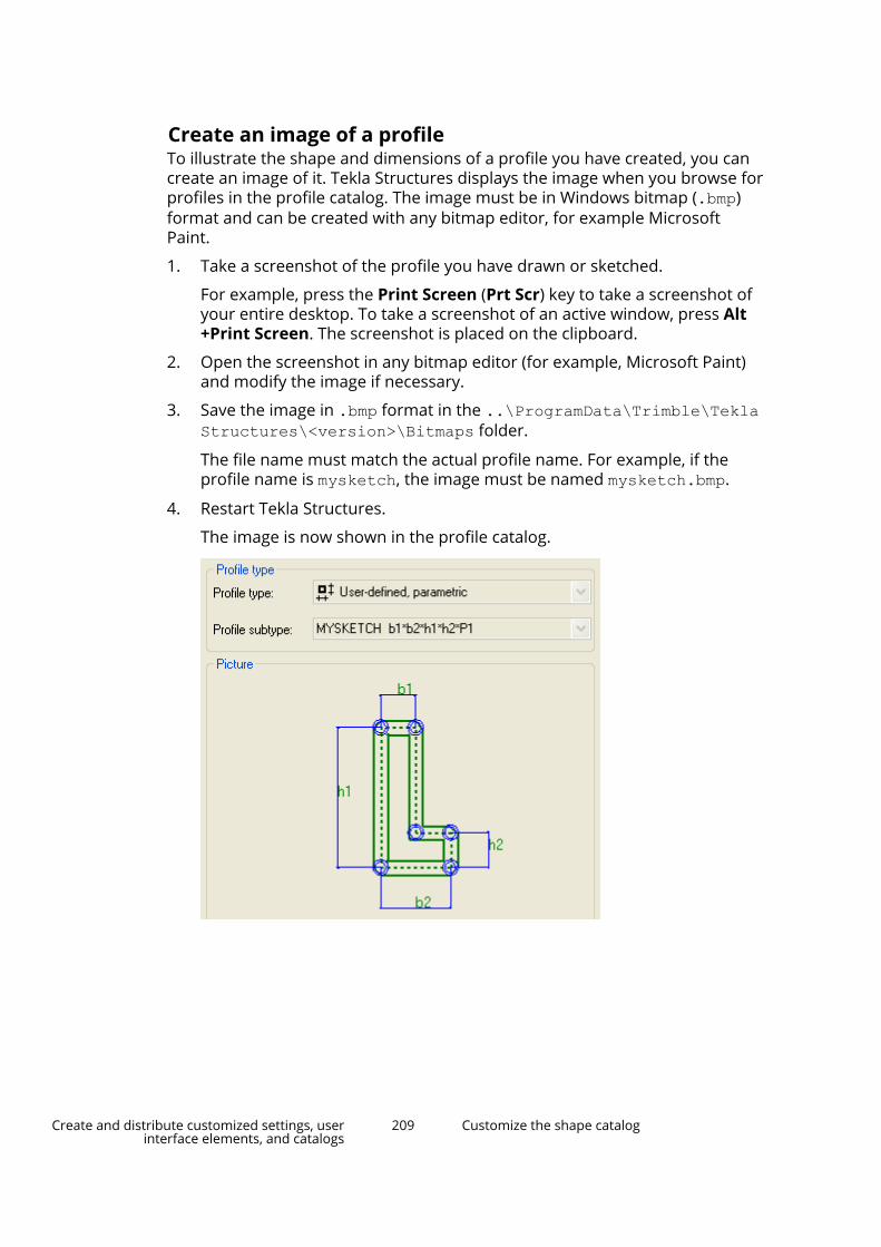
Create an image of a profileTo illustrate the shape and dimensions of a profile you have created, you cancreate an image of it. Tekla Structures displays the image when you browse forprofiles in the profile catalog. The image must be in Windows bitmap (.bmp)format and can be created with any bitmap editor, for example MicrosoftPaint.
1. Take a screenshot of the profile you have drawn or sketched.
For example, press the Print Screen (Prt Scr) key to take a screenshot ofyour entire desktop. To take a screenshot of an active window, press Alt+Print Screen. The screenshot is placed on the clipboard.
2. Open the screenshot in any bitmap editor (for example, Microsoft Paint)and modify the image if necessary.
3. Save the image in .bmp format in the ..\ProgramData\Trimble\TeklaStructures\<version>\Bitmaps folder.
The file name must match the actual profile name. For example, if theprofile name is mysketch, the image must be named mysketch.bmp.
4. Restart Tekla Structures.
The image is now shown in the profile catalog.
Create and distribute customized settings, userinterface elements, and catalogs
209 Customize the shape catalog
5.9 Customize the shape catalogThe shape catalog contains information on shapes that are used for definingitems. Use the Shape catalog dialog box to view and modify shape propertiesand metadata, to group and tag shapes, and to import and export shapes.
The shape catalog includes default shapes, for example Default andConcrete_Default, and other shapes that are read from specific shape foldersin a set folder search order (page 358). The shapes you import (page 211),download from Tekla Warehouse, or create using existing geometry (page 216)in the currently open model are also shown in the shape catalog.
Shape definition files
For each shape in the shape catalog, there are two definition files that containthe shape information:
• One .xml file for shape attributes, such as name and GUID, stored in the\Shapes folder
• One .tez or .xml file for geometric properties, such as coordinates,stored in the \ShapeGeometries folder
Tekla Structures searches for these subfolders and definition files in themodel, project, firm, and system folders, and in the folder defined by theadvanced option XS_DEFAULT_BREP_PATH.
The definition files of the shapes that are used for items in a model areautomatically copied to the model folder.
If you have shapes that you would like to have available in the shape catalogfor all new models that are created in your project or company, copy thecorresponding .xml and .tez files to the correct subfolders (\Shapes and\ShapeGeometries) in the \profil folder under your project or firm folder.
NOTE If your project, company, or environment uses a common location for shapesthat are used in several Tekla Structures versions including 2017i and older,use .xml format for shape geometry files. The compressed .tez files do notwork in Tekla Structures 2017i or older versions.
Group structure and other shape files
The hierarchical group structure of the shape catalog is read from theShapeCatalog.Groups.xml file in the model folder. Using this file, the groupstructure can be shared with all users in a project preferably in the beginningof the project.
If you modify the group structure, Tekla Structures saves the changes to theShapeCatalog.Groups.user.<username>.xml file in the model folder.
The *.shapecatalog and *.ShapeCatalog.Groups.xml files are used forexporting and importing shapes and the group structure between TeklaStructures models.
Create and distribute customized settings, userinterface elements, and catalogs
210 Customize the shape catalog

See also
Import shapes (page 211)
Create shapes (page 216)
Work with shapes and groups in the shape catalog (page 217)
Export shapes (page 222)
Organize the shape catalog view (page 223)
Import shapesYou can import the following types of shape files: tsc, skp, dxf, dwg, ifc,ifcZIP, ifcXML, igs, iges, dgn, stp, step, and shapecatalog.
When using other modeling software to model shapes that you want to importinto Tekla Structures, we recommend that you center parts around the originand direct the parts along the x axis.
From Tekla Structures models you can also import shape catalog groups(page 217) either with the shapes as .shapecatalog files or without theshapes as .ShapeCatalog.Groups.xml files.
1. Open the model to which you want to import shapes and/or shapecatalog groups.
2. On the File menu, click Catalogs --> Shape catalog to open the Shapecatalog dialog box.
3. To import shapes without the group structure to a certain group or sub-group in the shape catalog, select the group or sub-group on the left sideof the dialog box.
If you do not select a group, Tekla Structures imports the shapes to theUngrouped group.
4. Click Import.
5. In the Import shape definitions dialog box, browse to the folder thatcontains the files to be imported, select the files, and then click Open.
Tekla Structures checks if there are duplicates in the shapes in the importfiles compared to the existing shape catalog.
In the Import dialog box, you can see the Status of each imported shape(e.g. New shape definition, Shape name already exists) and, if a shape hasalready been used in the model, the Instances of the shape.
6. If shapes with the same name and GUID as the shapes being importedalready exist in the shape catalog, you can replace or keep the existingshapes. In the Import dialog box:
Create and distribute customized settings, userinterface elements, and catalogs
211 Customize the shape catalog

• Select the Overwrite check box for each existing shape that you wantto replace with a new, imported shape.
• Clear the Overwrite check box for each existing shape that you wantto keep unchanged.
7. Click Import in the Import dialog box.
Importing a large file can take several minutes.
8. Click OK to complete the import.
The groups that contain new or modified shapes are marked with onthe left side of the Shape catalog dialog box. The new or modified shaperows are highlighted in yellow in the list of shapes.
9. Click Save to save changes to the shape catalog.
Shape import has three possible results:
• Tekla Structures imports the shape as a watertight solid shape. All solidoperations are available.
• Tekla Structures imports the shape as a non-solid shape. A non-solid shapemeans that the object may not be watertight. For example, it has holes, oris missing a face or an edge.
• Import fails. This can happen, for example, if the shape is very complex orhas no volume. There may also be a tolerance difference between TeklaStructures and the original software that was used to create the shape. Tofind out why the import failed, check the session history log by going to Filemenu --> Logs --> Session history log.
The Solidity column in the shape catalog shows if a shape is solid or non-solid.
When you import a shape into the shape catalog, Tekla Structures creates twofiles: one .xml file for shape attributes, such as the name and GUID, andone .tez file for geometric properties, such as coordinates. The files aresaved in the current model folder under the \Shapes and\ShapeGeometries subfolders.
The shape name that is shown in the shape catalog is determined as follows:
• If you import a .tsc or .shapecatalog file, the shape name is read fromthe imported file.
• If you import other file types, the shape name is the name of the importedfile.
TIP You can also download shapes from Tekla Warehouse, or create shapesusing existing geometry (page 216) in Tekla Structures models.
Create and distribute customized settings, userinterface elements, and catalogs
212 Customize the shape catalog
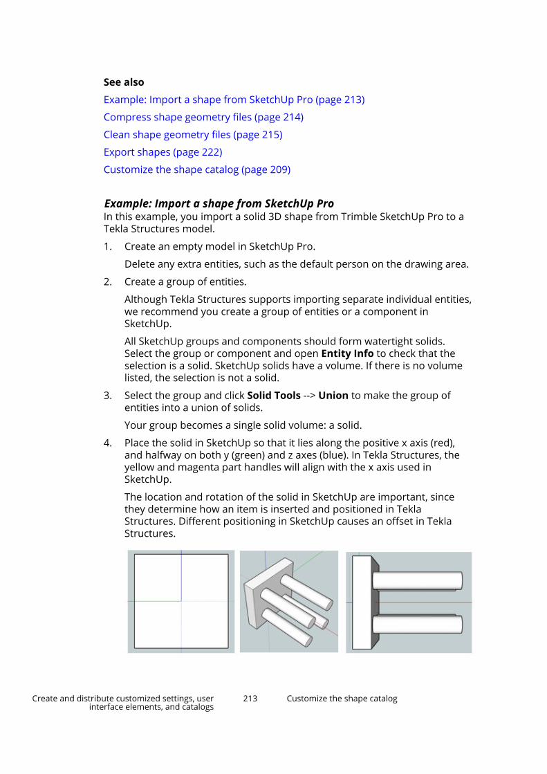
See also
Example: Import a shape from SketchUp Pro (page 213)
Compress shape geometry files (page 214)
Clean shape geometry files (page 215)
Export shapes (page 222)
Customize the shape catalog (page 209)
Example: Import a shape from SketchUp ProIn this example, you import a solid 3D shape from Trimble SketchUp Pro to aTekla Structures model.
1. Create an empty model in SketchUp Pro.
Delete any extra entities, such as the default person on the drawing area.
2. Create a group of entities.
Although Tekla Structures supports importing separate individual entities,we recommend you create a group of entities or a component inSketchUp.
All SketchUp groups and components should form watertight solids.Select the group or component and open Entity Info to check that theselection is a solid. SketchUp solids have a volume. If there is no volumelisted, the selection is not a solid.
3. Select the group and click Solid Tools --> Union to make the group ofentities into a union of solids.
Your group becomes a single solid volume: a solid.
4. Place the solid in SketchUp so that it lies along the positive x axis (red),and halfway on both y (green) and z axes (blue). In Tekla Structures, theyellow and magenta part handles will align with the x axis used inSketchUp.
The location and rotation of the solid in SketchUp are important, sincethey determine how an item is inserted and positioned in TeklaStructures. Different positioning in SketchUp causes an offset in TeklaStructures.
Create and distribute customized settings, userinterface elements, and catalogs
213 Customize the shape catalog
5. Save the SketchUp file.
6. In your Tekla Structures model, open the Shape catalog dialog box and
click Import.
7. Select the SketchUp file.
8. Click Import.
Tekla Structures imports the shape to the shape catalog and you can use it todefine the shape of an item or a concrete item.
See also
Customize the shape catalog (page 209)
Import shapes (page 211)
Compress shape geometry filesYou can compress shape geometry files by converting the files from .xmlformat to compressed format .tez. Using the .tez format saves disk space.
In Tekla Model Sharing models, the shape geometry files are automaticallyconverted from .xml to .tez when you use Tekla Structures 2018 or a newerversion.
In older versions and in models that are not shared, you can manuallycompress the shape geometry files that are stored in the \ShapeGeometriessubfolder in the current model folder. The files in the \Shapes subfolder willnot be compressed.
If you have already used any of the shapes for items in the model, they willwork the same way even after compression.
NOTE Compression is a permanent action, and you cannot undo it even if you donot save the model.
Do not compress shape geometry files if you need them in models that youwill open using Tekla Structures 2017i or an older version. The .tez files donot work in those versions.
If your project, company, or environment uses a common location for shapesthat are used in several Tekla Structures versions including 2017i and older,do not convert those shape geometry files to .tez format. Otherwise theshapes will not work in all versions.
How to compress shape geometry files
To compress existing shape geometry files, either re-import the original shapefiles (page 211), or use the Compress shape geometries application asfollows:
1. Open the model whose shape geometry files you want to compress.
Create and distribute customized settings, userinterface elements, and catalogs
214 Customize the shape catalog

2. Click the Applications & components button in the side pane toopen the Applications & components catalog.
3. Search for the Compress shape geometries application, and thendouble-click to open it.
4. In the Compress shape XML files to TEZ format dialog box, clickCompress.
5. Re-open the model.
Clean shape geometry filesIf some previously imported shapes cause missing faces or edges in items ordrawings, you can clean the shape geometry files. Cleaning means that TeklaStructures investigates and corrects the shape geometry and tries to createsolid objects. This is useful with shapes that have been imported to TeklaStructures models prior to version 2018i.
The Shape cleaner application provides an option to create backups of theoriginal shape geometry files and to revert to them, if needed.
How to clean shape geometry files
To clean existing shape geometry files, either re-import the original shape files(page 211), or use the Shape cleaner application as follows:
1. Open the model whose shape geometry files you want to clean.
2. Click the Applications & components button in the side pane toopen the Applications & components catalog.
3. Search for the Shape cleaner application, and then double-click to openit.
The Shape cleaner dialog box opens.
4. Select the shapes that you want to clean.
5. If you want to create backups of the shape geometry files, select theCreate backups from shapes before cleaning check box.
6. Click Clean.
Tekla Structures cleans the shapes and shows how many shapes resultedin being solid objects and how many non-solid.
If you need to interrupt the cleaning process, you can click Stop.
7. Re-open the model to see the changed shape geometry in the items in themodel.
8. If you are not happy with the result, and if you have created the backupfiles, you can go back to the original shape geometry files.
a. Open the Shape cleaner dialog box again.
Create and distribute customized settings, userinterface elements, and catalogs
215 Customize the shape catalog
b. Select the shapes that you want to restore.
c. Click Revert.
Create shapesIn addition to importing item shapes or downloading them from TeklaWarehouse, you can create shapes using existing geometry and parts in TeklaStructures models. For example, you can create a shape using a single part orseveral parts that have been attached to each other.
The part reference point that has the yellow handle determines the origin ofthe shape. The positive global x direction determines the direction of theshape. Later on when you create items using the shape, the shape origin anddirection will align with the yellow and magenta item handles.
The shape name is generated using the part name and part location in theformat <grid location>_<elevation>_<part name>. For example:
• 1/D_+0_FOOTING
• 3/C_+0-+3600_COLUMN
• 1-2/A-B_+3600_SLAB
If there is already a shape with the same name in the shape catalog, TeklaStructures adds two underscore characters and a running number at the endof the new shape name. For example, 1/D_+0_FOOTING__1.
Create a shape by using existing geometry in the modelUse this method if you want to create a new shape using an existing part, butyou do not want to delete the part or change it to an item.
1. Using parts, model the geometry from which you want to create a shape.
2. If you want to include more than one part in the shape, attach the parts toeach other.
3. On the Edit tab, click Create shape from geometry.
4. Select the part.
Alternatively, you can first select the part, right-click, and then selectCreate shape from geometry.
Tekla Structures adds a new shape to the shape catalog (page 209).
You can then use the shape when you create items in the model. You can alsomodify items and shapes further in the Geometry editing mode.
Create and distribute customized settings, userinterface elements, and catalogs
216 Customize the shape catalog

Create a shape by converting a part to an itemWhen you change an existing part in the model to an item, Tekla Structuresalso creates a new shape and adds it to the shape catalog.
When you change a part to an item, Tekla Structures deletes the original partand replaces it with the newly created item in the model. The name, material,finish, class, pour phase, and the numbering properties of the original part aresaved as the corresponding item properties. Other part type specificproperties and user-defined attributes are not saved. The objects that areattached to the original part, such as reinforcement and surfaces, are deleted.
1. Create the parts that you want to change to an item.
2. If you want to include more than one part in the item, attach the parts toeach other.
3. On the Edit tab, click Convert part to item.
4. Select the part.
Alternatively, you can first select the part, right-click, and then selectConvert part to item.
Tekla Structures changes the part to an item and adds a new shape to theshape catalog (page 209).
Work with shapes and groups in the shape catalogThe shapes in the shape catalog can be arranged to a hierarchical groupstructure. The group structure is shown on the left side of the Shape catalogand Select shape dialog boxes. In the Shape catalog dialog box, you can add,modify, and delete groups and sub-groups, and move and copy shapesbetween the groups and sub-groups.
Create and distribute customized settings, userinterface elements, and catalogs
217 Customize the shape catalog

The group structure may vary depending on the Tekla Structures environmentyou are using, or your company or project administrator may have createdand shared a group structure. The group structure is read from theShapeCatalog.Groups.xml file in the model folder and from the*.ShapeCatalog.Groups.xml files in the shape subfolders in the project,
firm, and system (XS_SYSTEM) folders. Some shapes may first be in the Ungrouped group, but if needed, you can regroup them.
The new shapes that you create (page 216) in the model are also added to theUngrouped group. If you import (page 211) new shapes without the groupstructure, you can select a group for the shapes. You can also group shapes bytagging or starring (page 223) them.
The groups that are marked with are system groups. The groups that are
marked with are user-defined groups.
The current user-defined groups and the changes you make to the groupstructure are stored in the ShapeCatalog.Groups.user.<username>.xmlfile in the model folder.
Note that even if you modify the group structure, the actual definition files(.xml and .tez) of each shape remain in the original \Shapes and\ShapeGeometries folders.
Create and distribute customized settings, userinterface elements, and catalogs
218 Customize the shape catalog
In the Select shape dialog box, which is used for selecting a shape for an item,
also the Recent group is shown. It contains the latest shapes that youhave used.
Add a new group or sub-group1. On the File menu, click Catalogs --> Shape catalog to open the Shape
catalog dialog box.
2. If you want to add a sub-group to an existing group, select the group onthe left side of the dialog box.
3. Click New group and do one of the following:
• To create a highest-level group, select New group.
• To add a sub-group under the selected group, select New sub-group.
4. In the New group name dialog box, type a name for the new group andclick Create.
5. Add, move, or copy shapes to the new group, or modify the shapeproperties as needed.
See the instructions below.
6. Click Save to save the changes to the shape catalog.
Modify a group or sub-groupFor example, you can rename groups and sub-groups.
1. On the File menu, click Catalogs --> Shape catalog to open the Shapecatalog dialog box.
2. Select the group or sub-group that you want to modify.
3. To rename the group, do the following:
a. Right-click and select Rename.
b. In the Rename group dialog box, type the new name and clickRename.
4. To modify group properties, such as the manufacturer or tags (page 226)of the shapes in the group, do the following:
a. Select all shapes in the group.
b. In the property area on the right side of the Shape catalog dialogbox, modify the properties.
Create and distribute customized settings, userinterface elements, and catalogs
219 Customize the shape catalog
5. Click Save to save the changes to the shape catalog.
Select shapesYou can use the following methods when you select shapes in the Shapecatalog dialog box.
Selecting different sets of shapes is useful when you want to export (page 222)or add tags (page 226) to certain shapes, or otherwise modify a sub-set ofshapes.
• Use the following commands on the catalog ribbon:
• Click Select all to select all the shapes in the currently visible group.
Alternatively, you can select one shape and then press Ctrl+A.
• Click Select none to clear the current selection.
• Click Invert selection to select the currently unselected shapes and todeselect the currently selected shapes.
• To select several consecutive shapes, select the first shape, then hold downShift and select the last shape.
• To select several non-consecutive shapes, select the first shape, then holddown Ctrl and select the other shapes.
Move or copy shapes between groups1. On the File menu, click Catalogs --> Shape catalog to open the Shape
catalog dialog box.
2. Browse to and select the group from which you want to move or copyshapes.
3. Do one of the following:
• To move one or more shapes to another group, select the shapes anddrag them to the other group.
The shapes are removed from the selected group.
• To copy one or more shapes to another group, select the shapes, holddown Ctrl, and then drag the shapes to the other group.
The shapes also remain in the selected group.
• To remove one or more shapes from the selected group, select theshapes, right-click on one of the selected shapes, and then selectRemove from group.
If the shapes only belong to the selected group, the shapes are movedto the Ungrouped group. If the shapes also belong to any other group,they remain in that group.
Create and distribute customized settings, userinterface elements, and catalogs
220 Customize the shape catalog

4. Click Save to save the changes to the shape catalog.
Modify shape properties1. On the File menu, click Catalogs --> Shape catalog to open the Shape
catalog dialog box.
2. Browse to and select the group in which you want to modify shapeproperties.
3. Select one or more shapes.
4. In the property area on the right side of the Shape catalog dialog box,modify the shape properties.
For example, you can add a description or tags (page 226) to the selectedshapes.
Note that you cannot rename shapes, or remove or change the solidityinformation, Tekla Structures version, source file location, or GUIDs of theshapes.
5. Click Save to save the changes to the shape catalog.
Delete a group or sub-group, or shapesYou can delete groups, sub-groups, and shapes within the groups from theshape catalog. You can delete both the groups and the actual shapes at thesame time, or you can delete groups and shapes separately.
Before you delete shapes, ensure that any shape you want to delete is notused for items in your Tekla Structures model. When you delete a shape fromthe shape catalog, the shape is no longer available anywhere in the model.
If you try to delete shapes that are used for items in the model or whosedefinition files are not in the model folder, Tekla Structures will not deletethose shapes.
1. On the File menu, click Catalogs --> Shape catalog to open the Shapecatalog dialog box.
2. Select a group or sub-group on the left side of the dialog box.
3. Do one of the following:
• To only delete the group but not the shapes in it, right-click on thegroup and select Delete.
If the shapes only belong to the deleted group, the shapes are movedto the Ungrouped group. If the shapes also belong to any other group,they remain in that group.
Create and distribute customized settings, userinterface elements, and catalogs
221 Customize the shape catalog

• To delete both the group and the shapes in it, right-click on the groupand select Delete with shapes.
• To only delete certain shapes in the group, select one or more unusedmodel-folder shapes, right-click on one of the shapes, and then selectDelete.
4. Click Yes to confirm the deletion.
5. Click Save to save the changes to the shape catalog.
Export shapesYou can export shapes and shape catalog groups together or separately fromeach other.
1. Open the model from which you want to export shapes and/or shapecatalog groups.
2. On the File menu, click Catalogs --> Shape catalog to open the Shapecatalog dialog box.
3. Choose from the following options to export shapes and/or groups:
To Do thisExport all the shapes in the catalog,but not the group structure
On the Shape catalog ribbon, click
Export --> Export all shapes.Export all the shapes and groups inthe catalog
On the Shape catalog ribbon, click
Export --> Export all shapeswith groups.
Export the group structure of thecatalog, but not the actual shapes
On the Shape catalog ribbon, click
Export --> Export groupstructure only.
Export all the shapes in a group orsub-group
Select the group or sub-group, right-click, and select Export shapes.
For example, you can export theshapes in the Starred group, orgroups of tagged shapes.
Export all the shapes in a group orsub-group and also the group
Select the group or sub-group, right-click, and select Export shapes withgroup.
Create and distribute customized settings, userinterface elements, and catalogs
222 Customize the shape catalog

To Do thisExport a group or sub-group and itssub-groups, but not the actual shapes
Select the group or sub-group, right-click, and select Export groupstructure only.
Export one or more individual shapes Select the shapes (page 220), right-click, and select Export.
4. In the Export to dialog box, browse to a folder, type a name for theexport file, and then click Save.
If you are only exporting one individual shape, browse to and select afolder for the export file, and click Select folder in the Export to dialogbox. The shape name is used as the name of the export file.
Tekla Structures saves the export file to the selected folder. When theexport is completed, you can click Open folder to open the export folder.
The file name extension of the export file depends on the exportedcontent, being:
• .tsc if only one shape is exported
• .shapecatalog if several shapes or both shapes and groups areexported
• .ShapeCatalog.Groups.xml if only the group structure is exported
TIP You can also upload shapes to Tekla Warehouse.
See also
Import shapes (page 211)
Customize the shape catalog (page 209)
Organize the shape catalog viewYou can organize the shape catalog view in the Shape catalog dialog box tosuit your needs and ways of working. For example, you can hide certainproperty columns, or change the order of the property columns. You can alsofilter shapes and mark them with stars and tags.
Some of these methods work the same way also in the Select shape dialogbox: showing and hiding property columns, changing the order of thecolumns, filtering, and starring. The Select shape dialog box opens when youclick the ... button next to the Shape box in the item properties, or in acomponent dialog box, to select a shape.
The changes you make to the dialog box layout are automatically saved to theshape_catalog.settings.UI file in the ..\Users\<user>\AppData\Local\Trimble\Tekla Structures\<version>\Catalogs\ folder. TeklaStructures will use the saved layout next time you open the dialog box.
Create and distribute customized settings, userinterface elements, and catalogs
223 Customize the shape catalog

Show or hide the catalog ribbonIf needed, you can show or hide the ribbon in the Shape catalog dialog boxand in the Select shape dialog box.
By default, the ribbon is shown in the Shape catalog dialog box, but hidden inthe Select shape dialog box.
• To show the ribbon, click the down arrow at the right end of the (Home)ribbon title bar.
• To hide the ribbon, click the up arrow at the right end of the (Home)ribbon title bar.
Work with property columns in the catalog viewYou can organize the shape catalog view in the Shape catalog dialog box andin the Select shape dialog box by showing and hiding the property columns,and by changing the order, sort order, and width of the columns.
The Star column is always visible and you cannot hide it.
To Do thisShow or hide a property column 1.
Click Show columns to opena list of the available propertycolumns.
A check mark in front of a columnname indicates that the columnis visible.
2. To show a column, click thecolumn name to add a checkmark in front of the columnname.
3. To hide a column, click thecolumn name to remove thecheck mark.
Change the order of the propertycolumns
Drag a column header to a newlocation.
Change the sort order of a propertycolumn
Click the column header.
The arrow symbol next to the columnheader indicates if the sort order isascending or descending .
To sort values by two properties andin two columns:
1. Sort by one column.
Create and distribute customized settings, userinterface elements, and catalogs
224 Customize the shape catalog

To Do this2. Hold down Shift and then sort by
the other column.Resize a property column Drag the edge between this and the
following column header. Forexample:
You can also click Fit columns toadjust the widths of the visiblecolumns so that the longest value ineach column is shown.
Filter shapesYou can filter shapes in both the Shape catalog dialog box and the Selectshape dialog box. You can use filtering together with the other methods, suchas sorting, to narrow down the number of shapes shown in the shape catalogview.
1. On the File menu, click Catalogs --> Shape catalog to open the Shapecatalog dialog box.
Alternatively, you can use the Select shape dialog box.
2. In the Filter box, type the search term or filtering criteria.
3. Select a group or sub-group.
Tekla Structures shows the matching shapes in the selected group.
Add stars to shapesYou can mark important or preferred shapes with stars, so that you can easilyfind these shapes later. The shapes that are marked with stars appear in theStarred group in the shape catalog. Starring is user-specific, so it is only visibleto you.
The starring settings are stored in theshape_catalog.settings.user.<username> file in the current modelfolder.
1. On the File menu, click Catalogs --> Shape catalog to open the Shapecatalog dialog box.
Alternatively, you can use the Select shape dialog box.
2. Browse or search for the shapes that you want to mark with stars.
Create and distribute customized settings, userinterface elements, and catalogs
225 Customize the shape catalog

3. In the list of shapes, click the white star symbol in the Star column foreach shape that you want to add to the Starred group.
By default, the Star column is the first column and the star symbol is atthe beginning of each shape row.
The star symbol turns yellow and the shape is added to the Starredgroup.
4. To remove the starring from a shape, click the yellow star symbol on theshape row.
The star symbol turns white again and the shape is removed from theStarred group.
Add tags to shapesIn the Shape catalog dialog box, you can add tags to shapes. Use tags to addkeywords or other metadata to the shapes.
Tags are model-specific and saved to theShapeCatalog.Groups.User.<username>.xml file in the current modelfolder.
1. On the File menu, click Catalogs --> Shape catalog to open the Shapecatalog dialog box.
2. Select the shapes (page 220) that you want to tag.
3. Type the tag in the Tags box at the bottom-right corner of the Shapecatalog dialog box, and then press Enter.
To add several tags to a shape, type the next tag in the next tag box andpress Enter.
Each group of tagged shapes appears with the symbol under Tags inthe list of groups.
4. To remove a tag from a shape, select the shape and click the X symbolafter the tag name in the Tags section in the property area.
5. To delete a tag completely, select the tagged group, select all the shapesin the group, and then click the X symbol after the tag name in the Tagssection in the property area.
6. Click Save to save the changes to the shape catalog.
Create and distribute customized settings, userinterface elements, and catalogs
226 Customize the bolt catalog

5.10 Customize the bolt catalogThe individual bolt assembly elements, such as bolts of different sizes andlengths, nuts and washers, are listed in the bolt catalog. Each bolt assemblythen consists of these bolt assembly elements. You cannot use a bolt if it doesnot belong to a bolt assembly. The bolt assemblies are listed in the boltassembly catalog.
Tekla Structures stores the bolt catalog information in the screwdb.db fileand the bolt assembly catalog information in the assdb.db file.
See also
How the bolt catalog and bolt assembly catalogs work together (page 227)
Manage bolts and bolt assemblies (page 228)
Import and export bolts and bolt assemblies (page 233)
Bolt length calculation (page 237)
How the bolt catalog and bolt assembly catalogs worktogether
(1) The Bolt standard options are read from the bolt assembly catalog.
Create and distribute customized settings, userinterface elements, and catalogs
227 Customize the bolt catalog
(2) The bolt assembly catalog defines which bolt standard is used in the boltassembly.
(3) The bolt catalog contains the different bolt diameters, lengths, and otherproperties used in the bolt standard.
(4) The Bolt size options are read from the bolt catalog depending on theselected Bolt standard option.
See also
Customize the bolt catalog (page 226)
Bolt catalog properties (page 240)
Bolt assembly catalog properties (page 242)
Manage bolts and bolt assembliesThis section describes how to manage bolts and bolt assemblies using the boltcatalog and the bolt assembly catalog. You can add, modify, and delete boltsand bolt assemblies.
Click the links below to find out more:
Add a bolt to the catalog (page 228)
Add a stud bolt to the catalog (page 229)
Modify bolt information in the catalog (page 230)
Delete a bolt from the catalog (page 231)
Add a bolt assembly to the catalog (page 231)
Modify bolt assembly information in the catalog (page 232)
Delete a bolt assembly from the catalog (page 232)
Add a bolt to the catalogYou need to add individual bolt elements, such as bolts, nuts, and washers, tothe bolt catalog before you can define bolt assemblies and use them in amodel.
The following steps are for adding bolts, but they also apply to adding nutsand washers.
1. On the File menu, click Catalogs --> Bolt catalog to open the BoltCatalog dialog box.
2. Enter the name of the bolt in the following box:
Create and distribute customized settings, userinterface elements, and catalogs
228 Customize the bolt catalog

You can enter a maximum of 40 characters in the name box.
3. In the Type list, select an option to define the bolt element type.
4. Define the other properties of the new bolt.
You can enter a maximum of 25 characters in the Standard box.
Use different names for bolt, nut, washer, and stud standards todistinguish bolt element types from each other when defining boltassemblies.
5. Click Add to add the bolt to the bolt catalog.
You cannot use a bolt if it does not belong to a bolt assembly. Therefore,we recommend checking that the catalog also includes nuts and washersthat work with the new bolt so that you can create a bolt assembly. If thecatalog does not include suitable nuts and washers, add them the sameway as you added the new bolt.
6. Click OK.
The Save confirmation dialog box appears.
7. Select Save changes to model folder to save the changes in thescrewdb.db file in the current model folder, and then click OK.
TIP You can also add bolts by importing them to the bolt catalog.
See also
Import bolts to the catalog (page 233)
Add a stud bolt to the catalog (page 229)
Modify bolt information in the catalog (page 230)
Delete a bolt from the catalog (page 231)
Bolt length calculation (page 237)
Bolt catalog properties (page 240)
Add a bolt assembly to the catalog (page 231)
Add a stud bolt to the catalogA stud is special type of bolt that is welded to steel parts to transfer loadsbetween steel and concrete. You cannot use studs unless you have defined astud assembly that contains the assembly's name and material.
1. On the File menu, click Catalogs --> Bolt catalog to open the BoltCatalog dialog box.
Create and distribute customized settings, userinterface elements, and catalogs
229 Customize the bolt catalog

2. Enter values for the following properties:
• Name: Name for the stud bolt.
• Type:
• Standard: This name is needed when creating a bolt assembly for thestud.
• Diameter: Shank diameter.
• Length: Stud length.
• Weight: Stud weight.
• top thick: Head thickness.
• top diameter: Head diameter.
The units depend on the settings in File menu --> Settings --> Options -->Units and decimals .
3. On the File menu, click Catalogs --> Bolt assembly catalog to open theBolt Assembly Catalog dialog box.
4. Select the standard for the stud bolt.
5. Set all the other bolt assembly elements to None.
6. To create studs in the model, create bolts and select the stud assemblystandard.
See also
Bolt catalog properties (page 240)
Modify bolt information in the catalog1. On the File menu, click Catalogs --> Bolt catalog to open the Bolt
Catalog dialog box.
2. Select a bolt from the list.
Create and distribute customized settings, userinterface elements, and catalogs
230 Customize the bolt catalog

3. Modify the properties.
4. Click Update.
5. Click OK.
The Save confirmation dialog box appears.
6. Select Save changes to model folder to save the changes in thescrewdb.db file in the current model folder, and then click OK.
See also
Add a bolt to the catalog (page 228)
Delete a bolt from the catalog (page 231)
Bolt catalog properties (page 240)
Delete a bolt from the catalog1. On the File menu, click Catalogs --> Bolt catalog to open the Bolt
Catalog dialog box.
2. Select a bolt from the list.
Use the Shift and Ctrl keys to select multiple bolts.
3. Click Delete.
4. Click OK.
The Save confirmation dialog box appears.
5. Select Save changes to model folder to save the changes in thescrewdb.db file in the current model folder, and then click OK.
See also
Add a bolt to the catalog (page 228)
Modify bolt information in the catalog (page 230)
Add a bolt assembly to the catalogYou can add new bolt assemblies to the bolt assembly catalog. Note that thebolt assembly can contain only bolts or studs, not both of them.
1. On the File menu, click Catalogs --> Bolt assembly catalog to open theBolt Assembly Catalog dialog box.
2. Enter the name of the bolt assembly in the following box:
Create and distribute customized settings, userinterface elements, and catalogs
231 Customize the bolt catalog

3. Define the other properties of the new bolt assembly.
You can enter a maximum of 30 characters in the Standard box. For allthe other properties, you can enter a maximum of 25 characters.
4. Click Add to add the bolt assembly to the catalog.
5. Click OK.
The Save confirmation dialog box appears.
6. Select Save changes to model folder to save the changes in theassdb.db file in the current model folder, and then click OK.
See also
Import bolt assemblies to the catalog (page 235)
Modify bolt assembly information in the catalog (page 232)
Delete a bolt assembly from the catalog (page 232)
Bolt assembly catalog properties (page 242)
Modify bolt assembly information in the catalog1. On the File menu, click Catalogs --> Bolt assembly catalog to open the
Bolt Assembly Catalog dialog box.
2. Select a bolt assembly from the list.
3. Modify the properties (page 242).
4. Click Update.
5. Click OK.
The Save confirmation dialog box appears.
6. Select Save changes to model folder to save the changes in theassdb.db file in the current model folder, and then click OK.
See also
Add a bolt assembly to the catalog (page 231)
Delete a bolt assembly from the catalog (page 232)
Bolt assembly catalog properties (page 242)
Delete a bolt assembly from the catalog1. On the File menu, click Catalogs --> Bolt assembly catalog to open the
Bolt Assembly Catalog dialog box.
2. Select a bolt assembly from the list.
3. Click Delete.
Create and distribute customized settings, userinterface elements, and catalogs
232 Customize the bolt catalog

4. Click OK.
The Save confirmation dialog box appears.
5. Select Save changes to model folder to save the changes in theassdb.db file in the current model folder, and then click OK.
See also
Add a bolt assembly to the catalog (page 231)
Modify bolt assembly information in the catalog (page 232)
Import and export bolts and bolt assembliesUse importing and exporting for merging bolts and bolt assemblies acrosscatalogs. Bolts are imported and exported as .bolts files, bolt assembliesas .bass files, and bolt catalogs as .lis files.
When you export single bolts or bolt assemblies, you can select the bolts orbolt assemblies you want to include in the .bolts or .bass file. When youimport and export bolt assemblies, also all the related bolt elements (bolts,studs, screws, nuts, washers) are included in the .bass file.
You can import and export an entire bolt catalog. You can also import a part ofan exported bolt catalog.
Importing and exporting bolt catalogs is useful, when you:
• Upgrade to newer version of Tekla Structures and you want to use acustomized bolt catalog from a previous version.
• Want to combine bolt catalogs that are stored in different locations.
• Want to share bolt catalog information with other users.
TIP You can also download or share bolt assemblies using Tekla Warehouse.
See also
Import bolts to the catalog (page 233)
Export bolts from the catalog (page 234)
Import bolt assemblies to the catalog (page 235)
Export bolt assemblies from the catalog (page 235)
Import a bolt catalog (page 236)
Import a part of the bolt catalog (page 236)
Export an entire bolt catalog (page 237)
Create and distribute customized settings, userinterface elements, and catalogs
233 Customize the bolt catalog

Import bolts to the catalog
Bolts are imported and exported as .bolts files. A .bolts file can includeone bolt or several bolts.
1. On the File menu, click Catalogs --> Bolt catalog to open the BoltCatalog dialog box.
2. Right-click in the Bolts list and select Import.
3. Select the import file.
4. Click OK.
The bolts are displayed on the Bolts list by their original names.
5. Click OK.
The Save confirmation dialog box appears.
6. Select Save changes to model folder to save the changes in thescrewdb.db file in the current model folder, and then click OK.
See also
Add a bolt to the catalog (page 228)
Import a bolt catalog (page 236)
Import a part of the bolt catalog (page 236)
Import bolt assemblies to the catalog (page 235)
Export bolts from the catalog (page 234)
Export bolts from the catalog
Bolts are imported and exported as .bolts files. A .bolts file can includeone bolt or several bolts.
1. On the File menu, click Catalogs --> Bolt catalog to open the BoltCatalog dialog box.
2. Select bolts from the Bolts list.
Use the Shift and Ctrl keys to select multiple bolts.
3. Right-click in the Bolts list and select Export.
4. Browse for the folder where you want to save the export file.
5. Enter a name for the file in the Selection box.
6. Click OK.
See also
Export bolt assemblies from the catalog (page 235)
Create and distribute customized settings, userinterface elements, and catalogs
234 Customize the bolt catalog
Export an entire bolt catalog (page 237)
Import bolts to the catalog (page 233)
Import bolt assemblies to the catalog
Bolt assemblies are imported and exported as .bass files. A .bass file caninclude one bolt assembly or several bolt assemblies.
1. On the File menu, click Catalogs --> Bolt assembly catalog to open theBolt Assembly Catalog dialog box.
2. Right-click in the Bolt assemblies list and select Import.
3. Select the import file.
4. Click OK.
The bolt assemblies are displayed on the Bolt assemblies list by theiroriginal names.
5. Click OK.
The Save confirmation dialog box appears.
6. Select Save changes to model folder to save the changes in theassdb.db file in the current model folder, and then click OK.
See also
Add a bolt assembly to the catalog (page 231)
Import a bolt catalog (page 236)
Import bolts to the catalog (page 233)
Export bolt assemblies from the catalog (page 235)
Export bolt assemblies from the catalog
Bolt assemblies are imported and exported as .bass files. A .bass file caninclude one bolt assembly or several bolt assemblies.
1. On the File menu, click Catalogs --> Bolt assembly catalog to open theBolt Assembly Catalog dialog box.
2. Select bolt assemblies from the Bolt assemblies list.
Use the Shift and Ctrl keys to select multiple bolt assemblies.
3. Right-click in the Bolt assemblies list and select Export.
4. Browse for the folder where you want to save the export file.
5. Enter a name for the file in the Selection box.
6. Click OK.
Create and distribute customized settings, userinterface elements, and catalogs
235 Customize the bolt catalog

See also
Export an entire bolt catalog (page 237)
Export bolts from the catalog (page 234)
Import bolt assemblies to the catalog (page 235)
Import a bolt catalogBolt catalogs are imported to Tekla Structures models as .lis files.
1. Open the model to which you want to import a bolt catalog.
2. Copy the screwdb.lis file that you want to import to the current modelfolder.
3. To import the bolt catalog file screwdb.lis from the current modelfolder, go to Quick Launch, start typing import bolt catalog, andselect the Import Bolt Catalog command from the list that appears.
Tekla Structures does not replace the entries that have the same namesas the entries in the import file.
4. Check the status bar for error messages.
To view errors, go to the File menu and click Logs --> Session historylog .
See also
Import a part of the bolt catalog (page 236)
Export an entire bolt catalog (page 237)
Import a part of the bolt catalogIf you do not want to import the entire bolt catalog, you can select the parts tobe imported.
TIP If you only want to import a few bolts or bolt assemblies, use the importand export commands of the corresponding catalogs.
1. Open the model that contains the bolt catalog you want to use.
2. Go to Quick Launch, start typing export bolt catalog, and select theExport Bolt Catalog command from the list that appears.
The bolt catalog is saved as the screwdb.lis file in the current modelfolder.
3. Open the screwdb.lis file using a text editor, for example, MicrosoftNotepad.
Each entry is listed on a separate row.
4. Delete the unwanted rows from the file.
Create and distribute customized settings, userinterface elements, and catalogs
236 Customize the bolt catalog

WARNING Do not delete the STARTLIST and ENDLIST rows.
5. Save the file with the name screwdb.lis.
6. Open the model to which you want to import the bolt catalog.
7. Copy the screwdb.lis file that you want to import to the current modelfolder.
8. To import the bolt catalog file screwdb.lis from the current modelfolder, go to Quick Launch, start typing import bolt catalog, andselect the Import Bolt Catalog command from the list that appears.
See also
Import bolts to the catalog (page 233)
Import bolt assemblies to the catalog (page 235)
Import a bolt catalog (page 236)
Export an entire bolt catalog (page 237)
Export an entire bolt catalogBolt catalogs are exported from Tekla Structures models as .lis files.
1. Open the model that contains the bolt catalog you want to export.
2. Go to Quick Launch, start typing export bolt catalog, and select theExport Bolt Catalog command from the list that appears.
The exported bolt catalog is the screwdb.lis file in the current modelfolder.
TIP The Export Bolt Catalog command exports the entire bolt catalog.To export only part of the bolt catalog, modify the export file tocontain only the required elements. You can also export bolts fromthe Bolt Catalog dialog box or bolt assemblies from the BoltAssembly Catalog dialog box.
See also
Export bolt assemblies from the catalog (page 235)
Export bolts from the catalog (page 234)
Import a bolt catalog (page 236)
Import a part of the bolt catalog (page 236)
Create and distribute customized settings, userinterface elements, and catalogs
237 Customize the bolt catalog

Bolt length calculationTekla Structures uses values from the bolt catalog and the bolt assemblycatalog when calculating the bolt length. If the bolt catalog does not containlong enough bolts for your purposes, you need to add them to the boltcatalog.
The following Assembly settings in the Bolt properties affect the bolt lengthcalculation process. If the check box is selected, the bolt element is used in thebolt assembly.
Bolt assembly Bolt elements1: If the check box is clear, only a holeis created
2: Washer (1)
3: Washer (2)
4: Washers (3)
5: Nut (1)
6: Nut (2)
The chart and the detailed steps below explain the process of bolt lengthcalculation.
1. Tekla Structures calculates the minimum possible length of the bolt asfollows:
washer (1) thickness (if the check box is selected) +
material thickness +
Create and distribute customized settings, userinterface elements, and catalogs
238 Customize the bolt catalog
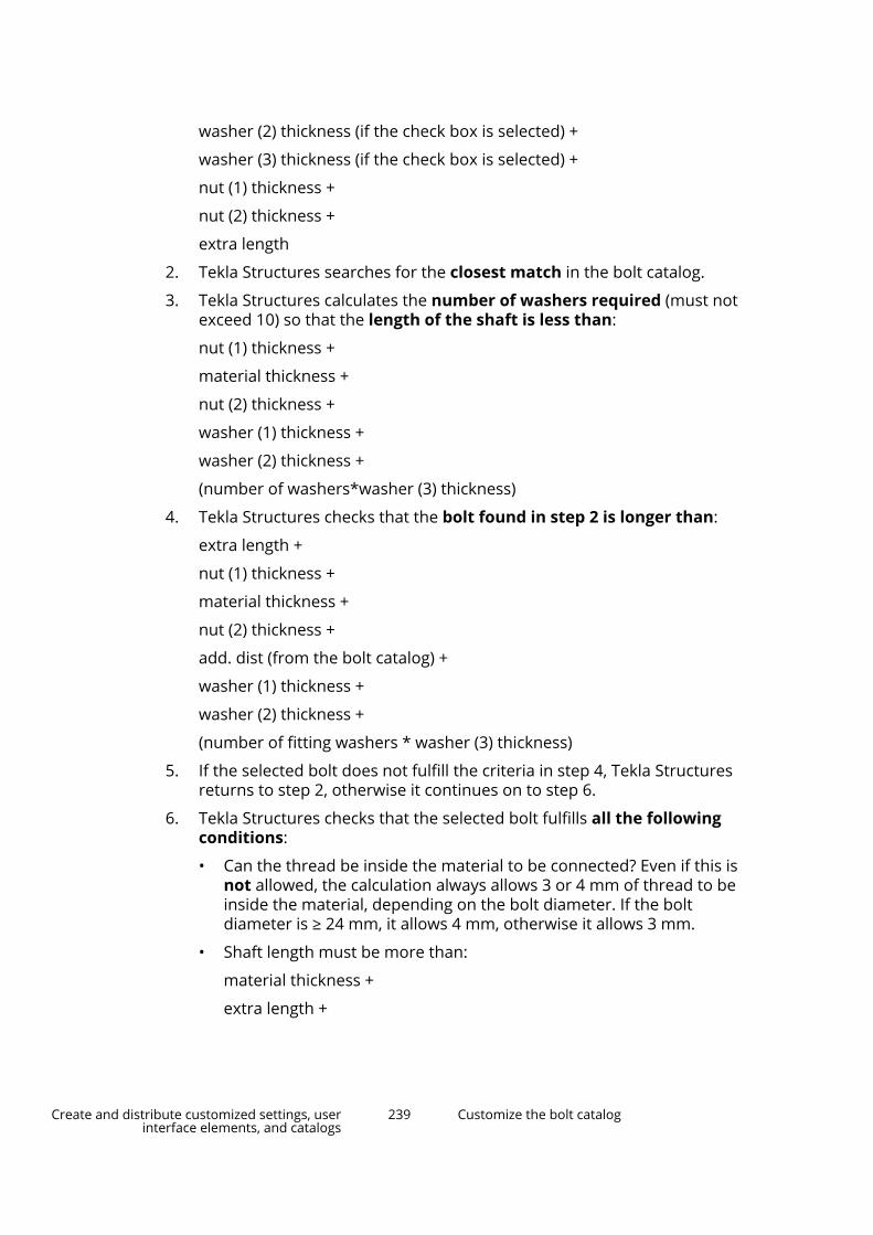
washer (2) thickness (if the check box is selected) +
washer (3) thickness (if the check box is selected) +
nut (1) thickness +
nut (2) thickness +
extra length
2. Tekla Structures searches for the closest match in the bolt catalog.
3. Tekla Structures calculates the number of washers required (must notexceed 10) so that the length of the shaft is less than:
nut (1) thickness +
material thickness +
nut (2) thickness +
washer (1) thickness +
washer (2) thickness +
(number of washers*washer (3) thickness)
4. Tekla Structures checks that the bolt found in step 2 is longer than:
extra length +
nut (1) thickness +
material thickness +
nut (2) thickness +
add. dist (from the bolt catalog) +
washer (1) thickness +
washer (2) thickness +
(number of fitting washers * washer (3) thickness)
5. If the selected bolt does not fulfill the criteria in step 4, Tekla Structuresreturns to step 2, otherwise it continues on to step 6.
6. Tekla Structures checks that the selected bolt fulfills all the followingconditions:
• Can the thread be inside the material to be connected? Even if this isnot allowed, the calculation always allows 3 or 4 mm of thread to beinside the material, depending on the bolt diameter. If the boltdiameter is ≥ 24 mm, it allows 4 mm, otherwise it allows 3 mm.
• Shaft length must be more than:
material thickness +
extra length +
Create and distribute customized settings, userinterface elements, and catalogs
239 Customize the bolt catalog

washer (1) thickness (if checked) -
maximum thread in material allowed (if thread in material = no) =3 mm or 4 mm
• Shaft length is calculated as:
Screw length - screw thread length - thread end.
• Thread end is the part of the bolt between the shaft and the thread. Itis calculated as follows:
Diameter of bolt (mm) Thread end (mm)>33.0 10.0>27.0 8.0>22.0 7.0>16.0 6.0>12.0 5.0>7.0 4.0>4.0 2.5≤4 1.5
7. If the selected bolt does not fulfill all the above conditions, TeklaStructures returns to step 2 and tries the next longest bolt.
8. If the advanced option XS_BOLT_LENGTH_EPSILON is set, the epsilonthickness is added to, or subtracted from, the material thickness to avoidinaccurate bolt length calculation.
For example, if this value is not taken into account, and the calculatedlength is 38.001 mm, a 39 mm bolt might be selected.
See also
How the bolt catalog and bolt assembly catalogs work together (page 227)
Add a bolt to the catalog (page 228)
Bolt catalog propertiesUse the Bolt Catalog dialog box to view and modify the properties ofindividual bolt elements, such as bolts, washers, and nuts. The units dependon the settings in File menu --> Settings --> Options --> Units and decimals .
Option DescriptionType The type of the bolt element. The options are:
Create and distribute customized settings, userinterface elements, and catalogs
240 Customize the bolt catalog

Option Description
(Nut)
(Washer)
(Stud)Standard The name of the bolt element standard.
Used in the Bolt Assembly Catalog dialog box for defining boltelements in a bolt assembly.
Use different names for bolt, nut, washer, and stud standards todistinguish bolt element types from each other.
Diameter The diameter of the bolt element.Length The length of the bolt element.Weight The weight of the bolt element.add. dist The length of the part of the bolt that protrudes from the nut.
The value is used in bolt length calculation.top thick The thickness of the bolt head.thread len The length of the threaded part of the bolt shaft.
The value is not used in bolt length calculation (value is 0) if thebolt is fully-threaded.
washer tol The tolerance between the washer inner diameter and the boltdiameter.
The value is used when searching for the correct-sized washerfor the bolt. Not used in bolt length calculation.
span size The size of the wrench needed.calc thick The calculation thickness of a nut or a washer.
This value is used in bolt length calculation.real thick The true thickness of a nut or a washer.
This is for information only.inner diam The inner diameter of a nut or a washer.
This is for information only.
Create and distribute customized settings, userinterface elements, and catalogs
241 Customize the bolt catalog

Option Descriptionouter diam The outer diameter of a nut or a washer.
This is for information only.top diam The diameter of the hexagon.
This is for information only.
See also
Add a bolt to the catalog (page 228)
How the bolt catalog and bolt assembly catalogs work together (page 227)
Bolt assembly catalog propertiesUse the Bolt Assembly Catalog dialog box to view and modify the propertiesof bolt assemblies. The units depend on the settings in File menu --> Settings--> Options --> Units and decimals .
Option DescriptionShort name This name is used in drawings and reports. It is usually the
commercial name for a specific bolt.Standard This name is the full name which is shown in the bolt
assemblies list in the Bolt Assembly Catalog dialog box, andin the Bolt standard list in the Bolt Properties dialog box.
The value is used in bolt length calculation.Material The material of the bolt assembly.Finish The type of the finish.Grade The grade of the bolt assembly.Tolerance The tolerances of the bolt assembly.
This is for information only. The values cannot be reported, forexample.
Create and distribute customized settings, userinterface elements, and catalogs
242 Customize the bolt catalog

Additional length for bolt calculation
Option DescriptionAdd. dist... The Additional Distance option controls how much of the
bolt protrudes from the nut.
Additional Distance updates the Additional Distance valuesof all bolts that use the selected bolt standard and have theselected diameter.
The value is used in bolt length calculation.
Select whether the value of the additional length affectsall or individual diameters of one bolt assembly.
Enter the additional length value.
Select whether the value is absolute or relative to thediameter.
See also
Add a bolt assembly to the catalog (page 231)
5.11 Customize the rebar catalogThe rebar catalog contains definitions for different reinforcement types, suchas reinforcing bars and strands of different grades.
The rebar catalog shows standard, environment-specific reinforcing bars andstrands of the environment (or environments) that you have installed and that
Create and distribute customized settings, userinterface elements, and catalogs
243 Customize the rebar catalog

is currently open. The blank project environment only contains undefinedreinforcing bars and strands.
You can add, copy, group, modify, and delete rebar definitions. You can alsoimport and export single definitions, groups of definitions, or entire rebarcatalogs.
Tekla Structures stores the rebar catalog information in therebar_database.inp file that is by default saved to the current modelfolder.
Reinforcement meshes are not included in the rebar catalog. Standard meshesare defined in their own catalog file (page 318), mesh_database.inp.
Work with definitions in the rebar catalogYou can add, copy, modify, and delete rebar definitions in the rebar catalog.
To use the newly added or modified rebar definitions in the model, reopen themodel.
Add a new rebar definitionYou can add new definitions to the rebar catalog by defining the barproperties from scratch.
1. On the File menu, click Catalogs --> Rebar catalog to open the Rebarcatalog dialog box.
2. Click New bar.
3. In the New bar dialog box, enter the bar properties.
If a property is shown in red, it is missing a value or has a value that is notvalid. For example, Grade and Size must have a value.
4. Click Add.
5. Click Save to save the changes to the rebar catalog.
Add a new rebar definition by copyingYou can add new definitions to the rebar catalog by copying an existingdefinition and then modifying it.
1. On the File menu, click Catalogs --> Rebar catalog to open the Rebarcatalog dialog box.
2. Browse for and select the definition that you want to copy.
Create and distribute customized settings, userinterface elements, and catalogs
244 Customize the rebar catalog

3. Click Copy.
Alternatively, you can right-click and select Copy.
4. In the Copy dialog box, enter or modify the bar properties.
Modify the property values that are shown in red so that the newdefinition is not a duplicate of the original definition.
5. Click Add.
6. Click Save to save the changes to the rebar catalog.
Select rebar definitionsYou can use the following methods when you select rebar definitions in theRebar catalog dialog box.
Selecting different sets of definitions is useful when you want to export(page 249) or add tags (page 253) to certain definitions, or otherwise modify asub-set of definitions.
• Use the following commands on the catalog ribbon:
• Click Select all to select all the definitions in the currently visible group.
Alternatively, you can select one definition and then press Ctrl+A.
• Click Select none to clear the current selection.
• Click Invert selection to select the currently unselected definitions andto deselect the currently selected definitions.
• To select several consecutive definitions, select the first definition, thenhold down Shift and select the last definition.
• To select several non-consecutive definitions, select the first definition,then hold down Ctrl and select the other definitions.
Modify a rebar definition1. On the File menu, click Catalogs --> Rebar catalog to open the Rebar
catalog dialog box.
2. Browse for and select the definition that you want to modify.
To modify several definitions, hold down Ctrl or Shift when you select(page 245).
3. In the property area on the right side of the Rebar catalog dialog box,modify the bar properties.
Create and distribute customized settings, userinterface elements, and catalogs
245 Customize the rebar catalog

For example, you can select whether the bar is a main bar, or a tie orstirrup. You may also want to add tags (page 253) to the bar.
If a property is shown in red, it is missing a value or has a value that is notvalid. For example, Grade and Size must have a value.
4. Click Save to save the changes to the rebar catalog.
Delete rebar definitions1. On the File menu, click Catalogs --> Rebar catalog to open the Rebar
catalog dialog box.
2. Select (page 245) one or more rebar definitions.
3. Right-click and select Delete.
4. Click Yes to confirm the deletion.
5. Click Save to save the changes to the rebar catalog.
Work with groups in the rebar catalogIn the rebar catalog, the rebar definitions are arranged to groups. You canadd, copy, modify, and delete groups, and arrange the groups according todifferent properties. The groups are listed on the left side of the Rebarcatalog and Select rebar dialog boxes.
Create and distribute customized settings, userinterface elements, and catalogs
246 Customize the rebar catalog

By default, the definitions in the rebar catalog are grouped according toreinforcement grades. You can change how the definitions are grouped(page 251) in the Rebar catalog dialog box or in the Select rebar dialog box.
To use the newly added or modified rebar definition groups in the model,reopen the model.
Add a new group to the catalogYou can create new groups in the rebar catalog by copying an existing groupand the definitions contained in it.
1. On the File menu, click Catalogs --> Rebar catalog to open the Rebarcatalog dialog box.
2. On the left side of the dialog box, select a group, and then click Copy.
Alternatively, you can right-click a group and select Copy.
3. In the New group name dialog box, enter a name for the new group, andthen click Copy.
Tekla Structures adds the new group to the catalog.
4. Add, modify, and delete definitions (page 244) contained in the new groupas needed.
Create and distribute customized settings, userinterface elements, and catalogs
247 Customize the rebar catalog
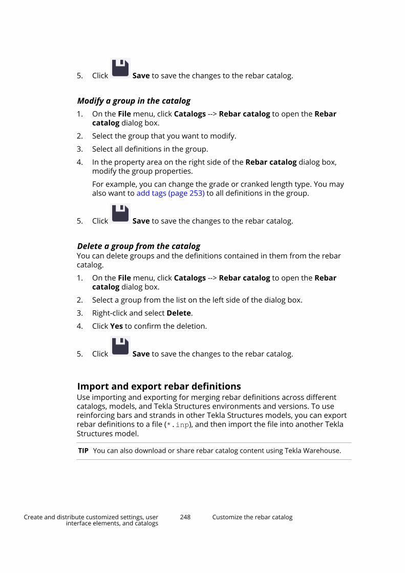
5. Click Save to save the changes to the rebar catalog.
Modify a group in the catalog1. On the File menu, click Catalogs --> Rebar catalog to open the Rebar
catalog dialog box.
2. Select the group that you want to modify.
3. Select all definitions in the group.
4. In the property area on the right side of the Rebar catalog dialog box,modify the group properties.
For example, you can change the grade or cranked length type. You mayalso want to add tags (page 253) to all definitions in the group.
5. Click Save to save the changes to the rebar catalog.
Delete a group from the catalogYou can delete groups and the definitions contained in them from the rebarcatalog.
1. On the File menu, click Catalogs --> Rebar catalog to open the Rebarcatalog dialog box.
2. Select a group from the list on the left side of the dialog box.
3. Right-click and select Delete.
4. Click Yes to confirm the deletion.
5. Click Save to save the changes to the rebar catalog.
Import and export rebar definitionsUse importing and exporting for merging rebar definitions across differentcatalogs, models, and Tekla Structures environments and versions. To usereinforcing bars and strands in other Tekla Structures models, you can exportrebar definitions to a file (*.inp), and then import the file into another TeklaStructures model.
TIP You can also download or share rebar catalog content using Tekla Warehouse.
Create and distribute customized settings, userinterface elements, and catalogs
248 Customize the rebar catalog
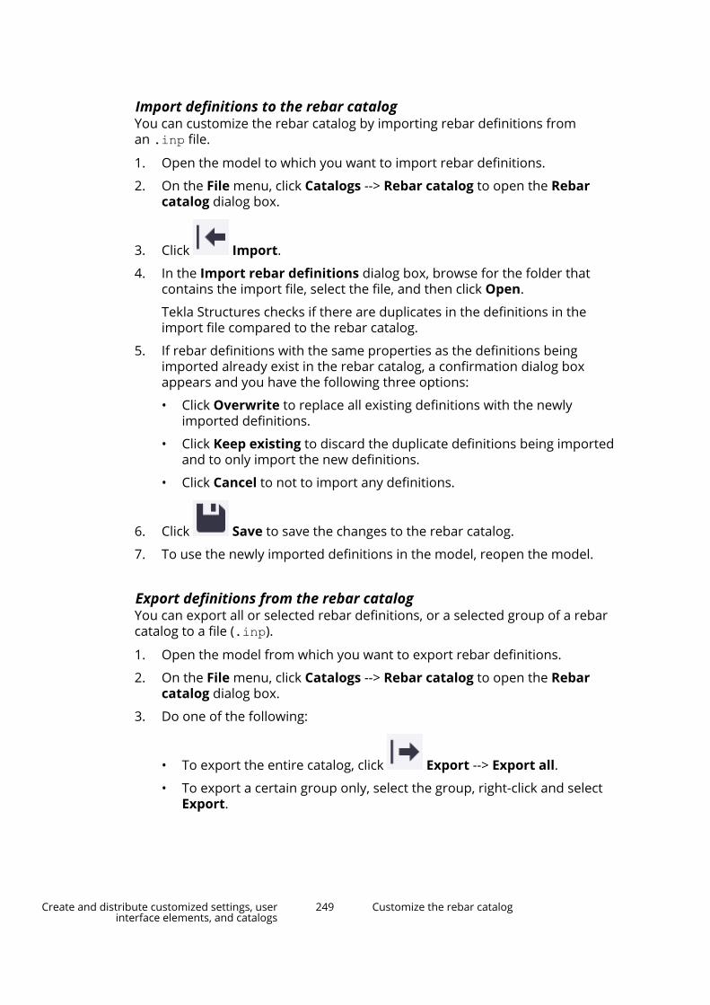
Import definitions to the rebar catalogYou can customize the rebar catalog by importing rebar definitions froman .inp file.
1. Open the model to which you want to import rebar definitions.
2. On the File menu, click Catalogs --> Rebar catalog to open the Rebarcatalog dialog box.
3. Click Import.
4. In the Import rebar definitions dialog box, browse for the folder thatcontains the import file, select the file, and then click Open.
Tekla Structures checks if there are duplicates in the definitions in theimport file compared to the rebar catalog.
5. If rebar definitions with the same properties as the definitions beingimported already exist in the rebar catalog, a confirmation dialog boxappears and you have the following three options:
• Click Overwrite to replace all existing definitions with the newlyimported definitions.
• Click Keep existing to discard the duplicate definitions being importedand to only import the new definitions.
• Click Cancel to not to import any definitions.
6. Click Save to save the changes to the rebar catalog.
7. To use the newly imported definitions in the model, reopen the model.
Export definitions from the rebar catalogYou can export all or selected rebar definitions, or a selected group of a rebarcatalog to a file (.inp).
1. Open the model from which you want to export rebar definitions.
2. On the File menu, click Catalogs --> Rebar catalog to open the Rebarcatalog dialog box.
3. Do one of the following:
• To export the entire catalog, click Export --> Export all.
• To export a certain group only, select the group, right-click and selectExport.
Create and distribute customized settings, userinterface elements, and catalogs
249 Customize the rebar catalog
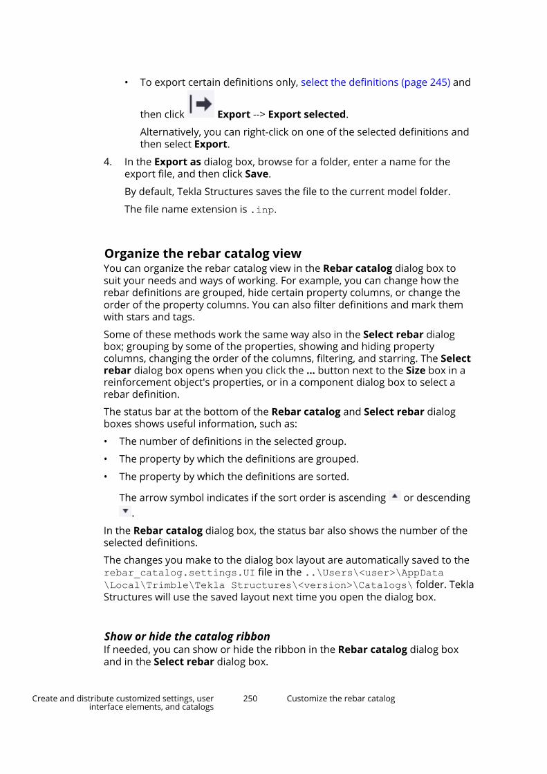
• To export certain definitions only, select the definitions (page 245) and
then click Export --> Export selected.
Alternatively, you can right-click on one of the selected definitions andthen select Export.
4. In the Export as dialog box, browse for a folder, enter a name for theexport file, and then click Save.
By default, Tekla Structures saves the file to the current model folder.
The file name extension is .inp.
Organize the rebar catalog viewYou can organize the rebar catalog view in the Rebar catalog dialog box tosuit your needs and ways of working. For example, you can change how therebar definitions are grouped, hide certain property columns, or change theorder of the property columns. You can also filter definitions and mark themwith stars and tags.
Some of these methods work the same way also in the Select rebar dialogbox; grouping by some of the properties, showing and hiding propertycolumns, changing the order of the columns, filtering, and starring. The Selectrebar dialog box opens when you click the ... button next to the Size box in areinforcement object's properties, or in a component dialog box to select arebar definition.
The status bar at the bottom of the Rebar catalog and Select rebar dialogboxes shows useful information, such as:
• The number of definitions in the selected group.
• The property by which the definitions are grouped.
• The property by which the definitions are sorted.
The arrow symbol indicates if the sort order is ascending or descending.
In the Rebar catalog dialog box, the status bar also shows the number of theselected definitions.
The changes you make to the dialog box layout are automatically saved to therebar_catalog.settings.UI file in the ..\Users\<user>\AppData\Local\Trimble\Tekla Structures\<version>\Catalogs\ folder. TeklaStructures will use the saved layout next time you open the dialog box.
Show or hide the catalog ribbonIf needed, you can show or hide the ribbon in the Rebar catalog dialog boxand in the Select rebar dialog box.
Create and distribute customized settings, userinterface elements, and catalogs
250 Customize the rebar catalog

By default, the ribbon is shown in the Rebar catalog dialog box, but hidden inthe Select rebar dialog box.
• To show the ribbon, click the down arrow at the right end of the (Home)ribbon title bar.
• To hide the ribbon, click the up arrow at the right end of the (Home)ribbon title bar.
Change the grouping of rebar definitionsYou can select the property by which the rebar definitions are grouped in therebar catalog. By default, the rebar definitions are grouped by grade.
1. On the File menu, click Catalogs --> Rebar catalog to open the Rebarcatalog dialog box.
Alternatively, you can use the Select rebar dialog box.
2. Click Group by, and then select the property by which you want togroup the rebar definitions.
The definitions can be grouped by the properties whose propertycolumns are visible. For example, you can select Size or Cross sectionarea.
The properties that are available may vary in the Rebar catalog andSelect rebar dialog boxes.
Work with property columns in the catalog viewYou can organize the rebar catalog view in the Rebar catalog dialog box andin the Select rebar dialog box by showing and hiding the property columns,and by changing the order, sort order, and width of the columns.
The Star column is always visible and you cannot hide it.
To Do thisShow or hide a property column 1.
Click Show columns to opena list of the available propertycolumns.
A check mark in front of a columnname indicates that the columnis visible.
2. To show a column, click thecolumn name to add a checkmark in front of the columnname.
Create and distribute customized settings, userinterface elements, and catalogs
251 Customize the rebar catalog

To Do this3. To hide a column, click the
column name to remove thecheck mark.
Change the order of the propertycolumns
Drag a column header to a newlocation.
Change the sort order of a propertycolumn
Click the column header.
The arrow symbol next to the columnheader indicates if the sort order isascending or descending .
To sort values by two properties andin two columns:
1. Sort by one column.
2. Hold down Shift and then sort bythe other column.
Resize a property column Drag the edge between this and thefollowing column header. Forexample:
You can also click Fit columns toadjust the widths of the visiblecolumns so that the longest value ineach column is shown.
Filter rebar definitionsYou can filter rebar definitions in both the Rebar catalog dialog box and theSelect rebar dialog box. You can use filtering together with the othermethods, such as sorting, to narrow down the number of definitions shown inthe rebar catalog view.
1. On the File menu, click Catalogs --> Rebar catalog to open the Rebarcatalog dialog box.
Alternatively, you can use the Select rebar dialog box.
2. In the Filter box, enter the search term or filtering criteria.
For example, to find rebar definitions that are suitable for stirrups andties, enter tie.
Tekla Structures shows the groups that contain matching definitions.
3. Select a group.
Tekla Structures shows the matching definitions in the group, forexample, the definitions that have Usage set to tie/stirrup.
Create and distribute customized settings, userinterface elements, and catalogs
252 Customize the rebar catalog

Add stars to rebar definitionsYou can mark important or preferred rebar definitions with stars, so that youcan easily find these definitions later. The definitions that are marked withyellow stars appear in the Starred group in the rebar catalog. Starring is user-specific, so it is only visible to you.
The starring settings are stored in the current model folder in therebar_catalog.settings.user.<username> file, where the <username>suffix is your username.
If you have starred definitions, the Rebar catalog dialog box opens with theStarred group selected.
1. On the File menu, click Catalogs --> Rebar catalog to open the Rebarcatalog dialog box.
Alternatively, you can use the Select rebar dialog box.
2. Browse or search for the definitions that you want to mark with stars.
3. In the definition list, click the white star symbol in the Star column foreach definition that you want to add to the Starred group.
By default, the Star column is the first column and the star symbol is atthe beginning of each definition row.
The star symbol turns yellow and the definition is added to theStarred group.
4. To remove the starring from a definition, click the yellow star symbol onthe definition row.
The star symbol turns white again and the definition is removed from theStarred group.
Add tags to rebar definitionsIn the Rebar catalog dialog box, you can add tags to rebar definitions. Youcan use tags to add keywords or other metadata to the definitions.
For example, you could use tags like Stainless and Acid proof.
Tags are model-specific and saved to the rebar_catalog.settings file inthe current model folder.
1. On the File menu, click Catalogs --> Rebar catalog to open the Rebarcatalog dialog box.
2. Select the definitions (page 245) that you want to tag.
Create and distribute customized settings, userinterface elements, and catalogs
253 Customize the rebar catalog
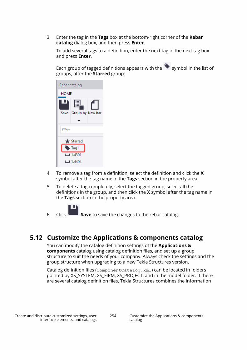
3. Enter the tag in the Tags box at the bottom-right corner of the Rebarcatalog dialog box, and then press Enter.
To add several tags to a definition, enter the next tag in the next tag boxand press Enter.
Each group of tagged definitions appears with the symbol in the list ofgroups, after the Starred group:
4. To remove a tag from a definition, select the definition and click the Xsymbol after the tag name in the Tags section in the property area.
5. To delete a tag completely, select the tagged group, select all thedefinitions in the group, and then click the X symbol after the tag name inthe Tags section in the property area.
6. Click Save to save the changes to the rebar catalog.
5.12 Customize the Applications & components catalogYou can modify the catalog definition settings of the Applications &components catalog using catalog definition files, and set up a groupstructure to suit the needs of your company. Always check the settings and thegroup structure when upgrading to a new Tekla Structures version.
Catalog definition files (ComponentCatalog.xml) can be located in folderspointed by XS_SYSTEM, XS_FIRM, XS_PROJECT, and in the model folder. If thereare several catalog definition files, Tekla Structures combines the information
Create and distribute customized settings, userinterface elements, and catalogs
254 Customize the Applications & componentscatalog

in the files. For more information on the folder search order, see Folder searchorder (page 358).
When you create a group structure for the Applications & componentscatalog, define the highest level structure in a catalog definition file that islocated in a folder pointed by XS_SYSTEM. To hide unnecessary parts of thegroup structure and catalog content from certain roles, edit the catalogdefinition files of these roles.
For general instructions on how to use the Applications & componentscatalog, see How to use the Applications & components catalog.
You can also add your own instructor side pane help pages for the tools in theApplications & components catalog, see Add instructor help for applicationsand components (page 260).
Edit the catalog1. Set the XS_COMPONENT_CATALOG_ALLOW_SYSTEM_EDIT advanced
option to TRUE to edit the catalog definition files.
2. In the Applications & components catalog, click Access advancedfeatures > Catalog management > Edit mode, and select the catalogdefinition file that you want to edit.
The list of files shows all the environment folders, the project and firmfolders if defined, and the model folder. You can define the neededcatalog definition file folder paths in XS_SYSTEM.
If XS_COMPONENT_CATALOG_ALLOW_SYSTEM_EDIT is not set to TRUE, asmall warning icon is shown next to the files in the XS_SYSTEM folderlocations. The image shows warning icons next to the files that appeardimmed.
Create and distribute customized settings, userinterface elements, and catalogs
255 Customize the Applications & componentscatalog

The files that appear dimmed do not exist, but you can create the files byselecting them, and answering Yes in the Edit mode message box.
You can remove an existing file by clicking the button next to the file.
Create and distribute customized settings, userinterface elements, and catalogs
256 Customize the Applications & componentscatalog

3. Select the file that you want to edit.
Create and distribute customized settings, userinterface elements, and catalogs
257 Customize the Applications & componentscatalog

The check mark in front of the folder name shows the file that is currentlybeing edited.
4. Create new groups and subgroups to organize the catalog content, right-click in the catalog and select New group....
5. Move the content from Ungrouped items to the new groups, or to otherpredefined custom groups. To move an item to another group, right-clickthe item, select Add to group, and then select the target group.
Create and distribute customized settings, userinterface elements, and catalogs
258 Customize the Applications & componentscatalog
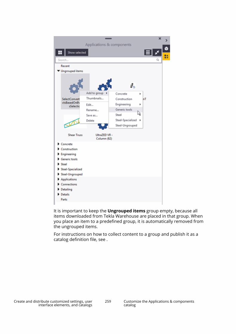
It is important to keep the Ungrouped items group empty, because allitems downloaded from Tekla Warehouse are placed in that group. Whenyou place an item to a predefined group, it is automatically removed fromthe ungrouped items.
For instructions on how to collect content to a group and publish it as acatalog definition file, see .
Create and distribute customized settings, userinterface elements, and catalogs
259 Customize the Applications & componentscatalog
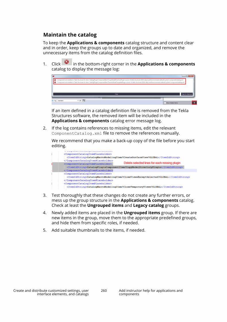
Maintain the catalogTo keep the Applications & components catalog structure and content clearand in order, keep the groups up to date and organized, and remove theunnecessary items from the catalog definition files.
1. Click in the bottom-right corner in the Applications & componentscatalog to display the message log:
If an item defined in a catalog definition file is removed from the TeklaStructures software, the removed item will be included in theApplications & components catalog error message log.
2. If the log contains references to missing items, edit the relevantComponentCatalog.xml file to remove the references manually.
We recommend that you make a back-up copy of the file before you startediting.
3. Test thoroughly that these changes do not create any further errors, ormess up the group structure in the Applications & components catalog.Check at least the Ungrouped items and Legacy catalog groups.
4. Newly added items are placed in the Ungrouped items group. If there arenew items in the group, move them to the appropriate predefined groups,and hide them from specific roles, if needed.
5. Add suitable thumbnails to the items, if needed.
Create and distribute customized settings, userinterface elements, and catalogs
260 Add instructor help for applications andcomponents

5.13 Add instructor help for applications and componentsYou can easily create side pane help for tools in the Applications &components catalog.
In the Applications & components catalob, the Instructor shows contentalready on selection, so the information is especially useful for giving advice toyour users on choosing between different components or giving instructionsbefore running a tool. To make full use of this feature, users should arrangetheir side panes so that both panes are visible.
1. Select the tool you want to add help for in the Applications &components catalog.
2. Click the Add help files button in the Instructor pane.
A dialog box opens for creating the necessary files according to yourselections.
3. Click Next and select the languages that are used as user interfacelanguages in your organization. There needs to be a content file for eachlanguage even if you do not translate the content.
4. Click Next and select the folder where you want to store the generatedfiles. The files can be stored in the model, project, firm, or system folder.The standard folder search order (page 358) is followed.
5. Click Create.
Tekla Structures creates an XML file that defines a link between the tool inthe Applications & components catalog and an HTML file for the helpcontent.
The HTML files are stored in a folder structure that separates files intolanguage-specific folders. The XML file and the root folder for the contentare named according to the identifier of the tool you are documenting.You can copy files between the allowed storage locations, but do notrename the files or folders or change the folder structure.
6. Edit the HTML content file(s) in your preferred tool, such as a text editor,or replace the file with your own HTML file of the same name. If you donot have any HTML editing experience, there are several good tutorialsavailable on the internet to quickly learn the few basics you need to know.You can create your own HTML files by saving as HTML from familiartools, such as Microsoft Word or Google Docs. Note that the resulting fileswill not look exactly the same as the original document.
Create and distribute customized settings, userinterface elements, and catalogs
261 Add instructor help for applications andcomponents
6 Files and folders in TeklaStructures
Sometimes you need to know where Tekla Structures stores information, andthe types of files that Tekla Structures contains, where the files are located,and how the files should be should be used.
Tekla Structures contains a large amount of files that affect the way thesoftware works. It is important to know which file controls which functionality,and also which files we do not recommend that you touch.
The initialization file reading order is also very important. You need to knowthe order in which the files are read when you open Tekla Structures, so thatyou do not modify the files unnecessarily.
See also
Initialization files (.ini files) (page 268)
Input files (.inp files) (page 299)
File storing options and advanced options (page 276)
Data files (.dat files) (page 312)
Message files (page 313)
Standard files (page 316)
Property files (page 315)
Catalog files (page 318)
Font files and font conversion files (page 321)
Symbol files (page 322)
Image files (page 323)
Files related to templates, reports and drawings (page 322)
Log files (page 324)
Model folder files and file name extensions (page 333)
Files and folders in Tekla Structures 262

Check and change Tekla Structures file and folder locations in Directorybrowser (page 357)
Folder search order (page 358)
Create project and firm folders (page 263)
Location of certain hidden files and folders (page 360)
6.1 Create project and firm foldersUse project and firm folders for customized files. These can be customribbons, drawing styles, profile and material catalogs, or any other settingsyou want to store for future use. You can use the same files each time youstart a new model or install a new version of Tekla Structures. This also meansyou can easily revert back to the default settings, because you have notoverwritten any of the system files.
Use the project folder and its sub-folders to store customized files that areonly used in a particular project. A project may consist of several models doneby separate teams, all spread out in different locations. You can save project-specific files and settings in the project folder, so that everyone in the projectcan use them. A project may also consist of one model that is shared bydifferent companies.
Use the firm folder and its sub-folders to store customized files for the entireorganization or company. The settings and files in the firm folder are meant tobe used in all projects within the company. For example, let's say you regularlywork for a company that has specific drawing layout standards it expects youto use. Customize the drawing templates once for the company and save themin the firm folder or in a sub-folder of the firm folder. You can then use thecustomized drawing templates for all future projects for that company.
When working within one company, the firm and project folders are usuallylocated in network folders so that everyone can access them. In collaborativeprojects that include multiple teams or companies, you can use a folder in thelinked .
Project and firm folders are defined by XS_FIRM and XS_PROJECT. Whenworking in a model sharing project, each company needs to have its own firmsettings in a folder defined by XS_FIRM, and a common project folder forproject settings defined by XS_PROJECT. It may be useful to create a startupshortcut (page 19) on your desktop for each project containing all necessaryfolders.
WARNING Changing an advanced option value in .ini files located outside themodel folder does not affect the existing models. You can only updateadvanced options in the Advanced Options dialog box or in theoptions.ini file located in model folder; not from an options.ini filelocated in folders defined for the advanced options XS_FIRM orXS_PROJECT. The .ini files are read also when you open an existing
Files and folders in Tekla Structures 263 Create project and firm folders

model, but only new advanced options that do not exist inoptions_model.db or options_drawings.db are inserted, forexample, such options that are not yet in the Advanced Options dialogbox but have been added in the software.
Create a project or firm folder1. Create an empty folder in a shared location, for example on a network
drive.
2. Name the folder appropriately.
3. In Tekla Structures, go to the File menu and click Settings --> Advancedoptions.
4. In the File Locations category, define the path to the firm or projectfolder you created in step 1 for the advanced option XS_FIRM or XS_PROJECT.
5. Restart Tekla Structures for the change to take effect.
See also
Folder search order (page 358)
Typical initialization files (.ini files) and their reading order (page 269)
Fixed sub-folders in project and firm foldersSome files need to be stored in particular, or fixed, sub-folders under projectand firm folders. If the files are not stored in these folders, Tekla Structurescannot read the files. See the files which should be stored in fixed sub-foldersin the following table.
XS_FIRM orXS_PROJECT sub-
folder
Further sub-folders and necessaryfiles
See also
\AdditionalPSets
Use this folder to store additionalproperty set configuration files for IFCexport in the .xml format.
•
\CustomInquiry Use this folder to store:
• report templates for custominquiries as .it files
• the InquiryTool.config file fordefining which attributes areincluded by default in the Managecontent dialog box for selecting
•
Files and folders in Tekla Structures 264 Create project and firm folders
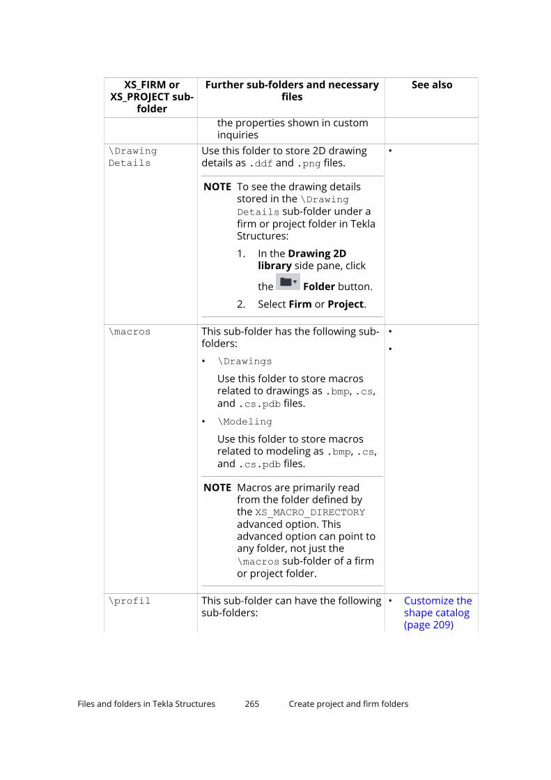
XS_FIRM orXS_PROJECT sub-
folder
Further sub-folders and necessaryfiles
See also
the properties shown in custominquiries
\DrawingDetails
Use this folder to store 2D drawingdetails as .ddf and .png files.
NOTE To see the drawing detailsstored in the \DrawingDetails sub-folder under afirm or project folder in TeklaStructures:
1. In the Drawing 2Dlibrary side pane, click
the Folder button.
2. Select Firm or Project.
•
\macros This sub-folder has the following sub-folders:
• \DrawingsUse this folder to store macrosrelated to drawings as .bmp, .cs,and .cs.pdb files.
• \ModelingUse this folder to store macrosrelated to modeling as .bmp, .cs,and .cs.pdb files.
NOTE Macros are primarily readfrom the folder defined bythe XS_MACRO_DIRECTORYadvanced option. Thisadvanced option can point toany folder, not just the \macros sub-folder of a firmor project folder.
•
•
\profil This sub-folder can have the followingsub-folders:
• Customize theshape catalog(page 209)
Files and folders in Tekla Structures 265 Create project and firm folders

XS_FIRM orXS_PROJECT sub-
folder
Further sub-folders and necessaryfiles
See also
• \ShapeGeometriesUse this folder to store shapegeometry descriptions as .tezor .xml files.
• \ShapesUse this folder to store shapedescriptions as .xml files.
\ProjectOrganizerData
This folder has the following sub-folders:
• \DefaultCategoryTreesUse this folder to store Organizercategories as .category files.
• \PropertyTemplatesUse this folder to store propertytemplates from Organizeras .propertytemplate files.
• \ExcelTemplatesUse this folder to storecustomized templates in .xltformat for exporting objectproperty values from Organizer.
•
\PropertyRepository\Templates
Use this folder to store customizedproperty pane layouts in the PropertyTemplates.xml file.
• Distributecustomizedproperty panelayouts byusing aproject, firm,orenvironmentfolder(page 135)
\Symbols Use this folder to store:
• symbols as .sym and .dwg files
• other images and bitmaps used indrawings
NOTE Symbols are primarily readfrom the folder defined bythe DXK_SYMBOLPATH
• Add symbolsin drawings
• DXK_SYMBOLPATH
Files and folders in Tekla Structures 266 Create project and firm folders

XS_FIRM orXS_PROJECT sub-
folder
Further sub-folders and necessaryfiles
See also
advanced option. Thisadvanced option can point toany folder, not just the \Symbols sub-folder of afirm or project folder.
\template Use this folder to store graphicaltemplates used in drawing layoutsas .tpl files.
NOTE Templates are primarily readfrom the folder defined bythe XS_TEMPLATE_DIRECTORYadvanced option.
In the same way, the tpled.ini is primarily readfrom the folder defined bythe XS_TPLED_INI advancedoption.
These advanced options canpoint to any folder, not justthe \Template sub-folder ofa firm or project folder.
This folder also contains the followingsub-folders:
• \markUse this folder to store graphicaltemplates used in drawing marks.
NOTE Templates used indrawing marks areprimarily read from thefolder defined by the XS_TEMPLATE_MARK_SUB_DIRECTORY folder. Thisadvanced option canpoint to any folder, notjust the \template\marksub-folder of a firm orproject folder.
•
•
Files and folders in Tekla Structures 267 Create project and firm folders
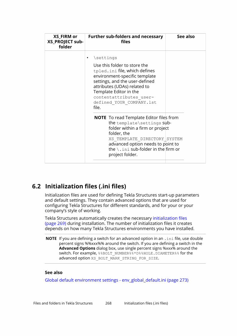
XS_FIRM orXS_PROJECT sub-
folder
Further sub-folders and necessaryfiles
See also
• \settingsUse this folder to store the tpled.ini file, which definesenvironment-specific templatesettings, and the user-definedattributes (UDAs) related toTemplate Editor in the contentattributes_user-defined_YOUR_COMPANY.lstfile.
NOTE To read Template Editor files fromthe template\settings sub-folder within a firm or projectfolder, the XS_TEMPLATE_DIRECTORY_SYSTEMadvanced option needs to point tothe \.ini sub-folder in the firm orproject folder.
6.2 Initialization files (.ini files)Initialization files are used for defining Tekla Structures start-up parametersand default settings. They contain advanced options that are used forconfiguring Tekla Structures for different standards, and for your or yourcompany’s style of working.
Tekla Structures automatically creates the necessary initialization files(page 269) during installation. The number of initialization files it createsdepends on how many Tekla Structures environments you have installed.
NOTE If you are defining a switch for an advanced option in an .ini file, use doublepercent signs %%xxx%% around the switch. If you are defining a switch in theAdvanced Options dialog box, use single percent signs %xxx% around theswitch. For example, %%BOLT_NUMBER%%*D%%HOLE.DIAMETER%% for theadvanced option XS_BOLT_MARK_STRING_FOR_SIZE.
See also
Global default environment settings - env_global_default.ini (page 273)
Files and folders in Tekla Structures 268 Initialization files (.ini files)

Local environment settings - env_<environment>.ini (page 274)
Role settings - role_<role>.ini (page 274)
Typical initialization files (.ini files) and their reading order
Below is a list of all the typical initialization files that are read when TeklaStructures is started. The numbers indicate their reading order at startup. Ifthere are conflicting settings, the ones read later override the ones readearlier.
WARNING Changing an advanced option value in .ini files located outsidethe model folder does not affect the existing models. You canonly update advanced options in the Advanced Options dialogbox or in the options.ini file located in model folder; not froman options.ini file located in folders defined for the advancedoptions XS_FIRM or XS_PROJECT. The .ini files are read alsowhen you open an existing model, but only new advancedoptions that do not exist in options_model.db oroptions_drawings.db are inserted, for example, such optionsthat are not yet in the Advanced Options dialog box but havebeen added in the software.
To check the files that have been read and their reading order, go to Filemenu --> Logs --> Session history log .
File and reading order Description1. fonts_<lang>.ini This file is optional, and it is only
needed for languages using specialcharacters. One example is thefonts_jpn.ini file for the Japaneselanguage.
This file is read from TeklaStructures\<version>\nt\bin\ ifit is available. It is installed tothe ..\nt\bin folder when TeklaStructures is installed.
NOTE: Do not change these settings.2. teklastructures.ini The file teklastructures.ini
starts Tekla Structures. It is readfrom ..\Program Files\TeklaStructures\<version>\nt\bin\.
This file contains basic systemsettings, such as the location ofsoftware and environment files. This
Files and folders in Tekla Structures 269 Initialization files (.ini files)
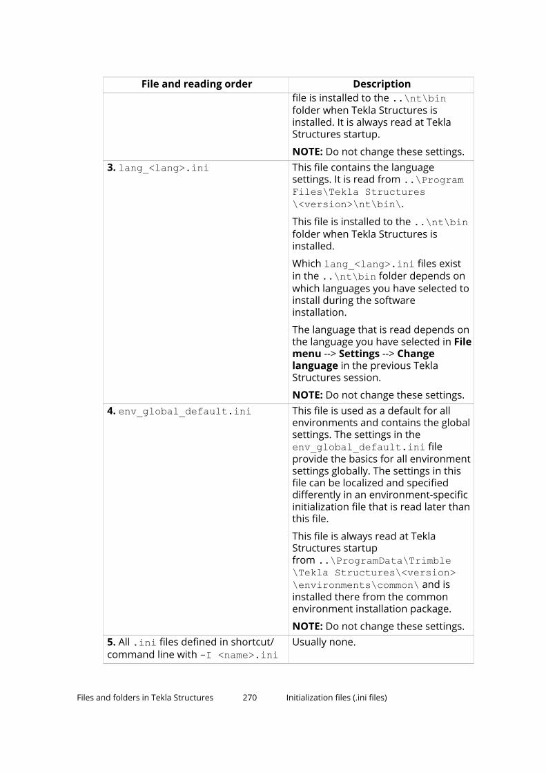
File and reading order Descriptionfile is installed to the ..\nt\binfolder when Tekla Structures isinstalled. It is always read at TeklaStructures startup.
NOTE: Do not change these settings.3. lang_<lang>.ini This file contains the language
settings. It is read from ..\ProgramFiles\Tekla Structures\<version>\nt\bin\.
This file is installed to the ..\nt\binfolder when Tekla Structures isinstalled.
Which lang_<lang>.ini files existin the ..\nt\bin folder depends onwhich languages you have selected toinstall during the softwareinstallation.
The language that is read depends onthe language you have selected in Filemenu --> Settings --> Changelanguage in the previous TeklaStructures session.
NOTE: Do not change these settings.4. env_global_default.ini This file is used as a default for all
environments and contains the globalsettings. The settings in theenv_global_default.ini fileprovide the basics for all environmentsettings globally. The settings in thisfile can be localized and specifieddifferently in an environment-specificinitialization file that is read later thanthis file.
This file is always read at TeklaStructures startupfrom ..\ProgramData\Trimble\Tekla Structures\<version>\environments\common\ and isinstalled there from the commonenvironment installation package.
NOTE: Do not change these settings.5. All .ini files defined in shortcut/command line with -I <name>.ini
Usually none.
Files and folders in Tekla Structures 270 Initialization files (.ini files)

File and reading order Description6. env_<environment>.ini The env_<environment>.ini files
contain all the advanced options thathave environment-specific settings.They are read from the environmentfolder ..\ProgramData\Trimble\Tekla Structures\<version>\environments\. The exact locationmay vary depending on yourenvironment.
The env_<environment>.ini filesthat exist on your computer dependson which environment packages youhave installed. Whichenv_<environment>.ini file is readdepends on the environment that youselect in the Tekla Structures startupdialog box.
NOTE: Do not change these settings.7. role_<role>.ini The role_<role>.ini files contain
all the advanced options that havetypical role-specific settings. They areread from the environmentfolder ..\ProgramData\Trimble\Tekla Structures\<version>\environments\. The exact locationmay vary depending on yourenvironment.
The available roles depend on theenvironments you have installed.
You can select the role in the TeklaStructures startup dialog box.
For example, this file defines that theUS environment imperial role usesimperial units, shows the fractionscorrectly, and understands input asimperial. In US environment metricrole metric units are used.
NOTE: Do not change these settings.8. All .ini files defined in shortcut/command line with -i <name>.ini
Usually none.
9. company.ini The company.ini file is usefulespecially for big companies thatwant to unify certain enterprise-level
Files and folders in Tekla Structures 271 Initialization files (.ini files)

File and reading order Descriptionsettings. This file is read from a folderspecified with the advanced optionXS_COMPANY_SETTINGS_DIRECTORY.This file is read only if the advancedoption XS_COMPANY_SETTINGS_DIRECTORYis set.
This file is created by the systemadministrator when necessary, it isnot created by the installation.
10. user.ini The user.ini file is where you cansave your personal user settings.
This file is located in the samelocation as the user-specificoptions.bin file, for example,C:\Users\<user>\AppData\Local\Trimble\Tekla Structures\<version>\UserSettings.
The user.ini is created in the abovementioned location when you startTekla Structures for the first time andcreate and save a model using thecurrent version. It is read when youstart Tekla Structures.
The changes you make in theadvanced options in the AdvancedOptions dialog box override thesettings in all other initialization files,if the advanced option exists in bothlocations.
If user.ini has system options theyare read always when TeklaStructures is opened.
If user.ini has model-specificoptions they are used when newmodel is created.
If user.ini has user-specific optionsthey are used when Tekla Structuresis used for the first time.
11. options.ini in system folder The folder is specified with theadvanced option XS_SYSTEM.
Files and folders in Tekla Structures 272 Initialization files (.ini files)

File and reading order Description12. options.ini, firm-specific, if anyexist
13. options.ini, project-specific, ifany exist
The option.ini files containingfirm- or project-specific modelsettings are saved in and read fromuser-defined locations specified withthe advanced options XS_FIRM andXS_PROJECT. They work in thespecified way for the firm in question,or for the specified project if themodel has been set up to readsettings from these locations, and ifthe user has manually moved theoptions.ini file to these locations.An options.ini is created in thefirm or project folder when you copyor move it there.
Updating of model-specific and user-specific advanced options can only bedone from the Advanced Optionsdialog box or options.ini located inmodel folder, not from the firm- orproject-specific options.ini files.
The options.ini in the firm orproject folder is read when you startTekla Structures or open the model.
14. options.ini, model-specific The options.ini in the modelfolder.
See also
Create start-up shortcuts with customized initializations (page 19)
Settings defined by advanced options (page 296)
Global default environment settings - env_global_default.iniThe env_global_default.ini file defines the global defaults for advancedoptions. The file is read from ..\ProgramData\Trimble\TeklaStructures\<version>\environments\common\.
WARNING Do not modify the env_global_default.ini file. If you need tomodify some environment settings, copy the needed advancedoptions from this file to your user.ini (page 275) file and modifythe settings there, or modify the settings in the AdvancedOptions dialog box.
Files and folders in Tekla Structures 273 Initialization files (.ini files)

For advanced options that are set according to your local standards, see theenvironment settings file env_<environment name>.ini (page 274) and the rolesettings file role_<role name>.ini (page 274). The local files override theadvanced options set in env_global_default.ini.
If the advanced option in the env_global_default.ini file is preceded byrem, the software defaults are used and shown as the value. The outdatedadvanced options are listed at the end of the file.
See also
Typical initialization files (.ini files) and their reading order (page 269)
Local environment settings - env_<environment>.iniThe env_<environment>.ini file contains advanced options that are setaccording to local standards and are different from the global defaults. The fileis read from the environment folder..\ProgramData\Trimble\TeklaStructures\<version>\environments\. The exact location may varydepending on your environment.
WARNING Do not modify the env_<environment>.ini file. If you need tomodify some settings, copy the needed advanced options fromthis file to your user.ini (page 275) file and modify the settingsthere, or modify the settings in the Advanced Options dialogbox.
The global default environment settings file env_global_default.ini (page 273)contains a complete listing of advanced options. The local files override theadvanced options set in env_global_default.ini.
See also
Typical initialization files (.ini files) and their reading order (page 269)
Role settings - role_<role>.iniThe role_<role>.ini files contain all the advanced options that have typicalrole-specific settings. The file is read from the environmentfolder ..\ProgramData\Trimble\Tekla Structures\<version>\environments\. The exact location may vary depending on theenvironment.
WARNING Do not modify the role_<role>.ini file. If you need to modifysome settings, copy the needed advanced options from this file
Files and folders in Tekla Structures 274 Initialization files (.ini files)
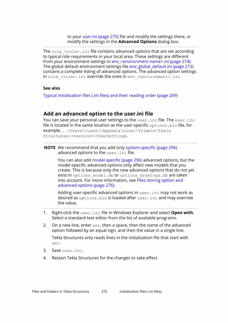
to your user.ini (page 275) file and modify the settings there, ormodify the settings in the Advanced Options dialog box.
The role_<role>.ini file contains advanced options that are set accordingto typical role requirements in your local area. These settings are differentfrom your environment settings in env_<environment name>.ini (page 274).The global default environment settings file env_global_default.ini (page 273)contains a complete listing of advanced options. The advanced option settingsin role_<role>.ini override the ones in env_<environment>.ini
See also
Typical initialization files (.ini files) and their reading order (page 269)
Add an advanced option to the user.ini fileYou can save your personal user settings to the user.ini file. The user.inifile is located in the same location as the user-specific options.bin file, forexample, ..\Users\<user>\AppData\Local\Trimble\TeklaStructures\<version>\UserSettings.
NOTE We recommend that you add only system-specific (page 296)advanced options to the user.ini file.
You can also add model-specific (page 296) advanced options, but themodel-specific advanced options only affect new models that youcreate. This is because only the new advanced options that do not yetexist in options_model.db or options_drawings.db are takeninto account. For more information, see Files storing option andadvanced options (page 276).
Adding user-specific advanced options in user.ini may not work asdesired as options.bin is loaded after user.ini and may overridethe value.
1. Right-click the user.ini file in Windows Explorer and select Open with.Select a standard text editor from the list of available programs.
2. On a new line, enter set, then a space, then the name of the advancedoption followed by an equal sign, and then the value in a single line.
Tekla Structures only reads lines in the initialization file that start with set.
3. Save user.ini.
4. Restart Tekla Structures for the changes to take effect.
Files and folders in Tekla Structures 275 Initialization files (.ini files)

Possible values ExampleTRUEFALSE
set XS_DISABLE_WELD_PREP_SOLID=TRUEsetXS_UNDERLINE_AFTER_POSITION_NUMBER_IN_HARDSTAMP=FALSE
1 set XS_SINGLE_CLOSE_DIMENSIONS=10 set XS_SINGLE_USE_WORKING_POINTS=0string value set
XS_USER_DEFINED_BOLT_SYMBOL_TABLE=bolt_symbol_table.txt
switches setXS_ASSEMBLY_FAMILY_POSITION_NUMBER_FORMAT_STRING=%%TPL:PROJECT.NUMBER%%Use two switches.
TIP When you are moving to a new version of Tekla Structures, you can usethe Migration Wizard to automatically copy your user.ini file to thenew version. The Migration Wizard appears once you start TeklaStructures for the first time after installation.
See also
Location of certain hidden files and folders (page 360)
Typical initialization files (.ini files) and their reading order (page 269)
6.3 File storing options and advanced options
WARNING Changing an advanced option value in .ini files located outsidethe model folder does not affect the existing models. You canonly update advanced options in the Advanced Options dialogbox or in the options.ini file located in model folder; not froman options.ini file located in folders defined for the advancedoptions XS_FIRM or XS_PROJECT. The .ini files are read alsowhen you open an existing model, but only new advancedoptions that do not exist in options_model.db oroptions_drawings.db are inserted, for example, such optionsthat are not yet in the Advanced Options dialog box but havebeen added in the software.
What happens at model creation
When a new model is created, Tekla Structures reads model-specific optionand advanced option values from the standard.opt file, and from the .ini
Files and folders in Tekla Structures 276 File storing options and advanced options
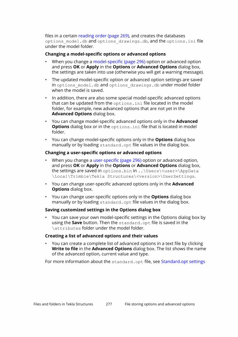
files in a certain reading order (page 269), and creates the databasesoptions_model.db and options_drawings.db, and the options.ini fileunder the model folder.
Changing a model-specific options or advanced options
• When you change a model-specific (page 296) option or advanced optionand press OK or Apply in the Options or Advanced Options dialog box,the settings are taken into use (otherwise you will get a warning message).
• The updated model-specific option or advanced option settings are savedin options_model.db and options_drawings.db under model folderwhen the model is saved.
• In addition, there are also some special model-specific advanced optionsthat can be updated from the options.ini file located in the modelfolder, for example, new advanced options that are not yet in theAdvanced Options dialog box.
• You can change model-specific advanced options only in the AdvancedOptions dialog box or in the options.ini file that is located in modelfolder.
• You can change model-specific options only in the Options dialog boxmanually or by loading standard.opt file values in the dialog box.
Changing a user-specific options or advanced options
• When you change a user-specific (page 296) option or advanced option,and press OK or Apply in the Options or Advanced Options dialog box,the settings are saved in options.bin in ..\Users\<user>\AppData\Local\Trimble\Tekla Structures\<version>\UserSettings.
• You can change user-specific advanced options only in the AdvancedOptions dialog box.
• You can change user-specific options only in the Options dialog boxmanually or by loading standard.opt file values in the dialog box.
Saving customized settings in the Options dialog box
• You can save your own model-specific settings in the Options dialog box byusing the Save button. Then the standard.opt file is saved in the\attributes folder under the model folder.
Creating a list of advanced options and their values
• You can create a complete list of advanced options in a text file by clickingWrite to file in the Advanced Options dialog box. The list shows the nameof the advanced option, current value and type.
For more information about the standard.opt file, see Standard.opt settings
Files and folders in Tekla Structures 277 File storing options and advanced options
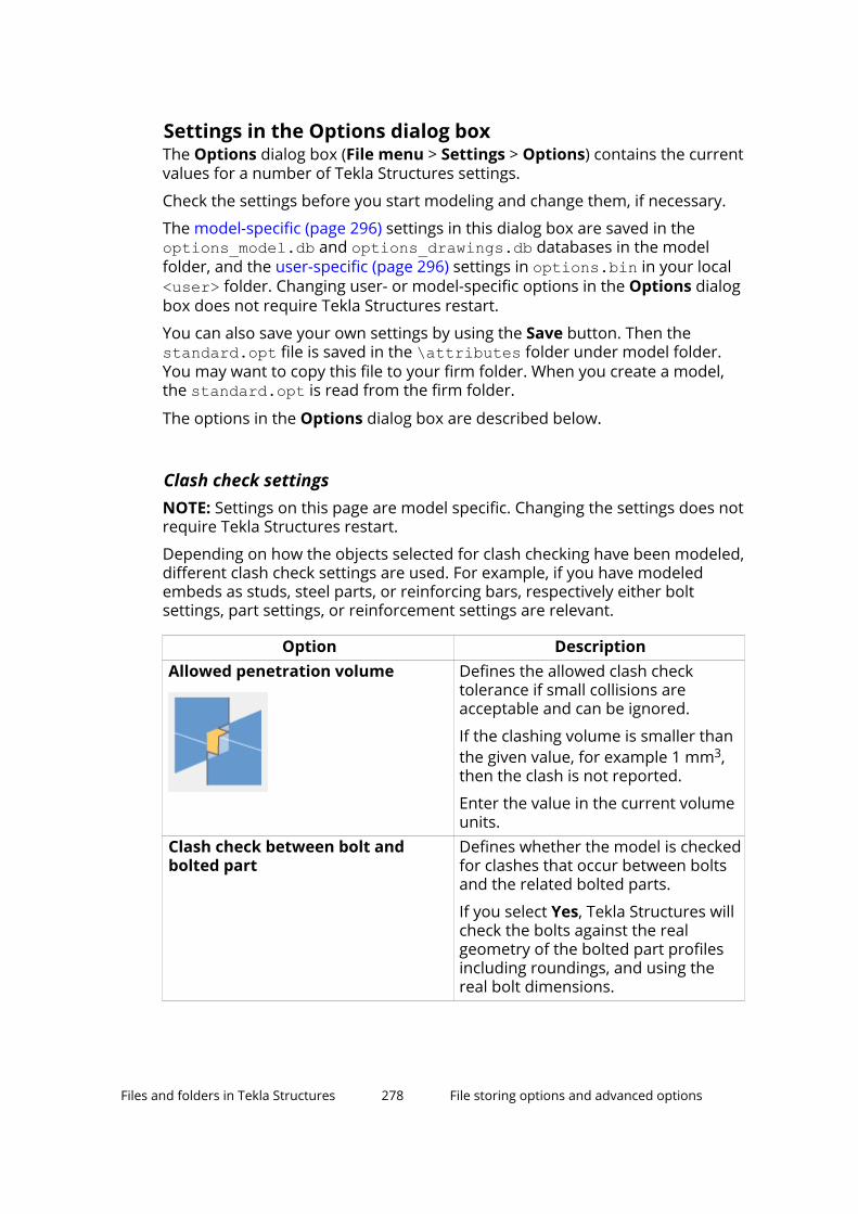
Settings in the Options dialog boxThe Options dialog box (File menu > Settings > Options) contains the currentvalues for a number of Tekla Structures settings.
Check the settings before you start modeling and change them, if necessary.
The model-specific (page 296) settings in this dialog box are saved in theoptions_model.db and options_drawings.db databases in the modelfolder, and the user-specific (page 296) settings in options.bin in your local<user> folder. Changing user- or model-specific options in the Options dialogbox does not require Tekla Structures restart.
You can also save your own settings by using the Save button. Then thestandard.opt file is saved in the \attributes folder under model folder.You may want to copy this file to your firm folder. When you create a model,the standard.opt is read from the firm folder.
The options in the Options dialog box are described below.
Clash check settingsNOTE: Settings on this page are model specific. Changing the settings does notrequire Tekla Structures restart.
Depending on how the objects selected for clash checking have been modeled,different clash check settings are used. For example, if you have modeledembeds as studs, steel parts, or reinforcing bars, respectively either boltsettings, part settings, or reinforcement settings are relevant.
Option DescriptionAllowed penetration volume Defines the allowed clash check
tolerance if small collisions areacceptable and can be ignored.
If the clashing volume is smaller thanthe given value, for example 1 mm3,then the clash is not reported.
Enter the value in the current volumeunits.
Clash check between bolt andbolted part
Defines whether the model is checkedfor clashes that occur between boltsand the related bolted parts.
If you select Yes, Tekla Structures willcheck the bolts against the realgeometry of the bolted part profilesincluding roundings, and using thereal bolt dimensions.
Files and folders in Tekla Structures 278 File storing options and advanced options

Option DescriptionDefine the clash check clearancearea for bolts
Use to check if bolts collide with partsand if there is enough space to fix thebolts.
Enter the clearance dimensions inrelation to the bolt head or nutdiameter d (the larger value), and thenut thickness t. The clearance in frontof the bolted parts is the same as thebolt length.
If you do not enter a value, TeklaStructures uses the default value.
If you clear the check boxes, theclearance will be zero.
If Tekla Structures cannot find thebolt head or nut diameter in the boltcatalog, it uses the shank diameterinstead.
Exact solid weld clash check Defines whether the model is checkedfor duplicate and overlapping weldsand for clashes that occur betweenwelds and other objects (such asparts and bolts).
If you select Yes, Tekla Structures willcheck the welds against other welds,against bolts, and against the realgeometry of the part profilesincluding roundings, and using theweld solid dimensions with normalaccuracy.
Reinforcing bar vs steel partclearance (negative value to allowoverlap)
Defines the minimum clearance orthe allowed overlap for reinforcingbars when they are checked againststeel parts.
To allow reinforcing bars to overlapsteel parts and to ignore the ribs ofbars, enter a negative value. Themaximum overlap is the actual barradius.
Tekla Structures only checks thedistance from bar side to part. Tekla
Files and folders in Tekla Structures 279 File storing options and advanced options

Option DescriptionStructures does not check thedistance from bar end to part.
If you clear the check box, TeklaStructures will not check theclearance.
Reinforcing bar clearance (negativevalue to allow overlap)
Defines the minimum clearance orthe allowed overlap for reinforcingbars when they are checked againstother reinforcing bars.
To allow reinforcing bars to overlap,enter a negative value.
If you clear the check box, TeklaStructures will not check theclearance.
Reinforcing bar cover thickness Defines the reinforcing bar coverthickness.
Tekla Structures checks the coverthickness against the part that thereinforcing bar belongs to. TeklaStructures only checks the distancefrom bar side to part surface. TeklaStructures does not check thedistance from bar end to part surface.If the bar penetrates a part surface, aclash is reported, even if the bar iscompletely inside a cast unit or pour.
If you clear the check box, TeklaStructures will not check the coverthickness.
Components settingsTekla Structures uses the information on the Components tab when it createsparts using system components.
Component properties defined in component dialog boxes override thesesettings. Tekla Structures only uses these settings if the corresponding boxesin the component dialog boxes are empty.
If you change settings here, Tekla Structures only applies the new settings tocomponents you subsequently create. Components you created prior tochanging the preferences are not affected.
NOTE: Settings on this page are model specific. Changing the settings does notrequire Tekla Structures restart.
Files and folders in Tekla Structures 280 File storing options and advanced options
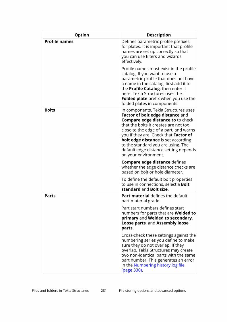
Option DescriptionProfile names Defines parametric profile prefixes
for plates. It is important that profilenames are set up correctly so thatyou can use filters and wizardseffectively.
Profile names must exist in the profilecatalog. If you want to use aparametric profile that does not havea name in the catalog, first add it tothe Profile Catalog, then enter ithere. Tekla Structures uses theFolded plate prefix when you use thefolded plates in components.
Bolts In components, Tekla Structures usesFactor of bolt edge distance andCompare edge distance to to checkthat the bolts it creates are not tooclose to the edge of a part, and warnsyou if they are. Check that Factor ofbolt edge distance is set accordingto the standard you are using. Thedefault edge distance setting dependson your environment.
Compare edge distance defineswhether the edge distance checks arebased on bolt or hole diameter.
To define the default bolt propertiesto use in connections, select a Boltstandard and Bolt size.
Parts Part material defines the defaultpart material grade.
Part start numbers defines startnumbers for parts that are Welded toprimary and Welded to secondary,Loose parts, and Assembly looseparts.
Cross-check these settings against thenumbering series you define to makesure they do not overlap. If theyoverlap, Tekla Structures may createtwo non-identical parts with the samepart number. This generates an errorin the Numbering history log file(page 330).
Files and folders in Tekla Structures 281 File storing options and advanced options

Drawing dimensions settingsNOTE: Settings on this page are model specific. Changing the settings does notrequire Tekla Structures restart.
For more information about dimension settings, see
Option DescriptionExaggeration This setting defines the default values
for Exaggeration limit andExaggeration scaling.
When you enable the exaggeration ofthe dimensions, a drawing dimensionthat is narrower than the defined limitis expanded. Exaggeration limitdefines the default value for this limit.
Exaggeration scaling defineswhether you are using Paper orModel as the exaggeration scalingmethod:
• If you select Paper, theexaggeration limit is multiplied bythe view scale.
• If you select Model, and the scaleis 1:10, all the dimensions smallerthan 10 mm are exaggeratedregardless of the drawing scale.
For more information aboutexaggerated dimensions, see .
Absolute dimensions Show zero in absolute dimensions--> Yes shows zero at the zero pointsin absolute dimensions.
Draw absolute dimension valuesparallel to dimension line --> Yesshows dimensions parallel todimension lines in absolutedimensions.
For more information, seeDimensions in tags Units, Format and Precision define
the default unit, format and precisionused in dimension tags.
Available units: mm, cm, m, foot -inch, cm / m, inch, feet.
Files and folders in Tekla Structures 282 File storing options and advanced options

Option DescriptionAvailable formats: ###, ###[.#],###.#, ###[.##], ###.##, ###[.###],###.###, ### #/# and ###/##.###.
Available precision: 0.00, 0.50, 0.33,0.25, 1/8, 1/16, 1/32, 1/10, 1/100,1/1000
Show dimension in middle tag ofautomatic dimension
Defines whether you want to createdual dimension tags in assembly,single-part, cast unit, or generalarrangement drawings.
For more information aboutautomatic dual dimensions, see .
For more information about manualdual dimensions, see
When Tekla Structures creates thedrawing, it adds the lower dimensiontag in the selected unit, format andprecision.
Dimension line Dimension line extension lengthfor line arrow defines the length ofthe line extension for dimensions thathave line arrows.
Note that line extensions are notapplied to dimensions that havedifferent arrows from line arrows,and certain knock-off dimensiontypes.
Drawing objects settingsNOTE: Settings on this page are model specific. Changing the settings does notrequire Tekla Structures restart.
Option DescriptionEdge chamfer Line color defines the default line
color of the edge chamfers indrawings.
Line type defines the default linetype of the edge chamfers indrawings.
Files and folders in Tekla Structures 283 File storing options and advanced options

Option DescriptionThese values are overridden by thevalues set in the Edge ChamferProperties dialog box.
For more information about edgechamfers, see .
General settingsNOTE: On this page, Autosave settings are user specific. All other settings aremodel specific. Changing the settings does not require Tekla Structuresrestart.
Option DescriptionAutosave Autosave interval: Autosave after
every xx modeling or editingcommands defines how often TeklaStructures automatically saves amodel and a drawing.
This number represents the numberof commands you have given. Forexample, if you create many objectswithout interrupting (Esc), it counts asone command.
Autosave after creating every xxdrawings defines the number ofdrawings after which Tekla Structuresautomatically saves your work.
For more information, see:
Default adaptivity Off means that adaptivity is notdefined.
Relative defines that handles retaintheir relative distances to the nearestpart faces in relation to the part’soverall size.
Fixed defines that handles retaintheir absolute distances to thenearest part faces.
You can also modify the adaptivitysettings for each part separately.These modifications override the
Files and folders in Tekla Structures 284 File storing options and advanced options
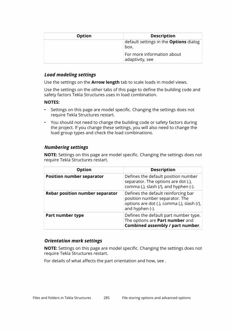
Option Descriptiondefault settings in the Options dialogbox.
For more information aboutadaptivity, see
Load modeling settingsUse the settings on the Arrow length tab to scale loads in model views.
Use the settings on the other tabs of this page to define the building code andsafety factors Tekla Structures uses in load combination.
NOTES:
• Settings on this page are model specific. Changing the settings does notrequire Tekla Structures restart.
• You should not need to change the building code or safety factors duringthe project. If you change these settings, you will also need to change theload group types and check the load combinations.
Numbering settingsNOTE: Settings on this page are model specific. Changing the settings does notrequire Tekla Structures restart.
Option DescriptionPosition number separator Defines the default position number
separator. The options are dot (.),comma (,), slash (/), and hyphen (-).
Rebar position number separator Defines the default reinforcing barposition number separator. Theoptions are dot (.), comma (,), slash (/),and hyphen (-).
Part number type Defines the default part number type.The options are Part number andCombined assembly / part number.
Orientation mark settingsNOTE: Settings on this page are model specific. Changing the settings does notrequire Tekla Structures restart.
For details of what affects the part orientation and how, see .
Files and folders in Tekla Structures 285 File storing options and advanced options

Option DescriptionNorth direction Project north (degrees counter
clockwise from global x) defineswhich direction is north in the model.Enter the value in degrees counter-clockwise from the global x axis.
Part viewing direction Defines which direction parts areviewed from in drawings.
Beam skew limit
Column skew limit
Tekla Structures uses limit angles todetermine whether a part is a beamor a column when creatingorientation marks. Tekla Structurestreats parts outside these limits asbraces.
Parts skewed more than 80° arecolumns.
Parts skewed less than 10° arebeams.
Preferred location for mark Defines the location of part marks indrawings, to the left or right end ofthe part.
Mark always to center of column This setting only affects columns.
Yes places part marks in the center ofcolumns in plan views. To indicatepart orientation, include compass
Files and folders in Tekla Structures 286 File storing options and advanced options
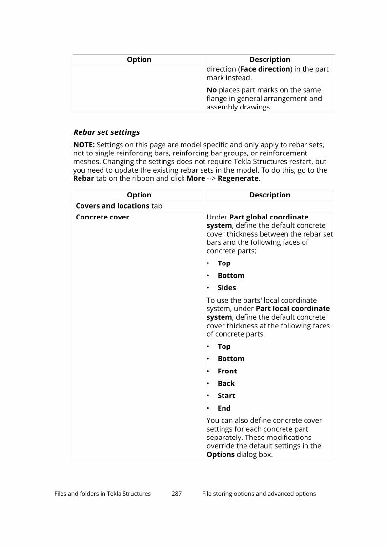
Option Descriptiondirection (Face direction) in the partmark instead.
No places part marks on the sameflange in general arrangement andassembly drawings.
Rebar set settingsNOTE: Settings on this page are model specific and only apply to rebar sets,not to single reinforcing bars, reinforcing bar groups, or reinforcementmeshes. Changing the settings does not require Tekla Structures restart, butyou need to update the existing rebar sets in the model. To do this, go to theRebar tab on the ribbon and click More --> Regenerate.
Option DescriptionCovers and locations tabConcrete cover Under Part global coordinate
system, define the default concretecover thickness between the rebar setbars and the following faces ofconcrete parts:
• Top
• Bottom
• Sides
To use the parts' local coordinatesystem, under Part local coordinatesystem, define the default concretecover thickness at the following facesof concrete parts:
• Top
• Bottom
• Front
• Back
• Start
• End
You can also define concrete coversettings for each concrete partseparately. These modificationsoverride the default settings in theOptions dialog box.
Files and folders in Tekla Structures 287 File storing options and advanced options

Option DescriptionLayer prefix Under Part global coordinate
system and/or Part local coordinatesystem, define the default bar layerprefixes at different faces of concreteparts.
You can also define bar layer settingsfor individual rebar sets or leg faces,or for individual bars using the user-defined attributes of propertymodifiers. These modificationsoverride the default settings in theOptions dialog box.
Links Define the bar layer prefix for rebarset bars that have four or more legs,for example closed stirrups.
General tabMinimum lengths to be created Define Minimum bar length to
prevent Tekla Structures fromcreating reinforcing bars that are tooshort. This setting is primarily forstraight bars. Enter the minimum barlength as Distance or as Coefficientof bar diameter.
Define Minimum straight start/endleg length for bent reinforcing bars.Enter the minimum leg length asDistance or as Coefficient of bardiameter.
These settings are also available inthe Rebar set properties and in theRebar property modifier properties.
Rounding and step tapering tabRounding Define whether the lengths of straight
bars, first and last legs, andintermediate legs are rounded in themodel, and whether the bar lengthsare rounded up, down, or to the
Files and folders in Tekla Structures 288 File storing options and advanced options

Option Descriptionnearest suitable number according tothe rounding accuracy.
At splitter locations, define how muchthe bar lengths can be rounded up.
Rounding settings are also availablein the Rebar set properties and in theRebar property modifier properties.
Step tapering Define the tapering step values forstraight bars, first and last legs, andintermediate legs.
Step tapering settings are alsoavailable in the Rebar set propertiesand in the Rebar property modifierproperties.
Units and decimals settingsNOTE: Settings on this page are model specific. Changing the settings does notrequire Tekla Structures restart.
The number located to the right of each option indicates the number ofdecimals. The number of decimals affects the input and storage accuracy.Always use a sufficient number of decimals.
For more information on unit and decimal settings, see Change units anddecimals.
Option DescriptionLength mm, cm, m, in (decimal), ft
(decimal), ft-inAngle o, rad
Files and folders in Tekla Structures 289 File storing options and advanced options

Option DescriptionSpring constant
Rot. spring constant
Factor (unitless)Force
Files and folders in Tekla Structures 290 File storing options and advanced options

Option DescriptionDistributed load
Surface load
Moment
Distributed moment
Temperature oC, oF, KDeformation
Files and folders in Tekla Structures 291 File storing options and advanced options
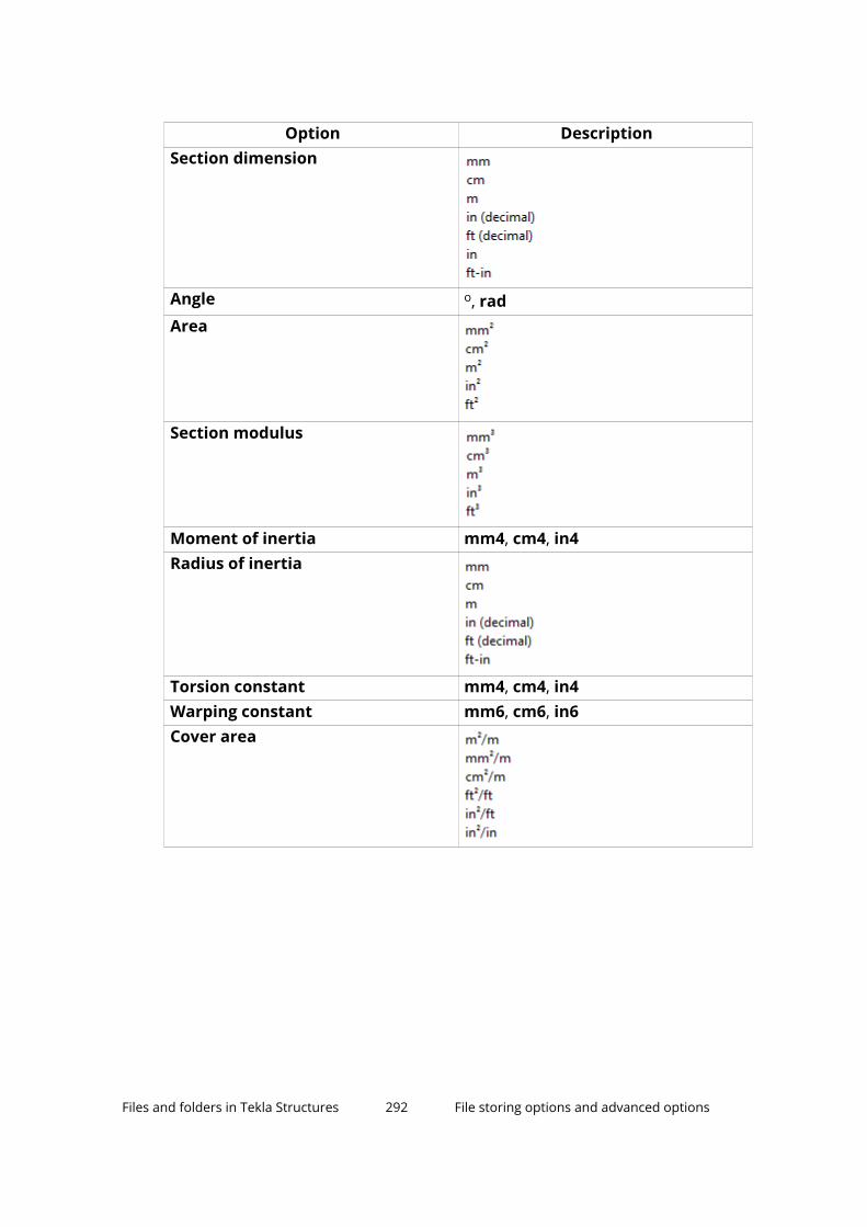
Option DescriptionSection dimension
Angle o, radArea
Section modulus
Moment of inertia mm4, cm4, in4Radius of inertia
Torsion constant mm4, cm4, in4Warping constant mm6, cm6, in6Cover area
Files and folders in Tekla Structures 292 File storing options and advanced options

Option DescriptionStrength
Modulus
Density
Files and folders in Tekla Structures 293 File storing options and advanced options
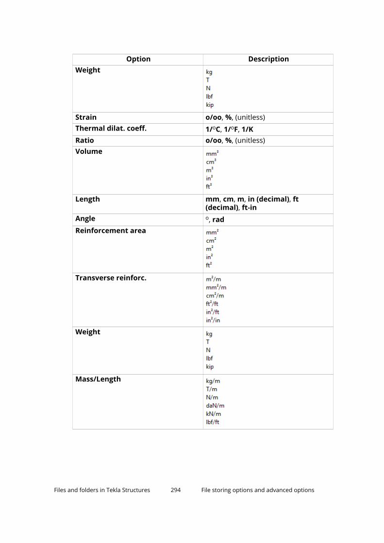
Option DescriptionWeight
Strain o/oo, %, (unitless)Thermal dilat. coeff. 1/oC, 1/oF, 1/KRatio o/oo, %, (unitless)Volume
Length mm, cm, m, in (decimal), ft(decimal), ft-in
Angle o, radReinforcement area
Transverse reinforc.
Weight
Mass/Length
Files and folders in Tekla Structures 294 File storing options and advanced options

Option DescriptionVolume
Force
Distributed load
Surface load
Moment
Temperature oC, oF, K
Files and folders in Tekla Structures 295 File storing options and advanced options

Option DescriptionStress
Deformation
See also
File storing options and advanced options (page 276)
Settings defined by advanced options
Advanced options can be user-, model-, system or role-specific:
• User-specific advanced options are saved in your local options.bin file,which is by default located in C:\Users\<user>\AppData\Local\Trimble\Tekla Structures\<version>\UserSettings, and work inthe specified way in all models that you have. The folder can be changedusing the advanced option XS_USER_SETTINGS_DIRECTORY. In theAdvanced Options dialog box, the type is USER. Some user-specificadvanced options require restarting of Tekla Structures after changing thevalue.
• Model-specific advanced options work in the specified way only in thecurrent model. They are saved to options_model.db andoptions_drawings.db under model folder. In the Advanced Optionsdialog box, the type is MODEL or DRAWING. Some special model-specific
Files and folders in Tekla Structures 296 File storing options and advanced options

options that are not visible in the Advanced Options dialog box can bechanged from options.ini file under the model folder.
• System-specific advanced options are general to all sessions of TeklaStructures, and work in the specified way for all users and in all models. Inthe Advanced Options dialog box, the type is SYSTEM. A system-specificadvanced option can be stored to options database by clicking SYSTEMnext to the option and changing it to MODEL(SYSTEM). Note that thechanged value only works for the current model. A MODEL(SYSTEM)advanced option can be changed back to SYSTEM by changing it toSYSTEM, and in this case it will be removed from the options database.Some system-specific advanced options require restarting of TeklaStructures after changing the value.
The system-specific advanced options are read from environment .inifiles:
• Global system settings are read from common env_global_default.ini(page 273) in ..\ProgramData\Trimble\Tekla Structures\<version>\environments\common\. These settings are used in allenvironments.
• Environment-specific system settings are read fromenv_<environment>.ini (page 274) in your environment folder. Theyoverride any settings that are defined on a global level inenv_global_default.ini.
• Role-specific system settings are read from role_<role>.ini (page 274)in environment folder. They override any settings that are defined on aglobal and environment level in env_global_default.ini andenv_<environment>.ini.
• Company level system-specific system settings override all othersystem-specific advanced options. You can save them in the firm orproject folders by setting the folders for the advanced options and .
• SYSTEM(ROLE) options are typically role specific. The settings are readfrom .ini files and are not saved to the databases. When changed or ifthe type is changed, the option will become model specific and be saved tothe databases. MODEL/DRAWING(ROLE) options are SYSTEM(ROLE)options whose type and/or setting has been changed. The change wouldbe used when you want the SYSTEM(ROLE) option to be saved with themodel to options_model.db and options_drawings.db under modelfolder. These settings can be set back to SYSTEM(ROLE), which will thentake into use the default value.
See also
Typical initialization files (.ini files) and their reading order (page 269)
Files and folders in Tekla Structures 297 File storing options and advanced options
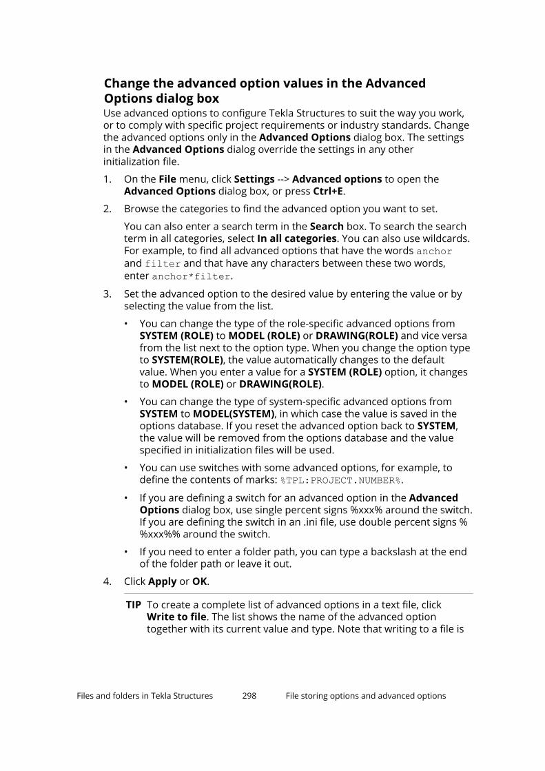
Change the advanced option values in the AdvancedOptions dialog boxUse advanced options to configure Tekla Structures to suit the way you work,or to comply with specific project requirements or industry standards. Changethe advanced options only in the Advanced Options dialog box. The settingsin the Advanced Options dialog override the settings in any otherinitialization file.
1. On the File menu, click Settings --> Advanced options to open theAdvanced Options dialog box, or press Ctrl+E.
2. Browse the categories to find the advanced option you want to set.
You can also enter a search term in the Search box. To search the searchterm in all categories, select In all categories. You can also use wildcards.For example, to find all advanced options that have the words anchorand filter and that have any characters between these two words,enter anchor*filter.
3. Set the advanced option to the desired value by entering the value or byselecting the value from the list.
• You can change the type of the role-specific advanced options fromSYSTEM (ROLE) to MODEL (ROLE) or DRAWING(ROLE) and vice versafrom the list next to the option type. When you change the option typeto SYSTEM(ROLE), the value automatically changes to the defaultvalue. When you enter a value for a SYSTEM (ROLE) option, it changesto MODEL (ROLE) or DRAWING(ROLE).
• You can change the type of system-specific advanced options fromSYSTEM to MODEL(SYSTEM), in which case the value is saved in theoptions database. If you reset the advanced option back to SYSTEM,the value will be removed from the options database and the valuespecified in initialization files will be used.
• You can use switches with some advanced options, for example, todefine the contents of marks: %TPL:PROJECT.NUMBER%.
• If you are defining a switch for an advanced option in the AdvancedOptions dialog box, use single percent signs %xxx% around the switch.If you are defining the switch in an .ini file, use double percent signs %%xxx%% around the switch.
• If you need to enter a folder path, you can type a backslash at the endof the folder path or leave it out.
4. Click Apply or OK.
TIP To create a complete list of advanced options in a text file, clickWrite to file. The list shows the name of the advanced optiontogether with its current value and type. Note that writing to a file is
Files and folders in Tekla Structures 298 File storing options and advanced options

only an export of the current settings, it is not another way ofchanging the advanced options.
See also
Settings defined by advanced options (page 296)
6.4 Input files (.inp files)Tekla Structures uses input files for various purposes, for example, to manageuser-defined attributes and some component dialog boxes, and for defininghow components work. All input files have the extension .inp.
Input files that you can use for configuring Tekla Structures are listed below.
File Descriptionanalysis_design_config.inp
Contains settings for analysis and design.
fltprops.inp Includes materials and dimensions of availableflat bars (page 309).
mesh_database.inp Contains definitions for reinforcement meshes.objects.inp Used to manage user-defined attributes
(page 302).objects_rebar_set.inp
Used to manage user-defined attributes of rebarsets.
pop_mark_parts.inp Contains settings for pop-marking.privileges.inp Used to control access rights.profitab.inp Contains available parametric profiles (page 162).rebar_config.inp Contains settings for reinforcement marks.rebar_database.inp Rebar catalog (page 243). Contains definitions for
reinforcing bars and strands.rebar_schedule_config.inp
Contains internal bending types of reinforcingbars and their mapping to area specific bendingcodes.
Rebar shape manager is a more versatile way todefine reinforcing bar bending shapes.
Tekla Structures also imports and exports rebar catalogs as .inp files.
See also
Environment database file (page 304)
Files and folders in Tekla Structures 299 Input files (.inp files)

Properties of the objects.inp file
Here, we explain the structure of user-defined attribute definitions. Forgeneral information on modifying the definitions, such as file locations andreading order, see Define and update user-defined attributes (UDAs)(page 302).
The example below shows the main properties of objects.inp.
Property In the example Descriptionattribute or unique_attribute
attribute attribute is a regularattribute, which iscopied with other partproperties.
unique_attribute is anon-copyable attribute.The value of theattribute is never copiedto another part. Forexample part checkingstatus attributes usuallycannot be copied.
attribute_name MY_INFO_1 Attribute name, used tofind the attribute value.
Ensure that TeklaStructures does notalready use the attributename you use. Considerusing a prefix thatensures the name isunique, for example,your initials, or anabbreviation of yourcompany name.
The attribute name iscase-sensitive. Do notuse spaces or reservedcharacters in attributenames. The maximum
Files and folders in Tekla Structures 300 Input files (.inp files)

Property In the example Descriptionlength of the name canbe 19 characters.
To include the attributein a report or template,add the name of theattribute to your layoutin the Template Editor.When you run a reportor create a drawing,Tekla Structures displaysthe current value of theattribute.
label_text My Info 1 Label that TeklaStructures displays inthe dialog box.
Some default attributeshave prompts like j_comment, meaningthat the prompt comesfrom the joints.ailmessage file.
value_type string integer or float fornumbers
string for text
string_not_modifiable for text whosemodification isprevented. A field withthe string_not_modifiable property is alwaysdisplayed as dimmedand it cannot beswitched on or off. Thevalue in the field is notsaved when clicking theApply button ormodified when clickingthe Modify button.
option for lists
date for date with smallcalendar
Files and folders in Tekla Structures 301 Input files (.inp files)

Property In the example Descriptiondate_time_min fordate and time [12:00]with small calendar
date_time_sec fordate and time [12:00:00]with small calendar
If you change the valuetype of a field thatalready contains valuesin the model, make surethat the values are validfor the new data typeand verify the results.
field_format %s Definition of the fieldformat in the dialog box
• %s for strings
• %d for numbersspecial_flag no no or yes
For parts: consider innumbering
For drawings: display theattribute value inDocument manager
For other elements: noeffect
check_switch none noneThis option is not used.
attribute_value_max 0.0 0.0This option is not used.
attribute_value_min 0.0 0.0This option is not used.
Define and update user-defined attributes (UDAs)The property pane and many dialog boxes contain user-defined attributes(UDAs) for various objects, including beams, columns, bolts and drawings.Tekla Structures displays these fields when you click the More button in theproperty pane or the User-defined attributes button in a dialog box. Forexample, comment, locked, and erection status are user-defined attributes.
Files and folders in Tekla Structures 302 Input files (.inp files)

When you define new user-defined attributes
The user-defined attributes are managed in the objects.inp (page 300) file. Todefine new user-defined attributes, create your own objects.inp file in themodel, project or firm folder. After adding your own user-defined attributes,you need to run the Diagnose and change attribute definitions commandto update the definitions (page 304) in the model.
When you define new user-defined attribute (page 305), make the definition ofthe user-defined attribute unique. This is because a user-defined attributecannot have different definitions for different object types, such as beams andcolumns.
The object.inp files are merged so that if there are user-defined attributesin any of the files, they are displayed in the user interface. Tekla Structuresmerges the files in a way that eliminates duplicate attributes. If TeklaStructures encounters the same attribute name in different objects.inpfiles, the attribute from the first read objects.inp file will be used.
If you need to have several objects.inp files in the same folder, you can usea suffix in the file name to use all the files. This enables having severalobjects_<suffix>.inp files in the same folder. The file name could beobjects_precast.inp, for example.
WARNING Do not copy the objects.inp file in the ..\environments\common\inp\ folder. Copying the file creates unnecessaryduplicates and later objects.inp updates by Tekla Structurescan be lost.
Tekla Structures reads the objects.inp files from the following folders in thefollowing order:
1. model folder
2. project folder
3. firm folder
4. system folder
5. inp folder
Changing existing user-defined attribute definitions
Updating a user-defined attribute definition in a model does not convert anyvalues that are already stored in the field. If you change the value type of afield that already contains values in the model, make sure that the values arevalid for the new data type and verify the results.
The safest approach is to create a new attribute when the format of the valuesin the field changes. If you want to convert user-defined attribute values, youcan create a report that lists the values, convert them using external tools andimport the converted values (page 400).
Files and folders in Tekla Structures 303 Input files (.inp files)

See also
Environment database file (page 304)
Update definitions of user-defined attributes (UDAs) in a modelWhen you have changed definitions of a user-defined attribute by modifyingthe objects.inp file, you need to update the definitions in the model.
1. Open the model.
2. On the File menu, click Diagnose & repair and in the Utilities area, clickDiagnose and change attribute definitions.
The Diagnose & Change Attribute Definitions dialog box opens.
3. Select an attribute from the list on left side to see the comparison ofcurrent definitions and objects.inp definitions.
4. Select the definitions you want to update in the Object classes withObjects.inp differences compared to current settings list.
5. Click Change current settings to selected Objects.inp settings.
See also
Define and update user-defined attributes (UDAs) (page 302)
Environment database file (page 304)
Properties of the objects.inp file (page 300)
Example: Create and update a user-defined attribute (UDA) (page 305)
Environment database fileTo guarantee consistent model behavior when a model is used with differentroles, the environment database file (environment.db) contains thedefinitions of the user-defined attributes (UDAs) used in the model.
When you create a new model, Tekla Structures merges the definitions fromyour objects.inp (page 300) files to the environment.db file. Later, when youadd new user-defined attributes in the objects.inp file, the definitions aresaved in environment.db as you open the model.
You can modify your user-defined attributes (page 302) in an objects.inpfile but the changed definitions do not come into effect automatically. If thereare conflicts, the definitions in environment.db win. You need to run theDiagnose and change attribute definitions command to see the conflictsbetween environment.db and objects.inp, and select the attributedefinitions that you want to update.
See also
Update definitions of user-defined attributes (UDAs) in a model (page 304)
Files and folders in Tekla Structures 304 Input files (.inp files)

Example: Create and update a user-defined attribute (UDA) (page 305)
Example: Create and update a user-defined attribute (UDA)This example shows how to create your own user-defined attribute (UDA) andupdate the model to use the changed attribute definition.
Create a user-defined attribute
1. Create a new model and save it.
The user-defined attributes in the model are merged from objects.inp(page 302) files and Tekla Structures saves the attribute definitions in theenvironment.db (page 304) file in the model folder.
2. Close the model.
3. Create an input file called objects.inp in the model folder by using astandard text editor.
4. Enter the following information in objects.inp. For details about theproperties in the attribute string, see objects.inp (page 302).
/***************************************************************************//* Part attributes *//***************************************************************************/part(0,"Part"){/* User defined tab page */tab_page("My UDA tab"){/* User defined attribute */attribute("MY UDA", "My UDA", string,"%s", no, none,"0,0", "0,0"){value("", 0)}}tab_page("My UDA tab", "My UDA tab", 19)modify (1)}
Files and folders in Tekla Structures 305 Input files (.inp files)

/***************************************************************************//* Column attributes *//***************************************************************************/column(0,"j_column"){/* Reference to the user defined tab page that is definedabove in *//* the part() section: */tab_page("My UDA tab", "My UDA tab", 19)modify (1)To see the example text file, click objects.inp - example 1.
NOTE If you want to create a user-defined attribute that also affectsnumbering, set the special_flag (page 300) property of theattribute to yes (it is no in the example above). Also, just like inthe example above, the definition of the tab_page must be in the part section, and the column (beam, etc.) section must have onlya reference to it.
5. Save objects.inp.
Test the user-defined attribute
1. Open the model.
2. Create a steel column.
3. Double-click the steel column to open its properties in the property pane.
4. Click the More button.
5. Go to My UDA tab.
6. Enter a value in the My UDA box.
7. Click Modify.
8. Copy the steel column.
9. Check the My UDA box of the new steel column.
The attribute value was also copied.
Files and folders in Tekla Structures 306 Input files (.inp files)
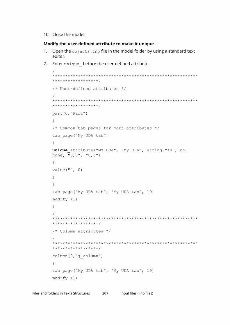
10. Close the model.
Modify the user-defined attribute to make it unique
1. Open the objects.inp file in the model folder by using a standard texteditor.
2. Enter unique_ before the user-defined attribute.
/***************************************************************************//* User-defined attributes *//***************************************************************************/part(0,"Part"){/* Common tab pages for part attributes */tab_page("My UDA tab"){unique_attribute("MY UDA", "My UDA", string,"%s", no,none, "0,0", "0,0"){value("", 0)}}tab_page("My UDA tab", "My UDA tab", 19)modify (1)}/***************************************************************************//* Column attributes *//***************************************************************************/column(0,"j_column"){tab_page("My UDA tab", "My UDA tab", 19)modify (1)
Files and folders in Tekla Structures 307 Input files (.inp files)
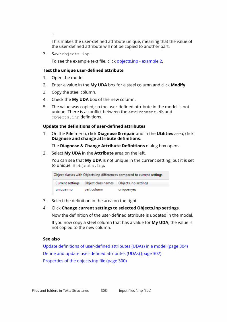
}This makes the user-defined attribute unique, meaning that the value ofthe user-defined attribute will not be copied to another part.
3. Save objects.inp.
To see the example text file, click objects.inp - example 2.
Test the unique user-defined attribute
1. Open the model.
2. Enter a value in the My UDA box for a steel column and click Modify.
3. Copy the steel column.
4. Check the My UDA box of the new column.
5. The value was copied, so the user-defined attribute in the model is notunique. There is a conflict between the environment.db andobjects.inp definitions.
Update the definitions of user-defined attributes
1. On the File menu, click Diagnose & repair and in the Utilities area, clickDiagnose and change attribute definitions.
The Diagnose & Change Attribute Definitions dialog box opens.
2. Select My UDA in the Attribute area on the left.
You can see that My UDA is not unique in the current setting, but it is setto unique in objects.inp.
3. Select the definition in the area on the right.
4. Click Change current settings to selected Objects.inp settings.
Now the definition of the user-defined attribute is updated in the model.
If you now copy a steel column that has a value for My UDA, the value isnot copied to the new column.
See also
Update definitions of user-defined attributes (UDAs) in a model (page 304)
Define and update user-defined attributes (UDAs) (page 302)
Properties of the objects.inp file (page 300)
Files and folders in Tekla Structures 308 Input files (.inp files)

Show plates as flat bars in drawings and reportsTekla Structures can show plates as the equivalent flat bars for manufacturing.Tekla Structures displays the plates as flat bars in reports and drawings.
1. Set the advanced option XS_USE_FLAT_DESIGNATION to TRUE.
2. Indicate the prefix you want to use for flat bars using the advanced optionXS_FLAT_PREFIX.
For example, XS_FLAT_PREFIX=FLAT.
3. Set other platework-related advanced options as required.
4. Define materials, thickness, and width of available flat bars in theFltprops.inp (page 309) file.
TIP • To prevent Tekla Structures from displaying the profile in metric units in theUS environment Imperial role, add the flat bar prefix to the profitab.inp(page 178) file as a parametric profile.
• See also page Platework in the Advanced Options dialog box forinformation about advanced options related to platework.
Define flat bar sizes with the Fltprops.inp fileUse the Fltprops.inp file, located in the \profil folder under theenvironment folder ..\ProgramData\Trimble\TeklaStructures\<version>\environments\, to define flat bar thickness, width andmaterial. The exact location may vary depending on your environment.
NOTE Copy the Fltprops.inp file to a model, project or firm folder and thenmodify the file in the new location as required.
The first row in the file contains flat bar material definitions (enclosed inquotes " ", and without spaces) followed by plate thicknesses. If you do notdefine a material, you can use all materials for all flat bars. The following rowsdefine the widths of available flat bars.
The units are millimeters.
Example
Fltprops.inp contains the following data:
Files and folders in Tekla Structures 309 Input files (.inp files)

With the above data, Tekla Structures displays the following plates as flat bars:
Plate Material5x40, 5x45, 6x50, 6x55 All materials8x60, 8x65, 10x70, 10x75 S23510x100, 10x110, 15x200, 15x220 S275J0
The flat bars get the prefix that is set in the XS_FLAT_PREFIX advanced option.
See also
Show plates as flat bars in drawings and reports (page 308)
Define unfolding parameters in theunfold_corner_ratios.inp fileThe unfolding parameters define the location of the neutral axis when aprofile is unfolded. The neutral axis is a line which runs along the length of aprofile where stress and strain are equal to zero. Tekla Structures uses theseparameters to create NC files and to display unfolded profiles in single-partdrawings.
To define unfolding parameters, modify the unfold_corner_ratios.inpfile, located in ..\ProgramData\Trimble\Tekla Structures\<version>\environments\common\system, using a standard text editor. You can copythe unfold_corner_ratios.inp file to a model, project or firm folder andthen modify the file in the new location as required. Tekla Structures searchesfor this file in the default search order.
After modifying the unfold_corner_ratios.inp file, restart TeklaStructures for the changes to take effect.
NOTE The settings in the unfold_corner_ratios.inp file have no effectin the following cases:
• If the advanced optionXS_USE_OLD_POLYBEAM_LENGTH_CALCULATION is set to TRUE.
• If the advanced optionXS_CALCULATE_POLYBEAM_LENGTH_ALONG_REFERENCE_LINE isset to TRUE. This only applies to polybeams with straight sections.
Unfold parameter properties
See below for an example of unfolding parameters in theunfold_corner_ratios.inp file and the descriptions of the parameters.
1 HE300A S235JR 0 180 2 0 1000 .7
Files and folders in Tekla Structures 310 Input files (.inp files)

Property In the example DescriptionType 1 1 is polybeams
2 is plates modeled aspolybeams (for example,PLT)
3 is for parts which arenot unfolded and followthe old polybeamcalculation (for example,the line 3 L* * disablesunfolding of L profiles)
Profile HE300A You can also usewildcards with profile,for example, HE300*.
Material S235JR You can also usewildcards with material,for example, S235*.
Rotation / thickness min 0 For polybeams: theminimum angle whenthe profile is rotatedaround its longitudinalaxis
For plates: the minimumthickness of plate
Rotation / thickness max 180 For polybeams: themaximum angle whenthe profile is rotatedaround its longitudinalaxis
For plates: the maximumthickness of plate
Flag 2 This property defineswhat kind of parts areaffected by the next twoproperties.
1 is sharp folds. Onlypolybeams with straightchamfers are affected.
2 is curved bends. Onlypolybeams with curvedchamfers are affected.
Files and folders in Tekla Structures 311 Input files (.inp files)

Property In the example DescriptionAngle / radius min 0 For sharp folds: the
minimum angle
For curved bends: theminimum radius
Angle / radius max 1000 For sharp folds: themaximum angle
For curved bends: themaximum radius
Ratio .7 Defines how much theprofile stretches orshrinks when unfolded.
Ratio = (1 - the relativelocation of the neutralaxis).
If only the inner surfaceof the profile shrinks,the ratio is 1. If only theouter surface of theprofile stretches, theratio is 0. By default, theratio is 0.5 for lengthcalculation and 0.0 forbending radiuscalculation.
Tekla Structures appliesthe unfolding ratio if theprofile properties arewithin the rangeindicated by theminimum and maximumvalues.
See also
Folder search order (page 358)
6.5 Data files (.dat files)Data files contain information used by certain components, or Rebar shapemanager, for example.
Files and folders in Tekla Structures 312 Data files (.dat files)

WARNING These files affect the operation of components or Rebar shapemanager. Do not modify the files listed here unless you are anadministrator.
File Descriptionjoints.dat Contains data used in Handrailing (1024) and
Stanchions (S76) components. Used in theStanchion connection type option.
railings.dat Contains data used in Handrailing (1024). Used inthe Stanchion connection type option.
steps.dat Contains the data for Stairs (S82) and Stairs(S71). Used in the Step profile and Cataloguestep options.
std_flange_plates.dat
Contains data for Tapered column (S99). Used inthe options:
• Outer flange profile
• Inner flange profile
• Top plate profilestd_stiffener_plates.dat
Contains data used in Tapered column (S99).Used in the Horizontal stiffener profile box.
marketsize.dat Contains available market sizes for certainmaterial grade. Can be used with fMarketSize()function in the custom component editor.
import_macro_data_types.dat
Contains the user-defined attributes that you caninclude in an input file in attribute import.
RebarShapeManager.CustomProperties.dat
Contains the custom properties, templateattributes, and user-defined attributes that youcan use in bending shape rules in Rebar shapemanager.
Note that default data files are read from the environment's system folder, butuser-defined data files are stored in the model’s \attributes folder.
See also
Define flat bar sizes with the Fltprops.inp file (page 309)
6.6 Message filesTekla Structures uses the information in the message files to display messagesin the user interface. Message files include, for example, texts used in dialogboxes.
Files and folders in Tekla Structures 313 Message files

• Message files with the .ail extension are located in the folder ..\TeklaStructures\<version>\messages.
• Message files with the .xml extension are located in the folder ..\TeklaStructures\<version>\messages\DotAppsStrings.
The files include texts in languages in which the Tekla Structures user interfaceis available.
See also
Customize message files (page 314)
Customize message filesYou can customize the messages that Tekla Structures displays in the userinterface.
1. Do one of the following:
• To modify an .ail message file, go to the ..\Tekla Structures\<version>\messages folder.
• To modify an .xml message file, go to the ..\Tekla Structures\<version>\messages\DotAppsStrings folder.
2. Open the message file you want to customize using a standard text editor.
3. Modify the message as required.
4. Save the message file.
Example: customize a message file
In this example, you will modify a message that Tekla Structures uses for nearside plates in drawings. You want Tekla Structures to display (NS) instead of (N/S).
1. Go to the ..\Tekla Structures\<version>\messages folder.
2. Open by_number.ail using a standard text editor.
The by_number.ail file contains both prompts and default texts thatTekla Structures uses in drawings.
3. Browse to the following section:
string by_number_msg_no_675{...entry = ("enu", "(N/S)");};
4. Change (N/S) to (NS) in the entry row.
Files and folders in Tekla Structures 314 Message files

5. Save and close the file.
See also
Message files (page 313)
6.7 Property filesProperty files are files that contain the object properties and settings that aredisplayed in the property pane or in the dialog boxes of different modelobjects or drawing objects.
By default, Tekla Structures uses the standard (page 316) property files whenyou apply commands. The default standard property files are read from theenvironment's system folder.
In addition to the default property files, you can define user-defined propertyfiles, and load these saved properties later when you create, for example, newmodel objects or drawing objects. Tekla Structures stores the saved, user-defined property files in the current model’s \attributes folder.
To save a user-defined property file, do the following:
In the property pane In a dialog box1. Enter a name for the property file
in the box next to the button.
2.Click to save the property file.
1. Enter a name for the property filein the box next to the Save asbutton.
2. Click Save or Save as to save theproperty file.
Example
Change the standard (page 316) steel column properties so that you create anew type of column that you call custom1.
1. Open the steel column properties in the property pane.
2. Enter or modify the properties you want to save.
3. In the box next to the button, enter a name for the new columnproperties, for example, custom1.
4. Click .
Tekla Structures saves the new custom1.clm property file in the currentmodel’s \attributes folder.
See also
Model folder files and file name extensions (page 333)
Files and folders in Tekla Structures 315 Property files

6.8 Standard filesStandard files are property files that Tekla Structures uses by default when youapply commands.
The standard properties are displayed in the property pane of different modelobjects, such as beams, columns or plates, or in the dialog boxes of, forexample, drawing objects.
How to take standard files into use
• In the property pane: the properties are loaded when you select thestandard option in the upper part of the property pane. The properties arein use immediately.
If the values that you loaded are different from the previous values, theproperty pane highlights the modified properties.
• In dialog boxes: the properties are loaded when you select the standardoption in the list next to the Load button, and click the Load button.
Standard files are named standard.* where the symbol * is the file nameextension. For example, standard.clm file is used for steel columnproperties. The user-defined attributes are saved with the standard files as*.morefiles. For example, standard.clm.more file is used for steel columnuser-defined attributes.
Tekla Structures reads the default standard files from the environment'ssystem folder.
Save a set of standard files
If needed, you can save a set of standard files in the current model's\attributes folder.
You can then copy the standard files to the project folder or the firm folderfor future use, to set up Tekla Structures to suit the way you work.
1. To save a set of standard files, go to Quick Launch.
2. Start typing save defaults.
3. Select the Save defaults command from the list.
Tekla Structures saves the following list of standard and *.more files inthe ..\TeklaStructuresModels\<model_name>\attributes folder:
Files and folders in Tekla Structures 316 Standard files

File Propertystandard.bplstandard.bpl.more
Bent plate properties
standard.clmstandard.clm.more
Steel column properties
standard.cplstandard.cpl.more
Contour plate properties
standard.crsstandard.crs.more
Orthogonal beam properties
standard.diastandard.dia.more
Twin profile properties
standard.fmsstandard.fms.more
Plotting frames
standard.fplstandard.fpl.more
Folded plate properties
standard.ipcstandard.ipc.more
Concrete item properties
standard.ipsstandard.ips.more
Item properties
standard.lerstandard.ler.more
Layer properties
standard.mvistandard.mvi.more
Model view properties
standard.numstandard.num.more
Numbering setup
standard.prfstandard.prf.more
Project properties
standard.prtstandard.prt.more
Steel beam properties
standard.scrstandard.scr.more
Bolt properties
standard.wldstandard.wld.more
Weld properties
Files and folders in Tekla Structures 317 Standard files

4. If you want to load the default property settings from the standard filesthat are saved in the attributes folder, go to Quick Launch and use theLoad defaults command.
Create user-defined standard files
You can also create your own standard files. Tekla Structures saves the user-defined standard files in current model’s \attributes folder.
1. To save a user-defined standard file, open the property pane or a dialogbox whose properties you want to save as a standard file.
2. Modify or enter the properties.
3. Save the properties.
• In the property pane: enter standard as the name
, and click .
• In a dialog box: in the box next to the Save as button, enter standard
as the name , and click Save as.
Tekla Structures saves the standard file and the related *.more file inthe current model’s \attributes folder. If a standard file with the samefile name extension exists in the in the \attributes folder, TeklaStructures overwrites the previous file.
4. When you want to load the standard file, select it from the list of theproperty files in the property pane or in a dialog box.
Alternatively, to load the default property settings from the standardfiles that are saved in the attributes folder, go to Quick Launch anduse the Load defaults command.
See also
Property files (page 315)
Settings in the Options dialog box (page 277)
6.9 Catalog filesTekla Structures uses ASCII and binary files to manage profile, material,reinforcement, bolt and bolt assembly catalogs.
Each environment has its own folder, where the files related to differentcatalogs are stored. For example, ..\environments\uk\general\profil\contains the files for managing catalog files used in the United Kingdom. The
Files and folders in Tekla Structures 318 Catalog files

exact file location may vary depending on the folder structure of yourenvironment files.
The following table lists files and file types related to catalogs.
File type File name Used for Located in.inp profitab.inp Defines the names
that you can usefor parametricprofiles.
In the \profil folder,under the environmentfolders,in ..\ProgramData\Trimble\TeklaStructures\<version>\environments\<environment>\
rebar_database.inp
The rebar catalog. In the \profil folder,under the environmentfolders,in ..\ProgramData\Trimble\TeklaStructures\<version>\environments\<environment>\
mesh_database.inp
The reinforcementmesh catalog.
In the \profil folder,under the environmentfolders,in ..\ProgramData\Trimble\TeklaStructures\<version>\environments\<environment>\
You can definethe file namewhile exporting.
Created when youexport rebarcatalogs.
You can define thefolder where to exportthe files.
.cnv matexp_<software>.cnv
Containsinformation toconvert materialnames whentransferring modelinformation usinglinks. For example,converts S235JR toFE360B for DSTV.
In the \profil folder,under the environmentfolders,in ..\ProgramData\Trimble\TeklaStructures\<version>\environments\<environment>\
prfexp_<software>.cnv
Containsinformation to
In the \profil folder,under the environment
Files and folders in Tekla Structures 319 Catalog files
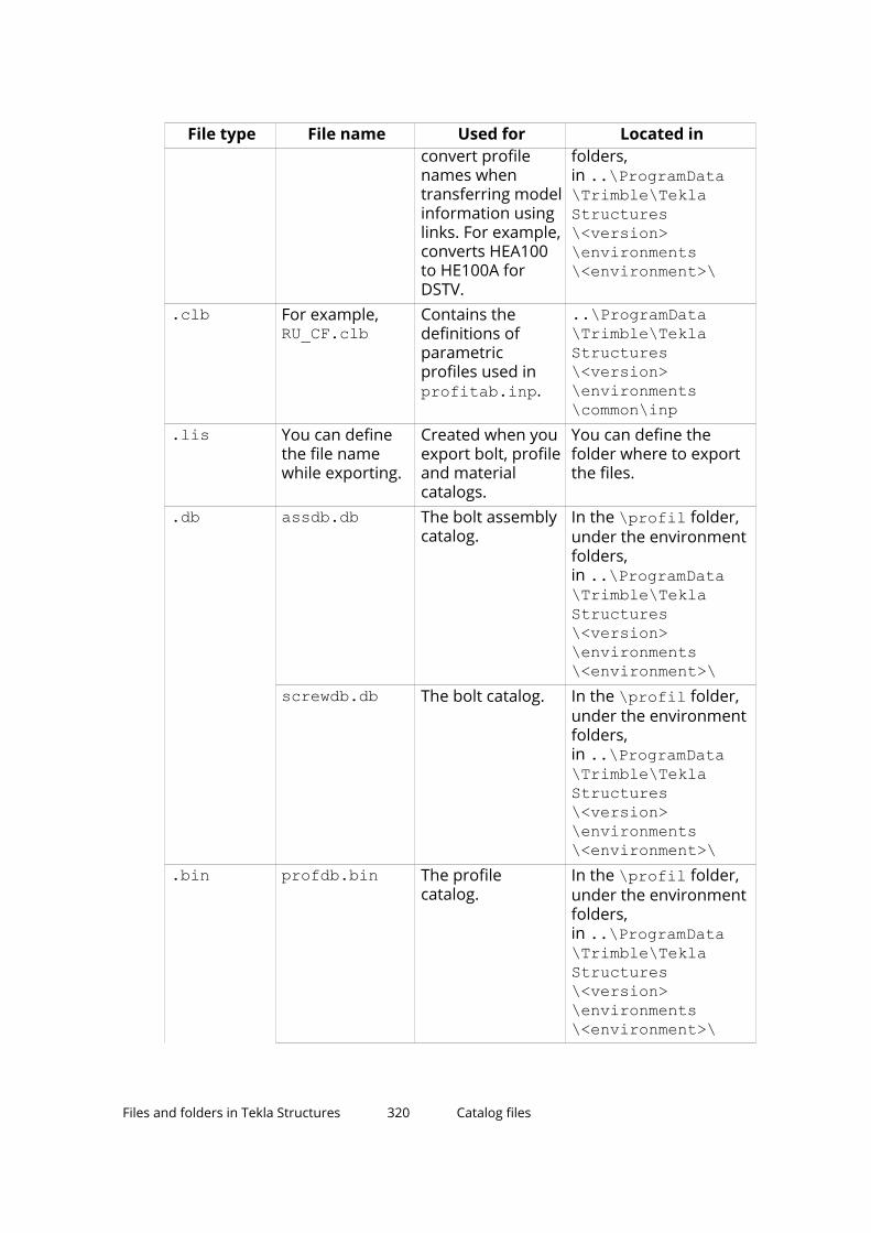
File type File name Used for Located inconvert profilenames whentransferring modelinformation usinglinks. For example,converts HEA100to HE100A forDSTV.
folders,in ..\ProgramData\Trimble\TeklaStructures\<version>\environments\<environment>\
.clb For example,RU_CF.clb
Contains thedefinitions ofparametricprofiles used inprofitab.inp.
..\ProgramData\Trimble\TeklaStructures\<version>\environments\common\inp
.lis You can definethe file namewhile exporting.
Created when youexport bolt, profileand materialcatalogs.
You can define thefolder where to exportthe files.
.db assdb.db The bolt assemblycatalog.
In the \profil folder,under the environmentfolders,in ..\ProgramData\Trimble\TeklaStructures\<version>\environments\<environment>\
screwdb.db The bolt catalog. In the \profil folder,under the environmentfolders,in ..\ProgramData\Trimble\TeklaStructures\<version>\environments\<environment>\
.bin profdb.bin The profilecatalog.
In the \profil folder,under the environmentfolders,in ..\ProgramData\Trimble\TeklaStructures\<version>\environments\<environment>\
Files and folders in Tekla Structures 320 Catalog files

File type File name Used for Located inmatdb.bin The material
catalog.In the \profil folder,under the environmentfolders,in ..\ProgramData\Trimble\TeklaStructures\<version>\environments\<environment>\
See also
Customize the profile catalog (page 146)
Customize the material catalog (page 138)
Customize the bolt catalog (page 226)
Customize the rebar catalog (page 243)
6.10 Font files and font conversion filesYou can define the location of font files with the advanced option DXK_FONTPATH in the teklastructures.ini or your environmentinitialization file. For example, you can use fonts available in thefolder ..\ProgramData\Trimble\Tekla Structures\<version>\environments\common\fonts.
This folder includes the following fonts:
Font Font typefixfont.fon Tekla Structures system fontromco.fon Tekla Structures system fontromsim.fon Tekla Structures system fontromsim8.fon Tekla Structures system font
Fonts are converted using font conversion files available in the same folder:
File Descriptiontemplate_fonts.cnv Used for converting Tekla Structures
system fonts (Template Editor fonts)to Windows fonts in DWG/DXF export.
dxf_fonts.cnv Used for converting True Type fontsto SHX fonts (font format understoodby AutoCAD) in DWG/DXF export.
Files and folders in Tekla Structures 321 Font files and font conversion files

NOTE The Cyrillic fonts GOST 2.304-81 type A.ttf and GOST 2.304-81 typeB.ttf are located in the C:\Windows\Fonts folder, notthe ..\ProgramData\Trimble\Tekla Structures\<version>\environments\common\fonts folder.
See also
Initialization files (.ini files) (page 268)
6.11 Symbol filesSymbols are used for example in various places in drawings, for example, asseparate objects, and in marks.
You can create symbols with Symbol Editor. In this case, the file nameextension is .sym. You can also use symbols of .dwg format.
Tekla Structures symbol files are by default located in thefolder ..\environments\common\symbols.
6.12 Files related to templates, reports and drawingsTekla Structures has several files that relate to templates, reports, drawingsand printing.
File or file type Description Location.rpt Report templates
(page 362) created withthe Template Editor
System folders definedfor the advanced option XS_SYSTEM
.tpl Drawing templates(page 362) created withthe Template Editor
Template foldersdefined for theadvanced option XS_TEMPLATE_DIRECTORY
.lay Layout definitionscreated with theDrawings & reports -->Drawing properties -->Drawing layout editorcommand.
The \attributes sub-folder in the modelfolder
Files and folders in Tekla Structures 322 Symbol files

File or file type Description Locationplotdev.bin Printer device definitions
created with the
Printer Catalog printerinstances.
System folders definedfor the advanced option XS_SYSTEM
xdproc Master DrawingCatalog rule set
System folders definedfor the advanced option XS_SYSTEM
xdproc.master Master DrawingCatalog master drawingfile
System folders definedfor the advanced option XS_SYSTEM
xdproc.master.png Master DrawingCatalog sample(preview) image files
System folders definedfor the advanced option XS_SYSTEM
xdproc.png Master DrawingCatalog thumbnailimage files
System folders definedfor the advanced option XS_SYSTEM
For more information about the folder search order, see Folder search order(page 358).
Note that default drawing, report, and template files are read from the systemfolders defined with XS_SYSTEM (or from the XS_TEMPLATE_DIRECTORYfolders), but user-defined files are stored in the model’s \attributes folder.
6.13 Image filesTekla Structures uses image files in several places:
• In templates in drawings
• In drawing snapshots
• In component dialog boxes and thumbnails
• In drawing line types
• In the surface treatment dialog box
• In the Master Drawing Catalog for thumbnails and sample images
• In profile properties dialog boxes
The following image file formats are supported in Tekla Structures:
• In templates: bmp, gif, grd, jpg, ppm, pgm, rle, tiff and xkrl• In drawing snapshots, and int thumbnail and sample images for the
Master Drawing Catalog: png
Files and folders in Tekla Structures 323 Image files

• Other situations: bmp
See also
Add images in a template (page 377)
6.14 Log filesTekla Structures writes information to log files when you, for example, numbera model or save a model.
File Descriptionanalysis.log Tekla Structures stores information in
this file when you run the analysis.The file also contains information onthe errors that occurred during loaddistribution. This log file is saved inthe current model folder.
check_database.log Tekla Structures stores information inthis file when you run the Repaircommand in File menu --> Diagnose& repair --> Model . This log file issaved in the current model folder.
ClashCheck.log Contains clashes found in the mostrecent clash check. This log file issaved in the current model folder.
ClientLog_cat.txtClientLog_dog.txt
The client log files contain diagnosticinformation and error messagesregarding the Tekla Model Sharingsharing service, such as connecting tothe sharing service or the status ofthe sharing service. The client log filesare saved in the \Users\<user>\AppData\Local\TeklaDataSharing folder.
The client log contains two log fileswith the maximum size of 1megabyte, so that the information willnot use too much disk space. Whenthe maximum file size is reached inthe ClientLog_cat.txt file, logwriting is switched to theClientLog_dog.txt file, and theother way around. Each time theclient log file is switched, anyinformation previously saved in the
Files and folders in Tekla Structures 324 Log files
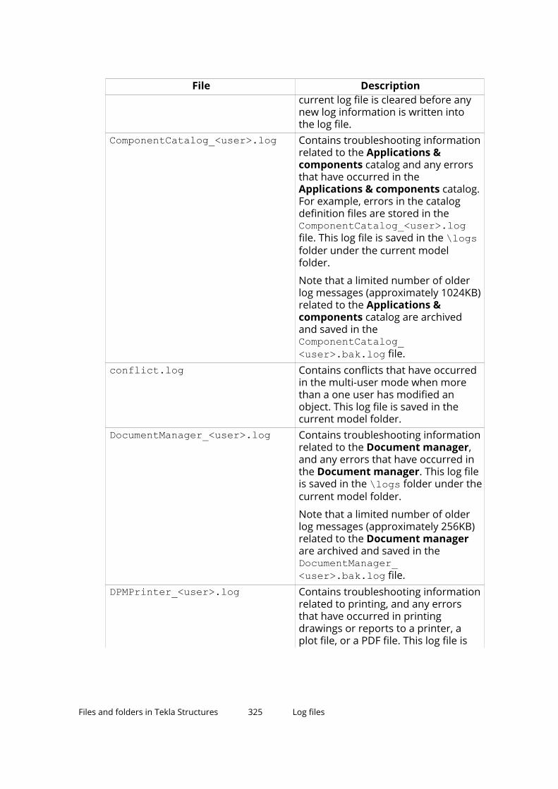
File Descriptioncurrent log file is cleared before anynew log information is written intothe log file.
ComponentCatalog_<user>.log Contains troubleshooting informationrelated to the Applications &components catalog and any errorsthat have occurred in theApplications & components catalog.For example, errors in the catalogdefinition files are stored in theComponentCatalog_<user>.logfile. This log file is saved in the \logsfolder under the current modelfolder.
Note that a limited number of olderlog messages (approximately 1024KB)related to the Applications &components catalog are archivedand saved in theComponentCatalog_<user>.bak.log file.
conflict.log Contains conflicts that have occurredin the multi-user mode when morethan a one user has modified anobject. This log file is saved in thecurrent model folder.
DocumentManager_<user>.log Contains troubleshooting informationrelated to the Document manager,and any errors that have occurred inthe Document manager. This log fileis saved in the \logs folder under thecurrent model folder.
Note that a limited number of olderlog messages (approximately 256KB)related to the Document managerare archived and saved in theDocumentManager_<user>.bak.log file.
DPMPrinter_<user>.log Contains troubleshooting informationrelated to printing, and any errorsthat have occurred in printingdrawings or reports to a printer, aplot file, or a PDF file. This log file is
Files and folders in Tekla Structures 325 Log files

File Descriptionsaved in the \logs folder under thecurrent model folder.
Note that a limited number of olderlog messages (approximately 1024KB)related to printing are archived andsaved in the DPMPrinter2_<user>.log file.
drawing_cloning.log Contains information on cloneddrawings. This log file is saved in thecurrent model folder.
drawing_history.log Contains information on drawinghistory. Use the advanced option XS_DRAWING_HISTORY_LOG_TYPE todefine the contents of the file. Thislog file is saved in the current modelfolder.
dstv_nc.log Each time you create NC files, TeklaStructures stores information in thisfile about the processed assemblies.This log file is saved in the currentmodel folder.
error_<user>_<YYYYMMDD>_<HHMMSS>.log
Each time an error occurs in TeklaStructures, the error is saved in anerror log file. Error log files containthe description of errors that haveoccurred at a particular time. Forexample, if an error has occurred onApril 1, 2019 at 9:15:30 AM, the nameof the related error log file iserror_<user>_20190401_091530.log. This log file is saved in the \logsfolder under the current modelfolder.
filetranerror.log Used only for cold rolled components,such as Albion, Ayrshire, and Hispan.If the File Transfer components donot work as expected, TeklaStructures stores error messages inthis file. This log file is saved in thecurrent model folder.
modelsharing.log Contains the sharing operations thathave been performed in Tekla ModelSharing. For example, opening ashared model and reading in thechanges made by other users are
Files and folders in Tekla Structures 326 Log files

File Descriptionstored in the modelsharing.log file.This log file is saved in the \logsfolder under the current modelfolder.
numberinghistory.txt Contains full details of eachnumbering session carried out on themodel. Each session is in a differentblock of the file. This log file is savedin the current model folder.
save_history.log Tekla Structures stores information inthis file each time you save a model.This log file is saved in the currentmodel folder.
sharingfacade.log Contains the essential informationfrom the client log files when an errorhas occurred in the Tekla ModelSharing sharing service. This log file issaved in the \logs folder under thecurrent model folder.
TeklaStructures_<user>.log Contains information on the entireTekla Structures session fromopening the model to closing it. Thefile contains, for example, errors andinformation on which catalogs wereused. This temporary log file is savedin the \TeklaStructuresModelsfolder, and it is removed when youclose Tekla Structures.
UserFeedbackLog.txt Contains the usage data on how youuse Tekla Structures. This log file issaved in the\TeklaStructuresModels folder.
Note that theUserFeedbackLog.txt log file isalways opened with the default texteditor, unlike other log files which canbe opened through Tekla Structureslog viewer. The option to switchbetween the viewers does not workfor the UserFeedbackLog.txt file.
wizard.log Tekla Structures stores information inthis file when you run a drawing ruleset (wizard) file. The file contains, forexample, errors and number of
Files and folders in Tekla Structures 327 Log files

File Descriptiondrawings created. This log file is savedin the current model folder.
See also
View a log file (page 328)
Change the name and location of session history log file (page 329)
Numbering history log file (page 330)
Numbering series in the numbering history log file (page 331)
View a log fileYou can select how Tekla Structures displays the log files. Also, if parts orassemblies are listed in a log file, you can check the parts or assemblies in themodel by selecting them in the log file.
1. Open the model whose log history you want view.
2. On the File menu, click Logs and select a log file you want to see.
• Clash Check history log (ClashCheck.log)
• Session history log (TeklaStructures_<user>.log)
• Numbering history log (numberinghistory.txt)
• Saving history log (save_history.log)
• Drawing history log (drawing_history.log)
• Analysis history log (analysis.log)
• Usage data log (UserFeedbackLog.txt)
You can view the log file either in Tekla Structures log viewer, or in aviewer that has been associated with the file type, for example, inMicrosoft Notepad.
To view the log file in the log viewer, in File --> Logs select View withTekla Structures log viewer
To view the log file in an associated viewer, File --> Logs select View withdefault application.
The UserFeedbackLog.txt log file can be viewed only in associatedviewer, not in the log viewer.
3. If the log file contains information about parts or assemblies, you cancheck the parts or assemblies in the model. In the log file, select a rowwhich contains a part or an assembly.
Files and folders in Tekla Structures 328 Log files

Parts and assemblies have the prefix guid.
Tekla Structures highlights the part in the model. If there are several partsor assemblies on a row and you select that row, Tekla Structureshighlights all the parts in the model. You can also select parts on differentrows.
TIP You can access a part’s or an assembly’s pop-up menu from the log fileby right-clicking a row that contains a part or an assembly. TeklaStructures displays the same pop-up menu as when you right-click a partor an assembly in the model.
See also
Log files (page 324)
Change the name and location of session history log file (page 329)
Numbering history log file (page 330)
Change the name and location of session history log fileYou can change the name and location of the session history log file(TeklaStructures_<user>.log).
If someone else manages your installation of Tekla Structures, do not changethese settings unless you are instructed to do so.
Windows username and the .log file extension are always added after thecustomizable part of the name.
1. Open a suitable initialization file (page 269) for editing.
For example, user.ini or company.ini.
2. To change the name of the session history log file, add the following lineto the initialization file:
set XS_LOG_FILE_NAME=<name of the file>For example:
set XS_LOG_FILE_NAME=sessionhistoryIf the Windows user name is "achilles", this example would result in a logfile named sessionhistory_achilles.log.
The default name is TeklaStructures_<user>.log.
3. To change the location of the session history log file, add the followingline to the initialization file:
set XS_LOGPATH=<location of the file>If there is no other location set, the file is stored in the parent folder formodel folders (by default c:\TeklaStructuresModels).
Files and folders in Tekla Structures 329 Log files

4. Save the initialization file.
5. Restart Tekla Structures for the changes to take effect.
See also
Log files (page 324)
View a log file (page 328)
Numbering history log fileThe numberinghistory.txt log file contains full details of each numberingsession carried out on the model. Each numbering session is in a differentblock of the file.
NOTE If you remove or delete the numberinghistory.txt log file, Tekla Structuresgenerates a new file with the same name next time when you run numbering.The new file does not contain a history of previous numbering sessions.
Example
Below is an example of the contents of a numberinghistory.txt log file.
1 User name, date and time of the numbering.2 Numbering method.
• Modified numbering is displayed when you run the Numbermodified objects command.
• Modified numbering for selected series is displayedwhen you run the Number series of selected objectscommand.
• Diagnose & Repair Numbering: All is displayed when yourun the Diagnose & repair numbering: All command.
• Diagnose & Repair Numbering: Series of selectedobjects is displayed when you run the Diagnose & repairnumbering: Series of selected objects command.
• Renumber all is displayed when you select the Renumber alloption in the Numbering Setup dialog box.
Files and folders in Tekla Structures 330 Log files

3 Some Compare options set in the Numbering Setup dialog boxare displayed in the numbering.history log file only if they areset differently than the default value:
• Compare modified to old parts• Compare new to old part• No holes comparing• No part name comparing• Beam orientation• Column orientationSome Compare options are not displayed at all:
• Reinforcing bars
• Embedded objects
• Surface treatment4 Numbering options.
• Use old numbers is displayed only when you have selectedthe Re-use old numbers option in the Numbering Setup dialogbox.
• Check for standard parts is displayed only when you haveselected the Check for standard parts option in theNumbering Setup dialog box.
5 Tolerances are set in the Numbering Setup dialog box.6 Changes in the position numbers and in the numbering series
during one numbering session. In addition:
If a numbering series overlaps another, the errors are written to thelog file.
See also
Numbering series in the numbering history log file (page 331)
Numbering series in the numbering history log fileTekla Structures lists information on the numbered parts and assemblies inthe numberinghistory.txt log file.
Example 1
The numberinghistory.txt log after one concrete beam B/20 has beencreated and numbered:
Files and folders in Tekla Structures 331 Log files
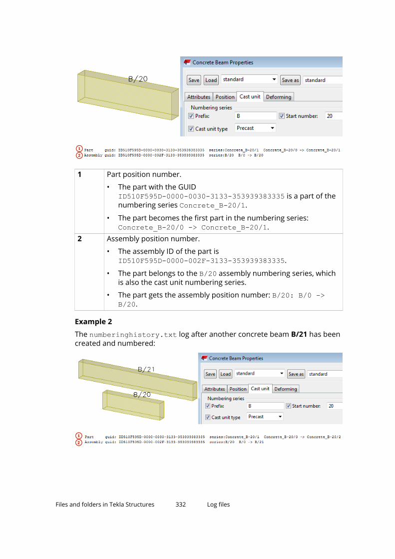
1 Part position number.
• The part with the GUID ID510F595D-0000-0030-3133-353939383335 is a part of thenumbering series Concrete_B-20/1.
• The part becomes the first part in the numbering series: Concrete_B-20/0 -> Concrete_B-20/1.
2 Assembly position number.
• The assembly ID of the part is ID510F595D-0000-002F-3133-353939383335.
• The part belongs to the B/20 assembly numbering series, whichis also the cast unit numbering series.
• The part gets the assembly position number: B/20: B/0 ->B/20.
Example 2
The numberinghistory.txt log after another concrete beam B/21 has beencreated and numbered:
Files and folders in Tekla Structures 332 Log files

1 Part position number of the new part.
• The part with the ID ID510F595D-0000-0030-3133-353939383335 is part of thenumbering series Concrete_B-20/1.
• The part becomes the second part in the numbering series: Concrete_B-20/0 -> Concrete_B-20/2.
2 Assembly position number.
• The assembly ID of the part is ID510F595D-0000-002F-3133-353939383335.
• The part belongs to the B/20 assembly numbering series, which isalso the cast unit numbering series.
• The part gets the assembly position number: B/20 B/0 ->B/21.
See also
Numbering history log file (page 330)
6.15 Model folder files and file name extensionsThe following tables list the folders, files and file name extensions of fileslocated in a Tekla Structures model folder.
Files in the Tekla Structures model folder
File or file name extension Description.db1 Model database.db2 Numbering databaseenvironment.db Database for user-defined attribute
definitionsxslib.db1 Contains information on user-defined
connections and details, and defaultcomponent descriptions.
.idrm Mapping file, which handles IDs. Donot modify.
xslib.db2 Contains numbering information.options_model.db andoptions_drawings.db
Contain values for model-specificoptions from the Options dialog boxand values for model-specificadvanced options from the Advanced
Files and folders in Tekla Structures 333 Model folder files and file name extensions

File or file name extension DescriptionOptions dialog box. When a model iscreated, Tekla Structures readsmodel-specific options and advancedoptions values from thestandard.opt file and .ini files inthe environment folders and savesthem in these two databases.
history.db Model history database.xsdb.xs File used for displaying the name of
the model in the Open dialog box.xs_user.<username> Contains interface settings specified
by the user.
Each time a model is saved, anxs_user.<username> file is createdor updated. These settings are userspecific. If the xs_user.<username>file is not found in the model folderwhen you open the model, TeklaStructures searches for thexs_user.default file in thefollowing folder search order: model,model\attributes, project, XS_FIRM\attributes, system. If this file is notfound, Tekla Structures defaultsettings will be used.
This file contains settings for many ofthe options in the Options dialog boxand the settings for the icons on theSelecting and Snapping toolbars.
drawing_user.<username> Contains information on which snapswitches are switched on or off in thedrawing mode. This file is userspecific. Do not modify this file.
save_history.log Tekla Structures stores theinformation in this file each time themodel is saved. The file includes thesaving time, date and information onany conflicts during saving.
notification_report.xsr File used for displaying a notificationreport of assignments when you opena model.
TeklaStructuresModel.xml Contains a copy of basic details aboutthe Tekla Structures model, forexample the model name, version it
Files and folders in Tekla Structures 334 Model folder files and file name extensions

File or file name extension Descriptionwas last saved with, and the TeklaStructures environment. TeklaStructures overwrites the details inthis file each time the model is saved.
The model details that you see whenyou select a model on the startupscreen are read from this file. The filecan also be used as an informationsource for external tools, such asscripts.
dotlog.txt A log file that contains information onTekla Open API application use.
.locked A temporary file that locks the modelfolder files to prevent modificationswhile the model is in use.
.bak A backup copy of a file with acorresponding name.
For example, the <modelname>.db1.bak file is thebackup copy of the model databasefile <modelname>.db1.
assert.txt A log file that contains information onassertion errors.
ClashCheck.txt A log file that contains information onclashes found in the most recentclash check and the date and time ofthe clash check.
ClashCheck.history A file that contains information on allclashes found in all clash checks andthe dates and times of the clashchecks.
wizard.txt Tekla Structures stores information inthis file when you run a drawing ruleset (wizard) file. The file contains, forexample, errors, number of drawingscreated, and information on whichcommands were used.
.lis Different catalogs can be exportedfrom and imported to different TeklaStructures models as .lis files.These include profile, material andbolt catalogs.
Files and folders in Tekla Structures 335 Model folder files and file name extensions

File or file name extension Description.tsc Shapes can be exported from and
imported to different Tekla Structuresmodels as .tsc files.
.This_is_multiuser_model Contains information about the PCrunning the Tekla Structures multi-user server.
Do not alter or delete this file innormal circumstances. If you move amodel to a different server, youshould delete this file. TeklaStructures generates a new file withthe same name.
ComponentCatalog.xml Contains the model level catalogdefinitions of the Applications &components catalog.
<user>_ComponentCatalogUserSettings.xml
Lists the recently used applicationsand components, and their location inthe Applications & componentscatalog structure.
Worktypes.xml Lists available task types. Createdwhen you start Task Manager.
WorkTypeProperties.xml Lists allowed property types and theirunits.
.tmp A file used to store temporary data.
.cnv A file used to map Tekla Structuresprofile and material names withnames used in other software.
.colorset Created when you export a color setfrom Organizer.
Files in the \Analysis folder
File or file name extension Description.ifc The analysis model exported in IFC
format..stp The analysis model exported in CIS/2
format..map A file used for debugging analysis
models.analysis_results.db5 Database for analysis load
combination results.
Files and folders in Tekla Structures 336 Model folder files and file name extensions

File or file name extension Description.db6 Analysis model database.
Files in the \attributes folder
File or file name extension Description.rop Reference object properties.rop.more Reference object user-defined
attribute properties.m10000017 FabTrol XML import properties.m10000015 Import attribute properties.ncf NC file properties.ExportIFC.MainDialog IFC export properties.m440000004 3D DWG/DXF export properties.m440000003 3D DGN export properties.m1000004 FEM export properties.m10000011 CIS analysis model export properties.m10000026 CIS manufacturing model export
properties.m1000007 CAD export properties.m10000016 Cover sheet export properties.SObjGrp Model selection filter properties.VObjGrp Model view filter properties.OrgObjGrp Organizer filter properties.bhuistd Building hierarchy properties.PObjGrp Object group filter properties.grd Rectangular grid properties.grd.more Rectangular grid user-defined
attribute properties.rgrd Radial grid properties.rgrd.more Radial grid user-defined attribute
properties.grdp Grid line properties.grdp.more Grid line user-defined attribute
properties.cnl Construction line properties.cncrl Construction circle properties.cnarc Construction arc properties
Files and folders in Tekla Structures 337 Model folder files and file name extensions

File or file name extension Description.cnplycrv Construction polycurve properties.mvi Model view properties that you have
saved for the model.
Default 3D, part, component, customcomponent, assembly, and cast unitview settings files need to be savedwith names used in commonenvironment:
3D view: basic_view
3D part view: part_basic_view
Part front view: part_front_view
Part top view: part_top_view
Part end view: part_end_view
Part perspective view:part_persp_view
3D component view:component_basic_view
Component front view:component_front_view
Component top view:component_top_view
Component end view:component_end_view
Component perspective view:component_persp_view
Custom component front view:custom_object_editor_front_view
Custom component top view:custom_object_editor_top_view
Custom component end view:custom_object_editor_end_view
Custom component perspective view:custom_object_editor_perspective_view
3D assembly or cast unit view:assembly_basic_view
Assembly or cast unit front view:assembly_front_view
Files and folders in Tekla Structures 338 Model folder files and file name extensions

File or file name extension DescriptionAssembly or cast unit top view:assembly_top_view
Assembly or cast unit end view:assembly_end_view
Assembly or cast unit back view:assembly_back_view
Assembly or cast unit bottom view:assembly_bottom_view
Assembly or cast unit perspectiveview: assembly_persp_view
.gvi Saved properties for creating viewsalong grid lines
.rep Object representation properties
.clm Steel column properties
.clm.more Steel column user-defined attributeproperties
.prt Steel beam properties
.prt.more Steel beam user-defined attributeproperties
.sb Steel spiral beam properties
.sb.more Steel spiral beam user-definedattribute properties
.crs Orthogonal beam properties
.crs.more Orthogonal beam user-definedattribute properties
.dia Twin profile properties
.dia.more Twin profile user-defined attributeproperties
.cpl Contour plate properties
.cpl.more Contour plate user-defined attributeproperties
.blp Bent plate properties
.blp.more Bent plate user-defined attributeproperties
.lpl Lofted plate properties
.lpl.more Lofted plate user-defined attributeproperties
.ips Item properties
.ips.more Item user-defined attribute properties
Files and folders in Tekla Structures 339 Model folder files and file name extensions

File or file name extension Description.cpf Pad footing properties.cpf.more Pad footing user-defined attribute
properties.csf Strip footing properties.csf.more Strip footing user-defined attribute
properties.ccl Concrete column properties.ccl.more Concrete column user-defined
attribute properties.cbm Concrete beam or concrete polybeam
properties.cbm.more Concrete beam or concrete polybeam
user-defined attribute properties.csb Concrete spiral beam properties.csb.more Concrete spiral beam user-defined
attribute properties.csl Concrete slab properties.csl.more Concrete slab user-defined attribute
properties.cpn Concrete panel properties.cpn.more Concrete panel user-defined attribute
properties.lsl Concrete lofted slab properties.lsl Concrete lofted slab user-defined
attribute properties.ipc Concrete item properties.ipc.more Concrete item user-defined attribute
properties.rbr Reinforcing bar properties.rbr.more Reinforcing bar user-defined attribute
properties.rbg Reinforcing bar group properties.rbg.more Reinforcing bar group user-defined
attribute properties.rcu Curved reinforcing bar group
properties.rci Circular reinforcing bar group
properties.rbm Reinforcement mesh properties
Files and folders in Tekla Structures 340 Model folder files and file name extensions

File or file name extension Description.rbm.more Reinforcement mesh user-defined
attribute properties.rbs Reinforcement strand pattern
properties.rbs.more Reinforcement strand pattern user-
defined attribute properties.rsp Reinforcement splice properties.rsp.more Reinforcement splice user-defined
attribute properties.rst Rebar set properties.rst.more Rebar set user-defined attribute
properties.rst.zones Rebar set spacing zone properties.rst_pm Rebar set property modifier
properties.rst_pm.more Rebar set property modifier user-
defined attribute properties.rst_edm Rebar set end detail modifier
properties.rst_edm.more Rebar set end detail modifier user-
defined attribute properties.rst_sm Rebar set splitter properties.admodel Analysis model properties.admodel.more Analysis model user-defined attribute
properties.lm1 Point load properties.lm2 Line load properties.lm3 Area load properties.lm4 Uniform load properties.m10000028 Wind load properties.lm6 Temperature load properties.lco Load combination properties.adnode Analysis node properties.adnode.more Analysis node user-defined attribute
properties.prt_ad, .prt_design File types associated with steel beam
analysis property settings. .prt_adcontains information associated withthe analysis part propertiesand .prt_design contains
Files and folders in Tekla Structures 341 Model folder files and file name extensions
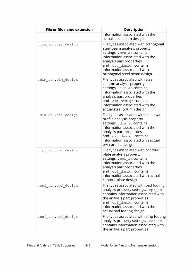
File or file name extension Descriptioninformation associated with theactual steel beam design.
.crs_ad, .crs_design File types associated with orthogonalsteel beam analysis propertysettings. .crs_ad containsinformation associated with theanalysis part propertiesand .crs_design containsinformation associated withorthogonal steel beam design.
.clm_ad, .clm_design File types associated with steelcolumn analysis propertysettings. .clm_ad containsinformation associated with theanalysis part propertiesand .clm_design containsinformation associated with theactual steel column design.
.dia_ad, .dia_design File types associated with steel twinprofile analysis propertysettings. .dia_ad containsinformation associated with theanalysis part propertiesand .dia_design containsinformation associated with actualtwin profile design.
.cpl_ad, .cpl_design File types associated with contourplate analysis propertysettings. .cpl_ad containsinformation associated with theanalysis part propertiesand .cpl_design containsinformation associated with actualcontour plate design.
.cpf_ad, .cpf_design File types associated with pad footinganalysis property settings. .cpf_adcontains information associated withthe analysis part propertiesand .cpf_design containsinformation associated with theactual pad footing design.
.csf_ad, .csf_design File types associated with strip footinganalysis property settings. .csf_adcontains information associated withthe analysis part properties
Files and folders in Tekla Structures 342 Model folder files and file name extensions

File or file name extension Descriptionand .csf_design containsinformation associated with theactual strip footing design.
.ccl_ad, .ccl_design File types associated with concretecolumn analysis propertysettings. .ccl_ad containsinformation associated with theanalysis part propertiesand .ccl_design containsinformation associated with theactual concrete column design.
.cbm_ad, .cbm_design File types associated with concretebeam analysis propertysettings. .cbm_ad containsinformation associated with theanalysis part propertiesand .cbm_design containsinformation associated with theactual concrete beam design.
.csl_ad, .csl_design File types associated with concreteslab analysis propertysettings. .csl_ad containsinformation associated with theanalysis part propertiesand .csl_design containsinformation associated with theactual slab design.
.cpn_ad, .cpn_design File types associated with concretepanel analysis propertysettings. .cpl_ad containsinformation associated with theanalysis part propertiesand .cpl_design containsinformation associated with theactual concrete panel design.
.srf Surface treatment properties
.srf.more User-defined surface treatmentattribute properties
.srfo Surface properties
.srfo.more User-defined surface attributeproperties
.cha Edge chamfer properties
.cha.more User-defined edge chamfer attributeproperties
Files and folders in Tekla Structures 343 Model folder files and file name extensions

File or file name extension Description.scr Bolt properties.scr.more User-defined bolt attribute properties.wld Weld properties.wld.more User-defined weld attribute
properties*.udwcs User-defined weld cross sections
(UserDefinedWeldCrossSections.udwcs)
.m1000009 Control number properties
.m1000010 Control number locking properties
.num Numbering setup properties
.rpr Report properties
.4d Project status visualization propertiesstandard.opt Settings are saved in standard.opt
in the \attributes folder only whenyou save your own settings in theOptions dialog box using Save.
There is a standard.opt file in theenvironment folder that gives theinitial values to be loaded when amodel is created.
Component properties files in the \attributes folder
Properties files for components available in the Applications & componentscatalog, for example .j310000063 for 2L Splice (63) component properties.These files are stored in the attributes folder under the model folder.
Object level drawing settings, saved in \attributes folder
File or file name extension Description.dprt Object level part properties.dim Object level dimension properties.dimension_mark Object level dimension tag properties.rdim Object level rebar dimension mark
properties.pm Object level part mark properties
Files and folders in Tekla Structures 344 Model folder files and file name extensions

File or file name extension Description.jm Object level connection mark
properties.sm Object level bolt mark properties.rm Object level reinforcement mark
properties.mrms Object level merged reinforcement
mark properties.pom Pour object mark properties.surfm Object level surface treatment mark
properties.note Object level associative note
properties.wls Object level weld mark properties.lev Object level level mark properties.rev Object level revision mark properties.drmsh Object level reinforcement mesh
properties.drbr Object level reinforcement properties.po Object level pour object properties.sc Object level bolt properties.dsrf Object level surface treatment
properties.dgr Object level grid properties.sbl Object level symbol properties.wls Object level weld mark properties.drtxt Object level text properties.gln Object level line properties.grt Object level rectangle properties.gci Object level circle properties.gar Object level arc properties.gpl Object level polyline properties.gpg Object level polygon and cloud
properties
Files and folders in Tekla Structures 345 Model folder files and file name extensions

View level drawing settings, saved in \attributes folder
File or file name extension Description.vi.vi.copt
View level view properties
.vclassif
.vclassif.coptView level detailed object levelsettings
.vpm View level part mark properties
.vsm View level bolt mark properties
.vnpm View level neighbor part markproperties
.vsurfm View level surface treatment markproperties
.vjm View level connection markproperties
.vrm View level reinforcement markproperties
.vnrm View level neighbor reinforcementmark properties
.vpom View level pour object markproperties
.vp View level part properties
.vs View level bolt properties
.vnp View level neighbor part properties
.vsurf View level surface treatmentproperties
.vw View level welding properties
.vr View level reinforcement properties
.vnr View level neighbor reinforcementproperties
.vrmp View level reference object properties
.vpo View level pour object properties
.vg View level grid properties
.vf View level filter properties
.vnf View level neighbor part filterproperties
Files and folders in Tekla Structures 346 Model folder files and file name extensions

Files related to single-part drawings, drawing levelproperties, saved in \attributes folder
File or file name extension Description.wd.wd.copt
Single-part drawing properties
.wd.more Single-part drawing user-definedattributes
.wdf Single-part drawing filter properties
.wdnf Single-part drawing neighbor partfilter properties
.wdl Single-part drawing layout properties
.wdl.more Single-part drawing user-definedlayout attributes
.wdv Single-part drawing view properties
.wdv.more Single-part drawing user-defined viewattributes
.wdc Single-part drawing section viewproperties
.wdc.more Single-part drawing user-definedsection view attributes
.wdd Single-part drawing dimensionproperties
.wdd.more Single-part drawing user-defineddimension attributes
.wdcd Single-part drawing dimensioningproperties
.wdcd more Single-part drawing user-defineddimensioning attributes
.wpm Single-part drawing part markproperties
.wsm Single-part drawing bolt markproperties
.wnpm Single-part drawing neighbor partmark properties
.wdsurfm Single-part drawing surface treatmentmark properties
.wdsurfm.more Single-part drawing user-definedsurface treatment mark attributes
.wjm Single-part drawing connection markproperties
Files and folders in Tekla Structures 347 Model folder files and file name extensions

File or file name extension Description.wdp Single-part drawing part properties.wds Single-part drawing bolt properties.wds.more Single-part drawing user-defined bolt
attributes.wdnp Single-part drawing neighbor part
properties.wdnp.more Single-part drawing user-defined
neighbor part attributes.wdsrf Single-part drawing surface treatment
properties.wdsrf.more Single-part drawing user-defined
surface treatment attributes.wdgr Single-part drawing grid properties.wdgr.more Single-part drawing user-defined grid
attributes.wdr Single-part drawing protection
properties.wdr.more Single-part drawing user-defined
protection attributes
Files related to assembly drawings, drawing levelproperties, saved in \attributes folder
File or file name extension Description.ad Assembly drawing properties.ad.more Assembly drawing user-defined
attributes.adf Assembly drawing filter properties.adnf Assembly drawing neighbor part filter
properties.adl Assembly drawing layout properties.adl.more Assembly drawing user-defined
layout attributes.adv Assembly drawing view properties.adc Assembly drawing section view
properties.add Assembly drawing dimension
properties
Files and folders in Tekla Structures 348 Model folder files and file name extensions

File or file name extension Description.add.more Assembly drawing user-defined
dimension attributes.adcd Assembly drawing dimensioning
properties.adcd.more Assembly drawing user-defined
dimensioning attributes.apm Assembly drawing part mark
properties.asm Assembly drawing bolt mark
properties.anpm Assembly drawing neighbor part
mark properties.adsurfm Assembly drawing surface treatment
mark properties.adsurfm.more Assembly drawing user-defined
surface treatment mark attributes.ajm Assembly drawing connection mark
properties.adp Assembly drawing part properties.adp.more Assembly drawing user-defined part
attributes.ads Assembly drawing bolt properties.adnp Assembly drawing neighbor part
properties.adnp.more Assembly drawing user-defined
neighbor part attributes.adsrf Assembly drawing surface treatment
properties.adsrf.more Assembly drawing user-defined
surface treatment attributes.adw Assembly drawing welding properties.adw.more Assembly drawing user-defined
welding attributes.adgr Assembly drawing grid properties.adgr.more Assembly drawing user-defined grid
attributes.adr Assembly drawing protection
properties
Files and folders in Tekla Structures 349 Model folder files and file name extensions

Files related to cast unit drawings, drawing levelproperties, saved in \attributes folder
File or file name extension Description.cud.cud.copt
Cast unit drawing properties
.cud.more Cast unit drawing user-definedattributes
.cudl Cast unit drawing layout properties
.cudl.more Cast unit drawing user-defined layoutattributes
.cudv Cast unit drawing view properties
.cudv.more Cast unit drawing user-defined viewattributes
.cudc Cast unit drawing section viewproperties
.cudc.more Cast unit drawing user-definedsection view attributes
.cudd Cast unit drawing dimensionproperties
.cudd.more Cast unit drawing user-defineddimension attributes
.cudcd Cast unit drawing dimensioningproperties
.cudcd.more Cast unit drawing user-defineddimensioning properties
.cupm Cast unit drawing part markproperties
.cusm Cast unit drawing bolt markproperties
.cunpm Cast unit drawing neighbor part markproperties
.cudsurfm Cast unit drawing surface treatmentmark properties
.cudsurfm.more Cast unit drawing user-definedsurface treatment mark attributes
.cudrm Cast unit drawing reinforcement markproperties
.cudrm.more Cast unit drawing user-definedreinforcement mark attributes
.cudp Cast unit drawing part properties
Files and folders in Tekla Structures 350 Model folder files and file name extensions

File or file name extension Description.cudp.more Cast unit drawing user-defined part
attributes.cuds Cast unit drawing bolt properties.cuds.more Cast unit drawing user-defined bolt
attributes.cudnp Cast unit drawing neighbor part
properties.cudnp.more Cast unit drawing user-defined
neighbor part attributes.cudsrf Cast unit drawing surface treatment
properties.cudsrf.more Cast unit drawing user-defined
surface treatment attributes.cudr Cast unit drawing reinforcement
properties.cudr.more Cast unit drawing user-defined
reinforcement attributes.cudw Cast unit drawing welding properties.cudw.more Cast unit drawing user-defined
welding attributes.cudgr Cast unit drawing grid properties.cudgr.more Cast unit drawing user-defined grid
attributes.cudrp Cast unit drawing protection
properties.cudrp.more Cast unit drawing user-defined
protection attributes.cuf Cast unit drawing filter properties.cunf Cast unit drawing neighbor part filter
properties
Files related to general arrangement drawings, drawinglevel properties, saved in \attributes folder
File or file name extension Description.gd.gd.copt
General arrangement drawingproperties
.gclassif
.gclassif.coptGeneral arrangement drawingdetailed object level settings
Files and folders in Tekla Structures 351 Model folder files and file name extensions

File or file name extension Description.gd.more General arrangement drawing user-
defined properties.gdl General arrangement drawing layout
properties.gdl.more General arrangement drawing user-
defined layout attributes.gdv General arrangement drawing view
properties.gdv.more General arrangement drawing user-
defined view attributes.gdd General arrangement drawing
dimension properties.gdd.more General arrangement drawing user-
defined dimension attributes.gdcd General arrangement drawing
dimensioning properties.gdcd.more General arrangement drawing user-
defined dimensioning attributes.gpm General arrangement drawing part
mark properties.gsm General arrangement drawing bolt
mark properties.gnpm General arrangement drawing
neighbor part mark properties.gdsurfm General arrangement drawing surface
treatment mark properties.gdsurfm.more General arrangement drawing user-
defined surface treatment markattributes
.gjm General arrangement drawingconnection mark properties
.gdrm General arrangement drawingreinforcement mark properties
.gdrm.more General arrangement drawing user-defined reinforcement markattributes
.gnrm General arrangement drawingneighbor reinforcement markproperties
.gpom General arrangement drawing pourobject mark properties
Files and folders in Tekla Structures 352 Model folder files and file name extensions

File or file name extension Description.gdp General arrangement drawing part
properties.gdp.more General arrangement drawing user-
defined part attributes.gds General arrangement drawing bolt
properties.gds.more General arrangement drawing user-
defined bolt attributes.gdnp General arrangement drawing
neighbor part properties.gdnp.more General arrangement drawing user-
defined neighbor part attributes.gdsrf General arrangement drawing surface
treatment properties.gdw General arrangement drawing
welding properties.gdw.more General arrangement drawing user-
defined welding attributes.gdr General arrangement drawing
reinforcement properties.gdr.more General arrangement drawing user-
defined reinforcement attributes.gnr General arrangement drawing
neighbor reinforcement properties.gpo General arrangement drawing pour
object properties.gpbr General arrangement drawing pour
break properties.gdrmp General arrangement drawing
reference object properties.gdrmp.more General arrangement drawing user-
defined reference model attributes.gdgr General arrangement drawing grid
properties.gdgr.more General arrangement drawing user-
defined grid attributes.gdrp General arrangement drawing
protection properties.gdrp.more General arrangement drawing user-
defined protection attributes
Files and folders in Tekla Structures 353 Model folder files and file name extensions
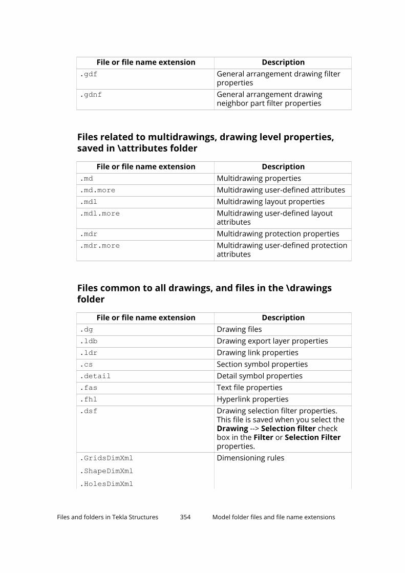
File or file name extension Description.gdf General arrangement drawing filter
properties.gdnf General arrangement drawing
neighbor part filter properties
Files related to multidrawings, drawing level properties,saved in \attributes folder
File or file name extension Description.md Multidrawing properties.md.more Multidrawing user-defined attributes.mdl Multidrawing layout properties.mdl.more Multidrawing user-defined layout
attributes.mdr Multidrawing protection properties.mdr.more Multidrawing user-defined protection
attributes
Files common to all drawings, and files in the \drawingsfolder
File or file name extension Description.dg Drawing files.ldb Drawing export layer properties.ldr Drawing link properties.cs Section symbol properties.detail Detail symbol properties.fas Text file properties.fhl Hyperlink properties.dsf Drawing selection filter properties.
This file is saved when you select theDrawing --> Selection filter checkbox in the Filter or Selection Filterproperties.
.GridsDimXml
.ShapeDimXml
.HolesDimXml
Dimensioning rules
Files and folders in Tekla Structures 354 Model folder files and file name extensions
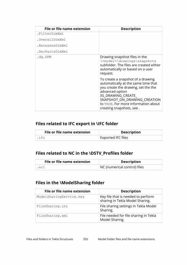
File or file name extension Description.FilterDimXml.OverallDimXml.RecessesDimXml.SecPartsDimXml.dg.DPM Drawing snapshot files in the
\<model>\drawings\snapshotssubfolder. The files are created eitherautomatically or based on a userrequest.
To create a snapshot of a drawingautomatically at the same time thatyou create the drawing, set the theadvanced optionXS_DRAWING_CREATE_SNAPSHOT_ON_DRAWING_CREATIONto TRUE. For more information aboutcreating snapshots, see .
Files related to IFC export in \IFC folder
File or file name extension Description.ifc Exported IFC files
Files related to NC in the \DSTV_Profiles folder
File or file name extension Description.nc1 NC (numerical control) files
Files in the \ModelSharing folder
File or file name extension DescriptionModelSharingService.key Key file that is needed to perform
sharing in Tekla Model Sharing.FileSharing.ini File sharing settings in Tekla Model
Sharing.FileSharing.xml File needed for file sharing in Tekla
Model Sharing.
Files and folders in Tekla Structures 355 Model folder files and file name extensions

Files in the \ProjectOrganizer folder
File or file name extension Description.db Created when Organizer is opened
for the first time. Contains allproperty template and categoryinformation used in the model.
The database name shows theversion of the database, for example,ProjOrg000020.db.
.propertytemplate Created when you export a propertytemplate from Organizer.
.category Created when you export a categoryfrom Organizer.
Files related to reports in the \Reports folder
File or file name extension Description.xsr Tekla Structures reports
Files in the \SessionFileRepository folder
File or file name extension DescriptionFiles in theSessionFileRepository folder
Backup copies of the files that areupdated or deleted in Tekla ModelSharing read in.
SessionFile.db Database for managing model folderfiles in Tekla Model Sharing.
.storage Configuration file ofSessionFile.db.
Files related to shapes in the \ShapeGeometries and\Shapes folders
File or file name extension Description.tez.xml
Shape geometry descriptions in the\ShapeGeometries folder.
Files and folders in Tekla Structures 356 Model folder files and file name extensions
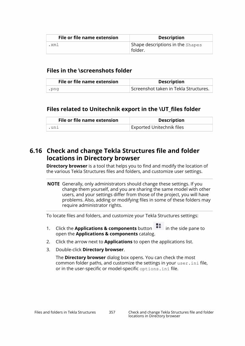
File or file name extension Description.xml Shape descriptions in the Shapes
folder.
Files in the \screenshots folder
File or file name extension Description.png Screenshot taken in Tekla Structures.
Files related to Unitechnik export in the \UT_files folder
File or file name extension Description.uni Exported Unitechnik files
6.16 Check and change Tekla Structures file and folderlocations in Directory browserDirectory browser is a tool that helps you to find and modify the location ofthe various Tekla Structures files and folders, and customize user settings.
NOTE Generally, only administrators should change these settings. If youchange them yourself, and you are sharing the same model with otherusers, and your settings differ from those of the project, you will haveproblems. Also, adding or modifying files in some of these folders mayrequire administrator rights.
To locate files and folders, and customize your Tekla Structures settings:
1. Click the Applications & components button in the side pane toopen the Applications & components catalog.
2. Click the arrow next to Applications to open the applications list.
3. Double-click Directory browser.
The Directory browser dialog box opens. You can check the mostcommon folder paths, and customize the settings in your user.ini file,or in the user-specific or model-specific options.ini file.
Files and folders in Tekla Structures 357 Check and change Tekla Structures file and folderlocations in Directory browser

4. Check the folder paths and change them if necessary by clicking thebuttons on the left of the Basic tab.
If you click the Project or Firm button and you have not set your firm andproject folder, Tekla Structures will prompt you to do so and add thefolder path definition to your user.ini file.
5. Check the settings in the user.ini and options.ini files and changethem if necessary by clicking the buttons on the right of the Basic tab.
6. Go to the Advanced tab and define the folder paths for additional foldersthat you may need to access, such as custom components and macros.
6.17 Folder search orderWhen you open a model, Tekla Structures searches for the associated files inspecific folders in a set order.
It is important that you keep files in correct folders. Once Tekla Structuresfinds the associated files, it stops searching. This means that files that have thesame name but are located lower down the search order are ignored.
The folder search order is:
Folder Defined byCurrent model The open modelProject Advanced option XS_PROJECT.
If property files are stored in user-defined sub-folders under the projectfolder, Tekla Structures searches thesub-folders for files in alphabeticalorder. The first associated file isselected. After that, each file with thesame file name suffix and file nameprefix as the selected file is ignored.The names of the ignored files arestored in the error log.
Firm Advanced option XS_FIRM.
If property files are stored in user-defined sub-folders under the firmfolder, Tekla Structures searches thesub-folders in alphabetical order. Thefirst associated file is selected. Afterthat, each file with the same file namesuffix and file name prefix as theselected file is ignored. The names of
Files and folders in Tekla Structures 358 Folder search order
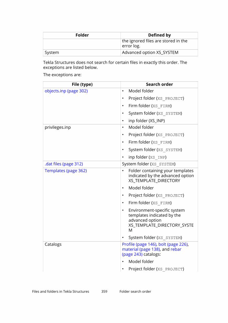
Folder Defined bythe ignored files are stored in theerror log.
System Advanced option XS_SYSTEM
Tekla Structures does not search for certain files in exactly this order. Theexceptions are listed below.
The exceptions are:
File (type) Search orderobjects.inp (page 302) • Model folder
• Project folder (XS_PROJECT)
• Firm folder (XS_FIRM)
• System folder (XS_SYSTEM)
• inp folder (XS_INP)privileges.inp • Model folder
• Project folder (XS_PROJECT)
• Firm folder (XS_FIRM)
• System folder (XS_SYSTEM)
• inp folder (XS_INP).dat files (page 312) System folder (XS_SYSTEM)Templates (page 362) • Folder containing your templates
indicated by the advanced optionXS_TEMPLATE_DIRECTORY
• Model folder
• Project folder (XS_PROJECT)
• Firm folder (XS_FIRM)
• Environment-specific systemtemplates indicated by theadvanced optionXS_TEMPLATE_DIRECTORY_SYSTEM
• System folder (XS_SYSTEM)Catalogs Profile (page 146), bolt (page 226),
material (page 138), and rebar(page 243) catalogs:
• Model folder
• Project folder (XS_PROJECT)
Files and folders in Tekla Structures 359 Folder search order

File (type) Search order• Firm folder (XS_FIRM)
• Folder indicated by the advancedoption XS_PROFDB
Shape catalog (page 209):
• Model folder
• Project folder (XS_PROJECT)
• Firm folder (XS_FIRM)
• System folder (XS_SYSTEM)
• Folder indicated by the advancedoption XS_DEFAULT_BREP_PATH
Printer catalog:
• Model folder
• Project folder (XS_PROJECT)
• Firm folder (XS_FIRM)
• Folder indicated by the advancedoption XS_DRIVER
WARNING Do not store customized files in the system folder. That way, youwill avoid having problems or doing a lot of unnecessary workwhen you upgrade to a newer version of the software.
6.18 Location of certain hidden files and foldersWhen Tekla Structures is installed in the ..\Program Files folder, some ofthe files needed to run Tekla Structures are located in hidden folders and aretherefore invisible. You can see the hidden files and folders if you make themvisible in the Windows Folder Options.
NOTE You can always check the settings below. If you run into problems with thesettings, ask your administrator or local support for assistance.
Files related to the software
Software and, for example, the following files are installed underthe ..\Program Files\Tekla Structures\<version>\ folder.
• contentattributes_global.lst
Files and folders in Tekla Structures 360 Location of certain hidden files and folders
• contentattributes_userdefined.lst(in the USA environment: contentattributes_customer.lst)
Files related to environments
Environments and, for example, the following files are installed underthe ..\ProgramData\Trimble\Tekla Structures\<version>\environments\<environment>\ folder. The exact file location may varydepending on the folder structure of your environment files.
• analysis_design_config.inp• contentattributes.lst• dimension_marks.sym• InquiryTool.config• objects.inp• objects.inp• privileges.inp• product_finishes.dat• rebar_config.inp• TeklaStructures.lin• TilePatternCatalog.dtd• TilePatternCatalog.xml
Files related to user settings
User settings and, for example, the following files are installed underthe ..\Users\<username>\AppData\Local\Trimble\Tekla Structures\<version>\ folder.
• user.ini• options.bin• customized property pane layout PropertyTemplates.xml file
• customized ribbon and customized tab .xml files
• customized contextual toolbar .xml files
• customized toolbar .json files
See also
Model folder files and file name extensions (page 333)
Files and folders in Tekla Structures 361 Location of certain hidden files and folders

7 Templates
Templates are descriptions of forms and tables that can be included in TeklaStructures. Templates are either graphical or textual. Graphical templates areinserted in drawing layouts as tables, text blocks, and drawing headers, forexample. Textual templates are used for creating reports. The contents of thetemplate fields are filled in by Tekla Structures at run time.
Tekla Structures includes a large number of standard templates you can use.Use Template Editor to modify existing templates, or create new ones to suityour needs.
Graphical template definitions have the file name extension .tpl. Textualtemplate definitions have the file name extension .rpt.
The ready-made textual and graphical templates are located under theenvironment folders, in ...\ProgramData\Trimble\Tekla Structures\<version>\environments\. The exact file location may vary depending onthe folder structure of your environment files. Textual and graphicaltemplates, except mark templates, can also be read from XS_FIRM or XS_PROJECT folders. For more information on where the templates aresearched for, see Folder search order (page 358).
Examples
Example of a title block:
Example of an inquiry report:
Templates 362
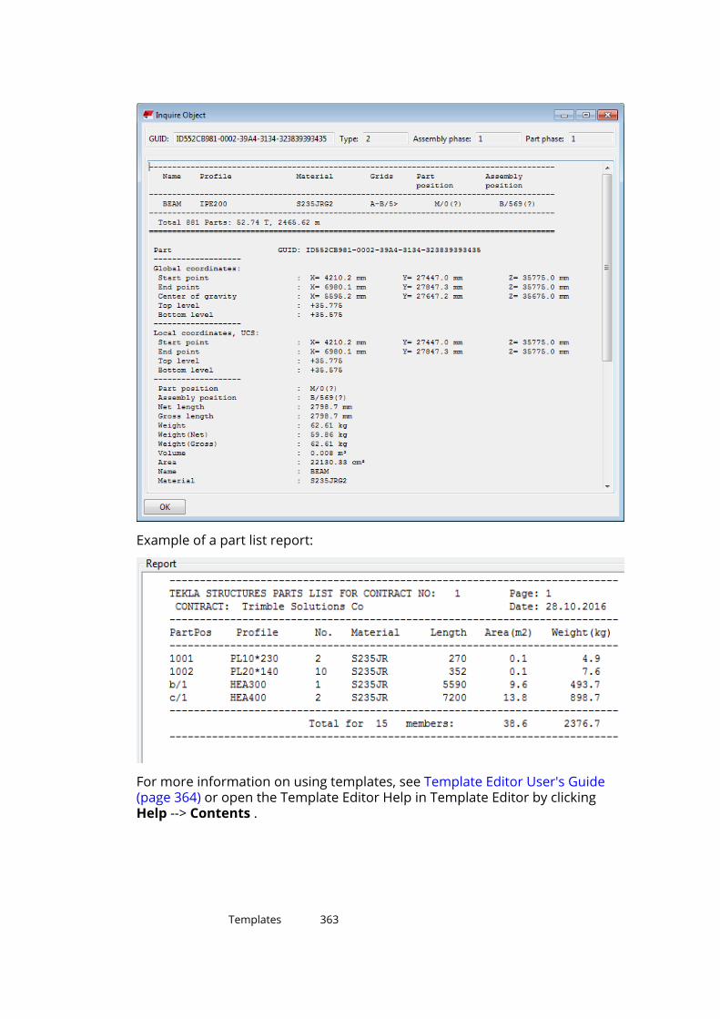
Example of a part list report:
For more information on using templates, see Template Editor User's Guide(page 364) or open the Template Editor Help in Template Editor by clickingHelp --> Contents .
Templates 363
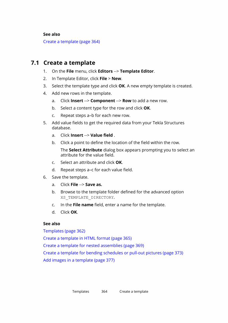
See also
Create a template (page 364)
7.1 Create a template1. On the File menu, click Editors --> Template Editor.
2. In Template Editor, click File > New.
3. Select the template type and click OK. A new empty template is created.
4. Add new rows in the template.
a. Click Insert --> Component --> Row to add a new row.
b. Select a content type for the row and click OK.
c. Repeat steps a–b for each new row.
5. Add value fields to get the required data from your Tekla Structuresdatabase.
a. Click Insert --> Value field .
b. Click a point to define the location of the field within the row.
The Select Attribute dialog box appears prompting you to select anattribute for the value field.
c. Select an attribute and click OK.
d. Repeat steps a–c for each value field.
6. Save the template.
a. Click File --> Save as.
b. Browse to the template folder defined for the advanced optionXS_TEMPLATE_DIRECTORY.
c. In the File name field, enter a name for the template.
d. Click OK.
See also
Templates (page 362)
Create a template in HTML format (page 365)
Create a template for nested assemblies (page 369)
Create a template for bending schedules or pull-out pictures (page 373)
Add images in a template (page 377)
Templates 364 Create a template

7.2 Template Editor User's GuideThis guide describes how you can use Template Editor to create, modify andmanage template definitions for both reports and drawings.
With Template Editor, you can produce labels, reports and legends allowingyou to gather and produce accurate and targeted information. TeklaStructures has a number of ready-made templates, and you can use TemplateEditor to modify the existing templates, or create new ones to suit your needs.
Template Editor is also used in other products than Tekla Structures. That iswhy the term 'product' is used frequently in the content instead of the actualsoftware name. For exact instructions on how to use Template Editor togetherwith Tekla Structures to create and modify templates, see the other articlesunder Templates (page 362).
The Template Editor User's Guide is currently available in English only. Thecontent is the same as in the Template Editor help.
7.3 Create a template in HTML formatTemplates in HTML format give you more possibilities for different layout,fonts, and images. Templates that generate output in HTML format aregraphical and have the file name extension *.html.rpt.
1. On the File menu, click Editors --> Template Editor.
2. In Template Editor, click File > New.
3. Select Graphical template and click OK.
4. Add new rows in the template.
a. Click Insert --> Component --> Row to add a new row.
b. Select a content type for the row and click OK.
c. Repeat steps a–b for each new row.
5. Add value fields to get the required data from your Tekla Structuresdatabase.
a. Click Insert --> Value field .
b. Click a point to define the location of the field within the row.
The Select Attribute dialog box appears prompting you to select anattribute for the value field.
c. Select an attribute and click OK.
d. Repeat steps a–c for each value field.
6. Add a header for each value field.
a. Click Insert --> Component --> Header...
Templates 365 Create a template in HTML format

b. Click Insert --> Text...
c. Enter a heading for the template, and then click OK.
d. Click a point to define the location of the heading in the header row.
e. Repeat steps a–d to create headings for all the value fields.
7. Save the template:
a. Click File --> Save as
b. Browse to the template folder defined for the advanced optionXS_TEMPLATE_DIRECTORY.
c. In the File name field, enter a name for the template.
Include the extension *.html.rpt in the file name. For example,Part_list.html.rpt.
d. Click OK.
NOTE If you add images in your HTML template, the images should be locatedin ..\Program Files\Tekla Structures\<version>\nt\TplEd\bitmaps folder, otherwise they are not shown in the HTML output.
Example
1. Header that contains text fields
2. Row that contains two value fields
See also
Templates (page 362)
Add images in a template (page 377)
Templates 366 Create a template in HTML format
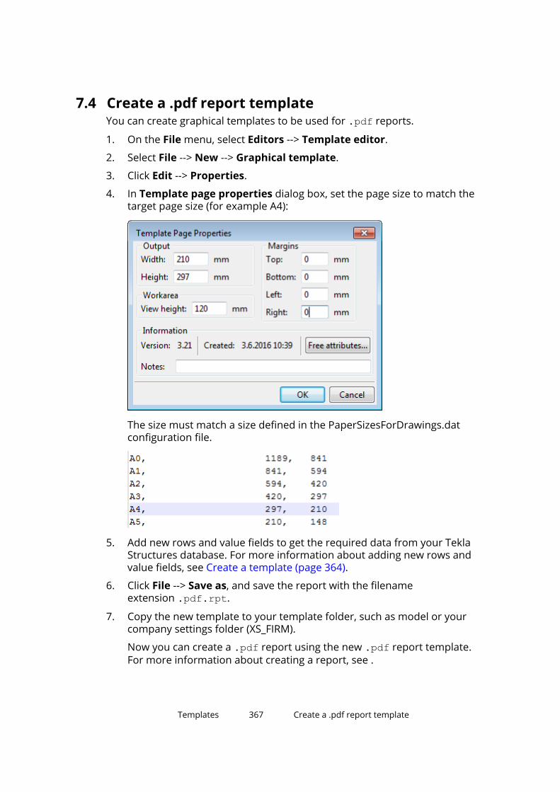
7.4 Create a .pdf report templateYou can create graphical templates to be used for .pdf reports.
1. On the File menu, select Editors --> Template editor.
2. Select File --> New --> Graphical template.
3. Click Edit --> Properties.
4. In Template page properties dialog box, set the page size to match thetarget page size (for example A4):
The size must match a size defined in the PaperSizesForDrawings.datconfiguration file.
5. Add new rows and value fields to get the required data from your TeklaStructures database. For more information about adding new rows andvalue fields, see Create a template (page 364).
6. Click File --> Save as, and save the report with the filenameextension .pdf.rpt.
7. Copy the new template to your template folder, such as model or yourcompany settings folder (XS_FIRM).
Now you can create a .pdf report using the new .pdf report template.For more information about creating a report, see .
Templates 367 Create a .pdf report template

Example .pdf report
In this report example, the following page size is used:
Below is an example of a report that has been created using this particularreport template. To open the report in a browser, click here.
Templates 368 Create a .pdf report template

7.5 Create a template for nested assembliesThis example shows how to produce a template that displays the hierarchicalstructure of nested assemblies. You will create a nested assembly structure ina textual template similar to the one in the following picture:
Templates 369 Create a template for nested assemblies

1. On the File menu, click Editors --> Template Editor.
2. In Template Editor, click File > New.
3. Select Textual template and click OK.
4. Add four new rows in the template.
a. Click Insert --> Component --> Row to add a new row.
b. Select a content type for the row, and then click OK.
For the first and third row, select the ASSEMBLY content type, and forthe second and fourth row, select the PART content type.
c. Repeat steps a–b for each new row.
5. Use the arrow buttons under Sorting and drawing order to create anested assembly structure for the template.
a. Move the second and third row down one level.
b. Move the fourth row down two levels.
The structure should now look like this:
Templates 370 Create a template for nested assemblies

6. Add value fields to get the required data from your Tekla Structuresdatabase.
In this example, the added value fields are assembly or part position,number, and weight.
a. Click Insert --> Value field .
b. Click a point to define the location of the field within the row.
The Select Attribute dialog box appears prompting you to select anattribute for the value field.
c. Select an attribute and click OK.
d. Repeat steps a–c for each value field.
7. Modify the layout of the template. For example:
a. Move objects to display the nested assembly structure in the printedreport. To do this, select the object you want to move and drag it tothe desired position.
b. Align objects. To do this, select all the objects you want to align, right-click and select the appropriate option from the pop-up menu, forexample Align --> Right .
c. Add a header and a footer. To do this, click Insert --> Component -->Page header and Page footer. Add the required information to theheader and footer.
8. Save the template.
Example
Below is an example textual template and a report that has been createdusing the template:
Templates 371 Create a template for nested assemblies
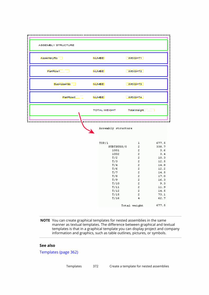
NOTE You can create graphical templates for nested assemblies in the samemanner as textual templates. The difference between graphical and textualtemplates is that in a graphical template you can display project and companyinformation and graphics, such as table outlines, pictures, or symbols.
See also
Templates (page 362)
Templates 372 Create a template for nested assemblies

7.6 Create a template for bending schedules or pull-outpicturesYou can use Template Editor for creating bending schedules or pull-outspictures on reinforcement bars and bent meshes, and control the type ofinformation that is shown in the bending schedules.
1. On the File menu, click Editors --> Template Editor.
2. Click File --> New .
3. Select Graphical template and click OK.
4. Click Insert --> Component --> Row to add a new row.
5. Select REBAR or MESH as the content type for the row.
6. Add value fields to get the required data from your Tekla Structuresdatabase.
a. Click Insert --> Value field .
b. Click a point to define the location of the field within the row.
The Select Attribute dialog box appears prompting you to select anattribute for the value field.
c. Select an attribute and click OK.
d. Repeat steps a–c for each value field.
7. Insert a graphical field to your REBAR or MESH content type row.
a. Click Insert --> Graphical Field...
b. Click and drag with the mouse to draw a frame.
8. Double-click the graphical field to open the Graphical Field Propertiesdialog box.
9. Click Free attributes and go to the Application tab.
10. Select the required bending diagram attributes.
You can also define the bending diagram attributes on the User tab. Notethat if the same attribute is set both as User attribute and Applicationattribute, the Application attribute takes precedence.
For a list of attributes and values that can be used for bending schedulesin templates, see Bending schedule attributes (page 376).
11. Save the template.
Templates 373 Create a template for bending schedules or pull-out pictures
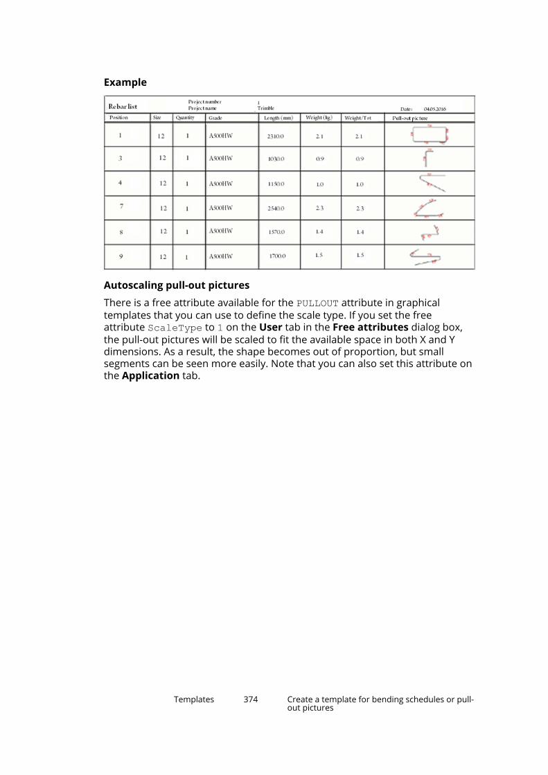
Example
Autoscaling pull-out pictures
There is a free attribute available for the PULLOUT attribute in graphicaltemplates that you can use to define the scale type. If you set the freeattribute ScaleType to 1 on the User tab in the Free attributes dialog box,the pull-out pictures will be scaled to fit the available space in both X and Ydimensions. As a result, the shape becomes out of proportion, but smallsegments can be seen more easily. Note that you can also set this attribute onthe Application tab.
Templates 374 Create a template for bending schedules or pull-out pictures

A bending shape may look like this if you do not define the free attribute ScaleType:
The same bending shape that uses the free attribute ScaleType with value 1.
Change the appearance of the pull-out pictures
Tekla Structures uses the settings in the rebar_config.inp file in the systemfolder defined by the advanced option XS_SYSTEM to define the appearance ofthe pull-out pictures. You can change the colors, lines, and dimension unit,format, and precision used in pull-out pictures, for example. For a list ofsettings and values in rebar_config.inp, see Reinforcement settings fordrawings (rebar_config.inp)
Templates 375 Create a template for bending schedules or pull-out pictures

Bending schedule attributesThe following table lists the attributes and values that can be used for bendingschedules in templates.
Attribute Default value Available valuesFontName romsim Available template fontsFontSize 2.0 Available font sizesFontColor 1 (black) 1 = black
2 = red
3 = bright green
4 = blue
5 = cyan
6 = yellow
7 = magenta
8 = brown
9 = green
10 = dark blue
11 = forest green
12 = orange
13 = grayRotationAxis 2 0 = by view
1 = by global Z
2 = by local axisScaleType 0 0 = no
1 = yes
If you set the freeattribute ScaleType to 1 for the PULLOUTattribute, the pull-outpictures will be scaled tofit the available space inboth X and Ydimensions. As a result,the shape becomes outof proportion, but small
Templates 376 Create a template for bending schedules or pull-out pictures

Attribute Default value Available valuessegments can be seenmore easily.
Exaggeration 1 0 = no
1 = yesEndMark 1 1 = straight
2 = half arrow
3 = full arrowDimensions 1 0 = no
1 = yesBendingRadius 0 Shows the bending
radius in form ofdiameter of the bendingroll.
0 = no
1 = yesBendingAngle 1 0 = no
1 = yesImageWidth Width of the graphical
field multiplied by 4.Number of pixels
ImageHeight Height of the graphicalfield multiplied by 4.
Number of pixels
CouplerSymbols 1 Display srebar couplerand end anchor symbolsin rebar bendingschedules. Rebarcoupler symbols will beshown ifCouplerSymbolsproperty value is set to 1and disabled if 0 isentered. The defaultvalue is 1.
See also
Create a template for bending schedules or pull-out pictures (page 373)
Templates 377 Add images in a template

7.7 Add images in a templateYou can add images in graphical templates. For example, you might want toinclude a company logo in your drawings. Tekla Structures supports thefollowing image formats in graphicaltemplates: .bmp, .jpg, .jpeg, .tif, .tiff and .png.
1. Open an existing graphical template or create a new graphical template inTemplate Editor.
2. Add a new row in the template:
a. Click Insert --> Component --> Row to add a new row.
b. Select a content type for the row and click OK.
3. Ensure that you have the row selected, and click Insert > Picture to openthe Select Picture File dialog box.
If a local symbols folder exists, the contents of that folder are shown bydefault. You can browse for the contents of the common\symbols folderby selecting that folder. If a local symbols folder does not exist, TeklaStructures displays the contents of the common\symbols folder.
4. If you have images in other folders, you can display these folders in theSelect Picture File dialog box:
a. In Template Editor, click Options --> Preferences.
b. Go to the File Locations tab and on the Symbols, pictures row, adda new folder separated by a semicolon (;), for example:
The folder you defined is displayed in the Directory list:
5. Select an image from the File list and click OK and add the image.
You can adjust the size by dragging from the image handles.
Templates 378 Add images in a template

Things to remember when adding images in templates
• Do not add very large images because they update very slowly.
• The image may look different in the image editor and in the printout or inthe exported DWG file.
• When you export the drawing to DWG, Tekla Structures copies the imagesin the same folder as the DWG file. If the image for some reason is not inthe same folder, only the name of the image is displayed together with anempty frame instead of the image in the DWG.
• If environments have local symbols, the local symbol folder is also includedin the search path with the common\symbols folder. If the local symbolsfolder contains files with the same name as common\symbols folder, thenthe local symbol file is used.
• When you open the drawing that contains images inserted in the template,Tekla Structures first looks for the images in the model folder and then inthe \symbols folder in the current environment.
• You can define a folder where Tekla Structures always looks for imagesusing the advanced option DXK_SYMBOLPATH. You can also define a firmfolder for your images.
Example
Below are some examples of the Select Picture File dialog box showing folderstructure in different environments.
Templates 379 Add images in a template

In the following example, a company logo has been added in a template.
See also
Templates (page 362)
7.8 Content typesWhen you create a new row in the template, you must select a content type forthe row. For example, when you add a row and then add a value field,Template Editor is asking for the content type. The content type determineswhich template attributes you can use on that row.
The available content types are:
Content type DescriptionANALYSIS_RIGID_LINK Use to create lists of analysis rigid links.
Templates 380 Content types

Content type DescriptionANTIMATERIAL Use to create lists of holes and recesses, or parts
removed as a result of a cut.
In Template Editor, the same attributes that areavailable for PART are available for ANTIMATERIAL.However, only the attributes that are useful to beused with ANTIMATERIAL are shown, including NAME, LENGTH, WIDTH, HEIGHT, AREA, PROFILE,and NUMBER, and user-defined attributes.
ASSEMBLY Use to create lists of assemblies and single parts.Includes all assemblies containing the selectedparts and bolts.
BOLT Use to create screw and bolt lists. Includes all boltsconnected to selected parts.
CAST_UNIT Use to create lists of cast units.CHAMFER Use to create lists of the length of the chamfers.COMMENT Use to create empty rows or rows that only have
textual data or lines anywhere on a template.CONNECTION Use to create lists of connections.DRAWING Use to create drawing lists without revision history
information. Use for reports and includeddrawings.
HIERARCHIC_CAST_UNIT
Use to create reports listing subassemblies ofconcrete.
HIERARCHIC_OBJECT Use to create lists of various types of hierarchies.For example, lists hierarchical objects in Organizer.
HISTORY Use to retrieve history information of the model.You can use this content type with PART, REBAR, CONNECTION and DRAWING rows.
The following template attributes can be used withthis content type:
• TYPE: the type of the historical action, forexample update or numbering.
• USER: the user who made the change.
• TIME: the time the change was made.
• COMMENT: the comment which was enteredupon clicking Save.
• REVISION_CODE: the revision code which wasentered upon clicking Save.
HOLE Use to create lists of holes.LOAD Use to create lists of loads.
Templates 381 Content types
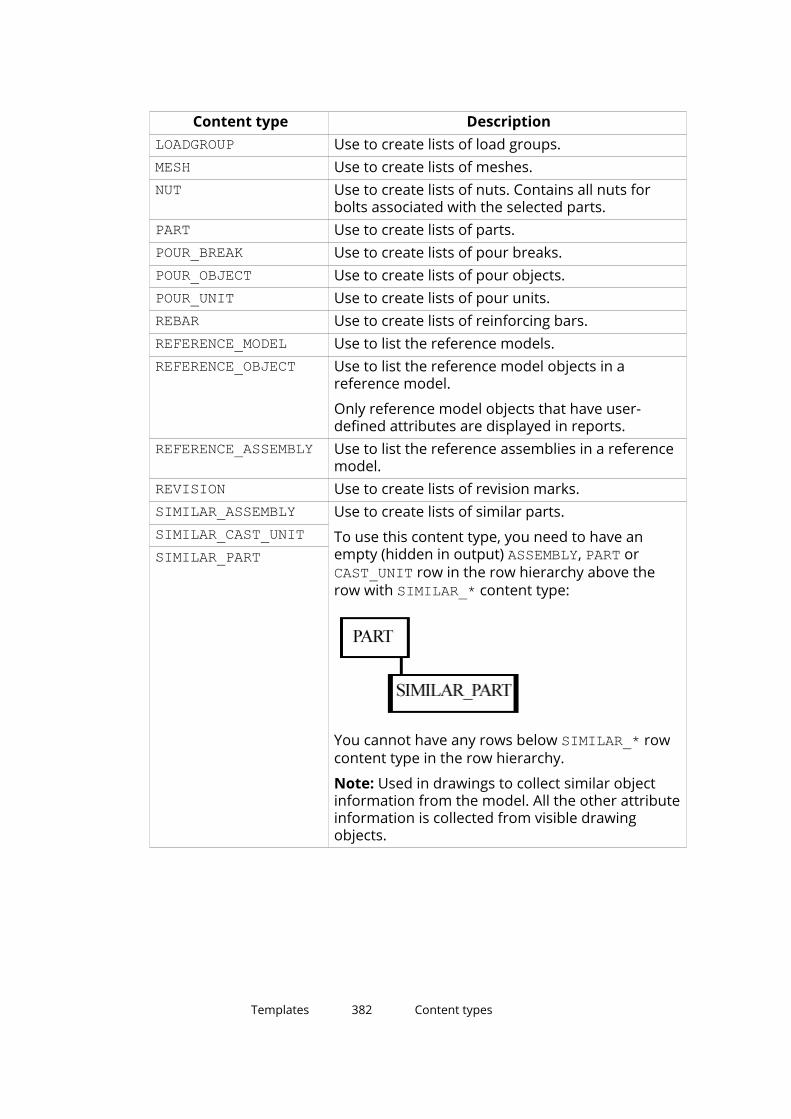
Content type DescriptionLOADGROUP Use to create lists of load groups.MESH Use to create lists of meshes.NUT Use to create lists of nuts. Contains all nuts for
bolts associated with the selected parts.PART Use to create lists of parts.POUR_BREAK Use to create lists of pour breaks.POUR_OBJECT Use to create lists of pour objects.POUR_UNIT Use to create lists of pour units.REBAR Use to create lists of reinforcing bars.REFERENCE_MODEL Use to list the reference models.REFERENCE_OBJECT Use to list the reference model objects in a
reference model.
Only reference model objects that have user-defined attributes are displayed in reports.
REFERENCE_ASSEMBLY Use to list the reference assemblies in a referencemodel.
REVISION Use to create lists of revision marks.SIMILAR_ASSEMBLY Use to create lists of similar parts.
To use this content type, you need to have anempty (hidden in output) ASSEMBLY, PART or CAST_UNIT row in the row hierarchy above therow with SIMILAR_* content type:
You cannot have any rows below SIMILAR_* rowcontent type in the row hierarchy.
Note: Used in drawings to collect similar objectinformation from the model. All the other attributeinformation is collected from visible drawingobjects.
SIMILAR_CAST_UNITSIMILAR_PART
Templates 382 Content types

Content type DescriptionSINGLE_REBAR Use to create lists of individual bars in reinforcing
bar groups.
For example, use it to get the lengths of theindividual bars in tapered reinforcing bar groups.
For rebar sets, SINGLE_REBAR works in the sameway as REBAR.
SINGLE_STRAND Use to create lists of individual prestressedstrands.
STRAND Use to create lists of prestressed strands.STUD Use to create lists of studs.SURFACE Use to create lists of surfaces.SURFACING Use to create lists of surface treatments.SUMMARY Use to summarize the contents of the row(s) that
are above SUMMARY in the hierarchy.
For example, use PART - SUMMARY hierarchy tosummarize the contents of the PART rows.
TASK Use to create lists of tasks.WASHER Use to create lists of washers. Contains all washers
for all bolts associated with the selected parts.WELD Use to create lists of welds.
See also
Template attribute files (contentattributes.lst) (page 383)
7.9 Template attribute files (contentattributes.lst)Template attributes represent object properties. You can use templateattributes in value fields, formulas, and row rules to get the required datafrom your Tekla Structures database.
When you output the template, Tekla Structures replaces the attribute withthe actual value of the corresponding object property. For example, if you
Templates 383 Template attribute files (contentattributes.lst)

include the attribute WEIGHT in a report template, Tekla Structures displaysthe weight of the model object in the report.
Template attributes are defined in the following files:
File name Descriptioncontentattributes.lst This is a container file listing all the
files that contain the actual attributedefinitions. The files are added with INCLUDE sentences. The order of thefiles included incontentattributes.lst definesthe reading order of the files.
This file is overwritten in theinstallation when you install a newerversion of Tekla Structures. Ensurethat you make a copy of this filebefore updating.
Generally, there is no need to modifycontentattributes.lst. Do notmodify it if you are not anadministrator.
contentattributes_global.lst This file contains attributes that arehard-coded into the program. Do notedit this file.
contentattributes_userdefined.lst
This file contains user-definedattributes, the same as in theobjects.inp file.
This file is overwritten in theinstallation when you install a newerversion of Tekla Structures. To useyour own attributes in templates andreports, create a copy of this file andadd the necessary attributes to thatfile.
By default, these files are located in ..\Program Files\Tekla Structures\<version>\nt\bin\TplEd\settings, but the location may be different inyour environment.
The search order for the contentattributes.lst file is defined in thetpled.ini file. The location of the tpled.ini file is defined by theXS_TPLED_INI advanced option.
The following pointers are allowed in the tpled.ini file:
• @\ = location of the tpled.ini file
Templates 384 Template attribute files (contentattributes.lst)

• .\ = location of tpled.exe (C:\Program Files\Tekla Structures\<version>\nt\bin\TplEd)
To include your own attributes, modify the contentattributes.lst files inthe relevant environment folders. Note that the contentattributes.lstfiles are overwritten when you install a new version of Tekla Structures.
See also
User-defined template attributes (page 385)
Location of certain hidden files and folders (page 360)
7.10 User-defined template attributesUser-defined template attributes are defined in thecontentattributes_userdefined.lst file. By default, this file includesmost of the user-defined attributes that are visible in the part properties. Touse your own attributes in templates and reports, you should make a copy ofthe file, rename it appropriately, and add the necessary attributes to that file.
The contentattributes_userdefined.lst file is divided into two sections:
• A list of attribute names and default settings:
Templates 385 User-defined template attributes

• A list of attributes assigned to content types:
1. The content type of the row in Template Editor
2. The attribute hierarchy in Template Editor
3. Customizable comments, such as the tab name in the user-definedattributes dialog box
4. The name of the user-defined attribute, must be the same as in theobjects.inp file
See also
Add user-defined template attributes to Template Editor (page 386)
Add comments to user-defined template attributes (page 388)
Add hierarchy to user-defined template attributes (page 388)
Add user-defined template attributes to Template EditorThis example shows how to add your own user-defined attributes to theattribute tree in Template Editor.
Before you start, add your user-defined attribute to the objects.inp file. Forexample, you might add an attribute named MY_ATTRIBUTE to the user-defined properties of drawings.
1. Open the contentattributes_userdefined.lst file in a text editor.
Templates 386 User-defined template attributes

2. Save the file with an appropriate name, for exampleMY_contentattributes_userdefined.lst, in the same folder.
3. Add MY_ATTRIBUTE to the list of attribute names and, define the settingsas follows:
4. Add MY_ATTRIBUTE to the list of attributes assigned to content types.
Select the content type according to which object the attribute isassociated to in the objects.inp file. In this example, the content type is DRAWING. Add the attribute in the format USERDEFINED.<ATTRIBUTE_NAME>.
5. Save the changes.
6. Open the contentattributes.lst file.
7. Add the following line in the file:
[INCLUDE MY_contentattributes_userdefined.lst]8. Save the changes.
The attribute is shown in the attribute tree in Template Editor, under DRAWING > USERDEFINED:
Templates 387 User-defined template attributes
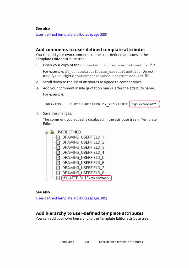
See also
User-defined template attributes (page 385)
Add comments to user-defined template attributesYou can add your own comments to the user-defined attibutes in theTemplate Editor attribute tree.
1. Open your copy of the contentattributes_userdefined.lst file.
For example, MY_contentattributes_userdefined.lst. Do notmodify the original contentattributes_userdefined.lst file.
2. Scroll down to the list of attributes assigned to content types.
3. Add your comment inside quotation marks, after the attribute name.
For example:
4. Save the changes.
The comment you added is displayed in the attribute tree in TemplateEditor:
See also
User-defined template attributes (page 385)
Add hierarchy to user-defined template attributesYou can add your own hierarchy to the Template Editor attribute tree.
Templates 388 User-defined template attributes

1. Open your copy of the contentattributes_userdefined.lst file.
For example, MY_contentattributes_userdefined.lst. Do notmodify the original contentattributes_userdefined.lst file.
2. Scroll down to the list of attributes assigned to content types.
3. Define the hierarchy in square brackets, between USERDEFINED. and theattribute name.
For example:
NOTE Notice the periods after the brackets, and between thehierarchies.
4. Save the changes.
The new hierarchy is shown in the attribute tree:
WARNING User-defined attributes are case sensitive. Ensure that you enter theattribute name using the correct case for all characters.
See also
User-defined template attributes (page 385)
Templates 389 Tips for templates

7.11 Tips for templatesThere are some things that you might consider to be able to use templatesmore efficiently.
Click the links below to find out more:
• Use text type attribute in calculations (page 390)
• Change value field content to use imperial units (page 390)
• Define customized date format (page 391)
• Assembly or cast unit drawing sheet number (page 391)
• Use format functions in value fields (page 392)
Use text type attribute in calculations
Change text to numeric format
double(GetValue("ASSEMBLY_TOP_LEVEL"))Change into correct format for calculation (double=decimals)
format(double(GetValue("ASSEMBLY_TOP_LEVEL")),"Length", "mm",1)Add all above into calculation formula
format(double(GetValue("ASSEMBLY_TOP_LEVEL")),"Length", "mm",1)+15000Another example of the same for part elevation
(double(GetValue("TOP_LEVEL"))-(double(GetValue("BOTTOM_LEVEL"))))*1000
Change value field content to use imperial units
Advanced option to check if imperial units are in use:
GetValue("ADVANCED_OPTION.XS_IMPERIAL")==TRUETranslated string call for multi lingual text:
GetValue("TranslatedText("albl_Diameter_")")Formatting of units:
format(GetValue("DIAMETER"),"Length","inch-frac", 1/16)format(GetValue("DIAMETER"),"Length","mm", 1)Combine all above in a rule:
Templates 390 Tips for templates

if GetValue("ADVANCED_OPTION.XS_IMPERIAL")==TRUE thenGetValue("TranslatedText("albl_Diameter_")")+format(GetValue("DIAMETER"),"Length","inch-frac", 1/16) + "Inches"elseGetValue("TranslatedText("albl_Diameter_")")+format(GetValue("DIAMETER"),"Length","mm", 1)+" mm"endif
Define customized date format
Use mid function to find year, month and day:
mid("","","") string, offset, nyear:
mid(format(GetValue("DATE"),"Date","dd.mm.yyyy", ),"6","4")month:
mid(format(GetValue("DATE"),"Date","dd.mm.yyyy", ),"3","2")days:
mid(format(GetValue("DATE"),"Date","dd.mm.yyyy", ),"0","2")Combine all above in rule:
mid(format(GetValue("DATE"),"Date","dd.mm.yyyy", ),"6","4")+"-"+mid(format(GetValue("DATE"),"Date","dd.mm.yyyy", ),"3","2")+"-"+mid(format(GetValue("DATE"),"Date","dd.mm.yyyy", ),"0","2")
Assembly or cast unit drawing sheet number
Use match function to find "-" character
match(GetValue("NAME_BASE"),"*-*")Use of mid function to return only characters after "-"
mid(GetValue("NAME_BASE"),(1+(find(GetValue("NAME_BASE"),"-"))),2)Combine all above in rule
if (match(GetValue("NAME_BASE"),"*-*"))
Templates 391 Tips for templates

then mid(GetValue("NAME_BASE"),(1+(find(GetValue("NAME_BASE"),"-"))),2)else ""endif
Use format functions in value fieldsYou can define the format used in a value field in two ways: In the Value FieldProperties dialog box by filling in the fields for Datatype, Meaning, Unit andDecimals, or by creating a formula in the Formula field. In formulas, you canuse the format function that converts an attribute value to a formattedinformation string.
When you use a format function in a formula, always set the Datatype to Textin the Value Field Properties dialog box. Leave the other fields in the Formatarea empty.
For example, if you want to convert the attribute value to numbers withdecimals in the report, you need to include the conversion function double inthe format function:
The default values for unit and decimals are defined in thecontentattributes_global.lst file. The format function converts theattribute value to a formatted information string on the basis of what you havedefined in the format function. The format function overrides the definitions inthe contentattributes_global.lst file and settings that you have definedin the Format area of Value Field Properties dialog box.
Example of the result in a report when you use the formula above:
Mesh Information:Geometry Size: 4/4-150/150-2750*2000Length: 9'-1/4"Height: 6'-6 3/4"
Templates 392 Tips for templates

Example of the result of the formula, when you use set the advanced option XS_IMPERIAL to FALSE instead of TRUE:
Mesh Information:Geometry Size: 4/4-150/150-2750*2000Length: 2750 mmHeight: 2000 mmFor a list of valid unit and precision strings, see the valuefieldclasses.lstfile located in the ..\Program Files\Tekla Structures\<version>\nt\TplEd\settings folder. Do not make changes in this file. Below is anexample of the file content, which may change between Tekla Structuresversions.
// ---------------------------------------------------------------------------------------// // - Use only letters, numbers, slashes and underlines.//// ---------------------------------------------------------------------------------------//// Class = units { presicions }
Length = mm, dm, cm, m, inch, ft, yd, inch-frac {1/2, 1/4, 1/8, 1/16 }, ft-frac { 1/2, 1/4, 1/8, 1/16 }Angle = Degrees, radiansArea = mm2, cm2, dm2, m2, sq.inch, sq.ft, sq.ydArea/length = mm2/m, cm2/m, dm2/m, m2/m, in2/in, in2/ft, ft2/ft, sq.yd/ftVolume = mm3, cm3, dm3, m3, cu.in, cu.ft, cu.yd Weight = kg, T, N, lbf, kipWeight/length = kg/m, T/m, N/m, daN/m, kN/m, lbf/ftDensity = kg/m3, T/m3, N/m3, kN/m3, lbf/ft3Temperature = Kelvin, Celsius, FahrenheitSection_modulus = mm3, cm3, in3Moment_of_inertia = mm4, cm4, in4Warping_modulus = mm6, cm6, in6Force = kg, T, N, daN, kN, lbf, kipForce/length = kg/m, T/m, N/m, daN/m, kN/m, lbf/in, lbf/ft, kip/in, kip/ftForce/area = kg/m, kg/cm, kg/mm, T/m, T/cm, T/mm, N/m, N/cm, N/mm, daN/m, daN/cm, daN/mm, kN/m, kN/cm, kN/mm, lbf/in, lbf/ft, kip/in, kip/ftMoment = kgm, Tm, Nm, daNm, kNm, lbf-in, lbf-ft, kip-in, kip-ftMoment/length = kgm/m, Tm/m, Nm/m, daNm/m, kNm/m, lbf-ft/ft, kip-ft/ftStress = kg/m2, kg/cm2, kg/mm2, T/m2, T/cm2, T/mm2, N/m2, N/cm2, N/mm2, daN/m2, daN/cm2, daN/mm2, kN/m2, kN/cm2, kN/mm2, psi, psf, ksi, ksfDate = dd.mm.yyyy, mm.dd.yyyy, mm/dd/yyyy, yyyy/mm/dd, dd-mm-yy, dd-mm-yy, yyyy-mm-dd, dd/mm/yyTime = hh:mm:ss, hh:mm:ss:am/pmDate&&Time = dd.mm.yyyy, mm.dd.yyyy, mm/dd/yyyy, yyyy/mm/dd, dd-mm-yy, dd-mm-yyyy, yyyy-mm-dd, dd/mm/yyDate_local = dd.mm.yyyy, mm.dd.yyyy, mm/dd/yyyy, yyyy/mm/dd, dd-mm-yy, dd-mm-yyyy, yyyy-mm-dd, dd/mm/yyTime_local = hh:mm:ss, hh:mm:ss:am/pm
Templates 393 Tips for templates

Date&&Time_local = dd.mm.yyyy, mm.dd.yyyy, mm/dd/yyyy, yyyy/mm/dd, dd-mm-yy, dd-mm-yyyy, yyyy-mm-dd, dd/mm/yyLeadingZeroesLeadingZeroesDistanceList = mm, dm, cm, m, inch, ft, yd, inch-frac {1/2, 1/4, 1/8, 1/16 }, ft-frac { 1/2, 1/4, 1/8, 1/16 }
For more information about value fields, formats, format functions and otherfunctions, see Template Editor User's Guide.
Templates 394 Tips for templates

8 Tekla Model Sharing and multi-user for administrators
You can find a table of the differences between Tekla Model Sharing and multi-user models here.
8.1 Tekla Model SharingTekla Model Sharing enables efficient global collaborative modeling within ashared Tekla Structures model. Tekla Model Sharing gives users the freedomto work with the same model at the same time in different locations and timezones.
In Tekla Model Sharing each user has a local version of the model on theircomputer, or on a network drive, and the model data is shared andsynchronized over the Internet using a Microsoft Azure cloud sharing service.When a model is shared, it is connected to the cloud-based sharing service.You can check the status of the service at any time.
NOTE The users of the same shared model need to have the same Tekla Structuresversion, and use the same latest service pack.
When a user starts to share a model, the organization the user belongs to getsthe model ownership. In Tekla Model Sharing, an organization always owns allthe models shared by the users in the organization. A shared model is alwaysowned by only one organization. You can manage and view all the sharedmodels owned by your organization with the web-based Management Consolefor Tekla Model Sharing. Logging in requires Trimble Identity administratorrights.
Tekla Model Sharing requires a valid Tekla Model Sharing license and aTrimble Identity which is part of a valid organization. Based on the TrimbleIdentity information, you can assign and manage Tekla Model Sharing licensesin the web-based Tekla Online Admin Tool. For more information, seeManaging Trimble Identities and Tekla Model Sharing licenses.
Tekla Model Sharing and multi-user foradministrators
395 Tekla Model Sharing
Tekla Model Sharing cloud sharing service status is publicly available at TeklaModel Sharing Status. On this web-site, you can also find information aboutany service breaks.
For more information on how Tekla Model Sharing works, see
•
•
•
•
• Manage models in Management Console for Tekla Model Sharing
NOTE Tekla Model Sharing requires a single-user model. A model cannot besimultaneously shared and used in the multi-user mode. If you want to startusing multi-user mode to share your model instead of Tekla Model Sharing,you first need to exclude your local version of the model from the sharingservice and then convert it to a multi-user model.
The excluded model has no connection to the original shared model in thesharing service. This means that if you exclude your local version of the modelfrom the sharing service and start to use the model in multi-user mode, youcannot later merge the original shared model and the multi-user model.
8.2 Multi-user modelsYou can work on Tekla Structures models in either single-user or multi-usermode. Multi-user mode allows several users to access the same model at thesame time. Several users can work on the same project and be aware of theothers' progress, so that copying and merging models is not needed.
The multi-user model consists of a single master model that can be locatedanywhere in the network. Each user can access this model, and open theirown local view of the model on a client computer. This local view is called aworking model. Any changes that a user makes to the working model are local,and not visible to other users, until the working model is saved to the mastermodel.
The multi-user model is locked during opening, saving, and numbering. Whenone of the users performs any of these operations, other users cannotperform them during that time. For more information, see .
NOTE All users of the multi-user model should use the same settings andthe same version and service pack of Tekla Structures.
Tekla Structures multi-user server runs as a service that is startedautomatically when you start the computer. You do not need to log in to theservice. We recommend that you use the latest multi-user server versionavailable regardless of the Tekla Structures version that you use. Note that
Tekla Model Sharing and multi-user foradministrators
396 Multi-user models
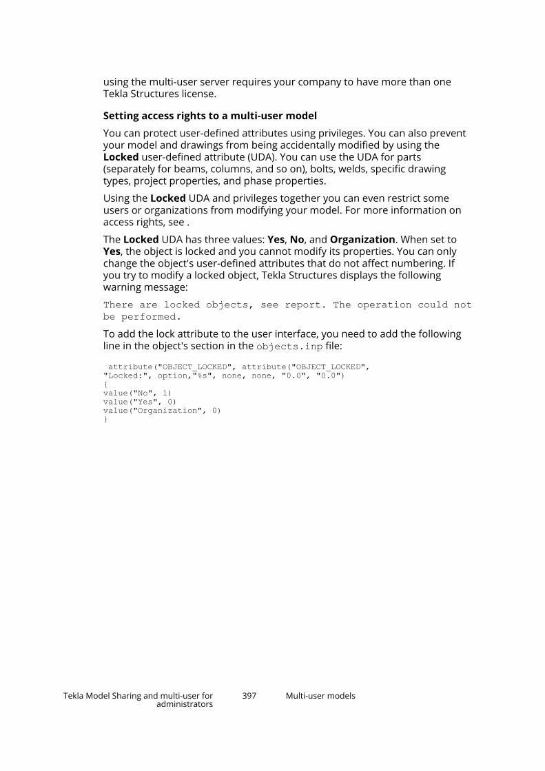
using the multi-user server requires your company to have more than oneTekla Structures license.
Setting access rights to a multi-user model
You can protect user-defined attributes using privileges. You can also preventyour model and drawings from being accidentally modified by using theLocked user-defined attribute (UDA). You can use the UDA for parts(separately for beams, columns, and so on), bolts, welds, specific drawingtypes, project properties, and phase properties.
Using the Locked UDA and privileges together you can even restrict someusers or organizations from modifying your model. For more information onaccess rights, see .
The Locked UDA has three values: Yes, No, and Organization. When set toYes, the object is locked and you cannot modify its properties. You can onlychange the object's user-defined attributes that do not affect numbering. Ifyou try to modify a locked object, Tekla Structures displays the followingwarning message:
There are locked objects, see report. The operation could notbe performed.To add the lock attribute to the user interface, you need to add the followingline in the object's section in the objects.inp file:
attribute("OBJECT_LOCKED", attribute("OBJECT_LOCKED","Locked:", option,"%s", none, none, "0.0", "0.0"){value("No", 1)value("Yes", 0) value("Organization", 0)}
Tekla Model Sharing and multi-user foradministrators
397 Multi-user models

9 Import Tekla Structures modeland drawings into anothermodel
You can use the Import model command to import a Tekla Structures modeland drawings to another model. If the imported model is later updated, youcan re-import the updated model.
• It is not possible to import a model or parts of it directly into the samemodel (for example, if the model folder has been copied in the file systemand then worked on separately). You can work around this, for example, byfirst importing the model into a new empty model or by using the Save ascommand to create a copy of the model.
• If you import to an existing model, fix the possible numbering conflicts byadding prefixes in numbering series.
• Importing models from older versions of Tekla Structures is not allowed.When you try to import an old model, the following message is displayed:"Importing models from previous versions is not supported. First save themodel with the current version. Note that you will not be able to use TeklaStructures of previous version to edit the model." Click Open for upgradeto open and save the model in the new version, or click OK.
• You can use the Import model command as a replacement to the oldmodel dump import. Import the model to an empty Tekla Structures modelcreated without a model template.
1. Open the Tekla Structures model into which you want to import the othermodel.
2. Go to Quick Launch, start typing import model, and select the Importmodel command from the list that appears.
Import Tekla Structures model and drawings intoanother model
398

3. Select a model folder to import and click OK.
The model objects and drawings are imported and the changes aredisplayed using the same listing as is used in Tekla Model Sharing.
With default settings, the Locked attribute is set to Yes in the importedobjects. Locking is controlled by the advanced option XS_MODEL_IMPORT_LOCK_OBJECTS in the Import category of the AdvancedOptions dialog box.
Import Tekla Structures model and drawings intoanother model
399

10 Import user-defined attributevalues
You can import user-defined attribute (UDA) values to a model from a text file.For example, you can import a list of manufactured or checked assemblies.You can also clear existing user-defined attribute values through attributeimport.
You can import attribute values to Tekla Structures model objects, drawings,and reference model objects (if configured, see ). You define matching criteriafor the attribute import in your input file, and you can additionally limit theimport scope to objects you select in the model or to reference model objects.
The input file can be:
• Exported from other software.
• Created manually using any standard text editor, for example, MicrosoftNotepad.
• Created from Microsoft Excel by saving the file with the Save as commandto Text (Tab-delimited) (*.txt) format.
• A simple Tekla Structures report containing the part GUIDs and user-defined attributes.
NOTE There are alternative ways to import data into user-defined attributes. Forexample, user-defined attributes can be filled in when you import IFC objectsand convert them to native Tekla Structures objects. There are also severalextensions in Tekla Warehouse that allow you to modify user-definedattribute data.
Import user-defined attribute values 400

11Develop applications usingTekla Open API
You can develop your own applications and additional features for TeklaStructures through the Tekla Open API (Application Programming Interface).Tekla Open API is implemented using Microsoft .NET technology.
Applications that are developed using Tekla Open API to work with TeklaStructures are called extensions. To use the power of the Tekla Open API, youmust write program code outside Tekla Structures. If you do not know how toprogram, you can still benefit from the Tekla Open API by downloadingextensions created by others from Tekla Warehouse.
With Tekla Open API you can:
• Record and run user interface actions
By recording and running user interface actions you can automate routinetasks, such as creating daily reports.
• Create automation tools
You can create automation tools for frequently needed objects. Withautomation tools you can, for example, create basic structures or addtypical details to drawings.
• Integrate Tekla Structures to other software
You can utilize the Tekla Open API and .NET in transferring informationbetween Tekla Structures and other software, such as Analysis & Designsoftware.
• Create new functionality.
For more information on Tekla Open API and extensions, visit the TeklaDeveloper Center.
Develop applications using Tekla Open API 401

12Disclaimer
© 2021 Trimble Solutions Corporation and its licensors. All rights reserved.
This Software Manual has been developed for use with the referencedSoftware. Use of the Software, and use of this Software Manual are governedby a License Agreement. Among other provisions, the License Agreement setscertain warranties for the Software and this Manual, disclaims otherwarranties, limits recoverable damages, defines permitted uses of theSoftware, and determines whether you are an authorized user of theSoftware. All information set forth in this manual is provided with the warrantyset forth in the License Agreement. Please refer to the License Agreement forimportant obligations and applicable limitations and restrictions on yourrights. Trimble does not guarantee that the text is free of technicalinaccuracies or typographical errors. Trimble reserves the right to makechanges and additions to this manual due to changes in the software orotherwise.
In addition, this Software Manual is protected by copyright law and byinternational treaties. Unauthorized reproduction, display, modification, ordistribution of this Manual, or any portion of it, may result in severe civil andcriminal penalties, and will be prosecuted to the full extent permitted by law.
Tekla Structures, Tekla Model Sharing, Tekla PowerFab, Tekla StructuralDesigner, Tekla Tedds, Tekla Civil, Tekla Campus, Tekla Downloads, Tekla UserAssistance, Tekla Discussion Forum, Tekla Warehouse and Tekla DeveloperCenter are either registered trademarks or trademarks of Trimble SolutionsCorporation in the European Union, the United States, and/or other countries.More about Trimble Solutions trademarks: http://www.tekla.com/tekla-trademarks. Trimble is a registered trademark or trademark of Trimble Inc. inthe European Union, in the United States and/or other countries. More aboutTrimble trademarks: http://www.trimble.com/trademarks.aspx. Other productand company names mentioned in this Manual are or may be trademarks oftheir respective owners. By referring to a third-party product or brand, Trimbledoes not intend to suggest an affiliation with or endorsement by such thirdparty and disclaims any such affiliation or endorsement, except whereotherwise expressly stated.
Portions of this software:
Disclaimer 402
EPM toolkit © 1995-2006 Jotne EPM Technology a.s., Oslo, Norway. All rightsreserved.
Portions of this software make use of Open CASCADE Technology software.Open Cascade Express Mesh Copyright © 2019 OPEN CASCADE S.A.S. All rightsreserved.
PolyBoolean C++ Library © 2001-2012 Complex A5 Co. Ltd. All rights reserved.
FLY SDK - CAD SDK © 2012 VisualIntegrity™. All rights reserved.
This application incorporates Open Design Alliance software pursuant to alicense agreement with Open Design Alliance. Open Design Alliance Copyright© 2002-2020 by Open Design Alliance. All rights reserved.
CADhatch.com © 2017. All rights reserved.
FlexNet Publisher © 2016 Flexera Software LLC. All rights reserved.
This product contains proprietary and confidential technology, informationand creative works owned by Flexera Software LLC and its licensors, if any. Anyuse, copying, publication, distribution, display, modification, or transmission ofsuch technology in whole or in part in any form or by any means without theprior express written permission of Flexera Software LLC is strictly prohibited.Except where expressly provided by Flexera Software LLC in writing,possession of this technology shall not be construed to confer any license orrights under any Flexera Software LLC intellectual property rights, whether byestoppel, implication, or otherwise.
To see the third party open source software licenses, go to Tekla Structures,click File menu --> Help --> About Tekla Structures and then click the 3rdparty licenses option.
The elements of the software described in this Manual are protected byseveral patents and possibly pending patent applications in the United Statesand/or other countries. For more information go to page http://www.tekla.com/tekla-patents.
Disclaimer 403

Index
.
.clb files........................................................ 172
.ini files.................................................... 19,268env_global_default.ini................... 273,274role_<role>.ini........................................274
Aaccess rights
configurations..........................................75example definitions................................ 75licenses..................................................... 73modifying............................................ 71,73
activating licensestroubleshooting.......................................85
activatinglicenses................................................64,67
adding toTemplate Editor.......................... 386adding
bolt assemblies to catalog................... 231bolts to catalog......................................228material grades..................................... 139profiles....................................................169stud bolts to catalog............................. 229user attributes to material grades...... 142user attributes to profiles.................... 149
administrators.ini files................................................... 110advanced options..................................110applications & components.................254bypassing............................................... 110company.................................................124customizing............................................110environment.......................................... 124environments........................................ 110folders.................................................... 110initialization files................................... 110installation................................................10licenses...................................................110licensing....................................................10
multi-user...............................................395project.................................................... 124registry keys.............................................10registry settings....................................... 10roles........................................................ 110setting up............................................... 110shortcuts................................................ 110tekla model sharing.............................. 395user-defined attributes........................ 110
advanced options....................................... 269changing.................................................297storing settings......................................276
API.................................................................401arcs............................................................... 183assemblies
bolt assemblies.............................. 226,231in templates........................................... 369
attributesin bending schedules............................376in templates........................................... 383
Bbefore installing the license server.............44bending schedules......................................373bending schedules
attributes and values............................376bolt assemblies........................................... 231
deleting...................................................232exporting................................................235importing................................................235modifying............................................... 232properties.............................................. 242
bolt assembly.............................................. 226bolt assembly catalog......................... 226,227bolt assembly element...............................226bolt catalog...........................................226,227bolts
adding bolt assemblies to catalog...... 231adding to catalog...................................228bolt assemblies.............................. 226,232
404
bolt assembly catalog....................226,227bolt catalog.....................................226,227creating studs........................................ 229deleting from catalog............................231exporting................................. 233,234,237importing........................................ 233,236length calculation..................................237modifying bolt information..................230
borrowing licensestroubleshooting.......................................89
borrowingexporting................................................104licenses.............................103,104,105,107product ID file................................ 103,104
Ccalculating
bolt length..............................................237calculations..................................................390catalog files..................................................318catalogs
bolt assembly catalog....................227,242bolt catalog.....................................227,240exporting material catalog...................145material catalog.....................................138profile catalog........................................146
chamfersin sketching.....................................197,200
checkingsketched profiles...................................196
circles............................................................183clash check
settings................................................... 277clb, see .clb files...........................................172codes
configurations..........................................75coincident constraints................................ 185comments
in templates........................................... 388company.ini................................................. 269components.clb...........................................172components
settings................................................... 277compressing
shape geometry files............................ 214configurations
codes.........................................................75
constraintscoincident...............................................185deleting...................................................185fixed........................................................ 185horizontal...............................................185in sketching............................................185parallel....................................................185perpendicular........................................ 185vertical.................................................... 185
content types...............................................380converting
profiles....................................................169copying
material grades..................................... 140profiles....................................................169
creatingcross sections........................................ 163customized initialization files.................19profiles............................. 162,169,172,180shapes from geometry......................... 216shortcuts.................................................. 19sketched profiles...................................183studs....................................................... 229templates........................................364,365
cross sectionscreating...................................................163defining.................................................. 163modifying............................................... 163profiles with variable cross sections...205user-defined.......................................... 163
custom tabs................................................. 133customized initializations.............................19customizing
message files......................................... 314property pane settings......................... 136property pane layout............................135ribbons................................................... 131tabs......................................................... 133toolbars.................................................. 137user-defined attributes........................ 302
Ddata files.......................................................312date
format.....................................................391deactivating licenses
troubleshooting.......................................89
405

deactivatinglicenses..................................................... 69
decimalssettings................................................... 277
definingcross sections........................................ 163flat bar sizes...........................................309unfolding parameters...........................310
deletingbolt assemblies......................................232bolts from catalog................................. 231material grades..................................... 141profiles....................................................154
dimensionsdefault format....................................... 277default precision................................... 277default unit............................................ 277in sketching.....................................188,200settings................................................... 277
distributingcustomized property pane settings....136customized property pane layouts..... 135customized ribbons.............................. 131customized tabs.................................... 133customized toolbars............................. 137licenses..................................................... 37
drawing objectssettings................................................... 277
DWG profile to library (6)........................... 163properties.............................................. 163
Eentitlement certificate.................................. 64environment settings
global default ........................................273local.........................................................274
environment variables............................... 276see advanced options...........................297
environment variables, see advancedoptions......................................................... 269environment.db.......................................... 304environment
database file.......................................... 304env_<environment>.ini................269,274,296env_global_default.ini......................... 269,296env_global_default.ini ................................273examples
adding dimensions to sketched profile....200adding user attributes to profiles....... 150creating user-defined attribute........... 305flat bar sizes...........................................309modifying chamfers in sketched profile.................................................................200profile export file...................................158setting sketch thickness....................... 200sketching symmetric C-shaped profile....200updating user-defined attribute..........305using sketched profile in model..........200
exportingbolt assemblies......................................235bolts......................................... 233,234,237groups from shape catalog..................222material grades.......................144,145,146profiles............................. 155,157,161,162rebar definitions....................................248reinforcement........................................248shapes.................................................... 222sketched profiles...................................162
extensions....................................................401extrusion types............................................197
Ffile name extensions.................................. 333file types
initialization files................................... 268files............................................................... 262
extensions..............................................333in model folder......................................333initialization files................................... 268locations................................................. 357symbol.................................................... 322
files related toenvironments........................................ 360software................................................. 360user settings.......................................... 360
firewallallowing traffic in TCP/IP ports.............. 55exceptions................................................53license server...........................................53
firewallsexceptions................................................54lmgrd.exe................................................. 54
406

tekla.exe................................................... 54firm folders.................................................. 263fixed constraints......................................... 185fixed profiles................................................169flat bars
in drawings ............................................308in reports................................................308sizes........................................................ 309
FlexNet........................................................... 29administrator's tasks.............................. 36examples of different setups.................39IT resources..............................................35starting Tekla Structures........................ 68
fltprops.inp.................................................. 309folders.......................................................... 262
in model folder......................................333locations................................................. 357search order.......................................... 358
font files....................................................... 321fonts..............................................................321fonts_<lang>.ini........................................... 269formulas
format.....................................................392free attributes............................................. 376
Gglobal default environment settings........ 273graphical templates.................................... 365
pull-out pictures.................................... 373grouping
profiles............................................ 148,149groups
in rebar catalog..................................... 246in shape catalog.................................... 217
Hhandles
of positioning planes............................ 192hidden files and folders............................. 360hiding
positioning planes.................................192hierarchy
in templates........................................... 388horizontal constraints................................ 185HTML templates..........................................365
html.rpt........................................................ 365
Iimage files....................................................323image
of profile.................................................208images
file formats.............................................323in templates........................................... 377
imperial units.............................................. 390import items................................................ 211importing
bolt assemblies......................................235bolts.................................................233,236groups to shape catalog.......................211material grades..................................... 144model......................................................398profiles.....................................155,156,161rebar definitions....................................248reinforcement........................................248shapes.................................................... 211sketched profiles...................................161SketchUp................................................ 213user-defined attribute values.............. 400
indexterm.................................................... 260ini files.......................................................... 269initialization files......................................... 268
creating customized................................19env_<environment>.ini.........................274env_global_default.ini...........................273file types................................................. 269reading order.........................................269role_<role>.ini........................................274usage...................................................... 269
input files..................................................... 299installation
license server...........................................46
Kkeywords
in access right definitions.......................75
407

Llang_<lang>.ini.............................................269length
bolt length calculation.......................... 237License Borrow Tool
returning licenses..................................108License Borrow Tool
borrowing licenses................................107license file
modifying................................................. 50license server.................................................29
administrator's tasks.............................. 36configuring manually.............................. 51firewall...................................................... 53installing................................................... 44manual installation................................. 47notifying automatically........................... 65notifying manually.................................. 67
license serverversion...................................................... 45
license serversautomatic installation.............................46
license service installation........................... 46license service
manual installation................................. 47licenses
access rights.............................................73activating.............................................64,67administrator's tasks.............................. 36allowing traffic through TCP/IP ports... 55automatic installation of license server....46borrowing........................ 103,104,105,107deactivating..............................................69different ways of distributing................ 37errors in activating.................................. 81errors in borrowing.................................81errors in deactivating..............................81examples of different setups.................39exceptions in firewall..............................54installing license server.......................... 44IT resources needed............................... 35maintaining.............................................. 71managing..................................................28modifying access rights.....................71,75modifying license access rights............. 75move between servers........................... 78
number of users......................................39on-premises............................................. 29problems in activation............................85problems in borrowing...........................89problems in deactivation........................89problems in license server connection.82problems in license server installation.82product ID file................................ 103,104repairing..............................................71,79returning................................................ 108troubleshooting Tekla licensing............ 80trust status..........................................79,90what is provided by Trimble.................. 34
licensing applicationslogging in as administrator.................... 37running as administrator....................... 37
lmgrd.exe....................................................... 54LMTOOLS ...................................................... 72LMTOOLS
configuring license server manually..... 51load defaults................................................316load modeling
settings................................................... 277local environment settings
env_<environment>.ini.........................274location
of hidden files........................................360locations
files..........................................................357folders.................................................... 357
log fileslist of....................................................... 324numberinghistory.txt log.............. 330,331session history.......................................329viewing....................................................328viewing parts or assemblies................ 328
Mmanual installation
license server...........................................47material catalog, see material grades...... 138material catalog
exporting................................................145material grades........................................... 138
adding.....................................................139adding user attributes..........................142copying................................................... 140
408

deleting...................................................141exporting................................. 144,145,146important buttons.................................139importing................................................144importing and exporting...................... 159material types........................................138modifying............................................... 141saving changes...................................... 139user-defined material symbols........... 143
message files............................................... 313customizing............................................314
Migration Wizard.........................................275model folder
file name extensions.............................333files..........................................................333
model-specific settings...............................296model
importing................................................398modifying
bolt assembly information...................232bolt information.................................... 230cross sections........................................ 163license file.................................................50material grades..................................... 141profile with variable cross sections.... 205profiles....................................................169rules........................................................ 149sketched profiles...................................197
mousesettings................................................... 277
movinglicenses..................................................... 78
Nnon-solid...................................................... 211north marks, see orientation marks.........277notifying Tekla license server...................... 65numbering history...............................330,331numbering
settings................................................... 277
Oobjects.inp................................................... 300offline use of Tekla Structures.................. 105on-premises licenses.................................... 29
Options dialog boxsettings................................................... 277
options filekeywords for defining access rights..... 75
options.bin.............................269,276,296,297options.ini.............................................269,296options
storing saving........................................ 276options_drawings.db............276,277,296,297options_model.db.................276,277,296,297orientation marks
settings................................................... 277
Pparallel constraints..................................... 185parametric profiles..................................... 208
creating...................................................180parametric
profiles....................................................172parts
defining the material of profile types.153pdf reports ..................................................367perpendicular constraints......................... 185pictures
in templates........................................... 377plates
flat bars.................................................. 308plotdev.bin...................................................322polylines....................................................... 183positioning planes.......................................192
moving....................................................192reverting to default............................... 192
problemsin Tekla licensing..................................... 80
product ID file (.tpi).....................................103profile catalog, see profiles........................146Profile cross section from plate (10).........163profile files................................................... 318profiles
adding rules........................................... 148adding user attributes..........................149adding user attributes to profiles....... 150associating with certain material........ 153converting.............................................. 169copying................................................... 169creating............................ 162,169,172,180creating image of profile...................... 208
409

defining cross sections......................... 163deleting...................................................154exporting.........................................155,157fixed........................................................ 169grouping..........................................148,149importing........................................ 155,156importing and exporting...................... 159modifying............................................... 169parametric............................................. 172profile catalog........................................146Profile Editor..........................................205profile export file...................................158rules........................................................ 148saving changes...................................... 147sketching................................................ 180user-defined.......................................... 162with variable cross sections.................205
profitab.inp..................................................172properties.............................................. 172
project folders............................................. 263properties
bolt assembly catalog...........................242bolt catalog............................................ 240DWG profile to library (6)..................... 163objects.inp..............................................300Profile cross section from plate (10)...163profitab.inp............................................ 172
property files........................................315,316property pane settings
customizing............................................136property pane editor...........................135,136property pane layouts
customizing............................................135pull-out pictures
bending schedules................................373
Rreading order
initialization files................................... 269rebar catalog............................................... 243
filtering................................................... 250organizing.............................................. 250sorting.................................................... 250stars........................................................ 250tags......................................................... 250
rebar definitionsexporting................................................248
importing................................................248rebar catalog
definitions.............................................. 244groups.................................................... 246
rebar definitions......................................... 244reinforcement
exporting................................................248importing................................................248rebar catalog..........................................243
repairing licenses.....................................71,79report files................................................... 322reports
tips.......................................................... 389returning
licenses...................................................108reverting
to default positioning planes...............192ribbon editor........................................ 131,133ribbons
customizing............................................131role settings................................................. 274roles..............................................................274role_<role>.ini...............................269,274,296rules
in profile catalog............................ 148,149profile catalog rules.............................. 148
Ssave and load properties........................... 315save defaults................................................316saving
advanced options..................................276options................................................... 276profiles....................................................147sketched profiles...................................196templates............................................... 364
search order................................................ 358session history............................................ 329settings
bolt assembly catalog properties........242bolt catalog properties......................... 240clash check.............................................277components...........................................277decimals................................................. 277dimensions............................................ 277drawing objects..................................... 277general....................................................277
410

in the Options dialog box.....................277load modeling........................................277mouse.....................................................277north marks, see orientation marks...277orientation marks................................. 277startup.................................................... 277units........................................................ 277
shape catalogfiltering................................................... 223groups.................................................... 217organizing.............................................. 223sorting.................................................... 223stars........................................................ 223tags......................................................... 223
shape catalog................................209,211,222shape cleaner.............................................. 215shapes
cleaning.................................................. 215compressing geometry files................ 214creating...................................................216deleting...................................................217exporting................................................222from geometry...................................... 216grouping.................................................217importing................................................211modifying properties............................ 217shape catalog.........................................209
sheet numbers............................................ 391shortcuts
creating.....................................................19showing
positioning planes.................................192Sketch Browser........................................... 180sketch editor................................................180sketched profiles.........................................180
adding constraints................................ 185adding dimensions............................... 188arcs..........................................................183chamfers................................................ 197checking................................................. 196circles......................................................183deleting constraints.............................. 185deleting dimensions............................. 188example: adding dimensions.............. 200example: creating symmetric C-shapedprofile..................................................... 200example: modifying chamfers.............200example: setting sketch thickness...... 200
example: using sketched profile inmodel......................................................200exporting.........................................161,162extrusion types......................................197importing................................................161modifying............................................... 197polylines................................................. 183positioning planes.................................192refining the shape.................................185saving......................................................196setting the thickness.............................197sketch editor..........................................180sketching the outline............................ 183using in model....................................... 199
sketching, see sketched profiles............... 180solid.............................................................. 211standard files....................................... 315,316standard.opt................................................277standardized values
for parametric profiles......................... 208starting
Tekla Structures with FlexNet licensing68startup
settings................................................... 277studs............................................................. 229switch license servers...................................69symbol files..................................................322system-specific settings............................. 296
Ttabs
importing customized tabs..................133TCP/IP ports
allowing traffic......................................... 55Tekla License Borrow Tool
changing the language......................... 105downloading.......................................... 105using....................................................... 105
Tekla license serverproblems in installation..........................82problems in server connection..............82
Tekla Open API............................................ 401Tekla Structures files.................................. 262Tekla Structures folders............................. 262tekla.exe......................................................... 54tekla.lic
modifying manually................................ 50
411

tekla.opt...............................................71,73,75example definitions................................ 75
teklastructures.ini....................................... 269TeklaStructures_<user>.log....................... 329template attributes.....................................383Template Editor................................... 362,364template files...............................................322templates..................................................... 362
adding images....................................... 377aligning objects......................................369attributes................................................383bending schedules................................373comments.............................................. 388content types.........................................380creating...................................................364free attributes........................................373graphical templates............... 365,373,377headers and footers......................365,369hierarchy................................................ 388in HTML format..................................... 365moving objects...................................... 369of bending schedules.................... 373,376of nested assemblies............................369rows........................................................ 380saving......................................................364sorting order..........................................369textual templates.................................. 369tips.......................................................... 389user-defined attributes..........385,386,388
temporary licenses..................................... 107testing
sketched profiles...................................196text type attributes
in calculations........................................390textual templates........................................ 369tez files...........................................209,211,214thickness
sketch thickness.............................197,200tips
templates and reports..........................389toolbars
customizing............................................137transfer licenses............................................69transfer licenses............................................78troubleshooting
access rights.............................................95error codes
Tekla licensing errors........................96
error reports............................................ 81license activation................................81,85license borrowing...............................81,89license deactivation........................... 81,89license server connection.......................82LMTOOLS..................................................91problems with FlexNet........................... 84starting Tekla Structures........................ 93Tekla licensing......................................... 96Tekla license server installation............ 82Tekla licensing......................................... 80tekla.opt....................................................95trust status............................................... 90
trust status.....................................................79trusted storage
broken licenses........................................90status........................................................ 79
Uunfolding parameters
defining.................................................. 310unfold_corner_ratios.inp............................310units
in importing and exporting..................159settings................................................... 277
updatinguser-defined attributes in model........ 304
updatingmaterial catalog.....................................139profile catalog........................................147
user attributesadding to material grades....................142to profiles............................................... 149
user-defined attributesimporting................................................400
user-defined attributescustomizing............................................302environment.db.....................................304example..................................................305in templates............................ 385,386,388objects.inp properties.......................... 300updating in model.................................304
user-defined material symbolscreating...................................................143
user-defined profiles.................................. 162user-specific settings.................................. 296user.ini.................................................. 268,269
412
modifying............................................... 275
Vvalue fields
format.....................................................392value fields
imperial units.........................................390variable cross sections............................... 205variables
in sketching............................................180vertical constraints..................................... 185viewing parts or assemblies
in log files............................................... 328viewing
log files................................................... 328virtual use of Tekla Structures.....................23virtualization.................................................. 23
XXML to TEZ................................................... 214XS_FIRM
fixed sub-folders................................... 264XS_PROJECT
fixed sub-folders................................... 264
413

414