Tekla Structures 2019 release notes
172
Tekla Structures 2019 Upgrade to this version March 2019 ©2019 Trimble Solutions Corporation
-
Upload
khangminh22 -
Category
Documents
-
view
1 -
download
0
Transcript of Tekla Structures 2019 release notes
Tekla Structures 2019Upgrade to this version
March 2019
©2019 Trimble Solutions Corporation

Contents
1 Tekla Structures 2019 release notes............................................71.1 Changes in Tekla Structures installation........................................................91.2 Licensing updates........................................................................................... 10
Tekla online licensing............................................................................................................ 11Updates in Tekla License Borrow Tool.................................................................................14Product name changes in licensing.....................................................................................15
1.3 Updates to start screen, side pane, Quick Launch, and projectproperties ........................................................................................................16Start screen updates............................................................................................................. 16Quick Launch updates...........................................................................................................19Side pane changes.................................................................................................................20New control for ribbon font size..........................................................................................21New style for Project properties in the File menu............................................................. 21New scalable icons................................................................................................................ 21
1.4 Updates to part labels, clip planes, and window options ......................... 21New Part label options..........................................................................................................22New clip plane command: Delete all clip planes............................................................... 22View windows in alphabetical order....................................................................................22
1.5 New way to find and select objects in model and drawings: Selectby identifier......................................................................................................22
1.6 Radial grids and grid properties in the property pane............................... 251.7 New plate type for bent plates: stand-alone bent plate............................ 291.8 New curved construction objects and other improvements.....................35
Construction arc.....................................................................................................................35Construction polycurve.........................................................................................................36Copy construction objects with offset.................................................................................37Modify construction objects.................................................................................................37Improvements in construction circles and lines................................................................ 38
1.9 Modeling and detailing improvements........................................................ 38Improvements in orthogonal snapping.............................................................................. 39Improvements in bolt holes................................................................................................. 40Improvements in welds.........................................................................................................40Adding and removing pour unit content............................................................................ 41Improvements in placing items in the model.....................................................................42Shape cleaner tool.................................................................................................................42Numbering improvements................................................................................................... 42
1.10 Rounding, step tapering, cranking, and other rebar set improvements..43Rounding bar lengths in the model.....................................................................................43Step tapering.......................................................................................................................... 44Create rebar set modifiers using new contextual tab.......................................................44Splitter improvements.......................................................................................................... 45Improvements in end detail modifiers................................................................................45New rebar display options on the ribbon...........................................................................46
2

Improvements in modifying leg faces................................................................................. 47Other improvements.............................................................................................................47
1.11 Clone selected in drawings............................................................................ 491.12 Improvements in Drawing content manager, marks and notes............... 53
Improvements in Drawing content manager..................................................................... 54Align selected marks to a point............................................................................................58
1.13 Layout editor improvements.........................................................................591.14 Dimensioning improvements........................................................................ 61
Dragging dimension points.................................................................................................. 61Display dimension associativity........................................................................................... 62Other dimensioning improvements.................................................................................... 66
1.15 Other drawing improvements....................................................................... 68Improvements in Document manager................................................................................68New options for aligning view labels...................................................................................70Dragging in drawings.............................................................................................................71Zoom selected now works in drawings...............................................................................71Changes in snapshot creation..............................................................................................71Drawing creation....................................................................................................................72Improvements in reinforcement drawing tools................................................................. 72
1.16 Improvements in Template Editor 3.8.......................................................... 741.17 Printing improvements.................................................................................. 75
Printer colors and line widths shown instantly in drawings.............................................75Adjust frames and fold marks directly through Print Drawings...................................... 75Include revision mark to file name...................................................................................... 75Other printing changes......................................................................................................... 75
1.18 Version control for drawings......................................................................... 761.19 Improvements in Tekla Model Sharing......................................................... 78
Version control for drawings................................................................................................ 78Check for regional settings................................................................................................... 79Printer device settings (plotdev.bin) shared....................................................................... 79Improved sharing operations performance with reference model objects................... 80Improved handling of parametric profiles..........................................................................80Improved handling of conflicting modifications................................................................ 80Drawing status shown correctly...........................................................................................80Enhanced scalability with the next generation sharing service....................................... 81Simplified connectivity to sharing service.......................................................................... 81
1.20 DWG export improvements............................................................................81Changes in the export dialog box........................................................................................ 82Other DWG export improvements.......................................................................................85
1.21 Other interoperability improvements..........................................................85Reference models..................................................................................................................85Trimble Connector.................................................................................................................87IFC object conversion............................................................................................................ 88NC files.................................................................................................................................... 88Import models........................................................................................................................88Other interoperability updates............................................................................................ 89
1.22 Updates in tools for concrete fabrication.................................................... 89Export Unitechnik (79)...........................................................................................................89Export EliPlan file (68)............................................................................................................93BVBS Export............................................................................................................................94
3

1.23 Tekla BIMsight and Tekla Web Viewer replaced by TrimbleConnect for Desktop....................................................................................... 94Tekla BIMsight........................................................................................................................ 94Tekla Web Viewer...................................................................................................................96
1.24 Improvements in components...................................................................... 96Concrete components...........................................................................................................96Steel components................................................................................................................104
1.25 Changes in advanced options...................................................................... 108New advanced options....................................................................................................... 108Changed advanced options................................................................................................109Deleted advanced options..................................................................................................109
1.26 Changes in template attributes.................................................................. 109New template attributes.....................................................................................................110
2 Tekla Structures 2019 administrator's release notes............1112.1 Administrator's release notes: General settings.......................................111
Administrator's release notes: Model templates in version update ........................... 112 Administrator's release notes: Applications & components catalog maintenance ...115Administrator's release notes: Radial grids......................................................................117Administrator's release notes: New construction objects..............................................117Administrator's release notes: User-defined columns in Drawing content manager.118Administrator's release notes: Document manager manual categories......................119Administrator's release notes: Improvements in drawings........................................... 121Administrator's release notes: New template attributes for pour units andsurfaces.................................................................................................................................123Administrator's release notes: Small general items........................................................124
2.2 Administrator's release notes: Steel settings............................................126Administrator's release notes: Improvements in steel items........................................ 126Administrator's release notes: Steel components...........................................................127
2.3 Administrator's release notes: Concrete settings.....................................138Administrator's release notes: Rebar set improvements............................................... 139
End detail modifier.........................................................................................................139Splitter improvements................................................................................................... 139Rounding and step tapering in model level settings................................................. 141Adding rounding and step tapering controls to rebar set and property modifier
level.................................................................................................................................................. 142Administrator's release notes: Reinforcement drawing tools........................................143 Administrator's release notes: Updates in tools for concrete fabrication...................144Adminstrator's release notes: Concrete components.................................................... 144
3 Localization release notes........................................................158
4 Upgrade Tekla Structures to a new version........................... 1594.1 Update the Tekla license server.................................................................. 1604.2 Renew a Tekla license................................................................................... 1614.3 Copy personal settings to a new Tekla Structures version...................... 1624.4 Transfer customized information to a new Tekla Structures version.... 163
5 Tekla Structures service packs.................................................1655.1 Install a Tekla Structures service pack....................................................... 165
4

5.2 Install an earlier Tekla Structures service pack........................................ 167
6 Disclaimer...................................................................................168
5

6

1 Tekla Structures 2019 releasenotes
Welcome to Tekla Structures 2019!
Check the links below for information on the many new features andimprovements in this version:
• Changes in Tekla Structures installation (page 8)
• Licensing updates (page 10)
• Updates to start screen, side pane, Quick Launch, and project properties(page 15)
• Updates to part labels, clip planes, and window options (page 21)
• New way to find and select objects in model and drawings: Select byidentifier (page 22)
• Radial grids and grid properties in the property pane (page 25)
• New plate type for bent plates: stand-alone bent plate (page 29)
• New curved construction objects and other improvements (page 35)
• Modeling and detailing improvements (page 38)
• Rounding, step tapering, cranking, and other rebar set improvements(page 43)
• Clone selected in drawings (page 49)
• Improvements in Drawing content manager, marks and notes (page 53)
• Layout editor improvements (page 59)
• Dimensioning improvements (page 60)
• Other drawing improvements (page 67)
• Improvements in Template Editor 3.8 (page 74)
• Printing improvements (page 75)
• Version control for drawings (page 76)
Tekla Structures 2019 release notes 7

• Improvements in Tekla Model Sharing (page 78)
• DWG export improvements (page 81)
• Other interoperability improvements (page 85)
• Updates in tools for concrete fabrication (page 89)
• Tekla BIMsight and Web Viewer replaced by Trimble Connect for Desktop(page 94)
• Improvements in components (page 96)
• Changes in advanced options (page 108)
• Changes in template attributes (page 109)
• Tekla Structures 2019 fixlist
Compatibility
We suggest that you complete any unfinished models using your currentversion of Tekla Structures.
This version is not backwards compatible. When you create or save a model inTekla Structures 2019, you cannot open it in older versions due to databasedifferences.
Tekla Structures 2019 can only be installed on 64-bit Windows operatingsystems.
See the Tekla Structures 2019 Hardware Recommendations for moreinformation.
Tekla Structures 2019 requires Tekla License Server 2017 or later. To checkwhich license server version to use with your current Tekla Structures version,see Which license server version to use.
Administrator's release notes
Advanced users should read the Tekla Structures administrator's release notesfor information on how to apply the additional customizations available in thisrelease.
Localization release notes
Environment-specific changes are explained in the Localization release notes(page 158).
Tekla Open API release notes
The Tekla Open API release notes can be found in the Tekla Developer Center.
Tekla Structures 2019 release notes 8 Changes in Tekla Structures installation

1.1 Changes in Tekla Structures installationTekla Structures 2019 introduces the following main changes to installation:
• Environment installers are now .msi installers that contain the .tsepinstallers related to the environment.
Tekla Structures 2019 environment installers are available in TeklaDownloads like in earlier Tekla Structures versions.
• The installation folder structure has changed so that the folder path under\ProgramData and under \Users now contains Trimble:
• Tekla Structures software is still by default installed under \ProgramFiles.
• Tekla Structures environments are still by default installed under\ProgramData. The folder path now contains Trimble as follows: ..\ProgramData\Trimble\Tekla Structures\<version>\Environments. This default location is used when you install thesoftware under \Program Files.
• User-specific settings are still installed under \Users. The folder pathnow contains Trimble as follows: ..\Users\<user>\Appdata\Local\Trimble\Tekla Structures\<version>.
• Tekla Structures version number is now written as 2019.0 in the folderstructure.
• The Windows registry installation settings are now saved to the HKEY_LOCAL_MACHINE\SOFTWARE\Trimble\Tekla Structures\<VERSION> registry key. This path now also includes Trimble.
• The RPC interface message buffer size has been increased to 4096. All RPC-based connections, details and detailing tools need to be compiled with thenew developer kit.
• Starting from this version, all Tekla Structures installations can be used withonline licenses, so it is no longer necessary to separately install standard,partner and learning (Tekla Campus) versions. See Licensing updates(page 10) for more information.
• A new environment is now available for Canada.
• There is now only one US environment. You can switch between imperialand metric modeling by using roles.
• In the Default environment, the role All is not available anymore.
Environment installers now contain .tsep installers
As a new feature in Tekla Structures 2019, the environment .msi installersinclude sets of .tsep installers that contain the actual environment files andsettings. When installing a new version of Tekla Structures, you still install thesoftware first and then the environments. Running the .msi installers requires
Tekla Structures 2019 release notes 9 Changes in Tekla Structures installation

administrator rights. The .msi installers are installed to your computer beforeopening Tekla Structures.
When you run the environment .msi installer, the installer creates theenvironment folder and copies the .tsep installers to the ..\TeklaStructures\2019.0\Extensions\To be installed folder.
The .tsep installers are run when you open Tekla Structures for the first time.Running the .tsep installers does not require administrator rights. TeklaStructures opens a dialog box that shows the installation progress ofthe .tsep installers. The .tsep installers install the environment files tothe ..\Tekla Structures\2019.0\Environments\<environment>folder.
In Tekla Structures version updates, Tekla Structures will only install thechanged .tsep installers.
The installed environment .tsep installers are listed in Extension manager inTekla Structures.
Environment folder structure
The environment folder structure has been renewed so that it is easier to keepthe folder content up to date.
The folders are now logically organized based on roles or materials, forexample, \Concrete, \Steel, \Engineering. The \General folder includescontent that is common for all roles and settings that are specific to modelingand drawings, for example. Note that the folder structure and content mayvary depending on the environment. Tekla Structures administrators maintainthe folder structure under the role and material folders and their subfolders,and define the settings that are used in the environment ini file of theirenvironment.
Use the XS_SYSTEM advanced option to point to the role and material folders.By default, the environments do not have the folder \Environments\<yourenvironment>\system anymore.
1.2 Licensing updatesTekla Structures 2019 introduces online licensing in some of theconfigurations. In Tekla License Borrow Tool, you can now specify the licenseserver and the product ID file more easily in the new Setup dialog box. Someproduct names in licensing have also been changed.
Tekla Structures 2019 release notes 10 Licensing updates
Tekla online licensing
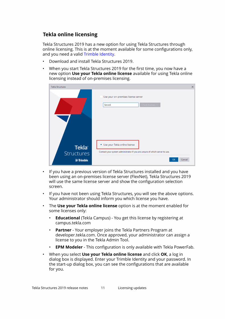
Tekla Structures 2019 has a new option for using Tekla Structures throughonline licensing. This is at the moment available for some configurations only,and you need a valid Trimble Identity.
• Download and install Tekla Structures 2019.
• When you start Tekla Structures 2019 for the first time, you now have anew option Use your Tekla online license available for using Tekla onlinelicensing instead of on-premises licensing.
• If you have a previous version of Tekla Structures installed and you havebeen using an on-premises license server (FlexNet), Tekla Structures 2019will use the same license server and show the configuration selectionscreen.
• If you have not been using Tekla Structures, you will see the above options.Your administrator should inform you which license you have.
• The Use your Tekla online license option is at the moment enabled forsome licenses only:
• Educational (Tekla Campus) - You get this license by registering atcampus.tekla.com
• Partner - Your employer joins the Tekla Partners Program atdeveloper.tekla.com. Once approved, your administrator can assign alicense to you in the Tekla Admin Tool.
• EPM Modeler - This configuration is only available with Tekla PowerFab.
• When you select Use your Tekla online license and click OK, a log indialog box is displayed. Enter your Trimble Identity and your password. Inthe start-up dialog box, you can see the configurations that are availablefor you.
Tekla Structures 2019 release notes 11 Licensing updates
• You can also change the licensing type later on through File --> Changelicense server , or by clicking the Change license server option in theTekla Structures start-up dialog box.
Offline use
• Partner works without an active internet connection for 7 days at a time:open a model and select the Stay signed in check box when signing inonline.
• Educational works offline for 24 hours.
• EPM Modeler works offline for 24 hours.
For administrators
The advanced option XS_LICENSE_SERVER_SELECTION can be used tooverride the behavior of Tekla Structures at start-up and to disable the option:
• Use your on-premises license server: The license server info mustalready be specified in order for this to work.
• Use your Tekla online license: Tekla Structures will prompt for sign in toTrimble Identity.
When this advanced option is set to either 1 or 2, Tekla Structures will notshow the dialog at start-up, unless the license server info is missing or there isa problem connecting to Trimble Identity. The value 1 will enable the Use youron-premises license server option and 2 the Use your Tekla online licenseoption. For this advanced option to work, it has to be set using one of thefollowing methods:
• Windows environment variable:
• Windows 10: Open Settings, search for “Edit the system environmentvariables”, click Environment Variables, add a user or system variable,enter XS_LICENSE_SERVER_SELECTION for the name, and 1 or 2 forthe value.
• Previous versions of Windows: Open Control Panel, click System -->Advanced system settings --> Environment Variables , add a user orsystem variable, enter XS_LICENSE_SERVER_SELECTION for the name,and 1 or 2 for the value.
Tekla Structures 2019 release notes 12 Licensing updates

• Batch file for starting Tekla Structures:
• Create a batch file (a text file that has either .bat or .cmd fileextension) with the following content:
set XS_LICENSE_SERVER_SELECTION=2start /D "C:\Program Files\Tekla Structures\2019\nt\bin\" TeklaStructures.exeexit /B 0
Also see the following articles:
Tekla Structures 2019 release notes 13 Licensing updates

• How to set a license server address without using the Tekla Structures userinterface
• Managing Tekla accounts and model sharing licenses
Updates in Tekla License Borrow Tool
To borrow a license using Tekla License Borrow Tool, you need to specify thelicense server and the product ID file (.tpi) that is specific for the licenseserver. Now you can do this in one dialog box.
• Open Tekla License Borrow Tool.
• When you open Tekla License Borrow Tool for the first time, the new Setupdialog box is displayed, where you can enter the port number and thehostname (computer name) of the license server in the Server box in theformat port@hostname, for example, 27007@server_hostname. Thenclick Browse and select the product ID file.
When you click OK, the Products area in the Tekla License Borrow Tool isupdated showing the available licenses, which you can now borrow.
Tekla Structures 2019 release notes 14 Licensing updates

• There is also a new button Setup in the window, which you can use tochange the license server or the product ID. You no longer need to restartto borrow from another license server.
• You can now return all licenses at the same time to multiple license servers.
For more information about license borrowing, see Borrowing licenses forusing Tekla Structures offline.
Product name changes in licensing
Old name New nameTekla Structures License Server Tekla License ServerTekla Structures Licensing Service Tekla Licensing ServiceTekla Structures LicenseAdministration Tool
Tekla License Administration Tool
Tekla Structures License Borrow Tool Tekla License Borrow Tool
Tekla Structures 2019 release notes 15 Updates to start screen, side pane, Quick Launch,and project properties

1.3 Updates to start screen, side pane, Quick Launch, andproject propertiesTekla Structures 2019 comes with a renewed user interface. The TeklaStructures 2019 user interface introduces a new, neutral color scheme,emphasizing the clarity of the ribbon and icons. This new blue-based colorscheme is in accordance with the color scheme of other Trimble products.
Start screen updatesThe start screen of Tekla Structures 2019 has been updated.
• All tabs of the start screen now have their own dedicated views.
• There is a new Shared models tab that includes the Tekla Model Sharingmodels. If you want to open a model that has been shared by using TeklaModel Sharing, you need to be logged in with your Trimble Identity.
• When you select a model on the Recent or on the All models tab, and theselected model does not have a thumbnail yet, a hyperlink is shown. Whenyou click the hyperlink, Tekla Structures displays a message which givesinstructions on how to create a thumbnail.
• When you select a model on the Recent or on the All models tab, theOpen button has a small arrow that opens a drop-down menu thatcontains the Convert to multi-user model, Convert to single-user modelor Exclude from sharing button, depending on the type of the model.
• On the Recent and All models tabs, you can sort each of the columns.Additionally, you can change the order and size of the columns by draggingthem.
• If the Recent tab is empty, then the All models tab is shown.
If the All models tab is empty, then the New tab is shown.
• If you want to remove a model from the list of models on the Recent tab,right-click a model and select one of the options.
Tekla Structures 2019 release notes 16 Updates to start screen, side pane, Quick Launch,and project properties

• Delete the selected item: remove the selected model from the list
• Clear all: remove all the models from the list
• Clear invalid entries: remove all invalid models from the list, such asdeleted models that cannot be opened anymore
• On the New tab, you can hide the model templates that you do not need,or mark the important templates as favorites.
1. Select a model template in the list.
2. Right-click and select Favorite or Hidden.
If you marked a template as Favorite, it is placed on top of thetemplate list. Alternatively, use the star icon on the template to mark itas Favorite, or to remove the marking.
If you marked a template as Hidden, it is removed from the templatelist. Select the Show hidden items check box to show it again.
• If you have collapsed the side sections, such as Your current TeklaStructures setup and Notifications, the side sections now remembertheir collapsed state.
• New command line capabilities have been added. You can now create newmodels or open an autosaved version of the model by adding the target inthe Tekla Structures shortcut.
For example:
Open an existing model TeklaStructures.exe "C:\TeklaStructuresModels\My ExistingModel"
Open an existing model(autosaved)
TeklaStructures.exe "C:\TeklaStructuresModels\My ExistingModel" /autosaved
Create a new model (notemplate)
TeklaStructures.exe /create:"C:\TeklaStructuresModels\automaticallycreated"
Create a new model(with template)
TeklaStructures.exe /create:"C:\TeklaStructuresModels\automaticallycreated" /modelTemplate:"Cast-in-Place"
Create a new multi-usermodel
TeklaStructures.exe /create:"C:\TeklaStructuresModels\automaticallycreated" /server:"my-server:1234"
Tekla Structures 2019 release notes 17 Updates to start screen, side pane, Quick Launch,and project properties

Tekla Structures 2019 release notes 18 Updates to start screen, side pane, Quick Launch,and project properties
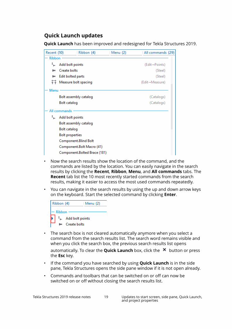
Quick Launch updatesQuick Launch has been improved and redesigned for Tekla Structures 2019.
• Now the search results show the location of the command, and thecommands are listed by the location. You can easily navigate in the searchresults by clicking the Recent, Ribbon, Menu, and All commands tabs. TheRecent tab list the 10 most recently started commands from the searchresults, making it easier to access the most used commands repeatedly.
• You can navigate in the search results by using the up and down arrow keyson the keyboard. Start the selected command by clicking Enter.
• The search box is not cleared automatically anymore when you select acommand from the search results list. The search word remains visible andwhen you click the search box, the previous search results list opensautomatically. To clear the Quick Launch box, click the button or pressthe Esc key.
• If the command you have searched by using Quick Launch is in the sidepane, Tekla Structures opens the side pane window if it is not open already.
• Commands and toolbars that can be switched on or off can now beswitched on or off without closing the search results list.
Tekla Structures 2019 release notes 19 Updates to start screen, side pane, Quick Launch,and project properties

• The Quick Launch search results on the ribbon, in the file menu, and inthe side pane are highlighted with yellow color.
• The Quick Launch search list now lists separately the local TeklaWarehouse collections, instead of listing all the local collections and localpackages. The Tekla Warehouse search content is visible only if there areany search results to be shown. Quick Launch shows the number of founditems on a button that opens the actual search in a web browser.
Side pane changesTekla Structures now opens only one side pane window at a time by default.
When you right-click a side pane button, you can select whether to use theSingle pane or the Stacked panes option.
Single pane: Tekla Structures opens a new side pane window and closes allthe other open side pane windows.
Stacked panes: Tekla Structures opens a new side pane window and keepsthe other open side pane windows stacked on top of each other.
Alternatively, you can click Ctrl+side pane button to open the side panewindows stacked on top of each other.
Note that the Single pane or the Stacked panes options do not affect thefloating panes. You can have one or more floating panes open while you areusing the Single pane option.
Tekla Structures 2019 release notes 20 Updates to start screen, side pane, Quick Launch,and project properties

New control for ribbon font sizeYou can now resize the ribbon font size. Use the Font size (Ribbon) slider inFile --> Settings --> User interface to adjust the ribbon font size.
You can set the ribbon font size between 9p and 14p. The default font size is11p. The setting is remembered when you close and start Tekla Structures.
New style for Project properties in the File menuThe Project properties in the File menu now works more like the propertypane.
• You can now start modifying the text fields without first enabling theediting.
• The changed text fields are highlighted with a light yellow backgroundcolor.
• When you have modified the Project properties, the Modify buttonbecomes active. Click Modify to apply the changes.
New scalable iconsAll commands, for example on the ribbon and in the file menu, now havescalable vector icons. Vector icons scale sharply to any size without the loss ofquality.
Previously the commands only had either a small or a big raster icon available.
1.4 Updates to part labels, clip planes, and windowoptionsIn Tekla Structures 2019 the part labels have new options, deleting clip planeshas been made easier, and the listing of view windows has changed.
Tekla Structures 2019 release notes 21 Updates to part labels, clip planes, and windowoptions

New Part label optionsPart labels on the View Properties --> Display dialog box now have newoptions.
Part labels have a new Show for list, where you can select for which parts youwant to show the part labels.
• All: Part labels are shown for all parts in the view.
• Selected: Part labels are only shown for the parts you select.
• Main part for selected: Part labels are only shown for the main parts ofthe assemblies you select.
• Main part for all: Part labels are shown for all main parts of all assemblies.
Note that if you select the Selected or the Main part for selected option,you need to first apply the changes to the view when the view is selected.Then continue to select the objects for which you want to show the partlabels.
Additionally, the Part label check box is now automatically selected when youclick Add > to add a property to the Part label list.
New clip plane command: Delete all clip planesYou can now delete all the clip planes at once. To delete all the clip planes in allthe open views, click View --> Delete all clip planes .
View windows in alphabetical orderWhen you now click Window to open the view list, the views are listed inalphabetical order.
1.5 New way to find and select objects in model anddrawings: Select by identifierIn Tekla Structures 2019 you can easily locate and select objects when youknow the GUID (globally unique identifier), the ID of an object, or the IFC GUIDof a reference object. This works both in the modeling mode and in thedrawing mode.
Tekla Structures 2019 release notes 22 New way to find and select objects in model anddrawings: Select by identifier

Reports and log files often contain information about the object GUID or ID.Previously, if you wanted to find these objects in the model or drawings, youhad to define a view filter or selection filter with the specific GUIDs or IDs. Nowyou can use the new Select by identifier command to find the objects basedon their GUID or ID. You can also use the IFC GUIDs of IFC reference objects.This is useful if you need to track updates and changes in IFC referencemodels.
Additionally, by using the Select by identifier command, you can inquire theGUIDs of selected objects, instead using the traditional inquiry.
To Do thisFind objects based onthe object GUID, ID, orIFC GUID identifier
1. • In the modeling mode: on the ribbon, clickthe small down arrow next to the arrow
button , and then click Selectby identifier.
• In the drawing mode: in Quick Launch,type Select by identifier.
The Select by identifier dialog box opens.
2. Copy the object identifier, for example from alog file, to the dialog box.
You can enter multiple identifiers in the dialogbox. Either enter each identifier on its ownrow, or separate them with semicolon ;.
3. To define the search, select the needed checkboxes.
Tekla Structures 2019 release notes 23 New way to find and select objects in model anddrawings: Select by identifier

To Do this• Reference objects: Tekla Structures selects
IFC objects based on their GUID or IFCGUID.
• Keep selection: Tekla Structures keeps thecurrently selected object and appends itwith new selection.
• Zoom to selected: Tekla Structures selectsthe object and zooms to it.
4. Click Select.
Tekla Structures selects the objects based onthe GUID in the model or in the drawing.
If there are identifiers that are not found in themodel or in the drawing, they are listed in thestatus bar as identifier?.
Find a model object in adrawing
You can select an object in a model, get itsidentifier, and then find it in a drawing based onthe identifier.
1. In the modeling mode: on the ribbon, click thesmall down arrow next to the arrow button
, and then click Select byidentifier.
The Select by identifier dialog box opens.
2. Select an object or objects in the model.
3. Click Get.
The Select by identifier dialog box lists theidentifiers of the selected objects.
If you want to get IFC GUIDs, ensure that theReference objects check box is selected.
4. Keep the dialog box open.
5. Open a drawing.
6. In the drawing mode, click Select to find theobjects in the drawing.
You can then continue working with the foundobjects.
Tekla Structures 2019 release notes 24 New way to find and select objects in model anddrawings: Select by identifier

To Do thisFind a drawing object ina model
You can select an object in a drawing, get itsidentifier, and then find it in a model based on theidentifier.
1. In the drawing mode: in Quick Launch, typeSelect by identifier.
The Select by identifier dialog box opens.
2. Select an object or objects in the drawing.
3. Click Get.
The Select by identifier dialog box lists theidentifiers of the selected objects.
4. Keep the dialog box open.
5. Close the drawing.
6. In the modeling mode, click Select to find theobjects in the model.
You can then continue working with the foundobjects.
1.6 Radial grids and grid properties in the property paneYou can now create truly radial grids. Previously, you could create onlyrectangular grids. Use the radial grids when you model round or curvedstructures, such as round columns, towers, tanks, circular platforms, and soon. If needed, you can create a full 360 degree grid.
Tekla Structures 2019 release notes 25 Radial grids and grid properties in the propertypane

Additionally, now the properties of rectangular grids, radial grids, and singlegrid lines are accessed through the property pane.
1. On the Edit tab, click Grid --> Create radial grid .
Tekla Structures shows a preview of the grid.
You can modify the Radial grid properties in the property pane beforeinserting the grid. The grid preview changes according to the changes inthe property pane.
2. Pick a point in the model to indicate the origin of the grid, or click themiddle mouse button to accept the Radial grid property pane values.
• If you pick an origin point to the grid, the grid is created using theproperties in the property pane, and the origin is the location youpicked.
• If you click the middle mouse button, the grid is created using theproperties in the property pane, and to the origin defined in theproperty pane.
Tekla Structures 2019 release notes 26 Radial grids and grid properties in the propertypane

Modify radial grid
In addition to the Radial grid properties in the property pane, you can usedirect modification and the contextual toolbar to modify radial grids. Ensure
that Direct modification is switched on.
• You can drag the arc lines to change the radius.
• You can drag the straight lines to change the angle.
• You can add new grid lines between the existing grid lines, both arc linesand straight lines.
Tekla Structures 2019 release notes 27 Radial grids and grid properties in the propertypane

• You can change the grid labels by using the contextual toolbar.
• You can change the radius and the angle by using the keyboard.
Tekla Structures 2019 release notes 28 Radial grids and grid properties in the propertypane

Property pane for grids and grid lines
Now the properties of rectangular grids, radial grids, and single grid lines areaccessed through the property pane.
The grid properties now include Grid color and Label font size and color.Previously, these were available in advanced options.
1.7 New plate type for bent plates: stand-alone bentplateYou can now create stand-alone bent plates that do not require any inputparts. Use stand-alone bent plates to model both cylindrical and conical parts,such as hoods, hoppers, cones, and so on.
Tekla Structures 2019 release notes 29 New plate type for bent plates: stand-alone bentplate

Before you start to create stand-alone bent plates, ensure that Directmodification is switched on.
1. On the Steel tab, click Plate --> Create stand-alone bent plate .
2. Define the first radius of the bend:
a. Pick the center point.
b. Pick the start point for the arc.
c. Pick the end point for the arc.
The picking order defines the up direction. For example, if you create anarc on the xy plane in the counterclockwise direction, the up directionpoints to the positive z axis, according to the right-hand rule.
3. Pick a point to define the height of the bend.
Tekla Structures 2019 release notes 30 New plate type for bent plates: stand-alone bentplate
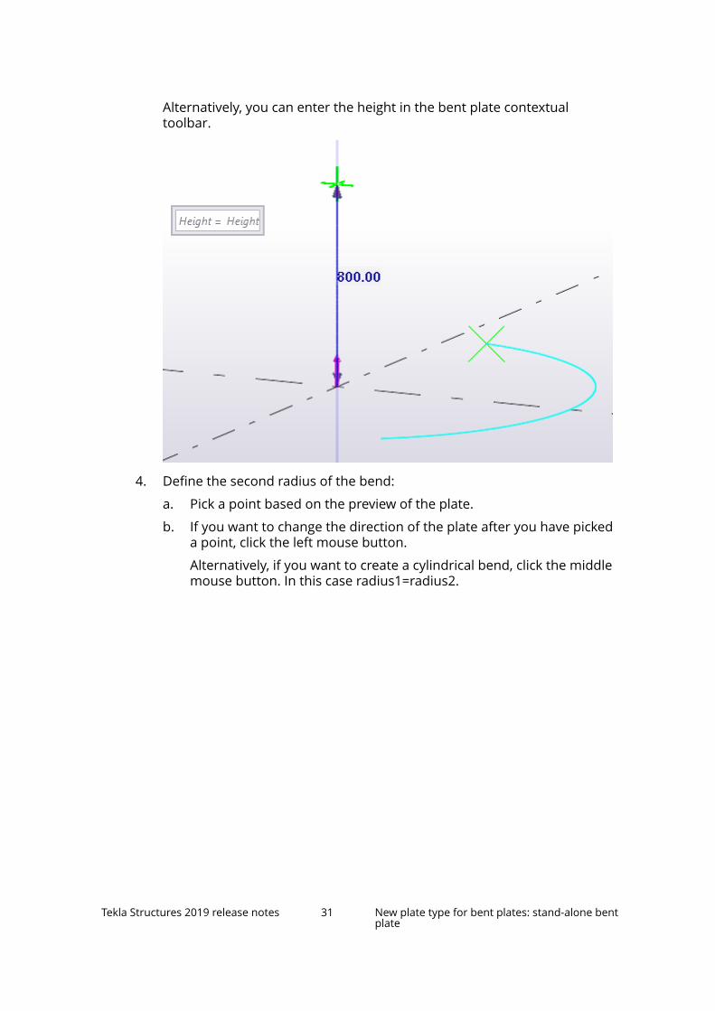
Alternatively, you can enter the height in the bent plate contextualtoolbar.
4. Define the second radius of the bend:
a. Pick a point based on the preview of the plate.
b. If you want to change the direction of the plate after you have pickeda point, click the left mouse button.
Alternatively, if you want to create a cylindrical bend, click the middlemouse button. In this case radius1=radius2.
Tekla Structures 2019 release notes 31 New plate type for bent plates: stand-alone bentplate

5. To complete the bent plate creation, click the middle mouse button.
Modify the shape of a stand-alone bent plate
Use direct modification dimension values and handles to modify the bentplate shape.
Tekla Structures 2019 release notes 32 New plate type for bent plates: stand-alone bentplate

• You can change the angle, radiuses and height of the bend by entering newdimension values.
• You can drag and stretch the edges of the bent plate.
Tekla Structures 2019 release notes 33 New plate type for bent plates: stand-alone bentplate
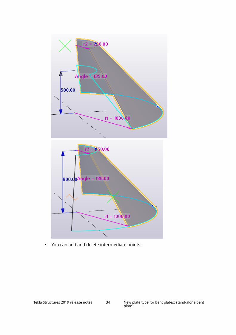
• You can add and delete intermediate points.
Tekla Structures 2019 release notes 34 New plate type for bent plates: stand-alone bentplate

• You can create unfolded drawings of the stand-alone bent plates.
Limitations
• Tekla Structures does not support full 360 degree stand-alone bent plates.However, you can create 359 degree plates instead.
• Use the local coordinate system in drawing creation.
• Unfolded drawings of less than 180 degree conical bent plates workcorrectly. However, with more than 180 degree conical bent plates theremight be some unexpected results in the drawing creation.
1.8 New curved construction objects and otherimprovementsTekla Structures 2019 introduces two new construction objects, constructionarc and construction polycurve, and a new command to copy constructionobjects. Construction circles and lines have also been improved.
Construction arcYou can create construction arcs by picking three points in the 3D space in themodel.
Start the Construction object --> Arc command on the Edit tab, and then usethe contextual toolbar to specify which set of point you want to pick:
For example, you can pick the center point, start point, and end point of thearc:
Tekla Structures 2019 release notes 35 New curved construction objects and otherimprovements
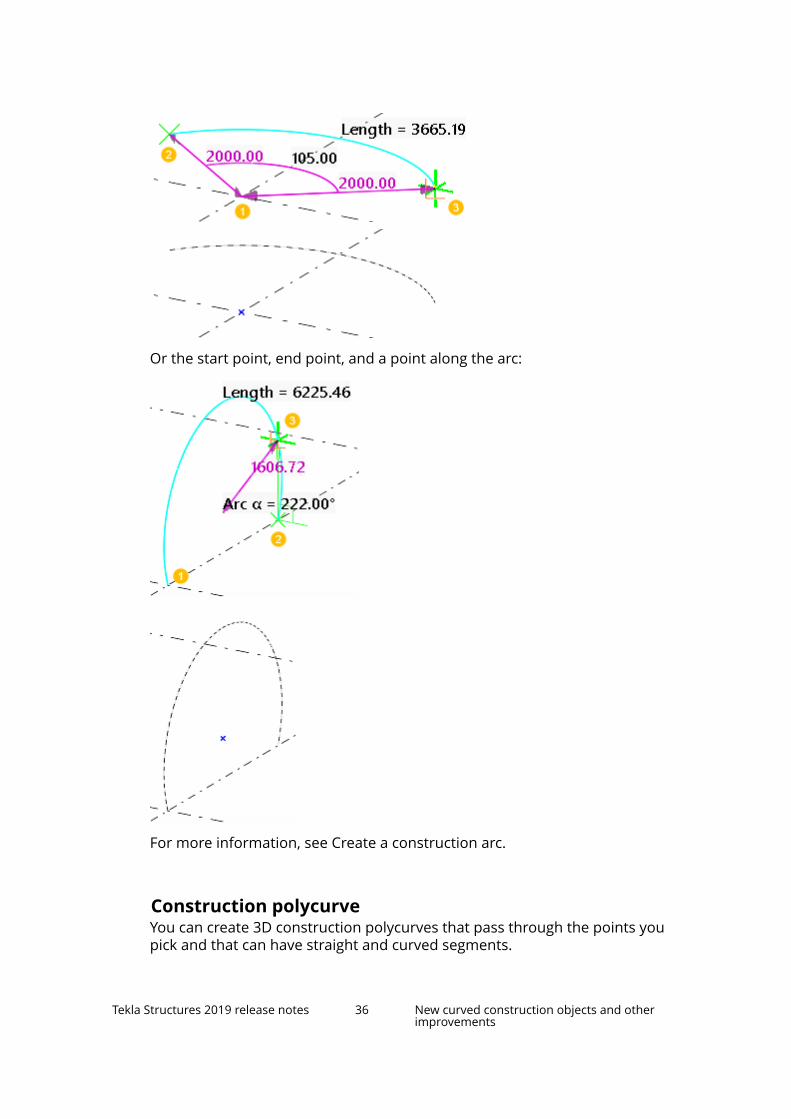
Or the start point, end point, and a point along the arc:
For more information, see Create a construction arc.
Construction polycurveYou can create 3D construction polycurves that pass through the points youpick and that can have straight and curved segments.
Tekla Structures 2019 release notes 36 New curved construction objects and otherimprovements

Start the Construction object --> Polycurve command on the Edit tab. Usethe contextual toolbar to switch between creating straight and curvedsegments, and then click the middle mouse button to complete the polycurve.
For more information, see Create a construction polycurve.
Copy construction objects with offsetYou can copy construction lines, circles, arcs, and polycurves in the directionthat you indicate, and using the offset values that you specify. For example,you can create new circles and arcs centered in the same location as theoriginal circle or arc, and adjust the radiuses using the offset values.
For more information, see Copy a construction object with offset.
Modify construction objectsYou can now change a construction line to an arc. Just drag the arc symbol
at the line midpoint.
To change a construction arc to a line, delete the arc midpoint .
For more information on how to use direct modification handles to modifyconstruction objects, see Modify a construction object.
Tekla Structures 2019 release notes 37 New curved construction objects and otherimprovements

Improvements in construction circles and lines• The command Edit --> Construction object --> Circle replaces the two
previous commands Circle using center point and radius and Circleusing three points.
You can now specify using the contextual toolbar which three points youwant to pick in the 3D space in the model to create a construction circle.The contextual toolbar appears after you have started the command.
• You can now change the line type of the construction lines and circles usingtheir property panes.
The advanced options XS_CONSTRUCTION_LINE_LINE_TYPE and XS_CONSTRUCTION_CIRCLE_LINE_TYPE that were previously used forchanging the line types have now been removed.
• Construction circles now have the standard file.
You can also save other property files for construction circles.
1.9 Modeling and detailing improvementsTekla Structures 2019 comes with many improvements in modeling anddetailing features.
Tekla Structures 2019 release notes 38 Modeling and detailing improvements

Improvements in orthogonal snapping• Snapping has been improved in Tekla Structures 2019 to make it work
better with the Ortho tool.
Previously, when Ortho was on, Tekla Structures remembered the lastplane and used the last picked point as a reference point, and continued tosnap to the plane where you had last picked a point. This resulted inunwanted snapping results, for example, parts were created to a differentplane than expected.
Now, when you interrupt a command, the reference point information iscleared. This means that there is no reference point information, meaningthe last picked point, that the orthogonal snapping could use. This resultsin more accurate snapping.
When you need to use the reference points, set the reference pointmanually by pressing the Ctrl key and picking a point when you run acommand.
• Previously, when the Ortho tool was active, the snapping distances wereincorrectly rounded. This has now been fixed.
• When using orthogonal snapping, the snap points are now shown withperpendicular snap symbols.
Tekla Structures 2019 release notes 39 Modeling and detailing improvements

Improvements in bolt holesThere is now a new option in the Bolt properties that you can use to specifywhich plies of the connection do not get holes.
To do this:
1. Go to the Holes section in the Bolt property pane.
2. Next to Parts with slotted holes, select the desired Special hole checkboxes.
3. In the Special hole type list, select No hole.
4. Click Modify.
The No hole option is also available for bolts in the system and customcomponents.
Improvements in weldsIf you are following the ISO standard (2553) for welds and have the advancedoption XS_AISC_WELD_MARK set to FALSE, you can now specify whether thefillet weld size determines the leg length or the throat thickness.
Set the new advanced option XS_ISO_LEG_LENGTH_AS_WELDSIZE to:
• TRUE to use the weld size as the leg length (z) of the fillet welds.
Tekla Structures 2019 release notes 40 Modeling and detailing improvements
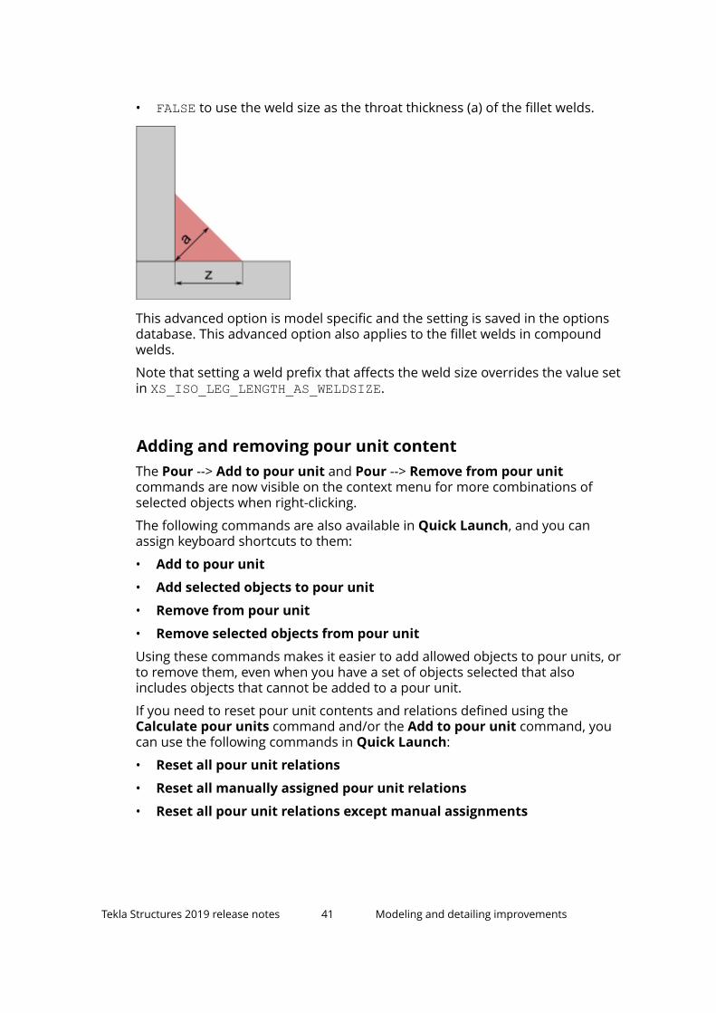
• FALSE to use the weld size as the throat thickness (a) of the fillet welds.
This advanced option is model specific and the setting is saved in the optionsdatabase. This advanced option also applies to the fillet welds in compoundwelds.
Note that setting a weld prefix that affects the weld size overrides the value setin XS_ISO_LEG_LENGTH_AS_WELDSIZE.
Adding and removing pour unit contentThe Pour --> Add to pour unit and Pour --> Remove from pour unitcommands are now visible on the context menu for more combinations ofselected objects when right-clicking.
The following commands are also available in Quick Launch, and you canassign keyboard shortcuts to them:
• Add to pour unit
• Add selected objects to pour unit
• Remove from pour unit
• Remove selected objects from pour unit
Using these commands makes it easier to add allowed objects to pour units, orto remove them, even when you have a set of objects selected that alsoincludes objects that cannot be added to a pour unit.
If you need to reset pour unit contents and relations defined using theCalculate pour units command and/or the Add to pour unit command, youcan use the following commands in Quick Launch:
• Reset all pour unit relations
• Reset all manually assigned pour unit relations
• Reset all pour unit relations except manual assignments
Tekla Structures 2019 release notes 41 Modeling and detailing improvements

Improvements in placing items in the modelIt is now easier to add and move items in the model in the same way ascustom parts, and to adjust item location and rotation using the axis androtation handles.
Shape cleaner toolIf some previously imported shapes cause missing faces or edges in items ordrawings, you can use the new Shape cleaner application for cleaning theshape geometries in Tekla Structures models. Cleaning means that TeklaStructures investigates and corrects the shape geometry and tries to createsolid objects. This is useful with shapes that have been imported to TeklaStructures models prior to version 2018i and are migrated to version 2018i ornewer. Shape cleaner provides an option to create backups of the shapegeometry files and to revert to the original files if you are not happy with thecleaning result.
Shape cleaner is available in the Applications & components catalog.
Numbering improvementsIn the Numbering Setup dialog box, Phase has been changed to Assemblyphase. Now the Assembly phase setting only affects the numbering ofassemblies, not the parts. This means that only the assembly phase of
Tekla Structures 2019 release notes 42 Modeling and detailing improvements
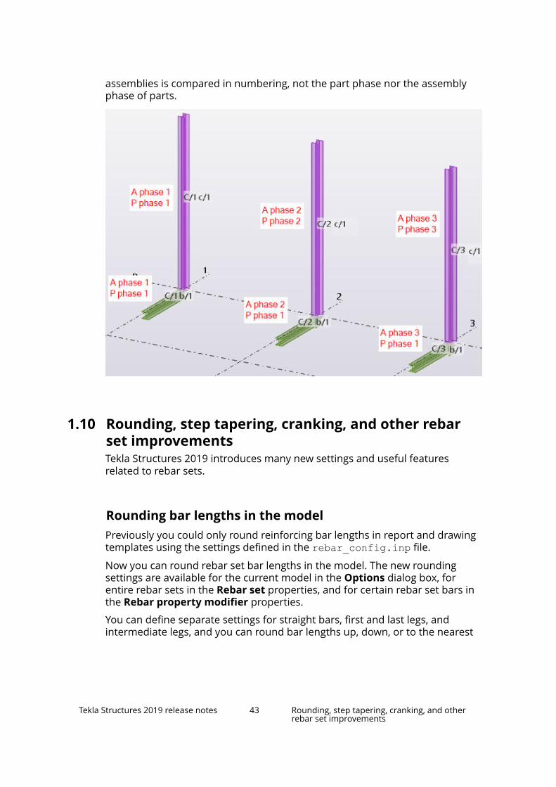
assemblies is compared in numbering, not the part phase nor the assemblyphase of parts.
1.10 Rounding, step tapering, cranking, and other rebarset improvementsTekla Structures 2019 introduces many new settings and useful featuresrelated to rebar sets.
Rounding bar lengths in the modelPreviously you could only round reinforcing bar lengths in report and drawingtemplates using the settings defined in the rebar_config.inp file.
Now you can round rebar set bar lengths in the model. The new roundingsettings are available for the current model in the Options dialog box, forentire rebar sets in the Rebar set properties, and for certain rebar set bars inthe Rebar property modifier properties.
You can define separate settings for straight bars, first and last legs, andintermediate legs, and you can round bar lengths up, down, or to the nearest
Tekla Structures 2019 release notes 43 Rounding, step tapering, cranking, and otherrebar set improvements

suitable number according to the rounding accuracy. There is also a separatesetting for defining how the bar lengths are rounded up at splitter locations.
Report and drawing templates continue using the rounding settings in therebar_config.inp file. If the rebar set bar lengths have already beenrounded in the model, and the rounding settings in the model and in therebar_config.inp file are in line, no additional rounding is done intemplates.
Step taperingYou can now define whether rebar set bars are tapered at slanted part edges,for example, and how the tapering steps are created. There are new steptapering settings for the current model in the Options dialog box, for entirerebar sets in the Rebar set properties, and for certain rebar set bars in theRebar property modifier properties.
You can define tapering step values separately for straight bars, first and lastlegs, and intermediate legs. Using the rebar set or property modifierproperties, you can also define the number of bars in the one tapering step.
Create rebar set modifiers using new contextual tabYou can now create rebar set modifiers for entire rebar sets, or for selectedbar groups or bars. Use one of the three reinforcement selection switches
to select the rebar set bars for which you want to create a modifier.
Then use the modifier commands on the new Rebar set contextual tab thatappears at the right end of the ribbon. The contextual tab is only visible whenyou have rebar set bars selected.
The first button on the contextual tab is for defining how to place the modifierin the model and how many points to pick. In addition to the previous single
point and multiple points picking modes, a new picking mode is now
Tekla Structures 2019 release notes 44 Rounding, step tapering, cranking, and otherrebar set improvements

available for the selected rebar set bars. Click the Picking mode button tocycle through the three modes.
The Rebar set contextual tab also has commands for adding secondaryguidelines and leg faces to rebar sets.
Splitter improvements• You can now define standard and custom lapping and cranking properties
for rebar set bars using splitters. Use the new settings in the Rebar splitterproperties in the property pane, for example Split type, Lapping type, andthe entire Cranking section.
The standard values of the lapping and cranking properties are read fromthe rebar_database.inp file in the environment, firm, and/or projectfolders.
• The Bars to split setting is now Bars affected with the new additional 1/4option.
• The previous Lap type setting has been removed.
• When you are adding a splitter or when you select a splitter, the lengths ofthe affected bars are now shown in the model.
• If you want to create a splitter at a certain or rounded distance from a barend, and the dimension shown is measured from the other bar end, holddown Shift when you place the splitter in the model to switch themeasuring point to the other bar end.
Improvements in end detail modifiersThe following new settings are now available in the Rebar end detail modifierproperties in the property pane:
• Hook rotation: You can rotate bar end hooks out of the bar plane. Forexample:
• Adjustment type: You can extend or shorten the bar length according toan end offset or a specified leg length.
• The previous Threading section is now End preparations with some newsettings.
• The Custom properties section: Click the More button to access the user-defined attributes (UDAs) of the end detail modifiers.
Tekla Structures 2019 release notes 45 Rounding, step tapering, cranking, and otherrebar set improvements
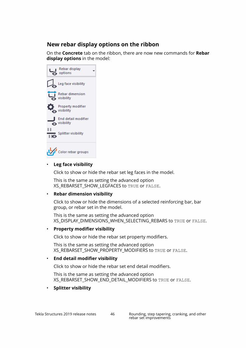
New rebar display options on the ribbonOn the Concrete tab on the ribbon, there are now new commands for Rebardisplay options in the model:
• Leg face visibility
Click to show or hide the rebar set leg faces in the model.
This is the same as setting the advanced optionXS_REBARSET_SHOW_LEGFACES to TRUE or FALSE.
• Rebar dimension visibility
Click to show or hide the dimensions of a selected reinforcing bar, bargroup, or rebar set in the model.
This is the same as setting the advanced optionXS_DISPLAY_DIMENSIONS_WHEN_SELECTING_REBARS to TRUE or FALSE.
• Property modifier visibility
Click to show or hide the rebar set property modifiers.
This is the same as setting the advanced optionXS_REBARSET_SHOW_PROPERTY_MODIFIERS to TRUE or FALSE.
• End detail modifier visibility
Click to show or hide the rebar set end detail modifiers.
This is the same as setting the advanced optionXS_REBARSET_SHOW_END_DETAIL_MODIFIERS to TRUE or FALSE.
• Splitter visibility
Tekla Structures 2019 release notes 46 Rounding, step tapering, cranking, and otherrebar set improvements

Click to show or hide the rebar set splitters.
This is the same as setting the advanced optionXS_REBARSET_SHOW_SPLITTERS to TRUE or FALSE.
• Color rebar groups
Click to use colors to indicate the bar groups within rebar sets instead ofthe rebar set classes.
This is the same as setting the advanced optionXS_REBARSET_COLOR_BARGROUPS to TRUE.
Improvements in modifying leg facesWhen you modify rebar sets by dragging leg faces, the following new andimproved methods are now available:
• If you drag a leg face, the connected leg face planes remain intact.
• If you hold down Alt and drag a leg face, the leg face size remains thesame, but the connected leg face planes may change.
This is what previously happened when you dragged a leg face.
• If you hold down Shift and drag a leg face, the leg face is detached fromthe connected leg faces.
This is what previously happened when you held down Alt and dragged aleg face.
• If you hold down Ctrl and drag a leg face, a new parallel leg face is created.
Other improvements• When you create crossing rebar set bars, you can modify the distribution
length of the bars by adjusting the length of the rebar set guideline beforethe bars are added to the model. When the Rebar set --> Create crossingrebars command is running, click the new button on the contextualtoolbar and then shorten or lengthen the guideline by dragging its endhandles .
• You can now work with rebar set modifiers, splitters, guidelines, and legfaces also using the Select rebar groups selection switch or the Selectsingle rebars selection switch. Previously this was only possible using theSelect rebar sets switch.
Tekla Structures 2019 release notes 47 Rounding, step tapering, cranking, and otherrebar set improvements

• All rebar set modifiers including splitters have the following new settings:
• Bars affected for defining how many bars can be modified in the samelocation.
This is similar to the Bars to split setting that the splitters previouslyhad, with the new additional 1/4 option.
• First affected bar for defining which is the first bar to be modified,starting from the first end of the modifier.
• An arrowhead symbol close to the midpoint of each rebar setmodifier now indicates the direction of the modifier, and the left and rightsides of a splitter, for example. The arrow points from the start towards theend of the modifier.
The primary and secondary guidelines of rebar sets also have the directionarrow.
• When you select a single rebar set bar or bar group, the modifiers andsplitters that affect the selected bars are shown in the model. Also, theother bars that are not selected in the rebar set are shown as semi-transparent.
When you select a modifier or splitter, the rebar set bars that are affectedby this modifier or splitter are indicated in the model. The other,unaffected bars are shown as semi-transparent.
With the rendering option Show only selected part (Ctrl+5), the affectedbars are made visible when you select a modifier or splitter.
• The rebar set modifiers are now shown more clearly in the model, usingthicker and solid lines on top of other objects.
• When you create rebar sets for concrete parts using the Createlongitudinal rebars, Create crossing rebars, and Create planar rebarscommands, Tekla Structures automatically cuts the new rebar sets usingthe existing cuts in the concrete parts. This means that you do not need tocreate separate cuts for new rebar sets.
However, you can separately modify and delete the cuts of rebar sets andthe cuts of concrete parts. Also, if you add a new cut to a concrete part withrebar set, the rebar sets are not automatically cut.
• You can now create rebar set bars at the inner sides of cuts and hollowprofiles.
• It is now possible to inquire rebar set bar groups in the model and indrawings.
• If rebar set group coloring is active, all rebar set bars whose group type isunknown are now colored using different colors.
• New template attributes (page 109) are available for reinforcement.
Tekla Structures 2019 release notes 48 Rounding, step tapering, cranking, and otherrebar set improvements
1.11 Clone selected in drawingsWhen editing GA drawings, you often need to add annotations, dimensioningand styles for building objects as a repetitive task. The new Clone selectedfeature clones existing annotation objects, drawing object representations andstyles from selected source objects to selected target objects in GA drawings.With this feature, you can reduce manual repetition considerably.
The Clone selected command allows you to clone previously createdannotation objects and drawing object representations among the assembliesor cast units with the same type and similar shape.
You can clone annotation objects and drawing object representations insideone drawing view or among different drawing views.
Clone selected recognizes the following types of drawing content:
• Associative and independent annotation objects: dimensions, marks, texts,symbols, text files, and DWG/DXF files
• Sketch objects, such as circles, rectangles, and polygons
• Object representations and styles: line colors, line types, hatches
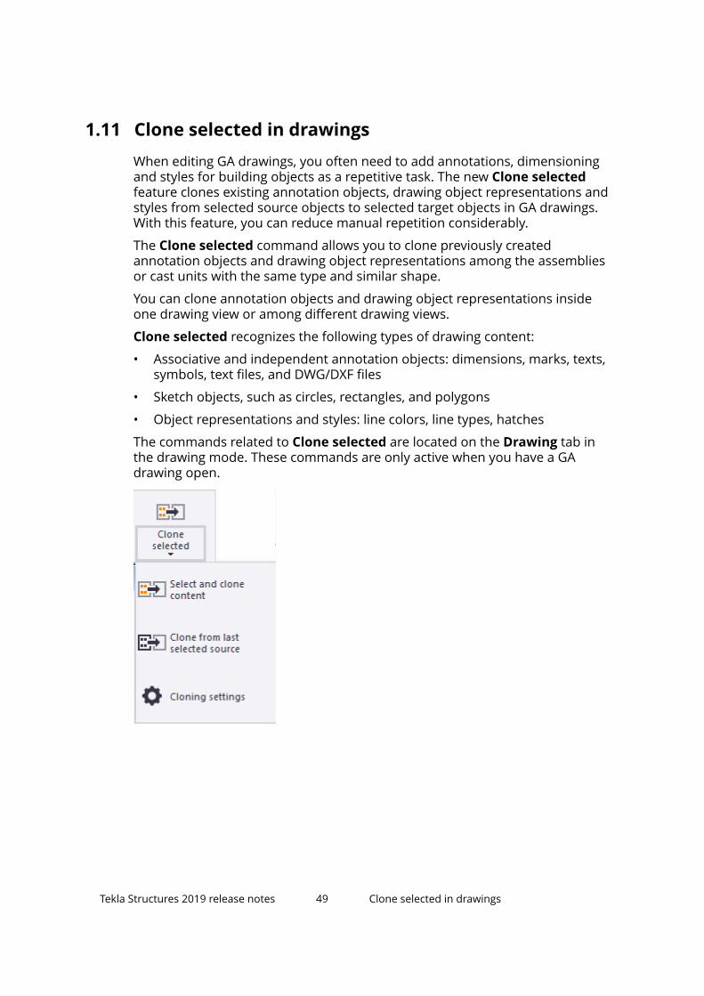
The commands related to Clone selected are located on the Drawing tab inthe drawing mode. These commands are only active when you have a GAdrawing open.
Tekla Structures 2019 release notes 49 Clone selected in drawings

• Before you clone, you may want to define how and what to clone. To dothis, select Cloning settings:
• Merge: Overrides all annotation objects and building object propertiesin the cloning target by cloning matching content from the cloningsource. This is the default mode.
• Keep all: Keeps the existing annotation objects and building objectproperties in the cloning target and only clones the missing ones fromthe cloning source.
• Discard all: Discards all annotation objects and building objectproperties in the cloning target and clones all selected content from thecloning source.
• Clone building object properties and styles: Clones building objectproperties such as line colors and types, hatching styles and otherrepresentation properties in the building object properties dialog boxfor parts, reinforcement, bolts and welds. This option is selected bydefault.
• Place marks and associative notes according to protection settings:Automatically runs the Arrange drawing objects near currentlocation command for all associative annotation objects except for levelmarks, weld marks, dimensions and independent annotation objects.This option positions the annotation objects in the target so that theydo not overlap other objects. Objects located in a free location are notmoved, and overlapping objects are moved as close to the currentlocation as possible.
• Before you clone, first modify the source object so that it contains thedesired dimensions and annotations, and adjust the source objectproperties.
• To clone, click Clone selected on the Drawing tab. Next, select the sourceobjects by clicking the objects or using area selection. Press the middle
Tekla Structures 2019 release notes 50 Clone selected in drawings

mouse button to complete the selection. Next, select the target objects byclicking the objects or using area selection. Press Esc to stop the cloning.
• You can also select the objects using Drawing content manager andselection filters. You can deselect objects by holding down Ctrl andclicking the selected object.
• You can also clone from the source that you selected last. To do this,click Clone from last selected source on the Drawing tab.
• When cloning dimensions, remember to set the dimension associativityrules before cloning to avoid the situation where it is unclear whichobject a dimension point is associated to. For more information, seeDisplay dimension associativity.
Below on the left a detailed footing and on the right a similar footing that willbe the target of cloning:
Below, the detailed footing on the left has been used as source for the targeton the right. The details have been cloned to the target.
Tekla Structures 2019 release notes 51 Clone selected in drawings

Limitations
• Some drawing objects cannot be used as source objects, such as grid lines,section view symbols, drawing view names, neighbor parts and neighborreinforcement. These objects types will not be highlighted during/after areaor single selection. Messages on the status bar indicate if an object cannotbe selected.
• Clone selected cannot be used with pour units.
• To achieve accurate cloning results, all dimensions should be associatedeither to grid line intersection points or to intersections of building objectsand grid lines.
Dimension point associated to intersection of two perpendicular grid lines:
Dimension point associated to intersection of part side and grid line:
Tekla Structures 2019 release notes 52 Clone selected in drawings

Note that all dimension points that are located in an arbitrary positionalong the grid lines in the source selection will be cloned to wrongcoordinates in the target.
• Clone selected cannot be used for cloning radial or curved dimensions.
• Cloning of annotations to mirrored objects created with the Mirrorcommand in the model does not produce accurate results.
• Cloning modes do not affect cloning of independent annotation objects orsketch objects. Listed object types will be copied to target as many times asClone selected is applied to the target objects.
• Dimensions will not be cloned if the viewing directions of the source andtarget drawing views do not match. In this case, a message is shown on thestatus bar.
For more information about cloning selected annotations and objectrepresentations and styles, see Clone selected in drawings.
1.12 Improvements in Drawing content manager, marksand notesThere are several improvements related to marks and notes. In Drawingcontent manager, you can now add new property columns to the list, andmodify, move and hide existing property columns. There are now some newbuilding object categories included. There is also a new command available onthe ribbon that aligns selected marks around a point.
Tekla Structures 2019 release notes 53 Improvements in Drawing content manager,marks and notes

Improvements in Drawing content manager
Add and modify property columns
You can now add new property columns to the Drawing content managerlist, and modify the existing property columns. Previously, the propertycolumns could not be edited, and the number of columns was fixed. You canalso remove columns, and change the column order. In addition, the editingdone to content manager categories is now saved in a specific xml file. Thegenerated file can be localized and used as a user-defined setup.
• To add a new property column in Drawing content manager, click thearrow button next to a category to expand the category, and then click the+ button on the property column title row.
• In the new Add/Edit properties dialog box, select the required propertyfrom the list on the left and drag it to the list on the right. Use the Searchbox for searching properties. You can add several properties to the samecolumn. Then enter the name for the property column and click OK.
Tekla Structures 2019 release notes 54 Improvements in Drawing content manager,marks and notes

• To add custom text in a column cell, select Custom text and type therequired text in the displayed Text box. The press Enter to add the customtext in the list on the right.
• To add any required property that is not listed in the available propertieslist, or to add a user-defined attribute defined in the object.inp file,select Custom property and type the required property or UDA in thedisplayed Property box. Then press Enter to add the property in the list onthe right.
• To show the property cells even though there is no value, select the Showempty fields of the column option.
• To change a property column, right-click the column name and select Edit.
• To remove a property column, right-click the column name and selectRemove.
• You can change the order of the existing columns in Drawing contentmanager by simply dragging the columns to the new position.
Tekla Structures 2019 release notes 55 Improvements in Drawing content manager,marks and notes

• You can hide category types from the list of visible categories by right-clicking Drawing content manager pane when no category is selected,and clicking the categories on the displayed list.
• In Tekla Structures 2019 onwards all generic properties are saved in theDrawingContentManagerCategories.xml file located by default inthe ..\ProgramData\Trimble\Tekla Structures\<version>\environments\common\system folder. All property columnmodifications (new columns, edited columns, column order) are saved inthe DrawingContentManagerCategories_<user>.xml file in the\attributes folder under the current model folder.
First, Tekla Structures tries to find the user-specific setting fileDrawingContentManagerCategories_ <user>.xml. If it cannot befound, Tekla Structures will next look forDrawingContentManagerCategories.xml.
You can convert the user-specific file to a generic one just by removing_<user> from the file name.
The folder search order for the generic settings file is the following:
• \attributes folder under the model folder
• Project folder (XS_PROJECT)
• Firm folder (XS_FIRM)
• System folder (XS_SYSTEM)
• Folder defined by the advanced option XS_USER_SETTINGS_DIRECTORY
Tekla Structures 2019 release notes 56 Improvements in Drawing content manager,marks and notes

New building object categories
• Connections and Neighbor reinforcement category types are nowavailable in Drawing content manager. Now you can check and editdrawing content for connections and neighbor reinforcement objects, suchas marks and associative notes, in the current drawing.
• All commands related to neighbor reinforcement objects and neighborreinforcement marks are available in the context menu. You can quicklyand easily:
• Add single rebar marks or associative notes to the selected singlerebars or group of rebars
• Add dimension marks, tag dimension marks or dimension lines to theselected group of rebars
• Adjust the location of the rebars in rebar groups
• Hide/show the reinforcement objects in drawings
• Add, modify or remove reinforcement marks
• Connection objects now have a symbol representation in drawings. Bydefault, the connection representation symbol is the symbol number 142 inthe xsteel.sym file in the ..\ProgramData\Trimble\TeklaStructures\<version>\environments\common\symbols\ folder. Youcan modify the connection representation symbol in Symbol Editor. Formore information about Symbol Editor, see Symbol Editor User's Guide.
Tekla Structures 2019 release notes 57 Improvements in Drawing content manager,marks and notes

• Connection objects are only highlighted in a drawing when you haveselected the objects from the Drawing content manager list, otherwiseconnection symbols are hidden.
• When you have selected a connection object from the Drawing contentmanager list, you can add, modify or remove connection marks.
• Note that only connection type of components are shown in theConnections category.
Align selected marks to a point
• The Annotations tab in the drawing mode has a new command Align to apoint for aligning selected marks around a point. This new command triesto avoid crossing leader lines.
If Ortho is on, the lines are placed in a 0, 90, 180, or 270 degree angle.
You can also hold down the middle mouse button during the command tochange the angle of the marks.
To use the command, select the marks to be aligned, select the commandand pick a point.
Tekla Structures 2019 release notes 58 Improvements in Drawing content manager,marks and notes

• The mark aligning commands are located in the new Align marks menu.
1.13 Layout editor improvementsPlacing and moving templates in drawing layouts is now much easier. Savingand closing of templates has also been changed.
• In Layout editor, placing templates in the drawing layout has beenimproved, and the templates are positioned automatically when you pick acorner or a midpoint on the drawing frame or on an existing template. Thetemplates now try to avoid overlapping with the existing templates. Theanchor snaps automatically to the closest corner or middle point of thedrawing frame or the existing template.
Anchoring suggestion while dragging revision template on top of drawingtitle template:
Snap point suggestion while dragging revision template over drawing titletemplate:
Tekla Structures 2019 release notes 59 Layout editor improvements

• In addition, moving the templates is now more straightforward, and youcan move templates just by dragging. When you drag, the templateattempts to position itself automatically, avoiding overlapping with theexisting templates. In the same way as when you are placing templates, theanchor snaps automatically to the closest corner or middle point of thedrawing border or the existing template.
• The Save as button has been changed to Save.
• The Close button has been removed. The layout editor mode closes whenyou close the Layout editor pane.
• The name of the first option Overwrite current layout in the Save layoutdialog box has been changed to more descriptive Save with the currentname in the model folder (all drawings using this layout will beupdated).
Tekla Structures 2019 release notes 60 Dimensioning improvements

1.14 Dimensioning improvementsThere are some important improvements in drawing dimensions. For example,you can now drag dimension points from handles, and display and change thedimension point associativity.
Dragging dimension points• Straight (linear) dimensions in drawings can now be modified by dragging
the dimension points from dimensio point handles.
• Dragging in single dimension lines: If you try to drag a dimension point to anew position that is located behind an existing dimension point, theselected dimension point will be deleted from the old position andrecreated in the new, preferred position. If you try to drag the point to thesame coordinate position where the existing point is already located, thedragged dimension point is dropped back automatically to the initialposition.
• Dragging in dimension sets: If you try to drag the dimension point into thearea between two points of neighbor dimension line, the selecteddimension point will be deleted from the old position and recreated in thenew, preferred position. If you try to drag the point to the same coordinateposition where the existing point is already located, the dragged dimensionpoint will be deleted from the old location and will be combined with theexisting one, after dropping to the new location.
Tekla Structures 2019 release notes 61 Dimensioning improvements

• Dragging a dimension point with a zero coordinate in running dimensionsallows you to change the coordinate of the start dimension point withoutrunning the Set dimension start point command.
• Note that if Drawing drag & drop switch in the Settings section in the Filemenu is activated, the dimension point handle can be dragged withoutselecting the handle first.
Display dimension associativity
Dimensioning points created in Tekla Structures are associated to the objectswhere the dimension points have been added. This allows the dimensions toupdate automatically when the objects are changed during modeling.
Sometimes the dimension point locations may be unclear due to orthogonalprojection. A dimension point might be not be associated to the desired objectbecause there are various other objects in the same point location. In drawingupdate or cloning, this may lead to unwanted dimensioning values orassociativity.
To avoid incorrect associativity, or to simply make the associativity selectiondistinct, there is now a new feature that allows you to check and change thedimension associativity rules in all types of drawings. This feature works onlywith straight dimensions.
• To change the dimension point associativity rule, select the desireddimension or dimension set. Next, click a dimension point associativityanchor. This displays the dimension associativity rule list, which shows theobjects where the dimension point can be associated. The Defaultassociativity rule is automatically selected by Tekla Structures. Click a rule inthe list to select it and associate the dimension point to a new object. Whenyou click the rule, the corresponding object is highlighted in the drawing.
Tekla Structures 2019 release notes 62 Dimensioning improvements

The corresponding grid lines are also highlighted. Click the drawingbackground to close the rule list.
• You can open several dimension associativity rule lists at a time by holdingdown Ctrl or Shift and clicking dimension point associativity anchors, orholding down Alt and using area selection.
• To open all associativity rules related to a selected dimension set, click thedimension set and select Show dimension associativity rules from thecontextual menu.
• You can change associativity rules by scrolling the mouse wheel while themouse cursor hovers over a rule list.
Tekla Structures 2019 release notes 63 Dimensioning improvements

• To select associativity rules related to same object types in all opened rulelists, double-click the desired rule. Selected rules will be highlighted withyellow color in all opened rule lists.
• The maximum number of shown rules in the rule list can be controlled withthe advanced option XS_INTELLIGENCE_MAX_RULE_COUNT. If the neededassociativity option is missing from the rule list, increase the number of theshown rules by changing the XS_INTELLIGENCE_MAX_RULE_COUNT value.
• The following attributes are shown in the rule list for the following buildingobjects:
• Steel parts: "NAME", "PART_POS", "PROFILE"
• Concrete objects: "NAME", "PROFILE"
• Polygon cuts: "NAME", "PROFILE"
• Reinforcement: "NAME", "REBAR_POS"
• Bolts: "NAME"
• Grid: Grid "NAME"
Tekla Structures 2019 release notes 64 Dimensioning improvements

• Intersection of grid line and building object side: Grid “NAME” or thelabel of the building object:
• Intersection of grid lines: Grid “NAME”/”NAME”:
• Pour units: Pour object "POUR_TYPE", # "POUR_NUMBER"
• If the Default option is selected, the dimension point will automaticallyselect which object to follow during the dimension update based on thenew position of the objects. Note that there might not be any rule in therules list that would correspond the behavior of the Default option.Selecting another option than the Default option makes it possible tocontrol which object will be followed during the dimension update.
Tekla Structures 2019 release notes 65 Dimensioning improvements
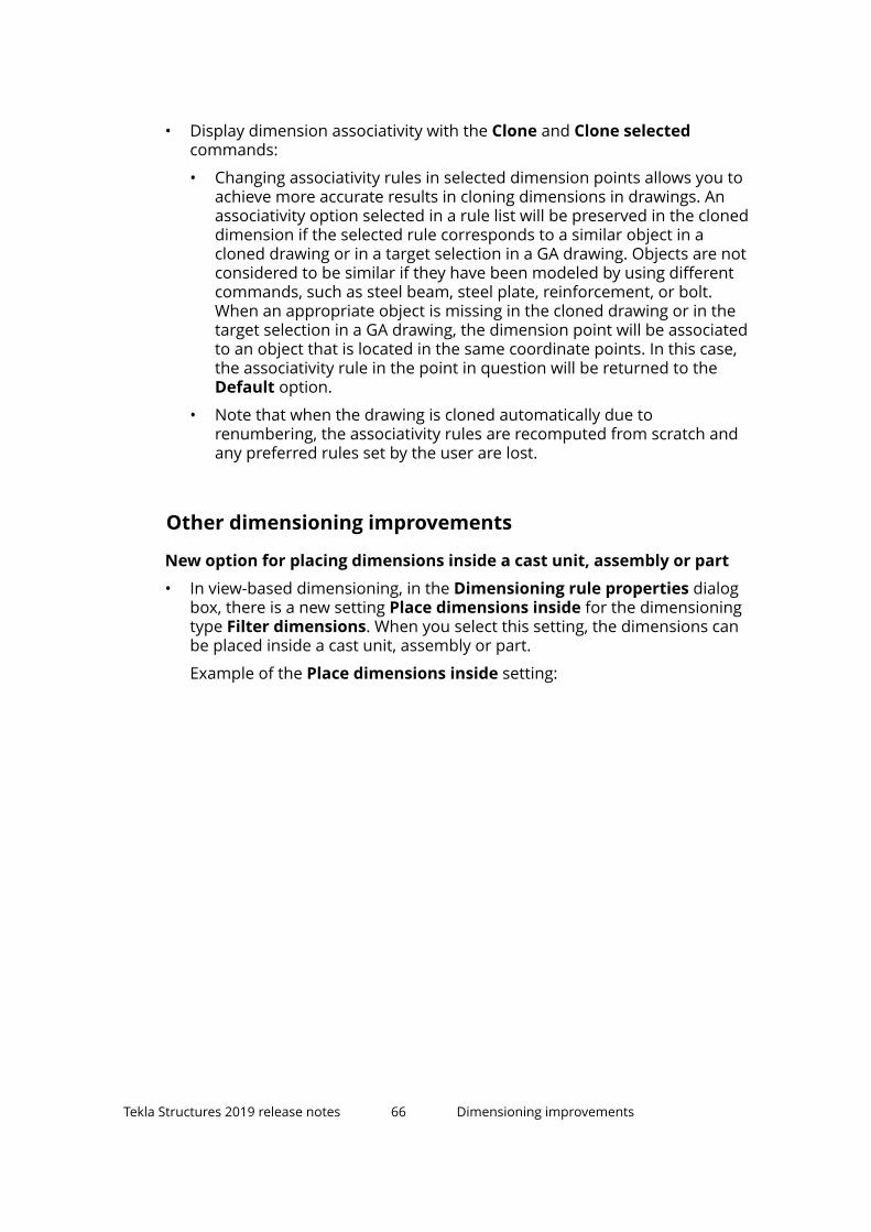
• Display dimension associativity with the Clone and Clone selectedcommands:
• Changing associativity rules in selected dimension points allows you toachieve more accurate results in cloning dimensions in drawings. Anassociativity option selected in a rule list will be preserved in the cloneddimension if the selected rule corresponds to a similar object in acloned drawing or in a target selection in a GA drawing. Objects are notconsidered to be similar if they have been modeled by using differentcommands, such as steel beam, steel plate, reinforcement, or bolt.When an appropriate object is missing in the cloned drawing or in thetarget selection in a GA drawing, the dimension point will be associatedto an object that is located in the same coordinate points. In this case,the associativity rule in the point in question will be returned to theDefault option.
• Note that when the drawing is cloned automatically due torenumbering, the associativity rules are recomputed from scratch andany preferred rules set by the user are lost.
Other dimensioning improvements
New option for placing dimensions inside a cast unit, assembly or part
• In view-based dimensioning, in the Dimensioning rule properties dialogbox, there is a new setting Place dimensions inside for the dimensioningtype Filter dimensions. When you select this setting, the dimensions canbe placed inside a cast unit, assembly or part.
Example of the Place dimensions inside setting:
Tekla Structures 2019 release notes 66 Dimensioning improvements
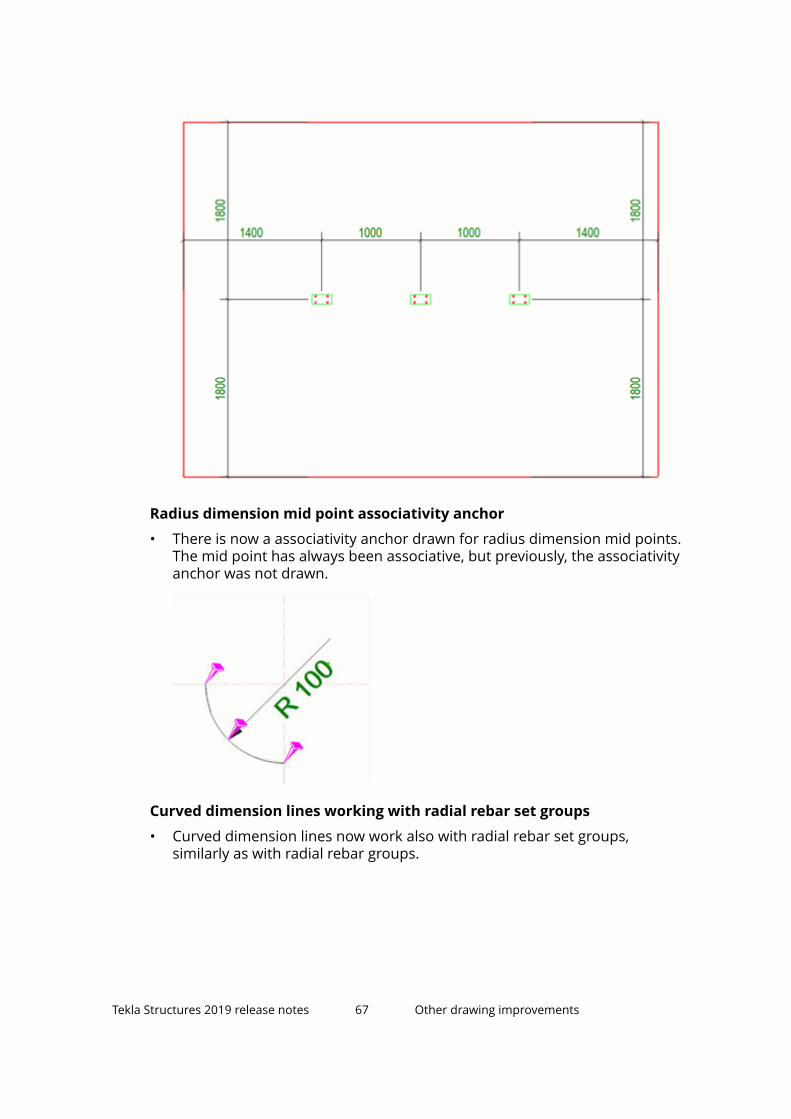
Radius dimension mid point associativity anchor
• There is now a associativity anchor drawn for radius dimension mid points.The mid point has always been associative, but previously, the associativityanchor was not drawn.
Curved dimension lines working with radial rebar set groups
• Curved dimension lines now work also with radial rebar set groups,similarly as with radial rebar groups.
Tekla Structures 2019 release notes 67 Other drawing improvements

1.15 Other drawing improvementsThere are a lot of other improvements in many of the drawing features. Forexample, you can now organize your documents in manual categories inDocument manager. Dragging in drawings has been made much easier andsimpler, and the rebar drawing tools have also been updated. Furthermore,drawing view labels have new alignment options.
Improvements in Document manager
Drawing list button name changed to Document manager
• On the Drawings & reports tab on the ribbon, the command button namehas been changed to Document manager.
• In Quick Launch, you can enter either document manager or drawinglist. The actual command name is Document manager (drawinglist).
Document manager category dialog box resizable
• The Document manager category dialog box has been improved to allowresizing in order to make search strings and other properties more easilyvisible. The category dialog box width is saved and restored from the datasaved in the model as the dialog box is closed and then re-opened.
Performance improvements
• Performance of some Document manager operations on drawings hasbeen improved.
Organize your documents in manual categories
Sometimes you may need to have a document category in Documentmanager for documents that would be difficult to categorize using the search.Now you can simply select documents, create a manual category and add yourdocuments there. You can also add documents to and remove documentsfrom existing manually created categories, and combine categories, bothsearch-based and manual ones. A manual category may contain bothdrawings and file documents.
Creating a manual category may be useful, for example, when you haveenabled the Show changes from the checkpoint set when the button isactivated feature in Document manager, and then when some documentshave changed and are listed, you can add the changed documents in a manualcategory.
To Do thisCreate a new manualcategory and adddocuments there
• Select the documents from the list, right-clickand select Manual category --> Add to new .Then type a name for the category, an optional
Tekla Structures 2019 release notes 68 Other drawing improvements

To Do thistooltip, and define other necessary settings.Then click Save.
Options are the same as in the search-basedcategories, except that the functionality related tosearch strings, and the Test button are missing ifthere are documents associated. If there are nodocuments associated, then the search controlsare visible and the category could become asearch-based category or a manual category.
The newly created or modified manual categoriesare saved to theDocumentManagerCategories_<user>.xml fileunder the current model folder.
Add documents to anexisting manual category
• Select the documents from the list, right-clickand select Manual category --> Add toexisting and then select the desired category.
All compatible manual categories are listed. Youcan add the selected documents to severalcategories.
Save recently changeddocuments in a newmanual category
• When you have enabled the Show changesfrom the checkpoint set when the button isactivated switch in Document manager, andthen when you disable this switch, you will getthe following message:Turning off 'Showchanges' will reset the changes checkpointand lose the history of which documentshave changed since the checkpoint was set.Are you sure you wish to continue?. SelectCreate new category.
You can also select to turn the switch off and losethe history.
Edit a manual category • Right-click the category in the category list andselect Edit.
Remove documentsfrom a manual category
Do one of the following:
• Select the documents from the list, right-click,select Manual category --> Remove from andthen select the category from which to removethe documents.
• Select manual categories first so that alldocuments in those categories are listed, right-click the list, and select Manual category -->Remove from selected .
Tekla Structures 2019 release notes 69 Other drawing improvements

To Do thisDelete a manualcategory
• Right-click the category in the category list, andselect Delete.
Improvements in Document manager search
• In Document manager, when you carry out a general search, which meansthat you are not defining specific properties to search for in the searchstring, the values you are searching for are only checked against propertiesthat are visible, and hidden column properties are now ignored.
New options for aligning view labelsPreviously, you could only center view labels horizontally by view frame or byview restriction box in drawing view label properties. Now you have moreoptions available:
• Left aligned to view frame
• Center aligned to view frame
• Right aligned to view frame
• Left aligned to view restriction box
Tekla Structures 2019 release notes 70 Other drawing improvements
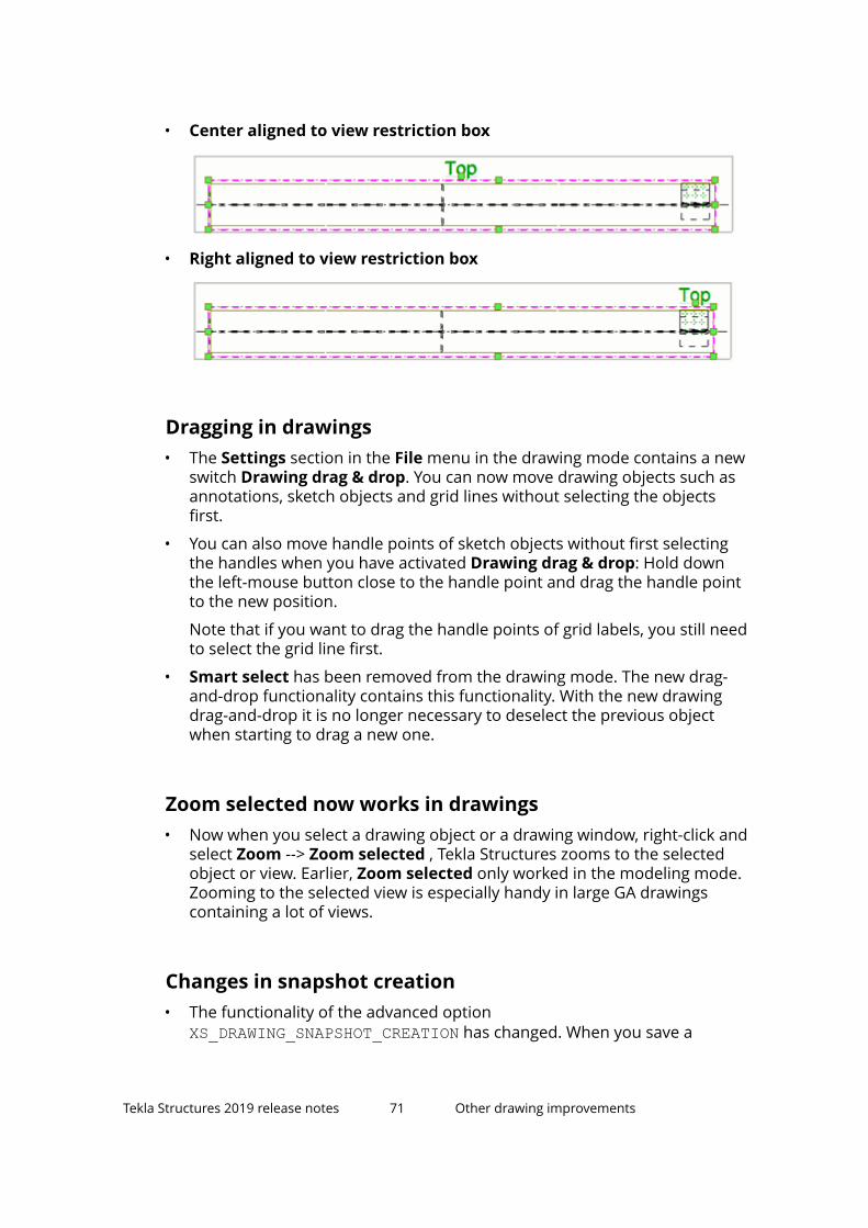
• Center aligned to view restriction box
• Right aligned to view restriction box
Dragging in drawings• The Settings section in the File menu in the drawing mode contains a new
switch Drawing drag & drop. You can now move drawing objects such asannotations, sketch objects and grid lines without selecting the objectsfirst.
• You can also move handle points of sketch objects without first selectingthe handles when you have activated Drawing drag & drop: Hold downthe left-mouse button close to the handle point and drag the handle pointto the new position.
Note that if you want to drag the handle points of grid labels, you still needto select the grid line first.
• Smart select has been removed from the drawing mode. The new drag-and-drop functionality contains this functionality. With the new drawingdrag-and-drop it is no longer necessary to deselect the previous objectwhen starting to drag a new one.
Zoom selected now works in drawings• Now when you select a drawing object or a drawing window, right-click and
select Zoom --> Zoom selected , Tekla Structures zooms to the selectedobject or view. Earlier, Zoom selected only worked in the modeling mode.Zooming to the selected view is especially handy in large GA drawingscontaining a lot of views.
Changes in snapshot creation• The functionality of the advanced option
XS_DRAWING_SNAPSHOT_CREATION has changed. When you save a
Tekla Structures 2019 release notes 71 Other drawing improvements

drawing, you are no longer asked if you want to create a snapshot. Whenthis advanced option is set to TRUE (default), the snapshot is always takenwhen you save a drawing, and never taken if set to FALSE.
Drawing creation• When you create several drawings at a time, Tekla Structures shows a
progress dialog with a Cancel button. However, clicking the Cancel buttondid not stop creating new drawings, but created them without templates.This has now been fixed. Moreover, now the dialog box also shows twoprogress bars: the first bar shows what is done for each drawing, and itgoes back and forth. The second bar proceeds steadily after every drawing.
Improvements in reinforcement drawing tools
Rebar group marking
• On the Mark 3 tab you can now define how to rotate the mark text usingthe new setting Mark rotation. You can rotate the mark text horizontallyand vertically or to the mark line direction (default).
• Rebar length output method Sum values A B C has been renamed to Sumof exact lengths on the Mark 1–Mark 3 tabs.
Rebar group dimensioning
• Text placement has been improved so that texts do not overlap with eachother or with rebar.
• The dimension line is now created correctly also in the case the rebargroup bars are only partially visible in a drawing view.
• The first and last rebar lines were missing. This has now been fixed.
• Now it is possible to also group together regularly represented groups.
Tekla Structures 2019 release notes 72 Other drawing improvements

• You can now also dimension circular bar groups.
• The beam type pad footing dimensioning is working again.
• The order of mark content elements is now correct in all use cases. The fixalso applies to extra marks.
• Rebar length output method Sum values A B C has been renamed to Sumof exact lengths.
• The extra marks are now positioned correctly.
• The tool now adds a correct number of dimension lines, and the lines arealigned correctly.
• In one-bar groups, the CC value is now 0.0.
• The static content of the mark placed in the direction of the dimension lineis now customizable. You can specify the content on the Extra marks infront or Extra marks behind tabs.
• The first type in the Annotation type list on the Parameters tab haschanged. The marks behind the dimension line are no longer shown there.Also the image is new.
• Bar grouping has been changed so that the border bar at spacing changegoes to the group of smaller spacing.
• Now you can define the space between mark 1 and mark 2 using the newsetting Space between Mark1 and Mark2 on the Advanced settings tab.On the same tab, Next mark spacing was moved under the new areaGrouping and renamed to Group mark spacing. Rebar group tolerancewas also moved to the Grouping area and renamed to Groupingtolerance.
• More space between fields was added to prevent overlapping on 4Kscreens. The Rebar group marking plugin was also adapted for 4K screens.
• Fixed the incorrectly dimensioned rebar groups in some combinations ofdistribution bar type and excluding start/end bars. The fix affects thesituations when you had selected Exclude first, Exclude last or Excludefirst and last, and combined it with one the following types of distribution:Equal distribution by target spacing value, By exact spacing value withflexible first space, By exact spacing value with flexible last space, orBy exact spacing value with flexible first and last space.
• The dimensions arrows were positioned incorrectly when you were usingthe setting Visibility of reinforcing bars in group with the option twobars in the middle of group. This has now been fixed.
Tekla Structures 2019 release notes 73 Other drawing improvements
Rebar pull-out picture and marking
• The placement and accuracy of rebar segment lengths has been improved.
• There are now more colors available for lines.
• Rebars are now selected from the selected part only.
• Drawing is now not saved in case the tool is called within the opened activedrawing
• Prevented a crash when the rebar size contains non-numeric characters,such as "HA20".
• Unit setting "cm m" on the Dimensions tab now works correctly.
• The pull-out picture creation of spiral and circular reinforcement nowworks correctly. Previously it caused Tekla Structures to hang.
• Text placement has been improved so, that texts do not overlap with eachother or rebar.
• Dimension text placement has been improved to use less space, whenborders are in use.
1.16 Improvements in Template Editor 3.8Template Editor 3.8 contains the improvements and fixes listed below.
• Fixed changing attributes (color, size, font,...) of multiple texts and valuefields.
• The object position was not updated in the work area after setting a newposition in the Move Object dialog box. This has now been fixed.
• The font type icons were updated in the Select font dialog box.
• Double-click now selects the font in the Select font dialog box.
• Symbol selection dialog can now be resized.
• The Extend command is working again.
• All icons and bitmaps were updated.
• Toolbar preview is no longer far away from the cursor when dragging thetoolbar to another location.
• Added DpiAwareness (bigger icons when highDpi is used).
• Template Editor again allows the formula to be changed in the formuladialog box.
For more information about Template Editor 3.8, see Template Editor user'sguide.
Tekla Structures 2019 release notes 74 Improvements in Template Editor 3.8
1.17 Printing improvementsPrinting in Tekla Structures 2019 has been further improved, and there areupdates especially in visualizing the line colors, adjusting frames and foldmarks, defining file name content, and closing the dialog box.
Printer colors and line widths shown instantly in drawings• When you have a drawing open, and you open the Print Drawings dialog
box, and change the line colors and line thicknesses on the Lineproperties tab , the changed colors and line thicknesses are nowimmediately reflected in the drawing. This only happens if you haveactivated the Printer line widths switch and the new Printer line colorsswitch through File --> Settings in the drawing mode.
Adjust frames and fold marks directly through PrintDrawings• There is a new Frames button available in the Print Drawings dialog box
for adjusting the drawing frames and fold marks in the Drawing FrameProperties dialog box. These settings are for the model and impact alldrawings.
If you have a drawing open while you adjust the frames and fold marks,you need to reopen the drawing to activate the changes. If you change theframe and fold mark settings for the drawing that is shown in the PrintDrawings dialog box preview, the preview does not update, and you needto reopen the dialog box to see the changes in the preview.
The old Drawing frames and fold marks command is still availablethrough Quick Launch.
Include revision mark to file name• The new setting Include revision mark to file name adds the revision
mark of the latest revision of the drawing to the file name.
Other printing changes• The separate Close button has been removed from the Print Drawings
dialog box. You can close the dialog box by clicking the Close button X inthe upper-right corner.
Tekla Structures 2019 release notes 75 Printing improvements
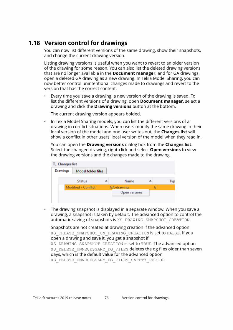
1.18 Version control for drawingsYou can now list different versions of the same drawing, show their snapshots,and change the current drawing version.
Listing drawing versions is useful when you want to revert to an older versionof the drawing for some reason. You can also list the deleted drawing versionsthat are no longer available in the Document manager, and for GA drawings,open a deleted GA drawing as a new drawing. In Tekla Model Sharing, you cannow better control unintentional changes made to drawings and revert to theversion that has the correct content.
• Every time you save a drawing, a new version of the drawing is saved. Tolist the different versions of a drawing, open Document manager, select adrawing and click the Drawing versions button at the bottom.
The current drawing version appears bolded.
• In Tekla Model Sharing models, you can list the different versions of adrawing in conflict situations. When users modify the same drawing in theirlocal version of the model and one user writes out, the Changes list willshow a conflict in other users' local version of the model when they read in.
You can open the Drawing versions dialog box from the Changes list.Select the changed drawing, right-click and select Open versions to viewthe drawing versions and the changes made to the drawing.
• The drawing snapshot is displayed in a separate window. When you save adrawing, a snapshot is taken by default. The advanced option to control theautomatic saving of snapshots is XS_DRAWING_SNAPSHOT_CREATION.
Snapshots are not created at drawing creation if the advanced option XS_CREATE_SNAPSHOT_ON_DRAWING_CREATION is set to FALSE. If youopen a drawing and save it, you get a snapshot if XS_DRAWING_SNAPSHOT_CREATION is set to TRUE. The advanced option XS_DELETE_UNNECESSARY_DG_FILES deletes the dg files older than sevendays, which is the default value for the advanced option XS_DELETE_UNNECESSARY_DG_FILES_SAFETY_PERIOD.
Tekla Structures 2019 release notes 76 Version control for drawings

• You can now select an older version of the drawing and show its snapshotor open it.
• If you want to change the current version of the drawing, open anotherversion, close the drawing, and when you are asked Do you want to keepthe changes to the drawing?, answer Yes. This makes the drawing versionthe current drawing version.
• To show all drawings and their versions related to the model, even thedeleted drawings, go to Document manager, and click Drawing versionswithout selecting a drawing in the Document manager list. In this dialogbox, you can see the drawing versions, open the different versions andshow the snapshots.
You can also compare drawings in two different models: from the currentmodel and from a model that you select at the top left corner of theDrawing versions dialog box.
Tekla Structures 2019 release notes 77 Version control for drawings

• You can open a version of a deleted GA drawing by selecting the drawingfrom the list in the Drawing versions dialog box, right-clicking andselecting Open as new.
1.19 Improvements in Tekla Model SharingTekla Structures 2019 introduces several improvements to Tekla ModelSharing.
Version control for drawingsIn Tekla Model Sharing models, you can now list the different versions of adrawing (page 76) in conflict situations and show drawing snapshots. You can
Tekla Structures 2019 release notes 78 Improvements in Tekla Model Sharing

now better control unintentional changes made to drawings and revert to theversion that has the correct content.
When users modify the same drawing in their local version of the model andone user writes out, the Changes list will show a conflict in other users' localversion of the model when they read in.
To open the Drawing versions dialog box and a snapshot of the drawing,select the changed drawing in the Changes list, right-click and select Openversions.
In the Drawing versions dialog box, you can select a drawing version, right-click and open the selected version. You can save the drawing version andwrite out to make it the current version for all users.
Check for regional settingsWhen you join a shared model, Tekla Model Sharing now checks if the currentWindows system locale is compatible with the system locale that was usedwhen the model was shared. If the current system locale is not compatible,Tekla Structures asks you to change the system locale. This is useful especiallyfor new Tekla Model Sharing users, as the effort and time in joining a sharedmodel is minimized.
The checking helps to avoid issues when distributed teams are using themodel. Tekla Structures may function incorrectly when a shared model isopened with a system locale that is not compatible with the one that was usedwhen starting to share the model.
Printer device settings (plotdev.bin) sharedThe plotdev.bin file is now shared when it is in the model folder. This way allteam members can produce printer outputs with the same settings that aremanaged by one user.
The plotdev.bin file contains the print device definitions that you create inPrinter Catalog (old printing), and that can be used for printing to pdf, forprinting to a file or to different printers, and for printing in different sizes.
For more general information about printing drawings, see Print drawings.
Tekla Structures 2019 release notes 79 Improvements in Tekla Model Sharing

Improved sharing operations performance with referencemodel objectsReference model object inquiries during read in and write out have beenoptimized to be faster than before. This will speed up the read in and write outoperations especially when there are a large number of reference modelobjects in the shared model.
In the Changes list, the names of new reference model objects are no longerdisplayed.
Improved handling of parametric profilesParametric profiles (.clb) are now displayed correctly in shared models.
Earlier, the parts with parametric profiles were shown as sticks, and they wereshown correctly only after Tekla Structures was restarted. In some cases, usersmight also have imported the parametric profiles manually, which causedproblems.
Improved handling of conflicting modificationsConflicting modifications of part cuts, site bolts, added parts, edge chamfers,site welds, shop welds, polygon welds, and sub-assemblies are now removedwhen reading in.
For example, a user deletes a part cut and writes out. Another user hasmodified the same cut, but needs to read in before sharing the modification.The read in result is now that the part keeps its correct numbering and thepart cut is deleted.
Drawing status shown correctlyThe drawing status flag in Document manager is now shown correctly in asituation where two users perform numbering locally. After the numbering,one user writes out. The other user still modifies a part and reads in. Thenumbering in the other user's local model is overwritten. Earlier, the drawingstatus was shown as not up to date for the other user, even though thedrawing was actually up to date. Now this status flag is cleared and thedrawing status is correctly shown as expected.
Tekla Structures 2019 release notes 80 Improvements in Tekla Model Sharing

Enhanced scalability with the next generation sharingserviceTekla Structures 2019 is the first version using the next generation sharingservice (v.2.0) that provides a solid growth path for the explanding use ofmodel sharing.
With the newly released sharing service, the service architecture has beenupdated. All classic Azure services have been replaced with more currentAzure services. Earlier Tekla Structures versions use the classic sharing servicethat utilizes classic Azure services.
Simplified connectivity to sharing serviceWith the new sharing service, the required network settings are now moresimple.
From Tekla Structures 2019 onward, only TCP port 443 outbound (defaultHTTPS) must be open outbound. Typically, this is open by default.
With earlier Tekla Structures versions, for the best performance, you still needto configure TCP ports 9350 - 9354 open outbound, as recommended byMicrosoft.
1.20 DWG export improvementsSome improvements have been made in the DWG export dialog box. Forexample, the preview now opens in a separate window, and on the Layerrules tab, there are new color codes indicating when a new DWG file is loaded,and when there are no layers in the DWG file. There are also some newconfirmation messages at DWG export. The exported block names nowcontain a drawing id to help the identification. Furthermore, you can nowenter a relative location in the output folder definition.
Tekla Structures 2019 release notes 81 DWG export improvements

Changes in the export dialog boxThe Export drawings to DWG/DXF dialog box has been improved in thefollowing ways:
• The layout of the export dialog box is now more user friendly and clear.
Tekla Structures 2019 release notes 82 DWG export improvements

• The drawing preview now opens in another window, where you can alsochange the current drawing. To open the preview, click Open preview andthen click Refresh preview.
• On the Layer rules rules tab, the name of the setting DWG template hasbeen changed to Target layers from DWG. The target layer boxes arebriefly colored in yellow when a new DWG file is loaded from the Target
Tekla Structures 2019 release notes 83 DWG export improvements

layers from DWG list. When there are no layers available in the DWG file,the boxes are colored in red.
• The DWG file not found text is displayed next to the Browse... button untila DWG or a DXF file is found and loaded.
• When you click the Export button, Tekla Structures first checks if the filescan be written to before the export starts, and asks you to close the
Tekla Structures 2019 release notes 84 DWG export improvements

necessary applications. It also checks if the files already exist and asks ifyou want to overwrite the existing files.
Other DWG export improvements• In DWG export, the exported block names now contain a drawing id, which
makes them easier to be identified. Earlier, the block names consisted ofthe object type and exporting order number.
• The DWG export now supports relative location in the output folderdefinition. The defined output folder is now saved in the export settings. Touse relative folder location, add .\ in front of the folder name.
• When using drawing DWG export for multiple drawings, previously itshowed a dialog box for each drawing that needed an update beforeexport. Now it shows one dialog box in the end instead.
• In DWG export, if you selected export line type to be following TeklaStructures object and a layer, continuous line type is now exportedexplicitly as continuous line type. Previously continuous line type wasexported as by layer.
1.21 Other interoperability improvementsIn Tekla Structures 2019, there are some improvements in the reference modelchange detection, IFC object conversion, NC files, and Trimble Connector.
Reference models
Updates in change detection
• The new tolerance settings can be used for getting relevant changes moreeasily. When you are comparing two versions of the same reference model,in the Change detection, click the Property set comparison tolerances
button . Change the tolerances by modifying the values, and apply thechanges by closing the dialog box and clicking Update view. You can alsosave the tolerances.
Tekla Structures 2019 release notes 85 Other interoperability improvements

The changed row appears as light yellow if the tolerance is bigger than thedifference.
For more information about the property set comparison and comparisonset tolerances, see Define a comparison set for reference model changedetection.
• IFC change detection has improved detailed data for geometry and locationcomparison.
• Geometry changes have not always provided any visible feedback in thedetails list about the changes. This has been improved, and some newproperties have been added.
Tekla Structures 2019 release notes 86 Other interoperability improvements

• When you removed a reference model version and did not click Modify,and then added a new version, the reference model version handling wasbroken. Now when you remove a version, you are asked if you want to setthe model as current and save changes.
• In change detection, selecting from the changes list and from the modelview has been improved. Previously, you could not select a deleted objectand a newer inserted object.
Other changes in reference models
• Status bar messages and log entries have been updated for the referencemodel insert and reference model visibility status. Information about thereference models outside the maximum work area is now available on thestatus bar. The following messages are now available:
• Insert succeeded. Objects are located in (Bounding box min X, Y,Z).
• Insert failed. Objects are located in (Bounding box min X, Y, Z). Objectstoo far to be visualized.
• Reference model handling speed has been improved if there are severalversions of the reference models. For example, the reference models areopened faster now.
• The performance of locking and unlocking multiple reference models in thereference model list has been improved.
Trimble Connector• You can now create a new Trimble Connect project directly in Trimble
Connector. Previously you needed to create the project in Trimble Connectfor Desktop or Trimble Connect for Web first.
Tekla Structures 2019 release notes 87 Other interoperability improvements
IFC object conversion• In IFC object conversion, date now works when copying date type
properties to UDAs that are defined as Date. In IFC object conversionsettings, the type needs to be set as integer.
• In IFC object conversion, Copy properties to UDas has been changed notto use reference object report functionality anymore. This provides fasterconversion and Date UDA usage as integer.
• Spaces can now be used in IFC object conversion profile mapping. They areremoved in internal mapping. For example, UB 356x171x45 finds UB356x171x45, not UKB356x171x45, like previously.
• The IFC object conversion has been improved. For example, the arc pointcalculation, chamfer combining, and the naming of the cut profiles havebeen improved.
• The IFC object conversion did not handle or convert round cuts for plate.This has now been fixed.
NC files• Now the bent line information contains the actual length of the bend, and
the line no longer extends to the bounding box of the plate.
• Now the DSTV coordinate system gives the coordinate system for theselected part, and not for the representative part.
• Some bolt holes were missing from the NC data. This has now been fixed.
• Sometimes, when using the option Maximum diameter for circular cutsto be drilled, the square cuts were recognized as circular. This has nowbeen fixed.
• The sawing angles for flanges are now available even if they are partiallycut.
• Now the hard stamp location avoids contour marking.
• When the hard stamps are placed, Tekla Structures now checks for boltsthat were modeled on the opposite side, and the end of the bolt hole couldoverlap the hard stamp.
Import models• Importing models from older versions of Tekla Structures is not allowed
any more.
Tekla Structures 2019 release notes 88 Other interoperability improvements

Other interoperability updates• Tekla Structures 2019 contains a new LandXML plugin version 1.19.
• Tekla Structures 2019 reference model insert now supports Sketchupversion 2019 and earlier.
1.22 Updates in tools for concrete fabricationExport Unitechnik contains several new useful features, and Export EliPlanfile, and Export BVBS have also been improved.
Export Unitechnik (79)Export Unitechnik has been improved in the following ways:
• The export now automatically recognizes and exports the gap width valuebetween sandwich panel shells.
• The line attribute scanning now recognizes chamfers correctly if thechamfer size is larger that half of the thickness of the element.
• Line attributes export has been improved for double wall 2nd shell.
• Electric tubes are now always exported with Z position as Z=0.
• Previously, when double wall shell was created from more than one partand Cut outer assemblies setting was turned on, the embeds weremissing from the export. This has now been fixed.
• Mountpart is now exported as a single line with corresponding length andwidth when it is overlapping with the contour and the Cut outerassemblies setting is turned on.
• The width of embeds created as B-rep items is now exported correctly.
• Production thicknesses of double wall shells are now calculated so that the1st shell thickness reports sub-assembly thickness including braced girders,and the 2nd shell reports complete cast unit thickness regardless of thechosen dialog box option. This is to ensure that the production thicknessvalues comply with the curing chamber slot maximum height.
• You can now use <VALUE> to inquire a part UDA and {VALUE} to inquire anassembly UDA in the Text[Template]#Counter option. This makes itpossible to use a shorter string instead of having to use a templateproperty to designate UDAs.
• You can now use all combinations of texts, templates and counter symbolswith the option Text[Template]#Counter.
Tekla Structures 2019 release notes 89 Updates in tools for concrete fabrication

• Rebars and meshes are no longer taken into cast unit extrema calculationwhen they are excluded from export. Thereby, any protrudingreinforcement that is excluded no longer creates an offset.
• You can use the new surface object user-defined attribute Use surface aspallet base to orient the object without changing the top-in-form face orthe rotation in export settings.
• Double walls are now exported correctly also when there are more thanone part specified as the 1st stage (or the 2nd stage) in the cast unit.
• Rebar or mesh wire using the terminal hook flection form will now havetheir geometrical data series systematically rounded in borderline cases.
• Rebar groups that have been collected to meshes are now correctlyunfolded.
• Reinforcing bars exported as embeds are now exported with correctgeometry.
• Braced girders are now placed into the 1st double wall shell regardless howthey are modeled unless specifically attached to the 2nd shell.
• The embed recognition has been improved in cases where both doublewall shells have the same hierarchy level in the assembly.
• Embed bounding boxes are now always exported perpendicular to pallet.
• Coordinate system and scanned geometry is now drawn with simple linesinstead of construction lines that where stored in model database.
• Geometrical plotting data is now optimized for embeds that are createdout of cut objects, and have varying thickness. The amount of intermediatepoints in geometrical lines or polygons is kept to a minimum.
• Reading data from the Mounting part data specification tab for steelparts is now working correctly.
• Main tab:
• It is now possible to use additional string length options 13, 14, 15, 16,and 20 in the file name mask settings.
• TS configuration tab:
• The setting Rotate 90° if pallet width exceeded has been renamed toAuto-rotate on pallet, and the functionality has changed. Now you canrotate the coordinate system for export +90° or -90° when the elementwidth exceeds the pallet width, or when the element width exceeds theelement length.
Tekla Structures 2019 release notes 90 Updates in tools for concrete fabrication
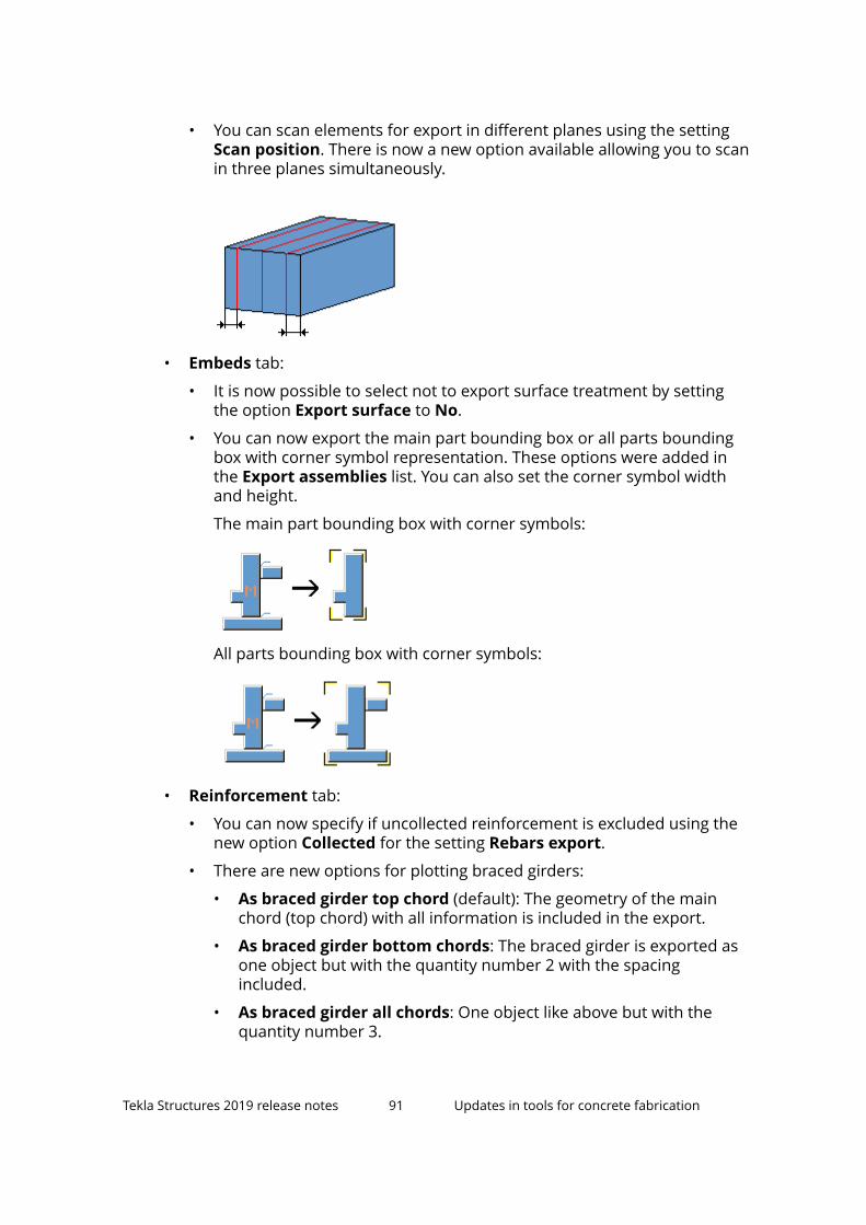
• You can scan elements for export in different planes using the settingScan position. There is now a new option available allowing you to scanin three planes simultaneously.
• Embeds tab:
• It is now possible to select not to export surface treatment by settingthe option Export surface to No.
• You can now export the main part bounding box or all parts boundingbox with corner symbol representation. These options were added inthe Export assemblies list. You can also set the corner symbol widthand height.
The main part bounding box with corner symbols:
All parts bounding box with corner symbols:
• Reinforcement tab:
• You can now specify if uncollected reinforcement is excluded using thenew option Collected for the setting Rebars export.
• There are new options for plotting braced girders:
• As braced girder top chord (default): The geometry of the mainchord (top chord) with all information is included in the export.
• As braced girder bottom chords: The braced girder is exported asone object but with the quantity number 2 with the spacingincluded.
• As braced girder all chords: One object like above but with thequantity number 3.
Tekla Structures 2019 release notes 91 Updates in tools for concrete fabrication

• As top chord with end symbols: 2 Mountpart symbols are placedat the top chord end points towards the braced girder direction, line20 mm long. In addition, the above-mentioned BRGIRDERinformation.
• As bottom chords with end symbols: 4 Mountpart symbols areplaced at the bottom chord end points towards the braced girderdirection, line 20 mm long. In addition, the above-mentionedBRGIRDER information.
• Only top chord end symbols: 2 Mountpart symbols are placed atthe top chord end points towards the braced girder direction, line 20mm long. No BRGIRDER.
• Only bottom chord end symbols: 4 Mountpart symbols are placedat the bottom chord end points towards the braced girder direction,line 20 mm long. No BRGIRDER.
• The setting Bent reinf. as unfolded now has a new option Onlymeshes. Using this option you can export bent meshes as unfolded,while other bent reinforcement is exported as bent.
• The setting Reinforcing bars length now has a new option Lines atthe edge (all leg lengths), which calculates the lengths of thereinforcing bar legs at the edge of the bars.
• You can now group similar rebars with equal spacing using the newsetting Rebar grouping. Similar rebars are exported using oneRODSTOCK row with correct quantity and spacing. The options are Yesand No (default). The rebar grouping is primarily intended to be used inthe production of simple mesh and reinforcement.
• SLABDATE block data specification tab:
• You can designate data about the exported element using the newsetting Item designation.
• You can now export the means of transportation information using thenew setting Transport type.
• Production thickness export for double walls has been changed. Withthe option Cast unit width the cast unit thickness is exported for bothshells.
• It is now possible to export exposition class using the new settingExposure class .
• Pallet tab:
• You can now align elements in the Y direction using the new settingAlign in Y axis. You can select whether to align
• element upper edge to pallet upper edge
• element upper edge to pallet center line
• element center line to pallet center line
Tekla Structures 2019 release notes 92 Updates in tools for concrete fabrication

• element lower edge to pallet center line
• element lower edge to pallet lower edge
• Validation tab:
• You can now validate rebar and mesh leg lengths, and mesh overhangsand spacings.
• Now you can also select to export non-valid rebars as non-automatedor to prevent the export.
Export EliPlan file (68)Export EliPlan file has been improved in the following ways:
• You can now use various product code mappings with the new settingProduct code on the Data content tab.
• The export of length L1 and L2 data has been improved for cut hollow coreslabs.
• Cuts created at diagonally cut slabs no longer affect the calculation of L1and L2 values.
Tekla Structures 2019 release notes 93 Updates in tools for concrete fabrication

BVBS ExportExport BVBS has been improved in the following ways:
• When multiple segments of a rebar are in 0-degree bendings, then it isexported as a continuous straight section.
• Now the exported circular and spiral rebars get the arc inner radius insteadof the center-line radius.This value is inquired from report property DIM_R,and calculated from the rebar geometry if the DIM_R is missing.
• Circular and spiral rebars had incorrect spacing values. This has now beenfixed.
• A new UDA BVBS_BENDING_ROLL has been added. The BVBS_BENDING_ROLL UDA is taken from reinforcements, there is a newBVBS tab in reinforcement properties containing a new setting Bendingroll diameter for this UDA.
1.23 Tekla BIMsight and Tekla Web Viewer replaced byTrimble Connect for Desktop
Tekla BIMsightTekla BIMsight is approaching its end-of-life by the end of 2019. As ofDecember 31, 2019, we discontinue to distribute, support and maintain TeklaBIMsight. You can still use it after that date.
As a substitute for Tekla BIMsight, you can use the Trimble Connect forDesktop offline version (free of charge). It has most of the Tekla BIMsightfunctionalities and some new functionalities as well. See the comparison tablebelow for the specific functionalities:
Feature/Software Trimble Connectfor Desktop
Tekla BIMsight
3D navigation
Viewing multiple models
Measuring
Clip planes
Markup
Desktop API
Customizable user interface
Tekla Structures 2019 release notes 94 Tekla BIMsight and Tekla Web Viewer replaced byTrimble Connect for Desktop

Feature/Software Trimble Connectfor Desktop
Tekla BIMsight
Enhanced 3D experience (directX)
Save model views
Object/Model coloring andtransparencyPoint clouds
Finding and grouping objects frommodelsQuantity by object group
Create notes (ToDos)
Status sharing
Clash detection
Share notes
Sharing the aggregated project
Check this video about Trimble Connect for Desktop features Trimble ConnectDesktop Feature Overview.
To start using Trimble Connect for Desktop:
1. In Tekla Structures, go to the Trimble Connect ribbon tab, and selectDesktop .
2. Log in to Trimble Connect for Desktop using your Trimble Identity.
When you launch Trimble Connect for Desktop:
• Trimble Connect for Desktop opens the desktop project attached to thecurrent Tekla Structures model.
• If you have not attached a project, Trimble Connect projects page isopened.
• If you have not installed Trimble Connect for Desktop, the web page todownload Trimble Connect for Desktop https://app.connect.trimble.com/tc/app#/store will be opened.
Tekla Structures 2019 release notes 95 Tekla BIMsight and Tekla Web Viewer replaced byTrimble Connect for Desktop

Tekla Web ViewerWe discontinue to support old Tekla Web Viewer in this version. TrimbleConnect provides new, modern web technologies to replace the Tekla WebViewer usage. We have multiple web technologies to be used, please visit thisweb page https://www.tekla.com/products/trimble-connect/getting-started/api-documentation for more information or contact us: [email protected]. You can start to explore Trimble Connect at https://connect.trimble.com. You can find more information here: https://www.tekla.com/products/trimble-connect/getting-started .
1.24 Improvements in componentsThere are several improvements in concrete components and steelcomponents in Tekla Structures 2019.
Concrete components
Embedded anchors (8)
On the Placement tab, it is now possible to move anchors to the closestbraced girder. You can select the class and name of the top braced girder bar,and also the maximum displacement of anchors.
Automated reinforcement layout - double tee beam (51)
On the Strand pattern tab, you can now use an external .CSV file to define aninfinite amount of individual strands.
Automated reinforcement layout - ledge spandrel (55), Automatedreinforcement layout - rectangular spandrel (56)
• Stem stirrup and ledge rebar creation has been changed so that the userinput spacing value is not exceeded when using Both in the Spandrel Endoption. In most cases, this means that in the middle there are two smallerspacings than the input value.
• You can now define advanced hook properties for rebar groups on theStem stirrups (for 55) and Ledge rebar tabs. The components are not fullybackward compatible with older versions due to these improvements.
Ledge spandrel - automated reinforcement layout (55)
• You can now control the secondary rebar set on the End rebar tab.
Beam reinforcement (63)
You can now select to create additional links on the Parameters tab.
Tekla Structures 2019 release notes 96 Improvements in components
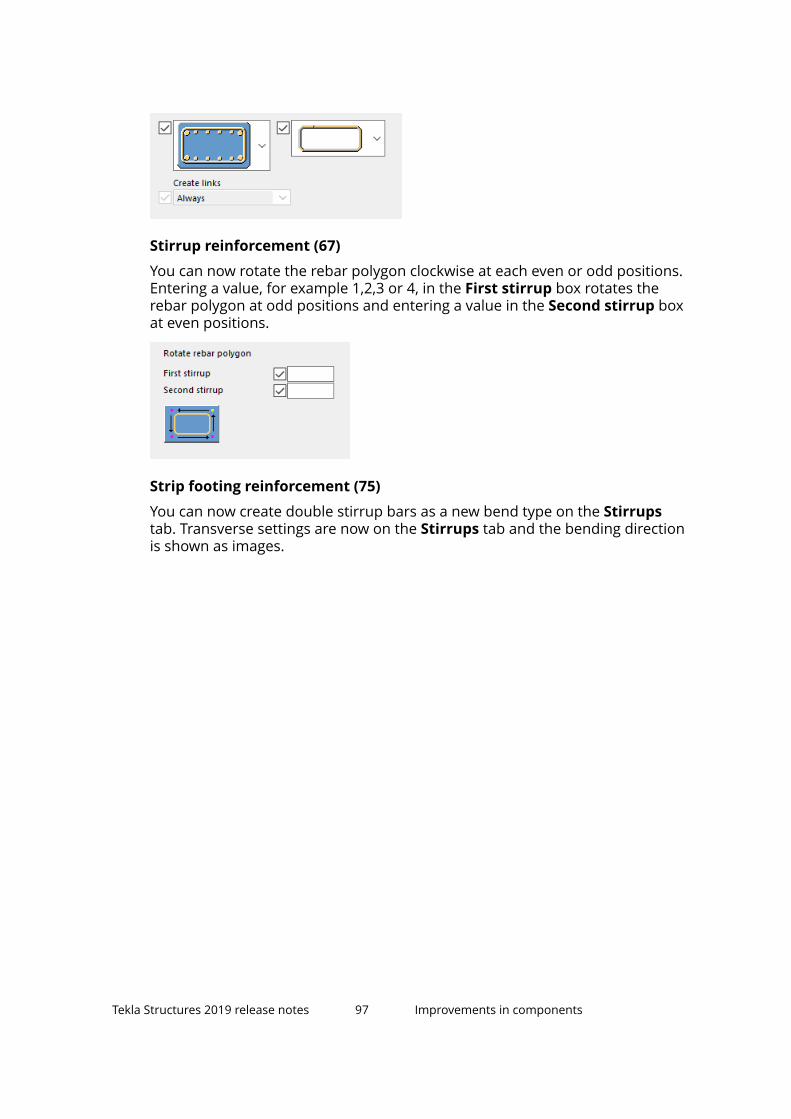
Stirrup reinforcement (67)
You can now rotate the rebar polygon clockwise at each even or odd positions.Entering a value, for example 1,2,3 or 4, in the First stirrup box rotates therebar polygon at odd positions and entering a value in the Second stirrup boxat even positions.
Strip footing reinforcement (75)
You can now create double stirrup bars as a new bend type on the Stirrupstab. Transverse settings are now on the Stirrups tab and the bending directionis shown as images.
Tekla Structures 2019 release notes 97 Improvements in components

Seating with dowel (75), Two sided seating with dowel (76) , Seating withdowel to flange (77), Two sided seating with dowel to flange (78)
You can now create a bearing plate relative to the column. Two sided seatingwith dowel to flange (78) is not fully backward compatible with older TeklaStructures versions due to the improvements.
Round column reinforcement (82)
You can now select on the Advanced (main bars) tab whether to cut thecreated rebars by the cut in the father part or not.
Tekla Structures 2019 release notes 98 Improvements in components
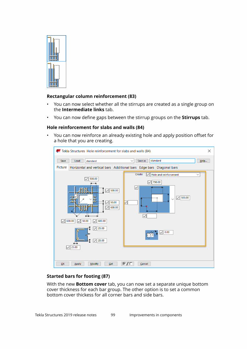
Rectangular column reinforcement (83)
• You can now select whether all the stirrups are created as a single group onthe Intermediate links tab.
• You can now define gaps between the stirrup groups on the Stirrups tab.
Hole reinforcement for slabs and walls (84)
• You can now reinforce an already existing hole and apply position offset fora hole that you are creating.
Started bars for footing (87)
With the new Bottom cover tab, you can now set a separate unique bottomcover thickness for each bar group. The other option is to set a commonbottom cover thickess for all corner bars and side bars.
Tekla Structures 2019 release notes 99 Improvements in components

Reinforced concrete stair (95)
• You can now select whether to create finished floor level on the Parts tab.The finished floor level is defined by a polygon created from an offset stairspolygon and it is used for drawings. Define the profile, properties andoffset of the dummy part that is created at each polygon vertex.
• You can now create reinforcement in stringers on the new Stringer barstab.
• On the Bar C tab, there is an option for a new rebar landing shape and asetting for adapting the nose shape.
• On the Bar E tab, you can now select to create stirrups and pins parallelwith the sloped edge of the step.
• On the Bar K tab, there is an option for a new rebar shape and itsappropriate I bars.
• On the Bar L tab, you can now define whether reinforcing bars are createdbetween the top and bottom step.
• On the Parameters tab, there is a new shape for the bottom landing.
Tekla Structures 2019 release notes 100 Improvements in components

• You can now define the name, prefix and start number for each type ofrebar and mesh on the Mesh bars, Bottom anchor bars, Top anchorbars, and Z anchor bars tabs.
Concrete console (110)
• You can now define the offsets for the tube profiles in both the X and Ydirections on the Anchor rods tab.
• You can now use the Legs symmetrically setting on the Socket tab toselect whether custom part sockets are created symmetrically.
• On Parameters tab, you can now find and cut extra secondary parts usingclasses or name search. You can also define the maximum width of thesecondary part and cut it to this width.
Concrete beam-beam (112)
• When defining the neoprene, you can now select on the Parts tab whetherthe neoprene is fitted to fill the cut space between the main part and thesecondary part, or whether it is created in a rectangular shape.
• You can now select on the Anchors tab whether the tubes are aligned withthe main part, or with the top or bottom of the secondary part.
Tekla Structures 2019 release notes 101 Improvements in components

Double wall edge and opening reinforcement
There is a new cover thickness offset C3 on the Picture tab. New options havebeen added for edge and opening reinforcement (not reinforcement andcreate just stirrups) on the Reinforcement and Opening tabs.
Mesh bars
You can now control the minimum length of primary and secondary barsseparately.
Rebar coupler, Rebar end anchor
• Rebar coupler and Rebar end anchor components have been changed sothat when used with rebar sets, the end-specific UDA values are set withend modifiers. For rebar sets, the end modifier properties thread length,extra fabrication length, and threading type values of the end modifier areset (instead of custom UDA values).
Note that to get the threading type controlled by coupler / end anchorcomponents, this value must be added to the RebarCoupler.Udas.datfile.
• Rebar coupler has been changed so that the free space between tworebars can be controlled with a new dimension attribute on Attributes tab.You can set this value manually or with the auto attribute file.
Tekla Structures 2019 release notes 102 Improvements in components

Rebar end anchor has been changed so that when it is used with rebarsets, the rebar is shortened with the given offset so that the anchor willhave the same cover distance as the original bar end. The concrete covercan be automatic or overridden with the (input) end detail modifier.
Wall layout
• When customizing the content of the UDA tab, you can now define in theWallLayout.Udas.dat file that layer UDA values are not swapped whenthe Wall layout layer swapper tool is used. You can do this by adding NoSwap at the end of the line (fourth field): string comment j_commentNoSwap.
• Wall layout has been modified so that the Geometry detailing strip atthe top/bottom is extended by default by the extreme of the part edges.
Wall layout T connector
The Add seam setting now has a new option First layer only. With this option,only the first layer is split into two parts. Previously, the No option has thisfunctionality. The No option now does not split the first layer part, instead acut that breaks the part into two solid objects is created.
Wall groove seam
You can now use the new Create fitting option on the Edge shape tab tocontrol whether the part end fitting is created.
Wall groove seam, Wall to wall connection
• You can now control the location of the last rebar/embed in the wall topedge on the Connectors tab.
• There is a new edge shape option on the Edge shape tab. With this optionyou can create a groove where one of the noses can be shortened by agiven distance.
• You can now control the offset of the loose bars at the bottom of theconnection/start of the seam on the Connectors tab.
• There is a new Thickening tab where you can create extra thickening towalls.
Tekla Structures 2019 release notes 103 Improvements in components

• You can now select to create part cuts or only extra part cuts, and definethe name of the cut. In Wall to wall connection, you can set thisseparately for both walls. For part properties of extra part cuts, select asaved settings file.
Steel components
Joining plates (14), Stiffened end plate (27), Partial stiff end plate (65),Two sided end plate (142), End plate (144)
You can now define a bolt comment on the Bolts tab.
Triangles generation (19)
You can now define chamfers for the created triangular plates on the newChamfers tab.
Tube gusset (20)
You can now create connection plate stiffeners and define the stiffenerchamfers on the Brace conn tab.
Welded tee (32)
You can now define the assembly position number and the Finish property onthe Parts tab.
Haunch (40)
You can now define the bolt type on the Holes tab.
Cranked beam (41)
You can now define a gap between the parts on the Picture tab.
Tekla Structures 2019 release notes 104 Improvements in components

Seat conn type 1 (52)
You can now define all the basic bolt properties, and the properties for slottedholes, bolt assembly and bolt length increase on the Secondary bolts tab.
Hollow brace wraparound gusset (59)
You can now define the width of the tongue plate on the Brace conn tab.
Wraparound gusset (58), Hollow brace wraparound gusset (59),Wraparound gusset cross (60)
You can now create the fastener plates extended through the connection mainand secondary part on the Gusset tab. You can also define the sizes of therespective cuts around the fastener plates.
Tekla Structures 2019 release notes 105 Improvements in components

Bolted gusset (11), Gusseted cross (62)
You can now select on the Picture tab whether to create the gusset platethrough the main part.
Bolted gusset (11), Tube gusset (20), Gusseted cross (62)
You can now create welding between the gusset and the base plate.
Gusseted cross (62)
• You can now define the filler plate creation side on the Brace conn tabwhen creating both connection plates.
• You can now create the gusset plate parallel to the brace without using abase plate.
Tekla Structures 2019 release notes 106 Improvements in components

HSS Brace special (66)
HSS Brace special (66) now has the Design type tab.
Rail connection (70)
You can now define bolt assemblies on the SBolts tab.
Splice connection (77)
• Welds 6 and 7 have been added.
• You can now change the weld access hole shape on the Weld prep tab. Youcan now define weld types for the secondary part.
• You can now select the flange plate creation side on the Parameters tab.Previously, this setting was on the Weld prep tab.
Clip angle (116)
You can now define the cut length of bolts on the Bolts tab.
Welded beam to beam (123)
You can now define the weld access hole offset on the Chamfers tab.
Tekla Structures 2019 release notes 107 Improvements in components

Shear plate simple (146)
You can now define the cut length of bolts on the Bolts tab.
Welded to top flange S (149), Full depth S (185)
You can now define the bolting direction on the Bolts tab.
Offshore (194)
You can now define the gap distance for haunched beam flanges.
Stiffened base plate (1014)
On the Parts tab, you can now define the Class property for plates, webplates, flange plates, and leveling plate. You can define the Finish property forplate, web plates, flange plates, leveling plate, fitting plates, additional beam,horizontal plates, and L profiles.
1.25 Changes in advanced options
New advanced options• XS_ISO_LEG_LENGTH_AS_WELDSIZE
• XS_DISPLAY_DIMENSIONS_WHEN_SELECTING_REBARS
• XS_REBARSET_SHOW_LEGFACES
• XS_REBARSET_SHOW_PROPERTY_MODIFIERS
• XS_REBARSET_SHOW_END_DETAIL_MODIFIERS
• XS_REBARSET_SHOW_SPLITTERS
Tekla Structures 2019 release notes 108 Changes in advanced options
• XS_HATCH_PATTERN_LINE_LIMIT
• XS_AD_LOAD_COMBINATION_METHOD
• XS_APPLICATIONS_PATH
• XS_MESSAGES_PATH
Changed advanced options• XS_DISPLAY_DIMENSIONS_WHEN_SELECTING_OBJECTS now only applies to
parts, and the new advanced optionXS_DISPLAY_DIMENSIONS_WHEN_SELECTING_REBARS to reinforcement.
• When XS_ENABLE_PHASE_OPTION_IN_NUMBERING is set to TRUE and therenamed Assembly phase check box is selected in the Numbering Setupdialog box, only the assembly phase of each assembly is now compared innumbering. The part phase or assembly phase of parts is not compared.
• The functionality of the advanced optionXS_DRAWING_SNAPSHOT_CREATION has changed. When you save adrawing, you are no longer asked if you want to create a snapshot. Whenthis advanced option is set to TRUE (default), the snapshot is always takenwhen you save a drawing, and never taken if set to FALSE.
Deleted advanced options• XS_DEFAULT_FONT_SIZE_GRID
You can now control the grid font size in the grid properties in the propertypane instead of using the advanced option.
• XS_GRID_COLORYou can now control the grid color in the grid properties in the propertypane instead of using the advanced option.
• XS_CONSTRUCTION_LINE_LINE_TYPE, XS_CONSTRUCTION_CIRCLE_LINE_TYPEYou can now control the line type of construction lines and constructioncircles in the property pane instead of using the advanced options.
1.26 Changes in template attributes
Tekla Structures 2019 release notes 109 Changes in template attributes

New template attributes• ADDED_TO_POUR_UNIT
• IS_REBARSET_BAR
• SUB_ID_LAST
• CRANK_SIDE_START, CRANK_SIDE_END• CRANK_ROTATE_START, CRANK_ROTATE_END• CRANK_STRLEN_START, CRANK_STRLEN_END• CRANK_LENTYPE_START, CRANK_LENTYPE_END• CRANK_RATIO_START, CRANK_RATIO_END• CRANK_DIST_START, CRANK_DIST_END• CRANK_OFFSET_START, CRANK_OFFSET_END• LAP_SIDE_START, LAP_SIDE_END• LAP_PLACEMENT_START, LAP_PLACEMENT_END• LAP_LENGTH_START, LAP_LENGTH_END
Tekla Structures 2019 release notes 110 Changes in template attributes

2 Tekla Structures 2019administrator's release notes
Upgrade guide from Tekla Structures 2018i to Tekla Structures 2019
Administrator's release notes are intended to provide advanced users withinstructions on how to apply the additional customizations available in a newTekla Structures version.
Administrator's release notes: General settings (page 111)
Administrator's release notes: Steel settings (page 126)
Administrator's release notes: Concrete settings (page 138)
2.1 Administrator's release notes: General settingsGeneral customization settings apply to all user groups. Use these settingstogether with your own user group settings.
Administrator's release notes: Model templates in version update (page 112)
Administrator's release notes: Applications & components catalogmaintenance (page 115)
Administrator's release notes: Radial grids (page 116)
Administrator's release notes: New construction objects (page 117)
Administrator's release notes: User-defined columns in Drawing contentmanager (page 118)
Administrator's release notes: Document manager manual categories(page 119)
Administrator's release notes: Improvements in drawings (page 121)
Tekla Structures 2019 administrator's releasenotes
111 Administrator's release notes: General settings

Administrator's release notes: New template attributes for pour units andsurfaces (page 123)
Administrator's release notes: Small general items (page 124)
Administrator's release notes: Model templates in versionupdate1. Open Tekla Structures 2019.
2. Create a new model using an existing model template.
3. Give the model the same name as in the previous Tekla Structuresversion.
4. Open a 3D view.
5. Diagnose and repair the model.
Tekla Structures 2019 administrator's releasenotes
112 Administrator's release notes: General settings

6. Create a project thumbnail, or add a custom image namedthumbnail.png in the model folder.
The preferred size of the image is 120 x 74 pixels.
Tekla Structures 2019 administrator's releasenotes
113 Administrator's release notes: General settings

7. Save the model.
If you do not do this, a message may appear warning about the modelbeing created with a previous version.
8. Save the model as a model template.
9. Include the needed catalog files and subfolders from the model folder,and click OK.
10. Remove manually all *.db files (environment database, optionsdatabases) from the model folder.
Tekla Structures 2019 administrator's releasenotes
114 Administrator's release notes: General settings

The *.bak, *.log and xs_user files are automatically removed from themodel folder.
The .idrm files (db.idrm and xslib.idrm) should be kept as they arepart of the model.
The model template is saved in a location pointed by XS_MODEL_TEMPLATE_DIRECTORY.
You now have a sample image for your model template. The Applications& components catalog is now also in order and easy to use.
Administrator's release notes: Applications & componentscatalog maintenanceKeep the Applications & components catalog in shape and usable. For moreinformation about the Applications & components catalog, see How to usethe Applications & components catalog.
Set XS_COMPONENT_CATALOG_ALLOW_SYSTEM_EDIT to TRUE to be able to editthe Applications & components catalog definition files that are located in the XS_SYSTEM folders.
Check and fix the following:
1. Add the items to groups
Check Ungrouped items and add the items to the appropriate group.
2. Check the logs for errors
Tekla Structures 2019 administrator's releasenotes
115 Administrator's release notes: General settings

The Applications & components catalog shows the message log buttonin the lower-right corner of the catalog if there are errors or warnings in thecatalog definition files, for example.
If there are references to missing plug-ins, go to the referredComponentCatalog.xml and remove the references manually:
Test thoroughly that these changes do not create any further errors, or changethe structure of your Applications & components catalog. Check at least theUngrouped items and Legacy catalog groups.
As in the example above, there may be errors for:
• CatalogPluginComponentItem?CopyModelDirectoryPlugin• CatalogPluginComponentItem?SaveAsModelTemplatePlugin3. Hide all non-related applications and components from roles
1. In the Ungrouped items catalog, select the Show hidden items checkbox at the bottom.
2. Right-click an application or a component and select Hide / Unhide.
4. Create custom thumbnails
Publish a component in the Applications & components catalog
You may need to use the same component with different settings in differentcases. To easily use the component, you can define the settings for each caseand publish the component in the catalog. This feature can be useful for someroles.
Tekla Structures 2019 administrator's releasenotes
116 Administrator's release notes: General settings

Administrator's release notes: Radial grids
Overview
Until now you have been able to create only rectangular grids with straight gridlines in Tekla Structures. However, there are use cases where radial / polargrids are needed. For this purpose, there have been workarounds (Radial Gridextension, for example) to create radial grid systems in Tekla Structuresmodels.
However, it was not possible to create any curved grid lines even when usingthe Radial Grid extension. This lead to radial grids that did not have a veryfinished look. To fix these issues you can now create radial grids in TeklaStructures
The old grid properties dialog box has been replaced by the property panewindow for both rectangular and radial grids.
You can now select grid (view plane) color, label font color and label font sizefor each grid in the model separately. This also means that the XS_GRID_COLOR and XS_DEFAULT_FONT_SIZE_GRID advanced options arenot in use anymore.
You can use this feature, for example, when modeling round or curvedstructures, such as round columns and towers, tanks and containers, circularplatforms, stadiums, and so on, whenever either radial grids or curved gridlines are needed. You can snap to the radial and curved grid lines, whichmakes modeling parts very easy.
To do
Create the needed radial grids as examples and save them to the wantedfolders in XS_SYSTEM, XS_FIRM, or XS_PROJECT path.
Administrator's release notes: New construction objects
To Do
Remove the obsolete advanced options and update their values in thestandard files.
Create the needed standard files with the new settings (Color and Line type).
New construction objects
Arc and polycurve are new construction objects. The Circle command replacesthe Circle using three points and Circle using center point and radiuscommands.
Tekla Structures 2019 administrator's releasenotes
117 Administrator's release notes: General settings

Advanced options
Construction object line type properties have been moved from advancedoptions to object properties. The XS_CONSTRUCTION_CIRCLE_LINE_TYPEand XS_CONSTRUCTION_LINE_LINE_TYPE advanced options have beenremoved.
Administrator's release notes: User-defined columns inDrawing content manager
Overview
Drawing content manager in the drawing mode side pane is an interactivetool for viewing and editing model objects and drawing content in the currentdrawing. With this functionality, missing, duplicate or false information can bechecked without having to manually go through all drawing objects separately.The functionality is also intended to aid new or inexperienced users to addannotations to drawing content without drawing properties set up.
Previously, the Drawing content manager functionality was restricted to alimited number of property columns for each category type. You can now editthe existing column property type and add new property columns.
From now it is possible to define the column property types and the preferablenumber of columns for each category. You can also add, edit, and removecolumns and change the column order in Drawing content manager.
Notes:
• It is not possible to add the same property twice in the same category withthe exception of Custom text.
• Mark quantity and quantity ("NUMBER") properties cannot have otherproperties in the column they are put.
• The available properties are those defined for the Template Editor.
Settings work in two levels. First, a user-specific setting fileDrawingContentManagerCategories_<username>.xml is searched for,and if it is found, it will be used. If this file cannot not be found, thenDrawingContentManagerCategories.xml will be looked for and used iffound. To convert the user-specific file to a generic one, just to remove the"_username" part from the file name.
Settings are searched for in the \attributes folder under the model folder,then XS_PROJECT, XS_FIRM, XS_SYSTEM, and XS_USER_SETTINGS_DIRECTORY.
Tekla Structures 2019 administrator's releasenotes
118 Administrator's release notes: General settings

To do
Create the needed categories. They are in <model>\attributes\DrawingContentManagerCategories_<username>.xml .
Remove the "_username" part from the file name and copy it to any folder in XS_PROJECT, XS_FIRM, or XS_SYSTEM path in the environment.
See also
Improvements in Drawing content manager, marks and notes (page 53)
Administrator's release notes: Document manager manualcategoriesSometimes you may need to have a document category in Documentmanager for documents that would be difficult to categorize using the search.Now you can simply select documents, create a manual category and add yourdocuments there. You can also add documents to and remove documentsfrom existing manually created categories, and combine categories, bothsearch-based and manual ones. A manual category may contain bothdrawings and file documents.
Creating a manual category may be useful, for example, when you haveenabled the Show changes from the checkpoint set when the button isactivated feature in Document manager, and then when some documentshave changed and are listed, you can add the changed documents in themanual category.
• To create a new category manually, and add documents there, select thedocuments from the list, right-click and select Manual category --> Add tonew . Type a name for the category, type an optional tooltip, and defineother necessary settings. The options are the same as in the search-basedcategories. Then click Save.
• The newly created or modified manual categories are saved to theDocumentManagerCategories_<username>.xml file under the currentmodel folder.
Tekla Structures 2019 administrator's releasenotes
119 Administrator's release notes: General settings

• To add a document to an existing manual category, select the documentsfrom the list, right-click and select Manual category --> Add to existingand then select the desired category. All compatible manual categories arelisted. You can add one document to several categories.
• To edit a manual category, right-click the category in the category list andselect Edit.
• To remove a document from a category, right-click the document, selectManual category --> Remove from and then select the category fromwhich to remove the document.
• To delete a manual category, right-click the category in the category list,and select Delete.
Tekla Structures 2019 administrator's releasenotes
120 Administrator's release notes: General settings

Settings work in two levels. First a user-specific setting fileDocumentManagerCategories_<username>.xml is tried to be found. If it isfound, it will be used. If not, then DocumentManagerCategories.xml will belooked for and used if found.
To convert the user-specific file to a generic one, just remove the "_username"part from the file name.
Settings are scanned first from the model folder, then from XS_PROJECT, XS_FIRM, XS_SYSTEM, and XS_USER_SETTINGS_DIRECTORY.
To do
Create the needed categories. They are in <model>\DocumentManagerCategories_<user>.xml.
Remove the "_username" part from the file name and copy it to any folder in XS_PROJECT, XS_FIRM, or XS_SYSTEM path in the environment.
See also
Other drawing improvements (page 67)
Administrator's release notes: Improvements in drawings
Option to set the view label orientation
Previously, you could only center view labels horizontally by view frame or byview restriction box in drawing view label properties. Now you have moreoptions available:
• Left aligned to view frame
• Center aligned to view frame
• Right aligned to view frame
• Left aligned to view restriction box
• Center aligned to view restriction box
• Right aligned to view restriction box
Tekla Structures 2019 administrator's releasenotes
121 Administrator's release notes: General settings
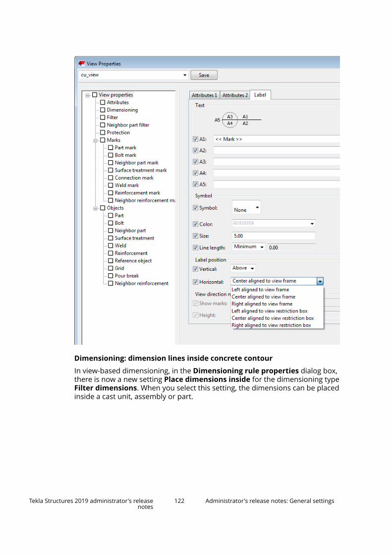
Dimensioning: dimension lines inside concrete contour
In view-based dimensioning, in the Dimensioning rule properties dialog box,there is now a new setting Place dimensions inside for the dimensioning typeFilter dimensions. When you select this setting, the dimensions can be placedinside a cast unit, assembly or part.
Tekla Structures 2019 administrator's releasenotes
122 Administrator's release notes: General settings
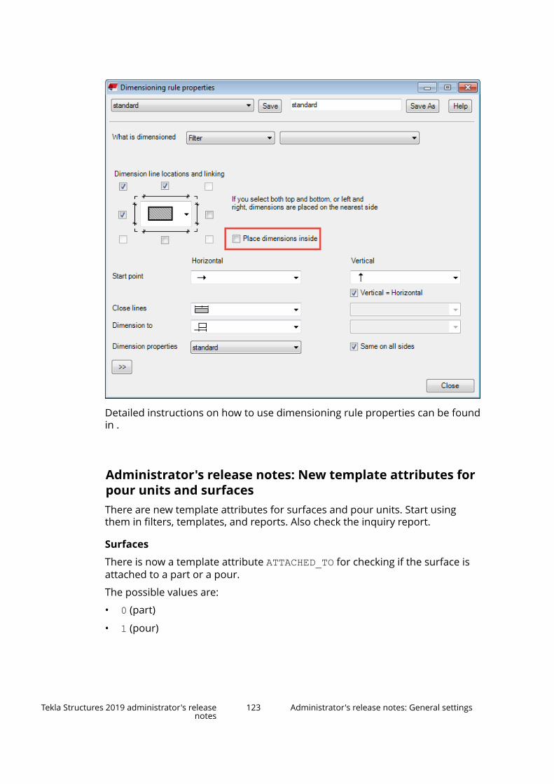
Detailed instructions on how to use dimensioning rule properties can be foundin .
Administrator's release notes: New template attributes forpour units and surfacesThere are new template attributes for surfaces and pour units. Start usingthem in filters, templates, and reports. Also check the inquiry report.
Surfaces
There is now a template attribute ATTACHED_TO for checking if the surface isattached to a part or a pour.
The possible values are:
• 0 (part)
• 1 (pour)
Tekla Structures 2019 administrator's releasenotes
123 Administrator's release notes: General settings

Pour units
There is now a template attribute ADDED_TO_POUR_UNIT for checking how theobject is added to a pour unit (automatically or manually).
The possible values are:
• 0 (unassigned, or modified after the pour units were calculated the lasttime)
• 1 (manually assigned)
• 2 (automatically assigned)
This attribute is added to the template category in filters and to templateattributes for the following object types:
• ASSEMBLY• BOLT• CAST_UNIT (only precast, not for cast in place)
• MESH• REBAR• SINGLE_REBAR• SINGLE_STRAND• STRAND• STUD
Administrator's release notes: Small general items
More fields in project properties
The following additional project fields have been added to project propertiesfrom the IFC4 standard:
• ASSEMBLY = PROJECT.LOCATION
• ASSEMBLY = PROJECT.POSTAL_BOX
• ASSEMBLY = PROJECT.TOWN
• ASSEMBLY = PROJECT.REGION
• ASSEMBLY = PROJECT.POSTAL_CODE
• ASSEMBLY = PROJECT.COUNTRY
You can use these new properties in reports and templates.
Tekla Structures 2019 administrator's releasenotes
124 Administrator's release notes: General settings

New label settings
There are new options in the Display dialog box to extend the functionality ofshowing part labels for different conditions.
There is a new setting Show for with the following options:
• All: This is the old behavior of part labels. Part labels are shown for all partsin the view.
• Selected: Part labels are only shown for all selected parts.
• Main part for selected: Part labels are only shown if the selected part isthe main part of its assembly.
• Main part for all: Part labels are only shown for all visible parts that arethe main parts of their assemblies.
For the Selected and Main part for selected options, note that you need tofirst apply the dialog box changes to the view when the view is selected, andthen continue to select objects that you want to investigate.
Load applications and extensions from several folders
To support extensions, you can create .tsep installation packages and deploythem into an environment under %commonEnvFolder%\extensions\applications.
Company-specific applications can be now located in company-specific foldersinstead of the Tekla Structures installation folder. The new location should beadded to XS_APPLICATIONS_PATH.
The new XS_APPLICATIONS_PATH advanced option allows you to add multiplepaths. Tekla Structures uses the paths to load system components.
Tekla Structures 2019 administrator's releasenotes
125 Administrator's release notes: General settings

The current configuration in teklastructures.ini is as follows:
set XS_APPLICATIONS=%XS_DIR%\applications\ setXS_APPLICATIONS_PATH=%XS_APPLICATIONS%;%XSDATADIR%environments\common\Extensions\applications\
Load translations for extensions from several folders
Company-specific translations can be now located in company-specific foldersinstead of the Tekla Structures installation folder. The new location should beadded to XS_MESSAGES_PATH.
The new XS_MESSAGES_PATH advanced option allows you to add multiplepaths. Tekla Structures uses the paths to load the translation files.
The current configuration in teklastructures.ini is as follows:
set XS_MESSAGES=%XS_DIR%\messages\ set XS_MESSAGES_PATH=%XS_MESSAGES%;%XSDATADIR%environments\common\Extensions\messages\
2.2 Administrator's release notes: Steel settingsThe following customization settings only apply to the steel user group.
Administrator's release notes: Improvements in steel items (page 126)
Administrator's release notes: Steel components (page 127)
Administrator's release notes: Improvements in steel items
Stand-alone bent plate
Stand-alone bent plate has been implemented as a part of the complexgeometry solutions in Tekla Structures. It can also be seen as furtherdevelopment to conical bent plate feature implemented in Tekla Structures2018i. Stand-alone bent plate does not require any input parts like thecylindrical or the conical bent plate. Stand-alone bent plate can be used tomodel both cylindrical and conical parts. It can be used, for example, to createhoods, hoppers, cones, and so on.
To do
Create the needed standard files.
Project level setting for fillet weld size control
When modeling fillet or compound welds, users now can control how the filletweld size is interpreted. This is done by using the new advanced option
Tekla Structures 2019 administrator's releasenotes
126 Administrator's release notes: Steel settings

XS_ISO_LEG_LENGTH_AS_WELDSIZE. It has impact only if XS_AISC_WELD_MARK is set to FALSE.
When XS_ISO_LEG_LENGTH_AS_WELDSIZE is set to FALSE, the fillet weld sizeis treated as throat thickness. When XS_ISO_LEG_LENGTH_AS_WELDSIZE isset to TRUE, the fillet weld size is treated as leg length. If the user sets a prefixthat influences the weld size, the prefix overrides the advanced option value.
To do
Start using the new advanced option if needed.
Administrator's release notes: Steel components
Tube gusset (20)
It is now possible to create a connection plate stiffener and define its chamferson the Brace conn tab. There is now welding available for the stiffener plates.
Welded tee (32)
You can now define the assembly position number and the Finish property onthe Parts tab.
Haunch (40)
You can now define the bolt type on the Holes tab.
Tekla Structures 2019 administrator's releasenotes
127 Administrator's release notes: Steel settings
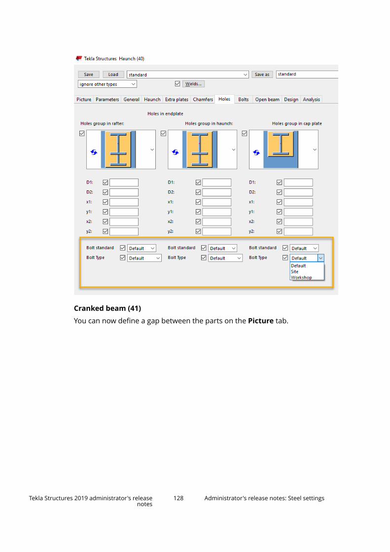
Cranked beam (41)
You can now define a gap between the parts on the Picture tab.
Tekla Structures 2019 administrator's releasenotes
128 Administrator's release notes: Steel settings

Seat conn type 1 (52)
You can now define all the basic bolt properties, and the properties for slottedholes, bolt assembly and bolt length increase on the Secondary bolts tab.Some bolt properties have been moved so that they are on the appropriatetabs.
Wraparound gusset (58), Hollow brace wraparound gusset (59),Wraparound gusset cross (60)
• You can now define the fastener plate cut through the connection profileon the Gusset tab.
Tekla Structures 2019 administrator's releasenotes
129 Administrator's release notes: Steel settings

• You can now define erection clearances for different sides of the secondarypart on the Gusset tab.
• Common Gusset tabs have been removed and recreated with modifiedlayout. In Hollow brace wraparound gusset (59) there is now a feature tomove fastener plates for non-L profiles.
Hollow brace wraparound gusset (59)
You can now define the width of the tongue plate on the Brace conn tab.
Bolted gusset (11), Gusseted cross (62)
You can now select on the Picture tab whether to create the gusset platethrough the main part.
Gusseted cross (62)
You can now define the filler plate creation side on the Brace conn tab whencreating both connection plates.
Tekla Structures 2019 administrator's releasenotes
130 Administrator's release notes: Steel settings

Rail connection (70)
You can now define bolt assemblies on the SBolts tab.
Splice connection (77)
• Welds 6 and 7 have been added.
• You can now change the weld access hole shape on the Weld prep tab. Youcan now define weld types for the secondary part.
• You can now select the flange plate creation side on the Parameters tab.Previously, this setting was on the Weld prep tab.
Tekla Structures 2019 administrator's releasenotes
131 Administrator's release notes: Steel settings

Stanchion side plate (83)
You can now set the bolt spacing when creating a rectangular or a diamondplate. Also, the component now works correctly when the up direction if set toauto.
Welded beam to beam (123)
You can now define the weld access hole offset on the Chamfers tab.
Bolted moment connection (134)
You can now select the bolt offset from the main part or the secondary part onthe Flange Blt tab.
Tekla Structures 2019 administrator's releasenotes
132 Administrator's release notes: Steel settings

Two sided end plate (142)
You can now create compensation flange plates (available on Plates 1 andPlates 2 tabs).
Welds 9 and 10 have been added for flange plates.
Two sided clip angle (143)
You can now sort the secondary parts by their profile height on the Picturetab. When set to Yes, the highest secondary part is always regarded as the firstsecondary part, regardless of the selection order. The selection order ofsecondary parts no longer affects the copying of secondary parts.
Tekla Structures 2019 administrator's releasenotes
133 Administrator's release notes: Steel settings

Welded to top flange (147)
Welds 8 and 9 for shear plates have been added.
Welded to top flange S (149), Full depth S (185)
You can now define the bolting direction on the Bolts tab.
Bent plate (151)
You can now define the notch cut radius on the Top notch and Btm notchtabs.
Joist to beam, type 1 (160)
You can now define a full depth stiffener and define the chamfers for it on theStabilizer tab.
Tekla Structures 2019 administrator's releasenotes
134 Administrator's release notes: Steel settings

Joist to column, type 2 (163)
You can now define welds for the stabilizer plate and the top/bottom weld forthe seat connection. The second side weld for seat connection has beenremoved.
Stiffened base plate (1014)
On the Parts tab, you can now define the Class property for plates, webplates, flange plates, and leveling plate. You can define the Finish property forplate, web plates, flange plates, leveling plate, fitting plates, additional beam,horizontal plates, and L profiles.
Tekla Structures 2019 administrator's releasenotes
135 Administrator's release notes: Steel settings

Seat det type 1 (1033)
You can now define horizontal welds (weld 3) for the seat profile.
U.S. Base plate (1047)
You can now select the chamfer type for stiffeners on the Picture tab.
Tekla Structures 2019 administrator's releasenotes
136 Administrator's release notes: Steel settings

Circular base plates (1052)
You can now select to create plate washers along a circle on the Anchor rodstab.
Tekla Structures 2019 administrator's releasenotes
137 Administrator's release notes: Steel settings

2.3 Administrator's release notes: Concrete settingsThe following customization settings only apply to the concrete user group.
Administrator's release notes: Rebar set improvements (page 139)
Administrator's release notes: Reinforcement drawing tools (page 143)
Tekla Structures 2019 administrator's releasenotes
138 Administrator's release notes: Concrete settings

Administrator's release notes: Updates in tools for concrete fabrication(page 144)
Adminstrator's release notes: Concrete components (page 144)
Administrator's release notes: Rebar set improvements
End detail modifier
To do
Update the end detail modifier standard files (standard.rst_edm andstandard.rst_edm.more) in your environment:
1. Create a rebar set > Interrupt > Select the rebar set.
2. Create an end detail modifier > Interrupt > Select the end detail modifier >The property pane opens.
3. Enter appropriate standard values and save them as standard.
4. Upload the newly created standard files again to your environment.
Splitter improvements
To do
Update the splitter standard file (standard.rst_sm) in your environment:
1. Create a rebar set > Interrupt > Select the rebar set.
2. Create a splitter > Interrupt > Select the splitter > The property paneopens.
3. Enter appropriate standard values and save them as standard.
4. Upload the newly created standard files again to your environment.
Cranking and lapping report attibutes
If you want to create report templates for reporting these new properties, youcan use these cranking and lapping report attributes:
• CRANK_SIDE_START• CRANK_ROTATE_START• CRANK_STRLEN_START• CRANK_LENTYPE_START• CRANK_RATIO_START• CRANK_DIST_START• CRANK_OFFSET_START
Tekla Structures 2019 administrator's releasenotes
139 Administrator's release notes: Concrete settings
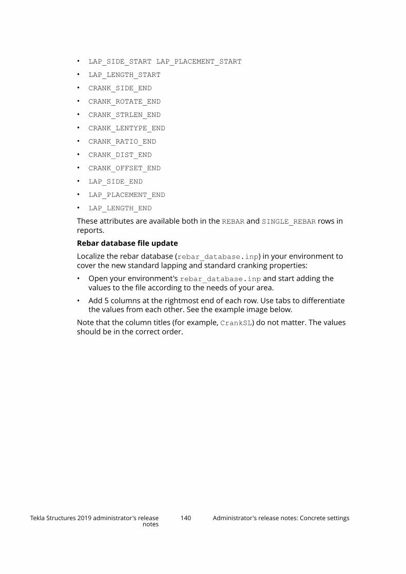
• LAP_SIDE_START LAP_PLACEMENT_START• LAP_LENGTH_START• CRANK_SIDE_END• CRANK_ROTATE_END• CRANK_STRLEN_END• CRANK_LENTYPE_END• CRANK_RATIO_END• CRANK_DIST_END• CRANK_OFFSET_END• LAP_SIDE_END• LAP_PLACEMENT_END• LAP_LENGTH_ENDThese attributes are available both in the REBAR and SINGLE_REBAR rows inreports.
Rebar database file update
Localize the rebar database (rebar_database.inp) in your environment tocover the new standard lapping and standard cranking properties:
• Open your environment's rebar_database.inp and start adding thevalues to the file according to the needs of your area.
• Add 5 columns at the rightmost end of each row. Use tabs to differentiatethe values from each other. See the example image below.
Note that the column titles (for example, CrankSL) do not matter. The valuesshould be in the correct order.
Tekla Structures 2019 administrator's releasenotes
140 Administrator's release notes: Concrete settings

Rounding and step tapering in model level settings
To do
Find out what would be the best values in your area for the reinforcementsettings. Localize them in your environment's standard.opt file.
This is how the above values are defined in the file:
Tekla Structures 2019 administrator's releasenotes
141 Administrator's release notes: Concrete settings

dia_option_settings.StepTaperingSingle 0.000000dia_option_settings.StepTaperingFree 0.000000dia_option_settings.StepTaperingIntermediate 0.000000dia_option_settings.RoundingSingle 1.000000dia_option_settings.RoundingFree 1.000000dia_option_settings.RoundingIntermediate 1.000000dia_option_settings.RoundingTypeSingle 1dia_option_settings.RoundingTypeFree 1dia_option_settings.RoundingTypeIntermediate 1dia_option_settings.RoundupInSplitters 1.000000
You can also localize the rest of the Reinforcement settings in the Optionsdialog box. Modify these settings in the same file if needed:
dia_option_settings.ConcreteCoverTop 25.000000dia_option_settings.ConcreteCoverBottom 25.000000dia_option_settings.ConcreteCoverSides 25.000000dia_option_settings.MinimumBarLength 0.000000dia_option_settings.MinimumLegLength 0.000000dia_option_settings.MinimumBarLengthType 0dia_option_settings.MinimumLegLengthType 0
Adding rounding and step tapering controls to rebar set and propertymodifier level
To do
Rebar set standard file update
Update the rebar set standard files (standard.rst, standard.rst.moreand standard.rst.zones) in your environment:
1. Create a rebar set > Interrupt > Select the rebar set > The property paneopens.
2. Enter appropriate standard values and save them as standard.
3. Upload the newly created standard files again to your environment.
Property modifier standard file update
Update the property modifier standard files (standard.rst_pm) in yourenvironment:
1. Create a rebar set > Interrupt > Select the rebar set.
2. Create a property modifier > Interrupt > Select the property modifier >The property pane opens.
3. Enter appropriate standard values and save them as standard.
4. Upload the newly created standard file again to your environment.
For environments that do not follow the ..\common\inp folder
Copy the objects_length_adjustment.inp file from ..\common\inpfolder and place it to your environment folder. If you do not do this, the rebarset auto-apply will not work.
Tekla Structures 2019 administrator's releasenotes
142 Administrator's release notes: Concrete settings

IS_REBARSET_BAR
If you want to differentiate old reinforcing bars from rebar set bars, there isnow a report template attribute that you can use: IS_REBARSET_BAR. Thevalue 1 is for rebar set bars, the value 0 is for the old bars. This attribute isavailable both in the REBAR and SINGLE_REBAR rows.
Administrator's release notes: Reinforcement drawing tools
Rebar group dimensioning
• The Extra marks tab was split into two separate extra mark tabs Extramarks in front and Extra marks behind.
On each tab it is possible to define the content of Mark 1 and Mark 2.
The grouping and positioning the marks for extra marks in front and extramarks behind is placed only on the first extra marks tab.
• Now you can define the space between mark 1 and mark 2 using the newsetting Space between Mark1 and Mark2 on the Advanced settings tab.On the same tab, Next mark spacing was moved under the new areaGrouping and renamed to Group mark spacing. Rebar group tolerancewas also moved to the Grouping area and renamed to Groupingtolerance.
• Rebar length output method Sum values A B C has been renamed to Sumof exact lengths on the Mark 1–Mark 3 tabs.
Rebar group marking
• On the Mark 3 tab you can now define how to rotate the mark text usingthe new setting Mark rotation. You can rotate the mark text horizontallyand vertically or to the mark line direction (default). Default mark linedirection is conserved.
• You can now have a frame around mark elements. Note that symbols, newlines and pullout pictures cannot have a frame.
• Origin sum values A B C have been replaced by the sum of exact lengths.
Rebar pullout picture and marking
• Added new line colors (added missing color options)
• Fixed option "m/cm" in segments length
Fixed 0.0 cm issue in drawings
Fixed conversion to Tekla Structures value through dimensions.
See also
Other drawing improvements (page 67)
Tekla Structures 2019 administrator's releasenotes
143 Administrator's release notes: Concrete settings
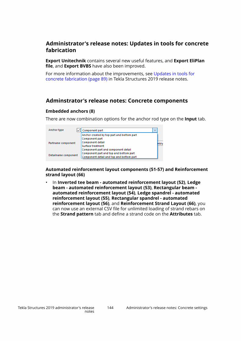
Administrator's release notes: Updates in tools for concretefabrication
Export Unitechnik contains several new useful features, and Export EliPlanfile, and Export BVBS have also been improved.
For more information about the improvements, see Updates in tools forconcrete fabrication (page 89) in Tekla Structures 2019 release notes.
Adminstrator's release notes: Concrete components
Embedded anchors (8)
There are now combination options for the anchor rod type on the Input tab.
Automated reinforcement layout components (51-57) and Reinforcementstrand layout (66)
• In Inverted tee beam - automated reinforcement layout (52), Ledgebeam - automated reinforcement layout (53), Rectangular beam -automated reinforcement layout (54), Ledge spandrel - automatedreinforcement layout (55), Rectangular spandrel - automatedreinforcement layout (56), and Reinforcement Strand Layout (66), youcan now use an external CSV file for unlimited loading of strand rebars onthe Strand pattern tab and define a strand code on the Attributes tab.
Tekla Structures 2019 administrator's releasenotes
144 Administrator's release notes: Concrete settings

Ledge spandrel - automated reinforcement layout (55)
• You can now load an external CSV file for longitudinal rebars to define anunlimited number of rebars on the Longitudinal rebar tab.
Tekla Structures 2019 administrator's releasenotes
145 Administrator's release notes: Concrete settings

• You can now control the secondary rebar set on the End rebar tab.
Tekla Structures 2019 administrator's releasenotes
146 Administrator's release notes: Concrete settings
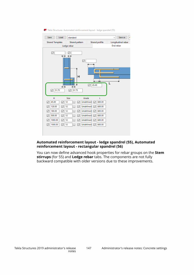
Automated reinforcement layout - ledge spandrel (55), Automatedreinforcement layout - rectangular spandrel (56)
You can now define advanced hook properties for rebar groups on the Stemstirrups (for 55) and Ledge rebar tabs. The components are not fullybackward compatible with older versions due to these improvements.
Tekla Structures 2019 administrator's releasenotes
147 Administrator's release notes: Concrete settings

Beam reinforcement (63)
You can now select to create additional links on the Parameters tab anddefine the minimum profile length.
Strip footing reinforcement (75)
You can now create double stirrup bars as a new bend type on the Stirrupstab. You can define the end shapes of the double stirrup bars (135°, 90° oroverlapped), and the overlap length. Transverse settings are now on theStirrups tab and the bending direction is shown as images.
Tekla Structures 2019 administrator's releasenotes
148 Administrator's release notes: Concrete settings

Round column reinforcement (82)
You can now create cranked reinforcing bars both at the top and at the bottomof the column. Enter the horizontal, vertical and sloped distance dimensionson the Main bars tab.
Tekla Structures 2019 administrator's releasenotes
149 Administrator's release notes: Concrete settings

Rectangular column reinforcement (83)
• You can now define bar cranking also at the column bottom. The length ofthe crank can now be defined using a sloped dimension, as an alternativeto the vertical dimension.
• You can now select whether all the stirrups are created as a single group onthe Intermediate links tab.
• You can now define gaps between the stirrup groups on the Stirrups tab.
Hole reinforcement for slabs and walls (84)
• You can now reinforce an already existing hole and apply position offsetsfor a hole that you are creating.
Tekla Structures 2019 administrator's releasenotes
150 Administrator's release notes: Concrete settings
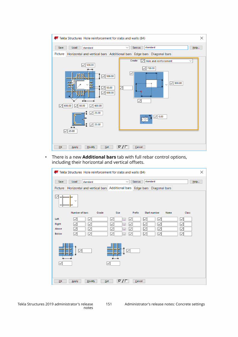
• There is a new Additional bars tab with full rebar control options,including their horizontal and vertical offsets.
Tekla Structures 2019 administrator's releasenotes
151 Administrator's release notes: Concrete settings

Starter bars for footing (87)
With the new Bottom cover tab, you can now set a separate unique bottomcover thickness for each bar group. The other option is to set a commonbottom cover thickess for all corner bars and side bars.
Reinforcement mesh array in area (89)
You can now define the polygon generation start point index.
Reinforced concrete stair (95)
Stirrups and pins on the Bar E tab can have a rectangular shape or they can beparallel with the sloped edge of the step (if slope is allowed).
Tekla Structures 2019 administrator's releasenotes
152 Administrator's release notes: Concrete settings

Concrete console (110)
• You can now create column cut out inclined around a T-profile.
• You can now select the default console thickness from the main part orfrom the secondary part.
• You can now define whether cuts are created around tubes using theCreate cuts around tubes option. You can do this on the Connection tab.
• You can now define the offsets for the tube profiles in both the X and Ydirections on the Anchor rods tab.
• You can now use the Legs symmetrically setting on the Socket tab toselect whether custom part sockets are created symmetrically.
• On Parameters tab, you can now find and cut extra secondary parts usingclasses or name search. You can also define the maximum width of thesecondary part and cut it to this width.
Tekla Structures 2019 administrator's releasenotes
153 Administrator's release notes: Concrete settings
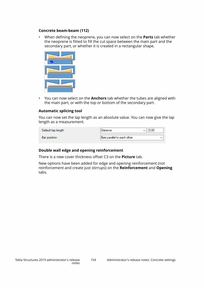
Concrete beam-beam (112)
• When defining the neoprene, you can now select on the Parts tab whetherthe neoprene is fitted to fill the cut space between the main part and thesecondary part, or whether it is created in a rectangular shape.
• You can now select on the Anchors tab whether the tubes are aligned withthe main part, or with the top or bottom of the secondary part.
Automatic splicing tool
You can now set the lap length as an absolute value. You can now give the laplength as a measurement.
Double wall edge and opening reinforcement
There is a new cover thickness offset C3 on the Picture tab.
New options have been added for edge and opening reinforcement (notreinforcement and create just stirrups) on the Reinforcement and Openingtabs.
Tekla Structures 2019 administrator's releasenotes
154 Administrator's release notes: Concrete settings

Mesh bars
You can now control the minimum length of primary and secondary barsseparately.
Rebar coupler and end anchor tools
Rebar coupler and Rebar end anchor components have been changed sothat when used with rebar sets, the end-specific UDA values are set with endmodifiers. For rebar sets, the end modifier properties thread length, extra
Tekla Structures 2019 administrator's releasenotes
155 Administrator's release notes: Concrete settings
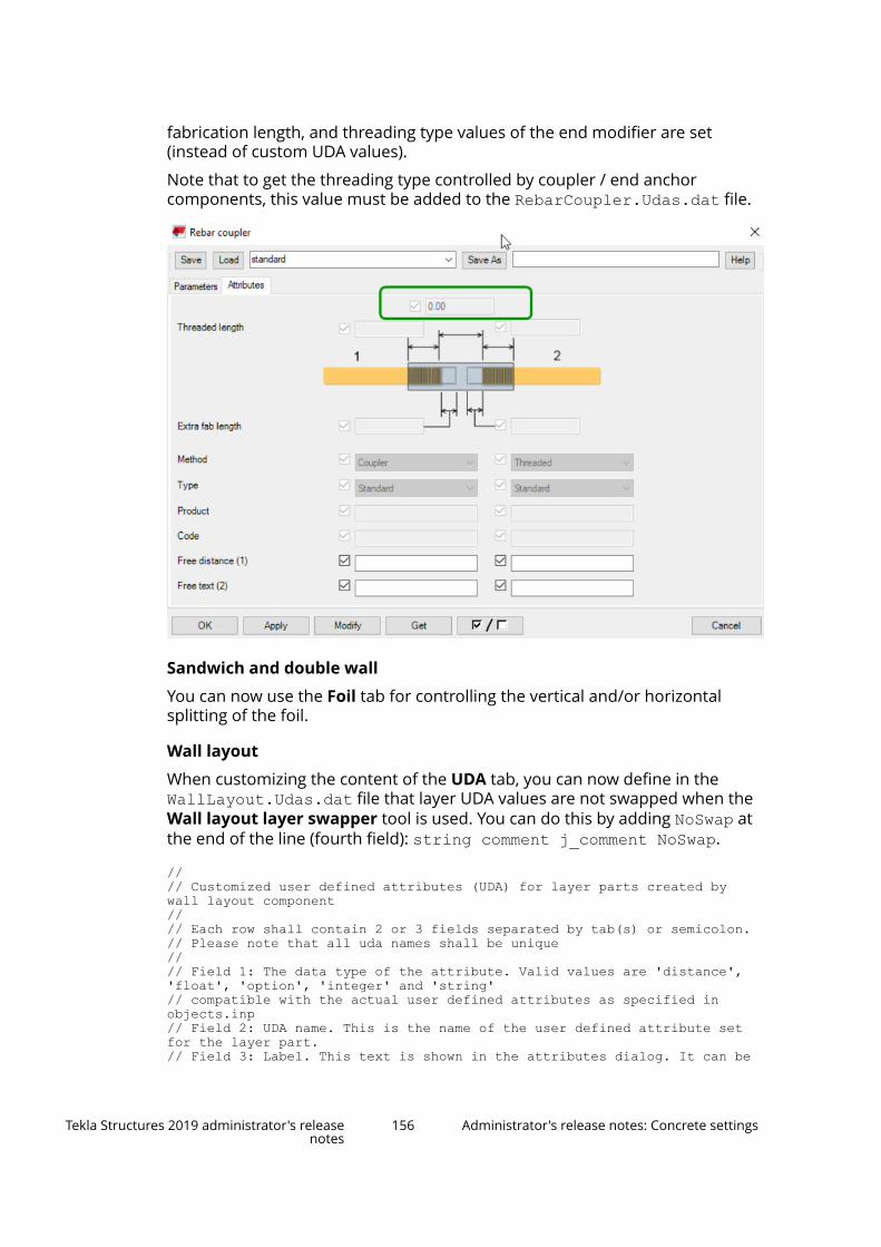
fabrication length, and threading type values of the end modifier are set(instead of custom UDA values).
Note that to get the threading type controlled by coupler / end anchorcomponents, this value must be added to the RebarCoupler.Udas.dat file.
Sandwich and double wall
You can now use the Foil tab for controlling the vertical and/or horizontalsplitting of the foil.
Wall layout
When customizing the content of the UDA tab, you can now define in theWallLayout.Udas.dat file that layer UDA values are not swapped when theWall layout layer swapper tool is used. You can do this by adding NoSwap atthe end of the line (fourth field): string comment j_comment NoSwap.
//// Customized user defined attributes (UDA) for layer parts created by wall layout component// // Each row shall contain 2 or 3 fields separated by tab(s) or semicolon. // Please note that all uda names shall be unique//// Field 1: The data type of the attribute. Valid values are 'distance', 'float', 'option', 'integer' and 'string'// compatible with the actual user defined attributes as specified in objects.inp// Field 2: UDA name. This is the name of the user defined attribute set for the layer part.// Field 3: Label. This text is shown in the attributes dialog. It can be
Tekla Structures 2019 administrator's releasenotes
156 Administrator's release notes: Concrete settings

a translatable label (albl_) or any text.// Field 4: 'NoSwap' if you do not want the 'Wall layout layer swapper' to swap the values. // string comment j_comment NoSwapstring USER_FIELD_1 _user_field_1string USER_FIELD_2 _user_field_2 string USER_FIELD_3 _user_field_3string USER_FIELD_4 _user_field_4
Tekla Structures 2019 administrator's releasenotes
157 Administrator's release notes: Concrete settings

3 Localization release notes
Environment-specific Tekla Structures localization release notes introduce newand changed features in the new Tekla Structures version from the localizationpoint of view. It lists the features that have been localized in your environmentand also helps you in your own customization tasks. The localization releasenotes are supplied by the localization teams at your local area and reselleroffices.
Localization release notes 158 Administrator's release notes: Concrete settings

4 Upgrade Tekla Structures to anew version
You can have many Tekla Structures versions on your computer. When youinstall and start using a new version, you do not need to uninstall the olderversions and you can keep using them. Service packs are cumulative updates,so they replace the previous service pack installation for the same TeklaStructures version.
NOTE We recommend that you complete any models you are already working onusing your current version of Tekla Structures. Once you save a model in thenew version, you cannot open it in the previous versions anymore.
You can download the installation packages from the Tekla Downloadsservice.
Complete the upgrade in this general order (follow the links in the text fordetailed instructions):
1. Update the Tekla license server (page 160). The updated version replacesthe existing version you have installed.
2. Renew your licenses as explained in Renew a Tekla license (page 161).
The renewed licenses can be used with the version indicated on thelicense and any previous versions that are compatible with your installedlicense server version.
3. Install Tekla Structures.
You can have many Tekla Structures versions and environments on yourcomputer. When you install and start using a new version, you do notneed to uninstall the older versions.
4. Copy personal settings to a new Tekla Structures version (page 162).
You can use the Migration Wizard (page 162) tool to copy some of thepersonal settings to the new version. You can skip the copying if you donot want to copy the settings, or if you want to copy the settings fromsome other Tekla Structures version than suggested in Migration Wizard.
Upgrade Tekla Structures to a new version 159 Administrator's release notes: Concrete settings
5. Transfer customized information to a new Tekla Structures version(page 163).
In the new Tekla Structures version, you can use the information you havecustomized in the previous version. We strongly recommend that youcreate project and firm folders, and store the files you customize in thesefolders. Tekla Structures does not replace the files in project and firmfolders when you install a new version. If you do not use project and firmfolders, you need to transfer the customized information to the newversion manually.
4.1 Update the Tekla license serverWe recommend that you have the newest version of Tekla license serversoftware installed on the Tekla license server. New versions of Tekla Structuresdo not always work at all with older license server versions.
You can use older versions of Tekla Structures with a newer version of thelicense server. In some older Tekla Structures versions, this requires that youhave installed recent enough updates; for more information about thecompatibility between Tekla Structures versions and Tekla license serverversions, see Which license server version to use.
To update the Tekla license server:
1. Save the model that you are working with and close Tekla Structuresbefore the server update.
2. Go to Tekla Licensing --> LMTOOLS through the Start menu or Startscreen, depending on your Windows operating system.
3. On the Stop/Start/Reread tab, click Stop Server to stop the Tekla licenseserver and any other licensing services.
When you have completed installing the Tekla license server, you canrestart the other licensing services.
4. Backup any files you have modified in the C:\Tekla\License\Serverfolder.
You do not need to back up tekla.lic or tekla.opt, because theinstaller will not changes these files.
5. Download the latest version of the Tekla license server and the optionalTekla License Borrow Tool (if you use it) from Tekla Downloads.
Upgrade Tekla Structures to a new version 160 Update the Tekla license server
6. Install the downloaded license server with administrator rights using theautomatic installation for normal setup. Follow the instructions displayedon the screen.
If the installation fails or the server does not start after installation, tryreinstalling with the local firewall and antispyware/antivirus protectiondisabled.
7. If you use the Tekla License Borrow Tool, install the new version of the toolon workstations that need it.
4.2 Renew a Tekla licenseLicense renewal means changing the details on an existing license, such asupdating the highest allowed software version or extending the validity periodof a temporary license. You deactivate the current license and then activate itagain with a new license entitlement certificate that contains the updatedinformation.
When you receive your renewed license, you must deactivate the existinglicense and then activate the new version of the license. Two versions of thesame license cannot be active at the same time. License deactivation andactivation is done on License server (which can also be the same computer onwhich Tekla Structures is installed) and requires an internet connection.
NOTE Before you deactivate licenses, ensure that the licenses are not in useor borrowed. To deactivate the licenses, users must return anyborrowed licenses as explained in Return a borrowed Tekla Structureslicense.
To renew a license:
1. Rename your previous entitlement certificate file in the license serverinstallation folder (by default C:\Tekla\License\Server) fromEntitlementCertificate.html to EntitlementCertificate-OLD.html.
2. Save the entitlement certificate file to the license server installation folder.
The person in your organization who has made the license purchase, orsomeone named as the contact person, receives a newEntitlementCertificate.html entitlement certificate by e-mail as anattachment.
3. Go to Tekla Licensing --> Tekla License Administration Tool throughthe Start menu or Start screen, depending on your Windows operatingsystem.
Upgrade Tekla Structures to a new version 161 Renew a Tekla license

4. In the Activated Licenses area, select the Deactivate check box next tothe license you want to deactivate.
5. Click the enabled Deactivate button.
When deactivation is complete, the License administration tool shows aconfirmation message.
NOTE Do not use automatic notification if you are using some otherFlexNet license and license server administration tool, such asFlexNet Manager. To notify the license server about licensechanges manually, see Activating Tekla Structures licensing usingmanual server notification.
6. If not already enabled, enable the automatic license server notificationfunctionality by clicking the Notify Server button.
7. Open the license entitlement certificate located in the ..\Tekla\License\Server folder by clicking Open, navigating to ..\Tekla\License\Server, selecting EntitlementCertificate.html, andclicking Open again. The license information is displayed in the EntitledLicenses area.
8. Click the Activate cell and select the number of licenses to activate.
9. Click the Activate button.
Your license server contacts the license activation server at TrimbleSolutions.
The activated licenses are displayed in the Activated Licenses area.
Do not forget to take a backup copy of the trusted storage of the activatedlicenses.
4.3 Copy personal settings to a new Tekla StructuresversionYou can copy some personal settings from an older Tekla Structures version toa newer Tekla Structures version using the Migration Wizard tool. Migration
Upgrade Tekla Structures to a new version 162 Copy personal settings to a new Tekla Structuresversion

Wizard opens automatically when you start a new version of Tekla Structuresfor the first time.
Migration Wizard shows the version number from which the settings arecopied and the version number to which the settings are copied. You canselect which settings are copied.
1. Start the new Tekla Structures version.
2. In Migration Wizard, click Next to start copying the settings.
3. Select the settings you want to copy and click Next.
4. Check that you have selected the correct settings.
5. Click Copy.
NOTE If you want to copy the settings later, you can start Migration Wizard manuallyby double-clicking the MigrationWizard.exe in the \Tekla Structures\<version>\nt\bin\applications\Tekla\Migrations folder. You canselect the version from which the settings are copied and the version to whichthe settings are copied.
See also
Upgrade Tekla Structures to a new version (page 159)
4.4 Transfer customized information to a new TeklaStructures versionYou can transfer customized information from a previous Tekla Structuresversion to the new Tekla Structures version.
1. If you have used project and firm folders to store customized files in amodel using a previous Tekla Structures version, go to File menu -->Settings --> Advanced Options and check that the XS_FIRM, XS_PROJECT and XS_COMPANY_SETTINGS_DIRECTORY advanced optionspoint to the folders where the customized files are located.
2. If you have not used project and firm folders to store customized files, youneed to transfer the customized files manually to the new Tekla Structuresversion to use the information.
Many types of files can be copied using a local or private online TeklaWarehouse collection. See Tekla Warehouse instructions for moreinformation.
Check at least the following:
• Advanced options
• Files related to templates, reports and drawings
Upgrade Tekla Structures to a new version 163 Transfer customized information to a new TeklaStructures version

• Catalog files: profile catalog, material catalog, bolt catalog, boltassembly catalog, rebar shape catalog
• Conversion files
• Extensions
You need to re-install extensions for the new Tekla Structures version.
• NC export settings
• Printer catalog settings
• User-defined attributes
• Saved model object properties
You can copy some information automatically to the new version usingthe Migration Wizard (page 162) tool.
See also
Upgrade Tekla Structures to a new version (page 159)
Upgrade Tekla Structures to a new version 164 Transfer customized information to a new TeklaStructures version

5 Tekla Structures service packs
Tekla Structures service packs are Tekla Structures version updates.
Service pack software installation files are stand-alone installers that containthe full Tekla Structures version software. You do not need to separately installthe related Tekla Structures version or a previous service pack. For example,you can install service pack 2 without installing service pack 1.
• Service packs can include new features, and improvements and fixes toexisting features. We recommend that all users install the latest servicepack.
• We recommend that you install the latest environments to ensure that theenvironments work correctly in the service pack. We recommend that youupdate all the environments that you are using.
You can find the service pack software and environment installation files inTekla Downloads.
See also
Install a Tekla Structures service pack (page 165)
Install an earlier Tekla Structures service pack (page 166)
5.1 Install a Tekla Structures service packYou can install a service pack to update a Tekla Structures version or aprevious service pack. Service packs can contain new features, andimprovements and fixes to existing features.
NOTE Service pack software installation files are stand-alone installers thatcontain the full Tekla Structures version software. You do not need toseparately install the related Tekla Structures version or a previousservice pack.
Tekla Structures service packs 165 Install a Tekla Structures service pack
If you have the related Tekla Structures version or a previous service packinstalled on your computer, you do not need to remove it before installing anew service pack.
NOTE You need to be logged in with administrator rights to install the TeklaStructures software on your computer.
1. Install the Tekla Structures service pack software.
a. Download the service pack software installation file from TeklaDownloads to your computer.
b. Double-click the installation file to run the installation.
c. Follow the steps in the installation wizard to complete the installation.
Note that if you have the related Tekla Structures version or aprevious service pack already installed, you cannot select theinstallation folder. The service pack will be installed to the samefolder as the version that you are updating.
If you do not have the related Tekla Structures version or a previousservice pack installed, you can select the installation folder and themodel folder.
2. Install the Tekla Structures environments.
Note that the location of the environment installation folder depends onwhere you have installed the software. You cannot select the environmentinstallation folder in the installation wizard.
You do not need to remove any environments. Installing a newer versionof an environment automatically upgrades the older version of thatenvironment.
a. Download the needed environment installation files from TeklaDownloads to your computer.
b. Double-click the installation file to run the installation.
c. Follow the steps in the installation wizard to complete the installation.The environment setting files are installed to the environment folderwhen you start Tekla Structures after the installation. Tekla Structuresopens a dialog box that shows the installation progress.
Related information
See also
Tekla Structures service packs (page 165)
Tekla Structures service packs 166 Install an earlier Tekla Structures service pack

5.2 Install an earlier Tekla Structures service packWe recommend that you use the latest Tekla Structures service pack. In certainsituations, you may need to take an earlier Tekla Structures service pack, orthe related Tekla Structures version, into use even though you are alreadyusing a newer service pack.
1. Uninstall the Tekla Structures service pack software you are now using inWindows Control Panel.
2. Uninstall the related Tekla Structures environments in Windows ControlPanel.
3. Install the Tekla Structures service pack software.
a. Download the software installation file of the service pack from TeklaDownloads.
b. Double-click the installation file to run the installation.
c. Follow the steps in the installation wizard to complete the installation.
You can select the installation folder and the model folder.
4. Install the Tekla Structures environments.
The latest environments are in Tekla Downloads.
a. Download the environment installation files related to the servicepack that you have installed.
b. Double-click the installation file to run the installation.
c. Follow the steps in the installation wizard to complete the installation.The environment setting files are installed to the environment folderwhen you start Tekla Structures after the installation. Tekla Structuresopens a dialog box that shows the installation progress.
See also
Tekla Structures service packs (page 165)
Tekla Structures service packs 167 Install an earlier Tekla Structures service pack

6 Disclaimer
© 2019 Trimble Solutions Corporation and its licensors. All rights reserved.
This Software Manual has been developed for use with the referencedSoftware. Use of the Software, and use of this Software Manual are governedby a License Agreement. Among other provisions, the License Agreement setscertain warranties for the Software and this Manual, disclaims otherwarranties, limits recoverable damages, defines permitted uses of theSoftware, and determines whether you are an authorized user of the Software.All information set forth in this manual is provided with the warranty set forthin the License Agreement. Please refer to the License Agreement for importantobligations and applicable limitations and restrictions on your rights. Trimbledoes not guarantee that the text is free of technical inaccuracies ortypographical errors. Trimble reserves the right to make changes andadditions to this manual due to changes in the software or otherwise.
In addition, this Software Manual is protected by copyright law and byinternational treaties. Unauthorized reproduction, display, modification, ordistribution of this Manual, or any portion of it, may result in severe civil andcriminal penalties, and will be prosecuted to the full extent permitted by law.
Tekla, Tekla Structures, Tekla BIMsight, BIMsight, Tekla Civil, Tedds, Solve,Fastrak and Orion are either registered trademarks or trademarks of TrimbleSolutions Corporation in the European Union, the United States, and/or othercountries. More about Trimble Solutions trademarks: http://www.tekla.com/tekla-trademarks. Trimble is a registered trademark or trademark of TrimbleInc. in the European Union, in the United States and/or other countries. Moreabout Trimble trademarks: http://www.trimble.com/trademarks.aspx. Otherproduct and company names mentioned in this Manual are or may betrademarks of their respective owners. By referring to a third-party product orbrand, Trimble does not intend to suggest an affiliation with or endorsementby such third party and disclaims any such affiliation or endorsement, exceptwhere otherwise expressly stated.
Portions of this software:
D-Cubed 2D DCM © 2010 Siemens Industry Software Limited. All rightsreserved.
Disclaimer 168 Install an earlier Tekla Structures service pack

EPM toolkit © 1995-2006 Jotne EPM Technology a.s., Oslo, Norway. All rightsreserved.
Open Cascade Express Mesh © 2015 OPEN CASCADE S.A.S. All rights reserved.
PolyBoolean C++ Library © 2001-2012 Complex A5 Co. Ltd. All rights reserved.
FLY SDK - CAD SDK © 2012 VisualIntegrity™. All rights reserved.
Teigha © 2002-2016 Open Design Alliance. All rights reserved.
CADhatch.com © 2017. All rights reserved.
FlexNet Publisher © 2014 Flexera Software LLC. All rights reserved.
This product contains proprietary and confidential technology, informationand creative works owned by Flexera Software LLC and its licensors, if any. Anyuse, copying, publication, distribution, display, modification, or transmission ofsuch technology in whole or in part in any form or by any means without theprior express written permission of Flexera Software LLC is strictly prohibited.Except where expressly provided by Flexera Software LLC in writing,possession of this technology shall not be construed to confer any license orrights under any Flexera Software LLC intellectual property rights, whether byestoppel, implication, or otherwise.
To see the third party open source software licenses, go to Tekla Structures,click File menu --> Help --> About Tekla Structures and then click the 3rdparty licenses option.
The elements of the software described in this Manual are protected byseveral patents and possibly pending patent applications in the United Statesand/or other countries. For more information go to page http://www.tekla.com/tekla-patents.
Disclaimer 169 Install an earlier Tekla Structures service pack

Disclaimer 170 Install an earlier Tekla Structures service pack

Index
Aadministrators
applications............................................115BVBS export........................................... 144component catalog............................... 115components...........................................115concrete fabrication..............................144EliPlan..................................................... 144model templates................................... 112Unitechnik.............................................. 144
Iinstalling Tekla Structures
copying personal settings.................... 162Migration Wizard............................159,162service packs.................................. 165,166service releases..............................165,166transferring customized files...............163upgrading........................................159,163upgrading Tekla Structures.................. 162
Llicense server
updating................................................. 160licenses
extending the licensing period............ 161renewing.................................................161
Rrenewing
licenses...................................................161
Uupdating
license server.........................................160upgrading
license server.........................................160
171

172