TechTip: PLC data exchange - EPLAN Help
27
TechTip: PLC data exchange EPLAN Platform Version 2023 Status: 13. June 2022 1 TechTip: PLC data exchange Contents 1. Use ............................................................................................................................... 3 2. Exchanged data........................................................................................................... 3 3. Recommended workflow in EPLAN ........................................................................... 4 3.1. Physical rack layout ............................................................................................. 4 3.1.1. Head station .................................................................................................... 4 3.1.2. Extension racks ............................................................................................... 5 3.1.3. Passive devices .............................................................................................. 5 3.2. I/O interconnection ............................................................................................... 6 3.3. Network structure ................................................................................................. 6 3.3.1. Connections between racks ............................................................................ 9 3.3.2. Automatic connections between associated bus ports................................... 10 4. Export from EPLAN ................................................................................................... 12 4.1. Hardware data ..................................................................................................... 12 4.2. Assignment list ................................................................................................... 13 5. Import in EPLAN ........................................................................................................ 14 5.1. Devices ................................................................................................................ 14 5.2. Connections ........................................................................................................ 14 6. Recommendation for preparation of the master data ............................................. 15 7. AutomationML AR APC............................................................................................. 15 7.1. Settings for different bus systems .................................................................... 17 7.2. PC station ............................................................................................................ 18 7.3. Switches .............................................................................................................. 18 7.4. Bus adapter ......................................................................................................... 19 7.5. IO-Link devices ................................................................................................... 20 7.5.1. IO-Link devices within a rack structure .......................................................... 20 7.5.2. IO-Link devices outside a rack structure ........................................................ 20 7.6. PLC subdevices .................................................................................................. 21 7.7. Accessories......................................................................................................... 22
-
Upload
khangminh22 -
Category
Documents
-
view
0 -
download
0
Transcript of TechTip: PLC data exchange - EPLAN Help
TechTip PLC data exchange
EPLAN Platform Version 2023
Status 13 June 2022
1
TechTip PLC data exchange
Contents
1 Use 3
2 Exchanged data 3
3 Recommended workflow in EPLAN 4
31 Physical rack layout 4
311 Head station 4
312 Extension racks 5
313 Passive devices 5
32 IO interconnection 6
33 Network structure 6
331 Connections between racks 9
332 Automatic connections between associated bus ports 10
4 Export from EPLAN 12
41 Hardware data 12
42 Assignment list 13
5 Import in EPLAN 14
51 Devices 14
52 Connections 14
6 Recommendation for preparation of the master data 15
7 AutomationML AR APC 15
71 Settings for different bus systems 17
72 PC station 18
73 Switches 18
74 Bus adapter 19
75 IO-Link devices 20
751 IO-Link devices within a rack structure 20
752 IO-Link devices outside a rack structure 20
76 PLC subdevices 21
77 Accessories 22
TechTip PLC data exchange
EPLAN Platform Version 2023
Status 13 June 2022
2
78 Device sets (Bundles) 22
79 Device-specific configuration values 22
710 Drives 23
8 Check of the PLC configuration project 24
81 Check via message management 24
Appendix A Relevant properties 25
TechTip PLC data exchange
EPLAN Platform Version 2023
Status 13 June 2022
3
1 Use
The multiple entry of data is avoided through the PLC data exchange This reduces the work
load across departments and avoids typing errors The configuration is accelerated overall
and the planning quality is improved
For the fundamental description of a property please refer to the current EPLAN help
bull Edit PLC Information gt PLC gt Basics
bull EPLAN Properties Overview
Further notes and specifications for individual properties can also be found in the TechTip
TechTip-Overview-of-the-PLC-properties
With Version 27 of EPLAN Electric P8 numerous new check runs which help you in
configuring the data exchange were implemented in the PLC field
You can find details on the PLC data exchange with specific PLC configuration programs in
separate TechTips
2 Exchanged data
1 Hardware data
Rack structure with part information
2 Symbol table (assignment list table of variables or similar)
Contains the assignment of the symbolic address to a hardware address
3 Network structure logical view (association of the devices to networks) not the exact
cabling
The PLC data exchange is based on a file that can be exchanged simply between the
EPLAN designer and the PLC programmer Data that an editing program does not find in the
exchange file because the other editing program does not know them are supplemented
during importing EPLAN supplements the further required data from the parts management
PLC configuration programs and EPLAN are based on different points of view
EPLAN configures electrical engineering hardware details such as voltage supply etc
PLC configuration programs have a logical view for the software programming
Through the different views of the programs and the current developments on the hardware
and software sector the PLC data exchange cannot always cover all the requirements
The applies for example to passive items in the bus bundle and used field bus systems
TechTip PLC data exchange
EPLAN Platform Version 2023
Status 13 June 2022
4
3 Recommended workflow in EPLAN
31 Physical rack layout
Begin with the rack layout on a single-line schematic page
Use single-line PLC boxes as main functions
Advantages
1 The hardware data of the used devices is planned through the rack layout All the main
functions exist in the single-line representation When this representation is copied the
parts entered there are copied as well
2 Individual functions (IO connection points power supply bus ports etc) can be placed
via drag amp drop from the PLC navigator
3 The rack layout can be exchanged with PLC configuration programs
The following properties must be filled at PLC cards that represent modules and or racks
ID Property
20427 Rack at a rack
20410 PLC card is placed on rack ID at modules on a rack
20411 Position (slot module) at modules on a rack As a rule this
field remains empty at racks or head stations
EPLAN assumes that devices on the same rack are connected by means of a backplane
This is not configured separately
Tip
Use the edit in table function to achieve effective editing of the specifications Special
schemes are available here
311 Head station
A head station is identified by being a rack and either has the Bus coupler head station
check box is not placed on a rack or the CPU check box is activated
PLC cards which are directly placed on the head station or are integrated into it are
identified by the check box PLC card is placed on head station For the corresponding
position on the head station the Position (slot module) property is used
TechTip PLC data exchange
EPLAN Platform Version 2023
Status 13 June 2022
5
For PLC cards that are adjoined next to the head station the PLC card is placed on head
station check box remains deactivated For the corresponding position next to the head
station the Position (slot module) property is used
The property PLC card is placed on head station is used during the PLC data exchange in
AutomationML AR APC format
312 Extension racks
Extension racks have to be connected with the main rack via bus ports Enter the
configuration project that belongs to the PLC box use the Local-Bus Extension bus system
at the bus port (see also chapter Connections between racks) Further properties are not
required in the AutomationML AR APC format To suppress the check run 004037 activate
the check box Ignore missing bus ID at the bus port
313 Passive devices
Passive devices as well as devices that should not or cannot be exchanged with the PLC
configuration program can be used for the configuration of the network structure
1 Terminals pins To do so activate the Net-connecting check box on the Symbol
function data tab
2 Passive switches bus repeaters and similar units
a) When using a PLC box The PLC structure data tab remains completely empty
no PLC-specific properties are required
b) When using a black box The settings for bus capable devices are not required
and remain empty Details on the individual properties can also be found in the
TechTip TechTip-Overview-of-the-PLC-properties Chapter Settings at bus-
capable devices
c) Bus ports are configured as Network Bus cable connection points switch
connection point Since these bus ports are treated as busbar connection points
no specifications are required on the Bus data tab
The network structure in the AutomationML AR APC format is exported
However the port-specific interconnection is missing
TechTip PLC data exchange
EPLAN Platform Version 2023
Status 13 June 2022
6
32 IO interconnection
Place the IO connection points with the associated sensors actuators on multi-line
schematic pages
Use bitwise representation (meaning one macro per channel) with functional grouping of the
devices
Advantages
1 Once macros have been created they can be used repeatedly for similar machine
functions
2 IO connection points or channels can be placed via drag amp drop from the PLC navigator
or assigned
3 You can check the assignment in the PLC navigator or on a PLC overview page
33 Network structure
Connect the single-line bus ports of the modules via autoconnecting Bus ports are by default
net-connecting and signal-transmitting
Advantages
1 The network structure can be documented clearly by connecting the single-line bus
ports
2 The network structure can be exchanged with PLC configuration programs The logical
view (association of the devices to networks) is always exchanged The export import
of the exact cabling depends on the bus system and the exchange format used
The following properties have to be filled at the bus ports
ID Property
20406 Plug designation
20308 Bus system
20311 Physical network Bus ID item number
20413 Physical network Name
20414 Logical network Name
20447 Bus interface Name at Ethernet-based bus systems
TechTip PLC data exchange
EPLAN Platform Version 2023
Status 13 June 2022
7
For the bus ports the Plug designation is identifying together with the Bus interface Name
property
In Ethernet-based bus systems associated bus ports are combined to a bus interface via the
bus interface name You can recognize this by the respective specifications in the manual or
through labels on the PLC card
An exact overview of the properties to be filled for the PLC data exchange in AutomationML
AR APC format can be found in chapter Settings for different bus systems
TechTip PLC data exchange
EPLAN Platform Version 2023
Status 13 June 2022
8
Example 6ES7516-3AN01-0AB0 of SIEMENS
This PLC card has three bus ports for Ethernet-based bus
systems
Connection
point
Plug designation Bus interface Name
1 P1 R X1
2 P2 R X1
3 P1 X2
In the process the connection points 1 and 2 form a bus interface
connection point 3 forms a second bus interface
Identify connection point 1 and 3 as main bus ports (activate Bus interface Main bus port
property) and enter the relevant bus data here
EPLAN treats the following bus systems equivalently during exporting importing because
they have the same hardware topology (Ethernet-based bus systems)
bull BACnet
bull CC-Link IE
bull CC-Link IE Control
bull CC-Link IE Field
bull CC-Link IE Field Basic
bull EtherCAT
bull EtherCAT G
bull EtherCAT P
bull Ethernet
bull EtherNetIP
bull Modbus TCP
bull Powerlink
bull PROFINET
bull SERCOS III
bull SSCNET III
bull VARAN
TechTip PLC data exchange
EPLAN Platform Version 2023
Status 13 June 2022
9
Special features of the EtherCAT bus system
bull The Physical network Bus ID item number property is not used for the EtherCAT
bus system The associated check run 004037 can be suppressed by activating the
property Ignore missing bus ID (ID 20412) for this bus port
bull The sequence of the bus ports is determined on the basis of the connections of the bus
nodes Therefore it is essential to configure the connections between the bus ports and
activate the option Export port-specific interconnection in the dialog Export PLC
data
Special features of the bus systems Local-Bus Extension DRIVE-CLiQ IO link
PortToPort and ET connection
bull These bus systems do not form a network
bull For these bus systems only the connection between the bus ports is exported (port-
specific interconnection)
bull The property Bus interface Name (ID 20447) must be identical at all associated bus
ports of a device an empty entry is permissible as well here
bull No bus address is required The associated check run 004037 can be suppressed by
activating the property Ignore missing bus ID (ID 20412) for this bus port
Note
A port-specific interconnection is only exported in the AutomationML AR APC format If
necessary you can deactivate this setting in the dialog Settings AutomationML AR APC
export
331 Connections between racks
Use the bus ports of the type Network bus cable connection point general for the
connection of racks with each other The Local-Bus Extension bus system must be set at
these bus ports
In addition take into account the special features described in the previous section for the
bus system Local Bus Extension
TechTip PLC data exchange
EPLAN Platform Version 2023
Status 13 June 2022
10
332 Automatic connections between associated bus ports
Network bus cable connection points of the type Network bus cable connection point
general are considered as belonging together and are automatically connected to each
other through an internal connection if they have the same DT belong to the same bus
system and have the same bus interface name Enter further data such as Physical
network Bus ID item number only at the main bus port of the bus interface
Note
A Network bus cable connection point general with empty bus interface name cannot
establish an internal connection to another Network bus cable connection point general
The check run 004040 can be used to find contradictory data
Note
During the PLC data exchange in the AutomationML AR APC format bus ports within the
same bus system and the same physical network (Physical network Name property) are
considered as connected with each other even if they have different DTs This is however
not evident during net tracking The 004104 check run reports such bus ports as not
connected to each other This message can be ignored if the network structure was
consciously configured like this due to the physical conditions
It is mandatory that the following properties be filled at the PLC bus port
ID Property
20006 DT
20406 Plug designation
20308 Bus system
20447 Bus interface Name
Must always be filled for Ethernet-based bus systems for other bus systems only if
automatic connections are to be generated between general network bus cable
connection points
TechTip PLC data exchange
EPLAN Platform Version 2023
Status 13 June 2022
11
The check run 004040 outputs a message when one of the following properties is different
ID Property
20413 Physical network Name
20414 Logical network Name
20310 Logical network Bus port is master
20311 Physical network Bus ID item number
20386 Physical network Bus ID item number 2
20309 DNSPROFINET device name
20313 Data transfer rate
20289 Integrated module
20334 MasterSystemID
20312 Subslot
20186 Marked for deletion
20446 Subnet mask
A check is carried out if the property to be checked is not empty at the second bus port
If the property to be checked is empty at the first bus port and is filled at the second bus port
a message is also output
TechTip PLC data exchange
EPLAN Platform Version 2023
Status 13 June 2022
12
4 Export from EPLAN
Before the export from EPLAN
1 Check the project by means of the check runs from the 004 range EPLAN makes
schemes available to you here that you use or adjust according to your requirements
2 Delete the data not required at the auxiliary functions (File gt Extras gt Command group
Organize gt Project gt Command group Optimize gt Compress project gt Field
Settings Button [] gt Remove project data gt Remove PLC structure data at PLC
auxiliary functions)
3 For an optimum PLC data exchange always configure all IO connection points and bus
ports of a device even when they are not connected
41 Hardware data
1 The EPLAN export references a configuration project that is specified at all the
associated PLC boxes
2 The bus ports are represented in single-line and are connected with each other During
the PLC data exchange in the AutomationML AR APC format multi-line representations
and bus ports connected to each other are also taken into consideration
3 A device is identified with the CPU property (check box is activated) The complete CPU name in the form [Configuration project][Station
ID][CPU identifier] must be unique project-wide
4 The device identification takes place by means of
a) the PLC type designation property or
b) a device description file (eg GSD GSDML EDS file property Device
description File name property) and the Object description or
c) a device description file (eg GSD GSDML EDS file property Device
description File name) and the Device description Index in file during the data
exchange in AutomationML AR APC format
The PLC type designation as a rule corresponds to the order number in the hardware
catalog of the respective PLC configuration program The exact spelling is important
Each PLC card can only have one device identification A combination of several parts by
entering several PLC type designations device description files or indexes is not supported
TechTip PLC data exchange
EPLAN Platform Version 2023
Status 13 June 2022
13
PLC connection points of the following categories are not exchanged
- General
- 2 connection points
- Power supply
- Card power supply
42 Assignment list
A PLC connection point (input output) existing in a assignment list (symbol table) is
exported if the following conditions are fulfilled
1 Only PLC connection points with the following function definitions are exchanged
a PLC connection point DI
b PLC connection point DO
c PLC connection point AI
d PLC connection point AO
e PLC connection point multi-function with the type of signal
bull Digital input
bull Digital output
bull Analog input
bull Analog output
(Exception PLC standard exchange format all PLC connection points are exchanged
here)
2 A PLC connection point multi-function is treated with its logic like the corresponding IO
connection For example
PLC connection point multi-function type of signal digital input corresponds to PLC
connection point DI
3 A CPU exists in a configuration project
4 The symbolic address is specified The symbolic address must be unique within a
CPU
5 The Data type (BOOL BYTE etc) is specified
6 The associated PLC box is assigned through specification of the property CPU Name
of a CPU
The correct and full specification of the CPU name at the PLC box is required so that
the assignment list (designation in the AutomationML AR APC format TagTable) can
be exported fully
TechTip PLC data exchange
EPLAN Platform Version 2023
Status 13 June 2022
14
5 Import in EPLAN
51 Devices
During importing EPLAN supplements item data such as inputs outputs from the parts data
1 The device identification takes place by means of
a) the PLC type designation property or
b) a GSD GSDML EDS file (Device description File name property) and the
Object description or
c) a GSD GSDML EDS file (property Device description File name) and the
Device description Index in file during the data exchange in AutomationML AR
APC format
2 If items with placeholder characters (such as and ) are found in the PLC type
designation in the parts database during an import into EPLAN the first suitable part is
used (PLC configuration programs do not always differentiate between parts that are
equivalent electrotechnically)
3 If multiple parts with the same PLC type designation are found during the import in
EPLAN the first of those parts with the matching Object description (in as far as this
import file is available) is assigned If no part has a matching object description the first
found part is assigned
4 If no appropriate part is found a simple PLC box is created
In these cases messages are output so that the imported devices can be checked
subsequently
Device and PLC connection points that are available in the project but not in the import file
have the Marked for deletion property assigned during import These objects can be filtered
in the PLC navigator and subsequently be edited Deactivate this property after the check or
editing
52 Connections
EPLAN detects existing connections during the import
New or changed connections are listed via the message management and have to be
created or changed by the user in EPLAN To this purpose the corresponding functions have
to be placed and connected to each other
TechTip PLC data exchange
EPLAN Platform Version 2023
Status 13 June 2022
15
6 Recommendation for preparation of the master data
EPLAN recommends prepared macros for standardization In many cases you can obtain the
parts and part macros from the EPLAN Data Portal It is nevertheless possible that a used
PLC card is not available there In this case you have to create the required parts and
macros yourself
The TechTip TechTip-Preparation-of-master-data-for-PLC-data-exchange is available
as an aid It contains additional information on editing parts data and the creation of macros
Appendix A Relevant properties contains an overview of all properties important for the
data exchange with the information on where the data can be entered
7 AutomationML AR APC
Details on the individual properties can be found in the TechTip TechTip-Overview-of-the-
PLC-properties
Free symbolic addresses (which are not assigned to any PLC connection point) can be
exported and imported in AutomationML AR APC format via the PLC data exchange After
the import of an AML file the free symbolic addresses existing there are available in EPLAN
The export in the AutomationML AR APC format can take place in the following AR APC
versions V100 V110 V120
Features in the export format for AutomationML AR APC Version 110
bull Through extensions in the AutomationML AR APC format longer device tags can be
replaced
bull An improved exchange of free symbolic addresses is possible through extensions in the
AutomationML AR APC format regarding the assignment list
bull The assignment of the PLC cards to your CPUs is replaced This way you can restore the
association of the PLC cards to their CPU during the data exchange
bull The bus system PortToPort can be used if you do not want to export the logical network
but only the connection between the bus ports (port-specific interconnection)
bull The bus systems DRIVE-CLiQ IO Link PortToPort and ET connection are
exchanged correctly with port-specific interconnection
bull The connections between racks are exchanged with port-specific interconnection
bull Safety addresses at the bus systems are exchanged
bull The manufacturer name at the devices can be replaced In EPLAN the manufacturer
name is saved in the part reference data
TechTip PLC data exchange
EPLAN Platform Version 2023
Status 13 June 2022
16
Features in the export format for AutomationML AR APC Version 120
bull The exchange of drive components is possible For the export of drives and drive
components you can activate the Export drives check box in the Settings
AutomationML AR APC export dialog
bull The exchange of device-specific configuration values is possible To this purpose you
can specify a template in the PLC device TemplateIdentifier or PLC station
TemplateIdentifier property or you can use user-defined part reference properties
Extensive information is provided in the TechTip TechTip-PLC-data-exchange-with-
device-related-configuration-values
Features in the export format for AutomationML AR APC Version 130
bull The exchange of symbolic addresses within user-defined data types (UDT) is possible
An import file in AutomationML AR APC format is always imported irrespective of the AR
APC version with which the file was created This means that all the data known for the
respective EPLAN version is imported
If the import file was created with a higher AR APC version than supported by the used
EPLAN version it is possible that not all file contents are imported As of EPLAN version 29
SP1 information is provided in this case
The following sections contain information about the bus systems and special features of
different devices
TechTip PLC data exchange
EPLAN Platform Version 2023
Status 13 June 2022
17
71 Settings for different bus systems
The following table provides an overview of the properties relevant for the PLC data
exchange in the AutomationML AR APC format Which properties at the bus ports must be
filled (x) should be filled or are optional (o) depends on the bus system being used
ID Property
Bus system
Ethernet-
based
PROFIBUS
DP
ASI DRIVE-CLiQ
IO link
PortToPort
ET-Connection
Local-Bus
extension
All others
20161 Configuration project o1 o1 o1 o1 o1
20308 Bus system x x x x x
20406 Plug designation x x x x x
20447 Bus interface Name x
20448 Bus interface Main
bus port
o
20413 Physical network
Name
o o o o
20311 Physical network
Bus ID item number
o o o o
20386 Physical network
Bus ID item number
2
o2
20446 Subnet mask o
20414 Logical network
Name
o o
20310 Logical network Bus
port is master
o o
20412 Ignore missing bus ID o3
1 Only required if the value deviates from that of the associated PLC box
2 Can be filled if it is an ASI dual device
3 Can be activated to ignore bus ports that do not require a bus address during the
execution of the 004037 error checking
TechTip PLC data exchange
EPLAN Platform Version 2023
Status 13 June 2022
18
Non-identified fields are not required for the PLC data exchange If the optional fields (o) are
left empty the import to the PLC configuration program is possible but post-processing is
required
Note
The properties Logical network Name and Logical network Bus port is master determine
the association of a station to the DP master or the IO controller
Within an IO system there is always a master that is designated through the check box
Logical network Bus port is master
72 PC station
1 The PC is a separate station and is configured as Rack 0 All other fields of the rack
assignment remain empty
2 The Bus coupler head station check box is to be activated
73 Switches
1 The switch is an own station and is configured as Rack 0 All other fields of the rack
assignment remain empty
2 The Bus coupler head station check box is to be activated
3 Bus ports
All bus ports have the function definition Network bus cable connection point general
and have the same bus interface names
a) All the required interface data are entered at the bus port that represents the
input (including Physical network Bus ID item number Bus interface Main
bus port)
b) At all other bus ports the specifications Physical network Name Logical
network Name and Physical network Bus ID item number amongst others
can be empty
TechTip PLC data exchange
EPLAN Platform Version 2023
Status 13 June 2022
19
Example SCALANCE X200IRT of SIEMENS
Settings at PLC box
ID Property Value
20416 PLC type designation 6GK5 204-0BA00-2BA3
20409 PLC station Type ScalanceX200IRT
Settings at the bus ports
20447 Bus interface Name X1 (for all bus ports)
20406 Plug designation Px R for all bus ports whereby x
= 1 Number of bus ports
Identify the first bus port as Bus interface Main bus port and enter the relevant bus data
here
74 Bus adapter
Stations of the ET 200SP type or similar or of a SCALANCE router require bus adapters
(media modules) to which the network connections are connected
In the case of these devices with adapter shafts for the bus ports the function templates for
the bus ports must be entered at the respective bus adapter Two parts must be created to
this purpose in the parts management
1 The device with the adapter shafts only has one function template for the PLC box
(main function) and if necessary further function templates for PLC inputs and outputs
2 The Bus adapter device has one function template for the PLC box (main function) as
well as function templates for the bus ports
Ensure that if the bus adapter is used on a head station the check box PLC card is placed
on head station (ID 20444) is activated in the device properties (PLC structure data tab) at
a bus adapter
In addition the device identification for the device with the adapter ducts and the Bus
adapter device must be carried out in the same way Either both must be identified by
means of the PLC type designation or both through the specification of a device description
file
TechTip PLC data exchange
EPLAN Platform Version 2023
Status 13 June 2022
20
Settings at the PLC box for the bus adapter
ID Property Value
20161 Configuration project Not empty
20416 PLC type designation eg 6ES7 193-6AR00-0AA0
20410 PLC card is placed on rack ID Like head station
20411 Position (slot module) Not empty
20444 PLC card is placed on head station
Settings at the bus ports
20447 Bus interface Name X1 (for all bus ports at all
adapters)
20406 Plug designation Px R for all bus ports whereby x
= 1 Number of bus ports the
method of counting is non-adapter-
specific
Identify the first bus port as Bus interface Main bus port and enter the relevant bus data
here
75 IO-Link devices
Devices that have bus ports of the IO-Link bus system are called IO-Link devices These
can either be part of a rack structure (for example an IO-Link master) or be located as an
independent device at any desired point in the network (for example a motor or sensor)
Additional information on the definition of PLC inputs and outputs or PLC bus ports can be
found in the TechTip TechTip-Preparation-of-master-data-for-PLC-data-exchange in
Section 24
751 IO-Link devices within a rack structure
IO-Link devices are parameterized like standard PLC devices within a rack structure
752 IO-Link devices outside a rack structure
The property dialog of a device depends on the function category The property dialog of a
PLC box thus contains the PLC structure data tab This tab is missing for non-PLC devices
In this case the required properties can be filled into the property table of the first tab
TechTip PLC data exchange
EPLAN Platform Version 2023
Status 13 June 2022
21
Settings at PLC box
ID Property
20161 Configuration project Not empty
20408 PLC station ID Not empty
Settings at the bus ports
ID Property
20308 Bus system IO Link
76 PLC subdevices
Specific PLC devices consist of multiple integrated modules that each have their own
Address ranges and start addresses Such a device can consist for example of an internal
CPU module an internal input output module internal analog module as well as an internal
counter module - however with only one part number Such integrated modules within a PLC
device can be displayed in EPLAN with PLC subdevices To this purpose up to twelve PLC
subdevices are available Each PLC subdevice is defined by the corresponding properties (x
in the following describes the number of PLC subdevice 1hellip12) You can find more
information in the Online help in the section PLC subdevices as well as in the TechTip
TechTip-Preparation-of-master-data-for-PLC-data-exchange in the chapter PLC
devices with subdevices
PLC subdevices are exported if they have at least one start address or one bus port or one
IO connection point or one Device identification
Note
If a PLC card has no PLC subdevices (meaning that it only consists of one module)
definitions for these can be omitted The value 0 is entered at the PLC subdevice Index
property at the associated PLC connection points
You obtain further information on the definition of PLC subdevices from your PLC
manufacturer or in the TechTip TechTip-Configuring-PLC-devices-with-device-
description-files
TechTip PLC data exchange
EPLAN Platform Version 2023
Status 13 June 2022
22
77 Accessories
A PLC card can have accessories
The requirement for a data exchange is
bull The accessory is defined in the parts management
bull The accessory has a PLC type designation
bull The number of units used is larger than 0
Note
You can deactivate the export of the accessories in the Settings AutomationML AR APC
export dialog if needed
78 Device sets (Bundles)
Device sets (so called Bundles meaning bundles that consist of different devices) are not
supported by all PLC configuration programs (for example SIEMENS STEP 7 TIA Portal) In
this case the device set for the PLC data exchange must be broken up by configuring the
devices contained in the device set individually with the associated device identification
79 Device-specific configuration values
As of AutomationML AR APC version 120 you can also specify device-specific
configuration values To do this activate the Export device-specific configuration values
check box in the Settings AutomationML AR APC export dialog
Further notes and specifications for handling of device-specific configuration values are
available in the Tech Tip TechTip-PLC-data-exchange-with-device-related-
configuration-values
TechTip PLC data exchange
EPLAN Platform Version 2023
Status 13 June 2022
23
710 Drives
As of AutomationML AR APC version 120 you can also specify drive components To do
this activate the Export drives check box in the Settings AutomationML AR APC export
dialog
If this check box is selected drive components are exported as well This means all other
functions that have a drive assigned are exported in addition to the PLC devices and bus-
capable devices
If the check box is deactivated only PLC devices and bus-capable devices are exported
Note During import the corresponding devices must be available in the parts management
otherwise an empty PLC box is created
For the export the following properties amongst others have to be filled at the drive
components
ID Property
20576 [1hellip 64] Drive
20415 Device description File name
20381 Device description Index in file
20577 Device type
20161 Configuration project
20417 Object description
20408 PLC station ID
20416 PLC type designation
TechTip PLC data exchange
EPLAN Platform Version 2023
Status 13 June 2022
24
8 Check of the PLC configuration project
All devices that atacutere to be exported or imported via PLC data exchange require the following
structure
1 Configuration project rarr This is the main node
2 Station ID rarr A grouping element
3 Rack rarr If the device is used as the basis for other devices this property has to be filled
numerically
A rack is numbered consecutively with the Rack property
A CPU or a bus coupler is numbered consecutively with a Rack if the device itself is not
placed on a rack
PLC devices that can add other PLC devices are also numbered consecutively with
Rack
4 All PLC devices that are placed on a rack or assigned to a rack receive the number of
the rack via the PLC card is placed on rack ID property
5 If the PLC card is placed on rack ID property is filled the position at which the device
is located has to be defined This is done via the Position (slot module) property
81 Check via message management
When checking the PLC configuration project you are supported by check runs In most
cases the PLC data exchange (Mitsubishi) run scheme can be used For adjustments of the
check runs a copy of this scheme is recommended
This check increases the quality of the project and helps with error prevention
TechTip PLC data exchange
EPLAN Platform Version 2023
Status 13 June 2022
25
Appendix A Relevant properties
The following overview shows which properties are important during the PLC data exchange
The data input in EPLAN can be effected
A = in the parts data
M = in the macro
P = in the project
We recommend entering the data preferably in the parts data and or in the macros
Note
If necessary you can create part variants in the EPLAN parts management
PLC connection point
ID Property Data input
A M P
20384 PLC subdevice Index x x x
20428 Channel designation x x x
20610 Symbolic address Group 1 - - x
20618 Symbolic address UDT (name) 2 - - x
20619 Symbolic address UDT (data type) 2 - - x
1 Exchange as of AutomationML AR APC Version 110
2 Exchange as of AutomationML AR APC Version 130
TechTip PLC data exchange
EPLAN Platform Version 2023
Status 13 June 2022
26
PLC bus port
ID Property Data input
A M P
20448 Bus interface Main bus port - x x
20447 Bus interface Name x x x
20386 Physical network Bus ID item number
2
- - x
20313 Data transfer rate - x x
20289 Integrated module - x x
20312 Subslot - x x
20308 Bus system x x x
20446 Subnet mask - x x
20613 Standard gateway - x x
20309 DNSPROFINET device name - x x
Exchange as of AutomationML AR APC Version 120
PLC card
ID Property Data input
A M P
20437 PLC card name - - x
20164 Bus coupler head station x x x
20381 Device description Index in file x x x
20521 foll PLC subdevice x Name x x x
20533 foll PLC subdevice x Position (slot module) x x x
20454 20382 20392
foll 20452 foll
PLC subdevice x Start address (inputs) - - x
20455 foll 20478
foll 20515 foll
PLC subdevice x Start address (outputs) - - x
TechTip PLC data exchange
EPLAN Platform Version 2023
Status 13 June 2022
27
ID Property Data input
A M P
20548 20605
20547 20551foll
20570
PLC subdevice x Data length (inputs) x x x
20550 20604
20549 20560foll
PLC subdevice x Data length (outputs) x x x
20607
20582 foll
PLC subdevice x PLC type designation x x x
20606
20593 foll
PLC subdevice x Device description
Index in file
x x x
20417 Object description x x x
20550 PLC device Data length (outputs) x x x
20548 PLC device Data length (inputs) x x x
20289 Integrated module - x x
20444 PLC card is placed on head station x x x
20312 Subslot - x x
20439 Safety address Target 1 - - x
20615 Safety address Source 1 - - x
20616 Safety address Upper value 1 - - x 3
20617 Safety address Lower value 1 - - x 3
20409 PLC station Type x x x
20580 PLC device TemplateIdentifier 2 x x x
20614 PLC station TemplateIdentifier 2 - x x
20576 Drive 2 - x x
1 Exchange as of AutomationML AR APC Version 110
2 Exchange as of AutomationML AR APC Version 120
3 Values in EPLAN are write-protected and are only filled via the PLC data exchange
TechTip PLC data exchange
EPLAN Platform Version 2023
Status 13 June 2022
2
78 Device sets (Bundles) 22
79 Device-specific configuration values 22
710 Drives 23
8 Check of the PLC configuration project 24
81 Check via message management 24
Appendix A Relevant properties 25
TechTip PLC data exchange
EPLAN Platform Version 2023
Status 13 June 2022
3
1 Use
The multiple entry of data is avoided through the PLC data exchange This reduces the work
load across departments and avoids typing errors The configuration is accelerated overall
and the planning quality is improved
For the fundamental description of a property please refer to the current EPLAN help
bull Edit PLC Information gt PLC gt Basics
bull EPLAN Properties Overview
Further notes and specifications for individual properties can also be found in the TechTip
TechTip-Overview-of-the-PLC-properties
With Version 27 of EPLAN Electric P8 numerous new check runs which help you in
configuring the data exchange were implemented in the PLC field
You can find details on the PLC data exchange with specific PLC configuration programs in
separate TechTips
2 Exchanged data
1 Hardware data
Rack structure with part information
2 Symbol table (assignment list table of variables or similar)
Contains the assignment of the symbolic address to a hardware address
3 Network structure logical view (association of the devices to networks) not the exact
cabling
The PLC data exchange is based on a file that can be exchanged simply between the
EPLAN designer and the PLC programmer Data that an editing program does not find in the
exchange file because the other editing program does not know them are supplemented
during importing EPLAN supplements the further required data from the parts management
PLC configuration programs and EPLAN are based on different points of view
EPLAN configures electrical engineering hardware details such as voltage supply etc
PLC configuration programs have a logical view for the software programming
Through the different views of the programs and the current developments on the hardware
and software sector the PLC data exchange cannot always cover all the requirements
The applies for example to passive items in the bus bundle and used field bus systems
TechTip PLC data exchange
EPLAN Platform Version 2023
Status 13 June 2022
4
3 Recommended workflow in EPLAN
31 Physical rack layout
Begin with the rack layout on a single-line schematic page
Use single-line PLC boxes as main functions
Advantages
1 The hardware data of the used devices is planned through the rack layout All the main
functions exist in the single-line representation When this representation is copied the
parts entered there are copied as well
2 Individual functions (IO connection points power supply bus ports etc) can be placed
via drag amp drop from the PLC navigator
3 The rack layout can be exchanged with PLC configuration programs
The following properties must be filled at PLC cards that represent modules and or racks
ID Property
20427 Rack at a rack
20410 PLC card is placed on rack ID at modules on a rack
20411 Position (slot module) at modules on a rack As a rule this
field remains empty at racks or head stations
EPLAN assumes that devices on the same rack are connected by means of a backplane
This is not configured separately
Tip
Use the edit in table function to achieve effective editing of the specifications Special
schemes are available here
311 Head station
A head station is identified by being a rack and either has the Bus coupler head station
check box is not placed on a rack or the CPU check box is activated
PLC cards which are directly placed on the head station or are integrated into it are
identified by the check box PLC card is placed on head station For the corresponding
position on the head station the Position (slot module) property is used
TechTip PLC data exchange
EPLAN Platform Version 2023
Status 13 June 2022
5
For PLC cards that are adjoined next to the head station the PLC card is placed on head
station check box remains deactivated For the corresponding position next to the head
station the Position (slot module) property is used
The property PLC card is placed on head station is used during the PLC data exchange in
AutomationML AR APC format
312 Extension racks
Extension racks have to be connected with the main rack via bus ports Enter the
configuration project that belongs to the PLC box use the Local-Bus Extension bus system
at the bus port (see also chapter Connections between racks) Further properties are not
required in the AutomationML AR APC format To suppress the check run 004037 activate
the check box Ignore missing bus ID at the bus port
313 Passive devices
Passive devices as well as devices that should not or cannot be exchanged with the PLC
configuration program can be used for the configuration of the network structure
1 Terminals pins To do so activate the Net-connecting check box on the Symbol
function data tab
2 Passive switches bus repeaters and similar units
a) When using a PLC box The PLC structure data tab remains completely empty
no PLC-specific properties are required
b) When using a black box The settings for bus capable devices are not required
and remain empty Details on the individual properties can also be found in the
TechTip TechTip-Overview-of-the-PLC-properties Chapter Settings at bus-
capable devices
c) Bus ports are configured as Network Bus cable connection points switch
connection point Since these bus ports are treated as busbar connection points
no specifications are required on the Bus data tab
The network structure in the AutomationML AR APC format is exported
However the port-specific interconnection is missing
TechTip PLC data exchange
EPLAN Platform Version 2023
Status 13 June 2022
6
32 IO interconnection
Place the IO connection points with the associated sensors actuators on multi-line
schematic pages
Use bitwise representation (meaning one macro per channel) with functional grouping of the
devices
Advantages
1 Once macros have been created they can be used repeatedly for similar machine
functions
2 IO connection points or channels can be placed via drag amp drop from the PLC navigator
or assigned
3 You can check the assignment in the PLC navigator or on a PLC overview page
33 Network structure
Connect the single-line bus ports of the modules via autoconnecting Bus ports are by default
net-connecting and signal-transmitting
Advantages
1 The network structure can be documented clearly by connecting the single-line bus
ports
2 The network structure can be exchanged with PLC configuration programs The logical
view (association of the devices to networks) is always exchanged The export import
of the exact cabling depends on the bus system and the exchange format used
The following properties have to be filled at the bus ports
ID Property
20406 Plug designation
20308 Bus system
20311 Physical network Bus ID item number
20413 Physical network Name
20414 Logical network Name
20447 Bus interface Name at Ethernet-based bus systems
TechTip PLC data exchange
EPLAN Platform Version 2023
Status 13 June 2022
7
For the bus ports the Plug designation is identifying together with the Bus interface Name
property
In Ethernet-based bus systems associated bus ports are combined to a bus interface via the
bus interface name You can recognize this by the respective specifications in the manual or
through labels on the PLC card
An exact overview of the properties to be filled for the PLC data exchange in AutomationML
AR APC format can be found in chapter Settings for different bus systems
TechTip PLC data exchange
EPLAN Platform Version 2023
Status 13 June 2022
8
Example 6ES7516-3AN01-0AB0 of SIEMENS
This PLC card has three bus ports for Ethernet-based bus
systems
Connection
point
Plug designation Bus interface Name
1 P1 R X1
2 P2 R X1
3 P1 X2
In the process the connection points 1 and 2 form a bus interface
connection point 3 forms a second bus interface
Identify connection point 1 and 3 as main bus ports (activate Bus interface Main bus port
property) and enter the relevant bus data here
EPLAN treats the following bus systems equivalently during exporting importing because
they have the same hardware topology (Ethernet-based bus systems)
bull BACnet
bull CC-Link IE
bull CC-Link IE Control
bull CC-Link IE Field
bull CC-Link IE Field Basic
bull EtherCAT
bull EtherCAT G
bull EtherCAT P
bull Ethernet
bull EtherNetIP
bull Modbus TCP
bull Powerlink
bull PROFINET
bull SERCOS III
bull SSCNET III
bull VARAN
TechTip PLC data exchange
EPLAN Platform Version 2023
Status 13 June 2022
9
Special features of the EtherCAT bus system
bull The Physical network Bus ID item number property is not used for the EtherCAT
bus system The associated check run 004037 can be suppressed by activating the
property Ignore missing bus ID (ID 20412) for this bus port
bull The sequence of the bus ports is determined on the basis of the connections of the bus
nodes Therefore it is essential to configure the connections between the bus ports and
activate the option Export port-specific interconnection in the dialog Export PLC
data
Special features of the bus systems Local-Bus Extension DRIVE-CLiQ IO link
PortToPort and ET connection
bull These bus systems do not form a network
bull For these bus systems only the connection between the bus ports is exported (port-
specific interconnection)
bull The property Bus interface Name (ID 20447) must be identical at all associated bus
ports of a device an empty entry is permissible as well here
bull No bus address is required The associated check run 004037 can be suppressed by
activating the property Ignore missing bus ID (ID 20412) for this bus port
Note
A port-specific interconnection is only exported in the AutomationML AR APC format If
necessary you can deactivate this setting in the dialog Settings AutomationML AR APC
export
331 Connections between racks
Use the bus ports of the type Network bus cable connection point general for the
connection of racks with each other The Local-Bus Extension bus system must be set at
these bus ports
In addition take into account the special features described in the previous section for the
bus system Local Bus Extension
TechTip PLC data exchange
EPLAN Platform Version 2023
Status 13 June 2022
10
332 Automatic connections between associated bus ports
Network bus cable connection points of the type Network bus cable connection point
general are considered as belonging together and are automatically connected to each
other through an internal connection if they have the same DT belong to the same bus
system and have the same bus interface name Enter further data such as Physical
network Bus ID item number only at the main bus port of the bus interface
Note
A Network bus cable connection point general with empty bus interface name cannot
establish an internal connection to another Network bus cable connection point general
The check run 004040 can be used to find contradictory data
Note
During the PLC data exchange in the AutomationML AR APC format bus ports within the
same bus system and the same physical network (Physical network Name property) are
considered as connected with each other even if they have different DTs This is however
not evident during net tracking The 004104 check run reports such bus ports as not
connected to each other This message can be ignored if the network structure was
consciously configured like this due to the physical conditions
It is mandatory that the following properties be filled at the PLC bus port
ID Property
20006 DT
20406 Plug designation
20308 Bus system
20447 Bus interface Name
Must always be filled for Ethernet-based bus systems for other bus systems only if
automatic connections are to be generated between general network bus cable
connection points
TechTip PLC data exchange
EPLAN Platform Version 2023
Status 13 June 2022
11
The check run 004040 outputs a message when one of the following properties is different
ID Property
20413 Physical network Name
20414 Logical network Name
20310 Logical network Bus port is master
20311 Physical network Bus ID item number
20386 Physical network Bus ID item number 2
20309 DNSPROFINET device name
20313 Data transfer rate
20289 Integrated module
20334 MasterSystemID
20312 Subslot
20186 Marked for deletion
20446 Subnet mask
A check is carried out if the property to be checked is not empty at the second bus port
If the property to be checked is empty at the first bus port and is filled at the second bus port
a message is also output
TechTip PLC data exchange
EPLAN Platform Version 2023
Status 13 June 2022
12
4 Export from EPLAN
Before the export from EPLAN
1 Check the project by means of the check runs from the 004 range EPLAN makes
schemes available to you here that you use or adjust according to your requirements
2 Delete the data not required at the auxiliary functions (File gt Extras gt Command group
Organize gt Project gt Command group Optimize gt Compress project gt Field
Settings Button [] gt Remove project data gt Remove PLC structure data at PLC
auxiliary functions)
3 For an optimum PLC data exchange always configure all IO connection points and bus
ports of a device even when they are not connected
41 Hardware data
1 The EPLAN export references a configuration project that is specified at all the
associated PLC boxes
2 The bus ports are represented in single-line and are connected with each other During
the PLC data exchange in the AutomationML AR APC format multi-line representations
and bus ports connected to each other are also taken into consideration
3 A device is identified with the CPU property (check box is activated) The complete CPU name in the form [Configuration project][Station
ID][CPU identifier] must be unique project-wide
4 The device identification takes place by means of
a) the PLC type designation property or
b) a device description file (eg GSD GSDML EDS file property Device
description File name property) and the Object description or
c) a device description file (eg GSD GSDML EDS file property Device
description File name) and the Device description Index in file during the data
exchange in AutomationML AR APC format
The PLC type designation as a rule corresponds to the order number in the hardware
catalog of the respective PLC configuration program The exact spelling is important
Each PLC card can only have one device identification A combination of several parts by
entering several PLC type designations device description files or indexes is not supported
TechTip PLC data exchange
EPLAN Platform Version 2023
Status 13 June 2022
13
PLC connection points of the following categories are not exchanged
- General
- 2 connection points
- Power supply
- Card power supply
42 Assignment list
A PLC connection point (input output) existing in a assignment list (symbol table) is
exported if the following conditions are fulfilled
1 Only PLC connection points with the following function definitions are exchanged
a PLC connection point DI
b PLC connection point DO
c PLC connection point AI
d PLC connection point AO
e PLC connection point multi-function with the type of signal
bull Digital input
bull Digital output
bull Analog input
bull Analog output
(Exception PLC standard exchange format all PLC connection points are exchanged
here)
2 A PLC connection point multi-function is treated with its logic like the corresponding IO
connection For example
PLC connection point multi-function type of signal digital input corresponds to PLC
connection point DI
3 A CPU exists in a configuration project
4 The symbolic address is specified The symbolic address must be unique within a
CPU
5 The Data type (BOOL BYTE etc) is specified
6 The associated PLC box is assigned through specification of the property CPU Name
of a CPU
The correct and full specification of the CPU name at the PLC box is required so that
the assignment list (designation in the AutomationML AR APC format TagTable) can
be exported fully
TechTip PLC data exchange
EPLAN Platform Version 2023
Status 13 June 2022
14
5 Import in EPLAN
51 Devices
During importing EPLAN supplements item data such as inputs outputs from the parts data
1 The device identification takes place by means of
a) the PLC type designation property or
b) a GSD GSDML EDS file (Device description File name property) and the
Object description or
c) a GSD GSDML EDS file (property Device description File name) and the
Device description Index in file during the data exchange in AutomationML AR
APC format
2 If items with placeholder characters (such as and ) are found in the PLC type
designation in the parts database during an import into EPLAN the first suitable part is
used (PLC configuration programs do not always differentiate between parts that are
equivalent electrotechnically)
3 If multiple parts with the same PLC type designation are found during the import in
EPLAN the first of those parts with the matching Object description (in as far as this
import file is available) is assigned If no part has a matching object description the first
found part is assigned
4 If no appropriate part is found a simple PLC box is created
In these cases messages are output so that the imported devices can be checked
subsequently
Device and PLC connection points that are available in the project but not in the import file
have the Marked for deletion property assigned during import These objects can be filtered
in the PLC navigator and subsequently be edited Deactivate this property after the check or
editing
52 Connections
EPLAN detects existing connections during the import
New or changed connections are listed via the message management and have to be
created or changed by the user in EPLAN To this purpose the corresponding functions have
to be placed and connected to each other
TechTip PLC data exchange
EPLAN Platform Version 2023
Status 13 June 2022
15
6 Recommendation for preparation of the master data
EPLAN recommends prepared macros for standardization In many cases you can obtain the
parts and part macros from the EPLAN Data Portal It is nevertheless possible that a used
PLC card is not available there In this case you have to create the required parts and
macros yourself
The TechTip TechTip-Preparation-of-master-data-for-PLC-data-exchange is available
as an aid It contains additional information on editing parts data and the creation of macros
Appendix A Relevant properties contains an overview of all properties important for the
data exchange with the information on where the data can be entered
7 AutomationML AR APC
Details on the individual properties can be found in the TechTip TechTip-Overview-of-the-
PLC-properties
Free symbolic addresses (which are not assigned to any PLC connection point) can be
exported and imported in AutomationML AR APC format via the PLC data exchange After
the import of an AML file the free symbolic addresses existing there are available in EPLAN
The export in the AutomationML AR APC format can take place in the following AR APC
versions V100 V110 V120
Features in the export format for AutomationML AR APC Version 110
bull Through extensions in the AutomationML AR APC format longer device tags can be
replaced
bull An improved exchange of free symbolic addresses is possible through extensions in the
AutomationML AR APC format regarding the assignment list
bull The assignment of the PLC cards to your CPUs is replaced This way you can restore the
association of the PLC cards to their CPU during the data exchange
bull The bus system PortToPort can be used if you do not want to export the logical network
but only the connection between the bus ports (port-specific interconnection)
bull The bus systems DRIVE-CLiQ IO Link PortToPort and ET connection are
exchanged correctly with port-specific interconnection
bull The connections between racks are exchanged with port-specific interconnection
bull Safety addresses at the bus systems are exchanged
bull The manufacturer name at the devices can be replaced In EPLAN the manufacturer
name is saved in the part reference data
TechTip PLC data exchange
EPLAN Platform Version 2023
Status 13 June 2022
16
Features in the export format for AutomationML AR APC Version 120
bull The exchange of drive components is possible For the export of drives and drive
components you can activate the Export drives check box in the Settings
AutomationML AR APC export dialog
bull The exchange of device-specific configuration values is possible To this purpose you
can specify a template in the PLC device TemplateIdentifier or PLC station
TemplateIdentifier property or you can use user-defined part reference properties
Extensive information is provided in the TechTip TechTip-PLC-data-exchange-with-
device-related-configuration-values
Features in the export format for AutomationML AR APC Version 130
bull The exchange of symbolic addresses within user-defined data types (UDT) is possible
An import file in AutomationML AR APC format is always imported irrespective of the AR
APC version with which the file was created This means that all the data known for the
respective EPLAN version is imported
If the import file was created with a higher AR APC version than supported by the used
EPLAN version it is possible that not all file contents are imported As of EPLAN version 29
SP1 information is provided in this case
The following sections contain information about the bus systems and special features of
different devices
TechTip PLC data exchange
EPLAN Platform Version 2023
Status 13 June 2022
17
71 Settings for different bus systems
The following table provides an overview of the properties relevant for the PLC data
exchange in the AutomationML AR APC format Which properties at the bus ports must be
filled (x) should be filled or are optional (o) depends on the bus system being used
ID Property
Bus system
Ethernet-
based
PROFIBUS
DP
ASI DRIVE-CLiQ
IO link
PortToPort
ET-Connection
Local-Bus
extension
All others
20161 Configuration project o1 o1 o1 o1 o1
20308 Bus system x x x x x
20406 Plug designation x x x x x
20447 Bus interface Name x
20448 Bus interface Main
bus port
o
20413 Physical network
Name
o o o o
20311 Physical network
Bus ID item number
o o o o
20386 Physical network
Bus ID item number
2
o2
20446 Subnet mask o
20414 Logical network
Name
o o
20310 Logical network Bus
port is master
o o
20412 Ignore missing bus ID o3
1 Only required if the value deviates from that of the associated PLC box
2 Can be filled if it is an ASI dual device
3 Can be activated to ignore bus ports that do not require a bus address during the
execution of the 004037 error checking
TechTip PLC data exchange
EPLAN Platform Version 2023
Status 13 June 2022
18
Non-identified fields are not required for the PLC data exchange If the optional fields (o) are
left empty the import to the PLC configuration program is possible but post-processing is
required
Note
The properties Logical network Name and Logical network Bus port is master determine
the association of a station to the DP master or the IO controller
Within an IO system there is always a master that is designated through the check box
Logical network Bus port is master
72 PC station
1 The PC is a separate station and is configured as Rack 0 All other fields of the rack
assignment remain empty
2 The Bus coupler head station check box is to be activated
73 Switches
1 The switch is an own station and is configured as Rack 0 All other fields of the rack
assignment remain empty
2 The Bus coupler head station check box is to be activated
3 Bus ports
All bus ports have the function definition Network bus cable connection point general
and have the same bus interface names
a) All the required interface data are entered at the bus port that represents the
input (including Physical network Bus ID item number Bus interface Main
bus port)
b) At all other bus ports the specifications Physical network Name Logical
network Name and Physical network Bus ID item number amongst others
can be empty
TechTip PLC data exchange
EPLAN Platform Version 2023
Status 13 June 2022
19
Example SCALANCE X200IRT of SIEMENS
Settings at PLC box
ID Property Value
20416 PLC type designation 6GK5 204-0BA00-2BA3
20409 PLC station Type ScalanceX200IRT
Settings at the bus ports
20447 Bus interface Name X1 (for all bus ports)
20406 Plug designation Px R for all bus ports whereby x
= 1 Number of bus ports
Identify the first bus port as Bus interface Main bus port and enter the relevant bus data
here
74 Bus adapter
Stations of the ET 200SP type or similar or of a SCALANCE router require bus adapters
(media modules) to which the network connections are connected
In the case of these devices with adapter shafts for the bus ports the function templates for
the bus ports must be entered at the respective bus adapter Two parts must be created to
this purpose in the parts management
1 The device with the adapter shafts only has one function template for the PLC box
(main function) and if necessary further function templates for PLC inputs and outputs
2 The Bus adapter device has one function template for the PLC box (main function) as
well as function templates for the bus ports
Ensure that if the bus adapter is used on a head station the check box PLC card is placed
on head station (ID 20444) is activated in the device properties (PLC structure data tab) at
a bus adapter
In addition the device identification for the device with the adapter ducts and the Bus
adapter device must be carried out in the same way Either both must be identified by
means of the PLC type designation or both through the specification of a device description
file
TechTip PLC data exchange
EPLAN Platform Version 2023
Status 13 June 2022
20
Settings at the PLC box for the bus adapter
ID Property Value
20161 Configuration project Not empty
20416 PLC type designation eg 6ES7 193-6AR00-0AA0
20410 PLC card is placed on rack ID Like head station
20411 Position (slot module) Not empty
20444 PLC card is placed on head station
Settings at the bus ports
20447 Bus interface Name X1 (for all bus ports at all
adapters)
20406 Plug designation Px R for all bus ports whereby x
= 1 Number of bus ports the
method of counting is non-adapter-
specific
Identify the first bus port as Bus interface Main bus port and enter the relevant bus data
here
75 IO-Link devices
Devices that have bus ports of the IO-Link bus system are called IO-Link devices These
can either be part of a rack structure (for example an IO-Link master) or be located as an
independent device at any desired point in the network (for example a motor or sensor)
Additional information on the definition of PLC inputs and outputs or PLC bus ports can be
found in the TechTip TechTip-Preparation-of-master-data-for-PLC-data-exchange in
Section 24
751 IO-Link devices within a rack structure
IO-Link devices are parameterized like standard PLC devices within a rack structure
752 IO-Link devices outside a rack structure
The property dialog of a device depends on the function category The property dialog of a
PLC box thus contains the PLC structure data tab This tab is missing for non-PLC devices
In this case the required properties can be filled into the property table of the first tab
TechTip PLC data exchange
EPLAN Platform Version 2023
Status 13 June 2022
21
Settings at PLC box
ID Property
20161 Configuration project Not empty
20408 PLC station ID Not empty
Settings at the bus ports
ID Property
20308 Bus system IO Link
76 PLC subdevices
Specific PLC devices consist of multiple integrated modules that each have their own
Address ranges and start addresses Such a device can consist for example of an internal
CPU module an internal input output module internal analog module as well as an internal
counter module - however with only one part number Such integrated modules within a PLC
device can be displayed in EPLAN with PLC subdevices To this purpose up to twelve PLC
subdevices are available Each PLC subdevice is defined by the corresponding properties (x
in the following describes the number of PLC subdevice 1hellip12) You can find more
information in the Online help in the section PLC subdevices as well as in the TechTip
TechTip-Preparation-of-master-data-for-PLC-data-exchange in the chapter PLC
devices with subdevices
PLC subdevices are exported if they have at least one start address or one bus port or one
IO connection point or one Device identification
Note
If a PLC card has no PLC subdevices (meaning that it only consists of one module)
definitions for these can be omitted The value 0 is entered at the PLC subdevice Index
property at the associated PLC connection points
You obtain further information on the definition of PLC subdevices from your PLC
manufacturer or in the TechTip TechTip-Configuring-PLC-devices-with-device-
description-files
TechTip PLC data exchange
EPLAN Platform Version 2023
Status 13 June 2022
22
77 Accessories
A PLC card can have accessories
The requirement for a data exchange is
bull The accessory is defined in the parts management
bull The accessory has a PLC type designation
bull The number of units used is larger than 0
Note
You can deactivate the export of the accessories in the Settings AutomationML AR APC
export dialog if needed
78 Device sets (Bundles)
Device sets (so called Bundles meaning bundles that consist of different devices) are not
supported by all PLC configuration programs (for example SIEMENS STEP 7 TIA Portal) In
this case the device set for the PLC data exchange must be broken up by configuring the
devices contained in the device set individually with the associated device identification
79 Device-specific configuration values
As of AutomationML AR APC version 120 you can also specify device-specific
configuration values To do this activate the Export device-specific configuration values
check box in the Settings AutomationML AR APC export dialog
Further notes and specifications for handling of device-specific configuration values are
available in the Tech Tip TechTip-PLC-data-exchange-with-device-related-
configuration-values
TechTip PLC data exchange
EPLAN Platform Version 2023
Status 13 June 2022
23
710 Drives
As of AutomationML AR APC version 120 you can also specify drive components To do
this activate the Export drives check box in the Settings AutomationML AR APC export
dialog
If this check box is selected drive components are exported as well This means all other
functions that have a drive assigned are exported in addition to the PLC devices and bus-
capable devices
If the check box is deactivated only PLC devices and bus-capable devices are exported
Note During import the corresponding devices must be available in the parts management
otherwise an empty PLC box is created
For the export the following properties amongst others have to be filled at the drive
components
ID Property
20576 [1hellip 64] Drive
20415 Device description File name
20381 Device description Index in file
20577 Device type
20161 Configuration project
20417 Object description
20408 PLC station ID
20416 PLC type designation
TechTip PLC data exchange
EPLAN Platform Version 2023
Status 13 June 2022
24
8 Check of the PLC configuration project
All devices that atacutere to be exported or imported via PLC data exchange require the following
structure
1 Configuration project rarr This is the main node
2 Station ID rarr A grouping element
3 Rack rarr If the device is used as the basis for other devices this property has to be filled
numerically
A rack is numbered consecutively with the Rack property
A CPU or a bus coupler is numbered consecutively with a Rack if the device itself is not
placed on a rack
PLC devices that can add other PLC devices are also numbered consecutively with
Rack
4 All PLC devices that are placed on a rack or assigned to a rack receive the number of
the rack via the PLC card is placed on rack ID property
5 If the PLC card is placed on rack ID property is filled the position at which the device
is located has to be defined This is done via the Position (slot module) property
81 Check via message management
When checking the PLC configuration project you are supported by check runs In most
cases the PLC data exchange (Mitsubishi) run scheme can be used For adjustments of the
check runs a copy of this scheme is recommended
This check increases the quality of the project and helps with error prevention
TechTip PLC data exchange
EPLAN Platform Version 2023
Status 13 June 2022
25
Appendix A Relevant properties
The following overview shows which properties are important during the PLC data exchange
The data input in EPLAN can be effected
A = in the parts data
M = in the macro
P = in the project
We recommend entering the data preferably in the parts data and or in the macros
Note
If necessary you can create part variants in the EPLAN parts management
PLC connection point
ID Property Data input
A M P
20384 PLC subdevice Index x x x
20428 Channel designation x x x
20610 Symbolic address Group 1 - - x
20618 Symbolic address UDT (name) 2 - - x
20619 Symbolic address UDT (data type) 2 - - x
1 Exchange as of AutomationML AR APC Version 110
2 Exchange as of AutomationML AR APC Version 130
TechTip PLC data exchange
EPLAN Platform Version 2023
Status 13 June 2022
26
PLC bus port
ID Property Data input
A M P
20448 Bus interface Main bus port - x x
20447 Bus interface Name x x x
20386 Physical network Bus ID item number
2
- - x
20313 Data transfer rate - x x
20289 Integrated module - x x
20312 Subslot - x x
20308 Bus system x x x
20446 Subnet mask - x x
20613 Standard gateway - x x
20309 DNSPROFINET device name - x x
Exchange as of AutomationML AR APC Version 120
PLC card
ID Property Data input
A M P
20437 PLC card name - - x
20164 Bus coupler head station x x x
20381 Device description Index in file x x x
20521 foll PLC subdevice x Name x x x
20533 foll PLC subdevice x Position (slot module) x x x
20454 20382 20392
foll 20452 foll
PLC subdevice x Start address (inputs) - - x
20455 foll 20478
foll 20515 foll
PLC subdevice x Start address (outputs) - - x
TechTip PLC data exchange
EPLAN Platform Version 2023
Status 13 June 2022
27
ID Property Data input
A M P
20548 20605
20547 20551foll
20570
PLC subdevice x Data length (inputs) x x x
20550 20604
20549 20560foll
PLC subdevice x Data length (outputs) x x x
20607
20582 foll
PLC subdevice x PLC type designation x x x
20606
20593 foll
PLC subdevice x Device description
Index in file
x x x
20417 Object description x x x
20550 PLC device Data length (outputs) x x x
20548 PLC device Data length (inputs) x x x
20289 Integrated module - x x
20444 PLC card is placed on head station x x x
20312 Subslot - x x
20439 Safety address Target 1 - - x
20615 Safety address Source 1 - - x
20616 Safety address Upper value 1 - - x 3
20617 Safety address Lower value 1 - - x 3
20409 PLC station Type x x x
20580 PLC device TemplateIdentifier 2 x x x
20614 PLC station TemplateIdentifier 2 - x x
20576 Drive 2 - x x
1 Exchange as of AutomationML AR APC Version 110
2 Exchange as of AutomationML AR APC Version 120
3 Values in EPLAN are write-protected and are only filled via the PLC data exchange
TechTip PLC data exchange
EPLAN Platform Version 2023
Status 13 June 2022
7
For the bus ports the Plug designation is identifying together with the Bus interface Name
property
In Ethernet-based bus systems associated bus ports are combined to a bus interface via the
bus interface name You can recognize this by the respective specifications in the manual or
through labels on the PLC card
An exact overview of the properties to be filled for the PLC data exchange in AutomationML
AR APC format can be found in chapter Settings for different bus systems
TechTip PLC data exchange
EPLAN Platform Version 2023
Status 13 June 2022
8
Example 6ES7516-3AN01-0AB0 of SIEMENS
This PLC card has three bus ports for Ethernet-based bus
systems
Connection
point
Plug designation Bus interface Name
1 P1 R X1
2 P2 R X1
3 P1 X2
In the process the connection points 1 and 2 form a bus interface
connection point 3 forms a second bus interface
Identify connection point 1 and 3 as main bus ports (activate Bus interface Main bus port
property) and enter the relevant bus data here
EPLAN treats the following bus systems equivalently during exporting importing because
they have the same hardware topology (Ethernet-based bus systems)
bull BACnet
bull CC-Link IE
bull CC-Link IE Control
bull CC-Link IE Field
bull CC-Link IE Field Basic
bull EtherCAT
bull EtherCAT G
bull EtherCAT P
bull Ethernet
bull EtherNetIP
bull Modbus TCP
bull Powerlink
bull PROFINET
bull SERCOS III
bull SSCNET III
bull VARAN
TechTip PLC data exchange
EPLAN Platform Version 2023
Status 13 June 2022
9
Special features of the EtherCAT bus system
bull The Physical network Bus ID item number property is not used for the EtherCAT
bus system The associated check run 004037 can be suppressed by activating the
property Ignore missing bus ID (ID 20412) for this bus port
bull The sequence of the bus ports is determined on the basis of the connections of the bus
nodes Therefore it is essential to configure the connections between the bus ports and
activate the option Export port-specific interconnection in the dialog Export PLC
data
Special features of the bus systems Local-Bus Extension DRIVE-CLiQ IO link
PortToPort and ET connection
bull These bus systems do not form a network
bull For these bus systems only the connection between the bus ports is exported (port-
specific interconnection)
bull The property Bus interface Name (ID 20447) must be identical at all associated bus
ports of a device an empty entry is permissible as well here
bull No bus address is required The associated check run 004037 can be suppressed by
activating the property Ignore missing bus ID (ID 20412) for this bus port
Note
A port-specific interconnection is only exported in the AutomationML AR APC format If
necessary you can deactivate this setting in the dialog Settings AutomationML AR APC
export
331 Connections between racks
Use the bus ports of the type Network bus cable connection point general for the
connection of racks with each other The Local-Bus Extension bus system must be set at
these bus ports
In addition take into account the special features described in the previous section for the
bus system Local Bus Extension
TechTip PLC data exchange
EPLAN Platform Version 2023
Status 13 June 2022
10
332 Automatic connections between associated bus ports
Network bus cable connection points of the type Network bus cable connection point
general are considered as belonging together and are automatically connected to each
other through an internal connection if they have the same DT belong to the same bus
system and have the same bus interface name Enter further data such as Physical
network Bus ID item number only at the main bus port of the bus interface
Note
A Network bus cable connection point general with empty bus interface name cannot
establish an internal connection to another Network bus cable connection point general
The check run 004040 can be used to find contradictory data
Note
During the PLC data exchange in the AutomationML AR APC format bus ports within the
same bus system and the same physical network (Physical network Name property) are
considered as connected with each other even if they have different DTs This is however
not evident during net tracking The 004104 check run reports such bus ports as not
connected to each other This message can be ignored if the network structure was
consciously configured like this due to the physical conditions
It is mandatory that the following properties be filled at the PLC bus port
ID Property
20006 DT
20406 Plug designation
20308 Bus system
20447 Bus interface Name
Must always be filled for Ethernet-based bus systems for other bus systems only if
automatic connections are to be generated between general network bus cable
connection points
TechTip PLC data exchange
EPLAN Platform Version 2023
Status 13 June 2022
11
The check run 004040 outputs a message when one of the following properties is different
ID Property
20413 Physical network Name
20414 Logical network Name
20310 Logical network Bus port is master
20311 Physical network Bus ID item number
20386 Physical network Bus ID item number 2
20309 DNSPROFINET device name
20313 Data transfer rate
20289 Integrated module
20334 MasterSystemID
20312 Subslot
20186 Marked for deletion
20446 Subnet mask
A check is carried out if the property to be checked is not empty at the second bus port
If the property to be checked is empty at the first bus port and is filled at the second bus port
a message is also output
TechTip PLC data exchange
EPLAN Platform Version 2023
Status 13 June 2022
12
4 Export from EPLAN
Before the export from EPLAN
1 Check the project by means of the check runs from the 004 range EPLAN makes
schemes available to you here that you use or adjust according to your requirements
2 Delete the data not required at the auxiliary functions (File gt Extras gt Command group
Organize gt Project gt Command group Optimize gt Compress project gt Field
Settings Button [] gt Remove project data gt Remove PLC structure data at PLC
auxiliary functions)
3 For an optimum PLC data exchange always configure all IO connection points and bus
ports of a device even when they are not connected
41 Hardware data
1 The EPLAN export references a configuration project that is specified at all the
associated PLC boxes
2 The bus ports are represented in single-line and are connected with each other During
the PLC data exchange in the AutomationML AR APC format multi-line representations
and bus ports connected to each other are also taken into consideration
3 A device is identified with the CPU property (check box is activated) The complete CPU name in the form [Configuration project][Station
ID][CPU identifier] must be unique project-wide
4 The device identification takes place by means of
a) the PLC type designation property or
b) a device description file (eg GSD GSDML EDS file property Device
description File name property) and the Object description or
c) a device description file (eg GSD GSDML EDS file property Device
description File name) and the Device description Index in file during the data
exchange in AutomationML AR APC format
The PLC type designation as a rule corresponds to the order number in the hardware
catalog of the respective PLC configuration program The exact spelling is important
Each PLC card can only have one device identification A combination of several parts by
entering several PLC type designations device description files or indexes is not supported
TechTip PLC data exchange
EPLAN Platform Version 2023
Status 13 June 2022
13
PLC connection points of the following categories are not exchanged
- General
- 2 connection points
- Power supply
- Card power supply
42 Assignment list
A PLC connection point (input output) existing in a assignment list (symbol table) is
exported if the following conditions are fulfilled
1 Only PLC connection points with the following function definitions are exchanged
a PLC connection point DI
b PLC connection point DO
c PLC connection point AI
d PLC connection point AO
e PLC connection point multi-function with the type of signal
bull Digital input
bull Digital output
bull Analog input
bull Analog output
(Exception PLC standard exchange format all PLC connection points are exchanged
here)
2 A PLC connection point multi-function is treated with its logic like the corresponding IO
connection For example
PLC connection point multi-function type of signal digital input corresponds to PLC
connection point DI
3 A CPU exists in a configuration project
4 The symbolic address is specified The symbolic address must be unique within a
CPU
5 The Data type (BOOL BYTE etc) is specified
6 The associated PLC box is assigned through specification of the property CPU Name
of a CPU
The correct and full specification of the CPU name at the PLC box is required so that
the assignment list (designation in the AutomationML AR APC format TagTable) can
be exported fully
TechTip PLC data exchange
EPLAN Platform Version 2023
Status 13 June 2022
14
5 Import in EPLAN
51 Devices
During importing EPLAN supplements item data such as inputs outputs from the parts data
1 The device identification takes place by means of
a) the PLC type designation property or
b) a GSD GSDML EDS file (Device description File name property) and the
Object description or
c) a GSD GSDML EDS file (property Device description File name) and the
Device description Index in file during the data exchange in AutomationML AR
APC format
2 If items with placeholder characters (such as and ) are found in the PLC type
designation in the parts database during an import into EPLAN the first suitable part is
used (PLC configuration programs do not always differentiate between parts that are
equivalent electrotechnically)
3 If multiple parts with the same PLC type designation are found during the import in
EPLAN the first of those parts with the matching Object description (in as far as this
import file is available) is assigned If no part has a matching object description the first
found part is assigned
4 If no appropriate part is found a simple PLC box is created
In these cases messages are output so that the imported devices can be checked
subsequently
Device and PLC connection points that are available in the project but not in the import file
have the Marked for deletion property assigned during import These objects can be filtered
in the PLC navigator and subsequently be edited Deactivate this property after the check or
editing
52 Connections
EPLAN detects existing connections during the import
New or changed connections are listed via the message management and have to be
created or changed by the user in EPLAN To this purpose the corresponding functions have
to be placed and connected to each other
TechTip PLC data exchange
EPLAN Platform Version 2023
Status 13 June 2022
15
6 Recommendation for preparation of the master data
EPLAN recommends prepared macros for standardization In many cases you can obtain the
parts and part macros from the EPLAN Data Portal It is nevertheless possible that a used
PLC card is not available there In this case you have to create the required parts and
macros yourself
The TechTip TechTip-Preparation-of-master-data-for-PLC-data-exchange is available
as an aid It contains additional information on editing parts data and the creation of macros
Appendix A Relevant properties contains an overview of all properties important for the
data exchange with the information on where the data can be entered
7 AutomationML AR APC
Details on the individual properties can be found in the TechTip TechTip-Overview-of-the-
PLC-properties
Free symbolic addresses (which are not assigned to any PLC connection point) can be
exported and imported in AutomationML AR APC format via the PLC data exchange After
the import of an AML file the free symbolic addresses existing there are available in EPLAN
The export in the AutomationML AR APC format can take place in the following AR APC
versions V100 V110 V120
Features in the export format for AutomationML AR APC Version 110
bull Through extensions in the AutomationML AR APC format longer device tags can be
replaced
bull An improved exchange of free symbolic addresses is possible through extensions in the
AutomationML AR APC format regarding the assignment list
bull The assignment of the PLC cards to your CPUs is replaced This way you can restore the
association of the PLC cards to their CPU during the data exchange
bull The bus system PortToPort can be used if you do not want to export the logical network
but only the connection between the bus ports (port-specific interconnection)
bull The bus systems DRIVE-CLiQ IO Link PortToPort and ET connection are
exchanged correctly with port-specific interconnection
bull The connections between racks are exchanged with port-specific interconnection
bull Safety addresses at the bus systems are exchanged
bull The manufacturer name at the devices can be replaced In EPLAN the manufacturer
name is saved in the part reference data
TechTip PLC data exchange
EPLAN Platform Version 2023
Status 13 June 2022
16
Features in the export format for AutomationML AR APC Version 120
bull The exchange of drive components is possible For the export of drives and drive
components you can activate the Export drives check box in the Settings
AutomationML AR APC export dialog
bull The exchange of device-specific configuration values is possible To this purpose you
can specify a template in the PLC device TemplateIdentifier or PLC station
TemplateIdentifier property or you can use user-defined part reference properties
Extensive information is provided in the TechTip TechTip-PLC-data-exchange-with-
device-related-configuration-values
Features in the export format for AutomationML AR APC Version 130
bull The exchange of symbolic addresses within user-defined data types (UDT) is possible
An import file in AutomationML AR APC format is always imported irrespective of the AR
APC version with which the file was created This means that all the data known for the
respective EPLAN version is imported
If the import file was created with a higher AR APC version than supported by the used
EPLAN version it is possible that not all file contents are imported As of EPLAN version 29
SP1 information is provided in this case
The following sections contain information about the bus systems and special features of
different devices
TechTip PLC data exchange
EPLAN Platform Version 2023
Status 13 June 2022
17
71 Settings for different bus systems
The following table provides an overview of the properties relevant for the PLC data
exchange in the AutomationML AR APC format Which properties at the bus ports must be
filled (x) should be filled or are optional (o) depends on the bus system being used
ID Property
Bus system
Ethernet-
based
PROFIBUS
DP
ASI DRIVE-CLiQ
IO link
PortToPort
ET-Connection
Local-Bus
extension
All others
20161 Configuration project o1 o1 o1 o1 o1
20308 Bus system x x x x x
20406 Plug designation x x x x x
20447 Bus interface Name x
20448 Bus interface Main
bus port
o
20413 Physical network
Name
o o o o
20311 Physical network
Bus ID item number
o o o o
20386 Physical network
Bus ID item number
2
o2
20446 Subnet mask o
20414 Logical network
Name
o o
20310 Logical network Bus
port is master
o o
20412 Ignore missing bus ID o3
1 Only required if the value deviates from that of the associated PLC box
2 Can be filled if it is an ASI dual device
3 Can be activated to ignore bus ports that do not require a bus address during the
execution of the 004037 error checking
TechTip PLC data exchange
EPLAN Platform Version 2023
Status 13 June 2022
18
Non-identified fields are not required for the PLC data exchange If the optional fields (o) are
left empty the import to the PLC configuration program is possible but post-processing is
required
Note
The properties Logical network Name and Logical network Bus port is master determine
the association of a station to the DP master or the IO controller
Within an IO system there is always a master that is designated through the check box
Logical network Bus port is master
72 PC station
1 The PC is a separate station and is configured as Rack 0 All other fields of the rack
assignment remain empty
2 The Bus coupler head station check box is to be activated
73 Switches
1 The switch is an own station and is configured as Rack 0 All other fields of the rack
assignment remain empty
2 The Bus coupler head station check box is to be activated
3 Bus ports
All bus ports have the function definition Network bus cable connection point general
and have the same bus interface names
a) All the required interface data are entered at the bus port that represents the
input (including Physical network Bus ID item number Bus interface Main
bus port)
b) At all other bus ports the specifications Physical network Name Logical
network Name and Physical network Bus ID item number amongst others
can be empty
TechTip PLC data exchange
EPLAN Platform Version 2023
Status 13 June 2022
19
Example SCALANCE X200IRT of SIEMENS
Settings at PLC box
ID Property Value
20416 PLC type designation 6GK5 204-0BA00-2BA3
20409 PLC station Type ScalanceX200IRT
Settings at the bus ports
20447 Bus interface Name X1 (for all bus ports)
20406 Plug designation Px R for all bus ports whereby x
= 1 Number of bus ports
Identify the first bus port as Bus interface Main bus port and enter the relevant bus data
here
74 Bus adapter
Stations of the ET 200SP type or similar or of a SCALANCE router require bus adapters
(media modules) to which the network connections are connected
In the case of these devices with adapter shafts for the bus ports the function templates for
the bus ports must be entered at the respective bus adapter Two parts must be created to
this purpose in the parts management
1 The device with the adapter shafts only has one function template for the PLC box
(main function) and if necessary further function templates for PLC inputs and outputs
2 The Bus adapter device has one function template for the PLC box (main function) as
well as function templates for the bus ports
Ensure that if the bus adapter is used on a head station the check box PLC card is placed
on head station (ID 20444) is activated in the device properties (PLC structure data tab) at
a bus adapter
In addition the device identification for the device with the adapter ducts and the Bus
adapter device must be carried out in the same way Either both must be identified by
means of the PLC type designation or both through the specification of a device description
file
TechTip PLC data exchange
EPLAN Platform Version 2023
Status 13 June 2022
20
Settings at the PLC box for the bus adapter
ID Property Value
20161 Configuration project Not empty
20416 PLC type designation eg 6ES7 193-6AR00-0AA0
20410 PLC card is placed on rack ID Like head station
20411 Position (slot module) Not empty
20444 PLC card is placed on head station
Settings at the bus ports
20447 Bus interface Name X1 (for all bus ports at all
adapters)
20406 Plug designation Px R for all bus ports whereby x
= 1 Number of bus ports the
method of counting is non-adapter-
specific
Identify the first bus port as Bus interface Main bus port and enter the relevant bus data
here
75 IO-Link devices
Devices that have bus ports of the IO-Link bus system are called IO-Link devices These
can either be part of a rack structure (for example an IO-Link master) or be located as an
independent device at any desired point in the network (for example a motor or sensor)
Additional information on the definition of PLC inputs and outputs or PLC bus ports can be
found in the TechTip TechTip-Preparation-of-master-data-for-PLC-data-exchange in
Section 24
751 IO-Link devices within a rack structure
IO-Link devices are parameterized like standard PLC devices within a rack structure
752 IO-Link devices outside a rack structure
The property dialog of a device depends on the function category The property dialog of a
PLC box thus contains the PLC structure data tab This tab is missing for non-PLC devices
In this case the required properties can be filled into the property table of the first tab
TechTip PLC data exchange
EPLAN Platform Version 2023
Status 13 June 2022
21
Settings at PLC box
ID Property
20161 Configuration project Not empty
20408 PLC station ID Not empty
Settings at the bus ports
ID Property
20308 Bus system IO Link
76 PLC subdevices
Specific PLC devices consist of multiple integrated modules that each have their own
Address ranges and start addresses Such a device can consist for example of an internal
CPU module an internal input output module internal analog module as well as an internal
counter module - however with only one part number Such integrated modules within a PLC
device can be displayed in EPLAN with PLC subdevices To this purpose up to twelve PLC
subdevices are available Each PLC subdevice is defined by the corresponding properties (x
in the following describes the number of PLC subdevice 1hellip12) You can find more
information in the Online help in the section PLC subdevices as well as in the TechTip
TechTip-Preparation-of-master-data-for-PLC-data-exchange in the chapter PLC
devices with subdevices
PLC subdevices are exported if they have at least one start address or one bus port or one
IO connection point or one Device identification
Note
If a PLC card has no PLC subdevices (meaning that it only consists of one module)
definitions for these can be omitted The value 0 is entered at the PLC subdevice Index
property at the associated PLC connection points
You obtain further information on the definition of PLC subdevices from your PLC
manufacturer or in the TechTip TechTip-Configuring-PLC-devices-with-device-
description-files
TechTip PLC data exchange
EPLAN Platform Version 2023
Status 13 June 2022
22
77 Accessories
A PLC card can have accessories
The requirement for a data exchange is
bull The accessory is defined in the parts management
bull The accessory has a PLC type designation
bull The number of units used is larger than 0
Note
You can deactivate the export of the accessories in the Settings AutomationML AR APC
export dialog if needed
78 Device sets (Bundles)
Device sets (so called Bundles meaning bundles that consist of different devices) are not
supported by all PLC configuration programs (for example SIEMENS STEP 7 TIA Portal) In
this case the device set for the PLC data exchange must be broken up by configuring the
devices contained in the device set individually with the associated device identification
79 Device-specific configuration values
As of AutomationML AR APC version 120 you can also specify device-specific
configuration values To do this activate the Export device-specific configuration values
check box in the Settings AutomationML AR APC export dialog
Further notes and specifications for handling of device-specific configuration values are
available in the Tech Tip TechTip-PLC-data-exchange-with-device-related-
configuration-values
TechTip PLC data exchange
EPLAN Platform Version 2023
Status 13 June 2022
23
710 Drives
As of AutomationML AR APC version 120 you can also specify drive components To do
this activate the Export drives check box in the Settings AutomationML AR APC export
dialog
If this check box is selected drive components are exported as well This means all other
functions that have a drive assigned are exported in addition to the PLC devices and bus-
capable devices
If the check box is deactivated only PLC devices and bus-capable devices are exported
Note During import the corresponding devices must be available in the parts management
otherwise an empty PLC box is created
For the export the following properties amongst others have to be filled at the drive
components
ID Property
20576 [1hellip 64] Drive
20415 Device description File name
20381 Device description Index in file
20577 Device type
20161 Configuration project
20417 Object description
20408 PLC station ID
20416 PLC type designation
TechTip PLC data exchange
EPLAN Platform Version 2023
Status 13 June 2022
24
8 Check of the PLC configuration project
All devices that atacutere to be exported or imported via PLC data exchange require the following
structure
1 Configuration project rarr This is the main node
2 Station ID rarr A grouping element
3 Rack rarr If the device is used as the basis for other devices this property has to be filled
numerically
A rack is numbered consecutively with the Rack property
A CPU or a bus coupler is numbered consecutively with a Rack if the device itself is not
placed on a rack
PLC devices that can add other PLC devices are also numbered consecutively with
Rack
4 All PLC devices that are placed on a rack or assigned to a rack receive the number of
the rack via the PLC card is placed on rack ID property
5 If the PLC card is placed on rack ID property is filled the position at which the device
is located has to be defined This is done via the Position (slot module) property
81 Check via message management
When checking the PLC configuration project you are supported by check runs In most
cases the PLC data exchange (Mitsubishi) run scheme can be used For adjustments of the
check runs a copy of this scheme is recommended
This check increases the quality of the project and helps with error prevention
TechTip PLC data exchange
EPLAN Platform Version 2023
Status 13 June 2022
25
Appendix A Relevant properties
The following overview shows which properties are important during the PLC data exchange
The data input in EPLAN can be effected
A = in the parts data
M = in the macro
P = in the project
We recommend entering the data preferably in the parts data and or in the macros
Note
If necessary you can create part variants in the EPLAN parts management
PLC connection point
ID Property Data input
A M P
20384 PLC subdevice Index x x x
20428 Channel designation x x x
20610 Symbolic address Group 1 - - x
20618 Symbolic address UDT (name) 2 - - x
20619 Symbolic address UDT (data type) 2 - - x
1 Exchange as of AutomationML AR APC Version 110
2 Exchange as of AutomationML AR APC Version 130
TechTip PLC data exchange
EPLAN Platform Version 2023
Status 13 June 2022
26
PLC bus port
ID Property Data input
A M P
20448 Bus interface Main bus port - x x
20447 Bus interface Name x x x
20386 Physical network Bus ID item number
2
- - x
20313 Data transfer rate - x x
20289 Integrated module - x x
20312 Subslot - x x
20308 Bus system x x x
20446 Subnet mask - x x
20613 Standard gateway - x x
20309 DNSPROFINET device name - x x
Exchange as of AutomationML AR APC Version 120
PLC card
ID Property Data input
A M P
20437 PLC card name - - x
20164 Bus coupler head station x x x
20381 Device description Index in file x x x
20521 foll PLC subdevice x Name x x x
20533 foll PLC subdevice x Position (slot module) x x x
20454 20382 20392
foll 20452 foll
PLC subdevice x Start address (inputs) - - x
20455 foll 20478
foll 20515 foll
PLC subdevice x Start address (outputs) - - x
TechTip PLC data exchange
EPLAN Platform Version 2023
Status 13 June 2022
27
ID Property Data input
A M P
20548 20605
20547 20551foll
20570
PLC subdevice x Data length (inputs) x x x
20550 20604
20549 20560foll
PLC subdevice x Data length (outputs) x x x
20607
20582 foll
PLC subdevice x PLC type designation x x x
20606
20593 foll
PLC subdevice x Device description
Index in file
x x x
20417 Object description x x x
20550 PLC device Data length (outputs) x x x
20548 PLC device Data length (inputs) x x x
20289 Integrated module - x x
20444 PLC card is placed on head station x x x
20312 Subslot - x x
20439 Safety address Target 1 - - x
20615 Safety address Source 1 - - x
20616 Safety address Upper value 1 - - x 3
20617 Safety address Lower value 1 - - x 3
20409 PLC station Type x x x
20580 PLC device TemplateIdentifier 2 x x x
20614 PLC station TemplateIdentifier 2 - x x
20576 Drive 2 - x x
1 Exchange as of AutomationML AR APC Version 110
2 Exchange as of AutomationML AR APC Version 120
3 Values in EPLAN are write-protected and are only filled via the PLC data exchange
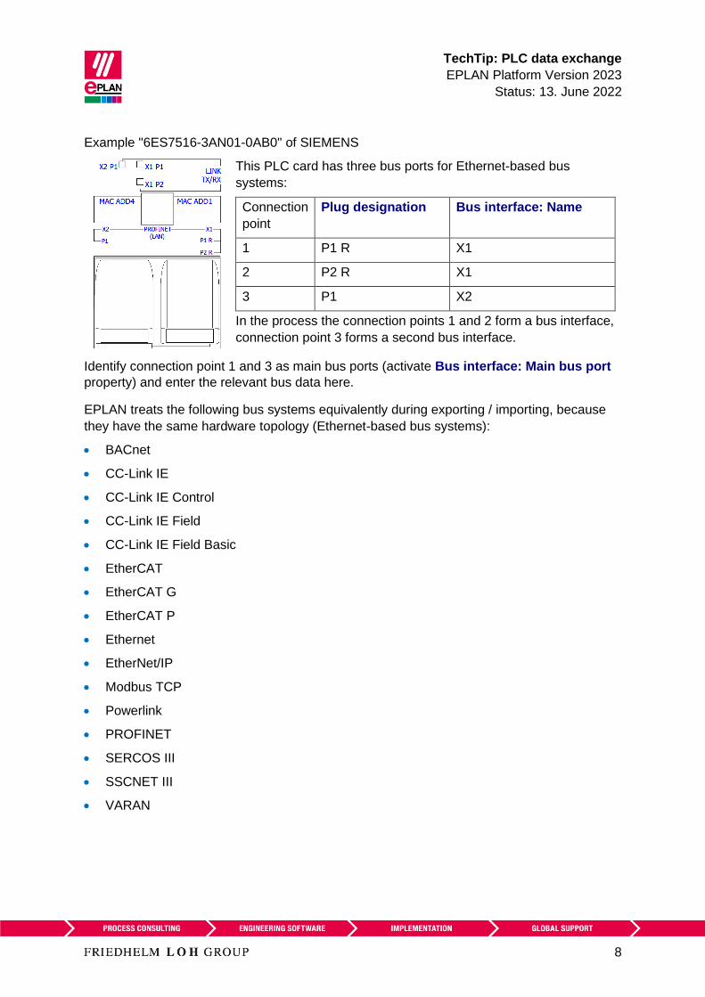
TechTip PLC data exchange
EPLAN Platform Version 2023
Status 13 June 2022
8
Example 6ES7516-3AN01-0AB0 of SIEMENS
This PLC card has three bus ports for Ethernet-based bus
systems
Connection
point
Plug designation Bus interface Name
1 P1 R X1
2 P2 R X1
3 P1 X2
In the process the connection points 1 and 2 form a bus interface
connection point 3 forms a second bus interface
Identify connection point 1 and 3 as main bus ports (activate Bus interface Main bus port
property) and enter the relevant bus data here
EPLAN treats the following bus systems equivalently during exporting importing because
they have the same hardware topology (Ethernet-based bus systems)
bull BACnet
bull CC-Link IE
bull CC-Link IE Control
bull CC-Link IE Field
bull CC-Link IE Field Basic
bull EtherCAT
bull EtherCAT G
bull EtherCAT P
bull Ethernet
bull EtherNetIP
bull Modbus TCP
bull Powerlink
bull PROFINET
bull SERCOS III
bull SSCNET III
bull VARAN
TechTip PLC data exchange
EPLAN Platform Version 2023
Status 13 June 2022
9
Special features of the EtherCAT bus system
bull The Physical network Bus ID item number property is not used for the EtherCAT
bus system The associated check run 004037 can be suppressed by activating the
property Ignore missing bus ID (ID 20412) for this bus port
bull The sequence of the bus ports is determined on the basis of the connections of the bus
nodes Therefore it is essential to configure the connections between the bus ports and
activate the option Export port-specific interconnection in the dialog Export PLC
data
Special features of the bus systems Local-Bus Extension DRIVE-CLiQ IO link
PortToPort and ET connection
bull These bus systems do not form a network
bull For these bus systems only the connection between the bus ports is exported (port-
specific interconnection)
bull The property Bus interface Name (ID 20447) must be identical at all associated bus
ports of a device an empty entry is permissible as well here
bull No bus address is required The associated check run 004037 can be suppressed by
activating the property Ignore missing bus ID (ID 20412) for this bus port
Note
A port-specific interconnection is only exported in the AutomationML AR APC format If
necessary you can deactivate this setting in the dialog Settings AutomationML AR APC
export
331 Connections between racks
Use the bus ports of the type Network bus cable connection point general for the
connection of racks with each other The Local-Bus Extension bus system must be set at
these bus ports
In addition take into account the special features described in the previous section for the
bus system Local Bus Extension
TechTip PLC data exchange
EPLAN Platform Version 2023
Status 13 June 2022
10
332 Automatic connections between associated bus ports
Network bus cable connection points of the type Network bus cable connection point
general are considered as belonging together and are automatically connected to each
other through an internal connection if they have the same DT belong to the same bus
system and have the same bus interface name Enter further data such as Physical
network Bus ID item number only at the main bus port of the bus interface
Note
A Network bus cable connection point general with empty bus interface name cannot
establish an internal connection to another Network bus cable connection point general
The check run 004040 can be used to find contradictory data
Note
During the PLC data exchange in the AutomationML AR APC format bus ports within the
same bus system and the same physical network (Physical network Name property) are
considered as connected with each other even if they have different DTs This is however
not evident during net tracking The 004104 check run reports such bus ports as not
connected to each other This message can be ignored if the network structure was
consciously configured like this due to the physical conditions
It is mandatory that the following properties be filled at the PLC bus port
ID Property
20006 DT
20406 Plug designation
20308 Bus system
20447 Bus interface Name
Must always be filled for Ethernet-based bus systems for other bus systems only if
automatic connections are to be generated between general network bus cable
connection points
TechTip PLC data exchange
EPLAN Platform Version 2023
Status 13 June 2022
11
The check run 004040 outputs a message when one of the following properties is different
ID Property
20413 Physical network Name
20414 Logical network Name
20310 Logical network Bus port is master
20311 Physical network Bus ID item number
20386 Physical network Bus ID item number 2
20309 DNSPROFINET device name
20313 Data transfer rate
20289 Integrated module
20334 MasterSystemID
20312 Subslot
20186 Marked for deletion
20446 Subnet mask
A check is carried out if the property to be checked is not empty at the second bus port
If the property to be checked is empty at the first bus port and is filled at the second bus port
a message is also output
TechTip PLC data exchange
EPLAN Platform Version 2023
Status 13 June 2022
12
4 Export from EPLAN
Before the export from EPLAN
1 Check the project by means of the check runs from the 004 range EPLAN makes
schemes available to you here that you use or adjust according to your requirements
2 Delete the data not required at the auxiliary functions (File gt Extras gt Command group
Organize gt Project gt Command group Optimize gt Compress project gt Field
Settings Button [] gt Remove project data gt Remove PLC structure data at PLC
auxiliary functions)
3 For an optimum PLC data exchange always configure all IO connection points and bus
ports of a device even when they are not connected
41 Hardware data
1 The EPLAN export references a configuration project that is specified at all the
associated PLC boxes
2 The bus ports are represented in single-line and are connected with each other During
the PLC data exchange in the AutomationML AR APC format multi-line representations
and bus ports connected to each other are also taken into consideration
3 A device is identified with the CPU property (check box is activated) The complete CPU name in the form [Configuration project][Station
ID][CPU identifier] must be unique project-wide
4 The device identification takes place by means of
a) the PLC type designation property or
b) a device description file (eg GSD GSDML EDS file property Device
description File name property) and the Object description or
c) a device description file (eg GSD GSDML EDS file property Device
description File name) and the Device description Index in file during the data
exchange in AutomationML AR APC format
The PLC type designation as a rule corresponds to the order number in the hardware
catalog of the respective PLC configuration program The exact spelling is important
Each PLC card can only have one device identification A combination of several parts by
entering several PLC type designations device description files or indexes is not supported
TechTip PLC data exchange
EPLAN Platform Version 2023
Status 13 June 2022
13
PLC connection points of the following categories are not exchanged
- General
- 2 connection points
- Power supply
- Card power supply
42 Assignment list
A PLC connection point (input output) existing in a assignment list (symbol table) is
exported if the following conditions are fulfilled
1 Only PLC connection points with the following function definitions are exchanged
a PLC connection point DI
b PLC connection point DO
c PLC connection point AI
d PLC connection point AO
e PLC connection point multi-function with the type of signal
bull Digital input
bull Digital output
bull Analog input
bull Analog output
(Exception PLC standard exchange format all PLC connection points are exchanged
here)
2 A PLC connection point multi-function is treated with its logic like the corresponding IO
connection For example
PLC connection point multi-function type of signal digital input corresponds to PLC
connection point DI
3 A CPU exists in a configuration project
4 The symbolic address is specified The symbolic address must be unique within a
CPU
5 The Data type (BOOL BYTE etc) is specified
6 The associated PLC box is assigned through specification of the property CPU Name
of a CPU
The correct and full specification of the CPU name at the PLC box is required so that
the assignment list (designation in the AutomationML AR APC format TagTable) can
be exported fully
TechTip PLC data exchange
EPLAN Platform Version 2023
Status 13 June 2022
14
5 Import in EPLAN
51 Devices
During importing EPLAN supplements item data such as inputs outputs from the parts data
1 The device identification takes place by means of
a) the PLC type designation property or
b) a GSD GSDML EDS file (Device description File name property) and the
Object description or
c) a GSD GSDML EDS file (property Device description File name) and the
Device description Index in file during the data exchange in AutomationML AR
APC format
2 If items with placeholder characters (such as and ) are found in the PLC type
designation in the parts database during an import into EPLAN the first suitable part is
used (PLC configuration programs do not always differentiate between parts that are
equivalent electrotechnically)
3 If multiple parts with the same PLC type designation are found during the import in
EPLAN the first of those parts with the matching Object description (in as far as this
import file is available) is assigned If no part has a matching object description the first
found part is assigned
4 If no appropriate part is found a simple PLC box is created
In these cases messages are output so that the imported devices can be checked
subsequently
Device and PLC connection points that are available in the project but not in the import file
have the Marked for deletion property assigned during import These objects can be filtered
in the PLC navigator and subsequently be edited Deactivate this property after the check or
editing
52 Connections
EPLAN detects existing connections during the import
New or changed connections are listed via the message management and have to be
created or changed by the user in EPLAN To this purpose the corresponding functions have
to be placed and connected to each other
TechTip PLC data exchange
EPLAN Platform Version 2023
Status 13 June 2022
15
6 Recommendation for preparation of the master data
EPLAN recommends prepared macros for standardization In many cases you can obtain the
parts and part macros from the EPLAN Data Portal It is nevertheless possible that a used
PLC card is not available there In this case you have to create the required parts and
macros yourself
The TechTip TechTip-Preparation-of-master-data-for-PLC-data-exchange is available
as an aid It contains additional information on editing parts data and the creation of macros
Appendix A Relevant properties contains an overview of all properties important for the
data exchange with the information on where the data can be entered
7 AutomationML AR APC
Details on the individual properties can be found in the TechTip TechTip-Overview-of-the-
PLC-properties
Free symbolic addresses (which are not assigned to any PLC connection point) can be
exported and imported in AutomationML AR APC format via the PLC data exchange After
the import of an AML file the free symbolic addresses existing there are available in EPLAN
The export in the AutomationML AR APC format can take place in the following AR APC
versions V100 V110 V120
Features in the export format for AutomationML AR APC Version 110
bull Through extensions in the AutomationML AR APC format longer device tags can be
replaced
bull An improved exchange of free symbolic addresses is possible through extensions in the
AutomationML AR APC format regarding the assignment list
bull The assignment of the PLC cards to your CPUs is replaced This way you can restore the
association of the PLC cards to their CPU during the data exchange
bull The bus system PortToPort can be used if you do not want to export the logical network
but only the connection between the bus ports (port-specific interconnection)
bull The bus systems DRIVE-CLiQ IO Link PortToPort and ET connection are
exchanged correctly with port-specific interconnection
bull The connections between racks are exchanged with port-specific interconnection
bull Safety addresses at the bus systems are exchanged
bull The manufacturer name at the devices can be replaced In EPLAN the manufacturer
name is saved in the part reference data
TechTip PLC data exchange
EPLAN Platform Version 2023
Status 13 June 2022
16
Features in the export format for AutomationML AR APC Version 120
bull The exchange of drive components is possible For the export of drives and drive
components you can activate the Export drives check box in the Settings
AutomationML AR APC export dialog
bull The exchange of device-specific configuration values is possible To this purpose you
can specify a template in the PLC device TemplateIdentifier or PLC station
TemplateIdentifier property or you can use user-defined part reference properties
Extensive information is provided in the TechTip TechTip-PLC-data-exchange-with-
device-related-configuration-values
Features in the export format for AutomationML AR APC Version 130
bull The exchange of symbolic addresses within user-defined data types (UDT) is possible
An import file in AutomationML AR APC format is always imported irrespective of the AR
APC version with which the file was created This means that all the data known for the
respective EPLAN version is imported
If the import file was created with a higher AR APC version than supported by the used
EPLAN version it is possible that not all file contents are imported As of EPLAN version 29
SP1 information is provided in this case
The following sections contain information about the bus systems and special features of
different devices
TechTip PLC data exchange
EPLAN Platform Version 2023
Status 13 June 2022
17
71 Settings for different bus systems
The following table provides an overview of the properties relevant for the PLC data
exchange in the AutomationML AR APC format Which properties at the bus ports must be
filled (x) should be filled or are optional (o) depends on the bus system being used
ID Property
Bus system
Ethernet-
based
PROFIBUS
DP
ASI DRIVE-CLiQ
IO link
PortToPort
ET-Connection
Local-Bus
extension
All others
20161 Configuration project o1 o1 o1 o1 o1
20308 Bus system x x x x x
20406 Plug designation x x x x x
20447 Bus interface Name x
20448 Bus interface Main
bus port
o
20413 Physical network
Name
o o o o
20311 Physical network
Bus ID item number
o o o o
20386 Physical network
Bus ID item number
2
o2
20446 Subnet mask o
20414 Logical network
Name
o o
20310 Logical network Bus
port is master
o o
20412 Ignore missing bus ID o3
1 Only required if the value deviates from that of the associated PLC box
2 Can be filled if it is an ASI dual device
3 Can be activated to ignore bus ports that do not require a bus address during the
execution of the 004037 error checking
TechTip PLC data exchange
EPLAN Platform Version 2023
Status 13 June 2022
18
Non-identified fields are not required for the PLC data exchange If the optional fields (o) are
left empty the import to the PLC configuration program is possible but post-processing is
required
Note
The properties Logical network Name and Logical network Bus port is master determine
the association of a station to the DP master or the IO controller
Within an IO system there is always a master that is designated through the check box
Logical network Bus port is master
72 PC station
1 The PC is a separate station and is configured as Rack 0 All other fields of the rack
assignment remain empty
2 The Bus coupler head station check box is to be activated
73 Switches
1 The switch is an own station and is configured as Rack 0 All other fields of the rack
assignment remain empty
2 The Bus coupler head station check box is to be activated
3 Bus ports
All bus ports have the function definition Network bus cable connection point general
and have the same bus interface names
a) All the required interface data are entered at the bus port that represents the
input (including Physical network Bus ID item number Bus interface Main
bus port)
b) At all other bus ports the specifications Physical network Name Logical
network Name and Physical network Bus ID item number amongst others
can be empty
TechTip PLC data exchange
EPLAN Platform Version 2023
Status 13 June 2022
19
Example SCALANCE X200IRT of SIEMENS
Settings at PLC box
ID Property Value
20416 PLC type designation 6GK5 204-0BA00-2BA3
20409 PLC station Type ScalanceX200IRT
Settings at the bus ports
20447 Bus interface Name X1 (for all bus ports)
20406 Plug designation Px R for all bus ports whereby x
= 1 Number of bus ports
Identify the first bus port as Bus interface Main bus port and enter the relevant bus data
here
74 Bus adapter
Stations of the ET 200SP type or similar or of a SCALANCE router require bus adapters
(media modules) to which the network connections are connected
In the case of these devices with adapter shafts for the bus ports the function templates for
the bus ports must be entered at the respective bus adapter Two parts must be created to
this purpose in the parts management
1 The device with the adapter shafts only has one function template for the PLC box
(main function) and if necessary further function templates for PLC inputs and outputs
2 The Bus adapter device has one function template for the PLC box (main function) as
well as function templates for the bus ports
Ensure that if the bus adapter is used on a head station the check box PLC card is placed
on head station (ID 20444) is activated in the device properties (PLC structure data tab) at
a bus adapter
In addition the device identification for the device with the adapter ducts and the Bus
adapter device must be carried out in the same way Either both must be identified by
means of the PLC type designation or both through the specification of a device description
file
TechTip PLC data exchange
EPLAN Platform Version 2023
Status 13 June 2022
20
Settings at the PLC box for the bus adapter
ID Property Value
20161 Configuration project Not empty
20416 PLC type designation eg 6ES7 193-6AR00-0AA0
20410 PLC card is placed on rack ID Like head station
20411 Position (slot module) Not empty
20444 PLC card is placed on head station
Settings at the bus ports
20447 Bus interface Name X1 (for all bus ports at all
adapters)
20406 Plug designation Px R for all bus ports whereby x
= 1 Number of bus ports the
method of counting is non-adapter-
specific
Identify the first bus port as Bus interface Main bus port and enter the relevant bus data
here
75 IO-Link devices
Devices that have bus ports of the IO-Link bus system are called IO-Link devices These
can either be part of a rack structure (for example an IO-Link master) or be located as an
independent device at any desired point in the network (for example a motor or sensor)
Additional information on the definition of PLC inputs and outputs or PLC bus ports can be
found in the TechTip TechTip-Preparation-of-master-data-for-PLC-data-exchange in
Section 24
751 IO-Link devices within a rack structure
IO-Link devices are parameterized like standard PLC devices within a rack structure
752 IO-Link devices outside a rack structure
The property dialog of a device depends on the function category The property dialog of a
PLC box thus contains the PLC structure data tab This tab is missing for non-PLC devices
In this case the required properties can be filled into the property table of the first tab
TechTip PLC data exchange
EPLAN Platform Version 2023
Status 13 June 2022
21
Settings at PLC box
ID Property
20161 Configuration project Not empty
20408 PLC station ID Not empty
Settings at the bus ports
ID Property
20308 Bus system IO Link
76 PLC subdevices
Specific PLC devices consist of multiple integrated modules that each have their own
Address ranges and start addresses Such a device can consist for example of an internal
CPU module an internal input output module internal analog module as well as an internal
counter module - however with only one part number Such integrated modules within a PLC
device can be displayed in EPLAN with PLC subdevices To this purpose up to twelve PLC
subdevices are available Each PLC subdevice is defined by the corresponding properties (x
in the following describes the number of PLC subdevice 1hellip12) You can find more
information in the Online help in the section PLC subdevices as well as in the TechTip
TechTip-Preparation-of-master-data-for-PLC-data-exchange in the chapter PLC
devices with subdevices
PLC subdevices are exported if they have at least one start address or one bus port or one
IO connection point or one Device identification
Note
If a PLC card has no PLC subdevices (meaning that it only consists of one module)
definitions for these can be omitted The value 0 is entered at the PLC subdevice Index
property at the associated PLC connection points
You obtain further information on the definition of PLC subdevices from your PLC
manufacturer or in the TechTip TechTip-Configuring-PLC-devices-with-device-
description-files
TechTip PLC data exchange
EPLAN Platform Version 2023
Status 13 June 2022
22
77 Accessories
A PLC card can have accessories
The requirement for a data exchange is
bull The accessory is defined in the parts management
bull The accessory has a PLC type designation
bull The number of units used is larger than 0
Note
You can deactivate the export of the accessories in the Settings AutomationML AR APC
export dialog if needed
78 Device sets (Bundles)
Device sets (so called Bundles meaning bundles that consist of different devices) are not
supported by all PLC configuration programs (for example SIEMENS STEP 7 TIA Portal) In
this case the device set for the PLC data exchange must be broken up by configuring the
devices contained in the device set individually with the associated device identification
79 Device-specific configuration values
As of AutomationML AR APC version 120 you can also specify device-specific
configuration values To do this activate the Export device-specific configuration values
check box in the Settings AutomationML AR APC export dialog
Further notes and specifications for handling of device-specific configuration values are
available in the Tech Tip TechTip-PLC-data-exchange-with-device-related-
configuration-values
TechTip PLC data exchange
EPLAN Platform Version 2023
Status 13 June 2022
23
710 Drives
As of AutomationML AR APC version 120 you can also specify drive components To do
this activate the Export drives check box in the Settings AutomationML AR APC export
dialog
If this check box is selected drive components are exported as well This means all other
functions that have a drive assigned are exported in addition to the PLC devices and bus-
capable devices
If the check box is deactivated only PLC devices and bus-capable devices are exported
Note During import the corresponding devices must be available in the parts management
otherwise an empty PLC box is created
For the export the following properties amongst others have to be filled at the drive
components
ID Property
20576 [1hellip 64] Drive
20415 Device description File name
20381 Device description Index in file
20577 Device type
20161 Configuration project
20417 Object description
20408 PLC station ID
20416 PLC type designation
TechTip PLC data exchange
EPLAN Platform Version 2023
Status 13 June 2022
24
8 Check of the PLC configuration project
All devices that atacutere to be exported or imported via PLC data exchange require the following
structure
1 Configuration project rarr This is the main node
2 Station ID rarr A grouping element
3 Rack rarr If the device is used as the basis for other devices this property has to be filled
numerically
A rack is numbered consecutively with the Rack property
A CPU or a bus coupler is numbered consecutively with a Rack if the device itself is not
placed on a rack
PLC devices that can add other PLC devices are also numbered consecutively with
Rack
4 All PLC devices that are placed on a rack or assigned to a rack receive the number of
the rack via the PLC card is placed on rack ID property
5 If the PLC card is placed on rack ID property is filled the position at which the device
is located has to be defined This is done via the Position (slot module) property
81 Check via message management
When checking the PLC configuration project you are supported by check runs In most
cases the PLC data exchange (Mitsubishi) run scheme can be used For adjustments of the
check runs a copy of this scheme is recommended
This check increases the quality of the project and helps with error prevention
TechTip PLC data exchange
EPLAN Platform Version 2023
Status 13 June 2022
25
Appendix A Relevant properties
The following overview shows which properties are important during the PLC data exchange
The data input in EPLAN can be effected
A = in the parts data
M = in the macro
P = in the project
We recommend entering the data preferably in the parts data and or in the macros
Note
If necessary you can create part variants in the EPLAN parts management
PLC connection point
ID Property Data input
A M P
20384 PLC subdevice Index x x x
20428 Channel designation x x x
20610 Symbolic address Group 1 - - x
20618 Symbolic address UDT (name) 2 - - x
20619 Symbolic address UDT (data type) 2 - - x
1 Exchange as of AutomationML AR APC Version 110
2 Exchange as of AutomationML AR APC Version 130
TechTip PLC data exchange
EPLAN Platform Version 2023
Status 13 June 2022
26
PLC bus port
ID Property Data input
A M P
20448 Bus interface Main bus port - x x
20447 Bus interface Name x x x
20386 Physical network Bus ID item number
2
- - x
20313 Data transfer rate - x x
20289 Integrated module - x x
20312 Subslot - x x
20308 Bus system x x x
20446 Subnet mask - x x
20613 Standard gateway - x x
20309 DNSPROFINET device name - x x
Exchange as of AutomationML AR APC Version 120
PLC card
ID Property Data input
A M P
20437 PLC card name - - x
20164 Bus coupler head station x x x
20381 Device description Index in file x x x
20521 foll PLC subdevice x Name x x x
20533 foll PLC subdevice x Position (slot module) x x x
20454 20382 20392
foll 20452 foll
PLC subdevice x Start address (inputs) - - x
20455 foll 20478
foll 20515 foll
PLC subdevice x Start address (outputs) - - x
TechTip PLC data exchange
EPLAN Platform Version 2023
Status 13 June 2022
27
ID Property Data input
A M P
20548 20605
20547 20551foll
20570
PLC subdevice x Data length (inputs) x x x
20550 20604
20549 20560foll
PLC subdevice x Data length (outputs) x x x
20607
20582 foll
PLC subdevice x PLC type designation x x x
20606
20593 foll
PLC subdevice x Device description
Index in file
x x x
20417 Object description x x x
20550 PLC device Data length (outputs) x x x
20548 PLC device Data length (inputs) x x x
20289 Integrated module - x x
20444 PLC card is placed on head station x x x
20312 Subslot - x x
20439 Safety address Target 1 - - x
20615 Safety address Source 1 - - x
20616 Safety address Upper value 1 - - x 3
20617 Safety address Lower value 1 - - x 3
20409 PLC station Type x x x
20580 PLC device TemplateIdentifier 2 x x x
20614 PLC station TemplateIdentifier 2 - x x
20576 Drive 2 - x x
1 Exchange as of AutomationML AR APC Version 110
2 Exchange as of AutomationML AR APC Version 120
3 Values in EPLAN are write-protected and are only filled via the PLC data exchange
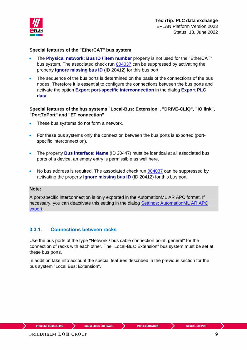
TechTip PLC data exchange
EPLAN Platform Version 2023
Status 13 June 2022
9
Special features of the EtherCAT bus system
bull The Physical network Bus ID item number property is not used for the EtherCAT
bus system The associated check run 004037 can be suppressed by activating the
property Ignore missing bus ID (ID 20412) for this bus port
bull The sequence of the bus ports is determined on the basis of the connections of the bus
nodes Therefore it is essential to configure the connections between the bus ports and
activate the option Export port-specific interconnection in the dialog Export PLC
data
Special features of the bus systems Local-Bus Extension DRIVE-CLiQ IO link
PortToPort and ET connection
bull These bus systems do not form a network
bull For these bus systems only the connection between the bus ports is exported (port-
specific interconnection)
bull The property Bus interface Name (ID 20447) must be identical at all associated bus
ports of a device an empty entry is permissible as well here
bull No bus address is required The associated check run 004037 can be suppressed by
activating the property Ignore missing bus ID (ID 20412) for this bus port
Note
A port-specific interconnection is only exported in the AutomationML AR APC format If
necessary you can deactivate this setting in the dialog Settings AutomationML AR APC
export
331 Connections between racks
Use the bus ports of the type Network bus cable connection point general for the
connection of racks with each other The Local-Bus Extension bus system must be set at
these bus ports
In addition take into account the special features described in the previous section for the
bus system Local Bus Extension
TechTip PLC data exchange
EPLAN Platform Version 2023
Status 13 June 2022
10
332 Automatic connections between associated bus ports
Network bus cable connection points of the type Network bus cable connection point
general are considered as belonging together and are automatically connected to each
other through an internal connection if they have the same DT belong to the same bus
system and have the same bus interface name Enter further data such as Physical
network Bus ID item number only at the main bus port of the bus interface
Note
A Network bus cable connection point general with empty bus interface name cannot
establish an internal connection to another Network bus cable connection point general
The check run 004040 can be used to find contradictory data
Note
During the PLC data exchange in the AutomationML AR APC format bus ports within the
same bus system and the same physical network (Physical network Name property) are
considered as connected with each other even if they have different DTs This is however
not evident during net tracking The 004104 check run reports such bus ports as not
connected to each other This message can be ignored if the network structure was
consciously configured like this due to the physical conditions
It is mandatory that the following properties be filled at the PLC bus port
ID Property
20006 DT
20406 Plug designation
20308 Bus system
20447 Bus interface Name
Must always be filled for Ethernet-based bus systems for other bus systems only if
automatic connections are to be generated between general network bus cable
connection points
TechTip PLC data exchange
EPLAN Platform Version 2023
Status 13 June 2022
11
The check run 004040 outputs a message when one of the following properties is different
ID Property
20413 Physical network Name
20414 Logical network Name
20310 Logical network Bus port is master
20311 Physical network Bus ID item number
20386 Physical network Bus ID item number 2
20309 DNSPROFINET device name
20313 Data transfer rate
20289 Integrated module
20334 MasterSystemID
20312 Subslot
20186 Marked for deletion
20446 Subnet mask
A check is carried out if the property to be checked is not empty at the second bus port
If the property to be checked is empty at the first bus port and is filled at the second bus port
a message is also output
TechTip PLC data exchange
EPLAN Platform Version 2023
Status 13 June 2022
12
4 Export from EPLAN
Before the export from EPLAN
1 Check the project by means of the check runs from the 004 range EPLAN makes
schemes available to you here that you use or adjust according to your requirements
2 Delete the data not required at the auxiliary functions (File gt Extras gt Command group
Organize gt Project gt Command group Optimize gt Compress project gt Field
Settings Button [] gt Remove project data gt Remove PLC structure data at PLC
auxiliary functions)
3 For an optimum PLC data exchange always configure all IO connection points and bus
ports of a device even when they are not connected
41 Hardware data
1 The EPLAN export references a configuration project that is specified at all the
associated PLC boxes
2 The bus ports are represented in single-line and are connected with each other During
the PLC data exchange in the AutomationML AR APC format multi-line representations
and bus ports connected to each other are also taken into consideration
3 A device is identified with the CPU property (check box is activated) The complete CPU name in the form [Configuration project][Station
ID][CPU identifier] must be unique project-wide
4 The device identification takes place by means of
a) the PLC type designation property or
b) a device description file (eg GSD GSDML EDS file property Device
description File name property) and the Object description or
c) a device description file (eg GSD GSDML EDS file property Device
description File name) and the Device description Index in file during the data
exchange in AutomationML AR APC format
The PLC type designation as a rule corresponds to the order number in the hardware
catalog of the respective PLC configuration program The exact spelling is important
Each PLC card can only have one device identification A combination of several parts by
entering several PLC type designations device description files or indexes is not supported
TechTip PLC data exchange
EPLAN Platform Version 2023
Status 13 June 2022
13
PLC connection points of the following categories are not exchanged
- General
- 2 connection points
- Power supply
- Card power supply
42 Assignment list
A PLC connection point (input output) existing in a assignment list (symbol table) is
exported if the following conditions are fulfilled
1 Only PLC connection points with the following function definitions are exchanged
a PLC connection point DI
b PLC connection point DO
c PLC connection point AI
d PLC connection point AO
e PLC connection point multi-function with the type of signal
bull Digital input
bull Digital output
bull Analog input
bull Analog output
(Exception PLC standard exchange format all PLC connection points are exchanged
here)
2 A PLC connection point multi-function is treated with its logic like the corresponding IO
connection For example
PLC connection point multi-function type of signal digital input corresponds to PLC
connection point DI
3 A CPU exists in a configuration project
4 The symbolic address is specified The symbolic address must be unique within a
CPU
5 The Data type (BOOL BYTE etc) is specified
6 The associated PLC box is assigned through specification of the property CPU Name
of a CPU
The correct and full specification of the CPU name at the PLC box is required so that
the assignment list (designation in the AutomationML AR APC format TagTable) can
be exported fully
TechTip PLC data exchange
EPLAN Platform Version 2023
Status 13 June 2022
14
5 Import in EPLAN
51 Devices
During importing EPLAN supplements item data such as inputs outputs from the parts data
1 The device identification takes place by means of
a) the PLC type designation property or
b) a GSD GSDML EDS file (Device description File name property) and the
Object description or
c) a GSD GSDML EDS file (property Device description File name) and the
Device description Index in file during the data exchange in AutomationML AR
APC format
2 If items with placeholder characters (such as and ) are found in the PLC type
designation in the parts database during an import into EPLAN the first suitable part is
used (PLC configuration programs do not always differentiate between parts that are
equivalent electrotechnically)
3 If multiple parts with the same PLC type designation are found during the import in
EPLAN the first of those parts with the matching Object description (in as far as this
import file is available) is assigned If no part has a matching object description the first
found part is assigned
4 If no appropriate part is found a simple PLC box is created
In these cases messages are output so that the imported devices can be checked
subsequently
Device and PLC connection points that are available in the project but not in the import file
have the Marked for deletion property assigned during import These objects can be filtered
in the PLC navigator and subsequently be edited Deactivate this property after the check or
editing
52 Connections
EPLAN detects existing connections during the import
New or changed connections are listed via the message management and have to be
created or changed by the user in EPLAN To this purpose the corresponding functions have
to be placed and connected to each other
TechTip PLC data exchange
EPLAN Platform Version 2023
Status 13 June 2022
15
6 Recommendation for preparation of the master data
EPLAN recommends prepared macros for standardization In many cases you can obtain the
parts and part macros from the EPLAN Data Portal It is nevertheless possible that a used
PLC card is not available there In this case you have to create the required parts and
macros yourself
The TechTip TechTip-Preparation-of-master-data-for-PLC-data-exchange is available
as an aid It contains additional information on editing parts data and the creation of macros
Appendix A Relevant properties contains an overview of all properties important for the
data exchange with the information on where the data can be entered
7 AutomationML AR APC
Details on the individual properties can be found in the TechTip TechTip-Overview-of-the-
PLC-properties
Free symbolic addresses (which are not assigned to any PLC connection point) can be
exported and imported in AutomationML AR APC format via the PLC data exchange After
the import of an AML file the free symbolic addresses existing there are available in EPLAN
The export in the AutomationML AR APC format can take place in the following AR APC
versions V100 V110 V120
Features in the export format for AutomationML AR APC Version 110
bull Through extensions in the AutomationML AR APC format longer device tags can be
replaced
bull An improved exchange of free symbolic addresses is possible through extensions in the
AutomationML AR APC format regarding the assignment list
bull The assignment of the PLC cards to your CPUs is replaced This way you can restore the
association of the PLC cards to their CPU during the data exchange
bull The bus system PortToPort can be used if you do not want to export the logical network
but only the connection between the bus ports (port-specific interconnection)
bull The bus systems DRIVE-CLiQ IO Link PortToPort and ET connection are
exchanged correctly with port-specific interconnection
bull The connections between racks are exchanged with port-specific interconnection
bull Safety addresses at the bus systems are exchanged
bull The manufacturer name at the devices can be replaced In EPLAN the manufacturer
name is saved in the part reference data
TechTip PLC data exchange
EPLAN Platform Version 2023
Status 13 June 2022
16
Features in the export format for AutomationML AR APC Version 120
bull The exchange of drive components is possible For the export of drives and drive
components you can activate the Export drives check box in the Settings
AutomationML AR APC export dialog
bull The exchange of device-specific configuration values is possible To this purpose you
can specify a template in the PLC device TemplateIdentifier or PLC station
TemplateIdentifier property or you can use user-defined part reference properties
Extensive information is provided in the TechTip TechTip-PLC-data-exchange-with-
device-related-configuration-values
Features in the export format for AutomationML AR APC Version 130
bull The exchange of symbolic addresses within user-defined data types (UDT) is possible
An import file in AutomationML AR APC format is always imported irrespective of the AR
APC version with which the file was created This means that all the data known for the
respective EPLAN version is imported
If the import file was created with a higher AR APC version than supported by the used
EPLAN version it is possible that not all file contents are imported As of EPLAN version 29
SP1 information is provided in this case
The following sections contain information about the bus systems and special features of
different devices
TechTip PLC data exchange
EPLAN Platform Version 2023
Status 13 June 2022
17
71 Settings for different bus systems
The following table provides an overview of the properties relevant for the PLC data
exchange in the AutomationML AR APC format Which properties at the bus ports must be
filled (x) should be filled or are optional (o) depends on the bus system being used
ID Property
Bus system
Ethernet-
based
PROFIBUS
DP
ASI DRIVE-CLiQ
IO link
PortToPort
ET-Connection
Local-Bus
extension
All others
20161 Configuration project o1 o1 o1 o1 o1
20308 Bus system x x x x x
20406 Plug designation x x x x x
20447 Bus interface Name x
20448 Bus interface Main
bus port
o
20413 Physical network
Name
o o o o
20311 Physical network
Bus ID item number
o o o o
20386 Physical network
Bus ID item number
2
o2
20446 Subnet mask o
20414 Logical network
Name
o o
20310 Logical network Bus
port is master
o o
20412 Ignore missing bus ID o3
1 Only required if the value deviates from that of the associated PLC box
2 Can be filled if it is an ASI dual device
3 Can be activated to ignore bus ports that do not require a bus address during the
execution of the 004037 error checking
TechTip PLC data exchange
EPLAN Platform Version 2023
Status 13 June 2022
18
Non-identified fields are not required for the PLC data exchange If the optional fields (o) are
left empty the import to the PLC configuration program is possible but post-processing is
required
Note
The properties Logical network Name and Logical network Bus port is master determine
the association of a station to the DP master or the IO controller
Within an IO system there is always a master that is designated through the check box
Logical network Bus port is master
72 PC station
1 The PC is a separate station and is configured as Rack 0 All other fields of the rack
assignment remain empty
2 The Bus coupler head station check box is to be activated
73 Switches
1 The switch is an own station and is configured as Rack 0 All other fields of the rack
assignment remain empty
2 The Bus coupler head station check box is to be activated
3 Bus ports
All bus ports have the function definition Network bus cable connection point general
and have the same bus interface names
a) All the required interface data are entered at the bus port that represents the
input (including Physical network Bus ID item number Bus interface Main
bus port)
b) At all other bus ports the specifications Physical network Name Logical
network Name and Physical network Bus ID item number amongst others
can be empty
TechTip PLC data exchange
EPLAN Platform Version 2023
Status 13 June 2022
19
Example SCALANCE X200IRT of SIEMENS
Settings at PLC box
ID Property Value
20416 PLC type designation 6GK5 204-0BA00-2BA3
20409 PLC station Type ScalanceX200IRT
Settings at the bus ports
20447 Bus interface Name X1 (for all bus ports)
20406 Plug designation Px R for all bus ports whereby x
= 1 Number of bus ports
Identify the first bus port as Bus interface Main bus port and enter the relevant bus data
here
74 Bus adapter
Stations of the ET 200SP type or similar or of a SCALANCE router require bus adapters
(media modules) to which the network connections are connected
In the case of these devices with adapter shafts for the bus ports the function templates for
the bus ports must be entered at the respective bus adapter Two parts must be created to
this purpose in the parts management
1 The device with the adapter shafts only has one function template for the PLC box
(main function) and if necessary further function templates for PLC inputs and outputs
2 The Bus adapter device has one function template for the PLC box (main function) as
well as function templates for the bus ports
Ensure that if the bus adapter is used on a head station the check box PLC card is placed
on head station (ID 20444) is activated in the device properties (PLC structure data tab) at
a bus adapter
In addition the device identification for the device with the adapter ducts and the Bus
adapter device must be carried out in the same way Either both must be identified by
means of the PLC type designation or both through the specification of a device description
file
TechTip PLC data exchange
EPLAN Platform Version 2023
Status 13 June 2022
20
Settings at the PLC box for the bus adapter
ID Property Value
20161 Configuration project Not empty
20416 PLC type designation eg 6ES7 193-6AR00-0AA0
20410 PLC card is placed on rack ID Like head station
20411 Position (slot module) Not empty
20444 PLC card is placed on head station
Settings at the bus ports
20447 Bus interface Name X1 (for all bus ports at all
adapters)
20406 Plug designation Px R for all bus ports whereby x
= 1 Number of bus ports the
method of counting is non-adapter-
specific
Identify the first bus port as Bus interface Main bus port and enter the relevant bus data
here
75 IO-Link devices
Devices that have bus ports of the IO-Link bus system are called IO-Link devices These
can either be part of a rack structure (for example an IO-Link master) or be located as an
independent device at any desired point in the network (for example a motor or sensor)
Additional information on the definition of PLC inputs and outputs or PLC bus ports can be
found in the TechTip TechTip-Preparation-of-master-data-for-PLC-data-exchange in
Section 24
751 IO-Link devices within a rack structure
IO-Link devices are parameterized like standard PLC devices within a rack structure
752 IO-Link devices outside a rack structure
The property dialog of a device depends on the function category The property dialog of a
PLC box thus contains the PLC structure data tab This tab is missing for non-PLC devices
In this case the required properties can be filled into the property table of the first tab
TechTip PLC data exchange
EPLAN Platform Version 2023
Status 13 June 2022
21
Settings at PLC box
ID Property
20161 Configuration project Not empty
20408 PLC station ID Not empty
Settings at the bus ports
ID Property
20308 Bus system IO Link
76 PLC subdevices
Specific PLC devices consist of multiple integrated modules that each have their own
Address ranges and start addresses Such a device can consist for example of an internal
CPU module an internal input output module internal analog module as well as an internal
counter module - however with only one part number Such integrated modules within a PLC
device can be displayed in EPLAN with PLC subdevices To this purpose up to twelve PLC
subdevices are available Each PLC subdevice is defined by the corresponding properties (x
in the following describes the number of PLC subdevice 1hellip12) You can find more
information in the Online help in the section PLC subdevices as well as in the TechTip
TechTip-Preparation-of-master-data-for-PLC-data-exchange in the chapter PLC
devices with subdevices
PLC subdevices are exported if they have at least one start address or one bus port or one
IO connection point or one Device identification
Note
If a PLC card has no PLC subdevices (meaning that it only consists of one module)
definitions for these can be omitted The value 0 is entered at the PLC subdevice Index
property at the associated PLC connection points
You obtain further information on the definition of PLC subdevices from your PLC
manufacturer or in the TechTip TechTip-Configuring-PLC-devices-with-device-
description-files
TechTip PLC data exchange
EPLAN Platform Version 2023
Status 13 June 2022
22
77 Accessories
A PLC card can have accessories
The requirement for a data exchange is
bull The accessory is defined in the parts management
bull The accessory has a PLC type designation
bull The number of units used is larger than 0
Note
You can deactivate the export of the accessories in the Settings AutomationML AR APC
export dialog if needed
78 Device sets (Bundles)
Device sets (so called Bundles meaning bundles that consist of different devices) are not
supported by all PLC configuration programs (for example SIEMENS STEP 7 TIA Portal) In
this case the device set for the PLC data exchange must be broken up by configuring the
devices contained in the device set individually with the associated device identification
79 Device-specific configuration values
As of AutomationML AR APC version 120 you can also specify device-specific
configuration values To do this activate the Export device-specific configuration values
check box in the Settings AutomationML AR APC export dialog
Further notes and specifications for handling of device-specific configuration values are
available in the Tech Tip TechTip-PLC-data-exchange-with-device-related-
configuration-values
TechTip PLC data exchange
EPLAN Platform Version 2023
Status 13 June 2022
23
710 Drives
As of AutomationML AR APC version 120 you can also specify drive components To do
this activate the Export drives check box in the Settings AutomationML AR APC export
dialog
If this check box is selected drive components are exported as well This means all other
functions that have a drive assigned are exported in addition to the PLC devices and bus-
capable devices
If the check box is deactivated only PLC devices and bus-capable devices are exported
Note During import the corresponding devices must be available in the parts management
otherwise an empty PLC box is created
For the export the following properties amongst others have to be filled at the drive
components
ID Property
20576 [1hellip 64] Drive
20415 Device description File name
20381 Device description Index in file
20577 Device type
20161 Configuration project
20417 Object description
20408 PLC station ID
20416 PLC type designation
TechTip PLC data exchange
EPLAN Platform Version 2023
Status 13 June 2022
24
8 Check of the PLC configuration project
All devices that atacutere to be exported or imported via PLC data exchange require the following
structure
1 Configuration project rarr This is the main node
2 Station ID rarr A grouping element
3 Rack rarr If the device is used as the basis for other devices this property has to be filled
numerically
A rack is numbered consecutively with the Rack property
A CPU or a bus coupler is numbered consecutively with a Rack if the device itself is not
placed on a rack
PLC devices that can add other PLC devices are also numbered consecutively with
Rack
4 All PLC devices that are placed on a rack or assigned to a rack receive the number of
the rack via the PLC card is placed on rack ID property
5 If the PLC card is placed on rack ID property is filled the position at which the device
is located has to be defined This is done via the Position (slot module) property
81 Check via message management
When checking the PLC configuration project you are supported by check runs In most
cases the PLC data exchange (Mitsubishi) run scheme can be used For adjustments of the
check runs a copy of this scheme is recommended
This check increases the quality of the project and helps with error prevention
TechTip PLC data exchange
EPLAN Platform Version 2023
Status 13 June 2022
25
Appendix A Relevant properties
The following overview shows which properties are important during the PLC data exchange
The data input in EPLAN can be effected
A = in the parts data
M = in the macro
P = in the project
We recommend entering the data preferably in the parts data and or in the macros
Note
If necessary you can create part variants in the EPLAN parts management
PLC connection point
ID Property Data input
A M P
20384 PLC subdevice Index x x x
20428 Channel designation x x x
20610 Symbolic address Group 1 - - x
20618 Symbolic address UDT (name) 2 - - x
20619 Symbolic address UDT (data type) 2 - - x
1 Exchange as of AutomationML AR APC Version 110
2 Exchange as of AutomationML AR APC Version 130
TechTip PLC data exchange
EPLAN Platform Version 2023
Status 13 June 2022
26
PLC bus port
ID Property Data input
A M P
20448 Bus interface Main bus port - x x
20447 Bus interface Name x x x
20386 Physical network Bus ID item number
2
- - x
20313 Data transfer rate - x x
20289 Integrated module - x x
20312 Subslot - x x
20308 Bus system x x x
20446 Subnet mask - x x
20613 Standard gateway - x x
20309 DNSPROFINET device name - x x
Exchange as of AutomationML AR APC Version 120
PLC card
ID Property Data input
A M P
20437 PLC card name - - x
20164 Bus coupler head station x x x
20381 Device description Index in file x x x
20521 foll PLC subdevice x Name x x x
20533 foll PLC subdevice x Position (slot module) x x x
20454 20382 20392
foll 20452 foll
PLC subdevice x Start address (inputs) - - x
20455 foll 20478
foll 20515 foll
PLC subdevice x Start address (outputs) - - x
TechTip PLC data exchange
EPLAN Platform Version 2023
Status 13 June 2022
27
ID Property Data input
A M P
20548 20605
20547 20551foll
20570
PLC subdevice x Data length (inputs) x x x
20550 20604
20549 20560foll
PLC subdevice x Data length (outputs) x x x
20607
20582 foll
PLC subdevice x PLC type designation x x x
20606
20593 foll
PLC subdevice x Device description
Index in file
x x x
20417 Object description x x x
20550 PLC device Data length (outputs) x x x
20548 PLC device Data length (inputs) x x x
20289 Integrated module - x x
20444 PLC card is placed on head station x x x
20312 Subslot - x x
20439 Safety address Target 1 - - x
20615 Safety address Source 1 - - x
20616 Safety address Upper value 1 - - x 3
20617 Safety address Lower value 1 - - x 3
20409 PLC station Type x x x
20580 PLC device TemplateIdentifier 2 x x x
20614 PLC station TemplateIdentifier 2 - x x
20576 Drive 2 - x x
1 Exchange as of AutomationML AR APC Version 110
2 Exchange as of AutomationML AR APC Version 120
3 Values in EPLAN are write-protected and are only filled via the PLC data exchange
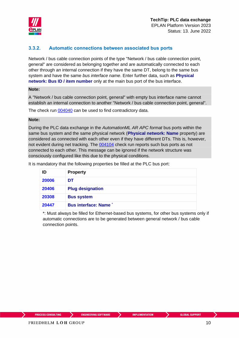
TechTip PLC data exchange
EPLAN Platform Version 2023
Status 13 June 2022
10
332 Automatic connections between associated bus ports
Network bus cable connection points of the type Network bus cable connection point
general are considered as belonging together and are automatically connected to each
other through an internal connection if they have the same DT belong to the same bus
system and have the same bus interface name Enter further data such as Physical
network Bus ID item number only at the main bus port of the bus interface
Note
A Network bus cable connection point general with empty bus interface name cannot
establish an internal connection to another Network bus cable connection point general
The check run 004040 can be used to find contradictory data
Note
During the PLC data exchange in the AutomationML AR APC format bus ports within the
same bus system and the same physical network (Physical network Name property) are
considered as connected with each other even if they have different DTs This is however
not evident during net tracking The 004104 check run reports such bus ports as not
connected to each other This message can be ignored if the network structure was
consciously configured like this due to the physical conditions
It is mandatory that the following properties be filled at the PLC bus port
ID Property
20006 DT
20406 Plug designation
20308 Bus system
20447 Bus interface Name
Must always be filled for Ethernet-based bus systems for other bus systems only if
automatic connections are to be generated between general network bus cable
connection points
TechTip PLC data exchange
EPLAN Platform Version 2023
Status 13 June 2022
11
The check run 004040 outputs a message when one of the following properties is different
ID Property
20413 Physical network Name
20414 Logical network Name
20310 Logical network Bus port is master
20311 Physical network Bus ID item number
20386 Physical network Bus ID item number 2
20309 DNSPROFINET device name
20313 Data transfer rate
20289 Integrated module
20334 MasterSystemID
20312 Subslot
20186 Marked for deletion
20446 Subnet mask
A check is carried out if the property to be checked is not empty at the second bus port
If the property to be checked is empty at the first bus port and is filled at the second bus port
a message is also output
TechTip PLC data exchange
EPLAN Platform Version 2023
Status 13 June 2022
12
4 Export from EPLAN
Before the export from EPLAN
1 Check the project by means of the check runs from the 004 range EPLAN makes
schemes available to you here that you use or adjust according to your requirements
2 Delete the data not required at the auxiliary functions (File gt Extras gt Command group
Organize gt Project gt Command group Optimize gt Compress project gt Field
Settings Button [] gt Remove project data gt Remove PLC structure data at PLC
auxiliary functions)
3 For an optimum PLC data exchange always configure all IO connection points and bus
ports of a device even when they are not connected
41 Hardware data
1 The EPLAN export references a configuration project that is specified at all the
associated PLC boxes
2 The bus ports are represented in single-line and are connected with each other During
the PLC data exchange in the AutomationML AR APC format multi-line representations
and bus ports connected to each other are also taken into consideration
3 A device is identified with the CPU property (check box is activated) The complete CPU name in the form [Configuration project][Station
ID][CPU identifier] must be unique project-wide
4 The device identification takes place by means of
a) the PLC type designation property or
b) a device description file (eg GSD GSDML EDS file property Device
description File name property) and the Object description or
c) a device description file (eg GSD GSDML EDS file property Device
description File name) and the Device description Index in file during the data
exchange in AutomationML AR APC format
The PLC type designation as a rule corresponds to the order number in the hardware
catalog of the respective PLC configuration program The exact spelling is important
Each PLC card can only have one device identification A combination of several parts by
entering several PLC type designations device description files or indexes is not supported
TechTip PLC data exchange
EPLAN Platform Version 2023
Status 13 June 2022
13
PLC connection points of the following categories are not exchanged
- General
- 2 connection points
- Power supply
- Card power supply
42 Assignment list
A PLC connection point (input output) existing in a assignment list (symbol table) is
exported if the following conditions are fulfilled
1 Only PLC connection points with the following function definitions are exchanged
a PLC connection point DI
b PLC connection point DO
c PLC connection point AI
d PLC connection point AO
e PLC connection point multi-function with the type of signal
bull Digital input
bull Digital output
bull Analog input
bull Analog output
(Exception PLC standard exchange format all PLC connection points are exchanged
here)
2 A PLC connection point multi-function is treated with its logic like the corresponding IO
connection For example
PLC connection point multi-function type of signal digital input corresponds to PLC
connection point DI
3 A CPU exists in a configuration project
4 The symbolic address is specified The symbolic address must be unique within a
CPU
5 The Data type (BOOL BYTE etc) is specified
6 The associated PLC box is assigned through specification of the property CPU Name
of a CPU
The correct and full specification of the CPU name at the PLC box is required so that
the assignment list (designation in the AutomationML AR APC format TagTable) can
be exported fully
TechTip PLC data exchange
EPLAN Platform Version 2023
Status 13 June 2022
14
5 Import in EPLAN
51 Devices
During importing EPLAN supplements item data such as inputs outputs from the parts data
1 The device identification takes place by means of
a) the PLC type designation property or
b) a GSD GSDML EDS file (Device description File name property) and the
Object description or
c) a GSD GSDML EDS file (property Device description File name) and the
Device description Index in file during the data exchange in AutomationML AR
APC format
2 If items with placeholder characters (such as and ) are found in the PLC type
designation in the parts database during an import into EPLAN the first suitable part is
used (PLC configuration programs do not always differentiate between parts that are
equivalent electrotechnically)
3 If multiple parts with the same PLC type designation are found during the import in
EPLAN the first of those parts with the matching Object description (in as far as this
import file is available) is assigned If no part has a matching object description the first
found part is assigned
4 If no appropriate part is found a simple PLC box is created
In these cases messages are output so that the imported devices can be checked
subsequently
Device and PLC connection points that are available in the project but not in the import file
have the Marked for deletion property assigned during import These objects can be filtered
in the PLC navigator and subsequently be edited Deactivate this property after the check or
editing
52 Connections
EPLAN detects existing connections during the import
New or changed connections are listed via the message management and have to be
created or changed by the user in EPLAN To this purpose the corresponding functions have
to be placed and connected to each other
TechTip PLC data exchange
EPLAN Platform Version 2023
Status 13 June 2022
15
6 Recommendation for preparation of the master data
EPLAN recommends prepared macros for standardization In many cases you can obtain the
parts and part macros from the EPLAN Data Portal It is nevertheless possible that a used
PLC card is not available there In this case you have to create the required parts and
macros yourself
The TechTip TechTip-Preparation-of-master-data-for-PLC-data-exchange is available
as an aid It contains additional information on editing parts data and the creation of macros
Appendix A Relevant properties contains an overview of all properties important for the
data exchange with the information on where the data can be entered
7 AutomationML AR APC
Details on the individual properties can be found in the TechTip TechTip-Overview-of-the-
PLC-properties
Free symbolic addresses (which are not assigned to any PLC connection point) can be
exported and imported in AutomationML AR APC format via the PLC data exchange After
the import of an AML file the free symbolic addresses existing there are available in EPLAN
The export in the AutomationML AR APC format can take place in the following AR APC
versions V100 V110 V120
Features in the export format for AutomationML AR APC Version 110
bull Through extensions in the AutomationML AR APC format longer device tags can be
replaced
bull An improved exchange of free symbolic addresses is possible through extensions in the
AutomationML AR APC format regarding the assignment list
bull The assignment of the PLC cards to your CPUs is replaced This way you can restore the
association of the PLC cards to their CPU during the data exchange
bull The bus system PortToPort can be used if you do not want to export the logical network
but only the connection between the bus ports (port-specific interconnection)
bull The bus systems DRIVE-CLiQ IO Link PortToPort and ET connection are
exchanged correctly with port-specific interconnection
bull The connections between racks are exchanged with port-specific interconnection
bull Safety addresses at the bus systems are exchanged
bull The manufacturer name at the devices can be replaced In EPLAN the manufacturer
name is saved in the part reference data
TechTip PLC data exchange
EPLAN Platform Version 2023
Status 13 June 2022
16
Features in the export format for AutomationML AR APC Version 120
bull The exchange of drive components is possible For the export of drives and drive
components you can activate the Export drives check box in the Settings
AutomationML AR APC export dialog
bull The exchange of device-specific configuration values is possible To this purpose you
can specify a template in the PLC device TemplateIdentifier or PLC station
TemplateIdentifier property or you can use user-defined part reference properties
Extensive information is provided in the TechTip TechTip-PLC-data-exchange-with-
device-related-configuration-values
Features in the export format for AutomationML AR APC Version 130
bull The exchange of symbolic addresses within user-defined data types (UDT) is possible
An import file in AutomationML AR APC format is always imported irrespective of the AR
APC version with which the file was created This means that all the data known for the
respective EPLAN version is imported
If the import file was created with a higher AR APC version than supported by the used
EPLAN version it is possible that not all file contents are imported As of EPLAN version 29
SP1 information is provided in this case
The following sections contain information about the bus systems and special features of
different devices
TechTip PLC data exchange
EPLAN Platform Version 2023
Status 13 June 2022
17
71 Settings for different bus systems
The following table provides an overview of the properties relevant for the PLC data
exchange in the AutomationML AR APC format Which properties at the bus ports must be
filled (x) should be filled or are optional (o) depends on the bus system being used
ID Property
Bus system
Ethernet-
based
PROFIBUS
DP
ASI DRIVE-CLiQ
IO link
PortToPort
ET-Connection
Local-Bus
extension
All others
20161 Configuration project o1 o1 o1 o1 o1
20308 Bus system x x x x x
20406 Plug designation x x x x x
20447 Bus interface Name x
20448 Bus interface Main
bus port
o
20413 Physical network
Name
o o o o
20311 Physical network
Bus ID item number
o o o o
20386 Physical network
Bus ID item number
2
o2
20446 Subnet mask o
20414 Logical network
Name
o o
20310 Logical network Bus
port is master
o o
20412 Ignore missing bus ID o3
1 Only required if the value deviates from that of the associated PLC box
2 Can be filled if it is an ASI dual device
3 Can be activated to ignore bus ports that do not require a bus address during the
execution of the 004037 error checking
TechTip PLC data exchange
EPLAN Platform Version 2023
Status 13 June 2022
18
Non-identified fields are not required for the PLC data exchange If the optional fields (o) are
left empty the import to the PLC configuration program is possible but post-processing is
required
Note
The properties Logical network Name and Logical network Bus port is master determine
the association of a station to the DP master or the IO controller
Within an IO system there is always a master that is designated through the check box
Logical network Bus port is master
72 PC station
1 The PC is a separate station and is configured as Rack 0 All other fields of the rack
assignment remain empty
2 The Bus coupler head station check box is to be activated
73 Switches
1 The switch is an own station and is configured as Rack 0 All other fields of the rack
assignment remain empty
2 The Bus coupler head station check box is to be activated
3 Bus ports
All bus ports have the function definition Network bus cable connection point general
and have the same bus interface names
a) All the required interface data are entered at the bus port that represents the
input (including Physical network Bus ID item number Bus interface Main
bus port)
b) At all other bus ports the specifications Physical network Name Logical
network Name and Physical network Bus ID item number amongst others
can be empty
TechTip PLC data exchange
EPLAN Platform Version 2023
Status 13 June 2022
19
Example SCALANCE X200IRT of SIEMENS
Settings at PLC box
ID Property Value
20416 PLC type designation 6GK5 204-0BA00-2BA3
20409 PLC station Type ScalanceX200IRT
Settings at the bus ports
20447 Bus interface Name X1 (for all bus ports)
20406 Plug designation Px R for all bus ports whereby x
= 1 Number of bus ports
Identify the first bus port as Bus interface Main bus port and enter the relevant bus data
here
74 Bus adapter
Stations of the ET 200SP type or similar or of a SCALANCE router require bus adapters
(media modules) to which the network connections are connected
In the case of these devices with adapter shafts for the bus ports the function templates for
the bus ports must be entered at the respective bus adapter Two parts must be created to
this purpose in the parts management
1 The device with the adapter shafts only has one function template for the PLC box
(main function) and if necessary further function templates for PLC inputs and outputs
2 The Bus adapter device has one function template for the PLC box (main function) as
well as function templates for the bus ports
Ensure that if the bus adapter is used on a head station the check box PLC card is placed
on head station (ID 20444) is activated in the device properties (PLC structure data tab) at
a bus adapter
In addition the device identification for the device with the adapter ducts and the Bus
adapter device must be carried out in the same way Either both must be identified by
means of the PLC type designation or both through the specification of a device description
file
TechTip PLC data exchange
EPLAN Platform Version 2023
Status 13 June 2022
20
Settings at the PLC box for the bus adapter
ID Property Value
20161 Configuration project Not empty
20416 PLC type designation eg 6ES7 193-6AR00-0AA0
20410 PLC card is placed on rack ID Like head station
20411 Position (slot module) Not empty
20444 PLC card is placed on head station
Settings at the bus ports
20447 Bus interface Name X1 (for all bus ports at all
adapters)
20406 Plug designation Px R for all bus ports whereby x
= 1 Number of bus ports the
method of counting is non-adapter-
specific
Identify the first bus port as Bus interface Main bus port and enter the relevant bus data
here
75 IO-Link devices
Devices that have bus ports of the IO-Link bus system are called IO-Link devices These
can either be part of a rack structure (for example an IO-Link master) or be located as an
independent device at any desired point in the network (for example a motor or sensor)
Additional information on the definition of PLC inputs and outputs or PLC bus ports can be
found in the TechTip TechTip-Preparation-of-master-data-for-PLC-data-exchange in
Section 24
751 IO-Link devices within a rack structure
IO-Link devices are parameterized like standard PLC devices within a rack structure
752 IO-Link devices outside a rack structure
The property dialog of a device depends on the function category The property dialog of a
PLC box thus contains the PLC structure data tab This tab is missing for non-PLC devices
In this case the required properties can be filled into the property table of the first tab
TechTip PLC data exchange
EPLAN Platform Version 2023
Status 13 June 2022
21
Settings at PLC box
ID Property
20161 Configuration project Not empty
20408 PLC station ID Not empty
Settings at the bus ports
ID Property
20308 Bus system IO Link
76 PLC subdevices
Specific PLC devices consist of multiple integrated modules that each have their own
Address ranges and start addresses Such a device can consist for example of an internal
CPU module an internal input output module internal analog module as well as an internal
counter module - however with only one part number Such integrated modules within a PLC
device can be displayed in EPLAN with PLC subdevices To this purpose up to twelve PLC
subdevices are available Each PLC subdevice is defined by the corresponding properties (x
in the following describes the number of PLC subdevice 1hellip12) You can find more
information in the Online help in the section PLC subdevices as well as in the TechTip
TechTip-Preparation-of-master-data-for-PLC-data-exchange in the chapter PLC
devices with subdevices
PLC subdevices are exported if they have at least one start address or one bus port or one
IO connection point or one Device identification
Note
If a PLC card has no PLC subdevices (meaning that it only consists of one module)
definitions for these can be omitted The value 0 is entered at the PLC subdevice Index
property at the associated PLC connection points
You obtain further information on the definition of PLC subdevices from your PLC
manufacturer or in the TechTip TechTip-Configuring-PLC-devices-with-device-
description-files
TechTip PLC data exchange
EPLAN Platform Version 2023
Status 13 June 2022
22
77 Accessories
A PLC card can have accessories
The requirement for a data exchange is
bull The accessory is defined in the parts management
bull The accessory has a PLC type designation
bull The number of units used is larger than 0
Note
You can deactivate the export of the accessories in the Settings AutomationML AR APC
export dialog if needed
78 Device sets (Bundles)
Device sets (so called Bundles meaning bundles that consist of different devices) are not
supported by all PLC configuration programs (for example SIEMENS STEP 7 TIA Portal) In
this case the device set for the PLC data exchange must be broken up by configuring the
devices contained in the device set individually with the associated device identification
79 Device-specific configuration values
As of AutomationML AR APC version 120 you can also specify device-specific
configuration values To do this activate the Export device-specific configuration values
check box in the Settings AutomationML AR APC export dialog
Further notes and specifications for handling of device-specific configuration values are
available in the Tech Tip TechTip-PLC-data-exchange-with-device-related-
configuration-values
TechTip PLC data exchange
EPLAN Platform Version 2023
Status 13 June 2022
23
710 Drives
As of AutomationML AR APC version 120 you can also specify drive components To do
this activate the Export drives check box in the Settings AutomationML AR APC export
dialog
If this check box is selected drive components are exported as well This means all other
functions that have a drive assigned are exported in addition to the PLC devices and bus-
capable devices
If the check box is deactivated only PLC devices and bus-capable devices are exported
Note During import the corresponding devices must be available in the parts management
otherwise an empty PLC box is created
For the export the following properties amongst others have to be filled at the drive
components
ID Property
20576 [1hellip 64] Drive
20415 Device description File name
20381 Device description Index in file
20577 Device type
20161 Configuration project
20417 Object description
20408 PLC station ID
20416 PLC type designation
TechTip PLC data exchange
EPLAN Platform Version 2023
Status 13 June 2022
24
8 Check of the PLC configuration project
All devices that atacutere to be exported or imported via PLC data exchange require the following
structure
1 Configuration project rarr This is the main node
2 Station ID rarr A grouping element
3 Rack rarr If the device is used as the basis for other devices this property has to be filled
numerically
A rack is numbered consecutively with the Rack property
A CPU or a bus coupler is numbered consecutively with a Rack if the device itself is not
placed on a rack
PLC devices that can add other PLC devices are also numbered consecutively with
Rack
4 All PLC devices that are placed on a rack or assigned to a rack receive the number of
the rack via the PLC card is placed on rack ID property
5 If the PLC card is placed on rack ID property is filled the position at which the device
is located has to be defined This is done via the Position (slot module) property
81 Check via message management
When checking the PLC configuration project you are supported by check runs In most
cases the PLC data exchange (Mitsubishi) run scheme can be used For adjustments of the
check runs a copy of this scheme is recommended
This check increases the quality of the project and helps with error prevention
TechTip PLC data exchange
EPLAN Platform Version 2023
Status 13 June 2022
25
Appendix A Relevant properties
The following overview shows which properties are important during the PLC data exchange
The data input in EPLAN can be effected
A = in the parts data
M = in the macro
P = in the project
We recommend entering the data preferably in the parts data and or in the macros
Note
If necessary you can create part variants in the EPLAN parts management
PLC connection point
ID Property Data input
A M P
20384 PLC subdevice Index x x x
20428 Channel designation x x x
20610 Symbolic address Group 1 - - x
20618 Symbolic address UDT (name) 2 - - x
20619 Symbolic address UDT (data type) 2 - - x
1 Exchange as of AutomationML AR APC Version 110
2 Exchange as of AutomationML AR APC Version 130
TechTip PLC data exchange
EPLAN Platform Version 2023
Status 13 June 2022
26
PLC bus port
ID Property Data input
A M P
20448 Bus interface Main bus port - x x
20447 Bus interface Name x x x
20386 Physical network Bus ID item number
2
- - x
20313 Data transfer rate - x x
20289 Integrated module - x x
20312 Subslot - x x
20308 Bus system x x x
20446 Subnet mask - x x
20613 Standard gateway - x x
20309 DNSPROFINET device name - x x
Exchange as of AutomationML AR APC Version 120
PLC card
ID Property Data input
A M P
20437 PLC card name - - x
20164 Bus coupler head station x x x
20381 Device description Index in file x x x
20521 foll PLC subdevice x Name x x x
20533 foll PLC subdevice x Position (slot module) x x x
20454 20382 20392
foll 20452 foll
PLC subdevice x Start address (inputs) - - x
20455 foll 20478
foll 20515 foll
PLC subdevice x Start address (outputs) - - x
TechTip PLC data exchange
EPLAN Platform Version 2023
Status 13 June 2022
27
ID Property Data input
A M P
20548 20605
20547 20551foll
20570
PLC subdevice x Data length (inputs) x x x
20550 20604
20549 20560foll
PLC subdevice x Data length (outputs) x x x
20607
20582 foll
PLC subdevice x PLC type designation x x x
20606
20593 foll
PLC subdevice x Device description
Index in file
x x x
20417 Object description x x x
20550 PLC device Data length (outputs) x x x
20548 PLC device Data length (inputs) x x x
20289 Integrated module - x x
20444 PLC card is placed on head station x x x
20312 Subslot - x x
20439 Safety address Target 1 - - x
20615 Safety address Source 1 - - x
20616 Safety address Upper value 1 - - x 3
20617 Safety address Lower value 1 - - x 3
20409 PLC station Type x x x
20580 PLC device TemplateIdentifier 2 x x x
20614 PLC station TemplateIdentifier 2 - x x
20576 Drive 2 - x x
1 Exchange as of AutomationML AR APC Version 110
2 Exchange as of AutomationML AR APC Version 120
3 Values in EPLAN are write-protected and are only filled via the PLC data exchange
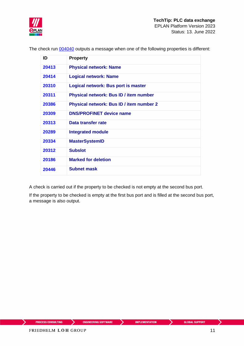
TechTip PLC data exchange
EPLAN Platform Version 2023
Status 13 June 2022
11
The check run 004040 outputs a message when one of the following properties is different
ID Property
20413 Physical network Name
20414 Logical network Name
20310 Logical network Bus port is master
20311 Physical network Bus ID item number
20386 Physical network Bus ID item number 2
20309 DNSPROFINET device name
20313 Data transfer rate
20289 Integrated module
20334 MasterSystemID
20312 Subslot
20186 Marked for deletion
20446 Subnet mask
A check is carried out if the property to be checked is not empty at the second bus port
If the property to be checked is empty at the first bus port and is filled at the second bus port
a message is also output
TechTip PLC data exchange
EPLAN Platform Version 2023
Status 13 June 2022
12
4 Export from EPLAN
Before the export from EPLAN
1 Check the project by means of the check runs from the 004 range EPLAN makes
schemes available to you here that you use or adjust according to your requirements
2 Delete the data not required at the auxiliary functions (File gt Extras gt Command group
Organize gt Project gt Command group Optimize gt Compress project gt Field
Settings Button [] gt Remove project data gt Remove PLC structure data at PLC
auxiliary functions)
3 For an optimum PLC data exchange always configure all IO connection points and bus
ports of a device even when they are not connected
41 Hardware data
1 The EPLAN export references a configuration project that is specified at all the
associated PLC boxes
2 The bus ports are represented in single-line and are connected with each other During
the PLC data exchange in the AutomationML AR APC format multi-line representations
and bus ports connected to each other are also taken into consideration
3 A device is identified with the CPU property (check box is activated) The complete CPU name in the form [Configuration project][Station
ID][CPU identifier] must be unique project-wide
4 The device identification takes place by means of
a) the PLC type designation property or
b) a device description file (eg GSD GSDML EDS file property Device
description File name property) and the Object description or
c) a device description file (eg GSD GSDML EDS file property Device
description File name) and the Device description Index in file during the data
exchange in AutomationML AR APC format
The PLC type designation as a rule corresponds to the order number in the hardware
catalog of the respective PLC configuration program The exact spelling is important
Each PLC card can only have one device identification A combination of several parts by
entering several PLC type designations device description files or indexes is not supported
TechTip PLC data exchange
EPLAN Platform Version 2023
Status 13 June 2022
13
PLC connection points of the following categories are not exchanged
- General
- 2 connection points
- Power supply
- Card power supply
42 Assignment list
A PLC connection point (input output) existing in a assignment list (symbol table) is
exported if the following conditions are fulfilled
1 Only PLC connection points with the following function definitions are exchanged
a PLC connection point DI
b PLC connection point DO
c PLC connection point AI
d PLC connection point AO
e PLC connection point multi-function with the type of signal
bull Digital input
bull Digital output
bull Analog input
bull Analog output
(Exception PLC standard exchange format all PLC connection points are exchanged
here)
2 A PLC connection point multi-function is treated with its logic like the corresponding IO
connection For example
PLC connection point multi-function type of signal digital input corresponds to PLC
connection point DI
3 A CPU exists in a configuration project
4 The symbolic address is specified The symbolic address must be unique within a
CPU
5 The Data type (BOOL BYTE etc) is specified
6 The associated PLC box is assigned through specification of the property CPU Name
of a CPU
The correct and full specification of the CPU name at the PLC box is required so that
the assignment list (designation in the AutomationML AR APC format TagTable) can
be exported fully
TechTip PLC data exchange
EPLAN Platform Version 2023
Status 13 June 2022
14
5 Import in EPLAN
51 Devices
During importing EPLAN supplements item data such as inputs outputs from the parts data
1 The device identification takes place by means of
a) the PLC type designation property or
b) a GSD GSDML EDS file (Device description File name property) and the
Object description or
c) a GSD GSDML EDS file (property Device description File name) and the
Device description Index in file during the data exchange in AutomationML AR
APC format
2 If items with placeholder characters (such as and ) are found in the PLC type
designation in the parts database during an import into EPLAN the first suitable part is
used (PLC configuration programs do not always differentiate between parts that are
equivalent electrotechnically)
3 If multiple parts with the same PLC type designation are found during the import in
EPLAN the first of those parts with the matching Object description (in as far as this
import file is available) is assigned If no part has a matching object description the first
found part is assigned
4 If no appropriate part is found a simple PLC box is created
In these cases messages are output so that the imported devices can be checked
subsequently
Device and PLC connection points that are available in the project but not in the import file
have the Marked for deletion property assigned during import These objects can be filtered
in the PLC navigator and subsequently be edited Deactivate this property after the check or
editing
52 Connections
EPLAN detects existing connections during the import
New or changed connections are listed via the message management and have to be
created or changed by the user in EPLAN To this purpose the corresponding functions have
to be placed and connected to each other
TechTip PLC data exchange
EPLAN Platform Version 2023
Status 13 June 2022
15
6 Recommendation for preparation of the master data
EPLAN recommends prepared macros for standardization In many cases you can obtain the
parts and part macros from the EPLAN Data Portal It is nevertheless possible that a used
PLC card is not available there In this case you have to create the required parts and
macros yourself
The TechTip TechTip-Preparation-of-master-data-for-PLC-data-exchange is available
as an aid It contains additional information on editing parts data and the creation of macros
Appendix A Relevant properties contains an overview of all properties important for the
data exchange with the information on where the data can be entered
7 AutomationML AR APC
Details on the individual properties can be found in the TechTip TechTip-Overview-of-the-
PLC-properties
Free symbolic addresses (which are not assigned to any PLC connection point) can be
exported and imported in AutomationML AR APC format via the PLC data exchange After
the import of an AML file the free symbolic addresses existing there are available in EPLAN
The export in the AutomationML AR APC format can take place in the following AR APC
versions V100 V110 V120
Features in the export format for AutomationML AR APC Version 110
bull Through extensions in the AutomationML AR APC format longer device tags can be
replaced
bull An improved exchange of free symbolic addresses is possible through extensions in the
AutomationML AR APC format regarding the assignment list
bull The assignment of the PLC cards to your CPUs is replaced This way you can restore the
association of the PLC cards to their CPU during the data exchange
bull The bus system PortToPort can be used if you do not want to export the logical network
but only the connection between the bus ports (port-specific interconnection)
bull The bus systems DRIVE-CLiQ IO Link PortToPort and ET connection are
exchanged correctly with port-specific interconnection
bull The connections between racks are exchanged with port-specific interconnection
bull Safety addresses at the bus systems are exchanged
bull The manufacturer name at the devices can be replaced In EPLAN the manufacturer
name is saved in the part reference data
TechTip PLC data exchange
EPLAN Platform Version 2023
Status 13 June 2022
16
Features in the export format for AutomationML AR APC Version 120
bull The exchange of drive components is possible For the export of drives and drive
components you can activate the Export drives check box in the Settings
AutomationML AR APC export dialog
bull The exchange of device-specific configuration values is possible To this purpose you
can specify a template in the PLC device TemplateIdentifier or PLC station
TemplateIdentifier property or you can use user-defined part reference properties
Extensive information is provided in the TechTip TechTip-PLC-data-exchange-with-
device-related-configuration-values
Features in the export format for AutomationML AR APC Version 130
bull The exchange of symbolic addresses within user-defined data types (UDT) is possible
An import file in AutomationML AR APC format is always imported irrespective of the AR
APC version with which the file was created This means that all the data known for the
respective EPLAN version is imported
If the import file was created with a higher AR APC version than supported by the used
EPLAN version it is possible that not all file contents are imported As of EPLAN version 29
SP1 information is provided in this case
The following sections contain information about the bus systems and special features of
different devices
TechTip PLC data exchange
EPLAN Platform Version 2023
Status 13 June 2022
17
71 Settings for different bus systems
The following table provides an overview of the properties relevant for the PLC data
exchange in the AutomationML AR APC format Which properties at the bus ports must be
filled (x) should be filled or are optional (o) depends on the bus system being used
ID Property
Bus system
Ethernet-
based
PROFIBUS
DP
ASI DRIVE-CLiQ
IO link
PortToPort
ET-Connection
Local-Bus
extension
All others
20161 Configuration project o1 o1 o1 o1 o1
20308 Bus system x x x x x
20406 Plug designation x x x x x
20447 Bus interface Name x
20448 Bus interface Main
bus port
o
20413 Physical network
Name
o o o o
20311 Physical network
Bus ID item number
o o o o
20386 Physical network
Bus ID item number
2
o2
20446 Subnet mask o
20414 Logical network
Name
o o
20310 Logical network Bus
port is master
o o
20412 Ignore missing bus ID o3
1 Only required if the value deviates from that of the associated PLC box
2 Can be filled if it is an ASI dual device
3 Can be activated to ignore bus ports that do not require a bus address during the
execution of the 004037 error checking
TechTip PLC data exchange
EPLAN Platform Version 2023
Status 13 June 2022
18
Non-identified fields are not required for the PLC data exchange If the optional fields (o) are
left empty the import to the PLC configuration program is possible but post-processing is
required
Note
The properties Logical network Name and Logical network Bus port is master determine
the association of a station to the DP master or the IO controller
Within an IO system there is always a master that is designated through the check box
Logical network Bus port is master
72 PC station
1 The PC is a separate station and is configured as Rack 0 All other fields of the rack
assignment remain empty
2 The Bus coupler head station check box is to be activated
73 Switches
1 The switch is an own station and is configured as Rack 0 All other fields of the rack
assignment remain empty
2 The Bus coupler head station check box is to be activated
3 Bus ports
All bus ports have the function definition Network bus cable connection point general
and have the same bus interface names
a) All the required interface data are entered at the bus port that represents the
input (including Physical network Bus ID item number Bus interface Main
bus port)
b) At all other bus ports the specifications Physical network Name Logical
network Name and Physical network Bus ID item number amongst others
can be empty
TechTip PLC data exchange
EPLAN Platform Version 2023
Status 13 June 2022
19
Example SCALANCE X200IRT of SIEMENS
Settings at PLC box
ID Property Value
20416 PLC type designation 6GK5 204-0BA00-2BA3
20409 PLC station Type ScalanceX200IRT
Settings at the bus ports
20447 Bus interface Name X1 (for all bus ports)
20406 Plug designation Px R for all bus ports whereby x
= 1 Number of bus ports
Identify the first bus port as Bus interface Main bus port and enter the relevant bus data
here
74 Bus adapter
Stations of the ET 200SP type or similar or of a SCALANCE router require bus adapters
(media modules) to which the network connections are connected
In the case of these devices with adapter shafts for the bus ports the function templates for
the bus ports must be entered at the respective bus adapter Two parts must be created to
this purpose in the parts management
1 The device with the adapter shafts only has one function template for the PLC box
(main function) and if necessary further function templates for PLC inputs and outputs
2 The Bus adapter device has one function template for the PLC box (main function) as
well as function templates for the bus ports
Ensure that if the bus adapter is used on a head station the check box PLC card is placed
on head station (ID 20444) is activated in the device properties (PLC structure data tab) at
a bus adapter
In addition the device identification for the device with the adapter ducts and the Bus
adapter device must be carried out in the same way Either both must be identified by
means of the PLC type designation or both through the specification of a device description
file
TechTip PLC data exchange
EPLAN Platform Version 2023
Status 13 June 2022
20
Settings at the PLC box for the bus adapter
ID Property Value
20161 Configuration project Not empty
20416 PLC type designation eg 6ES7 193-6AR00-0AA0
20410 PLC card is placed on rack ID Like head station
20411 Position (slot module) Not empty
20444 PLC card is placed on head station
Settings at the bus ports
20447 Bus interface Name X1 (for all bus ports at all
adapters)
20406 Plug designation Px R for all bus ports whereby x
= 1 Number of bus ports the
method of counting is non-adapter-
specific
Identify the first bus port as Bus interface Main bus port and enter the relevant bus data
here
75 IO-Link devices
Devices that have bus ports of the IO-Link bus system are called IO-Link devices These
can either be part of a rack structure (for example an IO-Link master) or be located as an
independent device at any desired point in the network (for example a motor or sensor)
Additional information on the definition of PLC inputs and outputs or PLC bus ports can be
found in the TechTip TechTip-Preparation-of-master-data-for-PLC-data-exchange in
Section 24
751 IO-Link devices within a rack structure
IO-Link devices are parameterized like standard PLC devices within a rack structure
752 IO-Link devices outside a rack structure
The property dialog of a device depends on the function category The property dialog of a
PLC box thus contains the PLC structure data tab This tab is missing for non-PLC devices
In this case the required properties can be filled into the property table of the first tab
TechTip PLC data exchange
EPLAN Platform Version 2023
Status 13 June 2022
21
Settings at PLC box
ID Property
20161 Configuration project Not empty
20408 PLC station ID Not empty
Settings at the bus ports
ID Property
20308 Bus system IO Link
76 PLC subdevices
Specific PLC devices consist of multiple integrated modules that each have their own
Address ranges and start addresses Such a device can consist for example of an internal
CPU module an internal input output module internal analog module as well as an internal
counter module - however with only one part number Such integrated modules within a PLC
device can be displayed in EPLAN with PLC subdevices To this purpose up to twelve PLC
subdevices are available Each PLC subdevice is defined by the corresponding properties (x
in the following describes the number of PLC subdevice 1hellip12) You can find more
information in the Online help in the section PLC subdevices as well as in the TechTip
TechTip-Preparation-of-master-data-for-PLC-data-exchange in the chapter PLC
devices with subdevices
PLC subdevices are exported if they have at least one start address or one bus port or one
IO connection point or one Device identification
Note
If a PLC card has no PLC subdevices (meaning that it only consists of one module)
definitions for these can be omitted The value 0 is entered at the PLC subdevice Index
property at the associated PLC connection points
You obtain further information on the definition of PLC subdevices from your PLC
manufacturer or in the TechTip TechTip-Configuring-PLC-devices-with-device-
description-files
TechTip PLC data exchange
EPLAN Platform Version 2023
Status 13 June 2022
22
77 Accessories
A PLC card can have accessories
The requirement for a data exchange is
bull The accessory is defined in the parts management
bull The accessory has a PLC type designation
bull The number of units used is larger than 0
Note
You can deactivate the export of the accessories in the Settings AutomationML AR APC
export dialog if needed
78 Device sets (Bundles)
Device sets (so called Bundles meaning bundles that consist of different devices) are not
supported by all PLC configuration programs (for example SIEMENS STEP 7 TIA Portal) In
this case the device set for the PLC data exchange must be broken up by configuring the
devices contained in the device set individually with the associated device identification
79 Device-specific configuration values
As of AutomationML AR APC version 120 you can also specify device-specific
configuration values To do this activate the Export device-specific configuration values
check box in the Settings AutomationML AR APC export dialog
Further notes and specifications for handling of device-specific configuration values are
available in the Tech Tip TechTip-PLC-data-exchange-with-device-related-
configuration-values
TechTip PLC data exchange
EPLAN Platform Version 2023
Status 13 June 2022
23
710 Drives
As of AutomationML AR APC version 120 you can also specify drive components To do
this activate the Export drives check box in the Settings AutomationML AR APC export
dialog
If this check box is selected drive components are exported as well This means all other
functions that have a drive assigned are exported in addition to the PLC devices and bus-
capable devices
If the check box is deactivated only PLC devices and bus-capable devices are exported
Note During import the corresponding devices must be available in the parts management
otherwise an empty PLC box is created
For the export the following properties amongst others have to be filled at the drive
components
ID Property
20576 [1hellip 64] Drive
20415 Device description File name
20381 Device description Index in file
20577 Device type
20161 Configuration project
20417 Object description
20408 PLC station ID
20416 PLC type designation
TechTip PLC data exchange
EPLAN Platform Version 2023
Status 13 June 2022
24
8 Check of the PLC configuration project
All devices that atacutere to be exported or imported via PLC data exchange require the following
structure
1 Configuration project rarr This is the main node
2 Station ID rarr A grouping element
3 Rack rarr If the device is used as the basis for other devices this property has to be filled
numerically
A rack is numbered consecutively with the Rack property
A CPU or a bus coupler is numbered consecutively with a Rack if the device itself is not
placed on a rack
PLC devices that can add other PLC devices are also numbered consecutively with
Rack
4 All PLC devices that are placed on a rack or assigned to a rack receive the number of
the rack via the PLC card is placed on rack ID property
5 If the PLC card is placed on rack ID property is filled the position at which the device
is located has to be defined This is done via the Position (slot module) property
81 Check via message management
When checking the PLC configuration project you are supported by check runs In most
cases the PLC data exchange (Mitsubishi) run scheme can be used For adjustments of the
check runs a copy of this scheme is recommended
This check increases the quality of the project and helps with error prevention
TechTip PLC data exchange
EPLAN Platform Version 2023
Status 13 June 2022
25
Appendix A Relevant properties
The following overview shows which properties are important during the PLC data exchange
The data input in EPLAN can be effected
A = in the parts data
M = in the macro
P = in the project
We recommend entering the data preferably in the parts data and or in the macros
Note
If necessary you can create part variants in the EPLAN parts management
PLC connection point
ID Property Data input
A M P
20384 PLC subdevice Index x x x
20428 Channel designation x x x
20610 Symbolic address Group 1 - - x
20618 Symbolic address UDT (name) 2 - - x
20619 Symbolic address UDT (data type) 2 - - x
1 Exchange as of AutomationML AR APC Version 110
2 Exchange as of AutomationML AR APC Version 130
TechTip PLC data exchange
EPLAN Platform Version 2023
Status 13 June 2022
26
PLC bus port
ID Property Data input
A M P
20448 Bus interface Main bus port - x x
20447 Bus interface Name x x x
20386 Physical network Bus ID item number
2
- - x
20313 Data transfer rate - x x
20289 Integrated module - x x
20312 Subslot - x x
20308 Bus system x x x
20446 Subnet mask - x x
20613 Standard gateway - x x
20309 DNSPROFINET device name - x x
Exchange as of AutomationML AR APC Version 120
PLC card
ID Property Data input
A M P
20437 PLC card name - - x
20164 Bus coupler head station x x x
20381 Device description Index in file x x x
20521 foll PLC subdevice x Name x x x
20533 foll PLC subdevice x Position (slot module) x x x
20454 20382 20392
foll 20452 foll
PLC subdevice x Start address (inputs) - - x
20455 foll 20478
foll 20515 foll
PLC subdevice x Start address (outputs) - - x
TechTip PLC data exchange
EPLAN Platform Version 2023
Status 13 June 2022
27
ID Property Data input
A M P
20548 20605
20547 20551foll
20570
PLC subdevice x Data length (inputs) x x x
20550 20604
20549 20560foll
PLC subdevice x Data length (outputs) x x x
20607
20582 foll
PLC subdevice x PLC type designation x x x
20606
20593 foll
PLC subdevice x Device description
Index in file
x x x
20417 Object description x x x
20550 PLC device Data length (outputs) x x x
20548 PLC device Data length (inputs) x x x
20289 Integrated module - x x
20444 PLC card is placed on head station x x x
20312 Subslot - x x
20439 Safety address Target 1 - - x
20615 Safety address Source 1 - - x
20616 Safety address Upper value 1 - - x 3
20617 Safety address Lower value 1 - - x 3
20409 PLC station Type x x x
20580 PLC device TemplateIdentifier 2 x x x
20614 PLC station TemplateIdentifier 2 - x x
20576 Drive 2 - x x
1 Exchange as of AutomationML AR APC Version 110
2 Exchange as of AutomationML AR APC Version 120
3 Values in EPLAN are write-protected and are only filled via the PLC data exchange
TechTip PLC data exchange
EPLAN Platform Version 2023
Status 13 June 2022
16
Features in the export format for AutomationML AR APC Version 120
bull The exchange of drive components is possible For the export of drives and drive
components you can activate the Export drives check box in the Settings
AutomationML AR APC export dialog
bull The exchange of device-specific configuration values is possible To this purpose you
can specify a template in the PLC device TemplateIdentifier or PLC station
TemplateIdentifier property or you can use user-defined part reference properties
Extensive information is provided in the TechTip TechTip-PLC-data-exchange-with-
device-related-configuration-values
Features in the export format for AutomationML AR APC Version 130
bull The exchange of symbolic addresses within user-defined data types (UDT) is possible
An import file in AutomationML AR APC format is always imported irrespective of the AR
APC version with which the file was created This means that all the data known for the
respective EPLAN version is imported
If the import file was created with a higher AR APC version than supported by the used
EPLAN version it is possible that not all file contents are imported As of EPLAN version 29
SP1 information is provided in this case
The following sections contain information about the bus systems and special features of
different devices
TechTip PLC data exchange
EPLAN Platform Version 2023
Status 13 June 2022
17
71 Settings for different bus systems
The following table provides an overview of the properties relevant for the PLC data
exchange in the AutomationML AR APC format Which properties at the bus ports must be
filled (x) should be filled or are optional (o) depends on the bus system being used
ID Property
Bus system
Ethernet-
based
PROFIBUS
DP
ASI DRIVE-CLiQ
IO link
PortToPort
ET-Connection
Local-Bus
extension
All others
20161 Configuration project o1 o1 o1 o1 o1
20308 Bus system x x x x x
20406 Plug designation x x x x x
20447 Bus interface Name x
20448 Bus interface Main
bus port
o
20413 Physical network
Name
o o o o
20311 Physical network
Bus ID item number
o o o o
20386 Physical network
Bus ID item number
2
o2
20446 Subnet mask o
20414 Logical network
Name
o o
20310 Logical network Bus
port is master
o o
20412 Ignore missing bus ID o3
1 Only required if the value deviates from that of the associated PLC box
2 Can be filled if it is an ASI dual device
3 Can be activated to ignore bus ports that do not require a bus address during the
execution of the 004037 error checking
TechTip PLC data exchange
EPLAN Platform Version 2023
Status 13 June 2022
18
Non-identified fields are not required for the PLC data exchange If the optional fields (o) are
left empty the import to the PLC configuration program is possible but post-processing is
required
Note
The properties Logical network Name and Logical network Bus port is master determine
the association of a station to the DP master or the IO controller
Within an IO system there is always a master that is designated through the check box
Logical network Bus port is master
72 PC station
1 The PC is a separate station and is configured as Rack 0 All other fields of the rack
assignment remain empty
2 The Bus coupler head station check box is to be activated
73 Switches
1 The switch is an own station and is configured as Rack 0 All other fields of the rack
assignment remain empty
2 The Bus coupler head station check box is to be activated
3 Bus ports
All bus ports have the function definition Network bus cable connection point general
and have the same bus interface names
a) All the required interface data are entered at the bus port that represents the
input (including Physical network Bus ID item number Bus interface Main
bus port)
b) At all other bus ports the specifications Physical network Name Logical
network Name and Physical network Bus ID item number amongst others
can be empty
TechTip PLC data exchange
EPLAN Platform Version 2023
Status 13 June 2022
19
Example SCALANCE X200IRT of SIEMENS
Settings at PLC box
ID Property Value
20416 PLC type designation 6GK5 204-0BA00-2BA3
20409 PLC station Type ScalanceX200IRT
Settings at the bus ports
20447 Bus interface Name X1 (for all bus ports)
20406 Plug designation Px R for all bus ports whereby x
= 1 Number of bus ports
Identify the first bus port as Bus interface Main bus port and enter the relevant bus data
here
74 Bus adapter
Stations of the ET 200SP type or similar or of a SCALANCE router require bus adapters
(media modules) to which the network connections are connected
In the case of these devices with adapter shafts for the bus ports the function templates for
the bus ports must be entered at the respective bus adapter Two parts must be created to
this purpose in the parts management
1 The device with the adapter shafts only has one function template for the PLC box
(main function) and if necessary further function templates for PLC inputs and outputs
2 The Bus adapter device has one function template for the PLC box (main function) as
well as function templates for the bus ports
Ensure that if the bus adapter is used on a head station the check box PLC card is placed
on head station (ID 20444) is activated in the device properties (PLC structure data tab) at
a bus adapter
In addition the device identification for the device with the adapter ducts and the Bus
adapter device must be carried out in the same way Either both must be identified by
means of the PLC type designation or both through the specification of a device description
file
TechTip PLC data exchange
EPLAN Platform Version 2023
Status 13 June 2022
20
Settings at the PLC box for the bus adapter
ID Property Value
20161 Configuration project Not empty
20416 PLC type designation eg 6ES7 193-6AR00-0AA0
20410 PLC card is placed on rack ID Like head station
20411 Position (slot module) Not empty
20444 PLC card is placed on head station
Settings at the bus ports
20447 Bus interface Name X1 (for all bus ports at all
adapters)
20406 Plug designation Px R for all bus ports whereby x
= 1 Number of bus ports the
method of counting is non-adapter-
specific
Identify the first bus port as Bus interface Main bus port and enter the relevant bus data
here
75 IO-Link devices
Devices that have bus ports of the IO-Link bus system are called IO-Link devices These
can either be part of a rack structure (for example an IO-Link master) or be located as an
independent device at any desired point in the network (for example a motor or sensor)
Additional information on the definition of PLC inputs and outputs or PLC bus ports can be
found in the TechTip TechTip-Preparation-of-master-data-for-PLC-data-exchange in
Section 24
751 IO-Link devices within a rack structure
IO-Link devices are parameterized like standard PLC devices within a rack structure
752 IO-Link devices outside a rack structure
The property dialog of a device depends on the function category The property dialog of a
PLC box thus contains the PLC structure data tab This tab is missing for non-PLC devices
In this case the required properties can be filled into the property table of the first tab
TechTip PLC data exchange
EPLAN Platform Version 2023
Status 13 June 2022
21
Settings at PLC box
ID Property
20161 Configuration project Not empty
20408 PLC station ID Not empty
Settings at the bus ports
ID Property
20308 Bus system IO Link
76 PLC subdevices
Specific PLC devices consist of multiple integrated modules that each have their own
Address ranges and start addresses Such a device can consist for example of an internal
CPU module an internal input output module internal analog module as well as an internal
counter module - however with only one part number Such integrated modules within a PLC
device can be displayed in EPLAN with PLC subdevices To this purpose up to twelve PLC
subdevices are available Each PLC subdevice is defined by the corresponding properties (x
in the following describes the number of PLC subdevice 1hellip12) You can find more
information in the Online help in the section PLC subdevices as well as in the TechTip
TechTip-Preparation-of-master-data-for-PLC-data-exchange in the chapter PLC
devices with subdevices
PLC subdevices are exported if they have at least one start address or one bus port or one
IO connection point or one Device identification
Note
If a PLC card has no PLC subdevices (meaning that it only consists of one module)
definitions for these can be omitted The value 0 is entered at the PLC subdevice Index
property at the associated PLC connection points
You obtain further information on the definition of PLC subdevices from your PLC
manufacturer or in the TechTip TechTip-Configuring-PLC-devices-with-device-
description-files
TechTip PLC data exchange
EPLAN Platform Version 2023
Status 13 June 2022
22
77 Accessories
A PLC card can have accessories
The requirement for a data exchange is
bull The accessory is defined in the parts management
bull The accessory has a PLC type designation
bull The number of units used is larger than 0
Note
You can deactivate the export of the accessories in the Settings AutomationML AR APC
export dialog if needed
78 Device sets (Bundles)
Device sets (so called Bundles meaning bundles that consist of different devices) are not
supported by all PLC configuration programs (for example SIEMENS STEP 7 TIA Portal) In
this case the device set for the PLC data exchange must be broken up by configuring the
devices contained in the device set individually with the associated device identification
79 Device-specific configuration values
As of AutomationML AR APC version 120 you can also specify device-specific
configuration values To do this activate the Export device-specific configuration values
check box in the Settings AutomationML AR APC export dialog
Further notes and specifications for handling of device-specific configuration values are
available in the Tech Tip TechTip-PLC-data-exchange-with-device-related-
configuration-values
TechTip PLC data exchange
EPLAN Platform Version 2023
Status 13 June 2022
23
710 Drives
As of AutomationML AR APC version 120 you can also specify drive components To do
this activate the Export drives check box in the Settings AutomationML AR APC export
dialog
If this check box is selected drive components are exported as well This means all other
functions that have a drive assigned are exported in addition to the PLC devices and bus-
capable devices
If the check box is deactivated only PLC devices and bus-capable devices are exported
Note During import the corresponding devices must be available in the parts management
otherwise an empty PLC box is created
For the export the following properties amongst others have to be filled at the drive
components
ID Property
20576 [1hellip 64] Drive
20415 Device description File name
20381 Device description Index in file
20577 Device type
20161 Configuration project
20417 Object description
20408 PLC station ID
20416 PLC type designation
TechTip PLC data exchange
EPLAN Platform Version 2023
Status 13 June 2022
24
8 Check of the PLC configuration project
All devices that atacutere to be exported or imported via PLC data exchange require the following
structure
1 Configuration project rarr This is the main node
2 Station ID rarr A grouping element
3 Rack rarr If the device is used as the basis for other devices this property has to be filled
numerically
A rack is numbered consecutively with the Rack property
A CPU or a bus coupler is numbered consecutively with a Rack if the device itself is not
placed on a rack
PLC devices that can add other PLC devices are also numbered consecutively with
Rack
4 All PLC devices that are placed on a rack or assigned to a rack receive the number of
the rack via the PLC card is placed on rack ID property
5 If the PLC card is placed on rack ID property is filled the position at which the device
is located has to be defined This is done via the Position (slot module) property
81 Check via message management
When checking the PLC configuration project you are supported by check runs In most
cases the PLC data exchange (Mitsubishi) run scheme can be used For adjustments of the
check runs a copy of this scheme is recommended
This check increases the quality of the project and helps with error prevention
TechTip PLC data exchange
EPLAN Platform Version 2023
Status 13 June 2022
25
Appendix A Relevant properties
The following overview shows which properties are important during the PLC data exchange
The data input in EPLAN can be effected
A = in the parts data
M = in the macro
P = in the project
We recommend entering the data preferably in the parts data and or in the macros
Note
If necessary you can create part variants in the EPLAN parts management
PLC connection point
ID Property Data input
A M P
20384 PLC subdevice Index x x x
20428 Channel designation x x x
20610 Symbolic address Group 1 - - x
20618 Symbolic address UDT (name) 2 - - x
20619 Symbolic address UDT (data type) 2 - - x
1 Exchange as of AutomationML AR APC Version 110
2 Exchange as of AutomationML AR APC Version 130
TechTip PLC data exchange
EPLAN Platform Version 2023
Status 13 June 2022
26
PLC bus port
ID Property Data input
A M P
20448 Bus interface Main bus port - x x
20447 Bus interface Name x x x
20386 Physical network Bus ID item number
2
- - x
20313 Data transfer rate - x x
20289 Integrated module - x x
20312 Subslot - x x
20308 Bus system x x x
20446 Subnet mask - x x
20613 Standard gateway - x x
20309 DNSPROFINET device name - x x
Exchange as of AutomationML AR APC Version 120
PLC card
ID Property Data input
A M P
20437 PLC card name - - x
20164 Bus coupler head station x x x
20381 Device description Index in file x x x
20521 foll PLC subdevice x Name x x x
20533 foll PLC subdevice x Position (slot module) x x x
20454 20382 20392
foll 20452 foll
PLC subdevice x Start address (inputs) - - x
20455 foll 20478
foll 20515 foll
PLC subdevice x Start address (outputs) - - x
TechTip PLC data exchange
EPLAN Platform Version 2023
Status 13 June 2022
27
ID Property Data input
A M P
20548 20605
20547 20551foll
20570
PLC subdevice x Data length (inputs) x x x
20550 20604
20549 20560foll
PLC subdevice x Data length (outputs) x x x
20607
20582 foll
PLC subdevice x PLC type designation x x x
20606
20593 foll
PLC subdevice x Device description
Index in file
x x x
20417 Object description x x x
20550 PLC device Data length (outputs) x x x
20548 PLC device Data length (inputs) x x x
20289 Integrated module - x x
20444 PLC card is placed on head station x x x
20312 Subslot - x x
20439 Safety address Target 1 - - x
20615 Safety address Source 1 - - x
20616 Safety address Upper value 1 - - x 3
20617 Safety address Lower value 1 - - x 3
20409 PLC station Type x x x
20580 PLC device TemplateIdentifier 2 x x x
20614 PLC station TemplateIdentifier 2 - x x
20576 Drive 2 - x x
1 Exchange as of AutomationML AR APC Version 110
2 Exchange as of AutomationML AR APC Version 120
3 Values in EPLAN are write-protected and are only filled via the PLC data exchange
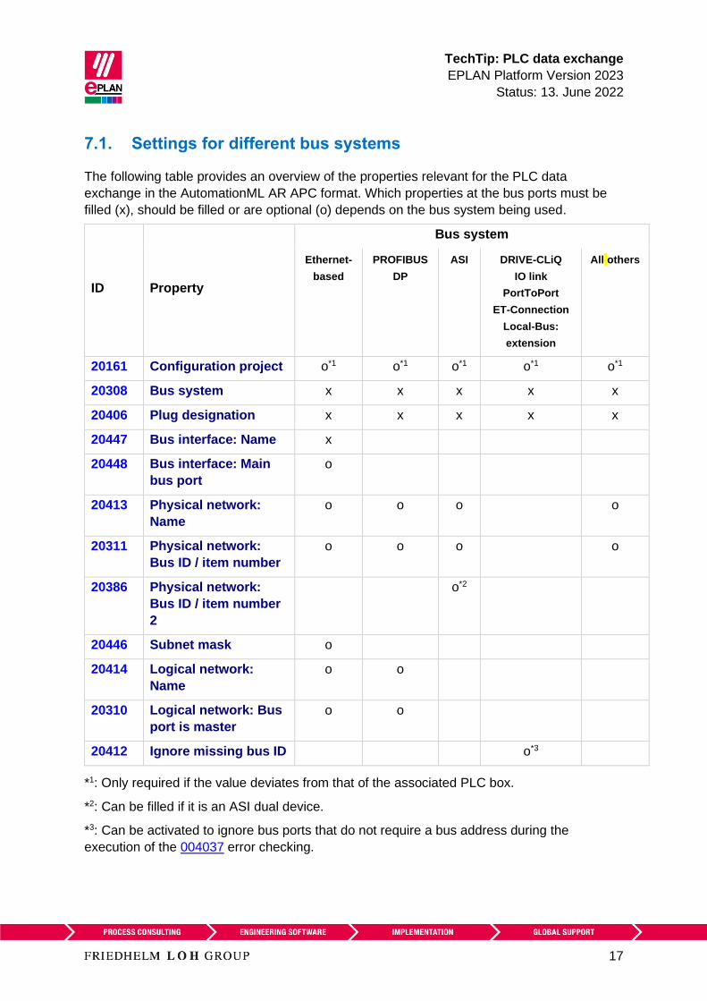
TechTip PLC data exchange
EPLAN Platform Version 2023
Status 13 June 2022
17
71 Settings for different bus systems
The following table provides an overview of the properties relevant for the PLC data
exchange in the AutomationML AR APC format Which properties at the bus ports must be
filled (x) should be filled or are optional (o) depends on the bus system being used
ID Property
Bus system
Ethernet-
based
PROFIBUS
DP
ASI DRIVE-CLiQ
IO link
PortToPort
ET-Connection
Local-Bus
extension
All others
20161 Configuration project o1 o1 o1 o1 o1
20308 Bus system x x x x x
20406 Plug designation x x x x x
20447 Bus interface Name x
20448 Bus interface Main
bus port
o
20413 Physical network
Name
o o o o
20311 Physical network
Bus ID item number
o o o o
20386 Physical network
Bus ID item number
2
o2
20446 Subnet mask o
20414 Logical network
Name
o o
20310 Logical network Bus
port is master
o o
20412 Ignore missing bus ID o3
1 Only required if the value deviates from that of the associated PLC box
2 Can be filled if it is an ASI dual device
3 Can be activated to ignore bus ports that do not require a bus address during the
execution of the 004037 error checking
TechTip PLC data exchange
EPLAN Platform Version 2023
Status 13 June 2022
18
Non-identified fields are not required for the PLC data exchange If the optional fields (o) are
left empty the import to the PLC configuration program is possible but post-processing is
required
Note
The properties Logical network Name and Logical network Bus port is master determine
the association of a station to the DP master or the IO controller
Within an IO system there is always a master that is designated through the check box
Logical network Bus port is master
72 PC station
1 The PC is a separate station and is configured as Rack 0 All other fields of the rack
assignment remain empty
2 The Bus coupler head station check box is to be activated
73 Switches
1 The switch is an own station and is configured as Rack 0 All other fields of the rack
assignment remain empty
2 The Bus coupler head station check box is to be activated
3 Bus ports
All bus ports have the function definition Network bus cable connection point general
and have the same bus interface names
a) All the required interface data are entered at the bus port that represents the
input (including Physical network Bus ID item number Bus interface Main
bus port)
b) At all other bus ports the specifications Physical network Name Logical
network Name and Physical network Bus ID item number amongst others
can be empty
TechTip PLC data exchange
EPLAN Platform Version 2023
Status 13 June 2022
19
Example SCALANCE X200IRT of SIEMENS
Settings at PLC box
ID Property Value
20416 PLC type designation 6GK5 204-0BA00-2BA3
20409 PLC station Type ScalanceX200IRT
Settings at the bus ports
20447 Bus interface Name X1 (for all bus ports)
20406 Plug designation Px R for all bus ports whereby x
= 1 Number of bus ports
Identify the first bus port as Bus interface Main bus port and enter the relevant bus data
here
74 Bus adapter
Stations of the ET 200SP type or similar or of a SCALANCE router require bus adapters
(media modules) to which the network connections are connected
In the case of these devices with adapter shafts for the bus ports the function templates for
the bus ports must be entered at the respective bus adapter Two parts must be created to
this purpose in the parts management
1 The device with the adapter shafts only has one function template for the PLC box
(main function) and if necessary further function templates for PLC inputs and outputs
2 The Bus adapter device has one function template for the PLC box (main function) as
well as function templates for the bus ports
Ensure that if the bus adapter is used on a head station the check box PLC card is placed
on head station (ID 20444) is activated in the device properties (PLC structure data tab) at
a bus adapter
In addition the device identification for the device with the adapter ducts and the Bus
adapter device must be carried out in the same way Either both must be identified by
means of the PLC type designation or both through the specification of a device description
file
TechTip PLC data exchange
EPLAN Platform Version 2023
Status 13 June 2022
20
Settings at the PLC box for the bus adapter
ID Property Value
20161 Configuration project Not empty
20416 PLC type designation eg 6ES7 193-6AR00-0AA0
20410 PLC card is placed on rack ID Like head station
20411 Position (slot module) Not empty
20444 PLC card is placed on head station
Settings at the bus ports
20447 Bus interface Name X1 (for all bus ports at all
adapters)
20406 Plug designation Px R for all bus ports whereby x
= 1 Number of bus ports the
method of counting is non-adapter-
specific
Identify the first bus port as Bus interface Main bus port and enter the relevant bus data
here
75 IO-Link devices
Devices that have bus ports of the IO-Link bus system are called IO-Link devices These
can either be part of a rack structure (for example an IO-Link master) or be located as an
independent device at any desired point in the network (for example a motor or sensor)
Additional information on the definition of PLC inputs and outputs or PLC bus ports can be
found in the TechTip TechTip-Preparation-of-master-data-for-PLC-data-exchange in
Section 24
751 IO-Link devices within a rack structure
IO-Link devices are parameterized like standard PLC devices within a rack structure
752 IO-Link devices outside a rack structure
The property dialog of a device depends on the function category The property dialog of a
PLC box thus contains the PLC structure data tab This tab is missing for non-PLC devices
In this case the required properties can be filled into the property table of the first tab
TechTip PLC data exchange
EPLAN Platform Version 2023
Status 13 June 2022
21
Settings at PLC box
ID Property
20161 Configuration project Not empty
20408 PLC station ID Not empty
Settings at the bus ports
ID Property
20308 Bus system IO Link
76 PLC subdevices
Specific PLC devices consist of multiple integrated modules that each have their own
Address ranges and start addresses Such a device can consist for example of an internal
CPU module an internal input output module internal analog module as well as an internal
counter module - however with only one part number Such integrated modules within a PLC
device can be displayed in EPLAN with PLC subdevices To this purpose up to twelve PLC
subdevices are available Each PLC subdevice is defined by the corresponding properties (x
in the following describes the number of PLC subdevice 1hellip12) You can find more
information in the Online help in the section PLC subdevices as well as in the TechTip
TechTip-Preparation-of-master-data-for-PLC-data-exchange in the chapter PLC
devices with subdevices
PLC subdevices are exported if they have at least one start address or one bus port or one
IO connection point or one Device identification
Note
If a PLC card has no PLC subdevices (meaning that it only consists of one module)
definitions for these can be omitted The value 0 is entered at the PLC subdevice Index
property at the associated PLC connection points
You obtain further information on the definition of PLC subdevices from your PLC
manufacturer or in the TechTip TechTip-Configuring-PLC-devices-with-device-
description-files
TechTip PLC data exchange
EPLAN Platform Version 2023
Status 13 June 2022
22
77 Accessories
A PLC card can have accessories
The requirement for a data exchange is
bull The accessory is defined in the parts management
bull The accessory has a PLC type designation
bull The number of units used is larger than 0
Note
You can deactivate the export of the accessories in the Settings AutomationML AR APC
export dialog if needed
78 Device sets (Bundles)
Device sets (so called Bundles meaning bundles that consist of different devices) are not
supported by all PLC configuration programs (for example SIEMENS STEP 7 TIA Portal) In
this case the device set for the PLC data exchange must be broken up by configuring the
devices contained in the device set individually with the associated device identification
79 Device-specific configuration values
As of AutomationML AR APC version 120 you can also specify device-specific
configuration values To do this activate the Export device-specific configuration values
check box in the Settings AutomationML AR APC export dialog
Further notes and specifications for handling of device-specific configuration values are
available in the Tech Tip TechTip-PLC-data-exchange-with-device-related-
configuration-values
TechTip PLC data exchange
EPLAN Platform Version 2023
Status 13 June 2022
23
710 Drives
As of AutomationML AR APC version 120 you can also specify drive components To do
this activate the Export drives check box in the Settings AutomationML AR APC export
dialog
If this check box is selected drive components are exported as well This means all other
functions that have a drive assigned are exported in addition to the PLC devices and bus-
capable devices
If the check box is deactivated only PLC devices and bus-capable devices are exported
Note During import the corresponding devices must be available in the parts management
otherwise an empty PLC box is created
For the export the following properties amongst others have to be filled at the drive
components
ID Property
20576 [1hellip 64] Drive
20415 Device description File name
20381 Device description Index in file
20577 Device type
20161 Configuration project
20417 Object description
20408 PLC station ID
20416 PLC type designation
TechTip PLC data exchange
EPLAN Platform Version 2023
Status 13 June 2022
24
8 Check of the PLC configuration project
All devices that atacutere to be exported or imported via PLC data exchange require the following
structure
1 Configuration project rarr This is the main node
2 Station ID rarr A grouping element
3 Rack rarr If the device is used as the basis for other devices this property has to be filled
numerically
A rack is numbered consecutively with the Rack property
A CPU or a bus coupler is numbered consecutively with a Rack if the device itself is not
placed on a rack
PLC devices that can add other PLC devices are also numbered consecutively with
Rack
4 All PLC devices that are placed on a rack or assigned to a rack receive the number of
the rack via the PLC card is placed on rack ID property
5 If the PLC card is placed on rack ID property is filled the position at which the device
is located has to be defined This is done via the Position (slot module) property
81 Check via message management
When checking the PLC configuration project you are supported by check runs In most
cases the PLC data exchange (Mitsubishi) run scheme can be used For adjustments of the
check runs a copy of this scheme is recommended
This check increases the quality of the project and helps with error prevention
TechTip PLC data exchange
EPLAN Platform Version 2023
Status 13 June 2022
25
Appendix A Relevant properties
The following overview shows which properties are important during the PLC data exchange
The data input in EPLAN can be effected
A = in the parts data
M = in the macro
P = in the project
We recommend entering the data preferably in the parts data and or in the macros
Note
If necessary you can create part variants in the EPLAN parts management
PLC connection point
ID Property Data input
A M P
20384 PLC subdevice Index x x x
20428 Channel designation x x x
20610 Symbolic address Group 1 - - x
20618 Symbolic address UDT (name) 2 - - x
20619 Symbolic address UDT (data type) 2 - - x
1 Exchange as of AutomationML AR APC Version 110
2 Exchange as of AutomationML AR APC Version 130
TechTip PLC data exchange
EPLAN Platform Version 2023
Status 13 June 2022
26
PLC bus port
ID Property Data input
A M P
20448 Bus interface Main bus port - x x
20447 Bus interface Name x x x
20386 Physical network Bus ID item number
2
- - x
20313 Data transfer rate - x x
20289 Integrated module - x x
20312 Subslot - x x
20308 Bus system x x x
20446 Subnet mask - x x
20613 Standard gateway - x x
20309 DNSPROFINET device name - x x
Exchange as of AutomationML AR APC Version 120
PLC card
ID Property Data input
A M P
20437 PLC card name - - x
20164 Bus coupler head station x x x
20381 Device description Index in file x x x
20521 foll PLC subdevice x Name x x x
20533 foll PLC subdevice x Position (slot module) x x x
20454 20382 20392
foll 20452 foll
PLC subdevice x Start address (inputs) - - x
20455 foll 20478
foll 20515 foll
PLC subdevice x Start address (outputs) - - x
TechTip PLC data exchange
EPLAN Platform Version 2023
Status 13 June 2022
27
ID Property Data input
A M P
20548 20605
20547 20551foll
20570
PLC subdevice x Data length (inputs) x x x
20550 20604
20549 20560foll
PLC subdevice x Data length (outputs) x x x
20607
20582 foll
PLC subdevice x PLC type designation x x x
20606
20593 foll
PLC subdevice x Device description
Index in file
x x x
20417 Object description x x x
20550 PLC device Data length (outputs) x x x
20548 PLC device Data length (inputs) x x x
20289 Integrated module - x x
20444 PLC card is placed on head station x x x
20312 Subslot - x x
20439 Safety address Target 1 - - x
20615 Safety address Source 1 - - x
20616 Safety address Upper value 1 - - x 3
20617 Safety address Lower value 1 - - x 3
20409 PLC station Type x x x
20580 PLC device TemplateIdentifier 2 x x x
20614 PLC station TemplateIdentifier 2 - x x
20576 Drive 2 - x x
1 Exchange as of AutomationML AR APC Version 110
2 Exchange as of AutomationML AR APC Version 120
3 Values in EPLAN are write-protected and are only filled via the PLC data exchange
TechTip PLC data exchange
EPLAN Platform Version 2023
Status 13 June 2022
18
Non-identified fields are not required for the PLC data exchange If the optional fields (o) are
left empty the import to the PLC configuration program is possible but post-processing is
required
Note
The properties Logical network Name and Logical network Bus port is master determine
the association of a station to the DP master or the IO controller
Within an IO system there is always a master that is designated through the check box
Logical network Bus port is master
72 PC station
1 The PC is a separate station and is configured as Rack 0 All other fields of the rack
assignment remain empty
2 The Bus coupler head station check box is to be activated
73 Switches
1 The switch is an own station and is configured as Rack 0 All other fields of the rack
assignment remain empty
2 The Bus coupler head station check box is to be activated
3 Bus ports
All bus ports have the function definition Network bus cable connection point general
and have the same bus interface names
a) All the required interface data are entered at the bus port that represents the
input (including Physical network Bus ID item number Bus interface Main
bus port)
b) At all other bus ports the specifications Physical network Name Logical
network Name and Physical network Bus ID item number amongst others
can be empty
TechTip PLC data exchange
EPLAN Platform Version 2023
Status 13 June 2022
19
Example SCALANCE X200IRT of SIEMENS
Settings at PLC box
ID Property Value
20416 PLC type designation 6GK5 204-0BA00-2BA3
20409 PLC station Type ScalanceX200IRT
Settings at the bus ports
20447 Bus interface Name X1 (for all bus ports)
20406 Plug designation Px R for all bus ports whereby x
= 1 Number of bus ports
Identify the first bus port as Bus interface Main bus port and enter the relevant bus data
here
74 Bus adapter
Stations of the ET 200SP type or similar or of a SCALANCE router require bus adapters
(media modules) to which the network connections are connected
In the case of these devices with adapter shafts for the bus ports the function templates for
the bus ports must be entered at the respective bus adapter Two parts must be created to
this purpose in the parts management
1 The device with the adapter shafts only has one function template for the PLC box
(main function) and if necessary further function templates for PLC inputs and outputs
2 The Bus adapter device has one function template for the PLC box (main function) as
well as function templates for the bus ports
Ensure that if the bus adapter is used on a head station the check box PLC card is placed
on head station (ID 20444) is activated in the device properties (PLC structure data tab) at
a bus adapter
In addition the device identification for the device with the adapter ducts and the Bus
adapter device must be carried out in the same way Either both must be identified by
means of the PLC type designation or both through the specification of a device description
file
TechTip PLC data exchange
EPLAN Platform Version 2023
Status 13 June 2022
20
Settings at the PLC box for the bus adapter
ID Property Value
20161 Configuration project Not empty
20416 PLC type designation eg 6ES7 193-6AR00-0AA0
20410 PLC card is placed on rack ID Like head station
20411 Position (slot module) Not empty
20444 PLC card is placed on head station
Settings at the bus ports
20447 Bus interface Name X1 (for all bus ports at all
adapters)
20406 Plug designation Px R for all bus ports whereby x
= 1 Number of bus ports the
method of counting is non-adapter-
specific
Identify the first bus port as Bus interface Main bus port and enter the relevant bus data
here
75 IO-Link devices
Devices that have bus ports of the IO-Link bus system are called IO-Link devices These
can either be part of a rack structure (for example an IO-Link master) or be located as an
independent device at any desired point in the network (for example a motor or sensor)
Additional information on the definition of PLC inputs and outputs or PLC bus ports can be
found in the TechTip TechTip-Preparation-of-master-data-for-PLC-data-exchange in
Section 24
751 IO-Link devices within a rack structure
IO-Link devices are parameterized like standard PLC devices within a rack structure
752 IO-Link devices outside a rack structure
The property dialog of a device depends on the function category The property dialog of a
PLC box thus contains the PLC structure data tab This tab is missing for non-PLC devices
In this case the required properties can be filled into the property table of the first tab
TechTip PLC data exchange
EPLAN Platform Version 2023
Status 13 June 2022
21
Settings at PLC box
ID Property
20161 Configuration project Not empty
20408 PLC station ID Not empty
Settings at the bus ports
ID Property
20308 Bus system IO Link
76 PLC subdevices
Specific PLC devices consist of multiple integrated modules that each have their own
Address ranges and start addresses Such a device can consist for example of an internal
CPU module an internal input output module internal analog module as well as an internal
counter module - however with only one part number Such integrated modules within a PLC
device can be displayed in EPLAN with PLC subdevices To this purpose up to twelve PLC
subdevices are available Each PLC subdevice is defined by the corresponding properties (x
in the following describes the number of PLC subdevice 1hellip12) You can find more
information in the Online help in the section PLC subdevices as well as in the TechTip
TechTip-Preparation-of-master-data-for-PLC-data-exchange in the chapter PLC
devices with subdevices
PLC subdevices are exported if they have at least one start address or one bus port or one
IO connection point or one Device identification
Note
If a PLC card has no PLC subdevices (meaning that it only consists of one module)
definitions for these can be omitted The value 0 is entered at the PLC subdevice Index
property at the associated PLC connection points
You obtain further information on the definition of PLC subdevices from your PLC
manufacturer or in the TechTip TechTip-Configuring-PLC-devices-with-device-
description-files
TechTip PLC data exchange
EPLAN Platform Version 2023
Status 13 June 2022
22
77 Accessories
A PLC card can have accessories
The requirement for a data exchange is
bull The accessory is defined in the parts management
bull The accessory has a PLC type designation
bull The number of units used is larger than 0
Note
You can deactivate the export of the accessories in the Settings AutomationML AR APC
export dialog if needed
78 Device sets (Bundles)
Device sets (so called Bundles meaning bundles that consist of different devices) are not
supported by all PLC configuration programs (for example SIEMENS STEP 7 TIA Portal) In
this case the device set for the PLC data exchange must be broken up by configuring the
devices contained in the device set individually with the associated device identification
79 Device-specific configuration values
As of AutomationML AR APC version 120 you can also specify device-specific
configuration values To do this activate the Export device-specific configuration values
check box in the Settings AutomationML AR APC export dialog
Further notes and specifications for handling of device-specific configuration values are
available in the Tech Tip TechTip-PLC-data-exchange-with-device-related-
configuration-values
TechTip PLC data exchange
EPLAN Platform Version 2023
Status 13 June 2022
23
710 Drives
As of AutomationML AR APC version 120 you can also specify drive components To do
this activate the Export drives check box in the Settings AutomationML AR APC export
dialog
If this check box is selected drive components are exported as well This means all other
functions that have a drive assigned are exported in addition to the PLC devices and bus-
capable devices
If the check box is deactivated only PLC devices and bus-capable devices are exported
Note During import the corresponding devices must be available in the parts management
otherwise an empty PLC box is created
For the export the following properties amongst others have to be filled at the drive
components
ID Property
20576 [1hellip 64] Drive
20415 Device description File name
20381 Device description Index in file
20577 Device type
20161 Configuration project
20417 Object description
20408 PLC station ID
20416 PLC type designation
TechTip PLC data exchange
EPLAN Platform Version 2023
Status 13 June 2022
24
8 Check of the PLC configuration project
All devices that atacutere to be exported or imported via PLC data exchange require the following
structure
1 Configuration project rarr This is the main node
2 Station ID rarr A grouping element
3 Rack rarr If the device is used as the basis for other devices this property has to be filled
numerically
A rack is numbered consecutively with the Rack property
A CPU or a bus coupler is numbered consecutively with a Rack if the device itself is not
placed on a rack
PLC devices that can add other PLC devices are also numbered consecutively with
Rack
4 All PLC devices that are placed on a rack or assigned to a rack receive the number of
the rack via the PLC card is placed on rack ID property
5 If the PLC card is placed on rack ID property is filled the position at which the device
is located has to be defined This is done via the Position (slot module) property
81 Check via message management
When checking the PLC configuration project you are supported by check runs In most
cases the PLC data exchange (Mitsubishi) run scheme can be used For adjustments of the
check runs a copy of this scheme is recommended
This check increases the quality of the project and helps with error prevention
TechTip PLC data exchange
EPLAN Platform Version 2023
Status 13 June 2022
25
Appendix A Relevant properties
The following overview shows which properties are important during the PLC data exchange
The data input in EPLAN can be effected
A = in the parts data
M = in the macro
P = in the project
We recommend entering the data preferably in the parts data and or in the macros
Note
If necessary you can create part variants in the EPLAN parts management
PLC connection point
ID Property Data input
A M P
20384 PLC subdevice Index x x x
20428 Channel designation x x x
20610 Symbolic address Group 1 - - x
20618 Symbolic address UDT (name) 2 - - x
20619 Symbolic address UDT (data type) 2 - - x
1 Exchange as of AutomationML AR APC Version 110
2 Exchange as of AutomationML AR APC Version 130
TechTip PLC data exchange
EPLAN Platform Version 2023
Status 13 June 2022
26
PLC bus port
ID Property Data input
A M P
20448 Bus interface Main bus port - x x
20447 Bus interface Name x x x
20386 Physical network Bus ID item number
2
- - x
20313 Data transfer rate - x x
20289 Integrated module - x x
20312 Subslot - x x
20308 Bus system x x x
20446 Subnet mask - x x
20613 Standard gateway - x x
20309 DNSPROFINET device name - x x
Exchange as of AutomationML AR APC Version 120
PLC card
ID Property Data input
A M P
20437 PLC card name - - x
20164 Bus coupler head station x x x
20381 Device description Index in file x x x
20521 foll PLC subdevice x Name x x x
20533 foll PLC subdevice x Position (slot module) x x x
20454 20382 20392
foll 20452 foll
PLC subdevice x Start address (inputs) - - x
20455 foll 20478
foll 20515 foll
PLC subdevice x Start address (outputs) - - x
TechTip PLC data exchange
EPLAN Platform Version 2023
Status 13 June 2022
27
ID Property Data input
A M P
20548 20605
20547 20551foll
20570
PLC subdevice x Data length (inputs) x x x
20550 20604
20549 20560foll
PLC subdevice x Data length (outputs) x x x
20607
20582 foll
PLC subdevice x PLC type designation x x x
20606
20593 foll
PLC subdevice x Device description
Index in file
x x x
20417 Object description x x x
20550 PLC device Data length (outputs) x x x
20548 PLC device Data length (inputs) x x x
20289 Integrated module - x x
20444 PLC card is placed on head station x x x
20312 Subslot - x x
20439 Safety address Target 1 - - x
20615 Safety address Source 1 - - x
20616 Safety address Upper value 1 - - x 3
20617 Safety address Lower value 1 - - x 3
20409 PLC station Type x x x
20580 PLC device TemplateIdentifier 2 x x x
20614 PLC station TemplateIdentifier 2 - x x
20576 Drive 2 - x x
1 Exchange as of AutomationML AR APC Version 110
2 Exchange as of AutomationML AR APC Version 120
3 Values in EPLAN are write-protected and are only filled via the PLC data exchange
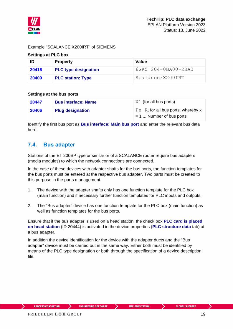
TechTip PLC data exchange
EPLAN Platform Version 2023
Status 13 June 2022
19
Example SCALANCE X200IRT of SIEMENS
Settings at PLC box
ID Property Value
20416 PLC type designation 6GK5 204-0BA00-2BA3
20409 PLC station Type ScalanceX200IRT
Settings at the bus ports
20447 Bus interface Name X1 (for all bus ports)
20406 Plug designation Px R for all bus ports whereby x
= 1 Number of bus ports
Identify the first bus port as Bus interface Main bus port and enter the relevant bus data
here
74 Bus adapter
Stations of the ET 200SP type or similar or of a SCALANCE router require bus adapters
(media modules) to which the network connections are connected
In the case of these devices with adapter shafts for the bus ports the function templates for
the bus ports must be entered at the respective bus adapter Two parts must be created to
this purpose in the parts management
1 The device with the adapter shafts only has one function template for the PLC box
(main function) and if necessary further function templates for PLC inputs and outputs
2 The Bus adapter device has one function template for the PLC box (main function) as
well as function templates for the bus ports
Ensure that if the bus adapter is used on a head station the check box PLC card is placed
on head station (ID 20444) is activated in the device properties (PLC structure data tab) at
a bus adapter
In addition the device identification for the device with the adapter ducts and the Bus
adapter device must be carried out in the same way Either both must be identified by
means of the PLC type designation or both through the specification of a device description
file
TechTip PLC data exchange
EPLAN Platform Version 2023
Status 13 June 2022
20
Settings at the PLC box for the bus adapter
ID Property Value
20161 Configuration project Not empty
20416 PLC type designation eg 6ES7 193-6AR00-0AA0
20410 PLC card is placed on rack ID Like head station
20411 Position (slot module) Not empty
20444 PLC card is placed on head station
Settings at the bus ports
20447 Bus interface Name X1 (for all bus ports at all
adapters)
20406 Plug designation Px R for all bus ports whereby x
= 1 Number of bus ports the
method of counting is non-adapter-
specific
Identify the first bus port as Bus interface Main bus port and enter the relevant bus data
here
75 IO-Link devices
Devices that have bus ports of the IO-Link bus system are called IO-Link devices These
can either be part of a rack structure (for example an IO-Link master) or be located as an
independent device at any desired point in the network (for example a motor or sensor)
Additional information on the definition of PLC inputs and outputs or PLC bus ports can be
found in the TechTip TechTip-Preparation-of-master-data-for-PLC-data-exchange in
Section 24
751 IO-Link devices within a rack structure
IO-Link devices are parameterized like standard PLC devices within a rack structure
752 IO-Link devices outside a rack structure
The property dialog of a device depends on the function category The property dialog of a
PLC box thus contains the PLC structure data tab This tab is missing for non-PLC devices
In this case the required properties can be filled into the property table of the first tab
TechTip PLC data exchange
EPLAN Platform Version 2023
Status 13 June 2022
21
Settings at PLC box
ID Property
20161 Configuration project Not empty
20408 PLC station ID Not empty
Settings at the bus ports
ID Property
20308 Bus system IO Link
76 PLC subdevices
Specific PLC devices consist of multiple integrated modules that each have their own
Address ranges and start addresses Such a device can consist for example of an internal
CPU module an internal input output module internal analog module as well as an internal
counter module - however with only one part number Such integrated modules within a PLC
device can be displayed in EPLAN with PLC subdevices To this purpose up to twelve PLC
subdevices are available Each PLC subdevice is defined by the corresponding properties (x
in the following describes the number of PLC subdevice 1hellip12) You can find more
information in the Online help in the section PLC subdevices as well as in the TechTip
TechTip-Preparation-of-master-data-for-PLC-data-exchange in the chapter PLC
devices with subdevices
PLC subdevices are exported if they have at least one start address or one bus port or one
IO connection point or one Device identification
Note
If a PLC card has no PLC subdevices (meaning that it only consists of one module)
definitions for these can be omitted The value 0 is entered at the PLC subdevice Index
property at the associated PLC connection points
You obtain further information on the definition of PLC subdevices from your PLC
manufacturer or in the TechTip TechTip-Configuring-PLC-devices-with-device-
description-files
TechTip PLC data exchange
EPLAN Platform Version 2023
Status 13 June 2022
22
77 Accessories
A PLC card can have accessories
The requirement for a data exchange is
bull The accessory is defined in the parts management
bull The accessory has a PLC type designation
bull The number of units used is larger than 0
Note
You can deactivate the export of the accessories in the Settings AutomationML AR APC
export dialog if needed
78 Device sets (Bundles)
Device sets (so called Bundles meaning bundles that consist of different devices) are not
supported by all PLC configuration programs (for example SIEMENS STEP 7 TIA Portal) In
this case the device set for the PLC data exchange must be broken up by configuring the
devices contained in the device set individually with the associated device identification
79 Device-specific configuration values
As of AutomationML AR APC version 120 you can also specify device-specific
configuration values To do this activate the Export device-specific configuration values
check box in the Settings AutomationML AR APC export dialog
Further notes and specifications for handling of device-specific configuration values are
available in the Tech Tip TechTip-PLC-data-exchange-with-device-related-
configuration-values
TechTip PLC data exchange
EPLAN Platform Version 2023
Status 13 June 2022
23
710 Drives
As of AutomationML AR APC version 120 you can also specify drive components To do
this activate the Export drives check box in the Settings AutomationML AR APC export
dialog
If this check box is selected drive components are exported as well This means all other
functions that have a drive assigned are exported in addition to the PLC devices and bus-
capable devices
If the check box is deactivated only PLC devices and bus-capable devices are exported
Note During import the corresponding devices must be available in the parts management
otherwise an empty PLC box is created
For the export the following properties amongst others have to be filled at the drive
components
ID Property
20576 [1hellip 64] Drive
20415 Device description File name
20381 Device description Index in file
20577 Device type
20161 Configuration project
20417 Object description
20408 PLC station ID
20416 PLC type designation
TechTip PLC data exchange
EPLAN Platform Version 2023
Status 13 June 2022
24
8 Check of the PLC configuration project
All devices that atacutere to be exported or imported via PLC data exchange require the following
structure
1 Configuration project rarr This is the main node
2 Station ID rarr A grouping element
3 Rack rarr If the device is used as the basis for other devices this property has to be filled
numerically
A rack is numbered consecutively with the Rack property
A CPU or a bus coupler is numbered consecutively with a Rack if the device itself is not
placed on a rack
PLC devices that can add other PLC devices are also numbered consecutively with
Rack
4 All PLC devices that are placed on a rack or assigned to a rack receive the number of
the rack via the PLC card is placed on rack ID property
5 If the PLC card is placed on rack ID property is filled the position at which the device
is located has to be defined This is done via the Position (slot module) property
81 Check via message management
When checking the PLC configuration project you are supported by check runs In most
cases the PLC data exchange (Mitsubishi) run scheme can be used For adjustments of the
check runs a copy of this scheme is recommended
This check increases the quality of the project and helps with error prevention
TechTip PLC data exchange
EPLAN Platform Version 2023
Status 13 June 2022
25
Appendix A Relevant properties
The following overview shows which properties are important during the PLC data exchange
The data input in EPLAN can be effected
A = in the parts data
M = in the macro
P = in the project
We recommend entering the data preferably in the parts data and or in the macros
Note
If necessary you can create part variants in the EPLAN parts management
PLC connection point
ID Property Data input
A M P
20384 PLC subdevice Index x x x
20428 Channel designation x x x
20610 Symbolic address Group 1 - - x
20618 Symbolic address UDT (name) 2 - - x
20619 Symbolic address UDT (data type) 2 - - x
1 Exchange as of AutomationML AR APC Version 110
2 Exchange as of AutomationML AR APC Version 130
TechTip PLC data exchange
EPLAN Platform Version 2023
Status 13 June 2022
26
PLC bus port
ID Property Data input
A M P
20448 Bus interface Main bus port - x x
20447 Bus interface Name x x x
20386 Physical network Bus ID item number
2
- - x
20313 Data transfer rate - x x
20289 Integrated module - x x
20312 Subslot - x x
20308 Bus system x x x
20446 Subnet mask - x x
20613 Standard gateway - x x
20309 DNSPROFINET device name - x x
Exchange as of AutomationML AR APC Version 120
PLC card
ID Property Data input
A M P
20437 PLC card name - - x
20164 Bus coupler head station x x x
20381 Device description Index in file x x x
20521 foll PLC subdevice x Name x x x
20533 foll PLC subdevice x Position (slot module) x x x
20454 20382 20392
foll 20452 foll
PLC subdevice x Start address (inputs) - - x
20455 foll 20478
foll 20515 foll
PLC subdevice x Start address (outputs) - - x
TechTip PLC data exchange
EPLAN Platform Version 2023
Status 13 June 2022
27
ID Property Data input
A M P
20548 20605
20547 20551foll
20570
PLC subdevice x Data length (inputs) x x x
20550 20604
20549 20560foll
PLC subdevice x Data length (outputs) x x x
20607
20582 foll
PLC subdevice x PLC type designation x x x
20606
20593 foll
PLC subdevice x Device description
Index in file
x x x
20417 Object description x x x
20550 PLC device Data length (outputs) x x x
20548 PLC device Data length (inputs) x x x
20289 Integrated module - x x
20444 PLC card is placed on head station x x x
20312 Subslot - x x
20439 Safety address Target 1 - - x
20615 Safety address Source 1 - - x
20616 Safety address Upper value 1 - - x 3
20617 Safety address Lower value 1 - - x 3
20409 PLC station Type x x x
20580 PLC device TemplateIdentifier 2 x x x
20614 PLC station TemplateIdentifier 2 - x x
20576 Drive 2 - x x
1 Exchange as of AutomationML AR APC Version 110
2 Exchange as of AutomationML AR APC Version 120
3 Values in EPLAN are write-protected and are only filled via the PLC data exchange
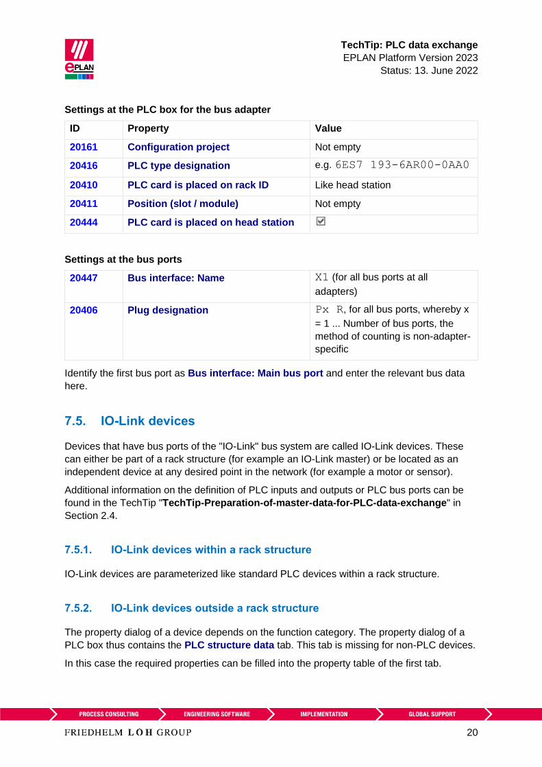
TechTip PLC data exchange
EPLAN Platform Version 2023
Status 13 June 2022
20
Settings at the PLC box for the bus adapter
ID Property Value
20161 Configuration project Not empty
20416 PLC type designation eg 6ES7 193-6AR00-0AA0
20410 PLC card is placed on rack ID Like head station
20411 Position (slot module) Not empty
20444 PLC card is placed on head station
Settings at the bus ports
20447 Bus interface Name X1 (for all bus ports at all
adapters)
20406 Plug designation Px R for all bus ports whereby x
= 1 Number of bus ports the
method of counting is non-adapter-
specific
Identify the first bus port as Bus interface Main bus port and enter the relevant bus data
here
75 IO-Link devices
Devices that have bus ports of the IO-Link bus system are called IO-Link devices These
can either be part of a rack structure (for example an IO-Link master) or be located as an
independent device at any desired point in the network (for example a motor or sensor)
Additional information on the definition of PLC inputs and outputs or PLC bus ports can be
found in the TechTip TechTip-Preparation-of-master-data-for-PLC-data-exchange in
Section 24
751 IO-Link devices within a rack structure
IO-Link devices are parameterized like standard PLC devices within a rack structure
752 IO-Link devices outside a rack structure
The property dialog of a device depends on the function category The property dialog of a
PLC box thus contains the PLC structure data tab This tab is missing for non-PLC devices
In this case the required properties can be filled into the property table of the first tab
TechTip PLC data exchange
EPLAN Platform Version 2023
Status 13 June 2022
21
Settings at PLC box
ID Property
20161 Configuration project Not empty
20408 PLC station ID Not empty
Settings at the bus ports
ID Property
20308 Bus system IO Link
76 PLC subdevices
Specific PLC devices consist of multiple integrated modules that each have their own
Address ranges and start addresses Such a device can consist for example of an internal
CPU module an internal input output module internal analog module as well as an internal
counter module - however with only one part number Such integrated modules within a PLC
device can be displayed in EPLAN with PLC subdevices To this purpose up to twelve PLC
subdevices are available Each PLC subdevice is defined by the corresponding properties (x
in the following describes the number of PLC subdevice 1hellip12) You can find more
information in the Online help in the section PLC subdevices as well as in the TechTip
TechTip-Preparation-of-master-data-for-PLC-data-exchange in the chapter PLC
devices with subdevices
PLC subdevices are exported if they have at least one start address or one bus port or one
IO connection point or one Device identification
Note
If a PLC card has no PLC subdevices (meaning that it only consists of one module)
definitions for these can be omitted The value 0 is entered at the PLC subdevice Index
property at the associated PLC connection points
You obtain further information on the definition of PLC subdevices from your PLC
manufacturer or in the TechTip TechTip-Configuring-PLC-devices-with-device-
description-files
TechTip PLC data exchange
EPLAN Platform Version 2023
Status 13 June 2022
22
77 Accessories
A PLC card can have accessories
The requirement for a data exchange is
bull The accessory is defined in the parts management
bull The accessory has a PLC type designation
bull The number of units used is larger than 0
Note
You can deactivate the export of the accessories in the Settings AutomationML AR APC
export dialog if needed
78 Device sets (Bundles)
Device sets (so called Bundles meaning bundles that consist of different devices) are not
supported by all PLC configuration programs (for example SIEMENS STEP 7 TIA Portal) In
this case the device set for the PLC data exchange must be broken up by configuring the
devices contained in the device set individually with the associated device identification
79 Device-specific configuration values
As of AutomationML AR APC version 120 you can also specify device-specific
configuration values To do this activate the Export device-specific configuration values
check box in the Settings AutomationML AR APC export dialog
Further notes and specifications for handling of device-specific configuration values are
available in the Tech Tip TechTip-PLC-data-exchange-with-device-related-
configuration-values
TechTip PLC data exchange
EPLAN Platform Version 2023
Status 13 June 2022
23
710 Drives
As of AutomationML AR APC version 120 you can also specify drive components To do
this activate the Export drives check box in the Settings AutomationML AR APC export
dialog
If this check box is selected drive components are exported as well This means all other
functions that have a drive assigned are exported in addition to the PLC devices and bus-
capable devices
If the check box is deactivated only PLC devices and bus-capable devices are exported
Note During import the corresponding devices must be available in the parts management
otherwise an empty PLC box is created
For the export the following properties amongst others have to be filled at the drive
components
ID Property
20576 [1hellip 64] Drive
20415 Device description File name
20381 Device description Index in file
20577 Device type
20161 Configuration project
20417 Object description
20408 PLC station ID
20416 PLC type designation
TechTip PLC data exchange
EPLAN Platform Version 2023
Status 13 June 2022
24
8 Check of the PLC configuration project
All devices that atacutere to be exported or imported via PLC data exchange require the following
structure
1 Configuration project rarr This is the main node
2 Station ID rarr A grouping element
3 Rack rarr If the device is used as the basis for other devices this property has to be filled
numerically
A rack is numbered consecutively with the Rack property
A CPU or a bus coupler is numbered consecutively with a Rack if the device itself is not
placed on a rack
PLC devices that can add other PLC devices are also numbered consecutively with
Rack
4 All PLC devices that are placed on a rack or assigned to a rack receive the number of
the rack via the PLC card is placed on rack ID property
5 If the PLC card is placed on rack ID property is filled the position at which the device
is located has to be defined This is done via the Position (slot module) property
81 Check via message management
When checking the PLC configuration project you are supported by check runs In most
cases the PLC data exchange (Mitsubishi) run scheme can be used For adjustments of the
check runs a copy of this scheme is recommended
This check increases the quality of the project and helps with error prevention
TechTip PLC data exchange
EPLAN Platform Version 2023
Status 13 June 2022
25
Appendix A Relevant properties
The following overview shows which properties are important during the PLC data exchange
The data input in EPLAN can be effected
A = in the parts data
M = in the macro
P = in the project
We recommend entering the data preferably in the parts data and or in the macros
Note
If necessary you can create part variants in the EPLAN parts management
PLC connection point
ID Property Data input
A M P
20384 PLC subdevice Index x x x
20428 Channel designation x x x
20610 Symbolic address Group 1 - - x
20618 Symbolic address UDT (name) 2 - - x
20619 Symbolic address UDT (data type) 2 - - x
1 Exchange as of AutomationML AR APC Version 110
2 Exchange as of AutomationML AR APC Version 130
TechTip PLC data exchange
EPLAN Platform Version 2023
Status 13 June 2022
26
PLC bus port
ID Property Data input
A M P
20448 Bus interface Main bus port - x x
20447 Bus interface Name x x x
20386 Physical network Bus ID item number
2
- - x
20313 Data transfer rate - x x
20289 Integrated module - x x
20312 Subslot - x x
20308 Bus system x x x
20446 Subnet mask - x x
20613 Standard gateway - x x
20309 DNSPROFINET device name - x x
Exchange as of AutomationML AR APC Version 120
PLC card
ID Property Data input
A M P
20437 PLC card name - - x
20164 Bus coupler head station x x x
20381 Device description Index in file x x x
20521 foll PLC subdevice x Name x x x
20533 foll PLC subdevice x Position (slot module) x x x
20454 20382 20392
foll 20452 foll
PLC subdevice x Start address (inputs) - - x
20455 foll 20478
foll 20515 foll
PLC subdevice x Start address (outputs) - - x
TechTip PLC data exchange
EPLAN Platform Version 2023
Status 13 June 2022
27
ID Property Data input
A M P
20548 20605
20547 20551foll
20570
PLC subdevice x Data length (inputs) x x x
20550 20604
20549 20560foll
PLC subdevice x Data length (outputs) x x x
20607
20582 foll
PLC subdevice x PLC type designation x x x
20606
20593 foll
PLC subdevice x Device description
Index in file
x x x
20417 Object description x x x
20550 PLC device Data length (outputs) x x x
20548 PLC device Data length (inputs) x x x
20289 Integrated module - x x
20444 PLC card is placed on head station x x x
20312 Subslot - x x
20439 Safety address Target 1 - - x
20615 Safety address Source 1 - - x
20616 Safety address Upper value 1 - - x 3
20617 Safety address Lower value 1 - - x 3
20409 PLC station Type x x x
20580 PLC device TemplateIdentifier 2 x x x
20614 PLC station TemplateIdentifier 2 - x x
20576 Drive 2 - x x
1 Exchange as of AutomationML AR APC Version 110
2 Exchange as of AutomationML AR APC Version 120
3 Values in EPLAN are write-protected and are only filled via the PLC data exchange
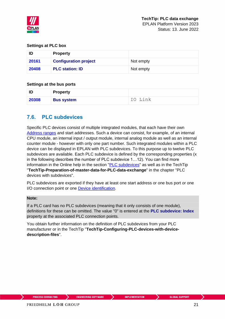
TechTip PLC data exchange
EPLAN Platform Version 2023
Status 13 June 2022
21
Settings at PLC box
ID Property
20161 Configuration project Not empty
20408 PLC station ID Not empty
Settings at the bus ports
ID Property
20308 Bus system IO Link
76 PLC subdevices
Specific PLC devices consist of multiple integrated modules that each have their own
Address ranges and start addresses Such a device can consist for example of an internal
CPU module an internal input output module internal analog module as well as an internal
counter module - however with only one part number Such integrated modules within a PLC
device can be displayed in EPLAN with PLC subdevices To this purpose up to twelve PLC
subdevices are available Each PLC subdevice is defined by the corresponding properties (x
in the following describes the number of PLC subdevice 1hellip12) You can find more
information in the Online help in the section PLC subdevices as well as in the TechTip
TechTip-Preparation-of-master-data-for-PLC-data-exchange in the chapter PLC
devices with subdevices
PLC subdevices are exported if they have at least one start address or one bus port or one
IO connection point or one Device identification
Note
If a PLC card has no PLC subdevices (meaning that it only consists of one module)
definitions for these can be omitted The value 0 is entered at the PLC subdevice Index
property at the associated PLC connection points
You obtain further information on the definition of PLC subdevices from your PLC
manufacturer or in the TechTip TechTip-Configuring-PLC-devices-with-device-
description-files
TechTip PLC data exchange
EPLAN Platform Version 2023
Status 13 June 2022
22
77 Accessories
A PLC card can have accessories
The requirement for a data exchange is
bull The accessory is defined in the parts management
bull The accessory has a PLC type designation
bull The number of units used is larger than 0
Note
You can deactivate the export of the accessories in the Settings AutomationML AR APC
export dialog if needed
78 Device sets (Bundles)
Device sets (so called Bundles meaning bundles that consist of different devices) are not
supported by all PLC configuration programs (for example SIEMENS STEP 7 TIA Portal) In
this case the device set for the PLC data exchange must be broken up by configuring the
devices contained in the device set individually with the associated device identification
79 Device-specific configuration values
As of AutomationML AR APC version 120 you can also specify device-specific
configuration values To do this activate the Export device-specific configuration values
check box in the Settings AutomationML AR APC export dialog
Further notes and specifications for handling of device-specific configuration values are
available in the Tech Tip TechTip-PLC-data-exchange-with-device-related-
configuration-values
TechTip PLC data exchange
EPLAN Platform Version 2023
Status 13 June 2022
23
710 Drives
As of AutomationML AR APC version 120 you can also specify drive components To do
this activate the Export drives check box in the Settings AutomationML AR APC export
dialog
If this check box is selected drive components are exported as well This means all other
functions that have a drive assigned are exported in addition to the PLC devices and bus-
capable devices
If the check box is deactivated only PLC devices and bus-capable devices are exported
Note During import the corresponding devices must be available in the parts management
otherwise an empty PLC box is created
For the export the following properties amongst others have to be filled at the drive
components
ID Property
20576 [1hellip 64] Drive
20415 Device description File name
20381 Device description Index in file
20577 Device type
20161 Configuration project
20417 Object description
20408 PLC station ID
20416 PLC type designation
TechTip PLC data exchange
EPLAN Platform Version 2023
Status 13 June 2022
24
8 Check of the PLC configuration project
All devices that atacutere to be exported or imported via PLC data exchange require the following
structure
1 Configuration project rarr This is the main node
2 Station ID rarr A grouping element
3 Rack rarr If the device is used as the basis for other devices this property has to be filled
numerically
A rack is numbered consecutively with the Rack property
A CPU or a bus coupler is numbered consecutively with a Rack if the device itself is not
placed on a rack
PLC devices that can add other PLC devices are also numbered consecutively with
Rack
4 All PLC devices that are placed on a rack or assigned to a rack receive the number of
the rack via the PLC card is placed on rack ID property
5 If the PLC card is placed on rack ID property is filled the position at which the device
is located has to be defined This is done via the Position (slot module) property
81 Check via message management
When checking the PLC configuration project you are supported by check runs In most
cases the PLC data exchange (Mitsubishi) run scheme can be used For adjustments of the
check runs a copy of this scheme is recommended
This check increases the quality of the project and helps with error prevention
TechTip PLC data exchange
EPLAN Platform Version 2023
Status 13 June 2022
25
Appendix A Relevant properties
The following overview shows which properties are important during the PLC data exchange
The data input in EPLAN can be effected
A = in the parts data
M = in the macro
P = in the project
We recommend entering the data preferably in the parts data and or in the macros
Note
If necessary you can create part variants in the EPLAN parts management
PLC connection point
ID Property Data input
A M P
20384 PLC subdevice Index x x x
20428 Channel designation x x x
20610 Symbolic address Group 1 - - x
20618 Symbolic address UDT (name) 2 - - x
20619 Symbolic address UDT (data type) 2 - - x
1 Exchange as of AutomationML AR APC Version 110
2 Exchange as of AutomationML AR APC Version 130
TechTip PLC data exchange
EPLAN Platform Version 2023
Status 13 June 2022
26
PLC bus port
ID Property Data input
A M P
20448 Bus interface Main bus port - x x
20447 Bus interface Name x x x
20386 Physical network Bus ID item number
2
- - x
20313 Data transfer rate - x x
20289 Integrated module - x x
20312 Subslot - x x
20308 Bus system x x x
20446 Subnet mask - x x
20613 Standard gateway - x x
20309 DNSPROFINET device name - x x
Exchange as of AutomationML AR APC Version 120
PLC card
ID Property Data input
A M P
20437 PLC card name - - x
20164 Bus coupler head station x x x
20381 Device description Index in file x x x
20521 foll PLC subdevice x Name x x x
20533 foll PLC subdevice x Position (slot module) x x x
20454 20382 20392
foll 20452 foll
PLC subdevice x Start address (inputs) - - x
20455 foll 20478
foll 20515 foll
PLC subdevice x Start address (outputs) - - x
TechTip PLC data exchange
EPLAN Platform Version 2023
Status 13 June 2022
27
ID Property Data input
A M P
20548 20605
20547 20551foll
20570
PLC subdevice x Data length (inputs) x x x
20550 20604
20549 20560foll
PLC subdevice x Data length (outputs) x x x
20607
20582 foll
PLC subdevice x PLC type designation x x x
20606
20593 foll
PLC subdevice x Device description
Index in file
x x x
20417 Object description x x x
20550 PLC device Data length (outputs) x x x
20548 PLC device Data length (inputs) x x x
20289 Integrated module - x x
20444 PLC card is placed on head station x x x
20312 Subslot - x x
20439 Safety address Target 1 - - x
20615 Safety address Source 1 - - x
20616 Safety address Upper value 1 - - x 3
20617 Safety address Lower value 1 - - x 3
20409 PLC station Type x x x
20580 PLC device TemplateIdentifier 2 x x x
20614 PLC station TemplateIdentifier 2 - x x
20576 Drive 2 - x x
1 Exchange as of AutomationML AR APC Version 110
2 Exchange as of AutomationML AR APC Version 120
3 Values in EPLAN are write-protected and are only filled via the PLC data exchange
TechTip PLC data exchange
EPLAN Platform Version 2023
Status 13 June 2022
22
77 Accessories
A PLC card can have accessories
The requirement for a data exchange is
bull The accessory is defined in the parts management
bull The accessory has a PLC type designation
bull The number of units used is larger than 0
Note
You can deactivate the export of the accessories in the Settings AutomationML AR APC
export dialog if needed
78 Device sets (Bundles)
Device sets (so called Bundles meaning bundles that consist of different devices) are not
supported by all PLC configuration programs (for example SIEMENS STEP 7 TIA Portal) In
this case the device set for the PLC data exchange must be broken up by configuring the
devices contained in the device set individually with the associated device identification
79 Device-specific configuration values
As of AutomationML AR APC version 120 you can also specify device-specific
configuration values To do this activate the Export device-specific configuration values
check box in the Settings AutomationML AR APC export dialog
Further notes and specifications for handling of device-specific configuration values are
available in the Tech Tip TechTip-PLC-data-exchange-with-device-related-
configuration-values
TechTip PLC data exchange
EPLAN Platform Version 2023
Status 13 June 2022
23
710 Drives
As of AutomationML AR APC version 120 you can also specify drive components To do
this activate the Export drives check box in the Settings AutomationML AR APC export
dialog
If this check box is selected drive components are exported as well This means all other
functions that have a drive assigned are exported in addition to the PLC devices and bus-
capable devices
If the check box is deactivated only PLC devices and bus-capable devices are exported
Note During import the corresponding devices must be available in the parts management
otherwise an empty PLC box is created
For the export the following properties amongst others have to be filled at the drive
components
ID Property
20576 [1hellip 64] Drive
20415 Device description File name
20381 Device description Index in file
20577 Device type
20161 Configuration project
20417 Object description
20408 PLC station ID
20416 PLC type designation
TechTip PLC data exchange
EPLAN Platform Version 2023
Status 13 June 2022
24
8 Check of the PLC configuration project
All devices that atacutere to be exported or imported via PLC data exchange require the following
structure
1 Configuration project rarr This is the main node
2 Station ID rarr A grouping element
3 Rack rarr If the device is used as the basis for other devices this property has to be filled
numerically
A rack is numbered consecutively with the Rack property
A CPU or a bus coupler is numbered consecutively with a Rack if the device itself is not
placed on a rack
PLC devices that can add other PLC devices are also numbered consecutively with
Rack
4 All PLC devices that are placed on a rack or assigned to a rack receive the number of
the rack via the PLC card is placed on rack ID property
5 If the PLC card is placed on rack ID property is filled the position at which the device
is located has to be defined This is done via the Position (slot module) property
81 Check via message management
When checking the PLC configuration project you are supported by check runs In most
cases the PLC data exchange (Mitsubishi) run scheme can be used For adjustments of the
check runs a copy of this scheme is recommended
This check increases the quality of the project and helps with error prevention
TechTip PLC data exchange
EPLAN Platform Version 2023
Status 13 June 2022
25
Appendix A Relevant properties
The following overview shows which properties are important during the PLC data exchange
The data input in EPLAN can be effected
A = in the parts data
M = in the macro
P = in the project
We recommend entering the data preferably in the parts data and or in the macros
Note
If necessary you can create part variants in the EPLAN parts management
PLC connection point
ID Property Data input
A M P
20384 PLC subdevice Index x x x
20428 Channel designation x x x
20610 Symbolic address Group 1 - - x
20618 Symbolic address UDT (name) 2 - - x
20619 Symbolic address UDT (data type) 2 - - x
1 Exchange as of AutomationML AR APC Version 110
2 Exchange as of AutomationML AR APC Version 130
TechTip PLC data exchange
EPLAN Platform Version 2023
Status 13 June 2022
26
PLC bus port
ID Property Data input
A M P
20448 Bus interface Main bus port - x x
20447 Bus interface Name x x x
20386 Physical network Bus ID item number
2
- - x
20313 Data transfer rate - x x
20289 Integrated module - x x
20312 Subslot - x x
20308 Bus system x x x
20446 Subnet mask - x x
20613 Standard gateway - x x
20309 DNSPROFINET device name - x x
Exchange as of AutomationML AR APC Version 120
PLC card
ID Property Data input
A M P
20437 PLC card name - - x
20164 Bus coupler head station x x x
20381 Device description Index in file x x x
20521 foll PLC subdevice x Name x x x
20533 foll PLC subdevice x Position (slot module) x x x
20454 20382 20392
foll 20452 foll
PLC subdevice x Start address (inputs) - - x
20455 foll 20478
foll 20515 foll
PLC subdevice x Start address (outputs) - - x
TechTip PLC data exchange
EPLAN Platform Version 2023
Status 13 June 2022
27
ID Property Data input
A M P
20548 20605
20547 20551foll
20570
PLC subdevice x Data length (inputs) x x x
20550 20604
20549 20560foll
PLC subdevice x Data length (outputs) x x x
20607
20582 foll
PLC subdevice x PLC type designation x x x
20606
20593 foll
PLC subdevice x Device description
Index in file
x x x
20417 Object description x x x
20550 PLC device Data length (outputs) x x x
20548 PLC device Data length (inputs) x x x
20289 Integrated module - x x
20444 PLC card is placed on head station x x x
20312 Subslot - x x
20439 Safety address Target 1 - - x
20615 Safety address Source 1 - - x
20616 Safety address Upper value 1 - - x 3
20617 Safety address Lower value 1 - - x 3
20409 PLC station Type x x x
20580 PLC device TemplateIdentifier 2 x x x
20614 PLC station TemplateIdentifier 2 - x x
20576 Drive 2 - x x
1 Exchange as of AutomationML AR APC Version 110
2 Exchange as of AutomationML AR APC Version 120
3 Values in EPLAN are write-protected and are only filled via the PLC data exchange
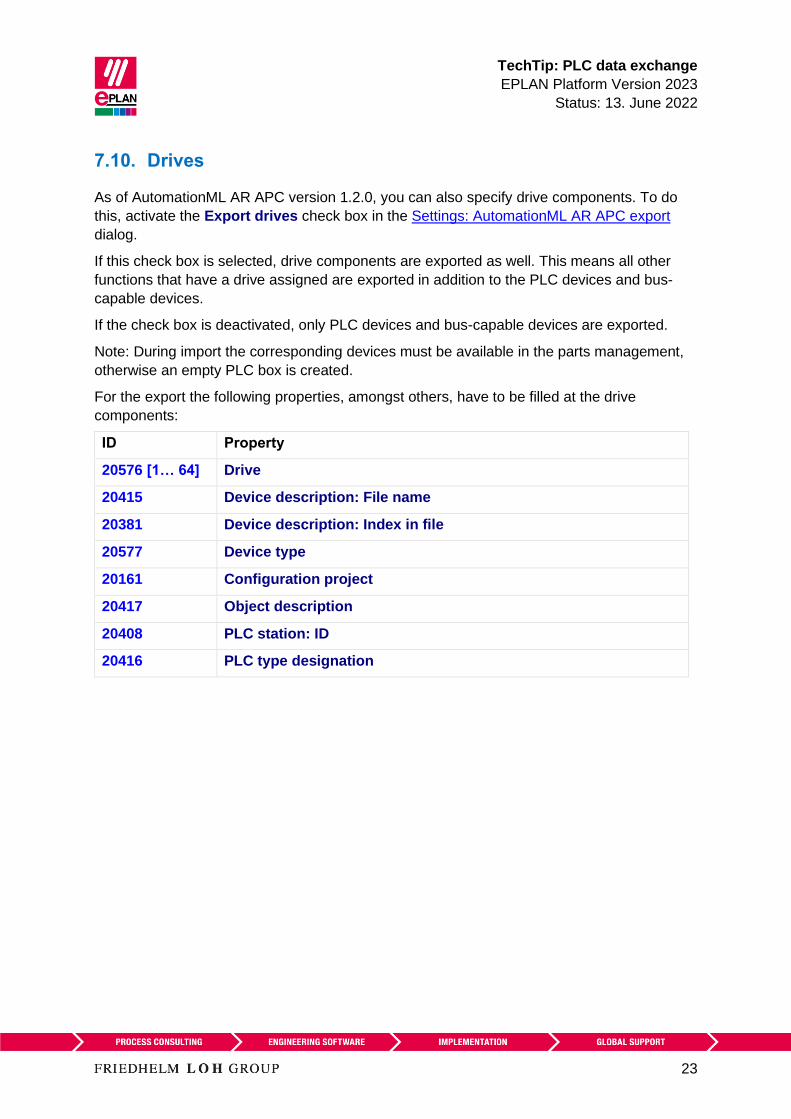
TechTip PLC data exchange
EPLAN Platform Version 2023
Status 13 June 2022
23
710 Drives
As of AutomationML AR APC version 120 you can also specify drive components To do
this activate the Export drives check box in the Settings AutomationML AR APC export
dialog
If this check box is selected drive components are exported as well This means all other
functions that have a drive assigned are exported in addition to the PLC devices and bus-
capable devices
If the check box is deactivated only PLC devices and bus-capable devices are exported
Note During import the corresponding devices must be available in the parts management
otherwise an empty PLC box is created
For the export the following properties amongst others have to be filled at the drive
components
ID Property
20576 [1hellip 64] Drive
20415 Device description File name
20381 Device description Index in file
20577 Device type
20161 Configuration project
20417 Object description
20408 PLC station ID
20416 PLC type designation
TechTip PLC data exchange
EPLAN Platform Version 2023
Status 13 June 2022
24
8 Check of the PLC configuration project
All devices that atacutere to be exported or imported via PLC data exchange require the following
structure
1 Configuration project rarr This is the main node
2 Station ID rarr A grouping element
3 Rack rarr If the device is used as the basis for other devices this property has to be filled
numerically
A rack is numbered consecutively with the Rack property
A CPU or a bus coupler is numbered consecutively with a Rack if the device itself is not
placed on a rack
PLC devices that can add other PLC devices are also numbered consecutively with
Rack
4 All PLC devices that are placed on a rack or assigned to a rack receive the number of
the rack via the PLC card is placed on rack ID property
5 If the PLC card is placed on rack ID property is filled the position at which the device
is located has to be defined This is done via the Position (slot module) property
81 Check via message management
When checking the PLC configuration project you are supported by check runs In most
cases the PLC data exchange (Mitsubishi) run scheme can be used For adjustments of the
check runs a copy of this scheme is recommended
This check increases the quality of the project and helps with error prevention
TechTip PLC data exchange
EPLAN Platform Version 2023
Status 13 June 2022
25
Appendix A Relevant properties
The following overview shows which properties are important during the PLC data exchange
The data input in EPLAN can be effected
A = in the parts data
M = in the macro
P = in the project
We recommend entering the data preferably in the parts data and or in the macros
Note
If necessary you can create part variants in the EPLAN parts management
PLC connection point
ID Property Data input
A M P
20384 PLC subdevice Index x x x
20428 Channel designation x x x
20610 Symbolic address Group 1 - - x
20618 Symbolic address UDT (name) 2 - - x
20619 Symbolic address UDT (data type) 2 - - x
1 Exchange as of AutomationML AR APC Version 110
2 Exchange as of AutomationML AR APC Version 130
TechTip PLC data exchange
EPLAN Platform Version 2023
Status 13 June 2022
26
PLC bus port
ID Property Data input
A M P
20448 Bus interface Main bus port - x x
20447 Bus interface Name x x x
20386 Physical network Bus ID item number
2
- - x
20313 Data transfer rate - x x
20289 Integrated module - x x
20312 Subslot - x x
20308 Bus system x x x
20446 Subnet mask - x x
20613 Standard gateway - x x
20309 DNSPROFINET device name - x x
Exchange as of AutomationML AR APC Version 120
PLC card
ID Property Data input
A M P
20437 PLC card name - - x
20164 Bus coupler head station x x x
20381 Device description Index in file x x x
20521 foll PLC subdevice x Name x x x
20533 foll PLC subdevice x Position (slot module) x x x
20454 20382 20392
foll 20452 foll
PLC subdevice x Start address (inputs) - - x
20455 foll 20478
foll 20515 foll
PLC subdevice x Start address (outputs) - - x
TechTip PLC data exchange
EPLAN Platform Version 2023
Status 13 June 2022
27
ID Property Data input
A M P
20548 20605
20547 20551foll
20570
PLC subdevice x Data length (inputs) x x x
20550 20604
20549 20560foll
PLC subdevice x Data length (outputs) x x x
20607
20582 foll
PLC subdevice x PLC type designation x x x
20606
20593 foll
PLC subdevice x Device description
Index in file
x x x
20417 Object description x x x
20550 PLC device Data length (outputs) x x x
20548 PLC device Data length (inputs) x x x
20289 Integrated module - x x
20444 PLC card is placed on head station x x x
20312 Subslot - x x
20439 Safety address Target 1 - - x
20615 Safety address Source 1 - - x
20616 Safety address Upper value 1 - - x 3
20617 Safety address Lower value 1 - - x 3
20409 PLC station Type x x x
20580 PLC device TemplateIdentifier 2 x x x
20614 PLC station TemplateIdentifier 2 - x x
20576 Drive 2 - x x
1 Exchange as of AutomationML AR APC Version 110
2 Exchange as of AutomationML AR APC Version 120
3 Values in EPLAN are write-protected and are only filled via the PLC data exchange
TechTip PLC data exchange
EPLAN Platform Version 2023
Status 13 June 2022
24
8 Check of the PLC configuration project
All devices that atacutere to be exported or imported via PLC data exchange require the following
structure
1 Configuration project rarr This is the main node
2 Station ID rarr A grouping element
3 Rack rarr If the device is used as the basis for other devices this property has to be filled
numerically
A rack is numbered consecutively with the Rack property
A CPU or a bus coupler is numbered consecutively with a Rack if the device itself is not
placed on a rack
PLC devices that can add other PLC devices are also numbered consecutively with
Rack
4 All PLC devices that are placed on a rack or assigned to a rack receive the number of
the rack via the PLC card is placed on rack ID property
5 If the PLC card is placed on rack ID property is filled the position at which the device
is located has to be defined This is done via the Position (slot module) property
81 Check via message management
When checking the PLC configuration project you are supported by check runs In most
cases the PLC data exchange (Mitsubishi) run scheme can be used For adjustments of the
check runs a copy of this scheme is recommended
This check increases the quality of the project and helps with error prevention
TechTip PLC data exchange
EPLAN Platform Version 2023
Status 13 June 2022
25
Appendix A Relevant properties
The following overview shows which properties are important during the PLC data exchange
The data input in EPLAN can be effected
A = in the parts data
M = in the macro
P = in the project
We recommend entering the data preferably in the parts data and or in the macros
Note
If necessary you can create part variants in the EPLAN parts management
PLC connection point
ID Property Data input
A M P
20384 PLC subdevice Index x x x
20428 Channel designation x x x
20610 Symbolic address Group 1 - - x
20618 Symbolic address UDT (name) 2 - - x
20619 Symbolic address UDT (data type) 2 - - x
1 Exchange as of AutomationML AR APC Version 110
2 Exchange as of AutomationML AR APC Version 130
TechTip PLC data exchange
EPLAN Platform Version 2023
Status 13 June 2022
26
PLC bus port
ID Property Data input
A M P
20448 Bus interface Main bus port - x x
20447 Bus interface Name x x x
20386 Physical network Bus ID item number
2
- - x
20313 Data transfer rate - x x
20289 Integrated module - x x
20312 Subslot - x x
20308 Bus system x x x
20446 Subnet mask - x x
20613 Standard gateway - x x
20309 DNSPROFINET device name - x x
Exchange as of AutomationML AR APC Version 120
PLC card
ID Property Data input
A M P
20437 PLC card name - - x
20164 Bus coupler head station x x x
20381 Device description Index in file x x x
20521 foll PLC subdevice x Name x x x
20533 foll PLC subdevice x Position (slot module) x x x
20454 20382 20392
foll 20452 foll
PLC subdevice x Start address (inputs) - - x
20455 foll 20478
foll 20515 foll
PLC subdevice x Start address (outputs) - - x
TechTip PLC data exchange
EPLAN Platform Version 2023
Status 13 June 2022
27
ID Property Data input
A M P
20548 20605
20547 20551foll
20570
PLC subdevice x Data length (inputs) x x x
20550 20604
20549 20560foll
PLC subdevice x Data length (outputs) x x x
20607
20582 foll
PLC subdevice x PLC type designation x x x
20606
20593 foll
PLC subdevice x Device description
Index in file
x x x
20417 Object description x x x
20550 PLC device Data length (outputs) x x x
20548 PLC device Data length (inputs) x x x
20289 Integrated module - x x
20444 PLC card is placed on head station x x x
20312 Subslot - x x
20439 Safety address Target 1 - - x
20615 Safety address Source 1 - - x
20616 Safety address Upper value 1 - - x 3
20617 Safety address Lower value 1 - - x 3
20409 PLC station Type x x x
20580 PLC device TemplateIdentifier 2 x x x
20614 PLC station TemplateIdentifier 2 - x x
20576 Drive 2 - x x
1 Exchange as of AutomationML AR APC Version 110
2 Exchange as of AutomationML AR APC Version 120
3 Values in EPLAN are write-protected and are only filled via the PLC data exchange
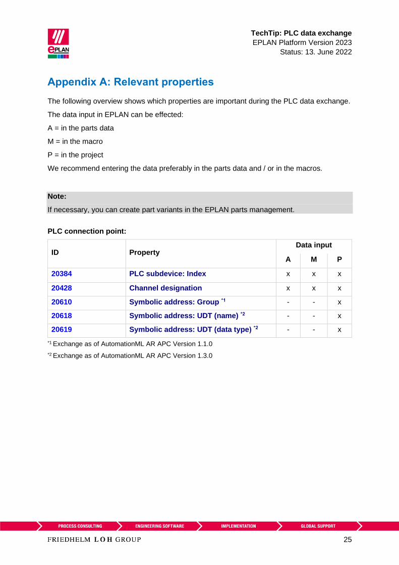
TechTip PLC data exchange
EPLAN Platform Version 2023
Status 13 June 2022
25
Appendix A Relevant properties
The following overview shows which properties are important during the PLC data exchange
The data input in EPLAN can be effected
A = in the parts data
M = in the macro
P = in the project
We recommend entering the data preferably in the parts data and or in the macros
Note
If necessary you can create part variants in the EPLAN parts management
PLC connection point
ID Property Data input
A M P
20384 PLC subdevice Index x x x
20428 Channel designation x x x
20610 Symbolic address Group 1 - - x
20618 Symbolic address UDT (name) 2 - - x
20619 Symbolic address UDT (data type) 2 - - x
1 Exchange as of AutomationML AR APC Version 110
2 Exchange as of AutomationML AR APC Version 130
TechTip PLC data exchange
EPLAN Platform Version 2023
Status 13 June 2022
26
PLC bus port
ID Property Data input
A M P
20448 Bus interface Main bus port - x x
20447 Bus interface Name x x x
20386 Physical network Bus ID item number
2
- - x
20313 Data transfer rate - x x
20289 Integrated module - x x
20312 Subslot - x x
20308 Bus system x x x
20446 Subnet mask - x x
20613 Standard gateway - x x
20309 DNSPROFINET device name - x x
Exchange as of AutomationML AR APC Version 120
PLC card
ID Property Data input
A M P
20437 PLC card name - - x
20164 Bus coupler head station x x x
20381 Device description Index in file x x x
20521 foll PLC subdevice x Name x x x
20533 foll PLC subdevice x Position (slot module) x x x
20454 20382 20392
foll 20452 foll
PLC subdevice x Start address (inputs) - - x
20455 foll 20478
foll 20515 foll
PLC subdevice x Start address (outputs) - - x
TechTip PLC data exchange
EPLAN Platform Version 2023
Status 13 June 2022
27
ID Property Data input
A M P
20548 20605
20547 20551foll
20570
PLC subdevice x Data length (inputs) x x x
20550 20604
20549 20560foll
PLC subdevice x Data length (outputs) x x x
20607
20582 foll
PLC subdevice x PLC type designation x x x
20606
20593 foll
PLC subdevice x Device description
Index in file
x x x
20417 Object description x x x
20550 PLC device Data length (outputs) x x x
20548 PLC device Data length (inputs) x x x
20289 Integrated module - x x
20444 PLC card is placed on head station x x x
20312 Subslot - x x
20439 Safety address Target 1 - - x
20615 Safety address Source 1 - - x
20616 Safety address Upper value 1 - - x 3
20617 Safety address Lower value 1 - - x 3
20409 PLC station Type x x x
20580 PLC device TemplateIdentifier 2 x x x
20614 PLC station TemplateIdentifier 2 - x x
20576 Drive 2 - x x
1 Exchange as of AutomationML AR APC Version 110
2 Exchange as of AutomationML AR APC Version 120
3 Values in EPLAN are write-protected and are only filled via the PLC data exchange
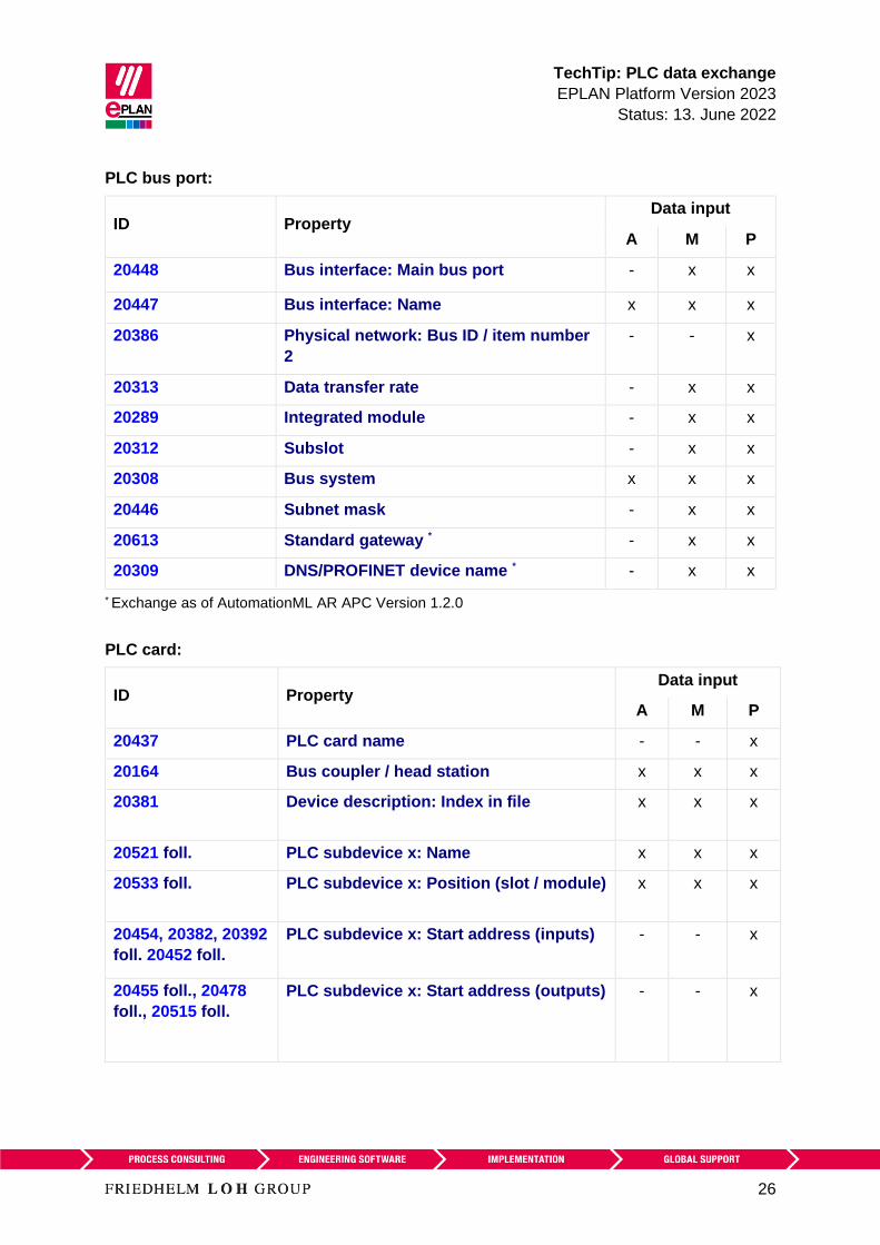
TechTip PLC data exchange
EPLAN Platform Version 2023
Status 13 June 2022
26
PLC bus port
ID Property Data input
A M P
20448 Bus interface Main bus port - x x
20447 Bus interface Name x x x
20386 Physical network Bus ID item number
2
- - x
20313 Data transfer rate - x x
20289 Integrated module - x x
20312 Subslot - x x
20308 Bus system x x x
20446 Subnet mask - x x
20613 Standard gateway - x x
20309 DNSPROFINET device name - x x
Exchange as of AutomationML AR APC Version 120
PLC card
ID Property Data input
A M P
20437 PLC card name - - x
20164 Bus coupler head station x x x
20381 Device description Index in file x x x
20521 foll PLC subdevice x Name x x x
20533 foll PLC subdevice x Position (slot module) x x x
20454 20382 20392
foll 20452 foll
PLC subdevice x Start address (inputs) - - x
20455 foll 20478
foll 20515 foll
PLC subdevice x Start address (outputs) - - x
TechTip PLC data exchange
EPLAN Platform Version 2023
Status 13 June 2022
27
ID Property Data input
A M P
20548 20605
20547 20551foll
20570
PLC subdevice x Data length (inputs) x x x
20550 20604
20549 20560foll
PLC subdevice x Data length (outputs) x x x
20607
20582 foll
PLC subdevice x PLC type designation x x x
20606
20593 foll
PLC subdevice x Device description
Index in file
x x x
20417 Object description x x x
20550 PLC device Data length (outputs) x x x
20548 PLC device Data length (inputs) x x x
20289 Integrated module - x x
20444 PLC card is placed on head station x x x
20312 Subslot - x x
20439 Safety address Target 1 - - x
20615 Safety address Source 1 - - x
20616 Safety address Upper value 1 - - x 3
20617 Safety address Lower value 1 - - x 3
20409 PLC station Type x x x
20580 PLC device TemplateIdentifier 2 x x x
20614 PLC station TemplateIdentifier 2 - x x
20576 Drive 2 - x x
1 Exchange as of AutomationML AR APC Version 110
2 Exchange as of AutomationML AR APC Version 120
3 Values in EPLAN are write-protected and are only filled via the PLC data exchange
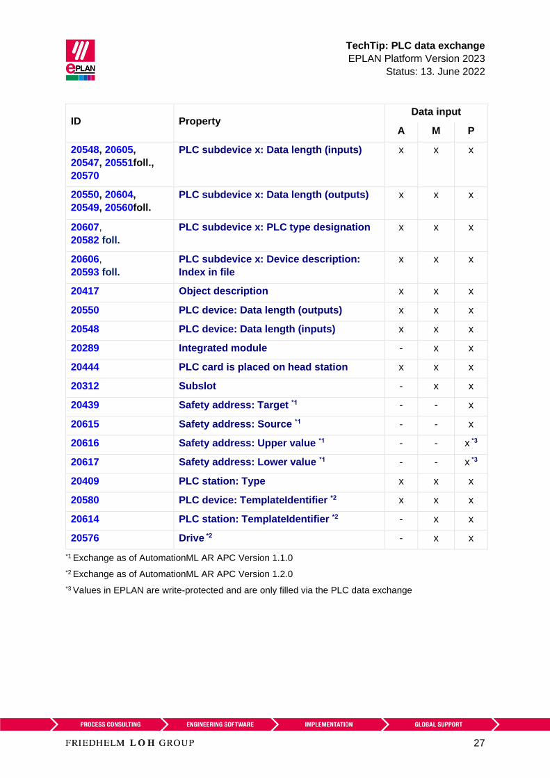
TechTip PLC data exchange
EPLAN Platform Version 2023
Status 13 June 2022
27
ID Property Data input
A M P
20548 20605
20547 20551foll
20570
PLC subdevice x Data length (inputs) x x x
20550 20604
20549 20560foll
PLC subdevice x Data length (outputs) x x x
20607
20582 foll
PLC subdevice x PLC type designation x x x
20606
20593 foll
PLC subdevice x Device description
Index in file
x x x
20417 Object description x x x
20550 PLC device Data length (outputs) x x x
20548 PLC device Data length (inputs) x x x
20289 Integrated module - x x
20444 PLC card is placed on head station x x x
20312 Subslot - x x
20439 Safety address Target 1 - - x
20615 Safety address Source 1 - - x
20616 Safety address Upper value 1 - - x 3
20617 Safety address Lower value 1 - - x 3
20409 PLC station Type x x x
20580 PLC device TemplateIdentifier 2 x x x
20614 PLC station TemplateIdentifier 2 - x x
20576 Drive 2 - x x
1 Exchange as of AutomationML AR APC Version 110
2 Exchange as of AutomationML AR APC Version 120
3 Values in EPLAN are write-protected and are only filled via the PLC data exchange