
Technology Characterization: Microturbines Prepared for: Environmental Protection Agency Combined...
24
Technology Characterization: Microturbines Prepared for: Environmental Protection Agency Combined Heat and Power Partnership Program Washington, DC Prepared by: Energy and Environmental Analysis (an ICF International Company) 1655 North Fort Myer Drive Suite 600 Arlington, Virginia 22209 December 2008 Technology Characterization Microturbines 1
-
Upload
independent -
Category
Documents
-
view
2 -
download
0
Transcript of Technology Characterization: Microturbines Prepared for: Environmental Protection Agency Combined...
Technology Characterization: Microturbines
Prepared for:
Environmental Protection Agency Combined Heat and Power Partnership Program Washington, DC
Prepared by:
Energy and Environmental Analysis (an ICF International Company) 1655 North Fort Myer Drive Suite 600 Arlington, Virginia 22209
December 2008
Technology Characterization Microturbines 1

Disclaimer: The information included in these technology overviews is for information purposes only and is gathered from published industry sources. Information about costs, maintenance, operations, or any other performance criteria is by no means representative of agency policies, definitions, or determinations for regulatory or compliance purposes.
Technology Characterization Microturbines i

Technology Characterization Microturbines ii
TABLE OF CONTENTS
INTRODUCTION AND SUMMARY...................................................................................... 1 APPLICATIONS ................................................................................................................ 1 TECHNOLOGY DESCRIPTION .......................................................................................... 2
Basic Processes....................................................................................................................2 Basic Components ................................................................................................................2 CHP Operation......................................................................................................................5
PERFORMANCE CHARACTERISTICS............................................................................... 6 Part-Load Performance.......................................................................................................11 Source: Energy Nexus Group. ............................................................................................12 Effects of Ambient Conditions on Performance ..................................................................12 Heat Recovery ....................................................................................................................14 Performance and Efficiency Enhancements .......................................................................14 Capital Cost.........................................................................................................................17 Maintenance........................................................................................................................18 Fuels ...................................................................................................................................19 Availability ...........................................................................................................................19
EMISSIONS .................................................................................................................... 20

Technology Characterization – Microturbines
Introduction and Summary Microturbines are small electricity generators that burn gaseous and liquid fuels to create high-speed rotation that turns an electrical generator. Today’s microturbine technology is the result of development work in small stationary and automotive gas turbines, auxiliary power equipment, and turbochargers, much of which was pursued by the automotive industry beginning in the 1950s. Microturbines entered field testing around 1997 and began initial commercial service in 2000.
The size range for microturbines available and in development is from 30 to 250 kilowatts (kW), while conventional gas turbine sizes range from 500 kW to 250 megawatts (MW). Microturbines run at high speeds and, like larger gas turbines, can be used in power-only generation or in combined heat and power (CHP) systems. They are able to operate on a variety of fuels, including natural gas, sour gases (high sulfur, low Btu content), and liquid fuels such as gasoline, kerosene, and diesel fuel/distillate heating oil. In resource recovery applications, they burn waste gases that would otherwise be flared or released directly into the atmosphere.
Applications Microturbines are ideally suited for distributed generation applications due to their flexibility in connection methods, ability to be stacked in parallel to serve larger loads, ability to provide stable and reliable power, and low emissions. Types of applications include:
o Peak shaving and base load power (grid parallel) o Combined heat and power o Stand-alone power o Backup/standby power o Ride-through connection o Primary power with grid as backup o Microgrid o Resource recovery Target customers include financial services, data processing, telecommunications, restaurant, multifamily residential buildings, lodging, retail, office building, and other commercial sectors. Microturbines are currently operating in resource recovery operations at oil and gas production fields, coal mines, and landfill operations, where byproduct gases serve as essentially free fuel. Reliable unattended operation is important since these locations may be remote from the grid, and even when served by the grid, may experience costly downtime when electric service is lost due to weather, fire, or animals. In CHP applications, the waste heat from the microturbine is used to produce hot water, to heat building space, to drive absorption cooling or desiccant dehumidification equipment, and to supply other thermal energy needs in a building or industrial process.
Technology Characterization Microturbines 1
Technology Description Basic Processes Microturbines are small gas turbines, most of which feature an internal heat exchanger called a recuperator. In a microturbine, a radial flow (centrifugal) compressor compresses the inlet air that is then preheated in the recuperator using heat from the turbine exhaust. Next, the heated air from the recuperator mixes with fuel in the combustor and hot combustion gas expands through the expansion and power turbines. The expansion turbine turns the compressor and, in single-shaft models, turns the generator as well. Two-shaft models use the compressor drive turbine’s exhaust to power a second turbine that drives the generator. Finally, the recuperator uses the exhaust of the power turbine to preheat the air from the compressor.
Single-shaft models generally operate at speeds over 60,000 revolutions per minute (rpm) and generate electrical power of high frequency, and of variable frequency (alternating current --AC). This power is rectified to direct current (DC) and then inverted to 60 hertz (Hz) for U.S. commercial use. In the two-shaft version, the power turbine connects via a gearbox to a generator that produces power at 60 Hz. Some manufacturers offer units producing 50 Hz for use in countries where 50 Hz is standard, such as in Europe and parts of Asia.
Thermodynamic Cycle
Microturbines operate on the same thermodynamic cycle, known as the Brayton cycle, as larger gas turbines. In this cycle, atmospheric air is compressed, heated, and then expanded, with the excess power produced by the expander (also called the turbine) over that consumed by the compressor used for power generation. The power produced by an expansion turbine and consumed by a compressor is proportional to the absolute temperature of the gas passing through those devices. Consequently, it is advantageous to operate the expansion turbine at the highest practical temperature consistent with economic materials and to operate the compressor with inlet airflow at as low a temperature as possible. As technology advances permit higher turbine inlet temperature, the optimum pressure ratio also increases. Higher temperature and pressure ratios result in higher efficiency and specific power. Thus, the general trend in gas turbine advancement has been towards a combination of higher temperatures and pressures. However, microturbine inlet temperatures are generally limited to 1,800ºF or below to enable the use of relatively inexpensive materials for the turbine wheel, and to maintain pressure ratios at a comparatively low 3.5 to 4.0.
Basic Components Turbo-Compressor Package
The basic components of a microturbine are the compressor, turbine generator, and recuperator (see Figure 1). The heart of the microturbine is the compressor-turbine package, which is commonly mounted on a single shaft along with the electric generator. Two bearings support the single shaft. The single moving part of the one-shaft design has the potential for reducing maintenance needs and enhancing overall reliability. There are also two-shaft versions, in which the turbine on the first shaft directly drives the compressor while a power turbine on the second shaft drives a gearbox and conventional electrical generator producing 60 Hz power. The two-
Technology Characterization Microturbines 2

shaft design features more moving parts but does not require complicated power electronics to convert high frequency AC power output to 60 Hz.
Figure 1. Microturbine-Based CHP System (Single-Shaft Design)
Moderate to large-size gas turbines use multi-stage axial flow turbines and compressors, in which the gas flows along the axis of the shaft and is compressed and expanded in multiple stages. However, microturbine turbomachinery is based on single-stage radial flow compressors and turbines. Radial flow turbomachinery handles the small volumetric flows of air and combustion products with reasonably high component efficiency.1 Large-size axial flow turbines and compressors are typically more efficient than radial flow components. However, in the size range of microturbines --0.5 to 5 lbs/second of air/gas flow -- radial flow components offer minimum surface and end wall losses and provide the highest efficiency.
In microturbines, the turbocompressor shaft generally turns at high rotational speed, about 96,000 rpm in the case of a 30 kW machine and about 80,000 rpm in a 75 kW machine. One 45 kW model on the market turns at 116,000 rpm. There is no single rotational speed-power size rule, as the specific turbine and compressor design characteristics strongly influence the physical size of components and consequently rotational speed. For a specific aerodynamic design, as the power rating decreases, the shaft speed increases, hence the high shaft speed of the small microturbines.
The radial flow turbine-driven compressor is quite similar in terms of design and volumetric flow to automobile, truck, and other small reciprocating engine turbochargers. Superchargers and turbochargers have been used for almost 80 years to increase the power of reciprocating engines by compressing the inlet air to the engine. Today’s world market for small automobile and truck turbochargers is around two million units per year. Small gas turbines, of the size and power rating of microturbines, serve as auxiliary power systems on airplanes. Cabin cooling (air conditioning) systems of airplanes use this same size and design family of compressors and 1 With axial flow turbomachinery, blade height would be too small to be practical.
Technology Characterization Microturbines 3

turbines. The decades of experience with these applications provide the basis for the engineering and manufacturing technology of microturbine components.
Generator
The microturbine produces electrical power either via a high-speed generator turning on the
Recuperators
Recuperators are heat exchangers that use the hot turbine exhaust gas (typically around
Bearings
Microturbines operate on either oil-lubricated or air bearings, which support the shaft(s). Oil-
ir bearings have been in service on airplane cabin cooling systems for many years. They allow
single turbo-compressor shaft or with a separate power turbine driving a gearbox and conventional 3,600 rpm generator. The high-speed generator of the single-shaft design employs a permanent magnet (typically Samarium-Cobalt) alternator, and requires that the high frequency AC output (about 1,600 Hz for a 30 kW machine) be converted to 60 Hz for general use. This power conditioning involves rectifying the high frequency AC to DC, and then inverting the DC to 60 Hz AC. Power conversion comes with an efficiency penalty (approximately five percent). To start-up a single shaft design, the generator acts as a motor turning the turbo-compressor shaft until sufficient rpm is reached to start the combustor. If the system is operating independent of the grid (black starting), a power storage unit (typically a battery UPS) is used to power the generator for start-up.
1,200ºF) to preheat the compressed air (typically around 300ºF) going into the combustor, thereby reducing the fuel needed to heat the compressed air to turbine inlet temperature. Depending on microturbine operating parameters, recuperators can more than double machine efficiency. However, since there is increased pressure drop in both the compressed air and turbine exhaust sides of the recuperator, power output typically declines 10 to 15 percent from that attainable without the recuperator. Recuperators also lower the temperature of the microturbine exhaust, reducing the microturbine’s effectiveness in CHP applications.
lubricated bearings are mechanical bearings and come in three main forms – high-speed metal roller, floating sleeve, and ceramic surface. The latter typically offer the most attractive benefits in terms of life, operating temperature, and lubricant flow. While they are a well-established technology, they require an oil pump, oil filtering system, and liquid cooling that add to microturbine cost and maintenance. In addition, the exhaust from machines featuring oil-lubricated bearings may not be useable for direct space heating in cogeneration configurations due to the potential for contamination. Since the oil never comes in direct contact with hot combustion products, as is the case in small reciprocating engines, it is believed that the reliability of such a lubrication system is more typical of ship propulsion diesel systems (which have separate bearings and cylinder lubrication systems) and automotive transmissions than cylinder lubrication in automotive engines. Athe turbine to spin on a thin layer of air, so friction is low and rpm is high. No oil or oil pump is needed. Air bearings offer simplicity of operation without the cost, reliability concerns, maintenance requirements, or power drain of an oil supply and filtering system. Concern does
Technology Characterization Microturbines 4

exist for the reliability of air bearings under numerous and repeated starts due to metal on metal friction during startup, shutdown, and load changes. Reliability depends largely on individual manufacturers' quality control methodology more than on design engineering, and will only be proven after significant experience with substantial numbers of units with long numbers of operating hours and on/off cycles.
Power Electronics
As discussed, single-shaft microturbines feature digital power controllers to convert the high
Electronic components also direct all of the operating and startup functions. Microturbines are
CHP Operation
CHP operation, a second heat exchanger, the exhaust gas heat exchanger, transfers the
Design Characteristics
Microturbines produce thermal output at temperatures in the 400 to
Fuel flexibility: Microturbines can operate using a number of different fuels: natural
eliability and life: Design life is estimated to be in the 40,000 to 80,000 hour range. While
frequency AC power produced by the generator into usable electricity. The high frequency AC is rectified to DC, inverted back to 60 or 50 Hz AC, and then filtered to reduce harmonic distortion. This is a critical component in the single-shaft microturbine design and represents significant design challenges, specifically in matching turbine output to the required load. To allow for transients and voltage spikes, power electronics designs are generally able to handle seven times the nominal voltage. Most microturbine power electronics are generating three-phase electricity.
generally equipped with controls that allow the unit to be operated in parallel or independent of the grid, and internally incorporate many of the grid and system protection features required for interconnect. The controls also allow for remote monitoring and operation.
Inremaining energy from the microturbine exhaust to a hot water system. Exhaust heat can be used for a number of different applications, including potable water heating, driving absorption cooling and desiccant dehumidification equipment, space heating, process heating, and other building or site uses. Some microturbine-based CHP applications do not use recuperators. With these microturbines, the temperature of the exhaust is higher and thus more heat is available for recovery. Figure 1 illustrates a microturbine-based CHP system.
Thermal output:
600°F range, suitable for supplying a variety of building thermal needs.
gas, sour gases (high sulfur, low Btu content), and liquid fuels such as gasoline, kerosene, and diesel fuel/heating oil.
Runits have demonstrated reliability, they have not been in commercial service long enough to provide definitive life data.
Technology Characterization Microturbines 5

Size range: Microturbines available and under development are sized from 30 to 250 kW.
Emissions: Low inlet temperatures and high fuel-to-air ratios result in NOx emissions of less than 10 parts per million (ppm) when running on natural gas.
Modularity: Units may be connected in parallel to serve larger loads and provide power reliability.
Part-load operation: Because microturbines reduce power output by reducing mass flow and combustion temperature, efficiency at part load can be below that of full-power efficiency.
Dimensions: About 12 cubic feet. Performance Characteristics Microturbines are more complex than conventional simple-cycle gas turbines, as the addition of the recuperator both reduces fuel consumption (thereby substantially increasing efficiency) and introduces additional internal pressure losses that moderately lower efficiency and power. As the recuperator has four connections -- to the compressor discharge, the expansion turbine discharge, the combustor inlet, and the system exhaust -- it becomes a challenge to the microturbine product designer to make all of the connections in a manner that minimizes pressure loss, keeps manufacturing cost low, and entails the least compromise of system reliability. Each manufacturer’s models have evolved in unique ways.
The addition of a recuperator opens numerous design parameters to performance-cost tradeoffs. In addition to selecting the pressure ratio for high efficiency and best business opportunity (high power for low price), the recuperator has two performance parameters, effectiveness and pressure drop, that also have to be selected for the combination of efficiency and cost that creates the best business conditions. Higher effectiveness recuperation requires greater recuperator surface area, which both increases cost and incurs additional pressure drop. Such increased internal pressure drop reduces net power production and consequently increases microturbine cost per kW.
Microturbine performance, in terms of both efficiency and specific power2, is highly sensitive to small variations in component performance and internal losses. This is because the high efficiency recuperated cycle processes a much larger amount of air and combustion products flow per kW of net powered delivered than is the case for high-pressure ratio simple-cycle machines. When the net output is the small difference between two large numbers (the compressor and expansion turbine work per unit of mass flow), small losses in component efficiency, internal pressure losses and recuperator effectiveness have large impacts on net efficiency and net power per unit of mass flow. 2 Specific power is power produced by the machine per unit of mass flow through the machine.
Technology Characterization Microturbines 6

For these reasons, it is advisable to focus on trends and comparisons in considering performance, while relying on manufacturers’ guarantees for precise values.
Electrical Efficiency
Figure 2 shows a recuperated microturbine electrical efficiency as a function of microturbine compressor ratio, for a range of turbine firing temperatures from 1,550 to 1,750°F, corresponding to conservative to optimistic turbine material life behavior. The reported efficiency is the gross generator output (without parasitic or conversion losses considered). Often this is at high frequency, so the output must be rectified and inverted to provide 60 Hz AC power. The efficiency loss in such frequency conversion (about 5 percent, which would lower efficiency from 30 percent to 28.5 percent) is not included in these charts. Figure 2 shows that a broad optimum of performance exists in the pressure ratio range from 3 to 4.
Figure 3 shows microturbine specific power for the same range of firing temperatures and pressure ratios. Higher pressure ratios result in greater specific power. However, practical considerations limit compressor and turbine component tip speed due to centrifugal forces and allowable stresses in economic materials, resulting in compressor pressure ratio limits of 3.5 to 5.
Technology Characterization Microturbines 7

Figure 2. Microturbine Efficiency as a Function of Compressor Pressure Ratio and Turbine Firing Temperature*
Microturbine Electrical Efficiency
20
22
24
26
28
30
32
1 1.5 2 2.5 3 3.5 4 4.5 5 5.5 6 6.5
Compressor Pressure Ratio
Effic
ienc
y (%
), H
HV
Efficiency at 1,550 deg F Efficiency at 1,650 deg F Efficiency at 1,750 deg F
Source: Energy Nexus Group * Most of the efficiencies quoted in this report are based on higher heating value (HHV), which includes the heat of condensation of the water vapor in the combustion products. In engineering and scientific literature the lower heating value (LHV) is often used, which does not include the heat of condensation of the water vapor in the combustion products). Fuel is sold on a HHV basis. The HHV is greater than the LHV by approximately 10 percent with natural gas as the fuel (i.e., 50 percent LHV is equivalent to 45 percent HHV). HHV efficiencies are about 8 percent greater for oil (liquid petroleum products) and 5 percent greater for coal.
Technology Characterization Microturbines 8
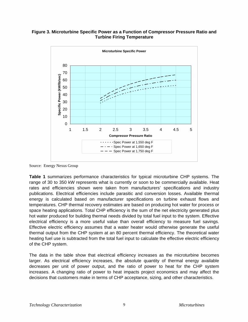
Figure 3. Microturbine Specific Power as a Function of Compressor Pressure Ratio and Turbine Firing Temperature
Microturbine Specific Power
0
10
20
30
40
50
60
70
80
1 1.5 2 2.5 3 3.5 4 4.5 5Compressor Pressure Ratio
Spec
ific
Pow
er (k
W/lb
/sec
)
Spec Power at 1,550 deg FSpec Power at 1,650 deg FSpec Power at 1,750 deg F
Source: Energy Nexus Group Table 1 summarizes performance characteristics for typical microturbine CHP systems. The range of 30 to 350 kW represents what is currently or soon to be commercially available. Heat rates and efficiencies shown were taken from manufacturers’ specifications and industry publications. Electrical efficiencies include parasitic and conversion losses. Available thermal energy is calculated based on manufacturer specifications on turbine exhaust flows and temperatures. CHP thermal recovery estimates are based on producing hot water for process or space heating applications. Total CHP efficiency is the sum of the net electricity generated plus hot water produced for building thermal needs divided by total fuel input to the system. Effective electrical efficiency is a more useful value than overall efficiency to measure fuel savings. Effective electric efficiency assumes that a water heater would otherwise generate the useful thermal output from the CHP system at an 80 percent thermal efficiency. The theoretical water heating fuel use is subtracted from the total fuel input to calculate the effective electric efficiency of the CHP system.
The data in the table show that electrical efficiency increases as the microturbine becomes larger. As electrical efficiency increases, the absolute quantity of thermal energy available decreases per unit of power output, and the ratio of power to heat for the CHP system increases. A changing ratio of power to heat impacts project economics and may affect the decisions that customers make in terms of CHP acceptance, sizing, and other characteristics.
Technology Characterization Microturbines 9

Table 1. Microturbine CHP - Typical Performance Parameters*
Cost & Performance Characteristics3 System 1 System 2 System 3
Nominal Electricity Capacity (kW) 30 65 250 Compressor Parasitic power (kW) 2 2 8 Package Cost (2007 $/kW)4 $1,290 $1,280 $1,410 Total Installed Cost (2007 $/kW)5 $2,970 $2,490 $2,440 Electric Heat Rate (Btu/kWh), HHV6 15,075 13,891 13,080 Electrical Efficiency (percent), HHV7 22.6% 24.6% 26.09% Fuel Input (MMBtu/hr) 0.422 0.875 3.165 Required Fuel Gas Pressure (psig) 75 75 75 CHP Characteristics Exhaust Flow (lbs/sec) 0.69 1.12 4.7 GT Exhaust Temp (degrees F) 530 592 468 Heat Output (MMBtu/hr) 0.17 0.41 1.2 Heat Output (kW equivalent) 50.9 119.5 351.6 Total CHP Efficiency (percent), HHV8 63.8% 71.2% 64.0% Power/Heat Ratio9 0.55 0.53 0.69 Net Heat Rate (Btu/kWh)10 7,313 5,796 6,882 Effective Electrical Efficiency (percent), HHV11 46.7% 58.9% 49.6%
* For typical systems commercially available in 2007 Source: EEA/ICF.
Each microturbine manufacturer represented in Table 1 uses a different recuperator, and each has made individual tradeoffs between cost and performance. Performance involves the extent to which the recuperator effectiveness increases cycle efficiency, the extent to which the recuperator pressure drop decreases cycle power, and the choice of what cycle pressure ratio
3 Characteristics presented are representative of “typical” commercially available or soon to be available microturbine systems. Table data are based on: Capstone Model 330 – 30 kW; Capstone C65 – 65kW, Ingersoll Rand Power MT250 – 250 kW 4 Equipment cost only. The cost for all units except for the 30 kW unit includes integral heat recovery water heater. All units include a fuel gas booster compressor. 5 Installed costs based on CHP system producing hot water from exhaust heat recovery. The 70 kW and 100 kW systems are being offered with integral hot water recovery built into the equipment. The 30 kW units are currently built as electric (only) generators and the heat recovery water heater is a separate unit. Other units entering the market are expected to feature built in heat recovery water heaters 6All turbine and engine manufacturers quote heat rates in terms of the lower heating value (LHV) of the fuel. On the other hand, the usable energy content of fuels is typically measured on a higher heating value (HHV) basis. In addition, electric utilities measure power plant heat rates in terms of HHV. For natural gas, the average heat content of natural gas is 1,030 Btu/scf on an HHV basis and 930 Btu/scf on an LHV basis – or about a 10% difference. 7 Electrical efficiencies are net of parasitic and conversion losses. Fuel gas compressor needs based on 1 psi inlet supply. 8 Total Efficiency = (net electric generated + net heat produced for thermal needs)/total system fuel input 9 Power/Heat Ratio = CHP electrical power output (Btu)/ useful heat output (Btu) 10 Net Heat Rate = (total fuel input to the CHP system - the fuel that would be normally used to generate the same amount of thermal output as the CHP system output assuming an efficiency of 80%)/CHP electric output (kW). 11 Effective Electrical Efficiency = (CHP electric power output)/(Total fuel into CHP system – total heat recovered/0.8).
Technology Characterization Microturbines 10

to use. Consequently, microturbines of different makes will have different CHP efficiencies and different net heat rates chargeable to power.
As shown, microturbines typically require 50 to 80 psig fuel supply pressure. Because microturbines are built with pressure ratios between 3 and 4 to maximize efficiency with a recuperator at modest turbine inlet temperature, the required supply pressure for microturbines is much less than for industrial-size gas turbines with pressure ratios of 7 to 35. Local distribution gas pressures usually range from 30 to 130 psig in feeder lines and from 1 to 50 psig in final distribution lines. Most U.S. businesses that would use a 30, 70, or 100 kW microturbine receive gas at about 0.5 to 1.0 psig. Additionally, most building codes prohibit piping higher-pressure natural gas within the structure. Thus, microturbines in most commercial locations require a fuel gas booster compressor to ensure that fuel pressure is adequate for the gas turbine flow control and combustion systems.
Most microturbine manufacturers offer the equipment package with the fuel gas booster included. It is included in all of the representative systems shown in Table 1. This packaging facilitates the purchase and installation of a microturbine, as the burden of obtaining and installing the booster compressor is no longer placed on the customer. Also, it might result in higher reliability of the booster through standardized design and volume manufacture.
Part-Load Performance When less than full power is required from a microturbine, the output is reduced by a combination of mass flow reduction (achieved by decreasing the compressor speed) and turbine inlet temperature reduction. In addition to reducing power, this change in operating conditions also reduces efficiency. Figure 4 shows a sample part-load derate curve for a microturbine.
Technology Characterization Microturbines 11

Figure 4. Microturbine Part Load Power Performance
Part Load Performance30 kW Microturbine
0
20
40
60
80
100
120
10 20 30 40 50 60 70 80 90 100
Percent Load (%)
Effic
ienc
y (%
)
Note: unit represented is a single-shaft, high-speed alternator system.
Source: Energy Nexus Group. Effects of Ambient Conditions on Performance The ambient conditions under which a microturbine operates have a noticeable effect on both the power output and efficiency. At elevated inlet air temperatures, both the power and efficiency decrease. The power decreases due to the decreased airflow mass rate (since the density of air declines as temperature increases), and the efficiency decreases because the compressor requires more power to compress air of higher temperature. Conversely, the power and efficiency increase with reduced inlet air temperature. Figure 5 shows the variation in power and efficiency for a microturbine as a function of ambient temperature compared to the reference International Organization for Standards (ISO) condition of sea level and 59°F. The density of air decreases at altitudes above sea level. Consequently, power output decreases. Figure 6 illustrates the change in power output as a function of altitude.
Technology Characterization Microturbines 12

Figure 5. Ambient Temperature Effects on Microturbine Performance
Impact of Ambient Temperature30 kW Microturbine
0102030405060708090
100110
0 10 20 30 40 50 60 70 80 90 100 110 120 130Ambient Temperature (°F)
Perc
ent (
%)
Power (% ISO Rated Output) Efficiency (%), HHV
Impact of Ambient Temperature 70 kW Microturbine
0102030405060708090
100110120130140
0 10 20 30 40 50 60 70 80 90 100 110 120 130
Ambient Temperature (°F)
Perc
ent (
%)
Power (% ISO Rated Output) Efficiency (%), HHV
Source: Energy Nexus Group.
Technology Characterization Microturbines 13

Figure 6. Altitude Effects on Microturbine Performance
Derate at Altitude
70
80
90
100
110
0 1000 2000 3000 4000 5000 6000
Altitude (ft)
Perc
ent o
f Ful
l Loa
d (%
)
Source: Energy Nexus Group Heat Recovery Effective use of the thermal energy contained in the exhaust gas improves microturbine system economics. Exhaust heat can be recovered and used in a variety of ways, including water heating, space heating, and driving thermally activated equipment such as an absorption chiller or a desiccant dehumidifier.
Microturbine CHP system efficiency is a function of exhaust heat temperature. Recuperator effectiveness strongly influences the microturbine exhaust temperature. Consequently, the various microturbine CHP systems have substantially different CHP efficiency and net heat rate chargeable to power. These variations in CHP efficiency and net heat rate are mostly due to the mechanical design and manufacturing cost of the recuperators and their resulting impact on system cost, rather than being due to differences in system size. Performance and Efficiency Enhancements Recuperators
Most microturbines include built in recuperators. The inclusion of a high effectiveness (90
Technology Characterization Microturbines 14

percent)12 recuperator essentially doubles the efficiency of a microturbine with a pressure ratio
of 3.2, from about 14 percent to about 29 percent depending on component details. Without a recuperator, such a machine would be suitable only for emergency, backup, or possibly peaking power operation. With the addition of the recuperator, a microturbine can be suitable for intermediate duty or price-sensitive baseload service.
While recuperators previously in use on industrial gas turbines developed leaks attributable to the consequences of differential thermal expansion accompanying thermal transients, microturbine recuperators have proven quite durable in testing to date. This durability has resulted from using higher strength alloys and higher quality welding along with engineering design to avoid the internal differential expansion that causes internal stresses and leakage. Such practical improvements result in recuperators being of appreciable cost, which detracts from the economic attractiveness of the microturbine. The cost of a recuperator becomes easier to justify as the number of full-power operational hours per year increases.
Incorporation of a recuperator into the microturbine results in pressure losses in the recuperator itself and in the ducting that connects it to other components. Typically, these pressure losses result in 10 to 15 percent less power being produced by the microturbine, and a corresponding loss of a few points in efficiency. The pressure loss parameter in gas turbines that is the measure of lost power is δp/p. As δp/p increases, the net pressure ratio available for power generation decreases, and hence the power capability of the expansion process diminishes as well. Figure 7 illustrates the relationship between recuperator effectiveness and microturbine efficiency. Figure 7. Microturbine Efficiency as a Function of Recuperator Effectiveness Recuperator
Impact on Efficiency
Recuperator Effectiveness (percent)
Source: Energy Nexus Group.
Firing Temperature
12 Effectiveness is the technical term in the heat exchanger industry for the ratio of the actual heat transferred to the maximum achievable.
Technology Characterization Microturbines 15

Large turbines (25 to 2,000 lbs/second of mass flow) are usually equipped with internal cooling capability to permit operation with firing temperatures well above those of the metallurgical limit of the best gas turbine alloys. Indeed, progress to higher and higher gas turbine efficiency, via higher firing temperatures, has occurred more through the development and advancement of blade and vane internal cooling technology than through the improvement of the high temperature capabilities of gas turbine alloys.
Unfortunately for microturbine development, the nature of the three dimensional shape of radial inflow turbines has not yet lent itself to the development of a manufacturing method that can produce internal cooling. Consequently, microturbines are limited to firing temperatures within the capabilities of gas turbine alloys. An ongoing program at the U. S. Department of Energy (DOE) Office of Energy Efficiency seeks to apply the technology of ceramic radial inflow turbines (previously advanced for the purpose of developing automotive gas turbines) to microturbines, to increase their efficiency to 36 percent (HHV). The design and materials technology from the previous efforts are applicable, since the automotive gas turbines were in the same size range, and of the same general geometry, as those used in microturbines. Inlet Air Cooling
As shown in Figure 5, the decreased power and efficiency of microturbines at high ambient temperatures means that microturbine performance is at its lowest at the times power is often in greatest demand and most valued. The use of inlet air cooling can mitigate the decreased power and efficiency resulting from high ambient air temperatures. While inlet air cooling is not a feature on today’s microturbines, cooling techniques now entering the market on large gas turbines can be expected to work their way to progressively smaller equipment sizes, and, at some future date, be used with microturbines.
Evaporative cooling, a relatively low capital cost technique, is the most likely to be applied to microturbines. It uses a very fine spray of water directly into the inlet air stream. Evaporation of the water reduces the temperature of the air. Since cooling is limited to the wet bulb air temperature, evaporative cooling is most effective when the wet bulb temperature is appreciably below the dry bulb (ordinary) temperature. In most locales with high daytime dry bulb temperatures, the wet bulb temperature is often 20ºF lower. This affords an opportunity for substantial evaporative cooling. However, evaporative cooling can consume large quantities of water, making it difficult to operate in arid climates.
Refrigeration cooling in microturbines is also technically feasible. In refrigeration cooling, a compression-driven or thermally activated (absorption) refrigeration cycle cools the inlet air through a heat exchanger. The heat exchanger in the inlet air stream causes an additional pressure drop in the air entering the compressor, thereby slightly lowering cycle power and efficiency. However, as the inlet air is now substantially cooler than the ambient air, there is a significant net gain in power and efficiency. Electric motor compression refrigeration requires a substantial parasitic power loss. Thermally activated absorption cooling can use waste heat from the microturbine, reducing the direct parasitic loss. The relative complexity and cost of these approaches, in comparison with evaporative cooling, render them less likely.
Finally, it is also technically feasible to use thermal energy storage systems, typically ice, chilled
Technology Characterization Microturbines 16

water, or low-temperature fluids, to cool inlet air. These systems eliminate most parasitic losses from the augmented power capacity. Thermal energy storage is a viable option if on-peak power pricing only occurs a few hours a day. In that case, the shorter time of energy storage discharge and longer time for daily charging allow for a smaller and less expensive thermal energy storage system.
Capital Cost This section provides study estimates of capital costs for basic microturbine CHP installations. It is assumed that the thermal energy extracted from the microturbine exhaust is used for producing hot water for use on-site. Equipment-only and installed costs are estimated for the three different size microturbine systems. It should be noted that installed costs can vary significantly depending on the scope of the plant equipment, geographical area, competitive market conditions, special site requirements, emissions control requirements, prevailing labor rates, and whether the system is a new or retrofit application.
Table 2 provides cost estimates for combined heat and power applications, assuming that the CHP system produces hot water. The basic microturbine package consists of the microturbine package and power electronics. All of the commercial and near-commercial units offer basic interconnection and paralleling functionality as part of the package cost. All but one of the systems offers an integrated heat exchanger heat recovery system for CHP within the package.
There is little additional equipment that is required for these integrated systems. A heat recovery system has been added where needed, and additional controls and remote monitoring equipment have been added. The total plant cost consists of total equipment cost plus installation labor and materials (including site work), engineering, project management (including licensing, insurance, commissioning and startup), and financial carrying costs during the 6- to 18-month construction period.
The basic equipment costs represent material on the loading dock, ready to ship. The cost to a customer for installing a microturbine-based CHP system includes a number of other factors that increase the total costs by 70 to 80 percent. Labor/materials represent the labor cost for the civil, mechanical, and electrical work and materials such as ductwork, piping, and wiring. Total process capital is the equipment costs plus installation labor and materials.
A number of other costs are incurred on top of total process capital. These costs are often referred to as soft costs because they vary widely by installation, by development channel and by approach to project management. Engineering costs are required to design the system and integrate it functionally with the application’s electrical and mechanical systems. In this characterization, environmental permitting fees are included here. Project and construction management also includes general contractor markup and bonding and performance guarantees. Contingency is assumed to be 3 percent of the total equipment cost in all cases. Up-front, financing costs are also included.
Technology Characterization Microturbines 17
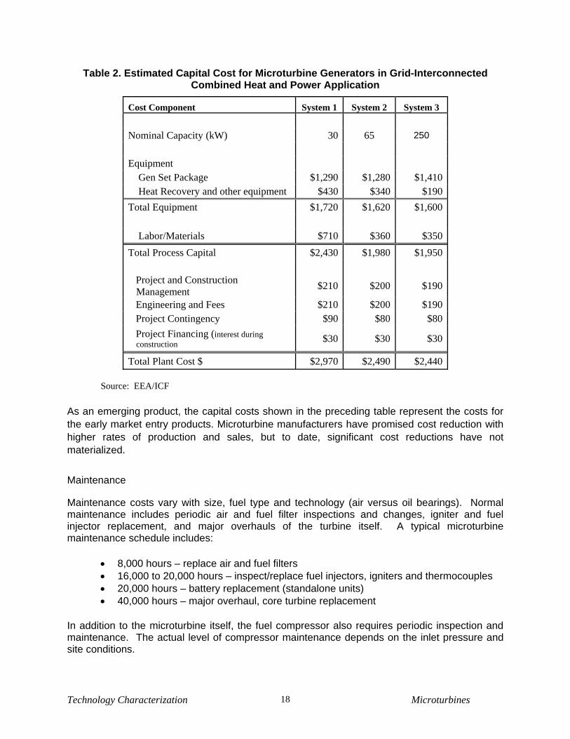
Table 2. Estimated Capital Cost for Microturbine Generators in Grid-Interconnected Combined Heat and Power Application
Cost Component System 1 System 2 System 3 Nominal Capacity (kW) 30 65 250 Equipment Gen Set Package $1,290 $1,280 $1,410 Heat Recovery and other equipment $430 $340 $190 Total Equipment $1,720 $1,620 $1,600 Labor/Materials $710 $360 $350 Total Process Capital $2,430 $1,980 $1,950 Project and Construction
Management $210 $200 $190
Engineering and Fees $210 $200 $190 Project Contingency $90 $80 $80 Project Financing (interest during
construction $30 $30 $30
Total Plant Cost $ $2,970 $2,490 $2,440 Source: EEA/ICF
As an emerging product, the capital costs shown in the preceding table represent the costs for the early market entry products. Microturbine manufacturers have promised cost reduction with higher rates of production and sales, but to date, significant cost reductions have not materialized.
Maintenance Maintenance costs vary with size, fuel type and technology (air versus oil bearings). Normal maintenance includes periodic air and fuel filter inspections and changes, igniter and fuel injector replacement, and major overhauls of the turbine itself. A typical microturbine maintenance schedule includes:
• 8,000 hours – replace air and fuel filters • 16,000 to 20,000 hours – inspect/replace fuel injectors, igniters and thermocouples • 20,000 hours – battery replacement (standalone units) • 40,000 hours – major overhaul, core turbine replacement
In addition to the microturbine itself, the fuel compressor also requires periodic inspection and maintenance. The actual level of compressor maintenance depends on the inlet pressure and site conditions.
Technology Characterization Microturbines 18
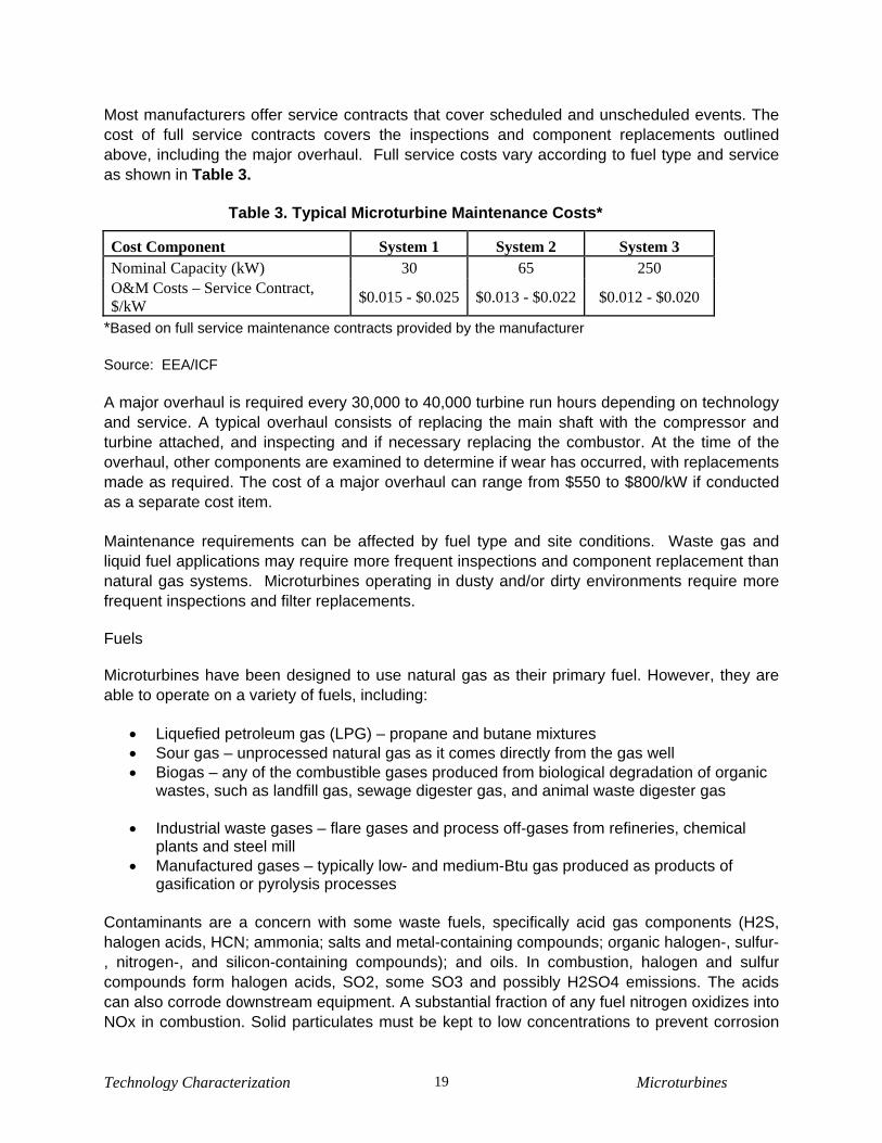
Most manufacturers offer service contracts that cover scheduled and unscheduled events. The cost of full service contracts covers the inspections and component replacements outlined above, including the major overhaul. Full service costs vary according to fuel type and service as shown in Table 3.
Table 3. Typical Microturbine Maintenance Costs*
Cost Component System 1 System 2 System 3 Nominal Capacity (kW) 30 65 250 O&M Costs – Service Contract, $/kW $0.015 - $0.025 $0.013 - $0.022 $0.012 - $0.020
*Based on full service maintenance contracts provided by the manufacturer Source: EEA/ICF A major overhaul is required every 30,000 to 40,000 turbine run hours depending on technology and service. A typical overhaul consists of replacing the main shaft with the compressor and turbine attached, and inspecting and if necessary replacing the combustor. At the time of the overhaul, other components are examined to determine if wear has occurred, with replacements made as required. The cost of a major overhaul can range from $550 to $800/kW if conducted as a separate cost item.
Maintenance requirements can be affected by fuel type and site conditions. Waste gas and liquid fuel applications may require more frequent inspections and component replacement than natural gas systems. Microturbines operating in dusty and/or dirty environments require more frequent inspections and filter replacements.
Fuels Microturbines have been designed to use natural gas as their primary fuel. However, they are able to operate on a variety of fuels, including:
• Liquefied petroleum gas (LPG) – propane and butane mixtures • Sour gas – unprocessed natural gas as it comes directly from the gas well • Biogas – any of the combustible gases produced from biological degradation of organic
wastes, such as landfill gas, sewage digester gas, and animal waste digester gas
• Industrial waste gases – flare gases and process off-gases from refineries, chemical plants and steel mill
• Manufactured gases – typically low- and medium-Btu gas produced as products of gasification or pyrolysis processes
Contaminants are a concern with some waste fuels, specifically acid gas components (H2S, halogen acids, HCN; ammonia; salts and metal-containing compounds; organic halogen-, sulfur-, nitrogen-, and silicon-containing compounds); and oils. In combustion, halogen and sulfur compounds form halogen acids, SO2, some SO3 and possibly H2SO4 emissions. The acids can also corrode downstream equipment. A substantial fraction of any fuel nitrogen oxidizes into NOx in combustion. Solid particulates must be kept to low concentrations to prevent corrosion
Technology Characterization Microturbines 19
and erosion of components. Various fuel scrubbing, droplet separation, and filtration steps will be required if any fuel contaminant levels exceed manufacturer specifications. Landfill gas in particular often contains chlorine compounds, sulfur compounds, organic acids, and silicon compounds which dictate pretreatment.
Availability Systems in the field have generally shown a high level of availability and reliability. The basic design and low number of moving parts hold the potential for systems of high availability; manufacturers have targeted availabilities of 98 to 99 percent. The use of multiple units or backup units at a site can further increase the availability of the overall facility. Emissions Microturbines have the potential for extremely low emissions. All microturbines operating on gaseous fuels feature lean premixed (dry low NOx, or DLN) combustor technology, which was developed relatively recently in the history of gas turbines and is not universally featured on larger gas turbines. All of the example commercial units have been certified to meet extremely stringent standards in Southern California of less than 4-5 ppmvd of NOx (15 percent O2.) CO and VOC emissions are at the same level. “Non-California” versions have NOx emissions of less than 9 ppmvd.
Table 4 presents typical emissions for microturbine systems. The data shown reflect manufacturers’ guaranteed levels.
Technology Characterization Microturbines 20

Technology Characterization Microturbines 21
Table 4. Microturbine Emissions Characteristics
Emissions Characteristics* System 1 System 2 System 3 Nominal Electricity Capacity (kW) 28 65 250 Electrical Efficiency, HHV 23% 25% 29% NOx, ppmv 9 4 5 NOx, lb/MWh13 0.54 0.22 0.29 CO, ppmv 40 9 5 CO, lb/MWh 1.46 0.30 0.14 THC, ppmv 9 5 5 THC, lb/MWh 0.19 0.09 0.10 CO2, (lb/MWh) 1,736 1,597 1,377
Note: Estimates are based on manufacturers’ guarantees for typical systems commercially available in 2007. Emissions estimates represent 15 percent O2 using natural gas fuel.
13 Conversion from volumetric emission rate (ppmv at 15% O2) to output based rate (lbs/MWh) for both NOx and CO based on conversion multipliers provided by Capstone Turbine Corporation and corrected for differences in efficiency.