Technical Information Steering Unit LAGU - White Drive Products
20
Technical Information Steering Unit LAGU
-
Upload
khangminh22 -
Category
Documents
-
view
6 -
download
0
Transcript of Technical Information Steering Unit LAGU - White Drive Products

Technical InformationSteering Unit LAGU

Contents
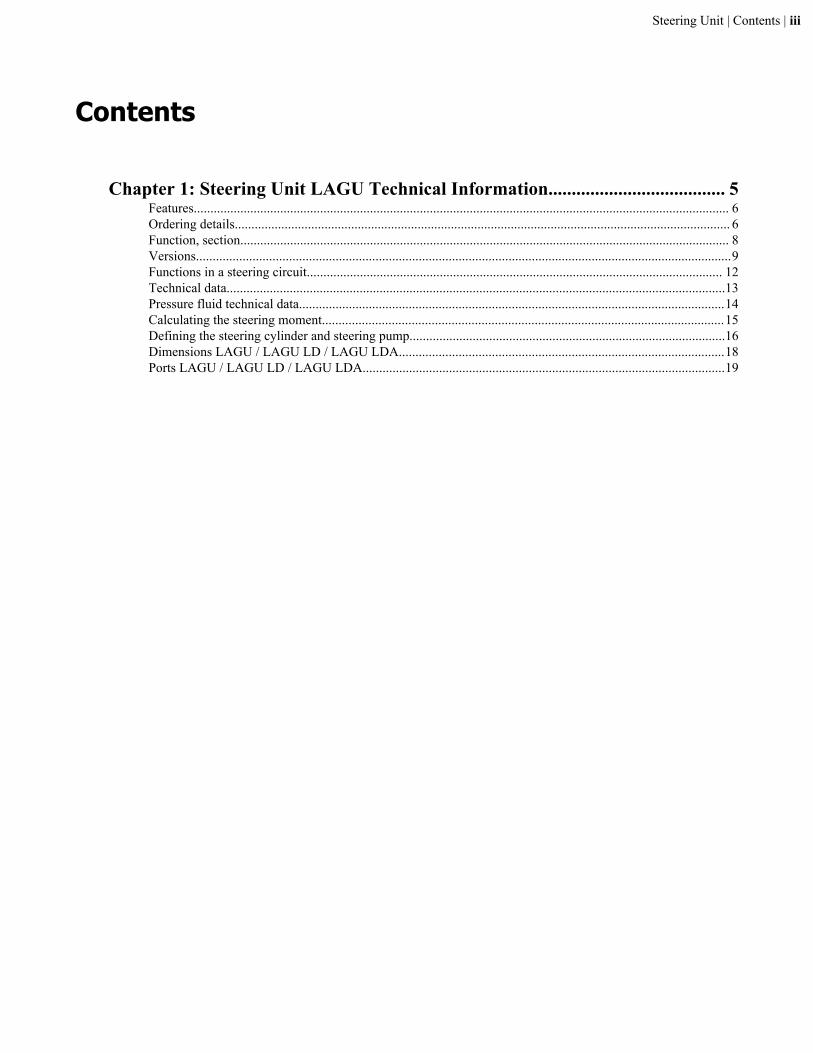
Chapter 1: Steering Unit LAGU Technical Information...................................... 5Features................................................................................................................................................................. 6Ordering details..................................................................................................................................................... 6Function, section................................................................................................................................................... 8Versions.................................................................................................................................................................9Functions in a steering circuit............................................................................................................................. 12Technical data......................................................................................................................................................13Pressure fluid technical data................................................................................................................................14Calculating the steering moment.........................................................................................................................15Defining the steering cylinder and steering pump...............................................................................................16Dimensions LAGU / LAGU LD / LAGU LDA..................................................................................................18Ports LAGU / LAGU LD / LAGU LDA.............................................................................................................19
Steering Unit | Contents | iii


Chapter
1Steering Unit LAGU Technical Information
Topics:
• Features• Ordering details• Function, section• Versions• Functions in a steering circuit• Technical data• Pressure fluid technical data• Calculating the steering moment• Defining the steering cylinder
and steering pump• Dimensions LAGU / LAGU LD /
LAGU LDA• Ports LAGU / LAGU LD / LAGU
LDA
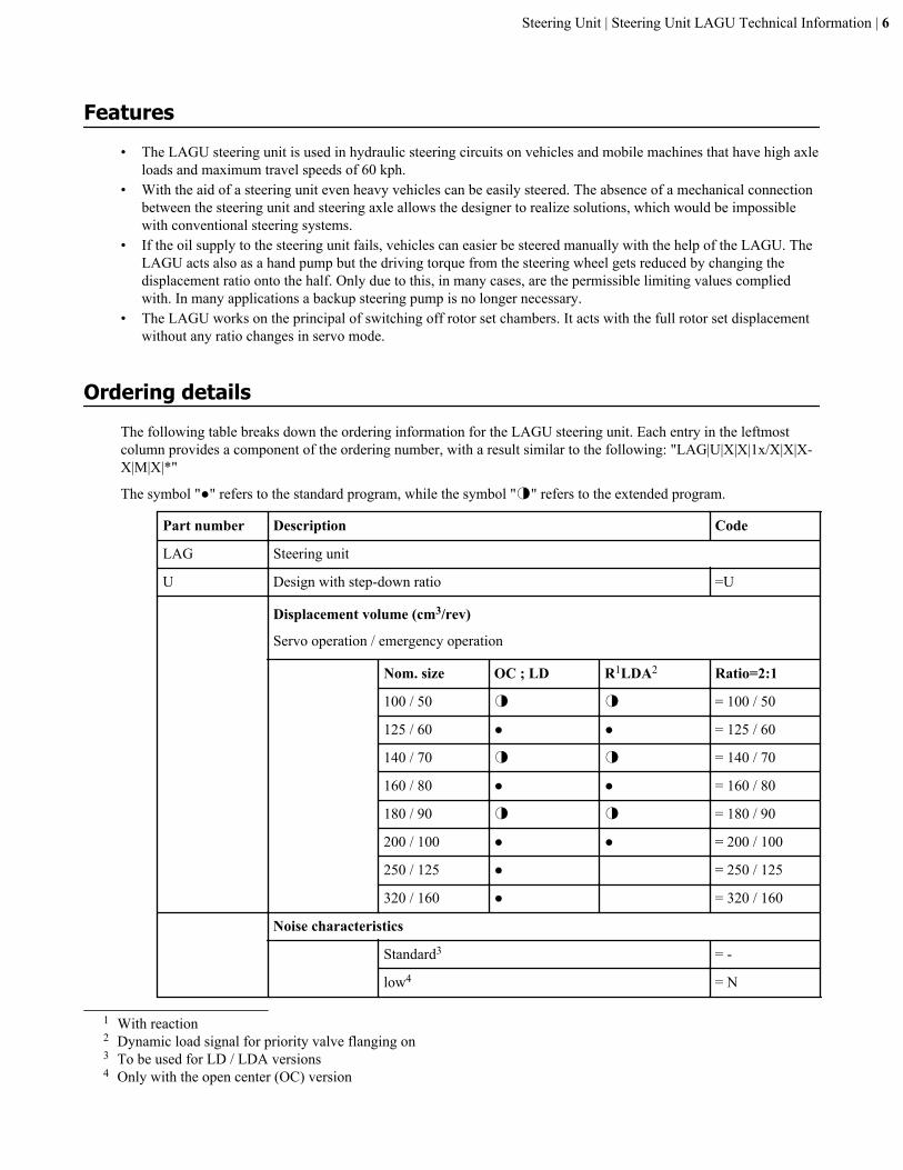
Features• The LAGU steering unit is used in hydraulic steering circuits on vehicles and mobile machines that have high axle
loads and maximum travel speeds of 60 kph.• With the aid of a steering unit even heavy vehicles can be easily steered. The absence of a mechanical connection
between the steering unit and steering axle allows the designer to realize solutions, which would be impossiblewith conventional steering systems.
• If the oil supply to the steering unit fails, vehicles can easier be steered manually with the help of the LAGU. TheLAGU acts also as a hand pump but the driving torque from the steering wheel gets reduced by changing thedisplacement ratio onto the half. Only due to this, in many cases, are the permissible limiting values compliedwith. In many applications a backup steering pump is no longer necessary.
• The LAGU works on the principal of switching off rotor set chambers. It acts with the full rotor set displacementwithout any ratio changes in servo mode.
Ordering detailsThe following table breaks down the ordering information for the LAGU steering unit. Each entry in the leftmostcolumn provides a component of the ordering number, with a result similar to the following: "LAG|U|X|X|1x/X|X|X-X|M|X|*"
The symbol "●" refers to the standard program, while the symbol "◑" refers to the extended program.
Part number Description Code
LAG Steering unit
U Design with step-down ratio =U
Displacement volume (cm3/rev)
Servo operation / emergency operation
Nom. size OC ; LD R1LDA2 Ratio=2:1
100 / 50 ◑ ◑ = 100 / 50
125 / 60 ● ● = 125 / 60
140 / 70 ◑ ◑ = 140 / 70
160 / 80 ● ● = 160 / 80
180 / 90 ◑ ◑ = 180 / 90
200 / 100 ● ● = 200 / 100
250 / 125 ● = 250 / 125
320 / 160 ● = 320 / 160
Noise characteristics
Standard3 = -
low4 = N
1 With reaction2 Dynamic load signal for priority valve flanging on3 To be used for LD / LDA versions4 Only with the open center (OC) version
Steering Unit | Steering Unit LAGU Technical Information | 6
Part number Description Code
1x (/) Component series
10 to 19 = 1x
(10 to 19: unchanged installation and connectiondimensions)
Load sensing
without load signal in open center
(OC) version = no code
dynamic load signal ● = LD
dynamic load signal,
priority valve can be flanged on
● = LDA
Reaction
without reaction = no code
with reaction = R
(-) Shock valve setting5
(pressure differential)
150 bar = 150
200 bar = 200
240 bar = 240
260 bar = 260
Pressure relief valve setting5
(pressure differential)
90 bar = 90
140 bar = 140
175 bar = 175
210 bar = 210
M Seals
NBR seals, suitable for mineral oil (HL, HLP) to DIN 51524, lowtorque.
= M
5 The response pressure of the shock valves must be 50 bar higher, however a maximum of 2.2 times that of thehydraulic pump pressure relief valves. (see §38 StVZO, German Road Traffic Licensing Regulation) Preferrably 150to 90; 200 to 140; 240 to 175 bar.
Steering Unit | Steering Unit LAGU Technical Information | 7
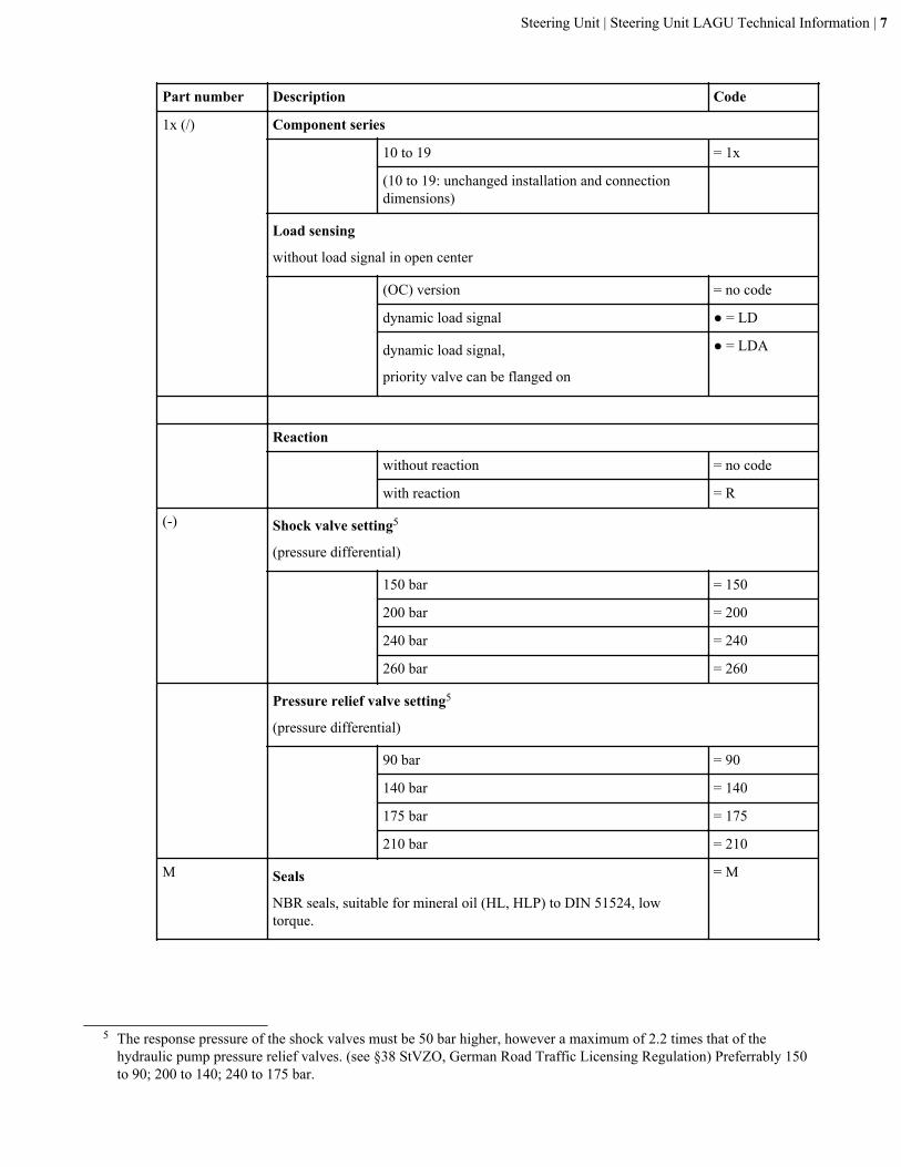
Part number Description Code
Pipe connections P, T, L, R/LD6
Pipe thread ● = 01
Metric DIN thread ◑ = 02 / 40
Metric ISO thread ◑ = 06
SAE thread ◑ = 12 / 19
* Special specifications. Please clarify with our sales organization.
Function, sectionControl spool (1) of the control valve is rotated via the steering column in relation to control sleeve (2). This openscross-sections between the spool and the sleeve. The pressurised oil acts on the rotor set (3) and sets the latter intomotion. The oil is then fed via the rotor set to the steering cylinder. The rotation of the rotor acts on the sleeve, whichthen follows the rotary movement of the spool.
The size of the opened cross-section depends on the turning speed of the steering wheel and on the steering pressure,on Load-Sensing versions it depends exclusively on the turning speed.
If the steering movement is interrupted and the spool is at a standstill, the oil, which still flows through the openedcross-sections to the rotor, causes the rotor and hence the sleeve to continue to rotate a bit.
The rotary movement then causes the cross-section to close now, the rotor also comes to a standstill and at the sametime the steering cylinder is in the desired position. The centering spring (4) brings and holds the spool and sleeve in aneutral position to each other.
The pressure relief valve (5) limits the system pressure of the steering circuit. On the Load-Sensing versions, the pilotpressure relief valve for the load signal is installed instead (see sectional drawing).
Two anti shock valves (6) protect the ports L and R to the steering cylinder. If one of the anti shock valves opens, thedischarged oil is fed via an anti-cavitation valve (7) to the opposite side, or missing oil will be sucked from the tank.
In the event of an oil supply failure, the LAGU operates as hand pump. In this case, via the cylinder pressure, the cut-off valve (10) opens and a specific number of displacement chambers are connected with the return (switched off).The check valves (11) and (12) prevent a connection from the switched off to the working rotor set chambers.
The displacement volume of the rotor set is therefore reduced by the volume of the switched off chambers.
In this (hand pump) state, oil can be sucked from the tank via the suction check valve (8), the inlet check valve (9)prevents that air gets into the P-port (P). During normal operation, this valve prevents shock or kick backs on thesteering wheel caused by excessive external steering forces.
6 For thread dimensions see Dimensions LAGU / LAGU LD / LAGU LDA on page 18
Steering Unit | Steering Unit LAGU Technical Information | 8
12 5 10 8 9
3
1167
1
4
2
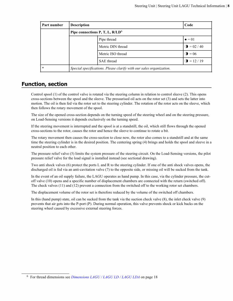
Figure 1: Cross Section LAGU
1 Control spool
2 Control sleeve
3 Rotor set
4 Centering spring
5 Pressure relief valve
6 Anti-shock valve
7 Anti-cavitation valve
8 Suction check valve
9 Inlet check valve
10 Cut-off valve
11 Check valve
12 Check valve
Versions
Standard version | Open Center with Non Reaction = OC / NRMainly used in steering systems with fixed displacement hydraulic pumps (e.g. gear pumps).
Steering Unit | Steering Unit LAGU Technical Information | 9
P T P T
L R L R
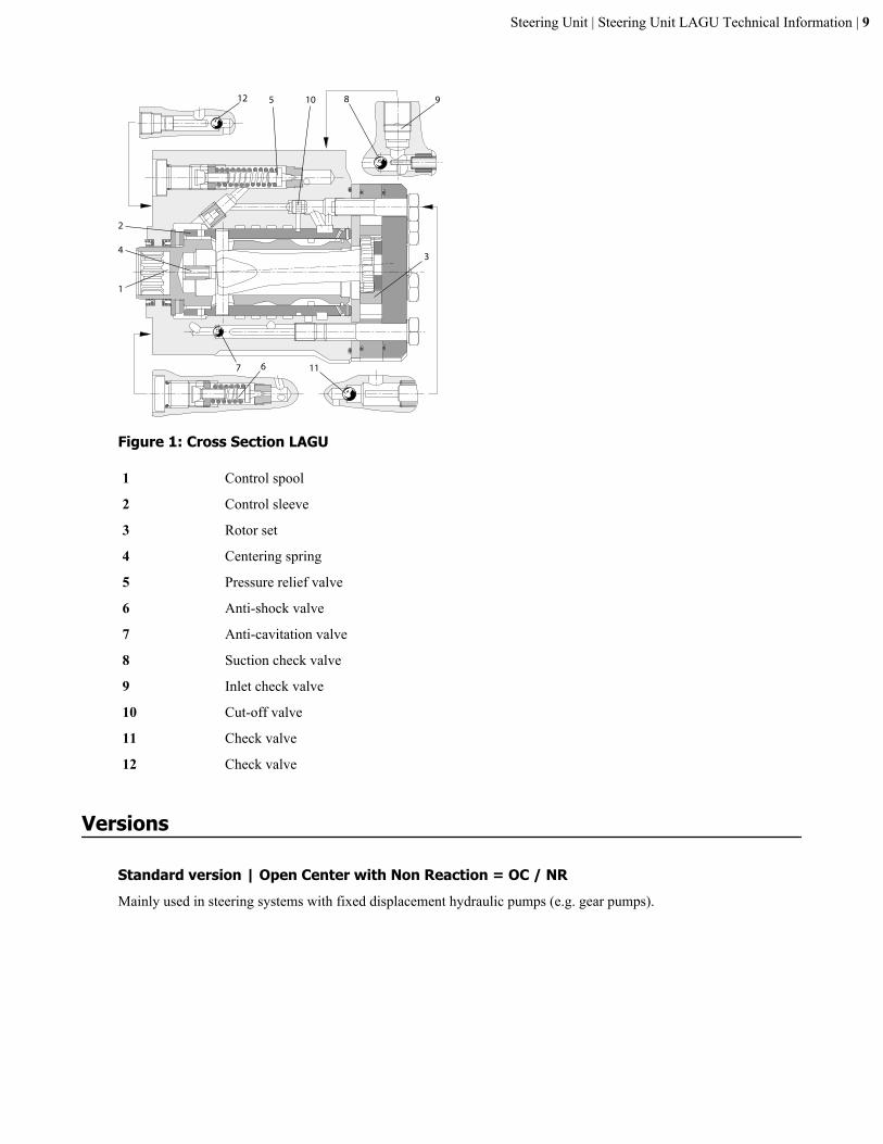
Figure 2: LAGU OC / NR schematic
When no steering movement is performed, the connection between pump port (P) and tank port (T) is open (OC), andthe pump flow is directed to the tank almost at zero pressure. Ports L1 (left) and R1 (right) are blocked in the neutralposition (NR). In this way, external forces acting via the steering cylinder are supported without the driver perceivingany resulting reaction forces on the steering wheel (Non Reaction).
Note: Steering units for vehicles with a articulated steering or with rear axle steering must always use the NR version.
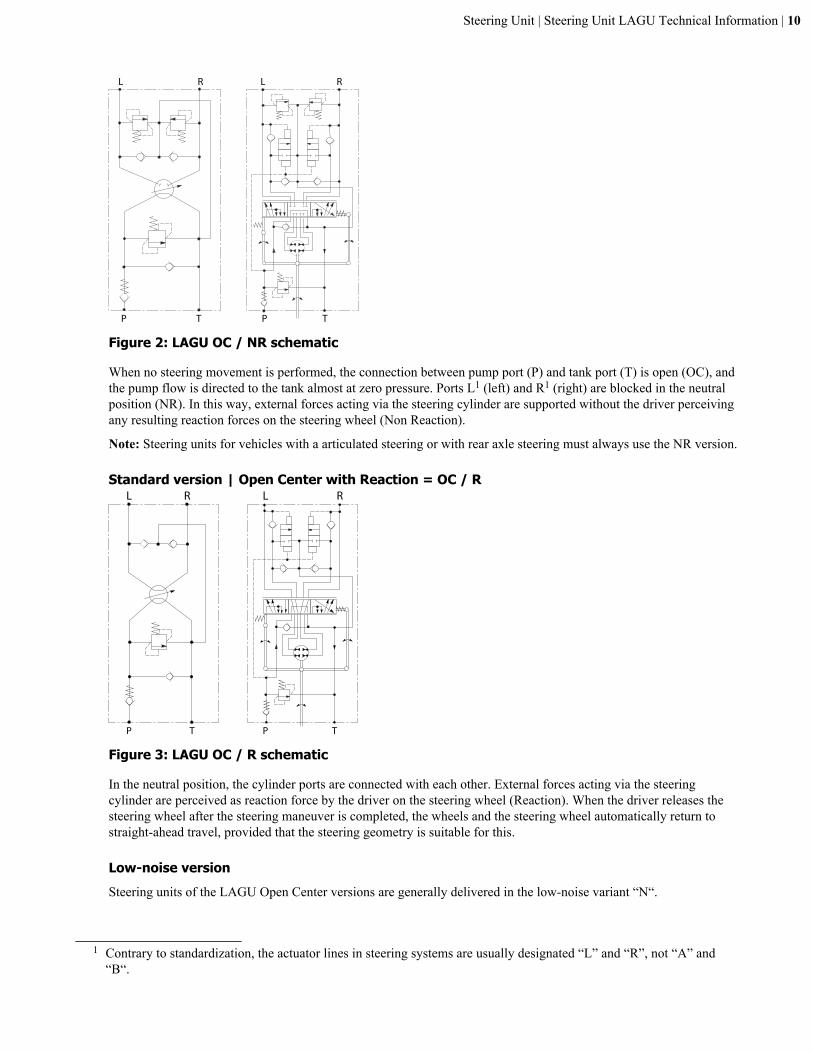
Standard version | Open Center with Reaction = OC / R
P T P T
L R L R
Figure 3: LAGU OC / R schematic
In the neutral position, the cylinder ports are connected with each other. External forces acting via the steeringcylinder are perceived as reaction force by the driver on the steering wheel (Reaction). When the driver releases thesteering wheel after the steering maneuver is completed, the wheels and the steering wheel automatically return tostraight-ahead travel, provided that the steering geometry is suitable for this.
Low-noise versionSteering units of the LAGU Open Center versions are generally delivered in the low-noise variant “N“.
1 Contrary to standardization, the actuator lines in steering systems are usually designated “L” and “R”, not “A” and“B“.
Steering Unit | Steering Unit LAGU Technical Information | 10
Load sensing versionSteering units with load sensing provide a load signal that can be used to control a priority valve and/or a pump. Theyare designed as closed center steering systems whereby the connection pump (P) to tank (T) is locked while neutralposition.
If the steering and implement hydraulics are supplied by a common pump then the use of a priority valve is necessary.The priority valve ensures that the steering unit gets a priority oil supply, whereby the control of the priority valveruns via the steering unit load signal. When steering is not operating then the entire oil flow from the pump is madeavailable to the implement hydraulics. Fixed or variable displacement pumps can be used.
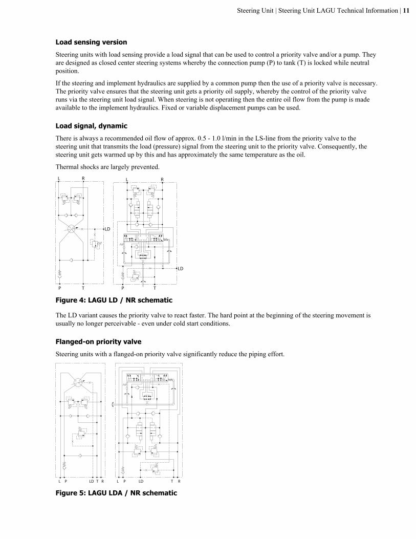
Load signal, dynamicThere is always a recommended oil flow of approx. 0.5 - 1.0 l/min in the LS-line from the priority valve to thesteering unit that transmits the load (pressure) signal from the steering unit to the priority valve. Consequently, thesteering unit gets warmed up by this and has approximately the same temperature as the oil.
Thermal shocks are largely prevented.L R L R
LD
P T P T
LD
Figure 4: LAGU LD / NR schematic
The LD variant causes the priority valve to react faster. The hard point at the beginning of the steering movement isusually no longer perceivable - even under cold start conditions.
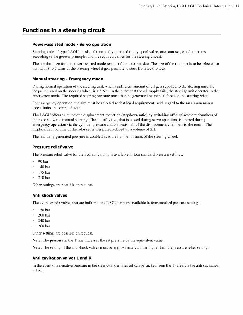
Flanged-on priority valveSteering units with a flanged-on priority valve significantly reduce the piping effort.
L P LD T R L P LD T R
Figure 5: LAGU LDA / NR schematic
Steering Unit | Steering Unit LAGU Technical Information | 11
Functions in a steering circuit
Power-assisted mode - Servo operationSteering units of type LAGU consist of a manually operated rotary spool valve, one rotor set, which operatesaccording to the gerotor principle, and the required valves for the steering circuit.
The nominal size for the power-assisted mode results of the rotor set size. The size of the rotor set is to be selected sothat with 3 to 5 turns of the steering wheel it gets possible to steer from lock to lock.
Manual steering - Emergency modeDuring normal operation of the steering unit, when a sufficient amount of oil gets supplied to the steering unit, thetorque required on the steering wheel is < 5 Nm. In the event that the oil supply fails, the steering unit operates in theemergency mode. The required steering pressure must then be generated by manual force on the steering wheel.
For emergency operation, the size must be selected so that legal requirements with regard to the maximum manualforce limits are complied with.
The LAGU offers an automatic displacement reduction (stepdown ratio) by switching off displacement chambers ofthe rotor set while manual steering. The cut-off valve, that is closed during servo operation, is opened duringemergency operation via the cylinder pressure and connects half of the displacement chambers to the return. Thedisplacement volume of the rotor set is therefore, reduced by a volume of 2:1.
The manually generated pressure is doubled as is the number of turns of the steering wheel.
Pressure relief valveThe pressure relief valve for the hydraulic pump is available in four standard pressure settings:
• 90 bar• 140 bar• 175 bar• 210 bar
Other settings are possible on request.
Anti shock valvesThe cylinder side valves that are built into the LAGU unit are available in four standard pressure settings:
• 150 bar• 200 bar• 240 bar• 260 bar
Other settings are possible on request.
Note: The pressure in the T line increases the set pressure by the equivalent value.
Note: The setting of the anti shock valves must be approximately 50 bar higher than the pressure relief setting.
Anti cavitation valves L and RIn the event of a negative pressure in the steer cylinder lines oil can be sucked from the T- area via the anti cavitationvalves.
Steering Unit | Steering Unit LAGU Technical Information | 12
Suction check valve T to PIf the hydraulic pump fails then the pressure fluid is drawn from the reservoir via this valve, which is fitted betweenthe P and T connections.
Inlet check valveThe check valve of the P-port prevents the return flow of oil from the steer cylinder - due to external forces workingonto the steer cylinder - into the hydraulic system. So it prevents kick back turning of the steering wheel. Whilemanual steering it prevents sucking air from the P-port.
Caution: The emergency operating mode is not intended for continuous operation! If a higher pressure isrequired for steering in emergency operation at 70 Nm, a steering unit with automatic displacement reduction,OSPU, OSPD, or LAGZ, can be installed.
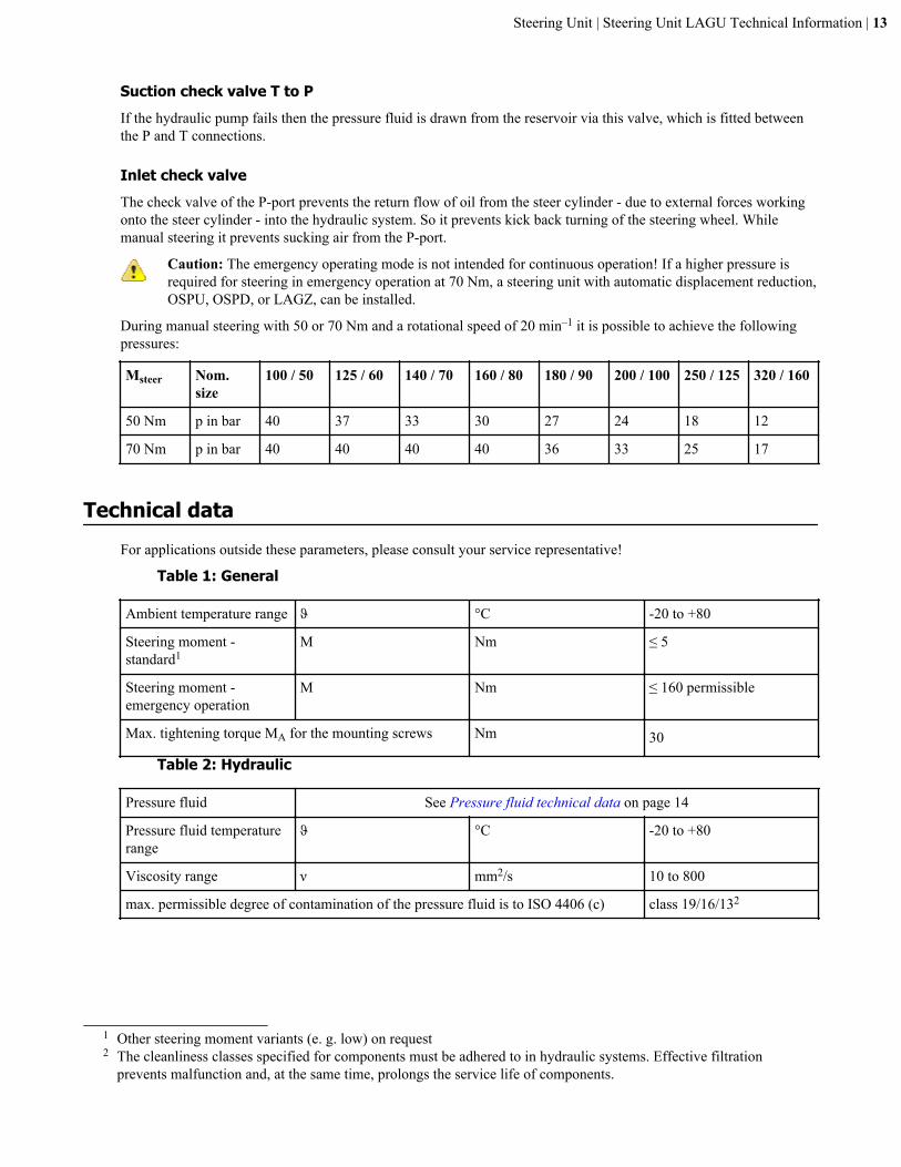
During manual steering with 50 or 70 Nm and a rotational speed of 20 min–1 it is possible to achieve the followingpressures:
Msteer Nom.size
100 / 50 125 / 60 140 / 70 160 / 80 180 / 90 200 / 100 250 / 125 320 / 160
50 Nm p in bar 40 37 33 30 27 24 18 12
70 Nm p in bar 40 40 40 40 36 33 25 17
Technical dataFor applications outside these parameters, please consult your service representative!
Table 1: General
Ambient temperature range ϑ °C -20 to +80
Steering moment -standard1
M Nm ≤ 5
Steering moment -emergency operation
M Nm ≤ 160 permissible
Max. tightening torque MA for the mounting screws Nm 30
Table 2: Hydraulic
Pressure fluid See Pressure fluid technical data on page 14
Pressure fluid temperaturerange
ϑ °C -20 to +80
Viscosity range ν mm2/s 10 to 800
max. permissible degree of contamination of the pressure fluid is to ISO 4406 (c) class 19/16/132
1 Other steering moment variants (e. g. low) on request2 The cleanliness classes specified for components must be adhered to in hydraulic systems. Effective filtration
prevents malfunction and, at the same time, prolongs the service life of components.
Steering Unit | Steering Unit LAGU Technical Information | 13
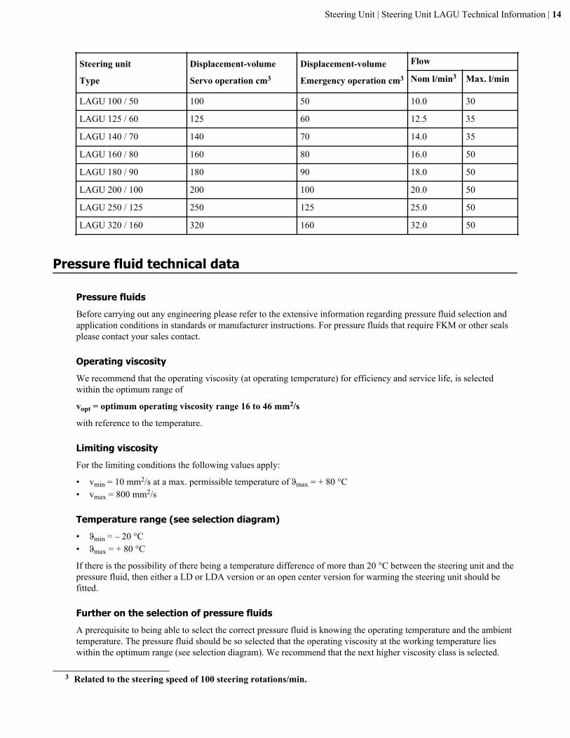
Steering unit
Type
Displacement-volume
Servo operation cm3
Displacement-volume
Emergency operation cm3
Flow
Nom l/min3 Max. l/min
LAGU 100 / 50 100 50 10.0 30
LAGU 125 / 60 125 60 12.5 35
LAGU 140 / 70 140 70 14.0 35
LAGU 160 / 80 160 80 16.0 50
LAGU 180 / 90 180 90 18.0 50
LAGU 200 / 100 200 100 20.0 50
LAGU 250 / 125 250 125 25.0 50
LAGU 320 / 160 320 160 32.0 50
Pressure fluid technical data
Pressure fluidsBefore carrying out any engineering please refer to the extensive information regarding pressure fluid selection andapplication conditions in standards or manufacturer instructions. For pressure fluids that require FKM or other sealsplease contact your sales contact.
Operating viscosityWe recommend that the operating viscosity (at operating temperature) for efficiency and service life, is selectedwithin the optimum range of
vopt = optimum operating viscosity range 16 to 46 mm2/s
with reference to the temperature.
Limiting viscosityFor the limiting conditions the following values apply:
• vmin = 10 mm2/s at a max. permissible temperature of ϑmax = + 80 °C• vmax = 800 mm2/s
Temperature range (see selection diagram)• ϑmin = – 20 °C• ϑmax = + 80 °C
If there is the possibility of there being a temperature difference of more than 20 °C between the steering unit and thepressure fluid, then either a LD or LDA version or an open center version for warming the steering unit should befitted.
Further on the selection of pressure fluidsA prerequisite to being able to select the correct pressure fluid is knowing the operating temperature and the ambienttemperature. The pressure fluid should be so selected that the operating viscosity at the working temperature lieswithin the optimum range (see selection diagram). We recommend that the next higher viscosity class is selected.
3 Related to the steering speed of 100 steering rotations/min.
Steering Unit | Steering Unit LAGU Technical Information | 14
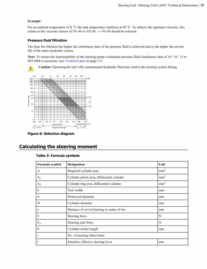
Example:
For an ambient temperature of X °C the tank temperature stabilises at 60 °C. To achieve the optimum viscosity, thisrelates to the viscosity classes of VG 46 or VG 68; → VG 68 should be selected.
Pressure fluid filtrationThe finer the filtration the higher the cleanliness class of the pressure fluid is achieved and so the higher the servicelife of the entire hydraulic system.
Note: To ensure the functionability of the steering pump a minimum pressure fluid cleanliness class of 19 / 16 / 13 toISO 4406 is necessary (see Technical data on page 13).
Caution: Operating the unit with contaminated hydraulic fluid may lead to the steering system failing.
5
10
4060
20
100
200
400600
10001600
16
46
5
1600
–40º –25º –10º 10º 30º 50º 90º 115º70º0º
VG 22VG 32VG 46VG 68
VG 100
0 º 20º 40º 60º 80º 100º–40º –20º
Pressure fluid
temperature range
temperature ϑ in °C
Visc
osity
rang
e
ϑmin = –40 °C ϑmax = 115 °C
ν opt
Figure 6: Selection diagram
Calculating the steering momentTable 3: Formula symbols
Formula symbol Designation Unit
A Required cylinder area mm2
A1 Cylinder piston area, differential cylinder mm2
A2 Cylinder ring area, differential cylinder mm2
b Tyre width mm
d Piston rod diameter mm
D Cylinder diameter mm
e Distance of swivel bearing to center of tire mm
F Steering force N
FA Steering axle force N
h Cylinder stroke length mm
i No. of steering wheel turns
l Smallest, effective steering lever mm
Steering Unit | Steering Unit LAGU Technical Information | 15
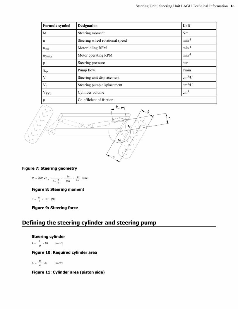
Formula symbol Designation Unit
M Steering moment Nm
n Steering wheel rotational speed min-1
nleer Motor idling RPM min-1
nMotor Motor operating RPM min-1
p Steering pressure bar
qvp Pump flow l/min
V Steering unit displacement cm3/U
Vp Steering pump displacement cm3/U
VZYL Cylinder volume cm3
μ Co-efficient of friction
h
l
b
e
M
Figure 7: Steering geometry
M = 0,05 • F A • • • [Nm]1
1+ eb
b
200
µ0,7
Figure 8: Steering moment
F = • 103 [N]MI
Figure 9: Steering force
Defining the steering cylinder and steering pump
Steering cylinder[mm2]A =
F• 10
p
Figure 10: Required cylinder area
[mm2]A1 =π
• D 2
4
Figure 11: Cylinder area (piston side)
Steering Unit | Steering Unit LAGU Technical Information | 16
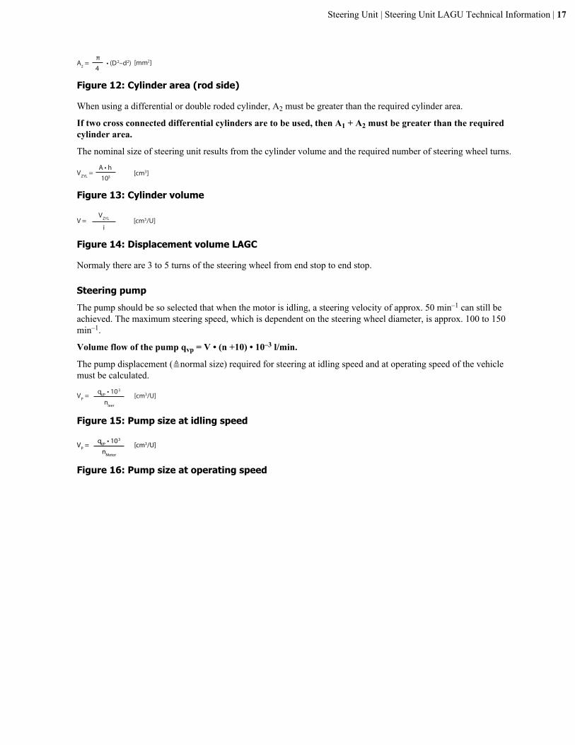
[mm2]A2 =π
• (D2–d2)4
Figure 12: Cylinder area (rod side)
When using a differential or double roded cylinder, A2 must be greater than the required cylinder area.
If two cross connected differential cylinders are to be used, then A1 + A2 must be greater than the requiredcylinder area.
The nominal size of steering unit results from the cylinder volume and the required number of steering wheel turns.
[cm3]VZYL = A • h
103
Figure 13: Cylinder volume
[cm3/U]V =VZYL
i
Figure 14: Displacement volume LAGC
Normaly there are 3 to 5 turns of the steering wheel from end stop to end stop.
Steering pumpThe pump should be so selected that when the motor is idling, a steering velocity of approx. 50 min–1 can still beachieved. The maximum steering speed, which is dependent on the steering wheel diameter, is approx. 100 to 150min–1.
Volume flow of the pump qvp = V • (n +10) • 10–3 l/min.
The pump displacement (≜normal size) required for steering at idling speed and at operating speed of the vehiclemust be calculated.
[cm3/U]VP = qVP • 103
nleer
Figure 15: Pump size at idling speed
[cm3/U]VP = qVP • 103
nMotor
Figure 16: Pump size at operating speed
Steering Unit | Steering Unit LAGU Technical Information | 17
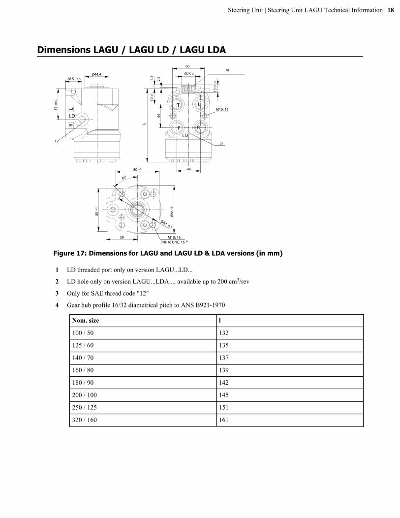
Dimensions LAGU / LAGU LD / LAGU LDA
LR
44
l 1
60
Ø44.4 Ø25.4
15 m
in.
T L
RP
6.3
2.8
LD
28.5 ±0.5
30 ±
1
59 ±
0.5
M10; 15
1)
44
80 +3Ø
88 +
3
59
80+3
Ø82 ±0,3
M10; 163/8-16 UNC; 16 3)
45°
4)
2)
LD
Figure 17: Dimensions for LAGU and LAGU LD & LDA versions (in mm)
1 LD threaded port only on version LAGU...LD...
2 LD hole only on version LAGU...LDA..., available up to 200 cm3/rev
3 Only for SAE thread code "12"
4 Gear hub profile 16/32 diametrical pitch to ANS B921-1970
Nom. size l
100 / 50 132
125 / 60 135
140 / 70 137
160 / 80 139
180 / 90 142
200 / 100 145
250 / 125 151
320 / 160 161
Steering Unit | Steering Unit LAGU Technical Information | 18
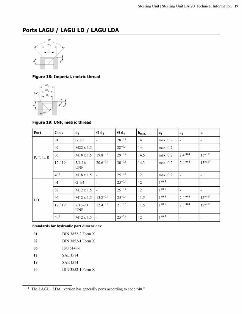
Ports LAGU / LAGU LD / LAGU LDA
d1
b a 1
90°
ød4
Figure 18: Imperial, metric thread
d1
ød2
ød4
b a 1
a 2
α
45°
Figure 19: UNF, metric thread
Port Code d1 Ø d2 Ø d4 bmin. a1 a2 α
P, T, L, R
01 G 1/2 - 28+0.4 14 max. 0.2 - -
02 M22 x 1.5 - 28+0.4 14 max. 0.2 - -
06 M18 x 1.5 19.8+0.1 29+0.4 14.5 max. 0.2 2.4+0.4 15°±1°
12 / 19 3/4-16UNF
20.6+0.1 30+0.5 14.3 max. 0.2 2.4+0.4 15°±1°
401 M18 x 1.5 - 25+0.4 12 max. 0.2 - -
LD
01 G 1/4 - 25+0.4 12 1±0.5 - -
02 M12 x 1.5 - 25+0.4 12 1±0.5 - -
06 M12 x 1.5 13.8+0.1 25+0.4 11.5 1±0.5 2.4+0.4 15°±1°
12 / 19 7/16-20UNF
12.4+0.1 21+0.5 11.5 1±0.5 2.3+0.4 12°±1°
401 M12 x 1.5 - 25+0.4 12 1±0.5 - -
Standards for hydraulic port dimensions:
01 DIN 3852-2 Form X
02 DIN 3852-1 Form X
06 ISO 6149-1
12 SAE J514
19 SAE J514
40 DIN 3852-1 Form X
1 The LAGU...LDA.. version has generally ports according to code “40.”
Steering Unit | Steering Unit LAGU Technical Information | 19