Technical Application Tri-proof LED light
7
Technical Application Tri-proof LED light CLP-TRP02-1200-40W-E
-
Upload
khangminh22 -
Category
Documents
-
view
0 -
download
0
Transcript of Technical Application Tri-proof LED light
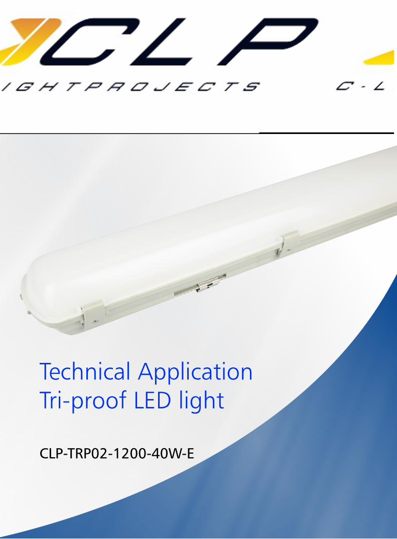
Technical Application Tri-proof LED light
CLP-TRP02-1200-40W-E

Introduction Tri-proof LED light adopts high lumen SMD light source, a compact high PF driver and insulated fireproof PC cover into a traditional tube replacement. The lampshade with, high transparency, soft&uniform light distribution; latch design make the lampshade disassembly and assembly easier; the natural-rubber seal ring has cable joint, dustproof waterproof rating as IP65.Anti-corrosion, shock resistance, easy cleaning, energy saving and environmental protection.
● Up to 70% energy saving compared to standard CFL● Long lifetime of 50,000 hours ● 120° wide beam angle● CCT: 3000K 4000K 5000K 5700K● No UV/IR light● Environment friendly, without Mercury or any other hazardous substances
Application notes● IP65 for indoor use● Professional electrician for installation only ● Switch off before installation● Do not touch when in use
Application AreasTri-proof LED light can be used in factory, warehouse, workshop, and other lighting area with high humidity and dusty places .
stainless steel buckle for optional

Technical SpecificationsModel Voltage Power Power
FactorLumen(±5%) CCT Beam
angle Lifespan CRI Dimmable Dimension
AC100-240V 40W ≥0.9
3400 3000K
120o 50,000h ≥80 No 1215*116*74mm4000 4000K
3900 5000K
3800 5700K
Fixture CompatibilityRated
WattageElectrical
ClassificationIngress
ProtectionOperating
TempOperatingHumidity
Storage Temp
40W Ⅰ IP65 -20oC~45oC 0~90% -20oC~65oC
Driver data Sheet
Product Information1215 116
74
Driver data Emergency Main Power
Input rated Voltage AC230V AC100-240V
Frequency 50/60Hz 50/60Hz
Input Voltage AC200-240V AC85-265V
Efficiency ≥70% ≥88%
No load wattage — ≤1W
Total load Wattage 3.5W±0.5W 40W±5%
Power Factor — ≥0.9
Rated input current ≤0.03A ≤0.45A
Full load output Voltage DC25-68V 60-75V
Rated output current 150-40mA 500mA
Output current range — 500mA±5%
Power tolerance — ±5%
Current output tolerance — ±5%
Battery duration [email protected] −
Charge Period 24h −
Short circuit protection — PASS
Over voltage protection — PASS
Over temperature protection — PASS
Withstand voltage — −
Wiring Diagram:
CABLE ENTRY HOLE
CABLE ENTRY HOLE
Switch
Switch
Terminal
Terminal
L’
L
L S1S2
OUT+
OUT-
LED-
LEDindicator
LED+
IN+IN-
END
N
L
N
NG
Lout
LinN
LED Emergency converter
G/RB+
B-
Test Switch
Lamp
Battery Pack
LED Driver
Cable connection
Mark Description Building wiring cable
L Switched Active Switch cable
L' Unswitched Active Unswitch cable
Earth Earth cable
N Neutral Neutral cable
CLP-TRP02-1200-40W-E

Spectral Distribution
380 500 600 700 800 380 500 600 700 800
380 500 600 700 800 380 500 600 700 800
Wavelength(nm) Wavelength(nm)
Wavelength(nm) Wavelength(nm)
Max=11793 [1.0=20000] Max=11721 [1.0=20000]
Max=5781 [1.0=20000] Max=8438 [1.0=20000]
Spec
trum
0.8
0.7
0.6
0.5
0.4
0.3
0.2
0.1
0.0
Spec
trum
0.8
0.7
0.6
0.5
0.4
0.3
0.2
0.1
0.0
Spec
trum
0.8
0.7
0.6
0.5
0.4
0.3
0.2
0.1
0.0
Spec
trum
0.8
0.7
0.6
0.5
0.4
0.3
0.2
0.1
0.0
Photometric Diagram
Beam diagram
Beam diagram Beam diagram
Polar intensity diagram Polar intensity diagram
Polar intensity diagram Polar intensity diagram
Cartesian intensity diagram Cartesian intensity diagram
Cartesian intensity diagram Cartesian intensity diagram
UNIT: cdAVERAGE BEAM ANGLE(50%): 125.7 DEG
-/+180
-120
-90
-30
120
90
30
0
200
400
600
800
1000
0
UNIT: cdAVERAGE BEAM ANGLE(50%): 127.5 DEG
-/+180
-120
-90
-30
120
90
30
0
300
600
900
1200
1500
0
UNIT: cdAVERAGE BEAM ANGLE(50%): 126.8 DEG
-/+180
-120
-90
-30
120
90
30
0
300
600
900
1200
1500
0
UNIT: cdAVERAGE BEAM ANGLE(50%): 127.9 DEG
-/+180
-120
-90
-30
120
90
30
0
300
600
900
1200
1500
0
Planar Illuminance Curve
Distance(m)
MH=10mE(LX)10
9
8
7
6
5
4
3
2
1
0
C0/180C90/270
-25 -20 -15 -10 -5 0 5 10 15 20 25
Planar Illuminance Curve
Distance(m)
MH=10mE(LX)15.0
13.5
12.0
10.5
9.0
7.5
6.0
4.5
3.0
1.5
0
C0/180C90/270
-25 -20 -15 -10 -5 0 5 10 15 20 25
Planar Illuminance Curve
Distance(m)
MH=10mE(LX)15.0
13.5
12.0
10.5
9.0
7.5
6.0
4.5
3.0
1.5
0
C0/180C90/270
-25 -20 -15 -10 -5 0 5 10 15 20 25
Planar Illuminance Curve
Distance(m)
MH=10mE(LX)15.0
13.5
12.0
10.5
9.0
7.5
6.0
4.5
3.0
1.5
0
C0/180C90/270
-25 -20 -15 -10 -5 0 5 10 15 20 25
Height Eavg, Emax Angle: 115.17deg Diameter Height Eavg, Emax Angle: 113.18deg Diameter
Height Eavg, Emax Angle: 113.66deg Diameter Height Eavg, Emax Angle: 112.99deg Diameter
Note: The Curves indicate the illuminated area and the average illumination when the Luminaire is at different distance.
Note: The Curves indicate the illuminated area and the average illumination when the Luminaire is at different distance.
Note: The Curves indicate the illuminated area and the average illumination when the Luminaire is at different distance.
Note: The Curves indicate the illuminated area and the average illumination when the Luminaire is at different distance.
Flux out: 2154 lm Flux out: 2444 lm
Flux out: 2439 lm Flux out: 2220 lm
5.64 SDCM F5700K
x=0.3235 y=0.3468
1.87 SDCM F4000K
x=0.3839 y=0.3841
1.95 SDCM F5000K
x=0.3470 y=0.3640
3000K
5000K 5700K
4000K
3000K
5000K 5700K
4000K
3.58 SDCM F3000K
x=0.4471 y=0.4087

Driver lifetime & LED light decay rate
90000
80000
70000
60000
50000
40000
30000
20000
10000
065oC 75oC 85oC 95oC 105oC
Life
time
(hou
rs)
Capacitor Tc (oC)
Driver Lifetime LED Light Decay Rate
% L
umin
ous
Flux
FLUX
△ U'V'
110%
105%
100%
95%
90%
85%
80%
75%
70%
0.0040
0.0035
0.0030
0.0025
0.0020
0.0015
0.0010
0.0005
0.00000 1000 2000 3000 4000 5000 6000 7000 8000 9000 10000
LifeTime (hours)
Tem
pera
ture
(o C)
The driver lifespan is based on capacitor working temperature.
IC
Capacitor
MOS
PCB
LED
Fitting
Environmental temperature
100
90
80
70
60
50
40
30
20
10
0
11:1
3:13
11:3
1:10
11:4
9:10
12:0
7:10
12:2
5:10
12:4
3:10
13:0
1:10
13:1
9:10
13:3
7:10
13:5
5:10
14:1
3:10
14:3
1:10
14:4
9:10
15:0
7:10
15:4
3:10
16:0
1:10
16:1
9:10
16:3
7:10
Time
Temperature● The testing is operated at 25°C
● The lifetime of capacitor, minimum of 5,000 hours if operated at 105°C, will be doubled whenever the temperature drops 10°C
● The highest withstand temperature of IC, MOS could be 120°C
● The highest withstand temperature of LED junction temperature is 150°C
Polar Diagram Comparison
AVERAGE BEAM ANGLE (50%): 127.9DEG
UNIT: cd
C0/180, 141.4 deg
C30/210, 135.8 deg
C60/240, 121.1 deg
C90/270, 113.3 deg
300
600
900
1200
1500
0O
+/-180O
150O-150O
120O-120O
90O-90O
60O-60O
30O-30O
0

InstallationSuspended
6. Connect the suspending ropes to the lamp.
1. Open the lamp by screw dr i ve r, take out the accessory pack from the lamp.
3. (a)Connect the AC cables to the terminal b l o c k ( i n s i d e w i r e 1-2.5mm2);(b)Protect the PCB from be ing damaged in the whole installation process.
2. Cut off the power, fix the holders of suspending ropes on the ceiling.
4. Assemble the lamp.
N =L =
YELLOW-GREEN
BROWNBLUE
=
5 . Lo c k t h e l amp fixture with screws, fix the mounting brackets on the back of lamp.
Surface Mounted
1. Open the lamp by screw dr iver, take out the accessory pack from the lamp. 2. Cut off the power, fix the mounting brackets on the ceiling.

Packaging Information
SIZE(CM) N.W/pc(KGS) G.W.(KGS) Q'TY(PCS)
Carton 124.5*24.5*34.5 1.95 20 8
CTNS Q'TY(PCS) VOLUME(CBM)
20'' standardcontainer 260 2080 28
40'' standardcontainer 520 4160 56
3. (a)Connect the AC cables to the terminal b l o c k ( i n s i d e w i r e 1-2.5mm2);(b)Protect the PCB from be ing damaged in the whole installation process.
4. Assemble the lamp.
6. Firmly attach the lamp to the mounting brackets.5, Lock the lamp fixture with screws.