TCU800 - Data Flow Systems, Inc.
168
Installation and Operation Manual TCU800 Data Flow Systems, Inc.
-
Upload
khangminh22 -
Category
Documents
-
view
0 -
download
0
Transcript of TCU800 - Data Flow Systems, Inc.
Installation and Operation Manual
T C U 8 0 0
Data Flow Systems, Inc.

Intentionally left blank.
Data Flow Systems, Inc. assumes no responsibility for any errors that may appear in this document, nor does it make any commitment to update the information contained herein. However, questions regarding the information contained in this document are welcomed.
Data Flow Systems also reserves the right to make changes to the specifications of the TCU800 and to the information contained in this document at any time without notice.
This document contains information related to special features and functions that are only available when the TCU is utilized in a DFS TAC II SCADA System. These special features and functions may not be available when the TCU800 is utilized in a 3rd party SCADA System. If you are unsure about the availability of a feature or function, please contact DFS for clarification.
© Data Flow Systems, Inc. 605 N. John Rodes Blvd., Melbourne, FL 32934 Phone 321-259-5009 Fax 321-259-4006 www.dataflowsys.com
DFS-00540-011-01
This document was last updated July 6, 2021.
Notice

D a t a F l o w S y s t e m s , I n c .
Intentionally left blank.
i
T C U 8 0 0 U s e r M a n u a l
Preface iiiPurpose of this Manual.....................................................................................................................................................................................................iiiDocument Conventions....................................................................................................................................................................................................iiiAbbreviations Used in this Manual..................................................................................................................................................................................iii
1. Safety Precautions 1General Precautions..........................................................................................................................................................................................................1Connecting/Disconnecting the TCU.................................................................................................................................................................................1
2. Product Overview 2Description.......................................................................................................................................................................................................................2Features............................................................................................................................................................................................................................3Compatibility....................................................................................................................................................................................................................4TCU800 vs TCU001........................................................................................................................................................................................................5PIN Names/Wiring Definitions........................................................................................................................................................................................7
3. Unit Overview 11User Interaction................................................................................................................................................................................................................11Hand-Off-Auto (HOA) Switches.....................................................................................................................................................................................12Soft Touch Button............................................................................................................................................................................................................12USB Ports........................................................................................................................................................................................................................13Touchscreen.....................................................................................................................................................................................................................13Monitoring and Control...................................................................................................................................................................................................15Digital Output Control.....................................................................................................................................................................................................15Analog Input Monitoring.................................................................................................................................................................................................15Serial Connectivity...........................................................................................................................................................................................................16
Full Contents
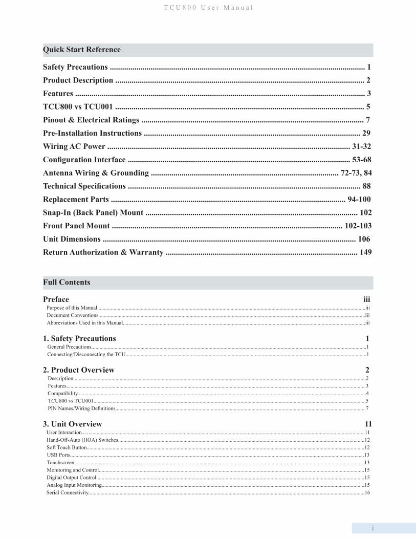
Quick Start Reference
Safety Precautions ............................................................................................................................. 1Product Description .......................................................................................................................... 2Features .............................................................................................................................................. 3TCU800 vs TCU001 .......................................................................................................................... 5 Pinout & Electrical Ratings ............................................................................................................. 7Pre-Installation Instructions .......................................................................................................... 29 Wiring AC Power ....................................................................................................................... 31-32Configuration Interface ............................................................................................................. 53-68Antenna Wiring & Grounding ............................................................................................ 72-73, 84Technical Specifications .................................................................................................................. 88Replacement Parts ................................................................................................................... 94-100Snap-In (Back Panel) Mount ........................................................................................................ 102Front Panel Mount ................................................................................................................. 102-103Unit Dimensions ............................................................................................................................ 106Return Authorization & Warranty .............................................................................................. 149

ii
Phase Voltage Monitoring................................................................................................................................................................................................16Internal Monitoring..........................................................................................................................................................................................................17Automatic/Manual Control..............................................................................................................................................................................................17Level Sensing Transducers..............................................................................................................................................................................................18Internal Phase Monitor....................................................................................................................................................................................................19Outputs.............................................................................................................................................................................................................................19Touchscreen.....................................................................................................................................................................................................................20Electrical Protection........................................................................................................................................................................................................20Battery Backup (Optional)..............................................................................................................................................................................................20Principles of Operation....................................................................................................................................................................................................21Discrete System (Contact Closure Devices)....................................................................................................................................................................21Analog System (Pressure Transducer)............................................................................................................................................................................23
4. Setup 29Pre-installation Modification ...........................................................................................................................................................................................29Mounting Instructions......................................................................................................................................................................................................30Electrical Installation and Wiring Diagrams....................................................................................................................................................................31Bias Voltage Source Options............................................................................................................................................................................................36Installed in RTU...............................................................................................................................................................................................................48
5. User Interface 49
6. Operating Procedures 53Configuring the Pump Control Process............................................................................................................................................................................53Main Settings....................................................................................................................................................................................................................56Alarm Outputs...................................................................................................................................................................................................................56Floats................................................................................................................................................................................................................................56Radio................................................................................................................................................................................................................................57Auxiliary...........................................................................................................................................................................................................................59Analog..............................................................................................................................................................................................................................60Pump Monitoring..............................................................................................................................................................................................................62Phase Monitoring..............................................................................................................................................................................................................62MODBUS Master.............................................................................................................................................................................................................63MODBUS Slave...............................................................................................................................................................................................................64Derived Flow....................................................................................................................................................................................................................65TCU Settings....................................................................................................................................................................................................................65Radio Test Mode...............................................................................................................................................................................................................66Reset Pump Stats..............................................................................................................................................................................................................67Time..................................................................................................................................................................................................................................67Auto Configuration...........................................................................................................................................................................................................67Device Manager................................................................................................................................................................................................................68Calibrate PMA..................................................................................................................................................................................................................68Factory Reset....................................................................................................................................................................................................................69Telemetry Configuration...................................................................................................................................................................................................69
7. Viewing and Troubleshooting Alarms 74AC Power Fault................................................................................................................................................................................................................74Auxiliary Input Alarm......................................................................................................................................................................................................75DC Bias Fault...................................................................................................................................................................................................................75Float Sequence Fault........................................................................................................................................................................................................75High Well Alarm...............................................................................................................................................................................................................76Phase Sequence Fault........................................................................................................................................................................................................76Phase Voltage Fault...........................................................................................................................................................................................................77Motor Starter Fault............................................................................................................................................................................................................77Motor Stop Fault...............................................................................................................................................................................................................78Transducer Fault................................................................................................................................................................................................................79Leaving the Alarms Screen................................................................................................................................................................................................80
8. Modbus Support 81
i
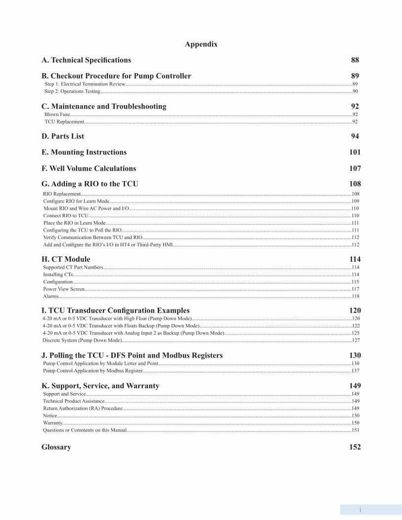
Appendix
A. Technical Specifications 88
B. Checkout Procedure for Pump Controller 89Step 1: Electrical Termination Review.............................................................................................................................................................................89Step 2: Operations Testing................................................................................................................................................................................................90
C. Maintenance and Troubleshooting 92Blown Fuse.......................................................................................................................................................................................................................92TCU Replacement............................................................................................................................................................................................................92
D. Parts List 94
E. Mounting Instructions 101
F. Well Volume Calculations 107
G. Adding a RIO to the TCU 108RIO Replacement..............................................................................................................................................................................................................108Configure RIO for Learn Mode........................................................................................................................................................................................109Mount RIO and Wire AC Power and I/O.........................................................................................................................................................................110Connect RIO to TCU........................................................................................................................................................................................................110Place the RIO in Learn Mode...........................................................................................................................................................................................111Configuring the TCU to Poll the RIO...............................................................................................................................................................................111Verify Communication Between TCU and RIO...............................................................................................................................................................112Add and Configure the RIO’s I/O in HT4 or Third-Party HMI........................................................................................................................................112
H. CT Module 114Supported CT Part Numbers.............................................................................................................................................................................................114Installing CTs....................................................................................................................................................................................................................114Configuration....................................................................................................................................................................................................................115Power View Screen...........................................................................................................................................................................................................117Alarms...............................................................................................................................................................................................................................118
I. TCU Transducer Configuration Examples 1204-20 mA or 0-5 VDC Transducer with High Float (Pump Down Mode)..........................................................................................................................1204-20 mA or 0-5 VDC Transducer with Floats Backup (Pump Down Mode)....................................................................................................................1224-20 mA or 0-5 VDC Transducer with Analog Input 2 as Backup (Pump Down Mode).................................................................................................125Discrete System (Pump Down Mode)...............................................................................................................................................................................127
J. Polling the TCU - DFS Point and Modbus Registers 130Pump Control Application by Module Letter and Point...................................................................................................................................................130Pump Control Application by Modbus Register...............................................................................................................................................................137
K. Support, Service, and Warranty 149Support and Service..........................................................................................................................................................................................................149Technical Product Assistance............................................................................................................................................................................................149Return Authorization (RA) Procedure..............................................................................................................................................................................149Notice................................................................................................................................................................................................................................150Warranty............................................................................................................................................................................................................................150Questions or Comments on this Manual...........................................................................................................................................................................151
Glossary 152

ii
Intentionally left blank.
iii
Purpose of this Manual
This manual is a reference guide for installing and operating the TCU800 (Telemetry Control Unit). It contains information
meant to guide and assist in the installation and configuration procedure. This includes mounting and wiring instructions,
product features and specifications, I/O listings, instructions for integrating with telemetry, information on Modbus
compatibility, and instructions for configuring and using the TCU’s pump control process. Refer to this manual when
designing, installing, configuring, or troubleshooting systems that use Data Flow Systems’ TCU. For information on
customizing the TCU’s operations, contact DFS.
Document Conventions
The following conventions are used throughout this manual:
• Bulleted lists provide information, not procedural steps.
• Numbered lists provide sequential steps or hierarchal information.
• Bold italic type is used for emphasis.
• All CAPITALIZED ITALIC type is used for terminal names.
Abbreviations Used in this Manual
H-O-A – Hand-Off-Auto
I/O – Input/Output
PCU – Pump Control Unit
PLC – Programmable Logic Controller
RTU – Remote Terminal Unit
SCU – Supervisory & Control Unit
TCU – Telemetry Control Unit
BEM – Bus Extender Module
STAT – Status
SSH – Secure Shell
RX – Receive
TX – Transmit
VAC – Voltage Alternating Current
VDC – Voltage Direct Current
Preface

ii
Intentionally left blank.
1
D a t a F l o w S y s t e m s , I n c .
1. Safety PrecautionsReview the following information before installing, servicing, or replacing the TCU or any of its components.
General Precautions
• Carefully read the installation and wiring instructions before connecting the TCU to its power source.
• If the TCU is to be installed into an existing control panel, make sure all sources of power are de-energized (including
those fed by external sources) before starting the installation.
• Do not work on the TCU or connect/disconnect any of its cables during periods of lightning activity.
• To prevent overheating the TCU, do not operate it in an area that exceeds the recommended temperature range of
-10°C to 60°C (14°F to 140°F). When using the recommended backup battery, the upper temperature limit is 50°C
(122°F).
• Ensure that the unit is connected to earth ground during normal use.
• Precautionary measures must be observed when installing, operating, and servicing the TCU in order to prevent shock.
• All wiring should conform to federal, state, and local electrical codes.
• Read and follow all precautions displayed on the TCU’s side-mounted labels.
Connecting/Disconnecting the TCU
When connecting the TCU:
1. Ensure the cables to be connected to the TCU are routed with sufficient strain relief.
2. Integrate all required wires and connect to the TCU.
3. Close circuit breakers as required; the TCU will start up as soon as power is applied.
When disconnecting the TCU:
1. Power down the unit by holding down the button on the front overlay.
2. Remove all sources of power, including those fed by external sources.
3. Remove all cables connected to the TCU including the ground cable.
4. Move the cables ensuring they will not become entangled in or caught on anything in the surrounding area.
Even if the LCD screen and status LED are not lit, assume the TCU is still powered. The TCU may be in the off
state, and AC power may still be present. To remove power, the external circuit breaker must be opened. Note
that TCU power and 3 phase power may be on separate circuit breakers.
2
C h a p t e r 2
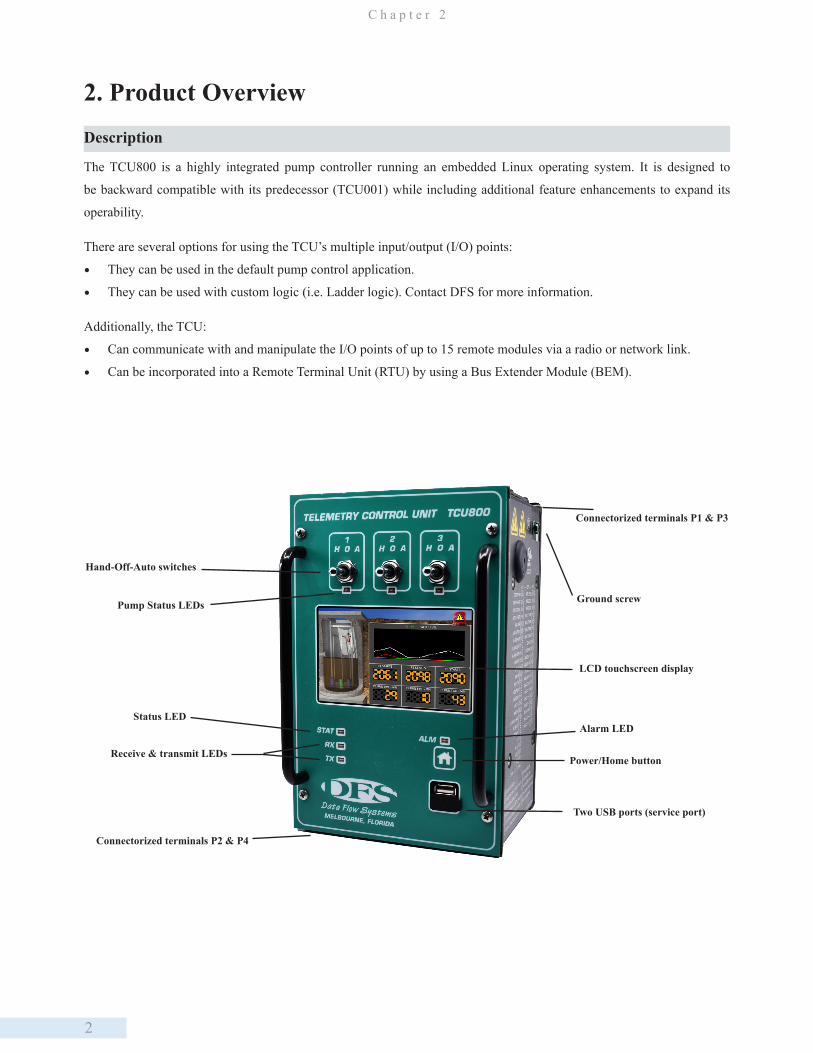
2. Product Overview
Description
The TCU800 is a highly integrated pump controller running an embedded Linux operating system. It is designed to
be backward compatible with its predecessor (TCU001) while including additional feature enhancements to expand its
operability.
There are several options for using the TCU’s multiple input/output (I/O) points:
• They can be used in the default pump control application.
• They can be used with custom logic (i.e. Ladder logic). Contact DFS for more information.
Additionally, the TCU:
• Can communicate with and manipulate the I/O points of up to 15 remote modules via a radio or network link.
• Can be incorporated into a Remote Terminal Unit (RTU) by using a Bus Extender Module (BEM).
Hand-Off-Auto switches
Connectorized terminals P2 & P4
Receive & transmit LEDsPower/Home button
LCD touchscreen display
Connectorized terminals P1 & P3
Two USB ports (service port)
Ground screw
Alarm LEDStatus LED
Pump Status LEDs

3
P r o d u c t O v e r v i e w
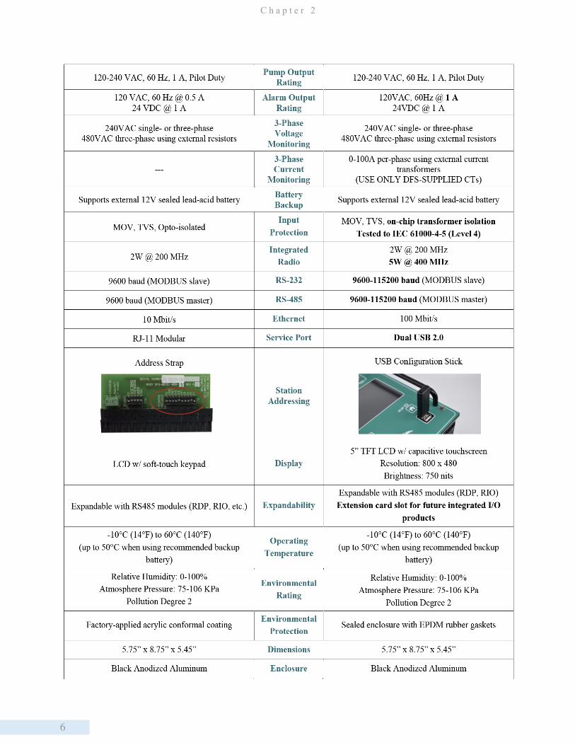
True RMS AC Phase Monitor True RMS AC phase monitor produces voltage readings for single- and three-phase power. Three-phase current can also be monitored using external current transformers.
H-O-A SwitchesThe H-O-A switches are fail-safe; they remain operational even if the TCU fails or loses power. They will continue to function in the “Hand” and “Off” positions with the TCU in a faulted state or powered down.
Integrated Radio The TCU’s integrated digital radio is on-site programmable and can run in legacy or a high-speed mode.
Battery Backup with Integrated Charger
The TCU supports a 12VDC sealed lead acid battery that supports a maximum charge current of 3A.
Display / InterfaceA touch screen LCD provides a large area for displaying data and menu navigation. One soft-touch home button allows the user to power up/down the TCU with a single touch, and seven LEDs provide system status at a glance.
Serial Connectivity
Standard RS-232 Modbus radio interface acts as an interface (slave only) to external industry standard radios. RS-485 Modbus half-duplex serial interface (master only) enables communication with industry standard devices and VFD motor controllers.
Network Adapter An integrated 10/100 network adapter allows remote access via SSH client over a local area network.
USB/Service PortThree full speed USB 2.0 ports (2 external/1 internal) storing station address, config-uration profiles, and pump statistics. Provides Ethernet connectivity with additional USB-to-ETH adapter.
Protection Protective features include an integrated, regulated power supply, surge protection, and isolation on all I/Os, and an externally-accessible fuse.
Protocols Supported Protocols supported are Modbus (ASCII/RTU) over RS485 or RS232, TAC II and DFP 3.0 over radio and BEM, and DFS NIM and Modbus TCP over TCP/IP.
The default pump control application program enables the TCU to be easily implemented in lift station or storage tank
applications. The TCU contains all the hardware and software needed to control up to three motor starters.
Placing custom logic on the TCU enables it to perform a variety of automated tasks when interfaced with other telemetry
Modbus-capable devices and equipment (DFS equipment or other devices using RS-485 or RS-232). Custom logic can
control and monitor the six onboard digital outputs, 18 digital inputs and four analog inputs. It also features an expansion
card slot which can be used to add additional I/O points for specialized applications, such as controlling VFD pumps.
Features

4
C h a p t e r 2
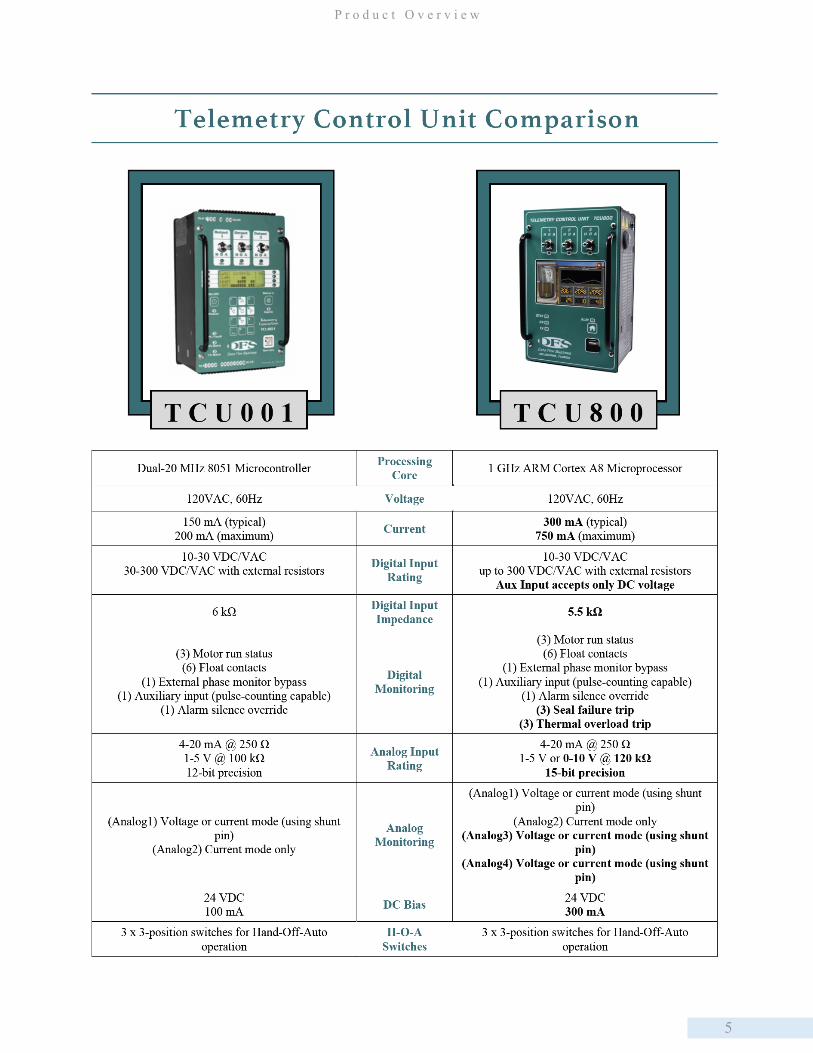
Compatibility
Please note that the PCU, PCU TAC Pack, SCU, and SCU TAC Pack are not “upward” compatible with the TCU800.
DFS’ Sales Department can provide assistance with ensuring that your system has appropriate replacement units on hand.
Contact DFS’ Sales Department (321-259-5009 or [email protected]) for more information.
When comparing the TCU001 and the TCU800, use the following table to review features that have been removed,
replaced, and added to the TCU800.
By default, the TCU800’s new digital and analog inputs are disabled so as not to conflict with any pre-configured MODBUS
devices that may be occupying modules H through O. In order to enable the new I/O, which will be dynamically assigned
at the next available module space, see Chapter 6: Operating Procedures.
Pump Run Time Meters Elapsed run time, average run time, and pump cycle counters are provided in software for each pump.
Self-MonitoringSelf-monitoring capabilities include radio current, temperature, battery voltage/charging current, AC power, bias fault, process and error logging with option to backup to a USB drive.
Connectorized Wire Terminals
Four connectorized wire terminals allow servicing or replacement of the unit without disconnecting wires.
Mounting Options Mounting options allow the TCU to be mounted to a front panel as well as mounted flush against or stood off from the back plate of a control panel.
Legacy TCU001 Operation The TCU800 is backward compatible with the TCU001. Existing TCU001 configurations can be transferred to the TCU800. For detailed instructions, see the compatibility chart below.
Enclosure Anodized aluminum, sealed and shielded when connected to Earth ground via grounding screw.
5
P r o d u c t O v e r v i e w
6
C h a p t e r 2
7
P r o d u c t O v e r v i e w
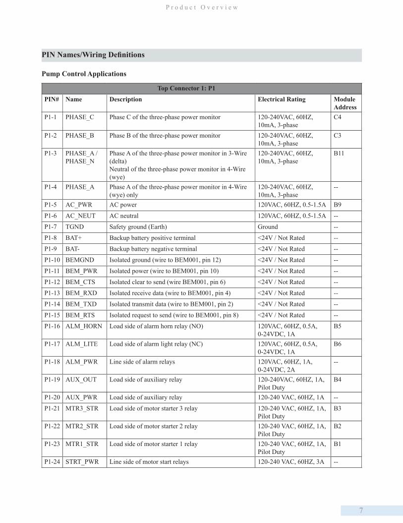
PIN Names/Wiring Definitions
Pump Control Applications
Top Connector 1: P1
PIN# Name Description Electrical Rating Module Address
P1-1 PHASE_C Phase C of the three-phase power monitor 120-240VAC, 60HZ, 10mA, 3-phase
C4
P1-2 PHASE_B Phase B of the three-phase power monitor 120-240VAC, 60HZ, 10mA, 3-phase
C3
P1-3 PHASE_A / PHASE_N
Phase A of the three-phase power monitor in 3-Wire (delta)Neutral of the three-phase power monitor in 4-Wire (wye)
120-240VAC, 60HZ, 10mA, 3-phase
B11
P1-4 PHASE_A Phase A of the three-phase power monitor in 4-Wire (wye) only
120-240VAC, 60HZ, 10mA, 3-phase
--
P1-5 AC_PWR AC power 120VAC, 60HZ, 0.5-1.5A B9
P1-6 AC_NEUT AC neutral 120VAC, 60HZ, 0.5-1.5A --
P1-7 TGND Safety ground (Earth) Ground --
P1-8 BAT+ Backup battery positive terminal <24V / Not Rated --
P1-9 BAT- Backup battery negative terminal <24V / Not Rated --
P1-10 BEMGND Isolated ground (wire to BEM001, pin 12) <24V / Not Rated --
P1-11 BEM_PWR Isolated power (wire to BEM001, pin 10) <24V / Not Rated --
P1-12 BEM_CTS Isolated clear to send (wire BEM001, pin 6) <24V / Not Rated --
P1-13 BEM_RXD Isolated receive data (wire to BEM001, pin 4) <24V / Not Rated --
P1-14 BEM_TXD Isolated transmit data (wire to BEM001, pin 2) <24V / Not Rated --
P1-15 BEM_RTS Isolated request to send (wire to BEM001, pin 8) <24V / Not Rated --
P1-16 ALM_HORN Load side of alarm horn relay (NO) 120VAC, 60HZ, 0.5A, 0-24VDC, 1A
B5
P1-17 ALM_LITE Load side of alarm light relay (NC) 120VAC, 60HZ, 0.5A, 0-24VDC, 1A
B6
P1-18 ALM_PWR Line side of alarm relays 120VAC, 60HZ, 1A, 0-24VDC, 2A
--
P1-19 AUX_OUT Load side of auxiliary relay 120-240VAC, 60HZ, 1A, Pilot Duty
B4
P1-20 AUX_PWR Load side of auxiliary relay 120-240 VAC, 60HZ, 1A --
P1-21 MTR3_STR Load side of motor starter 3 relay 120-240 VAC, 60HZ, 1A, Pilot Duty
B3
P1-22 MTR2_STR Load side of motor starter 2 relay 120-240 VAC, 60HZ, 1A, Pilot Duty
B2
P1-23 MTR1_STR Load side of motor starter 1 relay 120-240 VAC, 60HZ, 1A, Pilot Duty
B1
P1-24 STRT_PWR Line side of motor start relays 120-240 VAC, 60HZ, 3A --
8
C h a p t e r 2
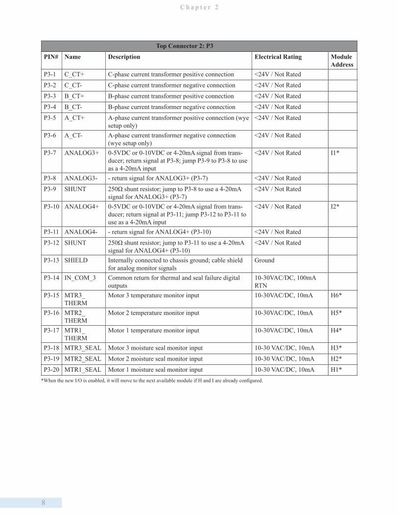
Top Connector 2: P3
PIN# Name Description Electrical Rating Module Address
P3-1 C_CT+ C-phase current transformer positive connection <24V / Not Rated
P3-2 C_CT- C-phase current transformer negative connection <24V / Not Rated
P3-3 B_CT+ B-phase current transformer positive connection <24V / Not Rated
P3-4 B_CT- B-phase current transformer negative connection <24V / Not Rated
P3-5 A_CT+ A-phase current transformer positive connection (wye setup only)
<24V / Not Rated
P3-6 A_CT- A-phase current transformer negative connection (wye setup only)
<24V / Not Rated
P3-7 ANALOG3+ 0-5VDC or 0-10VDC or 4-20mA signal from trans-ducer; return signal at P3-8; jump P3-9 to P3-8 to use as a 4-20mA input
<24V / Not Rated I1*
P3-8 ANALOG3- - return signal for ANALOG3+ (P3-7) <24V / Not Rated
P3-9 SHUNT 250Ω shunt resistor; jump to P3-8 to use a 4-20mA signal for ANALOG3+ (P3-7)
<24V / Not Rated
P3-10 ANALOG4+ 0-5VDC or 0-10VDC or 4-20mA signal from trans-ducer; return signal at P3-11; jump P3-12 to P3-11 to use as a 4-20mA input
<24V / Not Rated I2*
P3-11 ANALOG4- - return signal for ANALOG4+ (P3-10) <24V / Not Rated
P3-12 SHUNT 250Ω shunt resistor; jump to P3-11 to use a 4-20mA signal for ANALOG4+ (P3-10)
<24V / Not Rated
P3-13 SHIELD Internally connected to chassis ground; cable shield for analog monitor signals
Ground
P3-14 IN_COM_3 Common return for thermal and seal failure digital outputs
10-30VAC/DC, 100mA RTN
P3-15 MTR3_THERM
Motor 3 temperature monitor input 10-30VAC/DC, 10mA H6*
P3-16 MTR2_THERM
Motor 2 temperature monitor input 10-30VAC/DC, 10mA H5*
P3-17 MTR1_THERM
Motor 1 temperature monitor input 10-30VAC/DC, 10mA H4*
P3-18 MTR3_SEAL Motor 3 moisture seal monitor input 10-30 VAC/DC, 10mA H3*
P3-19 MTR2_SEAL Motor 2 moisture seal monitor input 10-30 VAC/DC, 10mA H2*
P3-20 MTR1_SEAL Motor 1 moisture seal monitor input 10-30 VAC/DC, 10mA H1**When the new I/O is enabled, it will move to the next available module if H and I are already configured.
9
P r o d u c t O v e r v i e w
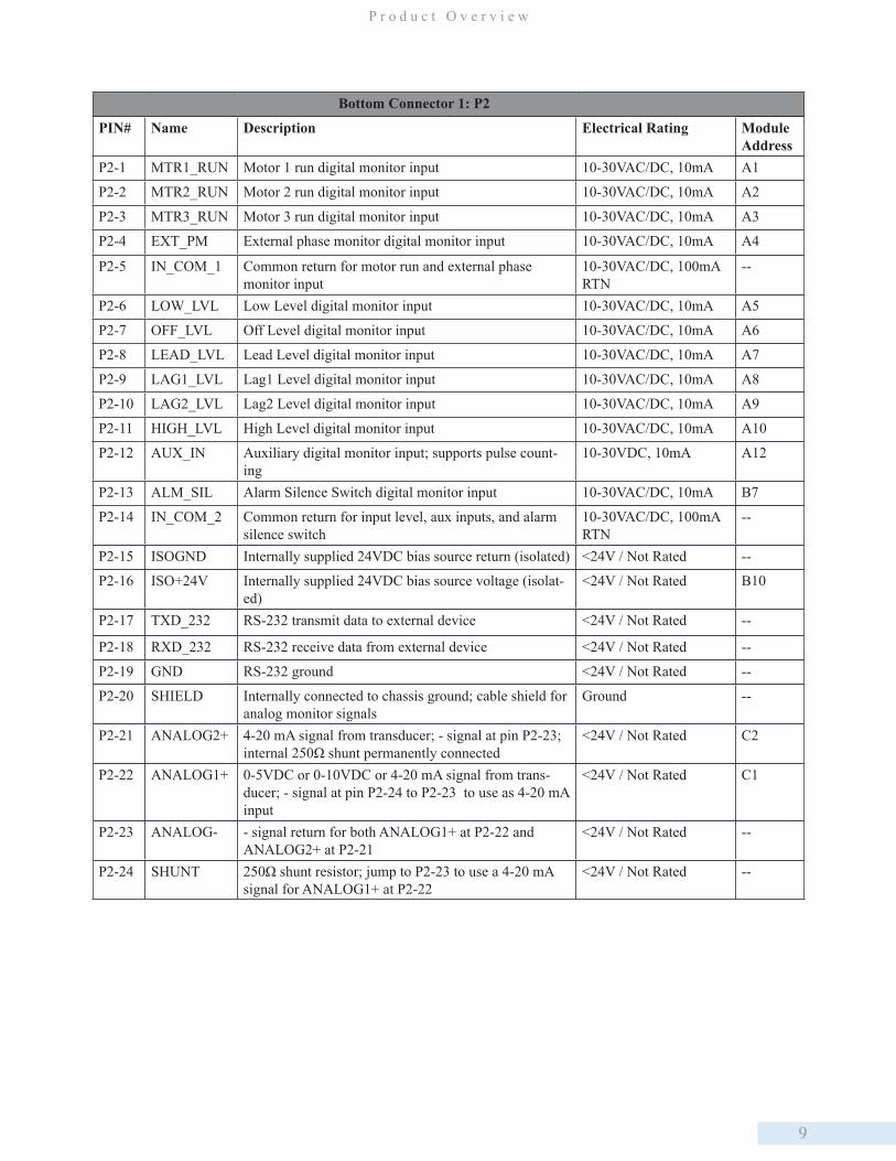
Bottom Connector 1: P2
PIN# Name Description Electrical Rating Module Address
P2-1 MTR1_RUN Motor 1 run digital monitor input 10-30VAC/DC, 10mA A1
P2-2 MTR2_RUN Motor 2 run digital monitor input 10-30VAC/DC, 10mA A2
P2-3 MTR3_RUN Motor 3 run digital monitor input 10-30VAC/DC, 10mA A3
P2-4 EXT_PM External phase monitor digital monitor input 10-30VAC/DC, 10mA A4
P2-5 IN_COM_1 Common return for motor run and external phase monitor input
10-30VAC/DC, 100mA RTN
--
P2-6 LOW_LVL Low Level digital monitor input 10-30VAC/DC, 10mA A5
P2-7 OFF_LVL Off Level digital monitor input 10-30VAC/DC, 10mA A6
P2-8 LEAD_LVL Lead Level digital monitor input 10-30VAC/DC, 10mA A7
P2-9 LAG1_LVL Lag1 Level digital monitor input 10-30VAC/DC, 10mA A8
P2-10 LAG2_LVL Lag2 Level digital monitor input 10-30VAC/DC, 10mA A9
P2-11 HIGH_LVL High Level digital monitor input 10-30VAC/DC, 10mA A10
P2-12 AUX_IN Auxiliary digital monitor input; supports pulse count-ing
10-30VDC, 10mA A12
P2-13 ALM_SIL Alarm Silence Switch digital monitor input 10-30VAC/DC, 10mA B7
P2-14 IN_COM_2 Common return for input level, aux inputs, and alarm silence switch
10-30VAC/DC, 100mA RTN
--
P2-15 ISOGND Internally supplied 24VDC bias source return (isolated) <24V / Not Rated --
P2-16 ISO+24V Internally supplied 24VDC bias source voltage (isolat-ed)
<24V / Not Rated B10
P2-17 TXD_232 RS-232 transmit data to external device <24V / Not Rated --
P2-18 RXD_232 RS-232 receive data from external device <24V / Not Rated --
P2-19 GND RS-232 ground <24V / Not Rated --
P2-20 SHIELD Internally connected to chassis ground; cable shield for analog monitor signals
Ground --
P2-21 ANALOG2+ 4-20 mA signal from transducer; - signal at pin P2-23; internal 250Ω shunt permanently connected
<24V / Not Rated C2
P2-22 ANALOG1+ 0-5VDC or 0-10VDC or 4-20 mA signal from trans-ducer; - signal at pin P2-24 to P2-23 to use as 4-20 mA input
<24V / Not Rated C1
P2-23 ANALOG- - signal return for both ANALOG1+ at P2-22 and ANALOG2+ at P2-21
<24V / Not Rated --
P2-24 SHUNT 250Ω shunt resistor; jump to P2-23 to use a 4-20 mA signal for ANALOG1+ at P2-22
<24V / Not Rated --
10
C h a p t e r 2
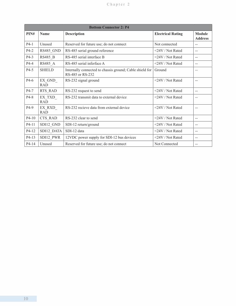
Bottom Connector 2: P4
PIN# Name Description Electrical Rating Module Address
P4-1 Unused Reserved for future use; do not connect Not connected --
P4-2 RS485_GND RS-485 serial ground reference <24V / Not Rated --
P4-3 RS485_B RS-485 serial interface B <24V / Not Rated --
P4-4 RS485_A RS-485 serial inferface A <24V / Not Rated --
P4-5 SHIELD Internally connected to chassis ground; Cable shield for RS-485 or RS-232
Ground --
P4-6 EX_GND_RAD
RS-232 signal ground <24V / Not Rated --
P4-7 RTS_RAD RS-232 request to send <24V / Not Rated --
P4-8 EX_TXD_RAD
RS-232 transmit data to external device <24V / Not Rated --
P4-9 EX_RXD_RAD
RS-232 recieve data from external device <24V / Not Rated --
P4-10 CTS_RAD RS-232 clear to send <24V / Not Rated --
P4-11 SDI12_GND SDI-12 return/ground <24V / Not Rated --
P4-12 SDI12_DATA SDI-12 data <24V / Not Rated --
P4-13 SDI12_PWR 12VDC power supply for SDI-12 bus devices <24V / Not Rated --
P4-14 Unused Reserved for future use; do not connect Not Connected --
11
U n i t O v e r v i e w
3. Unit OverviewThe following sections describe what the available features of the TCU800 are and how they monitor and operate various
parts of the pump control systems. The descriptions are from the perspective of the TCU800 as a unit interacting with a
pump control system.
User Interaction
The TCU800 provides local statuses and has mechanisms for user control locally and remotely. The interaction points are
the following: faceplate, USB ports, touch screen, and serial connectivity. The front of the TCU800 is called the faceplate.
It consists of LEDs, a soft touch button, access for USB ports, HOA switches, and a touch screen. The main purposes of
the faceplate are to provide the user with the status of the system at a glance, TCU800 operation, manual pump operation,
and configuration access.
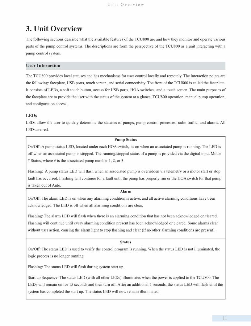
LEDsLEDs allow the user to quickly determine the statuses of pumps, pump control processes, radio traffic, and alarms. All
LEDs are red.
Pump Status
On/Off: A pump status LED, located under each HOA switch, is on when an associated pump is running. The LED is
off when an associated pump is stopped. The running/stopped status of a pump is provided via the digital input Motor
# Status, where # is the associated pump number 1, 2, or 3.
Flashing: A pump status LED will flash when an associated pump is overridden via telemetry or a motor start or stop
fault has occurred. Flashing will continue for a fault until the pump has properly run or the HOA switch for that pump
is taken out of Auto. Alarm
On/Off: The alarm LED is on when any alarming condition is active, and all active alarming conditions have been
acknowledged. The LED is off when all alarming conditions are clear.
Flashing: The alarm LED will flash when there is an alarming condition that has not been acknowledged or cleared.
Flashing will continue until every alarming condition present has been acknowledged or cleared. Some alarms clear
without user action, causing the alarm light to stop flashing and clear (if no other alarming conditions are present).
Status
On/Off: The status LED is used to verify the control program is running. When the status LED is not illuminated, the
logic process is no longer running.
Flashing: The status LED will flash during system start up.
Start up Sequence: The status LED (with all other LEDs) illuminates when the power is applied to the TCU800. The
LEDs will remain on for 15 seconds and then turn off. After an additional 5 seconds, the status LED will flash until the
system has completed the start up. The status LED will now remain illuminated.
12
C h a p t e r 3
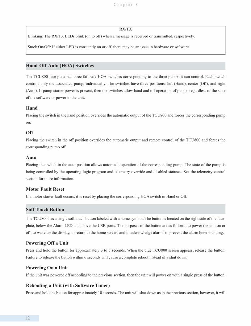
RX/TX
Blinking: The RX/TX LEDs blink (on to off) when a message is received or transmitted, respectively.
Stuck On/Off: If either LED is constantly on or off, there may be an issue in hardware or software.
Hand-Off-Auto (HOA) Switches
The TCU800 face plate has three fail-safe HOA switches corresponding to the three pumps it can control. Each switch
controls only the associated pump, individually. The switches have three positions: left (Hand), center (Off), and right
(Auto). If pump starter power is present, then the switches allow hand and off operation of pumps regardless of the state
of the software or power to the unit.
Hand Placing the switch in the hand position overrides the automatic output of the TCU800 and forces the corresponding pump
on.
Off Placing the switch in the off position overrides the automatic output and remote control of the TCU800 and forces the
corresponding pump off.
AutoPlacing the switch in the auto position allows automatic operation of the corresponding pump. The state of the pump is
being controlled by the operating logic program and telemetry override and disabled statuses. See the telemetry control
section for more information.
Motor Fault ResetIf a motor starter fault occurs, it is reset by placing the corresponding HOA switch in Hand or Off.
Soft Touch Button
The TCU800 has a single soft touch button labeled with a home symbol. The button is located on the right side of the face-
plate, below the Alarm LED and above the USB ports. The purposes of the button are as follows: to power the unit on or
off, to wake up the display, to return to the home screen, and to acknowledge alarms to prevent the alarm horn sounding.
Powering Off a UnitPress and hold the button for approximately 3 to 5 seconds. When the blue TCU800 screen appears, release the button.
Failure to release the button within 6 seconds will cause a complete reboot instead of a shut down.
Powering On a UnitIf the unit was powered off according to the previous section, then the unit will power on with a single press of the button.
Rebooting a Unit (with Software Timer)Press and hold the button for approximately 10 seconds. The unit will shut down as in the previous section, however, it will
13
U n i t O v e r v i e w
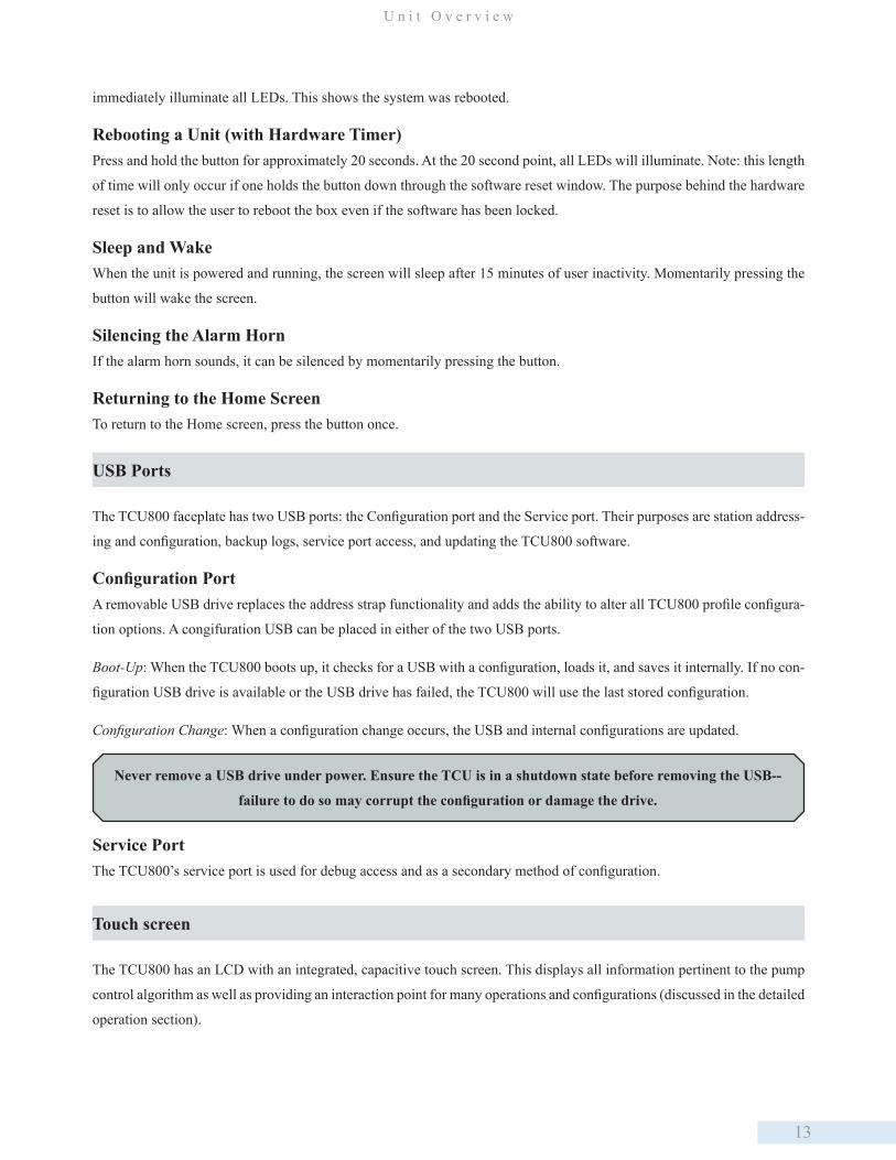
immediately illuminate all LEDs. This shows the system was rebooted.
Rebooting a Unit (with Hardware Timer)Press and hold the button for approximately 20 seconds. At the 20 second point, all LEDs will illuminate. Note: this length
of time will only occur if one holds the button down through the software reset window. The purpose behind the hardware
reset is to allow the user to reboot the box even if the software has been locked.
Sleep and WakeWhen the unit is powered and running, the screen will sleep after 15 minutes of user inactivity. Momentarily pressing the
button will wake the screen.
Silencing the Alarm HornIf the alarm horn sounds, it can be silenced by momentarily pressing the button.
Returning to the Home Screen To return to the Home screen, press the button once.
USB Ports
The TCU800 faceplate has two USB ports: the Configuration port and the Service port. Their purposes are station address-
ing and configuration, backup logs, service port access, and updating the TCU800 software.
Configuration PortA removable USB drive replaces the address strap functionality and adds the ability to alter all TCU800 profile configura-
tion options. A congifuration USB can be placed in either of the two USB ports.
Boot-Up: When the TCU800 boots up, it checks for a USB with a configuration, loads it, and saves it internally. If no con-
figuration USB drive is available or the USB drive has failed, the TCU800 will use the last stored configuration.
Configuration Change: When a configuration change occurs, the USB and internal configurations are updated.
Service PortThe TCU800’s service port is used for debug access and as a secondary method of configuration.
Touch screen
The TCU800 has an LCD with an integrated, capacitive touch screen. This displays all information pertinent to the pump
control algorithm as well as providing an interaction point for many operations and configurations (discussed in the detailed
operation section).
Never remove a USB drive under power. Ensure the TCU is in a shutdown state before removing the USB--
failure to do so may corrupt the configuration or damage the drive.
14
C h a p t e r 3
OperationWith a single finger, touch and release the screen over the desired option. Wait a moment for the operation to load and
complete.
Sleep and Wake After 15 minutes of no activity, the screenwill sleep. While the screen appears black, the normal TCU800 operations are
continuing. The screen sleeps to improve product longevity. To wake the screen, tap the screen gently or press the home
button. The screen may take a few seconds to illuminate.
Monitoring and Control
The TCU800 is capable of monitoring and controlling various interfaces for input/output logical operation and
communication. It interacts with digital inputs, digital outputs, analog inputs, serial communication, phase voltages, and
various internal features. The discussion in this section is limited to the default operation of the TCU800; contact Data
Flow Systems to discuss alternative operations.
Digital Input MonitoringThe TCU800 can monitor digital input devices such as contact closures, float switches, pressure switches, pump seal
and thermal overload contacts designed for mechanical and solid state signal closures. These input devices are used to
determine various statuses of the pump control system or its auxiliary components to maintain proper operation.
Float Inputs: Level sensing is provided via float switches when configured. Six discrete inputs are provided as float level
inputs with a common ground. The digital ground is also common to the auxiliary input and alarm silence inputs.
Auxiliary Input: The auxiliary input provides the ability to monitor an input and control an output (aux out) based on it’s
status, with several configurable options; see the auxiliary control configuration section. The digital ground is common
with the six discrete float and the alarm silence inputs. This input can also be used as a pulse counter.
Alarm Silence: The alarm silence input provides a connection for an external momentary switch. Additionally, the home
button is provided to silence alarms.
Motor Run Status: There are three motor run status inputs, one for each pump. These provide the statuses from the pump
starter relays. This allows for pump start and stop fault determination; see the Pump Start and Stop Fault section for more
information.
External Phase Monitor: The external phase monitor input is provided as both an internal bypass and an alarm input. The
purpose of this input is to allow a system to use either the TCU800’s phase monitoring system or an external phase monitor
whose alarming condition is passed through the TCU800’s alarms.
Phase Monitor Bypass: The input is held in the on (high) state, this causes the internal phase voltage monitoring
to be bypassed - no alarms will occur by internal phase voltage faults.
External Phase Monitoring: An external phase monitoring device can provide an input to the TCU800 to make use
15
U n i t O v e r v i e w
of the TCU800’s alarm system. The input is normally held high with no phase voltage fault. When an alarming
condition occurs on the external monitoring system, bringing the input low will cause an alarm on the TCU800.
Digital Output Control
The TCU800 controls digital outputs via two methods: solid-state relays and mechanical relays. The purpose of these
outputs is to provide pump start, auxiliary output, alarm light, and alarm horn control.
Solid State RelaysThere are four solid-state relay outputs used to control the three pump starter signals and one auxiliary output.
Pump StartersThe three pump start signals are independently powered via externally supplied Starter Power. The output control is
provided automatically or can be overridden using the HOA switches. See chapter 6 for HOA control.
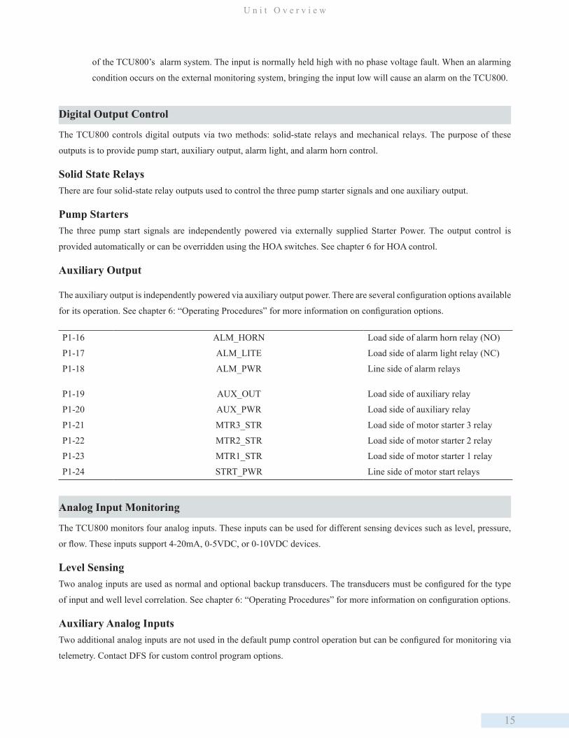
Auxiliary Output
The auxiliary output is independently powered via auxiliary output power. There are several configuration options available
for its operation. See chapter 6: “Operating Procedures” for more information on configuration options.
P1-16 ALM_HORN Load side of alarm horn relay (NO)
P1-17 ALM_LITE Load side of alarm light relay (NC)
P1-18 ALM_PWR Line side of alarm relays
P1-19 AUX_OUT Load side of auxiliary relay
P1-20 AUX_PWR Load side of auxiliary relay
P1-21 MTR3_STR Load side of motor starter 3 relay
P1-22 MTR2_STR Load side of motor starter 2 relay
P1-23 MTR1_STR Load side of motor starter 1 relay
P1-24 STRT_PWR Line side of motor start relays
Analog Input Monitoring
The TCU800 monitors four analog inputs. These inputs can be used for different sensing devices such as level, pressure,
or flow. These inputs support 4-20mA, 0-5VDC, or 0-10VDC devices.
Level SensingTwo analog inputs are used as normal and optional backup transducers. The transducers must be configured for the type
of input and well level correlation. See chapter 6: “Operating Procedures” for more information on configuration options.
Auxiliary Analog InputsTwo additional analog inputs are not used in the default pump control operation but can be configured for monitoring via
telemetry. Contact DFS for custom control program options.

16
C h a p t e r 3
Serial Connectivity
External RS-232The RS-232 connection is provided for an external radio or similar device. The connection is compatible with Modbus
protocol as a slave port. See chapter 8 for additional information. Additional configuration is required for operation. See
section 2 for installation instructions and section 6 for information on how to configure specific devices.
• Supports flow control
• Not isolated, but protected from voltage transients
• Supports baud rates 1200-115200
Isolated RS-485The RS-485 connection is provided to connect an RS-485 device. The connection is compatible with Modbus protocol as a
master port. See chapter 8 for additional information. Additional configuration is required for operation. See section 2 for
installation instructions and section 6 for information on how to configure specific devices.
• 2.5kVrms isolated RS485 bus that can be used to communicate with standard RS485 sensors as well as other DFS
telemetry equipment
• Protected from voltage transients
• Half duplex
• Supports baud rates 1200-115200
P4-2 RS485_GND RS-485 serial ground reference
P4-3 RS485_B RS-485 serial interface B
P4-4 RS485_A RS-485 serial interface A
P4-5 SHIELD Internally connected to chassis ground; Cable shield for RS-485 or RS-232
P4-6 EX_GND_RAD RS-232 signal ground
P4-7 RTS_RAD RS-232 request to send
P4-8 EX_TXD_RAD RS-232 transmit data to external device
P4-9 EX_RXD_RAD RS-232 recieve data from external device
P4-10 CTS_RAD RS-232 clear to send
Phase Voltage Monitoring
The TCU800 has an internal system to monitor phase voltages and provide fault detection for several faults. The TCU800’s
internal phase monitoring can also be bypassed and an external phase monitor can be used.
InternalThe TCU800 has an internal phase monitoring chip capable of monitoring several types of phase voltage configurations
and supplying failure conditions dependent upon those configurations.
Serial connectivity is provided on two interfaces to the TCU800: external RS-232 (slave) and isolated RS-485 (master).

17
U n i t O v e r v i e w
Single/Three Phase: Single or three-phase voltage systems can be monitored with ranges of nominal 240 and 480
VAC. The 480 VAC systems require external resistors installed on each phase.
Fault Detection: Fault detection is provided for loss of a phase, phase reversal, and low/high voltage conditions.
Faults will automatically stop all pumps from running to prevent damage.
ExternalThe external phase monitor must provide a closed set of contacts that open during a phase fault. The voltage used to
monitor the set of contacts must be the same voltage used to monitor the pump run statuses.
Internal Monitoring
The TCU800 monitors several internal features to provide the user with the status of how the unit is operating. These sta-
tuses are internal temperature, AC Power Fault, DC Bias Fault, and Process Fault.
Internal TemperatureInternal temperature monitors the TCU800’s temperature.
AC Power FaultAC Power fault is provided when no AC power is applied to the unit. This will only be available when the TCU800 is on
battery backup.
DC Bias FaultThe DC Bias fault is active when the 24VDC bias power supply drops below 20VDC.
Process FaultThe process fault is active when the control program is detected as no longer operating.
Automatic/Manual Control
When the TCU’s Hand-Off-Auto (H-O-A) switches are in the “Auto” position, the TCU provides automatic control over a
pump system. However, there are two ways to partially or completely override the TCU and manually control the system:
the H-O-A switches and telemetry interface.
H-O-A SwitchesThree H-O-A switches on the TCU’s face plate are provided to manually override the TCU’s automated control.
Hand Placing a switch in the “Hand” position overrides the TCU’s control and forces the corresponding pump on.
Off Placing a switch in the “Off” position overrides the TCU’s control and forces the corresponding pump off.
Auto The H-O-A switch for a pump must be in the “Auto” position for the TCU to provide automatic control whether manually over telemetry or automatically via the TCU coontrol programming.
The H-O-A switches are fail-safe; they remain operational even if the TCU fails or loses power. They will continue to
function in the “Hand” and “Off” positions with the TCU in a faulted state or powered down. Motor Starter faults are reset
when the corresponding H-O-A switch is moved from the “Auto” position.
18
C h a p t e r 3
Telemetry InterfaceConnecting to a telemetry system provides the ability to remotely control the individually pumps with two software
switches: Override – (when tuned on) remotely forces a pump On, and Disable - (when tuned on) remotely forces a pump
Off, and effectively disables the the TCU from automatically controlling a pump. The H-O-A switch on the TCU must be
in the Auto position for either of these switches to have any effect, and both of these switch need to be in their off state for
the TCU to automatically control the pumps.
All three H-O-A switches must be in the “Hand” or “Off” position before any changes can be made to the TCU’s
configurations.
Local H-O-A control will always override any telemetry control.
Level Sensing Devices
The TCU features interfaces to several industry-standard level-sensing devices.
Discrete (Contact Closure) Devices
The TCU can accommodate digital-type devices such as contact closures, float switches, and pressure switches. Several
digital-type devices can be connected to up to six discrete digital monitoring points to control the operation of pumps. The
TCU is designed to handle simplex, duplex, and triplex configurations.
Analog Level-Sensing DevicesThe TCU provides the option to monitor analog level-sensing devices, including ultrasonic, hydraulic pressure, and
pneumatic pressure transducers through an industry-standard 4-20mA / 0-5V interface. Any analog level-detection
transducer (self-powered or TCU powered) that supplies a 0-5V, 0-10V, or 4-20mA current signal can be used as an analog-
level input device and can be loop-powered using the provided 24VDC bias on the P2 connector.
A station can be controlled by:
1. Connecting an analog-type device to the TCU’s analog input terminals
2. Calibrating the maximum, minimum, and intermediate staging points
Internal Phase Monitor
A single- or three-phase 240 VAC power monitor is provided. An optional three-phase 480 VAC (using external resistors)
power monitor is also available (see “Appendix D: Parts List” for information on the 480 VAC Phase Monitor Kit). All
versions of the phase monitor detect phase loss and high and low line voltage phase faults. The three-phase 240 VAC and
optional 480 VAC power monitor also detect phase reversal. A fault of phase reversal, phase loss, or line voltage results
in an alarm and shuts down all automatically controlled pumps. The TCU has inputs for current transformers (CT) and
can support 3-phase 3-wire (delta) or 3-phase 4-wire (wye) setups. Active, reactive, and apparent power or energy can be
measured. The power factor can be measured when the CT inputs are used.
19
U n i t O v e r v i e w
The TCU reads and displays True RMS voltages much the same as modern voltmeters. Readings from older
voltmeters that display RMS, but not True RMS, might differ from the TCU’s readings.
Outputs
Solid-State ControlThe TCU features four solid-state (120-240VAC only) digital outputs. Three of these are used for Motor Start (P1-21
through 24) with the other used by the Aux Output (P1-19). The output for the Motor Starts are gated/switched through
the TCU’s H-O-A switches. In Auto the solid-state switches are used by the TCU to control the pumps, In Off no power is
permitted to the Motor Start outputs, and the solid-state relays are manually bypassed and Motor Start pins are electrically
energized by placing an H-O-A switch in the Hand position.
Mechanical Relay OutputsThe TCU’s two mechanical relay output are for the Alarm signals, both horn and light. They can be VAC or VDC with
recommended wiring instructions and relays rating listed elsewhere in this manual. Ifnot used for Alarms, either can be
configured for manual control, via telemetry.
USB Ports and Configuration
The TCU’s face plate features two USB type-A ports that can be used for diagnostics, configuration storage, and updating.
A USB flash drive correctly formatted and loaded with appropriate files will allow easy transfer of pump configuration
parameters from one TCU to another.
The TAC Pack TCU Configuration Connector or address card is not used in the TCU800. Instead, the USB
configuration stick will replace this method of setting the TCU’s station address.
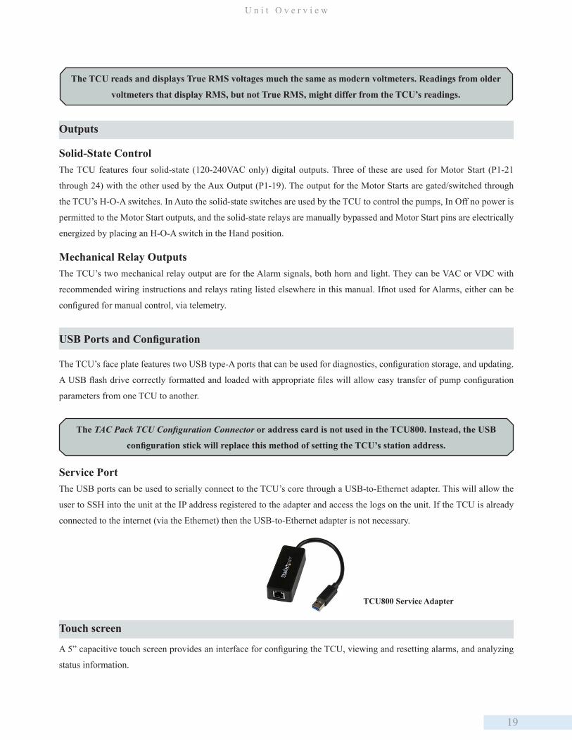
Service PortThe USB ports can be used to serially connect to the TCU’s core through a USB-to-Ethernet adapter. This will allow the
user to SSH into the unit at the IP address registered to the adapter and access the logs on the unit. If the TCU is already
connected to the internet (via the Ethernet) then the USB-to-Ethernet adapter is not necessary.
Touch screen
A 5” capacitive touch screen provides an interface for configuring the TCU, viewing and resetting alarms, and analyzing
status information.
TCU800 Service Adapter
20
C h a p t e r 3
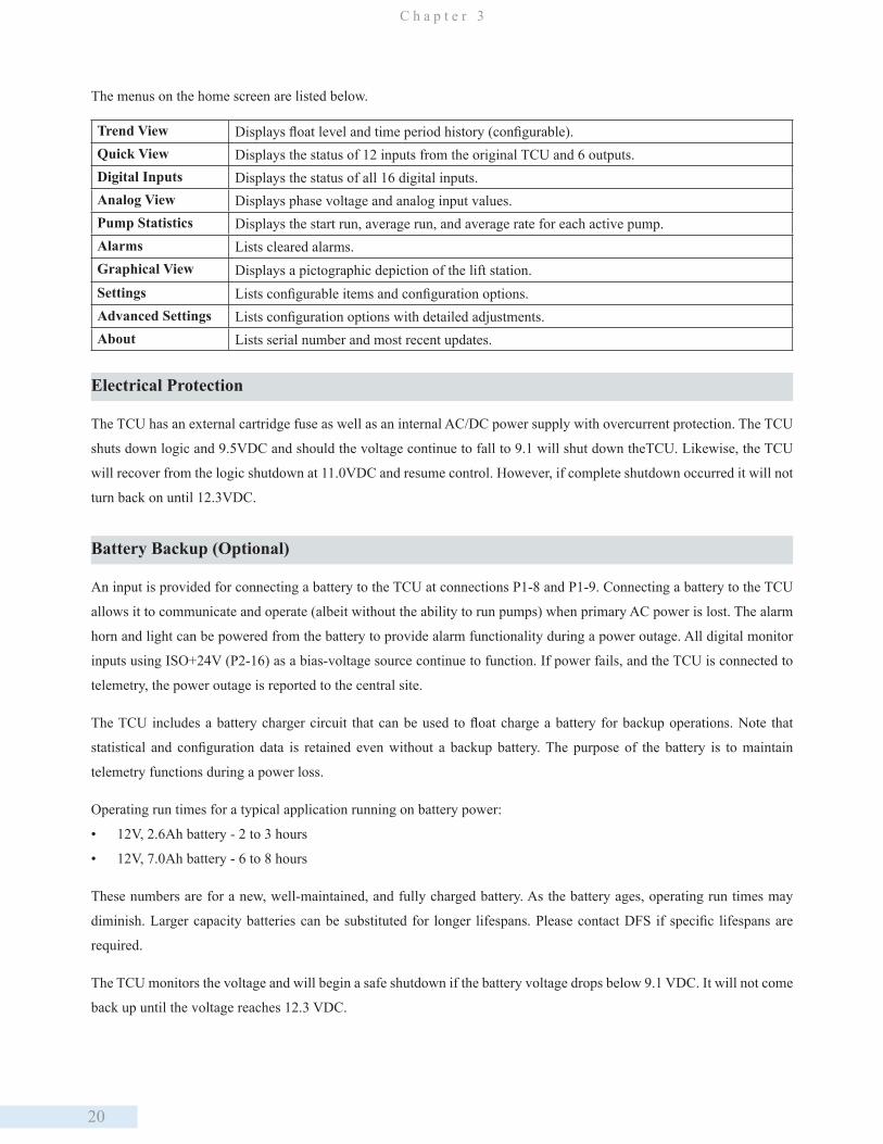
The menus on the home screen are listed below.
Trend View Displays float level and time period history (configurable). Quick View Displays the status of 12 inputs from the original TCU and 6 outputs. Digital Inputs Displays the status of all 16 digital inputs. Analog View Displays phase voltage and analog input values. Pump Statistics Displays the start run, average run, and average rate for each active pump. Alarms Lists cleared alarms. Graphical View Displays a pictographic depiction of the lift station. Settings Lists configurable items and configuration options. Advanced Settings Lists configuration options with detailed adjustments. About Lists serial number and most recent updates.
Electrical Protection
The TCU has an external cartridge fuse as well as an internal AC/DC power supply with overcurrent protection. The TCU
shuts down logic and 9.5VDC and should the voltage continue to fall to 9.1 will shut down theTCU. Likewise, the TCU
will recover from the logic shutdown at 11.0VDC and resume control. However, if complete shutdown occurred it will not
turn back on until 12.3VDC.
Battery Backup (Optional)
An input is provided for connecting a battery to the TCU at connections P1-8 and P1-9. Connecting a battery to the TCU
allows it to communicate and operate (albeit without the ability to run pumps) when primary AC power is lost. The alarm
horn and light can be powered from the battery to provide alarm functionality during a power outage. All digital monitor
inputs using ISO+24V (P2-16) as a bias-voltage source continue to function. If power fails, and the TCU is connected to
telemetry, the power outage is reported to the central site.
The TCU includes a battery charger circuit that can be used to float charge a battery for backup operations. Note that
statistical and configuration data is retained even without a backup battery. The purpose of the battery is to maintain
telemetry functions during a power loss.
Operating run times for a typical application running on battery power:
• 12V, 2.6Ah battery - 2 to 3 hours
• 12V, 7.0Ah battery - 6 to 8 hours
These numbers are for a new, well-maintained, and fully charged battery. As the battery ages, operating run times may
diminish. Larger capacity batteries can be substituted for longer lifespans. Please contact DFS if specific lifespans are
required.
The TCU monitors the voltage and will begin a safe shutdown if the battery voltage drops below 9.1 VDC. It will not come
back up until the voltage reaches 12.3 VDC.
21
U n i t O v e r v i e w
Principles of Operation
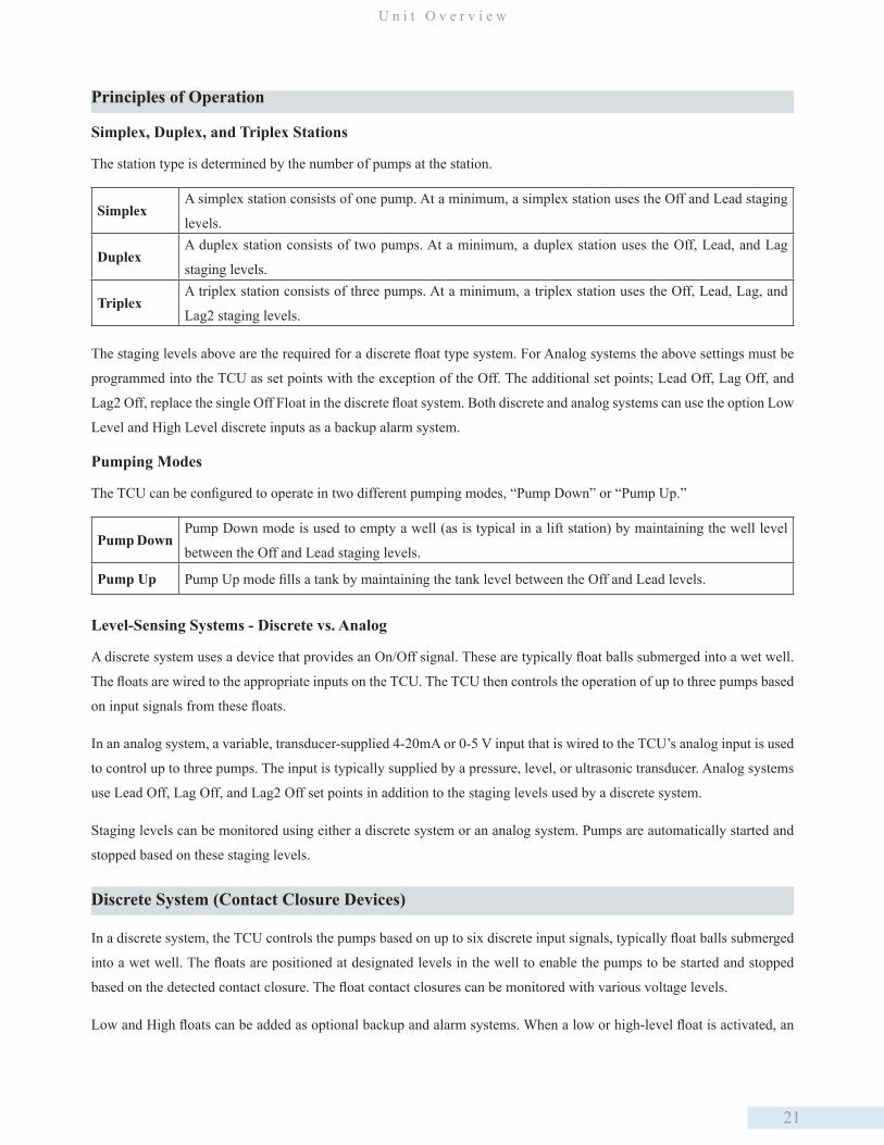
Simplex, Duplex, and Triplex Stations
The station type is determined by the number of pumps at the station.
SimplexA simplex station consists of one pump. At a minimum, a simplex station uses the Off and Lead staging
levels.
DuplexA duplex station consists of two pumps. At a minimum, a duplex station uses the Off, Lead, and Lag
staging levels.
TriplexA triplex station consists of three pumps. At a minimum, a triplex station uses the Off, Lead, Lag, and
Lag2 staging levels.
The staging levels above are the required for a discrete float type system. For Analog systems the above settings must be
programmed into the TCU as set points with the exception of the Off. The additional set points; Lead Off, Lag Off, and
Lag2 Off, replace the single Off Float in the discrete float system. Both discrete and analog systems can use the option Low
Level and High Level discrete inputs as a backup alarm system.
Pumping Modes
The TCU can be configured to operate in two different pumping modes, “Pump Down” or “Pump Up.”
Pump DownPump Down mode is used to empty a well (as is typical in a lift station) by maintaining the well level
between the Off and Lead staging levels.
Pump Up Pump Up mode fills a tank by maintaining the tank level between the Off and Lead levels.
Level-Sensing Systems - Discrete vs. Analog
A discrete system uses a device that provides an On/Off signal. These are typically float balls submerged into a wet well.
The floats are wired to the appropriate inputs on the TCU. The TCU then controls the operation of up to three pumps based
on input signals from these floats.
In an analog system, a variable, transducer-supplied 4-20mA or 0-5 V input that is wired to the TCU’s analog input is used
to control up to three pumps. The input is typically supplied by a pressure, level, or ultrasonic transducer. Analog systems
use Lead Off, Lag Off, and Lag2 Off set points in addition to the staging levels used by a discrete system.
Staging levels can be monitored using either a discrete system or an analog system. Pumps are automatically started and
stopped based on these staging levels.
Discrete System (Contact Closure Devices)
In a discrete system, the TCU controls the pumps based on up to six discrete input signals, typically float balls submerged
into a wet well. The floats are positioned at designated levels in the well to enable the pumps to be started and stopped
based on the detected contact closure. The float contact closures can be monitored with various voltage levels.
Low and High floats can be added as optional backup and alarm systems. When a low or high-level float is activated, an

22
C h a p t e r 3
alarm is issued and normal pump control is overridden.
Note: If the Low float is not going to be used, it must be disabled in the TCU’s local configuration for the TCU’s pump
control operations to function normally in automatic. Failing to disable the Low float configuration in this situation, results
in a false alarm condition. This false alarm condition occurs because an unconnected Low Float input signal indicates to
the TCU that the wet well is too low to operate pumps, or OFF, therefore the TCU will not permit pumps to operate. The
TCU expects Low float input’s normal/safe state to be ON which indicates the Low Float floating, to permit automatic
pump operation.
Staging Levels in Discrete System
Pumps are automatically started and stopped based on staging levels. The illustration below shows the behavior of pumps
at each staging level in a discrete system. Both a lift station (pump down mode) and a storage tank (pump up mode) are
shown.
Staging Levels in Pump Down Mode (Discrete System)
This chart describes the normal function of the TCU’s eight staging levels when used in Pump Down mode, such as that
used in a lift station. Note that not all of these levels must be configured for a lift station. The minimum number of levels
required depends on the type of station – simplex (one pump), duplex (two pumps), or triplex (three pumps).
Low LevelAll pumps are stopped and alarms are activated. Low is active when the well’s
level is below Low level. Must be set below all other levels.
Off LevelMinimum operational level of a well. All pumps are stopped when the well’s
level is below the Off level.
Lead LevelLead (first) pump is started. Lead is active when the well’s level is above the
Lead level.
Lag Level (duplex and triplex stations
only)
Lag (second) pump is started. Lag is active when the well’s level is above the
Lag level.
Lag2 Level (triplex stations only)Lag2 (third) pump is started. Lag2 is active when the well’s level is above
the Lag2 level.
High LevelAll pumps are stagger started and alarms are activated. High is active when
the well’s level reaches High level. Must be set above all other levels.
Staging Levels in Pump Up Mode (Discrete System)
The following paragraphs describe the function of the TCU’s eight staging levels when used in Pump Up mode, such as
that used in a storage tank. Note that not all of these levels must be configured for a lift station. The minimum number
of levels required depends on the type of station – simplex (one pump), duplex (two pumps), or triplex (three pumps).
High LevelAll pumps are stopped and alarms are activated. Low is active when the tank’s
level is above High level. Must be set above all other levels.

23
U n i t O v e r v i e w
Off LevelMinimum operational level of a tank. All pumps are stopped when the tank’s
level is above the Off level.
Lead LevelLead (first) pump is started. Lead is active when the tank’s level is below the
Lead level.
Lag Level (duplex and triplex stations
only)
Lag (second) pump is started. Lag is active when the tank’s level is below the
Lag level.
Lag2 Level (triplex stations only)Lag2 (third) pump is started. Lag2 is active when the tank’s level is below
the Lag2 level.
Low LevelAll pumps are stagger started and alarms are activated. Low is active when
the tank’s level is below Low level. Must be set below all other levels.
Analog System (Pressure Transducer)
In an analog system, pumps are controlled by a variable, transducer-supplied 4-20 mA or 0-5 V input that is wired to the
TCU’s analog input. The operator sets the 4 mA or the 1 V input equal to the transducer’s low range (in feet) and the 20
mA or 5 V input equal to the transducer’s high range (in feet). Low and High levels, as well as staging levels for the Lead,
Lag, and Lag2 pumps are also set by the operator. The TCU interprets the input signal and starts or stops pumps according
to the configured staging levels.
The TCU pump control operation functions with eight possible staging levels: Low, Lead Off, Lead, Lag Off, Lag, Lag2
Off, Lag2, and High.
An analog system has several options available for handling transducer faults:
• High and/or Low Float Override. Use a high and/or a low float to issue an alarm and override normal pump control.
• Switch to normal float behavior (Floats). This option requires an Off float to shut off the pumps and a minimum of one
float (Lead to High) to start the pumps.
• Switch to a second analog input (Analog2).
24
C h a p t e r 3
Note: If the Low float is not going to be used, it must be disabled in the TCU’s local configuration for the TCU’s pump
control operations to function normally in automatic. Failing to disable the Low float configuration in this situation, results
in a false alarm condition, which fails the transducer.
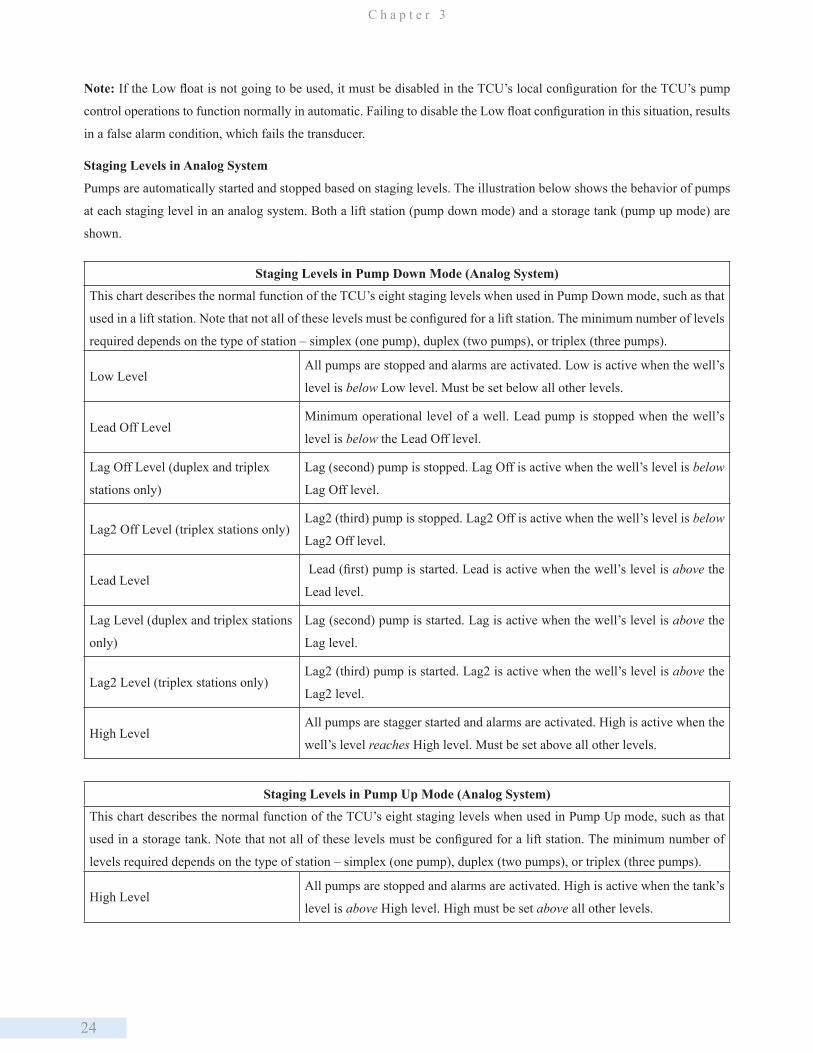
Staging Levels in Analog System
Pumps are automatically started and stopped based on staging levels. The illustration below shows the behavior of pumps
at each staging level in an analog system. Both a lift station (pump down mode) and a storage tank (pump up mode) are
shown.
Staging Levels in Pump Down Mode (Analog System)
This chart describes the normal function of the TCU’s eight staging levels when used in Pump Down mode, such as that
used in a lift station. Note that not all of these levels must be configured for a lift station. The minimum number of levels
required depends on the type of station – simplex (one pump), duplex (two pumps), or triplex (three pumps).
Low LevelAll pumps are stopped and alarms are activated. Low is active when the well’s
level is below Low level. Must be set below all other levels.
Lead Off LevelMinimum operational level of a well. Lead pump is stopped when the well’s
level is below the Lead Off level.
Lag Off Level (duplex and triplex
stations only)
Lag (second) pump is stopped. Lag Off is active when the well’s level is below
Lag Off level.
Lag2 Off Level (triplex stations only)Lag2 (third) pump is stopped. Lag2 Off is active when the well’s level is below
Lag2 Off level.
Lead Level Lead (first) pump is started. Lead is active when the well’s level is above the
Lead level.
Lag Level (duplex and triplex stations
only)
Lag (second) pump is started. Lag is active when the well’s level is above the
Lag level.
Lag2 Level (triplex stations only)Lag2 (third) pump is started. Lag2 is active when the well’s level is above the
Lag2 level.
High LevelAll pumps are stagger started and alarms are activated. High is active when the
well’s level reaches High level. Must be set above all other levels.
Staging Levels in Pump Up Mode (Analog System)
This chart describes the normal function of the TCU’s eight staging levels when used in Pump Up mode, such as that
used in a storage tank. Note that not all of these levels must be configured for a lift station. The minimum number of
levels required depends on the type of station – simplex (one pump), duplex (two pumps), or triplex (three pumps).
High LevelAll pumps are stopped and alarms are activated. High is active when the tank’s
level is above High level. High must be set above all other levels.
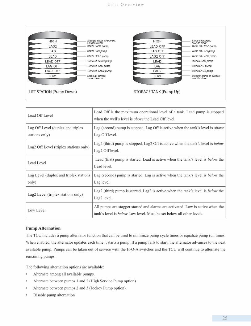
25
U n i t O v e r v i e w
Lead Off LevelLead Off is the maximum operational level of a tank. Lead pump is stopped
when the well’s level is above the Lead Off level.
Lag Off Level (duplex and triplex
stations only)
Lag (second) pump is stopped. Lag Off is active when the tank’s level is above
Lag Off level.
Lag2 Off Level (triplex stations only)Lag2 (third) pump is stopped. Lag2 Off is active when the tank’s level is below
Lag2 Off level.
Lead Level Lead (first) pump is started. Lead is active when the tank’s level is below the
Lead level.
Lag Level (duplex and triplex stations
only)
Lag (second) pump is started. Lag is active when the tank’s level is below the
Lag level.
Lag2 Level (triplex stations only)Lag2 (third) pump is started. Lag2 is active when the tank’s level is below the
Lag2 level.
Low LevelAll pumps are stagger started and alarms are activated. Low is active when the
tank’s level is below Low level. Must be set below all other levels.
Pump AlternationThe TCU includes a pump alternator function that can be used to minimize pump cycle times or equalize pump run times.
When enabled, the alternator updates each time it starts a pump. If a pump fails to start, the alternator advances to the next
available pump. Pumps can be taken out of service with the H-O-A switches and the TCU will continue to alternate the
remaining pumps.
The following alternation options are available:
• Alternate among all available pumps.
• Alternate between pumps 1 and 2 (High Service Pump option).
• Alternate between pumps 2 and 3 (Jockey Pump option).
• Disable pump alternation

26
C h a p t e r 3
The TCU uses a numeric alternation scheme. With numeric alternation, the pump assigned as the new Lead pump is always
the next in the numeric order. For example, in a triplex lift station, if pump 2 (current Lead pump) and pump 3 (current
Lag pump) are running when the Lead Off level is reached, pump 3 would become the new Lead pump regardless of the
number of pumps running.
If the Jockey Pump or High Service Pump options are enabled, the remaining pumps will alternate per the selected scheme.
When the alternator is disabled, Pump 1 is used as the Lead pump, Pump 2 as the Lag pump, and Pump 3 as the Lag2 pump.
Use of Unused Pump OutputsUnused pump outputs can be connected to any other type of control device. These devices can be turned on using the pump
override points. For example, in a duplex station (two pump operation), the third pump output could be connected to an
odor control injection.
Phase Monitor OptionsIn addition to the TCU’s internal phase monitor (see page 18), the TCU can use an external phase monitor or the internal
phase monitor can be bypassed.
External Phase Monitor
The TCU features an input at P2-4 that can accommodate the use of an external phase monitor where one is required. The
external phase monitor must provide a closed set of contacts that open during a phase fault. The voltage used to monitor
the set of contacts must be the same used to monitor the pump run statuses.
Phase Monitor Bypass
The TCU’s phase monitor can be bypassed if the internal phase monitor function is not required and there is no external
phase monitor. To bypass the TCU’s internal phase monitor, wire the phase monitor input (P2-4) in the ON state. The
voltage used to bias this point ON must be the same voltage used to monitor the pump run statuses.
Motor Run-Time MonitorThe TCU provides three digital monitor inputs for monitoring the status of the motors controlled by the TCU’s starter
relays:
• P2-1, MTR1_RUN
• P2-2, MTR2_RUN
• P2-3, MTR3_RUN
The Motor 1 Run input (MTR1_RUN) monitors the circuit controlled by the Motor 1 Starter output (MTR1_STR).
Correspondingly, MTR2_RUN monitors MTR2_STR, and MTR3_RUN monitors MTR3_STR.
Care should be taken to avoid cross-wiring the motor run inputs and starter outputs. For each pump controlled by the TCU,
the corresponding motor run input must be connected. After the TCU starts a pump, it checks the motor run input to verify
that the pump is running. If the signal is not present, it:
1. Shuts down the pump
2. Activates the pump’s motor-starter alarm
27
U n i t O v e r v i e w
3. Tries the next pump
The preferred method for monitoring motor run is to use phase A at the load side of the motor breaker as motor run bias,
and feed the bias through the starter auxiliary contacts to the TCU’s motor run input terminal with a proper bias resistor
in the circuit. Monitoring the starter auxiliary contacts by using Phase A as bias can provide fault detection of the TCU’s
starter relays, the motor-starter coils, and heater overloads, as well as an open breaker.
Solid State Motor Starter Control RelaysThe TCU features three solid-state relays, capable of controlling up to three motor starters. STR_PWR (starter power),
terminal P1-24, will be switched to the starter coils when the TCU’s starter relays are energized, or when the H-O-A
switches are placed in the “Hand” position. The TCU controls 120-240 VAC starter coils, with each output supporting a
maximum of one amp. A one-amp slow-blow fuse is required to protect the TCU’s relays from short-circuited motor-starter
coils. Size 3 or larger starters should be isolated with a relay. If starters are not maintained over time, they can draw over
one ampere.
Auxiliary Input and OutputThe TCU’s auxiliary digital input (AUX_IN; P2-12) and output (AUX_OUT; P1-19) can function together as a
programmable time delay relay or work independently as general monitor and control points for telemetry. Additionally,
the auxiliary input can operate as a pulse counter and be used with pulse-type flow meters and rain gauges.
To use AUX_IN and AUX_OUT as general monitor and control points, or to use AUX_IN as a pulse input, the time delay
relay function must be disabled. This is done by setting the function’s delay time to 0 (zero).
Time Delay RelayAn example of an auxiliary relay application is switching on a backup compressor for a bubbler system. The backup
compressor is connected to the AUX_OUT terminal, and an airflow switch for the primary compressor is connected to the
AUX_IN terminal. The Time Delay Relay function can then be configured to turn on the AUX_OUT when the flow switch
detects no airflow. The Time Delay Relay can also be configured to start the backup compressor only when the flow stops
for longer than a set time. This is accomplished by configuring the Time Delay Relay with the ON delay mode and setting
the desired delay time.
Pulse CountingFor the auxiliary input to be used as a pulse input, its corresponding HT3 point (point 12 of Module A, a DMM002) must
be configured as a digital pulse point (select DP for the Point Type). Additionally, the time delay relay function must be
disabled in the TCU.
The specifications for the pulse input are as follows:
• Supply voltage: 8 to 14 VDC
• Minimum pulse width: 25 ms
Alarm Light & Horn/Bell OutputsThe TCU contains two mechanical relays for controlling an alarm light and horn. Alarm devices can be AC or DC powered
for operation during power outages. If the TCU is connected to telemetry, these devices are not necessary and may be

28
C h a p t e r 3
disabled from the TCU’s local configuration. All conditions that activate the alarm horn and alarm light are reported
through the telemetry system.
Alarm outputs are activated only when the TCU detects an alarm condition, such as phase faults, high and low-well
conditions, and internal TCU faults. The alarm horn can be silenced by pressing the TCU’s Silence switch, by viewing the
TCU’s alarm screen from a telemetry-provided alarm silence control point or from a momentary switch connected to the
TCU’s Alarm Silence input. Any new alarm condition reactivates the alarm horn.
Failure ModesPump Failure
The TCU can operate around a pump that has failed and can be configured to retry the failed pump after a delay. If the retry
function is disabled, the TCU will alternate around the faulted pump until it is taken out of service via its corresponding
H-O-A switch.
Phase Fault
The TCU’s phase monitor is designed to detect phase losses, high and low phase faults, and phase sequence faults. When
the TCU detects a phase fault, it disables the pump motor outputs and activates the alarm light and horn relays. The TCU’s
H-O-A switches can be used to override the TCU’s phase monitor and control the pumps during a phase fault.
Analog Transducer Fault
The conditions that cause a transducer fault alarm to be generated are based on the TCU’s configuration. A few of the
conditions that can cause a transducer fault are:
• Transducer low condition
• High float condition
The TCU provides several options for maintaining well and tank levels when a transducer fault occurs. Control pumps
using:
• High and/or low float
• Second analog transducer
• Float system (Off float and at a minimum a Lead or High float)
• Combination of a high and/or low float and the desired fault mode (timer, second transducer, floats)
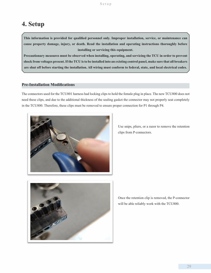
29
S e t u p
4. Setup
This information is provided for qualified personnel only. Improper installation, service, or maintenance can
cause property damage, injury, or death. Read the installation and operating instructions thoroughly before
installing or servicing this equipment.
Precautionary measures must be observed when installing, operating, and servicing the TCU in order to prevent
shock from voltages present. If the TCU is to be installed into an existing control panel, make sure that all breakers
are shut off before starting the installation. All wiring must conform to federal, state, and local electrical codes.
Pre-Installation Modifications
The connectors used for the TCU001 harness had locking clips to hold the female plug in place. The new TCU800 does not
need these clips, and due to the additional thickness of the sealing gasket the connector may not properly seat completely
in the TCU800. Therefore, these clips must be removed to ensure proper connection for P1 through P4.
Use snips, pliers, or a razor to remove the retention
clips from P-connectors.
Once the retention clip is removed, the P-connector
will be able reliably work with the TCU800.
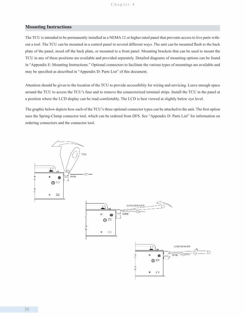
30
C h a p t e r 4
Mounting Instructions
The TCU is intended to be permanently installed in a NEMA 12 or higher rated panel that prevents access to live parts with-
out a tool. The TCU can be mounted in a control panel in several different ways. The unit can be mounted flush to the back
plate of the panel, stood off the back plate, or mounted to a front panel. Mounting brackets that can be used to mount the
TCU in any of these positions are available and provided separately. Detailed diagrams of mounting options can be found
in “Appendix E: Mounting Instructions.” Optional connectors to facilitate the various types of mountings are available and
may be specified as described in “Appendix D: Parts List” of this document.
Attention should be given to the location of the TCU to provide accessibility for wiring and servicing. Leave enough space
around the TCU to access the TCU’s fuse and to remove the connectorized terminal strips. Install the TCU in the panel at
a position where the LCD display can be read comfortably. The LCD is best viewed at slightly below eye level.
The graphic below depicts how each of the TCU’s three optional connector types can be attached to the unit. The first option
uses the Spring-Clamp connector tool, which can be ordered from DFS. See “Appendix D: Parts List” for information on
ordering connectors and the connector tool.
31
S e t u p
Electrical Installation and Wiring Diagrams
The electrical interface to the TCU is broken down into several groups of signals. The wiring of each group is detailed in
the following paragraphs.
These instructions are written specifically for a TCU using the built-in pump control process. Although many of them apply
to custom applications as well, the Applications Engineer will be primarily responsible for defining and implementing the
TCU’s inputs and outputs. In this chapter, functions specific to the pump control process are noted as such.
• Maximum wire size to TCU connectors is 12 AWG.
• Use copper conductors only with a minimum rating of 75C.
• The recommended circuit breaker is 10 Amp maximum.
• When using connectors with screw-type terminals, tighten screw terminals to a maximum 7 in-lb (.79 Nm).
• All AC source power wired to the TCU should be from the same leg of the three-phase system.
• The Power LED does not indicate that AC power has been removed. Even if the TCU’s Power LED is not
lit, you should assume that the TCU is still powered. To remove power, you must turn off the external circuit
breaker.
AC PowerThe TCU operates from 120 VAC. Verify the input voltage on the TCU’s connector label before wiring. Three terminals
are provided for wiring power:
• P1-5, AC_PWR (AC power)
• P1-6, AC_NEUT (AC neutral)
• P1-7, TGND (earth ground)
Terminal P1-7 is designated Earth or Safety ground. The TCU’s case is also connected to the TGND terminal. Wire in
accordance with Federal, State, and Local Electrical Codes.
The transformer must provide AC neutral. When wiring to a typical three-phase, 4-wire, 240 V transformer that provides
AC neutral, refer to “Wiring AC Power (typical 240V, 4-wire transformer).” Refer to “Wiring AC Power (typical 480 V,
3-wire transformer)” when connecting to a typical three-phase, 3-wire 480 V transformer with no neutral provided.
Note that these diagrams are for typical installations. If your installation deviates from what is shown here, then refer to the
National Electrical Code® (NEC®) Handbook.
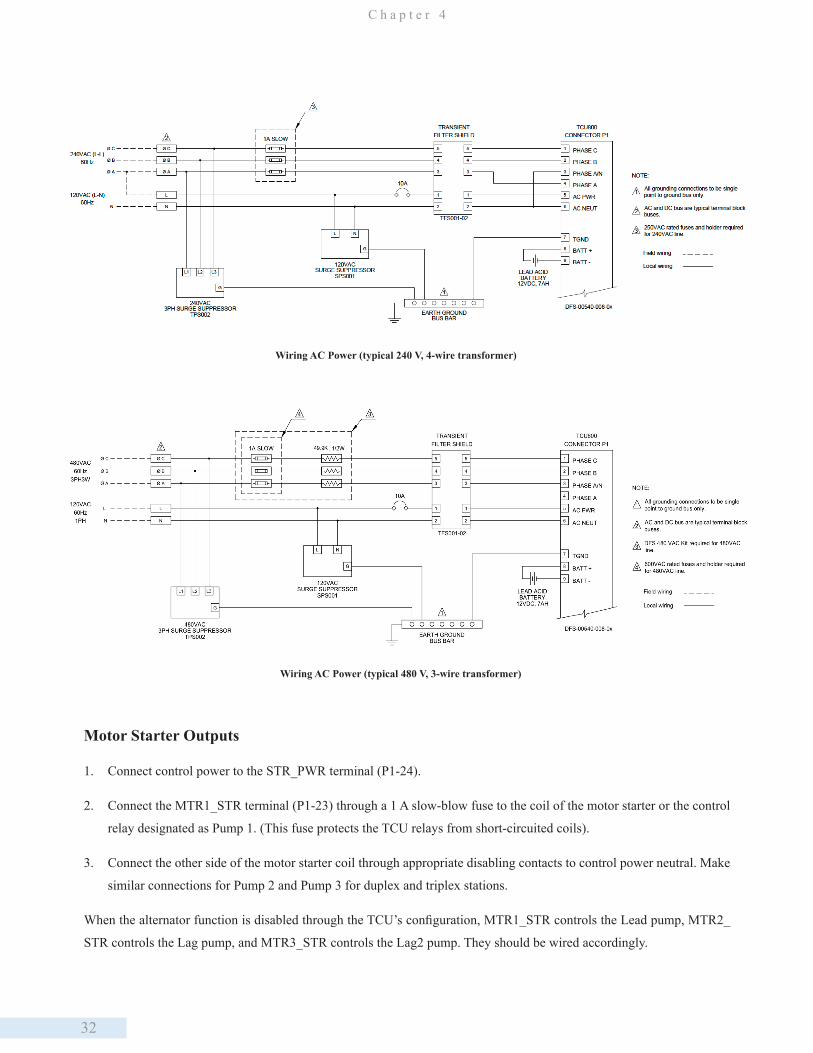
32
C h a p t e r 4
Wiring AC Power (typical 480 V, 3-wire transformer)
Motor Starter Outputs
1. Connect control power to the STR_PWR terminal (P1-24).
2. Connect the MTR1_STR terminal (P1-23) through a 1 A slow-blow fuse to the coil of the motor starter or the control
relay designated as Pump 1. (This fuse protects the TCU relays from short-circuited coils).
3. Connect the other side of the motor starter coil through appropriate disabling contacts to control power neutral. Make
similar connections for Pump 2 and Pump 3 for duplex and triplex stations.
When the alternator function is disabled through the TCU’s configuration, MTR1_STR controls the Lead pump, MTR2_
STR controls the Lag pump, and MTR3_STR controls the Lag2 pump. They should be wired accordingly.
Wiring AC Power (typical 240 V, 4-wire transformer)
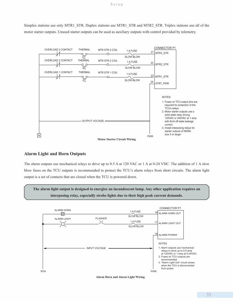
33
S e t u p
MTR STR 3 COIL 1 A FUSE
SLOW BLOW
NOTES
1. Fuses on TCU output pins are required for protection of the TCU's relays.2. Motor starter outputs use a solid-state relay driving 120VAC or 240VAC at 1 amp with 8mA off-state leakage current.3. Install interposing relays for starter outputs of NEMA size 3 or larger.
PWR
21
22
23
24
CONNECTOR P1THERMALOVERLOAD 3 CONTACT
OVERLOAD 2 CONTACT
OVERLOAD 1 CONTACT THERMAL
THERMAL
MTR STR 1 COIL
MTR STR 2 COIL 1 A FUSE
SLOW BLOW
1 A FUSE
SLOW BLOW
N
MTR3_STR
MTR2_STR
MTR1_STR
OUTPUT VOLTAGE
STRT_PWR
Motor Starter Circuit Wiring
Simplex stations use only MTR1_STR. Duplex stations use MTR1_STR and MTR2_STR. Triplex stations use all of the
motor starter outputs. Unused starter outputs can be used as auxiliary outputs with control provided by telemetry.
Alarm Light and Horn Outputs
The alarm outputs use mechanical relays to drive up to 0.5 A at 120 VAC or 1 A at 0-24 VDC. The addition of 1 A slow
blow fuses on the TCU outputs is recommended to protect the TCU’s alarm relays from short circuits. The alarm light
output is a set of contacts that are closed when the TCU is powered down.
The alarm light output is designed to energize an incandescent lamp. Any other application requires an
interposing relay, especially strobe lights due to their high peak current demands.
Alarm Horn and Alarm Light Wiring
1 A FUSE
NOTES
1. Alarm outputs use mechanical relays to drive up to 0.5 amp at 120VAC or 1 amp at 0-24VDC.2. Fuses on TCU outputs are recommended.3. "Alarm Light Out" circuit closes when the TCU is disconnected from power.
PWR
16
17
18
CONNECTOR P1
1 A FUSE
SLOW BLOW
ALARM HORN OUT
ALARM LIGHT OUT
ALARM POWER
INPUT VOLTAGE
ALARM HORN
FLASHERALARM LIGHT
RTN
SLOW BLOW

34
C h a p t e r 4
Using Snubbers When Connecting Alarm Outputs
For AC applications, we recommend an RC snubber (DFS # 007-0084) using a 0.1uF capacitor in series with a 47 Ω ½ W
resistor, such as that manufactured by RED LION (Model # SNUB0000).
OUT
PWR
R
CRTN
1 A FUSE
SLOW BLOW
INDUCTIVE FIELDDEVICE
SNUBBER
AC SUPPLY
RELAY OUTPUT
For DC applications, we recommend a power diode (DFS # 006-0019) with a minimum 3 A 100 peak inverse voltage (PIV)
fast acting rating, such as the industry standard 1N4004 (DIGIKEY # 1N4004CT-ND).
Snubber in AC Alarm Output Application
DC polarity is important. The diode must be connected in reverse bias across the coil terminals or as close
as is practical. That is, the cathode (the side with the white band on the diode body) must be connected to
the (+) supply power and the anode connected to the (-) supply power. Most DC relays do not have a polarity
requirement on their coils, so you must trace out the polarity or use a Voltmeter. Remember that the inductive
transient is a reverse voltage, which causes the diode to conduct and short out the voltage.
OUT
PWR+ -
RTN
+
-
1 A FUSE
SLOW BLOW
INDUCTIVE FIELDDEVICE
POWERDIODE
SUPPLY
RELAY OUTPUT
Snubber in DC Alarm Output Application
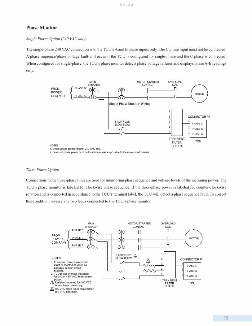
35
S e t u p
Three Phase Option
Connections to the three-phase lines are used for monitoring phase sequence and voltage levels of the incoming power. The
TCU’s phase monitor is labeled for clockwise phase sequence. If the three-phase power is labeled for counter-clockwise
rotation and is connected in accordance to the TCU’s terminal label, the TCU will detect a phase sequence fault. To correct
this condition, reverse any two leads connected to the TCU’s phase monitor.
PHASE B
PHASE A
MOTOR STARTERCONTACT
MAINBREAKER
MOTOR
OVERLOADCOIL
1 AMP FUSESLOW BLOW PHASE C
PHASE B
PHASE A5
4
3
2
1
TCU
CONNECTOR P1
1
2
3
NOTES1. Single-phase option valid for 240 VAC only.2. Fuses on phase power must be located as close as possible to the main circuit breaker.
FROMPOWERCOMPANY
TRANSIENTFILTERSHIELD
Single-Phase Monitor Wiring
Three-Phase Monitor Wiring
PHASE C
PHASE B
PHASE A
MAINBREAKER
MOTOR
1 AMP FUSESLOW BLOW
PHASE C
PHASE B
PHASE A5
4
3
2
1
TRANSIENTFILTERSHIELD
TCU
CONNECTOR P1NOTES1. Fuses on three phase power must be located as close as possible to main circuit breaker.2. TCU phase monitor designed for 240 or 480 VAC three-phase power.3 Resistors required for 480 VAC
three-phase power only.4 600 VAC rated fuses required for
480 VAC operation.
4
1
2
3
FROMPOWERCOMPANY
MOTOR STARTERCONTACT
OVERLOADCOIL
3
Phase Monitor
Single Phase Option (240 VAC only)
The single-phase 240 VAC connection is to the TCU’s A and B phase inputs only. The C phase input must not be connected.
A phase sequence/phase voltage fault will occur if the TCU is configured for single-phase and the C phase is connected.
When configured for single-phase, the TCU’s phase monitor detects phase voltage failures and displays phase A-B readings
only.

36
C h a p t e r 4
Digital Monitor Point Inputs
The TCU has 18 digital monitor point inputs. These monitor points require an input and a return. All digital inputs support
10-30VAC/DC or 30-300VAC with external resistors. Note that the auxiliary input (P2-12) supports pulse input capture
instead of VAC. These inputs are organized into groups, or “banks,” that are electrically isolated from one another and
equipped with chip scale transformers that protect up to 3.7kVrms.
Bank 1 Bank 2 Bank 3MTR 1 RUN P2-1 LOW LVL P2-6 MTR 1 SEAL P3-20MTR 2 RUN P2-2 OFF LVL P2-7 MTR 2 SEAL P3-19MTR 3 RUN P2-3 LEAD LVL P2-8 MTR 3 SEAL P3-18
EXT PM P2-4 LAG1 LVL P2-9 MTR 1 THERM P3-17INPUT COM 1 P2-5 LAG2 LVL P2-10 MTR 2 THERM P3-16
HIGH LVL P2-11 MTR 3 THERM P3-15AUX IN P2-12 INPUT COM 3 P3-14ALM SIL P2-13IN COM 2 P2-14
*MTR RUN (Motor Run) inputs are used to detect if a particular pump is running. *EXT PM (External Phase Monitor) is an input for an external phase monitor alarm. *LVL inputs are used as markers to determine the current level of the well. Using information from these inputs, pump control logic decides if pumps need to be turned on or off. *MTR SEAL (Motor Seal) inputs must be connected to a seal sensor. This detects the presence of water inside the pump housing which typically leaks past the shaft seal. The sensor will activate if a leak in the seal is detected. *MTR THERM (Motor Thermal Overload) inputs must be connected to a thermal sensor. The sensor will activate if the internal temperature of a pump gets too high. *ALM SIL (Alarm Silence) is an input that allows an activated alarm to be silenced from a source other than the soft-touch button on the overlay. *AUX INPUT can be used for general-purpose inputs (e.g. pulse meters or rain gauges).
Bias Voltage Source Options
Internally-Supplied Bias Voltage Source
A voltage of 10-30 VAC or VDC will bias the digital monitor inputs in the ON state. Any voltage less than 4 VAC or 4
VDC will force the digital monitor inputs to the OFF state. The internal bias source is the ISO+24V terminal (P2-16) and
the ISOGND terminal (P2-15).
ISO+24V
ISOGND
INPUT COMMON
INPUT
CONNECTOR P2
16
15
TCU
INPUT CONTACT OR SWITCH
BIAS SOURCERTN
INPUT VOLTAGE (24 VDC)
Biasing an Input with ISO+24V / ISOGUND Voltage
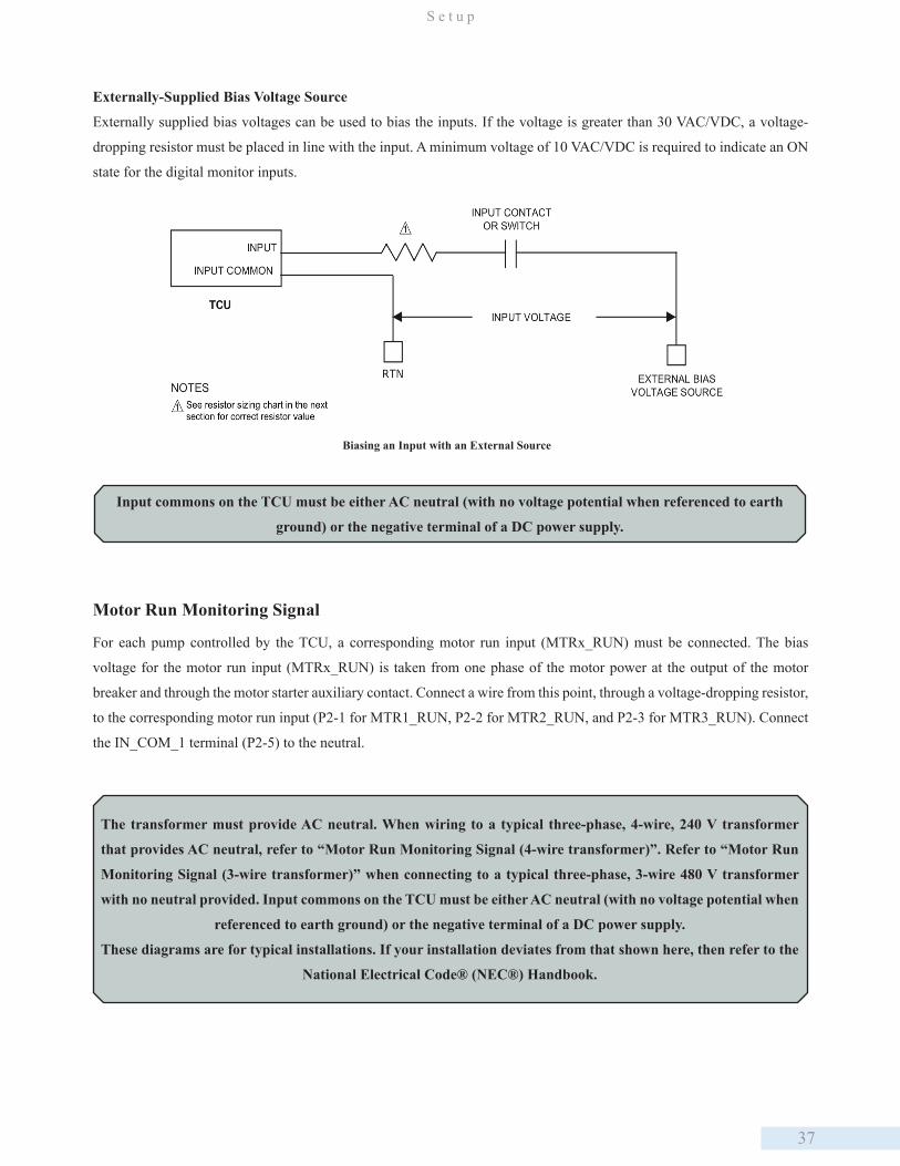
37
S e t u p
Externally-Supplied Bias Voltage Source
Externally supplied bias voltages can be used to bias the inputs. If the voltage is greater than 30 VAC/VDC, a voltage-
dropping resistor must be placed in line with the input. A minimum voltage of 10 VAC/VDC is required to indicate an ON
state for the digital monitor inputs.
Input commons on the TCU must be either AC neutral (with no voltage potential when referenced to earth
ground) or the negative terminal of a DC power supply.
Biasing an Input with an External Source
Motor Run Monitoring Signal
For each pump controlled by the TCU, a corresponding motor run input (MTRx_RUN) must be connected. The bias
voltage for the motor run input (MTRx_RUN) is taken from one phase of the motor power at the output of the motor
breaker and through the motor starter auxiliary contact. Connect a wire from this point, through a voltage-dropping resistor,
to the corresponding motor run input (P2-1 for MTR1_RUN, P2-2 for MTR2_RUN, and P2-3 for MTR3_RUN). Connect
the IN_COM_1 terminal (P2-5) to the neutral.
The transformer must provide AC neutral. When wiring to a typical three-phase, 4-wire, 240 V transformer
that provides AC neutral, refer to “Motor Run Monitoring Signal (4-wire transformer)”. Refer to “Motor Run
Monitoring Signal (3-wire transformer)” when connecting to a typical three-phase, 3-wire 480 V transformer
with no neutral provided. Input commons on the TCU must be either AC neutral (with no voltage potential when
referenced to earth ground) or the negative terminal of a DC power supply.
These diagrams are for typical installations. If your installation deviates from that shown here, then refer to the
National Electrical Code® (NEC®) Handbook.
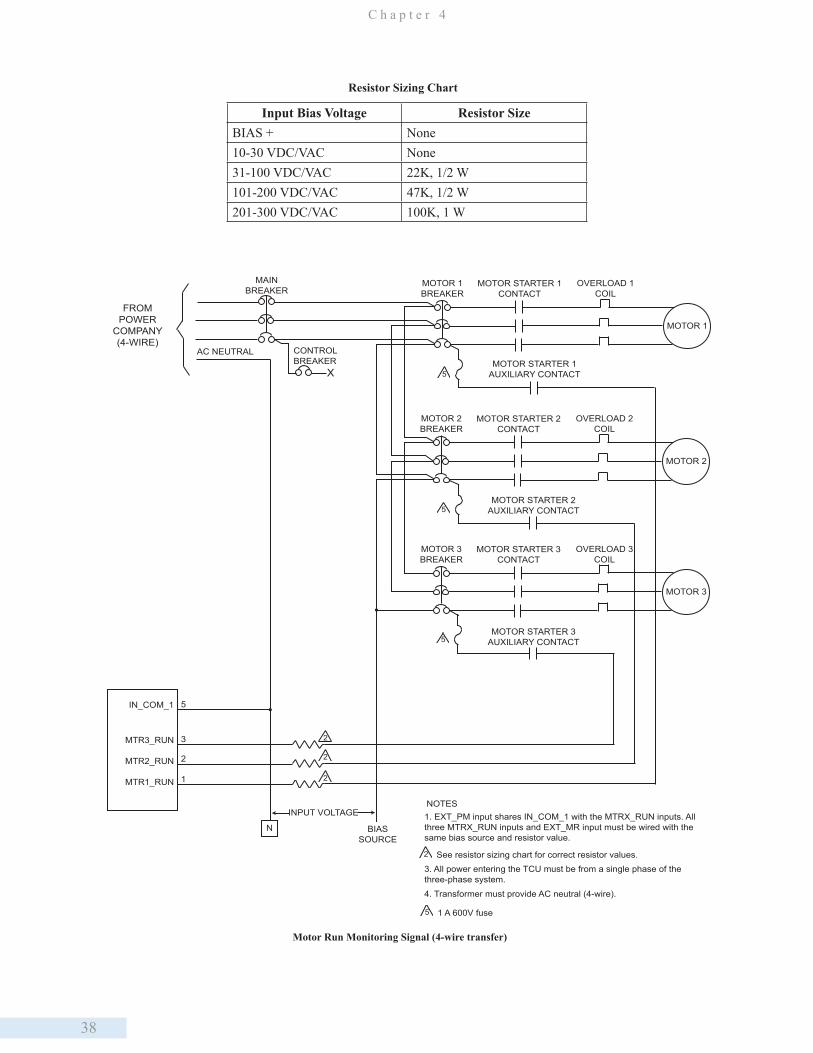
38
C h a p t e r 4
Input Bias Voltage Resistor SizeBIAS + None10-30 VDC/VAC None31-100 VDC/VAC 22K, 1/2 W101-200 VDC/VAC 47K, 1/2 W201-300 VDC/VAC 100K, 1 W
MOTOR 1
OVERLOAD 1COIL
MOTOR STARTER 1CONTACT
MOTOR 1BREAKER
MAINBREAKER
MOTOR STARTER 1AUXILIARY CONTACT
FROMPOWER
COMPANY(4-WIRE)
MOTOR 2
OVERLOAD 2COIL
MOTOR STARTER 2CONTACT
MOTOR 2BREAKER
MOTOR STARTER 2AUXILIARY CONTACT
MOTOR 3
OVERLOAD 3COIL
MOTOR STARTER 3CONTACT
MOTOR 3BREAKER
MOTOR STARTER 3AUXILIARY CONTACT
IN_COM_1
MTR3_RUN
MTR2_RUN
MTR1_RUN
5
3
2
1
N
INPUT VOLTAGE
BIASSOURCE
2
2
2
1. EXT_PM input shares IN_COM_1 with the MTRX_RUN inputs. Allthree MTRX_RUN inputs and EXT_MR input must be wired with thesame bias source and resistor value.
NOTES
2 See resistor sizing chart for correct resistor values.3. All power entering the TCU must be from a single phase of thethree-phase system.
X
CONTROLBREAKER
AC NEUTRAL
4. Transformer must provide AC neutral (4-wire).
5
5
5
5 1 A 600V fuse
Motor Run Monitoring Signal (4-wire transfer)
Resistor Sizing Chart
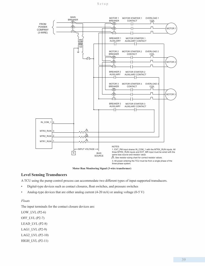
39
S e t u p
MOTOR 1
OVERLOAD 1COIL
MOTOR STARTER 1CONTACT
MOTOR 1BREAKER
MAINBREAKER
MOTOR STARTER 1AUXILIARY CONTACT
BREAKER 1AUXILIARY
FROMPOWER
COMPANY(3-WIRE)
480
120
MOTOR 2
OVERLOAD 2COIL
MOTOR STARTER 2CONTACT
MOTOR 2BREAKER
MOTOR STARTER 2AUXILIARY CONTACT
BREAKER 2AUXILIARY
MOTOR 3
OVERLOAD 3COIL
MOTOR STARTER 3CONTACT
MOTOR 3BREAKER
MOTOR STARTER 3AUXILIARY CONTACT
BREAKER 3AUXILIARY
IN_COM_1
MTR3_RUN
MTR2_RUN
MTR1_RUN
5
3
2
1
N
INPUT VOLTAGE
BIASSOURCE
2
2
2
1. EXT_PM input shares IN_COM_1 with the MTRX_RUN inputs. Allthree MTRX_RUN inputs and EXT_MR input must be wired with thesame bias source and resistor value.
NOTES
2 See resistor sizing chart for correct resistor values.3. All power entering the TCU must be from a single phase of the three-phase system.
Motor Run Monitoring Signal (3-wire transformer)
Level Sensing TransducersA TCU using the pump control process can accommodate two different types of input-supported transducers.
• Digital-type devices such as contact closures, float switches, and pressure switches
• Analog-type devices that are either analog current (4-20 mA) or analog voltage (0-5 V)
Floats
The input terminals for the contact closure devices are:
LOW_LVL (P2-6)
OFF_LVL (P2-7)
LEAD_LVL (P2-8)
LAG1_LVL (P2-9)
LAG2_LVL (P2-10)
HIGH_LVL (P2-11)
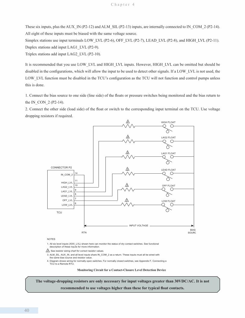
40
C h a p t e r 4
These six inputs, plus the AUX_IN (P2-12) and ALM_SIL (P2-13) inputs, are internally connected to IN_COM_2 (P2-14).
All eight of these inputs must be biased with the same voltage source.
Simplex stations use input terminals LOW_LVL (P2-6), OFF_LVL (P2-7), LEAD_LVL (P2-8), and HIGH_LVL (P2-11).
Duplex stations add input LAG1_LVL (P2-9).
Triplex stations add input LAG2_LVL (P2-10).
It is recommended that you use LOW_LVL and HIGH_LVL inputs. However, HIGH_LVL can be omitted but should be
disabled in the configurations, which will allow the input to be used to detect other signals. If a LOW_LVL is not used, the
LOW_LVL function must be disabled in the TCU’s configuration as the TCU will not function and control pumps unless
this is done.
1. Connect the bias source to one side (line side) of the floats or pressure switches being monitored and the bias return to
the IN_CON_2 (P2-14).
2. Connect the other side (load side) of the float or switch to the corresponding input terminal on the TCU. Use voltage
dropping resistors if required.2
2
2
NOTES
1. All six level inputs (XXX_LVL) shown here can monitor the status of dry contact switches. See functional description of these inputs for more information.
2 See resistor sizing chart for correct resistor values.
2
2
2
HIGH FLOAT
LAG2 FLOAT
LAG1 FLOAT
LEAD FLOAT
OFF FLOAT
LOW FLOATLOW_LVL
LEAD_LVL
LAG1_LVL
LAG2_LVL
HIGH_LVL
IN_COM_2
OFF_LVL
INPUT VOLTAGE
14
11
10
9
8
7
6
CONNECTOR P2
RTN
TCU
3. ALM_SIL, AUX_IN, and all level inputs share IN_COM_2 as a return. These inputs must all be wired with the same bias source and resistor value.4. Diagram shows wiring for normally open switches. For normally closed switches, see Appendix F, Connecting a TCU to a Remote RTU.
BIASSOURCE
Monitoring Circuit for a Contact-Closure Level Detection Device
The voltage-dropping resistors are only necessary for input voltages greater than 30VDC/AC. It is not
recommended to use voltages higher than these for typical float contacts.
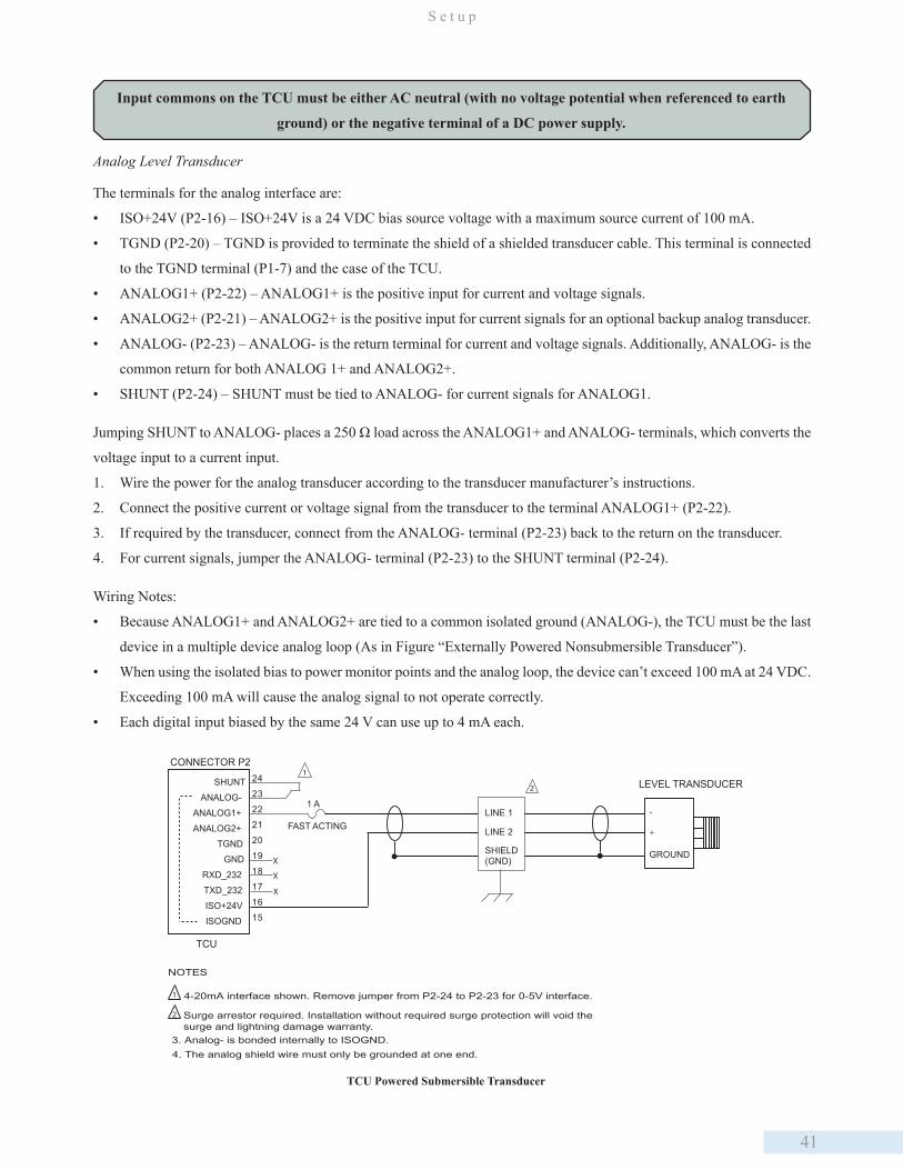
41
S e t u p
SHUNT
ANALOG-
ANALOG1+
ANALOG2+
TGND
GND
RXD_232
TXD_232
ISO+24V
ISOGND
24
23
22
21
20
19
18
17
16
15
X
X
X
1 A
FAST ACTING
LEVEL TRANSDUCER
-
+
GROUND
TCU
LINE 1
LINE 2
SHIELD(GND)
NOTES
1
2
1 4-20mA interface shown. Remove jumper from P2-24 to P2-23 for 0-5V interface.
2
3. Analog- is bonded internally to ISOGND.4. The analog shield wire must only be grounded at one end.
CONNECTOR P2
Surge arrestor required. Installation without required surge protection will void thesurge and lightning damage warranty.
TCU Powered Submersible Transducer
Input commons on the TCU must be either AC neutral (with no voltage potential when referenced to earth
ground) or the negative terminal of a DC power supply.
Analog Level Transducer
The terminals for the analog interface are:
• ISO+24V (P2-16) – ISO+24V is a 24 VDC bias source voltage with a maximum source current of 100 mA.
• TGND (P2-20) – TGND is provided to terminate the shield of a shielded transducer cable. This terminal is connected
to the TGND terminal (P1-7) and the case of the TCU.
• ANALOG1+ (P2-22) – ANALOG1+ is the positive input for current and voltage signals.
• ANALOG2+ (P2-21) – ANALOG2+ is the positive input for current signals for an optional backup analog transducer.
• ANALOG- (P2-23) – ANALOG- is the return terminal for current and voltage signals. Additionally, ANALOG- is the
common return for both ANALOG 1+ and ANALOG2+.
• SHUNT (P2-24) – SHUNT must be tied to ANALOG- for current signals for ANALOG1.
Jumping SHUNT to ANALOG- places a 250 Ω load across the ANALOG1+ and ANALOG- terminals, which converts the
voltage input to a current input.
1. Wire the power for the analog transducer according to the transducer manufacturer’s instructions.
2. Connect the positive current or voltage signal from the transducer to the terminal ANALOG1+ (P2-22).
3. If required by the transducer, connect from the ANALOG- terminal (P2-23) back to the return on the transducer.
4. For current signals, jumper the ANALOG- terminal (P2-23) to the SHUNT terminal (P2-24).
Wiring Notes:
• Because ANALOG1+ and ANALOG2+ are tied to a common isolated ground (ANALOG-), the TCU must be the last
device in a multiple device analog loop (As in Figure “Externally Powered Nonsubmersible Transducer”).
• When using the isolated bias to power monitor points and the analog loop, the device can’t exceed 100 mA at 24 VDC.
Exceeding 100 mA will cause the analog signal to not operate correctly.
• Each digital input biased by the same 24 V can use up to 4 mA each.

42
C h a p t e r 4
SHUNT
ANALOG-
ANALOG1+
ANALOG2+
TGND
GND
RXD_232
TXD_232
ISO+24V
ISOGND
24
23
22
21
20
19
18
17
16
15
X
X
X
1 A
FAST ACTING
TRANSDUCERPANEL
-
+
TCU
LINE 1
LINE 2
SHIELD(GND)
NOTES
1
2
1 4-20mA interface shown. Remove jumper from P2-24 to P2-23 for 0-5V interface.
2
METER
TRANSDUCER-
+
3
4. Do not ground cable shield in transducer panel.
3 Meter is optional.
5. Analog- is bonded internally to ISOGND.
6. The analog shield wire must only be grounded at one end.
CONNECTOR P2
Surge arrestor required. Installation without required surge protection will void thesurge and lightning damage warranty.
S HUNT
ANALOG -
ANALOG 1+
ANALOG 2+
TGND
GND
R XD_232
TXD_232
IS O+24V
IS OG ND
24
23
22
21
20
19
18
17
16
15
X
X
X
1 A
FAST ACTING
TRANSDUCER PANEL
LINE 1
LINE 2
SHIELD(GND)
NOTES
1
2 METER-+
TRANSDUCER-+
-+
X
3
1 4-20mA interface shown. Remove jumper from P2-24 to P2-23 for 0-5V interface.
2
4. Do not ground cable shield in transducer panel.
3 Meter is optional.
5. The analog shield wire must only be grounded at one end.
TCU
POWERSUPPLY
CONNECTOR P2
Surge arrestor required. Installation without required surge protection will void thesurge and lightning damage warranty.
Externally Powered Non-submersible Transducer
TCU Powered Non-submersible Transducer
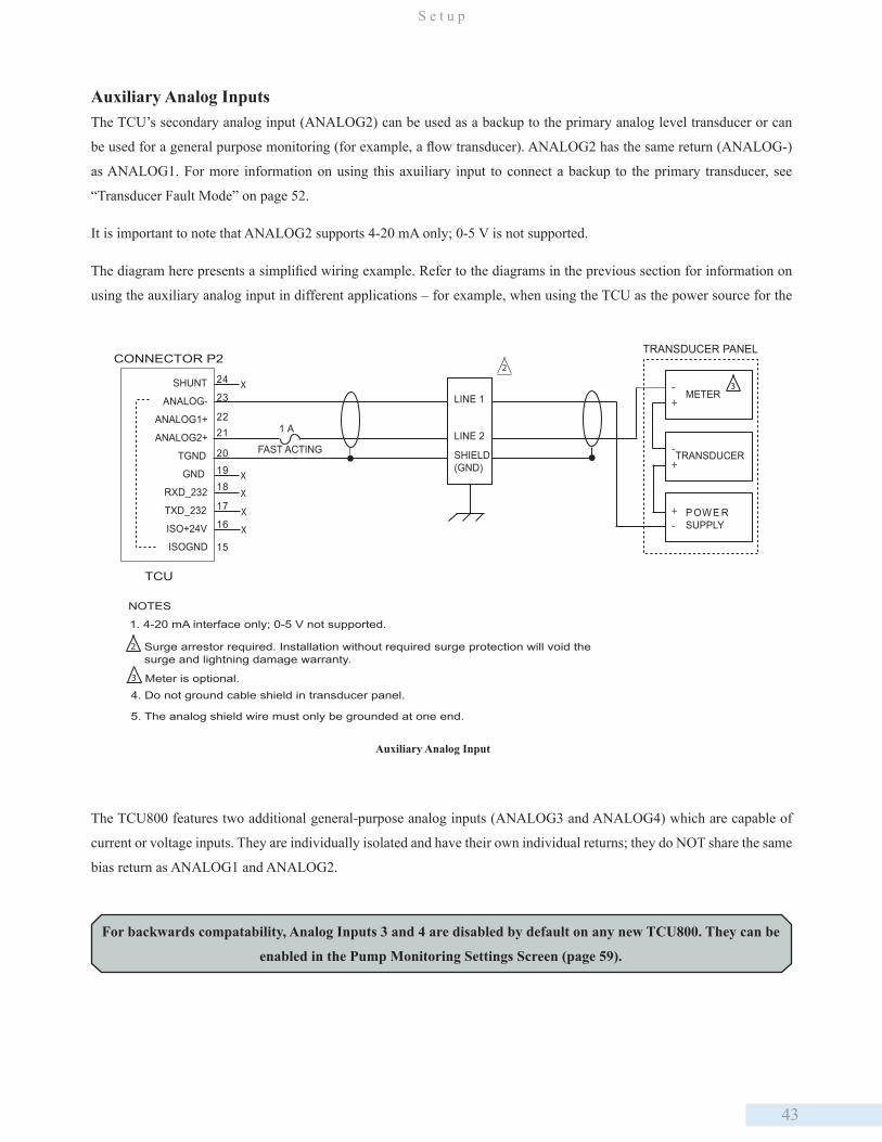
43
S e t u p
Auxiliary Analog InputsThe TCU’s secondary analog input (ANALOG2) can be used as a backup to the primary analog level transducer or can
be used for a general purpose monitoring (for example, a flow transducer). ANALOG2 has the same return (ANALOG-)
as ANALOG1. For more information on using this axuiliary input to connect a backup to the primary transducer, see
“Transducer Fault Mode” on page 52.
It is important to note that ANALOG2 supports 4-20 mA only; 0-5 V is not supported.
The diagram here presents a simplified wiring example. Refer to the diagrams in the previous section for information on
using the auxiliary analog input in different applications – for example, when using the TCU as the power source for the
SHUNT
ANALOG-
ANALOG1+
ANALOG2+
TGND
GND
RXD_232
TXD_232
ISO+24V
ISOGND
24
23
2221
201918
17
16
15
X
X
X
1 A
FAST ACTING
NOTES
2
1. 4-20 mA interface only; 0-5 V not supported.
2 Surge arrestor required. Installation without required surge protection will void thesurge and lightning damage warranty.
X
LINE 1
LINE 2
SHIELD(GND)
X
TRANSDUCER PANEL
METER-+
TRANSDUCER-+
POWE RSUPPLY-
+
3
4. Do not ground cable shield in transducer panel.
3 Meter is optional.
5. The analog shield wire must only be grounded at one end.
TCU
CONNECTOR P2
Auxiliary Analog Input
The TCU800 features two additional general-purpose analog inputs (ANALOG3 and ANALOG4) which are capable of
current or voltage inputs. They are individually isolated and have their own individual returns; they do NOT share the same
bias return as ANALOG1 and ANALOG2.
For backwards compatability, Analog Inputs 3 and 4 are disabled by default on any new TCU800. They can be
enabled in the Pump Monitoring Settings Screen (page 59).
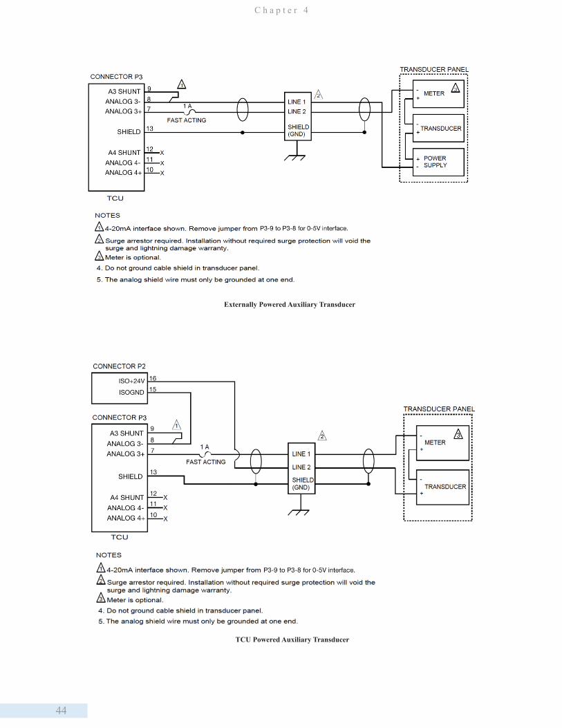
44
C h a p t e r 4
Externally Powered Auxiliary Transducer
TCU Powered Auxiliary Transducer
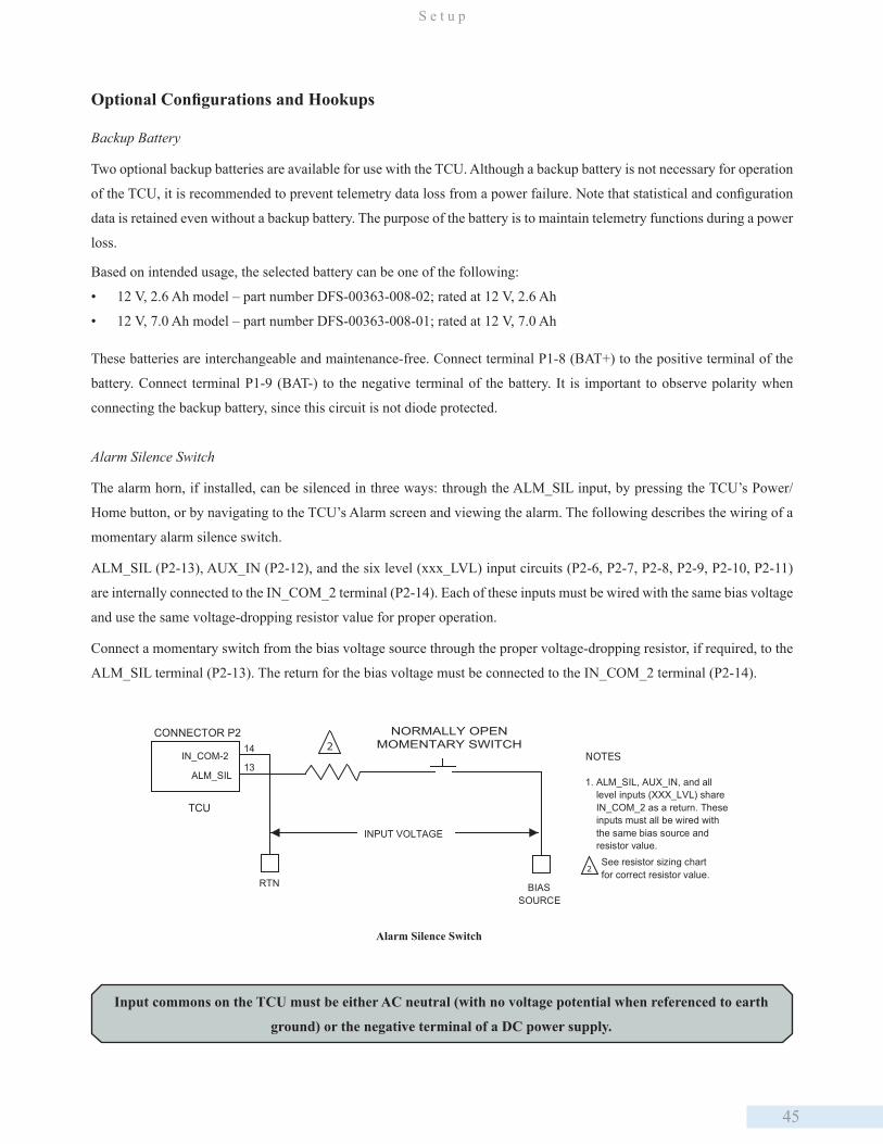
45
S e t u p
Input commons on the TCU must be either AC neutral (with no voltage potential when referenced to earth
ground) or the negative terminal of a DC power supply.
IN_COM-2
ALM_SIL
RTN
2
BIASSOURCE
INPUT VOLTAGE
TCU
NOTES
1. ALM_SIL, AUX_IN, and all level inputs (XXX_LVL) share IN_COM_2 as a return. These inputs must all be wired with the same bias source and resistor value.
2See resistor sizing chartfor correct resistor value.
CONNECTOR P214
13
NORMALLY OPENMOMENTARY SWITCH
Alarm Silence Switch
Based on intended usage, the selected battery can be one of the following:
• 12 V, 2.6 Ah model – part number DFS-00363-008-02; rated at 12 V, 2.6 Ah
• 12 V, 7.0 Ah model – part number DFS-00363-008-01; rated at 12 V, 7.0 Ah
These batteries are interchangeable and maintenance-free. Connect terminal P1-8 (BAT+) to the positive terminal of the
battery. Connect terminal P1-9 (BAT-) to the negative terminal of the battery. It is important to observe polarity when
connecting the backup battery, since this circuit is not diode protected.
Alarm Silence Switch
The alarm horn, if installed, can be silenced in three ways: through the ALM_SIL input, by pressing the TCU’s Power/
Home button, or by navigating to the TCU’s Alarm screen and viewing the alarm. The following describes the wiring of a
momentary alarm silence switch.
ALM_SIL (P2-13), AUX_IN (P2-12), and the six level (xxx_LVL) input circuits (P2-6, P2-7, P2-8, P2-9, P2-10, P2-11)
are internally connected to the IN_COM_2 terminal (P2-14). Each of these inputs must be wired with the same bias voltage
and use the same voltage-dropping resistor value for proper operation.
Connect a momentary switch from the bias voltage source through the proper voltage-dropping resistor, if required, to the
ALM_SIL terminal (P2-13). The return for the bias voltage must be connected to the IN_COM_2 terminal (P2-14).
Optional Configurations and Hookups
Backup Battery
Two optional backup batteries are available for use with the TCU. Although a backup battery is not necessary for operation
of the TCU, it is recommended to prevent telemetry data loss from a power failure. Note that statistical and configuration
data is retained even without a backup battery. The purpose of the battery is to maintain telemetry functions during a power
loss.
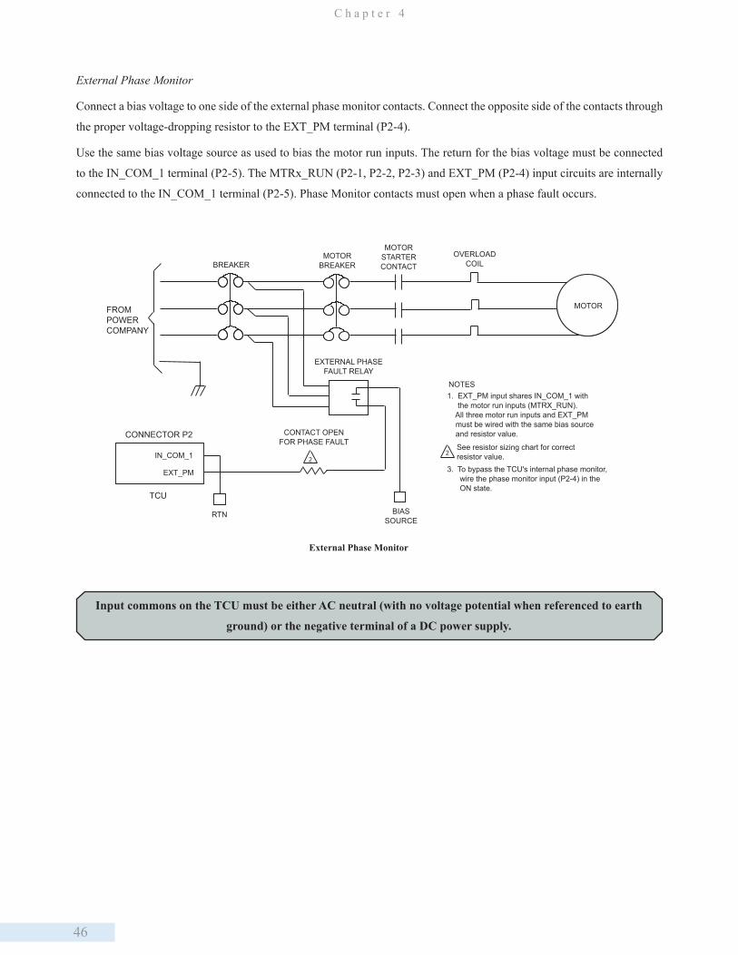
46
C h a p t e r 4
External Phase Monitor
Connect a bias voltage to one side of the external phase monitor contacts. Connect the opposite side of the contacts through
the proper voltage-dropping resistor to the EXT_PM terminal (P2-4).
Use the same bias voltage source as used to bias the motor run inputs. The return for the bias voltage must be connected
to the IN_COM_1 terminal (P2-5). The MTRx_RUN (P2-1, P2-2, P2-3) and EXT_PM (P2-4) input circuits are internally
connected to the IN_COM_1 terminal (P2-5). Phase Monitor contacts must open when a phase fault occurs.
TCU
2
2
FROMPOWERCOMPANY
BREAKERMOTOR
BREAKER
MOTORSTARTERCONTACT
OVERLOADCOIL
MOTOR
EXTERNAL PHASEFAULT RELAY
CONTACT OPENFOR PHASE FAULT
CONNECTOR P2
IN_COM_1
EXT_PM
RTN BIASSOURCE
NOTES1. EXT_PM input shares IN_COM_1 with the motor run inputs (MTRX_RUN). All three motor run inputs and EXT_PM must be wired with the same bias source and resistor value.
See resistor sizing chart for correctresistor value.
3. To bypass the TCU's internal phase monitor, wire the phase monitor input (P2-4) in the ON state.
External Phase Monitor
Input commons on the TCU must be either AC neutral (with no voltage potential when referenced to earth
ground) or the negative terminal of a DC power supply.

47
S e t u p
IN_COM_1
EXT_PM
RTN
2
BIASSOURCE
TCU
NOTES
2See resistor sizing chartfor correct resistor value.
CONNECTOR P25
4
1
1Phase monitor contactclosed on good threephase.
Phase Monitor Bypass
Auxiliary Input and Output Connections
The TCU provides an auxiliary digital input and output that can be configured together to function as an auxiliary relay.
The AUX_IN terminal (P2-12) functions as one side of a relay coil and the IN_COM_2 terminal (P2-14) as the other. The
AUX_PWR terminal (P1-18) and AUX_OUT terminal (P1-19) function as contacts for the relay.
Phase Monitor Bypass
The TCU’s internal phase monitor can be bypassed (i.e., disabled) if it is not required. To bypass the TCU’s phase monitor,
connect a bias voltage (through a voltage-dropping resistor if required) directly into the EXT_PM terminal (P2-4). Use
the same bias voltage source that was used to bias the motor run (MTRx_RUN) inputs (P2-1, P2-2, P2-3). The return for
the bias voltage must be connected to the IN_COM_1 terminal (P2-5). The MTRx_RUN and EXT_PM input circuits are
internally connected to the IN_COM_1 terminal (P2-5). Note that the TCU’s Phase Monitor is designed for 200-240 VAC
or 480 VAC (using external resistors) 3-phase only.
If you are using an external phase monitor and would like to have the voltage values available to HT3 for monitoring and
trending purposes, you can wire the TCU’s three phase inputs. For this option to work correctly you must also configure the
TCU’s phase monitor range and alarm trip points. This is necessary, because if the external phase monitor trips, the TCU
will apply these user-configured, internal phase monitor settings when deciding whether or not to run the pumps. Consider
the acceptable run conditions for your system when selecting phase monitor settings.
Input commons on the TCU must be either AC neutral (with no voltage potential when referenced to earth
ground) or the negative terminal of a DC power supply.

48
C h a p t e r 4
Input commons on the TCU must be either AC neutral (with no voltage potential when referenced to earth
ground) or the negative terminal of a DC power supply.
Auxiliary Digital Input
AUX_IN is an optically isolated digital monitor point and is wired the same as the other monitor points. Connect a bias
voltage to one side of a contact closure device. Connect the other side through a voltage-dropping resistor, if required, to
the AUX_IN terminal (P2-12).
IN_COM_2
AUX_IN
RTN
2
BIASSOURCE
INPUT VOLTAGE
TCU
NOTES
1. ALM_SIL, AUX_IN, and all level inputs (XXX_LVL) share IN_COM_2 as a return. These inputs must all be wired with the same bias source and resistor value.
2See resistor sizing chartfor correct resistor value.
CONNECTOR P214
12
NORMALLY OPENMOMENTARY SWITCH
Auxiliary Digital Input
Auxiliary Digital Output
AUX_OUT is a solid-state relay. Power is connected to the AUX_PWR terminal (P1-20). A load is connected between the
AUX_OUT terminal (P1-19) and the power source return.
AUX_OUT
AUX_PWR
RTN PWR
INPUT VOLTAGE
TCU
CONNECTOR P1LOAD 1 A FUSE
SLOW BLOW
19
20
NOTES
1. Fuses on output pins must be located as close to the TCU as possible.2. The auxiliary output uses a solid-state relay driving 120 VAC or 240 VAC at 1 A with 8 mA off-state leakage current.
Auxiliary Digital Output
Installed in RTU
When a TCU is included in an RTU via a BEM, it is important to remember that the TCU defines its internal modules
without exception. Any additional modules added to the RTU must be addressed beginning with the module letter after the
last dummy module defined in the TCU.
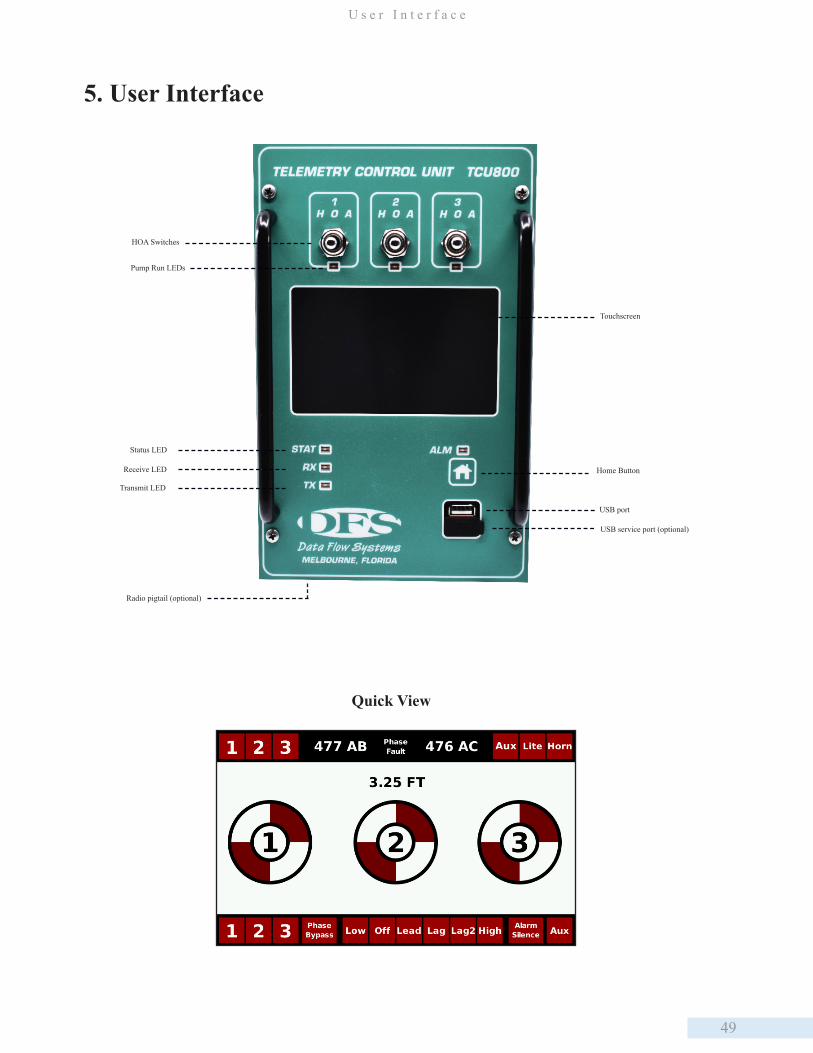
49
U s e r I n t e r f a c e
5. User Interface
Touchscreen
Home ButtonReceive LED
HOA Switches
USB port
Pump Run LEDs
Transmit LED
Status LED
USB service port (optional)
Radio pigtail (optional)
Quick View

50
C h a p t e r 5
Graphical View
Pump Statistics
Analog View
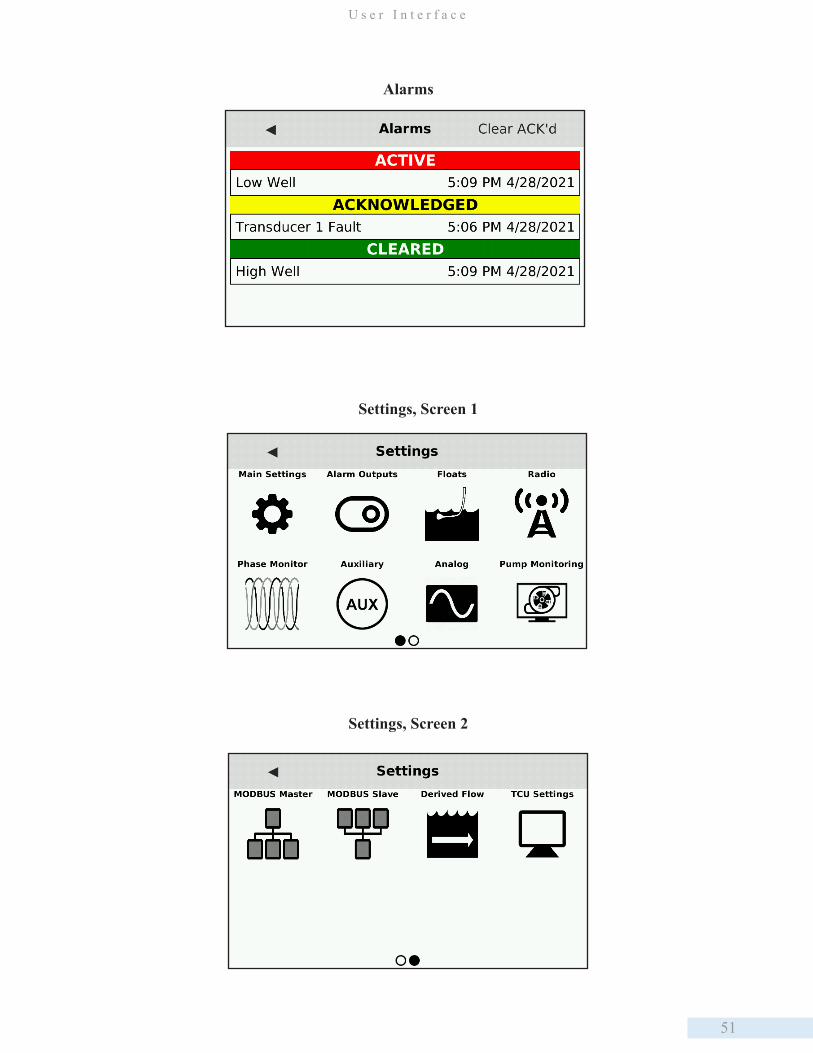
51
U s e r I n t e r f a c e
Alarms
Settings, Screen 1
Settings, Screen 2
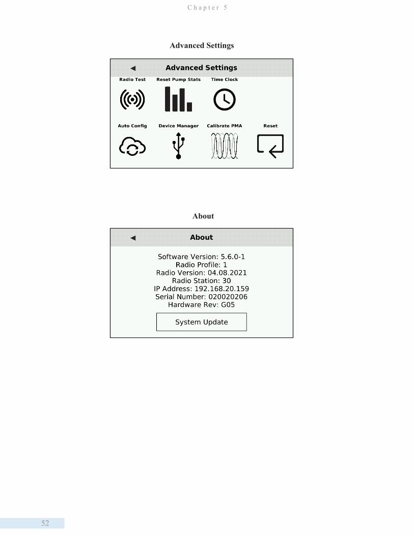
52
C h a p t e r 5
Advanced Settings
About
53
O p e r a t i n g P r o c e d u r e s
6. Operating Procedures
Configuring the Pump Control Process
Setting up the TCU as a component of the telemetry system enables you to remotely monitor conditions at the site and
control equipment from a central location via the HyperTAC SCADA software. For example, you can determine if a pump
is currently running and manually turn it on if necessary. In order for the TCU to interface with the central site and the
HyperTAC server, it must have access to radio or network communications and be properly configured in HyperTAC’s
Configuration Editor.
There are several options for connecting the TCU to the telemetry system. A TCU can be installed with a DFS RTU station,
or it can interface with industry standard radios using the TCU’s RS-232 Modbus radio interface. Alternately, the TCU
can operate as a stand-alone unit and communicate with the central computer or server via its integrated radio or network
interface.
Using the TCU in conjunction with a radio-based telemetry system requires that you obtain an FCC-licensed radio frequency
if you do not already have a licensed frequency that can be used. Even when adding a site to an existing frequency, the FCC
requires that a complete application be submitted. DFS can assist you in obtaining a new licensed frequency or adding a
site to an existing frequency.
Configuration SetupConfiguring the TCU800 is done from the Settings screen. First, ensure the H-O-A switches are all in the HAND or OFF
position. Then navigate to the Settings screen by tapping the screen, opening the left Navigation Menu by tapping ,
scroll down using an upward swipe, and tap to select Settings.
After making changes, select the to exit the Settings screen. A confirmation window will appear summarizing the
changes made and offer three options to continue: Discard (exit without saving), Save (save and implement changes), or
Edit (return to Settings Screen to further make changes before applying).
If the Save option is selected, a window will appear confirming the TCU800 and the Configuration USB have been updated
successfully.
The information in this section refers to the TCU’s built-in pump control process. It does not apply to a TCU
with a custom program installed.
Moving the H-O-A switches to Auto at any point while in the Settings or Advanced Settings screen will terminate
the session and return to the last viewed screen without saving any changes.
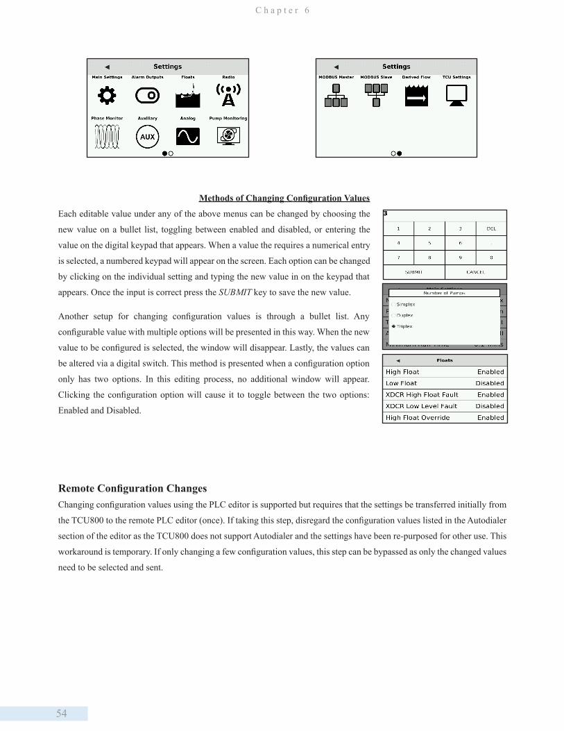
54
C h a p t e r 6
Methods of Changing Configuration Values
Each editable value under any of the above menus can be changed by choosing the
new value on a bullet list, toggling between enabled and disabled, or entering the
value on the digital keypad that appears. When a value the requires a numerical entry
is selected, a numbered keypad will appear on the screen. Each option can be changed
by clicking on the individual setting and typing the new value in on the keypad that
appears. Once the input is correct press the SUBMIT key to save the new value.
Another setup for changing configuration values is through a bullet list. Any
configurable value with multiple options will be presented in this way. When the new
value to be configured is selected, the window will disappear. Lastly, the values can
be altered via a digital switch. This method is presented when a configuration option
only has two options. In this editing process, no additional window will appear.
Clicking the configuration option will cause it to toggle between the two options:
Enabled and Disabled.
Remote Configuration ChangesChanging configuration values using the PLC editor is supported but requires that the settings be transferred initially from
the TCU800 to the remote PLC editor (once). If taking this step, disregard the configuration values listed in the Autodialer
section of the editor as the TCU800 does not support Autodialer and the settings have been re-purposed for other use. This
workaround is temporary. If only changing a few configuration values, this step can be bypassed as only the changed values
need to be selected and sent.
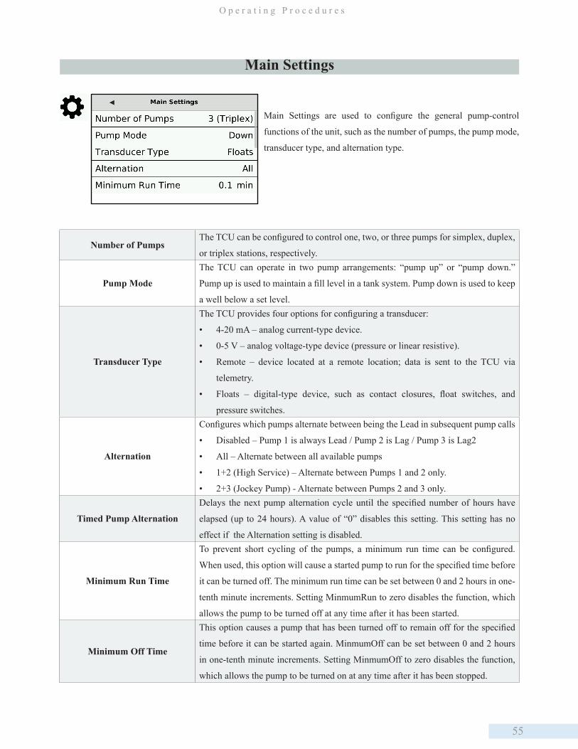
55
O p e r a t i n g P r o c e d u r e s
Main Settings are used to configure the general pump-control
functions of the unit, such as the number of pumps, the pump mode,
transducer type, and alternation type.
Main Settings
Number of PumpsThe TCU can be configured to control one, two, or three pumps for simplex, duplex,
or triplex stations, respectively.
Pump Mode
The TCU can operate in two pump arrangements: “pump up” or “pump down.”
Pump up is used to maintain a fill level in a tank system. Pump down is used to keep
a well below a set level.
Transducer Type
The TCU provides four options for configuring a transducer:
• 4-20 mA – analog current-type device.
• 0-5 V – analog voltage-type device (pressure or linear resistive).
• Remote – device located at a remote location; data is sent to the TCU via
telemetry.
• Floats – digital-type device, such as contact closures, float switches, and
pressure switches.
Alternation
Configures which pumps alternate between being the Lead in subsequent pump calls
• Disabled – Pump 1 is always Lead / Pump 2 is Lag / Pump 3 is Lag2
• All – Alternate between all available pumps
• 1+2 (High Service) – Alternate between Pumps 1 and 2 only.
• 2+3 (Jockey Pump) - Alternate between Pumps 2 and 3 only.
Timed Pump Alternation
Delays the next pump alternation cycle until the specified number of hours have
elapsed (up to 24 hours). A value of “0” disables this setting. This setting has no
effect if the Alternation setting is disabled.
Minimum Run Time
To prevent short cycling of the pumps, a minimum run time can be configured.
When used, this option will cause a started pump to run for the specified time before
it can be turned off. The minimum run time can be set between 0 and 2 hours in one-
tenth minute increments. Setting MinmumRun to zero disables the function, which
allows the pump to be turned off at any time after it has been started.
Minimum Off Time
This option causes a pump that has been turned off to remain off for the specified
time before it can be started again. MinmumOff can be set between 0 and 2 hours
in one-tenth minute increments. Setting MinmumOff to zero disables the function,
which allows the pump to be turned on at any time after it has been stopped.

56
C h a p t e r 6
Alarm Output settings are used to enable or disable the Alarm
Horn and Alarm Light relay outputs.
Start Fault AlarmThe amount of time the alarm will sound before the pump starts. The value can be
set between 0 and 99 seconds.
Stop Fault AlarmThe amount of time the alarm will sound before the pump stops. The value can be
set between 0 and 99 seconds.
Stagger Start DelayAfter any pump has been started, this setting configures the minimum number of
seconds to wait before turning on the next pump in the alternation scheme.
Pump Auto Retry
The TCU can be configured to retry a faulted pump - one that fails to start when
called (Motor Start Fault) or one that is running when it has not being called to run
(Motor Stop Fault). The TCU’s responses to Motor Start Faults and Motor Stop
Faults with the Auto Retry function enabled are identical. The response to Motor
Stop Faults differs if the Auto Retry function has been disabled.
Alarm Output
Alarm Horn
(Disabled/Enabled)
When enabled, certain high-priority alarms will cause the alarm horn relay to
energize (close) and send power to the alarm-horn output. If there are active alarms
when the TCU’s alarm horn option is enabled, the alarm horn will not sound until
the existing alarms have cleared and a new alarm occurs. Disabling the alarm horn
option does not prevent alarms from being reported via telemetry.
Alarm Light
(Disabled/Enabled)
When enabled, all alarms generated at the station cause the alarm light relay to
energize (close) and send power to the alarm-light output. Disabling the alarm light
option does not prevent alarms from being reported via telemetry.

57
O p e r a t i n g P r o c e d u r e s
High Float
(Disabled/Enabled)
If a high level float is being used, High Float must be enabled. If a high level float
is not connected and High Float is enabled, there is no effect on the operation of the
TCU. In a Pump Down Mode (Lift Station) system, all pumps are stagger-started
on a high float condition. In a Pump Up Mode (Storage Tank) system, all pumps are
stopped on a high float condition. A high float condition generates a high well alarm
and an optional transducer fault alarm.
Low Float
(Disabled/Enabled)
If a low level float is being used, Low Float must be enabled. Low Float must be
disabled if a low level float is not connected. (If Low Float is not disabled, the
Low Well alarm will interfere with station operation.) In a Pump Down Mode (Lift
Station) system, all pumps are stopped on a low float condition. In a Pump Up
Mode (Storage Tank) system, all pumps are stagger-started on a low float condition.
A low float condition generates a low well alarm and an optional transducer fault
alarm.
XDCR High Float Fault
(Disabled/Enabled)
When this option is enabled, a high float condition generates a transducer fault and
switches control to the configured fault mode. Leaving the option disabled leaves
pump control on the primary transducer whenever a high float condition occurs or
the transducer reaches or exceeds 20 mA.
XDCR Low Level Fault
(Disabled/Enabled)
When this option is enabled, a low float condition OR a transducer low level
condition (level drops below Low set point) generates a transducer fault and
switches control to the configured fault mode. Leaving the option disabled leaves
pump control on the primary transducer whenever a low float or transducer low
level condition occurs.
High Float Override
(Disabled/Enabled)
When this option is enabled, the High Float is given precedence in the event of an
Off float failure when the TCU is in Float control mode (this can be a floats-only
system or an analog transducer system that uses floats for backup).
Floats
Float settings are used to enabe or disable high and low float inputs,
and configure the faults associated with these float conditions.
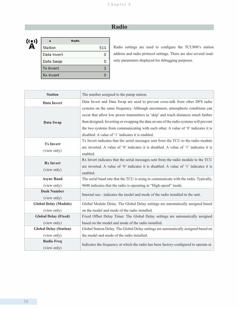
58
C h a p t e r 6
Radio settings are used to configure the TCU800’s station
address and radio protocol settings. There are also several read-
only parameters displayed for debugging purposes.
Radio
Station The number assigned to the pump station.
Data Invert Data Invert and Data Swap are used to prevent cross-talk from other DFS radio
systems on the same frequency. Although uncommon, atmospheric conditions can
occur that allow low power transmitters to ‘skip’ and reach distances much farther
than designed. Inverting or swapping the data on one of the radio systems will prevent
the two systems from communicating with each other. A value of ‘0’ indicates it is
disabled. A value of ‘1’ indicates it is enabled.
Data Swap
Tx Invert
(view only)
Tx Invert indicates that the serial messages sent from the TCU to the radio module
are inverted. A value of ‘0’ indicates it is disabled. A value of ‘1’ indicates it is
enabled.
Rx Invert
(view only)
Rx Invert indicates that the serial messages sent from the radio module to the TCU
are inverted. A value of ‘0’ indicates it is disabled. A value of ‘1’ indicates it is
enabled.Async Baud
(view only)
The serial baud rate that the TCU is using to communicate with the radio. Typically,
9600 indicates that the radio is operating in “High-speed” mode. Dash Number
(view only)Internal use - indicates the model and mode of the radio installed in the unit.
Global Delay (Module)
(view only)
Global Module Delay. The Global Delay settings are automatically assigned based
on the model and mode of the radio installed. Global Delay (Fixed)
(view only)
Fixed Offset Delay Timer. The Global Delay settings are automatically assigned
based on the model and mode of the radio installed.Global Delay (Station)
(view only)
Global Station Delay. The Global Delay settings are automatically assigned based on
the model and mode of the radio installed.Radio Freq
(view only)Indicates the frequency at which the radio has been factory-configured to operate at.
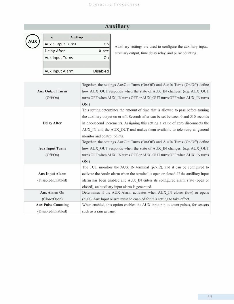
59
O p e r a t i n g P r o c e d u r e s
Auxiliary settings are used to configure the auxiliary input,
auxiliary output, time delay relay, and pulse counting.
Auxiliary
Aux Output Turns
(Off/On)
Together, the settings AuxOut Turns (On/Off) and AuxIn Turns (On/Off) define
how AUX_OUT responds when the state of AUX_IN changes. (e.g. AUX_OUT
turns OFF when AUX_IN turns OFF or AUX_OUT turns OFF when AUX_IN turns
ON.)
Delay After
This setting determines the amount of time that is allowed to pass before turning
the auxiliary output on or off. Seconds after can be set between 0 and 510 seconds
in one-second increments. Assigning this setting a value of zero disconnects the
AUX_IN and the AUX_OUT and makes them available to telemetry as general
monitor and control points.
Aux Input Turns
(Off/On)
Together, the settings AuxOut Turns (On/Off) and AuxIn Turns (On/Off) define
how AUX_OUT responds when the state of AUX_IN changes. (e.g. AUX_OUT
turns OFF when AUX_IN turns OFF or AUX_OUT turns OFF when AUX_IN turns
ON.)
Aux Input Alarm
(Disabled/Enabled)
The TCU monitors the AUX_IN terminal (p2-12), and it can be configured to
activate the AuxIn alarm when the terminal is open or closed. If the auxiliary input
alarm has been enabled and AUX_IN enters its configured alarm state (open or
closed), an auxiliary input alarm is generated.Aux Alarm On
(Close/Open)
Determines if the AUX Alarm activates when AUX_IN closes (low) or opens
(high). Aux Input Alarm must be enabled for this setting to take effect. Aux Pulse Counting
(Disabled/Enabled)
When enabled, this option enables the AUX input pin to count pulses, for sensors
such as a rain gauage.
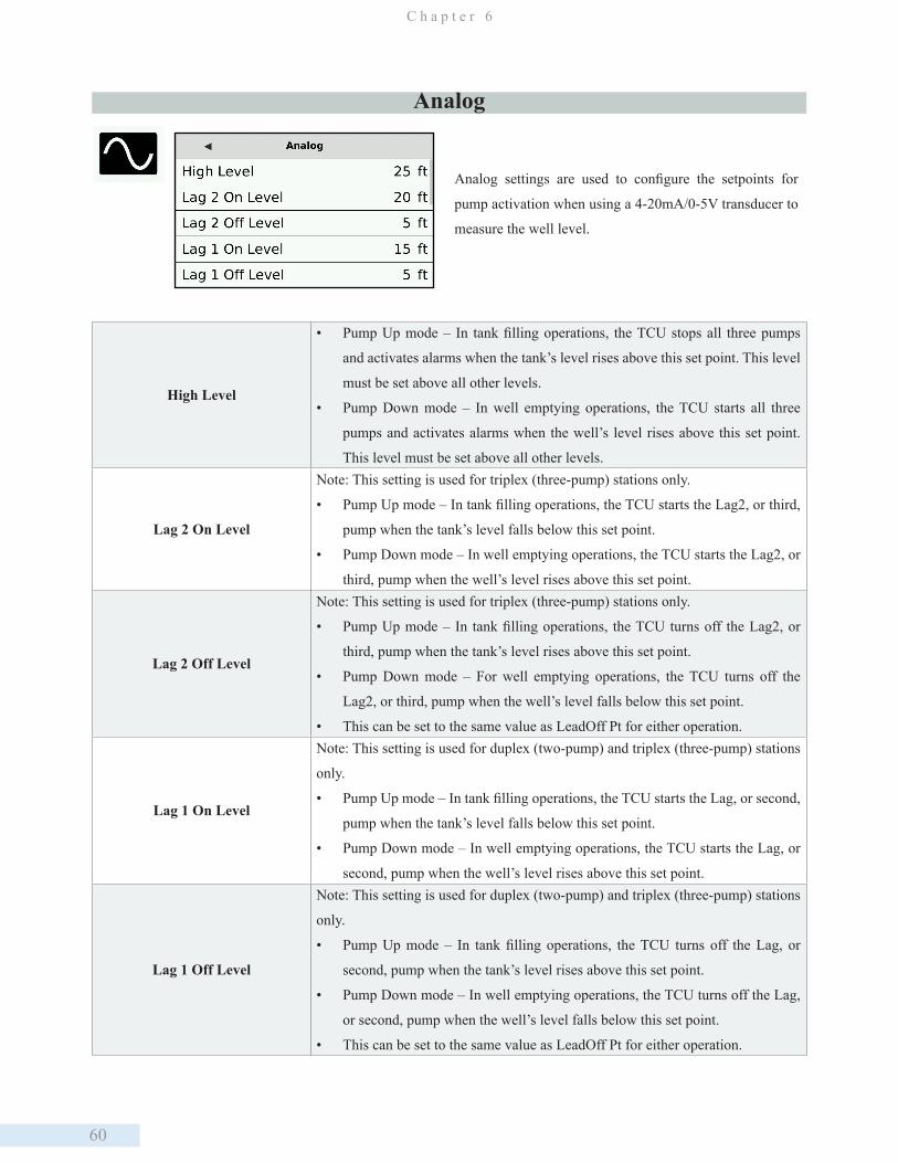
60
C h a p t e r 6
Analog settings are used to configure the setpoints for
pump activation when using a 4-20mA/0-5V transducer to
measure the well level.
High Level
• Pump Up mode – In tank filling operations, the TCU stops all three pumps
and activates alarms when the tank’s level rises above this set point. This level
must be set above all other levels.
• Pump Down mode – In well emptying operations, the TCU starts all three
pumps and activates alarms when the well’s level rises above this set point.
This level must be set above all other levels.
Lag 2 On Level
Note: This setting is used for triplex (three-pump) stations only.
• Pump Up mode – In tank filling operations, the TCU starts the Lag2, or third,
pump when the tank’s level falls below this set point.
• Pump Down mode – In well emptying operations, the TCU starts the Lag2, or
third, pump when the well’s level rises above this set point.
Lag 2 Off Level
Note: This setting is used for triplex (three-pump) stations only.
• Pump Up mode – In tank filling operations, the TCU turns off the Lag2, or
third, pump when the tank’s level rises above this set point.
• Pump Down mode – For well emptying operations, the TCU turns off the
Lag2, or third, pump when the well’s level falls below this set point.
• This can be set to the same value as LeadOff Pt for either operation.
Lag 1 On Level
Note: This setting is used for duplex (two-pump) and triplex (three-pump) stations
only.
• Pump Up mode – In tank filling operations, the TCU starts the Lag, or second,
pump when the tank’s level falls below this set point.
• Pump Down mode – In well emptying operations, the TCU starts the Lag, or
second, pump when the well’s level rises above this set point.
Lag 1 Off Level
Note: This setting is used for duplex (two-pump) and triplex (three-pump) stations
only.
• Pump Up mode – In tank filling operations, the TCU turns off the Lag, or
second, pump when the tank’s level rises above this set point.
• Pump Down mode – In well emptying operations, the TCU turns off the Lag,
or second, pump when the well’s level falls below this set point.
• This can be set to the same value as LeadOff Pt for either operation.
Analog
61
O p e r a t i n g P r o c e d u r e s
Lead On Level
• Pump Up mode – In tank filling operations, the TCU starts the Lead, or first,
pump when the tank’s level falls below this set point.
• Pump Down mode – In well emptying operations, the TCU starts the Lead, or
first, pump when the well’s level rises above this set point.
Lead Off Level
• Pump Up mode – For tank filling operations, this is the tank’s maximum
operational level. The TCU turns off the Lead, or first, pump when the tank’s
level rises above this set point.
• Pump Down mode – For well emptying operations, this is the well’s minimum
operational, or Off, level. The TCU turns off the Lead, or first, pump when the
well’s level falls below this set point.
Flow Equalization
The Flow Eq Lead option is a function utilized by the DFS patented “Symphony -
Harmonious Pump & Flow Management” technology. For more information about
Symphony please contact the DFS Sales Department at 321-259-5009 or by email
Low Level
• Pump Up mode – In tank filling operations, all pumps are running and alarms
are activated when the tank’s level falls below this set point. This level must
be set below all other levels.
• Pump Down mode – In well emptying operations, pumps are shut down and
alarms are activated when the well’s level falls below this set point. This level
must be set below all other levels.
XDCR 1 Low Cal PointThe depth of the well when the value measured on Analog1 is at its lowest signal
level (4 mA or 0 V, depending on transducer type).
XDCR 1 High Cal PointThe depth of the well when the value measured on Analog1 is at its highest signal
level (20 mA or 5 V, depending on transducer type).
XDCR 2 Low Cal Point
The depth of the well when the value measured on Analog2 is at its lowest signal
level (4 mA or 0 V, depending on transducer type). This is mainly for using a
backup/redundant transducer on the Analog2 input.
XDCR 2 High Cal Point
The depth of the well when the value measured on Analog2 is at its highest signal
level (20 mA or 5 V, depending on transducer type). This is mainly for using a
backup/redundant transducer on the Analog2 input.
XDCR Fault Mode
• Disable – Set to disable if the station will not be using one of the other fault
mode options (Analog2 or Floats). If this option is set to Disable and high
and/or low floats have not been enabled, the system will shut down when a
transducer fault occurs in either pump up or pump down station operation.
• Analog2 – When an auxiliary transducer is connected and this option is
selected, a fault with the primary transducer will cause the TCU to switch to
the backup transducer.
• Floats – When this option is selected, a fault with the primary transducer will
cause the TCU to switch to normal float behavior. This mode requires an Off
float to shut off the pumps and a miniumum of one float (Lead to High) to start
the pumps.
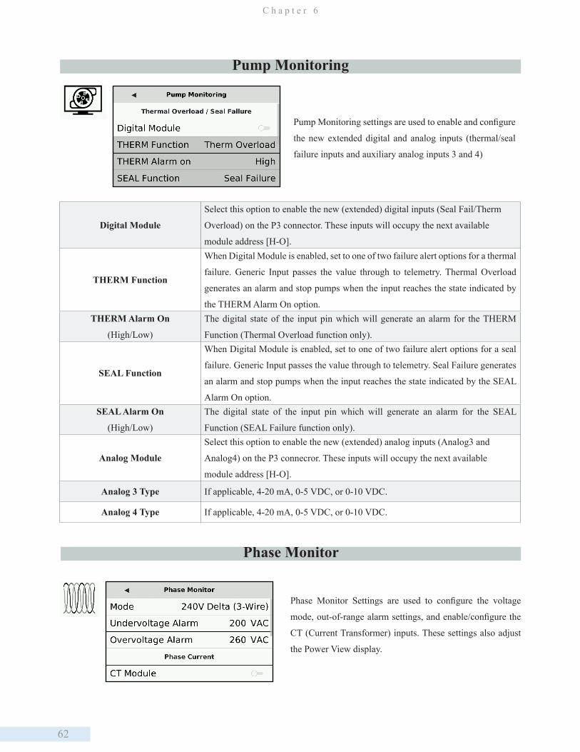
62
C h a p t e r 6
Pump Monitoring settings are used to enable and configure
the new extended digital and analog inputs (thermal/seal
failure inputs and auxiliary analog inputs 3 and 4)
Digital Module
Select this option to enable the new (extended) digital inputs (Seal Fail/Therm
Overload) on the P3 connector. These inputs will occupy the next available
module address [H-O].
THERM Function
When Digital Module is enabled, set to one of two failure alert options for a thermal
failure. Generic Input passes the value through to telemetry. Thermal Overload
generates an alarm and stop pumps when the input reaches the state indicated by
the THERM Alarm On option.THERM Alarm On
(High/Low)
The digital state of the input pin which will generate an alarm for the THERM
Function (Thermal Overload function only).
SEAL Function
When Digital Module is enabled, set to one of two failure alert options for a seal
failure. Generic Input passes the value through to telemetry. Seal Failure generates
an alarm and stop pumps when the input reaches the state indicated by the SEAL
Alarm On option.SEAL Alarm On
(High/Low)
The digital state of the input pin which will generate an alarm for the SEAL
Function (SEAL Failure function only).
Analog Module
Select this option to enable the new (extended) analog inputs (Analog3 and
Analog4) on the P3 connecror. These inputs will occupy the next available
module address [H-O].
Analog 3 Type If applicable, 4-20 mA, 0-5 VDC, or 0-10 VDC.
Analog 4 Type If applicable, 4-20 mA, 0-5 VDC, or 0-10 VDC.
Pump Monitoring
Phase Monitor Settings are used to configure the voltage
mode, out-of-range alarm settings, and enable/configure the
CT (Current Transformer) inputs. These settings also adjust
the Power View display.
Phase Monitor
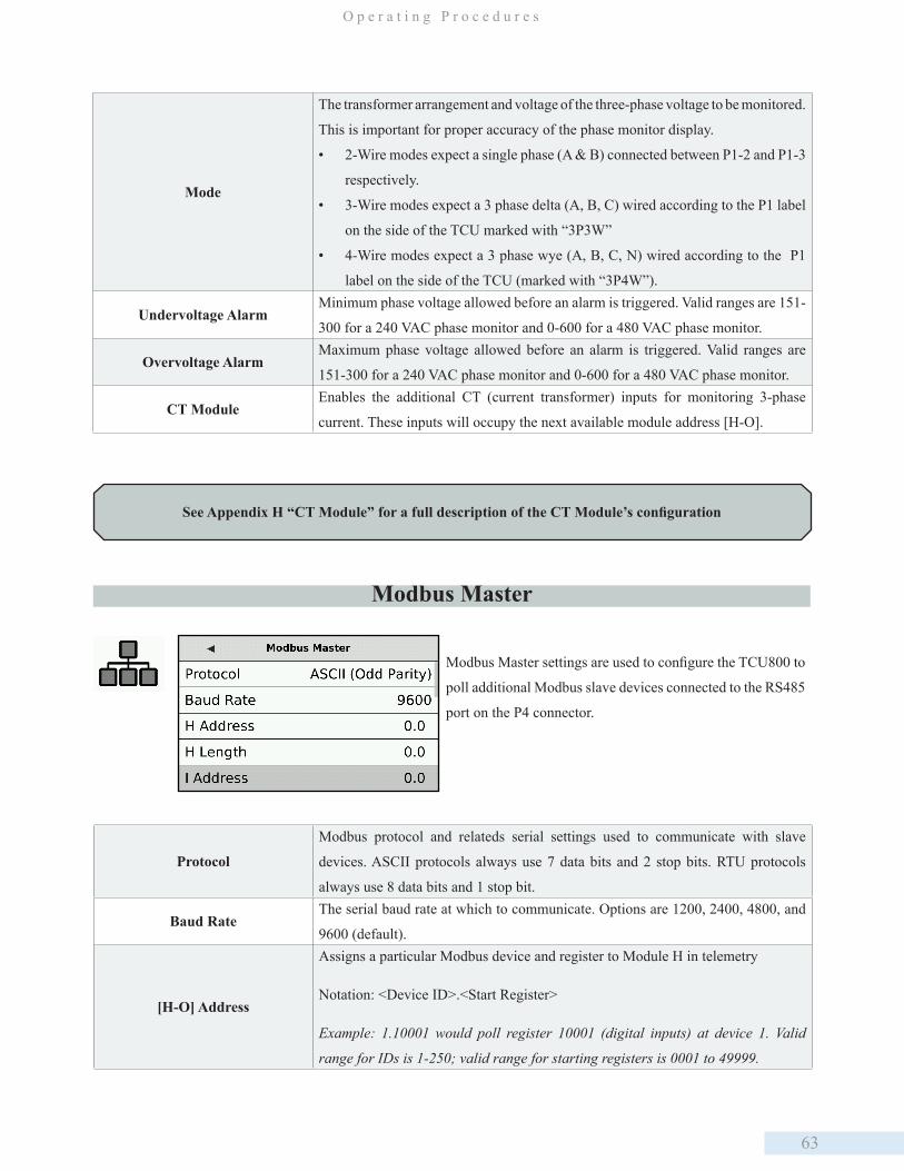
63
O p e r a t i n g P r o c e d u r e s
Mode
The transformer arrangement and voltage of the three-phase voltage to be monitored.
This is important for proper accuracy of the phase monitor display.
• 2-Wire modes expect a single phase (A & B) connected between P1-2 and P1-3
respectively.
• 3-Wire modes expect a 3 phase delta (A, B, C) wired according to the P1 label
on the side of the TCU marked with “3P3W”
• 4-Wire modes expect a 3 phase wye (A, B, C, N) wired according to the P1
label on the side of the TCU (marked with “3P4W”).
Undervoltage AlarmMinimum phase voltage allowed before an alarm is triggered. Valid ranges are 151-
300 for a 240 VAC phase monitor and 0-600 for a 480 VAC phase monitor.
Overvoltage AlarmMaximum phase voltage allowed before an alarm is triggered. Valid ranges are
151-300 for a 240 VAC phase monitor and 0-600 for a 480 VAC phase monitor.
CT ModuleEnables the additional CT (current transformer) inputs for monitoring 3-phase
current. These inputs will occupy the next available module address [H-O].
Modbus Master settings are used to configure the TCU800 to
poll additional Modbus slave devices connected to the RS485
port on the P4 connector.
Protocol
Modbus protocol and relateds serial settings used to communicate with slave
devices. ASCII protocols always use 7 data bits and 2 stop bits. RTU protocols
always use 8 data bits and 1 stop bit.
Baud RateThe serial baud rate at which to communicate. Options are 1200, 2400, 4800, and
9600 (default).
[H-O] Address
Assigns a particular Modbus device and register to Module H in telemetry
Notation: <Device ID>.<Start Register>
Example: 1.10001 would poll register 10001 (digital inputs) at device 1. Valid
range for IDs is 1-250; valid range for starting registers is 0001 to 49999.
Modbus Master
See Appendix H “CT Module” for a full description of the CT Module’s configuration
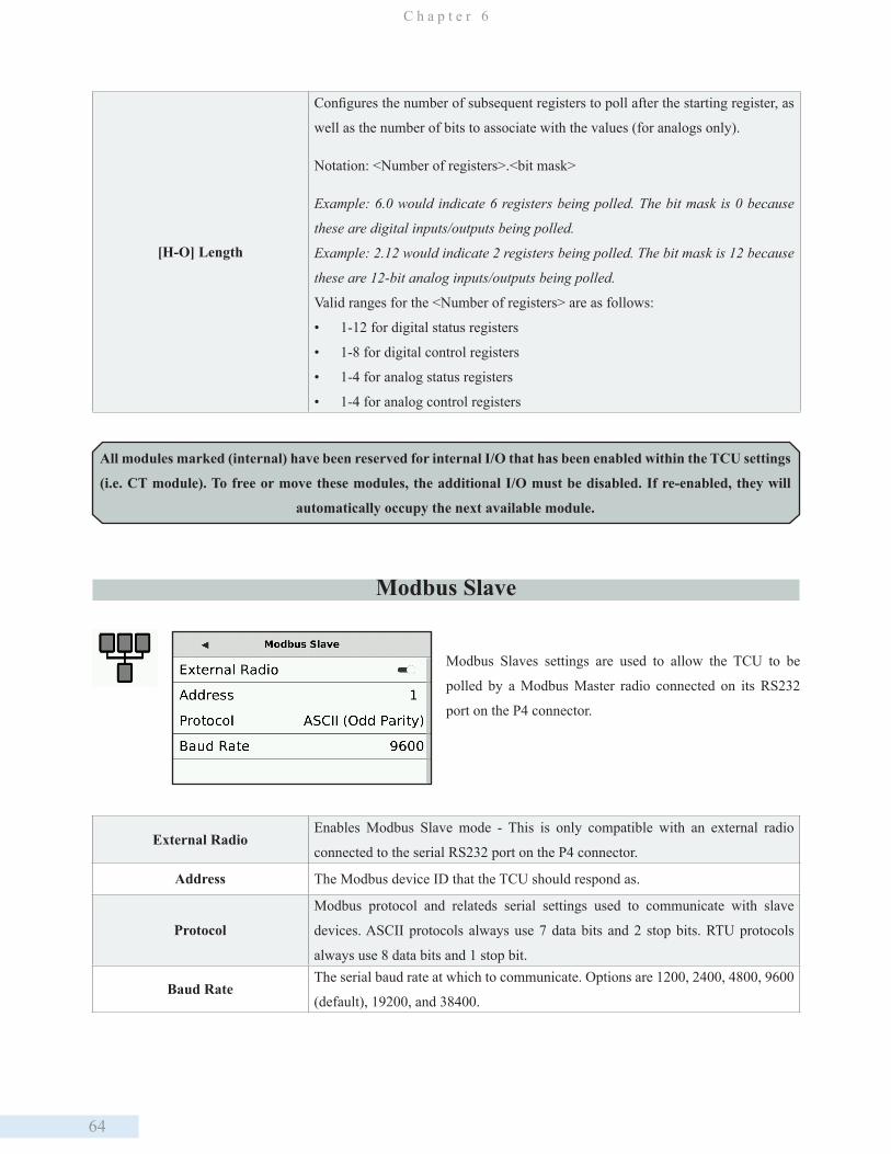
64
C h a p t e r 6
All modules marked (internal) have been reserved for internal I/O that has been enabled within the TCU settings
(i.e. CT module). To free or move these modules, the additional I/O must be disabled. If re-enabled, they will
automatically occupy the next available module.
[H-O] Length
Configures the number of subsequent registers to poll after the starting register, as
well as the number of bits to associate with the values (for analogs only).
Notation: <Number of registers>.<bit mask>
Example: 6.0 would indicate 6 registers being polled. The bit mask is 0 because
these are digital inputs/outputs being polled.
Example: 2.12 would indicate 2 registers being polled. The bit mask is 12 because
these are 12-bit analog inputs/outputs being polled.
Valid ranges for the <Number of registers> are as follows:
• 1-12 for digital status registers
• 1-8 for digital control registers
• 1-4 for analog status registers
• 1-4 for analog control registers
Modbus Slave
Modbus Slaves settings are used to allow the TCU to be
polled by a Modbus Master radio connected on its RS232
port on the P4 connector.
External RadioEnables Modbus Slave mode - This is only compatible with an external radio
connected to the serial RS232 port on the P4 connector.
Address The Modbus device ID that the TCU should respond as.
Protocol
Modbus protocol and relateds serial settings used to communicate with slave
devices. ASCII protocols always use 7 data bits and 2 stop bits. RTU protocols
always use 8 data bits and 1 stop bit.
Baud RateThe serial baud rate at which to communicate. Options are 1200, 2400, 4800, 9600
(default), 19200, and 38400.
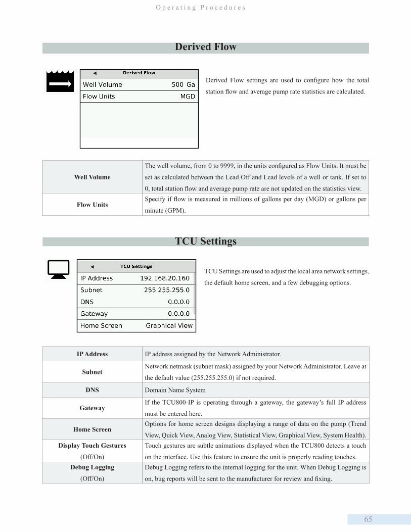
65
O p e r a t i n g P r o c e d u r e s
IP Address IP address assigned by the Network Administrator.
SubnetNetwork netmask (subnet mask) assigned by your Network Administrator. Leave at
the default value (255.255.255.0) if not required.
DNS Domain Name System
GatewayIf the TCU800-IP is operating through a gateway, the gateway’s full IP address
must be entered here.
Home ScreenOptions for home screen designs displaying a range of data on the pump (Trend
View, Quick View, Analog View, Statistical View, Graphical View, System Health).Display Touch Gestures
(Off/On)
Touch gestures are subtle animations displayed when the TCU800 detects a touch
on the interface. Use this feature to ensure the unit is properly reading touches. Debug Logging
(Off/On)
Debug Logging refers to the internal logging for the unit. When Debug Logging is
on, bug reports will be sent to the manufacturer for review and fixing.
TCU Settings are used to adjust the local area network settings,
the default home screen, and a few debugging options.
TCU Settings
Well Volume
The well volume, from 0 to 9999, in the units configured as Flow Units. It must be
set as calculated between the Lead Off and Lead levels of a well or tank. If set to
0, total station flow and average pump rate are not updated on the statistics view.
Flow UnitsSpecify if flow is measured in millions of gallons per day (MGD) or gallons per
minute (GPM).
Derived Flow
Derived Flow settings are used to configure how the total
station flow and average pump rate statistics are calculated.

66
C h a p t e r 6
Auto-Configuring At this time, using a TCU001 PLC configuration will cause an error in the TCU800. To avoid this, first transfer the existing
configuration of the TCU800 using HyperTAC PLC editor. Then save the .plc file, create an auto-config file, and upload it
to the appropriate station you want to auto-config.
Remote Configuration ChangesChanging configuration values using the PLC editor is supported but requires that the settings be transferred initially from
the TCU800 to the remote PLC editor (once). If taking this step, disregard the configuration values listed in the Autodialer
section of the editor as the TCU800 does not support Autodialer and the settings have been repurposed for other use. This
workaround is temporary. If only changing a few configuration values, this step can be bypassed as only the changed values
need to be selected and sent.
For more detail on remote configuration changes see the HT4 User Guide, available on dataflowsys.com.
Utilizing the USB Ports for Configuration When saving TCU settings for future use or transfer to another unit, a USB drive is needed. Insert the USB into the top port
on the face of the TCU. Then, navigate to the Advanced Settings and select the ‘Device Manager’ icon. On the screen that
appears, select ‘Export Settings.’ If the export to the USB drive was successful, a notification reading ‘Export successful’
Radio Test Mode
Utility mode to help with installing and aligning a
directional radio antenna. Radio traffic will temporarily
be displayed in the view.
KEY can be used to manually force the radio to
transmit.
Station telemetry will be temporarily disabled in this
mode. Selecting will exit the mode and return to
normal operation.
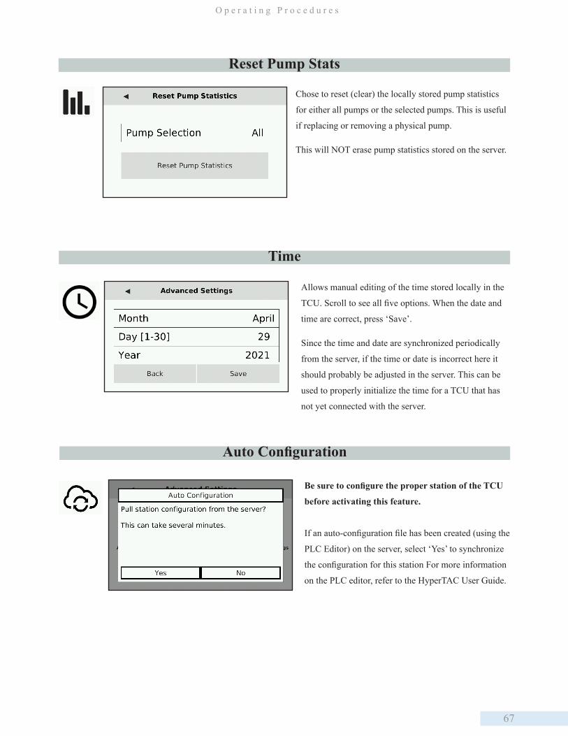
67
O p e r a t i n g P r o c e d u r e s
Auto Configuration
Be sure to configure the proper station of the TCU
before activating this feature.
If an auto-configuration file has been created (using the
PLC Editor) on the server, select ‘Yes’ to synchronize
the configuration for this station For more information
on the PLC editor, refer to the HyperTAC User Guide.
Time
Allows manual editing of the time stored locally in the
TCU. Scroll to see all five options. When the date and
time are correct, press ‘Save’.
Since the time and date are synchronized periodically
from the server, if the time or date is incorrect here it
should probably be adjusted in the server. This can be
used to properly initialize the time for a TCU that has
not yet connected with the server.
Reset Pump Stats
Chose to reset (clear) the locally stored pump statistics
for either all pumps or the selected pumps. This is useful
if replacing or removing a physical pump.
This will NOT erase pump statistics stored on the server.
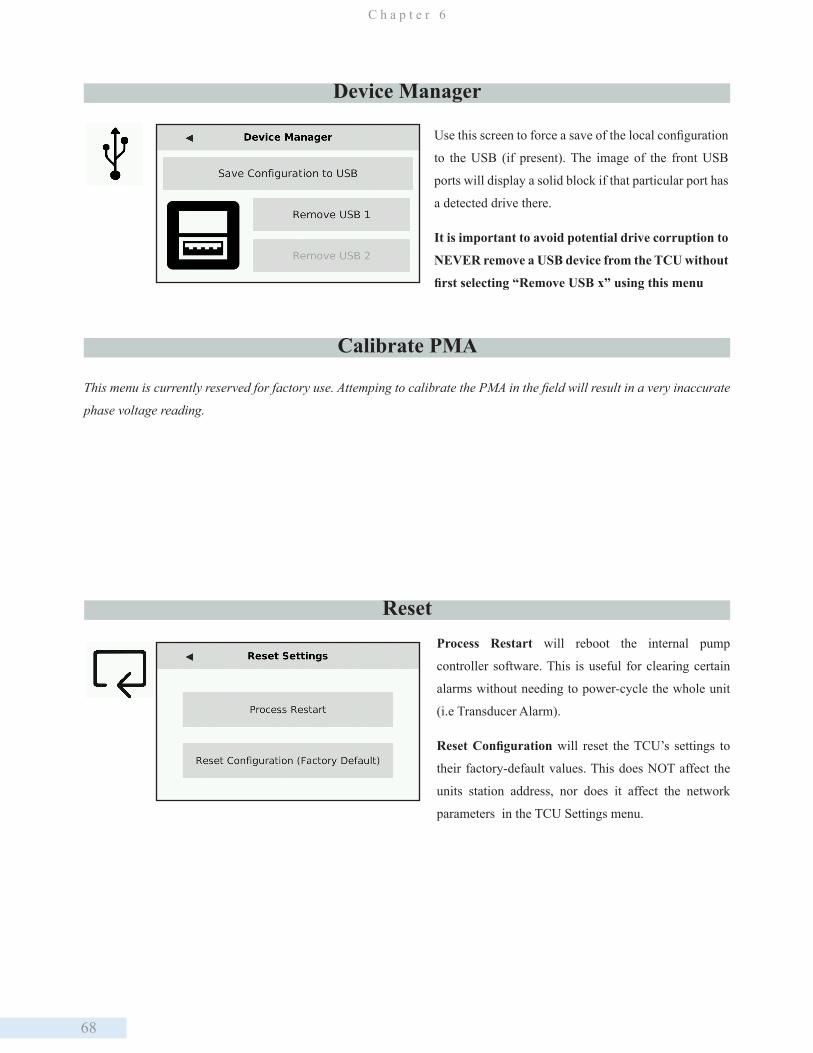
68
C h a p t e r 6
Device Manager
Use this screen to force a save of the local configuration
to the USB (if present). The image of the front USB
ports will display a solid block if that particular port has
a detected drive there.
It is important to avoid potential drive corruption to
NEVER remove a USB device from the TCU without
first selecting “Remove USB x” using this menu
Calibrate PMA
ResetProcess Restart will reboot the internal pump
controller software. This is useful for clearing certain
alarms without needing to power-cycle the whole unit
(i.e Transducer Alarm).
Reset Configuration will reset the TCU’s settings to
their factory-default values. This does NOT affect the
units station address, nor does it affect the network
parameters in the TCU Settings menu.
This menu is currently reserved for factory use. Attemping to calibrate the PMA in the field will result in a very inaccurate
phase voltage reading.
69
O p e r a t i n g P r o c e d u r e s
Telemetry Configuration
Setting up the TCU as a component of the telemetry system enables you to remotely monitor conditions at the site and
control equipment from a central location via the HyperTAC SCADA software. For example, you can determine if a pump
is currently running and force it on if necessary. For the TCU to interface with the central site and the HyperTAC server,
it must have access to radio or network communications and be properly configured in HyperTAC’s Configuration Editor.
Hardware Configuration There are several options for connecting the TCU to the telemetry system. A TCU can be installed with a DFS RTU station,
or it can interface with industry standard radios using the TCU’s RS-232 Modbus radio interface. Alternately, the TCU
can operate as a stand-alone unit and communicate with the central computer or server via its integrated radio or network
interface.
Using the TCU in conjunction with a radio-based telemetry system requires that you obtain an FCC-licensed radio frequency
if you do not already have a licensed frequency that can be utilized. Even when adding a site to an existing frequency, the
FCC requires that a complete application be submitted. DFS can assist you in obtaining a new licensed frequency or adding
a site to an existing frequency.
TCU Installed with DFS RTU
If the TCU is being interfaced with an RTU station, a Bus Extender Module (BEM) must be installed in the RTU and
connected to the TCU.
If the TCU’s pump controller process is being used, the TCU must be configured with the number of real modules already
on the bus. The TCU will then occupy the next available module addresses. If there are already four modules on the bus (A,
B, C, D), the TCU will start at module E. Note that this module offset also applies to a TCU configured as a legacy PCU.
If the TCU is being used as a pump controller or a legacy PCU, it must be configured as such in HyperTAC. A legacy PCU
occupies a single module address. A pump controller TCU occupies seven module addresses starting at the next available
modules address. The TCU responds as individual modules or a single PCU module based on how it is polled.
If the TCU is running a custom program, it is important to remember that the TCU defines its internal modules without
exception. Any additional modules added to the RTU must be addressed beginning with the module letter after the last
dummy module defined in the TCU.
Instructions for installing the Bus Extender Module appear on the next page.
Installing the BEM
Place the BEM in one of the RTU’s unused module slots.
Remove the corresponding address block or strap for the selected module slot.
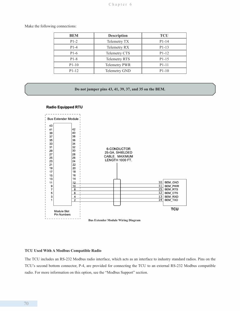
70
C h a p t e r 6
Make the following connections:
BEM Description TCUP1-2 Telemetry TX P1-14P1-4 Telemetry RX P1-13P1-6 Telemetry CTS P1-12P1-8 Telemetry RTS P1-15P1-10 Telemetry PWR P1-11P1-12 Telemetry GND P1-10
Do not jumper pins 43, 41, 39, 37, and 35 on the BEM.
Bus Extender Module Wiring Diagram
TCU Used With A Modbus Compatible Radio
The TCU includes an RS-232 Modbus radio interface, which acts as an interface to industry standard radios. Pins on the
TCU’s second bottom connector, P-4, are provided for connecting the TCU to an external RS-232 Modbus compatible
radio. For more information on this option, see the “Modbus Support” section.
71
O p e r a t i n g P r o c e d u r e s
PIN# Name DescriptionP4-1 Unused Reserved for future use; do not connect P4-2 RS485_GND RS-485 serial ground reference P4-3 RS485_B RS-485 serial interface B P4-4 RS485_A RS-485 serial inferface AP4-5 SHIELD Internally connected to chassis ground; Cable shield for RS-485 or RS-232P4-6 EX_GND_RAD RS-232 signal groundP4-7 RTS_RAD RS-232 request to sendP4-8 EX_TXD_RAD RS-232 transmit data to external deviceP4-9 EX_RXD_RAD RS-232 recieve data from external device P4-10 CTS_RAD RS-232 clear to send
TCU as Stand Alone Unit
The TCU can be ordered with an integrated 2 W, 200 MHz radio or 5 W, synthesized 400 MHz radio and operate
independently of an RTU. The TCU’s integrated digital radio enables radio communication between the TCU and the
HyperTAC central computer or server (Hyper SCADA Server). Through this radio link, you can remotely monitor and
control TCU operations.
Typical Setups
Refer to the TAC II Telemetry System Installation Planning Guide supplied with the TAC II telemetry equipment for
detailed wiring instructions.
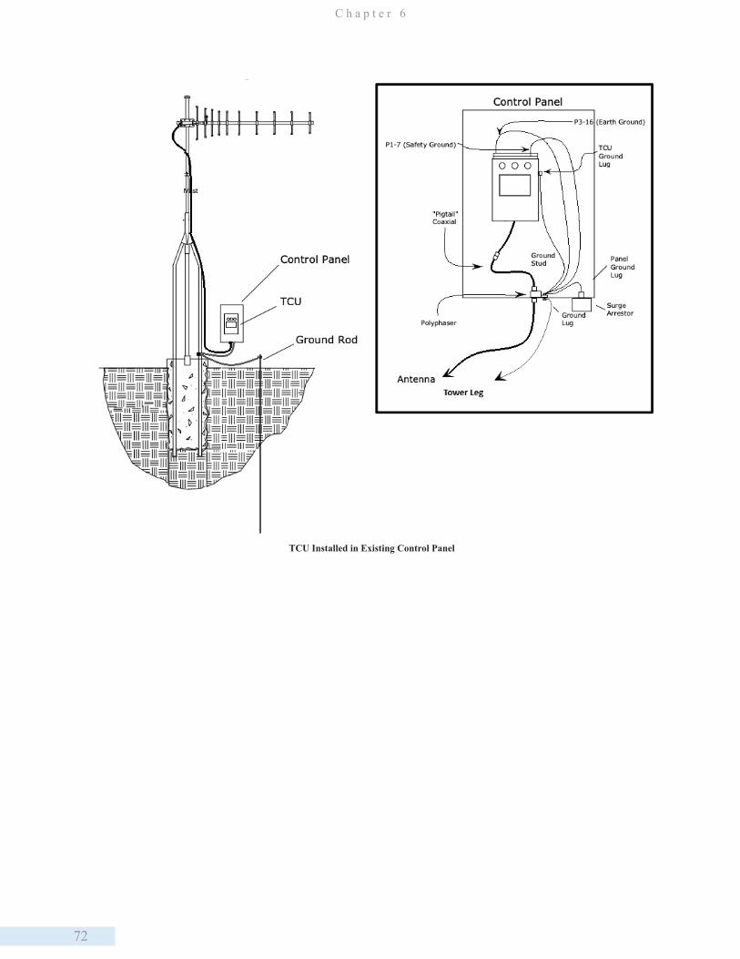
72
C h a p t e r 6
TCU Installed in Existing Control Panel

73
O p e r a t i n g P r o c e d u r e s
TCU Installed in Separate Control Panel
TCU Used without Telemetry
The TCU can operate independent of telemetry with limited data logging capabilities. Historical data can be accessed via
WinRTU Test or the TCU’s status screens. Historical data that can be reviewed includes:
- Derived total flow for the station
- Elapsed run time for each configured pump
- Average run time for each configured pump
- Average amount of flow each configured pump moves per pumping cycle
- Total cycles for each configured pump
The TCU begins logging these running totals and averages when the unit is installed. The unit continues accumulating data
until the time meters are reset.
HyperTAC Software Configuration
Telemetry components (drivers, stations, modules, points, etc) are configured using HyperTAC’s Configuration Editor. To
access Configuration Editor, log in to HyperTAC, click the “Configuration Tools” button, and then click the “View and
Configure Telemetry” button.
74
C h a p t e r 7
7. Viewing and Troubleshooting Alarms
The TCU’s Alarm LED illuminates if there are any alarms to view. The LED flashes for active alarms and is steady for
inactive (cleared) alarms that have not been viewed from the TCU’s Alarm screen or acknowledged via telemetry.
Following is a list of possible alarms:
• FltSeq – Floats are out of sequence
• Strt – Pump did not start
• Stop – Pump did not stop (this alarm message is displayed in the same location as Strt)
• HiWell – High well condition
• LoWell – Low well condition (this alarm message is displayed in the same location as HiWell)
• DCBias – DC bias (ISO+24V) failed
• ACPwr – AC power loss
• Xducer – Transducer fault
• PhaVol – Phase voltage fault
• PhaSeq – Phase sequence fault (this alarm message is displayed in the same location as PhaVol)
• AuxIn – Auxiliary input alarm
An alarm message flashes if there is an active alarm. If the alarm condition clears while the alarm message is being viewed,
the alarm message stops flashing. Messages for inactive (cleared) alarms are static (non-flashing). These messages are
stored in the TCU’s alarm log until they are viewed. Once a message for an inactive alarm condition has been viewed, it
is cleared from the TCU’s display. The Alarm LED flashes when there are active alarms and is static on (continuously lit)
until all alarms have cleared and all corresponding alarm messages have been viewed. The Alarm LED is cleared when the
alarm screen is exited and there are no active alarms.
When the TCU is used as a remote in conjunction with the telemetry system, active alarms will be displayed both locally
(at the TCU) and via the telemetry system at workstation computers. Note that the TCU’s alarm messages and alarm LED
are not cleared via telemetry; they must be cleared locally.
AC Power Fault
The ACPwr alarm is activated when the TCU determines AC power has been interrupted. The TCU must be on backup
battery power in order for this fault to function when the primary AC power fails.
The information contained in this chapter refers to the TCU’s built-in pump control process. It does not apply to
a TCU with a custom program installed.
75
V i e w i n g a n d T r o u b l e s h o o t i n g A l a r m s
If an AC power fault alarm occurs at a TCU that is connected to a backup battery:
• Check that all circuit breakers are on.
• Check if any circuit breaker has tripped. If a station control panel breaker has tripped, resolve the problem.
• Check if the TCU’s replaceable fuse has blown.
Auxiliary Input Alarm
The TCU monitors the AUX_IN terminal (p2-12), and it can be configured to activate the AuxIn alarm when the terminal
is open or closed. If the auxiliary input alarm has been enabled and AUX_IN enters its configured alarm state (open or
closed), an auxiliary input alarm is generated.
DC Bias Fault
The ISO+24V voltage, which is provided for biasing the digital monitor inputs and/or powering up to two analog
transducers, is monitored by the TCU. If a fault occurs with the ISO+24V voltage, the DCBias alarm is activated.
If a DC bias fault alarm occurs, measure the voltage between the ISO+24V and ISOGND terminals. The voltage should
be 20-24 VDC.
• Check for a short circuit condition between the ISO+24V and ISOGND terminals if the measured voltage is 0 (zero)
VDC.
• If the voltage is low, check the current load on the ISO+24V source. It should be less than 100 mA. If the current load
is excessive, disconnect and isolate ISO+24V and ISOGND terminals to determine if the fault is with the bias source
or in the external circuitry. If the fault appears to be with the external circuitry, try isolating each input connected to the
ISO+24V voltage until the problem is found. If the problem cannot be isolated, the TCU may require factory service.
See “Appendix K: Support, Service, and Warranty” for removal, replacement, and servicing instructions.
Float Sequence Fault
If the TCU detects floats out of sequence, it issues a FltSeq alarm. A FltSeq fault is not cleared at the TCU until the alarm
message is viewed or after 24 hours have passed. A float sequence fault that is reported through telemetry clears on the next
valid pump cycle (one without a float sequence fault).
Be sure that STRT_PWR (P1-24) and AC_PWR (P1-5) are both connected to the station’s control power. This ensures
that all pumps under local control receive an emergency shutdown when AC power drops. If this is not done,
multiple pumps could be commanded to start at the same time.
ISO+24V is provided only for biasing the 12 digital monitor inputs of the TCU and/or powering up to two analog
transducers while not exceeding the maximum current of 300 mA.
76
C h a p t e r 7
When a float sequence fault alarm occurs:
• Check the floats or pressure switches for the fault. Verify that the corresponding Well Level LED illuminates when
each float or pressure switch is on.
• Measure the voltage between the corresponding level input terminal and the IN_COM_2 terminal. The voltage should
be 10-30 VAC or VDC with the switch closed and 0 (zero) V with the switch opened.
• Check the wiring and verify all of the following:
- Only one bias source is used to bias all floats or pressure switches.
- The same voltage-dropping resistor is used for all floats or pressure switches.
- The return for the bias voltage is properly connected to the IN_COM_2 terminal.
- If ALM_SIL and AUX_IN are used, verify that they use the same bias voltage and dropping resistor value as the
level inputs.
High Well Alarm
The HiWell fault indicates that the HI_LVL input terminal is ON. Alternatively, if an analog transducer is being used,
HiWell indicates that the level has risen above the High-level set point
If an erroneous alarm occurs, check the high float or pressure switch and wiring.
• When the switch is opened, 0 (zero) VAC/VDC, should be measured at the HIGH_LVL input.
• Measure the voltage between the HIGH_LVL and IN_COM_2 terminals.
• Make sure the high float or pressure switch is not fouled or shorted.
• If necessary, disconnect the HIGH_LVL input to isolate the problem further.
Phase Sequence Fault
The TCU’s phase monitor is designed to detect phase losses, high and low phase faults, and phase sequence faults.
When the TCU detects a phase fault, it disables the pump motor outputs and activates the alarm light and horn relays. If a
phase is missing or the power is interrupted, the TCU also indicates that a phase sequence fault has occurred by issuing a
PhaSeq alarm.
If a sequence fault occurs, check the phase rotation of the incoming power. The label on the TCU’s connector indicates the
connection for clockwise phase rotation.
If the incoming power is labeled for counter-clockwise phase rotation, two of the leads wired into the TCU must be
swapped. Be sure to turn off the main breaker before making any wiring changes.
If the problem cannot be resolved, the TCU may require factory service. See “Appendix K: Support, Service, and Warranty”
for removal, replacement, and servicing instructions.

77
V i e w i n g a n d T r o u b l e s h o o t i n g A l a r m s
Phase Voltage Fault
The TCU’s phase monitor is designed to detect phase losses, high-and low-phase voltage faults and phase sequence faults.
When the TCU detects a phase fault, it disables the pump motor outputs and activates the alarm light and horn relays. The
H-O-A switches can be used to override the TCU’s phase monitor and control the pumps during a phase fault.
If a fault occurs, measure the TCU’s Phase A-B and Phase A-C line-to-line voltages. If a voltage is missing, turn off the
main breaker and check the external phase monitor fuses.
The phase voltage set points establish the range used by the TCU to detect a phase voltage fault. If an erroneous alarm
occurs, check to see that the overvoltage and undervoltage limits are set properly. See pages 59-60 in Chapter 6: Operating
Procedures” for instructions on setting voltage limits.
If the problem cannot be resolved, the TCU may require factory service. See “Appendix K: Support, Service, and Warranty”
for removal, replacement, and servicing instructions.
Motor Starter Fault
A motor starter fault indicates that the TCU’s motor run inputs do not agree with its motor run outputs when the H-O-A
switch is in the “Auto” position. The default time allowed for the input to follow the output is two seconds, but the start
delay and stop delay time intervals can be configured from 2-510 seconds. Zero disables the starter fault alarm, and the
output remains on regardless of the run status input.
To accommodate applications where the run signal may not be immediate, such as soft starts or Run signals from check
valves, you can configure the TCU with a longer start and stop delay.
A pump that experiences a Motor Start Fault (with or without Auto Retry enabled) remains faulted by the TCU (and
the PCU) until the pump sequence is complete (tank or well reaches the Off level set point; no pumps are running in
automatic). The TCU attempts to start the failed pump during the next regular pump cycle. Be aware that the Motor Start
Fault will not clear until the pump actually runs or the H-O-A switch is moved out of Auto.
The TCU requires proper feedback to monitor pump motor run status. If the feedback signal malfunctions, the TCU
activates the Strt alarm. The LED of the faulted pump (located under its H-O-A switch) flashes when a motor starter fault
occurs.
The TCU’s starter relays are solid-state devices with up to 0.1 mA off-state leakage current. This should not cause any
problems with starter coils. However, it may force a solid-state starter with a high-input impedance to energize. If this
occurs, there are two options to try.
• Try connecting a bleed resistor across the solid-state starter input. Select a resistance and wattage to shunt the leakage
current.
• Install isolating relays between the TCU and the solid-state starter. Connect the TCU’s starter relays to the coils of the
isolating relays and control power through the isolating relay contacts to the solidstate starter inputs.
78
C h a p t e r 7
Check the starter circuit for faults by using the H-O-A switches to control the pumps. Verify that the pump run LED and
the corresponding pump motor turn on when the H-O-A switch is in the “Hand” position and off when the switch is in the
“Off” position. Switching the H-O-A switch out of the “Auto” position should clear the flashing pump run LED. If the LED
does not turn on when the motor starts and turn off when the motor stops, check the wiring and verify that:
• Only one bias source is used to bias all motor run inputs.
• The same voltage-dropping resistor is used for all motor run inputs.
• The return for the bias voltage is properly connected to the IN_COM_1 terminal.
• If the EXT_PM input is used, make sure that it uses the same bias voltage and dropping resistor as the motor run
inputs.
Verify that the TCU’s configured motor start fault delay (Start Fault) is set to an adequate length of time. If necessary,
increase the Start Fault delay.
If the problem cannot be resolved, the TCU may require factory service. See “Appendix K: Support, Service, and Warranty”
for removal, replacement, and servicing instructions.
Motor Stop Fault
A motor stop fault indicates that either the TCU sent a signal to turn off a pump and the pump remained on, or a pump came
on without the TCU calling it. When this occurs, the LED under the faulted pump’s H-O-A switch flashes.
The default time allowed for the input to follow the output is two seconds. To accommodate applications where the stop
signal may not be immediate, such as occurs with solid-state motor controllers, you can configure the TCU with a start and
stop delay from 2-510 seconds.
If the Auto Retry function is enabled (see Auto Retry, page 53), the TCU will attempt to use the faulted pump the next time
its turn comes up in the alternation order. If the TCU is successful at calling the pump to run and receives a pump run status,
it will clear the Motor Stop Fault. This response is identical to that of the PCU.
If the Auto Retry function is disabled, the TCU will not clear a Motor Stop Fault and will not use a faulted pump until the
pump’s operation is overridden (by moving the corresponding H-O-A switch to the Off or Hand position, or by overriding
the pump via telemetry). The TCU considers the pump failed and will take the failed pump out of rotation and assign a new
lead pump to start with the lead level. A PCU with Auto Retry disabled also will not clear the Motor Stop Fault. However,
the PCU will attempt to start the faulted pump the next time its turn comes up in the alternation order. The PCU makes
the assumption that the pump run status is accurate and will delay another pump from starting until the number of pumps
required is one more than the failed number of pumps. For example if pump 2 has failed, and pump 1 is the lead pump,
pump 1 will not start until the Lag 1 level is reached.
If a motor stop fault occurs, verify that:
• The TCU’s configured motor stop fault delay (Stop Fault) is set for an adequate length of time. If necessary, increase
the Stop Fault delay.
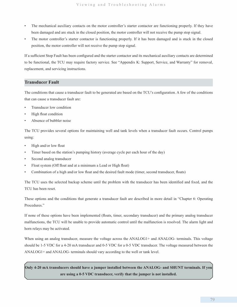
79
V i e w i n g a n d T r o u b l e s h o o t i n g A l a r m s
• The mechanical auxiliary contacts on the motor controller’s starter contactor are functioning properly. If they have
been damaged and are stuck in the closed position, the motor controller will not receive the pump stop signal.
• The motor controller’s starter contactor is functioning properly. If it has been damaged and is stuck in the closed
position, the motor controller will not receive the pump stop signal.
If a sufficient Stop Fault has been configured and the starter contactor and its mechanical auxiliary contacts are determined
to be functional, the TCU may require factory service. See “Appendix K: Support, Service, and Warranty” for removal,
replacement, and servicing instructions.
Transducer Fault
The conditions that cause a transducer fault to be generated are based on the TCU’s configuration. A few of the conditions
that can cause a transducer fault are:
• Transducer low condition
• High float condition
• Absence of bubbler noise
The TCU provides several options for maintaining well and tank levels when a transducer fault occurs. Control pumps
using:
• High and/or low float
• Timer based on the station’s pumping history (average cycle per each hour of the day)
• Second analog transducer
• Float system (Off float and at a minimum a Lead or High float)
• Combination of a high and/or low float and the desired fault mode (timer, second transducer, floats)
The TCU uses the selected backup scheme until the problem with the transducer has been identified and fixed, and the
TCU has been reset.
These options and the conditions that generate a transducer fault are described in more detail in “Chapter 6: Operating
Procedures.”
If none of these options have been implemented (floats, timer, secondary transducer) and the primary analog transducer
malfunctions, the TCU will be unable to provide automatic control until the malfunction is resolved. The alarm light and
horn relays may be activated.
When using an analog transducer, measure the voltage across the ANALOG1+ and ANALOG- terminals. This voltage
should be 1-5 VDC for a 4-20 mA transducer and 0-5 VDC for a 0-5 VDC transducer. The voltage measured between the
ANALOG1+ and ANALOG- terminals should vary according to the well or tank level.
Only 4-20 mA transducers should have a jumper installed between the ANALOG- and SHUNT terminals. If you
are using a 0-5 VDC transducer, verify that the jumper is not installed.

80
C h a p t e r 7
If the transducer is determined to be functional, the TCU may require factory service. See “Appendix K: Support, Service,
and Warranty” for removal, replacement, and servicing instructions.
Leaving the Alarms Screen
Use the TCU’s navigation keys to exit the Alarms screen. All inactive alarms are cleared from the TCU’s alarm log when
the Alarms screen is exited. Additionally, if no active alarm conditions exist, leaving the Alarms screen clears the Alarm
LED.

81
M o d b u s S u p p o r t
8. Modbus Support
Modbus Support
The TCU provides support for Modbus slave and master devices via its RS-232 and RS-485 serial interfaces.
Note that the TCU can be used as both simultaneously. For example, it could respond to queries from a Modbus master
HMI software package (via RS-232) while querying DIN-rail mounted RS-485 slave devices.
RS-232 Modbus
Slave Interface
The TCU’s standard RS-232 serial interface allows it to be polled by devices that use 9600 baud
and numerous Modbus protocol configurations. See “TCU as Modbus Slave (RS-232 Interface),”
below.
Note: The TCU must be factory configured by DFS to provide Modbus slave support.
RS-485 Modbus
Slave Interface
The TCU’s RS-485 Modbus serial interface enables it to act as a Modbus master device and
poll devices at 1200-9600 baud using Modbus serial ASCII or RTU protocol. The baud rate and
protocol selected for your installation must be identified in the TCU’s configuration.
TCU as Modbus Slave (RS-232 Interface)
The TCU’s RS-232 Modbus interface acts as an interface to industry standard Modbus-compatible devices, including
radios, modems, and PLCs. Connecting a serial Modbus device to the TCU’s RS-232 interface (connector P4) enables the
TCU to operate as a Modbus slave device and respond to queries of its I/O.
The following Modbus configurations are available:
Protocol Baud Rate Data Bits Parity Stop BitsOption 1 Modbus ASCII 9600 7 Odd 2Option 2 Modbus RTU 9600 8 No 1Option 3 Modbus RTU 9600 8 Even 1Option 4 Modbus RTU 9600 8 Odd 1
The illustrations below and on the next page show several examples of how the TCU can be integrated with a Modbus
master device.
• Figure 1, “TCU Communicating with Modbus Master / PLC”
• Figure 2, “TCU Communicating with Modbus Master via Modem”
• Figure 3, “TCU Communicating with Modbus Master via Radio”
To disable hardware flow control/hardware handshaking in any of these configurations, place a jumper between the TCU’s
RTS and CTS pins (as shown in each drawing).
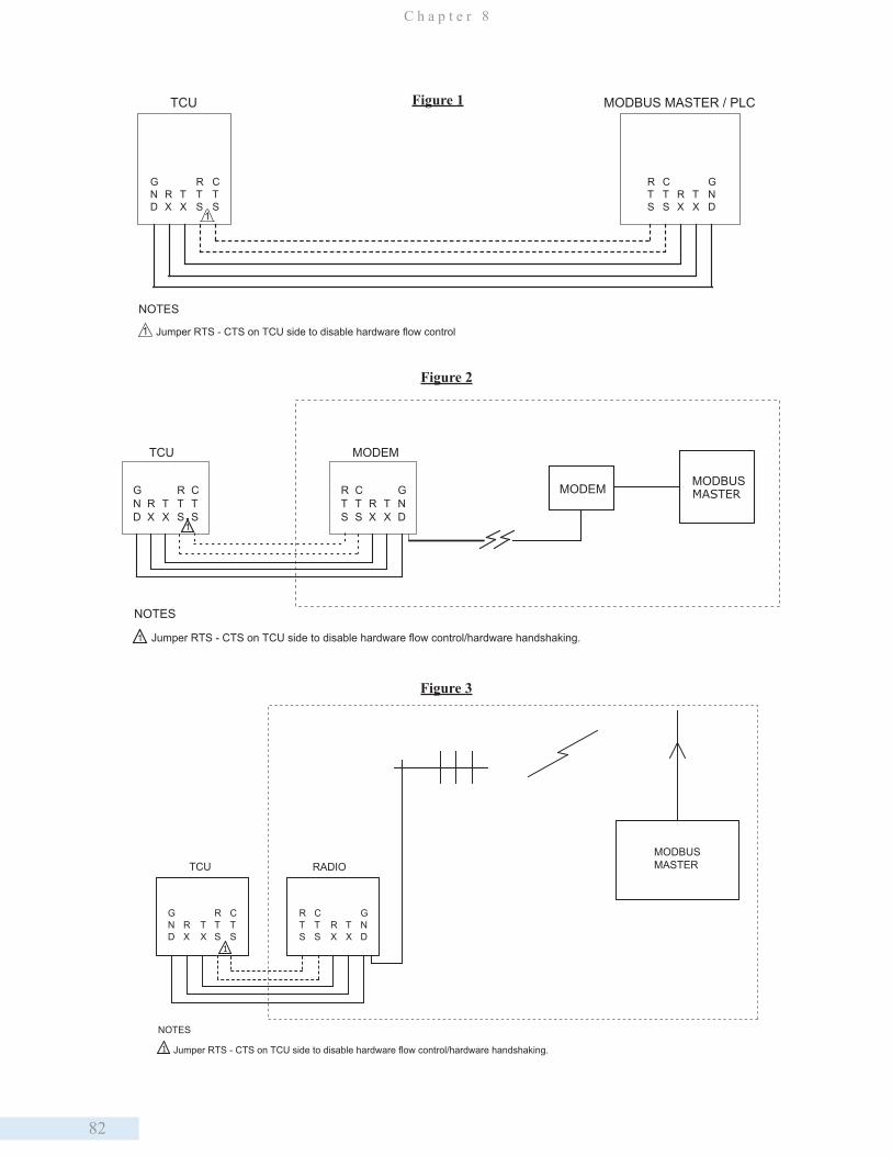
82
C h a p t e r 8
MODBUS MASTER / PLCTCU
RX
TX
RTS
CTS
RTS
CTS
RX
TX
GND
GND
Jumper RTS - CTS on TCU side to disable hardware flow control1
1
NOTES
Figure 1
MODEM MODBUSMASTER
MODEMTCU
1
CTS
RTS
TX
RX
GND
RTS
CTS
RX
TX
GND
Jumper RTS - CTS on TCU side to disable hardware flow control/hardware handshaking.1
NOTES
Figure 2
TCU RADIO
1
1 Jumper RTS - CTS on TCU side to disable hardware flow control/hardware handshaking.
MODBUSMASTER
GND
RX
TX
RTS
CTS
RTS
CTS
RX
TX
GND
NOTES
Figure 3
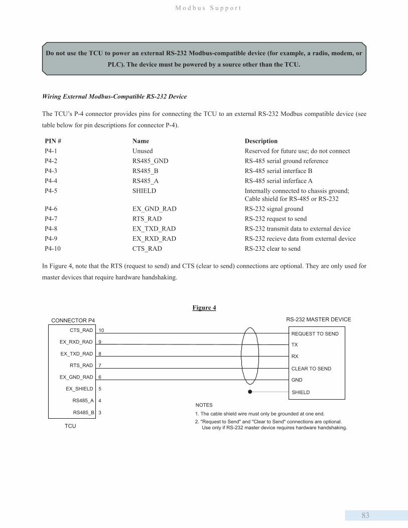
83
M o d b u s S u p p o r t
Wiring External Modbus-Compatible RS-232 Device
The TCU’s P-4 connector provides pins for connecting the TCU to an external RS-232 Modbus compatible device (see
table below for pin descriptions for connector P-4).
PIN # Name DescriptionP4-1 Unused Reserved for future use; do not connectP4-2 RS485_GND RS-485 serial ground reference P4-3 RS485_B RS-485 serial interface B P4-4 RS485_A RS-485 serial inferface AP4-5 SHIELD Internally connected to chassis ground;
Cable shield for RS-485 or RS-232P4-6 EX_GND_RAD RS-232 signal groundP4-7 RTS_RAD RS-232 request to sendP4-8 EX_TXD_RAD RS-232 transmit data to external deviceP4-9 EX_RXD_RAD RS-232 recieve data from external device P4-10 CTS_RAD RS-232 clear to send
In Figure 4, note that the RTS (request to send) and CTS (clear to send) connections are optional. They are only used for
master devices that require hardware handshaking.
Do not use the TCU to power an external RS-232 Modbus-compatible device (for example, a radio, modem, or
PLC). The device must be powered by a source other than the TCU.
CONNECTOR P4
TCU
SHIELD
10CTS_RAD
8EX_TXD_RAD
9EX_RXD_RAD
7RTS_RAD
6EX_GND_RAD
5EX_SHIELD
4RS485_A
3RS485_B
RS-232 MASTER DEVICE
TX
RX
GND
NOTES
1. The cable shield wire must only be grounded at one end.2. "Request to Send" and "Clear to Send" connections are optional. Use only if RS-232 master device requires hardware handshaking.
REQUEST TO SEND
CLEAR TO SEND
Figure 4
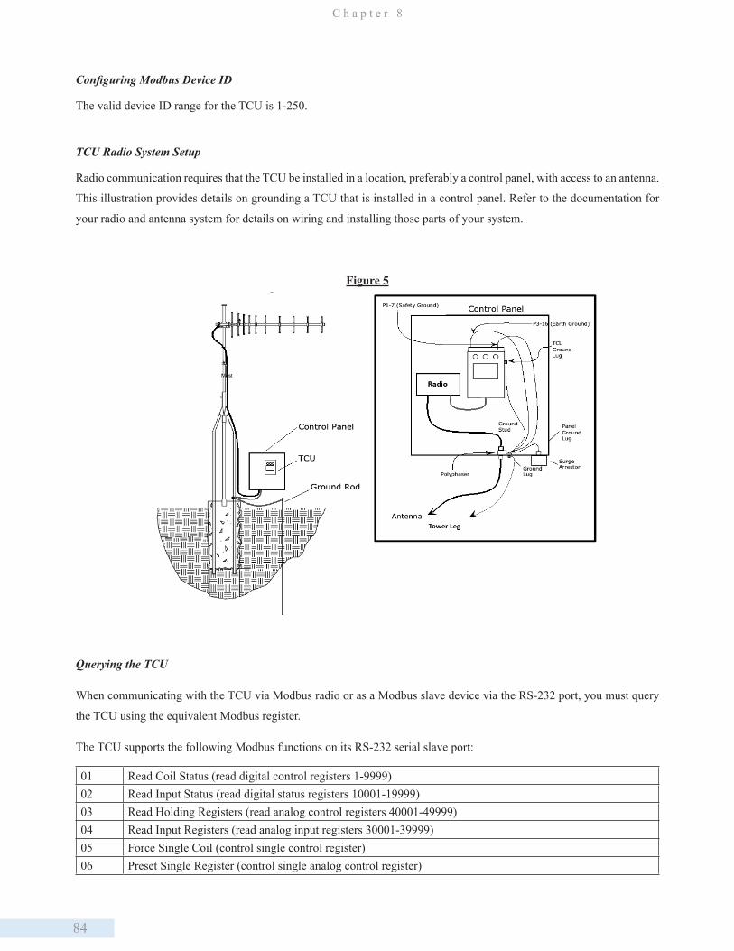
84
C h a p t e r 8
Configuring Modbus Device ID
The valid device ID range for the TCU is 1-250.
TCU Radio System Setup
Radio communication requires that the TCU be installed in a location, preferably a control panel, with access to an antenna.
This illustration provides details on grounding a TCU that is installed in a control panel. Refer to the documentation for
your radio and antenna system for details on wiring and installing those parts of your system.
Figure 5
Querying the TCU
When communicating with the TCU via Modbus radio or as a Modbus slave device via the RS-232 port, you must query
the TCU using the equivalent Modbus register.
The TCU supports the following Modbus functions on its RS-232 serial slave port:
01 Read Coil Status (read digital control registers 1-9999)02 Read Input Status (read digital status registers 10001-19999)03 Read Holding Registers (read analog control registers 40001-49999)04 Read Input Registers (read analog input registers 30001-39999)05 Force Single Coil (control single control register)06 Preset Single Register (control single analog control register)
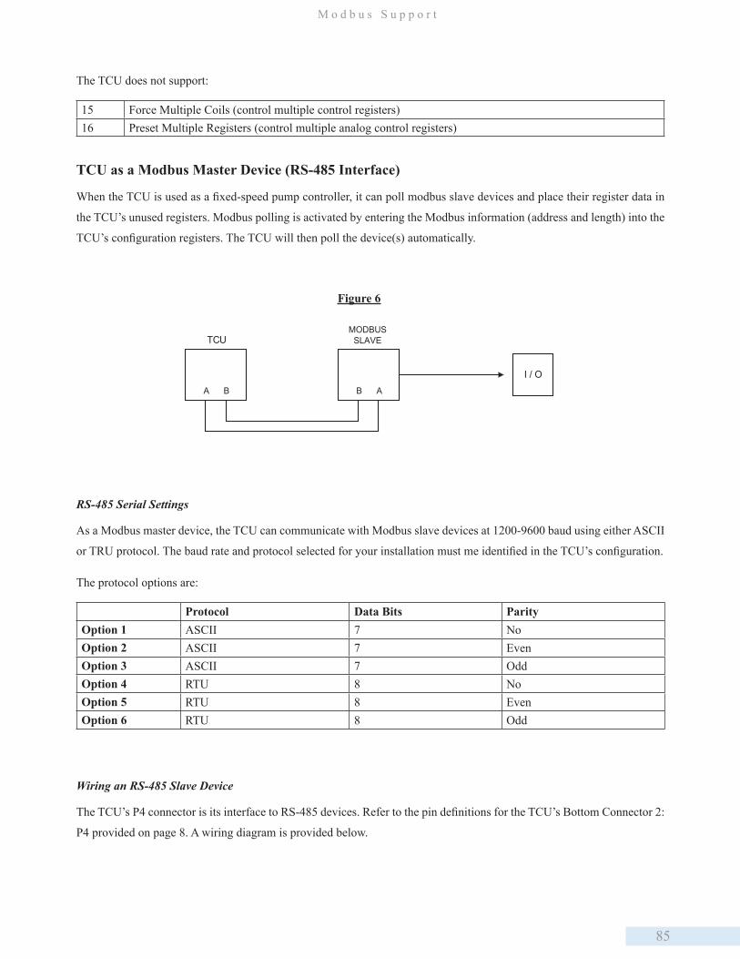
85
M o d b u s S u p p o r t
TCU
BA B A
I / O
MODBUSSLAVE
Figure 6
RS-485 Serial Settings
As a Modbus master device, the TCU can communicate with Modbus slave devices at 1200-9600 baud using either ASCII
or TRU protocol. The baud rate and protocol selected for your installation must me identified in the TCU’s configuration.
The protocol options are:
Protocol Data Bits ParityOption 1 ASCII 7 No Option 2 ASCII 7 EvenOption 3 ASCII 7 OddOption 4 RTU 8 No Option 5 RTU 8 Even Option 6 RTU 8 Odd
Wiring an RS-485 Slave Device
The TCU’s P4 connector is its interface to RS-485 devices. Refer to the pin definitions for the TCU’s Bottom Connector 2:
P4 provided on page 8. A wiring diagram is provided below.
The TCU does not support:
15 Force Multiple Coils (control multiple control registers)16 Preset Multiple Registers (control multiple analog control registers)
TCU as a Modbus Master Device (RS-485 Interface)
When the TCU is used as a fixed-speed pump controller, it can poll modbus slave devices and place their register data in
the TCU’s unused registers. Modbus polling is activated by entering the Modbus information (address and length) into the
TCU’s configuration registers. The TCU will then poll the device(s) automatically.
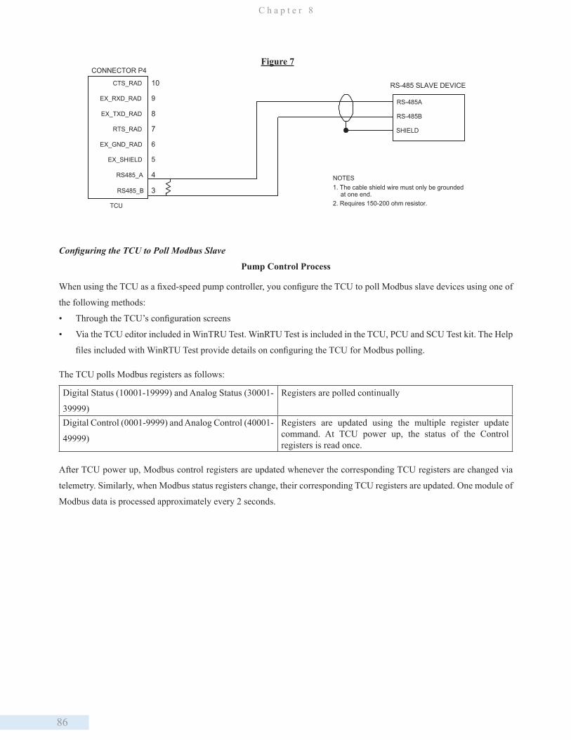
86
C h a p t e r 8
CONNECTOR P4
TCU
10CTS_RAD
8EX_TXD_RAD
9EX_RXD_RAD
7RTS_RAD
6EX_GND_RAD
5EX_SHIELD
4RS485_A
3RS485_B
RS-485 SLAVE DEVICE
RS-485A
RS-485B
SHIELD
NOTES1. The cable shield wire must only be grounded at one end.2. Requires 150-200 ohm resistor.
Figure 7
Configuring the TCU to Poll Modbus Slave
Pump Control Process
When using the TCU as a fixed-speed pump controller, you configure the TCU to poll Modbus slave devices using one of
the following methods:
• Through the TCU’s configuration screens
• Via the TCU editor included in WinTRU Test. WinRTU Test is included in the TCU, PCU and SCU Test kit. The Help
files included with WinRTU Test provide details on configuring the TCU for Modbus polling.
The TCU polls Modbus registers as follows:
Digital Status (10001-19999) and Analog Status (30001-
39999)
Registers are polled continually
Digital Control (0001-9999) and Analog Control (40001-
49999)
Registers are updated using the multiple register update command. At TCU power up, the status of the Control registers is read once.
After TCU power up, Modbus control registers are updated whenever the corresponding TCU registers are changed via
telemetry. Similarly, when Modbus status registers change, their corresponding TCU registers are updated. One module of
Modbus data is processed approximately every 2 seconds.

87
D a t a F l o w S y s t e m s , I n c .
Appendix
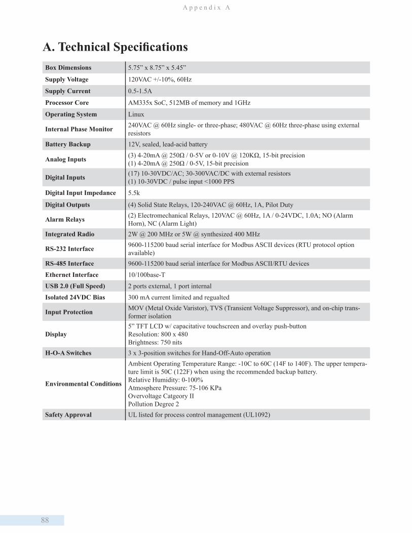
88
A p p e n d i x A
Box Dimensions 5.75” x 8.75” x 5.45”
Supply Voltage 120VAC +/-10%, 60Hz
Supply Current 0.5-1.5A
Processor Core AM335x SoC, 512MB of memory and 1GHz
Operating System Linux
Internal Phase Monitor 240VAC @ 60Hz single- or three-phase; 480VAC @ 60Hz three-phase using external resistors
Battery Backup 12V, sealed, lead-acid battery
Analog Inputs (3) 4-20mA @ 250Ω / 0-5V or 0-10V @ 120KΩ, 15-bit precision(1) 4-20mA @ 250Ω / 0-5V, 15-bit precision
Digital Inputs (17) 10-30VDC/AC; 30-300VAC/DC with external resistors(1) 10-30VDC / pulse input <1000 PPS
Digital Input Impedance 5.5k
Digital Outputs (4) Solid State Relays, 120-240VAC @ 60Hz, 1A, Pilot Duty
Alarm Relays (2) Electromechanical Relays, 120VAC @ 60Hz, 1A / 0-24VDC, 1.0A; NO (Alarm Horn), NC (Alarm Light)
Integrated Radio 2W @ 200 MHz or 5W @ synthesized 400 MHz
RS-232 Interface 9600-115200 baud serial interface for Modbus ASCII devices (RTU protocol option available)
RS-485 Interface 9600-115200 baud serial interface for Modbus ASCII/RTU devices
Ethernet Interface 10/100base-T
USB 2.0 (Full Speed) 2 ports external, 1 port internal
Isolated 24VDC Bias 300 mA current limited and regualted
Input Protection MOV (Metal Oxide Varistor), TVS (Transient Voltage Suppressor), and on-chip trans-former isolation
Display5” TFT LCD w/ capacitative touchscreen and overlay push-buttonResolution: 800 x 480Brightness: 750 nits
H-O-A Switches 3 x 3-position switches for Hand-Off-Auto operation
Environmental Conditions
Ambient Operating Temperature Range: -10C to 60C (14F to 140F). The upper tempera-ture limit is 50C (122F) when using the recommended backup battery. Relative Humidity: 0-100%Atmosphere Pressure: 75-106 KPaOvervoltage Catgeory IIPollution Degree 2
Safety Approval UL listed for process control management (UL1092)
A. Technical Specifications
89
C h e c k o u t P r o c e d u r e f o r P u m p C o n t r o l l e r
B. Checkout Procedure for Pump ControllerStep 1: Electrical Termination Review
NEC code and OSHA safety standards should be observed during all installation, grounding and testing procedures.
Modifications to the following should be made as necessary to stay within NEC and OSHA guidelines. Confirm with DFS
regarding proper procedure if the following becomes obsolete due to code or regulation changes.
1. Visually inspect all wiring. Check for loose wires and short circuits.
2. Verify 120 VAC exists at the line termination and between neutral and ground terminals on the TCU’s P1 connector.
3. Verify proper voltage dropping resistors are in place on all TCU digital input pins where voltage exceeds 30 VAC/VDC.
4. Verify that surge arrestor components are installed correctly as detailed in DFS approved drawings.
5. Verify that DFS onboard 24 VDC supply is not being used for any control devices. This onboard source is for biasing
analog and digital monitor inputs to the TCU only.
6. Verify that grounding is installed correctly. Bonding should occur between the DFS tower ground rod and Power
Company ground rod and finally to the DFS supplied Polyphaser. Refer to illustrations provided in “Chapter 7: Telemetry
Configuration.”
7. If 3-phase power is input directly to the TCU, verify that:
• Voltage exists at the P1 terminals for the appropriate phases.
• 3-phase power is fused and correctly routed through the TFS supplied by DFS.
If the TCU shows an active 3-phase error, follow the steps provided in “Chapter 6: Operation Procedures” to adjust the
Low Phase and High Phase limits. To facilitate a start-up, the 3-phase limits can initially be adjusted fully open, and then
later adjusted for less tolerance.
8. If the Phase Monitor Bypass is used to monitor third party 3-phase monitors with contacts that remain closed when the
3-phase is within specifications, wire the contacts using the same common as the pump run input circuits. The TCU will
only run the pumps if the Phase Monitor Bypass input is ON. If the third party phase monitor contacts should open, all Auto
operation will cease. This input takes precedence over the direct 3-phase input. Although the on-board 3-phase monitor and
phasemonitor-bypass input can be used simultaneously, we do not recommended that configuration.
9. Verify that the level detection device(s) connected to the TCU are properly wired. If floats or pressure switches are
used, check that they are in the correct sequence. If an analog 4-20 mA transducer is used, check that the jumper between
the ANALOG- and SHUNT terminals is installed. If an analog 0-5 V transducer is used, you must check that the jumper
between the ANALOG- and SHUNT terminals is removed. Verify the wiring of the alarm light and horn, if used. The
voltage connected to ALM_PWR is switched to the ALM_LITE and ALM_HORN terminals when the alarms are activated.
The returns for the light and horn must be connected to the return of the source used to power them.
90
A p p e n d i x B
10. Verify that the proper fuses are installed in the output circuits of the motor starter, alarm light and horn, and auxiliary.
11. If telemetry is used, verify the wiring of the interface cable.
Step 2: Operations Testing
Test all of the TCU functions listed below. If the tested function fails, first verify the circuit between the TCU and the
device. When verifying the circuit, check fuses, resistors, signal contacts, isolators, relays bias, and return voltages and
conductors, where applicable, as these components are occasionally subject to failure.
1. Before powering the TCU, place all three H-O-A switches in the Off position.
2. Turn circuit breakers on one at a time. Turn the TCU on last.
3. Verify Hand operation of the contactors (pumps) by placing each of the TCU’s H-O-A switches in the Hand position.
4. Verify that each Pump Run LED illuminates when its respective control is engaged in Hand operation. If the LED flashes,
the TCU has failed to receive the Motor Run Input for the contactor. If this occurs, verify the pump run circuit integrity.
5. Check float input operation by tipping the floats and verifying that the correct, corresponding, Float Input LED is
illuminated.
• When the High float is tipped and the high float is enabled, the bell or alarm should go on.
• If the Low float’s contact is open, the bell or alarm should go on.
• If the TCU is using an analog input for level control, refer to “Chapter 6: Operation Procedures” for information on
setting the level set points along with other options for analog and float back-up operation.
Note: The alarm light and alarm horn have to be enabled in the TCU’s configuration in order for them to operate.
6. If an alarm silence button is wired, verify the Alarm Silence input is operational by attempting to silence the bell or
alarm. The bell/alarm is silenced by pressing and holding the Alarm Silence Button for 2 seconds after the High float is
tipped. The Alarm Silence input shares the same common, and therefore the same voltage source, as the float inputs.
7. Configure the TCU for the site (station) in which it is installed.
8. Check the TCU’s Alarm screen to verify that all alarms have cleared.
9. Place the necessary TCU H-O-A switches in the Auto position. Allow the water level to rise, or manipulate the level
inputs manually, to verify Auto operation.
10. Verify alternation of the pumps by manipulating the “OFF” and ”LEAD” inputs to the TCU in the correct and natural
order based on what pump mode you have selected in the configuration. The TCU control outputs should respond by
alternating the lead pump position with alternation enabled. Allow for some delay on pump start after the level input is
activated.

91
C h e c k o u t P r o c e d u r e f o r P u m p C o n t r o l l e r
11. Verify, as the LAG1 and LAG2 inputs are toggled, that the TCU starts additional pumps that the level input demands.
Allow for some delay on pump start after the level input is activated.
12. After the system is checked out, connect the backup battery, if used. Make sure the battery is properly connected.
Observe polarity markings.
13. If the battery is charged, cycle the TCU’s AC power off and verify battery backup operation. Make sure to turn the TCU
on when finished with the checkout procedure.
92
A p p e n d i x C
C. Maintenance and TroubleshootingBlown Fuse
The TCU800 includes one 2A replaceable fuse. The fuse is located on the side of the TCU and is labled F601. The fuse is
designed to protect the TCU’s DC power circuitry from its operating AC input voltage.
If this fuse blows, you will see one of the following responses depending on the status of the TCU’s backup battery:
Functioning DC BatteryTCU triggers a local AC Power alarm and reports an AC Power Fault to the central
SCADA system. TCU indicators, such as LED lights and LCD screen, will be normal.
DC Battery Dead or Below
Tolerance
No local AC Power alarm is generated; No AC Power Fault is reported to the central
SCADA system. TCU indicators, such as LED lights and LCD screen, will be off. The
TCU station will eventually be shown as Offline in HT3.
Conditions that could cause the fuse to blow:
• Incorrect operating voltage
• Surge in operating AC power voltage greater than .375 A
• Heat condition that exceeds designed operating temperature of 160 degrees
• Incorrect control voltage wiring
• Shorted circuit within the TCU
Before replacing the fuse:
• Inspect the TCU site and wiring to see if any of the conditions listed above may have occurred.
• If you received an offline alarm for this station, check the battery to verify it is functioning properly. Replace the
battery if you find it is unable to hold a charge.
• Measure the input voltage and check the wiring to the TCU’s connector. The operating voltage is marked on the
connector label. Try replacing the fuse only when the proper voltage is connected.
Replacing the fuse:
Replace the fuse with a new identical one.
After replacing the fuse, verify that the TCU is functioning properly (LED lights are lit; LCD screen is working).
If the TCU isn’t working after you’ve replaced the fuse, the TCU may require Factory service. See “Appendix O: Support,
Service, and Warranty” for removal, replacement, and servicing instructions.
TCU Replacement
The TCU can easily be removed and replaced with a backup TCU if it is determined that the TCU needs servicing.
93
M a i n t e n a n c e a n d T r o u b l e s h o o t i n g
1. Before removing the TCU, either make a note of the TCU configuration or download the configuration to a computer.*
2. Turn off all circuit breakers before attempting to remove the TCU.
3. The terminals are connectorized for removal. Use an insulated screwdriver and gently pry the connectors free.
4. Remove the mounting fasteners that connect the TCU to its mounting brackets. You should be able to easily lift the TCU
from its mounting brackets.
5. Install the replacement TCU, replace the fasteners, and reconnect the terminals.
6. Place the replacement TCU’s three H-O-A switches into the “Off” position and turn the breakers back on.
7. Reconfigure the replacement TCU. If the faulted TCU’s configuration was backed up on a portable computer, it can be
restored on the replacement TCU.*
8. After configuring the replacement TCU, place the required H-O-A switches in the “Auto” position.
*TCU configurations can be uploaded/downloaded through telemetry using PCU Editor. You can also connect the TCU directly to a laptop computer and
use the WinRTU Test software to download/upload configurations. Refer to the help files of these applications for more information.
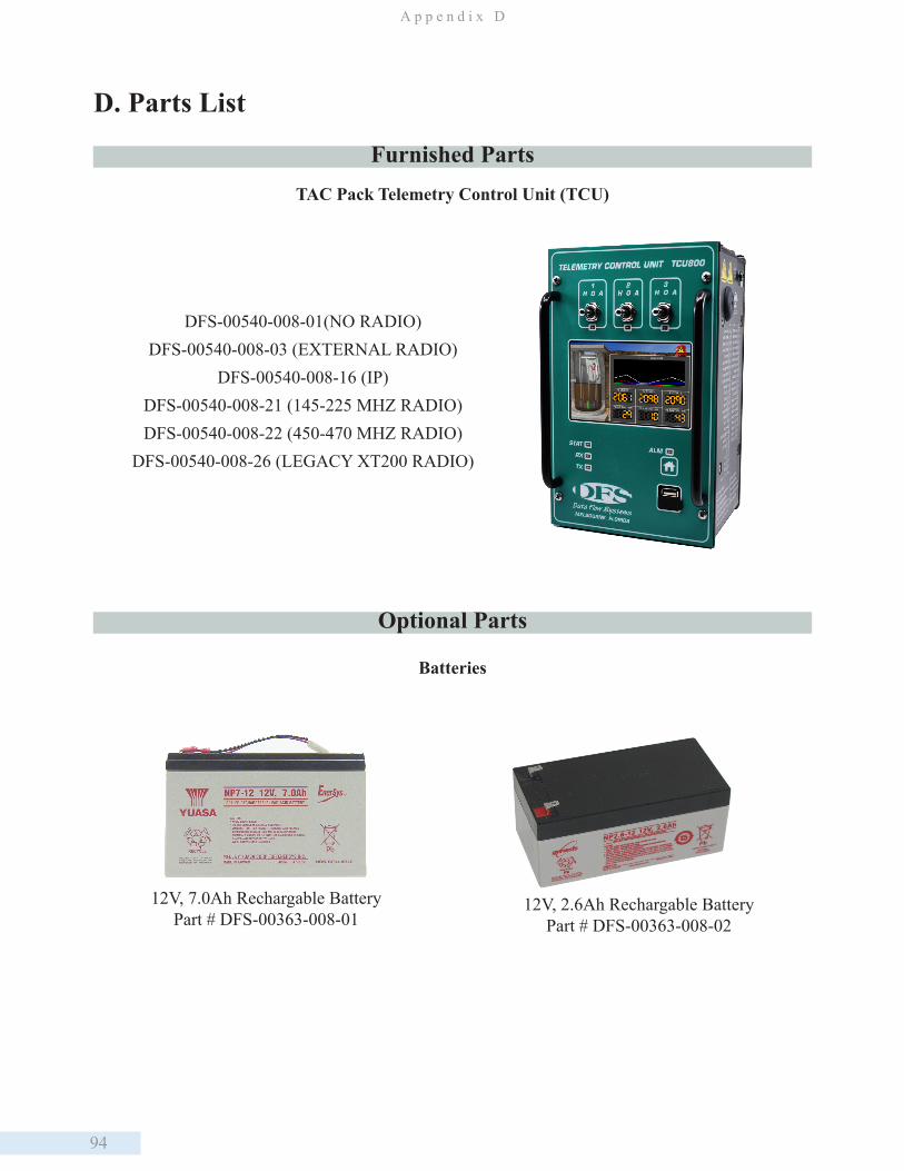
94
A p p e n d i x D
D. Parts List
TAC Pack Telemetry Control Unit (TCU)
Batteries
12V, 7.0Ah Rechargable BatteryPart # DFS-00363-008-01
12V, 2.6Ah Rechargable BatteryPart # DFS-00363-008-02
DFS-00540-008-01(NO RADIO) DFS-00540-008-03 (EXTERNAL RADIO)
DFS-00540-008-16 (IP) DFS-00540-008-21 (145-225 MHZ RADIO) DFS-00540-008-22 (450-470 MHZ RADIO)
DFS-00540-008-26 (LEGACY XT200 RADIO)
Furnished Parts
Optional Parts
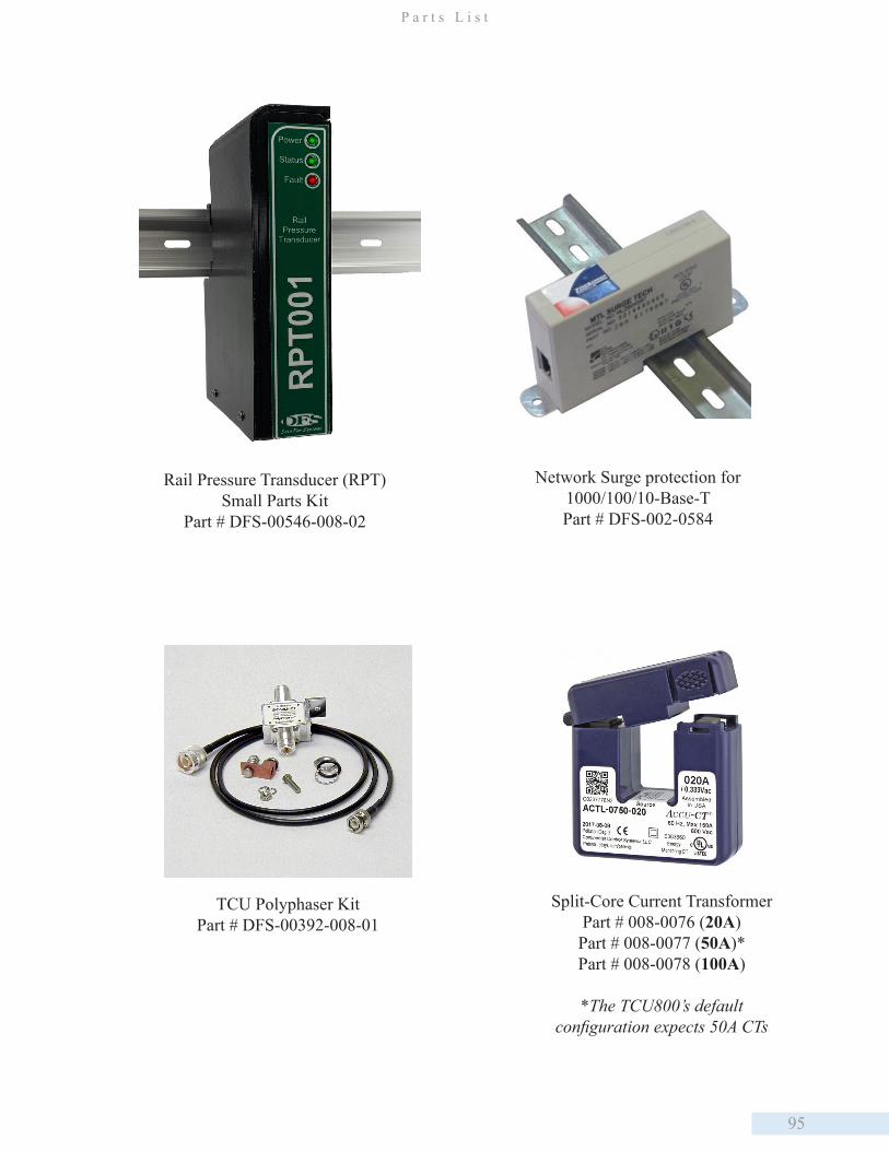
95
P a r t s L i s t
Split-Core Current TransformerPart # 008-0076 (20A)Part # 008-0077 (50A)*Part # 008-0078 (100A)
*The TCU800’s default configuration expects 50A CTs
Rail Pressure Transducer (RPT) Small Parts Kit
Part # DFS-00546-008-02
Network Surge protection for 1000/100/10-Base-T Part # DFS-002-0584
TCU Polyphaser KitPart # DFS-00392-008-01
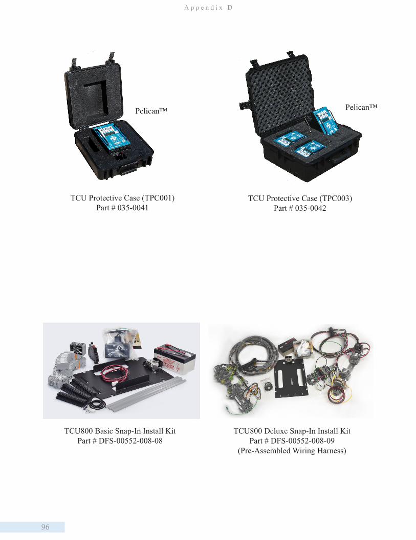
96
A p p e n d i x D
TCU Protective Case (TPC001) Part # 035-0041
TCU800 Basic Snap-In Install KitPart # DFS-00552-008-08
TCU Protective Case (TPC003)Part # 035-0042
Pelican™ Pelican™
TCU800 Deluxe Snap-In Install KitPart # DFS-00552-008-09
(Pre-Assembled Wiring Harness)
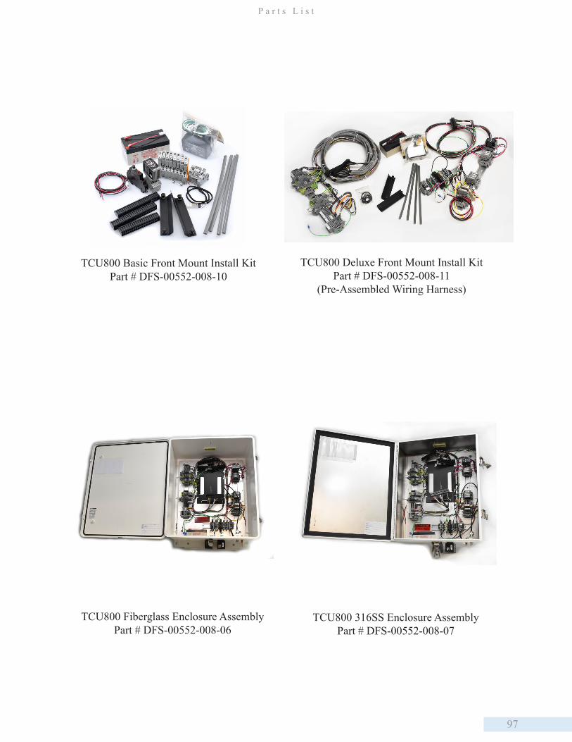
97
P a r t s L i s t
TCU800 Basic Front Mount Install KitPart # DFS-00552-008-10
TCU800 Deluxe Front Mount Install KitPart # DFS-00552-008-11
(Pre-Assembled Wiring Harness)
TCU800 316SS Enclosure AssemblyPart # DFS-00552-008-07
TCU800 Fiberglass Enclosure Assembly Part # DFS-00552-008-06
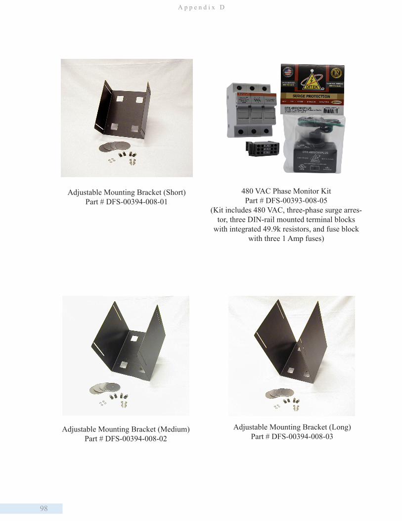
98
A p p e n d i x D
480 VAC Phase Monitor KitPart # DFS-00393-008-05
(Kit includes 480 VAC, three-phase surge arres-tor, three DIN-rail mounted terminal blocks
with integrated 49.9k resistors, and fuse block with three 1 Amp fuses)
Adjustable Mounting Bracket (Long)Part # DFS-00394-008-03
Adjustable Mounting Bracket (Medium)Part # DFS-00394-008-02
Adjustable Mounting Bracket (Short)Part # DFS-00394-008-01

99
P a r t s L i s t
120V Surge Protector (SPS001) Part # 005-0061
240V 3-Phase Surge Protector (TPS001) Part # 005-0062
RC SnubberPart # 007-0084
Service AdapterPart # 002-0540
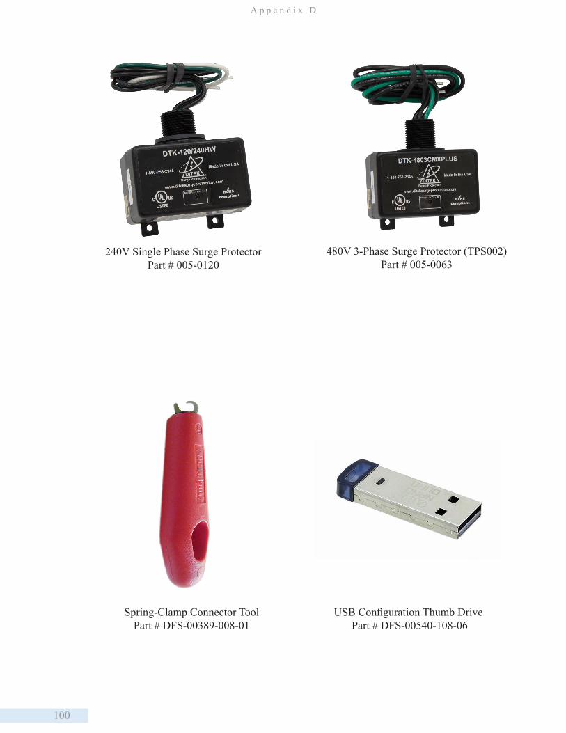
100
A p p e n d i x D
Spring-Clamp Connector ToolPart # DFS-00389-008-01
USB Configuration Thumb Drive Part # DFS-00540-108-06
240V Single Phase Surge Protector Part # 005-0120
480V 3-Phase Surge Protector (TPS002)Part # 005-0063
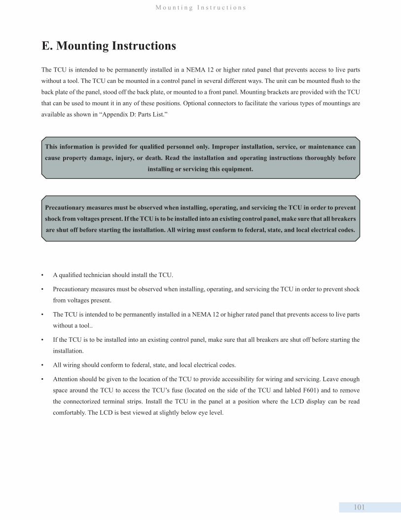
101
M o u n t i n g I n s t r u c t i o n s
E. Mounting Instructions
The TCU is intended to be permanently installed in a NEMA 12 or higher rated panel that prevents access to live parts
without a tool. The TCU can be mounted in a control panel in several different ways. The unit can be mounted flush to the
back plate of the panel, stood off the back plate, or mounted to a front panel. Mounting brackets are provided with the TCU
that can be used to mount it in any of these positions. Optional connectors to facilitate the various types of mountings are
available as shown in “Appendix D: Parts List.”
• A qualified technician should install the TCU.
• Precautionary measures must be observed when installing, operating, and servicing the TCU in order to prevent shock
from voltages present.
• The TCU is intended to be permanently installed in a NEMA 12 or higher rated panel that prevents access to live parts
without a tool..
• If the TCU is to be installed into an existing control panel, make sure that all breakers are shut off before starting the
installation.
• All wiring should conform to federal, state, and local electrical codes.
• Attention should be given to the location of the TCU to provide accessibility for wiring and servicing. Leave enough
space around the TCU to access the TCU’s fuse (located on the side of the TCU and labled F601) and to remove
the connectorized terminal strips. Install the TCU in the panel at a position where the LCD display can be read
comfortably. The LCD is best viewed at slightly below eye level.
This information is provided for qualified personnel only. Improper installation, service, or maintenance can
cause property damage, injury, or death. Read the installation and operating instructions thoroughly before
installing or servicing this equipment.
Precautionary measures must be observed when installing, operating, and servicing the TCU in order to prevent
shock from voltages present. If the TCU is to be installed into an existing control panel, make sure that all breakers
are shut off before starting the installation. All wiring must conform to federal, state, and local electrical codes.
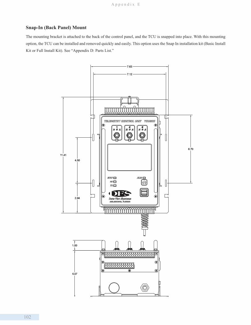
102
A p p e n d i x E
4.57
1.00
7.12
7.63
11.41
4.50
2.94
6.70
Snap-In (Back Panel) Mount
The mounting bracket is attached to the back of the control panel, and the TCU is snapped into place. With this mounting
option, the TCU can be installed and removed quickly and easily. This option uses the Snap In installation kit (Basic Install
Kit or Full Install Kit). See “Appendix D: Parts List.”

103
M o u n t i n g I n s t r u c t i o n s
5.81
9.00
4.50
5.50
0.72
7.63
7.13
4.50
2.24
0.25
TCU Front Panel Mount
With this mounting option, the TCU is attached to the mounting bracket with screws instead of being snapped into place.
This option uses the Front Mount installation kit (Basic Install Kit or Full Install Kit). See “Appendix D: Parts List.”
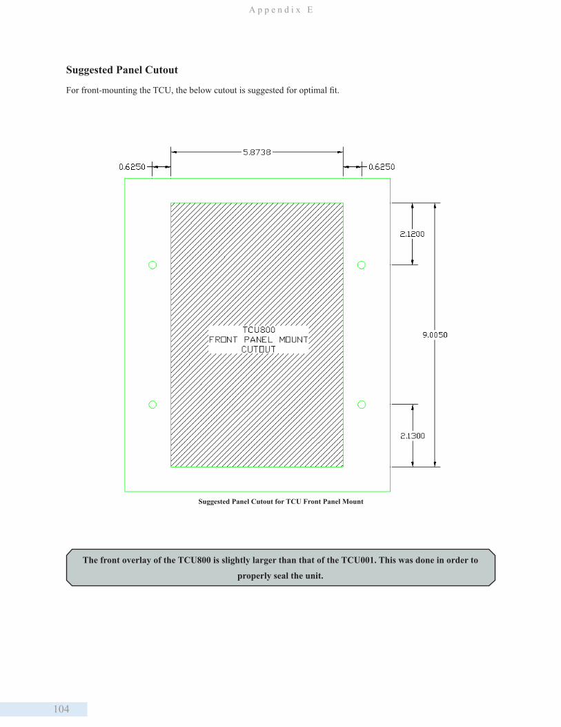
104
A p p e n d i x E
Suggested Panel Cutout for TCU Front Panel Mount
The front overlay of the TCU800 is slightly larger than that of the TCU001. This was done in order to
properly seal the unit.
Suggested Panel Cutout
For front-mounting the TCU, the below cutout is suggested for optimal fit.
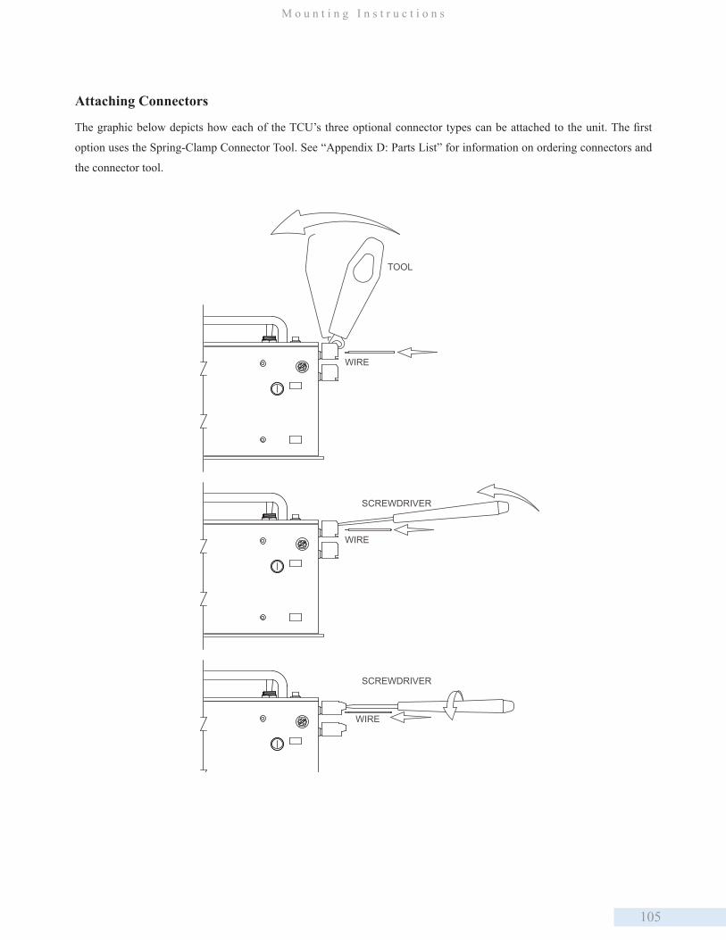
105
M o u n t i n g I n s t r u c t i o n s
Attaching Connectors
The graphic below depicts how each of the TCU’s three optional connector types can be attached to the unit. The first
option uses the Spring-Clamp Connector Tool. See “Appendix D: Parts List” for information on ordering connectors and
the connector tool.
TOOL
WIRE
WIRE
SCREWDRIVER
SCREWDRIVER
WIRE
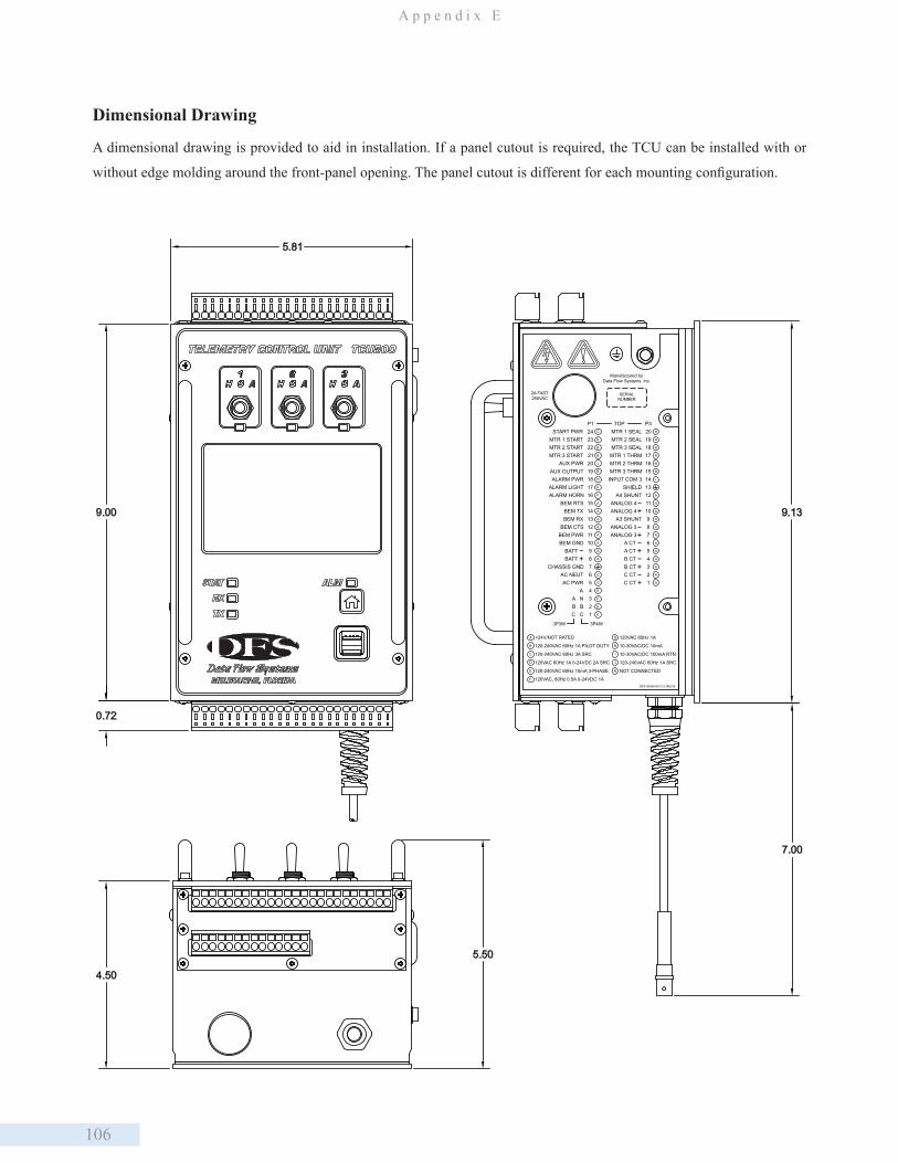
106
A p p e n d i x E
Dimensional Drawing
A dimensional drawing is provided to aid in installation. If a panel cutout is required, the TCU can be installed with or
without edge molding around the front-panel opening. The panel cutout is different for each mounting configuration.
A
B
C
D
E
F
G
H
<24V/NOT RATED
120-240VAC 60Hz 1A PILOT DUTY
120-240VAC 60Hz 3A SRC
120VAC 60Hz 1A 0-24VDC 2A SRC
120-240VAC 60Hz 10mA 3-PHASE
120VAC, 60Hz 0.5A 0-24VDC 1A
120VAC 60Hz 1A
10-30VAC/DC 10mA
10-30VAC/DC 100mA RTN
120-240VAC 60Hz 1A SRC
Manufactured byData Flow Systems, Inc.
DFS-00540-007-13 REV B
P1
11
1918
20
15
1716
12
1413
8
109
P3
MTR 2 SEAL
MTR 2 THRMMTR 3 THRM
INPUT COM 3SHIELD
A4 SHUNTANALOG 4ANALOG 4
A3 SHUNTANALOG 3
AUX PWRAUX OUTPUTALARM PWR
ALARM LIGHT
BEM TXBEM RX
BEM CTSBEM PWRBEM GND
BATTBATT
CHASSIS GNDAC NEUTAC PWR
AA NB BC C
START PWR
15
24
2223
2021
19
1718
16
8
1314
12
1011
9
5
76
34
21
C
B
B
B
J
B
D
F
F
H
H
H
H
H
H
I
A
7
54321
6ANALOG 3
A CTA CTB CTB CTC CTC CT
MTR 1 SEALMTR 1 STARTMTR 2 STARTMTR 3 START
ALARM HORNBEM RTS
+-
MTR 3 SEALMTR 1 THRM
+
+
+
+
+
-
-
-
-
-
I
J
A
A
A
A
A
A
A
A
A
A
A
A
A
A
A
A
A
A
A
G
G
E
E
E
E
NOT CONNECTEDN
TOP
3P3W 3P4W
SERIALNUMBER
2A FAST250VAC
9.13
5.81
9.00
7.00
4.50
5.50
0.72
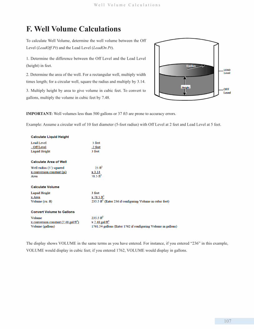
107
W e l l Vo l u m e C a l c u l a t i o n s
To calculate Well Volume, determine the well volume between the Off
Level (LeadOff Pt) and the Lead Level (LeadOn Pt).
1. Determine the difference between the Off Level and the Lead Level
(height) in feet.
2. Determine the area of the well. For a rectangular well, multiply width
times length; for a circular well, square the radius and multiply by 3.14.
3. Multiply height by area to give volume in cubic feet. To convert to
gallons, multiply the volume in cubic feet by 7.48.
F. Well Volume Calculations
IMPORTANT: Well volumes less than 500 gallons or 37 ft3 are prone to accuracy errors.
Example: Assume a circular well of 10 feet diameter (5-foot radius) with Off Level at 2 feet and Lead Level at 5 feet.
The display shows VOLUME in the same terms as you have entered. For instance, if you entered “236” in this example,
VOLUME would display in cubic feet; if you entered 1762, VOLUME would display in gallons.
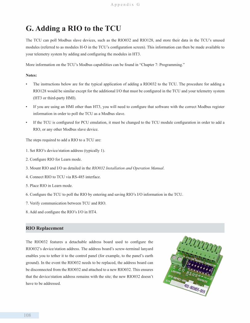
108
A p p e n d i x G
G. Adding a RIO to the TCUThe TCU can poll Modbus slave devices, such as the RIO032 and RIO128, and store their data in the TCU’s unused
modules (referred to as modules H-O in the TCU’s configuration screen). This information can then be made available to
your telemetry system by adding and configuring the modules in HT3.
More information on the TCU’s Modbus capabilities can be found in “Chapter 7: Programming.”
Notes:
• The instructions below are for the typical application of adding a RIO032 to the TCU. The procedure for adding a
RIO128 would be similar except for the additional I/O that must be configured in the TCU and your telemetry system
(HT3 or third-party HMI).
• If you are using an HMI other than HT3, you will need to configure that software with the correct Modbus register
information in order to poll the TCU as a Modbus slave.
• If the TCU is configured for PCU emulation, it must be changed to the TCU module configuration in order to add a
RIO, or any other Modbus slave device.
The steps required to add a RIO to a TCU are:
1. Set RIO’s device/station address (typically 1).
2. Configure RIO for Learn mode.
3. Mount RIO and I/O as detailed in the RIO032 Installation and Operation Manual.
4. Connect RIO to TCU via RS-485 interface.
5. Place RIO in Learn mode.
6. Configure the TCU to poll the RIO by entering and saving RIO’s I/O information in the TCU.
7. Verify communication between TCU and RIO.
8. Add and configure the RIO’s I/O in HT4.
RIO Replacement
The RIO032 features a detachable address board used to configure the
RIO032’s device/station address. The address board’s screw-terminal lanyard
enables you to tether it to the control panel (for example, to the panel’s earth
ground). In the event the RIO032 needs to be replaced, the address board can
be disconnected from the RIO032 and attached to a new RIO032. This ensures
that the device/station address remains with the site; the new RIO032 doesn’t
have to be addressed.
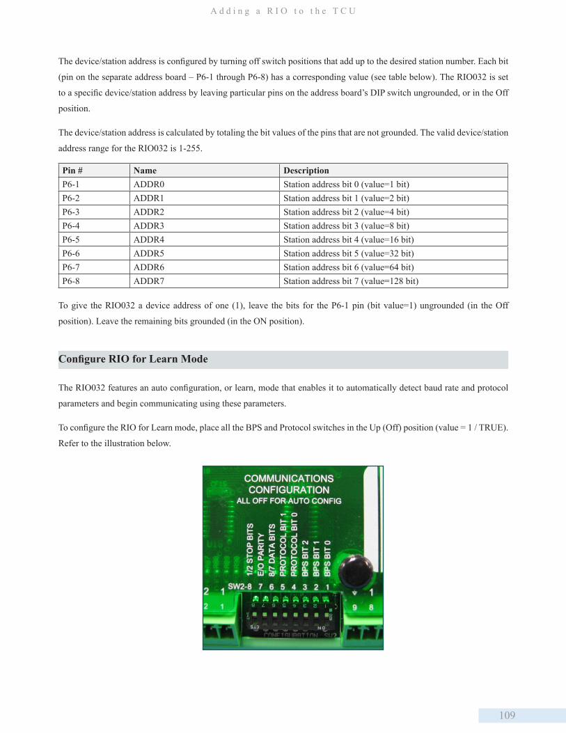
109
A d d i n g a R I O t o t h e T C U
The device/station address is configured by turning off switch positions that add up to the desired station number. Each bit
(pin on the separate address board – P6-1 through P6-8) has a corresponding value (see table below). The RIO032 is set
to a specific device/station address by leaving particular pins on the address board’s DIP switch ungrounded, or in the Off
position.
The device/station address is calculated by totaling the bit values of the pins that are not grounded. The valid device/station
address range for the RIO032 is 1-255.
Pin # Name Description P6-1 ADDR0 Station address bit 0 (value=1 bit)P6-2 ADDR1 Station address bit 1 (value=2 bit)P6-3 ADDR2 Station address bit 2 (value=4 bit)P6-4 ADDR3 Station address bit 3 (value=8 bit)P6-5 ADDR4 Station address bit 4 (value=16 bit)P6-6 ADDR5 Station address bit 5 (value=32 bit)P6-7 ADDR6 Station address bit 6 (value=64 bit)P6-8 ADDR7 Station address bit 7 (value=128 bit)
To give the RIO032 a device address of one (1), leave the bits for the P6-1 pin (bit value=1) ungrounded (in the Off
position). Leave the remaining bits grounded (in the ON position).
Configure RIO for Learn Mode
The RIO032 features an auto configuration, or learn, mode that enables it to automatically detect baud rate and protocol
parameters and begin communicating using these parameters.
To configure the RIO for Learn mode, place all the BPS and Protocol switches in the Up (Off) position (value = 1 / TRUE).
Refer to the illustration below.
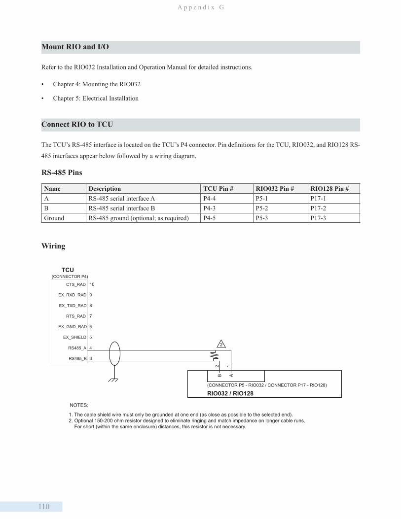
110
A p p e n d i x G
Mount RIO and I/O
Refer to the RIO032 Installation and Operation Manual for detailed instructions.
• Chapter 4: Mounting the RIO032
• Chapter 5: Electrical Installation
Connect RIO to TCU
The TCU’s RS-485 interface is located on the TCU’s P4 connector. Pin definitions for the TCU, RIO032, and RIO128 RS-
485 interfaces appear below followed by a wiring diagram.
RS-485 Pins
Name Description TCU Pin # RIO032 Pin # RIO128 Pin #A RS-485 serial interface A P4-4 P5-1 P17-1B RS-485 serial interface B P4-3 P5-2 P17-2Ground RS-485 ground (optional; as required) P4-5 P5-3 P17-3
Wiring
TCU
RIO032 / RIO128(CONNECTOR P5 - RIO032 / CONNECTOR P17 - RIO128)
B A
1. The cable shield wire must only be grounded at one end (as close as possible to the selected end).2. Optional 150-200 ohm resistor designed to eliminate ringing and match impedance on longer cable runs. For short (within the same enclosure) distances, this resistor is not necessary.
NOTES:
2 1
(CONNECTOR P4)
10CTS_RAD
8EX_TXD_RAD
9EX_RXD_RAD
7RTS_RAD
6EX_GND_RAD
5EX_SHIELD
4RS485_A
3RS485_B
2
111
A d d i n g a R I O t o t h e T C U
Place the RIO in Learn Mode
When all of the RIO’s communication configuration switches are left in the Off position (see step 2, Configure RIO for
Learn Mode, above) and the RIO’s configuration button is held down during power up, the RIO enters learn mode. The
RIO then attempts to determine baud and protocol settings within three to ten polling loops (depending on settings such
as baud rate).
1. Hold down the configuration button while powering up the device. All of the RIO032’s LED’s come on.
2. Release the configuration button when the RXD, TXD, and Status LED’s go off.
3. The TXD will flash rapidly and then the TXD, RXD, and Status LED’s will blink.
4. After a minimum of three polls are received (may take up to ten polls), the RXD will blink three times. The TXD, RXD
and Status LED’s will turn on and then off indicating that Learn (auto configuration) is complete.
During the Learn process, the RIO032 uses the CTS (clear to send) signal to determine if it is connected to a radio. Radios,
unlike other devices, don’t activate the CTS signal until an RTS (request to send) is asserted. If the RIO032 determines that
is it connected to a radio, it will communicate using the RTU Radio protocol. This protocol is identical to RTU protocol
except that the RIO expects a CTS to occur whenever it asserts an RTS, and it will wait for the CTS signal before it
transmits any data. This protocol allows the RIO032 to be connected to an RDR (Rail Data Radio) or other manufacturer
radio without using special cabling.
Configuring the TCU to Poll the RIO
In order for the TCU to poll the RIO and make the RIO’s data available to HT3, the RIO’s I/O information must be added
to the TCU’s configuration.
Modules H-O in the TCU are reserved for Modbus slave devices. Each module can accommodate up to:
• Twelve (12) digital status registers, or
• Eight (8) digital control registers, or
• Four (4) analog status registers, or
• Four (4) analog control registers
The instructions below are for a TCU using the built in pump control application.
1. Page through the TCU’s configuration screens until you reach the screen that includes the “Configure Modbus” option.
Navigate to the Configure Modbus line and press Enter.
2. The first screen allows you to configure the Module H and Module I registers. Use the right navigation button to page to
the screens for the remaining modules (J-O). When configuring for Modbus polling, we recommend that you use the first
available TCU module. For example, if modules J-O are available, configure module J; don’t skip to M.
3. For each module you want to configure, you must enter an address (ModX Adr) and length (ModX Lth):
112
A p p e n d i x G
• Address is the RIO’s device number and the first of the range of registers being added to the current module. For
example, ModH Adr would be 1.10001 when adding digital inputs to device 1, module H.
• Length is the number of registers being added to the current module. Length can be 1-12 for digital input (status)
registers, 1-8 for digital output (control) registers, and 1-4 for analog registers. For example, ModH Lth would be 8
when adding 8 digital inputs to module H.
• For Analog registers, the Length field requires an additional value that represents resolution (a TCU communicating
with a RIO uses a signed 15-bit resolution). For example, ModJ Lth would be 4.15 when adding 4 analog inputs to
module J.
The table below provides the information required for a RIO032 using all 32 I/O points.
I/O Type Module Letter Module Type Address (ModX Adr) Length (ModX Lth)8 digital inputs H DMM 1.10001 88 digital outputs I DCM 1.00001 84 analog inputs J AMM 1.30001 4.154 analog inputs K AMM 1.30005 4.154 analog outputs L ACM 1.40001 4.154 analog outputs M ACM 1.40005 4.15
4. After adding all of the required module and register information, navigate through the TCU’s configuration screens until
you reach the screen that reads Press Enter to Save, Esc to Abort.
Press Enter to replace the TCU’s existing configuration with the changes made during the current session. After the settings
are successfully save, you must cycle power to the TCU.
IMPORTANT: When the new settings are saved, they are written to a temporary memory location. In order for the TCU to
begin running on the new configurations, you must cycle power to the TCU. If the TCU’s power is cycled before selecting
the Save command, the last saved values are loaded on power up.
Verify Communication Between TCU and RIO
After cycling the TCU’s power, observe the TCU and RIO’s TX and RX LEDs to verify communications are occurring
between the two devices.
Refer to the troubleshooting sections of the TCU and RIO manuals if you encounter communication problems.
Add and Configure the RIO’s I/O in HT4 or Third-Party HMI
In your HT3 software, browse to the TCU’s configuration. Add and configure the modules and I/O that were added to the
TCU’s settings in step 3, above. The configuration in HT3 should exactly match the settings entered in the TCU.
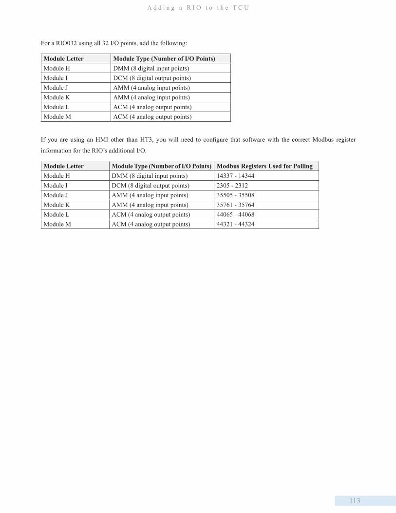
113
A d d i n g a R I O t o t h e T C U
For a RIO032 using all 32 I/O points, add the following:
Module Letter Module Type (Number of I/O Points)Module H DMM (8 digital input points)Module I DCM (8 digital output points)Module J AMM (4 analog input points)Module K AMM (4 analog input points) Module L ACM (4 analog output points) Module M ACM (4 analog output points)
If you are using an HMI other than HT3, you will need to configure that software with the correct Modbus register
information for the RIO’s additional I/O.
Module Letter Module Type (Number of I/O Points) Modbus Registers Used for PollingModule H DMM (8 digital input points) 14337 - 14344Module I DCM (8 digital output points) 2305 - 2312Module J AMM (4 analog input points) 35505 - 35508Module K AMM (4 analog input points) 35761 - 35764Module L ACM (4 analog output points) 44065 - 44068Module M ACM (4 analog output points) 44321 - 44324
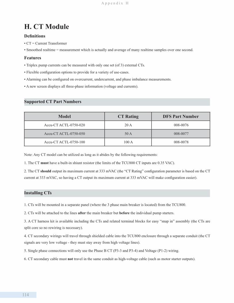
114
A p p e n d i x H
H. CT ModuleDefinitions• CT = Current Transformer
• Smoothed realtime = measurement which is actually and average of many realtime samples over one second.
Features• Triplex pump currents can be measured with only one set (of 3) external CTs.
• Flexible configuration options to provide for a variety of use-cases.
• Alarming can be configured on overcurrent, undercurrent, and phase imbalance measurements.
• A new screen displays all three-phase information (voltage and currents).
Supported CT Part Numbers
Note: Any CT model can be utilized as long as it abides by the following requirements:
1. The CT must have a built-in shiunt resistor (the limits of the TCU800 CT inputs are 0.35 VAC).
2. The CT should output its maximum current at 333 mVAC (the “CT Rating” configuration parameter is based on the CT
current at 333 mVAC, so having a CT output its maximum current at 333 mVAC will make configuration easier).
Installing CTs
1. CTs will be mounted in a separate panel (where the 3 phase main breaker is located) from the TCU800.
2. CTs will be attached to the lines after the main breaker but before the individual pump starters.
3. A CT harness kit is available including the CTs and related terminal blocks for easy “snap in” assembly (the CTs are
split core so no rewiring is necessary).
4. CT secondary wirings will travel through shielded cable into the TCU800 enclosure through a separate conduit (the CT
signals are very low voltage - they must stay away from high voltage lines).
5. Single phase connections will only use the Phase B CT (P3-3 and P3-4) and Voltage (P1-2) wiring.
6. CT secondary cable must not travel in the same conduit as high-voltage cable (such as motor starter outputs).
Model CT Rating DFS Part Number
Accu-CT ACTL-0750-020 20 A 008-0076
Accu-CT ACTL-0750-050 50 A 008-0077
Accu-CT ACTL-0750-100 100 A 008-0078
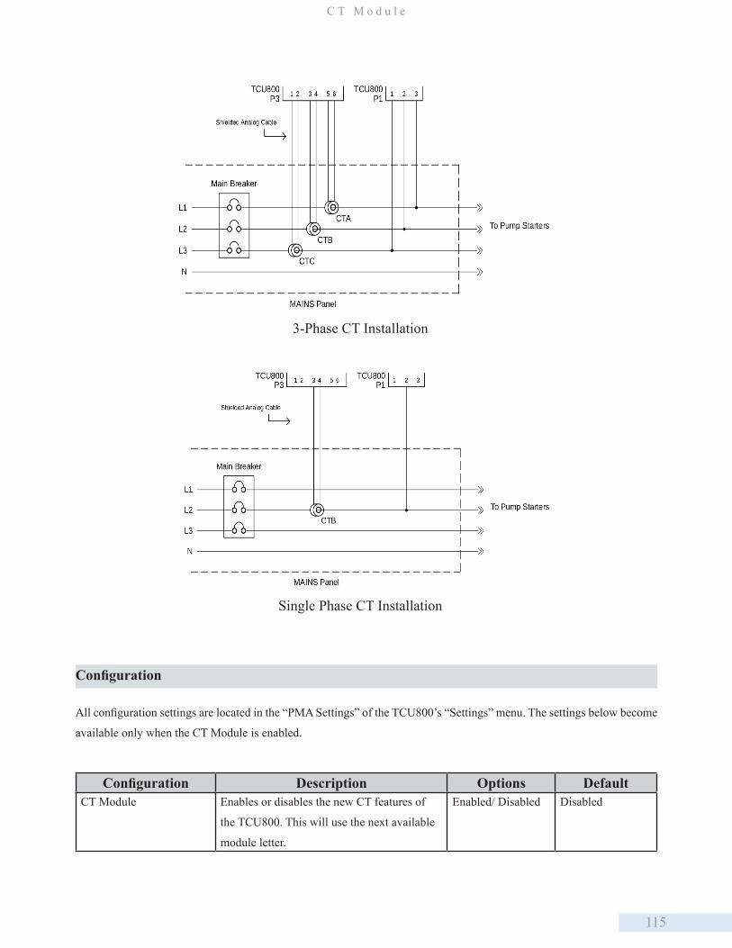
115
C T M o d u l e
Configuration
All configuration settings are located in the “PMA Settings” of the TCU800’s “Settings” menu. The settings below become
available only when the CT Module is enabled.
Configuration Description Options DefaultCT Module Enables or disables the new CT features of
the TCU800. This will use the next available
module letter.
Enabled/ Disabled Disabled
3-Phase CT Installation
Single Phase CT Installation
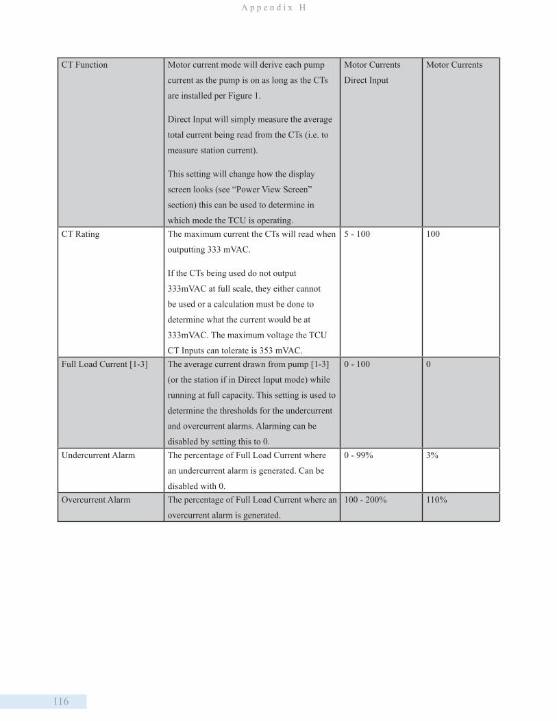
116
A p p e n d i x H
CT Function Motor current mode will derive each pump
current as the pump is on as long as the CTs
are installed per Figure 1.
Direct Input will simply measure the average
total current being read from the CTs (i.e. to
measure station current).
This setting will change how the display
screen looks (see “Power View Screen”
section) this can be used to determine in
which mode the TCU is operating.
Motor Currents
Direct Input
Motor Currents
CT Rating The maximum current the CTs will read when
outputting 333 mVAC.
If the CTs being used do not output
333mVAC at full scale, they either cannot
be used or a calculation must be done to
determine what the current would be at
333mVAC. The maximum voltage the TCU
CT Inputs can tolerate is 353 mVAC.
5 - 100 100
Full Load Current [1-3] The average current drawn from pump [1-3]
(or the station if in Direct Input mode) while
running at full capacity. This setting is used to
determine the thresholds for the undercurrent
and overcurrent alarms. Alarming can be
disabled by setting this to 0.
0 - 100 0
Undercurrent Alarm The percentage of Full Load Current where
an undercurrent alarm is generated. Can be
disabled with 0.
0 - 99% 3%
Overcurrent Alarm The percentage of Full Load Current where an
overcurrent alarm is generated.
100 - 200% 110%
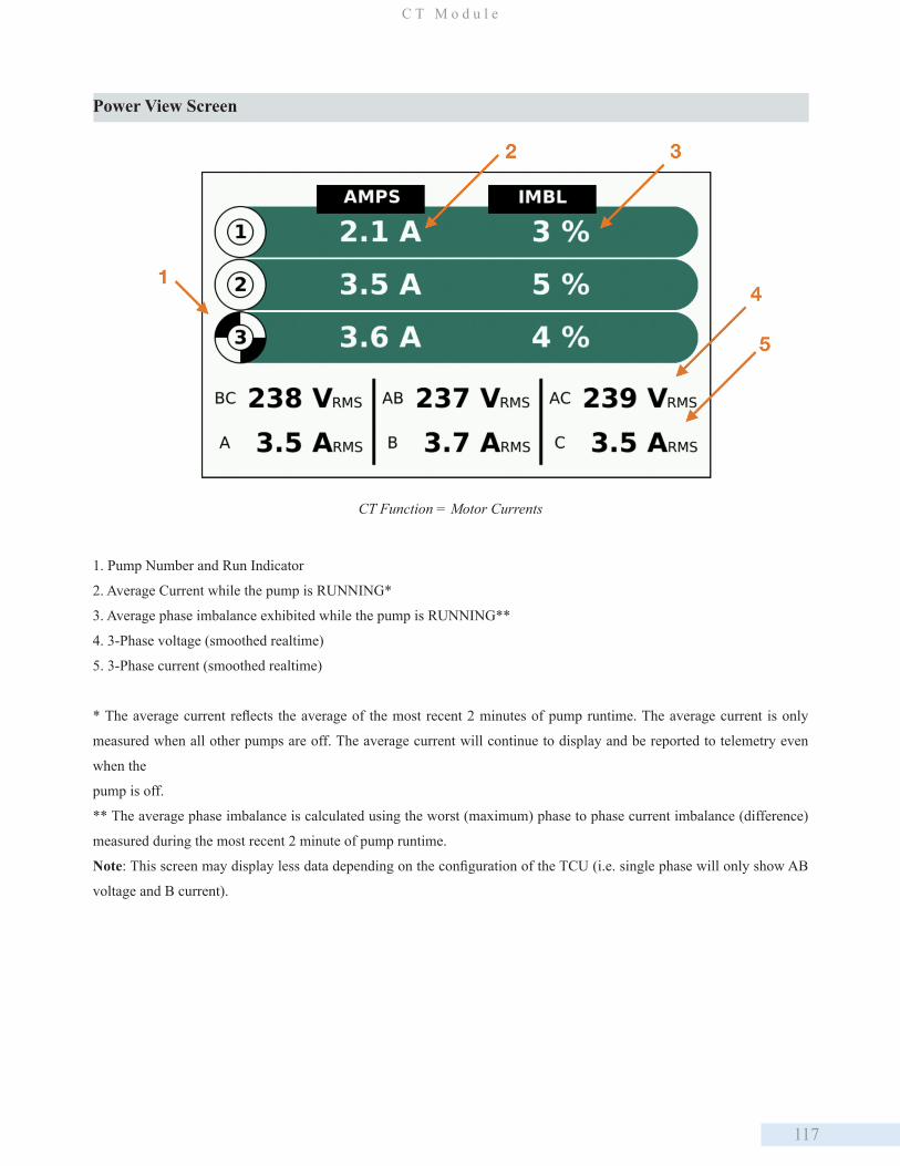
117
C T M o d u l e
CT Function = Motor Currents
1. Pump Number and Run Indicator
2. Average Current while the pump is RUNNING*
3. Average phase imbalance exhibited while the pump is RUNNING**
4. 3-Phase voltage (smoothed realtime)
5. 3-Phase current (smoothed realtime)
* The average current reflects the average of the most recent 2 minutes of pump runtime. The average current is only
measured when all other pumps are off. The average current will continue to display and be reported to telemetry even
when the
pump is off.
** The average phase imbalance is calculated using the worst (maximum) phase to phase current imbalance (difference)
measured during the most recent 2 minute of pump runtime.
Note: This screen may display less data depending on the configuration of the TCU (i.e. single phase will only show AB
voltage and B current).
Power View Screen
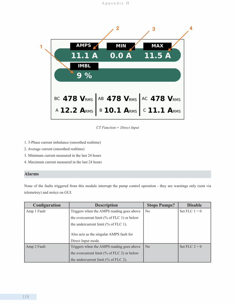
118
A p p e n d i x H
CT Function = Direct Input
1. 3-Phase current imbalance (smoothed realtime)
2. Average current (smoothed realtime)
3. Minimum current measured in the last 24 hours
4. Maximum current measured in the last 24 hours
Alarms
None of the faults triggered from this module interrupt the pump control operation - they are warnings only (sent via
telemetrey) and notice on GUI.
Configuration Description Stops Pumps? DisableAmp 1 Fault Triggers when the AMPS reading goes above
the overcurrent limit (% of FLC 1) or below
the undercurrent limit (% of FLC 1).
Also acts as the singular AMPS fault for
Direct Input mode.
No Set FLC 1 = 0
Amp 2 Fault Triggers when the AMPS reading goes above
the overcurrent limit (% of FLC 2) or below
the undercurrent limit (% of FLC 2).
No Set FLC 2 = 0

119
C T M o d u l e
Amp 3 Fault Triggers when the AMPS reading goes above
the overcurrent limit (% of FLC 3) or below
the undercurrent limit (% of FLC 3).
No Set FLC 2 = 0
Phase Current Fault Generic fault that indicate other misc.
issues with the current module (i.e. Phase
Imbalance).
No Set Imbalance
Alarm = 0
Faults will be indicated on the screen in the same way other alarms are (with a notice pop-up) and will highlight the
surrounding screen number in flashing red (see above).
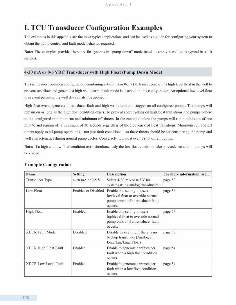
120
A p p e n d i x I
I. TCU Transducer Configuration ExamplesThe examples in this appendix are the most typical applications and can be used as a guide for configuring your system to
obtain the pump control and fault mode behavior required.
Note: The examples provided here are for systems in “pump down” mode (used to empty a well as is typical in a lift
station).
4-20 mA or 0-5 VDC Transducer with High Float (Pump Down Mode)
This is the most common configuration, combining a 4-20 ma or 0-5 VDC transducers with a high level float in the well to
prevent overflow and generate a high well alarm. Fault mode is disabled in this configuration. An optional low level float
to prevent pumping the well dry can also be applied.
High float events generate a transducer fault and high well alarm and stagger on all configured pumps. The pumps will
remain on as long as the high float condition exists. To prevent short cycling on high float transitions, the pumps adhere
to the configured minimum run and minimum off timers. In the example below the pumps will run a minimum of one
minute and remain off a minimum of 30 seconds regardless of the frequency of float transitions. Minimum run and off
timers apply to all pump operations – not just fault conditions – so these timers should be set considering the pump and
well characteristics during normal pump cycles. Conversely, low float events shut off all pumps.
Note: If a high and low float condition exist simultaneously the low float condition takes precedence and no pumps will
be started.
Example Configuration
Name Setting Description For more information, see...Transducer Type 4-20 mA or 0-5 V Select 4-20 mA or 0-5 V for
systems using analog transducers.page 52
Low Float Enabled or Disabled Enable this setting to use a lowlevel float to override normal pump control if a transducer fault occurs.
page 54
High Float Enabled Enable this setting to use a highlevel float to override normal pump control if a transducer fault occurs.
page 54
XDCR Fault Mode Disabled Disable this setting if there is no backup transducer (Analog 2, Lead/Lag/Lag2 Floats).
page 58
XDCR High Float Fault Enabled Enable to generate a transducer fault when a high float condition occurs.
page 54
XDCR Low Level Fault Enabled Enable to generate a transducer fault when a low float condition occurs.
page 54

121
T C U T r a n s d u c e r C o n f i g u r a t i o n E x a m p l e s
High Float Override Disabled Disable for systems not using a float system as the primary or backup method of pump control.
page 54
Minimum Run 1.0 Minimum time pumps should run. Used to prevent short cycling.
page 52
Minimum Off 0.5 Minimum time pumps should remain off. Used to prevent short cycling.
page 52
Response to Fault Conditions (TCU with High Float)
Fault(s) Alarms Pump Operation BehaviorTransducer low condition
• Transducer fault alarm
• Low well alarm
All pumps off Low well and transducer fault alarms are generated. All pumps are turned off. When the transducer level returns to the normal range, the low well alarm clears and normal pump operation resumes. The transducer fault alarm remains active until the TCU has been reset.
Transducer high condition
High well alarm All pumps on A high well alarm is generated and all pumps are staggered on. When the transducer level returns to the normal range, the high well alarm clears and normal pump operation resumes.
High float condition
• Transducer fault alarm
• High well alarm
All pumps on High well and transducer fault alarms are generated. All pumps are staggered on. Minimum pump run and off timers are applied. When the High float turns off, the high well alarm clears and normal pump operation resumes. The transducer fault alarm remains active until the TCU has been reset.
Concurrent transducer high and high float conditions
High well alarm All pumps on A high well alarm is generated. All pumps are staggered on. A transducer fault alarm is not generated if events occur in the following sequence: Transducer high condition precedes the high float condition; and the high float OFF precedes transducer normal. When the high float condition clears, normal pump operation resumes.
Concurrent transducer low and high float conditions
• Transducer fault alarm
• Low well alarm
• High well alarm
All pumps on Low well, high well, and transducer fault alarms are generated. High float condition takes precedence over the transducer low condition and all pumps are staggered on. Minimum run and off timers are applied. Normal pump operation resumes if both conditions clear. The transducer fault alarm remains active until the TCU has been reset.
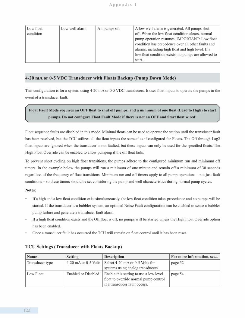
122
A p p e n d i x I
Low float condition
Low well alarm All pumps off A low well alarm is generated. All pumps shut off. When the low float condition clears, normal pump operation resumes. IMPORTANT: Low float condition has precedence over all other faults and alarms, including high float and high level. If a low float condition exists, no pumps are allowed to start.
4-20 mA or 0-5 VDC Transducer with Floats Backup (Pump Down Mode)
This configuration is for a system using 4-20 mA or 0-5 VDC transducers. It uses float inputs to operate the pumps in the
event of a transducer fault.
Float Fault Mode requires an OFF float to shut off pumps, and a minimum of one float (Lead to High) to start
pumps. Do not configure Float Fault Mode if there is not an OFF and Start float wired!
Float sequence faults are disabled in this mode. Minimal floats can be used to operate the station until the transducer fault
has been resolved, but the TCU utilizes all the float inputs the samecf as if configured for Floats. The Off through Lag2
float inputs are ignored when the transducer is not faulted, but these inputs can only be used for the specified floats. The
High Float Override can be enabled to allow pumping if the off float fails.
To prevent short cycling on high float transitions, the pumps adhere to the configured minimum run and minimum off
timers. In the example below the pumps will run a minimum of one minute and remain off a minimum of 30 seconds
regardless of the frequency of float transitions. Minimum run and off timers apply to all pump operations – not just fault
conditions – so these timers should be set considering the pump and well characteristics during normal pump cycles.
Notes:
• If a high and a low float condition exist simultaneously, the low float condition takes precedence and no pumps will be
started. If the transducer is a bubbler system, an optional Noise Fault configuration can be enabled to sense a bubbler
pump failure and generate a transducer fault alarm.
• If a high float condition exists and the Off float is off, no pumps will be started unless the High Float Override option
has been enabled.
• Once a transducer fault has occurred the TCU will remain on float control until it has been reset.
TCU Settings (Transducer with Floats Backup)
Name Setting Description For more information, see...Transducer type 4-20 mA or 0-5 Volts Select 4-20 mA or 0-5 Volts for
systems using analog transducers.page 52
Low Float Enabled or Disabled Enable this setting to use a low level float to override normal pump control if a transducer fault occurs.
page 54
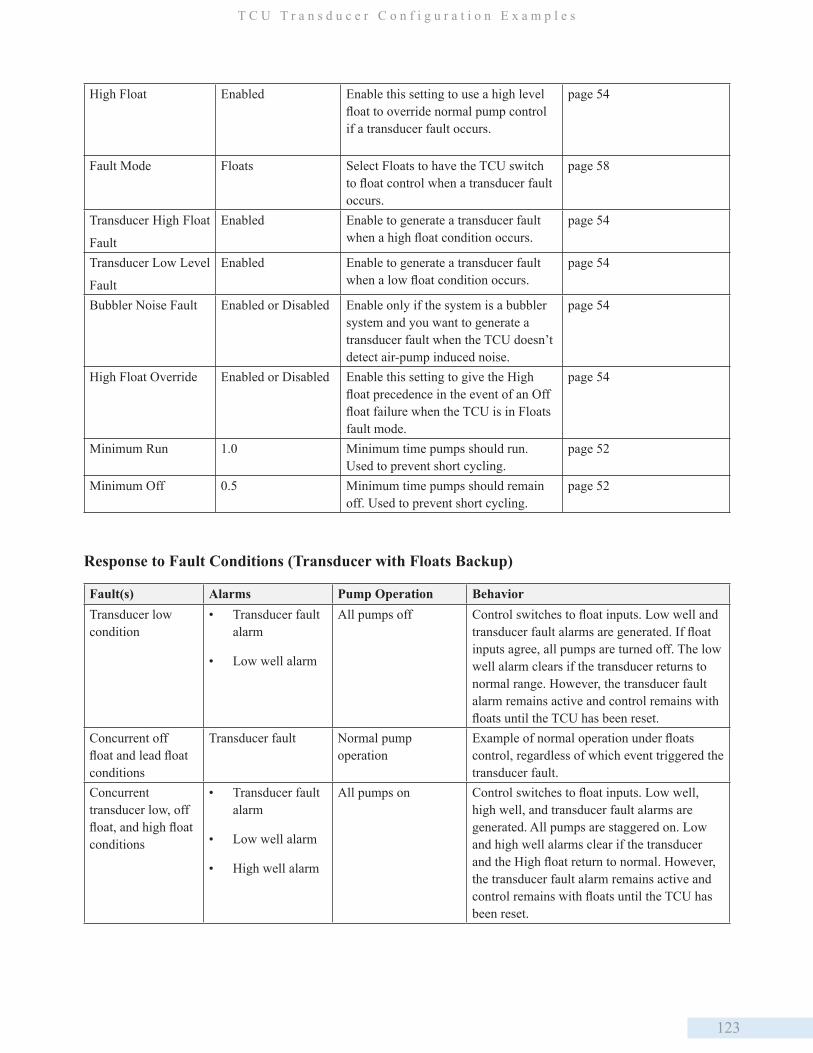
123
T C U T r a n s d u c e r C o n f i g u r a t i o n E x a m p l e s
High Float Enabled Enable this setting to use a high level float to override normal pump control if a transducer fault occurs.
page 54
Fault Mode Floats Select Floats to have the TCU switch to float control when a transducer fault occurs.
page 58
Transducer High Float
Fault
Enabled Enable to generate a transducer fault when a high float condition occurs.
page 54
Transducer Low Level
Fault
Enabled Enable to generate a transducer fault when a low float condition occurs.
page 54
Bubbler Noise Fault Enabled or Disabled Enable only if the system is a bubbler system and you want to generate a transducer fault when the TCU doesn’t detect air-pump induced noise.
page 54
High Float Override Enabled or Disabled Enable this setting to give the High float precedence in the event of an Off float failure when the TCU is in Floats fault mode.
page 54
Minimum Run 1.0 Minimum time pumps should run. Used to prevent short cycling.
page 52
Minimum Off 0.5 Minimum time pumps should remain off. Used to prevent short cycling.
page 52
Response to Fault Conditions (Transducer with Floats Backup)
Fault(s) Alarms Pump Operation BehaviorTransducer low condition
• Transducer fault alarm
• Low well alarm
All pumps off Control switches to float inputs. Low well and transducer fault alarms are generated. If float inputs agree, all pumps are turned off. The low well alarm clears if the transducer returns to normal range. However, the transducer fault alarm remains active and control remains with floats until the TCU has been reset.
Concurrent off float and lead float conditions
Transducer fault Normal pump operation
Example of normal operation under floats control, regardless of which event triggered the transducer fault.
Concurrent transducer low, off float, and high float conditions
• Transducer fault alarm
• Low well alarm
• High well alarm
All pumps on Control switches to float inputs. Low well, high well, and transducer fault alarms are generated. All pumps are staggered on. Low and high well alarms clear if the transducer and the High float return to normal. However, the transducer fault alarm remains active and control remains with floats until the TCU has been reset.
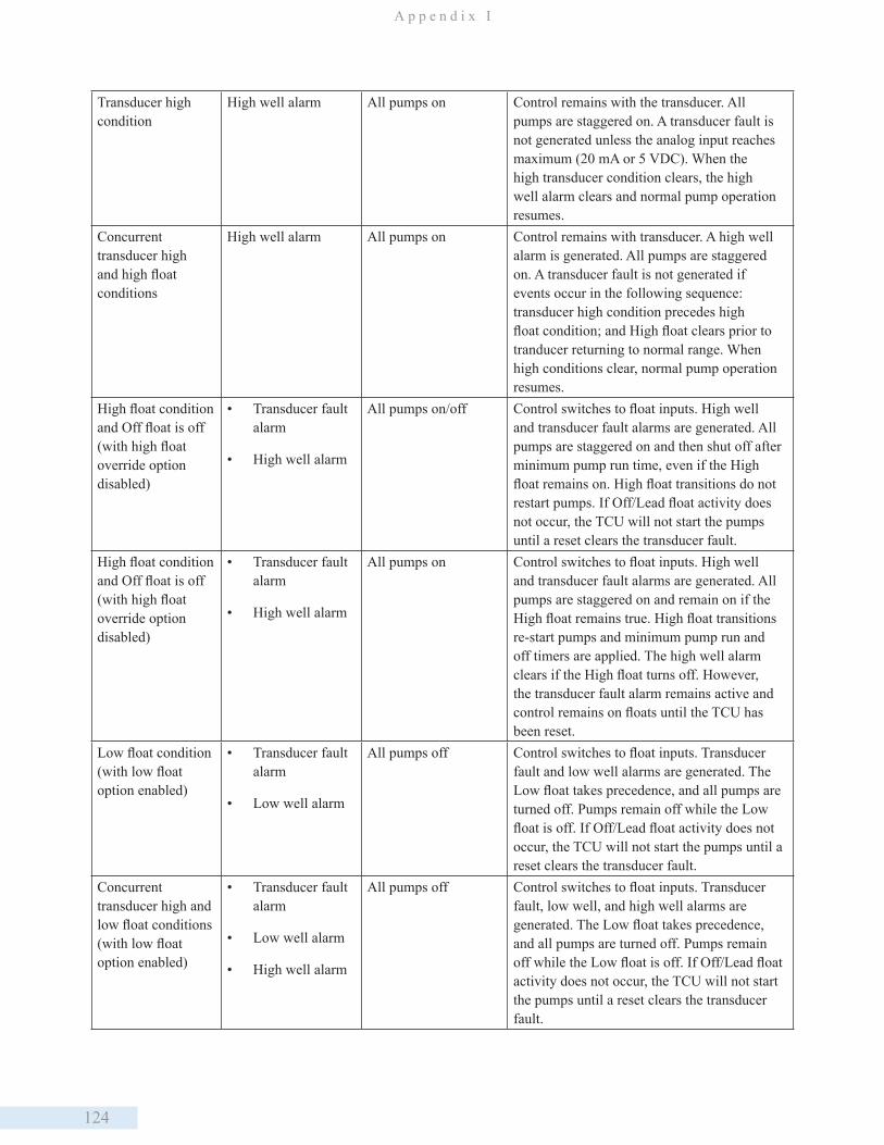
124
A p p e n d i x I
Transducer high condition
High well alarm All pumps on Control remains with the transducer. All pumps are staggered on. A transducer fault is not generated unless the analog input reaches maximum (20 mA or 5 VDC). When the high transducer condition clears, the high well alarm clears and normal pump operation resumes.
Concurrent transducer high and high float conditions
High well alarm All pumps on Control remains with transducer. A high well alarm is generated. All pumps are staggered on. A transducer fault is not generated if events occur in the following sequence: transducer high condition precedes high float condition; and High float clears prior to tranducer returning to normal range. When high conditions clear, normal pump operation resumes.
High float condition and Off float is off (with high float override option disabled)
• Transducer fault alarm
• High well alarm
All pumps on/off Control switches to float inputs. High well and transducer fault alarms are generated. All pumps are staggered on and then shut off after minimum pump run time, even if the High float remains on. High float transitions do not restart pumps. If Off/Lead float activity does not occur, the TCU will not start the pumps until a reset clears the transducer fault.
High float condition and Off float is off (with high float override option disabled)
• Transducer fault alarm
• High well alarm
All pumps on Control switches to float inputs. High well and transducer fault alarms are generated. All pumps are staggered on and remain on if the High float remains true. High float transitions re-start pumps and minimum pump run and off timers are applied. The high well alarm clears if the High float turns off. However, the transducer fault alarm remains active and control remains on floats until the TCU has been reset.
Low float condition (with low float option enabled)
• Transducer fault alarm
• Low well alarm
All pumps off Control switches to float inputs. Transducer fault and low well alarms are generated. The Low float takes precedence, and all pumps are turned off. Pumps remain off while the Low float is off. If Off/Lead float activity does not occur, the TCU will not start the pumps until a reset clears the transducer fault.
Concurrent transducer high and low float conditions (with low float option enabled)
• Transducer fault alarm
• Low well alarm
• High well alarm
All pumps off Control switches to float inputs. Transducer fault, low well, and high well alarms are generated. The Low float takes precedence, and all pumps are turned off. Pumps remain off while the Low float is off. If Off/Lead float activity does not occur, the TCU will not start the pumps until a reset clears the transducer fault.
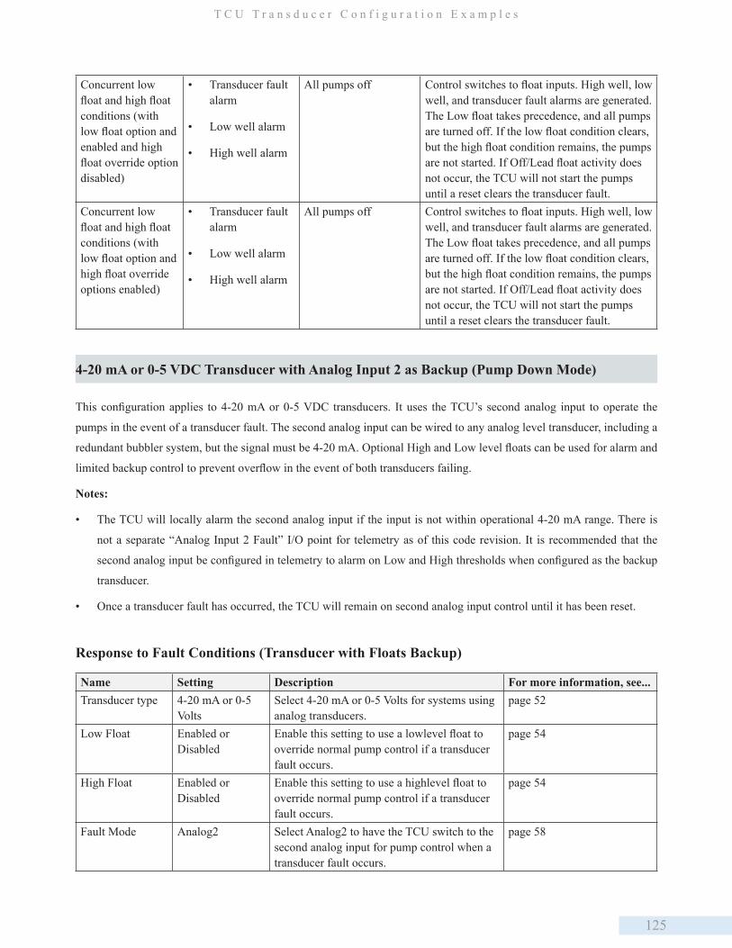
125
T C U T r a n s d u c e r C o n f i g u r a t i o n E x a m p l e s
Concurrent low float and high float conditions (with low float option and enabled and high float override option disabled)
• Transducer fault alarm
• Low well alarm
• High well alarm
All pumps off Control switches to float inputs. High well, low well, and transducer fault alarms are generated. The Low float takes precedence, and all pumps are turned off. If the low float condition clears, but the high float condition remains, the pumps are not started. If Off/Lead float activity does not occur, the TCU will not start the pumps until a reset clears the transducer fault.
Concurrent low float and high float conditions (with low float option and high float override options enabled)
• Transducer fault alarm
• Low well alarm
• High well alarm
All pumps off Control switches to float inputs. High well, low well, and transducer fault alarms are generated. The Low float takes precedence, and all pumps are turned off. If the low float condition clears, but the high float condition remains, the pumps are not started. If Off/Lead float activity does not occur, the TCU will not start the pumps until a reset clears the transducer fault.
4-20 mA or 0-5 VDC Transducer with Analog Input 2 as Backup (Pump Down Mode)
This configuration applies to 4-20 mA or 0-5 VDC transducers. It uses the TCU’s second analog input to operate the
pumps in the event of a transducer fault. The second analog input can be wired to any analog level transducer, including a
redundant bubbler system, but the signal must be 4-20 mA. Optional High and Low level floats can be used for alarm and
limited backup control to prevent overflow in the event of both transducers failing.
Notes:
• The TCU will locally alarm the second analog input if the input is not within operational 4-20 mA range. There is
not a separate “Analog Input 2 Fault” I/O point for telemetry as of this code revision. It is recommended that the
second analog input be configured in telemetry to alarm on Low and High thresholds when configured as the backup
transducer.
• Once a transducer fault has occurred, the TCU will remain on second analog input control until it has been reset.
Response to Fault Conditions (Transducer with Floats Backup)
Name Setting Description For more information, see...Transducer type 4-20 mA or 0-5
VoltsSelect 4-20 mA or 0-5 Volts for systems using analog transducers.
page 52
Low Float Enabled or Disabled
Enable this setting to use a lowlevel float to override normal pump control if a transducer fault occurs.
page 54
High Float Enabled or Disabled
Enable this setting to use a highlevel float to override normal pump control if a transducer fault occurs.
page 54
Fault Mode Analog2 Select Analog2 to have the TCU switch to the second analog input for pump control when a transducer fault occurs.
page 58
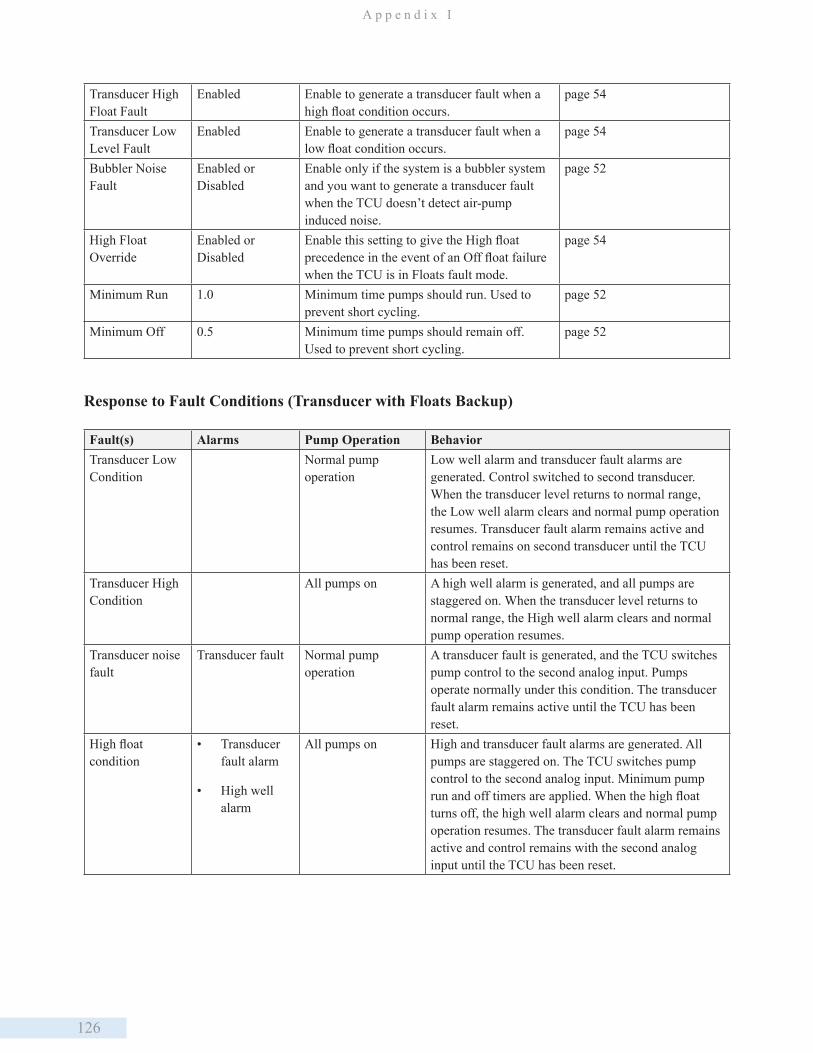
126
A p p e n d i x I
Transducer High Float Fault
Enabled Enable to generate a transducer fault when a high float condition occurs.
page 54
Transducer Low Level Fault
Enabled Enable to generate a transducer fault when a low float condition occurs.
page 54
Bubbler Noise Fault
Enabled or Disabled
Enable only if the system is a bubbler system and you want to generate a transducer fault when the TCU doesn’t detect air-pump induced noise.
page 52
High Float Override
Enabled or Disabled
Enable this setting to give the High float precedence in the event of an Off float failure when the TCU is in Floats fault mode.
page 54
Minimum Run 1.0 Minimum time pumps should run. Used to prevent short cycling.
page 52
Minimum Off 0.5 Minimum time pumps should remain off. Used to prevent short cycling.
page 52
Response to Fault Conditions (Transducer with Floats Backup)
Fault(s) Alarms Pump Operation BehaviorTransducer Low Condition
Normal pump operation
Low well alarm and transducer fault alarms are generated. Control switched to second transducer. When the transducer level returns to normal range, the Low well alarm clears and normal pump operation resumes. Transducer fault alarm remains active and control remains on second transducer until the TCU has been reset.
Transducer High Condition
All pumps on A high well alarm is generated, and all pumps are staggered on. When the transducer level returns to normal range, the High well alarm clears and normal pump operation resumes.
Transducer noise fault
Transducer fault Normal pump operation
A transducer fault is generated, and the TCU switches pump control to the second analog input. Pumps operate normally under this condition. The transducer fault alarm remains active until the TCU has been reset.
High float condition
• Transducer fault alarm
• High well alarm
All pumps on High and transducer fault alarms are generated. All pumps are staggered on. The TCU switches pump control to the second analog input. Minimum pump run and off timers are applied. When the high float turns off, the high well alarm clears and normal pump operation resumes. The transducer fault alarm remains active and control remains with the second analog input until the TCU has been reset.
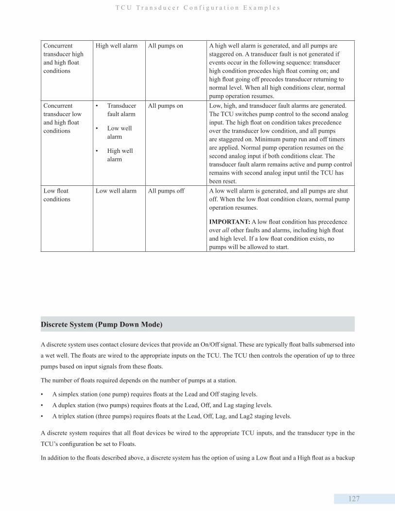
127
T C U T r a n s d u c e r C o n f i g u r a t i o n E x a m p l e s
Concurrent transducer high and high float conditions
High well alarm All pumps on A high well alarm is generated, and all pumps are staggered on. A transducer fault is not generated if events occur in the following sequence: transducer high condition procedes high float coming on; and high float going off precedes transducer returning to normal level. When all high conditions clear, normal pump operation resumes.
Concurrent transducer low and high float conditions
• Transducer fault alarm
• Low well alarm
• High well alarm
All pumps on Low, high, and transducer fault alarms are generated. The TCU switches pump control to the second analog input. The high float on condition takes precedence over the transducer low condition, and all pumps are staggered on. Minimum pump run and off timers are applied. Normal pump operation resumes on the second analog input if both conditions clear. The transducer fault alarm remains active and pump control remains with second analog input until the TCU has been reset.
Low float conditions
Low well alarm All pumps off A low well alarm is generated, and all pumps are shut off. When the low float condition clears, normal pump operation resumes.
IMPORTANT: A low float condition has precedence over all other faults and alarms, including high float and high level. If a low float condition exists, no pumps will be allowed to start.
Discrete System (Pump Down Mode)
A discrete system uses contact closure devices that provide an On/Off signal. These are typically float balls submersed into
a wet well. The floats are wired to the appropriate inputs on the TCU. The TCU then controls the operation of up to three
pumps based on input signals from these floats.
The number of floats required depends on the number of pumps at a station.
• A simplex station (one pump) requires floats at the Lead and Off staging levels.
• A duplex station (two pumps) requires floats at the Lead, Off, and Lag staging levels.
• A triplex station (three pumps) requires floats at the Lead, Off, Lag, and Lag2 staging levels.
A discrete system requires that all float devices be wired to the appropriate TCU inputs, and the transducer type in the
TCU’s configuration be set to Floats.
In addition to the floats described above, a discrete system has the option of using a Low float and a High float as a backup
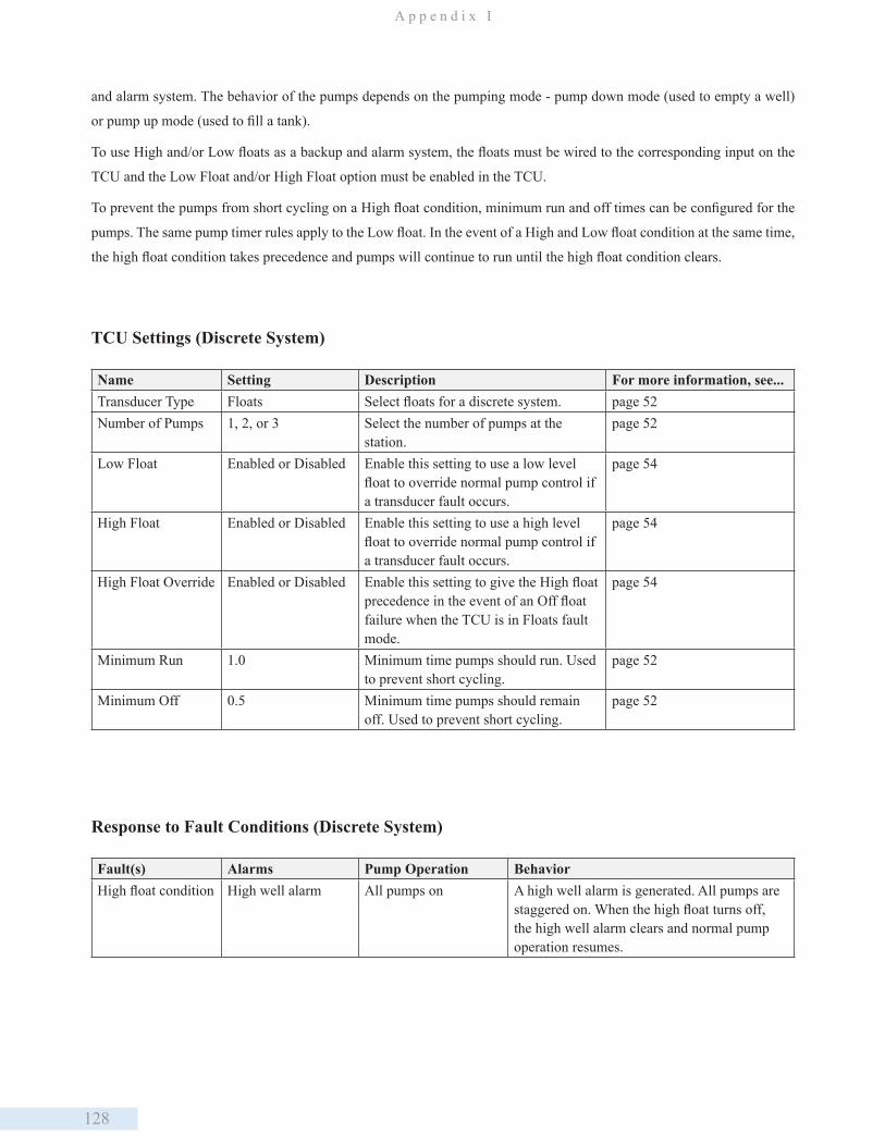
128
A p p e n d i x I
and alarm system. The behavior of the pumps depends on the pumping mode - pump down mode (used to empty a well)
or pump up mode (used to fill a tank).
To use High and/or Low floats as a backup and alarm system, the floats must be wired to the corresponding input on the
TCU and the Low Float and/or High Float option must be enabled in the TCU.
To prevent the pumps from short cycling on a High float condition, minimum run and off times can be configured for the
pumps. The same pump timer rules apply to the Low float. In the event of a High and Low float condition at the same time,
the high float condition takes precedence and pumps will continue to run until the high float condition clears.
TCU Settings (Discrete System)
Name Setting Description For more information, see...Transducer Type Floats Select floats for a discrete system. page 52Number of Pumps 1, 2, or 3 Select the number of pumps at the
station.page 52
Low Float Enabled or Disabled Enable this setting to use a low level float to override normal pump control if a transducer fault occurs.
page 54
High Float Enabled or Disabled Enable this setting to use a high level float to override normal pump control if a transducer fault occurs.
page 54
High Float Override Enabled or Disabled Enable this setting to give the High float precedence in the event of an Off float failure when the TCU is in Floats fault mode.
page 54
Minimum Run 1.0 Minimum time pumps should run. Used to prevent short cycling.
page 52
Minimum Off 0.5 Minimum time pumps should remain off. Used to prevent short cycling.
page 52
Response to Fault Conditions (Discrete System)
Fault(s) Alarms Pump Operation BehaviorHigh float condition High well alarm All pumps on A high well alarm is generated. All pumps are
staggered on. When the high float turns off, the high well alarm clears and normal pump operation resumes.
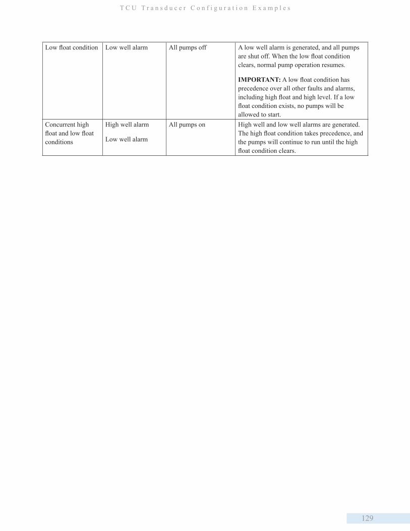
129
T C U T r a n s d u c e r C o n f i g u r a t i o n E x a m p l e s
Low float condition Low well alarm All pumps off A low well alarm is generated, and all pumps are shut off. When the low float condition clears, normal pump operation resumes.
IMPORTANT: A low float condition has precedence over all other faults and alarms, including high float and high level. If a low float condition exists, no pumps will be allowed to start.
Concurrent high float and low float conditions
High well alarm
Low well alarm
All pumps on High well and low well alarms are generated. The high float condition takes precedence, and the pumps will continue to run until the high float condition clears.
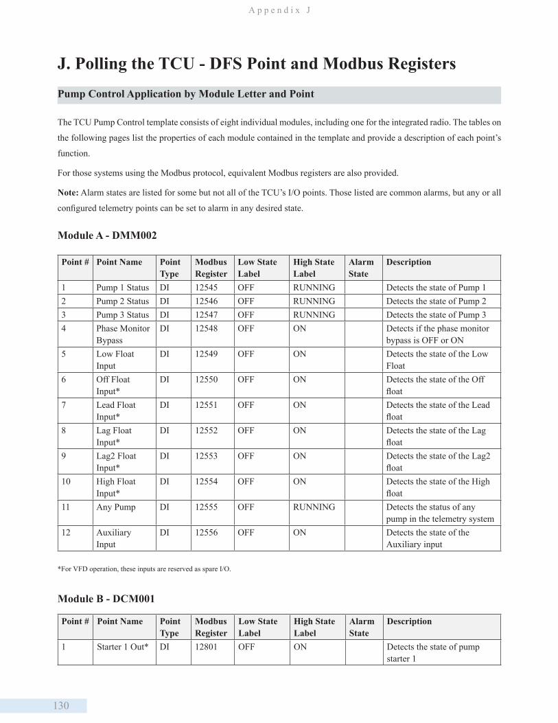
130
A p p e n d i x J
J. Polling the TCU - DFS Point and Modbus RegistersPump Control Application by Module Letter and Point
The TCU Pump Control template consists of eight individual modules, including one for the integrated radio. The tables on
the following pages list the properties of each module contained in the template and provide a description of each point’s
function.
For those systems using the Modbus protocol, equivalent Modbus registers are also provided.
Note: Alarm states are listed for some but not all of the TCU’s I/O points. Those listed are common alarms, but any or all
configured telemetry points can be set to alarm in any desired state.
Module A - DMM002
Point # Point Name Point Type
Modbus Register
Low State Label
High State Label
Alarm State
Description
1 Pump 1 Status DI 12545 OFF RUNNING Detects the state of Pump 12 Pump 2 Status DI 12546 OFF RUNNING Detects the state of Pump 23 Pump 3 Status DI 12547 OFF RUNNING Detects the state of Pump 34 Phase Monitor
BypassDI 12548 OFF ON Detects if the phase monitor
bypass is OFF or ON5 Low Float
InputDI 12549 OFF ON Detects the state of the Low
Float6 Off Float
Input*DI 12550 OFF ON Detects the state of the Off
float7 Lead Float
Input*DI 12551 OFF ON Detects the state of the Lead
float8 Lag Float
Input*DI 12552 OFF ON Detects the state of the Lag
float9 Lag2 Float
Input*DI 12553 OFF ON Detects the state of the Lag2
float10 High Float
Input*DI 12554 OFF ON Detects the state of the High
float11 Any Pump DI 12555 OFF RUNNING Detects the status of any
pump in the telemetry system12 Auxiliary
InputDI 12556 OFF ON Detects the state of the
Auxiliary input
*For VFD operation, these inputs are reserved as spare I/O.
Module B - DCM001
Point # Point Name Point Type
Modbus Register
Low State Label
High State Label
Alarm State
Description
1 Starter 1 Out* DI 12801 OFF ON Detects the state of pump starter 1
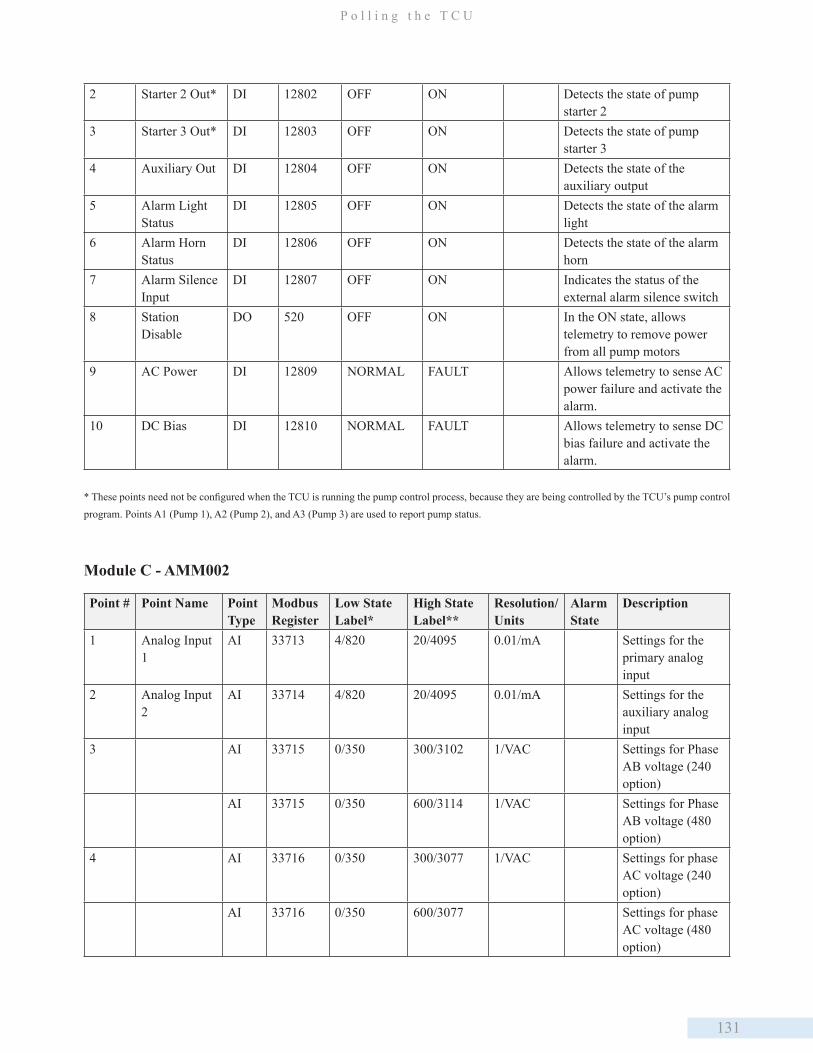
131
P o l l i n g t h e T C U
2 Starter 2 Out* DI 12802 OFF ON Detects the state of pump starter 2
3 Starter 3 Out* DI 12803 OFF ON Detects the state of pump starter 3
4 Auxiliary Out DI 12804 OFF ON Detects the state of the auxiliary output
5 Alarm Light Status
DI 12805 OFF ON Detects the state of the alarm light
6 Alarm Horn Status
DI 12806 OFF ON Detects the state of the alarm horn
7 Alarm Silence Input
DI 12807 OFF ON Indicates the status of the external alarm silence switch
8 Station Disable
DO 520 OFF ON In the ON state, allows telemetry to remove power from all pump motors
9 AC Power DI 12809 NORMAL FAULT Allows telemetry to sense AC power failure and activate the alarm.
10 DC Bias DI 12810 NORMAL FAULT Allows telemetry to sense DC bias failure and activate the alarm.
* These points need not be configured when the TCU is running the pump control process, because they are being controlled by the TCU’s pump control program. Points A1 (Pump 1), A2 (Pump 2), and A3 (Pump 3) are used to report pump status.
Module C - AMM002
Point # Point Name Point Type
Modbus Register
Low State Label*
High State Label**
Resolution/Units
Alarm State
Description
1 Analog Input 1
AI 33713 4/820 20/4095 0.01/mA Settings for the primary analog input
2 Analog Input 2
AI 33714 4/820 20/4095 0.01/mA Settings for the auxiliary analog input
3 AI 33715 0/350 300/3102 1/VAC Settings for Phase AB voltage (240 option)
AI 33715 0/350 600/3114 1/VAC Settings for Phase AB voltage (480 option)
4 AI 33716 0/350 300/3077 1/VAC Settings for phase AC voltage (240 option)
AI 33716 0/350 600/3077 Settings for phase AC voltage (480 option)
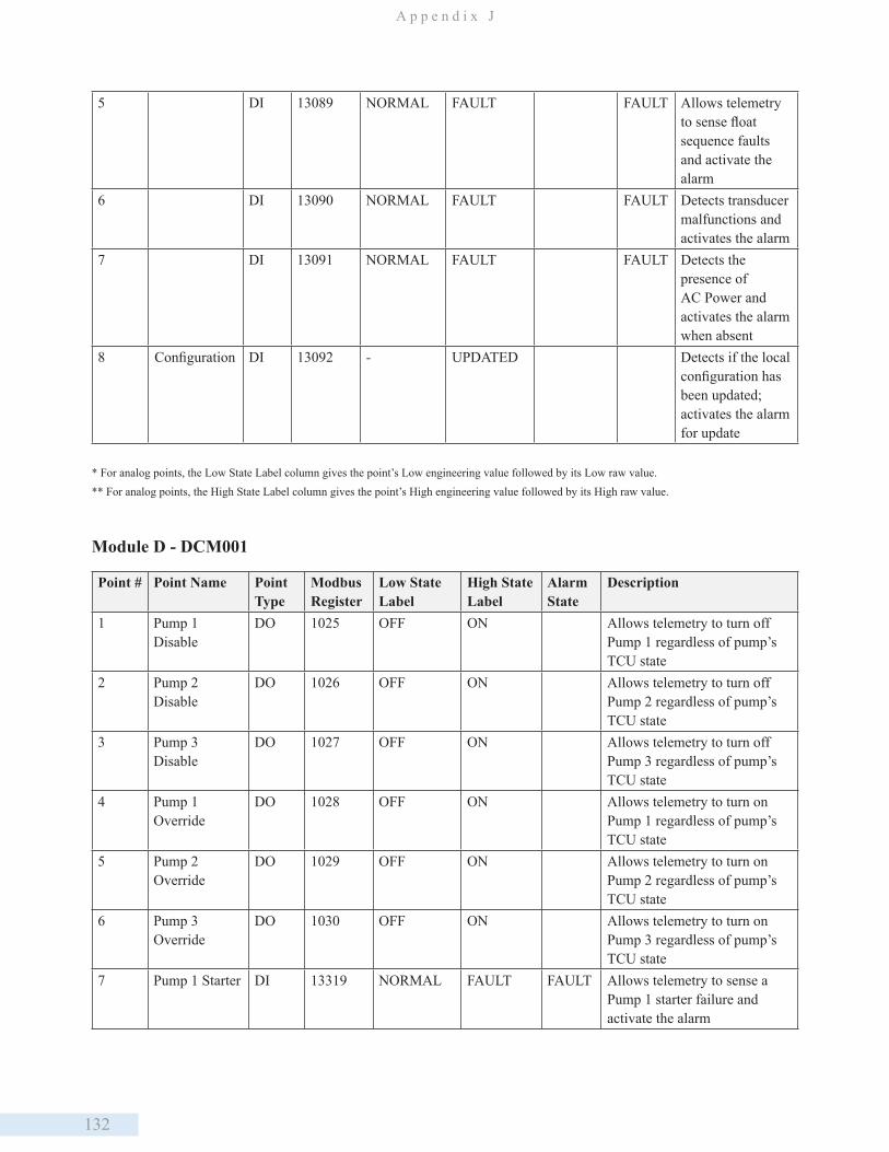
132
A p p e n d i x J
5 DI 13089 NORMAL FAULT FAULT Allows telemetry to sense float sequence faults and activate the alarm
6 DI 13090 NORMAL FAULT FAULT Detects transducer malfunctions and activates the alarm
7 DI 13091 NORMAL FAULT FAULT Detects the presence of AC Power and activates the alarm when absent
8 Configuration DI 13092 - UPDATED Detects if the local configuration has been updated; activates the alarm for update
* For analog points, the Low State Label column gives the point’s Low engineering value followed by its Low raw value.** For analog points, the High State Label column gives the point’s High engineering value followed by its High raw value.
Module D - DCM001
Point # Point Name Point Type
Modbus Register
Low State Label
High State Label
Alarm State
Description
1 Pump 1 Disable
DO 1025 OFF ON Allows telemetry to turn off Pump 1 regardless of pump’s TCU state
2 Pump 2 Disable
DO 1026 OFF ON Allows telemetry to turn off Pump 2 regardless of pump’s TCU state
3 Pump 3 Disable
DO 1027 OFF ON Allows telemetry to turn off Pump 3 regardless of pump’s TCU state
4 Pump 1 Override
DO 1028 OFF ON Allows telemetry to turn on Pump 1 regardless of pump’s TCU state
5 Pump 2 Override
DO 1029 OFF ON Allows telemetry to turn on Pump 2 regardless of pump’s TCU state
6 Pump 3 Override
DO 1030 OFF ON Allows telemetry to turn on Pump 3 regardless of pump’s TCU state
7 Pump 1 Starter DI 13319 NORMAL FAULT FAULT Allows telemetry to sense a Pump 1 starter failure and activate the alarm
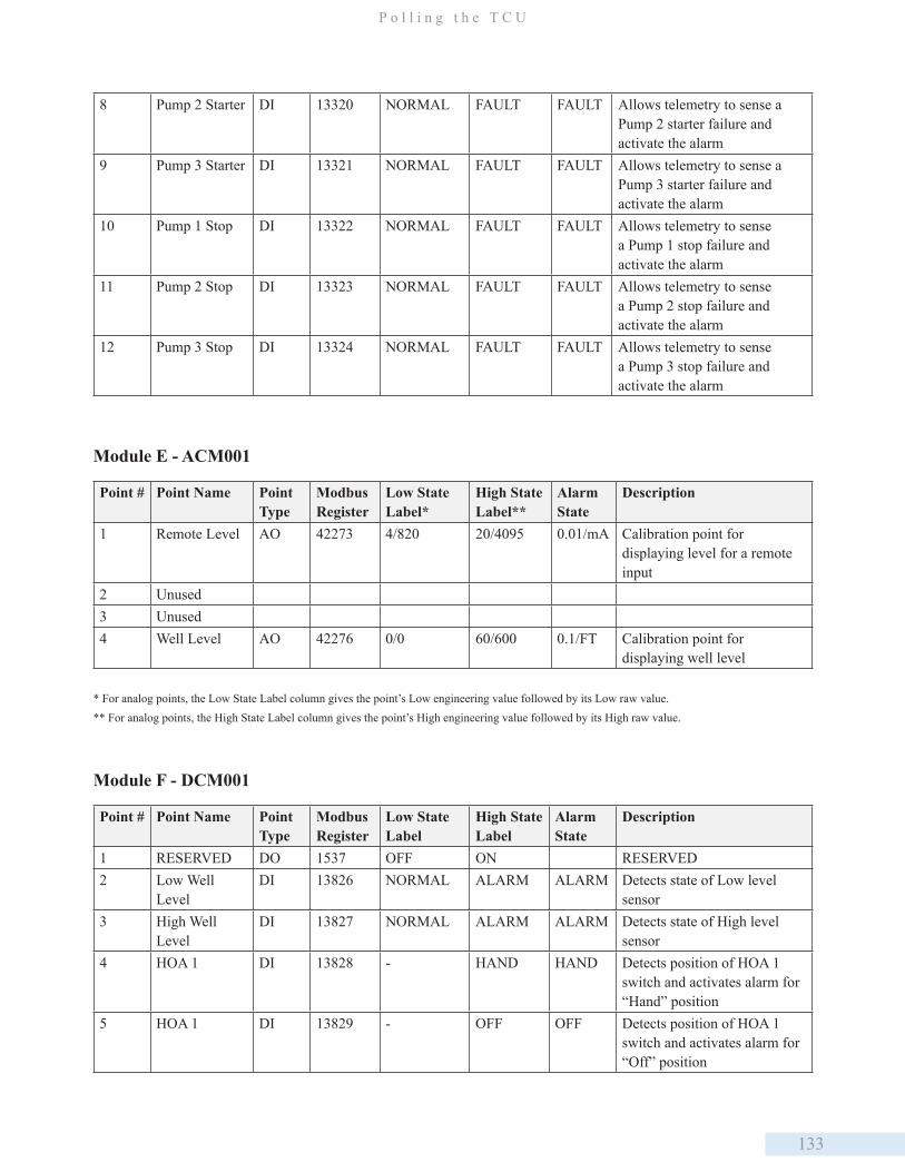
133
P o l l i n g t h e T C U
8 Pump 2 Starter DI 13320 NORMAL FAULT FAULT Allows telemetry to sense a Pump 2 starter failure and activate the alarm
9 Pump 3 Starter DI 13321 NORMAL FAULT FAULT Allows telemetry to sense a Pump 3 starter failure and activate the alarm
10 Pump 1 Stop DI 13322 NORMAL FAULT FAULT Allows telemetry to sense a Pump 1 stop failure and activate the alarm
11 Pump 2 Stop DI 13323 NORMAL FAULT FAULT Allows telemetry to sense a Pump 2 stop failure and activate the alarm
12 Pump 3 Stop DI 13324 NORMAL FAULT FAULT Allows telemetry to sense a Pump 3 stop failure and activate the alarm
Module E - ACM001
Point # Point Name Point Type
Modbus Register
Low State Label*
High State Label**
Alarm State
Description
1 Remote Level AO 42273 4/820 20/4095 0.01/mA Calibration point for displaying level for a remote input
2 Unused3 Unused4 Well Level AO 42276 0/0 60/600 0.1/FT Calibration point for
displaying well level
* For analog points, the Low State Label column gives the point’s Low engineering value followed by its Low raw value.** For analog points, the High State Label column gives the point’s High engineering value followed by its High raw value.
Module F - DCM001
Point # Point Name Point Type
Modbus Register
Low State Label
High State Label
Alarm State
Description
1 RESERVED DO 1537 OFF ON RESERVED2 Low Well
LevelDI 13826 NORMAL ALARM ALARM Detects state of Low level
sensor3 High Well
LevelDI 13827 NORMAL ALARM ALARM Detects state of High level
sensor4 HOA 1 DI 13828 - HAND HAND Detects position of HOA 1
switch and activates alarm for “Hand” position
5 HOA 1 DI 13829 - OFF OFF Detects position of HOA 1 switch and activates alarm for “Off” position
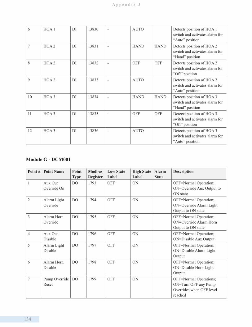
134
A p p e n d i x J
6 HOA 1 DI 13830 - AUTO Detects position of HOA 1 switch and activates alarm for “Auto” position
7 HOA 2 DI 13831 - HAND HAND Detects position of HOA 2 switch and activates alarm for “Hand” position
8 HOA 2 DI 13832 - OFF OFF Detects position of HOA 2 switch and activates alarm for “Off” position
9 HOA 2 DI 13833 - AUTO Detects position of HOA 2 switch and activates alarm for “Auto” position
10 HOA 3 DI 13834 - HAND HAND Detects position of HOA 3 switch and activates alarm for “Hand” position
11 HOA 3 DI 13835 - OFF OFF Detects position of HOA 3 switch and activates alarm for “Off” position
12 HOA 3 DI 13836 - AUTO Detects position of HOA 3 switch and activates alarm for “Auto” position
Module G - DCM001
Point # Point Name Point Type
Modbus Register
Low State Label
High State Label
Alarm State
Description
1 Aux Out Override On
DO 1793 OFF ON OFF=Normal Operation; ON=Override Aux Output to ON state
2 Alarm Light Override
DO 1794 OFF ON OFF=Normal Operation; ON=Override Alarm Light Output to ON state
3 Alarm Horn Override
DO 1795 OFF ON OFF=Normal Operation; ON=Override Alarm Horn Output to ON state
4 Aux Out Disable
DO 1796 OFF ON OFF=Normal Operation; ON=Disable Aux Output
5 Alarm Light Disable
DO 1797 OFF ON OFF=Normal Operation; ON=Disable Alarm Light Output
6 Alarm Horn Disable
DO 1798 OFF ON OFF=Normal Operation; ON=Disable Horn Light Output
7 Pump Override Reset
DO 1799 OFF ON OFF=Normal Operations; ON=Turn OFF any Pump Overrides when OFF level reached
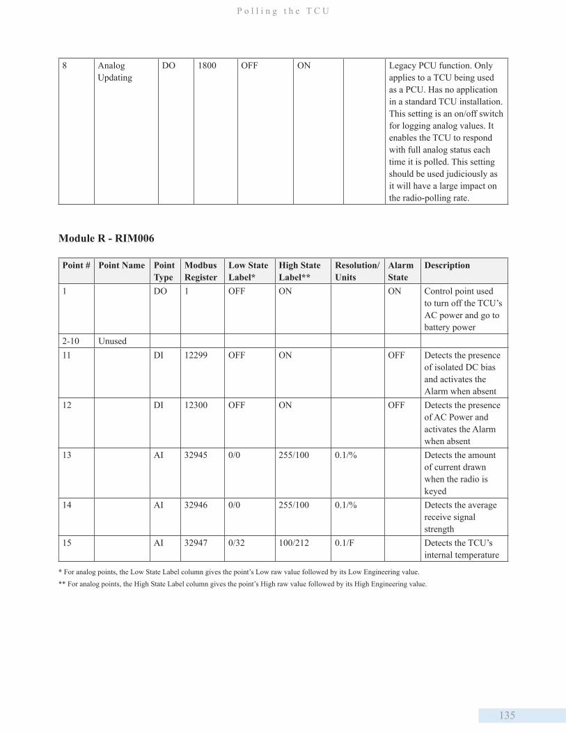
135
P o l l i n g t h e T C U
8 Analog Updating
DO 1800 OFF ON Legacy PCU function. Only applies to a TCU being used as a PCU. Has no application in a standard TCU installation.This setting is an on/off switch for logging analog values. It enables the TCU to respond with full analog status each time it is polled. This setting should be used judiciously as it will have a large impact on the radio-polling rate.
Module R - RIM006
Point # Point Name Point Type
Modbus Register
Low State Label*
High State Label**
Resolution/Units
Alarm State
Description
1 DO 1 OFF ON ON Control point used to turn off the TCU’s AC power and go to battery power
2-10 Unused11 DI 12299 OFF ON OFF Detects the presence
of isolated DC bias and activates the Alarm when absent
12 DI 12300 OFF ON OFF Detects the presence of AC Power and activates the Alarm when absent
13 AI 32945 0/0 255/100 0.1/% Detects the amount of current drawn when the radio is keyed
14 AI 32946 0/0 255/100 0.1/% Detects the average receive signal strength
15 AI 32947 0/32 100/212 0.1/F Detects the TCU’s internal temperature
* For analog points, the Low State Label column gives the point’s Low raw value followed by its Low Engineering value.** For analog points, the High State Label column gives the point’s High raw value followed by its High Engineering value.
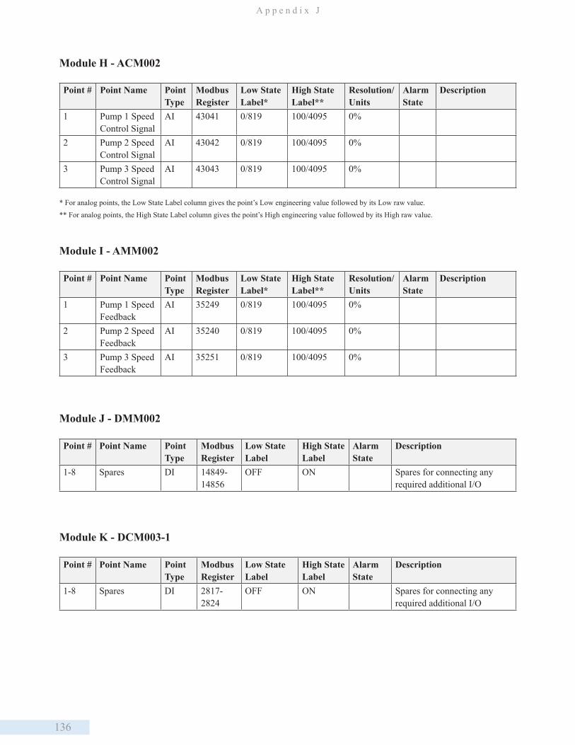
136
A p p e n d i x J
Module H - ACM002
Point # Point Name Point Type
Modbus Register
Low State Label*
High State Label**
Resolution/Units
Alarm State
Description
1 Pump 1 Speed Control Signal
AI 43041 0/819 100/4095 0%
2 Pump 2 Speed Control Signal
AI 43042 0/819 100/4095 0%
3 Pump 3 Speed Control Signal
AI 43043 0/819 100/4095 0%
* For analog points, the Low State Label column gives the point’s Low engineering value followed by its Low raw value.** For analog points, the High State Label column gives the point’s High engineering value followed by its High raw value.
Module I - AMM002
Point # Point Name Point Type
Modbus Register
Low State Label*
High State Label**
Resolution/Units
Alarm State
Description
1 Pump 1 Speed Feedback
AI 35249 0/819 100/4095 0%
2 Pump 2 Speed Feedback
AI 35240 0/819 100/4095 0%
3 Pump 3 Speed Feedback
AI 35251 0/819 100/4095 0%
Module J - DMM002
Point # Point Name Point Type
Modbus Register
Low State Label
High State Label
Alarm State
Description
1-8 Spares DI 14849-14856
OFF ON Spares for connecting any required additional I/O
Module K - DCM003-1
Point # Point Name Point Type
Modbus Register
Low State Label
High State Label
Alarm State
Description
1-8 Spares DI 2817-2824
OFF ON Spares for connecting any required additional I/O
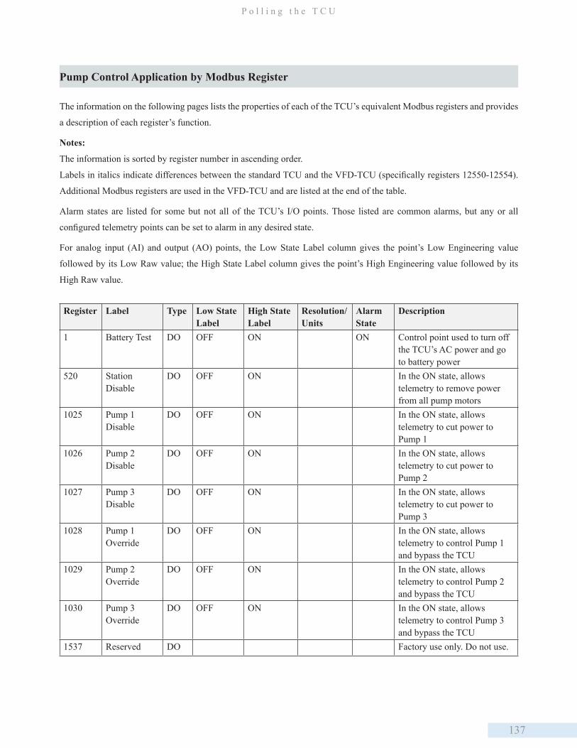
137
P o l l i n g t h e T C U
Pump Control Application by Modbus Register
The information on the following pages lists the properties of each of the TCU’s equivalent Modbus registers and provides
a description of each register’s function.
Notes:
The information is sorted by register number in ascending order.
Labels in italics indicate differences between the standard TCU and the VFD-TCU (specifically registers 12550-12554).
Additional Modbus registers are used in the VFD-TCU and are listed at the end of the table.
Alarm states are listed for some but not all of the TCU’s I/O points. Those listed are common alarms, but any or all
configured telemetry points can be set to alarm in any desired state.
For analog input (AI) and output (AO) points, the Low State Label column gives the point’s Low Engineering value
followed by its Low Raw value; the High State Label column gives the point’s High Engineering value followed by its
High Raw value.
Register Label Type Low State Label
High State Label
Resolution/ Units
Alarm State
Description
1 Battery Test DO OFF ON ON Control point used to turn off the TCU’s AC power and go to battery power
520 Station Disable
DO OFF ON In the ON state, allows telemetry to remove power from all pump motors
1025 Pump 1 Disable
DO OFF ON In the ON state, allows telemetry to cut power to Pump 1
1026 Pump 2 Disable
DO OFF ON In the ON state, allows telemetry to cut power to Pump 2
1027 Pump 3 Disable
DO OFF ON In the ON state, allows telemetry to cut power to Pump 3
1028 Pump 1 Override
DO OFF ON In the ON state, allows telemetry to control Pump 1 and bypass the TCU
1029 Pump 2 Override
DO OFF ON In the ON state, allows telemetry to control Pump 2 and bypass the TCU
1030 Pump 3 Override
DO OFF ON In the ON state, allows telemetry to control Pump 3 and bypass the TCU
1537 Reserved DO Factory use only. Do not use.
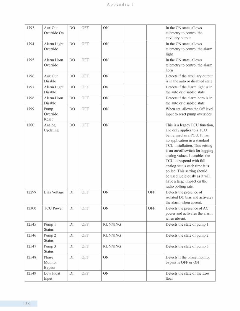
138
A p p e n d i x J
1793 Aux Out Override On
DO OFF ON In the ON state, allows telemetry to control the auxiliary output
1794 Alarm Light Override
DO OFF ON In the ON state, allows telemetry to control the alarm light
1795 Alarm Horn Override
DO OFF ON In the ON state, allows telemetry to control the alarm horn
1796 Aux Out Disable
DO OFF ON Detects if the auxiliary output is in the auto or disabled state
1797 Alarm Light Disable
DO OFF ON Detects if the alarm light is in the auto or disabled state
1798 Alarm Horn Disable
DO OFF ON Detects if the alarm horn is in the auto or disabled state
1799 Pump Override Reset
DO OFF ON When set, allows the Off level input to reset pump overrides
1800 Analog Updating
DO OFF ON This is a legacy PCU function, and only applies to a TCU being used as a PCU. It has no application in a standard TCU installation. This setting is an on/off switch for logging analog values. It enables the TCU to respond with full analog status each time it is polled. This setting should be used judiciously as it will have a large impact on the radio polling rate.
12299 Bias Voltage DI OFF ON OFF Detects the presence of isolated DC bias and activates the alarm when absent.
12300 TCU Power DI OFF ON OFF Detects the presence of AC power and activates the alarm when absent.
12545 Pump 1 Status
DI OFF RUNNING Detects the state of pump 1
12546 Pump 2 Status
DI OFF RUNNING Detects the state of pump 2
12547 Pump 3 Status
DI OFF RUNNING Detects the state of pump 3
12548 Phase Monitor Bypass
DI OFF ON Detects if the phase monitor bypass is OFF or ON
12549 Low Float Input
DI OFF ON Detects the state of the Low float
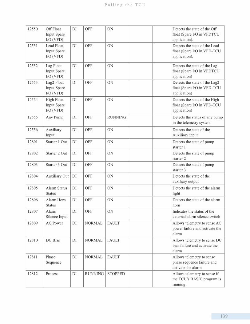
139
P o l l i n g t h e T C U
12550 Off Float Input Spare I/O (VFD)
DI OFF ON Detects the state of the Off float (Spare I/O in VFDTCU application).
12551 Lead Float Input Spare I/O (VFD)
DI OFF ON Detects the state of the Lead float (Spare I/O in VFD-TCU application).
12552 Lag Float Input Spare I/O (VFD)
DI OFF ON Detects the state of the Lag float (Spare I/O in VFDTCU application)
12553 Lag2 Float Input Spare I/O (VFD)
DI OFF ON Detects the state of the Lag2 float (Spare I/O in VFD-TCU application)
12554 High Float Input Spare I/O (VFD)
DI OFF ON Detects the state of the High float (Spare I/O in VFD-TCU application)
12555 Any Pump DI OFF RUNNING Detects the status of any pump in the telemetry system
12556 Auxiliary Input
DI OFF ON Detects the state of the Auxiliary input
12801 Starter 1 Out DI OFF ON Detects the state of pump starter 1
12802 Starter 2 Out DI OFF ON Detects the state of pump starter 2
12803 Starter 3 Out DI OFF ON Detects the state of pump starter 3
12804 Auxiliary Out DI OFF ON Detects the state of the auxiliary output
12805 Alarm Status Status
DI OFF ON Detects the state of the alarm light
12806 Alarm Horn Status
DI OFF ON Detects the state of the alarm horn
12807 Alarm Silence Input
DI OFF ON Indicates the status of the external alarm silence switch
12809 AC Power DI NORMAL FAULT Allows telemetry to sense AC power failure and activate the alarm
12810 DC Bias DI NORMAL FAULT Allows telemetry to sense DC bias failure and activate the alarm
12811 Phase Sequence
DI NORMAL FAULT Allows telemetry to sense phase sequence failure and activate the alarm
12812 Process DI RUNNING STOPPED Allows telemetry to sense if the TCU’s BASIC program is running
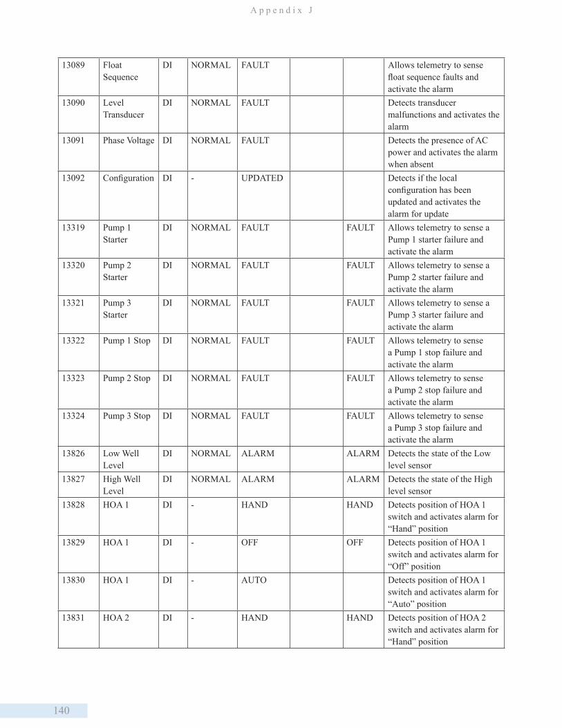
140
A p p e n d i x J
13089 Float Sequence
DI NORMAL FAULT Allows telemetry to sense float sequence faults and activate the alarm
13090 Level Transducer
DI NORMAL FAULT Detects transducer malfunctions and activates the alarm
13091 Phase Voltage DI NORMAL FAULT Detects the presence of AC power and activates the alarm when absent
13092 Configuration DI - UPDATED Detects if the local configuration has been updated and activates the alarm for update
13319 Pump 1 Starter
DI NORMAL FAULT FAULT Allows telemetry to sense a Pump 1 starter failure and activate the alarm
13320 Pump 2 Starter
DI NORMAL FAULT FAULT Allows telemetry to sense a Pump 2 starter failure and activate the alarm
13321 Pump 3 Starter
DI NORMAL FAULT FAULT Allows telemetry to sense a Pump 3 starter failure and activate the alarm
13322 Pump 1 Stop DI NORMAL FAULT FAULT Allows telemetry to sense a Pump 1 stop failure and activate the alarm
13323 Pump 2 Stop DI NORMAL FAULT FAULT Allows telemetry to sense a Pump 2 stop failure and activate the alarm
13324 Pump 3 Stop DI NORMAL FAULT FAULT Allows telemetry to sense a Pump 3 stop failure and activate the alarm
13826 Low Well Level
DI NORMAL ALARM ALARM Detects the state of the Low level sensor
13827 High Well Level
DI NORMAL ALARM ALARM Detects the state of the High level sensor
13828 HOA 1 DI - HAND HAND Detects position of HOA 1 switch and activates alarm for “Hand” position
13829 HOA 1 DI - OFF OFF Detects position of HOA 1 switch and activates alarm for “Off” position
13830 HOA 1 DI - AUTO Detects position of HOA 1 switch and activates alarm for “Auto” position
13831 HOA 2 DI - HAND HAND Detects position of HOA 2 switch and activates alarm for “Hand” position
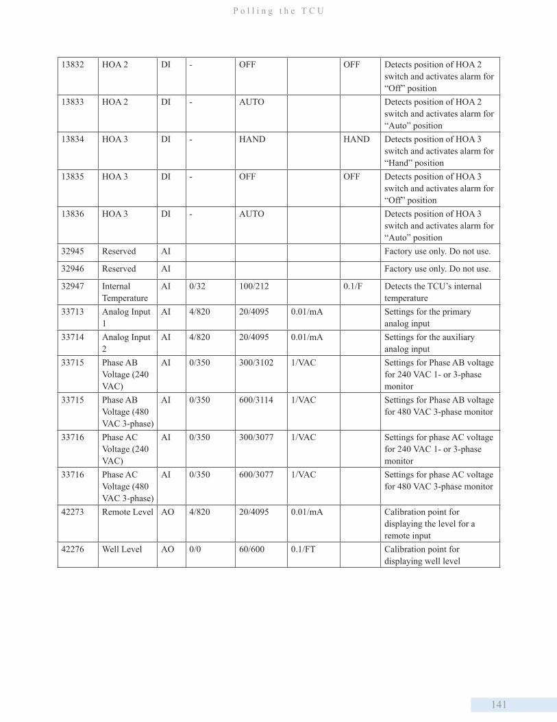
141
P o l l i n g t h e T C U
13832 HOA 2 DI - OFF OFF Detects position of HOA 2 switch and activates alarm for “Off” position
13833 HOA 2 DI - AUTO Detects position of HOA 2 switch and activates alarm for “Auto” position
13834 HOA 3 DI - HAND HAND Detects position of HOA 3 switch and activates alarm for “Hand” position
13835 HOA 3 DI - OFF OFF Detects position of HOA 3 switch and activates alarm for “Off” position
13836 HOA 3 DI - AUTO Detects position of HOA 3 switch and activates alarm for “Auto” position
32945 Reserved AI Factory use only. Do not use.
32946 Reserved AI Factory use only. Do not use.
32947 Internal Temperature
AI 0/32 100/212 0.1/F Detects the TCU’s internal temperature
33713 Analog Input 1
AI 4/820 20/4095 0.01/mA Settings for the primary analog input
33714 Analog Input 2
AI 4/820 20/4095 0.01/mA Settings for the auxiliary analog input
33715 Phase AB Voltage (240 VAC)
AI 0/350 300/3102 1/VAC Settings for Phase AB voltage for 240 VAC 1- or 3-phase monitor
33715 Phase AB Voltage (480 VAC 3-phase)
AI 0/350 600/3114 1/VAC Settings for Phase AB voltage for 480 VAC 3-phase monitor
33716 Phase AC Voltage (240 VAC)
AI 0/350 300/3077 1/VAC Settings for phase AC voltage for 240 VAC 1- or 3-phase monitor
33716 Phase AC Voltage (480 VAC 3-phase)
AI 0/350 600/3077 1/VAC Settings for phase AC voltage for 480 VAC 3-phase monitor
42273 Remote Level AO 4/820 20/4095 0.01/mA Calibration point for displaying the level for a remote input
42276 Well Level AO 0/0 60/600 0.1/FT Calibration point for displaying well level

142
A p p e n d i x J
Additional Modbus Registers Used in VFD-TCU
Register Label Module Letter
Module Type
Point Type Low State Label
High State Label
Resolution /Units
Notes
43041 Pump 1 Speed Control Signal
H ACM002 AI 0/819 100/4095 0/%
43042 Pump 2 Speed Control Signal
H ACM002 AI 0/819 100/4095 0/%
43043 Pump 3 Speed Control Signal
H ACM002 AI 0/819 100/4095 0/%
35249 Pump 1 Speed Feedack
I ACM002 AI 0/819 100/4095 0/%
35250 Pump 2 Speed Feedback
I ACM002 AI 0/819 100/4095 0/%
35251 Pump 3 Speed Feedback
I AMM002 AI 0/819 100/4095 0/%
14849-14856
Spares J DMM002 DO OFF ON Spares for connecting any required additional I/O
2817-2824 Spares K DCM003-1 DI OFF ON Spares for connecting any required additional I/O
Additional Modbus Registers Used in VFD-TCU
If you are using an HMI other than HT3, you will need to configure that software with the correct Modbus register
information in order to poll a Modbus slave device connected to the TCU. Modules H-O can be used to store data from
Modbus slave devices connected to the TCU on its RS-485 interface. (A typical application would be adding a RIO032/
RIO128. See “Appendix G: Adding a RIO to the TCU.”)
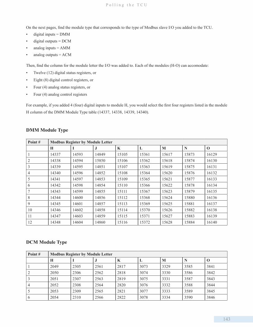
143
P o l l i n g t h e T C U
On the next pages, find the module type that corresponds to the type of Modbus slave I/O you added to the TCU.
• digital inputs = DMM
• digital outputs = DCM
• analog inputs = AMM
• analog outputs = ACM
Then, find the column for the module letter the I/O was added to. Each of the modules (H-O) can accomodate:
• Twelve (12) digital status registers, or
• Eight (8) digital control registers, or
• Four (4) analog status registers, or
• Four (4) analog control registers
For example, if you added 4 (four) digital inputs to module H, you would select the first four registers listed in the module
H column of the DMM Module Type table (14337, 14338, 14339, 14340).
DMM Module Type
Point # Modbus Register by Module LetterH I J K L M N O
1 14337 14593 14849 15105 15361 15617 15873 161292 14338 14594 15850 15106 15362 15618 15874 161303 14339 14595 14851 15107 15363 15619 15875 161314 14340 14596 14852 15108 15364 15620 15876 161325 14341 14597 14853 15109 15365 15621 15877 161336 14342 14598 14854 15110 15366 15622 15878 161347 14343 14599 14855 15111 15367 15623 15879 161358 14344 14600 14856 15112 15368 15624 15880 161369 14345 14601 14857 15113 15369 15625 15881 1613710 14346 14602 14858 15114 15370 15626 15882 1613811 14347 14603 14859 15115 15371 15627 15883 1613912 14348 14604 14860 15116 15372 15628 15884 16140
DCM Module Type
Point # Modbus Register by Module LetterH I J K L M N O
1 2049 2305 2561 2817 3073 3329 3585 38412 2050 2306 2562 2818 3074 3330 3586 38423 2051 2307 2563 2819 3075 3331 3587 38434 2052 2308 2564 2820 3076 3332 3588 38445 2053 2309 2565 2821 3077 3333 3589 38456 2054 2310 2566 2822 3078 3334 3590 3846
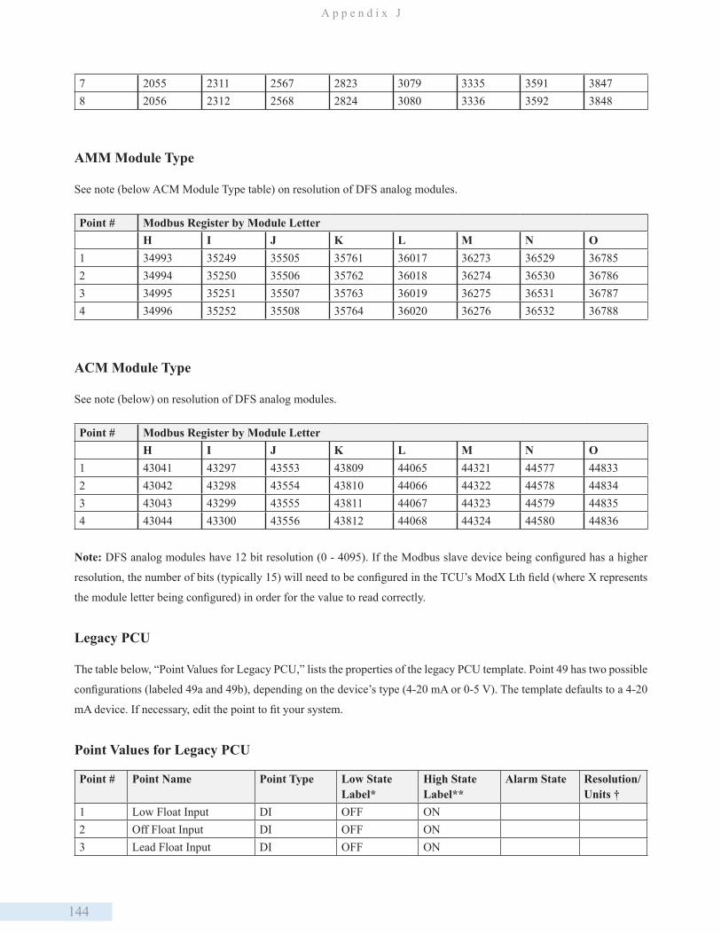
144
A p p e n d i x J
7 2055 2311 2567 2823 3079 3335 3591 38478 2056 2312 2568 2824 3080 3336 3592 3848
AMM Module Type
See note (below ACM Module Type table) on resolution of DFS analog modules.
Point # Modbus Register by Module LetterH I J K L M N O
1 34993 35249 35505 35761 36017 36273 36529 367852 34994 35250 35506 35762 36018 36274 36530 367863 34995 35251 35507 35763 36019 36275 36531 367874 34996 35252 35508 35764 36020 36276 36532 36788
ACM Module Type
See note (below) on resolution of DFS analog modules.
Point # Modbus Register by Module LetterH I J K L M N O
1 43041 43297 43553 43809 44065 44321 44577 448332 43042 43298 43554 43810 44066 44322 44578 448343 43043 43299 43555 43811 44067 44323 44579 448354 43044 43300 43556 43812 44068 44324 44580 44836
Note: DFS analog modules have 12 bit resolution (0 - 4095). If the Modbus slave device being configured has a higher
resolution, the number of bits (typically 15) will need to be configured in the TCU’s ModX Lth field (where X represents
the module letter being configured) in order for the value to read correctly.
Legacy PCU
The table below, “Point Values for Legacy PCU,” lists the properties of the legacy PCU template. Point 49 has two possible
configurations (labeled 49a and 49b), depending on the device’s type (4-20 mA or 0-5 V). The template defaults to a 4-20
mA device. If necessary, edit the point to fit your system.
Point Values for Legacy PCU
Point # Point Name Point Type Low State Label*
High State Label**
Alarm State Resolution/ Units †
1 Low Float Input DI OFF ON2 Off Float Input DI OFF ON3 Lead Float Input DI OFF ON
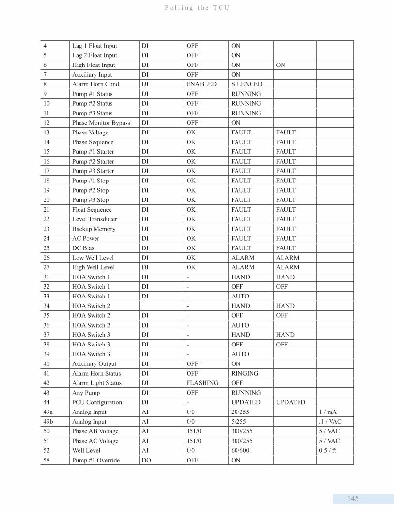
145
P o l l i n g t h e T C U
4 Lag 1 Float Input DI OFF ON5 Lag 2 Float Input DI OFF ON6 High Float Input DI OFF ON ON7 Auxiliary Input DI OFF ON8 Alarm Horn Cond. DI ENABLED SILENCED9 Pump #1 Status DI OFF RUNNING 10 Pump #2 Status DI OFF RUNNING11 Pump #3 Status DI OFF RUNNING12 Phase Monitor Bypass DI OFF ON13 Phase Voltage DI OK FAULT FAULT14 Phase Sequence DI OK FAULT FAULT15 Pump #1 Starter DI OK FAULT FAULT16 Pump #2 Starter DI OK FAULT FAULT17 Pump #3 Starter DI OK FAULT FAULT18 Pump #1 Stop DI OK FAULT FAULT19 Pump #2 Stop DI OK FAULT FAULT20 Pump #3 Stop DI OK FAULT FAULT21 Float Sequence DI OK FAULT FAULT22 Level Transducer DI OK FAULT FAULT23 Backup Memory DI OK FAULT FAULT24 AC Power DI OK FAULT FAULT25 DC Bias DI OK FAULT FAULT26 Low Well Level DI OK ALARM ALARM27 High Well Level DI OK ALARM ALARM31 HOA Switch 1 DI - HAND HAND32 HOA Switch 1 DI - OFF OFF33 HOA Switch 1 DI - AUTO34 HOA Switch 2 - HAND HAND35 HOA Switch 2 DI - OFF OFF36 HOA Switch 2 DI - AUTO37 HOA Switch 3 DI - HAND HAND38 HOA Switch 3 DI - OFF OFF39 HOA Switch 3 DI - AUTO40 Auxiliary Output DI OFF ON41 Alarm Horn Status DI OFF RINGING42 Alarm Light Status DI FLASHING OFF43 Any Pump DI OFF RUNNING44 PCU Configuration DI - UPDATED UPDATED49a Analog Input AI 0/0 20/255 1 / mA49b Analog Input AI 0/0 5/255 .1 / VAC50 Phase AB Voltage AI 151/0 300/255 5 / VAC51 Phase AC Voltage AI 151/0 300/255 5 / VAC52 Well Level AI 0/0 60/600 0.5 / ft58 Pump #1 Override DO OFF ON

146
A p p e n d i x J
59 Pump #2 Override DO OFF ON60 Pump #3 Override DO OFF ON61 Aux. Output Override DO OFF ON62 Alarm Horn Override DO OFF ON63 Alarm Light Disable DO OFF ON64 Station Disable DO OFF ON65 Pump #1 Disable DO OFF ON66 Pump #2 Disable DO OFF ON67 Pump #3 Disable DO OFF ON68 Aux. Output Disable DO OFF ON69 Alarm Horn Disable DO OFF ON70 Alarm Light Override DO OFF ON71 RESERVED DO OFF ON72 Override Reset DO DISABLE ENABLE73 Analog Updating DO OFF OFF
* For analog points, the Low State Label column gives the point’s Low engineering value followed by its Low raw value.** For analog points, the High State Label column gives the point’s High engineering value followed by its High raw value.† Resolution and units apply to analog points only.
Point Descriptions for Legacy PCU
Point # Point Name Description1 Low Float Input Detects if the Low Level sensor is in the OFF state or the ON state2 Off Float Input Detects if the Off Level sensor is in the OFF state or the ON state3 Lead Float Input Detects if the Lead Level sensor is in the OFF state or the ON state4 Lag 1 Float Input Detects if the Lag Level sensor is in the OFF state or the ON stat.5 Lag 2 Float Input Detects if the Lag2 Level sensor is in the OFF state or the ON state6 High Float Input Detects if the High Level sensor is in the OFF state or the ON stat.7 Auxiliary Input Detects if the Auxiliary Input is in the OFF state or the ON state8 Alarm Horn Cond. Gives status of external alarm-silence switch9 Pump #1 Status Detects whether pump 1 is in the OFF state or the RUNNING state10 Pump #2 Status Detects whether pump 2 is in the OFF state or the RUNNING state11 Pump #3 Status Detects whether pump 3 is in the OFF state or the RUNNING state12 Phase Monitor Bypass Detects whether the phase monitor is ENABLED or BYPASSED13 Phase Voltage Allows telemetry to sense phase voltage failure and activate the alarm14 Phase Sequence Allows telemetry to sense phase sequence failure and activate the alarm15 Pump #1 Starter Allows telemetry to sense Pump 1 Starter failure and activate the alarm16 Pump #2 Starter Allows telemetry to sense Pump 2 Starter failure and activate the alarm17 Pump #3 Starter Allows telemetry to sense Pump 3 Starter failure and activate the alarm18 Pump #1 Stop Activates the alarm any time Pump 1 is running and stops without control
by the PCU19 Pump #2 Stop Activates the alarm any time Pump 2 is running and stops without control
by the PCU
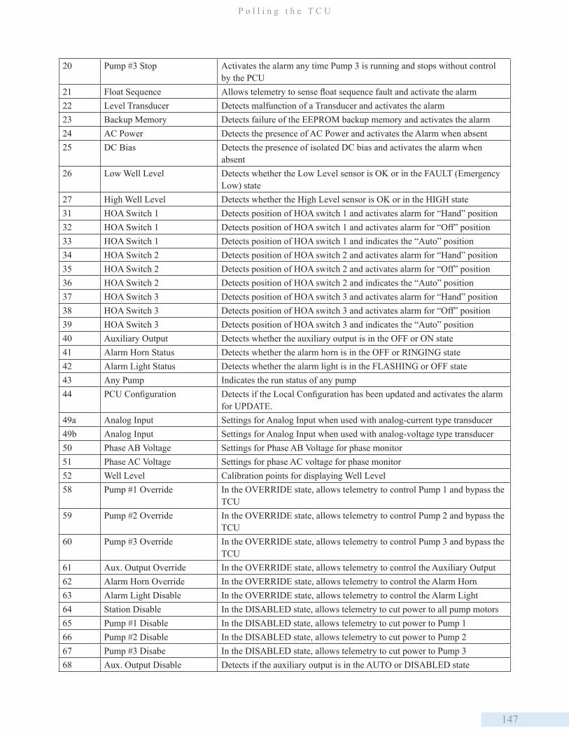
147
P o l l i n g t h e T C U
20 Pump #3 Stop Activates the alarm any time Pump 3 is running and stops without control by the PCU
21 Float Sequence Allows telemetry to sense float sequence fault and activate the alarm22 Level Transducer Detects malfunction of a Transducer and activates the alarm23 Backup Memory Detects failure of the EEPROM backup memory and activates the alarm24 AC Power Detects the presence of AC Power and activates the Alarm when absent25 DC Bias Detects the presence of isolated DC bias and activates the alarm when
absent26 Low Well Level Detects whether the Low Level sensor is OK or in the FAULT (Emergency
Low) state27 High Well Level Detects whether the High Level sensor is OK or in the HIGH state31 HOA Switch 1 Detects position of HOA switch 1 and activates alarm for “Hand” position32 HOA Switch 1 Detects position of HOA switch 1 and activates alarm for “Off” position33 HOA Switch 1 Detects position of HOA switch 1 and indicates the “Auto” position34 HOA Switch 2 Detects position of HOA switch 2 and activates alarm for “Hand” position35 HOA Switch 2 Detects position of HOA switch 2 and activates alarm for “Off” position36 HOA Switch 2 Detects position of HOA switch 2 and indicates the “Auto” position37 HOA Switch 3 Detects position of HOA switch 3 and activates alarm for “Hand” position38 HOA Switch 3 Detects position of HOA switch 3 and activates alarm for “Off” position39 HOA Switch 3 Detects position of HOA switch 3 and indicates the “Auto” position40 Auxiliary Output Detects whether the auxiliary output is in the OFF or ON state41 Alarm Horn Status Detects whether the alarm horn is in the OFF or RINGING state42 Alarm Light Status Detects whether the alarm light is in the FLASHING or OFF state43 Any Pump Indicates the run status of any pump44 PCU Configuration Detects if the Local Configuration has been updated and activates the alarm
for UPDATE.49a Analog Input Settings for Analog Input when used with analog-current type transducer49b Analog Input Settings for Analog Input when used with analog-voltage type transducer50 Phase AB Voltage Settings for Phase AB Voltage for phase monitor51 Phase AC Voltage Settings for phase AC voltage for phase monitor52 Well Level Calibration points for displaying Well Level58 Pump #1 Override In the OVERRIDE state, allows telemetry to control Pump 1 and bypass the
TCU59 Pump #2 Override In the OVERRIDE state, allows telemetry to control Pump 2 and bypass the
TCU60 Pump #3 Override In the OVERRIDE state, allows telemetry to control Pump 3 and bypass the
TCU61 Aux. Output Override In the OVERRIDE state, allows telemetry to control the Auxiliary Output62 Alarm Horn Override In the OVERRIDE state, allows telemetry to control the Alarm Horn63 Alarm Light Disable In the OVERRIDE state, allows telemetry to control the Alarm Light64 Station Disable In the DISABLED state, allows telemetry to cut power to all pump motors65 Pump #1 Disable In the DISABLED state, allows telemetry to cut power to Pump 166 Pump #2 Disable In the DISABLED state, allows telemetry to cut power to Pump 267 Pump #3 Disabe In the DISABLED state, allows telemetry to cut power to Pump 368 Aux. Output Disable Detects if the auxiliary output is in the AUTO or DISABLED state
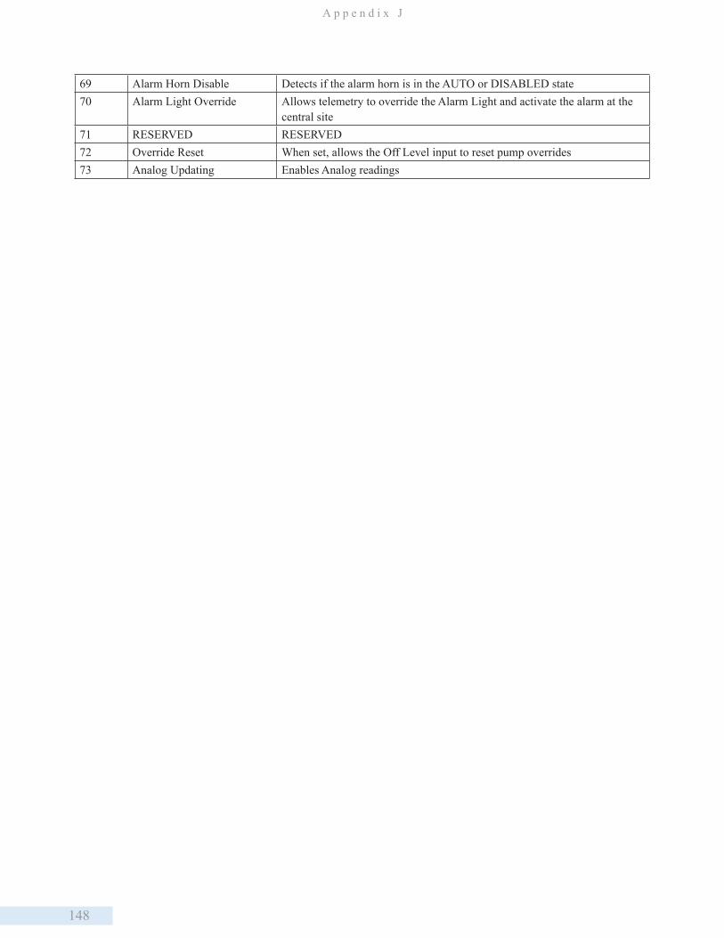
148
A p p e n d i x J
69 Alarm Horn Disable Detects if the alarm horn is in the AUTO or DISABLED state70 Alarm Light Override Allows telemetry to override the Alarm Light and activate the alarm at the
central site71 RESERVED RESERVED72 Override Reset When set, allows the Off Level input to reset pump overrides73 Analog Updating Enables Analog readings
149
S u p p o r t , S e r v i c e , a n d W a r r a n t y
Support and Service
Data Flow Systems, Inc. offers support services nationwide from its home office and through authorized Value Added
Resellers (VARs) and System Integrators. Contact your local Data Flow Systems, Inc. representative for:
• Sales and order support
• Product technical training
• Warranty support
• Support service agreements
If you are unsure of whom to contact, call DFS’ Melbourne headquarters at 321-259-5009 and ask for the Sales Department.
Alternitively, send an email to [email protected].
Technical Product Assistance
Please review the information in “Appendix C: Maintenance and Troubleshooting,” before contacting Data Flow Systems,
Inc. If you need further assistance, contact your local Data Flow Systems representative. If you are unsure of whom to
contact, call DFS’ Melbourne headquarters at 321-259-5009 and ask for the Service Department. Alterntively, send email
Return Authorization (RA) Procedure
Data Flow Systems’ function modules are designed to be robust and highly reliable. We back this performance with a
3-year full warranty (see our warranty statement for details). In the event that a function module fails, during or after the
warranty period, it may be returned to Data Flow Systems to be repaired or replaced.
All RA’s will be subject to standard shipping and handling charges. Minimum handling charge will be assessed, in most
cases, for work such as Radio Tuning, Backplanes, “No Problem Found,” and other minor repairs. Handling charges will
be waved on warranty equipment. Standard shipping and charges will be based on UPS ground, please advise if other
arrangements are needed (UPS Red, FedEx, Pickup, Freight…). Standard cost of repairs and shipping charges can be
obtained by contacting our RA Department by phone or e-mail.
STEP 1: Replace the failed module with a spare module of the same type, if one is available.
STEP 2: Contact Data Flow Systems Inc. in one of the following ways to receive an RA number. To recieve an RA number,
the following information will be needed:
Customer/Utility Name and Ship to Address
Contact Name and Phone Number
Products to be returned and Serial Numbers
Detailed description of failure
PO#
Email - An RA# can be obtained by e-mailing DFS at [email protected].
K. Support, Service, and Warranty
150
A p p e n d i x K
Phone - RA# will be issued over the phone by calling DFS at 321-259-5009 during normal operating hours.
Note: The lack of a detailed description of could result in the return of equipment due to the inability to properly determine
the nature of the failure or testing resulting in “no problem found.”
STEP 3: Place the function module(s) indivually in an electricrostatic discharge bag and then wrap with foam and bubble
wrap. Pack the wrapped module(s) in a sturdy box with styrofoam popcorn or bubble wrap. Include a packing slip with the
following information:
1. Module model, serial number, probable cause of failure, and the RA number
2. Shipping address
3. Shipping instructions (shipping costs greater than UPS ground are charged to the customer)
STEP 4: Address the box to:
RA Department # [the RA number you recieved here]
Data Flow Systems, Inc.
605 N John Rodes Blvd.
Melbourne, FL 32934-9105
STEP 5: Ship the box to DFS using any typical shipping carrier (e.g. UPS or FedEx). If circumstances permit, have a DFS
employee hand-carry the package to the headquarters for you. Please note that DFS employees are not permitted to hand-
carry an unpacked module.
Modules are typically repaired and shipped back to the customer within a two-week period starting at the time the module
reaches the RA department. If additional information is required during the repair of the module(s), the DFS service
department will contact you.
To get information on the progress of your equipment in for repair, contact the DFS RA Department at rma@dataflowsys.
com or 321-259-5009.
Replacement of equipment may be in the event that the equipment and/or parts are unrepairable. Warranty equipment will
be replaced without prior notification as warranty replacement. The customer will be notified by phone, if equipment not
under warranty cannot be repaired, with infomation of available options.
DFS reserves the right to return any material recieved without an RA# or not conforming to the requirements of this RA
process.
Notice
The intended purpose of the TCU is telemetry control. Using the TCU for purposes other than telemetry control is not
reccomended and will void the warranty.
Warranty
DFS products carry a one year warranty against defects in the material and workmanship. All Plug-in Function Models,
Telemetry Control Units, Power Supply Modules and Radio Interface Modules carry an extended two year return-to-
151
S u p p o r t , S e r v i c e , a n d W a r r a n t y
factory warranty. Products that carry an extended warranty are covered against damage due to lighting and surge for the
entire three year period when installed per factory-approved requirements.
Questions or Comments on this Manual
If you find a problem with any of the information in this manual or have suggestions on how it could be improved, please
contact us at the following address:
Data Flow Systems, Inc.
Documentation Department
605 N. John Rodes Blvd.
Melbourne, FL 32934
Alternatively, e-mail us at:

152
Glossary alternation Pumps configured for alternation take turns acting as lead. This shares the work of pumping over time.
bias voltage Voltage used to bias (or hold) an input in the ON state. Absence of the voltage forces the input in the
OFF state.
configure Choosing the operating conditions of the station from a menu.
external External equipment, devices, etc. outside of the TCU.
failure mode Failure conditions displayed in the Alarm display mode of the TAC Pack TCU’s LCD.
flow volume Well or tank volume between the Off level and the Lead level configured in the TCU. This setting is
used in the derived flow calculation.
ground Zero-voltage reference point of a circuit. May be connected to earth ground or used as a common
connection point.
Input Inputs to the TCU consist of 3 phase monitor inputs, 6 telemetry inputs, and 12 digital monitor inputs.
input common Point where multiple input circuits are terminated.
LCD Liquid-crystal display used to display messages.
LED Light-emitting diode used to indicate an on/off condition.
line Input side of switch or relay contacts.
load Output side of switch or relay contacts.
neutral Zero reference point of an AC voltage.
output Digital control output of the TCU.
override Control output logic is ignored and the output is set to a specific state.
pump mode Selected method of pumping for either a well (pump down) or storage tank (pump up).
return The circuit wire or terminal that completes the circuit path back to ground or neutral.
set points Those points configured in a station using an analog transducer to simulate the the function of float
switches. Pseudo levels corresponding to the desired levels for starting or stopping pumps and for
turning on level alarms are set in the user interface.
source Electric power supply. Provides voltage, AC or dc, for use in input/output circuits.
staging levels Levels in a well or tank at which an action (pump start or stop, or alarm activation) occurs.
telemetry Communication system used to monitor and control a remote unit or units from a central site.
total flow The Total Flow value is based on the time it takes to fill the flow volume (above). This derived flow is
used to meter the calculate the flow rate and total flow volume.

153
D a t a F l o w S y s t e m s , I n c .

154
D a t a F l o w S y s t e m s , I n c .

155
D a t a F l o w S y s t e m s , I n c .


157
D a t a F l o w S y s t e m s , I n c .
Data Flow Systems, Inc.605 N. John Rodes Blvd
Melbourne, Florida 32934(321) 259-5009
www.dataflowsys.com