b&k 801 capacitor analyst instruction manual ... - Pacific T.V.
Upload
khangminh22Category
view
0download
0
Tantalum Capacitor

Tantalum Capacitor
- 1 -
INTRODUCTION
Tantalum capacitor are designed with excellent performance characteristics for filtering, blocking,and R.C tunning circuits. They are used extensively in industrial, commercial, entertainment andmedical electronic equipment. They exhibit the proven characteristics of wide temperature rangeand long-term stability.The advantages of tantalum capacitor electrolytic capacitor consist of their chemical stability, thelow thickness and high dielectric constant of the tantalum oxide layer, and the capability ofsintering anodes with a very large surface from tantalum powder.The low reactivity of the tantalum oxide layer allows the employment of highly conductiveelectrolytes, and thus achieves a low series resistance. Capacitance and dissipation factor inrelation to temperature and frequency thus prove to be very favourable. Additionally, there is alsothe wide temperature range of several types form -55 to +125.A further advantage of the dielectric being inactive is a leakage current that is smaller than ofaluminium electrolytic capacitor which does not rise considerably even at dead storage. Tantalumelectrolytic capacitor thus show a very long life during operation and storage.The capacitance of the tantalum electrolytic capacitor is very high due to the high dielectricconstant and the low thickness of tantalum oxide layer. The use of sintered anodes with a largesurface allows very small dimensions that cannot be reached or exceeded by any other capacitor.The tantalum electrolytic capacitor at issue are polarized capacitors. In the case of polarizedelectrolytic capacitor, the dielectric is structured in such a manner that the flow of current isinterrupted in one direction. It is therefore necessary to observe the indications regarding polaritywhen using these capacitor(positive pole on anode and negative pole on cathode). In the case oftantalum capacitor, a mispolarizing is permissible up to the values indicated in reversal voltage.The tantalum capacitor is a polar electrolytic capacitor. The anode is a porous body of sinteredtantalum powder. A layer of tantalum oxide is formed over the whole sintered anode surface byan electrolytic oxidation process.This oxide layer, which has a high dielectric constant(ε≒27), functions as the dielectric medium ofthe capacitor. The final thickness of the layer determines the rated working voltage of thecapacitor. Manganese dioxide, a solid semiconducting electrolytic, is deposited in the pores andon the external surface of the formed anode to serve as the cathode. Electrical connection to thecathode is effected by applying a metallic coating to the outer MnO2 layer.As a result of the high stability of the oxide layer the leakage current to the capacitor is verysmall, even after prolonged storage. The use of a solid semiconducting electrolytic guaranteeshigh stability of the electrical properties over long periods of time and over a wide range oftemperatures and frequencies.
Tantalum Capacitor
- 2 -
FEATURE AND APPLICATION
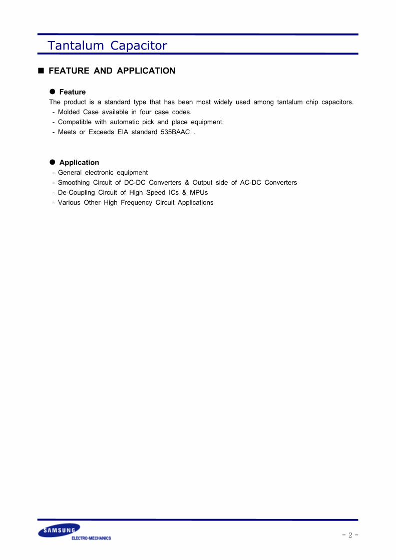
FeatureThe product is a standard type that has been most widely used among tantalum chip capacitors.- Molded Case available in four case codes.- Compatible with automatic pick and place equipment.- Meets or Exceeds EIA standard 535BAAC .
Application- General electronic equipment- Smoothing Circuit of DC-DC Converters & Output side of AC-DC Converters- De-Coupling Circuit of High Speed ICs & MPUs- Various Other High Frequency Circuit Applications

Tantalum Capacitor
- 3 -
STRUCTURE

Tantalum Capacitor
- 4 -
APPEARANCE AND DEMENSIONW2
ZZ
L
H
W1
Code EIA CodeDEMENSION (mm)
L W1 W2 H ZP 2012 2012 2.0 ±0.2 1.25 ±0.2 0.9 ±0.1 1.2 MAX
A 3216 3.2 ±0.2 1.6 ±0.2 1.2 ±0.1 1.6 ±0.2 0.8 ±0.3
B 3528 3.5 ±0.2 2.8 ±0.2 2.2 ±0.1 1.9 ±0.2 0.8 ±0.3
C 6032 6.0 ±0.3 3.2 ±0.3 2.2 ±0.1 2.5 ±0.3 1.3 ±0.3
D 7343 7.3 ±0.3 4.3 ±0.3 2.4 ±0.1 2.8 ±0.3 1.3 ±0.3
E 7343H 7.3 ±0.3 4.3 ±0.3 2.4 ±0.1 4.1 ±0.3 1.3 ±0.3

Tantalum Capacitor
- 5 -
PART NUMBERING
Product symbol : (Example) SCN Series, B Case, 6.3V 10 ±20%
① Tantalum CapacitorThe symbol shows a simplified character of the tantalum capacitor.
② Type of SeriesThe symbol shows the type of the capacitor. (SCN, SCS)SCN : Samsung Capacitor Normal - Standard series
③ Rated Voltage Code
④ Capacitance Code
⑤ Capacitance tolerance Code
⑥ Case size Code ;
⑦ Packing Code ; (A=7inches, C=13inches)
⑧ Packing polarity Code
Case P A B C D EEIA Code 2012 3216 3528 6032 7343 7343H
Symbol Tolerance(%)
KM
±10±20
Symbol Capacitance () Pico Farad () Symbol Capacitance () PicoFarad ()
105106107
1.010.0100.0
10×105
10×106
10×107
685476477
6.847470
68×105
47×106
47×107
Symbol 0G 0J 1A 1C 1D 1E 1VDC RatedVoltage
4 6.3 10 16 20 25 35
TC SCN 0J 106 M B A R① ② ③ ④ ⑤ ⑥ ⑦ ⑧
Taping andReel for Chip
Directionof Feed
Tape
+ Polarity Mark
RTaping andReel for Chip
Directionof Feed
+ Polarity Mark
L Bulk B

Tantalum Capacitor
- 6 -
PACKAGING
MARKING
P CASE
Capacitance Range 1 DIGIT 2 DIGIT
< 1.0 A Small Letter A Small Letter
1.0≤ Cap.< 10 A Capital Letter A Small Letter
≥ 10 A Capital Letter A Capital Letter
【Code Reference】
4 6.3 10 16 20
0.22 gj jj aj
0.33
0.47 gs js as cs ds
0.68 gw jw aw cw dw
1.0 Ga Ja Aa Ca
1.5
2.2 Gj Jj Aj
3.3 Gn Jn An
4.7 Gs Js As
6.8 Gw Jw
10 GA JA AA
15
22 GJ
V
JA
Polarity (White)
Capacitance Code
DC Working Voltage(G:4V J:6.3V A:10V C:16V D:20V)

Tantalum Capacitor
- 7 -
A CASE
B CASE
C,D,E CASE
A106
Polarity (White)
Capacitance Code(A:1.0 E:1.5 J:2.2 N:3.3 S:4.7 W:6.8)DC Working Voltage(G:4V J:6.3V A:10V C:16V D:20V)
Polarity (White)
Capacitance in
DC Working Voltage1020V
DC Working Voltage
1035V
Polarity (White)
Capacitance in

Tantalum Capacitor
- 8 -
EMBOSSED PLASTIC TYPE
D1
Embossed
D2P0
P1P2
BA
K
t
F
E
W
Right handOrientation available
EmbossedCarrierThe tantalum chip capacitors shall be packaged
in tape and reel form for effective use.
- Tape : Semitransparent embossed plastic- Cover tape : Attached with press, polyester- The tension of removing the cover tape,F=10∼70g
Removal speed50mm/sec15˚
FCover Tape
CaseCode
W±0.3(±.012)
F±0.1(±0.004)
E±0.1(±.004)
PO±0.1(±0.004)
P1±0.1(±0.004)
P2±0.1(±0.004)
D1+0.1(+0.004) D2Min. t A±0.2
(±0.008)B±0.2(±0.008)
K±0.2(±0.008)
P
8(0.315)
3.5(0.138)
1.75(0.069)
4(0.157)
2(0.079)
4(0.157)
ø1.5(0.059)
ø1.0(0.039)
0.2(0.008)
1.4(0.055)
2.3(0.091)
1.4(0.055)
A 1.9(0.075)
3.5(0.138)
1.9(0.075)
B
0.3(0.012)
3.3(0.130)
3.8(0.150)
2.1(0.083)
C
12(0.472)
5.5(0.217)
8(0.315)
ø1.5(0.059)
3.7(0.146)
6.4(0.252)
3.0(0.118)
D4.8
(0.189)7.7
(0.303)
3.3(0.130)
E 4.25(0.167)
Tantalum Capacitor
- 9 -
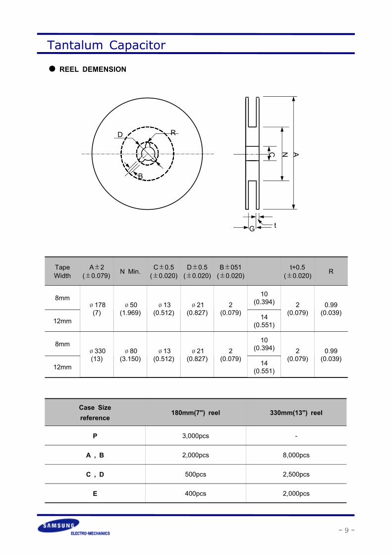
REEL DEMENSION
tG
C N A
D R
B
TapeWidth
A±2(±0.079) N Min. C±0.5
(±0.020)D±0.5(±0.020)
B±051(±0.020)
t+0.5(±0.020) R
8mmø178(7)
ø50(1.969)
ø13(0.512)
ø21(0.827)
2(0.079)
10(0.394) 2
(0.079)0.99(0.039)
12mm 14(0.551)
8mmø330(13)
ø80(3.150)
ø13(0.512)
ø21(0.827)
2(0.079)
10(0.394) 2
(0.079)0.99(0.039)
12mm 14(0.551)
Case Sizereference
180mm(7") reel 330mm(13") reel
P 3,000pcs -
A , B 2,000pcs 8,000pcs
C , D 500pcs 2,500pcs
E 400pcs 2,000pcs
Tantalum Capacitor
- 10 -
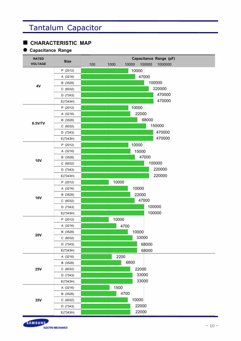
CHARACTERISTIC MAP Capacitance Range
RATEDVOLTAGE
SizeCapacitance Range (pF)
4V
P (2012)
A (3216)
B (3528)
C (6032)
D (7343)
E(7343H)
6.3V/7V
P (2012)
A (3216)
B (3528)
C (6032)
D (7343)
E(7343H)
10V
P (2012)
A (3216)
B (3528)
C (6032)
D (7343)
E(7343H)
16V
P (2012)
A (3216)
B (3528)
C (6032)
D (7343)
E(7343H)
20V
P (2012)
A (3216)
B (3528)
C (6032)
D (7343)
E(7343H)
25V
A (3216)
B (3528)
C (6032)
D (7343)
E(7343H)
35V
A (3216)
B (3528)
C (6032)
D (7343)
E(7343H)
100 1000 10000 100000 1000000
47000100000220000470000470000
2200068000
150000470000470000
1500047000
100000220000220000
100002200047000
100000100000
470010000330006800068000
22006800
220003300033000
15004700
100002200022000
10000
10000
10000
10000
10000

Tantalum Capacitor
- 11 -
Standard value and case size.
SCN Series
W.VCap.()
4V(0G)
6.3V(0J)
10V(1A)
16V(1C)
20V(1D)
25V(1E)
35V(1V)
0.15 154 A
0.22 224 A
0.33 334 A A
0.47 474 A A A B
0.68 684 A A
1.0 105 A A B
1.5 155 A A B
2.2 225 A A B C
3.3 335 A B C C C
4.7 475 B C C C D
6.8 685 B C C C D D
10 106 B C C C D D
15 156 C C C D D
22 226 C C D D
33 336 C D D
47 476 D D
68 686 D
Tantalum Capacitor
- 12 -
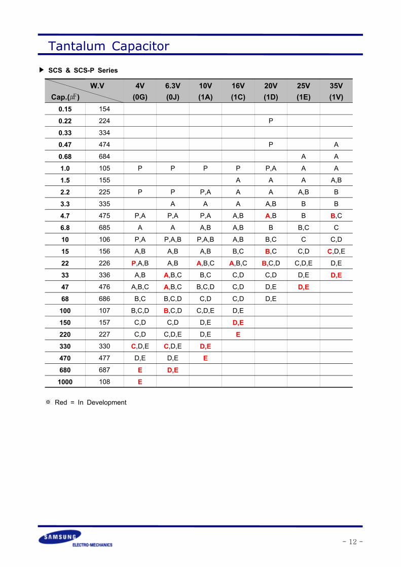
SCS & SCS-P Series
W.VCap.()
4V(0G)
6.3V(0J)
10V(1A)
16V(1C)
20V(1D)
25V(1E)
35V(1V)
0.15 154
0.22 224 P
0.33 334
0.47 474 P A
0.68 684 A A
1.0 105 P P P P P,A A A
1.5 155 A A A A,B
2.2 225 P P P,A A A A,B B
3.3 335 A A A A,B B B
4.7 475 P,A P,A P,A A,B A,B B B,C
6.8 685 A A A,B A,B B B,C C
10 106 P,A P,A,B P,A,B A,B B,C C C,D
15 156 A,B A,B A,B B,C B,C C,D C,D,E
22 226 P,A,B A,B A,B,C A,B,C B,C,D C,D,E D,E
33 336 A,B A,B,C B,C C,D C,D D,E D,E47 476 A,B,C A,B,C B,C,D C,D D,E D,E68 686 B,C B,C,D C,D C,D D,E
100 107 B,C,D B,C,D C,D,E D,E
150 157 C,D C,D D,E D,E220 227 C,D C,D,E D,E E330 330 C,D,E C,D,E D,E470 477 D,E D,E E680 687 E D,E1000 108 E
※ Red = In Development
Tantalum Capacitor
- 13 -
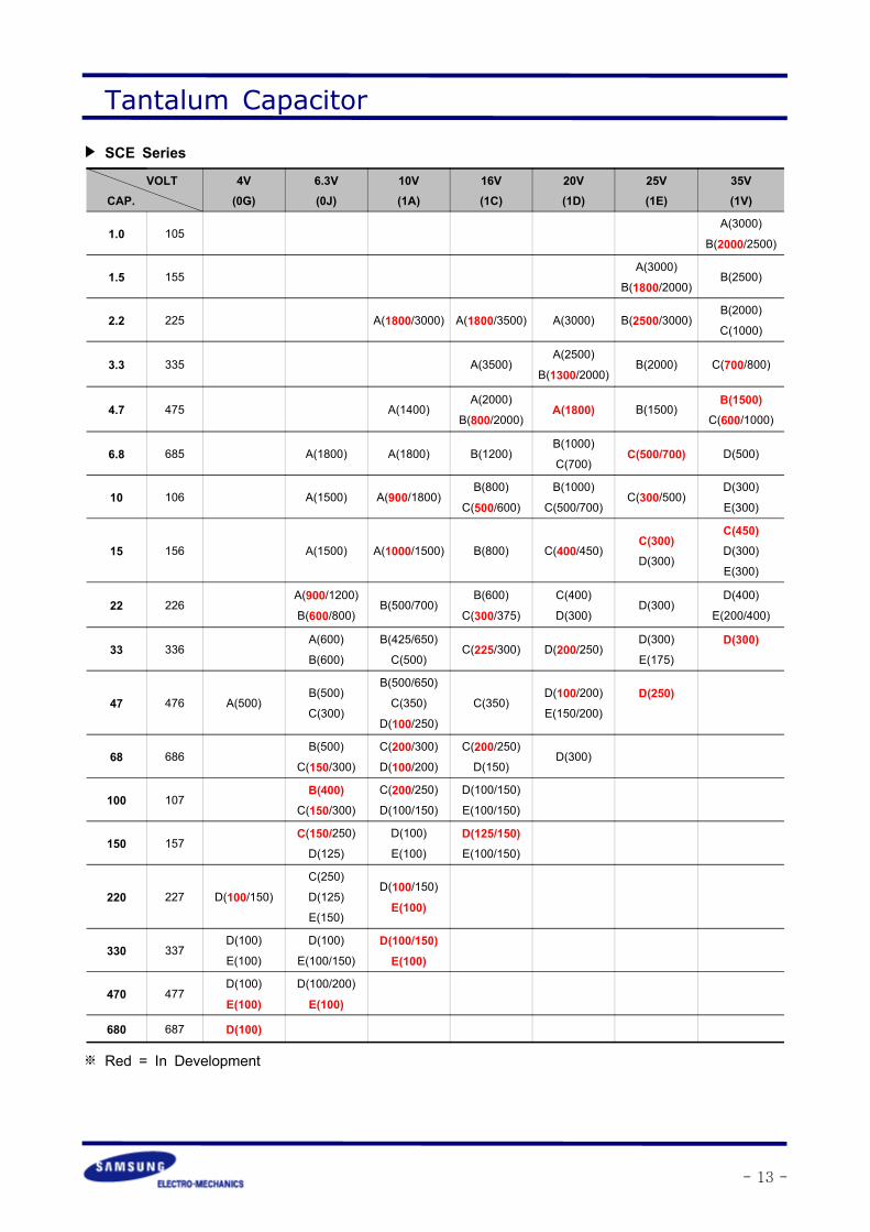
VOLTCAP.
4V(0G)
6.3V(0J)
10V(1A)
16V(1C)
20V(1D)
25V(1E)
35V(1V)
1.0 105A(3000)
B(2000/2500)
1.5 155A(3000)
B(1800/2000)B(2500)
2.2 225 A(1800/3000) A(1800/3500) A(3000) B(2500/3000)B(2000)
C(1000)
3.3 335 A(3500)A(2500)
B(1300/2000)B(2000) C(700/800)
4.7 475 A(1400)A(2000)
B(800/2000)A(1800) B(1500)
B(1500)C(600/1000)
6.8 685 A(1800) A(1800) B(1200)B(1000)
C(700)C(500/700) D(500)
10 106 A(1500) A(900/1800)B(800)
C(500/600)B(1000)
C(500/700)C(300/500)
D(300)
E(300)
15 156 A(1500) A(1000/1500) B(800) C(400/450)C(300)D(300)
C(450)D(300)
E(300)
22 226A(900/1200)B(600/800)
B(500/700)B(600)
C(300/375)C(400)
D(300)D(300)
D(400)
E(200/400)
33 336A(600)
B(600)
B(425/650)
C(500)C(225/300) D(200/250)
D(300)
E(175)
D(300)
47 476 A(500)B(500)
C(300)
B(500/650)
C(350)
D(100/250)C(350)
D(100/200)E(150/200)
D(250)
68 686B(500)
C(150/300)C(200/300)D(100/200)
C(200/250)D(150)
D(300)
100 107B(400)
C(150/300)C(200/250)D(100/150)
D(100/150)
E(100/150)
150 157C(150/250)D(125)
D(100)
E(100)
D(125/150)E(100/150)
220 227 D(100/150)C(250)
D(125)
E(150)
D(100/150)
E(100)
330 337D(100)
E(100)
D(100)
E(100/150)
D(100/150)E(100)
470 477D(100)
E(100)
D(100/200)
E(100)
680 687 D(100)
SCE Series
※ Red = In Development

Tantalum Capacitor
- 14 -
RELIABILITY TEST DATA
NO ITEMS TEST CONDITION PERFORMANCE
1 RATED DC VOLTAGE 4∼35V
2 CAPACITANCE
MEASURING FREQUENCY : 120±12HzMEASURING VOLTAGE : 0.5Vrms + 0.5∼2V DCMEASURING CIRCUITS : EQUIVALENT SERIES
CIRCUIT
CAPACITANCE RANGE0.1∼330TOLERANCE ON CAP.±10%, ±20%
3TANGENT OF LOSS
ANGLE
MEASUREMENT SHALL BE MADE UNDER THESAME CONDITIONS AS THOSE GIVEN FOR THEMEASUREMENT OF CAPACITANCE.
4 LEAKAGE CURRENT
THE RATED DC VOLTAGE SHALL BE APPLIEDTO TERMINALS ACROSS THE TEST CAPACITORCx, BY THE METHOD AS SHOWN BELOW. THELEAKAGE CURRENT SHALL THEN BEMEASURED AFTER CHARGE FOR 5 MIN.
MEASURING CIRCUITS
WHERERS : STANDARD RESISTOR(PROTECTIVE R :1KΩ): DC VOLTMETER OR ELECTRONICVOLTMETER
S1 : DC POWER SUPPLY SWITCHS2 : PROTECTIVE SWITCH FOR A AMMETERCX : TEST CAPACITOR
: DC AM-METER FOR LEAKAGE CURRENT
0.01CV or 0.5WHICHEVER IS GREATER
5 IMPEDENCE
AC VOLTAGE(0.5Vrms OR LESS) OF AFREQUENCY SPECIFIED ON NEXT PAGE SHALLBE APPLIED AND THE VOLTAGE DROPACROSS CAPACITOR TERMINALS SHALL BEMEASUREDTHE IMPEDANCE SHALL BE CALCULATED BYTHE FOLLOWING EQUATION.
WHEREE : VOLTAGE DROP ACROSS THE CAPACITORTERMINALSI : CURRENT FLOWING THROUGH THECAPACITOR (FREQUENCY : 100±10kHz)
V
A
+
-
RS
S1
S2
V Cx
A
+-
Impedance Z EI
=

Tantalum Capacitor
- 15 -
NO ITEMS TEST CONDITION PERFORMANCE
6TEMPERATURESTABILITY
THE CAPACITOR SHALL BE SUBJECTED IN TURN TO PROCEDURES SPECIFIEDBELOW
7 SURGE TEST
THE CAPACITOR SHALL BE SUBJECTED TO THE SURGEVOLTAGE AS SPECIFIED ON NEXT PAGE IN A CYCLE OF 6±0.5 MIN. WHICH CONSISTS OF 30±5 SEC. FOLLOWED BY ADISCHARGE PERIOD OF APPROX. 5 MIN 30 SEC. AT ATEMPERATURE OF +85 FOR 1,000 CYCLES.AND THE CAPACITOR SHALL BE STORED UNDERSTANDARD ATMOSPHERIC CONDITIONS TO OBTAINTHERMAL EQUILIBRIUM AFTER MEASUREMN\ENT.MEASURING CIRCUIT
WHERER1 : PROTECTIVE SERIES RESISTOR (33Ω )R2 : DISCHARGE RESISTOR(33Ω )Cx : TEST CAPACITORV : DC VOLTAGES : SWITCH
STEP TEMP. DURATIONCHANGE INCAPACITANCE
( ΔC )
TANGENT OFLOSS ANGLE
(D.F.)
LEAKAGECURRENT
1 25±2WITHIN
SPECIFIEDTOLERANCE
TABLE 1 ONPAGE 13
WITHINORIGINALLIMIT
2 2 HOURS.- 10 TO 0% OFINITIAL VALUE
TABLE 1 ONPAGE 13
N/A
3 25±2 25 MIN.
4 2 HOURS.0 TO +10% OFINITIAL VALUE
TABLE 1 ONPAGE 13
WITHIN 10XORIGINALLIMIT
5 2 HOURS.0 TO +12% OFINITIAL VALUE
TABLE 1 ONPAGE 13
WITHIN 12.5XORIGINALLIMIT
-55 0-3
+85 +30
+125 +30
RATED VOLTAGE 4V 6.3V 10V 16V 20V 25V 35V
SURGE VOLTAGE 5V 8V 13V 20V 26V 32V 45V
V
+
-
R1
R2
S
Cx+
-

Tantalum Capacitor
- 16 -
NO ITEMS TEST CONDITION PERFORMANCE
8DERATINGVOLTAGE
WHEN OPERATING AT HIGH TEMPERATURE RANGE FROM 85 to 125, THEOPERATION SHALL BE CARRIED OUT AT A DERATED VOLTAGE OR LESSDERATING VOLTAGE Vt AT ANY TEMPERATURE BETWEEN 85 AND 125SHALL BE CALCULATED BY THE FOLLOWING EQUATION
WHERE Vt : DERATED VOLTAGE AT ANY TEMP. BETWEEN 85 to 125Vr : RATED VOLTAGEVd : DERATED VOLTAGE AT 125
9ELECTRODE(TERMINALSTRENGTH)
APPLY PRESSURE IN THE DIRECTION OF THEARROW AT A RATE OF ABOUT 0.5MM/SEC. UNTIL ITREACHES A BENT WIDTH OF 3MM AND HOLD FOR 30SEC. THE TEST BOARD SHALL BE IEC 40(S) 541. FOROTHER PROCEDURES REFER TO IEC 40(S) 541.
Pessure rod
THERE SHALL BE NOEVIDENCE OFMECHANICAL DAMAGE.ELECTRICALCHARACTERISTICSSHALL SATISFY THEINITIAL REQUIREMENT.IF THERE AREELECTRODES ON BOTHSURFACES, IT SHALLSATISFY THE ABOVEREQUIREMENT ONWHICHEVER SURFACEIT MAY BE FIXATED ON.
Vt Vr Vr Vd T= −−
−40
85( )
-55 0 20 85 125
100806040200
OPERATING TEMPERATURE
VOLTAGEDERATING %
45±2 45±2
Board20
10
Tantalum Capacitor
- 17 -
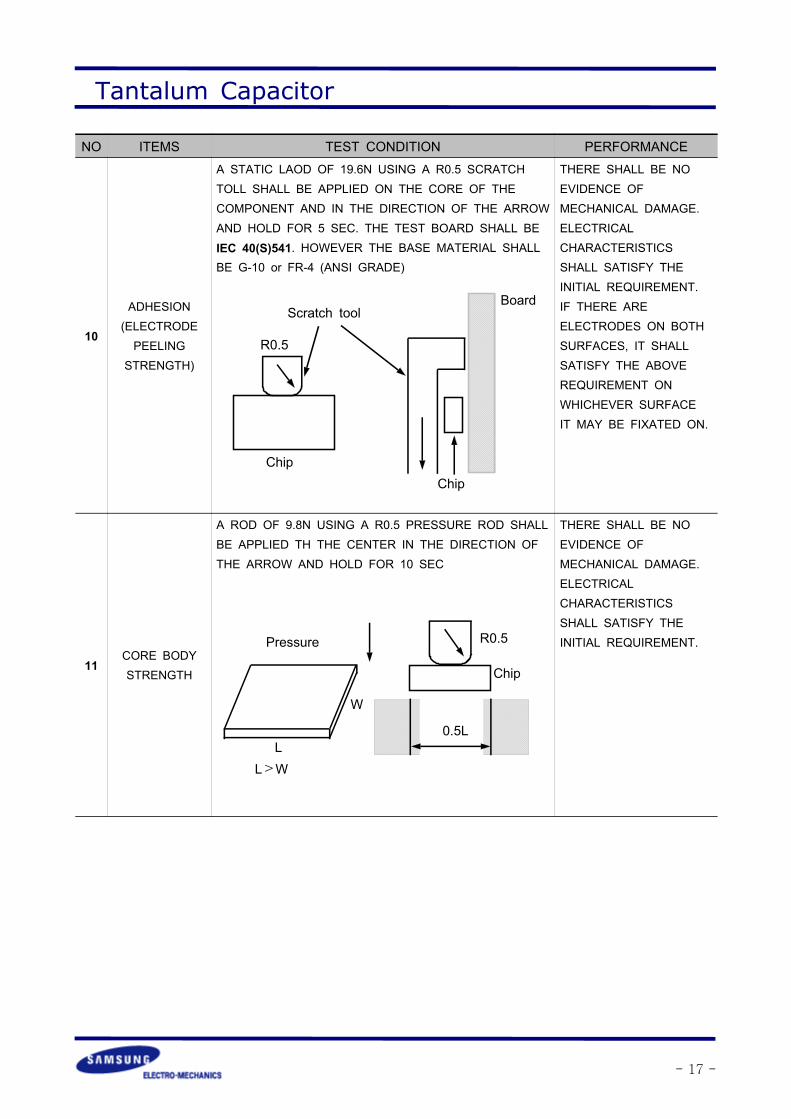
NO ITEMS TEST CONDITION PERFORMANCE
10
ADHESION(ELECTRODEPEELING
STRENGTH)
A STATIC LAOD OF 19.6N USING A R0.5 SCRATCHTOLL SHALL BE APPLIED ON THE CORE OF THECOMPONENT AND IN THE DIRECTION OF THE ARROWAND HOLD FOR 5 SEC. THE TEST BOARD SHALL BEIEC 40(S)541. HOWEVER THE BASE MATERIAL SHALLBE G-10 or FR-4 (ANSI GRADE)
THERE SHALL BE NOEVIDENCE OFMECHANICAL DAMAGE.ELECTRICALCHARACTERISTICSSHALL SATISFY THEINITIAL REQUIREMENT.IF THERE AREELECTRODES ON BOTHSURFACES, IT SHALLSATISFY THE ABOVEREQUIREMENT ONWHICHEVER SURFACEIT MAY BE FIXATED ON.
11CORE BODYSTRENGTH
A ROD OF 9.8N USING A R0.5 PRESSURE ROD SHALLBE APPLIED TH THE CENTER IN THE DIRECTION OFTHE ARROW AND HOLD FOR 10 SEC
THERE SHALL BE NOEVIDENCE OFMECHANICAL DAMAGE.ELECTRICALCHARACTERISTICSSHALL SATISFY THEINITIAL REQUIREMENT.
Scratch tool
R0.5
Board
ChipChip
R0.5
0.5L
Chip
Pressure
W
LL>W

Tantalum Capacitor
- 18 -
NO ITEMS TEST CONDITION PERFORMANCE
12 SOLDERABILITY
SOLDER TEMPERATURE : 230±5DIP TIME : 3±0.5 SEC.SOLDER : S63A(KSD 7604)FLUX : ROSIN (KSD 2951)
MORE THAN 75% OF THETERMINAL SURFACE MUST BESOLDERED NEWLY.
13RESISTANCETO SOLDERING
HEAT
PREHEAT : 100∼110 FOR 30 SEC.TEMPERATURE : 260±5DIP TIME : 10 ±1 SEC
ALL SAMPLES SHALL BE DIPPED IN SOLDERBATH. MEASUREMENT SHALL BE MADE ATROOM TEMPERATURE AFTER 1~2 HOURS OFCOOLING TIME.
CHANGE IN CAPACITANCE :±5% OF INITIAL VALUETANGENT OF LOSS ANGLE :
LEAKAGE CURRENT :
APPEARANCE :THERE SHALL BE NO EVIDENCEOF MECHANICAL DAMAGE. .
14RESISTANCE
TOCLEAN TEST
IMMERSION CLEANINGTHE CAPACITOR SHALL BE CLEANED ATROOM TEMPERATURE FOR 60sec. USINGISOPROPYL ALCOHOL
THERE SHALL BE NO EVIDENCEOF MECHANICAL DAMAGE. ANDMARKING SHALL BE LEGIBLE.ELECTRICAL CHARACTERISTICSSHALL SATISFY THE INITIALREQUIREMENT.
15
VIBRATION FREQUENCY : 10 to 55 to 10Hz (in 1 min.) MAXAMPLITUDE : 1.5 mm.DIRECTION OF VIBRATION : IN DIRECTION OFX,Y AND Z AXESTIME : 2 HOURS EACH DIRECTION AND 6HOURS IN TOTALDURING THE LAST 30 min. OF VIBRATION INEACH DIRECTION, THE CAPACITANCE SHALLBE MEASURED 3 TO 5 TIMES.FOR OTHER PROCEDURES REFER TO IECPub. 68-2-6.
MOUNTING METHOD
SOLDERALUMINABOARD
CHANGE IN CAPACITANCE :WITHIN : ±5% OF THE INITIALVALUETANGENT OF LOSS ANGLE :
LEAKAGE CURRENT :
APPEARANCE :THERE SHALL BE NO EVIDENCEOF MECHANICAL DAMAGE. .
16
MOISTURERESISTANCE
THE CAPACITOR SHALL BE STORED AT ATEMPERATURE OF 40±2 AND RELATIVEHUMIDITY OF 90% TO 95% FOR 500±8HOURS. ELECTRICAL MEASUREMENTS SHALLBE MADE AFTER BEING BOARD AT ROOMTEMPERATURE FOR 1∼2 HOURS. FOR OTHERPROCEDURES REFER TO IEC Pub. 68-2-2.
CHANGE IN CAPACITANCE :WITHIN : ±10% OF THE INITIALVALUETANGENT OF LOSS ANGLE :
LEAKAGE CURRENT :

Tantalum Capacitor
- 19 -
NO
ITEMS TEST CONDITION PERFORMANCE
17 LOAD LIFETHE CAPACITOR SHALL BE PLACED IN ACIRCULATING AIR OVEN AT AN AMBIENT.ELECTRICAL MEASUREMENTS SHALL BE MADEAFTER BEING STORED AT ROOM TEMPERATUREFOR 1~2 HOURS.
CHANGE IN CAPACITANCE :WITHIN : ±10% OF THEINITIAL VALUETANGENT OF LOSS ANGLE :
LEAKAGE CURRENT :
18STORAGE AT
LOWTEMPERATURE
THE CAPACITOR SHALL BE STORED AT ATEMPERATURE OF -55±2 FOR 240±8 HOURSWITHOUT LOAD.ELECTRICAL MEASUREMENTS SHALL BE MADEAFTER BEING STORED AT ROOM TEMPERATUREFOR 1~2 HOURS
ELECTRICALCHARACTERISTICS SHALLSATISFY THE INITIALREQUIREMENT.
19 Thermal Shock
THE CAPACITOR SHALL BE SUBJECTED TO EACHSPECIFIED TEMPERATURE FOR EACH SPECIFIEDTIME IN THE TABLE AVOBETHESE 4 STEP CONSTITUTES ONE CYCLES SHALLBE PERFORMED CONTINUOUSLY
CHANGE IN CAPACITANCE :WITHIN : ±10% OF THEINITIAL VALUETANGENT OF LOSS ANGLE :
LEAKAGE CURRENT :
TEMPERATURE VOLTAGE TIME
85 RATED VOLTAGE 2,000 HOURS
125 DERATED VOLTAGE 2,000 HOURS
STEP TEMPERATURE TIME
1 -55 30 ±3 MIN
2 25 ± 5 15 ±2 MIN
3 125 30 ±3 MIN
4 25 ± 5 15 ±2 MIN
0-3
0-3
Tantalum Capacitor
- 20 -
APPLICATION MANUAL (OPERATIONAL ATTENTION)
The operational attentions to the use of the tantalum capacitors are as follows:- Electrical- Environmental- Conditions for mounting on equipment and circuit boards- Mechanical vibration, shock
If the tantalum capacitors are used without satisfying any one of these conditions, the probabilityof short-circuiting, leakage current, ignition or other problems to occur increases. To avoid suchproblems, observe the following precautions when using the tantalum capacitors.
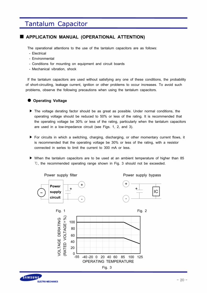
Operating Voltage
The voltage derating factor should be as great as possible. Under normal conditions, theoperating voltage should be reduced to 50% or less of the rating. It is recommended thatthe operating voltage be 30% or less of the rating, particularly when the tantalum capacitorsare used in a low-impedance circuit (see Figs. 1, 2, and 3).
For circuits in which a switching, charging, discharging, or other momentary current flows, itis recommended that the operating voltage be 30% or less of the rating, with a resistorconnected in series to limit the current to 300 mA or less.
When the tantalum capacitors are to be used at an ambient temperature of higher than 85, the recommended operating range shown in Fig. 3 should not be exceeded.
-
Powersupplycircuit
~
++
Fig. 1
Power supply filter
IC
+
-
+
Fig. 2
Power supply bypass
OPERATING TEMPERATURE-40 -20 0 20 40 60 85 100 125-55VO
LTAGEDERATING
(RATED
VOLTAGE×%)
100
80
60
40
200
Fig. 3

Tantalum Capacitor
- 21 -
Ripple
The maximum permissible ripple voltage and current are related to the ratings case size.Please consult us detail informations.
Ripple Current
The maximum permissible ripple current, IMAX, is calculated as follows:
where:
IMAX : Maximum permissible capacitor ripple current (Arms).
PMAX : Maximum permissible capacitor power loss (W).Varies with the ambient temperature and case size.Calculated according to Table 1.
ESR(f): Capacitor equivalent series resistance (Ω).
Since the ESR(f) value varies with the ripple frequency, however, the following correction mustbe made in accordance with the operating frequency (see Fig. 4).
K : Coefficient for the operating frequency ( Fig. 4).
where:ESR(120) : Equivalent series resistance at 120 Hz (Ω).
Xc : Capacitive reactance at 120 Hz (Ω).C : Electrostatic capacitance at 120 Hz (μF).f : Operating frequency (Hz).
Table.1 Maximum permissible power loss values (PMAX) by case size
Ambienttemperature ()
PMAX(W)P A B C D
25 0.015 0.030 0.030 0.030 0.05055 0.010 0.019 0.019 0.019 0.03285 0.005 0.010 0.010 0.010 0.018
ESR(f)
PMAXIMAX =
ESR(f) = K ∙ ESR(120)
ESR(120) = Tan δ ∙ Xc = 2πfCTan δ

Tantalum Capacitor
- 22 -
Ripple VoltageIf an excessive ripple voltage is applied to the tantalum capacitors, their internal temperaturerises due to Joule heat, resulting in the detriment of their reliability.
▷ The tantalum capacitors must be used in such a conditions that the sum of the WorkingVoltage and ripple voltage peak values does not exceed the rated voltage (Fig. 5)
▷ Ensure that an reverse voltage due to superimposed voltages is not applied to thecapacitors.
▷ The maximum permissible ripple voltage varies with the rated voltage. Ensure that ripplevoltage does not exceed the values shown in Figs 6 and 7. If, however, the capacitors areused at a high temperature, the maximum permissible ripple voltage must be calculated asfollows:
Vrms(at 55) = 0.7 x Vrms(at 25)Vrms(at 85) = 0.5 x Vrms(at 25)Vrms(at 125) = 0.3 x Vrms(at 25)
Frequency K
120 1.0
400 0.8
1k 0.65
10k 0.50
20k 0.45
40k 0.43
100k 0.40
1M 0.35
10
0.01
0.1
1.0
100 1K 10K 100K 1M
FREQUENCY(Hz)
K-FACTOR
Fig.4 Correction Coefficient(K)
Table.2 Hz VS KVoltage
Rated Voltage
WorkingVoltage
OperatingVoltage
Ripple Voltage
Time(sec)
Fig.5

Tantalum Capacitor
- 23 -
Reverse VoltageSolid tantalum capacitors are polarized device and may be permanently damaged or destroyed,if connected with the wrong polarity
.▷ The tantalum capacitors must not be operated and changed in reverse mode. And also thecapacitors must not be used in an only AC circuit.
▷ The tantalum capacitor dielectric has a rectifying characteristics. Therefore, when a reversevoltage is applied to it, a large current flows even at a low reverse voltage.As a result,it mayspontaneously generate heat and lead to shorting.
▷ Make sure that the polarity and voltage is correct when applying a multi-meter or similartesting instrument to the capacitors because a reverse voltage or overvoltage can beaccidentally applied.
▷ When using the capacitors in a circuit in which a reverse voltage is applied, consult yourlocal SAMSUNG ELECTRO-MECHANICS agent. If the application of an reverse voltage isunavoidable, it must not exceed the following values:
At 20°C: 10% of the rated voltage of 1 V, whichever smaller.At 85°C: 5% of the rated voltage or 0.5 V, whichever smaller.
Reliability of Tantalum Capacitors
GeneralThe failure rate of the tantalum capacitor varies with the derating ratio, ambient temperature,circuit resistance, circuit application, etc.Therefore, when proper selections are made so as to afford additional margins, higherreliability can be derived from the tantalum capacitors. Some examples of actual failure ratesare presented below for your reference.
Fig.7 Maximum permissible ripple voltage(C,D,E)
Maximum
permissibleripplevoltage
Frequency(Hz)
50V35V25V20V16V10V6.3/7V4V2.5V
Fig.6 Maximum permissible ripple voltage(P,A,B)
Maximum
permissibleripplevoltage
Frequency(Hz)
50V35V25V20V16V10V6.3/7V4V2.5V
0.1 1001010.1
100
10
1
0.1
100
10
1
0.1 100101

Tantalum Capacitor
- 24 -
Failure Rate Calculation FormulaThe tantalum capacitors are designed to work at their basic failurerates shown in Table 3 that prevail when the rated voltage isapplied for 1000 hours at 85.
Table 3 Basic failure rate
▷ Failure rate calculation formula
λuse : Estimated capacitor failure rate under the operating conditions.λ85 : Basic failure rate (Table 3)KV : Failure rate correction coefficient by the ambient temperature and derating factor.KR : Failure rate correction coefficient by the circuit resistance,
which is the series-connected resistance divided by the voltage applied to thecapacitor. This resistance is connected in series when the power supply side isviewed from the capacitor side.
K(derating factor)=operating voltage/rated voltage
Reliability Prediction
Solid tantalum capacitors exhibit no degration failure mode during shelf storage and show aconstantly decreasing failure rate(i.e. , absence of wearout mechanism) during life tests. thisfailure rate is dependent upon three important application conditions:DCvoltage, temperature, andcircuit impedance.Estimates of these respective effects are provided by the reliability nomograph.(Figure 9.)The nomograph relates failure rate to voltage and temperature while the table relates failurerate to impedance. These estimates apply to steady-state DC condition, and they assumeusage within all other rated conditions.Standard conditions, which produce a unity failure rate factor, are rated voltage, +85, and 0.1ohm-per-volt impedance.While voltage and temperature are straight-forward, there is sometimes difficulty in determiningimpedance. What is required is the circuit impedance seen by the capacitor. If severalcapacitors are connected in parallel, the impedance seen by each is lowered by the source ofenergy stored in the other capacitors. Energy is similarly stored in series inductors.Voltage "de-rating" is a common and useful approach to improved reliability. It can be persuedtoo far, however , when it leads to installation of higher voltage capacitors of much larger size.
TYPE Classification Basic failure rate
SCE Low ESR type
1%/1000hSCS-P CASE Miniature type(0805)
SCS Smail typeSCN Standard type
λuse = λ85 x KV x KR

Tantalum Capacitor
- 25 -
Table 4 Circuit Impedance Reliability Factors
Circuit Impedance(ohms/volt)
Failure Rate Impedance(multiplying factor)
0.1 1.0
0.2 0.8
0.4 0.6
0.6 0.4
0.8 0.3
1.0 0.2
2.0 0.1
3 or greater 0.07
It is possible to lose more via higherinherent failure rate than is gained byvoltage derating. SAMSUNG typicallyrecommends 50% derating, especially inlow impedance circuits.Failure rate is conventionally expressed inunits of percent per thousand hours. Asa sample calculation, suppose a particularbatch of capacitors has a failure rate of0.5% / Khr under standard conditions.
What would be the predicted failure rateat 0.7times rated voltage, 60 and 0.6Ω/V?
The nomgraph gives a factor of 7 × 10⁻²
and the table gives a factor of 0.4.
The failure rate estimate is then :0.5 × 7 × 10-2 × 0.4
= 1.4 × 10⁻² or 0.014%/Khr
T F V
Connect the temperatureand applied voltage ratioof interest with a straightedge. The multiplier offailure rate is given at theinersection of thisline with the model scale.
Given T1&v1 Read FailureRate Multiplier F1Given T, & F2Read Reguired Voltage V2Given F3 & V3Read Allowable Temp T3
120
110
100
90
80
70
60
50
40
30
20
OperatingTemperature(T)
FailureRateMultiplier(F)
102
101
100
10-1
10-2
10-3
10-4
10-5
AppliedVoltage
Ratio(V/Vo)
1.00.90.80.7
0.6
0.5
0.4
0.3
0.2
0.1
Fig.8 Reliability Nomograph

Tantalum Capacitor
- 26 -
Mounting Precautions
Limit Pressure on Capacitor Installation with MounterA capacitor that has been damaged should be discarded to avoid later problems resulting frommechanical stress.Pressure must not exceed 4.9 N with a tool end diameter of 1.5mm when applied to thecapacitors using an absorber, centering tweezers, or the like. An excessively low absorbersetting position would result in not only the application of undue force to the capacitors butcapacitor and other component scattering,circuit board wiring breakage, and / or cracking aswell, particularly when the capacitors are mounted together with other chips having a height of1 mm or less.
Flux▷ Select a flux that contains a minimum of chlorine and amine.▷ After flux use, the chlorine and amine in the flux remain and must therefore be removed.
Recommended Soldering Pattern Dimensions
Table 4 Recommended soldering pattern dimensions(mm)
Pattern
y
xz
L
Capacitor
x
W
Fig. 9
Capacitors size Pattern dimensionsL W x y z
P 2.0 1.25 1.2 1.1 0.8A 3.2 1.6 1.6 1.2 1.2B 3.5 2.8 1.6 2.2 1.4C 5.8 3.2 2.3 2.4 2.4D 7.3 4.3 2.3 2.6 3.8
DimensionsCase

Tantalum Capacitor
- 27 -
Chip Soldering Temperature and TimeCapacitors are capable of withstanding the following soldering temperatures and conditions;
▷ Waved solderingCapacitor body temperature : 230∼ 260Time : 5 seconds or less
▷ Reflow soldering see figures
100
200
50 100 150 Time(sec)
Cooling
235 MaxTemp.
Pre-heating
Heating
Figure : Typical Temperature Profile of Infrared Reflow Soldering
Figure :Typical Temperature Profile of Vapor Phase Reflow Soldering
100
200
50 100 150 Time(sec)
Pre-heating
Cooling
Heating219 Max
Temp.
Tantalum Capacitor
- 28 -
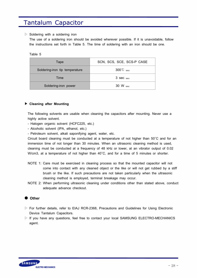
▷ Soldering with a soldering ironThe use of a soldering iron should be avoided wherever possible. If it is unavoidable, followthe instructions set forth in Table 5. The time of soldering with an iron should be one.
Table 5
Cleaning after Mounting
The following solvents are usable when cleaning the capacitors after mounting. Never use ahighly active solvent.- Halogen organic solvent (HCFC225, etc.)- Alcoholic solvent (IPA, ethanol, etc.)- Petroleum solvent, alkali saponifying agent, water, etc.Circuit board cleaning must be conducted at a temperature of not higher than 50°C and for animmersion time of not longer than 30 minutes. When an ultrasonic cleaning method is used,cleaning must be conducted at a frequency of 48 kHz or lower, at an vibrator output of 0.02W/cm3, at a temperature of not higher than 40°C, and for a time of 5 minutes or shorter.
NOTE 1: Care must be exercised in cleaning process so that the mounted capacitor will notcome into contact with any cleaned object or the like or will not get rubbed by a stiffbrush or the like. If such precautions are not taken particularly when the ultrasoniccleaning method is employed, terminal breakage may occur.
NOTE 2: When performing ultrasonic cleaning under conditions other than stated above, conductadequate advance checkout.
Other
▷ For further details, refer to EIAJ RCR-2368, Precautions and Guidelines for Using ElectronicDevice Tantalum Capacitors.
▷ If you have any questions, feel free to contact your local SAMSUNG ELECTRO-MECHANICSagent.
Tape SCN, SCS, SCE, SCS-P CASE
Soldering-iron tip temperature 300 MAX
Time 3 sec MAX
Soldering-iron power 30 W MAX
Copyright © 2022 FDOKUMEN