
TANKS CAUSED BY THE ACTIVITY OF MICRO-ORGANISMS.
175
T V/U. —(J. iOU. J uly 1939. ON THE GAS EVOLUTION IN PETROL STORAGE- TANKS CAUSED BY THE ACTIVITY OF MICRO-ORGANISMS.* By A. C. T haysen , M.Sc., P h .D.^ Iii a series of preliminary investigations it was found that a varied microflora inhabits the water-bottom of oil storage-tanks even where the tanks are used for the storage of purified oils only, including kerosine. It was found also that this microflora included types which reduce sulphates to hydrogen sulphide and nitrates to nitrogen. It is proposed in the fol- lowing to discuss the bearing of these observations on the problem of the evolution of gases in oil storage-tanks. The first question to dispose of in connection with these observations is obviously not so much where these sulphate- and nitrate-reducing micro- organisms have come from, as whether it can be shown that they are active in the water-bottom of oil storage-tanks. For their presence is not in itself a proof of their activity in the tanks, since the water used for water-bottoms is often very impure, being drawn from estuaries and rivers, and, therefore, polluted not only with sulphates and nitrates, but also with micro-organisms capable of decomposing these salts when conditions are favourable. In other words, the question to be answered is, whether conditions are favour- able in the water of oil storage-tanks for the establishment of an indigenous microflora. Experimental data obtained by myself and my colleagues unquestionably point to this being the case. It was noticed, for instance, that the sludge collecting on the floor of a tank in which a sulphide-free white oil was stored showed the presence of an appreciable percentage of iron sulphide—enough to discolour the sludge a deep black. At the same time the number of sulphate-reducing organisms in the sludge was estimated quantitatively, as far as this was possible with the available technique, and it was found that their numbers in the sludge, and even in the tank water, were much greater than that in the water used for making up the water-bottom. In another case a tank used for the storage of pure kerosine showed gas bubbles rising from the water through the oil. These bubbles, when col- lected, were found to contain a percentage of nitrogen in excess 6f that normally present in air, as well as small amounts of other gases. A bacterio- logical analysis of the water from this tank showed that a much larger number of nitrate-reducing bacteria was present than is normally found in estuarine water such as that used for this tank. Other observations and experiments which have been made have con- firmed that an indigenous microflora, capable of producing hydrogen * The reports in this Journal complete the series of papers presented at the Symposium on “ Dangerous Gases in the Petroleum and Allied Industries” held at the Royal Society of Arts on 1-tth March, 1939. The remaining papers were published in the June issue. t Chemical Research Laboratory, Teddington, Middlesex. G G
-
Upload
khangminh22 -
Category
Documents
-
view
0 -
download
0
Transcript of TANKS CAUSED BY THE ACTIVITY OF MICRO-ORGANISMS.

T V/U. — ( J . i O U . J u l y 1939.
ON THE GAS EVOLUTION IN PETROL STORAGE- TANKS CAUSED BY THE ACTIVITY OF MICRO-ORGANISMS.*
By A. C. T h a y s e n , M.Sc., P h .D .^
Iii a series of preliminary investigations it was found that a varied microflora inhabits the water-bottom of oil storage-tanks even where the tanks are used for the storage of purified oils only, including kerosine. It was found also that this microflora included types which reduce sulphates to hydrogen sulphide and nitrates to nitrogen. It is proposed in the following to discuss the bearing of these observations on the problem of the evolution of gases in oil storage-tanks.
The first question to dispose of in connection with these observations is obviously not so much where these sulphate- and nitrate-reducing microorganisms have come from, as whether it can be shown that they are active in the water-bottom of oil storage-tanks. For their presence is not in itself a proof of their activity in the tanks, since the water used for water-bottoms is often very impure, being drawn from estuaries and rivers, and, therefore, polluted not only with sulphates and nitrates, but also with micro-organisms capable of decomposing these salts when conditions are favourable. In other words, the question to be answered is, whether conditions are favourable in the water of oil storage-tanks for the establishment of an indigenous microflora. Experimental data obtained by myself and my colleagues unquestionably point to this being the case.
It was noticed, for instance, that the sludge collecting on the floor of a tank in which a sulphide-free white oil was stored showed the presence of an appreciable percentage of iron sulphide—enough to discolour the sludge a deep black. At the same time the number of sulphate-reducing organisms in the sludge was estimated quantitatively, as far as this was possible with the available technique, and it was found that their numbers in the sludge, and even in the tank water, were much greater than that in the water used for making up the water-bottom.
In another case a tank used for the storage of pure kerosine showed gas bubbles rising from the water through the oil. These bubbles, when collected, were found to contain a percentage of nitrogen in excess 6f that normally present in air, as well as small amounts of other gases. A bacteriological analysis of the water from this tank showed that a much larger number of nitrate-reducing bacteria was present than is normally found in estuarine water such as that used for this tank.
Other observations and experiments which have been made have confirmed that an indigenous microflora, capable of producing hydrogen
* The re p o rts in th is Jo u rn a l com plete th e series of p ap ers p re sen ted a t th e Sym posium on “ D angerous Gases in th e P e tro leu m an d A llied In d u s tr ie s ” h e ld a t th e R o y a l S ociety of A rts on 1-tth M arch, 1939. T he rem ain in g p ap ers w ere p u b lish ed in th e J u n e issue.
t Chem ical R esea rch L ab o ra to ry , T ed d in g to n , M iddlesex.G G

sulphide and nitrogen, establishes itself under normal conditions in the water-bottoms of oil storage-tanks, and is the cause of the evolution of these gases, which in some cases, at any rate, may cause considerable damage. Before dealing with this aspect of my problem let me refer to some observations which we have made, and which we consider have strengthened our belief in the existence of an indigenous microflora in oil storage- tanks.
It has already been mentioned that iron sulphide had been detected in the sludge of a tank which had been used solely for the storage of sulphide- free high-grade petrol. The water used for the bottom of this tank had been taken from a river which on the day when an examination of it was made was free from sulphuretted hydrogen. Whether it had been free also on the day when it was used for the tank cannot be confirmed with certainty, though it is almost certain to have been free, since the river in question has a considerable daily flow in addition to the tidal flow. Further, it is known to harbour fish life. If it may be assumed, therefore, that the iron sulphide found had not been introduced with the water, and knowing that hydrogen sulphide was not contained in the stored petrol, it must have been produced in the tank itself from the sulphates available in the water. This could only be done by their reduction through the activity of the specific bacteria found in the water. In turn the hydrogen sulphide would combine with available iron to form iron sulphide.
One of my colleagues, Mr. H. J. Bunker, undertook to determine whether a reaction such as that outlined could be carried out experimentally. The results obtained confirmed the explanation here given for the formation of iron sulphide in storage-tanks.
Before referring to Mr. Bunker’s results, it is relevant to mention certain other observations which have been made. In the case of another storage-tank for refined sulphide-free oils, which had been provided with a water-bottom at least as likely to be contaminated with sulphuretted hydrogen from the water source as the tank previously referred to, no trace of iron sulphide could be detected in the bottom sludge, and no sulphate-reducing micro-organisms were found in the water. The only difference between the two tanks was that the sulphide-free one had been given a cement wash after its cleaning, while the other one had not. It is suspected that the presence of the cement may have rendered the reaction of the water-bottom alkaline to such an extent that the activity of the sulphide-reducing bacteria became curtailed, but proof of this suspicion has not yet been obtained.
To turn to the laboratory experiments which have been carried out to demonstrate the effect of biological sulphate reduction in the presence of purified mineral oils. In one series of these experiments,1 samples of mild steel were immersed under the required anaerobic conditions in water containing sulphates to the extent of 0-35 per cent., but no sulphuretted hydrogen. Small amounts of a salt of an organic acid and of phosphates and ammonium salts had also been added. After introduction of the steel samples the water was inoculated with a sulphide-free culture of sulphate- ieducing organisms and incubated, together with another steel sample submerged in identically prepared water, which remained uninoculated. After 156 days’ exposure, the two specimens of steel wrere removed and
4 1 2 THAYSEN : ON THE GAS EVOLUTION IN PETROL STORAGE-TANKS

CAUSED BY THE ACTIVITY OF MICRO-ORGANISMS. 413
weighed. It was found that the sample incubated in the presence of sulphate-reducing organisms had lost 0-38 gm. in weight, wdiilst the control sample had lost only 0-02 gm. The liquid in the former sample contained a deposit of black iron sulphide; the sample itself showed corrosion pits and was stained dark, whilst the control sample was bright, free from pits and without sulphide deposit. Furthermore, the liquid from the inoculated sample smelled strongly of sulphuretted hydrogen.
The pitting of the experimental steel sample had its parallel in the steel of the storage-tank, where iron sulphide had been detected. Here also numerous corrosion pits were discovered on the floor and on the walls, up to the limit of the reach of the water-bottom. Pitting such as this has frequently been observed in our laboratory on steel pipes exposed to biological anaerobic corrosion in clayey soils, where it is unquestionably due to the activity of sulphate-reducing micro-organisms.2
The experiment reported upon not only strengthens the belief in the occurrence of biological sulphate reduction in oil storage-tanks, but points to the danger which may result from such activity. Another experiment which has been carried out indicates that not only the storage-tank may suffer from the effect of biological sulphate reduction, but the oil itself.
In this experiment, the results of which have not yet been published, strips of steel were immersed in water containing the food substances necessary for the growth of sulphate-reducing micro-organisms. After inoculation, a layer of refined gasoline with negative copper-strip test was placed above the water so that the steel strip was immersed partly in water and partly in petrol. During the subsequent incubation of the samples, hydrogen sulphide was formed in the water by the organism. This caused the precipitation of iron sulphide in the water layer and a blackening of the steel strips both here and in the petrol layer above, indicating that hydrogen sulphide had escaped into the petrol. This was confirmed in a copper- strip test on the oil, which was now strongly positive.
Analogous observations have been made in the gas industry, where it has been reported 3 that sulphates in the water of gas-holders can give rise to a serious contamination of stored gas with hydrogen sulphide. The two observations taken together undoubtedly point to the danger of allowing biological sulphate reduction to proceed in tanks in which purified hydrocarbons are stored.
Turning to the other aspect of gas production in oil storage-tanks, it may be recalled that I referred earlier to the observation that bubbles of gas, formed in the water layer of a tank used for the storage of purified kerosine, had been observed to rise through the remains of the kerosine which was left after the bulk had been removed consequent on a spontaneous ignition in the tank, which had occurred some weeks earlier.
It was possible to collect some of the gas which formed the bubbles, though the sample obtained was heavily contaminated with air. On analysis the gas was found to be composed of nitrogen, oxygen and a small percentage of a gaseous hydrocarbon, which was suspected of being either methane or ethane.
Through the courtesy of the company on whose premises the tank in question was situated, it was possible to secure a 10-gallon sample of the

water-bottom. One-half of this was transferred to a glass demijohn, which was connected with a cylinder for the collection of further gas samples. By the time this experiment could be undertaken, gas formation had unfortunately ceased in the water, though a bacteriological analysis showed that it still contained an active microflora which, in addition to several other types, comprised sulphate-reducing organisms and nitrate- reducing bacteria, the latter in large numbers.
For the purpose of reviving gas evolution it was decided to add certain food substances to the water. The first addition was intended to revive the sulphate-reducing organisms and consisted of a mixture of sodium lactate, ammonium chloride and magnesium sulphate in a concentration of approximately 0-1 per cent, of each salt, calculated on the total volume of liquid in the demijohn.
After one week’s incubation of the demijohn at approximately 20° C., gas evolution had not yet been revived, and it was concluded, therefore, that the sulphate-reducing organisms had not taken any conspicuous part in the original gas production.
Attention was next paid to the nitrate-reducing bacteria present, which were supplied with fresh food in the form of 0-1 per cent, of sodium nitrate calculated on the liquid present. Within a week gas evolution had commenced, yielding a daily output at the above temperature of 6-10 ml. An analysis of the gas showed it to be composed of 85-5 per cent, of nitrogen, 10-55 per cent, of methane and 3-95 per cent, of ethane.
Addition of nitrates, therefore, resulted not only in the resuscitation of nitrogen evolution, but also in a renewed production of the gaseous hydrocarbons which had been suspected present in the original sample.
These experiments, as far as they have gone, do not reveal the source of carbon from which the methane and the ethane have been produced. Nor is there at present evidence to indicate the types of micro-organisms which have produced them, though it is taken for granted that their origin must be microbiological. Seeing that their evolution re-started with the addition of sodium nitrate to the demijohn, it is tempting to connect their production with the activity of the nitrate-reducing organisms. However, no evidence is available in the microbiological literature to support this assumption, particularly as regards ethane production, which, to my knowledge, has not yet been observed during microbiological activity.
It will remain for future investigations to clear up this problem. The same must be admitted for the fixing of the carbon source from which the gaseous hydrocarbons given off from the demijohn were produced. Since they were found also in the storage-tank from which the sample of water used in our experiments was drawn, it cannot be excluded that the kerosine stored in the tank represents the carbon supply, particularly since the water sample withdrawn from the tank was covered with a layer of kerosine after being placed in the demijohn.
I do not wish to dwell on the significance from a practical point of view of the steady evolution in a kerosine storage-tank of a gas containing 14 per cent, of gaseous hydrocarbons, but I would like to remark that it does seem worth reflection that it was the very tank in which this gas evolution took place which was seriously damaged" through spontaneous ignition for
4 1 4 THAYSEN : ON THE GAS EVOLUTION IN PETROL STORAGE-TANKS

CAUSED BY THE ACTIVITY OF MICRO-ORGANISMS. 415
which the authorities have not yet been able to find a satisfactory explanation.
The work described above was carried out as part of the programme of the Chemistry Research Board, and is published by permission of the Department of Scientific and Industrial Research.
References.1 H . J . B unker, Trans. Soc. Chem. In d ., 1939 (in p rin t) .2 H . J . B unker, Proceedings Iliè m e Congrès M ondial du Pétrole, 1937, pp . 348-353.3 H . H ollings and W. K . H utchison, J . In st. Fuel, 1935, 8, 360.

4 1 6
PROTECTION FROM DANGEROUS GASES IN OIL TANKS.
By A. W. Cox, F.Inst.Pet.*
S y n o p s i s .
Dangers of em pty tan k s—Explosive and inflam m able lim its— H om e Office R egulations—Cleaning and vapour-freeing tan k s—T rea tm en t for various products— Testing for inflam m able vapour— T aking of sam ples—Electric testing m ethods— Flam e testing m ethods— P o ten tia l sources of vapour—- Removal of w ater and residues— P recau tions in vapour-testing work.
The prevention of fire and explosion in the petroleum industry has always been a serious problem, owing to the highly inflammable and explosive nature of many of its constituents. From the time oil is produced at the well until it is consumed by evaporation, inflammation or explosion the production, treatment, storage, transport and use of petroleum must be accompanied by suitable precautions against accidents.
The particular section of the history of petroleum with which this paper is concerned is that of transport and storage. This division can be narrowed still further, as it is really a consideration of the safety of empty tanks which have been used for the transport or storage. It must be recognized that a tank which has been emptied of its oil contents frequently constitutes a far greater source of danger than does the same tank when filled, or partly filled, with petroleum. The reasons for this are not far to seek.
In the first place, a tank which contains a volatile and inflammable oil is very unlikely to have an explosive atmosphere above the oil level. The restricted proportions of vapour to air which form explosive mixtures would prevent such a space being explosive, although it would probably be inflammable. The application of a flame in the space above the oil level would therefore cause a fire only. Protection against the spreading of such a fire can usually be provided beforehand, and therefore the damage can be confined. On the other hand, an empty tank may easily contain an explosive atmosphere, and one cannot readily provide protection from so destructive and unpredictable an event as an explosion.
In the second place, the risks attending an empty tank are not so evident as are those in a tank containing oil. The oil itself is recognized as a source of danger, but, when there is no liquid to be seen in a tank, it can more readily be assumed to be a safe space by those who are not familiar with the danger.
In addition, it will be realized that repair work requiring the use of • naked lights and fires would not be likely to take place on a tank which
contained inflammable oil. The emptying of a tank, however, is often carried out for the purpose of making repairs, and it might therefore be assumed that, because a tank was empty, it was in order for naked lights to be used. That such assumptions have been made has been evident from explosions and fires which have taken place even in recent years. Repair work on oil tanks is carried out more frequently on tank ships and
* Messrs. B. & R . Redw ood.

COX : PROTECTION FROM DANGEROUS GASES IN OIL TANKS.
barges than on land tanks, owing to the extra strains and stresses which occur in water-borne vessels.
The risks attending the repairing of tank vessels was recognized quite early in the petroleum industry. In a Paper read before the Institution of Civil Engineers in 1894 the late Sir Boverton Redwood dealt at length with this problem. The industry was then in its infancy, but already there had been a number of explosions and fires in ships, due to the presence of vapours from petroleum. In consequence, a considerable amount of investigation was carried out, and the subject of the vapour-freeing of ships was thoroughly examined. The conclusions then arrived at still hold good, and it is therefore all the more surprising, in these days, that obvious precautions against fire and explosion are sometimes omitted.
In recent years the risks attending repairs to tank vessels have been the subject of Government consideration. In 1931, after consultation with representatives of the oil and the ship-repairing industries, regulations were made governing the repairing of tank vessels.* The definite regulation was then made that
“ Until a certificate of test has been obtained no person shall bring near, or take into, any oil-tank, any naked light, fire or lamp other than a properly enclosed electric lamp, or apparatus of any kind for producing a light or spark, nor enter it except for the purpose of testing the atmosphere or the necessary preliminary cleaning.”
These Regulations then proceed to give details as to conditions under which the use of naked fights may be permitted on ships undergoing repair, and as to the methods to be adopted in preparing tanks for testing. The latter follow the practice of most ship-repairers for many years, and are a tribute to the care which has been exercised by that industry during the development of the tank ship.
In considering the dangers attendant upon repairs to oil tanks, two well-known facts have to be kept in mind. These are, the small proportion of vapour to air which can cause an explosion, and the heaviness of petroleum vapour in comparison with air. The paper by Redwood already referred to gives the results of numerous experiments with mixtures of air and petroleum vapour. These experiments showed that, in the case of pentane, 1-25 per cent, of vapour in air was required to produce an inflammable mixture, and the explosive limits were from about 1-5 per cent, to about 6 per cent. Since then many other workers have carried out experiments on the explosive limits of petroleum hydrocarbons, and there is a good agreement between these figures and those just quoted.
The figures obtained by various workers, for explosion limits of hydrocarbons, vary according to the conditions under which the experiments were conducted. In the early experiments of Redwood a large metal box was used to hold the air-gas mixture, and the source of ignition was a lighted taper. Later workers have generally used smaller vessels, of differing shapes and sizes, and have usually adopted electric ignition/ It has been shown that, in the case of mixtures in a tube, the explosion limits vary according to the position in the tube of the source of ignition, and figures quoted for explosion limits must always be considered in relation
* Shipbuild ing R egula tions, S .R . & O., 1931, No. 133.

to the conditions of the experiments. This fact is one argument for not paying too much regard to the amount of inflammable vapour contained in a tank, and for insisting on the complete absence of vapour. The issue of a certificate stating, because a test of the atmosphere of a tank shows a proportion of vapour which is below a recognized minimum for explosion, that the tank examined is therefore safe for the use of naked lights, is a very dangerous practice. Further consideration will be given to this matter later in the Paper.
Gas-Freeing Tanks.The methods to be used to render oil tanks safe for repairs, according
to the Shipbuilding Regulations, are as follows :—
“ All residual oil and any sludge or deposit therein shall be removed.” “ It shall be thoroughly steamed by means of steam jets, for such
period as will ensure the vapourisation of all volatile oil.”“ After it has been steamed (i) all covers of manholes and other
openings therein shall be removed, and it shall be thoroughly ventilated, by mechanical or other efficient means, so as to ensure the removal of all oil vapour, and (ii) the interior surfaces shall, if any deposit remains thereon, be washed or scraped down.”
The operation of rendering a tank safe for work requiring the use of naked lights is usually termed “ gas-freeing.” The term is somewhat deceptive, for the preparation of a tank for repair requires more than the removal of gas which is present after it has been emptied. It is possible to make the atmosphere of a tank free from inflammable vapour, and still leave residues and deposits on frames and on the bottom which, when disturbed, will produce vapour. This occurs especially in the case of crude oil, where the lighter products are difficult to remove by ordinary steaming and ventilating methods. Even in the case of lighter products such as motor spirit, however, it is possible to remove all visible liquid, and yet leave deposits of rust and dirt which, when disturbed, evolve dangerous vapours. The “ gas-freeing ” of a tank consists, therefore, of the operations of steaming, ventilating and cleaning, and each of these is essential if the work is to be carried out satisfactorily and in reasonable time.
The object of injecting steam into a tank is to raise the temperature, and thus distil off the lower-boiling products. This occurs particularly in the cases of products such as motor spirit and crude oil. In the case of higher-boiling and more viscous materials, the action of steaming is principally to cause the oil to flow to the bottom of the tank, where it can be more easily removed, and, at the same time, to lessen the quantity of oil on the sides and frames. The removal of “ all volatile oil ” by steaming, as mentioned in the Shipbuilding Regulations, is not a practical proposition in the case of crude oils, but steaming of tanks which have contained these oils is not less essential because of this. It is found to facilitate “ gas- freeing ” in these cases if the steaming is done after the removal of as much deposit as possible, instead of before any cleaning is carried out.
\ entilation is the next process. This can be accomplished by the use of windsails, but the more modern method is to use a steam ejector con-
4 1 8 COX : PROTECTION FROM DANGEROUS GASES IN OIL TANKS.

COX : PROTECTION FROM DANGEROUS GASES IN OIL TANKS.
nected to the pipe-lines of the tank. The latter method ensures that the gases removed are drawn from the lowest places in the tank, where the largest concentration of petroleum vapour is to be found. Ventilation by this means is therefore more efficient and more rapid. It is also unaffected by absence of wind, which renders windsails of little value. The removal of petroleum vapour by ventilation enables men to enter a tank, in order to carry out the cleaning which is necessary before the tank can be considered to be “ gas-free.” This is very important, as cleaning is an essential operation in preparing tanks for repair.
The method to be adopted in cleaning tanks varies according to the product which was contained in the tank. In the case o f the lighter products, such as motor spirit, white spirit or kerosine, the cleaning will consist of the removal of condensed steam, the higher-boiling parts of the products, dirt and loose rust. All these materials must be completely removed. The disturbance of these products will cause the production of dangerous vapours, which will rapidly affect men who are carrying out the cleaning. The Shipbuilding Regulations therefore state that
“ Where any person is employed in the cleaning of a tank which has contained oil with a flash point below 73° F. (close test), he shall be provided with suitable breathing apparatus consisting of a helmet or facepiece with necessary connections by means of which he can breathe outside air.”
It will be appreciated that, the more efficiently the steaming and ventilating operations have been carried out, the less risk will there be of men being overcome by gases during the cleaning process.
In the case of viscous oils, a very useful method of cleaning loose oil from the sides and framing of a tank is to wash the sides with water by means of hoses. By this means loose oil is sent to the bottom of the tank, where it can be removed, together with the water used for washing down, and thus reduce the time necessary for hand cleaning.
The sequence of “ gas-freeing ” methods adopted in the case of crude oil is often different from that of other oils. The tank is first washed down with water-hoses. Oil on the sides and on framing is thus washed to the bottom where it can be pumped out by the ship’s pumps together with the washing water or, in the case of special tank-cleaning methods, by the ejector provided. The tank is then hand cleaned, due regard being taken to the release of dangerous gases as the residue is disturbed, and as much ventilation as possible provided. The tank is then steamed, after which further cleaning by hand is carried out, and ventilation continued.
Throughout the operation of “ gas-freeing ” it must be remembered that, not only are immediate explosion and fire to be prevented, but potential sources of explosion and fire are to be removed. The necessity for this is not always self-evident.
The danger of explosion is dependent on the concentration of dangerous gases, and the obvious cure is ventilation. By this means the proportion of vapour in air is reduced below the minimum necessary for an explosion. But it is of little use ventilating a space until it is safe from an explosion, if there are means whereby vapour can be generated in the tank. These

means may be oil residues, condensed steam, rust, pipe-lines, heating coils and leaking bulkheads. Cases have also been known where hollow ladder hand-rails and hollow masts stepped into tanks have become filled with motor spirit. In many cases of this kind holes had previously been drilled at the bottom of the fittings, with the object of preventing such an event, but these holes had become blocked with rust, and thus retained the liquid with which they became filled when the tank contained a cargo of oil or spirit. A frequent source of trouble is heating coils. These are often not used for a considerable time, while a vessel is carrying mobile and volatile liquids. In consequence they become filled with dangerous liquids through leaking joints. If the vessel is then used for other cargoes, which are not dangerous, it may be assumed that no dangerous liquid is contained in the coils. The contents of the coils cannot be observed by the person appointed to make tests for the presence of inflammable or explosive gases, and, if the joints of such coils are broken during repair work, inflammable liquid may run out and nullify any certificate which may have been issued. This has actually occured on several occasions, and is an example of a potential source of explosion or fire mentioned above.
The opening of pumps in pump-rooms is a potential source of danger, for it is usual for some liquid to drop from the pump into the bilges of the pump-room, and this may create an explosive or inflammable atmosphere in the bilges. With the more volatile distillates this danger is usually suspected and steps are taken to prevent i t ; but, even with less volatile products, circumstances may arise which cause the production of a dangerous atmosphere. The playing of compressed air on to oily surfaces has been known to produce a dangerous condition, in an atmosphere which had previously been found free from inflammable gas.
A very important potential source of risk is that of spaces adjacent to those which have been examined, and found free from inflammable gas. Repairs to a tank which is free from gas may involve penetrating with a flame or rivet into an adjacent tank, with disastrous results. Leakages from adjacent spaces into a “ gas-free ” tank have also been the cause of trouble, motor spirit being known to have trickled into a tank which had previously been free from inflammable gas. Opening of pipe-lines, valves and heating coils in a tank must always be followed by fresh tests of the atmosphere, before work requiring the use of naked lights is allowed to be continued. The flooding with water of a tank which had originally been “ gas-free ” must be considered as cancelling any certificate which may have been given previously. When the water is removed the tank must be again cleaned and ventilated, and fresh tests made of the condition of the atmosphere, before naked light work is allowed.
A point to be remembered in inflammable vapour detection work is that a small fire, which may occur in a tank in which the atmosphere is free from inflammable gas, owing to the presence of oil, oily residues or rust, may be the cause of damage to life and property out of proportion to the size of the fire. Such a fire can be started by the use of burning plant on oily plates or heaps of rust. The sudden appearance of a fire in an oil tank causes a rush of workmen to the ladder. This means clambering hurriedly over awkward frames in the tank, and a scramble at the foot of the ladder. There is serious danger to limb, and also the probability of a
4 2 0 COX : PROTECTION FROM DANGEROUS GASES IN OIL TANKS.

COX : PROTECTION FROM DANGEROUS GASES IN OIL TANKS.
dangerous psychological effect on the minds of men working on the ship. The trouble is likely to be still greater if a windsail happens to be in the line of the fire, for this will readily ignite, and cause more serious damage. Such accidents have occurred.
These, and other considerations, lead to the view that the only safe policy is one of removal of all possible sources of both fire and explosion. It is in these matters that the experience and knowledge of the person appointed to make tests for inflammable vapour sometimes count for even more than the actual tests he makes.
The “ gas-freeing ” of petroleum-carrying tank barges is carried out in a manner similar to that of tank ships. The shells of these barges are usually separated from the tanks, and the spaces between the shells and tanks, as well as the cabins, must all be dealt with as dangerous places, and appropriate treatment given. The places cleaned must include the spaces round the outside of the tanks, from which all dirt and rust must be removed. Where tanks are supported on wooden beams, steps must be taken to prevent the release of inflammable vapour from oil with which they may have become impregnated.
Most of the remarks which have been made in regard to oil tanks in ships apply equally to oil tanks on land. When emptied of its contents, the tank is heated by steam, to remove as much as possible of the lower-boiling products. Water and oil residues are then pumped out as far as possible, all bolted manholes are removed, and as much ventilation as possible is secured. This can be arranged by the use of windsails, or of metal sheets placed in the manholes, and bent so as to catch the prevailing wind. The tank is then thoroughly cleaned by hand, all water, oil, rust and dirt being removed. Gas masks may be necessary for this operation. Pipe-lines and valves connected to a land tank must be completely disconnected, so that no liquid can possibly enter the tank. Foot-valves must also be completely dried, and the valves fixed well off their seatings. Swing-pipes must be disconnected and drained, and hung so that there is a fall along the whole of the pipes. When all connections are properly broken, and all residues of oil, water, dirt and rust are removed, as much ventilation as possible must be given continuously.
In the case of buried tanks, such as underground cylinders, the methods used for land tanks will apply. Ventilation must be arranged so that there is a free passage of air out of the tank, as well as into it. I t is only possible to examine the interior of tanks buried in the ground, and it must therefore be remembered that the ground surrounding such tanks may contain inflammable liquid or explosive vapour.
The treatment for “ gas-freeing ” tank wagons follows the lines given for land tanks. Steaming, cleaning and ventilating all need to be carried out. Steps must be taken to ensure that no liquid of any kind is left in valve chambers or other concealed places. Valves and manholes must be fully opened and maintained open.
The ‘ ‘ gas-freeing ’ ’ of drums is similar in principle to that of other land tanks. After thorough draining through the bung-hole, the drums are steamed. Water and residues are then run out, and compressed air is passed into the drum through the bung-hole. By this means ventilation is obtained. If a drum contains much rust or dirt which does not fall out

of the plug-hole after steaming, it may be dislodged by putting a quantity of water into the drum and rolling or shaking.
In the cases of cylinders, tank wagons and drums, it is not recommended to replace steaming by filling with water, owing to the difficulty of ensuring that inflammable liquid is not trapped above the surface of the water.
D etec to rs f o r I n f la m m a b le V a p o u r s .
The methods used for detecting the presence of inflammable vapour can be divided into two chief classes. These are electric and flame methods. Investigations on these methods have been conducted since the commencement of the bulk transport of petroleum, and in some cases have been adapted from the methods used or proposed for the detection of explosive gases in coal mines.
An early type of electrical detector was based on the fact that petroleum gases, when burned on a heated platinum wire, raise the temperature of the wire and increase the light emitted from it. By comparing the intensity of the light from the wire with that of another identical wire, which was subjected to the same current, an estimate of the amount of inflammable gas present could be made. The method suffers, in common with many electrical methods, from the disadvantage of the necessity for constantly checking and altering the zero indication.
As early as 1887 electrical detectors were used based on the principle of the contraction in volume of gases, due to the combustion of hydrocarbons on a filament heated by electricity. These apparatus were found to give good results, under favourable conditions, and with a fairly high proportion of combustible gas. They suffered from a number of disadvantages, including the time taken to obtain results, and the skill needed to ensure accurate zero settings for every test.
Detectors of a different type were constructed, on the principle of adding explosive gas in known proportions to the gas under examination, until an explosive mixture was formed. Experiments with known mixtures enabled calculations to be made of the proportion of inflammable gas in the sample examined.
Another interesting apparatus, devised in 1868, depended on the change in rate of diffusion through unglazed earthenware, caused by the presence of extraneous gases in the atmosphere, while yet others used the change in resonance of a musical pipe, due to the presence of dangerous gases. A further detector used the rise in temperature of platinum black on the bulb of a thermometer, when placed in contact with inflammable gases, to determine the condition of the air in mines.
The earliest method of inflammable gas detection in coal mines was the observation of the effect of these gases on a candle flame. This was the forerunner of modern methods. It was noticed that when inflammable gases were present in coal mines which contained methane, the latter gas burned above the candle flame, with a pale blue flame of conical shape. The “ flame cap,” as it was termed, was difficult to see owing to the brightness of the candle flame itself, and other types of flame were tried, in order to obtain more definite and delicate results.
The miner’s lamp, which burned oil, was found to furnish results similar to those of the candle flame, but again the brightness of the flame tended
4 2 2 COX : PROTECTION FROM DANGEROUS GASES IN OIL TANKS.

COX : PROTECTION FROM DANGEROUS GASES IN OIL TANKS.
to mask the pale blue flame of the inflammable gas, and it was difficult to detect less than 2 per cent, of gas.
The flames of colza oil, mineral colza oil, light petroleum spirit and alcohol were each used for the detection of inflammable gas in mines, and each was found to be unreliable. The alcohol flame was superior to the others in some respects, but it was not until the flame of hydrogen was used that delicate and accurate determinations could be made.
Modern examples of electric inflammable gas detectors are the Burrell, McLuckie, Martienssen, U.C.C. and M.S.A. In the cases of the first two mentioned, the principle of reduction in volume of a gas due to the combustion of inflammable constituents on a heated platinum wire is used. These detectors are calibrated for particular gases, so that the reduction in volume is indicated as a percentage of the inflammable gas, and they record up to a maximum which is approximately the lower explosive limit of the gas concerned. The principle on which these detectors work is a sound one and, provided alterations in volume due to temperature variations are avoided, the results given are accurate. The possibility of obtaining erroneous results, owing to temperature changes caused by the heat of the glowing wire, causes some delay in obtaining results, but, unless the necessary time is given for equilibrium to be established, correct readings will not be given by the apparatus. It is claimed, in the case of the McLuckie tester, that six determinations can be made in thirty minutes. The operation of this apparatus is quite simple, and consists of the aspiration of a sample of the air to be tested by means of a rubber bulb, and the movement of a handle into three positions. The percentage of vapour is read off from the calibrated scale of a U-tube gauge. Where the percentage of inflammable gas exceeds 1-2 per cent., the sample must be diluted with pure air before it is passed into the apparatus.
The indication of the presence of inflammable gas in the case of the Martienssen apparatus is the brightness caused by the combustion of the gas on an electrically heated platinum wire, which is coated with palladium salts. It has been found that this detector gives good results above about 0-6 per cent, of methane, and that the filament has a good length of life.
The principle of the U.C.C. and M.S.A. detectors is that the combustion of inflammable gases on a heated platinum wire causes an increase in the resistance of the wire to the passage of an electric current. In the U.C.C. apparatus the filament is a part of a Wheatstone bridge circuit, and the unbalancing of the circuit, when inflammable gas is passed over the heated filament, causes a hand to move over a calibrated dial, which is graduated in percentages of inflammable gas. Careful observations of zero error need to be made from time to time with this apparatus, and the filament of the detector needs to be replaced at intervals, as its resistance increases with age. This apparatus is suitable for detecting proportions of inflammable gas which are well below the lower explosition limit.
The M.S.A. detector contains two filaments in a balanced circuit, one being in the path of the atmosphere to be tested, and the other r e m a i n i n g
in a compartment of fresh air. The presence of inflammable vapour causes a rise in the temperature of the heated detector filament, and a consequent increase in the resistance of the filament. The disturbance of the balance thus produced is recorded on a dial, which is calibrated in parts

of the lower explosive limit. In this apparatus the zero must be checked at intervals, and provision is made for this purpose. In the case of this apparatus also, when the proportion of inflammable gas is above the lower explosive limit, the atmosphere must be diluted with fresh air. Provision for this is made in the outfit supplied. A new pattern of this detector weighs only 3 lb.
Electrical detectors of the kinds briefly described should be operated by persons who are well acquainted with electrical circuits of the types used. Careful checking of zero positions must be carried out frequently, possibly before each test, and the voltage of the batteries used must be maintained for accurate working of the apparatus. In common with all electrical apparatus of this kind, care must be taken that all electrical contacts are kept tight and clean, and filaments must be kept under observation to avoid poisoning by gases or burning out.
The hydrogen flame detecting lamp has been in constant use since it was introduced in 1894. The researches of Clowes and Redwood showed that the hydrogen flame was particularly suited to the detection of inflammable vapour. In the Redwood apparatus hydrogen is burned at a small jet, which is contained in a special form of lamp, into which the gas to be tested can be passed. The effect of inflammable vapour is to create a flame-cap above the hydrogen flame. The flame-cap varies in size according to the proportion of inflammable gas in the air which is being tested, and also increases in size with an increase in the height of the hydrogen flame. The recommended height of the hydrogen flame to be used for testing is 10 mm. Such a flame gives a flame-cap 17 mm. high when an air-pentane mixture containing 0 05 per cent, of pentane is passed into it. The test is therefore very sensitive, and there is no zero factor to be considered.
The complete apparatus for the hydrogen flame test consists of a specially designed lamp, a gas-collecting cylinder and pump, a cylinder of hydrogen and the necessary connecting tubes and fittings. In the standard pattern of the apparatus the collecting cylinder holds one-third cubic foot of gas, when filled to its working pressure of 30 lb. per square inch. It is therefore adapted for taking much larger samples of air than electrical types of apparatus, and this is a distinct advantage when sampling the atmosphere of tank steamers, where, owing to the framing in the bottoms of the tanks, pockets of vapour are liable to collect. Samples can be taken either by descending to the bottom of the tank, or by means of a flexible tubing reaching to the bottom. The examination of the samples thus obtained cannot be made in the tank in which the samples are taken, but the time taken for each test is only a few seconds, and there is no waiting period for establishment of equilibrium. This is important on a tank vessel, where there may be twenty or thirty compartments to be examined. When making a test, the sample vessel is connected by a screwed union to a copper tube, which is in turn connected to the testing-lamp, the valve is opened, and the effect is observed of the atmosphere thus released on the hydrogen flame which is burning in the lamp.
A more portable form of this apparatus is shown in Fig. 1. The principle of the unit is the same as that of the older pattern, but there are several improvements in design. The lamp is fitted with a viewing eyepiece, which obviates the need for a dark cloth in order to see the pale coloured
4 2 4 c o x : p r o t e c t i o n f r o m d a n g e r o u s g a s e s i n o i l t a n k s .

F i g . 1.
M O D I F I E D R E D W O O D V A P O U R - D E T E C T I O N A P P A R A T U S .
[To face p. 421.

COX : PROTECTION FROM DANGEROUS GASES IN OIL TANKS. 4 2 5
inflammable gas flame. The observation of the flame is rendered clearer by this modification. The collecting pump holds 2 litres, and is designed so that the interior of the cylinder, and the inlet and outlet valves, can all be cleaned in a few moments. The inlet of the sampling pump is at the bottom, so that bottom samples can be taken without the use of flexible tubing. Provision is made for the use of flexible tubing in cases where samples must be taken at a distance from the pump. In this form of the hydrogen flame apparatus the whole assembly is mounted in a light metal casting, so that there is no assembling of parts to be made when the apparatus is required for use. A smaller hydrogen cylinder is used than in the original form of apparatus, and this maintains the burning of the flame necessary for testing for about 3 hours, and enables very many tests to be carried out with one filling of the cylinder.
A flame apparatus cannot be used in a tank which is being examined. Each sample to be tested must be taken to a suitable room in which the apparatus can be set up. At the same time it has several advantages over electrical apparatus for work on oil tanks. There is no zero correction to be made, no battery to run down and cause erroneous indications, no filament to become poisoned or burnt out, no loose contacts which can upset results, and no possibility of error due to temperature alterations. Results can be obtained immediately samples are available, and the capacity of the collecting cylinder is sufficient to enable the atmosphere of a tank to be sampled at several places, thus resulting in a saving of time, without loss of accuracy. The examination of samples with a high proportion of inflammable gas does not interfere with the working of the apparatus.
The choice of apparatus for the detection of inflammable vapour may be one of personal convenience or preference, but, whatever apparatus is used, no examination is complete if it consists only of tests made on samples of the atmosphere of a tank. The examination of the condition of a tank, and its surroundings, is of vital importance. The matter is mentioned previously in this paper, and it cannot be insisted upon too strongly that examination for potential sources of the production of inflammable gas or liquid constitutes a responsibility of at least equal importance to the taking and testing of samples of air.
In making tests for inflammable vapour in oil tanks too much consideration must not be given to the actual proportion of inflammable vapour recorded by a detecting apparatus. Figures are deceptive in that, if there is inflammable gas present at all, there is always the possibility of the presence in some parts of the atmosphere of a tank of pockets of such gas in dangerous proportions. In addition, a proportion of inflammable gas much lower than that required for the lower explosive limit will cause illness to men who have to spend much time in that atmosphere. It has been found by experiment that 30 minutes’ exposure of men, in an atmosphere containing 0-3 per cent, of pentane vapour, caused intoxication. The amount of inflammable gas which can be breathed without ill effect varies with different people, and the only safe plan is to remove completely such vapours, and potential sources of such vapours.

4 2 6
FLUE-GAS PROTECTION FOR SHIPS’ TANKS.By 0 . W. J o h n s o n , Ph.D.*
S y n o p s i s .
Because of the large investm ent an d concentra tion of risk, tankers engaged in carrying volatile petroleum products offer an e x tra hazard from explosion and fire, and special precautions have been tak en to p ro tec t them from these hazards'. The m anner of form ation of explosive m ix tu res in ships’ tanks is reviewed, and it is shown th a t m ost of th e danger from explosion can be avoided by excluding air from th e tanks, supplying in its stead an oxygen- lean flue gas, to take th e place of th e oil when cargo is discharged.
The equipm ent which m akes up a com plete flue-gas system , and the m anner of operation, are briefly described.
Experience has shown th a t th e revised operating rou tine required on a flue-gas-equipped ship is easily acquired, and th a t operators are in general appreciative of the greater ease of handling an d im proved conditions. The pressure made available is a d istinc t aid to ge tting suction on ships’ cargo pumps, and is a v irtua l necessity when handling casing-head gasoline cargoes having high vapour pressure.
I t is pointed out th a t w ithou t some special equ ipm ent th e presence of explosive m ixtures in ships’ tan k s a t certa in tim es is th e rule ra ther than the exception, and th a t it appears unwise to place th e full burden of avoiding accident on the enforcem ent of safety rules, particu la rly since some sources of ignition m ay be beyond th e contro l of operators. The use of flue gas offers a means of providing additional safety . In view of the important operating advantages and th e general im provem ent of conditions, the expense of a flue-gas system is believed to be w arran ted .
A m o d e r n tank vessel is the home and working place of a crew of thirty or more men, and represents an investment of some $2,000,000. When used for carrying volatile oils, an extra hazard is involved, in that the ships’ tanks contain explosive mixtures at certain stages of the operating, and, during loading, vapours which are combustible, or even explosive, are ordinarily forced out of the tanks in close proximity to men at work. Since the lives of the crew and the whole of the large material investment may be jeopardized by explosion or fire, it is only natural that special attention should have been paid to the protection of tankers from these hazards. Efforts in this direction have ordinarily included attempts to prevent ignition by enforcing rigid operating routine and safe practices, the furnishing of devices and equipment for fighting fire once it has started, and, more recently, by providing special equipment both to prevent the formation of explosive mixtures within the tanks and to discharge the combustible vapours expelled from the tanks at a place remote from possible sources of ignition.
The use of flue gas as a means of excluding air from ships’ tanks, thus preventing the formation of explosive mixtures, was first started about ten years ago. As yet this method has not been widely adopted, although its use has been quite successful in certain instances. The following discussion reviews briefly the conditions which prevail in ships’ tanks, the way in which the use of flue gas reduces the operating hazard, the equipment employed, and some of the factors to be taken into account in considering the use of this specialized equipment.
Engineering D epartm ent, S tan d ard Oil Co. of California.

JOHNSON : FLU E -GAS PROTECTION FOR SH IPS ’ TANKS. 4 2 7
C o n d it io n s w i t h i n S h i p s ’ T a n k s H a n d l in g V o l a t il e O i l s .
It will be necessary to review briefly the conditions which prevail in ships’ tanks during the various stages of handling cargo. The discussion will refer particularly to oils having a relatively high vapour pressure, such as crude oils, gasolines, casing-head gasoline and similar products, which form, in equilibrium with air, mixtures which are above the upper limit of explosibility. Oils having a vapour pressure so low that no explosive mixture can be formed are of no interest in the present discussion. The few oils which normally produce equilibrium mixtures within the explosive range are dangerous at a different stage in the handling, as will be pointed out later.
It will be recalled that the explosive range for petroleum vapours in air lies between the lower limit of about per cent, by volume and the upper limit of around 6 per cent. Mixtures within this range will ignite and bum with explosive violence, the energy of the explosion decreasing as the limits are approached. Mixtures containing less combustible than the lower limit concentration cannot be ignited. A mixture containing more combustible than the upper limit concentration cannot be ignited, but, when exposed to the air, will quickly be diluted so that it will bum.
When a tank has been allowed to stand for some time while filled with a volatile oil, the space above the oil will contain enough vapour to make it too rich to explode. If the oil cargo is discharged, air will enter the tank as the oil is pumped out. Although this air will immediately mix with the saturated vapour already present, and although some additional evaporation will begin to take place, both from the liquid surface and from the oil-wetted interior of the tank, the rate of pumping out a ship’s tank is usually quite rapid, and at the completion of the process it is usual to find the upper two-thirds of the tank filled with a mixture below the lower limit concentration. Below this mixture will he a layer which is within the explosive range, and below this a further layer, which is too rich to explode. During the ensuing twenty-four hours diffusion and convection will take place, to largely overcome the initial stratification, so that by the end of this time the tank will probably be found completely filled with a mixture which is within the explosive range. This assumes, of course, that no appreciable quantity of oil was left in the tank after emptying, as will usually be the case unless cargo is being carried on to another port. Actually, the effect of residual oil in enriching vapour space after pumping out has been completed plays an important part in rendering the tank atmosphere explosive, but in ordinary circumstances there will not be enough liquid present to bring the whole vapour space above the explosive range. This situation will not, however, prevail where casing-head gasoline has been carried. In this instance the mixture within the tank after equilibrium has been established is likely to be much too rich to explode.
When a tank is subsequently refilled, the mixture within the vapour space is, of course, expelled. In the absence of some special provision, this vapour will be discharged from the vessel’s hatchway directly on to the deck. During the latter part of the filling operation, when evaporation from the rising oil surface has had a chance to enrich the mixture, the

4 2 8 JOHNSON : FLUE-GAS PROTECTION FOR SH IPS’ TANKS.
vapours discharged may be too rich to explode. This latter condition will also prevail during most or all the time a casing-head cargo is beingloaded. - .
It is seen that during about half the operating cycle—i.e., during the return voyage empty and a portion of the filling—the tank is likely to contain an explosive mixture, and that during the filling process explosive mixtures, or mixtures which become ignitable on contact with the air, are expelled from the tank. (In the special case of oils which produce an explosive mixture in equilibrium with the liquid, the explosive condition will prevail when the tank is full.) The flue-gas system has as its object the elimination or control of these hazards.
D il u t io n o f E x p l o s iv e M i x t u r e s w it h I n e r t G a s .
The inflammability of mixed gases is a subject which has attracted the attention of many workers. Coward and Jones (U.S. Dept, of Commerce, Bureau of Mines, Bulletin 279) have summarized the work in this field up to about 1930, and present data on the more common combustibles when mixed with air and other gases. Jones and Kennedy (In d . d E n g . C h em ., 1935, Vol. 27, p. 1344) have extended the available data, and show that for the average hydrocarbon vapours such as are produced from petroleum no explosive mixtures can be formed if the final oxygen content of the mixture is kept below about 11-9 per cent.
The significance of this situation can be explained as follows. Suppose that for a representative combustible, such as butane vapour, the limits of combustibility are obtained, first when mixed with air, and then when mixed with successive atmospheres which contain progressively less oxygen than pure air. It will be observed that as the oxygen content of the atmosphere is decreased, the lower limit (where oxygen is in excess) will be inappreciably affected, but that the explosive range is narrowed by lowering the upper limit, until when an oxygen concentration of about 12 per cent, is reached the two limits coincide, and it will no longer be possible to produce an explosive mixture.
Application of this principle of preventing the formation of explosive mixtures has been made in a few technical processes, such as, for example, the grinding of combustible materials in an atmosphere of nitrogen, the addition of carbon tetrachloride to petroleum to produce a cleaning solvent which will not form an explosive mixture, etc. The use of flue gas in ships’ tanks is an application of this same principle on a much larger scale. Basically, this consists simply of supplying flue gas, containing not more than 10 per cent, of oxygen, to the tanks in the place of air when the cargo is pumped out. This provides a satisfactory margin of safety in preventing the formation of explosive mixtures in the tanks.
F l u e -g a s S y s t e m s .
Methods of applying flue gas to reduce fire hazard in tanks and other iefinery equipment, and on diesel-driven tankers, have been reviewed by Pew (American Petroleum Institute, Eleventh Annual Meeting, Nov. 1930, Gioup Session on Refinery Engineering), who describes a special flue-gas

generator for use where ships’ boilers are not available as a source of flue gas. Hall (American Petroleum Institute, Eleventh Annual Meeting, Nov. 1930, Group Session on Refinery Engineering) has described in detail the equipment employed on the steam-driven tankers of the Standard Oil Company of California fleet. Minor changes made in this equipment during the past several years are incorporated in the following summary of the principal components of the system.
S ou rce o f F lu e G a s .—The gas is taken from the breeching of one of the ship’s boilers, the connection being made below the air heaters, to avoid the possibility of contamination by air leakage. Care is exercised to have fires burning in all furnaces in the boiler from which the gas is being obtained. Connections to more than one boiler are avoided because the valves required to block off the boiler not being used give trouble in this severe service.
W a s h e r .—The flue gas is cooled and washed with salt water in a bubble plate-washer having three plates. The wrasher is designed to operate under pressure, and the wash-water overflow is provided with a liquid seal to prevent loss of pressure. In the early design, corrosion presented something of a problem, which has been partly solved by using galvanized cast-iron parts.
B lo w e r .—A steam-jet injector is used to draw the flue gas from the stack and force it through the washer and distributing piping to the tanks. Centrifugal or displacement blowers have been found to be subject to clogging with soot and other troubles which make them unsatisfactory. Injectors have the advantage of low first cost and negligible maintenance. The steam consumption is comparatively high, however, and where ships’ boilers are fed with distilled water, this may prove to be a real objection, for which no satisfactory solution has yet been found.
D is tr ib u t in g P ip i n g .—The flue gas is conducted from the washer to the tanks through a system of piping, consisting of a header running the length of the ship, with branches to each tank. Tank branches leave the main at the top, and are carried vertically a short distance to furnish a trap to prevent liquid which might collect in the header from reaching the tanks. The header is provided with drains at low points. The tank branches are made of adequate size to carry away the gases discharged when loading at the high rates encountered at modern marine terminals, without exceeding about 2 lb. pressure on the tanks. A pressure relief valve may be installed on the header.
T a n k R e l ie f V a lv e s .—In the early systems each tank connection was provided with a block valve, and individual tanks were equipped with emergency pressure relief valves of conventional design. In the newer systems a special combination tank relief and shut-off valve has been provided. This is set to hold about 3 lb. pressure on the tank before opening to discharge into the flue-gas line, which thus serves as a vapour- collecting system. The suction valve is set to draw in air at a vacuum of 3 ins. of water. The pressure valve is provided with a lever so that the valve may be held open to permit flow of flue gas from the header into the tank. These valves are ordinarily located adjacent to the main header in the risers which lead to each tank, and are accessible for operation from the fore-and-aft bridge.
JO HNSON : FLUE-GAS PROTECTION FOR SH IPS’ TANKS. 429

430 JOHNSON : FLUE-GAS PROTECTION FOR SH IPS’ TANKS.
T a n k E m erg en cy R e lie f .—To protect the tanks against excess pressure, the ullage plugs are weighted so as to lift when the tank pressure exceeds a given value, usually slightly higher than that for which the tank relief valves are set.’ The pins in the plugs are removed before loading is started.
M a s t V e n t.—Vent lines for safe disposal of gases discharged from the tanks terminate at an elevation well above the deck on one or more of the forward masts. Although it has been required by statute in some instances that flame arresters be installed at the top of the mast vents, this requirement is illogical, and the disadvantages far outweigh any questionable advantage which might be obtained. There is no regulation requiring flame arresters on tanks which discharge vapours on deck, and it appears illogical to require an arrester when the gas is discharged in a relatively much safer place. With the use of flue gas the mixture will be incapable of transmitting flame back into the vapour line, even if it should by some means become ignited. Flame arresters are liable to clogging by freezing of condensed moisture, and may thus interfere with the operation of the flue-gas system and prove a source of danger rather than an aid to safety.
T a n k G a u g es .—Some method for gauging the tanks without opening them is, of course, necessary in connection with a flue-gas system, and the enclosed float gauges as originally supplied are still found to be the best solution, although numerous other combinations involving floats, look glasses, etc., have been tried. These automatic gauges consist of a float riding on guide wires, and connected with a steel tape and counter weight. The tape passes over a sheave located in a housing attached to the deck, and is visible through a sight glass equipped with a wiper. They have been found to be reliable, and are well liked by all operators. Mechanical ruggedness has been continually improved.
S a fe ty D e v ic e s .—As safeguards for the operation of the system, a few special devices have been incorporated. An automatic valve, which opens only when the steam pressure is turned on the injectors, provides a block to prevent gases from the tanks being forced back through the washer to the boiler-stack, and has proved very reliable. Excess pressure alarms are usually provided, consisting of a mercury manometer connected to the main flue-gas header, with electric contacts to sound an alarm when the pressure exceeds a safe value. In a late installation pressure taps are brought from each tank to a central location, where a manifold system permits reading the pressure in any tank as well as in the main header.
O p e ra tio n .—Mechanical operation of the flue-gas systems has not proved difficult. The routine involved in loading and discharging with the aid of the automatic gauges is easy to learn, and the operators appreciate the advantages of being able to gauge tanks during filling without having a blast of rich vapours discharged in their faces. It is much easier to keep track of the oil level w ith the automatic gauges, and loading at high rates can safely be continued until the filling of the last tank is nearly completed.
While discharging, the pound or two extra pressure on the tanks which is incidental to the use of the flue-gas system provides an additional head on the pumps, amounting to as much as 7 ft. where casing-head gasoline is being handled, and this has made it possible to pump out the last portions ol cargoes so volatile as to make discharging otherwise impossible

without recourse to blending or other unsatisfactory means. It is thus feasible to carry casing-head cargoes having 2-4 lb. higher Reid Vapour Pressure than could otherwise be economically handled. Operators customarily refer to this feature as an advantage of the use of flue gas, although it is apparent that the application of pressure to the tanks would not necessarily involve flue gas. While the installation of equipment to supply pressure as an aid to unloading could scarcely be justified on these grounds alone, it becomes an important additional argument for the installation of flue-gas systems.
One difficulty which develops in supervising the operation of flue-gas- equipped vessels is the difficulty of readily determining, by test of the mixture within the tanks, whether the desired protection is actually being achieved. Except for direct trial for explosibility, which yields either a positive or a negative result without telling anything about the margin of safety, there is no simple means for determining whether or not a given vapour-flue-gas mixture is dangerous. The relationship between combustible content, oxygen content, and explosibility is quite complicated, and the status of any mixture can be definitely ascertained only by chemical analysis. Safety from explosion can be determined by analysing for oxygen alone, since it is established that any mixture containing less than about 12 per cent, of oxygen cannot be explosive irrespective of the other constituents present. Oxygen analysis is, however, not sufficiently simple to make it feasible to rely on the ships’ personnel for making tests. The oxygen content of flue gas can be inferred from the carbon dioxide content (if the character of the fuel is known), and this proves the most satisfactory means of checking the quality of flue gas supplied to the tank. It is inapplicable to samples withdrawn from a tank, because the hydrocarbon vapours present (sometimes in large amount) will reduce the carbon-dioxide percentage, and thus give an erroneous idea of the oxygen present.
Because of these difficulties in actually determining the exact status of mixtures within the tanks, it has become the practice to rely mainly on good operating routine to ensure a supply of flue gas of suitable quality. There is actually a wide margin of safety, and if any reasonable care is exercised in the control of boiler fires, and if there are no appreciable air leaks between the fires and the point of flue-gas intake, there will be little danger of not obtaining a flue gas sufficiently low in oxygen to provide entire safety.
The discussion has so far been confined to the use of the flue-gas system in ordinary routine handling of cargo. The flue-gas system may, however, also have an important use in connection with tank cleaning. One of the essential steps in tank cleaning is to displace all combustible vapours. If the flue-gas system has been operated, the tank will contain, at the completion of the pumping-out period, a mixture which is non-explosive, because oxygen has been largely excluded. If such a tank is ventilated in the ordinary manner, using windsails or other means of introducing air, the oxygen content of the mixture will be built up at the same time that the combustible is diluted, and the tank may become explosive. Ih is situation can be avoided if in the initial stages of ventilation the vapours are displaced with flue gas. Pew (A.P.I. Eleventh Annual Meeting,
JOHNSON : FLUE-GAS PROTECTION FOR SH IPS’ TANKS. 431

JOHNSON ' FLUE-GAS PROTECTION FOR SHIPS TANKS.
Group Session on Refinery Engineering) has described the application of this process to tanks of all types, and has indicated that about 2 \ tank volumes of flue gas are required to completely displace combustible vapours. This presupposes, of course, that the points of injection of the flue gas and removal of the vapours are sufficiently remote so that a good sweeping action is obtained. In a ship s tank this action can be obtained either by blowing flue gas in through the main gas connection, and discharging through sounding-wells, as described by Pew, or by blowing the flue gas into the tank through the cargo lines by means of a special cross connection, discharging the vapours through the deck piping and mast vent as when loading. In either event, at the end of the purging period the tank w ill be comparatively free from combustible gas, but will contain practically pure flue gas, so that there will not be enough oxygen to sustain life. It will consequently be necessary to follow the flue-gas purging by ventilation with air in the customary manner, in order to make it possible for men to enter the tank to perform cleaning operations.
The use of flue gas for purging tanks has not been widely followed even on ships which are already equipped with flue-gas systems. This is partly the result of a fear that failure to completely remove the flue gas might introduce a hazard to personnel, and partly because mechanical tank-washing devices are coming into extensive use. With the mechanical system it is the practice to fasten some sort of oscillating or rotating nozzle to the tank top through a hole in the deck, and to wash the entire interior of the tank with high-pressure streams of hot water. This nozzle is ordinarily fastened in place immediately after the tank has been stripped and while the tank still contains a mixture rendered non-explosive by the presence of flue gas. When the hot-water stream is started, the whole of the tank interior is heated and a considerable amount of vapour is expelled. At the end of the washing process natural ventilation through an open tank top is ordinarily so rapid that even though explosive mixtures are formed in the tank, the duration of the explosive period is quite short.
One other method of tank ventilation, often used on flue-gas-equipped ships, is to instal some sort of steam-operated ejector, connected to the cargo piping in such a way that tank vapours may be withdrawn from the tank through the tank suction and discharged to the air. This system has the advantage of making the ventilation positive and independent of weather conditions, as well as avoiding the hazard incidental to having men work around the open tank hatches while rigging windsails. With this arrangement it is, of course, possible to supply flue gas during the first portion of the ventilating process, and fresh air through open ullage holes during the latter portion, to displace the flue gas. Experience has shown that one hour’s ventilation with air in this manner will serve to completely rid a tank of combustible gases, making it safe for men to enter, as indicated by tests made with the portable combustible gas indicator. If flue gas is used during the first stage of ventilation, the process would probably be prolonged by \ or f hour, but would be carried out without having an explosive mixture form in the tank at any time. This method is, of course, ideal, and it is hoped that it will be soon possible to follow it in all cases on flue-gas-equipped ships. With ventilation first with
ue gas, and then with air, using ejectors as above described, the cleaning

process is made entirely independent of weather, and may easily be carried out at sea. By using the portable combustible gas indicator to make the final check on the tank condition, it is readily possible for a ship to come into port from an empty return voyage entirely gas free and ready for tank cleaning or repairs.
D is c u s s io n .
It has been shown that it is theoretically possible, and entirely practical, to definitely protect the tanks of a tanker at all times against the presence of explosive mixtures. In actual use, results may fall slightly short of the ideal, in that explosive mixtures may sometimes occur for short periods during tank ventilation; but this is the result of failure to fully utilize the equipment, rather than a defect in the principle involved.
The whole question of how far it is necessary to go in providing accessory equipment to promote safety is rather involved, and has been discussed from all angles for many years. In 1930 an American executive stated, “ We feel that there is danger of over-stressing mechanical devices for the prevention of explosions, and of ignoring the fact that careful handling of marine equipment will go a very long way in reducing such hazards. In our opinion, there is no substitute for careful and conscientious attention to safety rules; and when these are followed the danger of fire or explosion is slight.”
While there is much to be said for the above reasoning, it does not appear that it should be carried too far. Conscientious compliance with safety rules will unquestionably go a long way toward reducing the danger of fire, but there are always unforeseen circumstances which cannot be guarded against, and the likelihood of human error also cannot be wholly ignored. In many instances an accident will result only from the coincidence of two unlikely events. For example, the dropping of a tool by a workman would not ordinarily be considered an accident unless, by coincidence, there should be someone beneath in position to be struck by it. In a situation of this kind anything which reduces either the likelihood of the tool being dropped, or the chance of anyone being in position to be struck, will decrease the chance of accident, and if both variables can be simultaneously controlled, the chance of accident can be greatly decreased.
In the operation of tank vessels carrying volatile oils the presence of explosive mixtures in the tanks at certain times is the rule rather than the exception. Hence it requires only one unlikely event— i . e . , the presence of a source of ignition—to produce a disastrous result. It would seem reasonable to conclude that where a mechanical device will increase safety without also tending to disrupt the ordinary routine of safe practice or otherwise increase the likelihood of human error, its use should be considered an additional safeguard, to be judged on its own merits. The possibility of human error cannot be reduced to zero, so that anything which will tend to ensure that the results of error will not necessarily involve an accident must surely be felt worthy of consideration.
Although ships’ tanks are ordinarily considered to be safe from ignition when closed, irrespective of what sort of mixture is within the tank, it
JOHNSON : FLUE-GAS PROTECTION FOR SH IPS’ TANKS. 4 3 3

4 3 4 JOHNSON : FLUE-GAS PROTECTION FOR S H IPS’ TANKS.
should be noted that even a closed tank is not quite immune from danger. Static electricity, collision or grounding, incendiarism or acts of a public enemy might serve to introduce a source of ignition into a closed tank, and a system of operation which ensures that such an occurrence would not result in an internal explosion must be considered to be worthy of serious consideration.
While it is possible to obtain the advantages of safe disposal of vapours during loading by providing a vapour-disposal system, as described by Musser (M a r in e E n g in e e r in g , Vol. 37, 1932, p. 119) without the use of flue gas, the cost of the piping and gauges represents a fairly large proportion of the cost of a complete flue-gas system, so that it has not seemed warranted to go only part way where flue gas is available. On motor- ships, where electric pumps are used for handling cargo, no flue gas is ordinarily available, and in such cases a simple collecting system has been installed, along with mast vents and automatic gauges, to provide the partial protection obtained by loading with tank tops closed. A special flue-gas generator can, of course, be provided if desired.
A flue-gas system involves a considerable investment and some additional compbcation in ships’ operating routine, and it is evident that the advantages of its installation must be very carefully weighed. The published data on the fire losses arising from the operation of tankers (as issued, for example, by the American Petroleum Institute) have revealed a steady decline during the past few years. On the basis of the latest figures, it might appear questionable whether any further investments in promoting fire safety are justified. It must be remembered, however, that these figures cover only a relatively short period, and that slight changes in operating conditions, or the occurrence of one or two extra fires in any one year, might greatly alter the loss ratio. It is believed that property loss is not a wholly satisfactory basis on which to judge the desirability of improving existing conditions on a tank vessel, since the danger to personnel represents a hazard which can scarcely be evaluated in terms of money.
Experience has not indicated that the installation of flue-gas systems has resulted in any decrease in the general care exercised in operation, or in relaxing safety rules. On the contrary, the fact that a large investment has been made in equipment to improve safety lias served to emphasize the importance attached to fire prevention. Men used to the new order seem to take pride in operating equipment which they consider safer and better, and it is believed that the overall advantages of the system has warranted the considerable cost involved.
Grateful acknowledgment is made to Standard Oil Company of California for permission to present the above discussion.

435
AN AUTOMATIC RECORDER FOR INFLAMMABLE GASES.
By H. L l o y d , M.Eng., Ph.D., A.M.I.E.E.*
I n d u s t r ia l development during recent years has brought about a large increase in the production, storage and handling of materials of an inflammable nature, and particularly substances such as liquid fuels, solvents and many synthetic products, which give off inflammable vapours. The large-scale use of such materials, coupled with the steadily increasing amount of mechanization in almost all industries and factories, has brought about many changes in the conditions under which manufacturing processes are carried out. Precautionary measures have had to be developed to a degree hitherto either unnecessary or unrecognized, with the object of maintaining the safety of personnel and plant against dangers introduced by these causes or intensified by increased productive capacity and by the substitution of machines for hand-labour. One of the most serious hazards which have had to be met in industries where quantities of inflammable materials are handled is that of fire and explosion, and in no industry has this received greater attention than in coal-mining. Here the work is carried on under artificial lighting conditions, with a variety of machines, in an atmosphere which may from time to time become inflammable, owing to sudden outbursts of methane.
Protective measures against risks of fire and explosion, not only in coal mines but also elsewhere, may take the form of special ventilation to prevent the accumulation of a sufficient concentration of inflammable gas to be a source of danger, or, on the other hand, steps may be taken to eliminate any possibility of the occurrence of exposed flames or sparks which could ignite any inflammable mixture in the atmosphere. Whilst either of these methods is, in principle, capable of giving immunity from danger, it is generally the case that where it is deemed necessary to put into practice one of these methods, the other method is at the same time applied as a second line of defence.
The present paper describes the principles and design of an instrument which may be used in connection with either or both of these safety measures, and goes on to suggest some of the ways in which it might be applied in fields other than that for which it was originally developed.
Several years ago the Safety in Mines Research Board was asked to try to produce an instrument, suitable for use in researches carried out in coal mines, which would record continuously and automatically the percentage of firedamp in the air in its neighbourhood. An ability to give indications down to as low as about 0-1 per cent., with a range extending up to 3 per cent., were among the requirements which had to be fulfilled. Of the many possible methods which were studied, some of which were tried experimentally, the only ones which seemed likely to be of practical value were those depending on the combustion of the methane. It is on this principle
* Safety in Mines R esearch B oard L abora to ries, Sheffield.

4 3 6 LLOYD : AN AUTOMATIC RECORDER FOR INFLAMMABLE GASES.
that the S.M.R.B. Firedamp Recorder works, and it is for this reason that it is capable of being applied also to the recording of other inflammable gases or vapours.
The principle of the combustion method oi estimation, as applied to firedamp, is briefly as follows : If a sample of air containing methane is taken, and the methane in the sample is burnt, there is a contraction in volume of the sample. In the case of methane, the percentage contraction is equal to twice the percentage of gas originally present, provided that the combustion is complete. Thus, if the sample contained 1 per cent, of methane, the contraction after burning would amount to 2 per cent.
F i g . 1.
Applied to hydrocarbon gases in general, the contraction depends on the number of hydrogen atoms in the molecule, the percentage contraction,
Titif m is the number of hydrogen atoms, being 1 + — times the percentageL 4 .
of gas in the sample. For instance, in the case of pentane there are 12 atoms of hydrogen in the molecule, and the percentage contraction is
1211 + = 1 times the percentage of pentane present. In our recorder
the sample is maintained at constant volume, so that, instead of the contraction in volume, there is a corresponding pressure change. In the case of methane the changes are large enough, after allowing for the dead volume of the aneroid cell and of connecting tubes, to operate a sufficiently robust barograph with concentrations as low as 0-1 per cent.
The Firedamp Recorder carries out the processes of sampling, burning and measuring automatically, the power being derived from a small electric motor or compressed-air turbine. Fig. 1 shows diagrammatically the cycle of operations. A pipe-line is led from the point at which the air is to be sampled, and connected to the intake side of the pump, P , which is running continuously. The delivery side of the pump connects to the sampling-chamber, through a mechanically operated inlet valve. The

chamber is also provided with two other ports, closed with valves similar to the first mentioned, one of these being an exhaust valve, leading to atmosphere, and the other communicating by a narrow-bore tube to the aneroid cell of a barograph, A . The chamber consists of a thick-walled metal enclosure of about 15 c.c. capacity. Besides the three valve-controlled ports, it is provided with a screwed plug which conveys insulated leads to a helix of platinum wire supported within the chamber. This wire can be heated electrically to about 1000° C., the current being controlled by a contactor working in conjunction with the valve-gear.
During the first stage of the cycle, (a ) Fig. 1, the inlet and exhaust valves are open, and a quantity of the air to be tested is being passed through the chamber, sweeping out the waste gases remaining in it from the previous cycle, and filling it with a fresh charge. This requires about 100 c.c. of air, the ports being so disposed as to secure the most effective scavenging. The second stage, (b ), shows the inlet valve closed and the other two valves open for a brief period to allow the contents of the chamber to recover from any slight adiabatic effects, and to assume atmospheric pressure. Stage three, (c), shows all the valves closed and the platinum wire heated to incandescence, causing any methane in the sample of air to be converted by combustion into carbon dioxide and water-vapour. During stage four, (d ), the contents of the chamber are cooling, the thick metal walls of the chamber acting as a large heat-sink. In the final stage, (e), the valve communicating with the barograph is opened, and the resulting deflection of the pointer indicates the change in pressure, and therefore the percentage of methane which was in the sample. The deflection of the pointer is recorded on a continuously moving chart by a mechanically operated striker and an inked thread. The striking mechanism is arranged to come into operation twice during each cycle; once, as explained, in the final stage, and also at stage (b ), when the pressure is atmospheric. Thus the succession of dots registered on the slowly moving chart presents a record in the form of two lines, one of which is the firedamp record, and the other a straight line, corresponding to atmospheric pressure, and forming a datum line from which the methane percentages are measured.
The whole cycle occupies 6 minutes, of which 3J minutes are allotted to the cooling stage. The cooling process is not carried to completion, as this would take too long, but it is arranged that the contents of the chamber always start to cool from the same temperature. This is ensured by using a platinum wire taking a heavy current, in order to liberate so much heat within the chamber that the heat of combustion of the methane, although variable according to the percentage present, is negligible by comparison. Thus the cooling process is consistent, from cycle to cycle, and no inaccuracy is introduced from this cause. In cases where it is desired to record the gas content more frequently than every 6 minutes, additional chambers, with valves and contactors operated from the same camshaft, are provided. With the design adopted, up to six chambers are easily accommodated without complication, and all the parts are interchangeable. It is, in fact, the practice to build these recorders with at least two chambers, the readings from them appearing successively on the chart. Agreement between them is then reasonable evidence that the
LLOYD : AN AUTOMATIC RECORDER FOR INFLAMMABLE GASES. 437
instrument is working correctly. An example of a two-chamber recorder is shown hi Fig. 2. This instrument is used in the laboratories of the Mines Department Testing Station, for keeping a continuous check on the percentage of firedamp in the atmospheres in which mining apparatus issubmitted to test.
Although it has been usual to include the recording pen and chart drum within the instrument, this is by no means essential, as it is possible to transmit the readings of the aneroid and record them at any distance. The transmitting device is operated by the aneroid, and consists of a resistance strip connected across the same electrical supply as that used for the platinum wires, and fitted beneath the striker. When the pointer of the aneroid is pressed against this resistance strip at each descent of the striker, contact is made, and the voltage which is picked up is a measure of the aneroid deflection. The voltage impulses which thus occur each time the striker is depressed can be sent along pilot wires to a remote recorder. This latter instrument consists of a recording voltmeter movement, graduated in terms of methane percentage. A relay, actuated by the impulses received from the transmitter, releases a clockwork striker mechanism which causes a reading to be recorded on the chart of the remote recorder, which thus produces a chart which is a facsimile of the readings of the master instrument.
Having described in outline the principle on which this instrument works, and the means by which the necessary operations are carried out automatically and continuously, mention may now be made of some of the modifications which are possible, to suit special requirements. The bare essentials of an instrument would consist of a pump, a combustion chamber with valve-gear, a recording aneroid and some form of motive power. Such an instrument could register the gas percentage every 6 minutes. If, as is our practice, for reasons already mentioned, two combustion chambers are provided, gas percentages are recorded at intervals of 3 minutes. In cases where sampling is only required at longer time intervals, the recorder would be run intermittently, by means of a time-switch, which could be set to start and stop the apparatus just as required. In this way records of gas concentration could be obtained automatically at any prearranged times during manufacturing processes. On the other hand, to secure more frequent records, the number of chambers is increased. A four-chamber instrument records every 1|- minutes, and a six-chamber every minute. The use of a number of chambers, all working in succession from a common cam-shaft, makes it possible to combine on a single chart records of gas samples drawn from several different points. A distributing valve is arranged to feed each chamber in turn from the particular supply pipe allotted to it, and a multi-colour recorder provides lor a series of lines of different colours, corresponding to the gas concentrations at the various sampling points. It may not be possible to choose a location for the recorder which enables short supply-pipes to be used. To avoid the lag in the readings which long pipe-lines would introduce, separate instruments can be used, all connected to a remote recorder operated successively by the transmitters in the instruments, and registering in distinctive colours on the one chart. Alternatively long pipe-
nes may be used without introducing lag, if auxiliary means are provided
4 3 8 LLOYD ; AN AUTOMATIC RECORDER FOR INFLAMMABLE GASES.


LLOYD : AN AUTOMATIC RECO R D ER FOR INFLAMMABLE GASES. 4 3 9
for conveying the gas at a rapid rate along the pipes, to the point where the recorder takes them in.
For use purely as an alarm, to give warning when the gas percentage exceeds a certain figure, the recording portion of the instrument is, of course, unnecessary, and the apparatus is correspondingly cheaper to produce. A pre-set contact, arranged in the same way as the transmitter unit, can close a circuit to operate warning devices, to switch on auxiliary ventilation or perform other duties.
When making use of the instrument as a warning device, it should be remembered, in considering its relative sensitivity to hydrocarbon vapours otlier than methane, that it is not simply a question of the deflection of the pointer for a given percentage, but of the deflection corresponding to the percentage of gas present at the lower limit of inflammability of the mixture. Thus, in the case of pentane, with a lower limit of inflammability of about 1 | per cent., as compared with about 5 per cent, for methane, an alarm would have to be set to give warning at a lower gas percentage than for methane. But the sensitivity of a given instrument to pentane is twice as great as its sensitivity to methane, so that its sensitivity to dangerous conditions is higher than might at first sight be supposed.
In conclusion, it should be said that a number of these firedamp recorders have been built in the Sheffield workshops of the Safety in Mines Research Board, and have been in use over a period of several years by the Board’s staff and by Mines Department officials for routine and research work both on the surface and underground. Their commercial manufacture has been undertaken by Messrs. Air Conditioning & Eng., Ltd., 123 D Victoria St., London.
Acknowledgments to the Safety in Mines Research Board are made for permission to publish this paper.

440
PORTABLE COMBUSTIBLE GAS INDICATORS IN THE OIL INDUSTRY
By 0 . W. J o h n s o n , Ph.D.*
S y n o p s i s .
Urgent need for new equipm ent or processes is o ften th e stim ulus required to bring about the ad ap ta tio n an d perfection of long-know n principles. The experience of the a u th o r’s com pany is a case in p o in t, for when research into the m anner of form ation of explosive gas m ix tu res in petroleum tanks emphasized the need for a b e tte r m ethod of m aking analyses in th e field, the answer was found to lie in principles d iscovered th ir ty years or more previously, and v irtually unused since th a t tim e. T he subsequent development of the J -W com bustible gas ind ica to r is briefly described.
Some of the more im p ortan t uses of po rtab le gas ind ica to rs are discussed, emphasis being placed on th e advantages of con tinuous sam pling and analysis on the spot, as an aid to th e in telligent d irection of various processes where explosive m ixtures m ay be encountered.
In connection w ith tan k cleaning, i t is po in ted o u t th a t the presence of men working on or around tan k s which are in th e explosive condition constitu tes a hazard which should be m inim ized w herever possible. If gas-freeing to make the tan k safe from explosion is m ade th e very first step in the cleaning process, the duration of tim e th a t th e ta n k rem ains su b jec t to possible ignition can be very greatly reduced.
Although residual sludge has som etim es been fe lt to provide a source of combustible gas, thus precluding th e possib ility of effective ventilation, the author believes the m agnitude of th is effect to be g rea tly exaggerated. The opinion is expressed th a t if th e bu lk of th e liqu id oil is d ra ined off or floated off w ith water, and the tan k th en v en tila ted down to one-fifth or less of the lower lim it concentration, th e balance of th e cleaning process, including sludge removal, can (w ith con tinual ven tilation) be carried o u t without the tank again becoming explosive. I t is assum ed, of course, th a t the whole process would be guided by te s ts m ade as o ften as necessary to establish conditions actually prevailing in th e tan k .
Examples of the successful use of th e above procedure under adverse conditions are given.
The hope is expressed th a t an increasing know ledge of the ease and accuracy w ith which field tes ts for gas co ncen tra tion can be m ade will serve to further extend the use of these m ethods to th e en d th a t increasing economy in operation will be accom panied by an im provem ent in safety .
The development of the modern combustible gas indicator furnishes an interesting example of the way in which new equipm ent and tools are made available to meet an insistent demand. In the early stages of the petroleum industry, with operations on a relatively sm all scale, and with equipment in many cases fairly widely spaced, fires were unlikely to assume very large proportions, and appear to have been regarded more or less as a necessary evil in an industry handling highly inflammable fluids. As the magnitude of operations grew, however, and the concentration and value of equipment increased, the results o f fire began to be of more serious consequence, and fire prevention received growing consideration.
Fire can result only from the simultaneous presence of the three pre- lequisites, gas (vapour), air (oxygen) and a source of ignition, with the
* Engineering D epartm en t, S ta n d ard Oil Co. of California.

further restriction that the proportions of gas and air must, at the point of ignition, fall within narrow and closely defined limits. Prevention of accidental fire may be accomplished by the control of any one of these factors, although emphasis has sometimes been placed on guarding against potential sources of ignition. In many cases, however, ignition sources are difficult to control, or are a necessity in the performance of work, so that control of the presence of gas, or of its proportions with respect to air, will offer the most promising means of avoiding fire.
With a recognition of the need for accurate knowledge of the composition of gas-air mixtures came a realization of the limitations of the methods available for obtaining such information. Chemical laboratories were not always conveniently close to the place where the work was being done, and the analytical process, although accurate, was time-consuming. The delay involved in drawing samples, taking them to the laboratory, and carrying the answer back to the place where it could be used was a real obstacle in the way of taking full advantage of the information which could thus be obtained. The development of the portable combustible gas indicator was the direct result of an urgent demand for some instrument which would make results of laboratory accuracy available where needed, without delay.
G a s D e t e c t io n .
Combustible gases encountered in the oil industry consist of methane and its higher homologues, which occur either as fixed gases, or as the vapours of the more volatile oils. These, for the sake of brevity, will be referred to simply as gas. Gas occurs rarely in pure form, as natural gas, but more usually as a mixture with air, and it is with these mixtures that we shall be most concerned. In most instances gas (vapour) will be derived from a liquid, and it is assumed that the significance of vapour pressure, and its relationship to the composition of saturated mixtures, are understood. A general knowledge of the characteristics of gas-air mixtures, the lower and higher explosive limits, properties of explosive mixtures, etc., is also presupposed.
Gas detection, as ordinarily understood, means the act of determining by test whether or not gas is present in a given location. The answer is either positive or negative, and yields no information as to the factor of safety involved. With a quantitative test, on the other hand, the usefulness is enormously enhanced, because, within the limitations imposed by the accuracy or reproducibility of the test, it becomes possible to establish factors of safety, and to follow changes in concentration. The expression “ gas indication ” is properly used to describe the quantitative test which yields a numerical answer in some such terms as “ per cent, by volume,” “ percentage of lower limit concentration,” etc.
Problems of gas detection fall roughly into two classes. In the first important but quite specialized application, it is desired to ascertain whether a given mixture is explosive, or whether it is too rich to explode. The range likely to be covered extends from mixtures consisting of almost pure gas down to a concentration of a few per cent. Requirements are usually adequately served by locating the composition approximately with respect to the upper explosive limit. In the second class of tests
JOHNSON : COMBUSTIBLE GAS INDICATORS IN THE OIL INDUSTRY. 4 4 1
it is desired to determine the status of a mixture with respect to the lower explosive limit. In this class the range of mixtures covered extends from the lower limit downward, with particular importance attached to the reliability of readings as the zero indication is approached. This determination of nearness to explosibility is of chief interest in connection with tank-cleaning and kindred processes, where the substantial removal of gas is necessary to provide a safe atmosphere for subsequent work.
The expression “ gas free ” has been used to describe a condition which is safe from the standpoint of explosibility. This usage is indefinite and unsatisfactory, and should be discouraged. Absolute freedom from gas is, of course, rare in any equipment which has contained petroleum, and it is absurd to insist that safety demands even an approximation of zero concentration where danger of explosion is the only hazard being guarded against.
A factor of safety (sometimes called a factor of ignorance) is a deliberate attempt to provide an extra margin to take care of defects in the knowledge of properties or conditions. In the case at hand the uncertainties involved may include errors in analysis, errors in sampling, and errors in judgment as to the possibility of changes in gas concentration subsequent to test. The need for a wide margin of safety to cover errors in analysis is eliminated as soon as an accurate and reliable test method is used. Errors in sampling may be guarded against if it is possible to take and analyse many samples without delay, and thus examine a given location at many points. A rapid and accurate test method also makes it possible to detect trends in change in gas concentration, and may help to guard against errors in judgment as to the possibility of future change.
With the modern combustible gas indicator a reading of one-twentieth of the lower explosive limit concentration is definite and reproducible. Although a tank containing such a small amount of gas would be safe from explosion by a wide margin, it could hardly be said to be “ gas free.” Under present conditions it appears better to abandon the use of this expression entirely, and substitute terms such as “ safe for men,” “ safe for hot work,” etc., in which the nature of the work to be done and the likelihood of change subsequent to test are taken into account in establishing the desired factor of safety.
It is evident, then, that an accurate and economical control of conditions in and around equipment handling volatile oils is largely dependent on having available a reliable means for determining gas concentration at the place where the gas occurs, without the delays associated with the process of drawing a sample and transporting it to the laboratory for analysis.
T h e P o r t a b l e C o m b u s t ib l e G a s I n d ic a t o r .
The problem of detecting the presence of inflammable gas is by no means unique to the oil industry. Coal mines have been faced with t iis problem ever since the development of underground mining, and we o\ er a century ago steps were taken to provide a means of warning of dangerous conditions. The first crude safety-lamps of Clanney, Stephen- sen an Davy were perfected and improved during ensuing years, and are s 1 wi ely used. Many other instruments intended to fill the same field
442 JOHNSON : COMBUSTIBLE g a s i n d i c a t o r s i n t h e o i l i n d u s t r y .
have been proposed from time to time, and the Bulletin, “ Flame Safety. Lamps ” (U.S. Dept, of Commerce, Bureau of Mines Bulletin 227), lists some two dozen of such devices, operating on eleven different principles. One early instrument that was originally described by Liveing ( P h i l . Mag., 1880, 9, 126) is particularly interesting in the light of the developments to be presently described. Another, the Burrell Methane Indicator, based on the principle of measuring the volume contraction after slow combustion, which appeared about 1915 as a portable indicator for use in mines, is of interest because even at that early date it was equipped with a scale such that it could be used in mixtures of gasoline vapour and air.
With all of this background of experience it might appear that the oil industry would find no difficulty in meeting its needs for a reliable gas indicator. It is evident, however, that the conditions of use in the oil industry were just different enough to prevent any of the previously known instruments from being wholly satisfactory. The flame safety lamp, although effective in the hands of the skilled mine fire foreman, was unreliable under the varying light conditions encountered in use above ground. The Burrell indicator was time-consuming, and its prototype, the N -D indicator (Neusbaum, DeVerter and Dean, I n d . E n g . C h e m ., 1926, 18, 182), although designed especially for the oil industry, suffered from the same defect and was never very widely adopted.
Some fourteen years ago, in the company with which the writer is associated, an increasing interest was beginning to be felt in the problems of handling combustible gases and the control of explosion hazard. An extensive survey was authorized to ascertain the conditions under which explosive mixtures may be formed in tanks holding various petroleum products. Ways and means of avoiding the presence of explosive mixtures were discussed, the effectiveness of ventilation as a preliminary step in tank-cleaning was investigated, and experiments were conducted on the ignition of gases and the extinction of flames. Repeatedly in the conduct of this work, which extended over a period of many years, the need was felt for improved methods of gas measurement.
Chemical methods successfully used in the laboratory were considered and found inapplicable to field conditions. In general, chemical methods depend on the batch handling of a sample, as, for example, where the mixture under analysis is treated with reagents, absorbents, catalysts, etc., to effect some chemical change which will be accompanied by a change in volume. These manipulations require time, so that a reliable result will not usually be obtained in less than five or ten minutes.
What was really required was a continuous method, which would perform the analysis instantaneously, so that a sample could be drawn continuously, and any change in concentration readily followed. The answer to this seemingly insurmountable problem was found to lie in a simple adaptation of the Liveing instrument previously mentioned. Whereas his method was to compare visually the brightness of two similar platinum filaments heated by the same current, one filament being exposed to the gas to be tested and the other shielded from it by pure air, it was found possible to make this same arrangement of filaments actuate a sensitive electric meter to give a direct indication of gas concentration.
11
JOHNSON : COMBUSTIBLE GAS INDICATORS IN THE OIL INDUSTRY. 4 4 3

This arrangement did not by any means represent an original discovery. A U.S. patent issued to Tilghman in 1894 discloses the use of a platinum spiral electrically heated to redness, to produce a catalytic combustion of gas in the presence of excess air, together with an indicating meter, flame arresters, etc. Additional patents appearing in both the United States and Great Britain in 1911 and 1912 disclose modifications of this same principle, but failed to produce a practical result. Thus the successful J-W Indicator which was finally produced, as described by Hall before the American Petroleum Institute in 1928 (Report of Ninth Annual Meeting, Dec. 3 to 6, 1928, p. 99), was not new in principle. It did, however, bring together in workable form the basic principles previously disclosed, to produce an instrument which amply filled the then existing need, and opened up new avenues for progress. It can be safely said that this and other similar instruments have served to introduce a new era in the hand- l i n g of combustible gases—an era in which accurate knowledge of prevailing conditions is substituted for guess-work, the nose, and rule of thumb.
Although a complete description of the combustible gas indicator is superfluous, a brief mention of some of the characteristics which have made it so useful will be of interest. Physically, indicators range in size from a sturdy indicator for field use, weighing a little over 6 lb., down to a small tester which can be carried in the pocket. Samples are drawn into the instrument through a hose, using a pump or rubber aspirator bulb, and the gas concentration is immediately registered directly on a meter scale. Operation is simple enough so that an ordinary workman can be trusted to produce accurate results.
An important feature is the indication of the quantity of gas present in terms of nearness to explosibility, without any need for knowing the kind of gas present or its volume per cent, concentration. This is made possible by the fact (observed by several workers) that for low-limit mixtures of all gases with air the heat of combustion is substantially the same, irrespective of the volume per cent, of gas present. The incandescent filament which is the active element in the indicator changes its resistance in proportion to the heat liberated, and by a proper choice of the shape and temperature of the filament, it has been found possible to bring the indication for low-limit mixtures of all common gases into approximate agreement. Minor variations become still less important as the zero concentration is approached. The indications are, in all cases, quite definite and reproducible, and may be converted to per cent, by volume of the particular gas present, by means of calibration curves, where this is desired.
Features which tend to ensure against obtaining false readings are the speed of operation, which invites repeated tests, the sensitivity and continuous sampling, which make it possible to cover all portions of a container with ease, and, in at least one model, a characteristic response when sample is being pumped which makes it impossible to mistake a failure to register for an indication of zero gas concentration.
Although the primary field of the combustible gas indicator lies in the range of low gas concentrations, it is readily possible to extend the range if desired. Air may be mixed with the sample in a predetermined ratio
J means of a proportioning orifice, so that rich mixtures may be analysed.
444 JOHNSON : COMBUSTIBLE g a s i n d i c a t o r s i n t h e o i l i n d u s t r y .
This method finds use in estimating the quantity of air present in nearly pure gases, in helping to locate gas leaks, and in kindred problems where rich mixtures are likely to be encountered.
A p p l ic a t i o n .
It will be necessary only to mention some of the more obvious ways in which the combustible gas indicator can serve the oil industry. In general, these many uses will fall into three categories, viz., tests to disclose the presence of gas, tests to demonstrate the substantial absence of gas, and tests to measure the change in concentration of gas which accompanies a given operation. The difference is more in the point of view than in the mechanics of the test, but the procedure followed and the interpretation of the results will vary quite widely.
Tests to reveal the presence of gas may be made in the interest of extending the existing knowledge of behaviour of products or equipment, or to establish standards of danger on which to base operating procedure or regulations, or as a periodic check, to reveal changes in condition, such as the development of leaks, etc. The suspected locations may include such varied places as tanks, cellars, sewers, pump rooms, refinery vessels, or the earth in the vicinity of buried lines. Where explosion hazard is the criterion, the presence of more than a small fraction of the lower explosive concentration of gas would be cause for alarm. Where the object is to determine the behaviour of equipment, the presence of a much larger quantity of gas, such as a mixture too rich to explode, may be the desired criterion. In the location of leaks the importance of the presence of gas may be subordinate to the determination of the rate of leakage, and various expedients, such as measuring the rate at which the gas concentration in a given space increases, may be resorted to.
Where tests are made to prove the existence of conditions safe for the use of fire, it becomes necessary to establish a factor of safety. A factor of five with respect to the lower explosive limit will be generous if all circumstances which might contribute to a subsequent increase in concentration are carefully considered. In practice it is often possible to obtain a greater factor of safety with little effort, and in extreme cases a gas concentration less than the smallest concentration shown by the indicator has been insisted upon. As previously pointed out, the requirement of excessively large factors of safety is unreasonable, and may not warrant the extra time and expense sometimes involved. In connection with tests to prove safe conditions, it is particularly important that the test be made to include representative samples, and that all possible means by which gas can subsequently enter the space be carefully guarded against.
Tests to establish the change in gas concentration which accompanies a given operation or procedure may not necessarily have as their object an improvement in safety. For example, a decrease in the concentration of gases escaping to the air might reflect a monetary saving because of decreased losses. In the case of tank ventilation, however, the object of the process is to displace gas as promptly as possible, in order to reduce hazard and avoid unnecessary delay. Since the application of the portable gas indicator to tank cleaning is an important one, and since some factors
JOHNSON : COMBUSTIBLE GAS INDICATORS IN THE OIL INDUSTRY. 4 4 5

in this process are frequently overlooked, the mechanism of tank ventilation will be discussed in some detail.
At the outset it is desired to emphasize one basic principle which it is felt should serve as a guide in all operations connected with tank cleaning : so far as possible, all manual operations in and around tanks should be deferred until after the tank has been rendered non-explosive by ventilation. While few will disagree with this simple basic principle, it is often found that lack of understanding of the mechanism of the processes employed will lead to establishing a routine which would seem to be directed toward the opposite end. A step by step consideration of the various processes which are ordinarily followed will make this meaning clear.
The occasion for cleaning an oil tank generally arises when it becomes necessary to take the tank out of service either for repair or because of a change in stock. The tank will ordinarily have been only recently drained of oil, and will contain a nearly saturated vapour-air mixture, which, if the oil had a fairly high vapour pressure, will probably be too rich to explode. It is usually desired to complete the cleaning or repairs and return the tank to service as promptly as possible. In addition to the residual air-vapour mixture, the tank may contain varying amounts of scale or other bottom residues, even to the extent of a waxy accumulation a foot or more in depth. According to the ideal routine previously described, it would be desirable that the first step in the cleaning process consist of dissipating the combustible gas so that the tank would be safe from explosion. The manner in which that can be accomplished depends somewhat on the nature of the tank, and the facilities available. If it is a shore tank remote from supplies of steam or compressed air, the simplest arrangement will be to open a manhole at the top and at the bottom of the tank, and allow natural ventilation to take place. The speed at which this occurs will, of course, depend on wind, the amount of sunshine, size of openings, and various other factors, but will in many cases take place much more rapidly than the uninitiated person would suspect. In an instance which came to the writer’s attention it was desired to test the effectiveness of some special tank ventilating equipment, and the tank was prepared for the test late one afternoon by opening top and bottom manholes. Next morning when the test was started, it was found that practically all the gas had been dissipated during the night.
It is frequently contended that it will be impossible to render a tank safe from explosion so long as accumulations of scale or other residue remain on the bottom. While this is true to a limited extent, it is believed that the importance of bottom residue as a potential source of combustible gas is greatly over-estimated. The writer has personally inspected the interior of many tanks immediately after preliminary ventilation, and before any attempt had been made to remove bottom residues. In one instance a two-foot layer of waxy residue from crude oil was present. In spite of this residue, ventilation provided by the usual means (in this case windsails, since it was a ship’s tank) was adequate to provide at the bottom of the tank a factor of safety of five against explosion.
Of course, when sludge is stirred up in the process of preparing it for removal, as by the use of hose streams, scrapers, etc., the rate of gas liberation will be increased. Thin layers of ignitable mixture may form immediately adjacent to the surface of the sludge. However, the actual
4 4 6 J O H N S O N : C O M B U S T I B L E g a s i n d i c a t o r s i n t h e o i l i n d u s t r y .

quantity of gas evolved will usually be small, and the explosive layers will be quickly dissipated. At the worst, the condition will be much better than to have a whole tank full of explosive mixture. In one extreme case, it was observed that the gas concentration at the breathing level in a shore tank increased from the initial concentration of one-fifth of the lower explosive concentration to about half of the explosive concentration. In this instance a slight delay in the cleaning process was necessary to permit the ventilation to catch up with the gas evolution, and give once more a concentration low enough to permit men to continue the work.
By following the recommended routine, guided by tests made during the process, it is possible to accomplish practically all of the work requiring the presence of men in and around a tank while the tank atmosphere is definitely outside of the explosive range.
In contrast to the above procedure, a routine sometimes followed in tank cleaning is to open the tank manholes, and immediately start flushing out the sludge by the use of hose streams directed from outside the tank. I f the tank is initially within the explosive range, it is very likely that it will remain so during the whole of this hosing process. Washing a tank with hose streams while it contains an explosive mixture is bad practice, to say the least. Static electricity, carelessness, etc., are possible sources of ignition which are inherently present during this process, and fire records show that several disastrous explosions have occurred at such times. In following this objectionable routine, the next step, after hosing is complete (assuming the tank to be still intact), would be to ventilate to remove the remaining gas. Ventilation after hosing will be accomplished in only slightly less time than would have been required if it had been done first, so that there is little to be gained in time saved. The objectionable feature of the process is the deliberate choice of prolonging the duration of the explosive condition while work is being done, when this could just as well be avoided.
In one instance recently observed aboard a small tanker, it was required to clean both port and starboard sides of two tanks in order to change cargo from gasoline to lubricating oil. The tanks were steamed for about 11 hours. They were then opened and windsails rigged. As soon as hoses could be laid out, the windsails were pulled out of the two starboard side tanks and hosing down was started, the windsails being left in the port tanks. At the end of three-quarters of an hour, when the hosing of the starboard side was completed, measurement showed these tanks to be still in the explosive condition. During this same period ventilation had been continued in the port side tanks, resulting in a gas concentration of about one-tenth of the lower explosive limit. During the subsequent hosing of the port side tanks the vapour concentration increased only slightly, so that the hosing was in this case done on tanks safe from explosion. It is evident that if the hosing had been delayed less than one hour, to permit all tanks to become ventilated first, the whole process could have been carried forward without any work being done on explosive tanks, other than raising the hatches and rigging the windsails.
Irrespective of the direct danger attached to any particular manual operation, it is contended that the presence of men around a tank while it contains an explosive mixture constitutes an undesirable situation. In spite of careful control, the activities of men can sometimes accidentally
J O H N S O N : C O M B U S T I B L E G A S I N D I C A T O R S I N T H E O I L I N D U S T R Y . 447

produce a source of ignition. Even if a tank should initially contain a mixture too rich to explode, washing with hand hoses could not be done in safety, because diffusion would produce an ignitable mixture in the vicinity of the tank openings.
In considering the mechanism of tank ventilation, it is important to keep in mind that natural ventilation is most effective where openings in the tank are available at both top and bottom. It rarely happens that the mixture inside the tank and the air outside have exactly the same temperature and density, and with both top and bottom openings a circulation is almost certain to be established under the influence of varying atmospheric conditions, sun, wind, etc., which will provide fairly rapid ventilation. In tanks which have openings at but one place, such as ships’ tanks, or horizontal cylindrical tanks, the same effect can be obtained by employing a canvas pipe or windsail which extends from outside the tank well down towards the bottom. This conductor acts like an inverted chimney and will permit the currents of air entering and leaving the tank to pass each other without interference, thus greatly facilitating ventilation.
This whole question of ventilation has been discussed at length because it appeals to the writer as being, from the standpoint of safety, one of the most important steps in tank-cleaning operations. It is his personal opinion that the principle of making tanks safe from explosion before other cleaning operations are commenced can be invariably carried out, usually with only slightly greater time consumption than is required by procedures which permit working on the tanks in an explosive condition. The only requirement for accomplishing these desired ends is intelligent supervision of the process, made possible by frequent tests to determine what is actually going on.
A summary of the uses of gas indicators would be incomplete without reference to the permanently installed indicator, which is sometimes used to continuously analyse samples from a particularly dangerous location. Such an indicator can be equipped with an alarm bell or light, if desired, to give audible or visual warning of increasing gas concentration. Such an installation is used with success in making a routine examination of steel drums before and during the process of repair by welding.
Although emphasis has been placed on the use of combustible gas indicators in the oil industry, it will be obvious that many other industries have similar problems which can and are being solved in an analogous manner. Chemical plants handling volatile solvents, gas-distributing companies, and others have joined the ranks of those who believe that there is no justification in guessing when it is so easy to know.
In conclusion the writ er would like to emphasize the thought that although a sound understanding of the physical principles involved will show the way to safety and efficiency in processes handling combustible gases and volatile oils, in the last analysis it will be necessary to rely on tests made under full-scale plant conditions to confirm the accuracy of design, and to insure continued safe conditions.
Grateful acknowledgment is made to the Standard Oil Company of California for permission to incorporate in this paper the results of much work done in the interest of fire safety.
4 4 8 J O H N S O N : C O M B U S T I B L E g a s i n d i c a t o r s i n t h e O I L I N D U S T R Y .

4 4 9
V A PO U R D E T E C T O R S IN T H E PE T R O L E U M IN D U ST R Y .
By P. D o c k s e y , B.A., A.M.Inst.Pet.*
S u m m a r y .
Vapour detectors in the petroleum industry have to measure gas/air mixtures in which the molecular weight of the gas or vapour m ay vary over wide lim its, and is usually unknown. For this reason a satisfactory detector should give the same response for mixtures containing equal percentages by weight of combustible gas, irrespective of their molecular weights. Certain criteria of sensitivity m ust also be fulfilled.
The detectors proposed for this purpose may be grouped according to the basic principles on which they work, i.e ., chemical; diffusion; volume changes on combustion; or heat of combustion. The suitability of these principles for the purpose of petroleum vapour detectors is discussed. I t is shown that detectors based on the heat of combustion principle m eet the requirements well.
V a p o u r detectors are used in the petroleum industry for the purposes of guarding against the risk of fire and explosion, and of ensuring that an atmosphere is non-toxic. While the first requirement may be defined with sufficient accuracy by the lower explosive limit of the vapour, the second is subject to no strict definition. In fact the toxic effect may in many cases be due not to the hydrocarbon content of the atmosphere but to traces of more potent compounds, e.g., sulphur compounds associated with it. It is customary to regard a tank as gas free if the hydrocarbon content of the air is one-fifth of the lower explosive limit, and it is desirable that some indication should be given by a quarter of this concentration, i.e., 5 per cent, of the lower explosive limit. A suitable instrument for the purpose therefore has a scale ranging from zero to something over the lower explosive limit, -with ability to respond with certainty to a concentration as low as 5 per cent, of this.
It is customary to refer to such an instrument as a vapour detector, but one which will merely detect and give warning at one pre-determined concentration, and which might properly be referred to as a detector, will not suffice. A suitable instrument would properly be called a meter, but since the term detector is commonly used it will be retained in what follows.
A further requirement of such instruments in the petroleum industry is that they should measure concentrations of vapours of widely varying, and usually unknown molecular weights ranging from methane upwards. It is important that a detector of a new type, and particularly one working on a not very clearly defined principle, should be tested in mixtures of severatl gases. Tests carried out solely using pentane-air or gasoline vapour-air mixtures can be most misleading.
Table I shows the value of the lower explosive limit for a wide range of hydrocarbon gases and vapours and also for hydrogen and hydrogen sulphide. The figures are given both for percentage by volume and
* Anglo-Iranian Oil Company.

450 DOCKSEY : VAPOUR DETECTORS IN THE PETROLEUM INDUSTRY.
percentage by weight. The figures all apply for upward propagation in a large tube (7-5 cms. diameter) or from the centre of a sphere.
T a b l e I .Lower Explosive L im its in A ir.
Gas or Vapour. Mol. wt. % byVolume.
% by W eight.
Ref.
Methane CH4 . 16-04 5-35 3-04 1Ethane C2H 6 . 30-07 3-12 3-24 1Propane c3h 8 . 44-09 2-15 3-24 2n-Butane C«H10. 58-12 1-60 3-16 3n-Pentane n-C6H 12 . 72-15 1-42 3-46 1isoPentane i-C6H 12 72-15 1-30 3-18 2Hexane c „h 14 86-17 1-30 3-77 4Heptane c ,h 16 100-20 1-10 3-70 4Octane BgHig 114-23 1-00 3-81 4Ethylene c 2h 4 28-05 3-02 2-93 1Propylene c3h 8 . 42-08 2-18 3-14 1Butylene C4H 8 . 56-10 1-77 3-24 1Acetylene c 2h 2 26-04 2-60 2-26 1Benzene c 6h 6 . 78-11 1-41 3-71 1Toluene c ,h 8 . 92-13 1-27 3-98 1Hydrogen h 2 . 2-02 4-15 0-302 1Hydrogen Sulphide H 2S . 34-08 4-3 5-00 1
It can be seen from this table that the lower explosive limit, when expressed as a percentage by weight, is approximately constant for the complete range of hydrocarbon vapours. Thus, a detector which gives the same response for equal percentages by weight of vapour whatever the molecular weight, will give approximately the same response at the lower explosive limit whatever the vapour in the mixture being tested.
U n d e r l y i n g P r i n c i p l e s .
A considerable number of detectors for hydrocarbon gases have been proposed. They are based for the most part on a few well-defined chemical or physical principles and differ merely in the method of application. The principles most commonly used as a basis are :
(1) Chemical.The gas mixture is passed through a heated tube in order to burn the
hydrocarbon, and the amount of carbon dioxide formed is estimated by passing the products through lime water. The amount of precipitate can conveniently be estimated from the turbidity of the lime water.5
Such a method as this is not rapid, but it can be made accurate. The limit of accuracy lies in the variation in the C02 content of the air, which in a refinery or works may be considerable. A blank experiment overcomes this difficulty but considerably increases the time for a test. It is evident that the correct figure for the percentage by weight or by

volume of the hydrocarbon vapour present can only be obtained if the chemical formula of the vapour is known. However, if the formula is unknown, the percentage of inflammable vapour by weight may be estimated within i 10 per cent. Thus, in this respect the chemical type meets the requirements of a good meter. It is, however, too slow in use to be generally adopted in a refinery.
(2) Diffusion.Methane detectors working on the principle of diffusion are well known.
Since, however, they depend essentially on the difference between the molecular weights of air and the combustible gas they are quite unsuitable for dealing with the wide range of molecular weights encountered with petroleum vapours.
A second type of detector depends on the pressure difference across a porous membrane due to the diffusion of the products of combustion of the gas (Ringrose detector). Such a detector works well for methane mixtures, but cannot be made sufficiently sensitive for mixtures containing hydrocarbons of higher molecular weights, e.g., pentane. It gives approximately equal response to equal percentages by volume.
Both diffusion types can be constructed to work as meters, and not merely as warning devices.
(3) Volume Changes on Combustion.I f a gas-air mixture is enclosed in a chamber and burnt on a red hot
filament, and is subsequently allowed to cool to its original temperature, there will be a decrease in pressure due to the condensation of the water formed during combustion. The decrease in pressure can be used as a measure of the concentration of the mixture. The McLuckie detector operates on this principle. I t consists of two copper chambers one of which contains the filament. A barrel-tap, actuated by a handle on the side of the case, may be set in one of three positions. In the first position both chambers are connected to air and may be filled with a representative sample for test by sucking air in with a small hand pump. In the second position both chambers are completely sealed, while in the third position the chambers are opened to the opposite sides of a small water manometer. The combustion is carried out with the tap in position (2). After allowing the gas to cool the tap is turned to position (3) and the amount of inflammable vapour read on the scale of the differential manometer.
This detector gives a discontinuous reading, but can be used if desired to test a small sample of gas, e.g., 500 ml. The time taken for a test is about ten minutes. I t can be made sufficiently sensitive and repeatable to meet the requirements laid down in the introduction, and it combines with this a considerable degree of ruggedness owing to the simple principle on which it works.
The weak point is that the detector does not measure percentages either by volume or by weight except of course for the particular gas or vapour for which it is calibrated. For example, if we have a detector of this type calibrated so that a reading of 1-0 on the scale corresponds to 1 per cent, by weight of pentane vapour, we can calculate the following table.
D O C K S E Y : V A P O U R D E T E C T O R S I N T H E P E T R O L E U M I N D U S T R Y . 451

4 5 2 D O C K S E Y : V A P O U R D E T E C T O R S I N T H E P E T R O L E U M I N D U S T R Y .
T a b l e I I .
Gas or Vapour. % by W eight. Reading on detector.
Pentane . . . . 1-0 1-0Methane . . . . 0-44 1 0Ethane . . . . 0-65 1 0Butane . . . . 0-91 1-0Octane . . . . 113 1 0Benzene . . . . 1-73 1 0
Thus for paraffin or define vapours over the range butane to octane the detector indicates percentages by weight to within ± 10 per cent. For gases lighter than butane the error increases but is in the direction of an increased factor of safety.
(4) Heat of Combustion.The principle of assessing the amount of inflammable gas present in the
air by means of the heat generated when the gas is burnt has been used for many years. A patent for a detector working on this principle was applied for in 1906 6 and many similar detectors have appeared since. While they have been all based on the same principle there has been a considerable variation in the method of application.
The heats of combustion of hydrocarbon gases and vapours are given in the following table.7 In the last column the heat in 100 g. of lower explosive limit mixture is shown. This is obtained by multiplying the figure in the last column of Table I by the net heat of combustion.
It will be seen that any device which measures the heat of combustion will give approximately equal responses to equal percentages by weight, irrespective of the molecular weight or chemical type. Consideration of the second column in Table I II shows that the response for lower explosive limit mixtures is even more nearly constant. The mean of the figures
T a b l e I I I .
Gas or Vapour.N et heat of combustion
at 0° C. and 760 mm. (dry) Cal15 per gm.
H eat in 100 gm. of lower explosive lim it
mixture. Cal.
Methane . . . . 11,957 36,300Ethane . . . . 11,352 36,800Propane . . . . 11,084 35,800m-Butane 10,936 34,600Pentane . . . . 10,846 37,450Hexane . . . . 10,783 40,500
Ethylene . . . . 11,280 33,050Propylene 10,900 34,200Butylene . . . . 10,792 34,950
Benzene . . . . 9,680 35,900Toluene . . . . 9,789 39,000Hydrogen 28,647 9,110Hydrogen sulphide 3,644 18,300
for hydrocarbons in the second column is 36,250 and the maximum deviation -f- 12 per cent, and — 5-7 per cent. In view of the very vide error which must be attached to the determination of the explosive limit this degree of constancy justifies the statement that detectors working on this principle measure the proportion of the lower explosive limit mixture.
Hydrogen and hydrogen sulphide are exceptions. The latter is not usually present in sufficient quantity to have a serious effect on the heat of combustion. I f the gas is rich in hydrogen, which is usually a special case, a special calibration would be necessary.
The principle may be applied in practice either by burning the mixture in a flame of standard size, or on a filament usually of platinum or palladium. The well-known Redwood lamp may perhaps be considered in this category, although the heat of combustion is not directly measured. Since it is being described elsewhere it will not be considered further in this paper.
A second example of the first type is the Spiralarm detector. A round wick burning kerosine is adjusted in gas-free air to give a flame of standard size. The flame is in a compartment fully protected by gauzes. When the lamp is placed in a gas mixture the temperature of the products of combustion rising from the flame is raised due to the extra heat of combustion in the gas mixture entrained in the flame. A bi-metallic spiral strip placed above the flame responds to the temperature and closes a pair of contacts actuating a warning light if the concentration of gas rises above a certain limit. The size of the flame must occasionally be checked in gas-free air, but beyond this the detector is continuous in operation. Such a device will give a warning at quite low concentrations, e.g., one- quarter of the lower explosive limit. Changes of temperature between that in which the flame is standardized and that in which it is used affect the reading somewhat, and on account of this the principle would not suffice for the purposes of a meter (as opposed to a warning device) without further refinement.
The majority of the detectors working on the heat of combustion principle use an electrically heated platinum filament to promote combustion. Owing to catalytic action the temperature to which the filament is adjusted initially in gas-free air can be quite low, but it must be raised above a certain limit for other reasons explained later. When gas-air mixture is admitted to the chamber containing the filament combustion proceeds on the filament surface and the temperature is increased proportionately to the heat of combustion available in the mixture. The increase in temperature may be estimated in various w ays; for example, by colour brightness directly observed by eye (Martienssen detector) or by observing the filament through standard opaque glass screens in comparison with a filament of standard brightness. A detector devised by Professor Thornton works on this principle.
A third method of estimating the temperature is to measure the resistance of the filament, a principle adopted in several detectors now on the market (U.C.C. detector; M.S.A. Explosimeter; J.W. detector). The measurement is made by including the filament as one arm of a Wheatstone’s Bridge, the other arms having fixed values. A controlling resistance is placed in series with the battery, and the current flowing through the filament can be adjusted by this. The bridge is initially balanced by
D O C K S E Y ! V A P O U R D E T E C T O R S I N T H E P E T R O L E U M I N D U S T R Y . 4 5 3

adjusting the rheostat with the filament in gas-free air. When gas-air mixture is admitted to the filament the temperature and resistance rise, and the bridge is thrown out of balance, causing a deflection on the galvanometer. This deflection is proportional to the concentration, and a scale on the galvanometer gives a measure either of concentration or of percentage of the lower explosive limit mixture.
The filament may be enclosed in a chamber protected by gauzes and lowered into the atmosphere to be measured on a cable, in which case a continuous reading of gas concentration is obtained. If this is done the reading is apt to be slightly affected by draughts. Usually, however, the filament chamber is incorporated in the case of the instrument, and the gas-air mixture sucked through it by means of a simple hand-pump. In this form discontinuous readings are obtained. The time required to obtain a reading is short (less than one minute).
These instruments need occasional checking in gas-free air as the battery runs down. Provision is usually made to tell when the battery is exhausted. It is also essential that the filament should be easily renewed.
These resistance-type detectors are obviously somewhat delicate and complicated instruments but have now been developed to a trustworthy and sufficiently robust state. They have a scale reading from 0 to 100 per cent, of the lower explosive limit. 5 per cent, of the explosive limit is easily detectable, and 20 per cent, measurable with an accuracy of i 2 per cent. Thus they easily meet the requirements discussed in the introduction.
There is one point in connection with this type of detector which needs watching. If the gas contains an appreciable proportion of H2S the filament may, in certain circumstances, be poisoned and the detector give false readings. This can be avoided if the temperature at which the filament is initially adjusted in gas-free air is sufficiently high. In some tests made in this connection it was found that if the initial temperature of the filament was 380° C., which was sufficiently high to promote combustion and give an accurate meter, poisoning took place. This was avoidable by raising the initial temperature to 480° C. At this temperature the filament can be left running in a mixture containing a high proportion of H2S (0-1 per cent, by volume) for several hours without altering the calibration.
(5) Miscellaneous Methods.It is obvious that any physical difference between air and combustible
gas can be made the basis of a method of analysis if sufficiently delicate apparatus can be devised. Thus the density or viscosity of an air-gas mixture may be used. For petroleum purposes the former has the same objections as the diffusion method mentioned above. The use of viscosity for analytical purposes would necessitate a large amount of work in calibrating, since there is no simple mixing law for the viscosities of gaseous mixtures. Moreover, owing to the small amount of gas which must be detected, both methods would require a great deal of experimental skill and would be correspondingly time consuming.
A further method is to use the difference in the refractive index of vapour and air as the basis. In this case extreme delicacy of measurement is obtainable by using an interferometer. Unfortunately no figures are
4 5 4 D O C K S E Y : V A P O U R D E T E C T O R S I N T H E P E T R O L E U M I N D U S T R Y .

available for the refractive indices of hydrocarbon gases and vapours, so that it is impossible to estimate the accuracy obtainable by such a method, nor how it would respond to gases of various molecular weights. It is possible to calculate refractive indices for gases and vapours though not with a high degree of certainty. From such calculated figures it appears that the sensitivity of this method will decrease with increase of molecular weight, and that the readings on the interferometer could not be converted to percentage by weight of inflammable vapour without a knowledge of the molecular weight of the particular vapour present.
I wish to record my thanks to the Chairman and Directors of the Anglo- Iranian Oil Company for permission to publish this paper.
References.1 W hite, J . chem. Soc., 1924, 125, 2387.2 Burgess and Wheeler, ibid., 1911, 99, 2013.3 Fischer and W olf, Ber., 1911, 44, 2956.4 Le Chatelier and Boudouard, Com.pt. rend.., 1899, 126, 1510.5 Seaber, Industrial Chemist, August 1927.6 Arnold and Steele, E .P ., 22, 129, 1906.7 “ Science of Petroleum ,” p. 1243.
D O C K S E Y : V A P O U R D E T E C T O R S I N T H E P E T R O L E U M I N D U S T R Y . 4 5 5

4 56
T H E “ R I K E N ” E X P L O SIV E GAS IN D IC A TO R .
By J. S. J a c k s o n , B.Sc., F.I.C.*
A m e t h o d of analysing mixtures of methane and air based on the fact that the refractive index of methane is considerably higher than that of air was described in Bulletin 42 of the U.S. Bureau of Mines, 1913. The apparatus used was the laboratory type of the Raleigh interferometer as adapted to gas analysis by Dr. F. Haber of Berlin and Dr. F. Lowe of Jena. Mohr,1 Haber,2 Lowe3 and Küppers4 have published studiesconcerning its use.
F ig . 1.
The “ R ik en ” Explosive Gas Indicator, designed and described 3 by Dr. Z. Tuzi, is based on the principle described in the above publication, and incorporates the Doi refractometer, which is similar in principle to the Jamin interferometer.
The construction of the Doi refractometer is shown in Fig. 1', G is a parallel prism and P a right-angled prism. The light from a lamp S is reflected at a, and subsequently separated into two parallel beams, one of which follows the path a-b-c-d-e-f-g-h, whilst the other follows a-b-c'-d'-e'-f'-g-h. The two beams come together again at g, and can be observed in the field of the telescope T . Interference occurs, and a striped field of fringes can be observed in the telescope. The gas mixture under test can be passed into the tubes A and A , which are connected, whilst
* Managor, Central Laboratories, Shell Marketing Co.
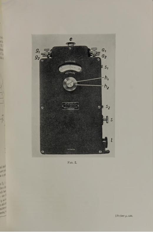
I
F ig . 2.
iß r■¡¡if
,h
in *I nie''t I'd*
¡00-jeetd,1
[T o face p . 456.

J A C K S O N : T H E “ R I K E N ” E X P L O S I V E G A S I N D I C A T O R . 4 5 7
the standard gas (usually air) is contained in the tube B. All three tubes are sealed by means of two glass plates. One beam passes through the tubes A and A , whilst the other passes forwards and backwards through tube B. When A and B both contain the same gas, the fringes do not move. If, however, another gas of higher refractive index is passed into the tubes A and A , the fringes are displaced. Since the refractive index of a gas is a function of pressure as well as temperature, it is possible to bring the fringes back to their original position by raising the pressure of the gas in tube B.
The instrument is extremely sensitive, and can be used to detect small quantities of gasoline vapours in air. With this object in view, the pressure gauge is first calibrated in terms of concentrations of gasoline by examining mixtures of known concentrations. The apparatus can then be used for the accurate and rapid detection of gasoline vapours.
The following procedure is adopted when using the “ Riken ” Indicator for this purpose (Fig. 2).
The air and gas tubes are thoroughly swept with clean air. The lamp is then switched on, when striped fringes of different colours and one black stripe can be seen in the field. The initial position of the fringes can be located accurately by means of an index line which can be brought into sharp focus by raising or lowering the eye-piece.
The initial position of the fringes is adjusted by means of the handle h1, so that the index line falls midway between the black stripe and the next upper coloured stripe. The zero mark on the scale is then brought into line with the centre line on the glass by operating the large handle h2, whilst the smaller handle hx is held so that h2 may rotate about hv
The air cocks are then closed, and the air-gasoline mixture to be examined is sucked into the gas tubes by means of a rubber pump provided, care being taken to ensure that the air in the tube is completely displaced by the mixture. The gas cocks are closed. It will then be observed that the fringes have moved, on account of the higher refractive index of the air-gasoline mixture. The fringes can, however, be restored to their original position by raising the refractive index of the air by increasing the pressure of the air by operating handle hv The volume percentage of gasoline present in the mixture is then read directly from the graduated scale.
It is understood that the instrument is standardized on the basic assumption of an arbitrary figure of 1-0015 for the refractive index of gasoline. This figure of 1-0015 was arrived at by examining a representative range of commercial gasolines, the vapours of which showed refractive indices varying from 1-001508 to 1-001621, which gave an average value of 1-0015.
Using a very early model of this apparatus, the following results were obtained upon air-gasoline mixtures of known concentrations :
Percentage o f Gasoline Percentage o f Gasoline Vapour in Mixture.
Vapour in Mixture. “ Riken Indicator. ”% vol. % vol.
0-09 0-10-35 0-300-59 0-490-98 0-79
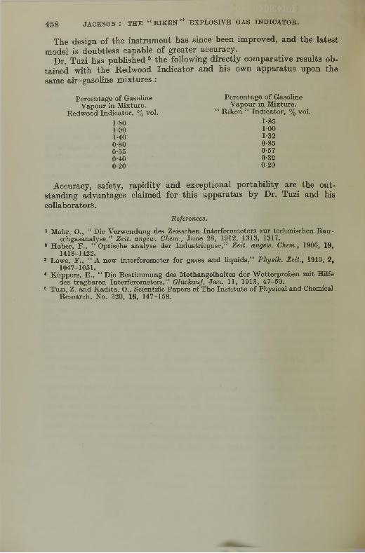
4 5 8 J A C K S O N : T H E “ r i k e n ” e x p l o s i v e g a s i n d i c a t o r .
The design of the instrument has since been improved, and the latest model is doubtless capable of greater accuracy.
Dr. Tuzi has published 5 the following directly comparative results obtained with the Redwood Indicator and his own apparatus upon the same air-gasoline mixtures :
Percentage of Gasoline Percentage o f GasolineVapour in Mixture. Vapour in Mixture.
Redwood Indicator, % vol. “ Riken ” Indicator, % vol.1-80 1-851-00 1-001-40 1-320-80 0-850-55 0-570-40 0-320-20 0-20
Accuracy, safety, rapidity and exceptional portability are the outstanding advantages claimed for this apparatus by Dr. Tuzi and his collaborators.
References.
1 Mohr, O., “ Die Verwendung des Zeisschen Interferometers zur techmischen Rau- schgasanalyse,” Z eit, angew. Chem., June 28, 1912, 1313, 1317.
1 Haber, F ., “ Optische analyse der Industriegase,” Z eit, angew. Chem., 1906, 19, 1418-1422.
s Lowe, F ., “ A new interferometer for gases and liquids,” P h ysik . Z eit., 1910, 2, 1047-1051.
* Küppers, E ., “ Die Bestimmung des M ethangelhaltes der Wetterproben mit Hilfe des tragbaren Interferometers,” G lückauf, Jan. 11, 1913, 47-50.
6 Tuzi, Z. and Kadita, O., Scientific Papers of The Institute o f Physical and Chemical Research, No. 320, 16, 147-158.

*±59
THE INFLAMMATION OF HYDROCARB ON-AIR MIXTURES.
B y D. T. A. T ow xeitd ,* D.Sc., Ph.D., D.I.C., and M. MiCCORiiAC.fPh.D., D.I.C.
IliT R O D T JC T IO Ji.
I t is well known that for a mixture of combustible and air to be explosive its composition must lie within the “ range of inflammability,” so that all mixtures the combustible-contents of which lie outside certain “ lower ” and “ upper ” limits are non-inflammable. Also, in order to initiate flame in an explosive mixture, it is necessary for the attainment of a certain thermal (or otherwise sensitized) condition at some region within it. After ignition, the speed and mode of propagation of flame depend essentially on the conditions of environment; for example, the development of an explosion is usually more rapid in a closed vessel than in an open one. And if a tube open at one end be employed, the violence will also depend on whether ignition occurs near the closed or the open end. Other factors influencing an explosion are the development of compression waves, the dynamic state of the mixture (i.e., whether at rest or in motion) and the direction of propagation of flame (i.e., whether upward, horizontal or downward).
While there is a considerable accumulation of data in the literature in regard to “ limits of inflammability ” and so-called “ ignition points,” rarely can observations made in experiments under one set of conditions be accepted as indicative of the safety conditions in any other set of conditions. And with the increasing use in industry of inflammable vapours at elevated temperatures and pressures, it is important that information relevant to these conditions should be available over sufficiently wide ranges.
The purpose of the present paper is to make clear recent developments in our knowledge of the subject, and particularly to direct attention to(a) the part played by pressure in inducing the spontaneous ignition of certain combustible—air mixtures at comparatively low temperatures by the incidence of the phenomenon known as a “ cool ” flame, and (b) the part played by both temperature and pressure in widening the ranges of inflammability of many combustibles, and particularly in inducing separate ranges for “ cool ” flames which may be initiated by suitable igniting sources. Until recently the origin and independent behaviour of a “ cool ” flame were not well understood; but it is now recognized as playing an important role under suitable conditions in the ignition of many i n f l a m m a b l e materials.
An important contribution on “ limits of inflammability ” by G. W. Jones has been published so recently (Symposium on Gaseous Combustion,
* Livesey Professor, The University, Leeds, t Gas, Light & Coke Company.
K K

460 T O W N E N D A N D M A C C O R M A C : T H E I N F L A M M A T I O N O F
American Chemical Society; Chemical Reviews, February 1938) that we have refrained from discussing that subject in detail; we have considered the field as a whole from the new view-points which have been forthcoming from experiments over wide pressure ranges.
In the first part of the paper we have dealt with spontaneous ignition phenomena, and in the second with inflammability limits, over vide pressure and temperature ranges. We have regarded as beyond the scope of our article any detailed consideration of possible sources of ignition of explosive media, most of which are well known and usually guarded against. Attention should, however, be specially directed to the danger of contact with bodies heated to comparatively low temperatures when inflammable materials such as carbon disulphide (I.T. <140° C.) are employed, or those which are now known to give rise to “ cool ” flames.
S p o n t a n e o u s I g n it io n P h e n o m e n a .
Pre-Flame Combustion.—In order to appreciate the factors responsible for ignition, it is necessary to consider what is known concerning the processes occurring during slow combustion and ultimately giving rise to it. It is well known that chemical change may occur in a gaseous explosive mixture at a much lower temperature than is required to develop flame, and according to the classical view of Arrhenius, the rate of slow combustion in any particular case is controlled by the number of molecules the energy of which exceeds the required activation energy, E, this number being approximately proportional to e~E,RT. According to this view, raising the temperature speeds up reaction in proportion to the increase in the number of such activated molecules, and an ignition temperature of any particular explosive mixture has been defined as that temperature to which the medium must be raised so that the heat lost from the system by conduction through the walls of the enclosure is more than counterbalanced by the rate at which it is evolved by the reaction. The process thus becomes self-accelerating, the temperature rising until ignition occurs and flame appears.
In recent years, however, many phenomena have been recognized which have tended to invalidate the universal application of this simple thermal view. Among these, mention may be made o f :—
(a) The observation of an abrupt transition with some small change in experimental pressure (or temperature) from an immeasurably slow reaction to explosion and vice versa.
(b) The disproportionate influence of traces of substances acting as inhibitors and promoters in controlling reaction rate.
(c) The accelerating effect on slow combustion of addition to the explosive media of inert diluent gases.
(d) The striking retardation of slow combustion by decreasing the diameter of the containing vessel, and
(e) The dependence of the reaction rate on the absolute concentration of one of the reactants and not on the other.
In amplification of (a), for example, mention may be made of the phenomenon of low-pressure ignition limits which, although first observed a century ago, more particularly in regard to the combustion of phosphorus,

H Y D R O C A R B O N - A I R M I X T U R E S . 461
was overlooked until comparatively recently.1 Its occurrence has now been confirmed with most simple combustibles, and this has led to results of great significance in relation to the development of modern kinetic theory.2 Briefly, if at a suitable high temperature, certain explosive mixtures are admitted to an evacuated vessel, they ignite spontaneously, provided the experimental pressure is (a) above a certain minimum value, Pj* (usually much less than 100 mm. mercury), but (b) below another higher pressure, p 2, above which the mixtures are again non-ignitable. At some still higher pressure, p3, a third pressure limit is found, corresponding, no doubt, with the type of spontaneous ignition with which we are normally familiar at atmospheric pressure. While perhaps it may be contended that such low-pressure ignition limits are without significance from the practical point of view, it has to be admitted that they indicate the operation of kinetic processes which must, to a greater or less extent, play some part in the spontaneous ignition of explosive mixtures generally. Also in amplification of (b), it will not be necessary to remind members of this Institute of Midge ley’s discovery of the influence of lead tetra-ethyl in suppressing “ knock,” its effectiveness being now attributed to its marked retardation of the slow combustion processes ahead of the flame in the cylinder head of an engine. In the same category may be placed the well-known discoveries of H. B. Dixon, firstly that the combustion of carbon monoxide is promoted by comparatively small amounts of water vapour,3 and secondly that the presence of traces of N 0 2 induces in a remarkable manner the spontaneous ignition of inflammable media generally.4 It may be recalled that Dixon, finding his determinations of the spontaneous ignition points of diethyl ether in nitrous oxide un- reproducible and on repetition tending to get lower and lower, tested under the same conditions mixtures of hydrogen in air which had previously never let him down; and he was astonished to find that these m i x t u r e s
also ignited some 150° C. lower than was usual. Eventually, the abnormal results were rightly attributed to the presence of traces of N 0 2 left from the products of the previous ether-nitrous oxide ignitions. N 0 2 is now known usually to depress ignition points at atmospheric pressure until an optimum concentration of it in any particular case has been added, further additions being less effective.5
It is now well known how such apparent abnormalities have been linked up with the remarkable quantum yields sometimes observed in photochemical reactions; and in the hands of Semenoff and Hinshelwood they have been satisfactorily explained on the basis of the modern chain theory o'f chemical reactions, whereby it is recognized that the progress of an exothermic process depends on specific encounters between certain reactive species. Insofar as the relative concentrations of these in the early stages of a reaction are small, any factor either increasing or decreasing them will have an apparently disproportionate influence on the time of completion of the reaction in question. In chain reactions the velocity depends on a time factor. Assuming initially no temperature change in the system, rate = Ae#1, where A = const, <f> = the net branching f probability and
* Below /jj homogeneous reaction is negligible.t “ Branching ” is the expression em ployed to denote m ultip lication of chain
carriers.

t = time.2 If (f> is greater than zero, the number of reactive centres on which the reaction velocity depends will increase exponentially with time.
There has been much speculation as to the nature of the reactive species promoting reaction in any particular case; at first these were considered as likely to be hot products of interaction which did not pass on energy by indiscriminate collision to the system as a whole, thereby causing general temperature rise; but by specific encounters with suitable reactant molecules, passed it on quantum-wise (bodily). Such a chain is referred to as an “ energy ” chain.
The discovery of the photo-sensitization of combustion, however, led to the view that the centres promoting combustion are more likely to be a reactive chemical species, and the participation of atoms and free radicals is nowadays frequently postulated. Thus, for example, the combustion of hydrogen is regarded as involving reactions requiring atomic oxygen and "hydrogen as well as radicals such as OH and H 0 2. The following is the sequence of events postulated by Hinshelwood and Williamson6 : H + 0 2 = H 0 2, H 0 2 + H 2 = H 20 + OH, 0 H + H 2 = H20 + H, the centres being " multiplied by processes such as H + 0 2 = OH + 0 , 0 -f- H2 = OH + H. Any change, particularly at the commencement of reaction, in the absolute concentration of any of the reactive species indicated, e.g., H, 0 or OH, will obviously materially affect its progress.
The Simpler Hydrocarbons.—In the light of the foregoing, we may consider briefly the behaviour of the simpler hydrocarbons during slow combustion. The classical researches of the late Professor Bone and his collaborators showed that in the oxidation of a hydrocarbon a series of intermediate oxygenated compounds is formed which, according to his view, arose by successive stages of hydroxylation. Nearly all the predictable intermediate products or their thermal decomponents were isolated in quantities depending on such factors as mixture composition, the working pressure and the circumstances of environment, as follows: With methane : methyl alcohol, formaldehyde, and formic acid were found; with ethane : ethyl alcohol, acetaldehyde, acetic acid, methyl alcohol, formaldehyde, and formic acid; and with ethylene : C2H40- isomers (acetaldehyde and ethylene oxide), acetic acid, formaldehyde, and formic acid. A variety of other products due to secondary reactions were also found, as well as substances of peroxidic character. In recent years discussion has centred mainly upon the possible kinetic mechanisms which lead to the formation of these products; there is, for example, doubt as to whether a simple hydroxylated molecule such as an alcohol is necessarily the immediate oxidation product. It may well result as the outcome of suitable encounters between other species.
When a hydrocarbon-oxygen mixture is introduced into a suitably heated enclosure, active combination does not immediately ensue; there is frequently an “ induction ” period during which very little oxygen is consumed. At the completion of this period, an interval of relatively rapid reaction sets in, during w'hich the greater part of the hydrocarbon or oxygen, whichever is in defect, is used up. Usually also, with increase in the experimental pressure or temperature, the reaction accelerates, so that under suitable conditions spontaneous ignition may ultimately occur. At the reduced pressures at which the low-pressure ignition limit phenomena
462 t o w n e n d a n d m a c c o r m a o : t h e i n f l a m m a t i o n o f

H Y D R O C A R B O N - A I R M I X T U R E S . 4 6 3
(p. 461) are observed, spontaneous ignition may be controlled essentially by factors influencing the breaking and branching of reaction chains; at higher pressures, chain propagation may also be accompanied by temperature rise in the system, which in turn increases the concentration of active centres and leads to the type of spontaneous ignition with which we are normally familiar.
The “ induction ” periods referred to may vary from a matter of a fraction of a second to a few hours, depending on the combustible concerned, the working pressure and temperature, etc. Also, with the simpler hydrocarbons, the most reactive mixture is found when the combustible— oxygen ratio is between 1 : 1 and 2 : 1 ; with more complex molecules, however, there is a tendency for this ratio to be even higher.
It is of particular importance to note that many of the intermediate oxygenated products when added to the combustible media are found powerfully to promote reaction and aldehydes as a class are specially potent in this regard. Having in mind the general expression of Semenoff, V = Ae^1, it may be seen how the induction period can be accounted for when cf> is very small but positive, and such a condition may be attributable to the formation of an intermediate product not necessarily influencing the primary reaction chain until a critical concentration of it has been attained in the medium. It may be further visualized how </> may either decrease to a low value, or markedly increase, due to the part played by the chains initiated by intermediate products. This conception, usually referred to as “ degenerate branching,” is supported by many experimental observations. Thus, Bone and Hill,7 when studying the slow combustion of an equimolecular ethane-oxygen mixture at 316° C. and 710 mm. pressure under conditions when normally reaction proceeded quite slowly, found that the presence in the medium of 1 per cent, of acetaldehyde (an intermediate product) caused an immediate ignition. Later, Bone and Gardner 8 made a special study of the part played by formaldehyde in the slow combustion of an equimolecular methane-oxygen mixture, finding the aldehyde not only powerful to promote the slow combustion generally, but also at the end of the “ induction period ” an equilibrium proportion of it was always present, irrespective of the particular reaction temperature. This agreed well with the view of Norrish that in the oxidation of methane a primary chain is propagated by oxygen atoms which first arise by the oxidation of formaldehyde formed by a surface reaction, as follows :—
(1) H-CHO + 0 2 = H-C02H + 0 followed by the chain
(2) CH4 + 0 = ICH2 + H20(3) : c h 2 + 0 2 = H-CHO + 0 .
Chain branching in the gas phase may occur by the further production of 0 atoms, thus :—
(4) H-CHO + 0 2 = H-C02H + 0 .Norrish regarded the formation of methyl alcohol as arising at sufficiently
high pressures by the triple collisions, CH4 + 0 + X = CH30 H + X', X being a third body (de-energizer) rendering the product stable.
Another chain mechanism has been proposed by Lewis and von Elbe 9 involving OH radicals instead of O-atoms as the principal “ carriers” ; this has been still further elaborated to meet the more complicated reactions observed with higher hydrocarbons. The chain suggested for the combustion of methane is given below, the formaldehyde produced by surface reaction being assumed to give rise to OH radicals, which react with the methane in the primary chain, thus
(1) H-CHO + 0 2 = H-C02 + OH(2) OH + CH4 = H20 -+- "CHg(3) -CH3 + 0 2 = H-CHO + OH(4) OH + H-CHO = H20 + HCO(5) HCO + 0 2 = H 0 2 + CO(6) H 0 2 + H-CHO = H20 + CO + OH.
Such views as these are now undergoing examination in various laboratories, but some long time will no doubt elapse before any final interpretation is forthcoming of the correct mechanism whereby even such a simple hydrocarbon as methane may be oxidized; the foregoing, however, serves to illustrate the present trend of thought.
With higher hydrocarbons and their derivatives, the combustion processes are even more complex, due to the survival of intermediate products which give rise, in certain low-temperature regions (300-400° C.) to luminescent phenomena, a matter which will be discussed later. Such phenomena may be related to the formation of peroxidic bodies, the presence of which was confirmed during 1925-27 by Callendar and Mardles,10 Egerton and Gates 11 and by Dumanois Mondain-Monval and Quanquin.12 Egerton was the first to apply the chain reaction view to the theory of combustion of such hydrocarbons and at that time thought an energy-chain mechanism resultant upon peroxide formation to be operative; more recently, with other collaborators, he has preferred a radical-chain rather than an energy- chain.13 During the past decade discussion on this subject has been to some extent of an academic character as to whether peroxides taking part in the combustion of higher hydrocarbons are primary peroxides or the outcome of secondary processes.
The Determination of Ignition Temperatures.—From what has been said it will be obvious that an ignition temperature can no longer be regarded as a physical constant, as was at one time supposed, and any such determination can only be regarded as pertaining to particular experimental circumstances. Further, the question of the relative time-lag (which involves both the “ induction ” and “ reaction ” periods prior to ignition) is of the utmost importance, for any particular stated ignition temperature might be materially lowered were a longer time-lag possible than that allowable by a particular experimental method.
The principal methods which have been employed to determine spontaneous ignition temperatures are :—
(1) Dixon and Coward’s concentric-tube method,14 (2) that of admitting an explosive mixture to an evacuated heated vessel (Mallard and Le Chatelier) 15; (3) the oil-drop method, due to H o lm 16; and (4) the adiabatic compression method (Dixon, Tizard and Pye).17
These are well known, and described elsewhere.18 (1) Suffers in that it
4 6 4 T O W N E N D A N D M A C C O R M A C : T H E I N F L A M M A T I O N O F

H Y D R O C A R B O N - A I R M I X T U R E S . 4 6 5
affords no information as to the effect of varying the proportion of combustible in air, and the ignition points are presumably the outcome, following the inter-diffusion of the reactants, of a homogeneous reaction, little affected by surface phenomena. The method has enabled a study to be made of ignition points over wide pressure ranges and with varying pre-flame tim e-lags; the results are in general agreement with those determined by other methods. The method (2) of passing an explosive mixture into an evacuated vessel heated to a known temperature has been widely employed. The results obtained, how'ever, depend to some extent both on the dimensions and the nature of the surface of the vessel employed; moreover, although the variation of ignition temperatures with time-lag is normally easily measurable, this becomes difficult when conditions of very short lag are under observation, owing to the necessity of the small time interval required for the operation of filling. In badly designed vessels also, if filling be too violent, ignition may be induced by “ shock.” The method, generally speaking, is, however, a good one, and it has been used extensively in the determination of low-pressure ignition limits,2 as well as of ignition temperatures at high pressures.19 The oil- drop method (3) is almost the only method employable when high-boiling- point fuels are under test, for they can only be handled in the vapour phase with difficulty, and at temperatures at which they would either oxidize and/or polymerize. The possible variations in working—e.g., drop size, the nature of the surface, velocity of the supporting atmosphere, etc.:—have, however, led to some discrepancies in published results; moreover, it is not possible to define the precise combustible—air mixture to which an ignition relates. The adiabatic compression method (4) requires special technique, and difficulty rests in calculating accurately the exact temperature and pressure to which an ignition relates. Further, the method cannot be applied to work at the comparatively low pressures which have been found of such interest in ignition-temperature work generally.
“ Cool ” Flames.—During the past ten years a number of investigations into the combustion of hydrocarbon fuels have been carried out, principally with the view of throwing light on intemal-combustion-engine problems. These have shown that when three or more carbon atoms are present in the molecule, additional complications arise owing to the incidence of processes which give rise over certain temperature ranges to the phenomena associated with “ cool ” flames. Such flames, which are of pale-bluish appearance, are in certain circumstances propagated through the explosive media, combustion being incomplete and resulting in the formation of intermediate products strongly aldehydic in character. Thus, Pope, Dykstra and Edgar,20 for example, showed that the initial oxidation of higher paraffin hydrocarbons commenced at 150-200° C., and although it became active between 250° and 270° C., and even mildly explosive at 270-300° C. with “ cool ” flames propagating through the media, at higher temperatures still combustion became less rapid, until 500° C. had been reached. Pease 21 observed a similar behaviour with propane-oxygen mixtures, and a temperature region in which reaction velocity actually decreased with temperature became recognized. About the same time, “ cool ” flame phenomena at atmospheric pressure formed the subject of a

special study by Prettre,22 who showed that while they were not observable with methane and ethane, rich mixtures of paraffins higher than propane gave rise to them. They were less easily detectable with higher defines and alcohols, but aldehydes and ethers readily exhibited them. “ Cool ” flames have also been observed, although they were not recognized as such, in determinations of ignition temperatures by the oil-drop method (cf. Coffey and Birchall23; also Thompson 24).
The Influence of Pressure.—Much light has been thrown on the subject in recent years by the systematic determination of ignition points over vide pressure ranges.19 With the higher paraffins, for example, whereas at low pressures ignition does not occur below 500 C., on the attainment of a critical pressure, which varies with the material concerned and with the composition of its mixture with air, it occurs abruptly in a temperature
466 T O W N E N D A N D M A C C O R M A C : T H E I N F L A M M A T I O N O F
F ig . 1.IG N IT IO N P O IN T C U R V ES O F C O R R E S P O N D IN G M IX T U R E S W IT H A IR O F 1 , M ETHANE;
2 , E T H A N E ; 3 , P R O P A N E ; 4, B U T A N E ; A N D 5 , H E X A N E .
range below about 370° C., which will now be remembered as that in which only “ cool ” flames are normally observable. As the outcome of this new work, the subject has been brought much closer into line with recent developments in our knowledge of the kinetics of chemical processes; for it is now appreciated that the absolute concentration or partial pressure of the reactants in any particular case is quite as important a factor as the experimental temperature. Moreover, in line with the experiments on slow combustion, there are temperature ranges in which some explosive mixtures are far more susceptible to spontaneous ignition than in others, no doubt owing to the formation and longer life of specific intermediate products.
The Paraffin Hydrocarbons.—The heated-vessel method was employed in this work; alteration in the dimensions of the vessel or in the material of its surface, while influencing according to circumstances the precise location of the ignition temperature curves, was without effect on the general character of the phenomena about to be described.
In Fig. 1 a series of curves has been drawn showing the influence of

H Y D R O C A R B O N — A I R M I X T U R E S . 4 6 7
pressure on the ignition points of corresponding rich mixtures with air of methane, ethane, propane, butane and hexane (curves 1, 2, 3, 4 and 5). The curve for the methane-air mixture fell rapidly from above 700° C. to about 500° C. as the pressure was raised to 5 atmospheres; thereafter it fell progressively to about 460° C. with increase of pressure to 30 atmospheres.
With the ethane-air mixture (No. 2) at pressures up to 15 atmospheres the curve was as found with methane, ignition now occurring at somewhat lower temperatures. At this pressure (and at about 430° C.), however, a sharp inflection occurred, the ignition points following an imposed lower system, settling down to temperatures about 325-340° C. at 25-30 atmospheres. Another interesting feature of this work relates to the preignition time-lags, or, in other words, the delays which occur between the completion of the filling operation and the occurrence of ignition, comprising both the induction and initial reaction periods. Whereas with methane these lags had increased progressively from 3 to 40 seconds, with fall in the ignition points to about 460° C., with ethane the increase was from 20 seconds at 550° C. to a few minutes at 435° C., the point of inflection; thereafter the lengthening was very marked, and at 325-340° C. the lags had reached 2 hours or more. In spite of the length of such lags, the results were remarkably reproducible.
In the early stages of these investigations it was considered not unlikely that at the lower temperatures some comparatively unstable material might well be responsible for the superposed lower system ; in particular, acetaldehyde, which is known strongly to promote the combustion of ethane at 316° C. (cf. p. 463), might well function in this way. This was soon borne out by a comparative study of the ignition-point curves of ethane-air mixtures with and without the addition of acetaldehyde (Fig. 2) for the addition of 1 per cent, of it to a 13 per cent, ethane-air mixture not only markedly promoted combustion in the lower system, but reduced the time lags from more than 2 hours to a few seconds. Moreover, the effect was limited entirely to the lower system, for above 435° C. the aldehyde had no influence whatever; if anything, it tended to retard the ignitions.
With all paraffins containing three or more carbon atoms (curves 3, 4, 5, Fig. 1, relate to the propane-, butane- and hexane-air mixtures, respectively) an abrupt fall in the ignition points occurred at critical pressures, an important observation being the occurrence of two pressure minima of ignition, one at about 280-330° C. and the other at about 340-370° C., both minima being lowered with increasing length of the hydrocarbon chain. Moreover, as the series was ascended, not only did the minimum pressures for ignition decrease, but the pre-ignition time lags were also materially reduced; for instance, lags of the order of 3 to 5 seconds with propane were reduced to less than 0-5 second with heptane. In all cases, also, additions to the explosive media of higher aldehydes facilitated ignition, this being marked in the temperature range below 450° C.
The “ Cool ’’-Flame Ranges.—With members containing three or more carbon atoms in the molecule there were also pressure and temperature limits within which “ cool ” flames were propagated, those for three
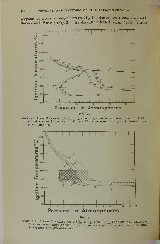
468 T O W N E N D A N D M A C C O R M A C : T H E I N F L A M M A T I O N O F
propane-air mixtures being illustrated by the shaded areas associated with the curves 1, 2 and 3 (Fig. 3). As already indicated, when “ cool ” flames
F ig . 2.C U RV ES 1, 2 A N D 3 R E L A T E TO 6 % , 10% A N D 13% E T H A N E -A IR M IX T U R E S. CURVES 4
AN D 5 A R E AS 3 B U T W IT H 1 % A N D 2 % A D D IT IO N O F C H 3CHO (TOWNEND AND C H A M B E R L A IN ).
F ig . 3.CURVES 1, 2 AN D 3 R E L A T E TO 2 '6 % , 5 '0 % AND 7 ‘5 % PR O PA N E -A IR MIXTURES.
SH A D E D A REAS SH O W P R E S S U R E A N D T E M P E R A T U R E L IM IT S FOR “ COOL FLAMES.” (T O W N E N D AN D C H A M B E R L A IN .)
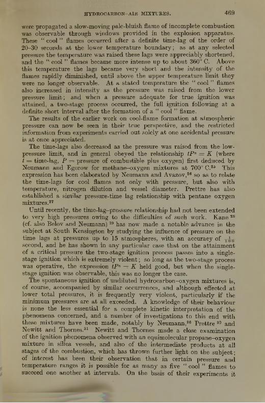
H Y D R O C A R B O N - A I R M I X T U R E S . 4 6 9
were propagated a slow-moving pale-bluish flame of incomplete combustion was observable through windows provided in the explosion apparatus. These “ cool ” flames occurred after a definite time-lag of the order of 20-30 seconds at the lower temperature boundary; as at any selected pressure the temperature was raised these lags were appreciably shortened, and the “ cool ” flames became more intense up to about 360° C. Above this temperature the lags became very short and the intensity of the flames rapidly diminished, until above the upper temperature limit they were no longer observable. At a stated temperature the “ cool ” flames alsa increased in intensity as the pressure was raised from the lower pressure limit; and when a pressure adequate for true ignition was attained, a two-stage process occurred, the full ignition following at a definite short interval after the formation of a “ cool ” flame.
The results of the earlier work on cool-flame formation at atmospheric pressure can now be seen in their true perspective, and the restricted information from experiments carried out solely at one accidental pressure is at once appreciated.
The time-lags also decreased as the pressure was raised from the low- pressure limit, and in general obeyed the relationship tP n = K (where t = time-lag, P = pressure of combustible plus oxygen) first deduced by Neumann and Egorow for methane-oxygen mixtures at 700° C.25 This expression has been elaborated by Neumann and Avazov,26 so as to relate the time-lags for cool flames not only with pressure, but also with temperature, nitrogen dilution and vessel diameter. Prettre has also established a similar pressure-time lag relationship with pentane-oxygen mixtures.27
Until recently, the time-lag-pressure relationship had not been extended to very high pressures owing to the difficulties of such work. Kane 28 (cf. also Belov and Neumann) 29 has now made a notable advance in the subject at South Kensington by studying the influence of pressure on the time lags at pressures up to 15 atmospheres, with an accuracy of second, and he has shown in any particular case that on the attainment of a critical pressure the two-stage ignition process passes into a single- stage ignition which is extremely violent; so long as the two-stage process was operative, the expression tP n = K held good, but when the single- stage ignition was observable, this was no longer the case.
The spontaneous ignition of undiluted hydrocarbon-oxygen mixtures is, of course, accompanied by similar occurrences, and although effected at lower total pressures, it is frequently very violent, particularly if the minimum pressures are at all exceeded. A knowledge of their behaviour is none the less essential for a complete kinetic interpretation of the phenomena concerned, and a number of investigations to this end with these mixtures have been made, notably by Neumann,26 Prettre 30 and Newitt and Thornes.31 Newitt and Thornes made a close examination of the ignition phenomena observed with an equimolecular propane-oxygen mixture in silica vessels, and also of the intermediate products at all stages of the combustion, which has thrown further light on the subject; of interest has been their observation that in certain pressure and temperature ranges it is possible for as many as five “ cool ” flames to succeed one another at intervals. On the basis of their experiments it

470 T O W N E N D A N D M A C C O R M A C : T H E I N F L A M M A T I O N O F
was concluded that a necessary condition for spontaneous “ cool ’’-flame initiation was the attainment in the medium of a critical concentration of higher aldehydes. During the passage of the flame the aldehydes were in°part destroyed and in part further oxidized to aldehyde peroxides and/or peracids, and ultimately formaldehyde. During the subsequent period before a second “ cool ” flame the aldehydes accumulated again up to a requisite concentration. Large amounts of propylene were also found in the gaseous reaction products, and the reactions by which this and the higher aldehydes were formed were thought to be related. Avazov and Neumann 26 adopted the view that “ cool ” flames are formed when the peroxides and aldehydes reached a certain critical concentration; quite recently also Neumami and Tutakin 32 have reported observations
F ig . 4.CURVES 1 , 2 , 3 A N D 4 A R E F O R T H E O R E T IC A L M IX T U R E S O F E T H Y L E N E , PROPYLENE,
B U T Y L E N E A N D A M Y L E N E . S H A D E D A R E A S D E N O T E P R E S S U R E AN D TEMPERATURE LIM IT S FO R “ COOL FL A M E S ” . (K A N E A N D T O W N E N D .)
on the thermal decomposition of diethyl peroxide, indicating that the minimum critical pressure for its self-propagating luminescent decomposition agrees with the partial pressure of peroxides determined with a butane-oxygen mixture at the minimum “ cool ’’-flame pressure. Harris and Egerton 33 have also studied the effect of additions of small concentrations of diethyl peroxide to a propane-oxygen mixture, finding that while the induction period was materially reduced, the subsequent reaction period was apparently uninfluenced by its presence.
The complexity and interplay of the processes concerned call for some hesitation in accepting at present any one particular view, for there is a very great deal still to be learned.
The Olefine Hydrocarbons.—Recently the investigations under pressure have been extended to cover observations with the simpler defines: ethylene, propylene, a-butylene and a-amylene.34 In Fig. 4 curves 1, 2,

H Y D R O C A R B O N - A I R M I X T U R E S . 471
3 and 4 show the influence of pressure on the ignition points of theoretical mixtures with air of these materials, the shaded areas defining the pressure and temperature limits within which “ cool ” flames were observable. Generally speaking, the olefines behave in a manner not unlike that of the corresponding paraffins. Thus ethylene behaves like methane, and although propylene and butylene do not reveal marked pressure minima of ignition, the ignition-point curves exhibit a sharp fall over narrow critical pressure ranges in the temperature ranges where cool flames are observed. With five carbon atoms in the molecule, however— i.e., with amylene—the ignition-point curve shows all the characteristics typical of higher paraffin-air mixtures.
While the behaviour of the simple olefines under pressure is not unlike that of corresponding paraffins, the main difference lies in the fact that both the luminosity and intensity of the “ cool ” flames are much less with the former; moreover the pressures at which they give rise to ignition are not abnormally reduced, as is the case with the paraffins, until the saturated end of the chain contains at least three carbon atom s; lastly, the time-lags are not only greater with the olefines, but decrease less rapidly with increase of pressure. All these facts indicate that the processes operative in the low-temperature system are less intense than with the paraffins.
There would seem no reason to postulate any difference in the intermediate products or chain initiators responsible for promoting reaction in both series. As with the paraffins, it is likely that they result from the formation of higher aldehydes, and the less vigorous behaviour of the olefines may be attributable to a slower building up of active centres depending on aldehyde concentration by virtue of difference in the chemical stages involved. This view would be in keeping with what is known concerning the respective stages possible in building up higher aldehydes from, say, propane and propylene; cf. Bone,35 Norrish, 36 Beatty and Edgar.37
Other Combustibles.—The ignition temperature determinations under pressure have been extended to other combustibles, including alcohols,38 aldehydes,38 ethers,39,40 ketones 40 and benzene,40 and the reader particularly interested in the subject is referred to the original papers.
The ignition-point curves of formaldehyde and methyl alcohol simulate that of methane, the more oxygenated bodies, however, being more easily ignited. Acetaldehyde and ethyl alcohol are also more easily ignitable than ethane, but whereas ethane and ethyl alcohol curves reveal merely a simple low-temperature system (Figs. 1 and 2), acetaldehyde gives rise to a very pronounced one, and is, moreover, probably the simplest material definitely to exhibit “ cool ” flames. There can be little doubt that the intermediate formation of acetaldehyde is responsible for the composite nature of the curves found with ethane and ethyl alcohol.
Further complications arise with the ethers, as they give rise to two “ cool ’’-flame systems. A lower “ cool ’’-flame zone located at about 200° C. appears to be initiated by the primary oxidation of the ether, whilst a secondary zone located at temperatures above 300-350° C., as found with hydrocarbons, is obviously initiated in the same way as the “ cool ” flames found with the latter; these matters, however, need

472 T O W N E N D A N D M A C C O R M A C : T H E I N F L A M M A T I O N O F
further investigation. Lastly, acetone 40 gives rise to “ cool ” flames at adequately high pressures; benzene, however, behaves like methane, being non-ignitable below 550° C. at pressures up to 15 atmospheres.
The Influence of Inhibitors and Promoters.—In general accord with the chain theory of the processes occurring in combustion, it has been found that spontaneous ignition points may be materially influenced by the presence in the explosive media of traces of materials acting either as inhibitors or promoters. Reference has already been made, for example, to the part played by aldehydes formed intermediately in the combustion of hydrocarbons in promoting the reaction as a whole; a trace of ether vapour has also been found to act in the same manner. Lead tetra-ethyl has been found (in common with the results of other researches) to inhibit combustion so that higher pressures are required to effect ignition over the whole temperature range. The importance of this effect is very marked at certain pressures, because spontaneous ignition in the “ cool ” flame temperature range is inhibited unless higher pressures are employed; this has the effect of raising the ignition temperature some 200° to the higher range (say, 500-600° C.).
NO., is also very interesting in the role it plays in the combustions.34 In the higher temperature range traces of it promote ignition in a remarkable way, just as is found with other combustibles—e.g., H2 and CO2. In the “ cool ’’-flame range, however, traces of N 0 2 are usually ineffective in influencing “ cool ’’-flame initiation; but when added in larger amounts, ignition is far more easily induced, but it is then unaided by prior “ coo l’’-flame formation. Reference should also be made to H. B. Dixon’s investigations relative to the respective influences of traces of iodine, ethylene dibromide, isoamyl bromide, and bromobenzene, and of phosphoryl chloride in larger amounts, in inhibiting combustion and raising ignition points at any particular pressure (Coward, J. chem. Soc., 1934, p. 1382).
Summary of Ignition Temperature Data.—For the convenience of the reader specially interested in this subject, we have tabulated data in Table I indicating in the first column ignition temperatures as near as they are known pertaining to theoretical mixtures of various combustible media at atmospheric pressure; as the theoretical mixture is rarely that most easily ignitable, in column 2 we have given what we consider to he the lowest ignition temperature ever likely to pertain to any mixture with air of a particular combustible. We have also indicated where necessary the occurrence of “ cool ” flames in the temperature range 300—400° C. Also, as already explained, not every complex combustible gives rise to cool flames at atmospheric pressure, and we have therefore indicated in columns 3 and 4 the approximate pressures which would have to be reached before “ cool ’’-flame propagation, or spontaneous ignition subsequent thereon, respectively, would be likely to occur in any particular case. In column 5 we have added, for general guidance, any remarks likely to help in assessing possible ignition points under other special circumstances.
While, for general purposes, conditions pertaining to atmospheric pressure are those which are perhaps of greatest value, as already indicated industrial processes are now operative which involve the oxidation of

jm v MIXTURES. 4 7 3
T a b l e I .
A pproxim ate Spontaneous Ign ition Tem peratures
(Mixtures with Air.)
C.) and Pressures (A tm s .).
Combustible.
Ignitiontemperature,
atatmospheric
pressure.
Theoreticalmixture.
(1)
Mosteasilyignit-ablemixture.
(2 )
Minimum pressure (atms.),(a) for cool flames and (6) ignition induced by cool
flames (250-400° C.).
Theoreticalmixture.(3a)
Mosteasilyignit-ablemixture.(3a)
Theoreticalmixture.(4b)
Mosteasilyignit-ablemixture.(4b)
Remarks.
MethaneEthane
Propane Butane ¿soButane Pentane Hexane Heptane Octane isoOctane 2:2:4-
trimethylpentane Ethylene
PropyleneButyleneAmyleneAcetylene
Benzene
cycfoHexane.
Methyl alcoholEthyl alcohol n-Propyl alcohol FormaldehydeAcetaldehyde * Acetone Dimethyl ether Diethyl ether
Diisopropyl ether .
700550
540530545510500260250550540
560540530500
700
510
500460470480275480480330
525
>650530
500480510470275255245530485
530510500335
550
480440430430230440310180
480
Cool flames not observed
Ditto
2-31-3200-750-450180-16
200-951-6 0-6 0-25 0-15 0-10
1-45 1-2Cool flames not
observed
3-01-751-6
1-751-00-8
>25
5-02-64-41-71-21 00-954-15
3-63-02-2
> 1 1
3 5 1-8 2-5 1-1 0-7 0-5 0-42-3
2-11-81-1
The effect of pressure on the spontaneous ignition has not
yet been determined Cool flames not —
observed
Minimum pressures for cool
flames not determined
Cool flames not observed
Ditto 1-6 | 1-2
Cool flames not observed
< 0-2 6-3 0 25 016
0-45
< 0-230
<0-250-06
1-55
2-52-4
0-811-01-151-3
4-5
1-1
1-91-8
0-4 7-0
< 1-01-0
Ignition never below 470° up to 30 atms. pressure.
Cool flames without ignition never observed. Ignition never below 310°.
Ignition never below 300°.„ 280°.
........................310°.
........................ 270°.„ ,, „ 255 .
245°. ....................... 240°.
,, 270°.Mixtures containing >10% of
C2H4 ignite below 400° at pressures >3 atms. Ignition never below 300°.
Ignition never below 290°.„ 280°.„ 270°.
Very little known.
Ignition does not occur much below 500°. Lower values have been recorded by oil- drop method.
At 10 atms. pressure, 270°.
Ignition never below 420°.
„ 290°.„ 290°.„ 370°.
............................. 170°.„ 310°.
Ignition never below 245°.The cool flames may extend
down to 170° C. Ignition never below 175°.
The cool flames may extend down to 165° C. Ignition never below 165°.
550°570°120°
HydrogenCarbon monoxide Carbon disulphide
Hydrogen sulphide Ammonia
if traces^o?impurities ^ r e s e n ^ 0“ temperatures of “ "“ ble-air media may vary appreciably
' Never below 520° except when ignitable at pressures between the low- pressure limits.Behaves like H2 at the low-pressure limits.
1 (D&SJ' 44, 305). Leicester (J . Soc. chem. In d .,1933, 52, 341) stated that the ignition temperatures fell from 323° with290° (Leicester,rfocn 0Sl"air miXtUre 81° C’ a 0 5 per Cent' mixture- 780° (Holm, Z . angew. Chem., 1913, 26, 273.)
If vapour previously exposed to air, lower values may be found.

474 T 0 W N E N D A N D M A C C O R M A C : T H E I N F L A M M A T I O N O F
inflammable media under pressure; on this account it is hoped that the data given in columns 3 and 4 may be of value.
L im it s o f I n f l a m m a b il it y .
An inflammable mixture is usually defined as one in which flame can spread to any distance, independently of, and away from, the original source of ignition; and there are, under given physical conditions, both a “ lower ” and an “ upper ” composition limit of inflammability within, but not outside, which self-propagation of flame will take place once ignition has been effected. The limits differ slightly with the position of the source of ignition, since flame progress may be assisted by convection currents depending on whether it has to pass in an upward or downward direction. The simple example of methane-air mixtures is as follows :—
Upward. Downward. Horizontal.
Lower limit (% methane in air) 5 0 0 6-00 5-40Upper limit . . . . . 1500 13-53 13-95
The precise limits also depend on the dimensions of the vessel in which they are determined, and on whether the explosive mixture is at rest or in motion. For all practical purposes, however, upward propagation in a 7-5-cm.-diameter tube may be taken as representing almost optimum conditions for flame propagation; and in Table II representative values mostly pertaining to such a tube have been tabulated.
It is of interest to note that, as originally pointed out by Burgess and Wheeler,41 the low limits of inflammability appear to be defined by their available heat content. Thus, if a calculation be made of the heat available in the mixture of low limit composition, it is found in all cases to approximate to 1000 calories, which would be expected to allow of a flame temperature approximating to 1150° C. An exception is foimd with inflammable materials having a low ignition temperature, such as carbon disulphide; also no such relation has been found for the mixtures of upper limit composition. This might be expected, owing to the varying degrees of partial combustion likely to be met with when the oxygen content of the mixture is in defect.
Ranges of inflammability widen with increasing temperature; thus, for example, for downward propagation of flame White 42 found :
Temp.,0 C. H 2-air. C2H 2-air. CO-air. C„Hj-air. CHj-air. wC5H 12-air.
17 9-4-71-5 2-9 -55-0 16-3-70-0 3-45-13-7 6-33-12-9 1-53-4-5100 8-8-73-5 2-68-65-0 14-8-71-5 3-20-14-0 5-95-13-7 1-44-4-75200 7-9-76-0 2-39-81-0 13-5-73-0 2-95-14-9 5-5 -14-6 1-34-5-05400 6-3-81-5 2 19- 11-4-77-5 2-75-17-9 4-8 -16-6 1-22-5-35
Briand, Bumanois and Laffitte43 have also studied the influence of temperature on the ranges of inflammability of mixtures with air of

T able I I .L im its o f In flam m ability of Combustibles in A ir .
O A R B O N - A I R M I X T U R E S . 4 7 5
Combustible.Direction of Propagation.
Upward. Horizontal. Downward.Methane . . . . 50 -150 1 5-40-13-95 3 5-95-13-53 3Ethane . . . . 312-14 95 ’ 315-12-85 3 3-26-10-15 3Propane . . . . 2-37- 9-50 3 — . _Butane . . . . 1-86- 8-41 3 — —isoButane 1-80- 8-44 * — —Pentane . . . . 1-40- 7-80 3 1-44- 7-45 3 1-48- 4-64 3tsoPentane 61-32- — 1-43- 4-85 4Hexane . . . . 1-25- 6-90 * — —Heptane ° 1 00- 6 00 7 — —Ethylene 4 2-75-34-0 3 3-20-23-70 3 3-33-15-50 3Propylene 2-00-11-10 * 2-22- 9-30 3 2-26- 7-40 3Butylene 1-70- 9-00 3 1-75- 9 00 3 1-80- 6-25 3Acetylene 4 2-5 -80-0 3 2-68-78-5 3 2-78-710 3Benzene * * 1-4X— 7-45 3 1-46- 6-65 3 1-48- 5-55 3Toluene • 4 1-27- 6-75 3 1-30- 5-80 3 1-32- 4-60 3Cj/cloHexane * . 1-33- 8-35 10 — 1-16- 4-34 31Methyl alcohol * 33 6-72-36-5 3 7-35-30-5 3 7-65-26-5 3Ethyi alcohol * 3-56-18-0 13 3-75-13-8 3 3-78-11-5 3Acetaldehyde t 4-0 -17-0
(cool flames 17-0-61-5)144-23-16-7
(cool flames 21-48)34-27-13-4 3
Diethyl ether t 1-71-48-0 (true and cool ranges)3
1-75-15-0 (cool flames 15-0-35-0)14
1-85- 6-40 3Divinyl ether t 1-70-10-5
(cool flames 10-5-26-5)ls — —Acetone . . . . 2-55-12-80 1 2-92-11-9 3 2-93- 8-60 3Methyl ethyl ketone 1-81-10-50 4 1-97-10-2 3 2-05- 7-60 3Methyl propyl ketone * 1-55- 8-15 4 —■ —Methyl butyl ketone * 1-22- 8 00 4 — —Ethyl acetate * 4 2-18-11-40 3 2-35- 9-8 3 2-37- 7-1 3Hydrogen 4-0 -75-0 3 3 6-5 - 8-8 -74-5 3Carbon monoxide 14 12-50-74-2 37 3 13-6 - 15-3 -70-5 3Carbon disulphide * . 34 1-25-50 0 3 1-83-49-0 3 2-03-34-0 3Hydrogen sulphide . 4-30-45-5 3 5-3 -35-0 3 5-85-21-3 3Ammonia 17-1 -26-4 13 17-4 -26-3 3 None 3Cyanogen 6-6 -42-6 13 — .— .Hydrocyanic acid 5-6 -40-0 30 — ■ —Ethylene oxide 3-00-80-0 31 — —Pyridine * 1-81-12-40 3 1-84- 9-8 3 2-37- 7-13Methyl chloride 8-25-18-70 33 — —Ethyl chloride . 4-00-14-80 33 —Dichloro-ethylene 9-70-12-80 33 — —Ethylene dichloride * 6-20-15-90 34 —
* It should be noted that in order to reach the upper limits of these materials, temperatures above atmospheric (but lower than 100° C.) were necessary in order to attain an adequate vapour pressure. In such cases where an inflammable liquid is present an adequate temperature may therefore itself be a means of ensuring a non-explosive atmosphere (cf. Jones, ref. 12).
t Cool flames cannot be propagated downwards in cold media.L ist of References.
1 G. W. Jones, E. S. Harris, and W. E. Miller, U.S. Bureau Mines Tech. Paper No. 544, 1933, pp. 26. 1 A. G. White, J . chem. Soc., 1924, 125, 2387.3 H. F. Coward, G. W. Jones, C. G. Dunkle, and B. E. Hess, Mining Met. Investigation Carnegie Inst.
Tech. Bull. No. 30, 1926.4 G. WT. Jones, E. S. Baker, and R. E. Kennedy, from Ann. Report of the Explosives D ivision Fiscal
Year 1936; U.S. Bureau of Mines Kept. Investigations No. 3337, Feb. 1937.6 M. J. Burgess and R. V. Wheeler, J . chem. Soc., 1911, 99, 2013.9 M. Briand, P. Dumanois, and P. Laffitte, Compt. rend., 1934, 199, 286 (estimations at 100° C.).7 National Fire Protection Assn., Committee on Flammable Liquids, “ Fire Hazard Properties of
Certain Flammable Liquids, Gas and Volatile Solids,” 1934.8 G. W. Jones, W. P. Yant, W. E. Miller, and R. E. Kennedy, U.S. Bur. Mines, Report Investigations
No. 3278, July 1935.8 A. G. White, J . chem. Soc., 1922, 121, 1244, 1688, 2561.
10 M. J. Burgess, G. Greenwood, U.S. Bur. Mines Bull. No. 279, 1931, pp. 71, 80, 81.11 M. Briand, P. Dumanois, and P. Laffitte, Compt. rend., 1933, 197, 322 (estimated at 100° C.).18 G. W. Jones, Chem. Rev., 1938, 22, 1. 18 A. G. White, J . chem. Soc., 1919, 115, 1462.14 Unpublished results. 15 G. W. Jones and B. B. Beattie, Ind. Eng. Chem., 1934, 26, 557.18 H. F. Coward, C. Carpenter, and W. Payman, J . chem. Soc., 1919, 115, 27.17 H. F. Coward and F. Brinsley, ibid., 1914, 105, 1859.11 H. H. Franck and G. Doring, Angew. Chem., 1931, 44, 273.18 E. Berl and K. Barth, Z . Elektrochem., 1933, 39, 73.20 A. H. Nuckolls, “ Method for the Classification of Hazardous Liquids,” Underwriters Laboratories,
March 1929.21 G. W. Jones and It. E. Kennedy, Ind. Eng. Chem., 1930, 22, 146.22 G. W. Jones, ibid., 1923, 20, 367.23 G. W. Jones, W. E. Miller, and H. Seaman, ibid., 1933, 25, 771.24 G. W. Jones and R. E. Kennedy, ib id ., 1930, 22, 963.
L L

t o w n e n d a n d m a c c o k m a c : T H E i n B E A M M A T I O N o e
acetone, benzene, cycZohexane, cycZohexene and isopentane, with results as follows :—
Temp.,° c. Benzene. cyclo-
Hexane.cyclo-
Hexene.iso-
Pentane. Acetone. MethylAlcohol.
EthylAlcohol.
PropylAlcohol.
100150200250
1-37-5-321-26-5-411-20-5-471-13-5-58
1-16-4-341-10-4-561-01-4-770-95-4-98
1-22-4-811-12-4-961-03-5-060-96-5-20
1-43-4-851-32-4-951-20-5051-10-5-25
2-78-8-702-61-8-952-50-9-352-33-9-75
6-85-6-15-5-80-5-45-
3-55-3-15-3-00-2-75-
2-45-2-20-2-05-1-75-
Our own results showing the influence of temperature on the inflammable ranges of ether-air mixtures are illustrated diagrammaticafly later on (p.■± t o;.
It has been found generally that, except when “ cool ” flames are observed, the limits of inflammability increase linearly with increase of initial temperature in accordance with the classical thermal theory of flame propagation.
As regards the influence of pressure, in 1928 Bone, Newitt and Smith 44 published the following “ explosion limits ” for the following media in steel bombs at room temperature (i.e., 17° ± 3° C.) :—
Mixtures. 10 atms. 50 atms. 125 atms.
Hydrogen-air . . . . . Carbon monoxide-air . . . . Methane-air . . . . .
10-2-68-517-8-62-8
6-0-17-1
10-0-73-320-6-56-8
5-4-29-0
9-9-74-820-7-51-6
5-7-45-5
Whereas the “ explosion ranges ” of hydrogen-air or methane-air media are widened (without much alteration in the lower limit) by increasing pressure, in the case of carbon monoxide-air media it is narrowed at both ends, the latter circumstance being partly due to the increasing dryness of the gases and partly also to an increasing effect due to nitrogen dilution with pressure. For further information as to the relative influences of these two factors, the original memoir should be consulted.
In 1919, White made an important discovery with ether-air mixtures that in a 2-5-cm. horizontal glass tube there are two independent ranges of inflammability, one for normal flames (1-88-9-45 per cent.) and another for “ cool ” flames (19-0-34 per cent.), separated by a range of mixtures which are incapable of flame propagation.45 An important factor in his experiments was that while the normal flame range could be determined by spark ignition, the “ cool ” flames were only initiated at atmospheric pressure by means of a heated wire. Subsequently White explored these two ranges at reduced pressures in a 4-5-cm. tube and discovered that there are two separate systems for each type of flame propagation which link up at about 600 mm. pressure (see Fig. 5).46
Townend and Chamberlain,39 recognizing a close analogy between White s observations in regard to the “ cool ’’-flame ranges at mom temperature and their own observations in spontaneous ignition experiments under pressure, examined the “ cool ’’-flame propagation in cold media more closely, particularly with the view of discovering whether at higher pressures the “ cool ” flames would give rise to “ normal ” ignitions,
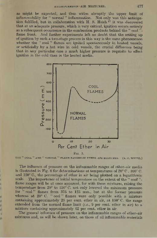
j n u ± n j L / A ± t ± s u J M — A I R M I X T U R E S . 4 7 7
as might be expected, and thus widen abruptly the upper limit of inflammability for “ normal ” inflammation. Not only was this anticipation fulfilled, but in collaboration with H. S. Hsieh 47 it was discovered that at an adequate pressure, which is very critical, ignition occurs entirely as a subsequent occurrence in the combustion products behind the “ cool flame front. And further experiments left no doubt that the setting up of ignition by such a two-stage process in this way is the same phenomenon whether the “ cool ” flames are ignited spontaneously in heated vessels, or artificially by a hot wire in cold vessels, the crucial difference being that in any particular case a much higher pressure is requisite to effect ignition in the cold than in the heated media.
Per Cent Ether in A irF ig . 5.
T H E “ COOL ” AND “ NORMAL ” FLAME RANGES OF E T H E R -A IR M IX TU RES. (A. G. W H IT E .)
The influence of pressure on the inflammable ranges of ether-air media is illustrated in Fig. 6 for determinations at temperatures of 20° C., 100° C. and 150° C., the percentage of ether in air being plotted on a logarithmic scale. The importance of initial temperature on the extent of the “ cool flame ranges will be at once apparent, for with these mixtures, raising the temperature from 20° to 150° C. not only lowered the minimum pressure for “ cool ” flames from 375 to 125 mm., but at the former pressure whereas at 20° C. “ cool ” flames were only possible with a mixture containing approximately 25 per cent, ether in air, at 150° C. the range extended from the normal flame limit (i.e., 9 per cent, ether in air) to a mixture containing approximately 62 per cent, ether in air.
The general influence of pressure on the inflammable ranges of ether-air mixtures and, as will be shown later, on those of all inflammable materials

t o w n e n d a n d m a c c o r m a c : T H E i n f l a m m a t i o n o f
giving rise to both normal and “ co o l’’-flame systems, may best beillustrated by reference to Fig. 7.
The curve EAB may be taken as representing the normal tlame range and CDH the “ cool ’’-flame range. A matter of great interest is that whereas the normal-flame range centres upon approximately the theoretical mixture for complete combustion (i.e., that with greatest heat content), the “ cool ’’-flame range centres upon mixtures of composition having a combustible ratio between 1 :1 and 2 : 1 (and with some combustibles even higher), or those which would be expected to be most reactive during slow combustion. If the pressure of any particular mixture giving rise
P e r Cent E t h e r in A i rFio. 6.
INFLUENCE OF PRESSURE AND TEM PERATURE ON TH E “ NORMAL ” AND “ COOL ” FLAME RANGES OF ETH ER—A IR M IXTURES.
to “ cool ” flames be raised to a critical value as indicated by the curve XG, a blue flame is formed some distance behind the “ cool ” flame in its combustion products. In closed vessels this blue flame travels at a velocity much greater than that of the “ cool ” flame, partly on account of the increased volume of products to which it gives rise. The events subsequent upon the formation of the blue flame depend mainly on the amount of oxygen remaining in the mixture. With little oxygen, the flames will probably travel separately; with more oxygen, the blue flame will increase in velocity and travel closely behind the “ cool ” flame, coalescing with it and causing its velocity to increase. With still further oxygen, the blue flame becomes a normal flame, and, once initiated, it

H Y D R O C A R B O X — A I R M I X T U R E S . 47 9
travels through the “ cool ” flame, replaces it and travels on with high velocity. In suitable circumstances, as with certain ether-oxygen m ixtures, detonation is set up.
The recognition of the relationship between the “ spontaneous ” and “ artificial ” initiation of “ cool ” flames, and the subsequent occurrence of a second flame likely to lead to normal ignition, indicated, owing to the similarity in spontaneous ignition experiments between the “ cool ”- flame ranges of both ether and the higher paraffins, that at high enough
Mixture CompositionF ig . 7.
DIAGRAM SHOWING TH E IN FLU EN CE OF PR ESSU R E ON TH E INFLAM M ABLE RANGES OF COMBUSTIBLES GIVING R IS E TO “ COOL FLA M E S.”
pressures “ cool ’’-flame ranges ought to be found at ordinary temperatures with the higher paraffins. Accordingly a determination of the limits of inflammability of representative higher hydrocarbons has recently been made, and by working in an explosion vessel provided with quartz windows, Fig. 8, these “ cool ’’-flame ranges have been located precisely in accord with this prediction.
The explosion vessel was provided with an explosion cavity 3-8 cm. in diameter and 15-3 cm. long; at one end it carried a plug fitted with inlet and outlet valves, and at the other a second plug carrying a quartz window for visual observation of the flames. An ignition plug P was

480 t o w n e n d a n d m a c c o k m a c : T H E i n f l a m m a t i o n o p
located at one end of the vessel, and three smaller quartz windows were disposed along its horizontal ax is; a mixture was considered within one or other of the inflammable ranges when flame reached the side window at the end remote from the ignition plug. “ Cool ” flames were characterized as usual by a slow-moving pale blue flame accompanied by low-pressure development and the production of intermediate products strongly aldehydic in character. The flames in the “ normal ” range gave rise to much greater pressure development and more complete combustion; both of these conditions also characterized the initiation at an adequate pressure of the “ blue ” flame ignition behind the “ cool ’’-flame front in the other range.
In illustration of some of the results obtained, reference may be made to Fig. 9, which shows the influence of pressure on the inflammable ranges of mixtures of hexane (a) in air and (b) in oxygen at temperatures of 100° and 150° C. Dealing first of all with the hexane-air mixtures at 150° C.,
EXPLOSION VESSEL FITTED W ITH W INDOW S FOR D ETERM IN IN G INFLAMMABLE RANGESU N D ER PR ESSU R E .
it will be seen that at pressures up to 4-1 atmospheres there was only one range of inflammable mixtures—namely, that for normal flames. This was at first almost unaffected by increase in initial pressure, the lower limit being lowered by about 0-3 per cent, and the higher limit raised by about 1 per cent, of hexane at pressures up to 4 atmospheres. At pressures of about 4-1 atmospheres, however, a “ cool ’’-flame range was located with mixtures of composition between 11 and 22 per cent, of hexane, the normal range at the same pressure extending over mixtures of hexane content between 1-2 and 7-0 per cent. The “ normal and “ cool ’’-flame ranges were thus separated by a range of non-inflammable mixtures containing between 7 and 11 per cent, of hexane. At pressures higher than 4-8 atmospheres the two ranges of inflammability became superposed so that at 6-5 atmospheres, for instance, mixtures containing between 1 and 14-5 per cent, of hexane were capable of propagating “ normal ” flames, and those between 14-5 and 32 per cent, of it “ cool ” flames.
The results obtained with hexane-oxygen mixtures correspond closely with those with the air mixtures; thus with the normal flames the lower imit varied little with increase of initial pressure, and the higher limit
vas progressively raised until at a pressure of 1-15 atmospheres at 100° C.

H T D B O C A E B O N - A I B M I X T T B E S . 481
and 0-9 atmospheres at 150° C. a cool ’"-flame range became superposed upon the normal flame range; thereafter an abrupt widening of the limits occurred.
10 20 30 40 50 60 70 80 90
PerCent Hexane in A ir or OxygenF i g . 9 .
IN FLUENCE OF PRESSU RE AND TEM PERATURE ON T H E “ N ORM A L” - AND “ COOL ’ -FLA M E RANGES OF H E X A N E-A IR AND H EX A N E—OXYGEN M IXTURES
J ? “ the ,of the «tter-air mixtures, with both hexane-air and hexane-oxygen imxtures the “ cool ".flame ranges appeared to centre

t o w n e n d a n d m a c c o r m a c : T H E i n f l a m m a t i o n o f
upon the mixture of 1 : 1 combustible-oxygen ratio. Also at 150° C. the minimum pressure (0-9 atm.) for “ cool ’’-flame propagation with the equimolecular hexane-oxygen mixture corresponded roughly with the partial pressure of combustible plus oxygen in the hexane-air mixture at its minimum pressure (4-1 atmospheres). This emphasizes the importance of taking account of the absolute concentrations of reactants as distinct from any accidental total pressure if diluents be present, when considering such' kinetic phenomena as may be responsible for “ cool ” flames. The values of such partial pressures, however, may be materially affected by such factors as convection, which is known to exert a controlling influence on “ cool ’’-flame propagation.
As far as experimental observations have been completed, “ cool ’’-flame ranges have been located at atmospheric pressure with the combustibles diethjd-ether, divinyl ether and acetaldehyde in admixture writh air; and with paraffin hydrocarbons higher than pentane in admixture with oxygen; there is little doubt that many other hydrocarbons and their derivatives would give rise to “ cool ” flames in oxygen-diluted media at room temperature and pressure. Further exploratory work, however, remains to be carried out.
With mixtures of the simpler paraffin hydrocarbons with air the following pressures at 100° C. have been found necessary to initiate cool flames :—
Atmospheres. Propane . . . . 12Butane . . . . 10Pentane . . . . 8Hexane . . . . 5Heptane . . . . < 5
From the practical point of view the initiation of a “ cool ” flame would of itself provide no great danger; a “ cool ” flame is hardly visible, and travels with a velocity of about 12 metres per minute, its maximum temperature not exceeding the upper temperature limit observed in spontaneous ignition experhnents—namely circa 400° C. A real danger, however, exists from the fact that a “ cool ” flame may travel unobserved over a considerable distance, and may act as a source of ignition giving rise to a true flame, with a subsequent violent explosion should it pass into a sufficiently explosive mixture. This might well occur, for example, if heavy vapours—e.g., that of ether—form a rich combustible-air mixture near the floor of a building; for brought in contact with a sufficiently heated body (i.e., of temperature between 170 and 400° C.) a “ cool ” flame initiated thereby might well pass upwards into more explosive atmospheres.
Influence of Foreign Gases.—According to the view of Mallard and Le C hatelier, the velocity of flame propagation is related to flame temperature, and at the limit the available heat is just sufficient to raise the medium ahead of the flame to an assumed ignition point. While it is now recognized that such a view is essentially qualitative, and that the reactivity of the medium ahead of the flame depends not only on theemperature gradient ahead of it, but probably also on the rate of diffusion
o e molecules and species taking part in the reaction, in general, it conve\s some idea of the processes concerned. It would therefore be

H Y D R O C A R B O N - A I R M I X T U R E S . 4 8 3
expected that factors controlling the reactivity of the medium ahead of the flame would also affect flame velocity. Insofar as inhibitors and promoters affect the processes leading to spontaneous ignition, they might also be expected to exert a like effect on the velocity of flame propagation in any particular case. So far, no work has been done on the influence of inhibitors on the limits for “ cool ” flames; this is a problem which we have now in hand in the Fuel Laboratories at Leeds. Such experiments as have been made on the limits for normal flames have led to little positive evidence that inhibitors have any great influence in narrowing them. Carbon monoxide appears to be an exception, however, for the influence of traces of water vapour would seem to be best explained on the basis of its facilitating chain propagation; and Egerton and Gates some few years ago 48 succeeded in showing that the presence of small quantities of iron carbonyl materially reduced the velocity of .sioic-travelling flames through CO-air mixtures. Generally speaking, however, the ranges of inflammability of combustible-air media can be effectively narrowed by additions to either the combustible or the supporting atmosphere of diluent gases such as nitrogen or carbon dioxide, and the effect is such that it may be generally related with the heat capacity of the diluents. In this connection use has also been made of such non-inflammable vapours as those of the chlorinated hydrocarbons, not only because of their noninflammability, but also because of their high molecular heat capacities. In Fig. 10 the results of Coward and Hartwell 49 are illustrated graphically showing the influence of additions of nitrogen, C02 and argon to the supporting air, on the ranges of inflammability of methane-diluted air media. The like influence of additions of chlorinated hydrocarbons has also been studied by Coward and Jones,50 and their results have been incorporated in the same diagram. In the insets (Fig. 10) we have also illustrated the observations of J. van Heiningen 51 on the influences of carbon dioxide, nitrogen and argon on the inflammable ranges of hydrogen and butane in air.
The Interpretation of the “ Cool ’’-Flame Ranges.—The discovery of the existence of “ cool ’’-flame ranges in cold media at appropriate w o rk in g pressures has opened up an important field for the theoretical investigation of the complicated combustion processes involved, for we are now enabled to study closely in many cases at quite low pressures, and in glass tubes the same phenomena which, under ignition temperature conditions, occur in vessels which have at best to be confined in electrically heated enclosures. Moreover, by examining the products from the various types of flame observed in these researches, a more reliable sample of the reaction products may probably be secured, owing to the comparative non-interference of subsequent secondary reactions (and particularly of surface reactions), which it is impossible to avoid when working in heated vessels near the spontaneous ignition point. So far, our investigations in this direction have shown that the “ cool ” flame of diethyl ether produces high concentrations of acetaldehyde and peroxidic substances, the proportionate amount of which is apparently independent of pressure. These materials are destroyed in the “ blue ” flame, which also effects the decomposition of much of the excess of combustible. The temperature of the “ blue ” flame is much higher than that of the “ cool ” flam e; none the less, this

mt o w n e n d a n d m a c c o r m a c : T H E i n f l a m m a t i o n o f
flame does not appear to be initiated thermally, for it seems to arise in the partially chilled products of the “ cool ” flame.
From what has been said earlier (p. 470), it would appear that, in the case of the higher hydrocarbons, most of the energy required for their “ cool ” flames is in some way provided by the oxidation of higher aldehydes which are formed as intermediate products. Judging from the inflammation of acetaldehyde, which we are now studying, in the “ cool ” flame, which is a kinetic phenomenon, the aldehyde appears to combine with oxygen to give rise, probably via an intermediate peroxidic product X ,
F i g . 1 0 .
INFLUENCE OF ADDITION OF D ILU EN T GASES TO TH E SU PPO K TIN G A IR ON LIM ITS OF INFLAMMABILITY. (COWARD AND HARTW ELL, COWARD AND JO N E S , J . VAN H EIN IN G EN .)
to the ultimate products CH3OH, HCHO, CO and some H.,0. It seems likely that either X or its initial decomponents may act in promoting both the further oxidation of the aldehyde, and (when relevant) of the parent hi drocarbon ; but such processes are accompanied by the decomposition of some of the aldehyde into CO and CH4. On these premises the upper temperature limit of “ cool ” flames may be conditioned by either or both
e t lermal decompositions of the product X or of the aldehyde itself. The one-stage ignition observed by Kane (p. 486) may well be connected with
e uence of pressure on the mode and rate of decomposition of X. e cool -flame products of diethyl ether contain much peroxide, and

H Y D R O C A R B O N - A I R M I X T U R E S . 4 8 5
it may well be that the “ blue ” flames which we have just described result from the decomposition of a critical concentration of it. In the presence of sufficient oxygen this process becomes uncontrolled combustion.
Much light on processes of this type is forthcoming from the recent work of Harris and Egerton 33 on the explosive decomposition of peroxides (cf. also Neumann and Tutakin 32).
In conclusion we desire to thank the Gas Light and Coke Company for their Research Fellowship at the Imperial College, during the tenure of which some of the work discussed herein was carried out, and for their continued interest in allowing one of us (M. M.) to continue it at Leeds University.
APPENDIX.
D e s c r ip t io n o f H ig h -P r e s s u r e E x p l o s io n V e s s e l U s e d fo r D e t e r m in in g I n f l a m m a b il it y L im it s .
The explosion vessel is of Ni-Cr steel, and is provided with a cylindrical chamber 3-8 cm. diameter and 15-3 cm. long. At one end it carries a plug fitted with inlet and outlet valves, and at the other end another plug carrying a conically ground quartz window for visual observation of the flames. An ignition plug and two quartz window-fittings are also provided and located along the horizontal axis of the vessel.
The explosive mixtures under pressure are ignited by (a) the electrical fusion in the case of normal flames, or (6) the electrical heating in the case of the “ cool ” flames, of a 1 cm. length of fine platinum wire. The criterion of inflammability is the propagation of flame from the igniting source to the far end of the vessel, as observed through the window nearest the inlet valves. The bomb can be heated electrically to any experimental temperature by means of asbestos-covered nichrome wire wound round it.
References.
1 Cf. Semenoff, Z . P h ysik , 1926, 39, 547.2 Semenoff, “ Chemical Kinetics and Chain Reactions.” Oxford, 1935.3 See “ Flame and Combustion.” Bone and Townend. Longmans, 1927.I Dixon and Higgins, M em . Proc. M anchester L it. and P h il. Soc., 1928-29, 73, 2.5 E .g., Foord and Norrish, Proc. R oy . Soc., A ., 1935, 152, 196.6 Hinshelwood and Williamson, “ The Reaction between Hydrogen and Oxygen ”
Oxford, 1934.7 Bone and Hill, Proc. R oy. Soc., A ., 1930, 129, 434.8 Bone and Gardner, ib id ., 1935, 152, 297.8a Norrish, ib id ., 1935, 150, 36.9 Lewis and von Elbe, J . Am er. chem. Soc., 1937, 59, 976.
39 Callendar and Mardles, Rep. and Mem. Aer. Res. Committee, N o. 1062 1997II Egerton and Gates, ib id ., No. 1079, 1927.12 Mondain Monoval and Quanquin, A n n . Chim . P h y s ., 1931, 15, 309; cf. also Moureu
Dufraise and Chaux, Com pt. rend., 1927, 184, 413.13 Egerton and collaborators, P hil. T rans. R oy. Soc., A ., 1935, 234, 433
Coward, J . chem. Soc., 1934, 1382.18 Mallard and Le Chatelier, Com pt. rend., 1880, 91, 825.
Holm, Z . angew. Chem., 1913, 26, 273.
" 1 "mis °‘ - 1926, 2 9 2 6 , ; T i “ rd * n d *'>•»•n a -

486 T O W N E N D A N D M A C C O R M A C : T H E I N F L A M M A T I O N O F A I R M I X T U R E S .
2° Pope Dvkstra and Edgar. J . Am er. chem. Soc., 1929, 51, 1875, 2203, 2213. P e a s e , ibid., 1929, 51. 1839; 1935, 57, 2296.
22 Prettre, Bull. Soc. chim., 1932, 52, 1132.23 Coffey and Birehall, J . Soc. chem. In d ., 1934, 5<J, 267.22 Thomson, Ind. Eng. Chem 1928, 21. 134.28 Neumann and Egorow, P hys. Z . Souqet, 1932, 1, '00-26 Neumann and Avazov, Z . P hys. Chem., B ., 193b, 3 3 , 34J.27 Prettre, Ann. comb. Liquides, 1936, 11, 669.28 Kane, Proc. Roy. Soc., A., 1938, 167, 62.29 Belov and Neumann, C.R . A cad. Sci. V .S .S .R ., 1938, 18, 333.30 Prettre, Compt. rend., 1936, 202, 1176.31 Newitt and Thornes, J . chem. Soc., 1937, 1669.32 Neumann and Tutakin, C .R . Acad. Sci. U .S .S .R ., 1936, 4, 127.33 Harris and Egerton, N ature, 1938, 141, 472; Proc. R oy. Soc., A., 1938, 168, 1.34 Kane and Townend, Proc. R oy. Soc., A., 1937, 160, 174.35 Bone, Bakerian Lecture, ib id ., A., 1932, 137, 243.36 Norrish, ibid., 1935, 150, 53.37 Beatty and Edgar, J . Am er. chem. Soc., 1934, 56, 102, 107, 112.38 Kane, Chamberlain, and Townend, J . chem. Soc., 1937, 436.39 Townend and Chamberlain, Proc. R oy. Soc., A., 1937, 158, 415.9 Maccormac and Townend, J . chem. Soc., 1938, 238.
Burgess and Wheeler, ib id ., 1911, 99. 2013.White, ibid., 1922, 121, 1244, 1688, 2561.
3 Briand, Dumanois, and Laffitte, Com pt. rend., 1933, 197, 322.4 Bone, Newitt, and Smith, Proc. Roy. Soc., A., 1928, 117, 553; 120, 563.5 White and Price, J . chem. Soc., 1919, 1462.6 White, ibid., 1927, 498.7 Hsieh and Townend, ib id ., 1939, 1, 332.8 Egerton and Gates, Proc. R oy. Soc., A., 1927, 116, 516.9 Coward and Hartwell, J . chem. Soc., 1926, 128, 1522.
59 Coward and Jones, In d . Eng. Chem., 1930, 22, 963.51 J. van Heiningen, Rec. trav. chim ., 1936, 55. 65.

■io7
THE INSTITUTE OF PETROLEUM
DANGEROUS GASES IN THE PETROLEUM AND ALLIED INDUSTRIES
1 4 t h MARCH, 1939
A s e r i e s of Papers on Dangerous Gases in the Petroleum and Allied Industries was discussed at a whole-day Meeting of the Institute of Petroleum held at the Royal Society of Arts on Tuesday, 14th March, 1939.
Mr. W. W. Goulston, B.A., B.Sc., A.I.C., F.Inst.Pet., acted as organizer of the meeting on behalf of the Council.
Mr. A. R. Stark, B.Sc., F.Inst.Pet., acted as General Reporter and presented a summary of the Papers at each Session.
The Programme of the Papers was as follows :—
M o r n i n g S e s s i o n , 10.0 t o 12.30.
Chairman— L t.-C ol. S. J. M. A ttld .
(1) “ An Automatic Recorder for Inflammable Gases.” Dr. H. Lloyd (S a fe ty in M in es Research B oard Laboratories, Sheffield).
(2) “ Portable Combustible Gas Indicators in the Oil Industry.” Dr. O. W. Johnson (Standard Oil Co. of California).
(3) “ Protection from Dangerous Gases in Oil Tanks.” A. W. Cox (B . and R . Redwood).
(4) “ The Inflammation of Hydrocarbon-Air M ixtures.” Prof. D. T. A. Townend and Dr. A. Maccormac (The U n iversity, Leeds).
(5) “ Flue-Gas Protection for Ships’ Tanks.” Dr. O. W. Johnson (Standard O il Co. of California).
(6) “ Gas Evolution in Petrol Storage Tanks caused by the A ctivity of Micro- Organisms.” Dr. A. C. Thaysen (Chemical Research Laboratory, Teddington).
(7) “ The Effect of Hydrogen Sulphide on Detectors for Combustible Gases.” P. Docksey (A nglo-Iranian Oil Com pany).
(8) “ The ‘ Riken ’ Explosive Gas Detector.” J . S. Jackson (Shell M arketin g Com pany).
A f t e r n o o n S e s s i o n , 2.30 to 5.0.
Chairman— J . M c C o n n e l l S a n d e r s .
(9) “ Physiological Effect of Toxic Vapours.” Wing-Comm. T. McClurkin (Chemical Defence S tation, Porton).
(10) “ The Safety of Electrical Apparatus for Use in Inflammable Gases and Vapours. Capt. C. B. P latt (Safety in M in es Research B oard Laboratories, Sheffield).
(11) Flame Arrestors.” H. H. Radier (Bataafsche Petroleum M aatschappii)L td )2) THe Handling ° f Industrial Solvents.” F. N. Harrap (Shell-M ex & B .P .,
t-. U L P rotection Against Dangerous Gases in the Operation o f Cracking Plants ”E. J. fa it ( U niversal O il Products of Chicago).J 1?,* “ Danger° us Gases in D istiUation and Refining Processes.” E. Le O Herbert (Shell Refineries, L td .).
(15) The D etection of Gas in the Field and Refinery in Iran.” (ChemicalDepartm ent, A n glo-Iran ian O il Co., A badan). '

E v e n i n g S e s s i o n , 6.15 to 7.30 p.m.
Chairman— L t.-C ol. S. J. M. A u ld .
(l T ] i I )pf p e t ion of Toxic Grasos in. Industry. .Lecture by Dr. B. B. Vallender (Chemical Defence Research S ta tion , Porton).
In connection with the Meeting an Exhibition of apparatus and models was held at the Institute’s Offices, The Adelphi, W.C.2, from 13th March to25th March, 1939. ,
The Exhibition had been arranged by Mr. C. L. Gilbert, B.Sc., A.R.C.S.,M.Inst.Pet. .
The Council was indebted to the following exhibitors who loaned apparatus or models for this Exhibition—National Physical Laboratory; Department of Scientific and Industrial Research (Chemical Research Labor- atory); University of Leeds (Professor Townend) ; Captain W. C. Bailey, Safety in Mines Research Board ; Messrs. Air Conditioning and Engineering, Ltd.; Amal, Ltd.; Ceag, Ltd.; Concordia Electric Safety Lamp Co.; Everett Edgcumbe & Co. ; Evershed and Vignoles, Ltd. ; Foster Instrument Co.; General Electric Co., Ltd. ; Griffin and Tatlock, Ltd. ; International Gas Detectors; Kent & Co., Ltd.; Newhaven Engineering Co., Ltd. ; Nife Batteries, Ltd. ; B. & R. Redwood & Sons ; Shell Marketing Co. (Central Laboratories), Shell Refineries (Shell Haven) ; Siebe Gorman & Co., and Townson & Mercer, Ltd.
^ g g d i s c u s s i o n o n d a n g e r o u s g a s e s .
D isc u ss io n o f P a p e r s o n D a n g e r o u s G a s e s .
Morning Session.Mr. W. W. G o t t l s t o n said, in opening the discussion, that it occurred to him when
reading the papers that a good deal of the information given could be practically applied to problems which they met in everyday work in connection with the petroleum industry. The phenomenon of “ cool ” flames which was so well developed by Prof. Townend might have an important practical application in explaining the cause of some fires which appeared to be of mysterious origin. In these cases an explosive mixture was known to be present, but how the actual ignition was started was a mystery. In some cases ignition was caused by a spark, produced m echanically or electrically, sometimes by careless striking of matches or by pyroplioric iron sulphide in contact with air, but there were cases where none of these possibilities existed. I t seemed to him that the possibility of slow combustion under “ cool ’’-flame conditions should be taken into consideration. Steam-heated radiators or superheated steam in pipes might reach temperatures of 100° C., or over, and at such temperatures slow combustion might take place. He considered that this was a m atter which required investigation.
The two papers by Dr. J ohnson contained a good deal of very interesting information. It was unfortunate that Dr. Johnson was not able to come from California to address the meeting on the subjects of his papers. The use of flue gas to get an inert atmosphere as a protection for ships’ tanks seemed a very interesting application. A t first sight one would think that this system would be rather expensive to operate, perhaps that might be the reason why it was not in more general use. I t would be of interest to learn the views of other members on the possibility of extending this system not only at sea, but also on shore. In some solvent-treating plants the use o f flue gas to ensure an meit atmosphere was standard practice, but in this case the purpose was to prevent deterioration of the solvent by oxidation.
He thought that Dr. Johnson in his other paper m entioned a rather important point, rea s ress was laid on the necessity for getting the tank free o f explosive mixture as
oon as possi e, paiticularly before any men were allowed to work on the tank. It

- u i d u u o a i u - iN u j n j j a N G E R O U S G A S E S . 4 8 9
very often happened that this was not done, and he emphasized very strongly that the first thing to do was to try to get the tank free o f explosive mixture. I t was o f very great importance to get safe working conditions in the tank before work was begun.
The paper by Mr. Docksey contained some very interesting information regarding the extent to which combustion indicators could be used under various conditions. It was interesting to learn that although the lower explosive lim it in volume percentage varied w ith the molecular weight o f hydrocarbons, ye t the lim it expressed in weight percentage was fairly constant. For this reason detectors which gave results depending on the weight percentage o f hydrocarbons could be used for all types o f hydrocarbons irrespective o f their molecular weight and also for m ixtures of a number of hydrocarbons in any proportion. This was a very important point and was very well brought out in this paper.
Lt .-Col. R. A. T h o m a s said that he would like to emphasize the importance o f the question o f spontaneous ignition in storage tanks. The Home Office had always approved o f investigations into the causes o f those explosions, because they always point out that when an explosion occurs not only have the officials and representatives of the oil company to get into the witness-box, but they also have to give evidence; and they are always asked “ what are you doing about it ? ” T hey had had several of these instances. Now, was enough being done ? The Hom e Office had taken up the matter, and investigations were in hand. They were only, at the present time, on a small scale; but he was sure that, i f necessary, the Hom e Office would press for the investigations to be continued on a greater scale.
In these times o f emergency while very large stocks o f petrol and oil are being put into reserve, the question is raised as to whether possible depreciation due to the theory put forward by Dr. Thaysen m ay not be enhanced, and the dangers when em ptying tanks increased.
They must get to the bottom of this problem, for might they not be putting down for indefinite tim es these large stores o f spirit and oil ?
Mb . A. R. W i l l i a m s o n said that Mr. Cox m entioned the danger o f windsails being set on fire. That actually occurred a t one North-East Coast repair yard, when rivets were being burned out by acetylene burners in a cargo tank o f a 10,000-ton tanker. The operator turned and fired the windsail, the burning portion fell into the bottom of the tank, causing vast quantities o f smoke and it was some tim e before a m an in the tank could be found and brought out.
This danger could be eliminated by fire-proofing windsails, which had now been done by some yards, who had fire-proofed their own windsails. Another point which he thought was worthy of mention was the question o f welding on the outside o f tanks containing oil. H is firm had carried out some experiments in conjunction w ith a large firm of ship-repairers on the North-East Coast, and they were o f the opinion that the danger is more apparent than real, provided the work is sanctioned by the chem ist and carried out under strict supervision.
H Mr. Cox was interested they would be happy to give him further information regarding the experiment mentioned, together w ith their conclusions.
M b . A. R . S t a b k said there was only one question he wanted to ask. H e had been \ery greatly interested in the flue-gas freeing o f ships. As far as he knew, there were no .board of Trade regulations in this country which said one m ust not use flue gas for g i s freeing but on the whole it seemed to be accepted that steam was to be used. He imagined that, since the repair bill for tankers, due to rusting and corrosion, was ex traordinarily large, a considerable amount could possibly be saved by replacing steam by flue gas. Lnfortunately, in Dr. Johnson’s paper there were no figures given for the cost of this means of tanker cleaning. He would like, i f possible, for Dr. Johnson to supply at some length the detailed cost o f freeing a 10,000-ton ship, for instance10 000 to33 T y-n ! T 0 ’ st€aming Process- H e had got a figure for steaming a10 000-ton slup— oO tons of steam and 4 tons o f fuel oil. H e would like to know Dr. Johnson s comparative figures.

490D I S C U S S I O N O N D A N G E R O U S G A S E S .
Mr R B. B r o c k said that he wished to raise a point concerning the actual temperature and pressure conditions needed for normally inflammable gases to give spontaneous
C° He was not quite clear as to the curves which have been shown, as they appeared to him to show that either considerably elevated pressures or temperatures are necessary. One of the previous speakers had mentioned that the information given about spontaneous combustion might account for unexpected explosions and fires, but it appeared to him from the figures which have been given that this is quite impossible, and he would be interested to know what are the conditions necessary for butane or pentane and other gases which are generally encountered.
With regard to the micro-organisms which were stated to cause trouble in the water - bottoms of oil tanks, he would be very interested to know what conditions are required for sterilization, as he presumed that steps will have to be taken to ensure this. Since the water-bottoms are a strictly confined area, he imagined that it would be quite simple to effect sterilization. He had assumed at first that micro-organisms had been discovered which would actually grow in the oil, and was very relieved to know that this was not the ease.
One other speaker had mentioned a number of cases in which instruments would have been of no value whatever in saving explosions and fires. H e would be very interested to have any details from other members who could give instances where instruments have been of value, and could possibly give information concerning other explosions which could have been prevented by new instruments. With this information we could possibly set about designing fresh instruments to reduce other hazards.
He had certainly got the impression during the course o f the m eeting that far too much attention was being paid to the cost of safety devices. I t appeared to him that this attention to cost was out of all reason.
He mentioned in particular the fact that really high concentrations of inflammable vapours must be present on many occasions. I t was advocated that these should be blown out of the tanks by air, either by fans, windsails, or some other means. This seemed to him a most unwise proceeding, as obviously the diluent gas would give a highly explosive mixture which must be ejected somewhere w ith consequent hazards.
He noticed from one of the papers that flue gas was suggested as being sufficiently inert to reduce explosion risks. Surely it would be a far more satisfactory plan to consider expelling inflammable vapours by inert diluent gas rather than by air. It seemed to him that diluent gas should be available at a reasonable cost, either by using flue gas or C02, or some other commercially available gas, and he could not see that a precaution of this type was likely to be too costly when the expense of an explosion was taken into account. After all, saving a good fire would pay handsomely for a very great deal of special precautions, and it did not appear to him that this aspect had been sufficiently stressed.
D r . M . M a c c o r m a c , in reply to the questions raised on the m atter submitted by Professor Townend and himself, said that, as far as he was aware, cool flames were never initiated at temperatures below 150° C., and then only in the case o f aeetaldehyde which had been exposed to air for some tim e in the vapour phase. Normally higher hydrocarbons never give rise to cool flames spontaneously at temperatures below about -30 C. or the ethers below about 170° C. The fact that the cool flames cannot be observed in daylight makes them dangerous as potential sources o f ignition and explosion.
An interesting observation is that of Leicester (J . Soc. chem. In d . 1933, 52, 341), vv o reported the spontaneous ignition of very weak m ixtures in air o f carbon disulphide a a, empeiature as low as 81“ C. This, however, seems to be an exceptional case, or m a ot er instances except that of methane and hydrogen (both of which ignite
on v a ig temperatures) rich mixtures of fuels are the m ost easily spontaneously
vinnr.,,1 Thavsen, in reply, said that he was very glad that the subject of thremark nrT oil 1U storage had been raised, as he would like to makeremark or two on that.

D I S C U S S I O N O N D A N G E R O U S G A S E S . 491
On discussing this subject with the representative o f a firm who had experienced several such ignitions, he was informed that some years previously this firm had introduced the precaution of coating the walls and floors o f their storage tanks w ith a cement wash before filling them, and that, since this had been done, they had had no filrther ignitions.
An analysis o f the water-bottom of a tank which had been given a cem ent wash revealed the very interesting fact that the accumulated corrosion products on the floor were entirely free from iron sulphide. This coincided with an absence o f sulphate- reducing bacteria in the water-bottom, which incidentally harboured very few m icroorganisms of any description—many times fewer than the numbers found in the water used to make up the water-bottom. Absence o f ignitions, therefore, had run parallel with improved hygienic conditions in the water-bottom.
Since it was observed that the water in the tanks contained fewer organisms than the water used for making the water-bottom, it appeared reasonable to him to argue that some substance must have been present in the tanks which destroyed the introduced bacteria. He suspected that the cement wash used m ight have contained this substance— that, in fact, it might be the alkalinity established in the water by the cement that had reduced the microflora. It had been ascertained in his laboratory that an alkalinity equivalent to a pH value of 11 -0 was sufficient to prevent the growth of sulphate-reducing bacteria, so that, if it were possible to raise the pH value o f the water-bottom to 11 -0, it would be possible to check the growth o f these organisms, and incidentally of most others, provided always that no agency was introduced which would counteract the effect of the cement.
D r . F. B. T h o l e said that Dr. Thaysen’s work on the existence o f sulphate-reducing bacteria in the water-bottoms of oil tanks had been followed w ith great interest by petroleum chemists.
It was well known that, quite apart from bacterial agencies, pyrophoric iron sulphide was invariably present in quantity in tanks containing those crude oils or unrefined distillates which possessed an appreciable H 2S content. This material created a definite fire hazard, which, however, was well recognized and suitably controlled by those in charge of such tanks, though carelessness in this respect had been the undoubted cause of a considerable number of tank-fires. I t was now, however, general refinery practice to soda-wash all distillates before storage to elim inate dissolved H 2S.
In tanks containing refined products, which are free from H 2S, it is difficult to conceive any circumstances which could give rise to a fire originating from iron sulphide formed by bacterial agencies.
I f one took a most extreme case, far outside practical probability, and assumed a tank containing a water-bottom 12 inches deep, this water being sea-water (which is far richer in sulphates than fresh or semi-fresh water), and assuming also that sulphate-reducing bacteria had converted the whole o f these sulphates into hydrogen sulphide, which was then entirely absorbed by the water-wetted tank-plates and converted into iron sulphide, the film would even then be only about one thousandth of an inch in thickness. The heat generated by even the rapid oxidation o f such a film on exposure (while in actual fact this film would be m oist w ith water and in contact with a mass of cold metal) could not conceivably give rise to temperatures o f an order requisite to ignite oil-air mixtures.
The effect of a cement wash in suppressing bacterial action was interesting, but there were no grounds at present for supposing that such treatm ent could be regarded as a preventive of, or even as a safeguard against tank fires o f ostensibly spontaneous origin, in view of the fact that although there were very m any thousands o f steel tanks (all wi h water-bottoms) in use for storage o f refined or H 2S-free petroleum oils, fires of unexplained origin were of extreme rarity.
D r . T h a y s e n in reply said that it was certainly correct to state that sulphate re ucmg bacteria could live in sea-water. They were able to function also in th. presence of crude and of purified mineral oils.
He was not emphasizing this in order to support the view held by m any that pyro p nc iron sulphide was the cause of spontaneous ignitions in oil storage-tanks Thi
MM

492 D I S C U S S I O N O N D A N G E R O U S G A S E S .
work which had been done in his laboratory seemed to deny a connection between biological iron sulphide formation and spontaneous ignitions.
It seemed difficult to conceive how iron sulphide present in the water-saturated corrosion products of the tank floor could become spontaneously ignited without a nreliminary removal of all the water present. Even if one were to assume that pyro- phoric iron sulphide had accumulated on the roof o f a tank, it would be difficult to understand how this could have been done without causing a serious contamination of the stored oil with hydrogen sulphide. To the best of his knowledge there was no information to show that the oils of tanks which had ignited spontaneously had contained corrosive sulphur. Further, he could not see how pyrophonc iron sulphide, accumulated on the roof of tanks in which nothing but purified oil had been stored for years, could be there in sufficient quantities to prevent a dissipation through the steel surface of the roof of any heat liberated through its oxidation. In his opinion the significance of iron sulphide in storage tanks was its connection with the corrosion of these tanks, rather than with the spontaneous ignition of the stored oil.
He would not like at the moment to express an opinion as to the cause of spontaneous ignitions, though observations to which he had already referred m ight indicate some sort of connection with the hygienic conditions o f the storage tanks.
Dr . T h o l e asked Mr. Docksey, with reference to the poisoning of the filament by hydrogen sulphide, whether a filament when once poisoned could by any treatment be revivified, or whether it was irretrievably spoilt.
Mr. P. D o c k s e y in reply said that the poisoning o f the filament appeared to be destroyed on heating it to a sufficiently high temperature. In practice it would be cheaper to replace a poisoned filament. The replacements were not expensive. All the commercial detectors of this type which he had tested did not suffer from the defect, i.e., the initial temperature of the filament was sufficiently high to prevent poisoning.
It is good policy to subject detectors to a periodical test, which m ay be made using a gas mixture of known concentration which gives a reading o f about half scale on the detector. Such a test can be made with simple and cheap apparatus. A wooden box without a lid is inverted over a piece of flat metal sheet. A suitable size of box would have a cubic content of about 1 cubic foot. In what is now the top o f the box a hole is bored, through which a sample of liquid pentane can be run in, or the sampling tube leading to the detector introduced. A slot is also cut, through which a flat sheet of wood supported by a cloth or leather hinge is inserted. This can be flapped to and fro, and acts as a stirrer. To make the test, a suitable volume of liquid pentane, calculated to give a mixture containing about 0-7 per cent, by weight when m ixed w ith the air in the box, is rim in from a burette, and the air in the box stirred for about 15 seconds. A sample is then pumped to the detector. In order to make a repeat, it is necessary to refill the box with pure air, and this can easily be done by lifting it off the metal sheet and operating the stirrer. Such a test with repeat is perfectly adequate, and takes less than 5 minutes to carry out.
Mr. N. A. Anfilogoff said he was the last person in the world to quibble at the researches which had been carried on in the past few years by their industry. He certainly appreciated that it was necessary to have certain theoretical truths brought before them.
He was interested in automatic recorders for inflammable gases. Any information t at would tend to help the man who was in charge of a refinery or storage, or which wou enable him to protect his place from an explosion, was all to the good. He did n<l i Hfi" " *1<'^ler he happened to be in a fortunate or an unfortunate position. Storing oi , o i crude and refined, he had never had an explosion— he had never had a fire, nn Um *■ seerr'l? that wherever there had been a fire there was no need to search for
y par icu ar y scientific reason for that fire. I t was either negligence or ignorance, subst^uentSfirUCk nS'C*e ^ sorne means or other, that caused that explosion and the

D I S C U S S I O N O N D A N G E R O U S G A S E S . 4 9 3
By all means they should protect their tanks by a cement wash, if only as a paint. The moment they had water in the tank they were going to cause a considerable amount o f rust, and trouble to them selves, both at the surface and on the bottom of the tanks. On the sides of the tanks crude oil or lubricating oil kept them beautifully clean, but when they were dealing with spirit it was very different.
Still, he was appreciative of the work that had been carried out. Really due care in the handling of the stuff they have to handle in their tanks would keep them free from explosions whether by or in spite o f an act o f God.
D r . M . B . B l a c k l e r said that h e supported the two speakers who had emphasized the fact that human beings are more important than instruments, because there was a general tendency to-day to glorify the instrument and forget the importance o f the human element.
When instruments give results intimating the absence o f dangerous proportions o f gas in tankers, tanks, or containers, it is very essential to investigate in the light of experience and with reference to the character o f the work to be carried out before accepting such results and giving instructions that work can be undertaken w ith safety.
Mr. Anfilogoff said that he had never had a fire in his w orks; the speaker considered him a very fortunate man, because his experience had brought him in touch w ith m any serious oil fires.
In several cases such fires had originated in some m ysterious manner in tanks and washers containing crude light distillates obtained from distillation units. He assumed that pyrophoric iron sulphide was the main cause o f such outbreaks; he was not prepared to accept the bacteria theory on the basis o f the evidence so far subm itted.
Over a period of some thirteen years he had adopted the plan o f washing all light vapours leaving the distillation units w ith a sodium hydroxide solution o f a suitable concentration, and by this means had practically elim inated condenser corrosion and, in addition, during that period had never experienced any m ysterious fires in either tanks or washers. In all tanks where corrosion was possible he was very particular regarding the protection o f the roof and roof rafters and he had found from his e x perience that if such were well brushed w ith wire brushes, then painted w ith a well- mixed red lead paint made with boiled oil and frequently m ixed on site by the painter (this is essential) during application, then if the first coat is well brushed into all crevices and is followed when dry with a second coat, such coating proved extrem ely effective in preventing internal roof corrosion and thereby avoiding the possible formation of pyrophoric iron sulphide in interstices in roof structure and between roof plates and rafters.
Afternoon Session.M r . J . M c C o n n e l l S a n d e r s in opening the Discussion said th at his own e x
perience with toxic gases in the petroleum industry had shown that in a great number o f cases the necessary knowledge o f their effects and the precautionary methods which should be adopted to combat them had very often not come into being until some accident had occurred which had focussed public attention upon the matter.
This was particularly the case with sulphuretted hydrogen, the poisonous nature o f which was well known long before it represented a serious menace to petroleum operations.
It was known to be. released during the distillation o f some o f the Mexican crude oils as far back as 1904, and its presence in quantity as a com ponent o f oilfield gases became known some four years later, when the sulphurous oils of the San Diego fields were being exploited. Although the toxic nature o f these gases was quite well known and appreciated by all operators, it was not until 1915 or 1916 that public attention was directed towards the necessity of taking system atic precautions, and this was brought a out by the fact that five men lost their lives, and another only narrowly escaped, in a ank-ship which was taking in a cargo o f crude distillate from a Mexican crude. This
fatality could probably have been avoided if the men in question had known about the insidious nature o f the gas and its rapid action, facts which were later brought out by the s udies and publications o f a special commission which was formed in the United

494D I S C U S S I O N O N D A N G E H O F S G A S E S .
where eases of a similar toxic nature had been found in a recently opened field, a n d where again some fatalities had brought the m atter to the attention of the
aUTn°comection with Captain P latt’s paper, he would like to ask if he had had any experience of inductive sparking due to the presence o f electric power-lines in theneighbourhood of pipe-lines ? , . . .
There were cases on record where pipe-lmes laid close to an electric tramway system occasionally showed such sparking when a pipe connection was broken for some necessary repair work, and he would be interested to know whether this was a common experience and whether it was a contingency covered by any special regulations.
Finally he would refer to Wing-Commander McClurkin’s paper and mention another toxic gas as an addition to those mentioned by him. I t was not universally known that some varieties of sludge acid are liable to give off highly toxic vapours similar in their effect to methyl sulphate, when the sludge is heated w ith open steam jets.
He had come across this accidentally when blowing steam through a large quantity of Mexican sludge acid in an open vessel, but had since heard that a similar experiencehas befallen other operators.
Mr . W. W. G o u l s t o n mentioned that the papers discussed in the afternoon session were chiefly of a practical nature and brought out very clearly how important it is to take proper safety measures. In Captain P la tt’s paper various types of electrical apparatus are described showing the different methods used for designing them to be intrinsically safe or for erecting suitable protective equipment to make them safe. That type of apparatus is suitable for use in pump-houses and in control-rooms where the atmosphere may contain an explosive mixture at tim es due to leaks. It is very important to make sure that the electrical equipment used is o f the safe type, but at the same time it is equally important to ensure that the atmosphere is safe, and this should be safeguarded by efficient ventilation.
Mr. Herbert has directed attention to the importance of training personnel to carry out operations under safe working conditions. They should be trained to be “ safety- minded.” It is necessary to have adequate regulations to cover working conditions, and these regulations should be posted in prominent positions around the plant. Even the most adequate regulations are not sufficient without efficient supervision. It often happens that men who are careful workers in the field or factory become quite careless when off duty. Although they have been carefully trained in safety work, yet they will allow dangerous things to be done at home, such as cleaning clothes with gasoline, a practice which is so dangerous that it ought to be made illegal.
A question which occurs to one is, How far is it really necessary to free a tank from gas ? Mr. Cox points out that one cannot be really sure that a tank is safe unless the tank is absolutely gas-free. But what is really the lim it which is in practice found to be necessary ? It is very expensive to clean out tanks, and the lim it to which the tank should be freed of gas should depend on the type o f operations which are to be carried out in the tank, whether men are to work inside the tank, and whether naked lights are to be used, as for welding work. The limit given by Mr. Docksey— that is, one-fifth of the lower explosive limit— seems to be a good practical standard for gas-freeing a tank, provided the atmosphere in the tank has been adequately sampled to make sure that there are no pockets containing a richer mixture. The toxic risk need not be considered, as men who are working inside tanks should always wear suitable gas masks.
Nearly all safety regulations are made after serious accidents. This is very well illustrated by the regulation in Texas making it compulsory to add an odorant to natural gas distributed in pipe-lines for domestic or industrial use. This regulation was introduced after the terrible disaster which caused a large number of fatalities at a school where natural gas was being used as a fuel, and where a leak in the cellars was undetected owing to the fact that the gas was odourless.
l ti t in u ° ° DS Sa'^ w‘sh®d t° add a few remarks on Captain P la tt’s paper, and a >o la . Ir. Herbert had raised an additional point which he would like to emphasize. iP •6. " m°,* connected with the petroleum industry, but w ith a firm o f engineers
r.csson e ephones, Ltd.) wrho had dealt for over tw enty years in safe signalling

D I S C U S S I O N O N D A N G E R O U S G A S E S . 4 9 5
apparatus for mines. They had little experience o f petroleum, except for providing telephones for wharfs, etc., but had supplied equipment for safe use in industrial gases— acetone, chloroform, ether, etc.— and for protection against dust explosions.
Perhaps the thing that matters m ost is maintenance. I t is often very difficult to obtain a high standard, particularly as small electrical apparatus is usually looked upon as a side line. The amount o f telephone and signalling apparatus used is extrem ely small compared with the industrial plant, and there is very little work connected w ith it. Maintenance is therefore in the hands o f men to whom it is unfamiliar and who m ay know very little of the safety considerations involved. Obviously the m aintenance man should not interfere with anything he does not understand, and when he begins to think that he understands, still less should he interfere.
Mr. Herbert mentioned that risk was not lim ited by tim e. This point will bear reiteration. Too often the argument is advanced, when bad practice is found, that no explosion has occurred over a long period. For ignition to occur, all the factors to cause it must be present together. I f a dangerous condition has existed w ithout ill effect, it proves nothing except that change has not y et been favourable to explosion.
Another question is that of the bare law versus the spirit o f the law. Some will ask a factory inspector or a supervisor to define exactly where risk commences. U sually there can be no datum line in practice, and insistence on the question indicates failure to appreciate responsibility. One should not be out to see how near one can sail to the wind.
Again, all humane considerations neglected, the cost of an explosion in an industrial plant is likely to be enormously out o f proportion to the saving in equipment or maintenance which would prevent it. In m aintenance so much depended upon the good or bad habits formed in training. The Post Office and the Railway Companies were good examples of how training can be directed to efficiency. Often no reason is given to the trainee as to why he should do such a thing, but he is trained to one law, and it is steadily insisted upon until it becomes habit. I t follows that if trained in good habits as regards safety gear, the result is safety.
Captain Platt stressed the value of intrinsic safety in telephones and signalling.They had experience of both, as they made both types, but he still held his original
opinion that wherever intrinsically safe equipment is obtainable one should equip w ith it. Safety devices are usually built integral w ith the electrical constituents and, deliberate interference apart, nothing can go wrong.
Maintenance of the safety factors is thus much less difficult, and one can have much greater confidence than is possible with flame-proof equipment, which is sensitive to factors scarcely perceptible to the untrained eye.
Mr . J. S. J a c k s o n thought that there was still a tendency, particularly among chemists, to run unnecessary risks for purely academic reasons. For instance, the use of carbon disulphide was still specified as a solvent in connection w ith the exam ination of asphaltic bitumen. The slight increase in academic efficiency obtained by using this solvent rather than trichlorethylene should not be allowed to justify the greater fire risk and danger to health associated w ith the use o f carbon disulphide.
Again, in the determination of the ignition quality o f diesel fuels, M ethod 2, Throttling Test (I.P.T. Serial designation F.O. 39 (T)) stipulates that the point at which the engine misfires can be observed by a puff o f white smoke from a test-cock provided in the exhaust pipe. Adequate precautions to remove the exhaust gases liberated into the room in this way will seldom, if ever, be taken.
He suggested that the Standardization Committee should be asked to reconsider the standard methods for testing petroleum and elim inate all such unnecessary dangers to health and also fire risks.
Mr . D. J. W. K r e u l e n said that there was no doubt a certain contradiction existing etween the papers of Mr. Johnson and Mr. Cox, since Mr. Johnson accepted a lim it of
concentration o f dangerous gases o f a fifth o f the explosion lim it, while Mr. Cox felt sure only if there were no gases at all. From the point o f view o f safety, he thought that everyone would agree w ith Mr. Cox, although it m ight be understood a t the same tim e
at it is not always possible to go so far. However, i f one-fifth o f the explosion lim it

496D I S C U S S I O N O N D A N G E R O U S G A S E S .
was accepted as a practical limit, there remained the possibility that the dangerous gases, which were present, were a result of some accumulation of dangerous fuel left
1 1 1 would therefore like to direct attention to the practice used in Holland— that is, to test a tank twice. I f the tank is found to be gas-free during the first test, it is closed and a new test is made after waiting for 24 hours. Only when the gas content of the’tank is found not to rise after 24 hours, the tank, or ship, is provided with a certificate stating that it is gas-free.
Mr A R. W i l l i a m s o n said that with regard to the point made by Mr. Kreulen of testing tanks twice, he could not see ship-owners waiting 24 hours. In most ports in this country testing was done every day. The testing was done during the day, and he could not see any reason why it should become unsafe just after midnight.
M r . E . G . H a n c o c k said that there was just one minor point in Mr. Herbert’s paper, which was of some interest to him, and that was the lowest detectable concentration of gas in the air. Any figures given in this connection m ust, o f necessity, be extremely rough, and the human element must enter to a considerable degree. He was, however, surprised to read that, according to 1 ables IV and V II, the minimum detectable concentration of ethyl mercaptan was twelve times greater than the corresponding detectable concentration of benzene. Anyone who has had experience of these two substances in the laboratory would agree, he thought, that, even allowing for the greater volatility of ethyl mercaptan, there was no question as to which was detectable at the lower concentration. He had looked up the reference given to Table VII (U.S. Bur. Mines Tech. Paper No. 267), and according to this paper ethyl mercaptan certainly has a lowest detectable concentration of 18 parts per million, but for the same paper ethyl ether is given as 1923 parts per million. In Table IV of Mr. Herbert’s paper the lowest detectable concentration of ethyl ether is given as 0-23 part per million. It would appear, therefore, that different workers are capable of obtaining very different results, and little reliance can bo placed on the detection of gases by odour.
Mr. P. D o c k s e y said that he wrould like Mr. Cox to give some particulars of the performance of the Redwood lamp when used on gases of different molecular weights. If one tests mixtures containing 1 per cent, by weight of m ethane and 1 per cent, by weight of pentane, is the flame height the same in both cases ?
He was still suffering from not having a very clear idea o f what “ gas-free ” meant in connection with testing tanks. Dr. Johnson deprecated the term, and presumably it did mean that the quantity of gas present was not detectable by whatever method of test the chemist chose to use. It seemed to him that the term was loose. He was not familiar with the Redwood lamp, but he thought he was right in saying that the detectable quantity would be between 5 and 10 per cent, o f the explosive limit. Mr. Goulston referred to 20 per cent, as being an acceptable lim it. That figure they took as being the toxic limit. A tank showing that concentration would be safe as long a there were no pools of liquid oil. I f liquid oil were present, such a concentration would indicate that they were probably still capable of giving off dangerous quantities of vapour. It would be a very good thing if somebody would say what “ gas-free ” has got to mean; he suggested something less than 5 per cent, o f the lower explosive limit.
M r . P o l l o c k said he thought that people should give exam ples o f experiences they ad had. Many of the papers were theoretical, and much o f the material presented
must be, but what they needed was to hear about the application o f these theories. I here must be a combination of the instruments used for testing and the intelligence of
e men who used them. There m ust be some common sense applied to the inspection ° an s' ^ r- Kreulen was quite right in saying that the situation could change in - ours, and he might be justified in saying that one should wait for 24 hours, but it
M k * , t0 h° ld tankers UP for that time. However, more effective measures fr,,°Ui i0 en t° prevent any danger of changing situation. Where human life is involved all possible precautions should be taken.

D I S C U S S I O N O N D A N G E R O U S G A S E S . 49 7
He would like to give an example o f what he attributed to a static condition :Two men took off the manhole covers and began to spray the inside o f a tank. They
had a piece of wire across the manhole for spraying the tank, and this produced a spark, and the top of the tank blew off. No one was hurt, but he was confident that this was an example of static electricity. The necessity for tests subsequent to the initial test was also exemplified by this.
Mr . H e r b e r t in reply said that Mr. Goulston had m entioned the nose as being a very satisfactory instrument o f detection. In reply to this he would suggest that the personal factor enters into the sense o f smell too much for any reliance to be placed on this method. Furthermore, a person’s sense o f smell depends, to a great exten t, on the atmosphere in which he has last been, and as the sense o f smell varies considerably, not only with different individuals but also from tim e to tim e in the same individual, it can be used only as a rough guide and too much faith should not be placed on it.
Regarding the question as to what constitutes a “ gas-free ” atmosphere— a point on which considerable discussion had taken place— he would refer to the figures given in his paper in which the lim its to which certain refineries work are given. The maximum limit allowed is 0-04 per cent, by volum e o f petroleum vapour— i.e ., less than 5 per cent, of the lower explosive lim it, which is a considerable reduction on the 20 per cent, of the lower explosive lim it m entioned by several speakers. E ven so, a reading of 0 04 per cent, by volume is not accepted as being safe for hot work unless it is certain that no possibility of the developm ent o f further vapour exists.
With regard to the remarks made by one speaker about the introduction into tanks of portable electric lamps for fighting purposes, such a procedure would, under the rules and conditions outlined in his paper, necessitate obtaining a certificate o f safety for the tank in question before any such apparatus could be used.
One of the speakers mentioned with regard to part of his paper that because no accident or explosion has occurred over a period o f several years, th is did not mean that danger did not exist. With this view one could not but cordially agree. The point he (Mr. Herbert) was trying to make was that by means o f good design and construction, plus rigid inspection and careful m aintenance and close supervision to see that all necessary safety precautions were in fact observed, even the m ost potentially dangerous plants could be operated year in, year out, w ithout accident. N evertheless, because of the very fact that this could be and is being done, it is v ita lly essential to guard against the gradual development am ongst operators o f the “ fam iliarity - breeds-contempt ” atmosphere.
M ith regard to the question raised by one speaker as to the figures quoted in Tables I \ and VTI of his (Mr. Herbert’s) paper for the lowest detectable concentration of benzine and ethyl mercaptan, respectively, the figures given have been checked from the original reference, and are in agreement w ith the figures quoted.
C a p t a i n P l a t t in reply said that the Chairman had asked whether intrinsically safe circuits might become unsafe due to induction from pipe-lines which had made contact with power-lines. I t would certainly seem to be possible that i f the safe circuit were situated very near to the pipe-line, induced current m ight be set up in the circuit unless the pipe-line were efficiently earthed—and in this connection he would suggest th at it might be advantageous to bond electrically each section o f the pipe-line.
Mr. W oods mentioned the question of maintenance, and he agreed entirely w ith him as to the importance of this aspect o f sa fe ty ; from his own experience it would seem t at the efficiency of maintenance was frequently in direct ratio to the size o f the apparatus. I t was just as important properly to m aintain, say, a small electric safety- type torch as a large flame-proof motor.
‘ TEWf f tT that in Mr. Cox’s paper draining then steam ing was recom- inen e or the gas-freeing ” o f oil drums. I t was, however, their experience that un er certain circumstances the steaming o f barrels which had contained spirit o f
erosine was liable to cause explosions. Several explosions while steam ing barrels a ac ually occurred in a works in Scotland, and although no one w as injured, the

498D I S C U S S I O N O N D A N G E K O U S G A S E S .
end- of the barrels were blown out. There was little doubt that static electricity resulting from the issue of steam from the nozzle was the cause o f ignition. Precautions to prevent recurrence had been
(1) T o u s e a steam pressure o f not more than 15 lb. per sq. in.(2) To “ ground ” the steam pipe and the copper strips on which the barrels
rest during steaming.
With regard to Mr. Tait’s paper and the danger arising from wastage of equipment due to corrosion, they had done some work on the H 2S corrosion o f m ild steel in the temperature range 200-550° C. Corrosion was found to start at about 340° C. and to become increasingly serious up to the maximum temperature investigated.. For instance, the corrosion at 425° C. was more than tw ice as severe as at 400° C., and at 500° C. about five times as severe. The apparent reduction in corrosion found about 430° C. in actual practice was probably due to the protective effect o f the coke film formed at about this temperature.
D r . P. M. E d m o n d S c h m i t z wrote : Mr. Herbert’s remark concerning the toxicity of trichlorethylene was no doubt true some years ago, but it is probably not true to-day, and is certainly not true for the trichlorethylene prepared industrially in France.
Since 1936, Herbert Eichert (J. Am er. M edical A ss., 1936, 106. 1652) has emphasized the difference in the number and intensity of the accidents due to trichlorethylene according as to whether the latter was an industrial product or one used for therapeutical purposes. This observation led Dr. Daniel Matruchot—who holds the Diploma of the Institute of Hygiene of the Faculty of Medicine in Paris—to re-investi- gate the whole question of the toxicity of trichlorethylene. The results of this important work were published in Paris in 1937 under the title “ Contribution à l’Étude toxicologique expérimentale des solvants volatils et en particulier, du rôle des impuretés du Trichloréthylene ” (obtainable from E. le François’ bookshop).
To-day the commercial trichlorethylene for industrial usage, which is manufactured in France, distils (Engler) 90 per cent, at 0-5° C., whilst other trichlorethylenes, even those sold as pure for therapeutic use, distil 95 per cent, volum e at 3-8° C.
From the work of Dr. Matruchot it appears that the industrial trichlorethylene which is sold on the French market slightly charges an atmosphere— 5 to 50 mgs. per litre of air—and that it presents no danger in its immediate or after-effects, even after prolonged exposure.
If it is a question of relatively high concentrations, 150 to 200 mgs. per litre of air, the danger is only limited, without apparent functional troubles, even after exposure of more than 1 hour. Only at a concentration of 600-1000 mg. per litre of air is the result fatal.
It follows that the French trichlorethylene is much less toxic than that used some years ago and which various authors have used for their experiments, which date back to the years 1927-1931.
The causes of this reduced toxicity lie in the degree of purity and in the stability of the actual trichlorethylene. But the stability is due to the use o f an effective stabilizer, and above all to the absence of the asymétrie dichlorethylene.
The effect of the impurities of the trichlorethylene on its toxicity is thus evident; it is chiefly the effect of the more volatile products, and in particular that of asymétrie dichlorethylene. This body is highly toxic by itself, and it increases the toxicity of the trichlorethylene in influencing the stability of the latter.
Trichlorethylene in equal concentrations is nearly three tim es less toxic than carbon tetrachloride, 90 per cent, benzole, or pure benzole.
If there is poisoning, a few whiffs of diluted oxygen are sufficient to stim ulate respira-îon, eat at 40 is an important element, to which can be added respiratory
medicines, and in particular eaffein.These few observations also serve as an answer to the remarks made by Wing-
Lommander T. McClurkin in his communication on “ The Physiological Effects of i f ses an apours, more particularly concerning di- and tri-chlorethylene.
se o ser\ at ions result from the most recent tests made on trichlorethylene.

D I S C U S S I O N O N D A N G E R O U S G A S E S . 49 9
Ms. A . W. Cox, in reply to the Discussion, wrote : There are occasions, as mentioned by Mr. W illiamson, when welding can be carried out on the outside of a tank which contains oil. In these cases the oil is of a type non-volatile at ordinary temperatures. Provided the position of the weld is well below the level of the oil in the tank, it is often possible to carry out such work w ith safety. I am of opinion, however, that it is unwise to give a general sanction to a ll work of this kind, and that each case m ust be dealt w ith on its merits.
In reply to Mr. Goulston I think that an average gas content of one-fifth of the lower explosive lim it is not a sufficient safeguard for work requiring the use of naked fights, hot rivets or welding. I f a lim it is to be placed at all, I should say one-twentieth of the lower explosive lim it. However, I prefer to agree w ith Mr. Herbert that even such a percentage is “ not accepted as being safe for hot work unless it is certain that no possibility of the development of further vapour ex ists.”
Mr. Goulston appears to consider that men working in oil tanks should always wear gas masks even though such tanks have been certified as free from gas. This raises the important problem of introducing one hazard while preventing another of a similar type. The operation of rivetting or welding has to be carried out frequently in places difficult of access, and the wearing of gas masks would render the work still more difficult, encourage slovenly work and introduce the liability of the firing of the masks from the flames used in the repairs. I consider that when a tank has been rendered free from inflammable gas, and provided no potential source of gas formation is allowed, there is no necessity whatever for the use of gas masks.
The Dutch practice of closing a tank for 24 horns after it has been found free from gas, as mentioned by Mr. Kreulen, should enable one to detect if there are any seams or rusty places which are still em itting inflammable gas. I t would cause consternation among ship owners and repairers in th is country if such a demand were made. Experience has shown that, provided the steaming, cleaning and ventilating have been efficiently carried out, and the necessary precautions taken against further production of vapour, there is no need to delay work for 24 horns after a tank has been declared free from gas.
I agree with Mr. Pollock that the common sense and intelligence of the operator who tests a tank are of v ital importance. Unfortunately he m ay not be given the details of the repair work requiring to be carried out, and in th is respect ship-repairers should give every facility for an operator to secure full knowledge about the work it is proposed to carry out on a tank after it has been tested.
Experiments made with methane and pentane show that the flame-cap m ethod of testing gives equivalent flame-caps for similar percentages by weight of the gases concerned. The point made by Mr. Docksey is an im portant one, and the flame-cap apparatus gives approximately the same indication for similar proportions of the explosive limits of these gases.
The experience of Mr. Stewart w ith oil drums is very interesting. There is no doubt that precautions such as he suggests are well worth taking.


A B STR A CTS .
G e o l o g y ..........................................P A G E
.. 226 aGeophysics .. 232 aAerial Survey .. 238 aDrilling .. 238 aProduction .. 242 aTransport and Storage ... .. 249 aGas... .. 249 aCracking ... .. 250 aHydrogenation .. 250 aPolymerization .. 2 5 1 aSynthetic Products 251 aRefining and Refinery Plant .. 252 aSafety Precautions .. 257 a
Chemistry and PhysicsP A G E
ofPetroleum . . . 260 A
Analysis and Testing . . . 266 AMotor Fuels ... ... 268 AKerosine ... . . . 269 AGas, D iesel and Fuel Oils . . . 270 ALubricants and Lubrication ... 271 AAsphalt and Bitum en ... 273 ASpecial Products ... . . . 277 ADetonation and E ngines... ... 278 ACoal and Shale .. . 278 AEconomics and Statistics .. . 279 ABook Reviews ... ... ... 281 ABooks Received ... . . . 285 A
AUTHOR IN D E X .
The numbers refer to the Abstract Number.Adams, H. E., 789 Adler, J. L., 691 Agruss, AI. S., 787 Akin, G. A., 757 Albright, J. C., 709, 765 Altman, B., 718 Alzner, E., 731 Astiz, B. L., 735 Ayers, G. W., Jr., 787Bahnemann, F., 682 Baker, H. M., 766 Ball, J. R., 663 Banks, W. H., 779 Bass, N. W., 658 Bataafsehe Petroleum
Mij., N.Y. de, 810, 823 Beattie, J. A., 792, 793 Bell, R. C., 835 Belluigi, A., 6S0 Bernal, S. G., 847 Boelter, L. M. K., 755 Bond, G. R., Jr., 823 Bonilla, C. F., 762 Bösing, E. A., 823 Bowler, S. F., 699 Boyer, R. F., 728 Bracaccini, O. I., 696 Brasher, F. N., 701 Breadmore, H. F., 714 Breyer, F., 684 Brown, C. C., 711, 731 Bryan, I. E., 731 Buinitskaya, V. L., 794 Burstin, H., 795Caldwell, L. T., 662 Cändea, C., 739 Cerchez, V. T., 832 Chalk, L. J., 825 Chamberlain, L. C., Jr.,
728Christian, S. M., 790 Clark, C. L., 761 Closs, H., 694 Coberly, 0. J., 731 Constantinescu, A., 807 Cooke, M. B., 823 Conlthurst, L. J., 809 Cozzens, F. R., 725 Czernikowski, J., 668
R
Daris, R. W. Gorman, 771
Deicher, —., 729 De Wolf, F. W., 659 Dittmar, H. R., 837 Dix, C. H., 692 Dixon, P. C., 721 Dobrynin, A. A., 841 Down, A. L., 842 Dry den, H. L., 754 Du Pont de Nemours,
E. I. & Co., 838 Duriez, M., 829Eaton, J. E., 661 Eberz, W. F., 802, 803 Eichwald, E., 823 Elgin, J. C., 748 Engelbrecht, W. B., 808 Etessam, A. H., 782 Evans, L. P., 823Falcke, H., 676 Faust, L. Y., 731 Ferrell, E., 776 Fischer, F., 745 Flood, H. Lee, 710 Folsom, R. G., 749 Folwell, J. H., 753 Foran, E. V., 721 Fossa-Mancini, E., 665 Fouret, M. E., 815 Freeman, R. R., 822 Freund, M., 819 Friedman, B. S., 791 Friend, L., 763 Fritsch, V., 681 Frosch, A., 695Gardner, H. S., 753 Garfield, L. E., 711 Gerhardt, G. W., 834 Gilliland, E. R., 730 Goldsmith, F. C., 731 Goldstein, D. L., 768 Goodger, A. H., 774 Gotzinger, G., 674 Gouq-Jen Su, 792, 793 Graf, P. A., 821 Graham, M. B., 711 Grandfield, E. M., 711
Gross, H. H., 823 Gutyrya, V. S., 794Haalck, H., 683 Haedrich, Y. W., 74 7 Haller, K., 831 Hammerschmidt, E. G.,
737Harrington, G. G., 731 Hedrick, J. E ., S22 Heiland, C. A., 6/8, 690 Henriques, H. J., 823 Hensoldt, E. E ., 677 Herbrich, J., 813 Hildorf, W. G., 761 Hinderliter, F. J., 711 Hokanson, M., 711 Hoover, H. I., 808 Hopthrow, H. Ewart,
775Houdry Process Corp.,
744Howell, L. G., 695 Hudson, H. G., 711 Hudson, J. H., 711I.G. Farbenindustrie,
A.-G., 742, 744, 746, 770, 810, 823, 838
Tiling, Y. G., 712 Ipatieff, V. N., 791 Ittner, F ., 688
Jakosky, J. J., 719 Jckel, O., 831 Jenkins, E. A., 715 Johnson, G. W., 744,
746, 770, 810, 823, 838 Johnston, C., 700 Johnston, N., 711 Jonassen, F ., 749 Jones, C. T., 660 Jones, G., 776, 790Kamusher, G. D., 800 Katz, E., 795 Kelly, P. C., 689 Kennelly, R. G., 837 Kepner, R. H., 755 Kerr, P., 731
Kessler, 804 Kinzbach, R. B., 711 Kleinman, M., 668, 806 Kleiwer, E. A., 731 Knock Rating Panel,
Institute of Petroleum, 839
Knox, G. S., 731 Kodak, Ltd., 810 Kolylskaya, M. Y., 800 Krasnow, S., 679 Krumbein, W. C., 662 Kudryavtsev, P. A., 811
Le Bas, G. F ., 711 Legendre, M., 816 Leman, A. L., 731 Lemley, J., 731 Leonardon, E. G., 720 Lindslv, B. E., 731 Lobo, W. E., 763 Loeffel, W. F ., 764 Lord, H. D., 784, 785 Louis, M., 814 Lowrev, G. A., 711 Lukes,' R. Y., 730McAdams, W. H., 757 McCann, D. C,, 720 McClure, H. B., 786 Mack, F. B., 743 McKittrick, D. S., 823 Maess, R., 796 Mekler, L. A., 738 Merlin, A., 818 Mills, B., 697, 698, 702,
708Mills, K. N., 717 Mitera, Z. A., 669 Moldavski, B. L., 800 Mueller, R. A., 731 Mullen, J. M., 767Nelson, W. L., 801 Nenitzescu, C. D., 807 Neumaim, H., 828 Newitt, D. M., 840 Niculescu, Y., 832 Nightingale, D., 788 Nomann, A., 687

226 aa b s t r a c t s .
O’Brien, M. P ., 749 Ocon, E. A., 738, 741 Oebler, J . L ., 731 Ospital, E . P., 733
Pamula, A., 817 Partridge, J . W., 7G6 Patty , E . J . , 823 Peterson, G-. S., 704 Phillips Petroleum Co.,
810Pichler, H ., 745 Plaizier, J . A., 827 Platymann, C. R ., 833 Plumb, D. S., 752 Post, E .S .,723 Potts, E. L., 711 P ratt, W. E ., 756 Pronin, N. S., 841
Raine, W. A., 823 Roberts, C. H . M., 802,
803Rogers, H. E ., 789 Ruhrchemie, A.-G-., 746 Ryder, H. M., 716
Saal, R. N. J . , 830 Salentine, H. M., 731 Sanders, C. W., 664 Sauciuc, L., 739
Sawdon, W. A., 705, 706, 707, 726, 727
Sawyer, M. P ., 782 Scheeline, H . \V., 730 Schnabel, E., 673 Schneider, V., 805 Schneider, W. K ., 834 Schultze, G. R ., 797, 798,
799Schultze, M., 797, 798,
799Schater, K . C., 703 Scott, P. L ., 711 Scott-Harley, C. R ., 783 Seagren, G. W., 834 Seder, L. A., 750 Semyonova, A. Y a., 768 Seyer, W. F ., 835 Sherwood, T. K ., 750,
751Simard, G. L ., 792, 793 Smith, B ., 724 Smith, L. I . , 788 Smith, R ., 731 Sommermeier, L ., 672 Stakhovich, E . S., 734 Standard Oil Develop
m ent Co., 823 Stanfield, K. E ., 824 S tanton, G. W., 805 Steam , N. H ., 685
Stenstrom , W ., 778 Steuzel, R. W ., 802, 803 Stevens, A. B ., 713 S tover, W. A ., 759 S train , D. E ., 837 Suida, H ., 831 Sutcliff, W. N ., 711
Taylor, J . W ., 731 Texaco Development Co.,
823Thom pson, R . R ., 693 Towle, W. L ., 750, 751 T racy , W. H ., 686 Trim ble, H . M., 808 T ro tte r , O. B ., 711 Tugm an, R. E ., 774 T u ttle , M. H ., 823
Underwood, L. R ., 731 U .S. Industria l Alcohol
Co., 838
V an Vlodrop, C., 777 Yegh Garzon, C. R ., 675 Veksler, Z. von, 811 Yiguess, I . , 778
Wade, H . N ., 722, 758 W agner, C. R ., 823 W aterm an, H . I . , 777
W atkins, E ., 805 Weigner, S., 666 W eir, J . W., 823 Weiss, F . B ., 748 W ernicke, E . A., 843 W est, W. W., 659 W hite, H. E ., 761 W hitney, A. M., 731 Whitwell, J . C., 752 W icher, C. A., 671 Wilhelm, R. H ., 764, 780 Wilson, R. A., 731 Wilson, V. W., 769 Williams, R. C., 820 W itterm ark, C. A., 731 Wolff, W., 694 Woods, R . J . , 773 W ork, L. T ., 747 W right, M. M., 835 W roughton, D. M., 764,
780W yrobek, S., 667, 669 W vszynski, O. W., 668,
G70
Y oung, G. H ., 834 Y .P .F . Librarian, 844
Zabryansky, E. I ., 841 Zachmann, A., 740 Z anetta, A., 826
Geology.656. British Petroleum Drilling Campaign. Anon. B u ll. Im p . In s t., Jan.-Mar. 1939, 37 (1), 88-103.— Two years have elapsed since the renewed oil search began with the Portsdown well. The Kingsclere well found the Jurassic to be very thick, with 144 ft. of poor-grade ironstone in the Inferior Oolite a t 3653 ft. The first Eskdale well was abandoned after prolonged fishing.
The Cousland-D’Arcy structure is relatively free from major faults and shows promising closure. Oil from the old D ’Arcy well has been shown to be much like that from the Dunnet mine, which was obviously a distillation product. The intrusions must have given much oil, but in the north-east there are possibilities of true petroleum. The first well on the Cousland dome m et five gas sands, some with high potentials, and an oil show at 1248-1275 ft. This well was apparently on the crest, and was sealed. A second well was drilled 200-300 ft. down the flank, and a third has been begun after preliminary geological bores. Geological bores have been put down near Balfour prior to a major test, and exploration has also been carried out along the Pentland fault.
The Anglo-American well, Midlothian No. 1, found several oil- and bitumen- impregnated sands and entered the Devonian. A test was made at 1733-1760 ft., and swabbing gave gas and an oil-water emulsion. After shooting, the oil yield was improved. Pumps have been installed. The output is 350-500 gal. of oil/day with 10,000 cu. ft. of gas. A second well was drilled to 2942 ft., and a third has been begun.
The second Eskdale well reached the Permian at 4196 ft., and a strong gas show was found in the top of the Permian limestone. Shallow borings have been made and geophysical work has been undertaken on the north and north-west flanks of the Cleveland Hills.
The Hardstoft well was deepened until it encountered water. Later treatment with acid, solvent, and shooting greatly increased the oil yield. The Leek test, found no satisfactory oil indications in the main limestone.
In the east Midlands the Palaiozoic is covered by Permian, Trias, and younger beds. Various bores have shown oil and gas, and two m et igneous sills. Geophysical work has confirmed the existence of a roughly north-south ridge in the Carboniferous near Ollerton, and a test has been commenced at Eakring.
The Edale well was abandoned after m eeting a strong water flow. The results inc south of England are considered unfavourable, and the Penshurst boring was
stopped in Carboniferous limestone at 5600 ft. New areas have been licensed in

A B S T R A C T S . 2 2 7 A
Lancashire, Derbyshire, Yorkshire, Fife, and Kinross. Geophysical work lias been undertaken in Lincolnshire and the Midlands. To date twelve major tests have been completed and four are in progress. Over thirty geological bores have been drilled. Only the Midlothian No. 1 and H ardstoft wells have been successful. A sum of the order of £500,000 has been expended in the search for oil in Britain.
A tabular summary is given of the borings up to 15th March, 1939. G. D. H.
657. Problems Set by the Development of Turner Valley. Anon. R ev. P etro lif., 5.5.39 (836), 598-599.-—The main events in the development of the Canadian oil industry since 1878 are noted.
Except in the east, where it adjoins the old gas and naphtha horizon, the lim its of the producing horizon at Turner Valley are yet undefined, especially in the south. In the north a well 12 miles from the actual field has shown another important oil horizon. An area 5 miles long and 1 \ m iles wide has been proved, and there appear to be considerable possibilities of further extensions.
In 1938 88-5% of the Alberta production was from the Madison, 10% from the naphtha horizon, and 1-5% of crude from old oil horizons.
Controlled production and proration have been introduced as well as conservation of gas in the naphtha-bearing zones.
Lack of suitable distributing facilities is retarding development. Considerable interest in Alberta is being shown by the British Air Ministry and Admiralty, and it appears likely that some of the major oil companies will embark on exploration there.
G. D. H.
658. Verden Sandstone of Oklahoma— An Exposed Shoestring Sand of Permian Age.N. W. Bass. B u ll. A m er. A ss . P etrol. Oeol., 1939, 23, 559-581.— This rock is a remarkable narrow, elongated body of sandstone outcropping in a long line of flat- topped buttes and stretching north-westward for a distance of 75 miles from Stephens Co. through South-west Grady and North-east Caddo counties into Canadian Co., Oklahoma.
In width the Verden Sandstone is only 200-600 ft. in m ost exposures, although locally it is as much as 1500 ft. In thickness it is generally 8-10 ft.
Stratigraphically, the sandstone lies within a sequence of regularly bedded red calcareous sandstone, siltstone, shale, and th in gypsum bands. These beds constitute the Marlow formation, which forms a portion of the red-beds sequence of Permian age. The Verden Sandstone is characterized by coarse-grained beds (8 in. to 2 ft. thick), which are everywhere prom inently cross bedded. Interbedded are thin layers of fine-grained sandy shale which contain ripple marks. Marine fossils are common in the Sandstone.
Regarding the mode of origin, two general processes of deposition are indicated : (1) deposition by a stream flowing in a narrow channel, or (2) by waves and longshore currents as some form of barrier beach (offshore bar).
The source of the coarse m aterials in the Sandstone was probably derived from the conglomerate beds in the underlying Duncan Sandstone. The main source of the calcareous material in the bed was probably derived from shells that had accumulated along the shore and had been pulverized by wave action. Also, much of the calcium carbonate of the Verden Sandstone was probably precipitated directly out of solution by the action of breakers which aerated the water along the growing sand-bars.
G. S. S.
659. Stratigraphic Studied of Baker-Glendive Anticline, Eastern Montana. F. W .DeWolf and W . W . W est. B u ll. A m er. A ss. P etrol. Geol., April 1939, 23 (4), 461- 475.—Three deep wells have been drilled on the Baker-Glendive (Cedar Creek) anticline. The Northern Pacific No. 1 found oil at 6747 ft. and again at 8130-8186 ft., but production was small. A second well 25 miles to the north-west went to 7360 ft., and a third to 6811 ft. The anticlino runs for 100 miles from Yellowstone River north-east into the north-west com er of South Dakota. Long ago gas was discovered on it in the Judith River sand of the Upper Cretaceous.
The anticline is asymmetrical, being steeper on the west, and surface mapping shows seven domes, four of which have closures not over 50 ft. The Little Beaver

2 2 8 a A B S T R A C T S .
dome has a closure of 550 ft. Geophysical work in which reflections were obtained at five horizons down to 8241 ft. showed about 50% greater closure at depth and little shift of the axis of the fold. The area surveyed was 42 m iles long and 3—5 m iles wide. The test well was located on the north-east flank of the L ittle Beaver dome.
Samples of the formations from the Mowry shales to the Madison lim estone were obtained from the Black H ills 90 miles away.
A section of the North Pacific No. 1 down to the Minnelusa (Tensleep) shows shale, sandstone, sandy shale, anhydrite, salt, and lim estone. The Upper M ississippian sections are compared w ith the corresponding sections in Central and Eastern Montana. The upper two-thirds of the Amsden contain dolomite and lim estone, and are som ewhat cherty, w ith breccia and conglomeratic zones. In the lower third are shale, dolomite, and lim estone. The B ig Snowy is believed to begin at 6115 ft. and extend to 7440 ft. I t comprises sandstone, lim estone, dolomite, anhydrite and black sh a le ; maroon shale, lim estone, dolomite, shaly sandstone, and gypsum lenses. The top of the Madison is at 7440 ft. and its base at 8055 ft. I t includes anhydritic, oolitic lim estone at the top, and light brown dolomite, shale, and dolomitic lim estones below. Beneath the Madison are supposed Upper Devonian beds of dolomite and fossiliferous lim estones w ith much shale and gypsum to 8130 ft. and then down to 8186 ft. oil- bearing sandstone, finely porous brown dolomite, and dolomitic limestone.
Lists of fossils from North Pacific No. 1 and W estphal No. 1 (on Porcupine dome 135 miles to the north-west) are given.
I t appears that the Big Snowy geosyncline of Mississippian age extends east at least to North Pacific No. 1 and is at least 375 miles long. G. D . H.
660. Geology of Wind River Canyon, Wyoming. C. T. Jones. B u ll. A m er. A ss. Petrol. Geol., 1939, 23, 476-491.— Formed by the W ind River cutting through the Bridger-Owl Creek Range, the canyon is 15 m iles long and, in places, has a depth of half a mile.
W ithin the canyon proper the rocks range in age from Pre-Cambrian to Eocene. Overlying the Pre-Cambrian is the Deadwood formation (Middle and Upper Cambrian), which is 1105 ft. thick. This, constituting the thickest sediments in the area, consists of several lithological units, made up of lim estones, shales, and a basal member— the Flathead Sandstone. Of the succeeding system s the Mississippian (Madison) and the Triassic (Chugwater) come next in thickness, 530 ft. and 820 ft., respectively. Above the Chugwater to the Upper Cretaceous (Mowry-Thermopolis) the remaining formations are not exposed in entirety in the canyon, being faulted out in part a t the north entrance.
Structurally, the Bridger-Owl Creek Range is an east-w est trending asymmetrical anticline. The south flank of the dome has been much broken in the canyon by six large and two minor fa u lts ; the north flank dips regularly 4° N . Descriptions of these m ovements are given, accompanied by sections.
From data obtained by the author the more accepted theory is favoured : that m ost of the mountain uplifts of the Rocky Mountain region, particularly the Bridger- Owl Creek Range, originated by vertical uplifting, and not by ramp thrusting.
G. S. S.
661. Ridge Basin, California. J. E. Eaton. B u ll. A m er. A ss . P etrol. Geol., 1939, 23, 517-558.— Ridge Basin is the deepest graben in Coastal California. I ts origin, developm ent, and decline are closely connected w ith the history of the San Andreas and Garlock rifts, as these were the parents of the San Gabriel fault, which, in turn, determined the basin.
Following the inception of the graben (about Middle Miocene tim e), its point sank rapidly, and formed an inland lake in which was deposited 21,000 ft. of Pliocene and Lower Pleistocene (?) sediments. Later, when deposition had ceased, the basin was deformed and degraded about 15,000 ft. in the Coast Range revolution of Middle and Upper Pleistocene time.
Subsequent development of the drainage is discussed, and it is suggested that the Piru Creek owes its present anomalous upper course to earth m ovem ents which prevailed at that period. These were responsible for the present position of Frazier M ountain, which acts as a barrier at the extreme north-west point of the basin.
G. S. S.

A B S T R A C T S . 2 29 A
662. Areal Variation of Organic Carbon Content of Barataria Bay Sediments, Louisiana.W. C. Krumbein and L. T. Caldwell. B u ll. A m er. A ss . P etrol. Beol., 1939, 23, 582— 594.—This paper describes the organic content of some bottom sedim ents collected from Barataria B ay in terms of its areal variation and its relation to the average size of the sediment.
The sedim ents are classified under five types, and these, w ith their characteristics, are given in tabular form. Generally, the finest sedim ents (clay silts) have the largest organic carbon con ten t; the relation between average size and organic carbon seems to be exponential.
D ata obtained from the present study are employed in connection w ith earlier work on “ Shoestring ” oil sands. I t is believed that support is given to N. W. Bass’s work in Kansas by providing supplementary data on the processes involved in the migration and trapping of oil.
Maps showing the distribution of the sedim ents and the location of samples collected accompany the paper. G. S. S.
663. Type Section of Bainbridge Formation of South-eastern Missouri. J. R. Ball. B u ll. A m er. A ss . P etrol. Beol., 1939, 23, 595-601.— This section of the Bainbridge formation is about 1 mile south of Moccasin Springs. Outcropping in a vertical cliff, it is about 120 ft. thick, and has been divided up into fifteen units. These consist m ainly of limestones— grey, m ottled, shaly, and earthy. One unit (No. 12), however, is made up of a compact and well-laminated brownish-black shale having a thickness of 5 ft. I t is conspicuous by the presence of abundant C yrtograptus ulrichi Ruedemann. The m ost fossiliferous unit is No. 10, a dark red, shaly lim estone ; a list of twenty-two species is given.
Lithologically, the Bainbridge formation is identical w ith that of Illinois, w ith the Henryhouse in Oklahoma, probably w ith the Lafferty in Arkansas, and w ith some parts of the Silurian strata of W estern Tennessee. B y further palaeontological work, more exact correlations w ith these formations m ay be possible. G. S. S.
664. Emba Salt-dome Region, U.S.S.R., and some Comparisons with other Salt-dome Regions. C. W . Sanders. B u ll. A m er. A ss . P etro l. Beol., 1939, 23, 492-516.— The Emba Salt-dome area is at the south-west edge of the Asiatic part of the Soviet Union, on the northern shore of the Caspian Sea. I t extends north-east at least to Temir, and m ay include several domes in the Aktiubinsk area.
The age of the salt series is predominantly Upper Permian, although it m ay include some Triassic sedim ents a t the top. The overburden is much thinner than that of the Gulf Coast, and consists m ainly of Jurassic and Cretaceous rocks. Local patches of Tertiary beds also occur w ith a blanket of Quaternary (Caspian) deposits in the coastal area. The Upper Carboniferous and Permian sections have been correlated by other investigators w ith the Pennsylvanian and Permian of the Mid-Continent region, based largely on determinations of the ammonite zones. The present author summarizes the main features of these correlations.
The tectonics of the domes are discussed. They are said to constitute structural traps similar to those of the Gulf Coast. Comparisons are also made w ith the domes of the North German basin, of Iran, and of the Carpathian foothills belt in Roumania.
G. S. S.
665. Remains of Former Lakes in the Province of San Luis. E. Fossa-Mancini. Bol. In form . Petroleras, February 1939, 16 (174), 17-42.— Description of a preliminary geological survey of the Province of San Luis, w ith a view to locating oil deposits. Exam ination of th is territory is particularly difficult, owing to outcrops and sedimentary rocks being largely covered by more recent alluvial deposits of the quaternary period.
H . I. L.
666. Exploration Wells of Pisarzowa and Mordawka. S. Weigner. P rzem . N a ft.,25.11.38 (22), 605-608.— Between the years 1924 and 1927 two deep wells were located in the W estern Carpathians near the town of Limanowa on the Magura fo ldthrust; one a t Pisarzowa, another at Mordawka.

2 3 0 a A B S T R A C T S .
The deep well at Pisarzowa was located on a geological window, where Krosno beds are outcropping.
I t was carried to a depth of 986 in. The series is composed of compact grey sandstones interbedded w ith grey sandy shales, where numerous gas and oil horizons were noted.
The deep well at Mordawka, located on a strongly folded and uplifted series of Cretaceous beds, was carried to a depth of 1117 m.
The series was composed of : grey sandy shales 0—178 m . ; hom stones and black shales 178-188 m . ; grey and black shales 188-258 m . ; grey sandy shales, interbedded w ith sandstones w ith calcite veins 258-1117 m. Also several oil and gas horizons were noted. E . J. W .
667. Seismic Profile, Stryj-Bilcze Wolica-Rozdol in the Sub-Carpathian Depression.S. Wyrobek. Przem . N a ft., 10.5.38 (9), 221-224.— During the years 1934-1936 the Pionier Company carried out a seism ic profile in the Sub-Carpathian Depression, between the southern margin of the Podolian Plateau and the Carpathian Range.
The extraordinary deep reflections occurring in th is area have been identified with hard, rigid gypsum beds which could serve for exact correlation.
In the course of interpretation the seismic profile was divided into five segments, according to the depth of the gypsum beds and the character of their elastic properties.
As to the tectonics, the gypsum beds seem to be strongly faulted, forming a series of steps dipping southward. E. J. W.
668. Exploration in the Kossow Area. O. W . W yszynski, J. Czemikowski, and M. Kleinman. P rzem . N a ft., 10.3.38 (5), 114-119.— During the years 1931 and 1934 the Pionier Company mapped the foreland of the Eastern Carpathians north of the town of Kossow, applying seismic reflection methods.
The existence of an anticline, running w ith its axial line from Chomczyn to Kobaki, was discovered. The general dip on the northern flank am ounted to 3-5°, on the southern to 10-30°.
Clays, shales, lignites, fresh water, and marine sands, sandstones and conglomerates are the chief rocks of the region, and show great resemblance to the gas-field of Daszawa.
Seven wells drilled on the fold penetrated a series of fresh-water sands, underlain by marine sandy shales, w ith a main gas horizon. E. J. W.
669. Geophysical Prospecting with Application of Seismic Refraction and Reflection Methods in the Gas-field of Daszawa. Z. A. Mitera and S. W yrobek. P rzem . N aft . ,25.2.38 (4), 95—99.— In the year 1934 the Pionier Company carried out some exploratory work in the Daszawa district.
As the entire region is covered w ith thick diluvial deposits, which preclude satisfactory geological studies at the surface, the work had to be guided by geophysical researches. Five profiles were worked out.
The work was intended as an experiment. The determ ination of the elastic properties of the rocks in the investigated area was very im portant for the selection of suitable m ethods and field technique of seism ic prospecting. From forty records obtained in the course of the seismic work conducted by the Pionier Company it was possible to tabulate the velocities of elastic waves for m ost typical rocks of the gas district. The beds showed differences in reflected wave velocities ranging between 1700 and 3000 m ./sec.
The existence of two seismic regions was proved : a northern area w ith shallow reflections, and a southern area w ith deep reflect ions. A third area was characterized by lack of either shallow or deep reflections. The interpretation of seismic prospec- tions in the gas-field of Daszawa is a difficult one, due to the com plexity of the elastic waves and difficulties in obtaining reliable reflections. E . J. W.
670. Geological Core-drillings in the Rudki Area. O. W . W yszynski. P rzem . N aft.,25.9.38 (18), 494—499.— During the years 1932—1936 the Pionier Company mapped and investigated the foreland of the Eastern Carpathians in the vicinity of Rudki and Drohobycz.
ABSTKACTS. 231 A
Geological researches, comprising twenty-two core-drillings and application of seismic refraction and reflection methods, proved the existence of the three uplifts at Konigsau, Dolhe, and Opary.
This area comprises foraminiferous grey shales, clays w ith th in layers of tuffs, sand and sandstones of tortonian age, covered up from the south by overthrusted Stebnik beds.
Deep wells at Konigsau, Opary, Letnie, and Wroblowice proved that the zone of contact between the Tortonian and Stebnik beds is gasiferous and of great industrial importance. E. J . W.
671. Microfauna from the Jurassic and Cretaceous of North-west Germany. Part I, Lias. C. A. Wicher. A b h . Preuaa. Geol. Landeaanat., 1938, New Series, No. 193.—The microfaunas of these zones of the Lias are described. There are twenty-seven full- page photographic plates, fourteen of which illustrate the various faunas, and the remainder show m any of the typical genera. A standard magnification of X 22 is adopted for the faunas and x 63 in the case of individual forms. None of the photographs has been retouched. S. E . C.
672. Petroleum Deposits and Economics in Territory of Former Czechoslovakia. L.Sommermeier. P etro l. Z ., 1939, 35, 231-237, 322-328, 365-367.— The author considers that there is no possibility of a substantial contribution from these areas to the supply of Greater Germany. A lthough production could possibly be increased within certain lim its in the oil-field of Gbely belonging to the Vienna basin, there is little prospect of any more oil deposits being found in the Carpathians in the neighbourhood of the Polish oil-fields. E. W . S.
673. New Problems for Petroleum Research and the Search for Bitumen in the Czechoslovak Republic. E. Schnabel. P etro l. Z ., 1939, 35, 141—145.— B y the Treaty of Munich 1938 the Republic lost about 80% of her coal deposits, and it is an obligation of the Government to look for other possibilities in the country w ith a view to making good these losses. There are some indications in m any places of oil and of asphalt deposits, but up till now no useful work has been done because of the disorganization of the geological department of the Government. The best experts are used for second- class work, and progress is possible only by the new deal set forth by the author.
E . W . S.
674. Deepest Stratum of the Upper Danube. G. Gotzinger. P etrol. Z ., 1938, 34 (31), 1—3.— An account of the geology and micropalaeontology of cores (1000—1533 m.) taken at Braunau A.I. C. G. G.
675. Discovery of Petroleum at Lobato, Brazil. C. R. Vegh Garzon. B o l. Inform .Petroleraa, February 1939, 16 (174), 62-67.— Petroleum has been found at a depthof 208 m. in oil-bearing sand close to the sea. The area surrounding the well has been reserved by the Brazilian Government. H . I . L.
676. The Question of Synchronism of Sedimentation and Folding near Mountain Chains. H . Falcke. P etro l. Z .. 1939, 35, 309—314.— Longitudinal depressions or pools as found in or near younger folded mountain chains indicate places where coal or oil has frequently been formed, the theory being almost generally accepted to-day th at there is no connection between the formation of coal and oil. According to our present knowledge, coal was formed in such a pool if the remains of terrestrial plants accumulated, whereas the formation of o il took place only if marine sedim entation went on for very long periods under special conditions. The question arises as to whether it was necessary in both cases for the formation of these minerals that the folding of the depression and the sedim entation should have been contemporaneous. Some cases are cited by the author where the deposits have been investigated by taking thousands of samples directly from underground, as in the German coal and oil areas. The conclusion is reached that sedim entation and depression have not always been synchronous, and certainly not in the case of the formation of oil- containing rock. E . W . S.
232 a ABSTRACTS.
677. Assumptions and Limitations of Micropalseontology. E . E . H ensoldt. P etrol.Z ., 1938, 34 (31), 8-9 .— In the author’s opinion, the commercial importance of fora- menifera in oil prospecting has led to neglect of the study of other microfossils, to the serious detriment of the science of micropalseontology as a whole.
I t is suggested that a closer study of other microfossils would remove some serious existing lacunse in the science, and would yield results of both theoretical and practical importance.
New lines of approach to and development of micropalseontology are sketched.C. G. G.
Geophysics.678. The Year’s Activities in Electrical, Geothermal, Radioactive, and Oil Analysis Methods. C. A. Heiland. Geophys., 1939, 4 (2), 130-137.— Rosaire considers that deep oil fields may be reflected in variations in the higher beds, and thus may be located if associated w ith resistance, reactance, etc., in those beds. H e has also found that the depth penetration for electrical transients does not appear to be greater than for other electrical m ethods under the same conditions. W est has described a new m ethod for the determination of the transient characteristics of ground circuits. Jakosky has described a mobile electrode which consists of a spiked wheel on a tractor.
A new development in the Schlumberger m ethod involves the use of a third curve, taken with a greater electrode separation in order to overcome the effect of the drilling mud. Determination of the true resistivity of the oil-sand, the salinity of the water, and of a number of other factors perm its the estim ation of the oil content of the sand.
A number of papers deal w ith the extension of the two-layer resistivity theory to three-layer problems. I t has been shown th at the potential drop-ratio method is superior in resolving power to the resistivity m ethod. The seismic-electric effect has also been discussed, and it has been related to polarization.
Other developments in electrical m ethods are included under the headings of mining and engineering. The application of system atic records of well temperatures to various problems in bore-holes has been considered. Other geothermal studies include an investigation of the effect of topography on the distribution of isothermal surfaces.
Work on the determination of the age of rocks by radioact ive m ethods continues.I t has been found that sedim ents overlying favourable structures are characterized
by halos of the heavier hydrocarbons as well as by transient anomalies. These patterns do not appear to be related to depth or structure. I t is concluded, therefore, that soil analysis m ethods are primarily adapted to reconnaissance work. S. E. C.
679. Progress in Geophysical Instruments in 1938. S. Krasnow. Geopliys., 1939, 4 (2), 123-129.— Such a review is essentially an account of the particulars of instrum ents released during the year, rather than of the instrum ents developed during the year.
The reluctance type of magnetic detector is still in general use in seismic work, and improvements are m ainly in detail and in the number of instrum ents in use per setup. Considerable work has been done on autom atic volume-control systems and in the improvement of amplifier un its. Power-operated reels are being used to wind up cables, and cheap shot wire is used and abandoned after each shot, in order to avoid the cost of reeling and unreeling.
A number of instrum ents have been developed for gravity work. A gravimeter by Mott Smith employs an astatic system made of quartz, w hilst another by Hoyt employs a helical spring w ith a m ass at the end, the variations in length of the spring being measured by a special optical system . Other gravimeters are the Thyssen, employing a horizontal lever, weight, and astatizing sp ring; one consisting of a pair of interconnected vessels containing a liquid, the system being balanced on a knife- edge and made stable by a spring on one of the vessels ; the Graf, employing a vertical spring and weight , the variation in position of the weight being measured electrically; the Wright, which uses a tension spring at zero stress when not being read ; the Haalk, in which a liquid column is balanced against gas pressure ; and the Lindblad, employing a mass supported by curved leaf springs to which are attached condenser plates, the measurements being made by applying an e.m .f. between these and another set of plates. Temperature control and tho m eans of reducing zero drift in these instru-

ABSTRACTS. 233 a
ments have been improved, as well as the auxiliary apparatus accompanying them . At least two types of gravimeter m ay be bought from stock.
W atson has modified the Broughton-Edge system , w ith the result th at a solution is obtained which is independent of electrode resistance. Developm ents in the transient m ethod involve the use of periodic impulses in the current circuit and the attem pt to neutralize the transient by a special c ircu it; the values necessary for this condition are recorded. Continuous profiling technique uses a tractor w ith spiked wheels to make contact w ith the ground, the electrodes thus being in motion.
Improvements in the magnetic field balance are a m atter of small details. An earth inductor apparatus is being constructed to measure magnetic intensity to less than one gamma. The orientation of cores is now being carried out by magnetic methods.
The Geiger-Miiller tube for radioactive work has been improved and a new portable type of apparatus developed. This has been used for measurements in cased boreholes, analogous to electrical logging in uncased holes. Several new system s of electrical coring have been announced. These employ single and double electrodes, instead of the usual three or four, and A.C. is used. One m ethod uses very high frequencies. The resistance elem ents and the cables in the resistance thermometer used in boreholes have been improved.
Geochemical m ethods have been restricted to the search for oil and gas. Soil samples or samples of gas collected from a pipe driven in the earth m ay be used. The analytical m ethods vary, but all are very complex, due to the exceedingly low concentrations sought. S. E . C.
680. Seismic-electric Effects and New Applications to Seismic Work. A. Belluigi.B eitr. angew. Qeophys., 1938, 7 (3), 260-264.— The seismic-electric effect is considered by American authors to be a new electrical phenomenon, and they consider that elastic deformation of a rock results in a momentary change in the electrical conductivity of the rock. This view-point is rejected by German authors, who have carried out much experimental work, and conclude that it is of an electro-chemical nature, and is seated at the contact between the electrodes and earth. I f th is is the case, the effect should be reproduced in every circuit arranged on the W enner or some other suitable pattern. Therefore the apparatus used for resistiv ity surveys can, w ith the addition of a registering oscillograph, be used as a seismograph. The “ electroelastic ” sensitivity of such an apparatus is as ye t unknown. If th is is sufficient, as m ay be assumed, then it has the great advantage over all other types of seismographs of not having any moving parts, and the m any difficulties due to damping w ill not arise. S. E. C.
681. Radio Prospecting. VI. Practical Application of the Capacity Method. V.Fritsch. B eitr. angew. Geophys., 1938, 7 (3), 265-280.— In the capacity m ethod the structure to be investigated forms part of the measuring circuit, usually in the antenna circuit. Variations in the natural frequency of the circuit can then be treated as a function of the electrical properties of the structure, and hence of its geological properties. In general, one does not actually measure frequency variations. The frequency of the circuit is kept constant by m eans of a com pensating condenser, and the complex resistance of the geological structure is therefore represented by a capacity. Six basic circuits are discussed and the application of each is indicated. The use of models in illustrating and elucidating certain problems connected w ith measurements in the field is also discussed. I t is shown that a series connection is best for the compensating condenser when searching for a non-conductor in a non-conducting body, w hilst a parallel connection is best in the case of conducting bodies. For maximum sensitiv ity the value of the adjustable part of the measuring circuit should agree approxim ately w ith the expected value of the geological conductor being investigated. This amount can be calculated or, in complicated cases, a graphical m ethod m ay be applied. S. E . C.
682. Magnetization of Geological Bodies. F . Bahnemann. B eitr. angew. G eophys., 1938, 7 (3), 281-284.— The rapid spread of m agnetic m easurements over greater and greater portions of the earth’s surface has yielded an increasing number of results

234 a ABSTRACTS.
which can be related w ith the induction theory only with difficulty or, in many cases, not at all. A number of outstanding cases in South Africa point to mechanical forces playing an important role in the m agnetization of geological bodies, and the theory that the anomalies are due to a reversal of the earth’s field m ust be rejected. In experimental physics the effect of elastic distortion on m agnetization has long been known, and it is now suggested that the anom alies found in the field are the result of shear and strain. S. E. C.
683. Static (Barometric) Gravimeter for Measurements on Land and Sea. H. Haalck.B eitr. angew. Geophys., 1938, 7 (3), 285-316.—The instrum ent consists of two mercury columns, each of which has a gas-chamber at each end w ith a difference in pressure of one atmosphere between them . Variations in gravity cause variations in the weights of the mercury columns, and hence in the pressures in the gas-chambers. Measurem ents of gas pressures therefore give a measure of the variations in gravity. Detailed descriptions are given of the design and construction of the instrum ent and of the various recording devices which are possible, as well as instructions for the use of the instrument in the field. The scale value can be determined by calculation from the dimensions of the instrum ent, or it may be found experimentally by tilting the instrument. In connection w ith the latter m ethod it is shown that errors due to incorrect levelling are negligible, being of the order of 1 mg. per 5 min. of arc. Damping depends, apart from friction, on the dim ensions of the connecting tube and capillary and the moment of inertia of the index liquid. It is such that when the instrument is perfectly still one need wait less than a m inute before a reading is made. Small movements, however, introduce errors, and hence the accuracy is not so high when working in storm y weather. S. E. C.
684. Graphical Methods for Gravitational Work. F. Breyer. B eitr. angew. Geophys., 1938, 7 (3), 317-336.— The various formulae which have been published for the purpose of plotting diagrams of gradient, curvature, gravity, deviation of the plumb- line, and potential are collected together in two tables, the first relating to three- dimensional cases and the second to two-dim ensional cases. Four different coordinate system s are used, rectilinear, cylindrical, conical, and spherical. Tables of the numerical values of the functions entering into the formulae are also given. Theiruse is discussed. S. E. C.
685. Geomagnetic Exploration in 1938. N . H . Stearn. Geophys., 1939. 4 (2), 118— 122.— Magnetic methods are being used more and more as preliminary to surveys by other m ethods and to outline regional structural features. A number of examples from the year’s work are given to illustrate th is. Magnet ic surveys have been used for oil prospecting in California, the Mid-Continent, the Gulf Coast, and South Texas. In South Texas they are credited w ith assisting in the discovery of the Sinton, Plym outh, Heyser, Sweden, and Hoffman pools, but there is not complete agreement on this point. The difficulty lies in the fact th at the technique of measuring magnetic anomalies is in advance of interpretation, and other m ethods have to be employed to determine their meaning. S. E. C.
686. Theory of Seismic Reflection Prospecting. W . H . Tracy. P etrol. Tech., May 1939, 2 (2), A.I.M.M.E. Tech. Pub. 1059, 2-9 .— According to the simple theory, a compression wave is created by an explosion and reflected from a stratum back to the surface. The explosion is a transient phenomenon and its efficiency in generating seismic waves is low. Beyond the Crushed zone a few thousandths of a second after the explosion is a hollow sphere of rock w ith the particles in m otion outwards and also under pressure (kinetic energy of m otion and potential energy of resilience). The short transient wave generated by an explosion differs in m any ways from steady- state simple harmonic motion. The wave-train is highly damped, and near the origin the time of passage is probably only , J)(lth of a second.
Most reflections in seismic prospecting are from strata of thickness less than the wave-length of the outgoing wave-train. The character of the reflection is dependent on the thickness of the bed as well as the differences in density and elastic moduli between it and the overlying and underlying adjacent media. Several reflections from

ABSTRACTS. 235 A
adjacent strata m ay be analysed, as a single “ reflection ” or reflections m ay arise where there is no sharp interface, hut only a gradual change. Undoubtedly there are pure interfacial reflections. For small angles of incidence it is believed th at at the interface m ost of the energy is converted into longitudinal reflected and refracted waves. There is reflection w ith the denser material below and w ith the denser material above the interface.
The reflection record shows (1) first arrival, (2) direct path compression wave,(3) reflections, (4) ground roll, (5) high-speed ground roll, (6 ) diffraction w a v es; but owing to the instrum ental characteristics of the receiving and recording apparatus, their true characters are not recorded. The first is used in weathering corrections. The direct-path compression wave should arrive shortly after the fastest wave and have the m axim um energy of all the waves. Reflections m ay have characteristic appearances. The onset m ay be sudden or gradual. Deep reflections tend to be of lower frequency than shallow. W ith the average filtered record there is no recognizable ground roll or Rayleigh wave. The frequency of the typical ground roll is 8-15 cycles/sec., as against the usual 25-50 cycles/sec. of reflected waves. G. D . H.
687. Instruments for Reflection Seismograph Prospecting. A. Nom ann. P e tro l. T ech., May 1939, 2 (2), A.I.M.M.E. Tech. Pub. No. 1059, 9-15.— Geophones or seism ometers are actuated by slight earth m ovem ents and generate electrical currents, which are amplified and recorded. Their frequencies have ranged 10 to several hundred cycles/sec. Those w ith a natural frequency of less than, say, 100 cycles/sec. m ust be well damped to give satisfactory records. A popular type has a natural frequency of 25-50 cycles, and the differential m ovem ent in the instrum ent due to earth m ovement w ill tend to have its m axim um displacem ent at the tim e of m aximum velocity of the m oving earth. I f the natural frequency is high, it should give a very close approxim ation to a fidelity record of the earth accelerations. However, the intermediate type has the advantage of giving high sensitiv ity to the range of frequencies which it is desired to record, and the lack of fidelity is more than made up for in the selective action in emphasizing the wanted reflection-wave trains in the record.
Differential m ovem ent of the com ponents of a geophone is converted into electrical impulses by a coil m oving in a m agnetic field, of which the air-gap is varied, by the piezo-electrical properties of crystals or by condenser action.
The character of the signal current from the geophone is more or less modified in the amplifiers. Filtering is used to accentuate the reflections, and can only be applied at the expense of loss of character of the reflections. F ilters tend to accentuate oscillations of frequencies between 30 and 50 cycles/sec. Amplification is of the vacuum-tube type in two to four stages. Slight filtering is preferable in correlation m ethods and severe filtering in dip shooting. In difficult territory geophones are compounded. Most recording system s now include a sensitiv ity control against tim e— an expander.
The camera makes a visible record from the amplified signal currents on sensitized paper fed at the rate of 12—18 in./sec. Parallel fines representing -¡^ th sec. intervals are formed on the paper as the record is made. The desired accuracy of at least 1 part in 5000 in the tim ing fines is attained by using an electrically m aintained tuning-fork. Coil and Einthoven string galvanometers are used. The natural frequencies desirable in galvanometers are 50—300 cycles/sec. Those of lower frequency should be critically dam ped; w ith the higher frequencies the am ount of damping may be less.
Electric blasting caps are now sufficiently uniform in their characteristics for the m oment of rupture of the firing circuit w ithin the blasting cap to be considered as the tim e a t which the explosion started. G. D. H.
688. Seismograph Field Operations. H . Ittner. P etro l. T ech ., May 1939, 2 (2),A.I.M.M.E. Tech. Pub. No. 1059, 15-21.-—Record quality at a particular shot point m ay vary w ith relative position of geophones and shot point, shot-hole depth, formations opposite position of s h o t ; size of charge, effect of repeated shots, surface geology and culture in the im m ediate vicin ity of the geophones and recorder instrum ent characteristics, particularly the filter.
Spread m ay be basically subdivided into close and open. In the former the geophones are set close to the shot point, and it is expected th at the effect of ground roll will have subsided before the reflections to be used reach the surface. A reflection

236 a ABSTRACTS.
tends to vary less in character from end to end of a close spread. The practice of using multiple geophones was developed particularly for use w ith close spread. In stead of a single geophone at each position , a group of two, three, or more geophones is arranged in line towards the shot point. Their spacing is calculated to cancel out the reflection frequency in the ground roll. In all conditions except extremely abrupt variations in thickness of the surface-weathered zone, the reflections will arrive at almost the same tim e at all the geophones of a group—-i.e., the pulses of the reflection will be in phase, and so w ill be additive for the group. The compound hook-up is a variant of the principle of m ultiple geophones. The open spread is commonly on one side of the shot point only. All the shallower reflections arrive in advance of the ground roll. Thus a very slightly filtered record m ay be used to advantage. In dip computation w ith open spread, the assumed velocities are more critical than with close spread. T and L spreads are also used w ith the shot point offset from the direction of the line of geophones. The circle spread has been used in special circumstances.
The shot hole should be at least as deep as the top of the “ unweathered ” zone, and usually a depth of 5-40 ft. w ithin the unweathered zone is desirable. Generally shale beds are preferable to sand opposite the charge.
Record quality usually becomes worse w ith repeated shots. The character of the surface in the immediate vicin ity of a geophone m ay have a marked effect on the record, and firm, evenly consolidated soil is more satisfactory than loose or sandy soil or swampy areas. Records from geophones on the surface and others directly below at the top of the unweathered zone show little sim ilarity in appearance.
Optical or electrical tim e parallax between the different recording channels should be particularly guarded against. G. D. H.
689. Determining Geologic Structure from Seismograph Records. R. C. Kelly.Petrol. Tech., May 1939, 2 (2), A.I.M.M.E. Tech. Pub. No. 1059, 22-29.—Marking of the reflections on the records is perhaps the m ost im portant step and the one most likely to determine the reliability of the final results. The lack of any definite criteria by which to judge what are good and usable reflections is the main difficulty. E xperience is essential w ith poor records. I f the same reflection appears on records from several spread positions, it is called a correlation reflection. If it is unmistakable on the different records, the correlation m ethod should lead to a considerably more accurate map than if the dip m ethod alone is used. I f several correlations at fixed tim e separations can be recognized, the reliance to be placed on each is greater. Correlation m ethods can show up faulting.
In the com putations the first assum ption is that the waves travel in straight lines except where reflected, and th at a t the position of reflection the angle of incidence is equal to the angle of reflection.
Well shooting shows that velocities generally increase w ith depth. This is due to loading and to previous history, and of course the velocities depend on the type of rock. Qualitatively it suffices to allow only for increase in velocity w ith depth, but consideration of the stratigraphic effect will give a more accurate picture. Reflections themselves can be used for determining velocities, and if a large number of solutions are made and properly averaged, the velocities should be accurate to possibly 2%.
In dip com putation it is assumed that for each spread the source of reflection is a bed which acts as a sm ooth, unwarped surface in producing the reflection. Actually the energy return considered as a single reflection on the seismogram may be a summation of several reflections from adjacent strata. The several amplitudes and phase relationships will determine the character of the sum m ation. This summation feature renders the computed dip particularly sensitive to variation of reflecting power of any one of the contributing beds.
Weathering corrections m ust be applied. In some areas a two-layer correction may be necessary. Experiment supports the assum ptions that wave velocity is independent of am plitude and frequency.
A straight-line traverse determines only dip com ponents. Where the survey includes a network of intersecting profiles it is geometrically sim ple to determine the correct position of the surface trace for each bed at the intersection of two profiles. This gives a basis for off-setting the profile lines on the structure map, so that the reflecting beds are shown in their correct position. G. D. H.

ABSTRACTS. 237 a
690. Gravimeters : Their Relation to Seismometers, Astatization and Calibration.C. A. Heiland. A m er. In st. M in . & M eta ll. E ngrs, Tech. Pub. No. 1049, 1939, pp. 26.— Gravimeters are now closely rivalling the torsion balance in oil-field exploration. The working principles of about a dozen gravimeters are briefly described and treated in relation to the action of corresponding seismometers and astatization methods.
The instrum ents are detailed and illustrated under two main groups : (1) pneumato- metric gravity methods based on variations in gas pressure, as in the Haalck apparatus, and (2) mechanical gravimeters using spring forces, w ith or without astatization.
Most of the paper is concerned w ith the more accurate mechanical instrum ents the sensitivity of which, like th at of seismometers, is inversely proportional to the square of their natural frequency. A concluding section discusses the effects of temperature, air pressure, and hum idity, m ethods of determining sensitivity, and means of calibration. D. W.
691. Improvements in Seismic Prospecting in 1938. J. L. Adler. Geophys., 1939, 4 (2), 115-117.— Improvements which give 100% autom atic volume control and the compounding of geophone energy have made reflection work possible in country hitherto considered impossible. Typical cases of such terrain are thick, irregular beds of drift overlying rock characterized by a high velocity and, the reverse case, great thicknesses of hard rock near the surface which are underlain by softer rocks. The distribution and spacing of geophones received considerable attention, and the effect of grouping geophones in various geometrical patterns instead of straight lines and arcs was examined. The tendency to extrem ely close spacing, w ith its attended disadvantages of increased stray im pulses and difficulty in separating reflected and refracted waves, is becoming less. The number of traces per oscillograph is increasing, as m any as tw enty being used by one company. Although th is increases the coverage, care m ust be taken to ensure that phase changes do not creep in when i t exceeds 750-1000 ft. S. E. C.
692. Refraction and Reflection of Seismic Waves. I. Fundamentals. C. H . D ix.Geophys., 1939, 4 (2), 81-101.— The theory of the refraction and reflection of elastic waves is given. The discussion of boundary problems is commenced, and w ill be continued in a later paper. The subject is considered more from the point of view of the geophysical prospector than from that of the pure seism ologist. S. E. C.
693. Seismic-Electric Effect. R. R. Thompson. Geophys., 1939, 4 (2), 102-105.—It has been claimed that the seismic-electric effect is due to polarization at the electrodes, and the question of a change in the resistiv ity of the earth while it is under the influence of seismic waves has received little attention. Experimental work from th is point of view was therefore carried out. Two current electrodes were connected to a storage battery and three potential electrodes to an amplifier w ith high input impedance. The outer potential electrodes were placed at equipotential points. The current electrodes could be connected either directly w ith the storage battery or in series w ith the battery and an inductance coil. Records were taken w ith the two arrangements, the explosion being as nearly as possible the same in each case. These records were found to be similar, and it is concluded th at the effect cannot be due to local variations at the electrode surface. The m ethod used made it impossible to determine whether the effect is due to changes in volume polarization or to changes in resistivity,
S. E. C.
694. Development of the State Geophysical Survey of Germany up to the end of 1938.H. Closs and W. Wolff. O el u. K oh le , 1939, 15, 275—284.—-The formation, object, and organization of the State Geophysical Survey are described, together w ith the m ethods available and their application. The work accomplished in each year from 1934-5 onward is recorded and maps are given showing the extent to which pendulum, gravimetric, magnetic, seismic, and torsion-balance surveys have been completed during each of the last five years. The results of electrical and radioactive investigations are also recorded, and m ention is made of the work of the Geophysical Laboratory in measuring porosity, elasticity, and other properties of samples from borings.
An extensive bibliography is appended giving references of work published in connection w ith the survey. T. T. D.

238 a ABSTRACTS.
695. Gamma-ray Well Logging. L. G. Howell and A. Frosch. Geophys., 1939, 4 (2), 106-114.—This m ethod was developed in an attem pt to solvo the problem of logging in cased holes. In addition, it was hoped that the alleged high radioactivity of oil would simplify the location of oil sands. An apparatus em ploying an ionization chamber containing nitrogen at 500 lb./sq. in. gave records in uncased holes which compared favourably w ith the normal electrical logs. A more robust type of instrument, employing two Geiger counters, each w ith its own amplifier and frequency meter, was then designed. W ith th is a continuous record could be made at a speed of 25 ft. per minute. This instrum ent, when used in both cased and uncased holes, gave records remarkably well in accord w ith the electrical logs for the wells. No evidence was found of high radioactivity in oil sands. S. E. C.
Aerial Survey.696. Photogrammetiic Mapping and Geological Exploration from the Air. O. I.Bracaccini. Report on a M eeting at Norman, Oklahoma, U.S.A. B o l. Inform . Petro- leras, February 1939, 16 (174), 43-45.—Eight papers read are referred to, and particular attention is directed to Nos. 1, 6, and 7, which bear directly on the problem of geological exploration. H. I. L.
Drilling.697. Automatic Geolograph Correlates Drilling Speed with other Pertinent Data.B. Mills. O il W kly, 10.4.39, 93 (5), 11.— A recent innovation has made it possibleto record automatically the speed of drilling on a tim e chart, together with suchinformation as round trips, circulating tim e, shut-down tim e, etc. Complete foot-by- foot drilling tim e records are a graphic presentation of the speed w ith which formations can be drilled under given conditions, such as weight on the bit, condition of hole, and of the mud fluid.
An apparatus has been developed which records autom atically the drilling depth and rate, and the drilling operations sim ultaneously in parallel columns on a chart which is turned by a clock.
A description of the apparatus and an interpretation of a chart are given.L. V. W. C.
698. Directional Drilling Prorates Cost of Expensive Derrick Foundation. B. Mills.O il W kly, 10.4.39, 93 (5), 14.— The use of directional drilling has effected a considerable saving in location expenditure, since from three to nine wells may be drilled from a single pier combination. The pier arrangement enables the denic-k to be skidded a short distance, the shift placing the wells from 24 to 34 ft. apart at the surface. In swampy areas one road serves the entire group of wells, w hilst at water locations the island for four or six wells m ay be constructed at a much smaller cost than for four or six separate piers.
The skidding of a derrick only its base width permits the use of a common pier foundation for two wells.
The first well is usually completed as a straight hole, and subsequent wells have been drilled from group arrangements, and have been deviated for completion at a desired point in the producing formation. L. V. W. C.
699. Well Completion Data. S. F. Bowley. O il W kly, 27.3.39, 93 (3), 17.—Improvements in drilling and completion technique, as well as the introduction of electrical measuring devices, have increased the degree of accuracy and correlation in order to be of maximum use and profit, particularly w ith the greater depths to which exploration is now carried. The types of data which are required for the most economical development of a field according to the m ost recent advances in technique are presented. The manner in which such data may be recorded graphically in order that they may have the greatest ut ility is illustrated, and inability is stressed in keeping the records and in assembling data. L. V. W. C.
700. Rearrangement of Slush Pits Cut Mud Costs. C. Johnston. O il W kly. 3.4.39, 93 (4), 20.— The Delta Drilling Co. is com pleting a number of wells in the Arkansas
.T .J J O IR . 'IU IO . 239 a
area with a minimum of mud expense, despite the penetration of a highly abrasive thick shale section. A rearrangement of the slush p its which perm its it to save mud that is in good condition and reject the laden fluid has enabled th is to be accomplished.
The quantity of mud is built up until the shale section is reached at 3800 ft. By this time there is usually ample mud on hand to cover the needs for the remainder of the hole. To cut down mud loss and y et be able to reject the shale laden mud the conventional lay-out of mud p its is discarded.
A sketch and description of the lay-out are given. L. V. W . C.( I
701. Gravel Packing 6400 ft. Southern Louisiana Flowing Wells. F. N. Brasher. O il W kly, 10.4.39, 93 (5), 22.— Gravel packing has been successfully used in the University field near Baton Range, Louisiana, where the producing horizon is an extremely fine and unconsolidated sand. Difficulty is experienced in m aintaining profitable production in this formation.
The gravel packing of the wells is done by placing the gravel w ith a patented hydraulic method. After the 7-in. casing has been set and cemented, the productive formation is under-reamed to 16 in. diameter. Then screen liner and packer are made up and lowered to bottom on tubing. The gravel equipment, consisting of high-pressure drums, pumps, control valves, etc., mounted on a truck, is then connected to one of the side outlets in the casing. The gravel is then m ixed w ith water and circulated and deposited by reverse circulation in the annular space between the screen and the wall of the hole. L. V. W. C.
ask702. Steam Efficiency Attained on Four-Engine Powered Rig. B. Mills. O il W kly,27.3.39, 93 (3), 32.— Efficient utilization of steam power has been an important factor in Gulf Oil Corporation’s barge drilling programme along the Louisiana Gulf Coast. Added flexibility is obtained by the use of four steam engines, while a heat-eonserva- tion programme has materially reduced fuel oil and water consum ption. The difficult conditions demand heavy steel drilling and boiler barges, and both barges are of the submersible type. W hen the barges are sunk to rest on the lake bottom , they become derrick and boiler foundations.
The rotary table is driven by a separate steam engine, the engine and table being mounted on a single base. A two-speed gear box is attached to the frame of the engine. The two slush pumps are driven by separate vertical engines, which are each capable of developing adequate horse-power w ith about half the steam required in direct-acting steam pumps. A further vertical-type engine drives the hoisting gear.
L. V. W. C.
703. Casing Used as Drill Pipe to Overcome Heaving Shale. K . C. Sclater. P etrol. E ngr, February 1939', 10 (5), 25.—A successful experiment was carried out in the Louisiana field which enabled a string of casing to be landed and cemented through a troublesome body of heaving shale.
The hole had been drilled w ith 4J-in. drill pipe to 8160 ft. w ith open hole from 6295 ft. below the lOf-in. shoe. Between 8133 ft. and 8150 ft. heaving shale was encountered. The hole would fill w ith shale to about 7900 ft., causing the circulation to be lost and the drill pipe to stick.
I t was decided to set the casing by rotating through the shale. Before pulling the drill pipe the mud was thoroughly conditioned to a depth of 7900 ft. The casing, equipped w ith a cast-iron shale b it, was then run into the hole. No float equipment was used in the casing string, but the bottom ten joints of casing were welded as a precaution against backing out. The casing was run to 7790 ft., at which depth circulation was established, mud reconditioned, and the casing rotated.
A special device was rigged up to allow the casing to be rotated and at the same tim e to be worked up and down. A picture of th is is given.
Great care was taken when the heaving shale was m et, and the last length of casing was lowered very slowly, at about 15 ft./hr. to 8165 ft. The casing was then cemented
L. V. W . C.
704. Measurement of toad on Cable during Cable-tool Drilling. G. S. Peterson P etrol. E nyr, February 1939, 10 (5), 33.—The author describes the weighing of cable

240 a ABSTRACTS.
loads by a Kembler W ell Weigher during the drilling of a well in Pennsylvania, and discusses the nature of the data obtained.
The weigher consists primarily of a magnetic strain gauge and photographic recording equipment. The gauge is m ounted between the cable hitch and the temper screw in such a way as to support the to ta l cable load in compression.
Strain versus stroke diagrams were taken on the well at three different drilling speeds with normal hitch and a loose hitch. Typical cards are given. A study of the card diagram shows, in general, the change in m agnitude of the maximum and minimum cable loads, together with change in load resulting from the tool striking the formation. Also a comparison of several of the cards shows in general the effect of a change in hitch. L. V. W. C.
705. Economies Result from Use of Drill-pipe Protectors in Drilling Open Hole. W. A.Sawdon. P etrol. E ngr, February 1939, 10 (5), 44.— The use of drill-pipe protectors to protect the casing in which the drill pipe is rotating has been standard practice. Recently study has been given to the possible value of protectors on drill pipe in open hole both for wear on tool joints and whipping.
The tests were carried out in the Coalinga Nose district, and were started at a depth of 5214 ft. and completed at 7324 ft., 1209 ft. of drill pipe being equipped with protectors. The 1209 ft. of protected drill pipe extended from 2604 ft. to 3813 ft. above the bottom of the drill string, leaving 781 ft. of unprotected pipe in open hole above the protectors at the start of the test and 2891 ft. at the finish.
The results of the test are shown graphically, and indicate clearly the value of the use of protectors. L. V. W. C.
706. Heavy Duty Surface Equipment for Deep Drilling being Tested in California.W. A. Sawdon. P etrol. E ngr, March 1939, 10 (6), 25.— Some of the heaviest surface equipment ever used for rotary drilling has been installed in the Rio Bravo Field, California. Steam at a pressure of 500 lb. is used in the draw-works engine and slush pumps. The steam generating plant is one of the outstanding features of the installation. A battery of five Broderick domeless boilers supplies the steam . These boilers have a rating of 130 h.p., and the superheater is bu ilt integral w ith the boiler. The feed-pumps and turbo-generators are m ounted as one un it on one base. The draw- works engine is rated at approxim ately 1700 h.p. Large crown and travelling blocks are used. The crown block equipped w ith 6-48-in. sheaves, and the travelling block provided with 5-48-in. sheaves w ill carry the lj - in . line being used for drilling. Thedraw-works is equipped w ith a hydromatic brake. L. V. W. C.
707. Use of Oil-well Cement containing Prepared Bentonite. W. A. Sawdon. Petrol. E ngr, March 1939,10 (6), 33.—Cement is given a high angle of repose and is prevented from dissipation into crevices or fissures by the gelling property imparted to it by the addition of prepared bentonite. The density of the cem ent is increased by the addition of 1-4% of bentonite, and perm eability, dilution, and shrinkage are simultaneously decreased. Where a squeeze job is undertaken, such an addition forms a product which is specially adapted.
The shutting-off of water in the E ast Texas Field just below' the producing zone is frequently a difficult operation. The use of gel-cement— the name given to the treated cement— has provided the m eans for applying the squeeze necessary to form a successful plug. •
A number of jobs are described. L. V. W. C.
708. Small Holes Lower Cost of Exploration. B. Mills. O il W kly, 6.3.39, 92 (13), 35.-—Small-hole drilling has become an accepted exploratory medium in both deep and shallow producing areas. This drilling should not be considered a cure for all development evils, and where cem enting requirements are exact, production is deep, and drilling conditions are severe, small hole drilling m ay not be effective.
The cost of drilling the small holes varies from $1.5 to $3.0 per foot for the 5000- 8000-ft. wells.
The size of hole below the surface casing varies, but where the well is drilled as an oil well, and not as an exploratory one, 8§ in. to about 7000 ft. has been satisfactory.

ABSTRACTS. 211 A
The bit cost in small hole drilling is about 5% of the total cost, and the mud cost has been even less in several wells.
The equipment best suited is the light rotary outfit that offers a full margin of safety, high portability, and ease of assembly. L. V. W . C.
709. Large Group of Wells to be Directionally Drilled at Huntington Beach. J . C.Albright. Petrol. E n gr, March 1939, 10 (6 ), 65.— The South-west Exploration Company commenced the drilling of eighty-seven slant holes along the Huntington Beach in November 1938.
An engineer is always on duty so that the drill pipe may be oriented into the hole when a whipstock or other tool is being set to control the deflection of the hole from the vertical. Single shot surveys are carried out at intervals of less than 100 ft., and the acuteness of the angle of deflection is controlled by the weight on the bit and by the speed of rotation, after the direction has been established by the whipstock. A elino- graph is used frequently to check the direction and angle as measured by the open- hole and inside single shot.
The plan includes three rows of wells, the first row bottom ed nearest the shore line, and the other two spaced farther out beneat h the ocean. The drilling rigs will be moved progressively westward until twenty-nine wells have been drilled if the zone is not defined earlier. After the first row has been drilled, the tools will be m oved to the starting point, and the next row started.
A central boiler battery of two units of three boilers each is included, and a series of piers supports the main steam distribution header and all service piping. A central mud pit was excavated and a central p it was maintained for disposal of shale and other cuttings. A central battery of oil/gas separators and flow tanks was built to be supplemented w ith others as drilling progresses. L. V. W . C.
710. Illinois Basin Section. H . Lee Flood. P etro l. E ngr, March 1939, 10 (6 ), 74 - 140.—This section deals w ith the activities of the Illinois basin, covering such questions as the drilling and completion m ethods in the Salem field, where the trend is towards decrease in weight and size of equipment, and where small-hole drilling gains in favour, and the refining facilities available for processing oil from these fields. The drilling and completion practices in the Louden field where welding of casing and gel- cement and soluble alloy sections of the casing are used extensively are considered. Pipe-line loops and new stations have increased capacity of old lines, and some new lines have been laid. In the new Illinois fields central power and unit pumping are about equally satisfactory, whilst paraffin problems and salt-water disposal have been economically solved. Excess gas is returned to the sands in the Salem and Louden fields, and the rate of pressure decline has been greatly reduced as a result. The roads in the fields impose extra burdens on the transport, and the standard equipm ent has been modified and special equipment developed to overcome these conditions.
L. V. W. C.
711. Drilling Patents. M. Hokanson. U .S.P. 2,145,262, 31.1.39. Appl. 22.4.37. Drill rod and bit joint.
R. B. Kinzbach. U .S.P. 2,145,433, 31.1.39. Appl. 25.7.36. W hipstock anchor.
J. H. Hudson and H. G. Hudson. U .S.P. 2,145,512, 31.1.39. Appl. 22.6.38. Setting and cem enting tool.
N. Johnston. U .S.P. 2,146,262, 7.2.39. Appl. 31.5.38. Method of coring by elevating the temperature of the circulating fluid in the well above its normal drilling temperature, introducing into the well a m etal fusible at the elevated temperature, forming a core at the bottom of the hole and below the m olten m etal. Then lowering the temperature of the fluid below the solidifying point of the m etal, thereby sealing the core w ithin the barrel.
W . N . Sutcliff. U .S.P. 2,146,454, 17.2.39. Appl. 15.6.35. Vibrating well jar.
E. M. Grandfield. U .S.P. 2,147,436, 14.2.39. Appl. 10.3.37. Shock absorber for cable-drilling machines.
S

242 a ABSTRACTS.
F. J. Hinderliter. U .S.P. 2,147,254, 14.2.39. Appl. 15.7.35. Rotary tool joint.
G. F. Le Bas. U .S.P. 2,147,491, 14.2.39. Appl. 4.12.36. Side tracking devicehaving knuckle joint.
G. A. Lowrey. U .S.P. 2,147,537, 14.2.39. Appl. 22.8.36. M ethod of sidetracking a well bore, which consists of com pletely removing a section of the casing to provide open hole, setting a deflector and lowering the drilling tools until they are deflected.
E. L. Potts. U .S.P. 2,147,544, 14.2.39. Appl. 29.9.38. Orienting sub, combination of a drill stem, a drill sub and a drill collar connected to the sub. A non-magnetic sleeve is disposed in a recess in the sub and a perm anent magnet carried by the sub. Means on the pipe and sleeve to indicate after assem bly the position of the magnet in the sub.
O. B. Trotter. U .S.P. 2,147,585, 14.2.39. Appl. 29.6.37. W hipstock having tapered portion and a string of drill pipe w ith b it attached. A ball-and-socket joint is disposed in the drill pipe to provide angular m ovem ent of the b it, and means on the stem to engage a locking ring for rigidly supporting the w hipstock while the latter is lowered or raised in the hole.
F. L. Scott. U .S.P. 2,147,926, 21.2.39. Appl. 7.12.36. Four-core drilling-bit.
F. L. Scott. U .S.P. 2,147,927, 21.2.39. Appl. 30.4.37. Core-cutter support.
M. B. Graham. U.S.P. 2,148,019, 21.2.39. Appl. 26.7.37. A fishing tool comprising a housing for attachm ent to the drill pipe and a basket having means for opening or closing the lower end as the tool is operated in the well.
L. E. Garfield. U .S.P. 2,148,372, 21.2.39. Appl. 21.3.36. Offset tricone bit.
L. E. Garfield. U .S.P . 2,148,373, 21.2.39. Appl. 19.6.36. Retractable core barrel.
C. C. Brown. U .S.P. 2,149,417, 7.3.39. Appl. 9.3.36. Means for removing pipe from wells. L. V. W. C.
Production.712. Some Factors in Oil Accumulation. V. C. Illing. J . In st. P etro l., 1939, 25, 201-229.—A paper w ith discussion on the influence of texture and buoyancy in the flow of oil and water m ixtures through sands and its bearing on oil accumulation.
G. R. N.
713. New Device for Determining Porosity by the Gas-expansion Method. A. B.Stevens. Petrol. Tech., May 1939, 2 (2), A.I.M.M.E. Tech. Pub. No. 1061, 1-5.—In the W ashbum -Bunting m ethod contact of the specimen w ith mercury when under high vacuum allows mercury to enter the pores, making it impossible to use it for check determinations or for a further te st such as perm eability.
The apparatus consists of an expansion chamber on the top of which is a capillary tube graduated in 0 05 ml. divisions and having a stopcock at the top. To the bottom a mercury reservoir is attached by rubber tubing, w ith a short length of glass tubing bearing a reference mark im m ediately below the expansion chamber. On the side of the expansion chamber is the core chamber, closed by a screw cap and separated from the expansion chamber by a stopcock. W ith the specimen in the core chamber and the core-chamber stopcock closed, all the air is driven out of the expansion chamber and calibrated tube by raising the mercury to the top of the latter, and then lowering it after closing the stopcock at the top of the calibrated tube. The mercury is then lowered to the reference mark. The air in the core chamber is allowed to expand into the expansion chamber, and when equilibrium has been attained, the core chamber is cut off and the mercury reservoir raised until the mercury in the reservoir and graduated tube are at the same level. The volume of air is read, and after expul

ABSTRACTS. 243 A
sion of this air, the process is repeated, more air being allowed to expand from the core chamber. The volume is again read and added to the first figure.
P - 100 v " ~ ( * / ~ Ff) b
P is percentage of effective porosity ; V b is bulk volume of sample ; V e is volume of core chamber ; V r is sum of readings in graduated tube. The bulk volume of the specimen is determined by mercury displacement, and the volum e of the core chamber by the use of solid specimens of known volum e. G. D. H.
714. Well-condition Analysis Aids Pumping Equipment Solution. H . F. Breadmore. O il W kly, 3.4.39, 93 (4), 15.— The data obtained from well studies prior to pumping may be applied to equipment selection. Field tests are important when the region does not have other fields for comparison, and they show energy in reservoir, flow characteristics, capacity of wells to produce and presence or possibility of cavings, corrosion, water, gas, etc.
An active water drive is indicated if the formation pressure declines some amount and then fails to decline farther at a constant rate of withdrawal over a period of months or years. I f increased withdrawal starts more pressure decline, the indications are of an active water drive. A gas-drive field is indicated when a somewhat constant rate of pressure decline occurs for each un it of fluid removed from the reservoir.
Flow tests measure the capacity of the well against varied back pressures, and are computed into a figure called the productivity index of the well. The index is commonly expressed as barrels per day of gross liquid produced per pound per square inch drop in pressure at a specified subsurface datum. L. V. W. C.
715. Fitting the Pumps to Well Conditions. E . A. Jenkins. O il W kly, 10.4.39, 93 (5), 36.— If the w ell’s allowable is to be produced economically, it is evident that the pump best fitted to a well is the one to be selected.
If the pumping jack, un it, or front is of conventional design, there are three variables to be used in selecting the pump ; (1) length of stro k e; (2) number of strokes, and(3) bore of the pump.
The selection of the surface equipm ent is influenced by m any of the factors that enter into the selection of the pump.
A number of factors having some bearing on the pump to be used are given in the article, together w ith a sucker-rod load chart, the use of which is explained.
L. V. W . C.
716. Practical Water-flooding Efficiency in Oil Production. H. M. Ryder. O il W kly, 24.4.39, 93 (7), 51.— Flooding operations m ust be carried out on an efficient basis if the increased costs for labour, etc., are to be balanced. Only by com petently fitting the development plan and operating procedure to the sand conditions as they exist can efficiency be obtained.
For each property there is one best drilling pattern, well spacing and pressure, and no one best plan for all properties. Sand characteristics vary greatly in any one property, not only from the top to the bottom of the sand, but also laterally from well to well. These variations m ust be compensated for, and can be by shooting according to conditions individually found.
Only by giving the strictest attention to each individual operation to the sand conditions in each property and in each well can the m ost oil be obtained at the low est un it cost. L. V. W . C.
717. Selection of Back-side Pumping Equipment. K. N. Mills. O il W kly, 1.5.39, 93 (8), 15.—Back-side pumping has expanded from a pum ping system used on relatively shallow wells to a practical m ethod for pumping medium-volume deep wells.
A torque diagram will show that the reducer load factor in back side pumping is a function of the number of wells being pumped from the reducer, and also that when wells of equal weight are being pumped w ith equal lengths of stroke, a reducer that

244 a ABSTRACTS.
has sufficient capacity to pump two wells will be capable of pumping four such wells if they are connected to two opposing cranks and the phase relationship of the cranks is correct.
Torque diagrams for a four- and three-well hook-up are given, together with the formul® for finding amount of counterbalance effect and the maximum overhung load. L. V. W. C.
718. Locating and Counterbalancing Central Powers Involves Many Variables. B. Altman. O il W kly, 8.5.39, 93 (9), 13.— The location of any central power m ust be satisfactory w ith regard to topography as well as w ith respect to counterbalancing.
A simple method for selecting a site for the power is to lay out the lease to scale on cardboard and to punch holes in the board for the various wells. Strings should then be run through the holes and all tied together above the cardboard. Weights should then be attached to the lower ends of the strings, the weights being in proportion to the weights of the wells as obtained by a dynamometer. The settling point at which all the strings are tied together will approxim ate the best location for the power.
Each well to be connected to the central power m ust be weighted w ith a dynamometer to determine the amount of h.p. required, as well as the maximum loads which are apt to be encountered. Total h.p. required at the power crank is the sum of the measured h.p. plus the friction h.p.
A recording tachom eter m ay be used to determine the effect of a dummy or counterbalance.
Graphs are given showing composite torque load curves w ith all wells on, rod-line friction horse-power v. rod-line travel in inches per m inute, horse-power required v. rod-line travel, etc. L. V. W. C.
719. Bottom-hole Measurements in Pumping Wells. J. J. Jakosky. Petrol. Tech., May 1939, 2 (2), A.I.M.M.E. Tech. Pub. No. 1058, 1-23.— One of the m ost important measurements in production studies is that of the bottom -hole pressure at various rates of production. This may be done directly by bottom -hole pressure gauges or by measuring the fluid-level height and the density of the fluid. Bottom-hole pressure-gauges are now usually of a self-contained, continuous recording design, and are fastened below the pump. This involves pulling the pump, and possibly the tubing, twice, in order to get a record. Hence the m ethod has certain drawbacks.
Measuring-line m ethods of finding fluid levels are generally not suitable during pumping operations. The m ost successful m ethods of finding fluid levels in pumping wells or wells under pressure utilize sonic or wave-reflection principles. Two methods have been applied commercially : (1) a pressure-impulse m ethod which employs a subaudio-frequency pressure impulse created by the release of compressed gas from a tank and (2) the selected frequency steep-front wave m ethod, which uses waves initiated by a cartridge. Details of the Echo-Meter are given.
As the sound wave travels down the annular area or opening between the tubing and the casing, it is gradually absorbed and partly reflected by practically all obstructions which change the effective area or opening between the tubing and the casing. Small reflections are generated by tubing collars, w hilst tubing-catchers and liner- tops usually send back much stronger reflections. The fluid surface sends back practically the whole of the wave front which has reached the bottom of the well. These various reflections are recorded, and perm it the determ ination of the required depths. The wave velocity depends on the temperature and com position of the gas in the well. This is determined by a calibration test. Corrections have to be applied for the high initial velocity of the gas.
An example is given of a depth determ ination w ith the Echo-Meter. In applying the density factor for the oil in the well the question of oil separation m ust be considered. Costs, the determ ination of pum ping rates and efficiencies, and formation pressures are discussed. G. D. H.
720. Exploring Drill Holes by Sample-Taking Bullets. E. G. Leonardon and D. C. McCann. Petrol. Tech., May 1939, 2 (2), A.I.M.M.E. Tech. Pub. No. 1062, 1-13 — Because of time and oxpense, core drilling cannot be used for the entire length of a drill

ABSTRACTS. 245 A
hole. Adm ittedly the cuttings brought to the surface by the mud give interesting data, but the only reasonably easily obtained continuous record of the formations encountered is that furnished by electrical surveys. I t would be preferable to make the electrical survey first, and then sample the walls of the hole according to the indications of the electrical log. In th is w ay it is possible to core only the exact sections required, elim inating the otherwise inevitable estim ates as to the point at which to start coring, and thereby reducing to a minimum th is expensive operation. A device for taking sam ples of the formations from the wall of the hole therefore offers the possibility of recovering cores from zones otherwise lost as a source of th is type of information.
The side-wall sample-taker is lowered into the hole on the cable used for electrical logging, electrodes being placed on the cable in the usual manner w ith the sample- taker a fixed distance away. Thus the sample-taker can be set according to the log alone. The bullet sample-taker is an open, hollow cylinder which is fired into the formation and, being attached to the apparatus by a cable, is capable of being withdrawn. B y m ultiple m ounting as m any as eighteen cores can be obtained from different horizons in a trip of about 3 hr.
The cores are f in. diameter, and 1 2 J in. long. They are not compacted or crushed. Side-wall sample-taking has shown that while invasion of the porous formations by drilling m ud occurs, a true oil sand retains much of its oil, even very near the hole, and a salt-water sand retains much of its salt. The core recovery is about 70%, and only 2% of the bullets are lost.
At present the usual object of a sampling operation is the verification of oil, gas, and water zones as indicated by electrical resistivity. In the laboratory salinity, porosity, permeability, and colloid or organic content of the cores m ay be determined. Exam ples of such observations are given. G. D . H .
721. Condensate Wells. Completion and Recycling Operations. E . V. Foran and P. C. Dixon. O il W kly, 20.3.39, 93 (2), 17.— The occurrence of deep-condensate-type producing horizons gives the industry an opportunity for a study of the application of new m ethods of development and practice th at m ay enable more efficient recoveries of the reservoir products to be made. At the tim e the reservoir is discovered its products exist entirely as a stable gas, and became unstable only under declining pressure. W hen th is occurs, it is observed that a portion of the reservoir gas products condense and liquids become unrecoverable. B y a maintenance of initial reservoir pressure all the products can be produced w ithout condensation taking place w ithin the reservoir, thus perm itting recoveries probably as high as 90% of the total reservoir content, w ith one-tenth of the number of wells required for drainage under conventional operations. L. V. W . C.
722. Pressure Maintenance for Economic Distillate Structure Production Essential.H. N . Wade. O il W kly, 27.3.39, 93 (3), 25.— Studies have been m ade of the economics of so-called distillate well production during the past year. These studies have resulted in the design and construction of one production and pressure-maintenance unit processing 50 m illion ft. per day of gas and producing 45,000 gal. per day of distillate.
The structures tested are all comparatively small, oval-shaped, closed dom es, and in every case there are numerous productive sands.
I t is definitely established that all hydrocarbon materials in a d istillate structure are in a vaporous or gaseous state.
The m ethod of production which has been in wide use in the Gulf Coast is to pass the gas to a conventional separator held at say 600 lb. pressure. Upon cooling and partial release of pressure, part of the heavier hydrocarbons condense and separate from the gas. The efficiency of th is single m ethod of production can be improved by applying artificial cooling in addition to the natural cooling through the well tubing. This cooling can be done in various ways, such as by cooling coils in an atmospheric cooling tower, etc.
The tests have proved that fair efficiencies of extraction can be attained by cooling and expansion to some moderate pressure, say in the range of from 800-1200 lb. in the separator. I t is essential, however, that the stripped gas be returned to the pro-

246 a ABSTRACTS.
ducing formation. The separator pressure m ust therefore be kept as high as possible.If the distillate sand is produced under usual oil-field conditions, w ithout returning the drv eas to the sand, the pressure on the sand will decline and condensation will start.
• L. V. W. C.
723. Gas-Distillate Production in South Texas. E. S. Post. Refiner, 1939,18. 80.—Inthe South Texas Gulf Coast there are several deep fields producing at high gas/oil ratios, and under present rulings wells m ust be shut in unless there is a market for residue gas. By practising high-pressure gas recirculation to the sands, it has been possible to recover premium natural gasoline or gas condensate, at the same tim e maintaining the pressure and stim ulating recovery of liquid. A short survey, w ith tables, of this area is given. G. R. N.
724. Wild Well Quickly Subdued. B. Sm ith. Petro l. E n gr, February 1939, 10 (5),128.—Modem m ethods of fighting wild wells was dem onstrated when a Texas well blew out and ran wild from a depth of 3000 ft. while preparations were being made for aproduction test.
By the tim e the well-fighting crew arrived the entire derrick was threatened with destruction. A truck was backed to the derrick floor and a 10-ton manifold was dropped into the open casing, all valves being open.
The tapered manifold was forced into th e casing-head and heavy cables and turn buckles were used to effect a gas-tight seal. The main control valve on the manifold was just above the derrick floor. W hen the manifold was safely tied into the casinghead, this valve was closed and the well was once more under control. L. V. W. C.
725. Exploiting Stray Sands in Stripper Fields. F. R. Cozzens. Petrol. Engr, April1939, 10 (7), 78.— Many sands have, in the past, been cased off, and only when the major sand has been exhausted have attem pts been made to exploit these sands.
In reclaiming a stray sand, as these sands are called, the pum ping equipment is pulled and the hole is plugged w ith cement to about 10 ft. below the sand to be treated. A nitroglycerine charge is then exploded opposite the sand. Before caving starts, a pipe-line is placed over the hole and the reservoir made by the blast is completely filled with crude oil. Casing is then sealed and the well capped and allowed to remain for 30-60 days.
The crude oil placed in the reservoir may, and often does, soften the sludge and penetrate into the rock for a considerable distance.
When no log of the well has been kept, it is usually necessary to ream the hole to the top of the sand, leaving a shoulder for the casing seat.
The presence of a sand may be determined w ithout re-drilling by plugging as for shooting and then introducing a pressure of from 300 to 500 lb., which should be maintained for several days. I f air bubbles appear outside the casing of other wells in the vicinity, it is an indication of the presence of that sand in those wells.
L. V. W. C.
726. Test Well in Eastern Peru Successfully Completed. W. A. Sawdon. Petrol. Engr,April 1939, 10 (7), 33.— A production area in the Andes M ountains has recently been discovered by the com pletion‘of a discovery well. The location is 2 miles from Pachitea River, and is approximately 700 ft. above the river. The road from the river to the site is 6 miles long, and over this road all the equipment and supplies, which had been brought by river-boats more than 3000 m iles from Para, Brazil, were hauled.
The discovery-well was the second well drilled. I t was drilled to a depth of 1174 ft., and when put on production produced 750 brl. per day through a ^-in. choke for 7 days and 1000 brl. per day through a 40/64-in. choke for 1 | days. Through open tubing the well produced 100 brl. per day. The gravity of the oil is 45° A .P .I. L. V. W. C.
727. Perforated Liner is Gravel-packed Before Being Placed in Well. W . A. Sawdon.Ietro l. Engr, April 1939, 10 (7), 42.— Gravel-packing through the producing zone has proved advantageous in the W ilm ington field in California, but, unfortunately, the wells in this field produce from more than one zone, and the formations between the producing zones m ust be cemented off. I t has been possible, therefore, to gravel-

ABSTRACTS. 247 A
pack only one zone in any one well. B y encasing the liner w ith gravel before it is run, this difficulty has definitely been overcome.
The construction of the gravel-encased liner is clearly shown in a sketch. On a 6£-in. slotted liner the gravel encasing is 1 in. thick. The gravel is held in place around the pipe by a heavy screen, the m esh of which is ju st small enough to hold the sm allest grains of gravel.
Several advantages are claimed for the prepacked liner over the normal m ethod of gravel-packing. L. V. W . C.
728. Acid Solvents for Oil Wells. L. C. Chamberlain and R . F. Boyer. In d u str . Engng Chein ., 1939, 31 (4), 400.— Laboratory and field data are presented to illustrate those chemical and physical properties of acidizing solutions which affect their attack on metallic parts of the well, their flow into and reaction on the porous rock, the formation of em ulsions and secondary precipitates, their return from the well, and their subsequent separation from the produced oil.
Attention is given to reaction rates as applied to determining the distance which acid travels in pores before spending itself, and the resultant shape of the pore after acidizing. For a capillary sufficiently long so that the flow of acid through it remains substantially constant during treatm ent, the normality of the acid after travelling a distance L is given by
20 n o S L
N = N oewhere N 0 = original normality,
p = density of limestone,<f> = flow rate c.c. per minute,S = b/N 0, where b is slope of r2 versus t curve, t = tim e seconds, and r = capillary radius.
The data given, taken in conjunction w ith calculations on the optim um distribution of permeability near a well face, lead to a m ethod for choosing the acid which is very desirable for field conditions. H . E . T.
729. Deep Pumping in Oil-field Operation. Deicher. P etro l. Z ., 1938, 34 (35), 7-12.— The gas-to-oil ratio in the crude being pumped has a great influence on power waste. The gas content m ay be controlled by choice of capacity and stroke of pumps, by adjustment of pump depth, and by increasing the back pressure in the efflux line.
The properties of the oil-sand and the viscosity of the oil determine the m ost advantageous clearances to be used in pumps. The author suggests extension of the present A .P.I. standard over-size gauges for pump pistons to embrace four over-size and four under-size pistons, w ith a corresponding range in cylinder sizes. This would permit eight re-grindings of piston and cylinder before discarding.
Since the stresses on pump rods and tubing are always in opposite phase, the strains produced are additive, and combine to reduce the stroke of the pump. This reduction m ust be allowed for in power-efficieney calculation, and has been evaluated experim entally for various depths and dim ensions of pum ping equipment.
Maximum pumping efficiency combined w ith minimum strain on pump foundations is attained by use of pump-rods of com posite diameter.
Nomograms are given for determ ination of production, power efficiency, and lift required at various depths and w ith various dim ensions of equipment, and for calculation of dim ensions of composite pump-rods for various pump depths, m aintaining a given safety factor. C. G. G.
730. Physical Properties of Hydrocarbons and their Mixtures. E. R. Gilliland, R. V. Lukes and H. W. Scheeline. P etrol. T ech., May 1939, 2 (2), A.I.M.M.E. Tech. Pub. No. 1060, 1—16.— Knowledge of a large number of the physical properties of hydrocarbons is needed in the calculations and studies of production engineering. In numerous operations in the petroleum industry vapour and liquid phases are encountered in contact w ith each other. For the calculations relating to such operations it is frequently necessary to be able to estim ate or predict the relative composition of the two phases. The so-called equilibrium still has been modified for use under high
248 a ABSTRACTS.
pressures, and the data for propane-i'sobutylene m ixtures are described and compared with the predictions from fugacities.
The effect of pressure on the enthalpy of hydrocarbon vapours can be fairly large, particularly at high pressures. Apparatus is described for the measurement of the isothermal enthalpy change for the isothermal expansion from a high pressure to substantially atmospheric pressure. Measurements were made on benzene and have been compared w ith the calculations based on pressure-volume-temperature data available for other hydrocarbons. I t is concluded that the enthalpy changes when correlated on the basis employed in th is paper are not greatly affected by the organic series to which the hydrocarbon belongs. G. D. H.
731. Production Patents. E. Alzner. U .S.P. 2,145,231, 31.1.39. Appl. 17.9.37.Gun perforator using an explosive gas contained w ithin the perforator and ignitingthe gas to explode the solid explosive charge.
C. C. Brown. U .S.P. 2,145,844, 7.2.39. Appl. 1.9.36. W ell-head structure having retractable tubing section.
A. L. Leman. U .S.P. 2,145,884, 7.2.39. Appl. 30.1.36. Flexible tubing stripperfor effecting a fluid-type seal between the well-head and the tubing.
I. E. Bryan. U .S.P. 2,145,918, 7.2.39. Appl. 21.12.36. Gas-lift apparatus.
G. S. Knox. U .S.P. 2,146,219, 7.2.39. Appl. 6.6.37. W ell-pipe plug comprising a body, a vertically moving sleeve, wedge slips mounted in the body and expansible by movement of the sleeve to prevent downward m ovem ent of the plug. Means to move the sleeve in a direction to expand slips.
L. R. Underwood. U .S.P. 2,146,363, 7.2.39. Appl. 30.4.38. Paraffin scraper.
R. A. Wilson. U .S.P. 2,147,072, 14.2.39. Appl. 13.11.34. W ell swab.
C. J. Coberly. U .S.P. 2,147,766, 21.2.39. Appl. 21.4.37. Fluid-operated pump- piston device.
G. G. Harrington. U .S.P. 2,147,896, 21.2.39. Appl. 27.8.37. Sample-taking device having valve-means to prevent outward flow through the upper end of the core barrel and means for sealing the lower end of the barrel, th is means being movable upwards during the taking of the core.
H. M. Salentine. U .S.P. 2,147,924, 21.2.39. Appl. 8.11.35. A well-pump mechanically connected to an hydraulic reciprocator and both parts located in the well.
B. E. Lindsly. U .S.P. 2,147,983, 21.2.39. Appl. 3.5.38. Bottom -hole sampler.
R. Smith and R. A. Mueller. U .S.P. 2,148,327, 21.2.39. Appl. 14.12.37. Wellhead fitting.
J. Lemley. U .S.P. 2,148,360, 21.2.39. Appl. 30.12.37. Oil-well casing head and tubing hanger.
J. W. Taylor. U .S.P. 2,148,592, 28.2.39. Appl. 31.12.36. Flow valve for starting wells flowing.
A. M. W hitney. U .S.P. 2,148,717, 28.2.39. Appl. 21.1.37. Process for recovering oil from an oil stratum comprising sinking two adjacent v e ils and then forcing superheated steam into the first well so as to vaporize the oil stratum , shielding the sides of the first well to produce heat radiation only towards the second well, and using the second well for recovery.
F. C. Goldsmith. U .S.P. 2,148,929, 28.2.39. Appl. 5.10.37. W ell pump.
L. Y. Faust. U .S.P. 2,149,427, 7.3.39. Appl. 12.10.37. A device for receivingaitificial seismic waves, transm itted through the earth having a surface layer of softer material overlying a harder material, which comprises a rod of sufficient length to

ABSTRACTS. 249 A
pass through the soft layer to the hard material and a wave detector m ounted on the upper end of the rod.
E. A. Kleiwer. U .S.P. 2,149,810, 7.3.39. Appl. 19.8.35. Scraper for oil well tubing.
C. A. W ittermark. U .S .P . 2,149,824, 7.3.39. Appl. 23.7.34. Tubing scraper.
J. L. Oehler. L .S .P . 2,150,077, 7.3.39. Appl. 11.2.38. Flow-regulating means for oil wells. L. V. W. C.
Transport and Storage.732. Tank Strapping. P. Kerr. J . In st. P etro l., 1939, 25, 109-136.— A paper with discussion, which deals in a comprehensive manner w ith the setting up of a tank calibration table and gives the chief precautions necessary to obtain high accuracy.
G. R. N.
733. Heating of Petroleum on a Tank Farm by means of Hot Water. E. P. Ospital. B o l. Inform . Petroleras, February 1939. 16 (174), 12—16.— Description of installation of hot-water coils in the tanks on a tank farm at Comodoro R ivadavia, where, especially in winter, the oil is so viscous that pum ping becomes very difficult. The water is heated by small gas-fired boilers which are therm ostatically controlled. H. I. L.
734. Losses from Aviation Gasoline during Storage. E. S. Stakhovich. N eft. K h o z ., January 1939, 20 (1), 26—30.—-Evaporation losses have been measured on two grey- painted tanks w ith breather valves, located w ithin the Russian Far Eastern Coastal Territory, containing an aviation gasoline distilling between 38 and 170° C. W ithin 21 months (April-June) of cool weather, weight losses amounted to 0-5%, I.B .P . dropped 7, F .B.P. 4 C., and volume distilled at 120° C., 3%.
Further measurements were carried out on three other tanks, from April to September, and a total yearly loss of 1-83% in weight was estim ated.
The merits of various m ethods of elim inating breathing losses, including W iggins steel balloons, are discussed. L. R.
735. Force Pumps. B. L. A stiz. B o l. Inform . Petroleras, March 1939, 16 (175), 36- 38.—Description and illustration of new type of pump for withdrawing oil from the tanks. These are slow-speed ram pum ps w ith adjustable stroke, operated in the same way as the well pumps. Their average stroke is 1-25 m ., diameter of ram about 150 mm., number of strokes per m inute 10, and normal output from 8-9 cu. m. per hour. They are being installed to replace the old type of lift pump, which was not satisfactory. The work is being done concurrently w ith the renovation of worn-out tanks. H. I. L.
Gas.736. Revised Method of Testing Gasoline Content of Gas. Anon. O il Gas J . , 4.5.39, 37 (51), 52. (Paper presented before N at. Gas Assoc, of America, Tulsa Meeting, May 1939.)— The m ethod of determ ining the gasoline content of natural gas by compression, recently adopted by the Natural Gas Association of America, is now published, and is expected to receive the formal approval of the American Gas Association shortly. The new m ethod is a revision of that portion of Code 101 jointly adopted by the N.G.A.A. and the A.G.A. in February' 1933, and is expected to become effective as a tentative standard on 1st July, 1939. C. L. G.
737. Preventing and Removing Gas Hydrate Formations in Natural Gas Pipe Lines.E. G. Hammerschmidt. O il G a s .I . , 11.5.39, 37 (52), 66. (Paper presented before Nat. Gas Section of Amer. Gas Ass., May 1939.)— The introduction of anti-freeze
250 a ABSTRACTS.
oompounds into natural gas to prevent the formation of gas hydrates is discussed from the theoretical and practical aspects.
The formulae for the lowering of the freezing-point of the hydrate by the addition of non-associating compounds (most organic materials and ammonia) and of associating materials (e.g., CaCl2) are presented. The effectiveness of 10% solutions of(a) ammonia, (b) methanol, (c) ethanol and calcium chloride, (d) n-propanol, (e) ammonium bicarbonate and (/) acetone, are shown in comparison w ith that of water in a graph giving the gas-hydrate decom position temperatures.
Ammonia appears to be of outstanding value, except where C 02 is present, owing to the formation of carbonates. I t also has a definite corrosive action towards brass.
Methanol is an effective anti-freeze compound, being non-corrosive, inert, water soluble, widely available at a low price, and is 100% volatile under pipe-line conditions. Its vapour pressure is greater than that of water, thu s preventing the deposition of additional moisture. Data on the freezing-point lowering of gas hydrates in methanol solutions are presented graphically, additional data being supplied to allow for the amount of water and hydrate in the line from a consideration of experimentally determined equilibrium conditions between the m ethanol vapour in the gas stream and that in the fluid at various temperatures and pressures. The advisability of introducing methanol as a vapour in order to utilize its latent heat of vaporization (512 B.t.u.), and thereby nullify the cooling caused by adding an alcohol to ice and water and in order to facilitate m ixing, is emphasized.
Atomization by a spray nozzle m ay be used, since the cooling effect of the latent heat of vaporization is generally dissipated, owing to the much greater bulk of gas.
Test data under actual operating conditions are given, together w ith details of a method for the determination of m ethanol vapour in natural gas. C. L. G.
Cracking.738. Patents on Cracking. L. A. Mekler. U .S.P. 2,152,905, 4.4.39. Appl. 13.6.35.Reforming process of conversion of relatively low-boiling hydrocarbon-oil distillates containing gasoline fractions of low anti-knock value, in order to enhance the antiknock value.
E. A. Ocon. U .S.P. 2,154,820, 18.4.39. Appl. 11.3.37. H eat treatm ent of mineral oils to produce anti-knock motor fuel and lubricants. The oil is first cracked to form gasoline vapour, which is separated from the liquids higher-boiling than gasoline. The vapour products are subjected to catalytic alkylation and the products are fractionated to recover condensates and gaseous material composed chiefly of CO and H 2. These gaseous products are subjected to a synthesizing hydrogenation of CO to produce oxygenated hydrocarbon derivatives and hydrocarbons. The synthesized products are then fractionated to obtain a gaseous m ixture containing unreacted CO and H 2, lower alcohols and hydrocarbons, and using the gaseous m ixture in the alkylation. w . S. E. C.
Hydrogenation.739. Cracking Hydrogenation of Petroleum Residues of Bucsani. C. Cândea and L Sauciuc. Petrol. Z ., 1939, 35, 361—364.— Hydrogenation, te sts on Roumanian oil residues showed that a sufficient saturation of the unsaturated cracking products is possible at 430° C. only if a catalyst and very high hydrogen pressures are used. At a working temperature of 440° the yields of petrol are better at the same pressures and with similar quantities of catalyst. I t was not possible to use higher temperatures, because the resulting cracking pressure am ounted to more than the allowable working pressure of the autoclave. Molybdenum trisulphide used as catalyst resulted in better cracking and higher yields of petrol, whereas m olybdenum trioxide gave a more pronounced hydrogenation effect, lower petrol yields, and petrol of a more saturated character. E. W. S.
I 40' Heavy-Current Technique in Synthetic Fuel Installations. A. Zachmann. Petrol. •» 34 (30), 1-7.— A review of modern electrical practice and equipment, more
ABSTRACTS. 251 a
particularly in coal-hydrogenation plant, Fischer-Tropsch plant, etc. The following branches are covered :
(а) Power generation and distribution.(б) Motors.(c) Flam e protection.(d ) Temperature control in reaction chambers.
An extensive bibliography is quoted. C. G. G.
741. Patent on Hydrogenation. E. A. Ocon. E .P. 502,798, 20.3.39. Appl. 20.9.37.■ -Production of m otor fuel by subjecting liquid petroleum products to a non-destructive hydrogenation. The materials present in the vapour phase are separated from those remaining in the liquid phase, and the latter are then cracked above the critical temperature. \y . S. E. C.
742. Patent on Dehydrogenation. I . G. Farbenindustrie A.-G. E .P. 502,675, 21.3.39. Appl. 21.9.37.— Manufacture of cyclic hydrocarbons by heating a diterpene to 200°- 350° C. in the presence of a catalyst, e.g., activated carbon which has been treated with phosphoric acid or phosphorous pentoxide. W. S. E. C.
See also Abstract No. 835.
Polymerization.743. Catalytic Polymerization of Butanes from Natural Gas. F. B. Mack. O il Gas J . ,4.5.39, 37 (51), 60. (Paper presented before N at. Gas Assoc, of America, Tulsa Meeting, May 1939.)— A description, w ith flow sheets, operating data, and properties of products, is given of a butane catalytic polym erization plant at a McKee (Texas) Refinery. Butane is charged to a cracking furnace, the exit gases containing 11-36% propylene, 1-18% tsobutylene, 0-82% butylene, and 46-00% butane. Some pyrolytic polymer is also separated. The above constituents of the exit gases are heated to 380-440° F ., and thence passed to the catalyst polym erization towers. A conversion of 86% of the olefines present into polymer is obtained, the product being depro- panized and the bottom s from th is stage stabilized to 6-10 lb. Reid. The overhead product from the stabilizer (butane) is condensed and recycled. An overall conversion of 40% of butane to polym er is obtained by keeping the ratio of combined feed to fresh feed at 2-5 to 1, the yield of pyrolytic polymer from the butane cracking- fumace bottom s being about 8-10% of the total polymer yield. The blending value of the catalytic polym er when m ixed w ith 66 O.N. pressure distillate and natural gas to 72 O.N. was found to be 95, and when m ixed w ith 50 O.N. straight-run gasoline and natural gas to 72 O.N. fuel was found to be 102. In general, the polymer products show, in addition, low sulphur and gum, high inhibitor susceptibility in blends of low end-point, and distillation range of motor-fuel requirements. C. L. G.
744. Patents on Polymerization. G. W . Johnson and I. G. Farbenindustrie A.-G. E.P. 502,730, 20.3.39. Appl. 20.9.37. Manufacture of polymerization products by treating w ith boron fluoride or aluminium chloride, a m ixture of styrene or styrene admixed w ith isobutylene, and a liquid hydrocarbon mixture containing unsaturated constituents obtained either by cracking or dehydrogenating hydrocarbons, or synthetically from CO and H 2.
Houdry Process Corp. E .P . 503,913, 12.4.39. Appl. 12.10.37. Catalytic po lymerization of olefines in which the active contact material is a blend or compound of silica and alumina, and sufficient pressure is imposed to keep the charge in a liquid phase condition. W. S. E . C.
Synthetic Products.745. Practical v. Theoretical Yield of Fischer-Pichler Mean-Pressure Synthesis. F .Fischer and H. Pichler. B rennstChem ie, 1939, 20, 221-228.— How far it is possible to approach theoretical yield figures in the mean-pressure synthesis has been investi-

252 a ABSTRACTS.
gated by careful balancing test conditions (see Abstr. No. 280, 1939). By this means from 1 standard cu. ft. of gas approximately 5-4 gm. of solid, fluid, and gas (C3 + C4) hydrocarbons could be obtained, i.e ., about 90% of the theoretical figures.
A reduction in gas throughput combined w ith lower temperatures necessary increased the yield of higher hydrocarbons as shown graphically. W ith a throughput of 2 (0-2) litres gas mixture/gm. Co/hr. at optim um temperature, maximum total yields were between 4 and 4-3 (5-4) gm. per standard cu. ft., consisting of 14 (48)% paraffin wax, 73 (44)% liquid hydrocarbons, and 13 (8)% C3 + C4 hydrocarbons. Although a throughput of 0-2 litres/gm. Co/hr. would not be practicable, the possibility of a very close approach to the theoretical maximum yield has been proved in principle.
The mechanism of the reaction is discussed in detail. In the mean-pressure synthesis, activity and life of catalysts permit a complete conversion of the carbon monoxide—hydrogen mixture for long periods before reactivation becomes necessary. Further, formation of C2 hydrocarbons being very lim ited, only the secondary reaction of methane formation has an essential effect on actual yields. I t is shown, however, that methane formation can be suppressed to a very great extent , perm itting an almost complete conversion of the carbon m onoxide-hydrogen m ixture into higher hydrocarbons. L. R.
746. Patents on Synthesis. G. W. Johnson and I. G. Farbenindustrie A.-G. E.P. 502,542, 20.3.39. Appl. 20.9.37. Conversion of CO and H 2 into hydrocarbons containing more than one carbon atom per molecule and/or liquid or solid oxygen derivatives of hydrocarbons using as catalyst a sintered m etal of the iron group which is surrounded by a liquid.
Ruhrchemie A.-G. E .P. 502,771, 24.3.39. Appl. 5.4.38. Catalytic conversion of CO and H 2 into liquid or solid hydrocarbons.
I. G. Farbenindustrie A.-G. E .P. 503,247, 4.4.39. Appl. 29.10.37. Catalytic conversion of CO and H 2 into hydrocarbons or their oxygen-containing derivatives.
W. S. E. C.
Refining and Refinery Plant.747. Performance of Ejectors as a Function of Molecular W eights of Vapours. L. T.Work and V. W. Haedrich. Industr. E n gn g Chem ., 1939, 31 (4), 464.—Two ejectors were studied using vapours having a molecular weight variation of 18-154. By applying the Carnot efficiency of compression compared w ith th at of suction, the performance of an ejector can be represented by a single line, regardless of vapour molecular weight or exhaust pressure. Entrainm ent was studied using one- or two- component systems, and the results are correlated so that the behaviour with any combination of vapours may be predicted from a knowledge of the performance of an ejector on steam. The applications of the results to stills and to air-conditioning systems are discussed. P. D.
748. Liquid Hold-up and Flooding in Packed Towers. J. C. E lgin and F . B. Weiss.Industr. Engng Chem ., 1939, 31 (4), 435.— Experim ents covering a wide range of flow of water and air were made in a 3-in. glass column packed w ith 0-25-in. and 0-5-in. Berl saddles, 0-625-in. clay Raschig rings, and 0-5-in. clay balls. Visual observation of flooding was made, and rates and pressure drop were measured. In general, hold up is not increased by gas velocity until the critical point is reached ; and with or without gas flow it varies linearly with liquid velocity except at low liquid flows. The results at the flooding point may be correlated by three m ethods : by plott ing square root of the gas velocity against the liquid velocity on rectangular co-ordinates, in which case a series of straight lines is obtained ; by the m ethod of Sherwood, Shipley, and Holloway (Industr. E ngng Chem ., 1938, 30, 765); or by an empirical method suggested by the authors. The mechanism of flooding is discussed in a general manner. P. D.
749. Fluid Resistance in Pipes. M. P. O’Brion, R. G. Folsom and F. Jonassen.Industr. Engng Chem ., 1 9 3 9 , 31 (4 ) , 4 7 7 .— The data of N i k u r a d s e a n d of W hite on the

ABSTRACTS. 253 A
behaviour of artificially roughened pipes are compared with data on commercial pipes, in order to obtain the equivalent roughness of the latter. Clean commercial pipes do not follow a curve similar to that of Nikuradse in the transition region between smooth and fully developed turbulent conditions, and the theory of turbulence does not provide a generalized treatm ent applicable to th is im portant region. P. D.
750. Effect of a Screen Grid on Turbulence of an Air-Stream. W . L. Towle, T. K. Sherwood and L. A. Seder. In d u str. E ngng Chem ., 1939, 31 (4), 462.— The m ethod described in a previous paper (ibid., p. 457) was used to measure the eddy diffusivity at points 0-5-62-5 duct diameters downstream from a wire grid in a 12-in. duct. Over the first 15 diameters downstream the presence of the grid decreased the eddy diffusivity by over 50%, but it approached the no-grid value asym ptotically at a point 45 diameters downstream. The R eynolds number varied from 86,000 to 91,000 in these tests. p . D.
751. Eddy Diffusion : Mass Transfer in the Central Portion of a Turbulent Air Stream.W. L. Towle and T. K. Sherwood. Ind u str. E ngng Chem ., 1939, 31 (4), 457.— Air flows were studied in two ducts 6 in. and 12 in. in diameter at R eynolds numbers from 12,000 to 180,000. C 02 or H 2 was adm itted centrally into the stream through a tubeof stream-lined shape, and samples were removed from the central third of the d iameter at a point 69-70 diameters downstream from the point of adm ission, and analysed. The results were analysed by applying a modification of the W ilson formula for heat conduction, and values of the eddy-conductivity obtained. These were of the order of 100 tim es th e value for molecular diffusivity, and are plotted against Reynolds number, w ith which they correlate well. K inem atic v iscosity of the fluid was not, however, varied. P . D .
752. Correlation of Rotameter Flow Rates. J. C. W hitwell and D. S. Plumb. Industr. Engng Chem ., 1939, 31 (4), 451.— A m ethod of correlating flow rates for various liquids and floats is proposed, based on the application of Bernoulli’s equation. The method is applied to results of experiments on a single tube using floats of lead, steel, aluminium, and rubber, using as fluids acetone, water, carbon tetrachloride, and sugar solutions. The correlation can be applied only above certain critical Reynolds numbers, and the liquids are classed as thick or th in . The intermediate range between these two classes is not determined. The application of the m ethod is illustrated by examples.
P. D.
753. Reduction of Shock Pressures in Solvent Delivery Lines. H. S. Gardner and J. H . Folwell. Industr. E n gn g Chem ., 1939, 31 (4), 446.— The simple theory of the production of shock pressure upon sudden closure of a valve is presented. The effects of shock pressure in a solvent delivery line and the steps taken to elim inate it are described. P. D.
754. Turbulence and Diffusion. H . L. Dryden. Ind u str. E ngng Chem ., 1939, 31(4), 416.—M odem theories of turbulence as developed by G. I. Taylor and von Karman are reviewed in connection w ith the diffusion induced in the fluid. Diffusion may be due to molecular m otion or to isotropic or non-isotropic turbulence. All three cases m ay be dealt w ith m athem atically, and the theory is illustrated by discussion of experiments on the diffusion of heat from a hot wire and on the m ixing produced by jets. In particular the separate effects of scale and in tensity of turbulence, and the differences between the diffusion of momentum and heat or m atter, are emphasized. P- D-
755. Pressure Drop Accompanying Two-component Flow through Pipes. L. M. K.Boelter and R . H . Kepner. In d u str . E n gn g Chem ., 1939, 31 (4), 426.—Experim ents were made on the flow of unemulsified m ixtures of air and oil, or air and water through

254 aABSTRACTS.
1 in and 4-in. pipes. The pipes were placed horizontally or at a gradient of 1 : 6. Pressure drops and the fraction of pipe volum e occupied by liquid are reported^
756. Selection of Pumps for Chemical Service. W. E. Pratt. Ind u str. Engng Chem.,1939, 31 (4), 408.— A general discussion of the various types of pumps used in chemical plant is presented. P- D.
757. Heat Transfer in Natural Convection Evaporators. G. A. Akin and W . H. McAdams. Industr. E ngng Chcrn., 1939, 31 (4), 487.— Film coefficients were determined for short, straight, nickel-plated copper tubes 0-75 and 0-54 in. o.d., using water and three alcohols at atmospheric pressure and under vacuum. The heat flux was plotted against temperature difference, and a m aximum value was obtained in all cases. The results are compared w ith those of previous observers. The effect of wetting agents was also observed in a few experiments. Further experim ents were made using a tube bundle, and the results obtained checked w ith those on the single tube. P. D.
758. Effects of Gas Injection on Natural Gasoline Plant Operation. H. N. Wade.Befiner, 1939, 18, 31.— The above subject is discussed in general term s under: the effect on the quality of the wet gas, the effect on the quantity of w et gas, the effect on the life of gasoline plant operation, the selection of trapping and gasoline plant pressures, compressor horse-power requirements, high-pressure compressor installation and operating costs, piping standards and safety provision, hydrate formation at high pressures, and the effect on plant design. I t is concluded that gas-pressure maintenance or repressuring operations tend to improve the operating conditions of natural gasoline plants associated w ith them : (a) by greatly increasing the average operating life, (b) by stabilizing the rate of natural gasoline production and (c) by preventing waste of dry gas, which may be eventually sold. G. R. N.
759. Purification of Absorption Oil. W. A. Stover. B efiner, 1939, 18, 89.—A newunit for the purification of absorption oil is described. I t consists of a still and a heater which discharges its product directly back into the m ain absorption oil still. About 1 % of the rich oil stream to the rich oil preheater is diverted and passed through the purifying unit, into which the agitation steam is charged instead of to the main still. This steam, together w ith the lighter fractions vaporized from the oil, then pass to the main, where the usual stripping operation is carried out. The quantity of steam consumed by the purification unit heater is balanced by the reduction in steam requirements of the m ain still. Accumulated sediment and gum are removed at the bottom of the tank. Operation o f th is system reduced the temperature difference of the lean oil coolers and incoming cooling water from 9° to 2° F. after 45 days, and simultaneously reduced the percentage boiling above 525° F. from 27% to 2%. The gasoline content of the plant exit gas was reduced from 0 0549 to 0-0404 gals./1000 cu. ft. after 27 days. G. R. N.
760. Good Efficiency at Low Load at Wilmington. Anon. Befiner, 1939, 18, 87.—Afields gasoline plant at W ilmington, California, having a w et gas throughput of20,000,000 cu. ft./day and a gasoline distillation capacity of 30,000 gals./day, now operates on a reduced gas volume of 4,500,000 cu. ft./day. W hile th is change in throughput permitted the more efficient extraction of the lower-boiling hydrocarbons, the finishing of the gasoline for the market resulted in over-fractionation of the raw gasoline. To conform to market requirements, and a t the same tim e produce more finished gasoline, the vapour pressure was raised (to 23-7 lb.) by adjustment of the operating conditions on the stabilizer section. Complete operating data for a 24-hr. period is given. Two features of th is plant are the entire condensation of exhaust steam and the cooling of engine jackets by -water freed from scale-forming solids and circulating in a closed system . G. R. N.
<61. Influence of Varying Chromium and Silicon Content on High-Temperature Characteristics Of Steels. H. E. W hite, C. L. Clark and W. G. Hildorf. Befiner, 1939, 18, ° * The high-temperature properties of eleven steels varying in chromium c o n te n t

ABSTRACTS. 256 A
from 0-0 to 6 0% and in silicon content from 0-20 to 1-5% were examined. Each steel contained 0-5% molybdenum. These properties included tensile-strength yield stress, ductility , Charpy im pact resistance, Brinell hardness, and grain size. Certain of the more definite effects observed are summarized as follows : (1) Increased silicon content, especially in the presence of chromium increase, (a) the room-tempera- ture strength and hardness, (6) the short tim e strength at 750° and 900° F ., (c) the hot impact resistance, (d) the oxidation and corrosion resistance, (e) the rupture strength at the more elevated temperatures, and (/) the life of the steel in service, especially because of increased surface and structural stability. (2) On the other hand, increased silicon content lowers (a) the room-temperature ductility and impact resistance slightly, and (6) the creep strength at the intermediate temperatures. (3) Increased chromium content increases (a) the room-temperature ductility and impact resistance, (6) the corrosion resistance, (c) the oxidation resistance at the intermediate tem peratures, and (d) the short-time high-temperature strength and creep resistance in amounts up to I to 1-5% chromium. (4) The results are believed to show definitely that very satisfactory steels for high-temperature service can be obtained through a proper combination of chromium and silicon in the presence of 0-5% molybdenum.
G. R. N.
762. Direct Solution of Isothermal Flow in Long Pipes. C. F. Bonilla. Industr. Engng Chem ., 1939, 31 (5), 618.— The customary m ethod of solving for pressure drop in a pipe is based on the use of the two dim ensionless groups, the Reynolds number and the friction factor. W hen these are used, the pressure gradient can be calculated directly, but calculation of any other variable involves a process of trial and error. The variables may be collected in other dimensionless groups, notably the von Karman number (which does not contain mass velocity), and a group which it is proposed to call the Size Factor (which does not contain diameter). B y means of suitable plots containing the four dimensionless groups, it is possible to solve directly for any variable except viscosity, which is not usually required. P. D.
763. Problems in Heat Exchange and Pressure Drop. L. Friend and W. E. Lobo. Industr. Engng Chem ., 1939, 31 (5), 597.— The tube area required in a gas-oil cooler is worked out by three m ethods, one due to Sieder and Tate (In d u str. Engng Chem ., 1936, 28, 1429), and two to Colburn (ibid., 1933, 25, 873). The pressure drop is also calculated by m ethods due to the same authors. The complete working and necessary charts are given.
As a second problem the pressure drop due to gas-oil vapour flowing through a packed tube is worked out by the m ethod of Chilton and Colburn (ib id ., 23, 913).
P. D.
764. Flow of Suspensions through Pipes. R. H . W ilhelm, D. M. W roughton and W. F. Loeffel. In d u str. E n gn g Chem ., 1939, 31 (5), 622.— Pressure drops were measured for the flow of suspensions of cement rock and Filter-Cel through 27-ft. lengths of 0-75-, 1-5-, and 3-in. pipe. The apparent viscosities of the suspensions were also measured in a rotating viscometer. The cement rock suspensions were 54% and 62% by weight, and the Filter-Cel from 21% to 34%.
The cement rock gave suspensions which resulted in “ plug ” (non-Newtonian) flow at low rates of shear, merging into turbulent flow at high rates. The Filter-Cel suspensions gave viscous and turbulent flow.
The observations in the turbulent region can be correlated by means of the usual Reynolds number plot if the v iscosity used in calculating the Reynolds number is that obtained from viscom eter m easurements extrapolated to zero shear. P. D.
765. Catalytic Polymerization and Copper Sweetening. J. C. Albright. Refiner, 1939,18, 91.— Sunray Oil Co, Allen, Oklahoma, who operate a 3600-brl. Dubbs unit, in stalled late in 1938 a catalytic polym erization un it to charge the pressure distillate overhead am ounting to 550,000 cu. ft. per day. This gas contains 35% olefins, and is mixed w ith an equal volume of residue gas from the “ poly ” un it which reduces the unsaturate content to around 20%. Stabilized polymer gasoline is produced

256 a ABSTRACTS.
at the yield of 3500 gals, per day aiul has a 95 octane blending value for 426° F. endpoint. The charge is heated to 385° F. at 485 lb. pressure, and leaves the two catalyst towers (in series) at 450° F. and 460° F ., respectively. The polymer gasoline is stabilized in a ring-packed tower to 24 lb. Reid. Operation of the unit to the time of writing had covered a period of 32 days and indicated around 95% conversion of the olefins. The polymer gasoline is sweetened in a U.O.P. copper-treating unit after an initial caustic wash and sand percolation to remove moisture. This un it is the conventional two-tower system w ith air-release equipment between the towers. After sweetening, the gasoline is inhibited. Construction details are given.
G. R. N.
766. Dehydration of Natural Gas. H. M. Baker and J. W. Partridge. O il Gas J.,13.4.39, 37 (48), 50. (Paper presented before A .P .I. Eastern District (Production Division) Meeting, Pittsburgh, April, 1939.)— A summary ispresentedof the experiences gained in the design, construction, and operation of three natural-gas dehydration plants in operation in the Charleston group of the Columbia system .
The first plant described is a combination water-dehydration and partial-eondensa- tion hydrocarbon-removal plant using a refrigerated CaCl2 water solution. The gas is passed through a cold gas heat exchanger to a separator, where entrained liquid condensates are removed, and thence to a contactor and chilling column, where it is chilled and scrubbed w ith calcium chloride solution refrigerated by ammonia. Hydrocarbons are removed from the calcium chloride solution by passing to the pressure separating-chamber. A brine concentrator removes the moisture collected from the gas.
The second plant at the outlet of a natural gasoline station utilizes a calcium chloride glycerine solution to remove water vapour only. The gas is delivered to the lower sections of parallel multi-stage contactors, where entrained liquids are removed and drained off, and then passes upward through baffles and a series of contactor trays, where it is brought into contact w ith a solution (cooled by heat exchange and by water) containing 40% CaCl2, 20% glycerine, and 40% water. The treated gas passes through final entrainment separators to the main line. The solution passes through a steam preheater into a fractionating column, where excess water is stripped by contact with a small quantity of low-pressure high-temperature gas.
The third plant handles gas passing through 450 m iles of 20-in. line, and uses a diethylene glycol absorbent. The gas flow is similar to that of the second plant, but the solution of diethylene glycol is revivified by live steam. The absorbent apparently absorbs condensable hydrocarbons from the gas as well as wTater vapour.
It is felt that the refrigerated CaCl2 solution plant is highly satisfactory for removing only hydrocarbons which would otherwise be condensed, any desired dew-point depression being obtainable. The calcium chloride plant is satisfactory where the dew-point depression need not exceed 30-35° F ., and the diethylene glycol for depressions of from 40° to 45° F. C. L. G.
767. Hydrogen Sulphide removed by using Tripotassium Phosphate. J. M. Mullen.O il Gas J . , 13.4.39, 37 (48), 37.— A plant operating on the tripotassium phosphate process for the removal of H 2S has been installed at a W atson (Calif.) refinery to treat35,000,000 cu. ft. per day of overhead (C4 to C4) gas from the gasoline stabilizer unit prior to its passage to a catalytic polymer plant. The H 2S content is reduced from 3000 grains to 100 grains per cu. ft. Absorption is accomplished by the following reaction : K 3P 0 4 + H 2S K 2H P 0 4 + K HS, the reaction being reversed during regeneration. Ammonia, but not mercaptans, is absorbed by the solution, which contains 2 0 gm.-mols. K 3P 0 4 per gm. The gas at 175 lb. pressure and 150° F. is admitted at the bottom of a 48-in.-diameter absorber tower containing thirty-six bubble plates, spaced 18 cm. apart, the solution entering at plate 18. The foul solution is released by level control to the regenerator— a steam-heated boiler—from whence the solution passes to a surge tank, whore it is kept at boiling point to complete regeneration, and is finally cooled and returned to the absorber. The vapours from the regenerator pass to a condensate stripper, the condensate being returned to the top of the absorber and the H 2S overhead passed to a waste-products burner. The equilibrium solution saturation is greater for a dilute solution than for a more con-

ABSTRACTS. 257 a
centrated one, so that the bulk of the stripping is performed with a concentrated solution in the lower section of the absorber, and a dilute solution (from condensate stripper plus a portion of regenerated solution) used to remove the last traces of H ,S in the upper section. Solution loss is negligible, w hilst the absorbent salt is stable and non-volatile and enters into no side reactions and introduces no impurity. No noticeable corrosion of the plant has taken place since being placed on stream in October. q L
768. Desulphurization of Sulphur-Gasolines by Means of Aluminium Chloride. A. Ya.Semyonova and D. L. Goldstein. N eft. K h o z ., February 1939, 20 (2), 31-35.— The tests revealed that A1C13 is highly effective in desulphurizing high-sulphur gasolines prepared from Ishimbaevo, Syzran, Tuimas. and Krasnokamsk crudes. In the process of reaction, at relatively low temperatures (30-40° C.), complex liquid compounds were formed. These liquid compounds were easily pumped through pipes, so that semi-continuous operation was possible.
Optimum results were obtained with gasolines which had undergone a preliminary alkali wash prior to the application of A1C13, but they were considerably affected when the gasoline had been stored for a long period. Alkali-treated Ishimbaevo gasoline with a F.B.P. of 143° C. could be desulphurized w ith A1C13 between 20° and 30° C. S contents were reduced under laboratory conditions from 0-48 to 0 039% . Results were improved by increasing agitation.
Time of reaction depended on temperature, percentage of A1C13, intensity of agitation, etc. In the above experim ents, optim um reaction time was 1 hr.
Tests on a semi-technical laboratory set-up at atmospheric pressure w ith circulation and injector agitation of the liquid phase gave similar results to laboratory tests w ith mechanical agitation.
By re-using the liquid compound, the consum ption of A1C13 could be reduced to 0-35-0-4%.
In the process of desulphurization of gasoline by A1C13 the lead susceptibility was improved, i.e., the octane number of Ishim baevo gasoline (F.B.P. 143° C.) was increased by addition of 3 ml. P bE t4/kg. from 55 to 83 ; that of Syzran gasoline (F.B.P. 140° C.) was improved by addition of 3 ml. P bE t4/kg. from 48 to 79. L. R.
769. Effect of Hydrogen Peroxide in Spent Doctor Regeneration. V. W. W ilson. Refiner, 1939, 18 (3), 98.— Frequently doctor solution is regenerated after use by air blowing at temperatures in the range 120-200° F. in a suitable tower system . It has been found that the addition of a small proportion of concentrated hydrogen peroxide together w ith the air at the outset of the reclamation operation improves the quality of the regenerated doctor solution. I t is believed that the effect of the hydrogen peroxide is two-fold : first it releases nascent oxygen, which reacts w ith the lead sulphide, and second, it promotes the activation of the doctor solution. I t has been noted that th is reagent attacks lead mercaptides, giving lead oxide and organic disulphides. D ata are given on full-size plant tests, and show that the time of regeneration is decreased, the litharge content of the reclaimed doctor solution is increased, and the thiosulphate content is decreased. In general, it is concluded that the process is economically attractive to refiners using any quantity of fresh litharge for replacement purposes. G. R. N.
770. Patent on Refining. G. W . Johnson and I. G. Farbenindustrie A.-G. E .P . 502,193, 14.3.39. Appl. 15.10.37. Purification of waste aqueous liquors containing phenol. W. S. E. C.
Safety Precautions.771. Respirators. R. W. Gorman Davis. Chem . and In d ., 1939, 58, 334—336.—The following types of respirator, w ith their uses and lim itations, are described, and suggestions are given to assist in selecting equipment for various chemical processes. As regards dust respirators, the Mark IV instrum ent evolved by D .S.I.R . is comfortable, efficient, and has low breathing resistance. Anti-gas respirators have a life at a given air rate roughly proportional to the concentration of gas. In the case of acid gcses,
T

258 a ABSTRACTS.
indicators are already available showing when the lim it of life is reached. In other cases, indicators are being developed. Of interest to the petroleum industry is tho fact that the box type of anti-gas respirator is not to be used in stills, tanks, etc., where gas concentration may be high, or where there is a shortage of oxygen. Alter- natives are : “ hose-masks,” through which the wearer inhales by his own lung power, and also the “ compressed-air-line respirator.” The air fed by a compressor preferably via a safety tank should be free from oil vapour. The “ self-contained oxygen- breathing apparatus ” renders the wearer independent of the atmosphere, and permits unhampered work in high concentrations of gas and in difficult places. A cylinder of oxygen supplies gas to a flexible bag, into and out of which the wearer breathes.
J. L. T.
772. Some Points in the Design and Inspection of Pressure Plant. A. H. Goodger.Chem. and In d ., 1939, 58, 352-358.— Design of pressure plant has of recent years been simplified as a result of the study of the mechanism of fatigue. An example given is that of a solid forged drum of sm ooth surface and uniform section. Stress required to produce fatigue failure is reduced when the surface is wetted w ith a liquid, even such a mildly corrosive liquid as distilled water. Vibration and bending stresses at high temperatures while under the action of liquids are im portant factors. As regards materials for high temperatures and pressures, m ild steels are usually satisfactory up to 900° F. Above this temperature it is usual to employ low alloy steels—e.g., molybdenum steels. Creep or continuous permanent deformation is a factor to be considered. Accelerated tests to determine th is come in for some criticism on the score of the excessively high stresses involved, stresses which are necessarily higher than in practice. High-temperature action on steels under stress lowers the impact value, a test which it is considered requires some clarification. This test is also used to determine the effect of low temperature, which also causes embrittlement of most metals. In the latest designs of vessels for liquid gases, arrangements are made to prevent the actual pressure vessel from reaching very low temperatures. For resisting the scaling action of hot gases, water vapour and other corroding agents, e.g., in cracking, the higher alloy steels of the stainless chrome-nickel class have been found advantageous. Other factors considered in the article are corrosion, welding as an adjunct to design and construction, jacketed pans, flanges, welded stays, seal welding, welding of stainless steels and clad m etals, heat treatm ent of welded vessels, and inspection. (9 references.) J. L. T.
773. Function of the Works Management in Safety. R. J. W oods. Chem. and Ind., 1939, 58, 347-351.—The initiative for accident prevention lies w ith the management, says this author. U ntil just apportionment is possible, the management should assume complete responsibility. As regards the human elem ent, it is suggested that too much is expected from the workman, w ith his lim ited education and intellect, whilst the staff man cannot or will not see with the workman’s eyes nor think with his mind. The psychological factors involved should be appreciated. Examples are fear of heights and enclosed places, and a desire to attract attention by “ daring do.” Accidents are classified broadly as those resulting from m ovement, i.e ., of personnel and of objects, and those resulting from chemical action. The former are more frequent. An accident should be defined by its cause rather than by its effect. Most classifications of accidents are misleading, and are mainly lists of items incidental to the causes. A list of possible causes includes worry, fear, superstition, fatigue, ill-health, etc. There is need of further research to ascertain the real causes. In investigations no attem pt should be made, it is considered, to apportion blame, hut rather to devise means to prevent repetition. Safety measures are fundamental considerations, and should be included in design, and not added afterwards. Instructions should be simple and clear, and personal protection considered a temporary measure until plant and process can be improved to elim inate risks. As regards frequency and severity of accidents, it is indicated that some clarification of the mode and meaning of expression is necessary.
For instance, as regards severity, th is should be subdivided to separate time lost, rate of fatality, and number and type of permanent disability. As regards propaganda, it is suggested that posters should be designed on simple lines, avoiding caricature

ABSTRACTS. 259 A
of the workman. Illustrations are preferably photographs of local interest. Information and statistics should be published sparingly and in simple form, and lectures should not stress the workman’s responsibility, but show sym pathy in the worker’s task. Safety com petitions are considered of doubtful value, as they tend to induce concealment and perhaps to reduce the period of necessary absence. The article ends w ith a summary of conclusions and recommendations. J. L. T.
774. Protective Clothing and Appliances. R. E. Tugman. Chem . and In d ., 1939, 58, 342-347.— A description is given of efforts made to supply the m ost suitable protective clothing for a particular set of conditions. A hard hat protects the wearer’s head from falling objects. Peaks m ay be at front and back if necessary. As regards protection of face and eyes, goggles should be worn if there is still risk after providing a shield. Such goggles should give the maximum protection consistent w ith comfort . They should be light, give clear and wide vision, and be without tendency to dim. Specifically the following types are amongst those which have been found suitable. For protection from dust, the Industrial E ye Veil and the folding celluloid goggle are two types, w hilst from relatively large flying objects, the wire-basket goggle, with or without side-screens, is described. For protection against splashes of corrosive liquids and m olten m etal, the spectacle goggle, but, better, the closed splash- proof chemical goggle, is recommended. The latter has a tendency to dim, and in some cases a visor giving 90% protection is preferred. Protection against irritant gases demands an unventilated goggle. The dimming tendency of th is type is to some extent overcome by inserting gelatine-coated celluloid eyepieces in gas masks. Protection from harmful heat rays, e.g., for welders and furnace workers, is not provided by blue or blue and red glass, as is commonly supposed. Green is a better colour, and it is suggested that the recent B .S.I. standard be adhered to. As regards body protection, briefly two types cover most risks. One is a suit, and the other an apron of Neoprene. For the arms and hands, gauntlets or, preferably, rubber gloves and armlets give protection against corrosives, which are the main risk. Where the corrosive is solid, thick twill gloves are preferable to rubber. For protection of the legs and feet, rubber boots or W ellingtons are adequate. Where perspiration is a problem, the clog is an alternative, or against caustic soda in particular a leather- lined canvas-topped boot w ith an internal steel toe-cap is used. Soles should be of a type to guard the wearer against slipping. Photographs illustrate some of the types described. Provision of protection should be supplemented by education in its use. J. L. T.
775. Factories Act 1937. H. Ewart Hopthrow. Chem . and In d ., 1939, 58, 336- 338.—This article is an attem pt to collate some of the provisions of the Act and Regulations under some headings, as guidance in the design of factories and equipment, with particular reference to chemical works. Buildings should be of minimum size, properly heated, cooled, and ventilated, readily cleaned to a proper standard, and made safe in respect of equipment such as lifting gear, etc. In the case of chemical works, protective clothing m ust be properly stored and, if necessary, laundered. As regards lifting gear, openings and lifts m ust be properly enclosed, and cranes m ust be firmly anchored, and on a level runway. New equipment of this kind should have test certificates. For lighting, the Home Office is issuing a memorandum suggesting proper standards of artificial lighting. W indows m ust be cleaned inside and outside. Water for drinking and also for washing, and in certain chemical works for baths, must be provided. Where poisonous substances, e.g., lead compounds and arsenic, are likely to be encountered, special provision m ust be provided for washing, accommodation for clothing, and mess-rooms. Fire hazards are dealt w ith in relation to the necessity for providing escapes and alarms, to be approved by the local authority. First-aid boxes, cupboards, and possibly ambulances, must be provided. As regards prime movers, flywheels and generators m ust be fenced off, and exhaust gases of I.C. engines m ust discharge into the open air, and the engines m ust be partitioned off. Similarly, belts and gears m ust be fenced off and means provided for cutting off power. This requirement is relaxed in certain circumstances, e.g., when the machinery is in a suitably safe place or m ust receive attention while in motion. Dangerous fumes

in confined spaces must be exhausted, breathing apparatus provided for persons working in such spaces, and minimum manhole-cover size is specified. Of particular interest to the petroleum industry are descriptions of procedure of opening plant containing explosive or inflammable vapour and for heating, e.g., welding equipment which contains or has contained such vapour. Boiler furnaces or boiler flues should not be worked upon until they are cool. J. L. T.
260 A ABSTRACTS.
Chemistry and Physics of Petroleum.776. Drainage of Viscometers and Pipettes. G. Jones and E. Ferrell. J . chem. Soc., February 1939, 325-332.— The authors describe the apparatus and m ethods employed for the measurement of absolute drainage error of variously shaped viscometer bulbs operated so that the efflux time of the liquid under investigation can be varied. Liquids used included water, methanol, butanol, and 1-46 JV-potassium chloride solution. The latter liquid has the same absolute viscosity as water, but a different density and surface tension.
The results show that the total volume of after-drainage m ultiplied by the outflow time is a constant for any given pipette and any liquid. Further, th is constant is proportional to the kinematic viscosity of the liquid used, thus the data show that
the relationship 1 ' ^ ^ is constant for the four liquids when examined in the same■n
pipette.The work has included an examination of three pipette shapes—namely, cylindrical,
spherical, and conical—the latter consisting of a bulb formed approximately similar to the shape of the two cones base to base. The latter form of bulb is to be preferred, since for a given liquid w ith a given efflux tim e the total volum e of after-drainage is the least, with the bulb of cylindrical shape the next best. W. E. J. B.
777. Preparation of Carbon Disulphide from Methane and Hydrogen Sulphide. H. I.Waterman and C. Van Vlodrop. J . Soc. chem. In d ., 1939, 58, 109-110.—This paper presents results obtained from experiments on the synthesis of carbon disulphide, using pure and technical methane. Most of the experim ents were carried out at atmospheric pressure at temperatures between 1080° and 1280° C., and using gas mixtures consisting of 1 vol. of methane to 2 vols. of hydrogen sulphide. A quartz reaction vessel was used.
In general, the yield of carbon disulphide increased w ith temperature over the range noted above, and the best conversion results were found w ith about 70% of hydrogen sulphide in the reaction mixture. This mixture gave the sm allest formation of carbon, sulphur, and tarry products, as well as a maximum yield of carbon disulphide of 75%. The product obtained was comparatively pure.
W ith inlet gas containing 2 vols. of hydrogen sulphide to 1 vol. of methane, the main reaction occurring is apparently
CH4 + 2H2S — > CS2 + 4H 2.W. E. J. B.
778. Changes in Mineral Oil due to X-ray or Ultra-violet Irradiations. W. Stenstrom and I. Vigness. J . P hys. Chem ., 1939, 43 (4), 531.—Absorption curves were measured in the ultra-violet for a liquid paraffin after irradiating w ith X-rays for tim es up to 6000 min. The same oil was also irradiated for periods up to 300 min. w ith ultraviolet light, both after degassing and in the presence of absorbed C 02, H 2, N 2, and 0.2. The resulting chemical reactions were studied by comparing the absorption curves with those for solutions of known compounds in the paraffin oil, and from observations on the spreading of the irradiated oil on water. The general conclusions are that irradiation in an evacuated container causes a small amount of unsaturation in the paraffin chains, followed by polymerization. In the presence of oxygen unsaturated fatty acids are formed. The presence of other gases has no effect. F. D-

ABSTRACTS. 261 A
779. Considerations of a Vapour Pressure-temperature Equation and their Relation to Burnop’s Boiling Point Function. W. H . Banks. J . chem. S oc., February 1939, 292-295.— The author has examined the constants A and B in Young’s empirical
jtjvapour-pressure equation log p = A — —. The thermodynamic basis of th is re
lation is considered, and it is shown that A can be expressed as log 760 -f- A ifo/2-303 R T b w ith an accuracy of about 10% over a reasonable temperature range; A H 0 is the calculated heat of vaporization at the absolute zero and T B the boiling point at atmospheric pressure. I t is possible to calculate AH 0 from known values of B , and these are shown to be related to the formula weight by an approxim ate empirical equation from which m ay be derived Burnop’s empirical function (J. chem. S oc., 1938, 826).
Burnop’s function is shown to be proportional to the formula weight from which follows its additive nature. W. E. J. B.
780. Concentric-cylinder Motor-driven Viscometer. R. H. W ilhelm and D. M. W roughton. In d u str. E n gn g Chem ., 1939, 31 (4), 482.— A concentric-cylinder viscom eter w ith dynamometer m ounting for the m otor is described. I t was calibrated in both stream-line and turbulent regions. In order to obtain reproducible results in the interm ediate region between stream-line and turbulent flow, it is necessary to arrange baffles on the wall of the stationary cylinder. Their influence on the calibration is discussed. P. D.
781. Fatty Acids from Paraffin Wax (German Process). Anon. Chem . T r . J . , 28.4.39, 104, 402.— In an article by Prof. Dr. W . Schrauth in Chem . Z e it., 19.4.39, further details are given of the process for the production of fa tty acids by the air oxidation, in the presence of a catalyst, of the soft paraffin by-product of the Fischer-Tropsch process (see J . In st. P etrol. T ech ., 1938, Abs. No. 1327). This product is preferred to the German lignite wax, as it is cheaper and yields purer fatty acids w ith a straight-chain or alm ost straight-chain structure, w hilst the structure of the natural material is branched. Oxidation temperature is particularly im portant, a rise of a few degrees above 100° C. leading to considerable increase in peroxide formation. 100 kg. of wax are oxidized w ith 70 cu. m etres of air for about 24 hr., yielding a product w ith 30-40% of crude fa tty acids of saponification value 130-150. The reaction consists in the oxidative sp litting of the hydrocarbon chain at any one of the CH2 groups, and thu s yields a m ixture of fa tty acids, some being lower members unsuitable for soap production, although the CH2 group in the middle is generally attacked. The fa tty acids contain members of odd or even numbers of carbon atom s, w hilst those from natural fats invariably contain even numbers. Paraffin w ax of I .B .P t. about 320-330° C. gives far larger quantities of lower-boiling fa tty acids than does a paraffin of I .B .P t. 350° C.
The crude fa tty acids are saponified to remove unsaponifiable constituents and the soaps sp lit w ith a mineral acid. After washing w ith water the resulting product is distilled under a high vacuum and yields 50-80% of suitable d istillate for soap production. The percentage com position of a representative distillate of fa tty acids is given as : Caprylic 0-2%, pelargonic 1-6%, capric 4 1% , undecanic 8 0%, lauric 11-2%, tridecanic 13-5%, m yristic 14-3%, pentadecanic 14-8%, palm itic 10-9%, heptadecanic 7-8%, octadecanic 6-8%, and higher acids 6-8%. C. L. G.
782. Melting Point and Molecular Weight in the -V-Paraffin Series. A. H . Etessam and M. F. Sawyer. J . In st. P etro l., 1939, 25, 254-262.— Two formulae are derived from published data which relate mol. weight and m elting point of the normal paraffin hydrocarbons. G. R . N.
783. Transition Effects in Paraffin Wax. C. R. Scott-Harley. J . In st . Petrol., 1939, 25, 238-251.— The phenomenon of transition is discussed w ith respect to the higher paraffins and an attem pt is made to show th at it may ex ist in petroleum waxes.
G. R. N.

784 Thermometric Determination of Transition Points in Paraffin Wax. H. D.Lord. J . Inst. Petrol., 1939, 25, 263-276.— The cooling carves of several waxes and their fractions were determined, and by using the inverse rate of plotting the results the phenomenon of transition is depicted in graphical form. G. R. N.
785. Analysis of Oil-wax Mixtures. H. D. Lord. J . In st. P etro l., 1939, 25, 277-287. Experimental work is described which shows th at the o il content of an oil-waxmixture can be determined w ith sufficient accuracy for refinery control purposes by determination of either (a) sp. gr. at 65° C., or (6) aniline point, or (c) refractive index at 65° C. G- R - N -
786. The Glycols and their Derivatives. H. B. McClure. Ind u str. Engng Chem. (News edition), 10.3.39, 17 (5), 149 ; Chem. T r. J . , 7.4.39, 104, 335.—The industrial applications of the glycols and their derivatives, of which six of the former and over fifty of the latter are now commercially available, are discussed.
These include : solvent for boric acid in electrolyte condensers ; plasticizers for adhesives, for binders in composition cork, and for the polyvinyl acetates used in safety g la ss; solvents for nitrocellulose lacquers and for water-soluble dyes used in wood sta in s; worsted lubricant (soluble in w ater); hygroscopic agent in starch solution, and textile printing p a stes; mutual solvents for soaps in mineral o i l ; dehydration agents for natural gas and constituent of brake fluids. Of the nitrogen derivatives, triethanolamine forms soaps valuable as oil-soluble emulsifying agents in the textile, leather, paper, and other industries. Phenyl ethanolamines are used as intermediates in the synthesis of dyes, w hilst ethylene dichloride is the cheapest chlorinated hydrocarbon, is an excellent solvent for oils, fats, waxes, and greases, and is an important constituent of ethyl anti-knock fluid. Dichlorethyl ether is an important lubricating-oil-refining solvent, the glycol stearates and oleates are excellent emulsifying agents, the thiocyanates good insecticides, and the acetates have unusual solvent power. C. L. G.
787. Organic Sulphides : Specific Gravities and Refractive Indices of a number of Aliphatic Sulphides. G. W. Ayers, Jr., and M. S. Agruss. J . A m er. chem. Soc., 1939, 61, 83-85.— Specific gravities at 0°/4°, 20°/4° and 25°/4° were determined for pure samples of ethyl, n-propyl, isopropyl, n-butyl, isobutyl, n-amyl, and isoamyl sulphides.
Refractive indices at 20° and 25° for the D sodium line were also determined for the same sulphides. From these values the molecular refraction values were calculated.
W . E. J. B.
202 A ABSTRACTS.
788. Action of Aluminium Chloride on Aromatic Hydrocarbons. 1. The 1 : 3-Di- methyl-4-Butylbenzenes. I). Nightingale and L. I. Sm ith. J . A m er. chem. Soc., 1939, 61, 101-104.— The four 1 : 3-dim ethyl-4-butylbenzenes and 1 : 3-dimethyl-5- •s.-butylbenzene have been synthesized, and crystalline trinitro-derivatives made of them with the exception of the 1 : 3-dimethyl-4-isobutylbenzene.
The 1 : 3-dimethyl-4-b-buty lbcnzene and the 1 : 3-dimethyl-4-s.-butylbenzene both undergo rearrangement on treatment w ith aluminium chloride to give 1 : 3-dimethyl- 5-b-butylbenzene. The identity of the 1 : 3 : 5-hydrocarbon formed by these rearrangements was established by means of m elting points of m ixtures of the trinitro- derivatives and by freezing points of m ixtures of rearrangement product with an authentic sample of the 1 : 3 : 5-hydrocarbon synthesized by the Friedel—Crafts reaction.
The 1 : 3-dimethyl-4-isobutylbenzene on treatm ent w ith aluminium chloride yields a mixture of hydrocarbons.
The 1 : 3-dimethyl-4-n-butylbenzene and aluminium chloride yields 1 : 3-dimethyl-5-s.-butylbenzene. W. E. J. B.
789. Viscosity of Solutions of Sulphur Dioxide in Organic Liquids. H . E. Adams and H. E. Rogers. J . Am er. chem. S oc., 1939, 61, 112-115.— U sing a sealed modified Ostwald viscometer, the authors have determined the viscosity of solutions of sulphur

ABSTRACTS. 263 A
dioxide in carbon tetrachloride, chloroform, and bromoform at 25° C. The densities of these solutions were also determined, and viscosity and fluidity curves for the various solutions have been obtained. In each case an expansion in volume was found on m ixing. W . E. J. B.
790. Viscosity of Normal Butanol. G. Jones and S. M. Christian. J . A m er. chem. Soc., 1939, 61, 82-83.— The authors have determined the density and viscosity of n-butanol a t 0° and 25° C.
The densities are respectively 0-8246 and 0-8057, w hilst the absolute viscosities are 0-05216 and 0-02605 poises. \y . E. J. B.
791. Reaction of Thiol Compounds with Aliphatic Olefins. Y. N. Ipatieff and B . S. Friedman. J . A m er. chem. S o c., 1939, 61, 71-74.— Aliphatic mercaptans, thioacetic acid, and hydrogen sulphide add to aliphatic olefins to give good yields of thioethers, thioesters, and mercaptans, respectively. The aliphatic mercaptans and thioacetic acid resemble thiophenol, and differ from hydrogen sulphide in that they add to the olefins more readily and in better yields, and in that they add practically com pletely in accordance w ith Markownikoff’s rule.
In all cases the yield of addition product increases w ith increasing branching of the olefins. W . E. J. B.
792. Compressibility of and an Equation of State for Gaseous Normal Butane. J . A.Beattie, G. L. Simard and Gouq-Jen Su. J . A m er. chem . S oc., 1939, 61, 26-27.—Over a temperature range 150-300° C., the com pressibility of gaseous normal butane has been determined.
From the data the constants of the Beattie-Bridgem an equation of state have been determined. For these the paper should be consulted. W. E. J. B.
793. Vapour Pressure and Critical Constants of Normal Butane. J. A. Beattie, G. L. Simard, and Gouq-Jen Su. J . A m er. chem. S oc., 1939, 61, 24-26.— The authors have investigated the vapour pressure of n-butane over a temperature range 75— 150° C. During the course of the experim ents it was observed that n-butane in a glass vessel confined by mercury did not perceptibly decompose at temperatures up to 300° C.
The critical constants of n-butane were found to be :
tc = 152-01 ± 0-01° (Int.),p c = 37-47 + 0-02 normal atmospheres,ve = 0-258 litres per mole (4-44 c.c. gm.),dc = 3-88 moles, per litre (0-225 gm. c.c.).
The uncertainty in the critical volume and density is 1%. W. E. J. B.
794. Hydration of Olefins. V. S. Gutyrya and V. L. B uinitskaya. Refiner, 1939, 18, 83.—A series of experim ents are described in which propylene (over 90% purity) was contacted w ith sulphuric acid varying in concentration from 58 to 94%, at different temperatures either alone or in the presence of one of the catalysts, copper sulphate, phosphoric acid, and silver sulphate. For the non-catalytic series it was found that :(1) the yield of alcohol (wopropyl) decreased w ith increased polym erization of the propylene over the range 90-94% acid ; (2) polym erization decreased slowly over the range 90-80% acid, practically ceasing w ith the 80% acid; and (3) w ith lower concentration of acid, i.e ., down to 58%, the alcohol yield decreased w ith decrease in acid concentration. Silver sulphate proved to be the best catalyst, but the catalytic effect seemed only to increase the conversion rate in the earlier phases of the reaction. W ithin the range 34r-68° C. the yield of alcohol increased w ith temperature, particularly rapidly above 50° C. G. R . N.
795. Determination of Coefficients of Friction by Means of the Wilder Oiliness Tester.H . Burstin and E. K atz. P etrol. Z . , 1938, 34 (23), 10-11.— The technique employed

264 a ABSTRACTS.
with the Wilder Machine (cf. Burstin, Petrol. Z ., 1938, 23, 1-9, Abstract No. 180, 1939) is described in full. Tables of results of repeatability tests show maximum deviations of 1% from mean values.
An investigation of the relationship between oiliness and chemical constitution was undertaken with the machine. Tables of specific gravity, viscosity, pour point, viscosity index, aniline point, wetting number (Irauth and Neyman) and coefficients of friction (p) are given for successive raffinâtes and extracts from (a) mixed-base crude oil residue, and (6) naphthenic crude-oil residue progressively extracted with cresol in each case. I t is shown that p increases w ith increasing paraffin content. The successive raffinâtes, however, decreased in viscosity, a factor which the authors were unable to eliminate.
Determinations of p and wetting number were also carried out on a standard oil alone, and with various admixed polar compounds. Good correlation between decreasing p and increasing wetting number is shown. C. G. G.
796. Rôle of Free Radicals in the Oxidation of «-Heptane. R. Maess. O el u. Kohle, 1939, 15, 299-306, 321-326.— It has been observed that there is definitely a parallel between the knocking properties of a hydrocarbon, its thermal stability, and its tendency to oxidize, and a chain reaction has been suggested by several authors as the reaction responsible for knocking. These chains are held to be caused by free radicals which are formed initially by very slight decom position of the hydrocarbon itself, and it must be assumed that they have a long enough life to lead to a vigorous reaction at a temperature at which the true thermal decom position of the hydrocarbon itself is immeasurably slow. The object of th is work was to investigate from a qualitative standpoint whether a marked acceleration of the rate of oxidation occurs through the artificial introduction of free radicals, and thereby prove the existence of the chain reaction mechanism.
Evidence is quoted from the literature to show th at free radicals are produced by the thermal decomposition of azomethane, and by the photochemically induced decomposition of azomethane and of acetone. Accordingly, azomethane or acetone was mixed with n-heptane, and subm itting the activating agent to the required treatment to produce the free radicals, the decom position of the heptane was observed at constant temperature and volume by measuring the increase in pressure in the reaction vessel. Above a minimum temperature and pressure of n-heptane, the pressure increase due to the decomposition induced by the thermal decomposition of azomethane is three tim es that due to the decomposition of the azomethane itself. Over the temperature range investigated n-heptane alone is thermally stable. Under these conditions the reaction is of the second order w ith respect to the azomethane and of zero order w ith respect to the heptane, above a m inimum pressure.
From the variation of reaction velocity (reciprocal of the tim e required for a pressure increase of 60 mm. Hg) w ith temperature the activation energy is calculated as 50 ± 4 Cals., in good agreement w ith the two values in the literature for the activation energy of the decomposition of pure azomethane, a fact which shows that the decomposition of the heptane is independent of temperature.
Observations on the oxidation of n-heptane induced by free radicals from azomethane and acetone were all made at temperatures below those a t which there is measurable interaction between n-heptane and oxygen. The induced oxidation varies greatly with temperature, but the photo-oxidation of acetone and of azomethane is practically independent of temperature. An activation energy of 12-1 Cals, and 20-5 Cals, respectively, is calculated for the oxidation induced by azomethane and acetone.
The reaction is (at least in part) heterogeneous, since the state of the wall is of very great influence on the reaction velocity. Since the reaction at comparatively low temperatures (less than 250° C.) after a short induction period can lead to an explosion, a chain reaction is also to be expected on th is account. Addition of nitrogen greatly accelerates the rate of reaction ; th is is to be explained on the assumption that reaction chains start in the gas phase and are broken at the walls.
The combustion does not go completely to COj and H aO ; besides CO, which is observed in varying amounts, other intermediate products m ust be assumed.
T. T. D.

ABSTRACTS. 265 A
797. Chemistry and Mechanism of the Pyrolysis of Ethylene (Method for the Production of the Technically Important Butadiene) Part I. M. Schultze and G. R. Schultze. Oel u. K o h le , 1939, 15, 193-198.— The polymerization of olefines is of increasing importance in the manufacture of numerous classes of organic compounds. B y in vestigating the polymerization of ethylene, the authors hope to throw light on the basic principles involved in the polymerization of higher homologues, and although they find even th is reaction to be very complicated, they feel that they have largely explained its mechanism.
The pyrolysis was observed first in a quartz vessel at constant volume. The ethylene used was purified from propylene by w ashingw ith sulphuric acid, and then passed into the evacuated apparatus, where it was condensed w ith liquid air. Permanent gases were pumped off under high vacuum, the residual ethylene adsorbed on active carbon at a low temperature, and any ethane pumped off at the temperature of solid COr. Some of the ethylene was then vaporized into a 2-litre flask, and released through a Bodenstein cock into the quartz reaction chamber, which was connected to the rest of the apparatus by capillary tubing (volume < 0-5% of the reaction vessel). The apparatus was then heated electrically to the desired temperature ( ± 1° C.), and the variation of pressure w ith tim e measured on a Bodenstein manometer.
The results of numerous experim ents are given, and it is deduced that at pressures > 1 at. and at temperatures < 800° K ., the chief reaction is 2C2H , C4H8. Thelatter product is itself thermally unstable, so that as the reaction proceeds the condensation of C4H 8 itself becomes increasingly important. At lower pressures and higher temperatures the reaction is essentially one of decomposition into aliphatic and aromatic compounds, which finally yield coke, H 2, CH4, C2H 2, etc. In the region where the simple dimerization takes place the reaction is essentially homogeneous and of the second order; it is strongly catalysed by traces of oxygen, and shows a large steric factor. T. T. D.
798. Chemistry and Mechanism of the Pyrolysis of Ethylene. Part n . M. Schultze and G. R. Schultze. O el u. K o h le , 1939, 15, 215-220.— In order to isolate the unstable and reactive interm ediate products it is necessary for the reaction tim e to be very short and for there to be some m ethod of “ freezing ” the reaction products. To satisfy these requirements a streaming system m ust be used. Purified ethylene diluted with purified nitrogen was passed at a high velocity through a strongly heated quartz tu b e ; im m ediately after leaving the furnace the tube was enclosed by a condenser through which cold water was circulated. A ll condensable products were then quantitatively removed from the gas stream and isolated for later analysis by cooling w ith liquid air. M ethane and hydrogen were oxidized by passing over copper oxide and the carbon dioxide and water estim ated, whilst the residual gas consisting only of nitrogen escaped to the atmosphere.
The principle of the analysis consists in fractional distillation into C2, C3, C4, C5 and C6 and higher fractions. Preliminary work showed that the first three fractions contained only acetylene, ethylene, ethane, propylene, and butadiene.
Acetylene was estim ated by the m ethod of Treadwell and Tauber, ethylene by shaking w ith bromine water in the dark, the rest of the C2 fraction assum ed to be ethane and confirmed by oxidation to carbon dioxide and w a ter; propylene was estimated by shaking w ith bromine water and oxidation. The C4H 6 was identified by hydrogenation at 100° C. to C4H 8 followed by hydrogenation at 200° C. to C4H ]0 and also confirmed by oxidation to carbon dioxide and water. B y comparing the vapour-pressure curve of th is fraction w ith those of the various isomeric C4H 8 com pounds, the authors identify their product as 1 : 3-butadiene, a conclusion supported by further physico-chem ical evidence.
The C5 fraction was alm ost entirely absent, and the C6 fraction shown to be essentially benzene by vapour-pressure and refractive-index m easurements. Traces of styrene and naphthalene were also detected in the residual higher fractions.
The authors direct attention to the pyrolysis of ethylene as a possible m ethod of manufacture of 1 : 3-butadiene, which is of great importance as a starting material for the preparation of synthetic rubber. T. T. D.
799. Chemistry and Mechanism of the Pyrolysis of Ethylene. Part m . M. Schultze and G. R . Schultze. O el u . K o h le , 1939, 15, 233-241.— In the static system butene

266 aABSTRACTS.
is the primary product, in the streaming system butadiene is the only C4 product obtained. This is to be attributed to the fact that the former system was observed at 500’ C., whilst 780° C. was the lowest practicable temperature for observations on
* hpiM d'ata obtained from the dynamic system were critically examined, and tables and diagrams are given showing the dependence of the amount of ethylene reacting on the rate of flow through the furnace at different tem peratures; the dependence of the velocity constants of the decomposition on temperature ; of the relative amounts of the various decomposition products on the rate of flow at different temperatures; of reaction products on the degree of dilution of the ethylene.
Runs were also made with the ethylene replaced by ethylene and butadiene ; pure 1 : 3-butadiene; acetylene and e th y len e; acetylene and butadiene. The data obtained for these reactions were used in conjunction w ith the figures obtained on the decomposition of ethylene to evolve a complete scheme for the latter reaction. This scheme, which involves ten simultaneous reactions, is critically discussed, and is used for the calculation of the velocity constants, and approximate heats of activation of the various primary and secondary reactions. T. T. D.
800. Catalytic Cyclization of Aliphatic Hydrocarbons. B. L. Moldavski, G. D. Kamusher and M. Y. Kolylskaya. Refiner, 1939, 18 (3), 118.— Several low-boiling aliphatic hydrocarbons were separately passed over chromic oxide in a glass tube heated in an electric furnace. The liquid reaction products were analysed for unsaturation by the bromide-bromate m ethod, and aromatics were determined by sulphuric-acid absorption. Normal octane at 460° C. gave a product containing 63% o-xylene, whilst normal heptane gave 26% toluene a t 470° C. Similarly, the liquid products given by normal hexane, diisobutyl, an octene mixture, ditsoamyl and cetene contained 17% benzene, 36% p-xylene, 43% o-xylene, 82% m-methyliso- propylbenzene and 100% high-boiling aromatics, respectively. The gas produced in the reaction was chiefly hydrogen in some cases am ounting to over 90% of the gas formed. In the case of normal hexane, however, the gas contained an appreciable amount of lower paraffins, viz. 23-2%. In every case the liquid product contained no fractions boiling below the starting material. In every case the aromatic hydrocarbon obtained had the same number of carbon atom s as the aliphatic hydrocarbon from which it was prepared. The work is being continued. G. R. N.
See also Abstract No. 835.
Analysis and Testing.801. Ways of Analyzing Crude Oil Data. W . L. Nelson. O il Gas J . , 4.5.39. 37 (51), 52.—Three methods are described for the analysis of crude-oil data to determine yields and properties of products, based on laboratory data on Rodessa crude. A 3-litre sample is distilled in a true-boiling point equipment and the condensate collected as 100-c.c. fractions, which are examined for the usual properties. The methods of plotting these properties are :
1. M id per cent, and Y ie ld Curves.— The figures for the particular properties (e.g., octane number, A.P.I. gravity, v iscosity at 100° F. and a t 210° F .) of each fraction are plotted against the mid percentage point of the particular portion (slight modifications are required for sharply curving portions of the curves). Y ield curves (e.g., for octane number and viscosity at 210° F.) are obtained by preparing a series of blends of fractions and determining the properties of these blends. From these the yield of each blend against its octane number or viscosity is plotted.
2. Iso-property Curves.—The graph used for th is m ethod has as abscissa the percentages corresponding to the beginning of the fraction the properties of which are known, and as ordinate that corresponding to the end of the fraction. On a diagonal line across the chart are plotted the particular properties of the fraction. Thus for a 0-30% gasoline cut with an octane number of 40, a perpendicular is dropped from 30% on the ordinate to the diagonal and the intersection becomes 40 on the scale, whilst a similar line dropped from the 20% on the ordinate becomes 50% on the scale. Similarly, data for the gravity of intermediate cuts or viscosity of cylinder stocks may be constructed, preferably on separate charts.

ABSTRACTS. 267 a
3. Property S ca le Curves.—In th is m ethod the distillation curve (or any other property curve) is plotted as the fundamental curve and additional scales prepared along the vertical axis by marking the values of the properties at the corresponding percentages distilled. Interpolation is, however, rather difficult, owing to the nonuniformity of the vertical scales. C. L. G.
802. Determination of Salts in Crude Oil. Part III. C. H. M. Roberts, R. W. Stenzel and W. F. Ebertz. P etrol. E ngr, March 1939, 10, 42.— For determining the plugging and corrosive properties of a crude oil a chloride determination is insufficient and complete analysis of the aqueous extract is desirable. For chloride the Volhard method is recommended, nitrobenzene being added to avoid filtration. Calcium and magnesium are determined individually as oxalate and phosphate or together by a modification of the soda reagent m ethod, in which they are precipitated together, dissolved in a known amount of perchloric acid, and the excess titrated w ith standard alkali. Sulphate is determined by barium precipitation. R esults are expressed in lb. per 1000 brls. The hypothetical com binations are computed in the order of corrosiveness. All magnesium (including aluminium and iron) is calculated as chloride. Calcium and alkali chlorides are then reported. I f the chloride is not equivalent to all the cations, it is combined in th is order, the sulphates, carbonates, etc., being assigned to the alkalis.
The total ash is determined by evaporation, followed by gentle ignition to a carbonaceous mass. This m ass is then sulphated, to avoid loss of volatile chlorides, before ignition to constant weight. The water-soluble solids are similarly treated after evaporation of the aqueous extract to dryness. Centrifugable solids are determined by centrifuging a solution of the crude oil in an equal volume of xylol after warming to 140° F. The precipitated solids are washed successively w ith xylol, acetone, water, and acetone, and finally dried and weighed. R. J. E.
803. Determination of Salts in Crude Oil. Parts IV and V. C. H. M. Roberts, R. W. Stenzel and W. F. Ebertz. P etro l. E n gr, April 1939, 10, 144 and May 1939, 10, 65.— The acidity of crude oils is classified into free acidity (strong and weak) and potential acidity. Strong acidity is due to acidic treatm ent in production, whilst weak acidity consists of phenolic and naphthenic acids. Potential acidity (HC1) is evolved on distillation and approximates to that generated in distillation equipment. I t is determined by steam distillation to 650° F. R esu lts of th is test show that the hydrolysis of chlorides in term s of HC1 are : sodium chloride negligible, calcium chloride 2%, and m agnesium chloride 50%. H ydrolysis may, however, be much greater in the presence of free acid ity. For the determination of free acid ity various conventional titration m ethods were found to be unsatisfactory and a potentiometric method was adopted. The titre giving a p B of 7 is taken as a measure of the strong acidity and a p B of 11-0 or 11-5 as the end-point for weak acidity.
Hydrogen sulphide is determined by the steam -distillation method used for potential acidity. Separation from mercaptans is effected by adjustm ent of the p a to 9-3, so that mercaptides are insoluble in water. Sulphide and chloride are determined together by the Volhard m ethod. The chloride is determined alone after boiling with acid to remove sulphide. The apparatus used for the steam distillation is clearly illustrated. R . J. E.
804. Influence of Atmospheric Pressure on Fuel Testing. Kessler. O el u . K o h le , 1939, 15, 255-263.— The ignition properties of five diesel fuels and four gasolines have been thoroughly investigated and shown to vary considerably w ith atmospheric pressure. Properties directly measured were the variation of self-ignition temperature with rate of oxygen flow at different altitudes and the variation of ignition delay with altitude. The results of these measurements and figures derived from them are given in four tables of results and fifteen diagrams. Measurements were made at different altitudes up to 2600 m ., and from the data obtained variations in the properties of other fuels w ith pressure can be estim ated.
I t is claimed that the results obtained in th is way correlate well w ith American work in which the knocking of fuels of different octane numbers was investigated in the engines of cars driven at altitudes of up to 12,100 ft. T. T. D.

268 a ABSTRACTS.
805 Method of Gasoline Analysis. V. Schneider, G. W. Stanton and E. Watkins.Refiner 1939, 18 (3), 112.—The gasoline is fractionally distilled into narrow cuts using an efficient column. The volume, refractive index at 20° C., the specific gravity at 25° C. and the amount of unsaturation (bromide-bromate method) are determined for"each cut. W ith the aid of numerous charts giving the above properties of pure hydrocarbons and a graph relating specific gravity and refractive index, the respective contents of paraffins, naphthenes, and aromatics in the fractions are obtained by solving three derived simultaneous equations of the first order. A feature of the method is a graph giving recommended empirical corrections on specific gravity and refractive index which allow for expansion on m ixing two or more types of hydrocarbons. G- R - N.
806. Analyses of Oil-fleld Waters from the Carpathians and their Foreland. III. M.Kle'inman. Przem . N a ft., 25.2.39, (4), 93-98.—This is the third series of analyses ofsalt waters from Polish oil fields. Their object is the geological correlation of different fields, as well as scientific control of the oil-water com position in connection with rational exploitation of the well. Accordingly special attention was paid to the occurrence of such ions as I, Br, Ba, Sr, Mn, which m ight be important from the geochemical point of view.
The results are tabulated in comprehensive tables, the analyses of some waters being illustrated by Krejci-Graf and Corps diagrams. E. J. W.
807. Composition of some Roumanian Straight Run Gasolines. C. D. Nenitzescu and A. Constantinescu. J . In st. P etrol., 1939, 25, 149-167.— Three Roumanian gasolines were fractionally distilled in a Fenske column into 1° C. cuts. The estimation of the aromatics, naphthenes, and paraffins in each cut was carried out by the usual methods.
G. R. N.
Motor Fuels.808. Blending of Motor Fuels. W. B. Engelbrecht, H. M. Trimble and H. I. Hoover.O il Gas J . , 4.5.39, 37 (51), 46. (Paper presented before N at. Gas. Assoc, of America, Tulsa, May, 1939.)—Recent increases in the octane rating of U.S. third-grade gasolines and the trend of refiners towards seasonal control of vo latility have led to the study of data on the blending of fuels w ith a view to the provision of suitable chart s for determining the characteristics of blends.
Charts are reproduced, based on laboratory blending data, showing the vapour pressures and distillation characteristics of blends of com ponents ranging from 0 to 25 lb. Reid vapour pressure. Data are also presented to show the financial savings owing to lower T.E.L. requirements resulting from the use of natural gasoline in the manufacture of 67 octane-number gasoline. C. L. G.
809. Manufacture of iso-Octane. L.-J. Coulthurst. O il G a s,J ., 27.4.39. 37 (50), 50.— A description is given of a process for the manufacture of iso -octane by the selective catalytic polymerization of caustic-treated depropanizer bottom s (butane-butene) from cracked gasoline, followed by hydrogenation.
To eliminate sulphur poisoning of the catalyst the butane-butene fraction is treated with caustic soda in three stages. In the selective catalytic polymerization process iso- and normal butane form several isomers, among which are 2 : 2 : 4-trimethyl- pentenes 1 and 2, the co-polymers giving on hydrogenation a product of equal octane blending value to iso-octane. The treated butane-butene stock is pumped to a steam- heated preheater and passed downward through each of three polymer reactors in series, containing an extruded type catalyst. To remove the heat of reaction of polymerization of butenes to octenes, and thereby keep the reaction selective, water at boiling point is circulated through the shell side of the reactors. The product from the reactors is passed to a debutanizer, where excess butanes and unreacted butenes are separated overhead and used as reflux, cycle stock, or refinery blending components. The polymer bottoms after leaving the reboiler are hydrogenated to obtain maximum yield of the rso-octane product or, to obtain a better quality iso-octane, the iso-octene is segregated in a fractionating column for hydrogenation. Owing to the relatively high cost of hydrogen at th is plant, hydrogenation is effected in two stages. In the first stage the octenes are heated in a steam preheater and treated

ABSTRACTS. 269 A
with unreacted hydrogen from the second stage in a series of catalyst tubes. The partly reacted m ixture is again preheated and passed through the second series of catalyst tubes, the shell containing which is water cooled. The iso-octane is condensed from the resulting vapours, and the surplus hydrogen passed back to the first-stage reactor. The heat requirements of all three processes are reduced to a minimum by the use of the heat released dining the exothermic polymerizat ion reactions to generate steam. C. L. G.
810. Patents on Motor Spirit. N. V. de Bataafsehe Petroleum Mij. E .P . 502,448,17.3.39. Appl. 9.5.38. Rem oval of mercaptans from hydrocarbons or derivatives by means of an alcoholic solution of an alkali metal hydroxide. The alkaline sludge is regenerable by oxidation.
Phillips Petroleum Co. E .P . 502.752, 24.3.39. Appl. 23.10.37. Sweetening of oil containing mercaptans by contacting it in the liquid form in admixture w ith a gas containing free oxygen, w ith an adsorbent material impregnated w ith an aqueous solution phase containing cupric ions and chlorine ions.
G. W. Johnson and I. G. Farbenindustrie A.-G. E .P . 503,602, 6.4.39. Appl.6.9.37. Production of anti-knock motor fuel by subjecting to vapour-phase cracking at 400-700° C., oils consisting wholly or substantially of unsaturated aliphatic hydrocarbons boiling above the boiling point of benzine, while adding mono-nuclear aromatic hydrocarbons.
N. Y. de Bataafsehe Petroleum Mij. E .P . 503,644, 12.4.39. Appl. 30.12.37. Removal of mercaptans from hydrocarbon m ixtures using an aqueous alkaline solution together w ith a solubility-prom oting agent, e.g., alkaline salt of a-aminoi'so- butyrate or a-hydroxyvalerate or a-aminovalerate.
N. V. de Bataafsehe Petroleum Mij. E .P . 503,645, 2.4.39. Appl. 30.12.37. Process as described in E .P . 503,644 for removing mercaptans from hydrocarbons in which the promoting agent is an alkali salt of phenylacetic acid or a substituted phenyl- acetic acid containing one neutral or basic polar group.
Kodak Ltd. E .P . 503,316, 3.4.39. Appl. 1.7.37. Stabilization of motor spirit by adding N (primary normal butyl) or N (alkyl-substituted primary normal butyl) p-aminophenol.
Kodak Ltd. E .P . 503,401, 3.4.39. Appl. 1.7.37. Stabilizer for motor fuel prepared by elim inating water from a reaction m ixture of a polyhydric phenol containing at least two phenolic hydroxy groups in ortho or para position to one another, and a primary or secondary alkyl primary amine containing at least 4 C atoms. W . S. E. C.
See also Abstracts Nos. 767 and 841.
Kerosine.811. Investigation of Power Kerosines. Z. V. Veksler and P. A. K udryavtsev. N eft. K hoz., February 1939, 20 (2), 41—45.— The tests were carried out in order to fin d th e necessary volatility and detonating characteristics of Baku commercial power kerosine ensuring satisfactory operation of STZ and KhTZ tractor engines (both being modified International Harvester Co. engines— L.R.). From Baku commercial kerosine (30% distilling at 200° C., F .B .P . 315° C., octane number 39) six fractions were prepared : (1) up to 160° C., (2) 160-200° C., (3) 200-240° C., (4) 240-280° C.,(5) 280-300° C., (6) above 300° C. Fractions (1) to (4), three blends prepared from the fractions, and two commercial power kerosines were tested.
Each fuel was exam ined in 15-hr. runs of an S.T.Z. engine operating on the bench . at 28 h.p. and 1000 r.p.m. In the erank-case a blend of 80% machine lubricating oil and 20% brightstock, E so = 10-3, was used. No oil was added during operation, and at the end of each test the oil was exam ined for dilution.
Results of te sts are given in tabular form. It has been found that the temperatures of distillation of 50% and 70% kerosine are related to the amount of oil dilution.
Although, to suppress detonation, between 6 and 9 lb. water had to be injected into

270 A ABSTRACTS.
the combustion chamber, in all cases only insignificant quantities of water (up to 0-8%) were detected in the used crankcase oil.
It is concluded that for operation w ithout water injection an octane number between 49 and 52 would be necessary. Generally available power kerosines in the U.S.S.R. having about 40 octane number make injection of about 3 litres water per hour necessary. To ensure a minimum lim it of v iscosity of E 50 = 3-5 after 15 hr. of operation, 70 (50)% of the kerosine used should not d istil at temperatures higher than 240 (220)° C. L - R -
Gas, Diesel and Fuel Oils.812. Gas—Compulsory Fuel for German Buses. Anon. P etrol. Z ., 1939, 35, 334-335. 4 new decree in Germany forbids the use of liquid fuels for all buses with sixteenpassenger seats or more and w ith Otto or carburettor engines on or after 1st October, 1939. The number of buses is given as 17,000, including 7000 diesel buses, so that about 10,000 vehicles are concerned. The decree orders the use of liquefied gas asfuel a mixture of butane and propane— which is a by-product of the petrol synthesis.The biggest difficulty will be the supply of gas all over the country, and an exception is therefore being granted for buses in places of less than 20,000 inhabitants. But until 1st October of this year every town with more than 20,000 inhabitants will have a station where empty containers can be exchanged for filled ones, and it is claimed that the fuel will also always be available after th is date. E. W. S.
813. Stability of Fuel Oils. J. Herbrich. I I " “ Congres M on d . Petrole, 1937, 2 (Sect. 2), 597-602.— Fuel oils used in France are classified as follows :—
(а) Mixtures of light fuel oil with gas oil, to a low viscosity, used for small central- heating plants and for small stationary diesel engines.
(б) Mixtures or straight residues of medium viscosity used for medium-sized burners or large diesel engines.
(c) Heavy fuels of high density used for large furnaces and generally preheated.(а) tend to throw down deposits of asphaltenes liable to choke jet filters. A quan
titative measure of this tendency by filtration through a standard-sized sieve is described and results are quoted for various oils. The use of heavier gas oils or gas oils of high solvent power for asphaltenes is recommended.
(б) tend to separate paraffin wax at low temperatures. Improvem ents may be effected by blending in heavy gas oil and using heavier residual oil to maintain the viscosity.
(c) give carbonaceous deposits due to use of cracked residues. Sediment content before and after certain heat treatm ents gives a measure of this tendency. Microscopic methods are also described. J. C.
814. Stability of Fuel Oil. M. Louis. I I " “ Congres M on d . P etrole, 1937, 2 (Sect. 2), 607-612.— Below certain critical temperatures fuel oils acquire pseudo-plastic properties, and precautions are necessary in the determination of viscosities at low temperatures.
Fuel oils form stable emulsions with 70-80% of water. These sediment to the bottom of the tank and may be mistaken for deposits. These emulsions have viscosities greatly in excess of that of the oil itself, are also pseudo-plastic, and sometimes impede diffusion when blending.
Fractional distillation in vacuum show's that asphaltic bodies tend to remain in the residues and do not pass over with the distillate, and that it is difficult to distil fuel oils above 250° C. without decomposition.
Certain treatments, such as cracking, cause instab ility . In particular the oils absorb oxygen at ordinary temperatures and pressures. The amount of oxygen and the rate at which it is absorbed vary greatly w ith the age, condition, and previous history of the sample, as well as with its origin.
On mixing two fuel oils a slight increase on the calculated amount of asphaltenes in the resulting mixture may be obtained. This increase is m ost apparent when gas oil is used as diluent.
The ageing of the fuel oil is accelerated by rise in temperature being slight below 100° C. and rapid at 140° C. M. I.

ABSTRACTS. 271 a
815. Sedimentation by Physico-Chemical Flocculation of Cracked Fuel Oils. M. E.Fouret. I I™ Congrès M on d . Pétrole, 1937, 2 (Sect. 2), 603-606.— The tendency of mixtures of fuel oil containing cracked residues to flocculate is due to the cracked fuels, but flocculation occurs only under certain conditions.
The W ilmington H eat Test gives a simple m eans of studying these conditions, and throws light on the physico-chemical changes which take place in these mixtures.
M. I.
816. Contamination of Fuel Oil by Water and Combustion of Contaminated Oils.M. Legendre. I I ™ Congrès M on d . P étrole, 1937, 2 (Sect. 2), 613-617.— Fuel oils used by the Navy are often contam inated w ith water, w ith which they form stable em ulsions.
The effects of temperature and of physical properties of the oils on the émulsification of démulsification properties are described.
Oils contaminated w ith water up to 40% can be used in boiler burners without damage to burners or feeding system . M. I.
817. Continuous Purification of Water-Contaminated Oils. A. Pamula. I I™ Congrès M ond. Pétrole, 1937, 2 (Sect. 2), 619—621.— Crudes containing water and solid impurities which cannot be separated by décantation can be purified by a continuous distillation process carried out in a specially adapted Dubbs cracking plant.
The oil is heated to 190° C. and introduced into a column under a pressure of 13 atmospheres. Solid contam inants are separated in part, and are drawn off at the bottom of the column. The oil is passed into a second column, where, at a temperature of 240° C. and a t a pressure of 0-1 atmosphere, the remaining impurities are removed. M. I.
818. Ash Contents of Fuel Oils. A. Merlin. I l ™ Congrès M on d . Pétrole, 1937, 2 (Sect. 2), 623-631.— The ash of fuel oils consists partly of natural impurities and partly of impurities introduced by industrial processing. In certain circumstances it can be very destructive to the refractory linings of combustion chambers. Chemical analysis enables a forecast of the detrimental effect to be made. Sodium sulphate and vanadium are particularly destructive. Methods for analysing the ash are given. Making the surfaces of the refractory bricks perfectly sm ooth by coating w ith a refractory cement prevents capillary penetration by the fused ash and is the most effective protection for the bricks. R. G. G.
Lubricants and Lubrication.819. Surface Tensions of Lubricating Oils. M. Freund. Petrol. Z ., 1939, 35, 295-300.-—Surface tension of all hydrocarbon oils is an important factor in all manufacturing processes in connection w ith heat convection to walls and fractionating, and it would be a definite advantage to establish a relation between other known quantities and surface tension of the oils, but so far th is has only been possible for some simply built hydrocarbons of low molecular weight. W ith lubricating oils the surface tension certainly has a connection w ith the lubricating value, but so far only a few measurements have been made. The author has tried to find out if there is some relation between the molecular weight and the surface tension of lubricating oils, or if the law of Eoetvoes is valid for these oils. From the results given it appears that no definite relations can be established for the following reasons : the lubricating oils are m ixtures of very different hydrocarbons, the form, size, and structure of the molecules being widely divergent. So it would be necessary in each case to know the molecular weight of all the components of the oil concerned, and even then it would be impossible to find the Eoetvoes-constant, because these big molecules are again different in their behaviour against the same surfaces according to their inner structure. E. W. S.
820. Electrodeposition of Lubricants from Aqueous Dispersions. R. O. W illiams. Industr. E ngng Chem ., 1939, 31 (6), 725.— Electrodeposition is an effective m ethod for forming or depositing lubricant films on wire or other metallic surfaces. The nature of the lubricating properties of such films resulting from electrodeposition depends to a great extent on the physical nature of the film. 11. E. T.

272 aa b s t r a c t s .
821 Lubrication of Ammonia - and Carbon Dioxide Refrigeration Plant. P. A. Graf.Petrol. Z „ 1938, 34 (23), Supp. 4-6 .—The functions and requirements of the lubricant are discussed. C. G. G.
822 Journal Lubrication Friction Coefficients in the Thin Film Region. J. E. Hedrickand" R. R. Freeman. Refiner, 1939, 18. 101.— Data are presented on the friction coefficients, seizure points, and wear for partial journals. A modified Timken machine was used, the pressure being varied from 800 to 23,000 lb. per sq. in., whilst the temperature range employed was 70-400° F. An Oklahoma oil, SAE 30 grade was used, and its Saybolt viscosities and V.I. were 578 secs./100° F., 63-2 secs./210° F. and 77, respectively. The influence of 2 : 4 : 6 trichlorophenol and dichlormethyl stearate as addition agents was studied. For steel bearings the latter compound lowers materially the friction and increases the seizure load, but wear also increases. The trichlorophenol reduced the amount of wear, but otherwise was inferior to the stearate. The effect of the roughness of the bearing surfaces on the performance is discussed, and a short review of other work on the subject is given. G. R. N.
823. Patents on Lubricating Oil. Standard Oil Developm ent Co. E.P. 502,335,15.3.39. Appl. 23.9.38. Improved lubricating oils for use in diesel engines which contain small amounts of a metallic soap of Al, Ca, Ni, Sn. or Mg obtained from products of the oxidation of “ sweater oil ” by steam distillation under a pressure of 4 mm. Hg.
N. V. de Bataafsche Petroleum Mij. E .P. 503,177, 26.3.39. Appl. 26.8.37. Preparation of improved lubricants for use at high pressures and temperatures and at high speeds, by the addition of a small quantity of oil-soluble organic compounds as specified.
Standard Oil Development Co. E .P. 503,575, 11.4.39. Appl. 9.4.38. Solvent extraction of hydrocarbon oils using as solvent an extract phase obtained in the extraction of a paraffinic-type oil with a solvent having a preferential solvent power for naphthenic and aromatic hydrocarbons.
G. W. Johnson and I. G. Farbenindustrie A.-G. E .P. 503,595, 3.4.39. Appl.3.8.37. Manufacture of viscous condensation products from diolefines and defines using boron fluoride as condensation agent.
Texaco Development Co. E .P. 503,886, 17.4.39. Appl. 20.4.38. Solvent refining of hydrocarbon oils using furfural in the presence of a m ixture of ortho- and para- chlorphenol.
E. Eichwald. U.S.P. 2,153,116, 4.4.39. Appl. 26.7.37. Solvent extraction of mineral oil by means of furfural to produce a lubricating oil of low Conradson carbon residue.
M. H. Tuttle. U.S.P. 2,153,353, 4.4.39. Appl. 20.7.32. Separation of residual mineral-oil stock without preliminary precipitation of asphalt by means of propane or nitrobenzene, etc.
D. S. McKittrick and H. J. Henriques. U .S.P. 2,153,895, 11.4.39. Appl. 20.6.36. Dewaxing of hydrocarbon oils using a m ixture of isopropyl alcohol and 1 : 2-dichloro- ethane.
J. W. Weir. U.S.P. 2,154,189 and U.S.P. 2,154,190, 11.4.39. Appl. 8.6.36. Solvent extraction of hydrocarbon oils using a solvent of the pyridine class and its homologues which does not react w ith alkalis in the presence of aqueous metal hydroxide solutions.
E. A. Bosing. U.S.P. 2,154,372, 11.4.39. Appl. 2.6.38. Solvent refining of lydrocarbon oils using solvents of the pyridine class and potassium n i t r i t e or sodium
hydrosulphide dissolved in water.
G R . B on d , Jr. U .S .P . 2,154,434, 18.4.39. Appl. 27.8.35. Method and apparatus'u i ( co oriz ing an d refin in g lu b r ica t in g o ils using adsorbent substances.

ABSTRACTS. 273 A
M. B. Cooke and E. J. Patty. U .S.P. 2,154,493, 18.4.39. Appl. 21.2.35. De- asphalting and dewaxing lubricating oils by means of propane.
L. P. Evans. L .S .P . 2,155,644, 25.4.39. Appl. 19.2.37. Solvent refining of hydrocarbon oils using furfural.
L. P. E vans and H . H . Gross. U .S.P . 2,155,645, 25.4.39. Appl. 24.2.37. D ewaxing of hydrocarbon oils using an aliphatic ketone and benzol at 100-120' F. in the presence of a wax crystal m odifying substance, e.g., aluminium stearate.
C. R. Wagner and W. A. Raine. U .S.P. 2,155,745, 25.4.39. Appl. 1.7.35. Preparation of lubricating oil by cracking a paraffin base bright stock and blending the distillate with a major portion of dewaxed wax distillate, and reducing the blend to the desired viscosity, flash point, and fire tests. W. S. E. C.
Asphalt and Bitumen.824. Some Asphalts from Oregon Basin (Wyoming) Crude Oil. K . E. Stanfield. U.S. Bur. of Mines, R .I. 3435, March 1939.—A description is given of the apparatus and method used by the Bureau of Mines for the production of asphalts from Oregon Basin (Wyoming) crude oil. F ull data on the properties of the asphalt and a d iscussion of the susceptibilities according to different factors are given.
The crude oil had the following properties : Specific Gravity 0-926 ; Sulphur 3-37%, Vise. S.U. at 100° F. 300 sec. ; Pour Point below 5° F. ; and on a Hempel distillation gave the following yields of products : light gasoline, 4 0% ; total gasoline and naphtha, 15-8%; kerosine distillate, 3-4% ; gas oil, 13-5%; non-viscous lub. d istillate, 9-9% ; med. lub. distillate, 7-4% ; vise. lub. distillate, 4-9% ; residuum, 44-4%.
The yields of asphalt were determined by distillation of the crude oil in a glass flask without fractionation under atmospheric pressure to a temperature of 225° C., followed by distillation under 2/3 mm. mercury absolute press- re to the required grades. Yields by weight of asphalt were as follows : 19 pen. 142' F. Soft. P t., 35-3%; 37 Pen. 130"' F. Soft. P t., 39-7% ; 69 Pen. 120° F . Soft. P t., 42-7% ; 119 Pen. I l l 3 F. Soft. P t., 45-2% ; 208 Pen. 99*' F. Soft. P t., 48-4%, and a softer grade 98 Pen. (at 6 0 'F.) 93’ F. Soft. P t., 48-6%. The yield of 100 Pen. w ith 115’ F. Soft. P t. is estim ated at 44-6%.
Some of the grades were slightly cracked, but no indication of heterogeneity was given by the Oliensis Spot Test.
The asphalts are characterized by high sulphur contents (4-62-5-03%), 100% solubility figures, slow losses on heating (with the exception of one which had undergone cracking) and high ductilities at 77’ F.
From the temperature susceptibility data provided it is concluded that these asphalts are similar in th is respect to commercial grades from Mid-Continent o i ls ; but have greater temperature susceptibilities than those reported for Mexican and Venezuelan asphalts and lower susceptibilities than those reported for Californian asphalts. C. L. G.
825. Rapid Determination of Soluble Bitumen in Road Carpets. L. J. Chalk. J . Inst. Petrol., 1939, 25, 168-177.— Two m ethods are described. In the first hot ex traction of the sample is carried out in simple apparatus and the bitum en is determined by difference. In the second m ethod a known volume of solvent is added to the sample, and after solution of the bitum en by agitation in the cold, an aliquot portion of the solution is evaporated and the bitumen is determined by direct weighing.
G. R . N.
826. Asphalts obtained from Argentine Petroleum. A. Zanetta. B o l. Inform . Petroleras, February 1939, 16 (174), 3-11.— Of the four oil-bearing zones in the Argentine, only two— nam ely, (a) Chubut (Comodoro Rivadavia) and (6) Xeuquen (Plaza Huincul)— produce an asphaltic residue after distillation in vacuo or in vacuo and steam, suitable for road-making. The percentages of asphalt relative to the total bulk of crude oil are for (a) 35-38% , and for (b) 15-17% . Characteristics of these are given and compared w ith other well-known asphalts. Attention is directed
U

ABSTRACTS.
to the fact that at the distillery at La Plata 2000 tons per m onth of residue is produced, oerfectlv suitable for road work, but is not used because it does not comply w ith an out-of-date specification. This residue is suitable as a base for preparing road oils, such as Tracam.
827. Asphalt Rubber Mixtures for Road Construction. J . A. Plaizier. Wegen, 1939, I The article describes the levelling of asphalt concrete w ith a m ixture of fine
aggregate, cutback, and rubber powder.The purpose of this treatment is to make the cheap and durable asphaltic concrete
suitable for city streets. . .The disadvantage, from a hygienic or an aesthetic point of view, of the numerous
little holes in the surface is thereby eliminated. A surface treatm ent is less effective, owing to dust formation and loosening of tar chippings.
A mixture of 100 parts by weight of fine sand, chippings, or clinker and filler with 7-8 parts of cutback shows only a little cohesion after rolling, unless only small quantities are applied. In th is case, however, not all holes are filled.
More cohesion is obtained by using more bitumen, but at the same tim e the surface will often become soft and slippery until the flux has evaporated from the cutback.
Fine rubber powder absorbs the flux of the cutback in the course of about 12 hr. Since 1934 several road patches have been treated w ith rubber-containing mixtures.
On the first patch (4 years old) the topsheet is still unimpaired.After some experiments the following m ixture has been applied :
85 parts by weight of river sand.15 ,, ,, ,, ,, filler.12 ,, ,, ,, ,, cutback 150-200 vise.
0-6 ,, ,, ,, ,, rubber powder.
After the roller has gone once over the warm asphaltic concrete, the cold rubber- containing mixture is spread in a quantity of 6 to 7-5 kg./sq. m.
The mixture has to be applied within 12 hr. after manufacture and distributed with warm rakes.
Skid-tests with a skid-test car showed no lower coefficients of friction than the original asphaltic concrete carpets. For speeds of 60 and 80 km./hr. a higher coefficient of friction was sometimes found.
The costs of the treatment are 20 to 22 cts./sq. m., dependent on the price of rubber.N . J. C. T.
828. Improved Apparatus for Testing the Flexibility of Asphalt Coatings. H . Neumann.A sph. u. Teer, 1.3.39, 9, 128.—An apparatus is described by which slabs of asphaltic material are tested at various temperatures for flexibility by bending over a hemispherical mandrel. The ends of the slab are held in such a w ay th at they can close in naturally as the bending becomes more acute, w ithout altering their lateral position. The rate of bending is controlled by the rate at which the mandrel is raised, and the reading is taken of the height to which the slab can be bent before cracking appears. Reproducibility is claimed to be good and the apparatus is said to be an improvement on those previously described. H. L. W.
829. Use of Asphalt Roads in France. M. Duriez. R ev. P itr o lif ., 1939, (828), 309.— A short summary is given of the production of various types of bitum en in France, followed by an account of the more important properties of bitum en, together with theoretical considerations of these properties.
In actual road construction and surfacing, bitum en alone is seldom used owing to the high temperatures necessary for its successful application and the rapid chilling which takes place on application making complete penetration difficult. Cutbacks are used to a large extent, and usually contain about 17% of fluxing agent, and bitumen emulsions of various types are also widely used. E. W. H.
sa°;i1NOi1' Skid Properties of Road Surfaces. R. N . J . Saal. A sp h . u. Teer, 1939, ( ), 38-140 and (10), 155—159.— The paper deals w ith the exam ination of road

ABSTRACTS. 275 A
'î1**. surfaces using a special machine for determ ining the adhesion between a tyre and the road. The machine consists of a short-chassis m otor truck fitted w ith an articulated platform at the rear, supported on a single wheel. This wheel, which is equipped with brakes and a speed indicator, is connected up to a dynamometer, and has provision for loads varying from 400 to 1000 kg. On the fore part of the truck is a water tank and pumping equipment, whereby water can be applied at varying rates on to
ar? ;- the road in front of the trailing wheel. The te sts depend on the fact that a tyreslides on the surface of the road when the horizontal force, measurable on a dynamo- meter, which the vehicle exerts on the wheel is greater than the frictional force between the tyre and the road, th is latter force being the product of the normal force exerted
tkcs- on the road, and the coefficient of friction.•i-4- On perfectly dry roads the coefficient of friction is practically independent of velocity,
and varies between 0-8 and 1-0. On w et roads, however, th e coefficient is influenced Bdhi by the speed, decreasing w ith increasing speed, except in the case of very rough
surfaces. With damp, as d istinct from thoroughly w et surfaces, th is decrease infriction coefficient with increasing speed is even more marked.
A coefficient of friction of 0-4 is regarded as the lim iting value between safe and unsafe roads, figures as low as 0-25 being regarded as dangerous.
Application of brakes was made in two w ays during the tests : (a) in such a way L-—r that the wheel just did not slide, and (6) fully, so that sliding took place. I t was found
that the coefficient of friction showed a 20% higher value under (a) conditions than (6).It was also found that when the v iscosity of the liquid medium between tyre and
road on a wet surface increased, as for example by the action of rain on dust, the coefficient of friction decreases.
Investigations were carried out on the effect of tyre-tread design, the influence of load on the trailing wheel, of tyre pressures, and of tyre use, i.e ., tread removal. Tests were also made w ith varying w et conditions, water being sprayed in front of the wheel at rates varying from 0-35 to 35 litres per minute, and these tests were repeated on road surfaces constructed of w idely differing materials. E. W. H.
831. Properties of Binders and Adhesion to Mineral Aggregates. H. Suida, O. Jekel, •vvrj and K. Haller. A sp h . u . Teer, 1939, 39 (17), 253; (18), 267; (19), 283 and (20),rjia; 295.—The paper deals w ith an investigation of the effect of various factors on the
resistance to displacement of bitum en coatings on aggregates when immersed in water ... ■ or aqueous solutions, the im m e r s io n te sts being made at 20° C. for 24 hr. and 40° C. y for 3 hr. The materials used were various types of stone, road tars, a series of synthetic
tars, and Mexican and Eoum anian bitum ens w ith and w ithout the addition of various fillers, which included hard asphalt from bitum en and material insoluble in benzole
L IS® from tars. The effect of the fillers on viscosity , penetration, softening point, and drop point was also determined. The authors do not agree w ith the views put forward by
Dggnii Mallison and Schmidt, and the following conclusions were reached from the results j i of the investigation. The properties of a binder are influenced by addition of filler
[jziS poly when the latter is capable of swelling in the binder. Hard asphalt or benzole- ¿jat» insoluble material from tar w ill disperse and give stable m ixtures w ith bitum en or
ffir> the increase in viscosity and adhesion obtained being approximately proportional usr’* ffi0 amounts added of m aterial from a given source. The effect of the of the
£ll aqueous medium is slight w ith binder-stone com binations having good adhesion, but the effect of varying is marked w ith materials of poor adhesion. The adhesion either decreases w ith increasing or reaches a minimum near the neutral point.
' The effect of solution of the stone in the aqueous phase is slight unless the p a value ' of the latter is changed by th is means. Bitum en and tar generally have similar
adhesivity to a given stone, but stones differ in their behaviour with a given binder.
i d *
^ i 832. Effect of Paraffin on Properties of Bitumen. V. T. Cerchez and I . Xiculescu. > M onit. P itr . roum ., 1938, 39 (19), 1535.— This paper represents the first of a series
¡yf of three on the effect of the addition of wax to bitum en. The effect on the physical properties is discussed here, w hilst the two subsequent papers will deal w ith adhesion of waxy bitumens to aggregates, and the effect of wax on the properties of bituminous
i ' concrete respectively.jjas-

276 a ABSTRACTS.
The first section of the paper gives an exhaustive review of the literature, and attention is directed to the work of Limbach, Hausmann, and J. Muller and Wandyez, who have worked with Boryslav bitumen. The review concludes w ith a summation of the various views put forward, and the conclusion is reached that the m ost recent work shows that, not only m ust the wax content be taken into account, but also the form in which it exists, i.e ., that the m ethod of preparation may substantially modify the properties of the resulting bitumen.
The experimental work described is on the effect of wax on the physical properties of a series of bitumens of softening points 60-91° C. The waxes used were a paraffin wax melting point 52-5° C., a commercial ceresin m elting point 85-5° C., and a casing wax, the latter containing about 10% of bitum inous substances. The properties studied include the dropping points, softening points by Kraemer Sarnow, and ring- and-ball methods, ductility, penetration, stability, and temperature susceptibility.
The conclusions derived from the forgoing experimental work are summarized under three headings, according to the wax used as additant. The paraffin wax causes, in general, a lowering of the m elting point, a dim inution of ductility , and a variable influence on penetration. The action of heat (5 hr. a t 163° C.) is also given.
The ceresin raises the softening point by both m ethods and causes a diminution of ductility. The casing wax, by reason of its bitum en content, exerts a slightly different effect from the pure ceresin. I t has a variable effect on the softening point, causes a diminution of the ductility, and has a slight influence on the penetration. The results obtained are compared w ith those of Mannheimer (Petr., 1932, No. 16). In conclusion it is suggested that the statem ent th at a waxy bitum en is of low quality is not true, and the functions that influence the properties of the bitumen are not only the wax content, but also the form in which it ex ists. H. L. W.
833. Bituminous Protective Coatings. C. R. Platzm ann. A s ph. u . Teer, 1.3.39, 9, 129-133.—The author suggests that w ith the large amount of bitum inous coatings now being used, not all of it can be completely satisfactory, due either to the use of the incorrect grade of bitumen and/or solvent. Figures are given for the covering power of typical coatings on smooth and rough concrete, and on metal, by different methods of application. The possibility of a coating by hot application not being properly keyed in, especially w ith damp concrete, is enlarged upon, and this is given as the reason for adopting a priming coat of liquid, cold bitum inous paint, followed, if necessary, by a hot application. For w et concrete a stable bitum en emulsion is suggested, as the quick breaking, road type is unsuitable. The disadvantage in regard to time and cost of hot application is analysed, comparing and contrasting with the cold coating, and the loss of solvent so incurred. I t is suggested that a middle course between the hot application and the all cold coating is a priming or undercoat of cold paint followed by a covering of “ floated ” asphalt.
The second part of the paper deals w ith the formation of blisters on the bitumen, this being regarded as very important, leading to failure by the lifting of the coating due to seepage. For concrete it is stipulated that for fluid coatings it should be air dry, otherwise with changes of temperature blisters w ill occur. The stable emulsion, which can be used with concrete, flows into the pores before breaking. Another cause of blisters is the too quick application of one coat on top of another, not allowing the solvent to dry properly. A three-day drying period for each coat is suggested.
Some practical examples of failure due to insufficient precautions having been taken are g iven ; one in which a concrete floor on which hard wood was cemented with bitumen failed, owing to water seepage causing the bitum en to lift from the concrete.
The type of bitumen to be used in paints for different purposes is then discussed, particularly in connection with the tim e of year a t which they are to be used. It is suggested that by adjusting the bitumen-solvent ratio the viscosity of the coatings can be kept almost constant to su it climatic conditions. Blends of bitumen are suggested as being preferable to a single type, and, while tending to complicate manufacture, amply repay the extra trouble involved. W hile bitum inous coatings, both in preparation and application, appear simple, such is no t the case, and, as it is not sufficient these days for the protective surface to just look black, so the preparation of the paints has gone beyond the cookery book stage. H. L. W.

ABSTRACTS. 277 a
Special Products.834. Film Continuity of Synthetic Resin Coatings. G. H. Young, G. W. Gerhardt, W. K. Schneider and G. W . Seagren. Ind u str. E n gn g Chem ., 1939, 31 (6), 719.—Studies in minimuni coating weight of three m ethylacrylate polymers namelymethylmethacrylate, n-propylmethacrylate, and n-butylmethaerylate, all of which have a molecular weight exceeding 40,000— have been carried out. Employing an electrical method, the effect of com position and chain length on the m inim um coating weights of these polymers was determined. I t was demonstrated that the coating weight just required to produce continuity seems to vary inversely as the chain length of the polymers, and directly w ith the effective polarity. This relation has already been shown to be valid for vinylacetate and vinylchloride copolymers.
*H. E. T.
835. Preparation of Pure cycZoHexane. W. F . Seyer, M. M. Wright and R. C. Bell. Industr. Engng Chem ., 1939, 31 (6), 759.— Evidence is presented to show that methyl- cyeZopentane is likely to be produced during the hydrogenation of pure benzene over a nickel catalyst. Thermodynamic considerations indicate that methylcycZopentane is more likely to be produced in the above reaction than cycZohexane, thus the data given by Thomas, Egloff, and Morrell (Industr. E ngng Chem ., 1937, 29, 1260) show that the free energy changes for the two reactions involved are :
C6H , + 3H 2 - > C6H u -CH3 A l-m = — 19,762
and for C6H6 - f 3H2 -> C6H 12A F ^ = — 4534
It is also possible that the m ethod employed in preparing the nickel catalyst m ay influence the course of the hydrogenation reaction.
Pure cycZohexane can, however, be produced from a reasonably pure commercial product by rectification in a Fenske, Quiggle, and Tongberg column. The physical constants of the pure cycZohexane obtained were, density at 20° C., 0-7784; p20.,1-42635; freezing point, 6-47° C. H. E . T.
836. Rust-proofing Greases. Anon. A u to. E ngr, 1939, 29 (383), 133.— A description is given of various types of lanoline rust preventatives, together with the results obtained with them against the other types of temporary rust preventative. Typical tests of various commercial materials w ith mineral oil or spirit as carrier are given. Also actual tests of the commercial lanolines used are quoted. The method of application, use, and precautions for best results are enumerated. I t is concluded that the increased protection obtained am ply rewards the trouble taken in preparing the metal before coating. H. L. W.
837. Methacrylate Resins. D . E . Strain, R. G. Kennelly and H. R. Dittmar. Industr. Engng Chem ., 1939, 31 (4), 382.— Polymeric m ethyl, ethyl, butyl, propyl, and iso- b u ty l esters of m ethylacrylic acid are water-white, thermoplastic resins w ith an established commercial value. D ata on the physical properties, solubilities, and compatibilities w ith other resins and plasters of these polymeric methylacrylate resins are given.
Polymeric m ethyl m ethylacrylate is a hard, rigid resin w ith high tensile strength, which softens appreciably at temperatures exceeding 100° C. As the molecular weight of the esterified alcohol radicle increases, the polymers become softer and more plastic, whilst film forming, adhesiveness and solubility also suffer marked change as the molecular weight of the series increases.
Methylacrylate polymer is soluble in a variety of solvents, the higher esters becoming increasingly more miseible w ith aliphatic type solvents, the butyl and ¡so-butyl esters being soluble in petroleum solvents. The properties of the m ethylacrylate polymers, especially the higher esters, render them suitable for general industrial use as coating materials and as thermoplastic adhesives applied from solution. The films produced are fast-drying, water-white, tough, durable, and possess excellent electrical properties.
These polymeric m ethylacrylate resins have found application in a large number of commercial processes. H- E . T.
278 a ABSTRACTS.
838. Patents on Special Products. E. I . Du Pont de Nemours & Co. E .P. 502,680,•’ 1 3* 39 Appl. 21.9.37. Manufacture of boron fluoride from a m ixture or compound containing boron fluoride and water, by reacting orthoboric acid w ith hydrogen fluoride and separating the boron fluoride from the resulting product by distillation under at least two different pressures.
G. W. Johnson. E.P. 502,961, 27.3.39. Appl. 27.7.37. Manufacture of hydrocarbons poor in H a by heating benzines richer in H 2 obtained by reduction of CO at 350-500° C. in the presence of catalysts, e.g., m ixtures of alumina and a smaller amount of a metal or compound of group 6 of the periodic system .
U.S. Industrial Alcohol Co. E .P. 503,052, 30.3.39. Appl. 16.5.38. Improved catalyst for the oxidation of defines comprising a carrier of fused aluminium oxide or “ Alundum ” and aluminium silicate impregnated w ith catalytic silver and promoted by a compound of one of the metals of the alkali and alkaline-earth m etal groups.
G. \V. Johnson and I. G. Farbenindustrie A.-G. E .P . 503,220, 27.3.39. Appl.26.8.37. Improvement in the manufacture of olefines and dioleftnes by the action of a halogen on saturated or unsaturated hydrocarbons in which the hydrogen halides are recovered. W. S. E. C.
Detonation and Engines.839. Development of Fuels for Automobile Engines. Knock R ating Panel, Institute of Petroleum. J . Inst. P etrol., 1939, 25, 181-200.— The paper gives (i) an outline of the advances in gasoline quality made during the past decade, (ii) a description of the accepted knock-rating test, and (iii) summarized information obtained from road tests. G. R. N.
840. Engine Knock and its Effect on Fuel Development. D. M. Newitt. J . Inst. Petrol., 1939, 25, 137-148.— A paper presented a t the South W ales branch which gives an account of the combustion of hydrocarbons in relation to their use in I.C. engines and with reference to the phenomenon of detonation. G. R. N.
841. Effect of Supercharging on Octane Rating. A. A. Dobrynin, E. I. Zabryansky,and N. S. Pronin. N eft. K h o z., April-M ay 1939, 20 (4—5), 56-58.— Several typical gasolines and benzol blends w ith octane numbers between 75 and 105 have been investigated on a supercharged C.F.R. engine. Induction pressure was varied between 1 and 1-5 atm., maintaining compression ratio constant a t 5-5.
Allowable boost ratios were estim ated according to Boerlage, Peletier, and Tops (Aircraft Engng, 1935, p. 306).
It has been found that straight-run and cracked gasolines containing lead had similar octane numbers determined by the supercharging and conventional “ Motor ” method. Octane numbers of gasoline-benzol blends, however, differed greatly from “ Motor ” method ratings. L. R.
See also Abstract No. 811.
Coal and Shale.842. Analysis of the Kerogen of Oil Shales. A. L. Down. J . In st. P etrol., 1939, 25, 230-237.— Sample of five British oil shales were exam ined; after removal of 99% of the mineral matter by acid treatm ent the de-ashed samples were analysed and the compositions of the kerogens were calculated. G. R. N.
843. Origin of Sulphur in Seefeld Shale Oil. E. A. W ernicke. BrennstChem ie, 1939, 20, 123-125. Seefeld shale oil contains about 13% sulphur, and similar contents are found in its product, ichthyol. Investigations have been carried out to ascertain whether the bitumen prepared from Seefeld shale contained organic sulphur compounds, or whether it consisted of hydrocarbons which reacted, in the course of retorting, with elementary sulphur or inorganic sulphur compounds under cyclization and formation, of thiophen compounds.

ABSTRACTS. 279 a
It has been proved that the chloroform-soluble portion of the original bitumen contains organic sulphur compounds, and, further, that the total sulphur (1-4-3%) is organically combined. The sulphur content of the extract is equal to that of the retorted oil. This renders it very likely that the insoluble higher polymerized portion of the bitumen also contains similar sulphur compounds. L. R.
Economics and Statistics.844. World Legislation concerning Petroleum. Y .P .F . Librarian. B o l. Inform . Petrolera?, February 1939, 16 (174), 56-71, and March 1939, 16 (175), 78-86.— A useful reference list is being compiled giving titles of books, articles, and official publications, from all countries in the world, dealing w ith legislation affecting mineral oil in all its aspects. Each reference is followed by a few words indicating the contents of the publication. This bibliography will be continued in further issues. H. I. L.
845. The World’s Petroleum Trade. Anon. P rzem . N a ft., 25.2.39 (4), 99-101.— A comparison of recent statistical data, relating to trade with crude oil and its products, with analogous data from pre-war tunes shows not only the general increase in quantity of transported goods, but also a definite shift in the proportion of the transported crude oil to its refined or semi-refined products. The trade in crude oil to-day has outnumbered by far the trade of any of its products.
Before the war, refineries were m ainly built in the vicinity of oil-fields. In time some plants were installed near more important ports, and later in some of the importing countries. In recent years the number of refining plants in countries poor in crude oil, where the refining process could only be carried on w ith financial help from the State, has increased considerably. Two reasons are given for this :
(1) The discovery of big oil deposits in countries w ith a low consumption capacity and small technical possibilities for refining large amounts of crude oil.
(2) The policy of some consumer states striving for development of a refining industry, independent of concrete possibilities or rational economy of supplying the refineries w ith the necessary am ounts of crude oil.
This has been brought about by either particularly propitious conditions of crude oil import or by advantages obtained through producing only those final products which can successfully compete w ith those imported.
The above views are illustrated by numerous examples and tables showing oil productionof different countries in relation to their exports of crude oil and its products.
Another table shows the shift from final products to crude oil in the imports of nonproducing countries. E. J. W.
846. Production and Export of Petroleum from Peru in 1938. Anon. B ol. Inform .Petroleras, March 1939, 16 (175), 77.-—This brief report in letter form gives total production of crude oil and export totals of crude oil and derivatives for 1938. Production amounted to nearly 2,100,000 metric tons. The editor of the B . I .P . points out that it is not possible to give the equivalent figure in barrels, because th is would vary with the average specific gravity of Peruvian petroleum, which figure has notbeen stated in the report. H. I. L.
847. Report by the National Inspectorate of Petroleum of Colombia. S. G. Bernal.B ol. Inform . Petroleras, March 1939, 16 (175), 60-76.— In this detailed report it is shown that under the contract of August 1919 concluded with the Tropical Oil Co., and in accordance w ith Laws 37 of 1931, 80 of 1931, and 160 of 1936, royalties and taxes due to the Government m ay be paid in money or in kind. In the former case difficulties are m et w ith in agreeing on the price, so that the best solution of the problem in the national interest would be establishment of a Government refinery or refineries, and assuming that for 1940 the royalties will be equivalent to 4 million barrels in round figures, the provision of tank farms at the ports will likewise be essential.

280 aABSTRACTS.
Full particulars are given, with numerous tables, of th e activ ities of th e different countries operating the wells, refining, and transporting (pipe-lines). Tables 15 and 16 show quantities exported to foreign countries and th e average prices obtained.
848 Production and Consumption of Petroleum in Hungary. I. K. Turyn. Petrol. Z .,1939 35 226-228. The oil-fields of Lispe, where very good drilling successes wereachieved’ in 1939, are controlled by a Hungaro-American company, the “ Maort,” and the production in 1939 was 20,000 tons of crude oil per month. At present nearly 13,000 tons are already extracted, and as the oil requirements of the country are only some 350,000 tons per year, it is hoped that the self-sufficiency of Hungary will be attained within two years as far as mineral oil products are concerned.
On the other hand, no cracking facilities are to be found in the country, the so- called refineries only being able to handle the semi-finished Roumanian products of different kinds, but a cracking plant of 20,000 tons yearly capacity is reported to have been ordered some weeks ago. E . W. S.
ZS1 A
BOOK REVIEWS.The Technology of Solvents. B y Dr. Otto Jordan. Translated by Alan D. W hite
head. Pp. 347. Technical Service Library, Leonard H ill, London. Price 25s.The 1932 edition of Jordan s Chem ische Technologic der Lösungsm ittel is already
well known as an indispensable handbook by the majority of oil and colour chem ists, and, in addition, has proved to be a valuable book of reference to m any technologists in other branches of the solvents industry.
Mr. W hitehead has made an excellent translation of the original and by bringing the present English edition up to date by including much additional inform ation concerning the more recently introduced solvents and plasticizers, has made a very useful contribution to th e reference literature of the subject. Many developments in this field have taken place since the publication of the German edition, and the translator’s task has been considerable in th is respect, but by a careful selection of material he has made the book an indispensable aid not only to solvent technologists, but, in view of its comprehensive nature, to academic workers in general. In this latter respect it is of particular value, in that it gives a very complete list of many commercially available solvents, which, although in some instances they have been vended for a considerable tim e, have not entered into academic research to the degree they deserve.
A general account of the theories of solution mechanism is given in simple terms, and this leads on to the more detailed treatm ent of the physical properties of solvents, such as : boiling point, vapour pressure, rate of evaporation, solvent mixtures, inflammability, and refractive index. In view of the fact that the prime use of solvents is in the field of paints and varnishes, the subsequent treatment of physical aspects, such as solvent power, viscosity, etc., has a direct bearing on the problems of lacquer production, and here the author’s expert knowledge has led to a very explicit exposition of the technicalities connected w ith the utilization of cellulose esters, synthetic polymerization products, rubber, and chlorinated rubber in finishes.
Although the treatm ent of the subject in itse lf is fairly comprehensive for the scope of the book, a welcome feature is the inclusion of well-chosen references. In this respect the book w ill be of value to newcomers to the field of lacquer technology, since it goes a long w ay in sorting the wheat from the chaff of a very extensive literature.
Plasticizers are dealt w ith chiefly in respect to their use in synthetic finishes, and here again th e author shows his close connection w ith and appreciation of the current problems of th is branch of technology.
The chapter dealing w ith the physiological action of solvents, although of a sum mary nature, is of value in itself, but, in addition, gives reference to the rapidly expanding medical literature on the subject. A detailed treatment would have been outside the scope of th e book, but the author has succeeded in stressing the chief health hazards and the protective measures which have led to a considerable reduction in the incidence of industrial diseases caused by solvents.
This comparatively complete treatm ent of the technology of solvents also includes brief descriptions of the m ethods employed in : the analysis of solvents, the recovery by absorption and condensation, the chemistry of the production of the chief solvents from raw materials. T his latter account would form a very useful addition to m ost text-books of organic chemistry.
A considerable portion of the book is devoted to the cataloguing of the chief industrial solvents, together w ith detailed information of their physical properties, and as the book is well indexed, it forms a ready source of everyday information. These main points, and the fact th at it is up to date, recommend it as indispensable to all solvent technologists and organic chemists. D . J. B r a n s c o m b e .
Solvents. B y Thos. H. Durrans, D.Sc. (Lond.), F.I.C. Pp. 238. D. \ an XostrandCompany, Inc., Xew York. Price 15«.A book which has passed successfully through three editions and has now entered
into its fourth needs no recommendation from a reviewer, especially when it is

282 a BOOK REVIEWS.
one of the first in the field of its kind to be written b y an a u th o r fully conversant with his subject. Since the publication of th e th ird ed itio n th ere has been considerable activity in the technology of synthetic finishes in so far as solvents and plasticizers are concerned, and thus the amount of new m ateria l incorporated in the latest edition presents an up-to-date handbook which should be on th e bookshelf of every technologist engaged in the chemical finish in d u stry .
The main feature of the book is the catalogue of the solvents which are industrially available, as this presents information concerning th e ir characteristics in a very accessible form, and this is all the more valuable in th a t a n a tte m p t has been made to equate chemical individuals w ith trade names.
The title is rather inapt, as it gives the impression that solvents are dealt with in a broad sense, but actually the author treats them chiefly from the angle of their application in chemical finishes. There is, however, a condensed exposition of the scientific fundamentals of the process solution couched in simple terms with the avoidance of mathematics, and the author has succeeded in expounding such subjects as solvent action, solvent power, plasticizing, solvent balance, viscosity, evaporation, and inflammability with such clarity and sim plicity that the book, in addition to being of use to the technician, should also appeal to the inquiring layman. A comprehensive treatment has not been aimed at, but the well-chosen references to the original literature make the book a very suitable stepping-off ground for those wishing to take a deeper interest in the technology of chemical finishes.
In addition, the book can be recommended to organic chem ists in general, as it should be of definite assistance in helping in th e everyday task of seeking the appropriate solvents for crystallization. D. J. B r a n s c o m b e .
On the Edeleanu Process. B y J. C. L. Defize. Pp. 310. Published by D. B. Centen’sUitgevers-Mij. N.V. Amsterdam, 1938.This is a book of considerable importance, as a lth o u g h th ere is no dearth of
literature to-day dealing w ith solvents and solvent processes— and indeed there are more than 133 references in the bibliography contained in th is book to literature dealing with this particular process—nevertheless there is no o th er single book which deals so thoroughly and so com petently w ith all aspects of th is very useful process.
The book is an expansion of a thesis presented for D.Sc., Strasbourg, and should satisfy the most exacting theorist in its treatment of phase-theory applied to mixtures of S 0 2 and oils. Nevertheless, the not-so-academic plant-chemist will be equally grateful for discussion of what he will consider the more practical, but still to some extent theoretical questions, such as the lim itations of the process, the reasons for introducing benzole, the bearing of aromatic content on the burning properties of kerosines, etc., in a manner which bears w itness to the author’s experience as a plant chemist. There is, in addition, a wealth of information for the engineers on lay-out, methods of evaporation and drying, metallurgy and other information indicating the patience and tenacity brought to bear on the problem, which have made possible the plant of to-day.
Dr. Defize, the author, would be the first to admit—-as indeed he does—th a t there will continue to be problems for some tim e to come, but the reviewer has had sufficient experience spread over seventeen years to concur h eartily in the claim made that the Edeleanu Process has evolved from a troublesome p lan t to a dependable, continuous, and economic production un it as a result of a fine piece of work in the domain of applied engineering.
The book has four main sections— Introduction, a process section, a theoretical section, and an experimental section—but the “ separation ” achieved in the book, as in the process, is not by any means complete, some degree of practical overlap being found in all the sections.
(1) I n t r o d u c t io n .—I n th e in tr o d u c tio n , d e s c r ip t io n s , including flow sheets of SO , p la n ts for l ig h t o ils , are g iv e n in d e ta il , a n d a lthough th e m ost modem units u sin g S 0 2 a n d b en zo le for th e tr e a tm e n t o f lu b r ic a t in g oil are n o t illustrated, sufficient is g iv e n to p r e se n t a v e r y g o o d p ic tu r e of th e general design and operation of th e E d e lea n u P ro cess .

BOOK REVIEWS. 283 A
(2) P r o c e s s S e c t i o n . —In th is section an excellent explanation is given of why the process works at all. The fact that oils usually dealt w ith have two classes of component— one of which (called for the purpose of th is process “ aromatics ” ) is miscible in all proportions w ith S 0 2, and the other class (called simply “ non- aromatics ” ) has a lim ited m iscibility— renders possible the use of this and other solvent processes for the refining of oils.
When S 0 2 is m ixed w ith the oil under such conditions that two layers are formed, one layer consists m ainly of S 0 2 and the other layer mainly of the non-aromatic portion; the S 0 2 layer holds m ost of the aromatic portion, but leaves some amount of aromatics and S 0 2 in the non-aromatic layer. Separation of these two layers and freeing them from S 0 2 gives a complete recovery of the original oil as two oils of different character, i .e ., A and X A . These are generally referred to as extract and raffinate, respectively. The degree to which the two products approximate to “ pure ” extract and “ pure ” raffmate (within the arbitrary definition) is settled by the conditions of operation, e.g., the temperature, the proportion of S 0 2 to oil, the degree of counter-currency, etc., thus giving the process great flexibility.
Considerations of design and operation are discussed in a manner which testifies to the experience and ability of the author.
(3 ) T h e o r e t i c a l S e c t i o n . — The now well-known and much-used application of triangular graph representation of three-component system s to the very complicated multi-component o il-S 0 2 equilibria are very well dealt w ith indeed. The predictions of theory are contrasted with actual findings, and considerations of economy which lim it the desirable completeness of separation even within theoretical possible lim its are discussed w ith great insight.
This part of the book could not, by its nature, be very easy reading, but any knitting of brows required to follow the arguments is well repaid by the very clear picture that emerges of the scientific and technical background to the process.
(4 ) E x p e r i m e n t a l S e c t i o n . — I f the Edeleanu Process can be considered for simplicity to have two main constituents, “ T ” and “ P ” (theory and practice), which are to be separated by the double solvent “ P ” and “ C ” (professor and chemical engineer), it has to be adm itted that th is particular product, Part TV, is the result of very incom plete separation. This is, however, no real drawback, and the result is a very useful m ixture of experimental findings and continued theoretical discussion. A very complete account is given of investigations, in particular of a kerosine distillate from Borneo crude, illustrating in detail the tests carried out, the triangular graphs constructed, and the conclusions to be drawn. The idea of introducing controlled aromatics in the form of benzole as an auxiliary solvent is discussed and explained. Lubricating oils are thoroughly dealt with, and it is shown that the simplification achieved by a theoretical treatment, assuming two oil constituents only— i.e ., aromatics and non-aromatics—whilst good enough for most purposes, gives discrepancies which indicate quite clearly that at least three oil components, e.g., aromatics, naphthenes, and paraffins, should really be considered. Petrol refining is also dealt w ith, and it is shown that separation of naphthenes and aliphatics by S 0 2 is very difficult, although segregation of aromatics is quite a practical proposition.
Of all the experimental work dealt w ith in connection w ith kerosine, lubricating oil, and petrol, it can be said that kerosine refining is m ost completely established, lubricating oil moderately well, and petrol rather in its infancy.
The book is rounded off w ith a miscellaneous chapter which deals in a competent way with practical matters such as the de-aerating of S 0 2, the removal of the last traces of S 0 2, and the economy of m odem m ethods of evaporation.
The whole constitutes a book that w ill repay study by every keen technologist, whether directly interested in designing and operating Edeleanu plants or not. It is, in fact, a very excellent and varied “ mixed grill,” and if little b its of fare are too tough for some teeth , well, there is enough on the plate to supply quite a good meal, even if some of the less digestible b its have been left on one side.
E. T h o r n t o n .

284 a BOOK REVIEWS.
De La Carbonization aux Carburants D’Aviation. Tome I. Le pétrole e t ses succédanés. B y Charles Berthelot. Preface by G. Claude. Pp. 327, w ith 73 figures in text. Published by Dunod, 92, Rue Bonaparte, Paris, 1939. Price 107 frs. ; Paper cover, 90 frs..This work is a continuation of the series of informative books by the same author,
published by Dunod, on synthetic and substitute motor fuels. That th is subject is of great public interest at the present tim e is evident by the fact that the author has been requested to write two more volum es in the same series. One of these will be devoted entirely to m odem coke-ovens and gas works, including the recovery of by-products and gas distribution, w hilst the other volum e w ill deal w ith the utilization of coke-oven gases as sources of synthetic chemical products, such as motor spirit, alcohols, etc.
In the volume under review, the author begins with a résum é of the three published reports by Sir David R ivett, Lord Falmouth; and the Labour Party. In each case the conclusions arrived at are clearly stated.
The national policy in regard to petrol and substitu te fuels of Great Britain, France, Belgium, Germany, and Italy is outlined. The estim ated annual requirem ents of these different countries are given, together w ith the various measures under consideration for m eeting those requirements.
The author describes in detail the principal processes in use in different countries for the carbonization of coal, lignite, bitum inous shales, wood, and oil-yielding seeds. He brings into focus the vast amount of information which he has obtained, for the m ost part personally, from numerous countries. A tribute is paid to the valuable papers presented to the recent Congresses held in Rome and in Glasgow, and to various French and foreign technical publications. The Institu te of Petroleum is congratulated on the success of the first International Congress on Bitum inous Shale and Cannel Coal, which it organized in Glasgow last year. A number of concrete examples of industrial achievements are described in the book, which enable the reader to appreciate the progress which has been made.
A section deals w ith the use of producer gas obtained from various carbonaceous materials as a motor fuel, and also w ith the utilization of compressed gas for the same purpose. Comparative costs are given and, in the case of cylinders for compressed gas, the chemical and physical characteristics of the special steels used are described. In discussing safety factors, an account is included of the bursting tests made by Monsieur Pignot, of the Paris Gas Company, to prove that there can be no objection on the grounds of safety to the use of bottled gas under pressures of 200 atmospheres, or even up to 400 atmospheres.
The final section of the book gives the general conclusions arrived at by the author.
M. Berthelot writes of the risks incurred during the last War of transporting fuel supplies by sea. He stresses the necessity, in tim e of peace, for countries to instal plant and machinery for obtaining substitute motor fuels, because all petrol supplies will be reserved for m ilitary purposes in the event of war. In the face of such grave dangers, he advocates that France and her Empire should make the maximum use of their immense reserves of timber, oil-yielding seeds, bituminous shale, etc.
The more general use of gas would assist the Gas Industry, and help to compensate for its losses due to the competition of electricity.
He points out how the Petroleum Industry has wisely recognized the importance of oil derived from shale, and refers to the very real progress that has been made in the Shale Industry as a result of co-operation w ith the Petroleum Industry. He advocates that all methods of obtaining liquid fuels should be co-ordinated, in order to supply the modern world w ith her requirements. H e predicts new achievements as a result of further research.
In the opinion of the author nothing is more important at the present tim e than the manufacture of high-octane-number aviation fuels in France for use in bombing aeroplanes, and a reference is made to various processes which he claims to have made this possible. As the question of the technical processes to be used in the manufacture of aviation gasoline in France is still under discussion, M. Berthelot has not attempted to express any opinion as to the relative m erits of the different processes which he mentions.

BOOKS AND PUBLICATIONS RECEIVED. 285 a
As in the case of the previous books written by M. Berthelot, the book under review is well printed and easy to read. I t should be of great interest to econom ists and technologists engaged in the Mining, Metallurgical, Gas and Petroleum In dustries, and it w ill also be useful to m any others interested in substitu te fuels.
W. H . C a d m a n .
Tar Roads. B y A. C. H ughes, W. G. Adam and F. J. E. China. Pp. 196. The Road-m akers’ Library. E . Arnold & Co., London. Price 18s.This book constitutes a very welcome and useful addition to The Roadmakers’
Library. The subject is dealt w ith in a comprehensive manner by adm itted ex perts, and the book w ill be accepted as an authoritative text-book as well as a book of reference.
Part I gives a brief historical introduction.Part I I deals w ith tar roads in great detail, and embodies the results of m ost of
the recent researches on the subject. The formation of tar, its physical structure, and its constitution are all dealt w ith in a very informative way. This section of the book also deals w ith refining, blending, tar compounds, and tar emulsions.
The application of road tars is dealt w ith in Parts I I I and IV, which give a very thorough survey of modern m ethods, plant, and specifications.
The laboratory testing of the materials concerned is treated rather briefly in Part V.
A very useful collection of foreign specifications is given as an append ix , an d th e book is rounded off w ith a good b ib liography. J . S. J a c k s o n .
BOOKS AND PUBLICATIONS RECEIVED.Methods for the Detection of Toxic Gases in Industry. Leaflet No. 3. Sulphur Dioxide.
Departm ent of Scientific and Industrial Research, H.M. Stationery Office, 1939.Price 2s. 6d.
The standard m ethod developed for the detection of th is gas depends on drawing a sample of the atmosphere by a hand-pump through test-paper treated w ith starch and potassium iodate to which potassium iodide has been added. The concentration is determined by comparing the stains produced w ith a standard colour-chart supplied w ith the leaflet. Concentrations down to 1 part in 250,000 can be estim ated by m aking not more than ten strokes w ith the hand-pump. Complete instructions for carrying out the te st are given.
Methods for the Detection of Toxic Gases in Industry. Leaflet No. 4. Benzene.Departm ent of Scientific and Industrial Research, H.M. Stationery Office, 1939.Price 3d.The chemical test recommended in th is leaflet is capable of detecting concentra
tions down to 1 part in 10,000. The test involves the absorption of benzene vapour in concentrated sulphuric acid containing a trace of formaldehyde. An orange- brown colour is produced, w ith even traces of benzene. The te st is carried out by drawing, by m eans of a hand-pump of definite capacity, a sample of the atmosphere under te st through a tube containing the reagent and determ ining the number of strokes required to produce a certain standard depth of colour. From the number of strokes of the pump required to produce the standard colour, the concentration of benzene vapour present is obtained by reference to a table.
Methods for the Detection of Toxic Gases in Industry. Leaflet No. 5. Nitrous Fumes.Departm ent of Scientific and Industrial Research, H.M. Stationery Office, 1939.Price 3d.The G riess-Ilosvay test has been adopted as the standard te st for nitrous fumes.
I t consists in drawing the atmosphere under test, by means of a hand pump, through a tube containing a m ixed solution of a-naphthylam ine and sulphanilic acid in acetic acid, un til a certain standard depth of colour is reached. From the number of strokes of the pump required to produce the standard colour, the concentration of nitrous fumes present is obtained by reference to a table.
286 a BOOKS AND PUBLICATIONS RECEIVED.
Transactions of the Institution of Chemical Engineers. Volume 16, 1938, pp. 250.Institution of Chemical Engineers, 56, Victoria Street, W estminster, S .W .l.Of the fifteen papers presented during the year, the following are of particular
in terest: “ Fundamental Principles of Industrial Filtration,” by P. C. Carman; “ The Principles of Design of Modem Industrial Furnaces,” by C. W ebb ; and “ The Sedimentation of Thick Clay Suspensions,” by M. B. Donald.
Accidents in the Petroleum Industry of Oklahoma for 1937 summarized and comparedwith 1923. By C. F. McCarroll, pp. 19. U .S. Bureau o f Mines. Report ofInvestigations No. 3446. May 1939.The severity of the accidents during 1937 caused an increase in the number of
days lost per accident and also in the average cost of compensation. The number of compensable accidents which occurred during 1937 were fewer than in 1923, the greatest decrease being in the refining and natural gasoline division, where the time lost per accident was also less.
Oil and Petroleum Year Book, compiled by W alter E. Skinner, 15, Dowgate Hill,Cannon Street, London, E.C.4. Pp. lxxvi + 416. Price 10s.This is the thirtieth year of issue of th is well-known directory of the petroleum
industry. In addition to the references to 850 companies which constitutes the main portion of the book, it contains an alphabetical directory of company directors, secretaries, and consulting engineers; a glossary of petroleum term s and a short article on oil-company finance during 1938. Two regular features of the directory have been brought up to date and considerably extended— viz., the lis t of trade names of petroleum products and the directory of manufacturers supplying equipment. The former is a remarkable achievement, covering as it does about 800 proprietary names in Europe and America.

I N S T IT U T E N O T E S .J u l y 1939.
T r a n s f e r s to N e w Cl a s s e s o f M e m b e r s h i p .
The Council has approved the following transfers under the new constitution of the In stitu te , and in accordance w ith the Regulations approved by the members a t the Special General Meeting of 10th January , 1939. These Lists are additional to the Lists contained in the April and Ju n e Journals.
Transfers from Member to Fellow.Berry, A. G. V. Faickney, A. P . Snodgrass, C. Stribling.
Stephenson, A. H.Child, J . A. M ackley, F. Stevenson, H . W.Cooper, L. H . Mardall, E. G. C.
Maung, M. W ingfield, C. B .Eastlake, Arthur W.
Transfers from Associate Member to Fellow.Blaekmore, H . A. Herseh, L. H . J . Stark, A. R .Bressey, R . J . Minchin, S. T.
Transfers from Associate Member to Member.Allen, A. E . Godfrey, R . Ross, C. A.
Chuter, F . A . Horley, E . J . Speight, T.Corbet, A. E . C. Stokoe, E.
Transfers from Associate to Member.Harris, H . A.
Transfers from Associate to Associate Member.Roe, J . G. A. Sigsworth, W.
N EW MEMBERS.
The following elections have been made by the Council in accordance w ith the By-Laws, Section IV, Para. 7.
Elections are subject to confirmation in accordance with the By- Laws, Section IV , Paras. 9 and 10.
P i z a n t y , Mihail .................R u t h r u f f , Robert Freeborn W a r d , John Thomas
F ellow s.
M em bers.
F o r r e s t e r , Donald Stewart Rose M o r g a n , Leo Clark
A sso cia te M em bers.
M o r l e y , Ronald Herbert Henry ...S o p p e t , Denis
S tu d en t.
B a n g e r t , Norman R oy
Roumania. New York. New Jersey.
Roumania.Kansas.
London.Worcester.
London.

ii INSTITUTE NOTES.
CANDIDATES FO R ADMISSION.
The following have applied for admission to the In stitu te or transfer to another grade of membership, and in accordance with the By-laws the proposals will no t be considered until the lapse of a t least one month subsequent to the issue of th is Journal, during which any Fellow, Member or Associate Member m ay communicate by letter to the Secretary, for the confidential inform ation of the Council, any particulars he may possess respecting the qualifications or suitability of any candidate.
The object of this information is to assist the Council in grading candidates according to the class of membership.
The names of the candidate’s proposer and seconder are given in parentheses.
C a m e r o n , Alexander Bryce, B.Sc., Petroleum Engineer, e / o Anglo-Iranian Oil Co., Ltd., Haft Kel, Iran. (A . W . N a sh ; L . V. W . C larke.) (Transfer
from A .M .)D o u g h t y , Walter David, A.I.C., Chemist, Messrs. C. C. W akefield & Co.,
Ltd., 30-32, Cheapside, E.C.2. (E . A . E v a n s ; G. H . Thornley.) E k o n o m o p o u l o s , N. P., Chief Chemist (Shell C o . , H ella s,, L td .), 26, Aunerica
Street, Athens. (J . Kew ley ; G. W . D orrell.)E l l i s , Dennis William Villiers, A.M.I.Mech.E., Consulting Engineer, P.O.
Box 4907, Johannesburg, S. Africa.F i n c h a m , Arthur Joseph, Engineer, c/o British Controlled Oilfields, Ltd.,
Apartado 232, Maracaibo, Venezuela. (G. W . H alse ; C . D a iley .)H a r r i s , Robert, Engineer, Standard-Vacuum Oil Co., P.O. B ox 181, Bombay,
India.K a n e , John, B.Sc., Chemist (Shell M arketing C o., L td .), 11 Crondace Road,
Fulham, S.W.6. (J . S . Jackson ; J . P a rrish .) (Transfer fro m Student.) P u t m a n , John Harold, F.C.S., Asst. Chemist (A n glo-A m erica n O il C o ., L td.),
43, St. Paul’s Road, Tottenham, N.17. (E . B . E v a n s ; C . Chilvers.)R a n s o n e , William Robert, Geophysicist, Geophysical Service Inc., 1311,
Republic Bank Bldg., Dallas, Texas, U .S.A. (V . C . I l l in g ; M . K am en K aye.)
Shen, Gann Jin Tai, Research Worker ( U niversity o f B irm ingham ), 68, Summer- field Crescent, Edgbaston, Birmingham. (A . IV. N a sh ; C . E . Wood.)
W i l l i a m s , John Henry, Chief Refinery Operator (Iraq P etroleum C o., Ltd.), A 3 Bungalow, Baba Gurgur, Kirkuk, Iraq.
A RTH U R W. EASTLAKE,
Honorary Secretary.
ROUMANIAN ASSOCIATION FO R T H E ADVANCEMENT OF PETROLEUM SCIENCE.
The formation is announced of a R oum anian Association for the Advancement of Petroleum Science. The object of this association is to contribute to the progress of petroleum science by the study of the scientific, technical and economic problems of petroleum and bitumen, either directly or through co-operation with similar organisations in Roumania or in other countries. I t will organize Roumanian participation in international congresses relating to petroleum.

S T E A M P I P E F L A N C E BOLTS
HAVE A HIGH CREEP STRENGTHFor use at the highest temperature employed in modern steam practice.Do not become brittle as a result of operating conditions.
Steel Castings a n d Forgings of a l l Kinds.
irtoow HADFIELDS LTD. ‘“fe•--- East Hecla and Hecla Works, SHEFFIELD, Eng. - = r
No. 1666.
CEAG Limited(The miners’ lamp people)
Manufacture a wide range of lamps approved
for use in Petrol Depots and other danger
ous atmospheres. Groups 1, II and III.
C E A G L i m i t e d , B a r n s l e yLondon Office: W in dso r House, Victoria Street Te le ,: Abbey 5068.
Kindly mention this Journal when communicating with Advertisers.

iv INSTITUTE NOTES.
The first President of the Association is Professor L. Mrazec, Hon M Inst.Pet. Among the founder members of the Association are the following members of the In stitu te of Petroleum . R. P. Bolton F Inst,Pet., Professor N. Danaila, M .Inst.Pet., E. C. Master- son, F .inst.Pet., and M. Pizanty, F .Inst.P et. Mr. R. P. Bolton and Professor N. Danaila are members of the Council of the Association.
The General Secretary is Ing. G. G. Antonescu, and the registered address is a t Calea Victoriei No. 118, Bucarest, Roum ania.
PERSONAL NOTES
Mr. H. A. B l a c k m o r e has left Mexico and is now in Singapore.Dr. J . A. L. H e n d e r s o n will be in Canada and U.S.A. for the
next six months.Mr. G. L. K e n n a b y is home from Iran.Mr. G. M a r d a l l has returned from Trinidad.Mr. H. H. M a r t in is returning to Ecuador.Mr. T . A. M i l l e r has returned from Iraq.Mr. G. E. W h e e l e r is home on leave from Iran .Mr. A. W i ls o n has returned to Japan .
Correspondence or Journals forwarded to the following members have been returned, and the Secretary would be pleased to receive any information regarding their present address : G. E . B a r b e r , E . C. B r o w n , K . B u r t o n , E . B . C h a p e l l e , V . C. S . G e o r g e s c u , J. J . L . H a m il t o n , J . R . H o r t h , A. D . J o n e s , J . L a n d e r , I . L u s t y , A. M a c L e a n , G. P. M e l v i l l e , C. A. M o o n , S . N i c o l , G . A. O ’N e i l l , R . G. R e id , N . D . R o t h o n , H . G. S p e a r p o in t , and P. F . T h u r l o w .
SCIENTIFIC FILMS COMMITTEE.
About two years ago the Association of Scientific W orkers set up the Scientific Films Committee, to act as a clearing house of in formation on scientific films. During this tim e they have seen and appraised some 150 films, and have produced a graded list of these films with particulars of length, availability, subject-m atter, distributor, etc. This list is available to anyone in terested a t a cost of Is ., and will be found invaluable in choosing films for shoving to audiences of practically any type. I f desired, the Committee will undertake, for a very reasonable charge, to choose a programme to suit any particular requirements. In addition, the Committee has compiled an index of scientific and film experts willing to be pu t in touch with people requiring advice on the m aking of films. Full particulars of the services offered can be obtained from the Secretary, S.F.C., 30 Bedford Row, London, W .C .l, w ith whom anyone interested in scientific films should get in touch.

PAINTS = PETROLEUM INDUSTRY
R E O P
TRADE MARK
“ DANBOLINE S ILV ER ET T E ” The super aluminium pa in t forall refinery purposes. Only actual experience can prove its amazing durability.
“ TANCTECTOL The only protective pa in t fo r theIN T E R IO R o f petroleum storage tanks. W ith stan ds perm an en t immersion in a ll petroleum fractions, benzole and salt or fresh w ater. U sed by the B ritish Admiralty, Royal A ir Force, and leading O il Companies.
Write for free booklet “ PAINT IN THE OIL INDUSTRY.”
INTERNATIONAL PAINT & COMPOSITIONS Co., Ltd.U.S. Enquiries : 21 W EST ST., HEW YORK.
31-32 Grosvenor Place, L O N D O N , S.W .I
Main Factory FELLING-ON-TYNE
ENGLAND
GEOPHYSICAL SURVEYSThe G.P.C. employs the most up-to-date
instruments and methods.GRAVIMETRIC
MAGNETIC EL ECTRIC S E I S M I C
Consult the G.P.C. regarding the method best suited to your particular problems.
WORLD WIDE EXPERIENCEExtending over a period of 15 years
Over 10,000 square miles in three continents surveyed during the past three years
AT YOUR SERVICE
T HE G E O P H Y S I C A L P R O S P E C T I N G C O . LTD.M anaging D ire c to r : Jas. C . Tem pleton, B .Sc., F .G .S ., M .Inst.M .M ., M .Inst.P.T.
9-11 Copthall Avenue, London, E.C.2Telephone: Telegram s and C a b le s :
M E T R O P O L IT A N , 6363 G E O P R O S C O , L O N D O N
Kindly mention this Journal when communicating with Advertisers.v

r -IL-»--.,
Above, control panels and record- ¡ng camera. Below, Electrolog instrument truck.
Lane-Wells Services and Pro- ductsinclude: Gun Perfo rato rs^ Electrolog ★ O i l W ell Surveys ★ Direction Control of Drilling Wells ★ Packers^Liner Hangers ★ Bridging Plugs ★ Single Shot Survey In'truments ★ Knuckle Jo in ts^W hipstocks and M ills ★ G EN ERA L O FFICE S
AND PLA N T5610 S. Soto St.. Los A ngeles, CaliL
EX PO R T O rriC E S420 Lexington Ave.. New York Citf. N. Y.
Jlan e-W eU * £LecttoLo<jBRINGS YOU NEW STANDARDS OF
PERFORMANCE FOR ELECTRICAL OPEN HOLE LOGGING
With the extension of Lane-Wells Electrolog Service to Mid-Continent and Gulf Coast areas, an advanced open hole electrical logging service will soon be made available to operators.
Developed by Lane-Wells engineers and perfected during the past two years through careful tests in actual field usage, Lane-Wells MULTICURVE Records accurately reflect formation conditions with maximum detail.
Complete information about Lane- Wells Electrolog Serviceiscontained in a new Electrolog Bulletin which will be sent on request. Write for a copy today.
L IS T O F A D V E R T IS E R S .A K TIK no LÄGET E l e k t r i s k M a l m l e t n i n g A s k a n ia - W e r k e , A .G .B a b c o c k & W i l c o x , L t d .E . B . B a d g e r & S o n s C o .B a k e r O i l T o o l s , I n c .B l u c h a l k C o . . ..C a r d w e l l M f g . C o .C e a g L t d .W. C h r i s t i e & G r e y , L t d . ...A . F . C r a i g & C o . , L t d .C h a r l e s D a b e l l & C o D u k e & O c k e n d e n , L t d .E d e l e a n u G e s e l l s c h a f t m . b .H .E v e r e t t , E d g c u m b e & Co., L t d .F o s t e r W h e e l e r , L t d .W . J . F r a s e r & Co., L t d .G e o p h y s i c a l P r o s p e c t i n g Co., L t d . H a d f i e l d s , L t d .H a y w a r d -T y l e r & Co., L t d .I . G. F a r b e n i n d u s t r i e A.G. ...I n s t i t u t e o p P e t r o l e u m I n t e r n a t i o n a l P a i n t & C o m p o s i t i o n s Co L a n e -W e l l s C o .L u f k i n R u l e C o .L u m m u s C o .M e t r o p o l it a n V i c k e r s E l e c t r i c C o . , L t N a t i o n a l S u p p l y C o r p o r a t io n O i l & P e t r o l e m Y e a r B o o k ...O i l C e n t e r T o o l C o . . . .O i l W e l l S u p p l y C o .O x f o r d U n i v e r s i t y P r e s s . ..S e c u r i t y E n g i n e e r i n g C o . , I n c .S o c i é t é d e P r o s p e c t i o n É l e c t r i q u e S p e r r y -S u n W e l l S u r v e y i n g C o . . . .J o h n G. S t e i n & Co., L t d ..........................S t e w a r t s a n d L l o y d s , L t d .SV E N S K A D IA M A N T B E R G B O R R N IN G S A K T IE BJ o h n T h o m p s o n ( W o l v e r h a m p t o n ) , L t d . T i n t o m e t e r , L t d .W e s t e r n G e o p h y s i c a l C o . . ..
Ltd
Inside back cover x iv
Inside back cover
X V Ix v ii v iii, x ii
X Xxv iii
X VB ack cover
viii
xviii
Kindly mention this Journal when communicating with Advertisers.

SUHWM MODtt'kr O
01(SU 0IIHH0 MIXIUMW0HI1An auxiliary service unit which finds a multitude of uses on oilfields.
Operated on Diesel fuel or natural gas it furnishes supplies of air, electric power and water for various oilfield purposes.
The unit incorporates
Superior 4-cycle Diesel engine, 21 h.p. at 1200 r.p.m., with radiator and 18 gallon fuel tank.
7 i kw. 125 v. D.C. Generator with control panel.2 " Centrifugal W ater Pump, V-belt driven, capacity 200 g.p.m. at 85 lbs. per sq. in.
250 lbs. per sq. in. A ir Compressor. V-belt driven with 250 lbs. pressure air receiver.
A ll mounted on structural steel skids.Full particulars on request.
N A T I O H A L O W E C OPIYERPLATE HOUSE LONDON E.C.2.
Kindly mention this Journal when communicating with Advertisers.
J

SVENSKA D IA M A N T B E R G B O R R N IN G S A KT IEBOLAG ET(The Sw edish D iam ond Rock Drilling Co.)
KUNGSGATAN 44 STO CK H O LM • SW EDENManufacturers of complete Core Drilling Outfits
system f C r a e l i u S
for Structure Investigations in Oil Fields Drilling Contracts undertaken in all parts of the World
London Representative : Telephone : V ictoria 8988REX LAMBERT, A .R.S.M ., 25, Victoria Street, London, S.W.1
Á.S.T.M. VISCOSITY-TEMPERATURE CHARTSC H A R T A : Saybolt Universal Viscosity (20 by I6 in.)— tem perature range, — 30° F. to + 450° F.
viscosity range, 33 to 100,000,000 Saybolt Universal Seconds. Price 7s. 6d. per pad of 25
C H A RT B : Saybolt Universal Abridged (8 J by I I in.)— tem perature range, — 10° F. to + 350° F. viscosity range, 33 to 100,000 seconds. Price 9s. 6d. per pad of 50
C H A RT C : Kinematic Viscosity, High Range (20 by 16 in.)— tem perature range, — 30° F. to + 450° F. viscosity range, 2 to 20,000,000 centistokes. Price 7s. 6d. per pad of 25
C H A RT D ; Kinematic Viscosity, Low Range (20 by 20 in.)— tem perature range, — 30° F. to + 450° F. viscosity range, 0.4 to 100 centistokes. Price 7s. 6d. per pad of 25,
O btainable from
THE INSTITUTE OF PETROLEUMTh e A d e lp h l, Lo n do n , W .C .2
PROCEEDINGS OF THE CONFERENCEON
OIL SHALE AND CANNEL COAL
GLASGOW, 1938Cloth Bound, pp. x/x + 476
Price 31 post free
O b t a i n a b l e f ro m
THE INSTITUTE OF PETROLEUMTHE ADELPHI, LONDON, W .C .2
Kindly mention this Journal when communicating with Advertisers.viii

A NEW PUBLICATION
Kindly mention this Journal when communicating with Advertisers.

★ The F i n e s t CONDENSING AND FRACTIONATING PLANT . .
. . . will b e f o u n d tob e a r this mark —
Why not send for further details ?
W. J. FRASER & CO., LTD.DAGEN HAM • ESSEX
The upper illustration shows a Multi- tubular Dephlegmating Condenser. The tubes and tube plates are of bronze. On the left is a Ring Packed Fractionating Column specially designed for high vacuum duty.
With our wide experience in the design and manufacture of Petroleum Refining Equipment, we can place the most up-to-date and economical plant at our clients' disposal.
JV-. . t . a . s . / f z . 194hindly mention this Journal when communicating with Advertisers.

( . A B L t T O O L O P E R A T O R S
MAKE A BULL’S EYE
ON EVERY RUN W ITH A
B A K E R Cable ToolC O R E B A R R E L
B A K E R A ffo rd s T h e se Im p o rta n t A d v a n ta g es:
H ig h e r p ercen ta g e o f reco v er ies in a w ider range o f form ation s
F aster ru n n in g tim e
L ow er m ain ten an ce cost
S im p lic ity o f o p era tio n
M a x im u m safety in serv ice
L on ger life
Low in itia l cost
C om p lete d eta ils con cern in g th is econ om ica l and efficient to o l w ill be g lad ly fu rn ished u pon req u est—or see you r 1939 C o m p o site C ata log .
BAKER OIL TOOLS, INC.Telephone JEfferson 8 2 11 - H U N TIN G TO N PA RK , C A L IF O R N IA - 2959 E. Slauson A ve .Telephone W Ayside 2 i 0 8 -H O U S T O N P LA N T A N D O F F IC E -6 02 3 Navigation Blvd.
M ID -CO N TIN EN T O F F IC E A N D W A R EH O U S E :Telephone 2-8083—Tulsa, Oklahoma - 3 12 East Fourth Street
WEST TEXAS BRA N C H O FF IC E EXPORT SALES O F F IC E R O C K Y M O U N TA IN H EAD Q UARTERSOdessa, Texas—Telephone 217 Rm. 1914-19 Rector St.. New York C ity Tel. 2230-Casper, Wyoming — Box 1464
Tel. Digby 4*5515
BAKER CABLE TOOL CORE BARRELKindly mention this Journal when communicating with Advertisers.

TO BE PUBLISHED IN A U G U S T , 1939
ANNUAL R E V I E W S OF
P E T R O L E U M TECHNOLOGY
Vol. 4(COVERING 19381
A collection of authoritative surveys of recent developments in every aspect of the technology
of petroleum
Cloth Bound
PRICE
I l s . Od.(Post free)
Members of the Institute and Annual
Subscribers to the Journal may purchase
one copy at 5s. 6d. (post free)
Published by
THE INSTITUTE OF PETROLEUMTHE ADELPHI, LO N D O N , W .C .2
Telephone: Temple Bar 1842
hindly mention this Journal when communicating w ith Advertisers.

íI
•ARDWELLMFG.rO.INC. • W e Bu ild 6 2 M o d e ls and S izes o í Scrv ic in9 W inches and D rilling Rigs — Send yo ur w ell depths and details o í your w e ll equipm ent ior recommended m odel and s ize .
F. J. OSLEN, Export M anager, 570 Lexington Avenue, New York City
L ig h t w e ig h t—tra n s p o r ta t io n saving w ill pay yo u r purchase price in five years .C o m p act-desig ned of few est parts w ith careful steel an a lys is . Every w earing part heat-treated for w ear resistance.Friction clutch d r iv e n - fo r faster d rilling ,cush ion ing theshocksand making operation much easier. Cardw ell D raw W orks w ill "d ril l- up ," elim inating stuck d rill pipe and " tw is t-o ffs " w hen cave-in occurs.Four reasons w h y C a rd w e ll equipment w ill save YO U m oney.
Give us th e form ation d a ta th a t is a problem ; we m ay be a b le to assist you.Write us to-day ; w e 'll g la d ly send you photographs, specifica tions and prices; or see our nearest representative.
Kindly mention this Journal when communicating with Advertisers.

La c h m a n V a p o u r P hase T r e a t in g P r o c e s s
■ ■
LACHMAN TREATED spi,it does not
require any inhibitor.
LACHMAN TREATING in a singleoperation conserves anti-knock q u a lity ; reduces
gum content to the vanishing p oin t; reduces sludge
and polymerization losses to the minimum and
reduces sulphur.
T h e practical advantages also of a m ethod which
is fool-proof in the sense th at it cannot be over
done must appeal to all refiners.
A. F. CRAIG & CO., LTD.P A I S L E Y
R epresenting:
VAPO UR T R E A T IN G THE WINKLER-KOCHP R O C E SSE S IN C ., ENGINEERING CO.,
555, South Flower Street, 335, West Lewis Street,Los Angeles CALIFORNIA Wichita KANSAS
Kindly mention this Journal when communicating with Advertisers.
x iv
' ' %
H E reliability of N E T T L E 42/44°/c
alumina firebricks in high tem perature
installations is undisputed. Users of this
brand are convinced of th is : those who
have their refractory problem still w ith
them may well find that a trial of N E T T L E
will provide a solution.
JOHN G. STEIN & CO. LTD., BONNYBRIDGE, SCOTLAND
Kindly mention this Journal when communicating with Advertisers.
XV

Twells va lve gear fitted to a H ayw ard-Tyle r 1 5 x1 2 x1 8 Duplex Steam Pump
}U\YV7AKI>T/i£ri& C O . LTD., LU TO N , BEDS. Telephone: Luton 951.
L O N D O N OFFICE: SHELL-MEX HOUSE, W.C.2
Kindly mention this Journal when communicating with Advertisers.
The waste paper basket in our design office holds many more ideas than ever get incorporated in our machinery. This ability to discard ideas is, we believe, one of the hall-marks of a good designer who, unlike the inventor with whom an idea is often an obsession, must be able to sift out the freaks and the fallacies without prejudice. This sort of training makes it difficult for us to sit back and survey our work with pride. There’s always some new idea on the way. But in spite of this we do believe that, to take just one example, the ideas which have resulted in a feature such as our patent valve gear to prevent short stroking on Duplex steam pumps will take a lot of beating.

>
p
^ > e -Burning mineral oil, benzine or any other liquid fuel is ex tinguished rapidly and w ithout risk b y
T u J t f t j e t f l ethe novel extinguishing agen t w hich resists alcohol. The Tutogen air foam coat w ithstands heat and keeps for days,preventing ignition from sparks or heat rays. Small w ater consum ption - reduced dam age from water.
Enquiries should be directed to
I. G. Farbenindustr ie Akt iengese l lschaftFR A N K F U R T (MAIN) 20
Kindly mention this Journal when communicating with Advertisers.x v i i

SCHLUMBERGER ELECTRICAL CORINGFrance.—Société de Prospection
Electrique, 30, rue Fabert, Paris.
U.S.A.—Schlumberger Well Surveying Corporation, 2720 Leeland, Houston, Texas.Local Offices : Long Beach, Oklahoma
City, New York, Corpus Christi, Bradford.
Venezuela.—P. Bayle, Villa Proselec, Maracaibo.
Trinidad, B.W.I.—Schlumberger Electrical Coring Methods, San Fernando.
Colombia.—H. Rappart, Puerto-Berrio.
Argentine.—G. Guichardot, Comodoro Rivadavia, Km. 27.
Morocco.—M. Texier, Société de Prospection Electrique, Petitjean.
Rumania.—A. Poirault, 18 Strada I. C. Bratianu, Campina, (Prahova).
Germany.—Firma von Flotow, Schil-lerstrasse 361, Hanover.Dr. B. Paul, Kobenzlgasse 30, Vienna.
Hungary.—M. Scheibli, Vadaszkürt Tür Istvan U.5, Budapest.
Iraq.—L. Beaufort, Qaiyarah.
British India.—A. Couret, Dicboi,Assam.
Burma.—L. Bordât, K hodaung.
Netherland East Indies.—R. Sauvage, Pladjoe, Sumatra.
Schlumberger Methods also applied in : U.S.S.R., Japan, Italy, Poland, Yugoslavia, Egypt and British North Borneo.
R E F L E C T I O N
S E I S M O G R A P HS U R V E Y S
•
The se rv ices of e x p e r i e n c e d Seismograph crews employing grea t ly im pro ved r e f l e c t io n instruments and technique are offered to those companies desiring an effective and highly advanced
Seismograph service•
W ESTERN G E O P H Y S IC A L C O M P A N YHENRY SALVA TO RI, PRESIDENT
EDISON BLDG. PHILCADE BLDG.LOS ANGELES, CALIF. TULSA, OKLAHOMA
kindly mention this Journal when communicating with Advertisers.
xviii

W ERE DES IGNED AND BUILT BY L U M M U S
O f the world's Furfural extraction capacity - nine plants, with a total chargingcapacity of 25,110 barrels per d ay - five plants, with a total charging capacityof 13,050 barrels per day,w ere designed and built by Lummus. Delivery on these five plants averaged 6y/2 months, and every unit operated more than thirty days on initial run.
WORLD CAPACITY- FURFURAL PROCESS C harg ing(Bbls./Day)
Company and Location C ap ac ity
Gulf O il Corporation, Port Arthur, T e x a s * 5,000Indian Refining Com pany, Law renceville , Illino is .................................................. 1,500The Texas Com pany, Port Arthur, T e x a s ........................................................................ 6,000Shell Refineries, Ltd., Eng land ................................................................................................ 1,650Elwerath, G e rm an y ........................................................................................................................ * 1,700Photogen Rafinerie de Petrol, Roum ania ......................................................................* 100The M agnolia Petroleum C o ., Beaumont, T e x a s ......................................................* 3,000Trinidad Leaseholds, Pointe-a-Pierre, T r....................................................................... 2,910Shell O il Com pany, M artinez, C a lifo rn ia ...................................................................... * 3,250
25J10
Low in first cost, Lummus Furfural plants yield high returns. They can be designed to handle all types of stocks, from the very paraffin ic , through mixed base crude, to extrem ely naphthenic crudes. W rite for complete data .
* Designed and built by The Lummus Com pany.
A. C. GRONBECK
R e p r e s e n t i n g : THE LUMMUS COMPANY
Bush H ouse, A ld w y c h , London, W. C. 2
Kindly mention this Journal when communicating with Advertisers.
x ix

Here is the siory 01COMPLETE DRILLABILITY
THIS UNRETOUCHED PHOTO
^ O W S „ V CHIPS
ACTUAL SIZE.
These are SECURALOY chips.They were taken from the mud ditch of a well in which
SECURALOY equipment w as being drilled up and are typical of the way all SECURALOY Liners and Drillable Accessories drill up when recommended procedures are followed.
But even this photograph doesn't tell the whole story.You can see that the chips are small, averaging well under
an inch in length. You can see that they are thin and able to circulate easily through restricted passages.
But Security engineers, in perfecting SECURALOY, took into consideration still another phase of drillability that doesn't show here—rem ovability. They were not content merely to perfect a metal that drilled up easily. Of eq u a l importance was the point that, w hen drilled, its chips should also readily circulate out of the hole with ordinary drilling muds.
So you will find that SECURALOY not only can be drilled up sm oothly and ea sily into small chips . . . if can also be drilled up into chips that are ea sily circulated from the hole. For SECURALOY has a specific gravity of only 2.69—less than most shales and 15 % less than oil w ell cements. That will give you some idea of the com plete drillability you get in SECURALOY Liners and Drillable Accessories.
From ev ery standpoint, SECURALOY equipment is the best protection y o u can b u y to sa feg u a r d your oil w ell investment!
Complete information on SECURALOY will gladly be sent on request.
S E C U R I T Y E N G I N E E R I N G CO. , INC.WHITTIER. C A LIFO R N IA • P H O N E 42004
MID CONTINENT: 5525 CLINTON DR.. H O U STO N . TEX.. PH O N E C A PIT O L 9538 • N EW IBERIA. LA.. (Box 121) PHONE 1309 EXPORT: SECURITY ENGINEERING C O . IN C., 420 LEXINGTON AVENUE. N EW YORK CITY
S te v e M . ilecurt& ui ★ SecM Sialcuf, ★ S e cu /u tif, jb^ ullaJU e. P^iodUudi
Kindly mention this Journal whsn w ith Advertisers.