System Generator for DSP Getting Started Guide - islab.soe ...
89
R System Generator for DSP Getting Started Guide Release 10.1.3 September, 2008
-
Upload
khangminh22 -
Category
Documents
-
view
4 -
download
0
Transcript of System Generator for DSP Getting Started Guide - islab.soe ...
R
System Generator for DSPGetting Started Guide
Release 10.1.3 September, 2008
System Generator for DSP www.xilinx.com Release 10.1.3 September, 2008
Xilinx is disclosing this Document and Intellectual Property (hereinafter “the Design”) to you for use in the development of designs to operate on, or interface with Xilinx FPGAs. Except as stated herein, none of the Design may be copied, reproduced, distributed, republished, downloaded, displayed, posted, or transmitted in any form or by any means including, but not limited to, electronic, mechanical, photocopying, recording, or otherwise, without the prior written consent of Xilinx. Any unauthorized use of the Design may violate copyright laws, trademark laws, the laws of privacy and publicity, and communications regulations and statutes.
Xilinx does not assume any liability arising out of the application or use of the Design; nor does Xilinx convey any license under its patents, copyrights, or any rights of others. You are responsible for obtaining any rights you may require for your use or implementation of the Design. Xilinx reserves the right to make changes, at any time, to the Design as deemed desirable in the sole discretion of Xilinx. Xilinx assumes no obligation to correct any errors contained herein or to advise you of any correction if such be made. Xilinx will not assume any liability for the accuracy or correctness of any engineering or technical support or assistance provided to you in connection with the Design.
THE DESIGN IS PROVIDED “AS IS” WITH ALL FAULTS, AND THE ENTIRE RISK AS TO ITS FUNCTION AND IMPLEMENTATION IS WITH YOU. YOU ACKNOWLEDGE AND AGREE THAT YOU HAVE NOT RELIED ON ANY ORAL OR WRITTEN INFORMATION OR ADVICE, WHETHER GIVEN BY XILINX, OR ITS AGENTS OR EMPLOYEES. XILINX MAKES NO OTHER WARRANTIES, WHETHER EXPRESS, IMPLIED, OR STATUTORY, REGARDING THE DESIGN, INCLUDING ANY WARRANTIES OF MERCHANTABILITY, FITNESS FOR A PARTICULAR PURPOSE, TITLE, AND NONINFRINGEMENT OF THIRD-PARTY RIGHTS.
IN NO EVENT WILL XILINX BE LIABLE FOR ANY CONSEQUENTIAL, INDIRECT, EXEMPLARY, SPECIAL, OR INCIDENTAL DAMAGES, INCLUDING ANY LOST DATA AND LOST PROFITS, ARISING FROM OR RELATING TO YOUR USE OF THE DESIGN, EVEN IF YOU HAVE BEEN ADVISED OF THE POSSIBILITY OF SUCH DAMAGES. THE TOTAL CUMULATIVE LIABILITY OF XILINX IN CONNECTION WITH YOUR USE OF THE DESIGN, WHETHER IN CONTRACT OR TORT OR OTHERWISE, WILL IN NO EVENT EXCEED THE AMOUNT OF FEES PAID BY YOU TO XILINX HEREUNDER FOR USE OF THE DESIGN. YOU ACKNOWLEDGE THAT THE FEES, IF ANY, REFLECT THE ALLOCATION OF RISK SET FORTH IN THIS AGREEMENT AND THAT XILINX WOULD NOT MAKE AVAILABLE THE DESIGN TO YOU WITHOUT THESE LIMITATIONS OF LIABILITY.
The Design is not designed or intended for use in the development of on-line control equipment in hazardous environments requiring fail-safe controls, such as in the operation of nuclear facilities, aircraft navigation or communications systems, air traffic control, life support, or weapons systems (“High-Risk Applications”). Xilinx specifically disclaims any express or implied warranties of fitness for such High-Risk Applications. You represent that use of the Design in such High-Risk Applications is fully at your risk.
© 2002-2008 Xilinx, Inc. All rights reserved. XILINX, the Xilinx logo, and other designated brands included herein are trademarks of Xilinx, Inc. PowerPC is a trademark of IBM, Inc. All other trademarks are the property of their respective owners.
R
Table of Contents
Preface: About This GuideGuide Contents . . . . . . . . . . . . . . . . . . . . . . . . . . . . . . . . . . . . . . . . . . . . . . . . . . . . . . . . . . . . . . 7
System Generator PDF Doc Set . . . . . . . . . . . . . . . . . . . . . . . . . . . . . . . . . . . . . . . . . . . . . . . 7
Additional Resources . . . . . . . . . . . . . . . . . . . . . . . . . . . . . . . . . . . . . . . . . . . . . . . . . . . . . . . . 8
Conventions . . . . . . . . . . . . . . . . . . . . . . . . . . . . . . . . . . . . . . . . . . . . . . . . . . . . . . . . . . . . . . . . . 8Typographical . . . . . . . . . . . . . . . . . . . . . . . . . . . . . . . . . . . . . . . . . . . . . . . . . . . . . . . . . . . . . 8Online Document . . . . . . . . . . . . . . . . . . . . . . . . . . . . . . . . . . . . . . . . . . . . . . . . . . . . . . . . . . 9
Chapter 1: IntroductionThe Xilinx DSP Block Set . . . . . . . . . . . . . . . . . . . . . . . . . . . . . . . . . . . . . . . . . . . . . . . . . . . 12
FIR Filter Generation. . . . . . . . . . . . . . . . . . . . . . . . . . . . . . . . . . . . . . . . . . . . . . . . . . . . . . . . 13
Support for MATLAB . . . . . . . . . . . . . . . . . . . . . . . . . . . . . . . . . . . . . . . . . . . . . . . . . . . . . . . 14
System Resource Estimation . . . . . . . . . . . . . . . . . . . . . . . . . . . . . . . . . . . . . . . . . . . . . . . . . 15
Hardware Co-Simulation . . . . . . . . . . . . . . . . . . . . . . . . . . . . . . . . . . . . . . . . . . . . . . . . . . . . 16
System Integration Platform . . . . . . . . . . . . . . . . . . . . . . . . . . . . . . . . . . . . . . . . . . . . . . . . . 17
Chapter 2: InstallationDownloading . . . . . . . . . . . . . . . . . . . . . . . . . . . . . . . . . . . . . . . . . . . . . . . . . . . . . . . . . . . . . . . 19
Hardware Co-Simulation Support . . . . . . . . . . . . . . . . . . . . . . . . . . . . . . . . . . . . . . . . . . 19
Installing . . . . . . . . . . . . . . . . . . . . . . . . . . . . . . . . . . . . . . . . . . . . . . . . . . . . . . . . . . . . . . . . . . . 19Software Prerequisites . . . . . . . . . . . . . . . . . . . . . . . . . . . . . . . . . . . . . . . . . . . . . . . . . . . . . 19Using the ISE Design Suite Installer . . . . . . . . . . . . . . . . . . . . . . . . . . . . . . . . . . . . . . . . . 20Hardware Co-Simulation Installation . . . . . . . . . . . . . . . . . . . . . . . . . . . . . . . . . . . . . . . . 20Compiling Xilinx HDL Libraries . . . . . . . . . . . . . . . . . . . . . . . . . . . . . . . . . . . . . . . . . . . . 22Configuring the System Generator Cache . . . . . . . . . . . . . . . . . . . . . . . . . . . . . . . . . . . . 22Displaying and Changing Versions of System Generator . . . . . . . . . . . . . . . . . . . . . . . 22
Chapter 3: Release InformationRelease Notes 10.1.3 . . . . . . . . . . . . . . . . . . . . . . . . . . . . . . . . . . . . . . . . . . . . . . . . . . . . . . . . . 25
Xilinx DSP Blockset Enhancements . . . . . . . . . . . . . . . . . . . . . . . . . . . . . . . . . . . . . . . . . . 25Tool Flow and Integration . . . . . . . . . . . . . . . . . . . . . . . . . . . . . . . . . . . . . . . . . . . . . . . . . 25Known Issues . . . . . . . . . . . . . . . . . . . . . . . . . . . . . . . . . . . . . . . . . . . . . . . . . . . . . . . . . . . . 26
Release Notes 10.1.2 . . . . . . . . . . . . . . . . . . . . . . . . . . . . . . . . . . . . . . . . . . . . . . . . . . . . . . . . . 27System Generator Enhancements . . . . . . . . . . . . . . . . . . . . . . . . . . . . . . . . . . . . . . . . . . . 27Xilinx DSP Blockset Enhancements . . . . . . . . . . . . . . . . . . . . . . . . . . . . . . . . . . . . . . . . . . 27Tool Flow and Integration . . . . . . . . . . . . . . . . . . . . . . . . . . . . . . . . . . . . . . . . . . . . . . . . . 28Known Issues . . . . . . . . . . . . . . . . . . . . . . . . . . . . . . . . . . . . . . . . . . . . . . . . . . . . . . . . . . . . 28
Release Notes 10.1.1 . . . . . . . . . . . . . . . . . . . . . . . . . . . . . . . . . . . . . . . . . . . . . . . . . . . . . . . . . 29System Generator Enhancements . . . . . . . . . . . . . . . . . . . . . . . . . . . . . . . . . . . . . . . . . . . 29Xilinx DSP Blockset Enhancements . . . . . . . . . . . . . . . . . . . . . . . . . . . . . . . . . . . . . . . . . . 29Tool Flow and Integration . . . . . . . . . . . . . . . . . . . . . . . . . . . . . . . . . . . . . . . . . . . . . . . . . 30Known Issues . . . . . . . . . . . . . . . . . . . . . . . . . . . . . . . . . . . . . . . . . . . . . . . . . . . . . . . . . . . . 30
Release Notes 10.1. . . . . . . . . . . . . . . . . . . . . . . . . . . . . . . . . . . . . . . . . . . . . . . . . . . . . . . . . . . 31System Generator Enhancements . . . . . . . . . . . . . . . . . . . . . . . . . . . . . . . . . . . . . . . . . . . 31Xilinx DSP Blockset Enhancements . . . . . . . . . . . . . . . . . . . . . . . . . . . . . . . . . . . . . . . . . . 32Tool Flow and Integration . . . . . . . . . . . . . . . . . . . . . . . . . . . . . . . . . . . . . . . . . . . . . . . . . 32Known Issues . . . . . . . . . . . . . . . . . . . . . . . . . . . . . . . . . . . . . . . . . . . . . . . . . . . . . . . . . . . . 32
Release 10.1.3 September, 2008 www.xilinx.com System Generator for DSP
Upgrading a Xilinx System Generator Model . . . . . . . . . . . . . . . . . . . . . . . . . . . . . . . . 33Upgrading v2.x and Prior Models . . . . . . . . . . . . . . . . . . . . . . . . . . . . . . . . . . . . . . . . . . . 33Upgrading v3.x, v6.x and v7.x Models . . . . . . . . . . . . . . . . . . . . . . . . . . . . . . . . . . . . . . . 33Examples . . . . . . . . . . . . . . . . . . . . . . . . . . . . . . . . . . . . . . . . . . . . . . . . . . . . . . . . . . . . . . . . 34
Chapter 4: Getting StartedIntroduction . . . . . . . . . . . . . . . . . . . . . . . . . . . . . . . . . . . . . . . . . . . . . . . . . . . . . . . . . . . . . . . . 35
Lesson 1 - Design Creation Basics . . . . . . . . . . . . . . . . . . . . . . . . . . . . . . . . . . . . . . . . . . . 36The System Generator Design Flow . . . . . . . . . . . . . . . . . . . . . . . . . . . . . . . . . . . . . . . . . 36The Xilinx DSP Blockset . . . . . . . . . . . . . . . . . . . . . . . . . . . . . . . . . . . . . . . . . . . . . . . . . . . 37Defining the FPGA Boundary . . . . . . . . . . . . . . . . . . . . . . . . . . . . . . . . . . . . . . . . . . . . . . 38Adding the System Generator Token . . . . . . . . . . . . . . . . . . . . . . . . . . . . . . . . . . . . . . . . 39Creating the DSP Design . . . . . . . . . . . . . . . . . . . . . . . . . . . . . . . . . . . . . . . . . . . . . . . . . . . 40Generating the HDL Code . . . . . . . . . . . . . . . . . . . . . . . . . . . . . . . . . . . . . . . . . . . . . . . . . 41Model-Based Design using System Generator . . . . . . . . . . . . . . . . . . . . . . . . . . . . . . . . 42Creating Input Vectors using MATLAB . . . . . . . . . . . . . . . . . . . . . . . . . . . . . . . . . . . . . . 43Lesson 1 Summary . . . . . . . . . . . . . . . . . . . . . . . . . . . . . . . . . . . . . . . . . . . . . . . . . . . . . . . . 44Lab Exercise: Using Simulink . . . . . . . . . . . . . . . . . . . . . . . . . . . . . . . . . . . . . . . . . . . . . . . 44Lab Exercise: Getting Started with System Generator . . . . . . . . . . . . . . . . . . . . . . . . . . 44
Lesson 2 - Fixed Point and Bit Operations . . . . . . . . . . . . . . . . . . . . . . . . . . . . . . . . . . . . 45Fixed-Point Numeric Precision . . . . . . . . . . . . . . . . . . . . . . . . . . . . . . . . . . . . . . . . . . . . . 45System Generator Fixed-Point Quantization . . . . . . . . . . . . . . . . . . . . . . . . . . . . . . . . . . 46Overflow and Round Modes . . . . . . . . . . . . . . . . . . . . . . . . . . . . . . . . . . . . . . . . . . . . . . . 47Bit-Level Operations . . . . . . . . . . . . . . . . . . . . . . . . . . . . . . . . . . . . . . . . . . . . . . . . . . . . . . 48The Reinterpret Block . . . . . . . . . . . . . . . . . . . . . . . . . . . . . . . . . . . . . . . . . . . . . . . . . . . . . 49The Convert Block . . . . . . . . . . . . . . . . . . . . . . . . . . . . . . . . . . . . . . . . . . . . . . . . . . . . . . . . 50The Concat Block . . . . . . . . . . . . . . . . . . . . . . . . . . . . . . . . . . . . . . . . . . . . . . . . . . . . . . . . . 51Slice Block . . . . . . . . . . . . . . . . . . . . . . . . . . . . . . . . . . . . . . . . . . . . . . . . . . . . . . . . . . . . . . . 52The BitBasher Block . . . . . . . . . . . . . . . . . . . . . . . . . . . . . . . . . . . . . . . . . . . . . . . . . . . . . . . 53Lesson 2 Summary . . . . . . . . . . . . . . . . . . . . . . . . . . . . . . . . . . . . . . . . . . . . . . . . . . . . . . . . 54Lab Exercise: Signal Routing . . . . . . . . . . . . . . . . . . . . . . . . . . . . . . . . . . . . . . . . . . . . . . . 54
Lesson 3 - System Control . . . . . . . . . . . . . . . . . . . . . . . . . . . . . . . . . . . . . . . . . . . . . . . . . . . 55Controlling a DSP System . . . . . . . . . . . . . . . . . . . . . . . . . . . . . . . . . . . . . . . . . . . . . . . . . . 55The MCode Block . . . . . . . . . . . . . . . . . . . . . . . . . . . . . . . . . . . . . . . . . . . . . . . . . . . . . . . . . 56The Xilinx “xl_state” Data Type . . . . . . . . . . . . . . . . . . . . . . . . . . . . . . . . . . . . . . . . . . . . 57State Machine Example . . . . . . . . . . . . . . . . . . . . . . . . . . . . . . . . . . . . . . . . . . . . . . . . . . . . 58The Expression Block . . . . . . . . . . . . . . . . . . . . . . . . . . . . . . . . . . . . . . . . . . . . . . . . . . . . . . 59Reset and Enable Ports . . . . . . . . . . . . . . . . . . . . . . . . . . . . . . . . . . . . . . . . . . . . . . . . . . . . 60Bursty Data . . . . . . . . . . . . . . . . . . . . . . . . . . . . . . . . . . . . . . . . . . . . . . . . . . . . . . . . . . . . . . 61Lesson 3 Summary . . . . . . . . . . . . . . . . . . . . . . . . . . . . . . . . . . . . . . . . . . . . . . . . . . . . . . . . 62Lab Exercise: System Control . . . . . . . . . . . . . . . . . . . . . . . . . . . . . . . . . . . . . . . . . . . . . . . 62
Lesson 4 - Multi-Rate Systems . . . . . . . . . . . . . . . . . . . . . . . . . . . . . . . . . . . . . . . . . . . . . . . 63Creating Multi-Rate Systems . . . . . . . . . . . . . . . . . . . . . . . . . . . . . . . . . . . . . . . . . . . . . . . 63Up and Down Sampling Blocks . . . . . . . . . . . . . . . . . . . . . . . . . . . . . . . . . . . . . . . . . . . . . 64Rate Changing Functional Blocks . . . . . . . . . . . . . . . . . . . . . . . . . . . . . . . . . . . . . . . . . . . 65Viewing Rate Changes in Simulink . . . . . . . . . . . . . . . . . . . . . . . . . . . . . . . . . . . . . . . . . . 66Debugging Tools . . . . . . . . . . . . . . . . . . . . . . . . . . . . . . . . . . . . . . . . . . . . . . . . . . . . . . . . . 67Sample Period “Rules” . . . . . . . . . . . . . . . . . . . . . . . . . . . . . . . . . . . . . . . . . . . . . . . . . . . . 68Lab Exercise: Multi-Rate Systems . . . . . . . . . . . . . . . . . . . . . . . . . . . . . . . . . . . . . . . . . . . 69
Lesson 5 - Using Memories . . . . . . . . . . . . . . . . . . . . . . . . . . . . . . . . . . . . . . . . . . . . . . . . . . 70Block vs. Distributed RAM . . . . . . . . . . . . . . . . . . . . . . . . . . . . . . . . . . . . . . . . . . . . . . . . . 70Initializing RAMs and ROMs . . . . . . . . . . . . . . . . . . . . . . . . . . . . . . . . . . . . . . . . . . . . . . . 71
Release 10.1.3 September, 2008 www.xilinx.com System Generator for DSP
System Generator RAM Blocks . . . . . . . . . . . . . . . . . . . . . . . . . . . . . . . . . . . . . . . . . . . . . 72System Generator ROM Blocks . . . . . . . . . . . . . . . . . . . . . . . . . . . . . . . . . . . . . . . . . . . . . 73The Delay Block . . . . . . . . . . . . . . . . . . . . . . . . . . . . . . . . . . . . . . . . . . . . . . . . . . . . . . . . . . 74The FIFO Block . . . . . . . . . . . . . . . . . . . . . . . . . . . . . . . . . . . . . . . . . . . . . . . . . . . . . . . . . . . 75Lab Exercise: Using Memories . . . . . . . . . . . . . . . . . . . . . . . . . . . . . . . . . . . . . . . . . . . . . . 76
Lesson 6 - Designing Filters . . . . . . . . . . . . . . . . . . . . . . . . . . . . . . . . . . . . . . . . . . . . . . . . . 77Introduction . . . . . . . . . . . . . . . . . . . . . . . . . . . . . . . . . . . . . . . . . . . . . . . . . . . . . . . . . . . . . 77The Virtex DSP48 Math Slice . . . . . . . . . . . . . . . . . . . . . . . . . . . . . . . . . . . . . . . . . . . . . . . 78FIR Compiler Block . . . . . . . . . . . . . . . . . . . . . . . . . . . . . . . . . . . . . . . . . . . . . . . . . . . . . . . 79Creating Coefficients with FDATool . . . . . . . . . . . . . . . . . . . . . . . . . . . . . . . . . . . . . . . . . 80Using FDA Tool Coefficients . . . . . . . . . . . . . . . . . . . . . . . . . . . . . . . . . . . . . . . . . . . . . . . 81Lab Exercise: Designing Filters . . . . . . . . . . . . . . . . . . . . . . . . . . . . . . . . . . . . . . . . . . . . . 82
Additional Examples and Tutorials . . . . . . . . . . . . . . . . . . . . . . . . . . . . . . . . . . . . . . . . . . 83Black Box Examples . . . . . . . . . . . . . . . . . . . . . . . . . . . . . . . . . . . . . . . . . . . . . . . . . . . . . . . 83ChipScope Examples . . . . . . . . . . . . . . . . . . . . . . . . . . . . . . . . . . . . . . . . . . . . . . . . . . . . . . 83DSP Examples . . . . . . . . . . . . . . . . . . . . . . . . . . . . . . . . . . . . . . . . . . . . . . . . . . . . . . . . . . . . 84M-Code Examples . . . . . . . . . . . . . . . . . . . . . . . . . . . . . . . . . . . . . . . . . . . . . . . . . . . . . . . . 85Processor Examples . . . . . . . . . . . . . . . . . . . . . . . . . . . . . . . . . . . . . . . . . . . . . . . . . . . . . . . 85Shared Memory Examples . . . . . . . . . . . . . . . . . . . . . . . . . . . . . . . . . . . . . . . . . . . . . . . . . 86Timing Analysis Examples . . . . . . . . . . . . . . . . . . . . . . . . . . . . . . . . . . . . . . . . . . . . . . . . . 87Miscellaneous Examples . . . . . . . . . . . . . . . . . . . . . . . . . . . . . . . . . . . . . . . . . . . . . . . . . . . 87System Generator Demos . . . . . . . . . . . . . . . . . . . . . . . . . . . . . . . . . . . . . . . . . . . . . . . . . . 88
Index . . . . . . . . . . . . . . . . . . . . . . . . . . . . . . . . . . . . . . . . . . . . . . . . . . . . . . . . . . . . . . . . . . . . . . . . . . . . 89
Release 10.1.3 September, 2008 www.xilinx.com System Generator for DSP
R
Preface
About This Guide
This Getting Started Guide introduces you to System Generator for DSP, then provides installation and configuration instructions, release information, and six mini-training modules that highlight the main features of the product. Each module starts with a lesson of 8-10 slides that explain important concepts, followed by a lab exercise that take about 30 minutes to complete. Because this introductory training is part of the tool, you can progress through the material at your own pace and on your own time schedule
Guide ContentsThis Getting Started Guide contains the following topics:
• Introduction
• Installation
• Release Information
• Getting Started
a. Design Creation Basics
b. Fixed Point and Bit Operations
c. System Control
d. Multi-Rate Systems
e. Using Memories
f. Designing Filters
g. Additional Examples and Tutorials
System Generator PDF Doc SetThis Getting Started Guide can be found in the System Generator Help system and is also part of the System Generator Doc Set that is provided in PDF format. The content of the doc set is as follows:
• System Generator for DSP Getting Started Guide
• System Generator for DSP User Guide
• System Generator for DSP Reference Guide
Note: Hyperlinks across these PDF documents work only when the PDF files reside in the same folder. After clicking a Hyperlink in the Adobe Reader, you can return to the previous page by pressing the Alt key and the left arrow key (←) at the same time.
System Generator for DSP www.xilinx.com 7Release 10.1.3 September, 2008
Preface: About This GuideR
Additional ResourcesTo find additional documentation, see the Xilinx website at:
http://www.xilinx.com/literature.
To search the Answer Database of silicon, software, and IP questions and answers, or to create a technical support WebCase, see the Xilinx website at:
http://www.xilinx.com/support.
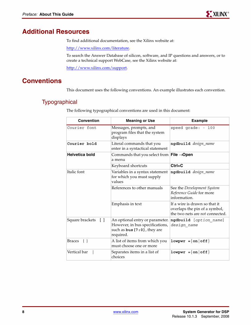
ConventionsThis document uses the following conventions. An example illustrates each convention.
TypographicalThe following typographical conventions are used in this document:
Convention Meaning or Use Example
Courier font Messages, prompts, and program files that the system displays
speed grade: - 100
Courier bold Literal commands that you enter in a syntactical statement
ngdbuild design_name
Helvetica bold Commands that you select from a menu
File → Open
Keyboard shortcuts Ctrl+C
Italic font Variables in a syntax statement for which you must supply values
ngdbuild design_name
References to other manuals See the Development System Reference Guide for more information.
Emphasis in text If a wire is drawn so that it overlaps the pin of a symbol, the two nets are not connected.
Square brackets [ ] An optional entry or parameter. However, in bus specifications, such as bus[7:0], they are required.
ngdbuild [option_name] design_name
Braces { } A list of items from which you must choose one or more
lowpwr ={on|off}
Vertical bar | Separates items in a list of choices
lowpwr ={on|off}
8 www.xilinx.com System Generator for DSPRelease 10.1.3 September, 2008
ConventionsR
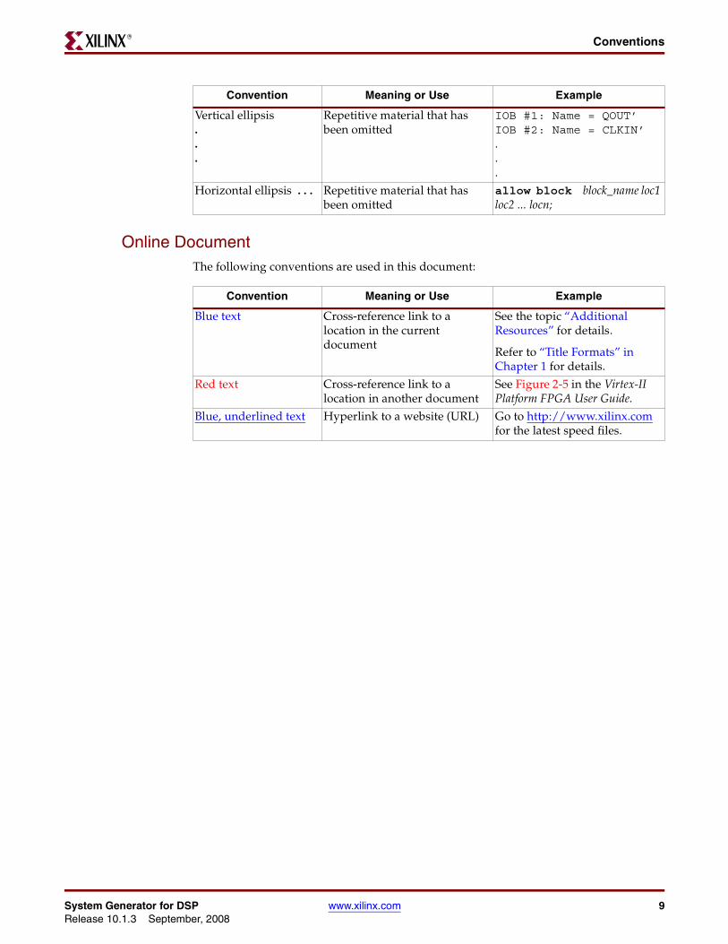
Online DocumentThe following conventions are used in this document:
Vertical ellipsis...
Repetitive material that has been omitted
IOB #1: Name = QOUT’ IOB #2: Name = CLKIN’...
Horizontal ellipsis . . . Repetitive material that has been omitted
allow block block_name loc1 loc2 ... locn;
Convention Meaning or Use Example
Convention Meaning or Use Example
Blue text Cross-reference link to a location in the current document
See the topic “Additional Resources” for details.
Refer to “Title Formats” in Chapter 1 for details.
Red text Cross-reference link to a location in another document
See Figure 2-5 in the Virtex-II Platform FPGA User Guide.
Blue, underlined text Hyperlink to a website (URL) Go to http://www.xilinx.com for the latest speed files.
System Generator for DSP www.xilinx.com 9Release 10.1.3 September, 2008
Preface: About This GuideR
10 www.xilinx.com System Generator for DSPRelease 10.1.3 September, 2008
R
Chapter 1
Introduction
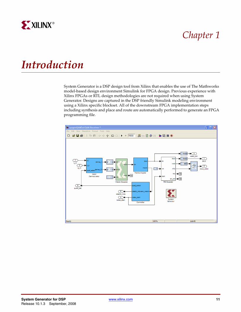
System Generator is a DSP design tool from Xilinx that enables the use of The Mathworks model-based design environment Simulink for FPGA design. Previous experience with Xilinx FPGAs or RTL design methodologies are not required when using System Generator. Designs are captured in the DSP friendly Simulink modeling environment using a Xilinx specific blockset. All of the downstream FPGA implementation steps including synthesis and place and route are automatically performed to generate an FPGA programming file.
System Generator for DSP www.xilinx.com 11Release 10.1.3 September, 2008
Chapter 1: IntroductionR
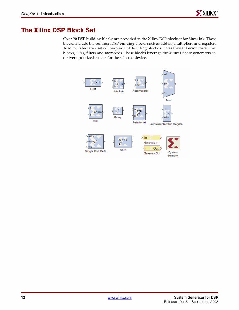
The Xilinx DSP Block SetOver 90 DSP building blocks are provided in the Xilinx DSP blockset for Simulink. These blocks include the common DSP building blocks such as adders, multipliers and registers. Also included are a set of complex DSP building blocks such as forward error correction blocks, FFTs, filters and memories. These blocks leverage the Xilinx IP core generators to deliver optimized results for the selected device.
12 www.xilinx.com System Generator for DSPRelease 10.1.3 September, 2008
FIR Filter GenerationR
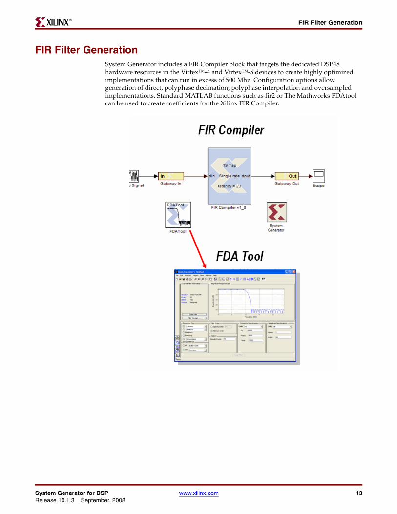
FIR Filter GenerationSystem Generator includes a FIR Compiler block that targets the dedicated DSP48 hardware resources in the Virtex™-4 and Virtex™-5 devices to create highly optimized implementations that can run in excess of 500 Mhz. Configuration options allow generation of direct, polyphase decimation, polyphase interpolation and oversampled implementations. Standard MATLAB functions such as fir2 or The Mathworks FDAtool can be used to create coefficients for the Xilinx FIR Compiler.
System Generator for DSP www.xilinx.com 13Release 10.1.3 September, 2008
Chapter 1: IntroductionR
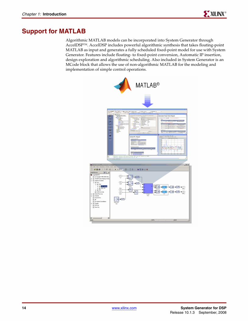
Support for MATLABAlgorithmic MATLAB models can be incorporated into System Generator through AccelDSP™. AccelDSP includes powerful algorithmic synthesis that takes floating-point MATLAB as input and generates a fully scheduled fixed-point model for use with System Generator. Features include floating- to fixed-point conversion, Automatic IP insertion, design exploration and algorithmic scheduling. Also included in System Generator is an MCode block that allows the use of non-algorithmic MATLAB for the modeling and implementation of simple control operations.
14 www.xilinx.com System Generator for DSPRelease 10.1.3 September, 2008

System Resource EstimationR
System Resource EstimationSystem Generator provides a Resource Estimator block that quickly estimates the area of a design prior to place and route. This can be a valuable aid in the hardware / software partitioning process by helping system designers take full advantage of the FPGA resources which include up to 640 multiply/accumulate (or DSP) blocks in the Virtex™-5 devices.
System Generator for DSP www.xilinx.com 15Release 10.1.3 September, 2008
Chapter 1: IntroductionR
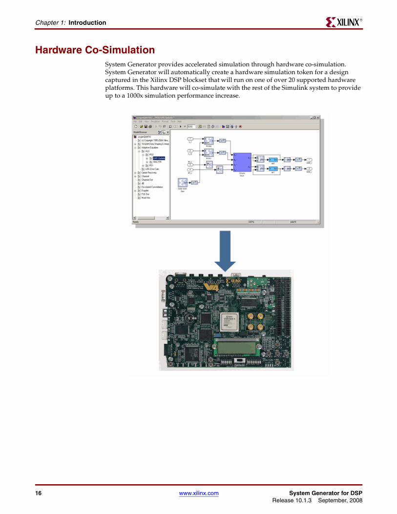
Hardware Co-SimulationSystem Generator provides accelerated simulation through hardware co-simulation. System Generator will automatically create a hardware simulation token for a design captured in the Xilinx DSP blockset that will run on one of over 20 supported hardware platforms. This hardware will co-simulate with the rest of the Simulink system to provide up to a 1000x simulation performance increase.
16 www.xilinx.com System Generator for DSPRelease 10.1.3 September, 2008
System Integration PlatformR
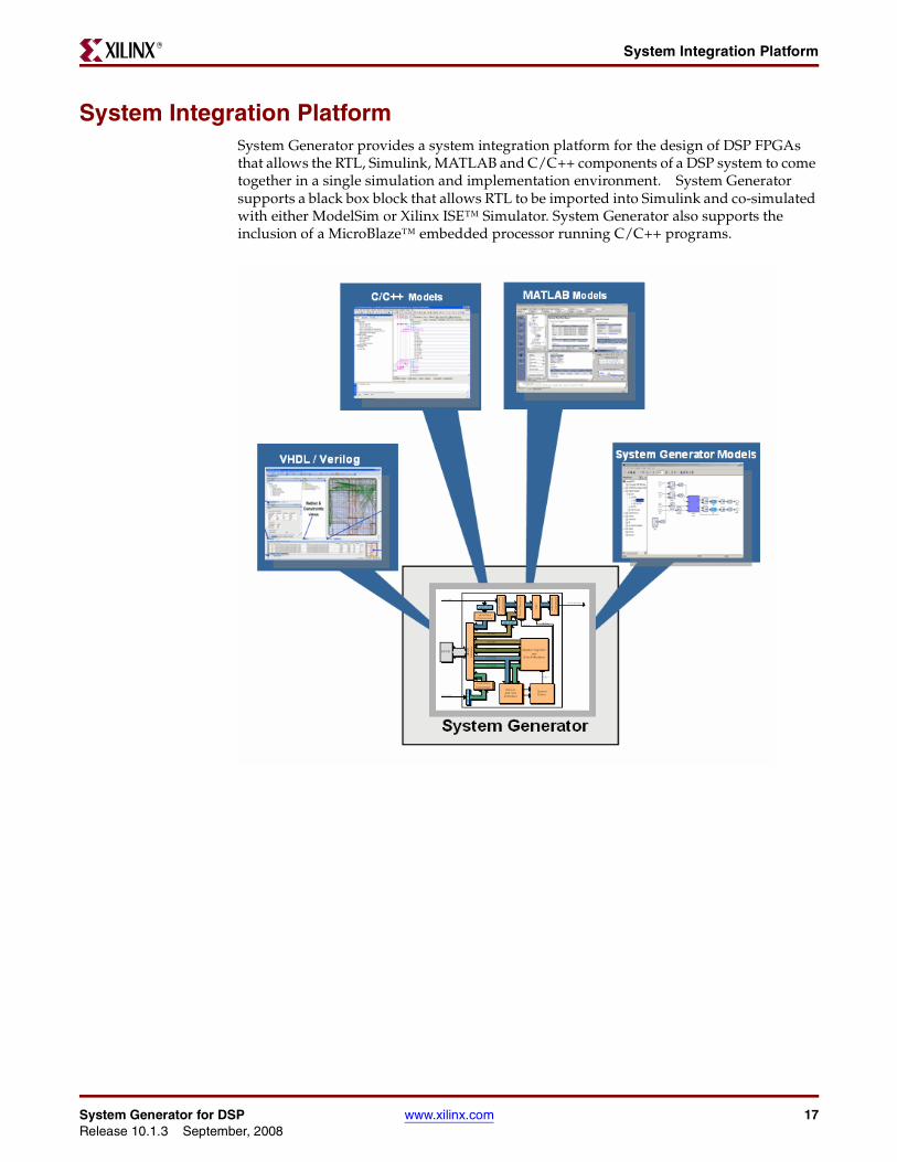
System Integration PlatformSystem Generator provides a system integration platform for the design of DSP FPGAs that allows the RTL, Simulink, MATLAB and C/C++ components of a DSP system to come together in a single simulation and implementation environment. System Generator supports a black box block that allows RTL to be imported into Simulink and co-simulated with either ModelSim or Xilinx ISE™ Simulator. System Generator also supports the inclusion of a MicroBlaze™ embedded processor running C/C++ programs.
System Generator for DSP www.xilinx.com 17Release 10.1.3 September, 2008
Chapter 1: IntroductionR
18 www.xilinx.com System Generator for DSPRelease 10.1.3 September, 2008
R
Chapter 2
Installation
DownloadingSystem Generator is only available via download from the Xilinx web page. You may purchase, register, and download the System Generator software from the site at:
http://www.xilinx.com/ise/optional_prod/system_generator.htm
Note: In special circumstances, System Generator can be delivered on a CD. Please contact your Xilinx distributor if your circumstances prohibit you from downloading the software via the web.
Hardware Co-Simulation SupportIf you have an FPGA development board, you may be able to take advantage of System Generator’s ability to use FPGA hardware co-simulation with Simulink simulations. The System Generator software includes support for the XtremeDSP Development Kit, the MicroBlaze™ Multimedia Demonstration boards, the MVI hardware platform, the ML402 Virtex™-4 platform, the ML506 Virtex™-5 platform, and the Spartan-3A DSP 1800 starter platform and 3400 development platform. Additional System Generator board support packages provide support for additional hardware co-simulation platforms. System Generator board support packages can be downloaded from the following URL:
http://www.xilinx.com/technology/dsp/thirdparty_devboards.htm
Installing
Software PrerequisitesYou must have the following software installed before running System Generator.
• One of the following versions of MATLAB from The MathWorks Inc:
• MATLAB v7.4/Simulink v6.6 (R2007a)
• MATLAB v7.5/Simulink v7.0 (R2007b)
Note: MATLAB must be installed in a directory with no spaces (e.g., C:\MATLAB\R2007a).
• Xilinx ISE™ Foundation™ version 10.1
Some features in System Generator require the following software to be installed:
• A logic synthesis tool. System Generator is fully compatible with Xilinx XST (included in the ISE Foundation bundle) and Synplify Pro v8.6.2 or v8.9 from Synplicity, Inc.
• A hardware description language (HDL) simulator is required only for co-simulating HDL modules within Simulink using System Generator. System Generator HDL co-
System Generator for DSP www.xilinx.com 19Release 10.1.3 September, 2008
Chapter 2: InstallationR
simulation interfaces are compatible with the Xilinx ISE Simulator, and ModelSim SE from Model Technology Inc.
Note: The Microsoft Windows environment variable $XILINX must be set and point to your ISE software installation directory.
ISE software service packs may be downloaded from the Xilinx Download Center:
http://www.xilinx.com/xlnx/xil_sw_updates_home.jsp
Using the ISE Design Suite InstallerBefore invoking the ISE™ Design Suite Installer, it is a good idea to make sure that all instances of MATLAB are closed. When all instances of MATLAB are closed, launch the installer and follow the directions on the screen.
Choose MATLAB Version for System Generator
As the last step of the System Generator installation, click the check box of the MATLAB installation you wish to associate with this verison of System Generator, then click Apply.
If you don’t see a valid version of MATLAB listed, for example a version installed on a network device, click the Add Version button, browse to the MATLAB root directory of the unlisted version, then click Add. If you wish to associate this version of MATLAB with System Generator, click the check box of the newly listed MATLAB installation, then click Apply.
If you have no version of MATLAB available, click Choose Later to continue with the installation. At a later time, after you have installed MATLAB, you can associate that version of MATLAB with System Generator by executing the Windows menu item Start > All Programs > Xilinx ISE Design Suite 10.1 > DSP Tools > Select MATLAB version for Xilinx System Generator.
Hardware Co-Simulation InstallationThis topic provides links to hardware and software installation procedures for hardware co-simulation. If you do not plan to use hardware co-simulation, you may skip this topic.
Ethernet-Based Hardware Co-Simulation
Installing an ML402 Platform for Ethernet Hardware Co-Simulation
Installing an ML506 Platform for Ethernet Hardware Co-Simulation
Installing a Spartan-3A DSP 1800A Starter Platform for Ethernet Hardware Co-Simulation
Installing a Spartan-3A DSP 3400A Development Platform for Ethernet Hardware Co-Simulation
Note: If installation instructions for your particular platform are not provided here, please refer to the installation instuctions that come with your Platform Kit.
JTAG-Based Hardware Co-Simulation
Installing an ML402 Board for JTAG Hardware Co-Simulation
Third-Party Hardware Co-Simulation
As part of the Xilinx XtremeDSP™ Initiative, Xilinx works with distributors and many OEMs to provide a variety of DSP prototyping and development platforms. Please refer to
20 www.xilinx.com System Generator for DSPRelease 10.1.3 September, 2008
InstallingR
the following Xilinx web site page for more information on available platforms:http://www.xilinx.com/technology/dsp/thirdparty_devboards.htm
System Generator for DSP www.xilinx.com 21Release 10.1.3 September, 2008
Chapter 2: InstallationR
Compiling Xilinx HDL LibrariesIf you intend to simulate System Generator designs using ModelSim, you must compile your IP (cores) libraries. This topic describes the procedure.
ModelSim SE
The Xilinx tool that compiles libraries for use in ModelSim SE is named compxlib. The following command can, for example, be used to compile all the VHDL and Verilog libraries with ModelSim SE:
compxlib –s mti_se –f all –l all
Complete instructions for running compxlib can be found in the ISE Software Manual titled “Synthesis and Simulation Design Guide”.
Configuring the System Generator CacheBoth the System Generator simulator and the design generator incorporate a disk cache to speed up the iterative design process. The cache does this by tagging and storing files related to simulation and generation, then recalling those files during subsequent simulation and generation rather than rerunning the time consuming tools used to create those files.
Setting the Size
By default, the cache will use up to 500 MB of disk space to store files. To specify the amount of disk space the cache should use, set the SYSGEN_CACHE_SIZE environment variable to the size of the cache in megabytes. Set this number to a higher value when working on several large designs.
Setting the Number of Entries
The cache entry database stores a fixed number of entries. The default is 20,000 entries. To set size of the cache entry database, set the SYSGEN_CACHE_ENTRIES environment variable to the desired number of entries. Setting this number too small will adversely affect cache performance. Set this number to a higher value when working on several large designs.
Displaying and Changing Versions of System GeneratorIt is possible to have several versions of System Generator installed. The MATLAB command xlVersion displays which versions are installed, and makes it possible to switch from one to another. xlVersion is useful when upgrading a model to run in the latest version of System Generator.
Entering "xlVersion" in the MATLAB console displays the versions of System Generator that are installed, and entering "xlVersion <version>" switches to the specified version. For example, if the versions that are installed are 9.2.01 and 10.1, and the currently selected version is 10.1, then entering "xlVersion" displays
Available System Generator installations: Version 9.2.01 in C:/Xilinx/9.2.01/DSP_Tools/sysgen Version 10.1 in C:/Xilinx/10.1/DSP_Tools/sysgen
Current version of System Generator is 10.1.
Entering "xlVersion 9.2.01" switches the System Generator version to 9.2.01.
22 www.xilinx.com System Generator for DSPRelease 10.1.3 September, 2008
InstallingR
Occasionally, it is necessary to restart MATLAB to make it possible to switch. In this case, the response to entering "xlVersion 10.1" looks like the following:
Please restart MATLAB and run xlVersion 10.1 again to switch.
When the switch succeeds, xlVersion prints the following:
Your System Generator has been switched. Please restart MATLAB.
If you install System Generator 10.1 after you install 9.2.01, you need to install 10.1 again in order to make xlVersion work.
Once you switch System Generator version, you need to switch to the right version of ISE in order to make System Generator work correctly.
System Generator for DSP www.xilinx.com 23Release 10.1.3 September, 2008
Chapter 2: InstallationR
24 www.xilinx.com System Generator for DSPRelease 10.1.3 September, 2008
R
Chapter 3
Release Information
Release Notes 10.1.3
Xilinx DSP Blockset Enhancements
DSP48 Abstraction for Mathematical Operators
Accumulator, AddSub, and Counter blocks can now be implemented using either a DSP48 or the original LUT-based implementation. This enables design portability across all supported Xilinx devices.
Fast Fourier Transform 6.0
New block now available in System Generator with the following features:
• Extended data and phase factor width to 34 bits
• Block floating-point support available for Pipelined, Streaming I/O architecture
WaveScope
• WaveScope waveforms can now be directly sent to a printer from WaveScope and a “Print Preview” capability allows you to view and customize the waveform formatting before printing. The capability can be accessed via the File pull-down menu or a toolbar shortcut.
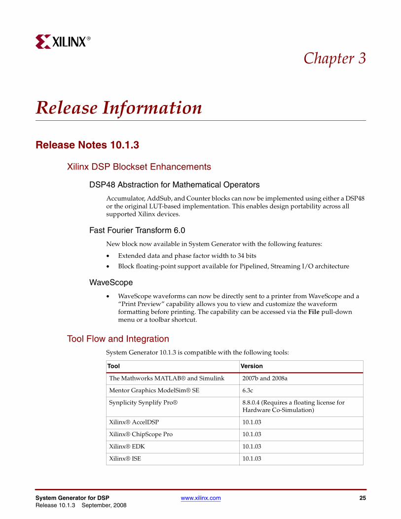
Tool Flow and IntegrationSystem Generator 10.1.3 is compatible with the following tools:
Tool Version
The Mathworks MATLAB® and Simulink 2007b and 2008a
Mentor Graphics ModelSim® SE 6.3c
Synplicity Synplify Pro® 8.8.0.4 (Requires a floating license for Hardware Co-Simulation)
Xilinx® AccelDSP 10.1.03
Xilinx® ChipScope Pro 10.1.03
Xilinx® EDK 10.1.03
Xilinx® ISE 10.1.03
System Generator for DSP www.xilinx.com 25Release 10.1.3 September, 2008
Chapter 3: Release InformationR
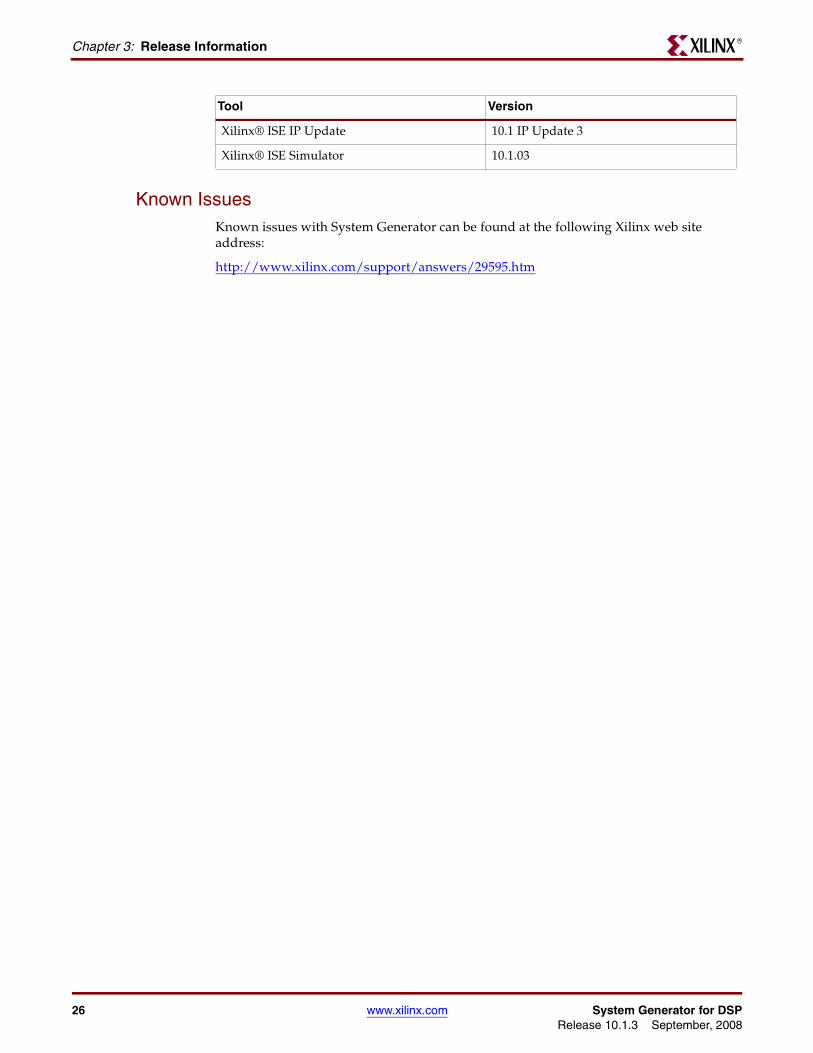
Known IssuesKnown issues with System Generator can be found at the following Xilinx web site address:
http://www.xilinx.com/support/answers/29595.htm
Xilinx® ISE IP Update 10.1 IP Update 3
Xilinx® ISE Simulator 10.1.03
Tool Version
26 www.xilinx.com System Generator for DSPRelease 10.1.3 September, 2008
Release Notes 10.1.2R
Release Notes 10.1.2
System Generator Enhancements
Hybrid DCM-CE Support
In the 10.1 release, System Generator introduced a new clocking option to automatically include a DCM (Digital Clock Manager) in a design. This option was limited to designs with no more than three clock rates.
In this release, this clocking option has been enhanced to support designs with more than three clock rates. The additional rates are automatically supported with the CE(Clock Enable) methodology. For example, if a design has six clock rates, the highest three clock rates are supported with a DCM and the lowest three clock rates are supported with the CE methodology.
MATLAB 2008a
MATLAB 2008a is now supported by System Generator.
Xilinx DSP Blockset Enhancements
FIR Compiler 4.0
New block now available in System Generator with the following features.
• Extended data and coefficient width range up to 49 bits.
• Polyphase filter bank support for channelizer applications & transpose multiply-accumulate architecture.
• Capability to share control and coefficient memory resources for up to 16 parallel data paths.
• Virtex-5 and Spartan-3A DSP support added for distributed arithmetic architecture.
This block supports all the features supported by FIR Compiler LogiCORE v4.0.
System Generator for DSP www.xilinx.com 27Release 10.1.3 September, 2008
Chapter 3: Release InformationR
Divider Generator 2.0
New block now available in System Generator that generates arithmetic division algorithms for integer division.
• Optional operand widths up to 54 bit wide, synchronous controls, and selectable latency.
• Supports Virtex-4, Virtex-5 & Spartan3A-DSP for both radix-2 integer division and high-radix division algorithms.
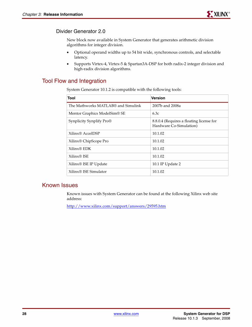
Tool Flow and IntegrationSystem Generator 10.1.2 is compatible with the following tools:
Known IssuesKnown issues with System Generator can be found at the following Xilinx web site address:
http://www.xilinx.com/support/answers/29595.htm
Tool Version
The Mathworks MATLAB® and Simulink 2007b and 2008a
Mentor Graphics ModelSim® SE 6.3c
Synplicity Synplify Pro® 8.8.0.4 (Requires a floating license for Hardware Co-Simulation)
Xilinx® AccelDSP 10.1.02
Xilinx® ChipScope Pro 10.1.02
Xilinx® EDK 10.1.02
Xilinx® ISE 10.1.02
Xilinx® ISE IP Update 10.1 IP Update 2
Xilinx® ISE Simulator 10.1.02
28 www.xilinx.com System Generator for DSPRelease 10.1.3 September, 2008
Release Notes 10.1.1R
Release Notes 10.1.1
System Generator Enhancements• Enhanced UCF Support for EDK Import Flow
The handling of UCF (User Constraint File) files in the EDK import flow has been enhanced to support larger UCF file sizes. The UCF file of an imported XPS project is now parsed and modified to form a new UCF file based on the settings of the EDK Processor block. The user has the ability to view and modify the original UCF file and then re-import the XPS project.
• Enhanced PLB Dual Clock Support
Xilinx Platform Studio projects that use clock generators to drive the PLB bus, MicroBlaze™ processor and other hardware peripherals with different clocks can now automatically be imported into System Generator for HDL netlisting and hardware co-simulation.
Xilinx DSP Blockset Enhancements
CIC Compiler 1.2
Update to existing block
• Simulation speedup of ~4x as compared to CIC Compiler 1.1
DDS Compiler 2.1
Update to existing block.
• Core generation time has been reduced by ~10x as compared to previous versions of the DDS Compiler.
• Ability to specify negative frequencies.
• In the previous version of the DDS Compiler, after reset has been de-asserted, the RDY output goes high 1-cycle too early; this error has been corrected.
System Generator for DSP www.xilinx.com 29Release 10.1.3 September, 2008
Chapter 3: Release InformationR
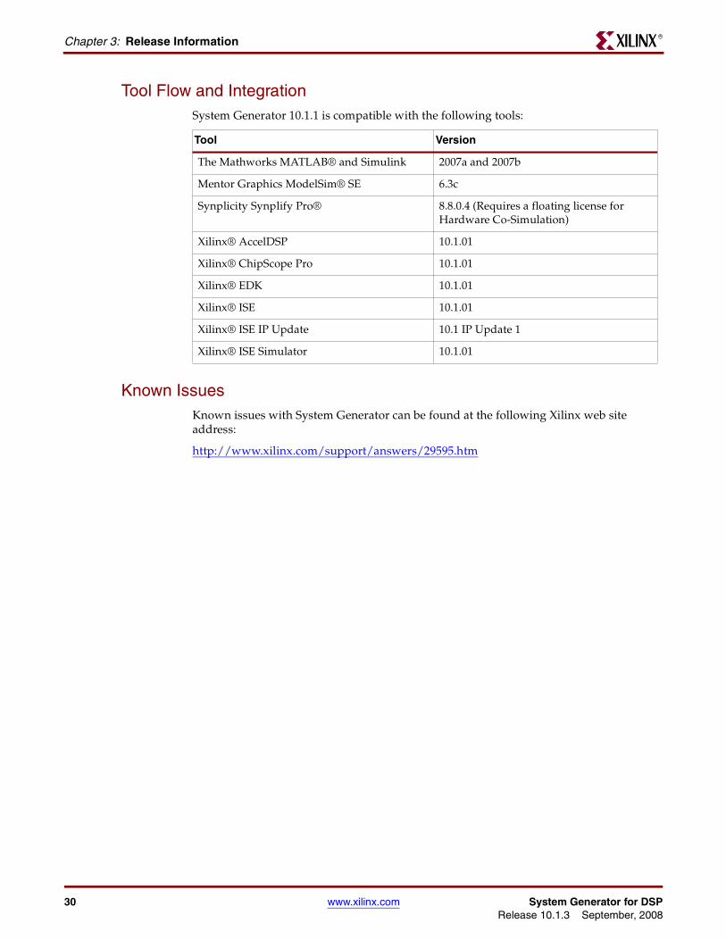
Tool Flow and IntegrationSystem Generator 10.1.1 is compatible with the following tools:
Known IssuesKnown issues with System Generator can be found at the following Xilinx web site address:
http://www.xilinx.com/support/answers/29595.htm
Tool Version
The Mathworks MATLAB® and Simulink 2007a and 2007b
Mentor Graphics ModelSim® SE 6.3c
Synplicity Synplify Pro® 8.8.0.4 (Requires a floating license for Hardware Co-Simulation)
Xilinx® AccelDSP 10.1.01
Xilinx® ChipScope Pro 10.1.01
Xilinx® EDK 10.1.01
Xilinx® ISE 10.1.01
Xilinx® ISE IP Update 10.1 IP Update 1
Xilinx® ISE Simulator 10.1.01
30 www.xilinx.com System Generator for DSPRelease 10.1.3 September, 2008
Release Notes 10.1R
Release Notes 10.1
System Generator Enhancements
System Generator / Project Navigator Integration
System Generator designs can now be more easily incorporated into a larger design inside of Project Navigator by using a new source type in Project Navigator. The System Generator design can also be launched from Project Navigator.
DCM Support
System Generator now provides the option to automatically include a DCM in a design. Although the optional DCM is abstracted away from the designer, the generated design will leverage DCMs available in the silicon.
An alternative option exposes the clock ports at the top level for manual connection to a DCM.
Dual Asynchronous-Clock Support for PLB46
This capability gives the designer additional flexibility by allowing the DSP and embedded processing portions of a design to run at different clock rates.
Run Time Speed Improvements
• Up to 2x faster first time initialization of a simulation
• >10x faster initialization when loading the Xilinx Blockset in the Simulink Library Browser
M-Based HW Co-Simulation
System Generator models compiled for HW Co-Simulation can now be embedded, configured and utilized in a MATLAB M-code script; allowing for calls into hardware to be made from MATLAB.
System Generator for DSP www.xilinx.com 31Release 10.1.3 September, 2008
Chapter 3: Release InformationR
Xilinx DSP Blockset Enhancements
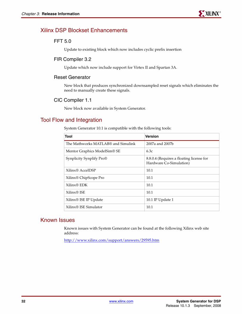
FFT 5.0
Update to existing block which now includes cyclic prefix insertion
FIR Compiler 3.2
Update which now include support for Virtex II and Spartan 3A.
Reset Generator
New block that produces synchronized downsampled reset signals which eliminates the need to manually create these signals.
CIC Compiler 1.1
New block now available in System Generator.
Tool Flow and IntegrationSystem Generator 10.1 is compatible with the following tools:
Known IssuesKnown issues with System Generator can be found at the following Xilinx web site address:
http://www.xilinx.com/support/answers/29595.htm
Tool Version
The Mathworks MATLAB® and Simulink 2007a and 2007b
Mentor Graphics ModelSim® SE 6.3c
Synplicity Synplify Pro® 8.8.0.4 (Requires a floating license for Hardware Co-Simulation)
Xilinx® AccelDSP 10.1
Xilinx® ChipScope Pro 10.1
Xilinx® EDK 10.1
Xilinx® ISE 10.1
Xilinx® ISE IP Update 10.1 IP Update 1
Xilinx® ISE Simulator 10.1
32 www.xilinx.com System Generator for DSPRelease 10.1.3 September, 2008
Upgrading a Xilinx System Generator ModelR
Upgrading a Xilinx System Generator Model
Upgrading v2.x and Prior ModelsIf you are upgrading from versions of System Generator earlier than v3.1, you must obtain System Generator v7.x and update your models to v7.x before you can update them to v9.1.01.
Upgrading v3.x, v6.x and v7.x ModelsThis section describes the process of upgrading a Xilinx System Generator v3.x, v6.x or v7.x model to work with v9.1.01.
Note: Any reference to v3.x or v6.x in this section can be used interchangeably with v7.x.
The basic steps for upgrading a v7.x model to v9.1.01 is as follows: 1) Save a backup copy of your v7.1 model and user-defined libraries that your model uses 2) Run xlUpdateModel on any libraries first and then on your model 3) Read the report produced by xlUpdateModel and follow the instructions 4) Check that your model runs under v9.1.01.
These steps are described in greater detail below.
1. Save a backup copy of your v7.1 model and user-defined libraries that your model uses.
2. Run the xlUpdateModel Function
From the MATLAB console, cd into the directory containing your model. If the name of your model is designName.mdl, type xlUpdateModel('designName').
The xlUpdateModel function performs the following tasks:
♦ Updates each block in your v7.x design to a corresponding v9.1.01 block with equivalent settings.
♦ Writes a report explaining all of the changes that were made. This report enumerates changes you may need to make by hand to complete the update.
In most cases, xlUpdateModel produces an equivalent v9.1.01 model. However, there are a few constructs that may require you to edit your model. It is important that you read the report and follow the remaining steps in this section.
3. Read the xlUpdateModel report and Follow the Instructions
If the report contains the issues listed below, manual intervention will be required to complete the conversion.
a. Xilinx System Generator v7.x models containing removed blocks
The following blocks have been removed from System Generator: CIC, Clear Quantization Error, Digital Up Converter, J.83 Modulator, Quantization Error, Sync.
b. Xilinx System Generator v7.x Models that Contain Deprecated Blocks
The DDSv4.0 block still exist in System Generator, but has been deprecated:
c. Xilinx System Generator v7.x Models Utilizing Explicit Sample Periods
The explicit sample period fields have been removed from most non-source blocks in System Generator v9.1.01. Source blocks (e.g., Counter block) continue to allow the specification of explicit sample periods. When upgrading models containing
System Generator for DSP www.xilinx.com 33Release 10.1.3 September, 2008
Chapter 3: Release InformationR
feedback loops, Assert blocks must typically be added by hand after xlUpdateModel has been run. This is necessary in order to help System Generator determine appropriate rates and types for the path. The following error message is an indication that an Assert block is required:
“The data rates could not be established for the feedback paths through this block. You may need to add Assert blocks to instruct the system”
In such a case, you should augment each feedback loop with an Assert block, and specify rates and types explicitly on this block.
The update script will annotate the converted model wherever the v7.1 model asserted an explicit period. In the converted model, you will most often not need to insert Assert blocks. To find out where you need them, try to update the diagram (the Update Diagram control is under the Edit menu). If rates do not resolve, you will need to insert one or more Assert blocks.
The update script can be configured to automatically insert Assert blocks immediately following blocks configured with an explicit sample period setting. To use this option, run the following command:
xlUpdateModel(designName,'assert')
4. Save and Close the updated model.
If you did not previously make a backup copy of the old model, you can save the updated model under a new name to preserve the old model.
5. Verify that Your model Runs Under System Generator v9.1.01.
If you have followed the instructions in the previous steps, your model should run with System Generator v9.1.01. Open the model with System Generator v9.1.01 and run it.
ExamplesExample 1:
>> xlUpdateModel('my_model_name');
Update the file my_model_name.mdl that is located in the current MATLAB working directory.
Example 2:
>> xlUpdateModel('my_model_name','lib');
Update the file my_model_name.mdl that is located in the current MATLAB working directory, along with the libraries that are associated with the model.
Example 3:
>> xlUpdateModel('my_model_name','assert’);
Update the file my_model_name.mdl that is located in the current MATLAB working directory. Add Assert blocks where necessary.
34 www.xilinx.com System Generator for DSPRelease 10.1.3 September, 2008
R
Chapter 4
Getting Started
IntroductionThis Getting Started training consists of six short lessons that introduce you to major features of System Generator for DSP. Each lesson takes less than 10 minutes to read and is followed by one or more hands-on lab exercises. The lab exercise folders are located in the System Generator software tree and contain data files and step-by-step instructions.
If you have System Generator installed on your computer, you can complete each lab exercise at your own pace and on your own time schedule. If you do not have System Generator installed, you can access this free training in a recorded e-learning format through the Xilinx web site at the following location: http://www.xilinx.com/support/training/rel/system-generator.htm
The lessons contained in this Getting Started are as follows:
• Lesson 1 - Design Creation Basics: Introduces the basics of creating and implementing a DSP design using System Generator.
• Lesson 2 - Fixed Point and Bit Operations: Covers the use of the System Generator routing blocks for extracting and manipulating the individual bits of a fixed-point signal.
• Lesson 3 - System Control: Covers the preferred methods for using System Generator to create finite state machines, logical control conditions, and the handling of bursty data typical of FFT and filtering operations.
• Lesson 4 - Multi-Rate Systems: Shows the proper way to create multi-rate systems using upsampling and downsampling of data.
• Lesson 5 - Using Memories: Covers proper usage of the Xilinx block RAM resources and the DSP blocks available for building DSP designs targeting Xilinx RAMs.
• Lesson 6 - Designing Filters: Discusses methods for creating efficient FIR filters in the Xilinx devices, use of the FIR Compiler block for filter implementation, and use of the FDATool for filter design.
System Generator for DSP www.xilinx.com 35Release 10.1.3 September, 2008
Chapter 4: Getting StartedR
Lesson 1 - Design Creation Basics
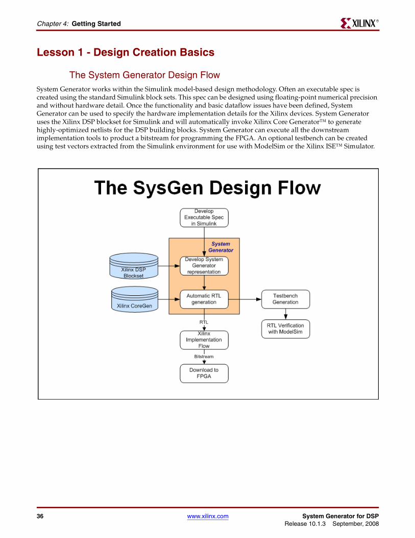
The System Generator Design FlowSystem Generator works within the Simulink model-based design methodology. Often an executable spec is created using the standard Simulink block sets. This spec can be designed using floating-point numerical precision and without hardware detail. Once the functionality and basic dataflow issues have been defined, System Generator can be used to specify the hardware implementation details for the Xilinx devices. System Generator uses the Xilinx DSP blockset for Simulink and will automatically invoke Xilinx Core Generator™ to generate highly-optimized netlists for the DSP building blocks. System Generator can execute all the downstream implementation tools to product a bitstream for programming the FPGA. An optional testbench can be created using test vectors extracted from the Simulink environment for use with ModelSim or the Xilinx ISE™ Simulator.
36 www.xilinx.com System Generator for DSPRelease 10.1.3 September, 2008
Lesson 1 - Design Creation BasicsR
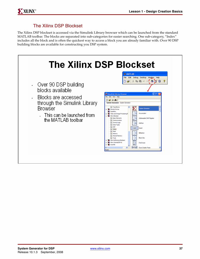
The Xilinx DSP BlocksetThe Xilinx DSP blockset is accessed via the Simulink Library browser which can be launched from the standard MATLAB toolbar. The blocks are separated into sub-categories for easier searching. One sub-category, “Index” includes all the block and is often the quickest way to access a block you are already familiar with. Over 90 DSP building blocks are available for constructing you DSP system.
System Generator for DSP www.xilinx.com 37Release 10.1.3 September, 2008
Chapter 4: Getting StartedR
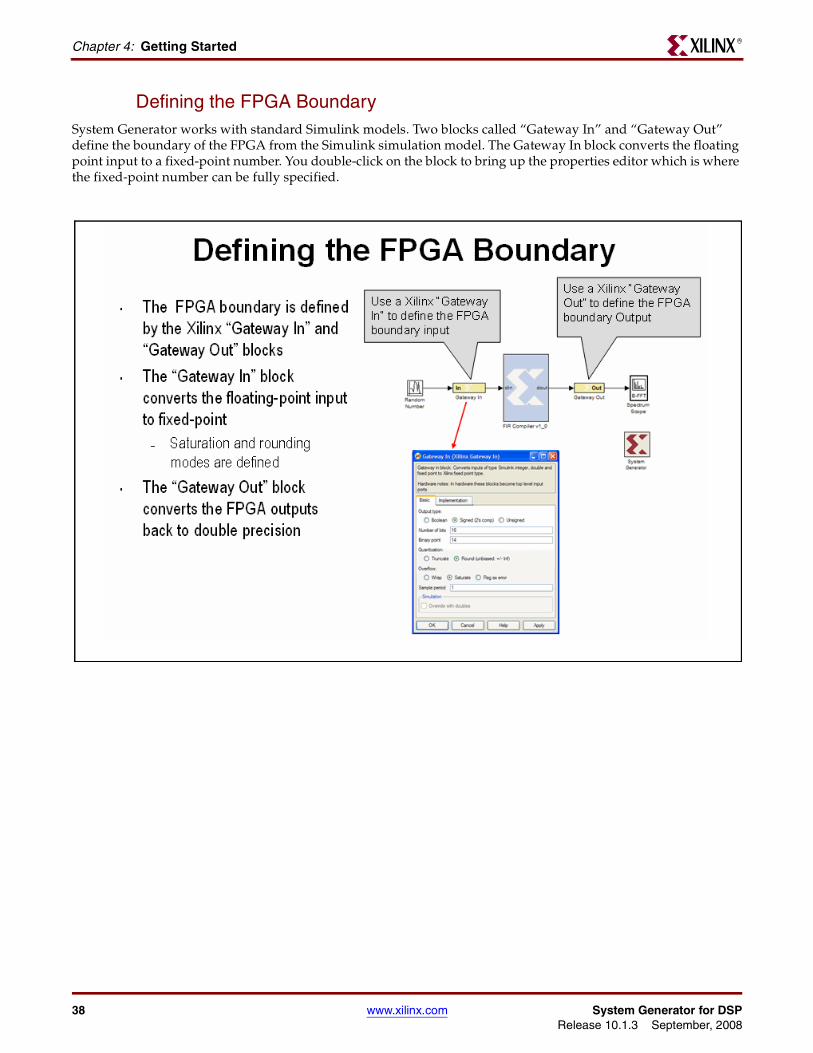
Defining the FPGA BoundarySystem Generator works with standard Simulink models. Two blocks called “Gateway In” and “Gateway Out” define the boundary of the FPGA from the Simulink simulation model. The Gateway In block converts the floating point input to a fixed-point number. You double-click on the block to bring up the properties editor which is where the fixed-point number can be fully specified.
38 www.xilinx.com System Generator for DSPRelease 10.1.3 September, 2008
Lesson 1 - Design Creation BasicsR
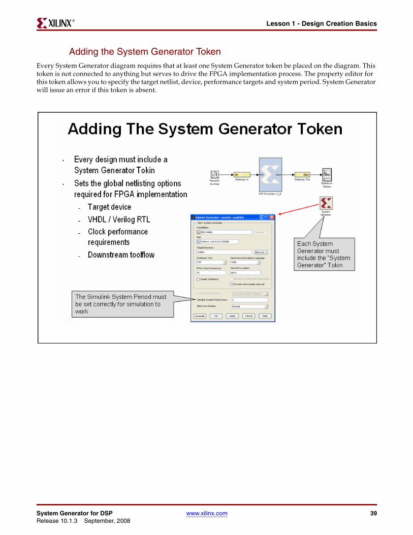
Adding the System Generator TokenEvery System Generator diagram requires that at least one System Generator token be placed on the diagram. This token is not connected to anything but serves to drive the FPGA implementation process. The property editor for this token allows you to specify the target netlist, device, performance targets and system period. System Generator will issue an error if this token is absent.
System Generator for DSP www.xilinx.com 39Release 10.1.3 September, 2008
Chapter 4: Getting StartedR
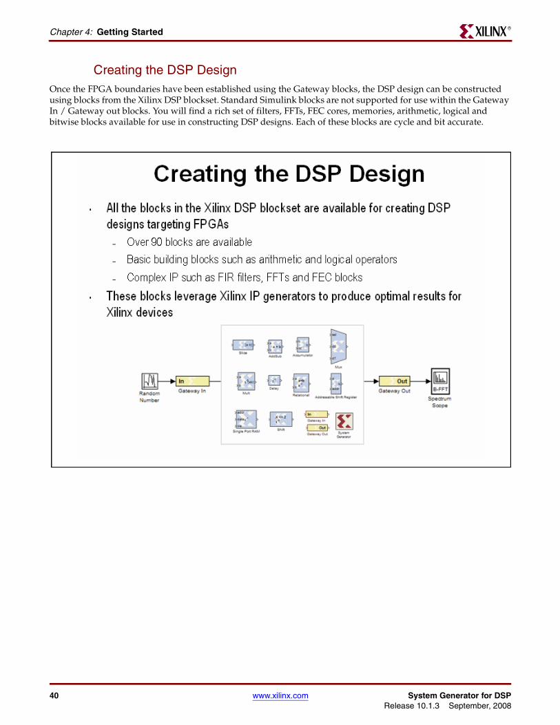
Creating the DSP DesignOnce the FPGA boundaries have been established using the Gateway blocks, the DSP design can be constructed using blocks from the Xilinx DSP blockset. Standard Simulink blocks are not supported for use within the Gateway In / Gateway out blocks. You will find a rich set of filters, FFTs, FEC cores, memories, arithmetic, logical and bitwise blocks available for use in constructing DSP designs. Each of these blocks are cycle and bit accurate.
40 www.xilinx.com System Generator for DSPRelease 10.1.3 September, 2008
Lesson 1 - Design Creation BasicsR
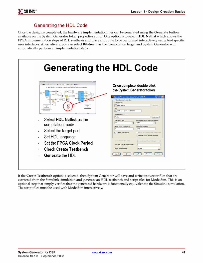
Generating the HDL CodeOnce the design is completed, the hardware implementation files can be generated using the Generate button available on the System Generator token properties editor. One option is to select HDL Netlist which allows the FPGA implementation steps of RTL synthesis and place and route to be performed interactively using tool specific user interfaces. Alternatively, you can select Bitstream as the Compilation target and System Generator will automatically perform all implementation steps.
If the Create Testbench option is selected, then System Generator will save and write test vector files that are extracted from the Simulink simulation and generate an HDL testbench and script files for ModelSim. This is an optional step that simply verifies that the generated hardware is functionally equivalent to the Simulink simulation. The script files must be used with ModelSim interactively.
System Generator for DSP www.xilinx.com 41Release 10.1.3 September, 2008
Chapter 4: Getting StartedR
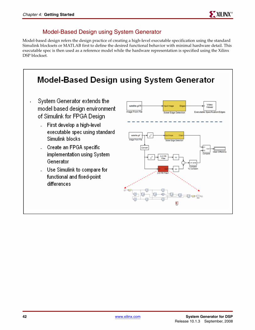
Model-Based Design using System GeneratorModel-based design refers the design practice of creating a high-level executable specification using the standard Simulink blocksets or MATLAB first to define the desired functional behavior with minimal hardware detail. This executable spec is then used as a reference model while the hardware representation is specified using the Xilinx DSP blockset.
42 www.xilinx.com System Generator for DSPRelease 10.1.3 September, 2008
Lesson 1 - Design Creation BasicsR
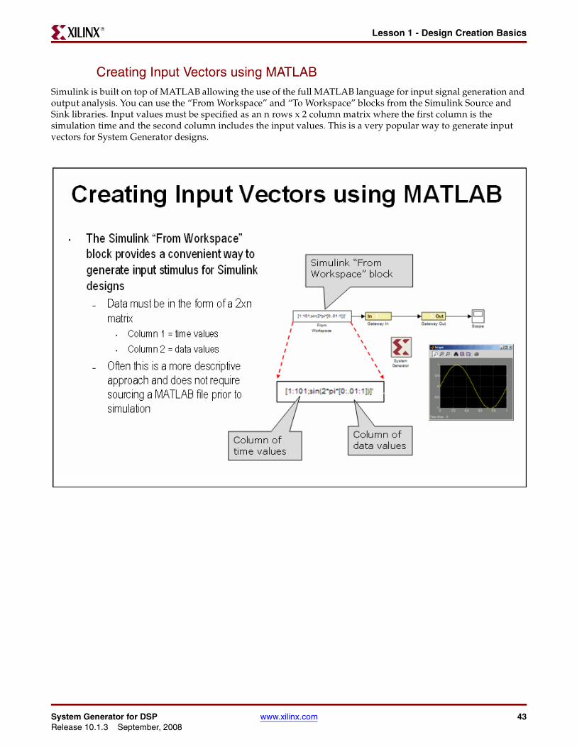
Creating Input Vectors using MATLABSimulink is built on top of MATLAB allowing the use of the full MATLAB language for input signal generation and output analysis. You can use the “From Workspace” and “To Workspace” blocks from the Simulink Source and Sink libraries. Input values must be specified as an n rows x 2 column matrix where the first column is the simulation time and the second column includes the input values. This is a very popular way to generate input vectors for System Generator designs.
System Generator for DSP www.xilinx.com 43Release 10.1.3 September, 2008
Chapter 4: Getting StartedR
Lesson 1 Summary• You partition the FPGA design from the Simulink “system” using Gateway In /
Gateway Out blocks.
• You always include a System Generator token on each sheet
• You should only use blocks from the Xilinx DSP blockset between the gateway blocks
• You should consider using the From / To workspace blocks to use MATLAB for input generation and output analysis
Lab Exercise: Using SimulinkIn this lab, you will learn the basics of Simulink. You will use a Simulink blockset to generate a simple design and take it through simulation. You will then change the sampling settings to see its effect on the output. You will then learn how to create a subsystem.
The lab instructions are located in the System Generator software tree at the following pathname:
...<sysgen_tree>/examples/getting_started_training/lab1/lab1.pdf
Lab Exercise: Getting Started with System GeneratorThis lab introduces you to the basic concepts of creating a design using System Generator within the model-based design flow provided through Simulink. The design is a simple multiply-add circuit.
The lab instructions and lab design are located in the System Generator software tree at the following pathname:
...<sysgen_tree>/examples/getting_started_training/lab2/
44 www.xilinx.com System Generator for DSPRelease 10.1.3 September, 2008

Lesson 2 - Fixed Point and Bit OperationsR
Lesson 2 - Fixed Point and Bit Operations
Fixed-Point Numeric PrecisionSystem Generator supports three data types, Unsigned for positive only DSP operations, Signed which is two’s complement used for DSP operations that involve negative numbers and Boolean for 1-bit control signals. Each block will typically have quantization parameters. The initial quantization is defined by the Gateway In blocks.
System Generator for DSP www.xilinx.com 45Release 10.1.3 September, 2008

Chapter 4: Getting StartedR
System Generator Fixed-Point QuantizationXilinx fixed-point data types are defined by specifying the total number of bits then specifying the location of the binary point. The difference, which represents the number of bits to the left of the binary point, are the integer bits for ufixed numbers and the integer bits plus sign bit for signed numbers. Xilinx FPGAs do not require that fixed-point numbers fall in pre-defined 8 bit boundaries as is the case with DSP processors. The logic can grow bit-by-bit to accommodate the required fixed-point precision.
46 www.xilinx.com System Generator for DSPRelease 10.1.3 September, 2008
Lesson 2 - Fixed Point and Bit OperationsR
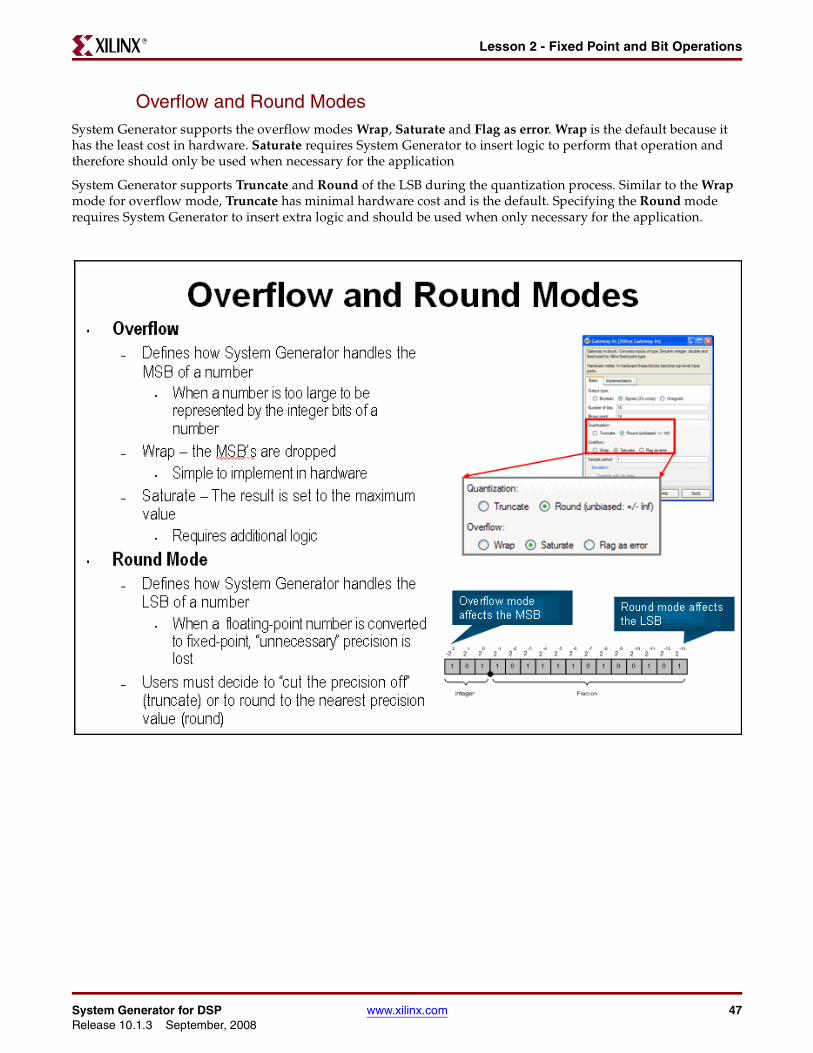
Overflow and Round ModesSystem Generator supports the overflow modes Wrap, Saturate and Flag as error. Wrap is the default because it has the least cost in hardware. Saturate requires System Generator to insert logic to perform that operation and therefore should only be used when necessary for the application
System Generator supports Truncate and Round of the LSB during the quantization process. Similar to the Wrap mode for overflow mode, Truncate has minimal hardware cost and is the default. Specifying the Round mode requires System Generator to insert extra logic and should be used when only necessary for the application.
System Generator for DSP www.xilinx.com 47Release 10.1.3 September, 2008
Chapter 4: Getting StartedR
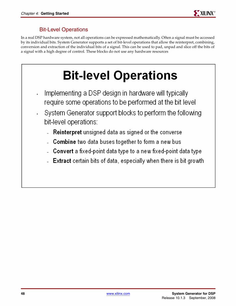
Bit-Level OperationsIn a real DSP hardware system, not all operations can be expressed mathematically. Often a signal must be accessed by its individual bits. System Generator supports a set of bit-level operations that allow the reinterpret, combining, conversion and extraction of the individual bits of a signal. This can be used to pad, unpad and slice off the bits of a signal with a high degree of control. These blocks do not use any hardware resources
48 www.xilinx.com System Generator for DSPRelease 10.1.3 September, 2008
Lesson 2 - Fixed Point and Bit OperationsR
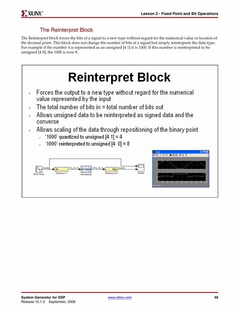
The Reinterpret BlockThe Reinterpret block forces the bits of a signal to a new type without regard for the numerical value or location of the decimal point. This block does not change the number of bits of a signal but simply reinterprets the data type. For example if the number 4 is represented as an unsigned [4 1] it is 1000. If this number is reinterpreted to be unsigned [4 0], the 1000 is now 8.
System Generator for DSP www.xilinx.com 49Release 10.1.3 September, 2008
Chapter 4: Getting StartedR
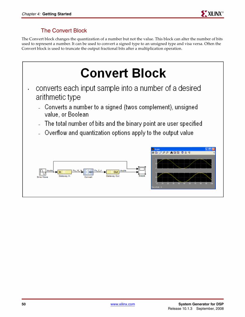
The Convert BlockThe Convert block changes the quantization of a number but not the value. This block can alter the number of bits used to represent a number. It can be used to convert a signed type to an unsigned type and visa versa. Often the Convert block is used to truncate the output fractional bits after a multiplication operation.
50 www.xilinx.com System Generator for DSPRelease 10.1.3 September, 2008
Lesson 2 - Fixed Point and Bit OperationsR
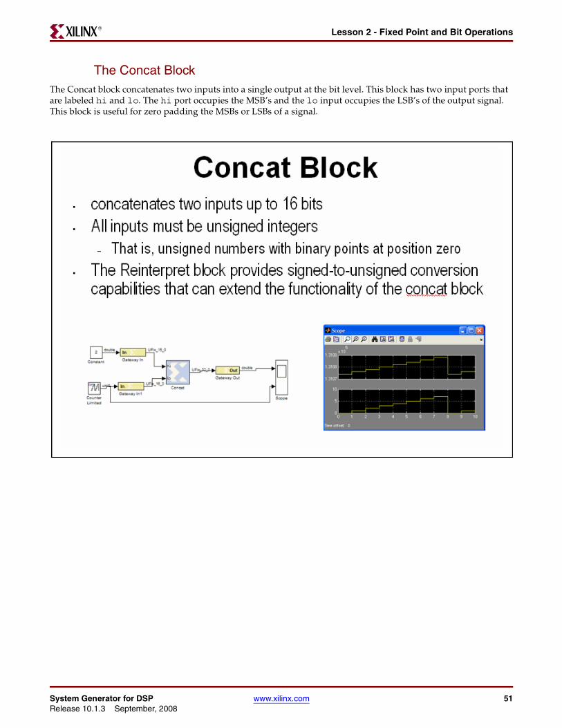
The Concat BlockThe Concat block concatenates two inputs into a single output at the bit level. This block has two input ports that are labeled hi and lo. The hi port occupies the MSB’s and the lo input occupies the LSB’s of the output signal. This block is useful for zero padding the MSBs or LSBs of a signal.
System Generator for DSP www.xilinx.com 51Release 10.1.3 September, 2008
Chapter 4: Getting StartedR
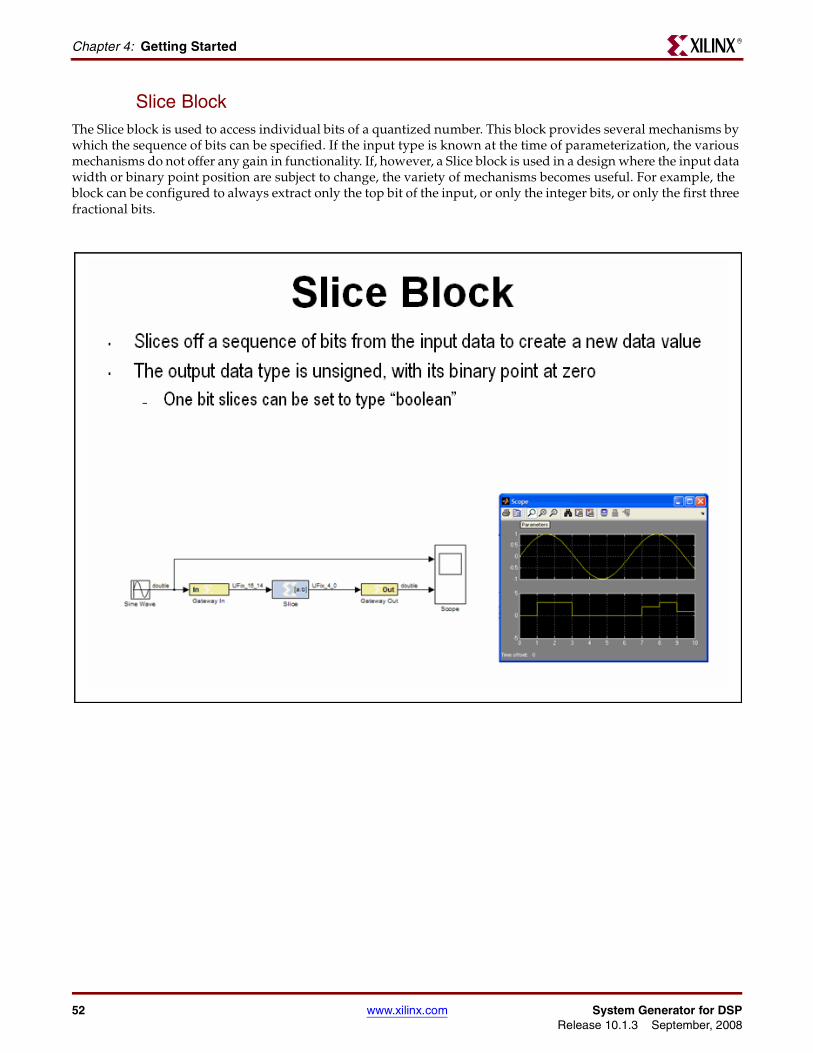
Slice BlockThe Slice block is used to access individual bits of a quantized number. This block provides several mechanisms by which the sequence of bits can be specified. If the input type is known at the time of parameterization, the various mechanisms do not offer any gain in functionality. If, however, a Slice block is used in a design where the input data width or binary point position are subject to change, the variety of mechanisms becomes useful. For example, the block can be configured to always extract only the top bit of the input, or only the integer bits, or only the first three fractional bits.
52 www.xilinx.com System Generator for DSPRelease 10.1.3 September, 2008
Lesson 2 - Fixed Point and Bit OperationsR
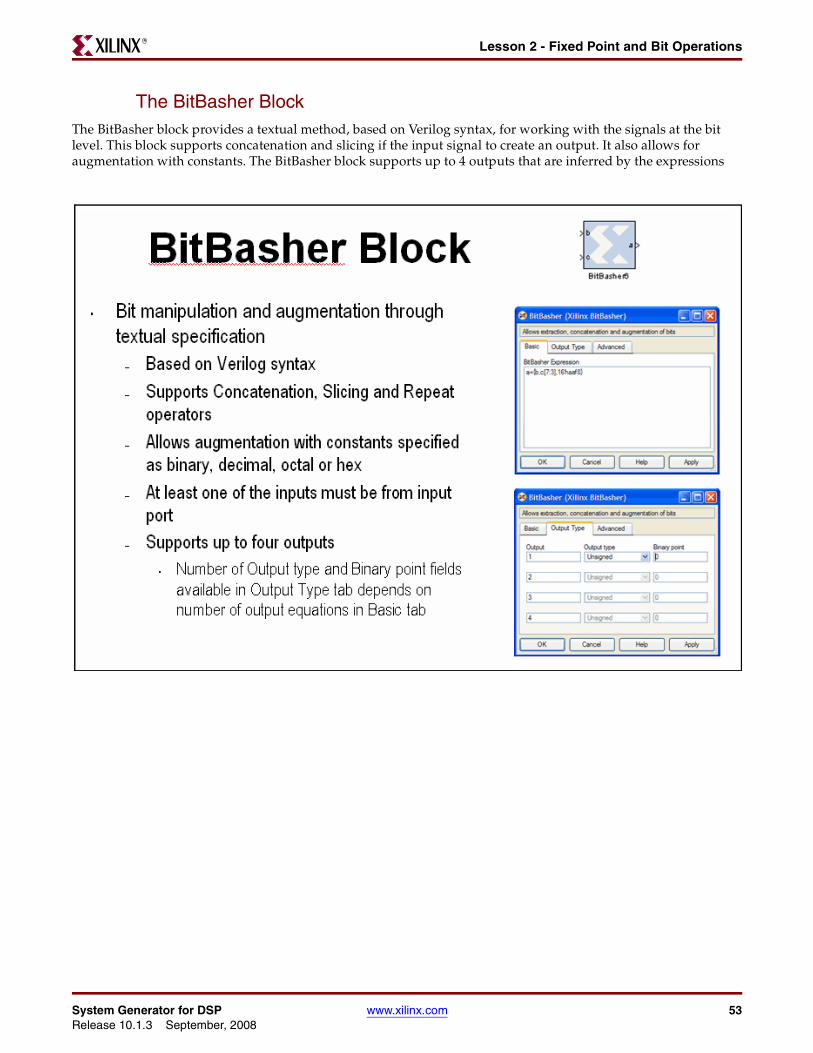
The BitBasher BlockThe BitBasher block provides a textual method, based on Verilog syntax, for working with the signals at the bit level. This block supports concatenation and slicing if the input signal to create an output. It also allows for augmentation with constants. The BitBasher block supports up to 4 outputs that are inferred by the expressions
System Generator for DSP www.xilinx.com 53Release 10.1.3 September, 2008
Chapter 4: Getting StartedR
Lesson 2 Summary• Quantization and overflow options are available when the output of a block is user
defined
• Quantization occurs when the number of fractional bits is insufficient to represent the fractional portion of a value
• Overflow occurs when a value lies outside the representable range
• Bit picking blocks allow combining of multiple buses into a single bus, force a conversion of data type without changing the number of bits, extract bits, and convert the number into different format
• The BitBasher block allows bit manipulation and augmentation through textual specification based in Verilog
Lab Exercise: Signal RoutingIn this lab you will design and verify padding and unpadding logic using the System Generator signal routing blocks
The lab instructions are located in the System Generator software tree at the following pathname:
...<sysgen_tree>/examples/getting_started_training/lab3/lab3.pdf
54 www.xilinx.com System Generator for DSPRelease 10.1.3 September, 2008
Lesson 3 - System ControlR
Lesson 3 - System Control
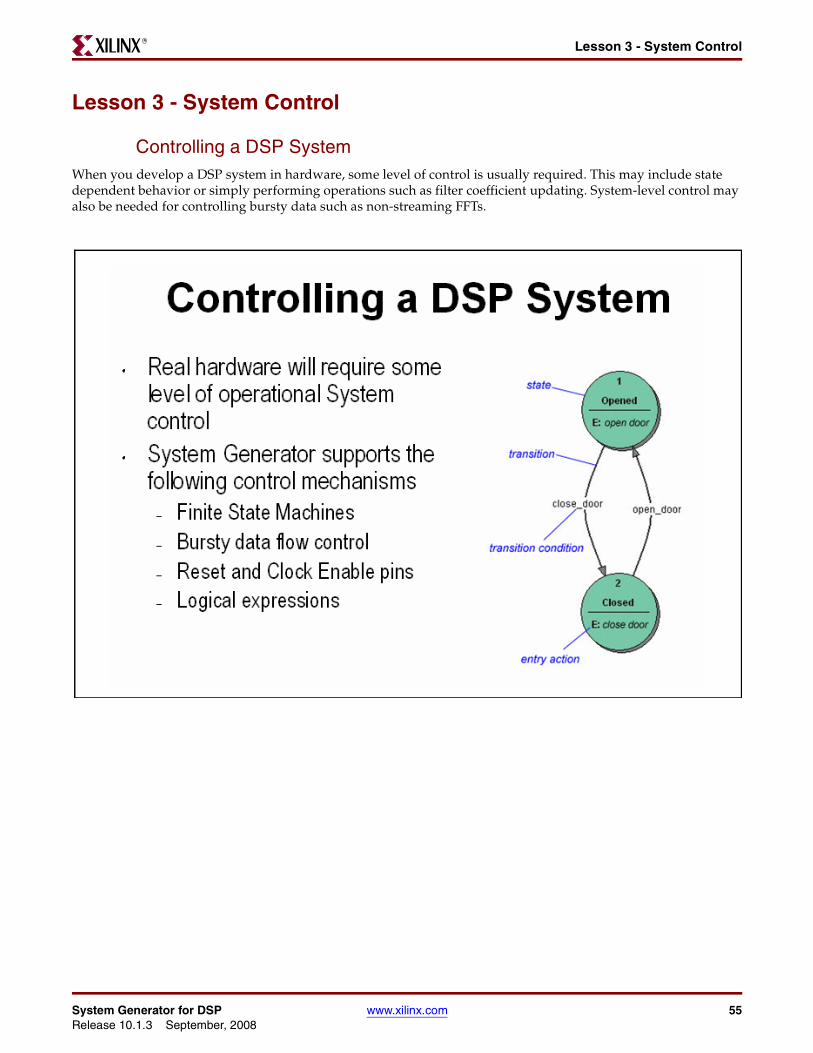
Controlling a DSP SystemWhen you develop a DSP system in hardware, some level of control is usually required. This may include state dependent behavior or simply performing operations such as filter coefficient updating. System-level control may also be needed for controlling bursty data such as non-streaming FFTs.
System Generator for DSP www.xilinx.com 55Release 10.1.3 September, 2008
Chapter 4: Getting StartedR
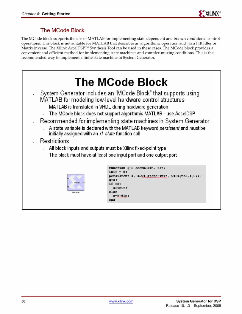
The MCode BlockThe MCode block supports the use of MATLAB for implementing state dependent and branch conditional control operations. This block is not suitable for MATLAB that describes an algorithmic operation such as a FIR filter or Matrix inverse. The Xilinx AccelDSP™ Synthesis Tool can be used in these cases. The MCode block provides a convenient and efficient method for implementing state machines and complex muxing conditions. This is the recommended way to implement a finite state machine in System Generator.
56 www.xilinx.com System Generator for DSPRelease 10.1.3 September, 2008
Lesson 3 - System ControlR
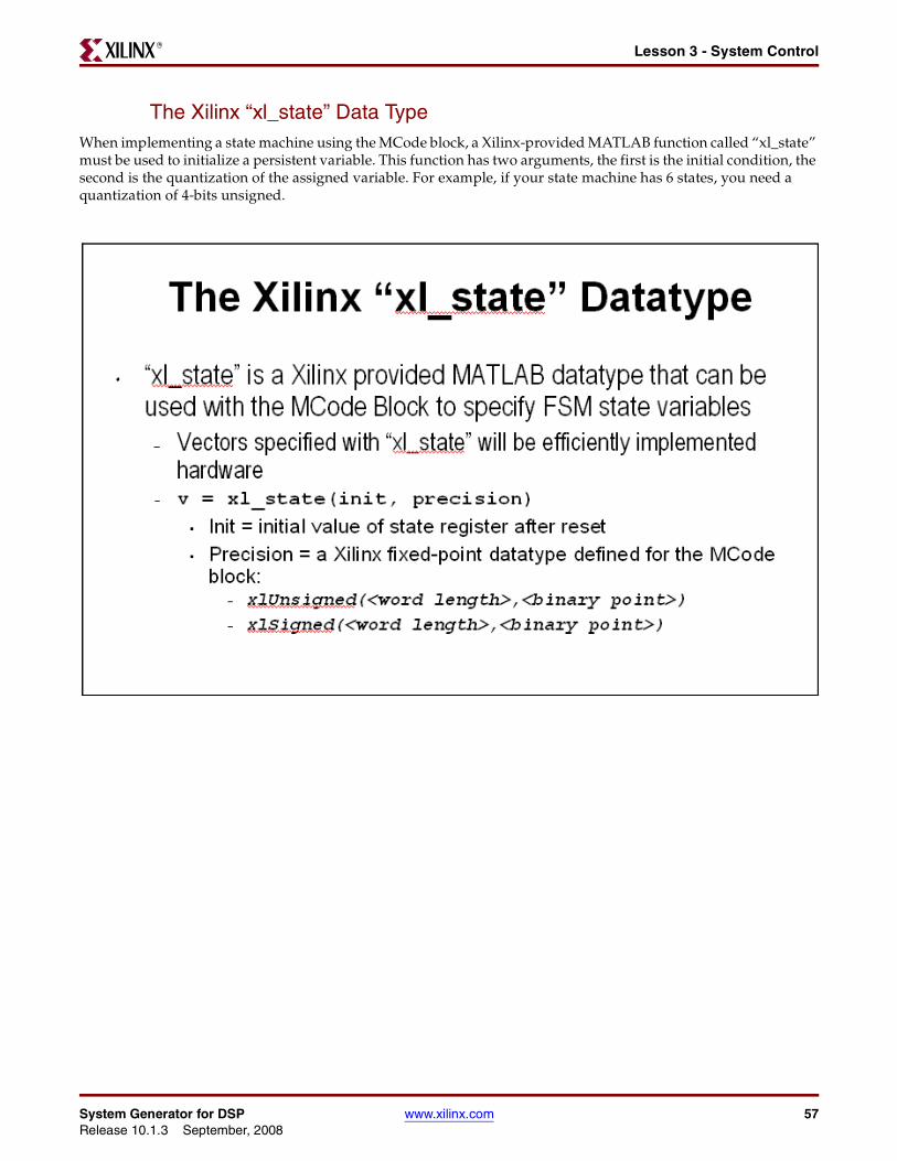
The Xilinx “xl_state” Data TypeWhen implementing a state machine using the MCode block, a Xilinx-provided MATLAB function called “xl_state” must be used to initialize a persistent variable. This function has two arguments, the first is the initial condition, the second is the quantization of the assigned variable. For example, if your state machine has 6 states, you need a quantization of 4-bits unsigned.
System Generator for DSP www.xilinx.com 57Release 10.1.3 September, 2008
Chapter 4: Getting StartedR
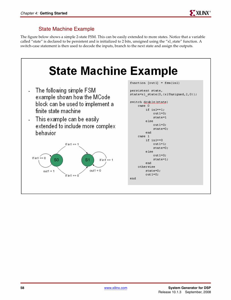
State Machine ExampleThe figure below shows a simple 2-state FSM. This can be easily extended to more states. Notice that a variable called “state” is declared to be persistent and is initialized to 2 bits, unsigned using the “xl_state” function. A switch-case statement is then used to decode the inputs, branch to the next state and assign the outputs.
58 www.xilinx.com System Generator for DSPRelease 10.1.3 September, 2008

Lesson 3 - System ControlR
The Expression BlockThe Expression block performs a bitwise not, and, or & xor on two input signals. The inputs can have a word length greater than 1. In cases where the two inputs have different word lengths, the binary points are matched up and then an element-by-element boolean operation is performed. This block provides a useful way to implement logical control in a DSP system
System Generator for DSP www.xilinx.com 59Release 10.1.3 September, 2008
Chapter 4: Getting StartedR
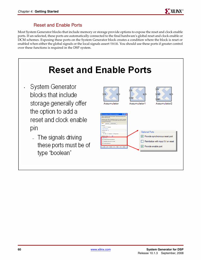
Reset and Enable PortsMost System Generator blocks that include memory or storage provide options to expose the reset and clock enable ports. If un-selected, these ports are automatically connected to the final hardware's global reset and clock enable or DCM schemes. Exposing these ports on the System Generator block creates a condition where the block is reset or enabled when either the global signals or the local signals assert TRUE. You should use these ports if greater control over these functions is required in the DSP system.
60 www.xilinx.com System Generator for DSPRelease 10.1.3 September, 2008
Lesson 3 - System ControlR
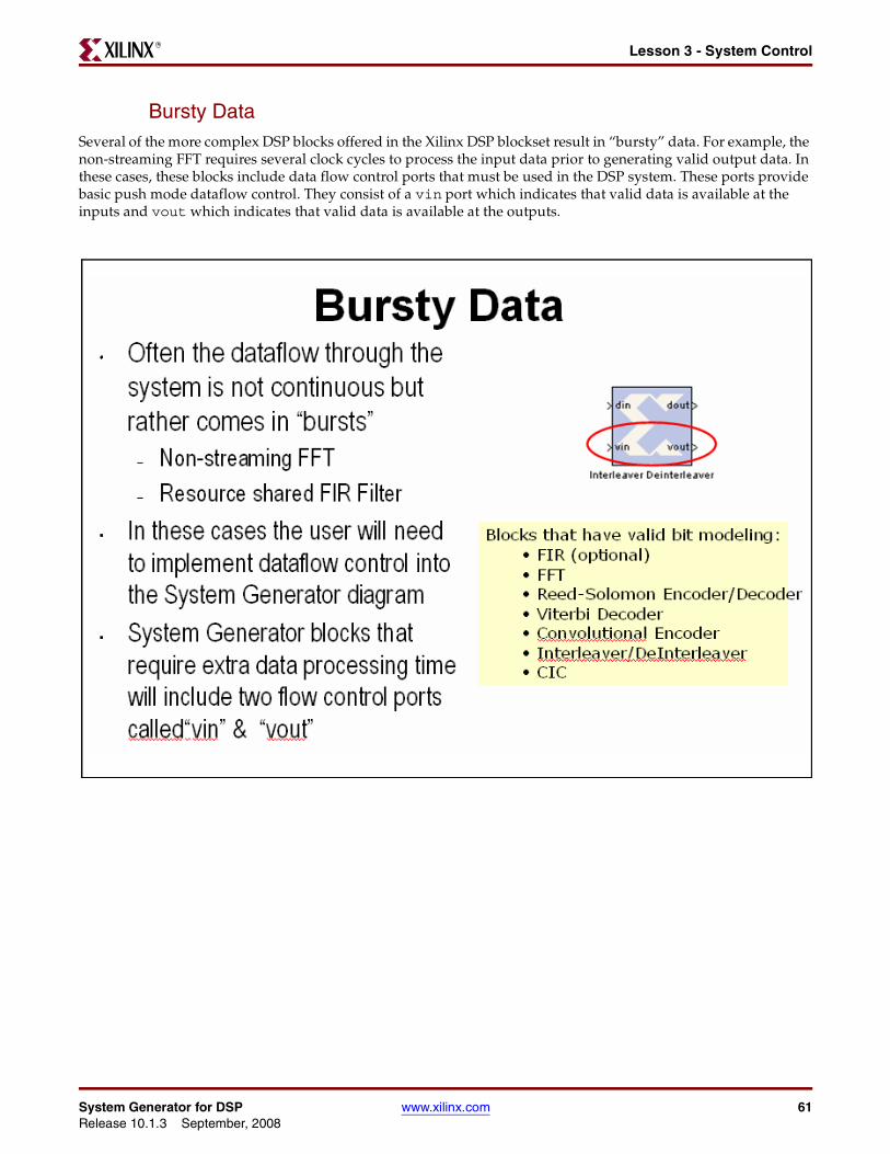
Bursty DataSeveral of the more complex DSP blocks offered in the Xilinx DSP blockset result in “bursty” data. For example, the non-streaming FFT requires several clock cycles to process the input data prior to generating valid output data. In these cases, these blocks include data flow control ports that must be used in the DSP system. These ports provide basic push mode dataflow control. They consist of a vin port which indicates that valid data is available at the inputs and vout which indicates that valid data is available at the outputs.
System Generator for DSP www.xilinx.com 61Release 10.1.3 September, 2008
Chapter 4: Getting StartedR
Lesson 3 Summary• Use the MCode block for state machines and branch conditional logic
• Use the Expression block to implement logical control at the bit level
• Storage elements have the ability to include optional reset and clock enable pins that can be connected in System Generator
• Blocks that operate on bursty data include data flow control pins called vin and vout
Lab Exercise: System ControlIn this lab you will be creating a simple state machine using the MCode block to detect a sequence of binary values “1011”. The FSM needs to be able to detect multiple transmissions as well, i.e., “10111011”
The lab data and instructions are located in the System Generator software tree at the following pathname:
...<sysgen_tree>/examples/getting_started_training/lab4/
62 www.xilinx.com System Generator for DSPRelease 10.1.3 September, 2008
Lesson 4 - Multi-Rate SystemsR
Lesson 4 - Multi-Rate Systems
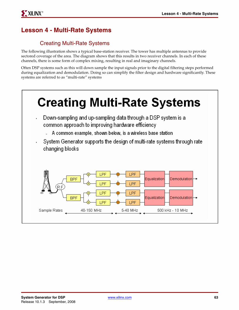
Creating Multi-Rate SystemsThe following illustration shows a typical base-station receiver. The tower has multiple antennas to provide sectored coverage of the area. The diagram shows that this results in two receiver channels. In each of these channels, there is some form of complex mixing, resulting in real and imaginary channels.
Often DSP systems such as this will down sample the input signals prior to the digital filtering steps performed during equalization and demodulation. Doing so can simplify the filter design and hardware significantly. These systems are referred to as “multi-rate” systems
System Generator for DSP www.xilinx.com 63Release 10.1.3 September, 2008
Chapter 4: Getting StartedR
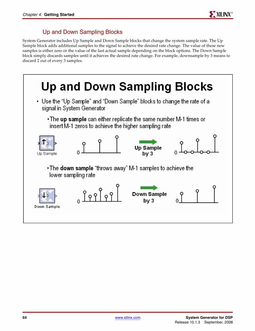
Up and Down Sampling BlocksSystem Generator includes Up Sample and Down Sample blocks that change the system sample rate. The Up Sample block adds additional samples to the signal to achieve the desired rate change. The value of these new samples is either zero or the value of the last actual sample depending on the block options. The Down Sample block simply discards samples until it achieves the desired rate change. For example, downsample by 3 means to discard 2 out of every 3 samples.
64 www.xilinx.com System Generator for DSPRelease 10.1.3 September, 2008
Lesson 4 - Multi-Rate SystemsR
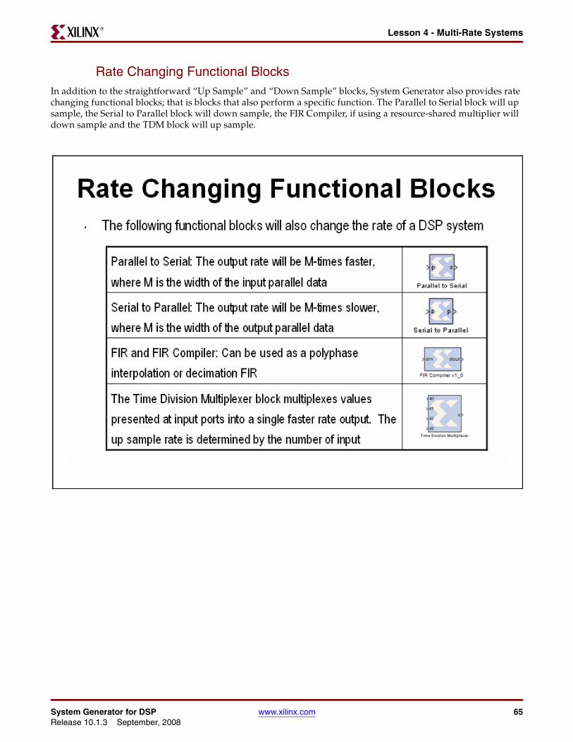
Rate Changing Functional BlocksIn addition to the straightforward “Up Sample” and “Down Sample” blocks, System Generator also provides rate changing functional blocks; that is blocks that also perform a specific function. The Parallel to Serial block will up sample, the Serial to Parallel block will down sample, the FIR Compiler, if using a resource-shared multiplier will down sample and the TDM block will up sample.
System Generator for DSP www.xilinx.com 65Release 10.1.3 September, 2008
Chapter 4: Getting StartedR
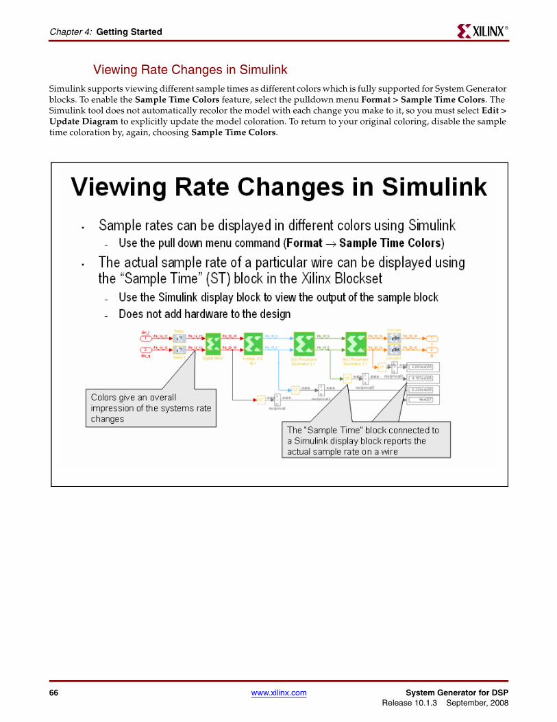
Viewing Rate Changes in SimulinkSimulink supports viewing different sample times as different colors which is fully supported for System Generator blocks. To enable the Sample Time Colors feature, select the pulldown menu Format > Sample Time Colors. The Simulink tool does not automatically recolor the model with each change you make to it, so you must select Edit > Update Diagram to explicitly update the model coloration. To return to your original coloring, disable the sample time coloration by, again, choosing Sample Time Colors.
66 www.xilinx.com System Generator for DSPRelease 10.1.3 September, 2008
Lesson 4 - Multi-Rate SystemsR
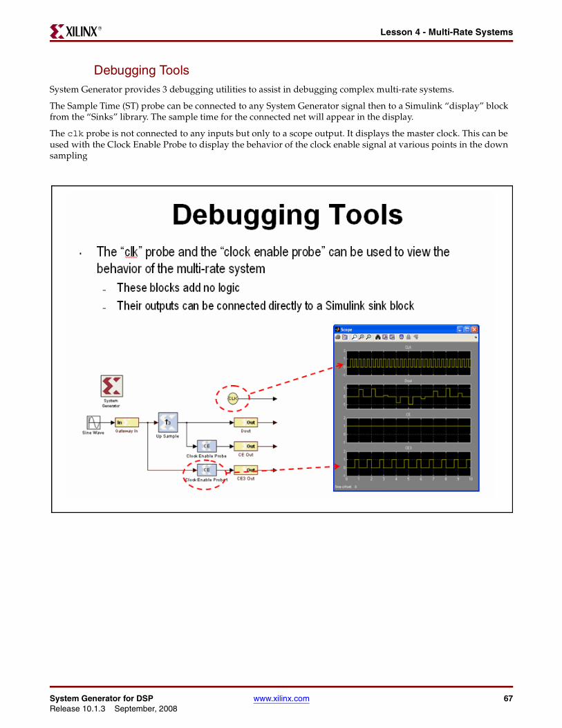
Debugging ToolsSystem Generator provides 3 debugging utilities to assist in debugging complex multi-rate systems.
The Sample Time (ST) probe can be connected to any System Generator signal then to a Simulink “display” block from the “Sinks” library. The sample time for the connected net will appear in the display.
The clk probe is not connected to any inputs but only to a scope output. It displays the master clock. This can be used with the Clock Enable Probe to display the behavior of the clock enable signal at various points in the down sampling
System Generator for DSP www.xilinx.com 67Release 10.1.3 September, 2008
Chapter 4: Getting StartedR
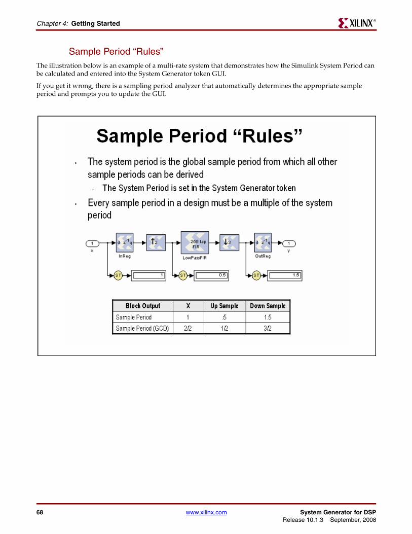
Sample Period “Rules”The illustration below is an example of a multi-rate system that demonstrates how the Simulink System Period can be calculated and entered into the System Generator token GUI.
If you get it wrong, there is a sampling period analyzer that automatically determines the appropriate sample period and prompts you to update the GUI.
68 www.xilinx.com System Generator for DSPRelease 10.1.3 September, 2008
Lesson 4 - Multi-Rate SystemsR
Lab Exercise: Multi-Rate SystemsIn this lab you will be exploring the effects of the rate changing blocks available in System Generator. These blocks include Upsample, Downsample, Serial to Parallel and Parallel to Serial.
The lab instructions and lab design are located in the System Generator software tree at the following pathname:
...<sysgen_tree>/examples/getting_started_training/lab5/
System Generator for DSP www.xilinx.com 69Release 10.1.3 September, 2008
Chapter 4: Getting StartedR
Lesson 5 - Using Memories
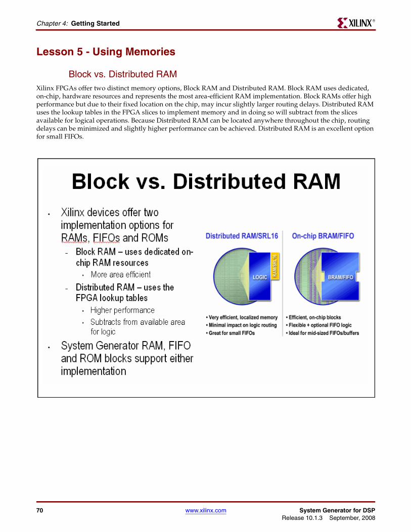
Block vs. Distributed RAMXilinx FPGAs offer two distinct memory options, Block RAM and Distributed RAM. Block RAM uses dedicated, on-chip, hardware resources and represents the most area-efficient RAM implementation. Block RAMs offer high performance but due to their fixed location on the chip, may incur slightly larger routing delays. Distributed RAM uses the lookup tables in the FPGA slices to implement memory and in doing so will subtract from the slices available for logical operations. Because Distributed RAM can be located anywhere throughout the chip, routing delays can be minimized and slightly higher performance can be achieved. Distributed RAM is an excellent option for small FIFOs.
70 www.xilinx.com System Generator for DSPRelease 10.1.3 September, 2008
Lesson 5 - Using MemoriesR
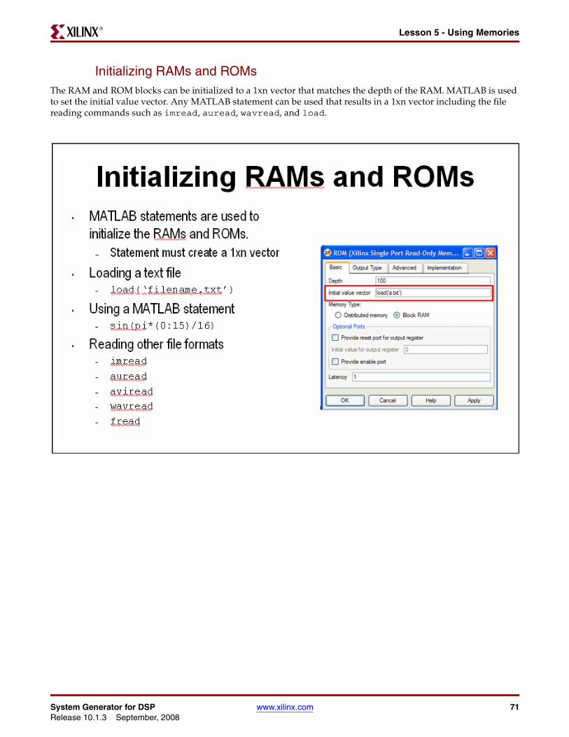
Initializing RAMs and ROMsThe RAM and ROM blocks can be initialized to a 1xn vector that matches the depth of the RAM. MATLAB is used to set the initial value vector. Any MATLAB statement can be used that results in a 1xn vector including the file reading commands such as imread, auread, wavread, and load.
System Generator for DSP www.xilinx.com 71Release 10.1.3 September, 2008
Chapter 4: Getting StartedR
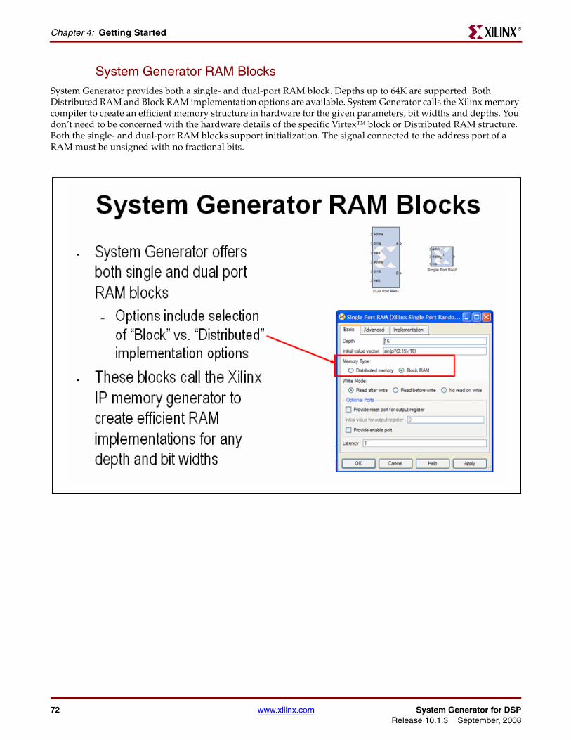
System Generator RAM BlocksSystem Generator provides both a single- and dual-port RAM block. Depths up to 64K are supported. Both Distributed RAM and Block RAM implementation options are available. System Generator calls the Xilinx memory compiler to create an efficient memory structure in hardware for the given parameters, bit widths and depths. You don’t need to be concerned with the hardware details of the specific Virtex™ block or Distributed RAM structure. Both the single- and dual-port RAM blocks support initialization. The signal connected to the address port of a RAM must be unsigned with no fractional bits.
72 www.xilinx.com System Generator for DSPRelease 10.1.3 September, 2008
Lesson 5 - Using MemoriesR
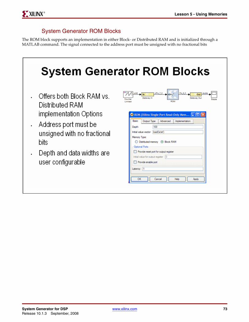
System Generator ROM BlocksThe ROM block supports an implementation in either Block- or Distributed RAM and is initialized through a MATLAB command. The signal connected to the address port must be unsigned with no fractional bits
System Generator for DSP www.xilinx.com 73Release 10.1.3 September, 2008
Chapter 4: Getting StartedR
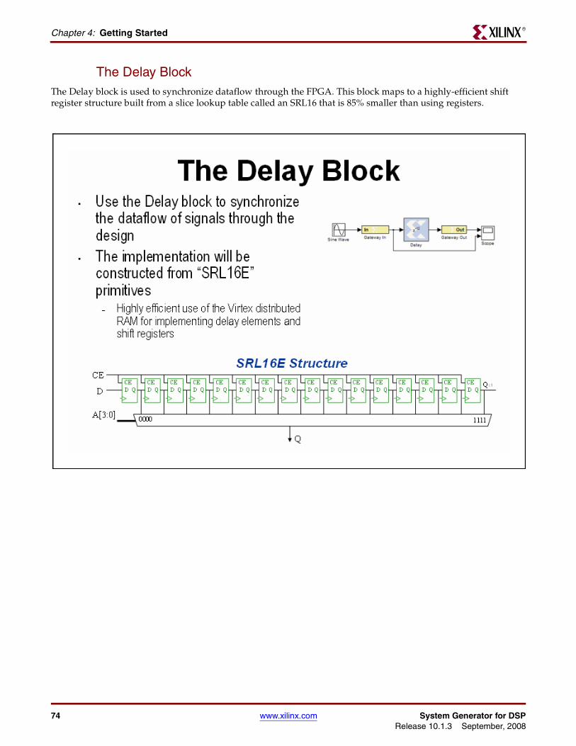
The Delay BlockThe Delay block is used to synchronize dataflow through the FPGA. This block maps to a highly-efficient shift register structure built from a slice lookup table called an SRL16 that is 85% smaller than using registers.
74 www.xilinx.com System Generator for DSPRelease 10.1.3 September, 2008
Lesson 5 - Using MemoriesR
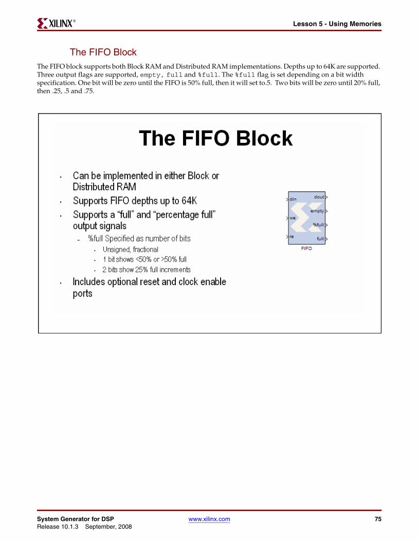
The FIFO BlockThe FIFO block supports both Block RAM and Distributed RAM implementations. Depths up to 64K are supported. Three output flags are supported, empty, full and %full. The %full flag is set depending on a bit width specification. One bit will be zero until the FIFO is 50% full, then it will set to.5. Two bits will be zero until 20% full, then .25, .5 and .75.
System Generator for DSP www.xilinx.com 75Release 10.1.3 September, 2008
Chapter 4: Getting StartedR
Lab Exercise: Using MemoriesIn this lab you will learn how to use a Xilinx ROM block to implement a LUT-based operation such as an Arcsin using Block RAM or Distributed RAM. This provides an efficient implementation for trig and math functions with inputs that can be quantized to 10 bits or less.
The lab instructions and lab design are located in the System Generator software tree at the following pathname:
...<sysgen_tree>/examples/getting_started_training/lab6/
76 www.xilinx.com System Generator for DSPRelease 10.1.3 September, 2008
Lesson 6 - Designing FiltersR
Lesson 6 - Designing Filters
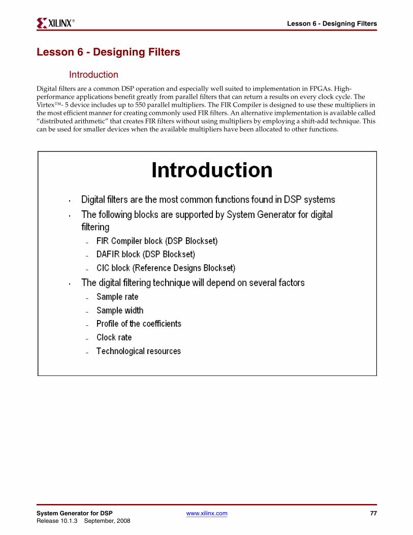
IntroductionDigital filters are a common DSP operation and especially well suited to implementation in FPGAs. High-performance applications benefit greatly from parallel filters that can return a results on every clock cycle. The Virtex™- 5 device includes up to 550 parallel multipliers. The FIR Compiler is designed to use these multipliers in the most efficient manner for creating commonly used FIR filters. An alternative implementation is available called “distributed arithmetic” that creates FIR filters without using multipliers by employing a shift-add technique. This can be used for smaller devices when the available multipliers have been allocated to other functions.
System Generator for DSP www.xilinx.com 77Release 10.1.3 September, 2008
Chapter 4: Getting StartedR
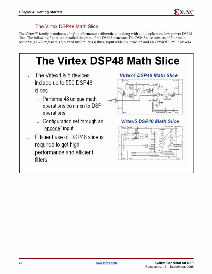
The Virtex DSP48 Math SliceThe Virtex™ family introduces a high-performance arithmetic unit along with a multiplier: the low-power DSP48 slice. The following figure is a detailed diagram of the DSP48 structure. The DSP48 slice consists of four main sections: (1) I/O registers, (2) signed multiplier, (3) three-input adder/subtractor, and (4) OPMODE multiplexers.
78 www.xilinx.com System Generator for DSPRelease 10.1.3 September, 2008
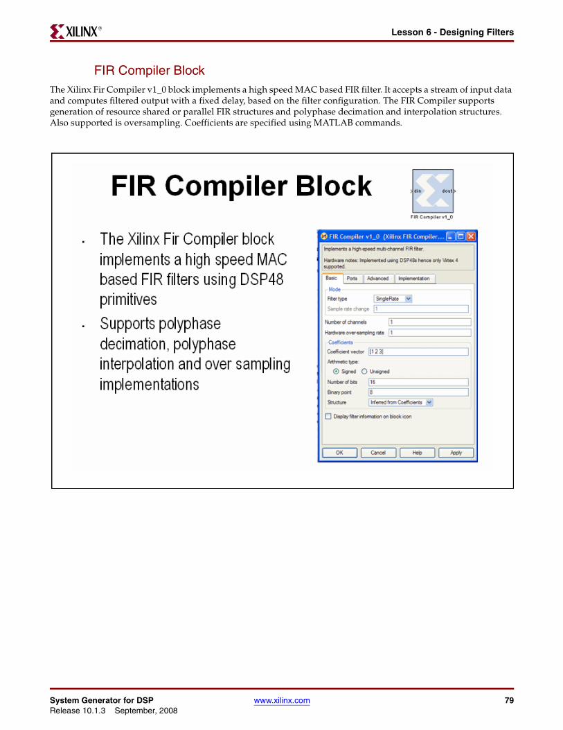
Lesson 6 - Designing FiltersR
FIR Compiler BlockThe Xilinx Fir Compiler v1_0 block implements a high speed MAC based FIR filter. It accepts a stream of input data and computes filtered output with a fixed delay, based on the filter configuration. The FIR Compiler supports generation of resource shared or parallel FIR structures and polyphase decimation and interpolation structures. Also supported is oversampling. Coefficients are specified using MATLAB commands.
System Generator for DSP www.xilinx.com 79Release 10.1.3 September, 2008
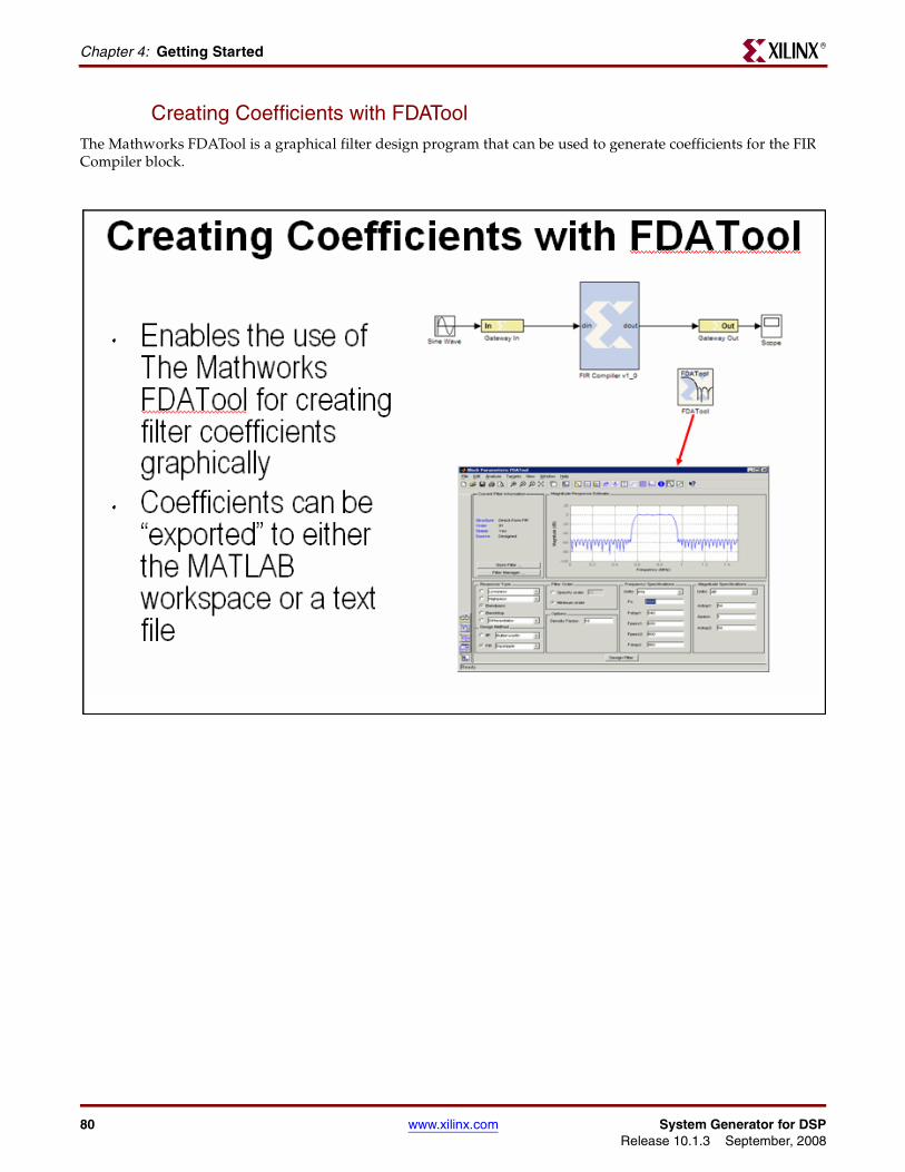
Chapter 4: Getting StartedR
Creating Coefficients with FDAToolThe Mathworks FDATool is a graphical filter design program that can be used to generate coefficients for the FIR Compiler block.
80 www.xilinx.com System Generator for DSPRelease 10.1.3 September, 2008
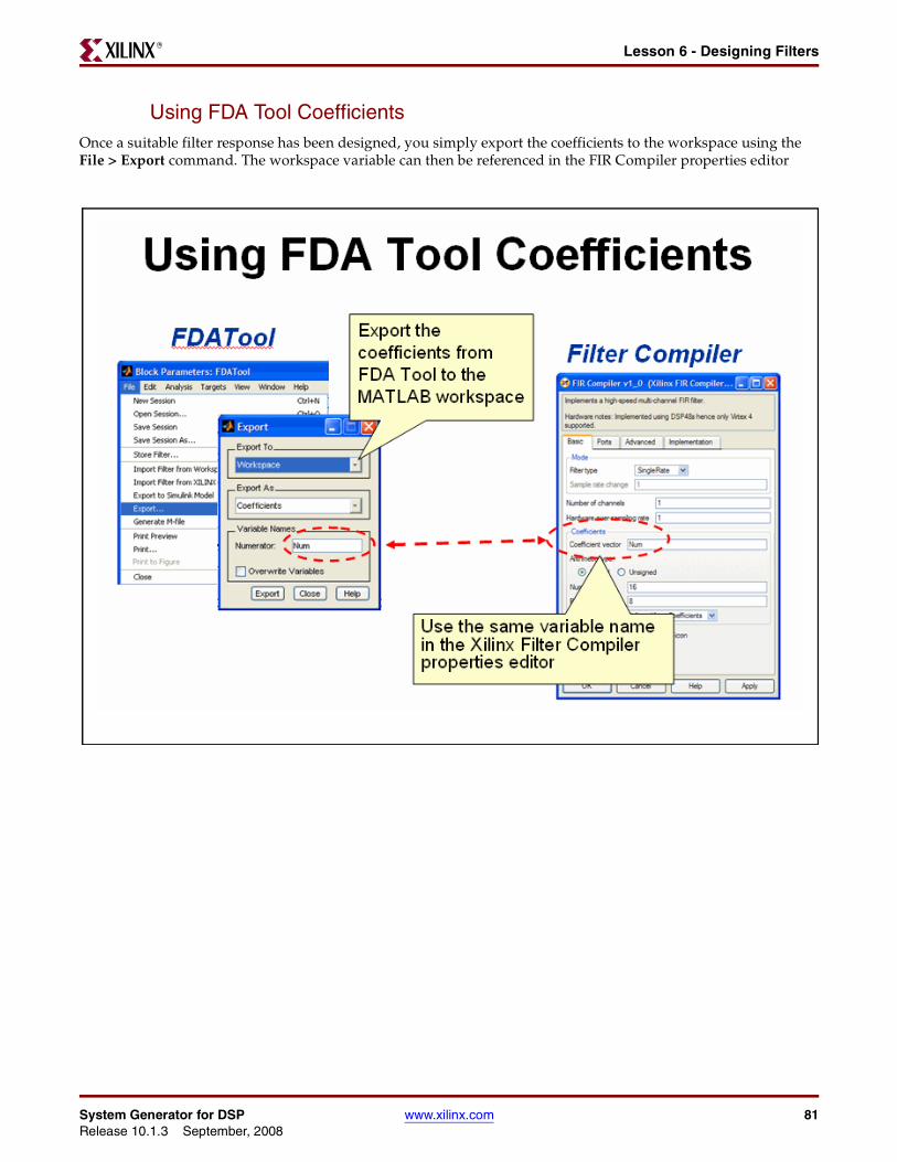
Lesson 6 - Designing FiltersR
Using FDA Tool CoefficientsOnce a suitable filter response has been designed, you simply export the coefficients to the workspace using theFile > Export command. The workspace variable can then be referenced in the FIR Compiler properties editor
System Generator for DSP www.xilinx.com 81Release 10.1.3 September, 2008
Chapter 4: Getting StartedR
Lab Exercise: Designing FiltersIn this lab you will be using the Filter Compiler block to generate optimized filters for the Virtex™-4 architecture.
The lab instructions and lab design are located in the System Generator software tree at the following pathname:
...<sysgen_tree>/examples/getting_started_training/lab7/
82 www.xilinx.com System Generator for DSPRelease 10.1.3 September, 2008
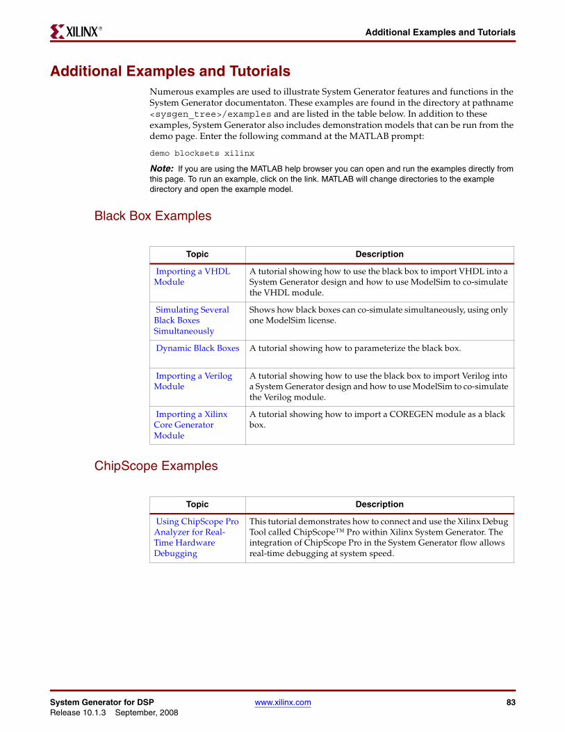
Additional Examples and TutorialsR
Additional Examples and TutorialsNumerous examples are used to illustrate System Generator features and functions in the System Generator documentaton. These examples are found in the directory at pathname <sysgen_tree>/examples and are listed in the table below. In addition to these examples, System Generator also includes demonstration models that can be run from the demo page. Enter the following command at the MATLAB prompt:
demo blocksets xilinx
Note: If you are using the MATLAB help browser you can open and run the examples directly from this page. To run an example, click on the link. MATLAB will change directories to the example directory and open the example model.
Black Box Examples
ChipScope Examples
Topic Description
Importing a VHDL Module
A tutorial showing how to use the black box to import VHDL into a System Generator design and how to use ModelSim to co-simulate the VHDL module.
Simulating Several Black Boxes Simultaneously
Shows how black boxes can co-simulate simultaneously, using only one ModelSim license.
Dynamic Black Boxes A tutorial showing how to parameterize the black box.
Importing a Verilog Module
A tutorial showing how to use the black box to import Verilog into a System Generator design and how to use ModelSim to co-simulate the Verilog module.
Importing a Xilinx Core Generator Module
A tutorial showing how to import a COREGEN module as a black box.
Topic Description
Using ChipScope Pro Analyzer for Real-Time Hardware Debugging
This tutorial demonstrates how to connect and use the Xilinx Debug Tool called ChipScope™ Pro within Xilinx System Generator. The integration of ChipScope Pro in the System Generator flow allows real-time debugging at system speed.
System Generator for DSP www.xilinx.com 83Release 10.1.3 September, 2008
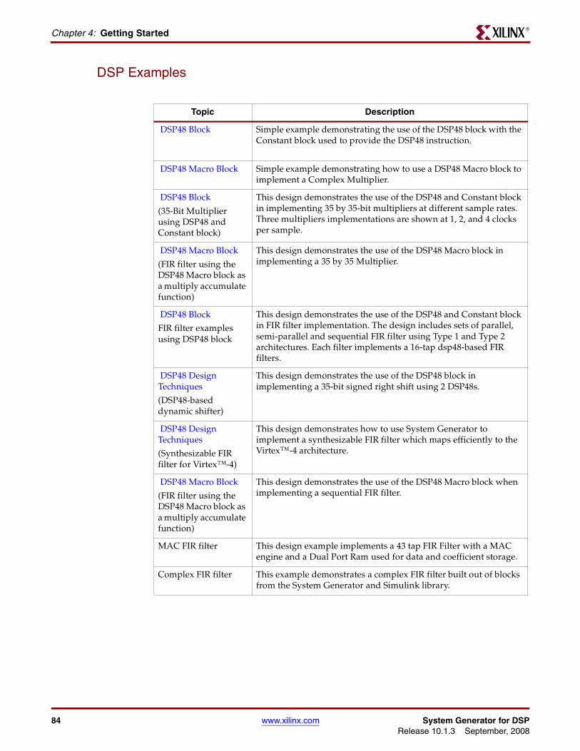
Chapter 4: Getting StartedR
DSP Examples
Topic Description
DSP48 Block Simple example demonstrating the use of the DSP48 block with the Constant block used to provide the DSP48 instruction.
DSP48 Macro Block Simple example demonstrating how to use a DSP48 Macro block to implement a Complex Multiplier.
DSP48 Block
(35-Bit Multiplier using DSP48 and Constant block)
This design demonstrates the use of the DSP48 and Constant block in implementing 35 by 35-bit multipliers at different sample rates. Three multipliers implementations are shown at 1, 2, and 4 clocks per sample.
DSP48 Macro Block
(FIR filter using the DSP48 Macro block as a multiply accumulate function)
This design demonstrates the use of the DSP48 Macro block in implementing a 35 by 35 Multiplier.
DSP48 Block
FIR filter examples using DSP48 block
This design demonstrates the use of the DSP48 and Constant block in FIR filter implementation. The design includes sets of parallel, semi-parallel and sequential FIR filter using Type 1 and Type 2 architectures. Each filter implements a 16-tap dsp48-based FIR filters.
DSP48 Design Techniques
(DSP48-based dynamic shifter)
This design demonstrates the use of the DSP48 block in implementing a 35-bit signed right shift using 2 DSP48s.
DSP48 Design Techniques
(Synthesizable FIR filter for Virtex™-4)
This design demonstrates how to use System Generator to implement a synthesizable FIR filter which maps efficiently to the Virtex™-4 architecture.
DSP48 Macro Block
(FIR filter using the DSP48 Macro block as a multiply accumulate function)
This design demonstrates the use of the DSP48 Macro block when implementing a sequential FIR filter.
MAC FIR filter This design example implements a 43 tap FIR Filter with a MAC engine and a Dual Port Ram used for data and coefficient storage.
Complex FIR filter This example demonstrates a complex FIR filter built out of blocks from the System Generator and Simulink library.
84 www.xilinx.com System Generator for DSPRelease 10.1.3 September, 2008
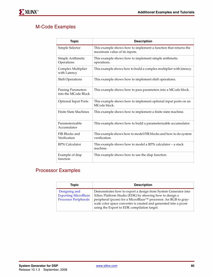
Additional Examples and TutorialsR
M-Code Examples
Processor Examples
Topic Description
Simple Selector This example shows how to implement a function that returns the maximum value of its inputs.
Simple Arithmetic Operations
This example shows how to implement simple arithmetic operations.
Complex Multiplier with Latency
This example shows how to build a complex multiplier with latency.
Shift Operations This example shows how to implement shift operations.
Passing Parameters into the MCode Block
This example shows how to pass parameters into a MCode block.
Optional Input Ports This example shows how to implement optional input ports on an MCode block.
Finite State Machines This example shows how to implement a finite state machine.
Parameterizable Accumulator
This example shows how to build a parameterizable accumulator.
FIR Blocks and Verification
This example shows how to model FIR blocks and how to do system verification.
RPN Calculator This example shows how to model a RPN calculator – a stack machine.
Example of disp function
This example shows how to use the disp function.
Topic Description
Designing and Exporting MicroBlaze Processor Peripherals
Demonstrates how to export a design from System Generator into Xilinx Platform Studio (EDK) by showing how to design a peripheral (pcore) for a MicroBlaze™ processor. An RGB to gray-scale color space converter is created and generated into a pcore using the Export to EDK compilation target.
System Generator for DSP www.xilinx.com 85Release 10.1.3 September, 2008
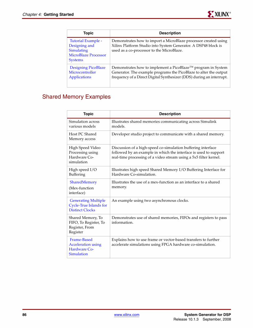
Chapter 4: Getting StartedR
Shared Memory Examples
Tutorial Example - Designing and Simulating MicroBlaze Processor Systems
Demonstrates how to import a MicroBlaze processor created using Xilinx Platform Studio into System Generator. A DSP48 block is used as a co-processor to the MicroBlaze.
Designing PicoBlaze Microcontroller Applications
Demonstrates how to implement a PicoBlaze™ program in System Generator. The example programs the PicoBlaze to alter the output frequency of a Direct Digital Synthesizer (DDS) during an interrupt.
Topic Description
Topic Description
Simulation across various models
Illustrates shared memories communicating across Simulink models.
Host PC Shared Memory access
Developer studio project to communicate with a shared memory.
High Speed Video Processing using Hardware Co-simulation
Discussion of a high-speed co-simulation buffering interface followed by an example in which the interface is used to support real-time processing of a video stream using a 5x5 filter kernel.
High speed I/O Buffering
Illustrates high speed Shared Memory I/O Buffering Interface for Hardware Co-simulation.
SharedMemory
(Mex-function interface)
Illustrates the use of a mex-function as an interface to a shared memory.
Generating Multiple Cycle-True Islands for Distinct Clocks
An example using two asynchronous clocks.
Shared Memory, To FIFO, To Register, To Register, From Register
Demonstrates use of shared memories, FIFOs and registers to pass information.
Frame-Based Acceleration using Hardware Co-Simulation
Explains how to use frame or vector-based transfers to further accelerate simulations using FPGA hardware co-simulation.
86 www.xilinx.com System Generator for DSPRelease 10.1.3 September, 2008
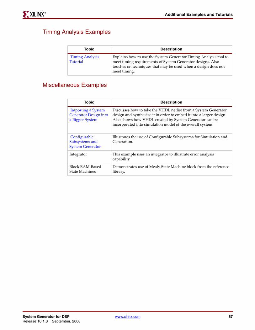
Additional Examples and TutorialsR
Timing Analysis Examples
Miscellaneous Examples
Topic Description
Timing Analysis Tutorial
Explains how to use the System Generator Timing Analysis tool to meet timing requirements of System Generator designs. Also touches on techniques that may be used when a design does not meet timing.
Topic Description
Importing a System Generator Design into a Bigger System
Discusses how to take the VHDL netlist from a System Generator design and synthesize it in order to embed it into a larger design. Also shows how VHDL created by System Generator can be incorporated into simulation model of the overall system.
Configurable Subsystems and System Generator
Illustrates the use of Configurable Subsystems for Simulation and Generation.
Integrator This example uses an integrator to illustrate error analysis capability.
Block RAM-Based State Machines
Demonstrates use of Mealy State Machine block from the reference library.
System Generator for DSP www.xilinx.com 87Release 10.1.3 September, 2008
Chapter 4: Getting StartedR
System Generator DemosSystem Generator for DSP provides the capability to model and implement high-performance DSP systems in field- programmable gate arrays (FPGAs) using Simulink. The Xilinx Blockset contains bit and cycle-true models of arithmetic and logic functions, memories, and DSP functions for digital filtering, spectral analysis, and digital communications. System Generator converts a Simulink model of Xilinx blocks into an efficient hardware implementation that combines synthesizable VHDL and intellectual property blocks that have been hand-crafted to run efficiently in FPGAs.
Included with the tool are numerous demonstration designs that highlight key features and tool capabilities, as well as general good design practices using real-world design applications. These designs may be accessed from the System Generator demo page. Enter the following command at the MATLAB prompt:
demo blocksets xilinx
88 www.xilinx.com System Generator for DSPRelease 10.1.3 September, 2008
System Generator for DSP www.xilinx.com 89Release 10.1.3 September, 2008
CCompatibility
MATLAB 25, 28, 30, 32ModelSim 25, 28, 30, 32Synplify Pro 25, 28, 30, 32
CompilingXilinx HDL Libraries 22
Configuringthe Sysgen cache 22
DDownloading
System Generator 19
HHardware Co-Sim
installation 20
IInstallation
Hardware Co-Sim 20software prerequisites 20
ISE Design Suite Installer 20
MMATLAB 25, 28, 30, 32ModelSim 25, 28, 30, 32
SSystem Generator
Cache 22changing versions 22displaying versions 22downloading the software 19ISE Design Suite Installer 20
System Generator UtilitiesxlUpdateModel 33
XXilinx HDL Libraries
compiling 22
xlUpdateModel 33
Index