
System Configuration in Design Automation - DIVA
75
IN DEGREE PROJECT MECHANICAL ENGINEERING, SECOND CYCLE, 30 CREDITS , STOCKHOLM SWEDEN 2019 System Configuration in Design Automation SÓLRÚN TRAUSTADÓTTIR KTH ROYAL INSTITUTE OF TECHNOLOGY SCHOOL OF INDUSTRIAL ENGINEERING AND MANAGEMENT
-
Upload
khangminh22 -
Category
Documents
-
view
1 -
download
0
Transcript of System Configuration in Design Automation - DIVA

IN DEGREE PROJECT MECHANICAL ENGINEERING,SECOND CYCLE, 30 CREDITS
, STOCKHOLM SWEDEN 2019
System Configuration in Design Automation
SÓLRÚN TRAUSTADÓTTIR
KTH ROYAL INSTITUTE OF TECHNOLOGYSCHOOL OF INDUSTRIAL ENGINEERING AND MANAGEMENT


System Configuration in DesignAutomation
Author
Sólrún Traustadóttir
KTH Royal Institute of Technology
School of Industrial Engineering and Management
MG213X Degree Project in Production Engineering and Management
Stockholm
June 2019
Abstract
Some companies have managed to gain an advantage in today’s increasingly
competitive market by utilizing product configuration software. However, many
companies in the industrial manufacturing industry offer systems of configurable
products and wish to be able to configure the products both individually and
together as a system.
The project described in this thesis was carried out at Tacton Systems, a provider
of sales and product configuration software. This project aims to contribute
to the literature knowledge on system configuration by researching, through
literature study and interviews, what types of systems companies want to be
able to configure, and what relationships or interfaces are needed between the
configurable modules forming the system.
The result was that it is possible to look at each system in levels of abstraction.
When looking at whole systems, the system structures can be split into two types,
i.e., linear systems and central systems. Parameters need to be communicated
between the modules in the system. The module interfaces defined in the Tacton
model could carry enough information to establish the necessary relationships
between the modules and thus make different parameter types irrelevant.
Furthermore, this project investigates different aspects of how Computer Aided
Design (CAD) models for system configuration in SolidWorks need to be
structured to work in a robust way for design automation. Different functions
were tried on a relatively simple model as a proof of concept. The main result is
that the most robust way to do the mates between the configurable components is
to assign them to reference geometry that is built into templates.
This project focused on investigating the possibility for system configuration in
the design automation environment, but it is necessary for Tacton to look at the
future development in a holistic view.
ii
Sammanfattning
Vissa företag har lyckats skapa en fördel i dagens alltmer konkurrensutsatta
marknad genom att använda produktkonfigurationsprogram. Många företag
inom industrin tillverkar dock hela system med konfigurbara produkter och vill
därför kunna konfigurera produkterna både individuellt och tillsammans som ett
system.
Projektet som beskrivs i denna avhandling utfördes hos Tacton Systems, en
leverantör av försäljnings- och produktkonfigurationsprogram. Avhandlingen
syftar till att bidra till litteraturkunskapen om systemkonfiguration genom att
undersöka vilka typer av system företag vill kunna konfigurera, och vilka
relationer eller gränssnitt som behövs mellan de konfigurbara modulerna som
bildar systemet. För att åstadkomma detta genomfördes en studie av litteratur
och intervjuer.
Resultatet var att det är möjligt att titta på varje system i abstraktionsnivåer.
När man tittar på hela system kan systemstrukturerna delas upp i två typer;
linjära system och centrala system. Parametrar måste kommuniceras mellan
modulerna i systemet. Modulgränssnittet som definieras i Tacton-modellen
kan bära tillräckligt information för att upprätta nödvändiga relationer mellan
modulerna och därigenom göra olika parametertyper irrelevanta.
Dessutom undersökte jag i denna avhandling olika aspekter på hur CAD-modeller
för systemkonfiguration i SolidWorks behöver struktureras för att fungera på
ett robust sätt för designautomatisering. Olika metoder prövades på en relativt
enkel modell som ett bevis på konceptet. Huvudresultatet är att det mest robusta
sättet att göra relationer mellan de konfigurbara komponenterna är använda
referensgeometri som är inbyggd i mallar.
Projektet fokuserade på att undersöka möjligheten för systemkonfiguration i
Design Automation-miljön, men det är nödvändigt för Tacton att se på framtida
utveckling i en helhetssyn.
iii
Acknowledgements
I would like to thank Tacton Systems for giving me the opportunity and all the
resources and help I needed to conduct my thesis at the company. I would
especially like to thank my industry supervisor, Mathias Storm, for his support
throughout the project work. Furthermore, I would like to thank all the employees
at Tacton for warmly welcoming me during my time there, many offering great
advice and guidance.
Special thanks go to all of the interviewees that took their time to contribute to
this study.
Last but not least, I would like to thank my academic supervisor, Lars Wingård,
for his guidance while supervising this thesis project.
iv

Author
Solrun [email protected] Engineering and ManagementKTH Royal Institute of TechnologyStockholm, Sweden
Academic Supervisor
Lars WingårdKTH Royal Institute of Technology
Industrial Supervisor
Mathias StormTacton Systems AB
Contents
1 Introduction 11.1 Background . . . . . . . . . . . . . . . . . . . . . . . . . . . . . . . . 1
1.2 Tacton Systems and its Software Solutions . . . . . . . . . . . . . . 2
1.3 Problem Description . . . . . . . . . . . . . . . . . . . . . . . . . . . 3
1.4 Research Questions . . . . . . . . . . . . . . . . . . . . . . . . . . . 5
1.5 Delimitations . . . . . . . . . . . . . . . . . . . . . . . . . . . . . . . 5
1.6 Outline . . . . . . . . . . . . . . . . . . . . . . . . . . . . . . . . . . 6
2 Methodology 72.1 Literature Study . . . . . . . . . . . . . . . . . . . . . . . . . . . . . 7
2.2 Software Study . . . . . . . . . . . . . . . . . . . . . . . . . . . . . . 7
2.3 Interviews . . . . . . . . . . . . . . . . . . . . . . . . . . . . . . . . . 7
3 Literature Study 93.1 Product Configuration . . . . . . . . . . . . . . . . . . . . . . . . . . 9
3.2 System Configuration . . . . . . . . . . . . . . . . . . . . . . . . . . 11
3.3 Modularisation . . . . . . . . . . . . . . . . . . . . . . . . . . . . . . 12
3.4 Design Automation . . . . . . . . . . . . . . . . . . . . . . . . . . . 13
4 Software Study 154.1 Tacton Design Automation . . . . . . . . . . . . . . . . . . . . . . . 15
4.2 Partners and Competitors . . . . . . . . . . . . . . . . . . . . . . . . 25
4.3 Designing in CAD for Design Automation . . . . . . . . . . . . . . . 28
4.4 Designing in CAD for System Configuration . . . . . . . . . . . . . . 29
5 Interviews 395.1 The Need for System Configuration . . . . . . . . . . . . . . . . . . 39
5.2 How to do System Configuration . . . . . . . . . . . . . . . . . . . . 40
5.3 Customers Using Layout Mode . . . . . . . . . . . . . . . . . . . . . 43
5.4 System Configuration in Tacton - A Holistic View . . . . . . . . . . 46
6 Results and Conclusions 476.1 Types of Systems . . . . . . . . . . . . . . . . . . . . . . . . . . . . . 47
6.2 Relationships Between Modules Within a System . . . . . . . . . . 52
vi

6.3 Building Assemblies for System Configuration . . . . . . . . . . . . 54
7 Discussion and Future Work 57
References 59
vii
1 Introduction
This chapter provides an introduction to the area of the thesis. This chapter
also presents a background on the external project provider, Tacton Systems AB.
Furthermore, the focus and the objective of the thesis is presented, leading to
the research questions. Finally, the structure of the thesis report is presented for
guidance.
1.1 Background
Customers have for a long time enjoyed the benefits of mass production such
as low cost, high quality, and fast product delivery. However, customers are
progressively expecting companies to offer customized products while keeping
the benefits of mass production. It is challenging for companies to successfully
respond to these changes in expectations because with growing customization
comes growing complexity. The term ”mass customization” refers to combining
customization with the benefits of mass production (Tseng & Hu 2014). For
companies to aim at mass customization, they need to act fast and operate
efficiently.
Some companies have achieved a competitive advantage, offering customized
products efficiently by implementing and using product configuration systems
(PCS) (Myrodia et al. 2017, Forza & Salvador 2002). Product configuration,
also known as knowledge-based configuration, refers to combining predefined
components in different ways to enable customization of a product (Orsvärn &
Axling 1999). The product configuration process is performed in PCS software,
also referred to as configurators. Product configuration is executed by choosing
from component variants and assigning values to parameters, to determine the
specific requirements of the final product. The amount of possible solutions
for a configured product rises exponentially with the number of available
components and component variants for the product. The components that
are combined adhere to predefined constraints (Sabin & Weigel 1998) that are
specified in the PCS along with all other product knowledge, such as available
1

component variants. The constraints can be defined for various reasons such as
technical restrictions, manufacturing limitations, or economic aspects. Artificial
Intelligence (AI) has for a long time been used in product configuration for
complex products (Sabin & Weigel 1998, Haug et al. 2012). A configuration
engine evaluates the constraints and makes sure that only possible solutions can
be selected, using AI techniques.
Product configuration can be applied in various scenarios for different purposes.
It can be used in sales to generate a correct sales bill-of-materials (SBOM) and
for creating quotations instantly. It can also create different types of BOMs such
as engineering BOM (EBOM), manufacturing BOM (MBOM) and service BOM,
including different kinds of product specifications such as lead-time calculations
and production instructions. Furthermore, product configuration can be used in
DesignAutomation (DA)where the configurationmodel is connected toComputer
Aided Design (CAD) software. It can be used early in the DA process to generate
simplified CAD files that can, e.g., be used for material quotation. It can also be
used later in the process during the product configuration. Then it is possible
to see the product change in real time as the product gets configured, and CAD
models and drawings for design engineers and manufacturing are generated
automatically. In the engineer-to-order (ETO) sector, where the products are
developed or modified to each customers’ specification and much time is spent
on design-related tasks, using DA is a very efficient way to shorten lead time,
to reduce cost and to maintain or even to improve the quality (Verhagen et al.
2012).
1.2 Tacton Systems and its Software Solutions
This thesis project was carried out at Tacton Systems AB, henceforward called
Tacton. Tacton is a provider of sales and product configuration software and
services. It started in 1987 as a research project on the application of Artificial
Intelligence (AI) to solve industry challenges and was founded as a company
in 1998. Today, as a result of over 20 years of AI development, Tacton offers
a highly sophisticated configurator, serving customers across the globe (Tacton
2019). Tacton has over 250 employees, where the majority work with Tacton
2

Configure Price Quote (CPQ). Tacton offers their own configurator that manages
advanced pricemodels and a quotation tool, Tacton CPQ, that enables sales teams
to configure the product according to the customers’ needs. The configurator
engine checks and validates the entire solution after each choice, ensuring that
the solution is always absolutely correct. Tacton CPQ delivers correct product
specifications instantly down to the BOM level. Tacton also offers other software
solutions, and one of them is Tacton Design Automation (DA). Tacton DA is a
configurator software connected to a CAD system. It enables configuration of
products and an automatic generation of complete 3D models and 2D drawings
with the correct dimensions and specifications. Tacton DA can also be used
in conjunction with CPQ, as a back-end CAD server, generating the CAD files
automatically during the sales process in CPQ. Tacton DA is, like CPQ, connected
to the configurator engine, so the entire solution is validated after each choice
is made, eliminating costly design errors. Tacton DA is available for different
CAD systems, more precisely, SolidWorks, Autodesk Inventor, and PTC Creo.
Using Tacton DA to automate repetitive engineering design work can reduce the
engineering hours drastically, allowing engineers to spend their time on other
tasks, such as innovation and product development.
1.3 Problem Description
Tacton DA has had its primary focus on product configuration where complex
products can easily be customized and modeled according to the customers’
needs. It is a developed software that can create 3D models and 2D drawings
of these configurable products. However, there is a need to expand Tacton DA’s
capabilities.
Customers want to be able to build entire systems of configurable products.
A typical example are customers that offer factory layouts of machines and
conveyors. Eachmachine and conveyor needs to be individually configurable, but
they also need to match each other and fit together. In other words, eachmachine
and each conveyor should be configured individually, but they should also be able
to communicate with surrounding machines and conveyors.
3

During the literature study for this project, no common definition of a system
configuration in the context of product configuration could be found. To clarify
what is meant with system configuration in this thesis, the following definition is
used:
System configuration means to be able to combine configurable modules
together and make them communicate the relevant input and output values of
the surrounding modules, making sure that they fit together and run as a whole
system.
The systems that customers want to configure can vary significantly in complexity
and structure. They can be anything from the typical factory layout consisting
of multiple machine lines to simple cabins that all need to have the same height.
Systems do not necessarily need to be composed of many separate products that
are placed together. If one product consists of two or more configurable modules,
the product on its own can be a system.
Tacton has been able to meet the customers’ needs for building whole systems
of configurable products both in CPQ and DA. However, Tacton does not offer
a genuine system configuration as it is defined in this thesis, but instead, each
problem solution is restricted to the use of existing options. Tacton DA offers
a feature called ’Layout’. The Layout feature is only available for SolidWorks,
does not use the Tacton configurator engine to validate the compatibility between
nodes and is limited in its usage. The Layout feature and its limitations are
explained in detail in chapter 4.1.1. Although the Layout option has solved some of
the customers’ requirements for building systems, due to its limitations, it should
not be confused with system configuration as it is defined in this thesis.
By offering system configuration in Tacton DA, it will be possible to break
down large projects into smaller ones. That allows separate teams to work on
different parts of the solution simultaneously, resulting in shorter configuration
time. System configuration will result in significantly easier maintenance of
the solutions. By making system configuration in Tacton DA use the Tacton
configurator engine, the choices made will be verified by the engine so the
solutionswill always be correct. Additionally, it will allow for systemconfiguration
to be compatible with Tacton CPQ, which the Layout option is currently not.
4

Now, Tacton wants to look into the possibility to replace Layout with a system
configuration solution.
1.4 Research Questions
This thesis project aims to research if and how Tacton can create system
configuration functionality in Tacton DA to be able to meet the customers’ needs.
Various areas and aspects need to be investigated to answer how the new system
configurator should be designed. For the scope of this thesis work, three research
questions were defined:
1. What types of systems exist in the manufacturing industry?
To be able to answer that, it is necessary to understandwhat kind of products
do customers have that they would like to be able to realize and configure in
design automation.
2. What relationships or interfaces between parts, modules, and products are
needed?
3. How should CAD models be built and structured to work in a good and
robust way for system configuration?
1.5 Delimitations
The focus of the project work was on how Tacton should do system configuration
in their DA software. Therefore the project work is built on knowledge
from Tacton. Additionally, the research was limited to the SolidWorks CAD
environment but could easily be expanded to other CAD software such as
Autodesk Inventor or PTC Creo. SolidWorks offers a vast amount of features and
commands, and they can be combined in different ways to achieve different final
results. Only the aspects that the author considered relevant to CAD designs for
system configuration were investigated during the project work, but because of
the number of possible functions and aspects to consider, some options might
have been overlooked and not taken into consideration in this thesis project.
5

Furthermore, this research is limited to the features and commands available in
SolidWorks 2019.
This project only provides an investigation, and no implementation of a real
software solution was carried out during the project work.
1.6 Outline
Following this introduction is an explanation of the research methodology used
to answer the research questions during the thesis project work. Chapter 3 covers
a literature review of the main concepts and methods related to the topic of the
thesis. Chapter 4 includes a software study that can be further broken down
into an explanation of how Tacton DA works and how designers should build
their CAD models for system configuration. The relevant information gathered
during the interviews is reviewed in chapter 5 to gain deeper knowledge than
what was possible during the literature review and software study. The results and
conclusions after analyzing all the information gathered are presented in chapter
6. Finally, in chapter 7, the results are discussed along with the delimitations and
future work.
6

2 Methodology
The information collection can be divided into three main parts, i.e., a literature
study, software study, and an empirical study.
2.1 Literature Study
The literature study covers the study of available literature that is related to the
field that Tactonworks in, i.e., product configuration, that is relevant to this thesis
work.
2.2 Software Study
The software study consists of a thorough explanation of how Tactons’ DA
solution works and a state-of-the-art review of other solutions, similar to Tactons’
DA, that exist on the market today, with a particular focus on DA for system
configuration.
The software study also includes an investigation into how CAD models can be
built up to work in a robust way for system configuration. Information was
collected from CAD vendors and engineering companies. When the relevant
information had been collected and reviewed, the methods found where applied
on relatively simple CAD models as a proof of concept.
The focus of the investigation was put on the SolidWorks CAD environment. It
offers an official Web Help where it is possible to read and get instructions on
different functions that the software offers.
2.3 Interviews
The main goal of the interviews was to gain a deeper understanding of the
field of product configuration, to establish the need and requirements for
system configuration further, and to investigate the possibilities for system
configuration.
7

When companies are discussing the need for a new system, one of the first things
that should be established are the requirements of the new system (Hull et al.
2011). That way, the requirements can be used to guide and drive the development
process of the project. Hull et al. (2011) defined two domains for the requirements
layers; the problem domain and the solution domain, see figure 2.1.
Figure 2.1: The three requirements layers, split into two domains (Hull et al.2011)
Interviews were conducted with stakeholders to get their view on what they want
and expect from system configuration to be able to define the problem domain,
according to Hull et al. (2011) definition.
The interviews were conducted with various people that work with product
configuration in one way or another. That included both employees of Tacton
as well as Tactons’ customers. The list of interviewees can be found in Appendix
A.
All interviews were semi-structured, where a set of pre-defined questions were
asked, as well as opening up for new ideas and topics to be discussed. The
reason why the interview method of semi-structured interviews was chosen is
that the group of people that were interviewed had a very diverse background
and knowledge. The pre-defined questions were also changed according to who
was being interviewed in order to collect the relevant information. Additionally,
some of the pre-defined questions were very open and were only meant to guide
the interviewee to a certain path or theme and get the interviewee to speak freely
about the topic.
8
3 Literature Study
A literature review was performed to understand the problems described in
chapter 1.3 better and to acquire more knowledge about the subjects related to
the problems.
3.1 Product Configuration
Product configuration enables efficient customization of products. Product
configuration systems (PCS), also referred to as configurators, is the software
system used for product configuration. Each PCS usually has a so-called front
end where the user selects from predefined components and assigns values to
parameters, tailoring the product to the customers’ needs (Orsvärn & Axling
1999). The PCS contains all the product knowledge, such as the available
components and the predefined constraints. Product configuration utilizes AI
technologies to search for a valid configuration, making sure that the solution
is always correct and no unfeasible choices have been made (Sabin & Weigel
1998). An example of a product configuration is when a customer orders a new
customized car from a car manufacturer. The customer begins by choosing a car
model, then continues going through a list of choices, making other selections
such as the body type, color, transmission, and engine. Naturally, not all choices
fit together, e.g., if the customer selects an SUV, the engine types that the customer
can select from are not the same as if the customer would have selected a sports
car.
Product configuration can be a very useful tool that provides substantial benefits
for companies that decide to implement and use it (Myrodia et al. 2017, Forza
& Salvador 2002). Companies using a PCS can determine which product
specifications they want to automate the generation of, such as bills-of-materials,
manufacturing instructions, and drawings. Digitization and automation of sales
and engineering processes to generate the necessary product specifications results
in reduced lead-times, reduced costs, as well as increased quality (Haug et al.
2012).
9

Aiming for mass customization, the concept of offering customized products
at near mass manufacturing efficiency, is becoming increasingly important to
survive in today’s competitive market (Tseng & Hu 2014). Time, cost, and quality
are critical factors that companies need to attend to carefully. Configurators can
be the heart of a company’s mass customization strategy (Hvam 2006).
One of themost significant issues facedwithin the engineer-to-order (ETO) sector,
where the products are developed or modified to each customers’ specification, is
a long lead time (Hicks et al. 2000). That is because with increased customization
comes increased complexity, which results in increased time for all processes
that affect the lead time within the organization. The sales process is time-
consuming because of the time it takes to calculate and give quotation for a
customized product and many engineering hours are spent on design and the
creation of all relevant information such as production specifications, CADmodels
and drawings for the customized product. That is why implementing and using a
PCS in conjunction with DA is an efficient way to decrease lead times and reduce
costs (Verhagen et al. 2012). Myrodia et al. (2017) investigated the impact of PCS
and concluded that using PCS resulted in increased accuracy of cost calculations,
resulting in increased profitability.
Implementing and utilizing product configurators can also be a very efficient
way to manage the product knowledge in regards to the variety offered by the
companies (Forza & Salvador 2002). It is common and recommended that
companies that decide to implement product configurators, also modularise their
product range, if the products are not already module-based. Modularising the
product range is an efficient way of handling product complexity (Blackenfelt
2001). The concept of modularisation is explained further in chapter 3.3.
The benefits of implementing and using product configurators can be substantial.
When implementing PCS, it opens up for an opportunity to implement and use
DA simultaneously, that can be especially beneficial for ETO companies to reduce
the engineering hours spent on repetitive design tasks. Although the benefits are
apparent, far from all ETO companies use configurators. One of the reasons for
companies being hesitant to implement configurators is because of the challenges
they might face during the implementation and utilization (Forza & Salvador
10

2002).
The companies providing product configurators and academia are well aware
of the advantages of configurators as well as the challenges companies face
when implementing them. The configurators and the implementation processes
are therefore continuously being improved, and more and more companies
are acquiring PCS, gaining a competitive advantage by taking advantage of AI
technology and digitizing their sales and engineering processes.
3.2 System Configuration
Although a substantial amount of research exists on the subject, barely any
information can be found on the matter of system level configuration in the
context of product configuration. In fact, no definition of a system configuration
in this context could be found. Therefore, a definition was provided in chapter 1.3
in the introductory part of this thesis, to be used in this work.
Kristianto et al. (2015) wrote about the need to think about configuration
on the system level, and not only on the product level. Their proposal was
directed towards ETO companies that develop large complex products where
the configuration cannot be completed fully from the beginning. Uncertainty
can remain for various reasons such as incomplete product parameters, more
engineering work being required or multiple teams or even companies delivering
components for the product. One example of such a large complex product is a
ship, where the production takes a long time, and components are ordered from
various suppliers, and different teams work on different parts of the product.
What Kristianto et al. (2015) suggested was to use a system level configuration
to include the main building blocks and the interfaces containing the important
parameters and constraints. That way, it is possible to provide individual building
blocks to the complete design (Kristianto et al. 2015).
Kristianto et al. (2015) made a significant contribution to the research on system
configuration, but understandably did not cover all aspects of it. Other research
on the topic mainly consists of short chapters included in more extensive papers,
only scratching the surface of the subject. More research is needed on the topic of
11
system level configuration to understand what the market needs and how system
level configuration should be performed. This master thesis contributes to that
research, with a focus on a system-level configuration for DA.
3.3 Modularisation
Modularisation is the concept of combining various building blocks with well-
defined interfaces in different ways to satisfy varying requirements (Blackenfelt
2001). Modularisation is closely related to product configuration. To be able to
offer product configuration, it is necessary to have predefined components and
component variants. Modularisation is exactly about that. In a modular product,
the parts composing the product have been divided into so-calledmodules. When
configuring the product, it is possible to choose between anywhere from none to
multiple module variants for each module of the product.
Increased product variety often results in increased gross revenue. However,
it also results in increased overall cost (Blackenfelt 2001). That is why one
of the main challenges with handling the product variety using modularisation
is to choose the right level of variety. Some of the key activities involved in
modularisation is understanding what the customers want and being able to
translate the customers’ needs into technical solutions. Companies need to
analyze what the right level of variety is, to be able to offer what the customers
want, without the product becoming too costly.
When implementing PCS, all components and component variants must be
predefined to be able to offer product configuration. Therefore, it is recommended
that the companies that implement product configurators begin by modularising
their product range. The PCS will then manage the validity of the offered
structures. The PCS also handles the translation of customer needs into
the physical components that the final product consists of (Kristianto et al.
2015).
12

3.4 Design Automation
Design Automation (DA) refers to automating the design process by creating
general models that represent an entire class of objects (Amadori et al. 2012). The
main goalwithDA is to automate repetitive engineeringmodeling tasks (Verhagen
et al. 2012, Cederfeldt & Elgh 2005). By combining DA with the concept of
product configuration, it is possible to create configurationmodels that include all
necessary knowledge and to control both CADmodels and CAD drawings through
it. The way Tacton performs DA is explained in detail in chapter 4.1.
3.4.1 SolidWorks Application Programming Interface
Application Programming Interfaces (API) are used to enable communication
between software programs. The API contains the communication methods
between components, i.e., a set of functions and procedures, that enable
information to be accessed by an external program. That way, it is possible to
perform actions in the software without using the user interface of the software.
The structure and contents of each API can vary greatly.
The SolidWorks API enables developers to create code and automate designing
processes in SolidWorks. It is not uncommon that SolidWorks users create
macros, using the API, to automatically perform common tasks. Similarly,
Tacton DA is able to exchange information with SolidWorks through the API and
drive changes in SolidWorks. Although API’s provide building blocks, making it
easier for developers to create programs, the developers are also limited to the
capabilities of each API.
13

4 Software Study
This chapter provides information about Tactons’ solutions that were studied
using material and tutorials available to Tacton employees. An investigation was
also performed on similar solutions to Tacton DA, and they were reviewed to
understand what products are available for customers.
Another investigation was conducted into how designers should build their CAD
models to make them work in a good and robust way when used in system
configuration. This involved information gathering as well as applying the
methods on a relatively simple CAD model as a proof of concept.
4.1 Tacton Design Automation
This chapter provides guidance through one of Tactons tutorials, “Simple
Conveyor”, to provide the reader with a comprehensive demonstration of how
Tacton DA works and how solutions are modeled in Tacton DA.
Tacton DA is available as an add-in for SolidWorks, Autodesk Inventor and PTC
Creo. The modeling of the solution is performed in the Tacton DA Studio. The
modeled solution is saved in a .tcx file. Each .tcx model is connected to a CAD file,
which is the so-called “Master Model” for the solution.
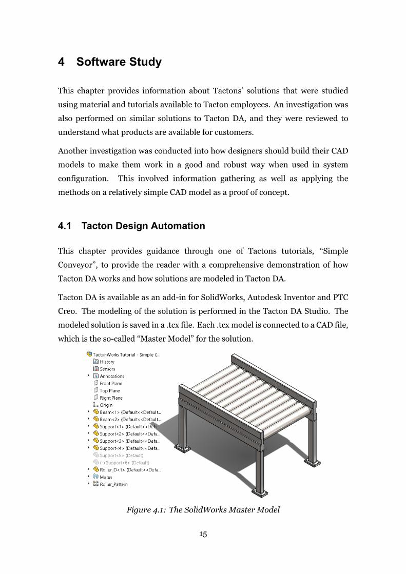
Figure 4.1: The SolidWorks Master Model
15

In this demonstration, the Master Model is a SolidWorks Assembly of a simple
conveyor, see figure 4.1. Tacton DA edits the Master Model by driving parametric
changes, by selecting from configurations or by replacing subcomponents or sub-
assemblies. For the Master Model to update successfully during modifications, it
must be a robust parametric model with a robust design intent.
When starting a new Tacton model, the first step is to create the component
design tree. The component design tree in Tacton DA often looks similar to
the SolidWorks design tree. One component is needed in the Tacton DA design
tree for every SolidWorks component that will be configured. The Tacton DA
components are thenmapped to the corresponding SolidWorks components. The
Tacton DA design tree can be seen to the left in figure 4.2.
Figure 4.2: The Tacton DA Studio
Only one beam and one support (for the four visible in the SolidWorks Master
Model) is needed in the TactonDA design tree because whenmultiple instances of
the same SolidWorks file is in an assembly, they act together so when parametric
changes are made to one component, the other instances also receive the same
modification. Only one roller is needed in the Tacton DA design tree because the
SolidWorks Master Model only used one roller that was patterned to make more
instances. However, since the suppression state of the two middle supports that
are suppressed in the SolidWorksMasterModel should be controlled, it is possible
16

to create a collection in the Tacton model, where they are grouped to make their
visibility state react in the same way.
Each Tacton DA component is associated with attributes, as can be seen in
the lower right part of figure 4.2. The attributes are then mapped to the
SolidWorks parameters that should be driven by Tacton DA. When attributes
have been mapped, the icon next to the attribute name changes to indicate the
mapping. An example in the conveyor tutorial is the roller_quantity attribute of
the conveyor that is connected to the quantity in the roller pattern. Similarly,
the roller_distance is mapped to the distance between instances in the pattern,
and finally, the roller_start_distance is mapped to the dimension in the mate
between the rollers and the beam, see figure 4.3. As seen in the figure, the
dimensions that the attributes are connected to all have a logical name such
as “Distance@Roller_Position” which is considered as good practice and makes
the modeling of the solution much easier than if the parameters are not named
logically, e.g., “Distance37”.
Figure 4.3: Mapping attributes
17

To be able to control the suppression state of the middle supports it is necessary
to associate it with the predefined ”qty” attribute as seen in figure 4.4.
Figure 4.4: Control Suppression State on Middle Support
Each attribute has a domain that specifies what values or range of values the
attribute can take. The configurator engine will then make sure to only consider
values in line with the specified domain for each attribute. It is possible to specify
a new custom domain or use one of the available pre-specified domains such as
“int” which allows all integers or “boolean”which allows the values 0 or 1. In figure
4.4 and 4.2 it is possible to see the domains specified for each attribute.
It is possible to create variant tables such as the one seen in figure 4.5 that
contain lists of variants from which the configurator can select. The configurator
must then choose one variant from the list, and that variant will occupy that
position in the design tree. When selecting from SolidWorks configurations or
when replacing SolidWorks components the variant tables must be used. In
this conveyor tutorial, a variant table is created for different types of rollers.
Each variant is connected to a SolidWorks model of the corresponding roller
type. When the user specifies the type of rollers, the roller component from the
SolidWorks Master Model gets replaced by the one from the variant table. The
symbol in front of the component name is different when a component is replaced,
see the different symbols on figure 4.4 and 4.5.
18

Figure 4.5: Variant Table
The variant table can be used and connected to the components in the design
tree. That is done for the rollers in the conveyor tutorial, as shown in figure 4.6.
Then the features of the variants from the variant table get added automatically
as attributes for the component in the design tree.
Figure 4.6: Variant Table Connected to Component
Not all combinations or parametric values make sense in the configured solution.
Constraints are used to define the relationships and dependencies between
attributes. Constraints can also be used to define the values of the attributes
further. The constraints used in the conveyor tutorial are shown in figure 4.7. The
first constraint in this tutorial defines the height of the conveyor. Then the roller
19

constraints make sure there is no space between the rollers, define the number
of rollers, and make sure they are located correctly. Finally, the last constraint
makes sure that if the conveyor is equal to or exceeds 1500mm in length, extra
support will be added in the middle of the conveyor.
Figure 4.7: Constraints
Finally, fields need to be created for the user interface. For each attribute, it is
possible to create a user interface field, but fields are normally only created for the
attributes that the user wants to be able to control by making choices or assigning
values. In the conveyor tutorial, three fields are created, as shown in figure 4.8,
each connected to an attribute.
Figure 4.8: Defining the User Interface
20

Before creating the fields, steps and groups must be created. One step is visible to
the user at a time. If the model contains two or more steps, the user will begin
by configuring the fields in the first step, and then move to the next step and
so on until the user has gone through all the steps in the model. Each step is
configurable, but when moving on to the next step, the selections made in the
previous step gets locked and cannot be changed. It could be explained as one-
way communication. Step 1 talks to step 2, but step 2 does not report back to
step 1. There is no way for the user to know how the values he/she commits in
step 1 will affect the possible choices in step 2. If the user decides in step 2 that
he/she wants to change the committed values from step 1, he/she needs to go
back to step 1, change the committed values, and when moving on to step 2, the
values he/she had already committed there might be changed. That is because
the changes the user made to the committed values in step 1 affects the possible
solutions in step 2 and the configurator engine will always search for a possible
solution in the following steps, but not in the preceding ones.
It is possible to select from various types when specifying the fields for the user
interface. They can, e.g., be a drop-down list, radio buttons, image list, slider, or
the user needs to type values manually. It is also possible to control other aspects
of a field such as its visibility or default value.
To use the model, and access the user interface just created in the Tacton DA
Studio, the Runtime is started. The Runtime runs inside SolidWorks and can be
seen in figure 4.9. The figure also shows different types of fields, the Roller Type
option has a drop-down list, the length has a slider, and the value for the height
should be typed in the field.
Figure 4.9: The User Interface
21

The CAD Master Model updates simultaneously as the user assigns values and
makes choices in the user interface. An example of the configured conveyor and
the corresponding updated Master Model in the SolidWorks graphics window is
shown in figure 4.10. The conveyor tutorial is only a one-step model, but if it
containedmore steps, it would be possible tomove between steps using the arrows
in the top right corner on the user interface.
Figure 4.10: The User Interface after Assigning Values
The configurator engine validates every choice that the usermakes, preventing the
user from making any combination of choices that conflicts with any constraint,
attribute domain, or other data specified in the model. The fields in the user
interface will show green, orange, or red color to indicate whether a choice is
possible or not. Two new constraints were added to the conveyor tutorial to
demonstrate how the conflict resolution works. One completely banning the 100
mm roller and the other only allowing the 80 mm if the conveyor exceeds 1000
mm in length. As seen in figure 4.11, the 100mmoption is red, and not possible to
choose. The length of the conveyor is set at 500mm, so the smaller rollers are the
only green options. However, it is possible to choose the orange option for 80mm
rollers, but then the user receives a message in a pop-up window saying that there
is a conflicting parameter. The configurator engine will automatically propose a
new value for the conflicting parameter. In this case, the length of the conveyor
needs to be changed to solve the conflict, and the user can either choose to accept
or decline that proposed value.
22

Figure 4.11: Conflict Resolution
However, because the Tacton configurator engine is a solver, i.e., the engine will
always give the user a valid solution, all fields have an automatically assigned value
for each parameter. The conflict resolution only checks on values assigned by
the user. That means that during configuration, while the user assigns values,
the configurator engine will be modifying the automatically assigned values, if
possible, to meet the users’ requirements.
Today, ifmultiple values need to be changed for an orange option towork, the user
receives a list of these in a pop-up window and only needs to press once to accept
or decline the proposed new values. Sometimes there is more than one possible
solution to resolve a problem, but the configurator engine will always only suggest
one feasible solution. If the user is not happy with the values suggested by the
configurator engine, he/she will need to decline the proposed values and commit
newvaluesmanually. The user can set different search criteria for the configurator
engine, e.g., for it to search for the cheapest solution or smallest solution.
4.1.1 Layout Option in Design Automation
Tacton DA has managed to meet some of the customers’ demand for more
advanced possibilities by offering a Layout option. The Layout option, as it is
today, allows configuring two or more configurable components together, i.e.,
placing two or more configurable SolidWorks parts or assemblies in the same
top assembly document. During the configuration, the configurable components
communicate with each other through global parameters. The global parameters
are specified in fields in the Layout Mapping Editor, see figure 4.12.
23
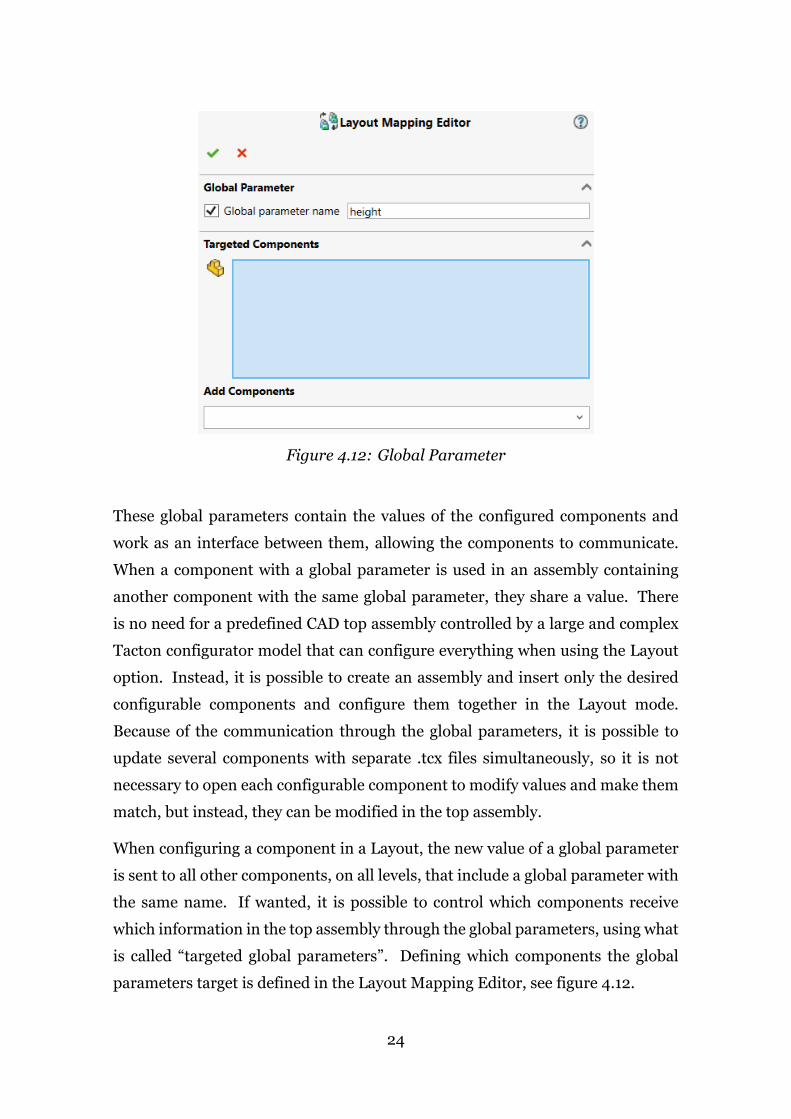
Figure 4.12: Global Parameter
These global parameters contain the values of the configured components and
work as an interface between them, allowing the components to communicate.
When a component with a global parameter is used in an assembly containing
another component with the same global parameter, they share a value. There
is no need for a predefined CAD top assembly controlled by a large and complex
Tacton configurator model that can configure everything when using the Layout
option. Instead, it is possible to create an assembly and insert only the desired
configurable components and configure them together in the Layout mode.
Because of the communication through the global parameters, it is possible to
update several components with separate .tcx files simultaneously, so it is not
necessary to open each configurable component to modify values and make them
match, but instead, they can be modified in the top assembly.
When configuring a component in a Layout, the new value of a global parameter
is sent to all other components, on all levels, that include a global parameter with
the same name. If wanted, it is possible to control which components receive
which information in the top assembly through the global parameters, using what
is called “targeted global parameters”. Defining which components the global
parameters target is defined in the Layout Mapping Editor, see figure 4.12.
24
Breaking the large configurator model down into many smaller configurator
models using the Layout option results in various other benefits. The performance
of the model is improved by reducing the size and complexity of it, and
maintenance becomes easier. Since each configurable component can be run
individually, it is possible for different teams to work on different parts of the
product concurrently.
However, as explained in chapter 1.3, various problems remain unsolved. The
limitations of the Layout functionality has been investigated further during
interviews with Tacton employees and customers using Layout. The results from
these interviews are explained in chapter 5.
4.2 Partners and Competitors
Tacton mainly sells Tacton DA licenses through partners around the globe. One
partner has expanded the capabilities of Tacton DA by building their own solution
on top of it. Naturally, Tacton also has competitors that offer design automation
systems. This chapter will cover what design automation solutions exist on the
market other than Tacton DA, with a particular focus on options similar to that
Tacton would want to offer with system configuration.
4.2.1 Lino GmbH
Lino GmbH is a partner of Tacton and resells and implements sales configuration,
product configuration, and design automation software in Germany, Austria,
and Switzerland. Lino describe themselves as more focused on the engineering
and manufacturing side and less in the sales and business side. They focus
on customers that offer machinery and plant equipment. Lino has developed
some tools of their own, building on software from Tacton, where they believe
something is missing in Tactons’ solutions. Therefore, integrations are critical to
Lino, and they have come very far in their development of integrations between
their software and Tactons’.
One of the products that Lino has developed is “Lino 3D Layout” that is built on
25

top of Tacton DA. That product is focused on factory layout planning. It runs
inside CAD and shows a library of all available machines, conveyors, and other
products, see right side of figure 4.13. The user drags a product from the library
and drops it into the graphics window in SolidWorks. The user can click on
the product to start configuring it. When the user drags the next product from
the library, red spheres will appear to indicate where it is possible to connect
the products, see figure 4.13. These red spheres are snapping points where the
products get automatically mated. When products have been mated using these
snapping points, they become a chain and inherit global parameters from each
other, so if a parameter is changed in one product, it will change in the other as
well. It is possible to manipulate the chain and either break chain connections or
link non-connected components/chains. Lino also offers a tool tomove and rotate
chains relative to one another.
Figure 4.13: Linos 3D Layout
Instead of using the detailed engineering assembly for each product while doing
the floor planning, Lino uses simplified sales components. Even though a
simplified component is used, the BOM delivered is correct in regard to the
detailed engineering assembly. It is possible to replace the simplified component
with the detailed assembly if the user wishes to, but then the assembly runs
26

significantly slower.
Lino also offers what they call ”System Configuration” where Lino 3D Layout is
synchronized with TCsite. TCsite is an older version of the CPQ solution from
Tacton that Tacton has stopped selling and has replaced with Tacton CPQ. With
Linos ”System Configuration” it is possible to send the configured layout to TCsite
and receive an instant quotation. It is also possible to modify the configuration in
TCsite and push the updated configured solution to DA.
4.2.2 Others
Naturally, Tacton has more competitors that offer DA solutions. However, when
the market was analyzed with a special emphasis on searching for something
similar to what Tacton wants to offer with its system configuration, not much was
found.
Driveworks has for many years been one of Tactons’ main competitors when
it comes to DA in SolidWorks, and they recently started offering CPQ software
as well. When looking into their product offering for something similar to the
system configuration Tacton would like to offer, the closest product found was
what they call ”Layout mode” in their DriveWorks Solo product. An assembly file
in SolidWorks needs to be open to activate the Layout Mode. The user needs to
browse for a product to insert into the assembly, configure the product, and click
”Preview” to send it into the assembly. The product will then appear somewhere
in the assembly. The Layout mode uses magnetic mates to simplify the mating
process, but it does not send any attributes between products. For example,
when inserting a conveyor into a conveyor line, the user needs to manually select
the correct length, width, and other attributes that need to match between the
conveyors. The Layout Mode in DriveWorks Solo is a way to combine multiple
DriveWorks projects but does not offermany other additional functions of interest
for this project.
Multiple other companies and their product offerings were investigated, but none
offer anything new or something interesting that has not been mentioned in this
thesis already.
27
The CAD vendors themselves offer some functionalities that can be used to
automate design up to a certain degree. They have continued developing design
automation tools, but none that can be compared to the capabilities of Tacton
or other commercial vendors of DA tools, especially when it comes to layouts or
systems.
4.2.3 Summary of Competitors
To summarize, Lino has built on top of Tactons’ solutions to expand the
capabilities even further. However, in regards to the system configuration that
Tacton wants to offer, no other commercial company offers anything similar to
those capabilities, or even the capabilities of the Layoutmode that exists in Tacton
DA today.
4.3 Designing in CAD for Design Automation
The way that 3D CAD models are structured affects how they can be configured
and how they will act if they are used in larger assembly models. The structure
of 3D CAD models is therefore extremely important when it comes to DA and
requires the engineers to adopt certain modeling techniques to be able to create
robust models that will function well in the DA environment.
When designing for DA it is critical to have a strong design intent. To do so,
the designer must think about the possible changes that will be made to the
model in the future, and how the model should behave when these changes are
applied.
Johan Ernfors (2009) created guidelines for how to create 3D CAD models, so
they work well during configuration in DA and Andréasson & Lord (2013) added
guidelines for the creation of 2D drawings. These instructions have proven to be
successful and are still being updated and used at Tacton today.
When creating a 3D CADmodel that will be used in DA the goal is to minimize the
work needed during the design and maintenance of the model while still being
able to configure it automatically using DA so that it updates successfully.
28

Some information such as parameters, constraints, and relationships can be
controlled either in the 3D CAD software or the configurator model. It is
important to avoid managing the same parameters in two different systems.
That is why, when using a configurator model, the only information that the
CAD software should include is the one needed to create the correct geometry
and all other information should be included in the configurator model (Ernfors
2009).
Modern CAD software uses parametric modeling and feature-based modeling to
be able to design with a strong design intent. During modeling, a sequence of
features is created that either add or removematerial to form the finished product.
Usually, the features are created from 2D sketch geometry.
An example of a parameter type is a dimension. Dimensions are used to control
the size and position of a sketch geometry and can also be used to relate and
constrain existing geometry. Another aspect of parametric modeling involves
creating relations between sketch entities in order to constrain geometries.
Examples of dimensions to control are the length of a line or the diameter of a
circle with a numerical value. Examples of constraints can be to make two circles
concentric, two lines parallel, of equal length or parallel with a certain distance
between them. By using dimensions and constraints, it is possible to make 2D
geometry fully defined.
Parametric changes can be driven from Tacton DA to a SolidWorks model, as was
explained in chapter 4.1.
4.4 Designing in CAD for System Configuration
When it comes to designing in CAD not only for DA, but for system configuration
in DA, new problems come to light. This chapter covers a few useful functions
that SolidWorks offers, some of the problems that might be encountered, as well
as solutions to them.
29
4.4.1 Reference Geometry
It is possible to use reference geometry such as planes, points, axes, or coordinate
systems to create features while designing in SolidWorks (SOLIDWORKS 2016).
It becomes easier to maintain and use models in DA if the designer uses reference
geometry to define the model, and as a result, the robustness of 3D models
also increases. The main reason for that is because whenever a designer creates
geometry, it will receive a unique SolidWorks internal ID code. Mates are assigned
to the specific geometry ID’s, and if the internal ID of a geometric entity has
changed for any reason, SolidWorks will lose the mate reference, resulting in a
mate error. Since the model geometry is constantly being changed in DA, the 3D
model will become more robust and less likely to lose references if a reference
geometry is used instead of edges, faces, and points on the model itself. However,
even if a reference geometry is used, if a component gets replaced by another one,
the mate will break unless the reference geometry that the mate was assigned to
has the same internal SolidWorks ID in both of the components that are being
replaced by one another. Thus, an evenmore robust way is to insert the necessary
reference geometry into templates in SolidWorks.
4.4.2 Templates
SolidWorks offers three default templates that create different types of files:
Part, Assembly, and Drawing. It is possible to create new customized templates
(SOLIDWORKS 2019a) based on one of the default templates, including more
information such as reference geometry if needed.
By building the reference geometry into the templates, all files will have the same
internal ID for the reference geometry that is built into them. It is possible to
create themates between the reference geometries that are built into the template.
Thematewill never break because the internal ID’s that define themate are always
the same, no matter though components are modified or even replaced.
If a reference geometry is deleted and re-added into the template-based file, the ID
will change and everything referencing it will fail. Even if a geometry identical to
another one is created, it will have a different internal ID. Therefore, the template
30

reference geometry should never be deleted.
SolidWorks, like other modern CAD software, has three standard reference
planes for 3D models: Top, Front, and Right. Different kinds of reference
geometry can be built into templates, such as planes, points, axes, and coordinate
systems. It depends on what the intended use is, what type of geometry is
best suited. It is worth noting that a lot of different reference geometry can
be set up into the SolidWorks templates, and not all must be used or visible in
every model. It is possible to organize the reference geometry into folders and
either hide it or show, as the user wishes. One of the interviewees during this
thesis work, Eric Schwieterman, a lead engineer at SMC Corporation of America,
has built coordinate systems into templates at SMC. The reason why they use
coordinate systems is that when two coordinate systems are mated together, the
corresponding components become fully defined (Schwieterman 2019). Hence,
by using coordinate systems as reference geometry, it is possible to determine
what the orientation of the component will be when mated.
When defining the reference geometry in a template, it needs to be constrained in
someway. If coordinate system is to be used as reference geometry, Schwieterman
(2019) recommends creating a 3D sketch with point(s) in it and to attach the
coordinate system to it, to give the designer the most freedom. By doing so, it is
possible to control the location and manipulate the orientation of the coordinate
system as needed through the Coordinate System Properties in SolidWorks.
4.4.3 Consistency in Design
It is not enough for companies to set up suitable reference geometry within their
templates, they also need to have a standardized way of working to make good
use of the templates. Companies need to establish the work procedures that the
engineers should follow when creating CAD models. That includes both defining
a standardized way of working during design and establishing a consistent way
of using the reference geometry within templates. That way, the mates between
components will never break due to lost references, and the models will function
in a robust manner and as intended during DA. Each company needs to create
31

guidelines for the engineers to follow in order to achieve uniformity, where
everyone works the same way.
4.4.4 Mating in SolidWorks
As explained in the previous chapter, it is recommended to use reference geometry
during the conventional mating process. This chapter covers other functions
that SolidWorks offers to automate and simplify the mating process significantly
compared to the conventional mating process.
SmartMates
One of the functionality is ”SmartMates” where different types of automaticmates
can be created (SOLIDWORKS 2018a). To use SmartMates, one component is
dragged onto another component, and SolidWorks will automatically create a
mate between them. Which type of mate SolidWorks creates is dependant on the
geometry on the two components being mated together. Therefore, SolidWorks
will identify the geometry that is used to drag the component as well as the
geometry that the component is dropped onto.
Additionally, it is possible to set up mating references so SolidWorks will know
how the component should be mated. When a component with mating references
is dragged into an assembly, SolidWorks will search for other reference mates
with the same name and type. That way, it is possible to automatically create the
desired mates for a component when inserting it into an assembly. Adding mate
references is convenient for components that are often used and typically mated
the same way every time.
Magnetic Mates
When using Magnetic Mates, the designer defines connecting points on the
components (SOLIDWORKS 2019b). The predefined connection points appear
as pink points. The designer can then drag components over each other, and a
pink connection line will indicate the two connection points which a mate will be
formed between when the designer drops the component into the assembly, see
32

figure 4.14.
Figure 4.14: Magnetic Mate
Althoughmagnetic mates are a really fast and simple way to insert components in
their correct place in an assembly, the functionality is not flawless. When a chain
has been formed with magnetic mates, it moves together. The designer can still
break themagneticmates andmove the individual components unless specifically
locking the magnetic mates, not allowing them to break.
Perhaps the biggest disadvantage with magnetic mates is that there is no way to
define the direction of components to control that they can only be fitted together
in a viable orientation in regards to other components that are already placed
in the assembly. For example, it is possible to place two conveyors back-to-
back together, although they only have one viable orientation in regards to each
other.
Ground Plane
It is possible to define ground planes in assemblies. However, only one ground
plane can be activated in each assembly at a time. The ground plane can be defined
as one of the three standard reference planes or any other plane already in the
assembly. When components are inserted into an assembly with a ground plane,
the ground face will snap onto the active ground plane. The ground face of the
33

component will automatically be the lowest face on the Y-axis unless the user
specifies another face especially.
When doing a factory layout, it is possible to insert a model of the floor layout into
the assembly and define the top of that model as the ground plane. That way, the
user can arrange all the products so that they fit on the factory floor.
SolidWorks recommends using Ground Planes in combination with Magnetic
Mates when doing factory layout. SolidWorks also recommends using SpeedPak
(SOLIDWORKS2017a), i.e., a simplified configuration of an assemblywhen doing
factory layout.
4.4.5 Large assemblies
When it comes to system configuration, when multiple large assemblies might
be placed in the same assembly file and configured together, it is inevitable to
consider the performance in SolidWorks. The normal state for an assembly is
the Resolved state where all of the model data is accessible and fully loaded in
memory. This can result in a long loading time and overall slow performance
in SolidWorks. In the past few years, SolidWorks has introduced new functions
aiming at improving the performance of large assemblies, and today, a number of
techniques exist to handle large assembly models.
Today, SolidWorks offers three additional ”modes” to the normal Resolved
mode, i.e., Lightweight, Large Assembly Mode and Large Design Review Mode.
This chapter covers what these different modes, and other functions offered by
SolidWorks, include and their relevance to improving performance in DA.
Lightweight Mode
It is possible to open an assembly with it sub-assemblies and parts in Lightweight
mode to increase the performance of the assembly. When using lightweight
mode, only a subset of the components’ data is loaded, resulting in faster loading
time (SOLIDWORKS 2017b). If the user wants to load more data than what is
accessible in the lightweight mode, it is necessary to fully resolve the component.
Since the user does not have access to all the features at all times, which is
34

necessary in DA when changes are being made to details in the model, this mode
will not be considered as useful for DA.
Large Assembly Mode
When an assembly is opened in Large Assembly Mode, various system settings
are applied that increase the assembly’s performance (SOLIDWORKS 2019c).
Additionally, all of its sub-assemblies and parts are opened in Lightweight mode,
which makes this option unsuitable for DA.
Large Design Review
Large Design Review enables users to open very large assemblies fast to view and
investigate the model rapidly. The feature manager is available to the user when
using the Large Design Review mode. When using this mode, it is, e.g., possible
to measure distances, cut cross sections and hide and show components. The
capability to edit the assembly while in Large Design Review was introduced in
SolidWorks 2019 (SOLIDWORKS 2019d). Mates are accessible and can be edited,
deleted, or created. Reference geometry and sketches are accessible and can be
shown or hidden and used as references when adding mates. In the edit mode,
it is possible to change configurations of components, delete them or insert new
components. Additionally to being able to mate newly inserted components, it
is possible to use magnetic mates to snap components into position in the Large
Design Review. When the user has made all necessary changes, it is possible to
save the assembly so that the next time it is opened, no matter in which mode,
the changes have been saved. It might be possible to use Large Design Review
for DA, however, it is going to need further investigation to really understand its
feasibility.
Defeature Tool
SolidWorks offers a Defeature tool to remove unnecessary detail and simplify
large assemblies (SOLIDWORKS 2018b). When using the Defeature tool, the
user manually selects which details should be simplified. The details that are
simplified are replaced with simplified solids that the user specifies. The user can
35

also select which details should not be simplified at all. When the simplification
is done, the simplified defeatured model can be saved with a link to the original
assembly.
When it comes to DA, it is obvious that parametric changes will not be driven
on details on components that have been simplified using the Defeature tool.
However, there are some possibilities to use the Defeature tool in DA.
One possibility is to simplify only the complex parts of the model that will never
be modified in any way. An example can be for a machine that uses a motor
that always has the same dimensions, and the motor could be replaced with a
simplified solid.
Another possibility is to utilize the connection between the simplified model and
the fully resolved one. It is possible to create additional code that enables the
simplified model to be open in the graphics window in SolidWorks, and when
the Tacton configuration is started, although it is driving changes to the fully
resolved model, it is possible to make it rebuild the simplified model and publish
the changes in the SolidWorks graphics window.
SpeedPak
SolidWorks offers a SpeedPak option that generates a simplified configuration
of an assembly (SOLIDWORKS 2019e). The simplified configuration retains
its references, so it is possible to substitute the simplified configuration for the
original complex one without losing references. The user needs to select what
features such as faces, reference geometry, and sketches should be selectable in the
SpeedPak configuration. All other details will only be loaded as a subset, similar
to in Lightweight mode, and will not be selectable and thus cannot be modified
or used for mating. Therefore, it is not considered feasible to use a SpeedPak
configuration in DA.
Save an Assembly as a Part
It is possible to save an assembly file as a part file to simplify the design and
improve the performance. By doing so, SolidWorks generates multiple solid or
surface bodies that are accessible in the feature tree of the part file. Although the
36

bodies are accessible in the feature tree, there is no feature history available for
the bodies and thus, not possible to drive parametric changes the way it is done in
DA.
4.4.6 Multiple instances of a component
A very likely scenario when doing system configuration is that more than one
instance of a component will be placed in the assembly. For example, when
doing a factory layout, it is very likely that more than one instance of a straight
conveyor will be used in the floor plan. One of the difficulties which imposes is
that SolidWorks treats the different instances as the same object until the different
instances are saved under different names. In an assembly with two instances
of a straight conveyor, if one were configured to have a length of 2 meters, the
other would automatically update with the same value if it is not saved under a
new name before starting the configuration. Normally during the configuration
process in DA, the files are not saved until after the user has committed all values
and is done making all changes to the model. When the configuration is done, the
files are exported and saved.
One possibility is to save the different instances with different names before
starting the configuration. This could be automated using the SolidWorks API in
multiple ways, and SolidWorks offers functionalities that can come in handy. An
example is the ”Pack and Go” option that SolidWorks offers. Pack and Go collects
all related files for the component into a folder or a zip file which might be useful
when automating the generation and saving the different instances. However,
the user often follows specific rules regarding where and how to save the model
files. It might become difficult to automate the saving process, e.g., for files with
unknown final saving destination or name.
Another possibility is to make the extra instances virtual and then independent.
The virtual model will not be saved until the assembly it is in gets saved. Until
then, the virtual models are only stored internally in the assembly file itself, and
when the assembly is closed, so are the virtual models. The user must therefore
be careful when using virtual models not to loose any work. It is possible to make
37

an instance independent from other instances of the same component as well as
it is possible to rename the virtual models in the feature tree, creating the desired
distinction between the instances. This method supports the way configurations
are done today very well, i.e., by saving everything at the end of the configuration,
when the files are exported and saved.
38

5 Interviews
Interviews were conducted to gain a deeper understanding of the field of product
configuration, to establish the needs and requirements for system configuration
further and to investigate the possibilities for system configuration, with a special
focus on the possibilities in DA.
The information from the interviews that is presented in this chapter can be
split into a discussion about the need for system configuration, how interviewees
envision system configuration, the use of the Layout option offered today in
Tacton DA and finally a holistic view of the future for system configuration at
Tacton.
5.1 The Need for System Configuration
FifteenTacton employeeswere interviewed, all ofwhich agreed that there is a need
for Tacton to enhance the support for customers that want to configure systems
of products. However, it varied significantly between employees how urgent they
saw the need for it. The employees had different opinions and views on system
configuration in general and especially on how Tacton should approach it.
Two customers using the Tacton DA Layout option and one customer that has
built their own ”system configuration” on top of an old sales product TCsite that
Tacton offered were also interviewed to get the customers’ point of view.
Even though Tacton does not offer system configuration as it is defined in this
thesis, they have been able to solve various system configuration problems for
their customers with their existing software solutions. Some of the Tacton
employees had worked on customer projects that involved system configuration.
They could provide information about the existing problem solutions and the
different aspects that worked well or could be improved upon, in order to better
fulfill the customers’ needs.
When askedwhat problems the employees hoped for systemconfiguration to solve
one answer was prominent. That was to be able to break very large solutions down
39

into smaller ones. Whenmodeling solutions for customers using the software that
Tacton offers today, themodeler has the whole solution in front of him-/herself at
all times. There is an “include” option available where the modeler can include a
.tcx file inside another .tcx file. Intuitively this means to include a configurable
module inside another configurable module. This option does not function as
dynamically as system configuration should be able to do. When solutions get
very large, they can get very complex and difficult to maintain or make changes
to. Being able to break very large solutions down into smaller ones has various
benefits. Among those benefits are:
• Easier maintenance
• Different teams working on different parts of the solution concurrently
• Better performance and faster configuration time
5.2 How to do System Configuration
During the interviews, different functions were discussed to understand their
relevance in system configuration. The different types of system structures and
necessary communication between the modules forming the system were also
discussed with the interviewees.
5.2.1 Functions in System Configuration
The interviewees’ opinion on how system configuration should be performed and
which functionalities they want it to include varied significantly. It is necessary to
go through some of the main functionalities that exist in Tacton’s solutions today
to evaluate their usefulness and relevance for system configuration.
Steps
As explained in chapter 4.1, it is possible to break solutions down into multiple
steps. Some employees like to break the models down into multiple steps, while
others try as much as they can to keep their modeled solutions in only one step.
40

The advantages of using steps are that the user does not have to look at all the
options at the same time resulting in easier navigation through the user interface.
It can be very appropriate to use steps in some cases to improve the performance
of the configurator model by excluding all options that are not appropriate for
the product being configured. An example can be when configuring a bike, the
first step could be to select what kind of bike it is, e.g., if it is a mountain bike or
a racer. By making that choice in the first step, all the inappropriate selections
for that product type get excluded. However, the obvious disadvantage of using
steps is that after a selection has been made in one step and the user moves to
the next one, the committed values in the previous step get locked and cannot be
changed.
Conflict resolution
The conflict resolution, i.e., the configuration choices being colored green, orange,
and red according to their feasibility, is very popular amongst all interviewees and
works very well.
As was explained in chapter 4.1, if an orange option is selected today, the user
receives a pop-up window saying that it is only possible to make this selection if
a value of something previously configured is changed. The configurator engine
will automatically propose a new value for the conflicting parameter.
Whatmight be one of the biggest problemswith including conflict resolutionwhen
doing system configuration is how everything is connected, which might trigger a
chain reaction of required changes to be able to change one value.
Interfaces
Tacton does not offer any way to specify the interfaces between configurable
modules in any of its solutions. The onlyway tomakemodules communicate today
is by manually writing constraints, except for the global parameters available in
the Layout option in Tacton DA.
The parameters that Tacton has used so far in their product configuration are
simply referred to as parameters. They could be explained as local parameters that
only apply to the configurable module that the modeler is working with. The only
41

way to establish relationships between these parameters is to write constraints
manually.
When Tacton started offering the Layout option in Tacton DA, they introduced
global parameters that share valueswith all other global parameters with the same
name in the sameSolidWorks assembly file. They also included the option tomake
the global parameter targeted, so themodeler can choosewhich other configurable
models that include a global parameter with the same name in the assembly will
share values. Using global parameters automates the way configurable modules
can communicate parameters and establish relationships between them up to a
certain degree.
It could very well be that other types of relationships might be applicable for
system configuration to automate the communication of parameters between
configurable models, and the Product Manager in DA had already detected two
other types of relationships, namely, chain and pair, that could be useful.
• Chain relationship: Often, one solution includes more than one system. An
example could be in a factory layout. There might be two parallel factory
lines running beside each other, containing the same configurable conveyors
andmachines, but requiring different parameter values, e.g., if the height of
the lines should not be the same. In a case like this, it might be convenient
to offer a chain relationship that only shares values with other parameters
in that same chain but not to other chains running in the same solution.
• Pair relationship: The pair relationship would only affect two configurable
models enabling one configurable model to only share value with the
adjacent module without affecting other parameters in the system.
The same final result could be achieved by using targeted global parameters in
Tacton DA. However, by introducing the chain and pair relationships, it would be
possible to simplify the process of sending parameter values between models in
the chain and pair scenarios.
42
5.2.2 System structures and communications
To be able to develop a tool for system configuration, it is very important to
understand the different system structures that the customers would like to
configure. That includes how the configurable modules are positioned and the
nature of the communication needed between themodules. Because of the diverse
background of the interviewees, the discussion was always different and dozens
of different system structures were looked into and reviewed.
The customers have systems spanning almost all of the industrial manufacturing
industry so it would be a tedious and uninteresting work to enumerate the
different products reviewed, how they connect to form a system and which
parameters need to be communicated in the systems. Throughout the interviews,
the discussion evolved from only discussing the different products forming a
system, to discussing how it is possible to group them logically. Almost all
the interviewees had input into forming the types of system structures that are
presented in chapter 6.1. However, it is worth noting that an employee at Tacton
with the job title ”Director Alliances in North America” had already put a lot of
thought into system configuration before our interview and had already grouped
the types of systems similarly to my conclusions that are presented in detail in
chapter 6.1.
5.3 Customers Using Layout Mode
As explained in chapter 4.1.1, Tacton DA offers a layout mode that uses global
parameters to enable the communication between configurable modules. When
using the layout mode, the new value of a global parameter is sent to all other
modules in the same assembly document, that includes a global parameter with
the same name, but only during the step in which they are activated. Because
the Layout feature is not compatible with the Tacton configurator engine, the
communication is limited.
Interviewswere conductedwith two companies that are currently using theLayout
mode to gain a better insight into the use of the Layout option as it is today.
43
Both customers demonstrated a configuration to show how they use the layout
mode and later answered questions and discussed what works well and what they
would like to be improved. In both customers cases, they use a SolidWorksmaster
model for the system, since the structure of the system does not change so much
between configurations. For more flexible solutions, where the system structure
is never the same, the customers can drag-and-drop the configurable models into
an assembly file instead of using a master model. An example of a system with
varying structure is a factory layout, where the solutions can be very different from
another.
Customer 1
This customer builds all the necessary logic in the .tcx file connected to themaster
model and therefore performs the whole configuration using that .tcx file. Steps
are used to break the configuration model down and control the visibility of the
fields between steps based on the user’s selections in the previous steps. This
model is not very flexible but very robust.
Customer 2
This customer only includes the global parameters and the necessary logic for the
conflict resolution to work in the .tcx file connected to themastermodel. They use
this top-level configuration model to configure the most important parameters
that have the greatest effects on the final solution. That way they can visualize
the approximate final look very quickly. When the engineers have finished going
through this top-level configuration with all the global parameters, they export
the files with the configured global parameter values and open each configurable
component and assigns values to it. The reason for not including everything in
the top-level assembly is that they have run into stability problems when the top-
level assembly is too large. Additionally, the user interface becomes very crowded
if it includes all the fields for all components. It is not an option for them to use
steps that would lock down values because the components in their system are
so dependent on each other. When the engineers start to configure individual
components, they need to be careful not to change values of global parameters
because changing values on this level will not transfer any changed values to other
44

components.
The use cases for the customers were very different from one another and
what works for one does not work for the other. The system complexity and
amount of fields that need configuration are higher for customer 2, resulting
in a more complex solution. Both customers agree on the need for breaking
down the solution. Customer 1 accomplishes this by using steps while customer
2 needed to work around the options available today by creating a top-level
configuration model with the global parameters but keeping all other parameters
at the component level.
By using a master model in SolidWorks for the system level configuration, the
solution has limited flexibility. Imagine offering a complex factory layout where
each user will need a different setup of machines. To create a master model for
that would be tedious work, and the performance of the SolidWorks model would
very likely be slow. A more flexible way of doing configuration would be only to
insert the configurable components wanted for each solution, into the SolidWorks
assembly containing the system. Each case is different, and each customers’ case
has to be studied to understand what solution is suitable for the configuration
model.
Both customers agreed on the benefits of the configurable components being able
to communicate dynamically and to be able to send values both from the top-level
model to the component models and vice versa.
If Tacton starts offering system configuration that can use the configurator engine
to allow these dynamic communications, it will open up for the possibility for
the top-level assembly not needing to include any logic to activate the conflict
resolution. Instead the top-level could be used as a ”shelf” for the preferred fields
(with their corresponding parameters) that are pulled from the component level,
so when a user assigns values at the top-level, the configurator engine could read
the logic from the component levels to use the conflict resolution.
45
5.4 System Configuration in Tacton - A Holistic View
This thesis project has so far investigated the possibilities for system configuration
in Tacton DA specifically. However, the interviews revealed a clear need for
system configuration in other settings, such as in Tacton CPQ. Therefore, it is
important for Tacton to look at the big picture before starting to offer system
configuration in any of their solutions.
There are some differences between discussing system configuration in the
setting of DA and in other settings. For example, in CPQ, the actual placement
of the modules does not matter whereas in DA it is necessary to know the
placement and how modules are attached to one another, to set up the modules
in the CAD environment. There are not only technical differences between
configuration in the different settings. Tacton CPQ is Tactons’ main product.
Tacton sells significantly more licenses for their CPQ software than the DA
software. Therefore, the importance of developing new functionalities that meet
the customers’ requirement even better in CPQ is more than in DA. Because of
these differences, it is important for Tacton to have a holistic view on their product
offerings, especially when it comes to offering the same or similar functionalities
in many of their solutions, such as system configuration that is wanted by
customers both in DA and CPQ. For Tacton to make their software solutions
work as a stand-alone solution, as well as dynamically together, it is crucial that
information can easily be transferred between the software solutions. Having the
software solutions compatible with one another, the customer could comfortably
export and import information between software solutions, enabling different
teams such as sales and engineers to work collaboratively.
Towards the end of this project, Tacton decided that in the future, all modeling
activities should be performedwithin their CPQAdmin environment. Thatmeans
that the modeling for DA will be performed in the same environment as the sales
modeling. This is a very positive step towards making the different products
compatible with each other and simplify the transfer of information between
different software solutions that Tacton offers. It is worth noting that the CPQ
Admin environment is recently released, so the way modeling is performed, and
which information is included might change in the near future.
46

6 Results and Conclusions
This chapter contains the main results of the thesis project and provides answers
to the research questions defined in chapter 1.4.
6.1 Types of Systems
Tactons’ customers aremainly companies in themanufacturing industry that offer
complex products or systems. The products and systems that these companies
manufacture and sell are very diverse.
By combining the information gathered during the interviewswith other research,
it is possible to group the types of systems in the manufacturing industry into two
main groups: (1) Linear systems and (2) Central systems.
Figure 6.1: Linear System
Figure 6.2: Central System
47
6.1.1 Linear systems
In a linear system, the configurable modules form a chain similar to that shown in
Figure 6.1. Eachmodule communicates the relevant input and output parameters
to the modules that lie next to it. The connections between the modules can be
with or without direction.
What characterizes a linear systemwith a direction is that it usually has tomanage
a certain throughput, i.e., to produce or process a specific amount of products
or material in a specific time frame. An example is a factory line consisting of
machines and conveyors where a product goes into the system at one end and
comes out of the system at the other end. The machines and conveyors transfer
the product through the system in a one-way direction.
Another example of a linear system, but without a direction, is multiple electrical
enclosures lying together where dimensional values such as height and depth
need to be transferred between the modules but the parameters have no specific
direction.
6.1.2 Central systems
The central system consists of one module that can be considered as the central
module and other modules that will either be attached to the central module or
determined by it in another way, see Figure 6.2. The central module is often larger
or is considered ofmore importance than othermodules in the same system.
Singular, complex products often form a central system, e.g., airplanes or boats.
In a boat, for example, the hull could be looked at as the central module that other
modules such as the engine, generators, and other parts will be attached to.
Another example of a central system can be a robotic cell. The robot itself can
be considered the central module, although it is usually only physically attached
to the platform it stands on and nothing else. However, there are other modules
that form the system of a robotic cell such as the fence and control box that is
determined by the robot, even though they do not touch it physically.
It varies greatly between each case with central systems how difficult it is to define
48
which module should be considered the central module. The central systems
can become very complex in structure and often consist of systems on more than
one level; in other words, systems within systems, that are explained in chapter
6.1.3.
Each of the modules that are attached to or determined by the central module
do not necessarily have to be a single independent module, but it can be a group
of modules that communicate certain input and/or output to the central module.
Looking at the boat example again, a boat manufacturer might buy mechanical
parts of the boat from different vendors. The vendors might provide multiple
configurable components, such as the engine, shafts, and gearbox, to the boat
manufacturer. In that case, the boat manufacturer can look at the components
provided by the vendor as a black box, only providing input and output values
to their system. This does not only apply to central systems but can easily be
translated to linear systems as well.
6.1.3 Complex system structures
The complexity of systems can vary greatly, and each company’s case is different
from the other. It is dangerous to generalize and state that only two types of
systems, linear and central, exist, but by dividing the system structures into these
two groups, it is possible to explain all imaginable cases of system structures,
on a high level. However, when digging deeper into the system structure, each
case can get very complex. Each system can be a part of a larger system, have
systems within themselves or simply be a complex version of a linear or central
system.
Systems within systems
Each system can be either independent or a part of a more complex structure.
If a system is a part of a more complex structure, it can contain a system within
it or be a part of another system, i.e., a system within a system. For example, a
linear system can contain a central system within itself. E.g., a factory line can be
the traditional linear system, but one (or more) of the modules within the system
49

could be a very complexmachinemade ofmore than one configurable component,
forming a central system within the linear system.
The abstraction can be looked at in levels, see Figure 6.3. The top level, level 1,
is the highest level of abstraction and as one moves down a branch in the tree,
specific sub-systems and modules are brought to focus - the fewer the levels, the
simpler the system structure.
Figure 6.3: System tree structure
Branched linear systems
Figure 6.1 illustrates a linear system. However, far from all linear systems are
that simple that they only form one straight line. Imagine a ventilation system for
a building, composed of various modules that together form a linear system with
branches that spread throughout the whole building. Another example is a more
complex factory layout where there are multiple entrances or exits to the factory
line, and not all products or materials are handled in the same way. Figure 6.4
illustrates a branched linear system.
50

Figure 6.4: Branched Linear System
Complex central systems
Central systems can easily become very complex. As complexity increases, it
can become more difficult to determine the central module. For example, if the
boat example is scaled up to the size of a cruise ship. Cruise ships are extremely
large and complex products, composed ofmultiple sub-systems such as the engine
room, cabins, and suites, forming a multiple-level system.
51
6.2 Relationships Between Modules Within a System
Now that different types of system structures have been established, it is possible
to further extend the definition to the necessary relationships between the
modules within the system.
6.2.1 Parameters
The information needed to allow different modules in the system to work
collectively, e.g., the relevant input and output values of adjacent modules, are
represented by parameters.
Tacton has been handling parameters since they started offering product
configurators. So far, the only possible way to make parameters communicate
is to write constraints manually. The only exception is the global parameters
available in the Layout option in TactonDA. In chapter 5.2.1 the option of different
relationships were discussed.
However, if Tacton starts offering system configuration, it is my conclusion that
for system configuration to work as dynamically and as efficiently as possible,
it will be necessary to define the interfaces, including all the information that
needs to be carried between the modules, to allow for communication in a more
automated way.
Interfaces instead of different parameter types
When Tacton thinks about system configuration, it is inevitable to think about
it in a bigger context than only for their DA product. There is also a clear need
for system configuration for their sales tool. For Tacton to take a holistic view
on this problem, it is necessary to aim for the system configuration in Tactons’
sales tool to be compatible with the system configuration in DA. To make system
configuration in the different settings compatible, and in general, to benefit the
most from using system configuration, it might be necessary to define the system
on a high level, including all the configurable modules and their interfaces. If the
interfaces and their relevant input and output parameters to adjacent modules
52
can be defined in such a way that enough information is conveyed to establish
the relationship between the modules, the different types of relationships might
become irrelevant.
As mentioned earlier in this thesis, Tacton has now taken the decision that
all modeling activities, both for sales and DA, are to be performed in the
same environment. This environment is relatively new, so the way modeling
is performed and which information can be included can change in the near
future. Furthermore, it is yet to be determined how system configuration can be
performed in that environment. To determine that, it is necessary to look at the
holistic picture of how Tacton could support the customer process in the future in
the best way.
It is not possible to state with absolute certainty that the interfaces will be able
to carry the necessary information to make different relationship types irrelevant
until it has been determined what information is defined by the user, how it is
defined and when in the process. Moreover, when that has been determined, it
will be possible to evaluate if and how that information can be transferred and
used in the DA setting specifically.
53
6.3 Building Assemblies for System Configuration
Chapter 4.4 discussed various different functions and ways to build stable
assemblies for system configuration in SolidWorks. This chapter, however,
summarizes the functions andways that are considered the best andmost suitable
for system configuration, although othermethods thatwere covered in chapter 4.4
might also be applicable. During the evaluation of the best andmost suitable ways
for building CAD assemblies for system configuration, themethodswere tested on
a simple model as a proof of context. Additionally, interviewees were consulted
with as well as Tacton employees working in the DA team.
When it comes to mating the configurable modules that form the system together
in SolidWorks, it is very important that the mates are stable and never break
during configuration or even if a model gets replaced by another one. That is why
the most stable way to set up mates for system configuration is to use reference
geometry that is built into the templates that a company uses. The company also
needs to establish the work procedures for engineers during design, and so the
engineers use the reference geometry in the templates in a standardizedway. That
way, it is ensured that the reference geometry that is used for mating will always
have the same internal SolidWorks ID’s and the mates will never break due to lost
references.
When it comes to system configuration, Schwieterman’s (2019) way of building
coordinate systems in templates is recommended. Themain reason for that being
recommended instead of other possible mating methods is that the coordinate
systems have a certain orientation, so the direction of the component when it is
mated is controlled by the orientation of the coordinate system. The locations
and the orientation of the coordinate systems are controlled during design, and
the components get fully mated by only mating two coordinate systems together.
Additionally, it is possible to use SmartMates in SolidWorks to set up mating
references so it will automatically recognize how the components should bemated
when they are inserted into the assembly. That is a smart and simple way to do
the mating and at the same time, control the direction of the components that are
mated together.
54
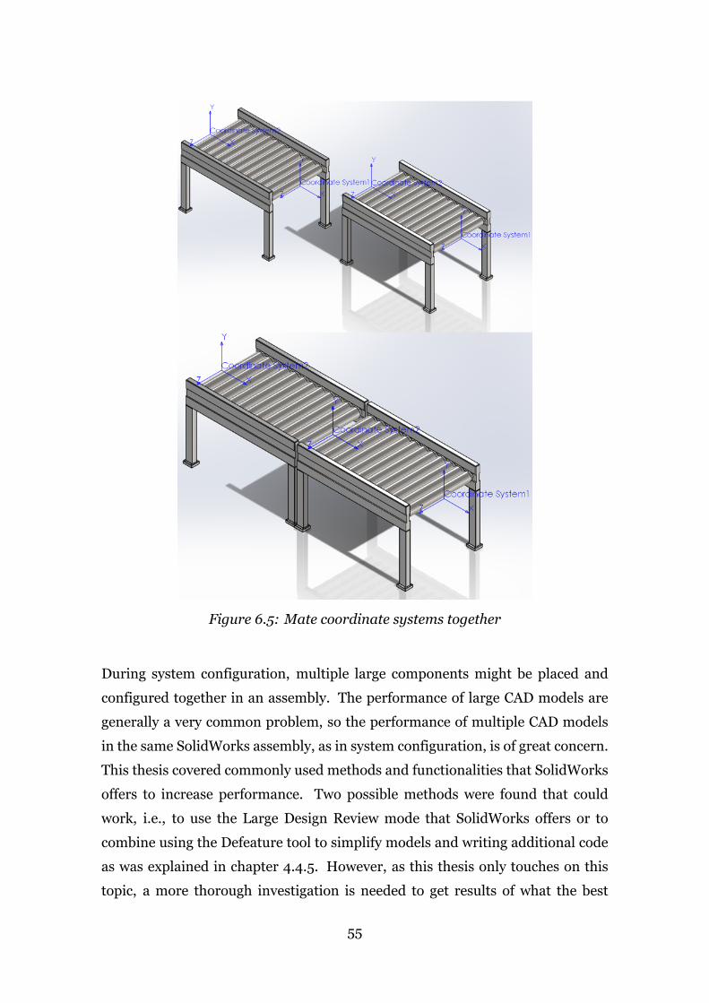
Figure 6.5: Mate coordinate systems together
During system configuration, multiple large components might be placed and
configured together in an assembly. The performance of large CAD models are
generally a very common problem, so the performance of multiple CAD models
in the same SolidWorks assembly, as in system configuration, is of great concern.
This thesis covered commonly used methods and functionalities that SolidWorks
offers to increase performance. Two possible methods were found that could
work, i.e., to use the Large Design Review mode that SolidWorks offers or to
combine using the Defeature tool to simplify models and writing additional code
as was explained in chapter 4.4.5. However, as this thesis only touches on this
topic, a more thorough investigation is needed to get results of what the best
55

solution to this problem is.
Another issue that needs to be solved is how to handle multiple instances of
the same model within SolidWorks. If more than one instance of the same
model is inserted in an assembly, SolidWorks will treat them the same way,
meaning that if one model is configured using Tacton DA, the other instance of
the model will automatically update exactly the same. To solve that problem, it
is possible to make the extra instances virtual and independent. By doing so, the
virtual instances are stored internally in the assembly file and can be configured
independently and then saved in the end when the configuration process is done.
This solution supports the way how the configuration process is done today, by
saving everything after the configuration is done when the files are exported and
saved.
56

7 Discussion and Future Work
This project investigated the foundation of system configuration in general,
i.e., the different types of system structures and the relationships between the
configurable modules within the system.
There aremany undetermined aspects when it comes to system configuration, and
it is necessary for Tacton to look at the future development in a holistic view. This
thesis project focused on investigating the possibility of system configuration in
the DA environment. However, the study revealed a need for it in other solutions
as well, such as in Tactons’ sales product, CPQ. Future work needs to be done
to decide how system configuration should be done in CPQ. When it has been
determined what information is defined by the user, how it is defined and when
in the process, it is possible to answer some of the unanswered questions such as
if the interfaces between the modules can carry information that makes different
types of parameters irrelevant. And then, if that information can be transferred
and re-used in the DA setting.
Furthermore, in this project, procedureswere established for how3DCADmodels
should be built and structured to work in a good and robust way for system
configuration. This research was limited to the SolidWorks CAD environment
but could easily be expanded to other CAD software such as Autodesk Inventor
or PTC Creo in the future. SolidWorks, like other CAD vendors, is continuously
expanding its capabilities and releasing new functions. Because of that, it will
be necessary to review what capabilities SolidWorks has introduced in its latest
releases at the time system configuration will be developed in Tacton DA.
57


References
Amadori, K., Tarkian, M., Ölvander, J. & Krus, P. (2012), ‘Flexible and robust cad
models for design automation’, Advanced Engineering Informatics 26(2), 180
– 195. Knowledge based engineering to support complex product design.
Blackenfelt, M. (2001), ‘Managing complexity by product modularisation’,
Doctoral Thesis, Department of Machine Design, The Royal Institute of
Technology .
Cederfeldt, M. & Elgh, F. (2005), ‘Design automation in smes - current state,
potential, need and requirements’, ICED 05 15th International conference on
engineering design .
Ernfors, J. (2009), ‘Riktlinjer för att konfigurera parametriskt definierade digitala
artikel- och produktmodeller’, Master’s Thesis, Department of Production
Engineering, The Royal Institute of Technology .
Forza, C. & Salvador, F. (2002), ‘Managing for variety in the order acquisition
and fulfilment process: The contribution of product configuration systems’,
International Journal of Production Economics 76(1), 87 – 98.
Haug, A., Hvam, L. &Mortensen, N. (2012), ‘Definition and evaluation of product
configurator development strategies’, Computers in Industry 63(5), 471–481.
Hicks, C., McGovern, T. & Earl, C. (2000), ‘Supply chainmanagement: A strategic
issue in engineer to order manufacturing’, International Journal of Production
Economics 65(2), 179 – 190.
Hull, E., Jackson, K. & Dick, J. (2011), Requirements engineering, Springer
Publishing Company, New York.
Hvam, L. (2006), ‘Mass customisation in the electronics industry: based on
modular products and product configuration’, Int. J. Mass Custom. 1(4), 410–
426.
Kristianto, Y., Helo, P. & Jiao, R. J. (2015), ‘A system level product configurator
for engineer-to-order supply chains’, Computers in Industry 72, 82 – 91.
59

Myrodia, A., Kristjansdottir, K. & Hvam, L.
(2017), ‘Impact of product configuration systems on product profitability and
costing accuracy’, Computers in Industry 88, 12 – 18.
Orsvärn, K. & Axling, T. (1999), ‘The Tacton View of Configuration Tasks and
Engines’, Workshop on Configuration, Sixteenth National Conference on
Artificial Intelligence pp. 127–130.
Sabin, D.&Weigel, R. (1998), ‘Product configuration frameworks - a survey’, IEEE
Intelligent Systems and their Applications 13(4), 42–49.
Schwieterman, E. (2019), ‘Automating solidworks assemblies using reference
geometry and api’. [Accessed on 27 March 2019].
URL: https://solidworksworld.lanyonevents.com/2019/connect/
sessionDetail.ww?SESSION_ID=12972
SOLIDWORKS (2016), ‘Reference geometry’. [Accessed on 10 April 2019].
URL: http://help.solidworks.com/2016/english/solidworks/sldworks/
c_reference_geometry_overview.htm
SOLIDWORKS (2017a), ‘Speedpak’. [Accessed on 18 April 2019].
URL: http://help.solidworks.com/2017/english/solidworks/sldworks/
c_speedpak_oh.htm
SOLIDWORKS (2017b), ‘Lightweight components’. [Accessed on 18 April 2019].
URL: http://help.solidworks.com/2017/english/SolidWorks/sldworks/
c_lightweight_components_swassy.htm
SOLIDWORKS (2018a), ‘Smartmates’. [Accessed on 15 April 2019].
URL: https://help.solidworks.com/2018/English/SolidWorks/sldworks/c_
SmartMates_Overview_SWassy.htm?id=e433356359924f1b904819945333abab#Pg0
SOLIDWORKS (2018b), ‘Using the defeature tool’. [Accessed on 19 April 2019].
URL: http://help.solidworks.com/2018/english/SolidWorks/sldworks/
t_defeature-using_the_defeature_tool.htm
SOLIDWORKS (2019a), ‘Default templates options’. [Accessed on 10 April 2019].
URL: https://help.solidworks.com/2019/English/SolidWorks/sldworks/
HIDD_OPTIONS_TEMPLATE_DEFAULTS.htm
60

SOLIDWORKS (2019b), ‘Magnetic mates’. [Accessed on 15 April 2019].
URL: http://help.solidworks.com/2019/english/SolidWorks/sldworks/
c_magnetic_mates_intro.htm
SOLIDWORKS (2019c), ‘Large assembly mode’. [Accessed on 18 April 2019].
URL: https://help.solidworks.com/2019/english/SolidWorks/sldworks/
r_Large_Assembly_Mode_SWassy.htm
SOLIDWORKS (2019d), ‘Improved large assembly performance’. [Accessed on 18
April 2019].
URL: https://www.solidworks.com/feature/improved-large-
assembly-performance
SOLIDWORKS (2019e), ‘Speedpak’. [Accessed on 19 April 2019].
URL: http://help.solidworks.com/2019/English/SolidWorks/sldworks/
c_SpeedPak_OH.htm
Tacton (2019), ‘About tacton’. [Accessed on 31 January 2019].
URL: https://www.tacton.com/about-tacton/
Tseng, M. M. & Hu, S. J. (2014), ‘Mass customization’, CIRP Encyclopedia of
Production Engineering pp. 836–843.
Verhagen, W. J., Bermell-Garcia, P., van Dijk, R. E. & Curran, R. (2012), ‘A
critical review of knowledge-based engineering: An identification of research
challenges’, Advanced Engineering Informatics 26(1), 5 – 15.
61


Appendix A: Interviewees
Job Title at Tacton Systems AB ↓ DateSenior Sales Executive 2019-02-06
Partner Sales Engineer 2019-02-06
Customer Success Manager 2019-02-07
VP Channel Sales and Design Automation 2019-02-07
Business Consultant 2019-02-08
Senior Sales Executive 2019-02-11
Solution Architect 2019-02-11
Customer Success Manager 2019-02-15
Principal Application Consultant 2019-02-19
Director Alliances Americas 2019-03-07
Product Marketing Manager 2019-03-15
Business Consultant 2019-03-19
Senior Product Manager 2019-05-06
Software Developer 2019-05-06
VP Product Management 2019-05-17
Job Title at Customer Company ↓ DateProduct Configuration Engineer 2019-02-21
Design Automation 2019-02-27
Lead Engineer 2019-03-07
63


TRITA ITM-EX 2019:157
www.kth.se