
System Architecture Specification Based on Behavior Models
20
15th ICCRTS “The Evolution of C2” System Architecture Specification Based on Behavior Models Paper ID 053 Topic 6: Modeling and Simulation Topic 8: C2 Assessment Metrics and Tools Topic 9: C2 Architectures and Technologies Authors: Mikhail Auguston, Clifford Whitcomb Point of Contact: Dr. Mikhail Auguston Computer Science Department Naval Postgraduate School 1411 Cunningham Rd, Monterey, CA, 93943-5201, USA Phone: 1-831-656-2607 email: [email protected] web: http://www.nps.navy.mil/cs/auguston/ Dr. Clifford Whitcomb Chairman, Systems Engineering Department, Naval Postgraduate School 1 University Circle, Code SE, Monterey, California, USA, 93943 phone: (831) 656-3001 fax: (831) 656-3129 email: [email protected] 1
-
Upload
khangminh22 -
Category
Documents
-
view
0 -
download
0
Transcript of System Architecture Specification Based on Behavior Models
15th ICCRTS “The Evolution of C2”
System Architecture Specification Based on Behavior
Models
Paper ID 053
Topic 6: Modeling and Simulation Topic 8: C2 Assessment Metrics and Tools Topic 9: C2 Architectures and Technologies
Authors: Mikhail Auguston, Clifford Whitcomb
Point of Contact: Dr. Mikhail Auguston
Computer Science Department Naval Postgraduate School
1411 Cunningham Rd, Monterey, CA, 93943-5201, USA Phone: 1-831-656-2607
email: [email protected] web: http://www.nps.navy.mil/cs/auguston/
Dr. Clifford Whitcomb Chairman, Systems Engineering Department,
Naval Postgraduate School 1 University Circle, Code SE,
Monterey, California, USA, 93943 phone: (831) 656-3001
fax: (831) 656-3129 email: [email protected]
1
System Architecture Specification Based on Behavior Models
Mikhail Auguston, Clifford Whitcomb Department of Computer Science, Department of Systems Engineering
Naval Postgraduate School Monterey, CA 93943, USA
Email: [email protected], [email protected] Abstract. This paper suggests an approach to formal software and system architecture specification based on behavior models. The behavior of the system is defined as a set of events (event trace) with two basic relations: precedence and inclusion. The structure of event trace is specified using event grammars and other constraints organized into schemas. The framework provides high level abstractions for analyzing system behavior properties expressed as computations over event traces. The automated tools can support extracting of different views from the model, and verification of behavior properties within a given scope. Advantages of this approach compared with the common simulation tools are as follows.
• Means to write assertions about the system behavior and tools to verify those assertions. • Exhaustive search through all possible scenarios (up to the scope limit). The small scope hypothesis states
that most of errors can be demonstrated on small examples. • The support for verifiable refinement of the architecture model, up to design and implementation models. • Integration of the architecture models with environment models for defining typical scenarios (use cases) and
verifying system’s behavior for those scenarios.
Keywords: system and software architecture models, architecture verification
1. Introduction One of the major concerns in the design of complex engineered systems from a holistic perspective is the question of the behavior of the system. This behavior must be modeled and analyzed simultaneously from software, hardware, and human aspects with concurrent consideration of the environment in which the system operates. The development of executable architecture models can allow for the study of emergent behaviors through computational modeling and simulation during the earliest stages of conceptual design. Architecture development is done very early in both the software and system design process and is concerned with the high-level structure and properties of the system. Software architecture can be viewed as a level of design and modeling that forms a bridge between requirements and code [10]. System architecture can be seen as an initial level of design and system modeling that forms the fundamental basis for defining elements, including software, hardware, and humans, and their relationships to one another and their operating environment considering stakeholder concerns. The purpose of this research is to demonstrate that behavior models may be used as a basis for system and software architecture description, that structural and some other properties may be extracted from the behavioral specifications, and that this framework can be supported by automation tools for the validation and verification of the developed architecture models. The following aspects define the characteristics for architecture descriptions [9][1][15]. • An architecture description belongs to a high level of abstraction, ignoring many of the
implementation details, such as algorithms and data structures.
• Architecture plays a role as a bridge between requirements and implementation.
• A system architecture model becomes the earliest form of the system structure, and is created so that stakeholders and designers can begin to reason about various proposed "to-be" alternatives.
2

• A system architecture model must allow for simulation in order to study behaviors and determine possible emergent properties.
• An architecture specification should be supportive for the refinement process, and needs to be checked carefully at each refinement step (preferably with tools).
• An architecture specification should support the reuse of well known architectural styles and patterns. Practice has provided several architectural styles and referential architectures, as well established, reusable architectural solutions. There should be flexible and expressive composition operators supporting the refinement process.
• Software and system architects need a number of different views of the architecture for the various uses and users (including visual representations, like diagrams).
In this paper we suggest a framework for system and software architecture specification called Monterey Phoenix. Our purpose is to demonstrate that behavior models may be used as a basis for software architecture description, that structural and some other properties may be extracted from the behavioral specifications, and that this framework can be supported by automation tools for the validation and verification of the developed architecture models. The initial idea for this work was well received by the research community, and the first publications have appeared in renowned software engineering conference proceedings [4], and in a journal [5]. 2. Technical Approach The tools and methods developed within Monterey Phoenix project will provide a significant improvement in our ability to develop system architecture, and to verify and test requirements and design decisions early in the development process. The approach supports the design of automation tools for architecture verification and validation, and for architecture model reuse. The main objectives of this research work are: • To develop a new approach to software and system architecture formal specification based on
behavior models. • To make architecture models executable on an abstract machine, so that it becomes possible
early in the system development phase to do testing and verification of the top level system design. Typical properties that can be verified/tested within this framework include:
a. Architecture’s behavioral properties, like event coordination, event patterns, and potential concurrency faults (deadlock, data race).
b. Performance estimates (like latency, throughput, and delays). c. With behavior model enhanced with the event attributes it becomes possible to
test/verify properties like security data flow, and covert channels [16][17]. d. Event trace models are also amenable for dynamic architecture specification.
• To provide a method and tools for extracting multiple views from the architecture models, and corresponding visualization tools that can be customized to the user’s needs.
• To provide the method for system stepwise refinement from the top level architecture models to the detailed design and implementation models, supported by tools for sanity checks and refinement consistency checks.
• To provide formalism for specifying system’s environment models, based on the behavior modeling, so that the system architecture can be tested and verified in the interaction with its environment.
3

The main novelty of this work is in the method for system behavior modeling based on event traces, which provides a high level of abstraction for system architecture and its environment descriptions, supports stepwise refinement up to the detailed design models, and allows architecture reuse, composition, and tool use for sanity checks during the process.
2.1 Behavior Models and the Event Concept In a certain sense, software development is a process aimed at the design of a compact description of a set of required behaviors. The source code written in any programming language - a finite object by itself - specifies a potentially infinite number of execution paths.
Our approach focuses on the notion of an event, which is an abstraction for any detectable action performed during the program execution, such as a statement execution, expression evaluation, procedure call, message transmission and reception, etc. An event has beginning, end, and duration, and usually corresponds to a time interval.
Actions (or events) are evolving in time, and the behavior model represents the temporal relationship between actions. This implies the necessity to introduce an ordering relation for events. Actions performed during the program execution are at different levels of granularity, some of them including other actions, e.g., a subroutine call event contains statement execution events. This consideration brings inclusion relation to the model. Under this relationship events can be hierarchical objects, and it becomes possible to consider behavior at the appropriate levels of granularity.
Two basic relations are defined for events: precedence (PRECEDES) and inclusion (IN). The behavior model of the system can be represented as a set of events with these two basic relations defined for them (event trace). Each of the basic relations defines a partial order of events. Two events are not necessarily ordered, that is, they may happen concurrently. Both relations are transitive, non-commutative, non-reflexive, and satisfy distributivity constraints. The following axioms should hold for any event trace. Let a, b, and c be events of any type.
Mutual Exclusion of Relations
Axiom 1) a PRECEDES b ⇒ ¬(a IN b) Axiom 2) a PRECEDES b ⇒ ¬(b IN a) Axiom 3) a IN b ⇒ ¬(a PRECEDES b) Axiom 4) a IN b ⇒ ¬(b PRECEDES a)
Non-commutativity
Axiom 5) a PRECEDES b ⇒ ¬(b PRECEDES a) Axiom 6) a IN b ⇒ ¬(b IN a)
Irreflexivity for PRECEDES and IN follows from non-commutativity.
Transitivity
Axiom 7) (a PRECEDES b) ∧ (b PRECEDES c) ⇒ (a PRECEDES c) Axiom 8) (a IN b) ∧ (b IN c) ⇒ (a IN c)
Distributivity
Axiom 9) (a IN b) ∧ (b PRECEDES c) ⇒ (a PRECEDES c) Axiom 10) (a PRECEDES b) ∧ (c IN b) ⇒ (a PRECEDES c) Event trace is always a directed acyclic graph. This concept of behavior modeling is one of the most distinctive novelty features of our approach.
4

2.2 Event Grammar The structure of possible event traces is specified by an event grammar. A grammar rule specifies structure for a particular event type (in terms of IN and PRECEDES relations). There are the following event patterns for use in the grammar rule’s right hand part. Here A, B, C, D stand for event type names or event patterns. Events may be visualized by small circles, and basic relations - by arrows, like
IN
PRECEDES
1) Sequence denotes ordering of events under the PRECEDES relation. The rule A:: B C; means that an event a of the type A contains ordered events b and c matching B and C, correspondingly (b IN a, c IN a, and b PRECEDES c). A grammar rule may contain a sequence of more than two events, like A:: B C D;
The rule A:: B C; specifies the following event trace.
A
B C
2) A:: (B | C); denotes an alternative - event B or event C. 3) A:: (* B *); means an ordered sequence of zero or more events of the type B. Here is an example of an event trace satisfying this pattern:
A
B B
B
The relations induced by the transitivity and the distributivity axioms are not explicitly shown in this and following pictures. 4) A:: [B]; denotes an optional event B. 5) A:: { B, C }; denotes a set of events B and C without an ordering relation between them.
C
A
B
5

6) A:: {* B *}; denotes a set of zero or more events B without an ordering relation between them. Extension (+ B +) may be used to denote a sequence of one or more events B, and {+ B +} as a set of one or more events B. Together with (* … *) and {* … *} event patterns those may be useful for specifying dynamic architectures.
2.3 Schema as a Behavior Specification for an Abstract Machine An abstract machine is a model of a software system. The behaviors of a particular abstract machine are specified as a set of all possible event traces using a schema. The concept of the Phoenix schema is inspired by Z schema [18]. The schema is similar to the fundamental architectural concept of configuration, which is a collection of interacting components and connectors, as introduced in [1]. A schema may define both finite and infinite traces, but most analysis tools for reasoning about a system’s behavior assume that a trace is finite.
Specifying the PRECEDES relation for a pair of events in the schema is usually a substantial design decision, manifesting the presence of a cause/effect in the model or other essential dependency condition for these events.
Some events appearing in the schema’s rule section at the left-hand side of the grammar rule are marked as root events. Usually root events correspond to the components and connectors in traditional architecture descriptions, while other event types are used to specify event structure and interactions. Example 1. Simple transaction. A very simple architectural model contains two components TaskA and TaskB with a connector between them. The presence of a connector usually means that components can interact, for example send and receive a message, call each other and pass a parameter, or use a shared memory to deliver a data item. The schema Simple_transaction specifies the behavior of components involved in a single transaction. Simple_transaction
root TaskA:: Send;
root TaskB:: Receive;
root Transaction:: Send Receive;
TaskA, Transaction share all Send;
TaskB, Transaction share all Receive;
The rule section introduces root events TaskA, TaskB, and Transaction, while Send and Receive events are needed to specify the root event’s structure. The event type stands for a set of event traces satisfying the event structure defined for that type. The constraints section uses the predicate share all, which is defined as following (here X, Y are root events, and Z is an event type).
X, Y share all Z ≡ { v: Z | v IN X} = {w: Z | w IN Y}
Event sharing in Phoenix plays the role of a synchronization mechanism similar to the communication events in CSP [11].
6

2.4 Schema Interpretation Similarly as context-free grammars could be used to generate strings, event grammars could be used as production grammars to generate instances of event traces (or graphs). The grammar rules in a schema S can be used for the basic trace generation, with the additional schema constraints filtering the generated traces to a set of traces called Basic(S). The process of generating traces from Basic(S) defines the semantics of the schema S and could be specified in the form of an abstract machine. If such an abstract machine can be designed for a particular version of Phoenix, it becomes possible to claim that schemas are executable.
The schema represents instances of behavior (event traces), in the same sense as a Java source code represents instances of program execution. Just as a particular program execution path can be extracted from a Java program by running it on the JVM, similarly a particular event trace from the Basic(S) can be extracted by running S on the Phoenix abstract machine, i.e. by generating a trace instance.
Traces from Basic(S) can be refined by introducing additional events, event types, and basic relations between them, while maintaining the consistency with original trace’s constraints. Checking this property during the schema’s refinement process may be one of the main applications for formal methods and tools supporting the Phoenix framework.
Figure 1 renders the only event trace from the Basic(Simple_transaction). There may be other traces consistent with the structure imposed by the schema, for example, a trace with an additional relation TaskA PRECEDES TaskB, but those traces with redundant relations (or redundant events) not imposed by the schema are not accepted as members of the basic trace set defined by the schema.
TaskA TaskB Transaction
Send Receive
Figure 1. Example of event trace for Simple_transaction schema
This example demonstrates that both a component and a connector within a model are uniformly characterized by the patterns of behavior; each of them is modeled as a certain activity using an event trace. Synchronization patterns may be specified using share all constraints.
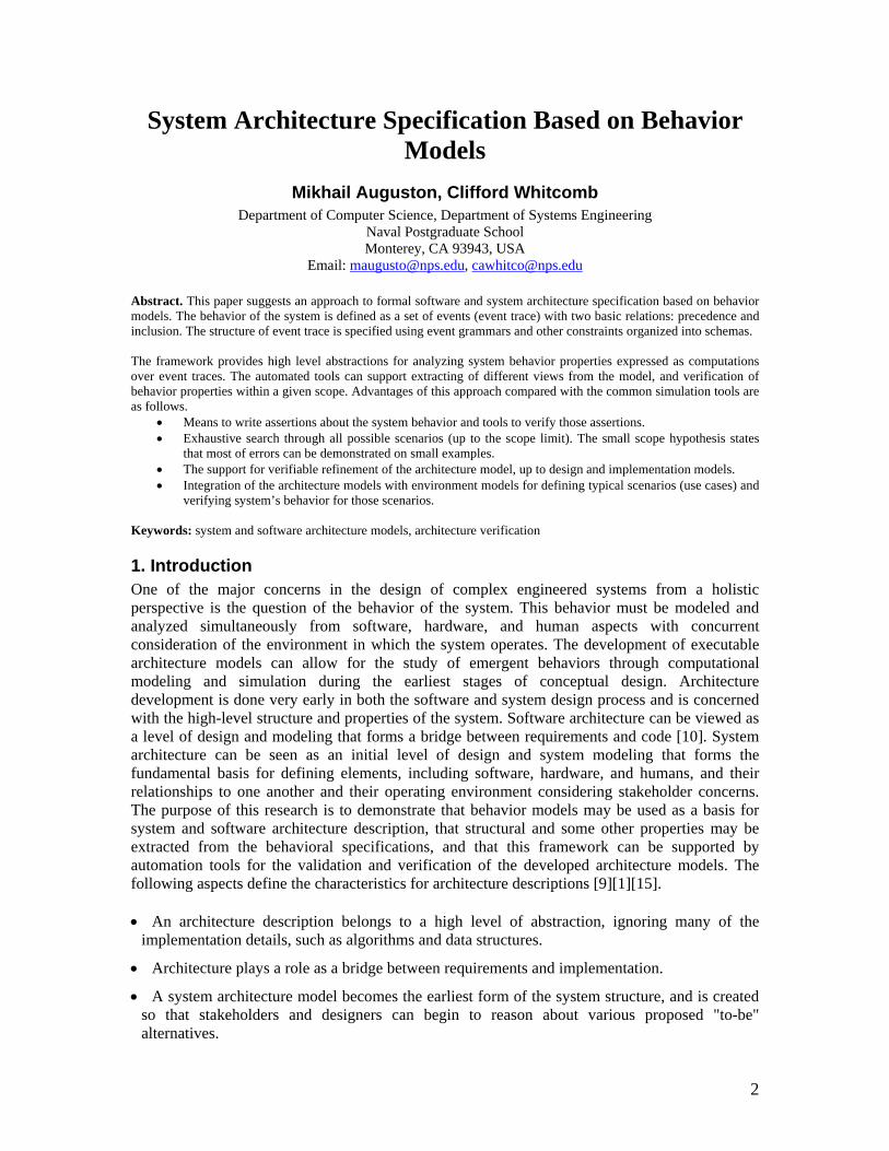
Alloy Analyzer [3] is a good candidate for implementing the Phoenix Abstract Machine. The following event trace for Example 1 was obtained by prototyping on Alloy Analyzer. The complete Alloy model for this schema can be found in the Appendix 1 in the paper [5].
7
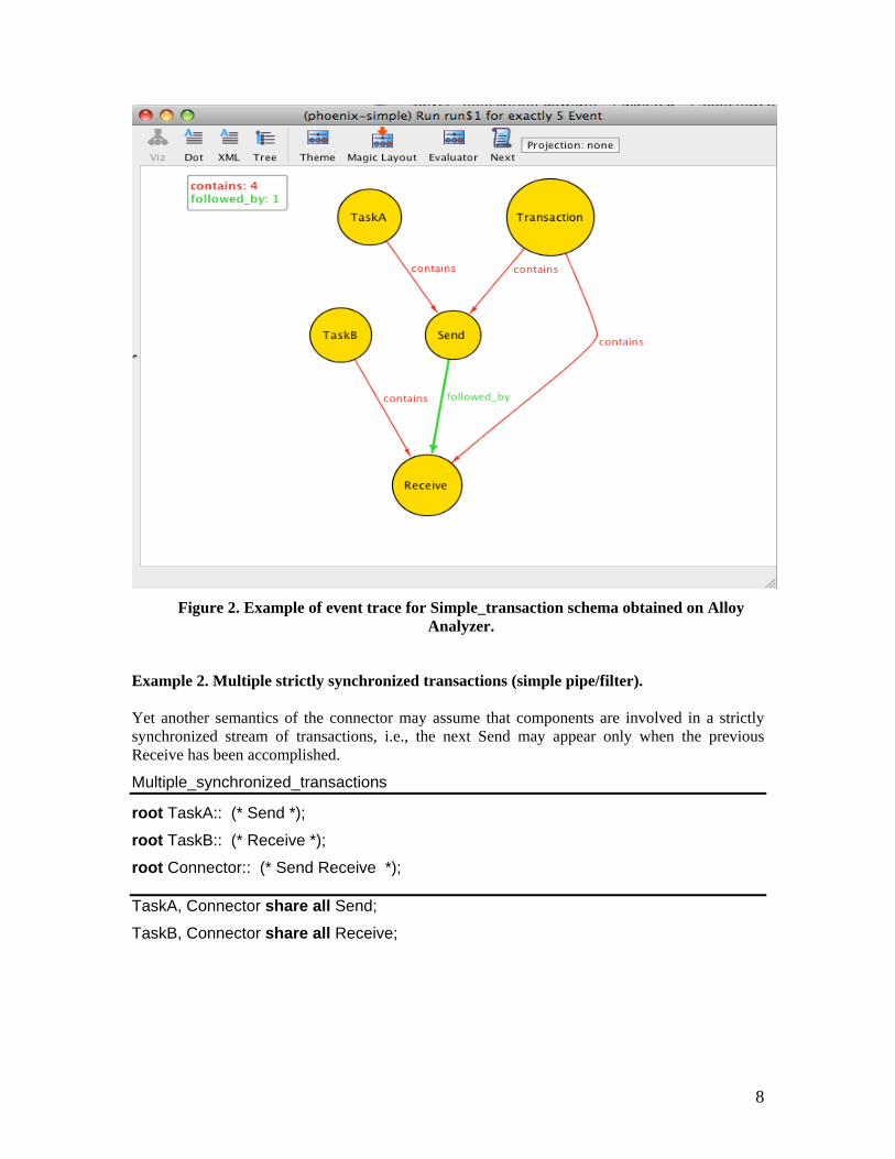
Figure 2. Example of event trace for Simple_transaction schema obtained on Alloy
Analyzer.
Example 2. Multiple strictly synchronized transactions (simple pipe/filter). Yet another semantics of the connector may assume that components are involved in a strictly synchronized stream of transactions, i.e., the next Send may appear only when the previous Receive has been accomplished.
Multiple_synchronized_transactions
root TaskA:: (* Send *);
root TaskB:: (* Receive *);
root Connector:: (* Send Receive *);
TaskA, Connector share all Send;
TaskB, Connector share all Receive;
8

TaskA
TaskB
Send
Connector
Receive
Receive
Send
Figure 3. Example of event trace for multiple synchronized transactions
PRECEDES relations enforced by the transitivity are not shown. The Connector event represents the communication activity, and may be refined further to provide details of the synchronization protocol.
2.5 Architecture Visualization and Views Different abstract views could be extracted from the Phoenix schemas. For example, let X and Y be the root events in the schema S, if there is at least one event trace in Basic(S), such that the predicate
CONNECTED(X, Y) ≡ ∃a ((a IN X) and (a IN Y))
is true on that trace, then a dependency exists between events X and Y in terms of sharing an event. This may be a data item sharing event, or method’s call, or any other synchronized activity between X and Y captured by the schema model. The root events correspond to components and connectors, and usually are rendered as boxes in architecture diagrams. The dependency between them could be visualized by connecting corresponding boxes in the diagram.
The architecture diagrams in Figure 4 (views of the static structure with respect to the root events) are extracted from behavior models in schemas Simple_transaction and Multiple_synchronized_transactions and are based on the CONNECTED predicate.
T askA T ran sactio n T askB
S im p le_ tr ans actio n
M u ltiple_ sy nch ro n ized _ tr an sac tio ns
T askA C on n ec to r T askB
Figure 4. Diagrams extracted from the schemas
9

Those models seem to be more abstract than corresponding schemas, and missing some details about the component’s interaction, but still may be of interest. This kind of abstraction is similar to a number of architecture description techniques currently in use.
Defining appropriate predicates on the events in the schema and mapping those events and relations into different kinds of diagrams may yield multiple architecture views. The IN relation provides for choice of granularity in rendering the hierarchy of models. Event threads loosely coupled by synchronization events (event sharing) may be used to model the separation of concerns issues. It seems that this way of extracting views from the architecture descriptions could provide at least the logical, process, and scenario (or event trace) views as suggested in the 4+1 view model [21].
2.6 Composition and Reuse Example 3. Compiler front end in batch processing mode. The simple model of lexical analyzer captures the behavior of the typical LEX machine. Lexer Input:: (* (Get_char | Unget_char) *); Output:: (* Put_token *); root Processing:: (* Token_recognition *); include Token_processing Processing, Input share all Get_char, Unget_char; Processing, Output share all Put_token; The root event is Processing, whereas Input and Output are auxiliary events to a large degree similar to the role concept in [2]. Their role is to define sort of pre- and post- conditions for the Processing component, formalizing our assumptions about input and output streams of events. These constraints should be checked for consistency when added to the schema. The structure of the Token_recognition event is defined in the schema Token_processing and is included (reused) in the Lexer schema. It refines the Lexer behavior toward the typical Unix/LEX semantics, when the regular expression in each LEX rule is applied independently, and hence no ordering is imposed. Each RegExpr_Match consumes one or more Get_char events until all finite automata involved in the token recognition enter the Error state, then the winner is selected and all look-ahead characters beyond the recognized lexeme are returned back into the input stream by Unget_char; the Fire_rule event follows it. As a result of the include composition operation the root mark is deleted. Token_processing root Token_recognition:: {* RegExpr_Match *} (* Unget_char *) Fire_rule; RegExpr_Match:: (+ Get_char +); Fire_rule:: Put_token; all RegExpr_Match share all Get_char; |{x: Get_char | x IN Token_recognition}| > |{ y: Unget_char | y IN Token_recognition}|; The first constraint enables synchronization between a sequence of one or more consecutive Get_char and a single Put_token, which follows this Get_char group via the Fire_rule. The second constraint ensures that at least one character will be consumed. All those constraints are imposed on the Lexer’s behavior when the Token_processing schema is included.
10

The following schema provides a rough model of a bottom-up parsing with a stack (represented by Push and Pop events). Parser Input:: (* Get_token *); Output:: (* Put_node *); root Parsing:: Push -- push the start symbol (* Get_token (* Reduce *) Shift *) [Syntax_error]; Shift:: Push ; Reduce:: (+ Pop +) Push Put_node; include Stack;
Parsing, Input share all Get_token; Parsing, Output share all Put_node; Parsing, Stack share all Pop, Push; Put_node events represent the construction of a parse tree. The behavior of the stack can be encapsulated for reuse in a separate schema and included in the Parser schema when needed. Stack behavior constraint will be inherited from the include operation. Stack ______________________________________________________________________ root Stack_operation:: (* ( Push | Pop ) *); ______________________________________________________________________ ∀x: Pop ( |{ y: Push | y PRECEDES x}| > |{ z: Pop | z PRECEDES x}| ); To merge both Lexer and Parser schemas into a single schema we need to tell how those components will interact. The following schema specifies batch processing. Batch_processing root Batch:: Produce_tokens Consume_tokens;
Produce_tokens:: (* Put_token *); Consume_tokens:: (* Get_token *); _____________________________________ ________________________________ |{x: Put_token | x IN Batch }| >= |{y: Get_token | y IN Batch}|
The ordering of Produce_tokens and Consume_tokens events in this schema ensures that production of the whole set of tokens will precede the consumption. The constraint requires that the number of produced tokens is sufficient, although there is no specific requirement how the tokens are consumed (e.g. by storing them in the queue or on the stack). The composition of the component and the connector architectures is described by the schema composition operation merge. The result is a new schema Batch_parsing. Batch_parsing merge Lexer, Parser, Batch_processing ; Lexer, Batch_processing share all Put_token; Parser, Batch_processing share all Get_token;
11

The diagram on Figure 5 represents a simplified component/connector view of this architecture.
Lexer/Processing
Batch_processing/Batch
Parser/Parsing
Figure 5. Diagram extracted from the Batch_parsing schema
Example 4. Compiler’s front end in incremental mode. Yet another possible interaction is a mode in which the Parser requests the next token and triggers an event inside the Lexer, generating a token (the traditional LEX/YACC operation pattern). The schema Incremental represents this operation mode. The IN relation imposed here reflects the synchronization between events from the Lexer and Parser schemas involved in token request/delivery. In fact, the Get_token event is now refined with the Token_recogniton event. Incremental Get_token:: Token_recognition; The composition of components with another connector schema is done in the same fashion. Incremental_parsing merge Lexer, Parser, Incremental; Lexer, Parser share all Token_recognition; The merged architecture defines a set of event traces where all structuring is inherited from Lexer, Parser, and Incremental schemas with the additional constraints for sharing the token processing events. The basic sanity checks for consistency of merged event sets (traces) may be reduced to standard regular expression equivalence and inclusion problems, and can be done by automated tools. The root events are inherited from all schemas. With the help of a CONNECTED predicate the root events may be rendered in Figure 6 diagram. This time both Lexer and Parser components are interacting directly via the shared Token_recogniton event, and there is no connector box.
12
Lexer/Processing
Parser/Pars ing
Figure 6. Diagram extracted from the Incremental_parsing schema
The examples above demonstrate the architecture reuse. Tools like Alloy Analyzer [3] can be used for sanity checks to verify whether the merged schema still has trace instances.
2.7 Event Attributes and Refinement At the top levels of architecture description schemas usually are focused on capturing event trace structure in terms of basic relations and event sharing (synchronization or coordination). With the progress of refinement the need to introduce more detailed view on data flow starts to appear. In order to specify meaningful system behavior properties events are enriched with attributes. An event may have a type and other attributes, such as event begin time, end time, duration, program state associated with the event (i.e. variable values at the beginning and at the end of event), etc.
To manage event attributes the concept of special event is introduced. Typically it represents some operation with event attributes and is enclosed in a pair of symbols / and /. In addition there are special events that may influence structure of event trace for alternatives depending on conditions of certain event attributes, like
IF (condition involving attributes) THEN E1 ELSE E2
This special event refines on the event alternative (E1 | E2) by making the choice depending on the value of the condition. In a similar way the number of event iterations may be constrained by conditions involving attributes, like WHILE(condition involving attributes) (* E *).
Special event is subjected to the basic relations IN and PRECEDES like any other event. The semantics of special events requires them to be executed in accordance to the PRECEDES. Thus if for special events S1 and S2 holds S1 PRECEDES S2 then S1 should be evaluated before S2.
Example 5. Implementation model
Phoenix emphasizes top-down design. Using special events and event attributes it becomes possible to refine schemas to the level when mapping into executable program becomes straightforward. Factorial_calculation ______________________________________________________________________ root Main:: /enter (Factorial.input);/ Factorial /print (Factorial.output);/ ;
Factorial:: IF ( Factorial[1].input <= 1) THEN /Factorial[1].output = 1;/
ELSE ( /Factorial[2].input = Factorial[1].input -1;/ Factorial
/Factorial[1].output = Factorial[2].output * Factorial[1].input;/ ) ;
13
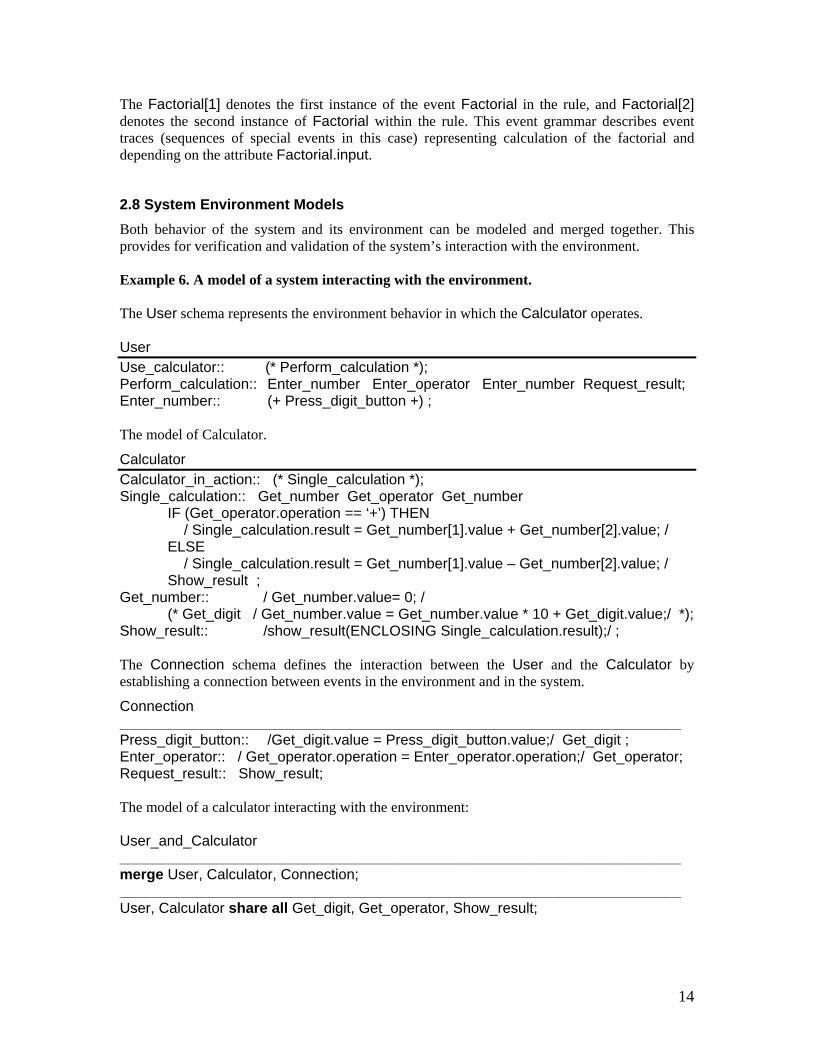
The Factorial[1] denotes the first instance of the event Factorial in the rule, and Factorial[2] denotes the second instance of Factorial within the rule. This event grammar describes event traces (sequences of special events in this case) representing calculation of the factorial and depending on the attribute Factorial.input.
2.8 System Environment Models Both behavior of the system and its environment can be modeled and merged together. This provides for verification and validation of the system’s interaction with the environment. Example 6. A model of a system interacting with the environment. The User schema represents the environment behavior in which the Calculator operates. User Use_calculator:: (* Perform_calculation *); Perform_calculation:: Enter_number Enter_operator Enter_number Request_result; Enter_number:: (+ Press_digit_button +) ; The model of Calculator.
Calculator Calculator_in_action:: (* Single_calculation *); Single_calculation:: Get_number Get_operator Get_number IF (Get_operator.operation == ‘+’) THEN / Single_calculation.result = Get_number[1].value + Get_number[2].value; / ELSE / Single_calculation.result = Get_number[1].value – Get_number[2].value; / Show_result ; Get_number:: / Get_number.value= 0; / (* Get_digit / Get_number.value = Get_number.value * 10 + Get_digit.value;/ *); Show_result:: /show_result(ENCLOSING Single_calculation.result);/ ; The Connection schema defines the interaction between the User and the Calculator by establishing a connection between events in the environment and in the system.
Connection _____________________________________________________________________ Press_digit_button:: /Get_digit.value = Press_digit_button.value;/ Get_digit ; Enter_operator:: / Get_operator.operation = Enter_operator.operation;/ Get_operator; Request_result:: Show_result; The model of a calculator interacting with the environment: User_and_Calculator _____________________________________________________________________ merge User, Calculator, Connection; _____________________________________________________________________ User, Calculator share all Get_digit, Get_operator, Show_result;
14

2.9 Assertions about event traces and model verification The same formalism used to specify schemas could be used to specify assertions about event traces, and is amenable to applying tools to verify or refute those assertions. The spectrum of properties covers a broad range from purely structural properties (e.g. to assert that selected subset of events within trace is totally ordered) to more detailed assertions involving event attributes. Of special interest may be properties involving event’s timing attributes. Event duration and frequency estimates obtained from the model may be used to figure out throughput and latency estimates, in particular, when combined with the environment behavior models. Tools for assertion checking implement Phoenix schemas simulation and apply assertion checking to all traces up to a certain limit. The simulation approach to model verification is based on the “small scope hypothesis”[13] stating that that if an assertion is invalid, it probably has a small counterexample (“most bugs have small counterexamples”). We find an inspiration in the statement by D.Jackson: ”Exploiting tools to check arguments at the design and requirements level may be more important, and it is often more feasible since artifacts at the higher level are much smaller” [20]. Here are some concepts of the Monterey Phoenix language necessary for understanding the following example, which demonstrates that typical scenarios could be defined, and typical errors could be detected on a relatively small traces.
Slices Slice is a set of concurrent events within the event trace (i.e. events that “may overlap”). The => operator here denotes PRECEDES relation. Concurrent(x, y) ≡ ¬(x => y) & ¬(y => x) But x and y may be under the in relation, or have common parent or common children events. Slice is a set of events from the event trace, such that
∀x,y ∈ Slice Concurrent(x, y)
Slice may be empty, e.g. at the beginning or at the end of a composite event.
When construct The When clause determines the structure of an event defined by the event grammar rule. It is similar in meaning to the exception handling construct in traditional programming languages like Java. E: P1 When {A => P2, B => P3}; Here E, A, B are event types, and P1, P2, P3 are event patterns. This grammar rule defines the structure of event E as following. The main alternative is defined by the pattern P1, although the actual structure may satisfy only initial (w.r.t. the => relation) part of the pattern P1. An event of the type A may appear after any Slice F of P1 (including the empty first slice). In this case the event E consists of:
• all events in F and preceding events generated by the initial part of P1,
15

• event a of the type A, where all events x from F (and preceding events ) precede a, i.e. (x => a).
Event a is followed by events satisfying pattern P2, and similar (and independent) structure is added for B and other When clauses (w.r.t. the same Slice F). Informally, this means that event A may be inserted at any time, and when it happens the “normal” event trace of E is interrupted and supplemented by A and events from P2 (exception handling). Events A and B may be shared with other events on the trace. If A appears inside P1 the result will be the same. The When clause corresponds to the transition triggered by a message A from a composite state P1 to a state P2 in the Statechart language.
Example 7. A model of system interacting with its environment and assertions about the system’s behavior. There is one Generator supplying enough power for Radar and Weapon when both are deployed. The environment is represented by Enemy_missile which can hit any of Generator, Radar, or Weapon, causing termination of energy production or consumption, correspondingly. The Enemy_missile may be detected by Radar, which in turn activates the Weapon. The Weapon can hit or miss the Enemy_missile, when deployed. When Generator is hit by the Enemy_missile, then the deployed Radar, Weapon, or both get in the critical state of missing the power supply. The task is to find a scenario that leads to the critical state. Example_7 _________________________ root Generator: (* Idle Generator_On Generating Generator_Off *) When { Generator_hit => Generator_Off Repair Generator }; root Radar: (* Idle Radar_On R When { Radar_hit => Radar_Off
adar_Working Radar_Off *)
Repair Radar }; Radar_Working: (* ( Target_detected | No_target ) *); Target_detected: Weapon_On; root Weapon: Idle | (Weapon_On Shoot Recharge) ) *) (* ( When { Weapon_hit => Repair Weapon }; Shoot: ( Hit | Miss ); root Control: (* Generator_On Radar_On Monitoring Radar_off Generator_Off *) When { Generator_hit => Generator_Off Repair Control ,
16

Radar_hit => Radar_Off Repair Radar_On Control }; root Enemy_missile: (* ( Approaching | Target_detected ) *) Boom When { Hit => }; Boom: ( Generator_hit | Radar_hit | Weapon_hit | Miss ); __________________________ Radar, Enemy_missile share all Target_detected; Radar, Weapon share all Weapon_On; Weapon, Enemy_missile share all Hit, Weapon_hit; Control, Generator share all Generator_On, Generator_Off; Control, Radar share all Radar_On, Radar_Off; (Generator + Radar), Control share all Repair; Control, Generator, Enemy_miss share all Generator_hit; ile Control, Radar, Enemy_missile share all Radar_hit; __________________________ Assertion 1. not exists Slice(Generator_off, Radar_Working); Assertion 2. not exists Slice(Generator_off, Weapon_On); The assertions above can be refuted on relatively small counterexamples of traces within a dozen events. The following counterexample for Assertion 1 has been found by Alloy Analyzer in less than 2 sec on iMac workstation with 2.8 GHz processor.
Figure 7. The counterexample for Assertion 1
17

3. Conclusions and Future Work. Architecture modeling touches on the very fundamental issues in system and software design process and has substantial consequences for the next phases in system design. This paper is just a very preliminary sketch of some approaches to the problem. There are many threads of future research stemming from the ideas described above. Each of those will require significant investment into a rigorous design and experimentation. The following outlines several prospective directions to pursue. Schemas composition and reuse. A good catalog of typical architecture styles and templates (e.g. different specializations of broadcasting, pipe/filter, client/server, layered architectures) could provide the basis for automated code synthesis tools. This also requires an assortment of schema composition operators. Operations with schemas will need tools for simple sanity checks, trace instance generation, and refinement checking. Visualization and architecture views. Libraries of predefined predicates, functions, and tools to extract and visualize views are needed. Assertion checking. Since schemas are executable via event trace generation on the Phoenix abstract machine, it becomes possible to do some model testing with respect to the formal properties specified in Phoenix formalism. Throughput/latency estimate. Given duration and frequency estimates for events within components and connectors it becomes possible to estimate throughput and latency. Environment models and Business Process Models for System Engineering. Behavior of the environment may be modeled by event grammars [8] and merged with the system models. The result is amenable to the same kind of analysis and verification as a stand-alone architecture long before the detailed design and implementation of the system are available. The model of interaction between the system and its environment may be of special value for testing of reactive and real-time systems. This provides yet another aspect for the environment modeling as a part of systems engineering, supported by the integration of systems behavior models. Instances of event traces generated from such integrated schemas are known as use cases, and may be of interest by itself, especially if this activity is supported by appropriate visualization and analysis tools. Dynamic and evolving architecture Some of the presented event grammar patterns, like iterators, are useful for modeling dynamics of component/connector creation at the run time. To accomplish the goals stated above we plan the following tasks. 1) First prototype design as a mapping from Phoenix to Alloy [3][13], as a feasibility proof. Obvious advantages: the full might of Alloy model building, ability to check assertions (specified in Alloy itself) and to provide counterexamples when assertions are violated, and Alloy's
18

impressive visualization tools. Results of these experiments will be used for the architecture formalism refinement. An example of such mapping is given in [5]. 2) To reach the performance of several hundreds or small thousands of events per second, which is a reasonable estimate for a typical event trace when testing an architecture model, it is necessary to design an independent implementation based directly on trace generation from event grammars and constraints. As the assertion language, some variant of FORMAN (the language for computations over event traces based on event pattern matching [6][7][8]) will be developed. It will be useful to include also visualization tools for customized rendering of the event traces, as a reuse of advanced graph visualization tools developed for the Alloy. Our preliminary experiments with trace generation demonstrate that performance of 35000 – 75000 events/sec is feasible. 3) The static verification tools. The encouragement comes from Allen & Garlan work on architecture connector protocol verification with the FDR/CSP [2], and Inverardy et al. with SPIN/Promela model checking tools [12][14]. We strongly believe that a reasonable subset of our architecture specification language is amenable to converting into the input language for a model checker tool like SPIN/Promela.
References. [1] Gregory Abowd, Robert Allen, and David Garlan, Formalizing Style to Understand Descriptions of
Software Architecture, ACM Transactions on Software Engineering and Methodology 4(4):319-364, October 1995.
[2] Robert Allen and David Garlan. A Formal Basis for Architectural Connection. In ACM Transactions on Software Engineering and Methodology, Vol. 6(3): 213-249, July 1997.
[3] "Alloy Analyzer 4.1.10” MIT, Accessed May 8, 2009 http://alloy.mit.edu/community/software
[4] Mikhail Auguston, “Monterey Phoenix, or How to Make Software Architecture Executable”, OOPSLA’09/Onward conference, OOPSLA Companion, October 2009, pp.1031-1038
[5] Mikhail Auguston, "Software Architecture Built from Behavior Models", ACM SIGSOFT Software Engineering Notes, Vol. 34, No 5, September 2009
[6] M. Auguston, "Program Behavior Model Based on Event Grammar and its Application for Debugging Automation", in Proceedings of the 2nd International Workshop on Automated and Algorithmic Debugging, Saint-Malo, France, May 1995.
[7] M.Auguston, C.Jeffery, S.Underwood, A Framework for Automatic Debugging, in Proceedings of the 17th IEEE International Conference on Automated Software Engineering, September 23-27, 2002, Edinburgh, UK, IEEE Computer Society Press, pp.217-222.
[8] M.Auguston, B.Michael, M.Shing, Environment Behavior Models for Automation of Testing and Assessment of System Safety, Information and Software Technology, Elsevier, Vol. 48, Issue 10 , October 2006, pp. 971-980
[9] Bass, Len; Paul Clements, Rick Kazman, Software Architecture In Practice, Second Edition, Boston: Addison-Wesley, 2003
[10] D.Garlan, Formal Modeling and Analysis of Software Architecture: Components, Connectors, and Events, in “Formal Methods for Software Architecture”, Lecture Notes in Computer Science, Vol. 2804, 2003, Springer Verlag, pp.1-24.
[11] C. A. R. Hoare. Communicating Sequential Processes. Prentice-Hall, 1985.
[12] Gerard J.Holzman, The SPIN Model Checker, Addison Wesley, 2004
19

[13] Jackson, Daniel. 2006. Software Abstractions: Logic, Language, and Analysis. Cambridge, Massachusetts: The MIT Press.
[14] Pelliccione, Patrizio; Inverardi, Paola; Muccini, Henry, CHARMY: A Framework for Designing and Verifying Architectural Specifications, IEEE Transactions on Software Engineering, Vol. 35, No 3, 2009, pp.325-346
[15] Dewayne E. Perry and Alexander L. Wolf. ``Foundations for the Study of Software Architecture'', ACM SIGSOFT Software Engineering Notes, 17:4 (1992), pp. 40-52.
[16] Alan B. Shaffer, Mikhail Auguston, Cynthia E. Irvine, Timothy E. Levin, “A Security Domain Model to Assess Software for Exploitable Covert Channels”, in Proceedings of ACM SIGPLAN Third Workshop on Programming Languages and Analysis for Security (PLAS’08), Tucson, Arizona, June 8, 2008, ACM Press, pp.45-56
[17] Alan Shaffer, Mikhail Auguston, Cynthia Irvine, Timothy Levin, “A Security Domain Model for Implementing Trusted Subject Behaviors“, 1st International Workshop on Modeling Security (MODSEC), at MODELS 2008, Toulouse, France, September 28, 2008, http://www.comp.lancs.ac.uk/modsec; on-line Proceedings at
http://sunsite.informatik.rwth-aachen.de/Publications/CEUR-WS/Vol-413/
[18] J.M.Spivey, The Z Notation: A reference manual, Prentice Hall International Series in Computer Science, 1989. (2nd ed., 1992)
[19] Boardman, John, and Brian Sauser, System of Systems – the meaning of "of", Proceedings of the 2006 IEEE/SMC International Conference on System of Systems Engineering, Los Angeles, CA, USA - April 2006.
[20] Jackson, Daniel, “A Direct Path to Dependable Software: Who could fault an approach that offers greater credibility at reduced cost? ”, Communications of the ACM, Vol. 52 No. 4, 2009, Pages 78-88, A version of this article with a fuller list of references is available at
http://sdg.csail.mit.edu/publications.html [21] Philippe Kruchten: Architectural Blueprints - the 4+1 View Model of Software Architecture. In: IEEE Software. 12 (6) November 1995, pp. 42-5
20