Development of a spherical motor with a 3‑DOF sensing system

http://ijr.sagepub.com
The International Journal of Robotics Research
DOI: 10.1177/0278364904044400 2004; 23; 625 The International Journal of Robotics Research
Yangnian Wu and Clément M. Gosselin Synthesis of Reactionless Spatial 3-DoF and 6-DoF Mechanisms without Separate Counter-Rotations
http://ijr.sagepub.com/cgi/content/abstract/23/6/625 The online version of this article can be found at:
Published by:
http://www.sagepublications.com
On behalf of:
Multimedia Archives
can be found at:The International Journal of Robotics Research Additional services and information for
http://ijr.sagepub.com/cgi/alerts Email Alerts:
http://ijr.sagepub.com/subscriptions Subscriptions:
http://www.sagepub.com/journalsReprints.navReprints:
http://www.sagepub.com/journalsPermissions.navPermissions:
© 2004 SAGE Publications. All rights reserved. Not for commercial use or unauthorized distribution. at PENNSYLVANIA STATE UNIV on February 7, 2008 http://ijr.sagepub.comDownloaded from

Yangnian WuClément M. GosselinDépartement de Génie MécaniqueUniversité LavalQuébec, Québec, Canada, G1K [email protected]@gmc.ulaval.ca
Synthesis of ReactionlessSpatial 3-DoF and 6-DoFMechanisms WithoutSeparate Counter-Rotations
Abstract
In this paper we present the synthesis of novel reactionless spatialthree-degrees-of-freedom (3-DoF) and 6-DoF mechanisms withoutany separate counter-rotation, using four-bar linkages. Based on theconditions of dynamic balancing of a single planar four-bar linkagedeveloped elsewhere, the spatial problem is shown to be equivalent toensuring that the inertia tensor of reactionless four-bar linkage(s),which is(are) attached on the moving link of a reactionless four-bar linkage, remains constant while moving. The reactionless condi-tions for planar four-bar linkages undergoing spatial motion are firstgiven. Then, reactionless spatial 3-DoF mechanisms using four-barlinkages are synthesized. A numerical example of the reactionlessspatial 3-DoF mechanism is given and, with the help of the dynamicsimulation software ADAMS, it is shown that the mechanism is re-actionless for arbitrary trajectories. Finally, this mechanism is usedto synthesize reactionless 6-DoF parallel mechanisms.
KEY WORDS—reactionless, dynamic balancing, four-barlinkages, spatial mechanisms, counter-rotations, parallelmechanisms, parallel manipulators
1. Introduction
Parallel mechanisms are excellent candidates for advancedrobotic applications by virtue of their low moving inertia,high stiffness, high dexterity, compact size, and high powerto weight ratio. However, similarly to other robotic devices,they exert forces and moments on their base (frame) whilemoving, causing fatigue, vibration, noise, and disturbances inthe supporting structure of the mechanism (Ricard and Gos-selin 2000).
A mechanism is said to be reactionless or dynamically bal-anced if, for any motion of the mechanism, there is no reaction
The International Journal of Robotics ResearchVol. 23, No. 6, June 2004, pp. 625-642,DOI: 10.1177/0278364904044400©2004 Sage Publications
force (excluding gravity) and moment at its base at all times.This property is crucial for space robotics to preserve the mo-mentum of the moving base (space vehicle, satellite or spacestation) and for telescopes to avoid exciting the structure ofthe telescope while moving the mirrors at high frequenciesin order to correct for atmospheric disturbances. In indus-trial applications involving high-speed motions especially inlarger-scale precision devices and in systems with delicateequilibrium, eliminating or reducing the reactions on the baseof the robot would also significantly improve the general per-formance by reducing vibrations and thereby improving theaccuracy.
The center of mass must remain fixed (zero linear momen-tum) and the angular momentum must remain constant (zero)with respect to a fixed point for a mechanism to be dynami-cally balanced. These conditions are necessary and sufficient.
The balancing of mechanisms has been an important re-search topic for several decades (Berkof and Lowen 1969;Lowen et al. 1983; Dresig et al. 1998; Kochev 2000). Ex-tensive studies on the dynamic balancing of planar link-ages (Berkof 1973; Gao 1989; Kochev 1990a; Bagci 1992)and some research works related to the complete balanc-ing of spatial linkages with only one degree of freedom(Bagci 1983; Yu 1987a,b) have been presented in the liter-ature. Some authors have addressed the trajectory planning ofmanipulators in order to generate reactionless trajectories orminimize disturbances (Kochev 1990b; Dubowsky and Tor-res 1991; Papadopoulos and Dubowsky 1991; Agrawal andShirumalla 1995; Papadopoulos and Abu-Abed 1996; Leg-nani et al. 1999). However, the approaches based on trajectoryplanning are only suitable for some special applications.
In order to obtain dynamically balanced mechanisms,most of the authors in the literature on dynamic balancinghave used separate counter-rotations—counter-rotating iner-tial elements designed to balance the shaking moments ofthe mechanisms—such as fixed-axis-inertia counterweights,planetary-gear-train or toothed-belt inertia counterweights
625
© 2004 SAGE Publications. All rights reserved. Not for commercial use or unauthorized distribution. at PENNSYLVANIA STATE UNIV on February 7, 2008 http://ijr.sagepub.comDownloaded from

626 THE INTERNATIONAL JOURNAL OF ROBOTICS RESEARCH / June 2004
(Gao 1989, 1991; Ye and Smith 1994; Arakelian and Smith1999; Esat and Bahai 1999), additional balancing links(dyads, triads, idler loops, etc.; Bagci 1982, 1992; Yu 1987a,1988) and symmetrically arranged identical mechanisms(Kochev 2000) or active control of counter-rotation (Kochev1992) or using redundant actuation (Angeles, Nahon, andThummel 1992). However, adding counter-rotations to amechanism increases its complexity and brings some sideeffects such as larger moving inertial and noise (Esat andBahai 1999), and then reduces its practicality significantly,especially in multi-degrees-of-freedom (multi-DoF) systems.Ricard and Gosselin (2000) have focused on the planar four-bar linkage and obtained the complete balancing of the link-age in the plane as a set of constraints on the geometric andinertial parameters of the links but without separate counter-rotations. These dynamically balanced four-bar linkages havebeen stacked up to synthesize reactionless planar 3-DoF par-allel mechanisms (Ricard and Gosselin 2000) and reaction-less spatial 3-DoF parallel mechanisms (Gosselin et al. 2004).However, since the reactionless four-bar linkages are balancedonly in the plane, the stacked reactionless mechanisms—usedas legs to synthesize planar or spatial 3-DoF mechanisms—can only move in the plane. Hence, these reactionless four-bar linkages cannot be directly used to synthesize reaction-less spatial 6-DoF mechanisms. Obtaining dynamically bal-anced four-bar linkages which can move spatially (out of theplane) is a more challenging problem and is necessary forthe development of spatial reactionless multi-DoF (havingup to six DoF) mechanisms or manipulators using four-barmechanisms.
In this paper, a general planar four-bar linkage is first con-sidered in order to obtain the conditions for its spatial dynamicbalancing. Based on the conditions of dynamic balancing ofa planar four-bar linkage, it is shown that the spatial problemis equivalent to ensuring that the inertia tensor of reactionlessfour-bar linkage(s), which is(are) attached on the moving linkof a reactionless four-bar linkage, remains constant while thelinkages are undergoing spatial motion. Then, the reaction-less conditions for planar four-bar linkages moving spatiallyare derived and reactionless spatial 3-DoF mechanisms usingfour-bar linkages without any separate counter-rotation aresynthesized. Finally, the latter mechanisms are used to syn-thesize 6-DoF reactionless mechanisms which do not involveany separate counter-rotation.
2. Reactionless Planar Four-Bar LinkagesWithout Separate Counter-Rotations
A general planar four-bar linkage with fixed base is shown inFigure 1. As indicated in the figure,mi andli are the mass andlength respectively of theith bar, andd is the distance betweenthe two joints on the fixed base. The position of the center ofmass of bari is described by parametersri andψi . Moreover,
θi is the angular position of bari with respect to theX-axis.By imposing that the center of mass of the mechanism is fixedand that the total angular momentum is constant (zero) withrespect to a fixed point (in order to obtain a dynamically bal-anced mechanism) Ricard and Gosselin (2000) have derivedthe dynamic balancing conditions for planar four-bar linkagesand have identified three families (designated here as cases I,II, and III, respectively) of reactionless four-bar mechanisms.The mechanisms are represented schematically in Figure 2.In each case, there are no separate counter-rotations and onlycounterweights are required for complete balancing.
For case I, the balancing conditions are written as
ε = ±1, ψ1 = 0, ψ2 = 0, ψ3 = π, d = l1, l2 = l3,
r2 = l2
(1 + m1r1
m2l1
), k2 =
√m2r2(l2 − r2)− Ic1
m2,
r3 = m2r2l3
m3l2, k3 =
√−m3r3(l3 + r3)− Ic1
m3, (1)
for case II,
ε = −1, ψ1 = π, ψ2 = 0, ψ3 = π, d = l2, l3 = l1,
r2 = l2
(1 − m1r1
m2l1
), k2 =
√m2r2(l2 − r2)− Ic1
m2,
r3 = m2r2l3
m3l2, k3 =
√−m3r3(l3 + r3)+ Ic1
m3, (2)
and, for case III,
ε = 1, ψ1 = π, ψ2 = π, ψ3 = 0, d = l3, l2 = l1,
r2 = −l1 + m1r1
m2
, k2 =√Ic1 −m2r2(l2 + r2)
m2,
r3 = m2r2l3
m3l2, k3 =
√m3r3(l3 − r3)− Ic1
m3. (3)
Here,ε(= ±1) is the assembly mode of the four-bar linkage,i.e., the sign used in the quadratic equation in the determina-tion ofθ2 andθ3 for a givenθ1 (AppendixA),ki is the radius ofgyration of theith bar with respect to its center of mass, andIc1 = m1k
21 +m1(r
21 − r1l1 cosψ1). Cases I and III are, struc-
turally speaking, completely the same. They are classified astwo separate cases due to the difference in the mounting modeas well as the actuation (i.e., the first link as input link). More-over, it is shown that the position of the global center of massof any mechanism in Figure 2 lies on the base lineOD at afixed distancer from jointO. This distance can be obtained,for case I, as
r = m2l1 +m1r1 +m3l1
m1 +m2 +m3
, (4)
while for cases II and III,
r = d(m2l1 −m1r1 +m3l1)
l1(m1 +m2 +m3). (5)
© 2004 SAGE Publications. All rights reserved. Not for commercial use or unauthorized distribution. at PENNSYLVANIA STATE UNIV on February 7, 2008 http://ijr.sagepub.comDownloaded from

Wu and Gosselin / Reactionless Spatial 3-DoF and 6-DoF Mechanisms 627
ll
r
r1
2
3
3
2r
θψ2
Y
m1
m2
3mψ1
θ3
3ψ
d X
Y
O D
X
l
1
θ1
2
Fig. 1. Planar four-bar linkage.
The radius of gyrationkt of the whole mechanism with respectto its center of mass can be written as
kt =√Ig + Id − (m1 +m2 +m3)r
2
m1 +m2 +m3
, (6)
where
Ig = m1k21 +m2k
22 +m3k
23
Id = m1r21 +m2(l1 + r2)
2 +m3(d − r3)2. (7)
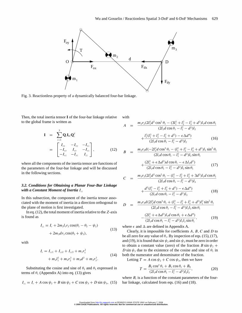
Any planar four-bar mechanism satisfying one of the threesets of conditions given above (eqs. (1), (2) or (3)) will bereactionless and will behave, globally, as a rigid body in theplane—fixed center of mass and constant radius of gyration—when undergoing planar motion. In other words, any motionof the linkage will induce zero reaction force and moment onthe base when the latter is fixed. Conversely, it is not possi-ble to induce internal motion of the mechanism by impartinglinear and/or angular accelerations to the base. Taking a dy-namically balanced mechanism of case II as an example, thereis no shaking force and shaking moment on the base due toits fixed center of mass and zero angular momentum. Clearly,the resulting external force and moment of the mechanism arezero. If we consider the balanced four-bar linkage as a systemisolated from the base (Figure 3), the external forces and mo-ment are the joint forces(Fox,Foy,Fdx,Fdy) and the actuatordriving torqueT acting on the system (gravity is excluded andfriction is neglected). Although the direction and magnitudeof the forces and torque depend on which motion is applied,the zero reaction force and moment on the base always comefrom Fox = Fdx, Foy = Fdy andT = dFdy and their oppositedirections. In other words, the reactions of the individual joint
forces act on the base and generate a couple to cancel the ac-tuator reaction torque for any motion. If the frictional torquesare considered on the joints, the actuator driving torque andthe joint forces will be changed. However, the resulting reac-tion moment on the base is stillT −Mf −dFdy = 0 (whereMf
is the sum of frictional torques on jointsO andD). Namely,friction does not affect the results of dynamic balancing. Notethat in a real prototype the actuator inertia must be consideredas part of the inertia of the input link.
Notice that the above dynamic balancing conditions werederived on the assumption that each link of the planar four-barlinkage is symmetric about the motion plane, i.e., the productsof inertia Ixz, Iyz of each link relative to its center of massare zero. Moreover, any mechanism behaving as a rigid bodyin the plane (i.e., fixed center of mass and constantIzz) andhaving zero products of inertia (Ixz, Iyz) can be mounted onthe moving link (the first or third link) of the planar four-barlinkage to synthesize a reactionless mechanism with moredegrees of freedom as long as the resulting parameters ofthe moving link meet the corresponding dynamic balancingconditions (eqs. (1), (2) or (3)).
3. Reactionless Conditions for Planar Four-BarLinkages Undergoing Spatial Motion
A reactionless mechanism behaves, globally, as a single rigidbody. Hence, a fixed center of mass and a time-invariant inertiatensor are necessary conditions for the dynamic balancing ofa mechanism undergoing general spatial motion.
Moreover, since a reactionless planar four-bar linkage be-haves as a rigid body moving in the plane, it can be mountedon the third (or first) link of another four-bar linkage to
© 2004 SAGE Publications. All rights reserved. Not for commercial use or unauthorized distribution. at PENNSYLVANIA STATE UNIV on February 7, 2008 http://ijr.sagepub.comDownloaded from

628 THE INTERNATIONAL JOURNAL OF ROBOTICS RESEARCH / June 2004
1ml1
l3
d
r1
l2
r2
m2
m3
r3O D
θ1
(a)
m2
l1
r1
r3
r2
m1
d
l3l2
m3
O Dθ1
(b)
d
m1
m2
r2
l2
l1
r1
m3
r3
l3
O D
θ1
(c)Fig. 2. Three families of reactionless four-bar linkages: (a)case I; (b) case II; (c) case III.
synthesize a reactionless planar 2-DoF mechanism. By re-peating this procedure, a reactionless planar multi-DoF mech-anism can be obtained simply by stacking the four-bar link-ages on each other. However, the stacked reactionless mech-anisms can only move in the plane. In order to obtain a 2-DoF mechanism using two four-bar linkages, which under-goes spatial motion for further synthesis of spatial multi-DoFmechanisms, the attached four-bar linkage must be mountedon the third link of the base four-bar linkage in such a way that
the motion plane of the former mechanism is not coplanar tothat of the latter mechanism. Therefore, if the attached mecha-nism behaves as a rigid body in space and the above synthesisand balancing conditions are satisfied, the synthesized spatialmechanism will be reactionless.Yet, there is no guarantee thata reactionless planar four-bar linkage (Figure 2) undergoingspatial motion will continue to behave as a rigid body in space.In order to address the balancing for spatial motion, the inertiatensor of a general planar four-bar linkage is now studied.
3.1. Determination of the Inertia Tensor of a PlanarFour-Bar Linkage
From Figure 1, the inertia tensors of the three mobile barsof a planar four-bar linkage with respect to the local frameswith origin atO—parallel to their corresponding local frameX, Y—are written as follows:
Ib1 = Ixx1 −Ixy1 0
−Ixy1 Iyy1 +m1r21 0
0 0 Izz1 +m1r21
(8)
Ib2 = Ixxb2 −Ixyb2 0
−Ixyb2 Iyyb2 00 0 Izzb2
(9)
Ib3 = Ixxb3 −Ixyb3 0
−Ixyb3 Iyyb3 00 0 Izzb3
, (10)
with
Ixxb2 = Ixx2 +m2l21 sin2 θa
Ixyb2 = Ixy2 +m2l1 sinθa(r2 + l1 cosθa)
Iyyb2 = Iyy2 +m2(r2 + l1 cosθa)2
Izzb2 = Izz2 +m2(l21 + r2
2 + 2l1r2 cosθa)
Ixxb3 = Ixx3 +m3d2 sin2 θb
Ixyb3 = Ixy3 −m3d(r3 + d cosθb) sinθbIyyb3 = Iyy3 +m3(r3 + d cosθb)
2
Izzb3 = Izz3 +m3(d2 + r2
3 + 2dr3 cosθb)
θa = θ1 − θ2 − ψ2
θb = θ3 + ψ3,
whereIxxi , Iyyi , Izzi andIxyi, i = 1, 2, 3 are the moments andproduct of inertia of theith bar relative to the local frameX, Ywith origin at the center of mass of the bar, andIzzi = mik
2i.
Moreover, a planar four-bar linkage is assumed symmetricabout the plane of motion, namely, the products of inertia(Ixzi, Iyzi) of theith bar are assumed to be zero.
The rotation matrixQi of the local frameX, Y relative tothe global frameX, Y can be given by
Qi =cos(θi + ψi) − sin(θi + ψi) 0
sin(θi + ψi) cos(θi + ψi) 00 0 1
, i = 1, 2, 3. (11)
© 2004 SAGE Publications. All rights reserved. Not for commercial use or unauthorized distribution. at PENNSYLVANIA STATE UNIV on February 7, 2008 http://ijr.sagepub.comDownloaded from
Wu and Gosselin / Reactionless Spatial 3-DoF and 6-DoF Mechanisms 629
m2
m1
m3
DOF
F
Fox
oy
dx
dy
F
T
d
Fig. 3. Reactionless property of a dynamically balanced four-bar linkage.
Then, the total inertia tensorI of the four-bar linkage relativeto the global frame is written as
I =3∑i=1
QiIbiQTi
= Ixx −Ixy −Ixz
−Ixy Iyy −Iyz−Ixz −Iyz Izz
, (12)
where all the components of the inertia tensor are functions ofthe parameters of the four-bar linkage and will be discussedin the following sections.
3.2. Conditions for Obtaining a Planar Four-Bar Linkagewith a Constant Moment of Inertia Izz
In this subsection, the component of the inertia tensor asso-ciated with the moment of inertia in a direction orthogonal tothe plane of motion is first investigated.
In eq. (12), the total moment of inertia relative to theZ-axisis found as
Izz = Ic + 2m2l1r2 cos(θ1 − θ2 − ψ2)
+ 2m3dr3 cos(θ3 + ψ3),(13)
with
Ic = Izz1 + Izz2 + Izz3 +m1r21
+m2l21 +m2r
22 +m3d
2 +m3r23 .
(14)
Substituting the cosine and sine ofθ2 andθ3 expressed interms ofθ1 (Appendix A) into eq. (13) gives
Izz = Ic + A cosψ2 + B sinψ2 + C cosψ3 +D sinψ3, (15)
with
A = m2r2(2l21d2 cos2 θ1 − (3l21 + l22 − l23 + d2)l1d cosθ1
(2l1d cosθ1 − l21 − d2)l2
+ l21(l
21 + l22 − l23 + d2)− ε�d4)
(2l1d cosθ1 − l21 − d2)l2(16)
B = m2r2d(−2l21d cos3 θ1 − (l21 + l22 − l23 + d2)l1 sin2 θ1
(2l1d cosθ1 − l21 − d2)l2 sinθ1
+ (2l21 + ε�d2)d cosθ1 − ε�l1d
2)
(2l1d cosθ1 − l21 − d2)l2 sinθ1
(17)
C = m3r3(2l21d2 cos2 θ1 − (l21 − l22 + l23 + 3d2)l1d cosθ1
(2l1d cosθ1 − l21 − d2)l3
+d2(l21 − l22 + l23 + d2)− ε�d4)
(2l1d cosθ1 − l21 − d2)l3(18)
D = m3r3d(2l31d cos3 θ1 + (l21 − l22 + l23 + d2)l21 sin2 θ1
(2l1d cosθ1 − l21 − d2)l1l3 sinθ1
− (2l21 + ε�d2)l1d cosθ1 + ε�d4)
(2l1d cosθ1 − l21 − d2)l1l3 sinθ1
, (19)
whereε and� are defined in Appendix A.Clearly, it is impossible for coefficientsA,B,C andD to
be all zero for any value ofθ1. By inspection of eqs. (15), (17),and (19), it is found that sinψ2 and sinψ3 must be zero in orderto obtain a constant value (zero) of the fractionB sinψ2 +D sinψ3 due to the existence of the cosine and sine ofθ1 inboth the numerator and denominator of the fraction.
LettingT = A cosψ2 + C cosψ3, then we have
T = B2 cos2 θ1 + B1 cosθ1 + B0
(2l1d cosθ1 − l21 − d2)l2l3, (20)
whereBi is a function of the constant parameters of the four-bar linkage, calculated from eqs. (16) and (18).
© 2004 SAGE Publications. All rights reserved. Not for commercial use or unauthorized distribution. at PENNSYLVANIA STATE UNIV on February 7, 2008 http://ijr.sagepub.comDownloaded from

630 THE INTERNATIONAL JOURNAL OF ROBOTICS RESEARCH / June 2004
We suppose that eq. (20) can be decomposed as
T = (A2 cosθ1 + A1)+ A0
(2l1d cosθ1 − l21 − d2). (21)
By comparing the coefficients of the polynomials in cosθ1 ineqs. (20) and (21), we have the following linear system ofequations:1 −(l21 + d2) 0
0 2l1d −(l21 + d2)
0 0 2l1d
A0
A1
A2
= 1
l2l3
B0
B1
B2
. (22)
Then,[A0 A1 A2
]Tcan be obtained as follows:
A0 = (m2r2l3 cosψ2 +m3r3l2 cosψ3)
2l2l3
· (l21l
22 − l21l
23 + l23d
2 − l22d2 − 2ε�d4)
2l2l3(23)
A1 = m2r2l3 cosψ2(l23 − 2l21 − l22)
2l2l3
+m3r3l2 cosψ3(l22 − 2d2 − l23)
2l2l3(24)
A2 = l1d(m2r2l3 cosψ2 +m3r3l2 cosψ3)
l2l3. (25)
From eq. (21), it can be found that only ifA0 = A2 = 0 thenT (and henceIzz) will be constant, namely,
m2r2l3 cosψ2 +m3r3l2 cosψ3 = 0. (26)
Since sinψ2 and sinψ3 must be zero, the values of cosψ2
and cosψ3 in eq. (26) must be opposite due to the positivegeometric parameters. Hence, over the interval[0, 2π [, wecan finally obtain
ψ2 = 0, ψ3 = π, (27)
or
ψ2 = π, ψ3 = 0, (28)
and
r3 = m2r2l3
m3l2, (29)
then
Izz = Ic ± m2r2(l23 − l21 − l22 + d2)
l2. (30)
Hence, eq. (27) (for cases I and II) or eq. (28) (for case III)and eq. (29) are the conditions for a planar four-bar linkageto have a constant moment of inertia relative to theZ-axis.
By comparing the two sets of conditions with eqs. (1)–(3),it is found that the conditions for a constant moment of inertia(Izz) are a subset of the dynamic balancing conditions in theplane, as it should be.
3.3. Conditions for Constant Moments of Inertia (Ixx, Iyy)of a Planar Four-Bar Linkage
In this section we investigate the possibility of obtaining con-stant moments of inertia relative to theX- andY -axis (Ixx ,Iyy) for a single planar four-bar linkage with constantIzz.
The moment of inertiaIxx is first studied. Suppose that allthe bars are symmetric, namely, the inertia products are zero,i.e.,Ixyi = Ixzi = Iyzi = 0,ψ1 = 0 (for case I) orψ1 = π (forcase II). Substituting eqs. (27) and (29) into eq. (12), we canfinally obtain
Ixx = B4 cos4 θ1 + B3 cos3 θ1 + B2 cos2 θ1 + B1 cosθ1 + B0
(2l1d cosθ1 − l21 − d2)2,
(31)
whereBi is a function of the constant parameters of the four-bar linkage.
Suppose that eq. (31) can be decomposed as follows:
Ixx = (A4 cos2 θ1 + A3 cosθ1 + A2)+ A1
(2l1d cosθ1 − l21 − d2)
+ A0
(2l1l2 cosθ1 − l21 − d2)2. (32)
By comparing the coefficients of the polynomials in cosθ1 ineqs. (31) and (32), we have the following linear system ofequations:
1 −V V 2 0 00 2U −4UV V 2 00 0 4U 2 −4UV V 2
0 0 0 4U 2 −4UV0 0 0 0 4U 2
A0
A1
A2
A3
A4
=
B0
B1
B2
B3
B4
,(33)
whereU = l1d andV = l21 + d2.Then,
[A0 A1 A2 A3 A4
]Tcan be obtained. From
eq. (32), it is clear that only ifA0 = A1 = A3 = A4 = 0 thenIxx could be constant, i.e.,Ixx = A2.
Finally, the conditions for constantIxx—the three inde-pendent solutions ofA0 = A1 = A3 = A4 = 0—are derivedas
Ixx1 − Iyy1 = m1r21 l2 +m2l
21l2 −m2r2l
21
l2(34)
Ixx2 − Iyy2 = m2r22 −m2r2l2 (35)
Ixx3 − Iyy3 = m22r
22 l
23 +m2m3r2l2l
23
m3l22
. (36)
Furthermore, substituting eqs. (34)–(36) into eq. (12) leadsto a constant and principal inertia tensor. In other words, thethree principal moments of inertia are all constant and all theproducts of inertia are zero.
Similarly, for case III, suppose thatIxyi = Ixzi = Iyzi = 0andψ1 = π , substituting eqs. (28) and (29) into eq. (12) and
© 2004 SAGE Publications. All rights reserved. Not for commercial use or unauthorized distribution. at PENNSYLVANIA STATE UNIV on February 7, 2008 http://ijr.sagepub.comDownloaded from

Wu and Gosselin / Reactionless Spatial 3-DoF and 6-DoF Mechanisms 631
using the same procedure as above leads to the following setof conditions for constantIxx andIyy for this case:
Ixx1 − Iyy1 = m1r21 +m1r1l1 (37)
Ixx2 − Iyy2 = m21r
21 −m1m2r1l1
m2
(38)
Ixx3 − Iyy3 = m3r23 −m3r3l3. (39)
Given the above results, it may seem possible for a singleplanar four-bar linkage to have a constant spatial inertia tensorwhile moving. However, from the balancing conditions (2) forcase II wherer2 < l2 and eq. (35), we can write
|Ixx2 − Iyy2| − Izz2 = Ic1 = Izz1 +m1(r21 + r1l1) > 0, (40)
i.e.,
|Ixx2 − Iyy2| > Izz2. (41)
Clearly, this is impossible since the difference between anytwo components must be smaller than or equal to the third onefor the three principal moments of inertia for any rigid body(Appendix B).
It has also been proved, with the help of the correspondingbalancing conditions of the discussed case (as in case II) thatcondition (34) of case I and condition (39) of case III can-not be satisfied. This means that it is impossible for a singleplanar dynamically balanced four-bar linkage without sepa-rate counter-rotations to have constant moments of inertiaIxxandIyy while moving. In other words, a single planar four-barlinkage can only behave as a rigid body in the plane but not fora spatial motion. Hence, it cannot be dynamically balancedfor spatial motion.
3.4. Synthesis of a Constant Inertia Tensor MechanismUsing a Pair of Planar Four-Bar Linkages
Since it is impossible for a single planar dynamically bal-anced four-bar linkage to maintain a constant inertia tensorwhen undergoing spatial motion, the possibility for a mech-anism composed of a pair of planar dynamically balancedfour-bar linkages is investigated in this section. Figure 4 isa schematic representation of this composition. The two dy-namically balanced four-bar linkages are arranged perpendic-ularly. The base links and the input links of the two mecha-nisms are fixed perpendicularly respectively. Hence, the twomechanisms move simultaneously (namely with the same val-ues ofθ1, θ2, andθ3) if the lengths of the corresponding barsof the two mechanisms are equal or have the same ratio. Thiscomposite mechanism has one degree of freedom. The ideaof using such a mechanism arose from the observation thatthe sum of the moments of inertiaIxx andIyy of a single dy-namically balanced four-bar linkage is constant for any valueof θ1. Hence, the composite mechanism emerges from theconjecture that by placing a pair of such four-bar linkages or-thogonally, the components of the inertia tensor of the whole
mechanism will be functions that may remain constant. Thisconjecture will now be verified. In the notation of Figure 4, thefirst index of the subscript is used for the number of the link,while the second index represents the number of the mecha-nism. Moreover, subscriptb denotes base links. The pair offour-bar mechanisms used here is of type II.Yet, mechanismsof type I or III could also be used. Indeed, it has been provedthat the planar dynamically balanced four-bar linkages of theother two cases (cases I and III) can also be synthesized as con-stant inertia tensor mechanisms for spatial motion. However, ithas been found that there are more possibilities of interferencein the synthesis for the latter two cases. Furthermore, there ismuch more freedom in the choice of the design parametersin case II than in the other two cases (Gosselin et al. 2004).Therefore, the four-bar linkages of case II are taken as com-ponents to synthesize reactionless multi-DoF mechanisms inthe present work. First, assume that the base links of the twofour-bar linkages are fixed andu andv represent respectivelythe ratios of the lengths and masses of the corresponding barsof the two mechanisms, i.e.,
li2 = uli1 (42)
mi2 = vmi1. (43)
After obtaining each inertia tensorIi of the four-bar link-ages, the total inertia tensorItwb (where the subscriptt meanstotal whilewb means without base links) of the compositemechanism with respect to the global frameX, Y can be writ-ten as
Itwb = I1 + Q4I2QT4, (44)
where
Q4 = 0 1 0
−1 0 00 0 1
. (45)
Finally from eq. (44) it is found that to obtain a compos-ite mechanism with constant inertia tensor the relationshipbetweenu andv should be as follows:
v = 1
u2. (46)
This result implies that the principal moments of inertiaof the corresponding bars of the two mechanisms relative totheir centers of mass should be equal.
After substituting eq. (46) into eq. (44), the following con-stant and principal inertia tensor can be obtained:
Itwb =Ixxtwb 0 0
0 Iyytwb 00 0 Izztwb
, (47)
© 2004 SAGE Publications. All rights reserved. Not for commercial use or unauthorized distribution. at PENNSYLVANIA STATE UNIV on February 7, 2008 http://ijr.sagepub.comDownloaded from

632 THE INTERNATIONAL JOURNAL OF ROBOTICS RESEARCH / June 2004
X
m
m
m
m
m
m
m
21
3112
22
32
b1
β
θ1
r11
t
Mmb2
X
Y
O1
θ1
O
Y
Fig. 4. Synthesis of a constant inertia tensor mechanism.
where
Ixxtwb = Iyytwb = [(m21 +m31)m221l
411 + 2m11m
221l
311r11
+m21m31l211(Ixx11 + Iyy11 + Ixx21 + Iyy21 + Ixx31
+Iyy31 +m11r211 +m21l
221 +m31l
221)+
m211m21l
211r
211 − 2m11m21m31l11l
221r11
+m211m31l
221r
211]/(m21m31l
211) (48)
Izztwb = 2Izz. (49)
Then, assuming that the base links are mobile and sym-metric with massesmb1 andmb2, hence the total massM andcenter of mass (described by a distancert and an angleβ inFigure 4) of the composite mechanism can be written as
M = mt1 +mt2 (50)
rt =√(mt1xg1)2 + (mt2yg2)2
M(51)
tanβ = mt2yg2
mt1xg1
, (52)
with
mt1 = m11 +m21 +m31 +mb1 (53)
mt2 = m12 +m22 +m32 +mb2 (54)
xg1 = l21(m21l11 −m11r11 +m31l11)+mb1l11rb1
mt1l11
(55)
yg2 = l22(m22l12 −m12r12 +m32l12)+mb2l12rb2
mt2l12
, (56)
whererbi is the distance from jointO to the center of massof the ith base link, whilexg1 andyg2 are the coordinates ofthe corresponding center of mass of the individual four-barlinkages including base links. It is apparent that the center ofmass of a four-bar linkage including the base link is situatedon its base line, namely on the axis of the frame.
The total inertia tensor of the two base links relative toglobal frameX, Y is written as
Itb =Ixxtb 0 0
0 Iyytb 00 0 Izztb
, (57)
with
Ixxtb = Ixxb1 + Iyyb2 +mb2r2b2 (58)
Iyytb = Iyyb1 + Ixxb2 +mb1r2b1 (59)
Izztb = Izzb1 + Izzb2 +mb1r2b1 +mb2r
2b2, (60)
whereIxxbi , Iyybi , andIzzbi are moments of inertia of the baselink of the ith four-bar linkage relative to the center of massof the base link.
Finally, the inertia tensor of the composite mechanism rel-ative to the local frameX, Y (with originO1 at the center ofmass of the total mechanism and theX-axis passing through
© 2004 SAGE Publications. All rights reserved. Not for commercial use or unauthorized distribution. at PENNSYLVANIA STATE UNIV on February 7, 2008 http://ijr.sagepub.comDownloaded from

Wu and Gosselin / Reactionless Spatial 3-DoF and 6-DoF Mechanisms 633
joint O and the center of mass) can be obtained as
Itg = Q5(Itwb + Itb)QT5 − R
= Ixxtg −Ixytg 0
−Ixytg Iyytg 00 0 Izztg
, (61)
where
Q5 =cosβ − sinβ 0
sinβ cosβ 00 0 1
(62)
R =0 0 0
0 Mr2t
00 0 Mr
2t
(63)
Ixxtg = Iyytwb + Ixxtb cos2 β + Iyytb sin2 β (64)
Iyytg = Ixxtwb + Ixxtb sin2 β + Iyytb cos2 β −Mr2t
(65)
Izztg = Izztwb + Izztb −Mr2t
(66)
Ixytg = sinβ cosβ(Iyytb − Ixxtb). (67)
From eqs. (58), (59), (61), and (67), it is clear that a prin-cipal inertia tensorItg can be obtained only ifIxytg is equal tozero, i.e.,
Iyytb = Ixxtb, (68)
or
Iyyb2 = Iyyb1 − Ixxb1 + Ixxb2 +mb1r2b1 −mb2r
2b2. (69)
This condition can be satisfied by properly choosing themass and inertia of the base links of the two four-bar linkages.
3.5. Synthesis of Reactionless Multi-DoF Mechanisms
A planar dynamically balanced four-bar linkage can be con-sidered as a rigid body when moving in the plane while thecomposite mechanism discussed in the preceding subsectioncan be regarded as a rigid body when moving spatially. There-fore, they can be attached on the third bar of another four-barlinkage to synthesize reactionless 2-DoF mechanisms.
A schematic representation of the synthesis principle isshown in Figure 5. A mechanism of massmm, behaving as arigid body as mentioned above is attached on the third bar withmassm3wm of a planar four-bar linkage with a fixed base. Thecenter of mass of the attached mechanism is located on theaxis of the third bar. The figure shows a global frameX, Y,Z
with the origin at the fixed pointO and a local frameX, Y ,Zwith the origin at the center of mass of the attached mechanismand with theX-direction along the axis of the third bar. Thesubscriptwm denotes without attached mechanism whilemdenotes the attached mechanism.
The resulting parameters of the third bar and the attachedmechanism, which include the resulting massm3, center of
massr3 and radius of gyrationk3 relative to the resulting centerof mass, can be written as
m3 = m3wm +mm (70)
r3 = mmrm −m3wmr3wm
m3
(71)
Izz3 = m3k23 = Izz3wm +m3wm(r3wm + r3)
2
+ Izzm +mm(rm − r3)2. (72)
If the attached mechanism is a planar four-bar linkage,mounted in the motion plane of the base mechanism, clearlyIxzm andIyzm are zero. Whereas if the attached mechanism isthe composite mechanism which is mounted on a plane or-thogonal to the motion plane of the base mechanism and withthe sameX-direction as in Figure 4 (i.e., theZ-direction isidentical to theY -direction in Figure 4) thenIxzm and Iyzmare zero since the inertia tensor of the composite mechanismrelative to its local frame (Figure 4) is principal under thecondition of eq. (68) or eq. (69). Clearly, if the resulting pa-rameters (eqs. (70)–(72)) and other parameters of the basemechanism meet the balancing conditions in eq. (2), the syn-thesized mechanism will then be reactionless. This result willbe confirmed by the calculation of the linear momentum andangular momentum of the synthesized mechanism.
Apparently, the synthesized mechanism has a fixed centerof mass (see eq. (5)), i.e., zero linear momentum. Moreover,the angular momentum with respect to the fixed pointO andthe global frame of the synthesized mechanism can be writ-ten as
ho =2∑i=1
(hgi + rgi ×mi rgi)+ hg3wm (73)
+ rg3wm ×m3wmrg3wm + Q6IgmQT6θθθm + rgm ×mmrgm,
with
rg1 =r1 cos(θ1 + π)
r1 sin(θ1 + π)
0
, rg2 =
l1 cosθ1 + r2 cosθ2
l1 sinθ1 + r2 sinθ2
0
rg3wm =d + r3wm cosθ3
r3wm sinθ3
0
, rgm =
d + rm cos(θ3 − π)
rm sin(θ3 − π)
0
hgi = 0
0Izzi θi
, hg3wm =
0
0Izz3wmθ3
, θθθm =
0
0θ3
Q6 =cos(θ3 − π) − sin(θ3 − π) 0
sin(θ3 − π) cos(θ3 − π) 00 0 1
,
Igm = Ixxm −Ixym 0
−Ixym Iyym 00 0 Izzm
,
© 2004 SAGE Publications. All rights reserved. Not for commercial use or unauthorized distribution. at PENNSYLVANIA STATE UNIV on February 7, 2008 http://ijr.sagepub.comDownloaded from

634 THE INTERNATIONAL JOURNAL OF ROBOTICS RESEARCH / June 2004
O
m1
l1
1
r2
m2
l2 l3
m
r
r
X
m
3wm
3wm
dθ1θ3
θ2
Y
mm
Zr
X
Y
Z
Fig. 5. Synthesis of reactionless multi-DoF mechanisms.
whereIgm is the inertia tensor of the attached mechanism rela-tive to the local frame (Ixym = 0 if the attached is a compositemechanism) whileQ6 is the rotation matrix of the local framewith respect to the global frame.
Substituting all the above parameters into eq. (73), we have
ho = 0
0hoz
, (74)
where
hoz = [Izz1 +m1r21 +m2(r2l1 cos(θ2 − θ1)+ l21)]θ1
+ [Izz2 +m2(r2l1 cos(θ2 − θ1)+ r22)]θ2 +
[Izz3wm + Izzm +m3wmr3wm(d cosθ3 + r3wm)
−mmrm(d cosθ3 − rm)]θ3. (75)
Substituting eqs. (2), (70)–(72) and (A3)–(A4) into eq. (75)leads tohoz = 0, i.e.,ho = 0. Hence, the synthesized mecha-nism has a fixed center of mass and zero angular momentum,namely, the mechanism is dynamically balanced.
Since the synthesized mechanism is reactionless, it still be-haves as a rigid body moving in the plane of the base four-barlinkage. Hence, the synthesized mechanism can be attachedon the third bar of another planar dynamically balanced four-bar linkage in order to obtain spatial reactionless mechanismswith more degrees of freedom.
4. Synthesis of Reactionless Spatial 3-DoFMechanisms
Now that two basic mechanisms—a single planar dynamicallybalanced four-bar linkage and a planar composite mechanism
with constant inertia tensor—have been obtained, reaction-less multi-DoF mechanisms can be synthesized according tothe synthesis principles and constraint conditions discussedin the above sections. Figure 6 schematically shows the syn-thesis of a reactionless spatial 3-DoF mechanism composedof these two basic mechanisms (the cylinders on the movinglinks are counterweights). Two planar four-bar linkages arestacked in the horizontal plane, while a composite mecha-nism is rigidly attached on the third bar of a planar four-barlinkage in the vertical plane. Note that the second actuatedjoint is driving the input link of the second four-bar linkage.The numbering of the four-bar mechanisms starts from thatwith a fixed base link. Since a reactionless 6-DoF parallelmanipulator using four-bar linkages will be constructed inthe next section, a point mass is here considered at the end-effector. Indeed, the 6-DoF manipulator will be composed ofthree legs connecting the base to a common thin platform.Each of the three legs will consist of the reactionless 3-DoFmechanism shown in Figure 6. The mass and inertia of theplatform are distributed among the attachment points of thelegs and replaced by three equivalent point massesmp. Hence,starting from this point mass, all the parameters of the bars ofthe four-bar mechanisms are chosen or calculated using thereactionless conditions. Finally a numerical example of thisreactionless 3-DoF mechanism is given in Table 1 (point massmp = 0.1143 kg). Note that if a point mass, a four-bar linkageor a combination of mechanisms is attached on one elementof another four-bar linkage, the parameters of the latter ele-ment in the table are actually the resulting parameters of theelement and the attached mechanisms. For example, the pa-rameters(m32, r32, k32) in the table are resulting quantities ofthe third bar of the second four-bar linkage and the compositemechanism.
© 2004 SAGE Publications. All rights reserved. Not for commercial use or unauthorized distribution. at PENNSYLVANIA STATE UNIV on February 7, 2008 http://ijr.sagepub.comDownloaded from

Wu and Gosselin / Reactionless Spatial 3-DoF and 6-DoF Mechanisms 635
��
���
����
��
��
��
��
��
��
��
��
��
��
���
fixed base
actuated joints
Fig. 6. Conceptual CAD model of a reactionless spatial 3-DoF mechanism.
Table 1. A Numerical Example of the Reactionless Spatial 3-DoF Mechanism
Composite Mechanism
Parameters First Four-bar Second Four-bar Third Four-bar Fourth Four-bar
m1j (kg) 16.386 5 0.7 2.8m2j (kg) 30.178 5 0.5 2.0m3j (kg) 21.475 10.875 0.775 3.1mbj (kg) 0.4 0.2l1j (mm) 1608 812 500 250l2j (mm) 5000 2500 1000 500l3j (mm) 1608 812 500 250lbj (mm) 1000 500r1j (mm) 804 285 174.46 87.23r2j (mm) 3642.55 1622.54 511.5 255.75r3j (mm) 1646.19 242.3 165 82.5rbj (mm) 500 250k1j (mm) 2673.709 636.766 197.312 98.656k2j (mm) 100 840 175 87.5k3j (mm) 1255.93 273.337 178.106 89.053
Furthermore, from eqs. (2) and (48)–(69), it is found thatbesides the parameters given in the table, some additionalparameters of the composite mechanism (i.e., the third andfourth four-bar mechanisms) have an influence on the dy-namic balancing. These parameters are given as follows:Iyyb3 = 3.3 × 10⁴ kg mm2, Ixx1j = Ixx2j = Ixx3j = Ixxbj = 6kg mm2, Iyy1j = Izz1j = m1j k
21j , Iyy2j = Izz2j = m2j k
22j ,
Iyy3j = Izz3j = m3j k23j , j = 3, 4.
The verification of the reactionless property is performedusing the dynamic simulation software ADAMS. For the
above example mechanism, a simulation model is built usingADAMS. Simulations have been performed for several arbi-trary trajectories. The resulting reaction forces and momentson the base are illustrated in Figure 7. The results clearlydemonstrate that the resulting reaction forces and momentson the base are very small with respect to the joint forces anddriving torques (with a ratio of 10−5 to 10−6). Indeed, the reac-tion forces and moments observed are due to small modelingerrors. Hence, it is clearly shown that the synthesized spatial3-DoF mechanism is completely balanced. In other words,
© 2004 SAGE Publications. All rights reserved. Not for commercial use or unauthorized distribution. at PENNSYLVANIA STATE UNIV on February 7, 2008 http://ijr.sagepub.comDownloaded from

636 THE INTERNATIONAL JOURNAL OF ROBOTICS RESEARCH / June 2004
3.02.52.01.51.00.50.0
1.3E-004
1.2E-004
1.1E-004
1.0E-004
9.0E-005
8.0E-005
7.0E-005
6.0E-005 0.0
0.6
0.5
0.4
0.3
0.2
0.1
0.0
Reaction Force and Moment on the Base
Time (sec)
Forc
e (n
ewto
n)
Mom
ent (
new
ton-
mm
)
Reaction ForceReaction Moment
Fig. 7. Verification of the reactionless property of the 3-DoF mechanism.
there are no reaction forces and moments on the base at alltimes, for any trajectory.
5. Synthesis of Reactionless Spatial 6-DoFParallel Mechanisms
The spatial 3-DoF mechanism mentioned above can be usedas a leg to synthesize spatial multi-DoF (having up to six DoF)parallel mechanisms or manipulators. The end-effector pointof the 3-DoF mechanism is attached to the mobile platformusing either a spherical or a Hooke joint, depending on thenumber of legs used and the desired number of degrees offreedom for the mechanism. These factors also determine thenumber of joints to be actuated for each leg. The mobilityl of the synthesized mechanism can be determined by theapplication of the general mobility criterion of Chebychev–Grübler–Kutzbach (Hunt 1978), i.e.,
l = d(n− g − 1)+g∑i=1
fi, (76)
wheren is the number of links including the base,g is thenumber of joints,fi is the degree of freedom of jointi, d is thedimension of the system under study (e.g. for a planar systemd = 3, while for a spatial systemd = 6). The spatial 6-DoFparallel mechanism schematically represented in Figure 8 iscomposed of three identical legs connecting the fixed base toa common moving platform with spherical joints. Each of thethree legs is a spatial 3-DoF mechanism (Figure 6) which iskinematically equivalent to a spatialRRR serial chain. Hence,for the proposed mechanism, we haved = 6,n = 11,g = 12,and�fi = 18, the mobility of the mechanism thus being equal
to 6. Moreover, if the first and second four-bar mechanism arechosen to be actuated for each leg, then all the six actuators canbe mounted on the frame for the 6-DoF parallel mechanism.
In order to simplify the design of reactionless spatial multi-DoF parallel mechanisms with several legs, only dynamicbalancing for each detached leg mechanism is considered in-dependently, if the mobile platform can be replaced by pointmasses located at the points of attachment of the legs to theplatform. To ensure that the point masses are dynamicallyequivalent to the solid platform, the point masses must have,globally, the same mass, the same center of mass and the sameinertia tensor with respect to any coordinate frame, as the plat-form. It has been found that if the platform can be replaced bypoint masses and each detached leg mechanism including thepoint mass is dynamically balanced the whole parallel mech-anism will then be reactionless (Appendix C). For the spatial6-DoF parallel mechanism of this paper, the mass and inertiaof the platform are assumed to be replaced by three identicalpoint massesmpm symmetrically arranged on a plane (Fig-ure 9). Clearly, their global center of mass coincides with thecenter of mass of the platform if the platform is uniform. Thecondition for dynamic equivalence can then be satisfied if themoments of inertia of the three point masses and those of theplatform are equal. The moments of inertia of the three pointmasses relative to the frame defined in Figure 9 can be writtenas
Ixx = 3
2mpmr
2pm
(77)
Iyy = Ixx (78)
Izz = 3mpmr2pm, (79)
whererpm is the distance between any point mass and the
© 2004 SAGE Publications. All rights reserved. Not for commercial use or unauthorized distribution. at PENNSYLVANIA STATE UNIV on February 7, 2008 http://ijr.sagepub.comDownloaded from

Wu and Gosselin / Reactionless Spatial 3-DoF and 6-DoF Mechanisms 637
Fig. 8. Conceptual CAD model of a reactionless spatial 6-DoF parallel mechanism.
m mpm pm
O
Y
Xrpm
mpm
Fig. 9. Determination of the three point masses.
centroid of the platform. Sincempm is equal to one-third ofthe mass of platformmpl, rpm is equal to the radius of gyrationof the platform with respect to thez′-axis.
From eqs. (77)–(79), it can be found that any symmetric
thin homogeneous platform can satisfy the above conditions,which lead toIxx = Iyy = 1
2Izz. Hence the platform can be
replaced by three point masses. However, if the platform hasa non-zero thickness, the above conditions cannot be satisfied(Bedford and Fowler 1996). In this case, the platform can bereplaced by four non-coplanar point masses. Consequently,four legs must be used and the attachment points of the legson the platform must not lie on one plane in order to obtain areactionless 6-DoF parallel mechanism. In order to limit thelength of the paper, this issue will be presented in anotherpaper.
Once the equivalent point masses have been determined,each of the point masses is included in the corresponding 3-DoF leg and is considered in the balancing. By dynamicallybalancing each of the three legs individually (including thepoint mass) and attaching the legs (without the point masses)to a common platform satisfying the above conditions, a reac-tionless 6-DoF parallel mechanism will be obtained. This re-sult is correct because the redistribution of the internal forcesdue to the kinematic constraints induced by the platform doesnot affect the dynamic balancing of the system. Indeed, dy-namic balancing is a property associated with the movingmasses and inertia only. In other words, although the reactionforces and moments on the base of each leg may not be zeroin the real system with the solid platform (because of the dis-tribution of the internal forces) the net reactions on the basewill be equal to zero.
© 2004 SAGE Publications. All rights reserved. Not for commercial use or unauthorized distribution. at PENNSYLVANIA STATE UNIV on February 7, 2008 http://ijr.sagepub.comDownloaded from

638 THE INTERNATIONAL JOURNAL OF ROBOTICS RESEARCH / June 2004
3.02.52.01.51.00.50.0
1.2E-004
9.5E-005
7.0E-005
4.5E-005
2.0E-005 0.0
0.6
0.45
0.3
0.15
0.0
Reaction Force and Moment on the Base
Time (sec)
Forc
e (n
ewto
n)
Mom
ent (
new
ton-
mm
)
Reaction ForceReaction Moment
Fig. 10. Verification of the reactionless property of the 6-DoF mechanism.
Hence, starting from this point mass, all the parametersof the bars of the four-bar mechanisms are chosen or cal-culated under the reactionless conditions. For example, ifa mobile platform can be replaced by three point masses(mpm = 0.1143 kg) a numerical example of the reactionless 3-DoF leg mechanism can be given in Table 1 and a reactionlessspatial 6-DoF parallel mechanism can finally be obtained.
The verification of the reactionless property of the spatial6-DoF parallel mechanism is also performed using ADAMS.Simulations have been performed for several arbitrary trajec-tories. The resulting reaction forces and moments on the baseare illustrated in Figure 10. The results clearly demonstratethat the resulting reaction forces and moments on the base arevery small with respect to the joint forces and driving torques(with a ratio of 10−5 to 10−6) due to small modeling errors.Hence, it is clearly demonstrated that the synthesized spatial6-DoF mechanisms are reactionless. These numerical simu-lation results support the formal mathematical proof and thealgorithm using point masses to replace a platform presentedin this paper.
6. Discussion
Note that the aim of this paper is to synthesize reactionlessspatial 3-DoF and 6-DoF mechanisms. The parameters of theexample reactionless mechanism (Table 1) were not deter-mined by optimization due to the complexity of the optimiza-tion for the complete system. As was the case with otherdynamically balanced mechanisms, the reactionless 3-DoFmechanism was achieved at the expense of a substantial mass
increase and complexity of the mechanism. The total massesof the composite mechanism, the second and the first mecha-nisms are 9.875, 20.875, and 68.039 kg, respectively. We canapproximately express this mass relationship with 1: 2 : 7.Kinematically, this mechanism can be regarded as a spatialthree-link serial chain. The mass variation of the distal linkproduces great influence for the balancing of the successivelinks. Hence, if we can decrease the mass of the compositemechanism, the total system mass will decrease greatly. Forinstance, if we choose the same link lengths for both four-barlinkages in the composite mechanism (i.e.,u = 1), the samelink masses can then be determined for both four-bar linkages(i.e.,v=1). Therefore, if the total mass of the composite mech-anism is decreased from 9.875 to 3.95, then the total massof the system will be about 27.65 kg by multiplying 3.95with 7 according to the above mass relationship. Addition-ally, there are some other possibilities to further decrease thesystem mass and shrink the reactionless 3-DoF mechanism,such as changing the position of the attached mechanism onthe third bar (i.e.,rm in Figure 5) or decreasing the length ofthe extension part of the link connected to the end-effector(or platform), etc. Moreover, an optimization for the com-plete mechanism with the considerations of the above factorsand detailed parameters using dimensional variables specif-ically tailored to the link geometry will definitely decreasethe system mass and shrink the whole reactionless 3-DoFmechanism.
Compared with a spatial three-link serial chain dynami-cally balanced using a counterweight and a separate counter-rotation at each pivot of the chain, the reactionless 3-DoF mechanism with four-bar linkages seems to have more
© 2004 SAGE Publications. All rights reserved. Not for commercial use or unauthorized distribution. at PENNSYLVANIA STATE UNIV on February 7, 2008 http://ijr.sagepub.comDownloaded from

Wu and Gosselin / Reactionless Spatial 3-DoF and 6-DoF Mechanisms 639
moving links and larger system size for the same payload.However, this does not necessarily imply greater system mass.Moreover, three separate counter-rotations have to be used andespecially two of them have to be mounted with the movinglinks for dynamically balancing the three-link serial chain.The design of separate counter-rotations is normally compli-cated relative to the initial mechanism. Furthermore, addingan actuator, a counterweight and a counter-rotation at eachpivot of the serial chain leads to a difficult design. There-fore, the most important advantage of the reactionless mech-anisms presented in this paper is that the use of additionalseparate counter-rotations and the corresponding side effectsare avoided. Moreover, all the actuators can be mounted inparallel for the 6-DoF parallel mechanism. Finally, it is easyto design and manufacture a practical dynamically balancedsystem with only counterweights and revolute joints.
Although the resulting force and moment on the base arezero for a dynamically balanced mechanism, internal forcesand moments exist on the base. If the base is flexible to someextent, and the forces or moments are large, this may cause ac-curacy and other transmission problems. However, in the con-text of dynamic balancing, the links and bases are normallyassumed to be rigid unless indicated and discussed otherwise.Moreover, dynamic balancing is only applicable to a systemwith constant mass, namely for certain applications with aconstant payload (e.g., motion simulator, telescope mecha-nism and satellite mechanism). If the payload varies, the bal-ancing conditions do not hold. Any change of the payloadwill deteriorate the dynamic balance. However, this problemis beyond the scope of our work.
Additionally, a constant inertia tensor is a necessary butnot sufficient condition for the dynamic balancing of a spa-tial mechanism. This result should be distinguished fromthe results presented in Asada and Youcef-Toumi (1984) andYoucef-Toumi andAsada (1985) where a class of manipulatorshaving a constant generalized inertia tensor was developed tosimplify the control. However, they are neither dynamicallynor statically balanced.
7. Conclusion
In this paper we have presented the reactionless conditionsfor planar four-bar linkages moving spatially and the synthe-sis of novel reactionless spatial 3-DoF and 6-DoF mechanismsusing four-bar linkages without separate counter-rotations.Based on the conditions of dynamic balancing of a singleplanar four-bar linkage moving in the plane, the spatial prob-lem has been addressed. It has been shown that a single planarfour-bar linkage cannot be dynamically balanced when mov-ing spatially. However, it has also been found that a mecha-nism composed of a pair of planar reactionless four-bar link-ages has the property of a rigid body—a fixed center of massand a constant inertia tensor—and can be dynamically bal-
anced in space when it is mounted on the moving link of a re-actionless four-bar linkage. Then, reactionless spatial 3-DoFmechanisms using four-bar linkages have been synthesized.Anumerical example of a reactionless spatial 3-DoF mechanismhas been given and, with the help of the dynamic simulationsoftware ADAMS, it has been shown that the mechanism isreactionless for arbitrary trajectories. Finally, 6-DoF reaction-less parallel mechanisms have been synthesized.
Future work includes the simplification of the synthesespresented in this paper for practical applications as well asthe design and fabrication of balanced prototypes of the reac-tionless spatial 3-DoF and 6-DoF mechanisms.
Appendix A: Determination of the DependentVariables in Planar Four-Bar Linkages
The kinematic constraint equations can be written from Fig-ure 1 as
l1cosθ1 + l2cosθ2 = d + l3cosθ3 (A1)
l1sinθ1 + l2sinθ2 = l3sinθ3. (A2)
Differentiating eqs. (A1) and (A2) with respect to time,θ2 andθ3 can be found as
θ2 = l1 sin(θ1 − θ3)
l2 sin(θ3 − θ2)θ1 (A3)
θ3 = l1 sin(θ1 − θ2)
l3 sin(θ3 − θ2)θ1. (A4)
Also, from eqs. (A1) and (A2), cosθ3 and sinθ3 can be writtenas
cosθ3 = (l1 cosθ1 + l2 cosθ2 − d)/ l3 (A5)
sinθ3 = (l1 sinθ1 + l2 sinθ2)/ l3. (A6)
Substituting eqs. (A5) and (A6) into the trigonometric identitycosθ2
i+ sinθ2
i= 1, we have
sinθ2 = (d − l1 cosθ1)l2 cosθ2 −H
l1l2 sinθ1
, (A7)
and
cosθ2 = −A1 + Y1
2A2
, (A8)
with
Y1 = ε√A2
1 − 4A2A0 = ε�
H = 1
2(l21 + l22 − l23 + d2)− dl1 cosθ1
A0 = H 2 − l21l22 sin2 θ1
A1 = −2l2H(d − l1 cosθ1)
A2 = l21l22 + d2l22 − 2dl1 cosθ1
ε = ±1.
Then,θ2, θ3, and their derivatives can be obtained using theabove formulae for givenθ1 andθ1.
© 2004 SAGE Publications. All rights reserved. Not for commercial use or unauthorized distribution. at PENNSYLVANIA STATE UNIV on February 7, 2008 http://ijr.sagepub.comDownloaded from

640 THE INTERNATIONAL JOURNAL OF ROBOTICS RESEARCH / June 2004
Appendix B: Relationship Between Ixx , Iyy ,and Izz
The moments of inertia relative to any three coordinate axesfor any rigid body can be written as
Ixx =∫(y2 + z2) dm
Iyy =∫(x2 + z2) dm
Izz =∫(x2 + y2) dm,
wherex, y, andz are the coordinates of a differential massdm of the body in the three-dimensional frame.
Clearly, the difference between any two moments of inertiamust be smaller than or equal to the third one.
Appendix C: Dynamic Balancing of a SpatialParallel Mechanism with Multiple Legs
Figure 11 shows a spatial multi-DoF parallel mechanism withk legs. Assume that each leg hasn links. A fixed and a mov-ing coordinate frame and some nomenclatures are defined asshown in the figure. The angular momentum of thek pointmasses with respect to the fixed pointO and the fixed framecan be written as follows
hkp =k∑i=1
pi ×mpi pi
=k∑i=1
(p + Qbi )×mpi(p + Qbi )
= p × (
k∑i=1
mpi)p + p × Q(k∑i=1
mpibi )
+ Q(k∑i=1
mpibi )× p +k∑i=1
Qbi
×mpi(ωωω × Qbi ), (C1)
wherepi and p are respectively the position vectors of theattachment point on the moving platformPi and the centroidof the platformO ′ expressed in the fixed frame,bi is the posi-tion vector ofPi in the moving frame,Q is the rotation matrixcorresponding to the orientation of the moving platform withrespect to the fixed frame, andmpi andωωω are the point massand the angular velocity of the platform, respectively.
If the center of mass of the point masses coincides withthat of the platform (i.e.,O ′), then�mpibi = 0 and eq. (C1)becomes
x
z
y
x’
y’
1im
nim
pim
r
r
1i
nipi
Bi
o’Pi
r
z’
o
Fig. 11. A spatial parallel mechanism with multiple legs.
hkp = p × (
k∑i=1
mpi)p +k∑i=1
Qbi
×mpi(ωωω × Qbi ). (C2)
Moreover, the second term in eq. (C2) denotes the angularmomentum of the point masses relative to their center of massO ′. We express the angular velocity of the platformωωω and theposition of the point masses relative to their center of massO ′ in the fixed frame (i.e.,Qbi) as
ωωω =ωxωyωz
, Qbi =
xbiybizbi
, (C3)
then the angular momentum of the point masses relative totheir center of massO ′ can be obtained as
ho′ = (C4) �mpi(y
2bi
+ z2bi)ωx −�mpixbiybiωy −�mpixbizbiωz
−�mpiybixbiωx +�mpi(x2bi
+ z2bi)ωy −�mpiybizbiωz
−�mpizbixbiωx −�mpizbiybiωy +�mpi(x2bi
+ y2bi)ωz
.
Using the definition of the moments and products of inertia(Bedford and Fowler 1996), eq. (C4) leads to
ho′ = Ixx −Ixy −Ixz
−Iyx Iyy −Iyz−Izx −Izy Izz
ωxωyωz
= Ikpωωω, (C5)
© 2004 SAGE Publications. All rights reserved. Not for commercial use or unauthorized distribution. at PENNSYLVANIA STATE UNIV on February 7, 2008 http://ijr.sagepub.comDownloaded from

Wu and Gosselin / Reactionless Spatial 3-DoF and 6-DoF Mechanisms 641
then
hkp = p × (
k∑i=1
mpi)p + Ikpωωω. (C6)
From eq. (C6), it is found that if thek point masses aredynamically equivalent to the platform (namely, with the samemass (mpl = �mpi), the same center of mass (O ′) and thesame inertia tensor (Ipl = Ikp)) the angular momentum of thepoint masses is identical to that of the platform. Therefore,by using the point masses to replace the platform, the angularmomentum of the complete mechanism relative to the fixedpointO and expressed in the fixed frame can be written as
ho =k∑i=1
(hg1i + (r1i + ai )×m1i r1i + · · · + hgni
+ (rni + ai )×mni rni + (rpi + ai )×mpi rpi)
=k∑i=1
(hg1i + r1i ×m1i r1i + · · · + hgni + rni ×mni rni
+ rpi ×mpi rpi)+k∑i=1
ai × (m1i r1i + · · · +mni rni
+mpi rpi), (C7)
wherehgji , j = 1 . . . n is the angular momentum of the cor-responding link relative to its center of mass andai is theposition vector of the attachment point on the baseBi in thefixed frame. If each leg mechanism including the point massis dynamically balanced, then the center of mass of the leg isfixed and the angular momentum of the leg with respect to thefixed pointBi is zero, namely, the sums in both parentheses ineq. (C7) are zero respectively. Hence,ho = 0 and the globalcenter of mass of the complete mechanism is fixed, i.e. thewhole system is reactionless. Furthermore, from eq. (C7) thesame conclusion can be obtained even if the leg mechanismsof the system are not identical, namely with different numberof links.
Acknowledgments
The authors would like to acknowledge the financial supportof the Natural Sciences and Engineering Research Councilof Canada (NSERC) as well as the financial support of theCanada Research Chair Program. Pierre-Luc Richard is alsoacknowledged for his help with the CAD modeling of themechanisms.
References
Agrawal, S. K. and Shirumalla, S. 1995. Planning motions ofa dual-arm free-floating manipulator keeping the base iner-tially fixed.Mechanism and Machine Theory 30(1):59–70.
Angeles, J., Nahon, M. A., and Thümmel, T. 1992. Activecontrol for the complete dynamic balancing of linkages.Flexible Mechanisms, Dynamics, and Analysis, Proceed-ings of the 22nd ASME Biennial Mechanisms Conference,Scottsdale, AZ, Vol. DE-47, pp. 305–310.
Arakelian, V. H. and Smith, M. R. 1999. Complete shakingforce and shaking moment balancing of linkages.Mecha-nism and Machine Theory 34(8):1141–1153.
Asada, H. andYoucef-Toumi, K. 1984.Analysis and design ofa direct-drive arm with a five-bar-link parallel drive mech-anism.Journal of Dynamic Systems, Measurement, andControl 106(3):225–230.
Bagci, C. 1982. Complete shaking force and shaking momentbalancing of link mechanisms using balancing idler loops.ASME Journal of Mechanical Design 104:482–493.
Bagci, C. 1992. Complete balancing of linkages using com-plete dynamical equivalents of floating links: CDELmethod.Flexible Mechanisms, Dynamics, and Analysis,Proceedings of the 22nd Biennial Mechanisms Conference,Scottsdale, AZ, Vol. DE-47, pp. 477–488.
Bagci, C. 1983. Complete balancing of space mechanisms—shaking force balancing.ASME Journal of Mechanisms,Transmissions, and Automation in Design 105:609–616.
Bedford, A. and Fowler, W. 1996.Engineering Mechanics:Dynamics, Addison-Wesley, Reading, MA.
Berkof, R. S. 1973. Complete force and moment balancing ofinline four-bar linkages.Mechanism and Machine Theory8:397–410.
Berkof, R. S. and Lowen, G. G. 1969.A new method for com-pletely force balancing simple linkages.ASME Journal ofEngineering for Industry 91(1):21–26.
Dresig, H. et al. (VDI). 1998. Dynamics of mechanisms—Rigid body mechanisms, Richtlinien 2149 Part 1, VereinDeutscher Ingenieure.
Dubowsky, S. and Torres, M. A. 1991. Path planning forspace manipulators to minimize spacecraft attitude distur-bances.Proceedings of the IEEE International Conferenceon Robotics and Automation, Sacramento, CA, pp. 2522–2528.
Esat, I., and Bahai, H. 1999. A theory of complete force andmoment balancing of planer linkage mechanisms.Mecha-nism and Machine Theory 34(6):903–922.
Gao, F. 1989. Complete shaking force and shaking momentbalancing of four types of six-bar linkages.Mechanism andMachine Theory 24(4):275–287.
Gao, F. 1991. Complete shaking force and shaking momentbalancing of 17 types of eight-bar linkages only with rev-olute pairs.Mechanism and Machine Theory 26(2):197–206.
Gosselin, C. M., Vollmer, F., Côté, G., and Wu, Y. 2004. Syn-thesis and design of reactionless three-degree-of-freedomparallel mechanisms.IEEE Transactions on Robotics andAutomation 20(2): in press.
© 2004 SAGE Publications. All rights reserved. Not for commercial use or unauthorized distribution. at PENNSYLVANIA STATE UNIV on February 7, 2008 http://ijr.sagepub.comDownloaded from

642 THE INTERNATIONAL JOURNAL OF ROBOTICS RESEARCH / June 2004
Hunt, K. H. 1978.Kinematic Geometry of Mechanisms, Ox-ford University Press, Oxford.
Kochev, I. S. 1990a. General method for active balancing ofcombined shaking moment and torque fluctuations in pla-nar linkages.Mechanism and Machine Theory 25(6):679–687.
Kochev, I. S. 1990b. Full shaking moment balancing of planarlinkages by a prescribed input speed fluctuation.Mecha-nism and Machine Theory 25(4):459–466.
Kochev, I. S. 1992. Active balancing of the frame shakingmoment in high speed planar machines.Mechanism andMachine Theory 27(1):53–57.
Kochev, I. S. 2000. General theory of complete shaking mo-ment balancing of planar linkages: a critical review.Mech-anism and Machine Theory 35(11):1501–1514.
Legnani, G., Zappa, B., Adamini, R., and Casolo, F. 1999. Acontribution to the dynamics of free-flying space manipu-lators.Mechanism and Machine Theory 34(3):359–372.
Lowen, G. G., Tepper, F. R., and Berkof, R. S. 1983. Bal-ancing of linkages—an update.Mechanism and MachineTheory 18(3):213–220.
Papadopoulos, E. and Abu-Abed, A. 1996. On the design ofzero reaction manipulators.ASME Journal of MechanicalDesign 118(3):372–376.
Papadopoulos, E. and Dubowsky, S. 1991. Coordinated ma-
nipulator/spacecraft motion control for space robotic sys-tems.Proceedings of the IEEE International Conferenceon Robotics and Automation, Sacramento, CA, pp. 1696–1701.
Ricard, R. and Gosselin, C. M. 2000. On the developmentof reactionless parallel manipulators.ASME 2000 DesignEngineering Technical Conference and Computers and In-formation in Engineering Conference, Baltimore, MA.
Ye, Z. and Smith, M. R. 1994. Complete balancing of pla-nar linkages by an equivalence method.Mechanism andMachine Theory 29(5):701–712.
Youcef-Toumi, K. andAsada, H. 1985. Design of arm linkageswith decoupled and configuration-invariant inertia tensors.ASME Winter Annual Meeting, Robotics and Manufactur-ing Automation, Miami, FL, pp. 145–161.
Yu,Y. Q. 1987a. Research on complete shaking force and shak-ing moment balancing of spatial linkages.Mechanism andMachine Theory 22(1):27–37.
Yu,Y. Q. 1987b. Optimum shaking force and shaking momentbalancing of theRSS ′R spatial linkage.Mechanism andMachine Theory 22(1):39–45.
Yu, Y. Q. 1988. Complete shaking force and shaking momentbalancing of spatial irregular force transmission mech-anisms using additional links.Mechanism and MachineTheory 23(4):279–285.
© 2004 SAGE Publications. All rights reserved. Not for commercial use or unauthorized distribution. at PENNSYLVANIA STATE UNIV on February 7, 2008 http://ijr.sagepub.comDownloaded from
Copyright © 2022 FDOKUMEN