Synthesis of polyaniline/graphite composite as a cathode of Zn-polyaniline rechargeable battery
7
Please cite this article in press as: K. Ghanbari et al., J. Power Sources (2007), doi:10.1016/j.jpowsour.2007.02.090 ARTICLE IN PRESS +Model POWER-9226; No. of Pages 7 Journal of Power Sources xxx (2007) xxx–xxx Synthesis of polyaniline/graphite composite as a cathode of Zn-polyaniline rechargeable battery Khadijeh Ghanbari a , Mir Fazlollah Mousavi a,∗ , Mojtaba Shamsipur b , Hassan Karami a a Department of Chemistry, Tarbiat Modares University, P.O. Box 14115-175, Tehran, Iran b Department of Chemistry, Razi University, Kermanshah, Iran Received 4 March 2006; received in revised form 23 January 2007; accepted 13 February 2007 Abstract The characteristics of polyaniline/graphite composites (PANi/G) have been studied in aqueous electrolyte. PANi/G films with different graphite particle sizes were deposited on a platinum electrode by means of cyclic voltammetry. The film was employed as a positive electrode (cathode) for a Zn-PANi/G secondary battery containing 1.0 M ZnCl 2 and 0.5 M NH 4 Cl electrolyte at pH 4.0. The cells were charged and discharged under a constant current of 0.6 mA cm −2 . The assembled battery showed an open-circuit voltage (OCV) of 1.55V. All the batteries were discharge to a cut off voltage of 0.7 V. Maximum discharge capacity of the Zn-PANi/G battery was 142.4 Ah kg −1 with a columbic efficiency of 97–100% over at least 200 cycles. The mid-point voltage (MPV) and specific energy were 1.14 V and 162.3 Wh kg −1 , respectively. The constructed battery showed a good recycleability. The structure of these polymer films was characterized by FTIR and UV–vis spectroscopies. Electrochemical impedance spectroscopy (EIS) was used as a powerful tool for investigation of charge transfer resistance in cathode material. The scanning electron microscopy (SEM) was employed as a morphology indicator of the cathodes. © 2007 Elsevier B.V. All rights reserved. Keywords: Rechargeable battery; Polyaniline/graphite composite; Zinc; Discharge capacity; Specific energy 1. Introduction Conducting polymers exhibit a wide range of novel elec- trochemical properties. They have potential applications in electrochromic displays [1], electronic devices [2], chemical sensors [3,4], etc. One of the most interesting characteristics of conducting polymers is their capacity to store charge which can be recovered under demand. This makes them good candidates as components of advanced rechargeable batteries [5–8]. Among the family of conducting polymers, polyaniline (PANi) has attracted renewed interest from recent researches as it is highly conducting and easy to synthesize both chemi- cally (in powder form) and electrochemically (as a film). It is cheap and stable to heat and air. It is also the first commercially available conducting polymer [9]. ∗ Corresponding author. Tel.: +98 21 88011001x3479/3474; fax: +98 21 88006544. E-mail addresses: [email protected], [email protected] (M.F. Mousavi). Polyaniline is among those conducting polymers whose elec- trical properties can be controlled suitably by charge-transfer doping and/or protonation. Due to its reversible electrochem- ical response during anodic oxidation and cathodic reduction, it is useful as a secondary electrode in rechargeable batter- ies and electrochromic display devices. Recently, our research group has been involved in the application of polyaniline in rechargeable batteries [10–14] and in preparation of ion selective electrodes [15,16]. However, the major limitations of conduct- ing polyaniline include the inability to process it by conventional methods and its poor mechanical properties. These limitations can be overcome by preparing conducting polyaniline blends and composites, which possess proper mechanical properties of insu- lating host matrix and the electrical properties of the conducting polyaniline guest [9]. Graphite has been used as conductive filler in the matrix of insulating polymers to render conductive polymers [17,18]. There are many advantages of using graphite in the composite materials. First, graphite has a high conductivity (>100 S/cm), high mechanical strength, and very good chemical stability. Second, graphite is cheap and available in large quantities 0378-7753/$ – see front matter © 2007 Elsevier B.V. All rights reserved. doi:10.1016/j.jpowsour.2007.02.090
-
Upload
independent -
Category
Documents
-
view
0 -
download
0
Transcript of Synthesis of polyaniline/graphite composite as a cathode of Zn-polyaniline rechargeable battery
P
A
pfaclas(©
K
1
tescba
(acca
f
m
0d
ARTICLE IN PRESS+ModelOWER-9226; No. of Pages 7
Journal of Power Sources xxx (2007) xxx–xxx
Synthesis of polyaniline/graphite composite as a cathode ofZn-polyaniline rechargeable battery
Khadijeh Ghanbari a, Mir Fazlollah Mousavi a,∗, Mojtaba Shamsipur b, Hassan Karami a
a Department of Chemistry, Tarbiat Modares University, P.O. Box 14115-175, Tehran, Iranb Department of Chemistry, Razi University, Kermanshah, Iran
Received 4 March 2006; received in revised form 23 January 2007; accepted 13 February 2007
bstract
The characteristics of polyaniline/graphite composites (PANi/G) have been studied in aqueous electrolyte. PANi/G films with different graphitearticle sizes were deposited on a platinum electrode by means of cyclic voltammetry. The film was employed as a positive electrode (cathode)or a Zn-PANi/G secondary battery containing 1.0 M ZnCl2 and 0.5 M NH4Cl electrolyte at pH 4.0. The cells were charged and discharged underconstant current of 0.6 mA cm−2. The assembled battery showed an open-circuit voltage (OCV) of 1.55 V. All the batteries were discharge to a
ut off voltage of 0.7 V. Maximum discharge capacity of the Zn-PANi/G battery was 142.4 Ah kg−1 with a columbic efficiency of 97–100% over ateast 200 cycles. The mid-point voltage (MPV) and specific energy were 1.14 V and 162.3 Wh kg−1, respectively. The constructed battery showed
good recycleability. The structure of these polymer films was characterized by FTIR and UV–vis spectroscopies. Electrochemical impedancepectroscopy (EIS) was used as a powerful tool for investigation of charge transfer resistance in cathode material. The scanning electron microscopySEM) was employed as a morphology indicator of the cathodes.
2007 Elsevier B.V. All rights reserved.
rge c
tdiiigreimc
eywords: Rechargeable battery; Polyaniline/graphite composite; Zinc; Discha
. Introduction
Conducting polymers exhibit a wide range of novel elec-rochemical properties. They have potential applications inlectrochromic displays [1], electronic devices [2], chemicalensors [3,4], etc. One of the most interesting characteristics ofonducting polymers is their capacity to store charge which cane recovered under demand. This makes them good candidatess components of advanced rechargeable batteries [5–8].
Among the family of conducting polymers, polyanilinePANi) has attracted renewed interest from recent researchess it is highly conducting and easy to synthesize both chemi-
Please cite this article in press as: K. Ghanbari et al., J. Power Sources (20
ally (in powder form) and electrochemically (as a film). It isheap and stable to heat and air. It is also the first commerciallyvailable conducting polymer [9].
∗ Corresponding author. Tel.: +98 21 88011001x3479/3474;ax: +98 21 88006544.
E-mail addresses: [email protected],[email protected] (M.F. Mousavi).
clp
oTmhS
378-7753/$ – see front matter © 2007 Elsevier B.V. All rights reserved.oi:10.1016/j.jpowsour.2007.02.090
apacity; Specific energy
Polyaniline is among those conducting polymers whose elec-rical properties can be controlled suitably by charge-transferoping and/or protonation. Due to its reversible electrochem-cal response during anodic oxidation and cathodic reduction,t is useful as a secondary electrode in rechargeable batter-es and electrochromic display devices. Recently, our researchroup has been involved in the application of polyaniline inechargeable batteries [10–14] and in preparation of ion selectivelectrodes [15,16]. However, the major limitations of conduct-ng polyaniline include the inability to process it by conventional
ethods and its poor mechanical properties. These limitationsan be overcome by preparing conducting polyaniline blends andomposites, which possess proper mechanical properties of insu-ating host matrix and the electrical properties of the conductingolyaniline guest [9].
Graphite has been used as conductive filler in the matrixf insulating polymers to render conductive polymers [17,18].
07), doi:10.1016/j.jpowsour.2007.02.090
here are many advantages of using graphite in the compositeaterials. First, graphite has a high conductivity (>100 S/cm),
igh mechanical strength, and very good chemical stability.econd, graphite is cheap and available in large quantities

IN+ModelP
2 Powe
[saPtpTfpfelmPc
igPotbem
mset
(btcresacocpalPriZbcPa
tpbs
woaoii
2
2
ZAscp(
2
mcbr(catcRtMmsomti
2
lwas4
r−r
ARTICLEOWER-9226; No. of Pages 7
K. Ghanbari et al. / Journal of
19]. Some recent attentions have focused on using compo-itions of graphite and conducting polymers for use as bothnodes and cathodes in rechargeable batteries. The inclusion ofPy into the graphite electrode material facilitates the particle-
o-particle contact due to the fact that conducting polymerrovides a conducting backbone between the graphite particles.hese graphite/PPy composites have shown promising results
or use as anode materials in batteries [20]. The composites pre-ared from a mixture of PANi, graphite and acetylene blackor cathodes in dry rechargeable batteries also show improvedfficiencies [12]. The fabrication and characterization of mono-ithic electrochemical actuators based on polyaniline and a
icrometer-sized graphite powder has been reported. TheseANi/graphite thin films have a graphite-rich layer that rendersomposite thin film conductive at all redox states [21].
The exploration of PANi/G composites has yielded conduct-ng composites which exhibit conductivities greater than theraphite or PANi alone [22]. Due to the higher conductivities,ANi/G composites have potential applications in a wide rangef fields including radar evasion, rechargeable batteries, conduc-ive inks and anti-static textiles [12,23,24]. Vulcan XC-72 carbonlack particles were incorporated into polyaniline matrix by anlectrochemical codeposition technique during the electropoly-erization process [25].The electrochemical methods offer an advantage over the
ethods involving the chemical oxidation of the monomer in theense that the composite is obtained as a coating on a conductivelectrode support. This is especially important in some applica-ions including batteries, electrocatalysis and sensors [26].
Since the Li/PANi battery has a high open-circuit voltageOCV) and high energy density [27–29], most of the works haveeen focused on non-aqueous media using Li/PANi combina-ion. For instance, Tsutsumi et al. [30] reported that PANi–PSSomposite could be used as a positive active material for aechargeable lithium battery. However, using lithium as negativelectrode in polyaniline batteries necessarily requires aproticolvents. Besides many problems associated with the use ofprotic solvents, the surface of lithium electrode is graduallyovered by a passive film of Li2CO3 during the repeated cyclesf charge and discharge [31]. In addition, due to the highathodic potential of Li/Li+ couple, the solvent may decom-ose. Besides such technical difficulties, pollution is alwaysccompanied with the lithium batteries. Considering these prob-ems, much effort has been directed toward developing aqueousANi electrodes. Polyaniline is used as a cathode material inechargeable batteries in aqueous electrolytes [32], with a capac-ty of about 100 m Ah g−1. Mirmohseni et al. [6] studied an/ZnCl2, NH4Cl/PANi-reticulated vitreous carbon cell. Theattery had a capacity of 121 mAh g−1 and a coulombic effi-iency of 75–100% with 1.2 V OCV. Polyaniline/nafion [33] andANi/TiO2 composites [5] have already been used as recharge-ble battery materials.
Thus, in the present study, we demonstrated for the first
Please cite this article in press as: K. Ghanbari et al., J. Power Sources (20
ime that graphite particles with different sizes can be incor-orated into the polyaniline matrix to form PANi/G compositesy electrochemical polymerization. Electrochemical impedancepectroscopy (EIS) and scanning electron microscopy (SEM)
hgse
PRESSr Sources xxx (2007) xxx–xxx
ere used for investigation of electrical resistance and morphol-gy of the PANi/G composites. These composites were then useds cathode materials for a PANi-Zn secondary battery. The effectf content and size of graphite particles in the PANi/G compos-te on the capacity and columbic efficiency of the battery werenvestigated.
. Experimental
.1. Materials
Prior to use, aniline (Aldrich) was distilled under vacuum.inc chloride and ammonium chloride were obtained fromldrich. Hydrochloric acid, sodium hydroxide, sodium dodecyl
ulphate (SDS) and sulfuric acid were of analytical reagent gradehemicals, prepared from Merck or Fluka. The water used forreparation of solutions was doubly distilled. Ultra-pure argon99.999%) was obtained from Rohamgas Co. (Tehran, Iran).
.2. Instrumentation
All electrochemical measurements including cyclic voltam-etry and electrochemical impedance spectroscopy (EIS) were
arried out in a conventional three electrode cell, poweredy a potentiostat/galvanostat (EG&G 273A) and a frequencyesponse detector (EG&G, 1025) and an Ag/AgCl, a Pt plate5 cm × 4 cm) and a Pt foil were used as reference, working andounter electrodes, respectively. The instrument for the chargend discharge experiments of the batteries was an automatic bat-ery tester unit BTS12-100 (BPT Co., Tehran, Iran) and a 486 PComputer with an A/D interface. Sieving was performed with aetsch Analytical sieve shaker AS 200 control. Scanning elec-
ron microscopy (SEM) was performed on a Philips instruments,odel X-30. pH measurements were made with a Metrohm pH-eter model 691. A Bomem (Quebec, Canada) MB102 FTIR
pectrometer equipped with a DTGS mid-range detector, CsIptics and a global source were employed to carry out the IReasurements. A Shimadzu UV/vis-3101 PC spectrophotome-
er was used to record the absorption spectrum of the samplesn m-cresol solution.
.3. Electrochemical characterization
The graphite particles of different sizes were prepared as fol-ows. The graphite powder was first grinded, and then washedith 10% NaOH solution and concentrated H2SO4, respectively,
nd dried. The resulting graphite powder with different particleizes was then separated in the ranges of <20 �m, 20–25 �m,5–50 �m and >75 �m.
Polyaniline/graphite (PANi/G) composites were prepared byepeated potential cycling at a platinum (Pt) plate electrode from0.20 to 0.85 V (versus Ag/AgCl) for 100 cycles at a sweep
ate of 50 mV s−1, while stirring a solution containing 1.0 M
07), doi:10.1016/j.jpowsour.2007.02.090
ydrochloric acid, 0.1 M aniline, 5.0 × 10⁻³ M SDS and 4% ofraphite in suspension. SDS was used as an additive in order touspend the graphite particles and to improve the stability andlectroactivity of the resulting films [34]. The coated electrode

IN PRESS+ModelP
Power Sources xxx (2007) xxx–xxx 3
wdwItbasa1LTo
sfpdA
3
3e
sttfi(ifipsre
Fcc(
o[
tcetipcow
aetolrp
aTtpt
ARTICLEOWER-9226; No. of Pages 7
K. Ghanbari et al. / Journal of
ith PANi/G composite was washed with distilled water andried. The amount of the deposits can be simply determined byeighting the electrode before and after the deposition process.
t is of importance to determine the exact mass of the elec-roactive material for the estimation of specific capacity of theattery. The coated electrode was then used as a cathode withoutny other treatment. The electrolyte of batteries was an aqueousolution of 1.0 M ZnCl2 and 0.5 M NH4Cl (pH 4.0). The neg-tive electrode consisted of a zinc plate with a working area of6 cm2 and was of the type that is prepared for a commercialeclanche battery (Type AA) by Ghoveh Pars Co (Tehran, Iran).he electrodes were mounted in a glass beaker containing 25 mlf electrolyte with no separator.
Composites were analyzed by electrochemical impedancepectroscopy (EIS) measurements in battery electrolyte. Therequency range extended from 100 mHz to 100 kHz and an acotential perturbation of 5 mV r.m.s. was used. The impedanceata were analyzed and fitted by Zplot/Zview software (Scribnerssociate Inc.).
. Results and discussion
.1. Typical SEM images and correspondinglectrochemical properties
Impedance spectra of the conducting polymer can be con-idered to study film conductivity, structures and chargeransport in polymer film|electrolyte interface. Fig. 1 showshe complex-plane spectra obtained from EIS data for PANi/Glms measured at open-circuit voltage in battery electrolyte1.0 M ZnCl2 and 0.5 M NH4Cl). Impedance spectra representedn this figure comprise two depressed semicircles. The highrequencies semicircle characterizes the polyaniline|substratenterface and the low frequencies semicircle characterizes the
Please cite this article in press as: K. Ghanbari et al., J. Power Sources (20
olyaniline|solution interface. The appearance of the depressedemi-circles (i.e., impedance dispersion) in the high frequencyegion is also ascribed to the blocking properties of a roughlectrode, which render extremely slow the faradaic process
ig. 1. The electrochemical impedance spectra of PANi film and PANi/Gomposites with different sizes of graphite particles in battery electrolyte at open-ircuit voltage. Curves: (♦) PANi, (*)<20 �m, (�) 20–25 �m, (�) 45–50 �m and�) >75 �m.
tis
gTatgac
TCs
P((((
Fig. 2. Schematic representation of an equivalent circuit model.
f the ionic exchange at the polymer|electrolyte interface35].
Interpretation of Nyquist diagrams is usually done by fittinghe experimental impedance spectra to an electrical equivalentircuit. That is, an electric circuit combined with some physicallements can be built that has an impedance spectrum identical tohat of the electrochemical system under investigation. However,t is often difficult to find an unambiguous physical meaning forarticular circuit elements. Moreover, the situation is furtheromplicated in the case of conducting polymers by differentpinions concerning the mode of transport of charge carriersithin the polymer film [36].Based on Nyquist diagrams represented in Fig. 1, an equiv-
lent circuit can be suggested (Fig. 2). In this circuit, Rs is thelectrolyte solution resistance, Rf is interpreted as the film resis-ance of the polyaniline film (resulting from the penetrationf the electrolyte), CPE1 is the capacitance of the polyani-ine film|metal interface and Rct denotes the charge transferesistance, CPE2 is the double layer capacitance related to theolyaniline film|electrolyte interface.
In spite of the similar shape of the impedance spectra, there isn obvious difference between the diameters of the semi-circles.hat is, the diameter of the semi-circle in PANi is larger than
hat in PANi/G composites. In other words, the polyaniline filmresents a higher electrochemical charge transfer resistance (Rct)han the PANi/G composite films. The Rct values evaluated fromhe analysis of impedance spectra of these composites are givenn Table 1. As seen, Rct was decreased with increasing particlesize of graphite.
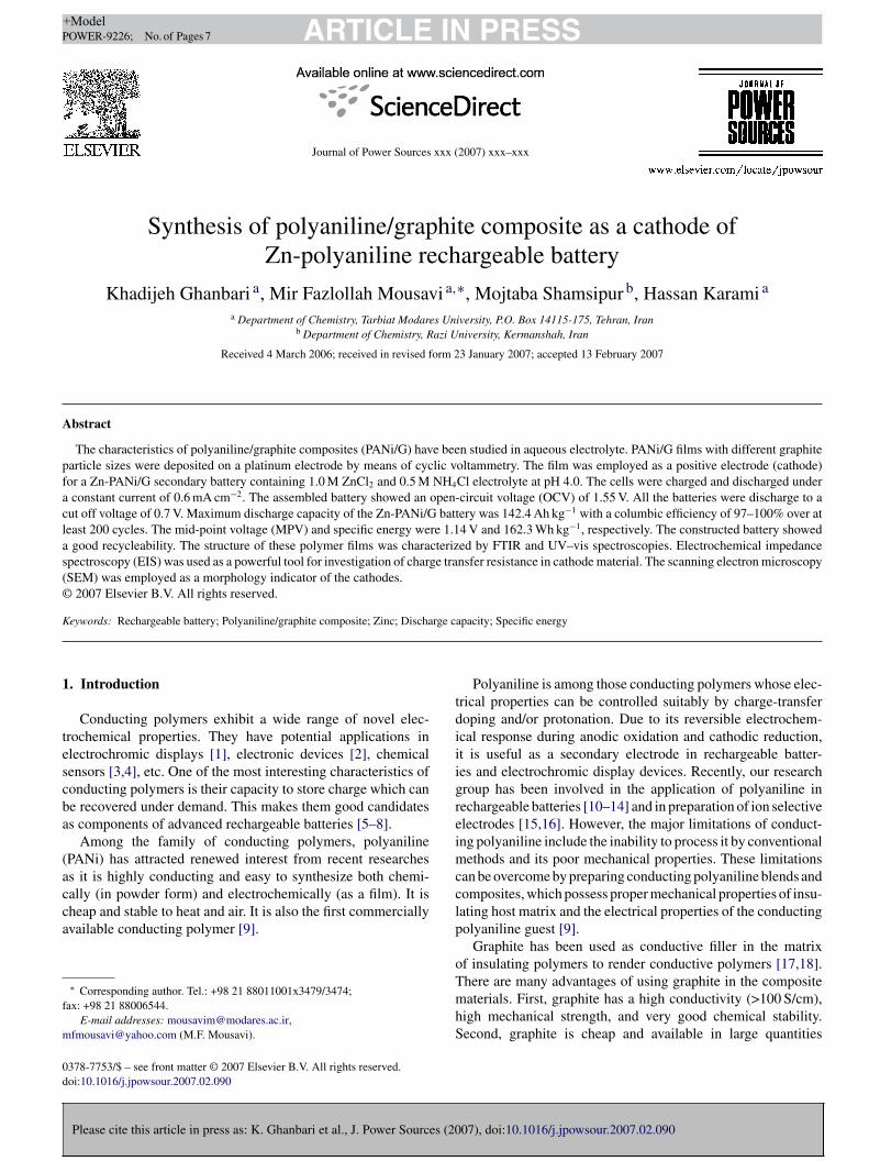
As shown in Fig. 3, the films prepared with and withoutraphite distinctly show differences in polymer morphology.he morphology of the film obtained from a solution containingniline and SDS, without graphite, is defined by fibular struc-ures (Fig. 3a). In contrast, in the presence of graphite, a porous
07), doi:10.1016/j.jpowsour.2007.02.090
lobular structure is observed (Fig. 3b). The graphite powdersre crystalline particles, some with sharp edges, which can belearly observed in Fig. 3b.
able 1harge transfer resistance (Rct) of PANi and PANi/G composites with various
izes of graphite particles
Rct (�)
ANi 1650PANi/G) < 20 �m 1100PANi/G) 20–25 �m 820PANi/G) 45–50 �m 245PANi/G) >75 �m 106
ARTICLE IN PRESS+ModelPOWER-9226; No. of Pages 7
4 K. Ghanbari et al. / Journal of Power Sources xxx (2007) xxx–xxx
F(<
3
a1p
Fp
Fs
fpa1rcq
ctcezTooe
3
ig. 3. (a) SEM micrograph of PANi film synthesized in the presence of SDS.b) SEM micrograph of PANi/G composite film with graphite particle size of20 �m.
.2. Characterization of PANi/G polymer
Please cite this article in press as: K. Ghanbari et al., J. Power Sources (20
The FTIR spectrum of synthesized pristine PANi gavebsorption bands at 1573.2, 1500, 1299.9, 1240.4 and145.5 cm−1, as shown in trace a of Fig. 4. This suggested thatolyaniline produced in the form of emeraldine salt [37]. While
ig. 4. FTIR spectra of (a) PANi and (b) PANi/G composite (with graphitearticles size >75 �m).
ihvai
ciioiavT1sid
o
ig. 5. Visible spectra of PANi and PANi/G composite (with graphite particlesize >75 �m).
or the PANi/G composite (trace b of Fig. 4), the absorptioneaks was similar to pure PANi, except that the absorption bandsssigned to the C C group of benzenoid and quinoid rings at500 and 1573.2 cm−1 were shifted to 1488.8 and 1604.9 cm−1,espectively. This indicated the interaction between the big �-onjugated structure of graphite particles and the benzenoid anduinoid rings of PANi molecules.
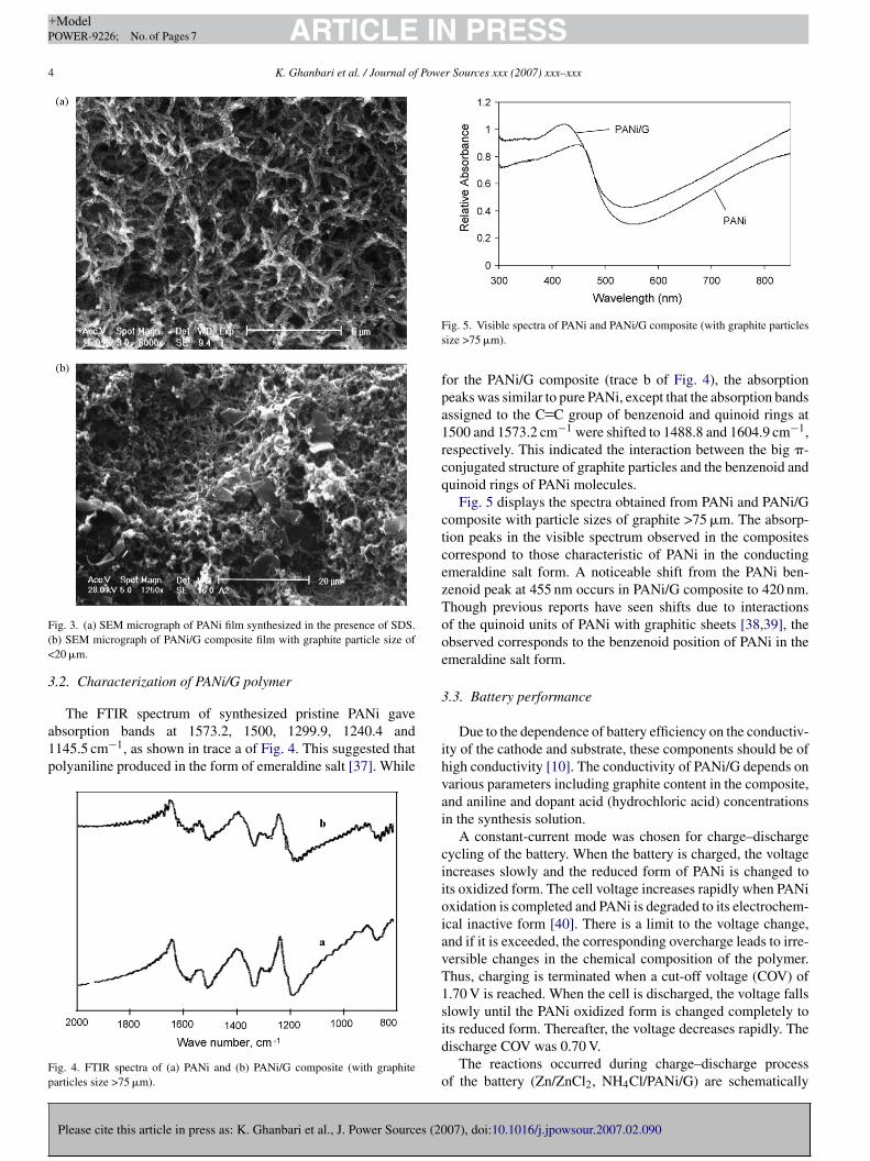
Fig. 5 displays the spectra obtained from PANi and PANi/Gomposite with particle sizes of graphite >75 �m. The absorp-ion peaks in the visible spectrum observed in the compositesorrespond to those characteristic of PANi in the conductingmeraldine salt form. A noticeable shift from the PANi ben-enoid peak at 455 nm occurs in PANi/G composite to 420 nm.hough previous reports have seen shifts due to interactionsf the quinoid units of PANi with graphitic sheets [38,39], thebserved corresponds to the benzenoid position of PANi in themeraldine salt form.
.3. Battery performance
Due to the dependence of battery efficiency on the conductiv-ty of the cathode and substrate, these components should be ofigh conductivity [10]. The conductivity of PANi/G depends onarious parameters including graphite content in the composite,nd aniline and dopant acid (hydrochloric acid) concentrationsn the synthesis solution.
A constant-current mode was chosen for charge–dischargeycling of the battery. When the battery is charged, the voltagencreases slowly and the reduced form of PANi is changed tots oxidized form. The cell voltage increases rapidly when PANixidation is completed and PANi is degraded to its electrochem-cal inactive form [40]. There is a limit to the voltage change,nd if it is exceeded, the corresponding overcharge leads to irre-ersible changes in the chemical composition of the polymer.hus, charging is terminated when a cut-off voltage (COV) of.70 V is reached. When the cell is discharged, the voltage fallslowly until the PANi oxidized form is changed completely to
07), doi:10.1016/j.jpowsour.2007.02.090
ts reduced form. Thereafter, the voltage decreases rapidly. Theischarge COV was 0.70 V.
The reactions occurred during charge–discharge processf the battery (Zn/ZnCl2, NH4Cl/PANi/G) are schematically

ARTICLE IN PRESS+ModelPOWER-9226; No. of Pages 7
K. Ghanbari et al. / Journal of Power Sources xxx (2007) xxx–xxx 5
SP
sttac
tsg
c(asbfoi(pfigltafftgftflta
Fig. 6. (a). Effect of current density on discharge capacity at various sizes parti-cle graphite. Curves: (1) <20 �m, (2) 20–25 �m, (3) 45–50 �m and (4) >75 �m.(C
dcpHaamcdzcitd
ioc1u
cheme 1. Schematic representation of charge–discharge process in a Zn-ANi/G rechargeable cell.
hown in Scheme 1. As is obvious, the cathodic reaction involvedhe oxidation/reduction processes are accompanied by the inser-ion and elimination of the chloride dopant. Meanwhile, at thenode, Zn deposits during charging and dissolves during dis-harging processes.
The effect of graphite content of the PANi/G composite onhe capacity and coulombic efficiency of battery was studied foreveral composites and the results revealed that the use of 4%raphite gives the best response characteristics.
The influence of current density on battery capacity andoulombic efficiency at various particle sizes of graphite<20 �m, 20–25 �m, 45–50 �m and >75 �m) was investigatednd the results are shown in Figs. 6a and b, respectively. As it iseen from Fig. 6a, maximum capacity of the battery is achievedy employing the larger size graphite particles (>75 �m), andurther increase in graphite particle size did not show any effectn the capacity of battery. Possible reasons for the observedncrease in capacity by increasing graphite particle size include:1) as described previously [38], the incorporation of graphitearticles into the PANi matrix leads to a larger peak currentor the PANi/G composite, which was found to increase withncreasing size of graphite particles in the composite. (2) Theraphite conductive particles cause an increase in conductivityevel in PANi/G composites and, as shown in Fig. 1, the chargeransfer resistance decreases by increasing graphite particle sizend lowers the total inner resistance of the system, therebyavoring the ohmic drop. With a decrease in ohmic drop, the use-ul voltage delivered by the cell was increased. Consequently,he discharge capacity of the battery increased with increasingraphite particle size, decrease the IR drop. (3) Results observedrom fractal dimension [41] show that in PANi/G composites,he polymer is more porous so that there is an increase in real sur-
Please cite this article in press as: K. Ghanbari et al., J. Power Sources (20
ace area and availability to lower layers of polymer and dopingevel; consequently, the battery capacity will increases, due tohe increased pore size in polymer, which facilitates the diffusionnd movement of dopant ions.
tocs
b). Effect of current density on coulombic efficiency at various sizes of graphite.urves: (1) <20 �m, (2) 20–25 �m, (3) 45–50 �m and (4) >75 �m.
The available capacity of the proposed battery is stronglyepend on discharge current density. By employing a dischargeurrent density of 0.6 mA cm−2 with respect to polyaniline com-osite weight, the battery capacity is maximum (142.4 Ah kg−1).owever, at higher current densities, only the outer layers of
ctive materials can contribute to the charge/discharge processesnd thus, the battery capacity will decrease. The capacity of theetal/polymer battery is controlled by the amount of cyclable
harge, i.e., by the doping level exchanged during charge andischarge [42]. This allows the charge and discharge of deeperones of PANi layers. As it is seen from Fig. 6a, the rate ofapacity drop with increasing current density is decreased withncreasing graphite particle size. As it is obvious from Fig. 6b,he columbic efficiency of the battery decreases with increasingischarge current densities.
The voltage-time behavior of the proposed battery dur-ng various charge and discharge cycles at a current densityf 0.6 mA cm−2 is shown in Fig. 7. The corresponding spe-ific energy for the average discharge voltage of 1.14 V is62.3 Wh kg−1. The open-circuit voltage (OCV) is 1.55 Vnder this condition. It was found that, after 150 cycles,
07), doi:10.1016/j.jpowsour.2007.02.090
he decrease in OCV was 4%. As a result, the performancef battery was not significantly affected due to cycling pro-ess. For example, the OCV in 100th and 150th cycles areimilar.

ARTICLE IN+ModelPOWER-9226; No. of Pages 7
6 K. Ghanbari et al. / Journal of Powe
Fig. 7. Charge–discharge curves during various cycles at constant current den-sity of 0.6 mA cm−2 for PANi/G composite (>75 �m).
FP(
bd1Woiapapea
io
TE
P
ONCC
baddpcw
4
bT1licpbfba
A
Cf
R
[
ig. 8. Discharge capacity and coulombic efficiency vs. cycle number forANi/G–Zn cell at a constant density of 0.6 mA cm−2 for PANi/G composite>75 �m). Working voltage range from 1.70 to 0.70 V.
The influence of cycle-life on battery capacity and coulom-ic efficiency is presented in Fig. 8. The battery capacityecreases significantly with increasing number of cycles from42.4 Ah kg−1 to a value of 105.1 Ah kg−1 after 100 cycles.hile, after 200 cycles, the capacity of battery reached a value
f 81.7 Ah kg−1. The average of capacity loss during 200 cycless 0.15% per cycle. The experimental results revealed that, inddition to electrochemical degradation of the polyaniline, zincassivation can also significantly reduce the battery capacity. Itppears that the kinetics of Zn passivation is faster than that ofolyaniline electrochemical degradation [13]. The coulombicfficiency of the cell remains more or less constant over 97%
Please cite this article in press as: K. Ghanbari et al., J. Power Sources (20
fter 200 complete cycles.In order to compare PANi and PANi/G composite batter-
es, the electrochemical parameters for battery application werebtained and compared in Table 2. As it is obvious, the proposed
able 2lectrochemical parameters for battery application
arameter Value
PANi PANi/G
pen-circuit voltage (V) 1.4 1.55umber of recharge cycles 250 200harge storage capacity (Ah kg−1) 112.1 142.4olumbic efficiency (%) 100 100
[
[
[
[
[[
[
[[
PRESSr Sources xxx (2007) xxx–xxx
attery has larger discharge (at current density 0.6 mA cm−2
t 1st cycle) capacity and OCV. Due to the presence of con-uctive graphite particles, more porous structure and enhancedoping level with increasing graphite particle size, the com-osites conductivity is increased in comparison with PANi and,onsequently the useful voltage delivered by cell is increasedhich resulted in the increased battery capacity.
. Conclusions
Studies on the Zn-PANi/G cell clearly demonstrated the via-ility of using this composite as an active electrode material.he results revealed that the battery has an output capacity of42.4 Ah kg−1 with a columbic efficiency of 97–100% over ateast 200 cycles between 0.70 and 1.70 V. The specific energys 162.3 Wh kg−1. A number of key factors such as capacity,olumbic efficiency and specific energy were improved com-ared to other works, and performance of the cell was found toe better than that of the Zn-PANi battery. The results obtainedrom FTIR and UV–vis experiments, indicated the interactionetween the large �-conjugated structure of graphite particlesnd the benzenoid and quinoid rings of the PANi molecules.
cknowledgements
The support of the Tarbiat Modares University Researchouncil is gratefully acknowledged. The supply of Zinc anodes
rom Ghovveh Pars Co. is also acknowledged.
eferences
[1] P. Somani, A.B. Mandel, S.R. Radhakkrishnan, Acta Mater. 48 (2000) 2859.[2] K. Gurunathan, A. Vadivel Murugan, P. Marimuthu, U.P. Mulik, D.P. Amal-
nerrkar, Mater. Chem. Phys. 61 (1999) 173.[3] M. Kanungo, A. Kumar, A.Q. Contractor, J. Electroanal. Chem. 528 (2002)
46.[4] T. Lindfors, A. Ivaska, Anal. Chim. Acta 437 (2001) 171.[5] K. Gurunathan, D.P. Amalnerkar, D.C. Trivedi, Mater. Lett. 57 (2003) 1642.[6] A.R. Mirmohseni, R. Solhjo, Eur. Polym. J. 39 (2003) 219.[7] G. Mengoli, M.M. Musiani, D. Pletcher, S. Valcher, J. Appl. Electrochem.
17 (1987) 515.[8] N.L.D. Somasiri, A.G. MacDiarmid, J. Appl. Electrochem. 17 (1988) 92.[9] J. Anand, S. Palaniappan, D.N. Sathyanarayana, Prog. Polym. Sci. 23
(1998) 993.10] M.S. Rahmanifar, M.F. Mousavi, M. Shamsipur, J. Power Sources 110
(2002) 229.11] H. Karami, M.F. Mousavi, M. Shamsipur, J. Power Sources 124 (2003)
303.12] H. Karami, M.F. Mousavi, M. Shamsipur, J. Power Sources 117 (2003)
255.13] M.S. Rahmanifar, M.F. Mousavi, M. Shamsipur, M. Ghaemi, J. Power
Sources 132 (2004) 296.14] Kh. Ghanbari, M.F. Mousavi, M. Shamsipur, Electrochem. Acta 52 (2006)
1514.15] H. Karami, M.F. Mousavi, Talanta 63 (2004) 743.16] M.F. Mousavi, M. Shamsipur, S. Riahi, M.S. Rahmanifar, Anal. Sci. 18
07), doi:10.1016/j.jpowsour.2007.02.090
(2002) 137.17] G.H. Chen, D.J. Wu, W.G. Weng, B. He, W.I. Yan, Polym. Int. 50 (2001)
980.18] J. Xu, Y. Hu, L. Song, Q. Wang, W. Fan, Mater. Res. Bull 36 (2001) 1833.19] W. Li, C.L. Johnson, H.-Lin. Wang, Polymer 45 (2004) 4769.

IN+ModelP
Powe
[
[[[
[[[
[
[[[[[
[[
[[
[[
[
[
ARTICLEOWER-9226; No. of Pages 7
K. Ghanbari et al. / Journal of
20] B. Veeraraghavan, J. Paul, B. Haran, B. Popov, J. Power Sources 109 (2002)377.
21] W. Li, C.L. Johnson, H.L. Wang, Polymer 45 (2004) 4769.22] T. Viswanathan, US Patent Application 20040232390 (2004).23] H.H. Kuhn, A.D. Child, Handbook of Conducting Polymers, Marcel
Dekker, New York, 1998, pp. 993–1013 (Chapter 35).24] P. Xiao, M. Xiao, P. Liu, K. Gong, Carbon 38 (2000) 623.25] G. Wu, L. Li, J.H. Li, B.Q. Xu, Carbon 43 (2005) 2579.26] R. Del Riı̌o, J.H. Zagal, G. de, T. Andrade, S.R. Biaggio, J. Appl. Elec-
trochem. 29 (1999) 759.27] A.G. MacDiarmid, L.S. Yang, W.S. Huang, B.D. Humpherey, Synth. Met.
18 (1987) 393.
Please cite this article in press as: K. Ghanbari et al., J. Power Sources (20
28] S. Sarkar, I.N. Basumallick, Trans. SAEST 23 (1988) 351.29] E. Genies, P. Hany, C. Santier, Synth. Met. 28 (1989) 647.30] H. Tsutsumi, S. Yamashita, T. Onishi, J. Appl. Electrochem. 27 (1997) 477.31] A. Kitani, M. Kaya, K. Sasaki, J. Electrochem. Soc. 133 (1986) 1069.32] M. Shaolin, Y. Jindai, W. Yuhua, J. Power Sources 45 (1993) 153.
[
[
PRESSr Sources xxx (2007) xxx–xxx 7
33] N. Li, J.Y. Lee, L.H. Ong, J. Appl. Electrochem. 22 (1992) 512.34] J.M. Pernaut, R.C.D. Peres, V.F. Juliano, M.A. De Paoli, J. Electroanal.
Chem. 274 (1989) 225.35] M. Sima, T. Visan, M. Buda, J. Power Sources 56 (1995) 133.36] B.G. Peter, Solid State Electrochemistry, Cambridge University Press,
1997.37] P. Xiao, M. Xiao, P.G. Liu, K. Gong, Carbon 38 (2000) 626.38] M. Cochet, W.K. Maser, A.M. Benito, M.A. Callejas, M.T. Martinez, J.M.
Benoit, et al., Chem. Commun. 16 (2001) 1450.39] H. Zengin, W. Zhou, J. Jin, R. Czerw, W. Dennis, J. Smith, et al., Polym.
Prepr. (Am. Chem. Soc. Div. Polym. Chem.) 44 (2003) 1104.40] L. Niu, Q. Li, F. Wei, X. Chen, H. Wang, J. Electroanal. Chem. 544 (2003)
07), doi:10.1016/j.jpowsour.2007.02.090
121.41] Kh. Ghanbari, M.F. Mousavi, M. Shamsipur, M.S. Rahmanifar, H. Heli,
Synth. Met. 156 (2006) 911.42] M.A. Vorotyntsev, J.P. Badiali, G. Inzelt, J. Electroanal. Chem. 472 (1999)
7.