Rechargeable Batteries with High Energy Storage Activated by In-situ Induced Fluorination of Carbon...
7
Rechargeable Batteries with High Energy Storage Activated by In-situ Induced Fluorination of Carbon Nanotube Cathode Xinwei Cui 1 , Jian Chen 2 , Tianfei Wang 1 & Weixing Chen 1,3 1 AdvEn Solutions Inc., 3231 Tredger Close, Edmonton, Alberta, Canada, T6R 3T6, 2 National Institute for Nanotechnology, NINT, NRC, 11421 Saskatchewan Drive, Edmonton, Alberta, Canada, T6G 2M9, 3 Department of Chemical and Materials Engineering, University of Alberta, Edmonton, Alberta, Canada T6G 2G6. High performance rechargeable batteries are urgently demanded for future energy storage systems. Here, we adopted a lithium-carbon battery configuration. Instead of using carbon materials as the surface provider for lithium-ion adsorption and desorption, we realized induced fluorination of carbon nanotube array (CNTA) paper cathodes, with the source of fluoride ions from electrolytes, by an in-situ electrochemical induction process. The induced fluorination of CNTA papers activated the reversible fluorination/ defluorination reactions and lithium-ion storage/release at the CNTA paper cathodes, resulting in a dual-storage mechanism. The rechargeable battery with this dual-storage mechanism demonstrated a maximum discharging capacity of 2174 mAh g carbon 21 and a specific energy of 4113 Wh kg carbon 21 with good cycling performance. A lthough Li-ion batteries (LIBs) have transformed portable electronics, the energy density and cycle life of existing LIBs, even if fully developed, remain insufficient 1,2 . Reaching beyond the horizon of LIBs requires the exploration of new electrochemistry and/or new materials 1 . The recent popular attempts are Li-sulfur (Li-S) 2–7 and Li-air (Li-O 2 ) batteries 8–11 . However, there are some formidable challenges for Li-S and Li-O 2 batteries, e.g., dissolution of discharging products, poor cathode electrical conductivity, and large volume expan- sion upon lithiation 2,4 . Li-CF x batteries have the highest energy density among all primary lithium batteries 12 with a theoretical specific energy of 2180 Wh kg (Li1CF) 21 . A high capacity of 615 mAh g CFx 21 was also reported for the pre-synthesized CF x cathodes 13 . It is well known that defluorination of carbon fluorides can be achieved with the assistance of lithium cations during discharging in Li-CF x batteries 14,15 . However, Li-CF x batteries have attracted limited interest because of their strictly non-rechargeable nature 16 and the non-environmental-friendly synthesis process for carbon fluorides, e.g., the use of F 2 gas and/or catalysts under extreme temperature conditions 12–15,17 . In a departure from previous approaches, we adopted the lithium-carbon battery configuration. Instead of using carbon materials as the surface provider for lithium-ion adsorption and desorption, we realized induced fluorination of carbon nanotube array (CNTA) paper cathodes, with the source of fluoride ions from electrolytes, by an in-situ electrochemical induction process. The induced fluorination of CNTA papers activates the reversible fluorination/defluorination reactions and lithium-ion storage/release at the CNTA paper cathodes, resulting in a dual-storage mechanism. It is the first time that the reversible fluorination/ defluorination reactions were realized at pure carbon and non-fluoride materials. The rechargeable battery with this dual-storage mechanism, as shown in Figure 1, is referred to as lithium-carbon-fluorine (Li-C-F) batteries. The cathode of the Li-C-F batteries in this report is made of CNTA papers (Figure S1 in supple- mentary materials); and hence, it is also denoted as Li-CNT-F batteries. After the battery cells were assembled, CNTA paper cathodes with no binding materials and no conductive additives were in-situ fluorinated by induction charging for a number of cycles, which enables Li-CNT-F batteries with high energy density and high reversibility. OPEN SUBJECT AREAS: MATERIALS SCIENCE APPLIED PHYSICS BATTERIES CARBON NANOTUBES AND FULLERENES Received 31 March 2014 Accepted 29 May 2014 Published 16 June 2014 Correspondence and requests for materials should be addressed to X.W.C. (xinwei.cui@ adven-solutions.com) or W.X.C. (weixing. [email protected]) SCIENTIFIC REPORTS | 4 : 5310 | DOI: 10.1038/srep05310 1
-
Upload
independent -
Category
Documents
-
view
1 -
download
0
Transcript of Rechargeable Batteries with High Energy Storage Activated by In-situ Induced Fluorination of Carbon...

Rechargeable Batteries with High EnergyStorage Activated by In-situ InducedFluorination of Carbon NanotubeCathodeXinwei Cui1, Jian Chen2, Tianfei Wang1 & Weixing Chen1,3
1AdvEn Solutions Inc., 3231 Tredger Close, Edmonton, Alberta, Canada, T6R 3T6, 2National Institute for Nanotechnology, NINT,NRC, 11421 Saskatchewan Drive, Edmonton, Alberta, Canada, T6G 2M9, 3Department of Chemical and Materials Engineering,University of Alberta, Edmonton, Alberta, Canada T6G 2G6.
High performance rechargeable batteries are urgently demanded for future energy storage systems. Here, weadopted a lithium-carbon battery configuration. Instead of using carbon materials as the surface providerfor lithium-ion adsorption and desorption, we realized induced fluorination of carbon nanotube array(CNTA) paper cathodes, with the source of fluoride ions from electrolytes, by an in-situ electrochemicalinduction process. The induced fluorination of CNTA papers activated the reversible fluorination/defluorination reactions and lithium-ion storage/release at the CNTA paper cathodes, resulting in adual-storage mechanism. The rechargeable battery with this dual-storage mechanism demonstrated amaximum discharging capacity of 2174 mAh gcarbon
21 and a specific energy of 4113 Wh kgcarbon21 with
good cycling performance.
Although Li-ion batteries (LIBs) have transformed portable electronics, the energy density and cycle life ofexisting LIBs, even if fully developed, remain insufficient1,2. Reaching beyond the horizon of LIBs requiresthe exploration of new electrochemistry and/or new materials1. The recent popular attempts are Li-sulfur
(Li-S)2–7 and Li-air (Li-O2) batteries8–11. However, there are some formidable challenges for Li-S and Li-O2
batteries, e.g., dissolution of discharging products, poor cathode electrical conductivity, and large volume expan-sion upon lithiation2,4.
Li-CFx batteries have the highest energy density among all primary lithium batteries12 with a theoretical specificenergy of 2180 Wh kg(Li1CF)
21. A high capacity of 615 mAh gCFx21 was also reported for the pre-synthesized CFx
cathodes13. It is well known that defluorination of carbon fluorides can be achieved with the assistance of lithiumcations during discharging in Li-CFx batteries14,15. However, Li-CFx batteries have attracted limited interestbecause of their strictly non-rechargeable nature16 and the non-environmental-friendly synthesis process forcarbon fluorides, e.g., the use of F2 gas and/or catalysts under extreme temperature conditions12–15,17.
In a departure from previous approaches, we adopted the lithium-carbon battery configuration. Instead ofusing carbon materials as the surface provider for lithium-ion adsorption and desorption, we realizedinduced fluorination of carbon nanotube array (CNTA) paper cathodes, with the source of fluoride ionsfrom electrolytes, by an in-situ electrochemical induction process. The induced fluorination of CNTA papersactivates the reversible fluorination/defluorination reactions and lithium-ion storage/release at the CNTApaper cathodes, resulting in a dual-storage mechanism. It is the first time that the reversible fluorination/defluorination reactions were realized at pure carbon and non-fluoride materials. The rechargeable batterywith this dual-storage mechanism, as shown in Figure 1, is referred to as lithium-carbon-fluorine (Li-C-F)batteries. The cathode of the Li-C-F batteries in this report is made of CNTA papers (Figure S1 in supple-mentary materials); and hence, it is also denoted as Li-CNT-F batteries. After the battery cells wereassembled, CNTA paper cathodes with no binding materials and no conductive additives were in-situfluorinated by induction charging for a number of cycles, which enables Li-CNT-F batteries with high energydensity and high reversibility.
OPEN
SUBJECT AREAS:MATERIALS SCIENCE
APPLIED PHYSICS
BATTERIES
CARBON NANOTUBES ANDFULLERENES
Received31 March 2014
Accepted29 May 2014
Published16 June 2014
Correspondence andrequests for materials
should be addressed toX.W.C. ([email protected])or W.X.C. (weixing.
SCIENTIFIC REPORTS | 4 : 5310 | DOI: 10.1038/srep05310 1
ResultsIn-situ electrochemical induction of carbon nanotube array papercathodes. CNTA papers18 were prepared simply by rolling andpressing 1.2 mm-thick CNT arrays grown on whole silicon wafers(Figure S1). In order to minimize the decomposition of the LiPF6
organic electrolyte commonly used in LIB at high potentials, anelectrolyte comprising of LiF and a fluoride-anion receptor oftris(pentafluorophenyl)borane (TPFPB) in the organic solventswas formulated and demonstrated excellent electrochemicalstability over 4.5 V vs. Li/Li1 at 22uC and 70uC (Figure S2 insupplementary materials). The conductive and binder-free CNTApaper cathodes with a CNT mass loading of 1.4–1.8 mg cm22 werethen assembled in the aforementioned electrolyte facing lithiummetals in 2032-type coin cells.
After the battery cells were assembled, an electrochemical induc-tion process was conducted, during which the induced fluorinationof CNTA papers was realized at the charging potential plateau over4.4 V. Two in-situ electrochemical induction processes are intro-duced in this report. One process, denoted as Process A1, was per-formed at 70uC using a controlled charging capacity method. Thebattery was slowly charged and discharged for two induction cycles,with the charging capacities being controlled at 900 mAh g21 for thefirst cycle and 1400 mAh g21 for the second cycle (Figure 2a). Theconstant current density used was 0.1 A g21 and the lower potentiallimit was set at 1.4 V. The battery shows pure supercapacitive beha-vior and a low discharging capacity, 102 mAh g21, if the potential iscut off at 4.4 V (the black lines in Figure 2a). When the potential goeshigher than 4.4 V at 70uC, a potential plateau at 4.49 V is seen (thegreen lines in Figure 2a), which corresponds to the induced fluorina-tion of CNTA papers as discussed later. This induced fluorinationresulted in a substantial increase in the discharging capacity(764 mAh g21), indicating an activation effect by the induced flu-orination. No potential plateau has been observed if the induction
process was performed at lower temperatures, revealing the import-ance of the induction temperature (Figure S3 in supplementarymaterials). During the second induction cycle, the potential plateauretards to appear and the discharging capacity can be furtherincreased up to 894 mAh g21 (the blue lines in Figure 2a).
Another process, termed as Process A2, consisted of two steps. Thefirst step was performed at room temperature using a pulse charging-discharging method which follows a square voltage waveform(Figure S4 in supplementary materials). This pulse charging-dischar-ging method increases the capacitance significantly after 300 cycles,due to pre-fluorination of CNTA paper cathodes, as discussed inFigure S4. The second step was performed at 70uC following proce-dures similar to those described for Process A1 (Figure 2b). However,in the first induction cycle of Step 2 (the green lines in Figure 2b), theslope of the charging curve decreases and the potential plateau for theinduced fluorination appears at a lower voltage, 4.47 V, when com-pared with those in Process A1. After applying three induction cycleswith three controlled charging capacities (1400 mAh g21, 2000 mAhg21, and 2700 mAh g21, respectively), the discharging capacity at70uC was increased up to 2174 mAh g21 (the red lines inFigure 2b). It is important to note that, the discharging capacitydid not increase if the induction charging capacities were furtherextended or if more induction cycles were added. Therefore, 2 induc-tion cycles for Process A1 and 3 cycles for Process A2 are optimal.After the induction processes, the potential plateau for the inducedfluorination disappeared below 4.5 V (will be seen in Figure 4). Itindicates that certain reversible reactions were activated and opti-mized in the batteries. The batteries were then cycled at differentrates within the voltage window between 1.4 V and 4.5 V to deter-mine their performance at both 70uC and 22uC.
Reversible fluorination of CNTA paper cathodes. In an attempt toinvestigate the reversible reactions occurring at CNTA papers, the
Figure 1 | Dual-storage mechanism with reversible fluorination/defluorination reactions and lithium-ion storage/release occurring at CNTA papercathode. (a) Induced fluorination of CNTA papers occurring at the potential plateau over 4.4 V during an electrochemical induction process at 70uC,
which also destructs the graphitic carbon structure to defective structures. (b) Defluorination of the in-situ formed carbon fluorides by the conversion
reaction with lithium ions; meanwhile, additional lithium ions store in the defective carbons. (c) Lithium ions release from the defective carbons;
meanwhile, the fluorination of the defective carbons by the reversed conversion reaction in (b). In particular, the LiF metastable solids formed in (b) and
facing the electrolyte will be dissociated during charging with assistance of TPFPB.
www.nature.com/scientificreports
SCIENTIFIC REPORTS | 4 : 5310 | DOI: 10.1038/srep05310 2

cells were disassembled and the active materials were characterizedafter they were charged to 4.5 V or discharged to 1.4 V, respectively.TPFPB was used in this study as a fluoride-anion receptor to dissolveLiF salts by displacing lithium cations from fluoride anions andforming [F-TPFPB]2 complex anions16. [F-TPFPB]2 is, therefore,the only source of fluorine in the current system. X-ray photo-electron spectroscopy (XPS) spectra in Figure 2c show highfluorine concentration in the charged sample. However, boron, acharacteristic element of TPFPB, was not detected in the chargedsample (Figures 2c and 2f). It indicates that CNTA papers havebeen fluorinated by the free fluoride ions released from [F-TPFPB]2, and the intercalation of bulky [F-TPFPB]2 anions intothe carbon cathode was suppressed. The free fluoride ions releasedfrom [F-TPFPB]2 are originally from the dissolved LiF salts, ratherthan from the decomposition of TPFPB molecules, which will bediscussed later in this report. The same result was also observed forthe sample charged to the end of the charging potential plateau in thefirst induction cycle. Therefore, the following reaction,
Czx F{TPFPB½ �{{xe{?CFxzxTPFPB ð1Þ
was occurring at the CNTA papers (Figure 1a), for the inducedfluorination during the induction and/or for the charging after theinduction.
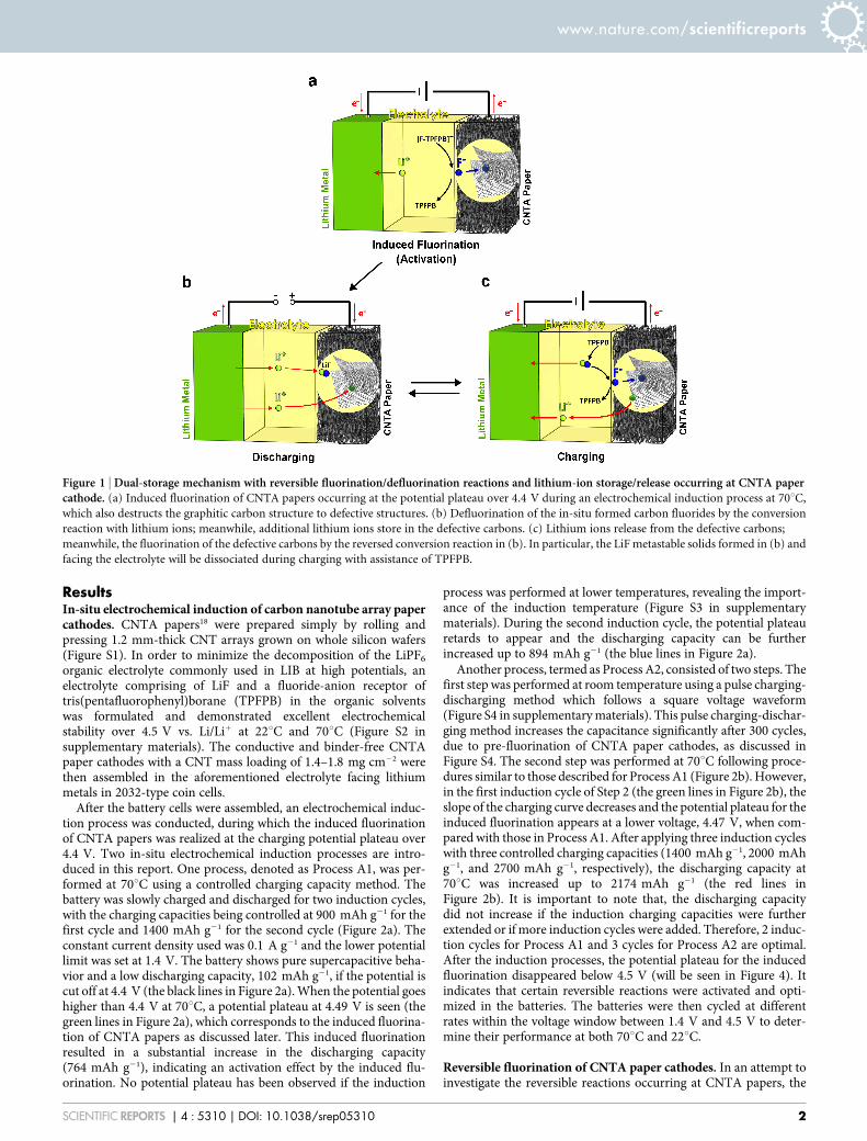
Elemental mapping of carbon, fluorine and oxygen on thecharged cathode was also performed by energy-filtering TEM(EFTEM) (Figure 3a). The distributions of carbon and fluorineare homogeneous and their concentration profiles completelyoverlap, suggesting the fluorination of CNTA papers, which agreeswell with the XPS results. The bright-field transmission electronmicroscopic (TEM) image in Figure 3a shows the morphology ofthe fluorinated CNTA paper cathode. The tubular structure ofmost CNTs was destructed, and the defective nanostructures were
formed surrounding the remaining CNTs that act as the electronconductive network for the reversible reactions. It is suggestedthat, during induced fluorination, fluoride ions were inserted intothe CNT wall layers through the open ends of the CNTs and/orthrough the defects along the tubes, causing breakdown of thetubular structures (also seen Figure S5 in supplementary materi-als). The destruction of the graphitic carbon structure may explainthe disappearance of the charging potential plateau after theinduced fluorination. The detailed analyses are in the discussionsection. Figure 2e reveals that the inserted fluoride ions form ionicor semi-ionic C-F bonds19 with the pure carbon cathodes, whichalso supports that TPFPB has not been decomposed at highvoltages.
In the discharged sample, the high concentration of fluorine wasalso detected by XPS (Figure 2c), which is caused by the formation oflithium fluoride solids (Li: 56.0 eV and F: 685.0 eV)20, as indicated inFigure 2d. Therefore, during discharging, the in-situ formed carbonfluorides from Reaction (1) will be defluorinated by lithium cationstransported from the anode, following the conversion reaction(Figure 1b):
CFxzxLizzxe{?CzxLiF ð2Þ
Elemental mapping of carbon, fluorine, lithium and oxygen on thedischarged sample further proves the occurrence of Reaction (2)(Figure 3b). The elemental map of C 1 F in Figure 3b shows thatthe fluoride anions (blue) were excluded from the defective carbonmatrix (red), and were bonded with lithium cations (green) formingLiF particles wrapping the carbon matrix (red) (the C 1 Li mappingimage in Figure 3b). It is noted that, after the release of F2 ions, thecarbon matrix maintains its defective structures, as shown in theTEM image in Figure 3b (also seen in XPS results in Figure S6 insupplementary materials).
Figure 2 | Induction processes and XPS characterization of the electrode materials. (a) Process A1, two induction cycles at 70uC for the induced
fluorination of CNTA papers. (b) Process A2, three induction cycles at 70uC after pulse-cycling treatment at room temperature. (c–f) XPS spectra of the
charged and discharged samples; a.u., arbitrary units.
www.nature.com/scientificreports
SCIENTIFIC REPORTS | 4 : 5310 | DOI: 10.1038/srep05310 3

In the presence of TPFPB, LiF solids formed during dischargingare a metastable phase in the current system. Interestingly, no LiFsolids were detected by XPS in the charged sample (Figure 2d). Thesame result was also obtained from Li K-edge electron energy-lossspectroscopy (EELS) spectra (Figure S7 in supplementary materials).It indicates that, with assistance of TPFPB, the metastable LiF solidsformed in Reaction (2) during discharging will be dissociated in thenext charging step by their reaction with the defective carbons(Figure 1c):
CzxLiF{xe{ ���?TPFPBCFxzxLiz ð3Þ
It is believed that the presence of TPFPB, the reaction temperature,and the defective carbons are three important factors for the occur-rence of the reversed conversion reaction (Reaction (3)). Duringcharging, Reaction (1) and Reaction (3) are competitive. AlthoughReaction (1) is more favorable than Reaction (3), metastable LiFsolids wrapping around the carbon matrix (the C 1 Li mappingimage in Figure 3b) may block the accessibility of [F-TPFPB]2 com-plex anions to the defective carbons and retard Reaction (1).Therefore, it is suggested that Reaction (1) mainly occurred at theinduced-fluorination potential plateau over 4.4 V during induction,and Reaction (3) mainly occurred during charging after the induc-tion processes.
In general, the reversible fluorination/defluorination reactionsoccurring at CNTA papers activated by the induced fluorinationcan be written as:
CzxLiF{xe{TPFPB
CFxzxLiz ð4Þ
Meanwhile, the induced fluorination caused the destruction of thetubular CNT structures to the defective nanostructures.
The low concentration of oxygen in both the charged and dis-charged samples (Figure 2c) implies that the decomposition of theorganic electrolyte was restricted to a low level. The O 1 Li image inFigure 2e suggests that oxygen is bonded to the carbon matrix, rather
than to the lithium to form lithium oxides, e.g., Li2O2, as in Li-airbatteries.
Lithium-ion storage by defective carbon. A high dischargingcapacity of 2174 mAh gcarbon
21 was obtained in Figure 2b. If itwere solely contributed from Reaction (2), Reaction (2) woulddeplete [F-TPFPB]2 complex anions in the electrolyte and causeproblems to the performance in the following cycles. However,Figure 4 shows excellent battery performance in terms of energydensity and cyclability for Li-CNT-F batteries. It indicates thatanother storage mechanism co-exists in the current system. The C1 Li mapping image in Figure 3b shows some overlapped regionbetween C and Li (yellow color in C 1 Li), suggesting the lithium-ionstorage in the defective carbon structures.
Traditional intercalation-type graphite materials in LIB can delivera lithium-ion storage capacity of 372 mAh/g by forming LiC6 at thepotential of 0 , 0.2 V. However, some disordered carbons24 wereshown to have a capacity much higher than 372 mAh g21, anddemonstrated reasonable capacities over 1.0 V22–26. The storage oflithium ions by carbon defective structures, such as functionalgroups22,23, increased interlayer spacing24,27, and edges and vacan-cies26,28, were rationalized. Hence, the defective carbons resulted fromthe induced fluorination are also suggested to storage lithium ions inthis lithium-carbon configuration (Figures 1b and 1c).
yCzLizze{Disch arg ing
Ch arg ing
LiCy ð5Þ
Electrochemical testing of Li-CNT-F batteries. According to thediscussion above, Li-CNT-F batteries exhibit a dual-storage mecha-nism, reversible fluorination/defluorination (Reaction (4)) andlithium-ion storage/release (Reaction (5)), occurring at the carboncathodes, which was activated by the induced fluorination of CNTApapers. Excellent battery performance in terms of energy density and
Figure 3 | Morphology and phase distribution in the cathodes after fluorination and defluorination processes. (a) Bright field (BF) TEM image showing
the morphology and structure of the charged sample, followed by the false-color elemental maps of C (red), F (blue) and O (orange) obtained by energy-
filtering imaging from the same region. (b) BF TEM image showing the morphology and structure of the discharged sample, followed by the false-color
elemental maps of C (red) 1 F (blue), C (red) 1 Li (green), O (orange) 1 Li (green) obtained by energy-filtering imaging from the same region.
www.nature.com/scientificreports
SCIENTIFIC REPORTS | 4 : 5310 | DOI: 10.1038/srep05310 4

cyclability was obtained for Li-CNT-F batteries due to the dual-storage mechanism. A maximum discharging capacity of 2174mAh gcarbon
21 and an energy density of 4113 Wh kgcarbon21 were
achieved during the third induction cycle at 70uC in Process A2(the red lines in Figure 2b). To the best of our knowledge, theseresults are 5 times higher than the best capacities previouslyreported for the lithium-carbon battery configuration21–23,26.Figure 4 shows the performance of Li-CNT-F batteries afterinduction Process A2. The reversible reactions demonstrate higherkinetics (higher power density) at 70uC (Figure 4a) than that at 22uC(Figure 4b). Interestingly, at 22uC, the discharging capacity alsomaintains a high level, 1406 mAh gcarbon
21, corresponding to anenergy density of 2982 Wh kgcarbon
21, with a columbic efficiency(,97%) (Figures 4b) higher than that at 70uC (,76%) (Figure 4a).Figure 4c shows that the discharging capacity decreases slowly from2174 mAh gcarbon
21 to 1640 mAh gcarbon21 in the initial 5 cycles
when cycling at 70uC with a current density of 0.1 A g21. Furthercycling at 22uC with a current density of 40 mA g21, the batteryshows high reversible capacity at ,1000 mAh gcarbon
21, with thecapacity retention being 93% after 30 cycles. When cycling thebattery back at 70uC, the original capacity was largely recovered to,1640 mAh gcarbon
21, demonstrating good cycling performance.Figure 5 compares the performance of different batteries on the
Ragone plot normalized to the weight of cathode materials, i.e., car-bon for Li-CNT-F batteries, sulfur for Li-S and carbon 1 oxygen forLi-O2 batteries. At 22uC, Li-CNT-F batteries outperform other typesof lithium-carbon-configuration batteries, including previouslyreported Li-functionalized CNT22 and Li-reduced graphene oxide
batteries23 using carboxyl groups for lithium-ion storage. Their per-formance is also higher than Li-S batteries and close to that of Li-O2
batteries. However, for the data presented as Li-S batteries2–7, thecathodes only contain 30 wt.% to 60 wt.% of sulfur, over half ofthe cathode is not active materials. For those results presented asLi-O2 batteries8–11, the energy densities reduce by half after 10 cycles.Therefore, CNTA paper cathodes with no binding materials and noconductive additives show remarkable features in Figure 5. Moreimportantly, the performance of Li-CNT-F batteries will alsoincrease appreciably with increasing temperatures (indicated by ared curve in Figure 5), demonstrating their great potential to bethe future energy storage systems.
The mass of the battery includes the mass of the anode, electrolyte,and other inert components in the battery. A reduction factor, massof the battery/mass of the cathode, is normally used to estimate thebattery performance from the cathode performance. For conven-tional LIBs, the reduction factor is in the range between 2.5 and 3depending on the type of lithium-transition metal oxide cath-odes1,22,29. The reduction factor for Li-S is claimed to be in the rangeof 4 to 71, and that for Li-O2 batteries is still unknown. For Li-CNT-Fbatteries, the fluoride ions in the electrolyte were involved in activ-ating the dual-storage mechanism, and therefore, a large reductionfactor of 10 was used to conservatively estimate their battery per-formance, which is ,300 Wh kgbattery
21 at 22uC.
DiscussionThe complex anion of [F-TPFPB]2 was previously found to bereversibly intercalated in graphite with limited capacity16, 60 ,
Figure 4 | Performance of Li-CNT-F batteries after Process A2. Charge-discharge curves at different rates at 70uC (a) and at 22uC (b) after Process A2.
(c) Cycle life test performed under different conditions, 0.1 A g21 at 70uC and 40 mA g21 at 22uC, on the same battery for up to 40 cycles in total.
www.nature.com/scientificreports
SCIENTIFIC REPORTS | 4 : 5310 | DOI: 10.1038/srep05310 5

80 mA gcarbon21. It is the intercalation of the bulky complex anion of
[F-TPFPB]2 that will sterically hinder further anion intercalationand worsen the cathode specific capacity16. However, in this report,the intercalation of [F-TPFPB]2 was successfully suppressed, as sug-gested in Figure 2f, which may explain the high capacity achieved inFigure 4. The suppression of bulky [F-TPFPB]2 intercalation is dueto the particular induction temperature (70uC) conducted, whichreduces the energy barrier for the F2 release from [F-TPFPB]2,and therefore, promotes the intercalation of free F2 in CNTA papers.It is also worth to note that the free fluoride ions released from [F-TPFPB]2 are originally from the dissolved LiF salts, rather than fromthe decomposition of TPFPB molecules. It has been calculated thatthe energy barrier for the fluoride anion release from TPFPB(59.2 kcal/mol) is much lower than the breakdown of a true covalentbond (typically on the order of 100 kcal/mol) in TPFPB16.
As indicated by the red arrows in Figures 2a and 2b, the polariza-tion between charge and discharge curves was decreasing withincreasing induction cycles, revealing that the energy barriers forthe reversible reactions were reducing with induction cycles at thesame induction temperature of 70uC. It implies that both Reaction(4) and Reaction (5) were facilitated at 70uC after the induced flu-orination, which is attributed to the defective carbon structures.
The temperature factor to reduce the energy barrier for the F2
release from [F-TPFPB]2 vanishes when running the batteries at22uC. However, the discharging capacity at 22uC was also signifi-cantly improved after the induction processes (Figure S9 in supple-mentary materials). This result further suggests that the in-situformed defective carbon structure plays an important role in facil-itating both Reaction (4) and Reaction (5).
It is, therefore, concluded that: 1) the presence of TPFPB and theinduction temperature of 70uC are two main reasons for the inducedfluorination of CNTA paper cathodes; 2) the induced fluorinationactivates the reversible reactions of Reaction (4) and Reaction (5),and destructs the graphitic carbon to defective nanostructures; 3) thein-situ formed defective carbons, further, facilitate the reversiblereactions at both 70uC and 22uC.
According to XPS results in Figure 2, the atomic ratio betweencarbon and fluorine is calculated to be 451, and hence, it is theformation of CF0.2 during charging for the sample after InductionProcess A1. The capacity contribution from the fluorination duringcharging is then calculated to be 447 mAh g21. Therefore, the
respective capacity contribution from the two storage mechanismsis determined to be around 151.
The relatively large polarization between charge and discharge isstill present in Figures 4a and 4b, which penalizes the energy effi-ciency, 40–60%, for the current Li-CNT-F battery systems, althoughsimilar challenge exists in many other battery systems30 such as Li-air(40–70%)8–11 and Zn-air batteries (40–70%)31,32. The polarization issuggested to be related to the energy barrier to dissociate LiF meta-stable solids. The relatively low power density at 22uC should beattributed to the sluggish kinetics for the reversible fluorination/defluorination reactions at room temperature and the defective car-bon structures formed during the induction processes. The develop-ment of an efficient catalyst to reduce the polarization and increasethe power density at room temperature requires further investi-gations in the future. Furthermore, the polarization, the power den-sity and the cyclability are also dependent on the degree of induction(activation), which should be considered as an important parameterwhen making Li-C-F batteries for various applications. This workmay also point out the potential of using cheap defective carbons asthe cathode for the next generation rechargeable batteries.
In conclusion, we realized the induced fluorination of CNTApaper cathodes by an in-situ electrochemical induction process at70uC and in the presence of TPFPB. The induced fluorination ofCNTA papers activated the reversible fluorination/defluorinationreactions and lithium-ion storage/release at the CNTA paper cath-odes, resulting in a dual-storage mechanism. It is the first time thatthe reversible fluorination/defluorination reactions were realized atpure carbon and non-fluoride materials. In addition, the inducedfluorination destructed the graphitic carbon to defective nano-structures, which further facilitated the two reversible reactions atboth 70uC and 22uC. The rechargeable battery with this dual-storagemechanism demonstrated a maximum discharging capacity of2174 mAh gcarbon
21 and a specific energy of 4113 Wh kgcarbon21 with
good cycling performance. This paper uncovers the significance ofenergy storage by carbon materials at high voltages, and demon-strates the Li-C-F battery system a new promising candidate forthe future energy storage systems.
MethodsBattery fabrication and testing. Millimeter-thick multi-walled CNT arrays weregrown on the whole 4- or 6-inch silicon wafers, following water-assisted chemicalvapor deposition (WACVD) method reported elsewhere18. The as-grown1.2 6
0.2 mm-thick CNT arrays on the silicon wafers were rolled and pressed to CNT array(CNTA) papers. After peeling from the wafer, each CNTA paper was measured to be35 6 3 mm thick using a micrometer screw-gauge and can be cut into the size of theelectrodes for making pouch cells. Two pieces of CNTA papers were stacked togetherto make one single cathode with a thickness of 70 6 6 mm and a CNT mass loading of1.4–1.8 mg cm22. After drying at 120uC overnight in a vacuum oven, these conductiveand binder-free CNTA papers were cut into 1 cm2 electrodes and assembled into2032-type coin cells in a glove box, using a piece of Li metal as the anode, two sheets ofmicroporous membrane (Celgard 2500, Celgard) as the separator, and 200 ml of0.8 M LiF and 0.8 M tris(pentafluorophenyl)borane (TPFPB) in ethylene carbonate(EC)/dimethyl carbonate (DMC) (152, v/v) as the electrolyte.
Galvanostatic charge/discharge tests, cyclic voltammetry (CV) tests and cycleperformance tests were conducted at 22 6 1uC and/or 70 6 1uC using a 1470E multipotentiostat/celltest system (Solartron). The induced fluorination of CNTA papercathodes was realized electrochemically during two induction processes, Process A1and Process A2. Both processes contained a controlled charging capacity step, whichwas performed at 70uC and a current density of 0.1 A g21 with different controlledcharging capacities. An additional step, the pulse charging-discharging step, wasadded to Process A2 before the controlled charging capacity step. This step wasperformed at 22uC, during which the as-assembled cells were pulse-charged to 4.5 V,held for 10 min, pulse-discharged to 1.5 V and then held for 5 min, following asquare voltage waveform, for many cycles (Figure S4). The pulse charging and dis-charging rates were controlled to be the same and were at three different levels: 10 Ag21, 20 A g21 and 50 A g21. The rate was increased by one level after every 100 cyclesup to a total of 300 cycles. Cyclic voltammetry tests in the range between 1.5 V and4.5 V were conducted for the evaluation of the performance for every 50 cycles.
Characterization. CNTA paper cathodes were characterized both in the charged(fluorinated) and discharged (defluorinated) states using samples from the samepaper cathode. After the Li-CNT-F was charged to 4.5 V, the battery cell wasdisassembled to obtain the CNTA paper cathode. This cathode was cut into two after
Figure 5 | Ragone plot, comparing Li-CNT-F batteries with otherbatteries in terms of weight of cathode materials. The highest energy
density for Li-CNT-F batteries, 4113 Wh kgcarbon21, obtained during the
third 70uC-induction cycle in Process A2, is presented as a red star.
www.nature.com/scientificreports
SCIENTIFIC REPORTS | 4 : 5310 | DOI: 10.1038/srep05310 6

being thoroughly rinsed with DMC and kept in a vacuum in the glove box. One half ofthe cathode was kept for characterization as the charged sample; the other half wasreassembled in the 2032-type coin cell, and discharged to 1.4 V before being removedfrom the battery and characterized as the discharged sample. In order to minimize theexposure of the cathode materials to the air, all the samples used for TEM and X-rayphotoelectron spectroscopy (XPS) were prepared inside the glove box and transferredto the examining stages using an argon protected sample loading holder.
The morphology and structure of CNTAs were analyzed by scanning electronmicroscopy (SEM, Hitachi S-4800, operated at 10 kV and 20 kV). Transmissionelectron microscopy (TEM, JEOL JEM-2100 with LaB6 cathode, 200 kV) was used tocharacterize the structural changes of CNTA paper electrodes before and after flu-orination. XPS was carried out using a Kratos AXIS Ultra-x-ray photoelectronspectrometer. Energy-filtering TEM (EFTEM) was employed for elemental mappingcalculations. Mapping was performed on a H-9500 TEM equipped with a GatanImaging Filter (GIF) spectrometer. In order to decrease possible electron beamdamage to the sample, an accelerating voltage of 100 kV was employed. All energy-filtering images were recorded using a binning of 2 3 2 giving 1024 3 1024 pixelimages, for reasons of sensitivity. Because the focus of an EFTEM image differssignificantly from the focus of the elastic image, the images were focused at an energy-loss between 100 and 200 eV. The three-window method which is effective at redu-cing thickness effects was used for elemental mapping. Electron energy-loss spec-troscopy (EELS) spectra were collected in image mode with an energy resolution of,1.3 eV as measured by the full width at half maximum (FWHM) of the zero-losspeak (ZLP).
1. Bruce, P. G., Freunberger, S. A., Hardwick, L. J. & Tarascon, J. M. Li-O2 and Li-Sbatteries with high energy storage. Nat. Mater. 11, 19–29 (2012).
2. Seh, Z. W. et al. Sulphur-TiO2 yolk-shell nanoarchitecture with internal voidspace for long-cycle lithium-sulphur batteries. Nat. Commun. 4, 133 (2013).
3. Wang, H. et al. Graphene-wrapped sulfur particles as a rechargeable lithium-sulfur battery cathode material with high capacity and cycling stability. Nano Lett.11, 2644–2647 (2011).
4. Xin, S. et al. Smaller sulfur molecules promise better lithium-sulfur batteries.J. Am. Chem. Soc. 134, 18510–18513 (2012).
5. Ji, X., Lee, K. T. & Nazar, F. A highly ordered nanostructured carbon-sulphurcathode for lithium-sulphur batteries. Nat. Mater. 8, 500–506 (2009).
6. He, M., Yuan, L. X., Zhang, W. X., Hu, X. L. & Huang, Y. H. Enhanced cyclabilityfor sulfur cathode achieved by a water-soluble binder. J. Phys. Chem. C. 115,15703–15709 (2011).
7. Ji, X., Ever, S., Black, R. & Nazar, F. Stabilizing lithium-sulphur cathodes usingpolysulphide reservoirs. Nat. Commun. 2, 325 (2011).
8. Jung, H. G., Hassoun, J., Park, J. B., Sun, Y. K. & Scrosati, B. An improved high-performance lithium-air battery. Nat. Chem. 4, 579–585 (2012).
9. Qin, Y. et al. In situ fabrication of porous-carbon-supported a-MnO2 nanorods atroom temperature: application for rechargeable Li-O2 batteries. Energy Environ.Sci. 6, 519–531 (2013).
10. Mitchell, R. R., Gallant, B. M., Thompson, C. V. & Horn, Y. S. All-carbon-nanofiber electrodes for high-energy rechargeable Li-O2 batteries. EnergyEnviron. Sci. 4, 2952–2958 (2011).
11. Christensen, J. et al. A critical review of Li/air batteries. J. Electrochem. Soc. 159,R1–R30 (2012).
12. Fulvio, P. F. et al. Low-temperature fluorination of soft-templated mesoporouscarbons for a high-power lithium/carbon fluoride battery. Chem. Mater. 23,4420–4427 (2011).
13. Chamssedine, F. et al. Reactivity of carbon nanofibers with fluorine gas. Chem.Mater. 19, 161–172 (2007).
14. Guerin, K. et al. Synthesis and characterization of highly fluorinated graphitecontaining sp2 and sp3 carbon. Chem. Mater. 16, 1786–1792 (2004).
15. Mickelson, E. T. et al. Fluorination of single-walled carbon nanotubes. Chem.Phys. Lett. 296, 188–194 (1998).
16. West, W. C. et al. Reversible intercalation of fluoride-anion receptor complexes ingraphite. J. Electrochem. Soc. 154, A929–A936 (2007).
17. Yazami, R. et al. Fluorinated carbon nanofibres for high energy and high powerdensities primary lithium batteries. Electrochem. Commun. 9, 1850–1855 (2007).
18. Cui, X., Wei, W. & Chen, W. Lengthening and thickening of multi-walled carbonnanotube arrays grown by chemical vapor deposition in the presence and absenceof water. Carbon 48, 2782–2791 (2010).
19. Palchan, I., Crespin, M., Estrade-Szwarckopf, H. & Rousseau, B. Graphitefluorides: an XPS study of a new type of C-F bonding. Chem. Phys. Lett. 157,321–327 (1989).
20. Kim, B. G., Lee, J. N., Lee, D. J., Park, J. K. & Choi, J. W. Robust cycling of Li-O2
batteries through the synergistic effect of blended electrolytes. Energy Environ. Sci.6, 443–448 (2013).
21. Stoller, M. D. et al. Activated graphene as a cathode material for Li-ion hybridsupercapacitors. Phys. Chem. Chem. Phys. 14, 3388–3391 (2012).
22. Lee, S. W. et al. High-power lithium batteries from functionalized carbon-nanotube electrodes. Nat. Nanotechnol. 5, 531–537 (2010).
23. Jang, B. Z. et al. Graphene surface-enabled lithium ion-exchanging cells: next-generation high-power energy storage devices. Nano Lett. 11, 3785–3791 (2011).
24. Sato, K., Noguchi, M., Demachi, A., Oki, N. & Endo, M. A mechanism of lithiumstorage in disordered carbons. Science 264, 556–558 (1994).
25. Wu, Y. P., Wan, C. R., Jiang, C. Y., Fang, S. B. & Jiang, Y. Y. Mechanism of lithiumstorage in low temperature carbon. Carbon 37, 1901–1908 (1999).
26. Zhamu, A. et al. Reviving rechargeable lithium metal batteries: enabling next-generation high-energy and high-power cells. Energy Environ. Sci. 5, 5701–5707(2012).
27. Suzuki, T., Hasegawa, T., Mukai, S. R. & Tamon, H. A theoretical study on storagestates of Li ions in carbon anodes of Li ion batteries using molecular orbitalcalculations. Carbon 41, 1933–1939 (2003).
28. Dahn, J. R., Zheng, T., Liu, Y. & Xue, J. S. Mechanisms for lithium insertion incarbonaceous materials. Science 270, 590–593 (1995).
29. Wang, X., Hou, Y., Zhu, Y., Wu, Y. & Holze, R. An aqueous rechargeable lithiumbattery using coated Li metal as anode. Sci. Rep. 3, 1401 (2013).
30. Thakur, M., Sinsabaugh, S., Isaacson, M. J., Wong, M. S. & Biswal, S. L.Inexpensive method for producing macroporous silicon particulates (MPSPs)with pyrolyzed polyacrylonitrile for lithium ion batteries. Sci. Rep. 2, 795 (2012).
31. Li, Y. et al. Advanced zinc-air batteries based on high-performance hybridelectrocatalysts. Nat. Commun. 4, 1805 (2013).
32. Toussaint, G., Stevens, P., Akrour, L., Rouget, R. & Fourgeot, F. Development of arechargeable zinc-air battery. ECS Trans. 28, 25–34 (2010).
AcknowledgmentsThe authors would like to thank Alberta Innovates-Energy and Environment Solutions(AIEES) and NanoBridge for financial support. The authors are grateful to Dr. MarkSummers for his many valuable suggestions in shaping the project to the current stage, andDrs. Surindar Singh, John Zhou, Mr. Rick Nelson and Dr. Eddy Isaacs for making theproject happen. The authors would also like to acknowledge Drs. Xiao-Qing Yang andHung-Sui Lee, Brookhaven National Laboratory, Upton, USA, for supplying a high puritychemical reagent for comparative studies, and Drs. Douglas Ivey and Thomas Thundat,University of Alberta, for proof reading the manuscript.
Author contributionsX.W.C. conceived and designed the experiments. X.W.C. did most part of the work withassistance from T.F.W. J.C. performed the energy filtering TEM imaging characterization.W.X.C. co-conceived the concept and provided supervision during the entire course of theinvestigation.
Additional informationSupplementary information accompanies this paper at http://www.nature.com/scientificreports
Competing financial interests: The authors declare no competing financial interests.
How to cite this article: Cui, X., Chen, J., Wang, T. & Chen, W. Rechargeable Batteries withHigh Energy Storage Activated by In-situ Induced Fluorination of Carbon NanotubeCathode. Sci. Rep. 4, 5310; DOI:10.1038/srep05310 (2014).
This work is licensed under a Creative Commons Attribution-NonCommercial-NoDerivs 4.0 International License. The images or other third party material inthis article are included in the article’s Creative Commons license, unless indicatedotherwise in the credit line; if the material is not included under the CreativeCommons license, users will need to obtain permission from the license holderin order to reproduce the material. To view a copy of this license, visit http://creativecommons.org/licenses/by-nc-nd/4.0/
www.nature.com/scientificreports
SCIENTIFIC REPORTS | 4 : 5310 | DOI: 10.1038/srep05310 7