Co-electrospraying of tumour cell mimicking hollow polymeric ...
Upload
khangminh22Category
view
2download
0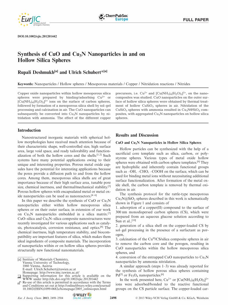
FULL PAPER
DOI:10.1002/ejic.201201442
Synthesis of CuO and Cu3N Nanoparticles in and onHollow Silica Spheres
Rupali Deshmukh[a] and Ulrich Schubert*[a]
Keywords: Nanoparticles / Hollow spheres / Mesoporous materials / Copper / Nitridation reactions / Nitrides
Copper oxide nanoparticles within hollow mesoporous silicaspheres were prepared by binding/adsorbing Cu2+ or[Cu(NH3)4(H2O)2]2+ ions on the surface of carbon spheres,followed by formation of a mesoporous silica shell by sol–gelprocessing and calcination in air. The CuO nanoparticles cansubsequently be converted into Cu3N nanoparticles by ni-tridation with ammonia. The effect of the different copper
Introduction
Nanostructured inorganic materials with spherical hol-low morphologies have received much attention because oftheir characteristic shape, well-controlled size, high surfacearea, large void space, and ready tailorability and function-alization of both the hollow cores and the shells.[1,2] Suchsystems have many potential applications owing to theirunique and interesting properties. Porous metal oxide cap-sules have the potential for interesting applications becausethe pores provide a diffusion path to and from the hollowcores. Among them, mesoporous silica shells are of greatimportance because of their high surface area, tunable poresize, chemical inertness, and thermal/mechanical stability.[3]
Porous hollow spheres with encapsulated metal or metal ox-ide nanoparticles can be used as nanoreactors.[4–6]
In this paper we describe the synthesis of CuO or Cu3Nnanoparticles either within hollow mesoporous silicaspheres or on their outer surface, in extension of our workon Cu3N nanoparticles embedded in a silica matrix.[7]
CuO–silica and Cu3N–silica composite nanostructures wererecently investigated for various applications such as cataly-sis, photocatalysis, corrosion resistance, and optics.[8] Thechemical inertness, high temperature stability, and biocom-patibility are important features of silica, which makes themideal ingredients of composite materials. The incorporationof nanoparticles within or on hollow silica spheres providesstructurally new functional nanomaterials.
[a] Institute of Materials Chemistry,Vienna University of Technology,1060 Vienna, AustriaE-mail: [email protected]: http://www.imc.tuwien.ac.at/Supporting information for this article is available on theWWW under http://dx.doi.org/10.1002/ejic.201201442Re-use of this article is permitted in accordance with the Termsand Conditions set out at http://onlinelibrary.wiley.com/journal/10.1002/(ISSN)1099-0682c/homepage/2005_onlineopen.html
Eur. J. Inorg. Chem. 2013, 2498–2504 © 2013 Wiley-VCH Verlag GmbH & Co. KGaA, Weinheim2498
precursors, i.e. Cu2+ and [Cu(NH3)4(H2O)2]2+, on the nano-composites was studied. CuO nanoparticles on the outer sur-face of hollow silica spheres were obtained by thermal treat-ment of hollow CuSiO3 spheres in air. Nitridation of theCuSiO3 spheres with ammonia resulted in Cu3N@SiO2 com-posites, with aggregated Cu3N nanoparticles on hollow silicaspheres.
Results and Discussion
CuO and Cu3N Nanoparticles in Hollow Silica Spheres
Hollow particles can be synthesized with the help of asacrificial core template such as silica, carbon, or poly-styrene spheres. Various types of metal oxide hollowspheres were obtained with carbon sphere templates.[9] Theyare hydrophilic and inherently contain functional groupssuch as –OH, –CHO, –COOH on the surface, which can beused for binding metal ions without necessitating additionalsurface functionalization. After formation of the metal ox-ide shell, the carbon template is removed by thermal oxi-dation in air.
The synthesis protocol for the rattle-type mesoporousCu3N@SiO2 spheres described in this work is schematicallyshown in Figure 1 and consists of1. adsorption of a copper(II) compound to the surface of300 nm monodispersed carbon spheres (CS), which wereprepared from an aqueous glucose solution according toSun et al.,[10]
2. generation of a silica shell on the copper-loaded CS bysol–gel processing in the presence of a surfactant as por-ogen,3. calcination of the CuII/CS/silica composite spheres in airto remove the carbon core and the porogen, resulting inCuO nanoparticles within the hollow mesoporous silicaspheres, and4. conversion of the entrapped CuO nanoparticles to Cu3Nnanoparticles by ammonia nitridation.
A similar approach (steps 1–3) was already reported forthe synthesis of hollow porous silica spheres containingPd[5] or Fe3O4 nanoparticles.[6]
In the work presented here, Cu2+ or [Cu(NH3)4(H2O)2]2+
ions were adsorbed/bonded to the reactive functionalgroups on the CS particle surface. The copper-loaded car-
www.eurjic.org FULL PAPER
Figure 1. Schematic illustration of the preparation of Cu3N nano-particles inside hollow mesoporous silica spheres.
bon spheres were then coated with a silica layer by sol–gelprocessing of Si(OEt)4 (TEOS) in the presence of cetyltri-methylammonium bromide (CTAB). The surfactant has therole of a porogen; inter-particle porosity is created upon itsthermal degradation. When the copper-loaded and silica-coated CS were heated in air, both the carbon core and theporogen were oxidatively removed. The (then porous) silicashell remained and CuO nanoparticles were formed withinthe hollow silica sphere.
Dispersion of the carbon spheres in an aqueousCu(NO3)2 solution led to adsorption/binding of Cu2+ ionson the surface of the carbon spheres. TGA of the Cu2+-loaded and silica-coated CS [labeled Cu2+/CS/SiO2] (Fig-ure S1) showed that the oxidation of the carbon spheres andorganic constituents is essentially finished at 400 °C, withsome char formation. Char is removed by further heatingto ca. 470 °C. On the basis of the TGA analysis, the Cu2+/CS/SiO2 were calcined at 550 °C in air, and a black powderwas obtained [labeled CuO@SiO2(A)]. The XRD patternof CuO@SiO2(A) (Figure 2, a) revealed monoclinic CuOnanoparticles (JCPDS 41-0254). The broad hump at �30°is from the amorphous silica. The CuO crystallite size was19 nm as calculated by Scherrer’s equation. Nitridation ofCuO@SiO2(A) at 300 °C under an ammonia atmosphere
Figure 2. XRD patterns of CuO@SiO2(A) spheres (a) and Cu3N@SiO2(A) spheres (b).
Eur. J. Inorg. Chem. 2013, 2498–2504 © 2013 Wiley-VCH Verlag GmbH & Co. KGaA, Weinheim2499
gave a brown product [labeled Cu3N@SiO2(A)], the XRDpattern of which corresponded to cubic Cu3N (JCPDS-86-2283, Figure 2, b). The average crystallite size of Cu3N was17 nm, i.e. the crystallite size was preserved upon nitrid-ation.
The nitrogen adsorption isotherms of CuO@SiO2(A)and Cu3N@SiO2(A) (Figure S2) are of type IV, which ischaracteristic of mesoporous materials, with some micro-and macroporosity (Table 1). CuO@SiO2(A) spheres have ahigh surface area, and the pore size distribution is centeredat 2.5 nm. The surface area and pore volume are slightlylower for Cu3N@SiO2(A). This may be because of the basicconditions during nitridation, which might lead to restruc-turing of some mesopores/micropores.
Table 1. Surface and pore characteristics.
Sample Specific surface Pore diameter Pore volumearea [m2/g] [nm] [cm/g]
CuO@SiO2(A) 953 2.5 0.78Cu3N@SiO2(A) 671 2.3 0.53CuO@SiO2(B) 747 2.6 0.70Cu3N@SiO2(B) 523 2.4 0.56
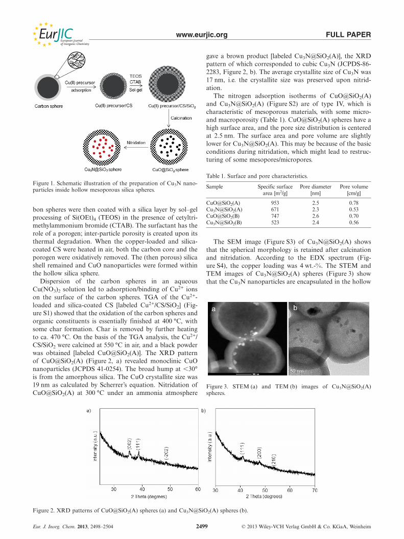
The SEM image (Figure S3) of Cu3N@SiO2(A) showsthat the spherical morphology is retained after calcinationand nitridation. According to the EDX spectrum (Fig-ure S4), the copper loading was 4 wt.-%. The STEM andTEM images of Cu3N@SiO2(A) spheres (Figure 3) showthat the Cu3N nanoparticles are encapsulated in the hollow
Figure 3. STEM (a) and TEM (b) images of Cu3N@SiO2(A)spheres.

www.eurjic.org FULL PAPER
mesoporous SiO2 spheres. As seen in the STEM image, theCu3N nanoparticles follow the shape of the sphere.
Although well-separated Cu3N nanoparticles with dia-meters �30 nm encapsulated in the hollow mesoporous sil-ica spheres were obtained starting from Cu(NO3)2, theamount of Cu3N nanoparticles per silica sphere was lim-ited. Therefore, the first step of the synthesis protocol, i.e.loading of the CS with a copper compound, was modifiedand the copper complex [Cu(NH3)4(H2O)2]2+ was employedinstead of Cu(NO3)2. This modification is not just a changeof the copper source, but also a change of the reaction con-ditions, because the employed aqueous [Cu(NH3)4-(H2O)2]2+ solution is inherently basic. All subsequent stepswere performed as described above.
TGA of [Cu(NH3)4(H2O)2]2+/CS/SiO2 (Figure S5)showed that oxidation of the organic constituents and theCS occurs at somewhat lower temperatures. For this reason,calcination of the composite in air was carried out at alower temperature, i.e. 500 °C for 2 h. The obtained CuOnanoparticles in the hollow mesoporous SiO2 spheres[CuO@SiO2(B)] were converted to Cu3N nanoparticles[Cu3N@SiO2(B)] by nitridation at 350 °C for 2 h in ammo-nia. The crystallite sizes of CuO (22 nm) and Cu3N (15 nm)were in the same range as the particle sizes obtained by thefirst route.
The nitrogen adsorption isotherm of CuO@SiO2(B)and Cu3N@SiO2(B) (Figure S6) was again characteristicof mesoporous materials (type IV isotherm). TheCuO@SiO2(B) spheres showed a surface area of 747 cm3/g,and the pore size distribution showed a sharp maximumcentered at 2.6 nm. After nitridation the surface area was523 cm3/g, and the pore size distribution was centered at2.4 nm (Table 1).
The SEM image of CuO@SiO2(B) (Figure S7) showedthat the spherical morphology of the template was also re-tained. Some broken spheres confirmed the hollow mor-phology. According to the EDX spectrum (Figure S8), thecopper loading was 24 wt.-%, which is much higher thanthat for the particles obtained from Cu(NO3)2 as the copperprecursor. The higher copper loading is also evidenced bythe higher intensity of the reflections in the diffractogramsof both CuO and Cu3N (Figure 4).
Figure 4. XRD pattern (* cristobalite) of CuO@SiO2(B) (a) and Cu3N@SiO2(B) (b).
Eur. J. Inorg. Chem. 2013, 2498–2504 © 2013 Wiley-VCH Verlag GmbH & Co. KGaA, Weinheim2500
TEM images of CuO@SiO2(B) (Figure 5) andCu3N@SiO2(B) spheres (Figure 6) clearly confirmed thatthe CuO nanoparticles are exclusively located inside thehollow mesoporous silica spheres and that the morphologywas not changed upon nitridation. The Cu3N particle sizedistribution appears to be broader than that of the CuOparticles, or the Cu3N particles are more agglomerated/ag-gregated. The thickness of the silica shell is around 40 nmin the present case; it could easily be tuned by changing theweight ratio of the carbon sphere to TEOS.
Figure 5. TEM images of CuO@SiO2(B) spheres.
Figure 6. TEM image of Cu3N@SiO2(B) spheres.
CuO and Cu3N Nanoparticles on Hollow Silica Spheres
The possibility of chemically converting metal silicatenanostructures into new chemical entities offers many op-

www.eurjic.org FULL PAPER
Figure 7. Synthesis of CuO on SiO2 and Cu3N on SiO2 from CuSiO3.
tions for the synthesis of new functional materials. For ex-ample, Jin et al. reported the synthesis of nickel-hollowsilica sphere composites by hydrogen reduction ofNi3Si2O5(OH)4 at elevated temperatures. The hollownanospheres exhibited high catalytic activity and goodselectivity in acetone hydrogenation reactions.[11]
Hydrothermal treatment of Stöber silica spheres[12] withcopper nitrate under alkaline conditions at 140 °C resultsin the formation of hollow CuSiO3 spheres as reported byWang et al.[13] Synthesis of CuO and Cu3N nanoparticleson the surface of hollow silica spheres (labeled “CuO onSiO2” and “Cu3N on SiO2”) from the CuSiO3 spheres isschematically shown in Figure 7. Heat treatment in air at700 °C led to the formation of CuO nanoparticles spreadon the surface of the hollow silica spheres. Cu3N nanopar-ticles on the hollow SiO2 spheres were obtained by reactionof the CuSiO3 spheres with ammonia at 350 °C.
Figure 8 shows TEM images of the starting CuSiO3 hol-low spheres, which are composed of nanocrystals (Fig-ure S9). Special features are nanotubes (Figure 8, b), whichare arranged vertically on the surface of the spheres andwere assumed to also consist of CuSiO3.[13] Similarmorphologies were also observed for other hollow spheresobtained by leaching processes.[14]
Figure 8. TEM images of the hollow CuSiO3 spheres.
Heat treatment of the blue hollow CuSiO3 spheres at700 °C in air led to the formation of the black CuO on theSiO2 composite through disintegration of the copper sili-cate. Temperatures below 700 °C did not result in the for-mation of CuO nanoparticles. The XRD pattern is clearevidence for the formation of monoclinic CuO nanocrystals(Figure 9). The crystallite size of the CuO crystals was10 nm. The surface area and average pore size of CuO onSiO2 was 181 m2/g and 3 nm, respectively (Figure S10). Themuch lower surface area, compared with CuO@SiO2(A) or
Eur. J. Inorg. Chem. 2013, 2498–2504 © 2013 Wiley-VCH Verlag GmbH & Co. KGaA, Weinheim2501
CuO@SiO2(B) (Table 1), is due to the different preparationmethod of the hollow silica spheres, where no template formesopores, i.e. no surfactant, was involved.
Figure 9. XRD pattern of CuO on SiO2 (* cristobalite).
TEM (Figure 10) images clearly show that the mor-phology of the CuO on SiO2 composite is almost the sameas that of the starting CuSiO3. The high magnificationTEM image revealed that CuO nanoparticles are spread onthe shell of the hollow silica spheres.
Figure 10. TEM images of CuO on SiO2. CuO nanoparticles aremarked by arrows.
After the nitridation reaction of the hollow CuSiO3
spheres with ammonia at 350 °C for 1 h, hollow silicaspheres with Cu3N nanoparticles on the surface were pro-duced without losing the hollow morphology of the CuSiO3
precursor. The nanotubes on the surface of the spheres wereagain retained. XRD analysis of the brown product (Fig-ure 11) showed the presence of cubic Cu3N nanocrystalsand amorphous silica as well as complete conversion fromCuSiO3 to Cu3N on SiO2. The crystallite size of Cu3N crys-tals was 31 nm. The BET surface area was 159 m2/g andthe pore size distribution from the adsorption branch of theisotherm was centered at 3–4 nm (Figure S11).

www.eurjic.org FULL PAPER
Figure 11. XRD pattern of Cu3N on SiO2 (* cristobalite).
SEM (Figure S12) and TEM analysis (Figure 12) of theCu3N on SiO2 clearly showed Cu3N nanoparticles on thesurface of the hollow silica particles.
Figure 12. TEM images of Cu3N on SiO2.
Both reactions showed that the copper ions of the coppersilicate structure migrated to the surface of the silica spheresduring heat treatment or nitridation to form CuO andCu3N nanoparticles, respectively. New morphologies ofCuO on SiO2 and Cu3N on SiO2 composites were thus syn-thesized from the CuSiO3 precursor. Although the tempera-ture during nitridation was much lower than during thermaldecomposition, the obtained Cu3N nanoparticles weremuch larger than the CuO nanoparticles. Extraction of theCu ions from the silicate network is apparently strongly fa-vored when supported by a chemical reaction. Although aCu3N nanoparticle size of 31 nm was determined from theXRD experiment, the particles appear to be much larger inthe TEM micrographs. This indicates that the larger par-ticles observed by TEM are in fact composed of smallernanoparticles.
An interesting side aspect is that the nanotubular struc-tures on the surface of the hollow particles were preserved.The XRD pattern after thermal decomposition (Figure 9)or nitridation (Figure 11) did not indicate any residualCuSiO3 phase. The investigation of the composition of thenanotubular structures in the CuO on the SiO2 compositesby electron microscopy failed because the nanotubes wereeasily deformed by the electron beam during the analysis.Although the chemical composition of the nanotubes couldnot be determined experimentally, the only reasonable pos-sibility is that they consist of silica. One possibility is thatthe nanotubes originally consisted of CuSiO3, as postulated
Eur. J. Inorg. Chem. 2013, 2498–2504 © 2013 Wiley-VCH Verlag GmbH & Co. KGaA, Weinheim2502
by Wang et al.[13] and the copper ions were leached duringthe subsequent reactions. Another possibility is that thenanotubes consisted of pure silica from the very beginning.
Conclusions
A multistep protocol for the synthesis of CuO or Cu3Nnanoparticles within hollow mesoporous silica spheres wasdescribed, starting from carbon spheres as templates towhich copper(II) precursors were adsorbed/bonded. Thisapproach, which was previously proven successful for metalor metal oxide nanoparticles,[5,6] was now extended to metalnitride nanoparticles. It is anticipated that this post-synthe-sis modification of metal oxide particles inside the hollowalbeit porous capsule can be generalized to prepare otherfunctional nanoparticles, such as other metal nitrides orchalcogenides, within hollow mesoporous silica spheres.
Variation of the copper precursor, i.e. Cu(NO3)2 vs.[Cu(NH3)4(H2O)2]2+ (and/or the concomitant different re-action conditions) was found to affect the loading of thecarbon spheres and thus the amount of Cu3N nanoparticlesper silica sphere. This allows controlling the Cu3N pro-portion in the final materials. Cu(NO3)2 and [Cu(NH3)4-(H2O)2]2+ interact differently with the functional surfacegroups on the carbon spheres or the nature of these groupsis changed by the more basic reaction conditions in the lat-ter case.
The conversion of CuSiO3 to CuO on SiO2 and Cu3N onSiO2 is a new observation. In each case the hollow spheremorphology of the starting CuSiO3 was well preserved. Itis anticipated that this approach can also be applied to syn-thesize other metal oxide and metal nitride/silica hollow hy-brid systems.
Experimental SectionGlucose and cetyltrimethylammonium bromide (CTAB) were pur-chased from Sigma Aldrich, Cu(NO3)2·3H2O 99.5% and ethanolfrom Merck, aqueous ammonia (28–30 wt.-%) from Baker,Si(OEt)4 (TEOS) from Fluka, and anhydrous ammonia gas(99.98%) from Messer Austria GmbH. All Chemicals were used asreceived. The carbon spheres were prepared from an aqueous solu-tion of glucose under hydrothermal conditions at 180 °C accordingto the procedure reported by Sun et al.[10]
Materials Characterization: Thermogravimetric analysis (TGA) wasperformed with a Netzsch TG 209C Iris at a heating rate of 10 °C/min under synthetic air. X-ray powder diffraction (XRD) measure-ments were performed with a PANalytical X�Pert PRO Bragg–Brentano X-ray powder diffractometer using Cu-Kα1 radiation (λ =1.5406 Å). Scanning electron microscope (SEM) images and energydispersive X-ray analysis (EDX) were obtained using a FEIQUANTA-200 SEM and transmission electron microscopy (TEM)as well as scanning transmission electron microscopy (STEM)images using a TECNAI F20-S-TWIN with field emission sourceoperating at 200 kV. The powders were deposited on a carbon gridfor TEM analysis.
Nitrogen sorption measurements at 77 K were carried out with aMicromeritics ASAP 2020. The samples were left standing in vacuo

www.eurjic.org FULL PAPER
overnight at room temp. prior to measurement. The surface areawas calculated according to Brunauer, Emmett, and Teller (BET)and the t-plot method, and the pore size distribution, pore dia-meters and pore volumes according to Barrett, Joyner, andHalenda (BJH) from the adsorption branch of the isotherm.
Preparation of Cu3N@SiO2(A) Spheres: Carbon spheres (200 mg)were dispersed in a Cu(NO3)2·3H2O solution (0.5 m, 50 mL) withultra-sonication for 60 min, followed by gentle stirring for 15 h.The copper-loaded CS were washed several times with distilledwater and separated by centrifugation and then dried at 80 °C for6 h.
The copper-loaded CS (175 mg) were dispersed in water (25 mL)with ultrasonication for 30 min. CTAB (0.28 g) was dissolved in amixture of water (29 mL) and ethanol (22.2 mL). Both solutionswere then mixed with stirring, followed by addition of aq. ammonia(25%, 0.9 mL). After stirring for 30 min TEOS (0.5 mL) was addeddropwise. The reaction mixture was stirred for 60 h at room temp.The CS/TEOS weight ratio was kept at 2.7, and the molar ratio ofTEOS/CTAB/NH3/EtOH/H2O was 1:0.34:5.3:168:1320. Cu2+/CS/SiO2 was obtained by centrifugation, followed by three lots ofwashing and dispersion in water and finally drying at 80 °C. Heat-ing at 550 °C for 6 h in air gave CuO@SiO2(A) as a black powder.
The CuO@SiO2(A) spheres were nitridated at 300 °C for 10 h in ahorizontal tube furnace, under ammonia atmosphere with a flowrate of 10 L/h. The furnace was allowed to cool in an ammoniaatmosphere, and a brown product was obtained.
Synthesis of Cu3N@SiO2(B) Spheres: An aqueous ammonia solu-tion was slowly added to 10 mL of a 0.5 m copper nitrate solution.Carbon spheres (100 mg) were dispersed into the dark blue solutionwith ultrasonication for 30 min followed by gentle stirring for 15 h.The CS loaded with [Cu(NH3)4(H2O)2]2+ were washed several timeswith distilled water and separated by centrifugation and then driedat 80 °C for 6 h.
The [Cu(NH3)4(H2O)2]2+-loaded CS (100 mg) were dispersed inwater (10 mL) with ultrasonication for 30 min. CTAB (0.12 g) wasdissolved in a mixture of water (13 mL) and ethanol (10 mL). Bothsolutions were mixed with stirring followed by addition of aq. am-monia (25%, 0.38 mL). The mixture was stirred for 30 min, andfinally 0.21 mL of TEOS was added dropwise. The reaction wasstirred for 60 h at room temp. The weight ratio of [Cu(NH3)4-(H2O)2]2+/CS to TEOS was 2. The molar ratio of TEOS/CTAB/NH3/EtOH/H2O was 1:0.34:5.3:168:1320. [Cu(NH3)4(H2O)2]2+/CS/SiO2 was obtained by centrifugation followed by three lots of wash-ing and dispersion in water and finally drying at 80 °C. Heating at500 °C for 2 h in air gave CuO@SiO2(B) as a black powder.
The CuO@SiO2(B) spheres were nitridated at 350 °C for 2 h underammonia with a flow rate of 15 L/h. The furnace was allowed tocool in ammonia atmosphere, and a brown product was obtained.
Synthesis of Stöber Particles: A solution of 81 mL of ethanol and24.5 mL of NH3 (28–30%) was stirred with 750 rpm at 30 °C in a500-mL round-bottomed flask sealed with a septum. TEOS(4.2 mL) was injected rapidly into this solution, and the reactionwas stirred for 60 min. A colloidal suspension of silica spheres wasobtained, which was centrifuged and washed with ethanol andwater several times. The white solid was dried at 60 °C for 6 h.
Synthesis of Hollow CuSiO3 Spheres: In a typical experiment, SiO2
spheres (0.130 g) were dispersed in distilled water (30 mL) usingultrasonication. Cu(NO3)·3H2O (0.7 mmol) was separately dis-solved in distilled water (30 mL) followed by addition of aq. ammo-nia (30%, 3 mL). The homogeneous solution obtained after mixing
Eur. J. Inorg. Chem. 2013, 2498–2504 © 2013 Wiley-VCH Verlag GmbH & Co. KGaA, Weinheim2503
the two solutions was transferred into an 80-mL Teflon-lined stain-less steel autoclave. The autoclave was kept at 140 °C for 24 h in apreheated electric oven and was then allowed to cool to room temp.A blue product was isolated by centrifugation and was washed sev-eral times with water, followed by drying at 70 °C for 6 h.
Synthesis of CuO on SiO2: The hollow CuSiO3 spheres were placedin a ceramic boat. The boat was kept in a horizontal tube furnaceat 700 °C for 30 min in air with a heating rate of 3 °C/min. BlackCuO on SiO2 was obtained.
Synthesis of Cu3N on SiO2: The hollow CuSiO3 spheres were placedin a ceramic boat. The boat was kept in a horizontal tube furnaceat 350 °C for 1 h in ammonia atmosphere with a heating rate of3 °C/min. The NH3 flow rate was maintained at 10 L/h. BrownCu3N on SiO2 was obtained.
Supporting Information (see footnote on the first page of this arti-cle): TGA analysis of Cu2+/CS/SiO2/ and [Cu(NH3)4(H2O)2]2+/CS/SiO2 composite spheres, N2 adsorption and desorption iso-therms of CuO@SiO2(A), CuO@SiO2(B), Cu3N@SiO2(A),Cu3N@SiO2(B), CuO on SiO2, Cu3N on SiO2, SEM images ofCu3N@SiO2(A), CuO@SiO2(B), Cu3N on SiO2, EDX spectra ofCu3N@SiO2(A), Cu3N@SiO2(B), and XRD pattern of CuSiO3
spheres.
Acknowledgments
This work was supported by the Austrian Science Funds (FWF)(project number P20750) and Vienna University of Technology(Doctoral School on Functional Materials). The authors thankE. Eitenberger for SEM, J. Bernardi for TEM, and E. Halwax forXRD measurements.
[1] a) Y. Zhao, L. Jiang, Adv. Mater. 2009, 21, 3621–3638 b) H. C.Zeng, J. Mater. Chem. 2011, 21, 7511–7526; c) X. W. Lou, L. A.Archer, Z. C. Yang, Adv. Mater. 2008, 20, 3987–4019; d) J. Hu,M. Chen, X. S. Fang, L. W. Wu, Chem. Soc. Rev. 2011, 40,5472–5491; e) X. Y. Lai, J. E. Halpert, D. Wang, Energy Envi-ron. Sci. 2012, 5, 5604–5618.
[2] For a review article on hollow silica nanospheres, see: X. Li,Y. Yang, Q. Yang, J. Mater. Chem. A 2013, 1, 1525–1535.
[3] For an example, see: a) X. F. Zhai, M. Yu, Z. Y. Cheng, Z. Y.Hou, P. A. Ma, D. M. Yang, X. J. Kang, Y. L. Dai, D. Wang,J. Lin, Dalton Trans. 2011, 40, 12818–12825; b) D. P. Wang,H. C. Zeng, Chem. Mater. 2011, 23, 4886–4899; c) Y. Yamada,M. Mizutani, T. Nakamura, K. Yano, Chem. Mater. 2010, 22,1695–1703.
[4] a) J. C. Park, H. Song, Nano Res. 2011, 4, 33–49; b) J. C. Park,H. J. Lee, J. Y. Kim, K. H. Park, H. Song, J. Phys. Chem. C2010, 114, 6381–6388; c) K. X. Yao, H. C. Zeng, Chem. Mater.2012, 24, 140–148; d) J. C. Park, E. Heo, A. Kim, M. Kim,K. H. Park, H. Song, J. Phys. Chem. C 2011, 115, 15772–15777.
[5] Z. Chen, Z. M. Cui, F. Niu, L. Jiang, W. G. Song, Chem. Com-mun. 2010, 46, 6524–6526.
[6] Y. F. Zhu, E. Kockrick, T. Ikoma, N. Hanagata, S. Kaskel,Chem. Mater. 2009, 21, 2547–2553.
[7] R. Deshmukh, U. Schubert, J. Mater. Chem. 2011, 21, 18534–18536.
[8] a) B. S. Lee, M. Yi, S. Y. Chu, J. Y. Lee, H. R. Kwon, K. R.Lee, D. Kang, W. S. Kim, H. Bin Lim, J. Lee, H. J. Youn, D. Y.Chi, N. H. Hur, Chem. Commun. 2010, 46, 3935–3937; b) F.Zaccheria, F. Santoro, R. Psaro, N. Ravasio, Green Chem. 2011,13, 545–548; c) Z. Y. Wang, Q. S. Lu, P. Y. Wang, J. G. Li, J.Exp. Nanosci. 2011, 6, 528–538; d) J. Yu, X. H. Ma, M. Z.Wang, C. J. Yu, T. Bai, Appl. Surf. Sci. 2008, 254, 5089–5094;e) A. P. L. Batista, H. W. P. Carvalho, G. H. P. Luz, P. F. Q.

www.eurjic.org FULL PAPER
Martins, M. Goncalves, L. C. A. Oliveira, Environ. Chem. Lett.2010, 8, 63–67.
[9] For an example, see: a) X. M. Sun, J. F. Liu, Y. D. Li, Chem.Eur. J. 2006, 12, 2039–2047; b) X. Wang, P. Hu, F. L. Yuan,L. J. Yu, J. Phys. Chem. C 2007, 111, 6706–6712; c) F. He, P. P.Yang, D. Wang, C. X. Li, N. Niu, S. L. Gai, M. L. Zhang,Langmuir 2011, 27, 5616–5623; d) X. M. Sun, Y. D. Li, Angew.Chem. 2004, 116, 3915; Angew. Chem. Int. Ed. 2004, 43, 3827–3831.
[10] X. M. Sun, Y. D. Li, Angew. Chem. 2004, 116, 607; Angew.Chem. Int. Ed. 2004, 43, 597–601.
Eur. J. Inorg. Chem. 2013, 2498–2504 © 2013 Wiley-VCH Verlag GmbH & Co. KGaA, Weinheim2504
[11] P. Jin, Q. W. Chen, L. Q. Hao, R. F. Tian, L. X. Zhang, L.Wang, J. Phys. Chem. B 2004, 108, 6311–6314.
[12] W. Stöber, A. Fink, E. Bohn, J. Colloid Interface Sci. 1968, 26,62–69.
[13] Y. Q. Wang, G. Z. Wang, H. Q. Wang, W. P. Cai, L. D. Zhang,Chem. Commun. 2008, 6555–6557.
[14] X. Li, V. T. John, G. He, L. Spinu, J. Mater. Chem. 2012, 22,17476–17484.
Received: November 28, 2012Published Online: March 8, 2013
Copyright © 2022 FDOKUMEN