Synthesis and Optoelectronic Properties of Imidic peri - -ORCA
330
Synthesis and Optoelectronic Properties of Imidic peri- Xanthenoxanthene Derivatives Andrea Sciutto Thesis submitted in accordance with the requirements for the degree of Doctor of Philosophy Prof. Davide Bonifazi School of Chemistry Cardiff University March 2018
-
Upload
khangminh22 -
Category
Documents
-
view
0 -
download
0
Transcript of Synthesis and Optoelectronic Properties of Imidic peri - -ORCA
Synthesis and Optoelectronic Properties of Imidic peri- Xanthenoxanthene Derivatives
Andrea Sciutto
Thesis submitted in accordance with the requirements for the
degree of Doctor of Philosophy
Prof. Davide Bonifazi School of Chemistry Cardiff University
March 2018

To my family,
who always supported me

Table of Contents
I
Table of Contents:
Acknowledgements IV
List of abbreviations V
Abstract X
Chapter 1: Introduction 1
1.1 Overview 1
1.2 Introduction 1
1.3 Tuning the colour of molecules by tuning the HOMO-LUMO gap 3
1.3.1. Conjugation Length 4
1.3.2 Resonance effect 4
1.3.3 Planarity 5
1.3.4 Peripheral Functionalisation 6
1.3.5 Heteroatom doping 7
1.4 Polycyclic Aromatic Hydrocarbons 7
1.4.1 Rylene derivatives 8
1.4.2 PDI derivatives 10
1.4.2.1 Preparation of N-substituted A2-Type PDIs 10
1.4.2.2 Preparation of N-substituted AB-Type PDIs 11
1.4.2.3 Preparation of bay-substituted PDIs 13
1.4.2.4 Optical properties 16
1.4.2.5 Redox properties of PDIs 18
1.5 Dyes molecules as Organic Semiconductors 18
1.5.1 Application of PDIs in OFET 19
1.5.2 Peri-Xanthenoxanthene 20
1.6 Aim 24
Chapter 2: O-Doped Polycyclic Aromatic Hydrocarbons 26
2.1 Overview 26
2.2 Retrosynthetic Analysis of PXXDI and PXXMI 27
2.2.1 N-Substituted A2-Type PXXDIs 27
2.2.2 Retrosynthesis of PXXMI 28
2.2.3 N-Substituted AB-Type PXXDI 29
2.3 General account on aryl-aryl bond formation 30
2.3.1 Oxidative coupling 30
2.3.2 Reductive coupling of aromatic halide 32
2.3.3 Palladium cross coupling 35
2.3.3.1 Suzuki cross coupling 36
Table of contents
II
2.3.3.2 Phosphine ligands 38
2.3.3.3 Synthesis of aryl-boron derivatives 42
2.4 General account on cyclic diaryl ether formation by oxidative
transition metal catalysis 45
2.4.1 Intramolecular C-O formation yielding furanyl ring 46
2.4.2 Intramolecular C-O formation yielding pyranyl ring 48
2.5 Synthetic pathway towards N-Substituted PXXMIs and PXXDIs 51
2.5.1 Synthesis of PXXDI A2-Type PATH B 51
2.5.1.1 Results and discussion of oxidative coupling (PATH A and B) 51
2.5.1.2 Results and discussion of reductive coupling of aromatic halide 54
2.5.1.3 Results and discussion of Suzuki cross coupling 56
2.5.2 Synthesis of PXXDI A2-Type PATH A 63
2.5.3 Synthesis of PXXMI PATH A 66
2.5.4 Synthesis of PXXMI PATH B 68
2.5.5 Synthesis of AB-Type N- substituted PXXDI 71
2.6 Conclusion 76
Chapter 3: Study of the photoredox properties 78
3.1 Overview 78
3.2 Excited states 79
3.2.1 Quenching pathways 80
3.2.1.1 Classic Examples of quenching 82
3.2.2 Stern-Volmer equation 83
3.3 Application of photoredox system in organic transformations 84
3.3.1 Photoredox system in inorganic transformation 84
3.3.2 Photoredox system in organic transformation 85
3.4 Steady and Transient Spectroscopy 94
3.4.1 UV-vis characterization 94
3.5 Electrochemical properties 100
3.6 Investigation of the photoredox properties: Dehalogenation reactions 109
3.6.1 Mechanistic investigations 115
3.6.2 Electron Paramagnetic Resonance Investigations 120
3.6.3 Phototriggered chemoselective dehalogenation 123
3.7 Conclusion 125
References 127
Table of Contents
III
4 Experimental part 143
4.1 Instrumentation 143
4.2 Materials and methods 146
4.3 Synthesis and detailed experimental procedure 147
4.4 Photophysical characterization 167
4.5 Stern-Volmer analysis 172
4.6 Photoactivated reactions and control experiments 201
4.7 Theoretical calculations 234
4.8 XRD analysis 235
4.9 EPR Experiments 237
4.10 Miscellaneous information 241
References 242
Appendix 243

Acknowledgements
IV
Acknowledgements
It is important at this moment to say how greatful I am to the people that throughout all
these years they have been supporting me and encouraging me to continue with my dreams
and goals.
Firstly, I would like to specially thank my supervisor, Prof. Davide Bonifazi for giving me
the opportunity to start this PhD and work on interesting and challenging projects and for
his constant guidance and support during these years.
Many thanks to Prof. Krief that even though he was not my supervisor he scientifically
embraced me and enriched my love and knowledge for chemistry.
Sincere thanks should go to Cardiff University that provided home and support for my
research.
I would also like to thank all the people from Bonifazi group for the warm and friendly
environment they created and for their help, which was provided whenever it was needed.
Special thanks to Dr. Andrea Fermi and Dr. Andrey Berezin with who I collaborated, as
well as Dr. Antoine Stopin and Dr. Tanja Miletic and Ms. Stavroula Sakellakou for their
support.
I would also like to thank my family, since without their constant support all these years I
wouldn’t have managed to reach and surpass my goals.
List of abbreviations
V
List of abbreviations:
Å Angstrom
Abs Absorption
Ac Acetyl
acac Acetylacetone
AMOLED Active-Matrix Organic Light-Emitting Diode
aq Aqueous
B3LYP Becke, 3-parameter, Lee-Yang-Parr
B2pin2 Bis(pinacolato)diboron
bpy Bipyridine
Bu Butyl
Bz Benzoyl
oC Degree Celcius (0 oC = 273.16 K)
ca Circa(latin)-approximately
calc Calculated
CuCT Copper(I)-thiophene-2-carboxylate
CV Cyclic Volametry
Cy Cyclohexyl
CW Continious Wave
dba Dibenzylideneacetone
DBU 1,8-Diazabicyclo(5.4.0)undec-7-ene
DCB 1,2 Dichlorobenzene
DCTB trans-2-[3-(4-tert-Butylphenyl)-2-methyl-2-propenylidene]malononitrile
DEA Diethylamine
DFT Density Functional Theory
DIPEA N,N - Diisopropylethylamine
DMA N,N-Dimethylacetamide
DMF N,N’ - Dimethylformamide
DMSO Dimethylsulfoxide
dppf 1,1'-Bis(diphenylphosphino)ferrocene
EI Electron Ionization
List of abbreviations
VI
Eg Energy bandgap
Eint Energy due to intermolecular interaction
Em Emission
EnT Energy Transfer
EPR Electron Paramagnetic Spectroscopy
Eres Aromatic stabilization resonance energy
ESI Electron Spray Ionisation
Esub Energy due to the substituents
ET Electron Transfer
Et3N Triethylamine
Et2O Diethyl ether
EtOAc Ethyl Acetate
EtOH Ethanol
eq Equivalents
eV Electronvolt (1eV= 1.602x10⁻¹⁹)
Eδr Energy due to the conjugation length
Eθ Energy due to the planarity
fac facial
Fc Ferrocene
FET Field Effect Transistor
h Hour
h Planck's constant
HAT Hydrogen Atom Transfer
HDI Hexarylenebis(dicarboximide)
HOMO Highest Occupied Molecular Orbital
HR High Resolution
HRMS High Resolution Mass Spectrometry
iPr Isopropyl
iPrOH Isopropanol
IR Infrared (spectroscopy)
K Kelvin
List of abbreviations
VII
LED Light Emitting Diode
LR Low Resolution
LUMO Highest Occupied Molecular Orbital
M Molar
MALDI Matrix Assisted Laser Desorption/ Ionization
MCH Methylcyclohexane
Me Methyl
MeCN Acetonitrile
MeOH Methanol
MHz Megahertz
min Minute
M.p. Melting point
MS Mass Spectrometry
ms millisecond
m/z Mass-to-charge ratio
NDI Naphtalene Diimide
NHE Normal Hydrogen Electrode
NIR Near Infrared
nm Nanometer
NMA Napthalenemonoanhydride
NMI Napthalenemonoimide
NMP N-Methyl-2-pyrrolidone
NMR Nuclear Magnetic Resonance
ns nanosecond
OFET Organic Field Effect Transistor
OLED Organic Light Emitting Diode
OPV Organophotovoltaic
OTFT Organic Thin Film Transistor
PAH Polycyclic Aromatic Hydrocarbon
PBN N-tert-Butyl-α-phenylnitrone
PDA Perylenedianhydride
List of abbreviations
VIII
PDI Perylene diimide
PET Photoinduced Electron Transfer
Ph Phenyl
PPh3 Triphenylphosphine
PivOH Pivalic acid
pTsOH pToluenesulfonic acid
ppm Parts per million
ppy Phenylpyridine
PXX peri-Xanthenoxanthene
PXXDI peri-Xanthenoxanthene diimide
PXXMI peri-Xanthenoxanthene monoimide
QDI Quaterrylenebis(dicarboximide)
Q-TOF Quadrupole Time Of Flight
r Radius
RT Room Temperature
Rt Retention time
SCE Saturated Calomel Electrode
SET Single Electron Transfer
t Time
t tert
T Tesla
TBAPF6 Tetrabutylammonium hexafluorophosphate
TCA Trichloroacetic acid
TCQN Tetracyanoquinodimethane
TDI Terrylenebis(dicarboximide)
TEAPF6 Tetraethylammonium hexafluorophosphate
TFA Trifluoroacetic acid
THF Tetrahydrofuran
TIPS Triisopropylsilane
TLC Thin Layer Chromatography
TMEDA Tetramethylethylenediamine
List of abbreviations
IX
TOF Time Of Flight
UV-vis Ultraviolet-visible
XRD X-Ray Diffraction
ΔE Energy Difference
ε Molecular extinction coefficient
εd Dielectric constant
θ Dihedral angle
λ Wavelength
μs Microsecond
ν Frequency
τf Fluorescence life time
τphos Phosphorescence life time
Φ Fluorescence quantum yield
5DI Pentarylenebis(dicarboximide)
List of abbreviations
X
Abstract
Nowadays polycyclic aromatic hydrocarbons (PAHs) have been the object of study in the
search for novel semiconductor materials. Synthetic research in this field is ongoing since
the beginning of the century, but it was only in recent years that technological development
caused an increased interest for the optoelectronic properties of such systems. As a result,
spectroscopic studies revealed interesting properties of peri-xanthenoxanthene (PXX) and
its derivatives that will be extensively presented and discussed in this thesis. Concerning
the tuning and tailoring of the optoelectronic properties of PAHs, many strategies can be
applied in the quest for novel and better performing materials. One of the most common
and efficient techniques is the atom doping that consists of a replacement of a carbon atom
with a heavier one, such as oxygen or sulphur.
In Chapter 1, before addressing the detailed investigation of this thesis work, a brief
introduction on the nature and applications of organic semiconductor materials is given.
Optoelectronic properties of well-known perylene diimides (PDIs) are compared and the
discussion eventually moves to PXX derivatives that are the core of this thesis.
In Chapter 2, a variety of synthetic pathways is explored in order to prepare PXX imide
derivatives bearing electron-withdrawing groups in the peri position. The bottom-up
approach is used to afford novel PXX systems. The synthesis of the desired systems is
shown and discussed exploiting the key hydroxynaphthalene anhydride substrate.
As a conclusion of this thesis, Chapter 3 deals with the characterisation of the
optoelectronic properties of PXX imide derivatives. Furthermore, PXX substrates have
been screened as photoredox systems to perform dehalogenation reactions and the
mechanism of the photo-triggered chemical transformation has been investigated.

Chapter I
1
Chapter 1. Introduction
1.1 Overview
This chapter will introduce the reader to dye molecules, their direct relationship with
semiconductor behaviour and the tool-box to tune the electronic properties of these
molecules by chemical modifications. Focusing on polycyclic aromatic hydrocarbons, and
more specifically perylene diimide (PDI) derivatives, examples will be seen for performing
these chemical modifications in order to tune their optical and redox properties.
Subsequently, the application of dye molecules as semiconductors will be introduced and
the application of PDIs and peri-xanthenoxanthene (PXX) derivatives as organic field
effect transistor (OFET) devices will be highlighted. Eventually, the aim of this doctoral
thesis will be presented.
1.2 Introduction
Human history is linked with pigments and dyes and from prehistoric times, humans have
been using colours in their society.[1] At the beginning of the nineteenth century, only
natural dyes and pigments were used such as indigo, alizarin and flavonol. In fact, only
two synthetic dyes were known, picric acid and murexide.[2] In 1856, Perkin discovered
Mauveine, which represents a milestone in human history as within 50 years from Perkin’s
first discovery,[3] synthetic dyes accounted for over 90% of the dyes used.[4]
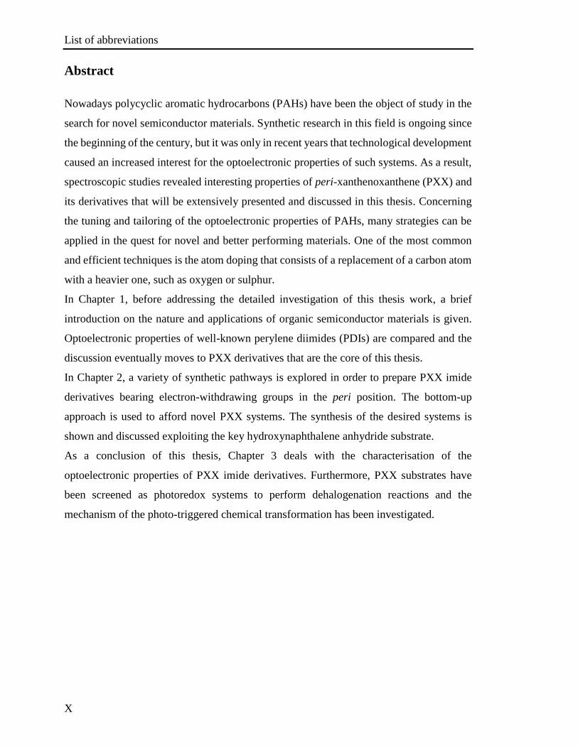
A dye is constituted by a molecule that is able to absorb electromagnetic radiation in the
UV and visible regions. The absorption of light promotes an electronic excitation from the
lower energy level to a higher energy level (Figure 1). A chromophore is defined as the
moiety in the molecule responsible for the absorption of the light in the UV or visible
region. The energy of the photon absorbed is directly related to the frontier molecular
orbital levels of the compound known as Highest-Occupied Molecular Orbital (HOMO)
and Lowest Unoccupied Molecular Orbital (LUMO). After light absorption, the molecular
chromophore in its excited state can relax to its ground state through different pathways:
emission of a photon through luminescence or through non-radiative processes.
Chapter I
2
Figure 1: a) Schematic representation of electronic transition of a dye; b) Schematic representation of the
valence and the conductive bands of a bulk material: metal, semiconductor and insulator.
Although the theory described before is valid for molecular chromophores, it is slightly
different for bulk materials. In that case, the description of single discrete molecular
orbitals cannot be used anymore and the band theory, representing a large number of
discrete quantum states of the electrons, needs to be employed.[5] Based on the value of the
energy gap between the valence and the conductive bands, the material can be defined as:
i) conductor if the valence band partially overlaps with conductive band; ii) semiconductor
if the difference of energy between the two bands E is between 1 eV and 4 eV; iii)
insulator if the band gap is higher than 4 eV.[6]
Typical semiconductors are based on gallium-,[7] aluminium-,[8] boron-[9] and silicon-based
inorganic materials.[10] While they are very efficient, their general use in devices is affected
by a major drawback, which is the high cost of preparation of semiconductors.[11] In this
respect, organic materials show electrical properties spanning from insulator to conductor,
including semiconductor.[12] However, several parameters, for instance, the morphology of
semiconductor materials, need to be taken into account to prepare a device based on them.
Organic semiconductors are promising because of the low cost preparation and purification
of the semiconductor material and the easier processing from solution in comparison with
the inorganic ones, which allows printing and therefore the preparation of large surface
devices.[13] Moreover organic materials are appealing for the preparation of flexible
devices.[14] Finally, the chemistry of organic molecules enables a fine tuning of the
electronic properties by chemical modifications. Nevertheless, the performance of the
devices based on organic semiconductors is lower in comparison with the one based on
inorganic materials, and especially their lifetime is shorter.[15] The devices based on
Chapter I
3
organic semiconductors exploit conjugated polymers or small molecules. In contrast with
the inorganic semiconductors, which are crystalline or polycrystalline, the structures of the
organic semiconductor materials at the solid state are driven by weak interactions,
principally van der Waals.[16] These interactions add to the material characteristic
properties between conventional low mobility hopping transport in amorphous glass
material[17] and high mobility band transport in covalently bonded single crystal.[18] The
lifetime of the OFET is shorter in comparison to inorganic FET because the organic
semiconductors show lower stability in working conditions. Extrinsic factors, such as
oxidation and presence of moisture, can also affect the lifetime of the OFET.[19]
1.3. Tuning the color of molecules by tuning the HOMO-LUMO gap
Nowadays new dye molecules are studied for organic electronics such as organic light-
emitting diodes (OLED),[20] organic photovoltaics (OPV)[21] and organic field-effect
transistors (OFET).[22] In this regard, the tuning of the HOMO-LUMO gap and the
magnitude of the HOMO and LUMO are essential requirements for the preparation of
suitable materials.[23] In this context, the most important factors affecting the HOMO-
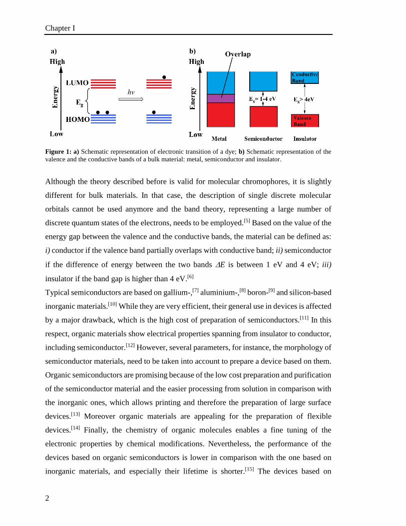
LUMO gap (Eg) have been rationalised by Roncali[24] and are the following: i) conjugation
length (Eδr), ii) resonance effect (Eres),[25] iii) planarity (Εθ),
[26] iv) peripheral
functionalisation (ESub),[27]and v) assembly effect (Eint).
The aforementioned factors can be summarised in the following empirical equation:
Eg= Eδr +Eres+ Εθ +ESub+Eint
The factors that affect the HOMO-LUMO gap tuning of single molecules are presented
below (Figure 2).
Figure 2: Representation of the structural factors that influence the HOMO-LUMO gap of -conjugated
systems.
Chapter I
4
1.3.1. Conjugation Length
Considering an extended linear -conjugated system with degenerated mesomeric
structures, such as polyenes, the electrons are delocalized all over the backbone structure,
which is an alternation of single and double carbon-carbon bonds. Applying a simple
Hückel approximation the energy gap should be ideally zero with all the carbon-carbon
bonds having the same length.[28] Nevertheless, such a mono-dimensional -conjugated
system has proved to be unstable, leading to a localization of the -electrons entailing in a
finite energy gap.[29] The degree of alternation of single and double bonds represents the
major contribution to a finite band gap in the -conjugated system.[30] Therefore, the bond
length alternation in the conjugated system affects the Eg value, and its contribution is
represented from Eδr. Typically, the extension of the conjugation length in a molecule
induces a rise in energy of the HOMO and diminution in energy of the LUMO, with
consequent shrinking of the HOMO-LUMO energy gap.[24a]
1.3.2 Resonance effect
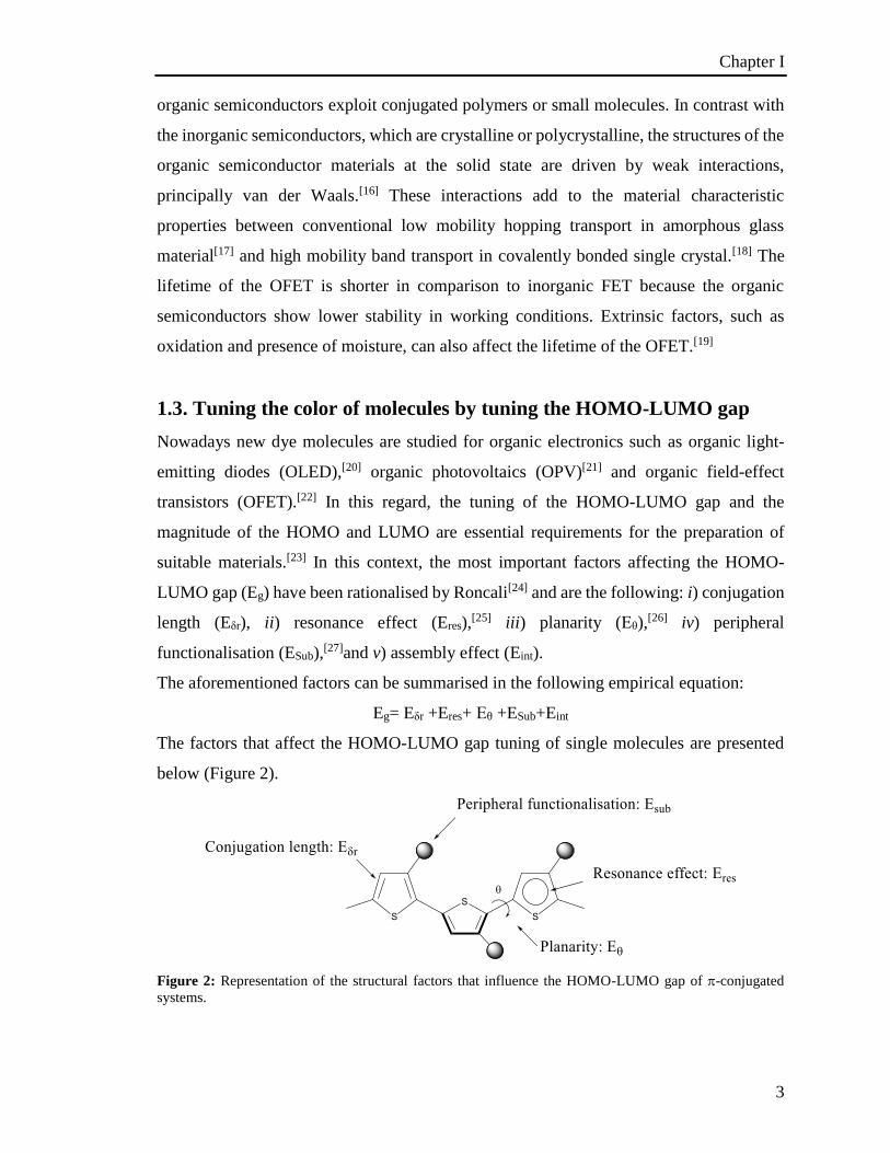
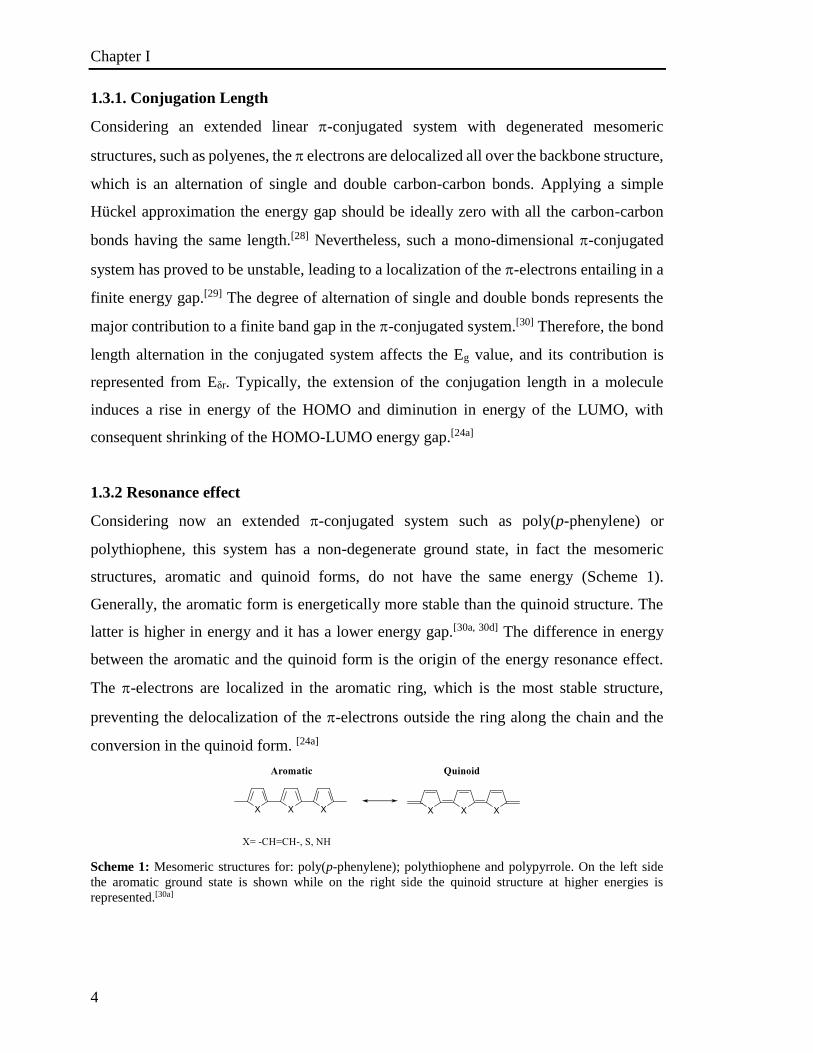
Considering now an extended -conjugated system such as poly(p-phenylene) or
polythiophene, this system has a non-degenerate ground state, in fact the mesomeric
structures, aromatic and quinoid forms, do not have the same energy (Scheme 1).
Generally, the aromatic form is energetically more stable than the quinoid structure. The
latter is higher in energy and it has a lower energy gap.[30a, 30d] The difference in energy
between the aromatic and the quinoid form is the origin of the energy resonance effect.
The -electrons are localized in the aromatic ring, which is the most stable structure,
preventing the delocalization of the -electrons outside the ring along the chain and the
conversion in the quinoid form. [24a]
Scheme 1: Mesomeric structures for: poly(p-phenylene); polythiophene and polypyrrole. On the left side
the aromatic ground state is shown while on the right side the quinoid structure at higher energies is
represented.[30a]
Chapter I
5
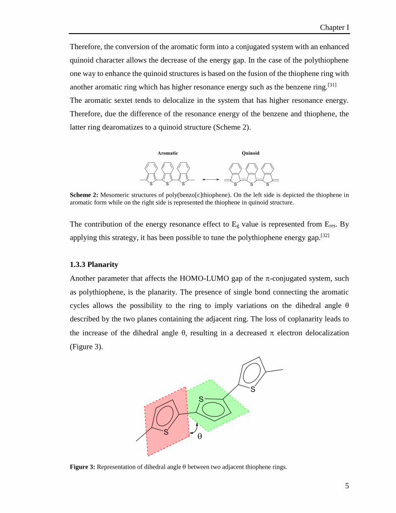
Therefore, the conversion of the aromatic form into a conjugated system with an enhanced
quinoid character allows the decrease of the energy gap. In the case of the polythiophene
one way to enhance the quinoid structures is based on the fusion of the thiophene ring with
another aromatic ring which has higher resonance energy such as the benzene ring.[31]
The aromatic sextet tends to delocalize in the system that has higher resonance energy.
Therefore, due the difference of the resonance energy of the benzene and thiophene, the
latter ring dearomatizes to a quinoid structure (Scheme 2).
Scheme 2: Mesomeric structures of poly(benzo[c]thiophene). On the left side is depicted the thiophene in
aromatic form while on the right side is represented the thiophene in quinoid structure.
The contribution of the energy resonance effect to Eg value is represented from Eres. By
applying this strategy, it has been possible to tune the polythiophene energy gap.[32]
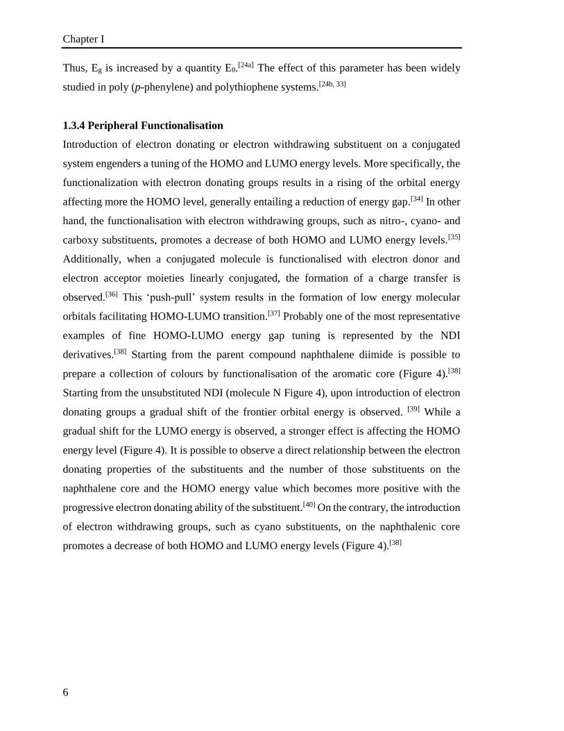
1.3.3 Planarity
Another parameter that affects the HOMO-LUMO gap of the -conjugated system, such
as polythiophene, is the planarity. The presence of single bond connecting the aromatic
cycles allows the possibility to the ring to imply variations on the dihedral angle θ
described by the two planes containing the adjacent ring. The loss of coplanarity leads to
the increase of the dihedral angle θ, resulting in a decreased electron delocalization
(Figure 3).
Figure 3: Representation of dihedral angle between two adjacent thiophene rings.
Chapter I
6
Thus, Eg is increased by a quantity Eθ.[24a] The effect of this parameter has been widely
studied in poly (p-phenylene) and polythiophene systems.[24b, 33]
1.3.4 Peripheral Functionalisation
Introduction of electron donating or electron withdrawing substituent on a conjugated
system engenders a tuning of the HOMO and LUMO energy levels. More specifically, the
functionalization with electron donating groups results in a rising of the orbital energy
affecting more the HOMO level, generally entailing a reduction of energy gap.[34] In other
hand, the functionalisation with electron withdrawing groups, such as nitro-, cyano- and
carboxy substituents, promotes a decrease of both HOMO and LUMO energy levels.[35]
Additionally, when a conjugated molecule is functionalised with electron donor and
electron acceptor moieties linearly conjugated, the formation of a charge transfer is
observed.[36] This ‘push-pull’ system results in the formation of low energy molecular
orbitals facilitating HOMO-LUMO transition.[37] Probably one of the most representative
examples of fine HOMO-LUMO energy gap tuning is represented by the NDI
derivatives.[38] Starting from the parent compound naphthalene diimide is possible to
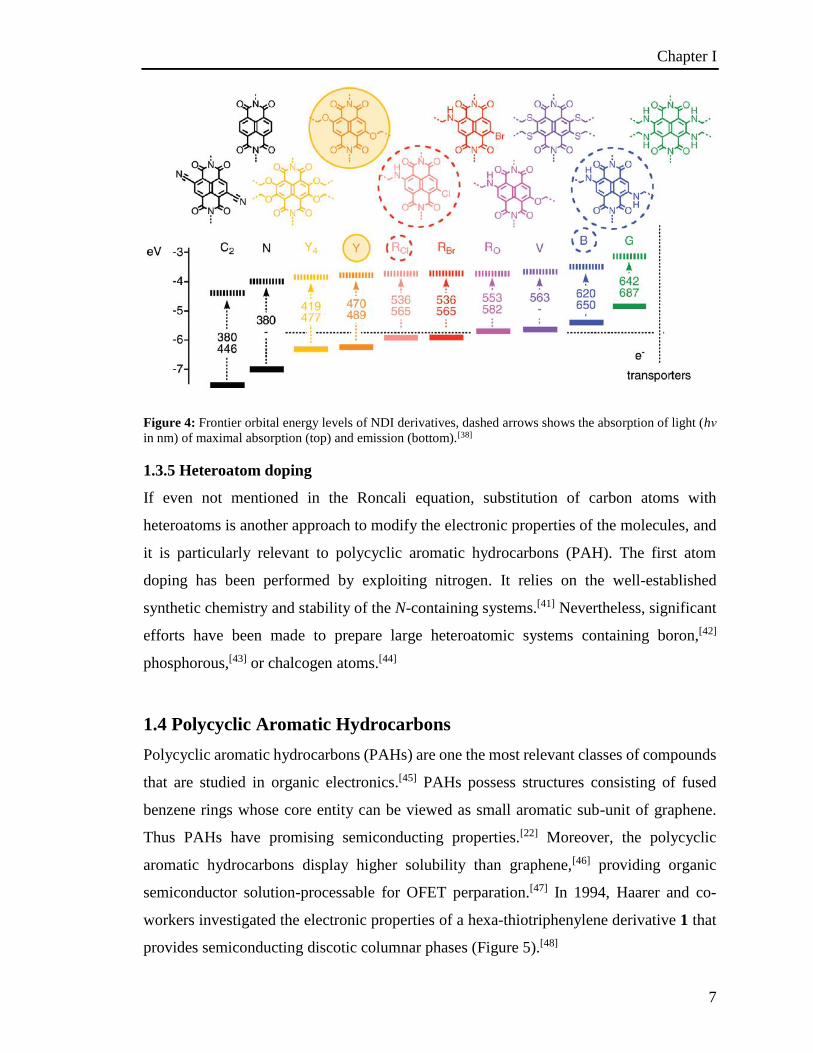
prepare a collection of colours by functionalisation of the aromatic core (Figure 4).[38]
Starting from the unsubstituted NDI (molecule N Figure 4), upon introduction of electron
donating groups a gradual shift of the frontier orbital energy is observed. [39] While a
gradual shift for the LUMO energy is observed, a stronger effect is affecting the HOMO
energy level (Figure 4). It is possible to observe a direct relationship between the electron
donating properties of the substituents and the number of those substituents on the
naphthalene core and the HOMO energy value which becomes more positive with the
progressive electron donating ability of the substituent.[40] On the contrary, the introduction
of electron withdrawing groups, such as cyano substituents, on the naphthalenic core
promotes a decrease of both HOMO and LUMO energy levels (Figure 4).[38]
Chapter I
7
Figure 4: Frontier orbital energy levels of NDI derivatives, dashed arrows shows the absorption of light (hν
in nm) of maximal absorption (top) and emission (bottom).[38]
1.3.5 Heteroatom doping
If even not mentioned in the Roncali equation, substitution of carbon atoms with
heteroatoms is another approach to modify the electronic properties of the molecules, and
it is particularly relevant to polycyclic aromatic hydrocarbons (PAH). The first atom
doping has been performed by exploiting nitrogen. It relies on the well-established
synthetic chemistry and stability of the N-containing systems.[41] Nevertheless, significant
efforts have been made to prepare large heteroatomic systems containing boron,[42]
phosphorous,[43] or chalcogen atoms.[44]
1.4 Polycyclic Aromatic Hydrocarbons
Polycyclic aromatic hydrocarbons (PAHs) are one the most relevant classes of compounds
that are studied in organic electronics.[45] PAHs possess structures consisting of fused
benzene rings whose core entity can be viewed as small aromatic sub-unit of graphene.
Thus PAHs have promising semiconducting properties.[22] Moreover, the polycyclic
aromatic hydrocarbons display higher solubility than graphene,[46] providing organic
semiconductor solution-processable for OFET perparation.[47] In 1994, Haarer and co-
workers investigated the electronic properties of a hexa-thiotriphenylene derivative 1 that
provides semiconducting discotic columnar phases (Figure 5).[48]

Chapter I
8
Figure 5: Molecular structure of 2,3,6,7,10,11-hexahexythiotriphenylene and a representation of the
structure of its helical columnar phase.[48]
Hareer and co-workers reported a higher charge mobility along the columnar axis when
the triphenylene units lie face to face with high degree of π-orbit overlap along the
columns.[48] Since then, a wide range of PAHs has been studied for device applications,
among them substituted hexabenzocoronenes have been the object of wide
investigations.[49]
1.4.1 Rylene derivatives
Another two-dimensional extension of the benzene unit is represented by rylene
chromophores. Rylene derivatives are based on the repetition of naphthalene units linked
to each other in peri-position.[50] In general, rylene derivatives present chemical-, thermal-
and photo-stability and also electron transport behaviour.[51] These derivatives are also
called oligo-naphthalenes and follow the subsequent nomenclature: perylene (n = 2),
terrylene (n = 3), quaterrylene (n = 4), pentarylene (n = 5) and hexarylene (n = 6). The
extension of the aromatic scaffold results in a bathochromic shift in the absorption and
emission properties. Rylenes can be functionalized in peri-positions and it was found that
the introduction of imide moieties provides a further stabilization and a red-shift in
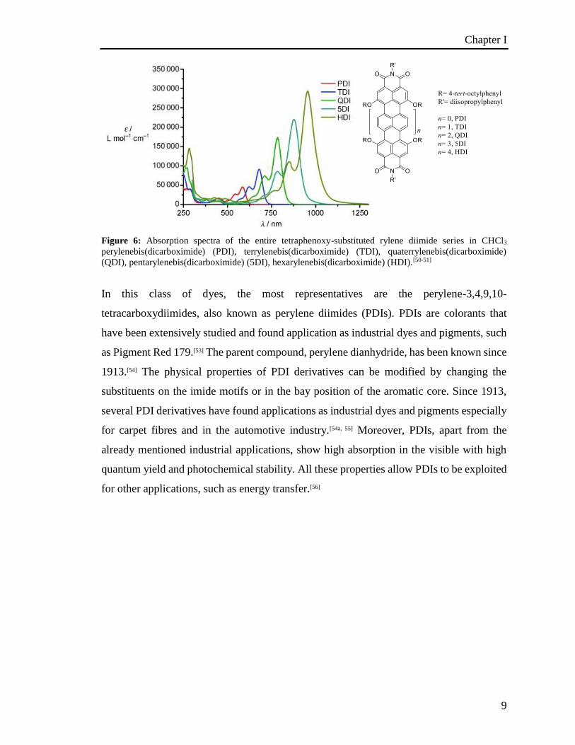
absorption. One illustrative example provided by Müllen and co-workers is the synthesis
and optical studies of rylene derivatives starting from perylene diimide to
hexarylenediimide.[50-51, 52] The spectroscopic measurements show a bathochromic shift of
about 100 nm per additional naphthalene unit (Figure 6).
Chapter I
9
Figure 6: Absorption spectra of the entire tetraphenoxy-substituted rylene diimide series in CHCl3
perylenebis(dicarboximide) (PDI), terrylenebis(dicarboximide) (TDI), quaterrylenebis(dicarboximide)
(QDI), pentarylenebis(dicarboximide) (5DI), hexarylenebis(dicarboximide) (HDI).[50-51]
In this class of dyes, the most representatives are the perylene-3,4,9,10-
tetracarboxydiimides, also known as perylene diimides (PDIs). PDIs are colorants that
have been extensively studied and found application as industrial dyes and pigments, such
as Pigment Red 179.[53] The parent compound, perylene dianhydride, has been known since
1913.[54] The physical properties of PDI derivatives can be modified by changing the
substituents on the imide motifs or in the bay position of the aromatic core. Since 1913,
several PDI derivatives have found applications as industrial dyes and pigments especially
for carpet fibres and in the automotive industry.[54a, 55] Moreover, PDIs, apart from the
already mentioned industrial applications, show high absorption in the visible with high
quantum yield and photochemical stability. All these properties allow PDIs to be exploited
for other applications, such as energy transfer.[56]
Chapter I
10
1.4.2 PDI derivatives
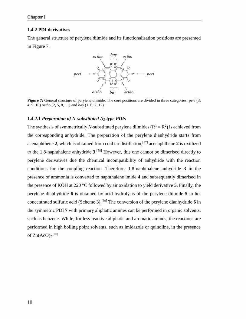
The general structure of perylene diimide and its functionalisation positions are presented
in Figure 7.
Figure 7: General structure of perylene diimide. The core positions are divided in three categories: peri (3,
4, 9, 10) ortho (2, 5, 8, 11) and bay (1, 6, 7, 12).
1.4.2.1 Preparation of N-substituted A2-type PDIs
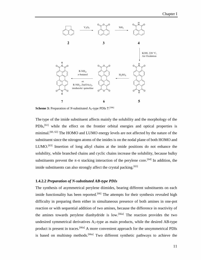
The synthesis of symmetrically N-substituted perylene diimides (R1 = R2) is achieved from
the corresponding anhydride. The preparation of the perylene dianhydride starts from
acenaphthene 2, which is obtained from coal tar distillation,[57] acenaphthene 2 is oxidized
to the 1,8-naphthalene anhydride 3.[58] However, this one cannot be dimerised directly to
perylene derivatives due the chemical incompatibility of anhydride with the reaction
conditions for the coupling reaction. Therefore, 1,8-naphthalene anhydride 3 in the
presence of ammonia is converted to naphthalene imide 4 and subsequently dimerised in
the presence of KOH at 220 °C followed by air oxidation to yield derivative 5. Finally, the
perylene dianhydride 6 is obtained by acid hydrolysis of the perylene diimide 5 in hot
concentrated sulfuric acid (Scheme 3).[59] The conversion of the perylene dianhydride 6 in
the symmetric PDI 7 with primary aliphatic amines can be performed in organic solvents,
such as benzene. While, for less reactive aliphatic and aromatic amines, the reactions are
performed in high boiling point solvents, such as imidazole or quinoline, in the presence
of Zn(AcO)2.[60]
Chapter I
11
Scheme 3: Preparation of N-substituted A2-type PDIs 7.[59b]
The type of the imide substituent affects mainly the solubility and the morphology of the
PDIs,[61] while the effect on the frontier orbital energies and optical properties is
minimal.[60, 62] The HOMO and LUMO energy levels are not affected by the nature of the
substituent since the nitrogen atoms of the imides is on the nodal plane of both HOMO and
LUMO.[63] Insertion of long alkyl chains at the imide positions do not enhance the
solubility, while branched chains and cyclic chains increase the solubility, because bulky
substituents prevent the - stacking interaction of the perylene core.[64] In addition, the
imide substituents can also strongly affect the crystal packing.[65]
1.4.2.2 Preparation of N-substituted AB-type PDIs
The synthesis of asymmetrical perylene diimides, bearing different substituents on each
imide functionality has been reported.[66] The attempts for their synthesis revealed high
difficulty in preparing them either in simultaneous presence of both amines in one-pot
reaction or with sequential addition of two amines, because the difference in reactivity of
the amines towards perylene dianhydride is low.[66a] The reaction provides the two
undesired symmetrical derivatives A2-type as main products, while the desired AB-type
product is present in traces.[66a] A more convenient approach for the unsymmetrical PDIs
is based on multistep methods.[66a] Two different synthetic pathways to achieve the
Chapter I
12
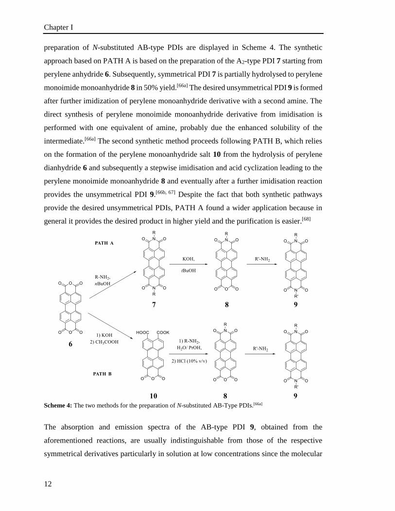
preparation of N-substituted AB-type PDIs are displayed in Scheme 4. The synthetic
approach based on PATH A is based on the preparation of the A2-type PDI 7 starting from
perylene anhydride 6. Subsequently, symmetrical PDI 7 is partially hydrolysed to perylene
monoimide monoanhydride 8 in 50% yield.[66a] The desired unsymmetrical PDI 9 is formed
after further imidization of perylene monoanhydride derivative with a second amine. The
direct synthesis of perylene monoimide monoanhydride derivative from imidisation is
performed with one equivalent of amine, probably due the enhanced solubility of the
intermediate.[66a] The second synthetic method proceeds following PATH B, which relies
on the formation of the perylene monoanhydride salt 10 from the hydrolysis of perylene
dianhydride 6 and subsequently a stepwise imidisation and acid cyclization leading to the
perylene monoimide monoanhydride 8 and eventually after a further imidisation reaction
provides the unsymmetrical PDI 9.[66b, 67] Despite the fact that both synthetic pathways
provide the desired unsymmetrical PDIs, PATH A found a wider application because in
general it provides the desired product in higher yield and the purification is easier.[68]
Scheme 4: The two methods for the preparation of N-substituted AB-Type PDIs.[66a]
The absorption and emission spectra of the AB-type PDI 9, obtained from the
aforementioned reactions, are usually indistinguishable from those of the respective
symmetrical derivatives particularly in solution at low concentrations since the molecular
Chapter I
13
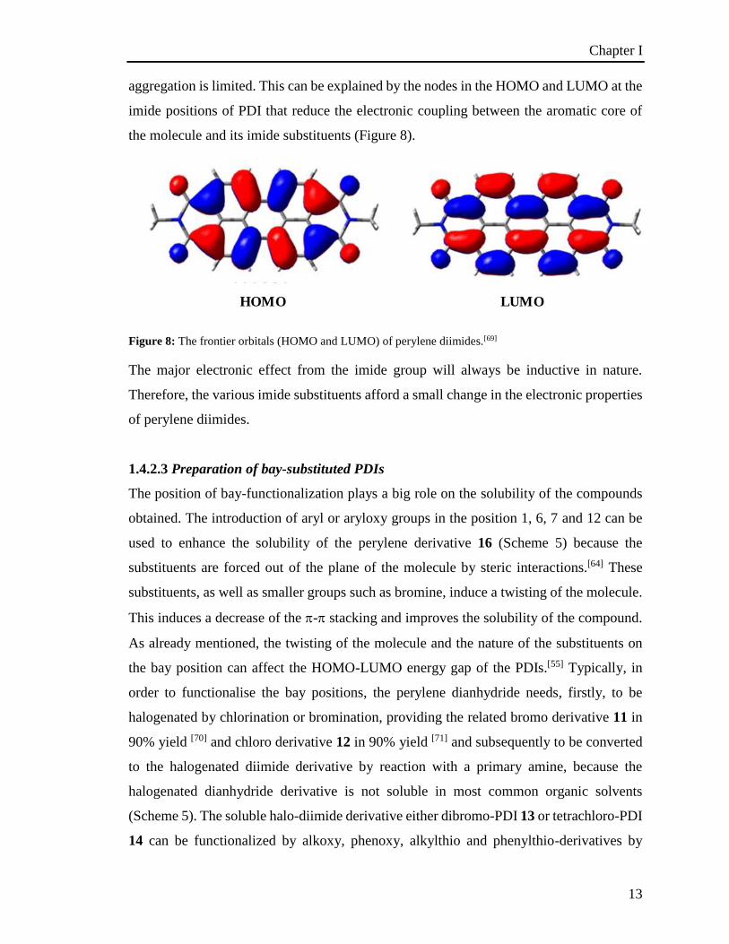
aggregation is limited. This can be explained by the nodes in the HOMO and LUMO at the
imide positions of PDI that reduce the electronic coupling between the aromatic core of
the molecule and its imide substituents (Figure 8).
Figure 8: The frontier orbitals (HOMO and LUMO) of perylene diimides.[69]
The major electronic effect from the imide group will always be inductive in nature.
Therefore, the various imide substituents afford a small change in the electronic properties
of perylene diimides.
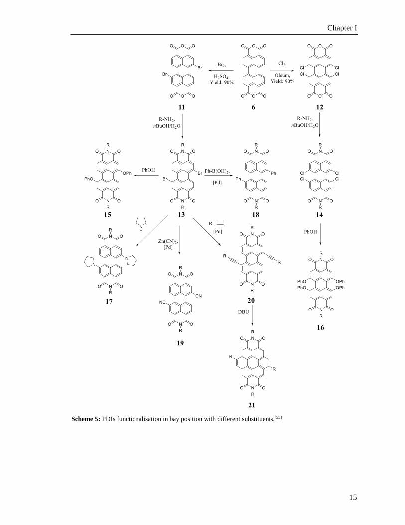
1.4.2.3 Preparation of bay-substituted PDIs
The position of bay-functionalization plays a big role on the solubility of the compounds
obtained. The introduction of aryl or aryloxy groups in the position 1, 6, 7 and 12 can be
used to enhance the solubility of the perylene derivative 16 (Scheme 5) because the
substituents are forced out of the plane of the molecule by steric interactions.[64] These
substituents, as well as smaller groups such as bromine, induce a twisting of the molecule.
This induces a decrease of the - stacking and improves the solubility of the compound.
As already mentioned, the twisting of the molecule and the nature of the substituents on
the bay position can affect the HOMO-LUMO energy gap of the PDIs.[55] Typically, in
order to functionalise the bay positions, the perylene dianhydride needs, firstly, to be
halogenated by chlorination or bromination, providing the related bromo derivative 11 in
90% yield [70] and chloro derivative 12 in 90% yield [71] and subsequently to be converted
to the halogenated diimide derivative by reaction with a primary amine, because the
halogenated dianhydride derivative is not soluble in most common organic solvents
(Scheme 5). The soluble halo-diimide derivative either dibromo-PDI 13 or tetrachloro-PDI
14 can be functionalized by alkoxy, phenoxy, alkylthio and phenylthio-derivatives by
HOMO LUMO
Chapter I
14
nucleophilic substitution.[55, 56b, 72] Substitution of the brominated derivative with
secondary amines such as pyrrolidine has been achieved by reacting bromo-PDIs in the
presence of an excess of amine leading the formation of the diamino substituted compound
17.[72a, 72b, 73] The functionalisation of the bay position starting from the halo-PDI
derivatives can also be performed by metal-catalysed cross coupling. Typically, Pd cross
coupling such as Suzuki,[74] Sonogashira,[74b, 75] and Nigishi [76] have been used to introduce
alkynyl 20, aryl 18 and cyano 19 derivatives, respectively. Furthermore, the Sonogashira
coupling provides acetylenic PDI 20 derivatives which could form coronene diimide 21
derivatives with an extension of the aromatic core.[75a, 77] Furthermore, several copper-
mediated couplings have been reported for the introduction of perfluorinated[78] and
cyano[56f] substituents in the bay positions. Apart from the enhancement of the solubility,
substituents in these positions strongly affect the morphology in the solid state, with small
substituents such as halogens or cyano groups 19 affording highly crystalline PDIs,[56f, 65]
while aryl groups in the bay position provide amorphous materials.[74c] The bay
substituents also affect the electronic properties. For instance, the presence of electron
withdrawing groups, such as halides, induces the lowering of the HOMO and LUMO
energy levels.[60] However, as both energy levels are affected, there is not a significant
effect on the spectroscopic properties of the molecules, only 10 nm shift in the absorbance
and emission properties in comparison with the unsubstituted PDI.[56f, 60, 79] On the
contrary, electron donating substituents, such as phenoxy and pyrrolidinyl, promote a rise
in energy of both, the HOMO and LUMO but in a different amount, with the HOMO
energy, rising more than that of the LUMO.[60]
Therefore the energy gap decreases, which induces a bathochromic shift in absorption. A
similar effect is observed for substituents that extend the -conjugation of the aromatic
core such as alkynyl and aryl groups.[74b, 74c, 75b]
Chapter I
15
Scheme 5: PDIs functionalisation in bay position with different substituents.[55]
Chapter I
16
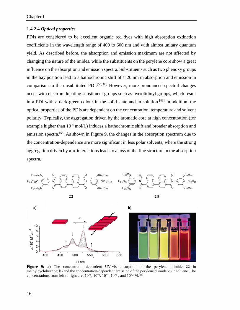
1.4.2.4 Optical properties
PDIs are considered to be excellent organic red dyes with high absorption extinction
coefficients in the wavelength range of 400 to 600 nm and with almost unitary quantum
yield. As described before, the absorption and emission maximum are not affected by
changing the nature of the imides, while the substituents on the perylene core show a great
influence on the absorption and emission spectra. Substituents such as two phenoxy groups
in the bay position lead to a bathochromic shift of ≈ 20 nm in absorption and emission in
comparison to the unsubtituted PDI.[55, 80] However, more pronounced spectral changes
occur with electron donating substituent groups such as pyrrolidinyl groups, which result
in a PDI with a dark-green colour in the solid state and in solution.[81] In addition, the
optical properties of the PDIs are dependent on the concentration, temperature and solvent
polarity. Typically, the aggregation driven by the aromatic core at high concentration (for
example higher than 10-4 mol/L) induces a bathochromic shift and broader absorption and
emission spectra.[55] As shown in Figure 9, the changes in the absorption spectrum due to
the concentration-dependence are more significant in less polar solvents, where the strong
aggregation driven by -interactions leads to a loss of the fine structure in the absorption
spectra.
Figure 9: a) The concentration-dependent UV-vis absorption of the perylene diimide 22 in
methylcyclohexane; b) and the concentration-dependent emission of the perylene diimide 23 in toluene .The
concentrations from left to right are: 10−6, 10−5, 10−4, 10−3 , and 10−2 M.[55]
Chapter I
17
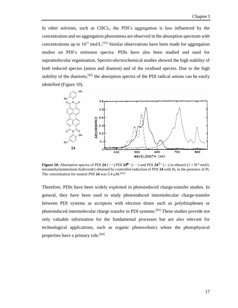
In other solvents, such as CHCl3, the PDI’s aggregation is less influenced by the
concentration and no aggregation phenomena are observed in the absorption spectrum with
concentrations up to 10-5 mol/L.[55] Similar observations have been made for aggregation
studies on PDI’s emission spectra. PDIs have also been studied and used for
supramolecular organisation. Spectro-electrochemical studies showed the high stability of
both reduced species (anion and dianion) and of the oxidised species. Due to the high
stability of the dianions,[82] the absorption spectra of the PDI radical anions can be easily
identified (Figure 10).
Figure 10: Absorption spectra of PDI 24 (∙) PDI 24– ( ) and PDI 242– () in ethanol (1 × l0-4 mol/L
tetramethylammonium hydroxide) obtained by controlled reduction of PDI 24 with H2 in the presence of Pt.
The concentration for neutral PDI 24 was 5.4 M.[82a]
Therefore, PDIs have been widely exploited in photoinduced charge-transfer studies. In
general, they have been used to study photoinduced intermolecular charge-transfer
between PDI systems as acceptors with electron donor such as polythiophenes or
photoinduced intermolecular charge transfer in PDI systems.[83] These studies provide not
only valuable information for the fundamental processes but are also relevant for
technological applications, such as organic photovoltaics where the photophysical
properties have a primary role.[84]
Chapter I
18
1.4.2.5 Redox properties of PDIs
The electrochemical properties of PDIs have been widely investigated. From these studies
it emerged that perylene diimides are electron deficient systems and thus it is easier to
reduce than to oxidise them. In general, perylene diimides display two reversible
reductions and one reversible oxidation.[55] For instance, from electrochemical analysis,
the PDI without substituent on the aromatic core shows two reversible reduction potentials
(at ⁓ -1.0 and -1.2 V vs Fc+/0) and one reversible oxidation potential (at ⁓ 1.2 V). Similarly
to the optical properties, the effect on the redox properties of the substituents on the imides
is moderate. This is due to the fact that the N atoms are on a nodal plane of the HOMO and
LUMO and the orbital energy is affected by inductive effects via the imide N atoms. The
substituents on the aromatic core have instead a great influence on the redox properties.
For example, PDIs bearing electron-withdrawing substituents at the bay positions, such as
cyano groups, are easily reduced and less readily oxidised in comparison to the
unsubstituted derivatives. On the other hand, derivatives with donating substituents, such
as pyrrolidinyl, in the bay positions are less easily reduced and more easily oxidised, in
comparison with the unsubstituted PDIs. PDIs bearing arylethynyl substituent in the bay
position are more easily reduced in comparison with the parent PDI.[85]
1.5 Dye molecules as organic semiconductors
In the last decades, organic electronics became one of the most attractive fields in
chemistry and material science.[86] This development has originated from the attractive role
that organic materials could play in solar cells, [21b, 87] organic field effect transistors
(OFET)[88] and organic light emitting displays.[89] In this regard, chemists have developed
a wide number of systems with -conjugated scaffolds. Polycyclic aromatic hydrocarbons
such as acenes,[45] conjugated polymers, such as polythiophenes, fullerenes[90] and
triphenylamines[91] are part of the molecules that have been investigated. Apart from the
already mentioned structures, other molecules that are used in industry were tested as
organic semiconductors, among them also two important pigments: phthalocyanine[92] and
PDI[51b, 93] have been studied. In 1986, Tang reported for the first time the fabrication of a
thin‐film, two‐layer organic heterojunction photovoltaic cell based on copper
phthalocyanine and a perylene tetracarboxylic derivative.[94] The most promising
Chapter I
19
application for the dye-based organic semiconductors is represented by the solar cell due
to the absorption of the visible light. Nowadays one of the most relevant challenges for the
electronics industry is the fabrication of flexible and lightweight devices. In this respect
PDI derivatives have been widely studied.[95]
1.5.1 Application of PDIs in OFET
Organic field-effect transistors (OFETs), using -conjugated systems as the active
semiconducting layer have attracted attention for printed and flexible electronic devices.
The most important parameters that determine the efficiency of the OFET devices are the
semiconducting properties and the charge mobility. These are related to the electronic
properties as well as the molecular packing of the semiconductor material.[96] Therefore,
the molecular packing of the organic semiconductors becomes very important for the
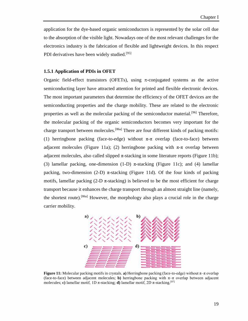
charge transport between molecules.[86a] There are four different kinds of packing motifs:
(1) herringbone packing (face-to-edge) without π-π overlap (face-to-face) between
adjacent molecules (Figure 11a); (2) herringbone packing with π-π overlap between
adjacent molecules, also called slipped π-stacking in some literature reports (Figure 11b);
(3) lamellar packing, one-dimension (1-D) π-stacking (Figure 11c); and (4) lamellar
packing, two-dimension (2-D) π-stacking (Figure 11d). Of the four kinds of packing
motifs, lamellar packing (2-D π-stacking) is believed to be the most efficient for charge
transport because it enhances the charge transport through an almost straight line (namely,
the shortest route).[86a] However, the morphology also plays a crucial role in the charge
carrier mobility.
Figure 11: Molecular packing motifs in crystals. a) Herringbone packing (face-to-edge) without π–π overlap
(face-to-face) between adjacent molecules; b) herringbone packing with π–π overlap between adjacent
molecules; c) lamellar motif, 1D π-stacking; d) lamellar motif, 2D π-stacking.[97]
Chapter I
20
1.5.2 Peri-Xanthenoxanthene
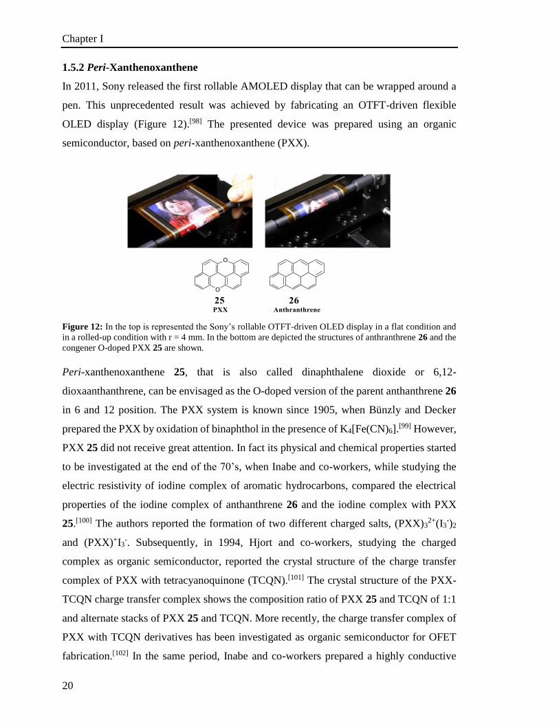
In 2011, Sony released the first rollable AMOLED display that can be wrapped around a
pen. This unprecedented result was achieved by fabricating an OTFT-driven flexible
OLED display (Figure 12).[98] The presented device was prepared using an organic
semiconductor, based on peri-xanthenoxanthene (PXX).
Figure 12: In the top is represented the Sony’s rollable OTFT-driven OLED display in a flat condition and
in a rolled-up condition with r = 4 mm. In the bottom are depicted the structures of anthranthrene 26 and the
congener O-doped PXX 25 are shown.
Peri-xanthenoxanthene 25, that is also called dinaphthalene dioxide or 6,12-
dioxaanthanthrene, can be envisaged as the O-doped version of the parent anthanthrene 26
in 6 and 12 position. The PXX system is known since 1905, when Bünzly and Decker
prepared the PXX by oxidation of binaphthol in the presence of K4[Fe(CN)6].[99] However,
PXX 25 did not receive great attention. In fact its physical and chemical properties started
to be investigated at the end of the 70’s, when Inabe and co-workers, while studying the
electric resistivity of iodine complex of aromatic hydrocarbons, compared the electrical
properties of the iodine complex of anthanthrene 26 and the iodine complex with PXX
25.[100] The authors reported the formation of two different charged salts, (PXX)32+(I3
-)2
and (PXX)+I3-. Subsequently, in 1994, Hjort and co-workers, studying the charged
complex as organic semiconductor, reported the crystal structure of the charge transfer
complex of PXX with tetracyanoquinone (TCQN).[101] The crystal structure of the PXX-
TCQN charge transfer complex shows the composition ratio of PXX 25 and TCQN of 1:1
and alternate stacks of PXX 25 and TCQN. More recently, the charge transfer complex of
PXX with TCQN derivatives has been investigated as organic semiconductor for OFET
fabrication.[102] In the same period, Inabe and co-workers prepared a highly conductive
Chapter I
21
charge transfer complex from PXX with dicyano(phthalocyaninato)cobalt(III).[103] In
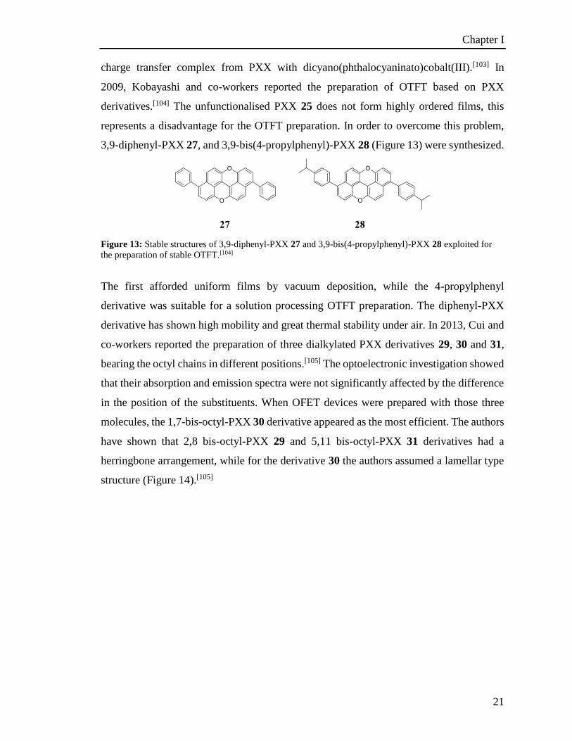
2009, Kobayashi and co-workers reported the preparation of OTFT based on PXX
derivatives.[104] The unfunctionalised PXX 25 does not form highly ordered films, this
represents a disadvantage for the OTFT preparation. In order to overcome this problem,
3,9-diphenyl-PXX 27, and 3,9-bis(4-propylphenyl)-PXX 28 (Figure 13) were synthesized.
Figure 13: Stable structures of 3,9-diphenyl-PXX 27 and 3,9-bis(4-propylphenyl)-PXX 28 exploited for
the preparation of stable OTFT.[104]
The first afforded uniform films by vacuum deposition, while the 4-propylphenyl
derivative was suitable for a solution processing OTFT preparation. The diphenyl-PXX
derivative has shown high mobility and great thermal stability under air. In 2013, Cui and
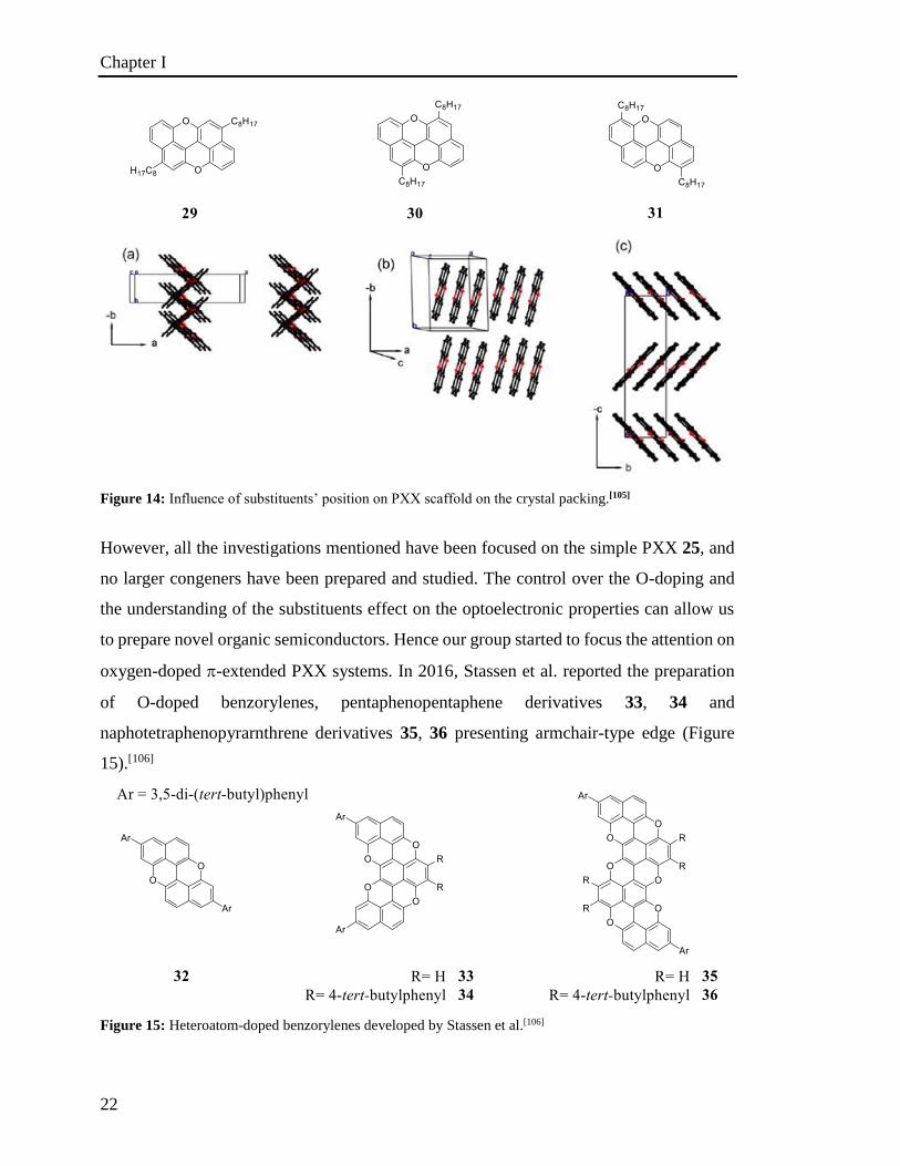
co-workers reported the preparation of three dialkylated PXX derivatives 29, 30 and 31,
bearing the octyl chains in different positions.[105] The optoelectronic investigation showed
that their absorption and emission spectra were not significantly affected by the difference
in the position of the substituents. When OFET devices were prepared with those three
molecules, the 1,7-bis-octyl-PXX 30 derivative appeared as the most efficient. The authors
have shown that 2,8 bis-octyl-PXX 29 and 5,11 bis-octyl-PXX 31 derivatives had a
herringbone arrangement, while for the derivative 30 the authors assumed a lamellar type
structure (Figure 14).[105]
Chapter I
22
Figure 14: Influence of substituents’ position on PXX scaffold on the crystal packing.[105]
However, all the investigations mentioned have been focused on the simple PXX 25, and
no larger congeners have been prepared and studied. The control over the O-doping and
the understanding of the substituents effect on the optoelectronic properties can allow us
to prepare novel organic semiconductors. Hence our group started to focus the attention on
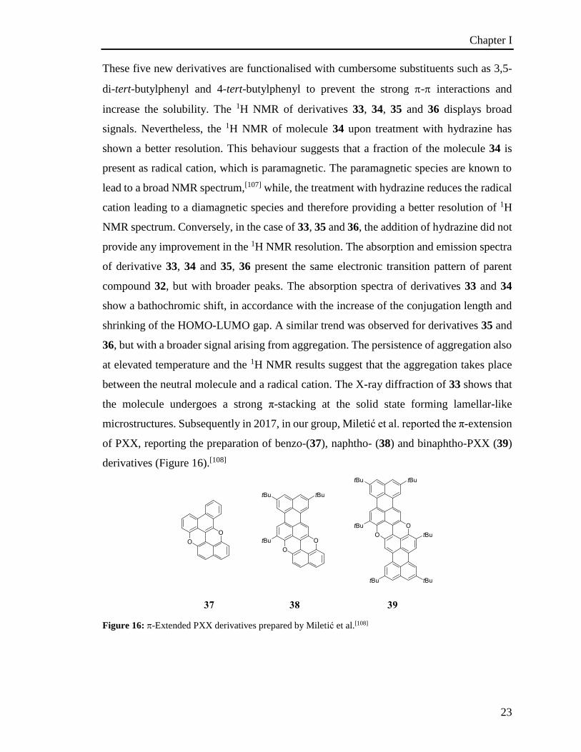
oxygen-doped -extended PXX systems. In 2016, Stassen et al. reported the preparation
of O-doped benzorylenes, pentaphenopentaphene derivatives 33, 34 and
naphotetraphenopyrarnthrene derivatives 35, 36 presenting armchair-type edge (Figure
15).[106]
Figure 15: Heteroatom-doped benzorylenes developed by Stassen et al.[106]
Chapter I
23
These five new derivatives are functionalised with cumbersome substituents such as 3,5-
di-tert-butylphenyl and 4-tert-butylphenyl to prevent the strong - interactions and
increase the solubility. The 1H NMR of derivatives 33, 34, 35 and 36 displays broad
signals. Nevertheless, the 1H NMR of molecule 34 upon treatment with hydrazine has
shown a better resolution. This behaviour suggests that a fraction of the molecule 34 is
present as radical cation, which is paramagnetic. The paramagnetic species are known to
lead to a broad NMR spectrum,[107] while, the treatment with hydrazine reduces the radical
cation leading to a diamagnetic species and therefore providing a better resolution of 1H
NMR spectrum. Conversely, in the case of 33, 35 and 36, the addition of hydrazine did not
provide any improvement in the 1H NMR resolution. The absorption and emission spectra
of derivative 33, 34 and 35, 36 present the same electronic transition pattern of parent
compound 32, but with broader peaks. The absorption spectra of derivatives 33 and 34
show a bathochromic shift, in accordance with the increase of the conjugation length and
shrinking of the HOMO-LUMO gap. A similar trend was observed for derivatives 35 and
36, but with a broader signal arising from aggregation. The persistence of aggregation also
at elevated temperature and the 1H NMR results suggest that the aggregation takes place
between the neutral molecule and a radical cation. The X-ray diffraction of 33 shows that
the molecule undergoes a strong π-stacking at the solid state forming lamellar-like
microstructures. Subsequently in 2017, in our group, Miletić et al. reported the π-extension
of PXX, reporting the preparation of benzo-(37), naphtho- (38) and binaphtho-PXX (39)
derivatives (Figure 16).[108]
Figure 16: -Extended PXX derivatives prepared by Miletić et al.[108]
Chapter I
24
The progressive -extension of the PXX core from derivative 37 to derivative 39 leads to
a consequent bathochromic shift of the absorption maximum corresponding to a shrinking
of the HOMO-LUMO gap and a decrease of the fluorescence lifetime.[108]
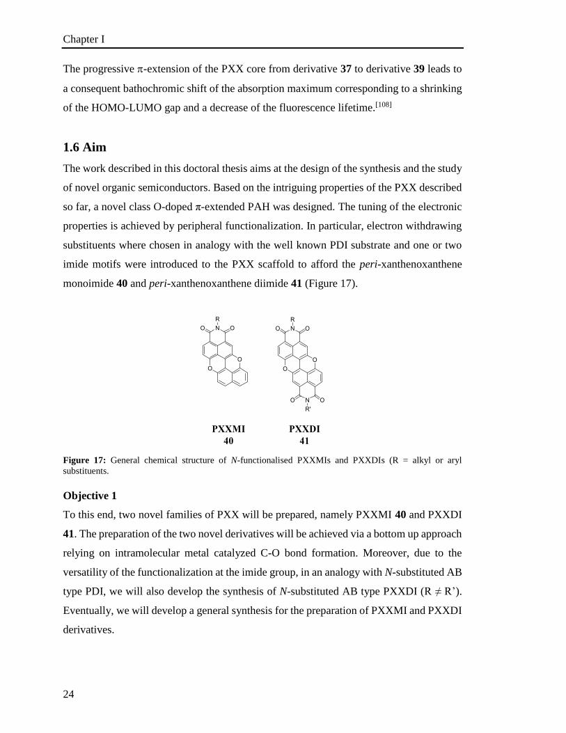
1.6 Aim
The work described in this doctoral thesis aims at the design of the synthesis and the study
of novel organic semiconductors. Based on the intriguing properties of the PXX described
so far, a novel class O-doped π-extended PAH was designed. The tuning of the electronic
properties is achieved by peripheral functionalization. In particular, electron withdrawing
substituents where chosen in analogy with the well known PDI substrate and one or two
imide motifs were introduced to the PXX scaffold to afford the peri-xanthenoxanthene
monoimide 40 and peri-xanthenoxanthene diimide 41 (Figure 17).
Figure 17: General chemical structure of N-functionalised PXXMIs and PXXDIs (R = alkyl or aryl
substituents.
Objective 1
To this end, two novel families of PXX will be prepared, namely PXXMI 40 and PXXDI
41. The preparation of the two novel derivatives will be achieved via a bottom up approach
relying on intramolecular metal catalyzed C-O bond formation. Moreover, due to the
versatility of the functionalization at the imide group, in an analogy with N-substituted AB
type PDI, we will also develop the synthesis of N-substituted AB type PXXDI (R ≠ R’).
Eventually, we will develop a general synthesis for the preparation of PXXMI and PXXDI
derivatives.
Chapter I
25
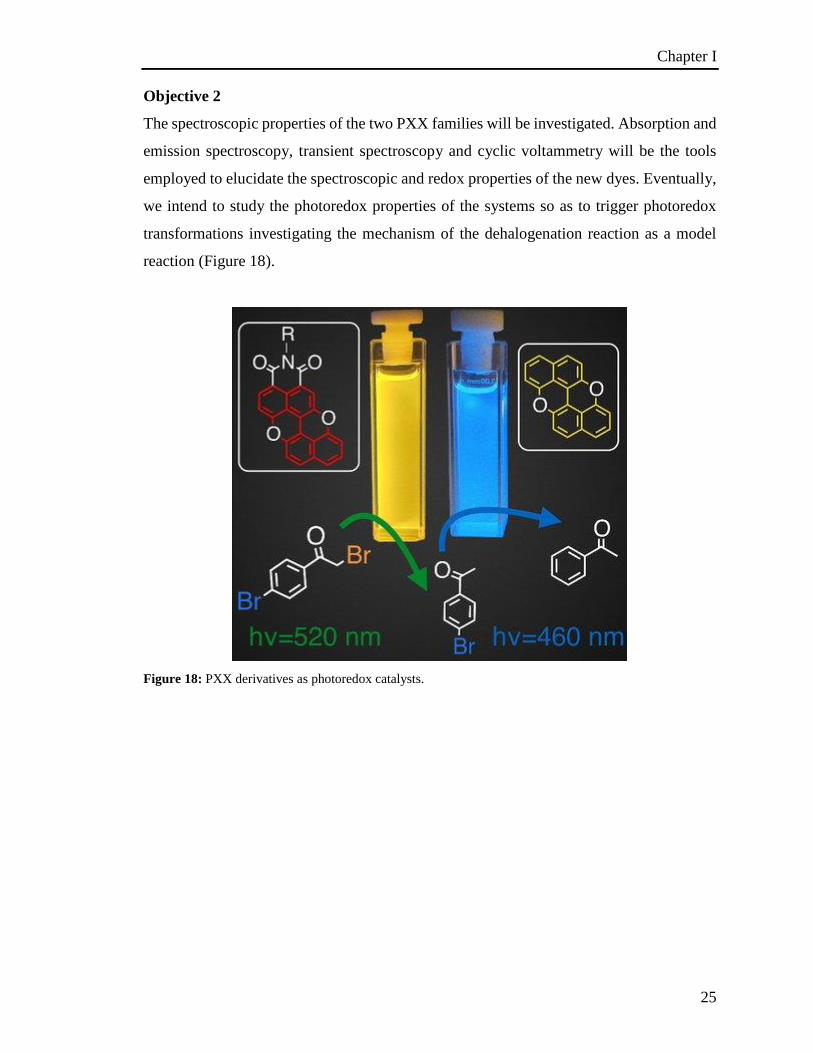
Objective 2
The spectroscopic properties of the two PXX families will be investigated. Absorption and
emission spectroscopy, transient spectroscopy and cyclic voltammetry will be the tools
employed to elucidate the spectroscopic and redox properties of the new dyes. Eventually,
we intend to study the photoredox properties of the systems so as to trigger photoredox
transformations investigating the mechanism of the dehalogenation reaction as a model
reaction (Figure 18).
Figure 18: PXX derivatives as photoredox catalysts.
Chapter II
26
Chapter 2. O-Doped Polycyclic Aromatic Hydrocarbons
2.1 Overview
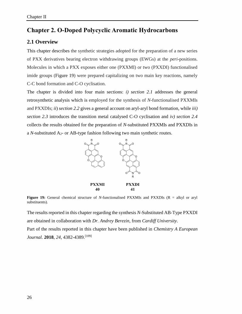
This chapter describes the synthetic strategies adopted for the preparation of a new series
of PXX derivatives bearing electron withdrawing groups (EWGs) at the peri-positions.
Molecules in which a PXX exposes either one (PXXMI) or two (PXXDI) functionalised
imide groups (Figure 19) were prepared capitalizing on two main key reactions, namely
C-C bond formation and C-O cyclisation.
The chapter is divided into four main sections: i) section 2.1 addresses the general
retrosynthetic analysis which is employed for the synthesis of N-functionalised PXXMIs
and PXXDIs; ii) section 2.2 gives a general account on aryl-aryl bond formation, while iii)
section 2.3 introduces the transition metal catalysed C-O cyclisation and iv) section 2.4
collects the results obtained for the preparation of N-substituted PXXMIs and PXXDIs in
a N-substituted A2- or AB-type fashion following two main synthetic routes.
Figure 19: General chemical structure of N-functionalised PXXMIs and PXXDIs (R = alkyl or aryl
substituents).
The results reported in this chapter regarding the synthesis N-Substituted AB-Type PXXDI
are obtained in collaboration with Dr. Andrey Berezin, from Cardiff University.
Part of the results reported in this chapter have been published in Chemistry A European
Journal. 2018, 24, 4382-4389.[109]
Chapter II
27
2.2 Retrosynthetic Analysis of PXXDIs and PXXMIs
2.2.1 N-Substituted A2-Type PXXDIs
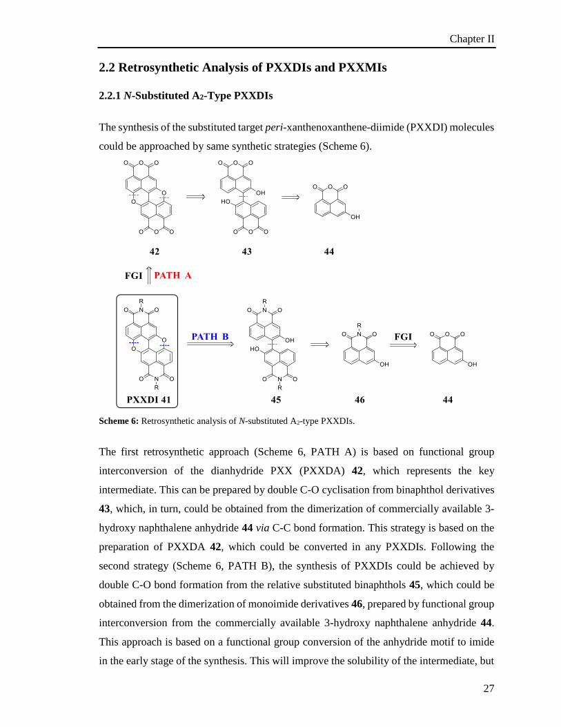
The synthesis of the substituted target peri-xanthenoxanthene-diimide (PXXDI) molecules
could be approached by same synthetic strategies (Scheme 6).
Scheme 6: Retrosynthetic analysis of N-substituted A2-type PXXDIs.
The first retrosynthetic approach (Scheme 6, PATH A) is based on functional group
interconversion of the dianhydride PXX (PXXDA) 42, which represents the key
intermediate. This can be prepared by double C-O cyclisation from binaphthol derivatives
43, which, in turn, could be obtained from the dimerization of commercially available 3-
hydroxy naphthalene anhydride 44 via C-C bond formation. This strategy is based on the
preparation of PXXDA 42, which could be converted in any PXXDIs. Following the
second strategy (Scheme 6, PATH B), the synthesis of PXXDIs could be achieved by
double C-O bond formation from the relative substituted binaphthols 45, which could be
obtained from the dimerization of monoimide derivatives 46, prepared by functional group
interconversion from the commercially available 3-hydroxy naphthalene anhydride 44.
This approach is based on a functional group conversion of the anhydride motif to imide
in the early stage of the synthesis. This will improve the solubility of the intermediate, but
Chapter II
28
on the other hand, the applicability of the synthesis is limited. Both synthetic strategies
rely on two key steps: C-C bond formation and subsequent double C-O cyclization.
2.2.2 Retrosynthesis of PXXMI
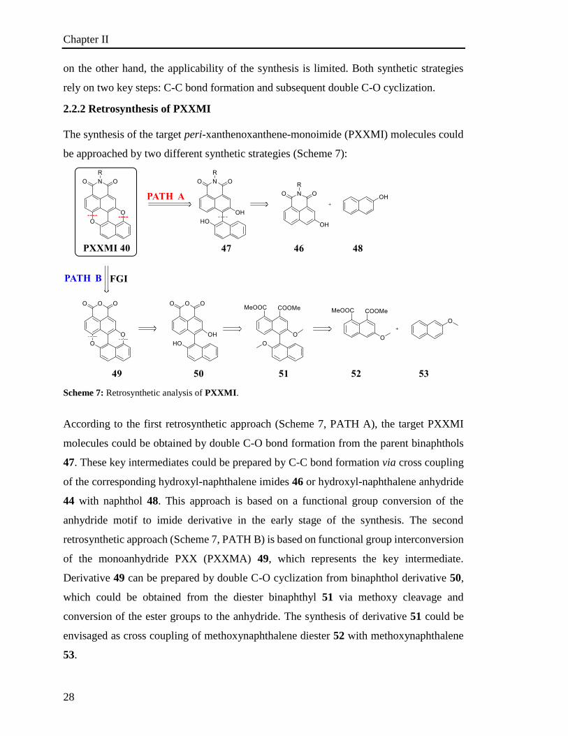
The synthesis of the target peri-xanthenoxanthene-monoimide (PXXMI) molecules could
be approached by two different synthetic strategies (Scheme 7):
Scheme 7: Retrosynthetic analysis of PXXMI.
According to the first retrosynthetic approach (Scheme 7, PATH A), the target PXXMI
molecules could be obtained by double C-O bond formation from the parent binaphthols
47. These key intermediates could be prepared by C-C bond formation via cross coupling
of the corresponding hydroxyl-naphthalene imides 46 or hydroxyl-naphthalene anhydride
44 with naphthol 48. This approach is based on a functional group conversion of the
anhydride motif to imide derivative in the early stage of the synthesis. The second
retrosynthetic approach (Scheme 7, PATH B) is based on functional group interconversion
of the monoanhydride PXX (PXXMA) 49, which represents the key intermediate.
Derivative 49 can be prepared by double C-O cyclization from binaphthol derivative 50,
which could be obtained from the diester binaphthyl 51 via methoxy cleavage and
conversion of the ester groups to the anhydride. The synthesis of derivative 51 could be
envisaged as cross coupling of methoxynaphthalene diester 52 with methoxynaphthalene
53.
Chapter II
29
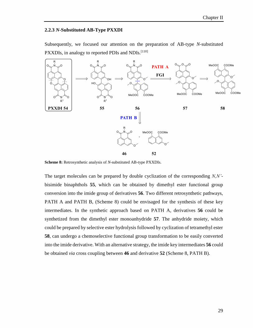
2.2.3 N-Substituted AB-Type PXXDI
Subsequently, we focused our attention on the preparation of AB-type N-substituted
PXXDIs, in analogy to reported PDIs and NDIs.[110]
Scheme 8: Retrosynthetic analysis of N-substituted AB-type PXXDIs.
The target molecules can be prepared by double cyclization of the corresponding N,N’-
bisimide binaphthols 55, which can be obtained by dimethyl ester functional group
conversion into the imide group of derivatives 56. Two different retrosynthetic pathways,
PATH A and PATH B, (Scheme 8) could be envisaged for the synthesis of these key
intermediates. In the synthetic approach based on PATH A, derivatives 56 could be
synthetized from the dimethyl ester monoanhydride 57. The anhydride moiety, which
could be prepared by selective ester hydrolysis followed by cyclization of tetramethyl ester
58, can undergo a chemoselective functional group transformation to be easily converted
into the imide derivative. With an alternative strategy, the imide key intermediates 56 could
be obtained via cross coupling between 46 and derivative 52 (Scheme 8, PATH B).
Chapter II
30
2.3. General account on aryl-aryl bond formation
Biaryl systems are largely found in natural products such as alkaloids, lignans,[111]
flavonoids,[112] tannins[113] just to mention a few. Moreover, biaryl motifs found wide
applications in material science due to their redox, semiconductor and non-linear optical
properties.[114] The formation of new carbon-carbon bonds between two aromatic units is
one of the most important reactions in modern organic chemistry. Therefore, many studies
have been performed to develop new synthetic methods to access biaryl scaffolds. Among
them, it is possible to mention: i) oxidative coupling; ii) reductive coupling; iii) radical
coupling; iv) metal-catalysed cross coupling; v) nucleophilic aromatic substitution; vi)
direct arylation through C-H activation.
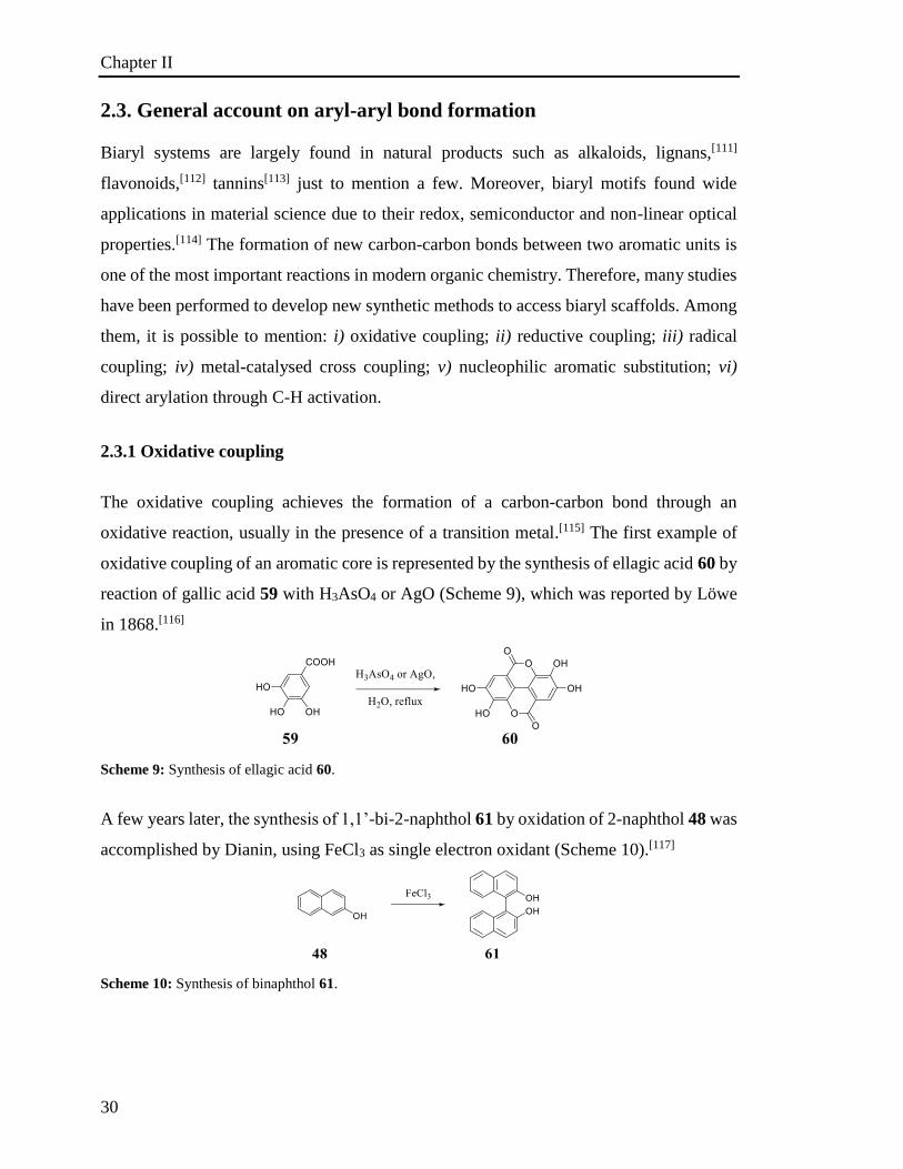
2.3.1 Oxidative coupling
The oxidative coupling achieves the formation of a carbon-carbon bond through an
oxidative reaction, usually in the presence of a transition metal.[115] The first example of
oxidative coupling of an aromatic core is represented by the synthesis of ellagic acid 60 by
reaction of gallic acid 59 with H3AsO4 or AgO (Scheme 9), which was reported by Löwe
in 1868.[116]
Scheme 9: Synthesis of ellagic acid 60.
A few years later, the synthesis of 1,1’-bi-2-naphthol 61 by oxidation of 2-naphthol 48 was
accomplished by Dianin, using FeCl3 as single electron oxidant (Scheme 10).[117]
Scheme 10: Synthesis of binaphthol 61.

Chapter II
31
At the same time, a wide range of phenols have been used in oxidative coupling to prepare
biphenol derivatives.[118] This strategy allows the formation of carbon-carbon bond in the
ortho- or para- position to the hydroxyl group. Indeed, the oxidative coupling of
substituted 2-naphthols represents one of the most important synthetic applications of this
approach. A wide range of oxidants has been investigated such as FeCl3,[119] Mn(acac)3
[120]
and Cu(II)-amine.[121] In particular, the Cu(II)amine complexes were found to be very
effective. In this respect, in an early work, Brussee described the preparation of
enantiomerically pure binaphthyls.[122] This involved the synthesis of symmetric systems
by homocoupling and also asymmetric derivatives through heterocoupling reactions. Many
efforts have been made to understand the mechanism of the oxidative coupling. It has been
found that its basis relies on the oxidation of the phenolic residue through a single electron
transfer, allowing the formation of a radical species, whose existence was demonstrated by
EPR spectroscopy (Scheme 11).[123]
Scheme 11: Single electron oxidation of phenol 62, 2-naphthol 48 and 1-naphthol 65.
Considering 2-naphthol 48, the mechanism proposed by Toda and co-worker suggests that
the deprotonation and oxidation of two molecules of starting 2-naphthol 48 yields the
formation of two radicals 64. These undergo radical coupling to give keto derivative 67
that, by keto-enol tautomerisation, leads to final binaphthol 61 (Scheme 12).[124]
Scheme 12: Radical coupling mechanism proposed by Toda and co-workers.[124]
Chapter II
32
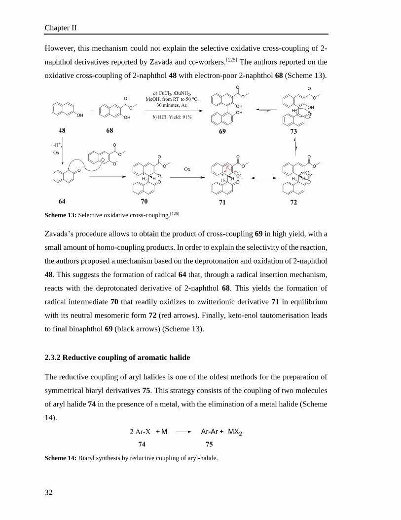
However, this mechanism could not explain the selective oxidative cross-coupling of 2-
naphthol derivatives reported by Zavada and co-workers.[125] The authors reported on the
oxidative cross-coupling of 2-naphthol 48 with electron-poor 2-naphthol 68 (Scheme 13).
Scheme 13: Selective oxidative cross-coupling.[125]
Zavada’s procedure allows to obtain the product of cross-coupling 69 in high yield, with a
small amount of homo-coupling products. In order to explain the selectivity of the reaction,
the authors proposed a mechanism based on the deprotonation and oxidation of 2-naphthol
48. This suggests the formation of radical 64 that, through a radical insertion mechanism,
reacts with the deprotonated derivative of 2-naphthol 68. This yields the formation of
radical intermediate 70 that readily oxidizes to zwitterionic derivative 71 in equilibrium
with its neutral mesomeric form 72 (red arrows). Finally, keto-enol tautomerisation leads
to final binaphthol 69 (black arrows) (Scheme 13).
2.3.2 Reductive coupling of aromatic halide
The reductive coupling of aryl halides is one of the oldest methods for the preparation of
symmetrical biaryl derivatives 75. This strategy consists of the coupling of two molecules
of aryl halide 74 in the presence of a metal, with the elimination of a metal halide (Scheme
14).
Scheme 14: Biaryl synthesis by reductive coupling of aryl-halide.
Chapter II
33
In 1901, Ullmann observed that copper metal is particularly effective in the condensation
of two molecules of aryl halide to yield the relative biaryl with the elimination of
copper(I)halide and this reaction is now known as Ullmann reaction.[126] This approach is
particularly effective in this type of carbon-carbon bond formation. Due to its versatility,
the Ullmann reaction has been employed to prepare a wide class of biaryl and poly-aryl
scaffolds.[127] Albeit newer biaryl synthetic methods were developed, the Ullmann reaction
remains an important method for biaryl synthesis, in particular due to its efficiency and
simplicity, making it very useful for the symmetrical biaryl formation. Typically, the
original procedure involves the reaction of two aromatic halides in the presence of an
excess of finely ground metallic copper at high temperature, which provides the biphenyl
derivatives. The success of the reaction depends on the aryl halide, with the order of
reactivity increasing with the halogen atom size (I > Br > Cl), while aromatic-fluoride has
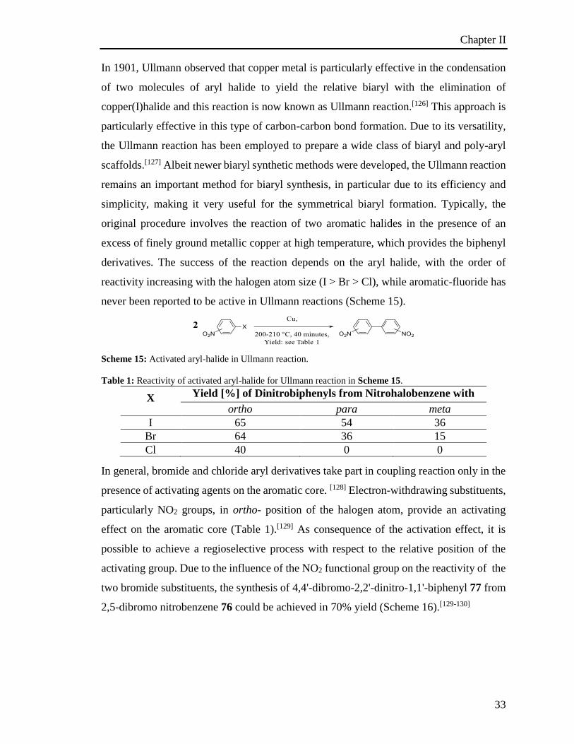
never been reported to be active in Ullmann reactions (Scheme 15).
Scheme 15: Activated aryl-halide in Ullmann reaction.
Table 1: Reactivity of activated aryl-halide for Ullmann reaction in Scheme 15.
X Yield [%] of Dinitrobiphenyls from Nitrohalobenzene with
copper ortho para meta
I 65 54 36
Br 64 36 15
Cl 40 0 0
In general, bromide and chloride aryl derivatives take part in coupling reaction only in the
presence of activating agents on the aromatic core. [128] Electron-withdrawing substituents,
particularly NO2 groups, in ortho- position of the halogen atom, provide an activating
effect on the aromatic core (Table 1).[129] As consequence of the activation effect, it is
possible to achieve a regioselective process with respect to the relative position of the
activating group. Due to the influence of the NO2 functional group on the reactivity of the
two bromide substituents, the synthesis of 4,4'-dibromo-2,2'-dinitro-1,1'-biphenyl 77 from
2,5-dibromo nitrobenzene 76 could be achieved in 70% yield (Scheme 16).[129-130]
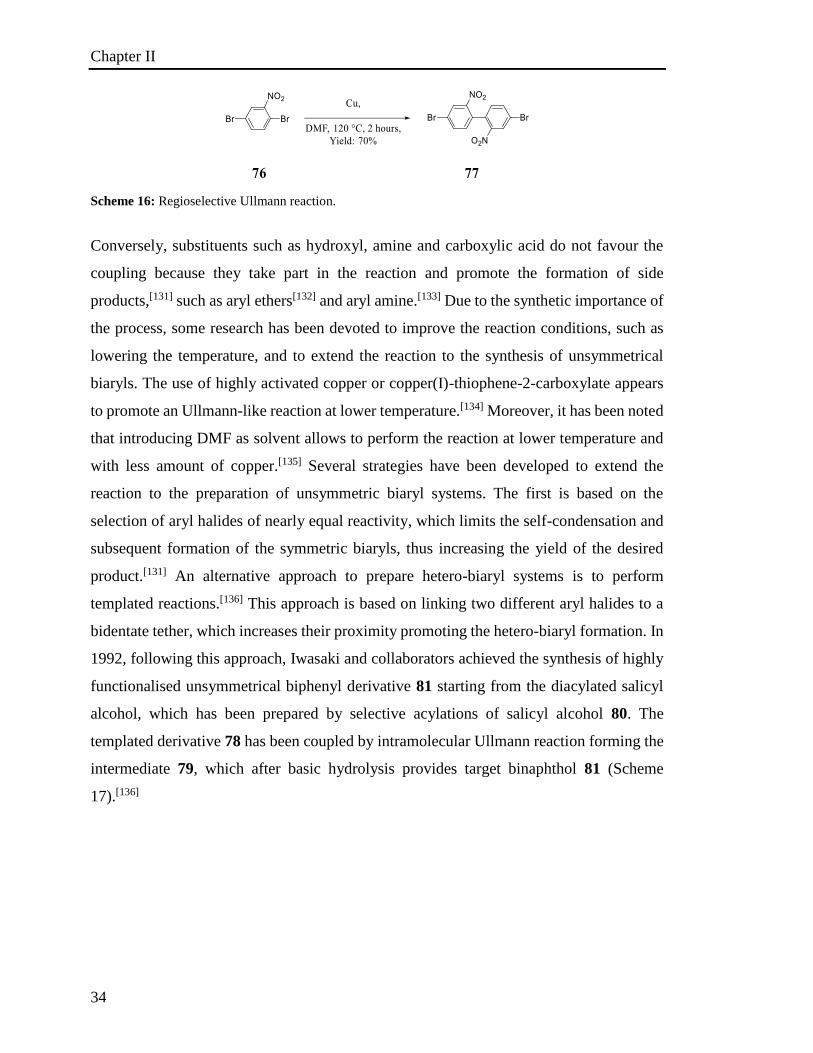
Chapter II
34
Scheme 16: Regioselective Ullmann reaction.
Conversely, substituents such as hydroxyl, amine and carboxylic acid do not favour the
coupling because they take part in the reaction and promote the formation of side
products,[131] such as aryl ethers[132] and aryl amine.[133] Due to the synthetic importance of
the process, some research has been devoted to improve the reaction conditions, such as
lowering the temperature, and to extend the reaction to the synthesis of unsymmetrical
biaryls. The use of highly activated copper or copper(I)-thiophene-2-carboxylate appears
to promote an Ullmann-like reaction at lower temperature.[134] Moreover, it has been noted
that introducing DMF as solvent allows to perform the reaction at lower temperature and
with less amount of copper.[135] Several strategies have been developed to extend the
reaction to the preparation of unsymmetric biaryl systems. The first is based on the
selection of aryl halides of nearly equal reactivity, which limits the self-condensation and
subsequent formation of the symmetric biaryls, thus increasing the yield of the desired
product.[131] An alternative approach to prepare hetero-biaryl systems is to perform
templated reactions.[136] This approach is based on linking two different aryl halides to a
bidentate tether, which increases their proximity promoting the hetero-biaryl formation. In
1992, following this approach, Iwasaki and collaborators achieved the synthesis of highly
functionalised unsymmetrical biphenyl derivative 81 starting from the diacylated salicyl
alcohol, which has been prepared by selective acylations of salicyl alcohol 80. The
templated derivative 78 has been coupled by intramolecular Ullmann reaction forming the
intermediate 79, which after basic hydrolysis provides target binaphthol 81 (Scheme
17).[136]
Chapter II
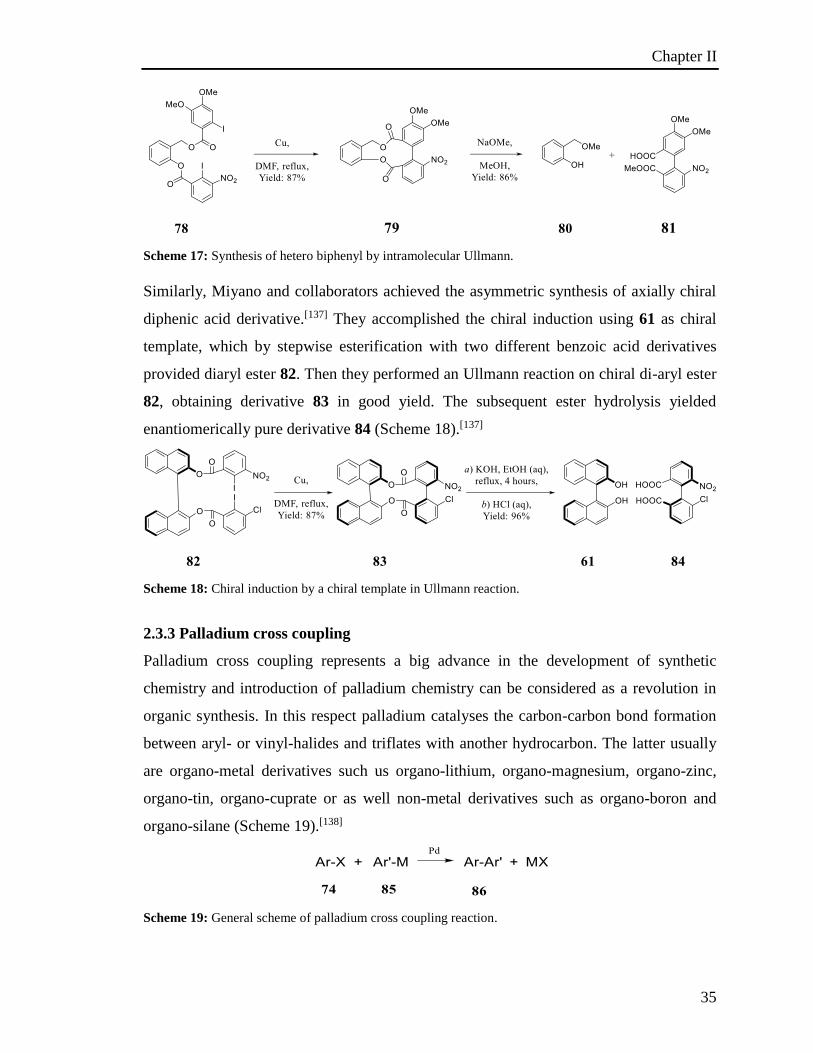
35
Scheme 17: Synthesis of hetero biphenyl by intramolecular Ullmann.
Similarly, Miyano and collaborators achieved the asymmetric synthesis of axially chiral
diphenic acid derivative.[137] They accomplished the chiral induction using 61 as chiral
template, which by stepwise esterification with two different benzoic acid derivatives
provided diaryl ester 82. Then they performed an Ullmann reaction on chiral di-aryl ester
82, obtaining derivative 83 in good yield. The subsequent ester hydrolysis yielded
enantiomerically pure derivative 84 (Scheme 18).[137]
Scheme 18: Chiral induction by a chiral template in Ullmann reaction.
2.3.3 Palladium cross coupling
Palladium cross coupling represents a big advance in the development of synthetic
chemistry and introduction of palladium chemistry can be considered as a revolution in
organic synthesis. In this respect palladium catalyses the carbon-carbon bond formation
between aryl- or vinyl-halides and triflates with another hydrocarbon. The latter usually
are organo-metal derivatives such us organo-lithium, organo-magnesium, organo-zinc,
organo-tin, organo-cuprate or as well non-metal derivatives such as organo-boron and
organo-silane (Scheme 19).[138]
Scheme 19: General scheme of palladium cross coupling reaction.
Chapter II
36
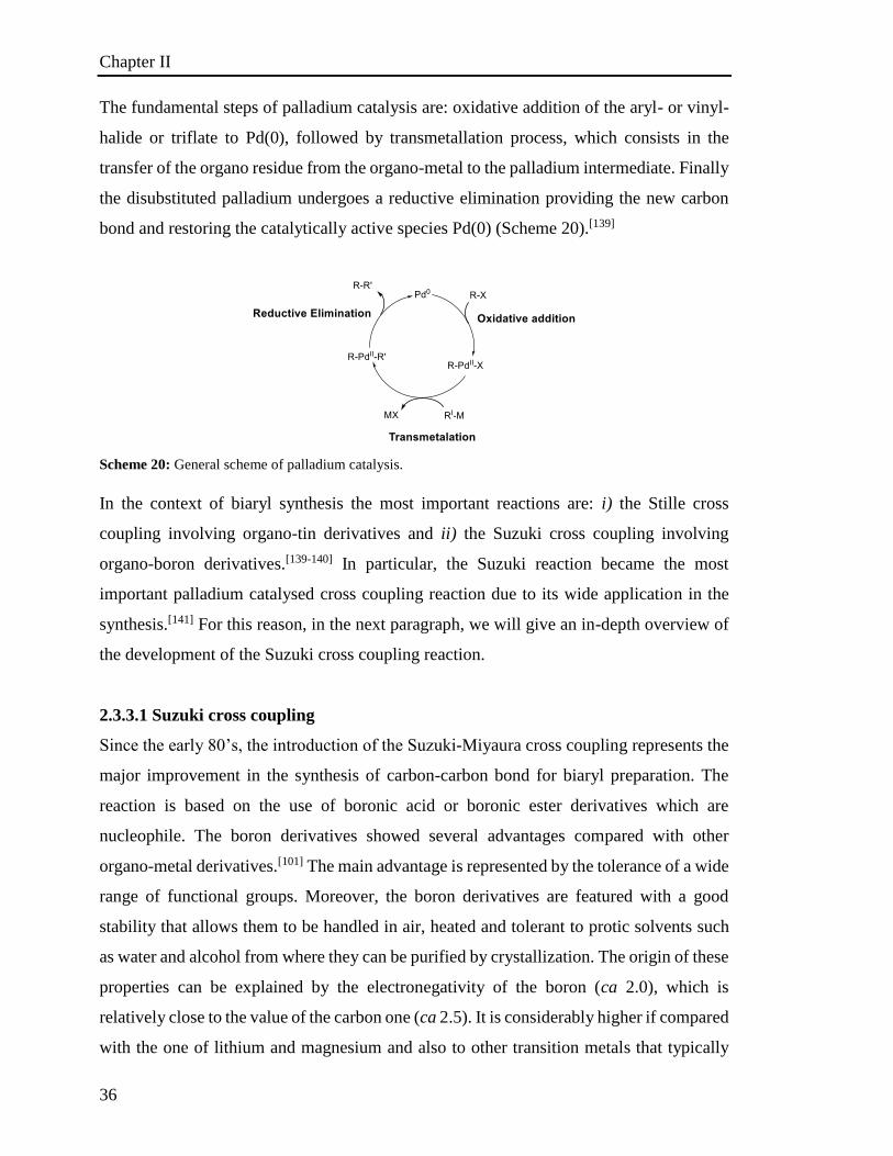
The fundamental steps of palladium catalysis are: oxidative addition of the aryl- or vinyl-
halide or triflate to Pd(0), followed by transmetallation process, which consists in the
transfer of the organo residue from the organo-metal to the palladium intermediate. Finally
the disubstituted palladium undergoes a reductive elimination providing the new carbon
bond and restoring the catalytically active species Pd(0) (Scheme 20).[139]
Scheme 20: General scheme of palladium catalysis.
In the context of biaryl synthesis the most important reactions are: i) the Stille cross
coupling involving organo-tin derivatives and ii) the Suzuki cross coupling involving
organo-boron derivatives.[139-140] In particular, the Suzuki reaction became the most
important palladium catalysed cross coupling reaction due to its wide application in the
synthesis.[141] For this reason, in the next paragraph, we will give an in-depth overview of
the development of the Suzuki cross coupling reaction.
2.3.3.1 Suzuki cross coupling
Since the early 80’s, the introduction of the Suzuki-Miyaura cross coupling represents the
major improvement in the synthesis of carbon-carbon bond for biaryl preparation. The
reaction is based on the use of boronic acid or boronic ester derivatives which are
nucleophile. The boron derivatives showed several advantages compared with other
organo-metal derivatives.[101] The main advantage is represented by the tolerance of a wide
range of functional groups. Moreover, the boron derivatives are featured with a good
stability that allows them to be handled in air, heated and tolerant to protic solvents such
as water and alcohol from where they can be purified by crystallization. The origin of these
properties can be explained by the electronegativity of the boron (ca 2.0), which is
relatively close to the value of the carbon one (ca 2.5). It is considerably higher if compared
with the one of lithium and magnesium and also to other transition metals that typically
Chapter II
37
span from 0.86 to 1.75. Because of the small difference in electronegativity between boron
and carbon, without the presence of a catalyst organo-boron does not generally react with
organo-halides or carbonyl groups. This low reactivity towards other functionalities has
made the boron derivatives one of the most attractive nucleophile for the palladium cross
coupling. If even this chemical stability and tolerance is also owned by the organo-tin
derivatives employable in the Still cross coupling, boron reagents and by-products, in
opposition to tin, are characterized by a lower toxicity.[140a] Typically Suzuki cross
coupling proceeds with a good yield and for all these reasons it became a general tool for
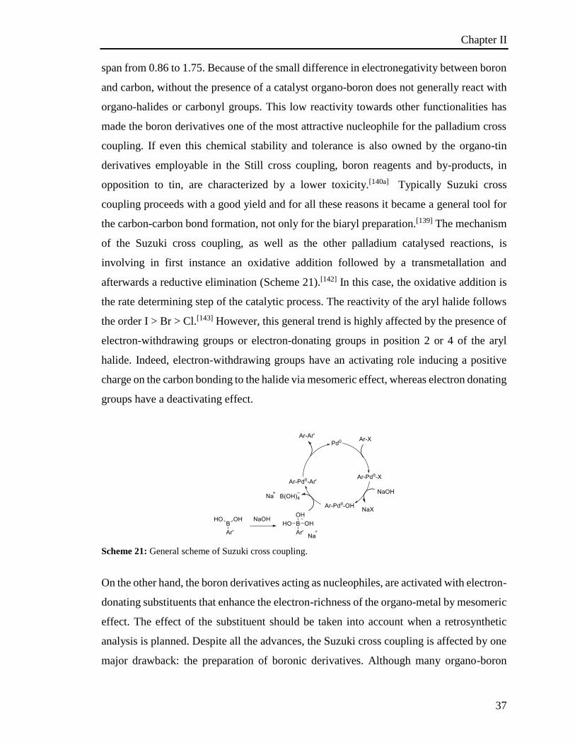
the carbon-carbon bond formation, not only for the biaryl preparation.[139] The mechanism
of the Suzuki cross coupling, as well as the other palladium catalysed reactions, is
involving in first instance an oxidative addition followed by a transmetallation and
afterwards a reductive elimination (Scheme 21).[142] In this case, the oxidative addition is
the rate determining step of the catalytic process. The reactivity of the aryl halide follows
the order I > Br > Cl.[143] However, this general trend is highly affected by the presence of
electron-withdrawing groups or electron-donating groups in position 2 or 4 of the aryl
halide. Indeed, electron-withdrawing groups have an activating role inducing a positive
charge on the carbon bonding to the halide via mesomeric effect, whereas electron donating
groups have a deactivating effect.
Scheme 21: General scheme of Suzuki cross coupling.
On the other hand, the boron derivatives acting as nucleophiles, are activated with electron-
donating substituents that enhance the electron-richness of the organo-metal by mesomeric
effect. The effect of the substituent should be taken into account when a retrosynthetic
analysis is planned. Despite all the advances, the Suzuki cross coupling is affected by one
major drawback: the preparation of boronic derivatives. Although many organo-boron

Chapter II
38
derivatives are commercially available, they undergo easy decomposition over time, and
generally most of them are employed in excess. Consequently, organo-boron derivatives
have to be prepared, which means that additional synthetic steps are required. The
preparation of such compounds generally requires a halide derivative to be transformed in
organo-metal, typically organo-lithium or organo-magnesium, followed by borylation.[144]
An alternative procedure to prepare the organo-boron is the Miyaura borylation based on
palladium catalysis.[145] The main synthetic importance of the Suzuki reaction is
represented by high yielding preparation of dissymmetrical biaryl, however homo biaryl
can be prepared as well. [146] One of the main challenges of the Suzuki coupling is the cross
coupling of cumbersome substrates, in particular substrates bearing substituents in ortho
position to the halide moiety or on the organo-boron derivative.[147] Infact the steric
hindrance in the ortho position of the aryl halide derivatives prevents the oxidative addition
addition of the Pd catalyst, leading to recover unreacted starting material.[148] Similarly,
organo-boron derivatives bearing substituents in ortho positions undergo the
transmetallation process more difficult, generally providing not satisfactory yield and
yielding the hydrolytic deborylation of the organo-boron derivatives.[149] For this reason
cross coupling of ortho substituted naphthalene halide with ortho substituted naphthalene
boron derivative can be considered as a difficult task.[150] An evidence of the difficulties is
the limited number of protocols reported to prepare 2,2’-dimethoxy-1,1’-binaphthalene.
2.3.3.2 Phosphine ligands
In the palladium catalytic cycle the ligands can modulate and enhance the catalytic activity,
especially electon-rich ligands result particularly efficient towards chloride derivatives and
as well electron rich substrates that do not undergo efficiently in oxidative addition
process.[151] In order to improve the efficiency of the oxidative addition, several research
groups developed electron-rich ligands that can be divided in five categories:
bis(diphenylphosphino)alkyl,[147b,-152] trialkylphospine,[153] palladacycle,[154] N-
heterocyclic carbene[155] and aryl-dialkylphosphine.[147a, 156] It is commonly agreed that the
in situ formation of the catalytic species using a source of Pd(II) and a sterically hindered
ligand, is based on the reduction of the Pd(II) to Pd(0) allowing the formation of
unsaturated coordinated complexes such as 16 e- PdL3, 14 e- PdL2 and 12 e- PdL, which
are the actual catalytic species.[157] In 1998, Buchwald and co-worker achived the catalytic
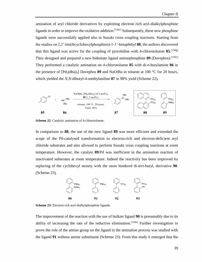
Chapter II
39
amination of aryl chloride derivatives by exploiting electron rich aryl-dialkylphosphine
ligands in order to improve the oxidative addition.[156c] Subsequently, these new phosphine
ligands were successfully applied also in Suzuki cross coupling reactions. Starting from
the studies on 2,2’-bis(dicyclohexylphosphino)-1-1’-binaphthyl 88, the authors discovered
that this ligand was active for the coupling of pyrrolidine with 4-chlorotoluene 85.[156g]
They designed and prepared a new bidentate ligand aminophosphine 89 (Davephos).[156c]
They performed a catalytic amination on 4-chlorotoluene 85 with di-n-butylamine 86 in
the presence of [Pd2(dba)3] Davephos 89 and NaOtBu in toluene at 100 °C for 20 hours,
which yielded the N,N-dibutyl-4-methylaniline 87 in 98% yield (Scheme 22).
Scheme 22: Catalytic amination of 4-chlorotoluene.
In comparison to 88, the use of the new ligand 89 was more efficient and extended the
scope of the Pd-catalysed transformation to electron-rich and electron-deficient aryl
chloride substrates and also allowed to perform Suzuki cross coupling reactions at room
temperature. However, the catalyst 89/Pd was inefficient in the amination reaction of
inactivated substrates at room temperature. Indeed the reactivity has been improved by
replacing of the cyclohexyl moiety with the more hindered di-tert-butyl, derivative 90.
(Scheme 23).
Scheme 23: Electron rich aryl-dialkylphosphine ligands.
The improvement of the reaction with the use of bulkier ligand 90 is presumably due to its
ability of increasing the rate of the reductive elimination.[156e] Further investigation to
prove the role of the amino group on the ligand in the amination process was studied with
the ligand 91 without amine substituent (Scheme 23). From this study it emerged that the
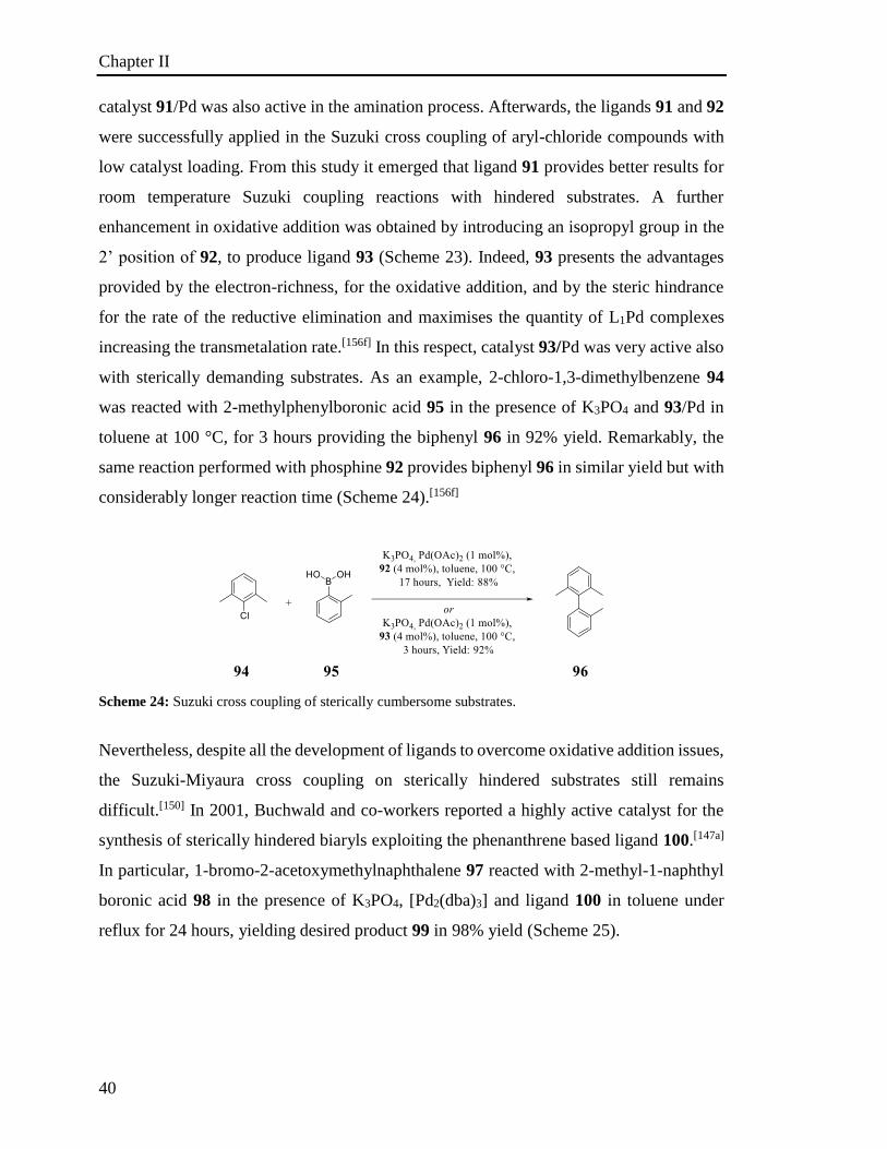
Chapter II
40
catalyst 91/Pd was also active in the amination process. Afterwards, the ligands 91 and 92
were successfully applied in the Suzuki cross coupling of aryl-chloride compounds with
low catalyst loading. From this study it emerged that ligand 91 provides better results for
room temperature Suzuki coupling reactions with hindered substrates. A further
enhancement in oxidative addition was obtained by introducing an isopropyl group in the
2’ position of 92, to produce ligand 93 (Scheme 23). Indeed, 93 presents the advantages
provided by the electron-richness, for the oxidative addition, and by the steric hindrance
for the rate of the reductive elimination and maximises the quantity of L1Pd complexes
increasing the transmetalation rate.[156f] In this respect, catalyst 93/Pd was very active also
with sterically demanding substrates. As an example, 2-chloro-1,3-dimethylbenzene 94
was reacted with 2-methylphenylboronic acid 95 in the presence of K3PO4 and 93/Pd in
toluene at 100 °C, for 3 hours providing the biphenyl 96 in 92% yield. Remarkably, the
same reaction performed with phosphine 92 provides biphenyl 96 in similar yield but with
considerably longer reaction time (Scheme 24).[156f]
Scheme 24: Suzuki cross coupling of sterically cumbersome substrates.
Nevertheless, despite all the development of ligands to overcome oxidative addition issues,
the Suzuki-Miyaura cross coupling on sterically hindered substrates still remains
difficult.[150] In 2001, Buchwald and co-workers reported a highly active catalyst for the
synthesis of sterically hindered biaryls exploiting the phenanthrene based ligand 100.[147a]
In particular, 1-bromo-2-acetoxymethylnaphthalene 97 reacted with 2-methyl-1-naphthyl
boronic acid 98 in the presence of K3PO4, [Pd2(dba)3] and ligand 100 in toluene under
reflux for 24 hours, yielding desired product 99 in 98% yield (Scheme 25).
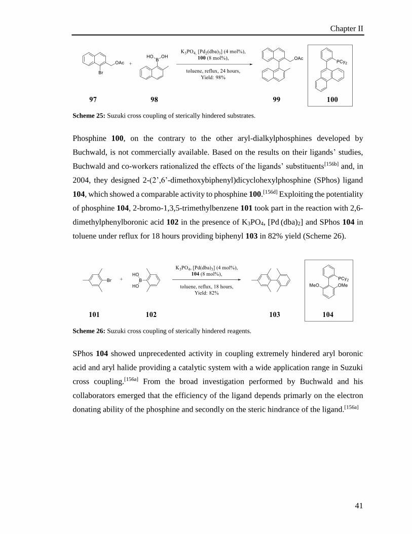
Chapter II
41
Scheme 25: Suzuki cross coupling of sterically hindered substrates.
Phosphine 100, on the contrary to the other aryl-dialkylphosphines developed by
Buchwald, is not commercially available. Based on the results on their ligands’ studies,
Buchwald and co-workers rationalized the effects of the ligands’ substituents[156b] and, in
2004, they designed 2-(2’,6’-dimethoxybiphenyl)dicyclohexylphosphine (SPhos) ligand
104, which showed a comparable activity to phosphine 100.[156d] Exploiting the potentiality
of phosphine 104, 2-bromo-1,3,5-trimethylbenzene 101 took part in the reaction with 2,6-
dimethylphenylboronic acid 102 in the presence of K3PO4, [Pd (dba)2] and SPhos 104 in
toluene under reflux for 18 hours providing biphenyl 103 in 82% yield (Scheme 26).
Scheme 26: Suzuki cross coupling of sterically hindered reagents.
SPhos 104 showed unprecedented activity in coupling extremely hindered aryl boronic
acid and aryl halide providing a catalytic system with a wide application range in Suzuki
cross coupling.[156a] From the broad investigation performed by Buchwald and his
collaborators emerged that the efficiency of the ligand depends primarly on the electron
donating ability of the phosphine and secondly on the steric hindrance of the ligand.[156a]
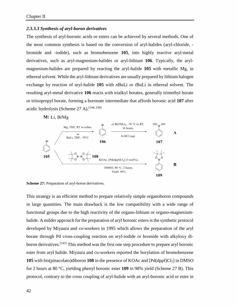
Chapter II
42
2.3.3.3 Synthesis of aryl-boron derivatives
The synthesis of aryl-boronic acids or esters can be achieved by several methods. One of
the most common synthesis is based on the conversion of aryl-halides (aryl-chloride, -
bromide and -iodide), such as bromobenzene 105, into highly reactive aryl-metal
derivatives, such as aryl-magnesium-halides or aryl-lithium 106. Typically, the aryl-
magnesium-halides are prepared by reacting the aryl-halide 105 with metallic Mg, in
ethereal solvent. While the aryl-lithium derivatives are usually prepared by lithium halogen
exchange by reaction of aryl-halide 105 with nBuLi or tBuLi in ethereal solvent. The
resulting aryl-metal derivative 106 reacts with trialkyl borates, generally trimethyl borate
or triisopropyl borate, forming a boronate intermediate that affords boronic acid 107 after
acidic hydrolysis (Scheme 27 A).[144, 158]
Scheme 27: Preparation of aryl-boron derivatives.
This strategy is an efficient method to prepare relatively simple organoboron compounds
in large quantities. The main drawback is the low compatibility with a wide range of
functional groups due to the high reactivity of the organo-lithium or organo-magnesium-
halide. A milder approach for the preparation of aryl boronic esters is the synthetic protocol
developed by Miyaura and co-workers in 1995 which allows the preparation of the aryl
borate through Pd cross-coupling reaction on aryl-iodide or bromide with alkyloxy di-
boron derivatives.[145] This method was the first one step procedure to prepare aryl boronic
ester from aryl halide. Miyaura and co-workers reported the borylation of bromobenzene
105 with bis(pinacolato)diboron 108 in the presence of KOAc and [Pd(dppf)Cl2] in DMSO
for 2 hours at 80 °C, yielding phenyl boronic ester 109 in 98% yield (Scheme 27 B). This
protocol, contrary to the cross coupling of aryl-halide with an aryl-boronic acid or ester in

Chapter II
43
the presence of a base such as K2CO3 or K3PO4, proceeds by promoting the borylation
process in the presence of KOAc.[145] Because of the weakness of the base, further cross
coupling between the aryl-halide and the organo-borate does not take place. However, if
the synthetic protocol is carried out in the presence of K2CO3 or K3PO4, cross-coupling
with formation of the biaryl can also occur. The rate of the reaction increases with solvent
polarity: e.g. DMSO ≥ DMF > dioxane > toluene.[145] In a similar manner, the rate of the
Suzuki cross coupling reaction of electron rich aryl halides is lower than that observed for
the electron-poor derivatives. Contrary to the method based on the use of aryl-lithium or
aryl-magnesium-halide derivatives, the Miyaura reaction displays the main advantage of
compatibility with -CO2Me, -COMe and -CN groups. In order to overcome the limitation
of applicability of the borylation protocol to aryl-iodide -bromide and -triflate, and to
extend the scope of the reaction to inactivated aryl chloride, other phosphines were tested.
In 2007, Buchwald and co-workers achieved the borylation of inactivated aryl chloride
derivatives using SPhos 104 and XPhos 112 phosphines.[159] The latter one permitted
conversion of the inactivated 1-chloro-4-methoxybenzene 110 by reaction with
bis(pinacolato)diboron 108 in the presence of KOAc, [Pd2(dba)3] and XPhos 112 as ligand
in dioxane under reflux in 10 minutes, affording phenyl boronic ester 111 in 97% yield
(Scheme 28).
Scheme 28: Miyaura borylation on deactivated aryl-chloride.
Thanks to the efficiency of the protocol, Buchwald and co-workers aimed at achieving the
Miyaura borylation at lower temperature.[159] When trying to apply this protocol at room
temperature, the process was unsuccessful. Nevertheless, when Pd(OAc)2/XPhos 112 was
used as catalyst in the presence of K3PO4 in lieu of [Pd2(dba)3]/XPhos 112 and KOAc, the
reaction proceeded efficiently at room temperature. Moreover, the room temperature
protocol was further improved by replacing the ligand XPhos 112 with SPhos 104, which
provided better results. In fact, SPhos ligand allowed the Miyaura borylation also on the
sterically hindered substrates. In particular, inactivated 1-chloro-4-methoxybenzene 110
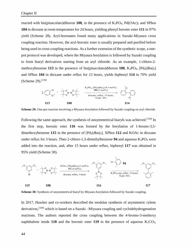
Chapter II
44
reacted with bis(pinacolato)diboron 108, in the presence of K3PO4, Pd(OAc)2 and SPhos
104 in dioxane at room temperature for 24 hours, yielding phenyl boronic ester 111 in 97%
yield (Scheme 28). Aryl-boronates found many applications in Suzuki-Miyaura cross
coupling reaction. However, the aryl-boronic ester is usually prepared and purified before
being used in cross-coupling reactions. As a further extension of the synthetic scope, a one-
pot protocol was developed, where the Miyaura borylation is followed by Suzuki coupling
to form biaryl derivatives starting from an aryl chloride. As an example, 1-chloro-2-
methoxybenzene 113 in the presence of bis(pinacolato)diboron 108, K3PO4, [Pd2(dba)3]
and SPhos 104 in dioxane under reflux for 15 hours, yields biphenyl 114 in 70% yield
(Scheme 29).[159]
Scheme 29: One-pot reaction involving a Miyaura borylation followed by Suzuki coupling on aryl chloride.
Following the same approach, the synthesis of unsymmetrical biaryls was achieved.[159] In
the first step, boronic ester 116 was formed by the borylation of 1-bromo-3,5-
dimethoxybenzene 115 in the presence of [Pd2(dba)3], XPhos 112 and KOAc in dioxane
under reflux for 3 hours. Then 2-chloro-1,3-dimethylbenzene 94 and aqueous K3PO4 were
added into the reaction, and, after 15 hours under reflux, biphenyl 117 was obtained in
95% yield (Scheme 30).
Scheme 30: Synthesis of unsymmetrical biaryl by Miyaura borylation followed by Suzuki coupling.
In 2017, Hawker and co-workers described the modular synthesis of asymmetric rylene
derivatives,[160] which is based on a Suzuki –Miyuara coupling and cyclodehydrogenation
reactions. The authors reported the cross coupling between the 4-bromo-3-methoxy
naphthalene imide 118 and the boronic ester 119 in the presence of aqueous K2CO3,
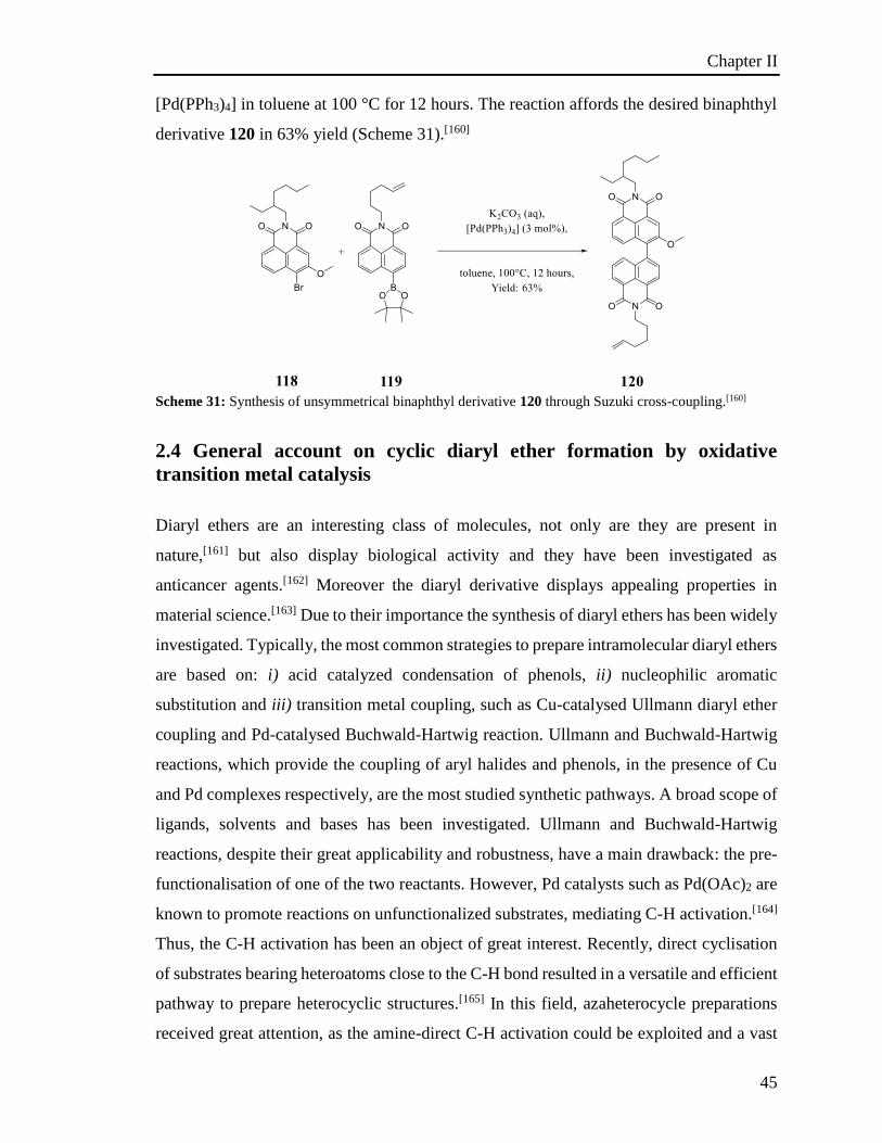
Chapter II
45
[Pd(PPh3)4] in toluene at 100 °C for 12 hours. The reaction affords the desired binaphthyl
derivative 120 in 63% yield (Scheme 31).[160]
Scheme 31: Synthesis of unsymmetrical binaphthyl derivative 120 through Suzuki cross-coupling.[160]
2.4 General account on cyclic diaryl ether formation by oxidative
transition metal catalysis
Diaryl ethers are an interesting class of molecules, not only are they are present in
nature,[161] but also display biological activity and they have been investigated as
anticancer agents.[162] Moreover the diaryl derivative displays appealing properties in
material science.[163] Due to their importance the synthesis of diaryl ethers has been widely
investigated. Typically, the most common strategies to prepare intramolecular diaryl ethers
are based on: i) acid catalyzed condensation of phenols, ii) nucleophilic aromatic
substitution and iii) transition metal coupling, such as Cu-catalysed Ullmann diaryl ether
coupling and Pd-catalysed Buchwald-Hartwig reaction. Ullmann and Buchwald-Hartwig
reactions, which provide the coupling of aryl halides and phenols, in the presence of Cu
and Pd complexes respectively, are the most studied synthetic pathways. A broad scope of
ligands, solvents and bases has been investigated. Ullmann and Buchwald-Hartwig
reactions, despite their great applicability and robustness, have a main drawback: the pre-
functionalisation of one of the two reactants. However, Pd catalysts such as Pd(OAc)2 are
known to promote reactions on unfunctionalized substrates, mediating C-H activation.[164]
Thus, the C-H activation has been an object of great interest. Recently, direct cyclisation
of substrates bearing heteroatoms close to the C-H bond resulted in a versatile and efficient
pathway to prepare heterocyclic structures.[165] In this field, azaheterocycle preparations
received great attention, as the amine-direct C-H activation could be exploited and a vast
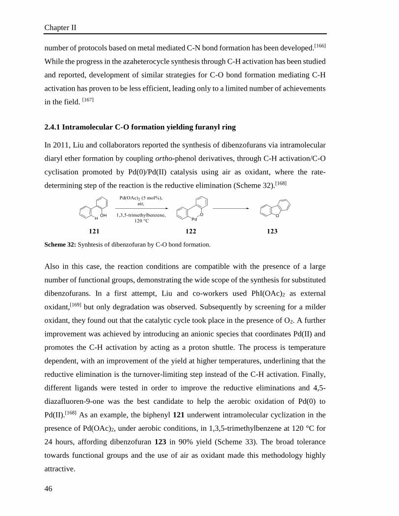
Chapter II
46
number of protocols based on metal mediated C-N bond formation has been developed.[166]
While the progress in the azaheterocycle synthesis through C-H activation has been studied
and reported, development of similar strategies for C-O bond formation mediating C-H
activation has proven to be less efficient, leading only to a limited number of achievements
in the field. [167]
2.4.1 Intramolecular C-O formation yielding furanyl ring
In 2011, Liu and collaborators reported the synthesis of dibenzofurans via intramolecular
diaryl ether formation by coupling ortho-phenol derivatives, through C-H activation/C-O
cyclisation promoted by Pd(0)/Pd(II) catalysis using air as oxidant, where the rate-
determining step of the reaction is the reductive elimination (Scheme 32).[168]
Scheme 32: Synhtesis of dibenzofuran by C-O bond formation.
Also in this case, the reaction conditions are compatible with the presence of a large
number of functional groups, demonstrating the wide scope of the synthesis for substituted
dibenzofurans. In a first attempt, Liu and co-workers used PhI(OAc)2 as external
oxidant,[169] but only degradation was observed. Subsequently by screening for a milder
oxidant, they found out that the catalytic cycle took place in the presence of O2. A further
improvement was achieved by introducing an anionic species that coordinates Pd(II) and
promotes the C-H activation by acting as a proton shuttle. The process is temperature
dependent, with an improvement of the yield at higher temperatures, underlining that the
reductive elimination is the turnover-limiting step instead of the C-H activation. Finally,
different ligands were tested in order to improve the reductive eliminations and 4,5-
diazafluoren-9-one was the best candidate to help the aerobic oxidation of Pd(0) to
Pd(II).[168] As an example, the biphenyl 121 underwent intramolecular cyclization in the
presence of Pd(OAc)2, under aerobic conditions, in 1,3,5-trimethylbenzene at 120 °C for
24 hours, affording dibenzofuran 123 in 90% yield (Scheme 33). The broad tolerance
towards functional groups and the use of air as oxidant made this methodology highly
attractive.
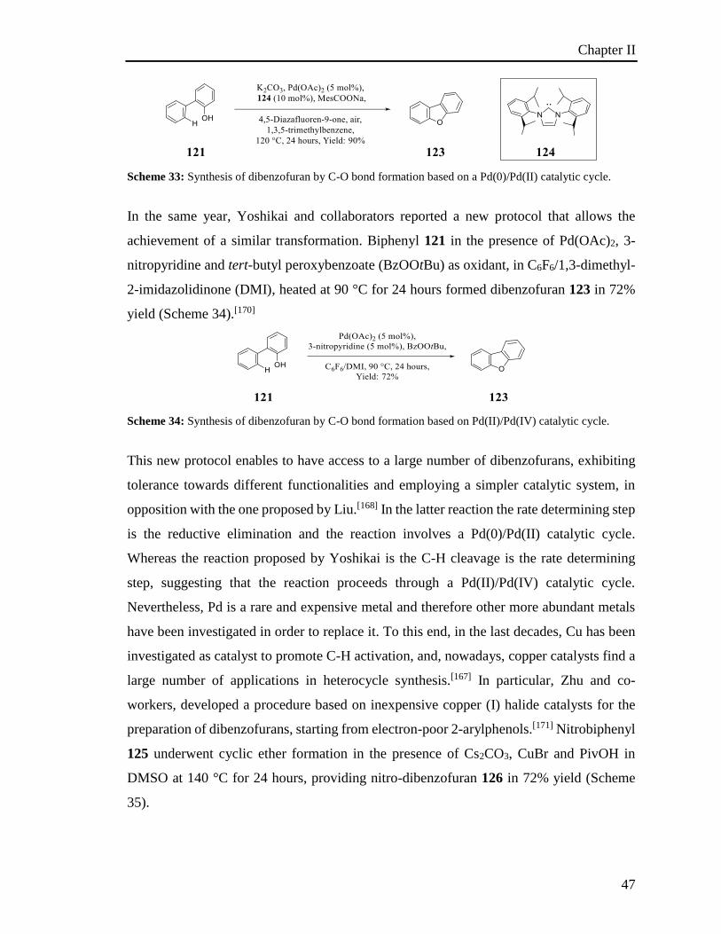
Chapter II
47
Scheme 33: Synthesis of dibenzofuran by C-O bond formation based on a Pd(0)/Pd(II) catalytic cycle.
In the same year, Yoshikai and collaborators reported a new protocol that allows the
achievement of a similar transformation. Biphenyl 121 in the presence of Pd(OAc)2, 3-
nitropyridine and tert-butyl peroxybenzoate (BzOOtBu) as oxidant, in C6F6/1,3-dimethyl-
2-imidazolidinone (DMI), heated at 90 °C for 24 hours formed dibenzofuran 123 in 72%
yield (Scheme 34).[170]
Scheme 34: Synthesis of dibenzofuran by C-O bond formation based on Pd(II)/Pd(IV) catalytic cycle.
This new protocol enables to have access to a large number of dibenzofurans, exhibiting
tolerance towards different functionalities and employing a simpler catalytic system, in
opposition with the one proposed by Liu.[168] In the latter reaction the rate determining step
is the reductive elimination and the reaction involves a Pd(0)/Pd(II) catalytic cycle.
Whereas the reaction proposed by Yoshikai is the C-H cleavage is the rate determining
step, suggesting that the reaction proceeds through a Pd(II)/Pd(IV) catalytic cycle.
Nevertheless, Pd is a rare and expensive metal and therefore other more abundant metals
have been investigated in order to replace it. To this end, in the last decades, Cu has been
investigated as catalyst to promote C-H activation, and, nowadays, copper catalysts find a
large number of applications in heterocycle synthesis.[167] In particular, Zhu and co-
workers, developed a procedure based on inexpensive copper (I) halide catalysts for the
preparation of dibenzofurans, starting from electron-poor 2-arylphenols.[171] Nitrobiphenyl
125 underwent cyclic ether formation in the presence of Cs2CO3, CuBr and PivOH in
DMSO at 140 °C for 24 hours, providing nitro-dibenzofuran 126 in 72% yield (Scheme
35).
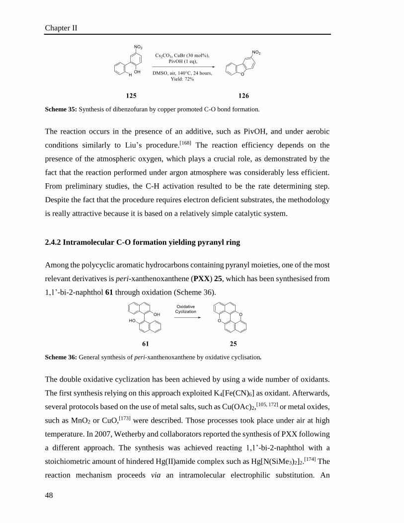
Chapter II
48
Scheme 35: Synthesis of dibenzofuran by copper promoted C-O bond formation.
The reaction occurs in the presence of an additive, such as PivOH, and under aerobic
conditions similarly to Liu’s procedure.[168] The reaction efficiency depends on the
presence of the atmospheric oxygen, which plays a crucial role, as demonstrated by the
fact that the reaction performed under argon atmosphere was considerably less efficient.
From preliminary studies, the C-H activation resulted to be the rate determining step.
Despite the fact that the procedure requires electron deficient substrates, the methodology
is really attractive because it is based on a relatively simple catalytic system.
2.4.2 Intramolecular C-O formation yielding pyranyl ring
Among the polycyclic aromatic hydrocarbons containing pyranyl moieties, one of the most
relevant derivatives is peri-xanthenoxanthene (PXX) 25, which has been synthesised from
1,1’-bi-2-naphthol 61 through oxidation (Scheme 36).
Scheme 36: General synthesis of peri-xanthenoxanthene by oxidative cyclisation.
The double oxidative cyclization has been achieved by using a wide number of oxidants.
The first synthesis relying on this approach exploited K4[Fe(CN)6] as oxidant. Afterwards,
several protocols based on the use of metal salts, such as Cu(OAc)2,[105, 172] or metal oxides,
such as MnO2 or CuO,[173] were described. Those processes took place under air at high
temperature. In 2007, Wetherby and collaborators reported the synthesis of PXX following
a different approach. The synthesis was achieved reacting 1,1’-bi-2-naphthol with a
stoichiometric amount of hindered Hg(II)amide complex such as Hg[N(SiMe3)2]2.[174] The
reaction mechanism proceeds via an intramolecular electrophilic substitution. An
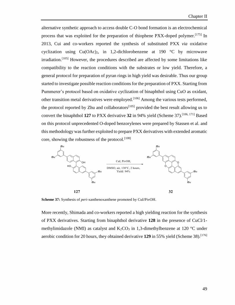
Chapter II
49
alternative synthetic approach to access double C-O bond formation is an electrochemical
process that was exploited for the preparation of thiophene PXX-doped polymer.[175] In
2013, Cui and co-workers reported the synthesis of substituted PXX via oxidative
cyclization using Cu(OAc)2, in 1,2-dichlorobenzene at 190 °C by microwave
irradiation.[105] However, the procedures described are affected by some limitations like
compatibility to the reaction conditions with the substrates or low yield. Therefore, a
general protocol for preparation of pyran rings in high yield was desirable. Thus our group
started to investigate possible reaction conditions for the preparation of PXX. Starting from
Pummerer’s protocol based on oxidative cyclization of binaphthol using CuO as oxidant,
other transition metal derivatives were employed.[106] Among the various tests performed,
the protocol reported by Zhu and collaborators[105] provided the best result allowing us to
convert the binaphthol 127 to PXX derivative 32 in 94% yield (Scheme 37).[106, 171] Based
on this protocol unprecedented O-doped benzorylenes were prepared by Stassen et al. and
this methodology was further exploited to prepare PXX derivatives with extended aromatic
core, showing the robustness of the protocol.[108]
Scheme 37: Synthesis of peri-xanthenoxanthene promoted by CuI/PivOH.
More recently, Shimada and co-workers reported a high yielding reaction for the synthesis
of PXX derivatives. Starting from binaphthol derivative 128 in the presence of CuCl/1-
methylimidazole (NMI) as catalyst and K2CO3 in 1,3-dimethylbenzene at 120 °C under
aerobic condition for 20 hours, they obtained derivative 129 in 55% yield (Scheme 38).[176]
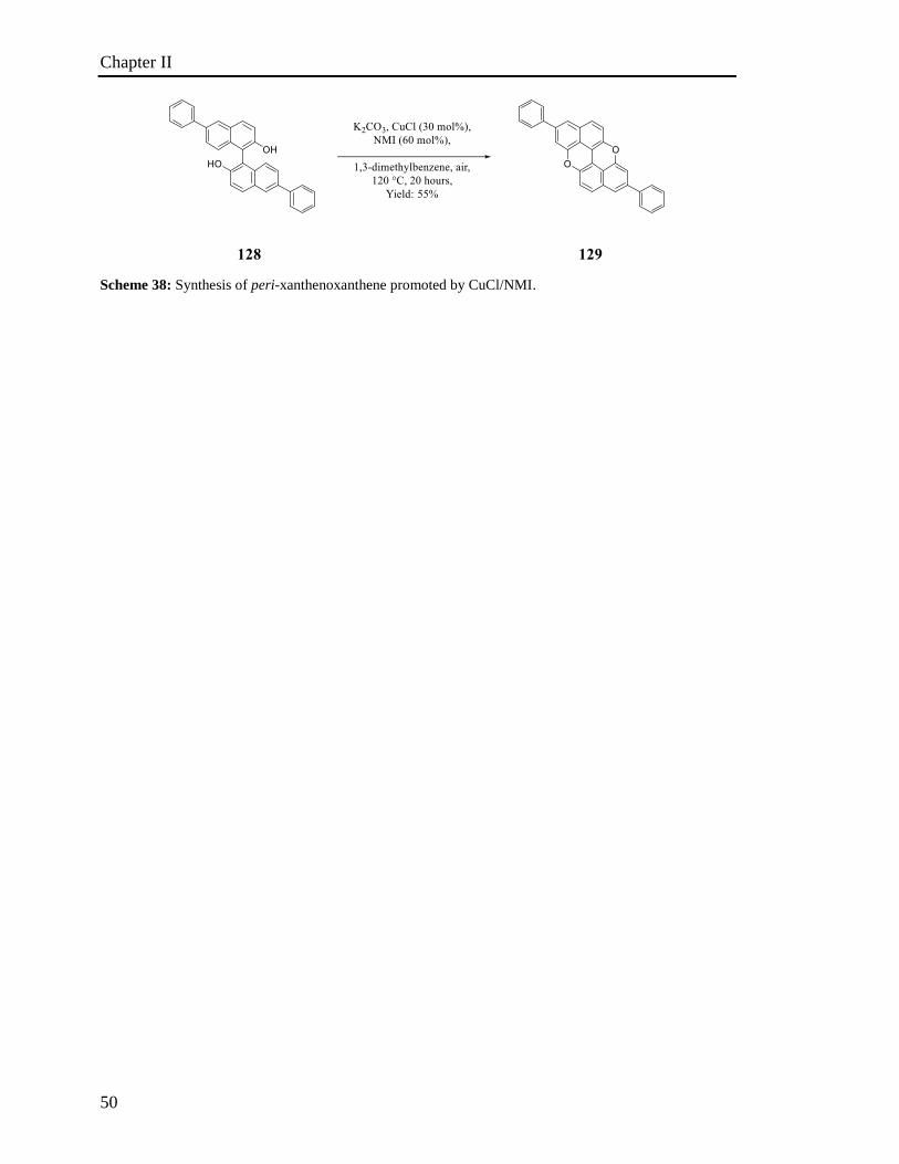
Chapter II
50
Scheme 38: Synthesis of peri-xanthenoxanthene promoted by CuCl/NMI.
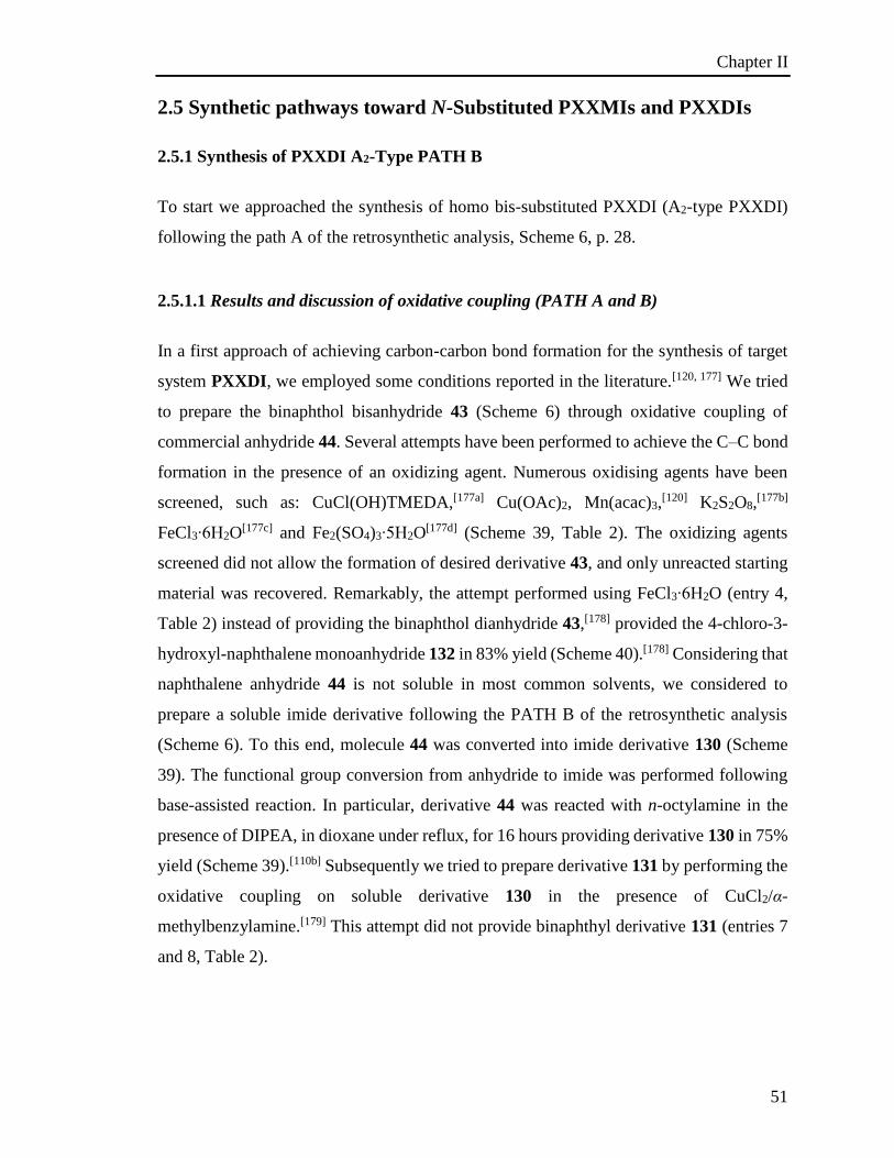
Chapter II
51
2.5 Synthetic pathways toward N-Substituted PXXMIs and PXXDIs
2.5.1 Synthesis of PXXDI A2-Type PATH B
To start we approached the synthesis of homo bis-substituted PXXDI (A2-type PXXDI)
following the path A of the retrosynthetic analysis, Scheme 6, p. 28.
2.5.1.1 Results and discussion of oxidative coupling (PATH A and B)
In a first approach of achieving carbon-carbon bond formation for the synthesis of target
system PXXDI, we employed some conditions reported in the literature.[120, 177] We tried
to prepare the binaphthol bisanhydride 43 (Scheme 6) through oxidative coupling of
commercial anhydride 44. Several attempts have been performed to achieve the C–C bond
formation in the presence of an oxidizing agent. Numerous oxidising agents have been
screened, such as: CuCl(OH)TMEDA,[177a] Cu(OAc)2, Mn(acac)3,[120] K2S2O8,
[177b]
FeCl3∙6H2O[177c] and Fe2(SO4)3∙5H2O
[177d] (Scheme 39, Table 2). The oxidizing agents
screened did not allow the formation of desired derivative 43, and only unreacted starting
material was recovered. Remarkably, the attempt performed using FeCl3∙6H2O (entry 4,
Table 2) instead of providing the binaphthol dianhydride 43,[178] provided the 4-chloro-3-
hydroxyl-naphthalene monoanhydride 132 in 83% yield (Scheme 40).[178] Considering that
naphthalene anhydride 44 is not soluble in most common solvents, we considered to
prepare a soluble imide derivative following the PATH B of the retrosynthetic analysis
(Scheme 6). To this end, molecule 44 was converted into imide derivative 130 (Scheme
39). The functional group conversion from anhydride to imide was performed following
base-assisted reaction. In particular, derivative 44 was reacted with n-octylamine in the
presence of DIPEA, in dioxane under reflux, for 16 hours providing derivative 130 in 75%
yield (Scheme 39).[110b] Subsequently we tried to prepare derivative 131 by performing the
oxidative coupling on soluble derivative 130 in the presence of CuCl2/α-
methylbenzylamine.[179] This attempt did not provide binaphthyl derivative 131 (entries 7
and 8, Table 2).
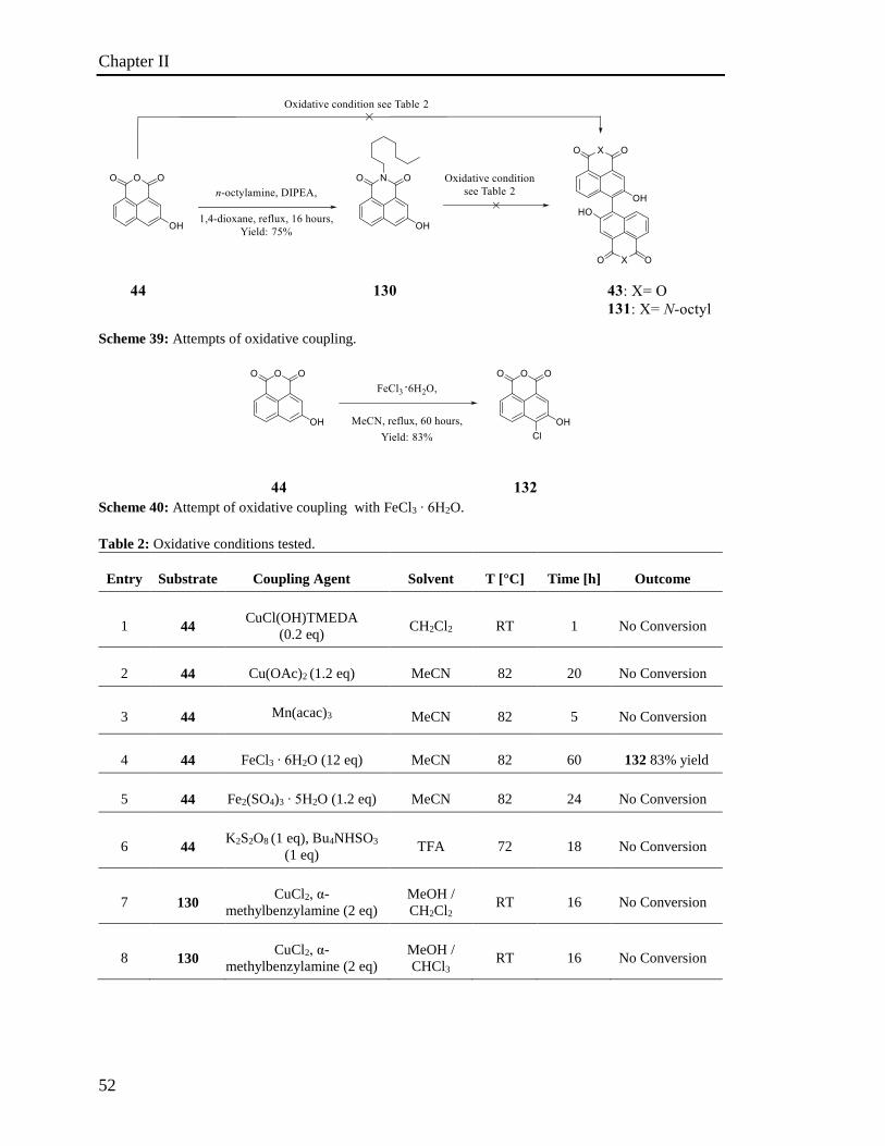
Chapter II
52
Scheme 39: Attempts of oxidative coupling.
Scheme 40: Attempt of oxidative coupling with FeCl3 ∙ 6H2O.
Table 2: Oxidative conditions tested.
Entry Substrate Coupling Agent Solvent T [°C] Time [h] Outcome
1 44 CuCl(OH)TMEDA
(0.2 eq) CH2Cl2 RT 1 No Conversion
2 44 Cu(OAc)2 (1.2 eq) MeCN 82 20 No Conversion
3 44 Mn(acac)3 MeCN 82 5 No Conversion
4 44 FeCl3 ∙ 6H2O (12 eq) MeCN 82 60 132 83% yield
5 44 Fe2(SO4)3 ∙ 5H2O (1.2 eq) MeCN 82 24 No Conversion
6 44 K2S2O8 (1 eq), Bu4NHSO3
(1 eq) TFA 72 18 No Conversion
7 130 CuCl2, α-
methylbenzylamine (2 eq)
MeOH /
CH2Cl2 RT 16 No Conversion
8 130 CuCl2, α-
methylbenzylamine (2 eq)
MeOH /
CHCl3 RT 16 No Conversion
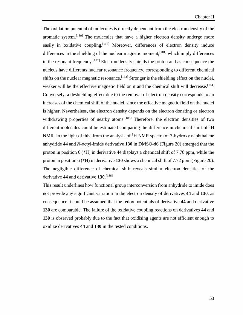
Chapter II
53
The oxidation potential of molecules is directly dependant from the electron density of the
aromatic system.[180] The molecules that have a higher electron density undergo more
easily in oxidative coupling.[115] Moreover, differences of electron density induce
differences in the shielding of the nuclear magnetic moment,[181] which imply differences
in the resonant frequency.[182] Electron density shields the proton and as consequence the
nucleus have differents nuclear resonance frequency, corresponding to different chemical
shifts on the nuclear magnetic resonance.[183] Stronger is the shielding effect on the nuclei,
weaker will be the effective magnetic field on it and the chemical shift will decrease.[184]
Conversely, a deshielding effect due to the removal of electron density corresponds to an
increases of the chemical shift of the nuclei, since the effective magnetic field on the nuclei
is higher. Nevertheless, the electron density depends on the electron donating or electron
withdrawing properties of nearby atoms.[185] Therefore, the electron densities of two
different molecules could be estimated comparing the difference in chemical shift of 1H
NMR. In the light of this, from the analysis of 1H NMR spectra of 3-hydroxy naphthalene
anhydride 44 and N-octyl-imide derivative 130 in DMSO-d6 (Figure 20) emerged that the
proton in position 6 (*H) in derivative 44 displays a chemical shift of 7.78 ppm, while the
proton in position 6 (*H) in derivative 130 shows a chemical shift of 7.72 ppm (Figure 20).
The negligible difference of chemical shift reveals similar electron densities of the
derivative 44 and derivative 130.[186]
This result underlines how functional group interconversion from anhydride to imide does
not provide any significant variation in the electron density of derivatives 44 and 130, as
consequence it could be assumed that the redox potentials of derivative 44 and derivative
130 are comparable. The failure of the oxidative coupling reactions on derivatives 44 and
130 is observed probably due to the fact that oxidising agents are not efficient enough to
oxidize derivatives 44 and 130 in the tested conditions.
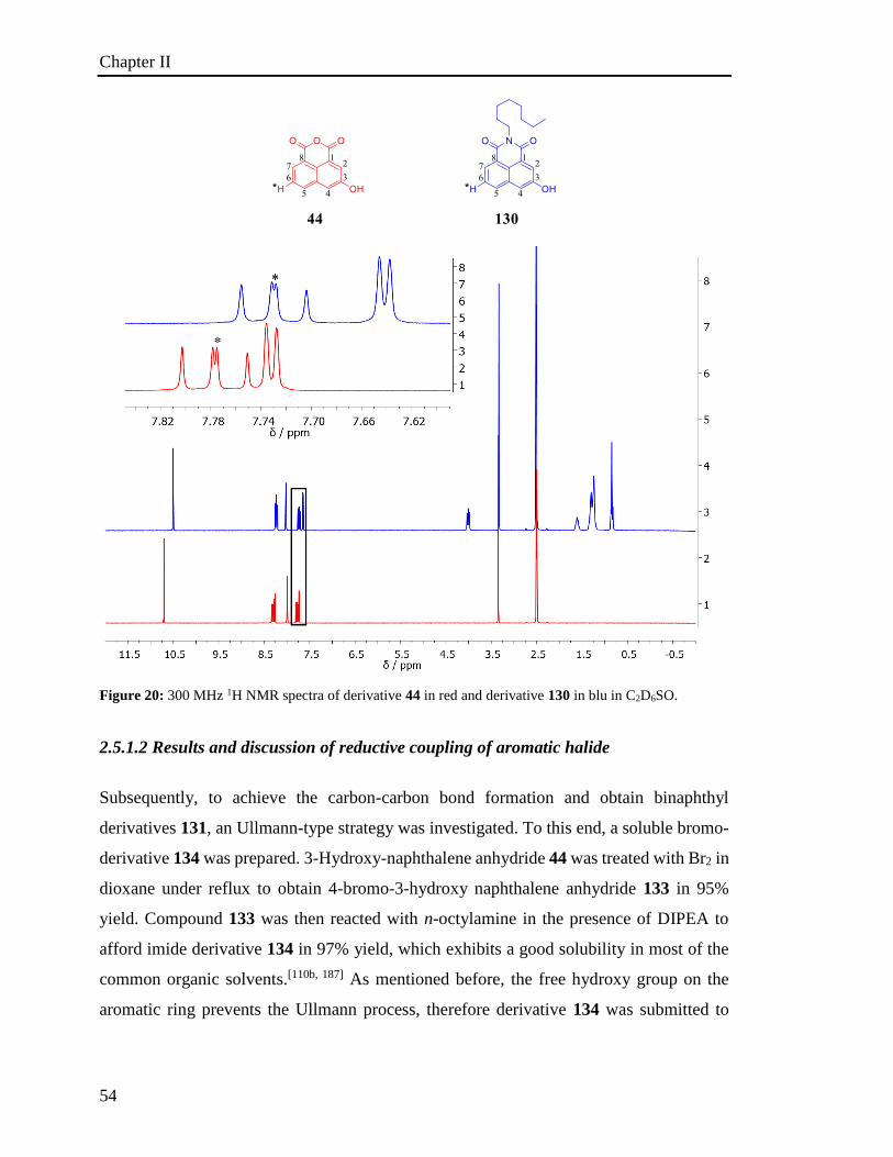
Chapter II
54
Figure 20: 300 MHz 1H NMR spectra of derivative 44 in red and derivative 130 in blu in C2D6SO.
2.5.1.2 Results and discussion of reductive coupling of aromatic halide
Subsequently, to achieve the carbon-carbon bond formation and obtain binaphthyl
derivatives 131, an Ullmann-type strategy was investigated. To this end, a soluble bromo-
derivative 134 was prepared. 3-Hydroxy-naphthalene anhydride 44 was treated with Br2 in
dioxane under reflux to obtain 4-bromo-3-hydroxy naphthalene anhydride 133 in 95%
yield. Compound 133 was then reacted with n-octylamine in the presence of DIPEA to
afford imide derivative 134 in 97% yield, which exhibits a good solubility in most of the
common organic solvents.[110b, 187] As mentioned before, the free hydroxy group on the
aromatic ring prevents the Ullmann process, therefore derivative 134 was submitted to
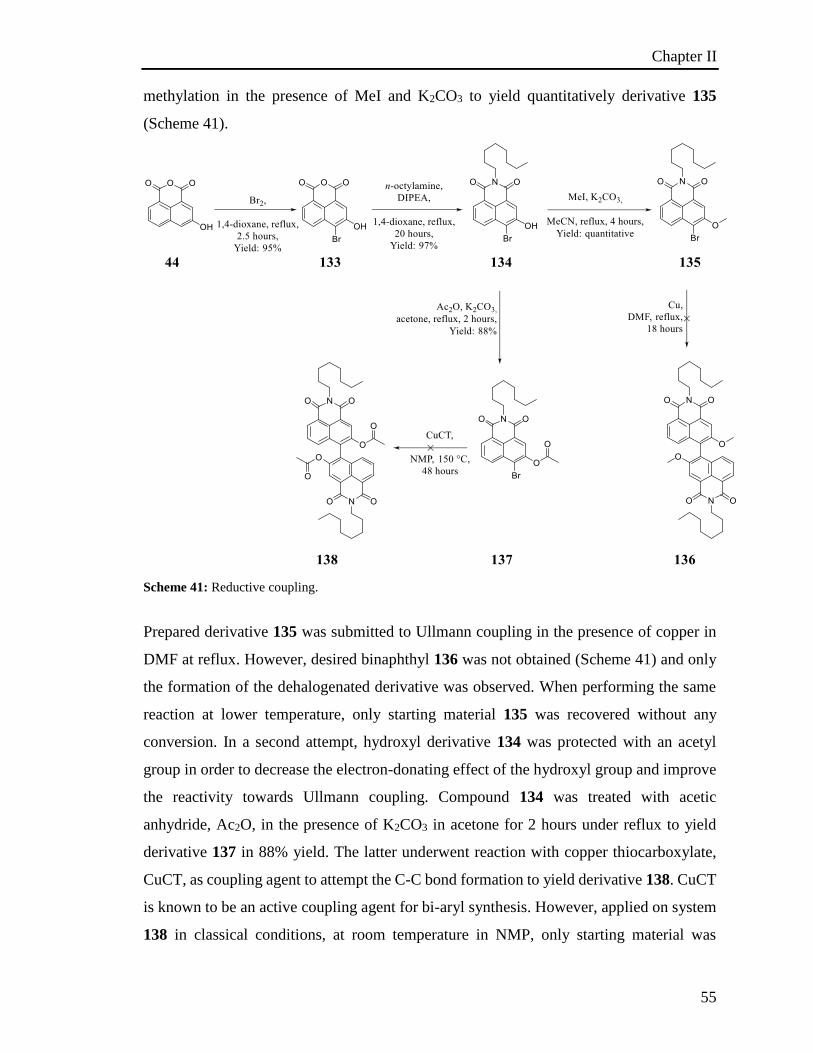
Chapter II
55
methylation in the presence of MeI and K2CO3 to yield quantitatively derivative 135
(Scheme 41).
Scheme 41: Reductive coupling.
Prepared derivative 135 was submitted to Ullmann coupling in the presence of copper in
DMF at reflux. However, desired binaphthyl 136 was not obtained (Scheme 41) and only
the formation of the dehalogenated derivative was observed. When performing the same
reaction at lower temperature, only starting material 135 was recovered without any
conversion. In a second attempt, hydroxyl derivative 134 was protected with an acetyl
group in order to decrease the electron-donating effect of the hydroxyl group and improve
the reactivity towards Ullmann coupling. Compound 134 was treated with acetic
anhydride, Ac2O, in the presence of K2CO3 in acetone for 2 hours under reflux to yield
derivative 137 in 88% yield. The latter underwent reaction with copper thiocarboxylate,
CuCT, as coupling agent to attempt the C-C bond formation to yield derivative 138. CuCT
is known to be an active coupling agent for bi-aryl synthesis. However, applied on system
138 in classical conditions, at room temperature in NMP, only starting material was
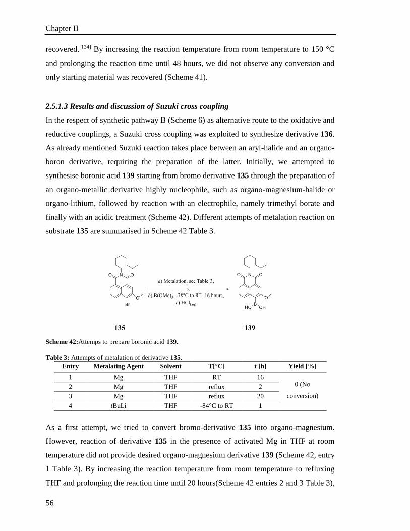
Chapter II
56
recovered.[134] By increasing the reaction temperature from room temperature to 150 °C
and prolonging the reaction time until 48 hours, we did not observe any conversion and
only starting material was recovered (Scheme 41).
2.5.1.3 Results and discussion of Suzuki cross coupling
In the respect of synthetic pathway B (Scheme 6) as alternative route to the oxidative and
reductive couplings, a Suzuki cross coupling was exploited to synthesize derivative 136.
As already mentioned Suzuki reaction takes place between an aryl-halide and an organo-
boron derivative, requiring the preparation of the latter. Initially, we attempted to
synthesise boronic acid 139 starting from bromo derivative 135 through the preparation of
an organo-metallic derivative highly nucleophile, such as organo-magnesium-halide or
organo-lithium, followed by reaction with an electrophile, namely trimethyl borate and
finally with an acidic treatment (Scheme 42). Different attempts of metalation reaction on
substrate 135 are summarised in Scheme 42 Table 3.
Scheme 42:Attemps to prepare boronic acid 139.
Table 3: Attempts of metalation of derivative 135.
Entry Metalating Agent Solvent T[°C] t [h] Yield [%]
1 Mg THF RT 16 0 (No
conversion)
2 Mg THF reflux 2
3 Mg THF reflux 20
4 tBuLi THF -84°C to RT 1
As a first attempt, we tried to convert bromo-derivative 135 into organo-magnesium.
However, reaction of derivative 135 in the presence of activated Mg in THF at room
temperature did not provide desired organo-magnesium derivative 139 (Scheme 42, entry
1 Table 3). By increasing the reaction temperature from room temperature to refluxing
THF and prolonging the reaction time until 20 hours(Scheme 42 entries 2 and 3 Table 3),
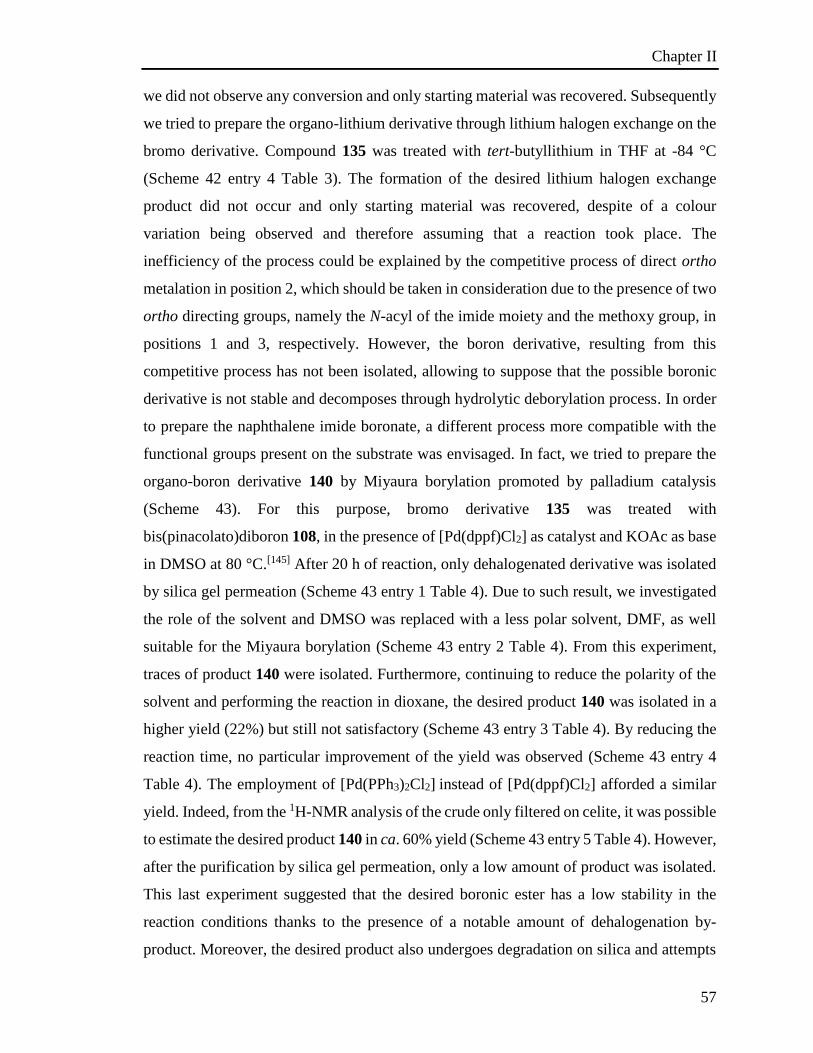
Chapter II
57
we did not observe any conversion and only starting material was recovered. Subsequently
we tried to prepare the organo-lithium derivative through lithium halogen exchange on the
bromo derivative. Compound 135 was treated with tert-butyllithium in THF at -84 °C
(Scheme 42 entry 4 Table 3). The formation of the desired lithium halogen exchange
product did not occur and only starting material was recovered, despite of a colour
variation being observed and therefore assuming that a reaction took place. The
inefficiency of the process could be explained by the competitive process of direct ortho
metalation in position 2, which should be taken in consideration due to the presence of two
ortho directing groups, namely the N-acyl of the imide moiety and the methoxy group, in
positions 1 and 3, respectively. However, the boron derivative, resulting from this
competitive process has not been isolated, allowing to suppose that the possible boronic
derivative is not stable and decomposes through hydrolytic deborylation process. In order
to prepare the naphthalene imide boronate, a different process more compatible with the
functional groups present on the substrate was envisaged. In fact, we tried to prepare the
organo-boron derivative 140 by Miyaura borylation promoted by palladium catalysis
(Scheme 43). For this purpose, bromo derivative 135 was treated with
bis(pinacolato)diboron 108, in the presence of [Pd(dppf)Cl2] as catalyst and KOAc as base
in DMSO at 80 °C.[145] After 20 h of reaction, only dehalogenated derivative was isolated
by silica gel permeation (Scheme 43 entry 1 Table 4). Due to such result, we investigated
the role of the solvent and DMSO was replaced with a less polar solvent, DMF, as well
suitable for the Miyaura borylation (Scheme 43 entry 2 Table 4). From this experiment,
traces of product 140 were isolated. Furthermore, continuing to reduce the polarity of the
solvent and performing the reaction in dioxane, the desired product 140 was isolated in a
higher yield (22%) but still not satisfactory (Scheme 43 entry 3 Table 4). By reducing the
reaction time, no particular improvement of the yield was observed (Scheme 43 entry 4
Table 4). The employment of [Pd(PPh3)2Cl2] instead of [Pd(dppf)Cl2] afforded a similar
yield. Indeed, from the 1H-NMR analysis of the crude only filtered on celite, it was possible
to estimate the desired product 140 in ca. 60% yield (Scheme 43 entry 5 Table 4). However,
after the purification by silica gel permeation, only a low amount of product was isolated.
This last experiment suggested that the desired boronic ester has a low stability in the
reaction conditions thanks to the presence of a notable amount of dehalogenation by-
product. Moreover, the desired product also undergoes degradation on silica and attempts
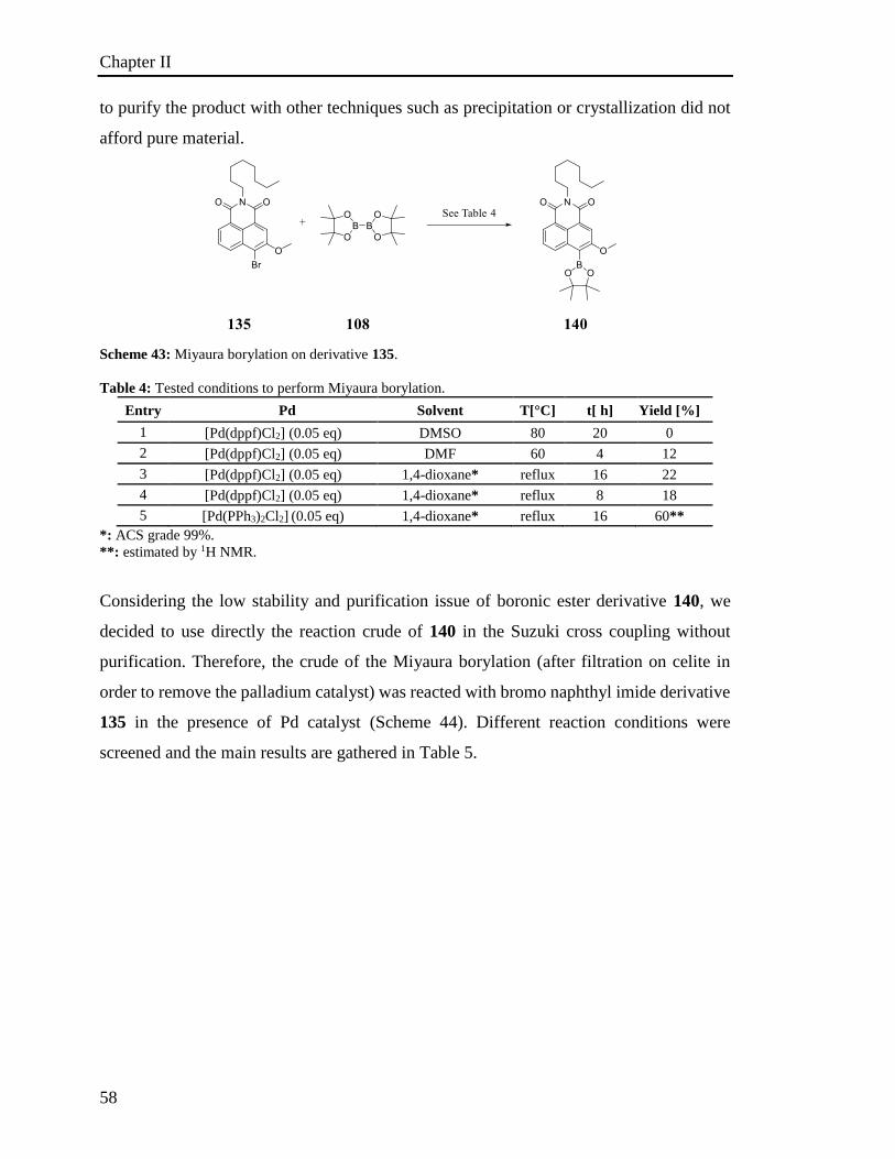
Chapter II
58
to purify the product with other techniques such as precipitation or crystallization did not
afford pure material.
Scheme 43: Miyaura borylation on derivative 135.
Table 4: Tested conditions to perform Miyaura borylation.
Entry Pd Solvent T[°C] t[ h] Yield [%]
1 [Pd(dppf)Cl2] (0.05 eq) DMSO 80 20 0
2 [Pd(dppf)Cl2] (0.05 eq) DMF 60 4 12
3 [Pd(dppf)Cl2] (0.05 eq) 1,4-dioxane* reflux 16 22
4 [Pd(dppf)Cl2] (0.05 eq) 1,4-dioxane* reflux 8 18
5 [Pd(PPh3)2Cl2] (0.05 eq) 1,4-dioxane* reflux 16 60**
*: ACS grade 99%.
**: estimated by 1H NMR.
Considering the low stability and purification issue of boronic ester derivative 140, we
decided to use directly the reaction crude of 140 in the Suzuki cross coupling without
purification. Therefore, the crude of the Miyaura borylation (after filtration on celite in
order to remove the palladium catalyst) was reacted with bromo naphthyl imide derivative
135 in the presence of Pd catalyst (Scheme 44). Different reaction conditions were
screened and the main results are gathered in Table 5.
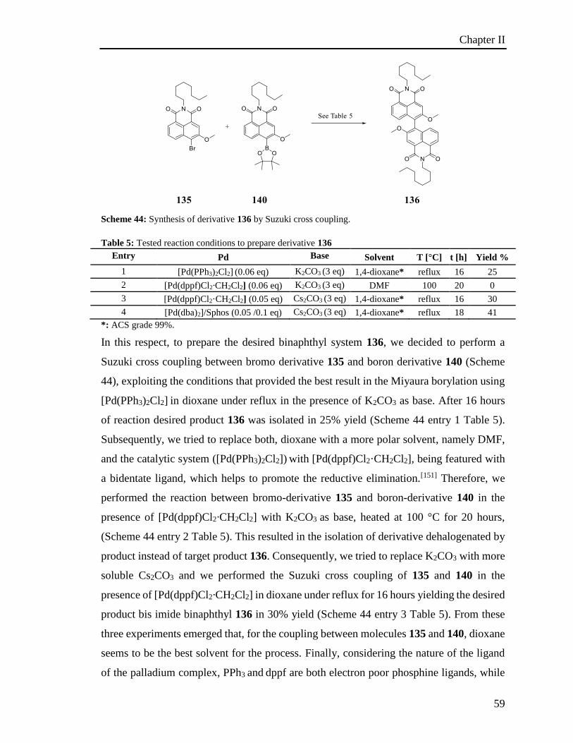
Chapter II
59
Scheme 44: Synthesis of derivative 136 by Suzuki cross coupling.
Table 5: Tested reaction conditions to prepare derivative 136
Entry Pd Base Solvent T [°C] t [h] Yield %
1 [Pd(PPh3)2Cl2] (0.06 eq) K2CO3 (3 eq) 1,4-dioxane* reflux 16 25
2 [Pd(dppf)Cl2·CH2Cl2] (0.06 eq) K2CO3 (3 eq) DMF 100 20 0
3 [Pd(dppf)Cl2·CH2Cl2] (0.05 eq) Cs2CO3 (3 eq) 1,4-dioxane* reflux 16 30
4 [Pd(dba)2]/Sphos (0.05 /0.1 eq) Cs2CO3 (3 eq) 1,4-dioxane* reflux 18 41
*: ACS grade 99%.
In this respect, to prepare the desired binaphthyl system 136, we decided to perform a
Suzuki cross coupling between bromo derivative 135 and boron derivative 140 (Scheme
44), exploiting the conditions that provided the best result in the Miyaura borylation using
[Pd(PPh3)2Cl2] in dioxane under reflux in the presence of K2CO3 as base. After 16 hours
of reaction desired product 136 was isolated in 25% yield (Scheme 44 entry 1 Table 5).
Subsequently, we tried to replace both, dioxane with a more polar solvent, namely DMF,
and the catalytic system ([Pd(PPh3)2Cl2]) with [Pd(dppf)Cl2·CH2Cl2], being featured with
a bidentate ligand, which helps to promote the reductive elimination.[151] Therefore, we
performed the reaction between bromo-derivative 135 and boron-derivative 140 in the
presence of [Pd(dppf)Cl2·CH2Cl2] with K2CO3 as base, heated at 100 °C for 20 hours,
(Scheme 44 entry 2 Table 5). This resulted in the isolation of derivative dehalogenated by
product instead of target product 136. Consequently, we tried to replace K2CO3 with more
soluble Cs2CO3 and we performed the Suzuki cross coupling of 135 and 140 in the
presence of [Pd(dppf)Cl2·CH2Cl2] in dioxane under reflux for 16 hours yielding the desired
product bis imide binaphthyl 136 in 30% yield (Scheme 44 entry 3 Table 5). From these
three experiments emerged that, for the coupling between molecules 135 and 140, dioxane
seems to be the best solvent for the process. Finally, considering the nature of the ligand
of the palladium complex, PPh3 and dppf are both electron poor phosphine ligands, while
Chapter II
60
the first is monodentate, the latter is bidentate, feature which should improve the reductive
elimination in the catalytic process.[156c] However, we did not observe any significant
difference in the yield for the two different ligands. This result highlights that the reductive
elimination does not represent the critical step in the catalytic process. Therefore, trying to
optimize the reaction conditions, we investigated the oxidative addition process to
determine if it is the crucial step. Electron-poor phosphines are known to promote the
transmetallation process, on the other hand electron rich phosphines enhance the oxidative
addition process. Nevertheless, as molecules 135 and 140 are sterically demanding
reagents, we tried to replace the electron-poor ligand of Pd, with an electron rich ligand
bidentate, namely SPhos 104. Eventually, we performed the coupling of bromo imide 135
and boron derivative 140 in the presence of the highly active catalytic system
[Pd(dba)2]/Sphos 104 with Cs2CO3 as base in dioxane under reflux for 18 hours affording
the desired product in 41 % yield with the full conversion of the bromo derivative 135
(Scheme 44 entry 4 Table 5). The electron-rich phosphine did not dramatically affect the
yield. Accordingly to these results, we can exclude the supposition that the oxidative
addition mainly affects the yield of the process. Based on these results, we concluded that
the yield of the Suzuki cross coupling between derivatives 135 and 140 is affected mainly
by the stability of the boron derivative 140 in the reaction conditions. In the end, inspired
by the work of Buchwald, a one-pot reaction approach involving a simultaneous Miyaura
borylation and Suzuki cross coupling, was tried.[159] This strategy was exploited in order
to overcome the low stability of organo-boron 140. In such reaction conditions, 135 was
treated with bis(pinacolato)diboron 108 in the presence of Pd-catalyst. The readily formed
organo-boron 140 undergoes immediately in carbon-carbon coupling reacting with the
excess of bromo-derivative 135. This is possible employing a strong base that promotes
not only the borylation but also the Suzuki coupling.[159] We first decided to perform the
one-pot reaction exploiting the already optimised conditions and investigating the
influence of the stoichiometry of bis(pinacolato)diboron 108 on the overall yield of the
process (Scheme 45). Therefore bromo-derivative 135 took part in a reaction in the
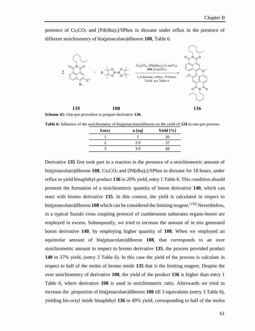
Chapter II
61
presence of Cs2CO3 and [Pd(dba)2]/SPhos in dioxane under reflux in the presence of
different stoichiometry of bis(pinacolato)diboron 108, Table 6.
Scheme 45: One-pot procedure to prepare derivative 136.
Table 6: Influence of the stoichiometry of bis(pinacolato)diboron on the yield of 124 in one-pot process.
Entry n [eq] Yield [%]
1 1 20
2 2.0 37
3 3.0 49
Derivative 135 first took part in a reaction in the presence of a stoichiometric amount of
bis(pinacolato)diboron 108, Cs2CO3 and [Pd(dba)2]/SPhos in dioxane for 18 hours, under
reflux to yield binaphthyl product 136 in 20% yield, entry 1 Table 6. This condition should
promote the formation of a stoichiometric quantity of boron derivative 140, which can
react with bromo derivative 135. In this context, the yield is calculated in respect to
bis(pinacolato)diboron 108 which can be considered the limiting reagent.[150] Nevertheless,
in a typical Suzuki cross coupling protocol of cumbersome substrates organo-boron are
employed in excess. Subsequently, we tried to increase the amount of in situ generated
boron derivative 140, by employing higher quantity of 108. When we employed an
equimolar amount of bis(pinacolato)diboron 108, that corresponds to an over
stoichiometric amount in respect to bromo derivative 135, the process provided product
140 in 37% yield, (entry 2 Table 6). In this case the yield of the process is calculate in
respect to half of the moles of bromo imide 135 that is the limiting reagent. Despite the
over stoichiometry of derivative 108, the yield of the product 136 is higher than entry 1
Table 6, where derivative 108 is used in stoichiometric ratio. Afterwards we tried to
increase the proportion of bis(pinacolato)diboron 108 till 3 equivalents (entry 3 Table 6),
yielding bis-octyl imide binaphthyl 136 in 49% yield, corresponding to half of the moles
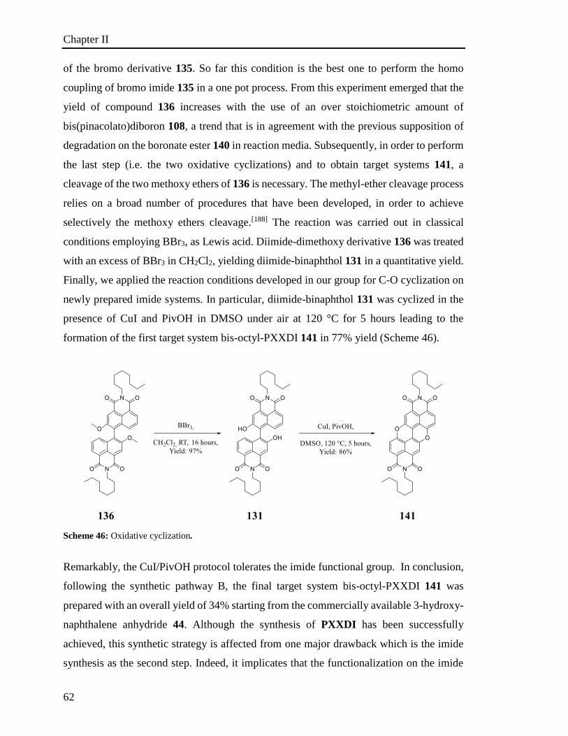
Chapter II
62
of the bromo derivative 135. So far this condition is the best one to perform the homo
coupling of bromo imide 135 in a one pot process. From this experiment emerged that the
yield of compound 136 increases with the use of an over stoichiometric amount of
bis(pinacolato)diboron 108, a trend that is in agreement with the previous supposition of
degradation on the boronate ester 140 in reaction media. Subsequently, in order to perform
the last step (i.e. the two oxidative cyclizations) and to obtain target systems 141, a
cleavage of the two methoxy ethers of 136 is necessary. The methyl-ether cleavage process
relies on a broad number of procedures that have been developed, in order to achieve
selectively the methoxy ethers cleavage.[188] The reaction was carried out in classical
conditions employing BBr3, as Lewis acid. Diimide-dimethoxy derivative 136 was treated
with an excess of BBr3 in CH2Cl2, yielding diimide-binaphthol 131 in a quantitative yield.
Finally, we applied the reaction conditions developed in our group for C-O cyclization on
newly prepared imide systems. In particular, diimide-binaphthol 131 was cyclized in the
presence of CuI and PivOH in DMSO under air at 120 °C for 5 hours leading to the
formation of the first target system bis-octyl-PXXDI 141 in 77% yield (Scheme 46).
Scheme 46: Oxidative cyclization.
Remarkably, the CuI/PivOH protocol tolerates the imide functional group. In conclusion,
following the synthetic pathway B, the final target system bis-octyl-PXXDI 141 was
prepared with an overall yield of 34% starting from the commercially available 3-hydroxy-
naphthalene anhydride 44. Although the synthesis of PXXDI has been successfully
achieved, this synthetic strategy is affected from one major drawback which is the imide
synthesis as the second step. Indeed, it implicates that the functionalization on the imide
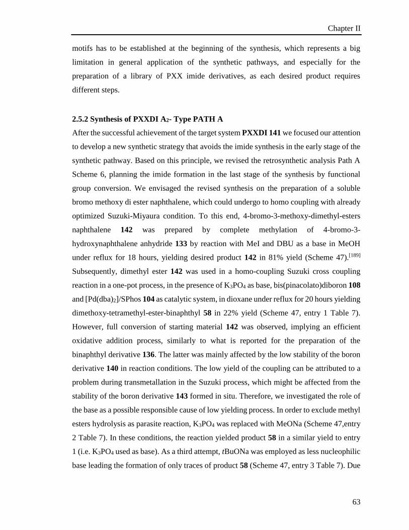
Chapter II
63
motifs has to be established at the beginning of the synthesis, which represents a big
limitation in general application of the synthetic pathways, and especially for the
preparation of a library of PXX imide derivatives, as each desired product requires
different steps.
2.5.2 Synthesis of PXXDI A2- Type PATH A
After the successful achievement of the target system PXXDI 141 we focused our attention
to develop a new synthetic strategy that avoids the imide synthesis in the early stage of the
synthetic pathway. Based on this principle, we revised the retrosynthetic analysis Path A
Scheme 6, planning the imide formation in the last stage of the synthesis by functional
group conversion. We envisaged the revised synthesis on the preparation of a soluble
bromo methoxy di ester naphthalene, which could undergo to homo coupling with already
optimized Suzuki-Miyaura condition. To this end, 4-bromo-3-methoxy-dimethyl-esters
naphthalene 142 was prepared by complete methylation of 4-bromo-3-
hydroxynaphthalene anhydride 133 by reaction with MeI and DBU as a base in MeOH
under reflux for 18 hours, yielding desired product 142 in 81% yield (Scheme 47).[189]
Subsequently, dimethyl ester 142 was used in a homo-coupling Suzuki cross coupling
reaction in a one-pot process, in the presence of K3PO4 as base, bis(pinacolato)diboron 108
and [Pd(dba)2]/SPhos 104 as catalytic system, in dioxane under reflux for 20 hours yielding
dimethoxy-tetramethyl-ester-binaphthyl 58 in 22% yield (Scheme 47, entry 1 Table 7).
However, full conversion of starting material 142 was observed, implying an efficient
oxidative addition process, similarly to what is reported for the preparation of the
binaphthyl derivative 136. The latter was mainly affected by the low stability of the boron
derivative 140 in reaction conditions. The low yield of the coupling can be attributed to a
problem during transmetallation in the Suzuki process, which might be affected from the
stability of the boron derivative 143 formed in situ. Therefore, we investigated the role of
the base as a possible responsible cause of low yielding process. In order to exclude methyl
esters hydrolysis as parasite reaction, K3PO4 was replaced with MeONa (Scheme 47,entry
2 Table 7). In these conditions, the reaction yielded product 58 in a similar yield to entry
1 (i.e. K3PO4 used as base). As a third attempt, tBuONa was employed as less nucleophilic
base leading the formation of only traces of product 58 (Scheme 47, entry 3 Table 7). Due

Chapter II
64
to the low influence of the base, we considered that the low yield of the process can be
affected by the stability of the boronic ester intermediate.
Scheme 47: Synthesis of dimethoxy-tetramethyl-ester-binaphthyl 58 one-pot procedure.
Table 7: Reaction conditions tested to prepare derivative 58.
Entry Base [3 eq] Yield [%]
1 K3PO4 22
2 MeONa 20
3 tBuONa trace
In order to study the stability of the boronic ester 143, Miyaura borylation on dimethyl
ester derivatives 142 has been investigated (Scheme 48). We first applied the best condition
previously found for the borylation of naphthalene monoimide 135 (Scheme 43, entry 5
Table 4). Performing the reaction on dimethyl ester 142 in the presence of KOAc,
bis(pinacolato)diboron 108 and [Pd(PPh3)2Cl2] in dioxane under reflux for 16 hours, we
noted the formation of the related boronic ester 143 which was surprisingly isolated by
precipitation in 78% yield (Scheme 48). Nevertheless, boronic ester derivative 143 also
exhibits a low stability on silica, feature which did not allow to follow the evolution of
reaction by TLC, as only bromo dimethyl ester derivative and relative dehalogenated
derivatives are detectable by TLC analysis. The achievement of boronic ester naphthalene
derivative 143 synthesis offers the opportunity to optimize the synthesis of the tetramethyl
ester derivative 58. To perform the Suzuki cross coupling between bromo dimethyl ester
142 and boron derivative 143, the optimised conditions of the dimethyl ester binaphthyl
derivative 51 were applied (Scheme 53). Derivative 142 and 143 were reacted in the
presence of K3PO4 as base and [Pd(dba)2]/SPhos 104 as catalytic system in dry dioxane
under reflux for 16 hours affording tetramethyl ester derivative 58 in 22% yield (Scheme
48, entry 1 Table 8). These Suzuki conditions allow us to afford desired product 58 in low
yield, comparable with the one-pot process, Scheme 47.
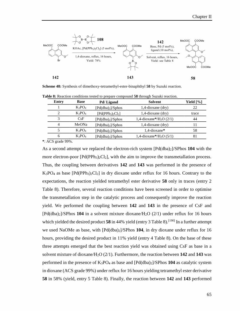
Chapter II
65
Scheme 48: Synthesis of dimethoxy-tetramethyl-ester-binaphthyl 58 by Suzuki reaction.
Table 8: Reaction conditions tested to prepare compound 58 through Suzuki reaction.
Entry Base Pd/ Ligand Solvent Yield [%]
1 K3PO4 [Pd(dba)2]/Sphos 1,4-dioxane (dry) 22
2 K3PO4 [Pd(PPh3)2Cl2] 1,4-dioxane (dry) trace
3 CsF [Pd(dba)2]/Sphos 1,4-dioxane*/H2O (2/1) 44
4 MeONa [Pd(dba)2]/Sphos 1,4-dioxane (dry) 11
5 K3PO4 [Pd(dba)2]/Sphos 1,4-dioxane* 58
6 K3PO4 [Pd(dba)2]/Sphos 1,4-dioxane*/H2O (5/1) 81
*: ACS grade 99%.
As a second attempt we replaced the electron-rich system [Pd(dba)2]/SPhos 104 with the
more electron-poor [Pd(PPh3)2Cl2], with the aim to improve the transmetallation process.
Thus, the coupling between derivatives 142 and 143 was performed in the presence of
K3PO4 as base [Pd(PPh3)2Cl2] in dry dioxane under reflux for 16 hours. Contrary to the
expectations, the reaction yielded tetramethyl ester derivative 58 only in traces (entry 2
Table 8). Therefore, several reaction conditions have been screened in order to optimise
the transmetallation step in the catalytic process and consequently improve the reaction
yield. We performed the coupling between 142 and 143 in the presence of CsF and
[Pd(dba)2]/SPhos 104 in a solvent mixture dioxane/H2O (2/1) under reflux for 16 hours
which yielded the desired product 58 in 44% yield (entry 3 Table 8).[190] In a further attempt
we used NaOMe as base, with [Pd(dba)2]/SPhos 104, in dry dioxane under reflux for 16
hours, providing the desired product in 11% yield (entry 4 Table 8). On the base of these
three attempts emerged that the best reaction yield was obtained using CsF as base in a
solvent mixture of dioxane/H2O (2/1). Furthermore, the reaction between 142 and 143 was
performed in the presence of K3PO4 as base and [Pd(dba)2]/SPhos 104 as catalytic system
in dioxane (ACS grade 99%) under reflux for 16 hours yielding tetramethyl ester derivative
58 in 58% (yield, entry 5 Table 8). Finally, the reaction between 142 and 143 performed
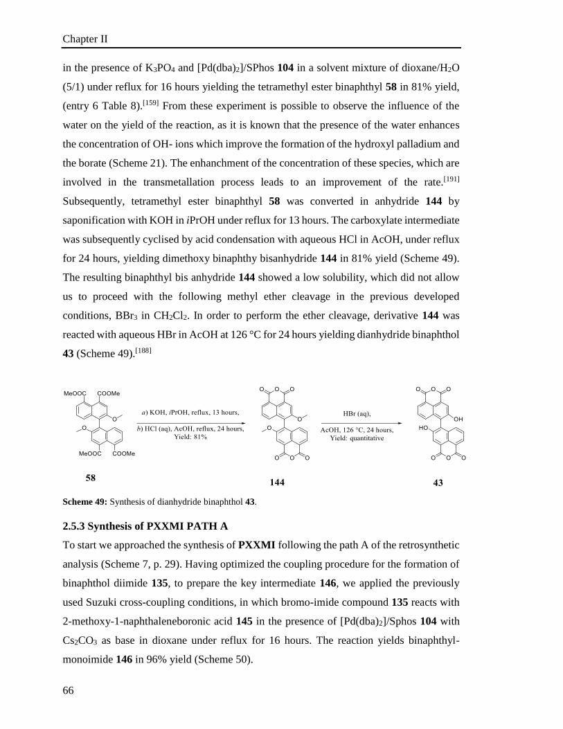
Chapter II
66
in the presence of K3PO4 and [Pd(dba)2]/SPhos 104 in a solvent mixture of dioxane/H2O
(5/1) under reflux for 16 hours yielding the tetramethyl ester binaphthyl 58 in 81% yield,
(entry 6 Table 8).[159] From these experiment is possible to observe the influence of the
water on the yield of the reaction, as it is known that the presence of the water enhances
the concentration of OH- ions which improve the formation of the hydroxyl palladium and
the borate (Scheme 21). The enhanchment of the concentration of these species, which are
involved in the transmetallation process leads to an improvement of the rate.[191]
Subsequently, tetramethyl ester binaphthyl 58 was converted in anhydride 144 by
saponification with KOH in iPrOH under reflux for 13 hours. The carboxylate intermediate
was subsequently cyclised by acid condensation with aqueous HCl in AcOH, under reflux
for 24 hours, yielding dimethoxy binaphthy bisanhydride 144 in 81% yield (Scheme 49).
The resulting binaphthyl bis anhydride 144 showed a low solubility, which did not allow
us to proceed with the following methyl ether cleavage in the previous developed
conditions, BBr3 in CH2Cl2. In order to perform the ether cleavage, derivative 144 was
reacted with aqueous HBr in AcOH at 126 °C for 24 hours yielding dianhydride binaphthol
43 (Scheme 49).[188]
Scheme 49: Synthesis of dianhydride binaphthol 43.
2.5.3 Synthesis of PXXMI PATH A
To start we approached the synthesis of PXXMI following the path A of the retrosynthetic
analysis (Scheme 7, p. 29). Having optimized the coupling procedure for the formation of
binaphthol diimide 135, to prepare the key intermediate 146, we applied the previously
used Suzuki cross-coupling conditions, in which bromo-imide compound 135 reacts with
2-methoxy-1-naphthaleneboronic acid 145 in the presence of [Pd(dba)2]/Sphos 104 with
Cs2CO3 as base in dioxane under reflux for 16 hours. The reaction yields binaphthyl-
monoimide 146 in 96% yield (Scheme 50).
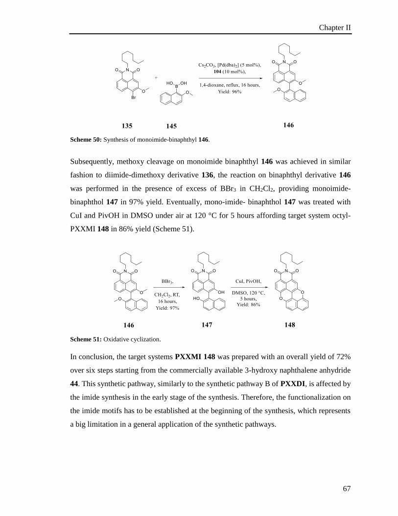
Chapter II
67
Scheme 50: Synthesis of monoimide-binaphthyl 146.
Subsequently, methoxy cleavage on monoimide binaphthyl 146 was achieved in similar
fashion to diimide-dimethoxy derivative 136, the reaction on binaphthyl derivative 146
was performed in the presence of excess of BBr3 in CH2Cl2, providing monoimide-
binaphthol 147 in 97% yield. Eventually, mono-imide- binaphthol 147 was treated with
CuI and PivOH in DMSO under air at 120 °C for 5 hours affording target system octyl-
PXXMI 148 in 86% yield (Scheme 51).
Scheme 51: Oxidative cyclization.
In conclusion, the target systems PXXMI 148 was prepared with an overall yield of 72%
over six steps starting from the commercially available 3-hydroxy naphthalene anhydride
44. This synthetic pathway, similarly to the synthetic pathway B of PXXDI, is affected by
the imide synthesis in the early stage of the synthesis. Therefore, the functionalization on
the imide motifs has to be established at the beginning of the synthesis, which represents
a big limitation in a general application of the synthetic pathways.
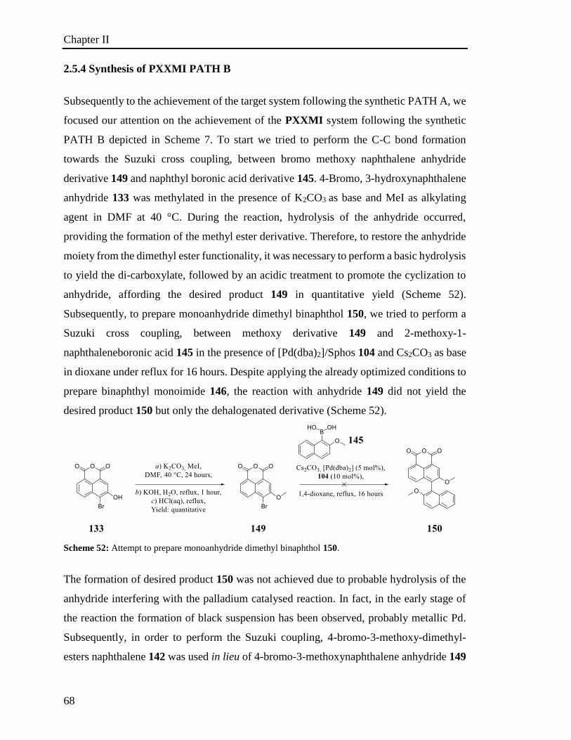
Chapter II
68
2.5.4 Synthesis of PXXMI PATH B
Subsequently to the achievement of the target system following the synthetic PATH A, we
focused our attention on the achievement of the PXXMI system following the synthetic
PATH B depicted in Scheme 7. To start we tried to perform the C-C bond formation
towards the Suzuki cross coupling, between bromo methoxy naphthalene anhydride
derivative 149 and naphthyl boronic acid derivative 145. 4-Bromo, 3-hydroxynaphthalene
anhydride 133 was methylated in the presence of K2CO3 as base and MeI as alkylating
agent in DMF at 40 °C. During the reaction, hydrolysis of the anhydride occurred,
providing the formation of the methyl ester derivative. Therefore, to restore the anhydride
moiety from the dimethyl ester functionality, it was necessary to perform a basic hydrolysis
to yield the di-carboxylate, followed by an acidic treatment to promote the cyclization to
anhydride, affording the desired product 149 in quantitative yield (Scheme 52).
Subsequently, to prepare monoanhydride dimethyl binaphthol 150, we tried to perform a
Suzuki cross coupling, between methoxy derivative 149 and 2-methoxy-1-
naphthaleneboronic acid 145 in the presence of [Pd(dba)2]/Sphos 104 and Cs2CO3 as base
in dioxane under reflux for 16 hours. Despite applying the already optimized conditions to
prepare binaphthyl monoimide 146, the reaction with anhydride 149 did not yield the
desired product 150 but only the dehalogenated derivative (Scheme 52).
Scheme 52: Attempt to prepare monoanhydride dimethyl binaphthol 150.
The formation of desired product 150 was not achieved due to probable hydrolysis of the
anhydride interfering with the palladium catalysed reaction. In fact, in the early stage of
the reaction the formation of black suspension has been observed, probably metallic Pd.
Subsequently, in order to perform the Suzuki coupling, 4-bromo-3-methoxy-dimethyl-
esters naphthalene 142 was used in lieu of 4-bromo-3-methoxynaphthalene anhydride 149
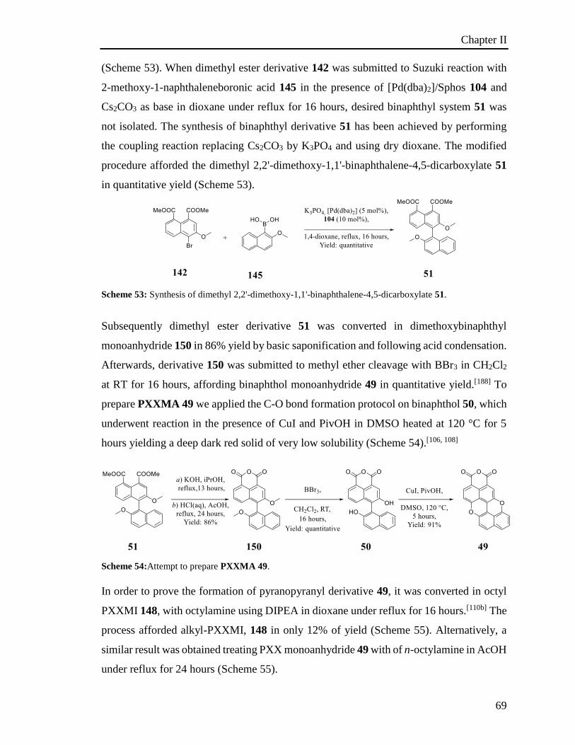
Chapter II
69
(Scheme 53). When dimethyl ester derivative 142 was submitted to Suzuki reaction with
2-methoxy-1-naphthaleneboronic acid 145 in the presence of [Pd(dba)2]/Sphos 104 and
Cs2CO3 as base in dioxane under reflux for 16 hours, desired binaphthyl system 51 was
not isolated. The synthesis of binaphthyl derivative 51 has been achieved by performing
the coupling reaction replacing Cs2CO3 by K3PO4 and using dry dioxane. The modified
procedure afforded the dimethyl 2,2'-dimethoxy-1,1'-binaphthalene-4,5-dicarboxylate 51
in quantitative yield (Scheme 53).
Scheme 53: Synthesis of dimethyl 2,2'-dimethoxy-1,1'-binaphthalene-4,5-dicarboxylate 51.
Subsequently dimethyl ester derivative 51 was converted in dimethoxybinaphthyl
monoanhydride 150 in 86% yield by basic saponification and following acid condensation.
Afterwards, derivative 150 was submitted to methyl ether cleavage with BBr3 in CH2Cl2
at RT for 16 hours, affording binaphthol monoanhydride 49 in quantitative yield.[188] To
prepare PXXMA 49 we applied the C-O bond formation protocol on binaphthol 50, which
underwent reaction in the presence of CuI and PivOH in DMSO heated at 120 °C for 5
hours yielding a deep dark red solid of very low solubility (Scheme 54).[106, 108]
Scheme 54:Attempt to prepare PXXMA 49.
In order to prove the formation of pyranopyranyl derivative 49, it was converted in octyl
PXXMI 148, with octylamine using DIPEA in dioxane under reflux for 16 hours.[110b] The
process afforded alkyl-PXXMI, 148 in only 12% of yield (Scheme 55). Alternatively, a
similar result was obtained treating PXX monoanhydride 49 with of n-octylamine in AcOH
under reflux for 24 hours (Scheme 55).
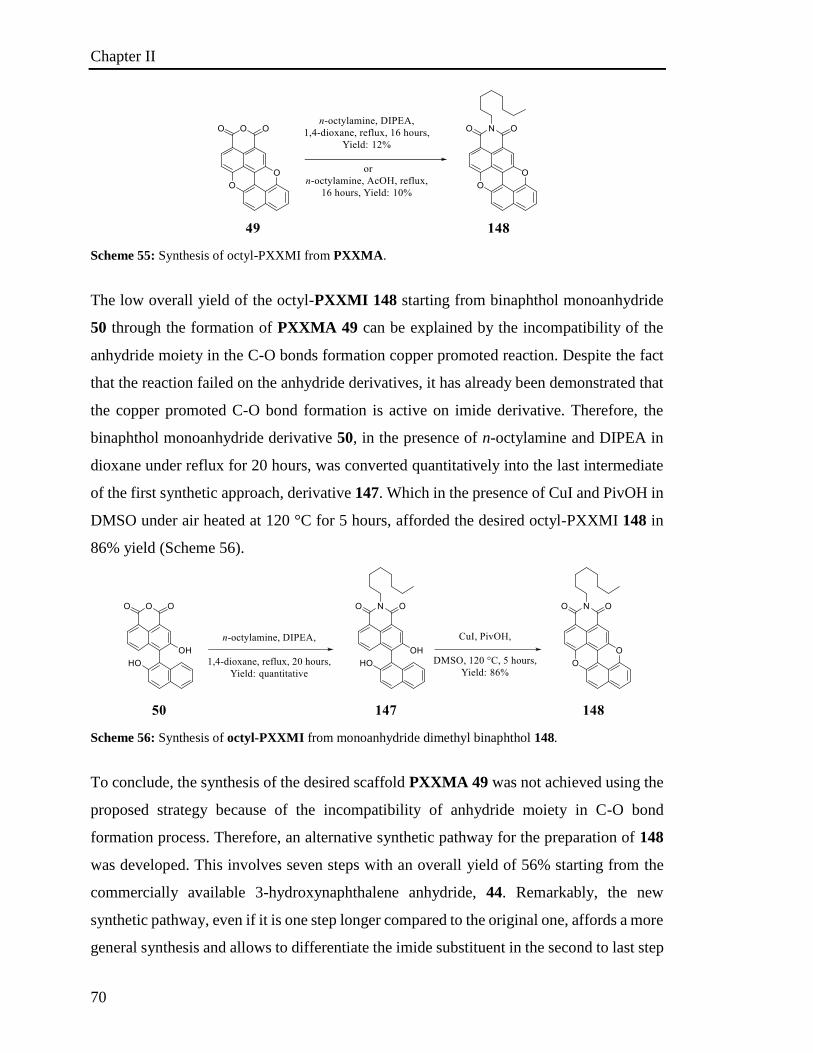
Chapter II
70
Scheme 55: Synthesis of octyl-PXXMI from PXXMA.
The low overall yield of the octyl-PXXMI 148 starting from binaphthol monoanhydride
50 through the formation of PXXMA 49 can be explained by the incompatibility of the
anhydride moiety in the C-O bonds formation copper promoted reaction. Despite the fact
that the reaction failed on the anhydride derivatives, it has already been demonstrated that
the copper promoted C-O bond formation is active on imide derivative. Therefore, the
binaphthol monoanhydride derivative 50, in the presence of n-octylamine and DIPEA in
dioxane under reflux for 20 hours, was converted quantitatively into the last intermediate
of the first synthetic approach, derivative 147. Which in the presence of CuI and PivOH in
DMSO under air heated at 120 °C for 5 hours, afforded the desired octyl-PXXMI 148 in
86% yield (Scheme 56).
Scheme 56: Synthesis of octyl-PXXMI from monoanhydride dimethyl binaphthol 148.
To conclude, the synthesis of the desired scaffold PXXMA 49 was not achieved using the
proposed strategy because of the incompatibility of anhydride moiety in C-O bond
formation process. Therefore, an alternative synthetic pathway for the preparation of 148
was developed. This involves seven steps with an overall yield of 56% starting from the
commercially available 3-hydroxynaphthalene anhydride, 44. Remarkably, the new
synthetic pathway, even if it is one step longer compared to the original one, affords a more
general synthesis and allows to differentiate the imide substituent in the second to last step
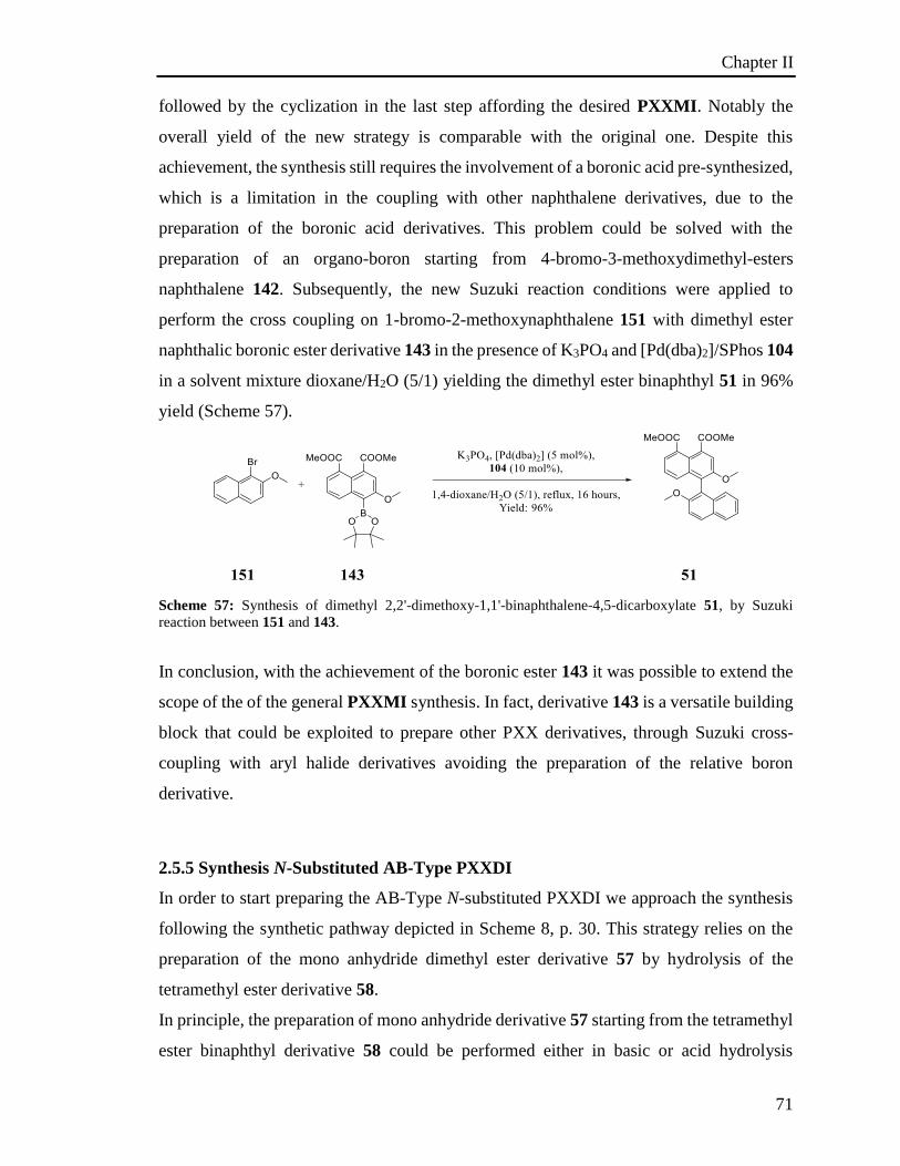
Chapter II
71
followed by the cyclization in the last step affording the desired PXXMI. Notably the
overall yield of the new strategy is comparable with the original one. Despite this
achievement, the synthesis still requires the involvement of a boronic acid pre-synthesized,
which is a limitation in the coupling with other naphthalene derivatives, due to the
preparation of the boronic acid derivatives. This problem could be solved with the
preparation of an organo-boron starting from 4-bromo-3-methoxydimethyl-esters
naphthalene 142. Subsequently, the new Suzuki reaction conditions were applied to
perform the cross coupling on 1-bromo-2-methoxynaphthalene 151 with dimethyl ester
naphthalic boronic ester derivative 143 in the presence of K3PO4 and [Pd(dba)2]/SPhos 104
in a solvent mixture dioxane/H2O (5/1) yielding the dimethyl ester binaphthyl 51 in 96%
yield (Scheme 57).
Scheme 57: Synthesis of dimethyl 2,2'-dimethoxy-1,1'-binaphthalene-4,5-dicarboxylate 51, by Suzuki
reaction between 151 and 143.
In conclusion, with the achievement of the boronic ester 143 it was possible to extend the
scope of the of the general PXXMI synthesis. In fact, derivative 143 is a versatile building
block that could be exploited to prepare other PXX derivatives, through Suzuki cross-
coupling with aryl halide derivatives avoiding the preparation of the relative boron
derivative.
2.5.5 Synthesis N-Substituted AB-Type PXXDI
In order to start preparing the AB-Type N-substituted PXXDI we approach the synthesis
following the synthetic pathway depicted in Scheme 8, p. 30. This strategy relies on the
preparation of the mono anhydride dimethyl ester derivative 57 by hydrolysis of the
tetramethyl ester derivative 58.
In principle, the preparation of mono anhydride derivative 57 starting from the tetramethyl
ester binaphthyl derivative 58 could be performed either in basic or acid hydrolysis
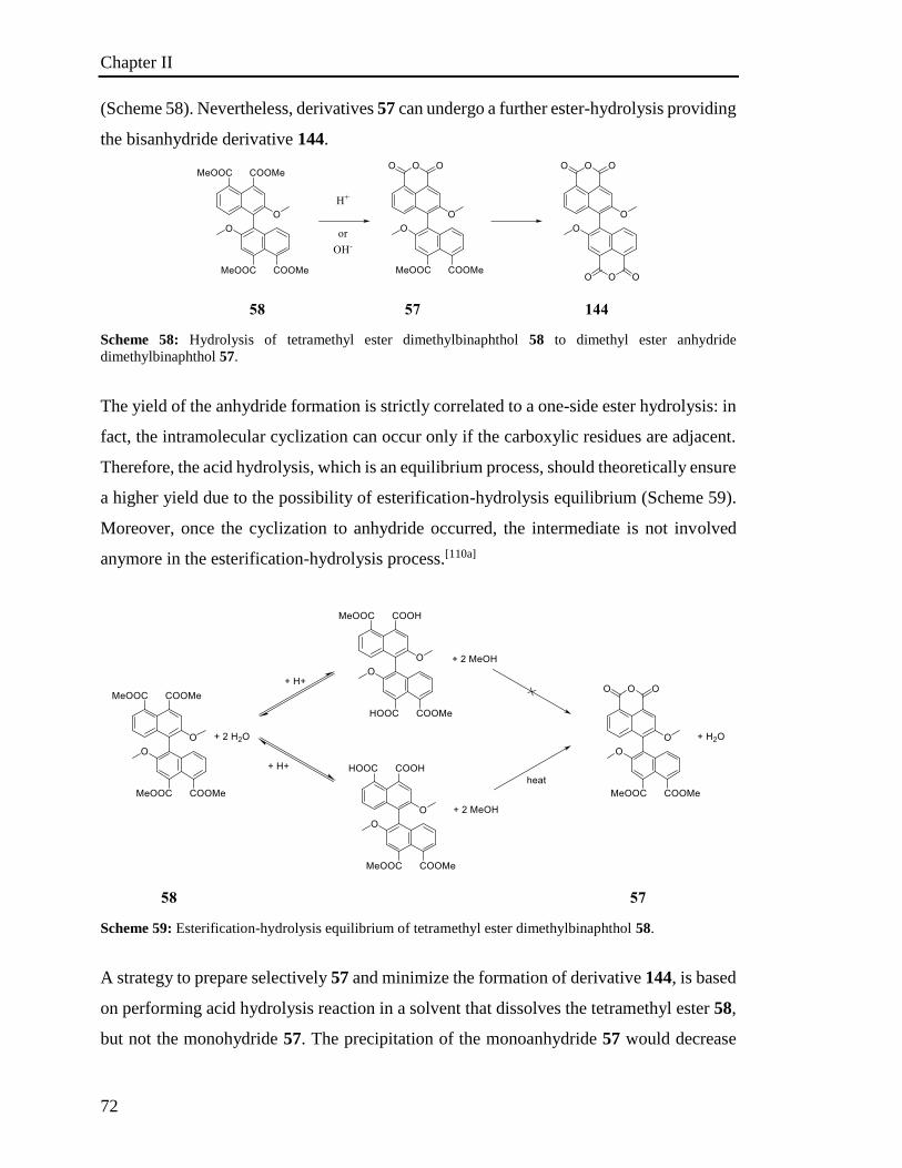
Chapter II
72
(Scheme 58). Nevertheless, derivatives 57 can undergo a further ester-hydrolysis providing
the bisanhydride derivative 144.
Scheme 58: Hydrolysis of tetramethyl ester dimethylbinaphthol 58 to dimethyl ester anhydride
dimethylbinaphthol 57.
The yield of the anhydride formation is strictly correlated to a one-side ester hydrolysis: in
fact, the intramolecular cyclization can occur only if the carboxylic residues are adjacent.
Therefore, the acid hydrolysis, which is an equilibrium process, should theoretically ensure
a higher yield due to the possibility of esterification-hydrolysis equilibrium (Scheme 59).
Moreover, once the cyclization to anhydride occurred, the intermediate is not involved
anymore in the esterification-hydrolysis process.[110a]
Scheme 59: Esterification-hydrolysis equilibrium of tetramethyl ester dimethylbinaphthol 58.
A strategy to prepare selectively 57 and minimize the formation of derivative 144, is based
on performing acid hydrolysis reaction in a solvent that dissolves the tetramethyl ester 58,
but not the monohydride 57. The precipitation of the monoanhydride 57 would decrease
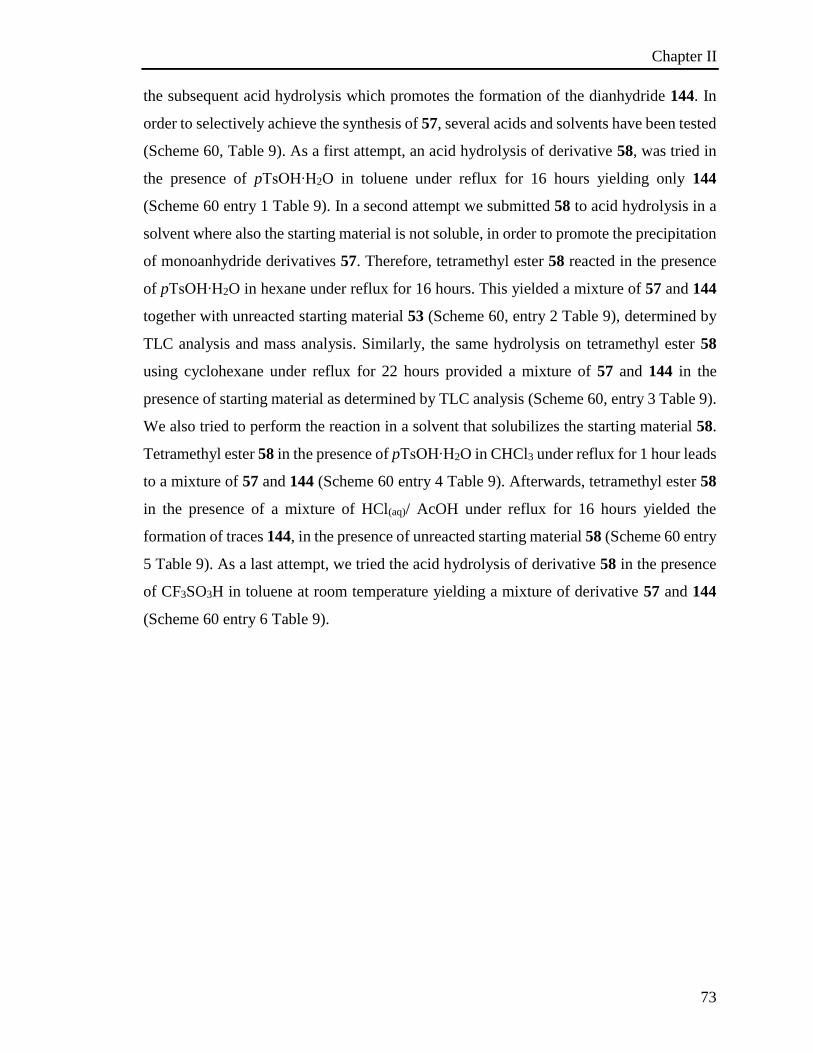
Chapter II
73
the subsequent acid hydrolysis which promotes the formation of the dianhydride 144. In
order to selectively achieve the synthesis of 57, several acids and solvents have been tested
(Scheme 60, Table 9). As a first attempt, an acid hydrolysis of derivative 58, was tried in
the presence of pTsOH∙H2O in toluene under reflux for 16 hours yielding only 144
(Scheme 60 entry 1 Table 9). In a second attempt we submitted 58 to acid hydrolysis in a
solvent where also the starting material is not soluble, in order to promote the precipitation
of monoanhydride derivatives 57. Therefore, tetramethyl ester 58 reacted in the presence
of pTsOH∙H2O in hexane under reflux for 16 hours. This yielded a mixture of 57 and 144
together with unreacted starting material 53 (Scheme 60, entry 2 Table 9), determined by
TLC analysis and mass analysis. Similarly, the same hydrolysis on tetramethyl ester 58
using cyclohexane under reflux for 22 hours provided a mixture of 57 and 144 in the
presence of starting material as determined by TLC analysis (Scheme 60, entry 3 Table 9).
We also tried to perform the reaction in a solvent that solubilizes the starting material 58.
Tetramethyl ester 58 in the presence of pTsOH∙H2O in CHCl3 under reflux for 1 hour leads
to a mixture of 57 and 144 (Scheme 60 entry 4 Table 9). Afterwards, tetramethyl ester 58
in the presence of a mixture of HCl(aq)/ AcOH under reflux for 16 hours yielded the
formation of traces 144, in the presence of unreacted starting material 58 (Scheme 60 entry
5 Table 9). As a last attempt, we tried the acid hydrolysis of derivative 58 in the presence
of CF3SO3H in toluene at room temperature yielding a mixture of derivative 57 and 144
(Scheme 60 entry 6 Table 9).
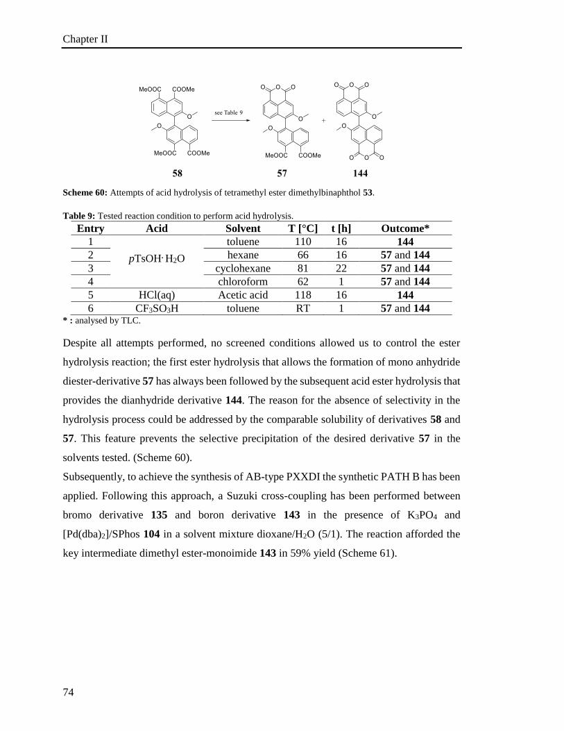
Chapter II
74
Scheme 60: Attempts of acid hydrolysis of tetramethyl ester dimethylbinaphthol 53.
Table 9: Tested reaction condition to perform acid hydrolysis.
Entry Acid Solvent T [°C] t [h] Outcome*
1
pTsOH. H2O
toluene 110 16 144
2 hexane 66 16 57 and 144
3 cyclohexane 81 22 57 and 144
4 chloroform 62 1 57 and 144
5 HCl(aq) Acetic acid 118 16 144
6 CF3SO3H toluene RT 1 57 and 144 * : analysed by TLC.
Despite all attempts performed, no screened conditions allowed us to control the ester
hydrolysis reaction; the first ester hydrolysis that allows the formation of mono anhydride
diester-derivative 57 has always been followed by the subsequent acid ester hydrolysis that
provides the dianhydride derivative 144. The reason for the absence of selectivity in the
hydrolysis process could be addressed by the comparable solubility of derivatives 58 and
57. This feature prevents the selective precipitation of the desired derivative 57 in the
solvents tested. (Scheme 60).
Subsequently, to achieve the synthesis of AB-type PXXDI the synthetic PATH B has been
applied. Following this approach, a Suzuki cross-coupling has been performed between
bromo derivative 135 and boron derivative 143 in the presence of K3PO4 and
[Pd(dba)2]/SPhos 104 in a solvent mixture dioxane/H2O (5/1). The reaction afforded the
key intermediate dimethyl ester-monoimide 143 in 59% yield (Scheme 61).
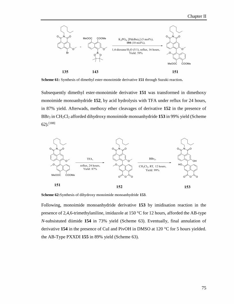
Chapter II
75
Scheme 61: Synthesis of dimethyl ester-monoimide derivative 151 through Suzuki reaction.
Subsequently dimethyl ester-monoimide derivative 151 was transformed in dimethoxy
monoimide monoanhydride 152, by acid hydrolysis with TFA under reflux for 24 hours,
in 87% yield. Afterwads, methoxy ether cleavages of derivative 152 in the presence of
BBr3 in CH2Cl2 afforded dihydroxy monoimide monoanhydride 153 in 99% yield (Scheme
62).[188]
Scheme 62:Synthesis of dihydroxy monoimide monoanhydride 153.
Following, monoimide monoanhydride derivative 153 by imidisation reaction in the
presence of 2,4,6-trimethylaniline, imidazole at 150 °C for 12 hours, afforded the AB-type
N-subsistuted diimide 154 in 73% yield (Scheme 63). Eventually, final annulation of
derivative 154 in the presence of CuI and PivOH in DMSO at 120 °C for 5 hours yielded.
the AB-Type PXXDI 155 in 89% yield (Scheme 63).
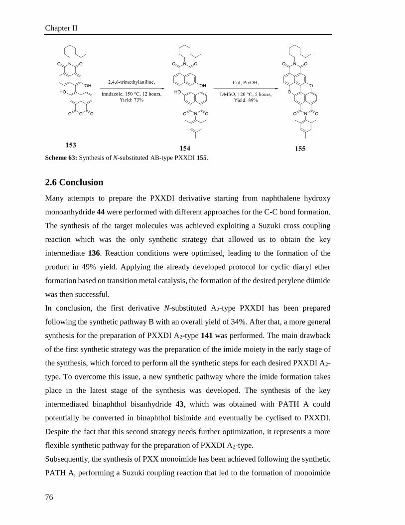
Chapter II
76
Scheme 63: Synthesis of N-substituted AB-type PXXDI 155.
2.6 Conclusion
Many attempts to prepare the PXXDI derivative starting from naphthalene hydroxy
monoanhydride 44 were performed with different approaches for the C-C bond formation.
The synthesis of the target molecules was achieved exploiting a Suzuki cross coupling
reaction which was the only synthetic strategy that allowed us to obtain the key
intermediate 136. Reaction conditions were optimised, leading to the formation of the
product in 49% yield. Applying the already developed protocol for cyclic diaryl ether
formation based on transition metal catalysis, the formation of the desired perylene diimide
was then successful.
In conclusion, the first derivative N-substituted A2-type PXXDI has been prepared
following the synthetic pathway B with an overall yield of 34%. After that, a more general
synthesis for the preparation of PXXDI A2-type 141 was performed. The main drawback
of the first synthetic strategy was the preparation of the imide moiety in the early stage of
the synthesis, which forced to perform all the synthetic steps for each desired PXXDI A2-
type. To overcome this issue, a new synthetic pathway where the imide formation takes
place in the latest stage of the synthesis was developed. The synthesis of the key
intermediated binaphthol bisanhydride 43, which was obtained with PATH A could
potentially be converted in binaphthol bisimide and eventually be cyclised to PXXDI.
Despite the fact that this second strategy needs further optimization, it represents a more
flexible synthetic pathway for the preparation of PXXDI A2-type.
Subsequently, the synthesis of PXX monoimide has been achieved following the synthetic
PATH A, performing a Suzuki coupling reaction that led to the formation of monoimide
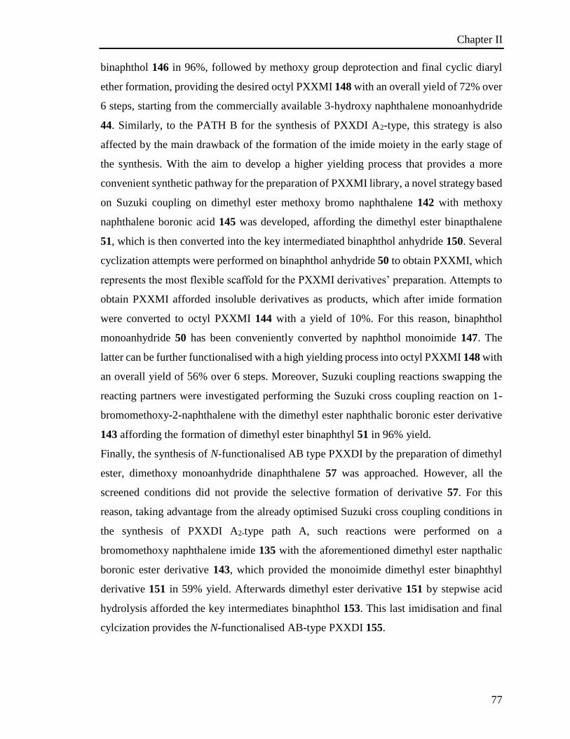
Chapter II
77
binaphthol 146 in 96%, followed by methoxy group deprotection and final cyclic diaryl
ether formation, providing the desired octyl PXXMI 148 with an overall yield of 72% over
6 steps, starting from the commercially available 3-hydroxy naphthalene monoanhydride
44. Similarly, to the PATH B for the synthesis of PXXDI A2-type, this strategy is also
affected by the main drawback of the formation of the imide moiety in the early stage of
the synthesis. With the aim to develop a higher yielding process that provides a more
convenient synthetic pathway for the preparation of PXXMI library, a novel strategy based
on Suzuki coupling on dimethyl ester methoxy bromo naphthalene 142 with methoxy
naphthalene boronic acid 145 was developed, affording the dimethyl ester binapthalene
51, which is then converted into the key intermediated binaphthol anhydride 150. Several
cyclization attempts were performed on binaphthol anhydride 50 to obtain PXXMI, which
represents the most flexible scaffold for the PXXMI derivatives’ preparation. Attempts to
obtain PXXMI afforded insoluble derivatives as products, which after imide formation
were converted to octyl PXXMI 144 with a yield of 10%. For this reason, binaphthol
monoanhydride 50 has been conveniently converted by naphthol monoimide 147. The
latter can be further functionalised with a high yielding process into octyl PXXMI 148 with
an overall yield of 56% over 6 steps. Moreover, Suzuki coupling reactions swapping the
reacting partners were investigated performing the Suzuki cross coupling reaction on 1-
bromomethoxy-2-naphthalene with the dimethyl ester naphthalic boronic ester derivative
143 affording the formation of dimethyl ester binaphthyl 51 in 96% yield.
Finally, the synthesis of N-functionalised AB type PXXDI by the preparation of dimethyl
ester, dimethoxy monoanhydride dinaphthalene 57 was approached. However, all the
screened conditions did not provide the selective formation of derivative 57. For this
reason, taking advantage from the already optimised Suzuki cross coupling conditions in
the synthesis of PXXDI A2-type path A, such reactions were performed on a
bromomethoxy naphthalene imide 135 with the aforementioned dimethyl ester napthalic
boronic ester derivative 143, which provided the monoimide dimethyl ester binaphthyl
derivative 151 in 59% yield. Afterwards dimethyl ester derivative 151 by stepwise acid
hydrolysis afforded the key intermediates binaphthol 153. This last imidisation and final
cylcization provides the N-functionalised AB-type PXXDI 155.
Chapter III
78
Chapter 3. Study of the photoredox properties
3.1 Overview
The chapter is divided into 4 sections: i) section 3.1. introduces the basic principles of
photoredox catalysis; ii) section 3.2 studies the optoelectronic properties of PXX
derivatives; iii) in section 3.3 the application of PXXs as photocatalytic agents are
explored; iv) finally section 3.4 presents the investigation on the photocatalytic mechanism
of PXX derivatives.
The results reported in this chapter are obtained in collaboration with Dr. Andrea Fermi,
Dr. Joseph M. Beames and Mr. Tommaso Battisti from Cardiff University for UV/vis
absorption and emission spectroscopy investigations, Dr. Andrea Folli and Prof. Damien
M. Murphy from Cardiff University for EPR investigations.
Part of the results reported in this chapter have been published in Chemistry A European
Journal. 2018, 24, 4382-4389.[109]
Chapter III
79
3.2 Excited states
An electronic state comprises of a set of closely spaced vibrational energy levels. In the
electronic ground state as well as in the excited states, all molecules display a variety of
nuclear geometries resulting from bond stretches or deformations, each of which
corresponds to a unique vibrational frequency. The lowest vibrational frequency level,
called the zero-point level, is normally populated. Photoexcited states are generally the
result of a transition from the lowest vibrational level of the electronic ground state to a
higher-energy electronic level via a vertical transition (Franck-Condon principle).
An excited state is rich in energy and corresponds to a reactive species. It can be defined
as a singleta (Si) or tripletb (Ti) according to its spin multiplicity. After initial population
of higher excited singlet states, the system often relaxes rapidly (10-11 – 10-13 s) to the
lowest energy excited state, which is a “stable’’ excited state that can undergo a
photochemical reaction.
In view of the matters treated in this section, a concise discussion of the various possible
relaxation pathways follows. Excited state relaxation pathways can be classified in two
main categories, i) radiative (i.e., transitions from higher-energy to lower-energy states
with emission of light) and ii) non-radiative (i.e., transitions from higher-energy to lower-
energy states with release of translational, vibrational, and rotational energy). Fluorescence
is a radiative relaxation pathway consisting of the emission of light related to a transition
from the lowest vibrational level of an electronic excited singlet state to any of the
vibrational levels of the electronic ground state. Phosphorescence is another radiative
pathway that consists of an emission of a photon accompanying a transition between two
states of different multiplicity, for example, between T1 and S0. Due to the fast relaxation
of the vibrational excited states, both types of emission always originate from the lowest
vibrational level of the excited states. Both emission processes are identified by a rate
constant (ki), by the energy of the released photons (hni), and by a quantum yield (fi)
a A singlet state (Si, with i indicating the labelling of the excited state) is, by definition, an electronic state in
which the spins of the electrons are antiparallel or paired. "Singlet" designates the multiplicity of the state
which is given in general by the well-known equation:
m = 2S + 1 (3.1)
where m is the multiplicity and S the total spin of all electrons. For example, for a molecule in the ground-
state, with only paired electrons, S = 0 and m = 1. b A triplet state (Ti) is an electronic state in which the spins of two electrons are parallel.

Chapter III
80
defined as the ratio between the number of photons emitted and the number of photons
absorbed. If the ground state and excited state have identical multiplicity and if the
vibrational levels of the two states are similar in energy, the fluorescence spectrum
corresponds to the mirror image of the absorption spectrum. However, the emitted
radiation is usually lower in energy than that of the excited state and, therefore, the
emission spectra are slightly shifted towards lower energies in comparison to the
absorption spectra. The difference between emission and absorption wavelength is called
Stokes shift and it provides an indication for the structural distortion between the ground
and the excited state. Phosphorescence spectra are further shifted in comparison to
fluorescence spectra due to the fact that the energy of the triplet state is generally lower
than that of the corresponding excited singlet state. The lifetimes are also quite different:
the fluorescence lifetimesc are rather short (10-10-10-6 s) whereas the phosphorescence
lifetimes are comparatively long, ranging from 10-6 to 10 s.
3.2.1 Quenching pathways
In addition to the radiative and non-radiative transitions described in the previous section
(3.2), the excited states can participate in numerous other inter- and intramolecular
reactions. These processes include i) addition reactions in which the excited state species
combine with a ground state molecule to form a stable product; ii) hydrogen abstraction;
iii) energy transfer (EnT) whereby energy is transferred from the excited state to the ground
state of another species; iv) electron transfer (ET) in which the excited state species act as
an electron donor or acceptor in its interaction with species that are ground state.
Energy and electron transfer, generically called quenching mechanisms, are deactivation
pathways taken by an excited species and involving an external component (quencher),
which can be supramolecularly or covalently attached via a rigid or flexible spacer. The
characteristics of the excited state and its decay pathways can be selectively tuned as a
c The lifetime of an excited state is, by definition, the time necessary for the concentration of the excited
state species to diminish to 1/e of its initial value as a result of the deactivation process. The decrease of the
concentration of the excited state (ES) species over time is given by equation 3.3:
– d[ES] / dt = ki[ES] (3.2)
where [ES] is the concentration of the ES species at time t and ki is the first-order rate constant of the
deactivation process i. The lifetime is thus given by equation 3.3:
1 / ki (3.3)
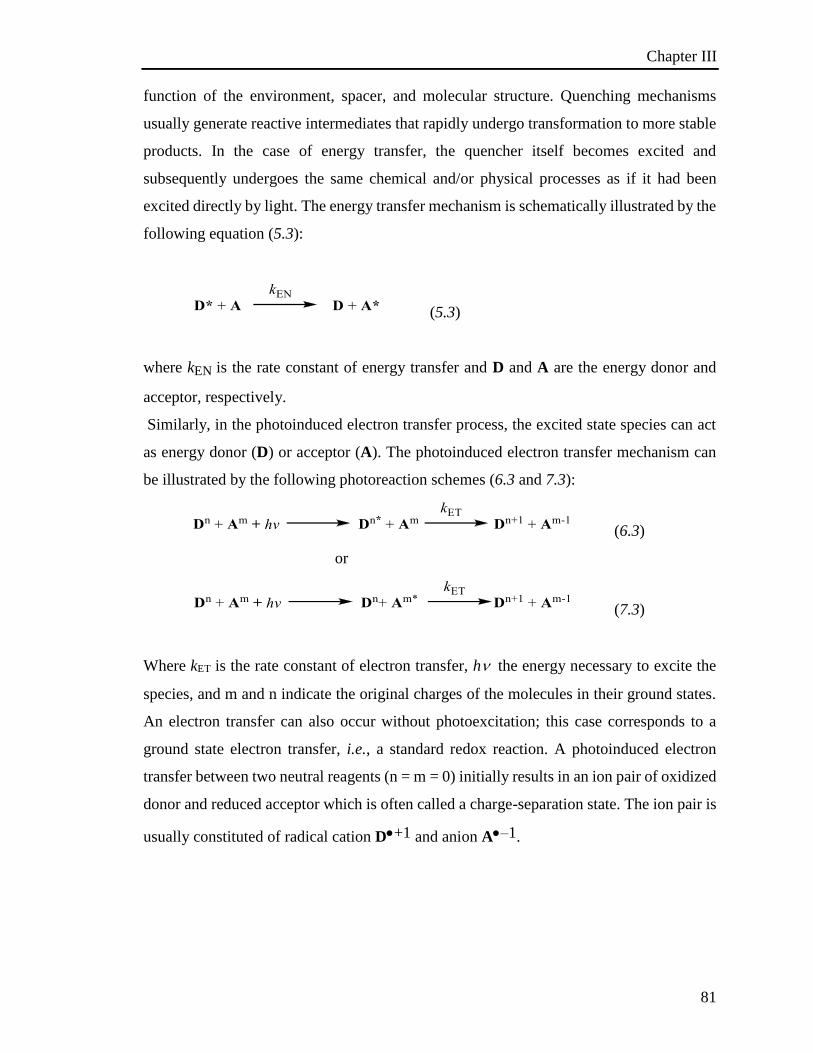
Chapter III
81
function of the environment, spacer, and molecular structure. Quenching mechanisms
usually generate reactive intermediates that rapidly undergo transformation to more stable
products. In the case of energy transfer, the quencher itself becomes excited and
subsequently undergoes the same chemical and/or physical processes as if it had been
excited directly by light. The energy transfer mechanism is schematically illustrated by the
following equation (5.3):
(5.3)
where kEN is the rate constant of energy transfer and D and A are the energy donor and
acceptor, respectively.
Similarly, in the photoinduced electron transfer process, the excited state species can act
as energy donor (D) or acceptor (A). The photoinduced electron transfer mechanism can
be illustrated by the following photoreaction schemes (6.3 and 7.3):
(6.3)
or
(7.3)
Where kET is the rate constant of electron transfer, h the energy necessary to excite the
species, and m and n indicate the original charges of the molecules in their ground states.
An electron transfer can also occur without photoexcitation; this case corresponds to a
ground state electron transfer, i.e., a standard redox reaction. A photoinduced electron
transfer between two neutral reagents (n = m = 0) initially results in an ion pair of oxidized
donor and reduced acceptor which is often called a charge-separation state. The ion pair is
usually constituted of radical cation D+1 and anion A–1.
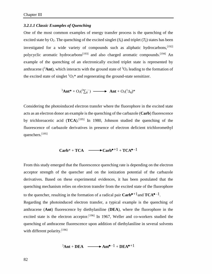
Chapter III
82
3.2.1.1 Classic Examples of Quenching
One of the most common examples of energy transfer process is the quenching of the
excited state by O2. The quenching of the excited singlet (Si) and triplet (Ti) states has been
investigated for a wide variety of compounds such as aliphatic hydrocarbons,[192]
polycyclic aromatic hydrocarbons[193] and also charged aromatic compounds.[194] An
example of the quenching of an electronically excited triplet state is represented by
anthracene (3Ant), which interacts with the ground state of 3O2 leading to the formation of
the excited state of singlet 1O2* and regenerating the ground-state sensitizer.
3Ant* + O2(3∑g
- Ant + O2(1g)*
Considering the photoinduced electron transfer where the fluorophore in the excited state
acts as an electron donor an example is the quenching of the carbazole (Carb) fluorescence
by trichloroacetic acid (TCA).[195] In 1980, Johnson studied the quenching of the
fluorescence of carbazole derivatives in presence of electron deficient trichloromethyl
quenchers.[195]
Carb* + TCA Carb+1 + TCA–1
From this study emerged that the fluorescence quenching rate is depending on the electron
acceptor strength of the quencher and on the ionization potential of the carbazole
derivatives. Based on these experimental evidences, it has been postulated that the
quenching mechanism relies on electron transfer from the excited state of the fluorophore
to the quencher, resulting in the formation of a radical pair Carb+1and TCA–1.
Regarding the photoinduced electron transfer, a typical example is the quenching of
anthracene (Ant) fluorescence by diethylaniline (DEA), where the fluorophore in the
excited state is the electron acceptor.[196] In 1967, Weller and co-workers studied the
quenching of anthracene fluorescence upon addition of diethylaniline in several solvents
with different polarity.[196]
3Ant + DEAAnt–1 + DEA+1
Chapter III
83
Transient absorption spectroscopy showed that in polar solvents occurs the formation of
the radical pair Ant–1 and DEA+1. The authors postulated the formation of a solvent
shared ion pair, in which the non-fluorescent radical ions are solvated. The solvation of the
radical ion pair is strongly dependent on the solvent polarity; the increase of the dielectric
constant of the solvent leads to an enhancement of the stabilisation of the radical ion pair.
3.2.2 Stern-Volmer equation
Fluorescence quenching refers to any process that decreases the intensity of fluorescence;
typical molecular interactions that induce quenching are excited-state reactions, molecular
rearrangements energy transfer, ground state complex interaction and collisional
quenching. When a quenching occurs, the concentration of the excited state is reduced
more rapidly than if the quencher Q was not present. Subsequently, the fluorescence, which
depends on the concentration of the excited state, decreases. So, in addition to the
intramolecular process of decay of the excited state M*, a bimolecular process between
M* and the quencher Q has to be considered. The rates of the processes are described as:
Rate
M 1M* Iabs
1M*M + hvf, kf[1M*]
1M*3M* + heat kisc[1M*]
1M*M + heat kic[1M*]
M*+ Q Q quenching kq[1M*] [Q]
Among the quenching processes, we can mention the collisional quenching. This process
takes place when a molecule in the excited state M* is deactivated by contact with another
molecule in solution, which is called the quencher (Q). The deactivation of M* occurs
during a diffusive encounter with the quencher.
The collisional quenching is described by the Stern Volmer equation: 𝐹0𝐹= 1 + 𝐾[𝑄] = 1 + 𝑘q𝜏0[𝑄]
where K is the Stern-Volmer quenching constant, kq is the bimolecular quenching constant,
0 is the lifetime in absence of quencher and [Q] is the concentration of the quencher. F0 is
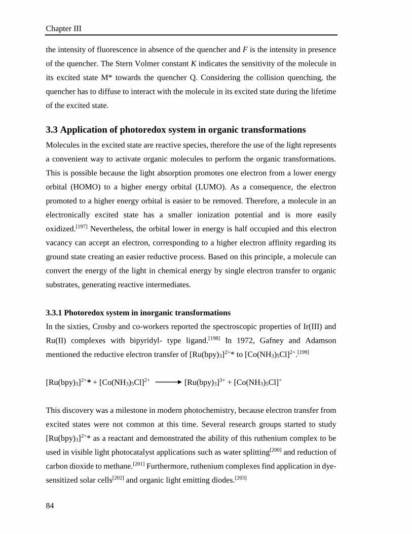
Chapter III
84
the intensity of fluorescence in absence of the quencher and F is the intensity in presence
of the quencher. The Stern Volmer constant K indicates the sensitivity of the molecule in
its excited state M* towards the quencher Q. Considering the collision quenching, the
quencher has to diffuse to interact with the molecule in its excited state during the lifetime
of the excited state.
3.3 Application of photoredox system in organic transformations
Molecules in the excited state are reactive species, therefore the use of the light represents
a convenient way to activate organic molecules to perform the organic transformations.
This is possible because the light absorption promotes one electron from a lower energy
orbital (HOMO) to a higher energy orbital (LUMO). As a consequence, the electron
promoted to a higher energy orbital is easier to be removed. Therefore, a molecule in an
electronically excited state has a smaller ionization potential and is more easily
oxidized.[197] Nevertheless, the orbital lower in energy is half occupied and this electron
vacancy can accept an electron, corresponding to a higher electron affinity regarding its
ground state creating an easier reductive process. Based on this principle, a molecule can
convert the energy of the light in chemical energy by single electron transfer to organic
substrates, generating reactive intermediates.
3.3.1 Photoredox system in inorganic transformations
In the sixties, Crosby and co-workers reported the spectroscopic properties of Ir(III) and
Ru(II) complexes with bipyridyl- type ligand.[198] In 1972, Gafney and Adamson
mentioned the reductive electron transfer of [Ru(bpy)3]2+* to [Co(NH3)5Cl]2+.[199]
[Ru(bpy)3]2+* + [Co(NH3)5Cl]2+ [Ru(bpy)3]
3+ + [Co(NH3)5Cl]+
This discovery was a milestone in modern photochemistry, because electron transfer from
excited states were not common at this time. Several research groups started to study
[Ru(bpy)3]2+* as a reactant and demonstrated the ability of this ruthenium complex to be
used in visible light photocatalyst applications such as water splitting[200] and reduction of
carbon dioxide to methane.[201] Furthermore, ruthenium complexes find application in dye-
sensitized solar cells[202] and organic light emitting diodes.[203]
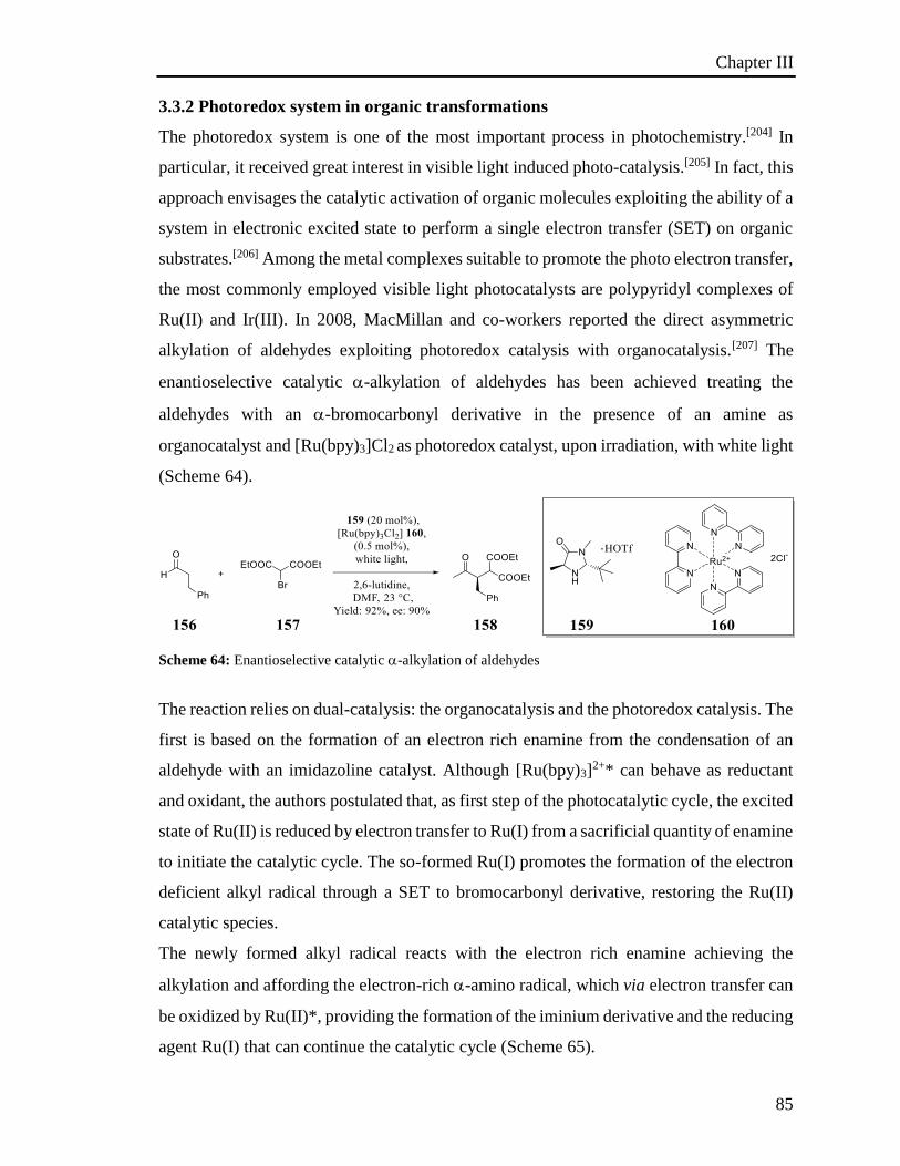
Chapter III
85
3.3.2 Photoredox system in organic transformations
The photoredox system is one of the most important process in photochemistry.[204] In
particular, it received great interest in visible light induced photo-catalysis.[205] In fact, this
approach envisages the catalytic activation of organic molecules exploiting the ability of a
system in electronic excited state to perform a single electron transfer (SET) on organic
substrates.[206] Among the metal complexes suitable to promote the photo electron transfer,
the most commonly employed visible light photocatalysts are polypyridyl complexes of
Ru(II) and Ir(III). In 2008, MacMillan and co-workers reported the direct asymmetric
alkylation of aldehydes exploiting photoredox catalysis with organocatalysis.[207] The
enantioselective catalytic -alkylation of aldehydes has been achieved treating the
aldehydes with an -bromocarbonyl derivative in the presence of an amine as
organocatalyst and [Ru(bpy)3]Cl2 as photoredox catalyst, upon irradiation, with white light
(Scheme 64).
Scheme 64: Enantioselective catalytic -alkylation of aldehydes
The reaction relies on dual-catalysis: the organocatalysis and the photoredox catalysis. The
first is based on the formation of an electron rich enamine from the condensation of an
aldehyde with an imidazoline catalyst. Although [Ru(bpy)3]2+* can behave as reductant
and oxidant, the authors postulated that, as first step of the photocatalytic cycle, the excited
state of Ru(II) is reduced by electron transfer to Ru(I) from a sacrificial quantity of enamine
to initiate the catalytic cycle. The so-formed Ru(I) promotes the formation of the electron
deficient alkyl radical through a SET to bromocarbonyl derivative, restoring the Ru(II)
catalytic species.
The newly formed alkyl radical reacts with the electron rich enamine achieving the
alkylation and affording the electron-rich -amino radical, which via electron transfer can
be oxidized by Ru(II)*, providing the formation of the iminium derivative and the reducing
agent Ru(I) that can continue the catalytic cycle (Scheme 65).
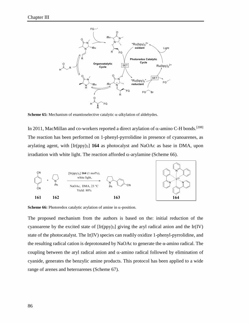
Chapter III
86
Scheme 65: Mechanism of enantioselective catalytic -alkylation of aldehydes.
In 2011, MacMillan and co-workers reported a direct arylation of -amino C-H bonds.[208]
The reaction has been performed on 1-phenyl-pyrrolidine in presence of cyanoarenes, as
arylating agent, with [Ir(ppy)3] 164 as photocalyst and NaOAc as base in DMA, upon
irradiation with white light. The reaction afforded -arylamine (Scheme 66).
Scheme 66: Photoredox catalytic arylation of amine in -position.
The proposed mechanism from the authors is based on the: initial reduction of the
cyanoarene by the excited state of [Ir(ppy)3] giving the aryl radical anion and the Ir(IV)
state of the photocatalyst. The Ir(IV) species can readily oxidize 1-phenyl-pyrrolidine, and
the resulting radical cation is deprotonated by NaOAc to generate the α-amino radical. The
coupling between the aryl radical anion and -amino radical followed by elimination of
cyanide, generates the benzylic amine products. This protocol has been applied to a wide
range of arenes and heteroarenes (Scheme 67).

Chapter III
87
Scheme 67: Mechanism of photoredox catalytic arylation of amine in -position.
Photoredox chemistry of transition metal complexes has been widely studied until today,
with the most outstanding examples being Ru and Ir complexes. However, these complexes
are based on rare and toxic metals so alternative photoinitiators have been explored.
Consequently, organic chromophores have already been studied to promote photoinduced
electron transfer (PET), but they have been exploited as photocatalytic agents only
recently. The main advantage of organic photocatalysts over their transition metal
counterparts is the variety of systems that can be exploited as photoredox catalysts, such
as pyryliums, acridiniums, xanthenes, thiazenes and perylene diimide.[204a] Morever the
chemical functionalization of those systems allows tuning of the redox properties of the
photocatalyst.[209]
In 2015, Kӧnig and co-workers reported the reductive photodehalogenation on activated
aryl-halides (-I; -Br and -Cl) and also arylation of methylpyrrole in -position exploiting
commercially available perylene diimide (PDI) 168 as photocatalyst (Scheme 68).[210]
Scheme 68: Organo photoredox catalytic arylation of methyl pyrrole in -position.
The proposed mechanism is based on two photoinduced electron transfers: the excited state
of the PDI* 168 is at first reductively quenched by Et3N yielding the formation of the
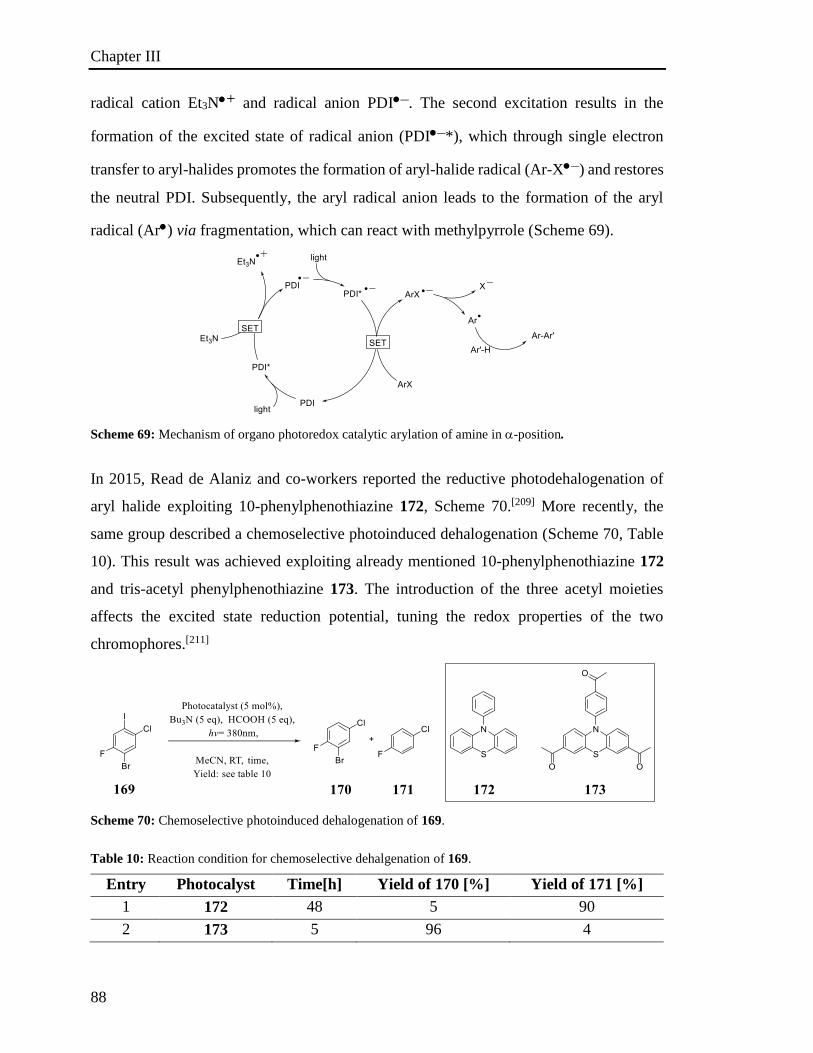
Chapter III
88
radical cation Et3N+ and radical anion PDI–. The second excitation results in the
formation of the excited state of radical anion (PDI–*), which through single electron
transfer to aryl-halides promotes the formation of aryl-halide radical (Ar-X–) and restores
the neutral PDI. Subsequently, the aryl radical anion leads to the formation of the aryl
radical (Ar) via fragmentation, which can react with methylpyrrole (Scheme 69).
Scheme 69: Mechanism of organo photoredox catalytic arylation of amine in -position.
In 2015, Read de Alaniz and co-workers reported the reductive photodehalogenation of
aryl halide exploiting 10-phenylphenothiazine 172, Scheme 70.[209] More recently, the
same group described a chemoselective photoinduced dehalogenation (Scheme 70, Table
10). This result was achieved exploiting already mentioned 10-phenylphenothiazine 172
and tris-acetyl phenylphenothiazine 173. The introduction of the three acetyl moieties
affects the excited state reduction potential, tuning the redox properties of the two
chromophores.[211]
Scheme 70: Chemoselective photoinduced dehalogenation of 169.
Table 10: Reaction condition for chemoselective dehalgenation of 169.
Entry Photocalyst Time[h] Yield of 170 [%] Yield of 171 [%]
1 172 48 5 90
2 173 5 96 4
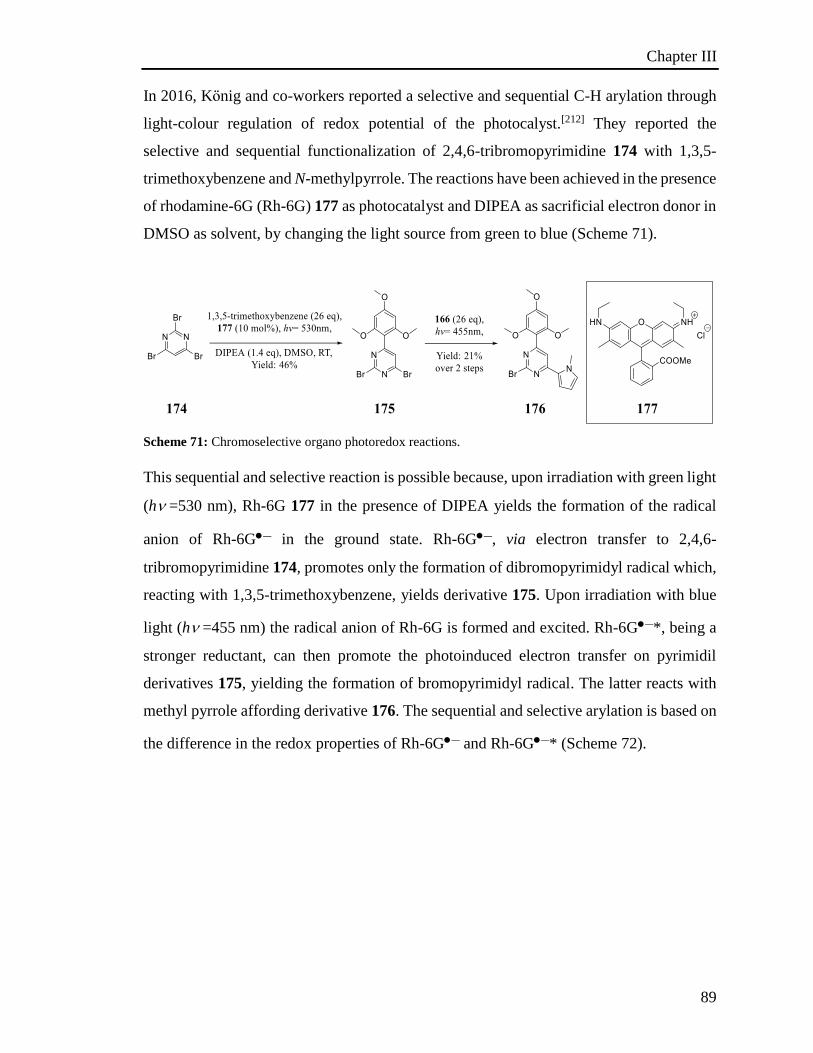
Chapter III
89
In 2016, Kӧnig and co-workers reported a selective and sequential C-H arylation through
light-colour regulation of redox potential of the photocalyst.[212] They reported the
selective and sequential functionalization of 2,4,6-tribromopyrimidine 174 with 1,3,5-
trimethoxybenzene and N-methylpyrrole. The reactions have been achieved in the presence
of rhodamine-6G (Rh-6G) 177 as photocatalyst and DIPEA as sacrificial electron donor in
DMSO as solvent, by changing the light source from green to blue (Scheme 71).
Scheme 71: Chromoselective organo photoredox reactions.
This sequential and selective reaction is possible because, upon irradiation with green light
(h=530 nm), Rh-6G 177 in the presence of DIPEA yields the formation of the radical
anion of Rh-6G– in the ground state. Rh-6G–, via electron transfer to 2,4,6-
tribromopyrimidine 174, promotes only the formation of dibromopyrimidyl radical which,
reacting with 1,3,5-trimethoxybenzene, yields derivative 175. Upon irradiation with blue
light (h=455 nm) the radical anion of Rh-6G is formed and excited. Rh-6G–*, being a
stronger reductant, can then promote the photoinduced electron transfer on pyrimidil
derivatives 175, yielding the formation of bromopyrimidyl radical. The latter reacts with
methyl pyrrole affording derivative 176. The sequential and selective arylation is based on
the difference in the redox properties of Rh-6G– and Rh-6G–* (Scheme 72).
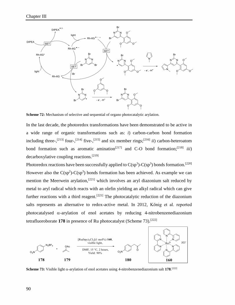
Chapter III
90
Scheme 72: Mechanism of selective and sequential of organo photocatalytic arylation.
In the last decade, the photoredox transformations have been demonstrated to be active in
a wide range of organic transformations such as: i) carbon-carbon bond formation
including three-,[213] four-,[214] five-,[215] and six member rings;[216] ii) carbon-heteroatom
bond formation such as aromatic amination[217] and C-O bond formation;[218] iii)
decarboxylative coupling reactions.[219]
Photoredox reactions have been successfully applied to C(sp3)-C(sp3) bonds formation.[220]
However also the C(sp2)-C(sp3) bonds formation has been achieved. As example we can
mention the Meerwein arylation,[221] which involves an aryl diazonium salt reduced by
metal to aryl radical which reacts with an olefin yielding an alkyl radical which can give
further reactions with a third reagent.[221] The photocatalytic reduction of the diazonium
salts represents an alternative to redox-active metal. In 2012, Kӧnig et al. reported
photocatalysed -arylation of enol acetates by reducing 4-nitrobenzenediazonium
tetrafluoroborate 178 in presence of Ru photocatalyst (Scheme 73).[222]
Scheme 73: Visible light -arylation of enol acetates using 4-nitrobenzenediazonium salt 178.[222]
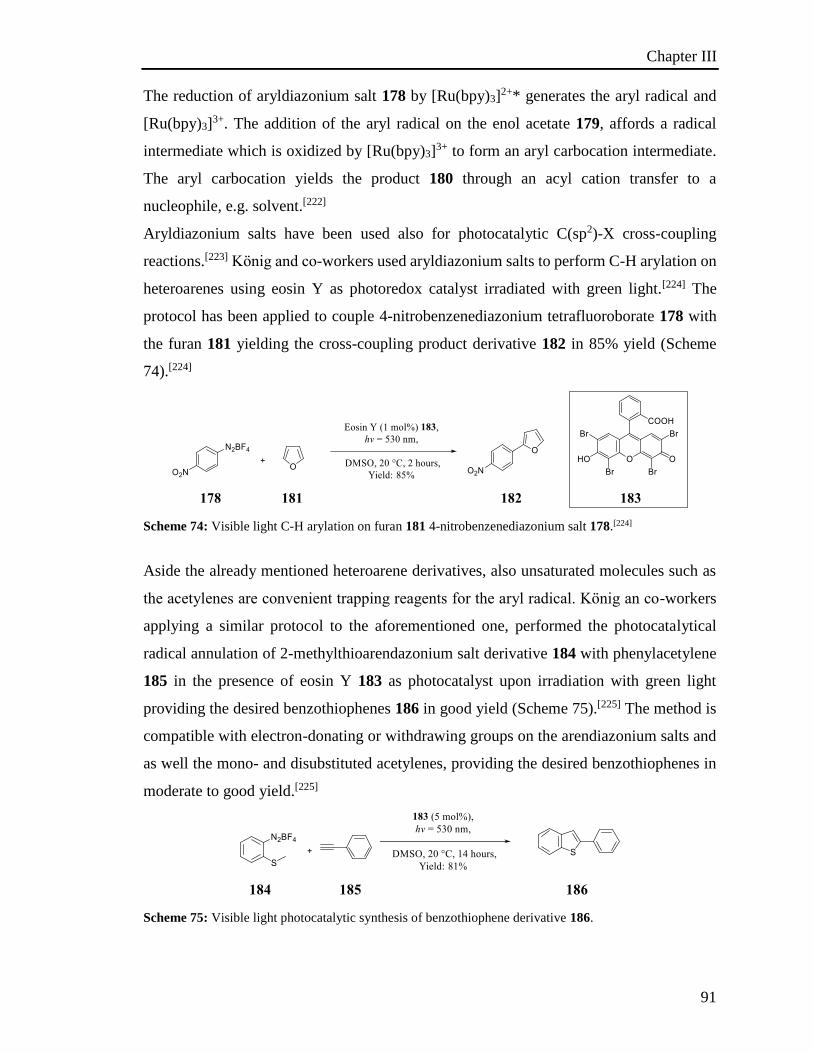
Chapter III
91
The reduction of aryldiazonium salt 178 by [Ru(bpy)3]2+* generates the aryl radical and
[Ru(bpy)3]3+. The addition of the aryl radical on the enol acetate 179, affords a radical
intermediate which is oxidized by [Ru(bpy)3]3+ to form an aryl carbocation intermediate.
The aryl carbocation yields the product 180 through an acyl cation transfer to a
nucleophile, e.g. solvent.[222]
Aryldiazonium salts have been used also for photocatalytic C(sp2)-X cross-coupling
reactions.[223] Kӧnig and co-workers used aryldiazonium salts to perform C-H arylation on
heteroarenes using eosin Y as photoredox catalyst irradiated with green light.[224] The
protocol has been applied to couple 4-nitrobenzenediazonium tetrafluoroborate 178 with
the furan 181 yielding the cross-coupling product derivative 182 in 85% yield (Scheme
74).[224]
Scheme 74: Visible light C-H arylation on furan 181 4-nitrobenzenediazonium salt 178.[224]
Aside the already mentioned heteroarene derivatives, also unsaturated molecules such as
the acetylenes are convenient trapping reagents for the aryl radical. Kӧnig an co-workers
applying a similar protocol to the aforementioned one, performed the photocatalytical
radical annulation of 2-methylthioarendazonium salt derivative 184 with phenylacetylene
185 in the presence of eosin Y 183 as photocatalyst upon irradiation with green light
providing the desired benzothiophenes 186 in good yield (Scheme 75).[225] The method is
compatible with electron-donating or withdrawing groups on the arendiazonium salts and
as well the mono- and disubstituted acetylenes, providing the desired benzothiophenes in
moderate to good yield.[225]
Scheme 75: Visible light photocatalytic synthesis of benzothiophene derivative 186.
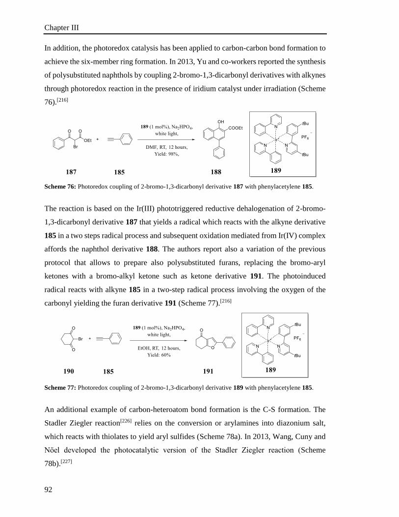
Chapter III
92
In addition, the photoredox catalysis has been applied to carbon-carbon bond formation to
achieve the six-member ring formation. In 2013, Yu and co-workers reported the synthesis
of polysubstituted naphthols by coupling 2-bromo-1,3-dicarbonyl derivatives with alkynes
through photoredox reaction in the presence of iridium catalyst under irradiation (Scheme
76).[216]
Scheme 76: Photoredox coupling of 2-bromo-1,3-dicarbonyl derivative 187 with phenylacetylene 185.
The reaction is based on the Ir(III) phototriggered reductive dehalogenation of 2-bromo-
1,3-dicarbonyl derivative 187 that yields a radical which reacts with the alkyne derivative
185 in a two steps radical process and subsequent oxidation mediated from Ir(IV) complex
affords the naphthol derivative 188. The authors report also a variation of the previous
protocol that allows to prepare also polysubstituted furans, replacing the bromo-aryl
ketones with a bromo-alkyl ketone such as ketone derivative 191. The photoinduced
radical reacts with alkyne 185 in a two-step radical process involving the oxygen of the
carbonyl yielding the furan derivative 191 (Scheme 77).[216]
Scheme 77: Photoredox coupling of 2-bromo-1,3-dicarbonyl derivative 189 with phenylacetylene 185.
An additional example of carbon-heteroatom bond formation is the C-S formation. The
Stadler Ziegler reaction[226] relies on the conversion or arylamines into diazonium salt,
which reacts with thiolates to yield aryl sulfides (Scheme 78a). In 2013, Wang, Cuny and
Nӧel developed the photocatalytic version of the Stadler Ziegler reaction (Scheme
78b).[227]
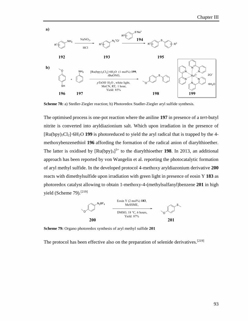
Chapter III
93
Scheme 78: a) Stedler-Ziegler reaction; b) Photoredox Stadler-Ziegler aryl sulfide synthesis.
The optimised process is one-pot reaction where the aniline 197 in presence of a tert-butyl
nitrite is converted into aryldiazionium salt. Which upon irradiation in the presence of
[Ru(bpy)3Cl2]·6H2O 199 is photoreduced to yield the aryl radical that is trapped by the 4-
methoxybenzenethiol 196 affording the formation of the radical anion of diarylthioether.
The latter is oxidised by [Ru(bpy)3]3+ to the diarylthioether 198. In 2013, an additional
approach has been reported by von Wangelin et al. reporting the photocatalytic formation
of aryl methyl sulfide. In the developed protocol 4-methoxy aryldiazonium derivative 200
reacts with dimethylsulfide upon irradiation with green light in presence of eosin Y 183 as
photoredox catalyst allowing to obtain 1-methoxy-4-(methylsulfanyl)benzene 201 in high
yield (Scheme 79).[219]
Scheme 79: Organo photoredox synthesis of aryl methyl sulfide 201
The protocol has been effective also on the preparation of selenide derivatives.[219]
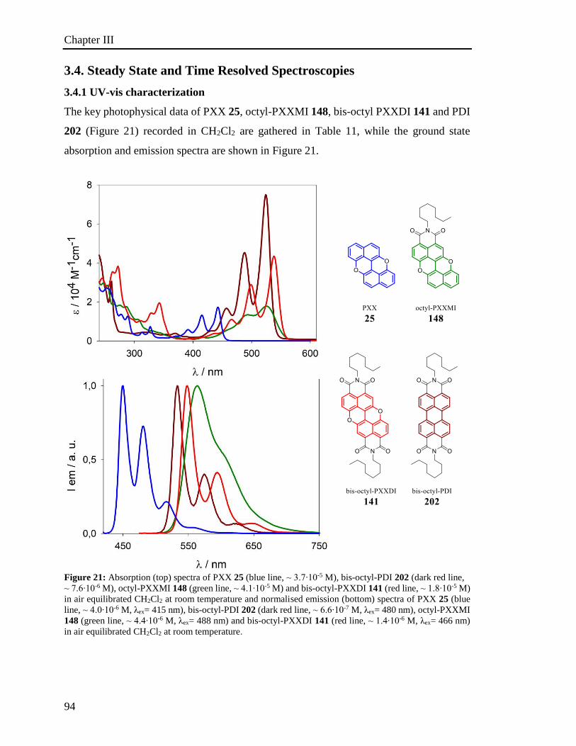
Chapter III
94
3.4. Steady State and Time Resolved Spectroscopies
3.4.1 UV-vis characterization
The key photophysical data of PXX 25, octyl-PXXMI 148, bis-octyl PXXDI 141 and PDI
202 (Figure 21) recorded in CH2Cl2 are gathered in Table 11, while the ground state
absorption and emission spectra are shown in Figure 21.
Figure 21: Absorption (top) spectra of PXX 25 (blue line, ⁓ 3.7∙10-5 M), bis-octyl-PDI 202 (dark red line,
⁓ 7.6∙10-6 M), octyl-PXXMI 148 (green line, ⁓ 4.1∙10-5 M) and bis-octyl-PXXDI 141 (red line, ⁓ 1.8∙10-5 M)
in air equilibrated CH2Cl2 at room temperature and normalised emission (bottom) spectra of PXX 25 (blue
line, ⁓ 4.0∙10-6 M, λex= 415 nm), bis-octyl-PDI 202 (dark red line, ⁓ 6.6∙10-7 M, λex= 480 nm), octyl-PXXMI
148 (green line, ⁓ 4.4∙10-6 M, λex= 488 nm) and bis-octyl-PXXDI 141 (red line, ⁓ 1.4∙10-6 M, λex= 466 nm)
in air equilibrated CH2Cl2 at room temperature.
Chapter III
95
Reference compound PXX 25 displays, in CH2Cl2 solution at RT, the lowest energy
electronic transition S0S1 with absorption bands at 414 nm and maximum around 440
nm. Octyl-PXXMI 148 and bis-octyl-PXXDI 141 display a strong red-shifted band, octyl-
PXXMI 148 is featured with a less structured electronic transition S0S1 displaying
vibronic bands at 490 nm and the maximum at 525 nm in CH2Cl2. The presence of the
second imide motif on the PXX scaffold induces a further red shift, bis-octyl-PXXDI 141
reveals indeed, a structured electronic transition S0S1, with absorption band at 498 nm
and the maximum at 538 nm in CH2Cl2. Furthermore, bis-octyl-PXXDI 141 shows an
absorption profile similar to the unsubstituted perylene diimides, in fact, the bis-octyl-PDI
202 displays the electronic transition S0S1 with the (0,0) vibronic transition at ⁓ 524 nm
and the (0,1) vibronic band at ⁓ 488 nm.[55] The red-shift observed in the PXX derivative
could be explained as an effect of the presence of the electron-withdrawing imide moieties,
which contribute to the stabilization of the S0 S1 transition. Moreover, symmetrical
substitution with a second imide function on the periphery of the PXX core restores a
vibrational structure and increases the intensity of the same band, similarly to other imide-
substituted extended aromatics.[197] It is worth highlighting that in the compounds shown
that the energy associated to these transitions is not dramatically modified (Figure 21),
while the presence of a different number of imide-substituents on the periphery can affect
the shape and the intensity of the absorption bands. In fact, while the introduction of the
first imide on PXX 25, giving octyl-PXXMI 148, yields a significant bathochromic shift
(82 nm), the following imide group introduction on octyl-PXXMI 148, to afford bis-octyl-
PXXDI 141, promotes a further bathochromic shift of only 15 nm (data recorded in
CH2Cl2). However, the absorption spectra of octyl-PXXMI 148 results in less structured
bands in comparison with the one of the PXX 25 and bis-octyl-PXXDI 141; the broadening
of the absorption profile is probably a result of aggregation phenomena of octyl-PXXMI
in solution. Similar behaviour has been observed from Bullock et al. in the study of
photophysical properties of rylene imide and diimide.[228] Similarly to the PDI,[55] PXX
derivatives show a fluorescence spectra as mirror image of the absorption profile (Figure
21). Both octyl-PXXMI 148 and bis-octyl-PXXDI 141 absorption bands cover the same
visible region as bis-octyl-PDI 202. However, the extinction coefficient of octyl-PXXMI
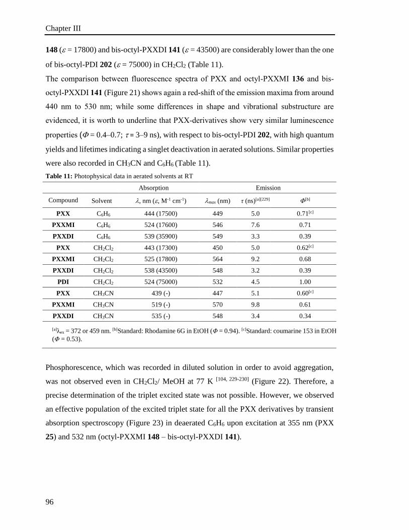
Chapter III
96
148 (= 17800) and bis-octyl-PXXDI 141 (= 43500) are considerably lower than the one
of bis-octyl-PDI 202 ( = 75000) in CH2Cl2 (Table 11).
The comparison between fluorescence spectra of PXX and octyl-PXXMI 136 and bis-
octyl-PXXDI 141 (Figure 21) shows again a red-shift of the emission maxima from around
440 nm to 530 nm; while some differences in shape and vibrational substructure are
evidenced, it is worth to underline that PXX-derivatives show very similar luminescence
properties ( = 0.4–0.7; = 3–9 ns), with respect to bis-octyl-PDI 202, with high quantum
yields and lifetimes indicating a singlet deactivation in aerated solutions. Similar properties
were also recorded in CH3CN and C6H6 (Table 11).
Table 11: Photophysical data in aerated solvents at RT
Phosphorescence, which was recorded in diluted solution in order to avoid aggregation,
was not observed even in CH2Cl2/ MeOH at 77 K [104, 229-230] (Figure 22). Therefore, a
precise determination of the triplet excited state was not possible. However, we observed
an effective population of the excited triplet state for all the PXX derivatives by transient
absorption spectroscopy (Figure 23) in deaerated C6H6 upon excitation at 355 nm (PXX
25) and 532 nm (octyl-PXXMI 148 – bis-octyl-PXXDI 141).
Absorption Emission
Compound Solvent , nm (, M-1 cm-1) max (nm) τ (ns)[a][229] Φ[b]
PXX C6H6 444 (17500) 449 5.0 0.71[c]
PXXMI C6H6 524 (17600) 546 7.6 0.71
PXXDI C6H6 539 (35900) 549 3.3 0.39
PXX CH2Cl2 443 (17300) 450 5.0 0.62[c]
PXXMI CH2Cl2 525 (17800) 564 9.2 0.68
PXXDI CH2Cl2 538 (43500) 548 3.2 0.39
PDI CH2Cl2 524 (75000) 532 4.5 1.00
PXX CH3CN 439 (-) 447 5.1 0.60[c]
PXXMI CH3CN 519 (-) 570 9.8 0.61
PXXDI CH3CN 535 (-) 548 3.4 0.34
[a]λex = 372 or 459 nm. [b]Standard: Rhodamine 6G in EtOH (Φ = 0.94). [c]Standard: coumarine 153 in EtOH
(Φ = 0.53).
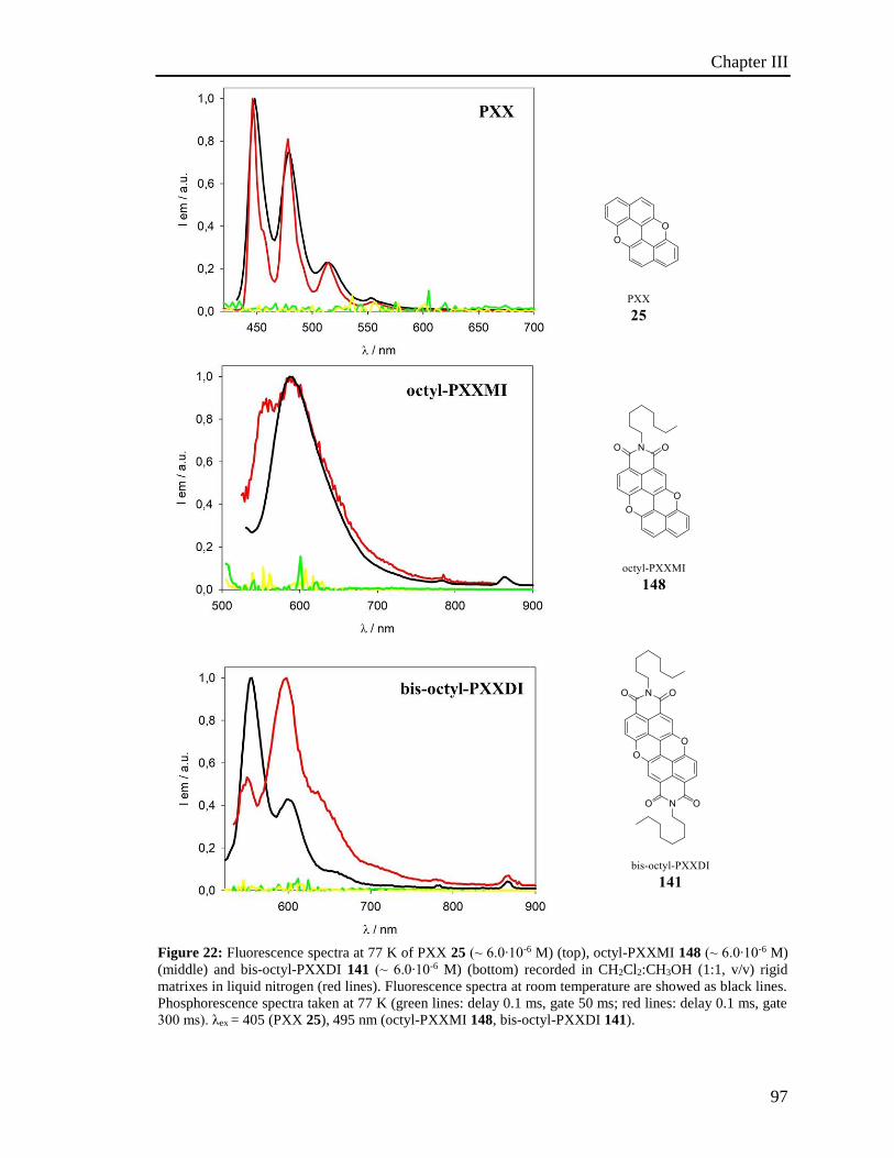
Chapter III
97
Figure 22: Fluorescence spectra at 77 K of PXX 25 (⁓ 6.0∙10-6 M) (top), octyl-PXXMI 148 (⁓ 6.0∙10-6 M)
(middle) and bis-octyl-PXXDI 141 (⁓ 6.0∙10-6 M) (bottom) recorded in CH2Cl2:CH3OH (1:1, v/v) rigid
matrixes in liquid nitrogen (red lines). Fluorescence spectra at room temperature are showed as black lines.
Phosphorescence spectra taken at 77 K (green lines: delay 0.1 ms, gate 50 ms; red lines: delay 0.1 ms, gate
300 ms). λex = 405 (PXX 25), 495 nm (octyl-PXXMI 148, bis-octyl-PXXDI 141).
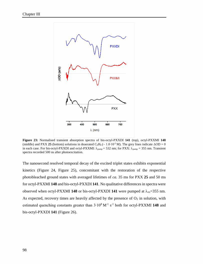
Chapter III
98
Figure 23: Normalised transient absorption spectra of bis-octyl-PXXDI 141 (top), octyl-PXXMI 148
(middle) and PXX 25 (bottom) solutions in deaerated C6H6 (⁓ 1.0∙10-5 M). The grey lines indicate OD = 0
in each case. For bis-octyl-PXXDI and octyl-PXXMI: pump = 532 nm; for PXX: pump = 355 nm. Transient
spectra recorded 500 ns after photoexcitation.
The nanosecond resolved temporal decay of the excited triplet states exhibits exponential
kinetics (Figure 24, Figure 25), concomitant with the restoration of the respective
photobleached ground states with averaged lifetimes of ca. 35 ms for PXX 25 and 50 ms
for octyl-PXXMI 148 and bis-octyl-PXXDI 141. No qualitative differences in spectra were
observed when octyl-PXXMI 148 or bis-octyl-PXXDI 141 were pumped at ex=355 nm.
As expected, recovery times are heavily affected by the presence of O2 in solution, with
estimated quenching constants greater than 3∙108 M-1 s-1 both for octyl-PXXMI 148 and
bis-octyl-PXXDI 141 (Figure 26).
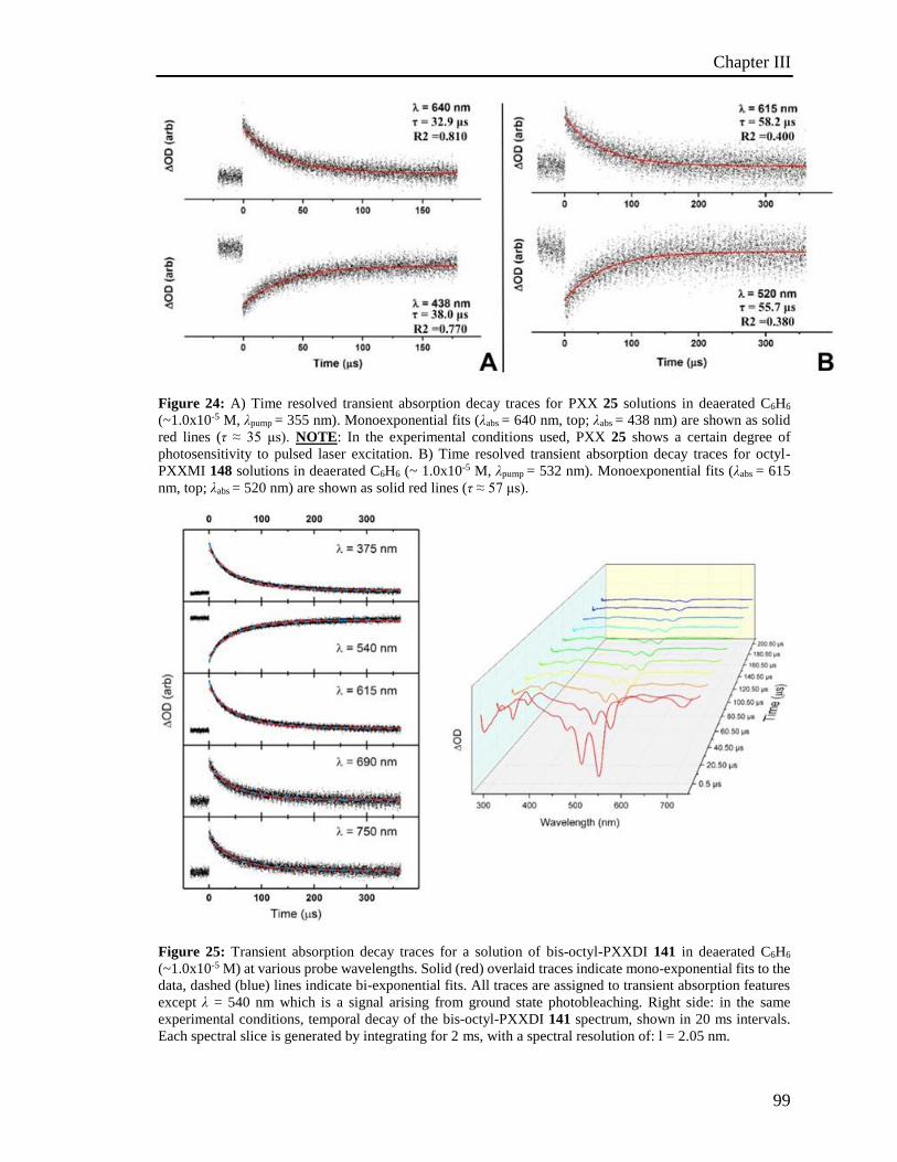
Chapter III
99
Figure 24: A) Time resolved transient absorption decay traces for PXX 25 solutions in deaerated C6H6
(~1.0x10⁻⁵ M, λpump = 355 nm). Monoexponential fits (λabs = 640 nm, top; λabs = 438 nm) are shown as solid
red lines (τ ≈ 35 μs). NOTE: In the experimental conditions used, PXX 25 shows a certain degree of
photosensitivity to pulsed laser excitation. B) Time resolved transient absorption decay traces for octyl-
PXXMI 148 solutions in deaerated C6H6 (~ 1.0x10⁻⁵ M, λpump = 532 nm). Monoexponential fits (λabs = 615
nm, top; λabs = 520 nm) are shown as solid red lines (τ ≈ 57 μs).
Figure 25: Transient absorption decay traces for a solution of bis-octyl-PXXDI 141 in deaerated C6H6
(~1.0x10⁻⁵ M) at various probe wavelengths. Solid (red) overlaid traces indicate mono-exponential fits to the
data, dashed (blue) lines indicate bi-exponential fits. All traces are assigned to transient absorption features
except λ = 540 nm which is a signal arising from ground state photobleaching. Right side: in the same
experimental conditions, temporal decay of the bis-octyl-PXXDI 141 spectrum, shown in 20 ms intervals.
Each spectral slice is generated by integrating for 2 ms, with a spectral resolution of: l = 2.05 nm.
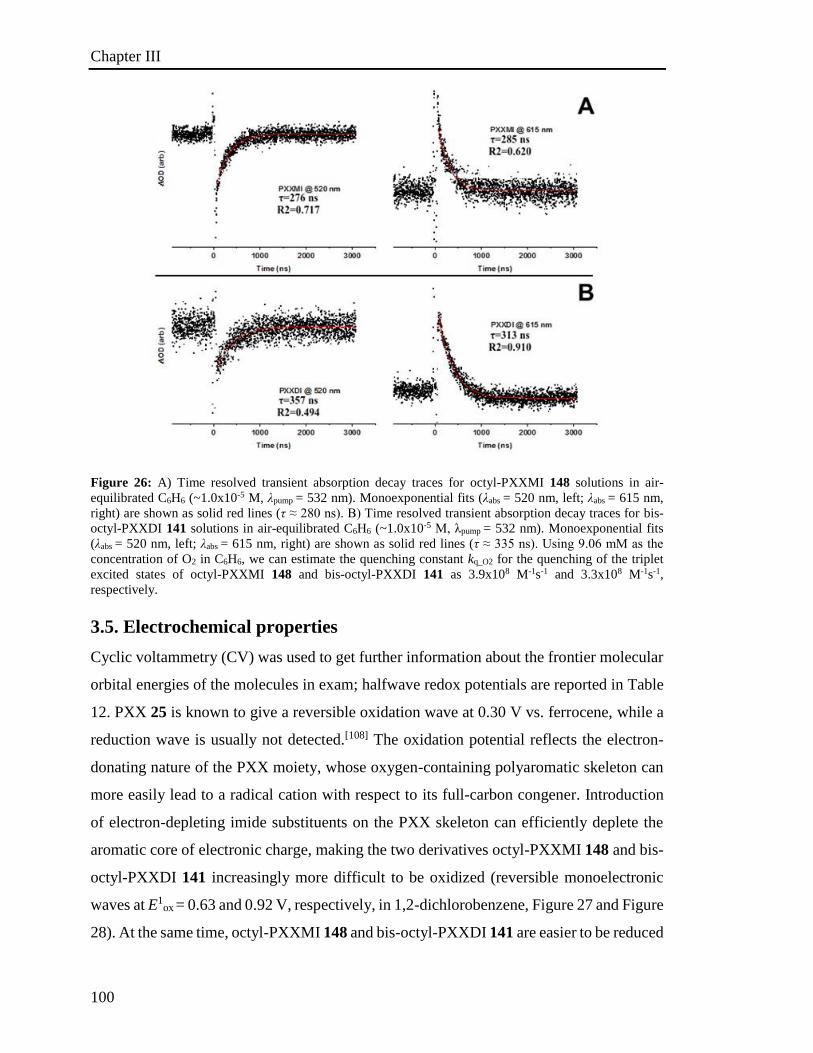
Chapter III
100
Figure 26: A) Time resolved transient absorption decay traces for octyl-PXXMI 148 solutions in air-
equilibrated C6H6 (~1.0x10⁻⁵ M, λpump = 532 nm). Monoexponential fits (λabs = 520 nm, left; λabs = 615 nm,
right) are shown as solid red lines (τ ≈ 280 ns). B) Time resolved transient absorption decay traces for bis-
octyl-PXXDI 141 solutions in air-equilibrated C6H6 (~1.0x10⁻⁵ M, λpump = 532 nm). Monoexponential fits
(λabs = 520 nm, left; λabs = 615 nm, right) are shown as solid red lines (τ ≈ 335 ns). Using 9.06 mM as the
concentration of O2 in C6H6, we can estimate the quenching constant kq_O2 for the quenching of the triplet
excited states of octyl-PXXMI 148 and bis-octyl-PXXDI 141 as 3.9x10⁸ M-1s-1 and 3.3x10⁸ M-1s-1,
respectively.
3.5. Electrochemical properties
Cyclic voltammetry (CV) was used to get further information about the frontier molecular
orbital energies of the molecules in exam; halfwave redox potentials are reported in Table
12. PXX 25 is known to give a reversible oxidation wave at 0.30 V vs. ferrocene, while a
reduction wave is usually not detected.[108] The oxidation potential reflects the electron-
donating nature of the PXX moiety, whose oxygen-containing polyaromatic skeleton can
more easily lead to a radical cation with respect to its full-carbon congener. Introduction
of electron-depleting imide substituents on the PXX skeleton can efficiently deplete the
aromatic core of electronic charge, making the two derivatives octyl-PXXMI 148 and bis-
octyl-PXXDI 141 increasingly more difficult to be oxidized (reversible monoelectronic
waves at E1ox = 0.63 and 0.92 V, respectively, in 1,2-dichlorobenzene, Figure 27 and Figure
28). At the same time, octyl-PXXMI 148 and bis-octyl-PXXDI 141 are easier to be reduced
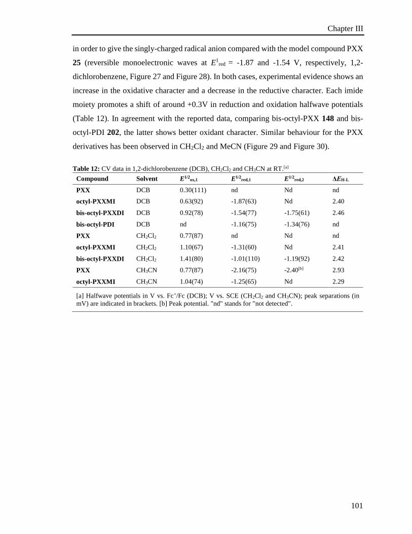
Chapter III
101
in order to give the singly-charged radical anion compared with the model compound PXX
25 (reversible monoelectronic waves at E1red = -1.87 and -1.54 V, respectively, 1,2-
dichlorobenzene, Figure 27 and Figure 28). In both cases, experimental evidence shows an
increase in the oxidative character and a decrease in the reductive character. Each imide
moiety promotes a shift of around +0.3V in reduction and oxidation halfwave potentials
(Table 12). In agreement with the reported data, comparing bis-octyl-PXX 148 and bis-
octyl-PDI 202, the latter shows better oxidant character. Similar behaviour for the PXX
derivatives has been observed in CH2Cl2 and MeCN (Figure 29 and Figure 30).
Table 12: CV data in 1,2-dichlorobenzene (DCB), CH2Cl2 and CH3CN at RT.[a]
Compound Solvent E1/2ox,1 E1/2
red,1 E1/2red,2 ΔΕH-L
PXX DCB 0.30(111) nd Nd nd
octyl-PXXMI DCB 0.63(92) -1.87(63) Nd 2.40
bis-octyl-PXXDI DCB 0.92(78) -1.54(77) -1.75(61) 2.46
bis-octyl-PDI DCB nd -1.16(75) -1.34(76) nd
PXX CH2Cl2 0.77(87) nd Nd nd
octyl-PXXMI CH2Cl2 1.10(67) -1.31(60) Nd 2.41
bis-octyl-PXXDI CH2Cl2 1.41(80) -1.01(110) -1.19(92) 2.42
PXX CH3CN 0.77(87) -2.16(75) -2.40[b] 2.93
octyl-PXXMI CH3CN 1.04(74) -1.25(65) Nd 2.29
[a] Halfwave potentials in V vs. Fc+/Fc (DCB); V vs. SCE (CH2Cl2 and CH3CN); peak separations (in
mV) are indicated in brackets. [b] Peak potential. "nd" stands for "not detected".
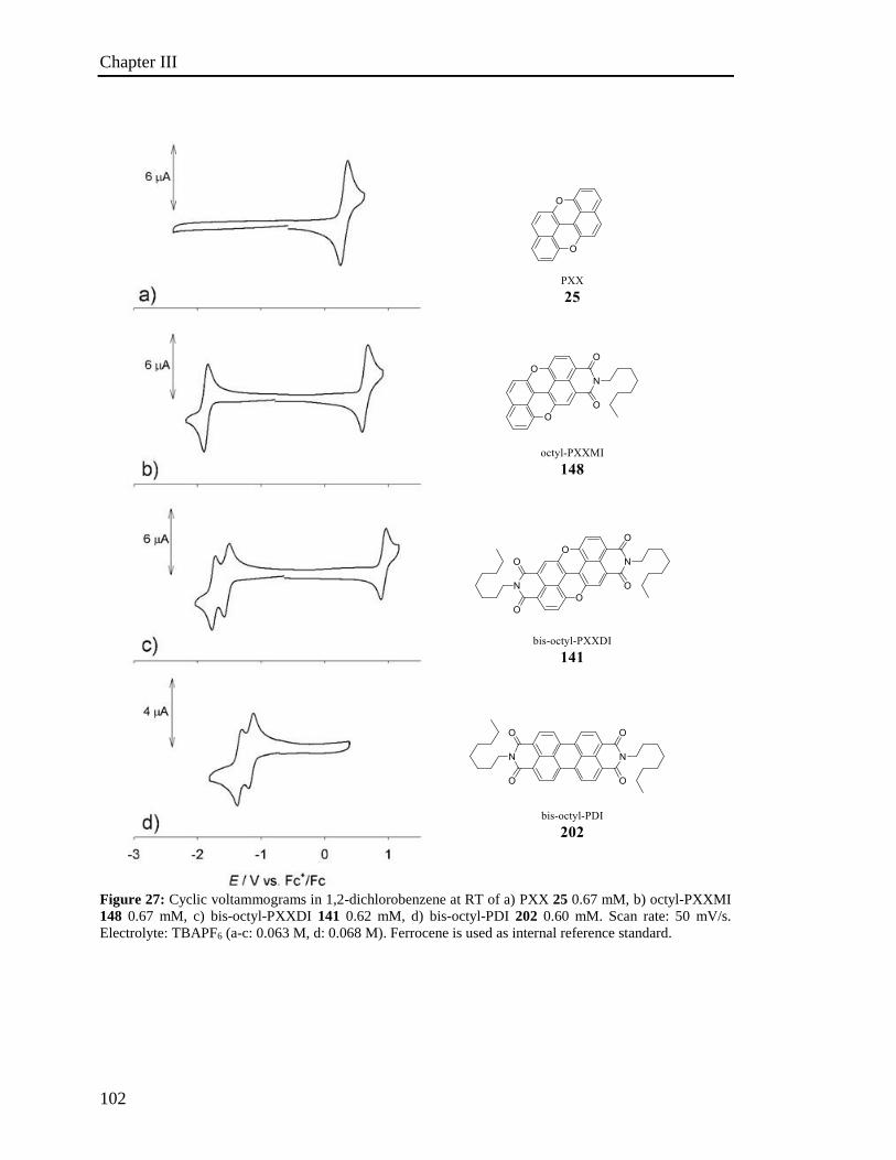
Chapter III
102
Figure 27: Cyclic voltammograms in 1,2-dichlorobenzene at RT of a) PXX 25 0.67 mM, b) octyl-PXXMI
148 0.67 mM, c) bis-octyl-PXXDI 141 0.62 mM, d) bis-octyl-PDI 202 0.60 mM. Scan rate: 50 mV/s.
Electrolyte: TBAPF6 (a-c: 0.063 M, d: 0.068 M). Ferrocene is used as internal reference standard.

Chapter III
103
Figure 28: Cyclic voltammograms at variable scan rates and relative linear dependence between anodic or
cathodic peak currents and scan rate1/2 for compounds: a-b) octyl-PXXMI 148 (0.67 mM), c-d) bis-octyl-
PXXDI 141 (0.70 mM), e-f) bis-octyl-PDI 202 (0.60 mM). For each calculated linear regression, the
coefficient of determination r2 is reported. Experimental conditions: 1,2-dichlorobenzene is used as solvent,
supporting electrolyte: TBAPF6 (0.063÷0.068 M for all experiments). Ferrocene is used as internal reference
standard (EFc+/Fc = 0.00 V).

Chapter III
104
Figure 29: Cyclic voltammograms of a) PXX 25, b) octyl-PXXMI 148 and c) bis-octyl-PXXDI 141 (0.90
mM, TBAPF6 0.10 M; 1.07 mM, TBAPF6 0.11 M; 0.67 mM, TBAPF6 0.11 M, respectively) in CH2Cl2 at
RT, scan rate 0.05 V/s. Ferrocene is used as internal reference; EFc+/Fc = 0.46 V vs. SCE.
Figure 30: Cyclic voltammograms of a) PXX 25 and b) octyl-PXXMI 141 (0.60 mM and 0.52 mM,
respectively; TEAPF6 0.11 M,) in MeCN at RT, scan rate 0.05 V/s. Ferrocene is used as internal reference;
EFc+/Fc = 0.395 V vs. SCE.
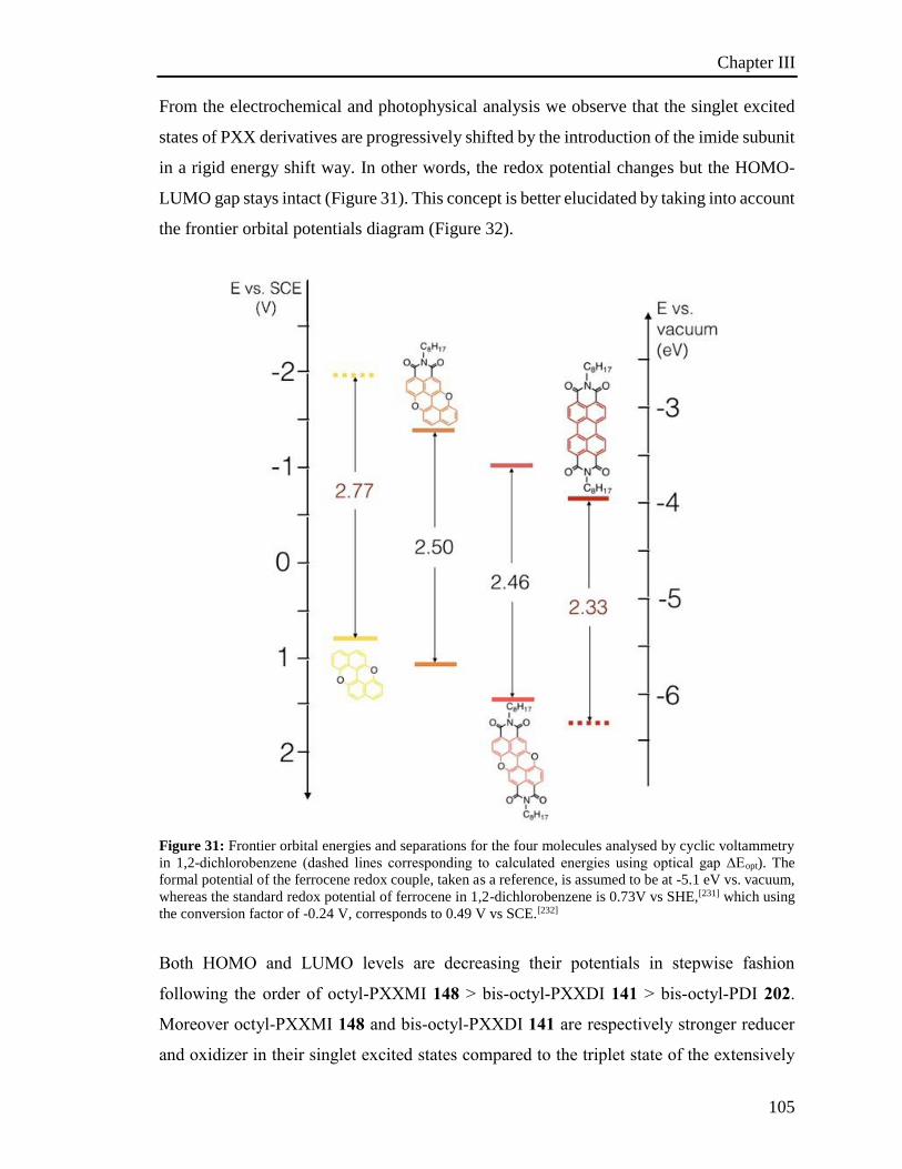
Chapter III
105
From the electrochemical and photophysical analysis we observe that the singlet excited
states of PXX derivatives are progressively shifted by the introduction of the imide subunit
in a rigid energy shift way. In other words, the redox potential changes but the HOMO-
LUMO gap stays intact (Figure 31). This concept is better elucidated by taking into account
the frontier orbital potentials diagram (Figure 32).
Figure 31: Frontier orbital energies and separations for the four molecules analysed by cyclic voltammetry
in 1,2-dichlorobenzene (dashed lines corresponding to calculated energies using optical gap ΔEopt). The
formal potential of the ferrocene redox couple, taken as a reference, is assumed to be at -5.1 eV vs. vacuum,
whereas the standard redox potential of ferrocene in 1,2-dichlorobenzene is 0.73V vs SHE,[231] which using
the conversion factor of -0.24 V, corresponds to 0.49 V vs SCE.[232]
Both HOMO and LUMO levels are decreasing their potentials in stepwise fashion
following the order of octyl-PXXMI 148 > bis-octyl-PXXDI 141 > bis-octyl-PDI 202.
Moreover octyl-PXXMI 148 and bis-octyl-PXXDI 141 are respectively stronger reducer
and oxidizer in their singlet excited states compared to the triplet state of the extensively
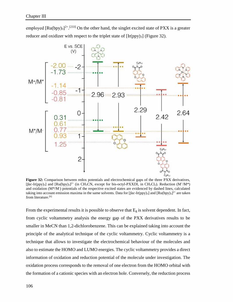
Chapter III
106
employed [Ru(bpy)3]2+.[233] On the other hand, the singlet excited state of PXX is a greater
reducer and oxidizer with respect to the triplet state of [Ir(ppy)3] (Figure 32).
Figure 32: Comparison between redox potentials and electrochemical gaps of the three PXX derivatives,
[fac-Ir(ppy)3] and [Ru(bpy)3]2+ (in CH3CN, except for bis-octyl-PXXDI, in CH2Cl2). Reduction (M+/M*)
and oxidation (M*/M-) potentials of the respective excited states are evidenced by dashed lines, calculated
taking into account emission maxima in the same solvents. Data for [fac-Ir(ppy)3] and [Ru(bpy)3]2+ are taken
from literature.[6]
From the experimental results it is possible to observe that Eg is solvent dependent. In fact,
from cyclic voltammetry analysis the energy gap of the PXX derivatives results to be
smaller in MeCN than 1,2-dichlorobenzene. This can be explained taking into account the
principle of the analytical technique of the cyclic voltammetry. Cyclic voltammetry is a
technique that allows to investigate the electrochemical behaviour of the molecules and
also to estimate the HOMO and LUMO energies. The cyclic voltammetry provides a direct
information of oxidation and reduction potential of the molecule under investigation. The
oxidation process corresponds to the removal of one electron from the HOMO orbital with
the formation of a cationic species with an electron hole. Conversely, the reduction process
Chapter III
107
corresponds to an addition of electron to LUMO orbital of the molecule leading the
formation of an anionic species with an unpaired electron.[234] The potential of oxidation
and reduction of a molecule can be correlated respectively to ionisation potential Ip and
electron affinity Ea, which leads to the estimation of the energy gap Eg[235] of the frontier
orbitals:
Eg = Ip - Ea
It has been demonstrated that Eox value defers depending on the nature of the solvent, Eox
shifts to less positive potentials when increasing the polarity of the solvent:
DMSO < DMF < MeCN < CH2Cl2.
In other words, this indicates that the oxidation of the molecules to cationic species
becomes more difficult when going from DMSO, the most polar solvent, to DCM, the least
polar solvent.[236] The shift of the oxidation potential can be explained by donor-acceptor
Lewis type interactions.[237] The newly formed cationic species M+ in contrast to the neutral
molecule is more prone to interact with the solvent. Therefore, this stronger interaction of
M+ - solvent molecule affects the oxidation process of the molecule and thus the Eox value.
Consequently, a strong electron contribution of the solvent molecule to the M+ results in a
diminution of the Eox. Conversely, for the reduction process the opposite trend is observed:
the reduction potential shifts over to more positive values when increasing the polarity of
the solvent.[238] In other words, the anion M- is more affected from the interaction with the
solvent. Similarly, the stronger the interaction of M- - solvent, the more is affected the Ered
value; with a consequent increase of the Ered value. From all the above, it is concluded that
it is easier to have an oxidation or reduction process in a more polar than in a less polar
solvent and the energy gap is smaller in a more polar solvent. In this context, our
experimental results are in agreement with the precedent statement since MeCN is the most
polar solvent (d = 35.9)[239] used in our analysis while CH2Cl2 and 1,2-dichlorobenzene
that have similar dielectric constants (d = 8.93 and d = 9.93 respectively) are the least
polar ones.[239] However, the energy gap determined by CV results to be bigger than the
one determined by optical measurements. The optical band gap has been determined
considering the maximum of emission (λmax). The molecule in the excited state M*
presents the HOMO and the LUMO half-filled. Upon irradiation of molecule M an electron
promotion occurs from the HOMO to the LUMO. Therefore, the excited state, M* presents
Chapter III
108
the HOMO and the LUMO half-filled; the so-called electron hole pair which is
characterized by a stronger interaction with the solvent in comparison with respective
cation M+ and anion M-. This interaction with the solvent is stronger for a more polar
solvent.[240] Thus, the more polar the solvent, the stronger the stabilization of M*- solvent.
Due to this stabilization the emission is shifted to lower energy.[241] In general, M* has a
bigger bipolar moment than M in the ground state. Therefore, upon excitation of M the
molecules of solvent can reorient around M* and lower the energy of the excited state.[242]
Thus, higher is the solvent polarity, larger is the stabilization effect, resulting in emission
at lower energy. Typically, this effect is pronounced only from molecules that display a
big bipolar moment, while non-polar molecules are less sensitive to the solvent
polarity.[243] Typically, the fluorescence lifetime is in the order of 1-10 ns. This time is
enough long to observe the solvent reorganization which takes place in 10-100 ps.[241] For
this, the fluorescence spectra are affected by the solvent while the absorption spectra are
not affected since the electronic transition promoted by light absorption is in the order of
10-15 sec, a time too short for the solvent reorganization.[243]

Chapter III
109
3.6 Investigation of the photoredox properties: Dehalogenation reactions
As mentioned in section 3.2.2, [Ru(bpy)3Cl2][207] and [Ir(ppy)3]
[208] have been used to
trigger photoredox reactions. However, simple organic molecules such us perylene
diimide[210], phenylphenothiazine[209] and others dyes[204a] have also been applied to
perform such organic photoredox transformations. Small molecular organic
semiconductors that absorb visible light upon irradiation generate a charge transfer
process, which could be used to trigger photoredox reactions.[244]
Based on the aforementioned results, PXX derivatives have been tested to trigger
photochemical reactions. In order to evaluate the photo-triggering activity of the PXX
derivatives, the photoinduced dehalogenation process has been taken in account as model
transformation, similar to the work of Kӧnig and co-workers, which has been achieved
using PDI derivative 168 as photocatalyst.[210]
Firstly, the photoinduced dehalogenation of 2-bromoacetophenone 203 has been tested in
the presence of DIPEA as sacrificial agent and either PXX 25, octyl-PXXMI 148 or bis-
octyl-PXXDI 141 in deaerated C6H6. Upon irradiation, we noted the complete conversion
of starting material 203, providing the dehalogenated product, acetophenone 204, which
was observed by GC-MS analysis (Scheme 80, entries 1, 4 and 7, Table 13, Figure 33).
Scheme 80: Photoinduced dehalogenation of 2-bromoacetophenone 203 in presence of PXX derivatives.
Table 13: Conditions used to perform photoinduced dehalogenation of 2–bromoacetophenone 203.
Entry Dye λex (nm) Solvent Time [h] Conversion
[%] 1 PXXMI
148
520 C6H6 24 100
2 520 CH2Cl2 24 95
3 520 MeCN 24 100
4 PXXDI
141
520 C6H6 29 100
5 520 CH2Cl2 24 100
6 520 MeCN 24 100
7
PXX 25
460 C6H6 24 100
8 460 CH2Cl2 24 100
9 460 MeCN 24 100
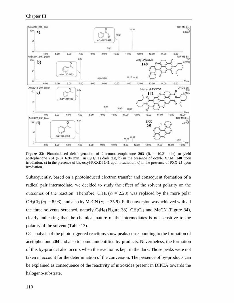
Chapter III
110
Figure 33: Photoinduced dehalogenation of 2-bromoacetophenone 203 (Rt = 10.21 min) to yield
acetophenone 204 (Rt = 6.94 min), in C6H6: a) dark test, b) in the presence of octyl-PXXMI 148 upon
irradiation, c) in the presence of bis-octyl-PXXDI 141 upon irradiation, c) in the presence of PXX 25 upon
irradiation.
Subsequently, based on a photoinduced electron transfer and consequent formation of a
radical pair intermediate, we decided to study the effect of the solvent polarity on the
outcomes of the reaction. Therefore, C6H6 (d= 2.28) was replaced by the more polar
CH2Cl2 (d= 8.93), and also by MeCN (d= 35.9). Full conversion was achieved with all
the three solvents screened, namely C6H6 (Figure 33), CH2Cl2 and MeCN (Figure 34),
clearly indicating that the chemical nature of the intermediates is not sensitive to the
polarity of the solvent (Table 13).
GC analysis of the phototriggered reactions show peaks corresponding to the formation of
acetophenone 204 and also to some unidentified by-products. Nevertheless, the formation
of this by-product also occurs when the reaction is kept in the dark. Those peaks were not
taken in account for the determination of the conversion. The presence of by-products can
be explained as consequence of the reactivity of nitroxides present in DIPEA towards the
halogeno-substrate.
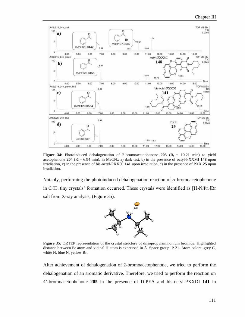
Chapter III
111
Figure 34: Photoinduced dehalogenation of 2-bromoacetophenone 203 (Rt = 10.21 min) to yield
acetophenone 204 (Rt = 6.94 min), in MeCN,: a) dark test, b) in the presence of octyl-PXXMI 148 upon
irradiation, c) in the presence of bis-octyl-PXXDI 141 upon irradiation, c) in the presence of PXX 25 upon
irradiation.
Notably, performing the photoinduced dehalogenation reaction of -bromoacetophenone
in C6H6 tiny crystals’ formation occurred. These crystals were identified as [H2NiPr2]Br
salt from X-ray analysis, (Figure 35).
Figure 35: ORTEP representation of the crystal structure of diisopropylammonium bromide. Highlighted
distance between Br atom and vicinal H atom is expressed in Å. Space group: P 21. Atom colors: grey C,
white H, blue N, yellow Br.
After achievement of dehalogenation of -bromoacetophenone, we tried to perform the
dehalogenation of an aromatic derivative. Therefore, we tried to perform the reaction on
4’-bromoacetophenone 205 in the presence of DIPEA and bis-octyl-PXXDI 141 in
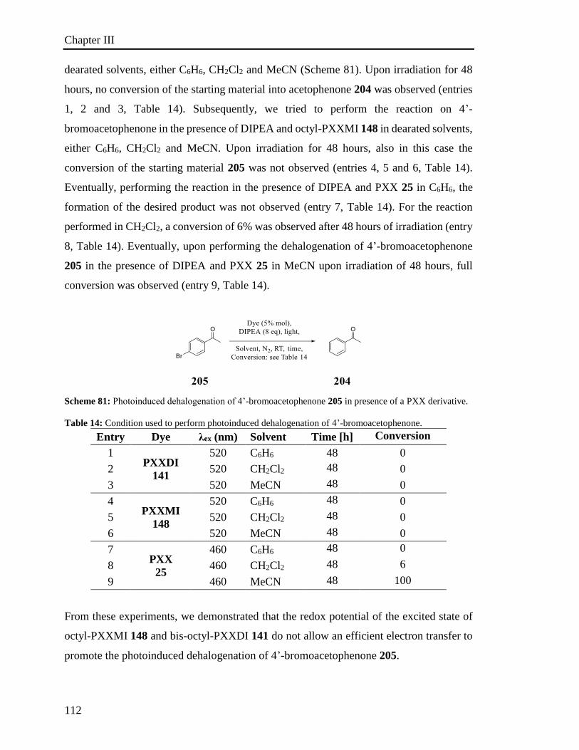
Chapter III
112
dearated solvents, either C6H6, CH2Cl2 and MeCN (Scheme 81). Upon irradiation for 48
hours, no conversion of the starting material into acetophenone 204 was observed (entries
1, 2 and 3, Table 14). Subsequently, we tried to perform the reaction on 4’-
bromoacetophenone in the presence of DIPEA and octyl-PXXMI 148 in dearated solvents,
either C6H6, CH2Cl2 and MeCN. Upon irradiation for 48 hours, also in this case the
conversion of the starting material 205 was not observed (entries 4, 5 and 6, Table 14).
Eventually, performing the reaction in the presence of DIPEA and PXX 25 in C6H6, the
formation of the desired product was not observed (entry 7, Table 14). For the reaction
performed in CH2Cl2, a conversion of 6% was observed after 48 hours of irradiation (entry
8, Table 14). Eventually, upon performing the dehalogenation of 4’-bromoacetophenone
205 in the presence of DIPEA and PXX 25 in MeCN upon irradiation of 48 hours, full
conversion was observed (entry 9, Table 14).
Scheme 81: Photoinduced dehalogenation of 4’-bromoacetophenone 205 in presence of a PXX derivative.
Table 14: Condition used to perform photoinduced dehalogenation of 4’-bromoacetophenone.
Entry Dye λex (nm) Solvent Time [h] Conversion
[%] 1 PXXDI
141
520 C6H6 48 0
2 520 CH2Cl2 48 0
3 520 MeCN 48 0
4 PXXMI
148
520 C6H6 48 0
5 520 CH2Cl2 48 0
6 520 MeCN 48 0
7 PXX
25
460 C6H6 48 0
8 460 CH2Cl2 48 6
9 460 MeCN 48 100
From these experiments, we demonstrated that the redox potential of the excited state of
octyl-PXXMI 148 and bis-octyl-PXXDI 141 do not allow an efficient electron transfer to
promote the photoinduced dehalogenation of 4’-bromoacetophenone 205.
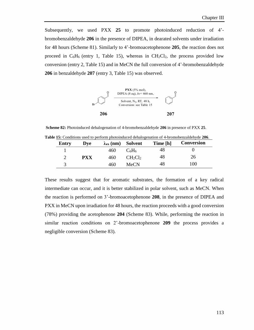
Chapter III
113
Subsequently, we used PXX 25 to promote photoinduced reduction of 4’-
bromobenzaldehyde 206 in the presence of DIPEA, in dearated solvents under irradiation
for 48 hours (Scheme 81). Similarly to 4’-bromoacetophenone 205, the reaction does not
proceed in C6H6 (entry 1, Table 15), whereas in CH2Cl2, the process provided low
conversion (entry 2, Table 15) and in MeCN the full conversion of 4’-bromobenzaldehyde
206 in benzaldehyde 207 (entry 3, Table 15) was observed.
Scheme 82: Photoinduced dehalogenation of 4-bromobenzaldehyde 206 in presence of PXX 25.
Table 15: Conditions used to perform photoinduced dehalogenation of 4-bromobenzaldehyde 206.
Entry Dye λex (nm) Solvent Time [h] Conversion
[%] 1
PXX
460 C6H6 48 0
2 460 CH2Cl2 48 26
3 460 MeCN 48 100
These results suggest that for aromatic substrates, the formation of a key radical
intermediate can occur, and it is better stabilized in polar solvent, such as MeCN. When
the reaction is performed on 3’-bromoacetophenone 208, in the presence of DIPEA and
PXX in MeCN upon irradiation for 48 hours, the reaction proceeds with a good conversion
(78%) providing the acetophenone 204 (Scheme 83). While, performing the reaction in
similar reaction conditions on 2’-bromoacetophenone 209 the process provides a
negligible conversion (Scheme 83).
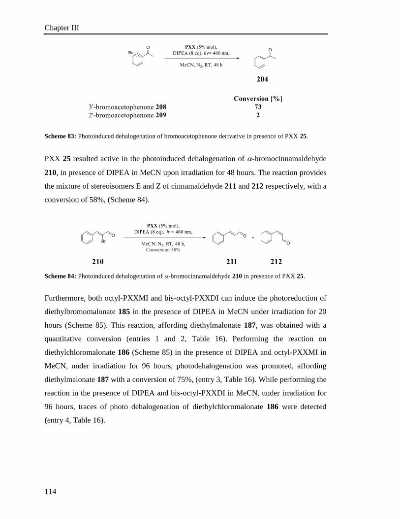
Chapter III
114
Scheme 83: Photoinduced dehalogenation of bromoacetophenone derivative in presence of PXX 25.
PXX 25 resulted active in the photoinduced dehalogenation of -bromocinnamaldehyde
210, in presence of DIPEA in MeCN upon irradiation for 48 hours. The reaction provides
the mixture of stereoisomers E and Z of cinnamaldehyde 211 and 212 respectively, with a
conversion of 58%, (Scheme 84).
Scheme 84: Photoinduced dehalogenation of -bromocinnamaldehyde 210 in presence of PXX 25.
Furthermore, both octyl-PXXMI and bis-octyl-PXXDI can induce the photoreduction of
diethylbromomalonate 185 in the presence of DIPEA in MeCN under irradiation for 20
hours (Scheme 85). This reaction, affording diethylmalonate 187, was obtained with a
quantitative conversion (entries 1 and 2, Table 16). Performing the reaction on
diethylchloromalonate 186 (Scheme 85) in the presence of DIPEA and octyl-PXXMI in
MeCN, under irradiation for 96 hours, photodehalogenation was promoted, affording
diethylmalonate 187 with a conversion of 75%, (entry 3, Table 16). While performing the
reaction in the presence of DIPEA and bis-octyl-PXXDI in MeCN, under irradiation for
96 hours, traces of photo dehalogenation of diethylchloromalonate 186 were detected
(entry 4, Table 16).
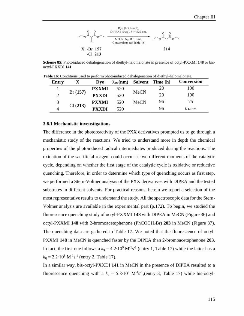
Chapter III
115
Scheme 85: Photoinduced dehalogenation of diethyl-halomalonate in presence of octyl-PXXMI 148 or bis-
octyl-PXXDI 141.
Table 16: Conditions used to perform photoinduced dehalogenation of diethyl-halomalonate.
Entry X Dye λex (nm) Solvent Time [h] Conversion
[%] 1 Br (157)
PXXMI 520 MeCN
20 100
2 PXXDI 520 20 100
3 Cl (213)
PXXMI 520 MeCN 96 75
4 PXXDI 520 96 traces
3.6.1 Mechanistic invenstigations
The difference in the photoreactivity of the PXX derivatives prompted us to go through a
mechanistic study of the reactions. We tried to understand more in depth the chemical
properties of the photoinduced radical intermediates produced during the reactions. The
oxidation of the sacrificial reagent could occur at two different moments of the catalytic
cycle, depending on whether the first stage of the catalytic cycle is oxidative or reductive
quenching. Therefore, in order to determine which type of quenching occurs as first step,
we performed a Stern-Volmer analysis of the PXX derivatives with DIPEA and the tested
substrates in different solvents. For practical reasons, herein we report a selection of the
most representative results to understand the study. All the spectroscopic data for the Stern-
Volmer analysis are available in the experimental part (p.172). To begin, we studied the
fluorescence quenching study of octyl-PXXMI 148 with DIPEA in MeCN (Figure 36) and
octyl-PXXMI 148 with -bromoacetophenone (PhCOCH2Br) 203 in MeCN (Figure 37).
The quenching data are gathered in Table 17. We noted that the fluorescence of octyl-
PXXMI 148 in MeCN is quenched faster by the DIPEA than -bromoacetophenone 203.
In fact, the first one follows a kq = 4.2∙109 M-1s-1 (entry 1, Table 17) while the latter has a
kq = 2.2∙108 M-1s-1 (entry 2, Table 17).
In a similar way, bis-octyl-PXXDI 141 in MeCN in the presence of DIPEA resulted to a
fluorescence quenching with a kq = 5.8∙109 M-1s-1,(entry 3, Table 17) while bis-octyl-
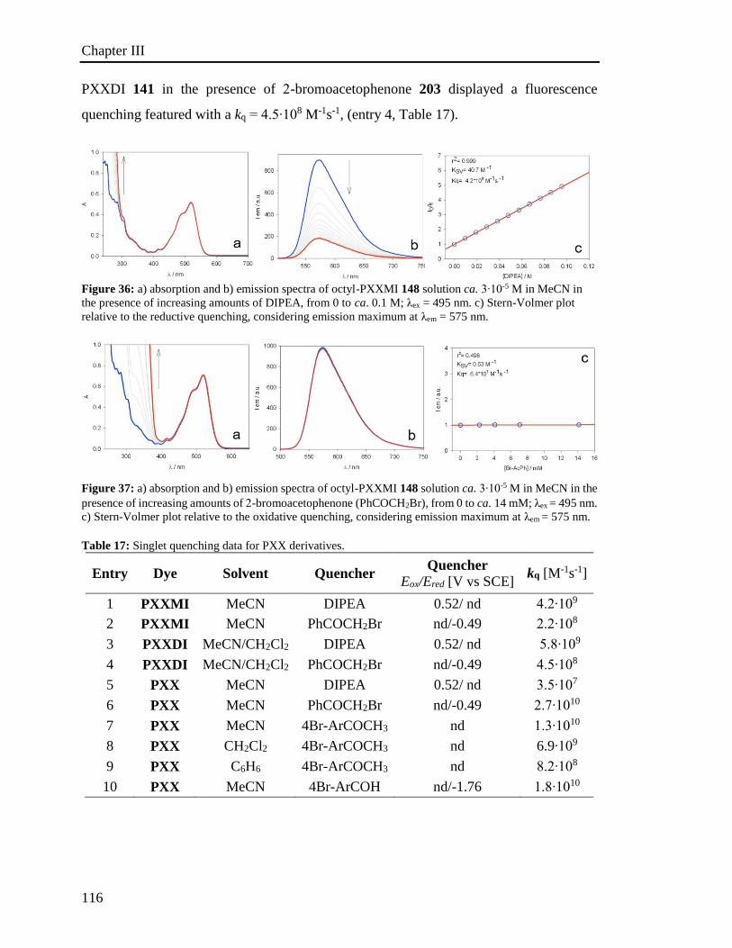
Chapter III
116
PXXDI 141 in the presence of -bromoacetophenone 203 displayed a fluorescence
quenching featured with a kq = 4.5∙108 M-1s-1, (entry 4, Table 17).
Figure 36: a) absorption and b) emission spectra of octyl-PXXMI 148 solution ca. 3∙10-5 M in MeCN in
the presence of increasing amounts of DIPEA, from 0 to ca. 0.1 M; λex = 495 nm. c) Stern-Volmer plot
relative to the reductive quenching, considering emission maximum at λem = 575 nm.
Figure 37: a) absorption and b) emission spectra of octyl-PXXMI 148 solution ca. 3∙10-5 M in MeCN in the
presence of increasing amounts of -bromoacetophenone (PhCOCH2Br), from 0 to ca. 14 mM; λex = 495 nm.
c) Stern-Volmer plot relative to the oxidative quenching, considering emission maximum at λem = 575 nm.
Table 17: Singlet quenching data for PXX derivatives.
Entry Dye Solvent Quencher Quencher
Eox/Ered [V vs SCE] kq [M-1s-1]
1 PXXMI MeCN DIPEA 0.52/ nd 4.2∙109
2 PXXMI MeCN PhCOCH2Br nd/-0.49 2.2∙108
3 PXXDI MeCN/CH2Cl2 DIPEA 0.52/ nd 5.8∙109
4 PXXDI MeCN/CH2Cl2 PhCOCH2Br nd/-0.49 4.5∙108
5 PXX MeCN DIPEA 0.52/ nd 3.5∙107
6 PXX MeCN PhCOCH2Br nd/-0.49 2.7∙1010
7 PXX MeCN 4Br-ArCOCH3 nd 1.3∙1010
8 PXX CH2Cl2 4Br-ArCOCH3 nd 6.9∙109
9 PXX C6H6 4Br-ArCOCH3 nd 8.2∙108
10 PXX MeCN 4Br-ArCOH nd/-1.76 1.8∙1010
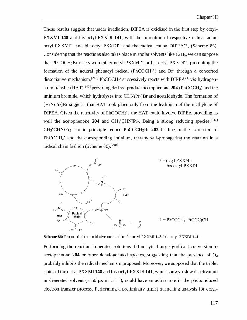
Chapter III
117
These results suggest that under irradiation, DIPEA is oxidised in the first step by octyl-
PXXMI 148 and bis-octyl-PXXDI 141, with the formation of respective radical anion
octyl-PXXMI• - and bis-octyl-PXXDI• - and the radical cation DIPEA• + , (Scheme 86).
Considering that the reactions also takes place in apolar solvents like C6H6, we can suppose
that PhCOCH2Br reacts with either octyl-PXXMI• - or bis-octyl-PXXDI• - , promoting the
formation of the neutral phenacyl radical (PhCOCH2•) and Br- through a concerted
dissociative mechanism.[245] PhCOCH2• successively reacts with DIPEA• + via hydrogen-
atom transfer (HAT)[246] providing desired product acetophenone 204 (PhCOCH3) and the
iminium bromide, which hydrolyses into [H2NiPr2]Br and acetaldehyde. The formation of
[H2NiPr2]Br suggests that HAT took place only from the hydrogen of the methylene of
DIPEA. Given the reactivity of PhCOCH2• , the HAT could involve DIPEA providing as
well the acetophenone 204 and CH3•CHNiPr2. Being a strong reducing species,[247]
CH3•CHNiPr2 can in principle reduce PhCOCH2Br 203 leading to the formation of
PhCOCH2• and the corresponding iminium, thereby self-propagating the reaction in a
radical chain fashion (Scheme 86).[248]
Scheme 86: Proposed photo-oxidative mechanism for octyl-PXXMI 148 /bis-octyl-PXXDI 141.
Performing the reaction in aerated solutions did not yield any significant conversion to
acetophenone 204 or other dehalogenated species, suggesting that the presence of O2
probably inhibits the radical mechanism proposed. Moreover, we supposed that the triplet
states of the octyl-PXXMI 148 and bis-octyl-PXXDI 141, which shows a slow deactivation
in deaerated solvent (~ 50 s in C6H6), could have an active role in the photoinduced
electron transfer process. Performing a preliminary triplet quenching analysis for octyl-
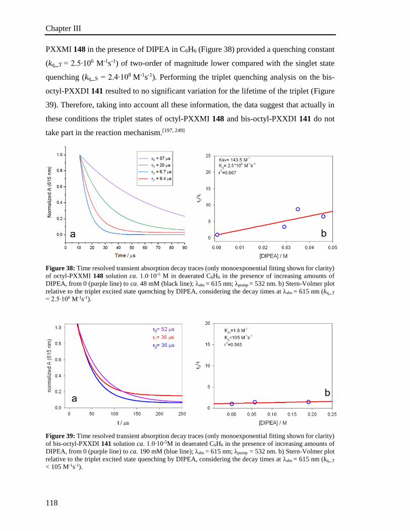
Chapter III
118
PXXMI 148 in the presence of DIPEA in C6H6 (Figure 38) provided a quenching constant
(kq_T = 2.5∙106 M-1s-1) of two-order of magnitude lower compared with the singlet state
quenching (kq_S = 2.4∙108 M-1s-1). Performing the triplet quenching analysis on the bis-
octyl-PXXDI 141 resulted to no significant variation for the lifetime of the triplet (Figure
39). Therefore, taking into account all these information, the data suggest that actually in
these conditions the triplet states of octyl-PXXMI 148 and bis-octyl-PXXDI 141 do not
take part in the reaction mechanism.[197, 249]
Figure 38: Time resolved transient absorption decay traces (only monoexponential fitting shown for clarity)
of octyl-PXXMI 148 solution ca. 1.0∙10-5 M in deaerated C6H6 in the presence of increasing amounts of
DIPEA, from 0 (purple line) to ca. 48 mM (black line); λabs = 615 nm; λpump = 532 nm. b) Stern-Volmer plot
relative to the triplet excited state quenching by DIPEA, considering the decay times at λabs = 615 nm (kq_T
= 2.5∙106 M-1s-1).
Figure 39: Time resolved transient absorption decay traces (only monoexponential fitting shown for clarity)
of bis-octyl-PXXDI 141 solution ca. 1.0∙10-5M in deaerated C6H6 in the presence of increasing amounts of
DIPEA, from 0 (purple line) to ca. 190 mM (blue line); λabs = 615 nm; λpump = 532 nm. b) Stern-Volmer plot
relative to the triplet excited state quenching by DIPEA, considering the decay times at λabs = 615 nm (kq_T
< 105 M-1s-1).

Chapter III
119
Regarding the PXX 25 Stern-Volmer studies (entries 5-10, Table 17), we observed that the
quenching rate with 4Br-ArCOCH3 (entry 7, Table 17) is considerably higher than the
quenching rate observed with DIPEA (entry 5, Table 17) in MeCN. As expected, lower
quenching constants are observed in less polar solvents such as CH2Cl2 (entry 8 Table 17)
and C6H6 (entry 9 Table 17). In contrast to the imide derivatives, this evidence suggests
that the formation of the radical cation PXX•+ with the simultaneous reduction of
4BrArCOCH3, into a ketyl radical anion derivative,[250] is stabilized in polar solvents
(Scheme 87). The newly formed ketyl radical anion 4BrArCOCH3• - undergoes
fragmentation by dissociative electron transfer, providing the formation of aryl radical
•ArCOCH3 and Br- anion.[251] In 1986, Andrieux et al. proposed that initially the unpaired
electron is located in a π* orbital of the aromatic system.[251] As consequence of the C-Br
stretching a three-electron bond is formed which afterwards cleaves in a unpaired electron
located in the σ-HOMO orbital of the aryl radical • ArCOCH3 and an electron pair is carried
away in the p atomic orbital of the bromine atom. The stretching of the C-Br bond
corresponds in stabilization of C-Br σ* orbital whereas the variation of energy π* orbital
is small.[252] The crossing point of π* and a σ* energy levels can thus be considered the
representation of the transition state.[251] Eventually in the proposed mechanism, PXX• +
reacts with DIPEA forming DIPEA• +. The latter is possibly reacting with •ArCOCH3
through hydrogen atom transfer affording the ArCOCH3 and the relevant iminium.
Remarkably, the ketyl radical intermediate cannot be formed by reduction with
CH3•CHNiPr2, otherwise it would have taken place in the photosystems involving octyl-
PXXMI 148 and bis-octyl-PXXDI 141.
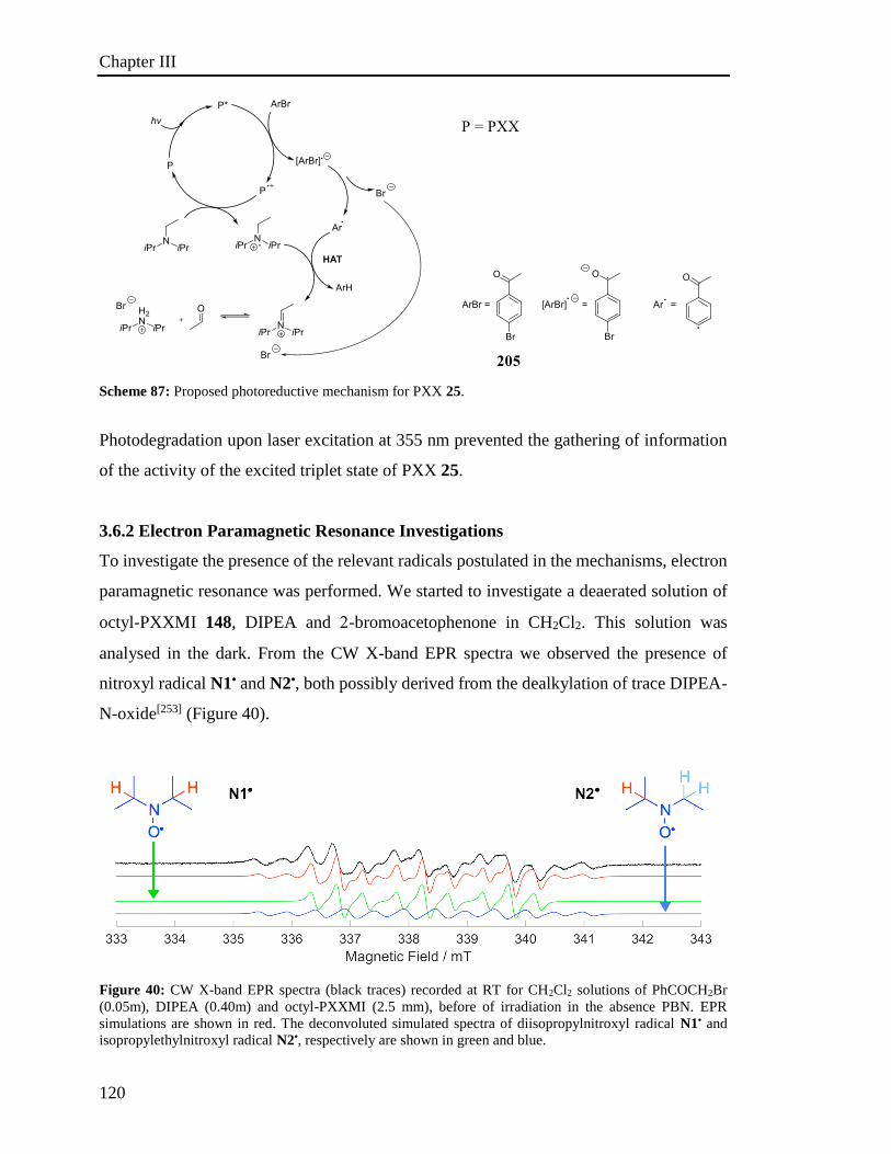
Chapter III
120
Scheme 87: Proposed photoreductive mechanism for PXX 25.
Photodegradation upon laser excitation at 355 nm prevented the gathering of information
of the activity of the excited triplet state of PXX 25.
3.6.2 Electron Paramagnetic Resonance Investigations
To investigate the presence of the relevant radicals postulated in the mechanisms, electron
paramagnetic resonance was performed. We started to investigate a deaerated solution of
octyl-PXXMI 148, DIPEA and -bromoacetophenone in CH2Cl2. This solution was
analysed in the dark. From the CW X-band EPR spectra we observed the presence of
nitroxyl radical N1• and N2•, both possibly derived from the dealkylation of trace DIPEA-
N-oxide[253] (Figure 40).
Figure 40: CW X-band EPR spectra (black traces) recorded at RT for CH2Cl2 solutions of PhCOCH2Br
(0.05m), DIPEA (0.40m) and octyl-PXXMI (2.5 mm), before of irradiation in the absence PBN. EPR
simulations are shown in red. The deconvoluted simulated spectra of diisopropylnitroxyl radical N1• and
isopropylethylnitroxyl radical N2•, respectively are shown in green and blue.
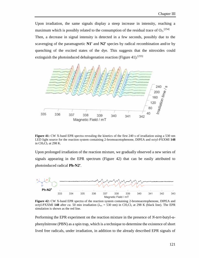
Chapter III
121
Upon irradiation, the same signals display a steep increase in intensity, reaching a
maximum which is possibly related to the consumption of the residual trace of O2.[254]
Then, a decrease in signal intensity is detected in a few seconds, possibly due to the
scavenging of the paramagnetic N1• and N2• species by radical recombination and/or by
quenching of the excited states of the dye. This suggests that the nitroxides could
extinguish the photoinduced dehalogenation reaction (Figure 41).[255]
Figure 41: CW X-band EPR spectra revealing the kinetics of the first 240 s of irradiation using a 530 nm
LED light source for the reaction system containing 2-bromoacetophenone, DIPEA and octyl-PXXMI 148
in CH2Cl2 at 298 K.
Upon prolonged irradiation of the reaction mixture, we gradually observed a new series of
signals appearing in the EPR spectrum (Figure 42) that can be easily attributed to
photoinduced radical Ph-N2•.
Figure 42: CW X-band EPR spectra of the reaction system containing 2-bromoacetophenone, DIPEA and
octyl-PXXMI 148 after ca. 50 min irradiation (λex = 530 nm) in CH2Cl2 at 298 K (black line). The EPR
simulation is shown as the red line.
Performing the EPR experiment on the reaction mixture in the presence of N-tert-butyl-α-
phenylnitrone (PBN) as a spin trap, which is a technique to determine the existence of short
lived free radicals, under irradiation, in addition to the already described EPR signals of

Chapter III
122
Ph-N2•, we observed the formation of EPR signals that can be unambiguously assigned to
the nitroxyl radical Ph-ST• which derived from the reaction of the photoinduced radical
PhCOCH2• with PBN, (Figure 43).
Figure 43: CW X-band EPR spectra of the reaction system containing 2-bromoacetophenone, DIPEA and
octyl-PXXMI 148 after ca. 50 min irradiation (λex = 530 nm) in CH2Cl2 at 298 K in the presence of N-tert-
butyl-α-phenylnitrone (PBN) as a spin trap (black line). The EPR simulation is shown as the red line. The
deconvoluted simulated spectra of the PBN-phenacyl radical adduct Ph-ST•.
Subsequently we studied a deaerated solution of PXX 25, DIPEA and 4’-
bromoacetophenone in CH2Cl2 in the dark. In solutions of octyl-PXXMI 148 kept in the
dark we observed the presence of nitroxyl radical N1• and N2• (Figure 44-a); upon
irradiation, their corresponding signals increase until a maximum and then decrease,
(Figure 45-b). After this time-lapse, a new series of EPR signals, which are related to the
formation of the photoinduced radical Ar-N2• (Figure 44-b) appear. When the reaction
mixture is irradiated in presence of PBN, in addition to the signal of Ar-N2•, new EPR
signals are present, which can be unambiguously assigned to the nitroxyl radical Ar-ST•,
as product of the reaction between PBN with •ArCOCH3 (Figure 44-c). The evolution of
the signal corresponding to Ar-ST• as function of the irradiation time is depicted in Figure
45-A, showing a steady increase after 180 seconds of irradiation, suggesting the formation
of Ar• and therefore the progression of the dehalogenation.
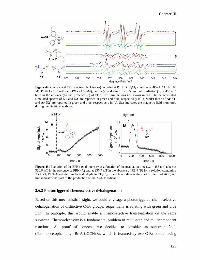
Chapter III
123
Figure 44: CW X-band EPR spectra (black traces) recorded at RT for CH2Cl2 solutions of 4Br-ArCOH (0.05
M), DIPEA (0.40 mM) and PXX (2.5 mM), before (a) and after (b) ca. 50 min of irradiation (ex = 455 nm)
both in the absence (b) and presence (c) of PBN. EPR simulations are shown in red. The deconvoluted
simulated spectra of N1• and N2• are reported in green and blue, respectively in (a) whilst those of Ar-ST•
and Ar-N2• are reported in green and blue, respectively in (c). Star indicates the magnetic field monitored
during the kinetical analysis.
Figure 45: Evolution of the EPR signal intensity as a function of the irradiation time (ex = 455 nm) taken at
336.6 mT in the presence of PBN (A) and at 336.7 mT in the absence of PBN (B) for a solution containing
PXX 25, DIPEA and 4-bromobenzaldehyde in CH2Cl2. Black line indicates the start of the irradiation; red
line indicates the start of the production of the Ar-ST• radical.
3.6.3 Phototriggered chemoselective dehalogenation
Based on this mechanistic insight, we could envisage a phototriggered chemoselective
dehalogenation of distinctive C-Br groups, sequentially irradiating with green and blue
light. In principle, this would enable a chemoselective transformation on the same
substrate. Chemoselectivity is a fundamental problem in multi-step and multicomponent
reactions. As proof of concept, we decided to consider as substrate 2,4’-
dibromoacetophenone, 4Br-ArCOCH2Br, which is featured by two C-Br bonds having
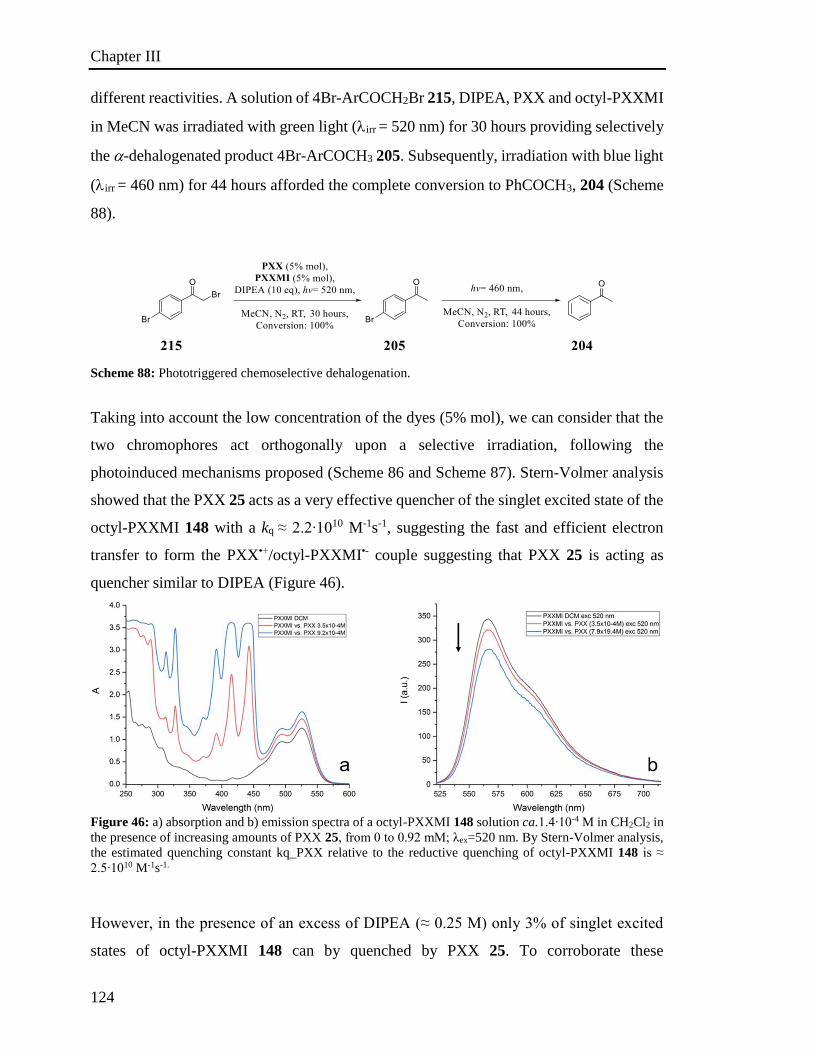
Chapter III
124
different reactivities. A solution of 4Br-ArCOCH2Br 215, DIPEA, PXX and octyl-PXXMI
in MeCN was irradiated with green light (irr = 520 nm) for 30 hours providing selectively
the -dehalogenated product 4Br-ArCOCH3 205. Subsequently, irradiation with blue light
(irr = 460 nm) for 44 hours afforded the complete conversion to PhCOCH3, 204 (Scheme
88).
Scheme 88: Phototriggered chemoselective dehalogenation.
Taking into account the low concentration of the dyes (5% mol), we can consider that the
two chromophores act orthogonally upon a selective irradiation, following the
photoinduced mechanisms proposed (Scheme 86 and Scheme 87). Stern-Volmer analysis
showed that the PXX 25 acts as a very effective quencher of the singlet excited state of the
octyl-PXXMI 148 with a kq ≈ 2.2∙1010 M-1s-1, suggesting the fast and efficient electron
transfer to form the PXX•+/octyl-PXXMI•- couple suggesting that PXX 25 is acting as
quencher similar to DIPEA (Figure 46).
Figure 46: a) absorption and b) emission spectra of a octyl-PXXMI 148 solution ca.1.4∙10-4 M in CH2Cl2 in
the presence of increasing amounts of PXX 25, from 0 to 0.92 mM; λex=520 nm. By Stern-Volmer analysis,
the estimated quenching constant kq_PXX relative to the reductive quenching of octyl-PXXMI 148 is ≈
2.5∙1010 M-1s-1.
However, in the presence of an excess of DIPEA (≈ 0.25 M) only 3% of singlet excited
states of octyl-PXXMI 148 can by quenched by PXX 25. To corroborate these
Chapter III
125
assumptions, we performed the dehalogenation reactions under more diluted conditions.
As expected the desired products were provided, although with a lower conversion.
3.7. Conclusion
Studying the spectroscopic properties of PXX derivatives using PXX 25 as a reference, the
absorption spectra show a clear bathochromic shift for both octyl-PXXMI 148 and bis-
octyl-PXXDI 141. This is a consequence of the presence of the electron withdrawing imide
group. As observed by comparing the spectra, the number of the imide moieties introduced
on the PXX changes the shape and intensity of the absorption band. However, it is worth
mentioning that, whereas in the case of octyl-PXXMI 148 we observe a strong shift of 82
nm, in the case of bis-octyl-PXXDI the further shift in the spectra is less than 15 nm in
CH2Cl2. This implies that the second imide functionalization does not affect dramatically
the energy associated to the transition. Similarly, the fluorescence spectra of PXX 25,
octyl-PXXMI 148 and bis-octyl-PXXDI 141 display a bathochromic shift highlighting the
difference in shape and vibrational structure of the absorption profile. The PXX derivatives
do not exhibit phosphorescence even at low temperature (77 K). However, a non-emissive
triplet has been detected by transient spectroscopy. From cyclic voltammetry analysis we
observe that the introduction of electron withdrawing imide substituents on the PXX
induces an electron depletion on the aromatic core. Consequently, octyl-PXXMI 148 and
bis-octyl-PXXDI 141 are increasingly more difficult to be oxidised and easier to be
reduced. In both cases, the shift in the reduction and oxidation halfwave potential is 0.3V.
Therefore, the spectroscopic and electrochemical results highlight a rigid energy shift of
the frontier molecular orbitals. Comparing the redox potential of the singlet excited state
of the PXX derivatives with the most well-known photoredox catalysts such as
[Ru(bpy)3]2+ and [Ir(ppy)3] complexes, we observe that octyl-PXXMI 148 and bis-octyl-
PXXDI 141 are stronger reducers and oxidisers than the triplet excited state of
[Ru(bpy)3]2+. Additionally, the singlet excited state of the parent PXX 25 is a greater
reducer and oxidiser compared to the triplet excited state of [Ir(ppy)3].
Capitalizing on these results, we employed the PXX derivatives in photoredox
transformation as photocatalysts. We studied the photocatalytic dehalogenation of organic
Chapter III
126
halides as a model reaction, as well as the subsequent phototriggered mechanism. The fact
that PXX derivatives have different photoredox properties results in a difference in their
photocatalytic activity. Based on this difference of their photoredox properties, octyl-
PXXMI 148 and bis-octyl-PXXDI 141 are catalytically active on dehalogenation of Csp3,
but not on aromatic substrates. On the other hand, PXX is active also on dehalogenation
reactions involving bromo aromatic derivatives. Investigation of the mechanisms by Stern-
Volmer analysis reveals that octyl-PXXMI 148 and bis-octyl-PXXDI 141 proceed through
an oxidative mechanistic quenching. However, PXX photocatalytic cycle is based on a
reductive quenching. Confirmation of the catalytic mechanism has been established by
EPR analysis. Based on the difference in the absorption and photoredox properties, we
were able to perform a chemoselective transformation by irradiating the reaction mixture,
containing PXX 25 and octyl-PXXMI 148, at two different wavelengths.
References
127
References:
[1] J. R. Barnett, S. Miller, E. Pearce, Opt. Laser Technol. 2006, 38, 445-453.
[2] R. D. Welham, J. Soc. Dyers Colour.1963, 79, 98-105.
[3] W. H. Perkin, Patent GB 1984, 1856.
[4] I. Holme, Color. Technol. 2006, 122, 235-251.
[5] S. Holgate, Understanding Solid State Physics, Boca Raton: CRC Press., 2009.
[6] M. Pope, C. E. Swenberg, Electronic Processes in Organic Crystals and
Polymers, Oxford University Press, 1999.
[7] a) R. R. Moskalyk, Miner. Eng. 2003, 16, 921-929; b) J. S. Blakemore, J. Appl.
Phys. 1982, 53, R123-R181.
[8] J. Whitaker, Solid State Electron.1965, 8, 649-652.
[9] a) G. Cassabois, P. Valvin, B. Gil, Nat. Photonics, 2016, 10, 262–266; b) G. K.
Gaule, Boron: Vol. 2: Preparation, Properties, and Applications, Plenum Press,
1965.
[10] a) M. Arif, M. Rahman, W. Y. San, Int. J. Adv. Manuf. Technol. 2012, 63, 481-
504; b) G. L. Pearson, J. Bardeen, Phys. Rev. 1949, 75, 865-883.
[11] W. M. Holt, Proc. IEEE Int’l Solid State Circuits Conf., 2016, 8–13.
[12] K. P. Goetz, D. Vermeulen, M. E. Payne, C. Kloc, L. E. McNeil, O. D. Jurchescu,
J. Mater. Chem. C 2014, 2, 3065-3076.
[13] a) A. C. Annis., Dig. Tech. Pap. 2017, 48, 1509-1511; b) H. E. Katz, Chem. Mater.
2004, 16, 4748-4756.
[14] S. E. Root, S. Savagatrup, A. D. Printz, D. Rodriquez, D. J. Lipomi, Chem. Rev.
2017, 117, 6467-6499.
[15] J. W. Ward, Z. A. Lamport, O. D. Jurchescu, ChemPhysChem 2015, 16, 1118-
1132.
[16] H. Sirringhaus, Adv. Mater. 2014, 26, 1319-1335.
[17] E. A. Davis, N. F. Mott, Philos. Mag. 1970, 22, 903-922.
[18] V. Coropceanu, J. Cornil, D. A. da Silva Filho, Y. Olivier, R. Silbey, J. L. Brédas,
Chem. Rev. 2007, 107, 926-952.
[19] H. Sirringhaus, Adv. Mater. 2009, 21, 3859-3873.
References
128
[20] a) A. A. Shoustikov, Y. Yujian, M. E. Thompson, IEEE Journal of Selected
Topics in Quantum Electronics 1998, 4, 3-13; b) M. Jacob, Electronics 2014, 3,
594-597; c) C., Sekine, Y. Tsubata, T. Yamada, M. Kitano, S. Doi, Sci. Technol.
Adv. Mater. 2014, 15, 034203; d) L. A. Duan, L. D. Hou, T. W. Lee, J. A. Qiao, D.
Q. Zhang, G. F. Dong, L. D. Wang and Y. Qiu, J. Mater. Chem. 2010, 20, 6392-
6407.
[21] a) J Roncali, P.Leriche, P. Blanchard, Adv. Mater.2014, 26, 3821-3838; b) Y. Lin,
Y. Li, X. Zhan, Chem. Soc. Rev. 2012, 41, 4245-4272.
[22] A. Facchetti, Mater. Today. 2007, 10, 28-37.
[23] Y. Xu, H. Sun, Y. Y. Noh, IEEE Trans. Electron Devices 2017, 64, 1932-1943.
[24] a) J Roncali, Macromol. Rapid Commun. 2007, 28, 1761-1775; b) J. Roncali,
Chem. Rev. 1997, 97, 173-206.
[25] a) H. A. M. van Mullekom, J. A. J. M. Vekemans, E. E. Havinga, E. W. Meijer,
Mater. Sci. Eng. R 2001, 32, 1-40; b) M. Stępień, E. Gońka, M. Żyła, N. Sprutta,
Chem. Rev. 2017, 117, 3479-3716.
[26] S. Ito, S. Hiroto, S. Lee, M. Son, I. Hisaki, T. Yoshida, D. Kim, N. Kobayashi, H.
Shinokubo, J. Am. Chem. Soc. 2015, 137, 142-145.
[27] a) P. M. Beaujuge, C. M. Amb, J. R. Reynolds, Acc. Chem. Res. 2010, 43, 1396-
1407; b) D. P. Hagberg, T. Marinado, K. M. Karlsson, K. Nonomura, P. Qin, G.
Boschloo, T. Brinck, A. Hagfeldt, L. Sun, J. Org. Chem. 2007, 72, 9550-9556.
[28] O. Wennerstroem, Macromolecules 1985, 18, 1977-1980.
[29] R. S. Peierls, Quantum theory of solids, Oxford: Oxford University Press, 2001.
[30] a) J. L. Brédas, J. Chem. Phys. 1985, 82, 3808-3811; b) W. P. Su, J. R. Schrieffer,
A. J. Heeger, Phys. Rev. Lett. 1979, 42, 1698-1701; c) J. P. Lowe, S. A. Kafafi, J.
Am. Chem. Soc. 1984, 106, 5837-5841; d) Y. S. Lee, M. Kertesz, J. Chem. Phys
1988, 88, 2609-2617.
[31] F. Wudl, M. Kobayashi, A. J. Heeger, J. Org. Chem. 1984, 49, 3382-3384.
[32] a) M. Pomerantz, B. Chaloner-Gill, L. O. Harding, J. J. Tseng, W. J. Pomerantz,
J. Chem. Soc., Chem. Commun. 1992, 22, 1672-1673; b) S. Y. Hong, D. S.
Marynick, Macromolecules 1992, 25, 4652-4657; c) G. A. Sotzing, K. Lee,
Macromolecules 2002, 35, 7281-7286.
References
129
[33] a) R. S. Mulliken, C. A. Rieke, W. G. Brown, J. Am. Chem. Soc. 1941, 63, 41-56;
b) J. L. Brédas, G. B. Street, B. Thémans, J. M. André, J. Chem. Phys 1985, 83,
1323-1329.
[34] J. Roncali, R. Garreau, A. Yassar, P. Marque, F. Garnier, M. Lemaire, J. Phys.
Chem. 1987, 91, 6706-6714.
[35] L. Zöphel, V. Enkelmann, K. Müllen, Org. Lett. 2013, 15, 804-807.
[36] E. E. Havinga, W. ten Hoeve, H. Wynberg, Polym. Bull. 1992, 29, 119-126.
[37] F. Würthner, S. Ahmed, C. Thalacker, T. Debaerdemaeker, Chem. Eur. J. 2002,
8, 4742-4750.
[38] R. S. K. Kishore, O. Kel, N. Banerji, D. Emery, G. Bollot, J. Mareda, A. Gomez-
Casado, P. Jonkheijm, J. Huskens, P. Maroni, M. Borkovec, E. Vauthey, N. Sakai,
S. Matile, J. Am. Chem. Soc. 2009, 131, 11106-11116.
[39] a) M. Licchelli, A. Orbelli Biroli, A. Poggi, Org. Lett. 2006, 8, 915-918; b) S.
Alp, Ş. Erten, C. Karapire, B. Köz, A. O. Doroshenko, S. İçli, J. Photochem.
Photobiol. A Chem. 2000, 135, 103-110.
[40] a) C. Thalacker, C. Röger, F. Würthner, J. Org. Chem. 2006, 71, 8098-8105; b)
C. Röger, F. Würthner, J. Org. Chem. 2007, 72, 8070-8075.
[41] T. H. Vo, M. Shekhirev, D. A. Kunkel, F. Orange, M. J. F. Guinel, A. Enders, A.
Sinitskii, Chem. Commun. 2014, 50, 4172-4174.
[42] A. Escande, M. J. Ingleson, Chem. Commun. 2015, 51, 6257-6274.
[43] a) T. Baumgartner, Acc. Chem. Res. 2014, 47, 1613-1622; b) Q. Miao, Polycyclic
Arenes and Heteroarenes, Wiley‐VCH Verlag, 2015.
[44] L. Zhang, S. M. Fakhouri, F. Liu, J. C. Timmons, N. A. Ran, A. L. Briseno, J.
Mater. Chem. 2011, 21, 1329-1337.
[45] J. E. Anthony, Chem. Rev. 2006, 106, 5028-5048.
[46] F. Dötz, J. D. Brand, S. Ito, L. Gherghel, K. Müllen, J. Am. Chem. Soc. 2000, 122,
7707-7717.
[47] S. Allard, M. Forster, B. Souharce, H. Thiem, U. Scherf, Angew. Chem. Int. Ed.
2008, 47, 4070-4098.
[48] D. Adam, P. Schuhmacher, J. Simmerer, L. Häussling, K. Siemensmeyer, K. H.
Etzbachi, H. Ringsdorf, D. Haarer, Nature 1994, 371, 141-143.
References
130
[49] a) W. Pisula, A. Menon, M. Stepputat, I. Lieberwirth, U. Kolb, A. Tracz, H.
Sirringhaus, T. Pakula, K. Müllen, Adv. Mater. 2005, 17, 684-689; b) A. M. van
de Craats, J. M. Warman, A. Fechtenkötter, J. D. Brand, M. A. Harbison, K.
Müllen, Adv. Mater. 1999, 11, 1469-1472; c) K. D. Harris, S. Xiao, C. Y. Lee, M.
S. Strano, C. Nuckolls, G. B. Blanchet, J. Phys. Chem. C 2007, 111, 17947-17951.
[50] N. G. Pschirer, C. Kohl, F. Nolde, J. Qu, K. Müllen, Angew. Chem. Int. Ed. 2006,
118, 1429-1432.
[51] a) T. Weil, T. Vosch, J. Hofkens, K. Peneva, K. Müllen, Angew. Chem. Int. Ed.
2010, 49, 9068-9093; b) X. Zhan, A. Facchetti, S. Barlow, T. J. Marks, M. A.
Ratner, M. R. Wasielewski, S. R. Marder, Adv. Mater. 2011, 23, 268-284.
[52] Y. Avlasevich, C. Li, K. Mullen, J. Mater. Chem. 2010, 20, 3814-3826.
[53] M. Kardos, Patent DE 276956, 1913.
[54] a) W. Herbst, K. Hunger, Industrial organic pigments: production, properties,
applications, John Wiley & Sons, 2006; b) M. Kardos, Patent DE 276357, 1913.
[55] F. Würthner, Chem. Commun. 2004, 14,1564-1579.
[56] a) W. E. Ford, P. V. Kamat, J. Phys. Chem. 1987, 91, 6373-6380; b) G. Seybold,
G. Wagenblast, Dyes and Pigm. 1989, 11, 303-317; c) T. Weil, U. M. Wiesler, A.
Herrmann, R. Bauer, J. Hofkens, F. C. De Schryver, K. Müllen, J. Am. Chem.
Soc. 2001, 123, 8101-8108; d) R. Gronheid, J. Hofkens, F. Köhn, T. Weil, E.
Reuther, K. Müllen, F. C. De Schryver, J. Am. Chem. Soc. 2002, 124, 2418-2419;
e) J. M. Serin, D. W. Brousmiche, J. M. J. Fréchet, Chem. Commun. 2002, 2605-
2607; f) B. A. Jones, A. Facchetti, M. R. Wasielewski, T. J. Marks, J. Am. Chem.
Soc. 2007, 129, 15259-15278.
[57] R. Schmidt, K. Griesbaum, A. Behr, D. Biedenkapp, H. Voges, D. Garbe, C.
Paetz, G. Collin, D. Mayer, H. Höke, Ullmann's Encyclopedia of Industrial
Chemistry, Vol. 18 Wiley‐VCH Verlag, 2014, 133-189.
[58] a) I. Farbenindustrie, Patent DE 428 088, 1921; b) Selden, Patent GB 318 617,
1929.
[59] H. Langhals, Heterocycles 1995, 40, 477-500.
[60] C. Huang, S. Barlow, S. R. Marder, J. Org. Chem. 2011, 76, 2386-2407.
[61] F. Würthner, C. Thalacker, S. Diele, C. Tschierske, Chem. Eur. J. 2001, 7, 2245-
2253.
References
131
[62] M. Sadrai, L. Hadel, R. R. Sauers, S. Husain, K. Krogh-Jespersen, J. D.
Westbrook, G. R. Bird, J. Phys. Chem. 1992, 96, 7988-7996.
[63] a) S. L. Oliveira, D. S. Corrêa, L. Misoguti, C. J. L. Constantino, R. F. Aroca, S.
C. Zilio, C. R. Mendonça, Adv. Mater. 2005, 17, 1890-1893; b) D. S. Corrêa, S.
L. Oliveira, L. Misoguti, S. C. Zilio, R. F. Aroca, C. J. L. Constantino, C. R.
Mendonça, J. Phys. Chem. A 2006, 110, 6433-6438.
[64] F. Würthner, A. Sautter, J. Schilling, J. Org. Chem. 2002, 67, 3037-3044.
[65] R. Schmidt, J. H. Oh, Y. S. Sun, M. Deppisch, A. M. Krause, K. Radacki, H.
Braunschweig, M. Könemann, P. Erk, Z. Bao, F. Würthner, J. Am. Chem. Soc.
2009, 131, 6215-6228.
[66] a) Y. Nagao, Prog. Org. Coat. 1997, 31, 43-49; b) I. K. Iverson, S. W. Tam-
Chang, J. Am. Chem. Soc. 1999, 121, 5801-5802.
[67] L. Ivan, L. Heinz, Chem. Ber. 1983, 116, 3524-3528.
[68] a) M. Sommer, S. M. Lindner, M. Thelakkat, Adv. Funct. Mater. 2007, 17, 1493-
1500; b) S. Michael, L. A. S., T. Mukundan, Angew. Chem. Int. Ed. 2008, 47,
7901-7904; c) S. M. Lindner, S. Hüttner, A. Chiche, M. Thelakkat, G. Krausch,
Angew. Chem. Int. Ed. 2006, 45, 3364-3368; d) S. Hόttner, M. Sommer, M.
Thelakkat, Appl. Phys. Lett. 2008, 92, 093302.
[69] F. Würthner, C. R. Saha-Möller, B. Fimmel, S. Ogi, P. Leowanawat, D. Schmidt,
Chem. Rev. 2016, 116, 962-1052.
[70] A. Boehm, H. Arms, G. Henning, P. Blaschka, Patent. DE 19547209 A1, 1997.
[71] V. I. Rogovik, L. F. Gutnik, Zh. Org. Khim. 1988, 24, 635-639.
[72] a) C. Zhao, Y. Zhang, R. Li, X. Li, J. Jiang, J. Org. Chem. 2007, 72, 2402-2410;
b) R. K. Dubey, A. Efimov, H. Lemmetyinen, Chem. Mater. 2011, 23, 778-788;
c) L. Perrin, P. Hudhomme, Eur. J. Org. Chem. 2011, 28, 5427-5440.
[73] F. Würthner, V. Stepanenko, Z. Chen, C. R. Saha- Möller, N. Kocher, D. Stalke,
J. Org. Chem. 2004, 69, 7933-7939.
[74] a) W. Qiu, S. Chen, X. Sun, Y. Liu, D. Zhu, Org. Lett. 2006, 8, 867-870; b) M.
Queste, C. Cadiou, B. Pagoaga, L. Giraudet, N. Hoffmann, New J. Chem. 2010,
34, 2537-2545; c) V. Sivamurugan, K. Kazlauskas, S. Jursenas, A. Gruodis, J.
Simokaitiene, J. V. Grazulevicius, S. Valiyaveettil, J. Phys. Chem. B 2010, 114,
References
132
1782-1789; d) S. Dey, A. Efimov, H. Lemmetyinen, Eur. J. Org. Chem. 2012,12,
2367-2374.
[75] a) U. Rohr, P. Schlichting, A. Böhm, M. Gross, K. Meerholz, C. Bräuchle, K.
Müllen, Angew. Chem. Int. Ed. 1998, 37, 1434-1437; b) N. V. Handa, K. D.
Mendoza, L. D. Shirtcliff, Org. Lett. 2011, 13, 4724-4727; c) C. Lόtke Eversloh,
C. Li, K. Müllen, Org. Lett. 2011, 13, 4148-4150.
[76] a) M. J. Ahrens, M. J. Fuller, M. R. Wasielewski, Chem. Mater. 2003, 15, 2684-
2686; b) B. A. Jones, M. J. Ahrens, M. H. Yoon, A. Facchetti, T. J. Marks, M. R.
Wasielewski, Angew. Chem. Int. Ed. 2004, 43, 6363-6366; c) R. T. Weitz, K.
Amsharov, U. Zschieschang, E. B. Villas, D. K. Goswami, M. Burghard, H.
Dosch, M. Jansen, K. Kern, H. Klauk, J. Am. Chem. Soc. 2008, 130, 4637-4645.
[77] U. Rohr, C. Kohl, K. Müllen, A. van de Craats, J. Warman, J. Mater. Chem. 2001,
11, 1789-1799.
[78] a) Y. Li, L. Tan, Z. Wang, H. Qian, Y. Shi, W. Hu, Org. Lett. 2008, 10, 529-532;
b) T. Schnitzler, C. Li, K. Müllen, Helv. Chim. Acta 2009, 92, 2525-2531.
[79] J. E. Anthony, A. Facchetti, M. Heeney, S. R. Marder, X. Zhan, Adv. Mater. 2010,
22, 3876-3892.
[80] F. Würthner, C. Thalacker, S. Diele, C. Tschierske, Chem. Eur. J. 2001, 7, 2245-
2253.
[81] A. S. Lukas, Y. Zhao, S. E. Miller, M. R. Wasielewski, J. Phys. Chem. B 2002,
106, 1299-1306.
[82] a) W. E. Ford, H. Hiratsuka, P. V. Kamat, J. Phys. Chem. 1989, 93, 6692-6696;
b) E. Shirman, A. Ustinov, N. Ben-Shitrit, H. Weissman, M. A. Iron, R. Cohen,
B. Rybtchinski, J. Phys. Chem. B 2008, 112, 8855-8858.
[83] a) Á. J. Jiménez, F. Spänig, M. S. Rodríguez-Morgade, K. Ohkubo, S. Fukuzumi,
D. M. Guldi, T. Torres, Org. Lett. 2007, 9, 2481-2484; b) M. P. O'Neil, M. P.
Niemczyk, W. A. Svec, D. Gosztola, G. L. Gaines, M. R. Wasielewski, Science
1992, 257, 63-65.
[84] G. Yu, A. J. Heeger, J. Appl. Phys. 1995, 78, 4510-4515.
[85] Z. An, S. A. Odom, R. F. Kelley, C. Huang, X. Zhang, S. Barlow, L. A. Padilha,
J. Fu, S. Webster, D. J. Hagan, E. W. Van Stryland, M. R. Wasielewski, S. R.
Marder, J. Phys. Chem. A 2009, 113, 5585-5593.
References
133
[86] a) H. Dong, X. Fu, J. Liu, Z. Wang, W. Hu, Adv. Mater. 2013, 25, 6158-6183; b)
L. Dou, J. You, Z. Hong, Z. Xu, G. Li, R. A. Street, Y. Yang, Adv. Mater. 2013,
25, 6642-6671; c) A. J. Heeger, Adv. Mater. 2014, 26, 10-28; d) H. Sirringhaus,
Adv. Mater. 2014, 26, 1319-1335; e) Y. Zhao, Y. Guo, Y. Liu, Adv. Mater. 2013,
25, 5372-5391; f) G. Schweicher, Y. Olivier, V. Lemaur, Y. H. Geerts, Isr. J.
Chem. 2014, 54, 595-620.
[87] a) Y. Lin, X. Zhan, Acc. Chem. Res. 2016, 49, 175-183; b) A. Mishra, P. Bäuerle,
Angew. Chem. Int. Ed. 2012, 51, 2020-2067; c) C. Li, M. Liu, N. G. Pschirer, M.
Baumgarten, K. Müllen, Chem. Rev. 2010, 110, 6817-6855.
[88] H. Klauk, Chem. Soc. Rev. 2010, 39, 2643-2666.
[89] A. C. Grimsdale, K. Leok Chan, R. E. Martin, P. G. Jokisz, A. B. Holmes, Chem.
Rev. 2009, 109, 897-1091.
[90] A. R. Murphy, J. M. J. Fréchet, Chem. Rev. 2007, 107, 1066-1096.
[91] Y. Shirota, H. Kageyama, Chem. Rev. 2007, 107, 953-1010.
[92] O. A. Melville, B. H. Lessard, T. P. Bender, ACS Appl. Mater. Interfaces 2015,
7, 13105-13118.
[93] S. R. Forrest, Chem. Rev. 1997, 97, 1793-1896.
[94] C. W. Tang, Appl. Phys. Lett. 1986, 48, 183-185.
[95] a) L. Ma, Y. Guo, Y. Wen, Y. Liu, X. Zhan, Appl. Phys. Lett. 2013, 103, 203303;
b) L. E. Shoer, S. W. Eaton, E. A. Margulies, M. R. Wasielewski, J. Phys. Chem.
B 2015, 119, 7635-7643.
[96] J. L. Brédas, J. P. Calbert, D. A. da Silva Filho, J. Cornil, Proc. Natl. Acad. Sci.
U.S.A 2002, 99, 5804-5809.
[97] K. Zhou, H. Dong, H. Zhang, W. Hu, Phys. Chem. Chem. Phys. 2014, 16, 22448-
22457.
[98] M. Noda, N. Kobayashi, M. Katsuhara, A. Yumoto, S. Ushikura, R. Yasuda, N.
Hirai, G. Yukawa, I. Yagi, K. Nomoto, T. Urabe, J. Soc. Inf. Disp. 2011, 19, 316-
322.
[99] H. Bünzly, H. Decker, Ber. Dtsch. Chem. Ges. 1905, 38, 3268-3273.
[100] D. Susumu, F. Akiyoshi, I. Shigeo, I. Tamotsu, M. Yoshio, Bull. Chem. Soc. Jpn.
1979, 52, 2494-2500.
[101] A. R. Martin, Y. Yang, Acta Chem. Scand. 1993, 47, 221-221.
References
134
[102] S. Yokokura, Y. Takahashi, H. Hasegawa, J. Harada, T. Inabe, M. M. Matsushita,
K. Awaga, J. Nanosci. Nanotechnol. 2016, 16, 3355-3359.
[103] a) T. Susumu, N. Toshio, I. Tamotsu, Chem. Lett. 1998, 27, 1249-1250; b) A.
Takehiro, N. Toshio, I. Tamotsu, M. Masaki, T. Hiroyuki, Chem. Lett. 2004, 33,
128-129; c) A. Takehiro, I. Manabu, N. Toshio, M. Masaki, T. Hiroyuki, I.
Tamotsu, Chem. Lett. 2005, 34, 936-937.
[104] N. Kobayashi, M. Sasaki, K. Nomoto, Chem. Mater. 2009, 21, 552-556.
[105] N. Lv, M. Xie, W. Gu, H. Ruan, S. Qiu, C. Zhou, Z. Cui, Org. Lett. 2013, 15,
2382-2385.
[106] D. Stassen, N. Demitri, D. Bonifazi, Angew. Chem. Int. Ed. 2016, 55, 5947-5951.
[107] G. N. La Mar, W. D. Horrocks, R. H. Holm, NMR of Paramagnetic Molecules,
Academic Press: New York, 1973.
[108] T. Miletić, A. Fermi, I. Orfanos, A. Avramopoulos, F. D. Leo, N. Demitri, G.
Bergamini, P. Ceroni, M. G. Papadopoulos, S. Couris, D. Bonifazi, Chem. Eur. J.
2017, 23, 2363-2378.
[109] A. Sciutto, A. Fermi, A. Folli, T. Battisti, J. M. Beames, D. M. Murphy, D.
Bonifazi, Chem. Eur. J. 2018, 24, 4382-4389.
[110] a) C. Xue, R. Sun, R. Annab, D. Abadi, S. Jin, Tetrahedron Lett. 2009, 50, 853-
856; b) A. Berezin, A. Sciutto, N. Demitri, D. Bonifazi, Org. Lett. 2015, 17, 1870-
1873.
[111] R. B. Teponno, S. Kusari, M. Spiteller, Nat. Prod. Rep. 2016, 33, 1044-1092.
[112] N. E. Es-Safi, S. Ghidouche, P. Ducrot, Molecules 2007, 12, 2228-2258.
[113] B. Lochab, S. Shukla, I. K. Varma, RSC Advances 2014, 4, 21712-21752.
[114] T. Yamamoto, Synlett 2003, 4, 425-450.
[115] M. Grzybowski, K. Skonieczny, H. Butenschön, D. T. Gryko, Angew. Chem. Int.
Ed. 2013, 52, 9900-9930.
[116] J. Löwe, Z. Chemie 1868, 603-604.
[117] A. P. Dianin, Zh. Russ. Fiz.-Khim. O-va. 1874, 183.
[118] A. I. Scott, Q. Rev. Chem. Soc. 1965, 19, 1-35.
[119] W. R. Roush, A. D. Palkowitz, J. Org. Chem. 1989, 54, 3009-3011.
[120] M. J. S. Dewar, T. Nakaya, J. Am. Chem. Soc. 1968, 90, 7134-7135.

References
135
[121] M. Smrcina, J. Polakova, S. Vyskocil, P. Kocovsky, J. Org. Chem. 1993, 58,
4534-4538.
[122] J. Brussee, J.L.G. Groenendijk, J.M. te Koppele, A.C.A. Jansen, Tetrahedron
1985, 41, 3313-3319.
[123] T. J. Stone, W. A. Waters, J. Chem. Soc 1964, 213-218.
[124] F. Toda, K. Tanaka, S. Iwata, J. Org. Chem. 1989, 54, 3007-3009.
[125] M. Hovorka, J.Günterová, J. Závada, Tetrahedron Lett. 1990, 31, 413-416.
[126] F. Ullmann, J. Bielecki, Ber. Dtsch. Chem. Ges. 1901, 34, 2174-2185.
[127] a) P. E. Fanta, Chem. Rev. 1964, 64, 613-632; b) P. E. Fanta, Synthesis 1974, 1,
9-21.
[128] W. Davey, R. W. Latter, J. Chem. Soc. 1948, 264-265.
[129] J. F. Corbett, P. F. Holt, J. Chem. Soc. 1960, 3646-3653.
[130] T. Yamato, C. Hideshima, K. Suehiro, M. Tashiro, G. K. S. Prakash, G. A. Olah,
J. Org. Chem. 1991, 56, 6248-6250.
[131] a) J. Forrest, J. Chem. Soc. 1960, 566-573; b) J. Forrest, J. Chem. Soc. 1960, 574-
580; c) J. Forrest, J. Chem. Soc. 1960, 581-588; d) J. Forrest, J. Chem. Soc. 1960,
592-594; e) J. Forrest, J. Chem. Soc. 1960, 589-592; f) J. Forrest, J. Chem. Soc.
1960, 594-601.
[132] Y. Zhai, X. Chen, W. Zhou, M. Fan, Y. Lai, D. Ma, J. Org. Chem. 2017, 82, 4964-
4969.
[133] J. Gao, S. Bhunia, K. Wang, L. Gan, S. Xia, D. Ma, Org. Lett. 2017, 19, 2809-
2812.
[134] S. Zhang, D. Zhang, L. S. Liebeskind, J. Org. Chem. 1997, 62, 2312-2313.
[135] N. Kornblum, D. L. Kendall, J. Am. Chem. Soc. 1952, 74, 5782-5782.
[136] M. Takahashi, Y. Moritani, T. Ogiku, H. Ohmizu, K. Kondo, T. Iwasaki,
Tetrahedron Lett. 1992, 33, 5103-5104.
[137] S. Miyano, H. Fukushima, S. Handa, H. Ito, H. Hashimoto, Bull. Chem. Soc. Jpn.
1988, 61, 3249-3254.
[138] S. P. Stanforth, Tetrahedron 1998, 54, 263-303.
[139] N. Miyaura, A. Suzuki, Chem. Rev. 1995, 95, 2457-2483.

References
136
[140] a) J. K. Stille, Angew. Chem. Int. Ed. Engl. 1986, 25, 508-524; b) S. P. H. Mee,
V. Lee, J. E. Baldwin, Angew. Chem. Int. Ed. 2004, 43, 1132-1136; c) N. Miyaura,
T. Yanagi, A. Suzuki, Synth. Commun. 1981, 11, 513-519.
[141] O. Navarro, R. A. Kelly, S. P. Nolan, J. Am. Chem. Soc. 2003, 125, 16194-16195.
[142] K. Matos, J. A. Soderquist, J. Org. Chem. 1998, 63, 461-470.
[143] P. Fitton, E. A. Rick, J. Organomet. Chem. 1971, 28, 287-291.
[144] H. C. Brown, T. E. Cole, Organometallics 1983, 2, 1316-1319.
[145] T. Ishiyama, M. Murata, N. Miyaura, J. Org. Chem. 1995, 60, 7508-7510.
[146] N. G. Andersen, S. P. Maddaford, B. A. Keay, J. Org. Chem. 1996, 61, 9556-
9559.
[147] a) J. Yin, M. P. Rainka, X.-X. Zhang, S. L. Buchwald, J. Am. Chem. Soc. 2002,
124, 1162-1163; b) A. N. Cammidge, K. V. L. Crepy, Chem. Commun. 2000, 18,
1723-1724.
[148] T. R. Hoye, M. Chen, J. Org. Chem. 1996, 61, 7940-7942.
[149] a) T. Watanabe, N. Miyaura, A. Suzuki, Synlett 1992, 3, 207-210; b) H. Chaumeil,
S. Signorella, C. Le Drian, Tetrahedron 2000, 56, 9655-9662.
[150] G. Miroslav, A. Antonio, E. Pablo, Chem. Eur. J. 2006, 12, 9346-9352.
[151] C. A. Fleckenstein, H. Plenio, Chem. Soc. Rev. 2010, 39, 694-711.
[152] a) T. Hayashi, M. Konishi, M. Kumada, Tetrahedron Lett. 1979, 20, 1871-1874;
b) W. J. Thompson, J. H. Jones, P. A. Lyle, J. E. Thies, J. Org. Chem. 1988, 53,
2052-2055.
[153] a) W. Shen, Tetrahedron Lett. 1997, 38, 5575-5578; b) A. F. Littke, C. Dai, G. C.
Fu, J. Am. Chem. Soc. 2000, 122, 4020-4028; c) G. C. Fu, Acc. Chem. Res. 2008,
41, 1555-1564.
[154] a) D. A. Albisson, R. B. Bedford, P. Noelle Scully, S. E. Lawrence, Chem.
Commun. 1998, 19, 2095-2096; b) H. Weissman, D. Milstein, Chem. Commun.
1999, 18, 1901-1902; c) D. A. Alonso, C. Nájera, M. C. Pacheco, Org. Lett. 2000,
2, 1823-1826; d) D. Zim, A. S. Gruber, G. Ebeling, J. Dupont, A. L. Monteiro,
Org. Lett. 2000, 2, 2881-2884.
[155] a) W. A. Herrmann, M. Elison, J. Fischer, C. Köcher, G. R. J. Artus, Angew.
Chem. Int. Ed. Engl. 1995, 34, 2371-2374; b) W. A. Herrmann, C. P. Reisinger,
M. Spiegler, J. Organomet. Chem. 1998, 557, 93-96; c) C. Zhang, J. Huang, M.
References
137
L. Trudell, S. P. Nolan, J. Org. Chem. 1999, 64, 3804-3805; d) M. Alcarazo, S. J.
Roseblade, A. R. Cowley, R. Fernández, J. M. Brown, J. M. Lassaletta, J. Am.
Chem. Soc. 2005, 127, 3290-3291.
[156] a) T. E. Barder, S. D. Walker, J. R. Martinelli, S. L. Buchwald, J. Am. Chem. Soc.
2005, 127, 4685-4696; b) R. Martin, S. L. Buchwald, Acc. Chem. Res. 2008, 41,
1461-1473; c) D. W. Old, J. P. Wolfe, S. L. Buchwald, J. Am. Chem. Soc. 1998,
120, 9722-9723; d) S. D. Walker, T. E. Barder, J. R. Martinelli, S. L. Buchwald,
Angew. Chem. Int. Ed. 2004, 43, 1871-1876; e) J. P. Wolfe, S. L. Buchwald,
Angew. Chem. Int. Ed. 1999, 38, 2413-2416; f) J. P. Wolfe, R. A. Singer, B. H.
Yang, S. L. Buchwald, J. Am. Chem. Soc. 1999, 121, 9550-9561; g) X. Zhang, K.
Mashima, K. Koyano, N. Sayo, H. Kumobayashi, S. Akutagawa, H. Takaya, J.
Chem. Soc., Perkin Trans. 1 1994, 2309-2322.
[157] C. Amatore, A. Jutand, Acc. Chem. Res. 2000, 33, 314-321.
[158] T. Leermann, F. R. Leroux, F. Colobert, Org. Lett. 2011, 13, 4479-4481.
[159] K. L. Billingsley, T. E. Barder, S. L. Buchwald, Angew. Chem. Int. Ed. 2007, 46,
5359-5363.
[160] C. S. Sample, E. Goto, N. V. Handa, Z. A. Page, Y. Luo, C. J. Hawker, J. Mater.
Chem. C 2017, 5, 1052-1056.
[161] a) M. V. Sargent, P. O. Stransky, J. Chem. Soc., Perkin Trans. 1 1982, 1605-1610;
b) R. T. Scannell, R. Stevenson, J. Chem. Soc., Perkin Trans. 1 1983, 2927-2931;
c) M. Millot, A. Dieu, S. Tomasi, Nat. Prod. Rep. 2016, 33, 801-811; d) K. Paul,
S. Jalal, S. Kundal, U. Jana, J. Org. Chem. 2016, 81, 1164-1174; e) T. Yempala,
B. K. Cassels, Synth. Commun. 2016, 46, 1909-1915.
[162] F. Bedos-Belval, A. Rouch, C. Vanucci-Bacqué, M. Baltas, Med. Chem.
Commum. 2012, 3, 1356-1372.
[163] Y. Shi, K. Hou, Y. Wang, K. Wang, H. Ren, M. Pang, F. Chen, S. Zhang, J. Mat.
Chem. A 2016, 4, 5415-5422.
[164] X. Chen, K. M. Engle, D. H. Wang, J. Q. Yu, Angew. Chem. Int. Ed. 2009, 48,
5094-5115.
[165] T.S. Mei, L. Kou, S. Ma, K. M. Engle, J. Q. Yu, Synthesis 2012, 44, 1778-1791.
[166] P. Thansandote, M. Lautens, Chem. Eur. J. 2009, 15, 5874-5883.
[167] X.-X. Guo, D.-W. Gu, Z. Wu, W. Zhang, Chem. Rev. 2015, 115, 1622-1651.
References
138
[168] B. Xiao, T.-J. Gong, Z.-J. Liu, J.-H. Liu, D.-F. Luo, J. Xu, L. Liu, J. Am. Chem.
Soc. 2011, 133, 9250-9253.
[169] X. Wang, Y. Lu, H.-X. Dai, J.-Q. Yu, J. Am. Chem. Soc. 2010, 132, 12203-12205.
[170] Y. Wei, N. Yoshikai, Org. Lett. 2011, 13, 5504-5507.
[171] a) J. Zhao, Y. Wang, Y. He, L. Liu, Q. Zhu, Org. Lett. 2012, 14, 1078-1081; b) J.
Zhao, Q. Zhang, L. Liu, Y. He, J. Li, J. Li, Q. Zhu, Org. Lett. 2012, 14, 5362-
5365.
[172] R. Pummerer, A. Rieche, Ber. Dtsch. Chem. Ges. 1926, 59, 2161-2175.
[173] R. Pummerer, E. Prell, A. Rieche, Ber. Dtsch. Chem. Ges. 1926, 59, 2159-2161.
[174] A. E. Wetherby, S. D. Benson, C. S. Weinert, Inorg. Chim. Acta 2007, 360, 1977-
1986.
[175] C. Song, T. M. Swager, Macromolecules 2009, 42, 1472-1475.
[176] T. Kamei, M. Uryu, T. Shimada, Org. Lett. 2017, 19, 2714-2717.
[177] a) A. S. Hay, J. Org. Chem. 1962, 27, 3320-3321; b) N. Y. More, M. Jeganmohan,
Org. Lett. 2015, 17, 3042-3045; c) T. Horiuchi, T. Ohta, M. Stephan, H. Takaya,
Tetrahedron: Asymmetry 1994, 5, 325-328; d) K. Ding, W. Yang, L. Zhang, W.
Yangjie, T. Matsuura, Tetrahedron 1996, 52, 1005-1010.
[178] Z. Zhang, Q. Zhou, R. Tang, H. Zai, Chemical Research and Application 2009,
21, 113-116.
[179] a) M. Smrcina, M. Lorenc, V. Hanus, P. Sedmera, P. Kocovský, J. Org. Chem.
1992, 57, 1917-1920; b) M. Smrcina, M. Lorenc, V. Hanuš, P. Kocovský, Synlett
1991, 4, 231-232.
[180] H. G. Roth, N. A. Romero, D. A. Nicewicz, Synlett 2016, 27, 714-723.
[181] J. T. Arnold, S. S. Dharmatti, M. E. Packard, J. Chem. Phys. 1951, 19, 507-507.
[182] W. G. Proctor, F. C. Yu, Phys. Rev. 1950, 77, 717-717.
[183] L. H. Meyer, A. Saika, H. S. Gutowsky, J. Am. Chem. Soc. 1953, 75, 4567-4573.
[184] H. S. Gutowsky, C. J. Hoffman, J. Chem. Phys.1951, 19, 1259-1267.
[185] a) L. Pauling, J. Am. Chem. Soc. 1932, 54, 3570-3582; b) M. I. Trofimov, E. A.
Smolenskii, Russ. Chem. Bull. 2005, 54, 2235-2246.
[186] T. Schaefer, W. G. Schneider, Can. J. Chem. 1963, 41, 966-982.
[187] A. K. Amegadzie, M. E. Carey, J. M. Domagala, L. Huang, R. G. Micetich, R.
Singh, M. A. Stier, A. Vaisburg, J. P. Sanchez, Patents WO 9819648 A2, 1998.
References
139
[188] M. V. Bhatt, S. U. Kulkarni, Synthesis 1983, 4, 249-282.
[189] J. Kelber, M.-F. Achard, F. Durola, H. Bock, Angew. Chem. Int. Ed. 2012, 51,
5200-5203.
[190] S. W. Wright, D. L. Hageman, L. D. McClure, J. Org. Chem. 1994, 59, 6095-
6097.
[191] A. A. Thomas, H. Wang, A. F. Zahrt, S. E. Denmark, J. Am. Chem. Soc. 2017,
139, 3805-3821.
[192] W. M. Nau, J. C. Scaiano, J. Phys. Chem. 1996, 100, 11360-11367.
[193] a) C. Wirp, H. D. Brauer, J. Bendig, Ber. Bunsen-Ges. Phys. 1997, 101, 961-967;
b) C. Grewer, H. D. Brauer, J. Phys. Chem. 1993, 97, 5001-5006; c) A. F. Olea,
F. Wilkinson, J. Phys. Chem. 1995, 99, 4518-4524; d) C. Sato, K. Kikuchi, K.
Okamura, Y. Takahashi, T. Miyashi, J. Phys. Chem. 1995, 99, 16925-16931; e)
M. Okamoto, F. Tanaka, J. Phys. Chem. A 2002, 106, 3982-3990; f) A. A.
Gorman, I. Hamblett, M. A. J. Rodgers, J. Am. Chem. Soc. 1984, 106, 4679-4682;
g) O. L. J. Gijzeman, F. Kaufman, G. Porter, J. Chem. Soc. Faraday Trans. 2 1973,
69, 708-720.
[194] K. Kikuchi, C. Sato, M. Watabe, H. Ikeda, Y. Takahashi, T. Miyashi, J. Am.
Chem. Soc. 1993, 115, 5180-5184.
[195] G. E. Johnson, J. Phys. Chem. 1980, 84, 2940-2946.
[196] H. Knibbe, K. Röllig, F. P. Schäfer, A. Weller, J. Phys. Chem. 1967, 47, 1184-
1185.
[197] V. Balzani, G. Bergamini, P. Ceroni, Angew. Chem. Int. Ed. 2015, 54, 11320-
11337.
[198] a) D. M. Klassen, G. A. Crosby, J. Phys. Chem.1968, 48, 1853-1858; b) G. A.
Crosby, J. N. Demas, J. Am. Chem. Soc. 1970, 92, 7262-7270.
[199] H. D. Gafney, A. W. Adamson, J. Am. Chem. Soc. 1972, 94, 8238-8239.
[200] M. Graetzel, Acc. Chem. Res. 1981, 14, 376-384.
[201] H. Takeda, O. Ishitani, Coord. Chem. Rev. 2010, 254, 346-354.
[202] K. Kalyanasundaram, Coord. Chem. Rev. 1982, 46, 159-244.
[203] C. Ulbricht, B. Beyer, C. Friebe, A. Winter, U. S. Schubert, Adv. Mater. 2009, 21,
4418-4441.
References
140
[204] a) N. A. Romero, D. A. Nicewicz, Chem. Rev. 2016, 116, 10075-10166; b) C. K.
Prier, D. A. Rankic, D. W. C. MacMillan, Chem. Rev. 2013, 113, 5322-5363.
[205] D. Ravelli, S. Protti, M. Fagnoni, Chem. Rev. 2016, 116, 9850-9913.
[206] M. H. Shaw, J. Twilton, D. W. C. MacMillan, J. Org. Chem. 2016, 81, 6898-
6926.
[207] D. A. Nicewicz, D. W. C. MacMillan, Science 2008, 322, 77-80.
[208] A. McNally, C. K. Prier, D. W. C. MacMillan, b 2011, 334, 1114-1117.
[209] E. H. Discekici, N. J. Treat, S. O. Poelma, K. M. Mattson, Z. M. Hudson, Y. Luo,
C. J. Hawker, J. R. de Alaniz, Chem. Commun. 2015, 51, 11705-11708.
[210] I. Ghosh, T. Ghosh, J. I. Bardagi, B. König, Science 2014, 346, 725-728.
[211] S. O. Poelma, G. L. Burnett, E. H. Discekici, K. M. Mattson, N. J. Treat, Y. Luo,
Z. M. Hudson, S. L. Shankel, P. G. Clark, J. W. Kramer, C. J. Hawker, J. Read de
Alaniz, J. Org. Chem. 2016, 81, 7155-7160.
[212] I. Ghosh, B. König, Angew. Chem. Int. Ed. 2016, 55, 7676-7679.
[213] Y. Zhang, R. Qian, X. Zheng, Y. Zeng, J. Sun, Y. Chen, A. Ding, H. Guo, Chem.
Commun. 2015, 51, 54-57.
[214] J. Du, T. P. Yoon, J. Am. Chem. Soc. 2009, 131, 14604-14605.
[215] J. W. Tucker, J. D. Nguyen, J. M. R. Narayanam, S. W. Krabbe, C. R. J.
Stephenson, Chem. Commun. 2010, 46, 4985-4987.
[216] H. Jiang, Y. Cheng, Y. Zhang, S. Yu, Org. Lett. 2013, 15, 4884-4887.
[217] N. A. Romero, K. A. Margrey, N. E. Tay, D. A. Nicewicz, Science 2015, 349,
1326-1330.
[218] J. A. Terrett, J. D. Cuthbertson, V. W. Shurtleff, D. W. C. MacMillan, Nature
2015, 524, 530-534.
[219] M. Majek, A. J. von Wangelin, Chem. Commun. 2013, 49, 5507-5509.
[220] a) K. T. Tarantino, P. Liu, R. R. Knowles, J. Am. Chem. Soc. 2013, 135, 10022-
10025; b) E. C. Gentry, R. R. Knowles, Acc. Chem. Res. 2016, 49, 1546-1556; c)
L. J. Rono, H. G. Yayla, D. Y. Wang, M. F. Armstrong, R. R. Knowles, J. Am.
Chem. Soc. 2013, 135, 17735-17738.
[221] M. R. Heinrich, Chem. Eur. J. 2009, 15, 820-833.
[222] T. Hering, D. P. Hari, B. König, J. Org. Chem. 2012, 77, 10347-10352.
[223] P. H. Durga, H. Thea, K. Burkhard, Angew. Chem. Int. Ed. 2014, 53, 725-728.

References
141
[224] D. P. Hari, P. Schroll, B. König, J. Am. Chem. Soc. 2012, 134, 2958-2961.
[225] D. P. Hari, T. Hering, B. König, Org. Lett. 2012, 14, 5334-5337.
[226] a) S. Otto, Ber. Dtsch. Chem. Ges. 1884, 17, 2075-2081; b) J. H. Ziegler., Ber.
Dtsch. Chem. Ges. 1890, 23, 2469-2472; c) G. E. Hilbert, T. B. Johnson, J. Am.
Chem. Soc. 1929, 51, 1526-1536.
[227] W. Xiao, C. G. D., N. Timothy, Angew. Chem. Int. Ed. 2013, 52, 7860-7864.
[228] J. E. Bullock, M. T. Vagnini, C. Ramanan, D. T. Co, T. M. Wilson, J. W. Dicke,
T. J. Marks, M. R. Wasielewski, J. Phys. Chem. B 2010, 114, 1794-1802.
[229] L. Wang, G. Duan, Y. Ji, H. Zhang, J. Phys. Chem. C 2012, 116, 22679-22686.
[230] a) R. Al-Aqar, A. C. Benniston, A. Harriman, T. Perks, ChemPhotoChem 2017,
1, 198-205; b) M. Noda, N. Kobayashi, M. Katsuhara, A. Yumoto, S. Ushikura,
R. Yasuda, N. Hirai, G. Yukawa, I. Yagi, K. Nomoto, T. Urabe, SID Symposium
Digest 2010, 41, 710-713.
[231] P. Peljo, T. Rauhala, L. Murtomaeki, T. Kallio, K. Kontturi, Int. J. Hydrogen
Energy 2011, 36, 10033-10043.
[232] G. J. Janz, D. J. Ives, Reference electrodes theory and practice, Academic Press,
1961.
[233] a) A. Juris, V. Balzani, F. Barigelletti, S. Campagna, P. Belser, A. von Zelewsky,
Coord. Chem. Rev. 1988, 84, 85-277; b) B. Colasson, A. Credi, G. Ragazzon,
Coord. Chem. Rev. 2016, 325, 125-134.
[234] N. Elgrishi, K. J. Rountree, B. D. McCarthy, E. S. Rountree, T. T. Eisenhart, J. L.
Dempsey, J. Chem. Educ. 2018, 95, 197-206.
[235] J. L. Brédas, R. Silbey, D. S. Boudreaux, R. R. Chance, J. Am. Chem. Soc. 1983,
105, 6555-6559.
[236] S. M. Batterjee, M. I. Marzouk, M. E. Aazab, M. A. El-Hashash, Appl.
Organomet. Chem. 2003, 17, 291-297.
[237] H. Svith, H. Jensen, J. Almstedt, P. Andersson, T. Lundbäck, K. Daasbjerg, M.
Jonsson, J. Phys. Chem. A 2004, 108, 4805-4811.
[238] Y. Marcus, J. Solution Chem. 1984, 13, 599-624.
[239] W. M. Haynes, CRC Handbook of Chemistry and Physics, 94th Edition, CRC
Press, 2013.
[240] M. Noboru, K. Yozo, K. Masao, Bull. Chem. Soc. Jpn. 1956, 29, 465-470.
References
142
[241] C. Reichardt, Chem. Rev. 1994, 94, 2319-2358.
[242] E. Lippert, Acc. Chem. Res. 1970, 3, 74-80.
[243] J. R. Lakowicz, Principles of fluorescence spectroscopy, Second edition. New
York: Kluwer Academic/Plenum, 1999.
[244] L. Wang, W. Huang, R. Li, D. Gehrig, P. W. M. Blom, K. Landfester, K. A. I.
Zhang, Angew. Chem. Int. Ed. 2016, 55, 9783-9787.
[245] C. P. Andrieux, J.-M. Savéant, A. Tallec, R. Tardivel, C. Tardy, J. Am. Chem.
Soc. 1997, 119, 2420-2429.
[246] I. Ghosh, B. König, Angew. Chem. Int. Ed. 2016, 55, 7676-7679.
[247] D. D. M. Wayner, J. J. Dannenberg, D. Griller, Chem. Phys. Lett. 1986, 131, 189-
191.
[248] A. Studer, D. P. Curran, Angew. Chem. Int. Ed. 2016, 55, 58-102.
[249] C. D. McTiernan, S. P. Pitre, J. C. Scaiano, ACS Catalysis 2014, 4, 4034-4039.
[250] D. D. Tanner, J. J. Chen, L. Chen, C. Luelo, J. Am. Chem. Soc. 1991, 113, 8074-
8081.
[251] C. P. Andrieux, J. M. Savéant, K. B. Su, J. Phys. Chem. 1986, 90, 3815-3823.
[252] J. M. Savéant, C. P. Andrieux, D. Zann, Nouv. J. Chim 1984, 8, 107.
[253] A. Albini, Synthesis 1993, 3, 263-277.
[254] G. Nardi, I. Manet, S. Monti, M. A. Miranda, V. Lhiaubet-Vallet, Free Rad. Biol.
Med. 2014, 77, 64-70.
[255] A. Seret, E. Gandin, A. Van De Vorst, J. Photochem. 1987, 38, 145-155.

Experimental Part
143
4. Experimental Part
4.1. Instrumentation
Melting points (M.p.) were measured on a Stuart SMP11 apparatus in open capillary tubes
and have not been corrected. Nuclear magnetic resonance (NMR) 1H, 13C spectra were
obtained on a 300 MHz NMR (Bruker Ultrashield 300), 400 MHz (Bruker Avance III 400
HD, BBFO Smartprobe) or 600 MHz (Bruker Avance III, Inverse QCI Cryoprobe) at RT,
unless otherwise stated. Chemical shifts are reported in ppm with TMS δ = 0 ppm using
the solvent residual signal as an internal reference (CDCl3: δH = 7.26 ppm, δC = 77.16 ppm;
(CD3)2SO: δH = 2.50 ppm, δC = 39.52 ppm; CD2Cl2: δH = 5.32 ppm, δC = 53.84; (CD3)2CO:
δH = 2.05 ppm, δC = 29.84 ppm, 206.26 ppm). Coupling constants (J) are given in Hz.
Resonance multiplicity is described as s (singlet), d (doublet), t (triplet), dd (doublet of
doublets), m (multiplet) and br (broad signal). Carbon spectra were acquired with a
complete decoupling for the proton. Infrared spectra were recorded on a Shimadzu IR-
Affinity 1S FTIR spectrometer on small amounts of powders. Mass spectrometry: i) High
resolution electrospray mass spectrometry (HRMS-ESI) was performed by the analytical
service at School of Chemistry, Cardiff University on a Waters Synapt G2-Si Time of flight
mass spectrometer coupled to a Waters H-class UPLC with the column removed. The data
was acquired in positive ion mode. 1 μl of solution of a CH2Cl2 solution of approximately
2 mg/ml was injected using 50:50 Water: ACN as the carrier solvent with 0.1% Formic
acid; ii) High resolution matrix assisted laser desorption ionisation (HRMS-MALDI) was
performed using a Waters Synapt G2-Si time of flight mass spectrometer. The matrix used
was DCTB. High resolution gas chromatography mass spectrometry was performed using
a Waters GCT premier time of flight mass spectrometer coupled to a GC chromatograph.
The column was purchased from Agilent, phase DB-5ms 30 m x 0.25 mm x 0.1 um. XRD
analysis: single-crystal XRD data were collected on an Agilent SuperNova Dual Atlas
diffractometer with a mirror monochromator [using either Cu (λ = 1.5418 Å) or Mo (λ =
0.7107 Å) radiation], equipped with an Oxford Cryosystems cooling apparatus. Crystal
structures were solved and refined using SHELX.[S1] Non-hydrogen atoms were refined
with anisotropic displacement parameters. Hydrogen atoms were inserted in idealized
positions and a riding model was used with Uiso set at 1.2 or 1.5 times the value of Ueq
Experimental Part
144
for the atom to which they are bonded. EPR analysis: the RT X-band CW-EPR spectra
were recorded on a Bruker EMX Micro spectrometer equipped with a Bruker ER4123-D
dielectric resonator, operating at 100 kHz field modulation. The spectra were recorded
either in darkness or under in situ irradiation using a Labino Nova 530 nm LED green light
source or a Labino Nova 455 nm LED blue light source. Both light sources have a 20 nm
bandwidth centred around the main wavelength. The experimental EPR spectra were
simulated using the EasySpin package[S2] operating within the Mathworks Matlab
environment. Electrochemical analysis: Cyclic voltammetry experiments were carried
out at RT in nitrogen-purged 1,2-dichlorobenzene (freshly filtered on alumina, 50-200
μm), dry CH2Cl2 or dry CH3CN with a Model 800 potentiostat (CH Instruments). The
working electrode consisted of a glassy carbon electrode (3 mm diameter), the counter
electrode was a Pt spiral and a Ag wire was used as quasi-reference electrode (AgQRE).
Working electrode and quasi-reference electrodes were polished on a felt pad with 0.05 or
0.3 μm alumina suspension and sonicated in deionized water for 1 minute before each
experiment; the Pt wire was flame-cleaned. Tetrabutylammonium hexafluorophosphate
(TBAPF6) or tetraethylammonium hexafluorophosphate (TEAPF6) were added to the
solution as supporting electrolytes at concentrations typically 100 times higher than the
electroactive analyte. Ferrocene (sublimed at reduced pressure) was used as an internal
reference (EFc+/Fc = 0.00 V for experiments in 1,2-dichlorobenzene; EFc+/Fc = 0.46 V vs.
SCE in CH2Cl2; EFc+/Fc = 0.395 V vs. SCE in CH3CN). HOMO and LUMO energies were
calculated from the first formal redox potentials (half-wave potentials) using
equations:[S3,S4]
E HOMO = -(5.1 eV + E1ox vs. Fc+/Fc)
E LUMO = -(5.1 eV + E1red vs. Fc+/Fc)
In the cases where oxidation or reduction waves were not detected by means of cyclic
voltammetry, HOMO or LUMO levels are calculated using the optical gap ΔEopt,
considering the maximum of the emission band (λmax) recorded in the same solvent,
following equation:
ΔE opt = 1240 / λmax (nm)
Redox potentials of the excited states of dyes in CH3CN or CH2Cl2 are calculated following
equations:
Experimental Part
145
E0 (A+/A*) = E0
(A+/A) - E00 (A*/A)
E0 (A*/A-) = E0
(A/A-) + E00 (A*/A)
where E0-0 (A*/A) indicates the one-electron potential associated to the electronic energy of
the excited state, calculated from the maxima of the emission bands of the dyes either in
CH3CN or CH2Cl2.
Photophysical analysis. Absorption spectra of compounds were recorded in air
equilibrated 1,2-dichlorobenzene, CH2Cl2, C6H6 or CH3CN solutions at RT with an Agilent
Cary 5000 UV-Vis spectrophotometer, using quartz cells with path length of 1.0 cm.
Emission spectra were recorded on an Agilent Cary Eclipse fluorescence
spectrofluorometer. Emission lifetime measurements were performed on a JobinYvon-
Horiba FluoroHub single photon counting module, using Nano-LED pulsed source at 459
nm. Quantum yield values were calculated using quinine sulfate in air equilibrated 0.5 M
H2SO4 (Φ = 0.546), Rhodamine 6G or coumarin153 in air equilibrated ethanol (Φ = 0.94
and 0.53, respectively), following the method of Demas and Crosby.[S5] Low temperature
emission spectra were recorded on CH2Cl2:MeOH 1:1 (v/v) rigid matrixes immersed in
liquid nitrogen contained in a quartz Dewar flask. Transient absorption (TA)
measurements are performed utilizing an Edinburgh Instruments LP920 spectrometer.
Spectra were collected using either the second (532 nm) or third (355 nm) harmonic of a
Continuum Surelite Nd:YAG laser (power < 2 mJ/pulse, 10 Hz, bandwidth < 1 nm) as the
pump light source. The probe beam intersects the sample normal to the Xe probe lamp,
affording TA signals between ca. 250 < λ < 750 nm. Wavelength dependent spectral
signatures were collected by dispersing the probe light on to an Andor ICCD camera, with
a 2.05 nm resolution 250 < λ < 750 nm, integrated between 0.5 and 2.5 ms after the pump
laser pulse. The spectra are presented as ΔOD signals, corresponding to the change in
optical density of the sample upon irradiation with the Xe lamp, with and without the pump
laser pulse. Lifetime data are also reported as ΔOD, collected using a Hamamatsu
photomultiplier tube (PMT) for time resolved signals relative to the pump pulse (τ0): data
collected using the PMT have an identical 2.05 nm resolution. Lifetime data were fitted
using the Origin 2017 software package. Uncertainties in lifetimes are taken directly from
the Least-Squares fitting algorithm and are not indicative of fluctuations over multiple
datasets. Lifetime traces have been corrected for pump laser induced fluorescence emission
at time ≈ τ0, using an active background subtraction scheme. All transient absorption
Experimental Part
146
measurements are made using degassed samples by means of a freeze/pump/thaw
procedure within a modified fluorescence quartz cuvette. Each pump step lasts
approximately 15 minutes and the cycle are repeated 3 times, with the sample purged with
nitrogen after each pump step. At the end of the procedure, the cell is re-filled to one
atmosphere with nitrogen and sealed. Typical sample concentrations are 10-5 M in
anhydrous 99.8% C6H6. Photochemical reactions: all reactions run under visible light
were performed using a 5 meters long TINGKAM® RGB LED flexible stripe (LED type:
5050 PLCC-4 SMT SMD), equipped with a remote controller and placed on the inner
surface of a metal cylinder (~ 20 cm diameter); estimated total output power: 36 W.
Calculations and geometry optimizations were carried out using Gaussian 09 including
the D01 revision[S6] at the B3LYP/6-31G* level of theory.[S7,S8]
4.2. Materials and methods
Thin layer chromatography (TLC) was conducted on pre-coated aluminum sheets with
0.20 mm Machevery-Nagel Alugram SIL G/UV254 with fluorescent indicator UV254.
Column chromatography was carried out using Merck Gerduran silica gel 60 (particle size
63-200 μm). Chemicals were purchased from Sigma Aldrich, Acros Organics,
Fluorochem, TCI, Alfa Aesar and ABCR and used as received. Solvents were purchased
from Sigma Aldrich, Fisher Scientific and VWR, while deuterated solvents from Sigma
Aldrich, Fluorochem and Eurisotop. Diethyl ether and THF were distilled from sodium-
benzophenone-cetyl, toluene was refluxed over calcium hydride and dichloromethane was
refluxed over phosphorous pentoxide. Anhydrous DMF was purchased from Acros
Organics. Sulfuric acid and hydrochloric acid (HCl 32%) were purchased from Fischer
Scientific. Pyridine was purchased from Acros Organics. MeOH, CHCl3 and acetone were
purchased as reagent-grade and used without further purification. Low temperature baths
were prepared using different solvent mixtures depending on the desired temperature: -
78°C with acetone/dry ice, -40 °C with CH3CN/liquid N2, -10 °C with ice-H2O/NaCl and
0 °C with ice/H2O. Anhydrous conditions were achieved by drying Schlenk tubes or 2-
neck flasks by flaming with a heat gun under vacuum and then purging with Argon. The
inert atmosphere was maintained using Argon-filled balloons equipped with a syringe and
needle that was used to penetrate the silicon stoppers used to close the flasks' necks.
Additions of liquid reagents were performed using dried plastic or glass syringes.
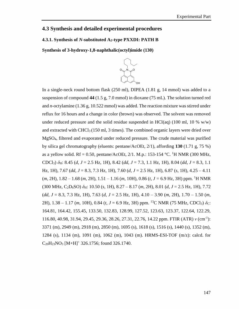
Experimental Part
147
4.3 Synthesis and detailed experimental procedures
4.3.1. Synthesis of N-substituted A2-type PXXDI: PATH B
Synthesis of 3-hydroxy-1,8-naphthalic(octyl)imide (130)
In a single-neck round bottom flask (250 ml), DIPEA (1.81 g, 14 mmol) was added to a
suspension of compound 44 (1.5 g, 7.0 mmol) in dioxane (75 mL). The solution turned red
and n-octylamine (1.36 g, 10.522 mmol) was added. The reaction mixture was stirred under
reflux for 16 hours and a change in color (brown) was observed. The solvent was removed
under reduced pressure and the solid residue suspended in HCl(aq) (100 ml, 10 % w/w)
and extracted with CHCl3 (150 ml, 3 times). The combined organic layers were dried over
MgSO4, filtered and evaporated under reduced pressure. The crude material was purified
by silica gel chromatography (eluents: pentane/AcOEt, 2/1), affording 130 (1.71 g, 75 %)
as a yellow solid. Rf = 0.50, pentane/AcOEt, 2/1. M.p.: 153-154 °C. 1H NMR (300 MHz,
CDCl3) δH: 8.45 (d, J = 2.5 Hz, 1H), 8.42 (dd, J = 7.3, 1.1 Hz, 1H), 8.04 (dd, J = 8.3, 1.1
Hz, 1H), 7.67 (dd, J = 8.3, 7.3 Hz, 1H), 7.60 (d, J = 2.5 Hz, 1H), 6.87 (s, 1H), 4.25 – 4.11
(m, 2H), 1.82 – 1.68 (m, 2H), 1.51 – 1.16 (m, 10H), 0.86 (t, J = 6.9 Hz, 3H) ppm. 1H NMR
(300 MHz, C2D6SO) δH: 10.50 (s, 1H), 8.27 – 8.17 (m, 2H), 8.01 (d, J = 2.5 Hz, 1H), 7.72
(dd, J = 8.3, 7.3 Hz, 1H), 7.63 (d, J = 2.5 Hz, 1H), 4.10 – 3.90 (m, 2H), 1.70 – 1.50 (m,
2H), 1.38 – 1.17 (m, 10H), 0.84 (t, J = 6.9 Hz, 3H) ppm. 13C NMR (75 MHz, CDCl3) δC:
164.81, 164.42, 155.45, 133.50, 132.83, 128.99, 127.52, 123.63, 123.37, 122.64, 122.29,
116.80, 40.98, 31.94, 29.45, 29.36, 28.26, 27.31, 22.76, 14.22 ppm. FTIR (ATR) ν (cm-1):
3371 (m), 2949 (m), 2918 (m), 2850 (m), 1695 (s), 1618 (s), 1516 (s), 1440 (s), 1352 (m),
1284 (s), 1134 (m), 1091 (m), 1062 (m), 1043 (m). HRMS-ESI-TOF (m/z): calcd. for
C20H23NO3 [M+H]+ 326.1756; found 326.1740.
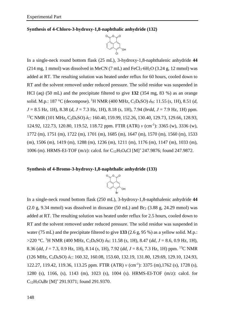
Experimental Part
148
Synthesis of 4-Chloro-3-hydroxy-1,8-naphthalic anhydride (132)
In a single-neck round bottom flask (25 mL), 3-hydroxy-1,8-naphthalenic anhydride 44
(214 mg, 1 mmol) was dissolved in MeCN (7 mL) and FeCl3∙6H2O (3.24 g, 12 mmol) was
added at RT. The resulting solution was heated under reflux for 60 hours, cooled down to
RT and the solvent removed under reduced pressure. The solid residue was suspended in
HCl (aq) (50 mL) and the precipitate filtered to give 132 (354 mg, 83 %) as an orange
solid. M.p.: 187 °C (decompose). 1H NMR (400 MHz, C2D6SO) δH: 11.55 (s, 1H), 8.51 (d,
J = 8.5 Hz, 1H), 8.38 (d, J = 7.3 Hz, 1H), 8.18 (s, 1H), 7.94 (brdd, J = 7.9 Hz, 1H) ppm.
13C NMR (101 MHz, C2D6SO) δC: 160.40, 159.99, 152.26, 130.40, 129.73, 129.66, 128.93,
124.92, 122.73, 120.80, 119.52, 118.72 ppm. FTIR (ATR) ν (cm-1): 3365 (w), 3336 (w),
1772 (m), 1751 (m), 1722 (m), 1701 (m), 1685 (m), 1647 (m), 1570 (m), 1560 (m), 1533
(m), 1506 (m), 1419 (m), 1288 (m), 1236 (m), 1211 (m), 1176 (m), 1147 (m), 1033 (m),
1006 (m). HRMS-EI-TOF (m/z): calcd. for C12H5O4Cl [M]+ 247.9876; found 247.9872.
Synthesis of 4-Bromo-3-hydroxy-1,8-naphthalic anhydride (133)
In a single-neck round bottom flask (250 mL), 3-hydroxy-1,8-naphthalenic anhydride 44
(2.0 g, 9.34 mmol) was dissolved in dioxane (50 mL) and Br2 (3.88 g, 24.29 mmol) was
added at RT. The resulting solution was heated under reflux for 2.5 hours, cooled down to
RT and the solvent removed under reduced pressure. The solid residue was suspended in
water (75 mL) and the precipitate filtered to give 133 (2.6 g, 95 %) as a yellow solid. M.p.:
>220 °C. 1H NMR (400 MHz, C2D6SO) δH: 11.58 (s, 1H), 8.47 (dd, J = 8.6, 0.9 Hz, 1H),
8.36 (dd, J = 7.3, 0.9 Hz, 1H), 8.14 (s, 1H), 7.92 (dd, J = 8.6, 7.3 Hz, 1H) ppm. 13C NMR
(126 MHz, C2D6SO) δC: 160.32, 160.08, 153.60, 132.19, 131.80, 129.69, 129.10, 124.93,
122.27, 119.42, 119.36, 113.25 ppm. FTIR (ATR) ν (cm-1): 3375 (m),1762 (s), 1728 (s),
1280 (s), 1166, (s), 1143 (m), 1023 (s), 1004 (s). HRMS-EI-TOF (m/z): calcd. for
C12H5O4Br [M]+ 291.9371; found 291.9370.
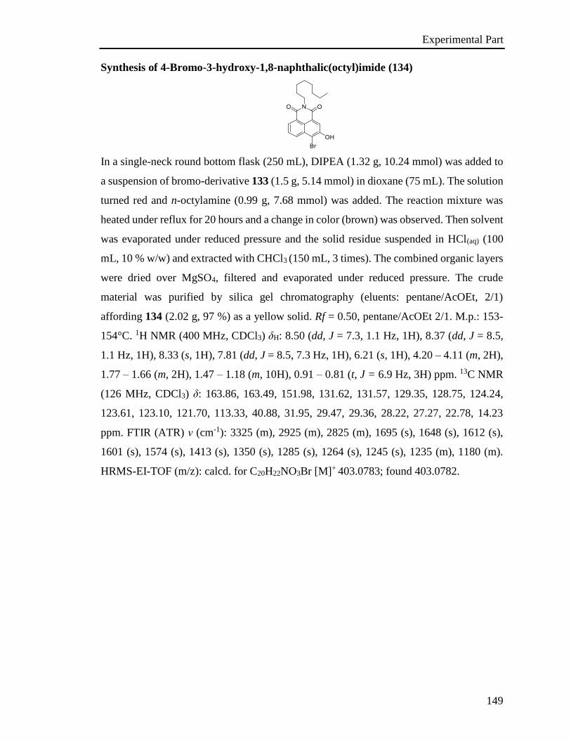
Experimental Part
149
Synthesis of 4-Bromo-3-hydroxy-1,8-naphthalic(octyl)imide (134)
In a single-neck round bottom flask (250 mL), DIPEA (1.32 g, 10.24 mmol) was added to
a suspension of bromo-derivative 133 (1.5 g, 5.14 mmol) in dioxane (75 mL). The solution
turned red and n-octylamine (0.99 g, 7.68 mmol) was added. The reaction mixture was
heated under reflux for 20 hours and a change in color (brown) was observed. Then solvent
was evaporated under reduced pressure and the solid residue suspended in HCl(aq) (100
mL, 10 % w/w) and extracted with CHCl3 (150 mL, 3 times). The combined organic layers
were dried over MgSO4, filtered and evaporated under reduced pressure. The crude
material was purified by silica gel chromatography (eluents: pentane/AcOEt, 2/1)
affording 134 (2.02 g, 97 %) as a yellow solid. Rf = 0.50, pentane/AcOEt 2/1. M.p.: 153-
154°C. 1H NMR (400 MHz, CDCl3) δH: 8.50 (dd, J = 7.3, 1.1 Hz, 1H), 8.37 (dd, J = 8.5,
1.1 Hz, 1H), 8.33 (s, 1H), 7.81 (dd, J = 8.5, 7.3 Hz, 1H), 6.21 (s, 1H), 4.20 – 4.11 (m, 2H),
1.77 – 1.66 (m, 2H), 1.47 – 1.18 (m, 10H), 0.91 – 0.81 (t, J = 6.9 Hz, 3H) ppm. 13C NMR
(126 MHz, CDCl3) δ: 163.86, 163.49, 151.98, 131.62, 131.57, 129.35, 128.75, 124.24,
123.61, 123.10, 121.70, 113.33, 40.88, 31.95, 29.47, 29.36, 28.22, 27.27, 22.78, 14.23
ppm. FTIR (ATR) ν (cm-1): 3325 (m), 2925 (m), 2825 (m), 1695 (s), 1648 (s), 1612 (s),
1601 (s), 1574 (s), 1413 (s), 1350 (s), 1285 (s), 1264 (s), 1245 (s), 1235 (m), 1180 (m).
HRMS-EI-TOF (m/z): calcd. for C20H22NO3Br [M]+ 403.0783; found 403.0782.
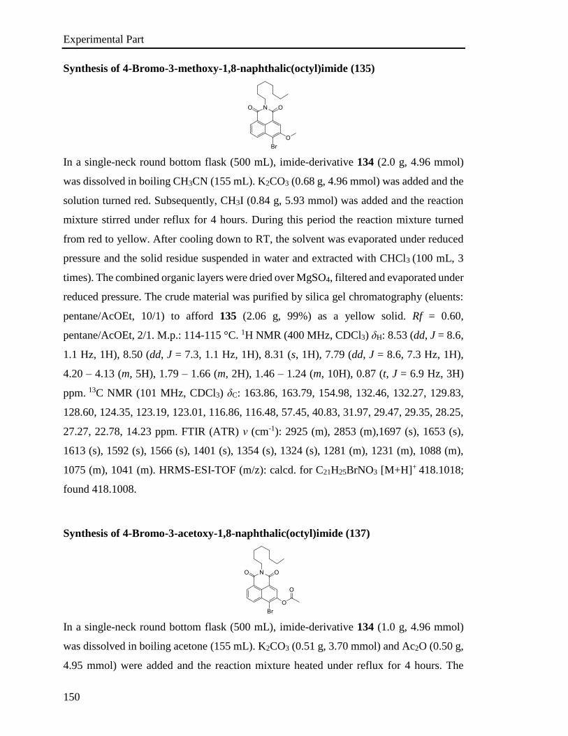
Experimental Part
150
Synthesis of 4-Bromo-3-methoxy-1,8-naphthalic(octyl)imide (135)
In a single-neck round bottom flask (500 mL), imide-derivative 134 (2.0 g, 4.96 mmol)
was dissolved in boiling CH3CN (155 mL). K2CO3 (0.68 g, 4.96 mmol) was added and the
solution turned red. Subsequently, CH3I (0.84 g, 5.93 mmol) was added and the reaction
mixture stirred under reflux for 4 hours. During this period the reaction mixture turned
from red to yellow. After cooling down to RT, the solvent was evaporated under reduced
pressure and the solid residue suspended in water and extracted with CHCl3 (100 mL, 3
times). The combined organic layers were dried over MgSO4, filtered and evaporated under
reduced pressure. The crude material was purified by silica gel chromatography (eluents:
pentane/AcOEt, 10/1) to afford 135 (2.06 g, 99%) as a yellow solid. Rf = 0.60,
pentane/AcOEt, 2/1. M.p.: 114-115 °C. 1H NMR (400 MHz, CDCl3) δH: 8.53 (dd, J = 8.6,
1.1 Hz, 1H), 8.50 (dd, J = 7.3, 1.1 Hz, 1H), 8.31 (s, 1H), 7.79 (dd, J = 8.6, 7.3 Hz, 1H),
4.20 – 4.13 (m, 5H), 1.79 – 1.66 (m, 2H), 1.46 – 1.24 (m, 10H), 0.87 (t, J = 6.9 Hz, 3H)
ppm. 13C NMR (101 MHz, CDCl3) δC: 163.86, 163.79, 154.98, 132.46, 132.27, 129.83,
128.60, 124.35, 123.19, 123.01, 116.86, 116.48, 57.45, 40.83, 31.97, 29.47, 29.35, 28.25,
27.27, 22.78, 14.23 ppm. FTIR (ATR) ν (cm-1): 2925 (m), 2853 (m),1697 (s), 1653 (s),
1613 (s), 1592 (s), 1566 (s), 1401 (s), 1354 (s), 1324 (s), 1281 (m), 1231 (m), 1088 (m),
1075 (m), 1041 (m). HRMS-ESI-TOF (m/z): calcd. for C21H25BrNO3 [M+H]+ 418.1018;
found 418.1008.
Synthesis of 4-Bromo-3-acetoxy-1,8-naphthalic(octyl)imide (137)
In a single-neck round bottom flask (500 mL), imide-derivative 134 (1.0 g, 4.96 mmol)
was dissolved in boiling acetone (155 mL). K2CO3 (0.51 g, 3.70 mmol) and Ac2O (0.50 g,
4.95 mmol) were added and the reaction mixture heated under reflux for 4 hours. The
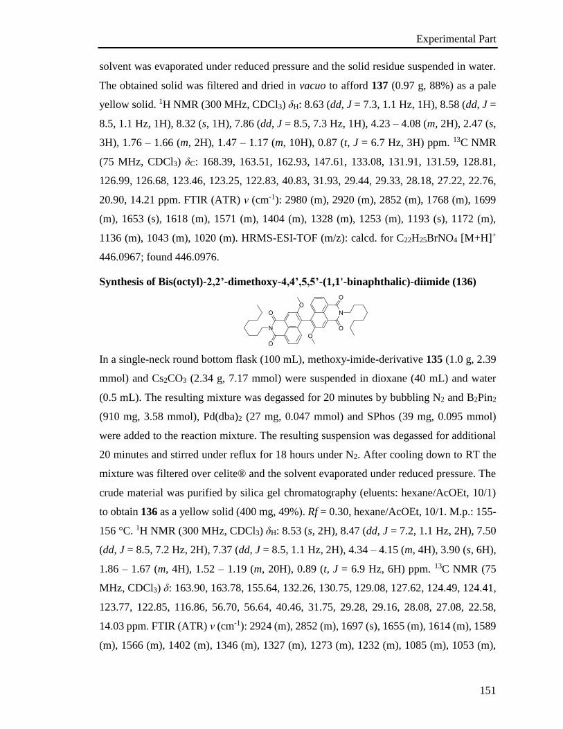
Experimental Part
151
solvent was evaporated under reduced pressure and the solid residue suspended in water.
The obtained solid was filtered and dried in vacuo to afford 137 (0.97 g, 88%) as a pale
yellow solid. 1H NMR (300 MHz, CDCl3) δH: 8.63 (dd, J = 7.3, 1.1 Hz, 1H), 8.58 (dd, J =
8.5, 1.1 Hz, 1H), 8.32 (s, 1H), 7.86 (dd, J = 8.5, 7.3 Hz, 1H), 4.23 – 4.08 (m, 2H), 2.47 (s,
3H), 1.76 – 1.66 (m, 2H), 1.47 – 1.17 (m, 10H), 0.87 (t, J = 6.7 Hz, 3H) ppm. 13C NMR
(75 MHz, CDCl3) δC: 168.39, 163.51, 162.93, 147.61, 133.08, 131.91, 131.59, 128.81,
126.99, 126.68, 123.46, 123.25, 122.83, 40.83, 31.93, 29.44, 29.33, 28.18, 27.22, 22.76,
20.90, 14.21 ppm. FTIR (ATR) ν (cm-1): 2980 (m), 2920 (m), 2852 (m), 1768 (m), 1699
(m), 1653 (s), 1618 (m), 1571 (m), 1404 (m), 1328 (m), 1253 (m), 1193 (s), 1172 (m),
1136 (m), 1043 (m), 1020 (m). HRMS-ESI-TOF (m/z): calcd. for C22H25BrNO4 [M+H]+
446.0967; found 446.0976.
Synthesis of Bis(octyl)-2,2’-dimethoxy-4,4’,5,5’-(1,1'-binaphthalic)-diimide (136)
In a single-neck round bottom flask (100 mL), methoxy-imide-derivative 135 (1.0 g, 2.39
mmol) and Cs2CO3 (2.34 g, 7.17 mmol) were suspended in dioxane (40 mL) and water
(0.5 mL). The resulting mixture was degassed for 20 minutes by bubbling N2 and B2Pin2
(910 mg, 3.58 mmol), Pd(dba)2 (27 mg, 0.047 mmol) and SPhos (39 mg, 0.095 mmol)
were added to the reaction mixture. The resulting suspension was degassed for additional
20 minutes and stirred under reflux for 18 hours under N2. After cooling down to RT the
mixture was filtered over celite® and the solvent evaporated under reduced pressure. The
crude material was purified by silica gel chromatography (eluents: hexane/AcOEt, 10/1)
to obtain 136 as a yellow solid (400 mg, 49%). Rf = 0.30, hexane/AcOEt, 10/1. M.p.: 155-
156 °C. 1H NMR (300 MHz, CDCl3) δH: 8.53 (s, 2H), 8.47 (dd, J = 7.2, 1.1 Hz, 2H), 7.50
(dd, J = 8.5, 7.2 Hz, 2H), 7.37 (dd, J = 8.5, 1.1 Hz, 2H), 4.34 – 4.15 (m, 4H), 3.90 (s, 6H),
1.86 – 1.67 (m, 4H), 1.52 – 1.19 (m, 20H), 0.89 (t, J = 6.9 Hz, 6H) ppm. 13C NMR (75
MHz, CDCl3) δ: 163.90, 163.78, 155.64, 132.26, 130.75, 129.08, 127.62, 124.49, 124.41,
123.77, 122.85, 116.86, 56.70, 56.64, 40.46, 31.75, 29.28, 29.16, 28.08, 27.08, 22.58,
14.03 ppm. FTIR (ATR) ν (cm-1): 2924 (m), 2852 (m), 1697 (s), 1655 (m), 1614 (m), 1589
(m), 1566 (m), 1402 (m), 1346 (m), 1327 (m), 1273 (m), 1232 (m), 1085 (m), 1053 (m),
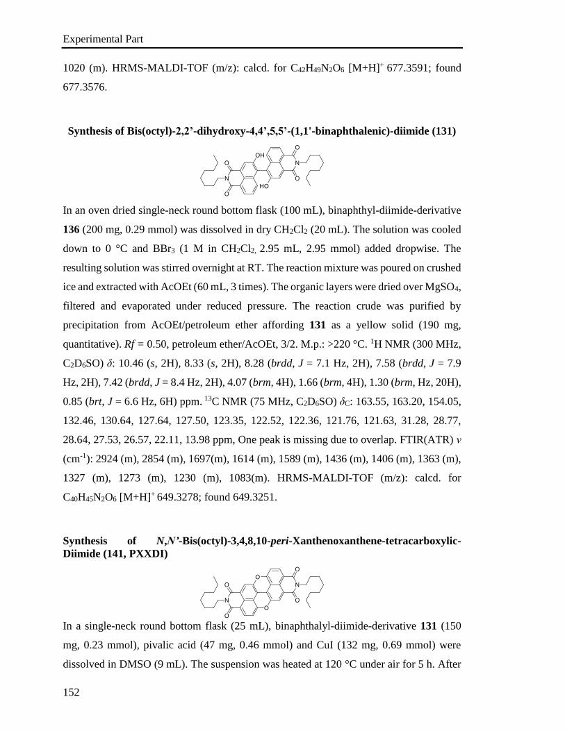
Experimental Part
152
1020 (m). HRMS-MALDI-TOF (m/z): calcd. for C42H49N2O6 [M+H]+ 677.3591; found
677.3576.
Synthesis of Bis(octyl)-2,2’-dihydroxy-4,4’,5,5’-(1,1'-binaphthalenic)-diimide (131)
In an oven dried single-neck round bottom flask (100 mL), binaphthyl-diimide-derivative
136 (200 mg, 0.29 mmol) was dissolved in dry CH2Cl2 (20 mL). The solution was cooled
down to 0 °C and BBr3 (1 M in CH2Cl2, 2.95 mL, 2.95 mmol) added dropwise. The
resulting solution was stirred overnight at RT. The reaction mixture was poured on crushed
ice and extracted with AcOEt (60 mL, 3 times). The organic layers were dried over MgSO4,
filtered and evaporated under reduced pressure. The reaction crude was purified by
precipitation from AcOEt/petroleum ether affording 131 as a yellow solid (190 mg,
quantitative). Rf = 0.50, petroleum ether/AcOEt, 3/2. M.p.: >220 °C. 1H NMR (300 MHz,
C2D6SO) δ: 10.46 (s, 2H), 8.33 (s, 2H), 8.28 (brdd, J = 7.1 Hz, 2H), 7.58 (brdd, J = 7.9
Hz, 2H), 7.42 (brdd, J = 8.4 Hz, 2H), 4.07 (brm, 4H), 1.66 (brm, 4H), 1.30 (brm, Hz, 20H),
0.85 (brt, J = 6.6 Hz, 6H) ppm. 13C NMR (75 MHz, C2D6SO) δC: 163.55, 163.20, 154.05,
132.46, 130.64, 127.64, 127.50, 123.35, 122.52, 122.36, 121.76, 121.63, 31.28, 28.77,
28.64, 27.53, 26.57, 22.11, 13.98 ppm, One peak is missing due to overlap. FTIR(ATR) ν
(cm-1): 2924 (m), 2854 (m), 1697(m), 1614 (m), 1589 (m), 1436 (m), 1406 (m), 1363 (m),
1327 (m), 1273 (m), 1230 (m), 1083(m). HRMS-MALDI-TOF (m/z): calcd. for
C40H45N2O6 [M+H]+ 649.3278; found 649.3251.
Synthesis of N,N’-Bis(octyl)-3,4,8,10-peri-Xanthenoxanthene-tetracarboxylic-
Diimide (141, PXXDI)
In a single-neck round bottom flask (25 mL), binaphthalyl-diimide-derivative 131 (150
mg, 0.23 mmol), pivalic acid (47 mg, 0.46 mmol) and CuI (132 mg, 0.69 mmol) were
dissolved in DMSO (9 mL). The suspension was heated at 120 °C under air for 5 h. After
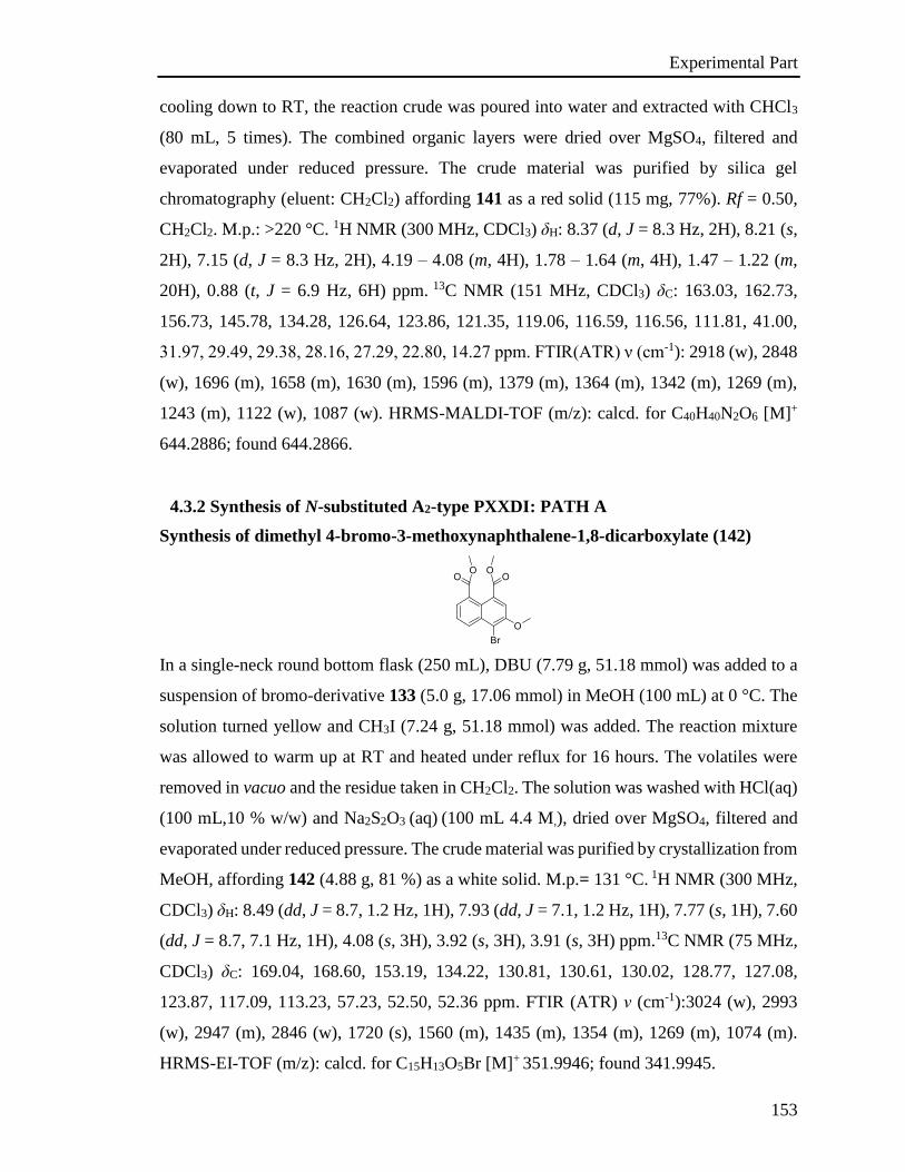
Experimental Part
153
cooling down to RT, the reaction crude was poured into water and extracted with CHCl3
(80 mL, 5 times). The combined organic layers were dried over MgSO4, filtered and
evaporated under reduced pressure. The crude material was purified by silica gel
chromatography (eluent: CH2Cl2) affording 141 as a red solid (115 mg, 77%). Rf = 0.50,
CH2Cl2. M.p.: >220 °C. 1H NMR (300 MHz, CDCl3) δH: 8.37 (d, J = 8.3 Hz, 2H), 8.21 (s,
2H), 7.15 (d, J = 8.3 Hz, 2H), 4.19 – 4.08 (m, 4H), 1.78 – 1.64 (m, 4H), 1.47 – 1.22 (m,
20H), 0.88 (t, J = 6.9 Hz, 6H) ppm. 13C NMR (151 MHz, CDCl3) δC: 163.03, 162.73,
156.73, 145.78, 134.28, 126.64, 123.86, 121.35, 119.06, 116.59, 116.56, 111.81, 41.00,
31.97, 29.49, 29.38, 28.16, 27.29, 22.80, 14.27 ppm. FTIR(ATR) ν (cm-1): 2918 (w), 2848
(w), 1696 (m), 1658 (m), 1630 (m), 1596 (m), 1379 (m), 1364 (m), 1342 (m), 1269 (m),
1243 (m), 1122 (w), 1087 (w). HRMS-MALDI-TOF (m/z): calcd. for C40H40N2O6 [M]+
644.2886; found 644.2866.
4.3.2 Synthesis of N-substituted A2-type PXXDI: PATH A
Synthesis of dimethyl 4-bromo-3-methoxynaphthalene-1,8-dicarboxylate (142)
In a single-neck round bottom flask (250 mL), DBU (7.79 g, 51.18 mmol) was added to a
suspension of bromo-derivative 133 (5.0 g, 17.06 mmol) in MeOH (100 mL) at 0 °C. The
solution turned yellow and CH3I (7.24 g, 51.18 mmol) was added. The reaction mixture
was allowed to warm up at RT and heated under reflux for 16 hours. The volatiles were
removed in vacuo and the residue taken in CH2Cl2. The solution was washed with HCl(aq)
(100 mL,10 % w/w) and Na2S2O3 (aq) (100 mL 4.4 M,), dried over MgSO4, filtered and
evaporated under reduced pressure. The crude material was purified by crystallization from
MeOH, affording 142 (4.88 g, 81 %) as a white solid. M.p.= 131 °C. 1H NMR (300 MHz,
CDCl3) δH: 8.49 (dd, J = 8.7, 1.2 Hz, 1H), 7.93 (dd, J = 7.1, 1.2 Hz, 1H), 7.77 (s, 1H), 7.60
(dd, J = 8.7, 7.1 Hz, 1H), 4.08 (s, 3H), 3.92 (s, 3H), 3.91 (s, 3H) ppm.13C NMR (75 MHz,
CDCl3) δC: 169.04, 168.60, 153.19, 134.22, 130.81, 130.61, 130.02, 128.77, 127.08,
123.87, 117.09, 113.23, 57.23, 52.50, 52.36 ppm. FTIR (ATR) ν (cm-1):3024 (w), 2993
(w), 2947 (m), 2846 (w), 1720 (s), 1560 (m), 1435 (m), 1354 (m), 1269 (m), 1074 (m).
HRMS-EI-TOF (m/z): calcd. for C15H13O5Br [M]+ 351.9946; found 341.9945.
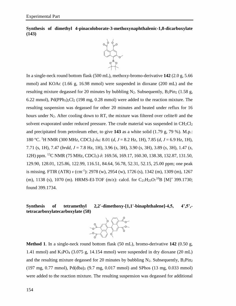
Experimental Part
154
Synthesis of dimethyl 4-pinacoloborate-3-methoxynaphthalenic-1,8-dicarboxylate
(143)
In a single-neck round bottom flask (500 mL), methoxy-bromo-derivative 142 (2.0 g, 5.66
mmol) and KOAc (1.66 g, 16.98 mmol) were suspended in dioxane (200 mL) and the
resulting mixture degassed for 20 minutes by bubbling N2. Subsequently, B2Pin2 (1.58 g,
6.22 mmol), Pd(PPh3)2Cl2 (198 mg, 0.28 mmol) were added to the reaction mixture. The
resulting suspension was degassed for other 20 minutes and heated under reflux for 16
hours under N2. After cooling down to RT, the mixture was filtered over celite® and the
solvent evaporated under reduced pressure. The crude material was suspended in CH2Cl2
and precipitated from petroleum ether, to give 143 as a white solid (1.79 g, 79 %). M.p.:
180 °C. 1H NMR (300 MHz, CDCl3) δH: 8.01 (d, J = 8.2 Hz, 1H), 7.85 (d, J = 6.9 Hz, 1H),
7.71 (s, 1H), 7.47 (brdd, J = 7.8 Hz, 1H), 3.96 (s, 3H), 3.90 (s, 3H), 3.89 (s, 3H), 1.47 (s,
12H) ppm. 13C NMR (75 MHz, CDCl3) δ: 169.56, 169.17, 160.30, 138.38, 132.87, 131.50,
129.90, 128.01, 125.86, 122.99, 116.51, 84.64, 56.78, 52.31, 52.15, 25.00 ppm; one peak
is missing. FTIR (ATR) ν (cm-1): 2978 (w), 2954 (w), 1726 (s), 1342 (m), 1309 (m), 1267
(m), 1138 (s), 1070 (m). HRMS-EI-TOF (m/z): calcd. for C21H25O710B [M]+ 399.1730;
found 399.1734.
Synthesis of tetramethyl 2,2'-dimethoxy-[1,1'-binaphthalene]-4,5, 4’,5’,-
tetracarboxylatecarboxylate (58)
Method 1. In a single-neck round bottom flask (50 mL), bromo-derivative 142 (0.50 g,
1.41 mmol) and K3PO4 (3.075 g, 14.154 mmol) were suspended in dry dioxane (20 mL)
and the resulting mixture degassed for 20 minutes by bubbling N2. Subsequently, B2Pin2
(197 mg, 0.77 mmol), Pd(dba)2 (9.7 mg, 0.017 mmol) and SPhos (13 mg, 0.033 mmol)
were added to the reaction mixture. The resulting suspension was degassed for additional
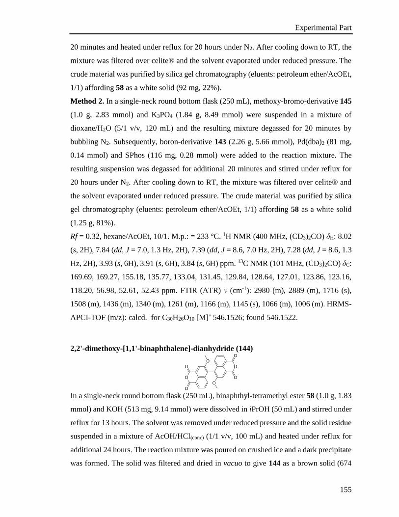
Experimental Part
155
20 minutes and heated under reflux for 20 hours under N2. After cooling down to RT, the
mixture was filtered over celite® and the solvent evaporated under reduced pressure. The
crude material was purified by silica gel chromatography (eluents: petroleum ether/AcOEt,
1/1) affording 58 as a white solid (92 mg, 22%).
Method 2. In a single-neck round bottom flask (250 mL), methoxy-bromo-derivative 145
(1.0 g, 2.83 mmol) and K3PO4 (1.84 g, 8.49 mmol) were suspended in a mixture of
dioxane/H2O (5/1 v/v, 120 mL) and the resulting mixture degassed for 20 minutes by
bubbling N2. Subsequently, boron-derivative 143 (2.26 g, 5.66 mmol), Pd(dba)2 (81 mg,
0.14 mmol) and SPhos (116 mg, 0.28 mmol) were added to the reaction mixture. The
resulting suspension was degassed for additional 20 minutes and stirred under reflux for
20 hours under N2. After cooling down to RT, the mixture was filtered over celite® and
the solvent evaporated under reduced pressure. The crude material was purified by silica
gel chromatography (eluents: petroleum ether/AcOEt, 1/1) affording 58 as a white solid
(1.25 g, 81%).
Rf = 0.32, hexane/AcOEt, 10/1. M.p.: = 233 °C. 1H NMR (400 MHz, (CD3)2CO) δH: 8.02
(s, 2H), 7.84 (dd, J = 7.0, 1.3 Hz, 2H), 7.39 (dd, J = 8.6, 7.0 Hz, 2H), 7.28 (dd, J = 8.6, 1.3
Hz, 2H), 3.93 (s, 6H), 3.91 (s, 6H), 3.84 (s, 6H) ppm. 13C NMR (101 MHz, (CD3)2CO) δC:
169.69, 169.27, 155.18, 135.77, 133.04, 131.45, 129.84, 128.64, 127.01, 123.86, 123.16,
118.20, 56.98, 52.61, 52.43 ppm. FTIR (ATR) ν (cm-1): 2980 (m), 2889 (m), 1716 (s),
1508 (m), 1436 (m), 1340 (m), 1261 (m), 1166 (m), 1145 (s), 1066 (m), 1006 (m). HRMS-
APCI-TOF (m/z): calcd. for C30H26O10 [M]+ 546.1526; found 546.1522.
2,2'-dimethoxy-[1,1'-binaphthalene]-dianhydride (144)
In a single-neck round bottom flask (250 mL), binaphthyl-tetramethyl ester 58 (1.0 g, 1.83
mmol) and KOH (513 mg, 9.14 mmol) were dissolved in iPrOH (50 mL) and stirred under
reflux for 13 hours. The solvent was removed under reduced pressure and the solid residue
suspended in a mixture of AcOH/HCl(conc) (1/1 v/v, 100 mL) and heated under reflux for
additional 24 hours. The reaction mixture was poured on crushed ice and a dark precipitate
was formed. The solid was filtered and dried in vacuo to give 144 as a brown solid (674
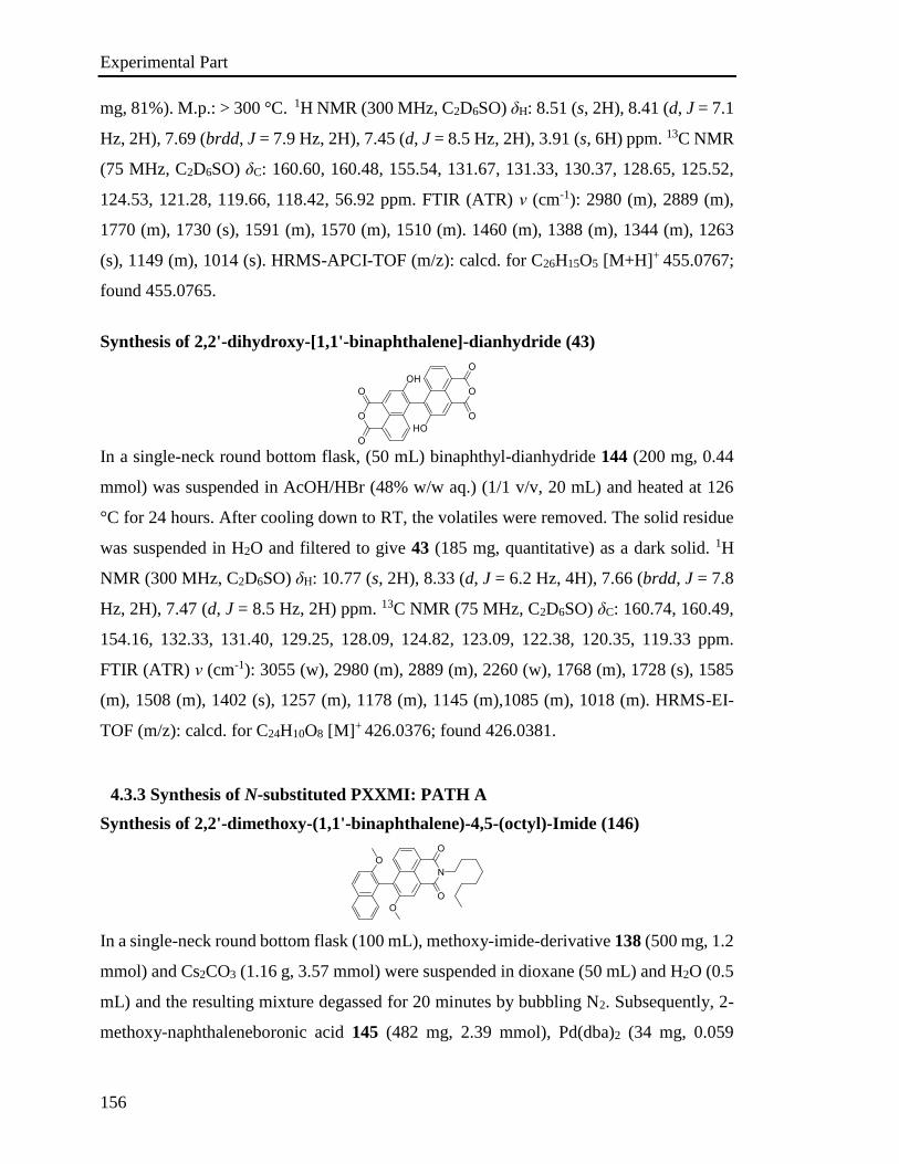
Experimental Part
156
mg, 81%). M.p.: > 300 °C. 1H NMR (300 MHz, C2D6SO) δH: 8.51 (s, 2H), 8.41 (d, J = 7.1
Hz, 2H), 7.69 (brdd, J = 7.9 Hz, 2H), 7.45 (d, J = 8.5 Hz, 2H), 3.91 (s, 6H) ppm. 13C NMR
(75 MHz, C2D6SO) δC: 160.60, 160.48, 155.54, 131.67, 131.33, 130.37, 128.65, 125.52,
124.53, 121.28, 119.66, 118.42, 56.92 ppm. FTIR (ATR) ν (cm-1): 2980 (m), 2889 (m),
1770 (m), 1730 (s), 1591 (m), 1570 (m), 1510 (m). 1460 (m), 1388 (m), 1344 (m), 1263
(s), 1149 (m), 1014 (s). HRMS-APCI-TOF (m/z): calcd. for C26H15O5 [M+H]+ 455.0767;
found 455.0765.
Synthesis of 2,2'-dihydroxy-[1,1'-binaphthalene]-dianhydride (43)
In a single-neck round bottom flask, (50 mL) binaphthyl-dianhydride 144 (200 mg, 0.44
mmol) was suspended in AcOH/HBr (48% w/w aq.) (1/1 v/v, 20 mL) and heated at 126
°C for 24 hours. After cooling down to RT, the volatiles were removed. The solid residue
was suspended in H2O and filtered to give 43 (185 mg, quantitative) as a dark solid. 1H
NMR (300 MHz, C2D6SO) δH: 10.77 (s, 2H), 8.33 (d, J = 6.2 Hz, 4H), 7.66 (brdd, J = 7.8
Hz, 2H), 7.47 (d, J = 8.5 Hz, 2H) ppm. 13C NMR (75 MHz, C2D6SO) δC: 160.74, 160.49,
154.16, 132.33, 131.40, 129.25, 128.09, 124.82, 123.09, 122.38, 120.35, 119.33 ppm.
FTIR (ATR) ν (cm-1): 3055 (w), 2980 (m), 2889 (m), 2260 (w), 1768 (m), 1728 (s), 1585
(m), 1508 (m), 1402 (s), 1257 (m), 1178 (m), 1145 (m),1085 (m), 1018 (m). HRMS-EI-
TOF (m/z): calcd. for C24H10O8 [M]+ 426.0376; found 426.0381.
4.3.3 Synthesis of N-substituted PXXMI: PATH A
Synthesis of 2,2'-dimethoxy-(1,1'-binaphthalene)-4,5-(octyl)-Imide (146)
In a single-neck round bottom flask (100 mL), methoxy-imide-derivative 138 (500 mg, 1.2
mmol) and Cs2CO3 (1.16 g, 3.57 mmol) were suspended in dioxane (50 mL) and H2O (0.5
mL) and the resulting mixture degassed for 20 minutes by bubbling N2. Subsequently, 2-
methoxy-naphthaleneboronic acid 145 (482 mg, 2.39 mmol), Pd(dba)2 (34 mg, 0.059
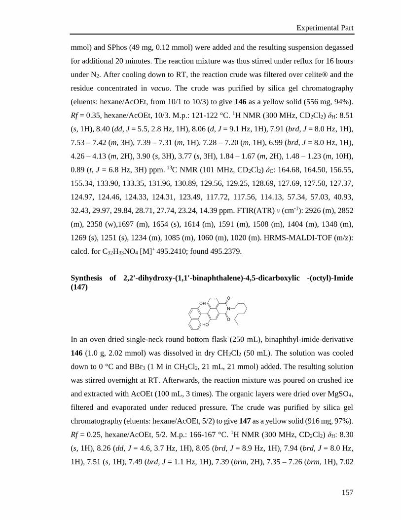
Experimental Part
157
mmol) and SPhos (49 mg, 0.12 mmol) were added and the resulting suspension degassed
for additional 20 minutes. The reaction mixture was thus stirred under reflux for 16 hours
under N2. After cooling down to RT, the reaction crude was filtered over celite® and the
residue concentrated in vacuo. The crude was purified by silica gel chromatography
(eluents: hexane/AcOEt, from 10/1 to 10/3) to give 146 as a yellow solid (556 mg, 94%).
Rf = 0.35, hexane/AcOEt, 10/3. M.p.: 121-122 °C. 1H NMR (300 MHz, CD2Cl2) δH: 8.51
(s, 1H), 8.40 (dd, J = 5.5, 2.8 Hz, 1H), 8.06 (d, J = 9.1 Hz, 1H), 7.91 (brd, J = 8.0 Hz, 1H),
7.53 – 7.42 (m, 3H), 7.39 – 7.31 (m, 1H), 7.28 – 7.20 (m, 1H), 6.99 (brd, J = 8.0 Hz, 1H),
4.26 – 4.13 (m, 2H), 3.90 (s, 3H), 3.77 (s, 3H), 1.84 – 1.67 (m, 2H), 1.48 – 1.23 (m, 10H),
0.89 (t, J = 6.8 Hz, 3H) ppm. 13C NMR (101 MHz, CD2Cl2) δC: 164.68, 164.50, 156.55,
155.34, 133.90, 133.35, 131.96, 130.89, 129.56, 129.25, 128.69, 127.69, 127.50, 127.37,
124.97, 124.46, 124.33, 124.31, 123.49, 117.72, 117.56, 114.13, 57.34, 57.03, 40.93,
32.43, 29.97, 29.84, 28.71, 27.74, 23.24, 14.39 ppm. FTIR(ATR) ν (cm-1): 2926 (m), 2852
(m), 2358 (w),1697 (m), 1654 (s), 1614 (m), 1591 (m), 1508 (m), 1404 (m), 1348 (m),
1269 (s), 1251 (s), 1234 (m), 1085 (m), 1060 (m), 1020 (m). HRMS-MALDI-TOF (m/z):
calcd. for C32H33NO4 [M]+ 495.2410; found 495.2379.
Synthesis of 2,2'-dihydroxy-(1,1'-binaphthalene)-4,5-dicarboxylic -(octyl)-Imide
(147)
In an oven dried single-neck round bottom flask (250 mL), binaphthyl-imide-derivative
146 (1.0 g, 2.02 mmol) was dissolved in dry CH2Cl2 (50 mL). The solution was cooled
down to 0 °C and BBr3 (1 M in CH2Cl2, 21 mL, 21 mmol) added. The resulting solution
was stirred overnight at RT. Afterwards, the reaction mixture was poured on crushed ice
and extracted with AcOEt (100 mL, 3 times). The organic layers were dried over MgSO4,
filtered and evaporated under reduced pressure. The crude was purified by silica gel
chromatography (eluents: hexane/AcOEt, 5/2) to give 147 as a yellow solid (916 mg, 97%).
Rf = 0.25, hexane/AcOEt, 5/2. M.p.: 166-167 °C. 1H NMR (300 MHz, CD2Cl2) δH: 8.30
(s, 1H), 8.26 (dd, J = 4.6, 3.7 Hz, 1H), 8.05 (brd, J = 8.9 Hz, 1H), 7.94 (brd, J = 8.0 Hz,
1H), 7.51 (s, 1H), 7.49 (brd, J = 1.1 Hz, 1H), 7.39 (brm, 2H), 7.35 – 7.26 (brm, 1H), 7.02
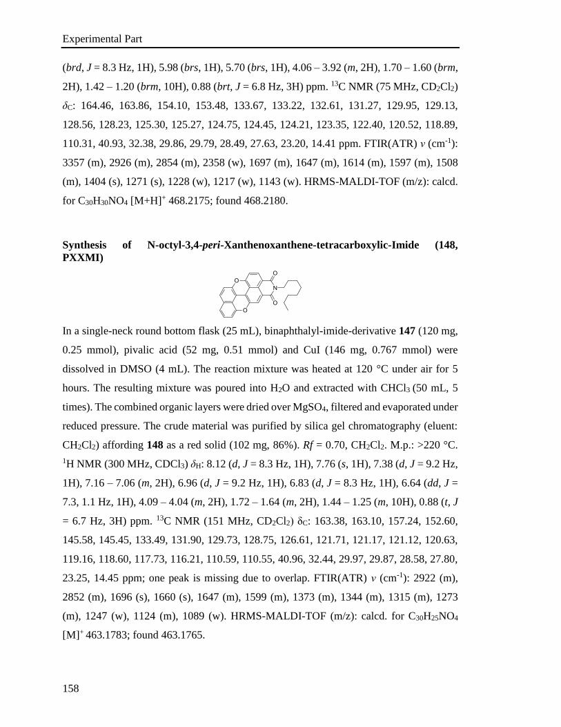
Experimental Part
158
(brd, J = 8.3 Hz, 1H), 5.98 (brs, 1H), 5.70 (brs, 1H), 4.06 – 3.92 (m, 2H), 1.70 – 1.60 (brm,
2H), 1.42 – 1.20 (brm, 10H), 0.88 (brt, J = 6.8 Hz, 3H) ppm. 13C NMR (75 MHz, CD2Cl2)
δC: 164.46, 163.86, 154.10, 153.48, 133.67, 133.22, 132.61, 131.27, 129.95, 129.13,
128.56, 128.23, 125.30, 125.27, 124.75, 124.45, 124.21, 123.35, 122.40, 120.52, 118.89,
110.31, 40.93, 32.38, 29.86, 29.79, 28.49, 27.63, 23.20, 14.41 ppm. FTIR(ATR) ν (cm-1):
3357 (m), 2926 (m), 2854 (m), 2358 (w), 1697 (m), 1647 (m), 1614 (m), 1597 (m), 1508
(m), 1404 (s), 1271 (s), 1228 (w), 1217 (w), 1143 (w). HRMS-MALDI-TOF (m/z): calcd.
for C30H30NO4 [M+H]+ 468.2175; found 468.2180.
Synthesis of N-octyl-3,4-peri-Xanthenoxanthene-tetracarboxylic-Imide (148,
PXXMI)
In a single-neck round bottom flask (25 mL), binaphthalyl-imide-derivative 147 (120 mg,
0.25 mmol), pivalic acid (52 mg, 0.51 mmol) and CuI (146 mg, 0.767 mmol) were
dissolved in DMSO (4 mL). The reaction mixture was heated at 120 °C under air for 5
hours. The resulting mixture was poured into H2O and extracted with CHCl3 (50 mL, 5
times). The combined organic layers were dried over MgSO4, filtered and evaporated under
reduced pressure. The crude material was purified by silica gel chromatography (eluent:
CH2Cl2) affording 148 as a red solid (102 mg, 86%). Rf = 0.70, CH2Cl2. M.p.: >220 °C.
1H NMR (300 MHz, CDCl3) δH: 8.12 (d, J = 8.3 Hz, 1H), 7.76 (s, 1H), 7.38 (d, J = 9.2 Hz,
1H), 7.16 – 7.06 (m, 2H), 6.96 (d, J = 9.2 Hz, 1H), 6.83 (d, J = 8.3 Hz, 1H), 6.64 (dd, J =
7.3, 1.1 Hz, 1H), 4.09 – 4.04 (m, 2H), 1.72 – 1.64 (m, 2H), 1.44 – 1.25 (m, 10H), 0.88 (t, J
= 6.7 Hz, 3H) ppm. 13C NMR (151 MHz, CD2Cl2) δC: 163.38, 163.10, 157.24, 152.60,
145.58, 145.45, 133.49, 131.90, 129.73, 128.75, 126.61, 121.71, 121.17, 121.12, 120.63,
119.16, 118.60, 117.73, 116.21, 110.59, 110.55, 40.96, 32.44, 29.97, 29.87, 28.58, 27.80,
23.25, 14.45 ppm; one peak is missing due to overlap. FTIR(ATR) ν (cm-1): 2922 (m),
2852 (m), 1696 (s), 1660 (s), 1647 (m), 1599 (m), 1373 (m), 1344 (m), 1315 (m), 1273
(m), 1247 (w), 1124 (m), 1089 (w). HRMS-MALDI-TOF (m/z): calcd. for C30H25NO4
[M]+ 463.1783; found 463.1765.
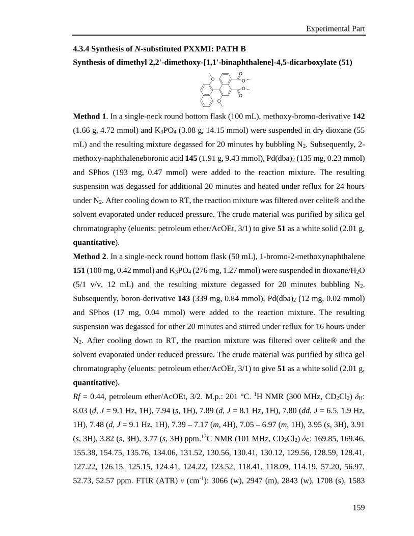
Experimental Part
159
4.3.4 Synthesis of N-substituted PXXMI: PATH B
Synthesis of dimethyl 2,2'-dimethoxy-[1,1'-binaphthalene]-4,5-dicarboxylate (51)
Method 1. In a single-neck round bottom flask (100 mL), methoxy-bromo-derivative 142
(1.66 g, 4.72 mmol) and K3PO4 (3.08 g, 14.15 mmol) were suspended in dry dioxane (55
mL) and the resulting mixture degassed for 20 minutes by bubbling N2. Subsequently, 2-
methoxy-naphthaleneboronic acid 145 (1.91 g, 9.43 mmol), Pd(dba)2 (135 mg, 0.23 mmol)
and SPhos (193 mg, 0.47 mmol) were added to the reaction mixture. The resulting
suspension was degassed for additional 20 minutes and heated under reflux for 24 hours
under N2. After cooling down to RT, the reaction mixture was filtered over celite® and the
solvent evaporated under reduced pressure. The crude material was purified by silica gel
chromatography (eluents: petroleum ether/AcOEt, 3/1) to give 51 as a white solid (2.01 g,
quantitative).
Method 2. In a single-neck round bottom flask (50 mL), 1-bromo-2-methoxynaphthalene
151 (100 mg, 0.42 mmol) and K3PO4 (276 mg, 1.27 mmol) were suspended in dioxane/H2O
(5/1 v/v, 12 mL) and the resulting mixture degassed for 20 minutes bubbling N2.
Subsequently, boron-derivative 143 (339 mg, 0.84 mmol), Pd(dba)2 (12 mg, 0.02 mmol)
and SPhos (17 mg, 0.04 mmol) were added to the reaction mixture. The resulting
suspension was degassed for other 20 minutes and stirred under reflux for 16 hours under
N2. After cooling down to RT, the reaction mixture was filtered over celite® and the
solvent evaporated under reduced pressure. The crude material was purified by silica gel
chromatography (eluents: petroleum ether/AcOEt, 3/1) to give 51 as a white solid (2.01 g,
quantitative).
Rf = 0.44, petroleum ether/AcOEt, 3/2. M.p.: 201 °C. 1H NMR (300 MHz, CD2Cl2) δH:
8.03 (d, J = 9.1 Hz, 1H), 7.94 (s, 1H), 7.89 (d, J = 8.1 Hz, 1H), 7.80 (dd, J = 6.5, 1.9 Hz,
1H), 7.48 (d, J = 9.1 Hz, 1H), 7.39 – 7.17 (m, 4H), 7.05 – 6.97 (m, 1H), 3.95 (s, 3H), 3.91
(s, 3H), 3.82 (s, 3H), 3.77 (s, 3H) ppm.13C NMR (101 MHz, CD2Cl2) δC: 169.85, 169.46,
155.38, 154.75, 135.76, 134.06, 131.52, 130.56, 130.41, 130.12, 129.56, 128.59, 128.41,
127.22, 126.15, 125.15, 124.41, 124.22, 123.52, 118.41, 118.09, 114.19, 57.20, 56.97,
52.73, 52.57 ppm. FTIR (ATR) ν (cm-1): 3066 (w), 2947 (m), 2843 (w), 1708 (s), 1583
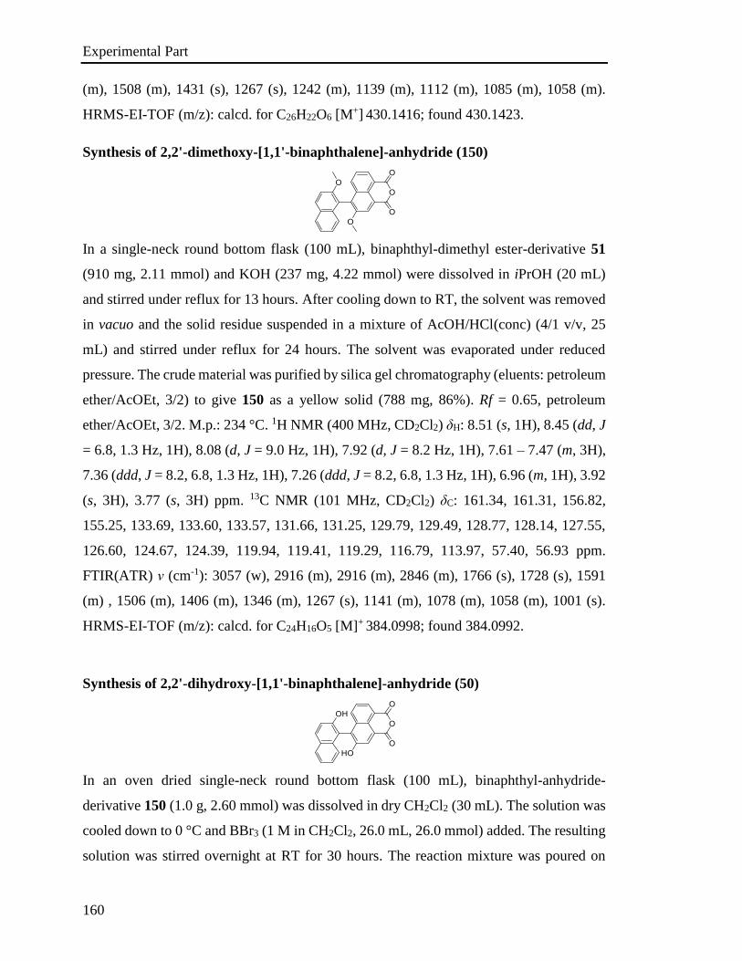
Experimental Part
160
(m), 1508 (m), 1431 (s), 1267 (s), 1242 (m), 1139 (m), 1112 (m), 1085 (m), 1058 (m).
HRMS-EI-TOF (m/z): calcd. for C26H22O6 [M+] 430.1416; found 430.1423.
Synthesis of 2,2'-dimethoxy-[1,1'-binaphthalene]-anhydride (150)
In a single-neck round bottom flask (100 mL), binaphthyl-dimethyl ester-derivative 51
(910 mg, 2.11 mmol) and KOH (237 mg, 4.22 mmol) were dissolved in iPrOH (20 mL)
and stirred under reflux for 13 hours. After cooling down to RT, the solvent was removed
in vacuo and the solid residue suspended in a mixture of AcOH/HCl(conc) (4/1 v/v, 25
mL) and stirred under reflux for 24 hours. The solvent was evaporated under reduced
pressure. The crude material was purified by silica gel chromatography (eluents: petroleum
ether/AcOEt, 3/2) to give 150 as a yellow solid (788 mg, 86%). Rf = 0.65, petroleum
ether/AcOEt, 3/2. M.p.: 234 °C. 1H NMR (400 MHz, CD2Cl2) δH: 8.51 (s, 1H), 8.45 (dd, J
= 6.8, 1.3 Hz, 1H), 8.08 (d, J = 9.0 Hz, 1H), 7.92 (d, J = 8.2 Hz, 1H), 7.61 – 7.47 (m, 3H),
7.36 (ddd, J = 8.2, 6.8, 1.3 Hz, 1H), 7.26 (ddd, J = 8.2, 6.8, 1.3 Hz, 1H), 6.96 (m, 1H), 3.92
(s, 3H), 3.77 (s, 3H) ppm. 13C NMR (101 MHz, CD2Cl2) δC: 161.34, 161.31, 156.82,
155.25, 133.69, 133.60, 133.57, 131.66, 131.25, 129.79, 129.49, 128.77, 128.14, 127.55,
126.60, 124.67, 124.39, 119.94, 119.41, 119.29, 116.79, 113.97, 57.40, 56.93 ppm.
FTIR(ATR) ν (cm-1): 3057 (w), 2916 (m), 2916 (m), 2846 (m), 1766 (s), 1728 (s), 1591
(m) , 1506 (m), 1406 (m), 1346 (m), 1267 (s), 1141 (m), 1078 (m), 1058 (m), 1001 (s).
HRMS-EI-TOF (m/z): calcd. for C24H16O5 [M]+ 384.0998; found 384.0992.
Synthesis of 2,2'-dihydroxy-[1,1'-binaphthalene]-anhydride (50)
In an oven dried single-neck round bottom flask (100 mL), binaphthyl-anhydride-
derivative 150 (1.0 g, 2.60 mmol) was dissolved in dry CH2Cl2 (30 mL). The solution was
cooled down to 0 °C and BBr3 (1 M in CH2Cl2, 26.0 mL, 26.0 mmol) added. The resulting
solution was stirred overnight at RT for 30 hours. The reaction mixture was poured on
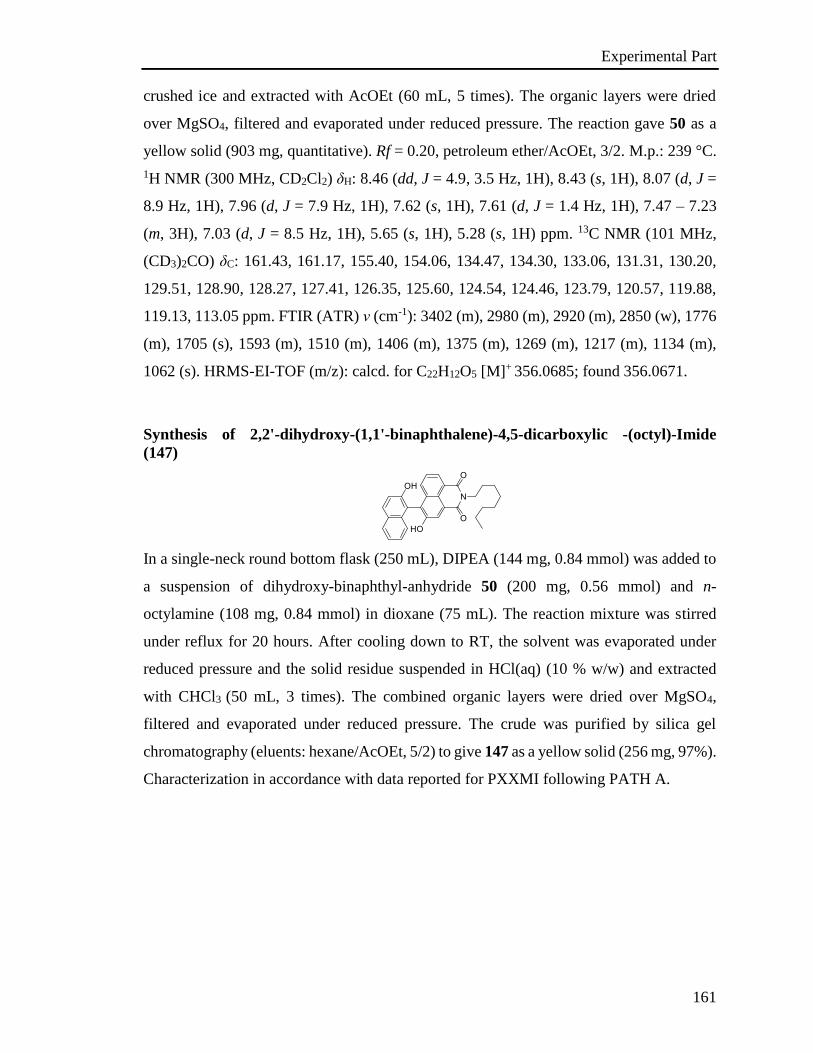
Experimental Part
161
crushed ice and extracted with AcOEt (60 mL, 5 times). The organic layers were dried
over MgSO4, filtered and evaporated under reduced pressure. The reaction gave 50 as a
yellow solid (903 mg, quantitative). Rf = 0.20, petroleum ether/AcOEt, 3/2. M.p.: 239 °C.
1H NMR (300 MHz, CD2Cl2) δH: 8.46 (dd, J = 4.9, 3.5 Hz, 1H), 8.43 (s, 1H), 8.07 (d, J =
8.9 Hz, 1H), 7.96 (d, J = 7.9 Hz, 1H), 7.62 (s, 1H), 7.61 (d, J = 1.4 Hz, 1H), 7.47 – 7.23
(m, 3H), 7.03 (d, J = 8.5 Hz, 1H), 5.65 (s, 1H), 5.28 (s, 1H) ppm. 13C NMR (101 MHz,
(CD3)2CO) δC: 161.43, 161.17, 155.40, 154.06, 134.47, 134.30, 133.06, 131.31, 130.20,
129.51, 128.90, 128.27, 127.41, 126.35, 125.60, 124.54, 124.46, 123.79, 120.57, 119.88,
119.13, 113.05 ppm. FTIR (ATR) ν (cm-1): 3402 (m), 2980 (m), 2920 (m), 2850 (w), 1776
(m), 1705 (s), 1593 (m), 1510 (m), 1406 (m), 1375 (m), 1269 (m), 1217 (m), 1134 (m),
1062 (s). HRMS-EI-TOF (m/z): calcd. for C22H12O5 [M]+ 356.0685; found 356.0671.
Synthesis of 2,2'-dihydroxy-(1,1'-binaphthalene)-4,5-dicarboxylic -(octyl)-Imide
(147)
In a single-neck round bottom flask (250 mL), DIPEA (144 mg, 0.84 mmol) was added to
a suspension of dihydroxy-binaphthyl-anhydride 50 (200 mg, 0.56 mmol) and n-
octylamine (108 mg, 0.84 mmol) in dioxane (75 mL). The reaction mixture was stirred
under reflux for 20 hours. After cooling down to RT, the solvent was evaporated under
reduced pressure and the solid residue suspended in HCl(aq) (10 % w/w) and extracted
with CHCl3 (50 mL, 3 times). The combined organic layers were dried over MgSO4,
filtered and evaporated under reduced pressure. The crude was purified by silica gel
chromatography (eluents: hexane/AcOEt, 5/2) to give 147 as a yellow solid (256 mg, 97%).
Characterization in accordance with data reported for PXXMI following PATH A.
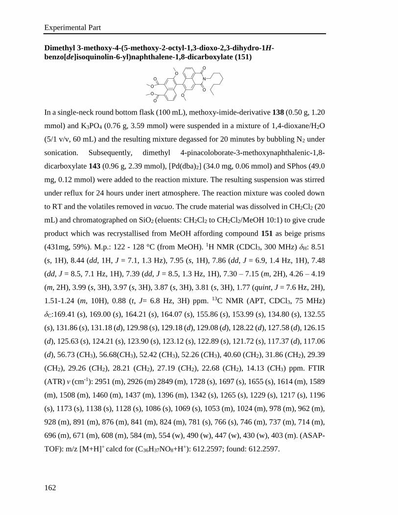
Experimental Part
162
Dimethyl 3-methoxy-4-(5-methoxy-2-octyl-1,3-dioxo-2,3-dihydro-1H-
benzo[de]isoquinolin-6-yl)naphthalene-1,8-dicarboxylate (151)
In a single-neck round bottom flask (100 mL), methoxy-imide-derivative 138 (0.50 g, 1.20
mmol) and K3PO4 (0.76 g, 3.59 mmol) were suspended in a mixture of 1,4-dioxane/H2O
(5/1 v/v, 60 mL) and the resulting mixture degassed for 20 minutes by bubbling N2 under
sonication. Subsequently, dimethyl 4-pinacoloborate-3-methoxynaphthalenic-1,8-
dicarboxylate 143 (0.96 g, 2.39 mmol), [Pd(dba)2] (34.0 mg, 0.06 mmol) and SPhos (49.0
mg, 0.12 mmol) were added to the reaction mixture. The resulting suspension was stirred
under reflux for 24 hours under inert atmosphere. The reaction mixture was cooled down
to RT and the volatiles removed in vacuo. The crude material was dissolved in CH2Cl2 (20
mL) and chromatographed on SiO2 (eluents: CH2Cl2 to CH2Cl2/MeOH 10:1) to give crude
product which was recrystallised from MeOH affording compound 151 as beige prisms
(431mg, 59%). M.p.: 122 - 128 °C (from MeOH). 1H NMR (CDCl3, 300 MHz) δH: 8.51
(s, 1H), 8.44 (dd, 1H, J = 7.1, 1.3 Hz), 7.95 (s, 1H), 7.86 (dd, J = 6.9, 1.4 Hz, 1H), 7.48
(dd, J = 8.5, 7.1 Hz, 1H), 7.39 (dd, J = 8.5, 1.3 Hz, 1H), 7.30 – 7.15 (m, 2H), 4.26 – 4.19
(m, 2H), 3.99 (s, 3H), 3.97 (s, 3H), 3.87 (s, 3H), 3.81 (s, 3H), 1.77 (quint, J = 7.6 Hz, 2H),
1.51-1.24 (m, 10H), 0.88 (t, J= 6.8 Hz, 3H) ppm. 13C NMR (APT, CDCl3, 75 MHz)
δC:169.41 (s), 169.00 (s), 164.21 (s), 164.07 (s), 155.86 (s), 153.99 (s), 134.80 (s), 132.55
(s), 131.86 (s), 131.18 (d), 129.98 (s), 129.18 (d), 129.08 (d), 128.22 (d), 127.58 (d), 126.15
(d), 125.63 (s), 124.21 (s), 123.90 (s), 123.12 (s), 122.89 (s), 121.72 (s), 117.37 (d), 117.06
(d), 56.73 (CH3), 56.68(CH3), 52.42 (CH3), 52.26 (CH3), 40.60 (CH2), 31.86 (CH2), 29.39
(CH2), 29.26 (CH2), 28.21 (CH2), 27.19 (CH2), 22.68 (CH2), 14.13 (CH3) ppm. FTIR
(ATR) ν (cm-1): 2951 (m), 2926 (m) 2849 (m), 1728 (s), 1697 (s), 1655 (s), 1614 (m), 1589
(m), 1508 (m), 1460 (m), 1437 (m), 1396 (m), 1342 (s), 1265 (s), 1229 (s), 1217 (s), 1196
(s), 1173 (s), 1138 (s), 1128 (s), 1086 (s), 1069 (s), 1053 (m), 1024 (m), 978 (m), 962 (m),
928 (m), 891 (m), 876 (m), 841 (m), 824 (m), 781 (s), 766 (s), 746 (m), 737 (m), 714 (m),
696 (m), 671 (m), 608 (m), 584 (m), 554 (w), 490 (w), 447 (w), 430 (w), 403 (m). (ASAP-
TOF): m/z [M+H]+ calcd for (C36H37NO8+H+): 612.2597; found: 612.2597.
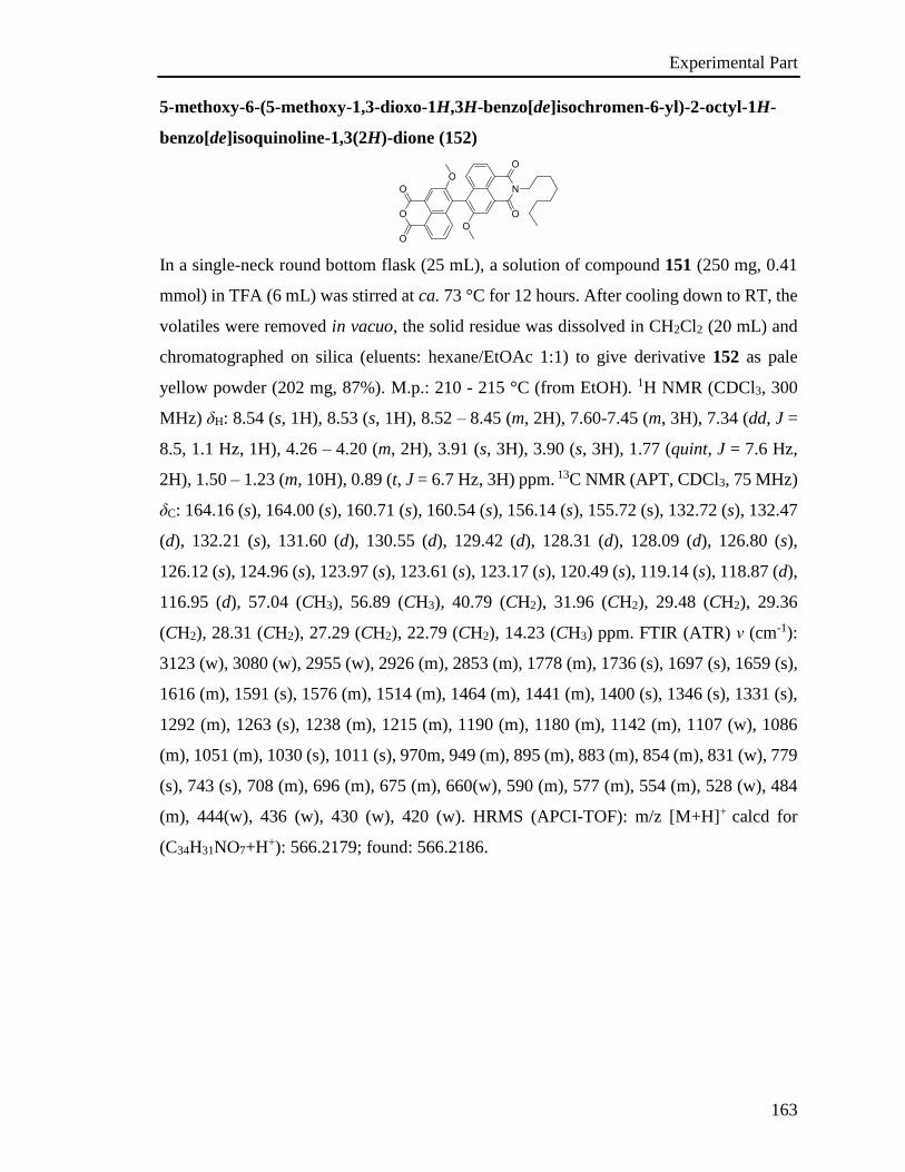
Experimental Part
163
5-methoxy-6-(5-methoxy-1,3-dioxo-1H,3H-benzo[de]isochromen-6-yl)-2-octyl-1H-
benzo[de]isoquinoline-1,3(2H)-dione (152)
In a single-neck round bottom flask (25 mL), a solution of compound 151 (250 mg, 0.41
mmol) in TFA (6 mL) was stirred at ca. 73 °C for 12 hours. After cooling down to RT, the
volatiles were removed in vacuo, the solid residue was dissolved in CH2Cl2 (20 mL) and
chromatographed on silica (eluents: hexane/EtOAc 1:1) to give derivative 152 as pale
yellow powder (202 mg, 87%). M.p.: 210 - 215 °C (from EtOH). 1H NMR (CDCl3, 300
MHz) δH: 8.54 (s, 1H), 8.53 (s, 1H), 8.52 – 8.45 (m, 2H), 7.60-7.45 (m, 3H), 7.34 (dd, J =
8.5, 1.1 Hz, 1H), 4.26 – 4.20 (m, 2H), 3.91 (s, 3H), 3.90 (s, 3H), 1.77 (quint, J = 7.6 Hz,
2H), 1.50 – 1.23 (m, 10H), 0.89 (t, J = 6.7 Hz, 3H) ppm. 13C NMR (APT, CDCl3, 75 MHz)
δC: 164.16 (s), 164.00 (s), 160.71 (s), 160.54 (s), 156.14 (s), 155.72 (s), 132.72 (s), 132.47
(d), 132.21 (s), 131.60 (d), 130.55 (d), 129.42 (d), 128.31 (d), 128.09 (d), 126.80 (s),
126.12 (s), 124.96 (s), 123.97 (s), 123.61 (s), 123.17 (s), 120.49 (s), 119.14 (s), 118.87 (d),
116.95 (d), 57.04 (CH3), 56.89 (CH3), 40.79 (CH2), 31.96 (CH2), 29.48 (CH2), 29.36
(CH2), 28.31 (CH2), 27.29 (CH2), 22.79 (CH2), 14.23 (CH3) ppm. FTIR (ATR) ν (cm-1):
3123 (w), 3080 (w), 2955 (w), 2926 (m), 2853 (m), 1778 (m), 1736 (s), 1697 (s), 1659 (s),
1616 (m), 1591 (s), 1576 (m), 1514 (m), 1464 (m), 1441 (m), 1400 (s), 1346 (s), 1331 (s),
1292 (m), 1263 (s), 1238 (m), 1215 (m), 1190 (m), 1180 (m), 1142 (m), 1107 (w), 1086
(m), 1051 (m), 1030 (s), 1011 (s), 970m, 949 (m), 895 (m), 883 (m), 854 (m), 831 (w), 779
(s), 743 (s), 708 (m), 696 (m), 675 (m), 660(w), 590 (m), 577 (m), 554 (m), 528 (w), 484
(m), 444(w), 436 (w), 430 (w), 420 (w). HRMS (APCI-TOF): m/z [M+H]+ calcd for
(C34H31NO7+H+): 566.2179; found: 566.2186.

Experimental Part
164
5-hydroxy-6-(5-hydroxy-1,3-dioxo-1H,3H-benzo[de]isochromen-6-yl)-2-octyl-1H-
benzo[de]isoquinoline-1,3(2H)-dione (153)
In a single-neck round bottom flask (25 mL), to a solution of compound 153 (224 mg, 0.40
mmol) in CH2Cl2 (5 mL) BBr3 (1M solution in CH2Cl2, 2 mL, 2.0 mmol) was added at ca.
0 °C. The reaction mixture was allowed to warm up to RT and stirred for 12 hours. The
reaction mixture was cooled down to ca. 0 °C and quenched with crushed ice. The
solidified reaction mixture was dispersed in petroleum ether (10 mL) and the solid material
collected by filtration. The crude solid product was dissolved in EtOAc (20 mL), passed
through a thin pad of silica (EtOAc) and the volatiles were removed in vacuo to give
product 154 as yellow powder (212 mg, 99%). M.p.: 278 - 293 °C (from EtOH). 1H NMR
((CD3)2SO, 300 MHz) δH: 10.61 (brs, 2H), 8.39-8.23 (m, 4H), 7.69-7.55 (m, 2H), 7.51 (d,
, J = 8.4 Hz 1H), 7.38 (d, , J = 8.4 Hz 1H), 4.14 – 4.00 (m, 2H), 1.73 – 1.58 (m, 2H), 1.42-
1.17 (m, 10H), 0.86 (t, J= 6.3 Hz, 3H) ppm. 13CNMR (APT, (CD3)2CO, 75 MHz) δC:
164.52 (s), 164.15 (s), 161.50 (s), 161.28 (s), 155.32 (s), 155.13 (s), 134.11 (s), 133.81 (s),
132.97 (d), 131.23 (d), 130.66 (d), 128.97 (d), 128.68 (d), 128.66 (d), 126.53 (s), 125.62
(s), 124.53 (d), 124.34 (s), 123.97 (s), 123.97 (s), 122.74 (d), 121.66 (s), 121.32 (s), 120.32
(s), 40.85 (CH2), 32.59 (CH2), 30.00 (CH2), 28.82 (CH2), 27.86 (CH2), 23.32 (CH2), 14.37
(CH3) ppm 1 CH2 missing. FTIR (ATR) ν (cm-1): 3246 (m), 2949 (m), 2924 (m), 2855 (m),
1769 (s), 1736 (s), 1701 (w), 1680 (s), 1639 (s), 1611 (m), 1593 (s), 1582 (s), 1535 (w),
1512 (m), 1466 (m), 1452 (m), 1408 (s), 1385 (m), 1368 (s), 1341 (m), 1321 (m), 1287
(m), 1265 (s), 1221 (s), 1188s, 1167 (m), 1134 (s), 1099 (m), 1082 (m), 1063 (m), 1043
(m), 1001 (s), 934 (m), 912 (m), 901 (m), 883 (m), 866 (m), 856 (m), 831 (m), 783 (s), 754
(m), 743 (m), 718 (m), 704 (m), 692 (m), 664 (m), 638 (m), 598s, 584 (m), 563 (m), 554
(m), 540 (m), 530 (m), 500 (m), 482 (m), 465 (m), 449 (m), 444 (m), 432 (m), 420 (m),
403 (m).HRMS (APCI-TOF): m/z [M+H]+ calcd for (C32H27NO7+H+): 538.1866; found:
538.1867.
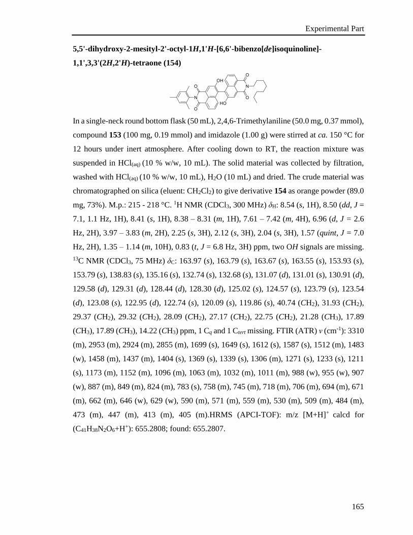
Experimental Part
165
5,5'-dihydroxy-2-mesityl-2'-octyl-1H,1'H-[6,6'-bibenzo[de]isoquinoline]-
1,1',3,3'(2H,2'H)-tetraone (154)
In a single-neck round bottom flask (50 mL), 2,4,6-Trimethylaniline (50.0 mg, 0.37 mmol),
compound 153 (100 mg, 0.19 mmol) and imidazole (1.00 g) were stirred at ca. 150 °C for
12 hours under inert atmosphere. After cooling down to RT, the reaction mixture was
suspended in HCl(aq) (10 % w/w, 10 mL). The solid material was collected by filtration,
washed with HCl(aq) (10 % w/w, 10 mL), H2O (10 mL) and dried. The crude material was
chromatographed on silica (eluent: CH2Cl2) to give derivative 154 as orange powder (89.0
mg, 73%). M.p.: 215 - 218 °C. 1H NMR (CDCl3, 300 MHz) δH: 8.54 (s, 1H), 8.50 (dd, J =
7.1, 1.1 Hz, 1H), 8.41 (s, 1H), 8.38 – 8.31 (m, 1H), 7.61 – 7.42 (m, 4H), 6.96 (d, J = 2.6
Hz, 2H), 3.97 – 3.83 (m, 2H), 2.25 (s, 3H), 2.12 (s, 3H), 2.04 (s, 3H), 1.57 (quint, J = 7.0
Hz, 2H), 1.35 – 1.14 (m, 10H), 0.83 (t, J = 6.8 Hz, 3H) ppm, two OH signals are missing.
13C NMR (CDCl3, 75 MHz) δC: 163.97 (s), 163.79 (s), 163.67 (s), 163.55 (s), 153.93 (s),
153.79 (s), 138.83 (s), 135.16 (s), 132.74 (s), 132.68 (s), 131.07 (d), 131.01 (s), 130.91 (d),
129.58 (d), 129.31 (d), 128.44 (d), 128.30 (d), 125.02 (s), 124.57 (s), 123.79 (s), 123.54
(d), 123.08 (s), 122.95 (d), 122.74 (s), 120.09 (s), 119.86 (s), 40.74 (CH2), 31.93 (CH2),
29.37 (CH2), 29.32 (CH2), 28.09 (CH2), 27.17 (CH2), 22.75 (CH2), 21.28 (CH3), 17.89
(CH3), 17.89 (CH3), 14.22 (CH3) ppm, 1 Cq and 1 Ctert missing. FTIR (ATR) ν (cm-1): 3310
(m), 2953 (m), 2924 (m), 2855 (m), 1699 (s), 1649 (s), 1612 (s), 1587 (s), 1512 (m), 1483
(w), 1458 (m), 1437 (m), 1404 (s), 1369 (s), 1339 (s), 1306 (m), 1271 (s), 1233 (s), 1211
(s), 1173 (m), 1152 (m), 1096 (m), 1063 (m), 1032 (m), 1011 (m), 988 (w), 955 (w), 907
(w), 887 (m), 849 (m), 824 (m), 783 (s), 758 (m), 745 (m), 718 (m), 706 (m), 694 (m), 671
(m), 662 (m), 646 (w), 629 (w), 590 (m), 571 (m), 559 (m), 530 (m), 509 (m), 484 (m),
473 (m), 447 (m), 413 (m), 405 (m).HRMS (APCI-TOF): m/z [M+H]+ calcd for
(C41H38N2O6+H+): 655.2808; found: 655.2807.
Experimental Part
166
N-mesityl, N’-octyl-3,4,8,10-peri-xanthenoxanthenetetracarboxylic-diimide (155)
In a single-neck round bottom flask (25 mL) derivative 154 (70.0 mg, 0.11 mmol), pivalic
acid (22.0 mg, 0.21 mmol) and CuI (60.0 mg, 0.32 mmol) were dissolved in DMSO (10
mL). The reaction mixture was heated at 120 °C under air for 12 hours and then diluted
with H2O (10 mL). The precipitated solid material was collected by filtration, washed with
H2O (10 mL), MeOH (2 mL) and then dissolved in CH2Cl2 (5 mL). The dissolved product
was chromatographed on silica (eluents: CH2Cl2/EtOH 10:0.5) to give derivative 155 as
red powder (62.0 mg, 89%). M.p.: 265 - 293 °C. 1H NMR (CDCl3, 300 MHz) δH: 8.44 (d,
J = 8.3 Hz, 1H), 8.34 (d, J = 8.3 Hz, 1H), 8.27 (s, 1H), 8.19 (s, 1H), 7.18 (d, J = 8.3 Hz,
1H), 7.13 (d, J = 8.3 Hz, 1H), 7.04 (s, 2H), 4.16 – 4.07 (m, 2H), 2.36 (s, 3H), 2.10 (s, 6H),
1.68 (quint, J = 7.3 Hz, 2H), 1.43 – 1.22 (m, 10H), 0.88 (t, J = 6.7 Hz, 3H). 13C NMR
(APT, CDCl3, 75 MHz) δC: 162.88 (s), 162.59 (s), 162.46 (s), 162.13 (s), 157.00 (s), 156.63
(s), 145.832(s), 145.80 (s), 138.81 (s), 135.10 (s), 134.74 (d), 134.26 (d), 131.27 (s), 129.63
(d), 127.45 (s), 126.65 (s), 124.00 (s), 123.96 (s), 121.76 (d), 121.36 (d), 119.32 (s), 119.03
(s), 116.82 (s), 116.70 (s), 116.64 (s), 116.44 (s), 111.87 (d), 111.83 (d), 40.97 (CH2), 31.96
(CH2), 29.47 (CH2), 29.36 (CH2), 28.16 (CH2), 27.27 (CH2), 22.78 (CH2), 21.33 (CH3),
17.90 (CH3), 14.24 (CH3) ppm. FTIR (ATR) ν (cm-1): 3080 (w), 3051 (w), 2953 (m), 2924
(m), 2855 (m), 1707 (m), 1694 (s), 1659(s), 1630(s), 1597(s), 1582 (m), 1560 (m), 1506
(m), 1485 (w), 1466 (w), 1458 (w), 1410(s), 1360(s), 1346(s), 1314 (m), 1298(s), 1267(s),
1242(s), 1204 (m), 1194 (m), 1179(s), 1171(s), 1119 (m), 1088 (m), 1053 (m), 1036 (m),
1015 (m), 959 (w), 945 (m), 907 (m), 870 (m), 853 (m), 839(s), 808(s), 758 (m), 741(s),
731 (m), 718 (m), 694 (m), 677 (m), 656 (m), 623 (m), 613 (m), 600 (m), 571 (m), 561
(m), 534 (m), 523 (m), 509 (m), 488 (m), 434 (s) .HRMS (APCI-TOF): m/z [M+H]+ calcd
for (C41H34N2O6+H+): 651.2495; found: 651.2491.
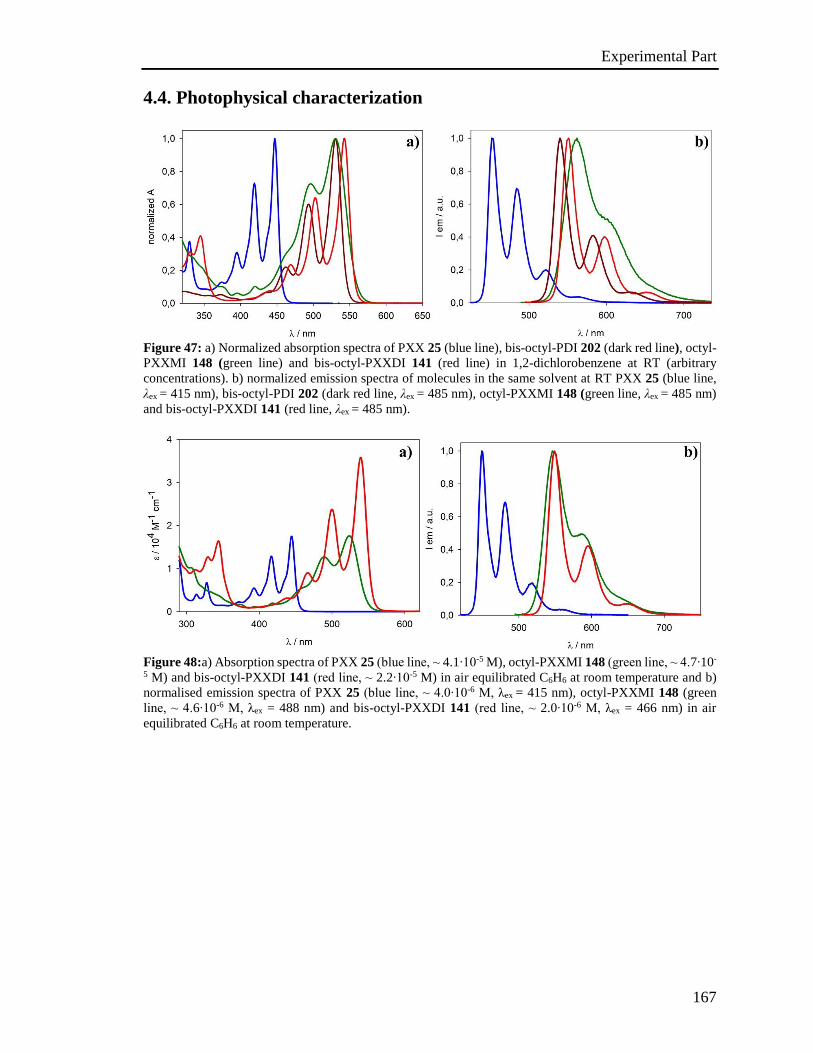
Experimental Part
167
4.4. Photophysical characterization
Figure 47: a) Normalized absorption spectra of PXX 25 (blue line), bis-octyl-PDI 202 (dark red line), octyl-
PXXMI 148 (green line) and bis-octyl-PXXDI 141 (red line) in 1,2-dichlorobenzene at RT (arbitrary
concentrations). b) normalized emission spectra of molecules in the same solvent at RT PXX 25 (blue line,
λex = 415 nm), bis-octyl-PDI 202 (dark red line, λex = 485 nm), octyl-PXXMI 148 (green line, λex = 485 nm)
and bis-octyl-PXXDI 141 (red line, λex = 485 nm).
Figure 48:a) Absorption spectra of PXX 25 (blue line, ⁓ 4.1∙10-5 M), octyl-PXXMI 148 (green line, ⁓ 4.7∙10-
5 M) and bis-octyl-PXXDI 141 (red line, ⁓ 2.2∙10-5 M) in air equilibrated C6H6 at room temperature and b)
normalised emission spectra of PXX 25 (blue line, ⁓ 4.0∙10-6 M, λex = 415 nm), octyl-PXXMI 148 (green
line, ⁓ 4.6∙10-6 M, λex = 488 nm) and bis-octyl-PXXDI 141 (red line, ⁓ 2.0∙10-6 M, λex = 466 nm) in air
equilibrated C6H6 at room temperature.
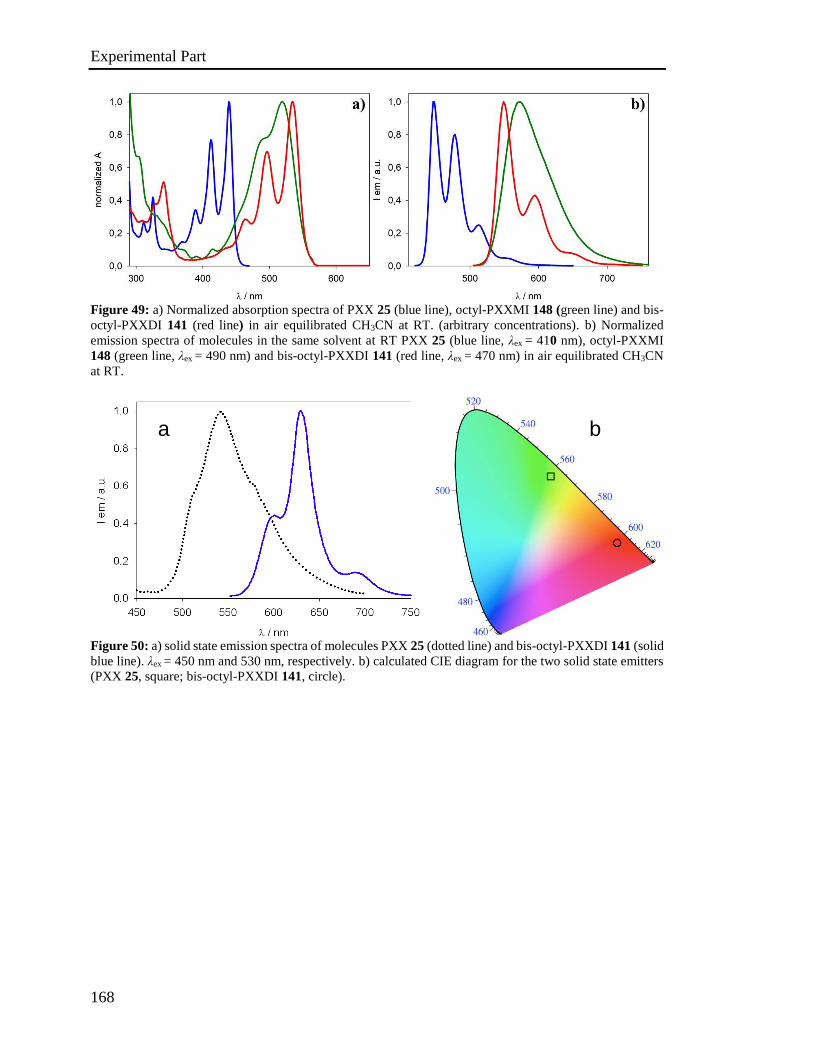
Experimental Part
168
Figure 49: a) Normalized absorption spectra of PXX 25 (blue line), octyl-PXXMI 148 (green line) and bis-
octyl-PXXDI 141 (red line) in air equilibrated CH3CN at RT. (arbitrary concentrations). b) Normalized
emission spectra of molecules in the same solvent at RT PXX 25 (blue line, λex = 410 nm), octyl-PXXMI
148 (green line, λex = 490 nm) and bis-octyl-PXXDI 141 (red line, λex = 470 nm) in air equilibrated CH3CN
at RT.
Figure 50: a) solid state emission spectra of molecules PXX 25 (dotted line) and bis-octyl-PXXDI 141 (solid
blue line). λex = 450 nm and 530 nm, respectively. b) calculated CIE diagram for the two solid state emitters
(PXX 25, square; bis-octyl-PXXDI 141, circle).
a b
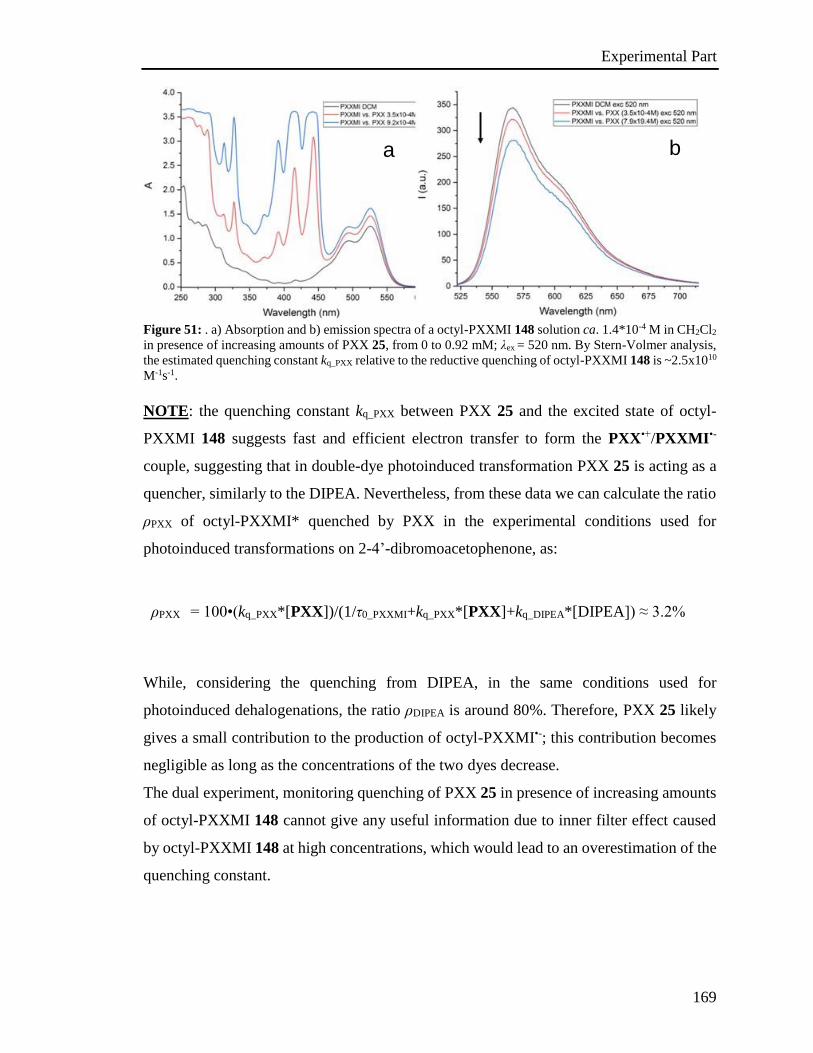
Experimental Part
169
Figure 51: . a) Absorption and b) emission spectra of a octyl-PXXMI 148 solution ca. 1.4*10-4 M in CH2Cl2
in presence of increasing amounts of PXX 25, from 0 to 0.92 mM; λex = 520 nm. By Stern-Volmer analysis,
the estimated quenching constant kq_PXX relative to the reductive quenching of octyl-PXXMI 148 is ~2.5x10¹⁰
M-1s-1.
NOTE: the quenching constant kq_PXX between PXX 25 and the excited state of octyl-
PXXMI 148 suggests fast and efficient electron transfer to form the PXX•+/PXXMI•-
couple, suggesting that in double-dye photoinduced transformation PXX 25 is acting as a
quencher, similarly to the DIPEA. Nevertheless, from these data we can calculate the ratio
ρPXX of octyl-PXXMI* quenched by PXX in the experimental conditions used for
photoinduced transformations on 2-4’-dibromoacetophenone, as:
ρPXX = 100•(kq_PXX*[PXX])/(1/τ0_PXXMI+kq_PXX*[PXX]+kq_DIPEA*[DIPEA]) ≈ 3.2%
While, considering the quenching from DIPEA, in the same conditions used for
photoinduced dehalogenations, the ratio ρDIPEA is around 80%. Therefore, PXX 25 likely
gives a small contribution to the production of octyl-PXXMI•-; this contribution becomes
negligible as long as the concentrations of the two dyes decrease.
The dual experiment, monitoring quenching of PXX 25 in presence of increasing amounts
of octyl-PXXMI 148 cannot give any useful information due to inner filter effect caused
by octyl-PXXMI 148 at high concentrations, which would lead to an overestimation of the
quenching constant.
a b

Experimental Part
170
Figure 52: Normalized emission profiles of the blue and green LEDs used to irradiate solutions of PXX 25
and octyl-PXXMI 148/bis-octyl-PXXDI 141, respectively.
Table 18: Lifetimes for bis-octyl-PXXDI 141 transient absorption features in deaerated C6H6 (~1.0x10⁻⁵
M, λpump = 532 nm), showing comparative mono-exponential and bi-exponential parameters.
λabs τ (μs)[a] R2 [a] τA (μs)[b] τB (μs)[b] R2 [b]
375 nm 51.5 (1) 0.974 19.3 (3) 93 (1) 0.986
540 nm 50.1 (2) 0.962 18.5 (4) 91 (2) 0.974
615 nm 52.2 (2) 0.966 18.5 (4) 92 (2) 0.978
690 nm 53.1 (5) 0.852 19.0 (11) 96 (5) 0.862
750 nm 52.4 (5) 0.867 20.1 (11) 98 (5) 0.877
[a] Monoexponential fitting. [b] Biexponential fitting.
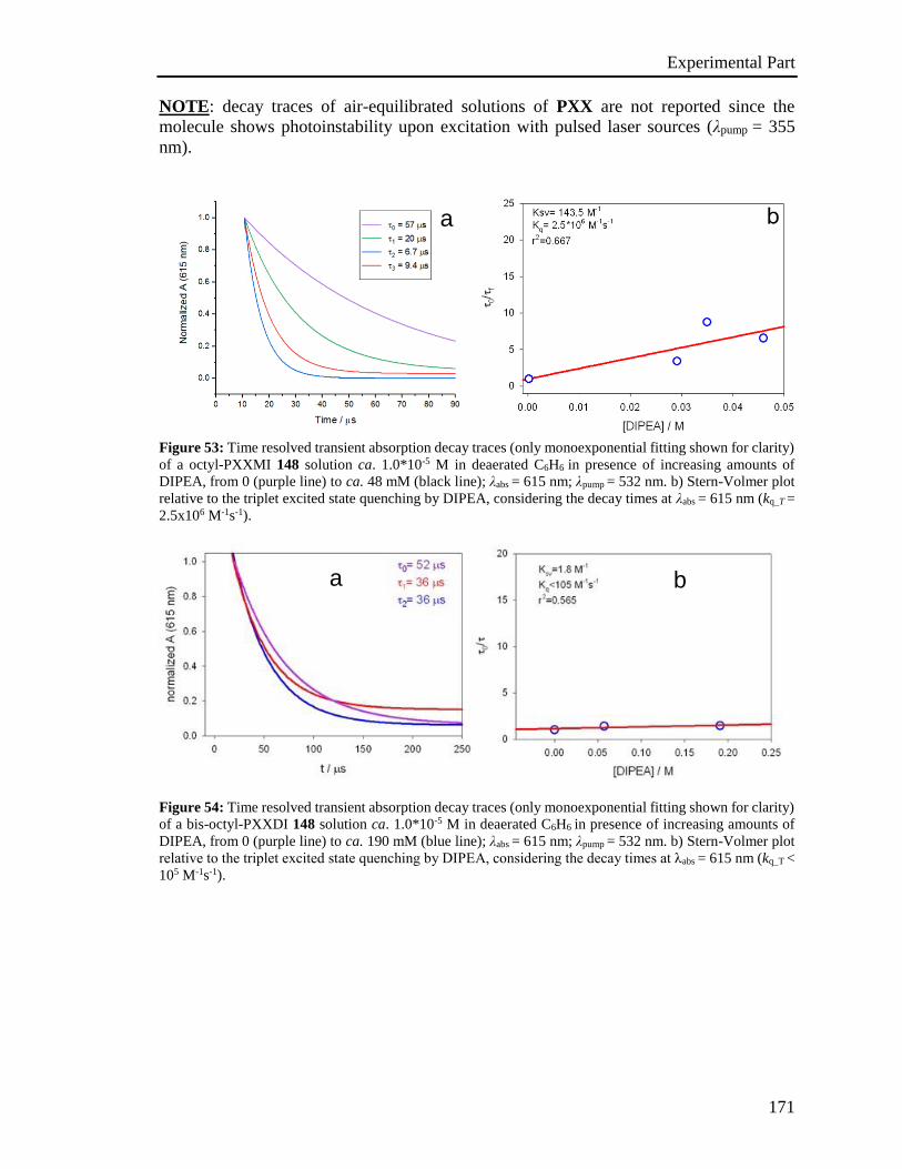
Experimental Part
171
NOTE: decay traces of air-equilibrated solutions of PXX are not reported since the
molecule shows photoinstability upon excitation with pulsed laser sources (λpump = 355
nm).
Figure 53: Time resolved transient absorption decay traces (only monoexponential fitting shown for clarity)
of a octyl-PXXMI 148 solution ca. 1.0*10-5 M in deaerated C6H6 in presence of increasing amounts of
DIPEA, from 0 (purple line) to ca. 48 mM (black line); λabs = 615 nm; λpump = 532 nm. b) Stern-Volmer plot
relative to the triplet excited state quenching by DIPEA, considering the decay times at λabs = 615 nm (kq_T =
2.5x10⁶ M-1s-1).
Figure 54: Time resolved transient absorption decay traces (only monoexponential fitting shown for clarity)
of a bis-octyl-PXXDI 148 solution ca. 1.0*10-5 M in deaerated C6H6 in presence of increasing amounts of
DIPEA, from 0 (purple line) to ca. 190 mM (blue line); λabs = 615 nm; λpump = 532 nm. b) Stern-Volmer plot
relative to the triplet excited state quenching by DIPEA, considering the decay times at λabs = 615 nm (kq_T <
105 M-1s-1).
a
a b

Experimental Part
172
4.5. Stern-Volmer analysis
Table 19: Fluorescence quenching constants for the fluorescence quenching of PXX 25 and octyl-PXXMI
148 measured in CH2Cl2 or CH3CN; values in italics are qualitatively estimated.
Dye (solvent) Quencher Quencher Eox/Ered
(V vs. SCE) kq (M-1s-1)
PXX (C6H6) DIPEA 0.52/nd a 2.9x10⁷
PXX (CH2Cl2) DIPEA 0.52/nd a 2.2x10⁷
PXX (CH3CN) DIPEA 0.52/nd a 3.5x10⁷
PXXMI (C6H6) DIPEA 0.52/nd a 2.4x10⁸
PXXMI (CH2Cl2) DIPEA 0.52/nd a 1.9x10⁹
PXXMI (CH3CN) DIPEA 0.52/nd a 4.2x10⁹
PXXDI (C6H6) DIPEA 0.52/nd a 5.7x10⁹
PXXDI
(CH3CN:CH2Cl2,1:1) DIPEA
0.52/nd a 5.8x10⁹
PXX (C6H6) PhCOCH2Br nd/-0.49 b 2.3x10¹⁰
PXX (CH3CN) PhCOCH2Br nd/-0.49 b 2.7x10¹⁰
PXXMI (C6H6) PhCOCH2Br nd/-0.49 b 2.2x10⁸
PXXMI (CH3CN) PhCOCH2Br nd/-0.49 b 2.2x10⁸
PXXDI (C6H6) PhCOCH2Br nd/-0.49 b 7.2x10⁸
PXXDI
(CH3CN:CH2Cl2,1:1) PhCOCH2Br
nd/-0.49 b 4.5x10⁸
PXX (C6H6) pBr-ArCOH nd/-1.76 c 7.0x10⁹
PXX (CH2Cl2) pBr-ArCOH nd/-1.76 c 1.3x10¹⁰
PXX (CH3CN) pBr-ArCOH nd/-1.76 c 1.8x10¹⁰
PXX (C6H6) pBr-ArCOCH3 nd 8.2x10⁸
PXX (CH2Cl2) pBr-ArCOCH3 nd 6.9x10⁹
PXX (CH3CN) pBr-ArCOCH3 nd 1.3x10¹⁰
PXXMI (C6H6) pBr-ArCOCH3 nd <107
PXXDI (C6H6) pBr-ArCOCH3 nd 8.8x10⁷
PXXMI (CH3CN) diethylchloromalonate nd 9.0x10⁶
PXXDI
(CH3CN:CH2Cl2,1:1) diethylchloromalonate
nd 3.8x10⁷
PXXMI (CH3CN) diethylbromomalonate nd 2.1x10⁷
PXXDI
(CH3CN:CH2Cl2,1:1) diethylbromomalonate
nd 8.6x10⁷
aTaken from reference [S9]. Other reported values are 0.72 V vs. SCE in CH3CN,[S10] 0.65 V vs. SCE in
CH3CN.[S11] bFrom reference [S12]. cPeak potential, from reference [S13].
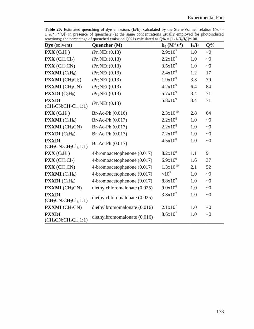
Experimental Part
173
Table 20: Estimated quenching of dye emissions (I0/If), calculated by the Stern-Volmer relation (I0/If =
1+kq*τ0*[Q]) in presence of quenchers (at the same concentrations usually employed for photoinduced
reactions); the percentage of quenched emission Q% is calculated as Q% = [1-1/(I0/If)]*100.
Dye (solvent) Quencher (M) kq (M-1s-1) I0/If Q%
PXX (C6H6) iPr2NEt (0.13) 2.9x10⁷ 1.0 ~0
PXX (CH2Cl2) iPr2NEt (0.13) 2.2x10⁷ 1.0 ~0
PXX (CH3CN) iPr2NEt (0.13) 3.5x10⁷ 1.0 ~0
PXXMI (C6H6) iPr2NEt (0.13) 2.4x10⁸ 1.2 17
PXXMI (CH2Cl2) iPr2NEt (0.13) 1.9x10⁹ 3.3 70
PXXMI (CH3CN) iPr2NEt (0.13) 4.2x10⁹ 6.4 84
PXXDI (C6H6) iPr2NEt (0.13) 5.7x10⁹ 3.4 71
PXXDI
(CH3CN:CH2Cl2,1:1) iPr2NEt (0.13)
5.8x10⁹ 3.4 71
PXX (C6H6) Br-Ac-Ph (0.016) 2.3x10¹⁰ 2.8 64
PXXMI (C6H6) Br-Ac-Ph (0.017) 2.2x10⁸ 1.0 ~0
PXXMI (CH3CN) Br-Ac-Ph (0.017) 2.2x10⁸ 1.0 ~0
PXXDI (C6H6) Br-Ac-Ph (0.017) 7.2x10⁸ 1.0 ~0
PXXDI
(CH3CN:CH2Cl2,1:1) Br-Ac-Ph (0.017)
4.5x10⁸ 1.0 ~0
PXX (C6H6) 4-bromoacetophenone (0.017) 8.2x10⁸ 1.1 9
PXX (CH2Cl2) 4-bromoacetophenone (0.017) 6.9x10⁹ 1.6 37
PXX (CH3CN) 4-bromoacetophenone (0.017) 1.3x10¹⁰ 2.1 52
PXXMI (C6H6) 4-bromoacetophenone (0.017) <107 1.0 ~0
PXXDI (C6H6) 4-bromoacetophenone (0.017) 8.8x10⁷ 1.0 ~0
PXXMI (CH3CN) diethylchloromalonate (0.025) 9.0x10⁶ 1.0 ~0
PXXDI
(CH3CN:CH2Cl2,1:1) diethylchloromalonate (0.025)
3.8x10⁷ 1.0 ~0
PXXMI (CH3CN) diethylbromomalonate (0.016) 2.1x10⁷ 1.0 ~0
PXXDI
(CH3CN:CH2Cl2,1:1) diethylbromomalonate (0.016)
8.6x10⁷ 1.0 ~0
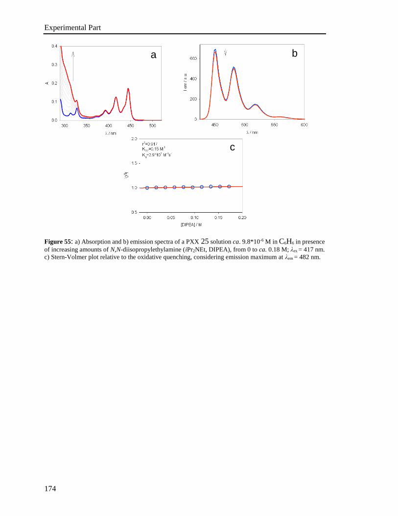
Experimental Part
174
Figure 55: a) Absorption and b) emission spectra of a PXX 25 solution ca. 9.8*10-6 M in C6H6 in presence
of increasing amounts of N,N-diisopropylethylamine (iPr2NEt, DIPEA), from 0 to ca. 0.18 M; λex = 417 nm.
c) Stern-Volmer plot relative to the oxidative quenching, considering emission maximum at λem = 482 nm.
c
a b
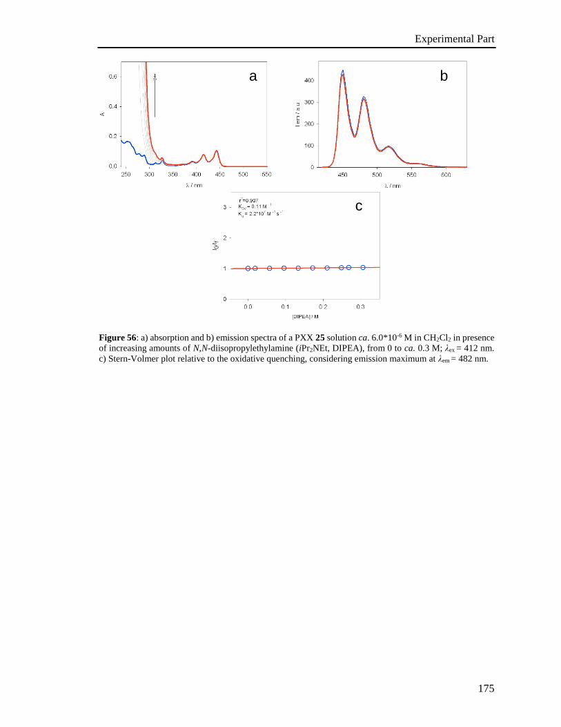
Experimental Part
175
Figure 56: a) absorption and b) emission spectra of a PXX 25 solution ca. 6.0*10-6 M in CH2Cl2 in presence
of increasing amounts of N,N-diisopropylethylamine (iPr2NEt, DIPEA), from 0 to ca. 0.3 M; λex = 412 nm.
c) Stern-Volmer plot relative to the oxidative quenching, considering emission maximum at λem = 482 nm.
a b
c
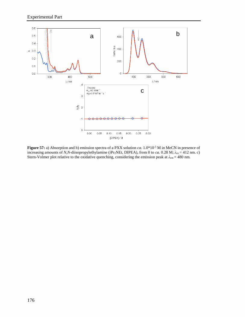
Experimental Part
176
Figure 57: a) Absorption and b) emission spectra of a PXX solution ca. 1.0*10-5 M in MeCN in presence of
increasing amounts of N,N-diisopropylethylamine (iPr2NEt, DIPEA), from 0 to ca. 0.28 M; λex = 412 nm. c)
Stern-Volmer plot relative to the oxidative quenching, considering the emission peak at λem = 480 nm.
c
a b

Experimental Part
177
Figure 58: a) Absorption and b) emission spectra of a octyl PXXMI 148 solution ca. 7.8*10-6 M in C6H6 in
presence of increasing amounts of N,N-diisopropylethylamine (iPr2NEt, DIPEA), from 0 to ca. 0.25 M; λex
= 490 nm. c) Stern-Volmer plot relative to the reductive quenching, considering the emission peak at λem =
590 nm.
a b
c
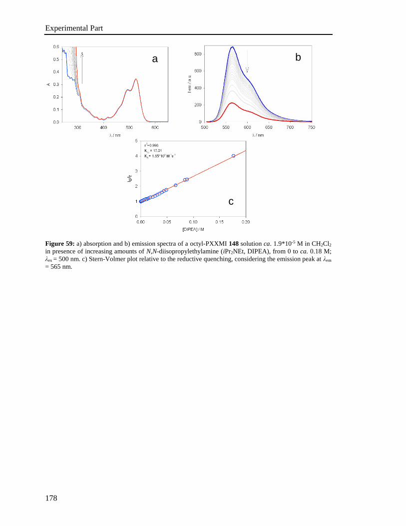
Experimental Part
178
Figure 59: a) absorption and b) emission spectra of a octyl-PXXMI 148 solution ca. 1.9*10-5 M in CH2Cl2
in presence of increasing amounts of N,N-diisopropylethylamine (iPr2NEt, DIPEA), from 0 to ca. 0.18 M;
λex = 500 nm. c) Stern-Volmer plot relative to the reductive quenching, considering the emission peak at λem
= 565 nm.
b
c
a
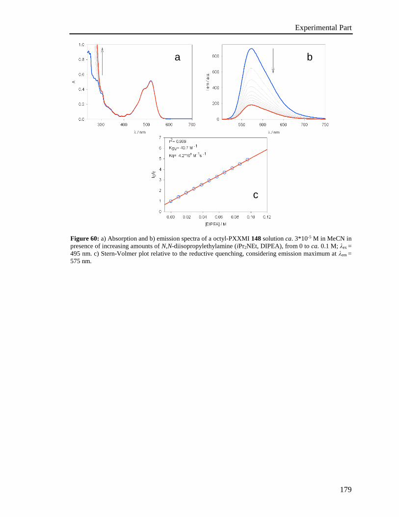
Experimental Part
179
Figure 60: a) Absorption and b) emission spectra of a octyl-PXXMI 148 solution ca. 3*10-5 M in MeCN in
presence of increasing amounts of N,N-diisopropylethylamine (iPr2NEt, DIPEA), from 0 to ca. 0.1 M; λex =
495 nm. c) Stern-Volmer plot relative to the reductive quenching, considering emission maximum at λem =
575 nm.
a b
c
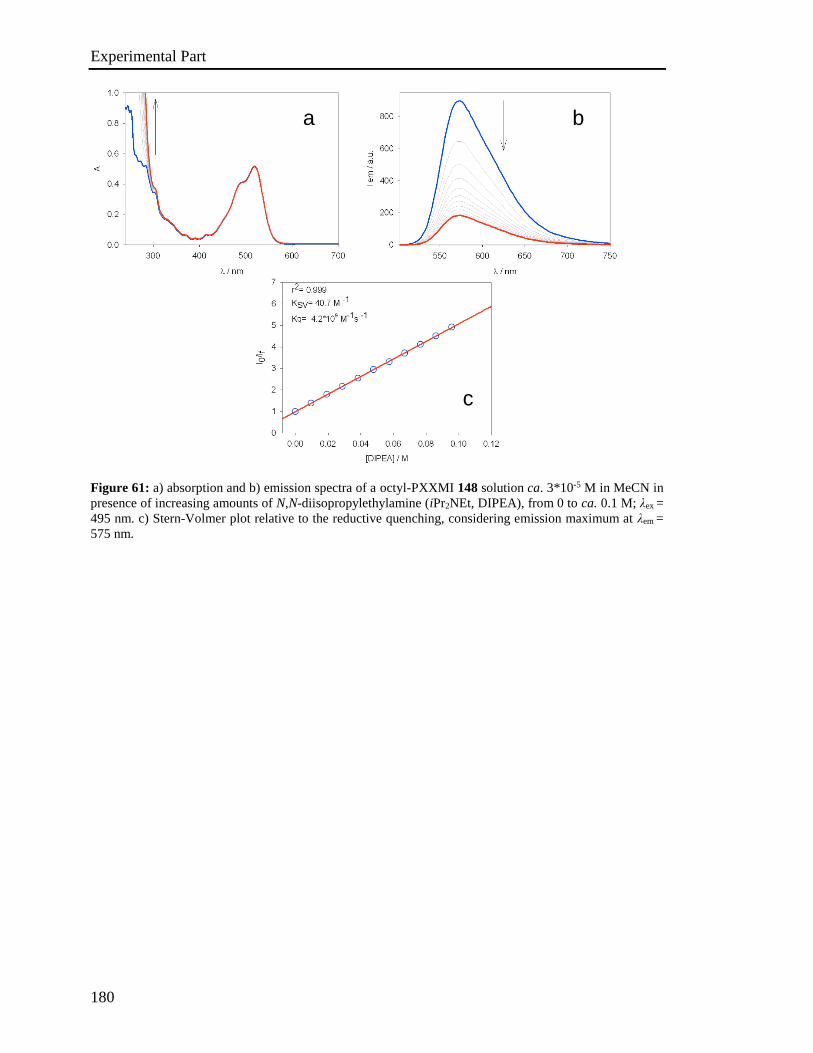
Experimental Part
180
Figure 61: a) absorption and b) emission spectra of a octyl-PXXMI 148 solution ca. 3*10-5 M in MeCN in
presence of increasing amounts of N,N-diisopropylethylamine (iPr2NEt, DIPEA), from 0 to ca. 0.1 M; λex =
495 nm. c) Stern-Volmer plot relative to the reductive quenching, considering emission maximum at λem =
575 nm.
a b
c
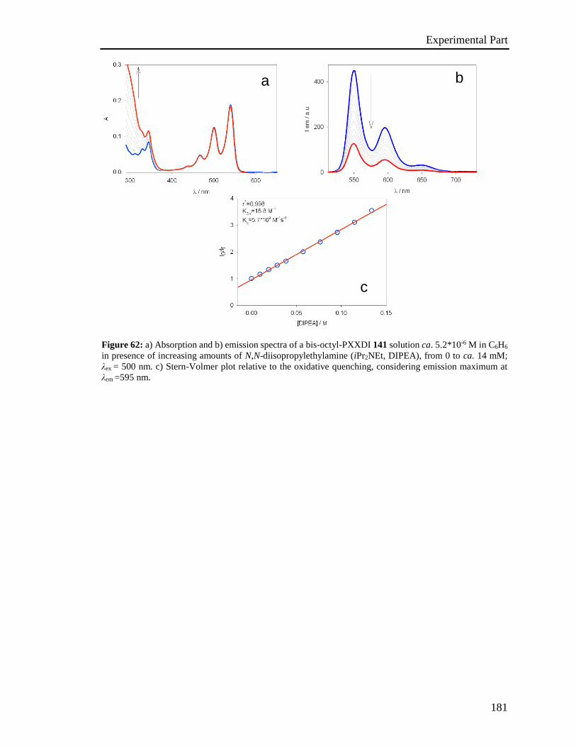
Experimental Part
181
Figure 62: a) Absorption and b) emission spectra of a bis-octyl-PXXDI 141 solution ca. 5.2*10-6 M in C6H6
in presence of increasing amounts of N,N-diisopropylethylamine (iPr2NEt, DIPEA), from 0 to ca. 14 mM;
λex = 500 nm. c) Stern-Volmer plot relative to the oxidative quenching, considering emission maximum at
λem =595 nm.
c
a b
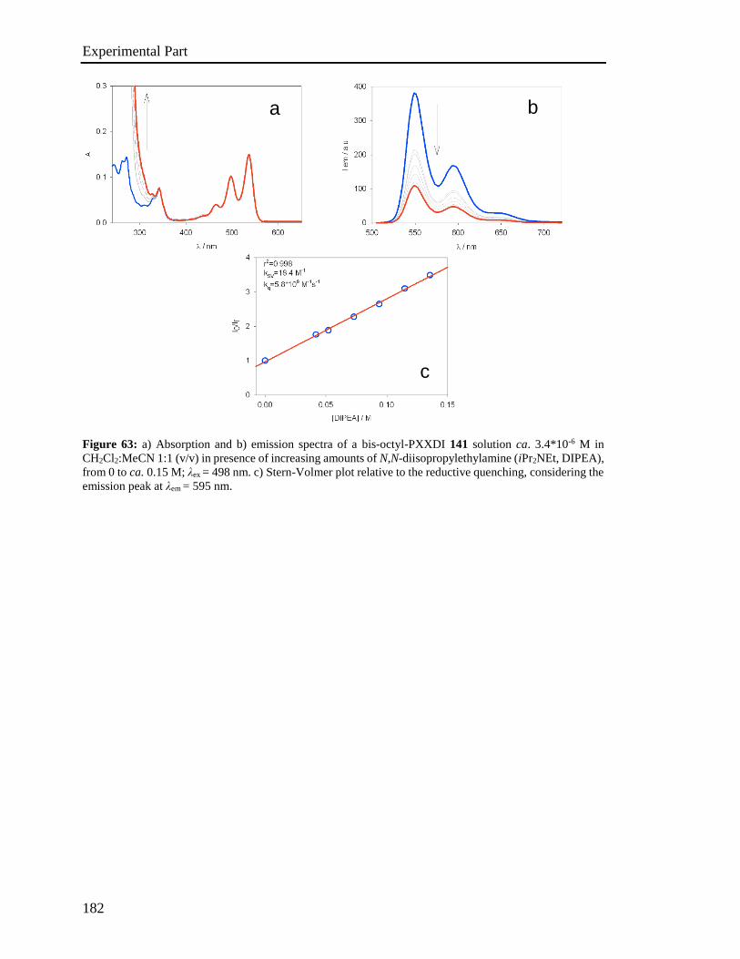
Experimental Part
182
Figure 63: a) Absorption and b) emission spectra of a bis-octyl-PXXDI 141 solution ca. 3.4*10-6 M in
CH2Cl2:MeCN 1:1 (v/v) in presence of increasing amounts of N,N-diisopropylethylamine (iPr2NEt, DIPEA),
from 0 to ca. 0.15 M; λex = 498 nm. c) Stern-Volmer plot relative to the reductive quenching, considering the
emission peak at λem = 595 nm.
a b
c
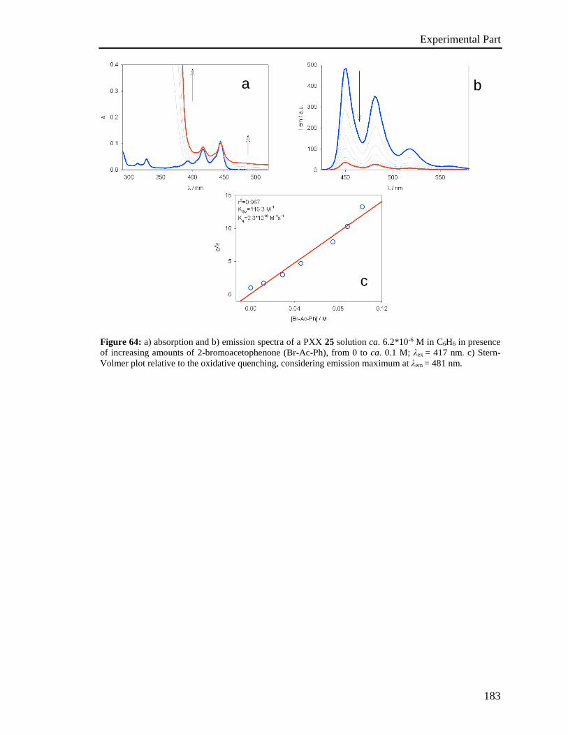
Experimental Part
183
Figure 64: a) absorption and b) emission spectra of a PXX 25 solution ca. 6.2*10-6 M in C6H6 in presence
of increasing amounts of 2-bromoacetophenone (Br-Ac-Ph), from 0 to ca. 0.1 M; λex = 417 nm. c) Stern-
Volmer plot relative to the oxidative quenching, considering emission maximum at λem = 481 nm.
c
b a

Experimental Part
184
Figure 65: a) Absorption and b) emission spectra of a PXX solution ca. 1.0*10-5 M in CH3CN in presence
of increasing amounts of 2-bromoacetophenone (Br-Ac-Ph), from 0 to ca. 0.25 M; λex = 413 nm. c) Stern-
Volmer plot relative to the oxidative quenching, considering emission maximum at λem = 477 nm.
c
a b
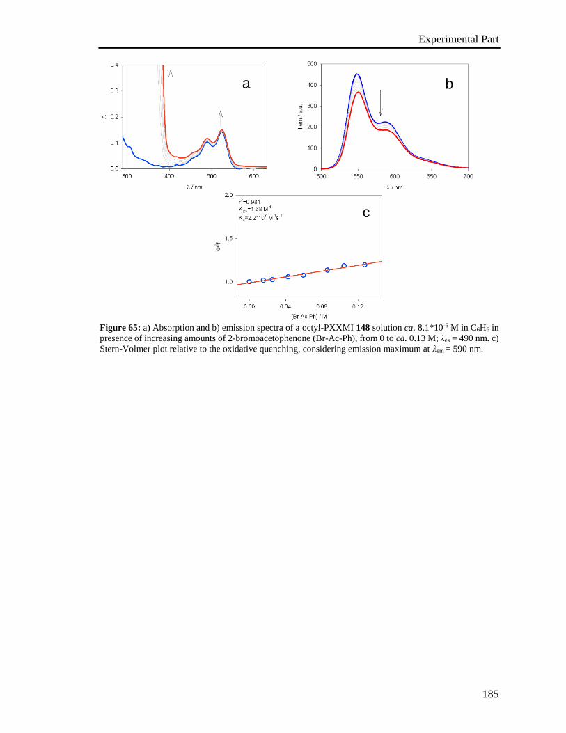
Experimental Part
185
Figure 65: a) Absorption and b) emission spectra of a octyl-PXXMI 148 solution ca. 8.1*10-6 M in C6H6 in
presence of increasing amounts of 2-bromoacetophenone (Br-Ac-Ph), from 0 to ca. 0.13 M; λex = 490 nm. c)
Stern-Volmer plot relative to the oxidative quenching, considering emission maximum at λem = 590 nm.
c
b a
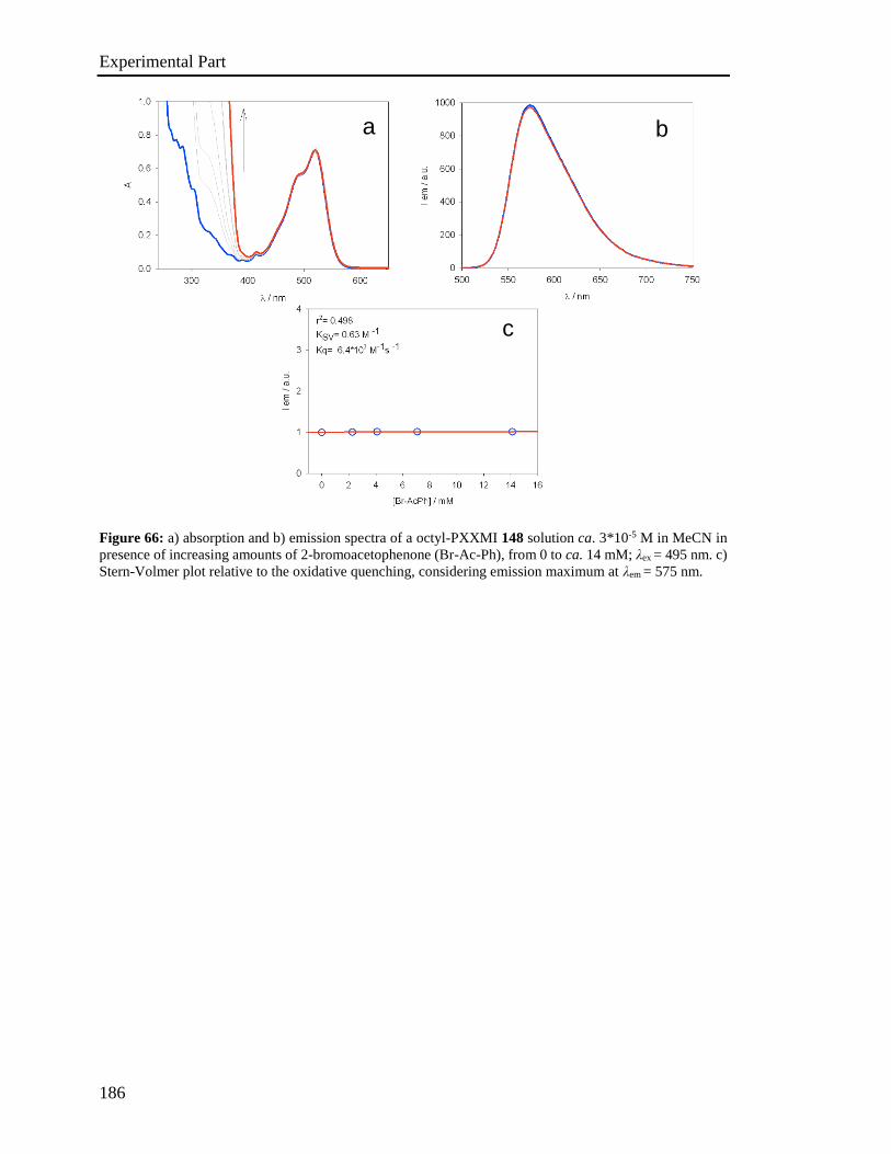
Experimental Part
186
Figure 66: a) absorption and b) emission spectra of a octyl-PXXMI 148 solution ca. 3*10-5 M in MeCN in
presence of increasing amounts of 2-bromoacetophenone (Br-Ac-Ph), from 0 to ca. 14 mM; λex = 495 nm. c)
Stern-Volmer plot relative to the oxidative quenching, considering emission maximum at λem = 575 nm.
c
a b

Experimental Part
187
Figure 67: a) Absorption and b) emission spectra of a bis-octyl-PXXDI 141 solution ca. 4.0*10-6 M in C6H6
in presence of increasing amounts of 2-bromoacetophenone (Br-Ac-Ph), from 0 to ca. 90 mM; λex = 500 nm.
c) Stern-Volmer plot relative to the oxidative quenching, considering emission maximum at λem = 595 nm.
c
a b

Experimental Part
188
Figure 68: a) Absorption and b) emission spectra of a bis-octyl-PXXDI 141 solution ca. 2.0*10-6 M in
CH2Cl2:MeCN 1:1 (v/v) in presence of increasing amounts of 2-bromoacetophenone (Br-Ac-Ph), from 0 to
ca. 0.07 M; λex = 498 nm. c) Stern-Volmer plot relative to the reductive quenching, considering the emission
peak at λem = 594 nm.
a b
c
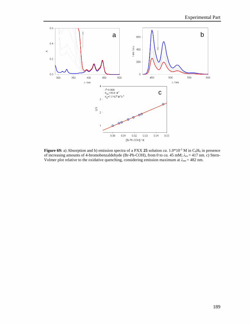
Experimental Part
189
Figure 69: a) Absorption and b) emission spectra of a PXX 25 solution ca. 1.0*10-5 M in C6H6 in presence
of increasing amounts of 4-bromobenzaldehyde (Br-Ph-COH), from 0 to ca. 45 mM; λex = 417 nm. c) Stern-
Volmer plot relative to the oxidative quenching, considering emission maximum at λem = 482 nm.
c
b a

Experimental Part
190
Figure 70: a) Absorption and b) emission spectra of a PXX 25 solution ca. 2.6*10-6 M in CH2Cl2 in presence
of increasing amounts of 4-bromobenzaldehyde (Br-Ph-COH), from 0 to ca. 20 mM; λex = 412 nm. c) Stern-
Volmer plot relative to the oxidative quenching, considering emission maximum at λem = 481 nm.
a b
c
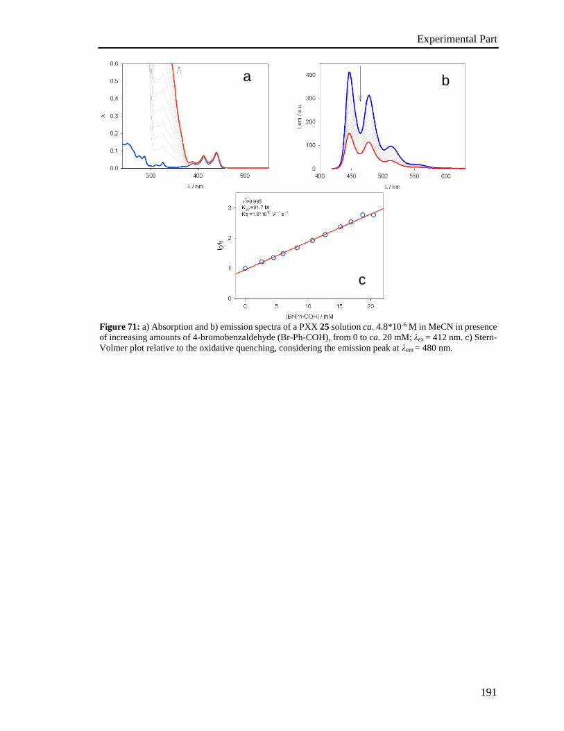
Experimental Part
191
Figure 71: a) Absorption and b) emission spectra of a PXX 25 solution ca. 4.8*10-6 M in MeCN in presence
of increasing amounts of 4-bromobenzaldehyde (Br-Ph-COH), from 0 to ca. 20 mM; λex = 412 nm. c) Stern-
Volmer plot relative to the oxidative quenching, considering the emission peak at λem = 480 nm.
a b
c
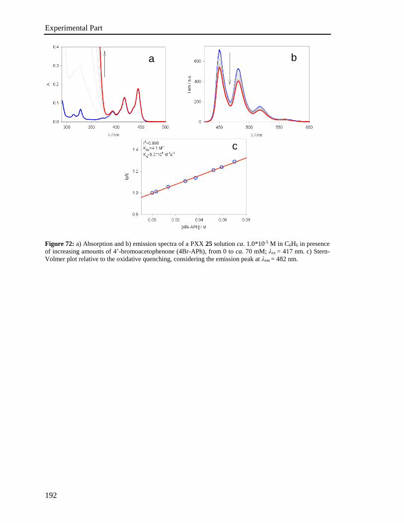
Experimental Part
192
Figure 72: a) Absorption and b) emission spectra of a PXX 25 solution ca. 1.0*10-5 M in C6H6 in presence
of increasing amounts of 4’-bromoacetophenone (4Br-APh), from 0 to ca. 70 mM; λex = 417 nm. c) Stern-
Volmer plot relative to the oxidative quenching, considering the emission peak at λem = 482 nm.
c
b a
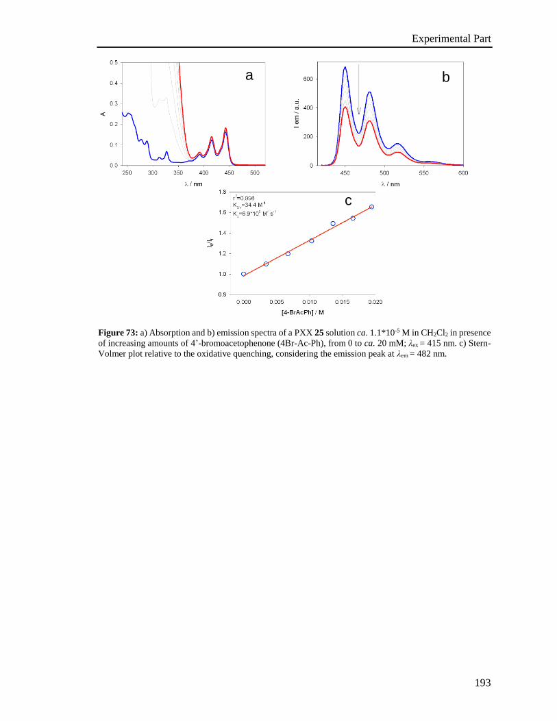
Experimental Part
193
Figure 73: a) Absorption and b) emission spectra of a PXX 25 solution ca. 1.1*10-5 M in CH2Cl2 in presence
of increasing amounts of 4’-bromoacetophenone (4Br-Ac-Ph), from 0 to ca. 20 mM; λex = 415 nm. c) Stern-
Volmer plot relative to the oxidative quenching, considering the emission peak at λem = 482 nm.
a b
c
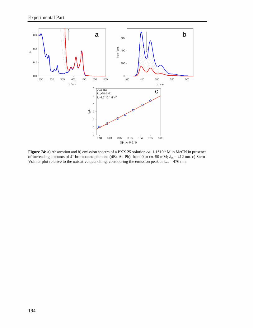
Experimental Part
194
Figure 74: a) Absorption and b) emission spectra of a PXX 25 solution ca. 1.1*10-5 M in MeCN in presence
of increasing amounts of 4’-bromoacetophenone (4Br-Ac-Ph), from 0 to ca. 50 mM; λex = 412 nm. c) Stern-
Volmer plot relative to the oxidative quenching, considering the emission peak at λem = 476 nm.
a b
c
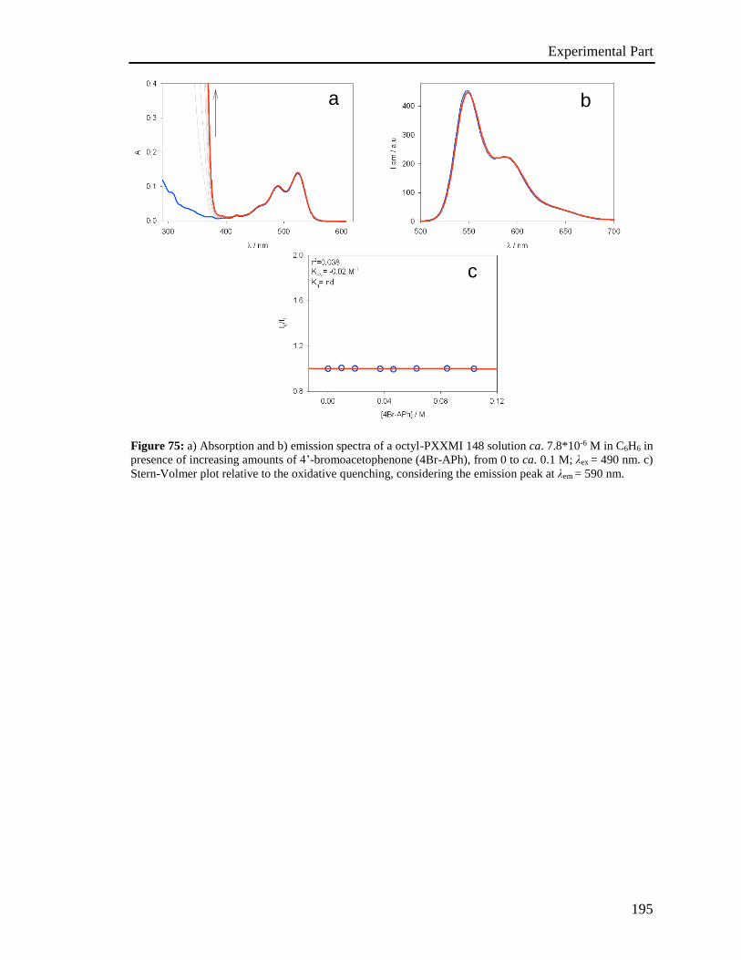
Experimental Part
195
Figure 75: a) Absorption and b) emission spectra of a octyl-PXXMI 148 solution ca. 7.8*10-6 M in C6H6 in
presence of increasing amounts of 4’-bromoacetophenone (4Br-APh), from 0 to ca. 0.1 M; λex = 490 nm. c)
Stern-Volmer plot relative to the oxidative quenching, considering the emission peak at λem = 590 nm.
c
b a
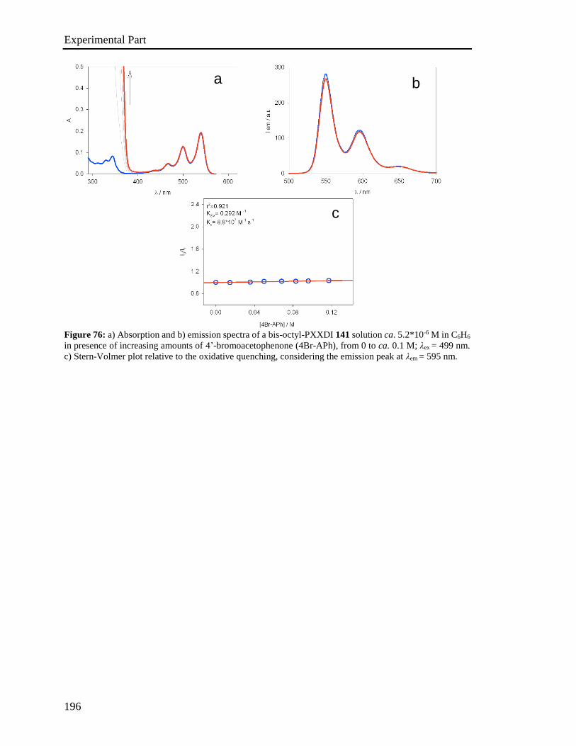
Experimental Part
196
Figure 76: a) Absorption and b) emission spectra of a bis-octyl-PXXDI 141 solution ca. 5.2*10-6 M in C6H6
in presence of increasing amounts of 4’-bromoacetophenone (4Br-APh), from 0 to ca. 0.1 M; λex = 499 nm.
c) Stern-Volmer plot relative to the oxidative quenching, considering the emission peak at λem = 595 nm.
a b
c

Experimental Part
197
Figure 77: a) Absorption and b) emission spectra of a octyl-PXXMI 148 solution ca. 4.1*10-6 M in MeCN
in presence of increasing amounts of diethylchloromalonate (DECM), from 0 to ca. 0.42 M; λex = 497 nm. c)
Stern-Volmer plot relative to the oxidative quenching, considering the emission peak at λem = 575 nm.
b a
c
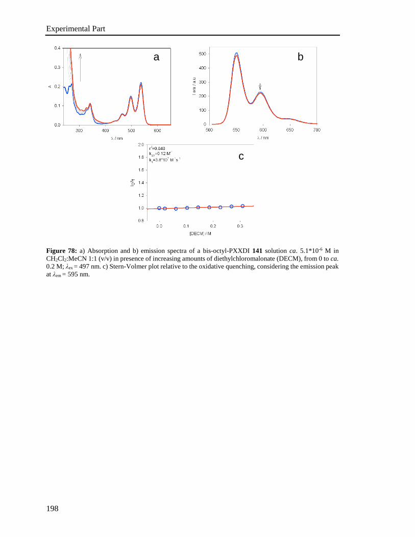
Experimental Part
198
Figure 78: a) Absorption and b) emission spectra of a bis-octyl-PXXDI 141 solution ca. 5.1*10-6 M in
CH2Cl2:MeCN 1:1 (v/v) in presence of increasing amounts of diethylchloromalonate (DECM), from 0 to ca.
0.2 M; λex = 497 nm. c) Stern-Volmer plot relative to the oxidative quenching, considering the emission peak
at λem = 595 nm.
a b
c
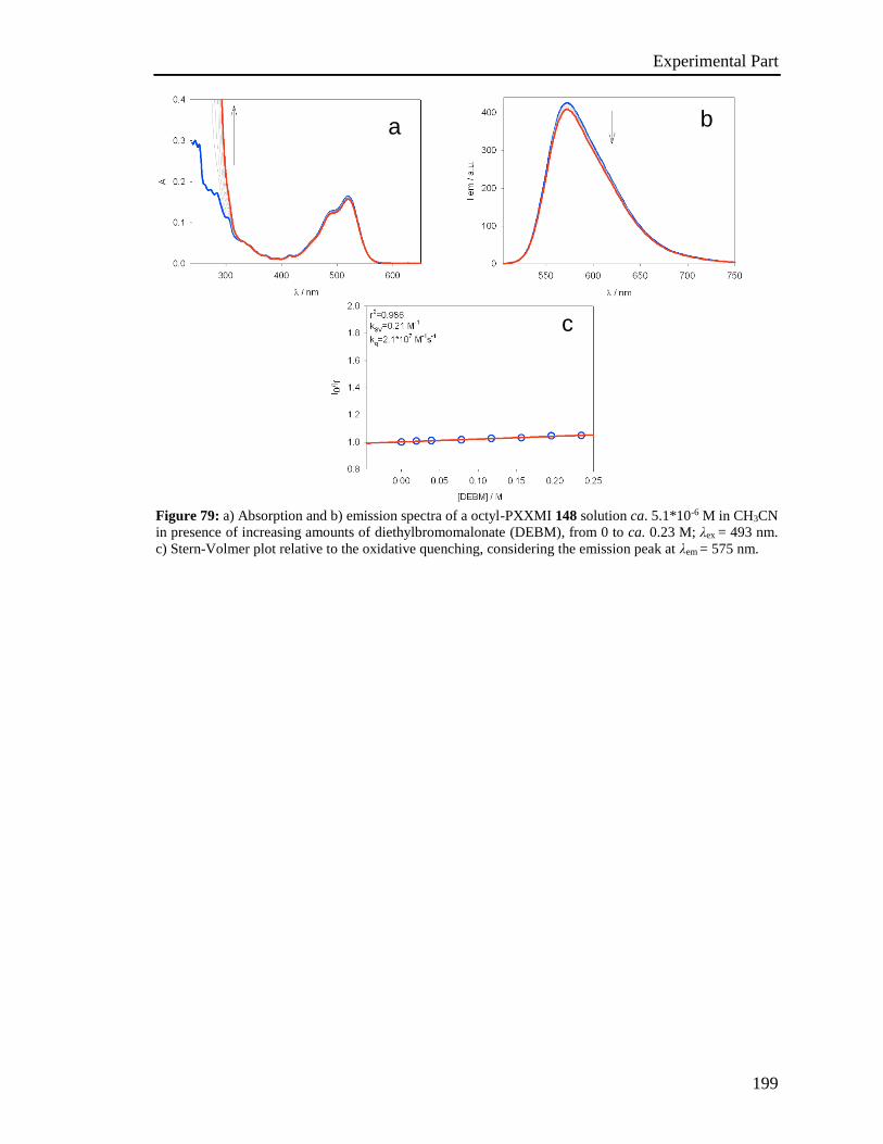
Experimental Part
199
Figure 79: a) Absorption and b) emission spectra of a octyl-PXXMI 148 solution ca. 5.1*10-6 M in CH3CN
in presence of increasing amounts of diethylbromomalonate (DEBM), from 0 to ca. 0.23 M; λex = 493 nm.
c) Stern-Volmer plot relative to the oxidative quenching, considering the emission peak at λem = 575 nm.
b a
c
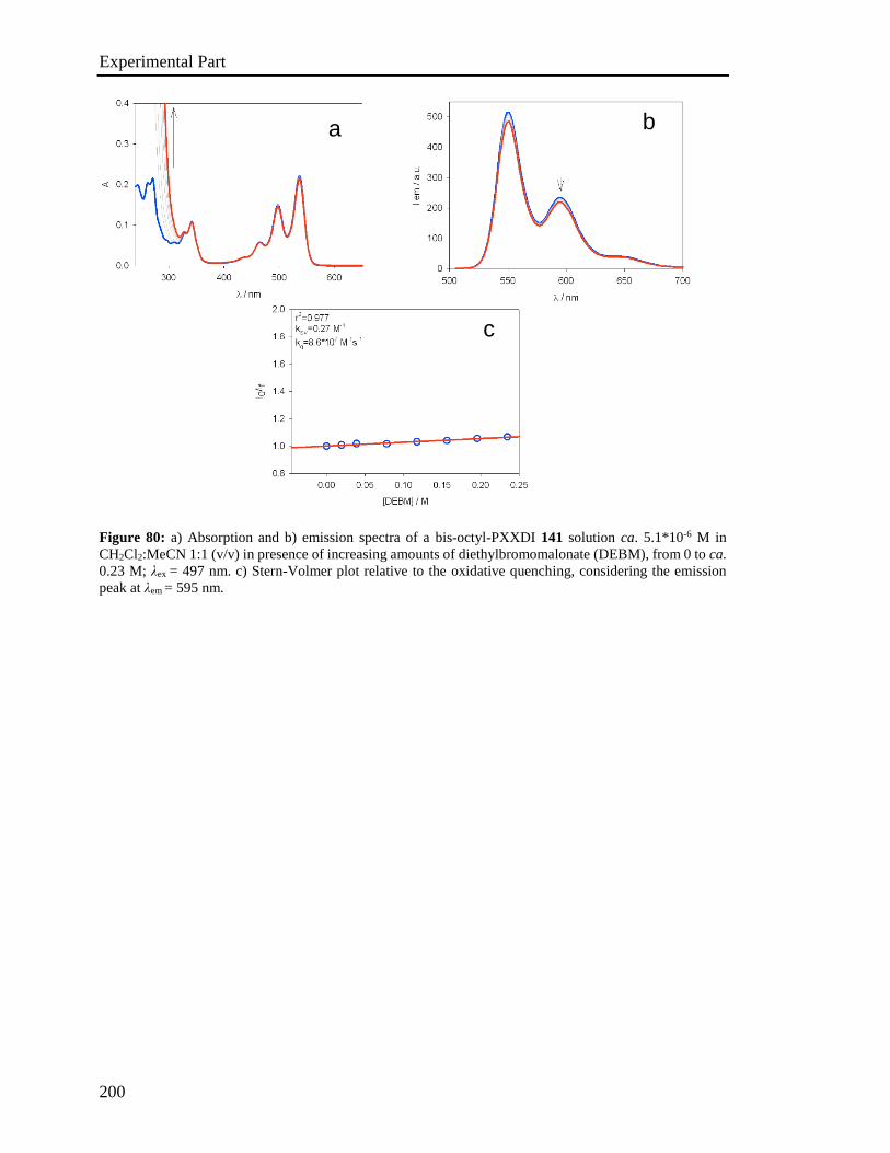
Experimental Part
200
Figure 80: a) Absorption and b) emission spectra of a bis-octyl-PXXDI 141 solution ca. 5.1*10-6 M in
CH2Cl2:MeCN 1:1 (v/v) in presence of increasing amounts of diethylbromomalonate (DEBM), from 0 to ca.
0.23 M; λex = 497 nm. c) Stern-Volmer plot relative to the oxidative quenching, considering the emission
peak at λem = 595 nm.
a b
c

Experimental Part
201
4.6. Photoactivated reactions and control experiments
All the photochemichal reactions run under visible light were performed using a 5 meters
long TINGKAM® RGB LED flexible stripe (LED type: 5050 PLCC-4 SMT SMD),
equipped with a remote controller and placed on the inner surface of a metal cylinder (~
20 cm diameter); estimated total output power: 36 W.
4.6.1. General procedure for photodehalogenation reactions
A screw cap vial was charged with halogen-derivative (5.0∙10-2 mmol), DIPEA (4.0∙10-1
mmol) and the dye (5 mol%, 2.5∙10-3 mmol, 8.3∙10-4 M), in solvent (3 mL).
For the experiments involving diethylbromo- or diethylchloromalonate, the vial was
charged with halogen-derivative (1.3∙10-1 mmol), DIPEA (1.3 mmol) and the dye (0.5
mol%, 6.7∙10-4 mmol, 1.3∙10-4 M), in solvent (5 mL).
For reactions on α-para-dibromoacetophenone, the experiments were carried out adding
DIPEA 0.27 M (7.5∙10-1 mmol in 3 mL) to the mixtures containing the dyes at 0.83 mM
and 0.41 mM.
The reaction mixtures were readily degassed by freeze/pump/thaw (3 cycles). The vial was
irradiated with a specified light source (see section 4.1), and cooled by compressed air in
order to maintain ambient temperature.
Control experiments were carried out on solutions at the same concentrations of reactants
kept in the dark for the same amount of time, depending on the reaction ("dark"
experiments), and on irradiated solutions at the same concentrations of reactants in the
absence of the photoactive species ("blank" experiments). Control experiments without
DIPEA were carried out with the usual concentration of the other reactants.
Reaction conversion was estimated by considering the ratio between integrations of each
product peak and the sum of product and starting material peaks, analysed by GC-MS.
R-XDye, DIPEA
Light, solvent, N2, r.t., timeRH
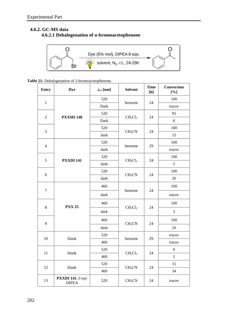
Experimental Part
202
4.6.2. GC-MS data
4.6.2.1 Dehalogenation of α-bromoacetophenone
Table 21: Dehalogenation of 2-bromoacetophenone.
Entry Dye λex [nm] Solvent Time
[h]
Conversion
[%]
1
PXXMI 148
520 benzene 24
100
Dark traces
2 520
CH2Cl2 24 95
Dark 6
3 520
CH3CN 24 100
dark 15
4
PXXDI 141
520 benzene 29
100
dark traces
5 520
CH2Cl2 24 100
dark 5
6 520
CH3CN 24 100
dark 20
7
PXX 25
460 benzene 24
100
dark traces
8 460
CH2Cl2 24 100
dark 3
9 460
CH3CN 24 100
dark 10
10 blank 520
benzene 29 traces
460 traces
11 blank 520
CH2Cl2 24 0
460 2
12 blank 520
CH3CN 24 15
460 34
13 PXXDI 141, 0 eqv
DIPEA 520 CH3CN 24 traces
Dye (5% mol), DIPEA 8 eqv.
solvent, N2, r.t., 24-29h
O
Br
O
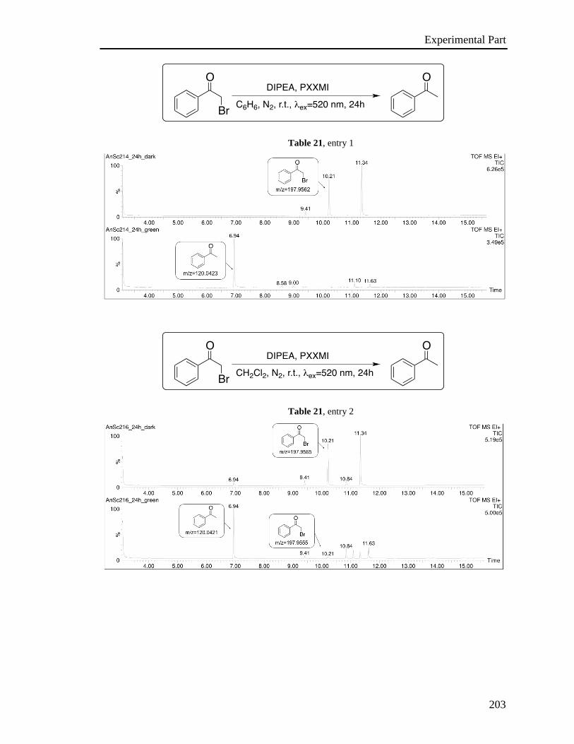
Experimental Part
203
Table 21, entry 1
Table 21, entry 2
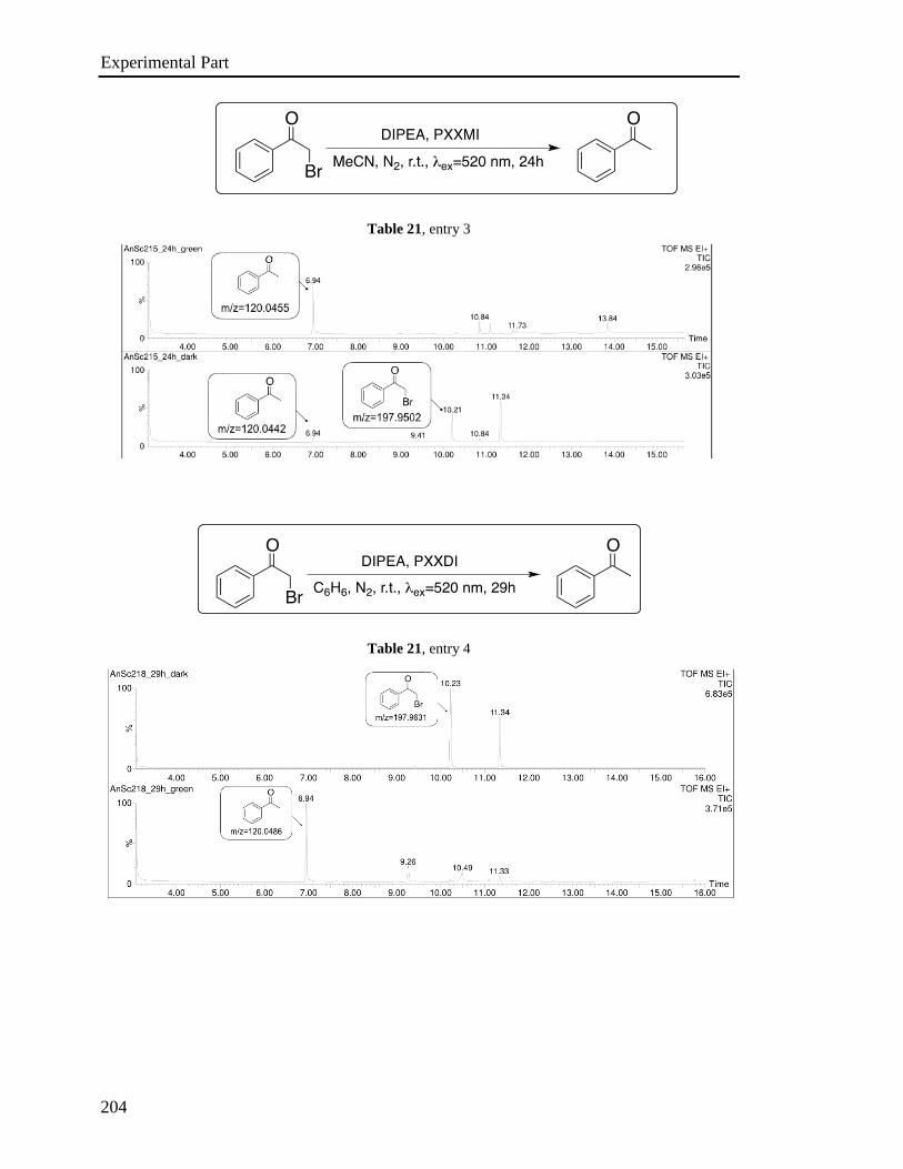
Experimental Part
204
Table 21, entry 3
Table 21, entry 4
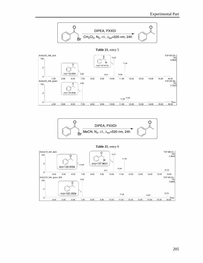
Experimental Part
205
Table 21, entry 5
Table 21, entry 6
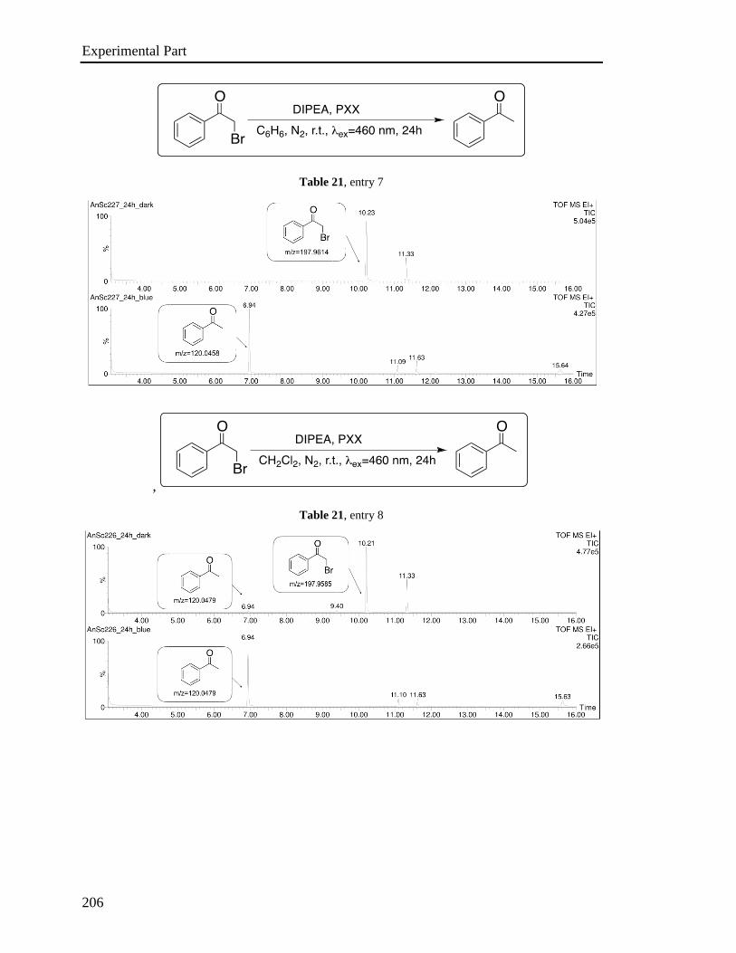
Experimental Part
206
Table 21, entry 7
,
Table 21, entry 8
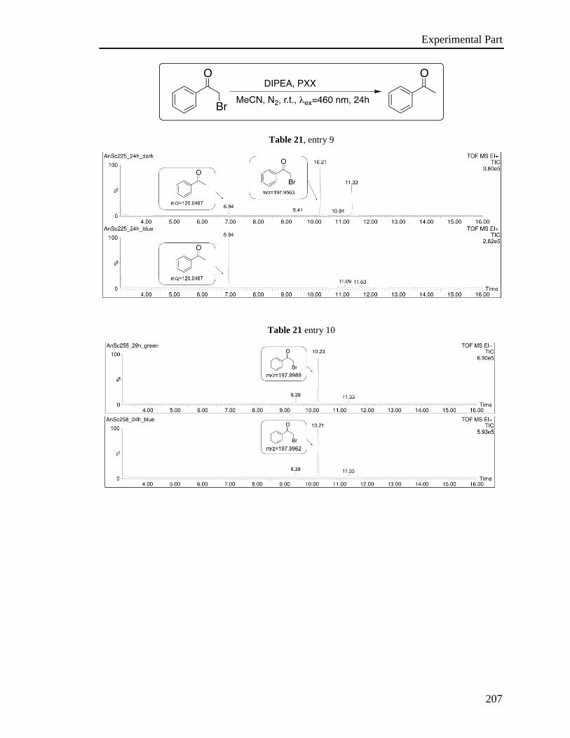
Experimental Part
207
Table 21, entry 9
Table 21 entry 10

Experimental Part
208
Table 21, entry 11
Table 21, entry 12

Experimental Part
209
Table 21, entry 13
A: acetophenone; B: 2-bromoacetophenone; C: irradiated solution at 520 nm after 24h.
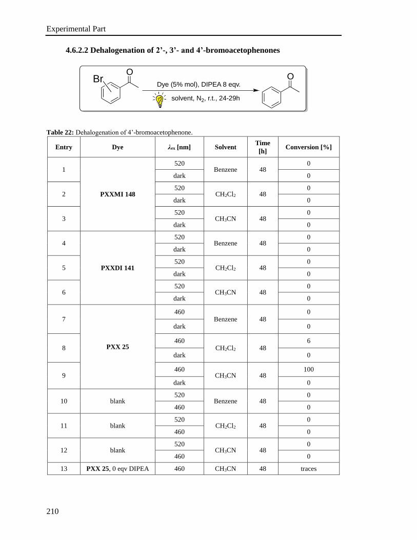
Experimental Part
210
4.6.2.2 Dehalogenation of 2’-, 3’- and 4’-bromoacetophenones
Table 22: Dehalogenation of 4’-bromoacetophenone.
Entry Dye λex [nm] Solvent Time
[h] Conversion [%]
1
PXXMI 148
520 Benzene 48
0
dark 0
2 520
CH2Cl2 48 0
dark 0
3 520
CH3CN 48 0
dark 0
4
PXXDI 141
520 Benzene 48
0
dark 0
5 520
CH2Cl2 48 0
dark 0
6 520
CH3CN 48 0
dark 0
7
PXX 25
460 Benzene 48
0
dark 0
8 460
CH2Cl2 48 6
dark 0
9 460
CH3CN 48 100
dark 0
10 blank 520
Benzene 48 0
460 0
11 blank 520
CH2Cl2 48 0
460 0
12 blank 520
CH3CN 48 0
460 0
13 PXX 25, 0 eqv DIPEA 460 CH3CN 48 traces
Dye (5% mol), DIPEA 8 eqv.
solvent, N2, r.t., 24-29h
OOBr
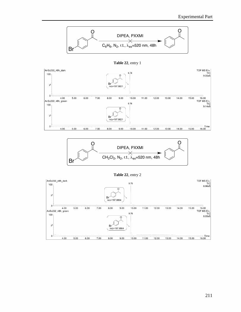
Experimental Part
211
Table 22, entry 1
Table 22, entry 2
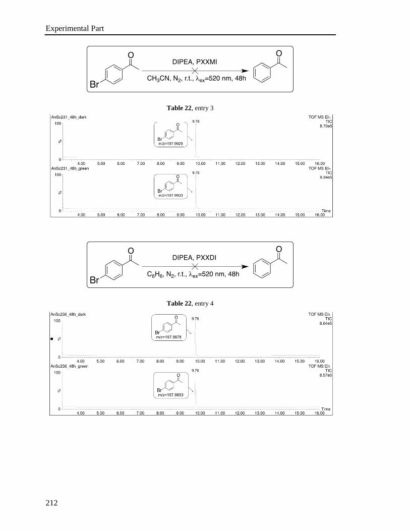
Experimental Part
212
Table 22, entry 3
Table 22, entry 4
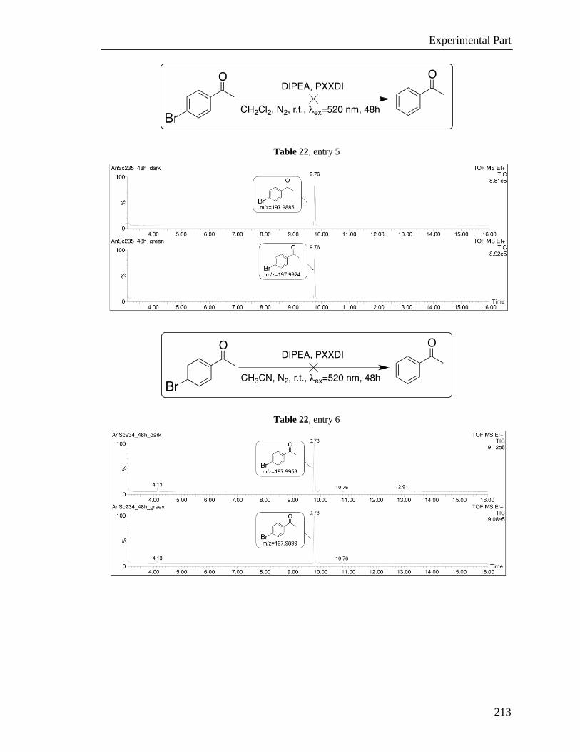
Experimental Part
213
Table 22, entry 5
Table 22, entry 6
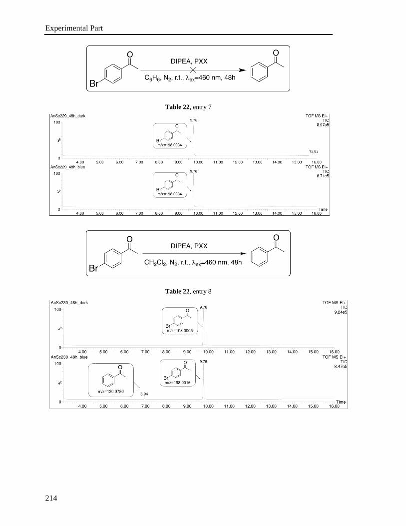
Experimental Part
214
Table 22, entry 7
Table 22, entry 8
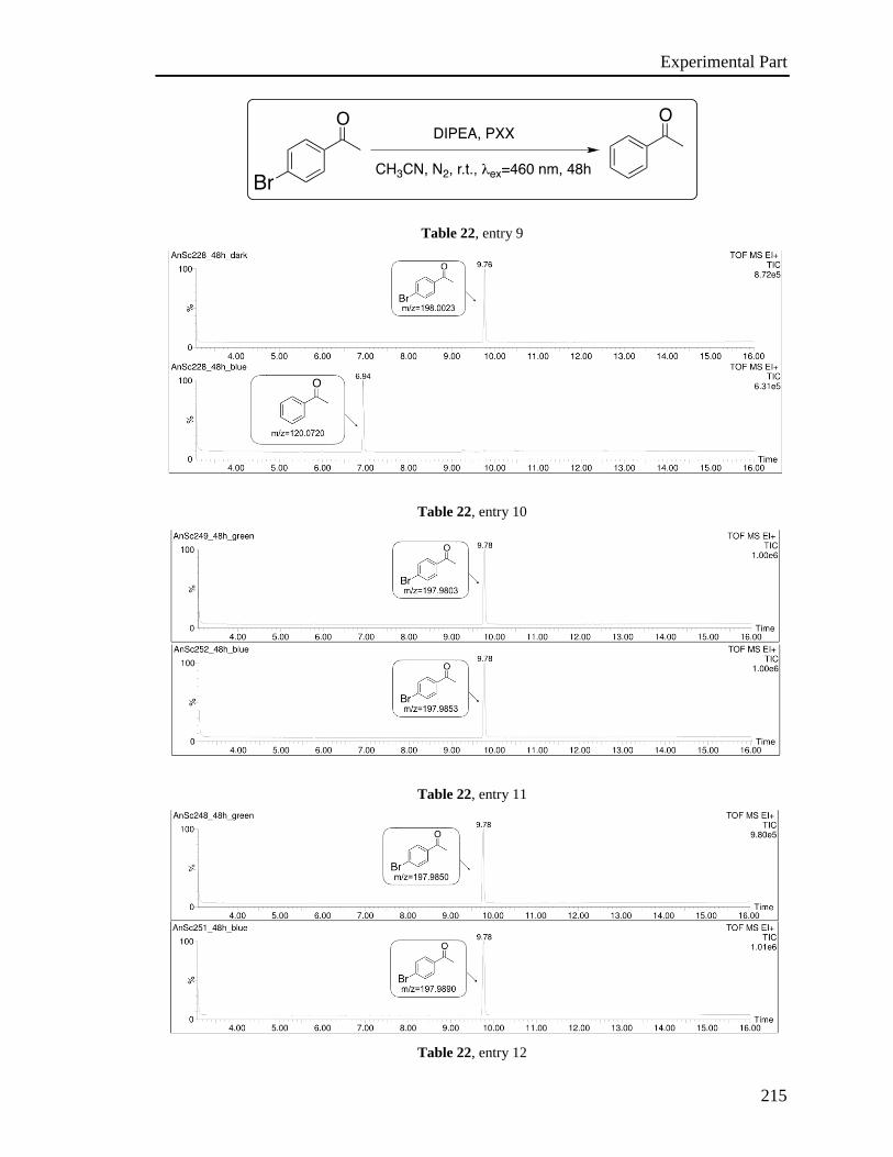
Experimental Part
215
Table 22, entry 9
Table 22, entry 10
Table 22, entry 11
Table 22, entry 12
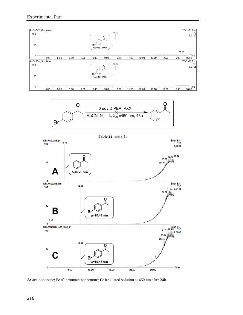
Experimental Part
216
Table 22, entry 13
A: acetophenone; B: 4’-bromoacetophenone; C: irradiated solution at 460 nm after 24h.
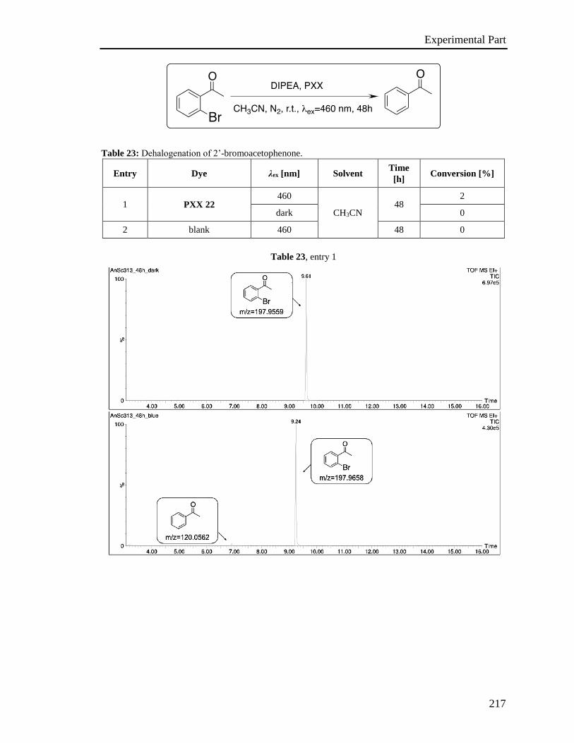
Experimental Part
217
Table 23: Dehalogenation of 2’-bromoacetophenone.
Entry Dye λex [nm] Solvent Time
[h] Conversion [%]
1 PXX 22 460
CH3CN 48
2
dark 0
2 blank 460 48 0
Table 23, entry 1

Experimental Part
218
Table 23, entry 2
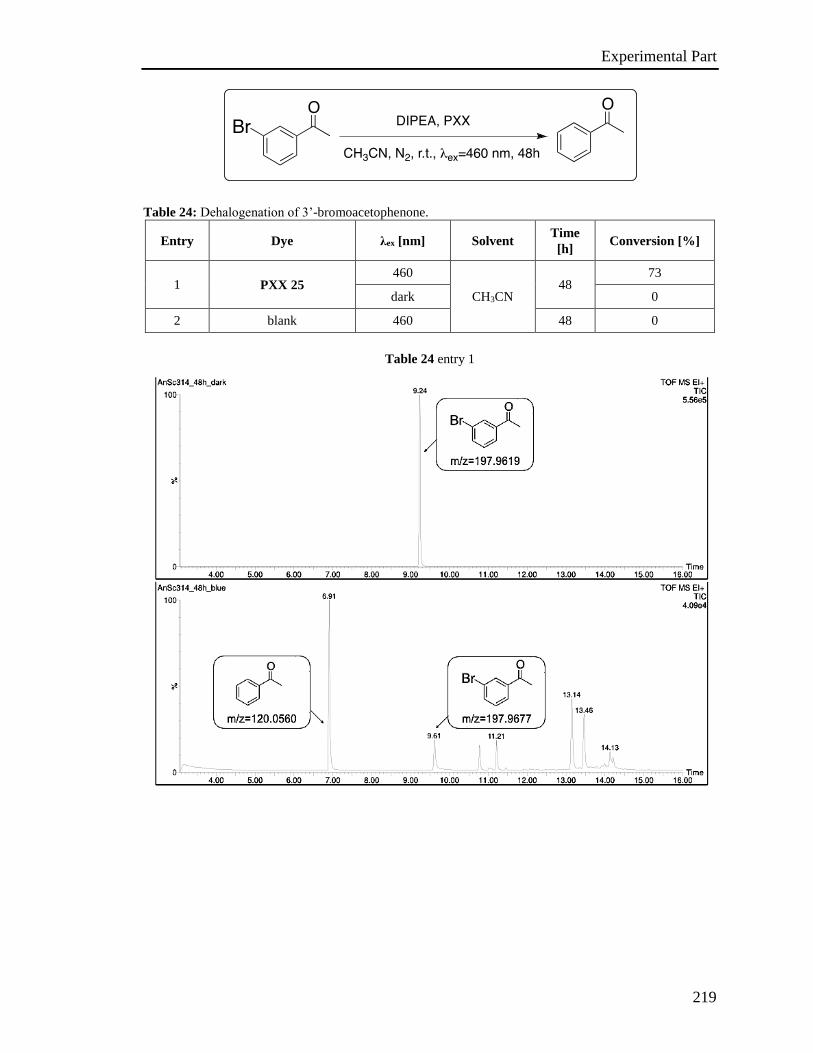
Experimental Part
219
Table 24: Dehalogenation of 3’-bromoacetophenone.
Entry Dye λex [nm] Solvent Time
[h] Conversion [%]
1 PXX 25 460
CH3CN 48
73
dark 0
2 blank 460 48 0
Table 24 entry 1

Experimental Part
220
Table 24, entry 2
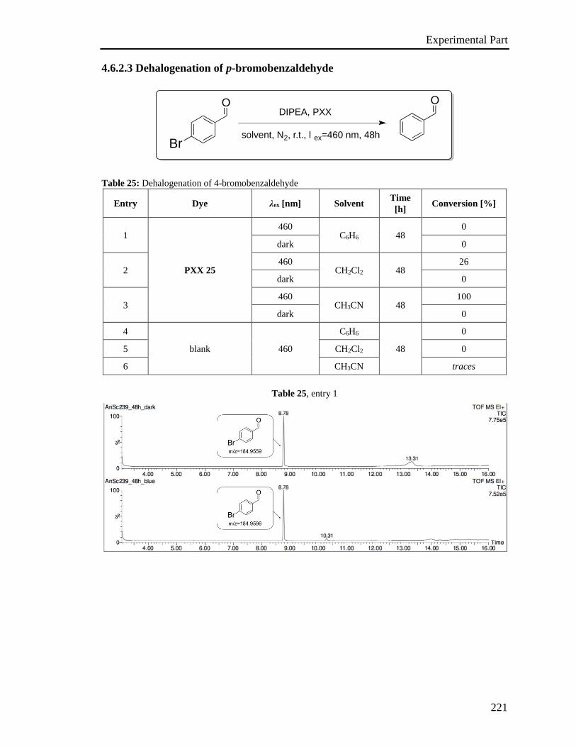
Experimental Part
221
4.6.2.3 Dehalogenation of p-bromobenzaldehyde
Table 25: Dehalogenation of 4-bromobenzaldehyde
Entry Dye λex [nm] Solvent Time
[h] Conversion [%]
1
PXX 25
460 C6H6 48
0
dark 0
2 460
CH2Cl2 48 26
dark 0
3 460
CH3CN 48 100
dark 0
4
blank 460
C6H6
48
0
5 CH2Cl2 0
6 CH3CN traces
Table 25, entry 1
DIPEA, PXX
solvent, N2, r.t., lex=460 nm, 48h
O O
Br
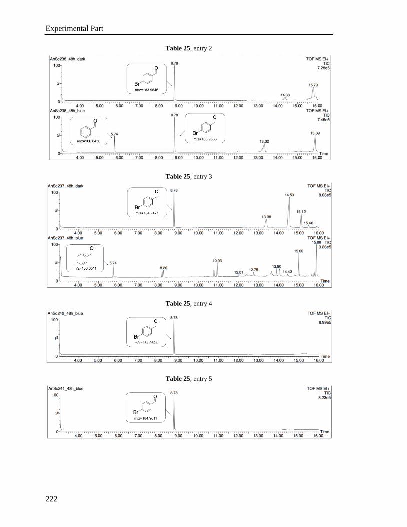
Experimental Part
222
Table 25, entry 2
Table 25, entry 3
Table 25, entry 4
Table 25, entry 5
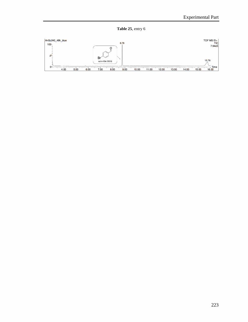
Experimental Part
223
Table 25, entry 6
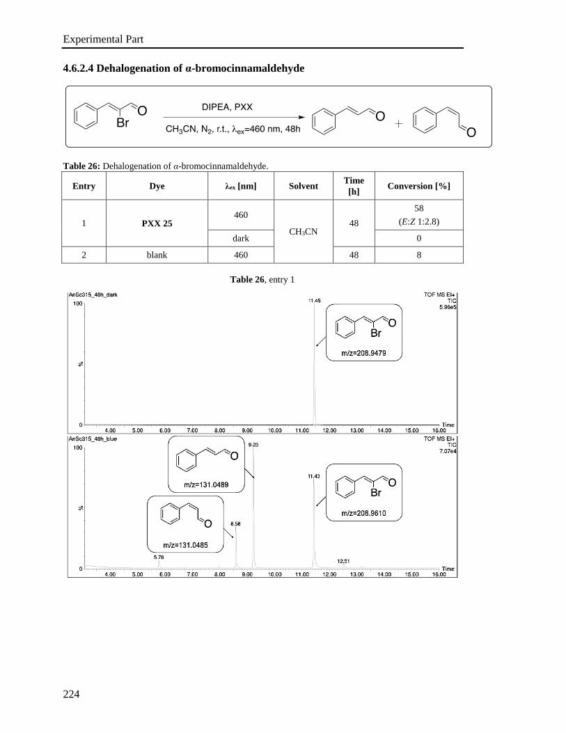
Experimental Part
224
4.6.2.4 Dehalogenation of α-bromocinnamaldehyde
Table 26: Dehalogenation of α-bromocinnamaldehyde.
Entry Dye λex [nm] Solvent Time
[h] Conversion [%]
1 PXX 25 460
CH3CN 48
58
(E:Z 1:2.8)
dark 0
2 blank 460 48 8
Table 26, entry 1
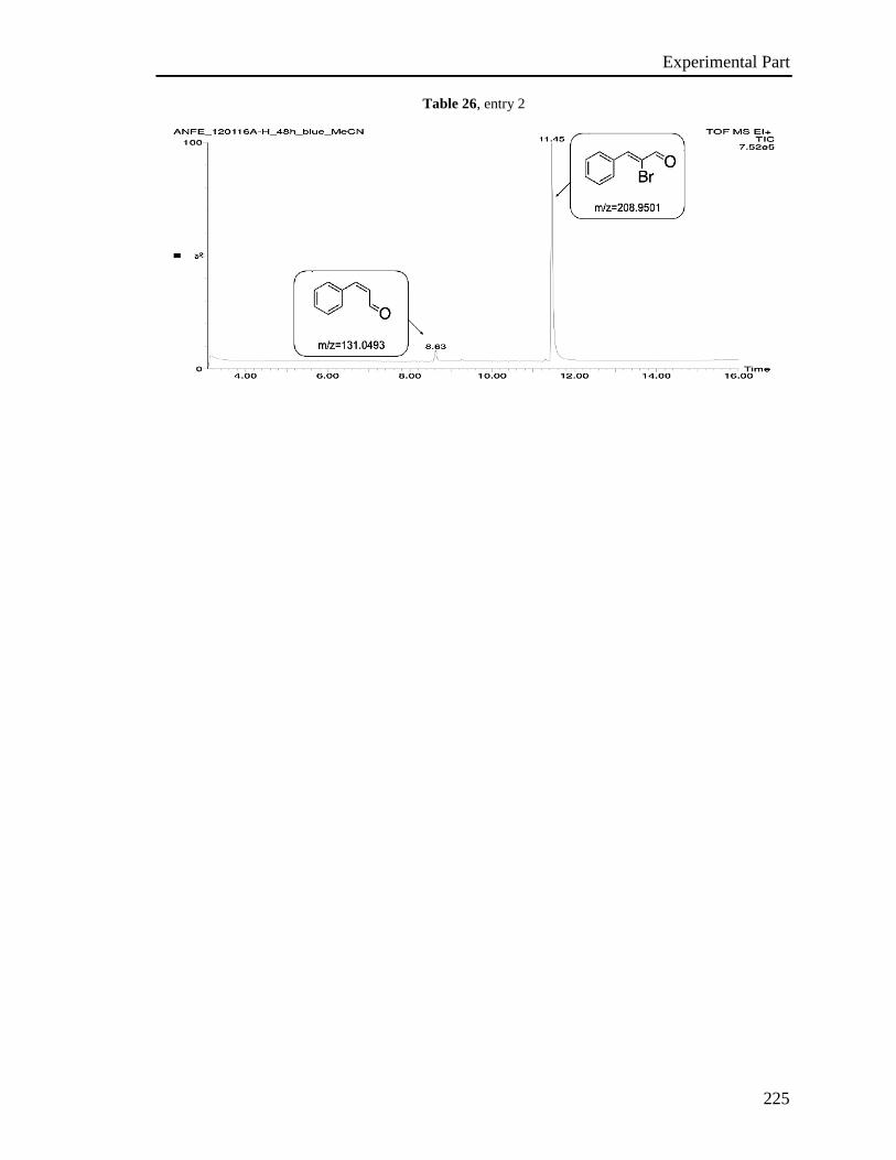
Experimental Part
225
Table 26, entry 2
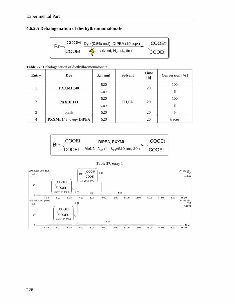
Experimental Part
226
4.6.2.5 Dehalogenation of diethylbromomalonate
Table 27: Dehalogenation of diethylbromomalonate.
Entry Dye λex [nm] Solvent Time
[h] Conversion [%]
1 PXXMI 148 520
CH3CN
20 100
dark 6
2 PXXDI 141 520
20 100
dark 8
3 blank 520 20 5
4 PXXMI 148, 0 eqv DIPEA 520 20 traces
Table 27, entry 1
Dye (0.5% mol), DIPEA (10 eqv.)
solvent, N2, r.t., time
COOEt
COOEtBr
COOEt
COOEt
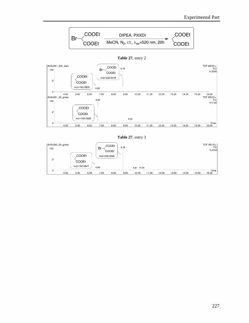
Experimental Part
227
Table 27, entry 2
Table 27, entry 3
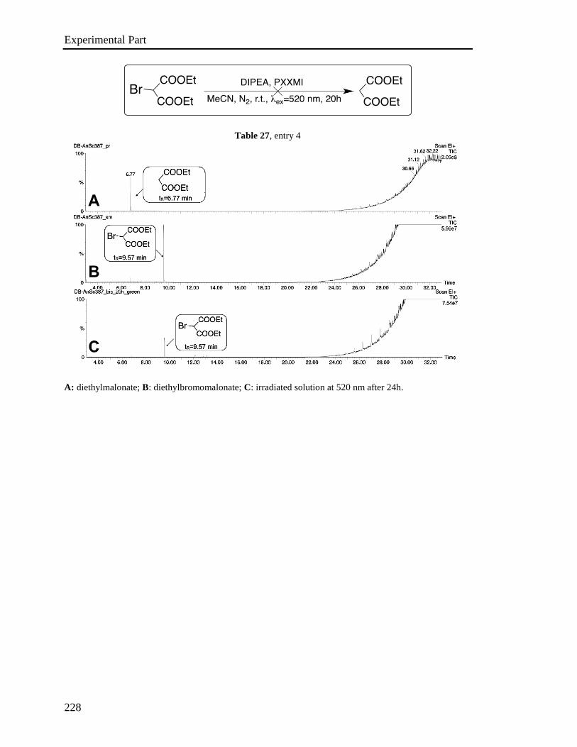
Experimental Part
228
Table 27, entry 4
A: diethylmalonate; B: diethylbromomalonate; C: irradiated solution at 520 nm after 24h.
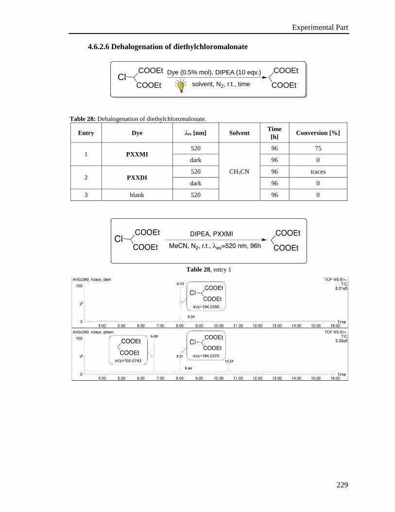
Experimental Part
229
4.6.2.6 Dehalogenation of diethylchloromalonate
Table 28: Dehalogenation of diethylchloromalonate.
Entry Dye λex [nm] Solvent Time
[h] Conversion [%]
1 PXXMI 520
CH3CN
96 75
dark 96 0
2 PXXDI 520 96 traces
dark 96 0
3 blank 520 96 0
Table 28, entry 1
Dye (0.5% mol), DIPEA (10 eqv.)
solvent, N2, r.t., time
COOEt
COOEtCl
COOEt
COOEt
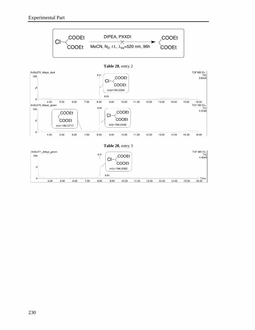
Experimental Part
230
Table 28, entry 2
Table 28, entry 3

Experimental Part
231
4.6.2.7 Sequential dehalogenation of 2-4’-dibromoacetophenone
Table 29: Sequential dehalogenation on 2-4’-dibromoacetophenone.
Entry Dye λex [nm] Solvent Time
[h] Conversion [%]
1
1. PXXMI 148 520
CH3CN
30 100 (α)
dark 30 48 (α)
2. PXX 25 460 74 100 (para)
dark 74 0 (para)
2 1. blank 520 30 42 (α)
2. blank 460 72 0 (para)
3
1. PXXMI 148
(0.41 mM)
520 30 100 (α)
dark - -
2. PXX 25
(0.41 mM)
460 74 10 (para)
dark 74 0 (para)
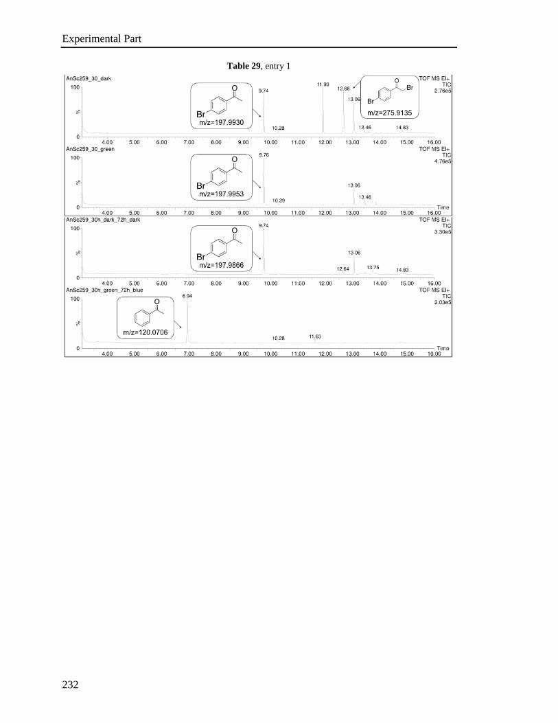
Experimental Part
232
Table 29, entry 1
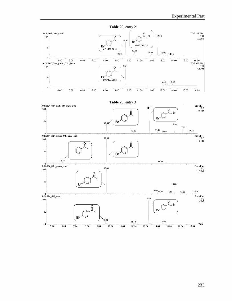
Experimental Part
233
Table 29, entry 2
Table 29, entry 3
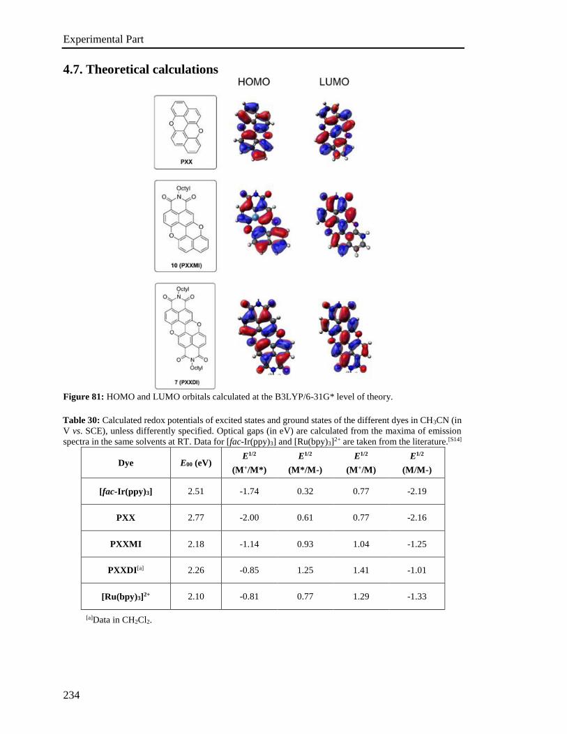
Experimental Part
234
4.7. Theoretical calculations
Figure 81: HOMO and LUMO orbitals calculated at the B3LYP/6-31G* level of theory.
Table 30: Calculated redox potentials of excited states and ground states of the different dyes in CH3CN (in
V vs. SCE), unless differently specified. Optical gaps (in eV) are calculated from the maxima of emission
spectra in the same solvents at RT. Data for [fac-Ir(ppy)3] and [Ru(bpy)3]2+ are taken from the literature.[S14]
Dye E00 (eV) E1/2
(M+/M*)
E1/2
(M*/M-)
E1/2
(M+/M)
E1/2
(M/M-)
[fac-Ir(ppy)3] 2.51 -1.74 0.32 0.77 -2.19
PXX 2.77 -2.00 0.61 0.77 -2.16
PXXMI 2.18 -1.14 0.93 1.04 -1.25
PXXDI[a] 2.26 -0.85 1.25 1.41 -1.01
[Ru(bpy)3]2+ 2.10 -0.81 0.77 1.29 -1.33
[a]Data in CH2Cl2.
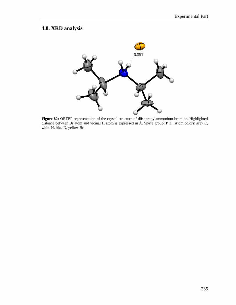
Experimental Part
235
4.8. XRD analysis
Figure 82: ORTEP representation of the crystal structure of diisopropylammonium bromide. Highlighted
distance between Br atom and vicinal H atom is expressed in Å. Space group: P 21. Atom colors: grey C,
white H, blue N, yellow Br.
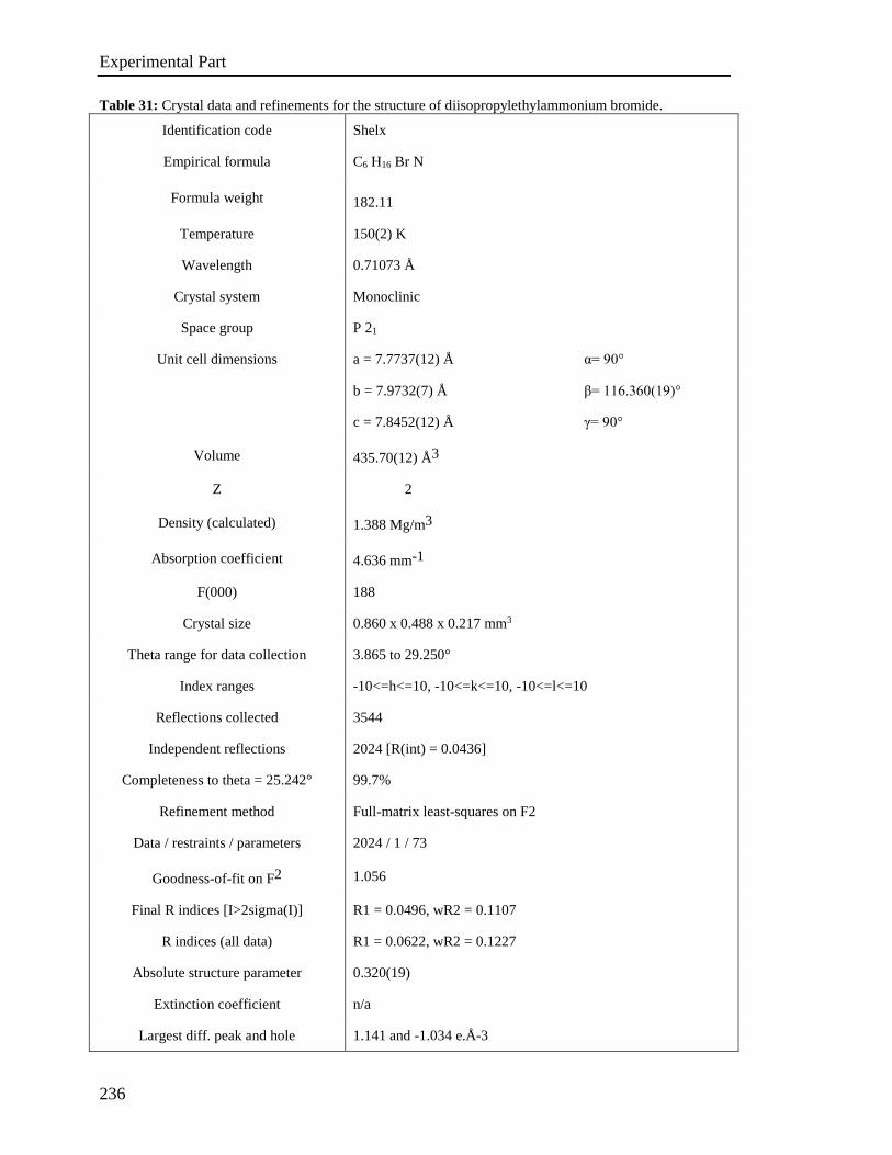
Experimental Part
236
Table 31: Crystal data and refinements for the structure of diisopropylethylammonium bromide.
Identification code Shelx
Empirical formula C6 H16 Br N
Formula weight 182.11
Temperature 150(2) K
Wavelength 0.71073 Å
Crystal system Monoclinic
Space group P 21
Unit cell dimensions a = 7.7737(12) Å α= 90°
b = 7.9732(7) Å β= 116.360(19)°
c = 7.8452(12) Å γ= 90°
Volume 435.70(12) Å3
Z 2
Density (calculated) 1.388 Mg/m3
Absorption coefficient 4.636 mm-1
F(000) 188
Crystal size 0.860 x 0.488 x 0.217 mm3
Theta range for data collection 3.865 to 29.250°
Index ranges -10<=h<=10, -10<=k<=10, -10<=l<=10
Reflections collected 3544
Independent reflections 2024 [R(int) = 0.0436]
Completeness to theta = 25.242° 99.7%
Refinement method Full-matrix least-squares on F2
Data / restraints / parameters 2024 / 1 / 73
Goodness-of-fit on F2 1.056
Final R indices [I>2sigma(I)] R1 = 0.0496, wR2 = 0.1107
R indices (all data) R1 = 0.0622, wR2 = 0.1227
Absolute structure parameter 0.320(19)
Extinction coefficient n/a
Largest diff. peak and hole 1.141 and -1.034 e.Å-3
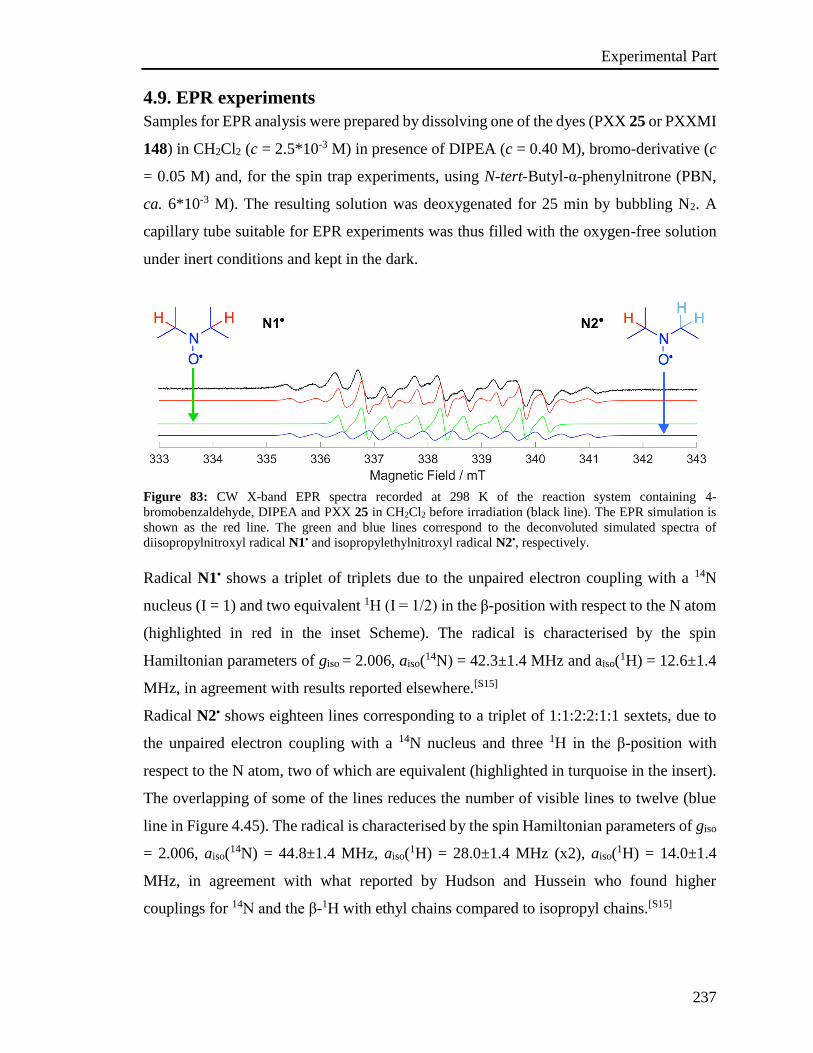
Experimental Part
237
4.9. EPR experiments
Samples for EPR analysis were prepared by dissolving one of the dyes (PXX 25 or PXXMI
148) in CH2Cl2 (c = 2.5*10-3 M) in presence of DIPEA (c = 0.40 M), bromo-derivative (c
= 0.05 M) and, for the spin trap experiments, using N-tert-Butyl-α-phenylnitrone (PBN,
ca. 6*10-3 M). The resulting solution was deoxygenated for 25 min by bubbling N2. A
capillary tube suitable for EPR experiments was thus filled with the oxygen-free solution
under inert conditions and kept in the dark.
Figure 83: CW X-band EPR spectra recorded at 298 K of the reaction system containing 4-
bromobenzaldehyde, DIPEA and PXX 25 in CH2Cl2 before irradiation (black line). The EPR simulation is
shown as the red line. The green and blue lines correspond to the deconvoluted simulated spectra of
diisopropylnitroxyl radical N1• and isopropylethylnitroxyl radical N2•, respectively.
Radical N1• shows a triplet of triplets due to the unpaired electron coupling with a 14N
nucleus (I = 1) and two equivalent 1H (I = 1/2) in the β-position with respect to the N atom
(highlighted in red in the inset Scheme). The radical is characterised by the spin
Hamiltonian parameters of giso = 2.006, aiso(14N) = 42.3±1.4 MHz and aiso(
1H) = 12.6±1.4
MHz, in agreement with results reported elsewhere.[S15]
Radical N2• shows eighteen lines corresponding to a triplet of 1:1:2:2:1:1 sextets, due to
the unpaired electron coupling with a 14N nucleus and three 1H in the β-position with
respect to the N atom, two of which are equivalent (highlighted in turquoise in the insert).
The overlapping of some of the lines reduces the number of visible lines to twelve (blue
line in Figure 4.45). The radical is characterised by the spin Hamiltonian parameters of giso
= 2.006, aiso(14N) = 44.8±1.4 MHz, aiso(
1H) = 28.0±1.4 MHz (x2), aiso(1H) = 14.0±1.4
MHz, in agreement with what reported by Hudson and Hussein who found higher
couplings for 14N and the β-1H with ethyl chains compared to isopropyl chains.[S15]
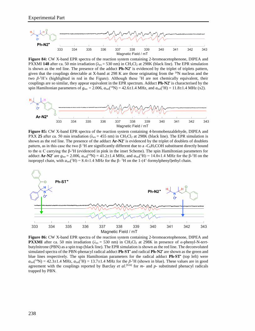
Experimental Part
238
Figure 84: CW X-band EPR spectra of the reaction system containing 2-bromoacetophenone, DIPEA and
PXXMI 148 after ca. 50 min irradiation (λex = 530 nm) in CH2Cl2 at 298K (black line). The EPR simulation
is shown as the red line. The presence of the adduct Ph-N2• is evidenced by the triplet of triplets pattern,
given that the couplings detectable at X-band at 298 K are those originating from the 14N nucleus and the
two β-1H’s (highlighted in red in the Figure). Although these 1H are not chemically equivalent, their
couplings are so similar, they appear equivalent in the EPR spectrum. Adduct Ph-N2• is characterised by the
spin Hamiltonian parameters of giso = 2.006, aiso(14N) = 42.6±1.4 MHz, and aiso(1H) = 11.8±1.4 MHz (x2).
Figure 85: CW X-band EPR spectra of the reaction system containing 4-bromobenzaldehyde, DIPEA and
PXX 25 after ca. 50 min irradiation (λex = 455 nm) in CH2Cl2 at 298K (black line). The EPR simulation is
shown as the red line. The presence of the adduct Ar-N2• is evidenced by the triplet of doublets of doublets
pattern, as in this case the two β 1H are significantly different due to a -C6H5COH substituent directly bound
to the C carrying the β-1H (evidenced in pink in the inset Scheme). The spin Hamiltonian parameters for
adduct Ar-N2• are giso = 2.006, aiso(14N) = 41.2±1.4 MHz, and aiso(1H) = 14.0±1.4 MHz for the β-1H on the
isopropyl chain, with aiso(1H) = 8.4±1.4 MHz for the β- 1H on the 1-(4’-formylphenyl)ethyl chain.
Figure 86: CW X-band EPR spectra of the reaction system containing 2-bromoacetophenone, DIPEA and
PXXMI after ca. 50 min irradiation (λex = 530 nm) in CH2Cl2 at 298K in presence of α-phenyl-N-tert-
butylnitrone (PBN) as a spin trap (black line). The EPR simulation is shown as the red line. The deconvoluted
simulated spectra of the PBN-phenacyl radical adduct Ph-ST• and radical Ph-N2• are shown as the green and
blue lines respectively. The spin Hamiltonian parameters for the radical adduct Ph-ST• (top left) were
aiso(14N) = 42.3±1.4 MHz, aiso(1H) = 13.7±1.4 MHz for the β-1H (shown in blue). These values are in good
agreement with the couplings reported by Barclay et al.[S16] for m- and p- substituted phenacyl radicals
trapped by PBN.
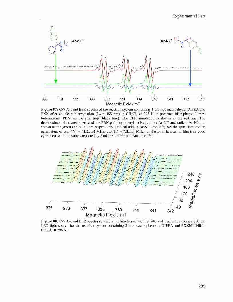
Experimental Part
239
Figure 87: CW X-band EPR spectra of the reaction system containing 4-bromobenzaldehyde, DIPEA and
PXX after ca. 50 min irradiation (λex = 455 nm) in CH2Cl2 at 298 K in presence of α-phenyl-N-tert-
butylnitrone (PBN) as the spin trap (black line). The EPR simulation is shown as the red line. The
deconvoluted simulated spectra of the PBN-p-formylphenyl radical adduct Ar-ST• and radical Ar-N2• are
shown as the green and blue lines respectively. Radical adduct Ar-ST• (top left) had the spin Hamiltonian
parameters of aiso(14N) = 41.2±1.4 MHz, aiso(1H) = 7.8±1.4 MHz for the β-1H (shown in blue), in good
agreement with the values reported by Sankar et al.[S17] and Buettner.[S18]
Figure 88: CW X-band EPR spectra revealing the kinetics of the first 240 s of irradiation using a 530 nm
LED light source for the reaction system containing 2-bromoacetophenone, DIPEA and PXXMI 148 in
CH2Cl2 at 298 K.
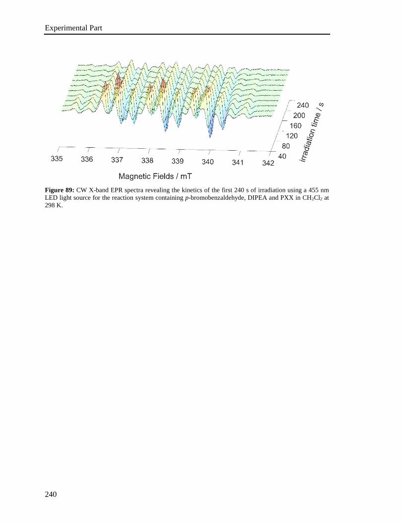
Experimental Part
240
Figure 89: CW X-band EPR spectra revealing the kinetics of the first 240 s of irradiation using a 455 nm
LED light source for the reaction system containing p-bromobenzaldehyde, DIPEA and PXX in CH2Cl2 at
298 K.
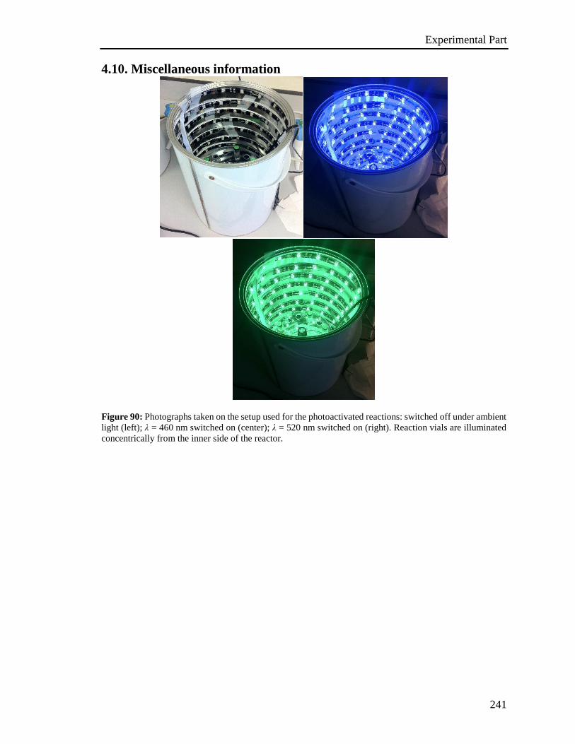
Experimental Part
241
4.10. Miscellaneous information
Figure 90: Photographs taken on the setup used for the photoactivated reactions: switched off under ambient
light (left); λ = 460 nm switched on (center); λ = 520 nm switched on (right). Reaction vials are illuminated
concentrically from the inner side of the reactor.
Experimental Part
242
4.11 References:
[S1] G. M. Sheldrick, Acta Crystallogr. Sec. A 2008, 64, 112–122.
[S2] S. Stoll, A. Schweiger, J. Magn. Reson. 2006, 178, 42–55.
[S3] C. M. Cardona, W. Li, A. E. Kaifer, D. Stockdale, G. C. Bazan, Adv. Mater. 2011,
23, 2367–2371.
[S4] A. Bolag, J. López-Andarias, S. Lascano, S. Soleimanpour, C. Atienza, N. Sakai,
N. Martín, S. Matile, Angew. Chem. Int. Ed. 2014, 53, 4890–4895.
[S5] G. Crosby, J. Demas, J. Phys. Chem. 1971, 75, 991–1024.
[S6] M. Frisch, G. Trucks, H. Schlegel, G. Scuseria, M. Robb, J. Cheeseman, G.
Scalmani, V. Barone, B. Mennucci, G. Petersson, et al., GAUSSIAN 09 (Revision
D.01), Gaussian Inc., Wallingford, CT 2013.
[S7] A. D. Becke, J. Chem. Phys. 1993, 98, 5648-5652.
[S8] C. Lee, W. Yang, R. Parr, Phys. Rev. B 1988, 37, 785–789.
[S9] L. Wang, W. Huang, R. Li, D. Gehrig, P. W. M. Blom, K. Landfester, K. A. I.
Zhang, Angew. Chem. Int. Ed. 2016, 55, 9783–9787.
[S10] J. Schwarz, B. König, Green Chem. 2016, 18, 4743–4749.
[S11] J. Li, H. Tian, M. Jiang, H. Yang, Y. Zhao, H. Fu, Chem. Commun. 2016, 52, 8862–
8864.
[S12] M. Neumann, S. Füldner, B. König, K. Zeitler, Angew. Chem. Int. Ed. 2011, 50,
951–954.
[S13] O. Amiri-Attou, T. Terme, M. Médebielle, P. Vanelle, Tetrahedron Lett. 2008, 49,
1016–1020.
[S14] C. K. Prier, D. A. Rankic, D. W. C. MacMillan, Chem. Rev. 2013, 113, 5322–5363.
[S15] A. Hudson, H. A. Hussain, J. Chem. Soc. B Phys. Org. 1967, 1299-1300.
[S16] L. R. C. Barclay, G. R. Cromwell, J. W. Hilborn, Can. J. Chem. 1994, 72, 35–41.
[S17] M. Sankar, E. Nowicka, E. Carter, D. M. Murphy, D. W. Knight, D. Bethell, G. J.
Hutchings, Nat. Commun. 2014, 5, 3332–3335.
[S18] G. R. Buettner, Free Radic. Biol. Med. 1987, 3, 259–303.
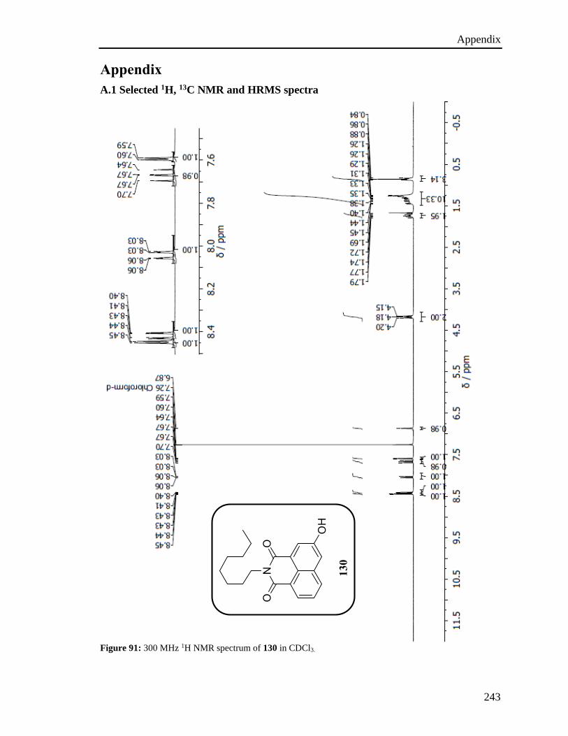
Appendix
243
Appendix
A.1 Selected 1H, 13C NMR and HRMS spectra
Figure 91: 300 MHz 1H NMR spectrum of 130 in CDCl3.
130
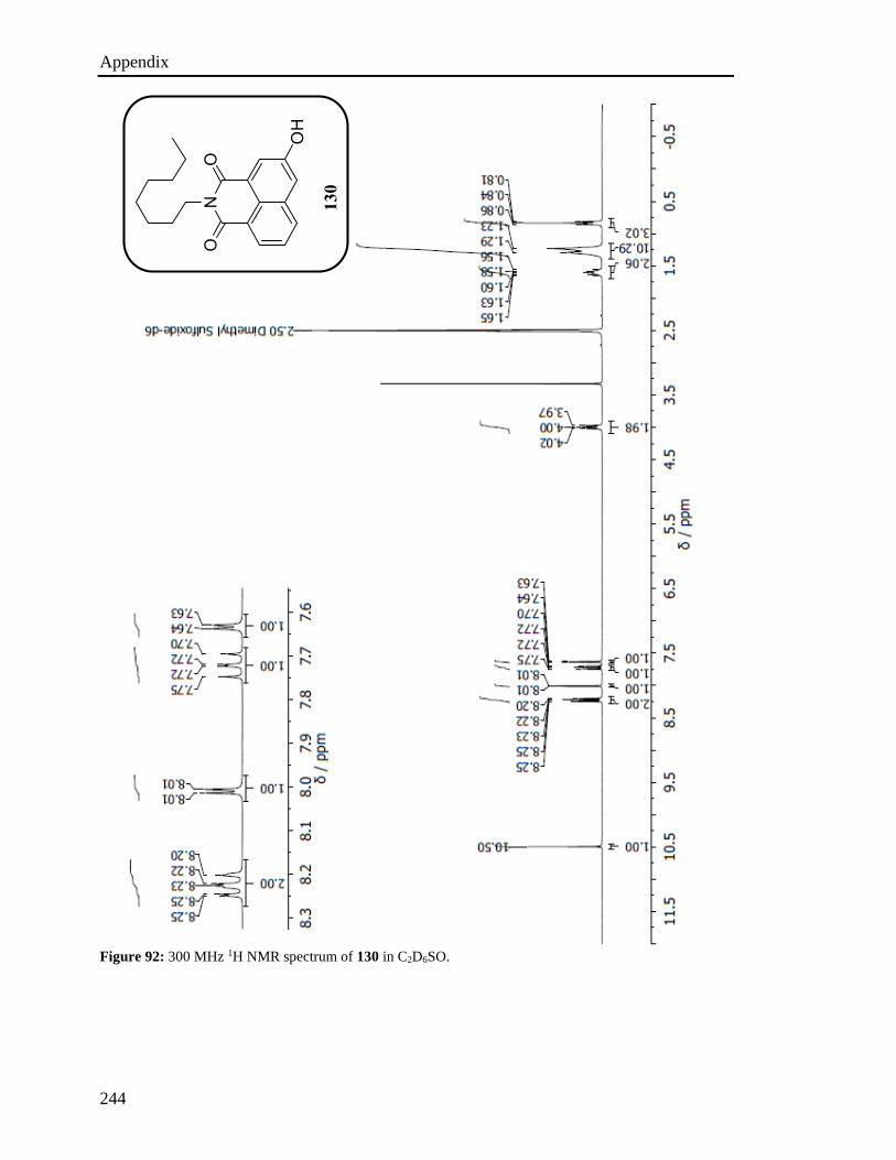
Appendix
244
Figure 92: 300 MHz 1H NMR spectrum of 130 in C2D6SO.
130
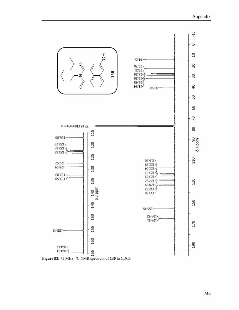
Appendix
245
Figure 93: 75 MHz 13C NMR spectrum of 130 in CDCl3.
130

Appendix
246
Figure 94: ESI-HRSM spectrum of 130.
130
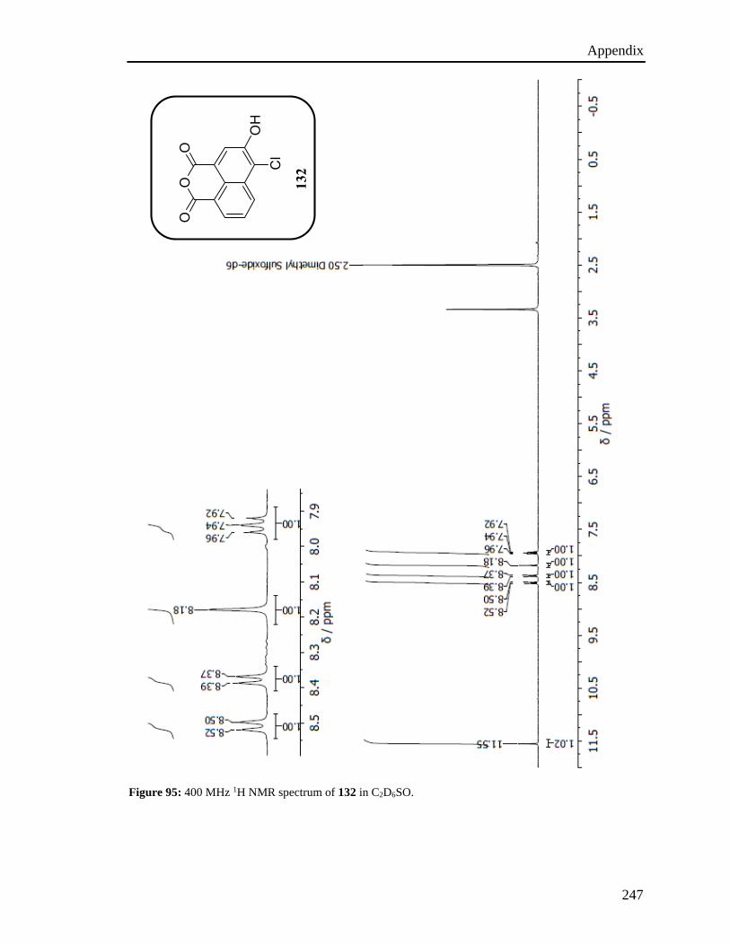
Appendix
247
Figure 95: 400 MHz 1H NMR spectrum of 132 in C2D6SO.
132
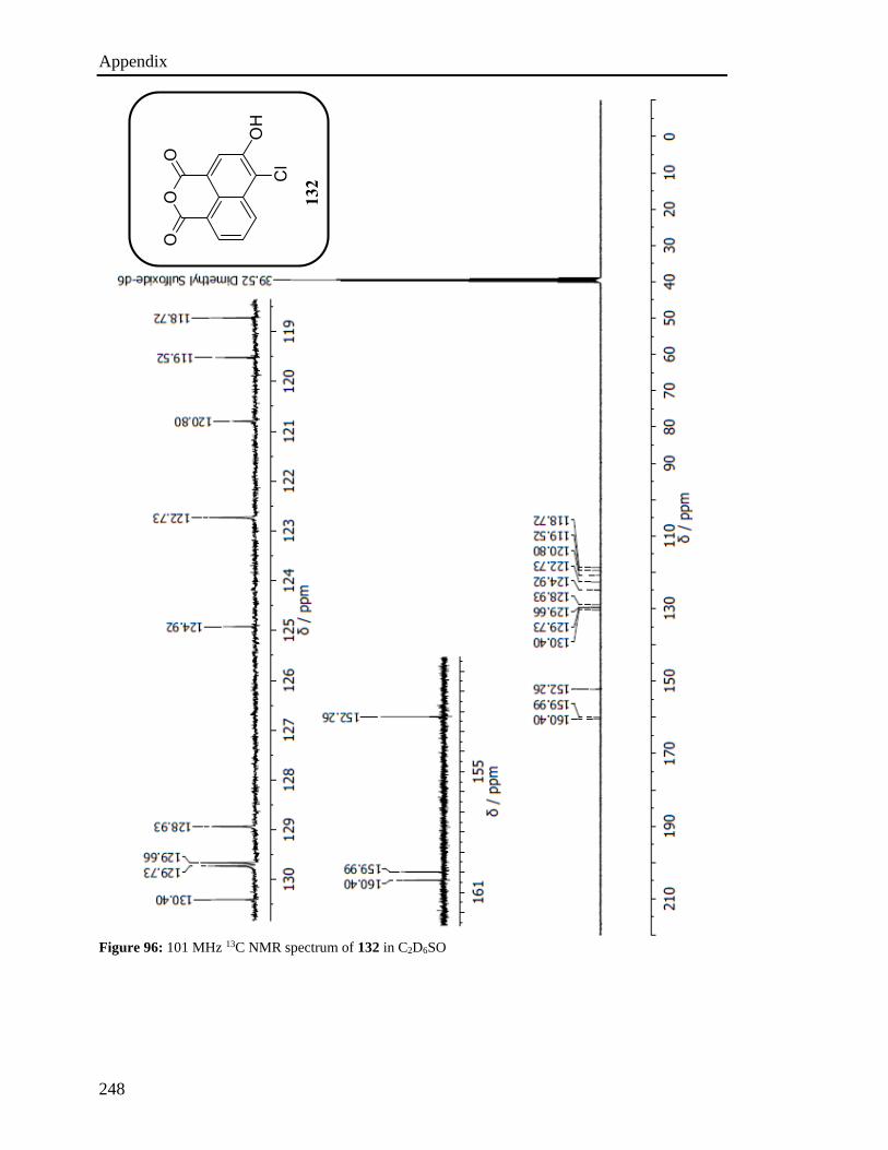
Appendix
248
Figure 96: 101 MHz 13C NMR spectrum of 132 in C2D6SO
132
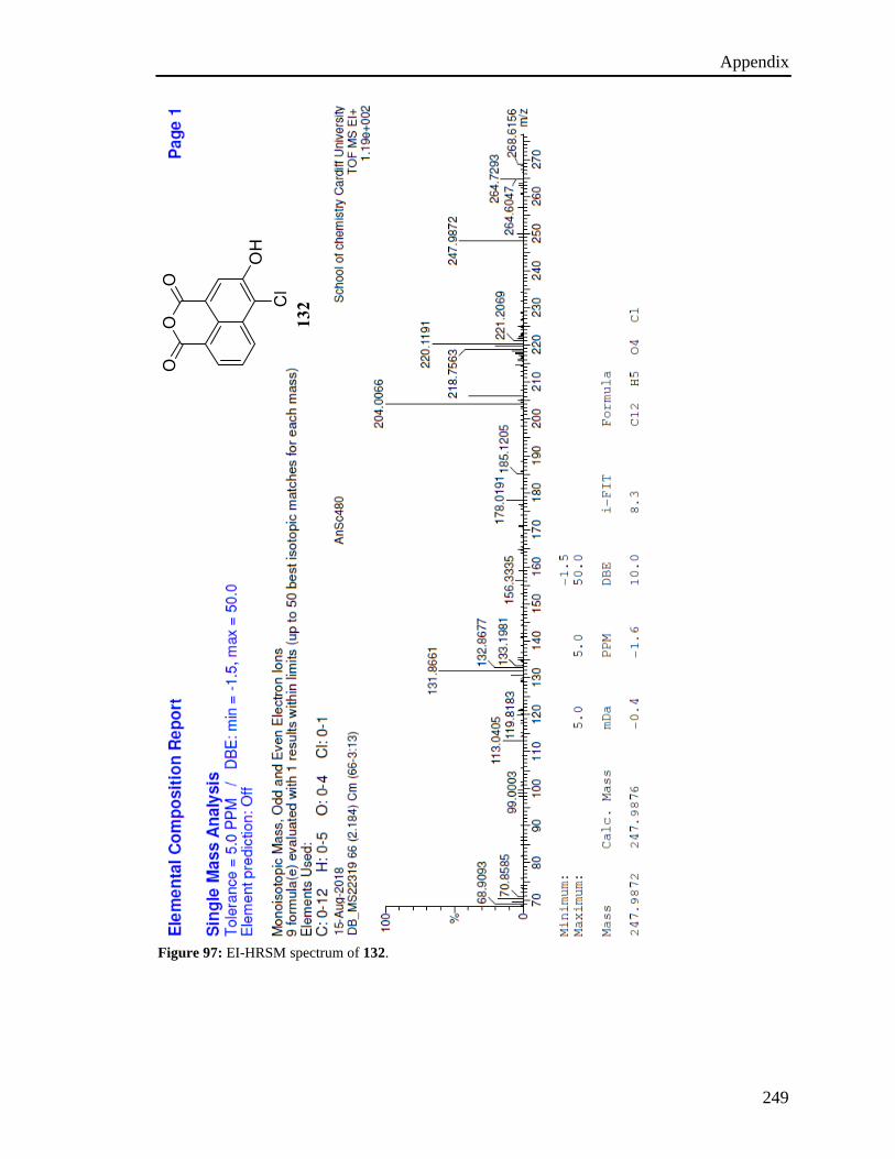
Appendix
249
Figure 97: EI-HRSM spectrum of 132.
132
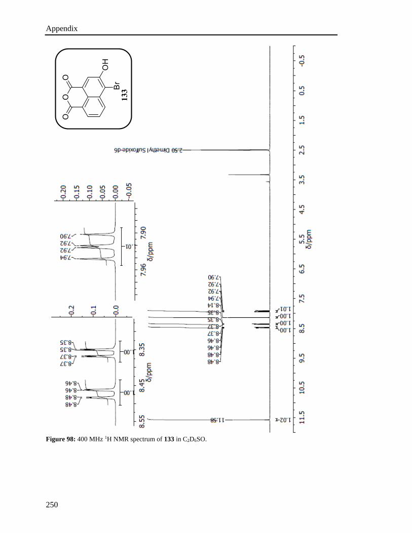
Appendix
250
Figure 98: 400 MHz 1H NMR spectrum of 133 in C2D6SO.
133
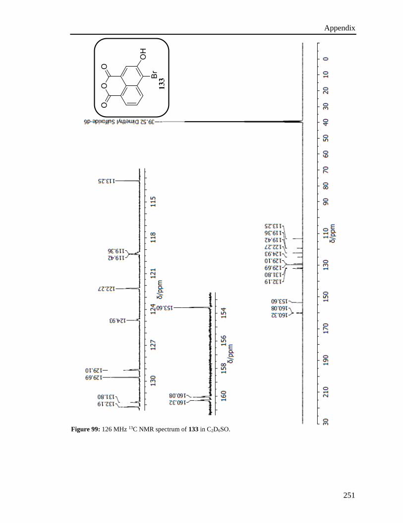
Appendix
251
Figure 99: 126 MHz 13C NMR spectrum of 133 in C2D6SO.
133

Appendix
252
Figure 100: EI-HRSM spectrum of 133.
133
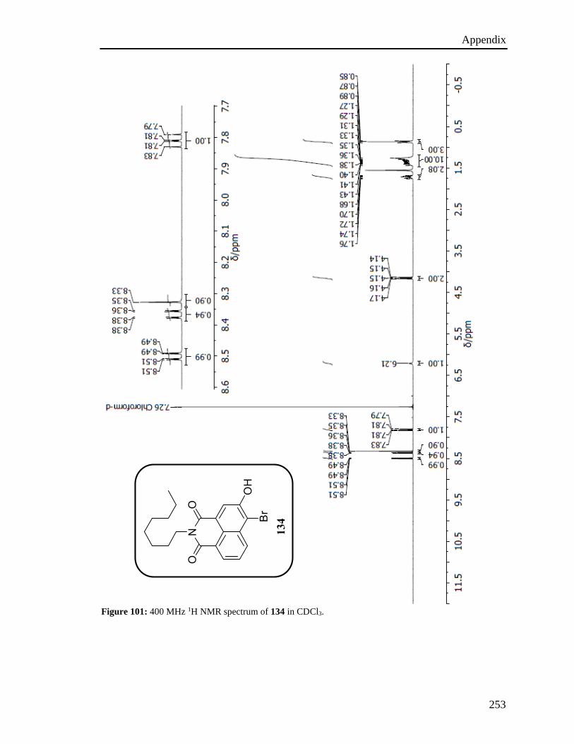
Appendix
253
Figure 101: 400 MHz 1H NMR spectrum of 134 in CDCl3.
134
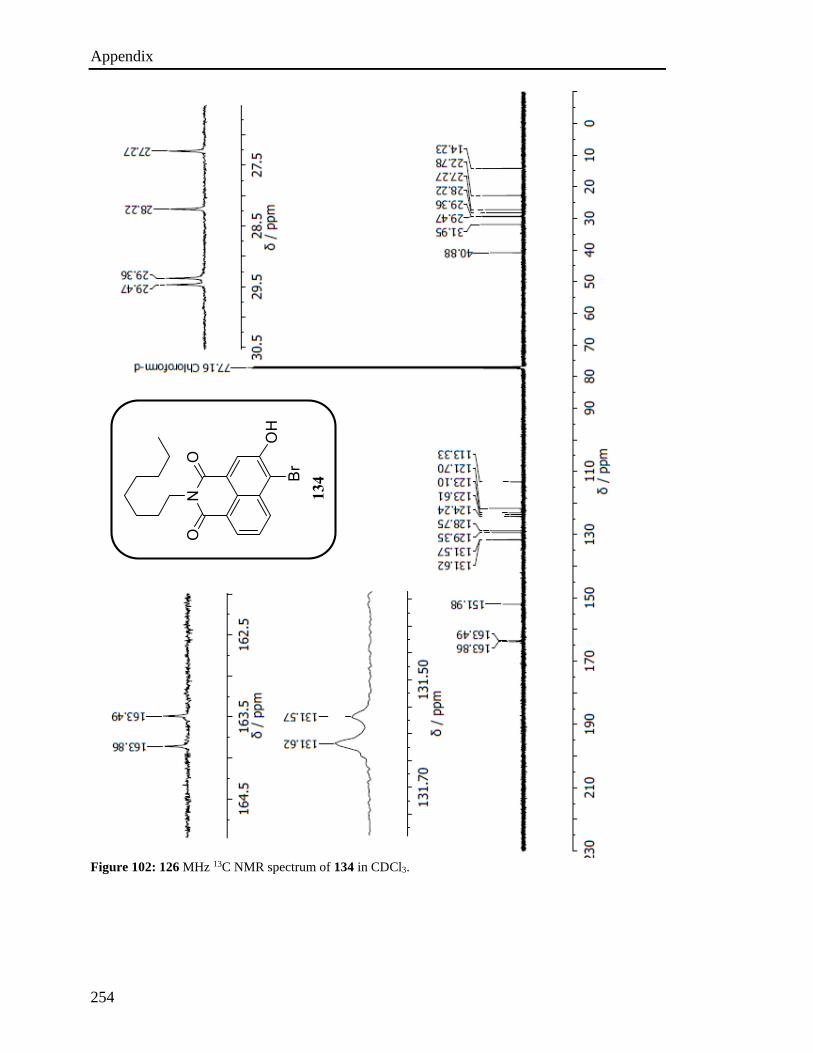
Appendix
254
Figure 102: 126 MHz 13C NMR spectrum of 134 in CDCl3.
134
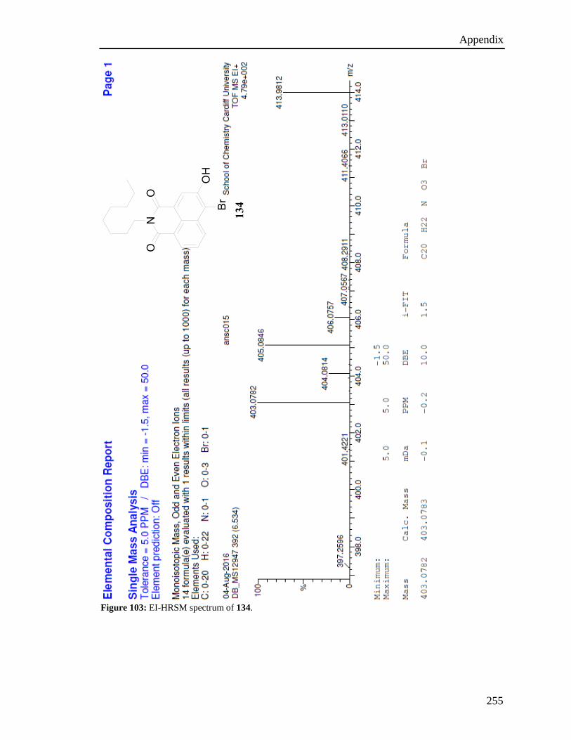
Appendix
255
Figure 103: EI-HRSM spectrum of 134.
134
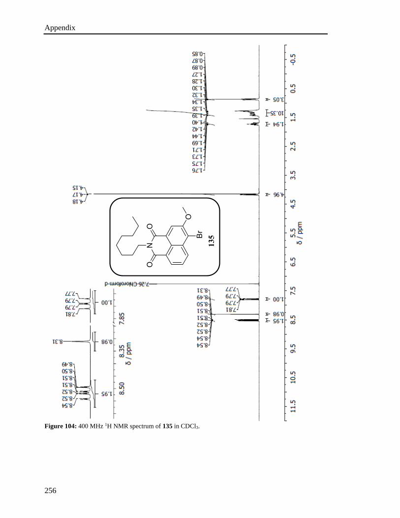
Appendix
256
Figure 104: 400 MHz 1H NMR spectrum of 135 in CDCl3.
135
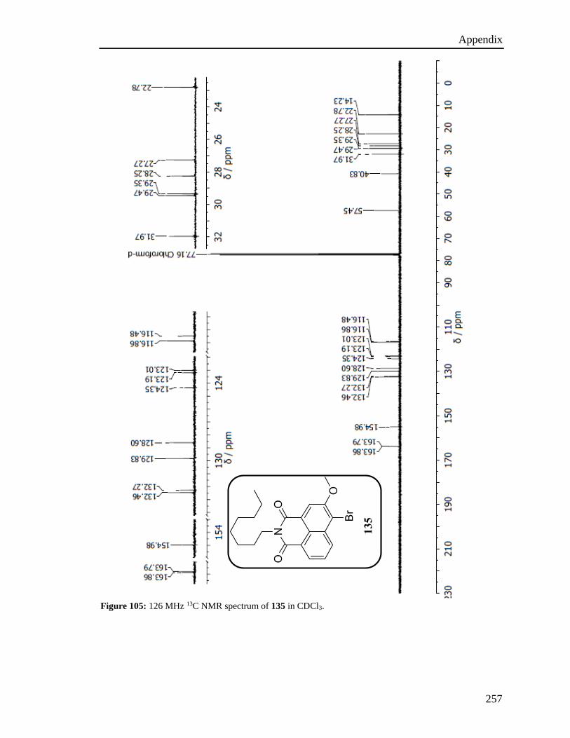
Appendix
257
Figure 105: 126 MHz 13C NMR spectrum of 135 in CDCl3.
135
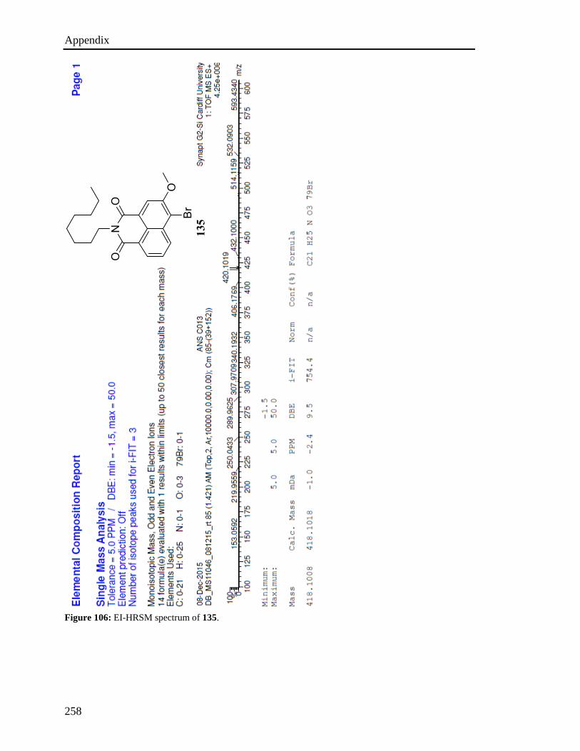
Appendix
258
Figure 106: EI-HRSM spectrum of 135.
135

Appendix
259
Figure 107: 300 MHz 1H NMR spectrum of 137 in CDCl3.
137
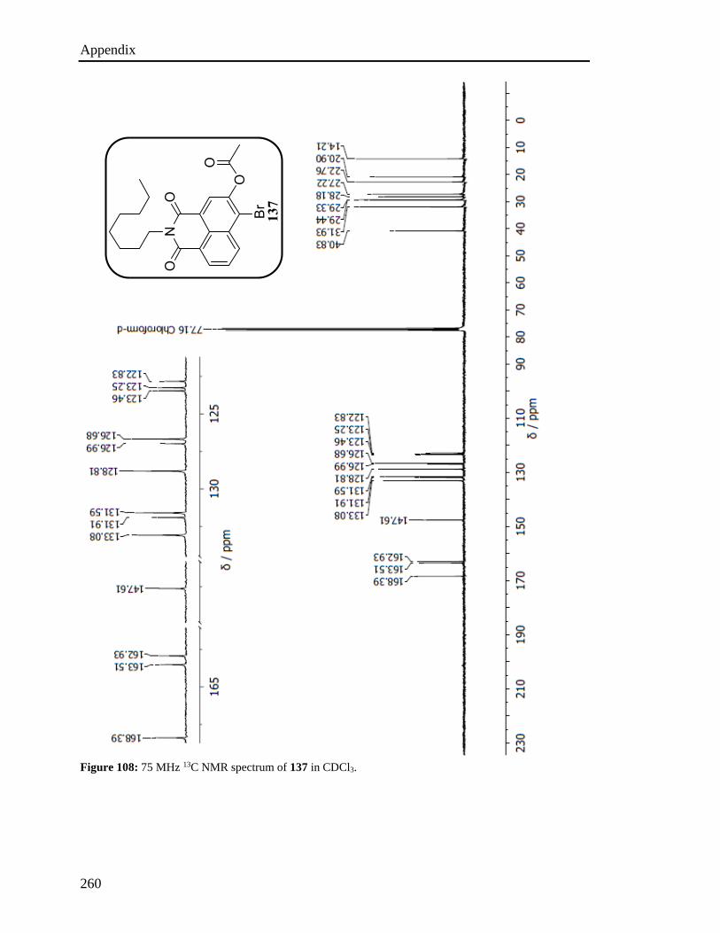
Appendix
260
Figure 108: 75 MHz 13C NMR spectrum of 137 in CDCl3.
137
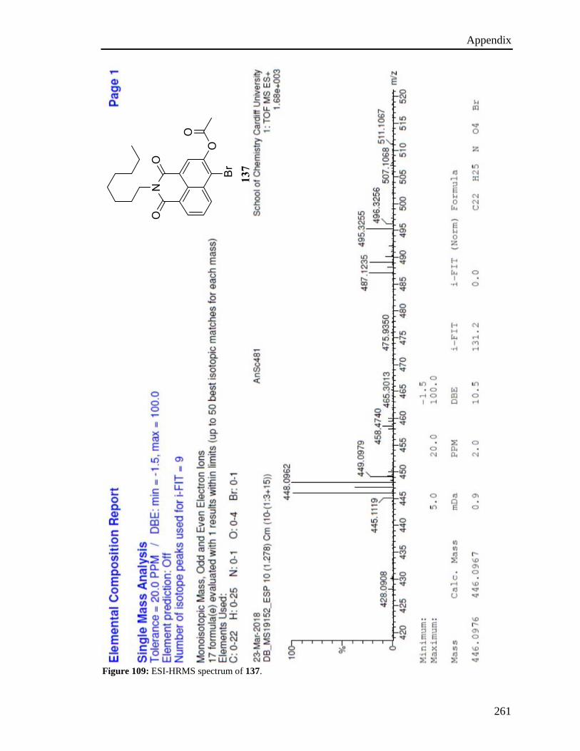
Appendix
261
Figure 109: ESI-HRMS spectrum of 137.
137

Appendix
262
Figure 110: 300 MHz 1H NMR spectrum of 136 in CDCl3.
136

Appendix
263
Figure 111: 75 MHz 13C NMR spectrum of 136 in CDCl3.
136
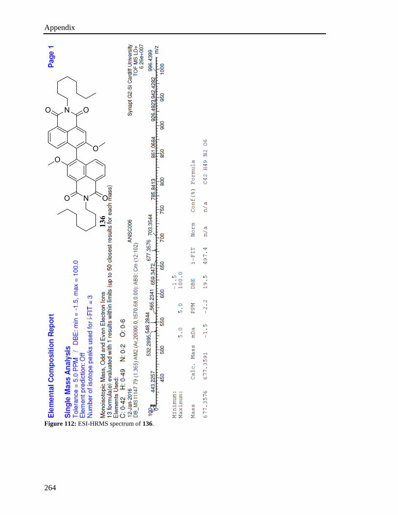
Appendix
264
Figure 112: ESI-HRMS spectrum of 136.
136

Appendix
265
Figure 113: 300 MHz 1H NMR spectrum of 131 in C2D6SO.
131
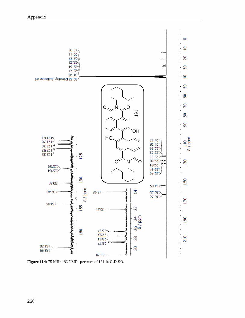
Appendix
266
Figure 114: 75 MHz 13C NMR spectrum of 131 in C2D6SO.
131
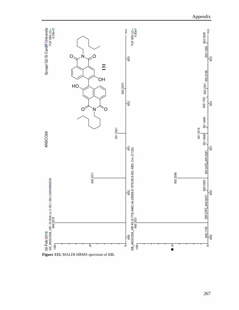
Appendix
267
Figure 115: MALDI-HRMS spectrum of 131.
131
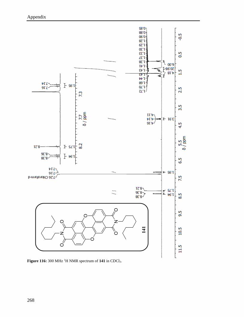
Appendix
268
Figure 116: 300 MHz 1H NMR spectrum of 141 in CDCl3.
141
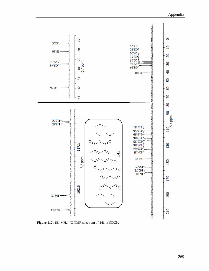
Appendix
269
Figure 117: 151 MHz 13C NMR spectrum of 141 in CDCl3.
141

Appendix
270
Figure 118: MALDI-HRMS spectrum of 141.
141
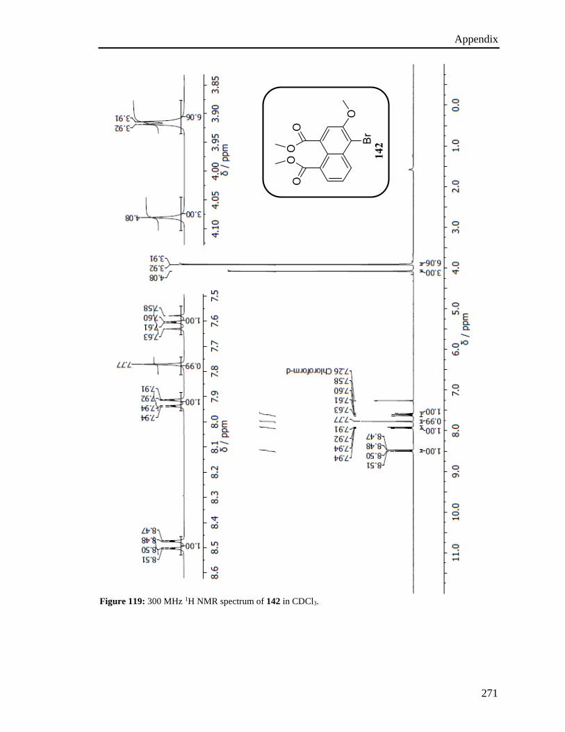
Appendix
271
Figure 119: 300 MHz 1H NMR spectrum of 142 in CDCl3.
142
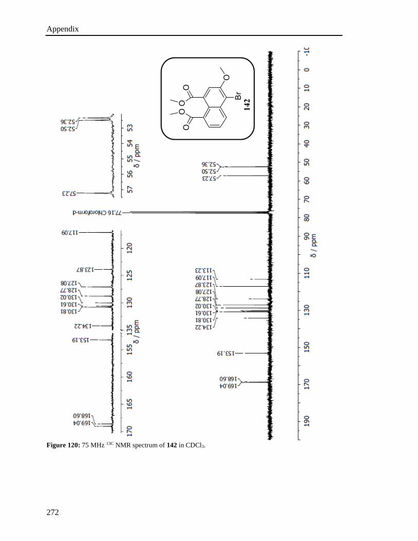
Appendix
272
Figure 120: 75 MHz 13C NMR spectrum of 142 in CDCl3.
142
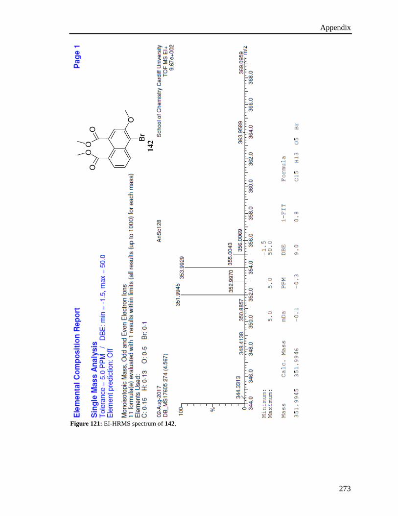
Appendix
273
Figure 121: EI-HRMS spectrum of 142.
142
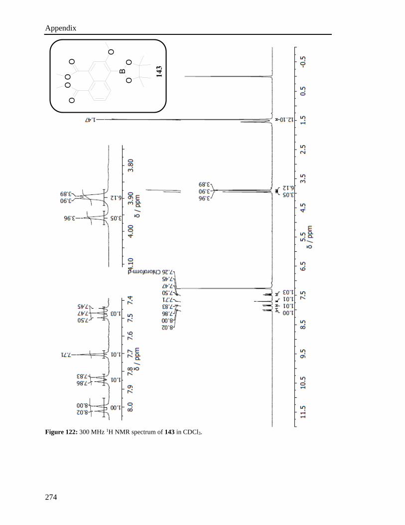
Appendix
274
Figure 122: 300 MHz 1H NMR spectrum of 143 in CDCl3.
143
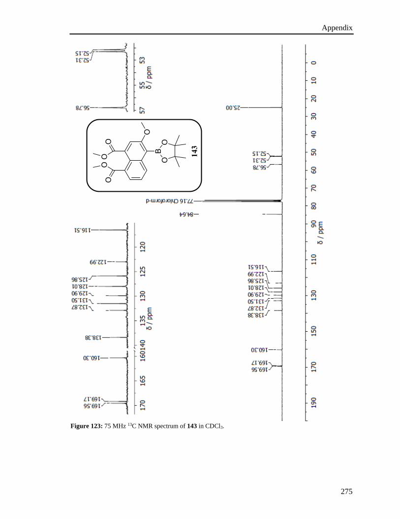
Appendix
275
Figure 123: 75 MHz 13C NMR spectrum of 143 in CDCl3.
143
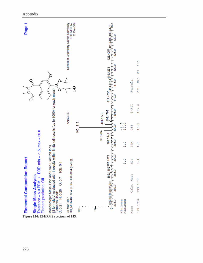
Appendix
276
Figure 124: EI-HRMS spectrum of 143.
143

Appendix
277
Figure 125: 400 MHz 1H NMR spectrum of 58 in (CD3)2CO.
58
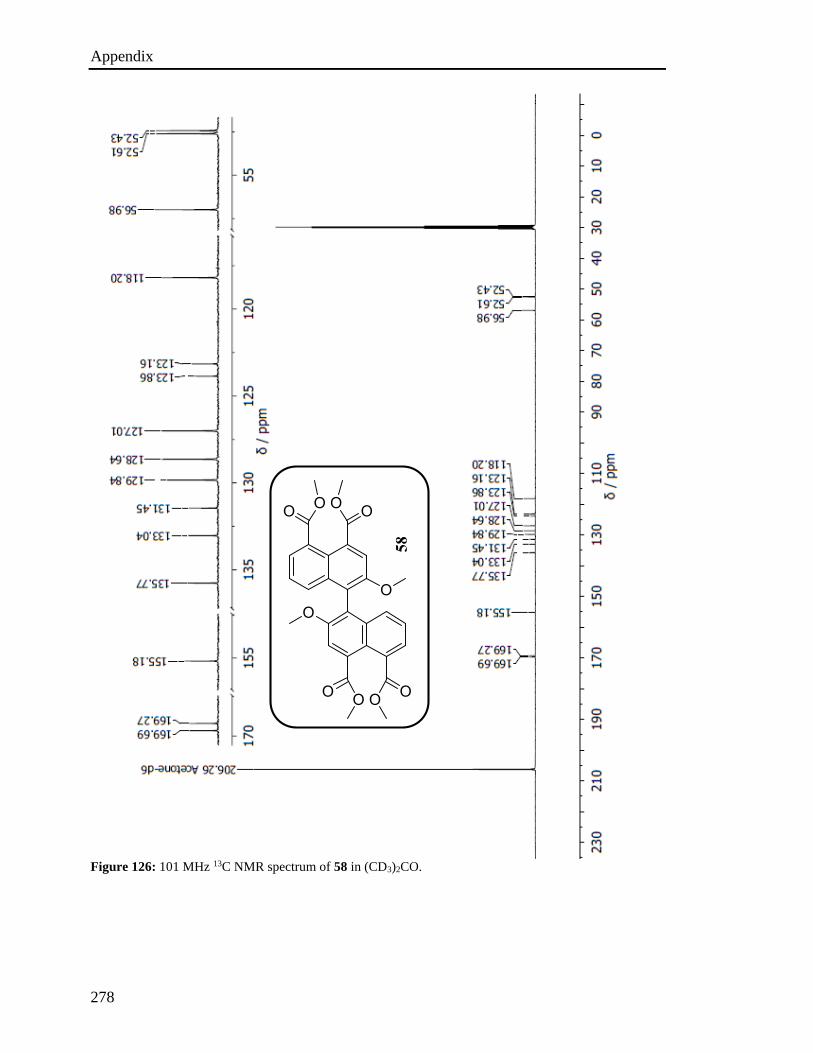
Appendix
278
Figure 126: 101 MHz 13C NMR spectrum of 58 in (CD3)2CO.
58

Appendix
279
Figure 127: APCI-HRMS spectrum of 58.
58
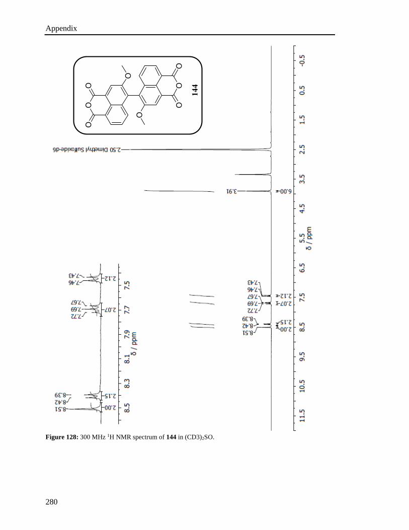
Appendix
280
Figure 128: 300 MHz 1H NMR spectrum of 144 in (CD3)2SO.
144
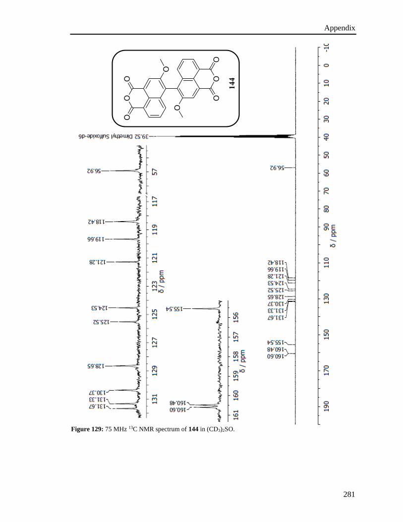
Appendix
281
Figure 129: 75 MHz 13C NMR spectrum of 144 in (CD3)2SO.
144
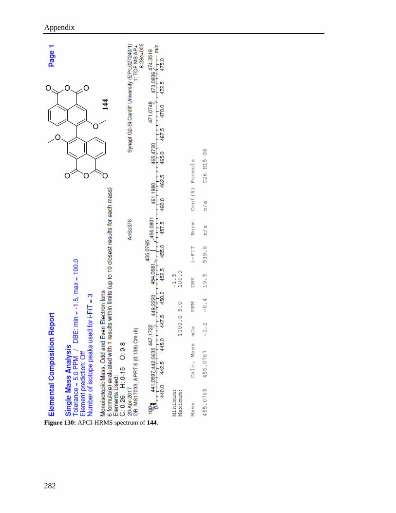
Appendix
282
Figure 130: APCI-HRMS spectrum of 144.
144
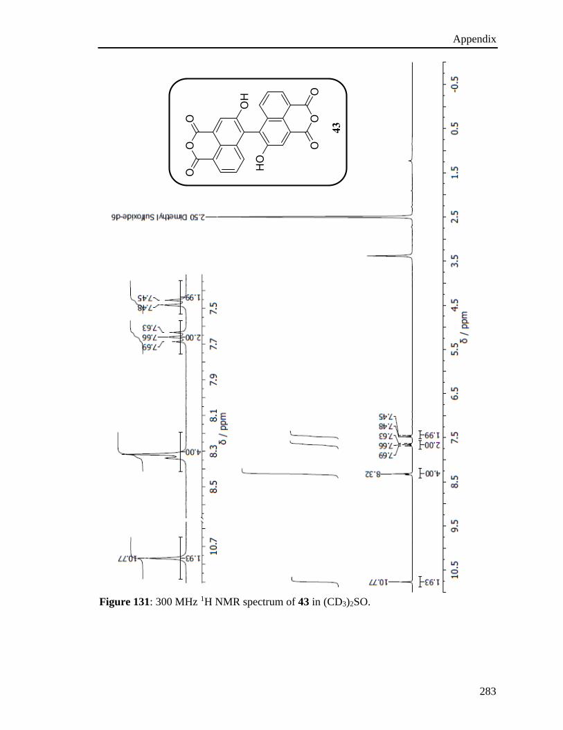
Appendix
283
Figure 131: 300 MHz 1H NMR spectrum of 43 in (CD3)2SO.
43
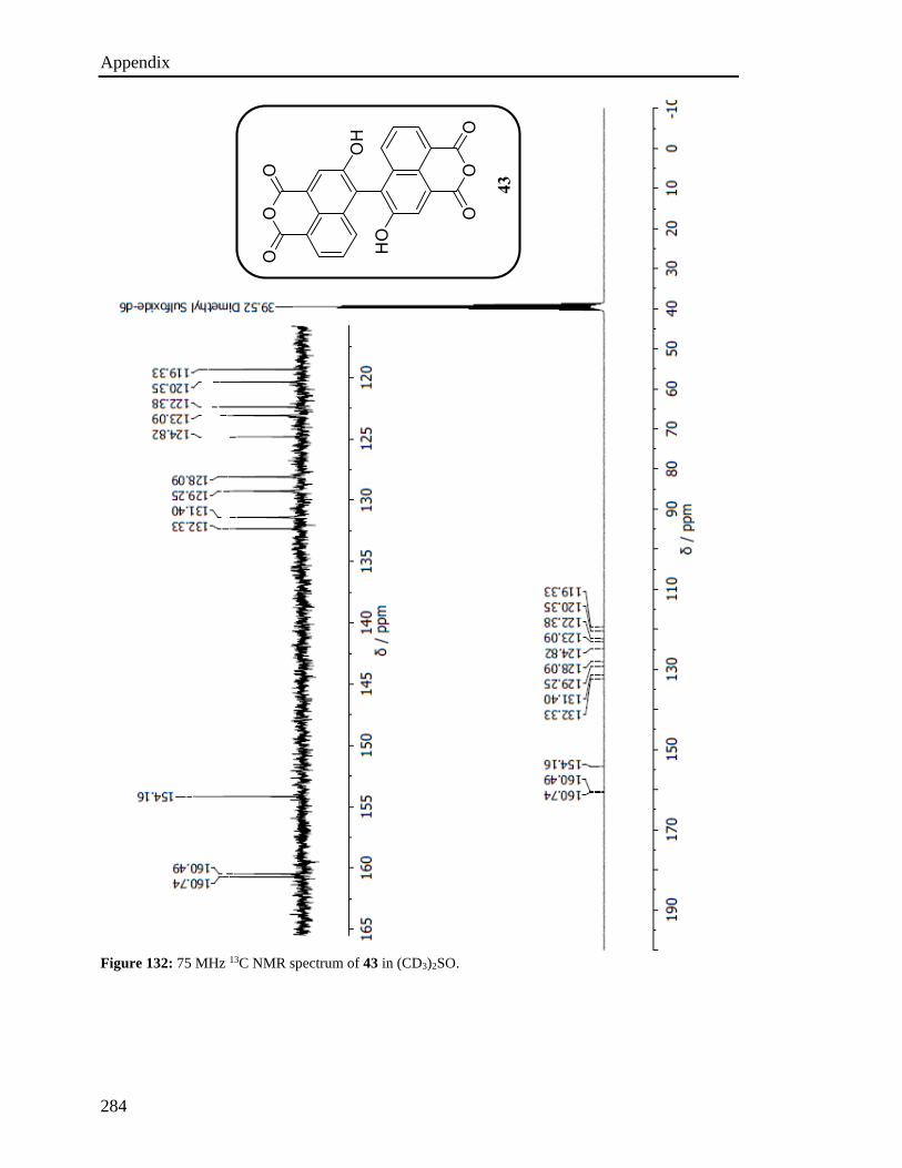
Appendix
284
Figure 132: 75 MHz 13C NMR spectrum of 43 in (CD3)2SO.
43
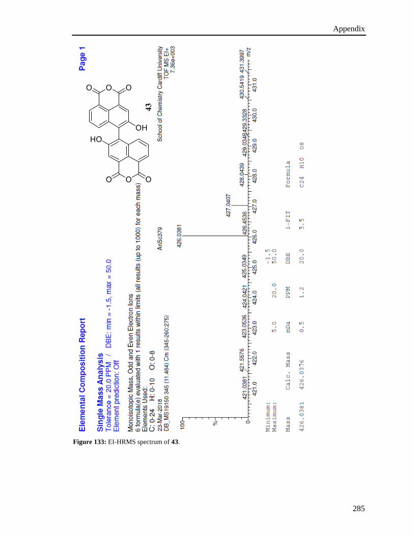
Appendix
285
Figure 133: EI-HRMS spectrum of 43.
43
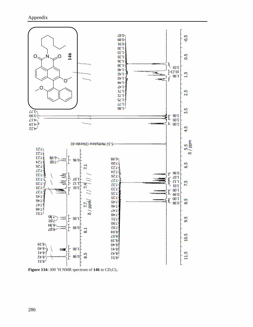
Appendix
286
Figure 134: 300 1H NMR spectrum of 146 in CD2Cl2.
146
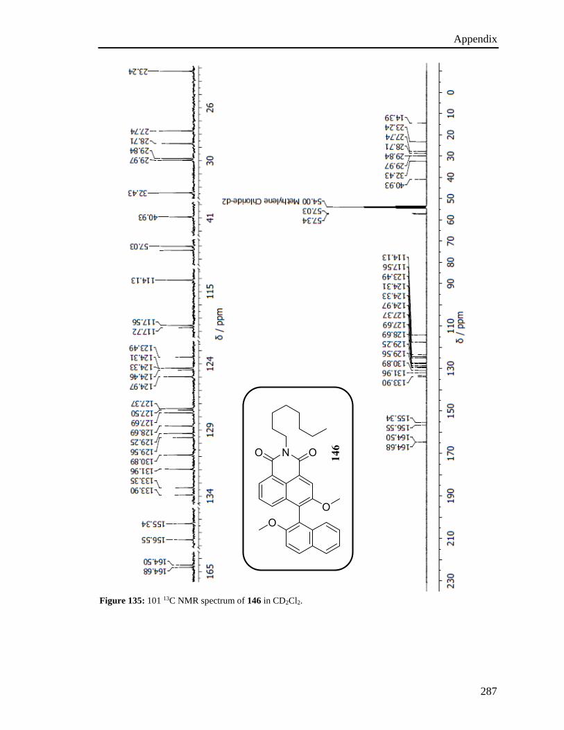
Appendix
287
Figure 135: 101 13C NMR spectrum of 146 in CD2Cl2.
146
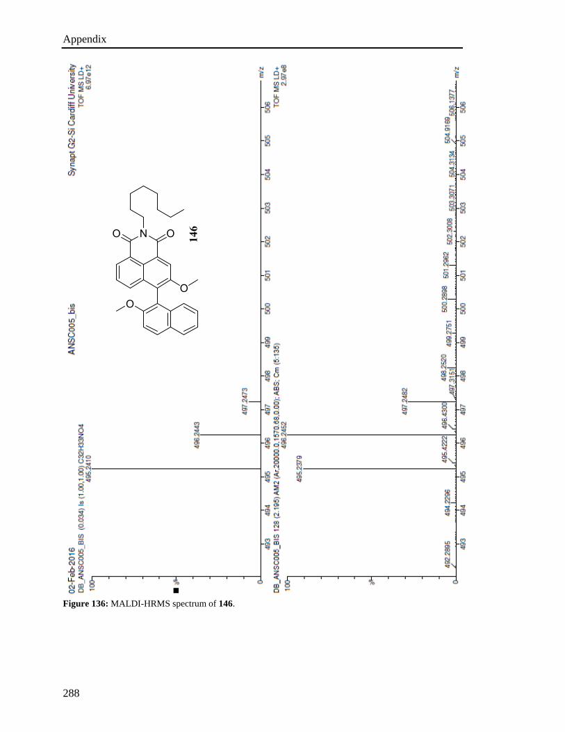
Appendix
288
Figure 136: MALDI-HRMS spectrum of 146.
146
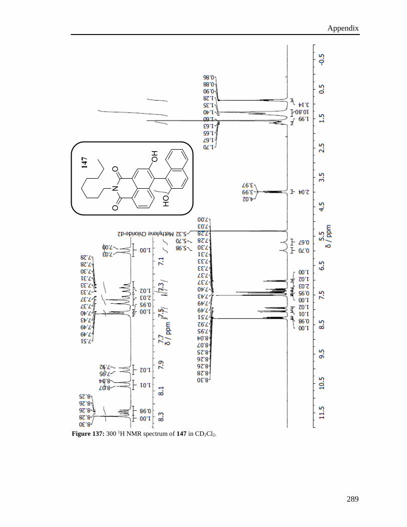
Appendix
289
Figure 137: 300 1H NMR spectrum of 147 in CD2Cl2.
147
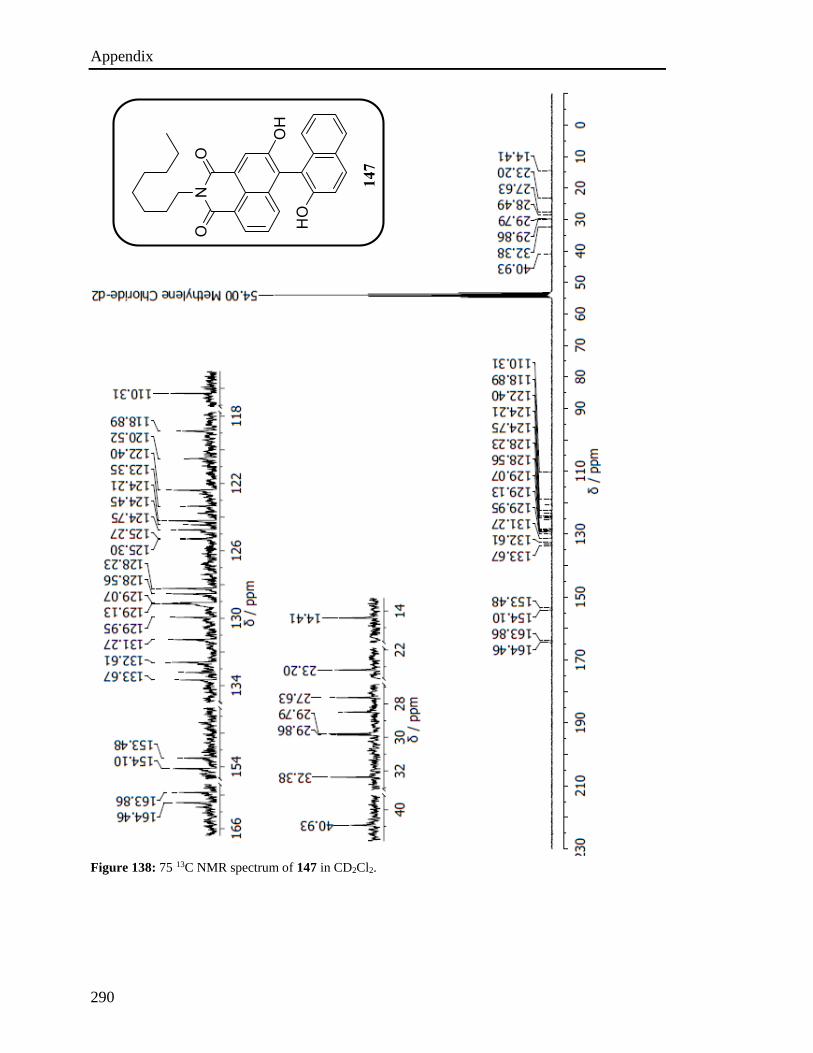
Appendix
290
Figure 138: 75 13C NMR spectrum of 147 in CD2Cl2.
147
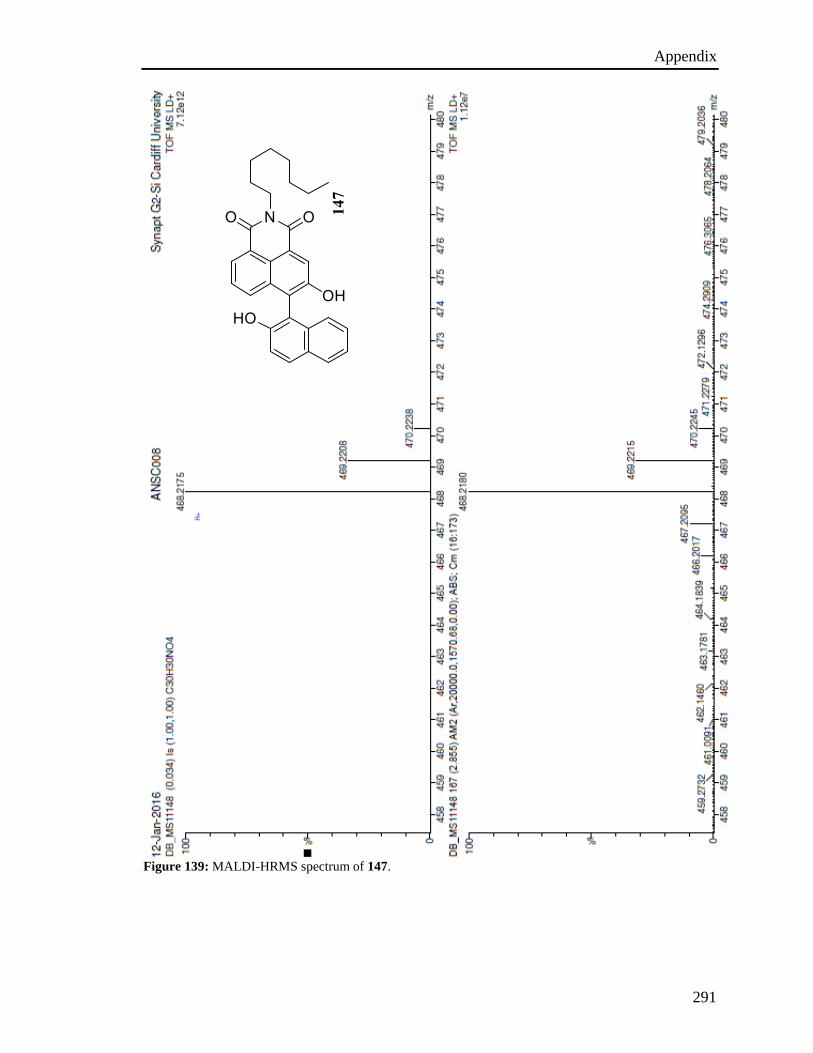
Appendix
291
Figure 139: MALDI-HRMS spectrum of 147.
147
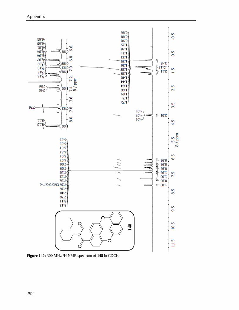
Appendix
292
Figure 140: 300 MHz 1H NMR spectrum of 148 in CDCl3.
148
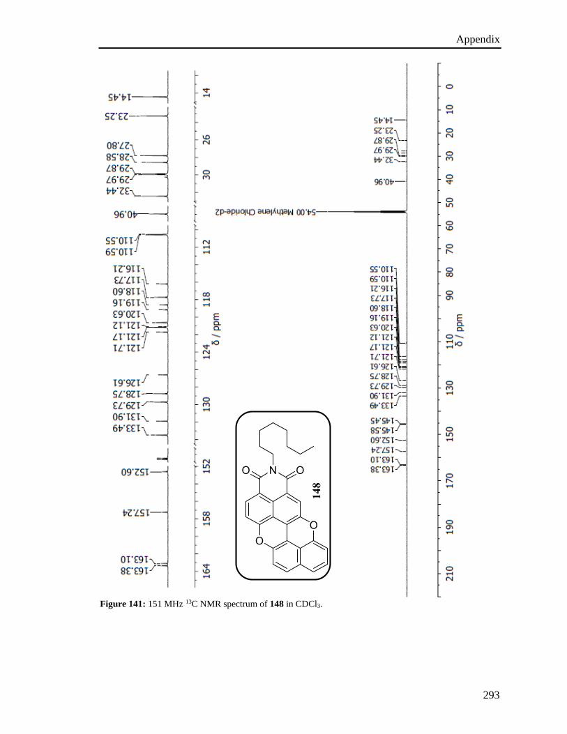
Appendix
293
Figure 141: 151 MHz 13C NMR spectrum of 148 in CDCl3.
148
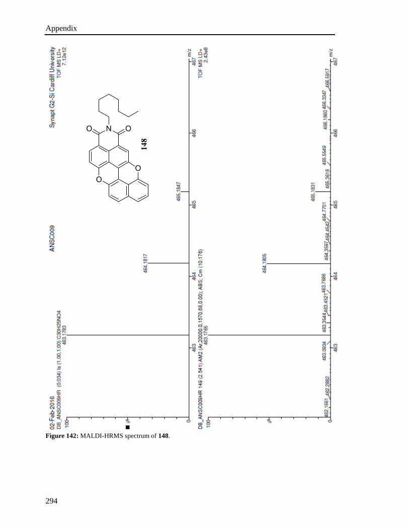
Appendix
294
Figure 142: MALDI-HRMS spectrum of 148.
148

Appendix
295
Figure 143: 300 MHz 1H NMR spectrum of 51 in CD2Cl2.
51
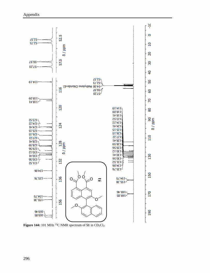
Appendix
296
Figure 144: 101 MHz 13C NMR spectrum of 51 in CD2Cl2.
51
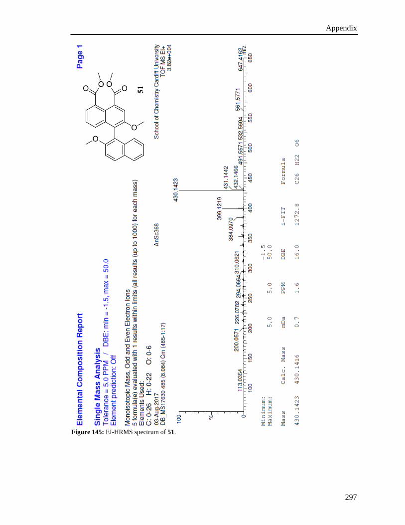
Appendix
297
Figure 145: EI-HRMS spectrum of 51.
51
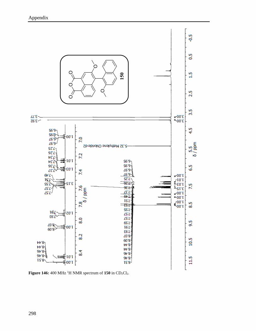
Appendix
298
Figure 146: 400 MHz 1H NMR spectrum of 150 in CD2Cl2.
150
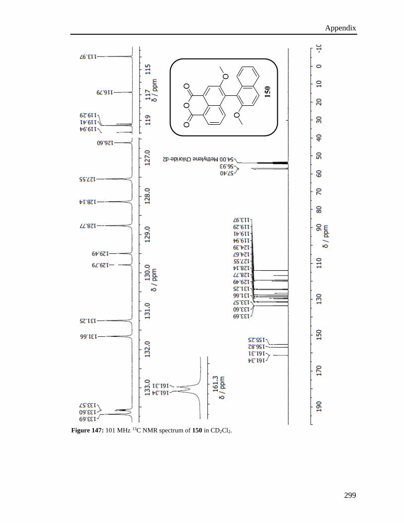
Appendix
299
Figure 147: 101 MHz 13C NMR spectrum of 150 in CD2Cl2.
150
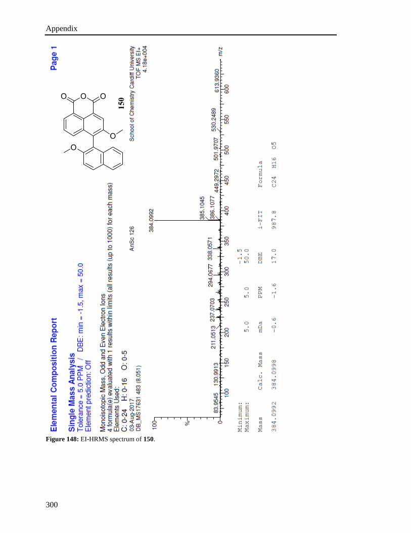
Appendix
300
Figure 148: EI-HRMS spectrum of 150.
150
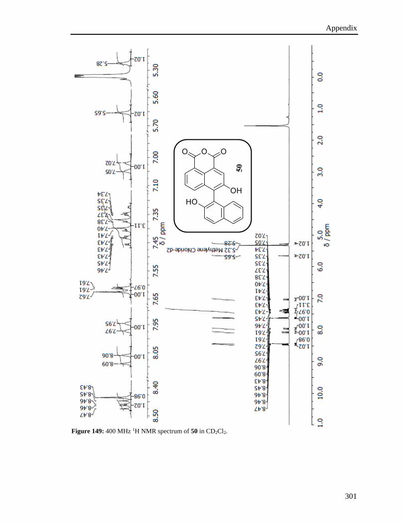
Appendix
301
Figure 149: 400 MHz 1H NMR spectrum of 50 in CD2Cl2.
50
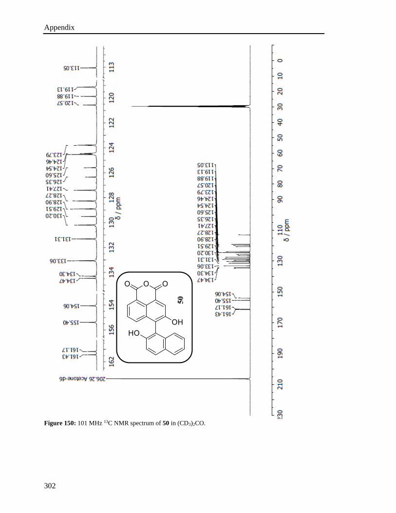
Appendix
302
Figure 150: 101 MHz 13C NMR spectrum of 50 in (CD3)2CO.
50
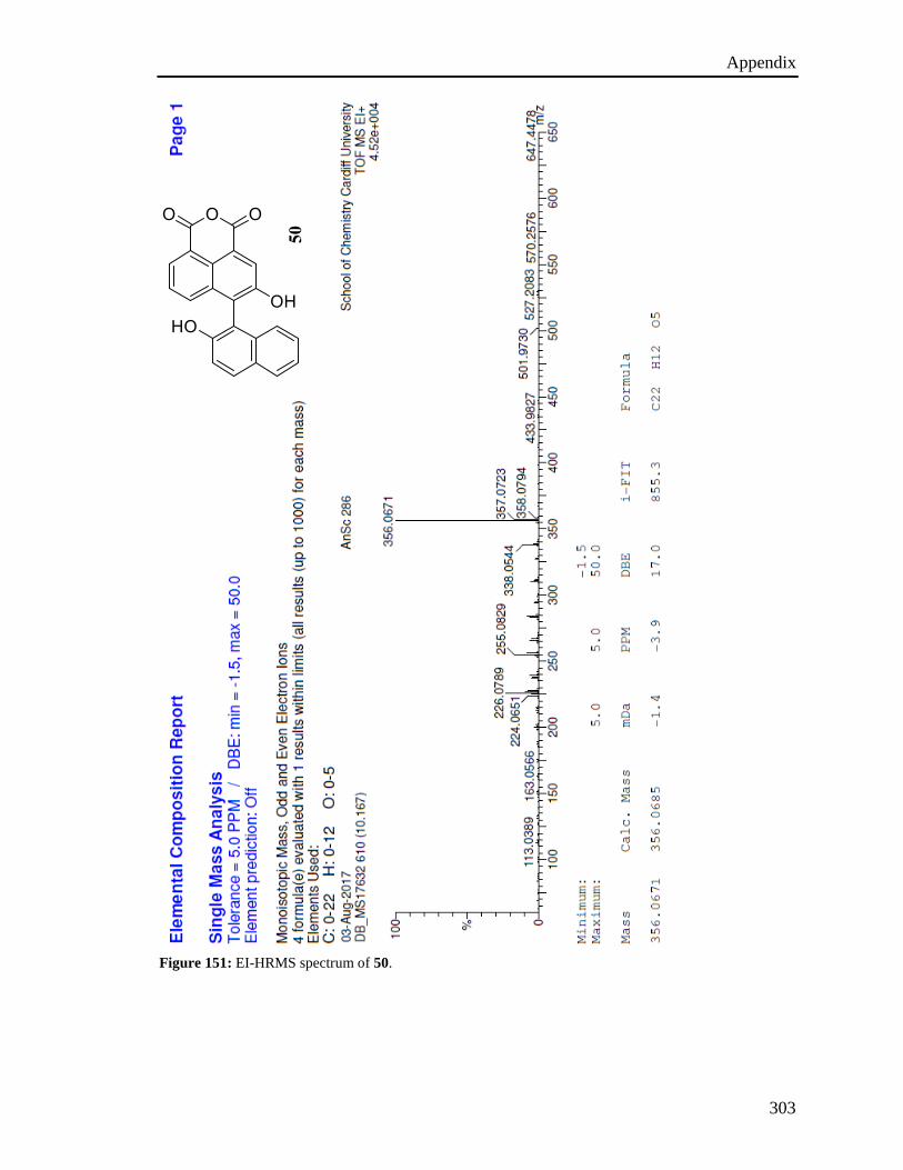
Appendix
303
Figure 151: EI-HRMS spectrum of 50.
50
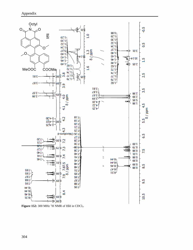
Appendix
304
Figure 152: 300 MHz 1H NMR of 151 in CDCl3.
151
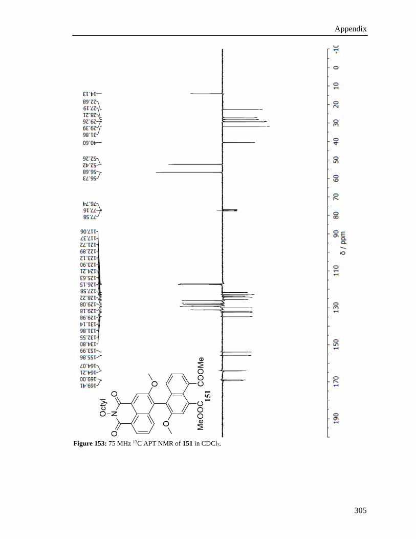
Appendix
305
Figure 153: 75 MHz 13C APT NMR of 151 in CDCl3.
151
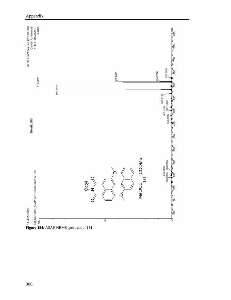
Appendix
306
Figure 154: ASAP-HRMS spectrum of 151.
151
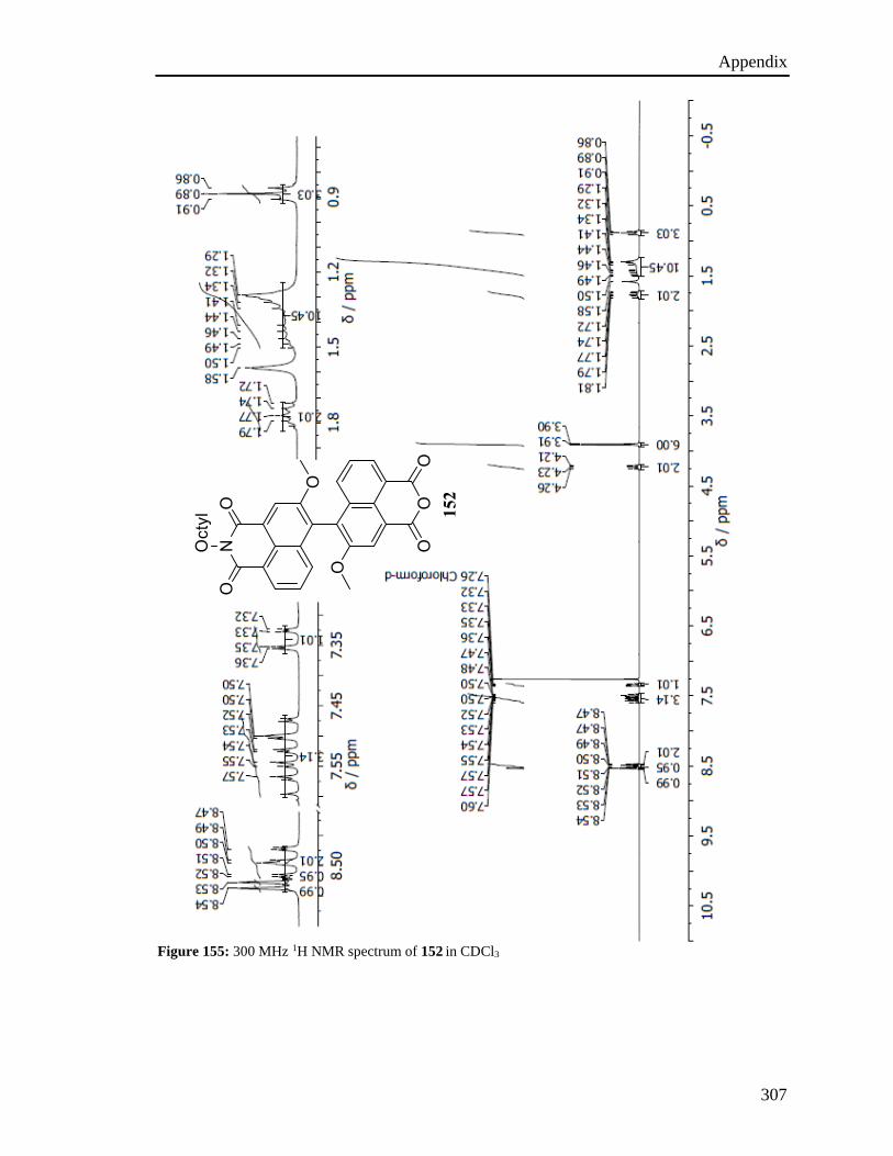
Appendix
307
Figure 155: 300 MHz 1H NMR spectrum of 152 in CDCl3
152
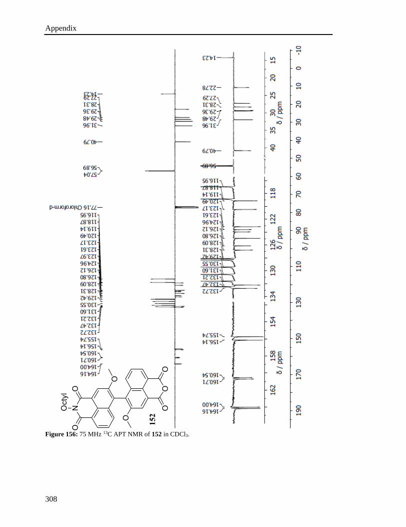
Appendix
308
Figure 156: 75 MHz 13C APT NMR of 152 in CDCl3.
152
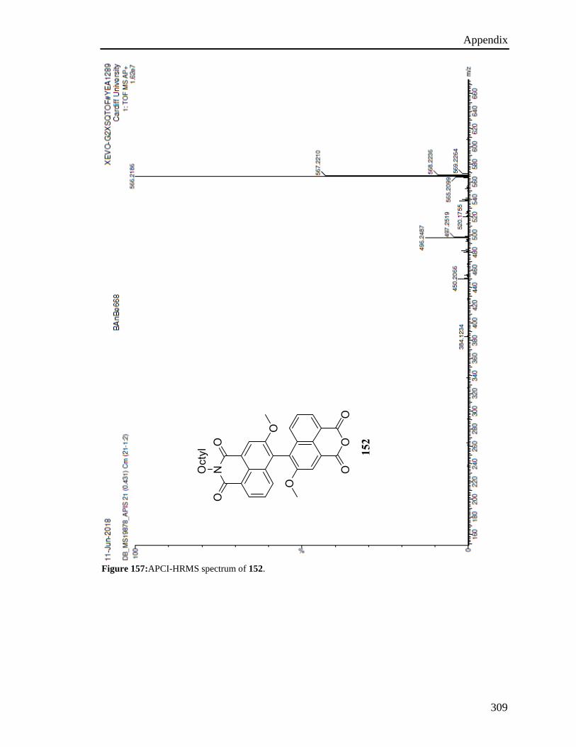
Appendix
309
Figure 157:APCI-HRMS spectrum of 152.
152
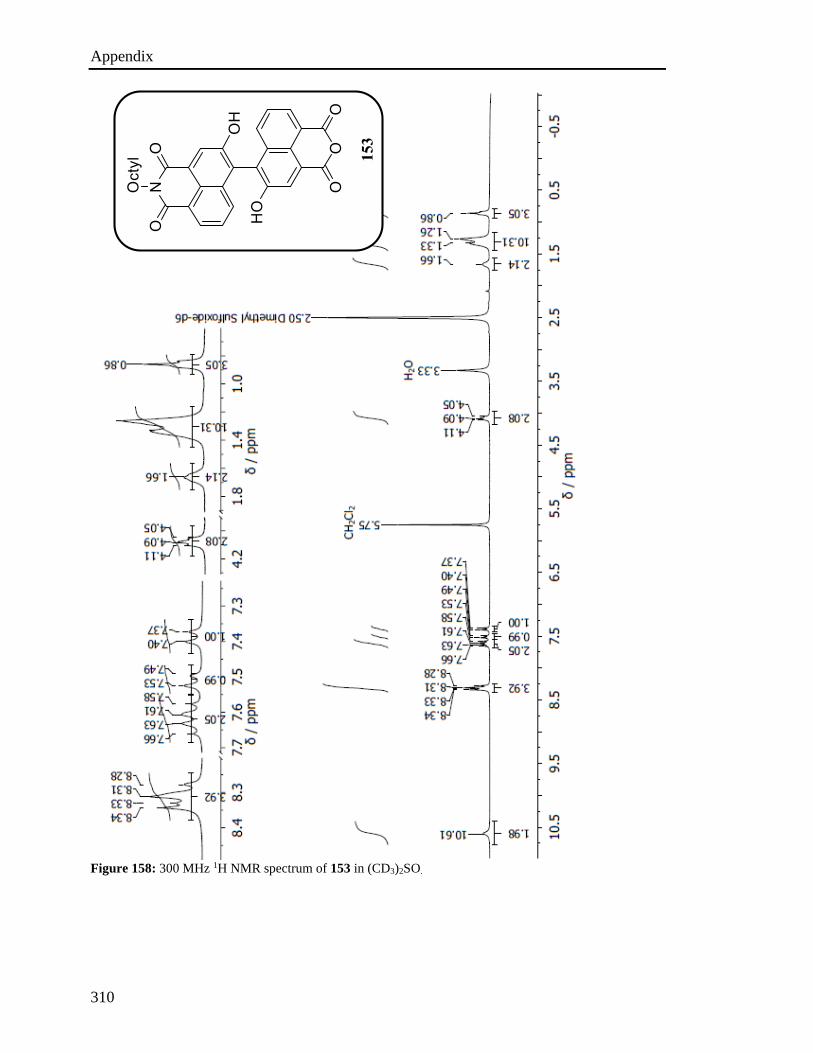
Appendix
310
Figure 158: 300 MHz 1H NMR spectrum of 153 in (CD3)2SO.
153
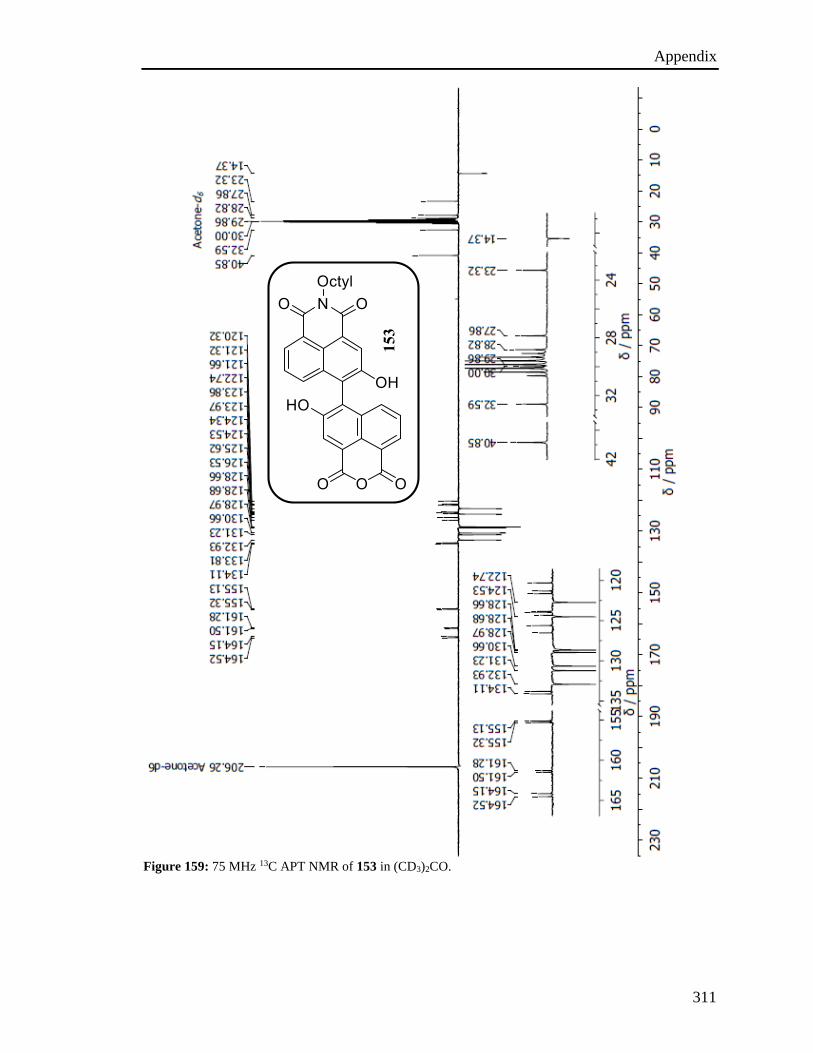
Appendix
311
Figure 159: 75 MHz 13C APT NMR of 153 in (CD3)2CO.
153
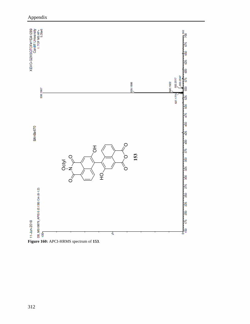
Appendix
312
Figure 160: APCI-HRMS spectrum of 153.
153

Appendix
313
Figure 161: 300 MHz 1H NMR spectrum of 154 in CDCl3.
154
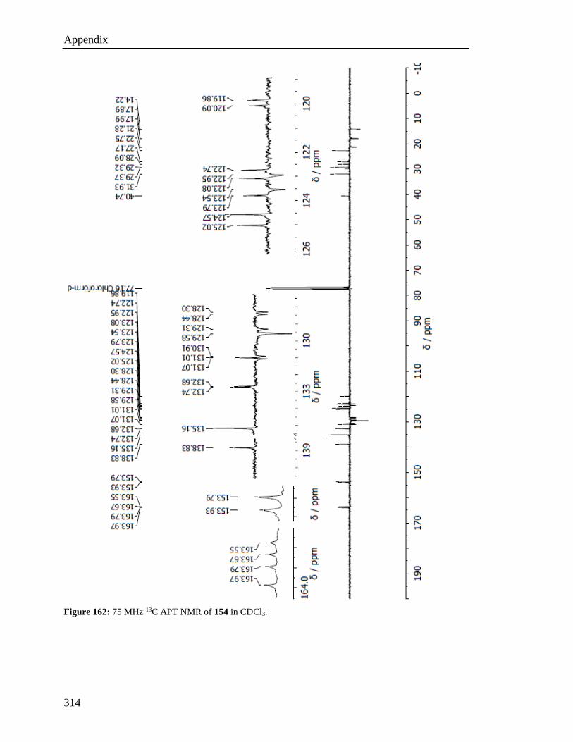
Appendix
314
Figure 162: 75 MHz 13C APT NMR of 154 in CDCl3.
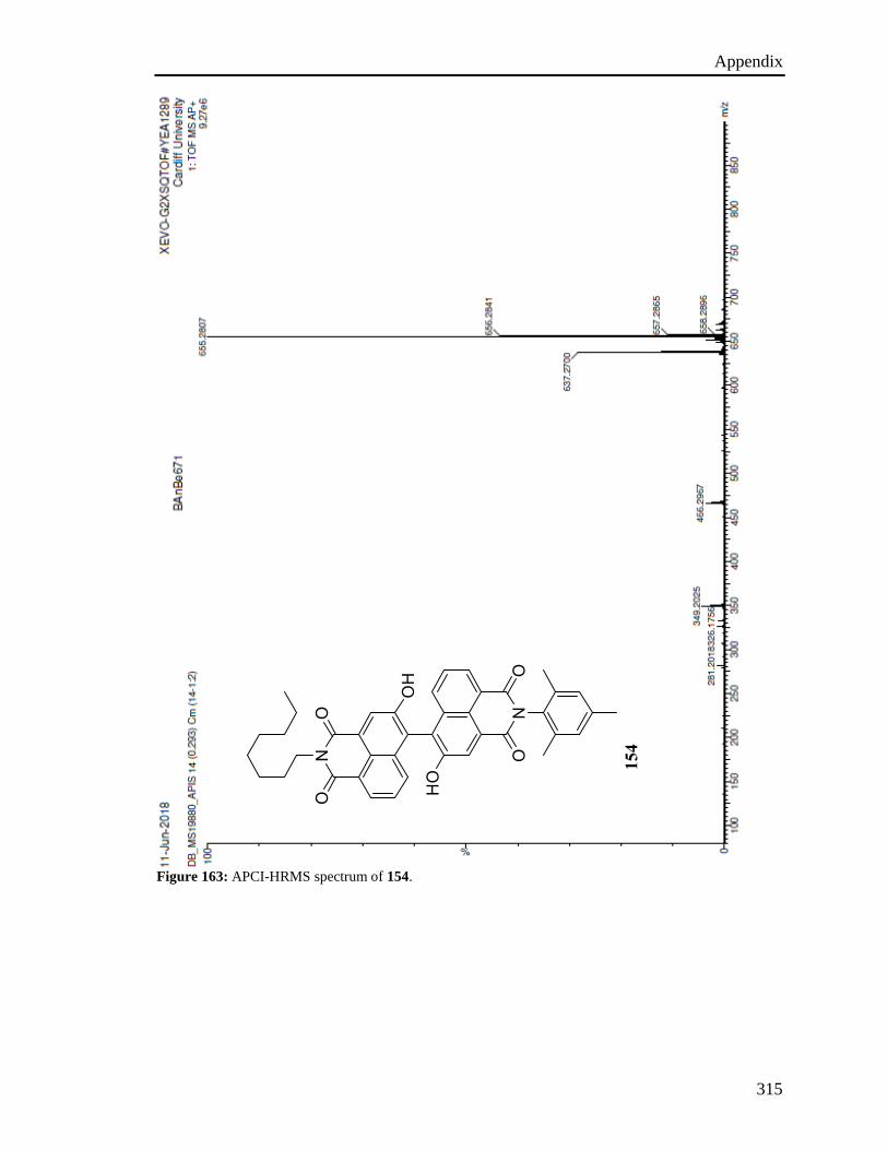
Appendix
315
Figure 163: APCI-HRMS spectrum of 154.
154

Appendix
316
Figure 164: 300 MHz 1H NMR spectrum of 155 in CDCl3.
155

Appendix
317
Figure 165: 75 MHz 13C APT NMR of 155 in CDCl3.
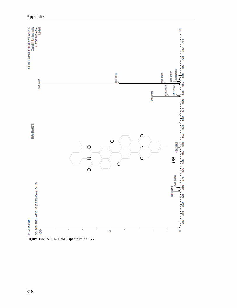
Appendix
318
Figure 166: APCI-HRMS spectrum of 155.
155