Swing Human Powered Generator: For the DC House Project
41
Swing Human Powered Generator For the DC House Project by Juan Vicente Avelar Juan Jose Galindo Juan Pramyr Ramos Advisor: Dr. Taufik Senior Project ELECTRICAL ENGINEERING DEPARTMENT California Polytechnic State University San Luis Obispo EE464 September 2012 - June 2013
-
Upload
khangminh22 -
Category
Documents
-
view
5 -
download
0
Transcript of Swing Human Powered Generator: For the DC House Project

Swing Human Powered Generator
For the DC House Project
by
Juan Vicente Avelar
Juan Jose Galindo
Juan Pramyr Ramos
Advisor:
Dr. Taufik
Senior Project
ELECTRICAL ENGINEERING DEPARTMENT
California Polytechnic State University
San Luis Obispo
EE464
September 2012 - June 2013

2
Table of Contents
Swing Human Powered Generator .............................................................................................. 1
Table of Contents ................................................................................................................... 2
List of Tables and Figures ...................................................................................................... 3
Acknowledgements ................................................................................................................... 4
Abstract................................................................................................................................. 5
Chapter 1. Introduction........................................................................................................... 6
General Introduction and Background ...................................................................................... 6
Chapter 2. Requirements and Specifications............................................................................10
Chapter 3. Functional Decomposition .....................................................................................12
Overview Block Diagram ......................................................................................................12
Chapter 4. Design and Manufacturing ....................................................................................15
Manufacturing ....................................................................................................................16
Component Specifications .................................................................................................18
Chapter 5. Testing and Results ..........................................................................................21
Chapter 6. Conclusion and Future Recommendations..............................................................28
Conclusion ..........................................................................................................................28
Future Recommendations ......................................................................................................28
References .............................................................................................................................30
Bibliography........................................................................................................................30
Appendix A — Analysis of Senior Project Design....................................................................32
Appendix B — Cost Estimates & Actual cost ..........................................................................38
Appendix C — Senior Project Gantt Chart ..............................................................................40

3
List of Tables and Figures
Figure 1-1: DC House System Overview ......................................................................................................................6
Figure 1 2: The traditional swing with chains (left) and the swing with solid bars (right) ............................................8
Table 1-1: Summary of advantages and disadvantages of proposed solution................................................................9
Table 2-1: Swing Human Powered Generator Requirements and Specifications........................................................10
Figure 3-1: Overview Block Diagram .........................................................................................................................12
Figure 3-2: Level Zero Block Diagram .......................................................................................................................12
Table 3-1: Function Table for Level Zero Block Diagram..........................................................................................12
Figure 3-3: Level One Block Diagram ........................................................................................................................13
Table 3-2: Function Tables for all the Modules of the Level One Block Diagram .....................................................13
Figure 4-1: CAD Preliminary Design of the Swing Set...............................................................................................15
Figure 4-2: Boat Trailer and Separated Axel Used in our Design ...............................................................................16
Figure 4-3: Semicircle Mechanism..............................................................................................................................17
Figure 4-4: Cement Blocks that Provide Stability .......................................................................................................17
Figure 4-5: Built Swing Set .........................................................................................................................................18
Figure 4-6: DC Generator Used in the Design.............................................................................................................19
Figure 4-7: Rectifier Used in the Design .....................................................................................................................20
Figure 5-1: Output voltage for slow speed with a 175 lb. person swinging at no load................................................21
Figure 5-2: Output voltage for casual speed with a 155 lb. person swinging at no load .............................................22
Figure 5-3: Output voltage for casual speed with a 155 lb. person swinging at no load .............................................22
Figure 5-4: Output voltage for high speed with a 175 lb. person swinging at no load ................................................23
Figure 5-5: Output voltage with a 10 Ohm load and a 155 lb. person swinging .........................................................24
Figure 5-6: Output voltage with a 20 Ohm load and a 155 lb. person swinging .........................................................24
Figure 5-7: Output voltage with a 30 Ohm load and a 155 lb. person swinging .........................................................25
Figure 5-8: Output voltage with a 40 Ohm load and a 155 lb. person swinging .........................................................25
Figure 5-9: Output voltage with a 50 Ohm load and a 155 lb. person swinging .........................................................26
Figure 5-10: Output voltage with a 100 Ohm load and a 155 lb. person swinging .....................................................26
Table 5-1: Measured and calculated output values for a 155lb person........................................................................27
Figure 5-11: Output Power vs. Output resistance plot for a 155lb. person..................................................................27
Table AB-1: Cost Estimates ........................................................................................................................................38
Table AB-2: Actual Costs............................................................................................................................................39
Figure AC-1: Senior Project Gantt chart for fall 2012.................................................................................................40
Figure AC-2: Senior Project Gantt chart for winter 2013............................................................................................40
Figure AC-3: Senior Project Gantt chart for spring 2013............................................................................................41

4
Acknowledgements
We would like to thank Dr. Taufik for giving us the opportunity to be part of the DC House team
and for his ongoing support throughout the course of our project. We would also like to express our
gratitude to Kevin Williams for all the time spent helping us develop the skills needed for the construction
of the swing and for all the time spent supervising our progress. In addition, we would like to
acknowledge fellow classmates who participated in the DC House project this quarter, especially those
whose constructive criticism helped us improve our design.
Finally, we would like to thank our families for their unwavering love and support that was our
beacon of light in dark times throughout our years of study.

5
Abstract
The Play Park Human Powered Generator project addresses various ways of generating power.
More specifically, this project entails the design and construction of the Swing Power Generator to
provide electrical power from mechanical energy. The swing generator will eventually be used as part of
the human-powered generators utilized in the DC House project.
A swing generator prototype was built for this project, which demonstrates the feasibility of its
use for electrical power source. Detailed design and construction of the swing generator is presented in
this report along with results from hardware testing.

6
Chapter 1. Introduction
General Introduction and Background
The DC House is a project designed as a solution for electrical system distribution for rural
villages that have no electricity. In order to accomplish this, the DC House relies on various types of
power generators that include wind, solar, hydro, and human-powered generators. The scope of this
project is to design a playground swing set that generates energy for the DC House. Figure 1-1 shows the
overview of the DC House system.
Figure 1-1: DC House System Overview
In addition to being a clean source of renewable energy, with no emissions or use of diminishing
resources, the human-powered play park provides access to electricity to the less fortunate. As of 2009,
1.4 billion people do not have access to electricity [1]. Even with the increasing number of transmission
lines to satisfy the world’s electricity demand, the high costs of infrastructure, operation, and maintenance
make it virtually impossible to bring the traditional power grid to remote villages. In many cases, rural
villages do not have the resources to implement the more traditional power systems for renewable energy,
such as wind turbines, PV panels, or even water [2]. The swing set, will be a cheaper option, as well as it
will be able to produce energy without the need of water, wind, or even sunlight. The swing set is a

7
device that uses kids’ playtime to generate power, making it a healthy and fun way for kids and adults to
generate energy for their homes. A human powered generator is not intermittent, and the swing set meets
a very important piece of the DC House humanitarian effort for increasing rural electrification while
promoting sustainability.
Human-powered generators have been designed and manufactured for various applications. Some
of the most popular human-powered devices on the market include radios, wristwatches and flashlights
[3]. These devices are powered by rotating a crank or shaking the device. Another commonly used
method with greater power output is the pedaling generator, which consists of a mounted bicycle which
energy output is stored in a battery. A similar approach has been implemented using exercise machines
that power themselves. By harvesting the energy from exercise equipment such as stationary bikes, and
elliptical machines, the machines can power themselves, as well as generate power that can potentially
power the gym. An example is RevRev, a company from Florida that sells commercial elliptical machines
that are also sources of power. The kinetic energy of the user generates DC power and then sent to an AC
converter and, finally, sent to the grid [4]. At Cal Poly San Luis Obispo, a similar project was developed
for the newly renovated Recreation Center as part of a student’s master thesis and senior project [5]. A
group of Cal Poly students also worked on a seesaw generator as part of their senior project on last year
[6].
Even though the elliptical machines are a great step towards producing renewable energy with
environmentally friendly human-powered generators, it does not meet the design and manufacturing
considerations for bringing electricity to remote villages and islands. Usually these rural areas won’t have
exercise equipment or the funds to obtain it. Another aspect that the stationary bike or elliptical machine
solution lacks is the fun factor. An exercise machine for generating electricity has that hard-physical-work
factor attached to it. In addition, the elliptical machine power generating system employs DC-AC
conversion, despite the fact that the majority of human-powered energy sources produce DC output power
and most house appliances operate on DC power. Converting the renewable energy sources to AC power
creates unnecessary power-loss and additional costs.

8
The nature of this Swing Generator project manufactures a swing set composed of locally
available materials that are environmentally friendly and inexpensive. In addition, the concept of a swing
will make the power generation a fun process for the kids. Since the swing will be used to power the DC
house, there won’t be any need for a DC-AC converter. A purely DC system with DC-DC converter will
have a higher energy efficiency and be a more sustainable system for remote areas.
A more detailed consideration of the nature of this project can be accomplished by analyzing a
traditional swing structure and how this would affect the generation of power. A traditional swing
consists of a steel frame where two chains are connected to the top of the frame using a hanger and a
fastener. The bottom of the chains is attached to a swing seat using another fastener as seen in the left
image of Figure 1-2. For this project, the swing will be designed using solid bars instead of the chain, in
order to allow maximum torque to the thrust bearings and reduce the thrust loss in each chain link as seen
in the right image of Figure 1-2.
Figure 1-2: The traditional swing with chains (left) and the swing with solid bars (right)
9
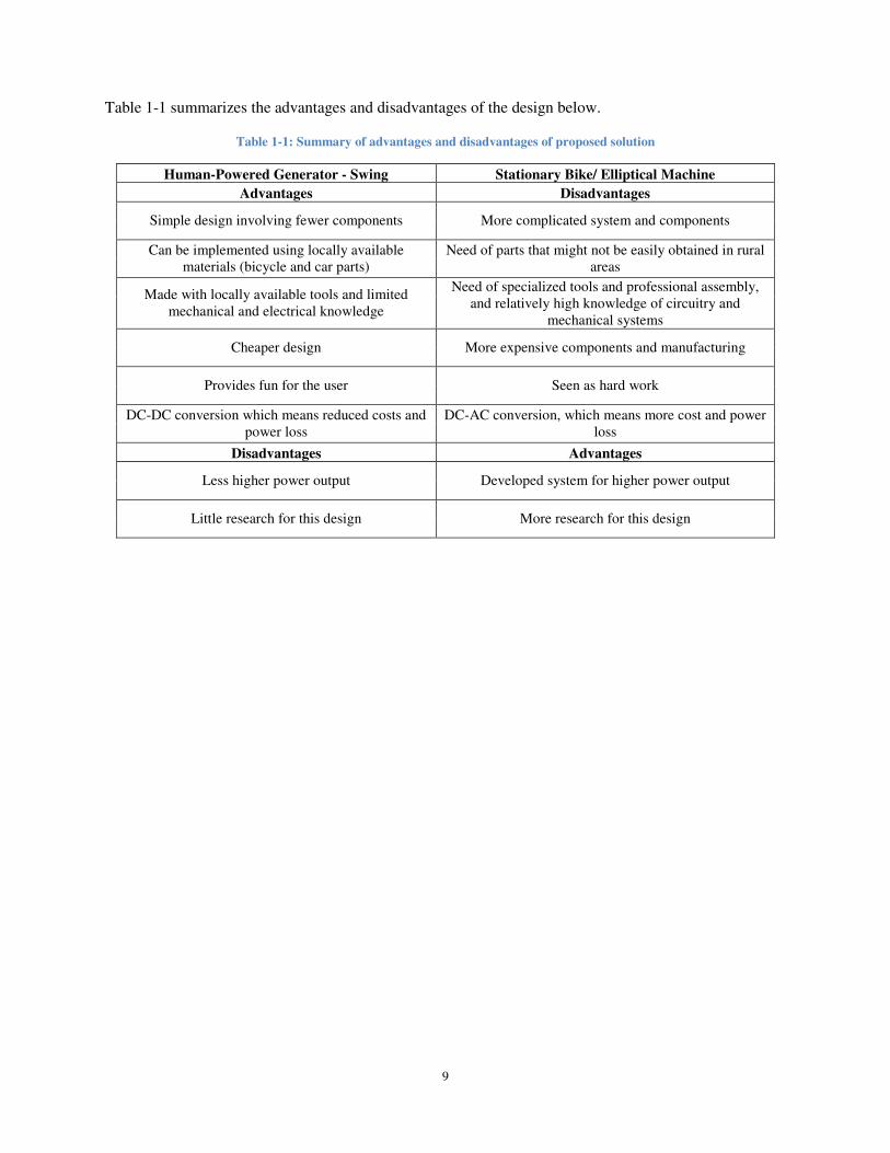
Table 1-1 summarizes the advantages and disadvantages of the design below.
Table 1-1: Summary of advantages and disadvantages of proposed solution
Human-Powered Generator - Swing Stationary Bike/ Elliptical Machine
Advantages Disadvantages
Simple design involving fewer components More complicated system and components
Can be implemented using locally available materials (bicycle and car parts)
Need of parts that might not be easily obtained in rural areas
Made with locally available tools and limited mechanical and electrical knowledge
Need of specialized tools and professional assembly, and relatively high knowledge of circuitry and
mechanical systems
Cheaper design More expensive components and manufacturing
Provides fun for the user Seen as hard work
DC-DC conversion which means reduced costs and power loss
DC-AC conversion, which means more cost and power loss
Disadvantages Advantages
Less higher power output Developed system for higher power output
Little research for this design More research for this design

10
Chapter 2. Requirements and Specifications
Table 2-1: Swing Human Powered Generator Requirements and Specifications
Marketing
Requirements
Engineering
Specifications Justification
1 The system costs less than $1,000. A low cost alternative to getting electricity
from a power company.
2, 3 Constructed using metal parts for the frame. Structurally sound swings can be made from
good quality materials. The type of materials
chosen determines its durability.
1, 2, 5 The size of the system should not exceed the
regular size of a swing, 10 feet high and 6 feet
wide, and assembles in less than 2 hour with
tools.
The size of the swing would determine how
easily it can be assembled. The system should
not consume a lot of time during assembly.
4 The system converts mechanical energy to
electrical energy at 33% efficiency.
Convert the abundant energy of playful kids
into powering homes.
4 The system generates an average of 0.5-3W
each full swing.
25kWh is the average power consumed by a
household in a day.
2 The system should abide by the Public
Playground Safety Handbook, more
specifically the swing section, set by the U.S.
Consumer Product Safety Commission [7].
Abiding by the regulations set for playground
safety when building the swing would increase
safety for users.
Marketing Requirements
1. Low cost.
2. Structurally sound.
3. Weather-proof and durable.
4. Efficiently converts mechanical energy to electrical energy.
5. Easy to assemble.
Table 2-1 shows the marketing requirements on the first column corresponding to an engineering
specification in the second column and the third column of the table justifies why certain specific values
corresponds to certain engineering specification. The marketing requirements such as low cost and easy to
assemble seen in the bottom of the table generally improve the sales of the product. The engineering
specifications, however, are characteristics specific to the project such as the average power produced by
the device. In most cases, an engineering specification supports a marketing requirement. However, there
are cases when an engineering support contradicts or opposes a marketing requirement. This can also
occur in marketing requirements. Usually this involves the marketing requirement of low cost. Low cost
usually contradicts improvements in other areas such as higher power or greater durability. Thus, cost and
improvements in other areas must balance. Having a specific budget can also limit the improvements, but

11
eases the trouble of choosing expensive components. The same occurred in the swing project. The initial
problem is that the budget has no limit, which complicated the design since the budget dictates the type of
motor other components. These components, then, dictates the performance of the swing. Setting a limit
to the budget solves the circular problem.
The physical output requirements of the swing set were to convert mechanical energy in
mechanical energy in an efficient way so that the swing set could be used as one of the components that
would power the DC house. For this preliminary design, the efficiency that was aimed for was 33%,
where the system would generate an average of 1.25W per full swing under the condition of low load.
This efficiency is limited to constant rotational speed.
12
Chapter 3. Functional Decomposition
Overview Block Diagram
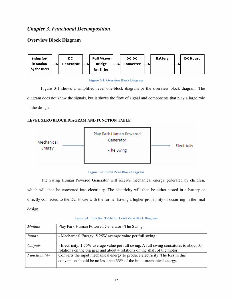
Figure 3-1: Overview Block Diagram
Figure 3-1 shows a simplified level one-block diagram or the overview block diagram. The
diagram does not show the signals, but it shows the flow of signal and components that play a large role
in the design.
LEVEL ZERO BLOCK DIAGRAM AND FUNCTION TABLE
Figure 3-2: Level Zero Block Diagram
The Swing Human Powered Generator will receive mechanical energy generated by children,
which will then be converted into electricity. The electricity will then be either stored in a battery or
directly connected to the DC House with the former having a higher probability of occurring in the final
design.
Table 3-1: Function Table for Level Zero Block Diagram
Module Play Park Human Powered Generator –The Swing
Inputs - Mechanical Energy: 5.25W average value per full swing.
Outputs - Electricity: 1.75W average value per full swing. A full swing constitutes to about 0.4 rotations on the big gear and about 4 rotations on the shaft of the motor.
Functionality Converts the input mechanical energy to produce electricity. The loss in this
conversion should be no less than 33% of the input mechanical energy.

13
Table 3-1 shows the specific values of the inputs, outputs, and the estimated performance of the
project. This table accompanies the level zero block diagram and explains in detail the inputs and outputs.
LEVEL ONE BLOCK DIAGRAM
Figure 3-3: Level One Block Diagram
The Swing Human Powered Generator will receive mechanical energy generated by children which will
then be converted into electricity. The electricity will then be either stored in a battery or directly connected to the
DC House with the former having a higher probability of being the final design. The DC Generator converts the
oscillatory motion produced by the swing into electrical energy that is a mix of AC (ripple) and DC. Another
component can be placed after the DC Motor to reduce the AC characteristics of the electrical energy.
Table 3-2: Function Tables for all the Modules of the Level One Block Diagram
Module Swing
Inputs - Mechanical Energy: 5.25W average value per swing.
Outputs - Mechanical Energy: 8RPM average value.
Functionality Converts the input mechanical energy to produce an oscillatory motion.
The swing will convert the mechanical energy from the kids into oscillatory motion. The values above are estimates.
Module DC Generator
Inputs - Mechanical Energy: 8RPM average value.
Outputs - Electricity: 20Vpp average value
Functionality Converts the oscillatory mechanical energy into electrical energy.
The generator will convert mechanical energy to electrical energy.
Module Rectifier
Inputs - Electricity: 0.100kWh average value.
Outputs - Electricity: 0.050kWh average value.
Functionality Converts the input ac electrical energy to a rectified electrical energy battery.
The Rectifier converts the ac electrical energy coming from the DC Motor into a rectified electrical energy.
Module DC-DC Converter
Inputs - Electricity: 0.050kWh average value per swing.
Outputs - Electricity: 0.50kWh
Functionality Converts DC voltage to appropriate DC voltage to charge battery or use in DC House.
The DC-DC converter will output a 12V regulated output suitable for the battery.

14
Module Battery
Inputs - Electricity: 12Vdc.
Outputs - Electricity: 12Vdc
Functionality Charges up with the output of the DC-DC converter.
The battery stores the energy generated by the system.

15
Chapter 4. Design and Manufacturing
As a preliminary design, Sketchup software was used to build the swing and the gear mechanism
that would allow it to convert the mechanical oscillatory motion to electrical power as shown in Figure 4-
1. Even though the final manufactured swing varied from this original design, the main structures were
retained from this early concept. The main structures that were kept as seen on the CAD design were the
A-beam frame, the bars that hold the swing seat, and the positioning of the gears. The main variations
from this design were the way that the generator was attached to the frame. Originally, a separate
mounting structure for the motor was decided, but it was decided to attach it to the actual frame instead in
order to reduce price and make it less bulky.
Another consideration that is neither shown by the CAD nor implemented in the final design is
the addition of a roofing system to protect the entire swing from rain. Rubber coating for the swing was
suggested, but the idea was eventually discarded. The roofing system would also protect the electrical
parts from water damage. The roofing system should be considered in future designs of this project.
Figure 4-1: CAD Preliminary Design of the Swing Set

16
Manufacturing
After the materials were purchased the construction of the main frame and mechanism was
initiated.
A boat trailer was dismantled into several beams, which were used for the frame. Since the trailer
contained an A beam section only another A beam is needed as shown in Figure 4-2. The trailer also
contained the rotating beam connected to hubs.
Figure 4-2: Boat Trailer and Separated Axel Used in our Design
Five extra metal rods were needed; these rods should be 6 inches at least. The heights of the A
beam from the ground measured to be about 8ft vertically. To make the second A beam while keeping the
angle of the premade A beam, the individual lengths of the beam must match the individual length of each
beam in the premade A beam. The main frame was created by welding the top beam which was measured
to be 5ft, which came from the trailer, to the top parts of the two A beams. Six inches below the top beam
a metal plate with two drilled holes was welded. This metal plate along with nuts and bolts is used to
secure the hub of the rotating beam onto the frame. Three metal rods are welded on the far end of the
rotating beam. Because the beam is square shaped, the metal rods are welded onto the bottom face and
two side faces. Finally, to finish the frame two more metal rods are welded equidistant from the ends to
the middle of the rotating rod. These two must be welded on to the bottom face. Two hollow aluminum
rods, both of which have lengths equal to the height of the swing seat will be connected to the two metal
rods in the middle and then secured via screws and bolts. The seat is secured onto these rods via washers,
bolts, and nuts.

17
The gear mechanism consists of a three plywood semi-circles with a diameter of 3ft as shown in
Figure 4-3. These pieces are secured onto the three metal rods at the far end with the use of dry-wall
screws. The motor is attached to the leg of the frame with nuts, bolts, and a metal mounting plate. A v-
pulley hub is then inserted into the shaft of the motor. Finally, a rope is used to translate the rotation from
the semi-circle piece to the hub.
Figure 4-3: Semicircle Mechanism
To increase the stability of the swing, concrete blocks were used to hold the horizontal metal rod
of the A beams. This is illustrated in Figure 4-4.
Figure 4-4: Cement Blocks that Provide Stability

18
The final design of the swing prototype consists of two A beams attached to a top frame and to a
rotating axel that is attached to two aluminum bars that hold the swing seat. The axel is also connected to
a plywood semicircle that is connected to the shaft of the generator through a string. The A beams were
attached to aluminum bars for stability as depicted in Figure 4-5.
Figure 4-5: Built Swing Set
Component Specifications
In order to meet the specifications for the swing set design, different options for some of the
electrical components needed for this project were researched. The two main components that were
purchased were the DC generator and the full-wave bridge rectifier.

19
443902 PERMANENT MAGNET DC GENERATOR
For this application, a low torque DC motor is essential since it was a mechanically commutated
electric motor powered from DC current. Since the shaft would be directly connected to the rotating axel,
and the swing, the low torque characteristic would allow for an easy swing of the user and is suitable for
the low torque that would be produced by the swing. The DC motor used in our design is shown in Figure
4-6. This specific DC motor may be replaced by a cheaper version or a low torque DC motor may even be
designed in its place. But since this motor is easily available to the team it is used in the project.
Figure 4-6: DC Generator Used in the Design
Specifications: 7.5A - CONTINUOUS DUTY
8A - 85 minute run time
10A - 43 minute run time
15A - 21 minute run time

20
FULL WAVE BRIDGE KIT
Since taking advantage of both forward and backward swing is the most beneficent than utilizing
just the forward swing, a full-wave bridge rectifier is used in order to rectify the output voltage of the
generator. The backward portion of the swinging motion would generate a positive voltage, and the
forward portion of the swing would generate a negative voltage on the generator. In order to rectify this
negative voltage, we chose to use the rectifier shown in Figure 4-7. This rectifier is rated at a large
maximum current and large maximum voltage which is unnecessary. The
Figure 4-7: Rectifier Used in the Design
Specifications: Electrical Capacity: 35A maximum current
200V maximum voltage

21
Chapter 5. Testing and Results
After assembling the swing and testing it, the first results that the team noticed was that the output
voltage varied depending on the weight of the person swinging. The higher the weight of the person
swinging is the lower the voltage produced is. This could be related to the fact that the casual speeds for
people of different weights are different. In addition, the faster an individual swings the more rotations the
shaft receives and therefore more voltage is produced. The team tested the swing with two different
people with weights of 175 lbs. and 155 lbs. The team also tested the swing for an individual weighing
200lbs, but the data were lost for that specific weight. As seen in Figures 5-2 and 5-3, at about the same
speed the average voltage for the heavier individual is 6.86 V and for the lighter one it increases to 7.89
V. This is because with a heavier person it is more difficult for the shaft to make more rotations due to
added friction. Figures 5-1 through 5-4 show how an increase in the speed is related to an increase in the
voltage produced from the rotations of the generator. With one full swing, the shaft makes about 6.5
rotations.
Figure 5-1: Output voltage for slow speed with a 175 lb. person swinging at no load.

22
Figure 5-2: Output voltage for casual speed with a 155 lb. person swinging at no load.
Figure 5-3: Output voltage for casual speed with a 155 lb. person swinging at no load.

23
Figure 5-4: Output voltage for high speed with a 175 lb. person swinging at no load.
When unloaded, the average output voltage obtained was about 11V (dependent on speed and
weight of the user). Then, the swing was tested with different loads ranging from 10Ω to 100Ω and
produced an average output voltage of 4.4V with a load of 10Ω. This corresponds to an output power of
about 2W. We obtained 11.25V for a load of 100Ω, which corresponds to an even lower output power of
about 1.3W.
These results are expected because by increasing the impedance of the system, more voltage is
produced by following Ohms law. After putting a 10Ω load, the voltage drops from 11 V to 4.39 V, but
after incrementing the loads the output average voltage increases accordingly as shown in Figures 5-5
through 5-10. However, the power is unable to follow the increase in load and peaks around 20Ω and
starts to decrease from then on.

24
Figure 5-5: Output voltage with a 10Ω load and a 155 lb. person swinging.
Figure 5-6: Output voltage with a 20Ω load and a 155 lb. person swinging.

25
Figure 5-7: Output voltage with a 30Ω load and a 155 lb. person swinging.
Figure 5-8: Output voltage with a 40Ω load and a 155 lb. person swinging.

26
Figure 5-9: Output voltage with a 50Ω load and a 155 lb. person swinging.
Figure 5-10: Output voltage with a 100Ω load and a 155 lb. person swinging

27
In order to further observe our measured results; the output power was plotted against output
resistance for the values in Table 5-1 as seen by Figure 5-11. The power column in the table is computed
using the P = Vo2/Ro.
Table 5-1: Measured and calculated output values for a 155lb. person
Vo (V) Po (W) Ro(W)
4.396 1.932482 10
7.713 2.974518 20
9.346 2.911591 30
10.059 2.529587 40
11.101 2.464644 50
11.252 1.266075 100
Figure 5-11: Output Power vs. Output resistance plot for a 155lb. person
If more points were plotted the output power shows a peak around 10Ω to 30Ω. The peak reaches
around 3V. The value is expected to go down based on the weight of the person and the rotational speed
or angular velocity because of the trend that was observed by the team when testing the output voltage
with varying weights and speeds.

28
Chapter 6. Conclusion and Future Recommendations
Conclusion
The entirety of the project is a success. There were some changes and modifications to make the
requirements feasible. There were ideas and plans that were omitted that the team would like future
designs to include mentioned in the future recommendations section. Overall the project met most of its
requirements given the limited materials and tools available to the team.
The goal to build the DC House components from cheap materials was met. The swing frame was
built from a discarded boat trailer. The gear mechanism was built from excess plywood and rope. The
gear mechanism was secured to the motor that generated the voltage. This is then rectified and sent to a
load. The swing produces an average voltage of 6V to 10V with no load depending on the weight of the
rider and the swinging speed. This translates to one to two watts of power. Unloaded, the swing produces
voltages of about 8V to 14V.
Future Recommendations
There are a few categories that the next team could work on in the design of the project. The first
is redesigning or improving the physical swing design. Due to the inexperience of the team when
handling mechanical and structural work, the swing is unstable when set on inconsistent ground level.
However, there is an easy fix to this. Adding two A beams on the current legs at an angle would support
the current frame of the swing and would reduce its tendency to overturn or tip over when going at high
rotational speeds or angular velocities. These A beams would be welded onto the main supporting beam
at the very top of the swing. Another approach would be to attach the concrete blocks on the horizontal
aluminum beam that connect the legs of the frame. Both redesigns are suitable when dealing with
stability. Doing both designs together would improve the stability of the entire swing. Having a
mechanical engineer or architectural engineering student in the future team is necessary.

29
The design of the motor and the redesign of the battery charging system, also, need work. The
total cost of the project would be greatly reduced if the motor is designed instead of bought and it works
well with the idea that all of the components of the project are made from excess material or scratch
materials. A motor may be designed from the rotating second beam and the top supporting beam. To do
this, coils would be placed on the rotating beam while permanent magnet would be placed on the top
beam. The performance of this suggested motor design is unknown. A second motor and gear system may
be attached to the other side of the swing to double the produced power. But this may cause difficulty in
swinging due to increased load. Finally, an extension to the rotating beam could be added and
cantilevered to the side. This rotating stub may be utilized the same way as the motor.
Currently, the battery charging system consists of the rectifier. The output of the rectifier as seen
in the testing and results section is a fairly sinusoidal voltage waveform with dead times that account for
the moment when the seat reaches maximum height. To properly charge the battery this needs to be
filtered and then boosted to the needed voltage since the voltage produced by the swing varies with the
speed. The charging system must be able to adapt to the ever changing filtered output voltage.
There are various ways of creating constant voltage from the swing motion. The first is by
mechanical means via the addition of a flywheel, which will keep rotating even during the dead time of
the shaft rotation. However, backward and forward motion by the upper beam must be translated to a
single backward or forward rotation of the shaft. Solving this problem by electrical means is achieved
with the use of filtering system. Furthermore it is easier to achieve the constant voltage problem by
electrical means. The rotating flywheel, also, needs start up time to get the flywheel at a certain
continuous rotational speed. Therefore, the solution to this problem leans toward the electrical approach.
Finally, the weather-proofing of the design must be improved. A compartment to store the future
electrical system must be created. The gear mechanism must be hidden via a plywood wall to avoid
tampering by people and to insure the safety of the rider.

30
References
Bibliography
[1] Ochs, Alexander, Sustainable energy roadmaps: guiding the global shift to domestic renewables. Washington,
D.C.: Worldwatch Institute, 2012
[2] Taufik, T.; Taufik, M.; , "The DC House Project: Promoting the use of renewable energy for rural
electrification," Power Engineering and Renewable Energy (ICPERE), 2012 International Conference on , vol.,
no., pp.1-4, 3-5 July 2012
doi: 10.1109/ICPERE.2012.6287254
URL: http://ieeexplore.ieee.org/stamp/stamp.jsp?tp=&arnumber=6287254&isnumber=6287219
[3] Paulides, J.J.H.; Jansen, J.W.; Encica, L.; Lomonova, E.A.; Smit, M.; , "Human-powered small-scale generation
system for a sustainable dance club," Electric Machines and Drives Conference, 2009. IEMDC '09. IEEE
International , vol., no., pp.439-444, 3-6 May 2009
doi: 10.1109/IEMDC.2009.5075243
URL: http://ieeexplore.ieee.org/stamp/stamp.jsp?tp=&arnumber=5075243&isnumber=5075166
[4] M. Meinhold. (2010, February 9). RevRev Makes Energy Generating Gyms a Reality [Online].
http://inhabitat.com/revrev-makes-energy-generating-gyms-a-reality/
[5] Arakaki, Justin, Praveen Lawrence, and Audrey Nakamura. "Energy Harvesting From
Exercise Machines Cal Poly Recreation Center Implementation." June 2010. File last
modified on June 2010. PDF file.
[6] Varsh, William, Jeffrey Healy. “Human Powered Generation – Seesaw” June 2012. File last modified on June
2012. PDF file.
[7] U. P. S. Commission, "Public Playground Safety Handout," 2008. [Online]. Available:
http://www.cpsc.gov/cpscpub/pubs/325.pdf.
Sources that are Useful for Future Designs
L. Marston, Playground equipment : do-it-yourself, indestructible, practically free, Jefferson, N.C.: McFarland,
1984.
H. Louie and K. Peng, "Design and testing of a small human-powered generator for developing rural communities,"
in North American Power Symposium (NAPS), 2010, Arlington, TX, 2010.
S. Pandian, "A human power conversion system based on children's play," in Technology and Society, 2004. ISTAS

31
'04. International Symposium on, 2004.
D. Wilson, "Human-Powered Vehicles and Machines," in Bicycling Science, MIT Press, 2004, p. 397.
S. Ohashi and T. Matsuzuka, "Basic characteristics of the linear synchronous generator using mechanical vibration,"
Magnetics, IEEE Transactions, vol. 41, no. 10, pp. 3829-3831, 2005.
C. Saha, T. O’Donnell, N. Wang and P. McCloskey, "Sensors & Actuators: A. Physical," Web of Science, vol. 147,
no. 1, pp. 248-253, 2008.
H. Yoshihide, Handbook of Power System Engineering, Hoboken, NJ: John Wiley & Sons, 2007.
S.-C. Chen, T.-C. Wu, C.-S. Weng and R.-T. Chen, "Bicycle generator". United States Patent 5,874,792, 23
February 1999.
L. Fuan Youyuan Electrical Machinery Co., Fractional Horsepower 3phase Electric Universal Motor Low rpm YS
Series.
L. Zhejiang Jujiang Power Supply Manufacturing Co., Dry car battery 58838 12V66AH VISCA.

32
Appendix A — Analysis of Senior Project Design
Project Title: Swing Human Powered Generator for the DC House Project
Student’s Name: Juan Vicente Avelar Juan Jose Galindo Juan Pramyr Ramos
Student’s Signature:
Advisor’s Name: Dr. Taufik
Advisor’s Initials:
Date:
• 1. Summary of Functional Requirements
The Play Park human Powered Generator project addresses various ways of generating power.
More specifically the Swing Power Generator efficiently generates power via the swing. The swing is low
cost because it replaces expensive power generators. The swing has high durability and has outer
weatherproof covering to reduce constant maintenance cost. It presents no danger to the user and should
be constructed using low cost and good quality materials. It stores and transport electricity efficiently
without significant loss.
• 2. Primary Constraints
The biggest challenges in the project implementation lie with the cost of the project, the physical
manufacturing of the frame, and the mechanical analysis of the project.
Choosing the best materials that would attain the durability and safety requirements increases the
cost of the project thereby conflicting with the requirement that the project is low cost and easily
accessible to rural areas. To resolve this issue the team decided to create a set budget.
The construction of the frame constituted of cutting individual beams and welding the proper
frame was the most challenging part of the entire project. Due to the team’s lack of manufacturing and
construction experience the construction of the frame took the longest time.
The mechanical analysis of the frame performance was mimicked from regular swings, but there
are no calculations on how the swing would react to different loads and different speeds.

33
• 3. Economic
Various human capitals will be used in this project such as the engineers that will design, build,
and test the swing, the delivery man who will deliver the project to various locations and will also deliver
the parts, the laborers who manufactured the components of the projects. Other indirect human capital
includes people and their efforts used to acquire, transport, and create the main materials for the
components, such as metal and plastic. The financial capital of this project is outlined in the cost
estimates section. The project uses manufactured goods such as the metal frame of the swing, the motor
acts as a generator, the battery, the wires, and all other parts of the project. The project uses Earth’s
resources such as the metals used to create the frame of the swing, the generator, the battery, and the
wires. The battery also uses various chemicals.
If the product is mass produced, within the first year of production the product will start to
generate revenue. This revenue will, however, gradually decrease due to maintenance fees, but will
slowly stabilize. This gradual decrease in revenue is due to the estimated lifecycle of playground swings,
which is estimated to be 10 years.
The project only requires mechanical energy which is provided by children. The cost estimates
section of the project cost outlines the cost estimate on page 19. The three engineers are the main
sponsors of this project.
The project should earn three times its cost, without the labor fees, within four years. However,
this benefit will not come as a monetary profit since the project will provide electricity. Households or
facilities using this project are the beneficiaries.
The first prototype of the project will emerge after the completion of the senior project and the
final product should be subjected to various tests. If the product passes these safety and standard tests then
the final products may emerge after 1-2 years of the prototype. The product lasts for 10-15 years without
any major maintenance or parts replacement. Keeping the motor operating and checking if it’s generating
electricity, wiring checks and battery checks are performed for maintenance. After the senior project ends,
improving and adding new features to the design may become senior projects for other students.

34
• 4. If manufactured on a commercial basis:
The estimated number of devices sold per year would be 200-500. The estimated manufacturing
cost for each device, assuming that the same functionalities and parts used are the same ones used for this
project, would be less than $1,000 without accounting for labor. The estimated purchase price for each
device would be greater than $1,000 but less than $2,000. The estimated profit, the electrical benefits
converted to monetary benefits, is equal to the purchase price for each device. The only cost that the
device will impose on the user other than the purchase price will be the time spent on the device. Since
the device will be likely used in either a school or in a park, the time spent by kids in this swing will be
the only cost, not accounting for the supervision by adults.
• 5. Environmental
The positive environmental impacts associated with manufacturing or use of the project
outweighs the negative. The negative impacts that the project impose on the environment comes from not
from the project, but from the manufactured parts that will be used in the project such as the creation of
the battery and motor for the project. The ores mined for the metal parts of the project are also a negative
impact to the environment. However, the benefits caused by this project is outweighs all of those negative
impacts. The project will provide “clean” electricity harvested from mechanical motion. This project will
substitute for the electricity obtained from electric company who could be generating their electricity that
causes greater negative impacts to the environment.
The natural resources that the project uses are metal ores and plastic. Gasoline for the
transportation of the device and parts are indirectly used in the project.
The ecosystem that the project improves applies to the whole world. This is because it is a clean
substitute for electrical generation.
As stated above the project impacts the whole world by reducing pollution caused by the
generation of electricity via unclean methods. Thus with this project many living creatures will benefit by
the reduction of pollution.

35
• 6. Manufacturability
The creation of the swing is the biggest issue in manufacturing the device. The three electrical
engineers working in the project do not have enough knowledge in mechanical systems. Creating the
system would need assistance from mechanical engineers. Stability and strength of the final product
should meet requirements.
• 7. Sustainability
The biggest challenge associated with the completed device is maintaining an operating generator
and checking the battery. If implemented with gears, the gears have to be checked daily. The project
impacts the sustainable use of resources indirectly. By being a renewable source of energy the project
indirectly reduces the use of natural resources for power generation.
Upgrades such as using two generators for each chain of the swing would double the electricity
generated by the project. The generator has to be identical to the one used on one side, however.
Harvesting the friction caused by stopping the swinging motion would also be ideal. Finally, a roofing
system to house the motors would be ideal and placing solar panels on this roof would provide electricity
even though the device is not in use.
Issues associated with upgrading the design lies with its main purpose. If the upgrade completely
ignores the main purpose of the design or worsens the performance of the project then it must not be
implemented. The main purpose of the project is to create a device that will efficiently generate electricity
using the swing at a low cost.
• 8. Ethical
If used ethically the device is beneficial to many parties if the IEEE Code of Ethics is followed
throughout the design, manufacture and use of the project. If the project is, however, misused or if the
IEEE Code of Ethics is violated is the project design and manufacture injury may result. Analyzing this
project using the platinum rule and golden rule, the project should not present danger to the user. As

36
engineers and consumers, this project seeks for the consumers’ best interest. If at any point in the design,
manufacture, and use of the product it violates these rules, the project will be redesigned. The obvious
flaw in the design of this project lies with the cost of the components; it contradicts who the product will
be used by. It violates the ethical principle that it benefits the majority and not the privileged few.
• 9. Health and Safety
This project deals with many health and safety concerns both associated with the manufacture and
use of the project. In the manufacturing stage the creation of the project poses health and safety concerns
to the engineers who will be either welding the frame of the swing, along with the motor, or plainly
connecting parts together if chosen to buy a premade swing frame. Exercising extreme caution during the
manufacturing stage would reduce potential risk of injury. The swing frame may collapse during the
manufacturing stage and cause injury to the engineers. When in use, however, the project may pose injury
to the user if regulations regarding safety of playground equipment are not followed. This can happen if
the motor falls onto the user or the frame cannot withstand the weight of the user and collapses. If the
device catches on fire the battery may cause an explosion thereby causing shards of the outer battery shell
to scatter. A roofing or compartment must be made to store all electrical components and gears so it does
not pose any injury to the user. All electrical wirings are stored in this waterproof compartment to avoid
electric shock to the user. Along with the IEEE Code of Ethics the Public Playground Safety Handbook a
publication by the U.S. Consumer Product Safety Commission must be followed regarding the project.
All other safety standards along with the replacement or disposal of various parts must be followed,
especially regarding the battery. There should be signs on the final product indicating the weight
limitations of the swing and guidelines on how to use it.
• 10. Social and Political
Social and political issues associated with the design, manufacture, and use of the project
revolves around the use of the device. Inequality regarding who gets to use the device may arise. These
problems result from the choice of materials. Using highly durable costly materials defeats the purpose

37
the DC House Project, but if a cheap less durable device is manufactured it creates a disadvantage to
those who can afford the more costly, but durable device.
The project, also, impacts many stakeholders such as the electric company indirectly, the children
using the device, their parents or adult supervisors indirectly, the household or community using the
device, the persons transporting the devices, the companies manufacturing the devices indirectly, the
engineers designing and building the system directly, and finally the entire world. The project harms only
one indirect stakeholder; the electric company loses profit due to the project. However, all other
stakeholders benefit from this device. The engineers gain experience from the design and manufacture of
the device, the kids gain a new playground equipment, the parents, relieved of taking care of their
children, will have free time, the household or community will gain monetary profits equal to the
electricity generated by the device, and the entire world benefits from the reduction of unclean electrical
generation by the electric company.
The project does create inequality because of the limitation on the supply of the device and thus
the device can only be used by certain communities. If mass-produced, then paying for the device gives
people equal chance to use the device. However, this presents a problem for the less fortunate. Using
cheaper easily accessible materials instead of high grade metal for the parts solves this problem of
inequality. This way a cheaper version used in areas without electricity and the durable version are both
available.
• 11. Development
The new techniques learned from the development and analysis of the project comes from the
various design of the swing either suggested by colleagues or seen in various websites. Refer to the
Bibliography section below for the list of resources used for new techniques and improvements, more
specifically the fifth source that talks about harnessing vibrations to create electricity. Most of the sources
talk about the proper ways of building swings and the rest about human powered generators.

38
Appendix B — Cost Estimates & Actual cost
Table AB-1: Cost Estimates
Optimistic Pessimistic Realistic Reason for Estimates
Labor (15hr/week)($10/hour)25weeks
for an individual $21,000 $24,000 $22,500
The reason why this cost is high is
because there are three individuals
working on this senior project. The
labor cost is appropriate for the
construction work.
Generator(Low RPM High Torque
DC Motor) $400.00 $600.00 $500.00
According to the Seesaw senior
project the dc motor used costs
$500.00 which is a good estimate
for this project.
DC Converter $20.00 $60.00 $40.00
This is also an estimate based on
the DC converter used in the
Seesaw senior project.
Battery(Properties dependent on
Generator) $100.00 $200.00 $150.00
This is the average cost of a car
battery.
Inverter $25.00 $75.00 $50.00
This is another estimate based on
the one used in the Seesaw senior
project.
Rectifier $20.00 $60.00 $40.00
An estimate based on the one used
in the Seesaw senior project.
Gears(May or may not be included) $50.00 $70.00 $60.00
This may or may not be used in
this project. It depends on the final
design whether gears such as the
one used in the Seesaw will be
used.
Swing Construction $450.00 $550.00 $500.00
Regarding swing sets this is the
average cost for a single seat
swings with metal frames.
Sum $22,065 $25,615 $23,840
Table AB-1 shows a rough estimate of the cost for the initial design of the project. It accounts for
the parts cost and labor cost, but does not account for delivery costs. It also does not calculate the
breakeven point at which the product, if manufactured and sold, will start to generate revenue. Without
the labor cost of the working engineers, the total cost of the project decreases to $1,340. This is a
reasonable cost for a structurally robust swing, but for the purpose of the DC House this cost is too high.

39
Table AB-2: Actual Costs
Item Cost Comments
Generator $389 443902 Permanent Magnet DC Generator.
Generator was donated but cost is included in this report for future reference.
Building Materials
$150
Main beams were made out of an old boat trailer. This cost also includes other recycled material
including the plywood for the semicircle and the rope.
Hardware $40 Includes washers, nuts, bolts, screws, sawsall
blades
Rectifier $37 Full wave Bridge Kit - rated for 35A
Stability Materials
$24 4 cement blocks and rope
V-Drive-Pulley $11 5/8" Hub that attaches to the shaft of the generator
Total Cost $651 This cost does not include labor
Table AB-2 shows the actual costs incurred during the construction of the final swing design. It
includes the mechanism to translate the mechanical motion to generator, and all the electrical parts. For
practical reasons, the table does not include labor costs related to the time spent designing and building
the swing. Based estimations on the time it would take to assemble the swing, given a completed design,
the added labor cost for two hours, assuming $10 per hour of labor, is $691. This is only true for two
workers. The actual cost could be reduced even further by designing and building the generator, rectifying
system, filtering system, and battery charging system.

40
Appendix C — Senior Project Gantt Chart
Figure AC-1: Senior Project Gantt chart for fall 2012
Figure AC-2: Senior Project Gantt chart for winter 2013

41
Figure AC-3: Senior Project Gantt chart for spring 2013
Figures AC-1 through AC-3 show the plan and schedule implemented while working on the
project. Three design, build, and test stages were planned, but due to constraints only the final design was
built and tested. The earlier version of this chart shows the building and testing of the first and second
design. Due to budget constraints and limitations in time for the swing frame construction these were
omitted. The biggest problem was following the earlier versions of the chart. This was caused by differing
schedules. Meeting schedules were omitted and construction dates were delayed. Since manual labor
plays a large role in the project, all members must be present to start construction. Another factor that
played in the modification of the original Gantt chart is the schedule of the supervising professor that
aided the construction. The team had limited time and due to inexperience in using welding tools the
supervising professor must be present at all times. Progress was delayed due to constant changes and
improvements to the design, which were, discussed in the future recommendations section. When the
original idea was singled out and all other improvements were set aside, the construction sped up. The
actual construction of the project only takes about two to three hours. In addition, if the tools and
materials are present during construction, which was rarely the case, the project could be finished in less
than a day’s worth of work with a specific blueprint to follow.