Supporting real-time traffic in multihop vehicle-to-infrastructure networks
17
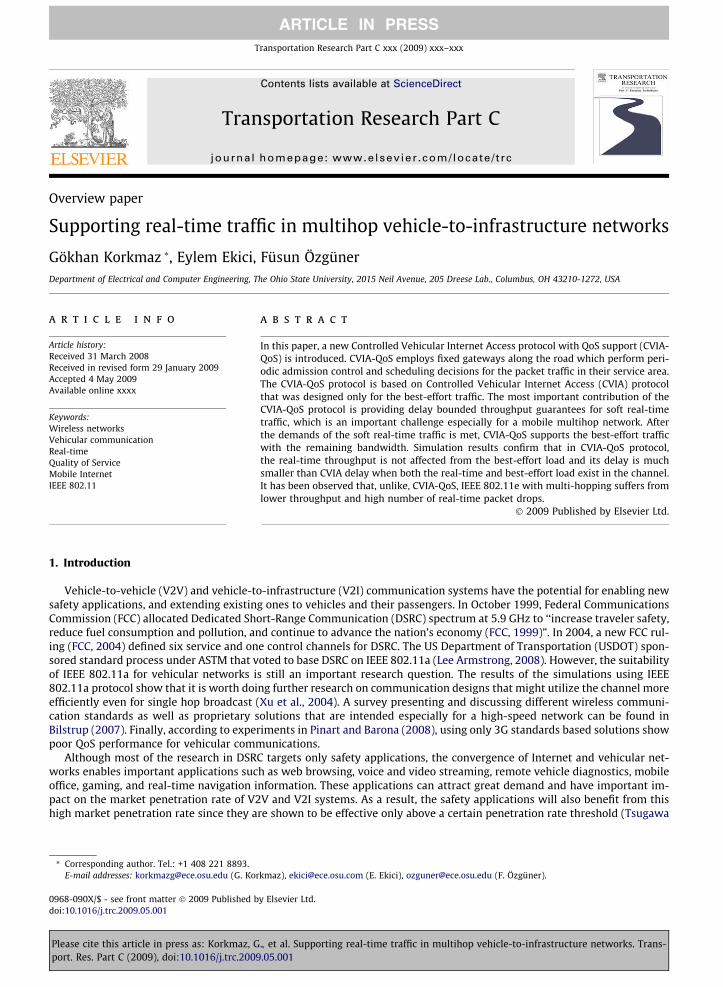
Overview paper Supporting real-time traffic in multihop vehicle-to-infrastructure networks Gökhan Korkmaz * , Eylem Ekici, Füsun Özgüner Department of Electrical and Computer Engineering, The Ohio State University, 2015 Neil Avenue, 205 Dreese Lab., Columbus, OH 43210-1272, USA article info Article history: Received 31 March 2008 Received in revised form 29 January 2009 Accepted 4 May 2009 Available online xxxx Keywords: Wireless networks Vehicular communication Real-time Quality of Service Mobile Internet IEEE 802.11 abstract In this paper, a new Controlled Vehicular Internet Access protocol with QoS support (CVIA- QoS) is introduced. CVIA-QoS employs fixed gateways along the road which perform peri- odic admission control and scheduling decisions for the packet traffic in their service area. The CVIA-QoS protocol is based on Controlled Vehicular Internet Access (CVIA) protocol that was designed only for the best-effort traffic. The most important contribution of the CVIA-QoS protocol is providing delay bounded throughput guarantees for soft real-time traffic, which is an important challenge especially for a mobile multihop network. After the demands of the soft real-time traffic is met, CVIA-QoS supports the best-effort traffic with the remaining bandwidth. Simulation results confirm that in CVIA-QoS protocol, the real-time throughput is not affected from the best-effort load and its delay is much smaller than CVIA delay when both the real-time and best-effort load exist in the channel. It has been observed that, unlike, CVIA-QoS, IEEE 802.11e with multi-hopping suffers from lower throughput and high number of real-time packet drops. Ó 2009 Published by Elsevier Ltd. 1. Introduction Vehicle-to-vehicle (V2V) and vehicle-to-infrastructure (V2I) communication systems have the potential for enabling new safety applications, and extending existing ones to vehicles and their passengers. In October 1999, Federal Communications Commission (FCC) allocated Dedicated Short-Range Communication (DSRC) spectrum at 5.9 GHz to ‘‘increase traveler safety, reduce fuel consumption and pollution, and continue to advance the nation’s economy (FCC, 1999)”. In 2004, a new FCC rul- ing (FCC, 2004) defined six service and one control channels for DSRC. The US Department of Transportation (USDOT) spon- sored standard process under ASTM that voted to base DSRC on IEEE 802.11a (Lee Armstrong, 2008). However, the suitability of IEEE 802.11a for vehicular networks is still an important research question. The results of the simulations using IEEE 802.11a protocol show that it is worth doing further research on communication designs that might utilize the channel more efficiently even for single hop broadcast (Xu et al., 2004). A survey presenting and discussing different wireless communi- cation standards as well as proprietary solutions that are intended especially for a high-speed network can be found in Bilstrup (2007). Finally, according to experiments in Pinart and Barona (2008), using only 3G standards based solutions show poor QoS performance for vehicular communications. Although most of the research in DSRC targets only safety applications, the convergence of Internet and vehicular net- works enables important applications such as web browsing, voice and video streaming, remote vehicle diagnostics, mobile office, gaming, and real-time navigation information. These applications can attract great demand and have important im- pact on the market penetration rate of V2V and V2I systems. As a result, the safety applications will also benefit from this high market penetration rate since they are shown to be effective only above a certain penetration rate threshold (Tsugawa 0968-090X/$ - see front matter Ó 2009 Published by Elsevier Ltd. doi:10.1016/j.trc.2009.05.001 * Corresponding author. Tel.: +1 408 221 8893. E-mail addresses: [email protected] (G. Korkmaz), [email protected] (E. Ekici), [email protected] (F. Özgüner). Transportation Research Part C xxx (2009) xxx–xxx Contents lists available at ScienceDirect Transportation Research Part C journal homepage: www.elsevier.com/locate/trc ARTICLE IN PRESS Please cite this article in press as: Korkmaz, G., et al. Supporting real-time traffic in multihop vehicle-to-infrastructure networks. Trans- port. Res. Part C (2009), doi:10.1016/j.trc.2009.05.001
-
Upload
independent -
Category
Documents
-
view
2 -
download
0
Transcript of Supporting real-time traffic in multihop vehicle-to-infrastructure networks
Transportation Research Part C xxx (2009) xxx–xxx
ARTICLE IN PRESS
Contents lists available at ScienceDirect
Transportation Research Part C
journal homepage: www.elsevier .com/locate / t rc
Overview paper
Supporting real-time traffic in multihop vehicle-to-infrastructure networks
Gökhan Korkmaz *, Eylem Ekici, Füsun ÖzgünerDepartment of Electrical and Computer Engineering, The Ohio State University, 2015 Neil Avenue, 205 Dreese Lab., Columbus, OH 43210-1272, USA
a r t i c l e i n f o
Article history:Received 31 March 2008Received in revised form 29 January 2009Accepted 4 May 2009Available online xxxx
Keywords:Wireless networksVehicular communicationReal-timeQuality of ServiceMobile InternetIEEE 802.11
0968-090X/$ - see front matter � 2009 Published bdoi:10.1016/j.trc.2009.05.001
* Corresponding author. Tel.: +1 408 221 8893.E-mail addresses: [email protected] (G. Kor
Please cite this article in press as: Korkmaz, Gport. Res. Part C (2009), doi:10.1016/j.trc.2009
a b s t r a c t
In this paper, a new Controlled Vehicular Internet Access protocol with QoS support (CVIA-QoS) is introduced. CVIA-QoS employs fixed gateways along the road which perform peri-odic admission control and scheduling decisions for the packet traffic in their service area.The CVIA-QoS protocol is based on Controlled Vehicular Internet Access (CVIA) protocolthat was designed only for the best-effort traffic. The most important contribution of theCVIA-QoS protocol is providing delay bounded throughput guarantees for soft real-timetraffic, which is an important challenge especially for a mobile multihop network. Afterthe demands of the soft real-time traffic is met, CVIA-QoS supports the best-effort trafficwith the remaining bandwidth. Simulation results confirm that in CVIA-QoS protocol,the real-time throughput is not affected from the best-effort load and its delay is muchsmaller than CVIA delay when both the real-time and best-effort load exist in the channel.It has been observed that, unlike, CVIA-QoS, IEEE 802.11e with multi-hopping suffers fromlower throughput and high number of real-time packet drops.
� 2009 Published by Elsevier Ltd.
1. Introduction
Vehicle-to-vehicle (V2V) and vehicle-to-infrastructure (V2I) communication systems have the potential for enabling newsafety applications, and extending existing ones to vehicles and their passengers. In October 1999, Federal CommunicationsCommission (FCC) allocated Dedicated Short-Range Communication (DSRC) spectrum at 5.9 GHz to ‘‘increase traveler safety,reduce fuel consumption and pollution, and continue to advance the nation’s economy (FCC, 1999)”. In 2004, a new FCC rul-ing (FCC, 2004) defined six service and one control channels for DSRC. The US Department of Transportation (USDOT) spon-sored standard process under ASTM that voted to base DSRC on IEEE 802.11a (Lee Armstrong, 2008). However, the suitabilityof IEEE 802.11a for vehicular networks is still an important research question. The results of the simulations using IEEE802.11a protocol show that it is worth doing further research on communication designs that might utilize the channel moreefficiently even for single hop broadcast (Xu et al., 2004). A survey presenting and discussing different wireless communi-cation standards as well as proprietary solutions that are intended especially for a high-speed network can be found inBilstrup (2007). Finally, according to experiments in Pinart and Barona (2008), using only 3G standards based solutions showpoor QoS performance for vehicular communications.
Although most of the research in DSRC targets only safety applications, the convergence of Internet and vehicular net-works enables important applications such as web browsing, voice and video streaming, remote vehicle diagnostics, mobileoffice, gaming, and real-time navigation information. These applications can attract great demand and have important im-pact on the market penetration rate of V2V and V2I systems. As a result, the safety applications will also benefit from thishigh market penetration rate since they are shown to be effective only above a certain penetration rate threshold (Tsugawa
y Elsevier Ltd.
kmaz), [email protected] (E. Ekici), [email protected] (F. Özgüner).
., et al. Supporting real-time traffic in multihop vehicle-to-infrastructure networks. Trans-.05.001
2 G. Korkmaz et al. / Transportation Research Part C xxx (2009) xxx–xxx
ARTICLE IN PRESS
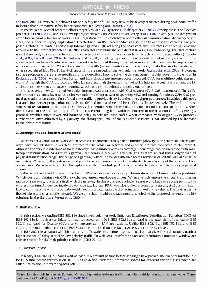
and Kato, 2003). However, it is shown that non-safety use of DSRC may have to be severly restricted during peak hours trafficto insure that automative safety is not compromised (Wang and Hassan, 2008).
In recent years, several research efforts target V2V and V2I systems (Hinsberger et al., 2007). Among these, the FleetNetproject (FLEETNET, 2008) and its follow-up project Network on Wheels (NoW) Festag et al. (2008) investigate the integrationof the Internet and vehicular networks. This integration requires mobility support, efficient communication, discovery of ser-vices, and support of legacy applications. FleetNet uses an IPv6 based addressing solution to address the vehicles. The pro-posed architecture contains stationary Internet gateways (IGW) along the road with two interfaces connecting vehicularnetworks to the Internet (Bechler et al., 2003). Vehicles communicate with distant IGWs via multi-hopping. This architectureis useful not only to connect vehicles to other networks but also to connect isolated vehicle groups to each other (Tchoutoet al., 2003; Baccelli et al., 2007). In Tsukada et al. (2008), a routing experiment is setup with simultaneously active multipleegress interfaces for each vehicle where a packet can be routed through internet or mobile ad-hoc network to improve net-work delay and bandwidth. When there are multiple APs (access points) exist in a network, hand-off is another study topicwhere specialized IEEE 802.11 hand-off algorithms are needed for the vehicular network (Giannoulis et al., 2008). However,in these proposals, there are no specific solutions describing how to solve the data movement problem over multiple hops. InKorkmaz et al. (2006), we introduced a fair and high-throughput internet access protocol, CVIA, for multihop vehicular net-works. Although the CVIA protocol provides fairness and high throughput for vehicular Internet access, it is not suitable forapplications like video and voice streaming which require throughput and delay guarantees.
In this paper, a new Controlled Vehicular Internet Access protocol with QoS support (CVIA-QoS) is proposed. The CVIA-QoS protocol is a cross-layer solution for vehicular multihop networks spanning MAC and routing functions. CVIA-QoS pro-tocol uses admission control for soft real-time traffic to provide delay bounded throughput guarantees. To achieve this goal,fast and slow packet propagation methods are defined for real-time and best-effort traffic, respectively. The real-time ses-sions send registration requests to the gateways that perform scheduling and admission control decisions periodically. Afterthe demands of the soft real-time traffic is met, the remaining bandwidth is allocated to the best-effort traffic. CVIA-QoSprotocol provides much lower and bounded delay to soft real-time traffic when compared with original CVIA protocol.Furthermore, once admitted by a gateway, the throughput level of the real-time sessions is not affected by the increasein the best-effort traffic.
2. Assumptions and internet access model
We consider a vehicular network which accesses the Internet through fixed Internet gateways along the road. These gate-ways have two interfaces: a wireless interface for the vehicular network and another interface connected to the Internet.Although the wireless interface of these gateways has a limited wireless coverage, their range can be increased with mul-ti-hop communication. As a result, a gateway can communicate with a vehicle at a distance several times longer than itsphysical transmission range. The range of a gateway where it provides Internet access service is called the virtual transmis-sion radius. We assume that gateways send periodic service announcements to indicate the availability of the service in theirservice area. We also assume that the uplink and the downlink packets are transmitted over two frequency separatedchannels.
Vehicles are assumed to be equipped with GPS devices used for time synchronization and obtaining vehicle positions.Vehicle positions obtained via GPS are exchanged among one-hop neighbors. When a vehicle enters the virtual transmissionradius of a gateway, it registers itself with the gateway. In this work, each vehicle is assumed to have one access point to thewireless medium. All devices inside the vehicle (e.g., laptops, PDAs, vehicle’s onboard computer, sensors, etc.) use this inter-face to communicate with the outside world, creating an aggregated traffic going in and out of the vehicle. The devices insidethe vehicle establish a mobile network. We assume that mobility management is handled by the proposed network mobilitysolutions in the literature Perera et al. (2004).
3. IEEE 802.11e
In this section, we outline IEEE 802.11e since in vehicular network, Enhanced Distributed Coordination Function (EDCF) ofIEEE 802.11e is the first candidate for Internet access with QoS. IEEE 802.11e standard is the extension of the legacy IEEE802.11 standard for Quality of Service enhancements in LAN applications. Unlike IEEE 802.11b, IEEE 802.11a, and IEEE802.11g, the main enhancement in IEEE 802.11e is proposed for the Media Access Control (MAC) layer.
In IEEE 802.11e, a station with high priority traffic waits less before it sends its packet that gives the high priority traffic ahigher chance of being sent than low priority traffic. To wait less, interframe space and maximum contention window arechosen shorter for the high priority traffic in IEEE 802.11e.
3.1. Interframe space
In legacy IEEE 802.11, all nodes wait at least DIFS amount of time before sending a new packet. The channel must be idlefor DIFS time before transmission. IEEE 802.11e defines different interframe spaces for different traffic classes which arecalled Arbitration Interframe Spaces (AIFS):
Please cite this article in press as: Korkmaz, G., et al. Supporting real-time traffic in multihop vehicle-to-infrastructure networks. Trans-port. Res. Part C (2009), doi:10.1016/j.trc.2009.05.001
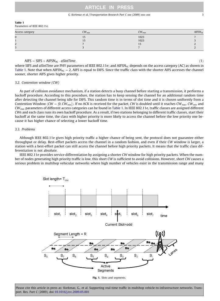
Table 1Parameters of IEEE 802.11e.
Access category CWmin CWmax AIFSNAC
0 15 1023 71 15 1023 32 7 15 23 3 7 2
G. Korkmaz et al. / Transportation Research Part C xxx (2009) xxx–xxx 3
ARTICLE IN PRESS
Pleaseport. R
AIFS ¼ SIFSþ AIFSNAC � aSlotTime; ð1Þ
where SIFS and aSlotTime are PHY parameters of IEEE 802.11e; and AIFSNAC depends on the access category (AC) as shown inTable 1. Note that when AIFSNAC ¼ 2, AIFS is equal to DIFS. Since the traffic class with the shorter AIFS accesses the channelsooner, shorter AIFS gives higher priority.3.2. Contention window (CW)
As part of collision avoidance mechanism, if a station detects a busy channel before starting a transmission, it performs abackoff procedure. According to this procedure, the station has to keep sensing the channel for an additional random timeafter detecting the channel being idle for DIFS. This random time is in terms of slot time and it is chosen uniformly from aContention Window ðCW ¼ ½0;CWmin�Þ. If no ACK is received for the packet, CW is doubled until it reaches CWmax. CWmin andCWmax parameters of different access categories can be found in Table 1. In IEEE 802.11e, traffic classes are assigned differentCWs and each class runs its own backoff procedure. As a result, if two stations belonging to different traffic classes, start theirbackoff at the same time, the class with higher priority is more likely to access the channel before the low priority one be-cause it has higher chance of selecting a lower backoff time.
3.3. Problems
Although IEEE 802.11e gives high priority traffic a higher chance of being sent, the protocol does not guarantee eitherthroughput or delay. Best-effort packets access the channel in a random fashion, and even if their CW window is larger, astation with a best-effort packet can still access the channel before high priority packets. It means that the traffic class dif-ferentiation is not absolute.
IEEE 802.11e provides service differentiation by assigning a shorter CW window for high priority packets. When the num-ber of nodes generating high priority traffic is low, this short CW is sufficient to avoid collisions. However, short CW causes aserious problem in multihop vehicular networks where high number of vehicles exist in the transmission range and many
Fig. 1. Slots and segments.
cite this article in press as: Korkmaz, G., et al. Supporting real-time traffic in multihop vehicle-to-infrastructure networks. Trans-es. Part C (2009), doi:10.1016/j.trc.2009.05.001

4 G. Korkmaz et al. / Transportation Research Part C xxx (2009) xxx–xxx
ARTICLE IN PRESS
vehicles are hidden to the communicating vehicle pairs. Consequently, there can be hundreds of vehicles which can interferewith the communication leading to a high number of collisions and low throughput for IEEE 802.11e.
4. Controlled Internet Access Protocol (Korkmaz et al., 2006)
In this section, we present the CVIA protocol on which our proposed CVIA-QoS protocol is based. CVIA is a cross-layercommunication protocol for vehicular internet access along highways. The protocol functions span MAC and network layers.The objective of the protocol is to increase the end-to-end throughput while achieving fairness in bandwidth usage between roadsegments for the best-effort traffic. The CVIA protocol aims to solve two main problems of IEEE 802.11 protocol in multi-hop-ping along a highway: low throughput and starvation of packets originating from vehicles far away from gateways.
The CVIA protocol forms temporary single hop clusters to mitigate the hidden node problem as it is unlikely for a vehicleto be a hidden node for a transmission between two vehicles in a single hop vehicle cluster. To form these clusters, the time isdivided into slots and the service areas of the gateways are divided into segments as shown in Fig. 1. In each time slot, theCVIA protocol allows transmissions only in the segments which are far away from each other, i.e., the transmission in onesegment does not interfere with the transmissions in the other active segments. To allow transmissions occur in all seg-ments, the active segments are switched periodically and a new set of segments becomes active in every time slot. Sincethe active segments do not interfere with each other, there is not a theoretically limit for the number of hops. However,increasing the number of hops increases the delay in the network.
The packet traffic is controlled by designated vehicles in segments called the temporary routers (TR) as shown in Fig. 2. Ineach time slot, the temporary router which is responsible for the outbound traffic receives packets originating from othersegments and local packets from its own segment. At the end of the time slot, all packets are moved out to the next segmenttogether without contention.
4.1. Definitions
(i) Communication range R: The physical transmission range of the vehicles as well as the gateway.(ii) Virtual transmission radius (VTR): The radius of the service area of the gateway where it provides Internet access
service.(iii) Segment iðSiÞ: Fixed section of VTR of length R. The segment closest to the gateway is denoted by S1.(iv) VTR length N: The number of segments in VTR of a gateway.(v) Time slot j ðTSjÞ: Time duration of length Tslot .
(vi) Neighboring segment Siþ: The neighboring segment in the direction of packet dissemination. Siþ is the neighboring seg-ment of Si closer to the gateway in the uplink channel and the neighboring segment of Si farther away from the gate-way in the downlink channel.
(vii) Neighboring segment Si�: The neighboring segment in the opposite direction of the packet dissemination.
(viii) Interference parameter (r): r ¼ interference rangeR
l mþ 1.
(ix) Active segment: Segments where vehicle communication is allowed to occur in a time slot. Si is active in TSj if ði mod rÞequals to ðj mod rÞ. Note that there are r � 1 inactive segments between two active segments according to the activesegment definition. In Fig. 1, when the current time slot is T5 and r ¼ 2, segments S1; S3; S5, and S7 become active. Inthis example, when segment i ðSiÞ is active, its two neighboring segments ðSi�; SiþÞ become inactive. In the next timeslot ðTSjþ1Þ, all segments change states where inactive segments become active and active segments become inactive.
Fig. 2. Packet movement types.
Please cite this article in press as: Korkmaz, G., et al. Supporting real-time traffic in multihop vehicle-to-infrastructure networks. Trans-port. Res. Part C (2009), doi:10.1016/j.trc.2009.05.001

G. Korkmaz et al. / Transportation Research Part C xxx (2009) xxx–xxx 5
ARTICLE IN PRESS
(x) Outbound temporary router ðTRouti Þ: In active segments, the packets are gathered in vehicles closest to the segment bor-
der in the direction of packet dissemination. The vehicle where the relayed packets are collected is called outboundtemporary router.
(xi) Inbound temporary router ðTRini Þ: At the end of an active time slot, TRout
i� moves the packets to Si. In Si, the vehicle whichreceives all packets from Si� is called inbound temporary router.
(xii) Packet train: It is a method where several packets are sent with only one RTS/CTS handshake among the same sourceand destination pair.
4.2. Packet movement types
CVIA employs two vehicles as temporary routers in each active segment i: TRouti and TRin
i . All packets entering a segmentgo through TRin
i and all packets leaving the segment go through TRouti . We choose TRin
i as the closest vehicle to Si� and TRouti as
the closest vehicle to Siþ. The CVIA protocol uses three types of packet movements as shown in Fig. 2:
1. TRini delivers the packet train originating from other segments to TRout
i .2. Local packets of the segment is gathered by TRout
i .3. TRout
i creates a new train using packets received in (1) and (2), and sends it to TRiniþ in Siþ.
4.3. Protocol phases
4.3.1. Inactive phaseVehicles in inactive segments do not access the channel. Inactive and active segments are determined using the slot num-
ber i and segment number j, i.e. Si is active when ði mod rÞ ¼ ðj mod rÞ. Vehicles compute i and j as follows: i ¼ DdR
� �, and
j ¼ DtTslot
j k, where Dd is the distance of the vehicle to the gateway and Dt is the time passed since an absolute reference point,
e.g., 12:00 pm. Note that vehicles obtain their positions and synchronize their clocks using GPS. The vehicles learn the posi-tions of gateways from a digital road map database or the service announcement packets broadcast periodically by gateways.
4.3.2. Temporary router selection phaseAt the beginning of each time slot, next temporary routers are selected by TRins. Since the topology of the vehicular net-
work changes fast, new temporary routers must be selected periodically. The selected routers are called TRouti;next and TRin
i;next
until they become active. TRouti;next and TRin
i;next must stay inside the segment for an amount of time called the router lifetime;therefore, they should be away from the segment borders by a certain distance. The details of the temporary router selectionphase is presented in Korkmaz et al. (2006).
4.3.3. Intra-segment packet train movement phaseTRin
i starts delivering the packet train received from Si� in the previous slots to TRouti . To avoid contention, TRin
i has thehighest access priority and waits only SIFS duration before accessing the channel.
4.3.4. Local packet gathering phaseAfter the intra-segment packet train movement ends, the channel becomes idle for DIFS duration and vehicles access the
channel using a contention based channel access scheme. In this local packet gathering phase, vehicles employ the DCFmethod of the IEEE 802.11 standard. Each node has the same priority and they directly send their packets to TRout
i . To de-crease the number of collisions, each vehicle starts this packet gathering phase with a random backoff counter.
4.3.5. Inter-segment packet train movement phaseTRout
i has the highest channel access priority among the vehicles in the LPG phase. When time left in the active slot is justenough to move out packets in the queues, TRout
i accesses the channel and ends the LPG phase. The new packet train is movedto TRin
iþ before the end of TSj. Note that all the packets pass through S1. Therefore, each TRouti can send out at most
ðC=NÞ � ðN � iþ 1Þ packets where C is the capacity of the protocol. These packets are buffered in TRiniþ until Siþ becomes active.
5. CVIA-QoS
In Korkmaz et al. (2006), it is shown through simulations that CVIA has up to 80% higher end-to-end throughput capacitywhen compared with the IEEE 802.11 protocol. In addition, the CVIA protocol distributes the throughput fairly among seg-ments while the vehicles far away from the gateway suffer from starvation under the IEEE 802.11 protocol. Although CVIA isa successful communication protocol for the best-effort traffic, it is not suitable for real-time applications. In CVIA, the pack-ets experience high delays that is directly proportional to the number of segments in the virtual transmission range as pack-ets move only one segment in each time slot. In addition, due to lack of an admission control mechanism, the protocol cannotprovide guaranteed throughput to real-time sessions.
Because of the shortcomings of the existing protocols, a new protocol, CVIA-QoS, is designed to provide throughput guar-antees and fixed delay bound to soft real-time applications like voice and video streaming in linear vehicular networks. The
Please cite this article in press as: Korkmaz, G., et al. Supporting real-time traffic in multihop vehicle-to-infrastructure networks. Trans-port. Res. Part C (2009), doi:10.1016/j.trc.2009.05.001

6 G. Korkmaz et al. / Transportation Research Part C xxx (2009) xxx–xxx
ARTICLE IN PRESS
best-effort traffic is handled with the remaining bandwidth after allocating resources for real-time traffic. In CVIA-QoS, onetime slot is divided into two periods, namely high priority period (HPP) and low priority period (LPP). Unlike the CVIA pro-tocol, packets admitted to HPP is delivered to the gateway in one time slot. Furthermore, an admission control mechanism isintroduced where admission decisions are made by the gateways and executed by the temporary routers.
5.1. Phases in the CVIA-QoS protocol
In CVIA-QoS, time is divided into slots of Tslot . Each time slot is composed of high priority and low priority periods asshown in Fig. 3. At the beginning of the HPP, sessions that request service in HPP send registration packets to outboundtemporary routers. Once these requests are collected in all segments, they are delivered to the gateway. To grant end-to-end throughput guarantees to sessions, the gateway uses the information about the new session requests, buffer statusof the temporary routers and the information about already active sessions. The session admission decisions and timeallocations for different phases in the time slot are sent to temporary routers. Temporary routers poll the vehicles thatare granted access. After the polling phase, the collected packets from all segments are propagated to the gateway inpacket trains in one time slot. Since the maximum length of LPP is Tslot , the network delay of the packets admittedto HPP are bounded by Tslot . In the remaining time, the original CVIA protocol is used to serve the best-effort trafficin LPP.
In this section, the phases inside the HPP and LPP periods are explained in detail. Moreover, computing the length of theHPP phase is discussed in Section 5.2.
5.1.1. High priority period5.1.1.1. Registration phase. Vehicles with new real-time sessions and vehicles with active sessions that enter a new segmentsend short registration packets to TRouts using IEEE 802.11 protocol without RTS/CTS handshakes. Inside the registrationpackets, vehicles send:
1. Source ID.2. Session ID.3. Session Lifetime (SLT).4. Minimum acceptable throughput.5. Maximum throughput.
Gateways use the minimum acceptable throughput to grant admission to the session. However, if there is more BW avail-able in a slot, more packets from the session up to maximum throughput can also be scheduled. Session Lifetime is the ex-pected active time of a session. The gateway may grant a session time less than SLT. However, sessions can piggybacknew requests in their data packets if they need more time in a contention free manner.
Vehicles start the phase with preset random backoff counters to decrease the probability of packet collisions at the begin-ning. If a registration packet is received successfully by TRout , an ACK packet is sent to the vehicle. To mitigate the hiddennode problem, fixed length sub-phases are defined in the registration phase. In each sub-phase, a new set of segments be-come active to send registration packets. Segment i becomes active in sub-phase k if i mod r ¼ k mod r. There arer � 1 ¼ interferencerange
R
l minactive segments between two active segments. As a result, after r sub-phases, all segments will have
become active once. Registration sub-phases are depicted in Fig. 4 for r = 2. In this figure, registration packets are sent in par-allel in active segments and registration phase is composed of two sub-phases.
Fig. 3. Phases in the CVIA-QoS protocol.
Please cite this article in press as: Korkmaz, G., et al. Supporting real-time traffic in multihop vehicle-to-infrastructure networks. Trans-port. Res. Part C (2009), doi:10.1016/j.trc.2009.05.001

Fig. 4. Sub-phases of registration and polling phases. Note that activity rules of the segments are same for both registration and polling phases.
G. Korkmaz et al. / Transportation Research Part C xxx (2009) xxx–xxx 7
ARTICLE IN PRESS
5.1.2. Control phaseAfter the Registration Phase, a control packet train is initiated by the furthest TRout . Control trains are forwarded by only
TRouts and TRins during their propagation as shown in Fig. 5. Each TRout includes the new high priority session requests andeach TRin includes the number of low priority packets in its buffer. Based on this new information and the information aboutthe existing active sessions, the gateway makes scheduling and admission control decisions as described in Section 5.3. In thesecond control train, the schedules are sent from the gateway to all TRs. In this control train originating from the gateway,the lengths of all phases and sub-phases until the end of the current time slot are announced. The fixed length and variablelength phases are shown in Fig. 3.
5.1.3. Polling phaseBased on the schedule received from the gateway, TRouts poll the vehicles with active sessions. In response to polling,
vehicles send their data packets. Acknowledgments to data packets are piggy-backed in the polling packets by TRouts. Similarto the Registration Phase, r polling sub-phases are employed to mitigate the hidden node problem in the polling phase. Thelength of the polling phase depends admitted real-time packets, the number of segments in the virtual transmission range,and r. Polling sub-phases are shown in Fig. 4 for r = 2 which is the same figure used to depict the registration sub-phases.Since the number of packets scheduled in each segment can be different, the active segment which needs the longest time(highest number of packets) determines the length of the current sub-phase. As a result, sub-phase lengths are not fixed inpolling phase unlike registration phase.
5.1.4. Propagation phaseIn the propagation phase, high priority packets collected by TRouts are moved towards the gateway in fast packet trains.
The packet trains are initiated in parallel by segments fSi; Siþr ; Siþ2r ; . . . ; Skg, where 1 6 i 6 r and k 6 N. This phase is also com-posed of several sub-phases. Segment i becomes active in sub-phase m if i mod r ¼ m mod r.
When Si becomes active, the fast train originating from Si� is moved to TRouti . Then, all local packets collected in the seg-
ment are attached to the packet train. At the end of each sub-phase, TRouti sends the packet train to TRout
iþ in the next segment.With this approach, all polled packets are delivered to the gateway in one time slot. As a result, network delay experiencedby real-time packets admitted to HPP is bounded by Tslot . As in polling phase, the length of the propagation phase depends onadmitted real-time traffic, the number of segments in the virtual transmission range and r.
Fig. 6 depicts the packet movement in propagation sub-phases. After the first sub-phase, packets from two segmentsmerge in one train and start moving together in parallel with other high priority trains. Since it takes N steps for the packetsfrom the furthest away segment to reach to the gateway, there are N sub-phases in each propagation phase.
Fig. 5. Control phase: control packet visits all the temporary routers. Encircled vehicles are temporary routers.
Please cite this article in press as: Korkmaz, G., et al. Supporting real-time traffic in multihop vehicle-to-infrastructure networks. Trans-port. Res. Part C (2009), doi:10.1016/j.trc.2009.05.001
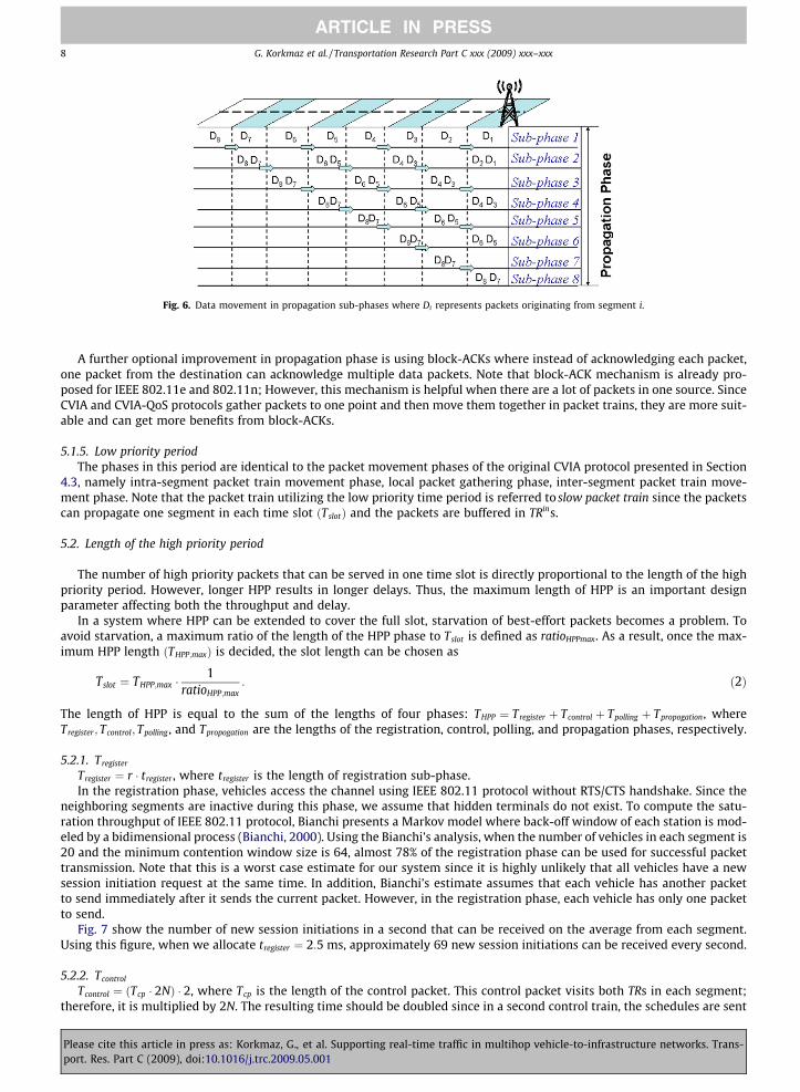
Fig. 6. Data movement in propagation sub-phases where Di represents packets originating from segment i.
8 G. Korkmaz et al. / Transportation Research Part C xxx (2009) xxx–xxx
ARTICLE IN PRESS
A further optional improvement in propagation phase is using block-ACKs where instead of acknowledging each packet,one packet from the destination can acknowledge multiple data packets. Note that block-ACK mechanism is already pro-posed for IEEE 802.11e and 802.11n; However, this mechanism is helpful when there are a lot of packets in one source. SinceCVIA and CVIA-QoS protocols gather packets to one point and then move them together in packet trains, they are more suit-able and can get more benefits from block-ACKs.
5.1.5. Low priority periodThe phases in this period are identical to the packet movement phases of the original CVIA protocol presented in Section
4.3, namely intra-segment packet train movement phase, local packet gathering phase, inter-segment packet train move-ment phase. Note that the packet train utilizing the low priority time period is referred to slow packet train since the packetscan propagate one segment in each time slot ðTslotÞ and the packets are buffered in TRins.
5.2. Length of the high priority period
The number of high priority packets that can be served in one time slot is directly proportional to the length of the highpriority period. However, longer HPP results in longer delays. Thus, the maximum length of HPP is an important designparameter affecting both the throughput and delay.
In a system where HPP can be extended to cover the full slot, starvation of best-effort packets becomes a problem. Toavoid starvation, a maximum ratio of the length of the HPP phase to Tslot is defined as ratioHPPmax. As a result, once the max-imum HPP length ðTHPP;maxÞ is decided, the slot length can be chosen as
Pleaseport. R
Tslot ¼ THPP;max �1
ratioHPP;max: ð2Þ
The length of HPP is equal to the sum of the lengths of four phases: THPP ¼ Tregister þ Tcontrol þ Tpolling þ Tpropogation, whereTregister; Tcontrol; Tpolling , and Tpropogation are the lengths of the registration, control, polling, and propagation phases, respectively.
5.2.1. Tregister
Tregister ¼ r � tregister , where tregister is the length of registration sub-phase.In the registration phase, vehicles access the channel using IEEE 802.11 protocol without RTS/CTS handshake. Since the
neighboring segments are inactive during this phase, we assume that hidden terminals do not exist. To compute the satu-ration throughput of IEEE 802.11 protocol, Bianchi presents a Markov model where back-off window of each station is mod-eled by a bidimensional process (Bianchi, 2000). Using the Bianchi’s analysis, when the number of vehicles in each segment is20 and the minimum contention window size is 64, almost 78% of the registration phase can be used for successful packettransmission. Note that this is a worst case estimate for our system since it is highly unlikely that all vehicles have a newsession initiation request at the same time. In addition, Bianchi’s estimate assumes that each vehicle has another packetto send immediately after it sends the current packet. However, in the registration phase, each vehicle has only one packetto send.
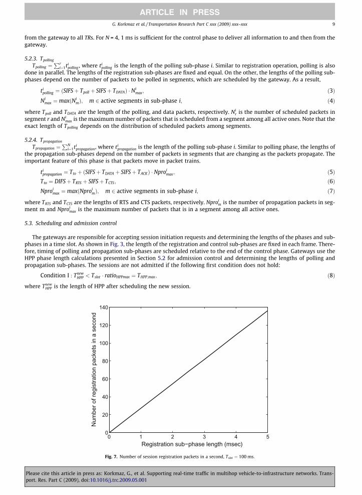
Fig. 7 show the number of new session initiations in a second that can be received on the average from each segment.Using this figure, when we allocate tregister ¼ 2:5 ms, approximately 69 new session initiations can be received every second.
5.2.2. Tcontrol
Tcontrol ¼ ðTcp � 2NÞ � 2, where Tcp is the length of the control packet. This control packet visits both TRs in each segment;therefore, it is multiplied by 2N. The resulting time should be doubled since in a second control train, the schedules are sent
cite this article in press as: Korkmaz, G., et al. Supporting real-time traffic in multihop vehicle-to-infrastructure networks. Trans-es. Part C (2009), doi:10.1016/j.trc.2009.05.001
G. Korkmaz et al. / Transportation Research Part C xxx (2009) xxx–xxx 9
ARTICLE IN PRESS
from the gateway to all TRs. For N = 4, 1 ms is sufficient for the control phase to deliver all information to and then from thegateway.
5.2.3. Tpolling
Tpolling ¼Pr
i¼1tipolling , where ti
polling is the length of the polling sub-phase i. Similar to registration operation, polling is alsodone in parallel. The lengths of the registration sub-phases are fixed and equal. On the other, the lengths of the polling sub-phases depend on the number of packets to be polled in segments, which are scheduled by the gateway. As a result,
Pleaseport. R
tipolling ¼ ðSIFSþ Tpoll þ SIFSþ TDATAÞ � Ni
max; ð3ÞNi
max ¼ maxðNimÞ; m 2 active segments in sub-phase i; ð4Þ
where Tpoll and TDATA are the length of the polling, and data packets, respectively. Nir is the number of scheduled packets in
segment r and Nimax is the maximum number of packets that is scheduled from a segment among all active ones. Note that the
exact length of Tpolling depends on the distribution of scheduled packets among segments.
5.2.4. Tpropagation
Tpropagation ¼PN
i¼1tipropagation, where ti
propagation is the length of the polling sub-phase i. Similar to polling phase, the lengths ofthe propagation sub-phases depend on the number of packets in segments that are changing as the packets propagate. Theimportant feature of this phase is that packets move in packet trains.
tipropagation ¼ Tto þ ðSIFSþ TDATA þ SIFSþ TACKÞ � Nproi
max; ð5ÞTto ¼ DIFSþ TRTS þ SIFSþ TCTS; ð6ÞNproi
max ¼ maxðNproimÞ; m 2 active segments in sub-phase i; ð7Þ
where TRTS and TCTS are the lengths of RTS and CTS packets, respectively. Nproim is the number of propagation packets in seg-
ment m and Nproimax is the maximum number of packets that is in a segment among all active ones.
5.3. Scheduling and admission control
The gateways are responsible for accepting session initiation requests and determining the lengths of the phases and sub-phases in a time slot. As shown in Fig. 3, the length of the registration and control sub-phases are fixed in each frame. There-fore, timing of polling and propagation sub-phases are scheduled relative to the end of the control phase. Gateways use theHPP phase length calculations presented in Section 5.2 for admission control and determining the lengths of polling andpropagation sub-phases. The sessions are not admitted if the following first condition does not hold:
Condition I : TnewHPP < Tslot � ratioHPPmax ¼ THPP;max; ð8Þ
where TnewHPP is the length of HPP after scheduling the new session.
0 1 2 3 4 50
20
40
60
80
100
120
140
Num
ber o
f reg
istra
tion
pack
ets
in a
sec
ond
Registration sub−phase length (msec)
Fig. 7. Number of session registration packets in a second, Tslot ¼ 100 ms.
cite this article in press as: Korkmaz, G., et al. Supporting real-time traffic in multihop vehicle-to-infrastructure networks. Trans-es. Part C (2009), doi:10.1016/j.trc.2009.05.001

10 G. Korkmaz et al. / Transportation Research Part C xxx (2009) xxx–xxx
ARTICLE IN PRESS
In addition to maximum length bound on HPP, the CVIA protocol introduces a bound on the maximum length of LPP. Themaximum ratio of the LPP to slot time is called Ratiomax. This bound also implies a bound on the minimum length of HPPwhich is 1� Ratiomax. Increasing the length of the LPP increases the number of new low priority packets accepted to the net-work. These packets are buffered in TRins; Therefore, the longer LPP, the higher the number of packets buffered in the net-work. Since the temporary routers are mobile and they change segments, packets cannot be buffered in temporary routerslonger than the routers’ lifetime beyond which they may leave their segments. Thus, in the CVIA-QoS, packets buffered in thenetwork are scheduled before accepting new real-time session requests. The buffered packets in the network decrease theresponse time of the protocol when a bursty real-time demand is encountered.
The response time is the price paid for not dropping any packets. As a result, low priority packets stored in TR buffersimpose a second condition, which can be more strict than condition in Eq. (8) for admission control:
Pleaseport. R
Condition II : TnewHPP < Tslot � TLPP;buffered; ð9Þ
where TLPP;buffered is the time it takes to schedule buffered low priority packets in LPP.As a result, the scheduling algorithm has four main steps:
1. Schedule already accepted high priority traffic: Packets of already accepted sessions are scheduled to HPP. With schedulingalready accepted traffic before accepting new requests, CVIA-QoS protocol satisfies the minimum throughput guaranteesgiven to real-time sessions in the previous slots.
2. Schedule low priority packets in the buffers of TRin s: since the CVIA-QoS protocol does not drop any packets once admittedto the network, the gateways allocate time for the buffered best-effort packets before the temporary routers leave thesegment. Buffered low priority packets that are admitted in the previous slots are scheduled to LPP. To achieve this sche-dule, a minimum time is allocated in intra-segment ðTintraÞ and inter-segment ðTinterÞ packet movement phases. In step 5, ifthere is still BW available for new best-effort packets, Tinter phase is extended.
3. Schedule packets from new sessions: After scheduling the packets of the existing sessions and buffered low priority packets,the gateway attempts to schedule new sessions if the following condition holds:
TnewHPP < minðTslot � TLPP;buffered; Tslot � ratioHPPmaxÞ: ð10Þ
If the THPP=Tslot < 1� ratiomax even after scheduling the new real-time packets, some of the best-effort packets alreadyscheduled to LPP are rescheduled to HPP until HPP reaches its minimum length=Tslot � ð1� RatiomaxÞ.
4. Schedule new best-effort packets : If there is still some remaining time in the current time slot, it is dedicated to new best-effort packets. To gather these new packets, TLPG amount of time is allocated to Local Packet Gathering Phase in LPP. Inaddition, enough time to move those packets to the next segment is added to Tinter whose details can be found in Korkmazet al. (2006). Note that if the real-time traffic is very high, no new best-effort packet is admitted to the network by settingTLPG ¼ 0 if the real-time demand exceeds the capacity of the time slot.
6. Performance evaluation
The performance of CVIA-QoS is assessed through simulations. In the simulation scenarios, simulated vehicles move on alinear highway segment with two lanes, one for each direction of traffic flow. Vehicles randomly enter the service area withexponentially distributed inter-arrival times. On the average, there are 34 vehicles/km per lane. Each vehicle is assigned aspeed from a Gaussian distribution with a mean of 90 km/h and standard deviation 5 km/h at the beginning of the simula-tion. The assigned speeds do not change during simulation. The common parameters of the simulations are: transmissionrange = 350 m, data rate = 27 Mbps, payload = 2000 or 500 bytes, base protocol = 802.11a (DSRC), Maximum number ofpacket retrials = 10, interference range to transmission range ratio = 1. The protocol parameters are: Tslot ¼ 100 ms; N ¼ 4or 8, and r ¼ 2. In IEEE 802.11e, AC = 0 and AC = 4 are used for the best-effort and real-time packets, respectively. Otherparameters of the MAC layer and the physical layer are taken from the ASTM E2213-02 standard document (DSRC, 2002).
To examine the effects of packet length and virtual transmission radius on the performance of the network, four differentscenarios are simulated and analyzed for various packet loads. The parameters for these scenarios are as follows: Scenario I:payload = 2000 bytes, VTR = 4R (N = 4), Scenario II: payload = 2000 bytes, VTR = 8R (N = 4), Scenario III: payload = 500 bytes,VTR = 4R (N = 4) and Scenario IV: payload = 500 bytes, VTR = 8R (N = 8).
6.1. Behavior of CVIA-QoS
In this section, the behavior of the CVIA-QoS protocol is examined for its HPP phase length, transient response delay, andthroughput capacity. In Section 6.2, the performance of the CVIA-QoS protocol is compared with CVIA and IEEE 802.11e pro-tocols in terms of throughput and delay.
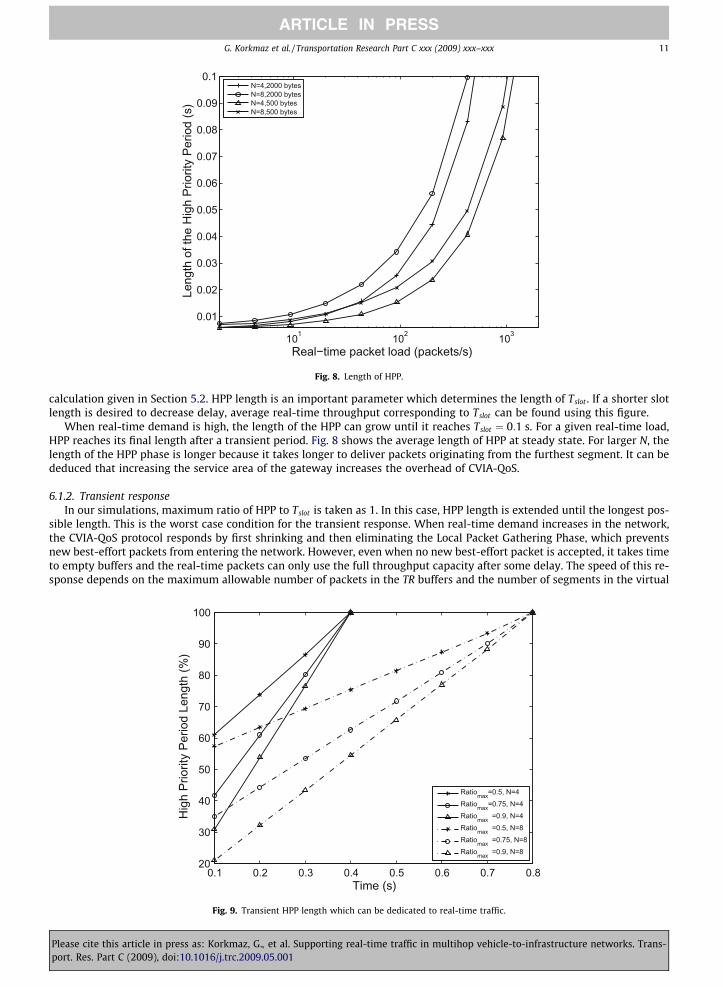
6.1.1. Length of HPPFig. 8 shows the length of the high priority period when the real-time packet demand is increased in the system. The gen-
erated real-time packets are distributed randomly to each vehicle and than the curves are obtained using the HPP length
cite this article in press as: Korkmaz, G., et al. Supporting real-time traffic in multihop vehicle-to-infrastructure networks. Trans-es. Part C (2009), doi:10.1016/j.trc.2009.05.001
101 102 103
0.01
0.02
0.03
0.04
0.05
0.06
0.07
0.08
0.09
0.1
Leng
th o
f the
Hig
h Pr
iorit
y Pe
riod
(s)
Real−time packet load (packets/s)
N=4,2000 bytesN=8,2000 bytesN=4,500 bytesN=8,500 bytes
Fig. 8. Length of HPP.
G. Korkmaz et al. / Transportation Research Part C xxx (2009) xxx–xxx 11
ARTICLE IN PRESS
calculation given in Section 5.2. HPP length is an important parameter which determines the length of Tslot . If a shorter slotlength is desired to decrease delay, average real-time throughput corresponding to Tslot can be found using this figure.
When real-time demand is high, the length of the HPP can grow until it reaches Tslot ¼ 0:1 s. For a given real-time load,HPP reaches its final length after a transient period. Fig. 8 shows the average length of HPP at steady state. For larger N, thelength of the HPP phase is longer because it takes longer to deliver packets originating from the furthest segment. It can bededuced that increasing the service area of the gateway increases the overhead of CVIA-QoS.
6.1.2. Transient responseIn our simulations, maximum ratio of HPP to Tslot is taken as 1. In this case, HPP length is extended until the longest pos-
sible length. This is the worst case condition for the transient response. When real-time demand increases in the network,the CVIA-QoS protocol responds by first shrinking and then eliminating the Local Packet Gathering Phase, which preventsnew best-effort packets from entering the network. However, even when no new best-effort packet is accepted, it takes timeto empty buffers and the real-time packets can only use the full throughput capacity after some delay. The speed of this re-sponse depends on the maximum allowable number of packets in the TR buffers and the number of segments in the virtual
0.1 0.2 0.3 0.4 0.5 0.6 0.7 0.820
30
40
50
60
70
80
90
100
Hig
h Pr
iorit
y Pe
riod
Leng
th (%
)
Time (s)
Ratiomax=0.5, N=4Ratiomax=0.75, N=4Ratiomax =0.9, N=4Ratiomax =0.5, N=8Ratiomax =0.75, N=8Ratiomax =0.9, N=8
Fig. 9. Transient HPP length which can be dedicated to real-time traffic.
Please cite this article in press as: Korkmaz, G., et al. Supporting real-time traffic in multihop vehicle-to-infrastructure networks. Trans-port. Res. Part C (2009), doi:10.1016/j.trc.2009.05.001
12 G. Korkmaz et al. / Transportation Research Part C xxx (2009) xxx–xxx
ARTICLE IN PRESS
transmission radius of the gateway. Fig. 9 shows the transient behavior of the length of the HPP that can be dedicated to real-time traffic. When the curve reaches 100%, it means that all of the bandwidth is dedicated to real-time packets.
In this analysis, the buffers of TRins are assumed to be full with best-effort packets before real-time traffic increases. Attime 0, the real-time demand is increased to the total protocol throughput capacity. Fig. 9 shows the HPP length percentagefor Scenario II and Scenario IV for different Ratiomax and N values after the increase in real-time load. It takes N � 1 time slotsto empty the buffers of the furthest TR. Hence, it takes longer to serve real-time traffic with full capacity when N is 8 in Sce-nario IV. Although response time to reach full capacity depends on N, the bandwidth that can be dedicated to real-time trafficbefore reaching the maximum capacity depends on Ratiomax value. In all Scenarios, when Ratiomax is higher, the length of HPPthat can be dedicated to real-time traffic becomes lower.
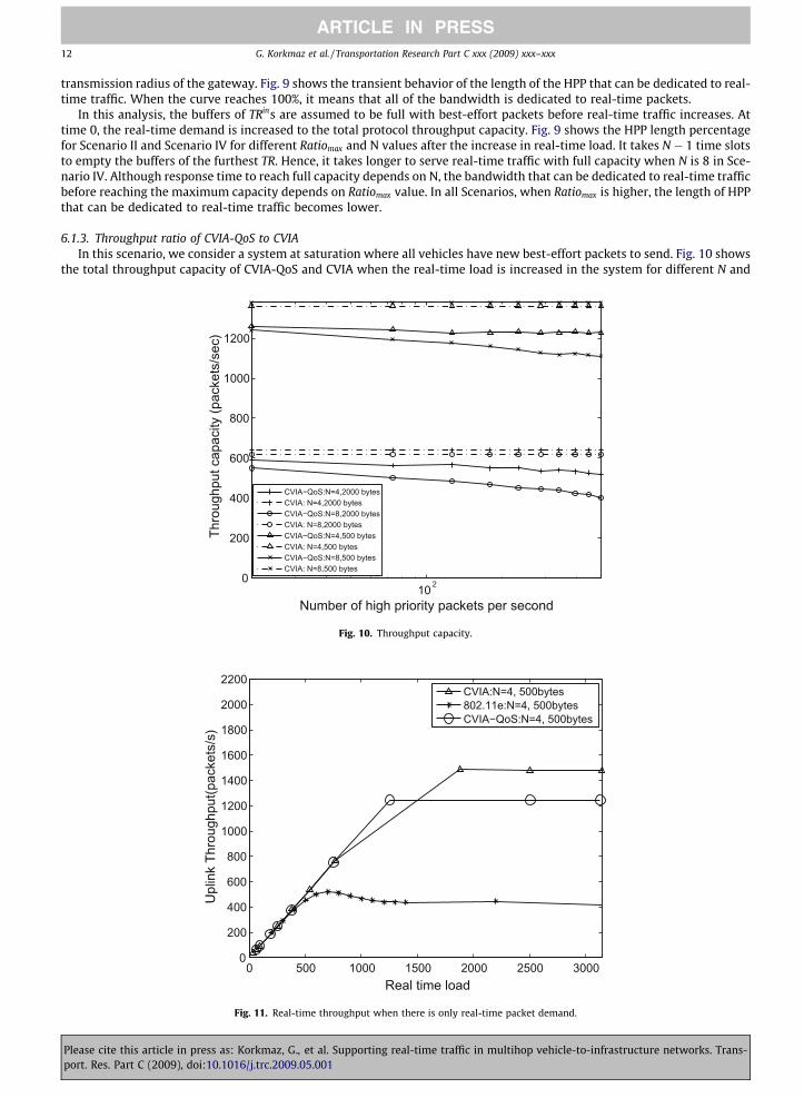
6.1.3. Throughput ratio of CVIA-QoS to CVIAIn this scenario, we consider a system at saturation where all vehicles have new best-effort packets to send. Fig. 10 shows
the total throughput capacity of CVIA-QoS and CVIA when the real-time load is increased in the system for different N and
10 20
200
400
600
800
1000
1200
Thro
ughp
ut c
apac
ity (p
acke
ts/s
ec)
Number of high priority packets per second
CVIA−QoS:N=4,2000 bytesCVIA: N=4,2000 bytesCVIA−QoS:N=8,2000 bytesCVIA: N=8,2000 bytesCVIA−QoS:N=4,500 bytesCVIA: N=4,500 bytesCVIA−QoS:N=8,500 bytesCVIA: N=8,500 bytes
Fig. 10. Throughput capacity.
0 500 1000 1500 2000 2500 30000
200
400
600
800
1000
1200
1400
1600
1800
2000
2200
Real time load
Upl
ink
Thro
ughp
ut(p
acke
ts/s
)
CVIA:N=4, 500bytes802.11e:N=4, 500bytesCVIA−QoS:N=4, 500bytes
Fig. 11. Real-time throughput when there is only real-time packet demand.
Please cite this article in press as: Korkmaz, G., et al. Supporting real-time traffic in multihop vehicle-to-infrastructure networks. Trans-port. Res. Part C (2009), doi:10.1016/j.trc.2009.05.001

G. Korkmaz et al. / Transportation Research Part C xxx (2009) xxx–xxx 13
ARTICLE IN PRESS
payload values. Throughput capacity of CVIA-QoS is always smaller than CVIA since CVIA-QoS protocol allocates some por-tion of its throughput to provide delay bounded throughput guarantees to real-time traffic. Any real-time packet admitted tothe system reserves bandwidth in segments on its path within the same time slot. As a result, when the N is high, the capac-ity of the system decreases for both payloads as shown in Fig. 10. When the real-time load is increased, more packets areserved in the HPP period leading to a decrease in the overall capacity of the system. As a result, since handling best-efforttraffic in HPP would result in decrease in total throughput, best-effort traffic is carried in LPP using CVIA guidelines.
6.2. Comparison of CVIA-QoS with CVIA and IEEE 802.11e
6.2.1. Throughput when no best-effort demand exist in the systemWhen no best-effort packet exists in the system, the throughput is only composed of real-time packets. As shown in
Fig. 11, the throughput curves of all three protocols increase linearly when the packet load is low. When the load is increasedfurther, the CVIA and CVIA-QoS protocols reach saturation points that are approximately three times the maximum
0 500 1000 1500 2000 2500 30000
500
1000
1500
2000
2500
3000
3500
4000
4500
Real time load
Dro
pped
Pac
ket R
ate
(pac
kets
/s)
CVIA:N=4, 500bytes802.11e:N=4, 500bytesCVIA−QoS:N=4, 500bytes
Fig. 12. Packet failure rate when there is only real-time packet demand.
0 500 1000 1500 2000 2500 30000
200
400
600
800
1000
1200
1400
1600
1800
2000
2200
Best effort load
Upl
ink
Thro
ughp
ut(p
acke
ts/s
)
CVIA:N=4, 500bytes802.11e:N=4, 500bytesCVIA−QoS:N=4, 500bytes
Fig. 13. Best effort throughput when there is only best-effort packet demand.
Please cite this article in press as: Korkmaz, G., et al. Supporting real-time traffic in multihop vehicle-to-infrastructure networks. Trans-port. Res. Part C (2009), doi:10.1016/j.trc.2009.05.001

14 G. Korkmaz et al. / Transportation Research Part C xxx (2009) xxx–xxx
ARTICLE IN PRESS
throughput of the IEEE 802.11e protocol. This figure shows that both CVIA and CVIA-QoS protocols use the channel moreefficiently than IEEE 802.11e protocol. This low IEEE 802.11e throughput is caused by small contention window of the highpriority packets which gives priority over low priority packets. However, when the real-time load is high, high priority pack-ets start to collide among each other. As a result, many packets are dropped in IEEE 802.11e as shown in Fig. 12. This highnumber of packet failures decreases the throughput of the IEEE 802.11e protocol.
6.2.2. Throughput when only best-effort demand exist in the systemFig. 13 shows the throughput curves of all three protocols when only the best-effort packets exist in the system. In this
scenario CVIA-QoS protocol operates very similar to the CVIA protocol, where, except the registration and control phases, theentire slot is dedicated to low priority traffic. As a result of this overhead, the throughput of CVIA-QoS becomes lower thanCVIA. The throughput of the 802.11e protocol is lower than the CVIA and CVIA-QoS. However, in this scenario, the number ofpacket failures are lower than the real-time load scenario as shown in Fig. 14.
0 500 1000 1500 2000 2500 30000
20
40
60
80
100
120
140
160
180
200
Best effort load
Dro
pped
Pac
ket R
ate
(pac
kets
/s)
CVIA:N=4, 500bytes802.11e:N=4, 500bytesCVIA−QoS:N=4, 500bytes
Fig. 14. Packet failure rate when there is only best-effort packet demand.
0 1000 2000 3000 4000 5000
50
100
150
200
250
300
350
Rea
l−tim
e Pa
cket
Thr
ough
put (
pack
ets/
s)
Best Effort Packet Load (packets/s)
CVIA−QoS:N=4,2000 bytesCVIA: N=4,2000 bytesCVIA−QoS:N=4,500 bytesCVIA: N=4,500 bytes802.11e:N=4,2000 bytes802.11e: N=4,500 bytes
Fig. 15. Real-time throughput in CVIA, CVIA-QoS and 802.11e protocols (real-time demand is 200 packets/s).
Please cite this article in press as: Korkmaz, G., et al. Supporting real-time traffic in multihop vehicle-to-infrastructure networks. Trans-port. Res. Part C (2009), doi:10.1016/j.trc.2009.05.001
G. Korkmaz et al. / Transportation Research Part C xxx (2009) xxx–xxx 15
ARTICLE IN PRESS
6.2.3. Effect of best-effort load on real-time throughputUp to this point, we have observed throughput of the protocols under only real-time or only best-effort load. In real oper-
ation, both real-time and best-effort load exist in the system at the same time, where the best-effort load should not affectthe real-time throughput. Fig. 15 shows the effect of the increase in the best-effort load on the real-time throughput. In allscenarios, real-time demand is 200 packets/s and it remains constant. In CVIA and IEEE 802.11e, real-time and best-effortpackets contend for the same channel. Therefore, when best-effort load increases, the share of real-time packets in the totalend-to-end throughput decreases. On the other hand, since the CVIA-QoS protocol employs admission control and polls thereal-time packets without any contention, the throughput of the real-time traffic is not affected by the background best-ef-fort load. Creating a separate channel for the real-time packets is one of the most important features of the CVIA-QoS pro-tocol that makes it superior when compared with the CVIA protocol.
500 1000 1500 2000 2500 3000 35000
0.05
0.1
0.15
0.2
0.25
0.3
0.35
0.4
Rea
l−tim
e de
lay
(s)
Real−time load (packets/s)
CVIA−QoS: N=4,500 bytesCVIA:N=4,500802.11e:N=4,500CVIA upper limitCVIA−QoS upper bound=slot length
Fig. 16. 500 bytes payload, no best-effort load.
500 1000 1500 2000 2500 3000 35000
0.05
0.1
0.15
0.2
0.25
0.3
0.35
0.4
Rea
l−tim
e de
lay
(s)
Real−time load (packets/s)
CVIA−QoS:N=4,2000 bytesCVIA:N=4,2000 bytes802.11e:N=4,2000CVIA upper limitCVIA−QoS upper bound=slot length
Fig. 17. 2000 bytes payload, no best-effort load.
Please cite this article in press as: Korkmaz, G., et al. Supporting real-time traffic in multihop vehicle-to-infrastructure networks. Trans-port. Res. Part C (2009), doi:10.1016/j.trc.2009.05.001
16 G. Korkmaz et al. / Transportation Research Part C xxx (2009) xxx–xxx
ARTICLE IN PRESS
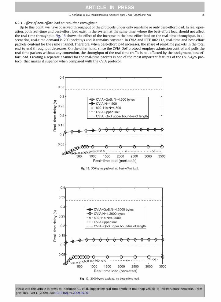
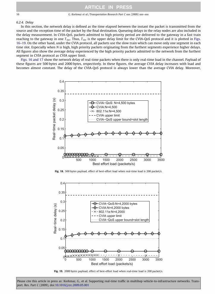
6.2.4. DelayIn this section, the network delay is defined as the time elapsed between the instant the packet is transmitted from the
source and the reception time of the packet by the final destination. Queueing delays in the relay nodes are also included inthe delay measurement. In CVIA-QoS, packets admitted to high priority period are delivered to the gateway in a fast trainreaching to the gateway in one Tslot . Thus, Tslot is the upper delay limit for the CVIA-QoS protocol and it is plotted in Figs.16–19. On the other hand, under the CVIA protocol, all packets use the slow train which can move only one segment in eachtime slot. Especially when N is high, high priority packets originating from the furthest segments experience higher delays.All figures also show the average delay experienced by the high priority packets admitted to the network from the furthestsegment in CVIA protocol as CVIA upper limit.
Figs. 16 and 17 show the network delay of real-time packets when there is only real-time load in the channel. Payload ofthese figures are 500 bytes and 2000 bytes, respectively. In these figures, the average CVIA delay increases with load andbecomes almost constant. The delay of the CVIA-QoS protocol is always lower than the average CVIA delay. Moreover,
500 1000 1500 2000 2500 3000 35000
0.05
0.1
0.15
0.2
0.25
0.3
0.35
0.4
Rea
l−tim
e pa
cket
del
ay (s
)
Best effort load (packets/s)
CVIA−QoS: N=4,500 bytesCVIA:N=4,500802.11e:N=4,500CVIA upper limitCVIA−QoS upper bound=slot length
Fig. 18. 500 bytes payload, effect of best-effort load when real-time load is 200 packet/s.
0 500 1000 1500 2000 2500 3000 35000
0.05
0.1
0.15
0.2
0.25
0.3
0.35
0.4
Rea
l−tim
e de
lay
(s)
Best effort load (packets/s)
CVIA−QoS:N=4,2000 bytesCVIA:N=4,2000 bytes802.11e:N=4,2000CVIA upper limitCVIA−QoS upper bound=slot length
Fig. 19. 2000 bytes payload, effect of best-effort load when real-time load is 200 packet/s.
Please cite this article in press as: Korkmaz, G., et al. Supporting real-time traffic in multihop vehicle-to-infrastructure networks. Trans-port. Res. Part C (2009), doi:10.1016/j.trc.2009.05.001

G. Korkmaz et al. / Transportation Research Part C xxx (2009) xxx–xxx 17
ARTICLE IN PRESS
CVIA-QoS delay is much lower than CVIA upper limit. Note that if the number of segments were larger, the CVIA delay wouldbe much larger while CVIA-QoS delay would not be affected. Although the delay of the IEEE 802.11e packets is the lowest inthese figures, it is because of the high failure rate of IEEE 802.11e as shown in Fig. 12. Since the maximum contention win-dow for high priority packets is small, these packets do not stay long in the queues of the relay nodes, and most of themcollide with other packets. Figs. 18 and 19 show the network delay of real-time packets for the mixed load scenario wherethe real-time load is constant and 200 packets/s. Note that in CVIA-QoS, similar to the throughput performance, real-timedelay is not affected by the best-effort load and it is almost six times less than the average and 17 times less than the upperlimit of the CVIA protocol.
7. Conclusions and future work
In this paper, a new channel access and routing strategy for vehicular Internet access along highways with QoS support isintroduced. The CVIA-QoS protocol use periodic admission control and scheduling for soft real-time traffic to provide delaybounded throughput guarantees. After the demands of the soft real-time traffic is met, CVIA-QoS supports the best-efforttraffic by allocating the remaining bandwidth.
Our simulation results confirm that in CVIA-QoS protocol, the real-time throughput is not affected from the best-effortload and its delay is much smaller than CVIA delay when both the real-time and best effort is carried in the network. Thethroughput of IEEE 802.11e is much lower than both CVIA-QoS and CVIA. In addition, IEEE 802.11e suffers from high numberof real-time packet failures at high loads.
In our future work, the CVIA-QoS protocol will be improved by allowing coordination of multiple gateways and multi-seg-ment reservation strategies. The packet traffic can be diverted from busy gateways to the gateways experiencing light load toimprove performance. In a linear highway without intersections, this can be achieved by varying the virtual service area ofthe gateways based on the load. However, if intersections exist in the packet trains’ paths which are shared by more than twogateways, a scheduling must be done for the packets of multiple gateways.
References
ASTM, 2002. ASTM E2213-02 Standard Specification for Telecommunications and Information Exchange Between Roadside and Vehicle Systems 5 GHz BandDedicated Short Range Communications (DSRC) Medium Access Control (MAC) and Physical Layer (PHY) Specifications.
Baccelli, E., Clausen, T., Jacquet, P., Nguyen, D., 2007. Integrating VANETs in the internet core with OSPF: the MPR–OSPF approach. In: InternationalConference on ITS Telecommunications (ITST).
Bechler, M., Franz, W., Wolf, L., 2003. Mobile internet access in FleetNet. In: 13. Fachtagung Kommunikation in Verteilten Systemen (KiVS 2003).Bianchi, G., 2000. Performance analysis of the 802.11 distributed coordination function. IEEE JSAC 18 (3), 535–547.Bilstrup, K., 2007. A survey regarding wireless communication standards intended for a high-speed vehicle environment. Tech. Rep. IDE0712, Univ.
Halmstad.FCC, October 1999. FCC 99-305. FCC Report and Order.FCC, Febuary 2004. FCC 03-024. FCC Report and Order.Festag, A., Noecker, G., Strassberger, M., Libke, A., Bochow, B., Torrent-Moreno, M., Schnaufer, S., Eigner, R., Catrinescu, C., Kunisch, J., 2008. (NoW) Network
on wheels: project objectives, technology and achievements. In: 5th International Workshop on Intelligent Transportation (WIT), pp. 211–216.FLEETNET, 2008. FleetNet homepage. <http://www.et2.tu-harburg.de/fleetnet/english/vision.html> [accessed 12.01.2008].Giannoulis, A., Fiore, M., Knightly, E.W., 2008. Supporting vehicular mobility in urban multi-hop wireless networks. In: MobiSys ’08: Proceeding of the 6th
International Conference on Mobile Systems, Applications, and Services. ACM, New York, NY, USA, pp. 54–66.Hinsberger, A., Wieker, H., Riegelhuth, G., Zurlinden, H., 2007. Benefits and technology of an intelligent roadside unit system for vehicle to infrastructure and
infrastructure to centre communication. In: 14th World Congress on Intelligent Transport Systems.Korkmaz, G., Ekici, E., Ozguner, F., 2006. A cross-layer multi-hop data delivery protocol with fairness guarantees for vehicular networks. IEEE Transactions
on Vehicular Technology 55 (3), 865–875.Lee Armstrong, 2008. Dedicated Short Range Communications (DSRC) Homepage [online]. <http://www.leearmstrong.com/dsrc/dsrchomeset.htm>
[accessed 12.01.2008].Perera, E., Sivaraman, V., Seneviratne, A., 2004. Survey on network mobility support. Mobile Computing and Communications Review 8 (2), 7–19.Pinart, C., Barona, I., Alba, C., 2008. Experimental measurement of vehicular QoS. In: 7th European Congress and Exhibition on Intelligent Transport Systems
and Services (ITS 2008).Tchouto, J.-J., Kutzner, K., Bochow, B., Luckenbach, T., Bechler, M., Wolf, L., 2003. Connecting vehicle scatternets by internet-connected gateways. In:
Multiradio Multimedia Communications.Tsugawa, S., Kato, S., 2003. Evaluation of incident information transmission on highways over inter-vehicle communications. In: Intelligent Vehicles
Symposium, 2003, pp. 12–16.Tsukada, M., Mehani, O., Ernst, T., March 2008. Simultaneous usage of NEMO and MANET for vehicular communication. In: WEEDEV 2008: 1st Workshop on
Experimental Evaluation and Deployment Experiences on Vehicular Networks in conjunction with TRIDENTCOM 2008, Innsbruck, Austria, March 18,2008.
Wang, Z., Hassan, M., 2008. How much of DSRC is available for non-safety use? In: VANET’08.Xu, Q., Mak, T., Ko, J., Sengupta, R., October 2004. Vehicle–vehicle safety messaging in DSRC. In: 1st ACM Workshop on Vehicular Ad-hoc Networks, pp. 19–
28.
Please cite this article in press as: Korkmaz, G., et al. Supporting real-time traffic in multihop vehicle-to-infrastructure networks. Trans-port. Res. Part C (2009), doi:10.1016/j.trc.2009.05.001