Supporting construction frame AL - Doka
44
© by Doka GmbH, A-3300 Amstetten 999816202 11/2021 en-GB - The Formwork Experts. Supporting construction frame AL User Information Instructions for assembly and use (Method statement) © by Doka GmbH, A-3300 Amstetten
-
Upload
khangminh22 -
Category
Documents
-
view
2 -
download
0
Transcript of Supporting construction frame AL - Doka

© b
y D
oka
Gm
bH, A
-330
0 Am
stet
ten
999816202 11/2021en-GB
-
The Formwork Experts.
Supporting construction frame ALUser InformationInstructions for assembly and use (Method statement)© by Doka GmbH, A-3300 Amstetten

2 999816202 - 11/2021
User Information Supporting construction frame AL
User Information Supporting construction frame AL
3999816202 - 11/2021
Contents
4 Introduction4 Elementary safety warnings7 Services
8 System description8 Supporting construction frame AL9 System dimensions
10 Used with Framed formwork DokaXlight14 Structural design
15 Used with Framed formwork Frami Xlife19 Structural design
20 Used with Framed formwork Framax25 Structural design
26 Assembly26 Pre-assembly27 Installation on the framed panel
28 General28 Repositioning unit for crane-lifting30 Pouring platforms31 Transferring the forces which occur32 Anchoring solutions for the supporting
construction frames34 Fitting diagonal anchors36 Transporting, stacking and storing
40 Article list
4 999816202 - 11/2021
Introduction User Information Supporting construction frame AL
IntroductionElementary safety warnings
User target groups
▪ This booklet is aimed at all persons who will be work-ing with the Doka product or system that it describes. It contains information on the standard design for setting up this system, and on correct, compliant uti-lisation of the system.
▪ All persons working with the product described herein must be familiar with the contents of this booklet and with all the safety instructions it contains.
▪ Persons who are incapable of reading and under-standing this booklet, or who can do so only with dif-ficulty, must be instructed and trained by the cus-tomer.
▪ The customer is to ensure that the information mate-rials provided by Doka (e.g. User Information book-lets, Instructions for Assembly and Use, Operating Instruction manuals, plans etc.) are up to date and available to all users, and that they have been made aware of them and have easy access to them at the usage location.
▪ In the relevant technical documentation and form-work utilisation plans, Doka shows the workplace safety precautions that are necessary in order to use the Doka products safely in the usage situations shown. In all cases, users are obliged to ensure compliance with national laws, standards and regulations throughout the entire project and to take appropriate additional or alternative workplace safety precau-tions where necessary.
Hazard assessment
▪ The customer is responsible for drawing up, docu-menting, implementing and continually updating a hazard assessment at every job-site. This booklet serves as the basis for the site-specific hazard assessment, and for the instructions given to users on how to prepare and utilise the system. It does not substitute for these, however.
Remarks on this booklet
▪ This document can be used as general Instructions for Assembly and Use (Method Statement) or be incorporated into site-specific Instructions for Assembly and Use (Method Statement).
▪ The graphics, animations and videos in this doc-ument or app sometimes depict partially assem-bled assemblies and may require additional safety equipment and/or measures to comply with safety regulations.The customer must ensure all applicable regulations are complied with, even if they are not shown or implied in the graphics, animations and videos pro-vided.
▪ Individual sections contain further safety instructions and/or special warnings as applica-ble.
Planning
▪ Provide safe workplaces for those using the form-work (e.g. for when it is being erected/dismantled, modified or repositioned etc). It must be possible to get to and from these workplaces via safe access routes!
▪ If you are considering any deviation from the details and instructions given in this booklet, or any application which goes beyond those described in the booklet, then revised static cal-culations must be produced for checking, as well as supplementary assembly instructions.
Regulations; industrial safety
▪ All laws, Standards, industrial safety regulations and other safety rules applying to the utilisation of our products in the country and/or region in which you are operating must be observed at all times.
▪ If a person or object falls against, or into, the side-guard component and/or any of its accessories, the component affected may only continue in use after it has been inspected and passed by an expert.
User Information Supporting construction frame AL Introduction
5999816202 - 11/2021
Rules applying during all phases of the assignment
▪ The customer must ensure that this product is erected and dismantled, reset and generally used for its intended purpose in accordance with the applica-ble laws, standards and rules, under the direction and supervision of suitably skilled persons. These persons' mental and physical capacity must not in any way be impaired by alcohol, medicines or drugs.
▪ Doka products are technical working appliances which are intended for industrial / commercial use only, always in accordance with the respective Doka User Information booklets or other technical docu-mentation authored by Doka.
▪ The stability and load-bearing capacity of all compo-nents and units must be ensured during all phases of the construction work!
▪ Do not step on or apply strain to cantilevers, clo-sures, etc. until suitable measures to ensure their stability have been correctly implemented (e.g. by tie-backs).
▪ Strict attention to and compliance with the functional instructions, safety instructions and load specifica-tions are required. Non-compliance can cause acci-dents and severe injury (risk of fatality) and consid-erable damage to property.
▪ Sources of fire in the vicinity of the formwork are pro-hibited. Heaters are permissible only when used cor-rectly and situated a correspondingly safe distance from the formwork.
▪ Customer must give due consideration to any and all effects of the weather on the equipment and regards both its use and storage (e.g. slippery surfaces, risk of slipping, effects of the wind, etc.) and implement appropriate precautionary measures to secure the equipment and surrounding areas and to protect workers.
▪ All connections must be checked at regular intervals to ensure that they are secure and in full working order. In particular threaded connections and wedged con-nections have to be checked and retightened as nec-essary in accordance with activity on the jobsite and especially after out-of-the-ordinary occurrences (e.g. after a storm).
▪ It is strictly forbidden to weld Doka products – in par-ticular anchoring/tying components, suspension components, connector components and castings etc. – or otherwise subject them to heating.Welding causes serious change in the microstruc-ture of the materials from which these components are made. This leads to a dramatic drop in the failure load, representing a very great risk to safety.It is permissible to cut individual tie rods to length with metal cutting discs (introduction of heat at the end of the rod only), but it is important to ensure that flying sparks do not heat and thus damage other tie rods.The only articles which are allowed to be welded are those for which the Doka literature expressly points out that welding is permitted.
Assembly
▪ The equipment/system must be inspected by the customer before use, to ensure that it is in an accept-able condition. Steps must be taken to exclude com-ponents that are damaged, deformed, or weakened due to wear, corrosion or rot (e.g. fungal decay).
▪ Using our safety and formwork systems together with those of other manufacturers can create risks that may lead to injury and damage to property. This requires separate verification by the user.
▪ The equipment/system must be assembled and erected in accordance with the applicable laws, standards and rules by trained customer personnel whilst maintaining any applicable safety inspections that may be required.
▪ It is not permitted to modify Doka products; such modifications constitute a safety risk.
Closing the formwork
▪ Doka products and systems must be set up so that all loads acting upon them are safely transferred!
Pouring
▪ Do not exceed the permitted fresh-concrete pres-sures. Over-high pouring rates overload the form-work, cause greater deflection and risk breakage.
Stripping the formwork
▪ Do not strip out the formwork until the concrete has reached sufficient strength and the person in charge has given the order for the formwork to be stripped out!
▪ When stripping out the formwork, never use the crane to break concrete cohesion. Use suitable tools such as timber wedges, special pry-bars or system features such as Framax stripping corners.
▪ When stripping out the formwork, do not endanger the stability of any part of the structure, or of any scaffolding, platforms or formwork that is still in place!
6 999816202 - 11/2021
Introduction User Information Supporting construction frame AL
Transporting, stacking and storing
▪ Observe all country-specific regulations applying to the handling of formwork and scaffolding. For system formwork the Doka slinging means stated in this booklet must be used – this is a mandatory require-ment.If the type of sling is not specified in this document, the customer must use slinging means that are suit-able for the application envisaged and that comply with the regulations.
▪ When lifting, always make sure that the unit to be lifted and its individual parts can absorb the forces that occur.
▪ Remove loose parts or secure them so that they can-not slip out of position and drop.
▪ When lifting formwork or formwork accessories with a crane, no persons must be carried along, e.g. on working platforms or in multi-trip packaging.
▪ All components must be stored safely, following all the special Doka instructions given in the relevant sections of this document!
Maintenance
▪ Only original Doka components may be used as spare parts. Repairs may only be carried out by the manufacturer or authorised facilities.
Miscellaneous
The weights as stated are averages for new material; actual weights can differ, depending on material toler-ances. Dirt accretions, moisture saturation, etc. can also affect weight.We reserve the right to make alterations in the interests of technical progress.
Eurocodes at Doka
The permissible values stated in Doka documents (e.g. Fperm = 70 kN) are not design values (e.g. FRd = 105 kN)! ▪ It is essential to avoid confusing permissible values
with design values! ▪ Doka documents will continue to state the permissi-
ble values. Allowance has been made for the following partial fac-tors: ▪ γF = 1.5 ▪ γM, timber = 1.3 ▪ γM, steel = 1.1 ▪ kmod = 0.9Consequently, all the design values for an EC design calculation can be determined from the permissible val-ues.
Symbols used
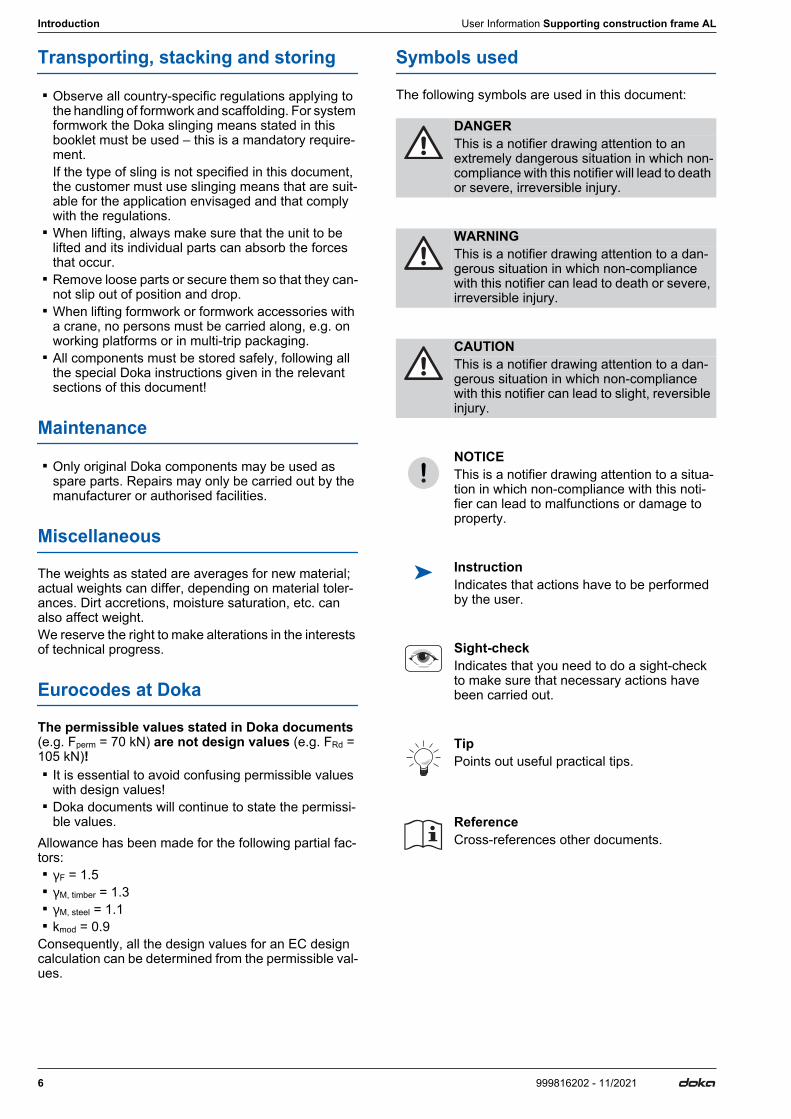
The following symbols are used in this document:
DANGERThis is a notifier drawing attention to an extremely dangerous situation in which non-compliance with this notifier will lead to death or severe, irreversible injury.
WARNINGThis is a notifier drawing attention to a dan-gerous situation in which non-compliance with this notifier can lead to death or severe, irreversible injury.
CAUTIONThis is a notifier drawing attention to a dan-gerous situation in which non-compliance with this notifier can lead to slight, reversible injury.
NOTICEThis is a notifier drawing attention to a situa-tion in which non-compliance with this noti-fier can lead to malfunctions or damage to property.
Instruction Indicates that actions have to be performed by the user.
Sight-checkIndicates that you need to do a sight-check to make sure that necessary actions have been carried out.
TipPoints out useful practical tips.
ReferenceCross-references other documents.
User Information Supporting construction frame AL Introduction
7999816202 - 11/2021
Services
Support in every stage of the project
▪ Project success assured by products and services from a single source.
▪ Competent support from planning through to assem-bly directly on site.
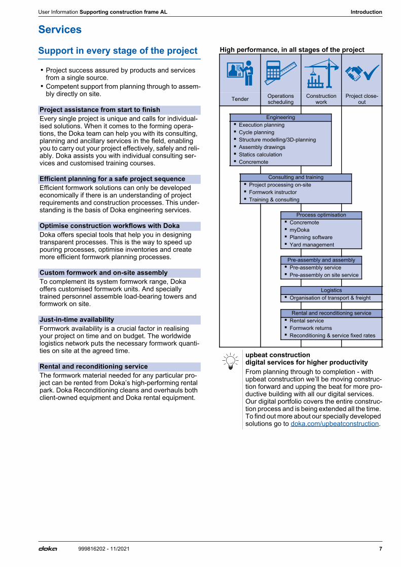
High performance, in all stages of the project
Project assistance from start to finishEvery single project is unique and calls for individual-ised solutions. When it comes to the forming opera-tions, the Doka team can help you with its consulting, planning and ancillary services in the field, enabling you to carry out your project effectively, safely and reli-ably. Doka assists you with individual consulting ser-vices and customised training courses.
Efficient planning for a safe project sequenceEfficient formwork solutions can only be developed economically if there is an understanding of project requirements and construction processes. This under-standing is the basis of Doka engineering services.
Optimise construction workflows with DokaDoka offers special tools that help you in designing transparent processes. This is the way to speed up pouring processes, optimise inventories and create more efficient formwork planning processes.
Custom formwork and on-site assemblyTo complement its system formwork range, Doka offers customised formwork units. And specially trained personnel assemble load-bearing towers and formwork on site.
Just-in-time availabilityFormwork availability is a crucial factor in realising your project on time and on budget. The worldwide logistics network puts the necessary formwork quanti-ties on site at the agreed time.
Rental and reconditioning serviceThe formwork material needed for any particular pro-ject can be rented from Doka’s high-performing rental park. Doka Reconditioning cleans and overhauls both client-owned equipment and Doka rental equipment.
Tender Operations scheduling
Construction work
Project close-out
Engineering ▪ Execution planning ▪ Cycle planning ▪ Structure modelling/3D-planning ▪ Assembly drawings ▪ Statics calculation ▪ Concremote
Consulting and training ▪ Project processing on-site ▪ Formwork instructor ▪ Training & consulting
Process optimisation ▪ Concremote ▪ myDoka ▪ Planning software ▪ Yard management
Pre-assembly and assembly ▪ Pre-assembly service ▪ Pre-assembly on site service
Logistics ▪ Organisation of transport & freight
Rental and reconditioning service ▪ Rental service ▪ Formwork returns ▪ Reconditioning & service fixed rates
upbeat construction digital services for higher productivityFrom planning through to completion - with upbeat construction we’ll be moving construc-tion forward and upping the beat for more pro-ductive building with all our digital services. Our digital portfolio covers the entire construc-tion process and is being extended all the time. To find out more about our specially developed solutions go to doka.com/upbeatconstruction.

8 999816202 - 11/2021
System description User Information Supporting construction frame AL
System descriptionSupporting construction frame AL ▪ The Supporting construction frame AL is an
extremely light supporting structure for single-sided wall formwork up to 3.00 m in height. With an exten-sion, pour heights up to 3.30 m are possible.
▪ The light aluminium frame means that the Support-ing construction frame AL can be opened and set up by hand.
▪ Total weight is 55 kg, so repositioning by hand is also easy.
▪ The Supporting construction frame AL can be com-bined with all Doka framed formwork systems, so it is a light and easy-to-use alternative to heavy sup-porting construction frames in all areas.
Note:Your regional Doka branch will be pleased to advise you on the exact planning and dimensioning.
User Information Supporting construction frame AL System description
9999816202 - 11/2021
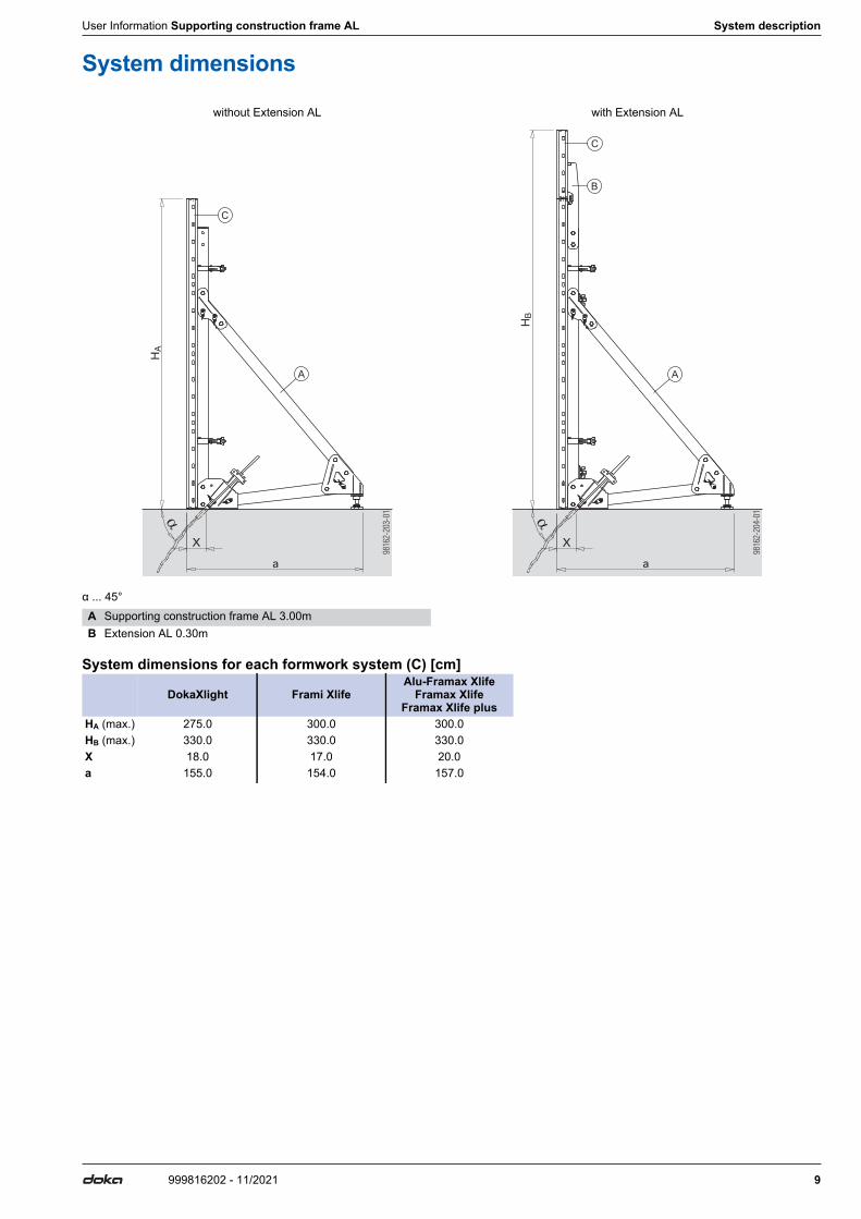
System dimensions
α ... 45°
System dimensions for each formwork system (C) [cm]
without Extension AL with Extension AL
HA
a
X
A
C
HB
a
X
B
A
C
A Supporting construction frame AL 3.00mB Extension AL 0.30m
DokaXlight Frami XlifeAlu-Framax Xlife
Framax XlifeFramax Xlife plus
HA (max.) 275.0 300.0 300.0HB (max.) 330.0 330.0 330.0X 18.0 17.0 20.0a 155.0 154.0 157.0
10 999816202 - 11/2021
Used with Framed formwork DokaXlight User Information Supporting construction frame AL
Used with Framed formwork DokaXlight
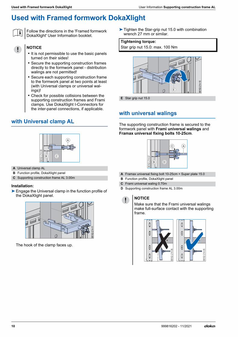
with Universal clamp AL
Installation:➤Engage the Universal clamp in the function profile of
the DokaXlight panel.
The hook of the clamp faces up.
➤Tighten the Star-grip nut 15.0 with combination wrench 27 mm or similar.
with universal walings
The supporting construction frame is secured to the formwork panel with Frami universal walings and Framax universal fixing bolts 10-25cm.
Follow the directions in the 'Framed formwork DokaXlight' User Information booklet.
NOTICE ▪ It is not permissible to use the basic panels
turned on their sides! ▪ Secure the supporting construction frames
directly to the formwork panel - distribution walings are not permitted!
▪ Secure each supporting construction frame to the formwork panel at two points at least (with Universal clamps or universal wal-ings)!
▪ Check for possible collisions between the supporting construction frames and Frami clamps. Use DokaXlight I-Connectors for the inter-panel connections, if applicable.
A Universal clamp ALB Function profile, DokaXlight panelC Supporting construction frame AL 3.00m
A
CB
98162-2
14-1
1
Tightening torque:Star grip nut 15.0: max. 100 Nm
E Star grip nut 15.0
A Framax universal fixing bolt 10-25cm + Super plate 15.0B Function profile, DokaXlight panelC Frami universal waling 0.70mD Supporting construction frame AL 3.00m
NOTICEMake sure that the Frami universal walings make full-surface contact with the supporting frame.
E
98162-2
14-1
0
AC
DB
User Information Supporting construction frame AL Used with Framed formwork DokaXlight
11999816202 - 11/2021
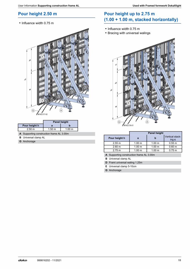
Pour height 2.50 m
▪ Influence width 0.75 m
Pour height up to 2.75 m (1.00 + 1.00 m, stacked horizontally)
▪ Influence width 0.75 m ▪ Bracing with universal walings
Panel heightPour height h a b
2.50 m 1.50 m 1.00 m
A Supporting construction frame AL 3.00mB Universal clamp ALG Anchorage
98162-217-02
ab
h
G A
B
B
Panel height
Pour height h a b Vertical stack-ing c
2.55 m 1.00 m 1.00 m 0.55 m2.60 m 1.00 m 1.00 m 0.60 m2.75 m 1.00 m 1.00 m 0.75 m
A Supporting construction frame AL 3.00mB Universal clamp ALD Frami universal waling 1.25mE Universal clamp 5-10cmG Anchorage
98162-216-01
ab
c
h
G A
B
B
D
E
12 999816202 - 11/2021
Used with Framed formwork DokaXlight User Information Supporting construction frame AL
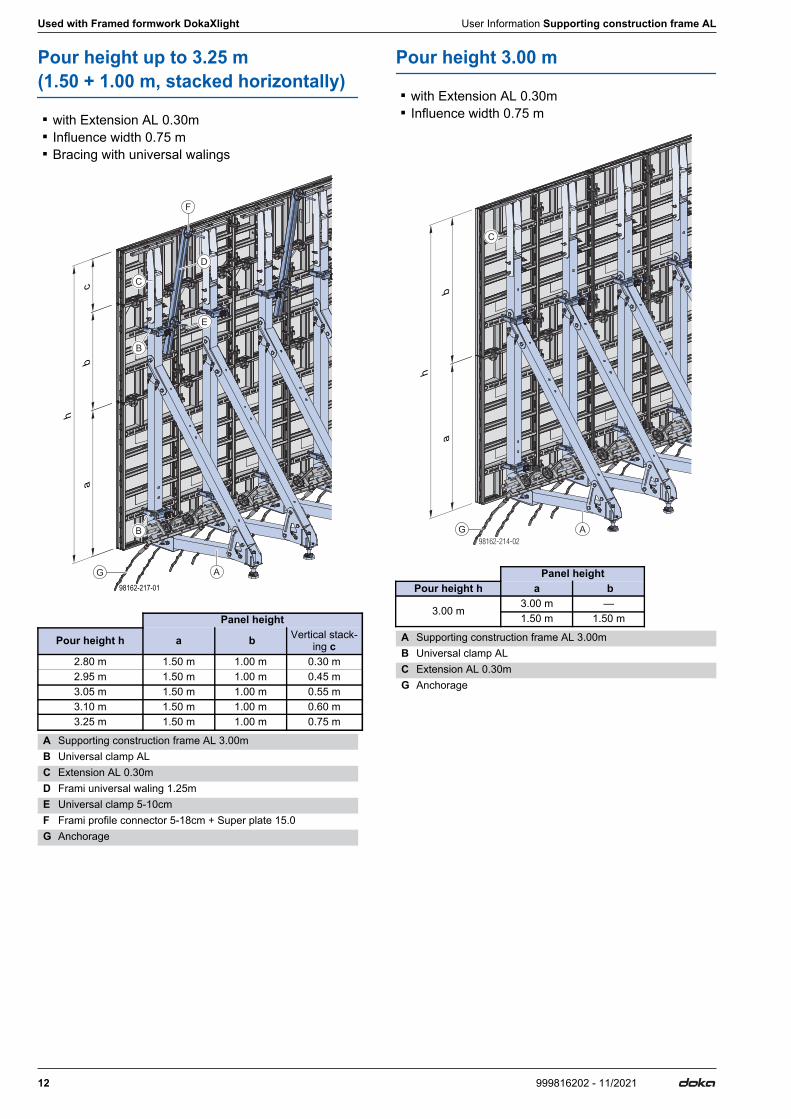
Pour height up to 3.25 m (1.50 + 1.00 m, stacked horizontally)
▪ with Extension AL 0.30m ▪ Influence width 0.75 m ▪ Bracing with universal walings
Pour height 3.00 m
▪ with Extension AL 0.30m ▪ Influence width 0.75 m
Panel height
Pour height h a b Vertical stack-ing c
2.80 m 1.50 m 1.00 m 0.30 m2.95 m 1.50 m 1.00 m 0.45 m3.05 m 1.50 m 1.00 m 0.55 m3.10 m 1.50 m 1.00 m 0.60 m3.25 m 1.50 m 1.00 m 0.75 m
A Supporting construction frame AL 3.00mB Universal clamp ALC Extension AL 0.30mD Frami universal waling 1.25mE Universal clamp 5-10cmF Frami profile connector 5-18cm + Super plate 15.0G Anchorage
98162-217-01
ca
b
h
G A
B
B
C
D
E
F
Panel heightPour height h a b
3.00 m3.00 m —1.50 m 1.50 m
A Supporting construction frame AL 3.00mB Universal clamp ALC Extension AL 0.30mG Anchorage
A
C
G
ab
h

User Information Supporting construction frame AL Used with Framed formwork DokaXlight
13999816202 - 11/2021
Pour height 3.30 m
▪ with Extension AL 0.30m ▪ Influence width 0.75 m ▪ Extension panel below basic panel
Panel width 0.75m
▪ Centre-to-centre distance e = 75 cm ▪ Panel width f = 75 cm
Version 1:
Anchorage centre-to-centre distance c ... 30 cm Anchorage centre-to-centre distance d ... 45 cm g ... 18 cm
Version 2:
Anchorage centre-to-centre distance c (uniform) ... 37.5 cm g ... 18 cm
Panel height
Pour height h Extension panel a b
3.30 m 0.30 m 3.00 m
A Supporting construction frame AL 3.00mB Universal clamp ALC Extension AL 0.30mG Anchorage
A
C
G
ab
h
B
B
A Supporting construction frame AL 3.00mD DokaXlight panelE Multi-purpose waling WS10 Top50 0.75mG Anchorage
g
e
f
cd cc dd/2
E
G
D
A
e/2
g
e
f
cccccc/2
D
E
G A
e/2
14 999816202 - 11/2021
Used with Framed formwork DokaXlight User Information Supporting construction frame AL
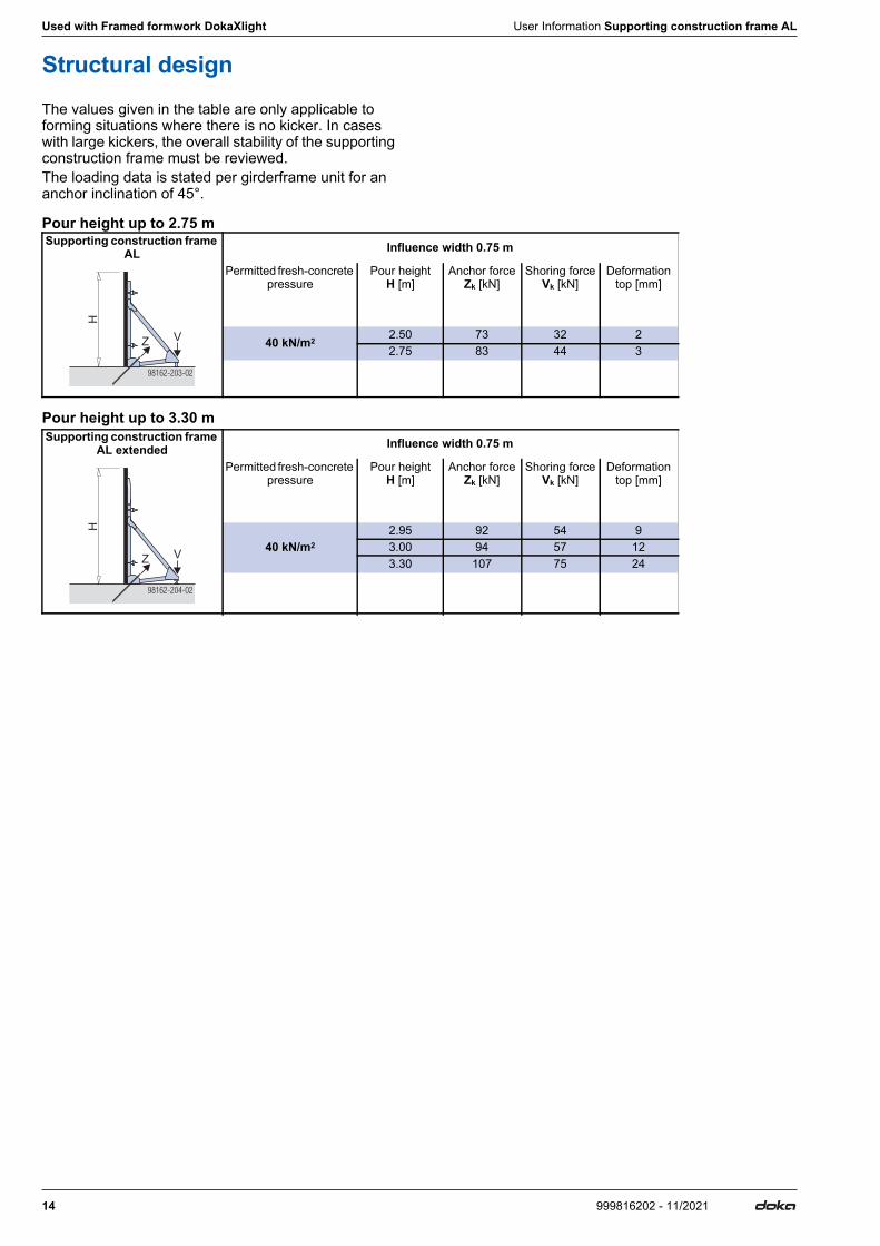
Structural designThe values given in the table are only applicable to forming situations where there is no kicker. In cases with large kickers, the overall stability of the supporting construction frame must be reviewed.The loading data is stated per girderframe unit for an anchor inclination of 45°.
Pour height up to 2.75 m
Pour height up to 3.30 m
Supporting construction frame AL Influence width 0.75 m
Permitted fresh-concrete pressure
Pour heightH [m]
Anchor forceZk [kN]
Shoring forceVk [kN]
Deformationtop [mm]
40 kN/m2 2.50 73 32 22.75 83 44 3
98162-203-02
H
Z V
Supporting construction frame AL extended Influence width 0.75 m
Permitted fresh-concrete pressure
Pour heightH [m]
Anchor forceZk [kN]
Shoring forceVk [kN]
Deformationtop [mm]
40 kN/m22.95 92 54 93.00 94 57 123.30 107 75 24
98162-204-02
H
Z V
User Information Supporting construction frame AL Used with Framed formwork Frami Xlife
15999816202 - 11/2021
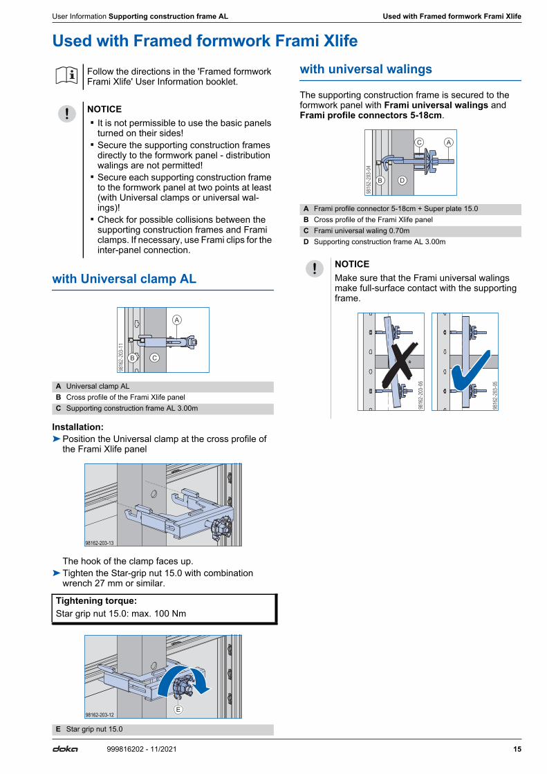
Used with Framed formwork Frami Xlife
with Universal clamp AL
Installation:➤Position the Universal clamp at the cross profile of
the Frami Xlife panel
The hook of the clamp faces up.➤Tighten the Star-grip nut 15.0 with combination
wrench 27 mm or similar.
with universal walings
The supporting construction frame is secured to the formwork panel with Frami universal walings and Frami profile connectors 5-18cm.
Follow the directions in the 'Framed formwork Frami Xlife' User Information booklet.
NOTICE ▪ It is not permissible to use the basic panels
turned on their sides! ▪ Secure the supporting construction frames
directly to the formwork panel - distribution walings are not permitted!
▪ Secure each supporting construction frame to the formwork panel at two points at least (with Universal clamps or universal wal-ings)!
▪ Check for possible collisions between the supporting construction frames and Frami clamps. If necessary, use Frami clips for the inter-panel connection.
A Universal clamp ALB Cross profile of the Frami Xlife panelC Supporting construction frame AL 3.00m
Tightening torque:Star grip nut 15.0: max. 100 Nm
E Star grip nut 15.0
B C
A
98162-203-13
98162-203-12E
A Frami profile connector 5-18cm + Super plate 15.0 B Cross profile of the Frami Xlife panelC Frami universal waling 0.70mD Supporting construction frame AL 3.00m
NOTICEMake sure that the Frami universal walings make full-surface contact with the supporting frame.
A
B D
C
9816
2-20
3-06
9816
2-20
3-05
16 999816202 - 11/2021
Used with Framed formwork Frami Xlife User Information Supporting construction frame AL
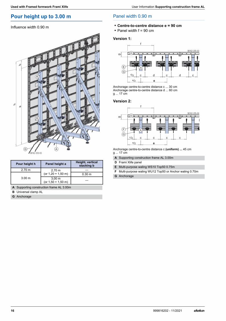
Pour height up to 3.00 m
Influence width 0.90 m
Panel width 0.90 m
▪ Centre-to-centre distance e = 90 cm ▪ Panel width f = 90 cm
Version 1:
Anchorage centre-to-centre distance c ... 30 cm Anchorage centre-to-centre distance d ... 60 cm g ... 17 cm
Version 2:
Anchorage centre-to-centre distance c (uniform) ... 45 cm g ... 17 cm
Pour height h Panel height a Height, vertical stacking b
2.70 m 2,70 m(or 1,20 + 1,50 m)
—
3.00 m0.30 m
3,00 m(or 1,50 + 1,50 m) —
A Supporting construction frame AL 3.00mB Universal clamp ALG Anchorage
h
B
B
AG
ab
A Supporting construction frame AL 3.00mD Frami Xlife panelE Multi-purpose waling WS10 Top50 0.75mF Multi-purpose waling WU12 Top50 or Anchor waling 0.70mG Anchorage
98162-205-03
E
G
c d
g
c d cd
f
D
e
A
/2
e/2
98162-205-04
F
G
c c c c
e
Dg
f
A
e/2
c/2
User Information Supporting construction frame AL Used with Framed formwork Frami Xlife
17999816202 - 11/2021
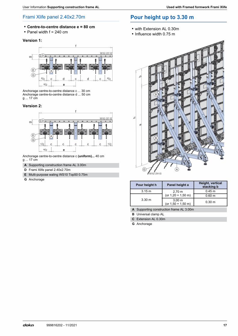
Frami Xlife panel 2.40x2.70m
▪ Centre-to-centre distance e = 80 cm ▪ Panel width f = 240 cm
Version 1:
Anchorage centre-to-centre distance c ... 30 cm Anchorage centre-to-centre distance d ... 50 cm g ... 17 cm
Version 2:
Anchorage centre-to-centre distance c (uniform)... 40 cm g ... 17 cm
Pour height up to 3.30 m
▪ with Extension AL 0.30m ▪ Influence width 0.75 m
A Supporting construction frame AL 3.00mD Frami Xlife panel 2.40x2.70mE Multi-purpose waling WS10 Top50 0.75mG Anchorage
98162-207-03
E
G
c d
g
c d c
f
D
e
A
d/2 d/2
e/2
98162-207-05
E
G
c
g
c c
f
D
e
A
c cc/2 c/2
e/2
Pour height h Panel height a Height, vertical stacking b
3.15 m 2,70 m(or 1,20 + 1,50 m)
0.45 m
3.30 m0.60 m
3,00 m(or 1,50 + 1,50 m) 0.30 m
A Supporting construction frame AL 3.00mB Universal clamp ALC Extension AL 0.30mG Anchorage
h
B
B
A
C
G
ab
18 999816202 - 11/2021
Used with Framed formwork Frami Xlife User Information Supporting construction frame AL
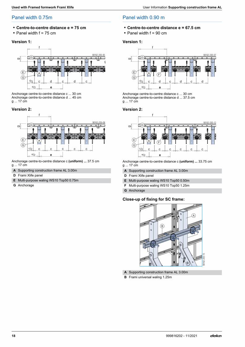
Panel width 0.75m
▪ Centre-to-centre distance e = 75 cm ▪ Panel width f = 75 cm
Version 1:
Anchorage centre-to-centre distance c ... 30 cm Anchorage centre-to-centre distance d ... 45 cm g ... 17 cm
Version 2:
Anchorage centre-to-centre distance c (uniform) ... 37.5 cm g ... 17 cm
Panel width 0.90 m
▪ Centre-to-centre distance e = 67.5 cm ▪ Panel width f = 90 cm
Version 1:
Anchorage centre-to-centre distance c ... 30 cm Anchorage centre-to-centre distance d ... 37.5 cm g ... 17 cm
Version 2:
Anchorage centre-to-centre distance c (uniform) ... 33.75 cm g ... 17 cm
Close-up of fixing for SC frame:
A Supporting construction frame AL 3.00mD Frami Xlife panelE Multi-purpose waling WS10 Top50 0.75mG Anchorage
f
98162-205-05
E
G
D
c d
g
c d c
e
A
d/2
e/2
98162-205-06
c
e
c c c c
E
G
Dg
f
A
c/2
e/2
A Supporting construction frame AL 3.00mD Frami Xlife panelE Multi-purpose waling WS10 Top50 0.50mF Multi-purpose waling WS10 Top50 1.25mG Anchorage
A Supporting construction frame AL 3.00mB Frami universal waling 1.25m
98162-205-07
c
e
d c c
E
G
Dg
f
A
d d
F
d/2
e/2
98162-205-12
c
e
c c c
E
G
Dg
f
A
c c
F
c/2
e/2
B
A
9816
2-20
5-15
User Information Supporting construction frame AL Used with Framed formwork Frami Xlife
19999816202 - 11/2021
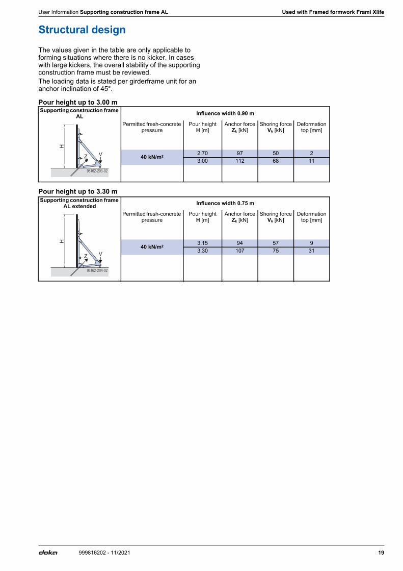
Structural designThe values given in the table are only applicable to forming situations where there is no kicker. In cases with large kickers, the overall stability of the supporting construction frame must be reviewed.The loading data is stated per girderframe unit for an anchor inclination of 45°.
Pour height up to 3.00 m
Pour height up to 3.30 m
Supporting construction frame AL Influence width 0.90 m
Permitted fresh-concrete pressure
Pour heightH [m]
Anchor forceZk [kN]
Shoring forceVk [kN]
Deformationtop [mm]
40 kN/m2 2.70 97 50 23.00 112 68 11
98162-203-02
H
Z V
Supporting construction frame AL extended Influence width 0.75 m
Permitted fresh-concrete pressure
Pour heightH [m]
Anchor forceZk [kN]
Shoring forceVk [kN]
Deformationtop [mm]
40 kN/m2 3.15 94 57 93.30 107 75 31
98162-204-02
H
Z V
20 999816202 - 11/2021
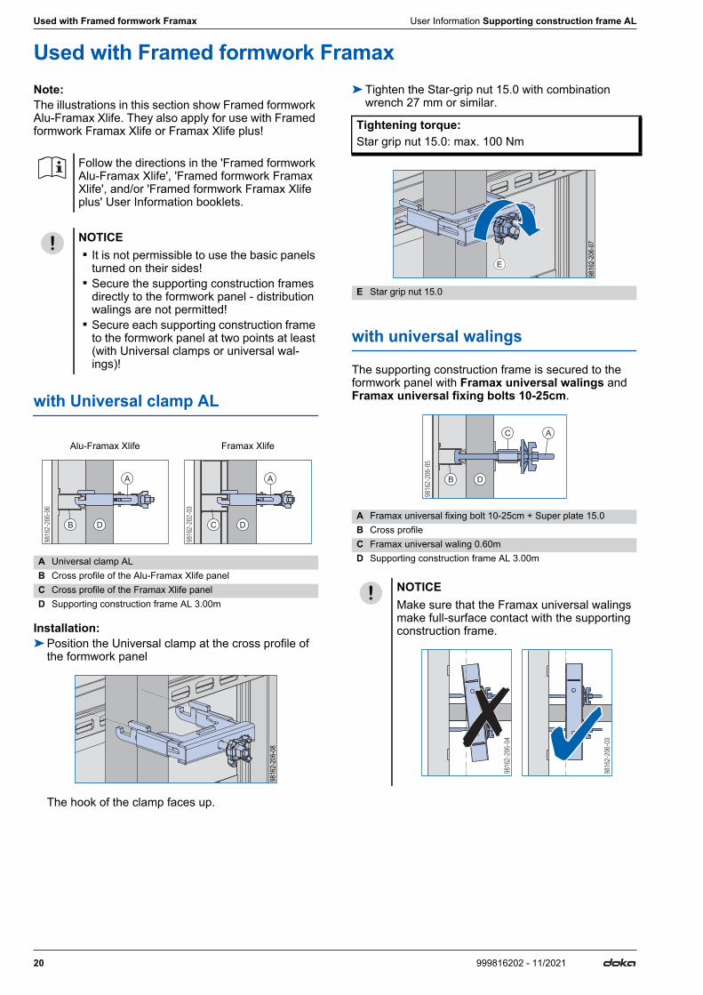
Used with Framed formwork Framax User Information Supporting construction frame AL
Used with Framed formwork FramaxNote:The illustrations in this section show Framed formwork Alu-Framax Xlife. They also apply for use with Framed formwork Framax Xlife or Framax Xlife plus!
with Universal clamp AL
Installation:➤Position the Universal clamp at the cross profile of
the formwork panel
The hook of the clamp faces up.
➤Tighten the Star-grip nut 15.0 with combination wrench 27 mm or similar.
with universal walings
The supporting construction frame is secured to the formwork panel with Framax universal walings and Framax universal fixing bolts 10-25cm.
Follow the directions in the 'Framed formwork Alu-Framax Xlife', 'Framed formwork Framax Xlife', and/or 'Framed formwork Framax Xlife plus' User Information booklets.
NOTICE ▪ It is not permissible to use the basic panels
turned on their sides! ▪ Secure the supporting construction frames
directly to the formwork panel - distribution walings are not permitted!
▪ Secure each supporting construction frame to the formwork panel at two points at least (with Universal clamps or universal wal-ings)!
Alu-Framax Xlife Framax Xlife
A Universal clamp ALB Cross profile of the Alu-Framax Xlife panelC Cross profile of the Framax Xlife panelD Supporting construction frame AL 3.00m
B D
A
C D
A
98
16
2-2
06
-08
Tightening torque:Star grip nut 15.0: max. 100 Nm
E Star grip nut 15.0
A Framax universal fixing bolt 10-25cm + Super plate 15.0 B Cross profileC Framax universal waling 0.60mD Supporting construction frame AL 3.00m
NOTICEMake sure that the Framax universal walings make full-surface contact with the supporting construction frame.
98
16
2-2
06
-07
E
9816
2-20
6-05
A
B D
C
9816
2-20
6-03
9816
2-20
6-04
User Information Supporting construction frame AL Used with Framed formwork Framax
21999816202 - 11/2021
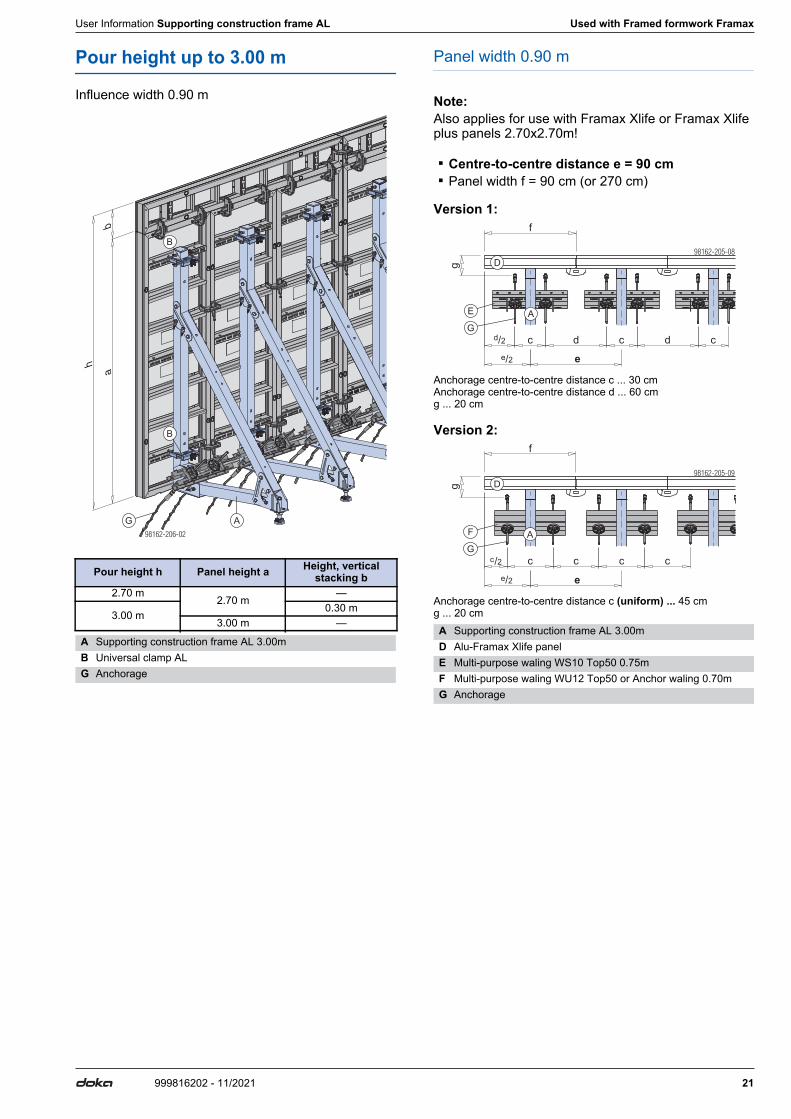
Pour height up to 3.00 m
Influence width 0.90 m
Panel width 0.90 m
Note:Also applies for use with Framax Xlife or Framax Xlife plus panels 2.70x2.70m!
▪ Centre-to-centre distance e = 90 cm ▪ Panel width f = 90 cm (or 270 cm)
Version 1:
Anchorage centre-to-centre distance c ... 30 cm Anchorage centre-to-centre distance d ... 60 cm g ... 20 cm
Version 2:
Anchorage centre-to-centre distance c (uniform) ... 45 cm g ... 20 cm
Pour height h Panel height a Height, vertical stacking b
2.70 m2.70 m
—
3.00 m0.30 m
3.00 m —
A Supporting construction frame AL 3.00mB Universal clamp ALG Anchorage
h
B
B
AG
ab
A Supporting construction frame AL 3.00mD Alu-Framax Xlife panelE Multi-purpose waling WS10 Top50 0.75mF Multi-purpose waling WU12 Top50 or Anchor waling 0.70mG Anchorage
98162-205-08
E
G
c d
g
c d c
f
D
e
A
d/2
e/2
98162-205-09
F
G
c c c c
e
Dgf
A
c/2
e/2
22 999816202 - 11/2021
Used with Framed formwork Framax User Information Supporting construction frame AL
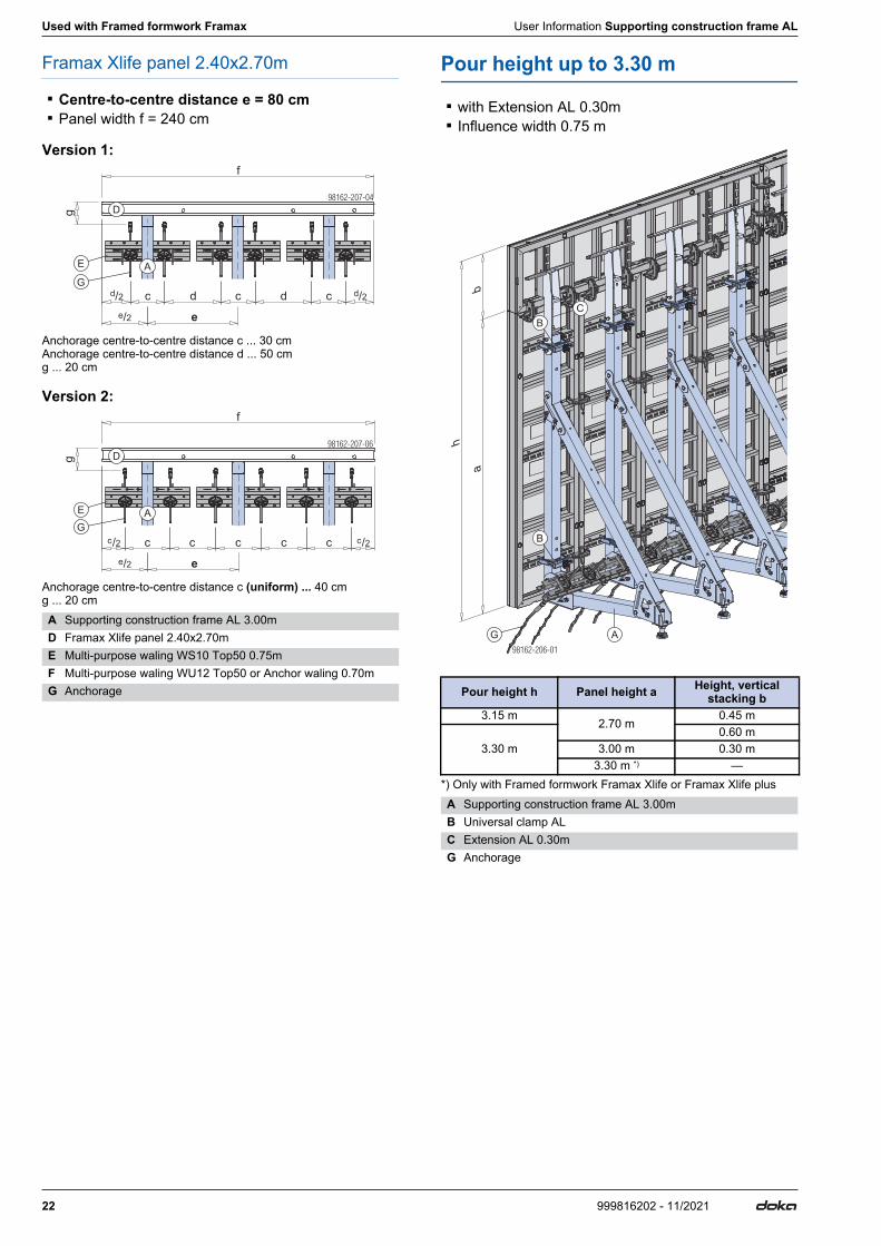
Framax Xlife panel 2.40x2.70m
▪ Centre-to-centre distance e = 80 cm ▪ Panel width f = 240 cm
Version 1:
Anchorage centre-to-centre distance c ... 30 cm Anchorage centre-to-centre distance d ... 50 cm g ... 20 cm
Version 2:
Anchorage centre-to-centre distance c (uniform) ... 40 cm g ... 20 cm
Pour height up to 3.30 m
▪ with Extension AL 0.30m ▪ Influence width 0.75 m
*) Only with Framed formwork Framax Xlife or Framax Xlife plus
A Supporting construction frame AL 3.00mD Framax Xlife panel 2.40x2.70mE Multi-purpose waling WS10 Top50 0.75mF Multi-purpose waling WU12 Top50 or Anchor waling 0.70mG Anchorage
98162-207-04
E
G
c d
g
c d c
f
D
e
A
d/2d/2
e/2
98162-207-06
E
G
c
g
c c
f
D
e
A
c cc/2 c/2
e/2
Pour height h Panel height a Height, vertical stacking b
3.15 m2.70 m
0.45 m
3.30 m0.60 m
3.00 m 0.30 m3.30 m *) —
A Supporting construction frame AL 3.00mB Universal clamp ALC Extension AL 0.30mG Anchorage
h
B
B
A
C
G
ab
User Information Supporting construction frame AL Used with Framed formwork Framax
23999816202 - 11/2021
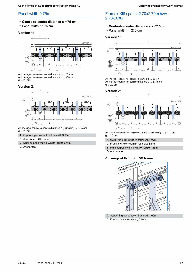
Panel width 0.75m
▪ Centre-to-centre distance e = 75 cm ▪ Panel width f = 75 cm
Version 1:
Anchorage centre-to-centre distance c ... 30 cm Anchorage centre-to-centre distance d ... 45 cm g ... 20 cm
Version 2:
Anchorage centre-to-centre distance c (uniform) ... 37.5 cm g ... 20 cm
Framax Xlife panel 2.70x2.70m bzw. 2.70x3.30m
▪ Centre-to-centre distance e = 67.5 cm ▪ Panel width f = 270 cm
Version 1:
Anchorage centre-to-centre distance c ... 30 cm Anchorage centre-to-centre distance d ... 37.5 cm g ... 20 cm
Version 2:
Anchorage centre-to-centre distance c (uniform) ... 33.75 cm g ... 20 cm
Close-up of fixing for SC frame:
A Supporting construction frame AL 3.00mD Alu-Framax Xlife panelE Multi-purpose waling WS10 Top50 0.75mG Anchorage
f
98162-205-10
E
G
D
c d
g
c d c
e
A
d/2
e/2
98162-205-11
c
e
c c c c
E
G
Dg
f
A
c/2
e/2
A Supporting construction frame AL 3.00mD Framax Xlife or Framax Xlife plus panelE Multi-purpose waling WS10 Top50 1.25mG Anchorage
A Supporting construction frame AL 3.00mB Framax universal waling 0.90m
98162-207-08
E
G
c d
g
c d
f
D
e
A
d ccd/2
e/2
d/2
98162-207-09
E
G
c
g
c c
f
D
e
A
c cccc/2
e/2
c/2
B
A
9816
2-20
7-10
24 999816202 - 11/2021
Used with Framed formwork Framax User Information Supporting construction frame AL
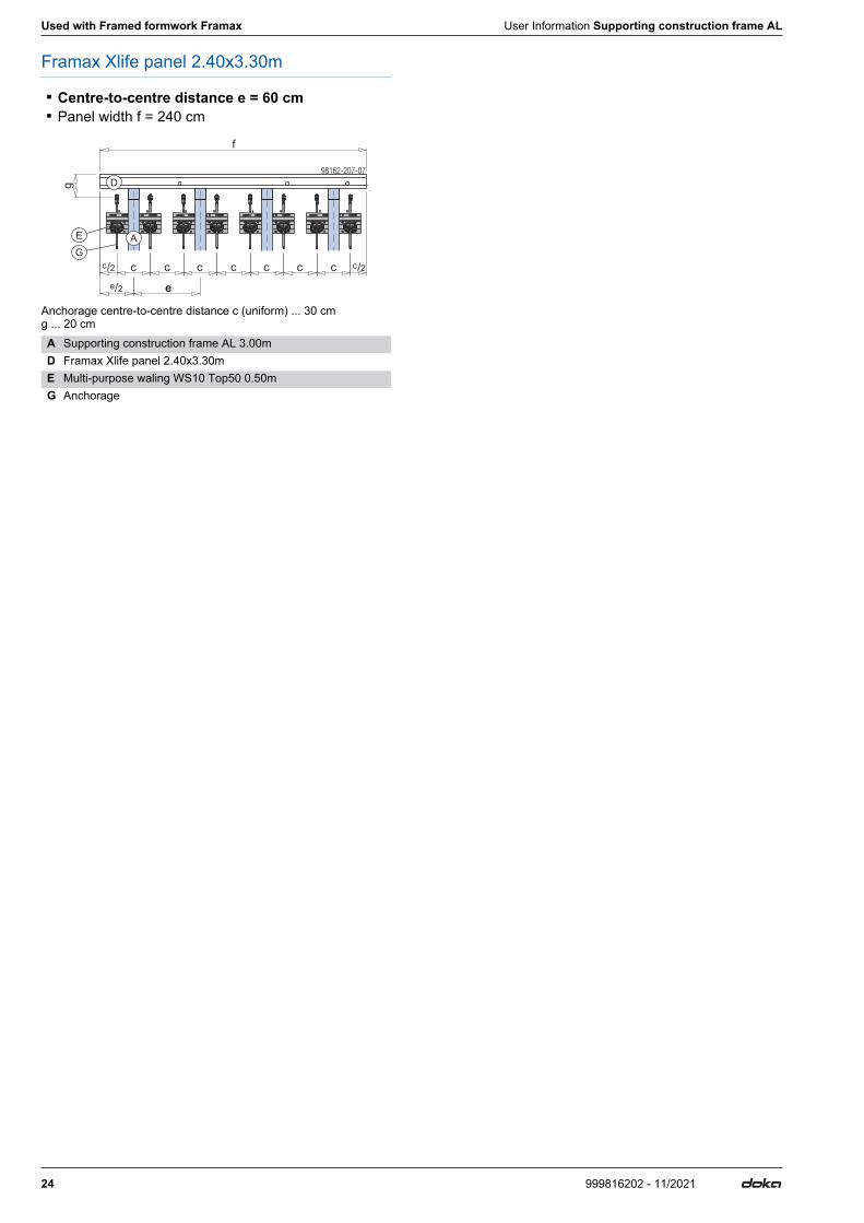
Framax Xlife panel 2.40x3.30m
▪ Centre-to-centre distance e = 60 cm ▪ Panel width f = 240 cm
Anchorage centre-to-centre distance c (uniform) ... 30 cm g ... 20 cmA Supporting construction frame AL 3.00mD Framax Xlife panel 2.40x3.30mE Multi-purpose waling WS10 Top50 0.50mG Anchorage
98162-207-07
E
G
c
g
c c
f
D
e
A
c c c cc/2
e/2
c/2
User Information Supporting construction frame AL Used with Framed formwork Framax
25999816202 - 11/2021
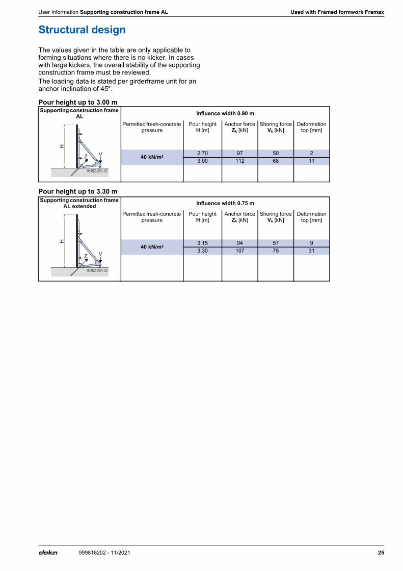
Structural designThe values given in the table are only applicable to forming situations where there is no kicker. In cases with large kickers, the overall stability of the supporting construction frame must be reviewed.The loading data is stated per girderframe unit for an anchor inclination of 45°.
Pour height up to 3.00 m
Pour height up to 3.30 m
Supporting construction frame AL Influence width 0.90 m
Permitted fresh-concrete pressure
Pour heightH [m]
Anchor forceZk [kN]
Shoring forceVk [kN]
Deformationtop [mm]
40 kN/m2 2.70 97 50 23.00 112 68 11
98162-203-02
H
Z V
Supporting construction frame AL extended Influence width 0.75 m
Permitted fresh-concrete pressure
Pour heightH [m]
Anchor forceZk [kN]
Shoring forceVk [kN]
Deformationtop [mm]
40 kN/m2 3.15 94 57 93.30 107 75 31
98162-204-02
H
Z V

26 999816202 - 11/2021
Assembly User Information Supporting construction frame AL
AssemblyPre-assembly
➤With the Supporting construction frame AL in its as-delivered condition, remove the safety pins from the parked positions.
➤Open up the Supporting construction frame AL.
➤Pin the Supporting construction frame AL with the safety pins and secure the safety pins.
Extending the Supporting construction frame AL➤Bolt the Extension AL 0.30m to the supporting con-
struction frame.
Animation: https://player.vimeo.com/video/367967718
NOTICEThroughout the assembly process, always make sure that the Supporting construction frame AL is adequately secured against tip-over!
A Supporting construction frame AL 3.00mC Safety pin
98162-208-01
C
C
A
98162-208-03
A Supporting construction frame AL 3.00mC Safety pin
A Supporting construction frame AL 3.00mB Extension AL 0.30mD Bolt and lock nut M 20
(Included with product)
98162-208-02
C
C
C
A
98162-208-04
A
D
B

User Information Supporting construction frame AL Assembly
27999816202 - 11/2021
Installation on the framed panel
➤Set up the formwork panels in position, connect them and use panel struts to prevent them from falling over.
➤Centre the Supporting construction frame AL 3.00m against the upright panel and secure it to the panel.
For positioning of the Supporting construction frames AL and securing to the formwork panel see the section applicable to the formwork system used.
➤ Install the anchorages (follow the directions in the following sections: sections of the formwork system used, 'Transferring the forces which occur', 'Anchoring solutions for the supporting construction frames', 'Fitting diagonal anchors').
➤Remove the panel struts.
➤Use the pressure spindle of the supporting construc-tion frame (width across flats 24 mm) to adjust the formwork to the correct angle of inclination.
For set-up of the framed formwork (inter-panel connections, stiffening, ...) follow the direc-tions in the User Information booklet of the framed formwork that is being used!
E Formwork panelF Panel strut
A Supporting construction frame AL 3.00m
98162-209-02
E
F
A
98162-208-05
+ 5
cm
- 5 c
m
28 999816202 - 11/2021
General User Information Supporting construction frame AL
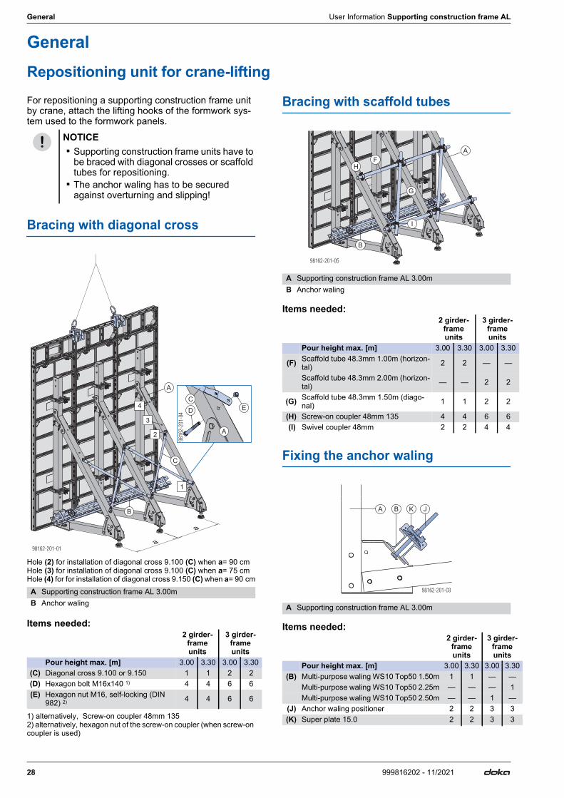
GeneralRepositioning unit for crane-liftingFor repositioning a supporting construction frame unit by crane, attach the lifting hooks of the formwork sys-tem used to the formwork panels.
Bracing with diagonal cross
Hole (2) for installation of diagonal cross 9.100 (C) when a= 90 cm Hole (3) for installation of diagonal cross 9.100 (C) when a= 75 cm Hole (4) for for installation of diagonal cross 9.150 (C) when a= 90 cm
Items needed:
1) alternatively, Screw-on coupler 48mm 135 2) alternatively, hexagon nut of the screw-on coupler (when screw-on coupler is used)
Bracing with scaffold tubes
Items needed:
Fixing the anchor waling
Items needed:
NOTICE ▪ Supporting construction frame units have to
be braced with diagonal crosses or scaffold tubes for repositioning.
▪ The anchor waling has to be secured against overturning and slipping!
A Supporting construction frame AL 3.00mB Anchor waling
2 girder-frame units
3 girder-frame units
Pour height max. [m] 3.00 3.30 3.00 3.30 (C) Diagonal cross 9.100 or 9.150 1 1 2 2 (D) Hexagon bolt M16x140 1) 4 4 6 6 (E) Hexagon nut M16, self-locking (DIN
982) 2) 4 4 6 6
B
A
C
A
1
2
3
C
D4
a
a
E
A Supporting construction frame AL 3.00mB Anchor waling
2 girder-frame units
3 girder-frame units
Pour height max. [m] 3.00 3.30 3.00 3.30
(F) Scaffold tube 48.3mm 1.00m (horizon-tal) 2 2 — —
Scaffold tube 48.3mm 2.00m (horizon-tal) — — 2 2
(G) Scaffold tube 48.3mm 1.50m (diago-nal) 1 1 2 2
(H) Screw-on coupler 48mm 135 4 4 6 6 (I) Swivel coupler 48mm 2 2 4 4
A Supporting construction frame AL 3.00m
2 girder-frame units
3 girder-frame units
Pour height max. [m] 3.00 3.30 3.00 3.30 (B) Multi-purpose waling WS10 Top50 1.50m 1 1 — —
Multi-purpose waling WS10 Top50 2.25m — — — 1Multi-purpose waling WS10 Top50 2.50m — — 1 —
(J) Anchor waling positioner 2 2 3 3 (K) Super plate 15.0 2 2 3 3
F
G
I
H
A
B
JB K
98162-201-03
A
User Information Supporting construction frame AL General
29999816202 - 11/2021
Lifting by crane
Doka 4-part chain 3.20m
➤Attach the Doka 4-part chain 3.20m to the lifting hooks.
➤Hang the remaining chain-lengths back in place.
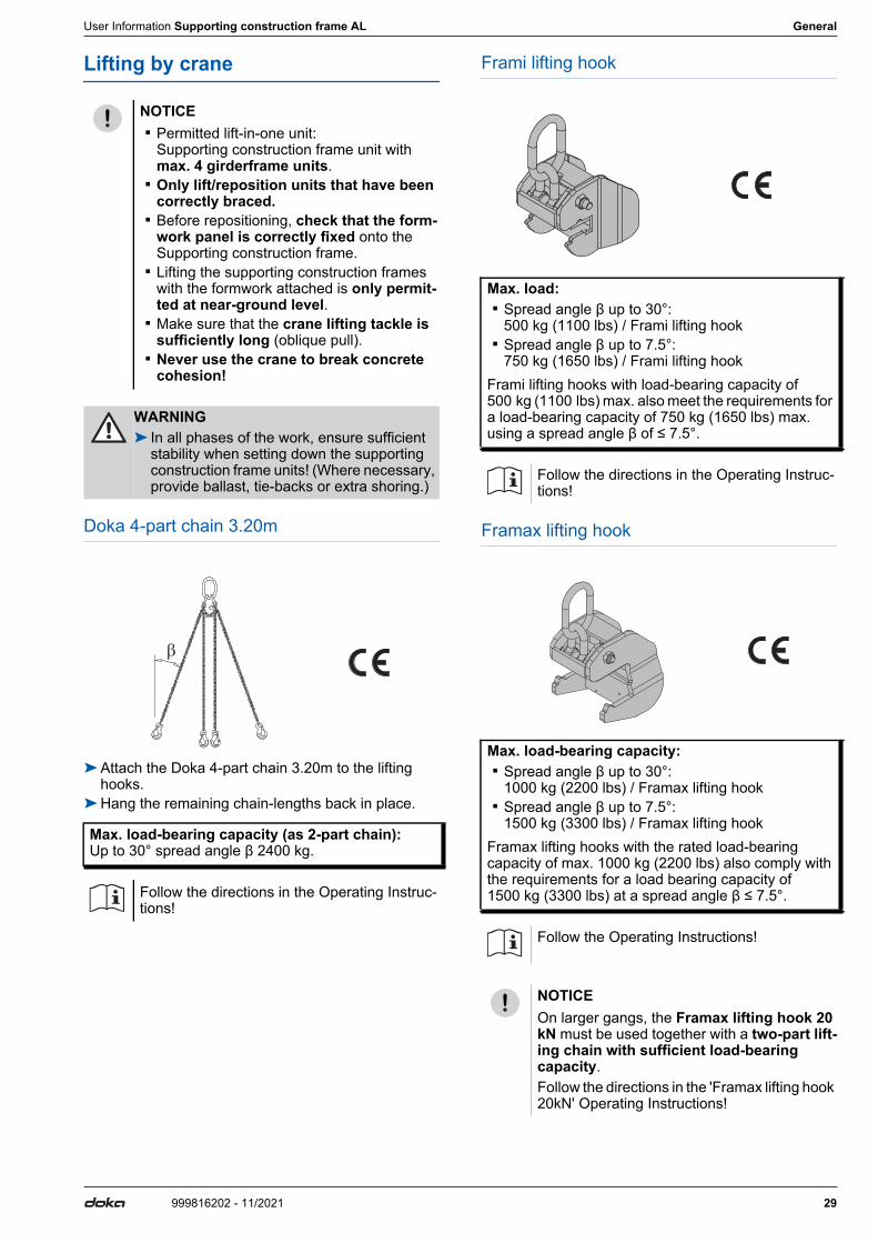
Frami lifting hook
Framax lifting hook
NOTICE ▪ Permitted lift-in-one unit:
Supporting construction frame unit with max. 4 girderframe units.
▪ Only lift/reposition units that have been correctly braced.
▪ Before repositioning, check that the form-work panel is correctly fixed onto the Supporting construction frame.
▪ Lifting the supporting construction frames with the formwork attached is only permit-ted at near-ground level.
▪ Make sure that the crane lifting tackle is sufficiently long (oblique pull).
▪ Never use the crane to break concrete cohesion!
WARNING➤ In all phases of the work, ensure sufficient
stability when setting down the supporting construction frame units! (Where necessary, provide ballast, tie-backs or extra shoring.)
Max. load-bearing capacity (as 2-part chain): Up to 30° spread angle β 2400 kg.
Follow the directions in the Operating Instruc-tions!
Max. load: ▪ Spread angle β up to 30°:
500 kg (1100 lbs) / Frami lifting hook ▪ Spread angle β up to 7.5°:
750 kg (1650 lbs) / Frami lifting hookFrami lifting hooks with load-bearing capacity of 500 kg (1100 lbs) max. also meet the requirements for a load-bearing capacity of 750 kg (1650 lbs) max. using a spread angle β of ≤ 7.5°.
Follow the directions in the Operating Instruc-tions!
Max. load-bearing capacity: ▪ Spread angle β up to 30°:
1000 kg (2200 lbs) / Framax lifting hook ▪ Spread angle β up to 7.5°:
1500 kg (3300 lbs) / Framax lifting hookFramax lifting hooks with the rated load-bearing capacity of max. 1000 kg (2200 lbs) also comply with the requirements for a load bearing capacity of 1500 kg (3300 lbs) at a spread angle β ≤ 7.5°.
Follow the Operating Instructions!
NOTICEOn larger gangs, the Framax lifting hook 20 kN must be used together with a two-part lift-ing chain with sufficient load-bearing capacity.Follow the directions in the 'Framax lifting hook 20kN' Operating Instructions!
30 999816202 - 11/2021
General User Information Supporting construction frame AL
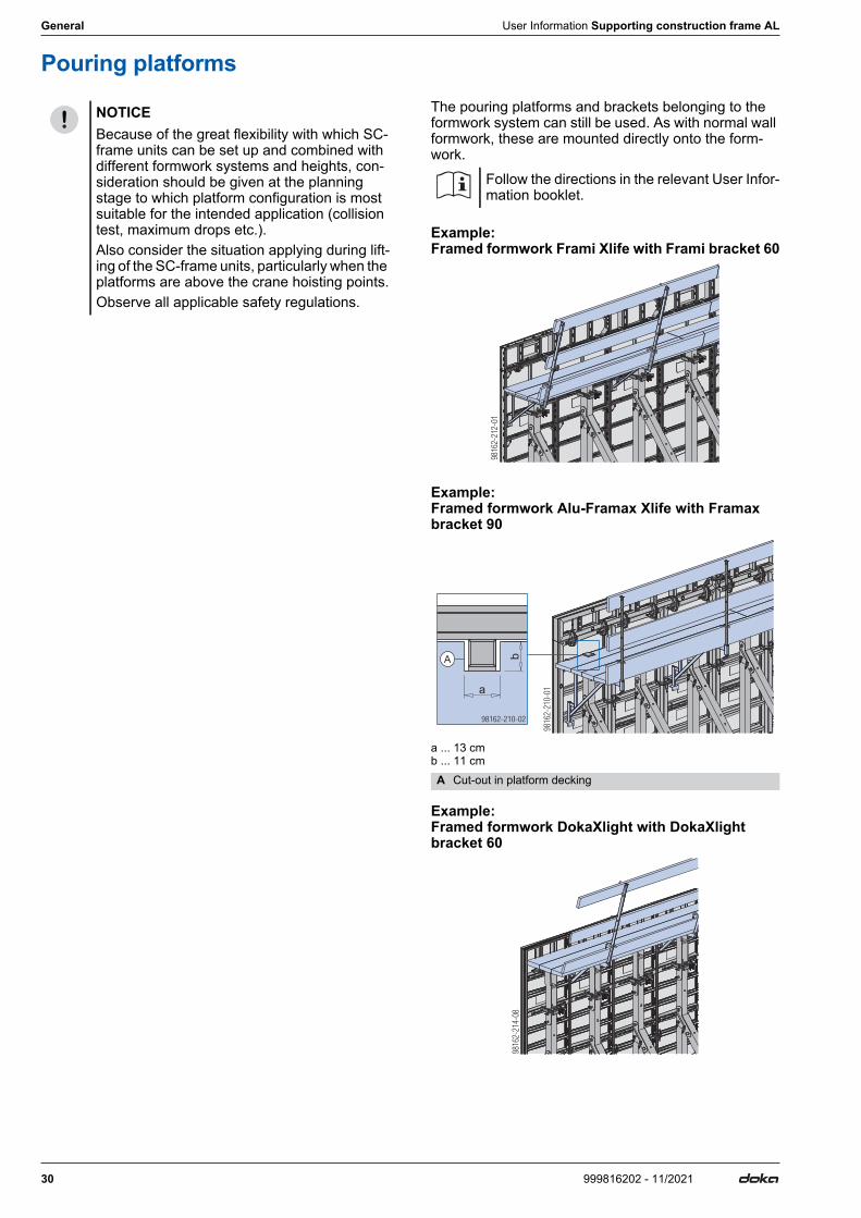
Pouring platformsThe pouring platforms and brackets belonging to the formwork system can still be used. As with normal wall formwork, these are mounted directly onto the form-work.
Example: Framed formwork Frami Xlife with Frami bracket 60
Example: Framed formwork Alu-Framax Xlife with Framax bracket 90
a ... 13 cm b ... 11 cm
Example: Framed formwork DokaXlight with DokaXlight bracket 60
NOTICEBecause of the great flexibility with which SC-frame units can be set up and combined with different formwork systems and heights, con-sideration should be given at the planning stage to which platform configuration is most suitable for the intended application (collision test, maximum drops etc.).Also consider the situation applying during lift-ing of the SC-frame units, particularly when the platforms are above the crane hoisting points.Observe all applicable safety regulations.
Follow the directions in the relevant User Infor-mation booklet.
A Cut-out in platform decking
9816
2-21
0-01a
b
98162-210-02
A
User Information Supporting construction frame AL General
31999816202 - 11/2021
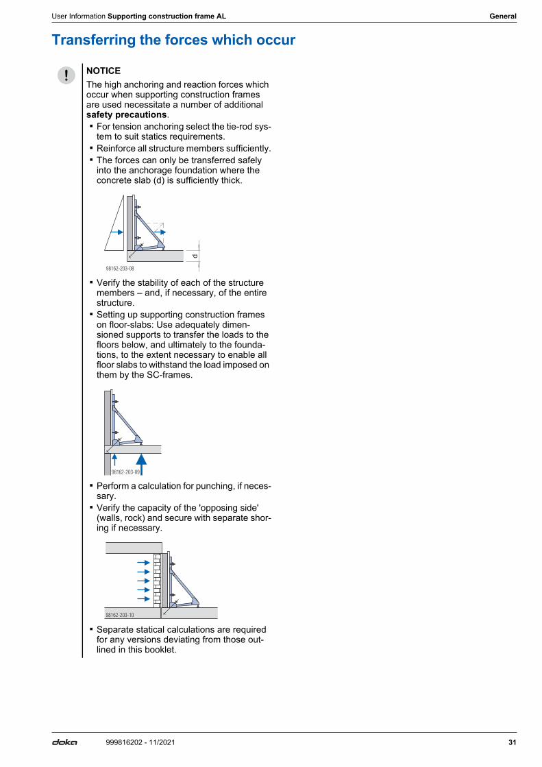
Transferring the forces which occur
NOTICEThe high anchoring and reaction forces which occur when supporting construction frames are used necessitate a number of additional safety precautions. ▪ For tension anchoring select the tie-rod sys-
tem to suit statics requirements. ▪ Reinforce all structure members sufficiently. ▪ The forces can only be transferred safely
into the anchorage foundation where the concrete slab (d) is sufficiently thick.
▪ Verify the stability of each of the structure members – and, if necessary, of the entire structure.
▪ Setting up supporting construction frames on floor-slabs: Use adequately dimen-sioned supports to transfer the loads to the floors below, and ultimately to the founda-tions, to the extent necessary to enable all floor slabs to withstand the load imposed on them by the SC-frames.
▪ Perform a calculation for punching, if neces-sary.
▪ Verify the capacity of the 'opposing side' (walls, rock) and secure with separate shor-ing if necessary.
▪ Separate statical calculations are required for any versions deviating from those out-lined in this booklet.
98162-203-08
d
98162-203-09
98162-203-10
32 999816202 - 11/2021
General User Information Supporting construction frame AL
Anchoring solutions for the supporting construction framesThe loads from the diagonal anchors are transferred via anchor walings. Set two anchors for each supporting construction frame. Separate statics calculation is required for anchoring with only one anchor per sup-porting construction frame!In each anchoring system, there are two variants to choose between: ▪ With pigtail anchor
This is the anchorage method that can best transfer the high tensile forces from SC-frames into the foun-dation slabs.
▪ With stop anchor
Permitted loads for anchor walings
Dimensioning the anchorages
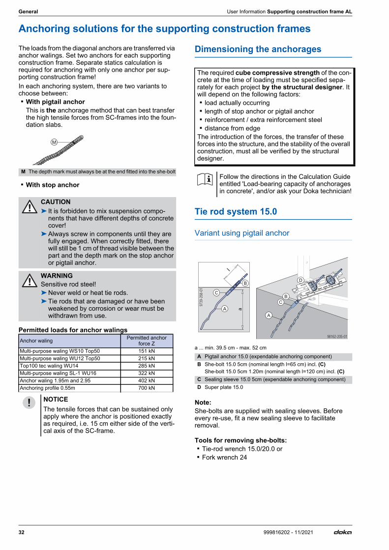
Tie rod system 15.0
Variant using pigtail anchor
a ... min. 39.5 cm - max. 52 cm
Note:She-bolts are supplied with sealing sleeves. Before every re-use, fit a new sealing sleeve to facilitate removal.
Tools for removing she-bolts: ▪ Tie-rod wrench 15.0/20.0 or ▪ Fork wrench 24
M The depth mark must always be at the end fitted into the she-bolt
CAUTION➤ It is forbidden to mix suspension compo-
nents that have different depths of concrete cover!
➤Always screw in components until they are fully engaged. When correctly fitted, there will still be 1 cm of thread visible between the part and the depth mark on the stop anchor or pigtail anchor.
WARNINGSensitive rod steel!➤Never weld or heat tie rods.➤Tie rods that are damaged or have been
weakened by corrosion or wear must be withdrawn from use.
Anchor waling Permitted anchor force Z
Multi-purpose waling WS10 Top50 151 kNMulti-purpose waling WU12 Top50 215 kNTop100 tec waling WU14 285 kNMulti-purpose waling SL-1 WU16 322 kNAnchor waling 1.95m and 2.95 402 kNAnchoring profile 0.55m 700 kN
NOTICEThe tensile forces that can be sustained only apply where the anchor is positioned exactly as required, i.e. 15 cm either side of the verti-cal axis of the SC-frame.
M
The required cube compressive strength of the con-crete at the time of loading must be specified sepa-rately for each project by the structural designer. It will depend on the following factors: ▪ load actually occurring ▪ length of stop anchor or pigtail anchor ▪ reinforcement / extra reinforcement steel ▪ distance from edgeThe introduction of the forces, the transfer of these forces into the structure, and the stability of the overall construction, must all be verified by the structural designer.
Follow the directions in the Calculation Guide entitled 'Load-bearing capacity of anchorages in concrete', and/or ask your Doka technician!
A Pigtail anchor 15.0 (expendable anchoring component)B She-bolt 15.0 5cm (nominal length l=65 cm) incl. (C)
She-bolt 15.0 5cm 1.20m (nominal length l=120 cm) incl. (C)C Sealing sleeve 15.0 5cm (expendable anchoring component)D Super plate 15.0
l
9739
-268
-01
a
98162-205-01
A
B
C
D

User Information Supporting construction frame AL General
33999816202 - 11/2021
Alternative method of preparing the positioning-point
Dismantling tools: ▪ for the Positioning cone: Positioning cone spanner
15.0 DK ▪ for turning the tie rod: Tie rod wrench 15.0/20.0
Another alternative:
Pigtail anchor protrudes from concrete: Instead of the she-bolt, fasten a Tie rod 15.0mm to the pigtail anchor using a Rod connector 15.0.
b ... min. 8.0 cm - max. 10.0 cm
Variant using stop anchor
Note:She-bolts are supplied with sealing sleeves. Before every re-use, fit a new sealing sleeve to facilitate removal.
Tools for removing she-bolts: ▪ Tie-rod wrench 15.0/20.0 or ▪ Fork wrench 24
Alternative method of preparing the positioning-point
Dismantling tools: ▪ for the Positioning cone: Positioning cone spanner
15.0 DK ▪ for turning the tie rod: Tie rod wrench 15.0/20.0
Another alternative:
Stop anchor protrudes from concrete: Instead of the she-bolt, fasten a Tie rod 15.0mm to the stop anchor using a Rod connector 15.0.
b ... min. 8.0 cm - max. 10.0 cm
Retrofitting anchorages in the concrete
▪ Tie rod 15.0mm ▪ Rock anchor spreader unit 15.0 1)
1) Expendable anchoring componentExtra components needed for preparing the anchoring point: ▪ Tensioning instrument 300kN, consisting of
- 1 hollow-piston cylinder- 1 hydraulic hand pump- 1 pressure support- 1 carrying case- 1 Rock anchor installation tube
▪ Tie-rod wrench 15.0/20.0 ▪ Super plate 15.0 ▪ Rock drill-bits diam. 37 or 38 mm
Note:Also, a slip-proof support surface must be provided so that the Tensioning instrument B can be used at a 45° angle.
- Positioning cone 15.0 5cm with Sealing sleeve 15.0 5cm1)
- Tie rod 15.0mm (length as required)
A Pigtail anchor 15.0E Tie rod 15.0mmF Rod connector 15.0
aStop anchor 15.0 40cm 55 30 cmStop anchor 15.0 16cm 55 13 cm
A Stop anchor 15.0 (expendable anchoring component)B She-bolt 15.0 5cm (nominal length l=65 cm) incl. (C) or
She-bolt 15.0 5cm 1.20m (nominal length l=120 cm) incl. (C)C Sealing sleeve 15.0 5cm (expendable anchoring component)D Super plate 15.0
b
9739-258-01
l
9739
-354
-01
a
98162-205-02
A
B
C
D
- Positioning cone 15.0 5cm with Sealing sleeve 15.0 5cm1)
- Tie rod 15.0mm (length as required)
➤The Stop anchor 15.0 16cm 55 is not suita-ble here!
Placement depth is too shallow!
A Stop anchor 15.0 40cm 55E Tie rod 15.0mmF Rod connector 15.0
Follow the directions in the ‘Rock-anchor spreader unit 15.0’ Fitting Instructions!
Observe load-bearing capacity as stated in the section headed ‘Carrying out the acceptance test’ in the ‘Rock anchor spreader unit 15.0’ Fitting Instructions!
9739-259-01
b
34 999816202 - 11/2021
General User Information Supporting construction frame AL
Fitting diagonal anchorsIn everyday site practice, there are various different ways of preparing positioning points for diagonal anchors at a precise angle (usually 45°), depending on the site situation.The following examples show several possible and effective variants. These apply equally to the use of either pigtail anchors or stop anchors.
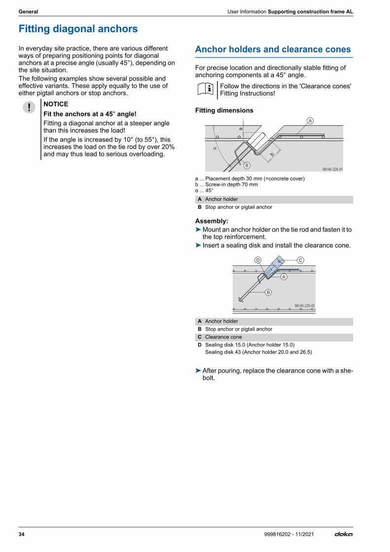
Anchor holders and clearance cones
For precise location and directionally stable fitting of anchoring components at a 45° angle.
Fitting dimensions
a ... Placement depth 30 mm (=concrete cover) b ... Screw-in depth 70 mm α ... 45°
Assembly:➤Mount an anchor holder on the tie rod and fasten it to
the top reinforcement.➤ Insert a sealing disk and install the clearance cone.
➤After pouring, replace the clearance cone with a she-bolt.
NOTICEFit the anchors at a 45° angle!Fitting a diagonal anchor at a steeper angle than this increases the load!If the angle is increased by 10° (to 55°), this increases the load on the tie rod by over 20% and may thus lead to serious overloading.
Follow the directions in the 'Clearance cones' Fitting Instructions!
A Anchor holderB Stop anchor or pigtail anchor
A Anchor holderB Stop anchor or pigtail anchorC Clearance coneD Sealing disk 15.0 (Anchor holder 15.0)
Sealing disk 43 (Anchor holder 20.0 and 26.5)
98140 29 1-2 -0
a
b
A
B
98140-229-02
C
A
B
D
User Information Supporting construction frame AL General
35999816202 - 11/2021
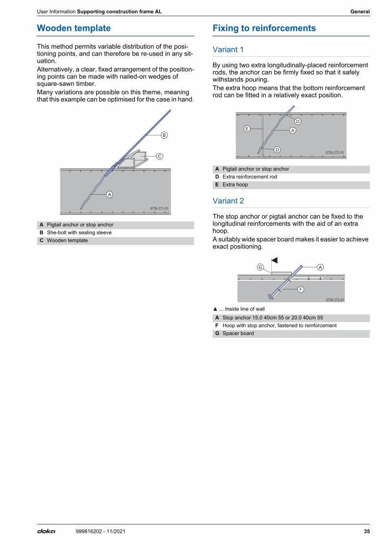
Wooden template
This method permits variable distribution of the posi-tioning points, and can therefore be re-used in any sit-uation.Alternatively, a clear, fixed arrangement of the position-ing points can be made with nailed-on wedges of square-sawn timber.Many variations are possible on this theme, meaning that this example can be optimised for the case in hand.
Fixing to reinforcements
Variant 1
By using two extra longitudinally-placed reinforcement rods, the anchor can be firmly fixed so that it safely withstands pouring.The extra hoop means that the bottom reinforcement rod can be fitted in a relatively exact position.
Variant 2
The stop anchor or pigtail anchor can be fixed to the longitudinal reinforcements with the aid of an extra hoop.A suitably wide spacer board makes it easier to achieve exact positioning.
▲ ... Inside line of wall
A Pigtail anchor or stop anchorB She-bolt with sealing sleeveC Wooden template
9739-271-01
A Pigtail anchor or stop anchorD Extra reinforcement rodE Extra hoop
A Stop anchor 15.0 40cm 55 or 20.0 40cm 55F Hoop with stop anchor, fastened to reinforcementG Spacer board
9739-272-01
9739-273-01
36 999816202 - 11/2021
General User Information Supporting construction frame AL
Transporting, stacking and storing
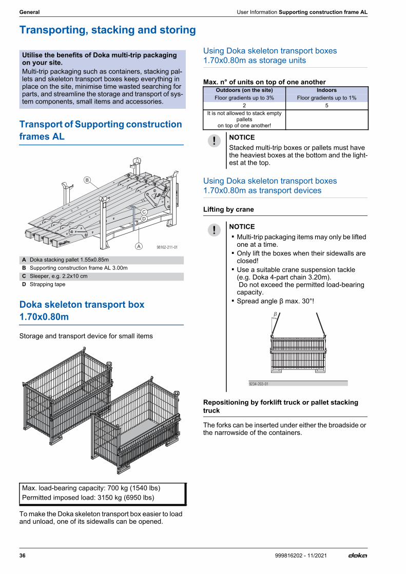
Transport of Supporting construction frames AL
Doka skeleton transport box 1.70x0.80m
Storage and transport device for small items
To make the Doka skeleton transport box easier to load and unload, one of its sidewalls can be opened.
Using Doka skeleton transport boxes 1.70x0.80m as storage units
Max. n° of units on top of one another
Using Doka skeleton transport boxes 1.70x0.80m as transport devices
Lifting by crane
Repositioning by forklift truck or pallet stacking truck
The forks can be inserted under either the broadside or the narrowside of the containers.
Utilise the benefits of Doka multi-trip packaging on your site.Multi-trip packaging such as containers, stacking pal-lets and skeleton transport boxes keep everything in place on the site, minimise time wasted searching for parts, and streamline the storage and transport of sys-tem components, small items and accessories.
A Doka stacking pallet 1.55x0.85mB Supporting construction frame AL 3.00mC Sleeper, e.g. 2.2x10 cmD Strapping tape
Max. load-bearing capacity: 700 kg (1540 lbs)Permitted imposed load: 3150 kg (6950 lbs)
B
A
D
C
98162-211-01
Outdoors (on the site) IndoorsFloor gradients up to 3% Floor gradients up to 1%
2 5It is not allowed to stack empty
pallets on top of one another!
NOTICEStacked multi-trip boxes or pallets must have the heaviest boxes at the bottom and the light-est at the top.
NOTICE ▪ Multi-trip packaging items may only be lifted
one at a time. ▪ Only lift the boxes when their sidewalls are
closed! ▪ Use a suitable crane suspension tackle
(e.g. Doka 4-part chain 3.20m). Do not exceed the permitted load-bearing capacity.
▪ Spread angle β max. 30°!
9234-203-01
User Information Supporting construction frame AL General
37999816202 - 11/2021
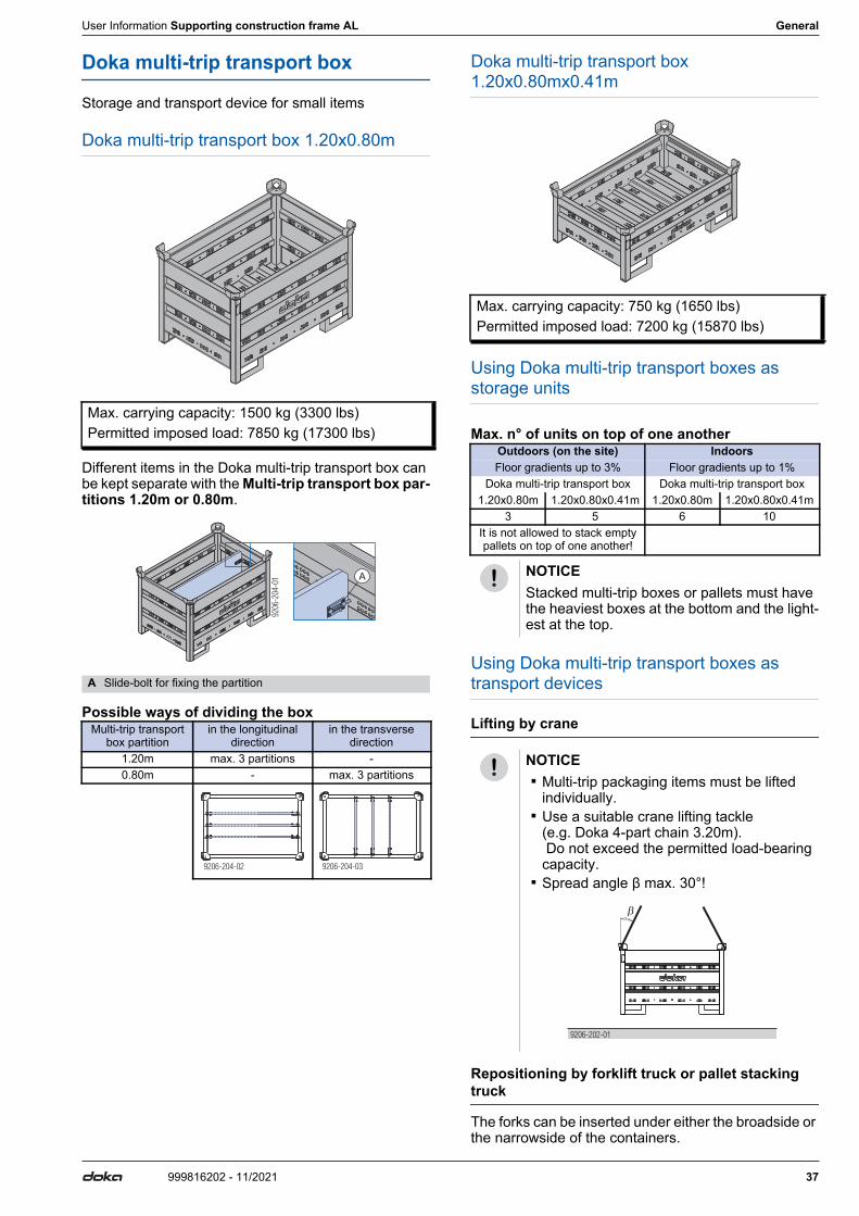
Doka multi-trip transport box
Storage and transport device for small items
Doka multi-trip transport box 1.20x0.80m
Different items in the Doka multi-trip transport box can be kept separate with the Multi-trip transport box par-titions 1.20m or 0.80m.
Possible ways of dividing the box
Doka multi-trip transport box 1.20x0.80mx0.41m
Using Doka multi-trip transport boxes as storage units
Max. n° of units on top of one another
Using Doka multi-trip transport boxes as transport devices
Lifting by crane
Repositioning by forklift truck or pallet stacking truck
The forks can be inserted under either the broadside or the narrowside of the containers.
Max. carrying capacity: 1500 kg (3300 lbs)Permitted imposed load: 7850 kg (17300 lbs)
A Slide-bolt for fixing the partition
Multi-trip transport box partition
in the longitudinal direction
in the transverse direction
1.20m max. 3 partitions -0.80m - max. 3 partitions
9206
-204
-01 A
9206-204-02 9206-204-03
Max. carrying capacity: 750 kg (1650 lbs)Permitted imposed load: 7200 kg (15870 lbs)
Outdoors (on the site) IndoorsFloor gradients up to 3% Floor gradients up to 1%
Doka multi-trip transport box Doka multi-trip transport box1.20x0.80m 1.20x0.80x0.41m 1.20x0.80m 1.20x0.80x0.41m
3 5 6 10It is not allowed to stack empty pallets on top of one another!
NOTICEStacked multi-trip boxes or pallets must have the heaviest boxes at the bottom and the light-est at the top.
NOTICE ▪ Multi-trip packaging items must be lifted
individually. ▪ Use a suitable crane lifting tackle
(e.g. Doka 4-part chain 3.20m). Do not exceed the permitted load-bearing capacity.
▪ Spread angle β max. 30°!
9206-202-01
38 999816202 - 11/2021
General User Information Supporting construction frame AL
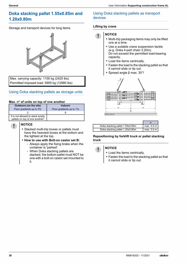
Doka stacking pallet 1.55x0.85m and 1.20x0.80m
Storage and transport devices for long items.
Using Doka stacking pallets as storage units
Max. n° of units on top of one another
Using Doka stacking pallets as transport devices
Lifting by crane
Repositioning by forklift truck or pallet stacking truck
Max. carrying capacity: 1100 kg (2420 lbs)Permitted imposed load: 5900 kg (12980 lbs)
Outdoors (on the site) IndoorsFloor gradients up to 3% Floor gradients up to 1%
2 6It is not allowed to stack empty pallets on top of one another!
NOTICE ▪ Stacked multi-trip boxes or pallets must
have the heaviest boxes at the bottom and the lightest at the top.
▪ How to use with Bolt-on castor set B:- Always apply the fixing brake when the
container is 'parked'.- When Doka stacking pallets are
stacked, the bottom pallet must NOT be one with a bolt-on castor set mounted to it.
NOTICE ▪ Multi-trip packaging items may only be lifted
one at a time. ▪ Use a suitable crane suspension tackle
(e.g. Doka 4-part chain 3.20m). Do not exceed the permitted load-bearing capacity.
▪ Load the items centrically. ▪ Fasten the load to the stacking pallet so that
it cannot slide or tip out. ▪ Spread angle β max. 30°!
aDoka stacking pallet 1.55x0.85m max. 4.5 mDoka stacking pallet 1.20x0.80m max. 3.0 m
NOTICE ▪ Load the items centrically. ▪ Fasten the load to the stacking pallet so that
it cannot slide or tip out.
92815-2 -0124
a= =
User Information Supporting construction frame AL General
39999816202 - 11/2021
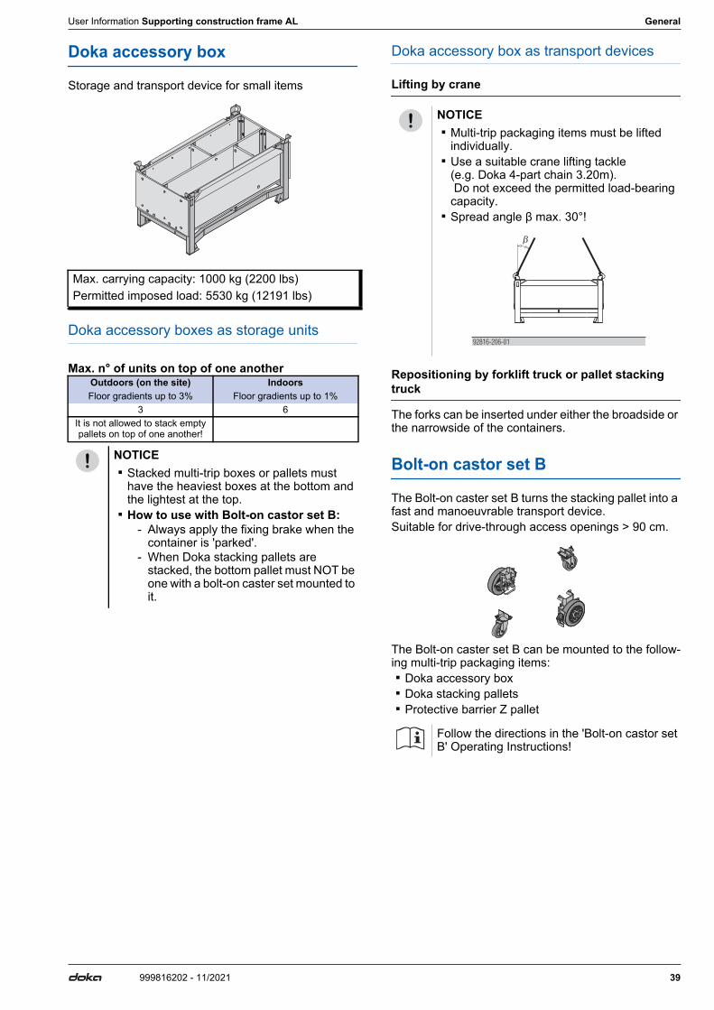
Doka accessory box
Storage and transport device for small items
Doka accessory boxes as storage units
Max. n° of units on top of one another
Doka accessory box as transport devices
Lifting by crane
Repositioning by forklift truck or pallet stacking truck
The forks can be inserted under either the broadside or the narrowside of the containers.
Bolt-on castor set B
The Bolt-on caster set B turns the stacking pallet into a fast and manoeuvrable transport device.Suitable for drive-through access openings > 90 cm.
The Bolt-on caster set B can be mounted to the follow-ing multi-trip packaging items: ▪ Doka accessory box ▪ Doka stacking pallets ▪ Protective barrier Z pallet
Max. carrying capacity: 1000 kg (2200 lbs)Permitted imposed load: 5530 kg (12191 lbs)
Outdoors (on the site) IndoorsFloor gradients up to 3% Floor gradients up to 1%
3 6It is not allowed to stack empty pallets on top of one another!
NOTICE ▪ Stacked multi-trip boxes or pallets must
have the heaviest boxes at the bottom and the lightest at the top.
▪ How to use with Bolt-on castor set B:- Always apply the fixing brake when the
container is 'parked'.- When Doka stacking pallets are
stacked, the bottom pallet must NOT be one with a bolt-on caster set mounted to it.
NOTICE ▪ Multi-trip packaging items must be lifted
individually. ▪ Use a suitable crane lifting tackle
(e.g. Doka 4-part chain 3.20m). Do not exceed the permitted load-bearing capacity.
▪ Spread angle β max. 30°!
Follow the directions in the 'Bolt-on castor set B' Operating Instructions!
92816-206-01
Article N°[kg] Article N°[kg]
40 999816202 - 11/2021
Article list User Information Supporting construction frame AL
Article list[kg]Article N°
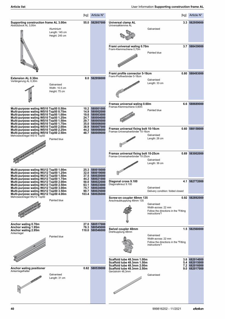
Supporting construction frame AL 3.00m 55.0 582957000Abstützbock AL 3,00m
Extension AL 0.30m 8.0 582958000Verlängerung AL 0,30m
Multi-purpose waling WS10 Top50 0.50m 10.2 580001000Multi-purpose waling WS10 Top50 0.75m 14.9 580002000Multi-purpose waling WS10 Top50 1.00m 19.6 580003000Multi-purpose waling WS10 Top50 1.25m 24.7 580004000Multi-purpose waling WS10 Top50 1.50m 29.7 580005000Multi-purpose waling WS10 Top50 1.75m 35.0 580006000Multi-purpose waling WS10 Top50 2.00m 38.9 580007000Multi-purpose waling WS10 Top50 2.25m 44.2 580008000Multi-purpose waling WS10 Top50 2.50m 48.7 580009000Mehrzweckriegel WS10 Top50
Multi-purpose waling WU12 Top50 1.00m 25.3 580018000Multi-purpose waling WU12 Top50 1.25m 32.0 580019000Multi-purpose waling WU12 Top50 1.50m 37.5 580020000Multi-purpose waling WU12 Top50 1.75m 44.2 580021000Multi-purpose waling WU12 Top50 2.00m 50.0 580022000Multi-purpose waling WU12 Top50 2.50m 63.1 580023000Multi-purpose waling WU12 Top50 3.00m 75.7 580024000Multi-purpose waling WU12 Top50 3.50m 90.7 580025000Multi-purpose waling WU12 Top50 4.00m 103.4 580026000Mehrzweckriegel WU12 Top50
Anchor waling 0.70m 27.0 580517000Anchor waling 1.95m 76.3 580545000Anchor waling 2.95m 110.0 580546000Ankerriegel
Anchor waling positioner 0.62 580539000Ankerriegelhalter
Universal clamp AL 3.3 582959000Universalklemme AL
Frami universal waling 0.70m 3.7 588439000Frami-Klemmschiene 0,70m
Frami profile connector 5-18cm 0.80 588493000Frami-Profilverbinder 5-18cm
Framax universal waling 0.60m 6.6 588689000Framax-Klemmschiene 0,60m
Framax universal fixing bolt 10-16cm 0.60 588158000Framax-Universalverbinder 10-16cm
Framax universal fixing bolt 10-25cm 0.69 583002000Framax-Universalverbinder 10-25cm
Diagonal cross 9.100 4.1 582772000Diagonalkreuz 9.100
Screw-on coupler 48mm 135 0.92 582892000Anschraubkupplung 48mm 135
Swivel coupler 48mm 1.5 582560000Drehkupplung 48mm
Scaffold tube 48.3mm 1.00m 3.6 682014000Scaffold tube 48.3mm 1.50m 5.4 682015000Scaffold tube 48.3mm 2.00m 7.2 682016000Scaffold tube 48.3mm 2.50m 9.0 682017000Gerüstrohr 48,3mm
AluminiumLength: 145 cmHeight: 245 cm
GalvanisedWidth: 10.5 cmHeight: 75 cm
Painted blue
Painted blue
Painted blue
GalvanisedLength: 31 cm
Galvanised
Painted blue
GalvanisedLength: 33 cm
Painted blue
GalvanisedLength: 26 cm
GalvanisedLength: 36 cm
GalvanisedDelivery condition: folded closed
GalvanisedWidth-across: 22 mmFollow the directions in the "Fitting instructions"!
GalvanisedWidth-across: 22 mmFollow the directions in the "Fitting instructions"!
Galvanised
Article N°[kg] Article N°[kg]
41999816202 - 11/2021
User Information Supporting construction frame AL Article list
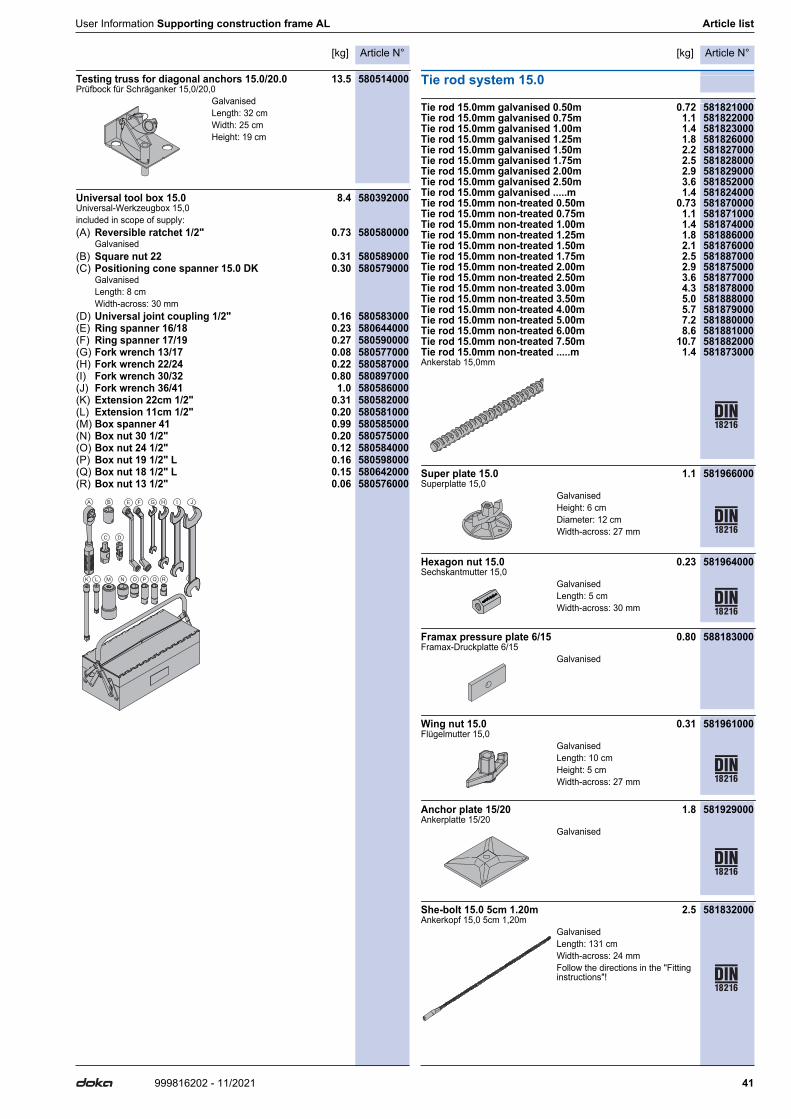
Testing truss for diagonal anchors 15.0/20.0 13.5 580514000Prüfbock für Schräganker 15,0/20,0
Universal tool box 15.0 8.4 580392000Universal-Werkzeugbox 15,0included in scope of supply:(A) Reversible ratchet 1/2" 0.73 580580000
Galvanised(B) Square nut 22 0.31 580589000(C) Positioning cone spanner 15.0 DK 0.30 580579000
GalvanisedLength: 8 cmWidth-across: 30 mm
(D) Universal joint coupling 1/2" 0.16 580583000(E) Ring spanner 16/18 0.23 580644000(F) Ring spanner 17/19 0.27 580590000(G) Fork wrench 13/17 0.08 580577000(H) Fork wrench 22/24 0.22 580587000(I) Fork wrench 30/32 0.80 580897000(J) Fork wrench 36/41 1.0 580586000(K) Extension 22cm 1/2" 0.31 580582000(L) Extension 11cm 1/2" 0.20 580581000(M) Box spanner 41 0.99 580585000(N) Box nut 30 1/2" 0.20 580575000(O) Box nut 24 1/2" 0.12 580584000(P) Box nut 19 1/2" L 0.16 580598000(Q) Box nut 18 1/2" L 0.15 580642000(R) Box nut 13 1/2" 0.06 580576000
Tie rod system 15.0
Tie rod 15.0mm galvanised 0.50m 0.72 581821000Tie rod 15.0mm galvanised 0.75m 1.1 581822000Tie rod 15.0mm galvanised 1.00m 1.4 581823000Tie rod 15.0mm galvanised 1.25m 1.8 581826000Tie rod 15.0mm galvanised 1.50m 2.2 581827000Tie rod 15.0mm galvanised 1.75m 2.5 581828000Tie rod 15.0mm galvanised 2.00m 2.9 581829000Tie rod 15.0mm galvanised 2.50m 3.6 581852000Tie rod 15.0mm galvanised .....m 1.4 581824000Tie rod 15.0mm non-treated 0.50m 0.73 581870000Tie rod 15.0mm non-treated 0.75m 1.1 581871000Tie rod 15.0mm non-treated 1.00m 1.4 581874000Tie rod 15.0mm non-treated 1.25m 1.8 581886000Tie rod 15.0mm non-treated 1.50m 2.1 581876000Tie rod 15.0mm non-treated 1.75m 2.5 581887000Tie rod 15.0mm non-treated 2.00m 2.9 581875000Tie rod 15.0mm non-treated 2.50m 3.6 581877000Tie rod 15.0mm non-treated 3.00m 4.3 581878000Tie rod 15.0mm non-treated 3.50m 5.0 581888000Tie rod 15.0mm non-treated 4.00m 5.7 581879000Tie rod 15.0mm non-treated 5.00m 7.2 581880000Tie rod 15.0mm non-treated 6.00m 8.6 581881000Tie rod 15.0mm non-treated 7.50m 10.7 581882000Tie rod 15.0mm non-treated .....m 1.4 581873000Ankerstab 15,0mm
Super plate 15.0 1.1 581966000Superplatte 15,0
Hexagon nut 15.0 0.23 581964000Sechskantmutter 15,0
Framax pressure plate 6/15 0.80 588183000Framax-Druckplatte 6/15
Wing nut 15.0 0.31 581961000Flügelmutter 15,0
Anchor plate 15/20 1.8 581929000Ankerplatte 15/20
She-bolt 15.0 5cm 1.20m 2.5 581832000Ankerkopf 15,0 5cm 1,20m
GalvanisedLength: 32 cmWidth: 25 cmHeight: 19 cm
B
C
E F G H IA
L M N O PK Q R Q
J
D
GalvanisedHeight: 6 cmDiameter: 12 cmWidth-across: 27 mm
GalvanisedLength: 5 cmWidth-across: 30 mm
Galvanised
GalvanisedLength: 10 cmHeight: 5 cmWidth-across: 27 mm
Galvanised
GalvanisedLength: 131 cmWidth-across: 24 mmFollow the directions in the "Fitting instructions"!
Article N°[kg] Article N°[kg]
42 999816202 - 11/2021
Article list User Information Supporting construction frame AL
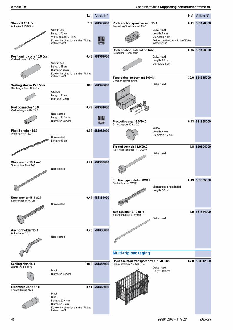
She-bolt 15.0 5cm 1.7 581972000Ankerkopf 15,0 5cm
Positioning cone 15.0 5cm 0.43 581969000Vorlaufkonus 15,0 5cm
Sealing sleeve 15.0 5cm 0.008 581990000Dichtungshülse 15,0 5cm
Rod connector 15.0 0.49 581981000Verbindungsmuffe 15,0
Pigtail anchor 15.0 0.92 581984000Wellenanker 15,0
Stop anchor 15.0 A40 0.71 581999000Sperranker 15,0 A40
Stop anchor 15.0 A21 0.44 581884000Sperranker 15,0 A21
Anchor holder 15.0 0.43 581835000Ankerhalter 15,0
Sealing disc 15.0 0.002 581885000Dichtscheibe 15,0
Clearance cone 15.0 0.51 581865000Freistellkonus 15,0
Rock anchor spreader unit 15.0 0.41 581120000Felsanker-Spreizeinheit 15,0
Rock anchor installation tube 0.85 581123000Felsanker-Einbaurohr
Tensioning instrument 300kN 32.0 581815000Vorspanngerät 300kN
Protective cap 15.0/20.0 0.03 581858000Schutzkappe 15,0/20,0
Tie-rod wrench 15.0/20.0 1.8 580594000Ankerstabschlüssel 15,0/20,0
Friction type ratchet SW27 0.49 581855000Freilaufknarre SW27
Box spanner 27 0.65m 1.9 581854000Steckschlüssel 27 0,65m
Multi-trip packaging
Doka skeleton transport box 1.70x0.80m 87.0 583012000Doka-Gitterbox 1,70x0,80m
GalvanisedLength: 76 cmWidth-across: 24 mmFollow the directions in the "Fitting instructions"!
GalvanisedLength: 11 cmDiameter: 3 cmFollow the directions in the "Fitting instructions"!
OrangeLength: 10 cmDiameter: 3 cm
Non-treatedLength: 10.5 cmDiameter: 3.2 cm
Non-treatedLength: 67 cm
Non-treated
Non-treated
Non-treated
BlackDiameter: 4.2 cm
BlackBlueLength: 20.6 cmDiameter: 7 cmFollow the directions in the "Fitting instructions"!
GalvanisedLength: 9 cmDiameter: 4 cmFollow the directions in the "Fitting instructions"!
GalvanisedLength: 50 cmDiameter: 3 cm
Galvanised
YellowLength: 6 cmDiameter: 6.7 cm
Galvanised
Manganese-phosphatedLength: 30 cm
Galvanised
GalvanisedHeight: 113 cm
Article N°[kg] Article N°[kg]
43999816202 - 11/2021
User Information Supporting construction frame AL Article list
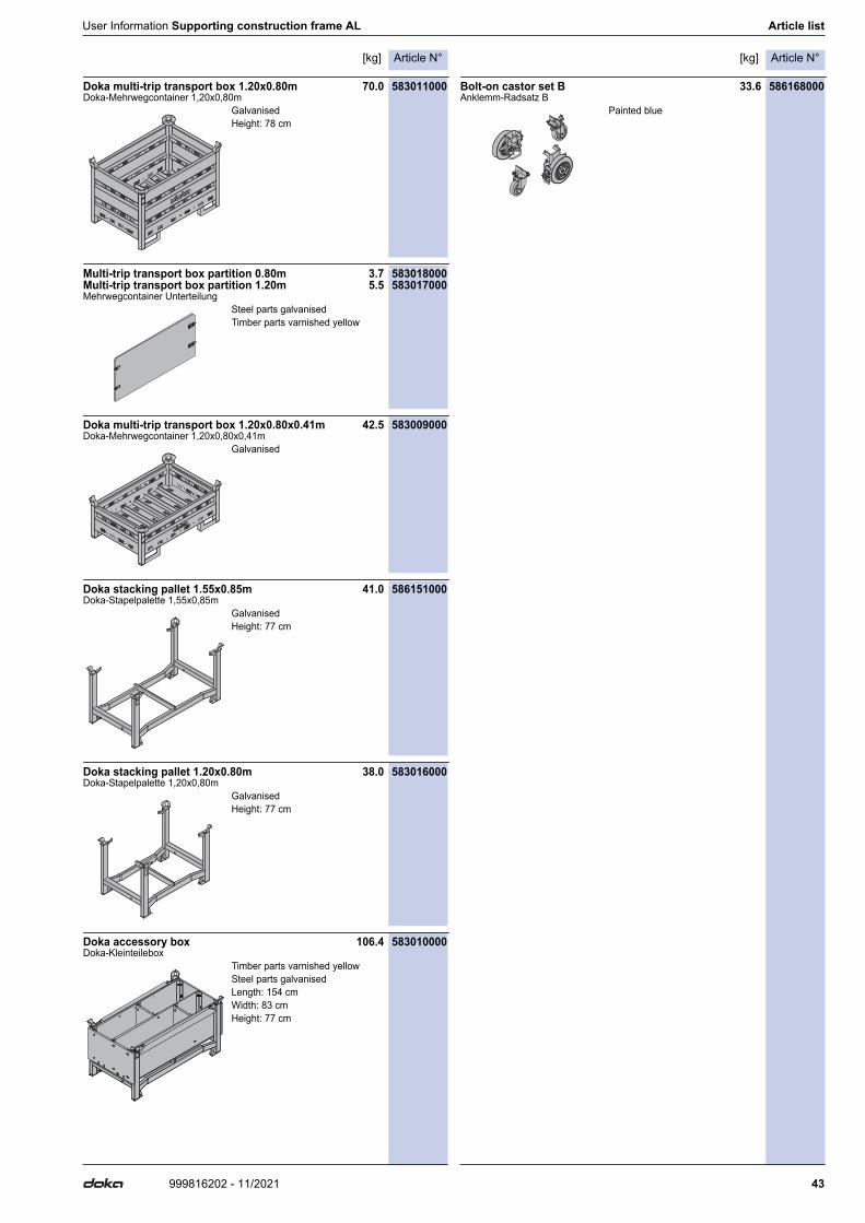
Doka multi-trip transport box 1.20x0.80m 70.0 583011000Doka-Mehrwegcontainer 1,20x0,80m
Multi-trip transport box partition 0.80m 3.7 583018000Multi-trip transport box partition 1.20m 5.5 583017000Mehrwegcontainer Unterteilung
Doka multi-trip transport box 1.20x0.80x0.41m 42.5 583009000Doka-Mehrwegcontainer 1,20x0,80x0,41m
Doka stacking pallet 1.55x0.85m 41.0 586151000Doka-Stapelpalette 1,55x0,85m
Doka stacking pallet 1.20x0.80m 38.0 583016000Doka-Stapelpalette 1,20x0,80m
Doka accessory box 106.4 583010000Doka-Kleinteilebox
Bolt-on castor set B 33.6 586168000Anklemm-Radsatz B
GalvanisedHeight: 78 cm
Steel parts galvanisedTimber parts varnished yellow
Galvanised
GalvanisedHeight: 77 cm
GalvanisedHeight: 77 cm
Timber parts varnished yellowSteel parts galvanisedLength: 154 cmWidth: 83 cmHeight: 77 cm
Painted blue
999816202 - 11/2021Doka GmbH | Josef Umdasch Platz 1 | 3300 Amstetten | Austria | T +43 7472 605-0 | F +43 7472 66430 | [email protected] | www.doka.com
Near to you, worldwide
Doka is one of the world leaders in developing, manu-facturing and distributing formwork technology for use in all fields of the construction sector.With more than 160 sales and logistics facilities in over 70 countries, the Doka Group has a highly efficient dis-tribution network which ensures that equipment and
technical support are provided swiftly and profession-ally.An enterprise forming part of the Umdasch Group, the Doka Group employs a worldwide workforce of more than 6000.
www.doka.com/supporting-construction-frame-al