Climate Simulation and Flood Risk Analysis for 2008–2040 for ...
Upload
khangminh22Category
view
3download
0
IMPORTANTFile in yourmaintenancerecords
Patient Transport Frame
Model 2040
MAINTENANCE MANUALFor beds with serial numbers of 0109036001 through 0109036500
For Parts or Technical Assistance1–800–327–0770

INTRODUCTION AND SET–UP INFORMATION
Introduction 1–1. . . . . . . . . . . . . . . . . . . . . . . . . . . . . . . . . . . . . . . . . . . . . . . . . . . . . . . . . . . . . . . . . . . . . . . . . . .
Specifications 1–1. . . . . . . . . . . . . . . . . . . . . . . . . . . . . . . . . . . . . . . . . . . . . . . . . . . . . . . . . . . . . . . . . . . . . . . . . .
Warning/Caution/Note Definition 1–1. . . . . . . . . . . . . . . . . . . . . . . . . . . . . . . . . . . . . . . . . . . . . . . . . . . . . . . . . .
Warranty 1–2, 1–3. . . . . . . . . . . . . . . . . . . . . . . . . . . . . . . . . . . . . . . . . . . . . . . . . . . . . . . . . . . . . . . . . . . . . . . . . .
Safety Tips and Guidelines 1–4, 1–5. . . . . . . . . . . . . . . . . . . . . . . . . . . . . . . . . . . . . . . . . . . . . . . . . . . . . . . . . .
Set–Up Procedures 1–6. . . . . . . . . . . . . . . . . . . . . . . . . . . . . . . . . . . . . . . . . . . . . . . . . . . . . . . . . . . . . . . . . . . . .
Symbols 1–7 – 1–14. . . . . . . . . . . . . . . . . . . . . . . . . . . . . . . . . . . . . . . . . . . . . . . . . . . . . . . . . . . . . . . . . . . . . . .
PREVENTIVE MAINTENANCE
Cleaning 2–2. . . . . . . . . . . . . . . . . . . . . . . . . . . . . . . . . . . . . . . . . . . . . . . . . . . . . . . . . . . . . . . . . . . . . . . . . . . . . .
Preventive Maintenance Checklist 2–3. . . . . . . . . . . . . . . . . . . . . . . . . . . . . . . . . . . . . . . . . . . . . . . . . . . . . . . .
Nurse Call Battery 2–4. . . . . . . . . . . . . . . . . . . . . . . . . . . . . . . . . . . . . . . . . . . . . . . . . . . . . . . . . . . . . . . . . . . . . .
Main Power Circuit Breaker 2–4. . . . . . . . . . . . . . . . . . . . . . . . . . . . . . . . . . . . . . . . . . . . . . . . . . . . . . . . . . . . . .
Battery Power Circuit Breaker 2–4. . . . . . . . . . . . . . . . . . . . . . . . . . . . . . . . . . . . . . . . . . . . . . . . . . . . . . . . . . . .
TROUBLESHOOTING
Troubleshooting Guide 3–2. . . . . . . . . . . . . . . . . . . . . . . . . . . . . . . . . . . . . . . . . . . . . . . . . . . . . . . . . . . . . . . . . .
Zoom� Troubleshooting Guide 3–3, 3–4. . . . . . . . . . . . . . . . . . . . . . . . . . . . . . . . . . . . . . . . . . . . . . . . . . . . . .
ELECTRICAL SYSTEM INFORMATION
CPU Board Diagram 4–2, 4–3. . . . . . . . . . . . . . . . . . . . . . . . . . . . . . . . . . . . . . . . . . . . . . . . . . . . . . . . . . . . . . . .
Display/CPU Diagram 4–4. . . . . . . . . . . . . . . . . . . . . . . . . . . . . . . . . . . . . . . . . . . . . . . . . . . . . . . . . . . . . . . . . . .
Power Supply Diagram 4–5. . . . . . . . . . . . . . . . . . . . . . . . . . . . . . . . . . . . . . . . . . . . . . . . . . . . . . . . . . . . . . . . . .
Power Board Diagram 4–6. . . . . . . . . . . . . . . . . . . . . . . . . . . . . . . . . . . . . . . . . . . . . . . . . . . . . . . . . . . . . . . . . .
AC Crossover Board Diagram 4–7. . . . . . . . . . . . . . . . . . . . . . . . . . . . . . . . . . . . . . . . . . . . . . . . . . . . . . . . . . . .
Optional Bed Exit Board Diagram 4–8. . . . . . . . . . . . . . . . . . . . . . . . . . . . . . . . . . . . . . . . . . . . . . . . . . . . . . . . .
Optional Smart TV Circuit Board Diagram 4–9. . . . . . . . . . . . . . . . . . . . . . . . . . . . . . . . . . . . . . . . . . . . . . . . .
Optional Bed Communications Tester 4–10. . . . . . . . . . . . . . . . . . . . . . . . . . . . . . . . . . . . . . . . . . . . . . . . . . . .
Head Wall Output Configuration 4–11. . . . . . . . . . . . . . . . . . . . . . . . . . . . . . . . . . . . . . . . . . . . . . . . . . . . . . . . .
Inverter Protection Features and Voltage Points 4–12. . . . . . . . . . . . . . . . . . . . . . . . . . . . . . . . . . . . . . . . . . .
Static Discharge Precautions 4–13. . . . . . . . . . . . . . . . . . . . . . . . . . . . . . . . . . . . . . . . . . . . . . . . . . . . . . . . . . .

BASE MAINTENANCE PROCEDURES
Brake Pedal Replacement 5–2. . . . . . . . . . . . . . . . . . . . . . . . . . . . . . . . . . . . . . . . . . . . . . . . . . . . . . . . . . . . . . .
Lift Motor and Capacitor Removal and Replacement 5–3. . . . . . . . . . . . . . . . . . . . . . . . . . . . . . . . . . . . . . . .
Lift Housing Removal and Replacement 5–4, 5–5. . . . . . . . . . . . . . . . . . . . . . . . . . . . . . . . . . . . . . . . . . . . . . .
Lift Potentiometer Replacement and Adjustment 5–6, 5–7. . . . . . . . . . . . . . . . . . . . . . . . . . . . . . . . . . . . . . . .
Lift Potentiometer “Burn–In” Procedure 5–7. . . . . . . . . . . . . . . . . . . . . . . . . . . . . . . . . . . . . . . . . . . . . . . . . . . .
Lift Motor Coupler Replacement 5–8. . . . . . . . . . . . . . . . . . . . . . . . . . . . . . . . . . . . . . . . . . . . . . . . . . . . . . . . . .
Power and Sensor Coil Cord Replacement 5–9, 5–10. . . . . . . . . . . . . . . . . . . . . . . . . . . . . . . . . . . . . . . . . .
Drive Motor Removal and Replacement 5–11. . . . . . . . . . . . . . . . . . . . . . . . . . . . . . . . . . . . . . . . . . . . . . . . . .
Drive Wheel Removal and Replacement 5–11. . . . . . . . . . . . . . . . . . . . . . . . . . . . . . . . . . . . . . . . . . . . . . . . . .
Battery Removal and Replacement 5–12. . . . . . . . . . . . . . . . . . . . . . . . . . . . . . . . . . . . . . . . . . . . . . . . . . . . . .
Power Board Removal and Replacement 5–13. . . . . . . . . . . . . . . . . . . . . . . . . . . . . . . . . . . . . . . . . . . . . . . . .
LITTER MAINTENANCE PROCEDURES
Scale System Diagnostics and Calibration 6–2, 6–3. . . . . . . . . . . . . . . . . . . . . . . . . . . . . . . . . . . . . . . . . . . . .
Load Cell Replacement 6–4. . . . . . . . . . . . . . . . . . . . . . . . . . . . . . . . . . . . . . . . . . . . . . . . . . . . . . . . . . . . . . . . .
Fowler Motor Removal and Replacement 6–5. . . . . . . . . . . . . . . . . . . . . . . . . . . . . . . . . . . . . . . . . . . . . . . . . .
Gatch Motor Removal and Replacement 6–6. . . . . . . . . . . . . . . . . . . . . . . . . . . . . . . . . . . . . . . . . . . . . . . . . .
Power Supply Removal and Replacement 6–7. . . . . . . . . . . . . . . . . . . . . . . . . . . . . . . . . . . . . . . . . . . . . . . . .
CPU Board Removal and Replacement 6–7. . . . . . . . . . . . . . . . . . . . . . . . . . . . . . . . . . . . . . . . . . . . . . . . . . .
Fowler and Lift Potentiometer “Burn–In” Procedure 6–8. . . . . . . . . . . . . . . . . . . . . . . . . . . . . . . . . . . . . . . . .
AC Crossover Board Replacement 6–9. . . . . . . . . . . . . . . . . . . . . . . . . . . . . . . . . . . . . . . . . . . . . . . . . . . . . . .
Display/CPU Board Replacement 6–9. . . . . . . . . . . . . . . . . . . . . . . . . . . . . . . . . . . . . . . . . . . . . . . . . . . . . . . . .
Control Bar Potentiometer Replacement 6–10, 6–11. . . . . . . . . . . . . . . . . . . . . . . . . . . . . . . . . . . . . . . . . . . . .
Control Bar Potentiometer “Burn–In” Procedure 6–12. . . . . . . . . . . . . . . . . . . . . . . . . . . . . . . . . . . . . . . . . . .
Optional Smart TV Interface “Burn–In” Procedure 6–13. . . . . . . . . . . . . . . . . . . . . . . . . . . . . . . . . . . . . . . . . .
SIDERAIL MAINTENANCE PROCEDURES
Head and Foot End Siderail Cover Removal 7–2. . . . . . . . . . . . . . . . . . . . . . . . . . . . . . . . . . . . . . . . . . . . . . .
Head and Foot Molded Siderail Replacement 7–3. . . . . . . . . . . . . . . . . . . . . . . . . . . . . . . . . . . . . . . . . . . . . .
Head End Siderail Cable Replacement 7–4, 7–5. . . . . . . . . . . . . . . . . . . . . . . . . . . . . . . . . . . . . . . . . . . . . . . .

FOOT BOARD MAINTENANCE PROCEDURES
Foot Board Hinge Removal 8–2. . . . . . . . . . . . . . . . . . . . . . . . . . . . . . . . . . . . . . . . . . . . . . . . . . . . . . . . . . . . . .
Foot Board Module Replacement 8–3. . . . . . . . . . . . . . . . . . . . . . . . . . . . . . . . . . . . . . . . . . . . . . . . . . . . . . . . .
Foot Board Interface Plug Replacement 8–4. . . . . . . . . . . . . . . . . . . . . . . . . . . . . . . . . . . . . . . . . . . . . . . . . . .
QUICK REFERENCE PARTS LIST
Parts List 9–1, 9–2. . . . . . . . . . . . . . . . . . . . . . . . . . . . . . . . . . . . . . . . . . . . . . . . . . . . . . . . . . . . . . . . . . . . . . . . . .
ASSEMBLY DRAWINGS AND PARTS LISTS
Base Assembly 10–3 – 10–10. . . . . . . . . . . . . . . . . . . . . . . . . . . . . . . . . . . . . . . . . . . . . . . . . . . . . . . . . . . . . . .
Lift Assembly 10–11 – 10–14. . . . . . . . . . . . . . . . . . . . . . . . . . . . . . . . . . . . . . . . . . . . . . . . . . . . . . . . . . . . . . . .
Isolation Plate Assembly 10–15. . . . . . . . . . . . . . . . . . . . . . . . . . . . . . . . . . . . . . . . . . . . . . . . . . . . . . . . . . . . . .
Brake Crank Assembly 10–16. . . . . . . . . . . . . . . . . . . . . . . . . . . . . . . . . . . . . . . . . . . . . . . . . . . . . . . . . . . . . . . .
Brake Bar Assembly 10–17. . . . . . . . . . . . . . . . . . . . . . . . . . . . . . . . . . . . . . . . . . . . . . . . . . . . . . . . . . . . . . . . . .
Brake Shaft Assembly 10–18. . . . . . . . . . . . . . . . . . . . . . . . . . . . . . . . . . . . . . . . . . . . . . . . . . . . . . . . . . . . . . . .
6” Caster Assembly 10–19. . . . . . . . . . . . . . . . . . . . . . . . . . . . . . . . . . . . . . . . . . . . . . . . . . . . . . . . . . . . . . . . . .
6” Wheel Assembly 10–20. . . . . . . . . . . . . . . . . . . . . . . . . . . . . . . . . . . . . . . . . . . . . . . . . . . . . . . . . . . . . . . . . . .
Zoom� Base Assembly 10–22 – 10–30. . . . . . . . . . . . . . . . . . . . . . . . . . . . . . . . . . . . . . . . . . . . . . . . . . . . . . .
Inverter Assembly 10–31. . . . . . . . . . . . . . . . . . . . . . . . . . . . . . . . . . . . . . . . . . . . . . . . . . . . . . . . . . . . . . . . . . . .
Drive Wheel Lift Lever Assembly 10–32. . . . . . . . . . . . . . . . . . . . . . . . . . . . . . . . . . . . . . . . . . . . . . . . . . . . . . .
Zoom Drive Train Assembly 10–33. . . . . . . . . . . . . . . . . . . . . . . . . . . . . . . . . . . . . . . . . . . . . . . . . . . . . . . . . . .
Battery Tray Assembly 10–34, 10–35. . . . . . . . . . . . . . . . . . . . . . . . . . . . . . . . . . . . . . . . . . . . . . . . . . . . . . . . .
Bottom Cover Assembly 10–36. . . . . . . . . . . . . . . . . . . . . . . . . . . . . . . . . . . . . . . . . . . . . . . . . . . . . . . . . . . . . .
Litter Assembly 10–37 – 10–48. . . . . . . . . . . . . . . . . . . . . . . . . . . . . . . . . . . . . . . . . . . . . . . . . . . . . . . . . . . . . .
Actuator Box Cover Assembly 10–49. . . . . . . . . . . . . . . . . . . . . . . . . . . . . . . . . . . . . . . . . . . . . . . . . . . . . . . . .
Fowler Brake Kit Assembly 10–50. . . . . . . . . . . . . . . . . . . . . . . . . . . . . . . . . . . . . . . . . . . . . . . . . . . . . . . . . . . .
Zoom� Litter Assembly 10–51– 10–58. . . . . . . . . . . . . . . . . . . . . . . . . . . . . . . . . . . . . . . . . . . . . . . . . . . . . . . .
Head End Siderail Assembly 10–59– 10–66. . . . . . . . . . . . . . . . . . . . . . . . . . . . . . . . . . . . . . . . . . . . . . . . . . . .
Head End Siderail Latch Assembly 10–67, 10–68. . . . . . . . . . . . . . . . . . . . . . . . . . . . . . . . . . . . . . . . . . . . . .
Head End Siderail Bypass Detent Clip Assembly 10–69. . . . . . . . . . . . . . . . . . . . . . . . . . . . . . . . . . . . . . . . .

ASSEMBLY DRAWINGS AND PARTS LISTS (CONTINUED)
Head End Siderail Outer Panel Assembly 10–70. . . . . . . . . . . . . . . . . . . . . . . . . . . . . . . . . . . . . . . . . . . . . . . .
Head End Siderail Inner Panel Assembly 10–71. . . . . . . . . . . . . . . . . . . . . . . . . . . . . . . . . . . . . . . . . . . . . . . .
Head End Siderail Smart TV Module Assembly 10–72, 10–73. . . . . . . . . . . . . . . . . . . . . . . . . . . . . . . . . . . .
Foot End Siderail Assembly 10–74– 10–77. . . . . . . . . . . . . . . . . . . . . . . . . . . . . . . . . . . . . . . . . . . . . . . . . . . .
Foot End Release Lever Assembly 10–78, 10–79. . . . . . . . . . . . . . . . . . . . . . . . . . . . . . . . . . . . . . . . . . . . . .
Head Board Assembly 10–80. . . . . . . . . . . . . . . . . . . . . . . . . . . . . . . . . . . . . . . . . . . . . . . . . . . . . . . . . . . . . . . .
Foot Board Assembly 10–81– 10–87. . . . . . . . . . . . . . . . . . . . . . . . . . . . . . . . . . . . . . . . . . . . . . . . . . . . . . . . . .
Foot Board Main Module Assembly 10–88. . . . . . . . . . . . . . . . . . . . . . . . . . . . . . . . . . . . . . . . . . . . . . . . . . . . .
Foot Board CPR Drop/Cardiac Chair Module Assembly 10–89. . . . . . . . . . . . . . . . . . . . . . . . . . . . . . . . . . .
Foot Board Bed Exit Module Assembly 10–90, 10–91. . . . . . . . . . . . . . . . . . . . . . . . . . . . . . . . . . . . . . . . . . .
Foot Board Scale Module Assembly 10–92. . . . . . . . . . . . . . . . . . . . . . . . . . . . . . . . . . . . . . . . . . . . . . . . . . . .
Pendant Assembly 10–93. . . . . . . . . . . . . . . . . . . . . . . . . . . . . . . . . . . . . . . . . . . . . . . . . . . . . . . . . . . . . . . . . . .
Removable I.V. Pole Assembly 10–94. . . . . . . . . . . . . . . . . . . . . . . . . . . . . . . . . . . . . . . . . . . . . . . . . . . . . . . . .
2–Stage I.V. Mounting Assembly, Foot End 10–95. . . . . . . . . . . . . . . . . . . . . . . . . . . . . . . . . . . . . . . . . . . . . .
2–Stage I.V. Mounting Assembly, Head End 10–96. . . . . . . . . . . . . . . . . . . . . . . . . . . . . . . . . . . . . . . . . . . . .
2–Stage I.V. Mounting Assembly, Dual Head End 10–97. . . . . . . . . . . . . . . . . . . . . . . . . . . . . . . . . . . . . . . . .
2–Stage I.V. Pole Assembly 10–98. . . . . . . . . . . . . . . . . . . . . . . . . . . . . . . . . . . . . . . . . . . . . . . . . . . . . . . . . . .
I.V. Pole Latch Assembly 10–99. . . . . . . . . . . . . . . . . . . . . . . . . . . . . . . . . . . . . . . . . . . . . . . . . . . . . . . . . . . . . .
Fowler X–Ray Cassette Holder Assembly 10–100. . . . . . . . . . . . . . . . . . . . . . . . . . . . . . . . . . . . . . . . . . . . . .
Siderail Transducer Mount Assembly 10–101. . . . . . . . . . . . . . . . . . . . . . . . . . . . . . . . . . . . . . . . . . . . . . . . . .
I.V. Pole Transducer Mount Assembly 10–102. . . . . . . . . . . . . . . . . . . . . . . . . . . . . . . . . . . . . . . . . . . . . . . . . .
Defibrillator Tray Assembly 10–103. . . . . . . . . . . . . . . . . . . . . . . . . . . . . . . . . . . . . . . . . . . . . . . . . . . . . . . . . . .
Pleur–Evac Rack with Defibrillator Tray Assembly 10–104, 10–105. . . . . . . . . . . . . . . . . . . . . . . . . . . . . .
Pleur–Evac Rack Assembly 10–106. . . . . . . . . . . . . . . . . . . . . . . . . . . . . . . . . . . . . . . . . . . . . . . . . . . . . . . . . .
Siderail Pleur–Evac Rack Assembly 10–107. . . . . . . . . . . . . . . . . . . . . . . . . . . . . . . . . . . . . . . . . . . . . . . . . . .
Foot End Pump Rack Assembly 10–108. . . . . . . . . . . . . . . . . . . . . . . . . . . . . . . . . . . . . . . . . . . . . . . . . . . . . . .
Upright Oxygen Bottle Holder Assembly 10–109. . . . . . . . . . . . . . . . . . . . . . . . . . . . . . . . . . . . . . . . . . . . . . . .
Optional Bed Extender Pad 10–110. . . . . . . . . . . . . . . . . . . . . . . . . . . . . . . . . . . . . . . . . . . . . . . . . . . . . . . . . . .
Optional Siderail Pad Set 10–111. . . . . . . . . . . . . . . . . . . . . . . . . . . . . . . . . . . . . . . . . . . . . . . . . . . . . . . . . . . . .

This quick reference guide will help you locate the section of the manual you need toservice your equipment or to order parts for it.
Find the black tab matching the section you are looking for and match it with the corre-sponding tabs that mark the section in the body of the manual.
Refer to the main table of contents at the front of the manual or each sectional table ofcontents to locate specific topics.


page 1–1
INTRODUCTION
This manual is designed to assist you with the maintenance of the 2040 ZOOM� Patient Transport Frame.Read it thoroughly before using the equipment or beginning any maintenance on it.
SPECIFICATIONS
Maximum Weight Capacity 500 pounds (227 kilograms)
Weigh System Capacity (optional equipment) patients weighing up to 500 pounds (227 kilograms)
Weigh System Accuracy (optional equipment) � 1% of total patient weight
Overall Length/Width L–93” /W–42.5” (L–238 cm. /W–108 cm.)
Minimum/Maximum Height (Standard)Minimum/Maximum Height (Enhanced)
18.25” to 32.5” (46.5 cm. to 82.5 cm.)19.9” to 34.5” (50.5 cm. to 88 cm.)
Knee/Gatch Angle 0� to 30�
Back/Fowler Angle 0� to 90�
Trendelenburg/Reverse Trendelenburg –10� to +12�
Electrical Requirements 115 VAC, 60 Hz, 7.0 Amps
Battery Voltage 24 V, 31 Ah
Stryker reserves the right to change specifications without notice.
WARNING / CAUTION / NOTE DEFINITION
The words WARNING, CAUTION and NOTE carry special meanings and should be carefully reviewed.
WARNING
The personal safety of the patient or user may be involved. Disregarding this information could result in injuryto the patient or user.
CAUTION
These instructions point out special procedures or precautions that must be followed to avoid damaging theequipment.
NOTEThis provides special information to make maintenance easier or important instructions clearer.

page 1–2
Warranty
Limited Warranty:
Stryker Medical Division, a division of Stryker Corporation, warrants to the original purchaser that its productsshould be free from defects in material and workmanship for a period of one (1) year after date of delivery.Stryker ’s obligation under this warranty is expressly limited to supplying replacement parts and labor for, orreplacing, at its option, any product which is, in the sole discretion of Stryker, found to be defective. Strykerwarrants to the original purchaser that the frame and welds on its beds will be free from structural defectsfor as long as the original purchaser owns the bed. If requested by Stryker, products or parts for which awarranty claim is made shall be returned prepaid to Stryker’s factory. Any improper use or any alteration orrepair by others in such manner as in Stryker’s judgement affects the product materially and adversely shallvoid this warranty. Any repair of Stryker products using parts not provided or authorized by Stryker shall voidthis warranty. No employee or representative of Stryker is authorized to change this warranty in any way.
Stryker Medical stretchers are designed for a 10 year expected life under normal use conditions and appropri-ate periodic maintenance as described in the maintenance manual for each device.
This statement constitutes Stryker’s entire warranty with respect to the aforesaid equipment. STRYKERMAKES NO OTHER WARRANTY OR REPRESENTATION, EITHER EXPRESSED OR IMPLIED, EXCEPTAS SET FORTH HEREIN. THERE IS NO WARRANTY OF MERCHANTABILITY AND THERE ARE NOWARRANTIES OF FITNESS FOR ANY PARTICULAR PURPOSE. IN NO EVENT SHALL STRYKER BELIABLE HEREUNDER FOR INCIDENTAL OR CONSEQUENTIAL DAMAGES ARISING FROM OR IN ANYMANNER RELATED TO SALES OR USE OF ANY SUCH EQUIPMENT.
To Obtain Parts and Service:
Stryker products are supported by a nationwide network of dedicated Stryker Field Service Representatives.These representatives are factory trained, available locally, and carry a substantial spare parts inventory tominimize repair time. Simply call your local representative, or call Stryker Customer Service at (800)327–0770.
Service Contract Coverage:
Stryker has developed a comprehensive program of service contract options designed to keep your equip-ment operating at peak performance at the same time it eliminates unexpected costs. We recommend thatthese programs be activated before the expiration of the new product warranty to eliminate the potential ofadditional equipment upgrade charges.
A SERVICE CONTRACT HELPS TO:� Ensure equipment reliability
� Stabilize maintenance budgets
� Diminish downtime
� Establish documentation for JCAHO
� Increase product life
� Enhance trade–in value
� Address risk management and safety

page 1–3
Warranty
Stryker offers the following service contract programs:
SPECIFICATIONS GOLD SILVER PM* ONLY
Annually scheduled preventative maintenance X X
All parts,** labor, and travel X X
Unlimited emergency service calls X X
Priority one contact; two hour phone response X X X
Most repairs will be completed within 3 business days X X
JCAHO documentation X X X
On–site log book w/ preventative maintenance & emergency service records X
Factory–trained Stryker Service Technicians X X X
Stryker authorized parts X X X
End of year summary X
Stryker will perform all service during regular business hours (9–5) X X X
* Replacement parts and labor for products under PM contract will be discounted.** Does not include any disposable items, I.V. poles (except for Stryker HD permanent poles), mattresses, or damage re-
sulting from abuse.
Stryker Medical also offers personalized service contracts.
Pricing is determined by age, location, model and condition of product.
For more information on our service contracts, please call your local representative,or call (800) 327–0770 (option #2).
Return Authorization:
Merchandise cannot be returned without approval from the Stryker Customer Service Department. An autho-rization number will be provided which must be printed on the returned merchandise. Stryker reserves theright to charge shipping and restocking fees on returned items.
SPECIAL, MODIFIED, OR DISCONTINUED ITEMS NOT SUBJECT TO RETURN.
Damaged Merchandise:
ICC Regulations require that claims for damaged merchandise must be made with the carrier within fifteen(15) days of receipt of merchandise. DO NOT ACCEPT DAMAGED SHIPMENTS UNLESS SUCH DAMAGEIS NOTED ON THE DELIVERY RECEIPT AT THE TIME OF RECEIPT. Upon prompt notification, Strykerwill file a freight claim with the appropriate carrier for damages incurred. Claim will be limited in amount tothe actual replacement cost. In the event that this information is not received by Stryker within the fifteen(15) day period following the delivery of the merchandise, or the damage was not noted on the delivery receiptat the time of receipt, the customer will be responsible for payment of the original invoice in full.
Claims for any short shipment must be made within thirty (30) days of invoice.
International Warranty Clause:
This warranty reflects U.S. domestic policy. Warranty outside the U.S. may vary by country. Please contactyour local Stryker Medical representative for additional information.

page 1–4
Safety Tips and Guidelines
Before operating the 2040 Patient Transport Frame, it is important to read and understand all information inthis manual. Carefully read and strictly follow the safety guidelines listed on this page. To ensure safe opera-tion of the transport frame, methods and procedures must be established for educating and training hospitalstaff on the intrinsic risks associated with the usage of motorized electric units.
WARNING� USE CAUTION while maneuvering the transport frame with the drive wheel activated. Always ensure
there are no obstacles near the transport frame while the drive wheel is activated. Injury to the patient,user or bystanders or damage to the transport frame or surrounding equipment could occur if the collideswith an obstacle.
� Serious injury can result if caution is not used when operating the transport frame. Operate transportframe only when all persons are clear of the electrical and mechanical systems.
� Leave the transport frame in the lowest position when the patient is unattended. Leaving the transportframe in a raised position could increase the chance of patient falls and injury.
� Leave the siderails fully up and locked when the patient is unattended. After raising the siderails, pullfirmly on the siderail to ensure it is securely locked into the up position. Siderails are not intended to serveas a patient restraint device to keep patients from exiting the transport frame. Siderails are designed tokeep a patient from inadvertently rolling off the transport frame. It is the responsibility of the attendingmedical personnel to determine the degree of restraint necessary to ensure a patient will remain in place.Failure to utilize the siderails properly could result in patient injury.
� Always apply the caster brakes when a patient is on the transport frame and push on the transport frameto ensure the brakes are locked. Injury could result if the transport frame moves while a patient is gettingin or out of the unit.
� Ensure the brakes are completely released prior to attempting to move the transport frame. Attemptingto move the transport frame with the brakes actuated could result in injury to the user and/or patient.
� Put the drive wheel in the neutral position and release the brakes before pushing the transport framemanually. Do not attempt to push the transport frame manually with the drive wheel engaged. The trans-port frame will be difficult to push and injury could result.
� If unanticipated motion occurs, unplug the power cord from the wall socket, push the battery power on/offswitch to the ”OFF” position (the LED will not be illuminated) and actuate the drive wheel pedal to theneutral position.
� When attaching equipment to the transport frame, ensure it will not impede normal operation. For exam-ple: hooks on hanging equipment must not actuate control buttons, equipment must not hide the nursecall button, etc.
� Use caution when lowering the bed with items attached to the optional accessory rail. If caution is notused, items may contact the floor resulting in damage to the items and/or injury to the patient or user.
� The CPR emergency release requires assistance to lower the Back if the angle of the Back is above 80�.Attempting to lower the Back in this position without assistance may result in injury to the operator.
� The power save mode is activated after one hour on battery power with no motion release switch activa-tion. Functions including Bed Exit, scale and motion will cease to operate when the transport frame entersthe power save mode. Injury to the patient could occur if proper patient monitoring protocol is not ob-served.
� The Bed Exit System is intended only to aid in the detection of a patient exiting the transport frame. Itis NOT intended to replace patient monitoring protocol. The bed exit system signals when a patient isabout to exit. Adding or subtracting objects from the transport frame after arming the bed exit systemmay cause a reduction in the sensitivity of the bed exit system.
� Hand wash all surfaces of the transport frame with warm water and mild detergent. Dry thoroughly. DONOT STEAM CLEAN, PRESSURE WASH, HOSE OFF OR ULTRASONICALLY CLEAN. Using thesemethods of cleaning is not recommended and may void this product’s warranty. Inspect the mattresscover after each use. Discontinue use if any cracks or rips are found in the cover which may allow fluidsto enter the mattress. Exposure to fluids may cause injury to patient and/or user.

page 1–5
Safety Tips and Guidelines (Continued)
WARNING
� If large fluid spills occur in the area of the circuit boards or motors, immediately unplug the power cordfrom the wall socket and push the battery power on/off switch to the “OFF” position. Remove the patientfrom the transport frame and clean up the fluid. Have maintenance completely check the transport frame.Fluids can short out controls and may cause the transport frame to operate erratically or make some func-tions completely inoperable. Component failure caused by fluids could even cause the transport frameto operate unpredictably and could cause injury to the patient. DO NOT put the transport frame back intoservice until it is completely dry and has been thoroughly tested for safe operation.
� Preventative maintenance should be performed at a minimum of biannually to ensure all features arefunctioning as designed. Close attention should be given to safety features including, but not limited to:Safety side latching mechanisms Caster braking systemsLeakage current 100 microamps max. No controls or cabling entangled in mechanismsFrayed electrical cords and components All controls return to off or neutral position when released
� Always unplug the power cord and push the battery power on/off switch to the “OFF” position before ser-vice or cleaning. When working under the transport frame, always place blocks under the litter frame toprevent injury in case the Litter Down switch is accidently activated.
� The battery tray assembly weighs 50 pounds. Take care when removing the two hex head screws secur-ing it to the base frame or personal injury could result.
� Battery posts, terminals and related accessories contain lead and lead compounds, chemicals knownto the State of California to cause cancer and birth defects or other reproductive harm. Wash hands afterhandling.
� The 2040 Patient Transport Frame is not intended for pediatric use or for patients under 50 pounds.
� The 2040 Patient Transport Frame is intended for use by trained hospital personnel only.
� Warning: Service only by qualified personnel. Refer to maintenance manual.
� Do not modify the 2040 Patient Transport Frame. Modifying the transport frame can cause unpredictableoperation resulting in injury to the patient or operator. Modifying the transport frame will also void itswarranty.
� Because individual beds may have different options, foot boards should not be moved from one bed toanother. Mixing foot boards could result in unpredictable bed operation.
WARNING
Potential pinch points

page 1–6
Set–Up Procedures
It is important that the 2040 Patient Transport Frame is working properly before it is put into service. Thefollowing list will help ensure that each part of the transport frame is checked.
� Plug the power cord into a properly grounded, hospital grade wall receptacle.
WARNING
The 2040 Patient Transport Frame is equipped with a hospital grade plug for protection against shock hazard.It must be plugged directly into a properly grounded three–prong receptacle. Grounding reliability can beachieved only when a hospital grade receptacle is used.
� Depress the pedal at either side of the transport frame fully to set the four wheel brakes and ensure allfour casters lock. Depress the pedal again to release the brakes.
� Ensure the siderails raise and lower smoothly and lock in the up and intermediate positions.
� Run through each function on the foot board control panel and ensure that each is working properly.
� Ensure all functions are working properly on the siderail controls.
� Ensure all motion functions are working properly at the head end of the transport frame.
� Raise the Back up to approximately 60�. Squeeze the CPR release handle and ensure the Back andKnee will drop with minimal effort.
� Unplug the power cord from the wall socket. Push the battery power switch located on the lower left cor-ner of the head end to the “ON” position. Again, verify each function on the foot board and siderails isoperating properly.
� With the battery power switch in the “ON” position and the brakes engaged, ensure the “Release Brakes”LED on the head end control panel is illuminated.
� With the battery power switch in the “ON” position and the drive wheel disengaged (not touching the floor),ensure the “Engage Drive Wheel” LED on the head end control panel is illuminated.
� Run through the operation of the drive wheel to ensure it is operating properly.

page 1–7
Symbols
Warning, Refer to Service/Maintenance Manual
Alternating Current
Type B Equipment: equipment providing a particular degree of protection against elec-tric shock, particularly regarding allowable leakage current and reliability of the protec-tive earth connection.
Class 1 Equipment: equipment in which protection against electric shock does not relyon BASIC INSULATION only, but which includes an additional safety precaution in thatmeans are provided for the connection of the EQUIPMENT to the protective earth con-ductor in the fixed wiring of the installation in such a way that ACCESSIBLE METALPARTS cannot become live in the event of a failure of the BASIC INSULATION.
IPX4: Protection from liquid splash
Dangerous Voltage Symbol
Protective Earth Terminal
Potential Equalization Symbol
~

page 1–8
Symbols
PLUG BED IN TO CHARGE
RELEASE BRAKES
DOWN
UP
KNEE BACK
ENGAGE DRIVE WHEEL
1
2
3
4
5
6
7 8
9
1. Press and hold to raise the litter. If your bed is equipped with the enhanced height option, continue tohold the button an additional 5 seconds after the first stop. The litter will raise an additional 2 inches.
2. Press and hold to lower the litter
3. Press to raise the Knee section.
4. Press to lower the Knee section.
5. Press to raise the Back section.
6. Press to lower the Back section.
7. The “Engage Drive Wheel” LED will be illuminated whenever the battery power switch is on and the drivewheel pedal is in the disengaged position. The light will go off when the drive wheel is engaged.
8. The “Release Brakes” LED will be illuminated whenever the frame’s brakes are engaged while the batterypower switch is on. The light will go off when the brakes are disengaged.
9. The “Plug Bed In To Charge” LED will be illuminated while the battery power switch is on if the batterylevel is low. Plug the power cord into the wall socket to charge the batteries.

page 1–9
Symbols
1. Press to raise back section.
2. Press to raise knee section.
3. Press to lower back section.
4. Press to lower knee section.
5. Press to activate nurse call.
6. Press to lower the head end (Trendelenburg).
7. Press to lower the foot end (Reverse Trendelenburg).
8. Press to raise the litter. If your bed is equipped with the enhanced height option, continue to hold the button an additional 5 seconds after the first stop. The litter will raise an additional 2 inches.
9. Press to lower the litter.
10. Press to activate emergency CPR positioning.
11. Press to activate Cardiac Chair positioning.

page 1–10
Symbols
1. Press to raise knee section.
2. Press to raise back section.
3. Press to lower knee section.
4. Press to lower back section.
5. Press to activate the nurse call.
6. Press to turn on the TV or radio. Press again to change TV channels and to turn off the TV.
7. Press to increase the TV or radio volume.
8. Press to decrease the TV or radio volume.
9. Press to turn on the room lights. Press again to turn off.
10. Press to turn on the reading light. Press again to turn off.

page 1–11
Symbols
WARNING
Because individual beds may have different options, foot boards should not be moved from one bed to anoth-er. Mixing foot boards could result in unpredictable bed operation
1. Press repeatedly for low, medium and high settings for the siderail control lights. Continue to press thisswitch to turn off the siderail control lights and the nurse call indicator light.
2. Press to lock out all motion controls on the siderails. Press again to unlock.
3. Press to lock out Back motion control on the siderails. Press again to unlock.
4. Press to lock out Knee motion control on the siderails. Press again to unlock.
5. Press to lock out up/down motion controls on the siderails. Press again to unlock.
6. Press to raise litter. If your bed is equipped with the enhanced height option, continue to hold the button an additional 5 seconds after the first stop. The litter will raise an additional 2 inches.
7. Press to lower litter.
8. Press to lower head end (Trendelenburg).
9. Press to lower foot end (Reverse Trendelenburg).
1. Press to raise back section.
2. Press to raise knee section.
3. Press to lower back section.
4. Press to lower knee section.

page 1–12
Symbols
1. Press to activate the emergency CPR function. The Back will lower to flat, the Knee will lower to flat, thelitter will level from Trendelenburg/reverse Trendelenburg, and the litter will lower to full down.
2. Press to activate the Cardiac Chair function. The Knee will raise, the Fowler will raise or lower to approxi-mately 52� and the bed will tilt to approximately –12� reverse Trendelenburg (foot end down) or –14�if the bed has the enhanced height option. Release the button to stop bed movement: hold the buttonuntil movement stops to complete the function.
1. Press to arm the Bed Exit function.
2. Press to disarm the Bed Exit function.
3. “BED EXIT ON” LED – will light when the BED EXIT function is armed.

page 1–13
Symbols
1. Press to arm or disarm the Bed Exit function.
2. Press to select the zone desired for Bed Exit function.
3. “BED EXIT ON” LED – will light when the BED EXIT function is armed.
1. LCD – displays patient weight. Trendelenburg angle is displayed when the scale is not active.
2. Press to zero system. Also press to scroll while Menu Mode is active.
3. Press to enter and exit the Menu Mode.
4. Press when adding or removing equipment on the frame.
5. Press to turn weigh system on and off. Also press to scroll while Menu Mode is active.
6. Press to change weight from pounds to kilograms or back. Also press while using the Menu Mode.
7. Press to display the Trendelenburg or Fowler angle.

page 1–14
Symbols

page 2–1
GENERAL INFORMATION
This section contains some simple procedures as well as cleaning instructions and a checklist to assist withthe routine preventive maintenance and cleaning of your equipment.
In the text, the words “right” and “left” refer to the right and left sides of a patient lying face up on the litter.
PREVENTIVE MAINTENANCE CONTENTS
Cleaning 2–2. . . . . . . . . . . . . . . . . . . . . . . . . . . . . . . . . . . . . . . . . . . . . . . . . . . . . . . . . . . . . . . . . . . . . . . . . . . . . .
Preventive Maintenance Checklist 2–3. . . . . . . . . . . . . . . . . . . . . . . . . . . . . . . . . . . . . . . . . . . . . . . . . . . . . . . .
Nurse Call Battery 2–4. . . . . . . . . . . . . . . . . . . . . . . . . . . . . . . . . . . . . . . . . . . . . . . . . . . . . . . . . . . . . . . . . . . . . .
Main Power Circuit Breaker 2–4. . . . . . . . . . . . . . . . . . . . . . . . . . . . . . . . . . . . . . . . . . . . . . . . . . . . . . . . . . . . . .
Battery Power Circuit Breaker 2–4. . . . . . . . . . . . . . . . . . . . . . . . . . . . . . . . . . . . . . . . . . . . . . . . . . . . . . . . . . . .

page 2–2
Cleaning
Hand wash all surfaces of the unit with warm water and mild detergent. Dry thoroughly. DO NOT STEAMCLEAN, PRESSURE WASH, HOSE OFF OR ULTRASONICALLY CLEAN. Using these methods of cleaningis not recommended and may void this product’s warranty.Clean Velcro AFTER EACH USE. Saturate Velcro with disinfectant and allow disinfectant to evaporate. (Ap-propriate disinfectant for nylon Velcro should be determined by the hospital.)
In general, when used in those concentrations recommended by the manufacturer, either phenolic type orquaternary type disinfectants can be used. Iodophor type disinfectants are not recommended for use be-cause staining may result. The following products have been tested and have been found not to have a harm-ful effect WHEN USED IN ACCORDANCE WITH MANUFACTURERS RECOMMENDED DILUTION.*
TRADE NAME DISINFECTANT
TYPEMANUFACTURER
*MANUFACTURER’SRECOMMENDED
DILUTION
A33 Quaternary Airwick (Professional Products Division) 2 ounces/gallon
A33 (dry) Quaternary Airwick (Professional Products Division) 1/2 ounce/gallon
Beaucoup Phenolic Huntington Laboratories 1 ounce/gallon
Blue Chip Quaternary S.C. Johnson 2 ounces/gallon
Elimstaph Quaternary Walter G. Legge 1 ounce/gallon
FranklinPhenomysan F2500
Phenolic Purex Corporation 1 1/4 ounce/gallon
Franklin Sentinel Quaternary Purex Corporation 2 ounces/gallon
Galahad Phenolic Puritan Churchill Chemical Company 1 ounce/gallon
Hi–Tor Quaternary Huntington Laboratories 1/2 ounce/gallon
LPH Phenolic Vestal Laboratories 1/2 ounce/gallon
Matar Phenolic Huntington Laboratories 1/2 ounce/gallon
Omega Quaternary Airwick (Professional Products Division) 1/2 ounce/gallon
Quanto Quaternary Huntington Laboratories 1 ounce/gallon
Sanikleen Quaternary West Chemical Products 2 ounces/ gallon
Sanimaster II Quaternary Service Master 1 ounce/gallon
Vesphene Phenolic Vestal Laboratories 1 1/4 ounce/ gallon
Quaternary Germicidal Disinfectants, used as directed, and/or Chlorine Bleach products, typically 5.25% So-dium Hypochlorite in dilutions ranging between 1 part bleach to 100 parts water, and 2 parts bleachto 100 parts water are not considered mild detergents. These products are corrosive in nature andmay cause damage to your bed if used improperly. If these types of products are used to clean Strykerpatient handling equipment, measures must be taken to insure the beds are rinsed with clean water and thor-oughly dried following cleaning. Failure to properly rinse and dry the beds will leave a corrosive residue onthe surface of the bed, possibly causing premature corrosion of critical components.
NOTEFailure to follow the above directions when using these types of cleaners may void this product’s warranty.
REMOVAL OF IODINE COMPOUNDSThis solution may be used to remove iodine stains from mattress cover and foam footrest pad surfaces.
1. Use a solution of 1–2 tablespoons Sodium Thiosulfate in a pint of warm water to clean the stained area.Clean as soon as possible after staining occurs. If stains are not immediately removed, allow solution tosoak or stand on the surface.
2. Rinse surfaces which have been exposed to the solution in clear water before returning the unit to service.

page 2–3
Biannual Checklist
All fasteners secure
Engage brake pedal and push on the frame to ensure all casters lock securely
Optional locking steer caster engages and disengages properly
Engage drive wheel and ensure it is operating properly
Motion release switches working properly
Confirm Head End Control Panel functionality
Confirm battery powered functionality
Siderails move, latch and stow properly
All functions on siderails working properly (including LED’s)
CPR release working properly
Foot prop intact and working properly
I.V. pole working properly
Foley bag hooks intact
Chart rack intact and working properly
CPR board not cracked or damaged and stores properly
No cracks or splits in head and foot boards
All functions on footboard working properly (including LED’s)
No rips or cracks in mattress cover
Scale and Bed Exit system calibrated properly
Power cord not frayed
No cables worn or pinched
All electrical connections tight
All grounds secure to the frame
Ground impedence not more than 100 milliohms
Current leakage not more than 100 microamps
Apply grease to litter grease points
Unit Serial No.
Completed By:_________________________________ Date:_____________

page 2–4
WARNING
Service only by qualified personnel. Refer to the maintenance manual.
Ensure the power cord is unplugged and the battery power switch is turned to the off position before servicing.
NURSE CALL BATTERY
To prevent a low battery condition when the power cord is not plugged in, position the cord out switch at thehead end to the off position. The switch is identified by the label shown below. If the switch is not positionedas shown below and the power cord and pendant cord are unplugged, the life of the back–up battery will besignificantly reduced.If the foot board POWER LED is flashing, the Nurse Call battery needs to be replaced. The battery is locatedon the patient’s left side under the litter frame. No tools are required to replace the battery. Unplug the powercord from the wall socket and replace the battery. After replacing the battery, verify the foot board POWERLED is no longer flashing.
MAIN POWER CIRCUIT BREAKER
In the event of a loss of electric function, unplug the power cord from the wall socket and reset the circuitbreaker(s) located under the head end of the litter on the patient’s left side. Plug the power cord into a properlygrounded wall receptacle and follow the set–up procedures listed on page 1–6.
BATTERY CHARGER CIRCUIT BREAKER
If the battery charger circuit breaker(s) located under the litter on the patient’s head end, left side are tripped,refer to the troubleshooting section of the maintenance manual.

page 3–1
GENERAL INFORMATION
This section contains troubleshooting charts to assist with the diagnosis of problems with your equipment.
In the text, the words “right” and “left” refer to the right and left sides of a patient lying face up on the frame.
TROUBLESHOOTING CONTENTS
Troubleshooting Guide 3–2. . . . . . . . . . . . . . . . . . . . . . . . . . . . . . . . . . . . . . . . . . . . . . . . . . . . . . . . . . . . . . . . . .
Zoom� Troubleshooting Guide 3–3 & 3–4. . . . . . . . . . . . . . . . . . . . . . . . . . . . . . . . . . . . . . . . . . . . . . . . . . . .

page 3–2
Troubleshooting Guide
DEFINITIONS:
DMM = Digital Multi–MeterPCB = Printed Circuit BoardCPU = Central Processing Unit
NOTESee page 4–2 through page 4–9 for an outline of the PCB’s and voltage test points.
PROBLEM/FAILURE RECOMMENDED ACTION
No power. A. Check circuit breaker.B. Check for 120 VAC power at J1 on power sup-ply. See page 4–5 for power supply voltage testpoints.C. Check for DC voltages on J2 (Pins 1,2,3 & 6)on power supply. See page 4–5 for power supplyvoltage test points.
No litter down motion. A. Enter diagnostics, (see page 6–2) and presslitter down. If motion is present, re–burn lift poten-tiometers. Monitor Pin 3 and Pin 2 of HDR7 andHDR12 on the CPU PCB using DMM. Verify volt-age changes on Pin 3 with changes in lift motion.See page 6–8 for voltage parameters for low andhigh limits.B. If no down motion in diagnostic, check for 120VAC power on HDR33 and HDR34, Pin 1 and Pin3, of the CPU.C. Check for 1.1–1.5 VDC signal on O6 and O8Pin 1 and HDR2 Pin 5 of the CPU PCB.D. Check for motion interrupt jumper on HDR3.
No litter up motion. A. Check 120 VAC power on HDR33 and HDR34,Pin 1 and Pin 6, of the CPU board.B. Check for 1.1–1.5 VDC signal on O5 and O7Pin 1 and HDR2 Pin 5 of the CPU PCB.
No Gatch down motion. A. Check for 120 VAC power on HDR30 Pin 1 andPin 3 of the CPU board.B. Check for 1.1–1.5 VDC signal on O3 Pin 1 andHDR2 Pin 5 of the CPU PCB.
No Gatch up motion. A. Check for 120 VAC on HDR30, Pin 1 and Pin 2of the CPU board.B. Check for 1.1–1.5 VDC on O1 Pin 1 and HDR2Pin 5 of the CPU PCB.
No Fowler down motion. A. Check for 120 VAC power on HDR29 Pin 3 andPin 1 of the CPU board.B. Check for 1.1–1.5 VDC signal on O4 Pin 1 andHDR2 Pin 5 of the CPU PCB.
No Fowler up motion. A. Check for 120 VAC on HDR29, Pin 1 and Pin 3of the power supply.B. Check for 1.1–1.5 VDC on O2 Pin 1 and HDR2Pin 5 of the CPU PCB.

page 3–3
Troubleshooting Guide
This section of the troubleshooting guide includes the Zoom� self–propelled drive and the battery backupfunctions. When using this guide, assume the bed is functioning properly when powered by the AC line cordwith the exception of the battery charging components.
PROBLEM/FAILURE POSSIBLE CAUSE RECOMMENDED ACTION
ON/OFF switch is in the on positionbut the power LED is off and the beddoes not function.
No DC voltage from the batteries. A. Check the fuse (F1) on the powerboard (see page 4–6) – replace if neces-sary (p/n 59–730).B. Check battery + to battery – on thepower board for greater than 22VDC.C. Verify the battery voltage is greaterthan 22 VDC.D. Check the battery fuse – replace if nec-essary (p/n 2040–1–802).E. Check the cable connections from thebatteries to the display board.F. Check the ON/OFF switch and cabling.
ON/OFF switch is in the on position,the power LED is on but the beddoes not function.
Display board is not functioning oris locking out all functions.
A. Check the safety switches on the drivebar.B. Verify the battery voltage is greaterthan 22 VDC.C. Verify the display board is functioning(see note below).D. Check all cable connections on the dis-play and power boards.
ON/OFF switch is in the on position,the power LED is on, the Zoom�
drive works but the battery backupdoes not work.
The thermostat on the inverter/charger board has tripped, indi-cating a temperature above 110�C (230� F).
A. Wait approximately 3–5 minutes to al-low the inverter/changer board to cooldown.
The Zoom� drive does not work –the bed does not drive – but all otherfunctions are working.
Zoom� drive circuitry is not re-sponding.
A. Verify the display board is functioning(see note below).B. Perform the control bar potentiometer“burn–in” procedure (see page 6–12).C. Check the control bar potentiometer.When the bar is centered, there should be2.25VDC – 2.75 VDC between pin 1 andpin 2 on header 1 on the display/CPUboard (see page 4–4)D. Check all cable connections on the dis-play and power boards.E. Verify the power board is functioning.F. Verify the drive wheel is functioning.
NOTEThe display board will display the state of battery charge when the bed is first powered using the ON/OFF switch:Three LED’s flash = 90% – 100% chargedTwo LED’s flash = 80% – 90% chargedOne LED flashes = 70% – 80% chargedNo LED’s flash = less than 70% charged.

page 3–4
Troubleshooting Guide
PROBLEM/FAILURE POSSIBLE CAUSE RECOMMENDED ACTION
The Zoom� drive does work – thebed will drive – but all other bedfunctions are not working.
No AC power from the Zoom�
base.A. Check AC voltage coming out of the in-verter. It should be 120VAC between pin1 and pin 4 on header 5 on the AC cross-over board (see page 4–7))B. Check all cable connections from thebatteries to the converter.C. Check the AC crossover board.
The bed power cord is plugged inbut the battery does not charge.
The battery charger is not func-tioning.
A. Check the circuit breakers on theZoom� litter (page 10–46, item NA) .B. Check the battery charger.C. Check all cable connections on thecharger.
page 4–1
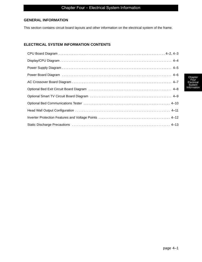
GENERAL INFORMATION
This section contains circuit board layouts and other information on the electrical system of the frame.
ELECTRICAL SYSTEM INFORMATION CONTENTS
CPU Board Diagram 4–2, 4–3. . . . . . . . . . . . . . . . . . . . . . . . . . . . . . . . . . . . . . . . . . . . . . . . . . . . . . . . . . . . . . . .
Display/CPU Diagram 4–4. . . . . . . . . . . . . . . . . . . . . . . . . . . . . . . . . . . . . . . . . . . . . . . . . . . . . . . . . . . . . . . . . . .
Power Supply Diagram 4–5. . . . . . . . . . . . . . . . . . . . . . . . . . . . . . . . . . . . . . . . . . . . . . . . . . . . . . . . . . . . . . . . . .
Power Board Diagram 4–6. . . . . . . . . . . . . . . . . . . . . . . . . . . . . . . . . . . . . . . . . . . . . . . . . . . . . . . . . . . . . . . . . .
AC Crossover Board Diagram 4–7. . . . . . . . . . . . . . . . . . . . . . . . . . . . . . . . . . . . . . . . . . . . . . . . . . . . . . . . . . . .
Optional Bed Exit Circuit Board Diagram 4–8. . . . . . . . . . . . . . . . . . . . . . . . . . . . . . . . . . . . . . . . . . . . . . . . . .
Optional Smart TV Circuit Board Diagram 4–9. . . . . . . . . . . . . . . . . . . . . . . . . . . . . . . . . . . . . . . . . . . . . . . . .
Optional Bed Communications Tester 4–10. . . . . . . . . . . . . . . . . . . . . . . . . . . . . . . . . . . . . . . . . . . . . . . . . . . .
Head Wall Output Configuration 4–11. . . . . . . . . . . . . . . . . . . . . . . . . . . . . . . . . . . . . . . . . . . . . . . . . . . . . . . . .
Inverter Protection Features and Voltage Points 4–12. . . . . . . . . . . . . . . . . . . . . . . . . . . . . . . . . . . . . . . . . . .
Static Discharge Precautions 4–13. . . . . . . . . . . . . . . . . . . . . . . . . . . . . . . . . . . . . . . . . . . . . . . . . . . . . . . . . . .

page 4–2
CPU Board Diagram
CPU KIT – 2040–700–10
59–137Shunt for
No Nurse Call

page 4–3
CPU Board Diagram (Continued)
CPU KIT – 2040–700–10
CONNECTORLOCATION
CABLELOCATION
VOLTAGE POSITIVELEAD
NEGATIVELEAD
DESCRIPTION
HDR 2 W +12 VDC Pin 1 Pin 4 or 5 Relays & SiderailsLight Voltage
HDR 2 W +5 VDC Pin 2 & 3 Pin 4 or 5 +5 VDC from PowerSupply
HDR 2 W –12 VDC Pin 6 Pin 4 or 5 Relays & SiderailsLight Voltage
HDR 6 ZZ +5 VDC Pin 1 Pin 4 +5 VDC for Fowler Pot
HDR 6 ZZ 0 – 5 VDC Pin 3 Pin 4 Fowler Pot Wiper
HDR 7 J 0 – 5 VDC Pin 3 Pin 2 Head Lift Pot Wiper
HDR 7 J +5 VDC Pin 4 Pin 2 +5 VDC for Head LiftPot
HDR 12 C +5 VDC Pin 1 Pin 2 +5 VDC for Foot LiftPot
HDR 12 C 0 – 5 VDC Pin 3 Pin 2 Foot Lift Pot Wiper
HDR 29 CC 0 VAC w/o Switch110 VAC w/Switch
Neutral Pin 1 Pin 2 Gatch Up
HDR 29 CC 0 VAC w/o Switch110 VAC w/Switch
Neutral Pin 1 Pin 3 Gatch Down
HDR 30 GG 0 VAC w/o Switch120 VAC w/
Switch
Neutral Pin 3 Pin 1 Fowler Up
HDR 30 GG 0 VAC w/o Switch120 VAC w/
Switch
Neutral Pin 3 Pin 2 Fowler Down
HDR 32 O 110 VAC Pin 1 Pin 2 Line Voltage to Bed
HDR 33 N 0 VAC w/o Switch120 VAC w/
Switch
Neutral Pin 1or 4
Pin 3 Head Lift Down
HDR 33 N 0 VAC w/o Switch120 VAC w/
Switch
Neutral Pin 1or 4
Pin 6 Head Lift Up
HDR 34 G 0 VAC w/o Switch120 VAC w/
Switch
Neutral Pin 1or 4
Pin 3 Foot Lift Down
HDR 34 G 0 VAC w/o Switch120 VAC w/
Switch
Neutral Pin 1or 4
Pin 6 Foot Lift Up

page 4–4
Display/CPU Diagram
DISPLAY/CPU – P/N 2040–31–910
CONNECTORLOCATION
VOLTAGE POSITIVELEAD
NEGATIVELEAD
DESCRIPTION
HDR 4 (L) Battery voltage around 24VDC Pin 3 Pin 1 Battery Voltage into theDisplay/CPU Board
HDR 1 (H) 0–5VDC Pin 2 Pin 1 Control Pot Wiper Voltage
HDR 6 (J) Battery voltage around 24VDC Pin 1 Pin 5 Battery Voltage Returnfrom On/Off Switch

page 4–5
Power Supply Diagram
POWER SUPPLY – P/N 59–157
CONNECTORLOCATION
VOLTAGE POSITIVE LEAD NEGATIVE LEAD
J1 110V Pin 1 Pin 2
J2 12V Pin 1 Pin 4 or 5
J2 5V Pin 2 Pin 4 or 5
J2 5V Pin 3 Pin 4 or 5
J2 GND Pin 4 Pin 4 or 5
J2 GND Pin 5 Pin 4 or 5
J2 –12V Pin 6 Pin 4 or 5

page 4–6
DC Motor Power Board Diagram
DC MOTOR POWER BOARD – P/N 2040–1–900
CONNECTORLOCATION
VOLTAGE POSITIVELEAD
NEGATIVELEAD
DESCRIPTION
HDR 1 (P) Battery voltage around 24VDC Pin 3 Pin 1 Battery Voltage out to theDisplay/CPU Board

page 4–7
AC Crossover Board Diagram
AC CROSSOVER BOARD – P/N 2040–31–900
CONNECTORLOCATION
VOLTAGE POSITIVE LEAD NEGATIVELEAD
DESCRIPTION
HDR 5 (A) 120VAC Pin 4 Pin 1 AC Input to Board fromthe Inverter with the
Power Cord Unplugged
HDR 1 (C) 120VAC Pin 3 Pin 1 AC Input to Board fromthe Wall Receptacle
HDR 2 (B) 120VAC Pin 2 Pin 1 AC Output of Board toMain Power
HDR 4 (E) +5VDC Pin 4 Pin 1 +5VDC when AC isUnplugged from the
Wall Receptacle
HDR 3 (D) Continuity Pin 3 Pin 1 Relay Contacts.Closed when PowerCord is Unplugged.
Turns on the Inverter

page 4–8
Optional Bed Exit Circuit Board Diagram
OPTIONAL BED EXIT BOARD – PART NUMBER 3002–508–900
CONNECTORLOCATION
NEGATIVELEAD
POSITIVELEAD
VOLTAGE DESCRIPTION
HDR 1 Main KeypadHDR 2, Pin 3
Pin 8 5 VDC LED Supply Voltage

page 4–9
Optional Smart TV Circuit Board Diagram
OPTIONAL SMART TV CIRCUIT BOARD – P/N 3001–330–970
CONNECTORLOCATION
VOLTAGE POSITIVELEAD
NEGATIVELEAD
DESCRIPTION
HDR 1 5 VDC Pin 2 Pin 1 Regulated 5 VDC Power to the board
HDR 1 Digital Control Pin 3–5 Pin 1 Serial control lines
HDR 1 5 VDC Pin 6 Pin 1 5 VDC for option relay
HDR 3 +5 or +12 VDC 2 Pin 1 Power/control line from the TVNote: This header provides TV control to
a non–Stryker pendant
DB1 +5 or +12 VDC Pin 34 Pin 33 Power/Control line from the TVNote: If this polarity is reversed, place
the shunts of J8 in the alternate position

page 4–10
3001–303–165 Optional Bed Communications Tester
Item Part No. Part Name Qty.A 3001–303–160 BCT Unit 1B 3001–303–825 37–Pin Cable 1C 3001–303–162 Instructions 1D 3000–303–871 9V Battery 1

page 4–11
Head Wall Output Configuration
37–PIN CONNECTOR
Pin 1 Option 2 CommonPin 2 Read LightPin 3 Room LightPin 4 Speaker HighPin 5 Pot WiperPin 6 Radio CommonPin 7 Nurse Call InterlockPin 8 Audio Transfer –Pin 9 Audio Transfer +Pin 10 Interlock +Pin 11 Interlock –Pin 12 SparePin 13 Options 3 CommonPin 14 Pot Low CommonPin 15 Pot High Common (Std.)/Audio (STV)Pin 16 Nurse Answer Light +Pin 17 Option 1 NO/NCPin 18 Option 1 CommonPin 19 Nurse Call Light +Pin 20 Option 2 NO/NCPin 21 Option 3 NO/NCPin 22 Option 3A NO/NCPin 23 Option 2A CommonPin 24 Option 2A NO/NCPin 25 Nurse Call +Pin 26 Nurse Call NO/NCPin 27 Room/Read Light CommonPin 28 Nurse Call Light –Pin 29 Nurse Answer Light –Pin 30 Priority NO/NCPin 31 Priority CommonPin 32 Option 3A CommonPin 33 TV – (Std.)/Data (STV)Pin 34 TV + (Std.)/Common (STV)Pin 35 Speaker Low CommonPin 36 Audio ShieldPin 37 Radio NO/NC
STRYKER PENDANT PORT
1 Scan Line2 Audio (–)
3 Nurse Call (+)4 +5 VDC
5 Scan Line6 Scan Line7 Nurse Call (–)
8 TV Channel Up9 Backlight
10 Audio (+)11 Gatch Up/Fowler In/Foot Up/DMS Firm
12 Gatch Down/Fowler Out/Foot Out/DMS Soft
13 Fowler Up/Trend In
14 Fowler Down/Trend Out15 Audio Shield
16 Not Used – Socket Filled17 Litter Up
18 Ground19 Read Light/Litter Down20 Room Light

page 4–12
Inverter Protection Features and Voltage Points
The inverter has several features to prevent internal damage:
1. Low Battery Voltage – If the battery voltage at the inverter drops below the low voltage cut–off, an alarmwill sound and the inverter will shut off. When battery voltage increases to 95% of nominal battery voltage,the inverter will restart.
2. High Battery Voltage – If the battery voltage input rises above the high voltage cut–off, the inverter willshut off. When the battery voltage input drops back within the normal voltage range, the inverter will re-start.
3. Over–Temperature – If the inverter gets too hot, it will shut off. The overheating may be caused by highambient temperature, blocked air flow or an overload condition. When the inverter reaches an acceptabletemperature, it will restart.
4. Over–Power – The inverter will source up to its maximum power rating. If the load requires more, theoutput voltage will be lowered to supply no more than its maximum power so the maximum power fromthe inverter is reduced to a safe amount.
WARNING
The inverter generates 115VAC, the same as a wall receptacle. To prevent injury, do not put anything intothe electrical outlets other than an appliance power cord. Keep the outlets covered when not in use. Do notsubmerge the unit or subject it to moisture.
VOLTAGE POSITIVE LEAD NEGATIVE LEAD
Approximately 24VDC Battery Red Battery Black
Approximately 120VAC Line Brown Neutral Blue

page 4–13
Static Discharge Precautions
The electronic circuits in the 2040 are completely protected from static electricity damage only while the frameis assembled. It is extremely important that all service personnel always use adequate static protection whenservicing the electronic systems of the 2040. Whenever you are touching wires, you should be using staticprotection.
Static Protection Equipment
The necessary equipment for proper static protection is:
� 1 static wrist strap; 3M part number 2214 or equivalent,
� 1 grounding plug; 3M part number 61038 or equivalent,
� 1 test lead with a banana plug on one end and an alligator clip on the other; Smith part number N132B699 or equivalent.
Stryker has available the following equipment for proper static protection:
� Complete static protection system – part number 3000–000–753
� 1 grounding plug – part number 3000–000–754
� 1 static wrist strap – part number 3000–000–755
� 1 test lead – part number 3000–000–756
CAUTION
All electronic service parts will be shipped in static shielding bags. Do not open the bags until you have com-pleted steps 2 and 3 of the static protection procedure. Do not place unprotected circuit boards on the floor.All circuit boards to be returned to Stryker Medical should be shipped in the static shielding bags the newboards were shipped in.
Static Protection Procedure
1. Unplug the power cord from the wall receptacle.
2. Insert the grounding plug into a properly grounded hospital grade wall receptacle. Plug the banana plugof the test lead into the receptacle on the grounding plug. Connect the alligator clip on the other end ofthe test lead to a ground point on the frame.
3. Place the static control wrist strap on your wrist. Connect the alligator clip at the other end of the wrist strapcord to a ground point on the frame.
BED
GROUNDING DIAGRAM

page 4–14
Notes

page 5–1
GENERAL INFORMATION
This section contains tool lists and step–by–step procedures to assist with the maintenance and servicingof the base portion of your equipment.
In the text, the words “right” and “left” refer to the right and left sides of a patient lying face up on the litter.
BASE MAINTENANCE CONTENTS
Brake Pedal Replacement 5–2. . . . . . . . . . . . . . . . . . . . . . . . . . . . . . . . . . . . . . . . . . . . . . . . . . . . . . . . . . . . . . .
Lift Motor and Capacitor Removal and Replacement 5–3. . . . . . . . . . . . . . . . . . . . . . . . . . . . . . . . . . . . . . . .
Lift Housing Removal and Replacement 5–4, 5–5. . . . . . . . . . . . . . . . . . . . . . . . . . . . . . . . . . . . . . . . . . . . . . .
Lift Potentiometer Replacement and Adjustment 5–6, 5–7. . . . . . . . . . . . . . . . . . . . . . . . . . . . . . . . . . . . . . . .
Lift Potentiometer “Burn–In” Procedure 5–7. . . . . . . . . . . . . . . . . . . . . . . . . . . . . . . . . . . . . . . . . . . . . . . . . . . .
Lift Motor Coupler Replacement 5–8. . . . . . . . . . . . . . . . . . . . . . . . . . . . . . . . . . . . . . . . . . . . . . . . . . . . . . . . . .
Power and Sensor Coil Cord Replacement 5–9, 5–10. . . . . . . . . . . . . . . . . . . . . . . . . . . . . . . . . . . . . . . . . .
Drive Motor Removal and Replacement 5–11. . . . . . . . . . . . . . . . . . . . . . . . . . . . . . . . . . . . . . . . . . . . . . . . . .
Drive Wheel Removal and Replacement 5–11. . . . . . . . . . . . . . . . . . . . . . . . . . . . . . . . . . . . . . . . . . . . . . . . . .
Battery Removal and Replacement 5–12. . . . . . . . . . . . . . . . . . . . . . . . . . . . . . . . . . . . . . . . . . . . . . . . . . . . . .
Power Board Removal and Replacement 5–13. . . . . . . . . . . . . . . . . . . . . . . . . . . . . . . . . . . . . . . . . . . . . . . . .

page 5–2
Brake Pedal Replacement
Required Tools:
5/16” Hex Allen Wrench Torque Wrench Loctite 242
Hammer Punch #2 Phillips Screwdriver
Bungee Cords (or Equivalent)
Procedure:
1. Raise the litter to the full up position.
2. Unplug the power cord from the wall socket and push the battery power on/off switch to the “OFF” posi-tion.
3. Using a #2 Phillips screwdriver, remove the three screws holding both the head end and the foot end up-per lift covers. If necessary, hold the covers out of the way by using bungee cords (or the equivalent)to secure them to the litter top.
4. Using a 5/16” hex Allen wrench, remove the two bolts holding the brake pedal to the brake rod.
5. Using a hammer and punch, remove the roll pins holding the brake shaft crank to the brake rod on boththe head and the foot end.
6. Push the brake rod through the frame until the brake pedal is clear. Remove the brake pedal.
7. Reverse steps 1 – 6 to attach the new brake pedal.
NOTEUse Loctite 242 when reinstalling the bolts and torque the bolts to 25 foot–pounds.

page 5–3
Lift Motor and Capacitor Removal and Replacement
Required Tools:
3/8” Socket Wrench w/Extension 5/16” Socket Wrench Floor JackSide Cutters 7/16” Open End Wrench 2 x 4 (or Equivalent)
ABD FOOT END
C
Procedure:
NOTEIf you need more space to work under the base frame, place a 2 x 4 across the base frame rails and use afloor jack to raise the base frame off the floor.
1. Unplug the power cord from the wall socket and push the battery power on/off switch to the “OFF” posi-tion.
2. Using a 5/16” socket wrench, remove the six bolts holding the lower lift cover to the base and removethe cover.
3. Disconnect the two connectors (A) at the motor capacitor.
4. Disconnect the white connector (B) from the power cord.
5. Using side cutters, cut the cable ties holding the capacitor (C) to the base and remove the capacitor.
6. Using a 3/8” socket wrench, remove the four screws (D) holding the motor assembly in the lift housingand remove the motor assembly.
7. Reverse steps 1 – 6 to install the new motor.
NOTEThe drive shaft on the new motor might need to be turned with a 7/16” open end wrench to align with the coupler.
The procedure for lift motor and capacitor removal and replacement is the same for both ends of the bed.

page 5–4
Lift Housing Removal and Replacement
Required Tools:
#2 Phillips Screwdriver Bungee Cord (or Equivalent) 5/16” Socket Wrench
Side Cutters 9/16” Socket Wrench Floor Jack
7/32” Hex Allen Socket Wrench Sawhorses (or Equivalent) 2 x 4 (or Equivalent)
3/8” Socket Wrench (w/ 6” extension)
Procedure:
NOTEIf you need more space to work under the base frame, place a 2 x 4 across the base frame rails and use afloor jack to raise the base frame off the floor.
1. Unplug the power cord from the wall socket and push the battery power on/off switch to the “OFF” posi-tion.
2. Using a 5/16” socket wrench, remove the six bolts holding the lower lift cover to the base and removethe cover.
3. Using a #2 Phillips screwdriver, remove the three screws holding the upper lift cover to the base. If neces-sary, hold the upper and lower covers out of the way by using bungee cords (or the equivalent) to securethem to the litter top.
4. Remove the lift motor and capacitor (refer to the procedure on page 5–3).
5. Remove the lift potentiometer (refer to the procedure on page 5–6).
6. Using a 5/16” socket wrench, remove the cable clamps holding the power and sensor coil cords on topof the lift housing assembly. Cut the cable ties and disconnect the coil cords from under the lift housing.The power and sensor coil cords are now free of the lift housing assembly. Drape them up out of the way.
7. Using a 7/32” hex Allen socket, remove the two screws holding the lift screws to the header crossbarplate.
8. Lift the litter top up and support it about 6” above the lift screws on sawhorses or the equivalent.

page 5–5
Lift Housing Removal and Replacement (Continued)
A
FOOT END – BOTTOM VIEW
9. Under the base, using a 9/16” socket, remove the four nuts (A) holding the lift housing to the base.
10. Lift up and out on the lift housing assembly to remove it from the base.
CAUTION
To ensure proper reattachment of the power and sensor coil cords, refer to the procedure on page 5–9.Refer to the procedure on page 5–6 for reattachment of the lift potentiometer.
11. Reverse steps 1 – 10 to reinstall the lift housing assembly after service is completed.
NOTEThe procedure for lift housing removal and replacement is the same for both ends of the bed.

page 5–6
Lift Potentiometer Replacement and Adjustment
Required Tools:
#2 Phillips Screwdriver Bungee Cord (or equivalent) 5/16” Socket Wrench3/8” Open End Wrench Side Cutters
B
C
A
B
Procedure:
1. Raise the litter to the full up position.
2. Unplug the power cord from the wall socket and push the battery power on/off switch to the “OFF” posi-tion.
3. Using a 5/16” socket wrench, remove the six bolts holding the lower lift cover to the base and removethe cover. If necessary, hold the covers out of the way by using bungee cords (or the equivalent) to se-cure them to the litter top.
4. Using a #2 Phillips screwdriver, remove the three screws holding the upper lift cover to the base. If neces-sary, hold the covers out of the way by using bungee cords (or the equivalent) to secure them to the litter.
5. Using side cutters, cut the cable tie (A) holding the pot cable to the coil cord.
6. Unplug the pot cable from the sensor coil cord. If replacing a pot at the head end of the bed, unplug thecables attached to the brake sensor switch.
7. Pull the pot cable up through the base.
8. Using a 3/8” open end wrench, remove the two bolts (B) holding the pot housing (C) to the lift housing.

page 5–7
Lift Potentiometer Replacement and Adjustment (Continued)
9. Lift up and out on the pot housing assembly to remove it from the lift housing.
10. Before installing the new pot on the bed, turn it clockwise until it stops. Turn it back counterclockwisetwo full (360�) revolutions. This allows a ”window” position for proper upper and lower limits.
11. Reverse steps 4–9 to install the new pot and pot housing assembly.
12. After installing the new pot, the “burn–in” procedure below must be followed.
NOTEBe sure to maintain the pot position while installing.
Lift Potentiometer ”Burn–In” Procedure
1. Unplug the power cord from the wall socket and push the battery power on/off switch to the “OFF” posi-tion.
2. On the foot board control panel, hold down the Bed Motion Lock and Knee Lock Out buttons simulta-neously.
3. While holding down the above two buttons, plug the power cord into the wall socket. Release the twobuttons. The Siderail Control Lights LED on the foot board control panel should be flashing, indicatingthe bed is in the diagnostics mode.
4. From the foot board, run the litter full up to a “hard stop”.
5. Hold down the Bed Motion Lock button until the light flashes. If your bed has the enhanced height op-tion, you must first press and hold the Knee Down button and then press the Bed Motion Lock buttonuntil the light flashes.
6. Release the button and unplug the power cord from the wall socket.
7. Plug the power cord back in to the wall socket. Run the bed to full down, then full up to verify the bedlimits.
8. The distance between the floor and the top of the litter seat section (without a mattress) should be approxi-mately 18.25” with the litter fully down and 32.5” with the litter fully up for a standard bed. For an enhancedheight bed, the distances are 19.9” and 34.5”.
9. If your bed has the standard height option and is equipped with an I.V. Caddy, a lower height limit mustbe burned in. Run the litter down to 19.5 inches. Hold down the Bed Up/Down Lock button until the lightflashes. If your bed has the enhanced height option, it is not necessary to burn–in the low height.
CAUTION
Do not run the litter all the way down while in the diagnostics mode. Damage to the bottom lift covers couldresult.

page 5–8
Lift Motor Coupler Replacement
Required Tools:
5/16” Socket Wrench 3/8” Socket Wrench (w/6” Extension) Floor Jack2 x 4 (or Equivalent)
B
A
C
A
Procedure:
NOTEIf you need more space to work under the base frame, place a 2 x 4 across the base frame rails and use afloor jack to raise the base frame off the floor.
1. Unplug the power cord from the wall socket and push the battery power on/off switch to the “OFF” posi-tion.
2. Using a 5/16” socket wrench, remove the six bolts holding the lower lift cover to the base and removethe cover.
3. Using a 3/8” socket with an extension, remove the four bolts (A) holding the isolation plate (B) to the lifthousing and lower the lift motor and isolation plate assembly to allow access to the coupler (C).
4. The motor coupler can now be removed from the lift housing.
5. Reverse steps 1 – 4 to install the new motor coupler and bushings.

page 5–9
Power and Sensor Coil Cord Replacement
Required Tools:
#2 Phillips Screwdriver Side Cutters 5/16” Socket Wrench
Bungee Cord (or equivalent) 5/16” Nut Driver Floor Jack
2 x 4 (or Equivalent)
Procedure:
NOTEIf you need more space to work under the base frame, place a 2 x 4 across the base frame rails and use afloor jack to raise the base frame off the floor.
1. Unplug the power cord from the wall socket and push the battery power on/off switch to the “OFF” posi-tion.
2. Using a 5/16” socket wrench, remove the six bolts holding the lower lift cover to the base and removethe cover.
3. Using a #2 Phillips screwdriver, remove the three screws holding the upper lift cover to the base. If neces-sary, hold the covers out of the way by using bungee cords (or the equivalent) to secure them to the littertop.
4. Using side cutters, cut the cable ties holding the power and sensor coil cords to the base. Remove theground wire coming from the sensor cord that is attached to the base (note the star washer arrangement).
5. Disconnect the cables going to the motor and the lift potentiometer (at the head end, the sensor cord isalso attached to the brake switch sensor).
6. Pull both cords up through the frame of the bed and the lift housing.
7. Using a 5/16” socket wrench, remove the two screws (A) holding the cable clamps* to the top of the lifthousing.
8. Using a 5/16” socket wrench, remove the two screws (B) securing the cable clamps* to the undersideof the header crossbar assembly.
9. Pull both coil cords up through the header crossbar assembly.
10. Disconnect the power and sensor coil cords from the connectors.
11. The cords should now be completely removed from the bed. Reverse the above steps to install the newpower and sensor cords.*
CAUTION
* When the power and sensor coil cords are being replaced, secure the cable clamps to the cords at the firstcoil both on the top and on the bottom to ensure there is not too much slack in the cords between the top ofthe lift housing assembly and the bottom of the header crossbar. Be sure the clamps are fastened at exactlythe correct angle, as shown by the arrows in the illustration on page 5–10. Arrange the cords exactly asshown in the illustration (left in front of right). If this is not done correctly, damage to the cords will result.

page 5–10
Power and Sensor Coil Cord Replacement Illustration
A
B
A
B
VIEW FROM CENTER OF BED

page 5–11
Drive Motor Removal and Replacement
Required Tools:
Phillips Screwdriver 1/2” Socket Wrench Bungee CordsFloor Jack T27 Torx
Procedure:
1. Raise the litter to the full up position.
2. Unplug the power cord from the wall socket and push the battery power on/off switch to the “OFF” posi-tion.
3. Using a Phillips screwdriver, remove the four screws holding the base hood to the base frame.
4. Open the cable clamp at the head end, left side of the base frame and remove the cables from the clamp.
5. Lift the base hood and support it from the litter frame using bungee cords or the equivalent.
6. Using a T27 Torx, remove the four screws holding the power board cover to the side of the electronicsbox. Remove the two motor wires from the power board and remove the T27 Torx ground screw.
7. Apply the brakes and disengage the drive wheel. Place a floor jack under the leaf spring at the foot endof the bed and raise the wheels approximately three inches off the floor.
8. Using a 1/2” socket wrench, remove the four bolts holding the drive motor to the leaf spring.
CAUTION
Support the drive motor before removing the four bolts to prevent it from falling to the floor and becomingdamaged.
9. Reverse steps 1 – 8 to install the new drive motor.
10. Run through the operation of the power drive wheel to ensure it is operating properly before returning theunit to service.
Drive Wheel Removal and Replacement
Required Tools:
Phillips Screwdriver 1/2” Socket Wrench Bungee Cords
Floor Jack T27 Torx
Procedure:
1. Remove the drive motor (see page 5–11).
2. Using a 1/2” socket wrench, remove the bolt holding the wheel to the drive motor.
3. Slide the wheel off the motor shaft.
4. Reverse steps 1 – 3 to install the new drive wheel and reinstall the drive motor.

page 5–12
Battery Removal and Replacement
Required Tools:
Torx T27 7/16” Wrench1/2” Socket Wrench Bungee CordsPhillips Screwdriver
Procedure:
1. Raise the litter to full up. Unplug thepower cord from the wall socket andpush the battery power on/off switch tothe “OFF” position.
2. Using a Phillips screwdriver, remove thefour screws holding the base hood to thebase frame.
3. Lift the base hood and support it fromthe litter frame using bungee cords orthe equivalent.
4. Properly ground yourself (seepage 4–13 for static discharge precau-tions).
5. Open the cable clamp at the head end,left side of the base frame and removethe cables from the clamp.
6. Using a Torx T27, remove the fourscrews (A) holding the electronics boxcover and remove the cover.
7. Disconnect the two battery cables (B).
WARNING
The battery tray assembly weighs 50pounds. Use caution when removing thetwo hex head screws securing it to the baseframe or personal injury could result.Battery posts, terminals and related acces-sories contain lead and lead compounds,chemicals known to the State of California tocause cancer and birth defects or other re-productive harm. Wash hands after han-dling.
8. Support the battery tray assembly fromthe bottom. Using a 7/16” hex socket orwrench, remove the two screws (C) sup-porting the battery tray.
9. The back of the battery tray assemblyhas a lip which catches on the electron-ics box. Lift up and out to remove thebattery tray assembly.
10. Reverse steps 1 – 9 to install thenew batteries. Complete the lastfour items of the set–up proce-dures on page 1–6.
B
C
A

page 5–13
Power Board Removal and Replacement
Required Tools:
Phillips Screwdriver 1/8” Allen Wrench Bungee CordsT27 Torx
Procedure:
1. Raise the litter to the full up position.
2. Unplug the power cord from the wall socket and push the battery power on/off switch to the “OFF” posi-tion.
3. Using a Phillips screwdriver, remove the four screws holding the base hood to the base frame.
4. Open the cable clamp at the head end, left side of the base frame and remove the cables from the clamp.
5. Lift the base hood and support it from the litter frame using bungee cords or the equivalent.
6. Using a T27 Torx, remove the four screws holding the cover to the side of the electronics box.
7. Properly ground yourself (see page 4–13 for static discharge precautions).
8. Using a 1/8” Allen wrench, remove the four bolts and standoffs holding the power board to the electronicsbox.
9. Remove all cables from the power board and remove the board.
NOTENotice the cable connections so you can connect them properly to the new power board.
10. Reverse steps 1 – 8 to install the new power board.

page 5–14
Notes

page 6–1
GENERAL INFORMATION
This section contains tool lists and step–by–step procedures to assist with the maintenance and servicingof the litter portion of your equipment.
In the text, the words “right” and “left” refer to the right and left sides of a patient lying face up on the litter.
LITTER MAINTENANCE CONTENTS
Scale System Diagnostics and Calibration 6–2, 6–3. . . . . . . . . . . . . . . . . . . . . . . . . . . . . . . . . . . . . . . . . . . . .
Load Cell Replacement 6–4. . . . . . . . . . . . . . . . . . . . . . . . . . . . . . . . . . . . . . . . . . . . . . . . . . . . . . . . . . . . . . . . .
Fowler Motor Removal and Replacement 6–5. . . . . . . . . . . . . . . . . . . . . . . . . . . . . . . . . . . . . . . . . . . . . . . . . .
Gatch Motor Removal and Replacement 6–6. . . . . . . . . . . . . . . . . . . . . . . . . . . . . . . . . . . . . . . . . . . . . . . . . .
Power Supply Removal and Replacement 6–7. . . . . . . . . . . . . . . . . . . . . . . . . . . . . . . . . . . . . . . . . . . . . . . . .
CPU Board Removal and Replacement 6–7. . . . . . . . . . . . . . . . . . . . . . . . . . . . . . . . . . . . . . . . . . . . . . . . . . .
Fowler and Lift Potentiometer “Burn–In” Procedure 6–8. . . . . . . . . . . . . . . . . . . . . . . . . . . . . . . . . . . . . . . . .
AC Crossover Board Replacement 6–9. . . . . . . . . . . . . . . . . . . . . . . . . . . . . . . . . . . . . . . . . . . . . . . . . . . . . . .
Display/CPU Board Replacement 6–9. . . . . . . . . . . . . . . . . . . . . . . . . . . . . . . . . . . . . . . . . . . . . . . . . . . . . . . . .
Control Bar Potentiometer Replacement 6–10, 6–11. . . . . . . . . . . . . . . . . . . . . . . . . . . . . . . . . . . . . . . . . . . . .
Control Bar Potentiometer “Burn–In” Procedure 6–12. . . . . . . . . . . . . . . . . . . . . . . . . . . . . . . . . . . . . . . . . . .
Optional Smart TV Interface “Burn–In” Procedure 6–13. . . . . . . . . . . . . . . . . . . . . . . . . . . . . . . . . . . . . . . . . .

page 6–2
Scale System Diagnostics and Calibration
Diagnostic Mode Functions:
1. Calibrate Scale: This is required in the field if a CPU board or a load cell is replaced.
2. Display Corner: This function displays the individual reference numbers for each load cell assembly andcan be used to isolate a defective load cell.
3. Init. to Defaults: This may be required in the field when replacing a CPU board or a load cell.
4. Erase E–prom: This is a factory setting not used in the field.
5. Display Factor: This is a factory setting not used in the field.
5. Exit Diagnostics: Changes made in the diagnostic mode must be saved in permanent memory using thisfunction. Switching off power without saving will reset all variables to their previous values.
Diagnostic Mode:
NOTEIt requires two people to enable the diagnostic mode for the scale system.
1. To enter diagnostic mode, unplug the power cord from the wall socket.
2. Press and hold down the LBS/KGS button.
3. While still holding the LBS/KGS button, plug the power cord into the wall socket.
4. After two seconds, release the LBS/KGS button. The LCD should display “CALIBRATE SCALE”. Thediagnostic mode is now active.
Displaying Individual Load Cell Outputs:
A defective load cell can be detected by entering diagnostics and displaying individual load cell outputs.
1. Enter the diagnostic mode. The LCD will display “CALIBRATE SCALE” when the diagnostic mode is acti-vated.
2. Repeatedly press and release the up or down arrow button (ZERO or SCALE ON/OFF) until the LCD dis-plays “DISPLAY CORNER”.
3. Press and release the ENTER button (LBS/KGS). The LCD should display “PICK CORNER NOW”.
The four buttons listed in the group below function as POSITION buttons corresponding with the four cor-ners of the litter. Whenever the LCD displays “PICK CORNER NOW”, press one of these buttons to selectthe load cell assembly at the desired corner.
A. ZERO = head end, patient’s left side
B. CHANGE EQUIP. = head end, patient’s right side
C. TREND/FOWLER ANGLE = foot end, patient’s right side
D. LBS/KGS = foot end, patient’s left side
4. Press and release the position button that corresponds with the load cell to be checked. The LCD shoulddisplay “X/X=NNN.N”. ”X/X” represents the initials of the selected corner, i.e. H/R will be displayed forthe patient’s head end, right side. ”NNN.N” represents the resistance of the load cell.
5. Repeat step four for each corner. Head end weight readings will normally be lower than foot end weights.Weight readings should be constant. A drifting 000.0 or 999.9 weight, or a reading that does not changewhen weight is applied to that corner of the litter indicates a problem with the selected load cell assemblyor load cell cable.
6. When all the load cell outputs have been checked, repeatedly press and release the SCALE ON/OFF but-ton until the LCD displays “EXIT DIAGNOSTICS”. Press the ENTER button (LBS/KGS) to exit diagnos-tics.

page 6–3
Scale System Diagnostics and Calibration
Verifying Scale Accuracy:
1. Zero the empty litter. Place a known weight on the center of the litter; the heavier the better and no lessthan 100 pounds. The displayed weight should be within 1% of the actual weight.
2. If the displayed weight is not accurate, remove the weight from the litter and proceed to the Scale Calibra-tion section.
Scale Calibration:
NOTEIt requires two people to enable the calibration mode for the scale system.Raise the siderails when calibrating the scale to avoid getting inaccurate scale readings due to possible inter-ference between the siderails and the casters.
Calibrate the scale system with a known 200 pound weight. If exactly 200 pounds is not available, the factorydefault for calibration will have to be changed as described in step 8.
1. To enter the calibration mode, unplug the power cord from the wall socket.
2. Press and hold down the LBS/KGS button.
3. While still holding the LBS/KGS button, plug the power cord into the wall socket.
4. After two seconds, release the LBS/KGS button. The LCD should read “CALIBRATE SCALE”. The cal-ibration mode is now active.
5. Using the up or down arrow button (ZERO or SCALE ON/OFF), toggle through the menu until “INIT. TODEFAULTS” is displayed. Press and hold the ENTER button (LBS/KGS) until “SAVING DEFAULTS” isdisplayed. Release the ENTER button.
6. Using the up or down arrow buttons (ZERO or SCALE ON/OFF), toggle through the menu until “CALI-BRATE SCALE” is displayed.
7. Press and hold the ENTER button (LBS/KGS). Zero the bed, following the displayed instructions. Whenthe bed is zeroed, the LCD should display “REF X100=<2 0000”. This is the factory default for 200pounds. If 200 pounds will be used to calibrate the scale, proceed to step 9.
8. If exactly 200 pounds is not available, change the display to match the weight you are using. Pressingthe TREND/FOWLER ANGLE button will move the cursor position to the right. Pressing the up arrow(ZERO) button will increase the numbers. Pressing the down arrow (SCALE ON/OFF) button will de-crease the numbers. Scroll through the numbers until they match the weight you will use for calibration.
9. Press and release the SCALE ON/OFF button and the LCD will display “PRESS REV. TREND”. Pressthe button with the Reverse Trendelenburg symbol (feet down/head up) until the bed reaches full reverseTrend. Release the button and the LCD will display “DO NOT TOUCH BED”.
10. The LCD will display “PRESS TREND.” Press the button with the Trendelenburg symbol (feet up/headdown) until the bed reaches full trend. Release the button and the LCD will display “DO NOT TOUCHBED”.
11. The LCD will display “CALIBRATE SCALE”. This indicates the calibration procedure is complete.
12. Exit scale calibration by pressing the up arrow button (ZERO) until the LCD displays “EXIT DIAGNOS-TICS”. Press the ENTER (LBS/KGS) button to exit.
13. Level the bed at a full up or full down position. Remove the weight and zero the bed.
14. Verify scale accuracy and functionality before returning the bed to service.

page 6–4
Load Cell Replacement
Required Tools:
9/16” Socket Wrench 9/16” Open End Wrench Saw Horse (or Equivalent)
Wire Cutters
Replacement Procedure:
1. Raise the Fowler or knee section, depending which end of the litter needs service.
2. Unplug the load cell connector from the load cell cable.
3. Using wire cutters, remove the wire ties holding the cable to the frame.
4. Using a 9/16” socket and a 9/16” open end wrench, remove the two bolts holding the load cell to the littercross tube and remove the load cell.
5. Using a saw horse or the equivalent, support the litter at the end where the load cell was removed. Reversethe above procedure to install the new load cell.
NOTEThe scale calibration procedure must be performed after the load cell is replaced (see page 6–3).

page 6–5
Fowler Motor Removal and Replacement
Required Tools:
T27 Torx 7/16” Socket Wrench 3/8” Socket WrenchWire Cutters
Procedure:
1. Run the litter to the full up position and remove the mattress from the litter.
2. Fold the foot section back toward the head end. Electrically run the knee section to full up. If the kneesection will not move electrically, pull the foot section toward the head end while pulling the CPR releasehandle (located at the head end of the bed). The knee section will raise.
3. Using a T27 torx, remove the four screws holding the cover to the actuator box and remove the cover.
4. Remove the two CPR release cables from the CPR release bracket. Using a 3/8” socket wrench under-neath the actuator box, remove the two bolts holding the release bracket to the actuator box and removethe bracket from the actuator box.
5. Disconnect all the electrical connections to the head motor and move aside any wiring that interferes withthe removal of the motor.
6. Using a 3/8” socket wrench underneath the actuator box, remove the four bolts holding the motor mount-ing bracket to the actuator box. Lift up and out on the motor to remove it.
7. Remove the motor mounting bracket from the old motor and install it on the replacement motor.
8. Reverse steps 3 through 6 to install the replacement motor.
9. Verify the unit is working properly before returning it to service.

page 6–6
Gatch Motor Removal and Replacement
Required Tools:
T27 Torx 7/16” Socket Wrench 3/8” Socket Wrench
Wire Cutters
Procedure:
1. Run the litter to the full up position and remove the mattress from the litter.
2. Fold the foot section back toward the head end. Electrically run the knee section to full up. If the kneesection will not move electrically, pull the foot section toward the head end while pulling the CPR releasehandle (located at the head end of the bed). The knee section will raise.
3. Using a 7/16’ socket wrench, remove the mounting bolt on the litter for the knee dampening cylinder. Thisleaves the knee dampener mounted only to the seat panel.
4. Using a T27 torx, remove the four screws holding the cover to the actuator box and remove the cover.
5. Remove the two CPR release cables from the CPR release bracket. Using a 3/8” socket wrench under-neath the actuator box, remove the two bolts holding the release bracket to the actuator box and removethe bracket from the actuator box.
6. Disconnect all the electrical connections going to the knee motor and move aside any wiring that couldinterfere with the removal of the motor.
7. Pull the foot panel toward the head end of the bed. This causes the knee motor linkage to roll past centerand allows the motor to be removed without supporting the knee section.
8. Using a 3/8” socket wrench underneath the actuator box, remove the four bolts holding the motor mount-ing bracket to the actuator box. Lift up and out on the motor to remove it.
9. Remove the motor mounting bracket from the old motor and install it on the replacement motor.
10. Install the replacement motor.
11. Reverse steps 3 – 5 to reinstall the knee dampener, CPR bracket and actuator box cover.
12. Pull the foot panel toward the foot end of the bed. This causes the knee motor linkage to roll back pastcenter.
CAUTION
If step 12 is not done, damage to the motor or linkage will occur.
13. Verify the bed is working properly before returning it to service.

page 6–7
Power Supply Removal and Replacement
Required Tools:
T27 Torx Needle–Nose Pliers
Procedure:
1. Run the litter to the full up position and remove the mattress from the litter.
2. Fold the foot section back toward the head end of the bed. Electrically run the knee section to full up.If the knee section will not move electrically, pull the foot section toward the head end of the bed whilepulling the CPR release handle (located at the head end of the bed). The knee section will raise.
3. Using a T27 torx, remove the four screws holding the cover to the actuator box and remove the cover.
4. Properly ground yourself (see page 4–13 for static discharge precautions).
5. Unplug all electrical connections from the power supply.
6. Using needle–nose pliers, squeeze the four stand–offs supporting the power supply and pull up gentlyon the power supply to remove it.
7. Reverse steps 2 through 5 to install the new power supply.
8. Verify the unit is working properly before returning it to service.
CPU Board Removal and Replacement
Required Tools:
T27 Torx Needle–Nose Pliers
Replacement Procedure:
1. Run the litter to the full up position and remove the mattress from the litter.
2. Fold the foot section back toward the head end of the bed. Electrically run the knee section to full up.If the knee section will not move electrically, pull the foot section toward the head end of the bed whilepulling the CPR release handle (located at the head end of the bed). The knee section will raise.
3. Using a T27 torx, remove the four screws holding the cover to the actuator box and remove the cover.
4. Properly ground yourself (see page 4–13 for static discharge precautions).
5. Unplug all electrical connections from the CPU board.
6. Press the six stand–offs away from the board while gently lifting the board up and out.
7. Install the replacement CPU board.
NOTEAfter the replacement CPU board is installed, the “burn–in” procedure must be performed for the Fowler andlift motor potentiometers (see page 6–8)
If the bed is equipped with a scale system, the scale calibration procedure must also be performed after thereplacement CPU board is installed (see page 6–3).

page 6–8
Fowler and Lift Potentiometer ”Burn–In” Procedure
NOTEIt requires two people to enable the diagnostics mode for the bed.
1. Unplug the bed power cord from the wall socket.
2. On the foot board control panel, hold down the bed motion lock button and the button to lock out the side-rail controls for the knee. While still holding the buttons, plug the bed power cord into the wall socket.Release the foot board buttons. The siderail control lights LED should be flashing to indicate the bed isin diagnostics mode.
3. Using the foot board controls, run the Fowler up to 90�. Press and hold the button on the foot board tolock out the siderail controls for the back until the padlock shaped LED flashes. Release the button.
4. Using the foot board controls, run the Fowler down to 0�. Press and hold the button on the foot boardto lock out the siderail controls for the knee until the padlock shaped LED flashes. Release the button..
5. To “burn in” the Bed Up/Down limits, raise the bed completely up until it can’t go any farther. Press andhold the “Bed Motion Lock” button. The “Bed Motion Lock” LED will light. Continue to hold the “Bed MotionLock” button until the “Bed Motion Lock” LED flashes. The flashing LED indicates the limits have beenset. Release the “Bed Motion Lock” button and unplug the power cord from the wall socket to completethe “burn–in” mode. If your bed has the enhanced height option, you must first press and hold the KneeDown button and then press the Bed Motion Lock button until the light flashes.
6. Plug the power cord into the wall socket and verify the back and bed lift limits are set properly before return-ing the unit to service.
NOTEThe distance between the floor and the top of the litter seat section (without a mattress) should be approxi-mately 18.25” with the litter fully down and 32.5” with the litter fully up for a standard bed. For an enhancedheight bed, the distances are 19.9” and 34.5”.
7. If your bed has the standard height option and is equipped with an I.V. Caddy, a lower limit must be burnedin. Run the litter down to 19.5 inches. Hold down the Bed Up/Down Lock button until the light flashes.If your bed has the enhanced height option, it is not necessary to burn–in the low height.
CAUTION
Do not run the litter all the way down while in the diagnostics mode. Damage to the bottom lift covers couldresult.

page 6–9
AC Crossover Board Replacement
Required Tools:
T27 Torx 1/2” Box End Wrench #2 Phillips ScrewdriverWire Cutters Small Flat Blade Screwdriver Needle Nose Pliers5/16” Nut Driver
Replacement Procedure:
1. Follow steps 1 – 9 of the control bar potentiometer replacement procedure on page 6–11.
2. Using a T–27 Torx, remove the 2 bolts holding the AC crossover board cover to the head end frame andremove the cover.
3. Disconnect all wires from the AC crossover board.
4. Using needle nose pliers, release the four mounting stand–offs from the board and remove the board.
5. Reverse steps 1 – 4 to install the new board.
6. Reverse steps 1 – 9 of the control bar potentiometer replacement procedure on page 6–11 to reassemblethe bed.
Display/CPU Board Replacement
Required Tools:
T27 Torx 1/2” Box End Wrench #2 Phillips ScrewdriverWire Cutters Small Flat Blade Screwdriver Needle Nose Pliers5/16” Nut Driver
Replacement Procedure:
1. Follow steps 1 – 9 of the control bar potentiometer replacement procedure on page 6–11.
2. Disconnect all wires from the display/CPU board.
3. Using a #2 Phillips screwdriver, remove the six screws holding the display/CPU board to the control barcover and remove the board.
4. Reverse steps 2 & 3 to install the new board. After the new board has been installed, the potentiometer“burn–in” procedure must be performed (see page 6–12).
5. Reverse steps 1 – 9 of the control bar potentiometer replacement procedure on page 6–11 to reassemblethe bed.

page 6–10
Control Bar Potentiometer Replacement
Required Tools:
T27 Torx 1/2” Box End Wrench #2 Phillips Screwdriver
Wire Cutters Small Flat Blade Screwdriver 5/16” Nut Driver
Replacement Procedure:
1. Raise the litter and the head end to the full up position.
2. Remove the head board from the bed.
3. Unplug the power cord from the wall socket and push the battery power on/off switch to the “OFF” posi-tion.
4. Using a 5/16” nut driver, remove the screw (A) holding the power cord clamp to the bumper weldmentand remove the clamp from the bumper.
A
FIGURE 1

page 6–11
Control Bar Potentiometer Replacement (Continued)
5. Using a T27 Torx, remove the four bolts (C) at the head end of the bed holding the control bar mountingbracket to the head end (see Figure 2).
6. Using a #2 Phillips screwdriver, remove the three screws (D) holding the control bar cover to the headend of the bed (see Figure 3).
7. Standing at the head end, pull the control bar toward you and fold down the control bar mounting bracket.
8. Using a 1/2” wrench, remove the nut holding the potentiometer to the mount. Using wire cutters, cut thewire ties. Unplug the pot cable from the CPU display board and remove the pot.
9. Install the new potentiometer. Using a small flat blade screwdriver, turn the pot shaft clockwise until itstops. Turn it back counterclockwise 1/2 turn.
10. After the new pot has been installed, the potentiometer “burn–in” procedure must be performed (see page 6–12).
11. After performing the “burn–in” procedure, reverse steps 1 – 9 to reassemble the bed.
12. Test all functions before returning the unit to service.
FIGURE 2
C
FIGURE 3
D
D D

page 6–12
Control Bar Potentiometer ”Burn–In” Procedure
Required Tools:
T27 Torx 1/2” Box End Wrench #2 Phillips Screwdriver
Wire Cutters Small Flat Blade Screwdriver 5/16” Nut Driver
1. If it has not already been done, follow steps 1 – 9 of the control bar potentiometer replacement procedureon page 6–11.
2. Hold down the switch on the back of the drive CPU board.
3. With the switch depressed, move the battery power on/off switch to the “ON” position.
4. Verify the “ENGAGE DRIVE WHEEL” LED at the head end of the bed is flashing.
5. Move the battery power on/off switch to the “OFF” position, close the drive control box, and move theswitch back to the “ON” position.
6. The “ENGAGE DRIVE WHEEL” LED will flash once. The control bar potentiometer is calibrated.
7. Grasp the drive handle and squeeze the motion release switch without moving the drive handle forwardor back. Verify the bed does not move.
8. Release the bed brakes and engage the drive wheel. Standing at the head end of the bed, grasp the drivehandle and squeeze the motion release switch while moving the drive handle away from you. Verify thebed moves forward.
9. Grasp the drive handle and squeeze the motion release switch while moving the drive handle toward you.Verify the bed moves backward.
10. Reverse steps 1 – 9 of the control bar potentiometer replacement procedure on page 6–11 to reassemblethe bed.

page 6–13
Optional Smart TV Interface ”Burn–In” Procedure
This procedure is used for selecting the style of TV interface desired for your bed. If traditional TV is desired,no calibration is required. If optional Smart TV is available on the bed, select one of the TV manufacturerslisted in the table below.
SET–UP
� Ensure the communication cable is connected between the bed and the Db37 wall port or the pillowspeaker port of the nurse call system. If available, a bed communication tester can be used instead ofthe hospital wiring.
PROCEDURE
1. Place the bed in the lift potentiometer burn–in mode (see page 6–8).
2. Notice the Nurse Call LED (yellow) is flashing. Notice the Nurse Answer LED (green) is flashing on/offslowly.
3. Press and release the TV ON/OFF switch on the bed’s siderail once. Notice the Nurse Call LED flashesonce. This is the first selection of TV manufacturers for the Smart TV mode. Notice the Nurse AnswerLED (green) is flashing on/off slowly. The Nurse Answer LED will only light when the Nurse Call LED(yellow) is flashing.
4. Press and release the TV ON/OFF switch on the bed’s siderail to scroll to other TV manufacturers. Noticethe number of times the Nurse Call LED flashes matches the number listed in the table below and repre-sents the TV manufacturer selected.
5. When the desired TV manufacturer has been selected, unplug the bed power cord from the wall socketand plug it back in to complete the Smart TV burn–in procedure.
NOTEIf the bed is connected to a television during the burn–in procedure, the television will turn on when the correctsetting is selected.
TV MANUFACTURER SELECTION FOR SMART TV BURN–IN PROCEDURE
Press and release TV ON/OFF switch: Nurse Call LED (Yellow) TV Manufacturer
One time One flash RCA 1
Two times Two flashes RCA 2
Three times Three flashes Zenith 1
Four times Four flashes Zenith 2
Five times Five flashes Phillips/Magnavox
Six times Six flashes Magnavox(models 9120, 9220, 9320)
Seven times Seven flashes Traditional TV
Eight times Eight flashes Traditional Plus

page 6–14
Notes

page 7–1
GENERAL INFORMATION
This section contains tool lists and step–by–step procedures to assist with the maintenance and servicingof the siderail portion of your equipment.
In the text, the words “right” and “left” refer to the right and left sides of a patient lying face up on the bed.
SIDERAIL MAINTENANCE CONTENTS
Head and Foot End Siderail Cover Removal 7–2. . . . . . . . . . . . . . . . . . . . . . . . . . . . . . . . . . . . . . . . . . . . . . .
Head and Foot Molded Siderail Replacement 7–3. . . . . . . . . . . . . . . . . . . . . . . . . . . . . . . . . . . . . . . . . . . . . .
Head End Siderail Cable Replacement 7–4, 7–5. . . . . . . . . . . . . . . . . . . . . . . . . . . . . . . . . . . . . . . . . . . . . . . .

page 7–2
Siderail Cover Removal
Required Tools:
#2 Phillips Screwdriver
Head End Siderail Cover Removal Procedure:
1. Unplug the bed power cord from the wall receptacle.
2. Using a #2 Phillips screwdriver, remove the 8 Phillips screws (A) holding the covers (B) to the siderail.
CAUTION
There are two cables connecting the head end siderail outside covers to the head end siderails. Be carefulnot to pull on them when removing the cover or damage could occur.
3. Disconnect the cables from the siderail. Note the proper location for the cables.
4. Reverse the above steps to reattach the cover.
CAUTION
Do not snag or pinch the cables when reinstalling the head end siderail covers or damage could occur.

page 7–3
Molded Siderail Replacement
Required Tools:
#2 Phillips Screwdriver 3/8” Nut Driver
Procedure:
1. Unplug the bed power cord from the wall receptacle.
2. Remove the siderail covers (see page 7–2).
3. Using a 3/8” nut driver, remove the four screws (A) holding the molded rail (C) to the siderail support assembly (B).
NOTENote the location of the spacers (D) for re–assembly purposes.
4. Pull up on the molded rail (C) to remove it from the siderail assembly.
5. Reverse the above steps to install the new molded rail.

page 7–4
Head End Siderail Cable Replacement
Required Tools:
#2 Phillips Screwdriver Side Cutters
Procedure:
1. Run the head section fully up.
2. Unplug the bed power cord from the wall receptacle.
3. Remove the outside siderail cover (see page 7–2).
4. Put the siderail in the down position.
5. Using a #2 Phillips screwdriver, remove the two screws (E) holding the rear siderail pivot arm cover tothe pivot arm. Remove the arm cover to expose the siderail cables.

page 7–5
Head End Siderail Cable Replacement (Continued)
6. Using side cutters, clip the cable ties (A) holding the cables together.
7. Using a #2 Phillips screwdriver, remove the cable clamp (C) from the siderail.
8. Disconnect cable (B) from the circuit board and cable (D) from the speaker.
NOTEThe speaker and nurse call are optional equipment and may not be present as shown in the illustration.
9. Pull the cables through the siderail (toward the center of the bed).
10. Unplug the cable assembly (F) underneath the head section.
11. Reverse the above steps to install the new cable.
CAUTION
Be sure to position the cables on both sides of the pivot arm, as shown in the illustration on page 7–4, beforereattaching the pivot arm cover. If the cables are not routed correctly, the arm cover will not fit properly anddamage could occur to the cables.

page 7–6
Notes

page 8–1
GENERAL INFORMATION
This section contains tool lists and step–by–step procedures to assist with the maintenance and servicingof the foot board portion of your equipment.
FOOT BOARD MAINTENANCE CONTENTS
Foot Board Hinge Removal 8–2. . . . . . . . . . . . . . . . . . . . . . . . . . . . . . . . . . . . . . . . . . . . . . . . . . . . . . . . . . . . . .
Foot Board Module Replacement 8–3. . . . . . . . . . . . . . . . . . . . . . . . . . . . . . . . . . . . . . . . . . . . . . . . . . . . . . . . .
Foot Board Interface Plug Replacement 8–4. . . . . . . . . . . . . . . . . . . . . . . . . . . . . . . . . . . . . . . . . . . . . . . . . . .

page 8–2
Foot Board Hinge Removal
AAAB
A
Required Tools:
#2 Phillips Screwdriver
Procedure:
1. Using a #2 Phillips screwdriver, remove the screws (A & B) holding the door and hinge assembly to thefoot board.
2. If replacing the hinge only, use a Phillips screwdriver to remove the screws holding the hinge to the door.
3. Reverse the above steps to attach the replacement door and/or hinge.
NOTEScrew (B) is a machine screw and must be reinstalled in the proper hole.

page 8–3
Foot Board Module Replacement
A
A
A
Required Tools:
#2 Phillips Screwdriver
Procedure:
1. Unplug the bed power cord from the wall socket. Remove the foot board hinge (see page 8–2).
NOTERegardless of which module is being replaced, the farthest module to the right must be removed first.
2. Pull the module out of the foot board and disconnect the cable from the module (A).
3. Reverse the above steps to install the new module.
CAUTION
The modules must be overlapped as shown in the illustration (right over left) when they are installed to preventfluids from entering the board cavity and causing damage.

page 8–4
Foot Board Interface Plug Replacement
Required Tools:
#2 Phillips Screwdriver
BOTTOM VIEW OF FOOT BOARD
A
B
A
Procedure:
1. Unplug the bed power cord from the wall socket.
2. Remove the foot board from the bed to access the bottom of the board.
3. Properly ground yourself (see page 4–13 for static discharge precautions).
4. Remove the foot board door (see page 8–2).
5. Using a #2 Phillips screwdriver, remove the two screws (A) holding the plug to the foot board.
6. Disconnect the interface cable from the foot board module cable. Note proper placement of the cableso it will be reconnected properly.
7. Reverse the above steps to install the new interface plug.
CAUTION
Be sure to install the new plug with the flat edge (B) at the top left, as shown in the illustration, or the foot boardinterface plug will not mate properly with the bed and damage to the plug or foot board could result.

page 9–1
ELECTRICAL COMPONENTS
AC CROSSOVER BOARD 2040–31–900
CHARGER 2040–1–66
CIRCUIT BREAKER (1.0 AMP) 59–190
FOOT BOARD KEYBOARD (S/R LIGHTS, LOCKOUTS, ETC.) 3001–500–930
FOOT BOARD SCALE DISPLAY 3001–507–900
FOOT BOARD SCALE KEYBOARD 3001–507–910
FOOT BOARD BED EXIT KEYBOARD 3001–508–900
CPU KIT (BED EXIT/SCALE) 2040–700–11
CPU KIT (ZONE BED EXIT/SCALE) 2040–700–12
DISPLAY/CPU BOARD 2040–31–910
INVERTER 2040–1–11
POWER BOARD 2040–1–900
POWER SUPPLY 59–157
SMART TV CIRCUIT BOARD 3001–330–970
SIDERAIL BOARDS
INSIDE BOARD 3001–400–930
OUTSIDE BOARD 3001–400–910
SMART TV BOARD, RIGHT 5000–400–920
SMART TV BOARD, LEFT 5000–400–930
SPEAKER W/CABLE 3000–403–831
OTHER COMPONENTS
ADHESIVE, HEAD & FOOT BOARD “C” BUMPERS 72–2–71
BATTERY KIT (2 BATTERIES) 2040–700–13
CAPACITOR, FOWLER & GATCH 59–779
CAPACITOR, FOWLER & GATCH, 230V 59–153
CAPACITOR, LIFT 59–778
CAPACITOR, LIFT, 230V 3221–200–243
CASTER, 6” 3001–200–60
CASTER, STEER, 6” 3001–200–50
COIL CORD, LIFT POWER 3001–200–864
COIL CORD, LIFT SENSOR 3001–200–815
COMMUNICATIONS TESTER 3001–303–165
DRIVE WHEEL MOTOR 3002–1–72
GREASE, SINGLE TUBE 3000–200–700

page 9–2
OTHER COMPONENTS (CONTINUED)
LOAD CELL 3001–307–57
MOTOR COUPLER KIT, LIFT 3000–200–725
MOTOR, FOWLER & GATCH W/CLUTCH 3001–300–560
MOTOR, FOWLER & GATCH W/CLUTCH, 230V 3221–300–705
MOTOR, LIFT (SAME FOR HEAD AND FOOT END) 3000–200–213
MOTOR, LIFT, 230V (SAME FOR HEAD AND FOOT END) 3221–200–213
PAINT, TOUCH–UP, OPAL, BOTTLE W/BRUSH 7000–1–321
PAINT, TOUCH–UP, OPAL, SPRAY CAN 7000–1–318
POTENTIOMETER, CONTROL BAR 2040–31–804
POTENTIOMETER, FOOT END 3001–200–230
POTENTIOMETER, FOWLER 2035–32–803
POTENTIOMETER, HEAD END 3001–200–240
POWER CORD 39–254
RESTRAINT STRAP, 2–PIECE 390–19
SIDERAIL COVER, RIGHT 3000–336–11
SIDERAIL COVER, LEFT 3000–336–12
SIDERAIL COVERS (SET OF FOUR) 2040–130

page 10–1
GENERAL INFORMATION
This section contains assembly drawings and parts lists to assist with the identification of individual compo-nents of the equipment and accessories.
In the parts lists, the words “right” and “left” refer to the right and left sides of a patient lying face up on thebed.
ASSEMBLY DRAWINGS AND PARTS LISTS CONTENTS
Base Assembly 10–3 – 10–10. . . . . . . . . . . . . . . . . . . . . . . . . . . . . . . . . . . . . . . . . . . . . . . . . . . . . . . . . . . . . . .
Lift Assembly 10–11 – 10–14. . . . . . . . . . . . . . . . . . . . . . . . . . . . . . . . . . . . . . . . . . . . . . . . . . . . . . . . . . . . . . . .
Isolation Plate Assembly 10–15. . . . . . . . . . . . . . . . . . . . . . . . . . . . . . . . . . . . . . . . . . . . . . . . . . . . . . . . . . . . . .
Brake Crank Assembly 10–16. . . . . . . . . . . . . . . . . . . . . . . . . . . . . . . . . . . . . . . . . . . . . . . . . . . . . . . . . . . . . . . .
Brake Bar Assembly 10–17. . . . . . . . . . . . . . . . . . . . . . . . . . . . . . . . . . . . . . . . . . . . . . . . . . . . . . . . . . . . . . . . . .
Brake Shaft Assembly 10–18. . . . . . . . . . . . . . . . . . . . . . . . . . . . . . . . . . . . . . . . . . . . . . . . . . . . . . . . . . . . . . . .
6” Caster Assembly 10–19. . . . . . . . . . . . . . . . . . . . . . . . . . . . . . . . . . . . . . . . . . . . . . . . . . . . . . . . . . . . . . . . . .
6” Wheel Assembly 10–20. . . . . . . . . . . . . . . . . . . . . . . . . . . . . . . . . . . . . . . . . . . . . . . . . . . . . . . . . . . . . . . . . . .
Zoom� Base Assembly 10–22 – 10–30. . . . . . . . . . . . . . . . . . . . . . . . . . . . . . . . . . . . . . . . . . . . . . . . . . . . . . .
Inverter Assembly 10–31. . . . . . . . . . . . . . . . . . . . . . . . . . . . . . . . . . . . . . . . . . . . . . . . . . . . . . . . . . . . . . . . . . . .
Drive Wheel Lift Lever Assembly 10–32. . . . . . . . . . . . . . . . . . . . . . . . . . . . . . . . . . . . . . . . . . . . . . . . . . . . . . .
Zoom Drive Train Assembly 10–33. . . . . . . . . . . . . . . . . . . . . . . . . . . . . . . . . . . . . . . . . . . . . . . . . . . . . . . . . . .
Battery Tray Assembly 10–34, 10–35. . . . . . . . . . . . . . . . . . . . . . . . . . . . . . . . . . . . . . . . . . . . . . . . . . . . . . . . .
Bottom Cover Assembly 10–36. . . . . . . . . . . . . . . . . . . . . . . . . . . . . . . . . . . . . . . . . . . . . . . . . . . . . . . . . . . . . .
Litter Assembly 10–37 – 10–48. . . . . . . . . . . . . . . . . . . . . . . . . . . . . . . . . . . . . . . . . . . . . . . . . . . . . . . . . . . . . .
Actuator Box Cover Assembly 10–49. . . . . . . . . . . . . . . . . . . . . . . . . . . . . . . . . . . . . . . . . . . . . . . . . . . . . . . . .
Fowler Brake Kit Assembly 10–50. . . . . . . . . . . . . . . . . . . . . . . . . . . . . . . . . . . . . . . . . . . . . . . . . . . . . . . . . . . .
Zoom� Litter Assembly 10–51– 10–58. . . . . . . . . . . . . . . . . . . . . . . . . . . . . . . . . . . . . . . . . . . . . . . . . . . . . . . .
Head End Siderail Assembly 10–59– 10–66. . . . . . . . . . . . . . . . . . . . . . . . . . . . . . . . . . . . . . . . . . . . . . . . . . . .
Head End Siderail Latch Assembly 10–67, 10–68. . . . . . . . . . . . . . . . . . . . . . . . . . . . . . . . . . . . . . . . . . . . . .
Head End Siderail Bypass Detent Clip Assembly 10–69. . . . . . . . . . . . . . . . . . . . . . . . . . . . . . . . . . . . . . . . .
Head End Siderail Outer Panel Assembly 10–70. . . . . . . . . . . . . . . . . . . . . . . . . . . . . . . . . . . . . . . . . . . . . . . .
Head End Siderail Inner Panel Assembly 10–71. . . . . . . . . . . . . . . . . . . . . . . . . . . . . . . . . . . . . . . . . . . . . . . .
Head End Siderail Smart TV Module Assembly 10–72, 10–73. . . . . . . . . . . . . . . . . . . . . . . . . . . . . . . . . . . .

page 10–2
ASSEMBLY DRAWINGS AND PARTS LISTS CONTENTS (CONTINUED)
Foot End Siderail Assembly 10–74– 10–77. . . . . . . . . . . . . . . . . . . . . . . . . . . . . . . . . . . . . . . . . . . . . . . . . . . .
Foot End Release Lever Assembly 10–78, 10–79. . . . . . . . . . . . . . . . . . . . . . . . . . . . . . . . . . . . . . . . . . . . . .
Head Board Assembly 10–80. . . . . . . . . . . . . . . . . . . . . . . . . . . . . . . . . . . . . . . . . . . . . . . . . . . . . . . . . . . . . . . .
Foot Board Assembly 10–81– 10–87. . . . . . . . . . . . . . . . . . . . . . . . . . . . . . . . . . . . . . . . . . . . . . . . . . . . . . . . . .
Foot Board Main Module Assembly 10–88. . . . . . . . . . . . . . . . . . . . . . . . . . . . . . . . . . . . . . . . . . . . . . . . . . . . .
Foot Board CPR Drop/Cardiac Chair Module Assembly 10–89. . . . . . . . . . . . . . . . . . . . . . . . . . . . . . . . . . .
Foot Board Bed Exit Module Assembly 10–90, 10–91. . . . . . . . . . . . . . . . . . . . . . . . . . . . . . . . . . . . . . . . . . .
Foot Board Scale Module Assembly 10–92. . . . . . . . . . . . . . . . . . . . . . . . . . . . . . . . . . . . . . . . . . . . . . . . . . . .
Pendant Assembly 10–93. . . . . . . . . . . . . . . . . . . . . . . . . . . . . . . . . . . . . . . . . . . . . . . . . . . . . . . . . . . . . . . . . . .
Removable I.V. Pole Assembly 10–94. . . . . . . . . . . . . . . . . . . . . . . . . . . . . . . . . . . . . . . . . . . . . . . . . . . . . . . . .
2–Stage I.V. Mounting Assembly, Foot End 10–95. . . . . . . . . . . . . . . . . . . . . . . . . . . . . . . . . . . . . . . . . . . . . .
2–Stage I.V. Mounting Assembly, Head End 10–96. . . . . . . . . . . . . . . . . . . . . . . . . . . . . . . . . . . . . . . . . . . . .
2–Stage I.V. Mounting Assembly, Dual Head End 10–97. . . . . . . . . . . . . . . . . . . . . . . . . . . . . . . . . . . . . . . . .
2–Stage I.V. Pole Assembly 10–98. . . . . . . . . . . . . . . . . . . . . . . . . . . . . . . . . . . . . . . . . . . . . . . . . . . . . . . . . . .
I.V. Pole Latch Assembly 10–99. . . . . . . . . . . . . . . . . . . . . . . . . . . . . . . . . . . . . . . . . . . . . . . . . . . . . . . . . . . . . .
Fowler X–Ray Cassette Holder Assembly 10–100. . . . . . . . . . . . . . . . . . . . . . . . . . . . . . . . . . . . . . . . . . . . . .
Siderail Transducer Mount Assembly 10–101. . . . . . . . . . . . . . . . . . . . . . . . . . . . . . . . . . . . . . . . . . . . . . . . . .
I.V. Pole Transducer Mount Assembly 10–102. . . . . . . . . . . . . . . . . . . . . . . . . . . . . . . . . . . . . . . . . . . . . . . . . .
Defibrillator Tray Assembly 10–103. . . . . . . . . . . . . . . . . . . . . . . . . . . . . . . . . . . . . . . . . . . . . . . . . . . . . . . . . . .
Pleur–Evac Rack with Defibrillator Tray Assembly 10–104, 10–105. . . . . . . . . . . . . . . . . . . . . . . . . . . . . .
Pleur–Evac Rack Assembly 10–106. . . . . . . . . . . . . . . . . . . . . . . . . . . . . . . . . . . . . . . . . . . . . . . . . . . . . . . . . .
Siderail Pleur–Evac Rack Assembly 10–107. . . . . . . . . . . . . . . . . . . . . . . . . . . . . . . . . . . . . . . . . . . . . . . . . . .
Foot End Pump Rack Assembly 10–108. . . . . . . . . . . . . . . . . . . . . . . . . . . . . . . . . . . . . . . . . . . . . . . . . . . . . . .
Upright Oxygen Bottle Holder Assembly 10–109. . . . . . . . . . . . . . . . . . . . . . . . . . . . . . . . . . . . . . . . . . . . . . . .
Optional Bed Extender Pad 10–110. . . . . . . . . . . . . . . . . . . . . . . . . . . . . . . . . . . . . . . . . . . . . . . . . . . . . . . . . . .
Optional Siderail Pad Set 10–111. . . . . . . . . . . . . . . . . . . . . . . . . . . . . . . . . . . . . . . . . . . . . . . . . . . . . . . . . . . . .

Base Assembly and Options
page 10–3
FOOT END
HEAD END

Base Assembly and Options
page 10–4
Installation of Roll Pininto Brake Shaft Crank
Typical 4 Places

Base Assembly and Options
page 10–5
HEAD END
HEAD END

Base Assembly and Options
page 10–6
HEAD END LEFT SIDE
FOOT END

Base Assembly and Options
page 10–7

Base Assembly and Options
page 10–8
Typical Both Ends
Typical Both Ends

Base Assembly and Options
page 10–9
Base Assembly Common Components – Part Number 3002–200–3 (Reference Only)
Item Part No. Part Name Qty.A 3–121 Hex Washer Hd. Screw 2B 3–122 Hex Washer Hd. Screw 8C 3–333 Hex Hd. Cap Screw 4D 7–52 Truss Hd. Torx 4E 11–310 Washer 4F 11–333 Flat Washer 4G 11–417 Washer 4H 16–2 Nylock Nut 8J 16–98 Hex Flange Nut 8K 16–104 Nylock Nut 4L 18–36 Plastic Clip Nut 4M 23–25 Hex Washer Hd. Screw 2N 26–14 Roll Pin 4P 38–151 Cable Tie 4R 3000–200–316 Brake Track Roller 1S 3000–200–305 Brake Shaft Bushing, Right 2T 3000–200–328 Brake Guide Bushing 4U 3000–200–331 Brake Shaft Bushing, Left 2W 3000–200–343 Brake Switch Bracket 1X 3000–300–2 Plastic Clip Nut 12Y 3000–300–58 Plunger Switch 1Z 3000–300–113 8” Cable Tie 6AA 3001–200–14 Edge Strip 8AB (page 10–11) Head End Lift Assembly 1AC (page 10–11) Foot End Lift Assembly 1AD 3001–200–306 Brake Pedal Shaft Bearing 4AE 3001–200–317 Brake Cam Shaft Bushing 4AF 3001–200–334 Brake Return Extension Spring 2AG (page 10–16) Brake Shaft Assembly, Left 1AH (page 10–16) Brake Shaft Assembly, Right 1AJ 3002–200–301 Brake Ratchet Track 1AK 3002–200–302 Brake Ratchet Link Assembly 1AL 3002–200–305 Brake Ratchet Crank, Left 1AM 3002–200–306 Brake Ratchet Crank, Right 1AN 3002–200–307 Brake Latch Spring 1AP 3002–200–308 Brake Ratchet Crank Pin 1AR 3002–200–311 Brake Shaft 2AS 3002–201–312 Brake Cam 2AT 3002–200–313 Brake Cam Spacer 1AU 3002–200–314 Brake Mounting Bracket 2AW (page 10–17) Brake Crank Assembly 2AX (page 10–18) Brake Bar Assembly 2AY 3000–200–349 Special Narrow Washer 2AZ 3000–300–115 Stand–Off 1

Base Assembly and Options
page 10–10
Base Assembly, Zoom ICU Bed – Part Number 2040–244–3 (Reference Only)
Item Part No. Part Name Qty.AB (page 10–11) Head End Lift Assembly 1AC (page 10–11) Foot End Lift Assembly 1BL 3002–200–102 Base Weldment 1CA 3000–300–115 Stand–Off 1CB 13–18 External Tooth Lock Washer 1CD 715–1–156 Ground Chain 1CE 2025–31–805 Ground Strap 1CF 3000–200–343 Brake Switch Bracket 1CG 3000–300–58 Switch Plunger 1CH 3001–200–306 Brake Pedal Shaft Bearing 2GA 2030–000–101 Bellows 2
Base Assembly, 6” Casters – Part Number 2040–999–138 (Reference Only)
Item Part No. Part Name Qty.FC (page 10–19) 6” Caster Assembly 4

Lift Assembly, Head and Foot End
page 10–11
3001–200–201 (Head – Standard Height)3001–200–251 (Foot – Standard Height)
Top View
2040–243–250 (Foot – Enhanced Height) 2040–243–200 (Head – Enhanced Height)
Item Part No. Part Name Qty. Item Part No. Part Name Qty.A (page 10–12) Common Lift Assembly 1 G 3001–200–815 Sensor Coil Cord 1B 3000–200–52 Bellows Bracket 1 H 3–128 Hex Washer Hd. Screw 2C 4–245 Flanged But. Hd. Screw 2 J 3–121 Hex Washer Hd. Screw 2D 34–22 Cord Clamp 2 K 3001–200–240 Head End Pot. Ass’y 1E 3–123 Hex Washer Hd. Screw 2 3001–200–230 Foot End Pot. Ass’y 1F 3001–200–864 Power Coil Cord 1 M 34–381 Cord Clamp 2

Lift A
ssemb
ly (Co
mm
on
)
page 10–12 Assembly part number 3000–200–275 (Standard Height)Assembly part number 2040–243–275 (Enhanced Fluoro Height Option)(reference only)

Lift Assembly (Common)
page 10–13
Lower Lift Housing Ass’y
Upper Lift Housing Ass’y
Inner Screw Ass’y
Idler Gear Ass’y(Manual Override Shaft)
Motor Pinion Gear Ass’y
Idler Gear Ass’y
Coupler Receiver Ass’y
M
AM
AM
AM
AV
N
B
V
G
D
V
K
AK
Q
AK
AK
J
R
K
P
H
F
E
AB
AD
A
Lift Motor Ass’y
P/N 3000–200–249 (Standard Height) ShownP/N 2040–200–249 (Enhanced Fluoro Height) Not Shown

Lift Assembly (Common)
page 10–14
Item Part No. Part Name Qty.A 3000–200–201 Upper Lift Housing 1B 3000–200–202 Lower Lift Housing 1C 3000–200–251 Outer Screw 2D 3000–200–204 Upper Housing Sleeve 2E 3000–200–205 Upper Stage Nut 2F 3000–200–249 Inner Screw, Standard Height 2
2040–200–249 Inner Screw, Enhanced Height 2G 3000–200–207 Lower Stage Nut 2H 3000–200–208 Glide Bushing 4J 3000–200–209 Motor Pinion Gear 1K 3000–200–210 Idler Gear 2L 3000–200–252 Output Gear 2M (page 10–15) Motor Isolation Plate Ass’y 1N 3000–200–213 Lift Motor 1
3221–200–213 230V Lift Motor 1P 3000–200–218 Idler Shaft, Lift 1Q 3000–200–219 Idler Man. Over. Shaft 1R 3000–200–220 Input Pinion Shaft 1S 3000–200–223 Output Gear Thr. Washer 4T 3000–200–224 Input Gear Thr. Washer 2U 81–212 Thrust Needle Roller Brg. 1V 3000–200–226 Pinion Shaft Bushing 6W 3001–200–228 Mounting Standoff 4X 26–231 Dowel Pin 2Y 3001–200–235 Man. Override Shaft Ass’y 1Z 3001–300–19 Isolation Sleeve 4AA 3000–200–233 Lift Motor Coupler 1AB 3000–200–234 Coupler Receiver 1AC 3000–200–241 Crush Washer 2AD 3000–300–455 Isolation Bushing 4AE 3000–200–245 Gear Washer 5AF 3000–200–246 Nylon Washer 1AG 11–408 Flat Washer 4AH 3–82 Hex Hd. Cap Screw 4AJ 4–213 Soc. Hd. Cap Screw 4AK 58–44 Woodruff Key 3AM 3–331 Hex Washer Hd. Screw 4AP 28–121 Retaining Ring 2AQ 28–97 Retaining Ring 1AR 26–178 Roll Pin 1AS 11–308 Serrated Belleville Washer 4AV 3000–300–604 Warning Label 1AX 3000–200–239 Pot. Drive Gear Shaft 1AY 3000–200–216 Potentiometer Drive Gear 1

3000–200–723 Isolation Plate Assembly
page 10–15
Assembly part number 3001–200–214 (reference only)
Item Part No. Part Name Qty.A 3001–200–213 Isolation Plate 1B 3000–300–442 Grommet 4

Brake Shaft Assembly, Left and Right
page 10–16
Assembly part number 3001–200–340 (Left)
A
B
C
Assembly part number 3001–200–345 (Right)
A
B
C
Item Part No. Part Name Qty.A 3000–200–314 Brake Shaft 1B 3001–200–325 Brake Pedal 1C 4–270 Soc. Hd. Cap Screw 2

3002–200–330 Brake Crank Assembly
page 10–17
Item Part No. Part Name Qty.A 14–4 Washer 4B 25–146 Semi–Tubular Rivet 4C 3000–200–302 Brake Shaft Crank 2D 3001–200–311 Brake Link 1E 3001–200–312 Dog Leg Brake Link 1F 3002–200–309 Brake Crank 1

Brake Bar Assembly
page 10–18
Assembly part number 3002–200–335 (reference only)
Item Part No. Part Name Qty.A 5–18 Carriage Bolt 4B 16–35 Nylock Hex Nut 6C 3000–200–318 Guide Pin 2D 3000–200–321 Brake Ring 2E 3000–200–323 Brake Bar 1F 3000–200–324 Brake Bar Bumper 2G 3002–200–310 Brake Bar Return Spring 2H 7000–1–326 Sealing Tape As Req’d

3001–200–60 6” Caster Assembly
page 10–19
Item Part No. Part Name Qty.A (page 10–20) Wheel Assembly 1B 16–60 Lock Nut 1C 3–342 Hex Hd. Cap Screw 1D 3001–200–61 Caster Horn w/Bearing 1

5000–2–10 6” Molded Wheel Assembly
page 10–20
Item Part No. Part Name Qty.A 81–226 Bearing 2B 715–1–255 Wheel Bushing 2C 5000–2–20 Molded Wheel 1D 6060–2–46 Bearing Spacer 1

Notes
page 10–21

page 10–22
Zoom Base Assembly�
Assembly part number2040–1–10(reference only)

page 10–23
Zoom Base Assembly�

page 10–24
Zoom Base Assembly�

page 10–25
Zoom Base Assembly�

page 10–26
Zoom Base Assembly�

page 10–27
Zoom Base Assembly�

page 10–28
Zoom Base Assembly�

page 10–29
Zoom Base Assembly�

page 10–30
Zoom Base Assembly�
Item Part No. Part Name Qty. Item Part No. Part Name Qty.A 3–32 Hex Hd. Cap Screw 4 AZ (page 10–34) Battery Tray Assembly 1B 3–85 Hex Hd. Cap Screw 4 BA 2040–1–18 Hood Assembly 1C 3–120 Hex Hd. Cap Screw 2 BB 2040–1–50 Charger Box Weldment 1D 4–39 Soc. Hd. Cap Screw 1 BC 2040–1–51 Pedal Crank Weldment 1E 4–278 But. Hd. Cap Screw 4 BD 2040–1–52 Charger/Inverter Cover 1F 4–315 But. Hd. Cap Screw 4 BE 2040–1–53 Dampner Crank Wldmnt. 1G 5–17 Carriage Bolt 1 BF 2040–1–60 Leaf Spring 1H 5–31 Carriage Bolt 2 BG 2040–1–61 Tie Down Strap 2J 7–52 Truss Hd. Torx 8 BH 2040–1–62 Reinforcement Tube 2K 7–63 Truss Hd. Torx 2 BJ 2040–1–66 Battery Charger Ass’y 1L 8–49 Soc. Hd. Shoulder Bolt 2 BK 2040–1–68 Power Board Cover 1M 52–313 Finishing Washer 4 BL 2040–1–82 Pedal Rod 1N 11–4 Washer 6 BM 2040–1–83 Pedal Crank Roller 1P 11–63 Washer 7 BN 2040–1–84 Pedal Rod Pivot Bracket 1R 42–6 Collar 2 BP 2040–1–92 Rod Bracket Lock Plate 2S 12–20 Lock Washer 4 BQ 2040–1–98 Lift Lever Spacer 1T 13–10 Ext. Tooth Star Washer 3 BR 2040–1–100 Drive Wheel Pos. Label 1U 14–3 Plastic Washer 8 BS 2040–1–101 Charger Box Cover Label 1V 14–4 Nylon Washer 4 BT 2040–1–102 Power Bd. Cover Label 1W 16–28 Nylock Nut 1 BU 2040–1–801 Base Switch Cable 1X 16–35 Nylock Nut 2 BV 2040–1–804 Pwr. Bd. DC Pwr. Cable 1Y 16–36 Nylock Nut 1 BW 2040–1–811 Inverter Filter Cable 1Z 21–22 Set Screw 1 BX 2040–1–900 Power Board 1AA 23–281 Self–Tapping Screw 4 BY 2040–1–905 Circuit Board Insulator 1AB 4–160 Soc. Hd. Cap Screw 1 BZ 2040–200–5 Zoom Bed Base Ass’y 1AC 26–261 Groove Pin 1 CA 2040–201–809 Umbilical Cable 1AD 26–277 Clevis Pin 1 CB 3000–200–601 Brake Label 2AE 26–297 Clevis Pin 1 CC 3000–200–602 Stryker Label 1AF 27–21 Rue Ring Cotter 1 CD 3000–300–58 Limit Switch 1AG 27–22 Rue Ring Cotter 1 CE 3000–300–428 Gatch Link Sleeve 4AH 30–38 Split Bushing 1 CF 3000–300–442 Grommet 4AJ 30–40 Grommet 1 CG 3000–300–113 Wire Tie 2AK 37–221 Hole Plug 1 CH 7–58 Truss Hd. Torx 2AL 42–20 Lock Collar 1 CJ 23–25 Hex Washer Hd. Screw 10AM 59–133 Wire Clip 1 CK 44–29 Foam Tape (2.75”) 1AN 59–187 Spacer 2 CL 44–29 Foam Tape (6”) 2AP 59–192 Split Ferrite 2 CM (page 10–36) Foot End Bottom Cover 1AQ 59–194 Split Ferrite 3 CN (page 10–36) Head End Bottom Cover 1AR 81–245 Bushing 2 CP 7000–1–326 Foam Tape (10”) 2AS 1210–201–153 Butterfly “V” Pedal 1 CQ 7000–1–326 Foam Tape (6”) 1AT 1210–201–251 Insert Bushing 1 CR 2040–1–103 Chgr. Box Sw. Brkt. Cov. 1AU 1210–201–671 Damper 1 CS 2040–1–104 Pwr. Bd. Insulator Label 1AW (page 10–31) Inverter Assembly 1 CU 4–307 But. Hd. Cap Screw 1AX (page 10–32) Drv. Whl. Lift Lever Ass’y 1 CW 16–3 Nylock Nut 1AY (page 10–33) Drive Train Assembly 1

page 10–31
2040–1–11 Inverter Assembly
Item Part No. Part Name Qty.A 2040–1–76 Inverter 1B 2040–1–805 Inverter DC Power Cable 1C 2040–1–807 Inverter Remote Cable 1D 2040–1–808 Inverter AC Jumper 1

page 10–32
Drive Wheel Lift Lever Assembly
Assembly part number 2040–1–12 (reference only)
Item Part No. Part Name Qty.A 11–3 Washer 3B 26–297 Clevis Pin 1C 27–21 Rue Ring 2D 45–232 O–Ring 1E 81–70 Flange Bearing 1F 2040–201–13 Drive Wheel Lift Plate Ass’y 1G 2040–1–87 Lift Lever Roller 1H 2040–1–99 Lift Lever Guide 1

page 10–33
2040–1–14 Base Drive Train Assembly
Item Part No. Part Name Qty.A 8839–793–700 Hex Hd. Cap Screw 1B 4–245 Flanged But. Hd. Screw 6C 11–262 Washer 1D 3–54 Hex Hd. Cap Screw 2E 2040–1–72 24 VDC Motor 1F 2040–1–73 Gear Box 1G 2040–1–74 Drive Wheel 1H 2040–1–75 Motor Mounting Bracket 1J 2040–1–97 Square Key 1K 3000–300–113 Wire Tie 1L 13–10 Star Washer 2
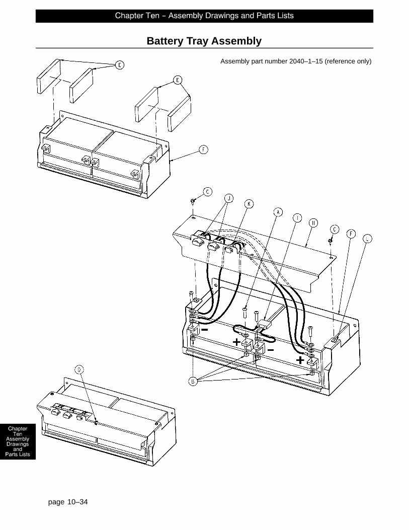
page 10–34
Battery Tray Assembly
Assembly part number 2040–1–15 (reference only)

page 10–35
Battery Tray Assembly
Item Part No. Part Name Qty.A 4–46 But. Hd. Cap Screw 4B 16–28 Nylock Nut 4C 23–25 Hex Washer Hd. Tap. Screw 2D 38–151 Cable Tie 1E 5000–101–43 Foam Block 4F 2040–1–69 Battery Tray 1H 2040–1–91 Terminal Guard 1I 2040–1–802 Battery Jumper Cable 1J 2040–1–803 Battery Harness Cable 2K 2040–1–810 Charger DC Jumper Cable 1L 3000–300–2 #10 Screw Push Nut 2
Note: battery kit part number 2040–700–13 includes two batteries.

page 10–36
2040–1–16 Foot End Bottom Cover
Item Part No. Part Name Qty.A 2040–1–78 Foot End Bottom Cover 1B 3000–000–039 Grommet 1
2040–1–17 Head End Bottom Cover
Item Part No. Part Name Qty.A 2040–1–79 Head End Bottom Cover 1B 3000–000–039 Grommet 1

Litter Assembly and Options
page 10–37

Litter Assembly and Options
page 10–38
GC

Litter Assembly and Options
page 10–39
GB

Litter Assembly and Options
page 10–40
HEAD WALL VIEW

Litter Assembly and Options
page 10–41
CP
R R
ELE
AS
E

Litter Assembly and Options
page 10–42
CPR SLIDE BRACKET DETAIL

Litter Assembly and Options
page 10–43
GR
OU
ND
ING
DE
TAIL
HE
AD
EN
DF
OO
T E
ND

Litter A
ssemb
ly and
Op
tion
s
page 10–44
HEAD ENDFOOT END
SIDERAIL EXTENSION CABLE ROUTING

Litter Assembly and Options
page 10–45
2030–231–10 Common Litter Components
Item Part No. Part Name Qty. Item Part No. Part Name Qty.
A 3–23 Hex Hd. Cap Screw 2 BS 59–774 Locking PCB Support 1B 3–74 Hex Hd. Cap Screw 3 BT 81–268 Flange Bearing 14C 3–78 Hex Hd. Cap Screw 4 BU 715–1–133 Rel. Valve Stop Sleeve 18D 3–214 Hex Hd. Cap Screw 8 BW 1550–90–13 Shock Caution Label 1E 3–347 Hex Hd. Cap Screw 4 BX 2020–34–758 Calf Section Rest 2F 4–32 Soc. Hd. Cap Screw 4 BY 2025–31–62 Pot. Actuator Link 1G 4–85 Soc. Hd. Cap Screw 2 BZ 2025–31–804 Ground Jumper 4H 4–101 Soc. Hd. Cap Screw 4 CA 2025–31–805 Ground Strap 6J 5–19 Carriage Bolt 18 CB 2025–32–68 Flange Bearing 2K 5–22 Carriage Bolt 4 CC 2025–32–74 Cover Plate 1L 5–23 Carriage Bolt 3 CD 2025–32–76 Ball Bearing 2M 7–58 Truss Hd. Torx 5 CE 2025–32–77 Fowler Actuator Link 2N 7–63 Truss Hd. Torx 19 CF 2025–32–82 Hydraulic Dampener 2P 7–65 Truss Hd. Torx 16 CG 2025–32–84 Fowler Screw Up Stop 1R 11–4 Washer 20 CH 2025–32–85 Fowler Screw Down Stop 1S 11–53 Washer 10 CJ 2025–32–86 Thrust Washer 5T 11–63 Washer 43 CK 2025–32–87 Roller Cage Bearing 2U 11–158 Washer 24 CL 2025–231–61 Pot. Timing Clamp 1W 13–10 Ext. Tooth Lock Washer 16 CM 2025–231–88 Fowler Link 2X 13–18 Ext. Tooth Lock Washer 14 CN 2025–231–90 Torque Tube Pivot Brg. 2Y 13–32 Ext. Tooth Lock Washer 2 CP 2025–231–99 Bed Extender Rel. Lever 2Z 14–7 Washer 2 CR 2025–231–112 Bed Extender Pin Lock 2AA 14–8 Washer 4 CS 2025–232–89 Fowler Nut Box 1AB 16–3 Nylock Nut 4 CT 2025–232–90 Fowler Ball Screw 1AC 16–28 Nylock Nut 22 CU 2035–31–48 Short CPR Cable 1AD 16–35 Nylock Nut 8 CW 2035–31–49 Long CPR Cable 1AE 16–102 Nylock Nut 8 CX 2035–31–50 Scale Frame Weldment 1AF 23–25 Hex Washer Hd. Screw 14 CY 2035–31–51 Torque Tube Weldment 1AG 25–79 Rivet 2 CZ 2035–31–54 Iso. Frame Weldment 1AH 25–142 Rivet 29 DA 2035–31–55 Head End Crosstube 1AJ 25–147 Rivet 4 DB 2035–31–57 Bed Extender Weldment 1AK 26–12 Roll Pin 2 DC 2035–31–64 Torque Tube Ret. Brkt., Lt. 1AL 26–168 Spiral Pin 2 DD 2035–31–65 Torque Tube Ret. Brkt., Rt. 1AM 27–15 Cotter Pin 4 DE 2035–31–66 Torque Block Channel 2AN 27–17 Cotter Pin 2 DF 2035–31–94 Foot Support Cover 1AP 28–120 External Retaining Ring 3 DG 2035–31–97 Seat Section Skin 1AR 30–27 Strain Relief 1 DH 2035–31–100 Wire Channel Cover 2AS 30–36 Grommet 4 DJ 2035–31–115 Roller Bracket Cover, Rt. 1AT 30–47 Right Angle Strain Relief 1 DK 2035–31–116 Roller Bracket Cover, Lt. 1AU 30–52 Snap Bushing 4 DL 2035–31–126 Protective Sleeve 2AW 37–221 Hole Plug 1 DM 2035–31–127 Nylon Stop 2AX 38–111 Cable Tie 10 DN 2035–31–801 Inlet/Fuse Cable 1AY 38–151 Cable Tie 17 DP 2035–31–802 Foot Board/CPU Cable 1AZ 38–382 Compression Spring 2 DR 2035–32–52 Gatch Trigger Weldment 1BA 44–29 Black Foam Tape 1 DS 2035–32–54 CPR Release Wldmt. Brkt. 1BB 44–32 1” Wide Poly Tape 50” DT 2035–32–72 CPR Release Pivot Brkt. 1BC 52–104 Cable Clamp 2 DU 2035–32–77 Gatch Actuator Link 2BD 52–759 Flange Bearing 2 DW 2035–32–79 Act. Box Cherry Swch. Brkt. 2BE 52–762 Nyliner Bushing 2 DX 2035–32–84 Gatch Screw Up Stop 1BF 58–56 Black Edge Trim 6” DY 2035–32–85 Gatch Screw Down Stop 1BG 58–76 Drive Fastener 2 DZ 2035–32–88 Act. Box Motor Mtg. Brkt. 2BH 59–133 Push–Mount Wire Clip 1 EA 2035–32–90 Gatch Ball Screw Ass’y 1BJ 59–135 Push–Mount Wire Clip 8 EB 2035–32–96 Ball Screw Cover 1BK 59–157 Power Supply 1 EC 2035–32–801 Gatch Limit Switch Cable 1BL 59–727 Jack Screw 4 ED 2035–32–802 Fowler/CPU Jumper Cable 1BM 59–743 Wire Harness Clip 2 EE 2035–32–803 Fowler Pot. Cable 1BN 59–751 Locking Circuit Bd. Supt. 6 EF 2035–32–804 Fuse/PCB Cable 1BP 59–767 Cable Clamp 2 EG 2035–32–805 CPU/Power Supply Cable 1BR 59–773 Push Spacer 4 EH 2035–33–50 Fowler Frame Weldment 1

Litter Assembly and Options
page 10–46
2030–231–10 Common Litter Components (Continued)
Item Part No. Part Name Qty. Item Part No. Part Name Qty.EJ 2035–33–62 CPR Release Slide Brkt. 2 FG 3000–300–462 CPR Wing 2EK 2035–33–63 Fowler Skin 1 FH 3000–300–464 CPR Engagement Spring 4EL 2035–34–50 Thigh Section Weldment 1 FJ 3000–300–473 Clevis Pin 2EM 2035–35–50 Foot Section Weldment 1 FK 3000–300–477 CPR Conduit Stud 6EN 2035–35–96 Foot Prop Rod 1 FL 3000–300–478 CPR Conduit Clamp 6EP 2035–231–85 Seat Section Cover 2 FM 3001–200–228 Mounting Standoff 2ER 2035–233–64 Quick Drop Rel. Brkt., Lt. 1 FN 3001–300–8 Thigh Bumper 4ES 2035–233–65 Quick Drop Rel. Brkt., Rt. 1 FP 3001–300–99 Flange Bearing 10ET 2035–400–565 Siderail Guide Bracket 2 FR 3001–300–603 CPR Release Label 2EU (page 10–49) Actuator Box Cover Ass’y 1 FS 3001–300–663 Velcro Strip 10EW 2040–90–5 500 Pound Label 2 FT 3001–300–877 Siderail Extension Cable 1EX 3000–300–58 Switch Plunger 2 FU (see page 9–1) CPU Assembly 1EY 3000–300–99 Modified Bushing 10 FW 5000–30–366 Fowler Nut Adapter 1EZ 3000–300–115 Standoff 4 FX 5010–80–7 Power Supply Gd. Cable 1FA 3000–300–349 Head/Foot Board Post Cap 4 FY 8800–380–000 Neoprene Sponge 1.5’FB 3000–300–353 Roller 8 FZ 8815–001–100 Wire Mount Clip 4FC 3000–300–442 Fowler Drive Grommet 16 GA 11–310 Washer 2FD 3000–300–455 CPR Isolation Bushing 4 GB 11–2 Washer 1FE 3000–300–456 CPR Isolator 2 GC 7–52 Truss Hd. Torx 4FF 3000–300–461 CPR Decoupler 2
2030–32–10 Epic/Epic+ Litter Components
Item Part No. Part Name Qty. Item Part No. Part Name Qty.HA 3–347 Hex Hd. Cap Screw 8 HL 25–50 Rivet 24HB 4–338 Flanged But. Hd. Screw 4 HM 30–27 Strain Grommet 2HC 5–29 Rd. Hd. Sq. Neck Bolt 4 HN 30–47 Right Angle Strain Relief 1HD 7–58 Truss Hd. Torx 1 HP 59–106 Strain Relief 1HE 11–4 Washer 16 HR 2030–31–801 Foot Pot. Exten. Cable 1HF 11–63 Washer 8 HU 2030–31–802 Head Pot. Exten. Cable 1HG 13–10 Ext. Tooth Lock Washer 1 HW 2030–31–803 Head Lift Motor Extension 1HH 13–32 Ext. Tooth Lock Washer 4 HX 2040–31–56 Foley Bag Hanger 6HJ 16–6 Kep Nut 9 HY 3001–300–4 Spacer 8HK 16–35 Nylock Nut 8
2040–32–20 Zoom/Epic/Epic+ Std. Height Option 2040–32–21 Zoom/Epic/Epic+ Enh. Height Option
Item Part No. Part Name Qty. Item Part No. Part Name Qty.HS 2030–331–52 Head End Header Wldmt. 1 HS 2040–31–252 Head End Header Wldmt. 1HT 2030–331–53 Foot End Header Wldmt. 1 HT 2040–31–253 Foot End Header Wldmt. 1
2040–32–11 Epic+/Zoom Litter Components
Item Part No. Part Name Qty. Item Part No. Part Name Qty.KA 7–58 Truss Hd. Torx 1 KE 3000–300–2 Plastic Clip Nut 3KB 13–10 Ext. Tooth Lock Washer 2 KF 2040–31–100 Manual Push Label 1KC 16–28 Nylock Nut 1 KG 59–194 Split Ferrite 3KD 2040–231–806 Bed CPU Cable 1 KH 59–738 Hole Plug 2
2040–32–15 Zoom Litter Domestic Components
Item Part No. Part Name Qty.NA 59–178 Circuit Breaker 2ND 2040–31–98 Specification Label 1NE 2035–300–705 Fowler Drive Assembly 2

Litter Assembly and Options
page 10–47
2030–30–100 No Scale or Bed Exit Options 2030–30–125 Scale Option Only
Item Part No. Part Name Qty. Item Part No. Part Name Qty.(page 10–82) Foot Board, No Scale/BE 1 OA 13–32 Ext. Tooth Lock Washer 4
OF 3001–300–511 “Imitation” Load Cell 4 (page 10–83) Foot Board, Scale Option 1OC 2035–31–805 Load Cell Cable, Head 2OD 2035–31–804 Load Cell Cable, Foot 2OE 3001–300–7 M/F Screw 8OF 3001–307–57 Load Cell 4
2030–30–175 Chaperone� Bed Exit Option 2030–30–150 Scale & Chaperone� Options
Item Part No. Part Name Qty. Item Part No. Part Name Qty.OA 13–32 Ext. Tooth Lock Washer 4 OA 13–32 Ext. Tooth Lock Washer 4
(page 10–84) Ft. Bd., Chaperone Option 1 (page 10–86) Ft. Bd., Scale & Chap. 1OC 2035–31–805 Load Cell Cable, Head 2 OC 2035–31–805 Load Cell Cable, Head 2OD 2035–31–804 Load Cell Cable, Foot 2 OD 2035–31–804 Load Cell Cable, Foot 2OE 3001–300–7 M/F Screw 8 OE 3001–300–7 M/F Screw 8OF 3001–307–57 Load Cell 4 OF 3001–307–57 Load Cell 4
2030–30–275 Chaperone II� Bed Exit Option 2030–30–250 Scale & Chaperone II� B. E. Options
Item Part No. Part Name Qty. Item Part No. Part Name Qty.OA 13–32 Ext. Tooth Lock Washer 4 OA 13–32 Ext. Tooth Lock Washer 4
(page 10–85) Ft. Bd., Chap. II Option 1 (page 10–87) Foot Board, Scale & BE 1OC 2035–31–805 Load Cell Cable, Head 2 OC 2035–31–805 Load Cell Cable, Head 2OD 2035–31–804 Load Cell Cable, Foot 2 OD 2035–31–804 Load Cell Cable, Foot 2OE 3001–300–7 M/F Screw 8 OE 3001–300–7 M/F Screw 8OF 3001–307–57 Load Cell 4 OF 3001–307–57 Load Cell 4
2030–30–151 Low–Sounding Beeper Option 2030–30–251 High–Sounding Beeper Option
Item Part No. Part Name Qty. Item Part No. Part Name Qty.PA 3001–508–869 Low–Sound Beeper Cable 1 PA 3001–508–870 High–Sound Beeper Cable 1
2035–30–207 Smart TV Option
Item Part No. Part Name Qty.UA 59–176 Jack Screw 2UB 2035–232–806 STV Option Control Cable 1UC 3001–330–970 STV Comm. Board 1
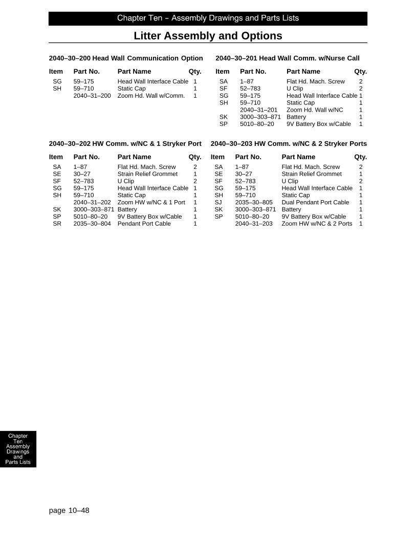
Litter Assembly and Options
page 10–48
2040–30–200 Head Wall Communication Option 2040–30–201 Head Wall Comm. w/Nurse Call
Item Part No. Part Name Qty. Item Part No. Part Name Qty.SG 59–175 Head Wall Interface Cable 1 SA 1–87 Flat Hd. Mach. Screw 2SH 59–710 Static Cap 1 SF 52–783 U Clip 2
2040–31–200 Zoom Hd. Wall w/Comm. 1 SG 59–175 Head Wall Interface Cable 1SH 59–710 Static Cap 1
2040–31–201 Zoom Hd. Wall w/NC 1SK 3000–303–871 Battery 1SP 5010–80–20 9V Battery Box w/Cable 1
2040–30–202 HW Comm. w/NC & 1 Stryker Port 2040–30–203 HW Comm. w/NC & 2 Stryker Ports
Item Part No. Part Name Qty. Item Part No. Part Name Qty.SA 1–87 Flat Hd. Mach. Screw 2 SA 1–87 Flat Hd. Mach. Screw 2SE 30–27 Strain Relief Grommet 1 SE 30–27 Strain Relief Grommet 1SF 52–783 U Clip 2 SF 52–783 U Clip 2SG 59–175 Head Wall Interface Cable 1 SG 59–175 Head Wall Interface Cable 1SH 59–710 Static Cap 1 SH 59–710 Static Cap 1
2040–31–202 Zoom HW w/NC & 1 Port 1 SJ 2035–30–805 Dual Pendant Port Cable 1SK 3000–303–871 Battery 1 SK 3000–303–871 Battery 1SP 5010–80–20 9V Battery Box w/Cable 1 SP 5010–80–20 9V Battery Box w/Cable 1SR 2035–30–804 Pendant Port Cable 1 2040–31–203 Zoom HW w/NC & 2 Ports 1

2035–432–75 Actuator Box Cover Assembly
page 10–49
Item Part No. Part Name Qty.A 2035–332–75 Main Actuator Box Cover 1B 2035–332–76 Actuator Box Side Cover 1C 7–58 Truss Hd. Torx 2

page 10–50
3001–300–775 Fowler Brake Kit Assembly
Item Part No. Part Name Qty.B 3001–300–455 CPR Coupler Assembly 1C 3000–300–465 CPR Clutch Spring 1D 81–212 Thrust Needle Roller Brg. 1E 3000–200–224 Idler Gear Thrust Washer 2F 3001–300–569 Brake Cup 1G 3001–300–552 CPR Brake Disc 1H 3001–300–551 CPR Spring Cup 2J 3001–300–563 CPR Brake Spring 1K 3001–300–570 CPR Spring Cup 1N 3–64 Hex Hd. Cap Screw 1P 3000–200–245 Flat Washer 2Q 11–193 Heavy Flat Washer 1R 16–12 Nylock Nut 1S 3000–300–113 8” Wire Tie 4

page 10–51
Zo
om
Litter A
ssemb
ly�
Assembly part number 2040–31–10 (reference only)

page 10–52
Zoom Litter Assembly�
DISPLAY HOUSING ASSEMBLY

page 10–53
Zoom Litter Assembly�

page 10–54
Zoom Litter Assembly�

page 10–55
Zoom Litter Assembly�

page 10–56
Zoom Litter Assembly�

page 10–57
Zoom Litter Assembly�
��
2040–31–200 Head Wall Communication Option 2040–31–201 Head Wall Comm. w/Nurse Call
Item Part No. Part Name Qty. Item Part No. Part Name Qty.CD 3001–300–7 M/F Screw 2 CD 3001–300–7 M/F Screw 2CF 30–38 Grommet 1 CF 30–38 Grommet 1
2040–31–202 HW Comm. w/NC & 1 Stryker Port 2040–31–203 HW Comm. w/NC & 2 Stryker Ports
Item Part No. Part Name Qty. Item Part No. Part Name Qty.CA 4–307 But. Hd. Cap Screw 4 CA 4–307 But. Hd. Cap Screw 8CB 13–10 Ext. Tooth Lock Washer 2 CB 13–10 Ext. Tooth Lock Washer 2CC 2040–31–104 Cord Out Label 1 CC 2040–31–104 Cord Out Label 1CD 3001–300–7 M/F Screw 2 CD 3001–300–7 M/F Screw 2CE 3001–314–920 Head Wall Pend. Port PCB 1 CE 3001–314–920 Head Wall Pend. Port PCB 2CF 30–38 Grommet 1 CF 30–38 Grommet 1
2040–31–204 No Head Wall Options
Item Part No. Part Name Qty.CG 37–30 Hole Plug 1

page 10–58
Zoom Litter Assembly�
Item Part No. Part Name Qty. Item Part No. Part Name Qty.A 4–142 Soc. Hd. Cap Screw 2 AX 2040–31–809 CPU/Crossover PCB 1B 7–52 Truss Hd. Torx 20 AY 2040–31–810 On/Off Cable 1C 11–193 Flat Washer 1 AZ 2040–31–900 AC/Switchover PCB 1D 13–10 Ext. Tooth Lock Washer 5 BA 2040–31–910 Display/CPU PCB 1F 16–33 Kep Nut 2 BB 2040–231–75 Reinforcement Brkt. Hd. 2G 23–80 Truss Hd. Screw 3 BC 2040–231–80 Pivot Bracket, Right 1H 23–112 Hi–Low Tapping Screw 6 BD 2040–231–81 Pivot Bracket, Left 1J 25–40 Rivet 2 BE 3000–200–215 Pot. Worm Gear 1K 21–140 Set Screw 4 BF 3000–200–253 Pot. Worm Gear Retainer 1L 26–303 Roll Pin 4 BG 3000–300–114 Wire Tie 5M 27–22 Rue Ring Cotter 2 BH 3000–300–115 Standoff 4Q 38–448 Switch Handle Ret. Spring 2 BJ 3001–300–99 Pivot Bearing 2R 52–762 Flange Bearing 4 BK 3001–300–870 Ground Strap 2S 59–133 Push–Mount Wire Clip 1 BL 3001–400–953 Switch Cap 6T 59–136 Push–Mount Wire Clip 1 BM 8800–380–000 Foam Tape (26.25”) 1U 59–190 1.0 Amp Circuit Breaker 2 BN 8800–380–000 Foam Tape (1.25”) 2V 59–191 On/Off Switch 1 BP 44–32 Press. Sens. Tape (1.5”) 4W 2011–1–215 Grounding Lug 1 BQ 59–781 4–Position Connector 2X 2035–31–803 Power Inlet Cable 1 BR 36–46 Ground Label 1Y 2040–31–11 Top Display Housing 1 BS 36–115 Ground Label 1Z 2040–31–51 Pot. Collar Weldment 1 BT 7–58 Truss Hd. Torx 4AA 2040–31–53 Hd. End Bottom Encl. 1 BU 7000–1–326 Foam Tape (26.75”) 1AB 2040–31–54 Bumper Attachment Wldmt. 1 BV 1550–90–1 Hosp. Grade Plug Label 1AD 2040–31–62 Display Label 1 BW 2011–1–104 Anesthetics Danger Label 1AE 2040–31–63 Hd. End Top Enclosure 1 BX 34–22 Cord Clamp 1AF 2040–231–64 Control Bar 1 BY 23–25 Hex Washer Hd. Screw 1AG 2040–31–68 Handle Switch 2 BZ 39–254 Power Cord 1AH 2040–231–69 Display Bumper 1 DA 7–56 Truss Hd. Torx 4AJ 2040–31–73 Stop Pin 2 DB 55–27 “U” Type Nut 4AK 2040–31–74 Control Bar Ret. Spring 2 DC 8800–233–500 P. Hd. Tapping Screw 2AL 2040–31–77 Cover Plate 1 DD 3–50 Hex Hd. Cap Screw 2AM 2040–31–82 Potentiometer Collar 1 DF 7–69 Nylon Washer 1AN 2040–31–92 Hd. End Electronics Cvr. 1 DG 16–28 Nylock Nut 2AP 2040–31–101 Drive Instruction Label 1 DH 38–482 Extension Spring 1AQ 2040–31–102 Drive Warning Label 1 DJ 2040–31–107 Locking Collar 1AR 2040–31–103 Power Label 1 DK 2040–31–108 Potentiometer Mount 1AS 2040–31–105 Logo Label 1 DL 2040–31–109 Reinforcement Bracket 1AT 2040–31–803 Contact Switch Cable 1 DM 2040–31–85 Umbilical Cord Supt. Plate 1AU 2040–31–804 Potentiometer Cable 1 DN 7–65 Truss Hd. Torx 3AV 2040–31–807 Bed AC Pwr. Jump. Cbl. 1 DP 2035–31–806 Headwall Interface Cable 1AW 2040–31–808 Charger AC Jumper 1

Head End Siderail Assembly, Left and Right
page 10–59

Head End Siderail Assembly, Left and Right
page 10–60
CA
RR
IER
/AR
M A
SS
EM
BLY

Head End Siderail Assembly, Left and Right
page 10–61
INNER SIDERAIL PANEL
OUTER SIDERAIL PANEL

Head End Siderail Assembly, Left and Right
page 10–62
LEFT HEAD END SIDERAIL WIRE ROUTING

Head End Siderail Assembly, Left and Right
page 10–63
RIGHT HEAD END SIDERAIL WIRE ROUTING

Head End Siderail Assembly, Left and Right
page 10–64
2030–400–105 Left Standard Components 2030–400–205 Right Standard Components
Item Part No. Part Name Qty. Item Part No. Part Name Qty.A 3–226 Hex Washer Hd. Screw 4 A 3–226 Hex Washer Hd. Screw 4B 3–344 Hex Hd. Screw 2 B 3–344 Hex Hd. Screw 2C 4–9 Soc. Hd. Cap Screw 1 C 4–9 Soc. Hd. Cap Screw 1D 4–101 Soc. Hd. Cap Screw 2 D 4–101 Soc. Hd. Cap Screw 2E 4–127 Soc. Hd. Cap Screw 2 E 4–127 Soc. Hd. Cap Screw 2F (page 10–78) Release Lever Ass’y, Left 1 F (page 10–79) Release Lever Ass’y, Right 1G 11–343 Shim Washer 2 G 11–343 Shim Washer 2H 11–377 Washer 2 H 11–377 Washer 2J 11–403 Steel Shim Washer 2 J 11–403 Steel Shim Washer 2K 13–10 Ext. Tooth Lock Washer 1 K 13–10 Ext. Tooth Lock Washer 1L 14–93 Washer 2 L 14–93 Washer 2N 16–23 Fiberlock Nut 2 N 16–23 Fiberlock Nut 2P 16–69 Twin Fastener 1 P 16–69 Twin Fastener 1R 23–86 High–Low Tapping Screw 1 R 23–86 High–Low Tapping Screw 1S 23–90 High–Low Tapping Screw 8 S 23–90 High–Low Tapping Screw 8T 23–112 High–Low Tapping Screw 16 T 23–112 High–Low Tapping Screw 16U 1–72 Ph. Flat Hd. Mach. Screw 4 U 1–72 Ph. Flat Hd. Mach. Screw 4W (page 10–67) Latch Ass’y, Head, Left 1 W (page 10–68) Latch Ass’y, Head, Right 1X 28–128 Retaining Ring 6 X 28–128 Retaining Ring 6Y (page 10–69) Detent Clip Assembly 1 Y (page 10–69) Detent Clip Assembly 1AB 2030–401–127 Arm Wldmt., Lt., Hd., Ft. 1 AB 2030–401–227 Arm Wldmt., Rt., Hd., Ft. 1AC 2035–20–60 Limit Switch Cam 1 AC 2035–20–60 Limit Switch Cam 1AD 2035–20–61 Insulation Card 1 AD 2035–20–61 Insulation Card 1AE 2035–20–62 Limit Switch Bracket 1 AE 2035–20–62 Limit Switch Bracket 1AF 2035–20–802 Siderail Cable 1 AF 2035–20–802 Siderail Cable 1AG 2035–20–804 Main Outside Cable, Lt. 1 AG 2035–20–803 Main Outside Cable, Rt. 1AH (page 10–70) Outer Panel Assembly 1 AH (page 10–70) Outer Panel Assembly 1AJ 2035–400–900 Outside Circuit Board 1 AJ 2035–400–900 Outside Circuit Board 1AK 3000–200–334 Release Lever Spring 1 AK 3000–200–334 Release Lever Spring 1AL 3000–300–41 Micro Switch 1 AL 3000–300–41 Micro Switch 1AM 3000–300–114 Cable Tie 5 AM 3000–300–114 Cable Tie 5AN 3000–300–478 CPR Conduit Clamp 1 AN 3000–300–478 CPR Conduit Clamp 1AP 3000–400–513 Wear Bushing 2 AP 3000–400–513 Wear Bushing 2AR 3000–400–523 Panel Spacer 2 AR 3000–400–523 Panel Spacer 2AS 3000–400–556 Warning Label 1 AS 3000–400–556 Warning Label 1AT 3000–400–557 Sleeve Bearing 4 AT 3000–400–557 Sleeve Bearing 4AU 3001–400–11 Head End Timing Link 1 AU 3001–400–11 Head End Timing Link 1AW (page 10–71) Inner Panel Assembly, Lt. 1 AW (page 10–71) Inner Panel Assembly, Rt. 1AX 3001–401–128 Arm Wldmt., Lt., Hd., Hd. 1 AX 3001–401–228 Arm Wldmt., Rt., Hd., Hd. 1AY 3001–400–130 Supt. Wldmt., Head, Left 1 AY 3001–400–230 Supt. Wldmt., Head, Right 1AZ 3001–400–501 Linkage Rivet 2 AZ 3001–400–501 Linkage Rivet 2BC 3001–400–515 Head Rail 1 BC 3001–400–515 Head Rail 1BD 3001–400–555 Mounting Bracket 1 BD 3001–400–555 Mounting Bracket 1BE 3001–400–558 SIderail Spacer 4 BE 3001–400–558 SIderail Spacer 4BF 3001–400–564 Glide Rod 2 BF 3001–400–564 Glide Rod 2BJ 3002–400–505 Bypass Pin 1 BJ 3002–400–505 Bypass Pin 1BM 3002–400–511 Glide Rod Bumper Pad 1 BM 3002–400–511 Glide Rod Bumper Pad 1BN 3002–400–512 Bumper Washer 2 BN 3002–400–512 Bumper Washer 2BP 3002–400–513 Pivot Bushing 6 BP 3002–400–513 Pivot Bushing 6BR 3002–400–519 Latch Bushing 1 BR 3002–400–519 Latch Bushing 1BT 3002–400–528 Carrier 1 BT 3002–400–528 Carrier 1BU 5000–20–5 Inner Arm Cover 2 BU 5000–20–5 Inner Arm Cover 2BW 3001–400–619 Outer Arm Cover 2 BW 3001–400–619 Outer Arm Cover 2BX 30–40 Grommet 2 BX 30–40 Grommet 2

Head End Siderail Assembly, Left and Right
page 10–65
2030–20–11 Standard Siderail
Item Part No. Part Name Qty.CA 2035–000–100 Label, Standard, Left 1CA 2035–000–200 Label, Standard, Right 1CC 3001–400–953 Switch Cap 28CD 3001–400–522 Filler Cap 18CE 3001–400–517 Speaker Seal 2CF 3001–400–535 Inner Panel Blank Module 2CH 2030–000–300 Label, Standard, Left 1CH 2030–000–400 Label, Standard, Right 1
2030–20–12 Standard Siderail with Nurse Call
Item Part No. Part Name Qty.CA 2035–000–101 Label, Standard, NC, Left 1CA 2035–000–201 Label, Standard, NC, Right 1CC 3001–400–953 Switch Cap 32CD 3001–400–522 Filler Cap 14CE 3001–403–831 Speaker with Cable 2CF 3001–400–535 Inner Panel Blank Module 2CH 2030–000–301 Label, Standard, NC, Left 1CH 2030–000–401 Label, Standard, NC, Right 1
2030–20–15 Standard Siderail w/NC & Comm.
Item Part No. Part Name Qty.CA 2035–000–102 Label, Standard, Left 1CA 2035–000–202 Label, Standard, Right 1CC 3001–400–953 Switch Cap 42CD 3001–400–522 Filler Cap 4CE 3001–403–831 Speaker with Cable 2CF 3001–400–535 Inner Panel Blank Module 2CH 2030–000–301 Label, Standard, NC, Lt. 1CH 2030–000–401 Label, Standard, NC, Rt. 1
Right Inner Siderail Label
Right Outer Siderail Label
Right Inner Siderail Label
Right Outer Siderail Label
Right Inner Siderail Label
Right Outer Siderail Label
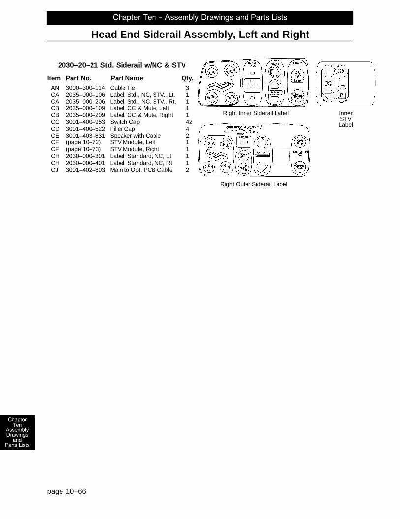
Head End Siderail Assembly, Left and Right
page 10–66
2030–20–21 Std. Siderail w/NC & STV
Item Part No. Part Name Qty.AN 3000–300–114 Cable Tie 3CA 2035–000–106 Label, Std., NC, STV., Lt. 1CA 2035–000–206 Label, Std., NC, STV., Rt. 1CB 2035–000–109 Label, CC & Mute, Left 1CB 2035–000–209 Label, CC & Mute, Right 1CC 3001–400–953 Switch Cap 42CD 3001–400–522 Filler Cap 4CE 3001–403–831 Speaker with Cable 2CF (page 10–72) STV Module, Left 1CF (page 10–73) STV Module, Right 1CH 2030–000–301 Label, Standard, NC, Lt. 1CH 2030–000–401 Label, Standard, NC, Rt. 1CJ 3001–402–803 Main to Opt. PCB Cable 2
Right Outer Siderail Label
Right Inner Siderail Label InnerSTVLabel

3002–400–70 Siderail Latch Assembly, Head End, Left
page 10–67
Item Part No. Part Name Qty.A 26–86 Blind Rivet 1B 81–317 Bronze Bushing 1C 3002–400–501 Latch 1D 3002–400–503 Head End Bypass Plate 1E 3002–400–509 Bypass Bushing Spacer 1

3002–400–75 Siderail Latch Assembly, Head End, Right
page 10–68
Item Part No. Part Name Qty.A 26–86 Blind Rivet 1B 81–317 Bronze Bushing 1C 3002–400–501 Latch 1D 3002–400–503 Head End Bypass Plate 1E 3002–400–509 Bypass Bushing Spacer 1

3002–400–90 Siderail Bypass Detent Clip Assembly
page 10–69
Item Part No. Part Name Qty.A 31–137 Steel Ball 1B 38–464 Compression Spring 1C 3002–400–524 Bypass Detent Housing 1

2035–400–50 Head End Siderail Outer Panel Assembly
page 10–70
Item Part No. Part Name Qty.A 23–112 Hi–Low Tapping Screw 2B 2035–400–102 Outer Panel 1C 3001–400–599 Handle Insert 1
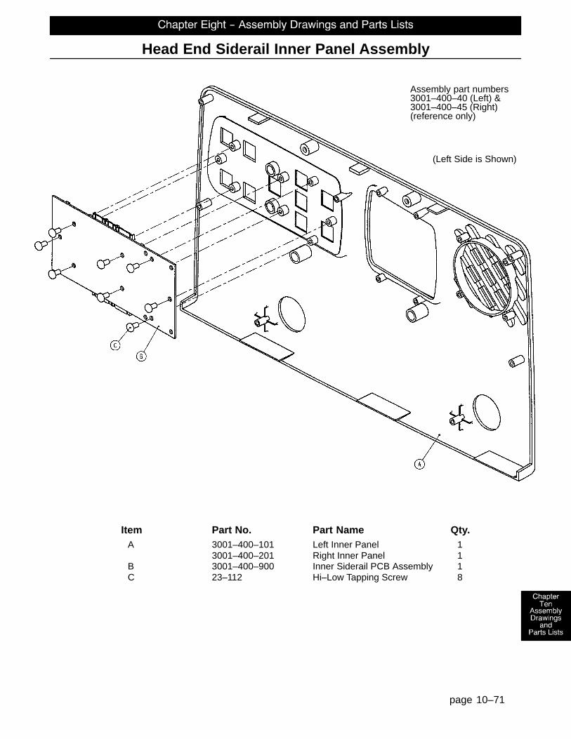
Head End Siderail Inner Panel Assembly
page 10–71
Assembly part numbers3001–400–40 (Left) &3001–400–45 (Right)
(Left Side is Shown)
(reference only)
Item Part No. Part Name Qty.A 3001–400–101 Left Inner Panel 1
3001–400–201 Right Inner Panel 1B 3001–400–900 Inner Siderail PCB Assembly 1C 23–112 Hi–Low Tapping Screw 8

2035–400–51 Optional Smart TV Siderail Module, Left
page 10–72
Item Part No. Part Name Qty.A 23–112 Ph. Hd. Hi–Lo Tapping Screw 6B 3001–400–522 Filler Cap 2C 3001–400–524 Module 1D 3001–400–953 Switch Cap 4E 5000–400–930 Keypad PCB, Left 1

2035–400–53 Optional Smart TV Siderail Module, Right
page 10–73
Item Part No. Part Name Qty.A 23–112 Ph. Hd. Hi–Lo Tapping Screw 6B 3001–400–522 Filler Cap 2C 3001–400–524 Module 1D 3001–400–953 Switch Cap 4E 5000–400–920 Keypad PCB, Right 1

Foot End Siderail Assembly, Left and Right
page 10–74

Foot End Siderail Assembly, Left and Right
page 10–75
Car
rier/
Arm
Ass
embl
yLe
ft F
oot E
nd S
ider
ail S
how
n

Foot End Siderail Assembly, Left and Right
page 10–76
Outer Siderail Panel Assembly
Inner Siderail Panel Assembly

Foot End Siderail Assembly, Left and Right
page 10–77
2030–400–305 Left Common Components 2030–400–405 Right Common Components
Item Part No. Part Name Qty. Item Part No. Part Name Qty.A 3–226 Hex Washer Hd. Screw 4 A 3–226 Hex Washer Hd. Screw 4B 3–344 Hex Hd. Cap Screw 2 B 3–344 Hex Hd. Cap Screw 2C (page 10–78) Release Lever Ass’y, Lt. 1 C (page 10–79) Release Lever Ass’y, Rt. 1D 11–343 Shim Washer 2 D 11–343 Shim Washer 2E 11–377 Washer 2 E 11–377 Washer 2F 11–403 Steel Shim Washer 2 F 11–403 Steel Shim Washer 2G 14–93 Washer 2 G 14–93 Washer 2J 2030–231–8 Outside Label 1 J 2030–231–8 Outside Label 1K 23–90 Pan Hd. Tapping Screw 8 K 23–90 Pan Hd. Tapping Screw 8L 23–112 Pan Hd. High–Low Tap. Scr. 8 L 23–112 Pan Hd. High–Low Tap. Scr. 8M 1–72 Ph. Flat Hd. Mach. Screw 4 M 1–72 Ph. Flat Hd. Mach. Screw 4P 28–128 Retaining Ring 6 P 28–128 Retaining Ring 6U 3000–200–334 Extension Spring 1 U 3000–200–334 Extension Spring 1W 3001–445–621 Blank Label, Left 1 W 3001–445–611 Blank Label, Right 1X 3001–400–535 Inner Panel Blank Module 1 X 3001–400–535 Inner Panel Blank Module 1Y 3000–400–513 Wear Bushing 2 Y 3000–400–513 Wear Bushing 2Z 3000–400–523 Panel Spacer 2 Z 3000–400–523 Panel Spacer 2AA 3000–400–556 Warning Label 1 AA 3000–400–556 Warning Label 1AB 3000–400–557 Sleeve Bearing 4 AB 3000–400–557 Sleeve Bearing 4AC 3001–400–11 Head End Timing Link 1 AC 3001–400–11 Head End Timing Link 1AD 3001–400–50 Outer Siderail Panel 1 AD 3001–400–50 Outer Siderail Panel 1AE 3001–400–101 Inner Siderail Panel, Left 1 AE 3001–400–201 Inner Siderail Panel, Right 1AF 3001–401–228 Arm Weldment, Rt., Hd., Hd. 1 AF 3001–401–128 Arm Weldment, Lt., Hd., Hd. 1AG 3001–400–130 Supt. Wldmt., Head, Left 1 AG 3001–400–230 Supt. Wldmt., Head, Right 1AH 3001–400–501 Siderail Linkage Rivet 2 AH 3001–400–501 Siderail Linkage Rivet 2AL 3001–400–515 Head Rail 1 AL 3001–400–515 Head Rail 1AM 3001–400–555 Mounting Bracket 1 AM 3001–400–555 Mounting Bracket 1AN 3001–400–558 Siderail Spacer 4 AN 3001–400–558 Siderail Spacer 4AP 3001–400–564 Glide Rod 2 AP 3001–400–564 Glide Rod 2AR 3001–400–517 Speaker Seal 1 AR 3001–400–517 Speaker Seal 1AS 2030–401–327 Arm Wldmt., Lt., Ft., Ft. 1 AS 2030–401–427 Arm Wldmt., Rt., Ft., Ft. 1AT 3002–400–501 Latch 1 AT 3002–400–501 Latch 1AU 11–185 Washer 1 AU 11–185 Washer 1AW 3002–400–505 Bypass Pin 1 AW 3002–400–505 Bypass Pin 1AX 3002–400–509 Bypass Bushing Spacer 1 AX 3002–400–509 Bypass Bushing Spacer 1AZ 3002–400–511 Glide Rod Bumper Pad 2 AZ 3002–400–511 Glide Rod Bumper Pad 2BA 3002–400–512 Bumper Washer 2 BA 3002–400–512 Bumper Washer 2BB 3002–400–513 Pivot Bushing 6 BB 3002–400–513 Pivot Bushing 6BC 3002–400–519 Latch Bushing 1 BC 3002–400–519 Latch Bushing 1BE 3002–400–528 Siderail Carrier 1 BE 3002–400–528 Siderail Carrier 1BF 5000–20–5 Inner Arm Cover 2 BF 5000–20–5 Inner Arm Cover 2BG 3001–400–619 Outer Arm Cover 2 BG 3001–400–619 Outer Arm Cover 2

3002–400–55 Siderail Release Lever Assembly, Left
page 10–78
Item Part No. Part Name Qty.A 4–278 Socket But. Hd. Cap Screw 2B 16–2 Hex Nut 2C 3001–400–505 Release Label 1D 3001–400–514 Release Lever Pad 1E 3002–400–510 Release Lever 1

3002–400–65 Siderail Release Lever Assembly, Right
page 10–79
Item Part No. Part Name Qty.A 4–278 Socket But. Hd. Cap Screw 2B 16–2 Hex Nut 2C 3001–400–505 Release Label 1D 3001–400–514 Release Lever Pad 1E 3002–400–510 Release Lever 1

2035–130–10 Head Board Assembly
page 10–80
Item Part No. Part Name Qty.A 23–88 Pan Hd. Screw 2B 2035–500–7 Dark Blue “C” Bumper 2C 3000–526–1 CPR Board 1D 3000–526–2 CPR Board Clip 1E 3000–526–3 CPR Board Label 1F 3000–600–10 Head Board Clam Shell Ass’y 1G 3000–600–56 Beige Head Board Laminate 1H 72–2–71 “C” Bumper Adhesive N/A

Foot Board Assembly and Options
page 10–81
part number 2030–000–151
part number 2035–000–153
part number 2035–000–155
2030–135–10 Foot Board Standard Components
Item Part No. Part Name Qty. Item Part No. Part Name Qty.A 23–99 Phil. Pan Hd. Tap. Screw 2 L 3001–500–10 Clamshell Assembly 1B 23–103 Pan Hd. Hi/Lo Tap. Screw 7 M 3001–500–801 Foot Board Drawer Cable 1C 50–38 Pan Hd. Mach. Screw 2 N 3000–500–25 Lid Label 1D 50–39 Pan Hd. Mach. Screw 2 P 2035–500–7 Blue “C” Bumper 2E 72–2–71 “C” Bumper Adhesive .30 R 2035–500–8 Strip Bumper 2F 3000–500–8 Chart Rack Cover 1 S 3000–500–56 Beige Laminate 1G 3000–500–29 Hazard Label 1 T (page 10–89) E–Drop/Card. Ch. Module 1H (page 10–88) Main Module 1 U 2035–000–155 E–Drop/Card. Ch. Label 1J 3001–500–64 Hinge Plate 1 W 2025–136–801 E–Drop/Card. Ch. Cable 1K 3001–500–1 Lid Assembly 1

Foot Board Assembly and Options
page 10–82
2030–135–11 Foot Board No Scale/No Bed Exit Option
Item Part No. Part Name Qty.AA 3000–500–4 End Module 1AB 2035–500–101 Foot Board Blank Label 4AC 3000–500–27 Blank End Label 1AD 3001–500–3 Blank Module 3AE 3000–500–26 Blank Module Label 3

Foot Board Assembly and Options
page 10–83
part number 2030–000–152
2030–135–13 Foot Board Scale Option
Item Part No. Part Name Qty.AA 2035–500–101 Foot Board Blank Label 1AB 3001–500–3 Blank Module 1AF (page 10–92) Scale Module Assembly 1AG 2030–000–152 Scale Module Label 1AJ 3002–507–11 Scale Lid Label 1AM 3000–500–26 Blank Label 1

Foot Board Assembly and Options
page 10–84
part number 2030–000–154
2030–135–12 Foot Board Chaperone� Option
Item Part No. Part Name Qty.
AA 3000–500–4 End Module 1AB 2035–500–101 Foot Board Blank Label 3AC 3000–500–27 Blank End Label 1AD 3001–500–3 Blank Module 2AE 3001–508–800 Bed Exit Keypad Cable 1AF 2030–000–154 Bed Exit Label 1AG 3002–508–10 Bed Exit Lid Label 1AH (page 10–90) Bed Exit Module Assembly 1AJ 3000–500–26 Blank Module Assembly 2

Foot Board Assembly and Options
page 10–85
part number 2030–000–156
2030–135–15 Foot Board Chaperone� w/Zone Control Option
Item Part No. Part Name Qty.
AA 3000–500–4 End Module 1AB 2035–500–101 Foot Board Blank Label 3AC 3000–500–27 Blank End Label 1AD 3001–500–3 Blank Module 2AE 2030–000–156 Chaperone II Module Label 1AF 3002–508–12 Chaperone II Label 1AG 3002–508–800 Zone Control Keypad Cable 1AH (page 10–91) Bed Exit Module Assembly 1AJ 3000–500–26 Blank Module Label 2

Foot Board Assembly and Options
page 10–86
part number 2030–000–154 part number 2030–000–152
2030–135–14 Foot Board Scale and Chaperone� Options
Item Part No. Part Name Qty.AA 3001–508–800 Bed Exit Keypad Cable 1AB 2030–000–154 Bed Exit Label 1AC 3002–508–10 Bed Exit Lid Label 1AD (page 10–90) Bed Exit Module Assembly 1AH (page 10–92) Scale Module Assembly 1AJ 2030–000–152 Scale Module Label 1AL 3002–507–11 Scale Lid Label 1

Foot Board Assembly and Options
page 10–87
part number 2030–000–152 part number 2030–000–156
2030–135–16 Foot Board Scale and Chaperone� w/Zone Control Options
Item Part No. Part Name Qty.AD (page 10–92) Scale Module Assembly 1AE 2030–000–152 Scale Module Label 1AG 3002–507–11 Scale Lid Label 1AK 2030–000–156 Chaperone II Module Label 1AL 3002–508–12 Chaperone II Label 1AM 3002–508–800 Zone Control Keypad Cable 1AN (page 10–90) Bed Exit Module Assembly 1

2030–235–20 Foot Board Main Module Assembly
page 10–88
part number 2030–000–151 part number 2035–000–153
Item Part No. Part Name Qty.B 3000–500–2 Foot Board Standard Module 1C 3000–501–1 Gatch/Fowler Module 1D 3001–400–953 Switch Cap 13E 3001–500–930 Main Foot Board PCB 1F 23–87 Pan Hd. Tapping Screw 9G 2035–000–153 Gatch/Fowler Label 1H 2030–000–151 Foot Board Std. Module Label 1

2025–136–21 Foot Board Emer. Drop/Cardiac Chair Module
page 10–89
Item Part No. Part Name Qty.A 3000–508–1 Bed Exit Module Panel 1B 3001–400–953 Switch Cap 2C 2025–136–900 CPR Drop/Card. Ch. Keypad 1D 23–87 Hi–Low Tapping Screw 3

2025–136–22 Opt. Foot Board Chaperone Bed Exit Module
page 10–90
Item Part No. Part Name Qty.A 3000–508–1 Bed Exit Module Panel 1B 3001–400–953 Switch Cap 2C 3001–508–910 Bed Exit Keypad Ass’y 1D 23–87 Hi–Low Tapping Screw 3

3002–508–30 Opt. Ft. Bd. Chaperone w/Zone Bed Exit Module
page 10–91
Item Part No. Part Name Qty.A 23–87 Hi–Low Tapping Screw 3B 3000–508–1 End Exit Module Panel 1C 3001–400–953 Switch Cap 2D 3002–508–900 Bed Exit Board 1

3002–507–30 Foot Board Scale Module Assembly
page 10–92
Item Part No. Part Name Qty.A 11–487 Nylon Washer 4B 23–87 Pan Hd. Hi–Lo Tapping Screw 4C 23–91 Pan Hd. Hi–Lo Tapping Screw 4D 3001–507–1 Scale Module 1E 3001–507–910 Scale Keypad 1F 3001–507–800 Scale Keypad Cable 1G 3001–400–953 Switch Cap 6H 3002–507–900 Scale Display Cable 1

page 10–93
Optional Pendant Assembly
3001–315–12 Combination PendantMotion/Communication
3001–315–14 Combination PendantMotion Only
3001–315–16 Combination PendantCommunication Only
3001–315–18 Combination PendantMotion/NurseCall

page 10–94
3000–300–80 Removable I.V. Pole Assembly
Item Part No. Part Name Qty.A 3000–300–81 Outer Tube 1B 3000–300–89 Label 1C 24–50 Fluted Knob 1D 52–17 Spacer 2E 7–40 Phillips Truss Hd. Screw 1F 1010–59–16 I.V. Hook 2G 3000–300–85 Inner Tube Assembly 1

page 10–95
2035–111 Optional 2–Stage I.V. Mounting Assembly, Foot End
Item Part No. Part Name Qty.A 4–199 But. Hd. Cap Screw 1B 16–11 Flexlock Nut 1C 21–140 Set Screw 2D 2035–111–1 I.V. Receptacle, Foot, Left 1E (page 10–98) I.V. Pole Assembly, Left 1F 3000–312–35 I.V. Cradle 1G 2035–112–110 Specification Label 1

page 10–96
2035–112 Optional 2–Stage I.V. Mounting Assembly, Head End
Item Part No. Part Name Qty.A 1015–24–35 Retaining Pin 1C 21–140 Set Screw 2D 2035–112–1 I.V. Receptacle, Head, Left 1E (page 10–98) I.V. Pole Assembly, Left 1F 3000–311–16 I.V. Rest 1G 2035–112–110 Specification Label 1

page 10–97
2040–110–3 Dual Head End I.V. Mounting Assembly
Item Part No. Part Name Qty.A 21–140 Set Screw 4B 1015–24–35 Retaining Pin 2C (page 10–98) I.V. Pole Assembly, Left 1D 2035–112–110 Specification Label 1E 2035–113–2 I.V. Receptacle, Dual Hd. End, Rt. 1F 2035–113–1 I.V. Receptacle, Dual Hd. End, Lt. 1G (page 10–98) I.V. Pole Assembly, Right 1H 2035–113–111 Specification Label 1J 2040–110–2 I.V. Pole Extension 2K 6060–90–114 ”Keep Hands Clear” Label 2

page 10–98
2035–112–10 & 2035–113–11 Optional 2–Stage I.V. Assembly
2035–112–10 Head End, Left 2035–113–11 Foot End, Right
Item Part No. Part Name Qty. Item Part No. Part Name Qty.A 8–31 Soc. Hd. Shoulder Screw 1 A 8–31 Soc. Hd. Shoulder Screw 1B 52–17 Washer 2 B 52–17 Washer 2C 52–310 Spacer 1 C 52–311 Spacer 1D 926–400–162 Spacer 1 D 926–400–162 Spacer 1E 1001–259–13 Dampener 1 E 1001–259–13 Dampener 1F 1001–259–32 Base Tube Weldment 1 F 1001–259–32 Base Tube Weldment 1G 1010–259–16 I.V. Hook 2 G 1010–259–16 I.V. Hook 2H (page 10–99) I.V. Pole Latch 1 H (page 10–99) I.V. Pole Latch 1I 1211–110–29 2nd Stage Assembly 1 I 1211–110–29 2nd Stage Assembly 1

page 10–99
1211–210–26 Optional I.V. Pole Latch Assembly
Item Part No. Part Name Qty.A 28–167 Retaining Ring 1B 31–4 Steel Ball 2C 38–392 Crest–to–Crest Spring 1D 1211–91–34 Release Label 1E 1211–110–18 I.V. Latch Seal 1F 1211–110–20 Washer 2G 1211–110–21 I.V. Latch Locking Pin 2H 1211–110–22 I.V. Latch Guide 1J 1211–110–24 I.V. Latch O.D. Housing 1K 1211–110–35 Washer 1L 1211–110–36 Self–Tapping Screw 2M 1211–210–23 I.V. Latch I.D. Housing 1

page 10–100
2035–140 Optional Fowler X–Ray Cassette Holder Assembly
Assembly part number2035–140–10(reference only)
Item Part No. Part Name Qty. Item Part No. Part Name Qty.A 1–20 Flat C’sunk Hd. Mach Scr. 2 M 1010–23–28 Tray Angle 1B 1–22 Flat C’sunk Hd. Mach Scr. 4 N 1010–23–37 Cassette Rod Guide 2C 4–149 H. Soc. But. Hd. Cap Scr. 4 P 1020–23–16 Cassette Post Housing 1D 14–3 Washer 1 Q 1020–23–19 Tray Hinge Wldmt., Rt. 1E 16–3 Hex Nut 4 R 1020–23–20 Tray Hinge Wldmt., Lt. 1F 38–122 Spring 1 S 1020–23–21 Knob 1G 926–23–64 Tray Post 2 T 1020–23–26 Spacer 2H 926–23–69 Cassette Washer 1 V 2025–140–2 Cassette Actuating Rod 2J 926–23–70 Cassette Block Subass’y 1 W 2035–140–25 Specification Label 1K 926–23–71 Cassette Bushing 1 X 2035–140–99 Cassette Tray 1L 1010–23–19 Instruction Label 1

page 10–101
2035–19–10 Optional Siderail Transducer Mount Assembly
Item Part No. Part Name Qty.A 24–63 T–Knob 1B 24–64 Thumb Screw 2C 2035–19–11 Transducer Mount, Top 1D 2035–19–12 Transducer Mount, Bottom 1

page 10–102
2035–18–10 Optional I.V. Pole Transducer Mount Assembly
Item Part No. Part Name Qty.A 24–63 T–Knob 1B 24–64 Thumb Screw 2C 2035–18–11 Transducer Mount 1

page 10–103
2025–120 Optional Defibrillator Tray Assembly
Item Part No. Part Name Qty. Item Part No. Part Name Qty.A 8–49 Soc. Hd. Shoulder Bolt 2 L 1010–50–21 Long Strap 1B 14–20 Thrust Washer 1 M 1010–50–50 Knob 1C 14–21 Thrust Washer 1 N 1010–50–57 Max. Weight Label 4D 16–28 Fiberlock Nut 2 P 1010–50–242 Lock Pin 1E 21–17 Set Screw 4 R 2025–120–5 Equipment Label 1F 37–214 Hole Plug 4 S 2025–120–6 Specification Label 1H 38–133 Spring 1 T 2025–120–18 Tray Assembly 1J 52–17 Spacer 2 W 2025–120–25 Pivot Weldment Frame 1K 1010–50–19 “Push/Pull” Label 1

page 10–104
2040–120–4 Optional Pleur–Evac Rack with Defibrillator Tray

page 10–105
2040–120–4 Optional Pleur–Evac Rack with Defibrillator Tray
Item Part No. Part Name Qty.A 8–49 Soc. Hd. Shoulder Bolt 2B 14–20 Thrust Washer 1C 14–21 Thrust Washer 1D 16–28 Fiberlock Nut 2E 21–17 Set Screw 4F 37–214 Hole Plug 4G 38–133 Spring 1H 52–17 Spacer 2J 1010–50–19 “Push/Pull” Label 1K 1010–50–21 Long Strap 1L 1010–50–50 Knob 1M 1010–50–57 “Max. Weight” Label 4N 1010–50–242 Lock Pin 1P 2025–120–5 Equipment Label 1R 2025–120–18 Tray Assembly 1S 2040–90–1 Warning Label 1T 2040–90–5 Specification Label 1U 2040–120–3 Rack Weldment 1

page 10–106
2040–120–20 Optional Pleur–Evac Rack Assembly
Item Part No. Part Name Qty.A 3–50 Hex Hd. Cap Screw 2B 3–85 Hex Hd. Cap Screw 1C 15–28 Nylock Nut 2D 16–36 Nylock Nut 1E 21–17 Set Screw 4F 37–214 Hole Plug 4G 1010–50–57 Maximum Weight Label 1H 2040–90–1 Acc. Rail Warning Label 1J 2040–90–4 Specification Label 1K 2040–120–3 Rack Weldment 1L 2040–120–10 Rack Top Weldment 1

page 10–107
2040–120–9 Optional Siderail Pleur–Evac Rack Assembly
Item Part No. Part Name Qty.A 2040–90–1 Warning Label 1B 2040–90–2 Maximum Weight Label 1C 2040–120–8 Rack Weldment 1

page 10–108
2040–111 Optional Pump Rack Assembly
Item Part No. Part Name Qty.A 58–87 End Cap 2B 2030–140–2 Pump Rack Label 1C 2040–111–5 Pump Rack Tube 1

page 10–109
040–150–10 Optional Upright Oxygen Bottle Holder Assembly
Item Part No. Part Name Qty.A 24–55 Knob 1B 1010–30–11 Upright Bottle Holder 1C 2025–150–1 Adaptor Sleeve 1D 2025–150–2 Specification Label 1E 26–5 Spring Pin 1F 2025–150–3 End Stop Bushing 1G 2040–110–2 Hd. End Dual I.V. Pole Collar 1

page 10–110
2025–40–10 Optional Bed Extender Pad Assembly

page 10–111
2040–130 Optional Siderail Pad Set
3000–336–11 Right Siderails 3000–336–12 Left Siderails

DH 12/01 2040–999–001 REV B
European Representative
Stryker France Phone: 33148632290BP 50040–95946 Roissy Ch. de Gaulle Fax: 33148632175Cedex–France
6300 Sprinkle Road, Kalamazoo, MI 49001–9799 (800) 327–0770www.med.strykercorp.com
Copyright © 2022 FDOKUMEN