Supercontinuum generation in both frequency and wavenumber domains in nonlinear waveguide arrays
6
PHYSICAL REVIEW A 89, 013826 (2014) Supercontinuum generation in both frequency and wavenumber domains in nonlinear waveguide arrays Truong X. Tran, 1, 2 , * D˜ ung C. Duong, 1 and Fabio Biancalana 2, 3 1 Department of Physics, Le Quy Don University, 236 Hoang Quoc Viet Street, 10000 Hanoi, Vietnam 2 Max Planck Institute for the Science of Light, G¨ unther-Scharowsky-Str. 1/Bau 24, 91058 Erlangen, Germany 3 School of Engineering and Physical Sciences, Heriot-Watt University, Edinburgh EH14 4AS, United Kingdom (Received 27 November 2013; published 21 January 2014) We study the spatiotemporal effects in waveguide arrays with Kerr and Raman nonlinearities when a short pulse is launched into the system where both dispersive and diffractive resonant radiations can be simultaneously emitted by solitons. We show that it is possible to generate and control the supercontinuum not only in the frequency domain, but also in the wavenumber domain. This work could potentially pave the way for designing unique optical devices that generate spectrally broad supercontinua with a controllable directionality by taking advantage of the combined physics of optical fibers and waveguide arrays. DOI: 10.1103/PhysRevA.89.013826 PACS number(s): 42.65.Wi, 42.82.Et I. INTRODUCTION Waveguide arrays (WAs) present a unique discrete periodic photonic system to investigate many interesting fundamen- tal phenomena such as discrete diffraction [1,2], discrete solitons [1,3,4], and photonic Bloch oscillations [1,5–8]. In applications, two-dimensional (2D) networks of nonlinear waveguides with discrete solitons may be useful for designing signal-processing circuits [9]. Binary WAs have also been intensively used to mimic relativistic phenomena typical of quantum field theory, such as Zitterbewegung [10], Klein para- dox [11], fermion pair production [12], and the Dirac equation in the linear regime [13]. Quite recently, the optical analog of relativistic Dirac solitons with exact analytical solutions in binary WAs was found [14], which could potentially pave the way to using binary WAs as a classical simulator of quantum nonlinear effects arising from the Dirac equation, something that is thought to be impossible to achieve in conventional (i.e., linear) quantum field theory. Dispersive resonant radiation (DisRR), which emerges due to high-order dispersion terms, has been well explored in the last decade in the temporal case for optical fibers [15–19]. When an ultrashort pulse is launched into optical fibers, a DisRR due to phase matching between the fiber and the soliton group velocity dispersion generates one or more new frequencies [18,19]. This DisRR, together with other well-known nonlinear effects such as self- and cross- phase modulation, soliton fission [20], and stimulated Raman scattering [21], are the main ingredients of supercontinuum generation [22,23], especially in highly nonlinear photonic crystal fibers [24]. Supercontinuum generation has quickly been established as one of the most important phenomena in nonlinear fiber optics and has led to a number of im- portant technological advances in various fields, such as spectroscopy and medical imaging [25], metrology [26], and the realization of broadband sources [27], to name just a few. In a recent study diffractive resonant radiation (DifRR)—an analog of DisRR—has been found when a spatial soliton in * [email protected] the continuous-wave (CW) regime is launched into WAs [28]. We have shown in Ref. [28] that when the phase-matching condition is satisfied, a spatial soliton emits DifRR with a new, well-defined direction, i.e., transverse wavenumber. It turns out that DifRR is a universal effect which can occur in WAs not only in the CW regime, but also in the spatiotemporal case, as we have shown in Ref. [29], where a long-pulse was used. In Ref. [29] wavenumber- supercontinuum generation and compensation of the soliton self-wavenumber shift by the emitted DifRR have also been revealed. The wavelength dependence of the coupling coefficient is large because it arises from the evanescent field overlap between adjacent waveguides. This in turn makes discrete diffraction, i.e., beam spreading, wavelength dependent. This was demonstrated dramatically when a continuum generated via a microstructure fiber was injected into a single waveguide and the spectrum of the colors in the light beam was spatially dispersed at the output of the WA made of a LiNbO 3 crystal with defocusing nonlinearity [30,31]. Note that in Refs. [30,31] the features of polychromatic light propagation (such as spatiospectral control, diffraction management, broadband switching, and self-trapping of polychromatic light) are in- vestigated when the input light launched into WAs is already a spectral supercontinuum source. Motivated by the latest achievements in DifRR studies and features of polychromatic light propagation in WAs, in this paper we first present the generalized coupled-mode equations governing the spatiotemporal effects in WAs made of silica which take into account the wavelength dependence of the coupling coefficient. Then we investigate the generation of a supercontinuum in WAs both in frequency and in wavenumber, its dynamics, and also ways to control it when short input pulses are launched into the system under various conditions. II. GENERALIZED COUPLED-MODE EQUATIONS Our starting point is the generalized coupled-mode equa- tions (GCMEs) of a WA consisting of identical waveguides made of silica in the frequency domain [see Eqs. (2.1.4)– 1050-2947/2014/89(1)/013826(6) 013826-1 ©2014 American Physical Society
-
Upload
independent -
Category
Documents
-
view
2 -
download
0
Transcript of Supercontinuum generation in both frequency and wavenumber domains in nonlinear waveguide arrays
PHYSICAL REVIEW A 89, 013826 (2014)
Supercontinuum generation in both frequency and wavenumber domains innonlinear waveguide arrays
Truong X. Tran,1,2,* Dung C. Duong,1 and Fabio Biancalana2,3
1Department of Physics, Le Quy Don University, 236 Hoang Quoc Viet Street, 10000 Hanoi, Vietnam2Max Planck Institute for the Science of Light, Gunther-Scharowsky-Str. 1/Bau 24, 91058 Erlangen, Germany
3School of Engineering and Physical Sciences, Heriot-Watt University, Edinburgh EH14 4AS, United Kingdom(Received 27 November 2013; published 21 January 2014)
We study the spatiotemporal effects in waveguide arrays with Kerr and Raman nonlinearities when a shortpulse is launched into the system where both dispersive and diffractive resonant radiations can be simultaneouslyemitted by solitons. We show that it is possible to generate and control the supercontinuum not only in thefrequency domain, but also in the wavenumber domain. This work could potentially pave the way for designingunique optical devices that generate spectrally broad supercontinua with a controllable directionality by takingadvantage of the combined physics of optical fibers and waveguide arrays.
DOI: 10.1103/PhysRevA.89.013826 PACS number(s): 42.65.Wi, 42.82.Et
I. INTRODUCTION
Waveguide arrays (WAs) present a unique discrete periodicphotonic system to investigate many interesting fundamen-tal phenomena such as discrete diffraction [1,2], discretesolitons [1,3,4], and photonic Bloch oscillations [1,5–8]. Inapplications, two-dimensional (2D) networks of nonlinearwaveguides with discrete solitons may be useful for designingsignal-processing circuits [9]. Binary WAs have also beenintensively used to mimic relativistic phenomena typical ofquantum field theory, such as Zitterbewegung [10], Klein para-dox [11], fermion pair production [12], and the Dirac equationin the linear regime [13]. Quite recently, the optical analogof relativistic Dirac solitons with exact analytical solutions inbinary WAs was found [14], which could potentially pave theway to using binary WAs as a classical simulator of quantumnonlinear effects arising from the Dirac equation, somethingthat is thought to be impossible to achieve in conventional (i.e.,linear) quantum field theory.
Dispersive resonant radiation (DisRR), which emergesdue to high-order dispersion terms, has been well exploredin the last decade in the temporal case for optical fibers[15–19]. When an ultrashort pulse is launched into opticalfibers, a DisRR due to phase matching between the fiberand the soliton group velocity dispersion generates one ormore new frequencies [18,19]. This DisRR, together withother well-known nonlinear effects such as self- and cross-phase modulation, soliton fission [20], and stimulated Ramanscattering [21], are the main ingredients of supercontinuumgeneration [22,23], especially in highly nonlinear photoniccrystal fibers [24]. Supercontinuum generation has quicklybeen established as one of the most important phenomenain nonlinear fiber optics and has led to a number of im-portant technological advances in various fields, such asspectroscopy and medical imaging [25], metrology [26],and the realization of broadband sources [27], to name justa few.
In a recent study diffractive resonant radiation (DifRR)—ananalog of DisRR—has been found when a spatial soliton in
the continuous-wave (CW) regime is launched into WAs [28].We have shown in Ref. [28] that when the phase-matchingcondition is satisfied, a spatial soliton emits DifRR witha new, well-defined direction, i.e., transverse wavenumber.It turns out that DifRR is a universal effect which canoccur in WAs not only in the CW regime, but also inthe spatiotemporal case, as we have shown in Ref. [29],where a long-pulse was used. In Ref. [29] wavenumber-supercontinuum generation and compensation of the solitonself-wavenumber shift by the emitted DifRR have also beenrevealed.
The wavelength dependence of the coupling coefficientis large because it arises from the evanescent field overlapbetween adjacent waveguides. This in turn makes discretediffraction, i.e., beam spreading, wavelength dependent. Thiswas demonstrated dramatically when a continuum generatedvia a microstructure fiber was injected into a single waveguideand the spectrum of the colors in the light beam was spatiallydispersed at the output of the WA made of a LiNbO3 crystalwith defocusing nonlinearity [30,31]. Note that in Refs. [30,31]the features of polychromatic light propagation (such asspatiospectral control, diffraction management, broadbandswitching, and self-trapping of polychromatic light) are in-vestigated when the input light launched into WAs is alreadya spectral supercontinuum source.
Motivated by the latest achievements in DifRR studiesand features of polychromatic light propagation in WAs, inthis paper we first present the generalized coupled-modeequations governing the spatiotemporal effects in WAs made ofsilica which take into account the wavelength dependence ofthe coupling coefficient. Then we investigate the generationof a supercontinuum in WAs both in frequency and inwavenumber, its dynamics, and also ways to control it whenshort input pulses are launched into the system under variousconditions.
II. GENERALIZED COUPLED-MODE EQUATIONS
Our starting point is the generalized coupled-mode equa-tions (GCMEs) of a WA consisting of identical waveguidesmade of silica in the frequency domain [see Eqs. (2.1.4)–
1050-2947/2014/89(1)/013826(6) 013826-1 ©2014 American Physical Society
TRAN, DUONG, AND BIANCALANA PHYSICAL REVIEW A 89, 013826 (2014)
(2.1.5) in Ref. [23]),
dAn
dz= i
[β(ω) + �βNL
n − β(ω0)]An
+ iκ(ω)[An+1 + An−1], (1)
where An is the electric field envelope in the nth waveguide inthe frequency domain, z is the longitudinal coordinate, β(ω)is the mode-propagation constant of identical waveguides atfrequency ω, �βNL
n is the nonlinear contribution to the mode-propagation constant in the nth waveguide, β(ω0) is the mode-propagation constant at carrier frequency ω0, and κ(ω) is thefrequency-dependent coupling coefficient between identicaladjacent waveguides (see Refs. [23,27] for more details). Notethat in most cases the coupling coefficient κ is often treated as aconstant, but in this specific work, where the supercontinuum isunder consideration, we would like to relax this approximation.
The above frequency-domain GCMEs can be converted tothe time domain by expanding both β(ω) and κ(ω) in Taylorseries around the carrier frequency ω0, replacing (ω − ω0) witha time derivative while taking the inverse Fourier transform,and using the comoving frame T = t − z/vg , where vg is thegroup velocity at ω0. In doing so we obtain the followingGCMEs in the time domain:
i∂zAn + D(i∂T )An + κ(i∂T )[An+1 + An−1]
+ γ
(1 + i
ω0∂T
)An(z,T )
∫ ∞
−∞R(t ′)|An(z,T − t ′)|2dt ′
= 0, (2)
where the linear dispersion operator is given by D(i∂T ) ≡s|β2|
2 ∂2T + ∑
m�3βm
m! [i∂T ]m, with s = +1 (s = −1) for theanomalous (normal) group velocity dispersion regime, andβm is the mth-order group velocity dispersion coefficient. Notethat the group velocity vg = 1/β1. Meanwhile, the operator forthe coupling coefficient is given by κ(i∂T ) ≡ ∑
m�0κm
m! [i∂T ]m
and κm is the mth-order derivative of κ(ω) at carrier frequencyω0. Here we assume that the WA consists of identical waveg-uides, with the nonlinear parameter of each waveguide beingγ . The nonlinear response function R(t) = (1 − fR)δ(t) +fRhR(t), where the first term represents the instantaneouselectronic contribution, with δ(t) being the Dirac δ function,hR(t) is the Raman response function of the core, and fR
represents its fractional contribution. For silica fR � 0.18 andthe Raman effect is included through a simple model in which
hR(t) has the form hR(t) = τ 21 +τ 2
2
τ1τ22
exp(−t/τ2)sin(t/τ1)(t),where τ1 = 12.2 fs and τ2 = 32 fs [27], and (t) is the Heav-iside step function that ensures causality. The self-steepeningeffect is included through the derivative ∂T in the nonlinearterms. Now we introduce dimensionless variables ξ = z/LD ,τ = T/T0, and an = An/
√P0, where the dispersion length
LD = T 20 /|β2|, and T0 is related to the full width at half-
maximum (FWHM) pulse duration in the case of a sech-shapedpulse as follows: TFWHM � 1.763T0 [27]. The power scaleis P0 = 1/(γLD). With these new variables, Eqs. (2) are
equivalent to the following dimensionless GCMEs:
i∂ξ an + D(i∂τ )an + LDκ(i∂τ )[an+1 + an−1]
+(
1 + i
ω0T0∂τ
)an
∫ ∞
−∞r(τ ′)|an(ξ,τ − τ ′)|2dτ ′ = 0,
(3)
where the dispersion operator now assumes the form D(i∂τ ) ≡12 s∂2
τ + ∑m�3 αm[i∂τ ]m, with αm ≡ βm/[m!|β2|T m−2
0 ],whereas the operator for the coupling coefficient now hasthe form κ(i∂τ ) ≡ ∑
m�0κm
m!T m0
[i∂τ ]m, and the dimensionlessfunction r(τ ) is obtained by rescaling time t with T0 in theresponse function R(t).
Equation (3) is used later to investigate supercontinuumgeneration in a WA. In order to simulate Eq. (3) one needsto calculate the dispersion D and the coupling coefficient κ
as functions of the wavelength. In the rest of this paper, asa practical example we specify the parameters for the WA asfollows: the WA is formed by identical conventional step-indexfibers with the cladding made of fused silica and the coremade of silica with 1.8% dopant GeO2. The dopant at the lowconcentration used here is just to ensure that the refractiveindex of the core (which has been well approximated with theSellmeier equation) is slightly larger than that of the cladding.The core radius is 5 μm and the center-to-center spacingbetween two adjacent cores is 20 μm. Recent advances infemtosecond-laser writing technologies for WAs of fused silica(see Ref. [32]) make the above-proposed WA feasible.
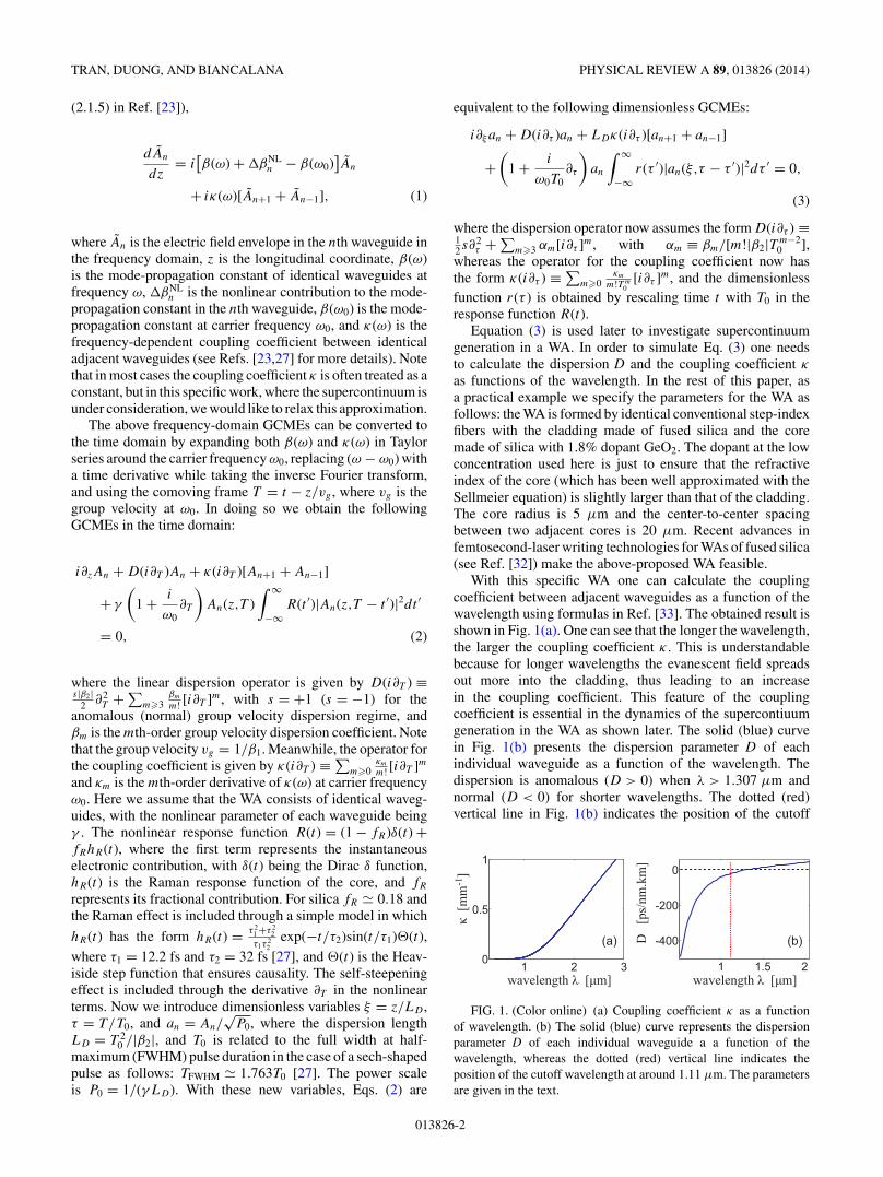
With this specific WA one can calculate the couplingcoefficient between adjacent waveguides as a function of thewavelength using formulas in Ref. [33]. The obtained result isshown in Fig. 1(a). One can see that the longer the wavelength,the larger the coupling coefficient κ . This is understandablebecause for longer wavelengths the evanescent field spreadsout more into the cladding, thus leading to an increasein the coupling coefficient. This feature of the couplingcoefficient is essential in the dynamics of the supercontiuumgeneration in the WA as shown later. The solid (blue) curvein Fig. 1(b) presents the dispersion parameter D of eachindividual waveguide as a function of the wavelength. Thedispersion is anomalous (D > 0) when λ > 1.307 μm andnormal (D < 0) for shorter wavelengths. The dotted (red)vertical line in Fig. 1(b) indicates the position of the cutoff
1 1.5 2
-400
-200
0
1 2 30
0.5
1
(a) (b)D[p
s/nm
.km
]
κ[m
m]
-1
wavelength λ [ m]μwavelength λ [ m]μ
FIG. 1. (Color online) (a) Coupling coefficient κ as a functionof wavelength. (b) The solid (blue) curve represents the dispersionparameter D of each individual waveguide a a function of thewavelength, whereas the dotted (red) vertical line indicates theposition of the cutoff wavelength at around 1.11 μm. The parametersare given in the text.
013826-2
SUPERCONTINUUM GENERATION IN BOTH FREQUENCY . . . PHYSICAL REVIEW A 89, 013826 (2014)
wavelength λco � 1.11 μm; thus for λ > λco waveguidesare single mode, whereas for shorter wavelengths they aremultimode.
III. SUPERCONTINUUM GENERATION IN WAVEGUIDEARRAYS IN BOTH FREQUENCY AND
WAVENUMBER DOMAINS
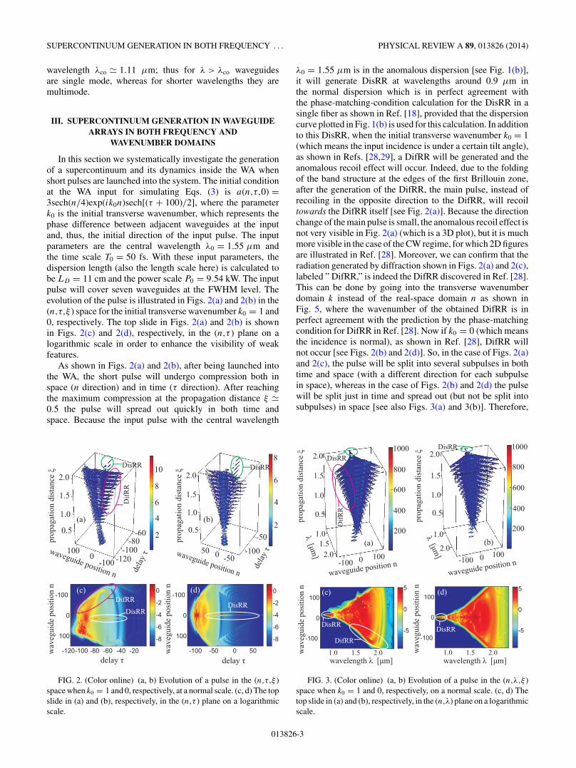
In this section we systematically investigate the generationof a supercontinuum and its dynamics inside the WA whenshort pulses are launched into the system. The initial conditionat the WA input for simulating Eqs. (3) is a(n,τ,0) =3sech(n/4)exp(ik0n)sech[(τ + 100)/2], where the parameterk0 is the initial transverse wavenumber, which represents thephase difference between adjacent waveguides at the inputand, thus, the initial direction of the input pulse. The inputparameters are the central wavelength λ0 = 1.55 μm andthe time scale T0 = 50 fs. With these input parameters, thedispersion length (also the length scale here) is calculated tobe LD = 11 cm and the power scale P0 = 9.54 kW. The inputpulse will cover seven waveguides at the FWHM level. Theevolution of the pulse is illustrated in Figs. 2(a) and 2(b) in the(n,τ,ξ ) space for the initial transverse wavenumber k0 = 1 and0, respectively. The top slide in Figs. 2(a) and 2(b) is shownin Figs. 2(c) and 2(d), respectively, in the (n,τ ) plane on alogarithmic scale in order to enhance the visibility of weakfeatures.
As shown in Figs. 2(a) and 2(b), after being launched intothe WA, the short pulse will undergo compression both inspace (n direction) and in time (τ direction). After reachingthe maximum compression at the propagation distance ξ �0.5 the pulse will spread out quickly in both time andspace. Because the input pulse with the central wavelength
50 0 -50-100
0.5
1.5
1.0
2.0
-502
4
6
8
1.0
1.5
2.0
0.5
-120
-80-60
-100-100100
0
2
4
6
8
10
waveguide position n
waveguide position n
delay
τ
delay
τ
prop
agat
ion
dist
ance
ξ
-120-100 -80 -60 -40 -20
-100
0
100 -8
-6
-4
-2
0
-100 -50 0 50
-100
0
100 -8
-6
-4
-2
0
prop
agat
ion
dist
ance
ξ
wav
egui
de p
ositi
on n
wav
egui
de p
ositi
on n
delay τdelay τ
DifR
R
DisRR DisRR
DisRRDisRR
DifRR
(a)
(d)(c)
(b)
FIG. 2. (Color online) (a, b) Evolution of a pulse in the (n,τ,ξ )space when k0 = 1 and 0, respectively, at a normal scale. (c, d) The topslide in (a) and (b), respectively, in the (n,τ ) plane on a logarithmicscale.
λ0 = 1.55 μm is in the anomalous dispersion [see Fig. 1(b)],it will generate DisRR at wavelengths around 0.9 μm inthe normal dispersion which is in perfect agreement withthe phase-matching-condition calculation for the DisRR in asingle fiber as shown in Ref. [18], provided that the dispersioncurve plotted in Fig. 1(b) is used for this calculation. In additionto this DisRR, when the initial transverse wavenumber k0 = 1(which means the input incidence is under a certain tilt angle),as shown in Refs. [28,29], a DifRR will be generated and theanomalous recoil effect will occur. Indeed, due to the foldingof the band structure at the edges of the first Brillouin zone,after the generation of the DifRR, the main pulse, instead ofrecoiling in the opposite direction to the DifRR, will recoiltowards the DifRR itself [see Fig. 2(a)]. Because the directionchange of the main pulse is small, the anomalous recoil effect isnot very visible in Fig. 2(a) (which is a 3D plot), but it is muchmore visible in the case of the CW regime, for which 2D figuresare illustrated in Ref. [28]. Moreover, we can confirm that theradiation generated by diffraction shown in Figs. 2(a) and 2(c),labeled ” DifRR,” is indeed the DifRR discovered in Ref. [28].This can be done by going into the transverse wavenumberdomain k instead of the real-space domain n as shown inFig. 5, where the wavenumber of the obtained DifRR is inperfect agreement with the prediction by the phase-matchingcondition for DifRR in Ref. [28]. Now if k0 = 0 (which meansthe incidence is normal), as shown in Ref. [28], DifRR willnot occur [see Figs. 2(b) and 2(d)]. So, in the case of Figs. 2(a)and 2(c), the pulse will be split into several subpulses in bothtime and space (with a different direction for each subpulsein space), whereas in the case of Figs. 2(b) and 2(d) the pulsewill be split just in time and spread out (but not be split intosubpulses) in space [see also Figs. 3(a) and 3(b)]. Therefore,
2.0
1.5
1.0
0.5
1.0
2.0-100 0 100
400
200
600
800
1000
0.5
1.0
1.5
2.0
1.01.5
2.0-100 0 100
200
400
600
800
1000
1000 1500 2000
-100
0
100
-5
0
5
1000 1500 2000
-100
0
100
-5
0
5
waveguide position n
prop
agat
ion
dist
ance
ξ
prop
agat
ion
dist
ance
ξ
wav
egui
de p
ositi
on n
wav
egui
de p
ositi
on n
DifR
R
DisRRDisRR
DisRRDisRR
DifRR
(a)
(d)(c)
(b)
λ[μm
]
λ[μm
]
waveguide position n
1.0 1.5 2.0 1.0 2.01.5wavelength [ m]μλ wavelength λ [ m]μ
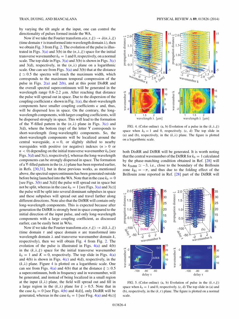
FIG. 3. (Color online) (a, b) Evolution of a pulse in the (n,λ,ξ )space when k0 = 1 and 0, respectively, on a normal scale. (c, d) Thetop slide in (a) and (b), respectively, in the (n,λ) plane on a logarithmicscale.
013826-3
TRAN, DUONG, AND BIANCALANA PHYSICAL REVIEW A 89, 013826 (2014)
by varying the tilt angle at the input, one can control thedirectionality of pulses formed inside the WA.
Now if we take the Fourier transform a(n,τ,ξ ) → a(n,λ,ξ )(time domain τ is transformed into wavelength domain λ), thenwe obtain Fig. 3 from Fig. 2. The evolution of the pulse is illus-trated in Figs. 3(a) and 3(b) in the (n,λ,ξ ) space for the initialtransverse wavenumber k0 = 1 and 0, respectively, on a normalscale. The top slide in Figs. 3(a) and 3(b) is shown in Figs. 3(c)and 3(d), respectively, in the (n,λ) plane on a logarithmicscale. One can see from Figs. 3(a) and 3(b) that at the distanceξ � 0.5 the spectra will reach the maximum width, whichcorresponds to the maximum temporal compression of thepulse in Figs. 2(a) and 2(b), and at this point DisRR andthe overall spectral supercontinuum will be generated in thewavelength range 0.8–2.2 μm. After reaching that distancethe pulse will spread out in space. Due to the dispersion of thecoupling coefficient κ shown in Fig. 1(a), the short-wavelengthcomponents have smaller coupling coefficients κ and, thus,will be dispersed less in space. On the contrary, the long-wavelength components, with larger coupling coefficients, willbe dispersed strongly in space. This will lead to the formationof the Y-filled pattern in the (n,λ) plane in Figs. 3(c) and3(d), where the bottom (top) of the letter Y corresponds toshort-wavelength (long-wavelength) components. So, theshort-wavelength components will be localized around thecentral waveguide, n = 0, or slightly shifted to nearbywaveguides with positive (or negative) indexes (n > 0 orn < 0) depending on the initial transverse wavenumber k0 [seeFigs. 3(d) and 3(c), respectively], whereas the long-wavelengthcomponents can be strongly dispersed in space. The formationof a Y-filled pattern in the (n,λ) plane has been reported earlier,in Refs. [30,31], but in these previous works, as mentionedabove, the spectral supercontinuum has been generated outsidebefore being launched into the WA. Note that in the case k0 = 0[see Figs. 3(b) and 3(d)] the pulse will spread out in space butnot be split, whereas in the case k0 = 1 [see Figs. 3(a) and 3(c)]the pulse will be split into several dominant subpulses in spaceand these subpulses will spread out and travel farther alongdifferent directions. Note also that the DifRR will contain onlylong-wavelength components. This is expected because aftergeneration the DifRR is strongly bent in space compared to theinitial direction of the input pulse, and only long-wavelengthcomponents with a large coupling coefficient, as discussedearlier, can be easily bent in WAs.
Now if we take the Fourier transform a(n,τ,ξ ) → a(k,λ,ξ )(time domain τ and space domain n are transformed intowavelength domain λ and transverse wavenumber domain k,respectively), then we will obtain Fig. 4 from Fig. 2. Theevolution of the pulse is illustrated in Figs. 4(a) and 4(b)in the (k,λ,ξ ) space for the initial transverse wavenumberk0 = 1 and K = 0, respectively. The top slide in Figs. 4(a)and 4(b) is shown in Figs. 4(c) and 4(d), respectively, in the(k,λ) plane. Figure 4 is plotted on a logarithmic scale. Onecan see from Figs. 4(a) and 4(b) that at the distance ξ � 0.5a supercontinuum, both in frequency and in wavenumber, willbe generated, and instead of being localized in a small regionat the input (k,λ) plane, the field will spread out and fill ina large region in the (k,λ) plane for ξ > 0.5. Note that inthe case k0 = 0 [see Figs. 4(b) and 4(d)], only DisRR will begenerated, whereas in the case k0 = 1 [see Fisg. 4(a) and 4(c)]
-5
0
5
10
15
2.01.51.0-2 0 2
2.0
1.5
1.0
0.5-5
0
5
10
15
-2 0 2 2.01.5
1.0
0.5
1.0
1.5
2.0
1 1.5 2
-2
0
2
-5
0
5
10
15
1 1.5 2
-2
0
2
0
5
10
15
wavenumber k
prop
agat
ion
dist
ance
ξ
prop
agat
ion
dist
ance
ξ
Dis
RR
(a)
(d)(c)
(b)
λ [μm]
wavelength λ [ m]μ wavelength λ [ m]μ
wav
enum
ber k
wav
enum
ber k
DifRR
DifRR
Dis
RR
λ [μm]wavenumber k
FIG. 4. (Color online) (a, b) Evolution of a pulse in the (k,λ,ξ )space when k0 = 1 and 0, respectively. (c, d) The top slide in(a) and (b), respectively, in the (k,λ) plane. The figure is plottedon a logarithmic scale.
both DisRR and DifRR will be generated. It is worth notingthat the central wavenumber of the DifRR for k0 = 1 calculatedby the phase-matching condition obtained in Ref. [28] willbe kDifRR � −3, i.e., close to the boundary of the Brillouinzone kB1 = −π , and thus due to the folding effect of theBrillouin zone reported in Ref. [28] part of the DifRR will
-2 2
0.5
1.0
1.5
2.0
5
10
15
20
25
30
35
5
1
111111
2
2
3
3
2222222 22222222
5
0
5
00
0
-100
-50
5
10
15
20
25
30
35
5
1
1
2
2
3
-2 0 2
-100
-50
2.0
1.5
1.0
0.5
-100 -80 -60
-2
0
210
20
30
-100 -80 -60
-2
0
2 5
10
15
20
25
wavenumber k
prop
agat
ion
dist
ance
ξ
prop
agat
ion
dist
ance
ξ
(a)
(d)(c)
(b)delay τ
delay τ
wav
enum
ber k
wav
enum
ber k
DifRR
wavenumber k
delay τ
delay τ
DifRR
FIG. 5. (Color online) (a, b) Evolution of pulse in the (k,τ,ξ )space when k0 = 1 and 0, respectively. (c, d) The top slide in (a) and(b), respectively, in the (k,τ ) plane. The figure is plotted on a normalscale.
013826-4
SUPERCONTINUUM GENERATION IN BOTH FREQUENCY . . . PHYSICAL REVIEW A 89, 013826 (2014)
100
0
200
-100-50
050
100
1 1.5 21 1.5 2-100
-50
0
50
100
100
0
200
200
400
600
800
1000
-100 0100
11.5
2
0.5
1.0
1.5
2.0
-1000 100
11.5
2
0.5
1.0
1.5
2.0
200
400
600
800
1000
prop
agat
ion
dist
ance
ξ
prop
agat
ion
dist
ance
ξ(a)
(d)(c)
(b)
wav
egui
de p
ositi
on n
wavelength λ [ m]μwavelength λ [ m]μ
wav
egui
de p
ositi
on n
λ[
m]μ
λ[
m]
μ
waveguide position nwaveguide position n
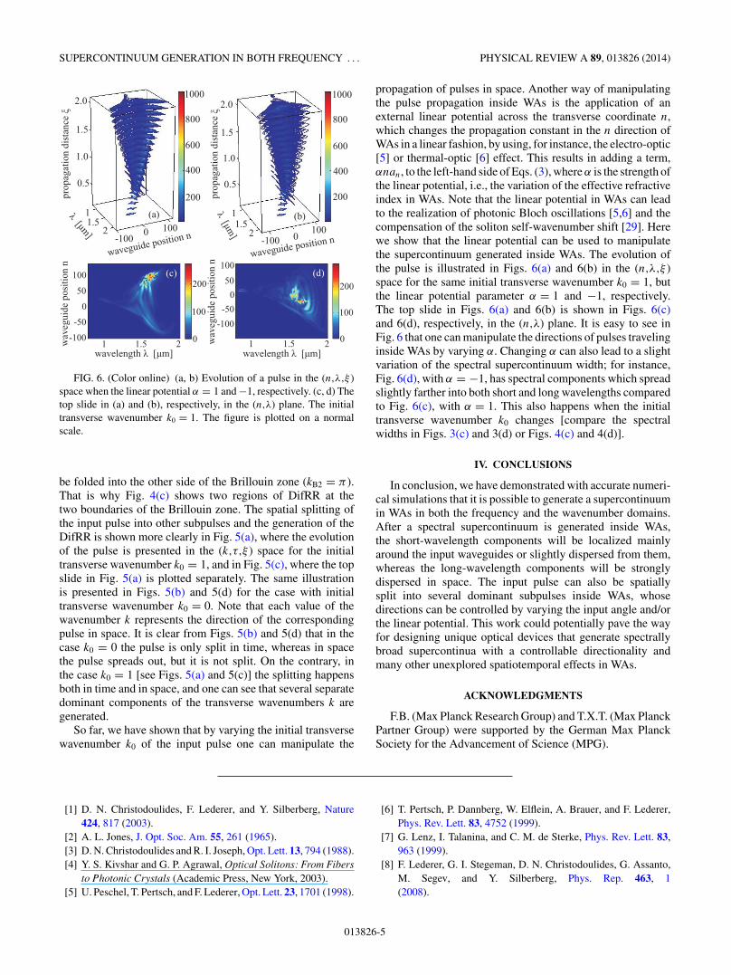
FIG. 6. (Color online) (a, b) Evolution of a pulse in the (n,λ,ξ )space when the linear potential α = 1 and −1, respectively. (c, d) Thetop slide in (a) and (b), respectively, in the (n,λ) plane. The initialtransverse wavenumber k0 = 1. The figure is plotted on a normalscale.
be folded into the other side of the Brillouin zone (kB2 = π ).That is why Fig. 4(c) shows two regions of DifRR at thetwo boundaries of the Brillouin zone. The spatial splitting ofthe input pulse into other subpulses and the generation of theDifRR is shown more clearly in Fig. 5(a), where the evolutionof the pulse is presented in the (k,τ,ξ ) space for the initialtransverse wavenumber k0 = 1, and in Fig. 5(c), where the topslide in Fig. 5(a) is plotted separately. The same illustrationis presented in Figs. 5(b) and 5(d) for the case with initialtransverse wavenumber k0 = 0. Note that each value of thewavenumber k represents the direction of the correspondingpulse in space. It is clear from Figs. 5(b) and 5(d) that in thecase k0 = 0 the pulse is only split in time, whereas in spacethe pulse spreads out, but it is not split. On the contrary, inthe case k0 = 1 [see Figs. 5(a) and 5(c)] the splitting happensboth in time and in space, and one can see that several separatedominant components of the transverse wavenumbers k aregenerated.
So far, we have shown that by varying the initial transversewavenumber k0 of the input pulse one can manipulate the
propagation of pulses in space. Another way of manipulatingthe pulse propagation inside WAs is the application of anexternal linear potential across the transverse coordinate n,which changes the propagation constant in the n direction ofWAs in a linear fashion, by using, for instance, the electro-optic[5] or thermal-optic [6] effect. This results in adding a term,αnan, to the left-hand side of Eqs. (3), where α is the strength ofthe linear potential, i.e., the variation of the effective refractiveindex in WAs. Note that the linear potential in WAs can leadto the realization of photonic Bloch oscillations [5,6] and thecompensation of the soliton self-wavenumber shift [29]. Herewe show that the linear potential can be used to manipulatethe supercontinuum generated inside WAs. The evolution ofthe pulse is illustrated in Figs. 6(a) and 6(b) in the (n,λ,ξ )space for the same initial transverse wavenumber k0 = 1, butthe linear potential parameter α = 1 and −1, respectively.The top slide in Figs. 6(a) and 6(b) is shown in Figs. 6(c)and 6(d), respectively, in the (n,λ) plane. It is easy to see inFig. 6 that one can manipulate the directions of pulses travelinginside WAs by varying α. Changing α can also lead to a slightvariation of the spectral supercontinuum width; for instance,Fig. 6(d), with α = −1, has spectral components which spreadslightly farther into both short and long wavelengths comparedto Fig. 6(c), with α = 1. This also happens when the initialtransverse wavenumber k0 changes [compare the spectralwidths in Figs. 3(c) and 3(d) or Figs. 4(c) and 4(d)].
IV. CONCLUSIONS
In conclusion, we have demonstrated with accurate numeri-cal simulations that it is possible to generate a supercontinuumin WAs in both the frequency and the wavenumber domains.After a spectral supercontinuum is generated inside WAs,the short-wavelength components will be localized mainlyaround the input waveguides or slightly dispersed from them,whereas the long-wavelength components will be stronglydispersed in space. The input pulse can also be spatiallysplit into several dominant subpulses inside WAs, whosedirections can be controlled by varying the input angle and/orthe linear potential. This work could potentially pave the wayfor designing unique optical devices that generate spectrallybroad supercontinua with a controllable directionality andmany other unexplored spatiotemporal effects in WAs.
ACKNOWLEDGMENTS
F.B. (Max Planck Research Group) and T.X.T. (Max PlanckPartner Group) were supported by the German Max PlanckSociety for the Advancement of Science (MPG).
[1] D. N. Christodoulides, F. Lederer, and Y. Silberberg, Nature424, 817 (2003).
[2] A. L. Jones, J. Opt. Soc. Am. 55, 261 (1965).[3] D. N. Christodoulides and R. I. Joseph, Opt. Lett. 13, 794 (1988).[4] Y. S. Kivshar and G. P. Agrawal, Optical Solitons: From Fibers
to Photonic Crystals (Academic Press, New York, 2003).[5] U. Peschel, T. Pertsch, and F. Lederer, Opt. Lett. 23, 1701 (1998).
[6] T. Pertsch, P. Dannberg, W. Elflein, A. Brauer, and F. Lederer,Phys. Rev. Lett. 83, 4752 (1999).
[7] G. Lenz, I. Talanina, and C. M. de Sterke, Phys. Rev. Lett. 83,963 (1999).
[8] F. Lederer, G. I. Stegeman, D. N. Christodoulides, G. Assanto,M. Segev, and Y. Silberberg, Phys. Rep. 463, 1(2008).
013826-5
TRAN, DUONG, AND BIANCALANA PHYSICAL REVIEW A 89, 013826 (2014)
[9] D. N. Christodoulides and E. D. Eugenieva, Phys. Rev. Lett. 87,233901 (2001).
[10] S. Longhi, Opt. Lett. 35, 235 (2010).[11] F. Dreisow, R. Keil, A. Tunnermann, S. Nolte, S. Longhi, and
A. Szameit, Europhys. Lett. 97, 10008 (2012).[12] S. Longhi, Appl. Phys. B 104, 453 (2011).[13] J. M. Zeuner, N. K. Efremidis, R. Keil, F. Dreisow, D. N.
Christodoulides, A. Tunnermann, S. Nolte, and A. Szameit,Phys. Rev. Lett. 109, 023602 (2012).
[14] Tr. X. Tran, S. Longhi, and F. Biancalana, Ann. Phys. 340, 179(2014).
[15] H. H. Kuehl and C. Y. Zhang, Phys. Fluids B 2, 889 (1990).[16] P. K. A. Wai, H. H. Chen, and Y. C. Lee, Phys. Rev. A 41, 426
(1990).[17] V. I. Karpman, Phys. Rev. E 47, 2073 (1993).[18] N. Akhmediev and M. Karlsson, Phys. Rev. A 51, 2602 (1995).[19] F. Biancalana, D. V. Skryabin, and A. V. Yulin, Phys. Rev. E 70,
016615 (2004).[20] A. V. Husakou and J. Herrmann, Phys. Rev. Lett. 87, 203901
(2001).[21] V. N. Serkin, T. L. Belyaeva, G. H. Corro, and M. A. Granados,
Quantum Electron. 33, 325 (2003).[22] J. M. Dudley, G. Genty, and S. Coen, Rev. Mod. Phys. 78, 1135
(2006).
[23] G. P. Agrawal, Applications of Nonlinear Fiber Optics, 2nd ed.(Academic Press, New York, 2008).
[24] P. St. J. Russell, Science 299, 358 (2003).[25] Edited by R. Alfano, The Supercontinuum Laser Source
(Springer-Verlag, Berlin, 2006).[26] R. Holzwarth, M. Zimmermann, Th. Udem, T. W. Hansch,
P. Russbuldt, K. Gabel, R. Poprawe, J. C. Knight, W. J.Wadsworth, and P. St. J. Russell, Opt. Lett. 26, 1376 (2001).
[27] G. P. Agrawal, Nonlinear Fiber Optics, 5th ed. (Academic Press,New York, 2013).
[28] Tr. X. Tran and F. Biancalana, Phys. Rev. Lett. 110, 113903(2013).
[29] Tr. X. Tran and F. Biancalana, Opt. Express 21, 17539(2013).
[30] D. N. Neshev, A. A. Sukhorukov, A. Dreischuh, R. Fischer,S. Ha, J. Bolger, L. Bui, W. Krolikowski, B. J. Eggleton,A. Mitchell, M. W. Austin, and Y. S. Kivshar, Phys. Rev. Lett.99, 123901 (2007).
[31] A. A. Sukhorukov, D. N. Neshev, and Y. S. Kivshar, Opt. Express15, 13058 (2007).
[32] A. Szameit, D. Blomer, J. Burghoff, T. Pertsch, S. Nolte, andA. Tunnermann, Appl. Phys. B 82, 507 (2006).
[33] R. Tewari and K. Thyagarajan, J. Lightwave Technol. 4, 386(1986).
013826-6