
SUN2000-(2KTL-6KTL)-L1 - User Manual - SKE-Solar
121
SUN2000-(2KTL-6KTL)-L1 User Manual Issue 03 Date 2020-07-20 HUAWEI TECHNOLOGIES CO., LTD.
-
Upload
khangminh22 -
Category
Documents
-
view
4 -
download
0
Transcript of SUN2000-(2KTL-6KTL)-L1 - User Manual - SKE-Solar

SUN2000-(2KTL-6KTL)-L1
User Manual
Issue 03
Date 2020-07-20
HUAWEI TECHNOLOGIES CO., LTD.

Copyright © Huawei Technologies Co., Ltd. 2020. All rights reserved.
No part of this document may be reproduced or transmitted in any form or by any means without priorwritten consent of Huawei Technologies Co., Ltd. Trademarks and Permissions
and other Huawei trademarks are trademarks of Huawei Technologies Co., Ltd.All other trademarks and trade names mentioned in this document are the property of their respectiveholders. NoticeThe purchased products, services and features are stipulated by the contract made between Huawei andthe customer. All or part of the products, services and features described in this document may not bewithin the purchase scope or the usage scope. Unless otherwise specified in the contract, all statements,information, and recommendations in this document are provided "AS IS" without warranties, guaranteesor representations of any kind, either express or implied.
The information in this document is subject to change without notice. Every effort has been made in thepreparation of this document to ensure accuracy of the contents, but all statements, information, andrecommendations in this document do not constitute a warranty of any kind, express or implied.
Huawei Technologies Co., Ltd.Address: Huawei Industrial Base
Bantian, LonggangShenzhen 518129People's Republic of China
Website: https://e.huawei.com
Issue 03 (2020-07-20) Copyright © Huawei Technologies Co., Ltd. i

About This Document
PurposeThis document describes the SUN2000-(2KTL-6KTL)-L1 (SUN2000 for short) interms of its installation, electrical connection, commissioning, maintenance, andtroubleshooting. Before installing and operating the SUN2000, ensure that you arefamiliar with the features, functions, and safety precautions provided in thisdocument.
Intended AudienceThis document is applicable to:
● Installers● Users
Symbol ConventionsThe symbols that may be found in this document are defined as follows.
Symbol Description
Indicates a hazard with a high level of risk which, if notavoided, will result in death or serious injury.
Indicates a hazard with a medium level of risk which, if notavoided, could result in death or serious injury.
Indicates a hazard with a low level of risk which, if notavoided, could result in minor or moderate injury.
Indicates a potentially hazardous situation which, if notavoided, could result in equipment damage, data loss,performance deterioration, or unanticipated results.NOTICE is used to address practices not related to personalinjury.
SUN2000-(2KTL-6KTL)-L1User Manual About This Document
Issue 03 (2020-07-20) Copyright © Huawei Technologies Co., Ltd. ii

Symbol Description
Supplements the important information in the main text.NOTE is used to address information not related topersonal injury, equipment damage, and environmentdeterioration.
Change HistoryChanges between document issues are cumulative. The latest document issuecontains all the changes made in earlier issues.
Issue 03 (2020-07-20)● Updated 5.1 Preparing Cables.● Updated 10.1 SUN2000 Technical Specifications● Updated A Grid Code.● Updated C Resetting Password.● Updated D Rapid Shutdown.
Issue 02 (2020-06-09)● Updated 4.2 Preparing Tools and Instruments.● Updated 5.1 Preparing Cables.● Updated 5.6 Connecting DC Input Power Cables.● Updated 5.8 (Optional) Connecting Signal Cables.● Updated 7.1.4 (Optional) Setting the Physical Layout of the Smart PV
Optimizers.● Updated C Resetting Password.
Issue 01 (2020-04-17)This issue is the first official release.
SUN2000-(2KTL-6KTL)-L1User Manual About This Document
Issue 03 (2020-07-20) Copyright © Huawei Technologies Co., Ltd. iii

Contents
About This Document................................................................................................................ ii
1 Safety Information.................................................................................................................. 11.1 General Safety.......................................................................................................................................................................... 11.2 Personnel Requirements....................................................................................................................................................... 21.3 Electrical Safety........................................................................................................................................................................31.4 Installation Environment Requirements.......................................................................................................................... 41.5 Mechanical Safety................................................................................................................................................................... 41.6 Commissioning......................................................................................................................................................................... 51.7 Maintenance and Replacement..........................................................................................................................................6
2 Product Introduction...............................................................................................................72.1 Overview.................................................................................................................................................................................... 72.2 Component Description...................................................................................................................................................... 102.3 Label Description.................................................................................................................................................................. 112.4 Working Principles................................................................................................................................................................ 13
3 SUN2000 Storage...................................................................................................................16
4 System Installation............................................................................................................... 174.1 Checking Before the Installation..................................................................................................................................... 174.2 Preparing Tools and Instruments.................................................................................................................................... 184.3 Determining the Installation Position............................................................................................................................194.4 Moving a SUN2000.............................................................................................................................................................. 234.5 Installing a SUN2000........................................................................................................................................................... 234.5.1 Wall-Mounted Installation............................................................................................................................................. 244.5.2 Support-Mounted Installation.......................................................................................................................................26
5 Electrical Connection............................................................................................................305.1 Preparing Cables................................................................................................................................................................... 315.2 Connecting PE Cables.......................................................................................................................................................... 355.3 (Optional) Installing a Smart Dongle............................................................................................................................ 375.4 Installing a WLAN Antenna...............................................................................................................................................395.5 Connecting an AC Output Power Cable........................................................................................................................405.6 Connecting DC Input Power Cables................................................................................................................................435.7 (Optional) Connecting Battery Cables.......................................................................................................................... 47
SUN2000-(2KTL-6KTL)-L1User Manual Contents
Issue 03 (2020-07-20) Copyright © Huawei Technologies Co., Ltd. iv

5.8 (Optional) Connecting Signal Cables.............................................................................................................................50
6 System Commissioning........................................................................................................ 586.1 Verification Before Power-On........................................................................................................................................... 586.2 System Power-On................................................................................................................................................................. 59
7 Man-Machine Interaction....................................................................................................627.1 App Commissioning............................................................................................................................................................. 627.1.1 Downloading the FusionSolar App..............................................................................................................................627.1.2 (Optional) Registering an Installer Account............................................................................................................ 637.1.3 Creating a PV Plant and a User.................................................................................................................................... 647.1.4 (Optional) Setting the Physical Layout of the Smart PV Optimizers..............................................................647.2 Parameters Settings............................................................................................................................................................. 677.2.1 Energy Control.................................................................................................................................................................... 677.2.1.1 Grid-tied Point Control................................................................................................................................................. 677.2.1.2 Battery Control................................................................................................................................................................707.2.2 AFCI........................................................................................................................................................................................ 757.2.3 IPS Check (for Italy CEI0-21 Grid Code Only)......................................................................................................... 777.2.4 DRM (Australia AS4777)................................................................................................................................................. 78
8 System Maintenance............................................................................................................ 818.1 System Power-Off.................................................................................................................................................................818.2 Routine Maintenance.......................................................................................................................................................... 828.3 Troubleshooting..................................................................................................................................................................... 82
9 SUN2000 Disposal................................................................................................................. 939.1 Removing a SUN2000......................................................................................................................................................... 939.2 Packing a SUN2000..............................................................................................................................................................939.3 Disposing a SUN2000.......................................................................................................................................................... 93
10 Technical Parameters......................................................................................................... 9410.1 SUN2000 Technical Specifications................................................................................................................................ 9410.2 Optimizer Technical Specifications............................................................................................................................... 98
A Grid Code.............................................................................................................................. 101
B Device Commissioning....................................................................................................... 104
C Resetting Password............................................................................................................ 107
D Rapid Shutdown................................................................................................................. 110
E Locating Insulation Resistance Faults............................................................................111
F Acronyms and Abbreviations............................................................................................114
SUN2000-(2KTL-6KTL)-L1User Manual Contents
Issue 03 (2020-07-20) Copyright © Huawei Technologies Co., Ltd. v

1 Safety Information
1.1 General Safety
StatementBefore installing, operating, and maintaining the equipment, read this documentand observe all the safety instructions on the equipment and in this document.
The "NOTICE", "CAUTION", "WARNING", and "DANGER" statements in thisdocument do not cover all the safety instructions. They are only supplements tothe safety instructions. Huawei will not be liable for any consequence caused bythe violation of general safety requirements or design, production, and usagesafety standards.
Ensure that the equipment is used in environments that meet its designspecifications. Otherwise, the equipment may become faulty, and the resultingequipment malfunction, component damage, personal injuries, or propertydamage are not covered under the warranty.
Follow local laws and regulations when installing, operating, or maintaining theequipment. The safety instructions in this document are only supplements to locallaws and regulations.
Huawei will not be liable for any consequences of the following circumstances:
● Operation beyond the conditions specified in this document● Installation or use in environments which are not specified in relevant
international or national standards● Unauthorized modifications to the product or software code or removal of the
product● Failure to follow the operation instructions and safety precautions on the
product and in this document● Equipment damage due to force majeure, such as earthquakes, fire, and
storms● Damage caused during transportation by the customer● Storage conditions that do not meet the requirements specified in this
document
SUN2000-(2KTL-6KTL)-L1User Manual 1 Safety Information
Issue 03 (2020-07-20) Copyright © Huawei Technologies Co., Ltd. 1

General Requirements
D ANGER
Do not work with power on during installation.
● Do not install, use, or operate outdoor equipment and cables (including butnot limited to moving equipment, operating equipment and cables, insertingconnectors to or removing connectors from signal ports connected to outdoorfacilities, working at heights, and performing outdoor installation) in harshweather conditions such as lightning, rain, snow, and level 6 or stronger wind.
● After installing the equipment, remove idle packing materials such as cartons,foam, plastics, and cable ties from the equipment area.
● In the case of a fire, immediately leave the building or the equipment area,and turn on the fire alarm bell or make an emergency call. Do not enter thebuilding on fire in any case.
● Do not scrawl, damage, or block any warning label on the equipment.● Tighten the screws using tools when installing the equipment.● Understand the components and functioning of a grid-tied PV power system
and relevant local standards.● Repaint any paint scratches caused during equipment transportation or
installation in a timely manner. Equipment with scratches cannot be exposedto an outdoor environment for a long period of time.
● Do not open the host panel of the equipment.
Personal Safety● If there is a probability of personal injury or equipment damage during
operations on the equipment, immediately stop the operations, report thecase to the supervisor, and take feasible protective measures.
● Use tools correctly to avoid hurting people or damaging the equipment.● Do not touch the energized equipment, as the enclosure is hot.
1.2 Personnel Requirements● Personnel who plan to install or maintain Huawei equipment must receive
thorough training, understand all necessary safety precautions, and be able tocorrectly perform all operations.
● Only qualified professionals or trained personnel are allowed to install,operate, and maintain the equipment.
● Only qualified professionals are allowed to remove safety facilities and inspectthe equipment.
● Personnel who will operate the equipment, including operators, trainedpersonnel, and professionals, should possess the local national requiredqualifications in special operations such as high-voltage operations, workingat heights, and operations of special equipment.
SUN2000-(2KTL-6KTL)-L1User Manual 1 Safety Information
Issue 03 (2020-07-20) Copyright © Huawei Technologies Co., Ltd. 2

● Only professionals or authorized personnel are allowed to replace theequipment or components (including software).
NO TE
● Professionals: personnel who are trained or experienced in equipment operationsand are clear of the sources and degree of various potential hazards in equipmentinstallation, operation, and maintenance
● Trained personnel: personnel who are technically trained, have required experience,are aware of possible hazards on themselves in certain operations, and are able totake protective measures to minimize the hazards on themselves and other people
● Operators: operation personnel who may come in contact with the equipment,except trained personnel and professionals
1.3 Electrical Safety
Grounding● For the equipment that needs to be grounded, install the ground cable first
when installing the equipment and remove the ground cable last whenremoving the equipment.
● Do not damage the ground conductor.● Do not operate the equipment in the absence of a properly installed ground
conductor.● Ensure that the equipment is connected permanently to the protective
ground. Before operating the equipment, check its electrical connection toensure that it is securely grounded.
General Requirements
D ANGER
Before connecting cables, ensure that the equipment is intact. Otherwise, electricshocks or fire may occur.
● Ensure that all electrical connections comply with local electrical standards.● Obtain approval from the local electric utility company before using the
equipment in grid-tied mode.● Ensure that the cables you prepared meet local regulations.● Use dedicated insulated tools when performing high-voltage operations.
AC and DC Power
D ANGER
Do not connect or disconnect power cables with power on. Transient contactbetween the core of the power cable and the conductor will generate electric arcsor sparks, which may cause fire or personal injury.
SUN2000-(2KTL-6KTL)-L1User Manual 1 Safety Information
Issue 03 (2020-07-20) Copyright © Huawei Technologies Co., Ltd. 3

● Before making electrical connections, switch off the disconnector on theupstream device to cut off the power supply if people may contact energizedcomponents.
● Before connecting a power cable, check that the label on the power cable iscorrect.
● If the equipment has multiple inputs, disconnect all the inputs beforeoperating the equipment.
Cabling● When routing cables, ensure that a distance of at least 30 mm exists between
the cables and heat-generating components or areas. This prevents damageto the insulation layer of the cables.
● Bind cables of the same type together. When routing cables of different types,ensure that they are at least 30 mm away from each other.
● Ensure that the cables used in a grid-tied PV power system are properlyconnected and insulated and meet specifications.
1.4 Installation Environment Requirements● Ensure that the equipment is installed in a well ventilated environment.● To prevent fire due to high temperature, ensure that the ventilation vents or
heat dissipation system are not blocked when the equipment is running.● Do not expose the equipment to flammable or explosive gas or smoke. Do
not perform any operation on the equipment in such environments.
1.5 Mechanical Safety
Using Ladders● Use wooden or fiberglass ladders when you need to perform live working at
heights.● When a step ladder is used, ensure that the pull ropes are secured and the
ladder is held firm.● Before using a ladder, check that it is intact and confirm its load bearing
capacity. Do not overload it.● Ensure that the wider end of the ladder is at the bottom, or protective
measures have been taken at the bottom to prevent the ladder from sliding.● Ensure that the ladder is securely positioned. The recommended angle for a
ladder against the floor is 75 degrees, as shown in the following figure. Anangle rule can be used to measure the angle.
SUN2000-(2KTL-6KTL)-L1User Manual 1 Safety Information
Issue 03 (2020-07-20) Copyright © Huawei Technologies Co., Ltd. 4

● When climbing a ladder, take the following precautions to reduce risks andensure safety:
– Keep your body steady.
– Do not climb higher than the fourth rung of the ladder from the top.
– Ensure that your body's center of gravity does not shift outside the legsof the ladder.
Drilling Holes
When drilling holes into a wall or floor, observe the following safety precautions:
● Wear goggles and protective gloves when drilling holes.
● When drilling holes, protect the equipment from shavings. After drilling, cleanup any shavings that have accumulated inside or outside the equipment.
Moving Heavy Objects● Be cautious to avoid injury when moving heavy objects.
● When moving the equipment by hand, wear protective gloves to preventinjuries.
1.6 CommissioningWhen the equipment is powered on for the first time, ensure that professionalpersonnel set parameters correctly. Incorrect settings may result in inconsistencywith local certification and affect the normal operation of the equipment.
SUN2000-(2KTL-6KTL)-L1User Manual 1 Safety Information
Issue 03 (2020-07-20) Copyright © Huawei Technologies Co., Ltd. 5

1.7 Maintenance and Replacement
D ANGER
High voltage generated by the equipment during operation may cause an electricshock, which could result in death, serious injury, or serious property damage.Prior to maintenance, power off the equipment and strictly comply with the safetyprecautions in this document and relevant documents.
● Maintain the equipment with sufficient knowledge of this document andusing proper tools and testing equipment.
● Before maintaining the equipment, power it off and follow the instructions onthe delayed discharge label to ensure that the equipment is powered off.
● Place temporary warning signs or erect fences to prevent unauthorized accessto the maintenance site.
● If the equipment is faulty, contact your dealer.● The equipment can be powered on only after all faults are rectified. Failing to
do so may escalate faults or damage the equipment.
SUN2000-(2KTL-6KTL)-L1User Manual 1 Safety Information
Issue 03 (2020-07-20) Copyright © Huawei Technologies Co., Ltd. 6

2 Product Introduction
2.1 Overview
FunctionThe SUN2000-(2KTL-6KTL)-L1 is a single-phase grid-tied string inverter thatconverts the DC power generated by PV strings into AC power and feeds theelectricity into the power grid.
ModelThis document involves the following product models:
● SUN2000-2KTL-L1● SUN2000-3KTL-L1● SUN2000-3.68KTL-L1● SUN2000-4KTL-L1● SUN2000-4.6KTL-L1● SUN2000-5KTL-L1● SUN2000-6KTL-L1
Figure 2-1 Model identifier (using SUN2000-5KTL-L1 as an example)
Table 2-1 Identifier description
No. Meaning Value
1 Series name SUN2000: grid-tied solar inverter
SUN2000-(2KTL-6KTL)-L1User Manual 2 Product Introduction
Issue 03 (2020-07-20) Copyright © Huawei Technologies Co., Ltd. 7

No. Meaning Value
2 Power level ● 2K: The power level is 2 kW.● 3K: The power level is 3 kW.● 3.68K: The power level is 3.68 kW.● 4K: The power level is 4 kW.● 4.6K: The power level is 4.6 kW.● 5K: The power level is 5 kW.● 6K: The power level is 6 kW.
3 Topology TL: transformerless
4 Design code L1: residential
Networking ApplicationThe SUN2000 applies to residential rooftop grid-tied systems. The system consistsof PV strings, grid-tied solar inverters, AC switches, and power distribution units(PDUs).
Figure 2-2 Single SUN2000 scenario (dashed boxes indicate optionalconfiguration)
SUN2000-(2KTL-6KTL)-L1User Manual 2 Product Introduction
Issue 03 (2020-07-20) Copyright © Huawei Technologies Co., Ltd. 8

Figure 2-3 SUN2000 cascading scenario (dashed boxes indicate optionalconfiguration)
NO TE
● indicates the power flow direction, indicates the signal line, and indicates the wireless communication.
● In the SUN2000 cascading scenario, the master and slave solar inverters are bothSUN2000-(2KTL-6KTL)-L1, and a maximum of three SUN2000s can be cascaded.
● In the SUN2000 cascading scenario, only one smart power sensor (G in the figure) canbe connected to the master inverter.
● In the SUN2000 cascading scenario, the SUN2000s connected to the power grid mustmeet the local power grid requirements.
(A) PV string (B) Smart PV optimizer (C) DC switch
(D) SUN2000 (E) AC switch (F) Residential PDU
(G) Smart Power Sensor (H) Residential powermeter
(I) Power grid
(J) Battery (K) Battery switch (L) Household load
(M) FusionSolar app (N) 4G Smart Dongle (O) WLAN-FE SmartDongle
(P) Router (Q) FusionSolar SmartPV Management System
SUN2000-(2KTL-6KTL)-L1User Manual 2 Product Introduction
Issue 03 (2020-07-20) Copyright © Huawei Technologies Co., Ltd. 9

Supported Power Grid Types
The SUN2000 supports the following power grid types: TN-S, TN-C, TN-C-S, andTT. In the TT power grid, the N-to-PE voltage must be less than 30 V.
Figure 2-4 Power grid types
2.2 Component Description
Appearance
Figure 2-5 Appearance
(1) LED indicators (2) Front panel
SUN2000-(2KTL-6KTL)-L1User Manual 2 Product Introduction
Issue 03 (2020-07-20) Copyright © Huawei Technologies Co., Ltd. 10

(3) Hanging kit (4) Mounting bracket
(5) Heat sink (6) Ventilation valve
(7) DC switch locking screw holea (8) DC switchb (DC SWITCH)
(9) DC input terminals (PV1+/PV1–) (10) DC input terminals (PV2+/PV2–)
(11) Battery terminals (BAT+/BAT–) (12) Smart Dongle port (4G/FE)
(13) Antenna port (ANT) (14) Communications port (COM)
(15) AC output port (AC) (16) Ground point
NO TE
● Note a: The DC switch locking screw is used to lock the DC switch to prevent accidentalstartup. It is delivered with the SUN2000.
● Note b: DC input terminals PV1 and PV2 are controlled by the DC switch.
2.3 Label Description
Enclosure Labels
Table 2-2 Enclosure label description
Icon Name Meaning
Burn warning Do not touch arunning SUN2000because the enclosureis hot when theSUN2000 is running.
Delayed discharge ● High voltage existsafter the SUN2000is powered on. Onlyqualified andtrained electricaltechnicians areallowed to performoperations on theSUN2000.
● Residual voltageexists after theSUN2000 ispowered off. Ittakes 5 minutes forthe SUN2000 todischarge to thesafe voltage.
SUN2000-(2KTL-6KTL)-L1User Manual 2 Product Introduction
Issue 03 (2020-07-20) Copyright © Huawei Technologies Co., Ltd. 11

Icon Name Meaning
Refer todocumentation
Reminds operators torefer to the documentsdelivered theSUN2000.
Grounding Indicates the positionfor connecting theprotective earthing(PE) cable.
Operation warning Do not remove theconnector or antennawhen the SUN2000 isrunning.
Grounding warning Ground the SUN2000before powering it on.
Serial number (SN) Indicates the SUN2000SN.
Media access control(MAC) address
Indicates the MACaddress.
QR code for logging into the SUN2000 WLAN
Scan the QR code toconnect to the HuaweiSUN2000 WLAN(Android) or obtainthe WLAN loginpassword (iOS).
NO TE
The labels are for reference only.
SUN2000-(2KTL-6KTL)-L1User Manual 2 Product Introduction
Issue 03 (2020-07-20) Copyright © Huawei Technologies Co., Ltd. 12

Nameplate
Figure 2-6 Nameplate (using SUN2000-5KTL-L1 as an example)
(1) Trademark and model (2) Key technical specifications
(3) Compliance symbols (4) Company name and country oforigin
NO TE
The nameplate figure is for reference only.
2.4 Working Principles
Schematic DiagramThe SUN2000 receives inputs from up to two PV strings. Then the inputs aregrouped into two MPPT routes inside the SUN2000 to track the maximum powerpoint of the PV strings. The DC power is then converted into single-phase ACpower through an inverter circuit. Surge protection is supported on both the DCand AC sides.
The SUN2000 uses a reserved battery port for energy storage expansion. Batteryperforms charging and discharging operations according to the battery workingmode.
SUN2000-(2KTL-6KTL)-L1User Manual 2 Product Introduction
Issue 03 (2020-07-20) Copyright © Huawei Technologies Co., Ltd. 13

Figure 2-7 Schematic diagram
Working Mode
Figure 2-8 Working modes
SUN2000-(2KTL-6KTL)-L1User Manual 2 Product Introduction
Issue 03 (2020-07-20) Copyright © Huawei Technologies Co., Ltd. 14
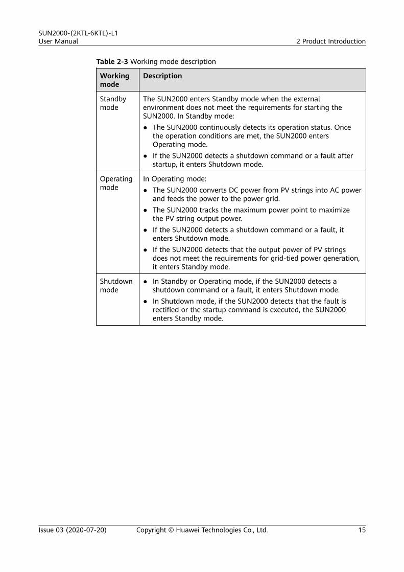
Table 2-3 Working mode description
Workingmode
Description
Standbymode
The SUN2000 enters Standby mode when the externalenvironment does not meet the requirements for starting theSUN2000. In Standby mode:● The SUN2000 continuously detects its operation status. Once
the operation conditions are met, the SUN2000 entersOperating mode.
● If the SUN2000 detects a shutdown command or a fault afterstartup, it enters Shutdown mode.
Operatingmode
In Operating mode:● The SUN2000 converts DC power from PV strings into AC power
and feeds the power to the power grid.● The SUN2000 tracks the maximum power point to maximize
the PV string output power.● If the SUN2000 detects a shutdown command or a fault, it
enters Shutdown mode.● If the SUN2000 detects that the output power of PV strings
does not meet the requirements for grid-tied power generation,it enters Standby mode.
Shutdownmode
● In Standby or Operating mode, if the SUN2000 detects ashutdown command or a fault, it enters Shutdown mode.
● In Shutdown mode, if the SUN2000 detects that the fault isrectified or the startup command is executed, the SUN2000enters Standby mode.
SUN2000-(2KTL-6KTL)-L1User Manual 2 Product Introduction
Issue 03 (2020-07-20) Copyright © Huawei Technologies Co., Ltd. 15
3 SUN2000 Storage
The following requirements should be met if the SUN2000 is not put into usedirectly:
● Do not unpack the SUN2000.● Keep the storage temperature at –40°C to +70°C and the humidity at 5%–
95% RH.● The product should be stored in a clean and dry place and be protected from
dust and water vapor corrosion.● A maximum of eight SUN2000s can be stacked. To avoid personal injury or
device damage, stack SUN2000s with caution to prevent them from fallingover.
● During the storage period, check the SUN2000 periodically. (It isrecommended that the check is performed every three months.) Replace thepacking materials that are damaged by insects or rodents in a timely manner.
● If the SUN2000 has been stored for more than two years, it must be checkedand tested by professionals before being put into use.
SUN2000-(2KTL-6KTL)-L1User Manual 3 SUN2000 Storage
Issue 03 (2020-07-20) Copyright © Huawei Technologies Co., Ltd. 16

4 System Installation
4.1 Checking Before the Installation
Checking Outer PackingBefore unpacking the SUN2000, check the outer packing for damage, such asholes and cracks, and check the SUN2000 model. If any damage is found or theSUN2000 model is not what you requested, do not unpack the package andcontact your dealer as soon as possible.
NO TICE
You are advised to remove the packing materials within 24 hours before installingthe SUN2000.
Checking DeliverablesAfter unpacking the SUN2000, check that the deliverables are intact and complete.If any item is missing or damaged, contact your dealer.
NO TE
For details about the number of accessories delivered with the SUN2000, see the PackingList in the packing case.
SUN2000-(2KTL-6KTL)-L1User Manual 4 System Installation
Issue 03 (2020-07-20) Copyright © Huawei Technologies Co., Ltd. 17

4.2 Preparing Tools and InstrumentsType Tools and Instruments
Installation
Hammer drill (with adrill bit of 8 mm)
Torque socket wrench Torque wrench
Diagonal pliers Wire strippers Torque screwdriver
Rubber mallet Utility knife Cable cutter
Crimping tool (model:PV-CZM-22100)
Cord end terminalcrimper
Disassembly andAssembly Tool (model:PV-MS-HZ open-endwrench)
Cable tie Vacuum cleaner Multimeter (DCvoltage measurementrange ≥ 600 V DC)
SUN2000-(2KTL-6KTL)-L1User Manual 4 System Installation
Issue 03 (2020-07-20) Copyright © Huawei Technologies Co., Ltd. 18

Type Tools and Instruments
Marker Steel measuring tape Level
Hydraulic pliers Heat-shrink tubing Heat gun
Personal protectiveequipment (PPE)
Safety gloves Safety goggles Anti-dust mask
Safety boots
- -
4.3 Determining the Installation Position
Basic Requirements● The SUN2000 is protected to IP65 and can be installed indoors or outdoors.● Do not install the SUN2000 in a place where personnel are easy to come into
contact with its enclosure and heat sink, because these parts are extremelyhot during operation.
● Do not install the SUN2000 near flammable or explosive materials.● Do not install the SUN2000 at a place within children's reach.● The SUN2000 will be corroded in salt areas, and the salt corrosion may cause
fire. Do not install the SUN2000 outdoors in salt areas. A salt area refers tothe region within 500 meters from the coast or prone to sea breeze. Theregions prone to sea breeze vary with weather conditions (such as typhoonsand monsoons) or terrains (such as dams and hills).
SUN2000-(2KTL-6KTL)-L1User Manual 4 System Installation
Issue 03 (2020-07-20) Copyright © Huawei Technologies Co., Ltd. 19

Installation Environment Requirements● The SUN2000 must be installed in a well-ventilated environment to ensure
good heat dissipation.
● When the SUN2000 is installed under direct sunlight, the power may bederated due to the temperature rise.
● You are advised to install the SUN2000 in a sheltered place or install anawning over it.
Mounting Structure Requirements● The mounting structure where the SUN2000 is installed must be fire resistant.
● Do not install the SUN2000 on flammable building materials.
● Ensure that the installation surface is solid enough to bear the weight of theSUN2000.
● In residential areas, do not install the SUN2000 on plaster board walls orwalls made of similar materials with a weak sound insulation performancebecause the noise generated by the SUN2000 may interfere with residents.
Installation Angle Requirements
The SUN2000 can be wall-mounted or pole-mounted. The installation anglerequirements are as follows:
● Install the SUN2000 vertically or at a maximum back tilt of 15 degrees tofacilitate heat dissipation.
● Do not install the SUN2000 at forward tilted, excessive back tilted, side tilted,horizontal, or upside down positions.
Figure 4-1 Installation angle
SUN2000-(2KTL-6KTL)-L1User Manual 4 System Installation
Issue 03 (2020-07-20) Copyright © Huawei Technologies Co., Ltd. 20

Installation Space Requirements● Reserve enough clearance around the SUN2000 to ensure sufficient space for
installation and heat dissipation.
Figure 4-2 Installation space
● When installing multiple SUN2000s, install them in horizontal mode ifsufficient space is available and install them in triangle mode if no sufficientspace is available. Stacked installation is not recommended.
Figure 4-3 Horizontal installation mode (recommended)
SUN2000-(2KTL-6KTL)-L1User Manual 4 System Installation
Issue 03 (2020-07-20) Copyright © Huawei Technologies Co., Ltd. 21

Figure 4-4 Triangle installation mode (recommended)
Figure 4-5 Stacked installation mode (not recommended)
NO TE
The installation figures are for reference only and are irrelevant to the SUN2000 cascadingscenario.
SUN2000-(2KTL-6KTL)-L1User Manual 4 System Installation
Issue 03 (2020-07-20) Copyright © Huawei Technologies Co., Ltd. 22

4.4 Moving a SUN2000
Procedure
Step 1 Hold the handles on both sides of the SUN2000, lift the SUN2000 from thepacking case, and transport it to the installation position.
CA UTION
● Move the SUN2000 with care to prevent device damage and personal injury.● Do not use the wiring terminals and ports at the bottom to support any weight
of the SUN2000.● When you need to temporally place the SUN2000 on the ground, use foam,
paper, or other protection material to prevent damage to its enclosure.
Figure 4-6 Moving a SUN2000
----End
4.5 Installing a SUN2000
Installation PrecautionsFigure 4-7 shows the dimensions of mounting holes for the SUN2000.
SUN2000-(2KTL-6KTL)-L1User Manual 4 System Installation
Issue 03 (2020-07-20) Copyright © Huawei Technologies Co., Ltd. 23

Figure 4-7 Mounting bracket dimensions
4.5.1 Wall-Mounted Installation
Procedure
Step 1 Determine the positions for drilling holes using the marking-off template. Levelthe positions of mounting holes using a level, and mark the positions with amarker.
Step 2 Secure the mounting bracket.
D ANGER
When drilling holes, avoid the water pipes and power cables buried in the wall.
NO TE
M6x60 expansion bolts are delivered with the SUN2000. If the length and amount of thebolts do not meet installation requirements, prepare M6 stainless steel expansion bolts byyourself.
Figure 4-8 Expansion bolt composition
(1) Bolt (2) Nut (3) Spring washer
(4) Flat washer (5) Expansion sleeve
SUN2000-(2KTL-6KTL)-L1User Manual 4 System Installation
Issue 03 (2020-07-20) Copyright © Huawei Technologies Co., Ltd. 24
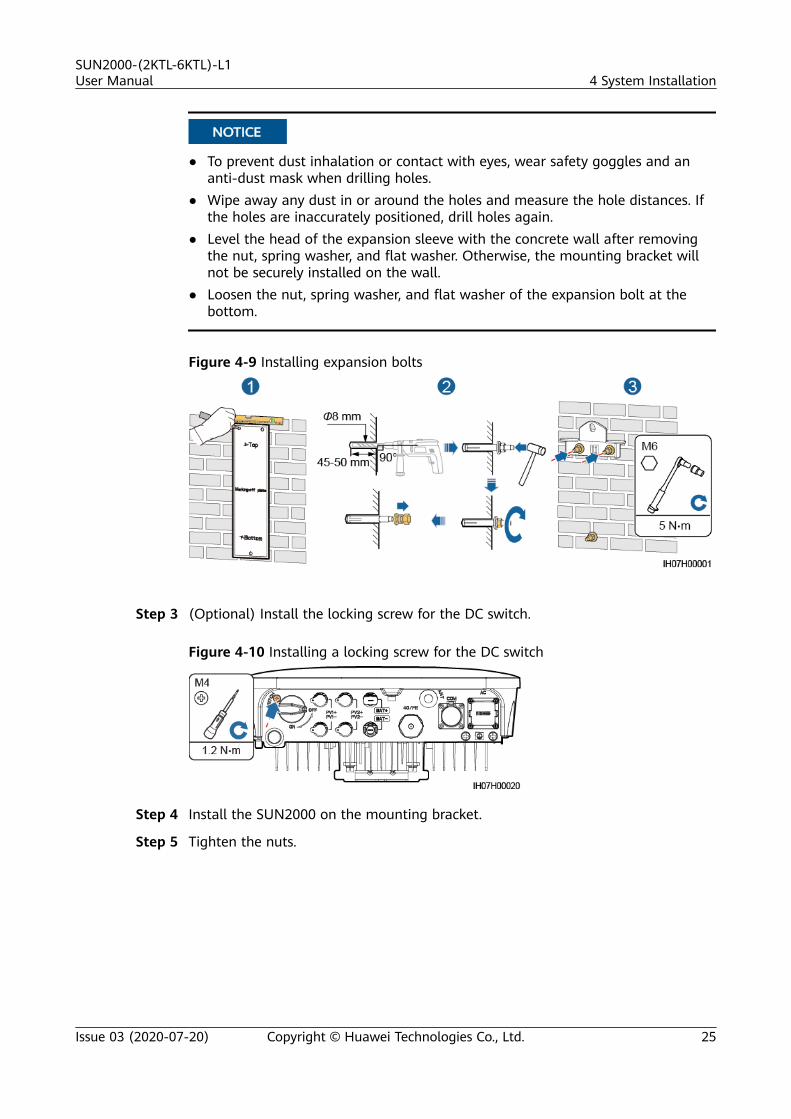
NO TICE
● To prevent dust inhalation or contact with eyes, wear safety goggles and ananti-dust mask when drilling holes.
● Wipe away any dust in or around the holes and measure the hole distances. Ifthe holes are inaccurately positioned, drill holes again.
● Level the head of the expansion sleeve with the concrete wall after removingthe nut, spring washer, and flat washer. Otherwise, the mounting bracket willnot be securely installed on the wall.
● Loosen the nut, spring washer, and flat washer of the expansion bolt at thebottom.
Figure 4-9 Installing expansion bolts
Step 3 (Optional) Install the locking screw for the DC switch.
Figure 4-10 Installing a locking screw for the DC switch
Step 4 Install the SUN2000 on the mounting bracket.
Step 5 Tighten the nuts.
SUN2000-(2KTL-6KTL)-L1User Manual 4 System Installation
Issue 03 (2020-07-20) Copyright © Huawei Technologies Co., Ltd. 25

Figure 4-11 Tightening nuts
Step 6 (Optional) Install an anti-theft lock.
NO TICE
● Prepare an anti-theft lock suitable for the lock hole diameter (Ф10 mm).
● An outdoor waterproof lock is recommended.
● Keep the key to the anti-theft lock.
Figure 4-12 Installing an anti-theft lock
----End
4.5.2 Support-Mounted Installation
Procedure
Step 1 Determine the positions for drilling holes using the marking-off template, andthen mark the positions with a marker.
SUN2000-(2KTL-6KTL)-L1User Manual 4 System Installation
Issue 03 (2020-07-20) Copyright © Huawei Technologies Co., Ltd. 26

Figure 4-13 Determining hole positions
Step 2 Drill holes using a hammer drill.
NO TE
You are advised to apply anti-rust paint on the hole positions for protection.
Figure 4-14 Drilling holes
Step 3 Secure the mounting bracket.
SUN2000-(2KTL-6KTL)-L1User Manual 4 System Installation
Issue 03 (2020-07-20) Copyright © Huawei Technologies Co., Ltd. 27

NO TE
Prepare bolt assemblies based on the hole diameter of the mounting bracket.
Step 4 (Optional) Install the locking screw for the DC switch.
Figure 4-15 Installing a locking screw for the DC switch
Step 5 Install the SUN2000 on the mounting bracket.
Step 6 Tighten the bolt assemblies.
Figure 4-16 Tightening bolt assemblies
SUN2000-(2KTL-6KTL)-L1User Manual 4 System Installation
Issue 03 (2020-07-20) Copyright © Huawei Technologies Co., Ltd. 28

Step 7 (Optional) Install an anti-theft lock.
NO TICE
● Prepare an anti-theft lock suitable for the lock hole diameter (Ф10 mm).● An outdoor waterproof lock is recommended.● Keep the key to the anti-theft lock.
Figure 4-17 Installing an anti-theft lock
----End
SUN2000-(2KTL-6KTL)-L1User Manual 4 System Installation
Issue 03 (2020-07-20) Copyright © Huawei Technologies Co., Ltd. 29

5 Electrical Connection
Precautions
D ANGER
Before connecting cables, ensure that the DC switch on the SUN2000 and all theswitches connecting to the SUN2000 are set to OFF position. Otherwise, the highvoltage of the SUN2000 may result in electric shocks.
WARNING
● The device damage caused by incorrect cable connections is not covered underany warranty.
● Only certified electricians are allowed to connect cables.● Operation personnel must wear proper PPE when connecting cables.
NO TE
The cable colors shown in the electrical connection diagrams provided in this chapter arefor reference only. Select cables in accordance with local cable specifications (green-and-yellow cables are only used for PE).
SUN2000-(2KTL-6KTL)-L1User Manual 5 Electrical Connection
Issue 03 (2020-07-20) Copyright © Huawei Technologies Co., Ltd. 30

5.1 Preparing Cables
Figure 5-1 SUN2000 cable connections (dashed boxes indicate optionalconfiguration)
Table 5-1 Component description
No. Component Description Source
A PV string ● A PV string iscomposed of the PVmodules connected inseries and works withan optimizer.
● The SUN2000 supportsthe input from two PVstrings.
Prepared by thecustomer
B Smart PV optimizer The SUN2000-450W-Psmart PV optimizer issupported.
Purchased fromHuawei
SUN2000-(2KTL-6KTL)-L1User Manual 5 Electrical Connection
Issue 03 (2020-07-20) Copyright © Huawei Technologies Co., Ltd. 31

No. Component Description Source
C DC switch Recommended: a DCcircuit breaker with arated voltage greaterthan or equal to 600 VDC and a rated current of20 A
Prepared by thecustomer
D Battery The SUN2000 canconnect to LG-RESUbatteries (LG RESU7H andRESU10H).
Prepared by thecustomer
E Battery switch Recommended: a DCcircuit breaker with arated voltage greaterthan or equal to 600 VDC and a rated current of20 A
Prepared by thecustomer
F Smart Donglea Supported models:● WLAN-FE Smart
Dongle: SDongleA-05● 4G Smart Dongle:
SDongleA-03
Purchased fromHuawei
G Smart Power Sensor b The SUN2000 canconnect to the DDSU666-H and DTSU666-H smartpower sensors.
Purchased fromHuawei
The following third-partymeters are alsosupported: GAVAZZI-EM340-DIN AV2 3 X S1 X,GAVAZZI-EM111-DIN AV81 X S1 X, GAVAZZI-EM112-DIN AV0 1 X S1 X,CCS-WNC-3Y-400-MB,and CCS-WNC-3D-240-MB.
Prepared by thecustomer
H SUN2000 Select a proper model asrequired.
Purchased fromHuawei
SUN2000-(2KTL-6KTL)-L1User Manual 5 Electrical Connection
Issue 03 (2020-07-20) Copyright © Huawei Technologies Co., Ltd. 32

No. Component Description Source
I AC switch Recommended: a single-phase AC circuit breakerwith a rated voltagegreater than or equal to250 V AC and a ratedcurrent of:● 16 A (SUN2000-2KTL-
L1)● 25 A (SUN2000-3KTL-
L1 andSUN2000-3.68KTL-L1)
● 32 A (SUN2000-4KTL-L1, SUN2000-4.6KTL-L1, SUN2000-5KTL-L1,and SUN2000-6KTL-L1)
Prepared by thecustomer
● Note a: For details about how to use the 4G Smart Dongle SDongleA-03, seethe SDongleA-03 Quick Guide (4G). For details about how to use the WLAN-FE Smart Dongle SDongleA-05, see the SDongleA-05 Quick Guide (WLAN-FE). You can obtain these documents at https://support.huawei.com/enterprise by searching for models.
● Note b: The Spanish version can use only the DDSU666-H smart powersensor provided by Huawei.
Table 5-2 Cable description
No. Cable Type RecommendedSpecifications
Source
1 DC inputpowercable
Common outdoor PVcable in the industry
● Conductor cross-sectional area: 4–6mm2
● Cable outerdiameter: 5.5–9mm
Prepared bythecustomer
2 (Optional)Batterycable
Common outdoor PVcable in the industry
● Conductor cross-sectional area: 4–6mm2
● Cable outerdiameter: 5.5–9mm
Prepared bythecustomer
SUN2000-(2KTL-6KTL)-L1User Manual 5 Electrical Connection
Issue 03 (2020-07-20) Copyright © Huawei Technologies Co., Ltd. 33

No. Cable Type RecommendedSpecifications
Source
3 (Optional)Signalcable
Outdoor shielded twistedpair cable
● Conductor cross-sectional area:– Combined
crimping ofcables on theport: 0.20–0.35mm2
– Crimping thecables on theport withoutcombining them:0.20–1 mm2
● Cable outerdiameter:– 4-hole rubber
plug: 4–8 mm– 2-hole rubber
plug: 8–11 mm
Prepared bythecustomer
4 ACoutputpowercablea
● Not using the PEequipotential point atthe AC output port:two-core (L and N)outdoor copper cable
● Using the PEequipotential point atthe AC output port:three-core (L, N, andPE) outdoor coppercable
● Conductor cross-sectional area: 4–6mm2
● Cable outerdiameter: 10–21mm
Prepared bythecustomer
5 PE cable Single-core outdoorcopper cable and M6 OTterminal
4–10 mm2 Prepared bythecustomer
Note a: The minimum cross-sectional area of the cable should be selected basedon the rated value of the AC fuse.
NO TE
● The minimum cable diameter must comply with local cable standards.● The factors that affect cable selection include the rated current, cable type, routing
mode, ambient temperature, and maximum expected line loss.
SUN2000-(2KTL-6KTL)-L1User Manual 5 Electrical Connection
Issue 03 (2020-07-20) Copyright © Huawei Technologies Co., Ltd. 34

5.2 Connecting PE Cables
Precautions
D ANGER
● Ensure that the PE cable is securely connected. Otherwise, electric shocks mayoccur.
● Do not connect the neutral wire to the enclosure as a PE cable. Otherwise,electric shocks may occur.
NO TE
● The PE point at the AC output port is used only as a PE equipotential point, and cannotsubstitute for the PE point on the enclosure.
● It is recommended that silica gel or paint be used around the ground terminal after thePE cable is connected.
Additional Information
The SUN2000 provides the grounding detection function. This function is used tocheck whether the SUN2000 is properly grounded before the SUN2000 starts, orcheck whether the ground cable is disconnected when the SUN2000 is running.This function is only available under limited conditions. To ensure the safeoperation of the SUN2000, properly ground the SUN2000 according to theconnection requirements of the ground cable. For some power grid types, if theoutput side of the SUN2000 is connected to an isolation transformer, ensure thatthe SUN2000 is properly grounded and set Grounding inspection to Disable toenable the SUN2000 to run properly. If you are not sure whether the SUN2000 isconnected to such a type of power grid, contact your dealer or Huawei technicalsupport for confirmation.
● According to IEC 62109, to ensure the safe operation of the SUN2000 in thecase of ground cable damage or disconnection, properly connect the groundcable of the SUN2000 and ensure that it meets at least one of the followingrequirements before the grounding detection function becomes invalid:
– The PE cable is a single-core outdoor copper cable with a conductorcross-sectional area of at least 10 mm2.
– Use cables with the same diameter as the AC output power cable andground the PE terminal on the AC connector and the ground screws onthe chassis.
● In some countries and regions, the SUN2000 must have additional groundcables. Use cables with the same diameter as the AC output power cable andground the PE terminal on the AC connector and the ground screws on thechassis.
SUN2000-(2KTL-6KTL)-L1User Manual 5 Electrical Connection
Issue 03 (2020-07-20) Copyright © Huawei Technologies Co., Ltd. 35

Procedure
Step 1 Crimp an OT terminal.
NO TICE
● Avoid scratching the core wire when stripping a cable.● The cavity formed after the conductor crimp strip of the OT terminal is crimped
must wrap the core wires completely. The core wires must contact the OTterminal closely.
● Wrap the wire crimping area with heat shrink tubing or insulation tape. Theheat shrink tubing is used as an example.
● When using a heat gun, protect the equipment from being scorched.
Figure 5-2 Crimping an OT terminal
(A) Core wire (B) Insulation layer (C) Heat shrink tubing
(D) Hydraulic pliers (E) Heat gun
Step 2 Connect the PE cable.
NO TICE
● Ensure that the PE cable is connected securely.● It is recommended to use the right ground point for grounding, and the other is
a reserved ground point.
SUN2000-(2KTL-6KTL)-L1User Manual 5 Electrical Connection
Issue 03 (2020-07-20) Copyright © Huawei Technologies Co., Ltd. 36

Figure 5-3 Connecting a PE cable
----End
5.3 (Optional) Installing a Smart Dongle
ProcedureNO TE
● You are advised to install the Smart Dongle before installing the WLAN antenna.● If you prepared a Smart Dongle without a SIM card, you need to prepare a standard SIM
card (size: 25 mm x 15 mm) with the capacity greater than or equal to 64 KB.● When installing the SIM card, determine its installation direction based on the silk
screen and arrow on the card slot.● Press the SIM card in place to lock it, indicating that the SIM card is correctly installed.● When removing the SIM card, push it inwards to eject it.● When reinstalling the cover of the Smart Dongle, ensure that the buckles spring back in
place with a click sound.
● 4G Smart Dongle (4G Communication)
SUN2000-(2KTL-6KTL)-L1User Manual 5 Electrical Connection
Issue 03 (2020-07-20) Copyright © Huawei Technologies Co., Ltd. 37

Figure 5-4 Installing a 4G Smart Dongle
● WLAN-FE Smart Dongle (FE Communication)You are advised to use a CAT 5E outdoor shielded network cable (outerdiameter < 9 mm; internal resistance ≤ 1.5 ohms/10 m) and shielded RJ45connectors.
Figure 5-5 Installing a WLAN-FE Smart Dongle (FE communication)
SUN2000-(2KTL-6KTL)-L1User Manual 5 Electrical Connection
Issue 03 (2020-07-20) Copyright © Huawei Technologies Co., Ltd. 38

NO TE
There are two types of Smart Dongle:● For details about how to use the WLAN-FE Smart Dongle SDongleA-05, see the
SDongleA-05 Quick Guide (WLAN-FE). You can also scan the QR code to obtainthe document.
● For details about how to use the 4G Smart Dongle SDongleA-03, see theSDongleA-03 Quick Guide (4G). You can also scan the QR code to obtain thedocument.
The quick guide is delivered with the Smart Dongle.
5.4 Installing a WLAN Antenna
Procedure
Step 1 Remove the watertight cap from the ANT port.
Step 2 Install the washer to the ANT port on the chassis.
Step 3 Install the WLAN antenna.
NO TICE
Ensure that the WLAN antenna is installed securely.
SUN2000-(2KTL-6KTL)-L1User Manual 5 Electrical Connection
Issue 03 (2020-07-20) Copyright © Huawei Technologies Co., Ltd. 39

Figure 5-6 Installing a WLAN antenna
----End
5.5 Connecting an AC Output Power Cable
PrecautionsAn AC switch must be installed on the AC side of the SUN2000 to ensure that theSUN2000 can be safely disconnected from the power grid.
WARNING
Do not connect loads between the SUN2000 and the AC switch.
Procedure
Step 1 Connect the AC output power cable to the AC connector.
SUN2000-(2KTL-6KTL)-L1User Manual 5 Electrical Connection
Issue 03 (2020-07-20) Copyright © Huawei Technologies Co., Ltd. 40

NO TICE
● The PE point at the AC output port is used only as a PE equipotential point, andcannot substitute for the PE point on the enclosure.
● Keep the AC output power cable and the PE cable close to each other.● Keep the AC output power cable and the DC input power cable close to each
other.● Ensure that the cable jacket is inside the connector.● Ensure that the exposed core is totally inserted into the cable hole.● Ensure that AC output cable is secured. Failing to do so may cause SUN2000
malfunction or damage to its AC connector.● Ensure that the cable is not twisted.
Figure 5-7 Assembling an AC connector (three-core wire)
Figure 5-8 Assembling an AC connector (two-core wire)
SUN2000-(2KTL-6KTL)-L1User Manual 5 Electrical Connection
Issue 03 (2020-07-20) Copyright © Huawei Technologies Co., Ltd. 41

NO TE
● The cable colors shown in the figures are for reference only. Select an appropriate cableaccording to the local standards.
● For the core installation method and the length for cable stripping, see the instructionson the side of the plug insert.
Figure 5-9 Length for cable stripping
Step 2 Connect the AC connector to the AC output port.
NO TICE
Ensure that the AC connector is connected securely.
Figure 5-10 Securing an AC connector
SUN2000-(2KTL-6KTL)-L1User Manual 5 Electrical Connection
Issue 03 (2020-07-20) Copyright © Huawei Technologies Co., Ltd. 42

Step 3 Check the route of the AC output power cable.
Figure 5-11 Cabling requirements
----End
Follow-up Procedure
WARNING
Before removing the AC connector, ensure that the DC switch at the bottom of theSUN2000 and all the switches connected to the SUN2000 are OFF.
To remove the AC connector from the SUN2000, perform the operations in reverseorder.
Figure 5-12 Removing a plug insert
5.6 Connecting DC Input Power Cables
Precautions
SUN2000-(2KTL-6KTL)-L1User Manual 5 Electrical Connection
Issue 03 (2020-07-20) Copyright © Huawei Technologies Co., Ltd. 43

D ANGER
● Before connecting the DC input power cables, ensure that the DC voltage iswithin the safe range (lower than 60 V DC) and that the DC switch on theSUN2000 is OFF. Failing to do so may result in electric shocks.
● When the SUN2000 is running, it is not allowed to work on the DC input powercables, such as connecting or disconnecting a PV string or a PV module in a PVstring. Failing to do so may cause electric shocks.
● If no PV string connects to a DC input terminal of the SUN2000, do not removethe watertight cap from the DC input terminals. Otherwise, the IP rating of theSUN2000 will be affected.
WARNING
Ensure that the following conditions are met. Otherwise, the SUN2000 may bedamaged, or even a fire could happen.● The DC input voltage of the SUN2000 shall not exceed maximum input voltage
under any circumstance.● The polarities of electric connections are correct on the DC input side. The
positive and negative terminals of a PV string connect to corresponding positiveand negative DC input terminals of the SUN2000.
● If the DC input power cables are reversely connected, do not operate the DCswitch as well as positive and negative connectors immediately. Wait until thenight when solar irradiance declines and the PV string current drops to below0.5 A. Then set the DC switch to the OFF position, remove the positive andnegative connectors, and correct the polarities of the DC input power cables.
NO TICE
● Since the output of the PV string connected to the SUN2000 cannot begrounded, ensure that the PV module output is well insulated to ground.
● During the installation of PV strings and the SUN2000, the positive or negativeterminals of PV strings may be short-circuited to ground if the power cable isnot properly installed or routed. In this case, an AC or DC short circuit mayoccur and damage the SUN2000. The caused device damage is not coveredunder any warranty or service agreement.
Figure 5-13 DC input terminals
SUN2000-(2KTL-6KTL)-L1User Manual 5 Electrical Connection
Issue 03 (2020-07-20) Copyright © Huawei Technologies Co., Ltd. 44
(1) Terminals of DC input 1 (2) Terminals of DC input 2
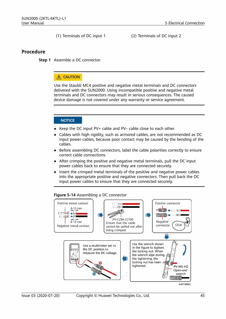
ProcedureStep 1 Assemble a DC connector.
CA UTION
Use the Staubli MC4 positive and negative metal terminals and DC connectorsdelivered with the SUN2000. Using incompatible positive and negative metalterminals and DC connectors may result in serious consequences. The causeddevice damage is not covered under any warranty or service agreement.
NO TICE
● Keep the DC input PV+ cable and PV– cable close to each other.● Cables with high rigidity, such as armored cables, are not recommended as DC
input power cables, because poor contact may be caused by the bending of thecables.
● Before assembling DC connectors, label the cable polarities correctly to ensurecorrect cable connections.
● After crimping the positive and negative metal terminals, pull the DC inputpower cables back to ensure that they are connected securely.
● Insert the crimped metal terminals of the positive and negative power cablesinto the appropriate positive and negative connectors. Then pull back the DCinput power cables to ensure that they are connected securely.
Figure 5-14 Assembling a DC connector
SUN2000-(2KTL-6KTL)-L1User Manual 5 Electrical Connection
Issue 03 (2020-07-20) Copyright © Huawei Technologies Co., Ltd. 45

NO TE
● If the PV string is not configured with an optimizer, use a multimeter to measure thevoltage at the DC position. The multimeter must have a DC voltage range of at least600 V. If the voltage is a negative value, the DC input polarity is incorrect and needscorrection. If the voltage is greater than 600 V, too many PV modules are configured tothe same string. Remove some PV modules.
● If the PV string is configured with an optimizer, check the cable polarity by referring tothe Smart PV optimizer quick guide.
WARNING
Before performing Step 2, ensure that the DC switch is set to OFF.
Step 2 Insert the positive and negative connectors into corresponding DC input terminalson the SUN2000.
NO TICE
After the positive and negative connectors snap into place, pull the DC inputpower cables back to ensure that they are connected securely.
Figure 5-15 Connecting DC input power cables
SUN2000-(2KTL-6KTL)-L1User Manual 5 Electrical Connection
Issue 03 (2020-07-20) Copyright © Huawei Technologies Co., Ltd. 46

NO TICE
If the DC input power cable is reversely connected and the DC switch is set to ON,do not immediately turn off the DC switch or reconnect the positive and negativeconnectors. Otherwise, the device may be damaged. The caused device damage isnot covered under any warranty or service agreement. Wait until the night whensolar irradiance declines and the PV string current drops to below 0.5 A. Then setthe DC switch to the OFF position, remove the positive and negative connectors,and correct the polarities of the DC input power cables.
----End
Follow-up Procedure
WARNING
Before removing the positive and negative connectors, ensure that the DC switchis OFF.
To remove the positive and negative connectors from the SUN2000, insert adisassembly tool into the notch and press the tool with an appropriate force.
Figure 5-16 Removing a DC connector
5.7 (Optional) Connecting Battery Cables
Prerequisites
SUN2000-(2KTL-6KTL)-L1User Manual 5 Electrical Connection
Issue 03 (2020-07-20) Copyright © Huawei Technologies Co., Ltd. 47

D ANGER
● Battery short circuits may cause personal injury. The high transient currentgenerated by a short circuit may release a surge of power and cause fire.
● Do not connect or disconnect the battery cable when the SUN2000 is running.Failing to do so may cause electric shocks.
● Before connecting the battery cables, ensure that the DC switch on theSUN2000 and all the switches connecting to the SUN2000 are OFF, and theSUN2000 has no residual electricity. Otherwise, the high voltage of theSUN2000 and battery may result in electric shocks.
● If no battery connects to the SUN2000, do not remove the watertight cap fromthe battery terminal. Otherwise, the IP rating of the SUN2000 will be affected.If a battery connects to the SUN2000, set aside the watertight cap. Reinstall thewatertight cap immediately after removing the connector. The high voltage ofthe battery terminal may result in electric shocks.
A battery switch can be configured between the SUN2000 and the battery toensure that the SUN2000 can be safely disconnected from the battery.
WARNING
Do not connect loads between the SUN2000 and the battery.The battery cables should be connected correctly. That is, the positive andnegative terminals of the battery connect to the positive and negative batteryterminals on the SUN2000 respectively. Otherwise, the SUN2000 may bedamaged, or even a fire could happen.
NO TICE
● During the installation of the SUN2000 and battery, the positive or negativeterminal of the battery will be short-circuited to ground if power cables are notinstalled or routed as required. In this case, an AC or DC short circuit may occurand damage the SUN2000. The caused device damage is not covered under anywarranty or service agreement.
● The cabling distance between the battery and the SUN2000 should be less thanor equal to 10 meters, and within 5 meters is recommended.
Procedure
Step 1 Assemble the positive and negative connectors by referring to 5.6 Connecting DCInput Power Cables.
SUN2000-(2KTL-6KTL)-L1User Manual 5 Electrical Connection
Issue 03 (2020-07-20) Copyright © Huawei Technologies Co., Ltd. 48

D ANGER
● The battery voltage will result in serious injury. Use dedicated insulation toolsto connect cables.
● Ensure that cables are correctly connected between the battery terminal andthe battery switch, and between the battery switch and the SUN2000 batteryterminal.
NO TICE
Cables with high rigidity, such as armored cables, are not recommended as batterycables, because poor contact may be caused by the bending of the cables.
Step 2 Insert the positive and negative connectors into corresponding battery terminalson the SUN2000.
NO TICE
After the positive and negative connectors snap into place, pull the battery cablesback to ensure that they are connected securely.
Figure 5-17 Connecting battery cables
----End
SUN2000-(2KTL-6KTL)-L1User Manual 5 Electrical Connection
Issue 03 (2020-07-20) Copyright © Huawei Technologies Co., Ltd. 49

5.8 (Optional) Connecting Signal Cables
Context
NO TICE
When laying out signal cables, separate them from power cables and keep themaway from strong interference sources to prevent communication interruption.
Figure 5-18 Signal cable ports
Table 5-3 COM port definition
No. Label Definition Single SUN2000Scenario
SUN2000 CascadingScenario
1 485B1 RS485B, RS485differentialsignal–
- Used for connecting tothe solar inverters.
2 485A1 RS485A, RS485differentialsignal+
3 485B2 RS485B, RS485differentialsignal–
Used for connectingto the RS485 signalports of the batteryand smart powersensor. When bothbattery and powermeter areconfigured, theyneed be crimped tothe 485B2 and485A2 ports.
Used for connecting tothe RS485 signal portsof the battery andsmart power sensor.When both batteryand smart powersensor are configured,they need be crimpedto the 485B2 and485A2 ports.
4 485A2 RS485A, RS485differentialsignal+
SUN2000-(2KTL-6KTL)-L1User Manual 5 Electrical Connection
Issue 03 (2020-07-20) Copyright © Huawei Technologies Co., Ltd. 50
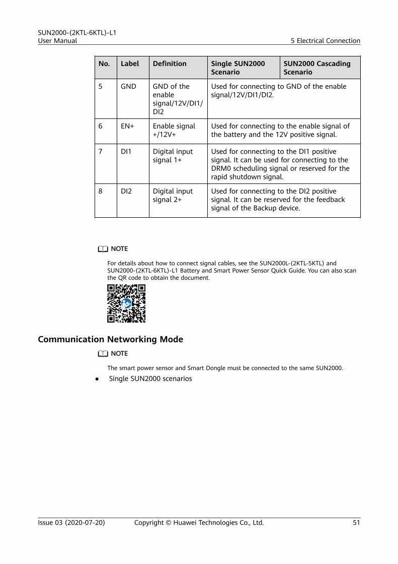
No. Label Definition Single SUN2000Scenario
SUN2000 CascadingScenario
5 GND GND of theenablesignal/12V/DI1/DI2
Used for connecting to GND of the enablesignal/12V/DI1/DI2.
6 EN+ Enable signal+/12V+
Used for connecting to the enable signal ofthe battery and the 12V positive signal.
7 DI1 Digital inputsignal 1+
Used for connecting to the DI1 positivesignal. It can be used for connecting to theDRM0 scheduling signal or reserved for therapid shutdown signal.
8 DI2 Digital inputsignal 2+
Used for connecting to the DI2 positivesignal. It can be reserved for the feedbacksignal of the Backup device.
NO TE
For details about how to connect signal cables, see the SUN2000L-(2KTL-5KTL) andSUN2000-(2KTL-6KTL)-L1 Battery and Smart Power Sensor Quick Guide. You can also scanthe QR code to obtain the document.
Communication Networking ModeNO TE
The smart power sensor and Smart Dongle must be connected to the same SUN2000.
● Single SUN2000 scenarios
SUN2000-(2KTL-6KTL)-L1User Manual 5 Electrical Connection
Issue 03 (2020-07-20) Copyright © Huawei Technologies Co., Ltd. 51

Figure 5-19 Single SUN2000
Figure 5-20 Connecting cables to the smart power sensor (single SUN2000)
● SUN2000 cascading scenarios– In-phase grid connection
SUN2000-(2KTL-6KTL)-L1User Manual 5 Electrical Connection
Issue 03 (2020-07-20) Copyright © Huawei Technologies Co., Ltd. 52
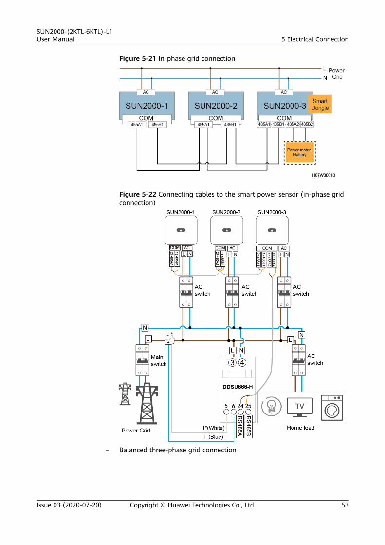
Figure 5-21 In-phase grid connection
Figure 5-22 Connecting cables to the smart power sensor (in-phase gridconnection)
– Balanced three-phase grid connection
SUN2000-(2KTL-6KTL)-L1User Manual 5 Electrical Connection
Issue 03 (2020-07-20) Copyright © Huawei Technologies Co., Ltd. 53

Figure 5-23 Balanced three-phase grid connection
Figure 5-24 Connecting cables to the smart power sensor (balancedthree-phase grid connection)
SUN2000-(2KTL-6KTL)-L1User Manual 5 Electrical Connection
Issue 03 (2020-07-20) Copyright © Huawei Technologies Co., Ltd. 54

NO TE
● In cascading scenarios, the inverters are required to connect to the managementsystem through a Smart Dongle.
● In the preceding networking, the SUN2000s are cascaded and support the grid-tiedpoint control function to achieve zero export.
● If the SUN2000s requires the grid-tied point control function, they need to beconnected to a smart power sensor.
● In the scenario of balanced three-phase grid connection, if the SUN2000s requiresthe grid-tied point control function, they need to be connected to a three-phasesmart power sensor to control the total three-phase power.
● Only one LG battery is supported, and the LG battery must be connected to theinverter installed with the Smart Dongle.
Procedure
Step 1 Connect signal cables to corresponding signal connectors.
NO TICE
● Ensure that the protection layer of the cable is in the connector. The surpluscore should be cut off from the protection layer.
● Ensure that the exposed core is totally inserted into the cable hole.● Ensure that the signal cables are connected securely.● Ensure that the cables are not twisted.● If multiple signal cables need to be connected to a single connector, ensure
that the outer diameters of the signal cables are the same.
Figure 5-25 Crimping two signal cables
Figure 5-26 Crimping three signal cables
SUN2000-(2KTL-6KTL)-L1User Manual 5 Electrical Connection
Issue 03 (2020-07-20) Copyright © Huawei Technologies Co., Ltd. 55

Figure 5-27 Assembling a signal connector (single SUN2000)
Figure 5-28 Assembling a signal connector (SUN2000 cascading)
Step 2 Connect the signal connector to the corresponding port.
NO TICE
Ensure that the signal connector is connected securely.
SUN2000-(2KTL-6KTL)-L1User Manual 5 Electrical Connection
Issue 03 (2020-07-20) Copyright © Huawei Technologies Co., Ltd. 56

Figure 5-29 Securing a signal connector
----End
SUN2000-(2KTL-6KTL)-L1User Manual 5 Electrical Connection
Issue 03 (2020-07-20) Copyright © Huawei Technologies Co., Ltd. 57

6 System Commissioning
6.1 Verification Before Power-On
Table 6-1 Check items and acceptance criteria
No. Check Item Acceptance Criteria
1 SUN2000 The SUN2000 is installed correctly andsecurely.
2 WLAN antenna The WLAN antenna is installedcorrectly and securely.
3 Cables routing Cables are routed properly as requiredby the customer.
4 Cable tie Cable ties are evenly distributed and noburr exists.
5 Grounding The PE cable is connected correctly,securely, and reliably.
6 Switch The DC switch and all the switchesconnecting to the SUN2000 are OFF.
7 Cable connection The AC output power cable, DC inputpower cable, battery cable, and signalcable are connected correctly, securely,and reliably.
8 Unused terminal and port Unused terminals and ports are lockedby watertight caps.
9 Installation environment The installation space is proper, andthe installation environment is cleanand tidy.
SUN2000-(2KTL-6KTL)-L1User Manual 6 System Commissioning
Issue 03 (2020-07-20) Copyright © Huawei Technologies Co., Ltd. 58

6.2 System Power-On
PrerequisitesBefore turning on the AC switch between the SUN2000 and the power grid, use amultimeter to check that the AC voltage is within the allowed range.
NO TICE
● If the DC power supply is connected but the AC power supply is disconnected,the SUN2000 will report a Grid Loss alarm. The SUN2000 can start properlyonly after the power grid recovers.
● If the AC power supply is connected but the battery is not connected, theSUN2000 reports a Battery Abnormal alarm.
● If the SUN2000 is connected to batteries, turn on the DC switch within 1minute after the AC switch is turned on. Otherwise, the SUN2000, connected tothe power grid, will shut down and start again.
Procedure
Step 1 If the battery port of the SUN2000 is connected to a battery, turn on the auxiliarypower switch of the battery and then the battery switch.
Step 2 Turn on the AC switch between the SUN2000 and the power grid.
Step 3 (Optional) Remove the locking screw from the DC switch.
Figure 6-1 Removing the locking screw from a DC switch
Step 4 Turn on the DC switch between the PV string and the SUN2000 if there is any.
Step 5 Turn on the DC switch at the bottom of the SUN2000.
Step 6 Observe the LEDs to check the SUN2000 operating status.
SUN2000-(2KTL-6KTL)-L1User Manual 6 System Commissioning
Issue 03 (2020-07-20) Copyright © Huawei Technologies Co., Ltd. 59

Table 6-2 LED indicators 1
Category Status Description
Running indicator LED1 LED2 –
Steady green Steady green The SUN2000 isoperating in grid-tiedmode.
Blinking green at longintervals (on for 1sand then off for 1s)
Off The DC is on and theAC is off.
Blinking green at longintervals (on for 1sand then off for 1s)
Blinking green at longintervals (on for 1s andthen off for 1s)
Both the DC and ACare on, and theSUN2000 is notexporting power to thepower grid.
Off Blinking green at longintervals (on for 1s andthen off for 1s)
The DC is off and theAC is on.
Off Off Both the DC and ACare off.
Blinking red at shortintervals (on for 0.2sand then off for 0.2s)
– There is a DCenvironmental alarm,such as an alarmindicating that HighString Input Voltage,String ReverseConnection, or LowInsulation Resistance.
– Blinking red at shortintervals (on for 0.2sand then off for 0.2s)
There is an ACenvironmental alarm,such as an alarmindicating GridUndervoltage, GridOvervoltage, GridOverfrequency, or GridUnderfrequency.
Steady red Steady red Fault.
Communicationindicator
LED3 –
Blinking green at short intervals (on for 0.2s andthen off for 0.2s)
Communication is inprogress.
Blinking green at long intervals (on for 1s andthen off for 1s)
The mobile phone isconnected to theSUN2000.
Off There is nocommunication.
SUN2000-(2KTL-6KTL)-L1User Manual 6 System Commissioning
Issue 03 (2020-07-20) Copyright © Huawei Technologies Co., Ltd. 60

Table 6-3 LED indicators 2
Category Status Description
Devicereplacementindication
LED1 LED2 LED3 –
Steady red Steady red Steady red The SUN2000 hardwareis faulty. The SUN2000needs to be replaced.
----End
SUN2000-(2KTL-6KTL)-L1User Manual 6 System Commissioning
Issue 03 (2020-07-20) Copyright © Huawei Technologies Co., Ltd. 61

7 Man-Machine Interaction
7.1 App Commissioning
7.1.1 Downloading the FusionSolar AppSearch for FusionSolar in Google Play (Android) to download and install the app.You can also scan one of the following QR codes to obtain the app.
Figure 7-1 QR code
NO TE
● The latest Android version must be used for device commissioning. The iOS version isnot updated and can be used only for viewing PV plant information. For iOS users, youcan search for FusionSolar in the App Store or scan the following QR code to downloadthe iOS version.
● The screenshots are for reference only. The actual screens prevail.
SUN2000-(2KTL-6KTL)-L1User Manual 7 Man-Machine Interaction
Issue 03 (2020-07-20) Copyright © Huawei Technologies Co., Ltd. 62

7.1.2 (Optional) Registering an Installer Account
NO TE
● If you have an installer account, skip this step.
● You can register an account only using a mobile phone only in China.
● The mobile number or email address used for registration is the user name for loggingin to the FusionSolar app.
Create the first installer account and create a domain named after the companyname.
Figure 7-2 Creating the first installer account
NO TICE
To create multiple installer accounts for a company, log in to the FusionSolar appand tap New User to create an installer account.
Figure 7-3 Creating multiple installer accounts for the same company
SUN2000-(2KTL-6KTL)-L1User Manual 7 Man-Machine Interaction
Issue 03 (2020-07-20) Copyright © Huawei Technologies Co., Ltd. 63
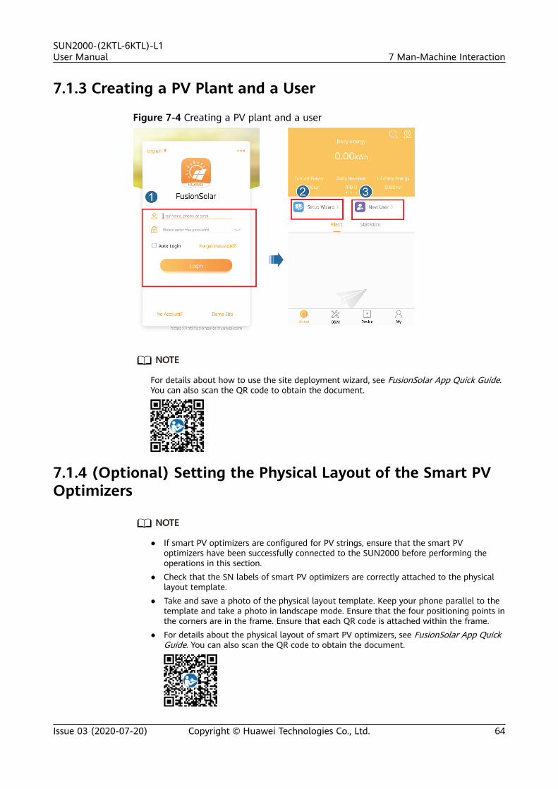
7.1.3 Creating a PV Plant and a User
Figure 7-4 Creating a PV plant and a user
NO TE
For details about how to use the site deployment wizard, see FusionSolar App Quick Guide.You can also scan the QR code to obtain the document.
7.1.4 (Optional) Setting the Physical Layout of the Smart PVOptimizers
NO TE
● If smart PV optimizers are configured for PV strings, ensure that the smart PVoptimizers have been successfully connected to the SUN2000 before performing theoperations in this section.
● Check that the SN labels of smart PV optimizers are correctly attached to the physicallayout template.
● Take and save a photo of the physical layout template. Keep your phone parallel to thetemplate and take a photo in landscape mode. Ensure that the four positioning points inthe corners are in the frame. Ensure that each QR code is attached within the frame.
● For details about the physical layout of smart PV optimizers, see FusionSolar App QuickGuide. You can also scan the QR code to obtain the document.
SUN2000-(2KTL-6KTL)-L1User Manual 7 Man-Machine Interaction
Issue 03 (2020-07-20) Copyright © Huawei Technologies Co., Ltd. 64

Scenario 1: Setting on the FusionSolar Server Side (Solar Inverter Connectedto the Management System)
Step 1 Log in to the FusionSolar app and tap the plant name on the Home screen to
access the plant screen. Select Plant layout, tap , and upload the physicallayout template photo as prompted.
Figure 7-5 Uploading the physical layout template photo (App)
NO TE
You can also upload the physical layout template photo on the WebUI as follows: Log in tohttps://intl.fusionsolar.huawei.com to access the WebUI of the FusionSolar Smart PVManagement System. On the home page, click the plant name to go to the plant page.
Choose Plant layout, click Add Physical Layout > , and upload the physical layouttemplate photo.
Figure 7-6 Uploading the physical layout template photo (WebUI)
Step 2 Log in to https://intl.fusionsolar.huawei.com to access the WebUI of theFusionSolar Smart PV Management System. On the Homepage page, click the
plant name to go to the plant page. Select Plant layout. Choose > Generatewith AI, and create a physical layout as prompted. You can also manually create aphysical location layout.
SUN2000-(2KTL-6KTL)-L1User Manual 7 Man-Machine Interaction
Issue 03 (2020-07-20) Copyright © Huawei Technologies Co., Ltd. 65

Figure 7-7 Physical layout design of PV modules
----End
Scenario 2: Setting on the Solar Inverter Side (Solar Inverter Not Connectedto the Management System)
Step 1 Access the Device Commissioning screen on the FusionSolar app to set thephysical layout of Smart PV Optimizers.
1. Log in to the FusionSolar app. On the Device Commissioning screen, chooseMaintenance > Physical layout design of PV modules. The Physical layoutdesign of PV modules screen is displayed.
2. Tap the blank area. The Identify image and Add PV modules buttons aredisplayed. You can use either of the following methods to perform operationsas prompted:– Method 1: Tap Identify image and upload the physical layout template
photo to complete the optimizer layout. (The optimizers that fail to beidentified need to be manually bound.)
– Method 2: Tap Add PV modules to manually add PV modules and bindthe optimizers to the PV modules.
SUN2000-(2KTL-6KTL)-L1User Manual 7 Man-Machine Interaction
Issue 03 (2020-07-20) Copyright © Huawei Technologies Co., Ltd. 66
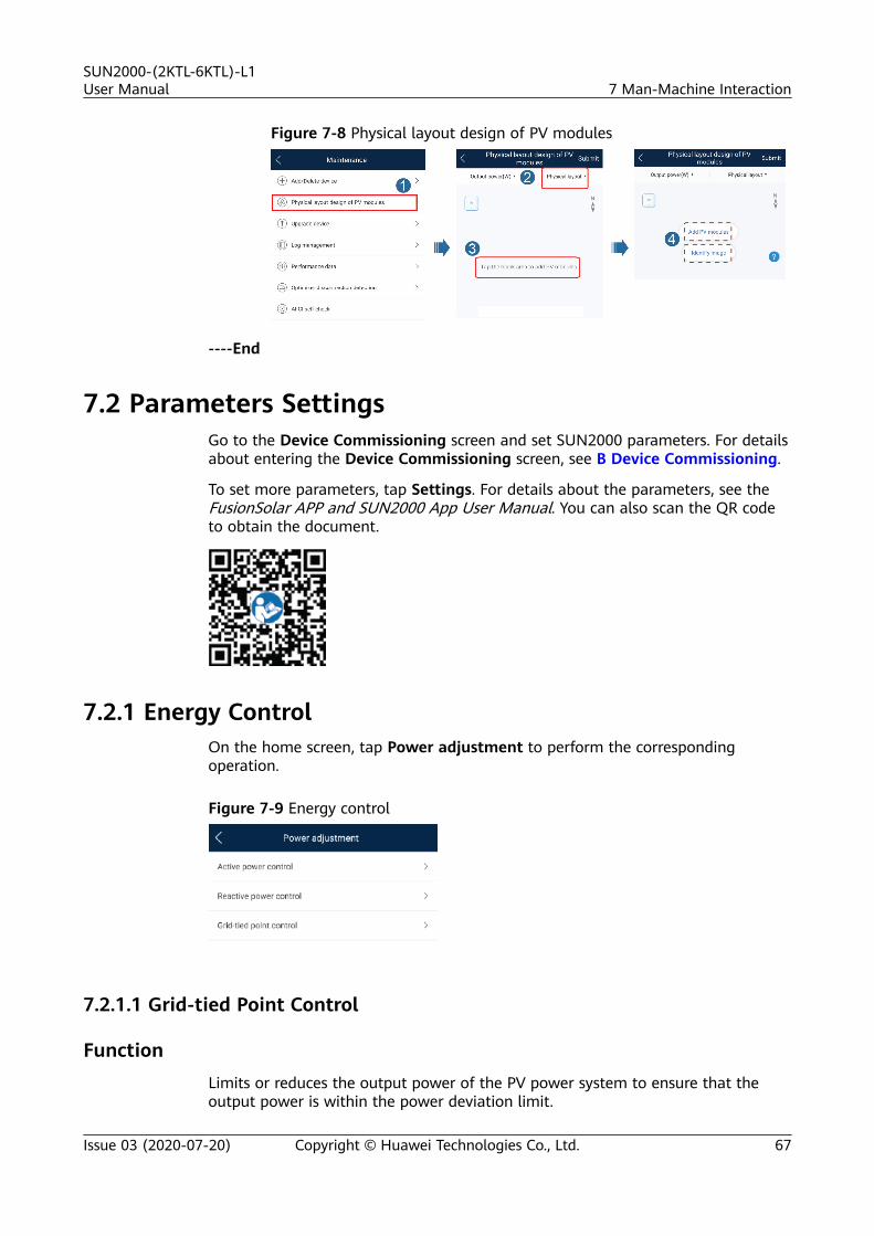
Figure 7-8 Physical layout design of PV modules
----End
7.2 Parameters SettingsGo to the Device Commissioning screen and set SUN2000 parameters. For detailsabout entering the Device Commissioning screen, see B Device Commissioning.
To set more parameters, tap Settings. For details about the parameters, see theFusionSolar APP and SUN2000 App User Manual. You can also scan the QR codeto obtain the document.
7.2.1 Energy ControlOn the home screen, tap Power adjustment to perform the correspondingoperation.
Figure 7-9 Energy control
7.2.1.1 Grid-tied Point Control
FunctionLimits or reduces the output power of the PV power system to ensure that theoutput power is within the power deviation limit.
SUN2000-(2KTL-6KTL)-L1User Manual 7 Man-Machine Interaction
Issue 03 (2020-07-20) Copyright © Huawei Technologies Co., Ltd. 67

Procedure
Step 1 On the home screen, choose Power adjustment > Grid-tied point control.
Figure 7-10 Grid-tied point control
Table 7-1 Grid-tied point control
Parameter Name Description
Activepower
Unlimited - If this parameter is set to Unlimited, the output power ofthe SUN2000 is not limited and the SUN2000 can connectto the power grid at the rated power.
Gridconnection withzeropower
Closed-loopcontroller
● If multiple SUN2000s are cascaded, set this parameter toSDongle/SmartLogger.
● If there is only one SUN2000, set this parameter toInverter.
Limitationmode
Total power indicates export limitation of the total powerat the grid-tied point.
Poweradjustmentperiod
Specifies the shortest interval for a single anti-backfeedingadjustment.
Power controlhysteresis
Specifies the dead zone for adjusting the SUN2000 outputpower. If the power fluctuation is within the power controlhysteresis, the power is not adjusted.
Active poweroutput limitfor fail-safe
Specifies the derating value of the SUN2000 active powerby percentage. If the Smart Dongle does not detect anymeter data or the communication between the SmartDongle and the SUN2000 is disconnected, the Smart Dongledelivers the derating value of the SUN2000 active power bypercentage.
Communicationdisconnectionfail-safe
In the SUN2000 anti-backfeeding scenario, if this parameteris set to Enable, the SUN2000 will derate according to theactive power derating percentage when the communicationbetween the SUN2000 and the Smart Dongle isdisconnected for a period longer than Communicationdisconnection detection time.
Communicationdisconnectiondetection time
Specifies the time for determining the communicationdisconnection between the SUN2000 and the Dongle.This parameter is displayed when Communicationdisconnection fail-safe is set to Enable.
SUN2000-(2KTL-6KTL)-L1User Manual 7 Man-Machine Interaction
Issue 03 (2020-07-20) Copyright © Huawei Technologies Co., Ltd. 68

Parameter Name Description
Gridconnection withlimitedpower(kW)
Closed-loopcontroller
● If multiple SUN2000s are cascaded, set this parameter toSDongle/SmartLogger.
● If there is only one SUN2000, set this parameter toInverter.
Limitationmode
Total power indicates export limitation of the total powerat the grid-tied point.
Maximum gridfeed-in power
Specifies the maximum active power transmitted from thegrid-tied point to the power grid.
Poweradjustmentperiod
Specifies the shortest interval for a single anti-backfeedingadjustment.
Power controlhysteresis
Specifies the dead zone for adjusting the SUN2000 outputpower. If the power fluctuation is within the power controlhysteresis, the power is not adjusted.
Active poweroutput limitfor fail-safe
Specifies the derating value of the SUN2000 active powerby percentage. If the Smart Dongle does not detect anymeter data or the communication between the SmartDongle and the SUN2000 is disconnected, the Smart Dongledelivers the derating value of the SUN2000 active power bypercentage.
Communicationdisconnectionfail-safe
In the SUN2000 anti-backfeeding scenario, if this parameteris set to Enable, the SUN2000 will derate according to theactive power derating percentage when the communicationbetween the SUN2000 and the Smart Dongle isdisconnected for a period longer than Communicationdisconnection detection time.
Communicationdisconnectiondetection time
Specifies the time for determining the communicationdisconnection between the SUN2000 and the Dongle.This parameter is displayed when Communicationdisconnection fail-safe is set to Enable.
Gridconnection withlimitedpower(%)
Closed-loopcontroller
● If multiple SUN2000s are cascaded, set this parameter toSDongle/SmartLogger.
● If there is only one SUN2000, set this parameter toInverter.
Limitationmode
Total power indicates export limitation of the total powerat the grid-tied point.
PV plantcapacity
Specifies the total maximum active power in the SUN2000cascading scenario.
Maximum gridfeed-in power
Specifies the percentage of the maximum active power ofthe grid-tied point to the PV plant capacity.
SUN2000-(2KTL-6KTL)-L1User Manual 7 Man-Machine Interaction
Issue 03 (2020-07-20) Copyright © Huawei Technologies Co., Ltd. 69

Parameter Name Description
Poweradjustmentperiod
Specifies the shortest interval for a single anti-backfeedingadjustment.
Power controlhysteresis
Specifies the dead zone for adjusting the SUN2000 outputpower. If the power fluctuation is within the power controlhysteresis, the power is not adjusted.
Active poweroutput limitfor fail-safe
Specifies the derating value of the SUN2000 active powerby percentage. If the Smart Dongle does not detect anymeter data or the communication between the SmartDongle and the SUN2000 is disconnected, the Smart Dongledelivers the derating value of the SUN2000 active power bypercentage.
Communicationdisconnectionfail-safe
In the SUN2000 anti-backfeeding scenario, if this parameteris set to Enable, the SUN2000 will derate according to theactive power derating percentage when the communicationbetween the SUN2000 and the Smart Dongle isdisconnected for a period longer than Communicationdisconnection detection time.
Communicationdisconnectiondetection time
Specifies the time for determining the communicationdisconnection between the SUN2000 and the Dongle.This parameter is displayed when Communicationdisconnection fail-safe is set to Enable.
----End
7.2.1.2 Battery Control
FunctionIf the SUN2000 connects to a battery, you need to set battery parameters.
Forcible Charge and Discharge
Step 1 On the home screen, choose Power adjustment > Battery control > Forcedcharge/discharge and perform operations as required. Tap Submit.
SUN2000-(2KTL-6KTL)-L1User Manual 7 Man-Machine Interaction
Issue 03 (2020-07-20) Copyright © Huawei Technologies Co., Ltd. 70

Figure 7-11 Forced charge/discharge
Table 7-2 Description of forced charge/discharge parameters
Parameter Description Value Range
Charge/Discharge Specifies the forcedcharge/dischargemanually.
● Stop● Charge● Discharge
Forced charge/dischargepower (kW)
Specifies the forcedcharge/discharge power.
● Charge: [0, maximumcharge power]
● Discharge: [0,maximum dischargepower]
Forced charge/dischargetime (min)
Specifies the forcedcharge/dischargeduration.
[0, 1440]
Remaining charge/discharge time (min)
It cannot be set, whichmeans the remainingtime of charge ordischarge.
-
----End
Control Mode
Step 1 On the home screen, choose Power adjustment > Battery control > Controlmode and perform the required operation. Tap Submit.
SUN2000-(2KTL-6KTL)-L1User Manual 7 Man-Machine Interaction
Issue 03 (2020-07-20) Copyright © Huawei Technologies Co., Ltd. 71

Figure 7-12 Fixed charge/discharge
Figure 7-13 Maximum self-consumption
Figure 7-14 Time-of-use
SUN2000-(2KTL-6KTL)-L1User Manual 7 Man-Machine Interaction
Issue 03 (2020-07-20) Copyright © Huawei Technologies Co., Ltd. 72

Table 7-3 Description of battery control parameters
Parameter Description Value Range
Control mode ● If this parameter is setto Fixed charge/discharge, the batteryis charging ordischarging duringthe configured period.A maximum of 10time periods can beadded.
● If this parameter is setto Maximum self-consumption and theSUN2000 is connectedto a smart powersensor, the SUN2000provides outputpower for local loadsbefore feeding theremaining power tothe power grid.
● If this parameter is setto Time-of-use, thebattery is dischargedwhen the electricityprice is high andcharged when theelectricity price is low.A maximum of 10time periods can beadded.
● Fixed charge/discharge
● Maximum self-consumption
● Time-of-use
----End
Charge from grid
Step 1 On the home screen, choose Power adjustment > Battery control > Charge fromgrid.
SUN2000-(2KTL-6KTL)-L1User Manual 7 Man-Machine Interaction
Issue 03 (2020-07-20) Copyright © Huawei Technologies Co., Ltd. 73

Figure 7-15 Charge from grid
Figure 7-16 End-of-discharge capacity
SUN2000-(2KTL-6KTL)-L1User Manual 7 Man-Machine Interaction
Issue 03 (2020-07-20) Copyright © Huawei Technologies Co., Ltd. 74

Table 7-4 Description of the grid charge parameter
Parameter Description Value Range
Charge fromgrid
● After Charge from grid is enabled:– When the battery capacity is 2%
lower than the End-of-discharge capacity, the systemforcibly charges batteries fromthe power grid. The chargingpower is limited to 1 kW. Whenthe battery capacity is 2% higherthan End-of-discharge capacity,the system stops chargingbatteries from the power grid.
– Except the Maximum self-consumption control mode, ifthe PV power is less than thepreset charge power, the systemcharges batteries from the powergrid. The charge power is limitedto 2 kW. When the batterycapacity is higher than Gridcharge cutoff SOC, the systemstops charging batteries from thepower grid.
● To set the discharge cutoff capacity,choose Maintenance > Add/Deletedevice > Battery > End-of-discharge capacity on the homescreen. The value range is 12%–20%, as shown in Figure 7-16.
● If Charge from grid function isdisabled by default, comply withthe grid charge requirementsstipulated in local laws andregulations when this function isenabled.
● Disable● Enable
----End
7.2.2 AFCI
FunctionIf PV modules or cables are incorrectly connected or damaged, electric arcs maybe generated, which may cause fire. Huawei solar inverters provide arc detectionmeets the requirement of UL 1699B-2018, ensuring the user safety and property.
SUN2000-(2KTL-6KTL)-L1User Manual 7 Man-Machine Interaction
Issue 03 (2020-07-20) Copyright © Huawei Technologies Co., Ltd. 75

This function is enabled by default. The solar inverter automatically detects arcfaults. To disable this function, log in to the FusionSolar app, enter the DeviceCommissioning screen, choose Settings > Feature parameters, and disable AFCI.
For details about entering the Device Commissioning screen, see B DeviceCommissioning.
Clearing AlarmsThe AFCI function involves the DC arc fault alarm.
The SUN2000 has the AFCI alarm automatic clearance mechanism. If an alarm istriggered for less than five times within 24 hours, the SUN2000 automaticallyclears the alarm. If the alarm is triggered for more than five times within 24 hours,the SUN2000 locks for protection. You need to manually clear the alarm on theSUN2000 so that it can work properly.
You can manually clear the alarm as follows:
Log in to the FusionSolar app and choose My > Device Commissioning. On theDevice commissioning screen, connect and log in to the SUN2000 that generatesthe AFCI alarm, tap Alarm management, and tap Clear on the right of the DCarc fault alarm to clear the alarm.
Figure 7-17 Alarm management
SUN2000-(2KTL-6KTL)-L1User Manual 7 Man-Machine Interaction
Issue 03 (2020-07-20) Copyright © Huawei Technologies Co., Ltd. 76

7.2.3 IPS Check (for Italy CEI0-21 Grid Code Only)
Function
The Italy CEI0-21 grid code requires an IPS check for the SUN2000. During theself-check, the SUN2000 checks the protection threshold and protection time ofthe maximum voltage over 10 min (59.S1), maximum overvoltage (59.S2),minimum undervoltage (27.S1), minimum undervoltage (27.S2), maximumoverfrequency (81.S1), maximum overfrequency (81.S2), minimumunderfrequency (81.S), and minimum underfrequency (81.S2).
Procedure
Step 1 On the home screen, choose Maintenance > IPS test to access the IPS test screen.
Step 2 Tap Start to start an IPS test. The SUN2000 detects maximum voltage over 10 min(59.S1), maximum overvoltage (59.S2), minimum undervoltage (27.S1), minimumundervoltage (27.S2), maximum overfrequency (81.S1), maximum overfrequency(81.S2), and minimum underfrequency (81.S1), and minimum underfrequency(81.S2).
Figure 7-18 IPS test
Table 7-5 IPS test type
IPS Test Type Description
Maximum voltageover 10 min(59.S1)
The default maximum voltage over 10 min protectionthreshold is 253 V (1.10 Vn), and the default protectiontime threshold is 3s.
SUN2000-(2KTL-6KTL)-L1User Manual 7 Man-Machine Interaction
Issue 03 (2020-07-20) Copyright © Huawei Technologies Co., Ltd. 77

IPS Test Type Description
Maximumovervoltage(59.S2)
The default overvoltage protection threshold is 264.5 V(1.15 Vn), and the default protection time threshold is 0.2s.
Minimumundervoltage(27.S1)
The default undervoltage protection threshold is 195.5 V(0.85 Vn), and the default protection time threshold is 1.5s.
Minimumundervoltage(27.S2)
The default undervoltage protection threshold is 34.5 V(0.15 Vn), and the default protection time threshold is 0.2s.
Maximumoverfrequency(81.S1)
The default overfrequency protection threshold is 50.2 Hz,and the default protection time threshold is 0.1s.
Maximumoverfrequency(81.S2)
The default overfrequency protection threshold is 51.5 Hz,and the default protection time threshold is 0.1s.
Minimumunderfrequency(81.S1)
The default underfrequency protection threshold is 49.8 Hz,and the default protection time threshold is 0.1s.
Minimumunderfrequency(81.S2)
The default underfrequency protection threshold is 47.5 Hz,and the default protection time threshold is 0.1s.
Step 3 After the IPS test is complete, IPS State is displayed as IPS state success. TapHistorical report in the upper right corner of the screen to view the IPS checkreport.
----End
7.2.4 DRM (Australia AS4777)
FunctionAccording to Australia AS 4777.2-2015, solar inverters need to support thefunction of demand response mode (DRM), and DRM0 is a mandatoryrequirement.
This function is disabled by default.
SUN2000-(2KTL-6KTL)-L1User Manual 7 Man-Machine Interaction
Issue 03 (2020-07-20) Copyright © Huawei Technologies Co., Ltd. 78

Figure 7-19 Wiring diagram for the DRM function
NO TE
The demand response enabling device (DRED) is a power grid dispatch device.
Table 7-6 DRM requirements
Mode Port on the SUN2000 Requirements
DRM0 DI1 and GND of the COMport
● When switches S0 and S9 areswitched on, the solar invertershould be turned off.
● When switch S0 is switchedoff, and switch S9 is switchedon, the solar inverter shouldbe grid-tied.
Procedure
Step 1 On the home page, choose Settings > Feature parameters.
Step 2 Set DRM to .
SUN2000-(2KTL-6KTL)-L1User Manual 7 Man-Machine Interaction
Issue 03 (2020-07-20) Copyright © Huawei Technologies Co., Ltd. 79

Figure 7-20 DRM
----End
SUN2000-(2KTL-6KTL)-L1User Manual 7 Man-Machine Interaction
Issue 03 (2020-07-20) Copyright © Huawei Technologies Co., Ltd. 80

8 System Maintenance
8.1 System Power-Off
Precautions
WARNING
After the SUN2000 powers off, the remaining electricity and heat may still causeelectric shocks and body burns. Therefore, put on protective gloves and beginoperating the SUN2000 five minutes after the power-off.
ProcedureStep 1 Send a shutdown command on the app.
Step 2 Turn off the AC switch between the SUN2000 and the power grid.
Step 3 Turn off the DC switch at the bottom of the SUN2000.
Step 4 (Optional) Install the locking screw for the DC switch.
Figure 8-1 Installing a locking screw for the DC switch
Step 5 Turn off the DC switch between the SUN2000 and PV strings.
Step 6 (Optional) Turn off the battery switch between the SUN2000 and batteries.
----End
SUN2000-(2KTL-6KTL)-L1User Manual 8 System Maintenance
Issue 03 (2020-07-20) Copyright © Huawei Technologies Co., Ltd. 81

8.2 Routine MaintenanceTo ensure that the SUN2000 can operate properly for a long term, you are advisedto perform routine maintenance on it as described in this chapter.
CA UTION
Before cleaning the SUN2000, connecting cables, and maintaining the groundingreliability, power off the SUN2000 (see 8.1 System Power-Off for details).
Table 8-1 Maintenance checklist
Check Item Check Method MaintenanceInterval
Systemcleanliness
Check periodically that the heat sinksare free from obstacles and dust.
Once every 6 to 12months
Systemrunning status
● Check that the SUN2000 is notdamaged or deformed.
● Check that the SUN2000 operateswith no abnormal sound.
● Check that all SUN2000 parametersare correctly set during operation.
Once every sixmonths
Electricalconnection
● Check that cables are secured.● Check that cables are intact, and
that in particular, the parts touchingthe metallic surface are notscratched.
● Check that unused DC inputterminals, battery terminals, COMports, ANT ports, and Smart Donglewaterproof covers are locked.
The first inspection is6 months after theinitialcommissioning.From then on, theinterval can be 6 to12 months.
Groundingreliability
Check that ground cables are securelyconnected.
The first inspection is6 months after theinitialcommissioning.From then on, theinterval can be 6 to12 months.
8.3 TroubleshootingAlarm severities are defined as follows:
SUN2000-(2KTL-6KTL)-L1User Manual 8 System Maintenance
Issue 03 (2020-07-20) Copyright © Huawei Technologies Co., Ltd. 82

● Major: The SUN2000 enters the shutdown mode or functions abnormallyafter a fault occurs.
● Minor: Some components are faulty but the SUN2000 can still connect to thepower grid and generate power.
● Warning: The SUN2000 functions normally, but its output power decreasesdue to external factors.
Table 8-2 Common alarms and troubleshooting measures
Alarm ID AlarmName
AlarmSeverity
Possible Causes Troubleshooting
2001 HighStringInputVoltage
Major The PV array is notproperly configured.Excessive PV modules areconnected in series to thePV string, and therefore theopen-circuit voltageexceeds the maximumSUN2000 operatingvoltage.Cause ID = 1, 2● 1: The PV1 input voltage
is high.● 2: The PV2 input voltage
is high.
Check the serial connectionconfiguration of the PV stringand ensure that the PV stringopen-circuit voltage is notgreater than the maximumoperating voltage of theSUN2000. After the PV arrayconfiguration is corrected, thealarm disappears.
2002 DC ArcFault
Major The PV string power cablesarc or are in poor contact.Cause ID = 1, 2● 1: PV1 DC arc fault● 2: PV2 DC arc fault
Check whether the string cablesarc or are in poor contact.
2011 StringReversed
Major The PV string is reverselyconnected.Cause ID = 1, 2● 1: PV1 is reversely
connected.● 2: PV2 is reversely
connected.
Check whether the PV string isreversely connected to theSUN2000. If yes, wait until thePV string current decreasesbelow 0.5 A, set DC switch toOFF, and adjust the PV stringpolarity.
2021 AFCICheckFailure
Major The AFCI check fails.Cause ID = 1, 2● 1: The AFCI check circuit
is abnormal.● 2: The AFCI circuit is
faulty.
Turn off the AC output switchand DC input switch, and thenturn them on after 5 minutes. Ifthe fault persists, contact yourdealer or Huawei technicalsupport.
SUN2000-(2KTL-6KTL)-L1User Manual 8 System Maintenance
Issue 03 (2020-07-20) Copyright © Huawei Technologies Co., Ltd. 83

Alarm ID AlarmName
AlarmSeverity
Possible Causes Troubleshooting
2032 GridFailure
Major Cause ID = 1● The power grid
experiences an outage.● The AC circuit is
disconnected or the ACcircuit breaker is OFF.
1. Check the AC voltage.2. Check whether the AC circuit
is disconnected or the ACcircuit breaker is OFF.
2033 GridUndervoltage
Major Cause ID = 1The grid voltage is belowthe lower threshold or thelow voltage duration haslasted for more than thevalue specified by lowvoltage ride-through(LVRT).
1. If the alarm occursoccasionally, the power gridmay be abnormaltemporarily. The SUN2000automatically recovers afterdetecting that the power gridbecomes normal.
2. If the alarm occurs frequently,check whether the power gridvoltage is within the allowedrange. If no, contact the localpower operator. If yes, modifythe grid undervoltageprotection threshold throughthe mobile app, SmartLogger,or network managementsystem (NMS) with theconsent of the local poweroperator.
3. If the fault persists for a longtime, check the connectionbetween the AC switch andthe output power cable.
SUN2000-(2KTL-6KTL)-L1User Manual 8 System Maintenance
Issue 03 (2020-07-20) Copyright © Huawei Technologies Co., Ltd. 84

Alarm ID AlarmName
AlarmSeverity
Possible Causes Troubleshooting
2034 GridOvervoltage
Major Cause ID = 1The grid voltage exceedsthe higher threshold or thehigh voltage has lasted formore than the valuespecified by high voltageride-through (HVRT).
1. If the alarm occursoccasionally, the power gridmay be abnormaltemporarily. The SUN2000automatically recovers afterdetecting that the power gridbecomes normal.
2. If the alarm occurs frequently,check whether the power gridvoltage is within the allowedrange. If no, contact the localpower operator. If yes, modifythe grid overvoltageprotection threshold throughthe mobile app, SmartLogger,or NMS with the consent ofthe local power operator.
3. Check whether the peakvoltage of the power grid istoo high. If the fault persistsand cannot be rectified for along time, contact the poweroperator.
2036 GridOverfrequency
Major Cause ID = 1Power grid exception: Theactual power gridfrequency is higher thanthe standard requirementfor the local power grid.
1. If the alarm occursoccasionally, the power gridmay be abnormaltemporarily. The SUN2000automatically recovers afterdetecting that the power gridbecomes normal.
2. If the alarm occurs frequently,check whether the power gridfrequency is within theallowed range. If no, contactthe local power operator. Ifyes, modify the gridoverfrequency protectionthreshold through the mobileapp, SmartLogger, or NMSwith the consent of the localpower operator.
SUN2000-(2KTL-6KTL)-L1User Manual 8 System Maintenance
Issue 03 (2020-07-20) Copyright © Huawei Technologies Co., Ltd. 85

Alarm ID AlarmName
AlarmSeverity
Possible Causes Troubleshooting
2037 GridUnderfrequency
Major Cause ID = 1Power grid exception: Theactual power gridfrequency is lower than thestandard requirement forthe local power grid.
1. If the alarm occursoccasionally, the power gridmay be abnormaltemporarily. The SUN2000automatically recovers afterdetecting that the power gridbecomes normal.
2. If the alarm occurs frequently,check whether the power gridfrequency is within theallowed range. If no, contactthe local power operator. Ifyes, modify the gridunderfrequency protectionthreshold through the mobileapp, SmartLogger, or NMSwith the consent of the localpower operator.
2038 UnstableGridFrequency
Major Cause ID = 1Power grid exception: Theactual grid frequencychange rate does notcomply with the localpower grid standard.
1. If the alarm occursoccasionally, the power gridmay be abnormaltemporarily. The SUN2000automatically recovers afterdetecting that the power gridbecomes normal.
2. If the alarm occurs frequently,check whether the power gridfrequency is within theallowed range. If no, contactthe local power operator.
2039 OutputOvercurrent
Major Cause ID = 1The power grid voltagedrops dramatically or thepower grid is short-circuited. As a result, theSUN2000 transient outputcurrent exceeds the upperthreshold and therefore theSUN2000 protection istriggered.
1. The SUN2000 detects itsexternal working conditionsin real time. After the fault isrectified, the SUN2000automatically recovers.
2. If the alarm occurs frequentlyand affects the energy yieldof the power plant, checkwhether the output is short-circuited. If the fault persists,contact your dealer orHuawei technical support.
SUN2000-(2KTL-6KTL)-L1User Manual 8 System Maintenance
Issue 03 (2020-07-20) Copyright © Huawei Technologies Co., Ltd. 86

Alarm ID AlarmName
AlarmSeverity
Possible Causes Troubleshooting
2040 OutputDCComponentOverhigh
Major Cause ID = 1The DC component of theSUN2000 output currentexceeds the specified upperthreshold.
1. The SUN2000 detects itsexternal working conditionsin real time. After the fault isrectified, the SUN2000automatically recovers.
2. If the alarm occurs frequently,contact your dealer orHuawei technical support.
2051 AbnormalResidualCurrent
Major Cause ID = 1The insulation impedanceof the input side to PEdecreases when theSUN2000 is operating.
1. If the alarm occursoccasionally, the externalcircuit may be abnormaltemporarily. The SUN2000automatically recovers afterthe fault is rectified.
2. If the alarm occurs frequentlyor persists, check whether theimpedance between the PVstring and the ground is toolow.
2062 LowInsulationResistance
Major Cause ID = 1● A short circuit occurs
between the PV arrayand the ground.
● The ambient air of thePV array is damp andthe insulation betweenthe PV array and theground is poor.
1. Check the output impedanceof the PV array to ground. Ifthere is a short circuit or lackof insulation, rectify it.
2. Check that the PE cable ofthe SUN2000 is correctlyconnected.
3. If the impedance is lowerthan the specified protectionthreshold in rainy and cloudydays, set Insulationresistance protection usingthe mobile app, SmartLogger,or NMS.Current insulation resistance:x MΩ, possible short circuitposition: x%. The short circuitposition is valid for a singlePV string. If there aremultiple PV strings, check thePV strings one by one. Fordetails, see E LocatingInsulation Resistance Faults.
SUN2000-(2KTL-6KTL)-L1User Manual 8 System Maintenance
Issue 03 (2020-07-20) Copyright © Huawei Technologies Co., Ltd. 87

Alarm ID AlarmName
AlarmSeverity
Possible Causes Troubleshooting
2063 Overtemperature
Minor Cause ID = 1● The SUN2000 is
installed in a place withpoor ventilation.
● The ambienttemperature is higherthan the upperthreshold.
● The SUN2000 is notworking properly.
● Check the ventilation andambient temperature of theSUN2000 installationposition.
● If the ventilation is poor orthe ambient temperatureexceeds the upper threshold,improve the ventilation andheat dissipation.
● If the ventilation and ambienttemperature both meetrequirements, contact yourdealer or Huawei technicalsupport.
2064 DeviceFault
Major An unrecoverable fault hasoccurred on a circuit insidethe SUN2000.Cause ID = 1–12● 1: The Boost input is
short-circuited.● 2: The Boost input
experiences overcurrent.● 3: The control circuit is
faulty.● 4: The inverter circuit is
abnormal.● 5: The residual current
sensor is faulty.● 6: The temperature
detection fails.● 7: EEPROM read/write
fails.● 8: The auxiliary power
supply is abnormal.● 9: The grid-tied relay is
abnormal.● 10: The DC bus
experiences overvoltage.● 11: The DC bus
experiencesundervoltage.
● 12: The DC busexperiences voltageimbalance.
Turn off the AC output switchand DC input switch, and thenturn them on after 5 minutes. Ifthe fault persists, contact yourdealer or Huawei technicalsupport.
SUN2000-(2KTL-6KTL)-L1User Manual 8 System Maintenance
Issue 03 (2020-07-20) Copyright © Huawei Technologies Co., Ltd. 88

Alarm ID AlarmName
AlarmSeverity
Possible Causes Troubleshooting
2065 UpgradeFailed orVersionMismatch
Minor The upgrade does notcomplete normally.Cause ID = 1–4, 7● 1. The software and
hardware of the maincontroller do not match.
● 2: The main andauxiliary controllersoftware versions do notmatch.
● 3: The monitoring andpower controllersoftware versions do notmatch.
● 4: The upgrade fails.● 7: The optimizer
upgrade fails.
1. Perform an upgrade again.2. If the upgrade fails for
multiple times, contact yourdealer or Huawei technicalsupport.
61440 Monitoring UnitFaulty
Minor Cause ID = 1● The flash memory is
insufficient.● The flash memory has
bad sectors.
Turn off the AC output switchand DC input switch, and thenturn them on after 5 minutes. Ifthe fault persists, replace themonitoring board or contactyour dealer Huawei technicalsupport.
2067 FaultyPowerCollector
Major Cause ID = 1The smart power sensor isdisconnected.
1. Check that the configuredpower meter model is thesame as the actual model.
2. Check that thecommunications parametersfor the smart power sensorsare the same as the SUN2000RS485 configurations.
3. Check whether the smartpower sensor is powered onand whether the RS485communications cable isconnected.
SUN2000-(2KTL-6KTL)-L1User Manual 8 System Maintenance
Issue 03 (2020-07-20) Copyright © Huawei Technologies Co., Ltd. 89

Alarm ID AlarmName
AlarmSeverity
Possible Causes Troubleshooting
2068 BatteryAbnormal
Minor The battery is faulty,disconnected, or thebattery circuit breaker isOFF when the battery isrunning.Cause ID = 1–4● 1: The battery
communication isabnormal.
● 2: The battery portexperiences overcurrent.
● 3. The battery enablingcable is not properlyconnected.
● 4: The battery portvoltage is abnormal.
1. If the battery fault indicator issteady on or blinking, contactthe battery supplier.
2. Check that the batteryenabling/power/communications cable iscorrectly installed, and thatthe communicationsparameters are the same asthe SUN2000 RS485configurations.
3. Check that the auxiliarypower switch on the batteryis set to ON.
4. Send a shutdown commandon the app. Turn off the ACoutput switch, DC inputswitch, and battery switch.Then turn on the batteryswitch, AC output switch, andDC input switch in sequenceafter 5 minutes.
5. If the fault persists, contactyour dealer or Huaweitechnical support.
2070 ActiveIslanding
Major Cause ID = 1When the power gridexperiences an AC poweroutage, the SUN2000detects islandingproactively.
Check that the grid connectionvoltage of the SUN2000 isnormal.
SUN2000-(2KTL-6KTL)-L1User Manual 8 System Maintenance
Issue 03 (2020-07-20) Copyright © Huawei Technologies Co., Ltd. 90

Alarm ID AlarmName
AlarmSeverity
Possible Causes Troubleshooting
2080 Abnormal PVModuleConfiguration
Major PV module configurationdoes not meetrequirements, or the PVmodule output is reverselyconnected or short-circuited.Cause ID = 2, 3, 6, 7, 8, 9● 2: The PV string power
or the number of PVmodules connected inseries exceeds the upperthreshold.
● 3: The PV string voltageis low or the number ofPV modules connectedin series is less than thelower threshold.
● 6: The PV string orparallel connection isabnormal.
● 7: The stringconfiguration ischanged.
● 8: The sunlight isabnormal.
● 9: The PV string voltageexceeds the upperthreshold.
Check whether the total numberof PV modules, number of PVmodules in a string, and numberof PV strings meet requirementsand whether the PV moduleoutput is reversely connected.● ID2: Check whether the PV
string power or the numberof PV modules connected inseries in the PV string exceedsthe upper threshold.
● ID3:1. Check whether the numberof optimizers connected inseries in the PV string isbelow the lower threshold.2. Check whether the PVstring output is reverselyconnected.3. Check whether the PVstring output is disconnected.4. Check whether theoptimizer output extensioncable is correct (positiveconnector at one end andnegative connector at theother).
● ID6:1. Check whether the numberof optimizers connected inseries in the PV stringsconnected in parallel underthe same MPPT is the same.2. Check whether theoptimizer output extensioncable is correct (positiveconnector at one end andnegative connector at theother).
● ID7: When the sunlight isnormal, perform theoptimizer search functionagain.
● ID8: When the sunlight isnormal, perform theoptimizer search functionagain.
SUN2000-(2KTL-6KTL)-L1User Manual 8 System Maintenance
Issue 03 (2020-07-20) Copyright © Huawei Technologies Co., Ltd. 91

Alarm ID AlarmName
AlarmSeverity
Possible Causes Troubleshooting
● ID9: Calculate the PV stringvoltage based on the numberof PV modules in the PVstring and check whether thePV string voltage exceeds theupper threshold of theinverter input voltage.
2081 Optimizer Fault
Warning Cause ID = 1An optimizer is faulty.
Go to the optimizer informationpage to view the faultinformation.
NO TE
Contact your dealer if all failure analysis procedures listed above are completed and thefault still exists.
SUN2000-(2KTL-6KTL)-L1User Manual 8 System Maintenance
Issue 03 (2020-07-20) Copyright © Huawei Technologies Co., Ltd. 92

9 SUN2000 Disposal
9.1 Removing a SUN2000
Procedure
Step 1 Power off the SUN2000. For details, see 8.1 System Power-Off.
Step 2 Disconnect all cables from the SUN2000, including signal cables, DC input powercables, battery cables, AC output power cables, and PE cables.
Step 3 Remove the WLAN antenna or the Smart Dongle from the SUN2000.
Step 4 Remove the SUN2000 from the mounting bracket.
Step 5 Remove the mounting bracket.
----End
9.2 Packing a SUN2000● If the original packaging is available, put the SUN2000 inside it and then seal
it using adhesive tape.● If the original packaging is unavailable, put the SUN2000 inside a suitable
hard carton and seal it properly.
9.3 Disposing a SUN2000If the SUN2000 service life expires, dispose the SUN2000 according to the localdisposal rules for electrical equipment and electronic component waste.
SUN2000-(2KTL-6KTL)-L1User Manual 9 SUN2000 Disposal
Issue 03 (2020-07-20) Copyright © Huawei Technologies Co., Ltd. 93
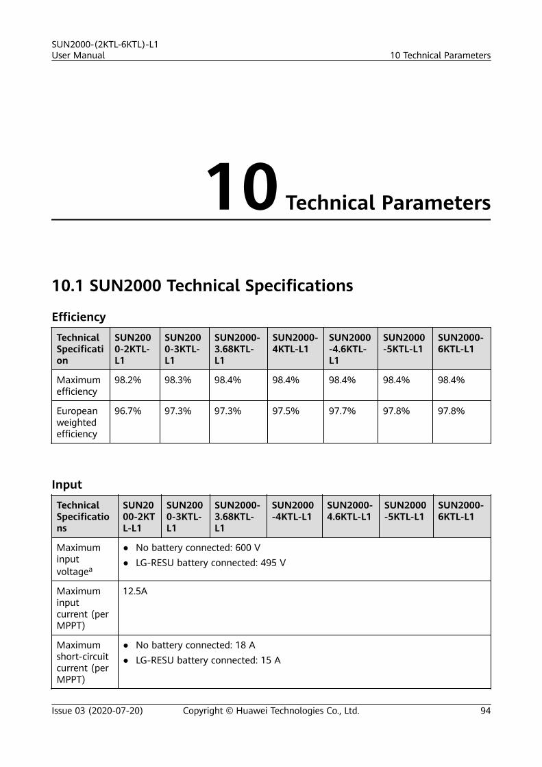
10 Technical Parameters
10.1 SUN2000 Technical Specifications
Efficiency
TechnicalSpecification
SUN2000-2KTL-L1
SUN2000-3KTL-L1
SUN2000-3.68KTL-L1
SUN2000-4KTL-L1
SUN2000-4.6KTL-L1
SUN2000-5KTL-L1
SUN2000-6KTL-L1
Maximumefficiency
98.2% 98.3% 98.4% 98.4% 98.4% 98.4% 98.4%
Europeanweightedefficiency
96.7% 97.3% 97.3% 97.5% 97.7% 97.8% 97.8%
Input
TechnicalSpecifications
SUN2000-2KTL-L1
SUN2000-3KTL-L1
SUN2000-3.68KTL-L1
SUN2000-4KTL-L1
SUN2000-4.6KTL-L1
SUN2000-5KTL-L1
SUN2000-6KTL-L1
Maximuminputvoltagea
● No battery connected: 600 V● LG-RESU battery connected: 495 V
Maximuminputcurrent (perMPPT)
12.5A
Maximumshort-circuitcurrent (perMPPT)
● No battery connected: 18 A● LG-RESU battery connected: 15 A
SUN2000-(2KTL-6KTL)-L1User Manual 10 Technical Parameters
Issue 03 (2020-07-20) Copyright © Huawei Technologies Co., Ltd. 94

TechnicalSpecifications
SUN2000-2KTL-L1
SUN2000-3KTL-L1
SUN2000-3.68KTL-L1
SUN2000-4KTL-L1
SUN2000-4.6KTL-L1
SUN2000-5KTL-L1
SUN2000-6KTL-L1
Operatingvoltagerange
● No battery connected: 80–600 V● LG-RESU battery connected: 350–450 V
Startupvoltage
100 V
MPPTvoltagerange
90–560 V
Rated inputvoltage
360 V
Powersupply
2
Number ofMPPTs
2
Note a: The maximum input voltage includes the PV input voltage and battery input voltage.
OutputTechnicalSpecifications
SUN2000-2KTL-L1
SUN2000-3KTL-L1
SUN2000-3.68KTL-L1
SUN2000-4KTL-L1
SUN2000-4.6KTL-L1
SUN2000-5KTL-L1
SUN2000-6KTL-L1
Ratedoutputpower
2000 W 3000 W 3680 W 4000 W 4600 W 5000Wa
6000 W
Maximumapparentpower
2200 VA 3300 VA 3680 VA 4400 VA 5000 VAb 5500VAc
6000 VA
Ratedoutputvoltage
220 V/230 V/240 V
Adaptedpower gridfrequency
50 Hz/60 Hz
Maximumoutputcurrent
10 A 15 A 16 A 20 A 23 Ad 25 Ad 27.3 A
Powerfactor
0.8 leading and 0.8 lagging
SUN2000-(2KTL-6KTL)-L1User Manual 10 Technical Parameters
Issue 03 (2020-07-20) Copyright © Huawei Technologies Co., Ltd. 95

TechnicalSpecifications
SUN2000-2KTL-L1
SUN2000-3KTL-L1
SUN2000-3.68KTL-L1
SUN2000-4KTL-L1
SUN2000-4.6KTL-L1
SUN2000-5KTL-L1
SUN2000-6KTL-L1
Maximumtotalharmonicdistortion(ratedpower)
≤ 3%
● Note a: The rated output power is 4991 W for the AS4777 grid code.● Note b: The maximum apparent power is 4600 VA for the VDE-AR-N 4105 grid code, and 4999
VA for the AS4777 grid code.● Note c: The maximum apparent power is 4999 VA for the AS4777 grid code.● Note d: The maximum output current is 21.7 A of the AS4777 grid code.
ProtectionTechnicalSpecifications
SUN2000-2KTL-L1
SUN2000-3KTL-L1
SUN2000-3.68KTL-L1
SUN2000-4KTL-L1
SUN2000-4.6KTL-L1
SUN2000-5KTL-L1
SUN2000-6KTL-L1
Anti-islandingprotection
Supported
DC reversepolarityprotection
Supported
Insulationresistancedetection
Supported
Residualcurrentmonitoringunit(RCMU)
Supported
AC short-circuitprotection
Supported
ACovercurrentprotection
Supported
SUN2000-(2KTL-6KTL)-L1User Manual 10 Technical Parameters
Issue 03 (2020-07-20) Copyright © Huawei Technologies Co., Ltd. 96

TechnicalSpecifications
SUN2000-2KTL-L1
SUN2000-3KTL-L1
SUN2000-3.68KTL-L1
SUN2000-4KTL-L1
SUN2000-4.6KTL-L1
SUN2000-5KTL-L1
SUN2000-6KTL-L1
Overtemperatureprotection
Supported
DC surgeprotection
Supported
AC surgeprotection
Supported
ACovervoltageprotection
Supported
Arc faultprotection
Supported
CommunicationsTechnicalSpecifications
SUN2000-2KTL-L1
SUN2000-3KTL-L1
SUN2000-3.68KTL-L1
SUN2000-4KTL-L1
SUN2000-4.6KTL-L1
SUN2000-5KTL-L1
SUN2000-6KTL-L1
Display LED indicators; WLAN+App
WLAN Supported
RS485 Supported
MaximumRS485communicationdistance
1000 m
Communicationsexpansionmodule
WLAN-FE (optional)/4G (optional)
SUN2000-(2KTL-6KTL)-L1User Manual 10 Technical Parameters
Issue 03 (2020-07-20) Copyright © Huawei Technologies Co., Ltd. 97

Common ParametersTechnicalSpecification
SUN2000-2KTL-L1
SUN2000-3KTL-L1
SUN2000-3.68KTL-L1
SUN2000-4KTL-L1
SUN2000-4.6KTL-L1
SUN2000-5KTL-L1
SUN2000-6KTL-L1
Topology Transformerless
IP rating IP65
Coolingmode
Natural cooling
Dimensions (H x W xD)
365 mm x 365 mm x 156 mm (including the mounting bracket)
Weight 12 kg
Operatingtemperature
–25°C to +60°C (derated when the temperature is higher than +45°C) –25°C to+60°C(deratedwhen thetemperature is higherthan+40°C)
Humidity 0–100% RH
Operatingaltitude
0–4000 m (derated above 2000 m)
10.2 Optimizer Technical Specifications
EfficiencyTechnicalSpecifications
SUN2000-450W-P
Maximum efficiency 99.5%
European weightedefficiency
99.0%
SUN2000-(2KTL-6KTL)-L1User Manual 10 Technical Parameters
Issue 03 (2020-07-20) Copyright © Huawei Technologies Co., Ltd. 98

InputTechnicalSpecifications
SUN2000-450W-P
Rated PV modulepower
450 W
Maximum PVmodule power
472.5 W
Maximum inputvoltage
80 V
MPPT voltagerange
8–80 V
Maximum short-circuit current
13 A
Overvoltage level II
OutputTechnicalSpecifications
SUN2000-450W-P
Rated output power 450 W
Output voltage 4–80 V
Maximum outputcurrent
15 A
Output bypass Yes
Shutdown outputvoltage/impedance
0 V/1 kΩ (±10%)
Common ParametersTechnicalSpecifications
SUN2000-450W-P
Dimensions (W x Hx D)
71 mm x 138 mm x 25 mm
Net weight ≤ 550 g
DC input andoutput terminals
Staubli MC4
SUN2000-(2KTL-6KTL)-L1User Manual 10 Technical Parameters
Issue 03 (2020-07-20) Copyright © Huawei Technologies Co., Ltd. 99

TechnicalSpecifications
SUN2000-450W-P
Operatingtemperature
–40°C to +85°C
Storagetemperature
–40°C to +70°C
Operating humidity 0–100% RH
Maximumoperating altitude
4000 m
IP rating IP68
Installation mode ● PV module support installation● PV module frame installation
SUN2000-(2KTL-6KTL)-L1User Manual 10 Technical Parameters
Issue 03 (2020-07-20) Copyright © Huawei Technologies Co., Ltd. 100

A Grid Code
NO TE
The grid codes are subject to change. The listed codes are for reference only.
Table A-1 Grid Code
National/RegionalGridCode
Description
SUN2000-2KTL-L1
SUN2000-3KTL-L1
SUN2000-3.68KTL-L1
SUN2000-4KTL-L1
SUN2000-4.6KTL-L1
SUN2000-5KTL-L1
SUN2000-6KTL-L1
VDE-AR-N-4105
GermanyLV powergrid
Supported
Supported
Supported
Supported
Supported
- -
UTE C15-712-1(A)
Francemainland powergrid
Supported
Supported
Supported
Supported
Supported
Supported
Supported
UTE C15-712-1(B)
Franceislandpowergrid
Supported
Supported
Supported
Supported
Supported
Supported
Supported
UTE C15-712-1(C)
Franceislandpowergrid
Supported
Supported
Supported
Supported
Supported
Supported
Supported
CEI0-21 Italypowergrid
Supported
Supported
Supported
Supported
Supported
Supported
Supported
RD1699/661
Spain LVpowergrid
Supported
Supported
Supported
Supported
Supported
Supported
Supported
SUN2000-(2KTL-6KTL)-L1User Manual A Grid Code
Issue 03 (2020-07-20) Copyright © Huawei Technologies Co., Ltd. 101

National/RegionalGridCode
Description
SUN2000-2KTL-L1
SUN2000-3KTL-L1
SUN2000-3.68KTL-L1
SUN2000-4KTL-L1
SUN2000-4.6KTL-L1
SUN2000-5KTL-L1
SUN2000-6KTL-L1
C10/11 Belgiumpowergrid
Supported
Supported
Supported
Supported
Supported
Supported
-
AS4777 Australiapowergrid
Supported
Supported
- Supported
Supported
Supported
Supported
AS4777-WP
Australiapowergrid
Supported
Supported
- Supported
Supported
Supported
Supported
IEC61727 IEC61727 LV(50 Hz)
Supported
Supported
Supported
Supported
Supported
Supported
Supported
IEC61727-60Hz
IEC61727 LV(60 Hz)
Supported
Supported
Supported
Supported
Supported
Supported
Supported
TAI-PEA Thailandgrid-tiedstandardpowergrid
- Supported
- - - Supported
-
TAI-MEA Thailandgrid-tiedstandardpowergrid
- Supported
- - - Supported
-
EN50549-LV
Irelandpowergrid
Supported
Supported
Supported
Supported
Supported
Supported
Supported
EN50549-SE
SwedenLV
Supported
Supported
Supported
Supported
Supported
Supported
Supported
ABNTNBR16149
Brazilpowergrid
Supported
Supported
- Supported
- Supported
Supported
Fuel-Engine-Grid
Dieselgenerator hybridpowergrid
Supported
Supported
Supported
Supported
Supported
Supported
Supported
SUN2000-(2KTL-6KTL)-L1User Manual A Grid Code
Issue 03 (2020-07-20) Copyright © Huawei Technologies Co., Ltd. 102

National/RegionalGridCode
Description
SUN2000-2KTL-L1
SUN2000-3KTL-L1
SUN2000-3.68KTL-L1
SUN2000-4KTL-L1
SUN2000-4.6KTL-L1
SUN2000-5KTL-L1
SUN2000-6KTL-L1
Fuel-Engine-Grid-60Hz
Dieselgenerator hybridpowergrid
Supported
Supported
Supported
Supported
Supported
Supported
Supported
Austria Austrianpowergrid
Supported
Supported
Supported
- - - -
G98 UK G98powergrid
Supported
Supported
Supported
- - - -
G99-TYPEA-LV
UKG99_TypeA_LVpowergrid
Supported
Supported
Supported
Supported
Supported
Supported
Supported
SUN2000-(2KTL-6KTL)-L1User Manual A Grid Code
Issue 03 (2020-07-20) Copyright © Huawei Technologies Co., Ltd. 103

B Device Commissioning
Step 1 Access Device Commissioning screen.
Figure B-1 Method 1: before login (not connected to the Internet)
SUN2000-(2KTL-6KTL)-L1User Manual B Device Commissioning
Issue 03 (2020-07-20) Copyright © Huawei Technologies Co., Ltd. 104

Figure B-2 Method 2: after login (connected to the Internet)
Step 2 Connect to the solar inverter WLAN and log in to the device commissioning screenas the installer user.
NO TICE
● If the mobile phone is directly connected to the SUN2000, the visible distancebetween the SUN2000 and the mobile phone must be less than 3 m when abuilt-in antenna is used and less than 50 m when an external antenna is usedto ensure the communication quality between the app and the SUN2000. Thedistances are for reference only and may vary with mobile phones and shieldingconditions.
● When connecting the SUN2000 to the WLAN over a router, ensure that themobile phone and SUN2000 are in the WLAN coverage of the router and theSUN2000 is connected to the router.
● The router supports WLAN (IEEE 802.11 b/g/n, 2.4 GHz) and the WLAN signalreaches the SUN2000.
● The WPA, WPA2, or WPA/WPA2 encryption mode is recommended for routers.Enterprise-level encryption is not supported (for example, public hotspotsrequiring authentication such as airport WLAN). WEP and WPA TKIP are notrecommended because these two encryption modes have serious securitydefects. If the access fails in WEP mode, log in to the router and change theencryption mode of the router to WPA2 or WPA/WPA2.
SUN2000-(2KTL-6KTL)-L1User Manual B Device Commissioning
Issue 03 (2020-07-20) Copyright © Huawei Technologies Co., Ltd. 105

NO TE
● Obtain the initial password for connecting to the solar inverter WLAN from the label onthe side of the solar inverter.
● USet the password at the first login. To ensure account security, change the passwordperiodically and keep the new password in mind. Not changing the initial password maycause password disclosure. A password left unchanged for a long period of time may bestolen or cracked. If a password is lost, devices cannot be accessed. In these cases, theuser is liable for any loss caused to the PV plant.
● When you access the Device Commissioning screen of the SUN2000 for the first time,you need to manually set the login password because the SUN2000 does not have aninitial login password.
Figure B-3 Quick settings
----End
SUN2000-(2KTL-6KTL)-L1User Manual B Device Commissioning
Issue 03 (2020-07-20) Copyright © Huawei Technologies Co., Ltd. 106

C Resetting Password
Step 1 Ensure that the SUN2000 connects to the AC and DC power supplies at the sametime. Indicators and are steady green or blink at long intervals for more than3 minutes.
Step 2 Perform the following operations within 3 minutes:1. Turn off the AC switch and set the DC switch at the bottom of the SUN2000
to OFF. If the SUN2000 connects to batteries, turn off the battery switch. Waituntil all the LED indicators on the SUN2000 panel turn off.
2. Turn on the AC switch and set the DC switch to ON. Ensure that the indicator is blinking green at long intervals.
3. Turn off the AC switch and set the DC switch to OFF. Wait until all LEDindicators on the SUN2000 panel are off.
4. Turn on the AC switch and set the DC switch to ON.
Step 3 Reset the password within 10 minutes. (If no operation is performed within 10minutes, all inverter parameters remain unchanged.)1. Wait until the indicator blinks green at long intervals.2. Obtain the initial WLAN hotspot name (SSID) and initial password (PSW)
from the label on the side of the SUN2000 and connect to the app.3. On the login screen, set a new login password and log in to the app.
Figure C-1 Setting the password
SUN2000-(2KTL-6KTL)-L1User Manual C Resetting Password
Issue 03 (2020-07-20) Copyright © Huawei Technologies Co., Ltd. 107

Step 4 Set router and management system parameters to implement remotemanagement.● Setting router parameters
Log in to the FusionSolar app, choose Device Commissioning > Settings >Communication configuration > Router connection settings, and set routerparameters.
Figure C-2 Setting router parameters
● Setting management system parametersLog in to the FusionSolar app, choose Device Commissioning > Settings >Communication configuration > Management System Configuration, andset management system parameters.
Figure C-3 Setting management system parameters
● (Optional) Resetting the WLAN passwordLog in to the FusionSolar app, choose Device Commissioning > Settings >Communication configuration > Inverter WLAN settings, and reset theWLAN password.
SUN2000-(2KTL-6KTL)-L1User Manual C Resetting Password
Issue 03 (2020-07-20) Copyright © Huawei Technologies Co., Ltd. 108

Figure C-4 Resetting the WLAN password
----End
SUN2000-(2KTL-6KTL)-L1User Manual C Resetting Password
Issue 03 (2020-07-20) Copyright © Huawei Technologies Co., Ltd. 109

D Rapid Shutdown
When all PV modules connected to the solar inverter are configured withoptimizers, the PV system shuts down quickly and reduces the output voltage ofthe PV string to below 30 V within 30 seconds. If optimizers are configured forsome PV modules, the rapid shutdown function is not supported.
Perform the following step to trigger rapid shutdown:
● Method 1: Turn off the AC switch between the solar inverter and the powergrid.(If the SUN2000 supports and enables the off-grid function, the rapidshutdown function is not supported.)
● Method 2: Turn off the DC switch at the bottom of the SUN2000. (If an extraDC switch is connected to the input side of the SUN2000, turning off this DCswitch will not trigger rapid shutdown.)
SUN2000-(2KTL-6KTL)-L1User Manual D Rapid Shutdown
Issue 03 (2020-07-20) Copyright © Huawei Technologies Co., Ltd. 110

E Locating Insulation Resistance Faults
If the ground resistance of a PV string connected to a solar inverter is too low, thesolar inverter generates a Low Insulation Resistance alarm.
The possible causes are as follows:● A short circuit occurs between the PV array and the ground.● The ambient air of the PV array is damp and the insulation between the PV
array and the ground is poor.
To locate the fault, connect each PV strings to a solar inverter, power on andcheck the solar inverter, and locate the fault based on the alarm informationreported by the FusionSolar app. If a system is not configured with any optimizer,skip the corresponding operations. Perform the following steps to locate aninsulation resistance fault.
NO TICE
If two or more ground insulation faults occur in a single PV string, the followingmethod cannot locate the fault. You need to check the PV modules one by one.
Step 1 The AC power supply is connected, and set the DC switch at the bottom of thesolar inverter to OFF. If the solar inverter connects to batteries, wait for 1 minute,and turn off the the battery switch and then the auxiliary power switch of thebattery.
Step 2 Connect each PV string to the solar inverter and set the DC switch to ON. If thesolar inverter status is Shutdown: Command, choose Device Commissioning >Maintenance > Inverter ON/OFF on the app and send a startup command.
Step 3 Log in to the FusionSolar app and choose My > Device Commissioning. On theDevice Commissioning screen, connect and log in to the solar inverter, and accessthe Alarm management screen. Check whether the Low Insulation Resistancealarm is reported.● If the Low Insulation Resistance alarm is not reported one minute after the
DC is supplied, choose Device Commissioning > Maintenance > InverterON/OFF on the app and send a shutdown command. Set the DC switch toOFF and go to Step 2 to connect another PV string to the solar inverter for acheck.
SUN2000-(2KTL-6KTL)-L1User Manual E Locating Insulation Resistance Faults
Issue 03 (2020-07-20) Copyright © Huawei Technologies Co., Ltd. 111

● If a Low Insulation Resistance alarm is still reported one minute after theDC is supplied, check the percentage for possible short-circuit positions on theAlarm details page and go to Step 4.
Figure E-1 Alarm details
NO TE
● The positive and negative terminals of a PV string are connected to the PV+ and PV–terminals of the solar inverter. The PV– terminal represents a possibility of 0% for theshort-circuit position and the PV+ terminal represents a possibility of 100% for theshort-circuit position. Other percentages indicate that the fault occurs on a PV moduleor cable in the PV string.
● Possible fault position = Total number of PV modules in a PV string x Percentage ofpossible short-circuit positions. For example, if a PV string consists of 14 PV modulesand the percentage of the possible short-circuit position is 34%, the possible faultposition is 4.76 (14 x 34%), indicating that the fault is located near PV module 4,including the previous and the next PV modules and the cables of PV module 4. Thesolar inverter has a detection precision of ±1 PV module.
Figure E-2 Definition of the percentage of the short-circuit position
Step 4 Set the DC switch to OFF and check whether the connector or DC cable betweenthe possible faulty PV modules and the corresponding optimizers, or thosebetween the adjacent PV modules and the corresponding optimizers are damaged.● If yes, replace the damaged connector or DC cable, set the DC switch to ON,
and view the alarm information.– If the Low Insulation Resistance alarm is not reported one minute after
the DC is supplied, the inspection on the PV string is complete. Choose
SUN2000-(2KTL-6KTL)-L1User Manual E Locating Insulation Resistance Faults
Issue 03 (2020-07-20) Copyright © Huawei Technologies Co., Ltd. 112

Device Commissioning > Maintenance > Inverter ON/OFF on the appand send a shutdown command. Set the DC switch to OFF. Go to Step 2to check other PV strings. Then go to Step 8.
– If the Low Insulation Resistance alarm is still reported one minute afterthe DC is supplied, go to Step 5.
● If not, go to Step 5.
Step 5 Set the DC switch to OFF, disconnect the possible faulty PV modules andcorresponding optimizers from the PV string, and connect a DC extension cablewith an MC4 connector to the adjacent PV modules or optimizers. Set the DCswitch to ON and view the alarm information.● If the Low Insulation Resistance alarm is not reported one minute after the
DC is supplied, the fault occurs on the disconnected PV module and optimizer.Choose Device Commissioning > Maintenance > Inverter ON/OFF on theapp and send a shutdown command. Go to Step 7.
● If the Low Insulation Resistance alarm is still reported one minute after theDC is supplied, the fault does not occur on the disconnected PV module oroptimizer. Go to Step 6.
Step 6 Set the DC switch to OFF, reconnect the removed PV module and optimizer, andrepeat Step 5 to check the adjacent PV modules and optimizers.
Step 7 Determine the position of the ground insulation fault.
1. Disconnect the possible faulty PV module from the optimizer.2. Set the DC switch to OFF.3. Connect the possible faulty optimizer to the PV string.4. Set the DC switch to ON. If the solar inverter status is Shutdown: Command,
choose Device Commissioning > Maintenance > Inverter ON/OFF on theapp and send a startup command. Check whether the Low InsulationResistance alarm is reported.– If the Low Insulation Resistance alarm is not reported one minute after
the solar inverter is powered on, the PV module is faulty. Choose DeviceCommissioning > Maintenance > Inverter ON/OFF on the app and senda shutdown command.
– If the Low Insulation Resistance alarm is still reported one minute afterthe solar inverter is powered on, the optimizer is faulty.
5. Set the DC switch to OFF. Replace the faulty component to rectify theinsulation resistance fault. Go to Step 2 to check other PV strings. Then go toStep 8.
Step 8 If the solar inverter connects to batteries, turn on the auxiliary power switch of thebattery and then the battery switch. Set the DC switch to ON. If the solar inverterstatus is Shutdown: Command, choose Device Commissioning > Maintenance >Inverter ON/OFF on the app and send a startup command.
----End
SUN2000-(2KTL-6KTL)-L1User Manual E Locating Insulation Resistance Faults
Issue 03 (2020-07-20) Copyright © Huawei Technologies Co., Ltd. 113

F Acronyms and Abbreviations
A
AC alternating current
D
DC direct current
DCI direct current identification
F
FRT fault ride through
H
HVRT high voltage ride-through
I
ID identifier
L
LED light emitting diode
LVRT low voltage ride-through
M
MAC Media Access Control
MPPT maximum power point tracking
P
PE protective earthing
SUN2000-(2KTL-6KTL)-L1User Manual F Acronyms and Abbreviations
Issue 03 (2020-07-20) Copyright © Huawei Technologies Co., Ltd. 114

PV photovoltaic
R
RCMU residual current monitoring unit
RH relative humidity
S
SN serial number
SUN2000-(2KTL-6KTL)-L1User Manual F Acronyms and Abbreviations
Issue 03 (2020-07-20) Copyright © Huawei Technologies Co., Ltd. 115


![S]l1~I~cek: - IRIS PAHO Home](https://static.fdokumen.com/doc/165x107/631510f36ebca169bd0b0b21/sl1icek-iris-paho-home.jpg)


