Necropola de tip Ciumbrud de la Orăştie - "Dealul Pemilor", Punct X8, în APVLVM, XXXVIII/1, 2001.
Upload
khangminh22Category
view
0download
0
Sun Microsystems, Inc.www.sun.com
Submit comments about this document at: http://www.sun.com/hwdocs/feedback
Sun™ Quad GbE UTP x8 PCIeExpressModule User’s Guide
Part No. 820-1609-12December 2009, Revision A

Copyright 2009 Sun Microsystems, Inc., 4150 Network Circle, Santa Clara, California 95054, U.S.A. All rights reserved.
Sun Microsystems, Inc. has intellectual property rights relating to technology embodied in the product that is described in this document. Inparticular, and without limitation, these intellectual property rights may include one or more of the U.S. patents listed athttp://www.sun.com/patents and one or more additional patents or pending patent applications in the U.S. and in other countries..
Sun, Sun Microsystems, the Sun logo, Solaris and SunVTS are trademarks or registered trademarks of Sun Microsystems, Inc. in the U.S. andother countries.
UNIX is a registered trademark in the U.S. and other countries, exclusively licensed through X/Open Company, Ltd.
UNIX®. PCI-Express ®. The Adobe. logo and the PostScript logo are trademarks or registered trademarks of Adobe Systems, Incorporated.
Products covered by and information contained in this service manual are controlled by U.S. Export Control laws and may be subject to theexport or import laws in other countries. Nuclear, missile, chemical biological weapons or nuclear maritime end uses or end users, whetherdirect or indirect, are strictly prohibited. Export or reexport to countries subject to U.S. embargo or to entities identified on U.S. export exclusionlists, including, but not limited to, the denied persons and specially designated nationals lists is strictly prohibited.
Use of any spare or replacement CPUs is limited to repair or one-for-one replacement of CPUs in products exported in compliance with U.S.export laws. Use of CPUs as product upgrades unless authorized by the U.S. Government is strictly prohibited.
DOCUMENTATION IS PROVIDED "AS IS" AND ALL EXPRESS OR IMPLIED CONDITIONS, REPRESENTATIONS AND WARRANTIES,INCLUDING ANY IMPLIED WARRANTY OF MERCHANTABILITY, FITNESS FOR A PARTICULAR PURPOSE OR NON-INFRINGEMENT,ARE DISCLAIMED, EXCEPT TO THE EXTENT THAT SUCH DISCLAIMERS ARE HELD TO BE LEGALLY INVALID.
Copyright 2009 Sun Microsystems, Inc., 4150 Network Circle, Santa Clara, Californie 95054, Etats-Unis. Tous droits réservés.
Sun Microsystems, Inc. détient les droits de propriété intellectuels relatifs à la technologie incorporée dans le produit qui est décrit dans cedocument. En particulier, et ce sans limitation, ces droits de propriété intellectuelle peuvent inclure un ou plus des brevets américains listés àl’adresse http://www.sun.com/patents et un ou les brevets supplémentaires ou les applications de brevet en attente aux Etats - Unis et dans lesautres pays.
Sun, Sun Microsystems, le logo Sun, Solaris, et SunVTS sont des marques de fabrique ou des marques déposées de Sun Microsystems, Inc. auxEtats-Unis et dans d’autres pays.
Toutes les marques SPARC sont utilisées sous licence et sont des marques de fabrique ou des marques déposées de SPARC International, Inc.aux Etats-Unis et dans d’autres pays. Les produits portant les marques SPARC sont basés sur une architecture développée par SunMicrosystems, Inc.
UNIX est une marque déposée aux Etats-Unis et dans d’autres pays et licenciée exlusivement par X/Open Company, Ltd.
UNIX®. PCI-Express ®. Le logo Adobe. et le logo PostScript sont des marques de fabrique ou des marques déposées de Adobe Systems,Incorporated.
Ce produit est soumis à la législation américaine en matière de contrôle des exportations et peut être soumis à la règlementation en vigueurdans d’autres pays dans le domaine des exportations et importations. Les utilisations , ou utilisateurs finaux, pour des armes nucléaires, desmissiles, des armes biologiques et chimiques ou du nucléaire maritime, directement ou indirectement, sont strictement interdites. Lesexportations ou reexportations vers les pays sous embargo américain, ou vers des entités figurant sur les listes d’exclusion d’exportationaméricaines, y compris, mais de manière non exhaustive, la liste de personnes qui font objet d’un ordre de ne pas participer, d’une façon directeou indirecte, aux exportations des produits ou des services qui sont régis par la législation américaine en matière de contrôle des exportationset la liste de ressortissants spécifiquement désignés, sont rigoureusement interdites. L’utilisation de pièces détachées ou d’unités centrales deremplacement est limitée aux réparations ou à l’échange standard d’unités centrales pour les produits exportés, conformément à la législationaméricaine en matière d’exportation. Sauf autorisation par les autorités des Etats-Unis, l’utilisation d’unités centrales pour procéder à des misesà jour de produits est rigoureusement interdite.
LA DOCUMENTATION EST FOURNIE "EN L’ETAT" ET TOUTES AUTRES CONDITIONS, DECLARATIONS ET GARANTIES EXPRESSESOU TACITES SONT FORMELLEMENT EXCLUES, DANS LA MESURE AUTORISEE PAR LA LOI APPLICABLE, Y COMPRIS NOTAMMENTTOUTE GARANTIE IMPLICITE RELATIVE A LA QUALITE MARCHANDE, A L’APTITUDE A UNE UTILISATION PARTICULIERE OU AL’ABSENCE DE CONTREFACON.

Contents
Preface xiii
1. Product Overview 1
Shipping Kit Contents 1
Product Description 1
Hardware and Software Requirements 2
Front Panel LED Displays on the ExpressModule 3
Patch Requirements 4
Patches and Updates 5
Features 6
2. Installing and Setting Up the Driver 7
Downloading and Installing the Driver on a Solaris SPARC or x86 Platform 7
▼ To Download the Driver on a Solaris Platform 7
▼ To Remove the Driver From a Solaris SPARC Platform 10
Downloading and Installing the Driver on a Linux Platform 11
▼ To Remove the Driver From a Linux Platform 13
3. Installing the ExpressModule 15
Installing the ExpressModule 15
▼ To Install the ExpressModule 15
iii

Verifying the Hardware Installation 18
▼ To Verify the Hardware Installation 19
▼ To Reboot the System 21
4. Network Configuration 23
Configuring the Network Host Files 23
Setting Up a Gigabit Ethernet Port on a Diskless Client System 25
▼ To Set Up a Gigabit Ethernet Port on a Diskless Client 26
Installing the Solaris Operating System Over a Gigabit Ethernet Network 27
▼ To Install the Solaris Operating System Over a Gigabit EthernetNetwork 27
5. Configuring the nxge Device Driver Parameters 31
nxge Hardware and Software Overview 31
Setting nxge Driver Parameters on a Solaris Platform 32
▼ To Set the Driver Parameters 32
Setting Parameters Using the ndd Utility 32
Noninteractive and Interactive Modes 32
▼ To Specify Device Instances for the ndd Utility 33
▼ To Specify Parameter Values Using the ndd Utility 33
▼ To Use the ndd Utility in Interactive Mode 34
Setting Parameters Using the nxge.conf File 34
▼ To Access a Man Page 35
▼ To Set Driver Parameters Using an nxge.conf File 35
6. Configuring the Jumbo Frames Feature 41
Jumbo Frames Overview 41
Checking Jumbo Frames Configurations 41
▼ To Show the Driver Statistics in a Solaris Environment 42
Enabling Jumbo Frames in a Solaris SPARC Environment 43
iv Sun Quad GbE UTP x8 PCIe ExpressModule User’s Guide • December 2009

▼ To Enable Jumbo Frames in a Solaris Environment Using nxge.conf 43
▼ To Check Layer 2 Configuration 43
▼ To Check Layer 3 Configuration 44
7. Configuring Link Aggregation 45
Overview of Link Aggregation 45
Configuring Link Aggregation in a Solaris Environment 46
▼ To Configure Link Aggregation in a Solaris Environment 46
8. Configuring VLANs 49
VLAN 49
Configuring VLANs in a Solaris Environment 51
▼ To Configure Static VLANs 52
A. Specifications 55
Connectors 55
Performance Specifications 57
Physical Characteristics 57
Power Requirements 58
B. Diagnostic Software 59
SunVTS Diagnostic Software 59
Updating SunVTS to Recognize the ExpressModule 60
▼ To Update SunVTS to Recognize the ExpressModule 60
Using the SunVTS netlbtest 61
▼ To Use the netlbtest 61
Index 63
Contents v

vi Sun Quad GbE UTP x8 PCIe ExpressModule User’s Guide • December 2009

Figures
FIGURE 1-1 Sun Quad GbE UTP x8 PCIe ExpressModule 2
FIGURE 1-2 Sun Quad GbE UTP x8 PCIe ExpressModule Ports 3
FIGURE 8-1 Example of Servers Supporting Multiple VLANs With Tagging ExpressModules 50
FIGURE 8-2 Ethernet Tag Header Format 52
FIGURE A-1 Sun GbE UTP x8 PCIe ExpressModule Connectors 56
vii

viii Sun Quad GbE UTP x8 PCIe ExpressModule User’s Guide • December 2009

Tables
TABLE 1-1 Hardware and Software Requirements 2
TABLE 1-2 Front Panel LEDs for the Sun Quad GbE UTP x8 PCIe ExpressModule 4
TABLE A-1 Connector Characteristics 57
TABLE A-2 Performance Specifications 57
TABLE A-3 Physical Characteristics 57
TABLE A-4 Power Requirements 58
TABLE B-1 SunVTS Documentation 60
ix

x Sun Quad GbE UTP x8 PCIe ExpressModule User’s Guide • December 2009

Declaration of Conformity
EMC
USA—FCC Class AThis equipment complies with Part 15 of the FCC Rules. Operation is subject to the following two conditions:1. This equipment may not cause harmful interference.2. This equipment must accept any interference that may cause undesired operation.
European UnionThis equipment complies with the following requirements of the EMC Directive 89/336/EEC:
SafetyThis equipment complies with the following requirements of the Low Voltage Directive 73/23/EEC:
Supplementary InformationThis equipment was tested and complies with all the requirements for the CE Mark.This equipment complies with the Restriction of Hazardous Substances (RoHS) directive 2002/95/EC.
Compliance Model Number: ATLS1QGC-EMProduct Family Name: Sun Quad GbE UTP x8 PCIe ExpressModule (X7287A-z)
As Information Technology Equipment (ITE) Class A per (as applicable):EN 55022:1994 +A1:1995 +A2:1997 Class AEN 61000-3-2:2000 PassEN 61000-3-3:1995 +A1:2000 PassEN 55024:1998 +A1:2001 +A2:2003 Required Limits:
IEC 61000-4-2 4 kV (Direct), 8kV (Air)IEC 61000-4-3 3 V/mIEC 61000-4-4 1 kV AC Power Lines, 0.5 kV Signal and DC Power LinesIEC 61000-4-5 1 kV AC Line-Line and Outdoor Signal Lines, 2 kV AC Line-Gnd, 0.5 kV DC Power LinesIEC 61000-4-6 3 VIEC 61000-4-8 1 A/mIEC 61000-4-11 Pass
EC Type Examination Certificates:EN 60950-1:2001, 1st EditionIEC 60950-1:2001, 1st EditionEvaluated to all CB CountriesUL and cUL/CSA 60950-1:2001, CSA C22.2 No. 60950-00 File:E138989-A92 Vol. 54
/S/ /S/Dennis P. Symanski DATEWorldwide Compliance EngineeringSun Microsystems, Inc.4150 Network Circle, MPK15-102Santa Clara, CA 95054 U.S.A.Tel: 650-786-3255Fax: 650-786-3723
Donald Cameron DATEProgram Manager/Customer QualitySun Microsystems Scotland, LimitedBlackness Road, Phase I, Main Bldg.Springfield, EH49 7LRScotland, United KingdomTel: +44 1 506 672 539 Fax: +44 1 506 670 011
xi

xii Sun Quad GbE UTP x8 PCIe ExpressModule User’s Guide • December 2009

Preface
This guide provides instructions for installing both the hardware and software forthe Sun Quad GbE UTP x8 PCIe ExpressModule. This guide also describes how toconfigure the nxge driver, which controls the ExpressModule.
These instructions are designed for enterprise system administrators with experiencein installing network hardware and software.
How This Document Is OrganizedChapter 1 provides an overview of the Sun Quad GbE UTP x8 PCIe ExpressModule.
Chapter 2 explains how to install the nxge device driver software.
Chapter 3 describes how to install the ExpressModule in your system and verify thatit has been installed correctly.
Chapter 4 describes how to configure the network host files after you install theExpressModule on your system. This chapter also describes how to set up a GigabitEthernet network on a diskless client and install the Solaris Operating System over aGigabit Ethernet network.
Chapter 5 explains how to set the nxge device driver parameters to customize eachdevice in your system.
Chapter 6 describes how to enable the Jumbo Frames feature.
Chapter 7 describes how to configure link aggregation.
Chapter 8 explains Virtual Local Area Networks (VLANs) in detail and providesconfiguration instructions and examples.
Appendix A lists the specifications for the Sun Quad GbE UTP x8 PCIe ExpressModule.
xiii

Appendix B provides an overview of the SunVTS™ diagnostic application andinstructions for updating the SunVTS software to recognize the ExpressModule.
Using UNIX CommandsThis document might not contain information about basic UNIX® commands andprocedures such as shutting down the system, booting the system, and configuringdevices. Refer to the following for this information:
■ Software documentation that you received with your system
■ Solaris™ Operating System documentation, which is at:
http://docs.sun.com
Shell Prompts
Shell Prompt
C shell machine-name%
C shell superuser machine-name#
Bourne shell and Korn shell $
Bourne shell and Korn shell superuser #
xiv Sun Quad GbE UTP x8 PCIe ExpressModule User’s Guide • December 2009

Typographic Conventions
Related DocumentationThe documents listed as online are available at:
http://www.sun.com/documentation/
Typeface*
* The settings on your browser might differ from these settings.
Meaning Examples
AaBbCc123 The names of commands, files,and directories; on-screencomputer output
Edit your.login file.Use ls -a to list all files.% You have mail.
AaBbCc123 What you type, when contrastedwith on-screen computer output
% su
Password:
AaBbCc123 Book titles, new words or terms,words to be emphasized.Replace command-line variableswith real names or values.
Read Chapter 6 in the User’s Guide.These are called class options.You must be superuser to do this.To delete a file, type rm filename.
Application Title Part Number Format Location
Release Notes Sun Quad GbE UTP x8 PCIe ExpressModule ReleaseNotes
820-1610 PDFHTML
Online
Getting Started Sun Quad GbE UTP x8 PCIe ExpressModule GettingStarted Guide
820-1611 Hardcopy Ship kit
Safety andcompliance
Safety and Compliance Manual 816-7190 PDFHTML
Online
Preface xv
Documentation, Support, and Training
Third-Party Web SitesSun is not responsible for the availability of third-party web sites mentioned in thisdocument. Sun does not endorse and is not responsible or liable for any content,advertising, products, or other materials that are available on or through such sitesor resources. Sun will not be responsible or liable for any actual or alleged damageor loss caused by or in connection with the use of or reliance on any such content,goods, or services that are available on or through such sites or resources.
Sun Welcomes Your CommentsSun is interested in improving its documentation and welcomes your comments andsuggestions. You can submit your comments by going to:
http://www.sun.com/hwdocs/feedback
Please include the title and part number of your document with your feedback:
Sun Quad GbE UTP x8 PCIe ExpressModule User’s Guide, part number 820-1609-12
Sun Function URL
Documentation http://www.sun.com/documentation/
Support http://www.sun.com/support/
Training http://www.sun.com/training/
xvi Sun Quad GbE UTP x8 PCIe ExpressModule User’s Guide • December 2009

CHAPTER 1
Product Overview
This chapter provides an overview of the Sun Quad GbE UTP x8 PCIeExpressModule, including:
■ “Shipping Kit Contents” on page 1
■ “Product Description” on page 1
■ “Hardware and Software Requirements” on page 2
■ “Features” on page 6
Shipping Kit ContentsThe carton in which your Sun Quad GbE UTP x8 PCIe ExpressModule was shippedshould contain the following items:
■ Sun Quad GbE UTP x8 PCIe ExpressModule
■ Sun Quad GbE UTP x8 PCIe ExpressModule Getting Started Guide.
Product DescriptionThe Sun Quad GbE UTP x8 PCIe ExpressModule provides high-performance packetprocessing capability optimized for throughput computing and throughputnetworking architecture. The ExpressModule provides four 10/100/1000BASE-Tcompliant Ethernet copper ports.
FIGURE 1-1 shows the ExpressModule.
1

FIGURE 1-1 Sun Quad GbE UTP x8 PCIe ExpressModule
Hardware and Software RequirementsBefore installing the ExpressModule, ensure that your system meets the hardwareand software requirements. TABLE 1-1 lists the supported hardware and software.
TABLE 1-1 Hardware and Software Requirements
Requirements Hardware or Software
Hardware Sun Blade x6220 server module, Sun Blade T6300 server module,Sun Blade x8400 server module, Sun Blade x8420 server module
Operating System Solaris 10 11/06 Operating SystemSuSE Linux Enterprise Server 10RedHat Enterprise Linux 4.0_u4RedHat Enterprise Linux 4.0_u3
2 Sun Quad GbE UTP x8 PCIe ExpressModule User’s Guide • December 2009

FIGURE 1-2 Sun Quad GbE UTP x8 PCIe ExpressModule Ports
Chapter 1 Product Overview 3
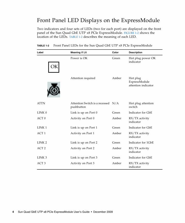
Front Panel LED Displays on the ExpressModuleTwo indicators and four sets of LEDs (two for each port) are displayed on the frontpanel of the Sun Quad GbE UTP x8 PCIe ExpressModule. FIGURE 1-2 shows thelocation of the LEDs. TABLE 1-2 describes the meaning of each LED.
TABLE 1-2 Front Panel LEDs for the Sun Quad GbE UTP x8 PCIe ExpressModule
Label Meaning if Lit Color Description
Power is OK Green Hot plug power OKindicator
Attention required Amber Hot plugExpressModuleattention indicator
ATTN Attention Switch is a recessedpushbutton
N/A Hot plug attentionswitch
LINK 0 Link is up on Port 0 Green Indicator for GbE
ACT 0 Activity on Port 0 Amber RX/TX activityindicator
LINK 1 Link is up on Port 1 Green Indicator for GbE
ACT 1 Activity on Port 1 Amber RX/TX activityindicator
LINK 2 Link is up on Port 2 Green Indicator for 1GbE
ACT 2 Activity on Port 2 Amber RX/TX activityindicator
LINK 3 Link is up on Port 3 Green Indicator for GbE
ACT 3 Activity on Port 3 Amber RX/TX activityindicator
OK
4 Sun Quad GbE UTP x8 PCIe ExpressModule User’s Guide • December 2009

Patch RequirementsThe SunBlade T6300 was released on Solaris 10 11/06 Operating System with patches.For more information on the SunOS 5.10: SunBlade T6300 & Sun Fire (T1000, T2000)platform patch, refer to the Sun Blade T6300 Server Module Product Notes (820-0278) atthe followingweb site:
http://www.sun.com/products-n-solutions/hardware/docs/Servers/blade_servers/
If the patches are not available on SunSolve, contact your local sales or servicerepresentative.
Patches and UpdatesCheck the Sun Update Connection to ensure that you have the latest recommendedpatch clusters and security patches. You can download the latest recommendedpatch clusters and security patches at:
http://sunsolve.sun.com/pub-cgi/show.pl?target=patchpage
Chapter 1 Product Overview 5

FeaturesThe Sun Quad GbE UTP x8 PCIe ExpressModule addresses the followingrequirements and provides additional features and benefits:
■ Four 10/100/1000BASE-T Ethernet interfaces (full-duplex only)
■ IEEE 802.3ab compliant
■ Uses Sun ASIC and software for innovative throughput networking design
■ Networking I/O virtualization supporting Solaris LDOM1.0
■ Hardware-based flow classification for extending parallelism and virtualization tonetworking
■ Up to 16 receive DMA channels and up to 24 transmit DMA channels, multiplereceive and transmit descriptor rings and dedicated networking hardwareresources (DMA, interrupts, buffer, and more) for each thread and strand
■ CPU/thread affinity and CPU load balancing at L1,L2,L3 and L4
■ Jumbo frames support (up to 9KBytes)
■ IPv4/IPv6 and IPMP support
■ TCP/UDP/IP checksum and CRC32 support
■ IEEE 802.1Q VLAN support
6 Sun Quad GbE UTP x8 PCIe ExpressModule User’s Guide • December 2009

CHAPTER 2
Installing and Setting Up the Driver
This chapter explains how to download and install the nxge driver. The nxgeGigabit Ethernet driver (nxge(7D)) is a multi-threaded, loadable, clonable, GLD-based STREAMS driver. The nxge driver is managed by the dladm(1M) commandline utility, which allows VLANs to be defined on top of nxge instances and fornxge instances to be aggregated. See the dladm(1M) man page for more details onconfiguring the data-link interfaces and link aggregations.
This chapter contains the following sections:
■ “Downloading and Installing the Driver on a Solaris SPARC or x86 Platform” onpage 7
Downloading and Installing the Driveron a Solaris SPARC or x86 PlatformIf your system uses the Solaris SPARC or x86 operating system you will need todownload and install the nxge device driver for Solaris platforms.
▼ To Download the Driver on a Solaris Platform1. Locate and download the nxge device driver software at the following web
site:
http://www.sun.com/products/networking/ethernet/index.html
2. Uncompress the gzipped tar file:
# gunzip nxge.tar.gz
7

3. Unpack the tar file:
a. For SPARC systems, change to the following directory:
b. For x86 systems:
4. For SPARC systems, determine which architecture your system is running:
a. For sun4v systems, install the software packages by typing the following atthe command line:
b. For sun4u systems, install the software packages by typing the following atthe command line:
# tar xvf nxge.tar
# cd 10_GigabitEthernet/Solaris_10/sparc/Packages
# cd 10_GigabitEthernet/Solaris_10/i386/Packages
# uname -m
# /usr/sbin/pkgadd -d SUNWnxge.v SUNWnxgem
# /usr/sbin/pkgadd -d SUNWnxge.u SUNWnxgem
8 Sun Quad GbE UTP x8 PCIe ExpressModule User’s Guide • December 2009
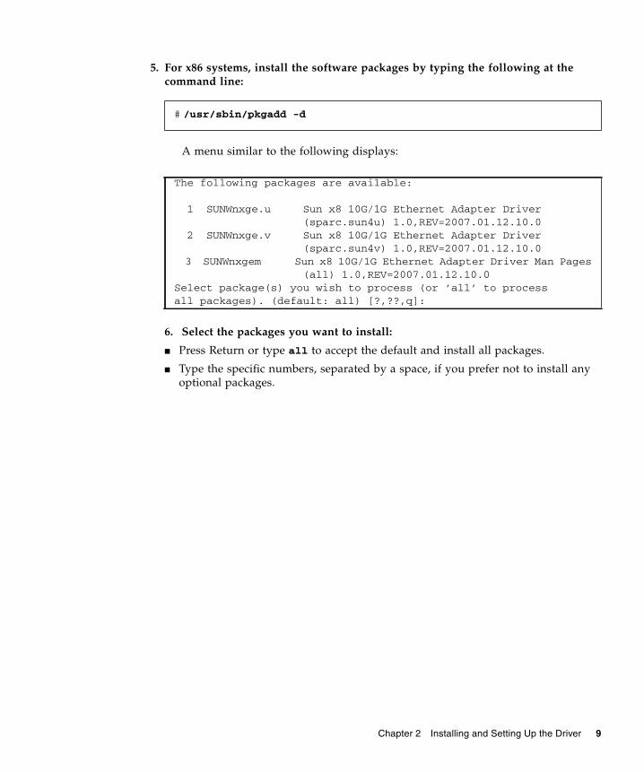
5. For x86 systems, install the software packages by typing the following at thecommand line:
A menu similar to the following displays:
6. Select the packages you want to install:
■ Press Return or type all to accept the default and install all packages.
■ Type the specific numbers, separated by a space, if you prefer not to install anyoptional packages.
# /usr/sbin/pkgadd -d
The following packages are available:
1 SUNWnxge.u Sun x8 10G/1G Ethernet Adapter Driver (sparc.sun4u) 1.0,REV=2007.01.12.10.0 2 SUNWnxge.v Sun x8 10G/1G Ethernet Adapter Driver (sparc.sun4v) 1.0,REV=2007.01.12.10.03 SUNWnxgem Sun x8 10G/1G Ethernet Adapter Driver Man Pages
(all) 1.0,REV=2007.01.12.10.0Select package(s) you wish to process (or ’all’ to processall packages). (default: all) [?,??,q]:
Chapter 2 Installing and Setting Up the Driver 9

7. Verify that the nxge driver is installed on the system:
▼ To Remove the Driver From a Solaris SPARCPlatform1. Determine the driver packages:
2. Remove the driver packages:
Sun x8 10G Ethernet Adapter Driver(sparc.sun4v) 1.0,REV=2007.01.06.10.0Copyright 2007 Sun Microsystems, Inc. All rights reserved.Use is subject to license terms.## Executing checkinstall script.Using </> as the package base directory.## Processing package information.## Processing system information. 8 package pathnames are already properly installed.## Verifying package dependencies.## Verifying disk space requirements.## Checking for conflicts with packages already installed.## Checking for setuid/setgid programs.
This package contains scripts which will be executed with super-userpermission during the process of installing this package.
Do you want to continue with the installation of <SUNWnxge> [y,n,?] y
Installing Sun x8 10G Ethernet Adapter Driver as <SUNWnxge>
## Installing part 1 of 1./platform/sun4v/kernel/drv/sparcv9/nxge[ verifying class <none> ][ verifying class <preserve> ]## Executing postinstall script.
Installation of <SUNWnxge> was successful.
# pkginfo | grep SUNWnxgesystem SUNWnxge Sun x8 10G Ethernet Adapter Driver
# pkgrm SUNWnxge plus any other packages from the previous command
10 Sun Quad GbE UTP x8 PCIe ExpressModule User’s Guide • December 2009

Downloading and Installing the Driveron a Linux Platform
1. Login to your system.
2. Download the driver RPM for your operating system:
http://www.sun.com/download/products.xml?id=44eb1efd
For example:
3. Discover the network interfaces before adding the package by using theifconfig -a command:
4. Use the rpm tool to install the driver on SuSe and RedHat Linux.
nxge-1.0-1.x86_64.rpm
# ifconfig -a |grep etheth0 Link encap:Ethernet HWaddr 00:14:4F:20:F1:DCeth1 Link encap:Ethernet HWaddr 00:14:4F:20:F1:DDeth2 Link encap:Ethernet HWaddr 00:14:4F:20:F1:DEeth3 Link encap:Ethernet HWaddr 00:14:4F:20:F1:DF
# rpm -ivh /tmp/RHEL4U4-large/RPMS/x86_64/nxge-1.0-1.x86_64.rpmPreparing... ###########################################1:nxge ###########################################
Chapter 2 Installing and Setting Up the Driver 11

Note – In RHEL5.0 and later releases, the driver is packaged in the kmod driverbinary package format. This packaging allows forward and backward driver binarycompatibility within the same flavors of RHEL5 releases. Driver packages nxgeversion 2.0.0 and later are not compatible with the earlier nxge-1.x-x releases. Toupgrade from 1.x-x to 2.x.x rpm package, it is necessary to remove nxge-1.x-x package before installing the 2.x.x package.
The RHEL5 nxge 2.x.x kmod package contains two separate packages: One for thedriver and another one for applications like nxge_config. You must install both ofthe following packages:
To install the complete package, enter the following:
To ensure that the driver is loaded after the rpm installation, enter the following:
5. Verify the new network interface instances corresponding to the Sun Quad GbEUTP x8 PCIe ExpressModule:
The Sun Quad GbE UTP x8 PCIe ExpressModule instances, eth4 and eth5, areshown in bold italics.
6. Add the nxge interfaces to the /etc/modules.conf file to automatically loadthe driver after system reboot:
kmod-nxge-rhel-2.0-1.x86_64.rpm (driver binary package)nxge-apps-rhel-2.0-1.x86_64.rpm (application package)
# rpm -ivh nxge-apps-rhel-2.0-1.x86_64.rpm kmod-nxge-rhel-2.0-1.x86_64.rpm
# modprobe nxge
# ifconfig -a |grep etheth0 Link encap:Ethernet HWaddr 00:14:4F:20:F1:DCeth1 Link encap:Ethernet HWaddr 00:14:4F:20:F1:DDeth2 Link encap:Ethernet HWaddr 00:14:4F:20:F1:DEeth3 Link encap:Ethernet HWaddr 00:14:4F:20:F1:DFeth4 Link encap:Ethernet HWaddr 00:14:4F:6C:78:E8eth5 Link encap:Ethernet HWaddr 00:14:4F:6C:78:E9
alias eth4 nxgealias eth5 nxge
12 Sun Quad GbE UTP x8 PCIe ExpressModule User’s Guide • December 2009

7. Use the ethtool command to check the parameter configurations that apply tothe nxge driver.
▼ To Remove the Driver From a Linux Platform● To remove the driver packages from a Linux Platform use the rpm -e command:
(For 10G)# ethtool -i eth4driver: nxgeversion: 2.0.1firmware-version: 2XGF PXE1.47 FCode 3.9 07/04/24bus-info: 0000:84:00.0
(Equivalent for 1G)# ethtool -i eth4driver: nxgeversion: 2.0.1firmware-version: QGC PXE1.47 FCode 3.9 07/04/24bus-info: 0000:02:00.2
# rpm -e nxge-1.0-1
Chapter 2 Installing and Setting Up the Driver 13

14 Sun Quad GbE UTP x8 PCIe ExpressModule User’s Guide • December 2009

CHAPTER 3
Installing the ExpressModule
This chapter describes how to install the Sun Quad GbE UTP x8 PCIeExpressModule in your system and verify that it has been installed correctly.
This chapter contains the following section:
■ “Installing the ExpressModule” on page 15
■ “Verifying the Hardware Installation” on page 18
Installing the ExpressModuleIf you are installing the Sun Quad GbE UTP x8 PCIe ExpressModule into a machinerunning Solaris 10, you must install the software before you install the hardware.
The following instructions describe the basic tasks required to install theExpressModule. Refer to your system installation or service manual for detailedExpressModule installation instructions.
Note – To maintain proper cooling for the ExpressModule in your chassis, allExpressModule slots must be filled with either operating ExpressModules or fillerpanels.
▼ To Install the ExpressModule1. Halt and power off your system.
2. Power off all peripherals connected to your system.
15

3. Attach the adhesive copper strip of the antistatic wrist strap to the metal casingof the power supply. Wrap the other end twice around your wrist, with theadhesive side against your skin.
4. Remove the filler panel from the ExpressModule opening.
5. Open the latch on the ExpressModule.
16 Sun Quad GbE UTP x8 PCIe ExpressModule User’s Guide • December 2009

6. Align the ExpressModule with the vacant ExpressModule slot (1).
Ensure that the ExpressModule’s indicator lights on the front panel are facingtoward you and that the ExpressModule ejector lever on the bottom is fullyopened.
7. Slide the ExpressModule into the vacant ExpressModule chassis slot until theejector lever engages and starts to close (2).
Failure to align the ExpressModule correctly can result in damage with theExpressModule’s internal connection to the chassis midplane.
8. Complete the installation by closing the ejector lever until the latch snaps intoplace (3).
Chapter 3 Installing the ExpressModule 17

Caution – Do not use excessive force when installing the ExpressModule into theslot. You might damage the ExpressModule’s connector. If the ExpressModule doesnot seat properly when you apply even pressure, remove the and carefully reinstallthe ExpressModule.
9. Detach the wrist strap.
10. Connect the Ethernet cables.
Verifying the Hardware InstallationAfter you have installed the ExpressModule, but before you boot your system,perform the following tasks to verify the installation. Refer to the your Solarisdocumentation for the detailed instructions.
18 Sun Quad GbE UTP x8 PCIe ExpressModule User’s Guide • December 2009

▼ To Verify the Hardware Installation1. Power on the system, and when the banner appears, press the Stop-A key
sequence to interrupt the boot process and display the OpenBoot (ok) prompt.
2. List the network devices on your system.
Checking the .properties output for each device is the surest way to identifythe device. Since the Sun Quad GbE UTP x8 PCIe ExpressModule has four ports,the show-nets command displays four lines for the ExpressModule, usually/pci@7c0/pci@0/pci@8 or /pci@7c0/pci@0/pci@9 correspond to PCIeslots, so look at those devices first.
Note – If you do not see the device listed, check that the ExpressModule is properlyseated. If necessary, reinstall the ExpressModule.
3. View the device that you installed.
Using the previous example, type:
ok show-netsa) /pci@7c0/pci@0/pci@9/network@0,3b) /pci@7c0/pci@0/pci@9/network@0,2c) /pci@7c0/pci@0/pci@9/network@0,1d) /pci@7c0/pci@0/pci@9/network@0e) /pci@7c0/pci@0/pci@8/network@0,1f) /pci@7c0/pci@0/pci@8/network@0g) /pci@7c0/pci@0/pci@2/network@0,1h) /pci@7c0/pci@0/pci@2/network@0i) /pci@780/pci@0/pci@1/network@0,1j) /pci@780/pci@0/pci@1/network@0m) MORE SELECTIONSq) NO SELECTION
a) /pci@7c0/pci@0/pci@9/network@0,3b) /pci@7c0/pci@0/pci@9/network@0,2c) /pci@7c0/pci@0/pci@9/network@0,1d) /pci@7c0/pci@0/pci@9/network@0
ok cd /pci@7c0/pci@0/pci@9/network@0
Chapter 3 Installing the ExpressModule 19

4. View the .properties file for a list of device properties.
The .properties command displays the specific information about the installedExpressModule. For this ExpressModule, your output will be similar to thefollowing:
5. Type the following when you finish looking at the .properties values:
ok .propertiesassigned-addresses 82770010 00000000 21000000 0000000001000000
82770018 00000000 20300000 00000000 0000800082770020 00000000 20308000 00000000 0000800082770030 00000000 20400000 00000000 00100000
local-mac-address 00 14 4f 83 5b 9aphy-type mifreg 00770000 00000000 00000000 00000000 00000000
03770010 00000000 00000000 00000000 0100000003770018 00000000 00000000 00000000 0000800003770020 00000000 00000000 00000000 0000800002770030 00000000 00000000 00000000 00100000
version QGC-PEM 1G Ethernet Adapter FCode 3.907/04/24board-model 501-7765-02model SUNW,pcie-qgc-pemcompatible pciex108e,abcd.108e.0.1 pciex108e,abcd.108e.0 pciex108e,abcd.1 pciex108e,abcd pciexclass,020000 pciexclass,0200address-bits 00000030max-frame-size 00002400network-interface-type ethernetdevice_type networkname networkfcode-rom-offset 00007a00interrupts 00000001cache-line-size 00000010class-code 00020000subsystem-vendor-id 0000108erevision-id 00000001device-id 0000abcdvendor-id 0000108e
ok device-end
20 Sun Quad GbE UTP x8 PCIe ExpressModule User’s Guide • December 2009

▼ To Reboot the SystemAfter verifying the ExpressModule installation, use the boot -r command toperform a reconfiguration boot on your system.
● Type the following
ok boot -r
Chapter 3 Installing the ExpressModule 21

22 Sun Quad GbE UTP x8 PCIe ExpressModule User’s Guide • December 2009

CHAPTER 4
Network Configuration
This chapter describes how to configure the network host files after you install theExpressModule on your system. This chapter also describes how to set up a GigabitEthernet network on a diskless client and install the Solaris Operating System over aGigabit Ethernet network.
This chapter contains the following sections:
■ “Configuring the Network Host Files” on page 23
■ “Setting Up a Gigabit Ethernet Port on a Diskless Client System” on page 25
■ “Installing the Solaris Operating System Over a Gigabit Ethernet Network” onpage 27
Configuring the Network Host FilesAfter installing the driver software, you must create a hostname.nxgenumber filefor the ExpressModule’s Ethernet interface. You must also create both an IP addressand a host name for the ExpressModule’s Ethernet interface in the /etc/hosts file.
Note – To preserve nxge instance numbers for interfaces between reboots, only oneproduct that uses the nxge driver can be used in a given slot. For example, numberscan change if between a series of reboots, a Sun Quad GbE UTP x8 PCIeExpressModule in one slot is removed and replaced by a different nxge driver-basednetwork interface product, and later a Sun Quad GbE UTP x8 PCIe ExpressModuleis reinstalled into that same slot.
23

1. At the command line, use the grep command to search the/etc/path_to_inst file for nxge interfaces.
In this example, the device instance is from a Sun Quad GbE UTP x8 PCIeExpressModule installed in Slot 1. The instance numbers are shown in bolditalics.
Be sure to write down your device path and instance, which in the example is"/pci@7c0/pci@0/pci@9/network@0" 0. Your device path and instance willbe similar. You need this information to make changes to the nxge.conf file. See“Setting Parameters Using the nxge.conf File” on page 34.
2. Set up the ExpressModule’s nxge interface.
Use the ifconfig command to assign an IP address to the network interface.Type the following at the command line, replacing ip-address with theExpressModule’s IP address:
Refer to the ifconfig(1M) man page and the Solaris documentation for moreinformation.
3. (Optional) If you want a setup that remains the same after you reboot, createan /etc/hostname.nxgenumber file, where number is the instance number ofthe nxge interface you plan to use.
To use the ExpressModule’s nxge interface in the Step 1 example, create an/etc/hostname.nxge0 file, where 0 is the number of the nxge interface. If theinstance number were 1, the filename would be /etc/hostname.nxge1. Thefilename would be /etc/hostname.nxge2, for instance 2, and so on.
Do not create an /etc/hostname.nxgenumber file for a Sun Quad GbE UTP x8PCIe ExpressModule interface you plan to leave unused.
Follow these guidelines for the host name:
■ The /etc/hostname.nxgenumber file must contain the host name for theappropriate nxge interface.
■ The host name must have an IP address listed in the /etc/hosts file.
# grep nxge /etc/path_to_inst"/pci@7c0/pci@0/pci@9/network@0" 0 "nxge""/pci@7c0/pci@0/pci@9/network@0,1" 1 "nxge""/pci@7c0/pci@0/pci@9/network@0,2" 2 "nxge""/pci@7c0/pci@0/pci@9/network@0,3" 3 "nxge"
# ifconfig nxge0 plumb ip-address up
24 Sun Quad GbE UTP x8 PCIe ExpressModule User’s Guide • December 2009

■ The host name must be different from any other host name of any other interface,for example: /etc/hostname.nxge0 and /etc/hostname.nxge1 cannot sharethe same host name.
The following example shows the /etc/hostname.nxgenumber file required fora system called zardoz that has an Sun Quad GbE UTP x8 PCIe ExpressModule.Note the system name changes for each interface.
4. Create an appropriate entry in the /etc/hosts file for each active nxgeinterface.
For example:
Setting Up a Gigabit Ethernet Port on aDiskless Client SystemBefore you can boot and operate a diskless client system across a Gigabit Ethernetport, you must first install the Gigabit Ethernet software packages into the rootdirectory of the diskless client. You can find the Gigabit Ethernet software packagesat the following web site:
http://www.sun.com/products/networking/ethernet/index.html
# cat /etc/hostname.nxge0zardoz# cat /etc/hostname.nxge1zardoz-11# cat /etc/hostname.nxge2zardoz-12# cat /etc/hostname.nxge3zardoz-13
# cat /etc/hosts## Internet host table#127.0.0.1 localhost129.144.10.57 zardoz loghost129.144.11.83 zardoz-11129.144.12.92 zardoz-12129.144.13.45 zardoz-13
Chapter 4 Network Configuration 25

Refer to the Solaris Advanced Installation Guide and the System Administration Guidefor more information about installing and administering diskless client systems.
▼ To Set Up a Gigabit Ethernet Port on a DisklessClient1. Locate the root directory of the diskless client on the host server.
The root directory of the diskless client system is commonly installed in the hostserver’s /export/root/client-name directory, where client-name is the disklessclient’s host name. In this procedure, the root directory is:
2. Download the software for the ExpressModule onto the server’s drive.
3. Use the pkgadd -R command to install the software packages to the disklessclient’s root directory on the server.
Install the software packages to the client’s root directory.
4. Create a hostname.nxgenumber file in the diskless client’s root directory.
Create an /export/root/client-name/etc/hostname.nxgenumber file for theGigabit Ethernet interface. See “Configuring the Network Host Files” on page 23for instructions.
5. Edit the hosts file in the diskless client’s root directory.
Edit the /export/root/client-name/etc/hosts file to include the IP address ofthe Gigabit Ethernet interface. See “Configuring the Network Host Files” onpage 23 for instructions.
6. Set the MAC address on the server side and rebuild the device tree if you wantto boot from the Gigabit Ethernet port.
7. Boot the diskless client from the Gigabit Ethernet port:
/export/root/client-name
ok pkgadd -R
ok boot path-to-device:link-param
26 Sun Quad GbE UTP x8 PCIe ExpressModule User’s Guide • December 2009
Installing the Solaris Operating SystemOver a Gigabit Ethernet NetworkThe Solaris Advanced Installation Guide describes the full procedure for installing theSolaris Operating System over the network. The following procedure assumes thatyou have created an install server, which contains the image of the Solaris CD, andthat you have set up the client system to be installed over the network.
Before you can install the Solaris Operating System on a client system with a GigabitEthernet ExpressModule, you must first add the Gigabit Ethernet software packagesto the install server. See Chapter 2 for the location of these software packages.
Note – Refer to the Solaris Advanced Installation Guide for more information aboutinstalling the Solaris Operating System over the network.
▼ To Install the Solaris Operating System Over aGigabit Ethernet Network1. Prepare the install server and client system to install the Solaris Operating
System over the network.
The Solaris Advanced Installation Guide describes how to create the install serverand set up the client systems.
Note – If you want to install the client system over a network that is not part of thesame subnet, you must also create a boot server. The Solaris Advanced InstallationGuide describes how to create a boot server.
Chapter 4 Network Configuration 27

2. Find the root directory of the client system.
The client system’s root directory can be found in the install server’s/etc/bootparams file. Use the grep command to search this file for the rootdirectory.
In this example, the root directory for the Solaris 10 client is /netinstall. InStep 4, you would replace root-directory with /netinstall.
Note – If the root directory is not found in the /etc/bootparams file, refer to theSolaris Advanced Installation Guide for configuration instructions.
3. Download the nxge driver onto the install server’s hard drive.
The package is a folder SUNWnxge.v or SUNWnxge.u, which you can downloadfrom the following web site:
http://www.sun.com/products/networking/ethernet/index.html
4. On the install server, install the nxge software to the client’s root directory, asdetermined in Step 2.
Replace root-directory with the location of the client’s root directory.
Note – Perform the following steps on the client system.
5. Shut down and halt the client system.
Use the shutdown command to obtain the OpenBoot (ok) prompt.
# grep client-name /etc/bootparamsclient_name root=server-name:/netinstall/Solaris_10/Tools/Bootinstall=server-name:/netinstall boottype=:in rootopts=:rsize=32768
# cd location where you downloaded the packages# ls SUNWnxge*# pkgadd -R root-directory/Solaris_10/Tools/Boot -d . SUNWnxge.v
# shutdown -i0 -g0 -y. . .(shutdown command messages omitted). . .ok
28 Sun Quad GbE UTP x8 PCIe ExpressModule User’s Guide • December 2009

6. At the ok prompt, use the show-nets command to find the device path of theGigabit Ethernet device.
The show-nets command lists the system devices. You should see the full pathsand names of the network devices, similar to the example below.
7. At the ok prompt, boot the client system using the full device path of theGigabit Ethernet device. For example:
8. Proceed with the Solaris Operating System installation.
Refer to the Solaris Advanced Installation Guide for more information aboutinstalling the Solaris Operating System over the network.
9. After installing the Solaris Operating System, install the nxge driver softwareon the client system.
The software installed in Step 4 is required to boot the client system over theGigabit Ethernet interface. You now need to install the software in order for theoperating system to use the client’s Gigabit Ethernet interfaces in normaloperation.
Before installing the nxge driver, ensure that the client system does not alreadyhave the driver installed. Use the pkginfo command to see if the nxge softwarepackages are installed on the client system.
■ If the software is installed, the previous command will return the package nameyou typed in. In that case, skip to Step 10.
ok show-netsa) /pci@7c0/pci@0/pci@9/network@0,3b) /pci@7c0/pci@0/pci@9/network@0,2c) /pci@7c0/pci@0/pci@9/network@0,1d) /pci@7c0/pci@0/pci@9/network@0e) /pci@7c0/pci@0/pci@8/network@0,1f) /pci@7c0/pci@0/pci@8/network@0g) /pci@7c0/pci@0/pci@2/network@0,1h) /pci@7c0/pci@0/pci@2/network@0i) /pci@780/pci@0/pci@1/network@0,1j) /pci@780/pci@0/pci@1/network@0m) MORE SELECTIONSq) NO SELECTIONEnter Selection, q to quit:
ok boot /pci@7c0/pci@0/pci@9/network@0
# pkginfo | grep SUNWnxge
Chapter 4 Network Configuration 29

■ If the software is not installed, install the software from the download center.
See Chapter 2 for instructions on installing the required software packages.
10. Confirm that the network host files have been configured correctly during theSolaris installation.
Although the Solaris software installation creates the client’s networkconfiguration files, you might need to edit these files to match your specificnetworking environment. See “Configuring the Network Host Files” on page 23for more information about editing these files.
11. Show configuration information for all data-links or the specified data-link.
By default, the system is configured to have one data-link for each knownnetwork device.
# dladm show-deve1000g0 link: up speed: 1000 Mbps duplex: fulle1000g1 link: down speed: 0 Mbps duplex: halfnxge2 link: up speed: 1000 Mbps duplex: fullnxge3 link: up speed: 1000 Mbps duplex: fullnxge4 link: up speed: 1000 Mbps duplex: fullnxge5 link: up speed: 1000 Mbps duplex: fulle1000g2 link: down speed: 0 Mbps duplex: halfe1000g3 link: down speed: 0 Mbps duplex: half
30 Sun Quad GbE UTP x8 PCIe ExpressModule User’s Guide • December 2009

CHAPTER 5
Configuring the nxgeDevice DriverParameters
The nxge device driver controls the Sun Quad Gigabit Ethernet interfaces. You canmanually set the nxge driver parameters to customize each device in your system.
This chapter lists the available device driver parameters and describes how you canset these parameters.
■ “nxge Hardware and Software Overview” on page 31
■ “Setting nxge Driver Parameters on a Solaris Platform” on page 32
■ “Setting Parameters Using the ndd Utility” on page 32
■ “Setting Parameters Using the nxge.conf File” on page 34
nxge Hardware and Software OverviewThe Sun Quad GbE UTP x8 PCIe ExpressModule provides four Gigabit full-duplexnetworking interfaces. The device driver automatically sets the link speed to 1000Mbit/sec and conforms to the IEEE 802.3ad Ethernet standard. Each interface has 4receive DMA channels and 6 transmit DMA channels to allow for parallel processingof the packets.
The Sun Quad GbE UTP x8 PCIe ExpressModule extends CPU and OS parallelism tonetworking with its support for hardware-based flow classification and multipleDMAs. Using CPU thread affinity to bind a given flow to a specific CPU thread, theExpressModule enables a one-to-one correlation of Rx and Tx packets across thesame TCP connection. This can help avoid cross-calls and context switching todeliver greater performance while reducing the need for CPU resources to supportI/O processing. The Sun Quad GbE UTP x8 PCIe ExpressModule uses the Suninnovative MAC controller.
31

Setting nxge Driver Parameters on aSolaris PlatformYou can set the nxge device driver parameters in two ways:
■ Using the ndd utility
■ Using the nxge.conf file
If you use the ndd utility, the parameters are valid only until you reboot the system.This method is good for testing parameter settings.
▼ To Set the Driver ParametersTo set parameters so they remain in effect after you reboot the system, perform thefollowing procedure:
1. Create an nxge.conf file:
2. Add parameter values to this file when you need to set a particular parameterfor a device in the system.
Setting Parameters Using the ndd UtilityUse the ndd utility to configure parameters that are valid until you reboot thesystem.
The following sections describe how you can use the nxge driver and the ndd utilityto modify (with the -set option) or display (without the -set option) theparameters for each nxge device.
Noninteractive and Interactive ModesYou can use the ndd utility in two modes:
■ Noninteractive
/platform/sun4u/kernel/drv/nxge.conf
32 Sun Quad GbE UTP x8 PCIe ExpressModule User’s Guide • December 2009

■ Interactive
In Noninteractive mode, you invoke the utility to execute a specific command. Oncethe command is executed, you exit the utility. In Interactive mode, you can use theutility to get or set more than one parameter value. Refer to the ndd(1M) man pagefor more information.
▼ To Specify Device Instances for the ndd Utility
Before you use the ndd utility to get or set a parameter for a nxge device, you mustspecify the device instance for the utility.
1. Check the /etc/path_to_inst file to identify the instance associated with aparticular device.
▼ To Specify Parameter Values Using the ndd Utility
This section describes how to modify and display parameter values.
1. Use the -set option to modify a parameter.
If you invoke the ndd utility with the -set option, the utility passes value, whichmust be specified, down to the named /dev/nxgedriver-instance, and assigns thevalue to the parameter:
where number is the driver instance, for example /dev/nxge0, /dev/nxge1.
2. Display the value of a parameter by specifying the parameter name andomitting the value.
When you omit the -set option, the utility queries the named driver instance,retrieves the value associated with the specified parameter, and prints it:
# grep nxge /etc/path_to_inst"/pci@7c0/pci@0/pci@9/network@0" 0 "nxge""/pci@7c0/pci@0/pci@9/network@0,1" 1 "nxge""/pci@7c0/pci@0/pci@9/network@0,2" 2 "nxge""/pci@7c0/pci@0/pci@9/network@0,3" 3 "nxge"
# ndd -set /dev/nxgenumber parameter-value
# ndd /dev/nxgenumber parameter
Chapter 5 Configuring the nxge Device Driver Parameters 33

▼ To Use the ndd Utility in Interactive Mode
1. Modify a parameter value in interactive mode by specifying ndd/dev/nxgenumber:
After you enter the parameter name, the ndd utility prompts you for the parametervalue.
2. List all the parameters supported by the nxge driver, by typing ?.
Setting Parameters Using thenxge.conf FileSpecify the driver parameter properties for each device by creating a nxge.conf filein the /platform/sun4v/kernel/drv/sparcv9/ directory. Use a nxge.conf filewhen you need to set a particular parameter for a device in the system.
# ndd /dev/nxge0name to get/set? (Enter the parameter name or ? to view allparameters)
# ndd /dev/nxge1 name to get/set ?? (read only)function_number (read only)adv_autoneg_cap (read and write)adv_10gfdx_cap (read and write)adv_1000fdx_cap (read and write)adv_100fdx_cap (read and write)adv_10fdx_cap (read and write)adv_pause_cap (read and write)accept_jumbo (read and write)rxdma_intr_time (read and write)rxdma_intr_pkts (read and write)class_opt_ipv4_tcp (read and write)class_opt_ipv4_udp (read and write)class_opt_ipv4_ah (read and write)class_opt_ipv4_sctp (read and write)class_opt_ipv6_tcp (read and write)class_opt_ipv6_udp (read and write)class_opt_ipv6_ah (read and write)class_opt_ipv6_sctp (read and write)
34 Sun Quad GbE UTP x8 PCIe ExpressModule User’s Guide • December 2009

The man pages for prtconf(1M) and driver.conf(4) include additional details.The next procedure shows an example of setting parameters in a nxge.conf file.
▼ To Access a Man Page● To access any man page, type the man command plus the name of the man
page.
For example, to access man pages for prtconf(1M), type:
▼ To Set Driver Parameters Using an nxge.confFile1. Obtain the hardware path names for the nxge devices in the device tree.
a. Check the /etc/driver_aliases file to identify the name associated witha particular device:
b. Locate the path names and the associated instance numbers in the/etc/path_to_inst file.
In this example:
■ The first part within the double quotes specifies the hardware node name in thedevice tree.
■ The number not enclosed in quotes is the instance number (shown in bolditalics for emphasis).
■ The last part in double quotes is the driver name.
% man prtconf
# grep nxge /etc/driver_aliasesnxge "pciex108e,abcd"
# grep nxge /etc/path_to_inst"/pci@7c0/pci@0/pci@9/network@0" 0 "nxge""/pci@7c0/pci@0/pci@9/network@0,1" 1 "nxge""/pci@7c0/pci@0/pci@9/network@0,2" 2 "nxge""/pci@7c0/pci@0/pci@9/network@0,3" 3 "nxge"
Chapter 5 Configuring the nxge Device Driver Parameters 35

To identify a PCIe device unambiguously in the nxge.conf file, use the name,parent name, and the unit-address for the device. Refer to the pci(4) man page formore information about the PCIe device specification.
In this example:
■ name = "pciex108e,abcd"
■ parent = "/pci@7c0/pci@0/pci@9/"
■ unit-address = "0"
2. Set the parameters for the nxge devices in the/platform/sun4u/kernel/drv/nxge.conf file.
■ The following parameters can be set using the/platform/sun4u/kernel/drv/nxge.conf file.
##---------------Link Configuration ----------------------# The link parameters depend on the type of the card# and the port.# 10 gigabit related parameters ( i.e adv_10gfdx_cap)# apply only to 10gigabit ports.# Half duplex is not supported on any NIU card.## adv-autoneg-cap# Advertise auto-negotiation capability.# default is 1# adv-autoneg-cap = 1;## adv_10gfdx_cap# Advertise 10gbps Full duplex capability.# default is 1# adv_10gfdx_cap = 1;## adv_1000fdx_cap# Advertise 1gbps Full duplex capability.# default is 1# adv_1000fdx_cap = 1;## adv_100fdx_cap# Advertise 100mbps Full duplex capability.# default is 1# adv_100fdx_cap = 1;## adv_10fdx_cap# Advertise 10mbps Full duplex capability.# default is 1# adv_10fdx_cap = 1;#
36 Sun Quad GbE UTP x8 PCIe ExpressModule User’s Guide • December 2009

# adv_asmpause_cap# Advertise Asymmetric pause capability.# default is 0# adv_asmpause_cap = 0;## adv_pause_cap# Advertise pause capability.# default is 1# adv_pause_cap = 1;###------- Jumbo frame support ---------------------------------# To enable jumbo support for all nxge interfaces,# accept_jumbo = 1;## To disable jumbo support for all nxge interfaces,# accept_jumbo = 0;## Default is 0. See the example at the end of this file for# enabling or disabling jumbo for a particular nxge interface.###------- Receive DMA Configuration ----------------------------## rxdma-intr-time# Interrupts after this number of NIU hardware ticks have# elapsed since the last packet was received.# A value of zero means no time blanking (Default = 8).## rxdma-intr-pkts# Interrupt after this number of packets have arrived since# the last packet was serviced. A value of zero indicates# no packet blanking (Default = 20).## Default Interrupt Blanking parameters.## rxdma-intr-time = 8;# rxdma-intr-pkts = 20;###------- Classification and Load Distribution Configuration ------## class-opt-****-***# These variables define how each IP class is configured.# Configuration options range from whether TCAM lookup ie# is enabled to flow hash generation.# This parameters also control how the flow template is# constructed and how packet is distributed within RDC# groups.
Chapter 5 Configuring the nxge Device Driver Parameters 37
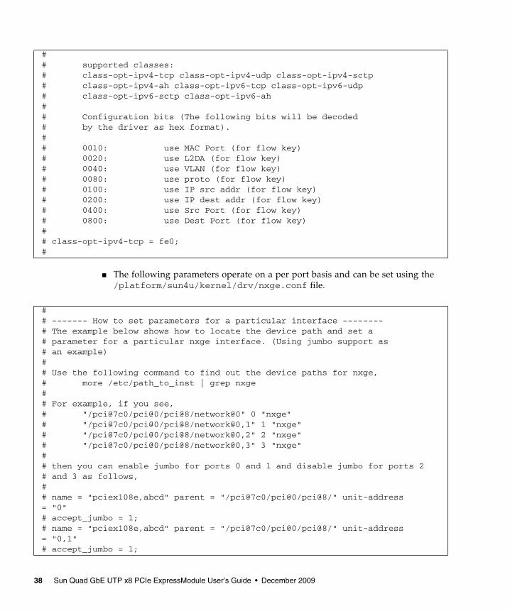
■ The following parameters operate on a per port basis and can be set using the/platform/sun4u/kernel/drv/nxge.conf file.
## supported classes:# class-opt-ipv4-tcp class-opt-ipv4-udp class-opt-ipv4-sctp# class-opt-ipv4-ah class-opt-ipv6-tcp class-opt-ipv6-udp# class-opt-ipv6-sctp class-opt-ipv6-ah## Configuration bits (The following bits will be decoded# by the driver as hex format).## 0010: use MAC Port (for flow key)# 0020: use L2DA (for flow key)# 0040: use VLAN (for flow key)# 0080: use proto (for flow key)# 0100: use IP src addr (for flow key)# 0200: use IP dest addr (for flow key)# 0400: use Src Port (for flow key)# 0800: use Dest Port (for flow key)## class-opt-ipv4-tcp = fe0;#
## ------- How to set parameters for a particular interface --------# The example below shows how to locate the device path and set a# parameter for a particular nxge interface. (Using jumbo support as# an example)## Use the following command to find out the device paths for nxge,# more /etc/path_to_inst | grep nxge## For example, if you see,# "/pci@7c0/pci@0/pci@8/network@0" 0 "nxge"# "/pci@7c0/pci@0/pci@8/network@0,1" 1 "nxge"# "/pci@7c0/pci@0/pci@8/network@0,2" 2 "nxge"# "/pci@7c0/pci@0/pci@8/network@0,3" 3 "nxge"## then you can enable jumbo for ports 0 and 1 and disable jumbo for ports 2# and 3 as follows,## name = "pciex108e,abcd" parent = "/pci@7c0/pci@0/pci@8/" unit-address= "0"# accept_jumbo = 1;# name = "pciex108e,abcd" parent = "/pci@7c0/pci@0/pci@8/" unit-address= "0,1"# accept_jumbo = 1;
38 Sun Quad GbE UTP x8 PCIe ExpressModule User’s Guide • December 2009

■ In the following example, the ports of all the Sun Quad GbE UTP x8 PCIeExpressModules are being set for load balancing Rx traffic based on IP sourceaddress. The default value is F80, indicating Rx load balancing based on IP 5-tuple. Notice the semicolon at the end of the last parameter.
The following example shows ports on two different cards being set. Only onenode needs to be specified.
3. Save the nxge.conf file.
# name = "pciex108e,abcd" parent = "/pci@7c0/pci@0/pci@8/" unit-address= "0,2"# accept_jumbo = 0;# name = "pciex108e,abcd" parent = "/pci@7c0/pci@0/pci@8/" unit-address= "0,3"# accept_jumbo = 0;
class-opt-ipv4-tcp = 100;class-opt-ipv4-udp = 100;
name = "pciex108e,abcd" parent = "/pci@780/pci@0/pci@8/" unit-address = "0" class-opt-ipv4-tcp = 0x100;
name = "pciex108e,abcd" parent = "/pci@7c0/pci@0/pci@9/" unit-address = "0" class-opt-ipv4-tcp = 0x40;
Chapter 5 Configuring the nxge Device Driver Parameters 39

40 Sun Quad GbE UTP x8 PCIe ExpressModule User’s Guide • December 2009

CHAPTER 6
Configuring the Jumbo FramesFeature
This chapter describes how to enable the Jumbo Frames feature. It contains thefollowing sections:
■ “Jumbo Frames Overview” on page 41
■ “Checking Jumbo Frames Configurations” on page 41
■ “Enabling Jumbo Frames in a Solaris SPARC Environment” on page 43
Jumbo Frames OverviewConfiguring Jumbo Frames enables the Ethernet interfaces to send and receivepackets larger than the standard 1500 bytes. However, the actual transfer sizedepends on the switch capability and the Ethernet ExpressModule driver capability.
Note – Refer to the documentation that came with your switch for exact commandsto configure Jumbo Frames support.
Checking Jumbo Frames ConfigurationsThe Jumbo Frames configuration checking occurs at Layer 2 or Layer 3, dependingon the configuration method.
41

▼ To Show the Driver Statistics in a SolarisEnvironment1. Use the kstat command to display driver statistics, for example:
The previous example diplays the receive packet counts on all of the eight receiveDMA channels on interface 1. Using the kstat nxge:1 shows all the statisticsthat the driver supports for that interface.
2. Use the kstat command to display driver statistics of a VLAN interface, forexample:.
# kstat nxge:1 |grep rdc_packets rdc_packets 798982054 rdc_packets 792546171 rdc_packets 803941759 rdc_packets 805674872
# kstat nxge:38001module: nxge instance: 38001name: nxge38001 class: net brdcstrcv 0 brdcstxmt 0 collisions 0 crtime 3842.493000352 ierrors 0 ifspeed 10000000000 ipackets 2116069805 ipackets64 6411037101 multircv 0 multixmt 0 norcvbuf 0 noxmtbuf 0 obytes 2757388874 obytes64 23380264381002 oerrors 0 opackets 37606022 opackets64 4332573318 rbytes 2937141290 rbytes64 47178857920554
42 Sun Quad GbE UTP x8 PCIe ExpressModule User’s Guide • December 2009

Enabling Jumbo Frames in a SolarisSPARC EnvironmentThis section describes how to enable Jumbo Frames in a Solaris SPARC environment.
▼ To Enable Jumbo Frames in a SolarisEnvironment Using nxge.conf
1. Enable Jumbo Frames for a port using the nxge.conf file.
For example:
2. Reboot the system:
▼ To Check Layer 2 Configuration● View the maximum transmission unit (MTU) configuration of an nxge instance
at any time with the kstat command:
The kstat mac_mtu variable represents the complete size of the Ethernet frame,which includes the Ethernet header, maximum payload, and crc. This valueshould be equal to or less than the MTU configured on the switch.
name = "pciex108e,abcd" parent = "/pci@7c0/pci@0/pci@9/"unit-address = "0"accept-jumbo=1;
% boot -r
# kstat nxge:0 | grep mac_mtu
Chapter 6 Configuring the Jumbo Frames Feature 43

▼ To Check Layer 3 Configuration● Check the Layer 3 configuration by using the dladm command with the show-
link option.
For example:
# dladm show-linke1000g0 type: non-vlan mtu: 1500 device: e1000g0e1000g1 type: non-vlan mtu: 1500 device: e1000g1e1000g2 type: non-vlan mtu: 1500 device: e1000g2e1000g3 type: non-vlan mtu: 1500 device: e1000g3nxge0 type: non-vlan mtu: 9194 device: nxge0nxge1 type: non-vlan mtu: 9194 device: nxge1nxge2 type: non-vlan mtu: 9194 device: nxge2nxge3 type: non-vlan mtu: 9194 device: nxge3nxge38001 type: vlan 38 mtu: 9194 device: nxge1
44 Sun Quad GbE UTP x8 PCIe ExpressModule User’s Guide • December 2009

CHAPTER 7
Configuring Link Aggregation
This chapter describes how to configure link aggregation. It contains the followingsections:
■ “Overview of Link Aggregation” on page 45
■ “Configuring Link Aggregation in a Solaris Environment” on page 46
Overview of Link AggregationLink Aggregation enables one or more network links to be aggregated together toform a link aggregation group. This link aggregation group appears to MAC clientsas a regular link. Link aggregation is defined by IEEE 802.3ad and it provides thefollowing benefits:
■ Increased bandwidth
■ Linearly incremental bandwidth
■ Load sharing
■ Automatic configuration
■ Rapid configuration and reconfiguration
■ Deterministic behavior
■ Low risk of duplication or misordering
■ Support of existing IEEE 802.3ad MAC clients
45

Configuring Link Aggregation in aSolaris EnvironmentThis section explains how to configure link aggregation in a Solaris environment.
▼ To Configure Link Aggregation in a SolarisEnvironment1. Aggregate nxge0, nxge1, nxge2, and nxge3 to form an aggregation and a
random number 33 as key.
a. Unplumb the interfaces to be aggregated:
b. Create a link-aggregation group with key 33 without specifying mode:
As the command returns, one line appears in the /etc/aggregation.conf fileand indicates that the default mode is off, as shown in the following example:
# ifconfig down unplumb nxge0# ifconfig down unplumb nxge1# ifconfig down unplumb nxge2# ifconfig down unplumb nxge3
# dladm create-aggr -d nxge0 -d nxge1 -d nxge2 -d nxge3 33
# tail -1 /etc/aggregation.conf# Use is subject to license terms.## ident "@(#)aggregation.conf 1.1 05/09/01 SMI"## DO NOT EDIT OR PARSE THIS FILE!## Use the dladm(1m) command to change the contents of this file.
33 L4 2 nxge4/0,nxge5/0 auto off short# dladm show-link aggr33aggr33 type: non-vlan mtu: 1500 aggregation: key 33
46 Sun Quad GbE UTP x8 PCIe ExpressModule User’s Guide • December 2009

2. Plumb up the interface aggrkey, which is aggr33 is this case:
3. Show link aggregation status again.
Now the state should become attached:
4. Use the dladm show-aggr -s command to display statistics:
# ifconfig aggr33 plumb# ifconfig aggr33aggr33: flags=1000842<BROADCAST,RUNNING,MULTICAST,IPv4> mtu 1500 index 8 inet 0.0.0.0 netmask 0 ether 0:3:ba:d8:9d:e8
# ifconfig aggr33 192.168.1.1/24 broadcast + up
# ifconfig aggr33aggr33: flags=1000843<UP,BROADCAST,RUNNING,MULTICAST,IPv4> mtu 1500 index 8 inet 192.168.1.1 netmask ffffff00 broadcast 192.168.1.255 ether 0:3:ba:d8:9d:e8
# dladm show-aggrkey: 33 (0x0021) policy: L4 address: 0:14:4f:6c:11:8 (auto) device address speed duplex link state
nxge0 0:14:4f:6c:11:8 1000 Mbps full up attachednxge1 0:14:4f:6c:11:9 1000 Mbps full up attachednxge2 0:14:4f:6c:11:a 1000 Mbps full up attachednxge3 0:14:4f:6c:11:b 1000 Mbps full up attached
# dladm show-aggr -skey: 33 ipackets rbytes opackets obytes %ipkts %opkts Total 380354 25872976 28 2648
nxge0 95089 6468278 7 662 25.0 25.0nxge1 95089 6468278 7 662 25.0 25.0nxge2 95089 6468278 7 662 25.0 25.0nxge3 95087 6468142 7 662 25.0 25.0
Chapter 7 Configuring Link Aggregation 47

5. Use the dladm show-aggr -L command to display LACP specificinformation:
For more information refer to the man pages for dladm, man dladm.
# dladm show-aggr -Lkey: 33 (0x0021) policy: L4 address: 0:14:4f:6c:11:8 (auto) LACP mode: off LACP timer: short device activity timeout aggregatable sync coll dist defaulted expired nxge0 passive short yes no no no no no nxge1 passive short yes no no no no no nxge2 passive short yes no no no no no nxge3 passive short yes no no no no no
48 Sun Quad GbE UTP x8 PCIe ExpressModule User’s Guide • December 2009

CHAPTER 8
Configuring VLANs
This chapter explains virtual local area networks (VLANs) in detail and providesconfiguration instructions and examples. It contains the following sections:
■ “VLAN” on page 49
■ “Configuring VLANs in a Solaris Environment” on page 51
VLANVLANs enable you to split your physical LAN into logical subparts, providing anessential tool for increasing the efficiency and flexibility of your network.
VLANs are commonly used to separate groups of network users into manageablebroadcast domains, to create logical segmentation of workgroups, and to enforcesecurity policies among each logical segment. Each defined VLAN behaves as itsown separate network, with its traffic and broadcasts isolated from the others,increasing the bandwidth efficiency within each logical group.
Although VLANs are commonly used to create individual broadcast domainsand/or separate IP subnets, it can be useful for a server to have a presence on morethan one VLAN simultaneously. Several Sun products support multiple VLANs on aper port or per interface basis, allowing very flexible network configurations.
With multiple VLANs on an ExpressModule, a server with a single ExpressModulecan have a logical presence on multiple IP subnets. By default, 128 VLANs can bedefined for each VLAN-aware ExpressModule on your server. However, you canincrease this number by changing the system parameters.
If your network does not require multiple VLANs, you can use the defaultconfiguration, in which case no further configuration is necessary.
FIGURE 8-1 shows an example network that uses VLANs.
49

FIGURE 8-1 Example of Servers Supporting Multiple VLANs With Tagging ExpressModules
The example network has the following features:
The physical LAN network consists of a switch, two servers, and five clients. TheLAN is logically organized into three different VLANs, each representing a differentIP subnet.
■ VLAN 1 is an IP subnet consisting of the Main Server, Client 3, and Client 5. Thisrepresents an engineering group.
■ VLAN 2 includes the Main Server, Clients 1 and 2 by means of a shared mediasegment, and Client 5. This is a software development group.
■ VLAN 3 includes the Main Server, the Accounting Server and Client 4. This is anaccounting group.
SoftwarePC 1(VLAN 2)
VLAN 1VLAN 2VLAN 3
SoftwarePC 2(VLAN 2)
AccountingServer(VLAN 3)
Main ServerAdapterGigabit/Tagged(All VLANs)
EngineeringPC 3(VLAN 1)
AccountingPC 4(VLAN 3)
Engineering/Software PC 5Adapter Gigabit/Tagged(VLAN 1 & 2)
Shared Media Segment
50 Sun Quad GbE UTP x8 PCIe ExpressModule User’s Guide • December 2009

The Main Server is a heavily used server that needs to be accessed from all VLANsand IP subnets. The server has a Sun Quad GbE UTP x8 PCIe ExpressModuleinstalled. All three IP subnets are accessed by means of the single physicalExpressModule interface. The server is attached to one of the switch’s GigabitEthernet ports, which is configured for VLANs 1, 2, and 3. Both the ExpressModuleand the connected switch port have tagging turned on. The tagging VLANcapabilities of both devices enable the sever to communicate on all three IP subnetsin this network, yet continue to maintain broadcast separation among the threesubnets. The following list describes the components of this network:
■ The Accounting Server is available to VLAN 3 only. The Accounting Server isisolated from all traffic on VLANs 1 and 2. The switch port connected to theserver has tagging turned off.
■ Clients 1 and 2 are attached to a shared media hub that is then connected to theswitch. Clients 1 and 2 belong to VLAN 2 only, and are logically in the same IPsubnet as the Main Server and Client 5. The switch port connected to this segmenthas tagging turned off.
■ Client 3 is a member of VLAN 1, and can communicate only with the Main Serverand Client 5. Tagging is not enabled on Client 3’s switch port.
■ Client 4 is a member of VLAN 3, and can communicate only with the servers.Tagging is not enabled on Client 4’s switch port.
■ Client 5 is a member of both VLANs 1 and 2, and has a Sun Quad GbE UTP x8PCIe ExpressModule installed. It is connected to switch port 10. Both theExpressModule and the switch port are configured for VLANs 1 and 2 and havetagging enabled.
VLAN tagging is only required to be enabled on switch ports that create trunk linksto other VLAN-aware Ethernet switches, or on ports connected to tag-capable end-stations, such as servers or workstations with VLAN-aware ExpressModules.
Configuring VLANs in a SolarisEnvironmentVLANs can be created according to various criteria, but each VLAN must beassigned a VLAN tag or VLAN ID (VID). The VID is a 12-bit identifier between 1and 4094 that identifies a unique VLAN. For each network interface (nxge0, nxge1,nxge2, and nxge3), 4094 possible VLAN IDs can be selected for each port.
Chapter 8 Configuring VLANs 51

Tagging an Ethernet frame requires adding a tag header to the frame. Insert theheader immediately following the destination MAC address and the source MACaddress. The tag header consists of two bytes of Ethernet Tag Protocol identifier(TPID, 0x8100) and two bytes of Tag Control Information (TCI). FIGURE 8-2 shows theEthernet tag header format.
FIGURE 8-2 Ethernet Tag Header Format
By default, a single VLAN is configured for every port. This groups all ports into thesame broadcast domain, just as if there were no VLANs at all, VLAN tagging for theswitch port is turned off.
Note – If you configure a VLAN virtual device for an ExpressModule, all traffic sentor received by that ExpressModule must be in VLAN-tagged format.
▼ To Configure Static VLANs1. Create one hostname.nxgenumber file for each VLAN that will be configured
for each ExpressModule on the server.
Use the following naming format, which includes both the VID and the physicalpoint of attachment (PPA):
VLAN logical PPA = 1000 * VID + Device PPAnxge123000 = 1000*123 + nxge
This format limits the maximum number of PPAs (instances) you can configure to1000 in the /etc/path_to_inst file.
For example, on a server with the Sun Quad GbE UTP x8 PCIe ExpressModulehaving an instance of 0, belonging to a member of two VLANs (with VID 123 and224) you would use nxge123000 and nxge224000, respectively, as the twoVLAN PPAs.
TPID (0x8100)
3 bits 1bit
12 bytes
User_priority CFI VID
Octet1
23
4
52 Sun Quad GbE UTP x8 PCIe ExpressModule User’s Guide • December 2009

2. Use the ifconfig(1M) to configure a VLAN virtual device.
For example:
The output of ifconfig -a on a system having VLAN devices nxge123000and nxge224000:
3. On the switch, set VLAN tagging and set VLAN ports to coincide with theVLANs you’ve set up on the server.
Using the examples in Step 2, you would set up VLAN ports 123 and 224 on theswitch.
Refer to the documentation that came with your switch for specific instructionsfor setting VLAN tagging and ports.
# ifconfig nxge123000 plumb up# ifconfig nxge224000 plumb up
# ifconfig -alo0: flags=1000849<UP,LOOPBACK,RUNNING,MULTICAST,IPv4> mtu 8232 index 1 inet 127.0.0.1 netmask ff000000hme0: flags=1000843<UP,BROADCAST,RUNNING,MULTICAST,IPv4> mtu 1500 index 2 inet 129.144.131.91 netmask ffffff00 broadcast 129.144.131.255 ether 8:0:20:a4:4f:b8nxge123000: flags=1000843<UP,BROADCAST,RUNNING,MULTICAST,IPv4> mtu 1500 index 3 inet 199.199.123.3 netmask ffffff00 broadcast 199.199.123.255 ether 8:0:20:a4:4f:b8nxge224000: flags=1000843<UP,BROADCAST,RUNNING,MULTICAST,IPv4> mtu 1500 index 4 inet 199.199.224.3 netmask ffffff00 broadcast 199.199.224.225 ether 8:0:20:a4:4f:b8
Chapter 8 Configuring VLANs 53

54 Sun Quad GbE UTP x8 PCIe ExpressModule User’s Guide • December 2009
APPENDIX A
Specifications
This appendix lists the specifications for the Sun Quad GbE UTP x8 PCIe ExpressModule. Itcontains the following sections:
■ “Connectors” on page 55
■ “Performance Specifications” on page 57
■ “Physical Characteristics” on page 57
■ “Power Requirements” on page 58
ConnectorsFIGURE A-1 shows the connectors for the Sun Quad GbE UTP x8 PCIe ExpressModule.
55

FIGURE A-1 Sun GbE UTP x8 PCIe ExpressModule Connectors
The green LED indicates the link status and the yellow LED indicates the link activity.
56 Sun Quad GbE UTP x8 PCIe ExpressModule User’s Guide • December 2009
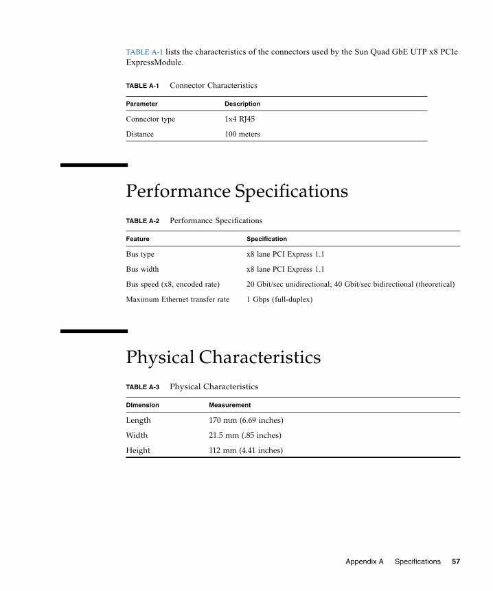
TABLE A-1 lists the characteristics of the connectors used by the Sun Quad GbE UTP x8 PCIeExpressModule.
Performance Specifications
Physical Characteristics
TABLE A-1 Connector Characteristics
Parameter Description
Connector type 1x4 RJ45
Distance 100 meters
TABLE A-2 Performance Specifications
Feature Specification
Bus type x8 lane PCI Express 1.1
Bus width x8 lane PCI Express 1.1
Bus speed (x8, encoded rate) 20 Gbit/sec unidirectional; 40 Gbit/sec bidirectional (theoretical)
Maximum Ethernet transfer rate 1 Gbps (full-duplex)
TABLE A-3 Physical Characteristics
Dimension Measurement
Length 170 mm (6.69 inches)
Width 21.5 mm (.85 inches)
Height 112 mm (4.41 inches)
Appendix A Specifications 57

Power RequirementsTABLE A-4 Power Requirements
Specification Measurement
Power consumption 14.31W RMS typical
17.56 W maximum
Voltage 12V @ 1.460A maximum (1.191A RMS typical)
3.3V @ 0.012A maximum (0.005A RMS typical)
58 Sun Quad GbE UTP x8 PCIe ExpressModule User’s Guide • December 2009

APPENDIX B
Diagnostic Software
This appendix provides an overview of the SunVTS diagnostic application andinstructions for updating the SunVTS software to recognize the ExpressModule. Thisappendix contains the following sections:
■ “SunVTS Diagnostic Software” on page 59
■ “Updating SunVTS to Recognize the ExpressModule” on page 60
■ “Using the SunVTS netlbtest” on page 61
SunVTS Diagnostic SoftwareThe SunVTS software executes multiple diagnostic hardware tests from a single userinterface and is used to verify the configuration and functionality of most hardwarecontrollers and devices. The SunVTS software operates primarily from a graphicaluser interface, enabling test parameters to be set quickly and easily while adiagnostic test operation is being performed.
You can use the SunVTS nettest diagnostic to test all of the networking interfaceson the system, including the interfaces on the ExpressModule.
To use the nettest diagnostic, you must have the SunVTS software installed onyour system. Refer to your Solaris documentation for installation instructions.
Refer to the SunVTS documentation (listed in TABLE B-1) for instructions on how torun and monitor the nettest diagnostic. These SunVTS documents are availableonline at the following URL:
http://www.sun.com/documentation
Search for title of the document you want to use.
59

Select the document for the Solaris release on your system.
Updating SunVTS to Recognize theExpressModuleUse SunVTS 6.3 or later. You need to update the SunVTS configuration to recognizethe ExpressModule.
▼ To Update SunVTS to Recognize theExpressModule1. Plug in a loopback cable.
2. Ensure that the SunVTS software and the nxge driver are installed on yoursystem.
3. Add the following lines to the /opt/SUNWvts/lib/conf/netlbtest.confand /opt/SUNWvts/lib/conf/nettest.conf files:
TABLE B-1 SunVTS Documentation
Title Description
SunVTS User’s Guide Describes the SunVTS diagnostic environment.
SunVTS Test Reference Manual Describes each SunVTS test (including the nettestnetlbtest) and describes the various test options andcommand-line arguments.
SunVTS Quick Reference Provides an overview of the user interface.
nxge nxge 10gbaseT
60 Sun Quad GbE UTP x8 PCIe ExpressModule User’s Guide • December 2009

Using the SunVTS netlbtestYou must have the Ethernet card and the device driver installed, a loopbackconnector in place, and Intervention mode enabled before running netlbtest.netlbtest cannot run if the network interface is connected to a live network, andrequires that the Ethernet device be configured offline before running the test. Usethe ifconfig(1M) command to halt the Ethernet device before runningnetlbtest.
▼ To Use the netlbtest
1. Ensure that the SunVTS software and the nxge driver are installed on yoursystem.
2. Plug in a loopback cable.
3. Unplumb the interface from the system, using the ifconfig command:
where instance is the instance number of the interface.
Refer to SunVTS documentation for instructions on how to run netlbtest.
# ifconfig nxgeinstance down# ifconfig nxgeinstance unplumb
Appendix B Diagnostic Software 61

62 Sun Quad GbE UTP x8 PCIe ExpressModule User’s Guide • December 2009
Index
Symbols/etc/hostname.nxgenumber file, 24
Aassigning an IP address, 24
Cconfiguring
network host files, 23nxge driver parameters, 31static VLAN, 52VLANs in a Solaris environment, 51
Ddiskless client system
setting up Gigabit Ethernet port on, 25documentation
related to the ExpressModule, xvSunVTS, 60URL, xvi
downloadingdriver for Solaris SPARC or x86 systems, 7
GGigabit Ethernet port
setting up on a diskless client, 26
Hhardware
components, 1requirements, 2
Iifconfig -a, 53ifconfig command, 24installing the ExpressModule, 15installing the Solaris OS over the network, 27
JJumbo Frames
checking configurations, 41enabling in a Solaris SPARC environment, 43
LLayer 2 configuration, checking, 43Layer 3 configuration, checking, 44link aggregation
overview, 45to configure in a Solaris OS, 46to show status, 47
Nndd utility, 33netlbtest, using, 61network host files
configuring, 23nxge device driver, 23
hardware and software overview, 31setting parameters using ndd, 32
Pparameter values
modifying and displaying, 33
63
patchesrecommended patch clusters, 5recommended security, 5
patches and updates, 5
Rrebooting the system, 21removing the driver, 10
Ssetting nxge driver parameters, 31setting parameters using nxge.conf, 32shipping kit contents, 1software requirements, 2Specifications
connectors, 55performance, 57physical, 57
SunVTSconfiguration, 60diagnostic application, 59documentation, 59updating to recognize the ExpressModule, 60
SUNW,nxge devices, 31
UURL
documentation, xvisupport, xvitraining, xvi
Vverify the installation, 18virtual device, 53VLAN
ID, 51naming format, 52overview, 49static configuring, 52
64 Sun Quad GbE UTP x8 PCIe ExpressModule User’s Guide • December 2009
Copyright © 2022 FDOKUMEN