Subcritical two-phase seawater convection near a dike
12
Sub-critical two-phase seawater convection near a dike Robert P. Lowell *, Wenyue Xu School of Earth and Atmospheric Sciences, Georgia Institute of Technology, Atlanta, GA 30332, USA Received 28 September 1998; accepted 13 October 1999 Abstract We address the circulation of hydrothermal seawater near an igneous dike emplaced in the oceanic crust. By using the two-phase finite difference hydrothermal code GTHM, we are able to treat the sub-critical two-phase flow that occurs just after emplacement as well as the later single-phase circulation, which occurs as the dike cools. We investigate the effects of bulk rock permeability and dike width. The simulations show that for a 2 m wide dike emplaced in country rock with uniform permeability of 10 39 m 2 , two-phase flow may occur briefly adjacent to the dike margin in a region that is less than 0.1 m across. The width of the two-phase region and the duration of two-phase flow vary inversely with permeability, but they increase as the dike width increases. During two-phase flow, the advective heat flux at the seafloor fluctuates about its mean and the temperature near the seafloor remains nearly constant. The mean heat flux increases with permeability, but is independent of dike width. The model is used in conjunction with chlorinity data from ‘A’ vent near 9‡N on the East Pacific Rise to indicate that the permeability there is V10 312 m 2 . The model suggests, however, that an additional heat source is required to account for the high-temperature vent fluids at 9‡N that have persisted for more than 3 years. The calculations also show that heat transport near a high permeability dike (i.e., v10 39 m 2 ) is consistent with the heat transport measured for the CoAxial event plumes. The calculations further suggest, however, that for a dike to generate an event plume, the zone of high permeability should be concentrated near the dike margin. ß 2000 Elsevier Science B.V. All rights reserved. Keywords: dikes; convection; hydrothermal conditions; numerical models; mid-ocean ridges 1. Introduction Seawater hydrothermal systems at ocean ridges are episodically impacted by magmatic events such as dike intrusions. When dike intrusion oc- curs, hydrothermal seawater near the 1200‡C magma undergoes phase transitions whose char- acter depends upon the subsurface pressure and temperature. The critical point for 3.2% salinity (Cl = 540 mmol/kg) seawater occurs at pressure p = 29.8 MPa (corresponding to a water depth of approximately 3000 m) and temperature T = 407‡C [1]. Thus at depths less than 3 km be- low sea level, the pressure is below the critical point, and boiling will yield a low-salinity and low-density vapor phase that tends to separate from the liquid phase as a result of its buoyancy. Phase transition of seawater at a depth greater than 3 km yields a high-density, high-salinity brine that condenses from the vapor phase. The brine tends to settle to the base of the system 0012-821X / 00 / $ ^ see front matter ß 2000 Elsevier Science B.V. All rights reserved. PII:S0012-821X(99)00275-7 * Corresponding author. Fax: +1-404-894-5638; E-mail: [email protected] Earth and Planetary Science Letters 174 (2000) 385^396 www.elsevier.com/locate/epsl
Transcript of Subcritical two-phase seawater convection near a dike

Sub-critical two-phase seawater convection near a dike
Robert P. Lowell *, Wenyue XuSchool of Earth and Atmospheric Sciences, Georgia Institute of Technology, Atlanta, GA 30332, USA
Received 28 September 1998; accepted 13 October 1999
Abstract
We address the circulation of hydrothermal seawater near an igneous dike emplaced in the oceanic crust. By using thetwo-phase finite difference hydrothermal code GTHM, we are able to treat the sub-critical two-phase flow that occursjust after emplacement as well as the later single-phase circulation, which occurs as the dike cools. We investigate theeffects of bulk rock permeability and dike width. The simulations show that for a 2 m wide dike emplaced in countryrock with uniform permeability of 1039 m2, two-phase flow may occur briefly adjacent to the dike margin in a regionthat is less than 0.1 m across. The width of the two-phase region and the duration of two-phase flow vary inversely withpermeability, but they increase as the dike width increases. During two-phase flow, the advective heat flux at theseafloor fluctuates about its mean and the temperature near the seafloor remains nearly constant. The mean heat fluxincreases with permeability, but is independent of dike width. The model is used in conjunction with chlorinity datafrom `A' vent near 9³N on the East Pacific Rise to indicate that the permeability there is V10312 m2. The modelsuggests, however, that an additional heat source is required to account for the high-temperature vent fluids at 9³N thathave persisted for more than 3 years. The calculations also show that heat transport near a high permeability dike (i.e.,v1039 m2) is consistent with the heat transport measured for the CoAxial event plumes. The calculations furthersuggest, however, that for a dike to generate an event plume, the zone of high permeability should be concentrated nearthe dike margin. ß 2000 Elsevier Science B.V. All rights reserved.
Keywords: dikes; convection; hydrothermal conditions; numerical models; mid-ocean ridges
1. Introduction
Seawater hydrothermal systems at ocean ridgesare episodically impacted by magmatic eventssuch as dike intrusions. When dike intrusion oc-curs, hydrothermal seawater near the 1200³Cmagma undergoes phase transitions whose char-acter depends upon the subsurface pressure and
temperature. The critical point for 3.2% salinity(Cl = 540 mmol/kg) seawater occurs at pressurep = 29.8 MPa (corresponding to a water depth ofapproximately 3000 m) and temperatureT = 407³C [1]. Thus at depths less than 3 km be-low sea level, the pressure is below the criticalpoint, and boiling will yield a low-salinity andlow-density vapor phase that tends to separatefrom the liquid phase as a result of its buoyancy.Phase transition of seawater at a depth greaterthan 3 km yields a high-density, high-salinitybrine that condenses from the vapor phase. Thebrine tends to settle to the base of the system
0012-821X / 00 / $ ^ see front matter ß 2000 Elsevier Science B.V. All rights reserved.PII: S 0 0 1 2 - 8 2 1 X ( 9 9 ) 0 0 2 7 5 - 7
* Corresponding author. Fax: +1-404-894-5638;E-mail: [email protected]
EPSL 5317 21-12-99
Earth and Planetary Science Letters 174 (2000) 385^396
www.elsevier.com/locate/epsl

under the action of gravity [2]. Thus just afterdike injection, one would expect to sample low-salinity £uid from sea£oor vents; whereas sometime later, as £uid that phase-separated at depthreaches the surface, the vent salinity may exceedthat of seawater. Eventually, as the dike cools andphase-separated £uid is £ushed from the system,the salinity of the vent £uid should return to nor-mal seawater values [3].
One example of evolving vent chlorinity isfound in the region between 9³ and 10³N on theEast Paci¢c Rise (EPR), where £uid from the `A'vent was sampled over a 2 week period followingthe eruptive event of April 1991 [4]. During thistime frame, vent temperatures increased from389³C to 403³C and silica concentration decreasedin a manner indicating the equilibration of sea-water with quartz at a depth of V200 m belowthe sea£oor. Chlorinity of the vent £uid was V35mmol/kg, consistent with sub-critical phase sepa-ration at a shallow depth beneath the sea£oor.Subsequent measurements [4] showed a declinein temperatures to 330³C, an increase in vent £uidchlorinity to V400 mmol/kg, and an increase insilica concentration in the vent £uid consistentwith deepening of the reaction zone to a depthof at least 500 m below the sea£oor. Data fromthe `A' vent are summarized in Table 1.
Another example of evolving vent chlorinitycomes from the `F' vent at 9³16.8PN on theEPR, where low-chlorinity £uids were sampledin 1991, and vent £uids in which the chlorinitywas V1.5 times that of seawater were sampledin 1994 [5].
Dikes also act as a local heat source for hydro-thermal circulation. Hydrothermal heat £ux may
increase signi¢cantly immediately following dikeinjection, perhaps resulting in an event plume[6]. As the dike cools, the heat £ux should decayto normal levels. An example of this is providedby the 1993 diking event at the CoAxial Site onthe Juan de Fuca Ridge, where an event plumewas followed by a chronic plume that decayeddramatically during the following years [7]
Liquid-phase hydrothermal circulation near adike-like intrusion has been treated by Chengand Minkowycz [8], Cheng and Pop [9], Pattersonand Lowell [10], Brikowski and Norton [11], andCherkaoui et al. [12]. Parmentier [13] and Chengand Verma [14] considered the boiling and theformation of steady-state vapor and liquid boun-dary layers ascending near a hot vertical plate. Todate there has been no modeling of two-phase£ow in a seawater system in which the evolutionof chlorinity has been considered.
The approach taken here most nearly resemblesthat of Cherkaoui et al. [12] who considered the¢nite heat content of the dike. Cherkaoui et al.,however, modeled only the decay of the heat £uxin the chronic plume. They did not consider theinitial period during which two-phase £ow mayhave occurred, nor did they attempt to modelthe initial event plume.
In this paper we examine the hydrothermalcooling of a dike injected at a shallow depth be-neath the sea£oor that includes the occurrence ofsub-critical two-phase £uid £ow. We investigatethe development and evolution of two-phase£ow near 2 m and 10 m wide dikes as a functionof crustal permeability. We consider the extremecases in which (1) the dike permeability is at leasttwo orders less than the country rock and (2) the
Table 1Data on `A' vent on the East Paci¢c Rise, near 9³Na
Date T(³C)
Si(mmol/kg)
Cl(mmol/kg)
Clbv(mmol/kg)
10 April 1991 390 7.16 80.3 [email protected] MPa17 April 1991 396 3.72 32.624 April 1991 403 2.72 45.2 49.1@27 MPa10 March 1992 332 18.8 28612 March 1994 334 16.5 398aFrom Von Damm et al., [4].bCalculated from Bischo¡ [21].
EPSL 5317 21-12-99
R.P. Lowell, W. Xu / Earth and Planetary Science Letters 174 (2000) 385^396386

dike initially has the same permeability as thecountry rock. We discuss the implications of theseresults for the formation of event plumes and thelater decay of the chronic plume above the dike.We also show that the observation of vapor-phase£ow at the `A' vent on the EPR near 9³N can beused to infer the subsurface permeability there.
2. Mathematical model
Two-phase (liquid^vapor) £uid £ow and heattransport in a porous medium can be describedby a set of conservation equations [15]. Symbolsare de¢ned in Table 2. Conservation of mass andenergy are expressed by:
D �P b �D t
� 9 W�q* l� q*
v� � Qm �1�
and
DD t�P bh� �13P �b rcrT � � 9 W�q* lhl� q
*vhv� �
9 W�V9T� �Qe �2�
respectively. Conservation of momentum for eachphase is expressed by Darcy's law. Thus:
q!l � 3kkrlb l
W l�9 p� b l g!� �3�
q!v � 3kkrvb v
W v�9 p� b v g!� �4�
The relative permeability functions krl and krv areexpressed as a function of saturation S using theCorey formulation with zero residual permeability[16]. Bulk density b and bulk enthalpy h are de-¢ned as:
b � Slb l � Svb v �5�
and
bh � Slb lhl � Svb vhv �6�
respectively. The volume saturation of the individ-
ual phases sums to unity. That is:
Sl � Sv � 1 �7�
In order to account for the salt transport withina sea£oor hydrothermal system a salt conserva-tion equation should be added to the above equa-tion set and the phase equilibrium of the NaCl^H2O system should also be considered [17]. Tosimplify the mathematical problem, we use themodi¢ed two-phase pure water ¢nite di¡erencecode GTHM based on the above equation set inwhich seawater is treated as a single component£uid, but with a seawater (3.2 wt% NaCl) criticalpoint [17]. In this approximation the transport ofsalt is neglected. This will not greatly change thedynamics and heat transfer properties of the sub-critical system but alleviates the problem of treat-ing phase separation in a multi-component £uidand tracking the transport of salt.
In GTHM thermodynamic properties of the
Table 2List of symbols used
Symbol Meaning Value
cr speci¢c heat of rock 950 J/kg-³Cg acceleration due to gravity 9.8 m/s2
h bulk enthalpy of £uidhl enthalpy of liquid phasehv enthalpy of vapor phasek permeability of medium 1039^10313 m2
kl relative permeability of liquid phasekv relative permeability of vapor phasep pressureql mass £ow rate of liquid phaseqv mass £ow rate of vapor phaseQe source/sink of energyQm source/sink of massSl volumetric saturation of liquidSv volumetric saturation of vaport timeT temperatureP porosity 0.1V e¡ective thermal conductivity 2.5 W/m-³CWl dynamic viscosity of liquid phaseWv dynamic viscosity of vapor phaseb bulk density of £uidbl density of liquid phasebv density of vapor phasebr density of rock 2.65U103 kg/m3
EPSL 5317 21-12-99
R.P. Lowell, W. Xu / Earth and Planetary Science Letters 174 (2000) 385^396 387

liquid are calculated assuming seawater salinity,whereas the properties of the vapor phase are ob-tained at the salinity of the conjugate phase of theliquid seawater using an equation of state devel-oped by Pitzer et al. [18^20] and data from Bis-cho¡ [21]. The viscosity of the liquid and vaporphases is calculated as a function of temperatureand density assuming the £uid is pure water byusing Kestin's equation [22].
The model (Fig. 1) consists of a two-dimension-al uniform £uid-saturated porous medium that is1 km in height and 1 km in width. The top is atthe sea£oor and a dike is emplaced with its center-line at the left-hand boundary of the model andits top set at 5 m below sea£oor. A uniform ther-mal conductivity 2.5 W/(m-³C) and uniform po-rosity of 0.1 were chosen for the whole system.The upper boundary was held at a constant pres-
Fig. 1. A schematic of the model geometry used in this pa-per. It consists of a medium with constant porosity and per-meability 1000 m highU2000 m wide with a dike intruded atthe center. The top of the dike is 5 m below the surface. Themodel is symmetric about the left vertical axis.
Fig. 2. Temperature, instantaneous heat £ux and cumulative heat output of hydrothermal venting near a cooling 2 m thick dikefor three di¡erent rock permeabilities as a function of time after dike emplacement. Temperature plotted is at the grid point adja-cent to the dike, where the mass £ow rate is the highest. Dike permeability is 10315 m2 for all three cases shown. Total heat out-put assumes the dike is 103 m along strike.
EPSL 5317 21-12-99
R.P. Lowell, W. Xu / Earth and Planetary Science Letters 174 (2000) 385^396388

sure of 18 MPa and an enthalpy of 30 kJ/kg(V2³C). At the bottom, zero mass £ux and aconstant heat £ux of 0.2 W/m2 were imposed.Zero mass and heat £uxes were prescribed acrossthe left and the right boundaries. The 18 MPapressure at the top boundary was chosen to assurethat the whole system was located within the sub-critical region of seawater. Heat transport in all ofthe simulated systems was convection-dominatedduring the time periods when two-phase £ow wassigni¢cant and the value of bottom heat £ow didnot have a signi¢cant e¡ect on the results. Theinitial pressure distribution was assumed to behydrostatic; and outside the dike we assumed aninitially linear steady-state temperature distribu-
tion that satis¢ed the top and bottom boundaryconditions. The £uid inside the dike was assumedto have and enthalpy of 5000 kJ/kg, which wasequivalent to V1157³C at 20 MPa and V1078³Cat 28 MPa. This is the maximum enthalpy thatcould be handled by GTHM. The dike itself wasassumed to have an initial temperature distribu-tion that is equal to that of the included £uid. Weneglected the latent heat of the dike, so eventhough we allowed a small amount of high-en-thalpy £uid to reside in the dike, the model under-estimates the heat content of a dike emplaced atits liquidus by about 30%. The permeability of thecountry rock was assumed to be uniform andrange between 1039 m2 and 10313 m2. The dike
Fig. 3. Vectors depicting mass £ow rate per unit area during a £uctuation in heat £ow (see Fig. 2, middle panel). The rock per-meability is 10311 m2. Only the three uppermost rows of grid points are shown and the vertical mass £ux vectors are reduced bya factor of 10. Maximum heat £ux occurs when the surface mass £ux at the grid point nearest the dike is greatest (at about8 days). At this time there is a relatively large inward, sub-horizontal mass £ux at a depth of around 20 m. The in£ux of cold£uid towards the dike causes the vertical mass £ux per unit area to decrease at day 11.
EPSL 5317 21-12-99
R.P. Lowell, W. Xu / Earth and Planetary Science Letters 174 (2000) 385^396 389

was assumed to have either a uniform permeabil-ity of 10315 m2 or the same permeability as thecountry rock.
To solve the set of Eqs. 1^7 for the boundaryand initial conditions and the model geometrydescribed above we had to balance the need toresolve two-phase £ow features near the dikewith the need for computational e¤ciency. Todo this, we set the horizontal grid spacing at0.1 m for the column closest to the dike, 0.2 mfor the next column, and 0.4 m, 0.8 m, 1.6 m and3.2 m for the four columns thereafter, respec-tively. The remaining horizontal grid points werespaced 500 m apart. The vertical grid spacing wasset at 5 m for the top row, 10 m for the next row,35 m and 50 m for the next two rows, respec-tively, and 100 m for the remaining rows. Thesehorizontal and vertical grids were selected afterseveral trial runs showed these grids capturedthe essential physics without requiring inordinate
computational time. Temperature, £ow rate, andadvective heat £ow were calculated for the rownext to the top row. More speci¢cally, the heat£ow was integrated to cover the top of the dikeand also to include the two 6.3 m wide areasalong each side of the dike, so that most of theupward advective heat transport across the sea-£oor was accounted for. Advective heat £ow iscalculated as the sum of the contribution fromboth liquid- and vapor-phase £uids.
3. Results
We ¢rst considered a dike 2 m in width em-placed into country rock in which the permeabil-ity was 1039, 10311, and 10313 m2, respectively.The dike permeability was set at 10315 m2. Fig.2 depicts the temperature of the £uid at the sea-£oor at the grid point exhibiting the highest £ow
Fig. 4. Plot of isotherms in ³C and contours of liquid saturation near a 2 m wide, low permeability dike for a rock permeabilityof 10311 m2 at selected times after dike emplacement. The thin two-phase zone within 10 cm of the dike margin is approximatelyoutlined by the 0.5 saturation contour.
EPSL 5317 21-12-99
R.P. Lowell, W. Xu / Earth and Planetary Science Letters 174 (2000) 385^396390

rate (i.e., adjacent to the dike wall), the instanta-neous heat £ow, and the cumulative heat outputas a function of time. Several items are apparentin Fig. 2. First, the occurrence of temperaturesgreater than 350^400³C for k = 10311 and 10313
m2 indicates that a zone of sub-critical two-phase£ow develops near the dike margin, whereas fork = 1039 m2 no two-phase £ow develops. Sec-ondly, there is a correlation between permeabilityand maximum heat £ux. Thirdly, for the casesexhibiting two-phase £ow, the heat £ux £uctuatesmarkedly about its mean during the period oftwo-phase £ow, exhibiting a slight maximumnear the end of the two-phase £ow period. Fi-nally, after two-phase £ow ceases, both temper-ature and £ow rate decline in a similar manner.
These results are not di¤cult to understandwithin the physical framework of the model. Atlower permeabilities, rapid heat transfer from the
dike to the adjacent £uid leads to boiling and theascent of both liquid and vapor phase as a resultof buoyancy. Because the temperature of the mix-ture stays relatively constant during two-phase£ow, the buoyant drive essentially comes fromthe di¡erence between the density of the coldfar-¢eld liquid phase and the density of the two-phase mixture near the dike. Because the advec-tive heat £ow depends upon the £ow rate andbecause, from Eqs. 3 and 4), the mass £ow rateof each phase is linearly proportional to the per-meability, it is not surprising that during two-phase £ow the heat £ux is correlated with thepermeability (see Fig. 2b). Once the two-phaseregime disappears, however, £ow of the liquidphase is driven by thermal buoyancy. As the sys-tem cools, this buoyancy decreases and both the£ow rate and temperature follow a monotonicdecay path.
Fig. 5. Same as Fig. 2, except that the dike is assumed to have the same permeability as the country rock. Temperature is plottedat the grid point above the dike, where the mass £ux is greatest
EPSL 5317 21-12-99
R.P. Lowell, W. Xu / Earth and Planetary Science Letters 174 (2000) 385^396 391

For k = 1039 m2, £uid £ow is so rapid that thedike margin quickly falls below the boiling pointof seawater. Careful examination of the computeroutput reveals that a maximum temperature ofabout 270³C is reached within less than 1 dayand the mass £ow rate is so great that £uid travelsthe 1 km vertical path in less than 1 day. More-over, because we assumed the country rock hasthe same permeability everywhere, cold £uid atsome distance from the dike is rapidly entrainedinto the ascending £uid. If the grid spacing at thedike margin were reduced from 0.1 m to 0.01 m,one would expect to capture a brief period of two-phase £ow near the dike.
Fig. 2 also shows that the heat £ux oscillatesduring the period of two-phase £ow. These £uc-tuations do not appear to be numerical instabil-ities. Careful examination of the calculated £uid£ow near the top of the dike reveals that as £uidnear the dike is brought to boiling, the vapor
phase separates and moves rapidly upwards be-cause of its low density. Somewhat colder £uidis then entrained towards the dike margin whereit mixes with £uid rising from below. Initially, theresulting two-phase mixture in denser than thevapor phase and the velocity decreases, loweringthe heat £ux. The denser, slower moving two-phase £uid becomes heated by conduction fromthe dike and again a vapor phase separates raisingthe heat £ux. The oscillations are more pro-nounced for the lower permeability case becausethe lower bulk upward £ow rate permits moretime for heating and phase separation e¡ects totake place. Fig. 3 shows the mass £ux fork = 10311 m2 over a few day interval during a£uctuation in heat £ux (see Fig. 2, middle panel).This ¢gure shows that smaller horizontal mass£ux towards the dike at a depth of about 25 mat day 6 is correlated with a larger mass £ux atthe surface at day 8. Similarly, the larger horizon-
Fig. 6. Same as Fig. 2, except that the dike is 10 m wide.
EPSL 5317 21-12-99
R.P. Lowell, W. Xu / Earth and Planetary Science Letters 174 (2000) 385^396392
tal mass £ux at depth at day 8 is re£ected in asmaller vertical mass £ux at the surface at day 11.
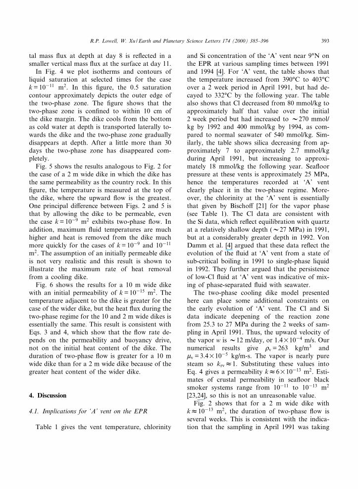
In Fig. 4 we plot isotherms and contours ofliquid saturation at selected times for the casek = 10311 m2. In this ¢gure, the 0.5 saturationcontour approximately depicts the outer edge ofthe two-phase zone. The ¢gure shows that thetwo-phase zone is con¢ned to within 10 cm ofthe dike margin. The dike cools from the bottomas cold water at depth is transported laterally to-wards the dike and the two-phase zone graduallydisappears at depth. After a little more than 30days the two-phase zone has disappeared com-pletely.
Fig. 5 shows the results analogous to Fig. 2 forthe case of a 2 m wide dike in which the dike hasthe same permeability as the country rock. In this¢gure, the temperature is measured at the top ofthe dike, where the upward £ow is the greatest.One principal di¡erence between Figs. 2 and 5 isthat by allowing the dike to be permeable, eventhe case k = 1039 m2 exhibits two-phase £ow. Inaddition, maximum £uid temperatures are muchhigher and heat is removed from the dike muchmore quickly for the cases of k = 1039 and 10311
m2. The assumption of an initially permeable dikeis not very realistic and this result is shown toillustrate the maximum rate of heat removalfrom a cooling dike.
Fig. 6 shows the results for a 10 m wide dikewith an initial permeability of k = 10315 m2. Thetemperature adjacent to the dike is greater for thecase of the wider dike, but the heat £ux during thetwo-phase regime for the 10 and 2 m wide dikes isessentially the same. This result is consistent withEqs. 3 and 4, which show that the £ow rate de-pends on the permeability and buoyancy drive,not on the initial heat content of the dike. Theduration of two-phase £ow is greater for a 10 mwide dike than for a 2 m wide dike because of thegreater heat content of the wider dike.
4. Discussion
4.1. Implications for `A' vent on the EPR
Table 1 gives the vent temperature, chlorinity
and Si concentration of the `A' vent near 9³N onthe EPR at various sampling times between 1991and 1994 [4]. For `A' vent, the table shows thatthe temperature increased from 390³C to 403³Cover a 2 week period in April 1991, but had de-cayed to 332³C by the following year. The tablealso shows that Cl decreased from 80 mmol/kg toapproximately half that value over the initial2 week period but had increased to V270 mmol/kg by 1992 and 400 mmol/kg by 1994, as com-pared to normal seawater of 540 mmol/kg. Sim-ilarly, the table shows silica decreasing from ap-proximately 7 to approximately 2.7 mmol/kgduring April 1991, but increasing to approxi-mately 18 mmol/kg the following year. Sea£oorpressure at these vents is approximately 25 MPa,hence the temperatures recorded at `A' ventclearly place it in the two-phase regime. More-over, the chlorinity at the `A' vent is essentiallythat given by Bischo¡ [21] for the vapor phase(see Table 1). The Cl data are consistent withthe Si data, which re£ect equilibration with quartzat a relatively shallow depth (V27 MPa) in 1991,but at a considerably greater depth in 1992. VonDamm et al. [4] argued that these data re£ect theevolution of the £uid at `A' vent from a state ofsub-critical boiling in 1991 to single-phase liquidin 1992. They further argued that the persistenceof low-Cl £uid at `A' vent was indicative of mix-ing of phase-separated £uid with seawater.
The two-phase cooling dike model presentedhere can place some additional constraints onthe early evolution of `A' vent. The Cl and Sidata indicate deepening of the reaction zonefrom 25.3 to 27 MPa during the 2 weeks of sam-pling in April 1991. Thus, the upward velocity ofthe vapor w is V12 m/day, or 1.4U1034 m/s. Ournumerical results give bv = 263 kg/m3 andWv = 3.4U1035 kg/m-s. The vapor is nearly puresteam so krvW1. Substituting these values intoEq. 4 gives a permeability kW6U10313 m2. Esti-mates of crustal permeability in sea£oor blacksmoker systems range from 10311 to 10313 m2
[23,24], so this is not an unreasonable value.Fig. 2 shows that for a 2 m wide dike with
kW10313 m2, the duration of two-phase £ow isseveral weeks. This is consistent with the indica-tion that the sampling in April 1991 was taking
EPSL 5317 21-12-99
R.P. Lowell, W. Xu / Earth and Planetary Science Letters 174 (2000) 385^396 393

place shortly after or even during a volcanic erup-tion. On the other hand, the numerical resultsindicate that the vent temperature for a 2 mwide dike would be less than 200 by the followingyear. Wider dikes would take longer to cool (e.g.,Fig. 6), nevertheless the fact that £uids exiting `A'vent at a temperature of V325³C in 1994, 3 yearsafter the eruption, suggests that the £uid must beheated by some source of heat other than a dike.The longevity of high temperature £ow at EPR9³^10³N following the magmatic eruption sug-gests the presence of a magma body or coolingpluton to provide the heat necessary to drive thecontinued output of the `A' vent.
4.2. Implications for event plumes
Event plumes involve the rapid injection of hy-drothermal e¥uents high into the water column.Several mechanisms have been suggested for theirformation [3,25^29], but the mechanisms mostcurrently favored are heat transport from thedike itself [27] and heat transport from surfacelavas [3,28]. The model of Lowell and Germano-vich [27] relating event plumes to dike injectionsu¡ers, in part, because the £uid £ow adjacentto the dike is not coupled to the heat transferfrom the dike. The numerical results given hereprovide a further test of whether event plumescan be associated with dike injection. Baker etal. [30] estimate the heat released from three in-dividual event plumes associated with the 1993diking event on the CoAxial segment of theJuan de Fuca Ridge to be 2.2, 3.8 and12.4U1015 J, respectively. The event plumesfrom the Cleft segment appear to have trans-ported V1017 J to several hundred meters abovethe sea£oor [31].
Fig. 2 shows that for k = 10311 m2 or less, therate of heat transport from the dike is too smallto account for event plume emissions. Fork = 1039 m2, however, approximately 3U1015 Jof heat is released within about 10 days afterthe dike is emplaced. This amount of heat is ofthe same order as that in the smaller CoAxialevent plumes and corresponds to approximatelyone-half of the heat contained in a 2 m widedike with a vertical surface area of 106 m2. Larger
event plumes such as those on the Cleft segmentwould require an order of magnitude greater dikelength. This is not an entirely unlikely occurrencebecause recent volcanic and hydrothermal activitythere is centered on an eruptive ¢ssure approx-imately 20 km in length [32]. Thus it appearsthat dike emplacement can generate event plumesif the permeability of the country rock isVk = 1039 m2.
This interpretation of the model results isoverly simplistic, however, because much of theheat £ux in the model is transported by low-tem-perature £uid. The maximum temperature of the£uid near the surface is approximately 270³C, butthis is only within 0.1 m of the dike margin. Mostof the broader upwelling zone that is used in thecalculation of heat £ux in Fig. 2 contains £uidthat is less than 200³C. This lower temperature£uid would not have su¤cient buoyancy to riseto the height observed in event plumes. If the dikewere permeable from the beginning, the heatwould be released more quickly (Fig. 5) and athigher temperature. This is not a very realisticassumption, however.
One drawback of the dike-driven hydrothermalcirculation model considered here is that the per-meability in the country rock is assumed to beuniform everywhere. As a result cool water £owsrapidly towards the dike. The amount of waterand rock thus heated by the dike is considerableand the resulting temperature is low. If the highlypermeable zone (i.e., k = 1039 m2) were restrictedto a narrow zone near the dike margin, however,as might be the case if the dike emplacement pro-cess itself generated the cracks [27], then heattransfer from the dike could generate an eventplume. This approach is taken by Germanovichet al. [33].
The model presented here neglects the latentheat of the dike and also assumes that the £uidis at rest prior to dike emplacement and that themean temperature in the country rock is relativelycool (V40³C). If we included the latent heat ofthe dike and assumed that the £uid was alreadyconvecting and at higher temperature prior todike emplacement, the advective heat £ux wouldbe greater. Larger event plumes would then resultfrom the same dike surface area considered here.
EPSL 5317 21-12-99
R.P. Lowell, W. Xu / Earth and Planetary Science Letters 174 (2000) 385^396394

Finally, even though a permeability of V1039
m2 is required for event plume emission, the decayof the chronic plume that follows is better mod-eled by lower permeability. Cherkaoui et al. [12]suggest that k = 10311^10312 m2 best ¢ts the datafrom CoAxial. Thus, if our model for event plumeformation is correct, the permeability should de-crease by at least an order of magnitude shortlyfollowing the event plume. Such a rapid reductionin permeability would most likely result fromthermoelastic stresses [33].
It is also worth noting that the measured heat£ux at CoAxial £uctuates markedly during the¢rst 40^50 days following the event plume [12].This could be a result of measurement error, how-ever, this time period also coincides with the du-ration of two-phase £ow for k = 10311^10313 m2
(Fig. 2). It is possible that £uctuations in the heat£ux are a manifestation of two-phase £ow.
5. Conclusion
We have developed a numerical model for hy-drothermal £ow of sub-critical two-phase sea-water by ignoring conservation and transport ofsalt. We then applied the model to the early stagesof cooling of a dike emplaced in oceanic crust ofconstant permeability. The results show that fork = 1039 m2, two-phase £ow does not developnear the dike margin. For k = 10311^10313 m2
two-phase £ow does develop, and during two-phase £ow the heat £ux £uctuates about a meanvalue that depends upon the permeability of thecountry rock. After the two-phase regime disap-pears, the temperature and heat £ux decay as ex-pected. The model was used to suggest that thepermeability near the `A' vent at 9³N EPR isV10312 m2. The model also suggests that theheat released during event plumes can resultfrom hydrothermal circulation following dike em-placement, provided a narrow zone of permeabil-ity v1039 m2 occurs near the dike margin, or theinitial heat content of the country rock is higherthan we assumed. Emplacement of a dike into acold, homogeneous zone of high permeability willnot lead to an event plume because the £uid tem-perature does not become high enough.
Acknowledgements
The authors thank Bill Wilcock and Frank San-sone for their thoughtful reviews. Their commentshelped improve the manuscript in many ways.This work was supported in part by the NationalScience Foundation under grants OCE 9314454and OCE 9633531.[CL]
References
[1] J.L. Bischo¡, R.J. Rosenbauer, Liquid-vapor relations inthe critical region of the system NaCl-H2O 380³ to 415³C:a re¢ned determination of the critical point and two-phaseboundary of seawater, Geochim. Cosmochim. Acta 52(1988) 2121^2126.
[2] J.L. Bischo¡, R.J. Rosenbauer, Salinity variations in sub-marine hydrothermal systems by layered double-di¡usiveconvection, J. Geol. 97 (1989) 613^623.
[3] D.A. Butter¢eld, I.R. Jonasson, G.J. Massoth, R.A.Feely, K.K. Roe, R.E. Embley, J.F. Holden, R.E.McDu¡, M.D. Lilly, J.R. Delaney, Sea£oor eruptionsand evolution of hydrothermal £uid chemistry, Phil.Trans. R. Soc. Lond. A 355 (1997) 369^386.
[4] K.L. Von Damm, S.E. Oosting, R. Kozlowski, L.G. But-termore, D.C. Colodner, H.N. Edmonds, J.M. Edmond,J.M. Grebmeier, Evolution of East Paci¢c Rise hydrother-mal vent £uids following a volcanic eruption, Nature 375(1995) 47^50.
[5] K.L. Von Damm, L.G. Buttermore, S.E. Oosting, A.M.Bray, D.J. Fornari, M.D. Lilley, W.C. Shanks III, Directobservations of the evolution of a sea£oor 'black smoker'from vapor to brine, Earth Planet. Sci. Lett. 149 (1997)101^111.
[6] E.T. Baker, G.J. Massoth, R.A. Feely, Cataclysmic hy-drothermal venting on the Juan de Fuca Ridge, Nature329 (1987) 149^151.
[7] E.T. Baker, G.J. Massoth, R.A. Feely, G.A. Cannon,R.E. Thomson, The rise and fall of the CoAxial hydro-thermal site, 1993^1996, J. Geophys. Res. 103 (1998)9791^9806.
[8] P. Cheng, W.J. Minkowycz, Free convection about a ver-tical £at plate embedded in a porous medium with appli-cation to heat transfer from a dike, J. Geophys. Res. 82(1977) 2040^2044.
[9] P. Cheng, I. Pop, Transient free convection about a ver-tical £at plate embedded in a porous medium, Int. J. Eng.Sci. 22 (1984) 253^264.
[10] P.L. Patterson, R.P. Lowell, Numerical models of hydro-thermal circulation for the intrusion zone at an oceanridge axis, in: K.A. Fanning, F.T. Manheim (Eds.), TheDynamic Environment of the Ocean Floor, University ofMiami, Coral Gables, FL, 1982, pp. 471^492.
[11] T. Brikowski, D. Norton, In£uence of magma chamber
EPSL 5317 21-12-99
R.P. Lowell, W. Xu / Earth and Planetary Science Letters 174 (2000) 385^396 395

geometry on hydrothermal activity at mid-ocean ridges,Earth Planet. Sci. Lett. 93 (1989) 241^255.
[12] A.S.M. Cherkaoui, W.S.D. Wilcock, E.T. Baker, Thermal£uxes associated with the 1993 diking event on the Co-Axial segment, Juan de Fuca Ridge: A model for convec-tive cooling of a dike, J. Geophys. Res. 102 (1997) 24887^24902.
[13] E.M. Parmentier, Two phase natural convection adjacentto a vertical heated surface in a permeable medium, Int. J.Heat Mass Transfer 22 (1979) 849^855.
[14] P. Cheng, A.K. Verma, The e¡ect of subcooled liquid on¢lm boiling about a vertical heated surface in a porousmedium, Int. J. Heat Mass Transfer 24 (1981) 1151^1160.
[15] W. Xu, R.P. Lowell, Oscillatory instability of one-dimen-sional two-phase hydrothermal £ow in heterogeneous po-rous media, J. Geophys. Res. 103 (1998) 20859^20868.
[16] A.T. Corey, Measurement of water and air permeabilityin unsaturated soil, Proc. Sci. Soc. 21 (1957) 7^10.
[17] W. Xu, Towards Numerical Modeling of Two-PhaseFlow in Sea£oor Hydrothermal Systems, Ph.D. Thesis,Georgia Institute of Technology, Atlanta, GA, 1996,157 pp.
[18] K.S. Pitzer, J.C. Piper, R.H. Busey, Thermodynamicproperties of aqueous sodium chloride solutions, J. Phys.Chem. Ref. Data 13 (1984) 1^102.
[19] J.C. Tanger IV, K.S. Pitzer, Thermodynamics of NaCl-H2O: A new equation of state for the near-critical regionand comparisons with other equations for adjoining re-gions, Geochim. Cosmochim. Acta 53 (1989) 973^987.
[20] A. Anderko, K.S. Pitzer, Equations-of-state representa-tion of phase equilibria and volumetric properties of thesystem NaCl-H2O above 573 K, Geochim. Cosmochim.Acta 57 (1993) 1657^1680.
[21] J.L. Bischo¡, Densities of liquids and vapors in boilingNaCl-H2O solutions: A PVTX summary from 300³ to500³C, Am. J. Sci. 291 (1991) 309^338.
[22] J. Kestin, J.V. Sengers, B. Kamgar-Parsi, J.M.H.L. Sen-gers, Thermophysical properties of £uid H2O, J. Phys.Chem. Ref. Data 13 (1984) 175^183.
[23] R.P. Lowell, L.N. Germanovich, On the temporal evolu-tion of high-temperature hydrothermal systems at oceanridge crests, J. Geophys. Res. 99 (1994) 565^575.
[24] W.S.D. Wilcock, A. McNabb, Estimates of crustal perme-ability on the Endeavor segment of the Juan de Fuca mid-ocean ridge, Earth Planet. Sci. Lett. 138 (1996) 83^91.
[25] J.R. Cann, M.R. Strens, Modeling periodic megaplumeemissions by black smoker systems, J. Geophys. Res. 94(1989) 12227^12238.
[26] L. Cathles, A capless 350³C £ow zone model to explainmegaplumes, salinity variations, and high-temperatureveins in ridge crest hydrothermal systems, Econ. Geol.88 (1993) 1977^1988.
[27] R.P. Lowell, L.N. Germanovich, Dike injection and theformation of megaplumes at ocean ridges, Science 267(1995) 1804^1807.
[28] M.R. Palmer, G.G.J. Ernst, Generation of hydrothermalmegaplumes by cooling of pillow basalts at mid-oceanridges, Nature 393 (1998) 643^647.
[29] W.S.D. Wilcock, A model for the formation of transientevent plumes above mid-ocean ridge hydrothermal sys-tems, J. Geophys. Res. 102 (1997) 12109^12121.
[30] E. Baker, G.J. Massoth, R.A. Feely, R.W. Embley, R.E.Thomson, B.J. Burd, Hydrothermal event plumes fromthe CoAxial sea£oor eruption site, Juan de Fuca Ridge,Geophys. Res. Lett. 22 (1995) 147^150.
[31] E.T. Baker, J.W. Lavelle, R.A. Feely, G.J. Massoth, S.L.Walker, J.E. Lupton, Episodic venting of hydrothermal£uids from the Juan de Fuca Ridge, J. Geophys. Res.94 (1989) 9237^9250.
[32] R.W. Embley, W.W. Chadwick Jr., Volcanic and hydro-thermal processes associated with a recent phase of sea-£oor spreading at the southern Cleft Segment: Juan deFuca Ridge, J. Geophys. Res. 99 (1994) 4741^4760.
[33] L.N. Germanovich, R.P. Lowell, D. Astakhov, Sea£oorevent plumes resulting from dike emplacement, J. Geo-phys. Res. (submitted April, 1999).
EPSL 5317 21-12-99
R.P. Lowell, W. Xu / Earth and Planetary Science Letters 174 (2000) 385^396396