STYRENE PRODUCTION PLANT - DWSIM
11
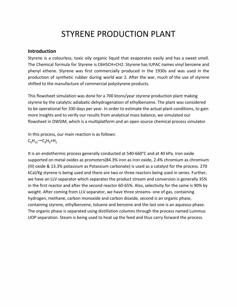
STYRENE PRODUCTION PLANT Introduction Styrene is a colourless, toxic oily organic liquid that evaporates easily and has a sweet smell. The Chemical formula for Styrene is C6H5CH=CH2. Styrene has IUPAC names vinyl benzene and phenyl ethene. Styrene was first commercially produced in the 1930s and was used in the production of synthetic rubber during world war 2. After the war, much of the use of styrene shifted to the manufacture of commercial polystyrene products. This flowsheet simulation was done for a 700 ktons/year styrene production plant making styrene by the catalytic adiabatic dehydrogenation of ethylbenzene. The plant was considered to be operational for 330 days per year. In order to estimate the actual plant conditions, to gain more insights and to verify our results from analytical mass balance, we simulated our flowsheet in DWSIM, which is a multiplatform and an open source chemical process simulator. In this process, our main reaction is as follows: C 0 H 10 →C 8 H 8 +H 2 It is an endothermic process generally conducted at 540-660°C and at 40 kPa. Iron oxide supported on metal oxides as promoters(84.3% iron as iron oxide, 2.4% chromium as chromium (III) oxide & 13.3% potassium as Potassium carbonate) is used as a catalyst for the process. 270 kCal/Kg styrene is being used and there are two or three reactors being used in series. Further, we have an LLV separator which separates the product stream and conversion is generally 35% in the first reactor and after the second reactor 60-65%. Also, selectivity for the same is 90% by weight. After coming from LLV separator, we have three streams- one of gas, containing hydrogen, methane, carbon monoxide and carbon dioxide, second is an organic phase, containing styrene, ethylbenzene, toluene and benzene and the last one is an aqueous phase. The organic phase is separated using distillation columns through the process named Lummus UOP separation. Steam is being used to heat up the feed and thus carry forward the process.
-
Upload
khangminh22 -
Category
Documents
-
view
0 -
download
0
Transcript of STYRENE PRODUCTION PLANT - DWSIM
STYRENE PRODUCTION PLANT
Introduction Styrene is a colourless, toxic oily organic liquid that evaporates easily and has a sweet smell.
The Chemical formula for Styrene is C6H5CH=CH2. Styrene has IUPAC names vinyl benzene and
phenyl ethene. Styrene was first commercially produced in the 1930s and was used in the
production of synthetic rubber during world war 2. After the war, much of the use of styrene
shifted to the manufacture of commercial polystyrene products.
This flowsheet simulation was done for a 700 ktons/year styrene production plant making
styrene by the catalytic adiabatic dehydrogenation of ethylbenzene. The plant was considered
to be operational for 330 days per year. In order to estimate the actual plant conditions, to gain
more insights and to verify our results from analytical mass balance, we simulated our
flowsheet in DWSIM, which is a multiplatform and an open source chemical process simulator.
In this process, our main reaction is as follows:
C0H10→C8H8+H2
It is an endothermic process generally conducted at 540-660°C and at 40 kPa. Iron oxide
supported on metal oxides as promoters(84.3% iron as iron oxide, 2.4% chromium as chromium
(III) oxide & 13.3% potassium as Potassium carbonate) is used as a catalyst for the process. 270
kCal/Kg styrene is being used and there are two or three reactors being used in series. Further,
we have an LLV separator which separates the product stream and conversion is generally 35%
in the first reactor and after the second reactor 60-65%. Also, selectivity for the same is 90% by
weight. After coming from LLV separator, we have three streams- one of gas, containing
hydrogen, methane, carbon monoxide and carbon dioxide, second is an organic phase,
containing styrene, ethylbenzene, toluene and benzene and the last one is an aqueous phase.
The organic phase is separated using distillation columns through the process named Lummus
UOP separation. Steam is being used to heat up the feed and thus carry forward the process.

Process Flowsheet in DWSIM
Complete Flowsheet
Fig 1 - Complete Flowsheet

Part 1 - Reaction step
Fig.2 - Reaction step

Part 2 - LLV separator
Fig. 3 - LLV Separator
Part 3 - Purification
Fig 5.3 - Distillation columns

Equipment
1. Reactors - R101, R102 We have modelled a plug flow reactor considering catalytic heterogeneous reactions as follows:
1. (C6H5)CH2CH3 ⟺ H2 + (C6H5)CHCH2 (Main reaction)
2. (C6H5)CH2H3 ⟺ C2H4 + C6H6
3. H2 + (C6H5)CH2CH3 ⟺ (C6H5)CH3+CH4
4. 2H2O + C2H4 ⟺ 4H2 + 2CO
5. H20 + CH4 ⟺ 3H2 + CO
The reaction kinetics which has been used to model the plug flow reactors are as follows:
Table 5.1- Reaction Kinetics
C6H5CH2CH3 → C6H5CHCH2 +H2
r1= k1PEB
C6H5CH2CH3 → C6H6 + C2H4
r2 = k2PEB
C6H5CH2CH3 + H2 → C6H5CH3 +CH4
r3= k3PEB PH2
2H20 + C2H4 → 2CO +4H2
r4= k4PH2OPETH0.5
H20 + CH4 → CO +3H2
r5= k5PH2OPCH4

The reactor is an adiabatic packed bed radial flow reactor and as the reaction is endothermic, there is an expected temperature drop. The temperature varies along the reactor length. Therefore all the kinetic parameters had to be put as a function of temperature. Thus, the data which we got from the literature survey and which we are using is:
Table 5.2 - Kinetics data for reactions
Reaction no. Activation Energy (Ea)
Rate constants
(ko)
1 207989 4329375423
2 91515 6302.4
3 103996 4059
4 65723 145.3
5 73268 6.03E+12
Fig. 4. DWSIM Simulation Results for R101
We found that the typical catalyst amount needed for a 300 kiloton per year plant in Ullmann's
Encyclopedia of Industrial Chemistry and considering that our plant is almost double the
capacity, 700 kilotons per year, we estimated the amount for our reactors. Also, the catalyst
parameters were found from literature as of a typical industrial catalyst, such as the density,
void fraction, particle size. The reactor volume was adjusted to match industrial conversions.

2. Liquid-Liquid-Vapour Separator - SP101 After the reactors, we have used a three-phase separator which is dividing the product stream
into three components:
1. Off Gas, which contains Hydrogen, Carbon dioxide, Carbon monoxide, Methane
2. The aqueous phase, containing water
3. The organic phase, which contains Styrene, Benzene, Toluene, Ethylbenzene,
Naphthalene, Biphenyl
3. Distillation Columns - D101, D102, D103, D104 and D105 There are four distillation columns being used.
1. Distillation column 1: D101
Shortcut Column
Minimum reflux ratio: 8.49
Minimum number of stages at infinite reflux: 22
Chemsep Column
No of stages: 75 (literature)
Feed stage: 38
Reflux Ratio: 12
Major components in distillate: Benzene, Toluene, Ethylbenzene, Styrene (1 mol %)
Major components in bottom: Styrene, Naphthalene, Biphenyl
Mass flow of distillate: 45374.76 kg/hr
Mass flow rate of bottom: 90012.24 kg/hr
Total condenser and partial reboiler are used.

Table 1.- Mass Flows in D101
2. Distillation 2: D102
Simple distillation column with sieve trays.
Shortcut Column
Minimum reflux ratio: 5
Minimum number of stages at infinite reflux: 20
Chemsep Column
No of stages: 30
Feed stage: 16
Reflux Ratio: 7.5
Components in distillate: Benzene, Toluene
Components in bottom: Ethylbenzene, Styrene
Mass flow of distillate: 1.47 kg/s
Mass flow rate of bottom: 11.12 kg/s
Total condenser and partial reboiler are used.

Table 2.- Mass Flows in D102
3. Distillation column 3: D103
Chemsep Column
No of stages: 10
Feed stage: 3
Reflux Ratio: 2
Components in distillate: Styrene
Components in bottom: Naphthalene, Biphenyl
Mass flow of distillate: 24.5367 kg/s
Mass flow rate of bottom: 0.409373 kg/s
Total condenser and partial reboiler are used
Table 3.- Mass Flows in D103

4. Distillation column 4: D104
Shortcut Column
Minimum reflux ratio: 2
Minimum number of stages at infinite reflux: 8
Chemsep Column
No of stages: 16
Feed stage: 8
Reflux Ratio: 3
Components in distillate: Benzene
Components in bottom: Toluene
Mass flow of distillate: 1.32 kg/s
Mass flow rate of bottom: 0.15 kg/s
Total condenser and partial reboiler are used.
Table 4.- Mass Flows in D104
5. Distillation column : D105
Chemsep Column
No of stages: 10
Feed stage: 5
Reflux Ratio: 1.5
Components in distillate: Styrene
Components in bottom: Anthracene, Naphthalene
Mass flow of distillate: 0.18 kg/s
Mass flow rate of bottom: 0.22 kg/s
Total condenser and partial reboiler are used.

Table 5.- Mass Flows in D105
ACKNOWLEDGEMENT
This flowsheet simulation was done as part of a group project in the course CL452 by final year
B.Tech chemical engineering students at IIT Bombay under the guidance of Prof. Kannan
Moudgalya, Mr Priyam Nayak, and Mr Rahul Nagraj. The team members involved were Ruchira
Goyal, Arundhoti Nayak, Vibha Talwar, Anuj Agrawal, and Parag Kale.