Study on Cutting Chip in Milling GH4169 with Indexable Disc ...
13
materials Article Study on Cutting Chip in Milling GH4169 with Indexable Disc Cutter Gensheng Li 1 , Chao Xian 2 and Hongmin Xin 3, * Citation: Li, G.; Xian, C.; Xin, H. Study on Cutting Chip in Milling GH4169 with Indexable Disc Cutter. Materials 2021, 14, 3135. https:// doi.org/10.3390/ma14113135 Academic Editors: Guijian Xiao, Yun Huang, Kun Zhou and Yi He Received: 8 May 2021 Accepted: 28 May 2021 Published: 7 June 2021 Publisher’s Note: MDPI stays neutral with regard to jurisdictional claims in published maps and institutional affil- iations. Copyright: © 2021 by the authors. Licensee MDPI, Basel, Switzerland. This article is an open access article distributed under the terms and conditions of the Creative Commons Attribution (CC BY) license (https:// creativecommons.org/licenses/by/ 4.0/). 1 College of Vehicle and Traffic Engineering, Henan University of Science and Technology, Luoyang 471003, China; [email protected] 2 Key Laboratory of Aero-engine High Performance Manufacturing, Ministry of Industry and Information Technology, Northwestern Polytechnical University, Xi’an 710072, China; [email protected] 3 Hubei Key Laboratory of Power System Design and Test for Electrical Vehicle, Hubei University of Arts and Science, Xiangyang 441053, China * Correspondence: [email protected] Abstract: The study and control for chip have a significant impact on machining quality and produc- tivity. In this paper, GH4169 was cut with an indexable disc milling cutter. The chips corresponding to each group of cutting parameters were collected, and the chip parameters (chip curl radius, chip thickness deformation coefficient, and chip width deformation coefficient) were measured. The qualitative relationship between the chip parameters and cutting parameters was studied. The quadratic polynomial models between chip parameters and cutting parameters were established and verified. The results showed that the chip parameters (chip curl radius, chip thickness deformation coefficient and chip width deformation coefficient) were negatively correlated with spindle speed; chip parameters were positively correlated with feed speed; chip parameters were positively cor- related with cutting depth. The maximum deviation rate between measured values and predicted values for chip curl radius was 9.37%; the maximum deviation rate for cutting thickness deformation coefficient was 13.8%, and the maximum deviation rate of cutting width deformation coefficient was 7.86%. It can be seen that the established models are accurate. The models have guiding significance for chip control. Keywords: cutting parameters; chip parameters; models 1. Introduction In the cutting process, long and continuous chips will wind around the workpiece, tool, or fixture, which will hinder the positioning and clamping of the workpiece, reduce the quality of the machined surface, aggravate the tool wear or damage, and even affect the safety of the operator. Sometimes the machine has to stop cutting to clean the chips, which greatly reduces productivity. In addition, long and messy chips are not easy to clean and transport. However, if the chip is too small, the chip will splash and accumulate everywhere, causing cutting vibration and premature tool damage, which will also affect the processing quality and endanger the safety of the operator. Therefore, the study and control of chip is a key problem to ensure the processing quality and improve productivity in machining, especially in automatic production. According to the formation parameters of chip, Japanese scholar Nakayama et al. [1,2] calculated the shape parameters of the spiral chip and established the chip geometry. By measuring the geometry size of the chip, the chip flow direction, up curl radius, and transverse curl radius can be calculated. Kharkevich et al. [3–6] defined six kinds of up curl radius and transverse curl radius on basis of the research of Nakayama Ichio and determined the above six kinds of up curl radius and transverse curl radius according to the geometric parameters of spiral chip, which enriched the chip shape geometry. Chen et al. [7,8] held that: in the actual cutting process, due to the constraints of tool shape Materials 2021, 14, 3135. https://doi.org/10.3390/ma14113135 https://www.mdpi.com/journal/materials
-
Upload
khangminh22 -
Category
Documents
-
view
5 -
download
0
Transcript of Study on Cutting Chip in Milling GH4169 with Indexable Disc ...
materials
Article
Study on Cutting Chip in Milling GH4169 with IndexableDisc Cutter
Gensheng Li 1, Chao Xian 2 and Hongmin Xin 3,*
�����������������
Citation: Li, G.; Xian, C.; Xin, H.
Study on Cutting Chip in Milling
GH4169 with Indexable Disc Cutter.
Materials 2021, 14, 3135. https://
doi.org/10.3390/ma14113135
Academic Editors: Guijian Xiao,
Yun Huang, Kun Zhou and Yi He
Received: 8 May 2021
Accepted: 28 May 2021
Published: 7 June 2021
Publisher’s Note: MDPI stays neutral
with regard to jurisdictional claims in
published maps and institutional affil-
iations.
Copyright: © 2021 by the authors.
Licensee MDPI, Basel, Switzerland.
This article is an open access article
distributed under the terms and
conditions of the Creative Commons
Attribution (CC BY) license (https://
creativecommons.org/licenses/by/
4.0/).
1 College of Vehicle and Traffic Engineering, Henan University of Science and Technology, Luoyang 471003,China; [email protected]
2 Key Laboratory of Aero-engine High Performance Manufacturing, Ministry of Industry and InformationTechnology, Northwestern Polytechnical University, Xi’an 710072, China; [email protected]
3 Hubei Key Laboratory of Power System Design and Test for Electrical Vehicle, Hubei University of Arts andScience, Xiangyang 441053, China
* Correspondence: [email protected]
Abstract: The study and control for chip have a significant impact on machining quality and produc-tivity. In this paper, GH4169 was cut with an indexable disc milling cutter. The chips correspondingto each group of cutting parameters were collected, and the chip parameters (chip curl radius, chipthickness deformation coefficient, and chip width deformation coefficient) were measured. Thequalitative relationship between the chip parameters and cutting parameters was studied. Thequadratic polynomial models between chip parameters and cutting parameters were established andverified. The results showed that the chip parameters (chip curl radius, chip thickness deformationcoefficient and chip width deformation coefficient) were negatively correlated with spindle speed;chip parameters were positively correlated with feed speed; chip parameters were positively cor-related with cutting depth. The maximum deviation rate between measured values and predictedvalues for chip curl radius was 9.37%; the maximum deviation rate for cutting thickness deformationcoefficient was 13.8%, and the maximum deviation rate of cutting width deformation coefficient was7.86%. It can be seen that the established models are accurate. The models have guiding significancefor chip control.
Keywords: cutting parameters; chip parameters; models
1. Introduction
In the cutting process, long and continuous chips will wind around the workpiece,tool, or fixture, which will hinder the positioning and clamping of the workpiece, reducethe quality of the machined surface, aggravate the tool wear or damage, and even affectthe safety of the operator. Sometimes the machine has to stop cutting to clean the chips,which greatly reduces productivity. In addition, long and messy chips are not easy toclean and transport. However, if the chip is too small, the chip will splash and accumulateeverywhere, causing cutting vibration and premature tool damage, which will also affectthe processing quality and endanger the safety of the operator. Therefore, the study andcontrol of chip is a key problem to ensure the processing quality and improve productivityin machining, especially in automatic production.
According to the formation parameters of chip, Japanese scholar Nakayama et al. [1,2]calculated the shape parameters of the spiral chip and established the chip geometry. Bymeasuring the geometry size of the chip, the chip flow direction, up curl radius, andtransverse curl radius can be calculated. Kharkevich et al. [3–6] defined six kinds of upcurl radius and transverse curl radius on basis of the research of Nakayama Ichio anddetermined the above six kinds of up curl radius and transverse curl radius accordingto the geometric parameters of spiral chip, which enriched the chip shape geometry.Chen et al. [7,8] held that: in the actual cutting process, due to the constraints of tool shape
Materials 2021, 14, 3135. https://doi.org/10.3390/ma14113135 https://www.mdpi.com/journal/materials
Materials 2021, 14, 3135 2 of 13
and cutting space, the chips not only produce upward curl and transverse curl but alsotwist. They studied the situation when the chips flow out along the rake face of straightedge and flat rake face tools and described the possible shape of chips in the cutting processfrom a mathematical point of view. Li et al. [9,10] systematically studied the constraintrelationship between the chip and the obstacle based on the spatial motion trajectory ofthe chip, established the constraint equation between the chip and the obstacle surface inthe process of chip formation, and established the mathematical models of upward curlingand transverse curling according to the chip breaking conditions.
Fang and Jawahir [11] verified the prediction formulas of chip curl radius, chip outflowangle, and cutting thickness by cutting medium carbon steel with P20 cemented carbidetool. Zhang and Peklenik [12] studied the chip flow direction and curl radius with a largenumber of experiments and pointed out that the ratio of the limit curvature radius of thechip to the original radius (also known as the chip radius ratio) falls in the range of 1.2 to2.0, and the obtained chip has no effect on the cutting process and the machined surfaceof the workpiece. Li et al. [13] observed the chip formation process of easy cutting steelunder the scanning electron microscope and achieved comprehensive research on metalchip formation mechanism, micro, quantitative, dynamic, and multiple factors.
Worthington and Redford [14,15] studied the influence of geometric parameters of chipbreaking groove, edge width, on chip breaking, and gave the range of edge width, which isconducive to chip breaking, and established the model of chip curl radius. Nedes et al. [16]established a mathematical model based on chip flow angle, effective rake angle, and chipcurl radius. Zhang et al. [17] held that the cutting force imposed on the shear plane of thechip and the cutting force imposed on the contact plane are not in a straight line, so there isa cutting bending moment, which is the cause of chip bending. According to the theoryof slip line field, the curl radius of the chip is calculated. Ramalingam et al. [18] gave acalculation model of chip curl radius in orthogonal cutting.
Maruda et al. [19] studied the tool wear and chip shape in turning AISI 1045 steel witha sintered carbide P25 tool under three cooling conditions: dry machining, MQCL method,and MQCL + EP/AW. The results showed that MQCL + EP/AW cooling mode had the leasttool wear and better chip shape. Singh et al. [20] established quadratic polynomial modelsof chip reduction coefficient (CRC), surface roughness, and chip tooth height with respectto cutting speed, feed speed, and cutting depth by using the response surface method andcarried out multi-objective parameters optimization in turning AISI 4340 steel with theyttria-stabilized zirconia toughened alumina (Y-ZTA) ceramic cutting tool. Das et al. [21]studied the influence of cutting depth, feed speed, and spindle speed on machiningforces and chip thickness when turning 4340 alloy steel with three lubrication conditions:compressed air, water-soluble coolant, and nanofluid. The quadratic polynomial models ofcutting force and cutting thickness with respect to cutting depth, feed rate, and spindlespeed were established. It showed that nanofluid produced the best performance incomparison to compressed air and water-soluble coolant. Iwata et al. [22] calculated thechip thickness, curl radius, and strain distribution by finite element simulation. Combiningthe finite element model with the ductile fracture criterion, the chip fracture was predicted.In the above literatures, the mathematical model for chip curl radius is derived fromrelated hypotheses and theories, but many parameters in the model are difficult to obtainaccurately. This paper studies the qualitative relationship between chip parameters (curlradius and deformation coefficient) and cutting parameters and establishes quadraticpolynomial models between chip parameters (curl radius and deformation coefficient) andcutting parameters, which can be used for the prediction of chip parameters.
2. Workpiece and Milling Cutter2.1. Workpiece
GH4169 is a common material for blisk manufacturing, which has good fatigueperformance, high strength, and good thermal stability. The material used in this test wasGH4169 (Shaanxi Changyu Aviation Equipment Co., Ltd., Xi’an, China), which is a solid
Materials 2021, 14, 3135 3 of 13
solution treated after forging. The size of workpiece was 265 mm × 165 mm × 23.5 mm.Nickel base superalloy GH4169 is a superalloy with Ni as the base element, in which thecontent of Ni is more than 50%. Its main chemical composition is shown in Table 1 [23].Ni has very good stability and can be stably dissolved with other metal elements, whichis beneficial to increase the service life of the alloy. The chemical composition of GH4169determines its good physical and mechanical properties, which are shown in Table 2 [23].
Table 1. Main chemical constituents of GH4169 (%).
Ni Cr Mo Nb Ti Al C Si Mn Fe
51.75 17 2.93 5.15 1.07 0.45 0.042 0.21 0.03 21.368
Table 2. Physical and mechanical properties of GH4169.
PhysicalProperties
Density(g/cm3)
Poisson’sRatio
ThermalConductivity
(W/mK)
Specific HeatCapacity(J/kg ◦C)
ElasticModulus
(GPa)
8.24 0.3 14.7 435 199.9
MechanicalProperties
Elongation(%)
Reduction ofArea(%)
TensileStrength
(MPa)
ImpactToughness
(MJ/m2)
Yield Stress(MPa)
24 40 1430 348 1100
2.2. Milling Cutter
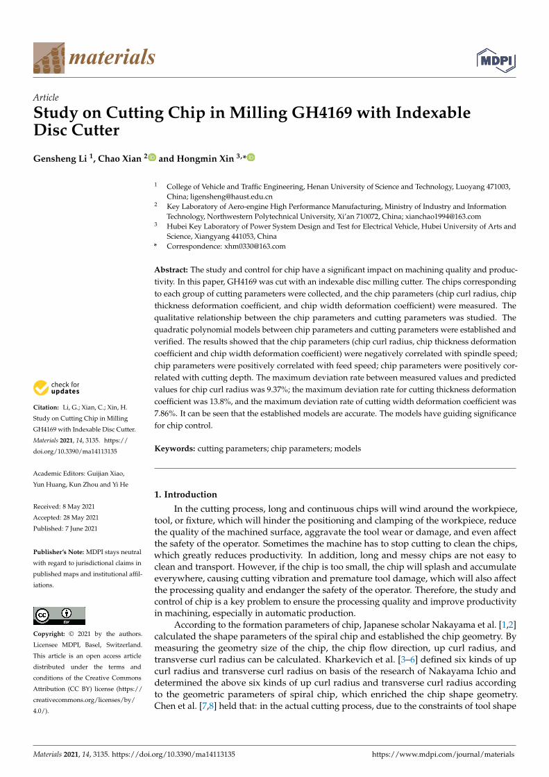
The milling cutter used for the experiment was a disc milling cutter of indexablethree-sided inserts, which consisted of a cutter disc and inserts connected by screws. Therewere 39 inserts, 13 left inserts, 13 right inserts, and 13 middle inserts, as shown in Figure 1.The left insert, right insert, and middle insert are staggered, which means their axes ofsymmetry do not coincide. The tool manufacturer is Zhuzhou Diamond Cutting Tools Co.,Ltd., China. The spindle speed should not be greater than 200 r/min. When the unit of thespindle speed is r/min, and the unit of the feed speed is mm/min, the value of the feedspeed must be smaller than the spindle speed.
Figure 1. Disc milling cutter of indexable three-sided inserts.
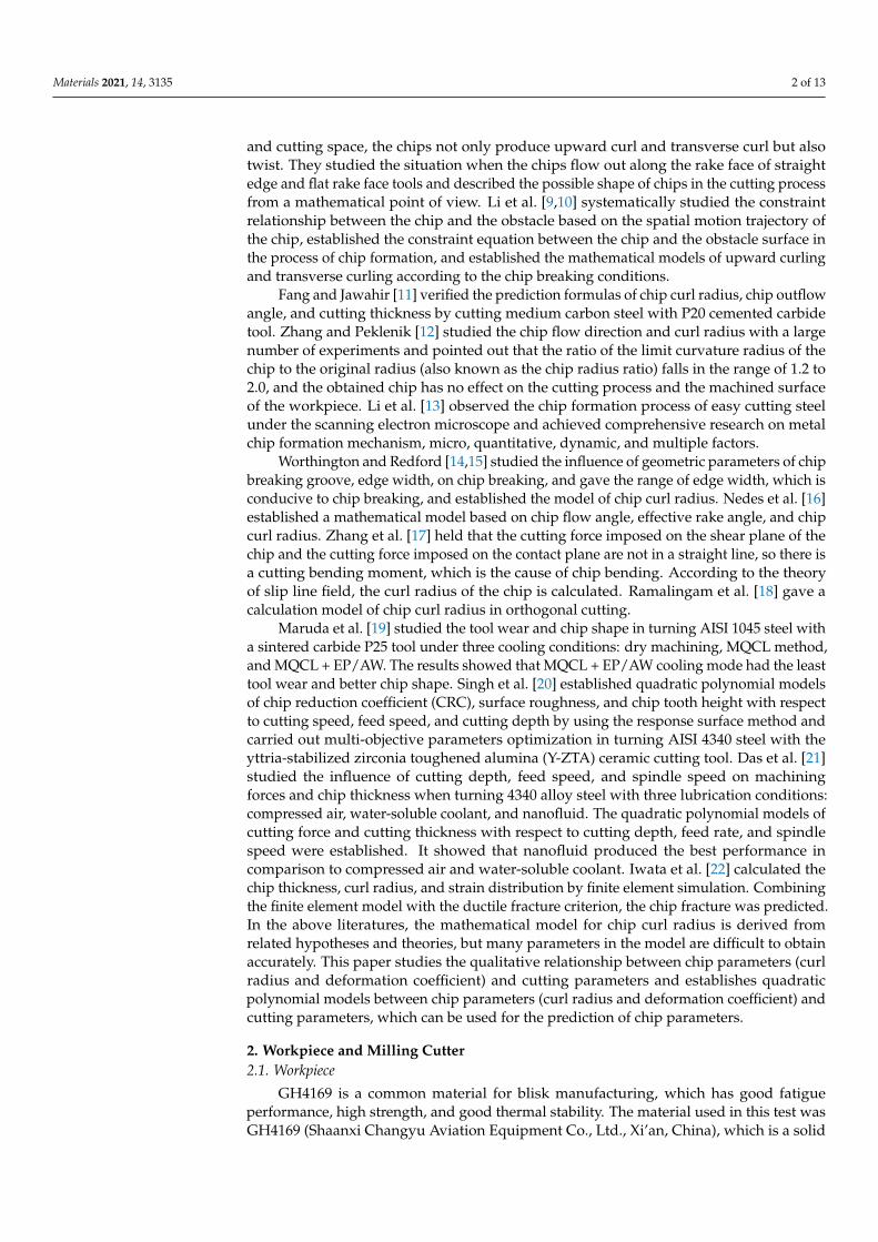
The angle between the cutting edge of inserts and the horizontal plane was 2.2 degrees,as shown in Figure 2. So, when the milling cutter was machining the workpiece, it was anoblique cutting process. So, it was an orthogonal cutting process when the middle insertwas cutting the workpiece; it was an oblique cutting process when the left insert and rightinsert were cutting the workpiece.
Materials 2021, 14, 3135 4 of 13
Figure 2. Position relationship of the three inserts.
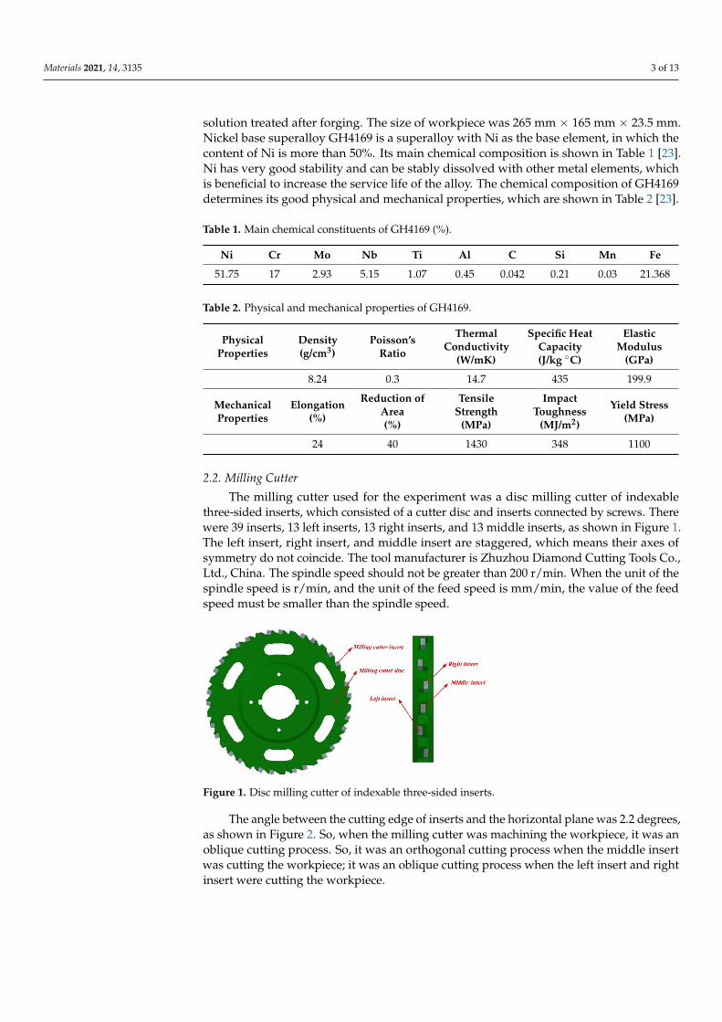
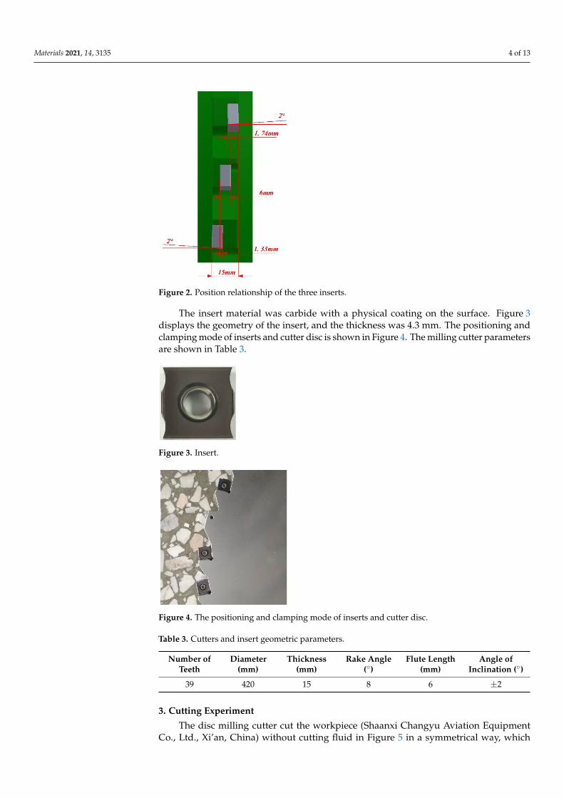
The insert material was carbide with a physical coating on the surface. Figure 3displays the geometry of the insert, and the thickness was 4.3 mm. The positioning andclamping mode of inserts and cutter disc is shown in Figure 4. The milling cutter parametersare shown in Table 3.
Figure 3. Insert.
Figure 4. The positioning and clamping mode of inserts and cutter disc.
Table 3. Cutters and insert geometric parameters.
Number ofTeeth
Diameter(mm)
Thickness(mm)
Rake Angle(◦)
Flute Length(mm)
Angle ofInclination (◦)
39 420 15 8 6 ±2
3. Cutting Experiment
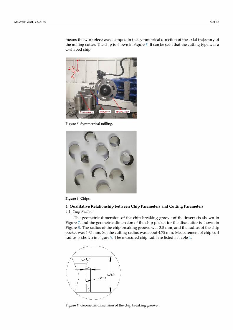
The disc milling cutter cut the workpiece (Shaanxi Changyu Aviation EquipmentCo., Ltd., Xi’an, China) without cutting fluid in Figure 5 in a symmetrical way, which
Materials 2021, 14, 3135 5 of 13
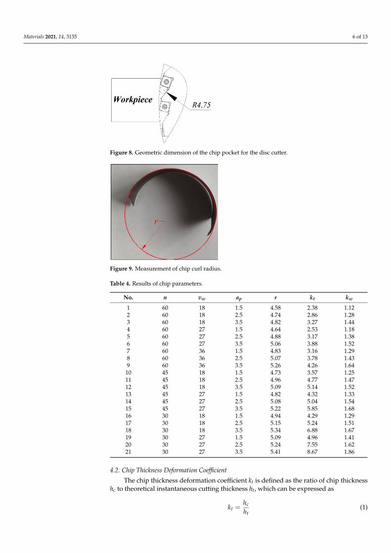
means the workpiece was clamped in the symmetrical direction of the axial trajectory ofthe milling cutter. The chip is shown in Figure 6. It can be seen that the cutting type was aC-shaped chip.
Figure 5. Symmetrical milling.
Figure 6. Chips.
4. Qualitative Relationship between Chip Parameters and Cutting Parameters4.1. Chip Radius
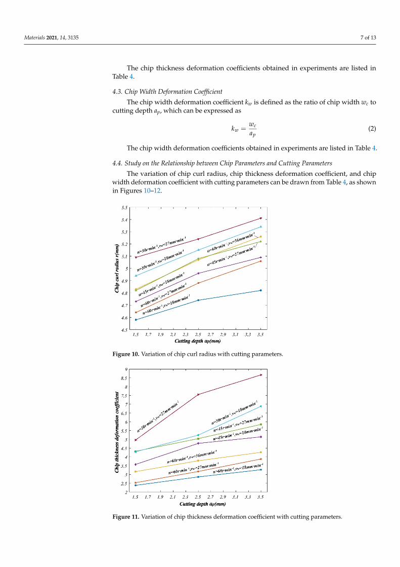
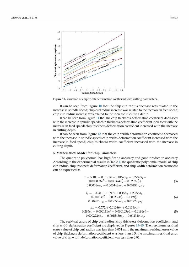
The geometric dimension of the chip breaking groove of the inserts is shown inFigure 7, and the geometric dimension of the chip pocket for the disc cutter is shown inFigure 8. The radius of the chip breaking groove was 3.5 mm, and the radius of the chippocket was 4.75 mm. So, the cutting radius was about 4.75 mm. Measurement of chip curlradius is shown in Figure 9. The measured chip radii are listed in Table 4.
Figure 7. Geometric dimension of the chip breaking groove.
Materials 2021, 14, 3135 6 of 13
Figure 8. Geometric dimension of the chip pocket for the disc cutter.
Figure 9. Measurement of chip curl radius.
Table 4. Results of chip parameters.
No. n vw ap r kt kw
1 60 18 1.5 4.58 2.38 1.122 60 18 2.5 4.74 2.86 1.283 60 18 3.5 4.82 3.27 1.444 60 27 1.5 4.64 2.53 1.185 60 27 2.5 4.88 3.17 1.386 60 27 3.5 5.06 3.88 1.527 60 36 1.5 4.83 3.16 1.298 60 36 2.5 5.07 3.78 1.439 60 36 3.5 5.26 4.26 1.64
10 45 18 1.5 4.73 3.57 1.2511 45 18 2.5 4.96 4.77 1.4712 45 18 3.5 5.09 5.14 1.5213 45 27 1.5 4.82 4.32 1.3314 45 27 2.5 5.08 5.04 1.5415 45 27 3.5 5.22 5.85 1.6816 30 18 1.5 4.94 4.29 1.2917 30 18 2.5 5.15 5.24 1.5118 30 18 3.5 5.34 6.88 1.6719 30 27 1.5 5.09 4.96 1.4120 30 27 2.5 5.24 7.55 1.6221 30 27 3.5 5.41 8.67 1.86
4.2. Chip Thickness Deformation Coefficient
The chip thickness deformation coefficient kt is defined as the ratio of chip thicknesshc to theoretical instantaneous cutting thickness ht, which can be expressed as
kt =hc
ht(1)
Materials 2021, 14, 3135 7 of 13
The chip thickness deformation coefficients obtained in experiments are listed inTable 4.
4.3. Chip Width Deformation Coefficient
The chip width deformation coefficient kw is defined as the ratio of chip width wc tocutting depth ap, which can be expressed as
kw =wc
ap(2)
The chip width deformation coefficients obtained in experiments are listed in Table 4.
4.4. Study on the Relationship between Chip Parameters and Cutting Parameters
The variation of chip curl radius, chip thickness deformation coefficient, and chipwidth deformation coefficient with cutting parameters can be drawn from Table 4, as shownin Figures 10–12.
Figure 10. Variation of chip curl radius with cutting parameters.
Figure 11. Variation of chip thickness deformation coefficient with cutting parameters.
Materials 2021, 14, 3135 8 of 13
Figure 12. Variation of chip width deformation coefficient with cutting parameters.
It can be seen from Figure 10 that the chip curl radius decrease was related to theincrease in spindle speed; chip curl radius increase was related to the increase in feed speed;chip curl radius increase was related to the increase in cutting depth.
It can be seen from Figure 11 that the chip thickness deformation coefficient decreasedwith the increase in spindle speed; chip thickness deformation coefficient increased with theincrease in feed speed; chip thickness deformation coefficient increased with the increasein cutting depth.
It can be seen from Figure 12 that the chip width deformation coefficient decreasedwith the increase in spindle speed; chip width deformation coefficient increased with theincrease in feed speed; chip thickness width coefficient increased with the increase incutting depth.
5. Mathematical Model for Chip Parameters
The quadratic polynomial has high fitting accuracy and good prediction accuracy.According to the experimental results in Table 4, the quadratic polynomial model of chipcurl radius, chip thickness deformation coefficient, and chip width deformation coefficientcan be expressed as
r = 5.185 − 0.0191n − 0.0157vw + 0.2792ap+0.000033n2 + 0.000324v2
w − 0.0293a2p+
0.00016nvw − 0.000448nap + 0.00294vwap
(3)
kt = −3.28 + 0.1399n + 0.15vw + 2.758ap−0.00063n2 + 0.00236v2
w − 0.119a2p−
0.00457nvw − 0.03553nap + 0.0172vwap
(4)
kw = 0.572 + 0.01086n + 0.0116vw+0.285ap − 0.000111n2 + 0.000103v2
w − 0.0186a2p−
0.000222nvw − 0.001543nap + 0.00231vwap
(5)
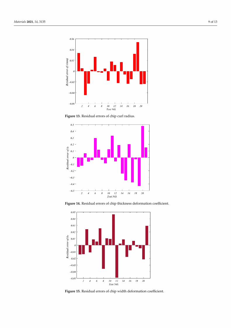
The residual errors of chip curl radius, chip thickness deformation coefficient, andchip width deformation coefficient are displayed in Figures 13–15. The maximum residualerror value of chip curl radius was less than 0.054 mm; the maximum residual error valueof chip thickness deformation coefficient was less than 0.5; the maximum residual errorvalue of chip width deformation coefficient was less than 0.05.
Materials 2021, 14, 3135 9 of 13
Figure 13. Residual errors of chip curl radius.
Figure 14. Residual errors of chip thickness deformation coefficient.
Figure 15. Residual errors of chip width deformation coefficient.
Materials 2021, 14, 3135 10 of 13
6. Experimental Verification
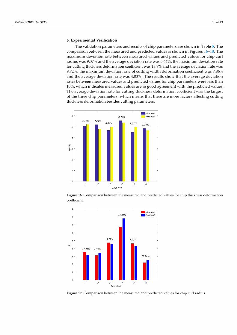
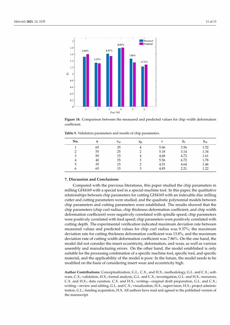
The validation parameters and results of chip parameters are shown in Table 5. Thecomparison between the measured and predicted values is shown in Figures 16–18. Themaximum deviation rate between measured values and predicted values for chip curlradius was 9.37% and the average deviation rate was 5.64%; the maximum deviation ratefor cutting thickness deformation coefficient was 13.8% and the average deviation rate was9.72%; the maximum deviation rate of cutting width deformation coefficient was 7.86%and the average deviation rate was 4.03%. The results show that the average deviationrates between measured values and predicted values for chip parameters were less than10%, which indicates measured values are in good agreement with the predicted values.The average deviation rate for cutting thickness deformation coefficient was the largestof the three chip parameters, which means that there are more factors affecting cuttingthickness deformation besides cutting parameters.
Figure 16. Comparison between the measured and predicted values for chip thickness deformationcoefficient.
Figure 17. Comparison between the measured and predicted values for chip curl radius.
Materials 2021, 14, 3135 11 of 13
Figure 18. Comparison between the measured and predicted values for chip width deformationcoefficient.
Table 5. Validation parameters and results of chip parameters.
No. n vw ap r kt kw
1 65 35 4 5.06 3.56 1.522 55 25 2 5.18 3.14 1.343 50 15 4 4.68 4.72 1.614 40 35 3 5.56 6.72 1.785 35 15 2 4.51 4.64 1.466 65 15 3 4.85 2.21 1.22
7. Discussion and Conclusions
Compared with the previous literatures, this paper studied the chip parameters inmilling GH4169 with a special tool in a special machine tool. In this paper, the qualitativerelationships between chip parameters for cutting GH4169 with an indexable disc millingcutter and cutting parameters were studied, and the quadratic polynomial models betweenchip parameters and cutting parameters were established. The results showed that thechip parameters (chip curl radius, chip thickness deformation coefficient, and chip widthdeformation coefficient) were negatively correlated with spindle speed; chip parameterswere positively correlated with feed speed; chip parameters were positively correlated withcutting depth. The experimental verification indicated maximum deviation rate betweenmeasured values and predicted values for chip curl radius was 9.37%; the maximumdeviation rate for cutting thickness deformation coefficient was 13.8%, and the maximumdeviation rate of cutting width deformation coefficient was 7.86%. On the one hand, themodel did not consider the insert eccentricity, deformation, and wear, as well as variousassembly and manufacturing errors. On the other hand, the model established is onlysuitable for the processing combination of a specific machine tool, specific tool, and specificmaterial, and the applicability of the model is poor. In the future, the model needs to bemodified on the basis of considering insert wear and eccentricity high.
Author Contributions: Conceptualization, G.L., C.X., and H.X.; methodology, G.L. and C.X.; soft-ware, C.X.; validation, H.X.; formal analysis, G.L. and C.X.; investigation, G.L. and H.X.; resources,C.X. and H.X.; data curation, C.X. and H.X.; writing—original draft preparation, G.L. and C.X.;writing—review and editing, G.L. and C.X.; visualization, H.X.; supervision, H.X.; project adminis-tration, G.L.; funding acquisition, H.X. All authors have read and agreed to the published version ofthe manuscript.
Materials 2021, 14, 3135 12 of 13
Funding: This research was funded by the National Science and Technology Major Project, China(No. 2013ZX04001081).
Institutional Review Board Statement: Not applicable.
Informed Consent Statement: Not applicable.
Data Availability Statement: No new data were created or analyzed in this study. Data sharing isnot applicable to this article.
Conflicts of Interest: The authors declared that they have no conflict of interest to this work. Wedeclare that we do not have any commercial or associative interest that represents a conflict of interestin connection with the work submitted.
Nomenclature
n Spindle speed, r/minvw Feed speed, mm/minap Cutting depth, mmr Chip curl radius, mmkt Chip thickness deformation coefficientkw Chip width deformation coefficienthc Chip thickness, mmht Theoretical instantaneous cutting thickness, mmwc Chip width, mm
References1. Nakayama, K.; Ogawa, M. Basic rules on the form of chip in metal cutting. CIRP Ann. 1978, 27, 17–21.2. Nakayama, K.; Arai, M. Comprehensive chip form classification based on the cutting mechanism. ACIRP Ann. 1992, 41, 71–74.
[CrossRef]3. Li, Z.J.; Qu, G.M.; Xu, Y.H. Forecast of breaking length of side curling short-spiral chips. Chin. J. Mech. Eng. 1999, 12, 297–302.4. Li, Z.J.; Qu, G.M.; Dong, L.H.; Yan, F.G.; Xu, Y.H.; Liu, Y.L.; Rong, Y.M. Mathematical model and a method for judging on the
breaking of cross curling short spiral chips. J. Mech. Eng. 1996, 32, 105–110. (In Chinese)5. Zheng, M.L.; Li, Z.J.; Wei, Y.L.; Rong, Y.M. Theoretical study on chip up-curling non-break plugging area. J. Mech. Eng. 2001, 37,
106–109. (In Chinese) [CrossRef]6. Kharkevich, A.; Venuvinod, P.K. Basic geometric analysis of 3-D chip forms in metal cutting: Part 1: Determining up-curl and
side-curl radii. Int. J. Mach. Tools Manuf. 1999, 39, 751–769. [CrossRef]7. Chen, Y.J.; Fang, N.; Shi, H.M.; Chen, R.Y. A study of three dimensional chip curl. J. Huazhong Univ. Sci. Technol. 1993, 21, 1–6.
(In Chinese)8. Chen, Y.J.; Huang, W.W. Kinematic analysis on three dimensional chip curls. China Mech. Eng. 2000, 11, 513–515. (In Chinese)9. Li, Z.J.; Xu, Y.H.; Yan, F.G.; Zheng, M.L.; Qu, G.M.; Liu, F.; Rong, Y.M. On mathematic model formation and breaking of c type
side-curling chips. Chin. J. Mech. Eng. 1997, 33, 33–38. (In Chinese) [CrossRef]10. Li, Z.J.; Zheng, M.L.; Wei, Y.L.; Liu, E.L.; Rong, Y.M. Study on chip movement contrail and constraint equation. Chin. J. Mech. Eng.
2001, 37, 42–50. (In Chinese) [CrossRef]11. Fang, N.; Jawahir, I.S. Analytical predictions and experimental validation of cutting force ratio, chip thickness, and chip back-flow
angle in restricted contact machining using the universal slip-line model. Int. J. Mach. Tools Manuf. 2002, 42, 681–694. [CrossRef]12. Zhang, Y.Z.; Peklenik, J. Chip curl, chip breaking and chip control of the difficult-to-cut materials. CIRP Ann. 1980, 29, 79–83.
[CrossRef]13. Li, Q.D.; Guo, Q.Y.; Zhang, H. Micro-dynamic cuttings forming principle and analysis. J. Shenyang Univ. Technol. 2002, 4, 12–14.
(In Chinese)14. Worthington, B.; Redford, A.H. Chip curl and the action of the groove type chip former. Int. J. Mach. Tool Des. Res. 1973, 13,
257–270. [CrossRef]15. Worthington, B. The effect of rake face configuration on the curvature of the chip in metal cutting. Int. J. Mach. Tool Des. Res. 1975,
15, 223–239. [CrossRef]16. Nedes, C.; Hintze, W.; Luttervelt, C.A. Characteristic parameters of chip control in turning operations with indexable inserts and
three-dimensionally shaped chip formers. CIRP Ann. 1989, 38, 75–79. [CrossRef]17. Zhang, H.T.; Liu, P.D.; Hu, R.S. The theoretical calculation of naturally curling radius of chip. Int. J. Mach. Tools Manuf. 1989, 29,
323–332.18. Ramalingam, S.; Doyle, E.D.; Turley, D.M. On chip curl in orthogonal machining. J. Eng. Ind. Trans. ASME 1980, 102, 177–183.
[CrossRef]

Materials 2021, 14, 3135 13 of 13
19. Maruda, R.W.; Krolczyk, G.M.; Nieslony, P.; Wojciechowski, S.; Michalski, M.; Legutko, S. The influence of the cooling conditionson the cutting tool wear and the chip formation mechanism. J. Manuf. Process. 2016, 24, 107–115. [CrossRef]
20. Singh, B.K.; Roy, H.; Mondal, B.; Roy, S.S.; Mandal, N. Measurement of chip morphology and multi criteria optimization ofturning parameters for machining of AISI 4340 steel using Y-ZTA cutting insert. Measurement 2019, 142, 181–194. [CrossRef]
21. Das, A.; Patel, S.K.; Biswal, B.B.; Sahoo, N.; Pradhan, A. Performance evaluation of various cutting fluids using MQL technique inhard turning of AISI 4340 alloy steel. Measurement 2019, 150, 107079. [CrossRef]
22. Iwata, K.; Osakada, K.; Terasaka, Y. Process modeling of orthogonal cutting by the rigid-plastic finite element method. J. Eng.Mater. Technol. 1984, 106, 132–138. [CrossRef]
23. Li, B. Research on Surface Integrity of Nickel base Superalloy GH4169 in High Speed Milling. Master’s Thesis, ZhongbeiUniversity, Taiyuan, China, May 2015.