Study of cFS to deploy OBC software for IoT missions
64
Polytechnic University of Catalonia Project Plathon Study of cFS to deploy OBC software for IoT missions Author: Gorka Unzueta Director: Dr. Juan José Alins MSc Thesis for Master’s Degree in Aerospace Engineering The 22nd of June, 2021
-
Upload
khangminh22 -
Category
Documents
-
view
1 -
download
0
Transcript of Study of cFS to deploy OBC software for IoT missions

Polytechnic University of Catalonia
Project Plathon
Study of cFS to deploy OBCsoftware for IoT missions
Author:Gorka Unzueta
Director:Dr. Juan José Alins
MSc Thesis for
Master’s Degree in Aerospace Engineering
The 22nd of June, 2021

Abstract
This thesis exposes the study, development, integration and validation of anOBC software of a satellite, using cFS. The OBC will be in charge of retrieving datafrom all sensors and subsystems as well as of transmitting it to the desired actuatorsor even the ground stations. The mission of the satellite is to transmit data fromIoT stations to control centres through a constellation. At the current stage of theproject, the developments are focused on integration in HitL simulations.

Resumen
Esta tesis expone el estudio, desarrollo, integración y validación de el software delOBC de un satélite, utilizando cFS. El OBC se encargará de recuperar los datos detodos los sensores y subsistemas, así como de transmitirlos a los actuadores deseadoso incluso a las estaciones de tierra. La misión del satélite es transmitir los datosde las estaciones IoT a centros de control a través de una constelación. En la faseactual del proyecto, los desarrollos se centran en la integración en simulaciones HitL.
Declaration of honor
I declare that,the work in this Master Thesis is completely my own work,no part of this Master Thesis is taken from other people’s work without giving
them credit,all references have been clearly cited,I understand that an infringement of this declaration leaves me subject to the
foreseen disciplinary actions by The Universitat Politècnica de Catalunya - BarcelonaT-ECH.
Gorka Unzueta García 22/06/2021
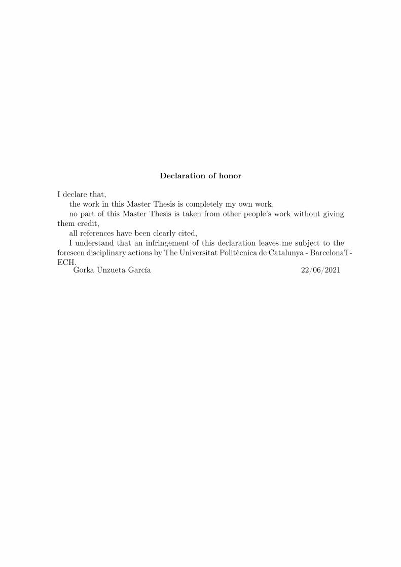
Nomenclature
A Ampere IoT Internet of Things
C&DH Communication andData Handling JAXA Japanese Aerospace
Exploration AgencyCAN Controller Area Network KB Kilobyte
CCSDS Consultative Committeefor Space Data Systems LEO Low Earth Orbit
cFE Core Flight Executives LOS Line of SightcFS Core Flight System LSB Least Significant BitCI Command Ingest M2M Machine-to-machineCPU Core Processor Unit mA miliAmpereDOF Degree of Freedom MB MegaByte
ESA European Space Agency NASA National Aeronautics andSpace Administration
FPGA Field Programmable Gate Array OBC On board computerg Acceleration unit OSAL Operating System Abstract LayerGB Gigabyte OSK OpenSatKitGEO Geostationary Orbit RPi Raspberry PiGHz Gigahertz RTOS Real-time Operating SystemGPIO General Purpose Input/Output SB Software BusGS Ground Station SCH SchedulerHitL Hardware in the Loop SitL Software in the LoopHK House Keeping SPI Serial Peripheral InterfaceI2C Inter-Integrated Circuit TO Telemetry OutputIMU Inertial Motion Unit µT microTesla

Contents
1 Objective 6
2 Justification 7
3 Scope and requirements 8
4 Tasks 9
5 State of the art 115.1 Plathon . . . . . . . . . . . . . . . . . . . . . . . . . . . . . . . . . . 11
5.1.1 IoT . . . . . . . . . . . . . . . . . . . . . . . . . . . . . . . . . 125.1.2 Satellite constellations . . . . . . . . . . . . . . . . . . . . . . 12
5.2 OBC . . . . . . . . . . . . . . . . . . . . . . . . . . . . . . . . . . . . 135.3 OSK . . . . . . . . . . . . . . . . . . . . . . . . . . . . . . . . . . . . 14
5.3.1 cFS . . . . . . . . . . . . . . . . . . . . . . . . . . . . . . . . . 145.3.2 42 Simulator . . . . . . . . . . . . . . . . . . . . . . . . . . . . 175.3.3 COSMOS . . . . . . . . . . . . . . . . . . . . . . . . . . . . . 17
6 Design 196.1 Architecture design . . . . . . . . . . . . . . . . . . . . . . . . . . . . 19
6.1.1 Plathon current state . . . . . . . . . . . . . . . . . . . . . . . 196.1.2 Plathon fundamentals . . . . . . . . . . . . . . . . . . . . . . 206.1.3 Proposed architecture . . . . . . . . . . . . . . . . . . . . . . 21
6.2 Hardware selection . . . . . . . . . . . . . . . . . . . . . . . . . . . . 236.2.1 OBC . . . . . . . . . . . . . . . . . . . . . . . . . . . . . . . . 236.2.2 GPS Simulator . . . . . . . . . . . . . . . . . . . . . . . . . . 246.2.3 IMU . . . . . . . . . . . . . . . . . . . . . . . . . . . . . . . . 26
6.3 Software development . . . . . . . . . . . . . . . . . . . . . . . . . . . 276.3.1 RPi/OBC . . . . . . . . . . . . . . . . . . . . . . . . . . . . . 276.3.2 NodeMCU/GPS . . . . . . . . . . . . . . . . . . . . . . . . . . 346.3.3 OSK modifications . . . . . . . . . . . . . . . . . . . . . . . . 37
7 Validation 437.1 Tests for cFS integration in hardware . . . . . . . . . . . . . . . . . . 43
7.1.1 Test 1.1. cFS execution on RPi. . . . . . . . . . . . . . . . . 437.1.2 Test 1.2. cFS connectivity through I2C to one slave. . . . . . 447.1.3 Test 1.3. cFS connectivity through I2C to two slaves. . . . . 45
7.2 Tests for nodeMCU integration . . . . . . . . . . . . . . . . . . . . . 477.2.1 Test 2.1. NodeMCU TCP connectivity. . . . . . . . . . . . . 47
2

CONTENTS
7.2.2 Test 2.2. NodeMCU I2C transmission of a fixed byte. . . . . 477.2.3 Test 2.3. NodeMCU I2C transmission of a parameter byte
array. . . . . . . . . . . . . . . . . . . . . . . . . . . . . . . . 497.3 Tests for integration in OSK . . . . . . . . . . . . . . . . . . . . . . . 50
7.3.1 Test 3.1. Integration of developed apps into OSK cFS. . . . . 507.3.2 Test 3.2. Transmission of 42 data to cFS. . . . . . . . . . . . 507.3.3 Test 3.3. COSMOS to cFS command send. . . . . . . . . . . 517.3.4 Test 3.4. COSMOS display of cFS telemetry. . . . . . . . . . 52
8 Budget review 54
9 Environmental impact 55
10 Future developments 56
11 Conclusions 58
Bibliography 60
3

List of Figures
4.1 Chronograph for project tasks. . . . . . . . . . . . . . . . . . . . . . . 10
5.1 Plathon architecture. . . . . . . . . . . . . . . . . . . . . . . . . . . . 115.2 LPWAN technologies. [1] . . . . . . . . . . . . . . . . . . . . . . . . . 125.3 OSK platforms connectivity. [2] . . . . . . . . . . . . . . . . . . . . . 145.4 cFS layered structure. [3] . . . . . . . . . . . . . . . . . . . . . . . . . 155.5 cFS apps structure. [3] . . . . . . . . . . . . . . . . . . . . . . . . . . 165.6 CCSDS packet structure. [4] . . . . . . . . . . . . . . . . . . . . . . . 175.7 COSMOS architecture. [5] . . . . . . . . . . . . . . . . . . . . . . . . 18
6.1 Current CubeSat prototype of Plathon. [6] . . . . . . . . . . . . . . . 196.2 Plathon reaction wheel. [7] . . . . . . . . . . . . . . . . . . . . . . . . 206.3 Plathon air bearing . . . . . . . . . . . . . . . . . . . . . . . . . . . . 216.4 Architecture scheme of the project. . . . . . . . . . . . . . . . . . . . 226.5 Raspberry Pi Models. [8] . . . . . . . . . . . . . . . . . . . . . . . . . 246.6 NodeMCU board. [9] . . . . . . . . . . . . . . . . . . . . . . . . . . . 256.7 MPU-9250 board. [10] . . . . . . . . . . . . . . . . . . . . . . . . . . 266.8 Flux diagram of IMU App. . . . . . . . . . . . . . . . . . . . . . . . . 306.9 Flux diagram of GPS App. . . . . . . . . . . . . . . . . . . . . . . . . 316.10 Flux diagram of GPS Simulator on NodeMCU. . . . . . . . . . . . . . 36
7.1 Results from test 1.1. cFS running on RPi. . . . . . . . . . . . . . . . 447.2 RPi - IMU connections. . . . . . . . . . . . . . . . . . . . . . . . . . . 457.3 RPi - IMU - NodeMCU connections. . . . . . . . . . . . . . . . . . . 467.4 NodeMCU - 42 Simulator transmission. . . . . . . . . . . . . . . . . . 487.5 42 Simulator - cFS transmission. . . . . . . . . . . . . . . . . . . . . . 517.6 COSMOS - cFS commands transmission. . . . . . . . . . . . . . . . . 527.7 COSMOS - cFS telemetry transmission. . . . . . . . . . . . . . . . . 53
10.1 Future architecture of Plathon . . . . . . . . . . . . . . . . . . . . . . 57
4

List of Tables
5.1 Highly integrated On-board Computing systems. [11] . . . . . . . . . 13
6.1 Raspberry Pi comparison table. [8] . . . . . . . . . . . . . . . . . . . 236.2 NodeMCU specifics. [9] . . . . . . . . . . . . . . . . . . . . . . . . . . 256.3 MPU-9250 specifics. [10] . . . . . . . . . . . . . . . . . . . . . . . . . 26
8.1 General budget . . . . . . . . . . . . . . . . . . . . . . . . . . . . . . 54
5
1 | Objective
This thesis aims to detail the procedure followed for the study, development, im-plementation and validation of the OBC software of a satellite using the softwareframework cFS from NASA.
The OBC shall be able to obtain data from different sensors, store this dataand process it accordingly. It shall also run simultaneously different algorithms ofscheduling, command ingest and telemetry output and be able to be used in a HitL.
This project needs to develop and integrate OBC software using cFS in somehardware, so it can be a starting point and a template for future developments andprototypes. Furthermore, connecting the different suites of the OSK would be ofutmost interest.
6

2 | Justification
The project is better understood as part of a bigger project, Plathon, which itsobjective is to develop a satellite constellation capable of transmitting data fromIoT Earth-based stations to GS using the whole constellation as a network.
In recent years, society has been changing rapidly towards a globalized and in-terconnected world, with a huge increase in the demand and offer of IoT solutionsand with the latest revolution of Industry 5.0. With this, the necessity of fastestand more efficient ways of communication appear, and solutions using satellite con-stellations, such as Starlink, are proposed.
Plathon offers this kind of solutions, proposing a fast optic transmission betweensatellites combined with a conventional, long-range electromagnetic communicationwith the IoT stations.
Then, as it is usually under this type of projects, it is necessary to completedifferent milestones and develop different prototypes before reaching the final goal.At the moment, the project is at a stage where, in order to test the different hard-ware and software parts developed for the different subsystems, both SitL and HitLsimulations would help in accelerating the testing and validation of the differentparts.
A key stone to test and validate satellite missions is OpenSatKit, OSK offers agreat framework for developing those kinds of platforms, thanks to its three com-ponents: 42, Cosmos and cFS. 42 software allows simulating orbit propagation andeven the satellite’s attitude both simulated and received from external sources. Cos-mos works as an open-source platform for GS software, allowing it to send commandsand receive telemetry packets. Finally, cFS works as a framework platform for de-veloping OBC software for RTOS.
Hence, developing an OBC software using cFS and integrating it in a micropro-cessor would be a huge first step into developing HitL simulations for testing andvalidating different subsystems, sensors and actuators.
7
3 | Scope and requirements
The project at hand focuses on the study of cFS framework to develop an OBCsoftware. Consequently, a revision of the needs and characteristics of OBCs, onsimilar satellites and similar missions as the one project Plathon is proposing, willbe necessary. It will also be of great importance to review the different features andpossibilities that cFS offers, as well as the rest of the components of the OSK.
Once the documentation has been done, a design of the architecture of the OBCthat is planned to develop shall be done, deciding the different modules and appli-cations necessary for the prototype planned to develop, as well as communicationinterfaces and protocols desired.
Then, a selection of the hardware components that best fit the needs of thearchitecture design, as well as the development of the algorithms and source codefor its integration in order to develop a first sample device working as OBC.
During the development and after its completion, a batch of tests shall be donefor the validation and verification of the different parts developed during the project,as well as to identify different limitations that can occur.
Then, it shall be of interest to do the implementations necessary in order toconnect the OBC with the other OSK platforms.
Finally, a resolution of the project regarding its viability and utility depending onits budget, future developments and environmental impact among different factorsshall be done.
8
4 | Tasks
This chapter exposes the different tasks executed for the completion of this project.
1. State of the art review. Study of the state of the art developments regardingsatellite constellations, IoT technologies and OBCs.
2. cFS and OSK study. Study of the features and possibilities that cFS andthe rest of the OSK suite offer.
3. Arquitecture design. Design of the architecture of the OBC planned to bedeveloped.
4. Hardware selection. Selection of hardware components for the OBC system.
5. cFS software development. Development of the source code of the OBC.
6. cFS integration on hardware. Integration of the source code in the hard-ware selected.
7. cFS validation. Validation of the correct behaviour of the software integratedinto the corresponding hardware.
8. OSK software development for integration with cFS. Development ofsoftware modifications and additions to the rest of the modules of the OSK inorder to connect with the OBC developed.
9. Validation of OSK connectivity. Validation of the behaviour of the OSKcomponents connected to the OBC.
10. Budget review. Review of the budget necessary for the project.
11. Environmental impact review. Review of the environmental impact pro-duced by the development of the project.
Figure 4.1 shows a chronograph representation of the project tasks that havebeen carried out.
9

CHAPTER
4.TA
SKS
Figure 4.1: Chronograph for project tasks.
10

5 | State of the art
This chapter intends to review the state of the art of the technologies exploredduring the thesis, as well as to serve as an introduction for the reader.
5.1 Plathon
As it has been mentioned before, this project is part of a bigger project calledPlathon, which intends to use a constellation of satellites to transmit data fromremote IoT, ground-based stations to GS where data can be processed, using optictransmission between satellites in order to achieve fast transmission rates. Figure5.1 shows a representation of the architecture proposed by the project.
Figure 5.1: Plathon architecture.
11

CHAPTER 5. STATE OF THE ART
5.1.1 IoT
Since Plathon intends to give a solution for rapid IoT data transmission, it is worthyof mention the current state of IoT.
Nowadays, it is clear that IoT is taking a major role in the current society,changing the industry and day-to-day life for many people, cities are turning tosmart cities and remote locations use IoT for fast monitoring. This means a neces-sity for a communications network integrated into itself, built-in layers, from radiotechnologies to electronic devices. [12]
For these IoT scenarios, communications are mainly M2M, where sensors trans-mit data to control centres, vehicles transmit to vehicles, etc. Therefore, the needsof these networks are different from conventional internet usage, being that the datapackets are smaller, require less energy consumption and greater distances to cover.
Regarding these communication technologies, the growth of the sector in thelast decade has been incredibly fast, with huge developments in wireless transmis-sion both in wireless sensor networks and in cellphone networks. The most commonsolution for this kind of networks requiring low energy consumption are LPWAN,which can send small packets to far distances (even kilometres). In these categoriestechnologies like NB-IoT, LTE-M, Sigfox or LoRaWAN are distinguished, and out-side the LPWAN group WiFi, Zigbee and Bluetooth are the most significant. Figure5.2 shows the relationship between bandwidth and range for the current IoT radiotechnologies.
Figure 5.2: LPWAN technologies. [1]
5.1.2 Satellite constellations
Another main aspect of the Plathon mission is the usage of a satellite constellationfor the transmission of data from IoT stations to control centres. Satellite constel-lations are currently used in many applications, such as communication, navigationand remote sensing and consist of a group of artificial satellites synchronized as asystem for the same goal. [13] [14]
12

CHAPTER 5. STATE OF THE ART
In the literature, it can be found how authors explore the usage of satelliteconstellations for IoT applications. It is mentioned how LEO satellite constellationscan allow for good communications with remote stations since this allows for moretime-efficient communications than GEO, it reduces the propagation distance so thesignal loss is smaller and permits connectivity even if the LOS is not clear, unlikeGEO satellites. [15]
An active satellite constellation with similar characteristics to the one Plathon isproposing is Iridium. This constellation is composed of 76 active satellites in LEOwhich provide communication services transmitting voice and data coverage in theL band for satellite phones. [16]
5.2 OBC
One of the main subsystems necessary for satellites, and the one this thesis has aspecial interest in, is the Command and Data Handling subsystem. This subsystemis in charge of managing all the data within the spacecraft, storing and transmittingit when it is needed being also in charge of receiving commands from ground stationsand sending back housekeeping reports.
The most important component of the C&DH subsystem is the on-board com-puter. Currently, the task of OBC is usually carried by microcontrollers and FPGAs.For FPGAs, it is possible to integrate easily peripherals, memories and achieve bet-ter power performances although the cost is severely increased. Table 5.1 showsstate of the art On-board Computing Systems.
Product Manufacturer Processor TRLStatus
NanomindA712D GomSpace ARM7 9
ISIS OBC ISIS ARM9 9Pluggable
Socketed ProcessorModule
PumpkinC8051F120, PIC24F256110,
PIC24F256GB210, MSP430F1612,MSP430F1611, MSP4302618
9
MODAS Utah StateUniversity TI320C6713DSP 9
RAD750 BAE 9Intrepid Tyvak ATMEL AT91SAM9G20 9
Q5, Q6, Q7 Xiphos
PowerPC 405, Xilinx Spartan-6,Actel ProASIC3 Control FPGA ,
Xilinx Zynq 7020 ARM dual core Cortex A9,Actel ProASIC3 Control FPGA
9
ArduSat NanoSatisf ATMEL ATmega328P 9
Medusa, HPD,RCC5, Athena-2 SBC,
FMC Gen2/3,AIP
SEAKR
2450 DMIPS, PowerPC e500 core,Xilinx Virtex 5 FPGA,
Virtex-5 FX-130T FPGAs,CCSDS, Leon Processor card,RCC4-LX160, RCC4-LX200
9
Table 5.1: Highly integrated On-board Computing systems. [11]
13
CHAPTER 5. STATE OF THE ART
It is common on CubeSats the usage of power-efficient microcontrollers featuringARM processors, including different peripherals such as USB, CAN, I2C and SPI.Also, an increase in the usage of microcontrollers with programmable flash memoryis seen nowadays. Furhtermore, a tendency towards ready-to-use hardware andsoftware development platforms is appearing due to its ability to provide for easymigrations to higher performance architectures.
It is also worthy of mention the appearance of open source platforms with greatperformances for OBCs of small satellites. One of these open-source platforms is Ar-duino, these boards’ core is a microcontroller and different hardware circuits can beattached depending on the necessities. Also, Arduino uses Atmel’s microcontrollerwhich has allowed for developers to take the maximum profit to the developmentenvironment tools, being that even manufacturers as ArduSat used the Arduinoplatform to engage their Kickstarter due to its friendly user approach.
Another open-source platform is RaspberryPi, a high-performance hardwareplatform capable of handling imaging and even high-speed communication appli-cations as Wooster, Boswell or Stakem. It is a full-featured embedded Linux systemrunning Raspbian Linux kernel out of the box, this allows the developer a broaderrange of tools available, easing the learning curve for novice developer and providingthe huge power of Linux systems for computation tasks at the same time.
5.3 OSK
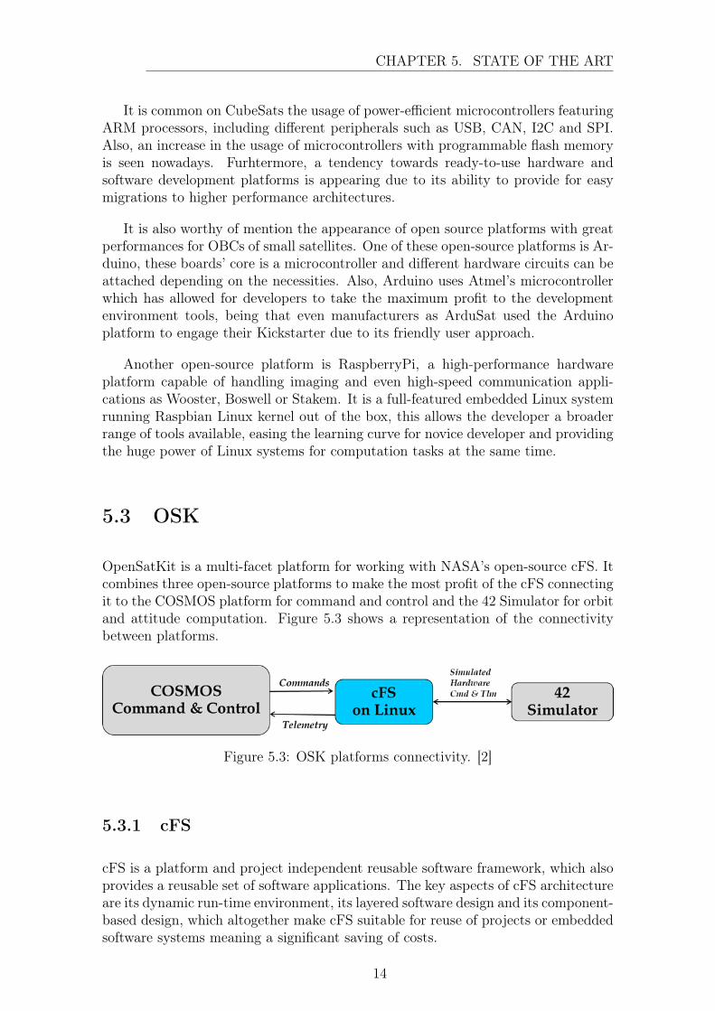
OpenSatKit is a multi-facet platform for working with NASA’s open-source cFS. Itcombines three open-source platforms to make the most profit of the cFS connectingit to the COSMOS platform for command and control and the 42 Simulator for orbitand attitude computation. Figure 5.3 shows a representation of the connectivitybetween platforms.
Figure 5.3: OSK platforms connectivity. [2]
5.3.1 cFS
cFS is a platform and project independent reusable software framework, which alsoprovides a reusable set of software applications. The key aspects of cFS architectureare its dynamic run-time environment, its layered software design and its component-based design, which altogether make cFS suitable for reuse of projects or embeddedsoftware systems meaning a significant saving of costs.
14

CHAPTER 5. STATE OF THE ART
This flight software framework provides a set of advantages due to its architectureand has been designed in order to withstand the growth in size and complexityexpected for flight software in the coming years. First, it supports reuse and projectindependence thanks to its configurable set of requirements and code. Also, itsconfigurable parameters permit to be tailored for each environment, from OBCsfor deployment to desktop simulations. This framework simplifies flight softwaredevelopment as well as simplifies maintenance due to its underlying infrastructureand run-time environment. [17]
Figure 5.4: cFS layered structure. [3]
It has been mentioned that the architecture is composed of layers, in figure 5.4a diagram where the different layers are represented is shown. From bottom to top,the first layer consists of the RTOS where the code will be run, working as a softwareinterface between the processor and the FS. cFS is expected to be run on real-timeoperative systems such as RTEMS or VxWorks, for real-time multitasking, but it isalso supported on Linux so it can be developed.
Then, layer two is the platform abstraction, in this layer, it can be found theOS Abstraction Layer, which consists of a software library that provides an API tothe next layer, the cFE, which is independent of the OS, and also in layer two thePlatform Support Package which also is a library to provide an API to underlyingavionics hardware.
The third layer, as has been just mentioned, is the cFE, it is a portable, platform-independent framework that creates an application run-time environment by provid-ing services that are common to most flight applications. It provides core servicessuch as the software bus or the message package library, which will allow for high-
15

CHAPTER 5. STATE OF THE ART
level development of the apps.
Following, the fourth layer includes the applications. The applications will pro-vide mission functionality using a combination of cFS community apps and mission-specific apps, taking benefit from the open-source idea so that the apps developedcan be reused for following projects and saving costs.
Finally, the last layer includes a set of tools that will enhance the experience fordevelopers, allowing to easily include test procedures for the applications developedand even to automatically create app templates reducing the effort needed by de-velopers. One of the most important tools is the Python Ground System since itwill allow to locally test the command ingest and telemetry output functions of theapps developed from the developing environment.
For the application layer, since it is the one where the developments for thisproject will be made, deeper comprehension is needed. In figure 5.5 it can be seena representation of the structure of the apps in the cFS. There, it can be seen thedifferent apps developed, coloured in pink in the image, that will be in charge ofacquiring data from the subsystems or computing the operations needed and storingthe data for the later transmission. In yellow, there can be seen the apps for thecommand and data handling, among these apps the telemetry output and commandingest are the most important for this project since they will be in charge of acquiringthe external commands received and transmitting the desired packets respectively.And finally, in blue the cFE apps are distinguished, executing core services of thesystem.
Figure 5.5: cFS apps structure. [3]
Also in figure 5.5, it is important to appreciate that the different apps are runningin parallel, hence the importance of high-performance OS, and all the different appsare connected through the SoftwareBus. The SB is a cFE service that allows the
16

CHAPTER 5. STATE OF THE ART
connection between all the apps in the cFE. It permits to create pipes from appsand send messages through this pipe as well as subscribing to certain messages inorder to receive the desired data.
Since all the apps are using the same SB, a standard is used for the messagepackets, the CCSDS. The CCSDS is an organization officially established by themanagement of its members and its participation is completely voluntary so theresults of their actions are termed Recommended Standards so they are not bindingto the agencies. Nevertheless, since the biggest space companies, such as ESA,NASA or JAXA, their standards are widely used in the industry.
Regarding the CCSDS Space Packet Standard, which is used in cFS for the Soft-wareBus communications and therefore the command ingest and telemetry output,these packets are divided into three parts: a primary and secondary header and thedata section, allowing for fast identification in the corresponding bits the source ofthe message, its length, its purpose and all the necessary information. Figure 5.6shows the structure of the CCSDS packet. [18] [19]
Figure 5.6: CCSDS packet structure. [4]
5.3.2 42 Simulator
The 42 simulator is an open-source visualization and simulation tool for spacecraftattitude and orbital dynamics and environmental data developed by NASA’s God-dard Space Flight Center.
It allows for the simulation of whole satellite constellations taking into accountits orbit propagation and even attitude behaviour. Attitude can be simulated fromwithin the 42 software or can be an input from external sources such as the cFS,which its OSK version already has the apps necessary for attitude simulation andcommunication to the 42 simulator in order to have SitL scenarios. [20]
5.3.3 COSMOS
COSMOS is a command and control system providing commanding, scripting anddata visualization capabilities for embedded systems. It is intended for use both intesting and during operation and it is composed of a huge set of applications whichallow it to be a command and telemetry server, sending commands, running scripts,running tests, visualizing telemetry data in real-time and graphing it, extractingdata from telemetry and commands and other applications.
This group of applications provide the tools necessary for maintaining a softwareground station that allows to communicate and receive the telemetry packets from
17

CHAPTER 5. STATE OF THE ART
a spacecraft. Also, inside the OSK, it is already prepared to communicate directlyto a cFS running in localhost. Figure 5.7 shows the architecture of the cosmos suite.
Figure 5.7: COSMOS architecture. [5]
18
6 | Design
This chapter includes the different methodologies followed for the design and devel-opment of the different aspects of this project, considering the different necessitiesin order to integrate the best solution possible.
6.1 Architecture design
The first step for the design of the architecture intended to develop in this projectis to review the key interests for the next step of project Plathon. It has been men-tioned that it is interesting to integrate a HitL, therefore this will be the angularpoint for the design. Nevertheless, a revision of the current state of Plathon tech-nologies is needed to identify its fundamentals.
6.1.1 Plathon current state
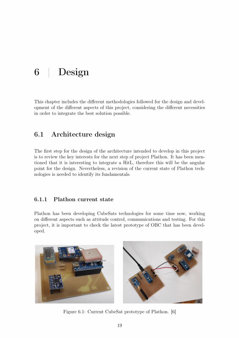
Plathon has been developing CubeSats technologies for some time now, workingon different aspects such as attitude control, communications and testing. For thisproject, it is important to check the latest prototype of OBC that has been devel-oped.
Figure 6.1: Current CubeSat prototype of Plathon. [6]
19

CHAPTER 6. DESIGN
This prototype can be seen in figure 6.1, and it has certain features. First, itincludes two different sensors. One of them is an IMU of 9DOF, this sensor includesa 3-axis accelerometer, a 3-axis gyroscope and a 3-axis magnetometer, using thegyroscope relative movements can be detected and it is possible to determine theposition and attitude of the spacecraft when it is known its position since it isunder the effect of the magnetic field of the Earth which has a certain direction.The other sensor is a GPS, which provides the latitude, longitude and altitude ofthe satellite. It also uses a bluepill as an OBC that is in charge of managing thedifferent subsystems and transmitting the data via Bluetooth, to a near PC.
Also, different ADCS hardware components have been developed such as reactionwheels and magnetorquers, so that the satellite can rotate and position itself whenin orbit. In figure 6.2 the current reaction wheel used can be seen.
Figure 6.2: Plathon reaction wheel. [7]
Finally, the last aspect of the current Plathon state to mention is the air bearing.An air bearing has been developed so that it uses air pressure in order to levitate theCubeSat placed in it. This way, it is possible to test attitude control on a simulatedmicrogravity case. Figure 6.3 shows the mentioned air bearing.
6.1.2 Plathon fundamentals
Having reviewed the current state of the different technologies that have been de-veloped for project Plathon it is possible to identify the most important necessitiesthat can be solved during this thesis.
First, the incorporation of an OBC running cFS will allow a better performanceand development of the satellite with higher parallel multitasking and providing thetools mentioned before.
Also, a problem existing with the current configuration is related to the GPS.
20

CHAPTER 6. DESIGN
Figure 6.3: Plathon air bearing
When the prototype is being tested on the air bearing, it will be static regardingthe GPS position. Then, it is interesting to use the position computed with the 42simulator so that the simulation can be tested in a real-case scenario.
6.1.3 Proposed architecture
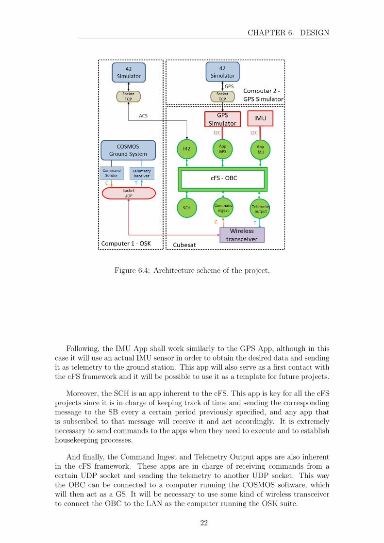
Therefore, having reviewed the current state and necessities the proposed architec-ture is shown in figure 6.4. The system will be built around the OBC, which will berunning cFS.
The first part of the proposed architecture is to separate the cFS from the otherelements of the OSK, since it is already prepared to run the three elements on thesame computer for simulation, but in this case, the cFS needs to be run on an OBCcapable of being installed on a CubeSat.
As is seen in the image, six different main apps are shown. First, there is the I42App, which is included in the OSK cFS version to allow, under certain commandsalready included in COSMOS, TCP communication with the 42 Simulator. ThisI42 App is in charge of simulating attitude data and sending it to the 42 Simulator,so the 42 can update the information for the specific spacecraft.
Then, there is the App GPS, this app will need to be developed, and it needs toact as if it were communicating with a standard GPS sensor. Nevertheless, insteadof an actual sensor, a microcontroller will be used, simulating the same behaviour asa conventional sensor but obtaining the data from a 42 simulator running on anothercomputer. Therefore, the microcontroller must communicate wirelessly with anotherhost, since 42 uses TCP sockets for communication this protocol will be used. Thenthe communication between the GPS simulator and the OBC shall be physical,therefore considering the most common communications protocols for GPS sensorsit has been decided to use I2C, although SPI or CAN would also be good options.
21
CHAPTER 6. DESIGN
Figure 6.4: Architecture scheme of the project.
Following, the IMU App shall work similarly to the GPS App, although in thiscase it will use an actual IMU sensor in order to obtain the desired data and sendingit as telemetry to the ground station. This app will also serve as a first contact withthe cFS framework and it will be possible to use it as a template for future projects.
Moreover, the SCH is an app inherent to the cFS. This app is key for all the cFSprojects since it is in charge of keeping track of time and sending the correspondingmessage to the SB every a certain period previously specified, and any app thatis subscribed to that message will receive it and act accordingly. It is extremelynecessary to send commands to the apps when they need to execute and to establishhousekeeping processes.
And finally, the Command Ingest and Telemetry Output apps are also inherentin the cFS framework. These apps are in charge of receiving commands from acertain UDP socket and sending the telemetry to another UDP socket. This waythe OBC can be connected to a computer running the COSMOS software, whichwill then act as a GS. It will be necessary to use some kind of wireless transceiverto connect the OBC to the LAN as the computer running the OSK suite.
22
CHAPTER 6. DESIGN
6.2 Hardware selection
Having defined the architecture that is expected to be implemented in this projectit is necessary to select the different hardware components best suited for each task.
6.2.1 OBC
The most important component of the architecture is the OBC, so the selection ofthe hardware for this task is key. First, the requirements for this component are thefollowing:
• It shall be able to run cFS, therefore RTOS or Linux is needed.
• It shall have I2C interface.
• It shall be a commercial board since its development is not in the scope of thisproject.
Then, as it was stated in the state of the art, this component shall be either anFPGA or a microprocessor/microcontroller. For this project, FPGAs are directlydiscarded, since although they offer extremely good performance and are optimalfor parallel execution and they can run OS they are generally OS agnostic.
Focusing on the commercial sector of microprocessors and microcontrollers, it isdecided to use one that allows running a Linux OS, since the OSAL of the cFS is wellsuited for this OS and it is a more friendly environment for developers. Although itis not an RTOS, a microprocessor able to run Linux will be chosen for these reasons.
Therefore, regarding development boards running Linux, the first candidate thatcomes to mind is the Raspberry Pi, which has also been mentioned as a good can-didate of Open Source hardware for OBCs on the state of the art.
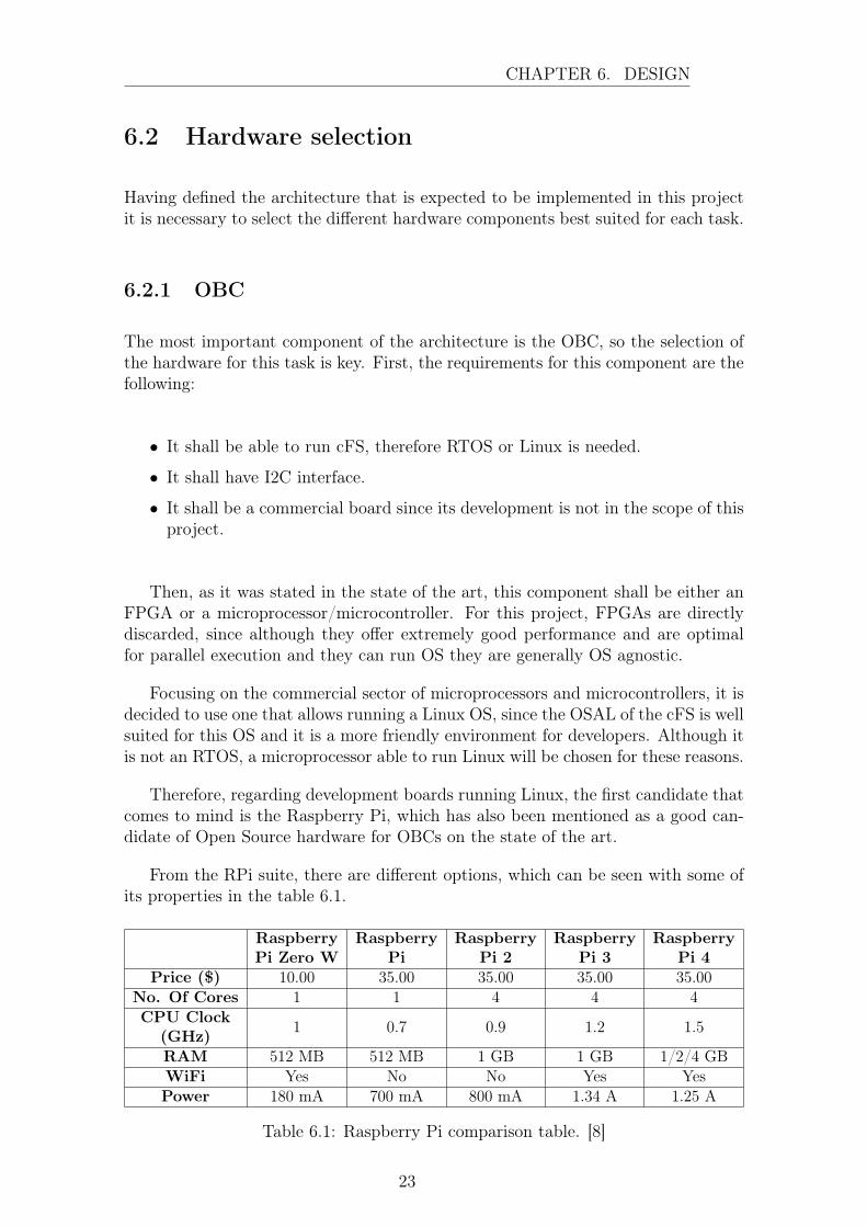
From the RPi suite, there are different options, which can be seen with some ofits properties in the table 6.1.
RaspberryPi Zero W
RaspberryPi
RaspberryPi 2
RaspberryPi 3
RaspberryPi 4
Price ($) 10.00 35.00 35.00 35.00 35.00No. Of Cores 1 1 4 4 4CPU Clock
(GHz) 1 0.7 0.9 1.2 1.5
RAM 512 MB 512 MB 1 GB 1 GB 1/2/4 GBWiFi Yes No No Yes YesPower 180 mA 700 mA 800 mA 1.34 A 1.25 A
Table 6.1: Raspberry Pi comparison table. [8]
23

CHAPTER 6. DESIGN
The first asset that is going to be considered, is the wireless connection. Ithas been shown in the proposed architecture that the OBC shall use a wirelesstransceiver in order to transmit telemetry and receive commands to COSMOS run-ning on another computer, as well as sending attitude data to the 42 Simulator.Selecting an OBC which already includes WiFi will simplify the development forthis prototype and allow the connectivity through a UDP socket to COSMOS forcommands and telemetry, and through a TCP socket to the 42 Simulator for attitudedata. This discards RPi and RPi 2 from the selection.
Regarding the other parameter, it is certain that a higher number of cores, CPUclock speed and RAM allows for faster computation and a better performance whenmultitasking. Nevertheless, cFS does not need an excess of resources, and with 1core at 0.9 GHz and 512 MB of RAM, the application intended to be developedwould run without difficulties.
Furthermore, when considering space applications of these characteristics, space-craft are supplied by batteries and solar panels, therefore the power consumption iscritical since it can increase the weight to be launched significantly. Taking this intoaccount, the best candidate is the RPi Zero W since it presents the lowest powerconsumption and even the lowest price.
Nevertheless, since the RPi 3 was already available in the laboratory where thedevelopments have been made, this model has been used instead of the RPi Zero,since the portability from one RPi to another supposes no difficulties. Both boardsare shown in figure 6.5
(a) RPi Model 3 B+ (b) RPi Zero W
Figure 6.5: Raspberry Pi Models. [8]
6.2.2 GPS Simulator
The second component that needs to be chosen is the GPS simulator. As it hasbeen mentioned, this component will act as a GPS, transmitting the correspondingvalues to petitioned registers via I2C wired interface, and will obtain said valuesfrom the 42 Simulator running on a PC wirelessly.
42 Simulator sends the information as a string, so the GPS simulator shall be
24
CHAPTER 6. DESIGN
able to parse the information to float values, the information being the time, thelatitude, the longitude and the altitude. For the time, the 42 Simulator provides itin the standard date format string "YYYY-MM-DD hh:mm:ss.sss" and the deviceneeds to convert it to a float.
Then, the requirements for the GPS Simulator are summarized next:
• I2C interface.
• The capability of processing data.
• Wireless connectivity.
• Commercial accessible board for easy implementation.
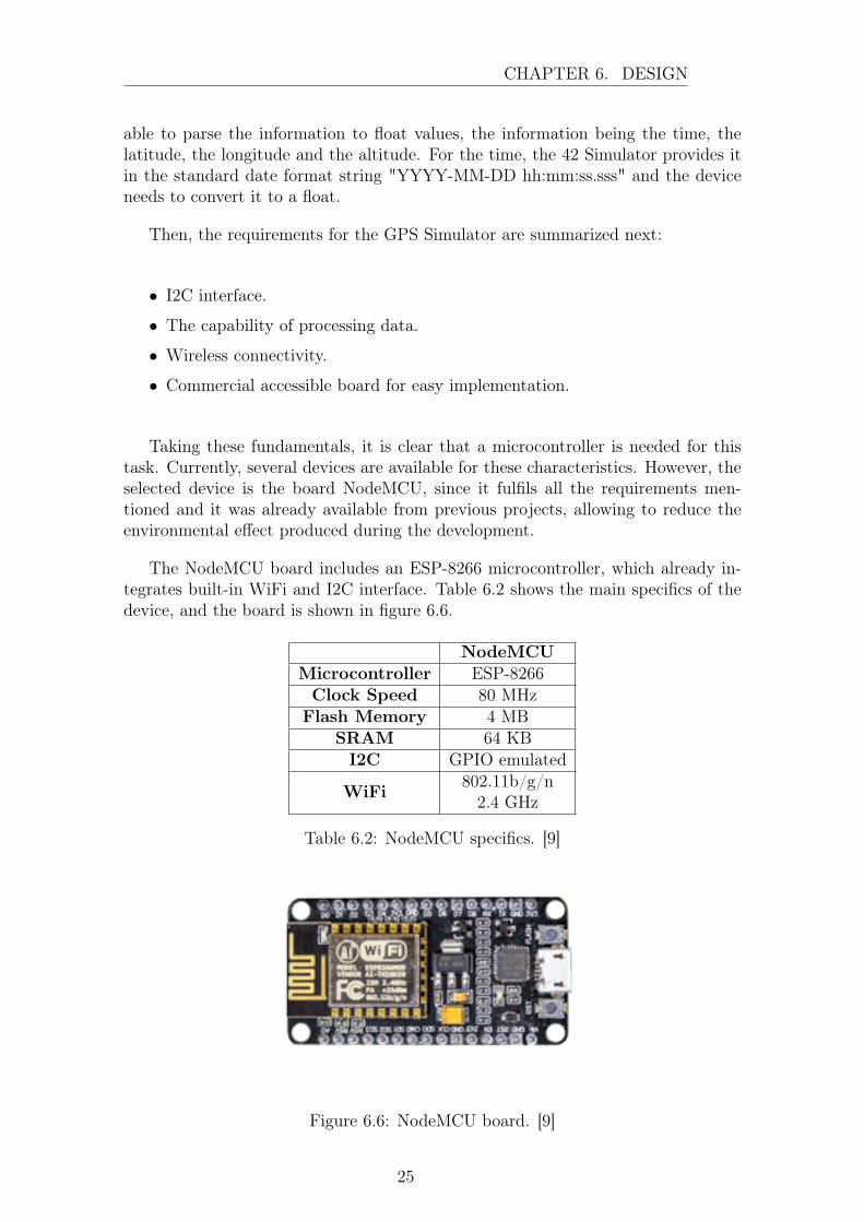
Taking these fundamentals, it is clear that a microcontroller is needed for thistask. Currently, several devices are available for these characteristics. However, theselected device is the board NodeMCU, since it fulfils all the requirements men-tioned and it was already available from previous projects, allowing to reduce theenvironmental effect produced during the development.
The NodeMCU board includes an ESP-8266 microcontroller, which already in-tegrates built-in WiFi and I2C interface. Table 6.2 shows the main specifics of thedevice, and the board is shown in figure 6.6.
NodeMCUMicrocontroller ESP-8266Clock Speed 80 MHzFlash Memory 4 MB
SRAM 64 KBI2C GPIO emulated
WiFi 802.11b/g/n2.4 GHz
Table 6.2: NodeMCU specifics. [9]
Figure 6.6: NodeMCU board. [9]
25

CHAPTER 6. DESIGN
6.2.3 IMU
Finally, the last component that remains to be selected is the IMU. As it is mostsensible, the same IMU used in the previous prototype of this project will be reusedto unify developments. The IMU is the MPU-9250, which has 9DOFs and thereforea 3-axis accelerometer, a 3-axis gyroscope and a 3-axis magnetometer. The specificsof this sensor are shown in the table 6.3 and a representation in figure 6.7.
MPU-9260GyroscopeRange ± 2000 º/sSensitivity 16.4 LSB / (º/s)AccelerometerRange ± 16gSensitivity 2.048 LSB/gMagnetometerRange ± 4800 µTSensitivity 0.6 µT/LSB
Table 6.3: MPU-9250 specifics. [10]
Figure 6.7: MPU-9250 board. [10]
26

CHAPTER 6. DESIGN
6.3 Software development
Following the hardware selection, it is necessary to develop the specific software foreach component, using the corresponding tools and framework. This chapter willexplain the methodology and procedure and the code can be found in the appendix.
6.3.1 RPi/OBC
The first step in the development of the RPi software is to install an adequate OS onan SD card, for this project the Raspbian Lite Kernel has been used since it keepsthe minimum processes and provides faster responses.
After installing the OS, it is necessary to install the cFS, which can be directlyobtained from GitHub [17], and it is possible to develop the apps desired. Following,the different apps and libraries developed for the standard cFS on the RPi areexposed.
BCM2835 Lib
One of the great features of the RPi hardware is the accessible GPIO ports and wiredinterfaces available for the user. There are many ways to access and control thesefeatures, and, since cFS is programmed in C language, a solution for this frameworkhas been found. Several libraries have been developed for RPi GPIO access in Clanguage, and the most common and reliable has been chosen for this project, theBCM2835. After the download of the library, the corresponding modifications inorder to adapt the library to the cFS framework were made and the files were addedto the directory apps inside cFS.
The BCM2835 library includes a group of functions and macros that allow sim-ple usage of the GPIO ports, the I2C communication and the SPI communicationavailable in the RPi. For this project, the I2C interface will be used plenty so theincorporation of this library will be of utmost usage. [21]
The library downloaded directly from the source includes a debug code that willnot compile on cFS, so it needs to be removed. Also, all apps and libraries on cFSrequire an initialization function, so one had to be added. The function added checksif the I2C is working properly and returns a success code.
MPU9DOF Lib
As it is usual for I2C sensors, specific libraries are usually used to acquire the desireddata from the device. The utility of this library is to include the different registersfrom which the data will be retrieved and functions to simplify the queries of datafor the developer.
27

CHAPTER 6. DESIGN
To develop this library, an existing library for this sensor but to be used in aPIC32 microcontroller has served as starting point. It already includes the differentregisters for the data and functions to acquire the necessary registers directly. Nev-ertheless, the functions to write or read from the I2C needed to be changed, and theones from the BCM2835 Lib were used. Also, the init function had to be included,which tests if the I2C communication has been enabled and checks if the sensor isconnected and responding.
GPSNodeMCU Lib
The GPSNodeMCU Lib has the same function as the MPU9DOF Lib, althoughsince in this case the sensor does not exist and is being simulated, the library hasbeen developed from scratch.
Certain registers have been defined for each byte of the corresponding value (time,latitude, longitude and altitude), and functions capable of acquiring the bytes usingthe BCM2835 Lib have been implemented. Also, it is necessary to parse the bytesarray into a float.
And finally, a checksum process has been implemented, where the XOR operationis applied for all the bytes of the same parameter and it is sent through the I2C,then the GPSNodeMCU Lib does the same operation and checks if the values arethe same. If they are not, it returns an error.
IMU App
The IMU App is an actual App of the cFS, and it has been developed following thecFS philosophy. The main task of this app is to acquire the data from the sensoreach time it is requested, and send housekeeping telemetry packets every certainamount of time previously specified.
The flux diagram for this app is specified in figure 6.8, which is stated by thefollowing steps:
1. The Global variables and structs of the App are initialized.
2. The telemetry message intended to be sent periodically is initialized.
3. The SB Pipe is created.
4. The App Subscribes to the following messages of the SB:
• IMU APP Execute.
• IMU APP Command.
• IMU APP Send HK Report.
5. The app waits until it receives a message. Depending on the message received:
28

CHAPTER 6. DESIGN
• Execute message:
(a) It takes an I2C Semaphore. This is done since different apps willbe trying to access the same resource when trying to communicatethrough the I2C interface, so a Semaphore has been implemented inorder to avoid having them accessing at the same time and producingerrors.
(b) If it has taken the Sem correctly, it goes to the next step. If not, itadds one to the current value of the variable I2C Error Counter andgoes back to 5.
(c) It has taken the Sem correctly so the App acquires the desired datafrom the IMU.
(d) It tries to Give the Sem back, so the other Apps can use the I2C. Ifit is Given successfully, it goes back to 5. If not, it adds one to theI2C Error Counter and writes a TRUE in the variable I2CBlocked, sothat it is possible to rapidly identify which App blocked the resourcesince it will block the rest of the applications too. Then goes backto 5.
• HouseKeeping message:
(a) Updates the HK telemetry message with the Global IMU App Data.(b) Builds the message and sends it through the SB.(c) Writes a log with the values sent and goes back to 5.
• Command message, it identifies if it is one of the following commands:
– NoOp Command. It executes no operation but writes a log confirm-ing that the message has been received. Goes back to 5.
– Reset Command. It resets all the counters of the IMU App, thengoes back to 5.
– If it is none of these, it writes a log and goes back to 5.
GPS App
This app is also coherent with the philosophy of the cFS, and since it also acquiresdata from a sensor, the procedure is almost the same as for the IMU App, as it canbe seen in its flux diagram in figure 6.9.
The only difference is that, as it has been mentioned before, a checksum hasbeen implemented for the GPS data. So if the GPSNodeMCU Lib returns an error,this error is accounted for and goes back to waiting for data on the SB.
29

CHAPTER
6.DESIG
NFigure 6.8: Flux diagram of IMU App.
30

CHAPTER
6.DESIG
N
Figure 6.9: Flux diagram of GPS App.
31

CHAPTER 6. DESIGN
Scheduler
As it has been mentioned before, the Scheduler App is in charge of sending cer-tain messages to the SB every certain time. Then, the messages mentioned beforeof Execute and Send HK Report for apps IMU and GPS have to be sent by thescheduler.
Since cFS tries to be a friendly framework for developers, its implementation isquite simple. The messages need to be added to the SCH_TBL_Structure table,in the file sch_lab_tbl.c, as it is shown in listing 6.1, where the number after themessage is the period in seconds.
1 SCH_LAB_ScheduleTable_t SCH_TBL_Structure = { . Conf ig = {2 {CFE_SB_MSGID_WRAP_VALUE(CFE_ES_SEND_HK_MID) , 4} ,3 {CFE_SB_MSGID_WRAP_VALUE(CFE_EVS_SEND_HK_MID) , 4} ,4 {CFE_SB_MSGID_WRAP_VALUE(CFE_TIME_SEND_HK_MID) , 4} ,5 {CFE_SB_MSGID_WRAP_VALUE(CFE_SB_SEND_HK_MID) , 4} ,6 {CFE_SB_MSGID_WRAP_VALUE(CFE_TBL_SEND_HK_MID) , 4} ,7 {CFE_SB_MSGID_WRAP_VALUE(CI_LAB_SEND_HK_MID) , 4} ,8 {CFE_SB_MSGID_WRAP_VALUE(TO_LAB_SEND_HK_MID) , 4} ,9 {CFE_SB_MSGID_WRAP_VALUE(IMU_APP_SEND_HK_MID) , 7} ,
10 {CFE_SB_MSGID_WRAP_VALUE(GPS_APP_SEND_HK_MID) , 4} ,
Listing 6.1: Scheduler table.
Telemetry Output
For the Telemetry Output App, the case is similar to that of the Scheduler. In thiscase, the Telemetry Output has to subscribe to the SB messages that are intendedto be transmitted, therefore, the HK messages have to be included.
Again, the process is very similar. In this case, the messages need to be addedin the table TO_LAB_Subs, which is in the file to_lab_sub.c, as it is shown inlisting 6.2, where the zeros are flags and the last number is the maximum amountof messages that can be queued in the pipe.
1 TO_LAB_Subs_t TO_LAB_Subs = { . Subs = {/∗ CFS App Subs ∗/2 {CFE_SB_MSGID_WRAP_VALUE(TO_LAB_HK_TLM_MID) , {0 , 0} , 4} ,3 {CFE_SB_MSGID_WRAP_VALUE(TO_LAB_DATA_TYPES_MID) , {0 , 0} , 4} ,4 {CFE_SB_MSGID_WRAP_VALUE(CI_LAB_HK_TLM_MID) , {0 , 0} , 4} ,5 {CFE_SB_MSGID_WRAP_VALUE(IMU_APP_HK_TLM_MID) , {0 , 0} , 4} ,6 {CFE_SB_MSGID_WRAP_VALUE(GPS_APP_HK_TLM_MID) , {0 , 0} , 4} ,
Listing 6.2: Telemetry Output table.
Definitions
Finally, after all the apps and libraries have been developed, it is necessary to addthem to the building files so that those are included in the compilation. To do so,two different files that have to be modified.
32
CHAPTER 6. DESIGN
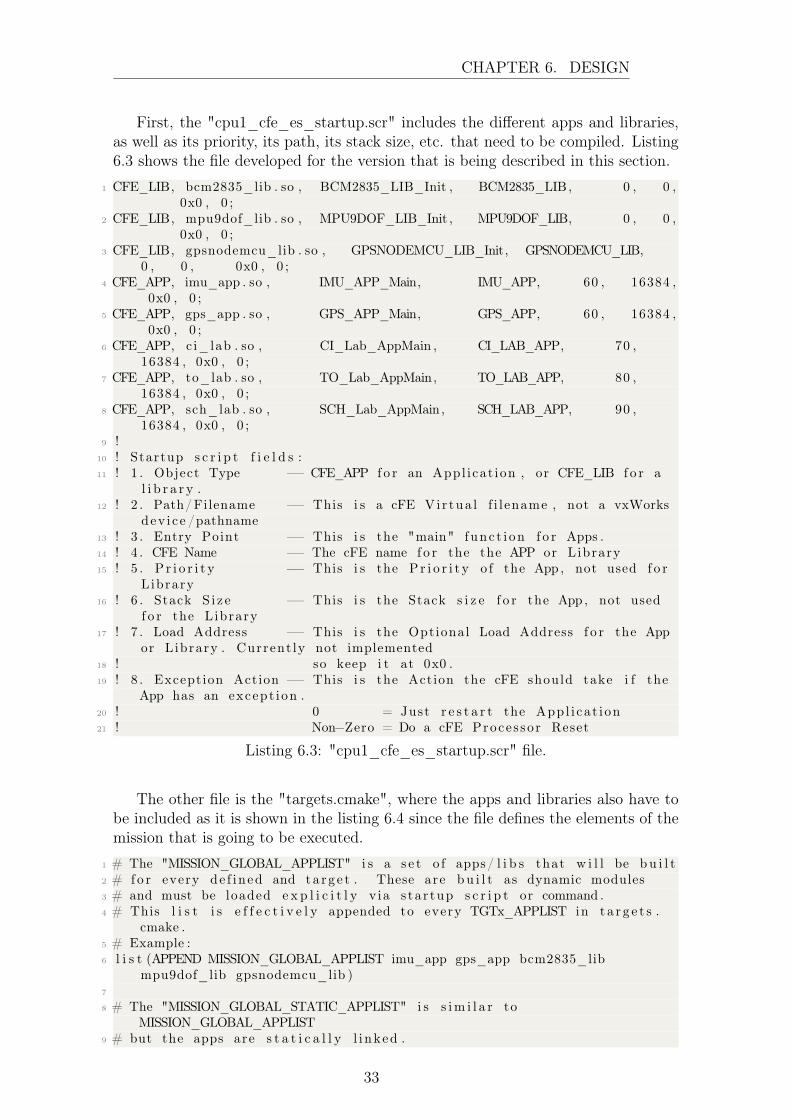
First, the "cpu1_cfe_es_startup.scr" includes the different apps and libraries,as well as its priority, its path, its stack size, etc. that need to be compiled. Listing6.3 shows the file developed for the version that is being described in this section.
1 CFE_LIB, bcm2835_lib . so , BCM2835_LIB_Init , BCM2835_LIB, 0 , 0 ,0x0 , 0 ;
2 CFE_LIB, mpu9dof_lib . so , MPU9DOF_LIB_Init , MPU9DOF_LIB, 0 , 0 ,0x0 , 0 ;
3 CFE_LIB, gpsnodemcu_lib . so , GPSNODEMCU_LIB_Init, GPSNODEMCU_LIB,0 , 0 , 0x0 , 0 ;
4 CFE_APP, imu_app . so , IMU_APP_Main, IMU_APP, 60 , 16384 ,0x0 , 0 ;
5 CFE_APP, gps_app . so , GPS_APP_Main, GPS_APP, 60 , 16384 ,0x0 , 0 ;
6 CFE_APP, ci_lab . so , CI_Lab_AppMain , CI_LAB_APP, 70 ,16384 , 0x0 , 0 ;
7 CFE_APP, to_lab . so , TO_Lab_AppMain, TO_LAB_APP, 80 ,16384 , 0x0 , 0 ;
8 CFE_APP, sch_lab . so , SCH_Lab_AppMain, SCH_LAB_APP, 90 ,16384 , 0x0 , 0 ;
9 !10 ! Startup s c r i p t f i e l d s :11 ! 1 . Object Type −− CFE_APP f o r an Appl icat ion , or CFE_LIB f o r a
l i b r a r y .12 ! 2 . Path/Filename −− This i s a cFE Vi r tua l f i l ename , not a vxWorks
dev i c e /pathname13 ! 3 . Entry Point −− This i s the "main" func t i on f o r Apps .14 ! 4 . CFE Name −− The cFE name f o r the the APP or Library15 ! 5 . P r i o r i t y −− This i s the P r i o r i t y o f the App , not used f o r
Library16 ! 6 . Stack S i z e −− This i s the Stack s i z e f o r the App , not used
f o r the Library17 ! 7 . Load Address −− This i s the Optional Load Address f o r the App
or Library . Current ly not implemented18 ! so keep i t at 0x0 .19 ! 8 . Exception Action −− This i s the Action the cFE should take i f the
App has an except ion .20 ! 0 = Just r e s t a r t the App l i ca t ion21 ! Non−Zero = Do a cFE Proces sor Reset
Listing 6.3: "cpu1_cfe_es_startup.scr" file.
The other file is the "targets.cmake", where the apps and libraries also have tobe included as it is shown in the listing 6.4 since the file defines the elements of themission that is going to be executed.
1 # The "MISSION_GLOBAL_APPLIST" i s a s e t o f apps/ l i b s that w i l l be bu i l t2 # fo r every de f ined and ta r g e t . These are bu i l t as dynamic modules3 # and must be loaded e x p l i c i t l y v ia s ta r tup s c r i p t or command .4 # This l i s t i s e f f e c t i v e l y appended to every TGTx_APPLIST in t a r g e t s .
cmake .5 # Example :6 l i s t (APPEND MISSION_GLOBAL_APPLIST imu_app gps_app bcm2835_lib
mpu9dof_lib gpsnodemcu_lib )7
8 # The "MISSION_GLOBAL_STATIC_APPLIST" i s s im i l a r toMISSION_GLOBAL_APPLIST
9 # but the apps are s t a t i c a l l y l i nked .
33

CHAPTER 6. DESIGN
10 # This l i s t i s e f f e c t i v e l y appended to every TGTx_STATIC_APPLIST int a r g e t s . cmake .
11 # Example :12 # l i s t (APPEND MISSION_GLOBAL_STATIC_APPLIST my_static_app )13
14 # FT_INSTALL_SUBDIR i nd i c a t e s where the black box t e s t data f i l e s ( luas c r i p t s ) should
15 # be copied during the i n s t a l l p roc e s s .16 SET(FT_INSTALL_SUBDIR "host / func t i ona l −t e s t ")17
18 # Each ta r g e t board can have i t s own HW arch s e l e c t i o n and s e t o finc luded apps
19 SET(MISSION_CPUNAMES cpu1 )20
21 SET(cpu1_PROCESSORID 1)22 SET(cpu1_APPLIST ci_lab to_lab sch_lab )23 SET(cpu1_FILELIST cfe_es_startup . s c r )
Listing 6.4: "targets.cmake" file modification.
6.3.2 NodeMCU/GPS
The next software development is for the NodeMCU acting as a GPS simulator.This device can be programmed with Arduino, so due to its accessibility and OpenSource resources, it is the IDE that will be used in this project.
As a quick reminder, the software needs to obtain GPS data from a TCP socket,process it, and send it through the I2C interface when it is requested. The algorithmdeveloped is represented as a flux diagram in figure 6.10 and follows the next steps:
1. The libraries are included and the global variables are defined.
2. The I2C is initialized as a slave with a certain address.
3. The events for I2C receive and I2C request are initialized.
4. The WiFi is initialized as an STA and it is connected to a defined SSID witha certain password.
5. Checks if a client has connected. If it is, it goes to the next step. If not, triesagain.
6. A bool is used as a semaphore to check that I2C transmission is not ongoingbefore advancing to the next step.
7. Check if data is available. If it is, store it until there is not.
8. From the whole message, obtain a line.
9. Scan the line and check if it matches one of the desired parameters.
10. If it is not the end of the message, do the same for the next line. If it is, sendan Ack, convert the time string to a float and convert the floats to byte arrays.
34

CHAPTER 6. DESIGN
11. Go back to 5.
Since the I2C is configured as slave, the process works by interruption so thefollowing steps can happen any time:
1. Receive event interruption.
2. Store the register that has been sent and save that I2C transmission is ongoing.
1. Request event interruption.
2. Transmit the register that was received last.
3. If it is the last byte of any value, compute the checksum.
4. If it is the last checksum, clear the I2C transmission ongoing variable.
35

CHAPTER
6.DESIG
N
Figure 6.10: Flux diagram of GPS Simulator on NodeMCU.
36

CHAPTER 6. DESIGN
6.3.3 OSK modifications
After the developments of the cFS in the RPi and configuring the GPS Simulatoron the NodeMCU, the next step in the design is to do the software modificationsnecessary so that the previous developments work within the OSK suite.
The modifications necessary will be reviewed for each of the components of theOSK, but the first step is to obtain the whole OSK software from GitHub [2].
cFS
The standard distribution of cFS has some differences from the one provided withOSK.
First, the cFE included in the OSK cFS is not complete, it lacks some modulessuch as the MSG. Therefore, some of the structures had to be redefined in order tomatch the OSK cFE. Both codes can be found in the appendix.
Also, the compiling instructions on the OSK cFS have been developed for aconventional Linux OS, and uses a specific command to force 32-bit outputs, the"-m32". Nevertheless, the RPi only works at 32 bits, hence, this command is notrecognized. It is necessary to remove this parameter from all the files, which can bedone using the following bash code:
- $ find . -name "*.mak" > out
- $ while read A; do sed -i -e ’s/-m32//g’ $A; done < out
Another issue from migrating the apps from the standard cFS to the OSK cFS, isthat the building code on the OSK cFS lacks the function "add_cfe_app_dependency"in the file "arch_build.cmake", and this function allows for the apps to access thefunctions on the libraries. Therefore, the function has been added directly to thefile.
The next aspect that needs to be considered is regarding the scheduler andtelemetry output apps. On the OSK cFS, these apps have been developed so themessages are included directly on a JSON file, and it is loaded into the apps duringthe initialization phase. This method allows changing the messages without havingto compile the mission again so it proves very useful during development.
Then, on the one hand, the telemetry output messages have to be added on files"cpu1_osk_to_pkt_tbl.json", as it is shown on listing 6.5, having to add differentparameters defining the message.
786 "packet": {787 "name": "GPS_APP_HK_TLM_MID",788 "stream -id": "\u0884",
37

CHAPTER 6. DESIGN
789 "dec -id": 2180,790 "priority": 0,791 "reliability": 0,792 "buf -limit": 4793 "filter": { "type": 2, "X": 1, "N": 1, "O": 0}794 },795
796 "packet": {797 "name": "IMU_APP_HK_TLM_MID",798 "stream -id": "\u0883",799 "dec -id": 2179,800 "priority": 0,801 "reliability": 0,802 "buf -limit": 4803 "filter": { "type": 2, "X": 1, "N": 1, "O": 0}804 }805
806 ]807 }
Listing 6.5: Telemetry Output JSON file for messages.
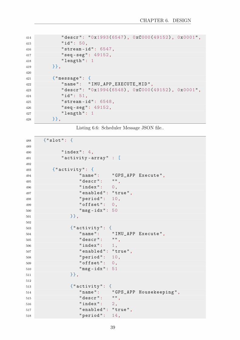
On the other hand, for the scheduler, the information has to be added totwo different files. First, the messages desired have to be specified in the file"cpu1_osk_sch_msg_tbl.json", here the message is defined, as it can be seen in list-ing 6.6. Then, the messages also have to be added to the file "cpu1_osk_sch_sch_tbl.json",and here the message is established to be called every a certain period, as it can beseen in listing 6.7.
394 {"message": {395 "name": "GPS_APP_SEND_HK_MID",396 "descr": "0x1893(6291), 0xC000(49152), 0x0001",397 "id": 48,398 "stream -id": 6291,399 "seq -seg": 49152,400 "length": 1401 }},402
403 {"message": {404 "name": "IMU_APP_SEND_HK_MID",405 "descr": "0x1883(6275), 0xC000(49152), 0x0001",406 "id": 49,407 "stream -id": 6275,408 "seq -seg": 49152,409 "length": 1410 }},411
412 {"message": {413 "name": "GPS_APP_EXECUTE_MID",
38
CHAPTER 6. DESIGN
414 "descr": "0x1993(6547), 0xC000(49152), 0x0001",415 "id": 50,416 "stream -id": 6547,417 "seq -seg": 49152,418 "length": 1419 }},420
421 {"message": {422 "name": "IMU_APP_EXECUTE_MID",423 "descr": "0x1994(6548), 0xC000(49152), 0x0001",424 "id": 51,425 "stream -id": 6548,426 "seq -seg": 49152,427 "length": 1428 }},
Listing 6.6: Scheduler Message JSON file..
488 {"slot": {489
490 "index": 4,491 "activity -array" : [492
493 {"activity": {494 "name": "GPS_APP Execute",495 "descr": "",496 "index": 0,497 "enabled": "true",498 "period": 10,499 "offset": 0,500 "msg -idx": 50501 }},502
503 {"activity": {504 "name": "IMU_APP Execute",505 "descr": "",506 "index": 1,507 "enabled": "true",508 "period": 10,509 "offset": 0,510 "msg -idx": 51511 }},512
513 {"activity": {514 "name": "GPS_APP Housekeeping",515 "descr": "",516 "index": 2,517 "enabled": "true",518 "period": 14,
39

CHAPTER 6. DESIGN
519 "offset": 0,520 "msg -idx": 48521 }},522
523 {"activity": {524 "name": "IMU_APP Housekeeping",525 "descr": "",526 "index": 3,527 "enabled": "true",528 "period": 14,529 "offset": 0,530 "msg -idx": 49531 }}532
533 ]534 }}
Listing 6.7: Scheduler Scheduler JSON file.
Nevertheless, it is important to notice that the messages in the scheduler JSONfile are divided into slots, with different activities each. This is important becausethe Scheduler App is limited to 4 slots of 15 activities each, and by default, the OSKis full and there is no space for more messages. Then, in order to add the HK andExecute messages, this limit have been changed to 5 slots. This can be changed inthe file "kit_sch_platform_cfg.h", changing the macros "SCHTBL_SLOTS" and"SCHTBL_ACTIVITES_PER_SLOT".
42
The 42 Simulator has been prepared to send GPS data to a TCP Socket so the GPSSimulator can receive it and process it. To do this, the Demo example has beenused, doing the modifications necessary to satisfy the requirements.
First, in order to establish the TCP connection, the file "Inp_IPC.txt" has beenmodified, as it is shown in listing 6.8 so that it transmits the GPS data of thespacecraft 7 to the IP and Port that has been established for the NodeMCU.
1 <<<<<<<<<<<42: In t e rProc e s s Comm Conf igurat ion F i l e >>>>>>>>>>>>>>2 1 ! Number o f Sockets3 ∗∗∗∗∗∗∗∗∗∗∗∗∗∗∗∗∗∗∗∗∗∗∗∗∗∗∗∗∗∗∗∗∗∗ IPC 0 ∗∗∗∗∗∗∗∗∗∗∗∗∗∗∗∗∗∗∗∗∗∗∗4 TX ! IPC Mode5 0 ! AC. ID f o r ACS mode6 " State00 .42" ! F i l e name f o r WRITE or READ7 CLIENT ! Socket Role8 192 . 1 68 . 1 . 4 6 8888 ! Server Host Name, Port9 TRUE ! Allow Blocking
10 TRUE ! Echo to stdout11 1 ! Number o f TX p r e f i x e s12 "SC [ 7 ] .AC.GPS" ! Pr e f i x 0
Listing 6.8: "Inp_IPC.txt" file.
40

CHAPTER 6. DESIGN
Following this, it is necessary to modify the file for spacecraft 7 so that ithas a GPS receiver. The spacecraft 7 in this example is the Cubesat1U, so the"SC_Cubesat1U.txt" has been modified and the number of GPS receiver has beenchanged from 0 to 1.
COSMOS
For the COSMOS environment, some modifications were also needed in order to beable to connect to the RPi and also to be able to interpret the telemetry sent by thenew apps developed and know the commands to send.
So, to connect to the RPi, it is necessary to change the file "cmd_tlm_server.txt".In that file, there shall be a line that says "INTERFACE LOCAL_CFS_INT", thisline shall be commented adding the character ’#’ at the beginning. Then, two linesover that, there is a commented line that says "INTERFACE PISAT_CFS_INT",this line shall be uncommented and then the IP and Ports that follow in that lineshall be changed to that of the RPi.
Following, to add the developed apps commands and telemetry, several modifi-cations are needed. First, in the same file as before, the "cmd_tlm_server.txt", itis necessary to add the apps as targets. For example, for this project, it has beenadded "TARGET GPS_APP and "TARGET IMU_APP".
Then, in the directory targets, a directory for each of the apps also has to beadded, for example, "GPS_APP/" and "IMU_APP/". Inside each directory, an-other directory called "cmd_tlm/" is needed. Finally, inside that directory, twofiles have to be defined, the cmd and tlm, which contain the information of thecommands and telemetry respectively for a certain app. Listings 6.9 and 6.10 showthe files for the GPS App as examples.
1 <%2 r e qu i r e ’ osk_config ’3 r e qu i r e ’ osk_global ’4
5 @APP_PREFIX_STR = "GPS_APP"6 @CMD_MID_STR = "GPS_APP_CMD_MID"7
8 %>9
10 COMMAND <%= @APP_PREFIX_STR %> <%= Osk : :CMD_STR_NOOP %> <%= Osk : : Cfg .processor_endian %> "Generate an i n f o event message with appve r s i on "
11 <%= Osk : : Cfg . cmd_hdr(@APP_PREFIX_STR, @CMD_MID_STR, 0 , 0) %>12
13 COMMAND <%= @APP_PREFIX_STR %> <%= Osk : :CMD_STR_RESET %> <%= Osk : : Cfg .processor_endian %> "Reset Counters and app l i c a t i o n to a d e f au l ts t a t e "
14 <%= Osk : : Cfg . cmd_hdr(@APP_PREFIX_STR, @CMD_MID_STR, 1 , 0) %>15
16 COMMAND GPS_APP PROCESS_TBL <%= Osk : : Cfg . processor_endian %> " ProcessIMU tab l e "
41

CHAPTER 6. DESIGN
17 <%= Osk : : Cfg . cmd_hdr(@APP_PREFIX_STR, @CMD_MID_STR, 2 , 0) %>
Listing 6.9: "gps_cmd.txt" file.
1 <%2 r e qu i r e ’ osk_config ’3
4 @APP_PREFIX_STR = "GPS_APP"5 @HK_TLM_MID_STR = "GPS_APP_HK_TLM_MID"6
7 %>8
9 TELEMETRY GPS_APP HK_TLM_PKT <%= Osk : : Cfg . processor_endian %> "GPS_appHousekeeping Packet"
10 <%= Osk : : Cfg . tlm_hdr (@APP_PREFIX_STR, @HK_TLM_MID_STR) %>11 APPEND_ITEM CMD_ERROR_COUNT 16 UINT "Error Command Count"12 APPEND_ITEM CMD_VALID_COUNT 16 UINT "Valid Command Count"13 APPEND_ITEM I2C_BLOCKEDMUT 16 UINT "Flag to i nd i c a t e i f t h i s app
has blocked the i 2 c "14 APPEND_ITEM I2C_ERROR_COUNT 16 UINT "Counter o f e r r o r s produced
due to i 2 c comms"15 APPEND_ITEM SPARE 32 UINT "Spare 4 bytes f o r s t r u c t
a l ignement "16 APPEND_ITEM GPS_TIME 64 FLOAT "GPS time . "17 APPEND_ITEM LAT 64 FLOAT "GPS l a t i t u d e . "18 APPEND_ITEM LONG 64 FLOAT "GPS long i tude . "19 APPEND_ITEM ALT 64 FLOAT "GPS a l t i t u d e . "
Listing 6.10: "gps_tlm.txt" file.
42
7 | Validation
For the validation of the system through the development of the project, a multitudeof tests have been carried constantly, from connecting the device to the power sourceto turning on an LED or validating the full chain of communications.
In this chapter, the tests that have been considered the most relevant will bedetailed.
7.1 Tests for cFS integration in hardware
7.1.1 Test 1.1. cFS execution on RPi.
Procedure
This test is done to check the compatibility and the performance of the cFS on theRPi. To do so, the cFS repository is obtained from GitHub and initialized.
- $ git clone https://github.com/nasa/cFS.git
- $ cd cFS
- $ git submodule init
- $ git submodule update
Following this, it is necessary to copy the default makefile and definitions tobuild the example code.
- $ cp cfe/cmake/Makefile.sample Makefile
- $ cp -r cfe/cmake/sample_defs sample_defs
And finally, it is only necessary to prepare, compile and run the application.
43

CHAPTER 7. VALIDATION
- $ make prep
- $ make
- $ make install
- $ cd build/exe/cpu1
- $ ./core-cpu1
Expected results
Under the circumstances that the procedure has been followed correctly and thereis no error due to a hardware malfunction, the cFS should start running showingon the terminal the different tasks it is executing, allowing the developer to check ifthere is an error at any point.
Results obtained
As expected, the test was successful and the cFS executed with no failures, showingin the terminal the different processes it is executing. Some of these tasks can beseen in figure 7.1.
Figure 7.1: Results from test 1.1. cFS running on RPi.
7.1.2 Test 1.2. cFS connectivity through I2C to one slave.
Procedure
This test will try to validate the I2C interface between the RPi as master and theIMU as a slave through the cFS. This will validate the physical channel and theintegration of the BCM2835 library.
To conduct this test, it is necessary to add the BCM2835 library to the cFS, andsince the MPU9250 will be used as a sensor, the MPU9DOF library and IMU Appwill also be included, so these apps will also be validated during the test.
44

CHAPTER 7. VALIDATION
Aside from integrating the different software assets, the connection between thesensor and the OBC shall be done correctly. The connections necessary are shownin figure 7.2.
Finally, cFS shall be compiled and run.
Figure 7.2: RPi - IMU connections.
Expected results
In case the software, the connections and the hardware are all correct and withoutfailures, cFS should execute and start showing on the terminal the acceleration foreach axis. When the physical sensor is moved, the values should vary accordingly.
Results obtained
The test was a success and no errors or warnings were detected, showing the corre-sponding values onscreen and reacting in real-time with the sensor movements.
7.1.3 Test 1.3. cFS connectivity through I2C to two slaves.
Procedure
This test has been carried out to see the performance of the cFS when accessingmultiple sensors through the I2C interface.
The sensors to be connected to in this test are the IMU and the NodeMCUacting as GPS, so the different apps and libraries developed for these sensors shall
45
CHAPTER 7. VALIDATION
be added to cFS. It is important to note that when this test was first executed theSemaphore was still not implemented.
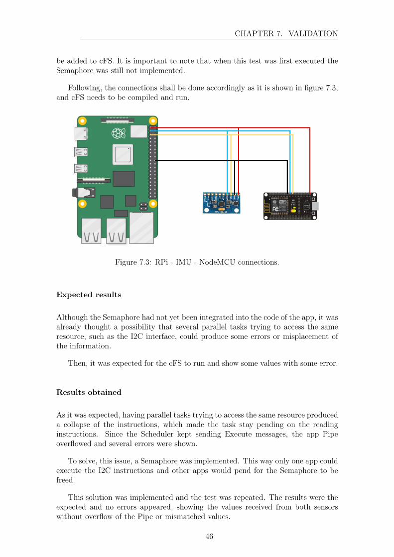
Following, the connections shall be done accordingly as it is shown in figure 7.3,and cFS needs to be compiled and run.
Figure 7.3: RPi - IMU - NodeMCU connections.
Expected results
Although the Semaphore had not yet been integrated into the code of the app, it wasalready thought a possibility that several parallel tasks trying to access the sameresource, such as the I2C interface, could produce some errors or misplacement ofthe information.
Then, it was expected for the cFS to run and show some values with some error.
Results obtained
As it was expected, having parallel tasks trying to access the same resource produceda collapse of the instructions, which made the task stay pending on the readinginstructions. Since the Scheduler kept sending Execute messages, the app Pipeoverflowed and several errors were shown.
To solve, this issue, a Semaphore was implemented. This way only one app couldexecute the I2C instructions and other apps would pend for the Semaphore to befreed.
This solution was implemented and the test was repeated. The results were theexpected and no errors appeared, showing the values received from both sensorswithout overflow of the Pipe or mismatched values.
46

CHAPTER 7. VALIDATION
7.2 Tests for nodeMCU integration
7.2.1 Test 2.1. NodeMCU TCP connectivity.
Procedure
The objective of this test is to validate and test the performance of the NodeMCUreceiving and processing data from a TCP socket.
To do so, the NodeMCU has been programmed to connect to the local WiFi andcreate a server on port 8888. Also, the code to parse the information received fromthe socket has been included and the serial port has been initialized to show theobtained data on the serial monitor of Arduino.
On the other hand, the 42 has been configured to connect to the NodeMCU IPand send GPS data to the socket at port 8888.
Expected results
It is expected a correct performance of the devices and it should appear the valuessent by the 42 on the serial monitor.
Results obtained
As expected, the was no malfunction of the system and the transmission betweenthe 42 and the NodeMCU is flawless. In figure 7.4 the results are shown.
7.2.2 Test 2.2. NodeMCU I2C transmission of a fixed byte.
Procedure
This test aims to validate the I2C transmission from the NodeMCU, as a slave, tothe cFS, as a master. In this test, only a byte will be requested and sent to makethe procedure as simple as possible in case some unknown error occurs.
To do so, the NodeMCU has been programmed to act as a slave and to answerone specific byte when a certain register is petitioned.
On the other end, the cFS has been programmed to request that certain bit andshow the value received.
47

CHAPTER 7. VALIDATION
Figure 7.4: NodeMCU - 42 Simulator transmission.
Expected results
It is expected for the NodeMCU to send the corresponding value so that it showscorrectly on the cFS terminal, meaning that the I2C transmission is correct.
Results obtained
In this case, the results were not the ones expected. The NodeMCU did not sendthe register when asked since it was not able to detect it was being addressed bythe RPi.
After several tests and debugging it was found that the reason behind this errorwas due to the speed of the I2C clock, which was set on the cFS. The NodeMCU doesnot have a dedicated I2C module, but it is capable of using this interface by digitallydriving the GPIO pins. Nevertheless, this makes the system a lot slower and at thestandard speed of 100 kHz, the NodeMCU did not detect the I2C communications.
Then, experimentally it was determined that the best I2C clock speed was 10kHz, at which the I2C was able to receive and transmit information. This speed waschanged and after repeating the test the results were successful.
48

CHAPTER 7. VALIDATION
7.2.3 Test 2.3. NodeMCU I2C transmission of a parameterbyte array.
Procedure
After test 2.3, the next step is to check the transmission of the actual parameter,which is a float, as a byte array and receive it in the cFS and transform it to thefloat again.
This is done by the GPSNodeMCU library, so it was incorporated together withthe GPS App in the cFS so it would request the parameters to the NodeMCU andturn the bytes to the corresponding float.
Meanwhile, the NodeMCU was programmed to receive the registers and hadassigned to send the byte array of the parameter depending on that register.
Expected results
It is expected to have no errors and receive the fixed values for the parameters onthe cFS terminal.
Results obtained
The results obtained have been quite different from the expected.
First, when requesting the byte array for one unique register the NodeMCU wasnot able to transmit correctly all of the bytes, and only the first one was received.This was improved by requesting each byte with a unique register each. The systemimproved but there were still faulty bytes which induced errors on the parameter.
These problems are also due to the speed of the NodeMCU processor and nothaving a dedicated I2C module. To solve completely this issue, it is proposed to useanother NodeMCU that includes the ESP32 instead of the ESP8266. The ESP32is a microcontroller of the same family as the ESP8266 but has higher computingresources as well as a dedicated I2C peripheral interface.
Nevertheless, the Arduino framework does not allow to program of the microcon-troller as an I2C slave, so it has to be programmed from the ESPRESSIF framework.
After implementing the new code and hardware, and repeating the tests theresults obtained have been satisfactory.
49

CHAPTER 7. VALIDATION
7.3 Tests for integration in OSK
7.3.1 Test 3.1. Integration of developed apps into OSK cFS.
Procedure
This test has as objective to integrate the apps developed with the OSK cFS so itincludes the rest of the different apps.
For the first iteration of this test the procedure was to obtain the frameworkfrom GitHub [2], add the new apps to its corresponding directory and update thedefinition files.
Then, it was just necessary to compile and run cFS as in the previous tests.
Expected results
It was expected to compile the cFS correctly and execute the developed tasks inparallel with the original OSK.
Results obtained
The results were not quite the expected since several errors occurred. These errorshave been explained in chapter 6.3.3, section cFS, and it was possible to solve themand achieve the expected results after several iterations.
7.3.2 Test 3.2. Transmission of 42 data to cFS.
Procedure
This test consists of the validation of the transmission stage between the 42 Simu-lator and the cFS running on the RPi.
To do this test, the NodeMCU will be the angular stone of the procedure, the 42Simulator will be configured to send data to its IP and the NodeMCU will receiveit, convert it to floats and store it as a byte array.
Then, the cFS will be configured with the GPS App, and it will periodicallyrequest the parameters to the NodeMCU via the I2C interface. Then it will castthe byte array into a float again and display it onscreen.
50
CHAPTER 7. VALIDATION
Expected results
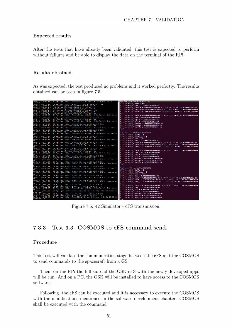
After the tests that have already been validated, this test is expected to performwithout failures and be able to display the data on the terminal of the RPi.
Results obtained
As was expected, the test produced no problems and it worked perfectly. The resultsobtained can be seen in figure 7.5.
Figure 7.5: 42 Simulator - cFS transmission.
7.3.3 Test 3.3. COSMOS to cFS command send.
Procedure
This test will validate the communication stage between the cFS and the COSMOSto send commands to the spacecraft from a GS.
Then, on the RPi the full suite of the OSK cFS with the newly developed appswill be run. And on a PC, the OSK will be installed to have access to the COSMOSsoftware.
Following, the cFS can be executed and it is necessary to execute the COSMOSwith the modifications mentioned in the software development chapter. COSMOSshall be executed with the command:
51
CHAPTER 7. VALIDATION
- $ ruby Launcher
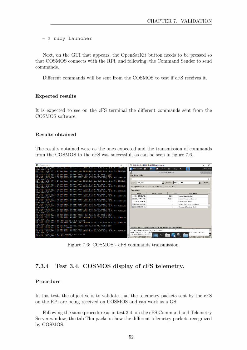
Next, on the GUI that appears, the OpenSatKit button needs to be pressed sothat COSMOS connects with the RPi, and following, the Command Sender to sendcommands.
Different commands will be sent from the COSMOS to test if cFS receives it.
Expected results
It is expected to see on the cFS terminal the different commands sent from theCOSMOS software.
Results obtained
The results obtained were as the ones expected and the transmission of commandsfrom the COSMOS to the cFS was successful, as can be seen in figure 7.6.
Figure 7.6: COSMOS - cFS commands transmission.
7.3.4 Test 3.4. COSMOS display of cFS telemetry.
Procedure
In this test, the objective is to validate that the telemetry packets sent by the cFSon the RPi are being received on COSMOS and can work as a GS.
Following the same procedure as in test 3.4, on the cFS Command and TelemetryServer window, the tab Tlm packets show the different telemetry packets recognizedby COSMOS.
52

CHAPTER 7. VALIDATION
When cFS is running, it is necessary to send a command to start receiving data.So, from the command sender, for the app KIT_TO the command Enable Telemetryshall be selected and the IP of the RPi shall be written as the input data.
Expected results
It is expected to see the telemetry packets defined for the developed apps updatedat the same time as the cFS.
Results obtained
At first, the results were not as expected. The received packet did not coincide withthe one sent, as some empty bytes appeared between data packets.
This is due to the data structure alignment, which means that the hardware isaligning the data naturally to perform more efficiently. So, since the architectureis of 32 bits, the data is stored in four consecutive bytes, and when this was notpossible, the system added empty bytes so that this case was forced.
This was solved by adding empty spare bytes on the telemetry packet so thatthe data was aligned correctly from the start.
After correcting this error the results obtained were the ones expected, as it canbe seen in figure 7.7.
Figure 7.7: COSMOS - cFS telemetry transmission.
53
8 | Budget review
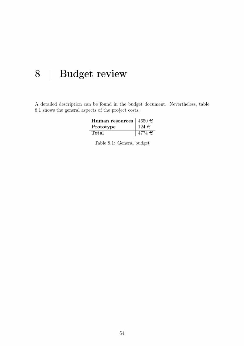
A detailed description can be found in the budget document. Nevertheless, table8.1 shows the general aspects of the project costs.
Human resources 4650 ePrototype 124 eTotal 4774 e
Table 8.1: General budget
54

9 | Environmental impact
Society is growing technologically at a huge rate, devouring resources to satisfy theneeds of humankind. So it is essential to consider the effect one is producing overthe planet when a project is carried out.
First, it is important to consider the objective of the project. This projectproposes the usage of satellite and IoT technologies to be able to transmit datafrom remote places on Earth so that it can be monitored at fast rates. This canallow for environmental applications such as the monitoring of temperatures on thepoles or the quality of rainwater in a variety of places, which would allow for a fasterreaction when an anomaly occurs.
Nevertheless, electronic devices such as IoT stations or satellite must run onsome kind of power supply, and although satellites generally use renewable ener-gies, especially solar, batteries are used for their storage, and this can harm theenvironment.
Finally, it is important to mention that all of the devices used for the prototypeof this object have been reused from previous projects, so the carbon footprint hasbeen reduced when compared with acquiring all the components as new. It is alsocertain that most electronics components possess chemical materials, but all of thecomponents used in this project comply with the European Directive 2011/65/UE(Restructuring of dangerous substances) [22].
55

10 | Future developments
Being that this thesis is part of Plathon, the thought of this work being continuedin the future has always been in mind. Therefore, it has been intended to describethrough this paper any issue and any solution with all the detail possible so thatfuture students can start some steps ahead.
And this is aligned with the philosophy of cFS and its open-source intention,being that this framework has been developed so that the community can sharetheir developments and they can be reused in future missions. That is the reasonwhy all of the apps and libraries developed in this project will be available in GitHubrepositories, free for anyone to use or improve them as it is pleased.
It would be interesting for future developments in this area, to take the next stepfrom the cFS development and develop an app for attitude control and determinationof the satellite. Communication with different kinds of sensors has already beenimplemented so it is a great idea to try and include actuators so that an ADCSsubsystem can be developed.
Also, from the developments carried out on the OSK and COSMOS as a GS, itwould prove useful to keep the developments for the management of IoT networks.COSMOS offers a lot of tools that have not been explored due to a limitation oftime but it can offer good solutions for Plathon.
Figure 10.1 shows an architecture that could be developed in the future.
56
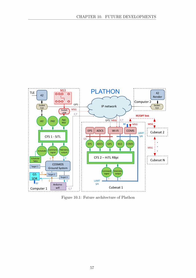
CHAPTER 10. FUTURE DEVELOPMENTS
Figure 10.1: Future architecture of Plathon
57

11 | Conclusions
This project had three core objectives: the study of the cFS and OSK frameworkfor app development, the integration of an OBC using cFS capable of acquiring dataand the incorporation of the OBC on a HitL simulation prototype.
The study of the cFS and OSK has been successful and has allowed for thesoftware development of the different apps and functionalities included in the project.Although the framework still offers more possibilities to be explored this objectiveis considered achieved.
Regarding the integration of an OBC using cFS, the selection of the RPi for thistask has produced good results, facilitating the incorporation of the framework andits development. Using the tools obtained from the study of the cFS it has beenpossible to configure the OBC to acquire data from multiple sensors, processingand storing it, and later generating the corresponding telemetry packets, alwaysfollowing the structure taught in cFS to unify the developments.
Finally, the developments with the 42 Simulator and COSMOS allow for a wire-less integration of the OBC on the network of the simulation, so it can be assumedthat the objective of incorporating the OBC on a HitL simulation prototype hasbeen achieved. Also, as it has been mentioned before, it has prepared the terrain forfuture projects to go further and achieve new goals, which is of utmost importance.
The system this project and Plathon are proposing, unifying satellites and IoT,is in sync with the current growth of the technological sector. Allowing fast com-munications for monitoring data from around the globe can bring vast solutions forcurrent society.
58

Bibliography
[1] U. Raza, P Kulkarni, and M. Sooriyabandara. Low power wide area networks:A survey. IEEE Commun. Surv. Tutorial, 2(19), 2017.
[2] OpenSatKit/OpenSatKit: Core Flight System (cFS) Application Developer’sKit. https://github.com/OpenSatKit/OpenSatKit. [Online; accessed 16-June-2021].
[3] Flight Software and Systems Branch. Core Flight System ( cFS ) Training.(April), 2020.
[4] PicSat. https://picsat.obspm.fr/communication/ccsds-packets?locale=en. [Online; accessed 16-June-2021].
[5] Requirements and Design. https://cosmosc2.com/docs/requirements. [On-line; accessed 16-June-2021].
[6] Juan Palomares. Estudio y diseno de dos placas de intercambio de datos deinclinación y posición entre dos cubesats. 2015.
[7] Joan Rodriguez. Proyecto de diseño de un control de attitude de un CubeSatbasado en motor brushless. page 77, 2020.
[8] Raspberry Pi. https://www.raspberrypi.org/. [Online; accessed 21-June-2021].
[9] Espressif Systems. ESP8266EX - Datasheet. 2020.
[10] MPU-9250 Product Specification Revision 1.1 MPU-9250 Product Specifica-tion. Technical report.
[11] Small Spacecraft Technology. State of the Art Small Spacecraft Technology.Technical report, 2018.
[12] M. Batty, K. W. Axhausen, F. Giannotti, A. Pozdnoukhov, A.and Bazzani,M. Wachowicz, and Y. Portugali. Smart cities of the future. The EuropeanPhysical Journal Special Topics, 1(214):481–518, 2012.
[13] ESA - Satellite constellation. http://www.esa.int/Applications/Observing_the_Earth/Copernicus/Sentinel-3/Satellite_constellations. [Online; accessed 16-June-2021].
59

BIBLIOGRAPHY
[14] Yuri Ulybyshev. Satellite constellation design for complex coverage. Journal ofSpacecraft and Rockets, 45(4):843–849, may 2008.
[15] Ahan Kak and Ian F. Akyildiz. Designing Large-Scale Constellations for theInternet of Space Things with CubeSats. IEEE Internet of Things Journal,8(3):1749–1768, 2021.
[16] Iridium. http://www.astronautix.com/i/iridium.htmls. [Online; accessed16-June-2021].
[17] Core Flight System. https://cfs.gsfc.nasa.gov/. [Online; accessed 16-June-2021].
[18] Ecss. ECSS-E-70-41A - Ground systems and Operations - Telemetry andtelecommand packet utilization. (January):228, 2003.
[19] Recommendation for Space Data System Standards BLUE BOOK RECOM-MENDED STANDARD SPACE PACKET PROTOCOL. Technical report,2020.
[20] NASA Operational Simulator for Small Satellites User Manual IndependentVerification and Validation (IV&V). Technical report.
[21] bcm2835: C library for Broadcom BCM 2835 as used in Raspberry Pi.
[22] Parlamento Europeo. Directiva 2011/65/UE del parlamento europeo y del con-sejo. Technical report, 2011.
60