Deploy VMware vSphere using Hitachi Virtual Storage ...
50
August 9, 2013 By Reference Architecture Guide Deploy VMware vSphere using Hitachi Virtual Storage Platform, IBM® x3550 M4 Servers, and Brocade Networks in a Scalable Environment Michael Nakamura (Hitachi Data Systems), Van Tran (Brocade), Marcus Thordal (Brocade)
-
Upload
khangminh22 -
Category
Documents
-
view
3 -
download
0
Transcript of Deploy VMware vSphere using Hitachi Virtual Storage ...

August 9, 2013
By
Reference Architecture Guide
Deploy VMware vSphere using Hitachi Virtual Storage Platform, IBM® x3550 M4 Servers, and Brocade Networks in a Scalable Environment
Michael Nakamura (Hitachi Data Systems), Van Tran (Brocade), Marcus Thordal (Brocade)
FeedbackHitachi Data Systems welcomes your feedback. Please share your thoughts by sending an email message to [email protected]. To assist the routing of this message, use the paper number in the subject and the title of this white paper in the text.

Table of ContentsSolution Overview........................ .......................................................................3
Key Solution Components..................................................................................5
Hardware Components......................... ....................................................5Software Components......................... .....................................................7
Solution Design........................ ...........................................................................9
Infrastructure Cell for Compute Resources......................... ...................11Infrastructure Cell for Storage Resources......................... .....................16Expansion Cell for Racks........................................................................17Application Cell for Management......................... ...................................19Application Cell for VMware vSphere......................... ............................23Scaling Using Expansion Cell for Storage Resources......................... ...28
Engineering Validation......................................................................................29
Test Methodology......................... ..........................................................29Test Results............................................................................................35
Conclusion........................ .................................................................................45

1
1
Deploy VMware vSphere using Hitachi Virtual Storage Platform, IBM® x3550 M4 Servers, and Brocade Networks in a Scalable EnvironmentReference Architecture Guide
This explains how to design a VMware vSphere environment using Hitachi Virtual Storage Platform, Brocade Networks, and IBM® x3550 M4 servers. It contains advice on how to build a virtual infrastructure that meets your organization’s unique requirements, providing the flexibility to scale out as organizational needs grow.
The benefits of this solution include the following:
Faster deployment
Reduced risk
Predictability
Ability to scale out
Lower cost of ownership
This reference architecture guide focuses on designing a virtual infrastructure capable of hosting virtual machines running general server application workloads. Hitachi Data Systems strongly recommends that you run a server capacity-planning pilot to gather sizing and IOPS information before designing your environment.

2
2
You need familiarity with the use and configuration of the following to use this reference architecture guide:
Hitachi Virtual Storage Platform
Hitachi Dynamic Provisioning
IBM x3550 M4 server
VMware vSphere 5
Brocade Networks with GEN 5 Fibre Channel switching and data center fabrics
Note — Testing of this configuration was in a lab environment. Many things affect production environments beyond prediction or duplication in a lab environment. Follow the recommended practice of conducting proof-of-concept testing for acceptable results in a non-production, isolated test environment that otherwise matches your production environment before your production implementation of this solution.

3
3
Solution OverviewThis reference architecture uses these components:
Hitachi Virtual Storage Platform — The first 3-D scaling storage platform designed for all data types and flexibly adapts for performance, capacity, and multi-vendor storage
Hitachi Dynamic Provisioning — Provides wide striping and thin provisioning functionalities for greater operational and storage efficiency
VMware vSphere 5 — Virtualization technology providing the infrastructure for the data center
Brocade VDX 6720 Ethernet switch — 60-port 10 Gb/sec Ethernet fabric switch provides connectivity to the data center network
Brocade 6510 Enterprise-class fabric switch — Provides SAN connectivity for Hitachi Unified Storage 150
Brocade 1860 Fabric Adapter — Dual port AnyIO (16 Gb/sec Fibre Channel, 10 GbE) provides Host Fibre Channel and Ethernet connectivity to SAN and Ethernet fabrics
IBM x3550 M4 server — Compact 1U rack server that supports Intel Xeon E5-2600 processors and advanced memory support for balanced performance and density
4
4
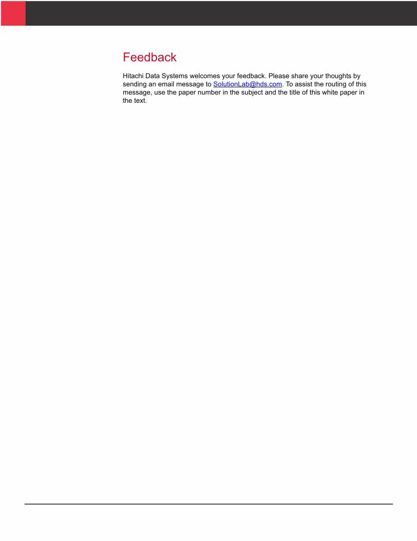
Figure 1 illustrates the high-level logical design of this reference architecture on Hitachi Virtual Storage Platform and IBM x3550 M4 servers.
Figure 1

5
5
T
Key Solution ComponentsThese are the key hardware and software components used to deploy this reference solution.
Hardware ComponentsTable 1 lists detailed information about the hardware components his solution uses.
able 1. Hardware Components
Hardware Description Version Quantity
Hitachi Virtual Storage Platform
4 virtual storage directors
4 front-end directors with 32 × 8 Gb/sec Fibre Channel ports
128 GB cache memory
128 SAS 600 GB 10k RPM disks, 2.5 inch SFF
70-05-03-00/00 1
IBM x3550 M4 server Rack mount server
2 × 8-core Intel Xeon E5-2690 processor, 2.90 GHz
96 GB RAM
6 × 16 GB DIMMs
2
Brocade 1860 Fabric Adapter
PCI Express Gen 2.0 Compatible (×8)
Dual Port AnyIO (HBA/CNA/NIC)
v3.2.0 4
Brocade 6510 SAN switch with 48 × 8 Gb/sec Fibre Channel ports
FOS 7.1.0 2
Brocade VDX 6720 Ethernet switch with 24 × 10 Gb/sec ports
NOS 3.0.0b 2

6
6
Hitachi Virtual Storage PlatformHitachi Virtual Storage Platform is the first 3-D scaling storage platform designed for all data types. The storage architecture flexibly adapts for performance, capacity, and multi-vendor storage. Combined with the unique Hitachi Command Suite management platform, it transforms the data center.
Scale Up — Meet increasing demands by dynamically adding processors, connectivity, and capacity in a single unit. Provide the highest performance for both open and mainframe environments.
Scale Out — Meet multiple demands by dynamically combining multiple units into a single logical system with shared resources. Support increased demand in virtualized server environments. Ensure safe multi-tenancy and quality of service through partitioning of cache and ports.
Scale Deep — Extend storage value by virtualizing new and existing external storage systems dynamically. Extend the advanced functions of Hitachi Virtual Storage Platform to multivendor storage. Offload less demanding data to external tiers to save costs and to optimize the availability of tier-one resources.
The 3D scaling capability of Virtual Storage Platform can dynamically add more storage resources to keep pace with I/O demand. This capability to add resources adds to the scalability of this solution.
IBM x3550 M4 ServerThe IBM System x3550 M4 server blends uptime, performance, and I/O flexibility for cost efficiency and reliability. This compact rack server offers an energy-smart, affordable, and easy-to-use solution with a pay-as-you-grow design to help lower costs and manage risks.
Brocade Fabric Switches and AdaptersBrocade and Hitachi Data Systems have collaborated to deliver storage networking and data center solutions. These solutions reduce complexity and cost, as well as enable customers’ implementing virtualization and cloud computing to increase their business agility.
This reference architecture uses the following Brocade products:
Brocade 6510 Switch
The Brocade 6510 switch meets the demands of hyper-scale, private cloud storage environments by delivering Gen5 Fibre Channel technology and capabilities that support highly virtualized environments.
Brocade VDX 6720 Ethernet Switch
The Brocade VDX 6720 switch is a high-performance, ultra-low latency wire-speed 10 Gigabit Ethernet (GbE) fixed configuration switch. The Brocade VDX 6720 with Brocade VCS Fabric technology is an ideal platform for a variety of fabric deployments.

7
7
T
Brocade 1860 Fabric Adapter
The Brocade 1860 Fabric Adapter meets all the connectivity needs of cloud-enabled data centers while providing unmatched performance, application-aware services, unified management, and reduced cost and complexity. It is the simplest, most flexible, and most powerful server connectivity adapter designed to extend fabric services to virtual machines and applications in highly demanding virtualized environments.
Ethernet fabrics are different from standard hierarchical networks. These networks include properties such as self-aggregation, self-healing, transparent internal topology, and Layer 2 multipathing, which help to minimize manual intervention.
Software ComponentsTable 2 describes the software components this solution uses.
Hitachi Dynamic ProvisioningOn Hitachi storage systems, Hitachi Dynamic Provisioning provides wide striping and thin provisioning functionalities.
Using Dynamic Provisioning is like using a host-based logical volume manager (LVM), but without incurring host processing overhead. It provides one or more wide-striping pools across many RAID groups. Each pool has one or more dynamic provisioning virtual volumes (DP-VOLs) of a specified logical size. Up to 60 TB can be created against it without initially allocating any physical space.
Deploying Dynamic Provisioning avoids the routine issue of hot spots that occur on logical devices (LDEVs). These occur within individual RAID groups when the host workload exceeds the IOPS or throughput capacity of that RAID group. Dynamic provisioning distributes the host workload across many RAID groups, which provides a smoothing effect that dramatically reduces hot spots.
able 2. Software Components
Software Version
Hitachi Storage Navigator Microcode Dependent
Hitachi Dynamic Provisioning Microcode Dependent
VMware vCenter server 5.1.0
VMware Virtual Infrastructure Client 5.1.0
VMware ESXi 5.1.0
Microsoft® Windows Server® 2008 Enterprise edition, R2
Microsoft SQL Server® 2008 Enterprise edition, R2

8
8
When used with Hitachi Virtual Storage Platform, Hitachi Dynamic Provisioning has the benefit of thin provisioning. Physical space assignment from the pool to the dynamic provisioning volume happens as needed using 42 MB pages, up to the logical size specified for each dynamic provisioning volume. There can be a dynamic expansion or reduction of pool capacity without disruption or downtime. You can rebalance an expanded pool across the current and newly added RAID groups for an even striping of the data and the workload.
VMware vSphere 5VMware vSphere 5 is a virtualization platform that provides a datacenter infrastructure. It features vSphere Distributed Resource Scheduler, High Availability, and Fault Tolerance.
VMware vSphere 5 has the following components:
ESXi 5 — This is a hypervisor that loads directly on a physical server. It partitions one physical machine into many virtual machines that share hardware resources.
vCenter Server 5 — This allows management of the vSphere environment through a single user interface. With vCenter, there are features available such as vMotion, Storage vMotion, Storage Distributed Resource Scheduler, High Availability and Fault Tolerance. In addition, new features such as single sign on allow ease of access and “single pane of glass” style administration.

9
9
Solution DesignThis is detailed information for this reference architecture environment. It includes software and hardware design information required to build the basic infrastructure for the virtualized data center environment.
To provide you with options for scaling out your environment in modular increments, this solution uses a cell architecture. This design defines compute and storage resource groups to support a specific usage scenario. You can add additional cells to scale out the environment to meet your organization's requirements.
Figure 2 provides a high-level concept of the cell architecture.
Figure 2

10
10
The architecture consists of preconfigured cells designed to support general server workload. These cells provide the following:
Infrastructure cell for compute resources — Foundation for compute components
Infrastructure cell for storage resources — Foundation for storage components
Application cell for management — Resource to manage this environment
This cell is required only if an existing configuration for managing a VMware vSphere environment does not exist.
Application cell for VMware vSphere — Provides the resource for hosting virtual machines running general server application workloads.
Expansion cell for compute resources — Provides the compute resources for scaling out the for VMware vSphere environment.
Expansion cell for racks — Provides additional rack space for scaling out the for VMware vSphere environment.
These cells provide the compute and storage hardware needed to build this scalable solution.

11
11
Infrastructure Cell for Compute ResourcesThe infrastructure cell for compute resources provides the foundation for the compute components needed to start building this solution.
Figure 3 shows the infrastructure cell for compute resources.
Figure 3
Use the infrastructure cell for compute in conjunction with the following cells:
Infrastructure cell for storage resources
Application cell for management
Application cell for VMware vSphere
Expansion cell for compute resources
The infrastructure cell for compute resources and the infrastructure cell for storage resources are the core infrastructure cells required to build a scalable solution. Both infrastructure cells support up to three expansion cells for compute resources before requiring a new infrastructure cell. Every infrastructure cell for compute resources requires one infrastructure cell for storage resources.

12
12
T
Table 3 shows the components of the infrastructure cell for compute resources.
The hardware in the infrastructure cell for compute resources makes up the core compute hardware in this solution.
Add an application cell for VMware vSphere and an application cell for management to the infrastructure cell for compute resources to complete the compute components for this solution.
Network InfrastructureThe network design used in this solution provides ample bandwidth and redundancy for the following:
A fully populated infrastructure cell for compute resources,
An infrastructure cell for storage resources,
Up to three expansion cells for compute resources
able 3. Infrastructure Cell for Compute Hardware
Hardware Detail Description Version Quantity
Ethernet Switch Brocade VDX6720-60 10 Gb/sec 60 port Ethernet switch
NOS 3.0.0b 2
Fibre Channel Switch Brocade 6510-48 8 Gb/sec 48 port Fibre Channel switch
FOS 7.1.0 2

13
13
Figure 4 shows the physical network configuration of the infrastructure cell for compute resources. For each compute resource NIC teaming is configured across ports on separate fabric adapter cards for redundancy purposes. Each of the links from the (defined) NIC ports are connected to two separate VDXs using an Ethernet fabric vLAG.
Figure 4

14
14
The network design is based on an Ethernet fabric where all links are forwarding and Brocade trunking enables frame based load balancing across multiple Inter Switch Links. Brocade's VCS Fabric Technology provides flexible network topologies that can grow without disruption simply by adding more switches, delivering:
Non-stop networking
Simplified, automated networks
An evolutionary approach that protects existing IT investments
See the Brocade website for more information about Brocade VCS Fabric Technology.
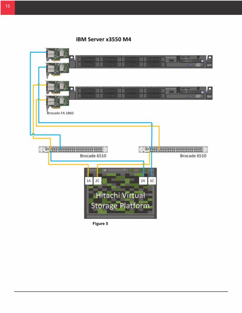
SAN InfrastructureThe Hitachi Virtual Storage Platform controller used for this solution has 32 ports for connections to the Brocade 6510 enterprise fabric switches.
For this reference architecture, the infrastructure cell for compute resources was zoned to four ports on Hitachi Virtual Storage Platform and two ports per cluster for each application cell. When adding expansion cells for compute resources, zone four new open storage ports on the controller.
Dedicating four ports to each IBM x3550 M4 server ensures bandwidth between the chassis and Virtual Storage Platform.
Note — Place port targets on different cluster and front-end director boards for maximum throughput and resilience.
Figure 5 on page 15 illustrates the physical SAN architecture of the infrastructure cell for compute. For each compute resource two HBA ports (defined) on separate Fabric Adapters are used connecting to the redundant fabrics for high availability.
15
15
Figure 5

16
16
Infrastructure Cell for Storage ResourcesThe infrastructure cell for storage resources contains all of the base storage hardware required to start building this solution.
Figure 6 shows the infrastructure cell for storage resources.
Figure 6
Use an infrastructure cell for storage resources in conjunction with the following cells:
Infrastructure cell for compute resources
Application cell for management
Application cell for VMware vSphere
The infrastructure cell for storage resources provides the storage infrastructure for the other cells in the solution. Once an infrastructure cell for storage resources is fully populated, add additional infrastructure cells for storage resources to scale out the solution.

17
17
Table 4 shows the components of the infrastructure cell for storage resources.
The infrastructure cell for storage resources contains the Hitachi Virtual Storage Platform controller chassis and two disk chassis.
In this reference architecture, the disk chassis houses the storage for the application cell for management and the application cell for VMware vSphere. You can also use the disk chassis for hot spares. Each infrastructure cell for storage resources can support up to 16 application cells for VMware vSphere.
Expansion Cell for RacksUse an expansion cell for racks when scaling out your configuration. Add expansion cell for racks when you have included the following in your environment:
Six application cells for VMware vSphere — Add one expansion cell.
Nine application cells for VMware vSphere — Add one additional expansion cell
Figure 7 on page 18 shows the expansion cell for racks.
Table 4. Infrastructure Cell for Storage Resources Hardware
Hardware Detail Description Version Quantity
Hitachi Virtual Storage Platform controller chassis
4 virtual storage directors
4 front-end director boards with 32 × 8 Gb/sec Fibre Channel ports
128 GB cache memory
70-05-03-00/00 1
Hitachi Virtual Storage Platform disk chassis
Contains disks for other cells
2
18
18
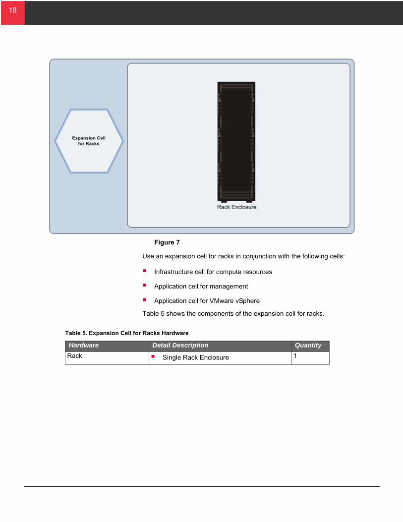
Figure 7
Use an expansion cell for racks in conjunction with the following cells:
Infrastructure cell for compute resources
Application cell for management
Application cell for VMware vSphere
Table 5 shows the components of the expansion cell for racks.
Table 5. Expansion Cell for Racks Hardware
Hardware Detail Description Quantity
Rack Single Rack Enclosure 1

19
19
Application Cell for ManagementThe application cell for management contains the compute and storage components for hosting the vSphere infrastructure services.
Figure 8 shows the application cell for management.
Figure 8
Use an application cell for management in conjunction with the following cells:
Infrastructure cell for compute resources
Infrastructure cell for storage resources
Application cell for VMware vSphere
Use an application cell for management when a VMware vSphere environment does not already exist.
Note — Scalability limits depend on application workloads running on this infrastructure.

20
20
Compute InfrastructureThe application cell for management provides enough capacity to support an emergency high availability event in case a single server fails.
Use VMware High Availability and Distributed Resource Scheduler to configure a cluster dedicated to the application cell for management to ensure virtual machine failover in the event of a hardware failure.
Table 6 shows the details of the hardware configuration in the application cell for management.
The compute infrastructure of the application cell for management supports all associated Microsoft SQL Server, Active Directory, and VMware vCenter requirements.
Manage your environment using these resources or by connecting to a preexisting VMware vSphere management environment.
Network InfrastructureFor the management VMkernel configuration, use the on-board NIC to provide an up-link from a standard virtual switch to a separate management network that is not related to the application management in the application cell tests.
In VMware vCenter, create a virtual distributed switch (vDS) with the two up-links to the Ethernet fabric from each ESXi server. Set Load Balancing on the dvPortGroups Settings dialog box in the vDS to Route based on IP hash, as shown in Figure 9 on page 21. Do this to match the static vLAG configuration on the VDXs.
Table 6. Application Cell for Management Hardware
Hardware Detail Description Version Quantity
IBM x3650 M4 Servers 2 × 8-Core Intel Xeon E5-2690 processor, 2.9 GHz
96 GB RAM per server
2 Brocade Fabric Adapter 1860Each adapter used for 16 Gb Fibre Channel and 10 GbE network
3.2.0.0 2
SFF disk drives
600 GB 10k RPM SAS drives
Installed in the infrastructure cell for storage resources
RAID-6 (6D+2P) 8
Hot spare 1

21
21
Figure 9
Following best practice, isolate different traffic types in separate VLANs for management, vMotion, and application virtual machines. This solution uses VLANs (each defined with a separate dvPortGroup) to separate network traffic in the application cell for VMware vSphere. Create the vLAG configuration by creating a virtual interface (portchannel) across the two VDXs and apply the port-channel to the respective interfaces where the (vDS) NICs are connected. Configure the switch-port as a trunk to carry the VLANs defined in each of the dvPortGroups allocated for the following:
Management-VLAN — Chassis management connections and primary management of the ESXi hypervisors
vMotion-VLAN — Configured for vMotion
VM-VLAN — Configured for the virtual machine network
For traffic isolation between tiles, place each tile and virtual client in the application cell in its own dvPortGroup and separate VLAN. Place the physical client in its own dvPortGroup and separate VLAN. Access to the virtual clients in each tile by routing in the Ethernet fabric via a VE (VRRP_E) gateway instance for each tile.
Storage InfrastructureThe storage infrastructure of the application cell for management consists of eight 600 GB 10k RPM SAS drives housed in the infrastructure cell for storage. Configure the storage into a single RAID-6 (6D+2P) dynamic provisioning pool dedicated to management servers. The pool provides an overall capacity of 3 TB.

22
22
Zone each server in the application cell for management to Hitachi Virtual Storage Platform through the Brocade 6510 Fiber Chanel switch using single initiator to multi target zoning for each port on the IBM x3550 and x3650 servers. This results in four paths available to each ESXi host, providing the following:
Resiliency to failure
Redundant paths to the storage subsystem
The storage multipathing policy for each target in ESXi was set to round robin. This results in optimal load distribution during an all paths available situation.
Table 7 shows the zoning configuration used for the application cell for management.
Table 7. Application Cell for Management Zone Configuration
Host Host HBA Number
Fabric Zone Name Storage Port
ESX 0 HBA1_1 Fabric 1 ESX0_HBA1_1_VSP_1A_2C 1A
2C
HBA1_2 Fabric 2 ESX0_HBA1_2_ VSP_2A_1C 2A
1C
ESX 1 HBA1_1 Fabric 1 ESX 1_ HBA1_1 VSP_1A_2C 1A
2C
HBA1_2 Fabric 2 ESX1_ HBA1_2_ VSP_2A_1C 2A
1C

23
23
Server Configuration Sizing GuidelinesIt is critical to apply proper resource allocation for virtual machines used to manage the for VMware vSphere environment. If using a separate environment outside of the designed solution designed by Hitachi Data Systems for management, use the virtual machine sizing recommendations in Table 8.
Table 8 lists the virtual machine configurations used for each component of the management infrastructure used in this reference architecture.
Application Cell for VMware vSphereThe application cell for VMware vSphere contains all compute and storage components necessary to run general server application workloads consisting of the following:
168 virtual CPUs
212 GB of virtual machine memory
16 TB of storage capacity
Figure 10 on page 24 shows the application cell for VMware vSphere.
Table 8. Virtual Machine Sizing Recommendations
Virtual Machine Configuration Count
Microsoft Active Directory®, DNS, DHCP vCPU — 1
vMemory — 4 GB
1
VMware vCenter vCPU — 2
vMemory — 10 GB
1
Microsoft SQL Server 2008 database for VMware vCenter vCPU — 2
vMemory — 8 GB
1
24
24
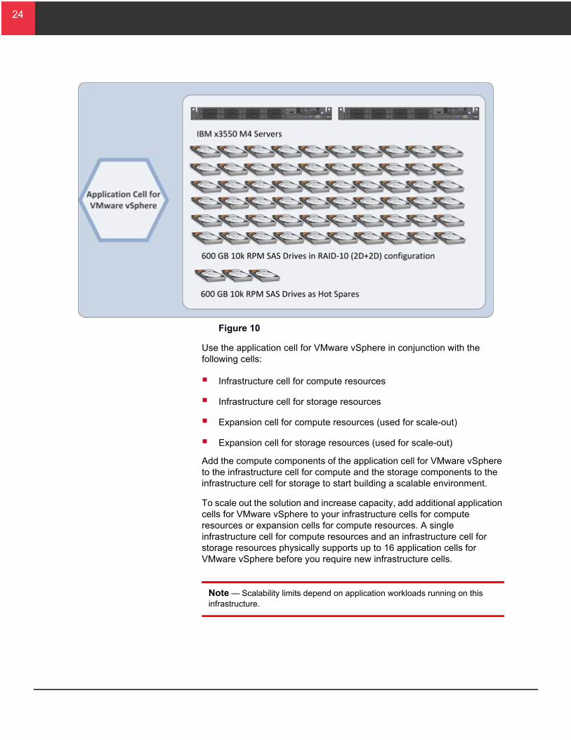
Figure 10
Use the application cell for VMware vSphere in conjunction with the following cells:
Infrastructure cell for compute resources
Infrastructure cell for storage resources
Expansion cell for compute resources (used for scale-out)
Expansion cell for storage resources (used for scale-out)
Add the compute components of the application cell for VMware vSphere to the infrastructure cell for compute and the storage components to the infrastructure cell for storage to start building a scalable environment.
To scale out the solution and increase capacity, add additional application cells for VMware vSphere to your infrastructure cells for compute resources or expansion cells for compute resources. A single infrastructure cell for compute resources and an infrastructure cell for storage resources physically supports up to 16 application cells for VMware vSphere before you require new infrastructure cells.
Note — Scalability limits depend on application workloads running on this infrastructure.

25
25
Compute InfrastructureThe application cell for VMware vSphere supports a maximum density of 168 virtual CPUs and 212 GB of virtual machine memory.
In a maximum density configuration, a cell cannot support the failover of virtual machines in case of a server failure. To provide high availability, do the following:
Reduce the number of virtual CPUs and virtual machine memory per host up to 50%.
Configure a VMware High Availability and Distributed Resource Scheduler cluster dedicated to application cells for VMware vSphere.
Place additional hosts from each application cell for VMware vSphere into the cluster. When scaling the solution, increase the number of virtual machines per host as you add more resources to the cluster.
Based on VMware maximums, each High Availability and Distributed Resource Scheduler cluster can support up to 16 application cells for VMware vSphere (32 hosts).
Table 9 shows the details of the hardware used in the application cell for VMware vSphere.
Table 9. Application Cell for VMware vSphere Hardware
Hardware Detail Description Version Quantity
IBM x3550 M4 server 2 × 8-Core Intel Xeon E5-2690 processors, 2.9 GHz
96 GB RAM per server
2 x Brocade Fabric Adapter 1860
Each adapter used for 16 Gb Fibre Channel and 10 GbE network
3.2.0.0 2
SFF Disk Drives
600 GB 10k RPM SAS drives
RAID-10 (2D+2D) 60
Hot spare 4

26
26
Network InfrastructureThe application cell for VMware vSphere uses the same networking configuration described in the application cell for management.
Storage InfrastructureThe storage infrastructure of the application cell for VMware vSphere consists of sixty 600 GB 10k RPM SAS drives in two dynamic provisioning pools with the following configuration:
Pool 0 — 20 drives consisting of 5 parity groups in a RAID-10 (2D+2D) configuration
Pool 1 — 40 drives consisting of 10 parity groups in a RAID-10 (2D+2D) configuration
Figure 11 shows the storage configuration for the application cell for VMware vSphere.
Figure 11

27
27
T
E
Use RAID-10 to maximize performance for random workloads, which is common with virtualized environments.
Create two pools to separate virtual machine workloads with different performance characteristics.
Because of its wide striping capability, Hitachi Dynamic Provisioning can balance the I/O load in pools of RAID groups. Mixing workloads in a single dynamic provisioning pool is possible to obtain certain levels of performance. However, grouping virtual machines with similar I/O profiles optimizes storage performance and results in a more efficient use of disk resources. Within a pool, create additional LUNs as necessary to spread the workload and avoid possible queue depth issues.
When scaling out with additional application cells for VMware vSphere, add RAID groups to grow the existing pools. Increasing spindle count allows the pool to support the increasing IOPS requirement dynamically. As stated before, create additional LUNs to prevent virtual machine workloads from saturating the LUN.
SAN InfrastructureConnect the IBM x3550 M4 servers in this reference architecture with one port from each Fabric adapter. This separates the Brocade 6510 Gen5 enterprise fabric switches to provide redundant 16 Gb/sec Fibre Channel connectivity.
The environment uses single initiator to multi-target zoning for each port on the x3550 M4 servers. Following best practice, configure the SAN environment in a dual fabric topology for redundancy and high availability. This results in four paths available to each ESXi host, providing the following:
Resiliency to failure
Redundant paths to the storage subsystem
The storage multipathing policy for each target in ESXi was set to round robin. This results in optimal load distribution during an all paths available situation.
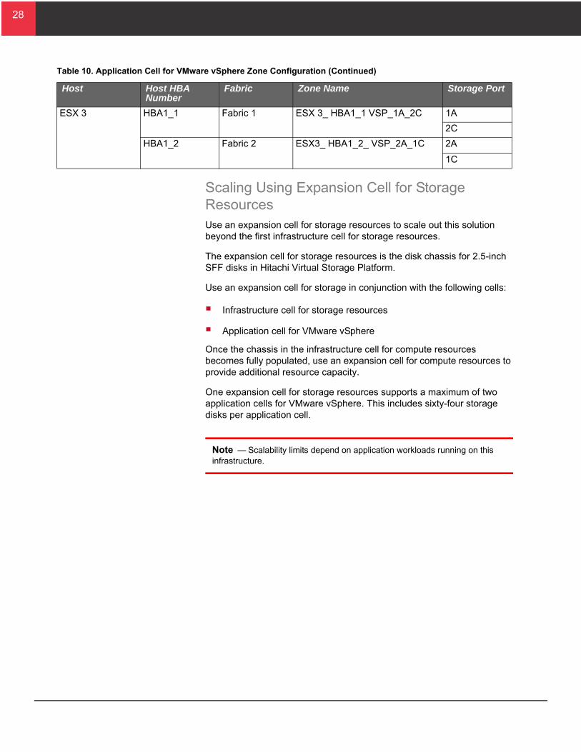
Table 10 shows the zone configuration used for the application cell for VMware vSphere.
able 10. Application Cell for VMware vSphere Zone Configuration
Host Host HBA Number
Fabric Zone Name Storage Port
SX 2 HBA1_1 Fabric 1 ESX2_HBA1_1_VSP_1A_2C 1A
2C
HBA1_2 Fabric 2 ESX2_HBA1_2_ VSP_2A_1C 2A
1C
28
28
E
T
Scaling Using Expansion Cell for Storage ResourcesUse an expansion cell for storage resources to scale out this solution beyond the first infrastructure cell for storage resources.
The expansion cell for storage resources is the disk chassis for 2.5-inch SFF disks in Hitachi Virtual Storage Platform.
Use an expansion cell for storage in conjunction with the following cells:
Infrastructure cell for storage resources
Application cell for VMware vSphere
Once the chassis in the infrastructure cell for compute resources becomes fully populated, use an expansion cell for compute resources to provide additional resource capacity.
One expansion cell for storage resources supports a maximum of two application cells for VMware vSphere. This includes sixty-four storage disks per application cell.
Note — Scalability limits depend on application workloads running on this infrastructure.
SX 3 HBA1_1 Fabric 1 ESX 3_ HBA1_1 VSP_1A_2C 1A
2C
HBA1_2 Fabric 2 ESX3_ HBA1_2_ VSP_2A_1C 2A
1C
able 10. Application Cell for VMware vSphere Zone Configuration (Continued)
Host Host HBA Number
Fabric Zone Name Storage Port

29
29
Engineering ValidationThis describes the test methodology used at Brocade Solutions laboratory to validate this reference architecture and the results of the validation testing. These tests demonstrated the maximum utilization of the reference architecture.
The purpose of the tests was to determine maximum loads that the solution could support and still maintain an acceptable application performance.
Test MethodologyThis reference architecture tested the core components of this solution to validate its performance and design. For validation purposes, testing used a mixed workload of the following:
Email messages
Web pages
Online transaction processing (OLTP)
The workload grouping was into a tile-based system to measure application performance and scalability. Each tile contained mixed workloads that stress critical compute and storage resources. These workloads represent a general purpose environment for VMware vSphere.
Each tile consists of the following virtual machines listed in Table 11.
Each tile represented a simulation of the following types of workloads:
Microsoft Exchange 2007 mail servers for general email workloads
Apache Olio web and database servers for Web 2.0 workloads
DVD Store 2 web and database servers for OLTP workloads
Standby servers for idle general infrastructure workload
Table 11. Virtual Machines for Each Testing Tile
Microsoft Exchange 2007
Apache Olio Web Server
Apache Olio Database Server
DVD Store 2 Database Server
DVD Store 2 Web Server
Standby
Quantity 1 1 1 1 3 1
CPU 4 vCPUs 4 vCPUs 2 vCPUs 4 vCPUs 2 vCPUs 1 vCPUs
Memory 8192 MB 6144 MB 2048 MB 4096 MB 2048 MB 512 MB

30
30
Figure 12 illustrates the cells used to validate this reference architecture.
Figure 12
Testing used eight tiles between two ESXi hosts in the application cell for VMware vSphere. There were a total of the following:
64 virtual machines
168 virtual CPUs
212 GB of configured virtual machine memory
A single client controls each tile. A primary client controls each tile client. The clients ran in other hosts, outside of the ESXi hosts for the workload virtual machines.

31
31
Table 12 shows how the tiles were distributed.
Testing placed the workload virtual machines in the above configuration based on the storage configuration design in “Application Cell for VMware vSphere,” starting on page 23.
Table 13 shows the tile workload definitions.
Table 12. Tile Distribution Across Compute and Storage Resources
Tile 1 Tile 2 Tile 3 Tile 4 Tile 5 Tile 6 Tile 7 Tile 8
ESXi Host 2 3 2 3 2 3 2 3
DP Pool 1 LUN 3: Mail Servers 1-3 LUN 4: Mail Servers 4-6 LUN 5: Mail Servers 7-8
LUN 2: DVD Store 2 Web Servers, Olio Web Servers, Olio Database Servers
LUN 6: Standby Servers
DP Pool 0 LUN 1: DVD Store 2 Database Servers
Table 13. Tile Workload Definitions
Workloads Applications Virtual Machine Platform
Simulated Load per Tile
Mail Server Microsoft Exchange 2007
Microsoft Exchange LoadGen
Microsoft Windows Server 2008 R2 (64 Bit)
4 vCPU
8 GB RAM
More than 100 GB boot and data disks
1000 users with a heavy workload profile
Standby None Microsoft Windows 2003 (32 Bit)
1 vCPU
512 MB RAM
4 GB boot disk
Non-load based functional test to activate idle resources for on-demand usage.

32
32
Web 2.0 load simulation
Olio DB
Web application servers
2-tier Java-based implementation of the Olio workload, including the following operations:
HomePage
Login
TagSearch
EventDetail
PersonDetail
AddPerson
AddEvent
Database:
SUSE Linux 11 64-bit
2 vCPU
2 GB RAM
10 GB boot and 4 GB data disks
400 concurrent users
Web server:
SLES 11 (64-bit)
4 vCPU
6 GB RAM
10 GB boot and 70 GB data disks
E-commerce simulation
DVD Store 2 Database:
SUSE Linux 11 (64-bit)
4 vCPU
4 GB RAM
10 GB boot and 35 GB data disks
10 constant driver thread loads from one web server
20 burst based driver threads from two web servers
Performance metric is transactions per minute (TPM)
Front end (×3):
SLES 11 (64-bit)
2 vCPU
2 GB RAM
10 GB disk
Table 13. Tile Workload Definitions (Continued)
Workloads Applications Virtual Machine Platform
Simulated Load per Tile

33
33
Dynamic virtual machine relocation
VMware vMotion
Relocation and then wait 3 Minutes to repeat
Olio database selected at random in round robin fashion (see specifications above)
Concurrent relocations Increase per number of tiles
Metric is measured in Relocations Per Hour (RPH)
Automated load balancing (vMotion)
VMware Distributed Resource Scheduler
Set to aggressive
All Infrastructure Functionality to load balance tile workload.
Workloads Applications Virtual machine platform
Simulated Load per Tile
Mail Server Microsoft Exchange 2007
Microsoft Exchange LoadGen
Microsoft Windows Server 2008 R2 (64 Bit)
4 vCPU
8 GB RAM
More than 100 GB boot and data disks
1000 users with a heavy workload profile
Table 13. Tile Workload Definitions (Continued)
Workloads Applications Virtual Machine Platform
Simulated Load per Tile
34
34
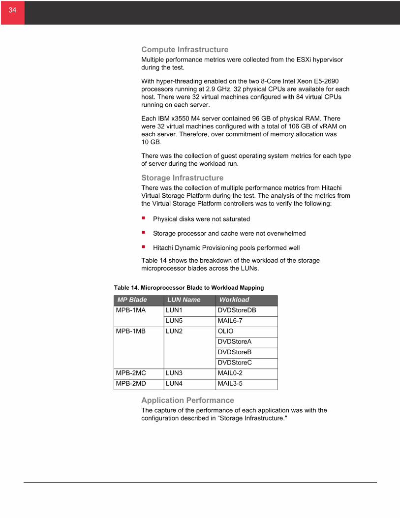
Compute InfrastructureMultiple performance metrics were collected from the ESXi hypervisor during the test.
With hyper-threading enabled on the two 8-Core Intel Xeon E5-2690 processors running at 2.9 GHz, 32 physical CPUs are available for each host. There were 32 virtual machines configured with 84 virtual CPUs running on each server.
Each IBM x3550 M4 server contained 96 GB of physical RAM. There were 32 virtual machines configured with a total of 106 GB of vRAM on each server. Therefore, over commitment of memory allocation was 10 GB.
There was the collection of guest operating system metrics for each type of server during the workload run.
Storage InfrastructureThere was the collection of multiple performance metrics from Hitachi Virtual Storage Platform during the test. The analysis of the metrics from the Virtual Storage Platform controllers was to verify the following:
Physical disks were not saturated
Storage processor and cache were not overwhelmed
Hitachi Dynamic Provisioning pools performed well
Table 14 shows the breakdown of the workload of the storage microprocessor blades across the LUNs.
Application PerformanceThe capture of the performance of each application was with the configuration described in “Storage Infrastructure."
Table 14. Microprocessor Blade to Workload Mapping
MP Blade LUN Name Workload
MPB-1MA LUN1 DVDStoreDB
LUN5 MAIL6-7
MPB-1MB LUN2 OLIO
DVDStoreA
DVDStoreB
DVDStoreC
MPB-2MC LUN3 MAIL0-2
MPB-2MD LUN4 MAIL3-5

35
35
Test ResultsThese are the test results for the environment operating in a steady state condition.
Compute InfrastructureFigure 13 on page 35 and Figure 14 on page 36 illustrate the physical CPU metrics collected on both ESXi hypervisors while running the 8-tile general server application workload.
The CPU performance characteristics are nearly identical for each system. This indicates an even balance of the workload across hosts.
With the core utilization averaging 83% and 85% during steady state, the servers are running with high CPU utilization.
The test was done to stress critical compute resources on the host. For high availability, reduce the number of servers or workload by up to fifty percent and place them in a cluster with VMware High Availability and Dynamic Resource Scheduler enabled.
Figure 13

36
36
Figure 14
Figure 15 and Figure 16 on page 37 illustrate the physical memory usage collected on both ESXi hypervisors while running the 8-tile general server application workload.
The memory usage is nearly identical for each system. This indicates an even balance of the workload across hosts.
Used physical RAM (with Shared VM RAM) is the active amount of memory used for all virtual machines on the host.
The difference in used physical RAM (with shared VM RAM) and used physical RAM (without shared VM RAM) indicates the amount of memory saved from transparent page sharing.

37
37
Figure 15
Figure 16
Figure 17 on page 38 illustrates a sample of a mail server and DVD Store 2 database server, showing the combined VMDK IOPS statistics for those specific virtual machines.
All servers, with the exception of the mail servers and DVD Store 2 database servers, had relatively low I/O with none peaking over 70 IOPS. Therefore, these results were omitted from Figure 17.
Due to their high I/O profile, no more than three mail server virtual machines were stored on a LUN to avoid LUN queue depth issues.

38
38
Figure 17
Storage InfrastructurePhysical disk performance was acceptable during the general server application workloads.
Figure 18 and Figure 19 on page 39 illustrate the average performance for physical drives from both dynamic provisioning pools and the average response time for each LDEV per workload. These disk performance graphs show the following:
Disk utilization peaked at 87% for Dynamic Provisioning Pool 0 and 68% for Dynamic Provisioning Pool 1.
Disk utilization averaged at 81% for Dynamic Provisioning Pool 0 during steady state which contained the DVD Store 2 database (OLTP) workloads.
Disk utilization averaged at 35% for Dynamic Provisioning Pool 1 during steady state which contained the mail server, Apache Olio, and DVD Store 2 web workloads.
The average response time across all LDEVs was 2.5 milliseconds, showing that with consistent high utilization, Hitachi Virtual Storage Platform handled the load with very low latency.
Separating workloads into different pools based on I/O profile decreased the disk latency reported by the ESXi hosts and provided a boost in storage performance.

39
39
Figure 18
Figure 19

40
40
Write cache saturation and storage processor core utilization on Hitachi Virtual Storage Platform was monitored throughout the entirety of the test.
There are four virtual storage directors. The processor for each virtual storage director saw occasional bursts in utilization, which can be common for server workloads. However, steady state was generally below 15%, showing the capability to support higher sustained workloads than the load presented in the eight-tile workload tests.
This data indicates the Hitachi Virtual Storage Platform controllers handle the various server applications with occasional spikes in workload.
Figure 20 shows that, although the distribution of the processing load was fairly even, the driving of the bulk of processor load was from MPB-1MA, which ran the DVD Store 2 database (OLTP) transactions and two mail server workloads.
The web workloads (DVDStores and Apache Olio workloads) sharing one processor had the highest write cache pending spikes without adding to the processor load significantly, illustrating the value of cache by offloading the writes.
Figure 20 illustrates the management processor utilization of the virtual storage platform.
Figure 20
Storage write cache pending is a measurement of the percentage of cache associated to a utilized microprocessor blade and waiting for writing to storage.
Write pending percentage peaked at 40% per microprocessor blade, indicating plenty of headroom for future growth.

41
41
Figure 21 illustrates the Hitachi Virtual Storage Platform performance metrics of the write cache.
Figure 21
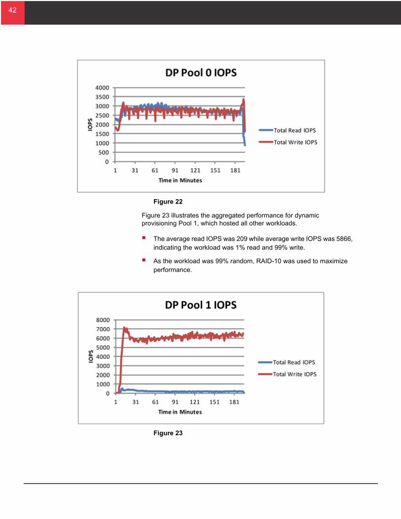
Figure 22 on page 42 illustrates the aggregated performance for Dynamic Provisioning Pool 0, which was dedicated to OLTP workloads.
The average read IOPS was 2737 while average write IOPS was 2707, indicating about 50% read and 50% write.
As the workload was 99% random, RAID-10 was used to maximize performance.
42
42
Figure 22
Figure 23 illustrates the aggregated performance for dynamic provisioning Pool 1, which hosted all other workloads.
The average read IOPS was 209 while average write IOPS was 5866, indicating the workload was 1% read and 99% write.
As the workload was 99% random, RAID-10 was used to maximize performance.
Figure 23

43
43
Application PerformanceFigure 24 shows the application workload throughput.
Figure 24
The performance was uniform across all tiles for each type of application.
Figure 25 on page 44 shows the average response time measured for each of the applications. At 119 milliseconds, the highest response was well within acceptable return times.

44
44
Figure 25

45
45
ConclusionThis reference architecture guide discusses how to design a solution using Hitachi Virtual Storage Platform, IBM x3550 M4 servers, and Brocade Networks. The purpose of the general server application workloads testing in the Brocade Solutions laboratory was to provide general guidance on the virtual resources available with this solution.
Each implementation has its own unique set of data center and application requirements. Design your implementation of this environment by understanding the I/O workload of the server applications in your environment. Creating an environment that meets your unique needs results in increased ROI from avoiding over or under provisioning resources.
Use Hitachi Dynamic Provisioning to reallocate I/O capabilities dynamically, as necessary. Having the capability to provision additional spindles to an already-provisioned datastore within VMware vSphere allows for non-disruptive upgrades to the underlying storage infrastructure. This provides immediate benefits to your environment without the shuffling of virtual machines, datastores, or LUs.
This design gives you a build-as-you-go model that uses performance-proven hardware resources, including Virtual Storage Platform and IBM x3550 M4 servers. The modular design, using a cell architecture, permits implementing an environment for modest needs that gives you the flexibility to scale out as your IT needs grow.
For More InformationHitachi Data Systems Global Services offers experienced storage consultants, proven methodologies and a comprehensive services portfolio to assist you in implementing Hitachi products and solutions in your environment. For more information, see the Hitachi Data Systems Global Services website.
Live and recorded product demonstrations are available for many Hitachi products. To schedule a live demonstration, contact a sales representative. To view a recorded demonstration, see the Hitachi Data Systems Corporate Resources website. Click the Product Demos tab for a list of available recorded demonstrations.
Hitachi Data Systems Academy provides best-in-class training on Hitachi products, technology, solutions and certifications. Hitachi Data Systems Academy delivers on-demand web-based training (WBT), classroom-based instructor-led training (ILT) and virtual instructor-led training (vILT) courses. For more information, see the Hitachi Data Systems Services Education website.
For more information about Hitachi products and services, contact your sales representative or channel partner or visit the Hitachi Data Systems website.

Corporate Headquarters2845 Lafayette Street, Santa Clara, California 95050-2627 USAwww.HDS.com
Regional Contact InformationAmericas: +1 408 970 1000 or [email protected], Middle East and Africa: +44 (0) 1753 618000 or [email protected] Asia-Pacific: +852 3189 7900 or [email protected]
© Hitachi Data Systems Corporation 2013. All rights reserved. HITACHI is a trademark or registered trademark of Hitachi, Ltd. “Innovate with Information” is a trademark or registered trademark of Hitachi Data Systems Corporation. IBM and System x are trademarks or registered trademarks of International Business Machines Corporation. Microsoft, Windows Server, SQL Server, and Active Directory are trademarks or registered trademarks of Microsoft Corporation. All other trademarks, service marks, and company names are properties of their respective owners.
Notice: This document is for informational purposes only, and does not set forth any warranty, expressed or implied, concerning any equipment or service offered or to be offered by Hitachi Data Systems Corporation.
AS-239-00, August 2013