
WOAD, A Platform to Deploy Flexible EPRs in Full Control of End-Users
87
Ann Blandford, Giuseppe De Pietro, Luigi Gallo, Andy Gimblett, Patrick Oladimeji, and Harold Thimbleby (Eds.) EICS4Med 2011 Proceedings of the 1st International Workshop on Engineering Interactive Computing Systems for Medicine and Health Care co-located with the ACM SIGCHI Symposium on Engineering Interactive Computing Systems (EICS 2011) Pisa, Italy June, 2011
-
Upload
independent -
Category
Documents
-
view
2 -
download
0
Transcript of WOAD, A Platform to Deploy Flexible EPRs in Full Control of End-Users

Ann Blandford, Giuseppe De Pietro, Luigi Gallo, Andy Gimblett, Patrick Oladimeji, and Harold Thimbleby (Eds.)
EICS4Med 2011 Proceedings of the 1st International Workshop on
Engineering Interactive Computing Systems for Medicine and Health Care co-located with the ACM SIGCHI Symposium on Engineering Interactive Computing Systems (EICS 2011) Pisa, Italy June, 2011

Preface
The EICS4Med workshop brings together and develops the community of researchers and practitioners concerned with the design and evaluation of interactive medical devices and systems, to deliver a roadmap for future research in this area. The workshop involves researchers and practitioners designing and evaluating dependable systems in a variety of contexts, and those developing innovative interactive computer systems for healthcare. These pose particular challenges because of the inherent variability — of patients, system configurations, and so on. Participants will represent a range of perspectives, including safety engineering and innovative design. The purpose of this workshop, then, is to build a community of researchers developing complementary but interconnected approaches to engineering dependable and innovative interactive medical systems. Ann Blandford, Giuseppe De Pietro, Luigi Gallo, Andy Gimblett, Patrick Oladimeji, and Harold Thimbleby Workshop Chairs
Copyright © 2011 for the individual papers by the papers’ authors. Copying permitted only for private and academic purposes. This volume is published and copyrighted by its editors.
i

EICS4Med 2011 Workshop Organization
Chairs Ann Blandford (UCLIC - University College London, UK) Giuseppe De Pietro (ICAR-CNR, Italy) Luigi Gallo (ICAR-CNR, Italy) Andy Gimblett (FIT Lab - Swansea University, UK) Patrick Oladimeji (FIT Lab - Swansea University, UK) Harold Thimbleby (FIT Lab - Swansea University, UK) Program Committee Gregory Abowd (Georgia Tech, USA) Marco Anisetti (University of Milan, Italy) Valerio Bellandi (University of Milan, Italy) Robert Boesecke (Leipzig University of Applied Science, Germany) Paul Cairns (University of York, UK) Abdellah Chehri (University of Ottawa, Canada) Paul Curzon (Queen Mary, University of London, UK) Ernesto Damiani (University of Milan, Italy) Alessandro De Mauro (VICOMTech, Spain) Gavin Doherty (Trinity College Dublin, Ireland) Ben Falchuk (Telcordia Technologies Inc., USA) Vincenzo Ferrari (Endocas, University of Pisa, Italy) Michael Harrison (University of Newcastle, UK) Pierre Jannin (INSERM/INRIA/IRISA, France) Gwanggil Jeon (University of Ottawa, Canada) Chris Johnson (University of Glasgow, UK) Paul Jones (FDA, USA) Bob Wears (University of Florida, USA)
ii
Table of contents
The visible and the invisible: Distributed Cognition for medical devices……………………………….......... 1-6 Dominic Furniss, Ann Blandford, Atish Rajkomar, Chris Vincent, Astrid Mayer
WOAD, A Platform to Deploy Flexible EPRs in Full Control of End-Users……………………………….... 7-12 Federico Cabitza, Stefano Corna, Iade Gesso, Carla Simone
Surgical simulators integrating virtual and physical anatomies………………………………………..……... 13-18 Marina Carbone, Sara Condino, Vincenzo Ferrari, Mauro Ferrari, Franco Mosca
Video see-through in the clinical practice……………………………………………………………..……… 19-24 Vincenzo Ferrari, Mauro Ferrari, Franco Mosca
Survivable and Scalable Wireless Solution for E-health and E-emergency Applications……..……………... 25-29 Abdellah Chehri
Care & Prepare – Usability Engineering for Mass Casualty Incidents………………………………..……… 30-35 Martin Christof Kindsmüller, Tilo Mentler, Michael Herczeg, Timo Rumland
Coordination in Perioperative Systems – A Tacit View……………………………………………..…...…... 36-41 Anke Dittmar, Robert Kühn, Peter Forbrig
Design of Perceptualization Applications in Medicine……………………………………………..…….….. 42-47 Jonas Forsslund, Eva-Lotta Sallnäs, Karl-Johan Lundin Palmerius
Virtual Reality Based Rehabilitation and Game Technology……………………………………….………... 48-52 Alessandro De Mauro
Towards Dependable Number Entry for Medical Devices…………………………………………….……... 53-58 Abigail Cauchi, Paul Curzon, Parisa Eslambolchilar, Andy Gimblett, Huayi Huang, Paul Lee, Yunqiu Li, Paolo Masci, Patrick Oladimeji, Rimvydas Ruksenas, Harold Thimbleby
Comparing Actual Practice and User Manuals: A Case Study Based on Programmable Infusion Pumps…... 59-64 Ann Blandford, Abigail Cauchi, Paul Curzon, Parisa Eslambolchilar, Dominic Furniss, Andy Gimblett, Huayi Huang, Paul Lee, Yunqiu Li, Paolo Masci, Patrick Oladimeji, Atish Rajkomar, Rimvydas Ruksenas, Harold Thimbleby
Visualization and Interaction System of Virtual Organs for Surgical Planning……………………….……... 65-68 Lucio T. De Paolis, Giovanni Aloisio
Design and Prototypical Development of a Web Based Decision Support System for Early Detection of Sepsis in Hematology………………………………………………………………………………………… 69-74 Andreas Wicht, Gerrit Meixner, Ulrike Klein
User-Centered Design for Citizens' Empowerment through the Portal of the Italian Ministry of Health……. 75-80 Tiziana Catarci, Maddalena D'Addario, Paolo Felli, Laura Franceschetti, Domenico Lembo, Massimo Mecella, Tatiana Pipan, Alessandro Russo, Annarita Vestri, Paolo Villari The biggest challenges are the social ones: workshop report from EICS4Med 2011………………………... 81-82 Ann Blandford, Giuseppe De Pietro, Luigi Gallo, Andy Gimblett, Patrick Oladimeji, Harold Thimbleby
iii

iv

The visible and the invisible: Distributed Cognition for medical devices
Dominic Furniss, Ann Blandford, Atish Rajkomar & Chris Vincent
UCLIC UCL, Gower Street
London WC1E 6BT, UK +44 20 7679 0688
Astrid Mayer Department of Oncology Royal Free NHS Trust
Pond Street London, NW3 2QG, UK
ABSTRACT Many interactive medical devices are less easy to use than they might be, and do not fit as well as they could in their contexts of use. Occasionally, the deficiencies lead to serious incidents; more often, they have a less visible effect on the resilience and efficiency of healthcare systems. These issues remain largely invisible as they are not reported and have rarely been studied. In this paper, we report on the use of DiCoT as an approach to representing and reasoning about medical work, and about the role of device design within that work. We focus in particular on the design and use of infusion devices. This work highlights the value of observational studies for engineering interactive medical devices, and illustrates the value of a systematic approach to gathering and analyzing qualitative data.
Keywords Distributed Cognition, medical devices, DiCoT, situated interaction, infusion devices.
INTRODUCTION To improve the engineering of interactive medical devices, it is essential to understand how those devices are used in context, as well as considering the engineering of the devices in isolation (e.g. ensuring consistency, reliability and safety of interactions). In this paper, we focus on the use of infusion devices, relatively simple devices that are used by both clinical professionals and lay people, but particularly by nurses. The use of such devices is inherently complex: even if the devices are configured as simply as possible, they are used in a variety of environments, as part of a complex set of tools and procedures. One source of information about the impact of device design on use is to be found in incident reports, particularly root cause analyses, such as the reports in the MAUDE (Manufacturer and User Facility Device Experience)database [12]. Occasionally, incidents hit the headlines and
provoke further discussion – e.g. the cases of Denise Melanson [10] and Lisa Norris [16]. However, such high profile incidents are mercifully rare, and many incidents are minor and may not be reported at all. For example, Husch et al. [7] suggest that few incidents are reported. In a study of infusion pump use in a busy hospital, covering 426 intravenous infusions, they identified a total of 389 errors, occurring in 285 of the infusions. In other words, 2/3 of the infusions on which data was gathered involved at least oneerror. Many of these errors would be classed as minor, but 55 were either rate deviation or incorrect medication errors, which had the potential to be serious. For comparison, only 48 incidents in the same categories had been reported through the formal reporting system over the previous two years from the same hospital. As discussed below, it might have been inappropriate to class all 389 events as “errors”, but this study highlights what a small proportion of errors are reported. However, error cases alone are not sufficient to engineer good systems: it is also necessary to have a good understanding of normal practice. In this paper, we present a study of normal practice in an oncology day care unit, focusing particularly on the use of infusion devices. We use DiCoT (Distributed Cognition for Teamwork) [3] as a framework for structuring observations and to support reasoning about design. We illustrate modes of reasoning about design by discussing two design requirements that were identified in our studies.
DISTRIBUTED COGNITION Distributed Cognition has emerged as an approach to reasoning about system design that starts from the premise that the ways that people make decisions and interact are dependent on the external environment as well as internal cognitive processes: that the environment provides resources to support thinking [5]. Furthermore, the structure of the environment can be analyzed from a cognitive perspective; i.e. the people, roles, tasks, artifacts and the physical layout of the system will impact the way information is processed. For example, a bridge of a ship [8] and an aircraft cockpit [9] have been analysed in this way. Distributed Cognition therefore describes how socio-technical systems are structured to process information.
Copyright © 2011 for the individual papers by the papers' authors. Copying permitted only for private and academic purposes. This volume is published and copyrighted bythe editors of EICS4Med 2011.
1

Properties of the system that help or hinder the processing of information can then be identified and engineered. Distributed Cognition has been applied as an approach to understanding healthcare systems; for example, Nemeth et al [13] and Xiao [18] analyse the roles of artifacts in supporting communication within clinical teams. However, the focus of these studies has been on facilitating communication rather than supporting the situated work of an individual nurse, or reasoning about the design of a particular device. Distributed Cognition (DC) has traditionally involved a high degree of craft skill on the part of the analysts. Two different approaches to codifying DC have been proposed. Wright et al [17] present the Resources Model as a structured approach to reasoning about the design of an interactive computer system from a DC perspective, focusing on the resources that the system makes available to its user. The Resources Model approach is tailored to the analysis of individual human–computer interactions. In contrast, the Distributed Cognition for Teamwork (DiCoT) [3] approach focuses attention on interactions between multiple people and multiple artifacts, and how the design of technology influences those interactions. A DiCoT analysis involves constructing five interdependent models: information flow, physical, artefact, social and evolutionary. These models each have associated principles from the distributed cognition literature. The method provides a structured approach for engaging with socio-technical systems. In the study reported here, we focus on the use of DiCoT to reason about the design of infusion pumps.Furniss and Blandford [4] identify four ways in which DiCoT can assist in moving from analysis to design and engineering:
1. To explain the basic mechanics of a system, e.g. so its structure and functions are understood.
2. The development of deep conceptual insight, e.g. we found the property of ‘buffering’ is particularly important to the performance of ambulance dispatch [3].
3. Identifying opportunities for incremental developments to improve the system.
4. Considering revolutionary designs where the system may work in a fundamentally different way.
In this paper we focus on two incremental design considerations from disturbances that were observed in practice.
BACKGROUND: INFUSION PUMPS Infusion pumps are important ubiquitous devices in hospitals. Volumetric infusion pumps are typically used to pump nutrients or medications from bags into patients intravenously. They control the rate of fluid in the line that
connects the patient to the bag. These devices can be programmed at specified volumes, times and rates. The interface on the pump broadly consists of a number entry system and a display. Infusion pumps are commonly configured for the different needs of intensive treatment units, paediatrics units and more general wards. This study focuses on an Oncology Day Care Unit. The unit provides treatment to patients on a day basis, i.e. typically patients will come in, get treatment and return home on the same day. This includes the use of infusion pumps for intravenous treatment; e.g. chemotherapy treatment. Due to their wide use and importance it should be no surprise that others have studied the broader class of infusion pumps. Lin et al. [11] assessed a PCA (patient-controlled analgesia) pump, identified HCI issues and proposed a redesign with a lower likelihood for error. Obradovich and Woods [15] evaluated a syringe pump that patients take home to use. Through interviews and evaluation, they found complex sequences, mode confusions and arbitrary alarms that needed redesigning. More recently, pro-formas have been proposed to standardise the observation of infusion pump use [1]; and nurses’ acceptance of infusion pump use with error-reducing software has been studied [2]. Our study took an exploratory approach to investigate HCI issues with volumetric infusion pumps in use in the Day Care Unit (DCU). To our knowledge the two issues we highlight have not been reported elsewhere.
METHOD Data for this study were gathered by conducting observations in the DCU. In addition, two members of staff in the unit were interviewed to clarify issues that had arisen in the observations. For the observations, extensive field notes were taken, structured according to the themes of DC. Interviews were audio recorded and transcribed. Data gathering lasted for 5 days. These were spread over a number of weeks to allow for reflection between data gathering days. Our primary focus was on the design and use of infusion pumps. A secondary focus was to understand the context in which they are used. Here we focus on how the pumps were set up and used. We focused on the information flow, physical and social models – to build an understanding of the infusion pump programming task and the environment in which they worked. We gathered data to describe the system in terms of the models, and used the associated principles to help embellish this picture. Disturbances in performance were noted in conjunction with direct observations and by interrogating the developing models. The models’ representations would often crystallise observations and raise questions that would need further data gathering.
2

Figure 1: Task steps and disturbances in infusion pump interaction
OBSERVATION RESULTS: NORMAL WORK 31 programmable infusion interactions were observed over the 5 days; not all observations were complete because key presses were not always visible. The nurses’ interactions were often very fast and without error or issue. We first describe the normal stages of setting up a pump, and then describe two of the disturbances that were observed. The normal stages for programming an infusion pump, which we observed in most cases, are as follows (see Figure 1):� The pump is turned on. � The eject button is pressed to open the pump’s door.
The tube that connects the bag to the patient is inserted and the door is closed.
� The pump asks the user to release the roller clamp and press OK when they have done so. The roller clamp’s release allows the fluid to flow from the bag to the patient.
� The pump displays zero values for the VTBI. The value needs to be entered by the user before pressing OK to confirm the value.
� The nurse can then enter either the time or infusion rate. Once they have confirmed either of these values by pressing OK, the pump calculates the missing value; i.e., if the pump knows the VTBI and time it can work out the rate, and if the pump knows the VTBI and the rate it can work out the time.
� Once all these values have been checked, the user presses the START button and the infusion commences.
Over the course of the observation period, several kinds of disturbance to this normal flow of activities were observed. Here, we discuss two of them.
VTBI (Volume To Be Infused) issue This issue relates to the stage in programming the infusion pump that needs the VTBI value. It is the first value that is required by the pump; it is a stage that cannot be skipped, and sometimes nurses do not have this value so it needs to be calculated manually. This is noted as disturbance 5 in Figure 1.
3

As well as specifying the type of medication, the prescription should detail the VTBI, the infusion rate and the time. However, in the incident that drew our attention to this issue, this was not the case. In this incident, the observer (hereafter referred to as A1) observed a nurse interact with the pump far more than normal. A1 overheard the nurse tell the patient that maths was not their strong point to make conversation and to allude to the difficulty they were having. A1 observed the nurse turn the pump on and off, and then program the pump with little difficulty. The nurse was too busy to discuss the matter at the time but we later found out the VTBI was not on the prescription chart and so they had to work it out mentally. The prescription instructed the nurse to set up an infusion with a rate of 15ml/hr over a 20 minute period. This is a standard calculation a nurse should be able to perform mentally, but the nurse reported that the calculation was just not working for them at that point in time. The nurse proceeded by entering a trial value of 10ml for VTBI to go through to the time and rate settings. The nurse then entered one of these given values and saw what the pump calculated for the remaining value. They could then see the calculated figure for the remaining value and deduce whether their guessed VTBI was higher or lower than that needed, and by what sort of margin. By performing this trial and error workaround, the nurse worked out the correct VTBI. The nurse then restarted the pump and programmed it correctly.
Battery issue The second issue we discuss is marked as disturbance 6 in Figure 1: an infusion was manually stopped as soon as it was started because the device had a low battery. Typically all pumps are charged overnight on the Day Care Unit ready for the next day. Pumps are run on their rechargeable battery rather than being plugged in. One of the main reasons for this is for mobility, both in terms of staff moving them around the unit and the patients remaining mobile while receiving their treatment, e.g. so that they can go to the toilet. A1 watched a nurse at intermittent times throughout the day setting up successive parts of one patient’s treatment. The nurse explained that some treatments last all day with a succession of different infusion programs. S/he remarked that you needed to be careful toward the end of the day because the device’s battery charge would not last for the last treatment. S/he said that forgetting this was highly frustrating because you have to program a new pump to finish the infusion with unfamiliar partial values. Later that day, A1 was watching the nurse; s/he seemed to program everything correctly, pressed start, but then immediately paused the pump. S/he pointed to the battery charge indicator, which was low, and said that it would not last. The nurse looked for a convenient socket to plug it in, but then went to get a new pump that was fully charged and reprogrammed the infusion with this new pump.
DISCUSSION We have presented an example of normal work and two disturbances to that work (drawn from a larger set, to illustrate the roles of observation and structured analysis in informing design). The description of normal work, which forms a basis for part of the DC analysis of nurses’ work inthe DCU, could, in principle, have been based on documentation of how to use the device, but was validated through observations of nurses at work. The disturbances that we observed are undocumented, and can only be identified through observation. They are not sufficiently disruptive to feature in incident reports, and therefore would not be identified if incident reports were the major source of information to inform new design; nevertheless, they are significant disturbances to normal work, and highlight possibilities for better engineered future designs. The description of normal work provides a structure for making sense of the disturbances. In this section, we consider three themes: the role of observation in revealing such interaction issues; the role of DiCoT in structuring the analysis; and possible interventions to improve future designs.
Revealing invisible interaction issues Early discussions with the nurses indicated that there was little wrong with the infusion pumps: they used the pumps frequently, they felt that they were well designed and they did not have any interaction issues to report. However, results reported here, in response to observational work rather than self-report, did find interaction issues. We speculate that self-reporting failed because of the nurses’ “can-do” attitude in the face of problems; time pressure; lack of vocabulary to articulate these HCI issues; and that they do not have the interest a HCI expert has in these interaction issues. Interviews and questionnaires aloneare limited for revealing these problems. As noted above, the issues discussed here have not featured prominently in reported incidents that have, typically, resulted in serious harm. Reported battery life issues are more commonly associated with the poor retention of power, or battery failure, rather than cuing the user to insufficient power at the point of programming. This design intervention has the potential to improve device and battery management for nurses. Low battery power can be a problem when a socket is unavailable, e.g. when a patient is in transfer from one ward to another. In these situations the normally invisible interaction issue would become a significant problem. We note that clarifying the need for entering VTBI for the safe use of the pump has been remarkably difficult. It is important to do this to understand the space for reengineering; however, the reasons for choosing VTBI as the first value to be entered were not known by the clinical staff we had contact with, either on the day care unit or their
4

management team. In this sense, potentially important interaction design rationale is not known or visible. Due to their contextual nature, it is unlikely that these issues would have been discovered by analytic methods or laboratory studies alone. For example, it is recent advances in pump design that have introduced the battery issue: advances in technology have made infusion pumps small enough to be easily mobile; older, larger pumps were difficult to move around, and were therefore commonly stationary. Whilst stationary, their battery would only be used for back-up, and so the battery issue would not have been a problem. These two results were unremarkable disturbances in the nurses’ normal work which, without observation, would remain unreported, unnoticed and invisible. For the nurses we observed having the difficulties, these are merely frustrations that could be alleviated. For the VTBI issue one might need to use a bit more caution and mental effort to work out the VTBI manually. For the battery issue one might need to plug the infusion pump in to one of the many sockets around the unit, or programme a new pump partway through an infusion. However, we could imagine rare situations where these could contribute to an incident if unresolved. Indeed, the safety literature often refers to accidents as an unfortunate combination of multiple minor failures rather than having a single main cause [6]. For example, imagine a novice nurse, in an emergency, who is trying to work out the VTBI manually because s/he cannot skip this stage. At the same time another pump’s alarm disturbs her/him to signify it isrunning out of battery charge: s/he forgot to check the battery indicator when s/he programmed it. S/he switches attention to changing the second pump. In trying to calculate the dose for the new pump s/he confuses it with the other VTBI calculation and enters too high an infusion rate; the patient comes to harm. This is only illustrative, but experience tells us to prepare for the unanticipated [6].
The role of DiCoT in the analysis The process diagram shown above (Figure 1) is one of many representations developed as part of this analysis. Others include representations of the device interface and of spatial layouts. As others (e.g. [14]) have noted, the details of healthcare work are messy, and it is essential to have an appropriate structuring representation to guide observations, and to organize information to support sensemaking. DiCoT served such a role in this study. Without such a structuring representation to focus data gathering and analysis, the task might have become intractable.
Socio-technical intervention Ideally, we would like to make interventions to alleviate interaction issues. We discuss different socio-technical interventions in response to our results below; this work is on-going, so we report it as work-in-progress. An important
concern is the lack of clarity on what is possible and what is current practice, making definitive recommendations difficult:
Manufacturer In terms of the VTBI issue, the device’s instructions tell us that the pump has been configured so the VTBI is a ‘target value’. This means that it must be entered first, then either the time or the rate, before the machine calculates the third. If the second or third value is manipulated then the target value should remain the same whilst the corresponding third or second value is automatically adjusted; e.g., if the time is changed then the VTBI should remain the same and the rate should adjust accordingly. Discussions with health services staff have revealed that the device can be configured so that values can be entered in any order (this is the set-up in the intensive care unit). However, devices in the Day Care Unit have been configured so that the user must enter the VTBI as the ‘target value’. An untidy workaround to enter the time and infusion rate so that the pump calculates the VTBI has been developed by technical staff, but nurses do not know this, and it is far from ideal. The battery issue is more clear-cut, in that this is a manufacturing design intervention, and not to do with local training, configuration, or management; i.e. the device could be designed to warn the user if the programmed treatment time will outlast the battery at the point of programming. During introductory meetings with the manufacturers of the observed pumps we raised this issue and proposed this intervention; this suggestion was well received.
Local Training, Configuration and Management In terms of the VTBI issue, some staff assert that all prescriptions have the VTBI available, which contradicts other accounts. The nurse we observed understood that the VTBI value was not available to her. We speculate that some doctors or pharmacists might not include this in their handwritten prescriptions if they do not recognise the importance of doing so. If VTBI is always present, then training should focus more on where the VTBI can be found; otherwise, training needs more focus on how to quickly and reliably calculate VTBI from time and rate. Alternatively, management might review policies and procedures. For example, if not entering the VTBI first does not pose any risk to patient safety then the pumps could be configured so that any value can be entered, which is the set-up in the intensive care unit. Alternatively the policy would need to state that there is an accurate VTBI for every prescription.
CONCLUSION In this position paper, we have discussed the roles of observation and analysis structured around Distributed Cognition in informing the engineering of medical devices that are better suited to their intended context of use. This
5
work is at an early stage of development; for example, it is essential to conduct similar studies in different wards, in different hospitals, and with devices from different manufacturers. However, this study has illustrated the value of DiCoT as a framework for structuring data gathering and analysis, and has also highlighted the importance of conducting observational studies of normal work, and of not relying on incident reports or self-report as the principal data sources for informing future design decisions.
ACKNOWLEDGMENTS We thank the staff for their cooperation and patience with the study. This work was funded by EPSRC Grant EP/G059063/1.
REFERENCES 1. Carayon, P., Hundt, A. & Wetterneck, T. (2010) Nurses’
Acceptance of Smart IV Pump Technology. Int. J. Medical Informatics, 79(6), 401-411.
2. Carayon, P., Wetterneck, T., Hundt, A., Ozkaynak, M., Ram, P., DeSilvey, J., Hicks, B., Robert, T., Enloe, M., Sheth, R. & Sobande, S. (2005) Observing Nurse Interaction with Infusion Pump Technologies. Advances in Patient Safety: Vol 2. AHRQ.
3. Furniss, D. & Blandford, A. (2006) Understanding Emergency Medical Dispatch in terms of Distributed Cognition: a case study. Ergonomics, 49(12-13), 1174-1203.
4. Furniss, D. & Blandford, A. (2010) DiCoT Modeling: From Analysis to Design. Proc. CHI 2010 Workshop onBridging the Gap: Moving from Contextual Analysis to Design.
5. Hollan, J.D., Hutchins, E.L. & Kirsh, D. (2000) Distributed cognition: toward a new foundation for human-computer interaction research. ACM Transactions on CHI, 7.2, 174-196.
6. Hollnagel, E. Barriers and Accident Prevention.Ashgate. 2004.
7. Husch, M., Sullivan, C., Rooney, D., Barnard, C., Fotis, M., Clarke, J. & Noskin, G. (2005). Insights from the sharp end of intravenous medication errors: implications for infusion pump technology. In Quality and Safety in Health Care, 14: 80-86
8. Hutchins, E. (1995) Cognition In The Wild. MIT Press, Cambridge, MA.
9. Hutchins, E. (1995) How a Cockpit Remembers Its Speed. Cognitive Science, 19, 265-288
10.ISMP Canada (2007) Fluorouracil Incident Root Cause Analysis. Available from http://www.cancerboard.ab.ca/ NR/rdonlyres/4107CCF0-2608-4E4D-AC75-E4E812F94FD6/0/Incident_Report_UE.pdf.
11.Lin, L., Isla, R., Doniz, K., Harkness, H., Vicente, K. & Doyle, D. Applying Human Factors to the Design of Medical Equipment. J Clin Monit, 14, 253-263. 1998.
12.MAUDE:http://www.accessdata.fda.gov/scripts/cdrh/cfdocs/cfmaude/search.cfm
13.Nemeth, C., Cook, R., O’Connor, M. and Klock, P. A. (2004) Using cognitive artifacts to understand distributed cognition. IEEE Transactions on Systems, Man and Cybernetics, Part A: Systems and Humans.34.6. 726-735.
14.Nemeth, C.P. Cook, R.I. Woods, D.D. (2004) The Messy Details: Insights from the Study of Technical Work in Healthcare. IEEE Transactions on Systems, Man and Cybernetics, Part A: Systems and Humans.34.6. 689 – 692.
15.Obradovich, J. & Woods, D. (1996) Users as Designers: How people cope with poor HCI design in computer-based medical devices. Human Factors, 38(4), 574-592.
16.Scottish Executive (2006) Unintended overexposure of patient Lisa Norris during radiotherapy treatment at the Beatson Oncology Centre, Glasgow in January 2006.Available from www.scotland.gov.uk/Resource/Doc/ 153082/0041158.pdf.
17.Wright, P.C., Fields, R.E. & Harrison, M.D. (2000) Analysing Human–Computer Interaction as Distributed Cognition: the Resources Model. Human–Computer Interaction Journal. 15. 1-41.
18.Xiao, Y. (2005) Artifacts and collaborative work in healthcare: methodological, theoretical, and technological implications of the tangible, Journal of Biomedical Informatics, 38.1, 26-33.
6
WOAD, A Platform to Deploy Flexible EPRsin Full Control of End-Users
Federico Cabitza, Stefano Corna, Iade Gesso and Carla SimoneUniversita degli Studi di Milano-Bicocca
Viale Sarca 336, 20126 Milano, Italy+39 02 6448 7815
{cabitza,gesso,simone}@disco.unimib.it
ABSTRACTIn this paper we present the architecture of WOAD, a frame-work that we propose to make clinical end-users more au-tonomous in tailoring Electronic Patient Records (EPR) totheir changing needs. We provide a short overview of themain concepts of WOAD and then we present the two visualtools that we developed to allow end-users to create theirown templates and endow these with proactive and context-aware mechanisms. Finally, we outline the main flows of in-teraction that have been implemented in ProDoc, a WOAD-compliant prototypical patient record.
KeywordsWOAD, ProDoc, Datoms, Didgets, Electronic Patient Record,End-User, Visual Editor
INTRODUCTIONElectronic Patient Records, under the promises of facilitat-ing accountability and research and improving care efficiencyand patient safety, have stimulated important investments inthe last twenty years. Therefore this kind of applications arenowadays become more and more common in clinical set-tings all over the world, although at a diffusion rate that ismuch lower than initially expected [1]. Recently, an increas-ing number of scholars propose to ascribe this phenomenonalso to the rising perception that going paper-less in hospitalwards is but a trivial endeavor [3, 14, 16]. Thus, although itis not an easy task to define what failures in ICT projects re-ally are [4] and although publication bias (i.e. the tendencynot to report bad results or failures) certainly affects ICT lit-erature [18, 2] (as indeed many other disciplines), the bestestimate is that most EPR projects fail in some way [13].Analysing the deep reasons why this can happen is out of thescope of this paper. In short, we can summarize these rea-sons with the fact that traditional EPRs are developed by ICTprofessionals with scarce or no experience about the clinicaldomain, and this leads them to not consider the existence ofspecific local needs (e.g. the needs of a single hospital ward),developing extremely rigid EPR systems. Yet, to present ourtechnological solution we start by taking the stance that de-signers of EPRs should focus on interaction first and fore-
most, rather than, e.g. exclusively on data types and data-oriented functionalities. Within the health informatics field,this stance is in line with those who advocate to adopt theinteraction design tenets [8] to design information systemsthat keep the people who will use them “in the loop” and,more yet, give them the control of how the application mustbe tailored to their specific and local needs.
In this line, in the past years we conducted a number of ob-servational studies (reported in [6]) to elicit the requirementsthat doctors and nurses perceived as the most important onesto avoid that the incumbent EPR project would end by blow-ing up in their face, either by requiring them more effort indocumental work than the paper-based counterparts, or byimposing organizational constraints and procedural bottle-necks that made sense only on paper. We categorized themain requirements in three classes: support, autonomy andflexibility. In the light of these requirements we conceivedan architecture, called WOAD (described in [5]) and real-ized ProDoc, a prototypical EPR that is based on this archi-tecture, which we described in [7]. While the class ‘sup-port’ is conceived general enough to encompass all thosetraditional data-oriented functionalities that support practi-tioners in carrying out their tasks (e.g., retrieving records bymultiple parameter queries, chart printing, calculating liq-uid balances and other scores), ProDoc was intended as aproof-of-concept application of the latter two: autonomy andflexibility. Obviously these latter are not uncorrelated, in-deed we consider flexibility as a necessary requirement tomake EPRs “malleable” and tailorable to the ever changingneeds of their users; but, differently from the mainstreamapproaches, we do not think that flexibility can be bestowedon practitioners “from above” but that rather they have tomake their EPR flexible “on their own”, in an autonomousmanner with respect to both the ICT vendor and the ICTspecialists. Thus in this paper we intend autonomy as a pre-condition for actual flexibility and as something that mustbe guaranteed toward concrete purposes. Specifically, wewill present a computational platform that is aimed at mak-ing practitioners autonomous in, on the one hand, buildingand maintaining over time their own electronic documents(seen as modular and reusable components of the EPR userinterface); and, on the other hand, in endowing these doc-uments with simple rules that are executed asynchronouslyby the system according to the context and the content thatpractitioners progressively fill in.
This platform, WOAD, is then an end-user programmingenvironment where the application layer of the EPR, like
7

ProDoc is, aggregates patient data in sets of electronic doc-uments, as if they were physical sheets of the paper-basedrecord; and where users can employ a specific editor to cre-ate the data types they need to document their work almost“on the go” and place the corresponding fields and input ele-ments in the templates of these sheets, in a manner that pur-posely mimic the way they used to edit the templates of theirpaper-based charts with a regular word processor. In addi-tion to the template editor, WOAD also encompasses a visualrule editor, by which practitioners are facilitated in creat-ing small bunches of if-then logic; these simple rules are in-tended to be local to the clinical documents and to be definedaccording to the conventions currently in use in a specific de-partment [6]. To this aim, the editor allows the practitionersto create specific conditions or data patterns over the tem-plates they have previously created. Although rules can acton any part of a document, we advocated their creation es-pecially to modulate how the document’s content looks like,and therefore to convey what in [6] is called Awareness Pro-moting Information (API), i.e., any additional indication thatcould help practitioners become aware of what is going onin their setting [10] and recall knowledgeable ways to copewith the situation.
In the following sections, we will briefly outline the WOADarchitecture and see how its components, including the tem-plate and rule editors, interact with the end-user to presentclinical data with the typical flexibility provided by the stillefficient and versatile paper-based patient record [11].
THE WOAD FRAMEWORKWOAD is a design-oriented framework that encompassesboth a conceptual model and a reference software architec-ture, and is grounded on the concepts of “active document”and “web of documental artifacts” [5]. In WOAD, docu-ments are composed by two intertwined parts: a passive partand an active part.The passive part contains the content users fill in and ar-ranges it according to a template. This defines how didgets(‘documental widget’) are topologically arranged. A did-get represents the reusable instance of a datom (‘documen-tal atom’) within a specific document. Datoms are modulardata structures encompassing a set of data fields that coher-ently represent a specific aspect of the reality of interest. Theactive part is composed by a set of mechanisms, i.e., spe-cialized ‘if-then’ statements that augment the passive partof a document with context-aware and proactive behaviors.A mechanism can be defined over either datoms, didgets ortheir content and is triggered according to the current con-tents of the document.
DOCUMENT TEMPLATE EDITINGThe Active Document Designer (ADD) represents the meansthat allows the end-users to create the WOAD documenttemplates, and consequently the datoms, that they need. Tothis aim, the ADD (Figure 1) encompasses two distinct vi-sual editors: the Datom Editor (DE) and the Template Editor(TE). While the DE allows the users to create the datoms bydefining both the data model (e.g., the data type of a field)and the layout model (e.g., the visual aspect), the TE allows
for the graphical design of the topological arrangement ofthe documents.
A user who wants either to create or edit a document tem-plate has to pick up the datoms from a palette (or stencil),which contains all the datoms that have been previously cre-ated with the DE, and place them into the drawing area thatrepresents the document. Once a datom has been placed inthe template, the corresponding didget is created and addedto another palette, which makes available the didget outsideof the document in which it was created and allows for thereuse of the same didget into other document templates.
The reuse of the didgets allows for sharing data between dif-ferent documents, either if those documents are based onthe same template or on a different one. Moreover, the did-gets can be also used for sharing data regarding different re-sources (e.g., all the patients of a hospital ward). This featureof the didgets is specified through their global attribute,which can assume four different values (see Table 1): G0)the didget holds some pieces of data that are local to a spe-cific instance of a document (local data), e.g., the value ofthe daily measurement of the patient’s temperature that prac-titioners inscribe on the Daily Sheet (DS); G1) the contentof a didget is shared between all the instances of a documentbased on a particular template and related to a specific re-source; G2) the didget shares some pieces of data betweenthe instances of some documents that are based on differenttemplates, but that are related to a single resource, e.g., someportions of a patient’s personal data (like the patient ID, hername and surname); G3) the contents of a didget are sharedbetween all the document instances without any constraintboth on the template and the resource. When a user who isediting a template drops a datom and creates the related newdidget, the latter will hold only local data by default (i.e., theglobal attribute is set to the G0 value). The user can set thedesired level of globality of a didget simply using a graphicmenu that appears directly under the graphic representationof the didget in the template draw area.
In a similar way, through the same graphic menu, the userscan also specify if a didget must display its set of fields onlyonce (“single didget”) or if this set of fields has to be re-peated in tight succession (“multiple didget”) for a certainnumber of times. For instance, the latter case is useful tohandle the need to organize some data in tabular format thatcould be repeatable on the same instance of a document (e.g.,the vital parameters of a newborn within few moments fromdelivery), using the structure of the didget (i.e., the relateddatom) to define the organization of the rows.
When a user has finished the composition of the documenttemplate, she stores it into the Template Manager (see belowfor details about this component). If the user has opened analready existing document template in order to modify it, thestoring operations are not destructive and adopt a simple ver-sioning system: each version of a template is labelled withthe timestamp of its creation.
Making the users able to build their documents in a what-
8

Data Shared BetweenInstances Templates Resources
G0G1G2G3
Table 1. The levels of the global attribute of a didget.
you-see-is-what-you-get manner allows for increasing time-liness, high flexibility and ‘tailorability’ with respect to bothcreating and modifying operations.An exemplificatory scenario is the need to add an element toa document (e.g., a checkbox) by which clinicians can indi-cate whether the patient has expressed the informed consentor not. Here the constraint associated with this documentelement is that all fill-in operations on any part of the doc-ument must be inhibited if the informed consent checkboxhas not been marked.Usually, in a traditional information system, addressing thisneed would require to apply a set of changes that may po-tentially involve the whole system and that have to be neces-sarily call for the involvement of software analysts and de-velopers. Adopting this approach requires the users to waituntil the software professionals have completed all the nec-essary tasks to make the required changes to the system.On the other hand, using the ADD, the users can directly andquickly add any new feature to their documents, without in-volving any other professionals. They have just to edit thedocument template that has to be modified, opening it withthe TE. Once the template has been opened, the user hasjust to select the previously created (with the DE) “InformedConsent” datom, dragging it over the template, and drop it atthe desired place. In a similar way, also the application logicthat prevents from or enables the editing of the fields in thesame document could be added using the Mechanism Editor(see the next section for more details).
Currently, the TE is a prototypical application based on theOryx Editor1 (see [9]). The Oryx Editor is a web-based,extensible editor, that has been initially conceived to modelbusiness processes. This editor adopts a plug-in architecturethat facilitates its extension by adding other graphic editingfeatures (e.g. the set of third party plug-ins to model theXForms, Workflows or the Petri Nets).The Oryx Editor is also coupled with another web applica-tion, the Oryx Repository, which acts as a simple “file man-ager” and allows for storing, browsing and managing thevarious models that the users create through the Oryx Ed-itor. Due to its simplicity, we used the Oryx Repository asthe user frontend of the Template Manager.
MECHANISM EDITINGThe Mechanism Editor (ME) is the tool that allows the end-users to create and edit their mechanisms. ME is a web edi-tor based on Oryx Editor, as well as the TE and the DE. MEprovides users with a simple GUI that allows to create the
1Oryx is an academic project that is mainly developed by the Busi-ness Process Technology research group at the Hasso-Plattner-Institute (http://bpt.hpi.uni-potsdam.de/Oryx/).
mechanisms. The composition of the mechanisms is mainlybased on drag & drop, in order to facilitate the use of the MEfor those users with little or no experience in programming.The GUI is split into three areas (see Figure 2). The top sec-tion of the left area contains the list of all existing templates(previously created with ADD). A template can be droppedboth to the central and the right areas, in order to respec-tively build the if-part and the then-part of the mechanism.The bottom section of left area contains the list of all thesaved mechanisms. A user can load an existing mechanismby performing a double click on the mechanism item in thislist. The left area also contains the trash area (like in moderndesktop environments) in which users can drop any action orcondition that they want to delete.
The if-part of a mechanism contains the conditions that thesystem must match to the document content; those condi-tions are defined on one or more didgets that are containedin one or more templates, as well as on basis of environmen-tal variables, like system time and current users. A conditionis composed through an interface that appears when a tem-plate has been dropped into the central area. This interface isunique for each of the dropped templates, and is composedby a form and a table where all the created conditions arelisted. The users compose their conditions through the formarea that contains three dropboxes and a textfield. The drop-boxes allow respectively for the selection of the didgets, thefields and the constraints. The constraints are filtered ac-cording to the selected field data type (e.g., for a numericfield, the constraints will be “greater”, “lower”, “equals” and“not equals”). The textfield is used to complete the conditionwith the value of the constraint. The then-part contains theactions to be triggered when the above mentioned conditionsare met. An action can be composed in the same way of theconditions, but in this case the third dropbox contains the listof the available API (e.g., any annotation, graphical clue, af-fordance, textual style and indication that could make actorsaware of something closely related to the context of readingand writing). The execution of the mechanisms can be seenas the process of API generation, i.e., some operations bywhich the affordance and the appearance of the documentsand their content are modified, and additional information(e.g., some messages), if any, are conveyed to the user. Eachtype of API has unique parameters. When a new action isadded, the ME shows a property window that contains a formwith the API parameters (e.g., the Criticality API changesthe field color, and consequently the related property win-dow contains a color palette).The actions can be defined to act both on the same docu-ment in which conditions are met (e.g., an action modifiesthe color of the temperature field when its value is higherthan 40 degree) and on some other documents (e.g., an actioncreates an alert message in all the documents if the patientsuffers drugs allergy).
In our scenario, the user needs to create a mechanism thatinhibits the fill-in operations on the document where the In-formed Consent checkbox is placed, if this has not beenchecked. The user starts the composition picking up the doc-ument template from the list in the left area and dropping it
9

��������������������� ������ ��
�������������� �����
��������
��������������������� ���� ����
����������������� �� �
��������������� ���������
������������������������
�������������������
��������������������� ����
������������������ ����
�����������������������
��������������� ���� ���������
�������������� ���������
�������������� �������
������������������� ����
����� ���
�������
��������
���������
���
����������������
���������� ���
������
������
����������
��������������
�������
��� !�������
��� !����� ���
��� !�������
������
�������
��"�#��� ���
����� ����������
Figure 1. The UML diagram of the components of the WOAD framework.
Figure 2. The Mechanism Editor user interface.
into the central area. Then, she selects the informed consentfield from the fields dropbox, and “equals” from the con-straints. Finally, she writes in the textbox the “false” valueand pushes the “Add Condition” button. Once the if-parthas been created, the user starts to compose the then-part.The user drops the previously chosen template in the rightarea, and selects all the fields that she needs to protect. Thenshe adds the action that makes a field read-only, and pushesthe “Add Action button” to complete. Once mechanism isdefined, the user saves it into the local repository (for futuremodifications), and then she converts the mechanism into therule engine dialect (i.e., the Drools DRL) in order to make itavailable for the Mechanism Interpreter (MI).
INTERACTIONS BETWEEN WOAD COMPONENTSWith respect to the architecture depicted in Figure 1, in thissection we describe how WOAD components interact whena user requires to read and update an active document (seealso the steps in Figure 3); at the same time, we will providea short description of these components and some detailsabout their current implementation in ProDoc. This descrip-tion is based on the assumption that the document templateshave already been created with the ADD and stored into theTM. Similarly, we describe the process of mechanism cre-ation.
When a user asks for a document, the GUI of the applicationsends the request to the Layout Engine (step 1 in Figure 3).
The LE allows for displaying and interacting with the doc-uments, and currently it is any regular web browser that isfully compliant with the W3C standards (i.e., HTML, CSSand JavaScript). The request is forwarded (step 2) to theActive Document Manager (ADM), the main component ofthe WOAD architecture, which builds the passive part of thedocument, and provides the data structures to support the ex-ecution of the mechanisms. Due to its complexity, the ADMis composed by five subcomponents: the above mentionedTemplate Manager (TM), the Didget Manager (DM), theDocument Builder (DB), the Mechanism Interpreter (MI)and the Markup Tagger (MT).The TM manages the templates and the related versioningcapabilities, and provides the access to the templates to theother components of the framework. The DM creates andmanages the didgets, provides the other components withthe access to the definition of the datoms, and works in con-junction with the Document Data Repository (DDR), a com-ponent that provides data persistence features2, to keep thedidgets synchronized with their contents.The DB builds an empty document and, if needed, fills in itwith the related contents of the didgets. To accomplish thiscomplex task, also the DB is divided into two subcompo-nents: the Document Composer (DC) and the Markup Man-ager (MM). The DC composes the document (steps from 3to 12) by coupling the topological arrangement, the datomdefinitions (both UIs and data models) and the contents ofthe specific document instance, if any, and produces the rep-resentation of the whole document using an intermediate for-mat (i.e., XHTML and XForms). The DC retrieves the in-stance of the document from its internal memory, and queriesthe TM and the DM respectively for the template, the datomsand the contents. In this phase, the MM acts as a translator3,getting the intermediate representation of the document fromthe DC and transforming it into a markup language expres-sion (i.e., HTML) that the LE is able to render (steps 12 and13), with no additional tool. Once the MM has finished with
2The DDR is a Java package based on the HyperJAXB library(http://java.net/projects/hyperjaxb3/).3The MM is a customization of the betterFORM XForms processor(http://www.betterform.de/).
10

the intermediate document, it sends the passive part of thedocument to the MT (step 13). The MT4 forwards the re-ceived document to the LE, and this latter displays the doc-ument to the user (steps 14 and 15).On the way round, if the user makes some changes on thedocument content (step 16), the LE forwards them to theMM (step 17). Consequently, the MM invokes the DM (steps18 to 21) to update its internal data structures. Finally, theDM sends the new contents to the DDR (step 19) for the sakeof data persistence.
Asynchronously with respect to the other operations, the MI5
constantly monitors both the data structures that the DC andthe DM maintain in their working memory and the executioncontext. When the MI detects that something has changed(e.g., the user edits some document), it checks the mech-anisms, activating and executing those in which the if-partis satisfied, following a resolution strategy that is based onspecificity and currentness [12]. When a mechanism is ac-tivated, the MI executes the operations defined in the then-part (alt in Figure 3) that can either modify the contents(step 25) or generate some metadata (step 22) to alter ei-ther the document aspect (e.g., changing the appearance of afield) or its behavior (e.g., making a field not writable).When the MT receives the metadata, it translates them intorendering attributes (e.g., CSS classes) and procedures (e.g.,JavaScript functions), and sends the latter to the LE (step23). Finally, the LE updates the active document, displayingthe new styles and running the new procedures (step 21).
The users can create their own mechanisms (step 1 in Figure4) using the Mechanism Editor (ME). The ME is a standardcomponent that allows the users to create, edit and exportmechanisms. ME requests to the TM the list of availabletemplates (step 2). The TM returns the current template list(step 3), and the ME fills its template menu and creates anempty mechanism (step 4).The user starts to compose a mechanism (step 5) picking upa template in the list and droping it in either the if-part or thethen-part areas. When a template has been dropped, the MErequests to the TM the list of the datoms that have been usedin this template (steps 6 and 7). Once the ME has receivedthis response, it fills the list of datoms, and for each of thesedatoms the ME requests the list of their fields to the DM(steps 8 and 9).Since the ME gets all these data, the user can start to set theconditions and actions that define the mechanism (steps 10and 11). Once the composition of the mechanism has beencompleted (step 12), and the user has requested to save it,the ME processes its internal data structures (i.e., the listsof conditions and actions) and stores them into a persistentstorage medium (e.g., a file). When the mechanism has beensaved, the user can convert it, and this process consists in thetranslation of the mechanism into the Drools language, andmakes the result available to the MI.
4The MT is a Java class that makes active the document couplingits passive part with the metadata produced by the MI.5The MI is based on JBoss Drools (http://jboss.org/drools/)
CONCLUSIONS AND FUTURE WORKThe paper illustrated two main functionalities of the WOADarchitecture: the first one allows for the flexible and modulardefinition of the structure of the electronic charts, forms anddocuments that mediate care and collaboration in hospitalsettings. The second functionality allows practitioners to de-fine simple rules and associate them to the documents so thattheir content can be visually and textually enriched (e.g., interms of different affordances) according to the context andat various levels of scope, from the hospital-wide level toeven the single practitioner one. In this paper we describedthese functionalities in terms of both the user interface thatsupports them and the architecture that realizes their imple-mentation. Both the prototypes have been tested and usedin a laboratory environment for one month by volunteer stu-dents that were called to digitize the charts and forms usedin two real hospital settings. This user session helped the de-velopment team detect and correct the main anomalies andidentify improvement areas in the experience of unskilledpractitioners.
As said in the Introduction, these two features are intended toenrich a prototypical application we deployed in the hospitaldomain as an innovative and yet lightweight EPR, ProDoc.Yet, this application can be also seen as a demonstrator ofa wider class of applications supporting collaborative work.In WOAD compliant applications, coordination is achievedmainly through documents, with respect to both their visiblestructure and to that particular kind of additional informationthat can be conveyed through the user interface to promote“collaboration awareness” [10]. In particular, this informa-tion is conveyed according to simple rules that end-users arecalled to visually create even if they have no specific ITskill, let alone programming skills. This is the most chal-lenging part of our research program, which places it withinthe scope of both the End-User Development and InteractionDesign fields.
Consequently, our future work will focus on how to presentand afford these functionalities for different classes of usersin order to modulate this kind of support according to theirtechnical skill and domain expertise. To this aim, the empir-ical work that inspired the conception of the WOAD frame-work and its proof-of-concept application, ProDoc, will con-tinue to both improve its “malleability” [17] to the work con-text and to validate its applicability in other domains wherewe have gained an initial positive feedback [15].
REFERENCES1. D. Balfour, S. Evans, J. Januska, H. Lee, S. Lewis, S. Nolan, M. Noga,
C. Stemple, and K. Thapar. Health information technology - resultsfrom a roundtable discussion. J. Manag. Care Pharm., 15(1):10–7,2009.
2. P. A. Bath. Health informatics: current issues and challenges. J.Inform. Sci., 34(4):501–518, 2008.
3. M. Berg. Implementing information systems in health careorganizations: Myths and challenges. Int. J. Med. Informatics,64(2-3):143–156, 2001.
4. C. Sauer. Why information systems fail: a case study approach. AlfredWaller Ltd., Publishers, 1993.
5. F. Cabitza and I. Gesso. Web of Active Documents: An Architecturefor Flexible Electronic Patient Records. In A. Fred, J. Filipe, and
11

���
������������� ������������������ ������������� � ��� ����������� � �������� ��������������� � �������� ������������
�������
��������� ������������
����������������
�����������������
����������������������
����������������������������������������
������������������������� ��������������������
�!������"����������#������"���������
���������� ������������
����������������$������
�����%�����������$������
������������������������
�����%������������������
������������������������
!�������������
����%������������������
#����%���������
�����������������
���������&�'�������
���������������(�������
�����%�����������
����������� ������������
�����%�����������
Figure 3. The UML sequence diagram of the typical interactions between the components of the WOAD framework.
Figure 4. The UML collaboration diagram of the rule creation process.
H. Gamboa, editors, Biomedical Engineering Systems andTechnologies, volume 127 of CCIS, pages 44–56. Springer BerlinHeidelberg, 2011.
6. F. Cabitza, C. Simone, and M. Sarini. Leveraging coordinativeconventions to promote collaboration awareness. CSCW, 18:301–330,2009.
7. F. Cabitza, C. Simone, and G. Zorzato. ProDoc: an electronic patientrecord to foster process-oriented practices. In ECSCW’09, pages119–138. Springer, 2009.
8. E. Coiera. Interaction design theory. Int. J. Med. Informatics,69:205–222, 2003.
9. G. Decker, H. Overdick, and M. Weske. Oryx – An Open ModelingPlatform for the BPM Community. In M. Dumas, M. Reichert, andM.-C. Shan, editors, Business Process Management, volume 5240 ofLect. Notes Comput. Sci., pages 382–385. Springer Berlin/Heidelberg,2008.
10. P. Dourish and V. Bellotti. Awareness and coordination in sharedworkspaces. In CSCW’92, pages 107–114, New York, NY, USA,1992. ACM Press.
11. G. Fitzpatrick. Understanding the Paper Health Record in Practice:Implications for EHRs. In HIC2000, Adelaide, Australia, 2000.
12. C. L. Forgy. Rete: A fast algorithm for the many pattern/many objectpattern match problem. Artif. Intell., 19(1):17–37, 1982.
13. R. Heeks. Health information systems: Failure, success andimprovisation. Int. J. Med. Informatics, 75:125–137, 2006.
14. M. Jones. “Computers can land people on Mars, why can’t they getthem to work in a hospital?” Implementation of an Electronic PatientRecord system in a UK Hospital. Meth. Inform. Med., 42:410–415,2003.
15. M. Locatelli, A. Viviana, and F. Cabitza. Supporting learning by doingin archaeology with active process maps. In eLearning 2010, 2010.
16. C. Nowinski, S. Becker, K. Reynolds, J. Beaumont, C. Caprinia,E. Hahn, A. Peresa, and B. Arnold. The impact of converting to anelectronic health record on organizational culture and qualityimprovement. Int. J. Med. Informatics, 76(1):S174–S183, 2007.
17. K. Schmidt and C. Simone. Coordination mechanisms: Towards aconceptual foundation of CSCW systems design. CSCW,5(2/3):155–200, 1996.
18. W. Tierney and C. McDonald. Testing informatics innovations: thevalue of negative trials. J. Am. Med. Inform. Assoc., 3(5):358–359,1996.
12

Surgical simulators integrating virtual and physical anatomies
Marina Carbone, Sara Condino, Vincenzo Ferrari Centro EndoCAS Università di Pisa +39 (0) 50 995689
Mauro Ferrari, Franco Mosca Centro EndoCAS Università di Pisa +39 (0) 50 995689
ABSTRACT According to literature evidences, simulation is of utmost importance for training purposes and for innovative surgical strategies assessment. Nowadays the market offers mainly two kind of simulators: rubber anatomies or virtual environments, each one with advantages and drawbacks.In this paper we describe a strategy to develop patient-specific simulators using a hybrid approach: silicone models of abdominal organs sensorized with electromagnetic coils, to acquire deformations, coupled with a virtual scene. As demonstrated, this approach allows to mix benefits of a real interaction with the physical replicas with the possibility to enrich the virtual visualization with add-ons and features difficult to obtain in the real environment.
Keywords Patient specific simulator, hybrid simulation, segmentation, silicone phantom, surgical training, abdominal surgery
INTRODUCTION Recent developments in minimally invasive surgery, both traditional and robotic, have strongly promoted the development of simulation technologies in order to help surgeons in the acquisition of the required psychomotor skills. Medical simulators are rapidly evolving from primitive plastic mannequins to machines with embedded technology and, recently, computer assistance capable of creating realistic physiological and patient scenarios. Consequentlymany types of simulators of varying complexity have been developed and marketed. The existing trainers can be essentially divided into two groups: virtual reality (VR) and physical simulators, while a third innovative approach to the simulation is now finding its space in market and research: hybrid simulation[2; 14].
Copyright © 2011 for the individual papers by the papers' authors. Copying permitted only for private and academic purposes. This volume is published and copyrighted by the editors of EICS4Med 2011.
Virtual Reality (VR) simulators virtually reproduce the surgical scenario and allows the user to interact with the anatomy through different interfaces that could be surgically realistic or not and that can or can’t embed some kind of haptic feedback. Even if during last decade many companies proposed virtual simulators, well described technical challenges must be still overcome to permit varied training in a realistic computer generated environment. These challenges include the development of realistic surgical interfaces and environments, and most of all the modelling of realistic interactions between objects and rendering of the surgical field [17]. Excellent results are anyhow reached in the VR simulation of endoscopies [7; 10; 18] or endovascular treatments [12; 20], where the involved anatomies are simple tubular structures and there are no complex tasks to simulate. Simulation using physical objects usually involves plastic, rubber and latex models arranged in boxes. These objects are used to render different organs and pathologies and allow to perform specific tasks such as cutting, suturing, grasping or clipping structures. The repetitive performance of a single task allows the trainee to develop the hand-eye coordination and the motor skills before entering the real-patient setting. The actual interaction with simulated anatomy can be considered the principal advantage of physical simulator that, on the other hand, are limited by being restricted to single or few standard anatomical structures and by requiring to buy a new phantom (usually expensive) for each destructive trial. Physical simulators can also be employed as testing environment for the in-vitro assessment and validation of innovative surgical technologies (like surgical instruments, robots or navigation) [4; 6; 8]. In the last years to overcome limits of the two former described approaches a new concept of simulation has been developed: hybrid simulation. It combines synthetic models with VR, deploying for example mixed-reality, to bridge the gap between the synthetic mannequin and the computer. This avoids some of technical difficulties associated with reproducing the feel of instruments and of human tissue in a complete virtual environment, while still allowing access to the advantages of computer simulation in particular for
13

the trainee performance evaluation, the possibility to enrich the scene with virtual elements and to give instructions for the surgical tasks execution [9]. This kind of simulators require sensors to quantitatively evaluate the trainee’s performance. This paper describes a fabrication strategy to build patient-specific hybrid simulators mixing patient specific synthetic anatomies with virtual reality features. The idea is to overcome the limit imposed by standard anatomy, starting from the elaboration of radiological images to develop a simulator including realistic synthetic organs paired with electromagnetic position sensors and enriched with consistent virtual model of the entire abdomen.
MATERIALS and METHODS The goal of the present work is to define a strategy to manufacture patient specific silicone organs and pair it with sensors in order to build a physical test bed enriched by a virtual environment in the direction of an hybrid simulators for abdominal surgery.The simulator is to be used for surgical training, with the chance of surgical performance evaluation, but also as testing environment to assess innovative surgical technologies like surgical robots or surgical navigators. The development of the simulator starts from the segmentation and surface extraction of anatomical components of interest from real medical image data sets. The obtained 3D virtual models are then employed on one side to build the graphic interface, on the other side as starting point to design the moulds for the silicone organs models. A commercial torso phantom (CLA® OGI Phantom) is used to enfold synthetic organs models in a realistic environment (14). Moreover supporting structures are designed to guarantee the correct positioning of synthetic models inside the commercial mannequin and replicate space constraint and relationships between organs. In this work NDI Aurora® electromagnetic (EM) tracking sensors have been used (Aurora® 5DOF Sensor, 0.5 mm x 8 mm, 2 m) to sensorize organs[3; 16].
Physic simulator fabrication The fabrication steps is divided into two principal phases:
� Images acquisition and elaboration for the 3D virtual models extraction
� Fabrication of the sensorized synthetic organs
Image acquisition and elaboration The virtual environment is obtained through the segmentation of actual radiological datasets. In this first phase it lays the key to obtain non standard anatomies and to choose real anatomies to build up surgical theatre challenging for the trainee.
As first simulator we selected an healthy patient, anonimized, dataset. The dataset has been segmented to obtain organs frontiers. For this purpose we used a semi-automatic tool previously developed in our lab: the EndoCAS Segmentation Pipeline[5] integrated in the open source software ITK-SNAP 1.5 (www.itksnap.org) [21].The whole segmentation procedure is based on the neighbourhood connected region growing algorithm that, appropriately parameterized for the specific anatomy and combined with the optimal segmentation sequence proposed, allows optimal segmentation results. The results of a complete upper abdomen segmentation are shown in Figure 1a.
Figure 1: 3D models of the upper abdomen and its segmentation in the segmentation software.
Fabrication of synthetic organs The class of silicone rubbers, which allows an easy reproduction of objects with complex shape, and an agarose hydrogel, which closely mimic the mechanical properties of soft tissues [1], have been selected to fabricate the synthetic organs. More in particular the employed silicones are RTV-TIXO, and GSP 400 from Prochima® while an agarose powder from Sigma [19] (Type I-A Low EEO) is used for the hydrogel preparation. We set up two fabrication procedures to reproduce different anatomical sensorized structures,respectively sensorized hollow organs and sensorized solid organ.Regarding hollow organs, for example stomach and gallbladder, a process has been studied to embed sensors inside the organ wall, between two layers of silicone. In the following is detailed the procedure for fabricating a sensorized gastric model. First the positions of 8 Aurora electromagnetic sensors have been identified on the 3D virtual model in function of
14

the clinicians needs. Then it has been fabricated a mould replicating the gastric lumen, with holes in correspondence of planned sensors positions. Figure 2 shows the gastric mould with planned, in virtual Figure 2a, and actual screws positioning used for an exact sensors positioning Figure 2b.In Figure 2c, a first layers of silicone RTV TIXO has been applied on the gastric model; after the silicone curing, Aurora sensors have been positioned between each couple of screws; the thin screws have been removed from the rigid gastric model and a final layer of GSP 400 has been applied, Figure2d.
Figure 2: Silicone stomach fabrication and sensorization: a) virtual position for sensors, b) prototyped mould with screw to locate sensors’ position, c) first silicon layer and sensors deposition, d) final stomach
model.
RTV TIXO has been chosen to fine reproduce gastric folds, the outer layer of the model instead has been fabricated using GSP 400 that allows to obtain a more uniform and smooth surface. The solid organs have instead been fabricated building mould where to inject silicone or hydrogel. In the following is detailed the procedure for fabricating a sensorized liver model. In particular the agarose powder has been mixed in water, heated until almost boiling, and then poured into the designed mould. Since liver Young modulus varies around 20 KPa [15] an agarose concentrations of 0.5 % has been used for obtaining gel with a consistent elastic modulus [1].As showed in Figure 3a,b the mould is composed of two joinable external shells that are the negative copy of the 3D liver model. The positions for 8 Aurora sensors have been identified on the 3D virtual model of the liver, Figure 3cshows the assembled mould. The process of fabrication started with the application of a layer of silicone RTV TIXO in the internal surface of both
the mould parts. Then, after silicone curing, Aurora sensors have been positioned in correspondence of the predisposed screws. A new layer of RTV TIXO silicone has been applied to properly cover sensors. When the silicone cured, after removing screws, the mould has been closed, ensuring the proper alignment of the two mould parts and using additional silicone to attach the two silicone shells.
Figure 3: a) Designed mould for the liver reproduction. In red dotted circles. b) Selected positions for eight Aurora sensor; c) Prototyped mould after silicone injection. d) Final silicone liver front (sx) and
back (dx).
Finally the prepared agarose gel has been injected into the closed mould. The final result can be seen in Figure 3d.In order to guarantee the correct positioning of synthetic organ models inside the commercial mannequin it has been decided to fabricate a supporting structure, that fits perfectly inside the commercial mannequin, and allows to insert synthetic organs models respecting their actual anatomical location in the patient. At this aim, after positioning some radio opaque markers on the mannequin, another CT scan has been executed, then a registration between patient images and mannequin ones has been performed and finally the segmentation obtained from patient CT images has been loaded on the mannequin greyscale images.This allowed to segment the empty space between the mannequin abdominal cavity and the organs models and thus to extract the 3D model of a supporting structure for patient silicone organs that fits perfectly inside the commercial mannequin abdomen. Then the segmented model has been refined to optimize its shape and allow an easy positioning inside the mannequin and an easy insertion of the organs. Finally the designed supporting structure has been fabricated using the 3D printers. A set of abdominal walls has been built to complete the simulator. Such walls have been added in order to simulate
15

the pneumoperitoneum during robotic or traditional laparoscopic interventions.
Figure 4: Assembled mannequin covered (up), the phantom organs inside the mannequin (down left) ant the virtual used to obtain
internal organs (down right)
The covers are fabricated in thermoformable plastic material modelled in the right shape. They are provided with some soft silicone windows in strategic positions to allow the insertion of the instruments access ports. In Figure 4 it is showed the mannequin with 4 organs inside: liver gallbladder stomach and pancreas. The organs are correctly arranged thanks to the supporting structure[3]. Design and build of the graphic interface for the hybrid environment A software interface that acquires signals coming from the embedded sensors and emulates organs deformations on a virtual scenario (Figure 5) has been implemented to show the potentialities offered by hybrid simulation. The software is written in c++ and deploys the openSG opensource libraries to deal with openGL window and the Qt libraries to build the interface.
Figure 5: Graphic Interface and texturized virtual anatomy rendering.
The 3D model of the organs are visualized inside the software. It is important to underline that the virtual environment is enriched respect to the real one by the possibility to add all abdominal segmented structures, i.e. vessels and kidneys. Color information are added to virtual model using vertex coloring techniques in order to increase the realism of the virtual scenario. The physics mannequin is registered with the virtual anatomy with a point based registration algorithm. This is necessary to align the reference frame of the aurora localizer, that read the sensors inside the mannequin, with the CT reference frame in which the virtual anatomy is referenced.The transformation between CT and Aurora reference frames is computed using the radiopaque artificial markers positioned on the commercial mannequin. Marker positions are acquired with the Aurora digitizer. Then the registration matrix is calculated through a least square error algorithm. Starting the simulation the Aurora localizer starts reading position information coming from sensors. Each sensors position is registered to find its coordinates in the mesh reference frame; these coordinates are then considered as “control points” to apply the deformation function for reproducing the deformation actually imposed to the organs. The class of Free Form Deformations methods are the most spread methods to modify the shape of geometrical objects when described with vertices and faces [11]. The inquire on deformation strategies to be followed is broad and literature is very rich about this field. Different decision has to be taken for different organs according to its morphology. At this moment we implemented deformation only for the stomach. We implemented a point based deformation method[13]. As said each sensors position is used as control point for the mesh of the organ to be deformed. When a sensors moves a Gaussian distribution function is evaluated at each mesh vertex, and its displacement iscalculated with this distribution function. The 3Dcoordinates of each vertex on the mesh are then coherentlyupdated, changing the shape of the 3D organ model, and hence deforming it.Below the mathematical description of the method is showed.
16

Figure 6: Example of real time deformation of the virtual environment. The stomach is highly deformed so in virtual it is highlighted in red to underline the entity of deformation
where
is the position of a mesh vertex at the instant t is the position of the sensor n at the instant t
n is the sensor number (in our case from 1�8)dn is the Euclidean distance between the mesh vertex and the sensor nσ is the standard deviation of the distribution.
The latter parameter describes the amplitude of the gaussian bell and in this application it somehow reflects the material property of the organ describing how much wide the deformation is. The Gaussian distribution of the
distances, is evaluated for each mesh vertex and each sensor “off line” when the mesh is loaded. So that, during the simulation, the amount of computational load to be done on the fly is reduced and the simulation is speeded up because it’s only needed to check precomputed values in a local area only. Steering the σ parameter we obtained a simulator that reproduce virtually the physical interaction with the anatomy (Figure 6). Moreover in order to add preliminary metric features to the simulator we inserted a visual effect that colours the deformed part in function of the deformation entity. This is to virtually transmit if a deformation is too strongly imposed and furthermore represent the first step to go towards bleeding anatomies and more complex virtual features.
CONCLUSIONS In this work we describe how to develop surgical simulators using a new paradigm. In particular it is shown a strategy to build up a complete hybrid simulator for surgical training. Regarding the physical phantom the strategy easily allow to modularly build surgical scenarios. The mannequin was showed to clinicians that confirmed the high degree of realism and the correct arrangement of organs inside the abdomen. Regarding the correspondence between real and virtual deformation real-time performances have been reached. At this moment only a simple deformation for the stomach is implemented but an integration of more complex functions is planned. The aim is to reach integration of enough functions in order to simulate a complete intervention. For example next steps will regard the development of virtual deformation for liver and gallbladder in order to simulate a complete colecistecthomy. This type of simulator overcomes the limits imposed by the use of standard anatomies and represents the first step for developing more complex hybrid platforms, that links benefits coming from having physical scenario to interact with (mostly in terms of force feedback) with virtual elements that enrich the realism of the simulation and can offer to trainee a complete environment to learn surgery from a single task to more complex ones.
17

While a complete evaluation as for this training purpose is currently underway, initial feedback from clinicians using the system has been positive. The winning strategy to build simulators not starting from standard anatomies but describing a wide variety of anomalies and pathological scenarios is very encouraged from surgeons.
ACKNOWLEDGMENTS The research leading to these results has received funding from the European Community's Seventh Framework Programme (FP7/2007-2013) under grant agreement num. 224565 (ARAKNES Project) REFERENCES 1. Bin Luo, R. Y., Peng Ying, Michael Awad, Michael
Choti, Russell Taylor. (2006). Elasticity and Echogenicity Analysis of Agarose Phantoms Mimicking Liver Tumors. Paper presented at the Bioengineering Conference, 2006. Proceedings of the IEEE 32nd Annual Northeast
2. Champion, H. R., & Gallagher, A. G. (2003). Surgical simulation - a 'good idea whose time has come'. British Journal of Surgery, 90(7), 767-768.
3. Condino, S., Carbone, M., Ferrari, V., Ferrari, M., & Mosca, F. (2010). Building patient specific synthetic abdominal anatomies. An innovative approach for surgical simulators from physical toward hybrid. submitted to The International Journal of Medical Robotics and Computer Assisted Surgery.
4. Enquobahrie, A., Gobbi, D., Turek, M., Cheng, P., Yaniv, Z., Lindseth, F., et al. (2008). Designing Tracking Software for Image-Guided Surgery Applications: IGSTK Experience. Int J Comput Assist Radiol Surg, 3(5), 395-403.
5. Ferrari, V., Cappelli, C., Megali, G., & Pietrabissa, A. (2008). An anatomy driven approach for generation of 3D models from multi-phase CT images, IJCARS Volume 3, Supplement 1 / June.
6. Ferrari, V., Megali, G., Troia, E., Pietrabissa, A., & Mosca, F. (2009). A 3-D Mixed-Reality System for Stereoscopic Visualization of Medical Dataset. Ieee Transactions on Biomedical Engineering, 56(11), 2627-2633.
7. Grantcharov, T. P., Carstensen, L., & Schulze, S. (2005). Objective assessment of gastrointestinal endoscopy skills using a virtual reality simulator. JSLS, 9(2), 130-133.
8. K. Yang, Z. L. S., A.P. Kencana, V.A. Huynh, M. Rasouli, S. J. Phee. (2010). Enhancement of Spatial Orientation and Haptic Perception for Master-Slave Robotic Natural Orifice Transluminal Endoscopic Surgery (NOTES). Robotics Automation and Mechatronics (RAM), 2010 IEEE (28-30 June 2010), 15 - 18
9. Kneebone, R. (2003). Simulation in surgical training: educational issues and practical implications. Med Educ, 37(3), 267-277.
10. Koch, A. D., Buzink, S. N., Heemskerk, J., Botden, S. M., Veenendaal, R., Jakimowicz, J. J., et al. (2008). Expert and construct validity of the Simbionix GI Mentor II endoscopy simulator for colonoscopy. Surg Endosc, 22(1), 158-162.
11. LaGreca, R., Raffin, R., & Gesqui`ere, G. (2007). Punctual constraint resolution and deformation path on NURBS. Paper presented at the GraphiCon'2007, Russia, Moscow, June 23-27, 2007.
12. Lee, J. T., Qiu, M., Teshome, M., Raghavan, S. S., Tedesco, M. M., & Dalman, R. L. (2009). The utility of endovascular simulation to improve technical performance and stimulate continued interest of preclinical medical students in vascular surgery. J Surg Educ, 66(6), 367-373.
13. Liu, Q., & Prakash, E. C. (2006). Cyber surgery: Parameterized mesh for multi-modal surgery simulation. Journal of Visualization, 9(4), 373-380.
14. McGaghie, W. C., Issenberg, S. B., Petrusa, E. R., & Scalese, R. J. (2010). A critical review of simulation-based medical education research: 2003-2009. Medical Education, 44(1), 50-63.
15. Nava, A., Mazza, E., Furrer, M., Villiger, P., & Reinhart, W. H. (2008). In vivo mechanical characterization of human liver. Medical Image Analysis, 12(2), 203-216.
16. NDI. http://www.ndigital.com.17. Seymour, N. E., & Rotnes, J. S. (2006). Challenges to
the development of complex virtual reality surgical simulations. Surg Endosc, 20(11), 1774-1777.
18. Shirai, Y., Yoshida, T., Shiraishi, R., Okamoto, T., Nakamura, H., Harada, T., et al. (2008). Prospective randomized study on the use of a computer-based endoscopic simulator for training in esophagogastroduodenoscopy. Journal of Gastroenterology and Hepatology, 23(7), 1046-1050.
19. Sigma Chemical, I. http://www.sigmaaldrich.com.20. Tedesco, M. M., Pak, J. J., Harris, E. J., Jr., Krummel,
T. M., Dalman, R. L., & Lee, J. T. (2008). Simulation-based endovascular skills assessment: the future of credentialing? Journal of vascular surgery : official publication, the Society for Vascular Surgery [and] International Society for Cardiovascular Surgery, North American Chapter, 47(5), 1008-1001; discussion 1014.
21. Yushkevich, P. A., Piven, J., Hazlett, H. C., Smith, R. G., Ho, S., Gee, J. C., et al. (2006). User-guided 3D active contour segmentation of anatomical structures: significantly improved efficiency and reliability. Neuroimage, 31(3), 1116-1128.
18

Video see-through in the clinical practice
Vincenzo Ferrari Centro EndoCAS Università di Pisa +39 (0) 50 995689
Mauro Ferrari, Franco Mosca Centro EndoCAS Università di Pisa +39 (0) 50 995689
ABSTRACT In this paper, we discuss potentialities and technological limits to overcome for the introduction in the clinical practice of useful functionalities, using video see-through visualizations, created mixing virtual preoperative information, obtained by means of radiological images, with real patient live images, for procedures where the physician have to interact with the patient (palpation, percutaneous biopsy, catheterism, intervention, etc…).
Keywords Mixed reality, surgical navigation, general surgery.
INTRODUCTION Modern CT and MRI scanners coupled with new contrast mediums allow the acquisition of volumetric datasets describing human anatomy, functionality and pathology, with high level of detail. The detailed information contained in a volumetric dataset are fully used during the diagnostic phase, but are partially lost passing from the radiological department to the surgical department. In fact, generally, surgeons plan interventions just using limited information provided by the radiologist and consisting in the textual diagnosis coupled with few 2D significant images selected from the volumetric dataset. The application of the “computer assisted” model to the patient workflow, consisting of computer aided diagnosis (CAD) and computer aided surgery (CAS) technologies, allows the optimal use of medical dataset and to overcome the above cited limitations of the current clinical practice. The 3D visualization of patient specific virtual models of anatomies [23; 24], extracted from medical dataset, drastically simplifies the interpretation process of exams and provides benefits both in diagnosing and in surgical planning phases. Computer assisted technologies allow to augment real views of the patient, grabbed by means of cameras, with virtual information[26]. This augmented-reality, or in general mixed-reality techniques [20],introduces many advantages for each task where the
physician have to interact with the patient (palpation, introduction of biopsy needle, catheterization, intervention, etc.) [9; 10; 25] The next figure shows a binocular see-through mixed reality system at work implemented using a HMD (Head Mounted Display) and external cameras [8].
Figure 1: Stereoscopic video see-through in the operative room
To implement this kind of systems is generally required to localize the anatomy in respect to the real video source and to determine its projection model in order to coherently mix virtual and real scenarios. Localization can be done using commercial tracking systems, introducing additional costs and logistic troubles in the traditional clinical scenario, with large errors on soft tissues, while the projection model of the video source can be calculated using theoretical algorithms that impose some constrains for the real camera. In the following is described in the detail the problem and possible solutions to avoid the need of the tracker or to improve the localization quality on soft tissues taking into account the limits of the current images source used in surgery.
HOW TO OBTAIN A MIXED REALITY VIEW The following picture essentially describes the video see-through concept.
Figure 2: Video see-through concept
Copyright © 2011 for the individual papers by the papers' authors. Copying permitted only for private and academic purposes. This volume is published and copyrighted by the editors of EICS4Med 2011.
19

Figure 3: Functional scheme of a surgical see-through system
Real video frames, grabbed by of real camera/s, are mixed with virtual objects not visible in the real scene and shown on a display/s. This virtual information can be obtained using radiological images as depicted in the next figure. The using of volumetric scanners, like CT (Computed Tomography) or MRI (Magnetic Resonance Imaging), allows to obtain a 3D virtual model of the anatomy [4; 6], which can be loaded in a virtual scene, running on a computer, rendered from a point of view coherent with the real point of view. The mixing of the real (2D) images with the virtual (2D) rendered images can be done using a hardware video mixer or using the real images in the scene graph as foreground or background [19]. The concept and the work to do are similar: in the first case the mixing is done by external hardware after the rendering of the virtual scene, while in the second one by the GPU during the rendering. Figure 4 shows this concept. The real camera acquires video frames from the real environment (a spleen in this case). Video frames are shown as background of the virtual scene. Virtual objects are positioned in the scene (green flashes in this case) and rendered from a virtual camera. In order obtain a coherent fusion we have to obtain a virtual scene where:
virtual camera projection model ≈ to the real onevirtual camera position ≈ to the real one
virtual objects positions ≈ to the real ones
The following paragraphs describes how to obtain the previous three conditions.
Figure 4: Implementation of mixed-reality in a virtual scene
How to determine camera projection model Line scan and telecentric cameras are used for particular industrial applications, while for all visualization purposes, including laparoscopy, the perspective projective camera is the only used, because it offers the most similar images in respect to human vision. Regarding the sensor, two technologies are predominantly applied: CCD (Charge Coupled Device) and CMOS (Complementary Metal Oxide Semiconductor). In each case unitary elements (pixels) are disposed on a regular grid (with fixed resolution). Each camera, composed of a projective optics and a grid sensor, can be represented by the following model:
Figure 5: Schematic representation of the pinhole camera model: the generic point Pc is ideally projected
on the image sensor of the camera (the plane with origin OI) through the projection center OC (where the origin
of the camera reference frame is fixed)
The perspective projection matrix Mp, mapping a generic 3D point Pc = [x, y, z, 1]T, in the camera reference system, to the corresponding 2D point Pp = [u, v, 1]T in the image reference system (fixed on the center of the sensor), i.e.:
cpp PMP � (1)
is defined starting from the internal camera parameters (f,Cx, Cy) as follows:
���
�
�
���
�
�
01000000
CyfCxf
M p (2)
where f is the focal distance and (Cx, Cy) are the coordinates of the projection of the Oc on the image reference frame (with origin in OI). Other internal camera parameters parameterize the model of the radial distortion, introduced by common lens, by means of which the projected point Pp is deviated on Pd.The pixelization process is defined by the pixel dimensions dx and dy and the image sensor dimensions Dx and Dy. These
20
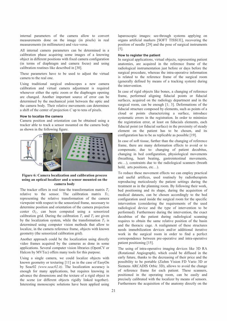
internal parameters of the camera allow to convert measurements done on the image (in pixels) in real measurements (in millimeters) and vice-versa. All internal camera parameters can be determined in a calibration phase acquiring some images of a knowing object in different positions with fixed camera configuration (in terms of diaphragm and camera focus) and using calibration routines like described in [30].These parameters have to be used to adjust the virtual camera to the real one. Using traditional surgical endoscopes a new camera calibration and virtual camera adjustment is required whenever either the optic zoom or the diaphragm opening are changed. Another important source of error can be determined by the mechanical joint between the optic and the camera body. Their relative movements can determines a shift of the center of projection C up to tens of pixels.
How to localize the camera Camera position and orientation can be obtained using a tracker able to track a sensor mounted on the camera body as shown in the following figure.
Figure 6: Camera localization and calibration process using an optical localizer and a sensor mounted on the
camera body The tracker offers in real time the transformation matrix T1relative to the sensor. The calibration matrix Tc,representing the relative transformation of the camera viewpoint with respect to the sensorized frame, necessary to determine position and orientation of the camera projection center OC, can been computed using a sensorized calibration grid. During the calibration T1 and T2 are given by the localization system, while the transformation T3 is determined using computer vision methods that allow to localize, in the camera reference frame, objects with known geometry (the sensorized calibration grid). Another approach could be the localization using directly video frames acquired by the cameras as done in some applications. Several computer vision libraries (OpenCV or Halcon by MVTec) offers many tools for this purpose. Using a single camera, we could localize objects with known geometry or texturing [11] as in the case of EasyOn by Seac02 (www.seac02.it). The localization accuracy is enough for many applications, but requires knowing in advance the dimensions and the texture of a rigid object in the scene (or different objects rigidly linked together).Interesting monoscopic solutions have been applied using
laparoscopic images: see-through systems applying on organs artificial markers [SOFT TISSUE], recovering the position of needle [29] and the pose of surgical instruments [5].
How to register the patient In surgical applications, virtual objects, representing patient anatomies, are acquired in the reference frame of the radiological instrumentation just before or days before the surgical procedure, whereas the intra-operative information is related to the reference frame of the surgical room (generally defined by means of a tracking system) during the intervention. In case of rigid objects like bones, a changing of reference frame, performed aligning fiducial points or fiducial surfaces, acquired on the radiology department and in the surgical room, can be enough [1; 3]. Deformations of the fiducial structure composed by elements, such as points of a cloud or points characterizing a surface, introduce systematic errors in the registration. In order to minimize the registration error, at least on fiducials elements, each fiducial point (or fiducial surface) in the proximity of steady element on the patient has to be chosen, and its configuration has to be as replicable as possible [19].In case of soft tissue, further than the changing of referenceframe, there are many deformation effects to avoid or to compensate, due to: changing of patient decubitus, changing in bed configuration, physiological movements (breathing, heart beating, gastrointestinal movements, etc…), constraints due to the radiological scanners (breath hold, arts positions, etc…).To reduce these movement effects we can employ practical and useful artifices, used routinely by radiotherapists reproducing meticulously the patient settings during the treatment as in the planning room. By following their work, bed positioning and its shape, during the acquisition of medical datasets, can be chosen accordingly to the bed configuration used inside the surgical room for the specific intervention (considering the requirements of the used radiological device and the type of intervention to be performed). Furthermore during the intervention, the exact decubitus of the patient during radiological scanning requires to obtain the same relative position of the basin and the thoracic cage. A realignment of these structures needs immobilization devices and/or additional iterative work in the surgical room in order to find a perfect correspondence between pre-operative and intra-operative patient positioning [15].The using of intra-operative imaging devices like 3D RA (Rotational Angiograph), which could be diffused in the early future, thanks to the decreasing of their price and the possibility to be portable (Ziehm Vision FD Vario 3D or Siemens ARCADIS Orbic 3D), allows to avoid the change of reference frame for each patient. These scanners, positioned in the operating room, can be easily and precisely calibrated with the localizer by means of sensors. Furthermore the acquisition of the anatomy directly on the
21

surgical bed allows to dramatically simplify the problem, by removing error due to the change of bed and patient decubitus. This simplification will allow to obtain high precision also on soft tissues. As proven by experimental results, the application of predictive models of organs motion due to breathing, driven by simple intra-operative parameters like the trajectory of a point on the patient skin or the time over the breathing cycle, can be applied in the real surgical scenario [14; 22].
ALTERNATIVE SOLUTIONS Head mounted tracker-free stereoscopic video see-through Depth perception can be drastically increased using head mounted stereoscopic devices [17], that allow to evaluate object depth dislocation, like in the natural binocular view. The use of localized head mounted displays (HMD), like the one shown in figure 1, allows to see a synthetic scene from a point of view aligned with the real user’s point of view. For the implementation of head mounted mixed reality systems, the video see-through approach, based on the acquisition of real images by means of external cameras, is preferable to the optic see-through approach that projects virtual information on semi transparent glasses. This is due to the fact that tracking of eye movements, strictly required for optical see-through approach, is very difficult to be performed with sufficient precision [16; 18]. On the contrary, head tracking, required for video see-through approach, can be performed with high precision using external localizer based on different technologies [2; 12],like described before.We implemented a head mounted stereoscopic video see-through system, that does not require the use of an external localizer to track head movements [8]. Our system implements mixed-reality aligning in real-time virtual and real scene just using geometric information extracted by segmenting coloured markers, attached on the patient’s skin, directly from couples of camera images.
Figure 7: Schematic representation of our stereoscopic mixed-reality system
Figure 8: Image composed by 3 frames of a laparoscopic video with fixed camera and a moving instrument. The projections of instrument axes, represented with blue
lines, are constrained to pass through a point representing the projection (on the image plane) of the
insertion point (on the abdominal wall) Figure 7 shows the functional scheme of our system, where video frames are used, not only as background of the virtual scene, but also to localize the cameras and to register the patient. Epipolar geometry [13], using two or more cameras, allows to detect the 3D position of each conjugate points, identifiable in the images. In a stereoscopic configuration, knowing the internal camera parameters, for each marker position, in the image plane, the relative projection line in the 3D world, defined as the line l passing through the camera center of projection Oc and lying on the point Pc, is determined. These steps, performed both on left and right images, identify respectively two projection lines ll and lr.Knowing the relative pose of the right camera to the left camera (expressed by a roto-traslation matrix determinable in a calibration phase), the 3D position of each marker is then defined as the intersection point between ll and lr.Since ll and lr do not intersect (due to pixelization process and noise in marker identification) the 3D marker position is approximated with the position of the closest point to both projection lines. After fiducials localization a rigid registration is performed using a point based approach. Results demonstrate that stereoscopic localization approach, adopted in our system, is enough for system usability.
Laparoscope auto localization As described before, localization using monoscopiccameras can be done in case of objects with known geometry or texturing. In case of laparoscopic interventions the localization of the endoscopic camera can be determined using information offered by endoscopic video images without the introduction of any artificial add-on in the scenario[7].The position and orientation of the endoscopic camera can be determined, with respect to a reference frame fixed to the access ports configuration, elaborating video images and knowing the distances between insertion points. During laparoscopic interventions, camera movements are minor respect to instruments movements. Therefore the laparoscope can be considerate steady in a time interval,
22
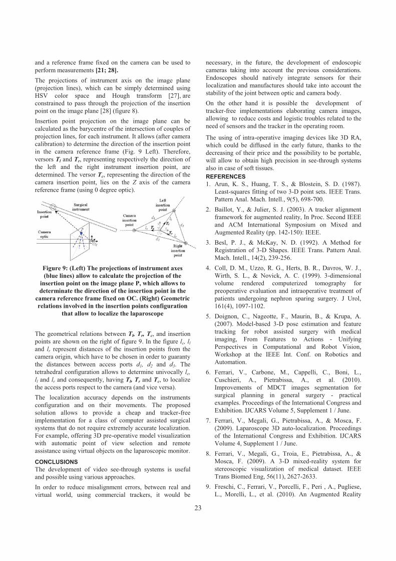
and a reference frame fixed on the camera can be used to perform measurements [21; 28].The projections of instrument axis on the image plane (projection lines), which can be simply determined using HSV color space and Hough transform [27], are constrained to pass through the projection of the insertion point on the image plane [28] (figure 8). Insertion point projection on the image plane can be calculated as the barycentre of the intersection of couples of projection lines, for each instrument. It allows (after camera calibration) to determine the direction of the insertion point in the camera reference frame (Fig. 9 Left). Therefore, versors Tl and Tr, representing respectively the direction of the left and the right instrument insertion point, are determined. The versor Tc, representing the direction of the camera insertion point, lies on the Z axis of the camera reference frame (using 0 degree optic).
Figure 9: (Left) The projections of instrument axes (blue lines) allow to calculate the projection of the
insertion point on the image plane P, which allows to determinate the direction of the insertion point in the
camera reference frame fixed on OC. (Right) Geometric relations involved in the insertion points configuration
that allow to localize the laparoscope
The geometrical relations between Tl, Tr, Tc, and insertion points are shown on the right of figure 9. In the figure lc, lland lr represent distances of the insertion points from the camera origin, which have to be chosen in order to guaranty the distances between access ports d1, d2 and d3. The tetrahedral configuration allows to determine univocally lc,ll and lr and consequently, having Tl, Tr and Tc, to localize the access ports respect to the camera (and vice versa).The localization accuracy depends on the instruments configuration and on their movements. The proposed solution allows to provide a cheap and tracker-free implementation for a class of computer assisted surgical systems that do not require extremely accurate localization. For example, offering 3D pre-operative model visualization with automatic point of view selection and remote assistance using virtual objects on the laparoscopic monitor.
CONCLUSIONS The development of video see-through systems is useful and possible using various approaches. In order to reduce misalignment errors, between real and virtual world, using commercial trackers, it would be
necessary, in the future, the development of endoscopic cameras taking into account the previous considerations.Endoscopes should natively integrate sensors for their localization and manufactures should take into account the stability of the joint between optic and camera body.On the other hand it is possible the development of tracker-free implementations elaborating camera images, allowing to reduce costs and logistic troubles related to the need of sensors and the tracker in the operating room.
The using of intra-operative imaging devices like 3D RA, which could be diffused in the early future, thanks to the decreasing of their price and the possibility to be portable, will allow to obtain high precision in see-through systems also in case of soft tissues. REFERENCES 1. Arun, K. S., Huang, T. S., & Blostein, S. D. (1987).
Least-squares fitting of two 3-D point sets. IEEE Trans. Pattern Anal. Mach. Intell., 9(5), 698-700.
2. Baillot, Y., & Julier, S. J. (2003). A tracker alignment framework for augmented reality, In Proc. Second IEEE and ACM International Symposium on Mixed and Augmented Reality (pp. 142-150): IEEE.
3. Besl, P. J., & McKay, N. D. (1992). A Method for Registration of 3-D Shapes. IEEE Trans. Pattern Anal. Mach. Intell., 14(2), 239-256.
4. Coll, D. M., Uzzo, R. G., Herts, B. R., Davros, W. J., Wirth, S. L., & Novick, A. C. (1999). 3-dimensional volume rendered computerized tomography for preoperative evaluation and intraoperative treatment of patients undergoing nephron sparing surgery. J Urol, 161(4), 1097-1102.
5. Doignon, C., Nageotte, F., Maurin, B., & Krupa, A. (2007). Model-based 3-D pose estimation and feature tracking for robot assisted surgery with medical imaging, From Features to Actions - Unifying Perspectives in Computational and Robot Vision, Workshop at the IEEE Int. Conf. on Robotics and Automation.
6. Ferrari, V., Carbone, M., Cappelli, C., Boni, L., Cuschieri, A., Pietrabissa, A., et al. (2010). Improvements of MDCT images segmentation for surgical planning in general surgery - practical examples. Proceedings of the International Congress and Exhibition. IJCARS Volume 5, Supplement 1 / June.
7. Ferrari, V., Megali, G., Pietrabissa, A., & Mosca, F. (2009). Laparoscope 3D auto-localization. Proceedings of the International Congress and Exhibition. IJCARS Volume 4, Supplement 1 / June.
8. Ferrari, V., Megali, G., Troia, E., Pietrabissa, A., & Mosca, F. (2009). A 3-D mixed-reality system for stereoscopic visualization of medical dataset. IEEE Trans Biomed Eng, 56(11), 2627-2633.
9. Freschi, C., Ferrari, V., Porcelli, F., Peri , A., Pugliese, L., Morelli, L., et al. (2010). An Augmented Reality
23

Navigation Guidance for High Intensity Focused Ultrasound Treatment. Paper presented at the Conf Proc ICABB, International Conference on Applied Bionics and Biomechanics 2010, Venice, Italy.
10.Freschi, C., Troia, E., Ferrari, V., Megali, G., Pietrabissa, A., & Mosca, F. (2009). Ultrasound guided robotic biopsy using augmented reality and human-robot cooperative control. Conf Proc IEEE Eng Med Biol Soc, 2009, 5110-5113.
11.Gao, C., & Ahuja, N. (2004). Single camera stereo using planar parallel plate, Pattern Recognition, 17th International Conference on (ICPR'04) Volume 4 (pp. 108-111).
12.Genc, Y., Sauer, F., Wenzel, F., Tuceryan, M., & Navab, N. (2000). Optical see-through HMD calibration: A stereo method validated with a video see-through system, International Symposium for Augmented Reality.
13.Hartley, R., & Zisserman, A. (2004). Multiple View Geometry in Computer Vision.
14.Hawkes, D. J., Penney, G. P., Atkinson, D., Barratt, D. C., Blackall, J. M., Carter, T. J., et al. (2007). Motion and Biomechanical Models for Image-Guided Interventions, ISBI (pp. 992-995).
15.Hinson, W. H., Kearns, W. T., Ellis, T. L., Sprinkle, D., Cullen, T., Smith, P. G., et al. (2007). Reducing set-up uncertainty in the elekta stereotactic body frame using stealthstation software. Technology in cancer research & treatment, 6(3), 181-186.
16.Hua, H., Krishnaswamy, P., & Rolland, J. P. Video-based eyetracking methods and algorithms in head-mounted displays. Optics Express, 14, 4328-4350.
17.Johnson, L., Philip, E., Lewis, G., & Hawkes, D. (2004). Depth perception of stereo overlays in image-guided surgery, Medical Imaging, Proceedings of the SPIE, Volume 5372, pp. 263-272.
18.Lee, E. C., & Park, K. R. (2008). A robust eye gaze tracking method based on a virtual eyeball model. Machine Vision and Applications.
19.Megali, G., Ferrari, V., Freschi, C., Morabito, B., Cavallo, F., Turini, G., et al. (2008). EndoCAS navigator platform: a common platform for computer and robotic assistance in minimally invasive surgery.
The International Journal of Medical Robotics and Computer Assisted Surgery, 4, 242 - 251.
20.Milgram, P., & Kishino, F. (1994). A Taxonomy of Mixed Reality Visual Displays. IEICE transactions on information and systems, 77(12), 1321-1329.
21.Naogette, F., Zanne, P., Doignon, C., & De Mathelin, M. (2006). Visual Servoing-Based Endoscopic Path Following for Robot-Assisted Laparoscopic Surgery, International Conference on Intelligent Robots and Systems (IROS).
22.Olbricha, B., Traubb, J., Wiesnerb, S., Wicherta, A., Feussnera, H., & N.Navabb. (2005). Respiratory MotionAnalysis: Towards Gated Augmentation of the Liver, CARS 2005 Computer Assisted Radiology and Surgery, 19st International Congress and Exhibition.
23.Peters, T. M. (2006). Image-guidance for surgical procedures. Physics in Medicine and Biology, 51(14), R505-R540.
24.Peters, T. M. (2000). Image-guided surgery: from X-rays to virtual reality. Computer Methods in Biomechanics and Biomedical Engineering, 4(1), 27-57.
25.Pietrabissa, A., Morelli, L., Ferrari, M., Peri, A., Ferrari, V., Moglia, A., et al. (2010). Mixed reality for robotic treatment of a splenic artery aneurysm. Surg Endosc, 24(5), 1204.
26.Shuhaiber, J. H. (2004). Augmented Reality in Surgery. Archive of surgery, 139, 170-174.
27.Tonet, O., Ramesh, T. U., Megali, G., & Dario, P. (2007). Tracking endoscopic instruments without localizer: a shape analysis-based approach. Computer Aided Surgery, 12(1), 35-42.
28.Voros, S., Long, J.-A., & Cinquin, P. (2006). Automatic Localization of Laparoscopic Instruments for the Visual Servoing of an Endoscopic Camera Holder, MICCAI (1) (pp. 535-542).
29.Wengert, C., Bossard, L., Baur, C., Szekely, G., & Cattin, P. C. (2008). Endoscopic navigation for minimally invasive suturing. Comput Aided Surg, 13(5), 299-310.
30.Zhang, Z. (2000). A Flexible New Technique for Camera Calibration. IEEE Transactions on Pattern Analysis and Machine Intelligence, 22(11), 1330-1334.
24

Survivable and Scalable Wireless Solution for E-health and E-emergency Applications
Abdellah Chehri, Hussein. T. Moutah School of Information Technology and Engineering,
800 King Edward Avenue Ottawa, Ontario, Canada, K1N 6N5
achehri,[email protected]
ABSTRACT Most conventional medical systems use fixed wired LAN, cable, and other land line systems to transmit medical data or operations. As wireless technology becomes increasingly pervasive, e-health professionals are considering wireless networks for their mobile medicine systems with the advent of e-health care, a wide range of technologies can now be applied to provide medical care products and services. Wireless Sensor Networks (WSNs) are composed by small devices that possess the ability to measure and to exchange a variety of vital data. In this paper we evaluate the performance of wireless sensor network technology for patient’s remote monitoring. The system is mainly composed of static biomedical sensor nodes, which are mounted on the patient body in under to collect the main vital data such as temperature, ECG etc. The main characteristic of the networks such as the throughput and ratio delivery packet have been evaluated in this paper. Keywords E-health application, wireless body area sensor networks, IEEE 208.15.4
INTRODUCTION The world is facing problems to provide high quality healthcare services at a reasonable cost to the citizens due to the increasing percentage of graying population. As the population ages and the risk of chronic disease increases, the cost of healthcare will rise. The solution to decrease both the cost of healthcare services and also the load of medical practitioners requires a dramatic change in the way future healthcare services are provided [1]. The expected necessary changes are: moving from reactive to preventive medicine [2], [3].By the summer of 2005, the initiative of marrying information technology to medicine seemed clear, and the media was heralding what some called “the e-health” revolution [4].
The employment of new technologies for medical healthcare could reduce the cost and improve the efficiency of treatment. Wireless technology capabilities are growing at a fantastic rate. There appears to be no limit to what technology might accomplish, given infinite resources [5].In this paper, we analyze a survivable and scalable wirelesssolution for E-health and E-emergency applications. We focus mainly of the performance of wireless body area sensor networks for remote monitoring application. Using this architecture, patients, doctors, and nurses could be empowered to receive or provide real-time, distant health care services. Both patients and providers would have the freedom to be anywhere in the world while sending, receiving, checking, and examining medical data in a timely fashion.At the health institutions, patients are monitored during treatment and recovery. This will be the monitoring of vital body functions such as ECG and blood pressure. Compared to wired solutions, the wireless transmission for monitoring provides several advantages [6].The patient mobility will be improved, and that it will provide the opportunity for monitoring patients outside the health institutions. Patients' well-being and retention of health care has also influenced the recovery time. A transition to wireless systems will therefore help to improve patients' wellbeing and reduce recovery time. In addition, we describe a global mobile system to provide unconfined e-health services, one that combines WLAN (Wireless Local Area Network) with wireless body sensor networks (WBANs), and the Internet or UMTS (Universal Mobile Telecommunications System, or GSM). The reminder of the paper is organized as follows: section II gives an overview of a scalable wireless solution for e-health and e-emergency applications. In section III deals with system description. The performance evaluation of the
Copyright © 2011 for the individual papers by the papers' authors. Copying permitted only for private and academic purposes. This volume is published and copyrighted bythe editors of EICS4Med 2011.
25

wireless body area sensor networks is given in section IV. Finally, we conclude the paper in section V.
SCALABLE WIRELESS SOLUTION FOR E-HEALTH AND E-EMERGENCY APPLICATIONS The recent advances in wireless technology have led to the development of wireless body area sensor networks (WBASN), where a set of communicating devices arelocated around the human body [7].
The application and use of wireless devices and computer-based technologies in health care have undergone an evolutionary process. Advances in information, telecommunication, and network technologies have led to the emergence of a revolutionary new paradigm for health care that some refer to as e-health [8].
These systems use modern wireless communication and information technologies to provide clinical care to remote located individuals. With more research progresses in this field it will be possible to provide a better quality of life to patients while reducing healthcare costs. Enabling underlying infrastructures such as wireless medical sensor devices, wearable medical systems integrating sensors on body's patient can offers pervasive solutions for continuous health status monitoring through biomedical, biochemical and physical measurements. Remote monitoring systems typically collect these patient readings and then transmit them to a remote server for storage and later examination by healthcare professionals [2]-[3].Once available on the server, the readings can be used in numerous ways by home health agencies, by clinicians, by physicians, and by informal care providers. However remote healthcare monitoring systems will be exploited to their full potential when the analysis is also performed automatically through clinical decision support systems fed by expert knowledge. A clinical practice guide line constitutes the most suitable source of information for building such clinical decision support systems [3].In this scalable wireless solution for E-health and E-emergency applications, we select several wireless communication standards with publicly available specifications, which are namely Bluetooth (IEEE802.15.1.), Wi-Fi (IEEE 802.11), WPAN (IEEE 802.15.4 / ZigBee) and wireless Mesh networks (IEEE802.11s).While comparing all wireless technologies, we had to choose relevant criteria for an evaluation. The main criteria that should be considered in this architecture were robustness, range, energy consumption, availability, usability and security.This system interfaces to healthcare providers, doctors, care-givers and the medical call centers (see Fig. 1) and also is integrated with a mobile platform for the occupant to
remote control his home and another mobile platform for the doctors and nurses to view the state of their patients.Typically they will receive an alarm in case of a health problem of their patients. This figure shows that the system is integrated with vital sign monitoring devices and sensors.
Figure 1: Survivable and scalable wireless solution for E-health and E-emergency applications
WIRELESS BODY AREA SENSOR NETWORKS In general, wireless body area sensor networks (WBASNs) are wireless networks that support the use of biomedical sensors and are characterized by its (1) very low transmit power to coexist with other medical equipments and provide efficient energy consumption, (2) high data rate to allow applications with high QoS (Quality-of-Service)constraints, (3) low cost, low complexity and miniature size to allow real feasibility [9].BSN, unlike wired monitoring systems, provide long term and continuous monitoring of patients under their natural physiological states even when they move. The system allows unobtrusive ubiquitous monitoring and can generate early warnings if received signals deviate from predefined personalized ranges.Figure 2 illustrates the architecture of body sensor network. One patient is equipped with several sensors monitoring different parameters. A WBASN is made up of one or more body area networks and a base station. When theinformation has been gathered in the sensor network it is forwarded to this base station.The information is then received at a relay station and passed on through a backbone network. In the end, the information can be viewed at terminals or monitoringstations that are connected to the network. This system has the potential of making remote monitoring and immediate diagnostics a reality [10], [11], [12].Sensors are heterogeneous, and all integrate into the human body. The number and the type of biosensors vary from one patient to another depending on the state of the patient. The
26

most common types of biosensors are EEG “Electroencephalography” to measure the electrical activity produced by the brain, ECG “Electrocardiogram” to record the electrical activity of the heart over time, EMG “Electromyography” to evaluate physiologic properties of muscles, Blood pressure, heart rate, glucose monitor, SpO2 “Oxymeter” to measure of oxygen saturation in blood, and to measure temperature of the body [13], [14].
Figure 2: Wireless Body Area Sensor Network organization
As shown in the Table 1, according to the characteristics of physiological measurements or type of application services which can be real-time or non real-time with high or low rate.
Type of Service Data rate Latency Class of Service
ECG High Low Real-time high rate
EEG, EMG Low Low Real-time low rate
Blood pressure, body temperature, heart rate, glucosemonitoring
Low High Non real-time low rate
Medical image, X-ray, MRI
High High Non real-time high rate
Table 1: Service Classification of Physiological Measurements
SIMULATION AND RESULTS We investigate on wireless body sensor networkarchitecture for smart healthcare that possesses the following proprieties:
� Real-time and long-term remote monitoring;� Tiny sensor with very low complexity;� Can be integrated with existing medical practices
and technology;
To meet these requirements, we have planned scenario where a patient has been equipped with an important biosensors nodes. Ns2 simulator with WPAN models is used [15]. We have considered a wide range of network topologies and test-validated the performance of WBASN with all considered topologies. Due to the posed space limitation, we present our results for a static network. We set a 2 m x 2 m area to simulate patient body. We consider a static network configuration with six nodes and a gateway.These nodes are mounted around his body (Fig. 2). Each node is implemented with one medical biosensor ECG, SpO2, body temperature, glucose monitoring, respiration and blood pressure.All sensors, including sink node (gateway) are considered static (see fig 2). Transmit power of devices are configured based on the realistic radio map of sensor node around body network. In addition, the propagation model between nodes which are different from general indoor/outdoor models [16].In the simulations, we evaluate system’s the throughput,
and latency of WBASN architecture.
Figure 3: Deployment of WBASN using NS2
27

Throughput Analysis and packet delivery ratio In order to analyze the drawbacks of CSMA/CA, we performed simulations of traditional IEEE 802.15.4 network. A beacon-enabled slotted CSMA/CA was chosen where beacons are sent by the PAN Coordinator and all nodes in the network synchronize with the beacon. A single-hop Star topology was considered. The network performance was analyzed using two transmission scenarios; first where a single node sends data to the cluster head or PAN Coordinator, and, second, where 6 nodes send data to the PAN Coordinator. The traffic load was varied from 10 to 500 kbps. The highest throughput achieved when there is one source is around 160 kbps as shown in Figure 4.
Figure 4: Throughput of the patient monitoring system
The packet delivery ratio also falls drastically with an increase in data rate as shown in Figure 5.
Figure 5: Packet delivery ratio of the patient monitoring system
CONCLUSION The overall goal of this paper was to contribute and help through simulations towards dimensioning of the sensor networks for patient’s remote monitoring. We examined the reliability for both the point-to point communication and multihop communication using IEEE 802.15.4 standard. These performances are measured in term of throughput and packet error rate. The first results show that it ispossible to use wireless body area sensor network to remote the vital data of the patient with reasonable throughput. In the future, more scenarios will be investigated. REFERENCES 1. M. Fieldand, K. Lohr, “Guidelines for Clinical Practice:
From development to use” Institute of Medicine, National Academy Press, Washington, DC (1992).
2. J. Tan “E-Health Care Information Systems: An Introduction for Students and Professionals”, 624 p., Hardcover, ISBN: 978.
3. O. Nee, A. Hein, T. Gorath, N. Hulsmann, G. Laleci, “SAPHIRE: Intelligent Healthcare Monitoring based on Semantic Interoperability Platform - Pilot Applications”, IEE Proceedings Communications Special Issue on Telemedicine and e-Health Communication Systems.
4. M. Mahar, “Money-Driven Medicine: The Real Reason Health Care Costs So Much”, Harpercollins Trade Sales Dept., 1st Edn. (July 7, 2009).
5. R. Kohno, K. Hamaguchi, H. Li, K. Takizawa, “R&D and standardization of body area network (BAN) for medical healthcare”. In: Proc. IEEE Intl. Conf. On Ultra-Wideband (ICUWB 2008), Hannover, Germany, September 10-12, vol. 3, pp. 5–8 (2008).
6. A. Lymberis, “Progress In R&D On Wearable And Implantable Biomedical Sensors For Better Health care And Medicine. In: Proceedings of the 3rd Annual International IEEE EMBS Special Topic Conference on Microtechnologies in Medicine and Biology Kahuku, Oahu, Hawaii (May 12-15, 2005).
7. E. Alasaarela, R. Nemana, S. DeMello, Drivers and challenges of wireless solutions in future healthcare. In: International Conference on eHealth, Telemedicine, and Social Medicine (2009)
8. S. Nourizadeh, Y. Song, J. P. Thomesse, C.Deroussent, “A Distributed Elderly Healthcare System”,In: MobiHealth 2009, Porto, Portugal, January 16 (2009).
9. A. Chehri and Hussein Mouftah, “Performance Analysis of UWB Body Sensor Networks for Medical Applications”, In the book: Ad Hoc Networks, Editors Jun Zheng, David Simplot-Ryl and Victor C. M. Leung, Lecture Notes of the Institute for Computer Sciences, Social Informatics and Telecommunications Engineering, Volume 49, Part 8, 471-481,2010.
0 50 100 150 200 250 300 350 400 450 5000
20
40
60
80
100
120
140
160
180
200
Network Input Load (kbps)
Net
wor
k Th
roug
hput
(kbp
s)
One source nodeSix source nodes
0 50 100 150 200 250 300 350 400 450 5000
10
20
30
40
50
60
70
80
90
100
Network Input Load (kbps)
Del
iver
y R
atio
%
One source nodeSix source nodes
28

10.R. Hongliang, M. Meng, X. Chen, “Physiological Information Acquisition through Wireless Biomedical Sensor Networks”. In: Proceedings of the IEEE International Conference on Information Acquisition, June 27-July 3 (2005)[11] Blount, M.: Remote health-care monitoring using Personal Care Connect. IBM Systems Journal 46(1) (2007)
11.Baker, R., et al.: Wireless Sensor Networks for Home Health Care. In: 21st International Conference on Advanced Information Networking and Applications Workshops (AINAW 2007). IEEE, Los Alamitos (2007)
12.J. Ben Slimane, Y. O. Song, A. Koubaa, M. Frikha, “AThree-Tiered Architecture for Large-Scale Wireless
Hospital Sensor Networks”. In: MobiHealthInf 2009, pp. 20–31 (2009)
13.B. Gyselinckx, C. Van Hoof, S. Donnay “Body area networks: the ascent of autonomous wireless Microsystems”, pp. 73–83. Springer, Heidelberg (2006).
14.www.isi.edu/nsnam/ns/ 15.C. Lee, J. Kim, H. Lee, J. Kim, “Physical Layer Designs
for WBAN Systems in IEEE 802.15.6 Proposals” In: 9th International Symposium on Communication and Information Technology, Incheon (September 28-30, 2009).
29

Care & Prepare – Usability Engineering for Mass Casualty Incidents
Martin Christof Kindsmüller, Tilo Mentler, Michael Herczeg
Institute for Multimedia and Interactive Systems University of Lübeck
Ratzeburger Allee 160, D-23562 Lübeck, Germany
{mck|mentler|herczeg}@imis.uni-luebeck.de
Timo RumlandDIGITALYS GmbH Barkenboomsweg 1
D-27619 Schiffdorf, Germany [email protected]
ABSTRACT Best possible pre-hospital treatment in the event of a mass casualty incident (MCI) is related to prioritizing rescue tasks and using rescue resources efficiently. Currently, in-formation is almost always documented on paper-based forms and communicated by one-to-one talks, messengers, radio and mobile phone. Pervasive computer-based solu-tions are not established yet. Although the mere technologi-cal challenges are on the way of being solved within the near future, questions of usability remain. Concerning this matter, we propose an entangled User Centered System Design (UCSD) and Feature Driven Development (FDD) process and introduce the principle Care & Prepare. It is based on two fundamental assumptions. First, the whole design process has to care for the rescue personnel’s’ needs in these challenging situations and second, the rescue per-sonnel has to be prepared for using these specialized com-puter applications in case of an MCI. Therefore, daily rou-tine has to be the training foundation for these extraordinary operations.
Keywords Mass Casualty Incident, Usability Engineering, User-Centered Design, Feature Driven Development
INTRODUCTION Without regard to differences in national regulations and exact wordings, a mass casualty incident (MCI) can be de-fined as “an event, which generates more patients at one time than locally available resources can manage using rou-tine procedures. It therefore requires exceptional emergency arrangements and additional or extraordinary assistance [30]. Due to the disproportions between casualties, rescue workers and material resources, dedicated tactics are neces-sary. Managerial structures and forms of organization must be adapted as circumstances demand [23]. Therefore, an MCI is very different from the sum of many individual emergencies. In order to ensure optimal pre-hospital medi-
cal treatment, patients and the severity of their injuries have to be the basis for all interaction. Today paper-based forms, tables, patient records and plastic tags are used to gather and document required information (Figure 1). Depending on the specific system identification numbers or barcodes are used. These are supposed to en-sure assignments of various documents to a single person. Communication, coordination and cooperation needs are met by a complex mix of face-to-face communication, radio calls, mobile phone talks and messengers.
Figure 1: Current documentation and information tools Pervasive computer-based tools and systems are not estab-lished even in otherwise highly developed countries. Ra-ther, most emergency medical services (EMS) still rely on paper to carry out daily job routine. Mobile solutions are introduced gradually. As an informal survey on the leading European professional fairs “RETTmobil 2010” and “Inter-schutz 2010” revealed, most stakeholders believe that it will take at least some months, if not years until a paperless workflow from patient to accounting is the rule rather than the exception. A computer-based solution replacing and possibly extend-ing the current paper-based systems has to be designed in due consideration of the following aspects: � Its advantages will only be effective, if data can be
entered and accessed efficiently and securely.
Copyright © 2011 for the individual papers by the papers' authors. Copying permitted only for private and academic purposes. This volume is published and copyrighted bythe editors of EICS4Med 2011.
30

� Time consuming adaption and learning phases are notacceptable during an MCI. Any delay has to be avoided. The ability to use the system instantly in an effective and efficient way is of utmost importance.
� MCIs are rare events for a single EMS [1].Disregarding these points can and most likely will result in faults and inefficiencies, which not only endanger general usability but can – in this field of application – as well cause a threat to the life or the physical conditions for the patients involved. We pursue four objectives within this contribution. First we describe the state of the art of how EMSs are currently han-dling MCIs using classical means. Then we sketch how –mainly research projects – use advanced technology in or-der to improve the handling of MCIs. Third we present our approach Care & Prepare, where the focus is shifted from what can be done with modern technology to how technol-ogy can be applied to support the users in order to perform their demanding tasks. Finally we draft our specific devel-opment process that we use to ensure that our system will meet the demands of the users.
BACKGROUND AND RELATED WORK Although first publications (e.g. [27]) pointed out ad-vantages of computer-based solutions as opposed to paper-based ones almost 20 years ago, MCIs have not been high on the agenda of research and development departments.This changed rapidly after the terrorist attacks on Septem-ber 11th 2001. As a consequence of these incidents and in preparation for upcoming major events, (e.g. the Soccer World Championship in Germany 2006) numerous research projects have been launched. Due to the various challenges associated with MCIs, they differ in scope and scale. With a specific view to usability, two basic approaches can be distinguished: � providing support of subtasks, � providing pervasive solutions.
Supporting Subtasks In the event of an MCI, paramedics and emergency physi-cians are confronted with several activities, which are notpart of daily job routine. The 5-T-rule outlines the main task areas as follows [6]: � tactics, � triage, � treatment, � take care, � transport. Triage, as the process of determining a patient’s priority of treatment based on objective criteria, is of particular im-portance. It can be called the single most import task except for basic life support [23]. It implies an order which is geared to saving as many lives as possible and utilizing resources efficiently.
Triage algorithms have been developed to ease the assess-ment of patients. Most of them (e.g. SALT, START, and CareFlight) are based on vital signs (e.g. respiratory rate) that can be determined without special utilities [10], [14]. Inthe end, patients are typically classified into one out of four or five categories. Tactics, treatment and transport are often interrelated as-pects of more extensive approaches. For that reason, our literature reviews showed no usability-related work which addresses one of these topics separately. Taking care of people who are not seriously physically in-jured but affected by the incident is in the realm of interper-sonal relationship. In order to handle, for example, missing person reports or contact witnesses later on, those persons have to be registered in the system as well. Contrary to tactics, treatment, taking care and transport, triage has been addressed as a singular subtask by different projects and researchers. Jokela et al. presented an applica-tion system to simplify the process based on commercial mobile networks and regular mobile phones with integrated RFID technology [9]. Usability aspects had a lower priority. Inoue, Sonoda and Yasuura prototypically realized a triage system with RFID tags [8]. They measured times for input operations according to single text fields (e.g. name, sex and age) and compared performances with and without the application system. The TUMult-project concentrates on developing user interfaces for mobile devices to support rescue workers in performing triage [19]. They designed several concepts for keyboard and multi-tap input and pro-posed adaptive user interfaces [18], [20].In addition, essential usability issues, e.g. combining elec-tronic and paper-based approaches, related to MCIs were and are considered [17]. One of their findings is that “the introduction of RFID technology in MCIs leads to more challenges as […] expected” [16].
Addressing System Solutions Besides designing and implementing extensive application systems, projects like WISTA, WIISARD, AID-N, SpeedUpor ALARM challenge several technical and organ-izational questions with reference to MCIs, e.g. how to deal with stampedes or how to define common quality standards and indexes [26], [29]. They are primarily focused on MCIs and widely disregard daily job routine of emergency medi-cal services. Chu and Ganz designed and prototypically implemented WISTA, a wireless telemedicine system for disaster patient care [3]. Instead of deploying proprietary hardware, they used off-the-shelf PDAs and based their two-layered system architecture on Bluetooth and 802.11g wireless connec-tions. Main aim of the project was to demonstrate a budget-friendly solution in a testbed. In addition, simulation results proved the scalability of the system. Usability aspects had a lower priority. The WIISARD project (2004-2008) addressed the issue whether medical care could be improved by means of wire-
31

less network technologies in the event of an MCI. Designed for the American Incident Command System (ICS) which differentiates three types of first responders, the final sys-tem consists of several hardware and software components [12]. Frontline workers who are responsible for triage und treatment on site are equipped with the WIISARD First Responder (WFR), a PDA with wireless network adapter and barcode scanner [11]. Mid-tier supervisors and team-leaders exchange clipboards and forms with tablet PCs [2].The Command Center System, which is used by third-level first responders, is not explicitly connected to a certain type of hardware but features like maps or diagrams require a lager screen size than PDAs provide [4]. Furthermore, In-telligent Triage Tags (ITT) and different vital sensors are used to document and monitor patients’ conditions [13].
Figure 2: WIISARD equipment [www.wiisard.org] All components are interconnected by a mobile ad-hoc net-work. Special-purpose computers, so-called CalMesh nodes, provide a self-scaling network infrastructure and act as both wireless routers and access points [12]. Figure 2gives an overview of the WIISARD hardware components. WIISARD followed a classic participatory development process, which integrated first responders into the design teams. In addition, designers attended first responder exer-cises. Iterative refinements, based on experiences of five simulated MCIs, and a final evaluation study were accom-plished. The WIISARD system was evaluated according to the fol-lowing key measures: � decision and information quality, � speed of patient processing, � system scalability. The results revealed potential advantages of a computer-supported mass casualty management system in comparison to paper-based solutions [12]. WIISARD was renamed to WIISARD-SAGE and is under ongoing development. The Advanced Health and Disaster Aid Network (AID N) was following the same goals as WIISARD. Requirement analysis, technology development and evaluation framed the three main phases of this project. Development was
organized as a “cyclical build-demonstrate-rebuild process”[28]. The overall system was tested in a simulated mass casualty event and evaluated with the aid of a questionnaire. The results indicate that EMS personnel, hospital adminis-trators and other public health staff could improve their understanding of processes and conditions. Nevertheless, one main finding was that “technologies must be used every day, if they are to be successfully used in a critical situa-tion” [28]. Furthermore, the principle of familiarity is intro-duced as follows: “Match the system with current practice: Integrate systems to in non-disruptive ways to promote use during routine ambulance runs” [5]. These statements indi-cate that the training for rare and extraordinary incidents has to be integrated in day-to-day operations.
THE CARE & PREPARE APPROACH Designing and deploying a Mobile Data Gathering System (MDGS) for handling MCIs is a challenge for many rea-sons. The whole process from analyzing the working con-text and the needs of the users to premature test runs and field tests are ethically as well as legally very difficult. Experiments under controlled laboratory conditions on the other hand have to be questioned as well because it is very hard to simulate the extraordinary circumstances of an MCI in all its facets. To meet these challenges we propose a new approach named “Care & Prepare” as a principle for de-signing and deploying support systems for handling MCIs.
A Definition of Care & Prepare The two pillar structure of our approach is based on two basic principles: � Care: An application for managing MCIs and its user
interface in particular have to be designed in considera-tion of users’ context (physical, mental, temporal). A sys-tem has to be tailored to meet the constraints of the human cognitive-perceptive system in these particular situational conditions.
� Prepare: The cornerstone of handling an MCI success-fully is to be prepared. Highly trained routine behavior is formed in day-to-day practice of paramedics and emer-gency physicians. A system for handling MCIs therefore has to be a “natural” extension of MDGS for regular res-cue und transport missions.
This principle is in line with Quarantelli’s remark that the difference between an MCI and daily job routine “is one of kind rather than degree” [24]. While this is obviously true for medical treatment strategies and other aforementioned aspects, this statement is no indication for strictly divided application systems. Rather, this principle takes into ac-count that MCIs are rare events in terms of a specific EMS and is based on the assessment that routine can only be de-rived from intense and regular application [7].
Guiding Principles: The Users Specific Situation Drilling down the extraordinary circumstances of an MCI leads to a set of statements describing the users’ (rescue personnel) situation:
32
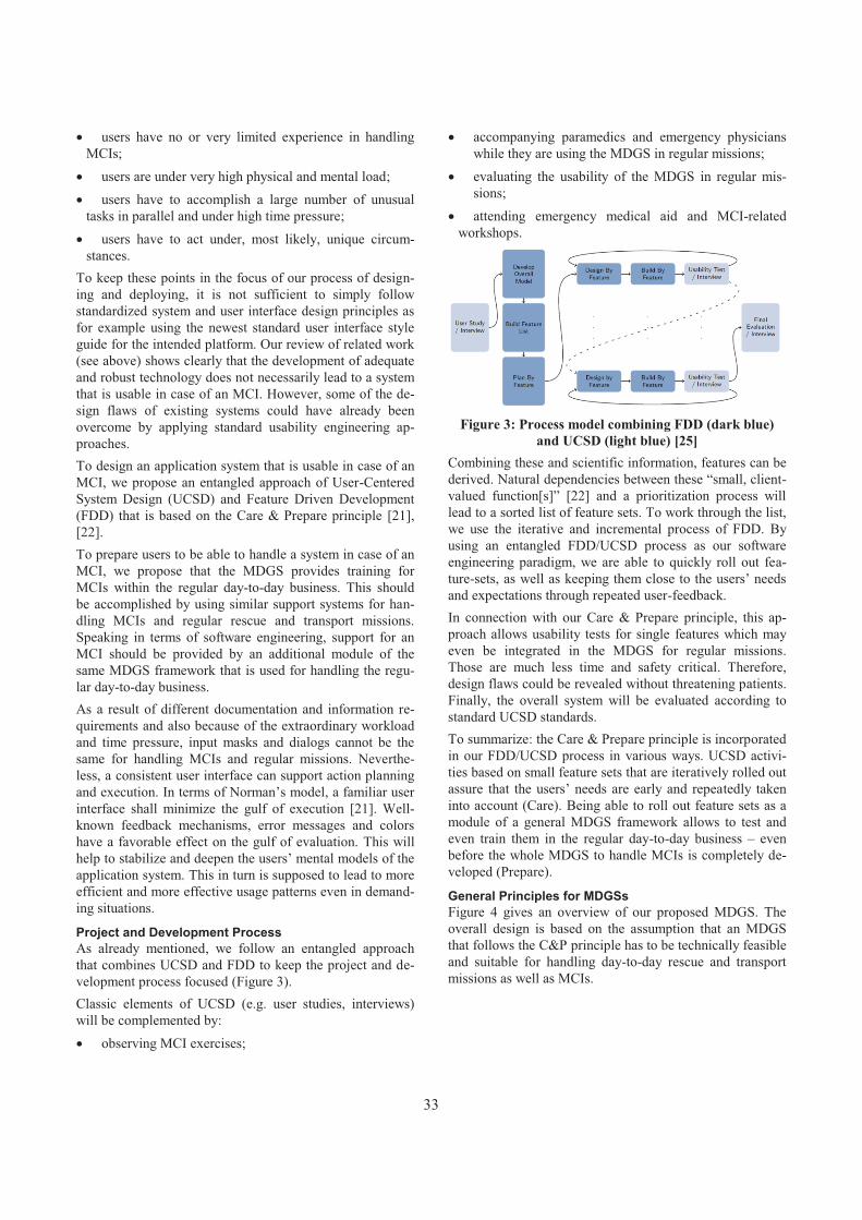
� users have no or very limited experience in handling MCIs;
� users are under very high physical and mental load; � users have to accomplish a large number of unusual
tasks in parallel and under high time pressure; � users have to act under, most likely, unique circum-
stances. To keep these points in the focus of our process of design-ing and deploying, it is not sufficient to simply follow standardized system and user interface design principles as for example using the newest standard user interface style guide for the intended platform. Our review of related work (see above) shows clearly that the development of adequate and robust technology does not necessarily lead to a system that is usable in case of an MCI. However, some of the de-sign flaws of existing systems could have already been overcome by applying standard usability engineering ap-proaches. To design an application system that is usable in case of an MCI, we propose an entangled approach of User-Centered System Design (UCSD) and Feature Driven Development (FDD) that is based on the Care & Prepare principle [21],[22].To prepare users to be able to handle a system in case of an MCI, we propose that the MDGS provides training for MCIs within the regular day-to-day business. This should be accomplished by using similar support systems for han-dling MCIs and regular rescue and transport missions. Speaking in terms of software engineering, support for an MCI should be provided by an additional module of the same MDGS framework that is used for handling the regu-lar day-to-day business. As a result of different documentation and information re-quirements and also because of the extraordinary workloadand time pressure, input masks and dialogs cannot be the same for handling MCIs and regular missions. Neverthe-less, a consistent user interface can support action planning and execution. In terms of Norman’s model, a familiar user interface shall minimize the gulf of execution [21]. Well-known feedback mechanisms, error messages and colors have a favorable effect on the gulf of evaluation. This will help to stabilize and deepen the users’ mental models of the application system. This in turn is supposed to lead to more efficient and more effective usage patterns even in demand-ing situations.
Project and Development Process As already mentioned, we follow an entangled approach that combines UCSD and FDD to keep the project and de-velopment process focused (Figure 3). Classic elements of UCSD (e.g. user studies, interviews) will be complemented by: � observing MCI exercises;
� accompanying paramedics and emergency physicians while they are using the MDGS in regular missions;
� evaluating the usability of the MDGS in regular mis-sions;
� attending emergency medical aid and MCI-related workshops.
Figure 3: Process model combining FDD (dark blue) and UCSD (light blue) [25]
Combining these and scientific information, features can be derived. Natural dependencies between these “small, client-valued function[s]” [22] and a prioritization process will lead to a sorted list of feature sets. To work through the list, we use the iterative and incremental process of FDD. By using an entangled FDD/UCSD process as our software engineering paradigm, we are able to quickly roll out fea-ture-sets, as well as keeping them close to the users’ needs and expectations through repeated user-feedback. In connection with our Care & Prepare principle, this ap-proach allows usability tests for single features which may even be integrated in the MDGS for regular missions.Those are much less time and safety critical. Therefore, design flaws could be revealed without threatening patients. Finally, the overall system will be evaluated according to standard UCSD standards. To summarize: the Care & Prepare principle is incorporated in our FDD/UCSD process in various ways. UCSD activi-ties based on small feature sets that are iteratively rolled out assure that the users’ needs are early and repeatedly taken into account (Care). Being able to roll out feature sets as a module of a general MDGS framework allows to test and even train them in the regular day-to-day business – even before the whole MDGS to handle MCIs is completely de-veloped (Prepare).
General Principles for MDGSs Figure 4 gives an overview of our proposed MDGS. The overall design is based on the assumption that an MDGS that follows the C&P principle has to be technically feasible and suitable for handling day-to-day rescue and transport missions as well as MCIs.
33

Figure 4: Handling of MCIs as an integrated part of general MDGS
The basic features as shown in the figure are: � All rescue workers (paramedics, emergency physicians,
team leader, and incident commander) are using the same handheld device, most likely a rugged tablet PC.
� All stakeholders (public-safety answering point, crisis squad, hospital staff, and rescue teams) are kept in the loop. They are aware of all necessary information. The users are guided by dialogues that are simple enough to be still useful even in very demanding situations.
� The location of every patient and rescue worker is made available by location-based services for the stake-holders in command.
� Ambulance crews are informed on their way to the area of operation as well as while waiting at the ambulance as-sembly area. Supplying this information to the rescue workers can help to cope with anxieties and help to pre-pare them for the situations they will be confronted with [15].
� All relevant information is stored on central servers for ad-hoc as well as post-hoc analyses. This information can be very useful to implement organizational learning and gradually improving the whole man-machine-system over time.
At the moment our project is still in a first prototypical state. The goal is to integrate the system as a module into the R2-System, an end-to-end solution for regular transport and rescue missions, of the DIGITALYS GmbH. The most important single maxim in order to successfully deploy a system, which is functional, usable and acceptable, is to involve the users early, repeatedly and consistently during the development process. We achieve this by following an entangled approach that combines UCSD and FDD and involves the users, as well as (at least) computer scientists, psychologists and designers.
ACKNOWLEDGMENTS The research leading to these results has received funding from Innovationsstiftung Schleswig Holstein, Behra Unter-nehmensberatung GmbH and University of Lübeck.
REFERENCES 1. Beck, A., Bayeff-Filloff, M., Bischoff, M., and Schnei-
der, B. M. 2002. Analyse der Inzidenz und Ursachen von Großschadensereignissen in einem süddeutschen Rettungsdienstbereich. Der Unfallchirurg 105, 968–973.
2. Chan, T. C., Buono, C. J., Killeen, J. P., Griswold, W. G., Huang, R., and Lenert, L. 2006. Tablet computing for disaster scene managers. AMIA Annu Symp Proc,875.
3. Chu, Y. and Ganz, A. 2007. WISTA: a wireless tele-medicine system for disaster patient care. Mob. Netw. Appl. 12, 201-214.
4. Demchak, B., Chan, T. C., Griswold, W. G., and Lenert, L. A. 2006. Situational awareness during mass-casualty events: command and control. AMIA Annu Symp Proc,905.
5. Gao, T., Massey, T., Sarrafzadeh, M., Selavo, L., and Welsh, M. 2007. Participatory user centered design techniques for a large scale ad-hoc health information system. In Proceedings of the 1st ACM SIGMOBILE in-ternational workshop on Systems and networking sup-port for healthcare and assisted living environments.HealthNet ‘07. ACM, New York, NY, USA, 43-48.
6. Hanno, P. and Maurer, K., Eds. 2000. Die Leitstelle beim MANV. Stumpf + Kossendey.
7. Herczeg, M. 2009. Software-Ergonomie. Theorien, Mo-delle und Kriterien für gebrauchstaugliche interaktive Computersysteme. Oldenbourg, München.
8. Inoue, S., Sonoda, A., and Yasuura, H. 2008. Triage with RFID Tags for Massive Incidents. In RFID hand-book. Applications, technology, security, and privacy,S. Ahson, Ed. CRC Press, Boca Raton, Fla., 329–349.
9. Jokela, J., Simons, T., Kuronen, P., Tammela, J., Jalasvirta, P., Nurmi, J., Harkke, V., and Castrén, M. 2008. Implementing RFID technology in a novel triage system during a simulated mass casualty situation. Int J Electron Healthc 4, 1, 105–118.
10.Kahn, C. A., Schultz, C. H., Miller, K. T., and Ander-son, C. L. 2009. Does START triage work? An out-comes assessment after a disaster. Annals of emergency medicine 54, 3, 424–430. doi:10.1016/j.annemergmed.2008.12.035.
11.Killeen, J. P., Chan, T. C., Buono, C., Griswold, W. G., and Lenert, L. A. 2006. A wireless first responder handheld device for rapid triage, patient assessment and documentation during mass casualty incidents. AMIA Annu Symp Proc, 429–433.
12.Lenert, L. A., Chan, T. C., Kirsh, D., and Griswold, W. G. 2008. Wireless Internet Information System for Med-ical Response in Disasters (WIISARD). Final Report.http://collab.nlm.nih.gov/webcastsandvideos/siirsv/ucsdsummaryreport.pdf. Accessed 10 March 2011.
34

13.Lenert, L. A., Palmer, D. A., Chan, T. C., and Rao, R. 2005. An Intelligent 802.11 Triage Tag for medical re-sponse to disasters. AMIA Annu Symp Proc, 440–444.
14.Lerner, E. B., Schwartz, R. B., Coule, P. L., Weinstein, E. S., Cone, D. C., Hunt, R. C., Sasser, S. M., Liu, J. M., Nudell, N. G., Wedmore, I. S., Hammond, J., Bulger, E. M., Salomone, J. P., Sanddal, T. L., Markenson, D., and O'Connor, R. E. 2008. Mass casualty triage: an evalua-tion of the data and development of a proposed national guideline. Disaster Med Public Health Prep 2 Suppl 1,25–34. doi:10.1097/DMP.0b013e318182194e.
15.Luiz, T., Lackner, C. K., Peter, H., and Schmidt, J., Eds. 2010. Medizinische Gefahrenabwehr. Katastrophenme-dizin und Krisenmanagement im Bevölkerungsschutz.Elsevier, Urban & Fischer, München.
16.Nestler, S., Artinger, E., Coskun, T., Endres, T., and Klinker, G. 2010. RFID based Patient Registration in Mass Casualty Incidents. In 10. Workshop Mobile In-formationstechnologien in der Medizin (MoCoMed 2010), Mannheim, Germany.
17.Nestler, S., Huber, M., and Klinker, G. 2009. Improving the documentation in mass casualty incidents by com-bining electronic and paper based approaches. In AmI-09: Roots for the Future of Ambient Intelligence, Salz-burg, Austria.
18.Nestler, S. and Klinker, G. 2007. Towards adaptive us-er-interfaces: Developing mobile user-interfaces for thehealth care domain. In Mobiles Computing in der Medizin (MoCoMed), Augsburg, Germany.
19.Nestler, S. and Klinker, G. 2007. Using Mobile Hand-Held Computers in Disasters. In UbiComp Workshop on Interaction with Ubiquitous Wellness and Healthcare Applications (UbiWell), Innsbruck, Austria.
20.Nestler, S. and Klinker, G. 2009. Mobile User-Interfaces for Text Input in Time-Critical, Unstable and Life-Threatening Situations. In HCI International 2009 - Posters. Springer, 176-180.
21.Norman, D. A. and Draper, S. W. 1986. User centered system design. New perspectives on human-computer interaction. Erlbaum, Hillsdale, N.J.
22.Palmer, S. R. and Felsing, J. M. 2002. A Practical Guide to Feature-Driven Development. Prentice Hall PTR, Upper Saddle River NJ.
23.Peter, H., Weidringer, J. W., and Clemens-Mitschke, A. 2005. Vielzahl von Verletzten und Erkrankten. In Be-rufskunde und Einsatztaktik, R. Lipp, K. Enke and B. Domres, Eds. Stumpf + Kossendey, Edewecht, 311–343.
24.Quarantelli, E. L. 1985. Needed Innovation In Emer-gency Medical Services In Disasters Of The Future.http://dspace.udel.edu:8080/dspace/handle/19716/471. Accessed 11 March 2011.
25.Roenspieß, A. 2009. Entwicklung einer mobilen Benut-zungsschnittstelle für das Terminkoordinationssystem TeaCo. Bachelor thesis, University of Lübeck.
26.Sauer, S. 2011. SpeedUp. http://www.speedup-projekt.de/speedup_multimedia/dokumente/Brosch%C3 %BCre+SpeedUp.pdf. Accessed 10 March 2011.
27.Unknown Author. 1993. Mobile computing to the res-cue. Healthc Inform 10, 5, 69–70.
28.White, D. M. 2007. Advanced Health and Disaster Aid Network. Final Report. http://www.jhuapl.edu/AID-N/Pub/AID-N_Final_Report_v_0_7__091807.pdf. Ac-cessed 10 March 2011.
29.Wirth, C., Roscher, D., Zernicke, P., Schultz, M., and Carius-Düssel, C. 2010. Architektur eines prozessunter-stützenden Softwaresystems für den Rettungsdienstein-satz bei einem Massenanfall von Verletzen. In Software Engineering 2010. Fachtagung des GI-Fachbereichs Softwaretechnik, 22. - 26.02.2010 in Paderborn. GI-Edition Proceedings 159. GI e.V., Bonn.
30.World Health Organization. 2007. Mass casualty man-agement systems. strategies and guidelines for building health sector capacity. http://www.who.int/hac/techguid ance/MCM_guidelines_inside_final.pdf. Accessed 10 March 2011
35

Coordination in Perioperative Systems – A Tacit View
Anke Dittmar, Robert Kühn and Peter Forbrig Department of Computer Science
University of Rostock A.-Einstein-Str. 21
D-18051 Rostock, Germany {anke.dittmar,robert.kuehn,peter.forbrig}@uni-rostock.de
ABSTRACT Coordination of perioperative systems is a deeply collabo-rative process, distributed over time and space. The paper analyses coordination in a perioperative centre along the three temporal levels suggested in [1]: allocation, scheduling, and synchronization. In particular, the tension between schedules and actual demands in synchronization work is reflected by looking at example situations. It is shown how dedicated coordination workers try to find a balance between different co-existing values and goals of all stakeholders. Their abilities to analyze a situation, to negotiate problems and to react flexibly are needed in systems such as modern hospitals. It has to be taken into account in systems design. Keywords Collaborative and distributed healthcare, temporal coordi-nation, invisible work, resilience.
FRAGMENTS... {F1} “Perioperative systems design describes a rational approach to managing the convergent flow of patients from disparate physical and temporal starting points (frequently home), through the operating room (OR), and then to such a place and time (home or hospital bed) where future events pertaining to the patient have no further impact on OR operations. This process for an individual patient can be envisioned as a nested set of timelines: a coarse-grained timeline beginning with the decision to perform an operation and ending when the patient definitively leaves the postoperative experience, and a fine-grained timeline encompassing the immediate pre-, intra-, and postoperative course... Perioperative systems design can be concep-tualized, studied, and optimized like any industrial process in which many materials, actors, and processes are brought together in a coordinated workflow to achieve a designed goal” [7].{F2} According to the business manager of OR Soft Jänicke GmbH, business directors of big hospitals wish to consider the throughput at a hospital in a holistic way to aim for meeting lower length of stay during planning at least. This can be achieved if data are promptly recorded.The application of the “Patient Manager” makes it possible
to achieve this goal. By using “Treatment Patterns”, the system is able to plan even before the admission of the patient to the clinic. (Treatment patterns are simplified clinical paths reduced to the description of the medical service and needed resources). The Patient Manager allocates automatically beds and time slots for examina-tions and operations. The system automatically fills in a variety of forms. Algorithms guarantee the availability of time slots and the absence of conflicts (translated from [4]).{F3} The mother of the first author told her that their neighbour, a 69-year old woman, had to undergo a surgery this winter. She packed her bag and went by taxi (paid by the health insurance) to the hospital in the other town. However, after the examinations for the operation the following day she was told to go home and then come back next morning. She was not prepared for this situation, had to call another taxi (and a third one next morning) and spent an uneasy night alone at home. When talking with the nurses about these new practices they told her about a man in a similar situation whose bus was too late. When he finally arrived at the hospital he was chilled to the bone and not ready for operation. It had to be rescheduled. {F4} “Well-defined processes enhance mutual understan-ding of all parties involved in the perioperative care. When each person involved has a clear understanding of his re-sponsibilities and duties, the process can run efficiently” [5].{F5} “Operating rooms are regarded as the most costly hospital facilities. In this context several strategies have been proposed that optimize patient throughput by redesigning perioperative processes. The successful deployment of effective practices for continuous process improvements in operating rooms will require that operating room management sets targets and monitors improvements throughout all phases of process engineering. Simulation can be used to study the effects of process improvements through novel facilities, techno-logies and/or strategies” [2].{F6} “According to Valgårda (1992), the arguments behind the evolution of the modern Danish hospital organisation have been based on the production factory as an equivalent analogy. Hence, a rationalistic approach to organisations –as evident in Weberian bureaucracies, Tayloristic management theories, and Fordist rationalization of the production of goods – has also been one of the most influential conceptualisation of organisations and
Copyright © 2011 for the individual papers by the papers' authors. Copying permitted only for private and academic purposes. This volume is published and copyrighted bythe editors of EICS4Med 2011.
36

cooperation within hospitals. This rationalistic organisation of collaborative work emphasises that (i) there is a functional division of work, (ii) the responsibility for organising work should be shifted from workers to management, hence separating planning from implementing work, (iii) control of time becomes the key to control labour, by paying salaries in based on workhours, and (iv) work is production-oriented” [1]. {F7} “The presence or participation of a resident physician prolongs the duration of the surgery up to 70% increasing costs accordingly. Adequate resident training, possibly with the aid of a simulator and experienced assistance should be provided to the residents starting to operate more independently. Even small reductions in operative time can increase OR throughput...Teaching a resident seems to delay the anesthesiologist only by 2–3 min. Covering more than one room statistically causes a delay of 6 min” [5].{F10} “Intra-organisational coordination requires planning, and sophisticated schedules become necessary to provide a degree of predictability. The operation schedule is clearly an indispensable mediator for temporal coordination at the surgical clinic. However, as pointed out by Zerubavel (1981), one of the most significant consequences of the invention of the schedule has been the consolidation of the element of routine in collaborative work, which is essential antithetical to spontaneity. In general, there is an inherent trade-off between the static quality of pre-set plans and schedules and the dynamic quality of ongoing collaboration” [1]. …of an IntroductionHospitals are sensitive and well-studied working environ-ments. The above fragments show that they are studied by people with different backgrounds, assumptions, methods and intentions. And of course, they are reflected by people in their everyday life (e.g. {F3}). This paper adds a report about an analysis of coordinating activities in a peri-operative centre where different surgical departments share ten operating rooms. Perioperative systems, their under-lying rationale and assumptions are explained in {F1}, {F2}, {F4} and {F5}. Their development is critically reflected in {F6} and {F8}. The case study shows how important it is in the current system that coordination workers are able to negotiate and solve problems and to react flexibly to unexpected or only vaguely expected situations. Improvements to the system will have to take into account these aspects. THE CASE STUDY The analysis was conducted as part of the Perikles project with two other partners to support “flexible workprocesses” in perioperative systems.Objective and Research Approach The goal of the analysis was to gain a deeper understanding of coordination in perioperative systems. On the one hand, such systems need a sophisticated scheduling of operations and examinations and are mainly measured in terms of operation room throughput. On the other hand, the personnel have to react flexibly to emergencies,
complications during an operation or patients who are not ready for the operation. They may be confronted with staffing shortages1 or a lack of resources. Last but not least, they may be confronted with a mismatch of organisational goals and their own values. We were particularly interested in how people who perform coordination work actually cope with these tensions. How do they use their skills to coordinate the work as smoothly as possible? The analysis was based on an activity-oriented, tacit conception of work2. This view was not fully shared by all participants of the project but helped to counterbalance other interpretations of data. Just to give a small example, we could observe several “methods” the operation manager applied to track the situation in the first floor of the operation suite. For example, she explained: “The first point in room 1 is finished now. I heard the anaesthetist talking”. She asked the storage male nurse to do her a favour and check whether room 4 is already dark (meaning here that the operation is almost finished). She was also aware of equipment and patients passing her open office.One interpretation was that this behaviour is error-prone and should be replaced by reliable tracking mechanisms automatically recording relevant points of time3. Our work was influenced by studies grounded in conceptual frameworks such as activity theory or distributed cognition, e.g. [1,6,10]. Data collection was conducted from spring 2009 to fall 2010. It involved participative observations (e.g. of the operation manager, the head nurses, the head anaesthetist, a storage male nurse), interviews at workplaces (e.g. anaesthesia consultation, central patient management of the general
1 “In many countries shortage of anesthesiologists or anesthesia nurses restricts the availability of ORs.” [6]2 In [9] an “organizational, explicit view” and an “activity-oriented, tacit view” on work are distinguished. While the first perspective conceptualizes work in terms of defined tasks, processes, and work flows to achieve business goals, a tacit perspective focuses on analyzing everyday work practices. Sachs shows general design implications from taking one or the other view. For example, people are rather considered as producing errors and deskilling is desirable in an explicit view. Social interaction is seen as nonpro-ductive. In contrast, people are considered as able to discover and solve problems and skill development is desirable in a tacit view. Communities are seen as funds of knowledge and a system is flexible if people are skilled. Sachs argues that a balance of the two views is needed but rarely achieved in design activities. 3 In [10], the interweaving of coordination and control in computer-based information systems and possible effects are discussed. “Resources for action should be separated from accounts of action” is recommended in [3]. However, operation management systems such the one in this study show an opposing trend.
37

surgery unit) and studies of documents4. Audio tapes were transcribed. Photographs were taken. Information artefacts such as schedules and allocation plans were collected. Visual materials were processed to remove any patient identifying information. Accumulated data were discussed and analysed in individual work and in group meetings. ANALYSIS Within this paper, we focus on some aspects of the analysis only. First, perioperative processes and the studied system are briefly described. Second, the distributed nature of coordination work is described along three temporal levels as suggested in [1]. Third, a glimpse of the work of the operation manager in the study is given by a reflection of situations where she used her skills and spontaneity to respond to actual demands during continuous temporal coordination. We argue that dedicated workers try to find a balance between different co-existing values and goals of all stakeholders. The paper closes with a discussion of how to support the flexibility of systems such as modern hospitals. Description of the Analyzed System In perioperative systems, the treatment of patients follows a scheme called perioperative process. A short explanation of this model is already given in fragment {F1}. Figure 1 shows typical ‘patient movements’ with a focus on the fine-grained timeline (see {F1}). The perioperative process in a hospital includes all clinical steps from admission of the patient on the ward, examinations and anaesthesia consultation through surgery (including premedication and anaesthesia care) to care and patient release from hospital. However, the treatment of a single patient is seen through the lenses of the whole perioperative system which aims to reduce costs. The main goals are maximizing the use of operating rooms (OR) and reducing staff. Hence, most perioperative systems have OR-suites and so called nurse pools for a shared use by different surgical departments. In addition, single ORs consist of different areas for anaesthetic preparation, the actual surgery and emergence from anaesthesia to allow an overlapping of surgeries.
Figure 1. Perioperative movement of patients, in [7]. 4 Interviews were conducted in other hospitals as well. They are not subject of this paper but helped to understand the impact of the specific constraints on the overall perioperative system (e.g. physical constraints, permanent staff shortage and actual division of labour).
Figure 2 partly illustrates the specific situation in the analyzed perioperative centre which is part of clinical centre with different locations. The OR-suite consists of two floors with four and six ORs respectively. The physical layout of an OR and of the first floor is to be seen in the figure. The centre is at the main location of the clinical centre and accommodates many surgical departments, the radiology and the anaesthesiology department with two ICUs. The anaesthetists are in charge of five functional areas spread around the whole clinical centre. Bottlenecks in this system are shortages of nurses, anaesthetists and beds in the ICUs.
Figure 2. The perioperative centre – overview.
The coordination of the perioperative system is a deeply collaborative process, distributed over time and space. Some members of the staff are exclusively concerned with coordination tasks to ensure a proper treatment of all patients. Other people such as the head surgery nurse, the head anaesthetic nurse and the head anaesthetist in the OR-suite coordinate the work of their co-workers but are also involved in the actual surgeries. At the time the participative observations were conducted,an operation manager (OP-manager) was responsible for the coordination of work in the OR-suite. She was directly responsible to the head of the clinical centre. For reasons of brevity, the description of coordination work is mainly restricted to the central patient management (CPM) of one department with two wards (called department 1, ward A and ward B), to the anaesthesia consultation (AC) and to the work of the OP-manager. This is indicated in Figure 2. Distributed Coordination of Perioperative Processes On the one hand, distributed collaborative coordination helps to consider multiple interests by gradually shaping future activities in a working system. On the other hand, coordination is an activity itself and participants develop activity rhythms which have to be coordinated as well. This also includes the development and appropriation of artefacts. In the example, all coordination work is constrained by the organisational goal to achieve a high throughput through the ORs. More specifically, – Two nurses in the CPM are responsible for the inpatient
planning of department 1. This includes appointments for necessary examinations and anaesthesia consultations, if possible prior admission at the ward.
38

– The nurse in the AC has to organize appointments with anaesthetists for the perioperative centre and other departments of the clinic to ensure that all patients had a consultation at least 24 hours before the operation.
– The OP-manager has to schedule operations for the next day and to synchronize actual activities in the OR-suite.
In the first case, the urgency of an operation is considered but also time constraints of doctors and patients. It is aimed for reduced costs of the wards and less waiting time for patients. In the second case, the safety of the patients during the surgery is in the focus of interest. The OP-manager has to consider, for example, the demands of all surgery departments but also has to act in the interests of the staff in the OR-suite5. We apply the approach taken in [1] and describe aspects of coordination along three macro-temporal levels of collaborative work: synchronization (continuous temporal coordination), scheduling (planned temporal coordination), and allocation (coordination temporal motives).Scheduling Figure 3 sketches some schedules with different time granularities and different level of detail as they are created and used by different stakeholders. They are indicated by encircled numbers.
Figure 3. Different schedules in use: long-term schedules, weekly schedules, and days schedule of the OR-suite.
(1) is a long-term schedule maintained by the nurses in the CPM. It contains appointments for operations of depart-ment 1 planned up to several months in advance because this department has many elective patients. The nurses use a blackboard, their own software system, printouts and paper for scheduling. (Other departments use e.g. operation books as described in [1] and Excel for planning.) (2) Every Friday, the CPM nurses send their operation schedule of next week to the OP-manager (by fax) and the
5 A big calendar sheet is pinned to the wall in her office
quoting Laurence Sterne: “The art of drawing up a budget is to spread the disappointments evenly.” (transl.)
weekly lists of admissions to the wards A and B. “Always only for the next week...Something can change though. A new patient can come. Okay, the ward will tell her [the OP-manager] that. Or, a doctor realizes that he doesn’t need to operate this patient. This is only a preview. She gets the real [plan] every day from the wards.” (nurse CPM) (3),(4) The wards inform the OP-manager every day (officially until 11:00, often between 11:00 and 12:00 due to work overload) about their surgeries planned for the next day by registering them in the central management system (called CoMed here).(5) The OP-manager uses CoMed to create the next day’s schedule for OR-suite usage (day plan). A first and second version is given e.g. to the wards, the AC, labs (fax), head anaesthetist, head nurses, storage male nurses and cleaning service (printout). She pins a printout to the wall outside her office. “There, the nurses already take a look and prepare themselves for tomorrow. And also the surgeons, when they have a break, take a look at tomorrow.” Allocation Allocations can be considered as long-term agreements onthe usage of shared resources. They often have a rhythmic structure to support their internalization by collaborators. An example is the allocation plan of the OR-suite which has existed for many years. It says, for example, that trauma surgery can use OR1 on Mondays from 8 to 14, that OR3 and OR4 are always reserved for heart surgery, that OR6 is a “long table” every Thursday and so on. An exemplar of this plan hangs in the office of the OP-manager (Figure 4) but is internalized by her. Allocation is important for constraining scheduling problems. Another example is reflected in the following explanation of a CPM nurse: “Monday is visceral consultation, Dr. X cannot be in the OR then. Dr. Y is here in the consultation on Tuesday. He makes small surgeries, laparoscopic galls, hernia and so on, we cannot check in him on Tuesday...” Due to their stability allocation plans can also cause permanent conflicts. For example, amismatch between the OR allocation plan and the actual needs of a surgery department developed in the studied system because that department grew larger.
Figure 4. Artefacts of the OP-Manager. Top: CoMed system,preview of weekly schedule of a department (Excel), OR
allocation plan. Bottom: paper calendar for prebookings (e.g. ICU beds), notes, “done”.
39

Synchronisation Synchronisation is fine-grained temporal coordination and is prepared by scheduling. For example, the nurse in the AC is waiting for the day plan at lunchtime (first version) in order to select at least those of the patients waiting for ananaesthesia consultation who will be operated the following day. “That’s why I always push a little bit. With her [OP-manager] it works very well. If she has a substitute, I have to push sometimes. OK, they are substitutes.”In Figure 5, three “instances” of the day plan are shown which serve to coordinate the actual events in the OR-suite. On the left, part of the day plan is hanging in an OR. The printout was annotated and copied by anaesthetists during their afternoon meeting the other day to convey important information about patients to colleagues. The screenshot detail in the middle illustrates how the CoMed system helps to keep track of events. The staff members have to enter relevant points of time of each perioperative process (e.g. patient enters OR suite, patient in OR, surgeon arrived, begin blood arrest...).
Figure 5. “Instances” of the day plan for synchronization.
The picture on the right shows the so called “table of anaesthetists” in the floor of the OR-suite with different forms and a printout of the day plan which is continuously annotated by the OP-manager to show the course of events. A Glimpse of Continuous Temporal Coordination Although the actual course of events in a perioperative system is shaped a great deal by schedules, there are often unexpected or only vaguely expected situations. Emer-gencies and complications during a surgery can happen anytime. As another example, schedules are known as being too optimistic very often [5]. Communication plays an important role for establishing relationships, shared understanding and commitment. This is needed to be able to respond adequately to the demands in this working environment. Two interleaved “small” situations which required flexible behaviour are described from the perspec-tive of the OP-manager (in the following called OM). Situation 1: Rescheduling of 3.3 Five surgeries were planned in OR3: point 3.1 at 7:006,point 3.2 at 9:30, 3.3 at 12:30, 3.4 at 14:00 and 3.5 at 15:00. All surgeries were planned by the department which permanently lacks of OR capacities. The second point started very late. OM was called at 12 o’clock by the surgeon of point 3.3 asking her whether they couldn’t operate this patient in parallel in another OR. – [12:20] OM calls the head nurse. She tells her that the point
in OR4 is almost finished and asks whether they could move
6 A surgery in the OR-suite is also called point. 3.1 refers to
the first surgery of the day in OR3, 3.2 to the second etc.
point 3.3 to OR4. “I would call him [the patient] then. OK, let’s say he will be in the room at three quarter to or even at one. Thanks. Bye.”
– OM calls a ward but the patient is at a different ward. – OM calls and asks whether OR4 is now ready. – OM calls the other ward and asks them to premedicate the
patient and bring him to the OR-suite7. – OM goes to OR4 and informs them about the movement of
3.3 to OR4. – Head nurse and OM are looking for a team for OR4. – OM is back in her office and enters the movement of 3.3 into
the CoMed system. Situation 2: “Emergency heart”OM sees in the morning that the heart surgery expects to operate an “emergency heart” today. She opens the weekly plan of the department to get more information about patient H who will come by helicopter. She looks for H in the CoMed system but can’t find the patient. She knows from experience that there can be a spelling mistake in the name. She thinks that she will need an additional ICU bed. – [9:30] OM talks with the head anaesthetist (HA) about “the
heart” and that the arrival is not to be expected too soon. – [10:30] OM calls ward W and ICU, but H is not there. – [11:30] OM calls ward W, H hasn’t arrived yet. But the
nurses will call her back. – [12:05] A doctor calls OM and tells her that he can hear the
helicopter. OM tells him to bring H to the ward for preparation. OR5 will be ready soon.
– [12:30] OM calls ward W to be sure that H has arrived. – [12:34] HA comes and asks OM whether H is at ward W or
at the ICU. – OM calls a doctor for the surgery of H. – OM (still at the phone) and HA decide to premedicate H in
the OR-suite and not send an anaesthetist to the ward in order to save time.
– OM explains to the doctor on the phone their decision to have him earlier in the OR suite.
– [12:39] OM calls the nurses in OR5 and prepares them for the next steps.
In the first situation, the OP-manager knows that the late point in OR3 will likely result in the cancellation of an operation. She also knows that this department generally needs more OR capacity. When the surgeon calls her she initiates the formation of an OR team. She knows that this means extra work for the nurses and helps them. In the second situation, the OP-manager needs to coordi-nate an additional operation with a high priority. She has to keep track of the situation to prepare her colleagues. Thedoctor who informs her about the arrival of the helicopter is aware of her role in the overall process. The OM and HA decide to modify the premedication process in the interest of the patient and the nurses who otherwise will probably have to work overtime. They have to do it too often. DISCUSSION Flexibility by or despite Information Technology? At the time of the analysis, a central management of patients and the coordination of perioperative processes were partly supported by the system CoMed. The nurses in 7 Normally, the nurses would call the ward.
40

the CPM of department 1 and in the anaesthesia consul-tation were promised to get access to the system as well.The information system’s infrastructure was heterogeneous. For example, anaesthetists had to enter some data multiple times into different information systems (additionally, handwritten documents are required in some cases). They had no direct access to archived data of patients. We often observed that people were wondering what of the information they have access to can be accessed by colleagues using CoMed in a different role. For each perioperative process relevant points in time had to be recorded, but were sometimes not promptly entered.A more homogeneous information structure certainly improves the quality of the whole system. The operation manager may work more efficiently if CoMed would record some more relevant points of time. The nurses in the CPM and AC criticized that they did not get enough information about cancellations of operations. In a more matured management system, such information could “flowback” to them. However, flexible systems require a healthy co-development of skilled workers and new information technology (e.g. [8]). From our point of view, the inter-dependencies of distributed activity cycles concerning scheduling and synchronisation of perioperative processes have to be understood much deeper. What makes planning more robust? For example, scheduling includes negotiating and ensuring commitment of collaborators [1]. Too restricted synchronous communication for scheduling may affect continuous temporal coordination as well.Smart scheduling also means to find an appropriate level of detail of plans. It does not make much sense in the analyzed system to plan with an exact number of free beds in the two ICUs. If necessary, some patients have to be moved to the PACU in order to have ICU beds available. And this is a matter of negotiating and problem solving. A revision of concepts such as “complete” or “precise information” which often guide the design of management systems (see e.g. {F2} in the introduction) may be useful. Invisible Work? The studied system was often described to us as “chaotic”. Indeed, there is a high turnover among nurses and anaes-thetists. In this paper, we could only touch on activities and attitudes of some of the coordination workers. Their dedicated work maybe often remains “invisible”. The nurses in the CPM realized e.g. that doctors often do not have enough time to find out side diseases of patients. “And then we ask here and hear stories! That we sometimes have to send the patient back to the doctor and the doctor thanks for that… you just have to talk with each other.” The situations described in the previous section reveal the ability of the OP-manager to respond spon-taneously to actual demands and to make decisions in order to support colleagues and patients. The importance of this ability is pointed out in {F8} (introduction). We could also observe the OP-manager giving colleagues background information or preparing them for their next task. This awareness is only achievable by experience and deep reflection.
SUMMARY Surgery environments are dynamic and high risk. “They require coordination across multiple groups whose incen-tives, cultures, and routines can conflict” [6]. Perioperative systems even increase the coordination effort and the potential for conflict. A system can be considered as flexible if it allows achieving multiple goals with varying priorities according to the actual context. The presented study analysed coordination work in a concrete periopera-tive system. The need for workers who are able to react flexibly and negotiate problems has been revealed. We think that a too strong focus on the improvement of information systems does not necessarily result in more flexible systems. This requires the co-development of skilled and dedicated workers and technology. ACKNOWLEDGMENTS We are grateful to the staff at the hospital supporting us.We thank the reviewers for their useful comments. The work was partly funded by the BMBF grant 01IS099009. REFERENCES 1. Bardram, J.E.: Temporal coordination – on time and
coordination of collaborative activities at a surgical department. Computer Supported Cooperative Work. An International Journal, 9(2):157–187, 2000.
2. Baumgart, A., Zoeller, A., Denz, C., Bender, H.-J., Heinzl, A. and Badreddin, E.: Using Computer Simulation in Operating Room Management: Impacts on Process Engineering and Performance. In: Proceedings of HICSS’07 (2007).
3. Bosson, C.: The Parameters of Common Information Spaces: the Heterogeneity of Cooperative Work at a Hospital Ward. In: Proceedings of CSCW’02 (2002), ACM press, 176-185.
4. http://www.ors-h.de/fachartikel.htm: Simultane Betten-belegungs- und Leistungsstellenplanung mit ORS-H
5. Marjamaa, R., Vakkuri, A., and Kirvela, O.: Operating room management: why, how and by whom? Acta Anaesthesiologica Scandinavica, 52(5) (2008), 596-600.
6. Ren, Y., Kiesler, S., Fussell, S. R., and Scupelli, P.: Trajectories in Multiple Group Coordination: A Field Study of Hospital Operating Suites. In: Proceedings of HICSS’07 (2007).
7. Sandberg, W.S., Ganous, T.J., and Steiner, C.: Setting a Research Agenda for Perioperative Systems Design.Seminars in Laparoscopic Surgery, Vol. 10, No. 2 (2003), 57-71.
8. Sachs, P.: Transforming work: collaboration, learning and design. Commun. ACM 38, 9 (1995), 36-44.
9. Suchman, L.: Making work visible. Commun. ACM 38, 9 (1995), 56-64.
10.Xiao, Y., Schenkel, S., Faraj, S., Mackenzie, C., and Moss, J.: What Whiteboards in a Trauma Center Operating Suite Can Teach Us About Emergency Department Communication. Annals of Emergency Medicine, 50(4) (2007), 387-395
41

Design of Perceptualization Applications in Medicine Jonas Forsslund, Eva-Lotta Sallnäs Pysander School of Comp. Science and Communication
Royal Institute of Technology 100 44 Stockholm, Sweden
+46 8 790 60 00 [email protected], [email protected]
Karl-Johan Lundin Palmerius Norrköping Visualization and Interaction Studio
Linköping University 601 74 Norrköping, Sweden
+46 11 36 33 26 [email protected]
ABSTRACT We are in this position paper presenting the experiences we have from three medical application projects. A user centered design methodology have been applied in order to ground the design in requirements gathered from field studies of professional medical environments. Methods used have been interviews, user observations in the work context and cooperative evaluations of prototypes. With a particular focus on haptic (touch) feedback, we are exploring how novel medical applications can benefit from feedback to more senses than vision and how needs can be revealed and transformed into effective design.
Keywords User centered design, perceptualization, haptics, medical applications
INTRODUCTIONIn this position paper we will report on the application of User Centered Design as a valuable method when developing medical applications that aim at exploiting the benefits of perceptualization techniques, i.e. visualization extended to audio and haptic feedback. We propose that grounding medical software design in user requirement data gathered from field studies and prototype-based user studies are an effective and efficient way of improving complex medical procedures of today. This will be discussed based on the following three cases:
Case 1: Oral surgery simulator Case 2: Liver surgery planning Case 3: Heart simulation
The radiologist and researcher Ratib [23] argues that ”It is important to convey to device manufacturers that a wider adoption of multi modality imaging techniques such as PET/CT in clinical routine will be properly enhanced only if the technology has an effect on the whole process of patient management and not just on achieving higher diagnostic accuracy” and that “an important step in the process of patient management is the collegial discussion between interpreting and referring physicians, surgeons, and oncologists who review the images together to make an
appropriate decision” [23]. We suggest that applying a User Centered Design method that also addresses aspects of collaborative work is very well suited to fill these needs.
BACKGROUND We will here give a brief description of User-centered design and how we applied it, perceptualization theory and the field of surgical simulators.
Application of UCD in the medical domain A method is qualified as a User Centered Design method as defined by ISO 13407 if the method includes four distinct design activities that form one development iteration [11]:
1. understand and specify the context of use 2. specify the user and organizational requirements 3. produce design solutions 4. evaluate design against requirement
The iterative nature of this process leads to gradual improvements of the product, as well as allowing for early changes of the direction of application development. To understand and specify the context of use contextual inquiry [4] is used which involves field studies with observations of the intended users workplace and on-site interviews to elicit user needs. Much emphasis is put on understanding how the future users of the system carry out their tasks today, and the field studies are rather designed to get a broad description of the workspace than of obtaining detailed requirements. In an ethnographic study of multi-disciplinary medical team meetings, Kane et al. [13] show the importance of the radiologist and pathologist being able to point to specific areas in the medical information (radiology images and pathology samples), as it is an essential part when presenting their statements to the other participants in an inter-disciplinary meeting. This kind of information is fundamental to consider in a design process in order to develop a system with good validity. In our studies annotations are made of video recordings and audio recordings of interviews. The results of the analysis of the data gathered in field studies together with concurrent technical feasibility studies informs the requirements and design recommendations. These recommendations are in turn used as a basis for implementation of lo-fi or hi-fi prototypes. The primary evaluation methods used are cooperative evaluation and observations of groups of collaborating users. Cooperative
LEAVE BLANK THE LAST 2.5 cm (1”) OF THE LEFT COLUMN ON THE FIRST PAGE FOR THE
COPYRIGHT NOTICE.
42

evaluation is a method where the user is given a task to solve with the prototype, and the user and the evaluator is allowed to discuss the interface during the session. The user is also encouraged to “think aloud” [20]. A rather new approach to “think aloud” is evaluating users that collaboratively solve tasks which allows the researcher to observe the complex and often more realistic use of a system [19]. The users discuss the task with each other while using the system and that result in a more natural kind of “think aloud” data that most probably does not add as much to the cognitive load of the users as traditional “think aloud”. The analysis of the dialogue provides information about problems in the design of the system. This method also reveals how well the system supports social interaction.
Perceptualization Perceptualization is an emerging research field that expands visualization to utilizing several senses such as hearing and touch. Just as the purpose of visualization is mainly insight, and not necessarily realism, the purpose of perceptual-ization is insight and to afford exploration of data in an effective and efficient way. The research presented here aims at exploring how advanced interaction devices can support medical professionals analytical work by providing feedback to more senses than vision. One example is making it easier to analyse the images from ultrasound-based diagnostic medical imaging. Already today colours in Doppler echocardiography represent information such as the direction and velocity of blood flow. Researchers have however shown that temporally distributed events such as velocity and direction are easier to perceive kinesthetically (touch modality) than by vision and even better by hearing the information [15]. In a perceptual perspective colour coding is might not an optimal way of representing that kind of information. The most spread use of haptic feedback systems in medical applications are simulators for training surgical procedures and robot assisted surgery [21]. Haptic sensing is defined as “The use of touch in combination with motor behaviours to identify objects” [2]. With a haptic feedback system it is possible to feel the shape, weight, texture, friction and stiffness of an object and for example collisions between objects. In collaborative virtual environments it is also possible for each user to feel the other’s persons pulling and pushing forces on shared objects or the other persons cursor.Our sense of touch and kinaesthetics is capable of supplying large amounts of intuitive information about the location, structure, stiffness and other material properties of objects. Providing feedback to more human senses in interfaces makes it possible for humans to access more of their brain capacity [15] or more popularly stated, it increases their cognitive bandwidth. It has been shown [5] that the integration of senses in multimodal environments is done implicitly in the perceptual system by statistically
optimal integration. This means that the addition of touch is of increasing importance with decreasing quality of the visual impression. While some applications may see only marginal improvement in user performance and understanding others may depend entirely on the successful integration of the haptic modality. Also, with the increasing size, detail and complexity of data presented in volume visualization environments it is of increasing interest to augment the visual impression with information obtained via other complementary sensory channels. Thus, the integration of haptics with volume visualization has potential to significantly increase the speed and accuracy of volumetric data exploration as well as improved interactivity. It has also been shown that the design of the haptic feedback is of utmost importance. Choosing the wrong haptic representation of a feature in data may result in poor understanding or even misinterpretation of the features at hand [22]. This further stresses the importance of user centered design in the application development.
Surgical simulation Simulation of surgical procedures is a popular and important application of perceptualization technology such as haptic feedback. The goal with a simulator is usually high realism that makes the person using it feel that it is a real patient or object she is handling. Meijden and Schijven [18] review a number of studies with VR-simulators and results indicate that haptic feedback is especially useful when it comes to achieving psychomotor skills. Haptic feedback has been implemented in applications for surgery simulation, bone drilling and virtual prototyping [3, 21]. Simulation-based training of laparascopic procedure has proved to improve the performance of novice surgeons as well as ensure they reach required skill level prior to practice in real operations [1, 17]. The conventional apprentice-based training of surgery is being challenged, since supervised practice in operating theaters are expensive and occupies teachers for long time. In 2009 United Kingdom implemented the European Working Time Directive to limit surgeons working hours to 48 per week. This have led to complaints by the president of Royal College of Surgeons who argue that trainees do not gain enough experince anymore [10]. In the field of medical simulation for training a distinction can be drawn between scenario mannequins and task trainers. The scenario mannequins often consist of a full scale human mannequin with some simulated behavior and it is often remotely controlled by a technician that can suddenly invoke a heart stop or something similar. The scenario is prepared in beforehand by the teacher and technician and the purpose is often to teach team skills in critical situations. The task trainers, on the other hand, often simulate a specific procedure or are designed to improve the student’s fine motor skills. Many of the laparoscopy trainers are of this type. According to Johnson
43

[12] this type of simulators builds “on an understanding of medical practice as being made up of constellations of discrete skills that can be learned separately and out of context, and then put together in the examination or operating room to create a complete medical procedure”. That implicit knowledge or situation-based experience is important, is also argued by Giles when he states that the simulators (task trainers) only cover a small part of the surgical curriculum, even though he acknowledge their value and fit for purpose [10].
CASE 1: ORAL SURGERY SIMULATOR The first case in this paper concerns a surgery simulator for teaching. The purpose of this project is to allow for dental students to practice surgical extraction of wisdom teeth in a risk-free virtual environment together with a supervising teacher.
Figure 1 Oral surgery simulator
Design process To form a mental model of what was possible to implement within reasonable time, a technical feasibility study was conducted in advance. Previous work, such as a temporal bone surgery simulator [3] shows that haptic feedback enabled virtual reality based simulations can well be used for training of bone drilling tasks. To find out what is the most important aspects of the procedure that is new to the students, a contextual inquiry method was applied that involved observations, interviews and experimentation. These studies revealed some of the tacit knowledge the surgeons depend on such as haptic perception of different tooth and bone material.
Application The oral surgery simulator consists of a physical and visual model and provides haptic and audio feedback. The monitor is aligned in a way such that the user looks with stereoscopic shutter glasses through a mirror that makes the
visual and virtual haptic model co-located and that allows the user to feel the model where she sees it (figure 1). In the image, a ray-cased based volume rendering of bone and teeth are projected within an artificial 3D face model. The purpose of the face model is to limit the view as is the case in real life. A physical head model (mannequin) is also used where the haptic device is located to limit the physical work space of the haptic device and to give the correct hand support. With the haptic feedback device, the user can feel the shape of the teeth and resistance and vibrations while drilling with differences depending on material such as bone, enamel and dentin. A segmentation map of the volume also keeps track of where the user should and should not drill, and which parts can be removed with the tools (drill and elevator). A state-machine progress the user through the procedure. These features are all designed based on data from field studies [7].
Results The work has resulted in an open architecture and open source software, as well as a particular simulation model for training of surgical extraction of wisdom teeth. Results from cooperative evaluation sessions showed important design considerations such as shading and coloring of the teeth, physical hand support and positioning of dental instruments. Shading is an important clue for seeing texture and depth in the rendering [6]. In an independent course intervention study of the oral surgery simulator conducted by Karolinska Institutet in Huddinge, 73% of the 60 course participants very much agreed on that this simulator training should be a permanent part of the course [24]. Preliminary results from the latest evaluation suggest that the best benefit from the simulator is the opportunity for the teacher and student to discuss the procedure freely while performing it repeatedly. The simulator is used as a mediating artefact that makes it easier for the teacher and the students to contextualize theory, makes instructions more concrete and makes it possible to teach tacit knowledge like what forces to apply, drilling angles and depth etc.
CASE 2: LIVER SURGERY PLANNING Our second case is a visualization tool for supporting decision-making. In the liver surgery planning project, the objective is to explore multi modal technologies for enhancing communication in medical multidisciplinary team meetings concerning patient specific liver surgery planning.
Design process In these multidisciplinary team meetings, a patient case is introduced by a surgeon and discussed while a radiologist presents radiological diagnosis along with the patients' medical images as shown in figure 2 [9]. The images are mostly contrast-enhanced computed tomography (CT) but also magnetic resonance imaging (MRI) and ultrasound
44

images are displayed. Although they occasionally display pre-computed (non-interactive) 3D volume renderings, gray-scale 2D slices are the standard way of presenting.
Figure 2 Multi-disciplinary team meeting An understanding of the context of use has been obtained by observation analysis of video recordings of real meetings. The radiologists use their standard workstation for this demonstration, but utilize scrolling and pointing with the mouse cursor to indicate regions of interest. The discussion is often related to the location and dimension of one or several tumors in relation to blood vessels and other organs. The surgical audience has to mentally reconstruct the region of interest in the 2D images to the 3D anatomy, which can be challenging. When the radiologist is absent, as when a surgeon is revisiting the case report before a surgery, the surgeon has to depend on their ability to perceptually link the verbal descriptions in the reports even though some markings in the images exist. For this reason, have our research group proposed an interactive radiology report system where verbal statements can be directly linked to image annotations [14]. Furthermore, our observations showed a need for improved visualization and for new ways for the audience to interact with the data to enhance communication between radiologists, surgeons and other specialists. In one case, a surgeon uttered "oh, is it that big?" referring to a tumor, half-way through the discussion, although the radiologist had shown images and attempt to state the size prior to the discussion. Gestures were also made in the air by the surgeons in the audience that indicates a need to point at specific parts of the patient images, to get the radiologist to show more of some specific data or zoom in on details or to show where the surgeon planned to cut in order to take out the tumor. These pointing behaviors were however very imprecise as the surgeons did not have access to any other means of interaction than gesturing with their hands.
Application To allow for a richer visualization while leaving the radiologist with a familiar interface we developed a software solution that combined visualization of 2D slices of a Computed Tomography volume, with a stereographic
visual and haptic rendering of iso-surfaces of the same volume (figure 3). With a haptic feedback device, the surgeon is able to feel the size and shape of a pre-segmented tumor, and distances to contrast-enhanced tissues. The two views are linked in such a way that the radiologist can scroll the stack of slices and point with the mouse cursor, which is shown simultaneous in the 3D view along with the position of the current slice. The position of the haptic device proxy is also displayed in the 3D view.
Figure 3 Collaborative surgical planning tool The purpose of the haptic rendering in this case is not to simulate the feeling of performing surgery, but rather as an additional perceptual channel to explore the dataset. In the prototype, a binary classification based on the attenuation level in the images is used, and all voxels (after filtering) above a threshold are perceived as hard material. To support several haptic feedback devices, a custom network haptic device proxy has been implemented, where each haptic device is controlled by a dedicated computer sending position and receiving calculated force over a local network with a measured ~800 Hz update rate. Evaluations of the system with expert users are currently performed and it is too early to report on results from those. Suggested future work is to evaluate the concept in the natural setting, the medical multidisciplinary team meetings concerning patient specific liver surgery planning, as well as improving the feasibility of multiple haptic devices.
CASE 3: HEART SIMULATION In the third project the added value is investigated of including multi modal feedback in a simulation of a human heart that is based on ultra sound data with the purpose to support experts that perform physiological examinations. In this recently started project the requirements are currently gathered for the design of a future simulation-based diagnostic tool for clinical physicians.
Design process Based on a finite element method simulation of blood pressure and velocity inside a geometrical model of left ventricle of a human heart, derived from a arbitrary patient, the goal is to be able to predict heart dysfunction of a specific patient given certain attributes as input to the
45
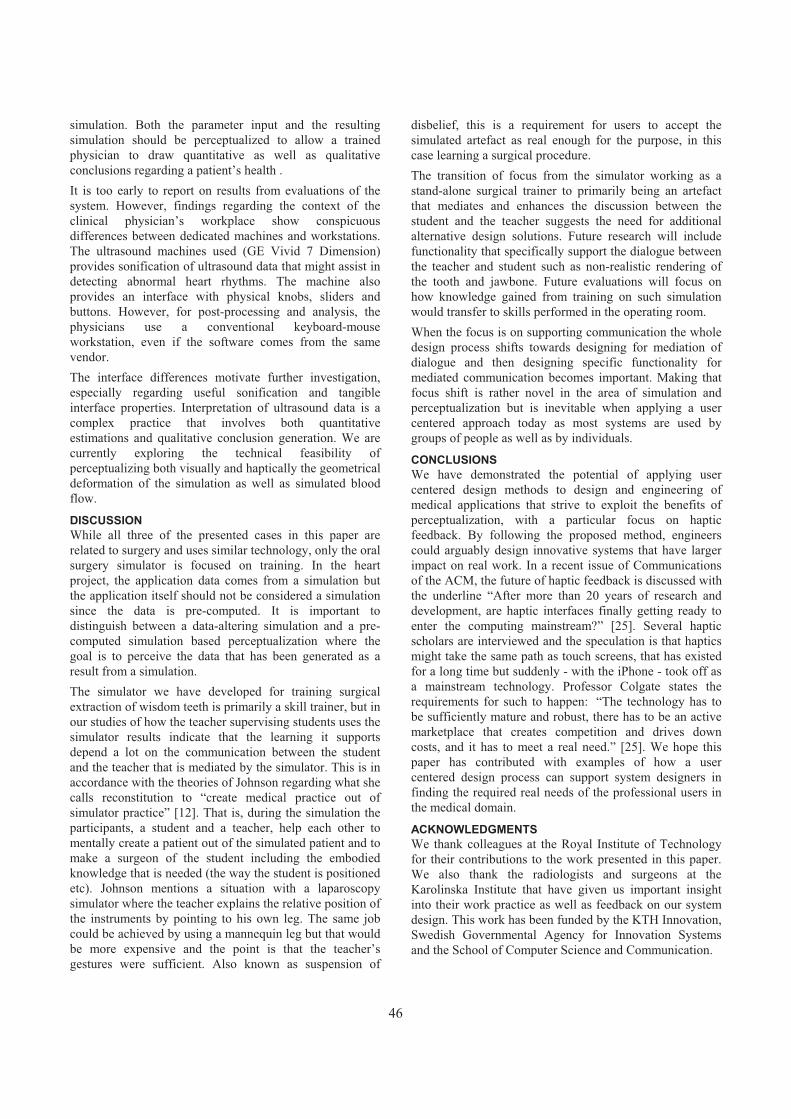
simulation. Both the parameter input and the resulting simulation should be perceptualized to allow a trained physician to draw quantitative as well as qualitative conclusions regarding a patient’s health . It is too early to report on results from evaluations of the system. However, findings regarding the context of the clinical physician’s workplace show conspicuous differences between dedicated machines and workstations. The ultrasound machines used (GE Vivid 7 Dimension) provides sonification of ultrasound data that might assist in detecting abnormal heart rhythms. The machine also provides an interface with physical knobs, sliders and buttons. However, for post-processing and analysis, the physicians use a conventional keyboard-mouse workstation, even if the software comes from the same vendor.The interface differences motivate further investigation, especially regarding useful sonification and tangible interface properties. Interpretation of ultrasound data is a complex practice that involves both quantitative estimations and qualitative conclusion generation. We are currently exploring the technical feasibility of perceptualizing both visually and haptically the geometrical deformation of the simulation as well as simulated blood flow.
DISCUSSIONWhile all three of the presented cases in this paper are related to surgery and uses similar technology, only the oral surgery simulator is focused on training. In the heart project, the application data comes from a simulation but the application itself should not be considered a simulation since the data is pre-computed. It is important to distinguish between a data-altering simulation and a pre-computed simulation based perceptualization where the goal is to perceive the data that has been generated as a result from a simulation. The simulator we have developed for training surgical extraction of wisdom teeth is primarily a skill trainer, but in our studies of how the teacher supervising students uses the simulator results indicate that the learning it supports depend a lot on the communication between the student and the teacher that is mediated by the simulator. This is in accordance with the theories of Johnson regarding what she calls reconstitution to “create medical practice out of simulator practice” [12]. That is, during the simulation the participants, a student and a teacher, help each other to mentally create a patient out of the simulated patient and to make a surgeon of the student including the embodied knowledge that is needed (the way the student is positioned etc). Johnson mentions a situation with a laparoscopy simulator where the teacher explains the relative position of the instruments by pointing to his own leg. The same job could be achieved by using a mannequin leg but that would be more expensive and the point is that the teacher’s gestures were sufficient. Also known as suspension of
disbelief, this is a requirement for users to accept the simulated artefact as real enough for the purpose, in this case learning a surgical procedure. The transition of focus from the simulator working as a stand-alone surgical trainer to primarily being an artefact that mediates and enhances the discussion between the student and the teacher suggests the need for additional alternative design solutions. Future research will include functionality that specifically support the dialogue between the teacher and student such as non-realistic rendering of the tooth and jawbone. Future evaluations will focus on how knowledge gained from training on such simulation would transfer to skills performed in the operating room. When the focus is on supporting communication the whole design process shifts towards designing for mediation of dialogue and then designing specific functionality for mediated communication becomes important. Making that focus shift is rather novel in the area of simulation and perceptualization but is inevitable when applying a user centered approach today as most systems are used by groups of people as well as by individuals.
CONCLUSIONSWe have demonstrated the potential of applying user centered design methods to design and engineering of medical applications that strive to exploit the benefits of perceptualization, with a particular focus on haptic feedback. By following the proposed method, engineers could arguably design innovative systems that have larger impact on real work. In a recent issue of Communications of the ACM, the future of haptic feedback is discussed with the underline “After more than 20 years of research and development, are haptic interfaces finally getting ready to enter the computing mainstream?” [25]. Several haptic scholars are interviewed and the speculation is that haptics might take the same path as touch screens, that has existed for a long time but suddenly - with the iPhone - took off as a mainstream technology. Professor Colgate states the requirements for such to happen: “The technology has to be sufficiently mature and robust, there has to be an active marketplace that creates competition and drives down costs, and it has to meet a real need.” [25]. We hope this paper has contributed with examples of how a user centered design process can support system designers in finding the required real needs of the professional users in the medical domain.
ACKNOWLEDGMENTS We thank colleagues at the Royal Institute of Technology for their contributions to the work presented in this paper. We also thank the radiologists and surgeons at the Karolinska Institute that have given us important insight into their work practice as well as feedback on our system design. This work has been funded by the KTH Innovation, Swedish Governmental Agency for Innovation Systems and the School of Computer Science and Communication.
46

REFERENCES1. Aggarwal, R., Grantcharov, T. P., Eriksen, J. R.,
Blirup, D., Kristiansen, V. B., Funch-Jensen, P., and Darzi, A. (2006). An evidence-based virtual reality training program for novice laparoscopic surgeons. Annals of surgery, 244(2):310-314.
2. Appelle, S. (1991). Haptic perception of form: Activity and stimulus attributes. In M. Heller, & W. Schiff, (Eds.), The psychology of touch. (pp. 169-188). New Jersey: Lawrence Erlbaum Associates, Inc.
3. Agus, M. (2004). Haptic and Visual Simulation of Bone Dissection. PhD thesis, Dept. of Mechanical Engineering, University of Cagliari, year 2004
4. Beyer, H., and Holtzblatt, K. (1998). Contextual Design: Defining Customer-Centered Systems. San Francisco: Morgan Kaufmann. ISBN 1-55860-411-1
5. Ernst, M. (2006). A Bayesian view on multimodal cue integration. Perception of the human body from the inside out Volume: 131, Issue: Chapter 6, Publisher: Oxford University Press, New York, Pages: 105-131
6. Flodin, M. (2009). The importance of shading in volume rendered visualization in a multimodal simulator for operative extraction of wisdom teeth. Master's Thesis in Interactive Media Technology, Royal Institute of Technology
7. Forsslund, J. (2008). Simulator for surgical extraction of wisdom teeth. Master’s Thesis in Computer Science, Royal Institute of Technology
8. Forsslund J., Sallnäs, E-L, and Palmerius, K-J. (2009). A user-centered designed FOSS implementation of bone surgery simulations In proceedings of World Haptics Conference, 2009.
9. Frykholm, O., and Groth, K. (2010). Shared visualization of patient information. Technical report NADA, April 2010. (Note: Position paper, Workshop on Interactive Systems in Healthcare (WISH), in conjunction with CHI2010)
10. Giles, J. A. (2010). Surgical training and the european working time directive: The role of informal workplace learning. International Journal of Surgery,8(3):179-180.
11. ISO. (1999). Human-centred design processes for interactive systems (ISO 13407:1999). International Organization for Standardization.
12. Johnson, E. (2007). Surgical Simulators and Simulated Surgeons: Reconstituting Medical Practice and Practitioners in Simulations. Social Studies of Science2007 37:585
13. Kane, B. & Saturnino, L. (2006). Multidisciplinary Medical Team Meetings: An Analysis of Collaborative Working with Special Attention to Timing and Teleconferencing. In Journal of CSCW, 15, 501-535.
14. Kapourkatsidou, C. (2010). Visualization of Findings in Radiologists’ Statements based on 2D and 3D Images. Master’s Thesis in Computer Science (30 ECTS credits) at the Interactive Systems Engineering Master Programme Royal Institute of Technology.
15. Lederman, S. J. & Klatzky, R. L. (2009). Haptic perception: A tutorial. Attention, Perception, & Psychophysics. 71(7), 1439-1459.
16. Lee, J-H., and Spence, C. (2008). Assessing the benefits of multimodal feedback on dual-task performance under demanding conditions. Proceedings of the 22nd British HCI Group Annual Conference on HCI 2008. Liverpool, United Kingdom, pp. 185-192.
17. Felländer-Tsai, L. and Wredmark, T. (2004). Image-guided surgical simulation - a proven improvement. Acta Orthop Scand, 75(5):515–515.
18. Meijden, O.A.J., and Schijven, M.P. (2009). The value of haptic feedback in conventional and robot-assisted minimal invasive surgery and virtual reality training: a current review. Surgical Endoscopy, 23(6),1180-1190.
19. Moll, J., and Sallnäs, E-L. (2009). Communicative Functions of Haptic Feedback. In Proceedings of Haptic and Audio Interaction Design, Dresden Germany September 10-11. HAID 2009. LNCS 5763, Springer, 2009, 1-10.
20. Monk, A., Wright, P., Haber, J., and Davenport, L. (1993). Improving your human-computer interface: a practical technique. A volume in the BCS Practitioner Series, Prenice-Hall, ISBN 0-13-010034-X.
21. Morris D, Sewell C, Barbagli F, Blevins N, Girod S, and Salisbury K. (2006). Visuohaptic Simulation of Bone Surgery for Training and Evaluation. IEEETransactions on Computer Graphics and Applications,November 2006, pp. 48-57.
22. Lundin Palmerius, K-J and Forsell, C. (2009). The impact of feedback design in haptic volume visualization. in Proceedings of World Haptics Conference, 2009 pp. 154-159.
23. Ratib, O. (2004). PET/CT Image Navigation and Comm-unication The Journal of Nuclear Medicine,Vol. 45, No.1 (Supl), January 2004
24. Rosén, A., Fors, U., Zary, N. Sejersen, R., Sallnäs Pysander, E-L., and Lund B. (2009). Can students learning improve in oral surgery with different simulator techniques? Poster at Karolinska Institutets utbild-ningskongress, March 2009.
25. Wright, A. (2011). The touchy subject of haptics. Commun. ACM , 54 , 20-2
47

Virtual Reality Based Rehabilitation and Game Technology
Alessandro De Mauro eHealth & Biomedical Applications
Vicomtech Mikeletegi Pasealekua 57
San Sebastián 20009 Spain +34 943 30 92 30
ABSTRACT Virtual Reality technology is currently part of advanced physical rehabilitation therapy. However, several questions remain unanswered: Can this technology improve or even substitute the traditional methodologies? Can it really influence the nervous system or does moving within a virtual environment just motivate the individual to perform? In this paper we present the state of the art, the new advanced technology available and the most promising applications in this field. Finally we will introduce our research as a case study in the area.
Keywords Rehabilitation, Therapy, Virtual Reality, Motor Disorders,Game Technology
INTRODUCTION TO VIRTUAL REHABILITATION Following an authoritative description of traditional rehabilitation therapy of motor disorders [1] it is by its nature repetitive, and repetition tends to “decouple” the mind, and reduce patient’s motivation. In other words: it is boring. There are several universally accepted definitions of Virtual reality (VR). One of the most clear was provided in [2]: VR is an immersive, interactive, 3-dimensional computer experience occurring in real time. Virtual reality has the ability to simulate real-life tasks [3] and comes together with several evident benefits for rehabilitation:1) specificity and adaptability to each patient and disease;2) repeatability; 3) ability to provide patient engagement; 4) tele-rehabilitation and remote data access;
5) capability for precise assessment; 6) safety. VR offers the possibility to be precisely adapted to the patient’s therapy and to be specific. VR environments can provide realistic training for the patient in different scenarios and phases of the rehabilitation. Repetition is crucial for the re-learning of motor functions and for the training of the cortical activity. This task has to be connected with the sensorial feedback on every single exercise. Patient motivation is fundamental because active cooperation of the patient is needed to achieve a more functional outcome of the therapy. Motivation can be improved by assigning a serious game format to the therapy. In this way the training activity becomes more attractive and interesting [4, 5]. Remote data access is a fundamental requirement, especially for rural patients, since they do not have to travel to urban clinics. In addition, VR represents a precise tool for the assessment of the therapy during each session. The (tracked/saved) data can be used by the rehabilitation specialists for monitoring and managing the therapy [6]. By using VR in conjunction with Human Computer Interfaces (HCI) the training of daily life activities can be much improved in terms of time and quality. This approach permits a realistic and ergonomic training in a safe, interactive and immersive environment. In particular, VR provides the user with the possibility to perform tasks with a degree of safety which is normally not possible in the traditional rehabilitation. VR provides the rehabilitators with the possibility to influence qualitatively the training program, even in real-time. Another evident benefit is the patient’s engagment which is a key factor in rehabilitation (especially for children). Examples of interfaces able to interact with VR are mice, joysticks, haptic interfaces with force feedback and motion tracking systems. Several researches have shown that, during VR rehabilitation, the movements are very similar to those used
Copyright © 2011 for the individual papers by the papers' authors. Copying permitted only for private and academic purposes. This volume is published and copyrighted by the editors of EICS4Med 2011.
48

in traditional therapy. Although they appear to be a bit slower and less accurate, [7, 8] show that they are anyway appropriate for rehabilitation. Finally, [9] have proven good results in executing the movements trained in VR in reality. In [10], [11], and [12] good results are shown in improving of motor skills for post-stroke rehabilitation of functional deficits in reaching, hand function and walking, respectively. A personal computer based desktop VR system was developed in [13] for rehabilitating hand function in stroke patients. The system uses a tracking system based on gloves to exercise four parameters of hand movement: range, speed, fractionation, and strength. Their results show that each patient showed improvement on most of the hand parameters over the course of the training and that some of the subjects have re-learned difficult functions of daily life like buttoning a shirt. Some of the significant studies on the application of robotics and VR for rehabilitation purposes shall be introduced briefly. In [14], results were presented obtained from the comparison of a training with a robot-virtual reality system with a robot alone on the gait of individuals after stroke.[15] presents a development of an advanced upper extremity prosthesis with the potential to restore full motor and sensory capability to upper extremity amputee patients. In addition, a GUI interface for patient training and therapeutic applications was developed during this research. The Rutgers Arm [16] is one of the first prototypes composed of a PC, a motion tracking system and a low-friction table for the upper extremity rehabilitation. The system has been tested on a chronic stroke subject and has shown improvements in arm motor control and shoulder range of motion (Fugl-Meyer [17] test scores). The same group has developed the Rutgers Ankle [18] for the lower extremity rehabilitation. It is a haptic/robotic platform, which works with six degrees of freedom, driving the patient’s feet movements (Fig. 1, up).The tests of the Rutgers Ankle system have shown that the group of patients trained with the robotic device coupled with the VR demonstrated greater changes in velocity and distance than the group trained with the robot alone [19]. Most of the gait rehabilitation systems currently used for therapy are based both on treadmills and body weight support. The state-of-art in rehabilitation using virtual reality (VR) and robotics is provided by Lokomat® and Armeo® (from Hocoma) for the lower and the upper extremity, respectively (Fig. 1 down left and right). These two systems are validated by the medical community and used in several rehabilitation centers [20]. Both are completed by an augmented feedback module which extends the conventional hardware with a computer and a large monitor with acoustic stereo feedback together with software for the interactive training tasks. This option provides various engaging virtual environments to motivate your patients, adjustable level of difficulty and intensity
according to the cognitive abilities and the specific needs of each patient.
Low Cost VR based Rehabilitation using game technology Recently there has been an explosion of new technologies: especially low cost gaming devices based on optical tracking systems, radio frequencies, infrared cameras, and haptics are accessible to almost everybody. Considering the general trend to decrease the costs for the health systems all over the world one question comes upurgently: can low-cost gaming technology serve the needs of at least not severely injured patients with motor disorders? In terms of costs and deployment logistics it is evident that a transition of the rehabilitation from traditional hospitals or clinics to home environments can be a winning challenge [21].Many research groups have started the exploration of the use of such systems like Nintendo Wii® or more recently Kinect® as tools for rehabilitative therapy, including occupational and physical therapy. An exploration of researches and low-cost programs is presented below. An example of tele-rehabilitation can be found in [22], where a home-based tele-rehabilitation system based on low-cost haptic devices (game pad and joysticks) is described. The system focuses on a series of virtual reality therapeutic exercises for upper limb motor rehabilitation. It provides effective visualization and quantification of the patient’s motions and associated pathologies. Therapists can access remotely the collected data.
Figure 1: Successful examples of applied technologies for rehabilitation. They are all based on
robots/exoskeletons and VR. Upper left: Rutgers Ankle, lower left Armeo® and right Lokomat®.
49

Sony PlayStation2® was successfully used as low-cost VR system in home environment by [23] to improve sensory/motor recovery on an individual two years poststroke with residual sensorimotor deficits. Sony PlayStation3® was used for tele-rehabilitation of children with hemiplegia togheter with 5DT 5 Ultra (five sensor) glove for the hand tracking, a computer, display, keyboard and a mouse [24]. The release of the Wii® Fit (software) and Wii Balance (platform) has stimulated new researches. The system eBavir is a low-cost balance virtual rehabilitation system based on the Wii® balance board. [25] has presented a comparison of the feasibility, safety, and efficacy of virtual reality using the Nintendo Wii gaming system (VRWii) versus standard rehabilitation to evaluate arm motor improvement. They have shown that gaming technology represents a safe, feasible, and potentially effective alternative to facilitate rehabilitation therapy and promote motor recovery after stroke. Another reference research group in the field is working about virtual rehabilitation using Kinect® [27]. In particular they are developing a high level library (the Flexible Action and Articulated Skeleton Toolkit) which can be used upon the open source library OpenNI [28] to produce virtual rehabilitation software.
Case Study: the HYPER project We are currently working on providing a VR rehabilitation platform for the HYPER project [29]. This research involves different results in neurorobotics (NR) and motor neuroprosthetics (MNP), both for rehabilitation and functional compensation of motor disorders. The project focuses its activities on new wearable NR-MNP systems that will combine biological and artificial structures in order to overcome the major limitations of the current rehabilitation solutions to Cerebrovascular Accident (CVA) and Spinal Cord Injury (SCI). VR, an important part of the complex system, was initially based on radio frequency tracking technology. This solution offers good tracking performances but it suffers from the use of many cables. Considering the patient’s needs it is therefore not an optimal solution. Therefore we are now exploring a new wireless and inexpensive technology: Kinect®. First results (see Fig. 2) are very promising and even if the accuracy of the tracking has to be measured exactly it seems that for this type of application the needs in terms of accuracy are not highly demanding. Additionally the tracking system appears to be robust enough to track the patient and the related robotic exoskeleton or neuroprosthetic devices on both upper and lower part of the body.
A limitation to be considered is that the Kinect® IR tracking suffers when the subject is illuminated strongly by the sun light. This is, however, a merely technological limitation which can be overridden. Finally, a further part of our research concerns theconjunction between a Brain Computer Interface and virtual reality in order to create a good diagnostic and personalized environment in which it is possible to study the brain signals as answers to external (VR) stimuli or to assess the progress of the patient in the rehabilitation therapy.
Figure 2: Snapshots of simple VR scenes: reaching, moving and grasping a virtual object. Kinect® is used for the tracking of the upper part of the patient body
CONCLUSIONS This paper reviews the state of art, advantages and perspectives of Virtual Rehabilitation used in various forms of therapy. The recent introduction of new technology,originally developed for game purposes, provides a number of challenges and increases the possibilities of Virtual Rehabilitation to gain wide acceptance. We have presented, as a case study, the first development status of an advanced system that combines VR based on game technology with a hybrid NR and MNP system for functional compensation of motor disorders.
ACKNOWLEDGMENTS This paper is a dissemination activity of the HYPER project funded by CONSOLIDER-INGENIO 2010, Spanish Ministry for Science and Innovation.
50

REFERENCES 1. Burdea, G. Keynote Address: Virtual Rehabilitation
Benefits and Challenges, Proc. 1st Int’l Workshop on Virtual Reality Rehabilitation (Mental Health, Neurological, Physical, Vocational), IEEE CS Press, 2002, pp. 1-11.
2. Reid, D. The influence of virtual reality on playfulness in children with cerebral palsy: a pilot study. Occupational Therapy Int. 2004; 11:131–144
3. Adamovich, S. et al. A virtual reality Based Exercise System for Hand Rehabilitation Post-Stroke. Presence, Special Issue on Virtual Rehabilitation, 14(2), 161-174.
4. Weiss, P., Kizony, R., Feintuch, U. and Katz, N., Virtual reality in neurorehabilitation Textbook of neural repair and neurorehabilitation, vol. 2, pp. 182–197, 2006.
5. Fidopiastis, C. et al., Human experience modeler: Context-driven cognitive retraining to facilitate transfer of learning,” CyberPsychology & Behavior, vol. 9, pp. 183–187, 2006.
6. Cano de la Cuerda, R. et al., Telerehabilitacion y neurología, Rev Neurol, vol. 51, pp. 49–56, 2010.
7. Rizzo, A., Kin, G., A swot analysis of the field of vr rehabilitation and therapy, Presence: Teleoperators and Virtual Environments, vol. 14, pp. 119–46, 2005.
8. Viau, A. et al., Reaching in reality and virtual reality: a comparison of movement kinematics in healthy subjects and in adults with hemiparesis, Journal of neuroengineering and rehabilitation, vol. 1, December 2004.
9. Subramanian, S. et al., Virtual reality environments for post-stroke arm rehabilitation, Journal of neuroengineering and rehabilitation, vol. 4, 2007.
10. Holden, M., Todorov, E., Callahan, J., Bizzi, E.: Virtual environment training improves motor performance in two patients with stroke: case report. Neurol Rep. 23(2), 57–67 (1999)
11.Merians, A.S., Jack, D., Boian, R., Tremaine, M., Burdea, G.C., Adamovich, S.V., Recce, M., Poizner, H.: VR-augmented rehabilitation for patients following stroke. Physical Therapy 82, 898–915 (2002)
12.You, S.H., Jang, S.H., Kim, Y.H., Hallett, M., Ahn, S.H., Kwon, Y.H., Kim, J.H., Lee, Y.: Virtual reality-induced cortical reorganization and associated locomotor recovery in chronic stroke. An experimenter-blind randomized study. Stroke 36, 1166–1171 (2005)
13.Mirelman A., Bonato, P., Deutsch, J., Effects of training with a robot-virtual reality system compared with a robot alone on the gait of individuals after stroke. Stroke2008;40:169-74.
14.Jack, D. et al., Virtual Reality-Enhanced Stroke Rehabilitation, IEEE Trans. Neural Systems and Rehabilitation Eng., vol. 9, no. 3, 2001, pp. 308-318.
15.Zeher, MJ., Armiger, R., Burck, J., Moran, C., Kiely J., Weeks, S., Tsao, J., Pasquina, P., Davoodi, R., Loeb, G., Using a virtual integration environment in treating phantom limb pain. Stud Health Technol. Inform.2011;163:730-6.
16.Kuttuva, M. et al., The rutgers arm: an upper-extremity rehabilitation system in virtual reality. 4th International workshop on virtual reality rehabilitation, Catalina Islands, Citeseer, 2005.
17.Fugl-Meyer, A. et al. The post-stroke hemiplegic patient A method for evaluation of physical performance. Scandinavian journal of rehabilitation medicine, vol 7, pp. 13–31, 1975.
18.Boian, R. et al. Virtual reality-based system for ankle rehabilitation post stroke, Proceedings of the First International Workshop on Virtual Reality Rehabilitation, pp. 77–86, Citeseer , 2002.
19.Deutsch J. Et al., Improved gait and elevation speed of individuals post-stroke after lower extremity training in virtual environments. Journal of Neurologic Physical Therapy. 2004;28:185–186.
20.Koenig, A. et al., Virtual gait training for children with cerebral palsy using the lokomat gait orthosis, Medicine meets virtual reality, vol. 16, 2008.
21.Flynn S, Palma P, Bender A., Feasibility of using the Sony PlayStation 2 gaming platform for an individual poststroke: A case report. Journal of Neurological Physical Therapy 2007;31:180-189.
22.Dhurjaty, S., The Economics of Telerehabilitation, Telemedicine J. and e-Health, vol. 10, no. 2, 2004, pp. 196-199.
23.Jadhav C., Nair P, Krovi V., Individualized interactive home-based haptic telerehabilitation. IEEE Multimedia Systems Magazine: Haptic User Interfaces in Multimedia Systems, 2006.
24.Huber, M., Rabin, B., Docan, C., Burdea, G., Nwosu, M.E., Abdelbaky, M., Golomb, M.R., PlayStation 3-based tele-rehabilitation for children with hemiplegia, Virtual rehabilitation, 2008, pp. 105 - 112.
25.Saposnik, G., Teasell, R., Mamdani, M., Hall, J., McIlroy, W., Cheung, D., Thorpe, K., Cohen, L., Bayley M., Stroke Outcome Research Canada (SORCan) Working Group.Effectiveness of virtual reality using Wii gaming technology in stroke rehabilitation: a pilot randomized clinical trial and proof of principle, Stroke. 2010 Jul;41(7):1477-84. Epub 2010 May 27.
26.Shih-Ching, Y. et al., Evaluation Approach for Post-Stroke Rehabilitation via Virtual Reality Aided Motor Training, HCI International 2007, Beijing, P.R. China, July 22-27, 2007.
51

27. Flexible Action and Articulated Skeleton Toolkit (FAAST), Web: http://projects.ict.usc.edu/mxr/faast/,status March 2011.
28.OpenNI project, Web: http://www.openni.org/, status March 2011.
29. De Mauro A. et al., Virtual Reality System in Conjunction with Neurorobotics and Neuroprosthetics for Rehabilitation of Motor Disorders, Studies in Health Technology and Informatics, Vol. 163, Ed. Westwood, 2011
52

Towards Dependable Number Entry for Medical DevicesAbigail Cauchi,1 Paul Curzon,2 Parisa Eslambolchilar,1 Andy Gimblett∗,1
Huayi Huang,2 Paul Lee,3 Yunqiu Li,1 Paolo Masci,2 Patrick Oladimeji,1
Rimvydas Ruksenas,2 Harold Thimbleby1
(1) Swansea University, (2) Queen Mary University of London, (3) Singleton Hospital, Swansea
CHI-MED: Computer-Human Interaction for Medical Deviceswww.chi-med.ac.uk
ABSTRACTNumber entry is an ubiquitous task in medical devices,but is implemented in many different ways, from deci-mal keypads to seemingly simple up/down buttons. Op-erator manuals often do not give clear and complete ex-planations, and all approaches have subtle variations,with details varying from device to device. This paperexplores the design issues, critiques designs, and showsthat methods have advantages and disadvantages, par-ticularly in terms of undetected error rates.
Author KeywordsMedical devices; modelling; formal methods; HCI; health-care; number entry
Note. This is a working paper that we will developfurther through interactive workshop participation. Wewill engage additional authors as necessary for contin-ued work to progress towards a high-quality journal pa-per fully covering the relationship of all relevant medi-cal, manufacturing and computing factors. It is an im-portant topic that we want to get right.
1. INTRODUCTIONThere are many applications where numbers have tobe entered into computer systems, from setting alarmclocks to programming infusion pumps. In most appli-cations the consequences of mistakes are limited, but inmany cases—in particular with medical devices—theyare potentially critical. Mistakes in entering numbers
∗Corresponding author.
Submission to EICS4Med Workshop at EICS 2011
into infusion and syringe pumps could lead to incorrectdoses being delivered, causing harm.
There are several inter-related properties of importancein a safety-critical number entry system: efficiency inentering numbers, the likelihood that errors are madeand the efficiency of recovery from error [1]. In a hos-pital it is vital that nurses can use pumps efficiently asthey are very busy and multitasking is the norm. Ob-servational studies have suggested that nurses may fre-quently make minor mistakes in entering numbers, forexample not following the ‘golden path’ that is the mostefficient way of entering a particular number, but thatthese errors are caught and corrected. Thus it mightbe argued that number entry is not a particularly se-vere safety critical problem; however, efficiency remainsan important concern in a busy ward. Therefore a de-vice where such mistakes do not need to be constantlycorrected or where the golden path is most often theone naturally followed would provide significant bene-fit, given the number of times such devices need to beset. Furthermore, work in resilience engineering sug-gests that single mistakes rarely lead to disasters. Itis when a range of different causes combine. If a largenumber of trivial and normally unproblematic errors arebeing made then this increases the potential for otherrarer causes to interact with them and lead to a criticalincident—as in Reason’s “swiss cheese model” [5].
If a patient is given an incorrect drug dose, perhapsten times higher than intended, the patient may die orhave some other adverse outcome. It is therefore cru-cial that number entry is dependable, that there are nodesign defects, no mismatches between user conceptualmodels and device behaviour, and that users can (so faras reasonably possible) detect and correct their errors.This paper shows that this problem is more intricatethan might appear at first sight, that many medical de-vices and their operator manuals fall short, and thatbetter solutions are possible.
153
Submission to EICS4Med Workshop at EICS 2011

Our goal is to identify a set of properties that pro-grammers of medical devices should implement—or ifwe cannot do that, to recommend a set of key prop-erties to consider before implementation—to minimizeerror rates, specifically for number entry. It is not obvi-ous how to do this, as it involves a variety of tradeoffs,and thus we propose a debate within the EICS4Medworkshop to explore the issues. We bring to the de-bate prepared material and a variety of demonstrationresources to explore ideas. In this paper we highlightthe issues involved to promote that debate.
1.1 Typographic conventionsWe render arrow keys pressed by users as:
� �
�� �
� �
�� �
� �
�� �
� �
�� �.
We represent number displays with a box around eachvisible digit, some of which might be empty. For ex-ample, 2 0 9 . 4 shows a six-digit display withtwo decimal places, showing the number 209.4, with thecursor in the tens column; if the display were reduced toonly one decimal place, we’d write it as 2 0 9 . 4
2. PRIOR WORKThere is much prior work on user interface design prin-ciples in general, such as Nielsen’s Usability Engineer-ing [4], but they are very vague for programmers. Forexample, undo (which Nielsen recommends) can be im-plemented in many ways.
Work on human computer interaction specifically linkedto number entry is varied and little has been appliedspecifically in the medical domain.
For example, Hourizi and Johnson [2] consider a numberentry error that resulted from a mode error, and whichled to the crash of an A320 airliner with loss of life.They argue that this should not be seen as a perceptionor knowledge error, but rather as due to an inadequatecommunication protocol between pilot and autopilot; avariation on the design based on this hypothesis wasfound to eliminate the error in simple user tests.
Brumby et al. [1] investigated trade-offs between effi-ciency of entering mobile phone numbers vs avoiding er-rors in driving. Their analysis suggests that interleavingnumber entry at chunk boundaries efficiently trades thetime given up to dialling with that of ensuring enoughattention is paid to driving to avoid drifting.
It is well known that device design can encourage cer-tain number entry errors in medicine. For exampleZhang et al [7] report an incident where a nurse in-tending to program a pump at 130.1ml/h inadvertentlyprogrammed the pump at 1301ml/h — a rate 10 timeslarger than the intended rate. Unknown to the nurse,the decimal point on the interface of the pump onlyworks for numbers up to 99.9.
Thimbleby and Cairns [6] show that out by 10 errorsin number entry systems, like the one described above,can be halved with better interaction design focussing
Figure 1. Screenshot of interactive Alaris GP simulation
on error management.
3. EXAMPLE DEVICESWe have investigated and simulated a number of med-ical devices in order to explore their behaviour and re-lated HCI issues; in this section we introduce the twoparticular devices, both infusion pumps, whose num-ber entry behaviour is both typical and interesting, andaround which the rest of this paper is built.
The Alaris GP infusion pump (figure 1) exemplifies anumber entry interface style found on a variety of sy-ringe and infusion pumps: two pairs of buttons changethe displayed value; one pair increases the value, theother decreases it. In each pair, one of the buttonscauses a bigger change than the other. Each buttoncan also be held down to increase the rate of change ofthe number on the screen.
The B.Braun Infusomat Space pump (figure 2) has threedistinct number entry systems used for different tasks,
all based around a set of� �
�� �
� �
�� �
� �
�� �
� �
�� �buttons; it exhibits
a number of interesting behaviours. It is a good exam-ple of the way in which number entry is widely perceivedas unproblematic and trivial, while in fact harbouringpotential for surprises and difficult. Its user manualhas very little to say on the topic: “When editing pa-
rameters, switch digits/levels using� �
�� �
� �
�� �. White back-
ground indicates current digit/level. Use� �
�� �or
� �
�� �to
change current setting.” Elsewhere in the manual, thearrows are described as: “Arrow up and down: Scrollthough menus, change setting of numbers from 0-9, an-swer Yes/No questions. Arrow left and right: Selectdata from a scale and switch between digits when num-bers are entered. Open a function while pump is run-ning or stopped with the left arrow key.”
This description is inadequate; for example, it suggests
254

Figure 2. Screenshot of interactive B.Braun simulation
that if the display is 9 ⋅ (say) and� �
�� � is
pressed, then the display will become 0 ⋅
In fact, it becomes 1 0 ⋅ , i.e. an arithmeticoperation was performed (9 + 1).
More concerningly, if the display is 1 0 ⋅ and� �
�� �is pressed, it becomes 0 0 0 ⋅ 1 . The arith-metic operation performed in this case was 10 - 100= -10, which result was then clamped to a minimumvalue, 0.1. It is easy to imagine scenarios in which thisbehaviour leads to an underdose, perhaps harmfully.The pump has similarly surprising and inconsistent be-haviour around the maximum value. These issues aredescribed further in the next section.
For a new user, the infusion pump is likely to behave un-predictably, though we do not know what implicationsthis unpredictability has on safety in medical scenarios.The lack of symmetry between minimum and maximumbehaviour might have an impact on usability, as do thearithmetic operations, particularly when subtracting avalue which results in a number less than 0.
4. RESOURCES FOR DEBATEIn order to support debate around these issues, we willbring a range of resources to the workshop.
Simulations — We have implemented a variety of userinterfaces for entering numbers, closely based on real in-fusion pumps, specifically those described above. Thesesimulations allow detailed exploration of the propertiesof the devices’ number entry systems, and comparisonsbetween different designs—there are many possible vari-ations to experiment with, as described in more detailin the next section. In particular, several variants of theB.Braun Infusomat Space VTBI number entry interfacehave been implemented.
Workshop annotation mechanism — We also in-troduce the concept of state annotation as a researchtool to enhance collaborative critique of an interactivesystem. Members of this session will be able to addannotations to any states in the interactive simulationsto identify or mark issues regarding the usability, safetyor design of the system being evaluated. Annotationswill be automatically saved with information about thecurrent state of the system as well as the user interac-tions that led to that state starting from power up, andare automatically shared among all clients connected tothe simulation.
Number entry techniques
Serial entry
?
Incremental entry
Decade Arithmetic
Figure 3. Number entry—basic classification
Commercial simulations — We have some commer-cial simulations, intended for hospital training purposes,including for versions C and D of the B.Braun; our phys-ical pump is version E. The simulation diverges fromobserved behaviour (at least) in that it does not clampto a minimum value as described above, but rather to0. This suggests that the defaulting minimum value isintroduced in version E.
Physical devices and manuals — Finally we willbring some real physical devices together with their op-erator manuals for comparison with our and the com-mercial simulations.
5. A TAXONOMY FOR NUMBER ENTRYIn order to support discussion in the workshop, in thissection we propose an initial ‘taxonomy’ of features andbehaviours of number entry interfaces, particularly con-sidering some of the behaviours described above. Wehope that further debate will refine and augment thislist. As we describe the taxonomy we make some obser-vations and speculations about relevance to usability,simplicity of conceptual models, etc. but our main pur-pose in this paper is to ask questions and so promotediscussion, not provide answers specifically — most ofthis space remains intellectually unexplored.
At the top level, we distinguish between serial and incre-mental entry. Serial entry involves entering the numberas a string, usually via a numeric keypad; consider en-tering a number into a desktop calculator, for example.Conversely, incremental entry involves making a seriesof incremental changes to some displayed value in orderto obtain the desired value — often but not necessar-ily on a digit-by-digit basis. As incremental entry can
be implemented using just a few keys, typically� �
�� �
� �
�� �
� �
�� �
� �
�� �, which may already be present for navigational
purposes, it is a common style on the kinds of medi-cal devices we are interested in. As such, and as it isused by each of our example devices, we concentrateon issues surrounding this style, though serial entry isstill interesting and appropriate further exploration, arequestions as to which style is preferable in general andin particular situations, and why.
Focusing on incremental number entry, we identify threemajor aspects of interest: basic behaviour (decade vsarithmetic, see figure 3); behaviour at minimum andmaximum values (see figure 4); and digit visibility.
First we consider basic behaviour, which may be decade
355

or arithmetic style. In decade style, each digit is editedindependently, and typically subject to wraparound at0 and 9. For example, given a display of 1 9 2 . 4 ,
if the user hits� �
�� �, the new value is 1 0 2 . 4 —the
9 increased by 1, modulo 10, wrapping round to 0, andall other digits are unaffected. In this style the numberreally must be dialled in one digit at a time.
In arithmetic style, user actions cause arithmetic modi-fications to the value displayed: add 1, subtract 10, etc.On the Alaris GP there are dedicated up/down buttons
of differing magnitude; on the B.Braun� �
�� �and
� �
�� �nav-
igate between digits and� �
�� �and
� �
�� �modify values. Re-
peating the previous example in arithmetic style leadsto a display of 2 0 2 . 4 with the increment in thetens column being ‘carried’ to the hundreds. It is un-clear if or when this would be preferable to users, thoughone can imagine that for fine adjustments around some
value it is easier and would involve less� �
�� �/
� �
�� �actions.
Either of these ‘starting points’ may be implementedusing little code, and with very simple logic. (See ourexample simulations.) They each provide a clear con-ceptual model of the interface which users ought to beable to fathom completely with very little experimenta-tion. Edge cases are often where problems arise; thus,what happens around the maximum and minimum val-ues? There are a number of subtleties, not immediatelyobvious. First: what are the maximum and minimumvalues? Either might be a function of what we canfit in the display (which might change over time —see below), or some semantically-relevant value. Theminimum could be the negative of the maximum, or(more often) zero, or something else. For VTBI en-try on the B.Braun, the minimum is either 1 or 0.1depending on digit visibility (see below), and can onlybe zeroed by an exact operation. Thus, for example,
0 1 . followed by� �
�� �leads to 0 0 . 1 (‘min-
imum’ value), whereas 1 . followed by� �
�� �leads
to 0 . (true zero). This leads to some strangebehaviour and a messy conceptual model, and we arepresently unable to imagine any user-driven motivationfor implementing this feature, though we note that 0 is
not an allowed value for VTBI (the� �
OK� �button doesn’t
work when the display is 0).
Assuming we know what the maximum and minimumought to be, how should a device behave at those val-ues? For the decade interface this issue can be ignored:the interface ‘wraps round’ naturally; one could in factapply the following strategies in that context instead,but doing so breaks the conceptual model badly.
Arithmetic entry can also wrap round between min/maxvalues, but now we are wrapping on the total value,not individual digits. Consider 0 0 0 on a display
with boundaries at 0 and 9999, followed by� �
�� �; this
subtracts 100, taking us to 9 9 0 0 . Then� �
�� �un-
does this, adding 100 with wraparound, returning to
Minimum/maximum value handling
Wraparound Clamped
Absolute Stateful Invertible
Figure 4. Number entry—boundary value handling
0 0 0 . This retains a clean conceptual model, butwith the danger of allowing large numbers to be easily
entered accidentally: a single� �
�� �takes us from an ini-
tial (and safe) 0 to 9 9 9 9 —though at leastthis is easy to undo.
More commonly, arithmetic interfaces restrict (‘clamp’)numbers to the boundaries. Here, we identify threeapproaches, which we call absolute clamping, statefulclamping, and invertible—see figure 4.
In absolute clamping, an attempt to move the value be-
yond a limit stops at the limit. E.g., 9 9 4 5 then� �
�� �
leads to 9 9 9 9 ; similarly, 0 9 5 3 then� �
�� �leads
to 0 0 0 0 . This is a fairly natural behaviour, easy toprogram and conceptually clear once discovered; how-ever, as it throws information away it could be annoyingto users. In the face of annoyed users, a natural exten-sion is stateful clamping where some state is introducedallowing accidental clamping operations to be undone.
Here 9 9 4 5 then� �
�� �gives 9 9 9 9 but an imme-
date� �
�� �restores 9 9 4 5 (without state, we would
get 9 8 9 9 ); anything other than� �
�� �throws away
the state and disallows the undo. This is how VTBIentry on the B.Braun operates, for example.
In decade style� �
�� �and
� �
�� �are inverses of each other,
and it’s always possible to undo the last change easily.This is lost with absolute clamping, even with state,
e.g. 9 9 4 5 then� �
�� �
� �
�� �
� �
�� �
� �
�� �gives 9 9 9 7 not
9 9 4 5 . An extension which seeks to fix this withoutintroducing wraparound is to make all successful oper-ations invertible. Here, if an operation would take thevalue beyond its maximum or minimum, it doesn’t hap-pen, and this is indicated to the user via a beep (say).
Now 9 9 4 5 then� �
�� �leaves the value unchanged, but
the user is alerted that this is the case. The more gen-eral rule is: any operation that does not have an inversehas no effect other than a warning such as a beep; nowthe user knows, if they hear a beep, the normal inversebehaviour doesn’t apply; otherwise, they know withoutlooking that they can undo the last operation.
The third general area of interest we identify is thatof digit visibility, around which there are several re-lated issues. First, consider a decade-style system im-plemented in hardware — a physical device with one
456

Figure 5. An improved number entry interface in action.
wheel per digit: spinning the wheel naturally wrapsaround modulo 10 (indeed, we obtain the name ‘decadesystem’ from such devices, which have one wheel perdecade to be entered). On such a system, every digit isalways visible, which can lead to confusion: for exam-ple it can be hard to distinguish 0 8 0 . 0 0 from
0 0 0 . 0 0 . We are aware of two strategies for mit-igating this: blanking leading/trailing zeros, and hidingdigits entirely. The first strategy is obvious: only showsignificant digits. There are (at least) two questionsto ask: what to display for blank (a space? an un-derscore?) and whether to ‘follow the cursor’ filling inzeros prospectively (e.g. do you display 0 0 1 or
1 ?); the cognitive implications of either choiceremain uninvestigated. On some systems we also seeuse of a second strategy, where digits are shown/hiddendepending on the magnitude of the value being en-tered, usually on grounds of semantic relevance. Forexample and in particular, for VTBI mL entry, theB.Braun hides the hundredths and then tenths digitsif the hundreds and thousands digits (respectively) arenon-blank (including while ‘following the cursor’ as de-scribed above.) Similarly, ten-thousands is only shownif tenths is hidden. This is semantically sensible, butslightly disorienting to the user as the display is alwaysright-aligned, so sometimes one digit disappears, an-other disappears, and the whole thing shifts to the right.Related to this: is the decimal point visible if no frac-tional digits are filled in? Canada’s Institute for SafeMedication Practices (ISMP) says it should not be —and also mandates reducing the size of fractional digits,to more clearly distinguish 5.0 from 50 (say); changingcolour may also be a worthwhile tactic here [3]. On theB.Braun, the decimal point is visible while the tenthscolumn is visible, whether it is empty or not.
We’ve identified a large design space for the apparentlysimple question of incremental number entry; the taskremains to identify the trade-offs each of these choicesinvolves, and how they affect the conceptual mappingsusers build between their actions and their effects.
6. A SAMPLE BETTER INTERFACE?Figure 5 shows a working mock-up of a potentially bet-
ter user interface, to be operated by� �
�� �
� �
�� �
� �
�� �
� �
�� �keys
as on the B.Braun. It has several interesting features:
● The cursor (shown on the right-most digit position)and the decimal point are highly salient.
● Digits to the right of the decimal point are high-lighted and smaller. The decimal point remains butis dimmed when the decimal digits are zero.
● Following good practice, leading and trailing zeroesare suppressed (shown as ). However, they behave
exactly like 0 in how they are controlled by� �
�� �
� �
�� �.
● The number has upper and lower bounds (for the5-digit example shown below, the bounds must bewithin 0 to 999.99).
● There is no hidden state. The behaviour of the inter-face is predictable from the display alone.
● Sometimes keys cannot work: as shown the� �
�� �cannot
move the cursor further right; or if the display showed9 9 9 . 9 9 no digit could be incremented; and so
on. Whenever a key is pressed that cannot do any-thing, the interface beeps and otherwise does nothing.(Thus adding 1 to 999.00 does not increase it to themaximum value 999.99.)
● Always, a key beeps or its effect can be cancelled by
pressing the opposite key: thus always� �
�� �
� �
�� �and the
other 3 pairs do nothing unless the first key pressedcauses a beep, in which case the second key behavesnormally.
● The rule above can be followed with the arithmeticstyle of interaction or with decade style. We prefer
the arithmetic style, since after pressing� �
�� �or
� �
�� �the
number is always changed by ±10n or 0 if the keybeeps. With the decade style, there can be a beep(if the number would hit a limit) or the number maychange either by ±10n (most often) or at most ±9×10n
(about 1 in 10 times); this behaviour is much lesspredictable.
● Hence,� �
�� �
� �
�� �work on arithmetic; that is, they al-
ways add ±10n to the displayed number (n depend-ing solely on the cursor position), or they beep (andotherwise do nothing) if ±10n would have resulted inoverflow.
● The design generalises readily, for instance to timesby using different bases for each digit (i.e., base 10,10, 6, 10 respectively, with an upper bound of 2359).
● If the application requires a movable decimal point,
then� �
�� �pressed when the cursor is in the right-most
column and the left-most digit is then the decimal
point will move left (and conversely for� �
�� �). This
behaviour ensures no significant figures are ever lostand that the decimal point is always shown within thedisplay. Again, the precision is limited by bounds andif the decimal point cannot move, then the key beeps.
Starting with the example on the left in figure 5: press-
ing� �
�� �(beeps and otherwise does nothing) then
� �
�� �
� �
�� �
� �
�� �
� �
�� �obtains the view on the left in figure 5. Notice
number carry, moved cursor and changed decimal pointstyle.
557

7. DISCUSSION AND FUTURE WORKOur aim here is to start debate and exploration of theseissues; future work is to continue that systematically.Here we identify some key challenges and opportunities.
A problem with work of this sort is that seemingly sen-sible design properties have unexpected impacts on howusers behave. Therefore the workshop must help iden-tify issues for empirically-based research. Consider, forexample, the ‘undo’ design heuristic recommended byNielsen [4]. How might we arrive at a more detailedset of properties for programmers of medical devices?Let us suppose we start by asking the following two re-search questions: 1) Is the ‘undo’ heuristic a significantaffector for both serial and incremental number entryin terms of error rates? 2) Are error rates on systems inthe same ‘class’ effected in similar ways by the level ofundo offered? Formally-guided experimental investiga-tion could help answer these questions. To avoid empir-ical experimentation on every possible variant of num-ber entry, we might identify a set of distinct ‘centroid-cases’ (specific variants representative of some ‘cluster’of similar variants), by preliminary exploration via aformal model of human-device interaction; this processcould also produce a suitable feature-set for classify-ing different kinds of number entry system, formalisingand completing the taxonomy suggested above. The re-sults from experimental investigation following the for-mal modelling step would give a more precise descrip-tion of the trends seen for these determining features ofkeypads with respect to ‘undo’ and error-rate.
The question of how users’ mental models of number en-try systems develop and relate to the developers’ modelsand the code they write, is of particular interest. Wepropose that users of medical devices largely developtheir mental models of device behaviour through inter-action with the devices themselves, and by existing con-ventions; how can devices be designed to optimise thislearning process, guiding users to the ‘golden path’?
This paper has mainly described incremental interfaces;serial entry of course also needs to be explored. The re-lated task of time entry is also critical and worthy ofattention. For example, in the B.Braun most of the in-terface principles of the VTBI and Rate number entryinterface are found in the time entry interface: pre-setmaximums and minimums, jumping to the minimum ifthe edited number is less than the minimum, for exam-ple. Interestingly, if the VTBI is set to 99999 and we try
to set the time, when we press� �
�� �on any position the
time jumps up to 83:20; we remain unable to explainthis behaviour.
8. CONCLUSIONSInteractive number entry is deceptively complex, andparticularly for dependable applications —medicine andhealthcare — must be done well on the basis of a thor-ough analysis of requirements. This paper has thereforeexplored the related design issues and principles, andthrough case studies and analysis, developed potentiallymore dependable approaches. Ideally after appropri-ate empirical testing (particularly in real environments)and iterative design, this work will lead to a definitiveapproach for dependable number entry.
9. ACKNOWLEDGMENTSFunded as part of the CHI+MED: MultidisciplinaryComputer-Human Interaction research for the designand safe use of interactive medical devices project, EP-SRC Grant Number EP/G059063/1 and Formally-basedtools for user interface analysis and design, EPSRCGrant Number EP/F020031/1.
10. REFERENCES1. D. P. Brumby, D. D. Salvucci, and A. Howes. Focus
on driving: how cognitive constraints shape theadaptation of strategy when dialing while driving.In Proceedings of the 27th international conferenceon Human factors in computing systems, CHI ’09,pages 1629–1638, New York, NY, USA, 2009. ACM.
2. R. Hourizi and P. Johnson. Unmasking modeerrors: A new application of task knowledgeprinciples to the knowledge gaps in cockpit design.In Proceedings of Interact 2001, 8th IFIP TC Conf.on Human Computer Interaction. IOS Press, 2001.
3. Institute for Safe Medication Practices. List oferror-prone abbreviations, symbols and dosedesignations. www.ismp.org/tools/abbreviations,2006.
4. J. Nielsen. Usability Engineering. MorganKaufmann Publishers Inc., San Francisco, CA,USA, 1993.
5. J. Reason. Human error: models and management.BMJ, 320(7237):768–770, March 2000.
6. H. Thimbleby and P. Cairns. Reducing numberentry errors: Solving a widespread, serious problem.Journal Royal Society Interface, 7(51):1429–1439,2010.
7. J. Zhang, V. L. Patel, T. R. Johnson, and E. H.Shortliffe. A cognitive taxonomy of medical errors.J. of Biomedical Informatics, 37:193–204, June2004.
658

Comparing Actual Practice and User Manuals:A Case Study Based on Programmable Infusion Pumps
Ann Blandford,4 Abigail Cauchi,3 Paul Curzon,1 Parisa Eslambolchilar,3 Dominic Furniss,4
Andy Gimblett,3 Huayi Huang,1 Paul Lee,2 Yunqiu Li,3 Paolo Masci∗,1 Patrick Oladimeji,3
Atish Rajkomar,4 Rimvydas Rukšenas,1 Harold Thimbleby3
(1) Queen Mary University of London, (2) Singleton Hospital, Swansea,(3) Swansea University, (4) University College London
CHI-MED: Computer-Human Interaction for Medical Deviceswww.chi-med.ac.uk
ABSTRACTWe report on a case study investigating current practice inthe use of a programmable infusion pump. We start by for-malising an existing description of the procedure followedby nurses for setting up a commercial infusion pump ob-tained via observation and interview. We then compare andcontrast this procedure with a formal description of the se-quence of actions reported in the pump’s user manual. Mis-matches were validated by a training manager. The aimof this comparison is to point out how minor mismatchesbetween the two descriptions can be used to reveal majorsafety issues. Our contributions are: first, we analyse a real-world system and show the importance of having a clear andconsistent specification of the procedures; second, we showhow a graph-based notation can be conveniently used as thebasis for building non-ambiguous and intuitive specificationsin higher-order logic. We argue that this can provide sup-port to an investigator when building a description of actualpractice in that it can help focus attention on areas to ob-serve more closely and on questions to ask to understandwhy procedures, as followed, are the way they are.
KeywordsMedical devices; Formal methods.
1. INTRODUCTION AND MOTIVATIONThe use of medical devices such as infusion pumps is safety-critical and therefore it is vital that safe procedures are fol-lowed. Manufacturers set out such procedures in the man-uals. However, with any complex technology there is often
∗Corresponding author.
EICS4Med Workshop at EICS 2011
a mismatch between the prescribed usage and the actualbehaviour of people using it. Such behaviour is not neces-sarily unsafe or even wrong. It can occur due to differencesin context from the expected, or workarounds to improveefficiency for example.
Manuals can be used as one of the approaches for designersto express their conceptual model. Furthermore, manualscan be one of the approaches used by designers to commu-nicate their conceptual model of the system to users. How-ever, when device users are developing their mental modelsof the same system, the manual only fills part of the pic-ture. The procedure recommended by the designer is firstinterpreted by the training staff, before it reaches the nurses.The nurses then construct their mental models of how thesystem should work through training and interaction beforeusing it in practice. In both stages, the model is influencedby other factors, such as existing conventions used to pro-gram other devices, personal preferences and sometimes thecapability of interpreting technical terms.
However, if there is such a mismatch between what nursesare trained to do, what the manual says or what happensin reality, then this mismatch might be dangerous. It couldbe for example, that those who developed the workaroundswere not aware of the reasons for the prescribed procedureand so are omitting safety checks [6]. It is therefore impor-tant to have a clear, rigorous and consistent way to analysethe procedures prescribed in training, those in manuals andactual practice in fine detail. This would allow us to betterunderstand these procedures and so detect potentially dan-gerous mismatches to ensure that we do not facilitate thewidespread acceptance of these potential “latent errors”.
We use a graph-based notation for building an abstract de-scription of current practice and user manuals, and we trans-late such a description into higher-order logic for generatinga non-ambiguous specification suitable to be analysed in au-tomated reasoning tools, such as PVS [7] or SAL [2]. Inorder to trial our ideas, here we consider a case study onprogrammable infusion pumps: we show how actual prac-tice and user manuals can be specified in higher-order logic,
59

�Figure 1: B.Braun Infusomat Space
and we present the insights we gained on the design of pro-cedures by analysing such a formal specification.
The paper is organised as follows. In Section 2, we reporton related work on formal methods applied to the analysisof procedures and user manuals. In Section 3, we overviewthe procedure followed by nurses for setting up an infusionpump. In Section 4, we describe how we translated informaldescriptions into a higher-order logic specifications. In Sec-tion 5, we present the analysis carried out and the obtainedresults. In Section 6, we conclude the paper.
2. RELATED WORKSeveral projects have explored how to combine formal mod-elling with user models as a way to obtain accurate usermanuals. For example, [9, 11] show how a user manual canbe automatically generated from a logic specification of adesign and that such an automated process can help detecterrors in the design.
Massink et al. [4] explore how model checking can be usedto generate traces from a specification to answer how to andwhat if questions posed in temporal logic. Weitl et al [12] ex-plore how to maintain consistency of context dependent doc-uments including training manuals, focusing on user supportby a pattern-based specification methodology. They com-bine temporal logic, ontologies, and a pattern-based specifi-cation approach.
Hebert [3] investigated the degree to which manuals wereuser tested to check their quality in six high-tech compa-nies through interviews with key people. Where testing wasdone, testing methods were generally found to be limited.
3. PROCEDURE FOR SETTING UP A PRO-GRAMMABLE INFUSION PUMP
In this section, we overview the description of the proce-dure followed by medical practitioners for setting up pro-grammable infusion pumps as analysed in the study [8] thatthe work described here is based on. For the purposes ofthis paper, we focus on the sequence of actions carried outby nurses for starting a constant flow rate infusion. For clar-ity of exposition, we use a slightly re-worded version of theoriginal description here.
In the particular hospital studied, the B.Braun InfusomatSpace infusion pump was used (see Figure 1). The pump
has up, down, left and right arrow buttons for navigatingthrough menus and entering numbers. The dot matrix dis-play of the pump shows the current state of the pump aswell as instructions of what the buttons do in that currentstate to aid user interaction.
3.1 Setting up a Constant Flow Rate InfusionIn intensive care units, nurses prepare and administer drugsaccording to prescriptions decided by doctors. Specifically,nurses prepare the medication, fill a bag with it, and thenadminister it through an infusion pump. The informal de-scription of the activities carried out by nurses follows. Thisdescription describes the process in a single hospital as ob-tained through observation and interviews. In the descrip-tion here, we will use a level of detail appropriate for thepurposes of this article only. Readers interested in the full,original description, which has been validated by a seniornurse, should refer to [8].
Preparing a bag with the medication. In the particular hos-pital studied, the list of drugs to be administered to a patientand the details for preparing the medication are reported inthe electronic patient record. Nurses read such informa-tion and proceed as follows: they prepare the bag with themedication and stick a descriptive label onto the bag; theyconnect the infusion line to the bag; they prime the infusionline, i.e., they push the fluid to the tip of the infusion linein order to bleed all air bubbles from the infusion line.
Starting the infusion. The infusion pump is turned on bypressing the On/Off button. When the pump is turned on,the nurse can open the pump door by pressing the Openbutton, and insert the infusion line in the pump: the infusionline end connected to the bag must be placed into the InletLine, while the other end must be fit into the Outlet line.The pump door can be closed after inserting the line in thepump. At this point, the pump displays the main menu,and the nurse can set up the infusion rate by selecting theInfusion Rate menu item. This item is the first in the mainmenu of the pump, and is highlighted by default. Whensetting up the infusion rate, the pump displays a numberof digit spots with a decimal point (“ . ”), and thefirst digit spot is selected by default. The nurse can use theUp/Down Arrow buttons for increasing/decreasing the digit,and the Left/Right Arrow buttons for highlighting a digit.Once the correct digits have been entered, the nurse pressesthe Ok button to confirm the entered value. Once the valuehas been confirmed, the pump displays the main menu. Atthis point, the nurse presses the Start/Stop button to startthe infusion.
4. FORMAL SPECIFICATIONIn this section, we translate the informal description of theactivities carried out by nurses into a formal specification.Such a specification can be mechanically analysed with auto-mated reasoning tools, such as in [10]. The notation we usedraws concepts from Activity Networks [5], a widely usedformalism for modelling complex concurrent systems, andrelies on higher-order logic to formally specify both the de-pendency relations among activities and the activities them-selves.
The formal specification for the activities carried out by the
60

Figure 2: Procedure followed by nurses for preparing a bag with the medication
Figure 3: Procedure followed by nurses for starting the infusion
nurse in preparing a bag with the medication and for start-ing the infusion is graphically depicted as a labelled graph inFigures 2 and 3. In the graph, labelled nodes represent ac-tivities, and edges between nodes represent causal and tem-poral dependency relations among activities. An activitycan be performed only if all directly connected activitieshave already been performed. For instance, consider the ac-tivity “Nurse prepares bag with medication” shown in Figure2; such an activity can be performed only if two other ac-tivities have already been performed (“Nurse reads list ofdrugs” and “Nurse reads details for preparing medication”).Edges in the graph may have labels that specify control-flowconditions.
In the following, we show how activities can be specified inhigher-order logic. To this end, we describe an excerpt fromour formal specification developed in the PVS specificationand verification system [7]. The PVS specification languagebuilds on classical typed higher-order logic with the usualbase types (e.g., bool, nat, integer and real), functiontype constructors [A -> B] (predicates are functions withboolean range type), structured data types, and abstractdata types. PVS specifications are packaged as theories.PVS theories can use definitions and theorems of other the-
ories by importing them. Providing a detailed descriptionof the developed PVS theories is beyond the scope of thispaper.
In the following we outline the formal definition of a simpleactivity from the theory concerned with preparing a bag.Our aim is to give a feel for the style of specification used.In the prepare_bag_th theory, given in Figure 4, we havetwo type definitions: the first definition specifies the pumpstate as a structured data type (pump_state) containing twofields (display, of type message, and door, of a user-definedenumerated type); similarly, the other type definitions spec-ify the bag state as an enumerated data type, and the systemstate as a structured data type with four fields, which rep-resent the pump, the bag, the infusion line, and the rollerclamp.
The activities carried out by nurses are specified as tran-sition functions over the system state. In our example, inFigure 4, we specify the activity “Pump powers up” as a(higher-order) function that changes the state of the pumpaccording to the pressed button, which is specified as func-tion parameter. The keyword LAMBDA here just specifies thata function follows, taking in this case a single argument —
61
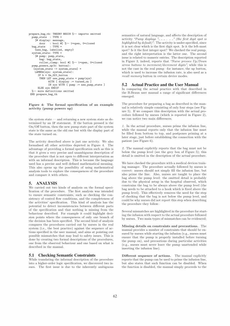
prepare_bag_th: THEORY BEGIN %-- imports omittedpump_state : TYPE =[# display: message,
door : bool #] %-- 1=open, 0=closedbag_state : TYPE ={new_bag, labelled, empty}
system_state: TYPE =[# pump: pump_state,
bag: bag_state,roller_clamp: bool #] %-- 1=open, 0=closed
pump_powers_up(b: button):[system_state -> system_state] =LAMBDA(sys: system_state):IF b = On_Off_buttonTHEN LET new_pump_state = pump(sys)
WITH [ display := turned_on ]IN sys WITH [ pump := new_pump_state ]
ELSE sys ENDIF%-- more definitions omitted
END prepare_bag_th
Figure 4: The formal specification of an exampleactivity (pump powers up)
the system state — and returning a new system state as de-termined by an IF statement. If the button pressed is theOn/Off button, then the new pump state part of the systemstate is the same as the old one but with the display part ofthe state turned on.
The activity described above is just one activity. We alsoformalised all other activities depicted in Figure 4. Theadvantage of providing a formal specification such as this isthat it gives a very precise and unambiguous description ofthe procedure that is not open to different interpretation aswith an informal description. This is because the languageused has a precise and well defined mathematical meaning.This also opens up the possibility of using mathematicalanalysis tools to explore the consequences of the procedureand compare it with others.
5. ANALYSISWe carried out two kinds of analysis on the formal speci-fication of the procedure. The first analysis was intendedto ensure semantic constraints, such as checking the con-sistency of control flow conditions, and the completeness ofthe activities’ specification. This kind of analysis has thepotential to detect inconsistencies between different partsof the specification and that nothing is missing from thebehaviour described. For example it could highlight deci-sion points where the consequences of only one branch ofthe decision has been specified. The second kind of analysiscompares the procedures carried out by nurses in the realsystem (i.e., the best practice) against the sequence of ac-tions specified in the user manual, and aims at pointing outpossible mismatches that may lead to safety issues. This isdone by creating two formal descriptions of the procedures,one from the observed behaviour and one based on what isdescribed in the manual.
5.1 Checking Semantic ConstraintsWhile translating the informal description of the procedureinto a higher-order logic specification, we discovered two is-sues. The first issue is due to the inherently ambiguous
semantics of natural language, and affects the description ofactivity “Pump displays ” . ” (the first digit spot ishighlighted by default)”. The activity is under-specified, sinceit is not clear which is the first digit spot. Is it the left-mostspot? Is it the first integer spot? We checked the real pump,and the right interpretation is the latter one. The secondissue is related to numeric entries. The description reportedin Figure 3, indeed, reports that “Nurse presses Up/Downarrow buttons to increment/decrement digits”, while this isnot the case in the real pump –for instance, the up button,which is used to increase the infusion rate, is also used as arecall memory button in certain device modes.
5.2 Actual Practice and the User ManualIn comparing the actual practice with that described inthe B.Braun user manual a range of significant differencesemerged.
The procedure for preparing a bag as described in the man-ual is relatively simple consisting of only four steps (see Fig-ure 5). If we compare this description with the actual pro-cedure followed by nurses (which is reported in Figure 2),we can notice two main differences.
1. In the actual procedure, nurses prime the infusion line,while the manual reports only that the infusion line mustbe filled from bottom to top, and postpones priming at alater stage, just before establishing the connection with thepatient (see Figure 6).
2. The manual explicitly reports that the bag must not bebelow the pump level (see the grey box of Figure 5); thisdetail is omitted in the description of the actual procedure.
We have checked the procedure with a medical devices train-ing manager. The procedure actually followed by nurses iscorrect: nurses should not simply fill the infusion line, butalso prime the line. Also, nurses are taught to place thebag above the pump level: the omitted detail is probablydue to the physical setup in the hospital observed, whichconstrains the bag to be always above the pump level (thebag needs to be attached to a hook which is fixed above thepump level). This effectively removes the need for the stepof checking that the bag is not below the pump level, andcould be why nurses did not report this step when describingthe procedure they follow.
Several mismatches are highlighted in the procedure for start-ing the infusion with respect to the actual procedure followedby nurses. Two main types of mismatches can be evidenced:
Missing details on constraints and precautions. Themanual provides a number of constraints that should be en-sured by nurses while starting the infusion (e.g., nurses mustensure that the pump is properly installed before turningthe pump on), and precautions during particular activities(e.g., nurses must never leave the pump unattended whileinserting the infusion line).
Different sequence of actions. The manual explicitlyreports that the pump can be used to prime the infusion line,but also states that such function can be disabled. Whenthe function is disabled, the manual simply proceeds to the
62

Figure 5: Procedure specified in B.Braun’s Manual for preparing a bag with the medication
Figure 6: Procedure specified in B.Braun’s Manual for starting the infusion
next step (“Press the Up Arrow if the prime function is en-abled. [...] Then press Down Arrow to proceed. Establishthe patient connection” [1]).
We engaged a medical devices training manager for dis-cussing the above differences. It turns out that the missingdetails on constraints and precautions are not only relatedto activities that nurses simply omit to explicitly state (e.g.,nurses are aware of the situations in which there is a dan-ger of free-flow), but there are also a number of activitiesthat nurses are actually not able to perform due to the par-ticular work context, which is always very busy and doesnot allow nurses to dedicate time to certain activities, suchas observing the messages shown by the pump during theself-test.
Regarding the different sequence of actions, the most criticaldifference is related to priming the infusion line. The manual
reports that it can be done with the pump, given that theprime function is enabled on the pump; if the function isdisabled, the next step is to establish the patient connection(see Figure 6). However, before starting the infusion, theline must be primed, otherwise there is a safety issue for thepatient. The manual omits to point out this detail, and theprocedure, as described in the manual, is not best practice.The medical devices training manager reported that, in fact,there were incidents due to nurses and trainers followingprocedures reported in the manuals, like the one described.
6. DISCUSSION AND CONCLUSIONSWe have described a study that compares a formal specifica-tion of actual practice for setting up an infusion pump witha formal specification of the sequence of actions described inthe user manual of the pump. The study is based on a realpump and on observations made in a real hospital.
63

We discovered several issues and mismatches, such as ambi-guity in the language used in the descriptions, and variouschecks prescribed in the manual of the pump but omitted inthe actual practice. Our study shows how a model-based en-gineering approach can be conveniently used to support aninvestigator to understand workflow situations. Such issuesare easily missed when using only informal descriptions.
The formalisation process uncovered an issue in the usermanual related to priming the line (the procedure describedin the manual was not consistent with the actual best prac-tice). This demonstrates that a model-based engineeringapproach could be used to improve manuals and trainingmaterial. Whilst this study concerned a B.Braun pump webelieve that similar issues would apply with the pumps ofother manufacturers and their actual use.
Understanding how devices are used in practice and pointingout issues with manuals is of potential use to manufacturers,trainers and procurement staff. For example, if staff areusing workarounds then it is important for device designersto be aware of this so that they can determine whether thesepractices are safe.
Providing a direct support in training literature is likely toprovide a commercial advantage for manufacturers: if suchworkarounds are adapted to context to make the pump useeasier or more effective, then the pump in question wouldbetter support the nurses in doing their work. On the otherhand if the practices are unsafe, it is in the manufacturer’sinterest to design the device in ways to remove the need orpossibility of such workarounds. Similarly, if a device designis such that unsafe practices result to deal with the reali-ties of the job, then training and procurement staff need toknow how to improve procurement decisions and trainingregimes. Also, if training staff are aware of why proceduresare the way they are, then they can help spread good prac-tice. Formal specifications can be simulated, and this opensup the possibility of automatically generating visualisationtools of scenarios for use in training (either to show badconsequences of actions or to illustrate ways to improve per-formance and safety).
Whilst in this study the investigation of actual behaviourwas complete when the formal work was carried out, thesetechniques could also help an investigator collecting ethno-graphical data and actually build a deeper understanding ofthe system as observations and interviews take place. Forexample, insights gained during model-based analysis canhelp focus attention on areas to observe more closely andquestions to ask. When only an informal description is be-ing used, such issues can easily be missed.
Current tools are not at a stage of maturity that an ac-tual investigator could easily develop a formal specificationand analyse it, though this may be possible in the futureas the techniques are developed and built into tools. In themeantime, however, the approach can be applied if a formalmethods expert is paired with the investigator to do modeldevelopment and analysis and interpret the results in dia-logue with the investigator.
AcknowledgementsFunded as part of the CHI+MED: Multidisciplinary Computer-Human Interaction research for the design and safe use ofinteractive medical devices project, EPSRC Grant NumberEP/G059063/1, Formally-based tools for user interface anal-ysis and design, EPSRC Grant Number EP/F020031/1, andExtreme Reasoning Grant Number EP/F02309X/1.
7. REFERENCES[1] B|Braun Melsungen AG. Infusomat space and
accessory: Instruction for use (ver. 686e).
[2] Leonardo de Moura, Sam Owre, Harald Ruess, JohnRushby, N. Shankar, Maria Sorea, and Ashish Tiwari.SAL 2. In Rajeev Alur and Doron A. Peled, editors,Computer Aided Verification: CAV 2004, volume 3114of Lecture Notes in Computer Science, pages 496–500.Springer-Verlag, July 2004.
[3] Susan M. Hebert. The cat in the reaper: Usabilitytesting of software instruction manuals. Master’sthesis, San Jose State University, 1989.
[4] M. Massink and D. Latella. Deriving Manuals fromFormal Specifications, volume 1. 2003.
[5] A. Movaghar and J.F. Meyer. Performabilitymodelling with stochastic activity networks. InProceedings of the 1984 Real-Time SystemsSymposium, pages 215–224, 1984.
[6] Donald A. Norman. The Design of Everyday Things.Basic Books, New York, reprint paperback edition,2002.
[7] S. Owre, S. Rajan, J.M. Rushby, N. Shankar, andM.K. Srivas. PVS: combining specification, proofchecking, and model checking. In Rajeev Alur andThomas A. Henzinger, editors, Computer-AidedVerification, CAV ’96, number 1102 in Lecture Notesin Computer Science, pages 411–414, New Brunswick,NJ, July/August 1996. Springer-Verlag.
[8] Atish Rajkomar. Extending distributed cognitionanalysis for complex work settings: a case study ofinfusion pumps in the intensive care unit., 2010. MScThesis.
[9] H. Thimbleby and P. B. Ladkin. From logic tomanuals. Software Engineering Journal,11(6):347–354, 1997.
[10] Harold Thimbleby. Contributing to safety and duediligence in safety-critical interactive systemsdevelopment by generating and analyzing finite statemodels. In Proceedings of the 1st ACM SIGCHIsymposium on Engineering interactive computingsystems, EICS ’09, pages 221–230, New York, NY,USA, 2009. ACM.
[11] Harold W. Thimbleby and Peter B. Ladkin. Fromlogic to manuals again. IEEE Proceedings - Software,144(3):185–192, 1997.
[12] Franz Weitl, Mirjana Jaksic, and Burkhard Freitag.Towards the automated verification of semi-structureddocuments. Data Knowl. Eng., 68:292–317, March2009.
64

Visualization and Interaction System for Surgical Planning
Lucio T. De Paolis, Giovanni Aloisio
Dept. of Innovation Engineering Salento University
Lecce, ITALY {lucio.depaolis, giovanni.aloisio}@unisalento.it
ABSTRACT Modern technologies give a great support to the minimally invasive surgical procedures through medical image processing and visualization, 3D organ’s reconstruction and intra-operative surgical guidance. The practice of Minimally Invasive Surgery is becoming more and more widespread and is being adopted as an alternative to the classical procedure. This technique presents some limitations for surgeons. In particular, the lack of depth in perception and the difficulty in estimating the distance of the specific structures in laparoscopic surgery can impose limits to delicate dissection or suturing. The presence of new systems for the pre-operative planning can be very useful to the surgeon. In this paper we present a visualization and interaction system that allows surgeon to visualize the 3D model of the patient’s organs built from the CT images. Different visualization modalities are available according to the surgeon needs in laparoscopy and an Augmented Reality application permits the choice of the best insertion points of the trocars on the 3D virtual model and the visualization of these points on the real patient’s body. Two case studies have been considered. The system can be used as support for the diagnosis, for the surgical preoperative planning and also as visual support during the surgical procedure. Keywords User interface, image-guided surgery, Augmented Reality INTRODUCTION One trend in surgery is the transition from open procedures to minimally invasive laparoscopic operations where the visual feedback to the surgeon is only available through the laparoscope camera and the direct palpation of organs is not possible. Minimally Invasive Surgery (MIS) has become very important and the researches in this field are ever more widely accepted because these surgical techniques provide surgeons with less invasive means of reaching the patient’s
internal anatomy and allow entire procedures to be performed with only minimal trauma to the patients. As a promising technique, the practice of MIS is becoming more and more widespread and is being adopted as an alternative to the classical procedures. The diseased area is reached by means of small incisions on the body; specific instruments and a camera are inserted through these ports and what happens inside the body is shown in a monitor. The surgeon does not have a direct vision of the organs and so he is guided by the camera images. This surgical approach is very different from the open surgery where the organs can be fully visualized and handled. The advantages of using this surgical method are evident in the patient because the trauma is reduced, the postoperative recovery is almost always faster and the scarring is reduced. Despite the improvement in outcomes, these techniques show their limitations for the surgeons. In particular, the lack of the perception of the depth and the difficulty in estimating the distances of the specific organs in laparoscopic surgery can impose some limits on delicate dissection or suturing. Anyway, the overall risk of complications is of 8.0% in laparoscopy versus 15.2% in laparotomy. Among these, more than 50% of laparoscopic complications occur during the initial entry into the abdomen. The modern medical imaging acquisition associated to the medical image processing could lead to an improvement in patient care by guiding the surgeons. The medical image processing allows detecting and identifying anatomical and pathological structures and building 3D models of the patient’s organs that could be used to guide the surgical procedures. Many research teams have dealt with the task of segmentation and have developed techniques that allow automatic or interactive extraction of the patient’s organ models from CT-scan or MRI [1], [2]. The Augmented Reality (AR) technology can provide the advantage of a direct visualization in open surgery also in minimally invasive surgery and can increase the physician's view of his/her surroundings with information gathered from patient medical images [3]. In general, AR technology in minimally invasive surgery may be used for training
65

purposes, pre-operative planning and advanced visualization during the real procedure. In surgery, Augmented Reality technology makes possible to overlay virtual medical images on the patient, allowing surgeons to have a sort of “X-ray" vision of the body and providing them with a view of the patient’s internal organs [4]. Motivated by the benefits that MIS can bring to patients, many research groups are now focusing on the development of systems in order to assist the surgeons during the surgical procedures and have developed solutions to support the preoperative surgical plannings and the intra-operative surgical procedures. Samset et al. [5] present tools based on novel concepts in visualization, robotics and haptics providing tailored solutions for a range of clinical applications. Examples of radio-frequency ablation of liver tumors, laparoscopic liver surgery and minimally invasive cardiac surgery will be presented. Bichlmeier et al. [6] focus on the problem of misleading perception of depth and spatial layout in medical AR and present a new method for medical in-situ visualization that allows improved perception of 3D medical imaging data and navigated surgical instruments relative to the patient’s anatomy. They describe a method for integrating surgical tools into the medical AR scene in order to improve navigation. Navab et al. [7] introduce an interaction and 3D visualization paradigm that presents a new solution for using 3D virtual data in many AR medical applications. They introduce the concept of a laparoscopic virtual mirror: a virtual reflection plane within the live laparoscopic video, that allows visualizing a reflected side view of the organ and its interior. A clinical evaluation investigating the perceptive advantage of a virtual mirror integrated into a laparoscopic AR scenario has been carried out. De Paolis et al. [8] present an Augmented Reality system that can guide the surgeon in the operating phase in order to prevent erroneous disruption of some organs during surgical procedures. The distance information is provided to the surgeon and an informative box is shown in the screen in order to visualize the distance between the surgical instrument and the organ concerned. In this paper we present an advanced platform for the visualization and the interaction with the 3D patient models of the organs built from CT images. The developed application allows the surgeon to choose the points for the insertion of the trocars on the virtual model, to simulate the insertion of the surgical tools in order to verify the correctness of the insertion sites and to overlap the chosen entry points on the real patient body using the Augmented Reality technology. The system could be used as support for a more accurate diagnosis, in the surgical preoperative planning and also for an image-guided surgery.
THE CASE STUDIES In MIS the use of the registered images of the patient is a prerequisite both for the pre-operative planning and the guidance during the operation. From the medical image of a patient (MRI or CT), an efficient 3D reconstruction of his anatomy can be provided in order to improve the standard slice view; colors associated to the different organs replace the grey levels in the medical images. In our case study the 3D models of the patient’s organs have been reconstructed using segmentation and classification algorithms provided by ITK-SNAP [9]. We processed two different case studies; the slice thickness equal to 3 mm has caused some aliasing effects on the reconstructed 3D models that could lead to inaccuracies. Therefore we have paid special attention to the smoothing of the reconstructed models in order to maintain a good correspondence with the real organs. The first case study, shown in Figure 1, is a two-year-old child with a benign tumor of the right kidney. The second case study, shown in Figure 2, is a twelve-year-old child with a tumor of the peripheral nervous system (ganglioneuroma).
Figure 1: 3D model of a child with a tumor at the kidney
THE USER INTERFACE The developed application is supplied with a specific user interface that allows the user to take advantage of the feature offered by the software. The application is provided of 4 sections with the aim to provide support to the surgeons in the different steps of the surgical procedure such as the study of the case, the diagnosis, the pre-operative planning, the choice of the trocar entry points and the simulation of the surgical instruments interaction. Starting from the models of the patient’s organs, the surgeon can notice some data about the patient, collect information about the pathology and the diagnosis, choose
66

the most appropriate positions for the trocar insertion and overlap these points on the patient’s body using the Augmented Reality technology.
Figure 2: Virtual model of a child with a ganglioneuroma In this way it is possible to use this platform for the pre-operative surgical planning and during the real surgical procedure too. In addition, it could be used in order to describe the pathology, the surgical procedure and the associated risks to the child’s parents, with the aim of obtaining informed consent for the surgical procedure. In the developed application, all the patient’s information (personal details, diseases, specific pathologies, diagnosis, medical images, 3D models of the organs, notes of the surgeon, etc.) are structured in a XML file associated to each patient. A specific section for the pre-operative planning includes the visualization of the virtual organs and the physician can get some measurements of organ or pathology sizes and some distances; this section is shown in Figure 3. By means of a detailed view of the 3D model, the surgeon can choose the trocar entry points and check if, with this choice, the organs involved in the surgical procedure can be reached and the procedure can be carried out in the best way.
Figure 3: Measurement of organs
THE AUGMENTED REALITY SECTION Sometimes, using the standard insertion points for the surgical tools, also a simple surgical procedure can be very difficult due to the specific anatomy of the different patients. The surgeon can have some difficulties to reach the specific organ or the interaction of the surgical tools can be very hard. In this case the surgeon has to choose another insertion point in order to be able to carry out the surgical procedure in the most suitable way. Our aim is to avoid the occurrence of this situation during the real surgical procedure using the visual information provided by means of the 3D models of the patient’s anatomy. In the developed application, in order to verify if the chosen insertion points allow properly reaching the specific organ interested by the surgical operation and permitting to carry out the procedure in a correct way, it is also possible to simulate the interaction of the surgical instruments. We also use the AR technology in order to visualize on the patient’s body the precise location of the selected points on the virtual model of the patient. For the augmented visualization, in order to have a correct and accurate overlapping of the virtual organs on the real ones, a registration phase is carried out; this phase is based on fiducial points. Using the augmented visualization, the chosen entry points for the trocars can be visualized on the patient’s body in order to support the physician in the real trocar insertion phase.
Figure 4: Simulation of the surgical tools interaction
In our application, we have used the Polaris Vicra optical tracker of NDI [10]; the system consists of 2 IR cameras and uses a position sensor to detect retro-reflective markers affixed to the surgical tools or located on the patient’s body; based on the information received from these markers, the sensor is able to determine position and orientation of tools within a specific measurement volume. The tracker can calculate the current position of the tool in the space with an accuracy of 0.2 mm and 0.1 tenth of a degree. Usually the tracking technology is already in the operating
67

rooms and provides an important help to enhance the performance during the real surgical procedures. Figure 4 shows the specific section for the simulation of the surgical tools interaction with the possibility to move the trocar entry points using the arrows; Figure 5 shows the augmented visualization of the chosen trocar entry points on the patient's body (a dummy).
Figure 5: Augmented visualization of the entry points
CONCLUSIONS AND FUTURE WORK The developed application offers a tool to visualize the 3D reconstructions of the patient’s organs, obtained by segmentation of a CT slices, and to simulate the placement of the trocars in order to verify the correctness of the insertion sites. A complete user interface allows a simple and efficient utilization of the developed application. Furthermore the system retains patient and pathology information that the surgeon can insert and includes an Augmented Reality module that supports the placement of the trocars on the patient’s body during the real surgery procedure. An accurate integration of the virtual organs in the real scene is obtained by means of an appropriate registration phase based on fiducial points. The developed platform can support the physician in the diagnosis steps and in the pre-operative planning when a laparoscopic approach will be followed. This support could also lead to a better communication between physicians and patient’s parents in order to obtain their informed consent. The platform has been tested on study cases already operated by the surgeon; the future work will be the validation of the developed application on a new study case by following all the steps from the diagnosis to the pre-operative planning and to the first phase of the real surgical procedure. The building of a new Augmented Reality system that could also help the surgeon during the other phases of the surgical procedure has been planned as future work.
ACKNOWLEDGMENTS This work is part of ARPED Project (Augmented Reality
Application in Paediatric Minimally Invasive Surgery) funded by the Fondazione Cassa di Risparmio di Puglia, Italy. The aim of the ARPED Project is the design and development of an AR system that can support the surgeon through the visualization of anatomical structures during a laparoscopic surgical procedure.
REFERENCES 1. Camara, O., Colliot, O., and Bloch, I. Computational
Modeling of Thoracic and Abdominal Anatomy Using Spatial Relationships for Image Segmentation. Real Time Imaging, 2004, 10(4), 263-273.
2. Kitasaka, T. et al. Automated extraction of abdominal organs from uncontrasted 3D abdominal X-Ray CT images based on anatomical knowledge. Journal of Computer Aided Diagnosis of Medical Images, 2005, 9(1), 1-14.
3. Furtado, H., and Gersak, B. Minimally Invasive Surgery and Augmented Reality. New Technology Frontiers in Minimally Invasive Therapies, 2007, 195-201.
4. Sielhorst, T., Obst, T. et al. An Augmented Reality Delivery Simulator for Medical Training, Workshop on Augmented Environments for Medical Imaging (MICCAI 2004), 11-20.
5. Samset, E., Schmalstieg, D., Vander Sloten, J., Freudenthal, A., Declerck, J., Casciaro, S., Rideng, Ø., and Gersak, B. Augmented Reality in Surgical Procedures. SPIE Human Vision and Electronic Imaging XIII, 2008.
6. Bichlmeier, C., Wimmer, F., Michael, H.S., and Nassir, N. Contextual Anatomic Mimesis: Hybrid In-Situ Visualization Method for Improving Multi-Sensory Depth Perception in Medical Augmented Reality. Sixth IEEE and ACM International Symposium on Mixed and Augmented Reality (ISMAR '07), 2007, 129-138.
7. Navab, N., Feuerstein, M., and Bichlmeier, C. Laparoscopic Virtual Mirror - New Interaction Paradigm for Monitor Based Augmented Reality. IEEE Virtual Reality Conference 2007 (VR 2007), Charlotte, North Carolina, USA, 2007, 10-14.
8. De Paolis, L.T., Pulimeno, M., Lapresa, M., Perrone, A., and Aloisio, G. Advanced Visualization System Based on Distance Measurement for an Accurate Laparoscopy Surgery. Joint Virtual Reality Conference of EGVE - ICAT - EuroVR, Lyon, France, 2009.
9. Yushkevich, P.A., Piven, J., Cody, H., Ho, S., Gee, J.C., and Gerig, G. User-Guided Level Set Segmentation of Anatomical Structures with ITK-SNAP. Insight Journal, Special Issue on ISC/NA-MIC/MICCAI Workshop on Open-Source Software, 2005.
10. NDI Polaris Vicra. Available at http://www.ndigital.com/.
68
Design and Prototypical Development of a Web Based Decision Support System for Early Detection of Sepsis in Hematology
Andreas Wicht Heidelberg University Hospital, Institute of Medical Biometry
and Informatics Im Neuenheimer Feld 305
Heidelberg, 69120 Germany Andreas.Wicht@med.
uni-heidelberg.de
Gerrit MeixnerGerman Research Center for Artificial Intelligence (DFKI)
Trippstadter Strasse 122Kaiserslautern, 67663 Germany
Ulrike Klein Heidelberg University Hospital,
Department of Hematology and Oncology
Im Neuenheimer Feld 410 Heidelberg, 69120 Germany
Ulrike.Klein2@med. uni-heidelberg.de
ABSTRACT Physicians do not always make optimal decisions. Computer based clinical support systems are intended to provide clinicians with decision aids, but their practical impact remains low. We introduce a software architecture which might overcome key barriers and present the prototypical implementation of a web based knowledge module for early detection a life-threatening medical condition, sepsis.
Keywords Clinical decision support, Knowledge-based systems in medicine, hematology, sepsis, fever, web-based application, knowledge maintenance, ESGOAB.
INTRODUCTION The information overload physicians are confronted every day with makes it impossible for them to keep up with all the information and knowledge that would be potentially useful in making optimal clinical judgments. Empirical studies have shown that physicians do not always make optimal decisions [17] [6]. Clinical decisions are often made under time pressure, without having all information and knowledge needed in the right place at the right time. Computer-assisted clinical decision support systems(CDSS) are intended to provide “clinicians, patients or individuals with knowledge and person-specific or population information, intelligently filtered or presented at appropriate times, to foster better health processes, better individual patient care, and better population health. CDS interventions include alerts, reminders, and order sets […]” [11].Although research has been done in the field of CDSS for
decades, the practical impact remains low for several reasons, e.g. [3]:
- Systems failed to cover an entire medical domain - Poor practicability and integration into the clinical
workflow - Poor availability of digital patient data- Poor acceptance
Within the ESGOAB1 project, which will be described in more detail in the next section, we are trying to overcome the weaknesses mentioned above. In this paper we will briefly describe the ESGOAB software architecture, which provides an electronic health record (EHR) and is designed to provide the base to interact with knowledge modules. Wefocused on two specific clinical challenges: supporting the physicians’ order entry process (CPOE) and supporting early detection of sepsis (a serious and life-threatening medical condition) on patients with hematological underlying diseases. In this paper we will describe the second challenge. We introduce our conceptual design of the sepsis knowledge module and present the currently implemented web-based prototype.
Project Background The ESGOAB project is a 2-year public funded joined research project between two scientific partners (Heidelberg University Hospital, DFKI) and two industrial partners (COPRA System GmbH, Dosing GmbH). A survey at the Department of Hematology and Oncology of the Heidelberg University Hospital has shown a range of problems concerning various applications of Information and Communications technologies (ICT) within the hospital (response rate = 70.5 %, 36 of 51 of the medical personnel)
1 ESGOAB = „Entwicklung einer Softwareumgebung zur Generierung
von organisationsspezifischen Anwendungen zum Behandlungs-prozessmanagement“; english: Development of a Software Environment for Generation of Organization-Specific Applications for Treatment Process Management
Copyright © 2011 for the individual papers by the papers' authors. Copying permitted only for private and academic purposes. This volume is published and copyrighted bythe editors of EICS4Med 2011.
69

[20]. The study revealed problems concerning e.g., time consuming searches, redundant data entries, use of various software applications to perform the various tasks, different user interfaces, and only marginal decision support. However we found a promising openness towards CDSS [20]. In general the staff was open-minded towards new Information Technology (IT) systems (88 % indicated to be “rather open-minded” or “open-minded”), concerning CDSS, the potential benefit was assessed by the majority (72 %) as “rather high” or “high”, as well as prospects of success (53 %). At least 47 % rated reliability as well as acceptance as “rather high” or “high”.The ESGOAB project aims at encapsulating various data sources like e.g., hospital information system (HIS), laboratory data or drug information systems (see Figure 1)into one integrated software system which provides one consistent user interface. The second main aim is the development and integration of knowledge bases into the ESGOAB system. The ESGOAB system is based on a 3-layer software architecture concept. A data collector (layer 1) is responsible to capture and gather data from various existing sub systems which are illustrated below the three layers.Adapters for each of the sub systems are transforming data into defined structures. The knowledge carrier (layer 2) analyzes incoming data from the data collector layer or handles requests triggered by user interactions. The knowledge carrier consists of various knowledge bases (e.g., about drug information) which are connected following a modular concept. If there are e.g., new blood values these will be evaluated by the knowledge carrier and according hints or warnings will be immediately displayed by the visualizer (layer 3) following a defined alerting concept, taking into account the importance, severity etc. of the alert [4].
HIS Lab PACS …
Layer 1Data Collector
Layer 2Knowledge Carrier
Layer 3Visualizer Dynamic Desktop
Workflow Model
Decision Model
Adapters
Meta Data Model
Sub Systems
Patient X….
…
Figure 1: 3-layer architecture of the ESGOAB systemAt the end of the ESGOAB project we expect an increase of efficiency of tasks and processes at the Department of Hematology and Oncology at the Heidelberg University Clinic (due to time-savings), a reduction of performance
stress, and optimization of clinical decisions, which altogether may improve quality of care.
Related work Research in the field of medical knowledge-based systems has been done since the early 1960s. Many different research approaches have been explored, but yet the degree of impact of clinical decision support systems still remains low [5]. Only few knowledge-based systems are widely used day-to-day, such as automated electrocardiogram (ECG) interpretation [18]. However, systems utilizing a broad variety of individual patient data had to fail due to poor availability of digital data. Providing an EHR eliminates this obstacle [3]. Research in the field of monitoring and analyzing vital signs in Intensive Care Units (ICU) for early warning of patient deterioration or sepsis were done by [15] and [12].However, including microbiological findings as well as the accurate handling of the specifics of the hematological patients remained unconsidered.
Clinical Background The treatment of patients with hematological diseases has advanced enormously in the past years. Nevertheless such infections pose a serious life-threatening risk for these immunocompromised patients. Beside various other clinical and laboratory parameters, fever is an essential factor, which indicates a manifest or beginning infection. Therefore a refined assessment of the body temperature is needed. The responsible physician has to distinguish between innocent fever as immunologic reaction, fever of unknown origin, fever caused by bacteremia or the onset of a severe sepsis. Hereby assists the combination of lab-values, microbiological findings and vital signs. The emphasis and valuation of the combination of single-values and the experience of the doctor partly determine the treatment course and the outcome of the patient. Clinical studies demonstrated that the survival probability of patients with sepsis depends most essentially on the period of time between diagnosis and start of effective antibiotic treatment [7]. Sepsis is not only a problem of hematological patients. It’s rather a challenge for the population. Severe sepsis is considered to be the most common cause of death in non-coronary critical care units. Approximately 150.000 persons die annually in Europe and more than 200.000 in the United States [1]. The problematic nature of a timely recognition is not that data is missing, but it is detached from one another, generated at various places and different times. The responsible physician has to link the separated information for the plurality of patients. Ward rounds, printouts with lab values, calls from the microbiologist and signs from monitors serve as instruments for this connection. This work has to be done by the medical personnel even in the future, but the model we present in this article offers the convincing advantage of automated joining of relevant data and usable presentation, resulting in efficient and faster decisions.
70

APPROACH Conceptual Requirements When deploying and operating knowledge-based systems, a weak point is often poor practicability, in particular in terms of maintenance. Either the knowledge model is implemented statically, there is no way experts of the certain domain (in the present case hematologists) can modify the model on their own. This leads to the fact that each adaptation has to be done by a software engineer. Or the user interfaces do not provide intuitive means to modify the knowledge base; thus users have to be instructed and the system becomes error-prone. Between designing and using knowledge-based systems, a long-lasting cyclic process of modeling, testing, adapting, and retesting of the core engine has to be passed through. While operating knowledge-based systems the focus shifts towards maintenance issues. Maintaining the knowledge within the system is critical to successful delivery of decision support [3]. In this context practicability plays an important role. Being aware of this issue, easy knowledge maintenance was an important goal.The clinical expert should be able to modify the underlying knowledge model without extensive training. It has to be simple and intuitive to use. Furthermore it should be possible to test the constructed or adapted model right away. Beyond that, the knowledge model should be generic,so it might be useful for other diagnostic problems.
Knowledge Engineering Process Knowledge Engineering is the systematic approach for the development of knowledge based systems. The process may be divided into two main phases (Figure 2): knowledge acquisition and knowledge operationalization [14]. Itshould be noted, that typically the process of acquisition and operationalization is not a linear process but rather a cyclic process characterized by continuous, iterative refinement.
Figure 2: The Knowledge Engineering Process Knowledge acquisition is the process of capturing, structuring and formalizing knowledge. The result of the acquisition phase is a knowledge model and an information model which both serve as a base for the system design of an implementation [5]. Sources of knowledge are typically domain experts, medical literature and patient data repositories. Our approach was based on expert opinion and literature research.
Information Model A specification of the kinds of information that were required was created, including the data format and the taxonomy. The resulting information model – which will be implemented as an object-oriented data model – provides us
the flexibility to use the same implementation (objects) in two kinds of settings:
1. Interactive data retrieval with the user (module execution)
2. Running in background through a web service retrieving data from the EHR
Knowledge Model Sepsis accompanies with several symptoms, such as fever, increased heart rate, low blood pressure etc. Further important parameters are signs of infections such as specific blood values and microbiological findings. The sequence of appearance and the severity of these manifestations differ from patient to patient. We have to deal with fuzzy and uncertain information. However, some signs are more important than others and certain value ranges are supporting sepsis more than other diagnoses. So the idea was to design a decision model, which balances between a set of differential diagnoses and specifies the one which can be explained best by the observed findings. The set covering model is a potentially useful approach, which was introduced by [13], as well as the more abstract view on multiple diagnose problems by [9]. Our approach is based on the set covering model, extended by the possibility to define parameters which contradict certain diagnoses since we experienced a further need for accuracy.Two sub modules based on a rule engine were required to handle two specific problems:
1. Interpretation of microbiological findings: Presence of an infection or suspected contamination?
2. Interpretation of white blood cell count (leukocytes): May we take this parameter into account?
Implementation Initially, the basic idea was demonstrated using a prototype realized in Microsoft Excel (Figure 3). Taking advantage of quick implementation possibilities, this prototype helped us to refine our knowledge model.
Figure 3: Prototype developed with Microsoft Excel (result presentation in the upper left corner, value selection in the mid-area) The decision to proceed with the development of a web-based application was made due to the following main reasons:
- Easy Accessibility from all clients via the clinic’s intranet; no need to install software on clients
- Quick deployment of new versions
Knowledge Acquisition
Capturing
Structuring
Formalization
Knowledge Operationalization
Design
ImplementationKnowledge Model
Information Model
71

We used a XAMPP [2] installation on Windows including an Apache 2.2.14 web server and a MySQL database system. We used the scripting language PHP and the Ajax toolkit xajax [19]. The application is based on the Model-View-Controller (MVC) design pattern; the PHP code architecture follows an object-oriented approach. The application is implemented using the open source relational database management system MySQL, with use of the InnoDBstorage engine. An initial database model was designed using the database-modeling tool MySQL Workbench [10].The model was refined iteratively during the implementation of the application.
WEB-BASED PROTOTYPE Application Structure The application is composed of three modules: Sepmod,Leukomod and Mibimod (Figure 4). Sepmod represents the generic core model, which implements the weight model as specified before and interacts with the sub modules Leukomod and Mibimod. Leukomod is based on a rule engine, which is responsible for the white blood cells’assessment. Mibimod is also based on a rule engine and performs the assessment of the microbiologic findings.
Figure 4: Structure of the application The web-front-end provides the following two main sections:
- Maintenance: Provides editors for each module for construction and modification of the knowledge base.
- Module-Execution: Interactive tool, which requests for data or selection of options by the user and presents the results.
The interactive tool is basically designed for testing purposes. The impact of adaptions of the knowledge base can be explored right away.
Knowledge Maintenance Section Sepmod In this section the user can create a new and edit existing knowledge models. Created models can be loaded, saved, and deleted. The core element is the weight table (Figure 5).
Figure 5: Screenshot of a weight table (columns: diagnoses, rows: parameters and values) The process of creating a new model facilitates the following steps:
1. Add diagnoses2. Add parameters3. Add value ranges for each parameter 4. Create weight relations between value and diagnosis 5. Define Equivalencesets6. Define Minimalsets
These steps are described in more detail below. Step 1: Firstly we need to add diagnoses, by providing its name and optionally a description. For each diagnoseadded, the table will be expanded by one column.Example definition:
Step 2: In the second step, symptoms or “parameter” can be defined, specifying its name, type, unit, value range,validity, importance. The type tells us, which kind of data we deal with, e.g. integer, float or special medical classifications like the anatomic therapeutic classification(ATC) code. The value range defines the valid value range for the parameter and is used to perform plausibility checks. Regarding the process of diagnosis, an important and relevant issue is always the time context. How long can I rely on a measured value? The answer depends on each parameter. In the present model we therefore define for each parameter a time frame (validity), entering a numerical value for the absolute time (minutes, hours or days) within this parameter remains valid or in other words we can assume that the measured value may be used for the diagnostic assessment. If a parameter exceeds the defined time frame, it will be ignored and treated, as it would be not available. Alternatively we can define a relative time frame such like “Valid until next measurement”. Some parameters may have a more significant importance than other. Thus for each parameter the importance can be defined, choosing from given weights “very important”, “fairly important”, “important”.
Name: SIRS
Range: Systemic Inflammatory Response Syndrome
72

Example definition:
Step 3: In the next step, for each parameter, several valueshave to be defined. The values are specified by its name and its value range. Example definition:
Step 4: Adding diagnoses, parameter and its values results in a count(diagnoses) x count(values) matrix. For each pair of a value and a diagnosis we can now define a weight relation between a specific value and a diagnosis by clicking on the corresponding button. A weight relation is the symbol for the strength a specific value supports a diagnosis. The currently implemented model supports five different weights, ranging from H0 (value does not support the diagnosis or even contradicts) to H4 (value strongly supports the diagnosis or is even essential) depending on the currently used weight model which can be defined in a separate section. For each weight symbol the value can be selected through a slide control. Step 5: In the section called equivalencesets we define sets of previously defined parameters, which are clinically equivalent (Figure 6). In other words all of these parameters support a specific context diagnosis, such as low blood pressure.
Figure 6: Screenshot of the equivalenceset dialog In this case we would define that low blood pressure exists if at least one of these blood pressure parameters takes a specific value (and a corresponding high weight) or in this special case we also assume low blood pressure if vasopressors (substances which result in an increase in blood pressure) are given what we can specify through a list of ATC codes. Step 6: A decision model might be sophisticated but its accuracy highly depends on the available parameters. So it only makes sense to perform a diagnostic assessment if at
least a certain set of parameters is available. In the section minimalset the clinical experts can define, which parameters they consider as being essential for performing a profound assessment. It is possible to define more then one set.
Leukomod Leukomod is based on a rule engine. The rules were defined by clinical experts. In the current version they are implemented statically and can be activated or deactivated through the web-front-end in the section leukomod/rules. Further we can adapt various parameters (like thresholds) ofthe rules. For the assessment, if the white blood cells may be included, the underlying disease is of high importance. A dynamic list of diagnosis codes (ICD, International Statistical Classification of Diseases and Related Health Problems) can be maintained in the section diagnoses.
Mibimod Mibimod is based on a rule engine. A dynamic list of germs which support the suspicion of a contamination can be maintained in this section. The rules of this module are currently implemented statically.
Module Execution Section For testing purposes the web-front-end provides a section to run the modules. The current version has one section to run each of the modules separately and one, which encapsulates all three of them. These execution modules are implemented as interactive tools, requesting each parameter step-by-step. For each input field a check for plausibility is performed while entering data, considering two main issues
- Valid characters (depending on the data type) - Valid value range (as defined in the model).
To keep track of entered values, we show breadcrumbs horizontally across the top of the input form (Figure 7).
Figure 7: Entering values using the interactive mode The user can easily go back to previously entered values and change them if necessary. Each breadcrumb item shows the name of the parameters as well as the entered value and unit. Once all values are entered, the system performs the assessment and presents the results, giving explanations and a visualization of the results (Figure 8). Presenting results in an appropriate way means finding a balance between (1) simple, clear and aggregated representations, supporting e.g. quick task completion and (2) comprehensive and detailed representations, which are needed for making comprehensible decisions.
Name: bodytemperature
Type: float
Unit: °C
Range: 30.0 to 43.0 Validity: 6 hours
Importance: very important
Name: fever
Range: 38.0 to 43.0
73
Figure 8: Result presentation (diagram and textual explanation)
DISCUSSION & FUTURE WORK We identified two important and promising factors that will help overcome key barriers limiting more widespread use of CDSS: Firstly we did not experience the “physician resistance” using decision support systems; they are rather convinced of their usefulness as described in the introduction. Secondly we can take advantage of the software infrastructure we presented which has the potential to improve clinical processes and to integrate and interact with sharable knowledge modules conceived to support the physicians in their decisions. We also introduced a web based prototype of a knowledge module for early detection of sepsis. We believe to contribute important elements to lift computer-aided decision support into widespread practice. However, our approach still needs to be refined and evaluated. It has to be shown that our knowledge modules are able to provide accurate and traceable support, characterized by high sensitivity. A test concept as well as test scenarios will be defined. Further alerting concepts will be tested in practice since empirical studies have shown that too many generated alerts could lead to “alert fatigue”,whereas “non-interruptive” alerts only have low impact and are not effective [8].
ACKNOWLEDGMENTS This work was funded by the German Federal Ministry of Education and Research under grant number 01 IS 09027 C. The responsibility for the content of this publication lies with the authors.
REFERENCES 1. Angus, D.C., Linde-Zwirble, W.T., Lidicker, J.,
Clermont, G., Carcillo, J., and Pinsky, M.R. Epidemiology of severe sepsis in the United States: analysis of incidence, outcome, and associated costs of care. Critical care medicine 29, 7 (2001), 1303-1310.
2. Apache Friends. XAMPP distribution. Available at http://www.apachefriends.org/xampp.html.
3. Bates, D.W., Kuperman, G.J., Wang, S., et al. Ten commandments for effective clinical decision support: making the practice of evidence-based medicine a reality. Journal of the American Medical Informatics Association 10, 6 (2003), 523–530.
4. Durieux, P. Electronic Medical Alerts – So Simple, So Complex. New England Journal of Medicine 352, 10 (2005), 1034-1036.
5. Greenes, R.A. (Ed.). Clinical decision support.
Elsevier Academic Press, Amsterdam; Boston, 2007. 6. Kohn, L.T. (Ed.). To err is human. National Academy
Press, Washington, DC, 2000. 7. Kumar, A., Roberts, D., Wood, K.E., et al. Duration of
hypotension before initiation of effective antimicrobial therapy is the critical determinant of survival in human septic shock. Critical care medicine 34, 6 (2006), 1589-1596.
8. Lo, H.G., Matheny, M.E., Seger, D.L., Bates, D.W., and Gandhi, T.K. Impact of non-interruptive medication laboratory monitoring alerts in ambulatory care. Journal of the American Medical Informatics Association 16, 1 (2009), 66–71.
9. Miller, R.A. A Heuristic Approach to the Multiple Diagnoses Problem. Proceedings of the 6th Conference on Artificial Intelligence in Medicine in Europe, Springer-Verlag (1997), 187–198.
10. MySQL Workbench visual tool. Available at http://www.mysql.com/products/workbench/.
11. Osheroff, J.A., Teich, J.M., Middleton, B., Steen, E.B., Wright, A., and Detmer, D.E. A roadmap for national action on clinical decision support. Journal of the American medical informatics association 14, 2 (2007), 141-145.
12. Pilz, U., and Engelmann, L. Früherkennung von septischen Krankheitsverläufen durch Einsatz eines Expertensystems. Intensivmedizin und Notfallmedizin 43, 7 (2006), 575-579.
13. Reggia, J.A., Nau, D.S., and Wang, P.Y. Diagnostic Expert Systems Based on a Set Covering Model. International Journal of Man-Machine Studies,(1983), 437-460.
14. Spreckelsen, C., and Spitzer, K. Wissensbasen und Expertensysteme in der Medizin. Vieweg + Teubner, Wiesbaden, 2008.
15. Tarassenko, L., Hann, A., and Young, D. Integrated monitoring and analysis for early warning of patient deterioration. British Journal of Anaesthesia 97, 1 (2006), 64-68.
17. Warner, H.R., Sorenson, D.K., and Bouhaddou, O. Knowledge engineering in health informatics.Springer, New York; Berlin; Heidelberg, 1997.
18. Willems, J.L., Abreu-Lima, C., Arnaud, P., et al. Evaluation of ECG interpretation results obtained by computer and cardiologists. Methods of Information in Medicine 29, 4 (1990), 308-316.
19. xajax Project. xajax framework. Available at http://www.xajax-project.org/.
20. Zuehlke, D., Meixner, G., and Klein, U. Smart Medical Software Systems For Dummies? The Case For A User-Centered Systems Design. Proceedings of the 3rd International Conference on Health Informatics 2010 (Valencia ESP, 2010), 350-354.
74

User-Centered Design for Citizens’ Empowerment throughthe Portal of the Italian Ministry of Health
Tiziana Catarci1, Maddalena D’Addario2, Paolo Felli1, Laura Franceschetti3, Domenico Lembo1,Massimo Mecella1, Tatiana Pipan3, Alessandro Russo1, Annarita Vestri2, and Paolo Villari2
1 SAPIENZA Universita di RomaDip. di Informatica e [email protected]
2 SAPIENZA Universita di RomaDip. di Sanita Pubblica e Malattie Infettive
[email protected] SAPIENZA Universita di Roma
Dip. di Scienze [email protected]
ABSTRACTIn this paper we report on a study concerning the redesign ofthe Web portal of the Italian Ministry of Health, jointly con-ducted by the ministry and Sapienza Universita di Roma. Inthis project, a multidisciplinary team consisting of computerscientists and engineers, sociologists and experts in commu-nication, doctors and experts in public health was involved,in order to fully identify and understand citizens’ needs interms of health information, on the one hand, and to applythe most innovative methodologies and techniques for user-centered design and interfaces, on the other. Guidelines foron-line communication on protection and promotion of thehealth, and a mock-up for the future Web portal of the ItalianMinistry of Health have been realized during the project.
Author KeywordsWeb portal, taxonomies, guidelines, mock-up
ACM Classification KeywordsH.5.2 User Interfaces: User-centered design; J.3 Life andMedical Sciences: Health
INTRODUCTIONCurrent Web portals of ministries of Health, in Europe andall over the world, are evolving from simple informationsites, mostly oriented to offer institutional and adminis-trative information, to really interactive e-health systems,providing citizens and operators with various services re-lated to health promotion and prevention, as well as facil-itating the access to services of the National Health Sys-tems (NHSs) (cf. http://www.dh.gov.uk and http://www.nhs.uk in the UK, and http://www.bmg.bund.de in Germany).
In this paper we report on a study concerning the redesign
Proceedings of ENGINEERING INTERACTIVE COMPUTING SYS-TEMS FOR MEDICINE AND HEALTH CARE (EICS4Med 2011), June13, 2011, Pisa, Italy.
of the Web portal of the Italian Ministry of Health1, jointlyconducted by the ministry and Sapienza Universita di Roma,from February 2010 to January 2011. Sapienza participatedin the project with a multidisciplinary team involving com-puter scientists and engineers, sociologists and experts incommunication, doctors and experts in public health, in or-der to fully identify and understand citizens’ needs in termsof health information, on the one hand, and to apply the mostinnovative methodologies and techniques for user-centereddesign and interfaces, on the other. The main products real-ized within this investigation have been:
• Guidelines for online communication on protection andpromotion of the health and access to the Italian NHS [5],targeted mainly to Italian local (i.e., at the regional andmunicipal level) health administrations; such guidelinesare focused on communication issues (“how to talk to cit-izens?”) and on Web design suggestions;
• a mock-up for the future Web portal of the Italian Ministryof Health, together with its design specifications [8].
This work is part of the process of renewing the relationshipbetween health organizations and citizens, in order to im-prove the condition of empowered citizens, repeatedly em-phasized by the WHO (1978, 1986, 1998, 2005)2. The em-powered citizen is able to understand and choose, to defineher own life-style, and to take an active role in managingher well-being, and is thus able to interact rationally and re-sponsibly with those to whom she refer, i.e., the NHS. Em-powerment means “giving power” to citizen. A citizen whohas control over her state of health is a citizen able to par-ticipate in her own diagnostic, therapeutic, and rehabilitativeprocesses, but she can act in this way only because she is in-formed. Even if a citizen is not yet a patient, provided healthinformation could play a double role: on the one hand, itcould prevent the onset of specific diseases, and, on the otherhand, it could play an educational role that makes the citizenmore aware of her rights and duties towards the NHS.
The aim of this experience paper is to present both the partic-ular methodology adopted to produce the guidelines and the
1http://www.salute.gov.it2cf. the Alma Ata Declaration (1978), the Ottawa Charter (1986),the Jakarta Declaration (1998), the Bangkok Charter (2005).
1
ProProPrProProPrProPProPPProProProroProPPPProProProProrroProPProPrProoProrProPrrroorProooProoPPPPrrooroooProP oceeceececeececeeceeeeeececeeeeceeceeececeeceeceeeececceeceeeceeeecceeeceeeecceeceeeeceeeeec eeeedindindindinidindindindidindindindindinidindindindindindinindinddindidinddidindindindininnnndinndd nngs ogs ogs ogs ogs oggs ogs ogs ogs oggs og ogs oggs ogs ogs ogs oggs oggs oogggs ogs ogssssgg oggs f ENf ENf ENf Ef ENf Ef ENf EEf ENf EENf ENEf ENEEENf ENENENENEf EENNf ENEEEEf EEf EEENEff EEEEENGINGINGINGINGINGINGINGINGINGINGIINNNINGGIGGINGININNGINGINGINGGINGINGIGINNGINIGINNGINGING NGINNGINNGINGINNGINGIIIG NINIINEEREEREEREEREEREREERREEREEREEREEREEEEEEREEREEREEREREEREEREERREEREREEREEREEREEREERRREEREEREEREEREEEEEREEEEREREREEREEREEREEEEREEREEEEEE INGNGNNGNGNGNGGNGNGINGNGNGGNGGNGINGNNGNGNGGNGINGNNNGNGGNGNNGNGNNG INTINTINTINTNTNTNTTNTININTTTNTINTINTINTNTNTNTINTNTINTNTNTINTNTINTNTINTINTINTININTINTNTNTNTTNINTNNNNTINTINNNNTTERAERAERAERAERAERAERAERAERAERAERAERARAEERAERAERRERERAERAERAERARRAERAERAERAEERRERAERAERAERARAAERAERAERAERAAAERARERAARREERAAAERAEERERACTICTCTICTCTCTICTCCTICTITCTCCTCTCTCCTICTCCTICTCTICTICTICTICTICCTTTCTCTICTCTCTCCCTCCTITTIICTC VE CVE CVE CVEVE CVEVEEEVEVE CVEVEVEVE CVEVEVVEVEVE CVE CVEVEVEVVEVEVEVEVE CVEE CVEEVEVE CE CVEVEVE CVE CVEVEVE CCEVE CVEVVEEV COMPOMPOMPOMPOMPOMPMPMOMPMPOMPOMPOMPOMPOMPOMPOMOOMPOOMPOMPMPOMPOMOMMOMPOMPOMPOMPOMPOMPOMPOMMPMOMPOOMMOOMMPPPOMPMOMPMMMOOOOOMPUTIUTIUTIUTITIUTIUTIUUTIUTIUTUTUTITUTIUUTIUTIUTIUTUTUTIUTITUTUUTIUTIUTTUTUTIUTUUTUUUUTUTIITTUUTTUTTT NG SNGG SNGNGNGNGNG SNGNGNGNGNGNGNGNGNGNGGNGGNGNNGNGNGNGNGNGNGNGNGNGNGGGNGGGNGNGNGNGNGGGNGGNNN YS-YSYSYYYYSYYYSYSYSYSYYSYSYSSSYSYSYSYSYYSYYSYSYSYSYSYYSSYYSSYYSSSYYSYYSYSYTEMTEMTTEMTEETTTTEMETEMTETTEMETEMTTEMTETEMTEMTEMTEMTEMTEMTETTEMMTTEMEMMEEMMMTEEETEMME S FOS FOFS FOFS FOFS FOS FOS FOS FS FOS FOS FOS FS FOFOFOS FOS FOS FOS FOS FFS FFOOS FOS FOS FOS FOFFFS FOS FOOS FOOFOFOS F R MER MER MEMER MER MEMER MER MEER MER MER MER MEMEMERRR MR MR MEMEMERRRR MER MMR MR MEERR MRR MEERR MER MEMEEDICDDDICDICDICDIDICDICDICDICDIDDDDICDICIICDICICDICICDICDICDICDICDDICIICCCI INEIINEINNEINENEIINEINEINENEINEINEINEEINEINENNEEINEINEINENNNENEINEINENEINENENINEEEEENE ANDANDANDANDANDNDANDANDANDANDNDNDANAANDANDANDANDNDANAANDANDNDANANDANDANAANNDNANDNDANDANDANNNDANDDDDNNAANA D HEAHEHHEAHEHHEHEAHEEAHEAHEAHEHEHEAHEAAHEAHEEHEHEAAHHEAHHEAHEHEAAHH AHEEHHEAAEEH AHHE LTHLLLLLLLLLLLLLLLLLLLLLL CARE (EICS4Med 2011), June13, 2011, Pisa, ItIIIIIIIIIIIIIIII aly.
75
mock-up, and the main technical innovations of the portal, interms of interactivity and user interface. We therefore struc-ture the paper as follows: Section 2 outlines the methodol-ogy and the activities carried out in the project; Sections 3–5 describe such activities and the related outcomes; Sec-tion 6 presents the redesign of the portal and describe themechanisms used in the portal for semantic classificationof contents to empower information retrieval; finally, Sec-tion 7 concludes the paper.
THE METHODOLOGY ADOPTED IN THE PROJECTTo devise the mock-up and the guidelines, we adopted aUser-Centered Design (UCD) approach, which, as standard-ized in the ISO 13407, identifies four principal activities: (i)understand and specify the context of use, (ii) understandand specify the user and business requirements, (iii) designthe product, in particular by creating a prototype, and (iv)evaluate the design.
In this project, we focused on (i) – (iii), whereas activity (iv)is currently on progress. In the initial activities, the mainchallenge has been to understand the context and the require-ments of a portal which potentially could be visited and usedby millions of citizens. In particular, we had the need to ob-tain useful insights on the following questions:
• which are the health needs of the Italian population, i.e.,what is the epidemiological situation of the main diseasesand risk factors for diseases in Italy?
• who searches the Internet/Web for health information,which forms she adopts to surf the Web, and which kindof health information is actually looked for?
• what are other information needs in terms of protectionand promotion of health that could be satisfied throughonline communication?
• what works on Internet/Web, i.e., which types of Inter-net/Web health interventions are actually efficacious andeffective for improving health?
To this aim, we carried out our analysis in three main stages:(i) design and administration, for several months, of an on-line questionnaire, aimed at identifying the needs of the cit-izens using (also) Internet/Web to access health informationand health services; (ii) systematic study of the literatureconcerning health needs and what has been discussed anddemonstrated about the effectiveness of Internet-based in-terventions on public health; (iii) systematic analysis of asignificative number of sites/portals of local health admin-istrations, in order to derive possible best practices and toidentify the critical points to be addressed.
Then, on the basis of the outcomes, a mock-up of the portalhas been devised. The following sections provides some in-sights on the various activities. For the full details (includingall the collected data) the reader is referred to [5].
THE ON-LINE QUESTIONNAIREIn order to collect data concerning the online informationneeds of users of the Italian NHS, we have run a survey inthe period ranging from April 14 to September 21, 2010,through the definition and the online administration of aquestionnaire. The questionnaire considered the following
aspects:
• socio-demographic characteristics of the interviewees(age, sex, geographic area, education level, employmentstatus);
• how they access Italian NHS Web sites;• frequency of consultation of the Web, reasons for
their consultations and main diseases included in theirsearches;
• which health promotion campaigns and which data onquality of the healthcare performances they would like tosee advertised on NHS sites;
• how they evaluate the quality (i.e., completeness and use-fulness) of online information currently available on theportals of the Ministry of Health and of other NHS orga-nizations.
The questionnaire has been advertised on various sites, in-cluding the current portal of the Ministry of Health, the sitesof some local health organizations, and on Facebook. Wecollected 2381 responses, 2324 of which have been ana-lyzed, after checking the quality. 866 respondents were male(27%) and 1458 (63%) were female. 62% of the surveyedcitizens use the Web especially for finding general informa-tion. Only around 30% use the Web in the first instanceto search about an health problem, percentage that is rela-tively homogenous in different age groups; it varies from23% for those who are 65 years old or more to 28% forthose who are under 30. Around 58% of respondents pre-fer to search online information about the protection of thehealth rather than apply directly to a doctor. This is primar-ily due to the fact that through the Web they can immediatelyget some information. The information mainly searched in-cludes: (i) specific diseases, therapies/treatments, side ef-fects of therapies; (ii) hospitals or other medical facilities,booking systems for medical examinations, doctors or spe-cialists; (iii) lifestyle. People look for information aboutthe following diseases or health conditions: cardiovascularand/or lung diseases (23%); rheumatic and musculoskeletaldiseases (16%); gastrointestinal diseases (gastritis, colitis,etc.) (12%); infectious and/or sexually transmitted diseases(9%); cancer (7%).
According to those who filled out the questionnaire, thehealth campaigns that should be promoted through the websites of the Ministry of Health and other NHS organizations,as first option, should concern blood donation (20%), organdonation/transplantation (16%), workplace safety (13%),and responsible use of medicines (12%). If we considermore than one answer option for each respondent, pref-erences also include issues concerning the responsible useof drugs, screening cancers (breast, cervical and colorec-tal), proper nutrition/obesity. About half of the respondentsconsider important to find on institutional sites informationon attitudes and actions necessary to maintain good health(49%), and indications concerning the levels of quality ofhealth services provided by the local health organizationsand hospitals (50%). For the 78% of respondents, the dataon levels of quality should be published on the portal of theMinistry of Health. For what concerns the quality3 of health3The quality of information is expressed in term of usefulness, ac-curacy, level of update.
2
76

information currently available on the Web, the best over-all score has been obtained by the sites of associations ofpatients with specific diseases. Interestingly, the most use-ful information currently available on the portal of the Min-istry of Health has been considered the one on transplan-tation, statistical data and materials on contests, announce-ments and legislation.
THE REVIEW OF THE LITERATUREThe epidemiological analysis of the health status of the Ital-ian population was made through consultation of officialdata and reports of the Italian Ministry of Health, the Na-tional Observatory of Health of the Italian Regions and theNational Institute of Statistics [4, 2, 3, 10].
To understand the Internet health information needs of thepopulation, also in order to validate the online questionnaire,a systematic review of the literature was performed. A to-tal of 52 cross-sectional surveys were retrieved, carried outmainly in the USA and Europe. The analysis of the threemain surveys performed in USA, Europe and Italy [9, 7, 1]allowed us to identify the main determinants of Internet usefor health purposes, the type of health information most fre-quently searched on the Web and other useful information.Gender, age and socioeconomic status are the major determi-nants of Internet use for health purposes. Women search theInternet for information about health more than men, even ifthey are penalized by the fact that they sometimes have lessaccess to the Web. Younger people and people with highsocio-economic level search more frequently the Internet forobtaining health information, but the quote of elderly anddisadvantaged people using Internet for health is increasing.Specific diseases and specific treatments are the most popu-lar topics searched through Internet. However, it is importantto note that people searching the Internet for having informa-tion about health promotion activities and interventions fordisease prevention are increasing, as well as people seek-ing information about access to health services and the per-formance of health care organizations. Although the mainhealth related activity on the Internet is information seeking,a considerably increasing number of people use the Internetas a communication channel, participating in forums, self-help groups, etc. The increasing use of Internet to tackleisolation, to access experiential knowledge and for gainingsocial support should definitively taken in proper considera-tion when defining the Internet health information needs ofthe population.
The evaluation of the effectiveness of health interventionsdelivered through Internet is a difficult task. The field hassuffered from a lack of clarity and consistency. The absenceof professional leadership and of accepting governing ap-proaches, terminology, professional standards, and method-ologies has caused the field of the evaluation of these in-tervention to be diffused and unstructured. Only recentlysome categorizations have been proposed, as the classifica-tion proposed by Strecher [14], considering the ways thatInternet can interact with the user: (i) user navigation; (ii)collaborative filters; (iii) applications; (iv) human-to-humaninteractions. Given the number of original studies evaluat-ing the effectiveness of Internet health intervention, in thiscase the systematic search of the literature was limited to
systematic reviews and/or meta-analysis published in theliterature. A total of 52 systematic reviews/meta-analysesfulfilled our predetermined inclusion criteria and were in-cluded for analysis. The methodological quality of the stud-ies evaluating the effectiveness of Internet health interven-tion is not high, and the possibility of some conflict of in-terests cannot be ruled out in some situations. Despite theselimitations, considering the most comprehensive reviews onthe topic [14, 12, 11], it is possible to draw different con-clusions: (i) the most effective Internet health interven-tions are the tailored interventions, with adaptation to theuser, personalization and feedback; (ii) the sizes of theseinterventions could be categorized as small to medium forpopulation-based interventions; (iii) however, the potentialimpact of these interventions on population health is high,and the cost-effectiveness ratio potentially highly favorablecompared to other health interventions; (iv) however, com-mon sense advices to implement hybrid models, which couldcombine applications or tailored interventions, user naviga-tion, collaborative filtering, as well as human-to-human in-teractions, considering the high popularity of the latter onesamong the Internet users.
The results of the review of the literature allow us to drawa set of recommendations for the construction of a nationalevidence-based health website. In summary it should:
1. contain information concerning the physiopathology ofthe human body, the most frequent diseases, risk behav-iors, and health interventions of proven effectiveness, inorder to improve the health literacy of citizens (cf. SaluteA–Z in Figure 1);
2. include tailored interventions, with adaptation, personal-ization and feedback, aimed to promote healthy behaviorsfor disease prevention and compliance to secondary pre-vention programs of proven effectiveness (cf. the avail-ability of applications on the portal, see Section 6);
3. give accurate information on the organizational structureof the national NHS, in order to facilitate the access to thehealth care organizations and, at the same time, to pro-mote the appropriate use of them (cf. Esplora SSN in Fig-ure 1);
4. contain information about the performance of the differenthealth care organizations (hospitals, etc.) and, possibly, ofphysicians;
5. include systems and tools able to endorse the participationof citizens, as well as the human-to-human interactions(cf. the use of Web 2.0 tools, as discussed in Section 6).
AN ANALYSIS OF ITALIAN HEALTH WEBSITESAn analysis of Italian health organizations’ websites hasbeen carried out in order to obtain useful indications in plan-ning for an effective online communication strategy. Its ob-jective was to respond to the following questions:
• what kind of health information is available on the web-sites of such organizations (aims, logical informationstructure, content, online services, technologies, etc.)?
• do the websites satisfy the health information needs of thepopulation concerning the available healthcare services,the promotion of public health and the prevention of dis-eases?
3
77

(a) Homepage
(b) Menu
Figure 1. The mock-up
• do they observe the standards set by the Italian e-government policy?
We have identified a set of indices and organised them in4 dimensions, that explain the concept of “quality of onlinehealth information supply”:
1. institutional identity and networking attitude: the possibil-ity to easily identify the site with a specific authority, andalso its attitude towards the development of thematic andoperative networks with other public health administra-tions or professional associations or patients’ associationsworking in the health service;
2. administrative transparency, based on the availability ofonline information regarding the organizational structureof the NHS, tasks and performance, and the availability ofcitizen protection mechanisms/tools;
3. availability and quality of the online services, concerningnot only the quality of the website content and the useof Internet healthcare interventions, but also the quality(interactivity) of electronic forms and of facilities for online booking of such services
4. accessibility and ICT quality, referring to the different so-lutions for presenting and organising the website content,regarding both accessibility for Internet users and techno-logical criteria.
The analysis has considered the websites of all the Re-gional Governments (in fact, 19 regions and 2 autonomousprovinces) and the websites of a sample of 84 Local HealthAuthorities (out of 195 in total). The main results of theanalysis highlight that Regional Government health websitesshow:
• a strong institutional identity, because they present the lo-cal health policy as an outcome of the approach taken byRegional Governments and have a low international per-spective;
• a weak attitude to networking with other public health ad-ministrations or private associations working in the localhealth service;
• a satisfactory level of administrative transparency, eventhough citizen protection mechanisms/tools are mainlynormative statements;
• an high level of attention to the promotion of publichealth, even though they rarely make use of the commu-nication campaigns offered by the Ministry of Health;
• a good level of ICT quality.
Instead, the websites of the Local Health Authorities arecharacterized by:
• a significant institutional identity, with frequent refer-ences to their respective Regional Government rather thanto the Ministry;
• a good level of administrative transparency, even thoughthe citizen protection mechanisms are mainly normativestatements;
• a satisfactory level of availability of information regard-ing online services, even though electronic forms and fa-cilities for online booking of health services are not veryfrequent;
• a good level of ICT quality.
Therefore, analyzing the websites of the Regional Govern-ments and of the Local Health Authorities we can see a sce-nario revealing different online health communication strate-gies, with a strong local identity and with weak coordina-tion by and towards the central institutional level (Ministry).In order to improve on line health communication, we sug-gested the following strategies:
• to recognize the centrality of citizens/patients, both in thephase of identifying and structuring the content of web-sites, and during the editing of the website and the orga-nization of health services via the Internet;
• to strengthen the orientation and coordination role that theMinistry of Health should play in respect of other health-care administrations as regards information and commu-
4
78

nication activities;• to view online health information as the result of coop-
erative networking between the Ministry of Health andthe other healthcare administrations (at national and locallevel);
• to build a network of health public administrations andprofessional associations and patients’ associations work-ing in the health services, aimed at exchanging informa-tion and strengthening mutual legitimacy, in order to re-duce the fragmentation of information and to promotewider communication.
THE PORTALFigure 1 shows the homepage of the proposed mock-up. Thefour main pillars of the proposal are (i) a navigation inter-face, on the top of the page, based on ”buttons” instead ofthe classical links, (ii) a large number of interactive applica-tions, either accessible on the portal or downloadable on mo-bile devices, (iii) the possibility to customize the home pagethrough the MyPage application (a-la iGoogle) and (iv) ad-vanced search functionalities and page-to-page correlationsbased on taxonomies. In terms of contents, the (mock-up ofthe) portal respects the suggestions previously described.
The navigation menu based on buttons has the twofold aimof being aesthetically more catchy than the classical one,and ready for visualization on touch devices (e.g., iPads,touchpads, etc.), which represent the future of Web surf-ing. In order to enforce the citizen-oriented vocation of pro-moting good life habits, a lot of applications will be madeavailable, e.g., for dietary calculation, alcohol abuse control,pregnancy check schedule, etc.; such applications, which en-hance the level of interactivity of the portal and therefore at-tract users, can be mobile apps to be downloaded on devices,or Web applications accessible through the portal.
The possibility of customizing the page of the portal is an ab-solute novelty wrt existing public administrations/agencies,not only in Italy but, at the best of our knowledge, all overEurope. This has been obtained by including a MyPage ap-plication, which allows each registered user to personalizethe information she wants to access.
The portal provides four main “channels”, i.e., sectionsspecifically tailored to particular categories of informationand possible interested users: citizens (corresponding to Lanostra salute), health and administrative operators (Attivitae professioni), users interested in institutional and organiza-tional information (Ministro e Ministero), and users inter-ested in News e Media. Each section, which is managedby a specific editorial board, has its own space in the homepage, even if, in compliance with the user-centered approachpreviously described, the section dedicated to citizens is pre-dominant.
Moreover, in order to satisfy the suggestion 4 of Section 4,a specific information system, collecting quality and perfor-mance data of healthcare organizations, will be developedand made accessible through the portal. It is also worth re-marking that Web 2.0 tools are used throughout the portal(e.g., tag clouds, wiki and blogs, correlations with Facebook,Twitter, etc.), in order to promote user interaction.
To provide users with powerful and effective means to re-trieve the information they are looking for on the portal,its contents are being classified according to a taxonomy,i.e., a classification scheme which organizes in a hierarchi-cal structure the main categories of interest in the domain.By virtue of this classification, the user can query the por-tal by referring to the categories of the taxonomy, and getas reply those documents that belong to the same or relatedcategories. Notably, the reference to the categories does notneed to be explicit, i.e., the user is not required to a prioriknow the taxonomy to pose queries to the portal (see alsobelow).
In order to simplify the process of definition, validation, andmaintenance of the taxonomy, and to ease the possible inte-gration in the portal of contents coming from external infor-mation sources, to realize our taxonomy we analyzed exist-ing (de-facto) standards. Among various proposals for con-tent classification and terminological representation in thebiomedical domain (e.g., UMLS4, ICD5, SNOMED CT6,GALEN7), in our project we referred to MeSH (Medical Sub-ject Headings)8 a taxonomy developed by the National Li-brary of Medicine (NLM) of the United States. This choicehas been motivated by the fact that MeSH is specifically tai-lored to information retrieval (and thus suited to our aims),contains also non-biomedical or clinical categories, and withrespect to other proposals has more compact dimensions (itincludes around 22000 terms), which makes it simpler touse.
In fact, to make easier the process of content classifica-tion, we operated a simplification of the MeSH, aimed atboth reducing the number of categories and eliminating themost technical ones. However, to not loose the advantagesof adopting a (de-facto) standard, we simply “cut” somebranches of the “MeSH tree” so as to exclude too detailedcategories. In this process, we have been helped by do-main experts. The resulting taxonomy contains around 3500MeSH terms.
Despite MeSH includes general purpose categories (e.g., theones of the Disciplines and Occupations or Phenomena andProcesses branches), we found out cases in which MeSH re-sults insufficient in order to satisfactory classify some doc-uments included in the portal. To overcome this problem,we decided to include in our taxonomy some of the cate-gories used for article classification in (the Italian versionof) Wikipedia9, and in particular we selected the categoriesincluded in the Human Activities branch of the Wikipediaclassification schema10, which in fact substitutes in our tax-onomy the (more limited) Humanities branch of MeSH. Wechoose the Wikipedia classification for two main reasons:
4http://www.nlm.nih.gov/research/umls/index.html5http://www.who.int/classifications/icd/en/6http://www.ihtsdo.org/snomed-ct/7http://www.opengalen.org8http://www.nlm.nih.gov/mesh/meshhome.html9http://www.wikipedia.org/
10http://it.wikipedia.org/w/index.php?title=Speciale:AlberoCategorie&target=attivita+umane&mode=categories&dotree=Vai
5
79

(i) Wikipedia is one of the most popular portal on the In-ternet, and its contents are widely shared among several mil-lions of users; (ii) its category tree is designed through a col-laborative process aiming at including categories proposedby the users, and therefore particularly suited for informa-tion retrieval activities.
We finally observe that, to further support the process of con-tent classification in the portal, we foreseen the developmentof tools helping the research of the categories in the taxon-omy. In this respect several directions can be followed: (i)realization of keyword-based search mechanisms to directlyaccess the categories of interest in the taxonomy (thus avoid-ing to manually navigate the taxonomy); (ii) use of a dic-tionary (extending the one already available with MeSH) toinclude in the taxonomy also synonyms of categories, thusboth expanding the lexicon of the taxonomy and includingmore terms in it, in a way transparent to the user; (iii) def-inition of techniques for automatic keyword extraction fromtext documents, in such a way that document classificationcould be done according to extracted terms, in the spiritof [6, 13]. More details on the taxonomy and the classifi-cation process in the portal of the Italian Ministry of Healthcan be found in [8].
CONCLUSIONSIn this experience paper we have presented a project, car-ried out during 2010, focused on the definition of guidelinesfor online communication on protection and promotion ofthe health in the Italian NHS (including regional health webportals, local health authorities websites, hospital websites,etc.), and the realization of a mock-up to serve as input fora redesign of the web portal of the Ministry of Health. Theguidelines, as well as the mock-up, were successfully pre-sented in a workshop on February 17, 2011. They are pub-lished online and are currently in the process of being for-mally adopted by all the interested administrations.
In a scenario in which all websites of the NHS organizationsare realized in accordance with the guidelines, the portal ofthe Ministry of Health can be also able to act as a broker,in order to offer a centralized access to information and ser-vices of the NHS. An interesting future issue will be to con-sider how users will react, with respect to trust and privacyconcerns, about the personalization features of the portal of-fered through the MyPage, as they may feel as their infor-mation access requests on the portal might be logged andanalysed for potential medical information.
Acknowledgements.The authors would like to thanks the team of the Italian Ministry of Healthfor the fruitful and active collaboration during the project, in particu-lar Daniela Rodorigo, Massimo Aquili, Claudia Biffoli, Claudia Spicola,Daniela Cricenti, Cristina Giordani. Moreover, they would like to thankall the Sapienza people collaborating in the project, namely Sara Ausiello,Andrea De Angelis, Priscilla Carcione, Eliana Ferroni, Emanuele Leoncini,Lucia Marinelli, Orazio Giancola and Domenico Lovecchio.
REFERENCES1. Disparita e prossimita. Performance dei servizi,
domanda di comunicazione e malattie oncologiche (in
Italian). Franco Angeli, Milano, 2007.
2. Rapporto OsservaSalute 2008. Stato di salute e qualitadell’assistenza nelle regioni italiane (in Italian), 2008.
3. Rapporto OsservaSalute 2009. Stato di salute e qualitadell’assistenza nelle regioni italiane (in Italian), 2009.
4. Relazione sullo stato sanitario del paese 2007-2008 (inItalian). http://www.salute.gov.it/pubblicazioni/ppRisultatiRSSP.jsp.,2009.
5. Linee guida per la comunicazione on line in tema ditutela e promozione della salute (in Italian). http://www.salute.gov.it/pubblicazioni/ppRisultato.jsp?id=1473, 2011.
6. Ananiadou, S., and McNaught, J. Text mining forbiology and biomedicine. Artech House Books, 2006.
7. Andreassen, H., Bujnowska-Fedak, M., Chronaki, C.,Dumitru, R., Pudule, I., Santana, S., Voss, H., andWynn, R. European citizens’ use of e-health services: astudy of seven countries. BMC Public Health 7, 53(2007).
8. Ausiello, S., De Angelis, A., Felli, P., Lembo, D.,Mecella, M., and Russo, A. Ministero della Salute:Ipotesi di progettazione e mock-up del nuovo portaleorientato al cittadino e del relativo canale (in Italian),2010.
9. Fox, S., and Jones, S. The social life of healthinformation. Online:www.pewinternet.org/Reports/2009/8-The-Social-Life-of-Health-Information.aspx.
10. ISTAT. Indagine multiscopo. Condizioni di salute,fattori di rischio e ricorso ai servizi sanitari 2005 (inItalian). www.istat.it/salastampa/comunicati/non_calendario/20070302_00/testointegrale.pdf, 2007.
11. Krebs, P., Prochaska, J., and Rossi, J. A meta-analysisof computer-tailored interventions for health behaviorchange. Prev. Med. 51, (3–4) (2010), 214–221.
12. Portnoy, D., Scott-Sheldon, L., Johnson, B., and Carey,M. Computer-delivered interventions for healthpromotion and behavioral risk reduction: ameta-analysis of 75 randomized controlled trials,1988-2007. Prev. Med. 47 (2008), 3–16.
13. Rullo, P., Policicchio, V., Cumbo, C., and Iiritano, S.Olex: effective rule learning for text categorization.IEEE Transaction on Knowledge and DataEngineering 21, 8 (2009), 1118–1132.
14. Strecher, V. Internet methods for delivering behavioraland health-related interventions (ehealth). Annu. Rev.Clin. Psychol. 3 (2007), 53–76.
6
80

The biggest challenges are the social ones: workshop report from EICS4Med 2011
Ann Blandford UCLIC
University College London London WC1E 6BT
United Kingdom [email protected]
Giuseppe De Pietro & Luigi Gallo ICAR-CNR
Via Pietro Castellino 111 80131 Naples, Italy {giuseppe.depietro,
luigi.gallo}@na.icar.cnr.it
Andy Gimblett, Patrick Oladimeji
& Harold Thimbleby FIT Lab
Swansea University Swansea, Wales, SA2 8PP {a.m.gimblett, p.oladimeji,
h.thimbleby}@swansea.ac.uk
ABSTRACT EICS4Med was held in conjunction with EICS2011 in Pisa. Many challenges to designing innovative healthcare applications where identified, including the tendency to design conservatively to avoid patient harm and the difficulties of establishing rich communications between clinicians and engineers. In considering the timescales for developments, the group concluded that technical developments are more easily achieved than the equally essential cultural changes, such that which errors are accepted and regarded as learning opportunities, and investment is directed toward the design of safer, more usable systems.
INTRODUCTION First the statistics: the workshop was attended by 23 participants from 6 countries, and 14 papers were presented. These covered a variety of medical systems:
� Visualisation, simulation and VR systems (e.g. for training or surgery);
� Systems to support cooperation, coordination and planning;
� Clinical information systems; and � Medical devices.
Presentations were kept brief so as to maximise the time for discussion.
CRITERIA FOR SUCCESS In discussing criteria for success, it became apparent that our research is motivated by many different aims, including:
� Avoiding harm to patients; � Improving the reliability of systems; � Delivering better training for clinicians; and � Improving patient treatment through innovation.
The aims of delivering innovative technologies that may improve patient outcomes and of avoiding harm can sometimes be in conflict with each other, as avoiding harm may imply a conservative approach to development, focusing on reliable engineering rather than innovation. Other challenges that were identified included:
� How to balance the need for consistency (as nurses and patients move from one context to another) with the need for specialisation (to optimise for local needs);
� When systems should be context-aware, adapting to the context of use, and when design should be tailored to specific needs;
� To what extent clinicians (and other users) should be expected to be trained in the use of particular systems, and to what extent systems should be “walk up and use” tools that require minimal training;
� How to improve communications between clinicians and engineers, who bring complementary skills sets to design, but may also bring incompatible understandings and conflicting values; and
� How to identify and meet the real needs of medicine, and avoid “tilting at windmills”, addressing imagined but low priority issues.
Although participants came with different interests and priorities, there was nevertheless a consensus that the ultimate aim of research on the engineering of interactive computer systems for medicine should be on developing systems that work for the people (clinicians, patients and others) who use them, and who are dependent on them for effective treatment.
PRIORITISING FUTURE RESEARCH The afternoon activity built on the theme of challenges by considering what the priorities for future research and development should be. This was done with the aid of post-it notes and a time-line, considering not just what the priorities are, but also the timescale on which they might be achieved (see Figure 1).
Workshop report from EICS4Med 2011 workshop.
Copyright is held by the authors.
81

The latter proved to be the subject of much discussion, as the question of what it means to “have achieved” something in this area is often unclear: unlike challenges such as mapping the human genome or putting a person on the moon, most of the challenges we identified cannot be easily classified as “done” or “not done”, as typically something has already been achieved, but it is always possible to do better.
Figure 1: constructing and voting on a timeline Priorities were voted on by the group with the use of coloured dots, and proposals were grouped into larger themes to produce a summary timeline (Figure 2). A common thread of these themes was that technology developments were typically judged to be achievable on a shorter timescale than social and cultural changes. This may be because the technologies that we can envisage are ones that – by definition – we have already made some progress on, and for which we can envision what further developments are needed, whereas we recognise the magnitude of the challenge in effecting social change.
Figure 2: the summarised timeline and issues So, for example, the development of inspectable safety assessments for devices, and the introduction of a “near miss” button for incident reporting were considered to be achievable within a few years, whereas the creation of a culture in which errors are accepted and regarded as learning opportunities, and where the healthcare system invests heavily in the design of safer, more usable systems, were regarded as much longer term objectives. These challenges help define a future research agenda in engineering interactive computer systems for medicine.
ACKNOWLEDGEMENTS We thank all authors and other participants for their contributions, and the EICS organizers for administrative support. The workshop was partially funded by the CHI+MED programme (EPSRC grant EP/G059063).
82