Study of blended wing body design concept
108
ن الرحيم الرحم بسم اSudan University of Science and Technology Faculty of Engineering Aeronautical Engineering Department Study of blended wing body design concept Thesis Submitted in Partial Fulfillment of the Requirements for the Degree of Bachelor of Science. (BSc Honor) By: 1. REEM MOHAMMED ABDELGAFFER ABDALLAH 2. SAMAR MOHAMMED EBAID HASSAB-ELSEED 3. SHOWG IDRIS JAFER TAHA Supervised By: October 2016
-
Upload
khangminh22 -
Category
Documents
-
view
3 -
download
0
Transcript of Study of blended wing body design concept
بسم اهلل الرحمن الرحيم
Sudan University of Science and
Technology
Faculty of Engineering
Aeronautical Engineering Department
Study of blended wing
body design concept Thesis Submitted in Partial Fulfillment of the
Requirements for the Degree of Bachelor of Science. (BSc
Honor)
By:
1. REEM MOHAMMED ABDELGAFFER ABDALLAH
2. SAMAR MOHAMMED EBAID HASSAB-ELSEED
3. SHOWG IDRIS JAFER TAHA
Supervised By:
October 2016

I
اآليــــة
:ىلاعت لاق
الرحيم نمحرلا هللا مسب
* الدُّوْيَا مِهَ وَصِيبَلَ تَنْسَ وَلَا *وَابْتَغِ فِيمَا آتَاكَ اللَّهُ الدَّارَ الْآخِرَةَ }
اللَّهَ إِنَّ * الْؤَرْضِ فِي الْفَسَادَ تَبْغِ وَلَاۖ * إِلَيْلَ اللَّهُ أَحْسَهَ مَمَا وَأَحْسِهْ
{الْمُفْسِدِيهَ يُحِبُّ لَا
صدق اهلل العظيم
{77} اآليت القصصة سور
II
Abstract
This thesis represents a simple study of the design concept of a new generation of
civilian aircrafts called "BLENDED WING BODY" aircraft , which are meant to
replace the current cylindrical figure aircrafts in the sooner future .
The search and study began with the conceptual design phase , taking both AIRBUS
380 & BOEING 747 & BOEING 777 as design references as they are all of the same
weight and passenger capacity (500) .
The design process started by setting the requirements based on historical data mostly,
following all the conceptual design stages till the 3D-VIEWS was obtained. Going
through airfoil selection , mission , weight estimation to the performance analysis of
the aircraft which is mentioned in details .
To conclude this study, this type of aircrafts has less fuel consumption and a better
performance when compared to conventional aircrafts. However , the only problem
that had to be dealt with was the airfoil selection which was solved at the drawing
phase . with a better solutions proposed for any future work.
III
Acknowledgement
Foremost , we would like to express our sincere gratitude to our
advisor Mr.Abdelsameea for the continuous support of our thesis
study and research , for his patience , motivation , enthusiasm ,
and immense knowledge . his guidance helped us in all the time
of research and writing of this thesis . we could not have
imagined having a better advisor and mentor for our study .
Miss.raheegwahby has been an inspiration . her sage advice ,
insightful criticisms , and patient encouragement aided the
writing of this thesis in innumerable ways. we would also like to
thank Mr.mohammedmahmoud whose steadfast support of this
project was greatly needed and deeply appreciated.
Last but not least , we would like to thank whoever supported
our idea and encourage us to keep working despite the harden
ships.
We are forever grateful .

IV
Dedication
Every challenging work needs self-efforts as well as guidance of elders especially
those who are very close to our hearts.
Our humble effort , we dedicate to our loving families.
Mother , father , brothers & sisters
Whose affection , love , encouragement and prays of day and night makes us able to get
such success and honor.
Along with all the hard working and respected teachers.
V
Contents
I .......................................................................................................................... اآليــــة
Abstract ..................................................................................................................... II
Acknowledgement .................................................................................................... III
Dedication ................................................................................................................ IV
Contents .................................................................................................................... V
List of figures ........................................................................................................... IX
List of tables .............................................................................................................. X
List of Symbols ........................................................................................................ XI
Chapter 1 : INTRODUCTION ................................................................................... 1
1.1 Overview .......................................................................................................... 1
1.2 PROBLEM STATEMENT ............................................................................... 2
1.3 Aim and Objective ........................................................................................... 2
1.3.1 Aim ........................................................................................................... 2
1.3.2 Objectives .................................................................................................. 2
1.4 METHODOLOGY ........................................................................................... 2
1.5 OUTLINES ...................................................................................................... 2
Chapter 2 : literature Review ..................................................................................... 3
2.1 Difference between a blended wing body and a flying wing ............................. 3
2.2 Negative factors of a BWB Configuration Design ............................................ 9
2.3 Difficulties in Designing a BWB .................................................................... 10
2.4 Environmental benefits ................................................................................... 12
2.6 Advantages of BWB....................................................................................... 13
2.6.1 Aerodynamics .......................................................................................... 13
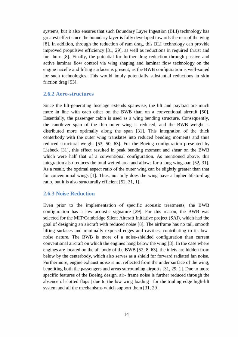
2.6.2 Aero-structures ........................................................................................ 14
2.6.3 Noise Reduction ...................................................................................... 14
2.6.4 Marketing And Manufacturing : ............................................................... 15
2.6.5 Size:......................................................................................................... 15
2.6.6 Application: ............................................................................................. 15
2.6.7 Safety : .................................................................................................... 16
2.6.8 Stability And Flight Control : ................................................................... 16
2.6.9 Other : ..................................................................................................... 16
2.7 Disadvantages of BWB : ................................................................................ 16

VI
2.7.1 Aerodynamics : ........................................................................................ 16
2.7.2 Propulsion................................................................................................ 17
2.7.3 Structures ................................................................................................. 17
2.7.4 Stability And Flight Control ..................................................................... 18
2.7.5 Marketing And Manufacturing : ............................................................... 18
2.7.6 Certification ............................................................................................. 18
2.7.7 Other ....................................................................................................... 19
2.8 PREVIOUS WORK ....................................................................................... 20
2.8.1 NASA Projects (USA) : ........................................................................... 20
2.8.2 Multidisciplinary OptimisationOf A Blended Wing Body (MOB) Project
(Europe) ........................................................................................................... 21
2.8.3 Tohoku University (Japan) : ..................................................................... 23
2.8.4 TsAGI (Russia) : ...................................................................................... 23
2.8.5 MIT/Cambridge Silent Aircraft Initiative (SAI) (USA/UK) : ................... 23
2.8.6 Universidad Politecnica de Madrid (Spain) : ............................................ 24
2.8.7 Airbus Projects (Europe) .......................................................................... 24
2.9 LIST OF BLENDED WING BODY AIRCRAFTS ........................................ 26
2.9.1 Westland Dreadnought ............................................................................. 26
2.9.2 Stout Batwing .......................................................................................... 27
2.9.3 Northrop Grumman X-47A Pegasus......................................................... 28
2.9.4 Miles M.30 .............................................................................................. 29
2.9.5 McDonnell XP-67 .................................................................................... 30
Final design ...................................................................................................... 30
Project cancellation .......................................................................................... 31
2.9.6 Lockheed Martin RQ-170 Sentinel ........................................................... 32
2.9.7 Lockheed Martin RQ-3 DarkStar ............................................................. 34
2.9.8 DassaultnEUROn ..................................................................................... 35
2.9.9 Boeing X-45 ............................................................................................ 35
X-45A .............................................................................................................. 36
X-45N .............................................................................................................. 38
2.9.10 Boeing X-48 .......................................................................................... 38
Background ...................................................................................................... 39
X-48 ................................................................................................................. 40
VII
Chapter 3 : calculation .......................................................................................... 41
3.1 Requirement ................................................................................................... 41
3.2 The weight of an airplane and its first estimate ............................................... 42
3.2.1 Estimation of value ..................................................................... 42
3.2.2 Estimation of value ..................................................................... 43
3.2.3 Calculation of ................................................................................... 44
3.3 Estimation of the critical performance parameters .......................................... 45
3.3.1 Maximum lift coefficient ......................................................................... 45
3.3.2 Wing loading W/S ................................................................................... 46
3.4 Configuration layout ...................................................................................... 52
3.4.1 Wing configuration .................................................................................. 52
3.4.2 Fuselage configuration ............................................................................. 53
3.4.3Resulting layout ........................................................................................ 55
3.4.4 Results From the drawing: ....................................................................... 57
3.4.6Center of gravity location: First estimate ................................................... 59
3.5 A better weight estimate ................................................................................. 60
3.6 Performance analysis ..................................................................................... 61
3.6.1 Thrust required and thrust available ......................................................... 62
3.6.2 Power required and power available ......................................................... 62
3.6.3 Stalling speed........................................................................................... 63
3.6.4 Rate of climb ........................................................................................... 63
3.6.5 Range ...................................................................................................... 63
3.6.6 Landing distance ...................................................................................... 64
3.6.7 Takeoff distance ...................................................................................... 65
Chapter 4 : RESULTS &DISCUSION ................................................................. 67
4.1 Results ........................................................................................................... 67
4.1.1 Results from calculation ........................................................................... 67
4.1.2 Results from CATIA ................................................................................ 68
4.1.3 Results after better weight estimation has been achieved .......................... 68
4.1.4 Seating arrangement ................................................................................ 69
4.1.5 Resulting layout ....................................................................................... 69
4.2 Discussion ...................................................................................................... 71

VIII
Chapter 5 : CONCLUSIONS & RECOMMENDATIONS .................................. 74
5.1 conclusion ...................................................................................................... 74
5.2 Recommendation ........................................................................................... 74
5.3 Future work .................................................................................................... 75
References............................................................................................................... 76
Appendices: ............................................................................................................ 91
IX
List of figures
Figure 2.1 .................................................................................................................. 4
Figure 2.2 Armstrong Whitworth A.W. 52 ............................................................ 5
Figure 2.3 Kayaba HK 1 ........................................................................................ 5
Figure 2.4 Features of BWB Aircraft Configuration............................................... 6
Figure 2.5 Boeing Joined-Wing Concept Configuration (Steinke 2001) ................. 7
Figure 2.6 .................................................................................................................. 8
Figure 2.7 Cranfield BW-98 BWB Study (up: Smith 2000, down: Howe 2001) ..... 8
Figure 2.8 Distribution of Loads in a conventional aircraft vs. a blended-wing-body
................................................................................................................................ 10
Figure2.9 Molecularization” of the BWB Design .................................................. 12
Figure 2.10 Head-on view of the XP-67. ............................................................... 31
Figure 2.11 airspace violation by the U.S.[3][4][5] ................................................... 32
Figure 2.12............................................................................................................... 34
Figure 2.13............................................................................................................... 35
Figure 2.14............................................................................................................... 36
Figure 2.15 X-45A underside with weapons bay door open .................................. 36
Figure 2.16 The newer, larger X-45C ..................................................................... 37
Figure 2.17 X-45C from the side ............................................................................ 37
Figure 2.18............................................................................................................... 39
Figure 2.19 X-48B on static display at the 2006 Edwards Airshow ........................ 40
Figure 2.20 The X-48C featuring two engines and inboard vertical stabilizers ....... 40
Figure 3. 12 empty weight fraction ...................................................................... 42
Figure 3. 11 mission profile .................................................................................. 43
Figure 3. 12 seating arrangement......................................................................... 54
Figure 3.24 front view .......................................................................................... 55
Figure 3.25 top view ............................................................................................. 56
Figure 3.26 side view ............................................................................................ 56
Figure 3. 72 CF6-80C2 ........................................................................................... 58
Figure 3.28 thrust required and thrust available at 43000 ft ................................. 62
Figure 3.29 Power required and power available at 43000 ft................................ 62
Figure 3. 23 maximum rate of climb as a function of altitude ............................... 63
Figure 4.31 seating arrangement .......................................................................... 69
Figure 4.32 front view .......................................................................................... 69
Figure 4.33 top view ............................................................................................. 70
Figure 4.34 side view ............................................................................................ 70
Figure 4.35 Power required and power available at 43000 ft ................................ 72
Figure 4.36 thrust required and thrust available at 43000 ft .................................. 72
Figure 4.37 maximum rate of climb as a function of altitude ............................... 73

X
List of tables
Table 3. 1 empty weight estimation .......................................................................... 42
Table 3. 2 fuselage parameters ................................................................................ 54
Table 3. 3 cabin length estimation ........................................................................... 55
Table 4 Results from the drawing .......................................................................... 57
Table 4. 1 results from calculations ........................................................................... 67
Table 4.2 results from CATIA ................................................................................. 68
Table 4.3 after better weight estimation results ........................................................ 68
XI
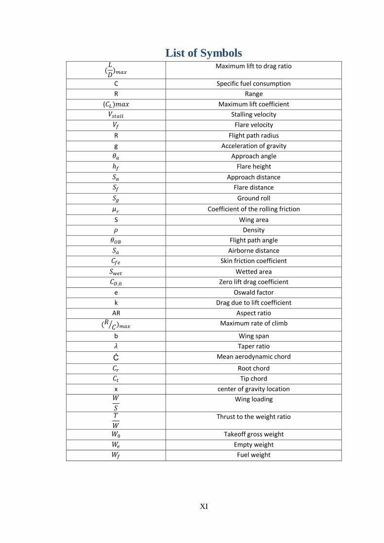
List of Symbols
Maximum lift to drag ratio
C Specific fuel consumption
R Range
( Maximum lift coefficient
Stalling velocity
Flare velocity
R Flight path radius
g Acceleration of gravity
Approach angle
Flare height
Approach distance
Flare distance
Ground roll
Coefficient of the rolling friction
S Wing area
Density
Flight path angle
Airborne distance
Skin friction coefficient
Wetted area
Zero lift drag coefficient
e Oswald factor
k Drag due to lift coefficient
AR Aspect ratio
⁄ Maximum rate of climb
b Wing span
Taper ratio
Ć Mean aerodynamic chord
Root chord
Tip chord
x center of gravity location
Wing loading
Thrust to the weight ratio
Takeoff gross weight
Empty weight
Fuel weight
1
Chapter 1 : INTRODUCTION
1.1 Overview
A blended wing body (BWB) is a fixed wing aircraft having no clear dividing line
between the wing and the main body of the craft . The form is composed of distinct
wing and body structures though the wings are smoothly blended into the body unlike
a flying wing which has no distinct fuselage .[1]
The BWB airframe merges efficient high-lift wings with a wide airfoil-shaped body,
allowing the entire aircraft to generate lift and minimize drag .
The streamlined shape between fuselage and wing intersections reduces interference
drag, reduces wetted surface area that reduces friction drag while the slow evolution
of fuselage-to-wing thickness by careful design may suggest that more volume can be
stored inside the BWB aircraft, hence, increases payload and fuel capacity[6,7]
.
The BWB has several distinct advantages over the conventional tube aircraft. Some of
these advantages are outlined below:
1-Higher fuel efficiency:
Initial testing of the BWB aircraft has indicated that it can have up to a 27% reduction
in fuel burn during flight [8]
.
2-Higher payload capacity:
Due to the blended nature of the fuselage, the fuselage is no longer distributed along
the centerline of the aircraft. As a result, the fuselage is more ―spread out,‖ allowing
for greater volume and a larger payload capacity [8]
.
3. Lower takeoff weight:
Early design concepts have determined that the BWB can have up to a 15% reduction
of take-off weight when compared to the conventional baseline [8]
.
4. Lower wetted surface area:
The compact design results in a total wetted difference of 14,300 ft2, a 33% reduction
in wetted surface area. This difference implies a substantial improvement in
aerodynamic efficiency [8]
.
5. Commonality:
One of the greatest advantages of the BWB is commonality of size and of application [9]
. Firstly, the commonality of the components of the airplane will allow it the
2
payload of the airplane to be varied at little cost. For the 250, 350, and 450 –
passenger capacity of the BWB, many components are interchangeable. This
interchangeability serves to drive down the cost of the aircraft. Secondly,
commonality of function allows the BWB to be used in many applications, both
military and civilian. The BWB can be modified to be used as a freighter, troop
transport, tanker, and stand-off bomber in addition to its function as a commercial
airliner.
1.2 PROBLEM STATEMENT
This project represents a study of the concept and performance of a blended wing
body , going through conceptual design phase
1.3 Aim and Objective
1.3.1 Aim
The primary aim is to create a design of a blended wing body , with the capacity of
500 passenger based on Airbus 380 specifications
1.3.2 Objectives
1. achieve aircraft final configuration
2. performane analysis
3. aircraft initial sizing
4. structure analysis
1.4 METHODOLOGY
Firstly, we start with collecting data from differentsources ,mainly web. Then setting
the requirements of the aircraft using historical data from available similar aircrafts as
a reference .Secondly , we get into the conceptual design phase where we obtain the
configuration of the aircraft using (CATIA V5) . followed by performance analysis
using mathematical equations.
1.5 OUTLINES
Chapter one: introduction
Chapter two: literature review
Chapter three: conceptual design
Chapter four : results and discussion
Chapter five: recommendations and future work
3
Chapter 2 : literature Review
2.1 Difference between a blended wing body and a flying
wing
Flying wing designs are defined as having two separate bodies and only a
single wing, though there may be structures protruding from the wing.
Blended wing/body aircraft have a flattened and airfoil shaped body, which
produces most of the lift to keep itself aloft, and distinct and separate wing
structures, though the wings are smoothly blended in with the body.
In recent years unconventional aircraft configurations, such as Blended-Wing-Body
(BWB) aircraft, are being investigated and researched with the aim to develop more
efficient aircraft configurations, in particular for very large transport aircraft that are
more efficient and environmentally-friendly. The BWB configuration designates an
alternative aircraft configuration where the wing and fuselage are integrated which
results essentially in a hybrid flying wing shape.
The first example of a BWB design was researched at the Lockhead Company in the
United States ofAmerica in 1917. The Junkers G. 38, the largest land plane in the
world at the time, was produced in 1929 for LuftHansa (present day; Lufthansa).
Since 1939 Northrop Aircraft Inc. (USA), currently Northrop Grumman Corporation
and the Horten brothers (Germany) investigated and developed BWB aircraft for
military purposes. At present, the major aircraft industries and several universities has
been researching the BWB concept aircraft for civil and military activities, although
the BWB design concept has not been adapted for civil transport yet. The B-2 Spirit,
(produced by the Northrop Corporation) has been used in military service since the
late 1980s. The BWB design seems to show greater potential for very large passenger
transport aircraft. A NASA BWB research team found an 800 passenger BWB
concept consumed 27 percent less fuel per passenger per flight operation than an
equivalent conventional configuration (Leiebeck 2005).
A BWB configuration has superior in flight performance due to a higher Lift-to-Drag
(L/D) ratio, and could improve upon existing conventional aircraft, in the areas of
noise emission, fuel consumption and Direct Operation Cost (DOC) on service.
However, a BWB configuration needs to employ a new structural system for
passenger safety procedures, such as passenger ingress/egress.
4
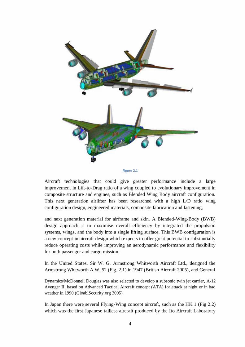
Figure 2.1
Aircraft technologies that could give greater performance include a large
improvement in Lift-to-Drag ratio of a wing coupled to evolutionary improvement in
composite structure and engines, such as Blended Wing Body aircraft configuration.
This next generation airlifter has been researched with a high L/D ratio wing
configuration design, engineered materials, composite fabrication and fastening,
and next generation material for airframe and skin. A Blended-Wing-Body (BWB)
design approach is to maximise overall efficiency by integrated the propulsion
systems, wings, and the body into a single lifting surface. This BWB configuration is
a new concept in aircraft design which expects to offer great potential to substantially
reduce operating costs while improving an aerodynamic performance and flexibility
for both passenger and cargo mission.
In the United States, Sir W. G. Armstrong Whitworth Aircraft Ltd., designed the
Armstrong Whitworth A.W. 52 (Fig. 2.1) in 1947 (British Aircraft 2005), and General
Dynamics/McDonnell Douglas was also selected to develop a subsonic twin jet carrier, A-12
Avenger II, based on Advanced Tactical Aircraft concept (ATA) for attack at night or in bad
weather in 1990 (GloablSecurity.org 2005).
In Japan there were several Flying-Wing concept aircraft, such as the HK 1 (Fig 2.2)
which was the first Japanese tailless aircraft produced by the Ito Aircraft Laboratory
5
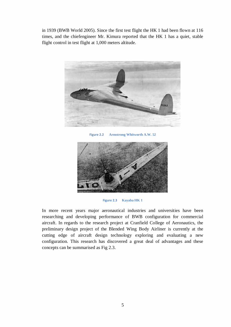
in 1939 (BWB World 2005). Since the first test flight the HK 1 had been flown at 116
times, and the chiefengineer Mr. Kimura reported that the HK 1 has a quiet, stable
flight control in test flight at 1,000 meters altitude.
Figure 2.2 Armstrong Whitworth A.W. 52
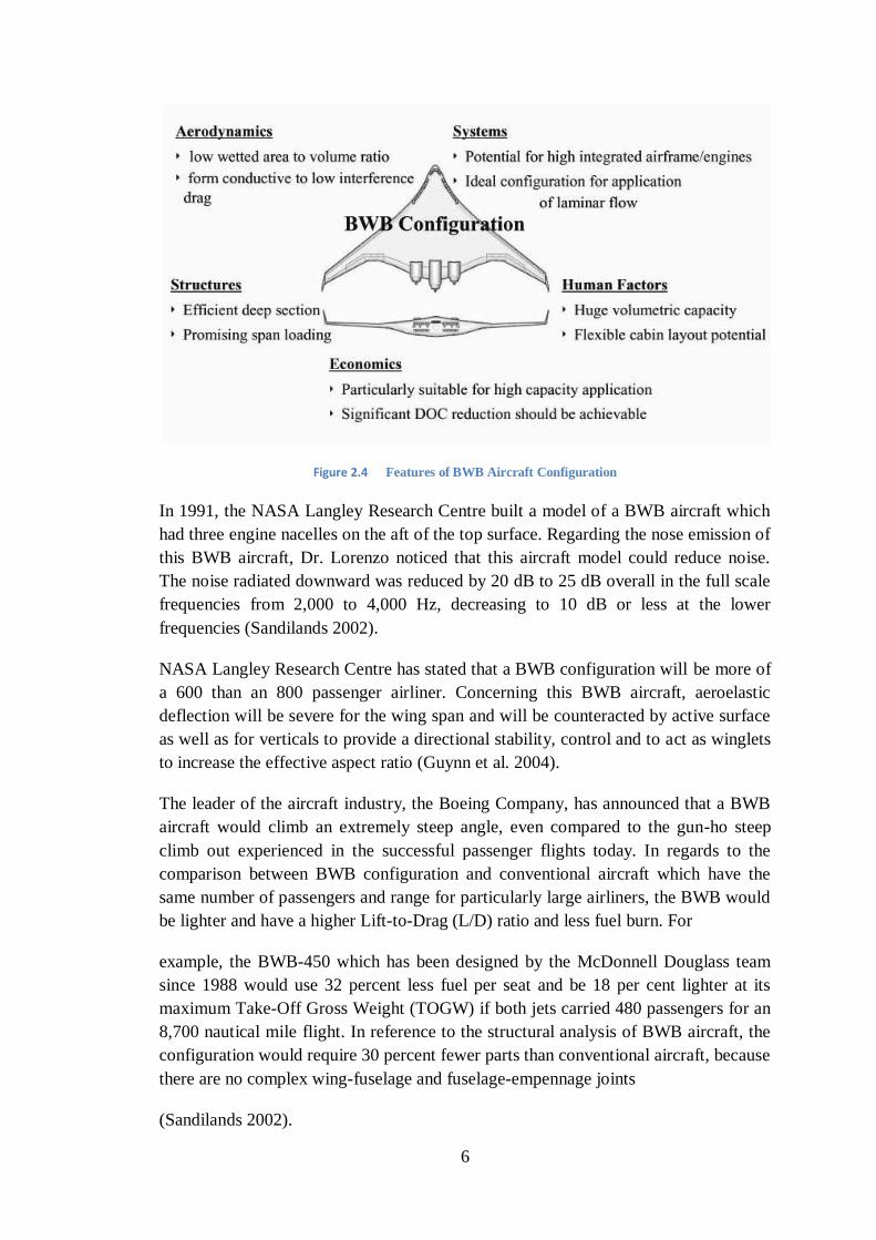
Figure 2.3 Kayaba HK 1
In more recent years major aeronautical industries and universities have been
researching and developing performance of BWB configuration for commercial
aircraft. In regards to the research project at Cranfield College of Aeronautics, the
preliminary design project of the Blended Wing Body Airliner is currently at the
cutting edge of aircraft design technology exploring and evaluating a new
configuration. This research has discovered a great deal of advantages and these
concepts can be summarised as Fig 2.3.
6
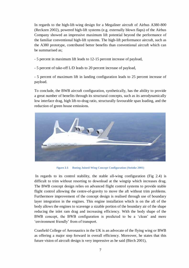
Figure 2.4 Features of BWB Aircraft Configuration
In 1991, the NASA Langley Research Centre built a model of a BWB aircraft which
had three engine nacelles on the aft of the top surface. Regarding the nose emission of
this BWB aircraft, Dr. Lorenzo noticed that this aircraft model could reduce noise.
The noise radiated downward was reduced by 20 dB to 25 dB overall in the full scale
frequencies from 2,000 to 4,000 Hz, decreasing to 10 dB or less at the lower
frequencies (Sandilands 2002).
NASA Langley Research Centre has stated that a BWB configuration will be more of
a 600 than an 800 passenger airliner. Concerning this BWB aircraft, aeroelastic
deflection will be severe for the wing span and will be counteracted by active surface
as well as for verticals to provide a directional stability, control and to act as winglets
to increase the effective aspect ratio (Guynn et al. 2004).
The leader of the aircraft industry, the Boeing Company, has announced that a BWB
aircraft would climb an extremely steep angle, even compared to the gun-ho steep
climb out experienced in the successful passenger flights today. In regards to the
comparison between BWB configuration and conventional aircraft which have the
same number of passengers and range for particularly large airliners, the BWB would
be lighter and have a higher Lift-to-Drag (L/D) ratio and less fuel burn. For
example, the BWB-450 which has been designed by the McDonnell Douglass team
since 1988 would use 32 percent less fuel per seat and be 18 per cent lighter at its
maximum Take-Off Gross Weight (TOGW) if both jets carried 480 passengers for an
8,700 nautical mile flight. In reference to the structural analysis of BWB aircraft, the
configuration would require 30 percent fewer parts than conventional aircraft, because
there are no complex wing-fuselage and fuselage-empennage joints
(Sandilands 2002).
7
In regards to the high-lift-wing design for a Megaliner aircraft of Airbus A380-800
(Reckzen 2002), powered high-lift systems (e.g. externally blown flaps) of the Airbus
Company showed an impressive maximum lift potential beyond the performance of
the familiar conventional high-lift systems. The high-lift performance aircraft, such as
the A380 prototype, contributed better benefits than conventional aircraft which can
be summarised as;
- 5 percent in maximum lift leads to 12-15 percent increase of payload,
- 5 percent of take-off L/D leads to 20 percent increase of payload,
- 5 percent of maximum lift in landing configuration leads to 25 percent increase of
payload.
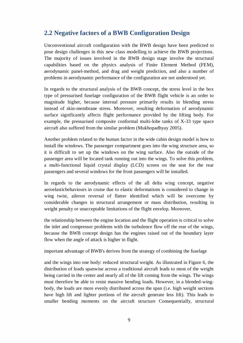
To conclude, the BWB aircraft configuration, synthetically, has the ability to provide
a great number of benefits through its structural concepts, such as its aerodynamically
low interface drag, high lift-to-drag ratio, structurally favourable span loading, and the
reduction of green house emissions.
Figure 2.5 Boeing Joined-Wing Concept Configuration (Steinke 2001)
In regards to its control stability, the stable all-wing configuration (Fig 2.4) is
difficult to trim without resorting to download at the wingtip which increases drag.
The BWB concept design relies on advanced flight control systems to provide stable
flight control allowing the centre-of-gravity to move the aft without trim problems.
Furthermore improvement of the concept design is realised through use of boundary
layer integration in the engines. This engine installation which is on the aft of the
body allows the engines to scavenge a sizable portion of the boundary air of the shape
reducing the inlet ram drag and increasing efficiency. With the body shape of the
BWB concept, the BWB configuration is predicted to be a ‗clean‘ and more
‗environment friendly‘ from of transport.
Cranfield College of Aeronautics in the UK is an advocate of the flying wing or BWB
as offering a major step forward in overall efficiency. Moreover, he states that this
future vision of aircraft design is very impressive as he said (Birch 2001),

8
By using nuclear fuel to power what is essentially a closed-cycle stream engine
driving propellers, there would be no atmospheric emissions to cause concern.
Therefore, there would probably be some degradation in airliner cruising speed -
about Mach 0.7 would be typical - but the efficiency of the aircraft, without the need
to carry an enormously heavy fuel load ontake-off, would be very high. Cranfield
College said that while the researchers fully understand that public and political
unease about nuclear-powered aircraft would be considerable, and nevertheless feel
that the use of nuclear power should be considered as a serious alternative aviation
fuel. Considerable interest has been raised by the fact that the BWB layout may
confer substantial overall advantages when applied to a transport aircraft in the ultra-
high-capacity category. The most famous BWB design of the Cranfield College of
Aeronautics is the College of Aeronautics BW-98 projectillustrated in Fig. 2.6 and Fig
2.7 (Howe 2001 & Smith 2000). This Cranfield baseline BWB configuration is
similar to the Boeing concept in configuration, and currently represents the only UK
National project of its scale.
Figure 2.6
Figure 2.7 Cranfield BW-98 BWB Study (up: Smith 2000, down: Howe 2001)
9
2.2 Negative factors of a BWB Configuration Design
Unconventional aircraft configuration with the BWB design have been predicted to
pose design challenges in this new class modelling to achieve the BWB projections.
The majority of issues involved in the BWB design stage involve the structural
capabilities based on the physics analysis of Finite Element Method (FEM),
aerodynamic panel-method, and drag and weight prediction, and also a number of
problems in aerodynamic performance of the configuration are not understood yet.
In regards to the structural analysis of the BWB concept, the stress level in the box
type of pressurised fuselage configuration of the BWB flight vehicle is an order to
magnitude higher, because internal pressure primarily results in blending stress
instead of skin-membrane stress. Moreover, resulting deformation of aerodynamic
surface significantly affects flight performance provided by the lifting body. For
example, the pressurised composite conformal multi-lobe tanks of X-33 type space
aircraft also suffered from the similar problem (Mukhopadhyay 2005).
Another problem related to the human factor in the wide cabin design model is how to
install the windows. The passenger compartment goes into the wing structure area, so
it is difficult to set up the windows on the wing surface. Also the outside of the
passenger area will be located tank running out into the wings. To solve this problem,
a multi-functional liquid crystal display (LCD) screen on the seat for the rear
passengers and several windows for the front passengers will be installed.
In regards to the aerodynamic effects of the all delta wing concept, negative
aeroelasticbehaviours in cruise due to elastic deformations is considered to change in
wing twist, aileron reversal of flatter identified which will be overcome by
considerable changes in structural arrangement or mass distribution, resulting in
weight penalty or unacceptable limitations of the flight envelop. Moreover,
the relationship between the engine location and the flight operation is critical to solve
the inlet and compressor problems with the turbulence flow off the rear of the wings,
because the BWB concept design has the engines raised out of the boundary layer
flow when the angle of attack is higher in flight.
important advantage of BWB's derives from the strategy of combining the fuselage
and the wings into one body: reduced structural weight. As illustrated in Figure 6, the
distribution of loads spanwise across a traditional aircraft leads to most of the weight
being carried in the center and nearly all of the lift coming from the wings. The wings
must therefore be able to resist massive bending loads. However, in a blended-wing-
body, the loads are more evenly distributed across the span (i.e. high weight sections
have high lift and lighter portions of the aircraft generate less lift). This leads to
smaller bending moments on the aircraft structure Consequentially, structural
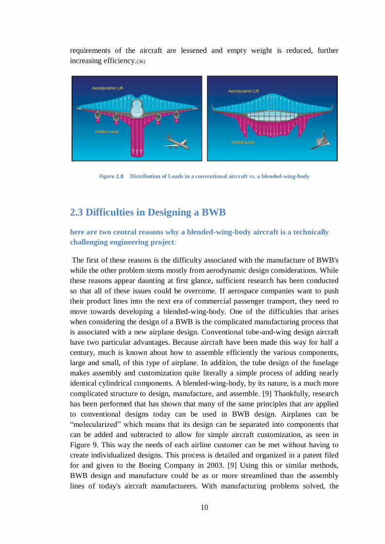
10
requirements of the aircraft are lessened and empty weight is reduced, further
increasing efficiency.(36)
Figure 2.8 Distribution of Loads in a conventional aircraft vs. a blended-wing-body
2.3 Difficulties in Designing a BWB
here are two central reasons why a blended-wing-body aircraft is a technically
challenging engineering project:
The first of these reasons is the difficulty associated with the manufacture of BWB's
while the other problem stems mostly from aerodynamic design considerations. While
these reasons appear daunting at first glance, sufficient research has been conducted
so that all of these issues could be overcome. If aerospace companies want to push
their product lines into the next era of commercial passenger transport, they need to
move towards developing a blended-wing-body. One of the difficulties that arises
when considering the design of a BWB is the complicated manufacturing process that
is associated with a new airplane design. Conventional tube-and-wing design aircraft
have two particular advantages. Because aircraft have been made this way for half a
century, much is known about how to assemble efficiently the various components,
large and small, of this type of airplane. In addition, the tube design of the fuselage
makes assembly and customization quite literally a simple process of adding nearly
identical cylindrical components. A blended-wing-body, by its nature, is a much more
complicated structure to design, manufacture, and assemble. [9] Thankfully, research
has been performed that has shown that many of the same principles that are applied
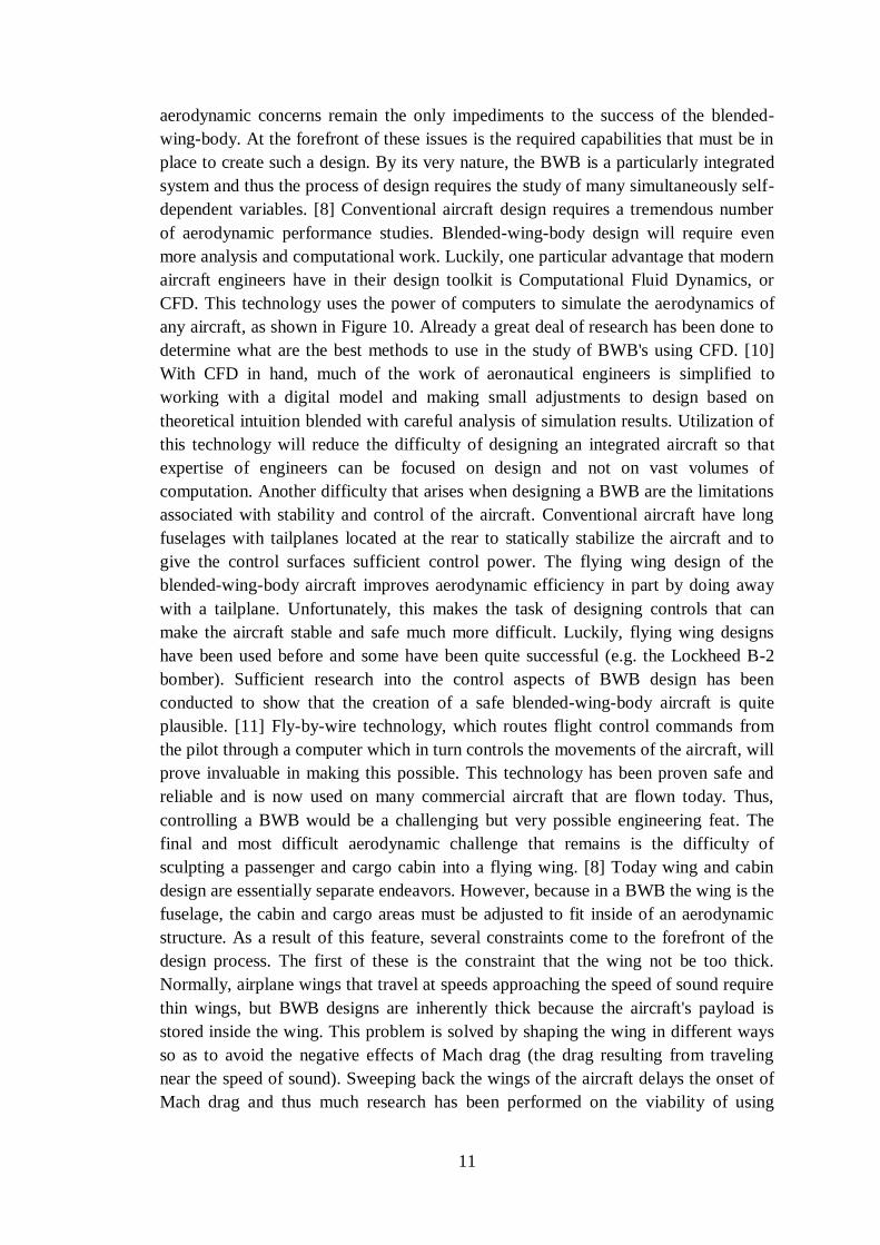
to conventional designs today can be used in BWB design. Airplanes can be
―molecularized‖ which means that its design can be separated into components that
can be added and subtracted to allow for simple aircraft customization, as seen in
Figure 9. This way the needs of each airline customer can be met without having to
create individualized designs. This process is detailed and organized in a patent filed
for and given to the Boeing Company in 2003. [9] Using this or similar methods,
BWB design and manufacture could be as or more streamlined than the assembly
lines of today's aircraft manufacturers. With manufacturing problems solved, the
11
aerodynamic concerns remain the only impediments to the success of the blended-
wing-body. At the forefront of these issues is the required capabilities that must be in
place to create such a design. By its very nature, the BWB is a particularly integrated
system and thus the process of design requires the study of many simultaneously self-
dependent variables. [8] Conventional aircraft design requires a tremendous number
of aerodynamic performance studies. Blended-wing-body design will require even
more analysis and computational work. Luckily, one particular advantage that modern
aircraft engineers have in their design toolkit is Computational Fluid Dynamics, or
CFD. This technology uses the power of computers to simulate the aerodynamics of
any aircraft, as shown in Figure 10. Already a great deal of research has been done to
determine what are the best methods to use in the study of BWB's using CFD. [10]
With CFD in hand, much of the work of aeronautical engineers is simplified to
working with a digital model and making small adjustments to design based on
theoretical intuition blended with careful analysis of simulation results. Utilization of
this technology will reduce the difficulty of designing an integrated aircraft so that
expertise of engineers can be focused on design and not on vast volumes of
computation. Another difficulty that arises when designing a BWB are the limitations
associated with stability and control of the aircraft. Conventional aircraft have long
fuselages with tailplanes located at the rear to statically stabilize the aircraft and to
give the control surfaces sufficient control power. The flying wing design of the
blended-wing-body aircraft improves aerodynamic efficiency in part by doing away
with a tailplane. Unfortunately, this makes the task of designing controls that can
make the aircraft stable and safe much more difficult. Luckily, flying wing designs
have been used before and some have been quite successful (e.g. the Lockheed B-2
bomber). Sufficient research into the control aspects of BWB design has been
conducted to show that the creation of a safe blended-wing-body aircraft is quite
plausible. [11] Fly-by-wire technology, which routes flight control commands from
the pilot through a computer which in turn controls the movements of the aircraft, will
prove invaluable in making this possible. This technology has been proven safe and
reliable and is now used on many commercial aircraft that are flown today. Thus,
controlling a BWB would be a challenging but very possible engineering feat. The
final and most difficult aerodynamic challenge that remains is the difficulty of
sculpting a passenger and cargo cabin into a flying wing. [8] Today wing and cabin
design are essentially separate endeavors. However, because in a BWB the wing is the
fuselage, the cabin and cargo areas must be adjusted to fit inside of an aerodynamic
structure. As a result of this feature, several constraints come to the forefront of the
design process. The first of these is the constraint that the wing not be too thick.
Normally, airplane wings that travel at speeds approaching the speed of sound require
thin wings, but BWB designs are inherently thick because the aircraft's payload is
stored inside the wing. This problem is solved by shaping the wing in different ways
so as to avoid the negative effects of Mach drag (the drag resulting from traveling
near the speed of sound). Sweeping back the wings of the aircraft delays the onset of
Mach drag and thus much research has been performed on the viability of using
12
sweep to combat effectively Mach drag effects. [12] This technology could effectively
solve the thickness problem while still maintaining the cabin size requirements.
The second limitation is more of an imposed constraint, but it is equally if not more
important than all the others. Since the BWB will carry passengers in a non
conventional way, its design must be able to meet cabin egress requirements set by
aviation authorities. Many BWB cabin designs put passengers at further
distances from emergency exits than conventional aircraft, so there is the worry that
people would be unable to escape a crashed aircraft within the ninetysecond-
time limit. However, with the use of simulation and with innovative design and
emergency exit placement, it can be shown that BWB egress performance is
comparable to that of a conventional aircraft. [6] Using tools like this, the design of
the BWB cabin will be a challenge not without its complications and difficulties but
one that is entirely within the reach of today's engineers. (37)
Figure2.9 Molecularization” of the BWB Design
2.4 Environmental benefits
increasing environmental concerns are a global issue faced by many industries, and
the aerospace industry is no exception. While aviation is responsible for about 4.9%
of global greenhouse emissions [27], growth in the industry is only expected to
increase. For instance, between 2009 and 2029, Boeing predicts an annual growth of
5.3% in total world traffic flow [68]. Aviation is a culprit for more than just the
13
expected growth [77]: _first, planes are delivering nitrogen oxides at higher altitudes
and therefore, very efficiently contributing to the problem. Combined with the effects
of cirrus clouds from contrails, the direct effect of carbon dioxide is tripled [65, 77]!
Secondly, since not everyone is flying or can even afford to y, an inequality in
responsibility exists. Finally, immediate alternatives to fossil fuels are not quite
available: hydrogen could add to cirrus clouds; biofuels are promising but unlikely to
replace standard jet fuel for several decades, leaving fuel efficiency improvement as
one of the key options [77]. Improving fuel efficiency is not only important from an
environmental perspective, but also from an economics perspective: with increasing
fuel prices | up by almost 13% from about a year ago [22] | airlines will need more
fuel efficient options given the predicted growth in the air traffic. The work in this
thesis brings two ideas together | the unconventional blended-wing-body aircraft
configuration and high-fidelity aerodynamic shape optimization | in the hopes of
effectively contributing to the development of future solutions which are more fuel-
efficient and environmentally-friendly.
2.6 Advantages of BWB
2.6.1 Aerodynamics
A key aspect of the BWB is its lift-generating centerbody | a gain over the cylindrical
fuselage of a conventional aircraft | which improves the aerodynamic performance by
reducing the wing loading [46, 48, 63]. In addition, the decrease in wetted area, via a
smaller outer wing, relative to a similar sized conventional aircraft translates into an
increased lift-to-drag ratio, since it is proportional to the wetted aspect ratio; this
aspect ratio increases due to its inverse proportionality to the wetted area [29, 31, 59,
53]. The lower wetted area to volume ratio for larger BWBs in comparison to
conventional aircraft also adds to the benefit. Interference drag is reduced due to the
elimination and reduction of junctions which exist between the wings and fuselage on
conventional aircraft [55, 53, 54, 63, 50, 46], resulting in a more streamlined shape for
the BWB. The absence of the horizontal tail also implies a reduction in the
corresponding friction and induced drag penalties, further increasing the lift-to-drag
ratio [1]. The naturally area-ruled shape of the BWB means higher cruise Mach
numbers are more easily attainable without changes in the basic configuration
geometry [60, 29]. In fact, the BWB's cross-sectional area variation resembles that of
the body of minimum wave drag due to volume, the Sears-Haack body, translating
into wave drag reductions at transonic speeds [60, 29].
With engines partially embedded in the BWB aft-body, an advantage unique to this
configuration arises: the potential for boundary layer ingestion from a portion of the
centerbody upstream of the engine inlet. Not only does this aft-location of the engines
effectively balance the airframe and offset the weight of the payload, furnishings, and
14
systems, but it also ensures that such Boundary Layer Ingestion (BLI) technology has
greatest effect since the boundary layer is fully developed towards the rear of the wing
[8]. In addition, through the reduction of ram drag, this BLI technology can provide
improved propulsive efficiency [31, 29], as well as reductions in required thrust and
fuel burn [8]. Finally, the potential for further drag reduction through passive and
active laminar flow control via wing shaping and laminar flow technology on the
engine nacelle and lifting surfaces is present, as the BWB configuration is well-suited
for such technologies. This would imply potentially substantial reductions in skin
friction drag [53].
2.6.2 Aero-structures
Since the lift-generating fuselage extends spanwise, the lift and payload are much
more in line with each other on the BWB than on a conventional aircraft [50].
Essentially, the passenger cabin is used as a wing bending structure. Consequently,
the cantilever span of the thin outer wing is reduced, and the BWB weight is
distributed more optimally along the span [31]. This integration of the thick
centerbody with the outer wing translates into reduced bending moments and thus
reduced structural weight [53, 50, 63]. For the Boeing configuration presented by
Liebeck [31], this effect resulted in peak bending moment and shear on the BWB
which were half that of a conventional configuration. As mentioned above, this
integration also reduces the total wetted area and allows for a long wingspan [52, 31].
As a result, the optimal aspect ratio of the outer wing can be slightly greater than that
for conventional wings [1]. Thus, not only does the wing have a higher lift-to-drag
ratio, but it is also structurally efficient [52, 31, 1].
2.6.3 Noise Reduction
Even prior to the implementation of specific acoustic treatments, the BWB
configuration has a low acoustic signature [29]. For this reason, the BWB was
selected for the MIT/Cambridge Silent Aircraft Initiative project (SAI), which had the
goal of designing an aircraft with reduced noise [8]. The airframe has no tail, smooth
lifting surfaces and minimally exposed edges and cavities, contributing to its low-
noise nature. The BWB is more of a noise-shielded configuration than current
conventional aircraft on which the engines hang below the wing [8]. In the case where
engines are located on the aft-body of the BWB [52, 8, 63], the inlets are hidden from
below by the centerbody, which also serves as a shield for forward radiated fan noise.
Furthermore, engine exhaust noise is not reflected from the under surface of the wing,
benefiting both the passengers and areas surrounding airports [31, 29, 1]. Due to more
specific features of the Boeing design, air- frame noise is further reduced through the
absence of slotted flaps | due to the low wing loading | for the trailing edge high-lift
system and all the mechanisms which support them [31, 29].
15
2.6.4 Marketing And Manufacturing :
In terms of passenger comfort levels in the BWB, this configuration's vertical cabin
walls might present a more spacious environment than the current curved walls of
conventional aircraft [29]. Liebeck [29] compares this design and spacious
environment to that in a railroad car. Direct operating costs per seat/mile for the BWB
are also estimated to be 15% lower than current conventional designs [1]. Due to the
simplicity of the BWB configuration, such as the elimination of fillets and joints of
highly loaded structures at 90 degrees to each other, a significant reduction in the
number of parts | on the order of 30% | has also been estimated [30, 29]. A two-fold
sense of commonality is another design constraint considered by the Boeing team [30]
as a result of the BWB's unique capability to be stretched and re-configured
2.6.5 Size:
commonality between different sizes of the BWB in order to create a family of
aircraft.
2.6.6 Application:
commonality between military and commercial applications.
For the former, the aircraft can be stretched laterally, enabling the addition of span
and wing area while increasing the payload. This advantageous capability is not
afforded by conventional aircraft which are longitudinally stretched to increase
payload [29]. Specifically, commonality between 250-passenger and 450-passenger
versions has been studied, with the outer wings and nose/cockpit section being
common between members of this aircraft family. The necessary fuel volume in the
outer wing is adequate for all members of the family, and the modular centerbodies
are aerodynamically smooth and balanced. Furthermore, such commonality offers
23% reduction in non-recurring costs and 12% reduction in recurring costs compared
to the stand-alone cases for the 250- and 450-passenger versions. Such cost reduction
would likely increase with the inclusion of additional sizes of BWB, such as a 350-
passenger version [30, 29]. For the Boeing cabin design, this commonality between
families also extends to the interior with the growth concept in place, since the cabin
cross-sections would be the same between the different aircraft. For airlines, these
benefits mean fleet mix requirements can be easily accommodated, manufacturing
learning curve penalties are reduced, and maintenance and life-cycle cost savings
increased. All of this is achieved through a natural variation of the span and wing area
with weight in order to maintain aerodynamic efficiency | an advantage that is
possible with this configuration [29]. With respect to the commonality of applications,
aircraft applications have also been demonstrated for a variety of military applications
including freighter, stand-o_ bomber, troop transport, and tanker; details of military
BWBs can be found in [30].
16
In addition to these possibilities for commonality, the BWB's previously-noted,
naturally area-ruled shape could also reduce manufacturing costs associated with
conventional aircraft, which must be manufactured with a varying cross-section,
`coke-bottle' fuselage in order to achieve area-ruling [60]. This highlights the potential
for the BWB to perform at higher speeds at lower costs. Further cost savings are
implied since the interior configuration of a BWB is no longer a challenge. In
contrast, a conventional aircraft with a varying cross-section will also have varying
seats abreast along the area-ruled portion of the fuselage [30]. In the case of the SAI
design, the increased aerodynamic and structural efficiency are features which could
help offset potentially higher operating costs of a silent engine design [8].
2.6.7 Safety :
The rear location of engines on the BWB places shrapnel from a failed engine behind
the pressure vessel, most flight controls, systems and fuel tanks. The pressure vessel,
due to its unique structural requirements and the necessity to handle both wing
bending and pressure loads, must be robust and will likely have substantial
crashworthiness [31, 29]. In addition, in certain configurations, the passenger
compartment and fuel are separated by broad cargo bays [31].
2.6.8 Stability And Flight Control :
Liebeck noted that a complicated high-lift system is not required for the Boeing design due to
the low effective wing loading of the configuration. Redundance and reconfigurability of the
trailing edge flight controls for this design are also discussed [31]. Furthermore, a reduction in
the secondary power required by the control system is also demonstrated [30].
2.6.9 Other :
Other potential benefits include increased loading and o_-loading times due to the
shorter fuselage length on a medium-sized (200-passenger) BWB [48], as well as a
shorter take-off field length without the need for complicated high-lift devices [47].
2.7 Disadvantages of BWB :
2.7.1 Aerodynamics :
For instance, atypical transonic airfoils of high thickness to chord ratio | up to about
17% in the Boeing designs [29] | are required inboard to accommodate passengers,
cargo and landing gear. Furthermore, adding to the difficulty of the design of such
airfoils, this thickness to chord ratio must be maintained along a considerable portion
of the chord length [52, 29]. This poses problems for maintaining low drag [76]. In
addition, due to deck angle limitations, the centerbodyairfoils must be designed to
generate the necessary lift at angles of attack which are consistent with deck angle
requirements [52, 59, 29]. Supersonic flow on the lower surface of the BWB is
17
another challenge, which is not typical on the conventional configuration [52].
Smooth transition from the thicker center- body airfoils to the thinner outer wing
airfoils can also be cause for difficulty, particularly for medium-sized 200 passenger
BWBs since the transition could be more abrupt for such smaller aircraft [48].
Additionally, the benefit of the reduced wetted area may not hold in all cases; for
instance, Pambagjo et al. pointed out that achieving the wetted area reduction could
be more challenging in the case of a medium-sized BWB aircraft, which was, in fact,
found to have a higher wetted area when compared to conventional aircraft [48].
Finally, while BLI technologies and embedded engines sound promising, challenges
with the integration of the engine and airframe and incorporation of these
technologies include the design of low-loss inlet ducts, the control of the inlet flow
distortion, and the turbo-machinery integration [8]. In the aerodynamic design of the
aircraft, manufacturing constraints must also be factored in: complex, three-
dimensional shapes which might be expensive and difficult to manufacture must be
avoided with smooth, simply curved surfaces being favoured [59, 29].
2.7.2 Propulsion
Additional difficulties of aft-mounted engines and propulsion and airframe integration
exist, since engine integration affects several disciplines more directly than is the case
for conventional aircraft [76, 31]. Indeed, interaction between the wing, control
surfaces, and engines increase the complexity of the design of this region [59].
Liebeck et al. Explore solutions for this issue in [31].
2.7.3 Structures
A key challenge is posed by the BWB's non-cylindrical pressure vessel, which must
be light-weight yet capable of handling both the wing bending loads as well as the
cabin pressure loads. As shown in [41], a box-type BWB fuselage could have stress
about an order of magnitude higher than the stress in a cylindrical pressurized
fuselage. The increased stresses in such a pressure vessel naturally lead to increased
structural weight [31, 74]. Mukhopadhyay et al. [42, 41] and Velicki et al. [73]
discuss detailed concepts considered specifically for the BWB configuration.
Mukhopadhyay et al. study different concepts in order to determine the optimal
fuselage configuration for the BWB including multibubble fuselage models: two,
three, four, and five bubble models [42, 41]. Through this study an overall weight
reduction of 20-30% compared to using all at surfaces could be achieved through the
proper integration of partially cylindrical surfaces in pressurized fuselage design. In
[41], a Y-braced 480-passenger aircraft fuselage which develops into a modified
fuselage in which the Y-brace is replaced by a vaulted shell is also discussed. Velicki
et al. present the technology likely incorporated in this Y-braced configuration:
Pultruded Rod Stitched Efficient Unitized Structure (PRSEUS) | a technology
specifically designed, tailored and optimized for the BWB airframe [73]. Features of
this technology include continuous load paths in two directions, accommodating the
18
unique spanwise and streamwise load paths of the BWB fuselage, thin skins which
operate in the post-buckled design regime, and stitched interfaces to arrest damage
propagation. The pressurized shell elements (skin panels and frames) have also been
found to be 28% lighter for the PRSEUS concept than comparable sandwich panel
designs.
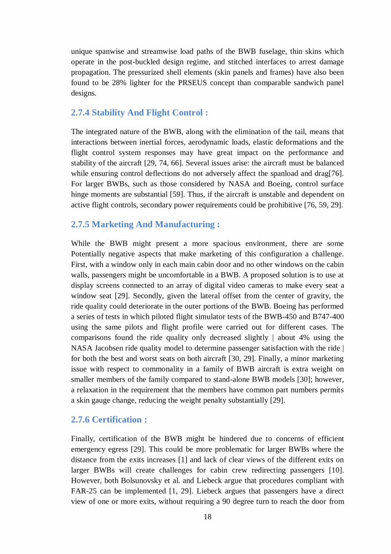
2.7.4 Stability And Flight Control :
The integrated nature of the BWB, along with the elimination of the tail, means that
interactions between inertial forces, aerodynamic loads, elastic deformations and the
flight control system responses may have great impact on the performance and
stability of the aircraft [29, 74, 66]. Several issues arise: the aircraft must be balanced
while ensuring control deflections do not adversely affect the spanload and drag[76].
For larger BWBs, such as those considered by NASA and Boeing, control surface
hinge moments are substantial [59]. Thus, if the aircraft is unstable and dependent on
active flight controls, secondary power requirements could be prohibitive [76, 59, 29].
2.7.5 Marketing And Manufacturing :
While the BWB might present a more spacious environment, there are some
Potentially negative aspects that make marketing of this configuration a challenge.
First, with a window only in each main cabin door and no other windows on the cabin
walls, passengers might be uncomfortable in a BWB. A proposed solution is to use at
display screens connected to an array of digital video cameras to make every seat a
window seat [29]. Secondly, given the lateral offset from the center of gravity, the
ride quality could deteriorate in the outer portions of the BWB. Boeing has performed
a series of tests in which piloted flight simulator tests of the BWB-450 and B747-400
using the same pilots and flight profile were carried out for different cases. The
comparisons found the ride quality only decreased slightly | about 4% using the
NASA Jacobsen ride quality model to determine passenger satisfaction with the ride |
for both the best and worst seats on both aircraft [30, 29]. Finally, a minor marketing
issue with respect to commonality in a family of BWB aircraft is extra weight on
smaller members of the family compared to stand-alone BWB models [30]; however,
a relaxation in the requirement that the members have common part numbers permits
a skin gauge change, reducing the weight penalty substantially [29].
2.7.6 Certification :
Finally, certification of the BWB might be hindered due to concerns of efficient
emergency egress [29]. This could be more problematic for larger BWBs where the
distance from the exits increases [1] and lack of clear views of the different exits on
larger BWBs will create challenges for cabin crew redirecting passengers [10].
However, both Bolsunovsky et al. and Liebeck argue that procedures compliant with
FAR-25 can be implemented [1, 29]. Liebeck argues that passengers have a direct
view of one or more exits, without requiring a 90 degree turn to reach the door from
19
the aisle. This is accommodated by the fact that the Boeing design has a main cabin
door directly in front of each aisle and an exit through the aft pressure bulkhead at the
rear of each aisle. In addition, four spanwise aisles intersect with these longitudinal
aisles [29]. Both computer simulations and full- scale evacuation trials carried out by
Galea et al. for a 1000+ passenger BWB aircraft showed that improved visual access
and awareness of the aircraft layout are key to efficient egress in emergency
situations. Fire simulations found 12 fatalities deemed inevitable but independent of
the cabin architecture [10].
2.7.7 Other :
Other issues include landing approach speed and attitude and buffet and stall
characteristics [59, 29]. In addition, other studies of BWB have shown engines
arranged on pylons under the wing [1], which would eliminate a lot of the benefits
outlined with respect to noise and drag reduction previously discussed.
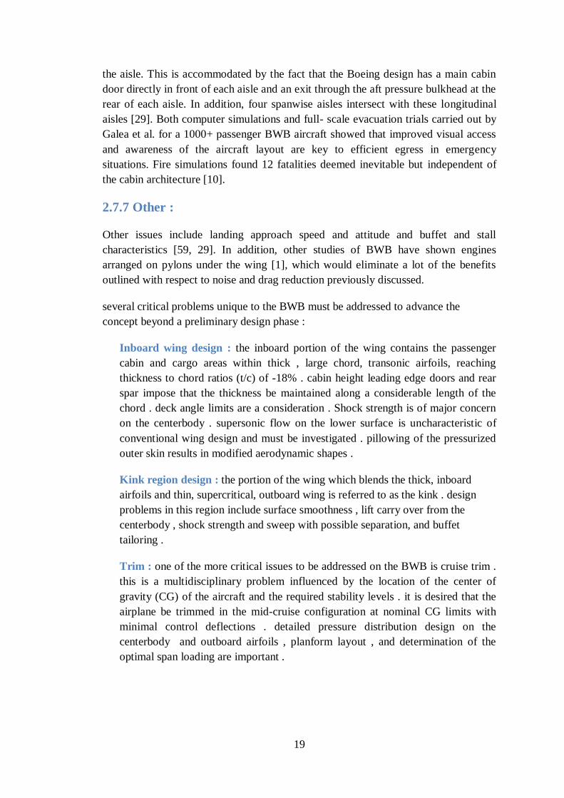
several critical problems unique to the BWB must be addressed to advance the
concept beyond a preliminary design phase :
Inboard wing design : the inboard portion of the wing contains the passenger
cabin and cargo areas within thick , large chord, transonic airfoils, reaching
thickness to chord ratios (t/c) of -18% . cabin height leading edge doors and rear
spar impose that the thickness be maintained along a considerable length of the
chord . deck angle limits are a consideration . Shock strength is of major concern
on the centerbody . supersonic flow on the lower surface is uncharacteristic of
conventional wing design and must be investigated . pillowing of the pressurized
outer skin results in modified aerodynamic shapes .
Kink region design : the portion of the wing which blends the thick, inboard
airfoils and thin, supercritical, outboard wing is referred to as the kink . design
problems in this region include surface smoothness , lift carry over from the
centerbody , shock strength and sweep with possible separation, and buffet
tailoring .
Trim : one of the more critical issues to be addressed on the BWB is cruise trim .
this is a multidisciplinary problem influenced by the location of the center of
gravity (CG) of the aircraft and the required stability levels . it is desired that the
airplane be trimmed in the mid-cruise configuration at nominal CG limits with
minimal control deflections . detailed pressure distribution design on the
centerbody and outboard airfoils , planform layout , and determination of the
optimal span loading are important .
20
2.8 PREVIOUS WORK
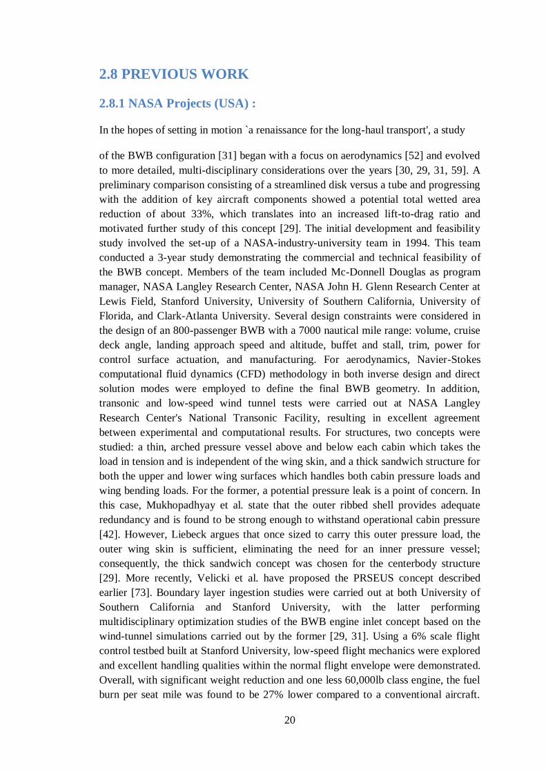
2.8.1 NASA Projects (USA) :
In the hopes of setting in motion `a renaissance for the long-haul transport', a study
of the BWB configuration [31] began with a focus on aerodynamics [52] and evolved
to more detailed, multi-disciplinary considerations over the years [30, 29, 31, 59]. A
preliminary comparison consisting of a streamlined disk versus a tube and progressing
with the addition of key aircraft components showed a potential total wetted area
reduction of about 33%, which translates into an increased lift-to-drag ratio and
motivated further study of this concept [29]. The initial development and feasibility
study involved the set-up of a NASA-industry-university team in 1994. This team
conducted a 3-year study demonstrating the commercial and technical feasibility of
the BWB concept. Members of the team included Mc-Donnell Douglas as program
manager, NASA Langley Research Center, NASA John H. Glenn Research Center at
Lewis Field, Stanford University, University of Southern California, University of
Florida, and Clark-Atlanta University. Several design constraints were considered in
the design of an 800-passenger BWB with a 7000 nautical mile range: volume, cruise
deck angle, landing approach speed and altitude, buffet and stall, trim, power for
control surface actuation, and manufacturing. For aerodynamics, Navier-Stokes
computational fluid dynamics (CFD) methodology in both inverse design and direct
solution modes were employed to define the final BWB geometry. In addition,
transonic and low-speed wind tunnel tests were carried out at NASA Langley
Research Center's National Transonic Facility, resulting in excellent agreement
between experimental and computational results. For structures, two concepts were
studied: a thin, arched pressure vessel above and below each cabin which takes the
load in tension and is independent of the wing skin, and a thick sandwich structure for
both the upper and lower wing surfaces which handles both cabin pressure loads and
wing bending loads. For the former, a potential pressure leak is a point of concern. In
this case, Mukhopadhyay et al. state that the outer ribbed shell provides adequate
redundancy and is found to be strong enough to withstand operational cabin pressure
[42]. However, Liebeck argues that once sized to carry this outer pressure load, the
outer wing skin is sufficient, eliminating the need for an inner pressure vessel;
consequently, the thick sandwich concept was chosen for the centerbody structure
[29]. More recently, Velicki et al. have proposed the PRSEUS concept described
earlier [73]. Boundary layer ingestion studies were carried out at both University of
Southern California and Stanford University, with the latter performing
multidisciplinary optimization studies of the BWB engine inlet concept based on the
wind-tunnel simulations carried out by the former [29, 31]. Using a 6% scale flight
control testbed built at Stanford University, low-speed flight mechanics were explored
and excellent handling qualities within the normal flight envelope were demonstrated.
Overall, with significant weight reduction and one less 60,000lb class engine, the fuel
burn per seat mile was found to be 27% lower compared to a conventional aircraft.
21
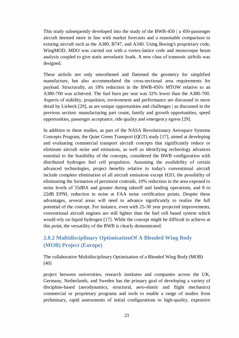
This study subsequently developed into the study of the BWB-450 | a 450-passenger
aircraft deemed more in line with market forecasts and a reasonable comparison to
existing aircraft such as the A380, B747, and A340. Using Boeing's proprietary code,
WingMOD, MDO was carried out with a vortex-lattice code and monocoque beam
analysis coupled to give static aeroelastic loads. A new class of transonic airfoils was
designed.
These airfoils not only smoothened and flattened the geometry for simplified
manufacture, but also accommodated the cross-sectional area requirements for
payload. Structurally, an 18% reduction in the BWB-450's MTOW relative to an
A380-700 was achieved. The fuel burn per seat was 32% lower than the A380-700.
Aspects of stability, propulsion, environment and performance are discussed in more
detail by Liebeck [29], as are unique opportunities and challenges | as discussed in the
previous section: manufacturing part count, family and growth opportunities, speed
opportunities, passenger acceptance, ride quality and emergency egress [29].
In addition to these studies, as part of the NASA Revolutionary Aerospace Systems
Concepts Program, the Quiet Green Transport (QGT) study [17], aimed at developing
and evaluating commercial transport aircraft concepts that significantly reduce or
eliminate aircraft noise and emissions, as well as identifying technology advances
essential to the feasibility of the concepts, considered the BWB configuration with
distributed hydrogen fuel cell propulsion. Assuming the availability of certain
advanced technologies, project benefits relative to today's conventional aircraft
include complete elimination of all aircraft emissions except H2O, the possibility of
eliminating the formation of persistent contrails, 10% reduction in the area exposed to
noise levels of 55dBA and greater during takeoff and landing operations, and 8 to
22dB EPNL reduction in noise at FAA noise certification points. Despite these
advantages, several areas will need to advance significantly to realize the full
potential of the concept. For instance, even with 25-30 year projected improvements,
conventional aircraft engines are still lighter than the fuel cell based system which
would rely on liquid hydrogen [17]. While the concept might be difficult to achieve at
this point, the versatility of the BWB is clearly demonstrated.
2.8.2 Multidisciplinary OptimisationOf A Blended Wing Body
(MOB) Project (Europe)
The collaborative Multidisciplinary Optimisation of a Blended Wing Body (MOB)
[40]
project between universities, research institutes and companies across the UK,
Germany, Netherlands, and Sweden has the primary goal of developing a variety of
discipline-based (aerodynamics, structural, aero-elastic and flight mechanics)
commercial or proprietary programs and tools to enable a range of studies from
preliminary, rapid assessments of initial configurations to high-quality, expensive
22
computational simulations and assessments by distributed design teams. Essentially,
this distributed yet integrated system, the Computational Design Engine (CDE), is a
multi-level, multi-site, multidisciplinary design tool. A secondary goal of the project
is to apply the CDE to the BWB aircraft. At Sheffield University, Qin et al.'s
contributions to the MOB project include various aerodynamics studies of the BWB
[53]. Both high-fidelity RANS evaluation with a Baldwin-Lomax algebraic turbulence
model and Euler equations are used in the design process, with key considerations
being wave drag, spanwise load distribution, aerofoil section design and 3D shaping
for performance improvement. First, an inverse design of the spanwise loading
employed a panel method with three target loadings: elliptical | reduces induced drag,
triangular | reduces wave drag, and an average of the two | a compromise, with the
goal of alleviating high wave drag by shifting the load inboard.
Significant wave drag reduction on the outer wing was achieved for the new twist
distributions with the averaged distribution having the minimum total drag and thus,
the highest aerodynamic efficiency. The loading on all three designs is moved
inwards towards the centerbody relative to the baseline loading, with the highest
centerbody loading for the triangular distribution and lowest for the elliptical.
Structural and stability advantages to the averaged distribution are highlighted in [53,
54]. Subsequently, starting from the twist inverse design results, airfoils were mapped
from 3D to 2D, optimized, and mapped back to 3D. The resulting geometry had a
20% increase in lift-to-drag ratio compared to the baseline; however, the high sweep
and 3-dimensionality of the BWB shape implies 2D optimization cannot fully capture
the potential of shape optimization, leading to the _nal portion of the study: 3D Euler
aero surface optimization, incorporating a twist and camber optimization with
pitching moment constraint and 3D surface optimization with trim constraint. The
twist inverse design previously obtained was used as the starting geometry.
Minimizing pressure drag was deemed crucial since it dominates the total drag due to
the lower surface to volume ratio. In addition, the optimal spanwise lift distribution
for best aerodynamic performance should be a _ne balance of induced drag due to lift
and wave drag due to shock wave formation at transonic speeds, such as the average
elliptical/triangular distribution studied. As such, the elliptic distribution should no
longer be the target for minimum drag design, unless wave drag can be eliminated by
the design optimization, in which case an elliptic distribution may still be favourable
for aerodynamics [63]. Further studies done by Qin et al. involve BWB configurations
with forward swept wings [63], varying the outer wing sweep angles, defined as the
leading edge sweep of the wing, from -40 degrees (forward sweep) to 55 degrees
(backwards sweep), keeping planform fixed and using a pitching moment constraint.
The lift-to-drag ratio for forward swept wings was low and relatively constant as
forward sweep angles were increased. In this case, the wing sweep cancels with the
sweep of the body, creating intense shocks at the junction between the two. Increased
contributions to the wave drag result in the trend observed. In contrast, for 0 to 55
degrees, the lift-to-drag ratio increased substantially and peaked at 45 degrees. Other
23
interesting studies include the control of shock waves on the BWB via 3D shock
control bumps [78].
2.8.3 Tohoku University (Japan) :
Pambagjo et al.'s research [47, 48] aimed to design a regional BWB aircraft for about
224 passengers, a cruise Mach number of 0.8 and a range of 2000 nautical miles.
Using a Navier-Stokes flow solver with a fully turbulent boundary layer (Baldwin-
Lomax turbulence model), an inverse design and target pressure specification
technique were carried out. The first step of this process was to design the target
pressure distribution based on the required aerodynamic performance. For the initial
design [48], the specified target pressure distribution was obtained with discrepancies
at the leading and trailing edges. The outboard wing was inversely designed with the
goal of elliptical loading, while ensuring sufficient fuel volume. The inboard section
was designed as thin as possible without sacrificing too much of the internal space
and comfort. For the follow-up design [47], shocks were eliminated on the upper and
lower surfaces and agreement with the target elliptical span loading was improved;
however, the pitching moment was slightly higher for this configuration than for the
final configuration initially presented [48].
2.8.4 TsAGI (Russia) :
This work | done in conjunction with Airbus and Boeing | placed emphasis on the
rationale behind the main design of flying wing configurations and developing and
analyzing alternative configurations, while taking the aerodynamic and structural
concepts into consideration. The analysis process consisted of three stages: first,
development of a baseline configuration to define the project requirements; second,
development of three candidate concepts: an integrated wing body (IWB), a lifting-
body configuration, and a pure flying wing | all designed for the same requirements
for a fair comparison; and third, detailed computational and experimental studies for
the most promising layout. With a design mission for 750 passengers, 13,700 km
range and cruise Mach number of 0.85, comparisons of the alternatives to the
conventional configuration on the basis of aerodynamics, weight, fuel efficiency, etc.,
led to the selection of the IWB configuration. This configuration maintains the high
L/D advantage of a flying wing at about 24.5 for a Mach number of 0.85, maintains
structural efficiency, and meets all the main requirements of FAR-25 [1].
2.8.5 MIT/Cambridge Silent Aircraft Initiative (SAI) (USA/UK) :
Given its aerodynamic advantages, noise reduction, and characteristic cost savings,
the BWB configuration was an ideal option for SAI's goal of designing an aircraft
which is inaudible outside the airport boundary in a typical urban area [69, 8, 9].
Diedrich et al. combined WingMOD [75], an established MDO tool also utilized by
Boeing, which incorporates aerodynamics, loads, performance, weights, balance,
stability and control considerations with first principles and empirically-based design
24
and acoustic prediction methods, to explore an unconventional BWB aircraft
configuration to achieve the stated goal, while also ensuring competitive performance
with next-generation aircraft such as the B787 [8]. Based on a design mission of 215
passengers, a range of 5000 nautical miles, a cruise Mach number of 0.80, and
technology levels consistent with 2030 entry to service, an optimized aircraft which
achieves significant noise reduction compared to similar, existing commercial aircraft
was obtained; however the goal of being inaudible outside of the airport perimeter
was not achieved and further technology developments were deemed necessary. The
optimized aircraft fuel burn was competitive with B787-type aircraft, as desired.
Other interesting outcomes of the project include research into the use of leading-
edge carving which enables the entire planform to generate lift (an `all-lifting' design)
and produces a final aircraft which is both balanced and statically stable | without the
use of a reflexed airfoil, for instance [69, 62]. Additional research into landing gear
studies [56], Boundary Layer Ingestion studies [51], continuous descent [58] and
surface roughness [32] are examples of the types of projects that have and are
developing out of this project.
2.8.6 Universidad Politecnica de Madrid (Spain) :
Martinez-Val et al. [34] showed a medium-sized C-wing flying wing for 300
passengers was operationally efficient and preferable to conventional airplanes of
similar capacity. The horizontal stabilizers incorporated on the C-wing portion of the
body are considered useful for stability and control improvements. Compared to the
A330-200 and B777-200, the take-o_ and landing field lengths are shortened for the
C-wing. Fuel burn is found to be 19.8g/passenger-km | less than the 21.5 and
23.5g/passenger-km for the A330 and B777, respectively. Extending this work, a
comparison of the C-wing with a U-wing flying wing aircraft (a flying wing with
vertical winglets) was carried out with a study of how relevant, emerging technologies
such as laminar flow control (LFC), vectored thrust, and active stability can provide
additional improvements [34]. The U-wing configuration along with the emerging
technologies resulted in a fuel efficiency of 14.6g/passenger- km | the lowest of all the
options considered. Overall, both the C-wing and U-wing configuration present
significant advantages over the conventional layouts; however, it is important to note
that while the U-wing configuration is lighter, for this design, it requires vectored-
thrust which is currently unavailable for civil aviation [34].
2.8.7 Airbus Projects (Europe)
Airbus is involved in various projects with ONERA and DLR as major collaborators,
in addition to other companies and institutions. The Very Efficient Large Aircraft
(VELA) project has Airbus as the leading company with 17 European partners from
industry and research working together to extend their knowledge of BWB
configurations [67]. AVECA, a national project carried out in close collaboration
between Airbus and ONERA, focuses on lower capacity flying wing aircraft since this
25
topic has not been as extensively evaluated as the larger counterparts [38]. Finally, the
New Aircraft Concepts Research (NACRE) project is also led by Airbus with 36
partners [39, 38]. As part of VELA, each configuration studied in [67] was defined by
two leading edge sweep angles on the inboard and outboard wing sections and a
corresponding cabin geometry. Constraints included volume, deck cabin angle, and
stability considerations. A DLR finite volume flow solver, FLOWer, which solves the
3D compressible Euler equations in integral form, was employed in this two part
process consisting of 2D multipoint airfoil design optimization and a 3D twist and
chord-length optimization. The 3D optimization employed GenOpt-software as the
optimizer - specifically, the Nelder-Mead Simplex algorithm. Eight design variables,
such as the change of twist and chord length with constant thickness to chord for the
three outer wing sections, were used. Additional details can be found in [67]. The
flow analysis was performed in Euler mode with stripwise boundary layer analysis,
using the integral method for friction drag estimation. Sixteen percent drag reduction
with constant lift was achieved. The shock wave on the outer wing was modified from
a strong single shock close to the trailing edge to a weaker double shock system;
consequently, the drag reduction was dominated by wave drag reduction (63%). This
wave drag reduction was achieved by increasing chord lengths in the outer wing and
adjusting twist angles [67]; however, since wave drag was still present, the optimum
lift distribution was not of elliptical form, which might be expected if total minimum
drag is achieved [39]. Additional research includes the determination of static and
dynamic derivatives for stability and handling characteristics, along with high-speed
testing, to create an experimental database for aerodynamic performance assessment
and Semi-Buried engines (SEBU), through which engine installation effects are
studied [39]. The AVECA project [38] studied lower capacity BWB configurations,
aiming to design viable flying wing geometries considering aerodynamic cruise
performance, longitudinal trimming constraints and geometric constraints such as
cabin and landing gear volumes. Specific details of the design mission were excluded.
Navier-Stokes, multiblock, structured flow solves for Mach 0.85, Re/c of 172.2
million per meter (Note: the units of Re/c are not specified in the paper and are
inferred from geometry images) were carried out using the ONERA elsA code. Some
of the goals included increasing the lift-to-drag ratio at the design point and avoiding
strong shocks on both sides of the wing while meeting the various geometric
constraints. A manual, iterative strategy with a total of 60 configurations was used to
design the inboard section and ultimately suppress the shock. For the outboard
section, optimization driven by the gradient algorithm, CONMIN, was used to define
the twist distribution of the configuration.
The total drag, considering constraints on lift and on the location of the center of
pressure, made up the objective function. Two design points were considered: Mach
0.85, Re/c of 172.2 million per meter and Mach 0.87, Re/c of 176.3 million per meter.
For the first point, a 9.5% and 39.1% decrease in viscous and wave drag was
achieved, respectively; while for the second point, these reductions were 18.9% and
37%, respectively [38]. Additional research under the NACRE project includes
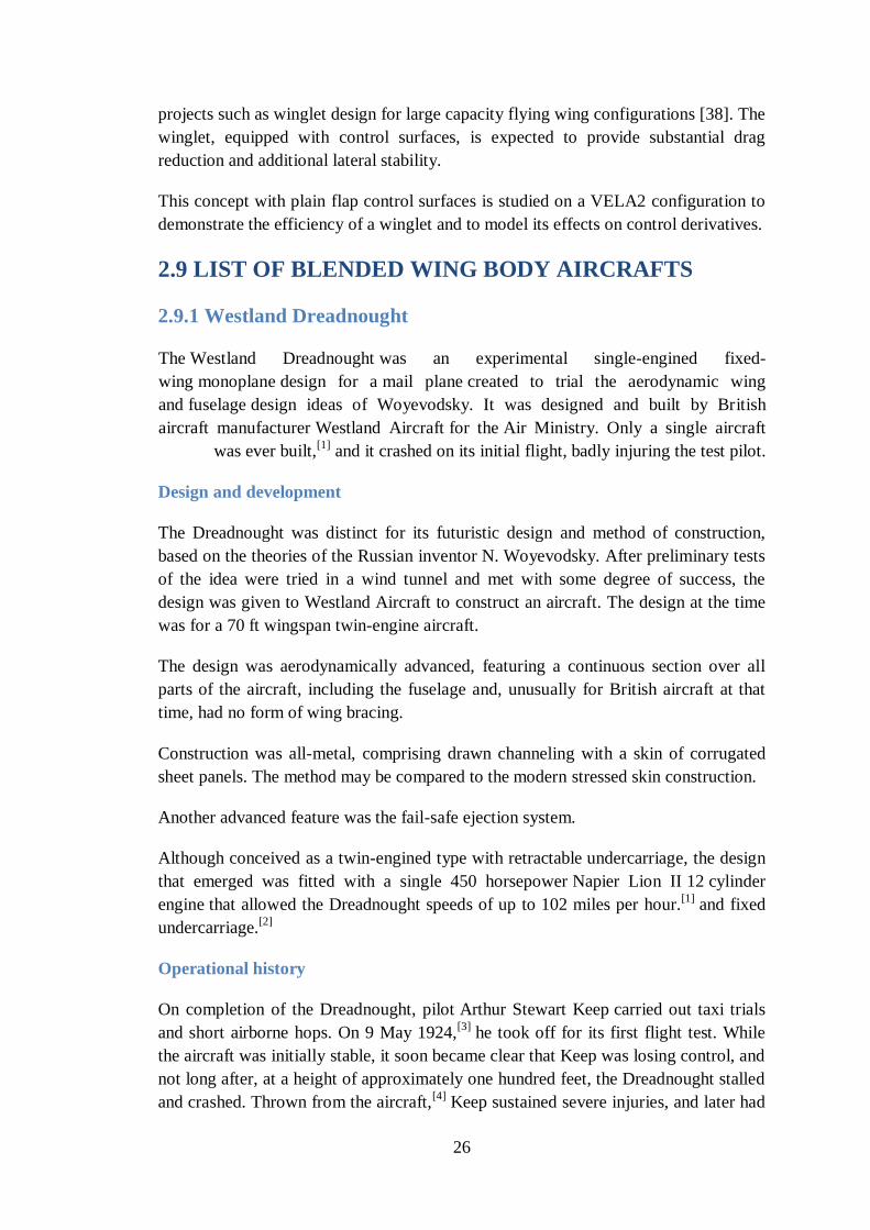
26
projects such as winglet design for large capacity flying wing configurations [38]. The
winglet, equipped with control surfaces, is expected to provide substantial drag
reduction and additional lateral stability.
This concept with plain flap control surfaces is studied on a VELA2 configuration to
demonstrate the efficiency of a winglet and to model its effects on control derivatives.
2.9 LIST OF BLENDED WING BODY AIRCRAFTS
2.9.1 Westland Dreadnought
-engined fixed-was an experimental single Westland Dreadnought The
created to trial the aerodynamic wing mail plane design for a monoplane wing
itish design ideas of Woyevodsky. It was designed and built by Br fuselage and
. Only a single aircraft Air Ministry for the Westland Aircraft aircraft manufacturer
and it crashed on its initial flight, badly injuring the test pilot. [1]
as ever built,w
Design and development
The Dreadnought was distinct for its futuristic design and method of construction,
based on the theories of the Russian inventor N. Woyevodsky. After preliminary tests
of the idea were tried in a wind tunnel and met with some degree of success, the
design was given to Westland Aircraft to construct an aircraft. The design at the time
was for a 70 ft wingspan twin-engine aircraft.
The design was aerodynamically advanced, featuring a continuous section over all
parts of the aircraft, including the fuselage and, unusually for British aircraft at that
time, had no form of wing bracing.
Construction was all-metal, comprising drawn channeling with a skin of corrugated
sheet panels. The method may be compared to the modern stressed skin construction.
Another advanced feature was the fail-safe ejection system.
Although conceived as a twin-engined type with retractable undercarriage, the design
that emerged was fitted with a single 450 horsepower Napier Lion II 12 cylinder
engine that allowed the Dreadnought speeds of up to 102 miles per hour.[1]
and fixed
undercarriage.[2]
Operational history
On completion of the Dreadnought, pilot Arthur Stewart Keep carried out taxi trials
and short airborne hops. On 9 May 1924,[3]
he took off for its first flight test. While
the aircraft was initially stable, it soon became clear that Keep was losing control, and
not long after, at a height of approximately one hundred feet, the Dreadnought stalled
and crashed. Thrown from the aircraft,[4]
Keep sustained severe injuries, and later had
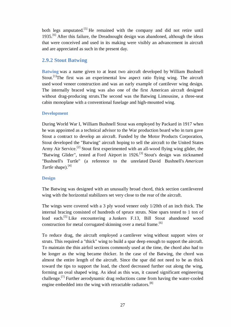
27
both legs amputated.[5]
He remained with the company and did not retire until
1935.[6]
After this failure, the Dreadnought design was abandoned, although the ideas
that were conceived and used in its making were visibly an advancement in aircraft
and are appreciated as such in the present day.
2.9.2 Stout Batwing
Batwing was a name given to at least two aircraft developed by William Bushnell
Stout.[1]
The first was an experimental low aspect ratio flying wing. The aircraft
used wood veneer construction and was an early example of cantilever wing design.
The internally braced wing was also one of the first American aircraft designed
without drag-producing struts.The second was the Batwing Limousine, a three-seat
cabin monoplane with a conventional fuselage and high-mounted wing.
Development
During World War I, William Bushnell Stout was employed by Packard in 1917 when
he was appointed as a technical advisor to the War production board who in turn gave
Stout a contract to develop an aircraft. Funded by the Motor Products Corporation,
Stout developed the "Batwing" aircraft hoping to sell the aircraft to the United States
Army Air Service.[2]
Stout first experimented with an all-wood flying wing glider, the
"Batwing Glider", tested at Ford Airport in 1926.[3]
Stout's design was nicknamed
"Bushnell's Turtle" (a reference to the unrelated David Bushnell's American
Turtle shape).[4]
Design
The Batwing was designed with an unusually broad chord, thick section cantilevered
wing with the horizontal stabilizers set very close to the rear of the aircraft.
The wings were covered with a 3 ply wood veneer only 1/20th of an inch thick. The
internal bracing consisted of hundreds of spruce struts. Nine spars tested to 1 ton of
load each.[5]
Like encountering a Junkers F.13, Bill Stout abandoned wood
construction for metal corrugated skinning over a metal frame.[6]
To reduce drag, the aircraft employed a cantilever wing without support wires or
struts. This required a "thick" wing to build a spar deep enough to support the aircraft.
To maintain the thin airfoil sections commonly used at the time, the chord also had to
be longer as the wing became thicker. In the case of the Batwing, the chord was
almost the entire length of the aircraft. Since the spar did not need to be as thick
toward the tips to support the load, the chord decreased further out along the wing,
forming an oval shaped wing. As ideal as this was, it caused significant engineering
challenge.[7]
Further aerodynamic drag reductions came from having the water-cooled
engine embedded into the wing with retractable radiators.[8]
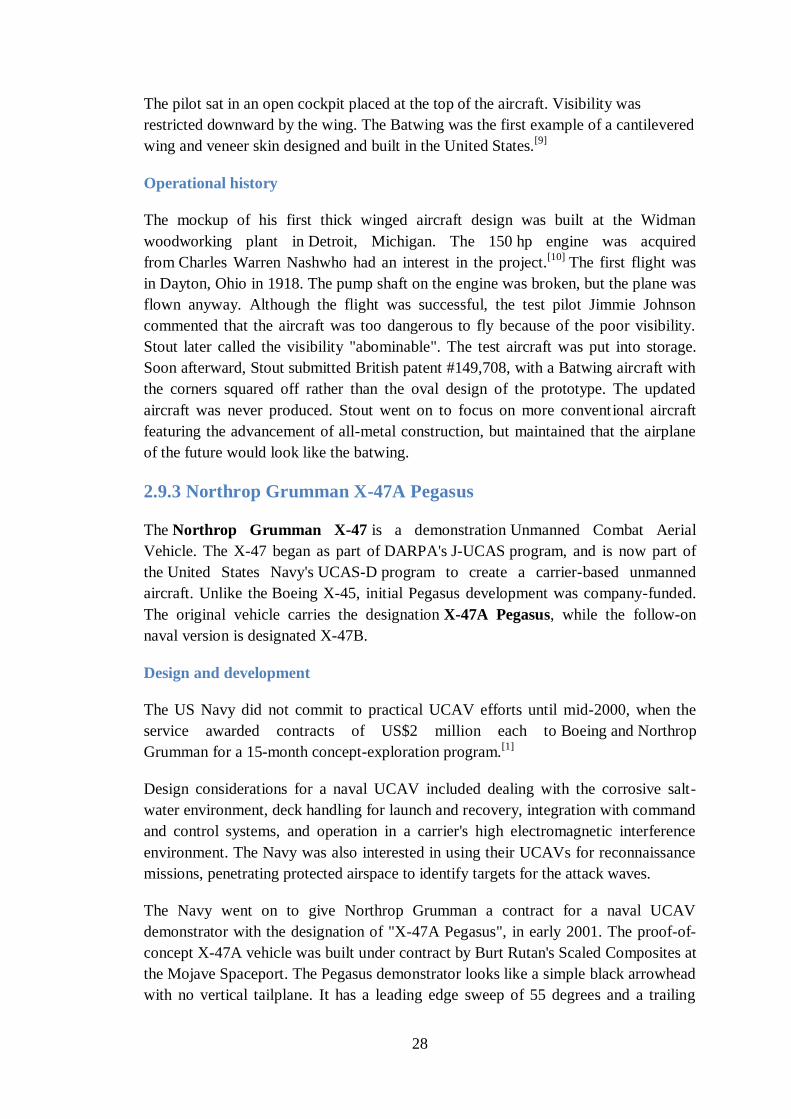
28
The pilot sat in an open cockpit placed at the top of the aircraft. Visibility was
restricted downward by the wing. The Batwing was the first example of a cantilevered
wing and veneer skin designed and built in the United States.[9]
Operational history
The mockup of his first thick winged aircraft design was built at the Widman
woodworking plant in Detroit, Michigan. The 150 hp engine was acquired
from Charles Warren Nashwho had an interest in the project.[10]
The first flight was
in Dayton, Ohio in 1918. The pump shaft on the engine was broken, but the plane was
flown anyway. Although the flight was successful, the test pilot Jimmie Johnson
commented that the aircraft was too dangerous to fly because of the poor visibility.
Stout later called the visibility "abominable". The test aircraft was put into storage.
Soon afterward, Stout submitted British patent #149,708, with a Batwing aircraft with
the corners squared off rather than the oval design of the prototype. The updated
aircraft was never produced. Stout went on to focus on more conventional aircraft
featuring the advancement of all-metal construction, but maintained that the airplane
of the future would look like the batwing.
2.9.3 Northrop Grumman X-47A Pegasus
The Northrop Grumman X-47 is a demonstration Unmanned Combat Aerial
Vehicle. The X-47 began as part of DARPA's J-UCAS program, and is now part of
the United States Navy's UCAS-D program to create a carrier-based unmanned
aircraft. Unlike the Boeing X-45, initial Pegasus development was company-funded.
The original vehicle carries the designation X-47A Pegasus, while the follow-on
naval version is designated X-47B.
Design and development
The US Navy did not commit to practical UCAV efforts until mid-2000, when the
service awarded contracts of US$2 million each to Boeing and Northrop
Grumman for a 15-month concept-exploration program.[1]
Design considerations for a naval UCAV included dealing with the corrosive salt-
water environment, deck handling for launch and recovery, integration with command
and control systems, and operation in a carrier's high electromagnetic interference
environment. The Navy was also interested in using their UCAVs for reconnaissance
missions, penetrating protected airspace to identify targets for the attack waves.
The Navy went on to give Northrop Grumman a contract for a naval UCAV
demonstrator with the designation of "X-47A Pegasus", in early 2001. The proof-of-
concept X-47A vehicle was built under contract by Burt Rutan's Scaled Composites at
the Mojave Spaceport. The Pegasus demonstrator looks like a simple black arrowhead
with no vertical tailplane. It has a leading edge sweep of 55 degrees and a trailing
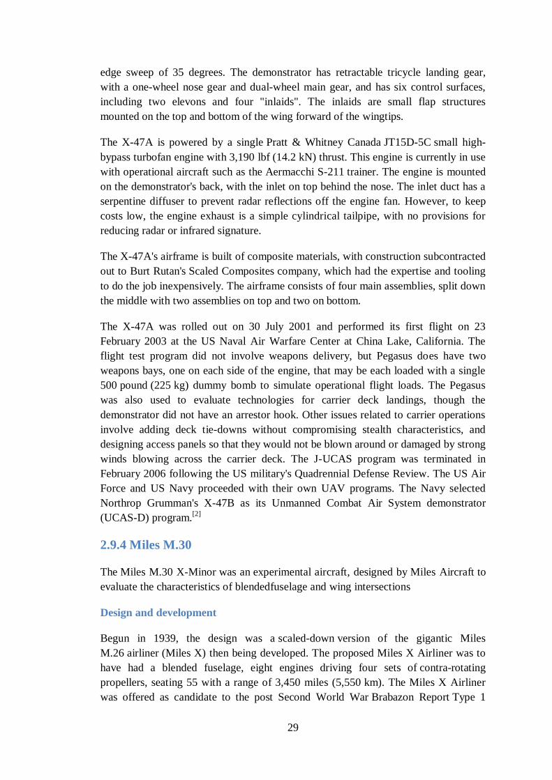
29
edge sweep of 35 degrees. The demonstrator has retractable tricycle landing gear,
with a one-wheel nose gear and dual-wheel main gear, and has six control surfaces,
including two elevons and four "inlaids". The inlaids are small flap structures
mounted on the top and bottom of the wing forward of the wingtips.
The X-47A is powered by a single Pratt & Whitney Canada JT15D-5C small high-
bypass turbofan engine with 3,190 lbf (14.2 kN) thrust. This engine is currently in use
with operational aircraft such as the Aermacchi S-211 trainer. The engine is mounted
on the demonstrator's back, with the inlet on top behind the nose. The inlet duct has a
serpentine diffuser to prevent radar reflections off the engine fan. However, to keep
costs low, the engine exhaust is a simple cylindrical tailpipe, with no provisions for
reducing radar or infrared signature.
The X-47A's airframe is built of composite materials, with construction subcontracted
out to Burt Rutan's Scaled Composites company, which had the expertise and tooling
to do the job inexpensively. The airframe consists of four main assemblies, split down
the middle with two assemblies on top and two on bottom.
The X-47A was rolled out on 30 July 2001 and performed its first flight on 23
February 2003 at the US Naval Air Warfare Center at China Lake, California. The
flight test program did not involve weapons delivery, but Pegasus does have two
weapons bays, one on each side of the engine, that may be each loaded with a single
500 pound (225 kg) dummy bomb to simulate operational flight loads. The Pegasus
was also used to evaluate technologies for carrier deck landings, though the
demonstrator did not have an arrestor hook. Other issues related to carrier operations
involve adding deck tie-downs without compromising stealth characteristics, and
designing access panels so that they would not be blown around or damaged by strong
winds blowing across the carrier deck. The J-UCAS program was terminated in
February 2006 following the US military's Quadrennial Defense Review. The US Air
Force and US Navy proceeded with their own UAV programs. The Navy selected
Northrop Grumman's X-47B as its Unmanned Combat Air System demonstrator
(UCAS-D) program.[2]
2.9.4 Miles M.30
The Miles M.30 X-Minor was an experimental aircraft, designed by Miles Aircraft to
evaluate the characteristics of blendedfuselage and wing intersections
Design and development
Begun in 1939, the design was a scaled-down version of the gigantic Miles
M.26 airliner (Miles X) then being developed. The proposed Miles X Airliner was to
have had a blended fuselage, eight engines driving four sets of contra-rotating
propellers, seating 55 with a range of 3,450 miles (5,550 km). The Miles X Airliner
was offered as candidate to the post Second World War Brabazon Report Type 1
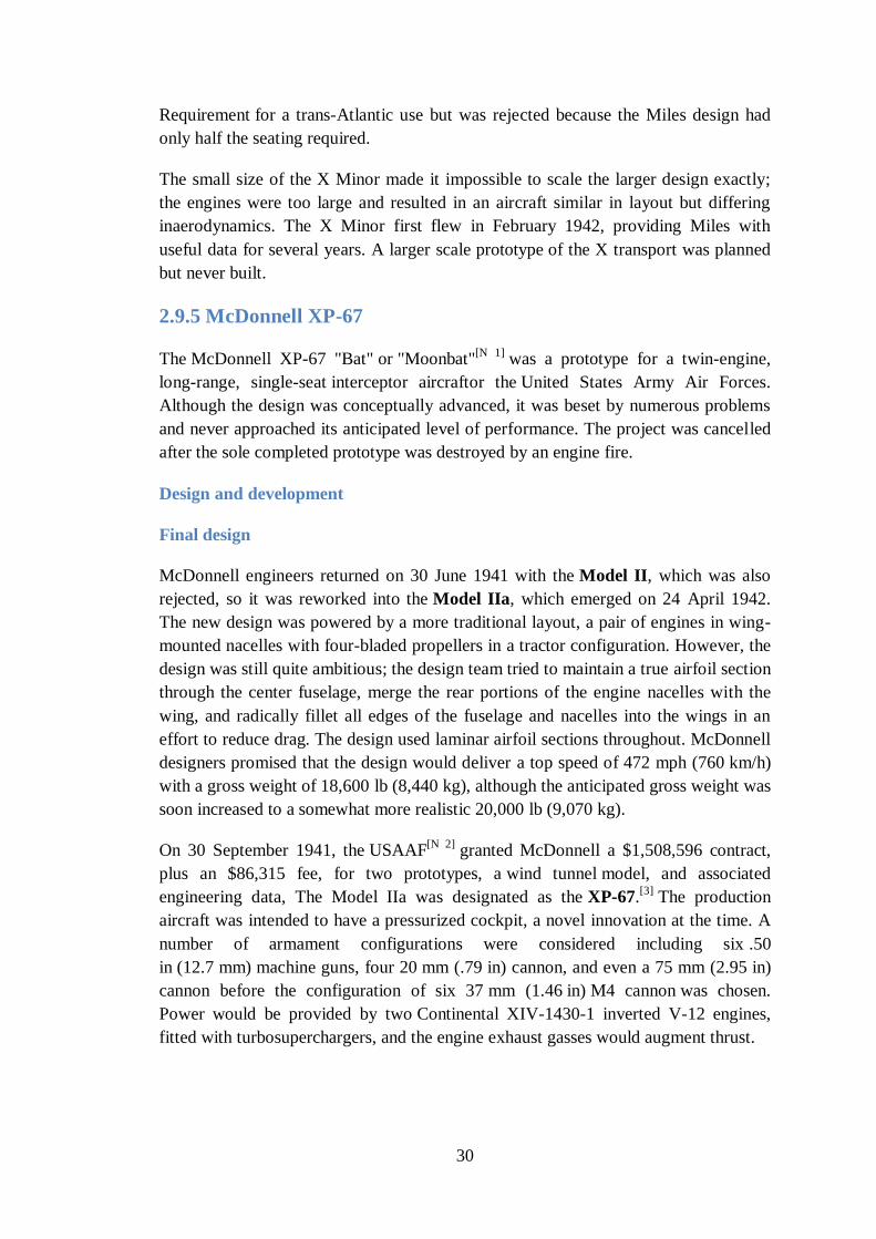
30
Requirement for a trans-Atlantic use but was rejected because the Miles design had
only half the seating required.
The small size of the X Minor made it impossible to scale the larger design exactly;
the engines were too large and resulted in an aircraft similar in layout but differing
inaerodynamics. The X Minor first flew in February 1942, providing Miles with
useful data for several years. A larger scale prototype of the X transport was planned
but never built.
2.9.5 McDonnell XP-67
The McDonnell XP-67 "Bat" or "Moonbat"[N 1]
was a prototype for a twin-engine,
long-range, single-seat interceptor aircraftor the United States Army Air Forces.
Although the design was conceptually advanced, it was beset by numerous problems
and never approached its anticipated level of performance. The project was cancelled
after the sole completed prototype was destroyed by an engine fire.
Design and development
Final design
McDonnell engineers returned on 30 June 1941 with the Model II, which was also
rejected, so it was reworked into the Model IIa, which emerged on 24 April 1942.
The new design was powered by a more traditional layout, a pair of engines in wing-
mounted nacelles with four-bladed propellers in a tractor configuration. However, the
design was still quite ambitious; the design team tried to maintain a true airfoil section
through the center fuselage, merge the rear portions of the engine nacelles with the
wing, and radically fillet all edges of the fuselage and nacelles into the wings in an
effort to reduce drag. The design used laminar airfoil sections throughout. McDonnell
designers promised that the design would deliver a top speed of 472 mph (760 km/h)
with a gross weight of 18,600 lb (8,440 kg), although the anticipated gross weight was
soon increased to a somewhat more realistic 20,000 lb (9,070 kg).
On 30 September 1941, the USAAF[N 2]
granted McDonnell a $1,508,596 contract,
plus an $86,315 fee, for two prototypes, a wind tunnel model, and associated
engineering data, The Model IIa was designated as the XP-67.[3]
The production
aircraft was intended to have a pressurized cockpit, a novel innovation at the time. A
number of armament configurations were considered including six .50
in (12.7 mm) machine guns, four 20 mm (.79 in) cannon, and even a 75 mm (2.95 in)
cannon before the configuration of six 37 mm (1.46 in) M4 cannon was chosen.
Power would be provided by two Continental XIV-1430-1 inverted V-12 engines,
fitted with turbosuperchargers, and the engine exhaust gasses would augment thrust.
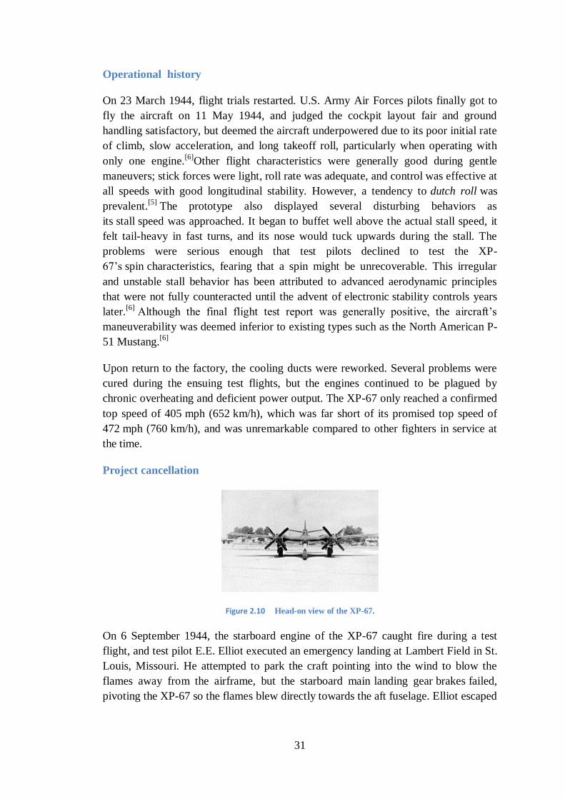
31
Operational history
On 23 March 1944, flight trials restarted. U.S. Army Air Forces pilots finally got to
fly the aircraft on 11 May 1944, and judged the cockpit layout fair and ground
handling satisfactory, but deemed the aircraft underpowered due to its poor initial rate
of climb, slow acceleration, and long takeoff roll, particularly when operating with
only one engine.[6]
Other flight characteristics were generally good during gentle
maneuvers; stick forces were light, roll rate was adequate, and control was effective at
all speeds with good longitudinal stability. However, a tendency to dutch roll was
prevalent.[5]
The prototype also displayed several disturbing behaviors as
its stall speed was approached. It began to buffet well above the actual stall speed, it
felt tail-heavy in fast turns, and its nose would tuck upwards during the stall. The
problems were serious enough that test pilots declined to test the XP-
67‘s spin characteristics, fearing that a spin might be unrecoverable. This irregular
and unstable stall behavior has been attributed to advanced aerodynamic principles
that were not fully counteracted until the advent of electronic stability controls years
later.[6]
Although the final flight test report was generally positive, the aircraft‘s
maneuverability was deemed inferior to existing types such as the North American P-
51 Mustang.[6]
Upon return to the factory, the cooling ducts were reworked. Several problems were
cured during the ensuing test flights, but the engines continued to be plagued by
chronic overheating and deficient power output. The XP-67 only reached a confirmed
top speed of 405 mph (652 km/h), which was far short of its promised top speed of
472 mph (760 km/h), and was unremarkable compared to other fighters in service at
the time.
Project cancellation
Figure 2.10 Head-on view of the XP-67.
On 6 September 1944, the starboard engine of the XP-67 caught fire during a test
flight, and test pilot E.E. Elliot executed an emergency landing at Lambert Field in St.
Louis, Missouri. He attempted to park the craft pointing into the wind to blow the
flames away from the airframe, but the starboard main landing gear brakes failed,
pivoting the XP-67 so the flames blew directly towards the aft fuselage. Elliot escaped
32
safely, but the blaze gutted the fuselage, engine, nacelle and starboard wing; the
aircraft was a total loss.[7]
The destruction of the lone flying prototype dealt a serious blow to the entire program
because the second prototype was only 15% complete at the time. Army leaders
decided to reevaluate the XP-67, ultimately deciding on 13 September that it offered
no significant advantages over existing fighters already in service.[7]
The project was
canceled, the remains of the first prototype were scrapped, and work was halted on the
second prototype.[N 3]
2.9.6 Lockheed Martin RQ-170 Sentinel
The Lockheed Martin RQ-170 Sentinel is an unmanned aerial vehicle (UAV)
developed by Lockheed Martin and operated by the United States Air Force (USAF)
for the Central Intelligence Agency (CIA). While the USAF has released few details
on the UAV's design or capabilities, defense analysts believe that it is a stealth
aircraft fitted with aerial reconnaissanceequipment.
RQ-170s have been reported to have operated in Afghanistan as part of Operation
Enduring Freedom. It has been confirmed that the UAVs have operated
over Pakistan and Iran; operations over Pakistan included sorties that collected
intelligence before and during the operation which led to the death of Osama bin
Laden in May 2011.[2]
In December 2011, the Iranian armed forces claimed to have captured an RQ-170
flying over Iran. The U.S. military has acknowledged losing an RQ-170 in the region.
United States administration asked Iran to return the UAV. Iran denied the request
and lodged a complaint to the UN Security Council over
Figure 2.11 airspace violation by the U.S.[3][4][5]
33
Development
The RQ-170 Sentinel was developed by Lockheed Martin's Skunk Works as
a stealth Unmanned Aerial Vehicle (UAV). Journalists have noted design similarities
between the RQ-170 and previous stealth and UAV programs such as the RQ-3
DarkStar and Polecat.[6][7]
It is a tailless flying wing aircraft with pods, presumably for
sensors or SATCOMs, built into the upper surface of each wing. Few details of the
UAV's characteristics have been released, but estimates of its wingspan range from
approximately 65 feet (20 m)[8]
to 90 feet (27 m).[9]
In a December 2012 report,
journalist David Axe stated that "20 or so" RQ-170s had been built.[1]
Design
The RQ-170 is a flying wing design containing a single (as yet classified) engine and
is estimated by Aviation Week as having a wingspan of approximately 66 feet
(20 m).[15]
Its takeoff weight is estimated as being greater than the RQ-3 DarkStar's,
which was 8,500 pounds (3,900 kg). The design lacks several elements common to
stealth engineering such as zig-zag edged landing gear doors and sharp leading edges,
and the exhaust is not shielded by the wing.[15]
Aviation Week postulates that these
elements suggest the designers have avoided 'highly sensitive technologies' due to the
near certainty of eventual operational loss inherent with a single engine design and a
desire to avoid the risk of compromising leading edge technology.[15]
The publication
also suggests that the medium-grey color implies a mid-altitude ceiling, unlikely to
exceed 50,000 feet (15,000 m) since a higher ceiling would normally be painted
darker for best concealment.[15]
The postulated weight and ceiling parameters suggests
the possible use of a General Electric TF34 engine, or a variant, in the airframe.[15]
On the basis of the few publicly available photographs of the RQ-170, aviation
expert Bill Sweetman has assessed that the UAV is equipped with an electro-
optical/infrared sensor and possibly an active electronically scanned array (AESA)
radar mounted in its belly fairing. He has also speculated that the two undercarriage
fairings over the UAV's wings may house datalinks and that the belly fairing could be
designed for modular payloads, allowing the UAV to be used for strike missions
and/or electronic warfare.[16]
The New York Times has reported that the RQ-170 is
"almost certainly" equipped with communications intercept equipment as well as
highly sensitive sensors capable of detecting very small amounts of radioactive
isotopes and chemicals which may indicate the existence of nuclear weapons
facilities.[17]
Following Iranian claims of downing an RQ-170 near the Afghan border in December
2011, Iranian TV showed video footage of what appears to be an advanced unmanned
U.S. aircraft that most closely resembles the RQ-170 UAV. In the footage, a member
of the Iranian revolutionary guard released dimensions of the aircraft, including a
wingspan of about 26 metres (85 ft), a height of 1.84 metres (6.0 ft), and a length of
4.5 metres (15 ft).[18]
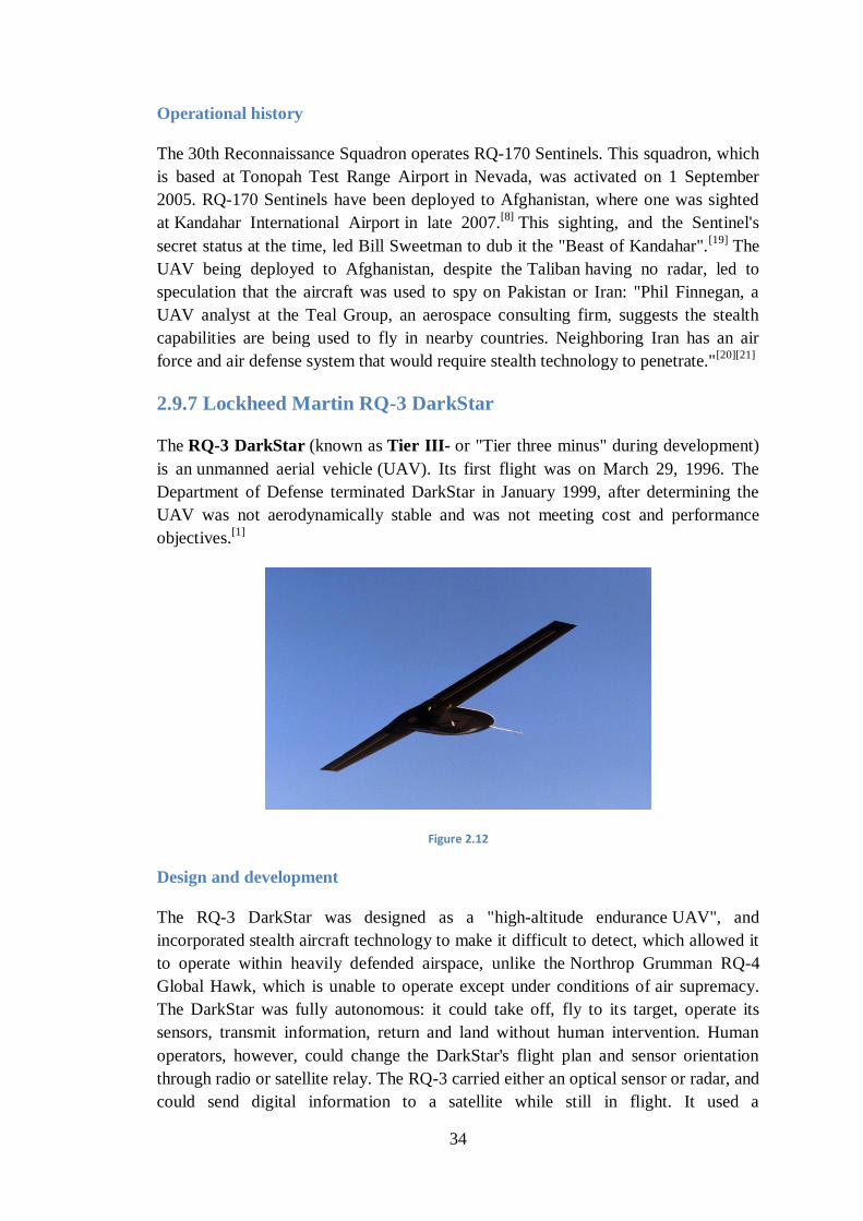
34
Operational history
The 30th Reconnaissance Squadron operates RQ-170 Sentinels. This squadron, which
is based at Tonopah Test Range Airport in Nevada, was activated on 1 September
2005. RQ-170 Sentinels have been deployed to Afghanistan, where one was sighted
at Kandahar International Airport in late 2007.[8]
This sighting, and the Sentinel's
secret status at the time, led Bill Sweetman to dub it the "Beast of Kandahar".[19]
The
UAV being deployed to Afghanistan, despite the Taliban having no radar, led to
speculation that the aircraft was used to spy on Pakistan or Iran: "Phil Finnegan, a
UAV analyst at the Teal Group, an aerospace consulting firm, suggests the stealth
capabilities are being used to fly in nearby countries. Neighboring Iran has an air
force and air defense system that would require stealth technology to penetrate."[20][21]
2.9.7 Lockheed Martin RQ-3 DarkStar
The RQ-3 DarkStar (known as Tier III- or "Tier three minus" during development)
is an unmanned aerial vehicle (UAV). Its first flight was on March 29, 1996. The
Department of Defense terminated DarkStar in January 1999, after determining the
UAV was not aerodynamically stable and was not meeting cost and performance
objectives.[1]
Figure 2.12
Design and development
The RQ-3 DarkStar was designed as a "high-altitude endurance UAV", and
incorporated stealth aircraft technology to make it difficult to detect, which allowed it
to operate within heavily defended airspace, unlike the Northrop Grumman RQ-4
Global Hawk, which is unable to operate except under conditions of air supremacy.
The DarkStar was fully autonomous: it could take off, fly to its target, operate its
sensors, transmit information, return and land without human intervention. Human
operators, however, could change the DarkStar's flight plan and sensor orientation
through radio or satellite relay. The RQ-3 carried either an optical sensor or radar, and
could send digital information to a satellite while still in flight. It used a
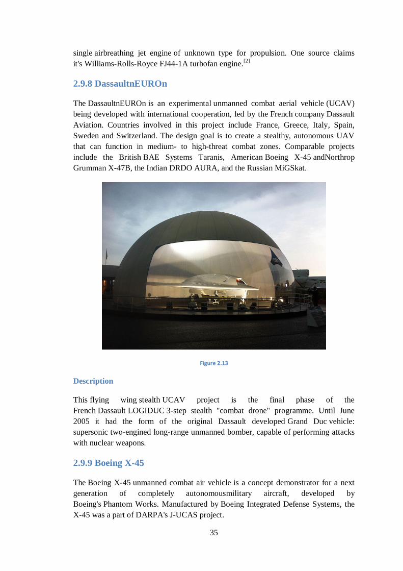
35
single airbreathing jet engine of unknown type for propulsion. One source claims
it's Williams-Rolls-Royce FJ44-1A turbofan engine.[2]
2.9.8 DassaultnEUROn
The DassaultnEUROn is an experimental unmanned combat aerial vehicle (UCAV)
being developed with international cooperation, led by the French company Dassault
Aviation. Countries involved in this project include France, Greece, Italy, Spain,
Sweden and Switzerland. The design goal is to create a stealthy, autonomous UAV
that can function in medium- to high-threat combat zones. Comparable projects
include the British BAE Systems Taranis, American Boeing X-45 andNorthrop
Grumman X-47B, the Indian DRDO AURA, and the Russian MiGSkat.
Figure 2.13
Description
This flying wing stealth UCAV project is the final phase of the
French Dassault LOGIDUC 3-step stealth "combat drone" programme. Until June
2005 it had the form of the original Dassault developed Grand Duc vehicle:
supersonic two-engined long-range unmanned bomber, capable of performing attacks
with nuclear weapons.
2.9.9 Boeing X-45
The Boeing X-45 unmanned combat air vehicle is a concept demonstrator for a next
generation of completely autonomousmilitary aircraft, developed by
Boeing's Phantom Works. Manufactured by Boeing Integrated Defense Systems, the
X-45 was a part of DARPA's J-UCAS project.
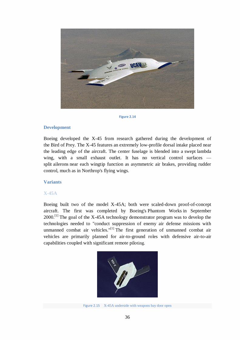
36
Figure 2.14
Development
Boeing developed the X-45 from research gathered during the development of
the Bird of Prey. The X-45 features an extremely low-profile dorsal intake placed near
the leading edge of the aircraft. The center fuselage is blended into a swept lambda
wing, with a small exhaust outlet. It has no vertical control surfaces —
split ailerons near each wingtip function as asymmetric air brakes, providing rudder
control, much as in Northrop's flying wings.
Variants
X-45A
Boeing built two of the model X-45A; both were scaled-down proof-of-concept
aircraft. The first was completed by Boeing's Phantom Works in September
2000.[1]
The goal of the X-45A technology demonstrator program was to develop the
technologies needed to "conduct suppression of enemy air defense missions with
unmanned combat air vehicles."[1]
The first generation of unmanned combat air
vehicles are primarily planned for air-to-ground roles with defensive air-to-air
capabilities coupled with significant remote piloting.
Figure 2.15 X-45A underside with weapons bay door open
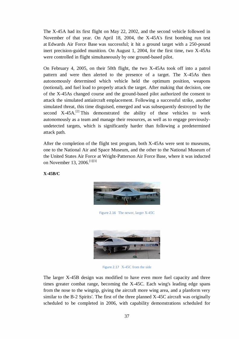
37
The X-45A had its first flight on May 22, 2002, and the second vehicle followed in
November of that year. On April 18, 2004, the X-45A's first bombing run test
at Edwards Air Force Base was successful; it hit a ground target with a 250-pound
inert precision-guided munition. On August 1, 2004, for the first time, two X-45As
were controlled in flight simultaneously by one ground-based pilot.
On February 4, 2005, on their 50th flight, the two X-45As took off into a patrol
pattern and were then alerted to the presence of a target. The X-45As then
autonomously determined which vehicle held the optimum position, weapons
(notional), and fuel load to properly attack the target. After making that decision, one
of the X-45As changed course and the ground-based pilot authorized the consent to
attack the simulated antiaircraft emplacement. Following a successful strike, another
simulated threat, this time disguised, emerged and was subsequently destroyed by the
second X-45A.[2]
This demonstrated the ability of these vehicles to work
autonomously as a team and manage their resources, as well as to engage previously-
undetected targets, which is significantly harder than following a predetermined
attack path.
After the completion of the flight test program, both X-45As were sent to museums,
one to the National Air and Space Museum, and the other to the National Museum of
the United States Air Force at Wright-Patterson Air Force Base, where it was inducted
on November 13, 2006.[1][3]
X-45B/C
Figure 2.16 The newer, larger X-45C
Figure 2.17 X-45C from the side
The larger X-45B design was modified to have even more fuel capacity and three
times greater combat range, becoming the X-45C. Each wing's leading edge spans
from the nose to the wingtip, giving the aircraft more wing area, and a planform very
similar to the B-2 Spirits'. The first of the three planned X-45C aircraft was originally
scheduled to be completed in 2006, with capability demonstrations scheduled for
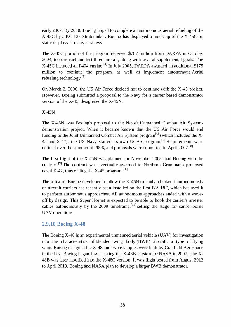
38
early 2007. By 2010, Boeing hoped to complete an autonomous aerial refueling of the
X-45C by a KC-135 Stratotanker. Boeing has displayed a mock-up of the X-45C on
static displays at many airshows.
The X-45C portion of the program received $767 million from DARPA in October
2004, to construct and test three aircraft, along with several supplemental goals. The
X-45C included an F404 engine.[4]
In July 2005, DARPA awarded an additional $175
million to continue the program, as well as implement autonomous Aerial
refueling technology.[5]
On March 2, 2006, the US Air Force decided not to continue with the X-45 project.
However, Boeing submitted a proposal to the Navy for a carrier based demonstrator
version of the X-45, designated the X-45N.
X-45N
The X-45N was Boeing's proposal to the Navy's Unmanned Combat Air Systems
demonstration project. When it became known that the US Air Force would end
funding to the Joint Unmanned Combat Air System program[6]
(which included the X-
45 and X-47), the US Navy started its own UCAS program.[7]
Requirements were
defined over the summer of 2006, and proposals were submitted in April 2007.[8]
The first flight of the X-45N was planned for November 2008, had Boeing won the
contract.[9]
The contract was eventually awarded to Northrop Grumman's proposed
naval X-47, thus ending the X-45 program.[10]
The software Boeing developed to allow the X-45N to land and takeoff autonomously
on aircraft carriers has recently been installed on the first F/A-18F, which has used it
to perform autonomous approaches. All autonomous approaches ended with a wave-
off by design. This Super Hornet is expected to be able to hook the carrier's arrester
cables autonomously by the 2009 timeframe,[11]
setting the stage for carrier-borne
UAV operations.
2.9.10 Boeing X-48
The Boeing X-48 is an experimental unmanned aerial vehicle (UAV) for investigation
into the characteristics of blended wing body (BWB) aircraft, a type of flying
wing. Boeing designed the X-48 and two examples were built by Cranfield Aerospace
in the UK. Boeing began flight testing the X-48B version for NASA in 2007. The X-
48B was later modified into the X-48C version. It was flight tested from August 2012
to April 2013. Boeing and NASA plan to develop a larger BWB demonstrator.
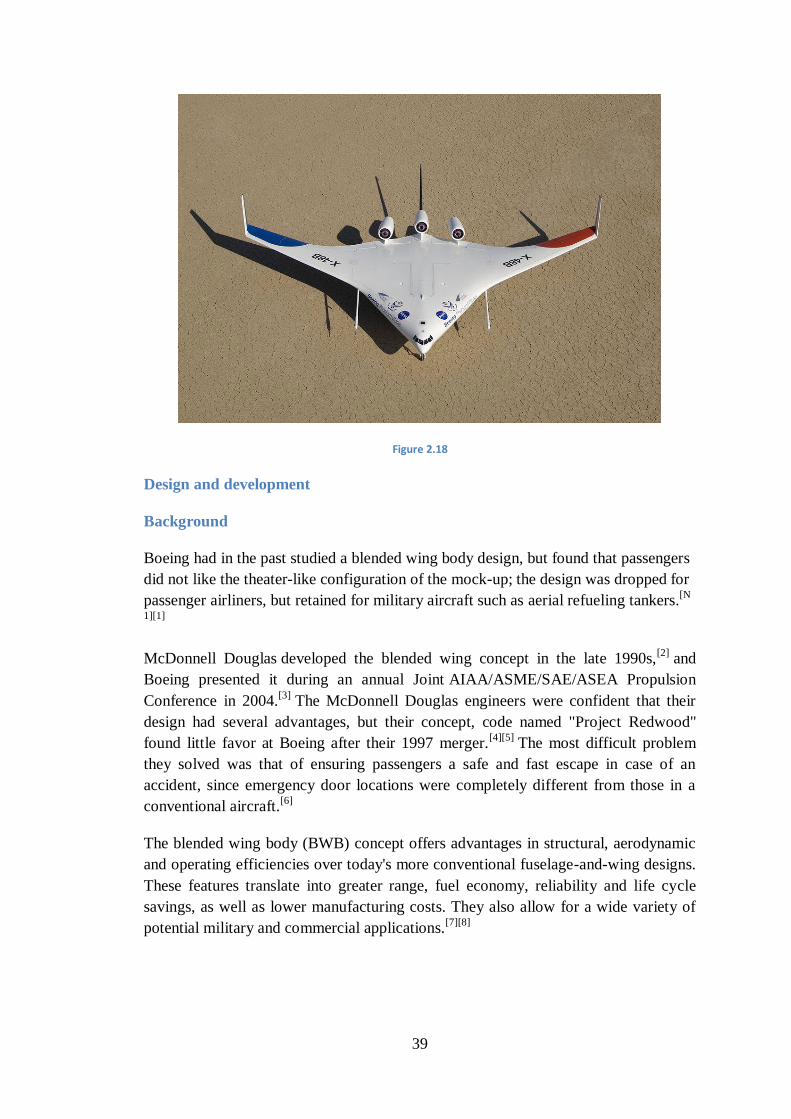
39
Figure 2.18
Design and development
Background
Boeing had in the past studied a blended wing body design, but found that passengers
did not like the theater-like configuration of the mock-up; the design was dropped for
passenger airliners, but retained for military aircraft such as aerial refueling tankers.[N
1][1]
McDonnell Douglas developed the blended wing concept in the late 1990s,[2]
and
Boeing presented it during an annual Joint AIAA/ASME/SAE/ASEA Propulsion
Conference in 2004.[3]
The McDonnell Douglas engineers were confident that their
design had several advantages, but their concept, code named "Project Redwood"
found little favor at Boeing after their 1997 merger.[4][5]
The most difficult problem
they solved was that of ensuring passengers a safe and fast escape in case of an
accident, since emergency door locations were completely different from those in a
conventional aircraft.[6]
The blended wing body (BWB) concept offers advantages in structural, aerodynamic
and operating efficiencies over today's more conventional fuselage-and-wing designs.
These features translate into greater range, fuel economy, reliability and life cycle
savings, as well as lower manufacturing costs. They also allow for a wide variety of
potential military and commercial applications.[7][8]
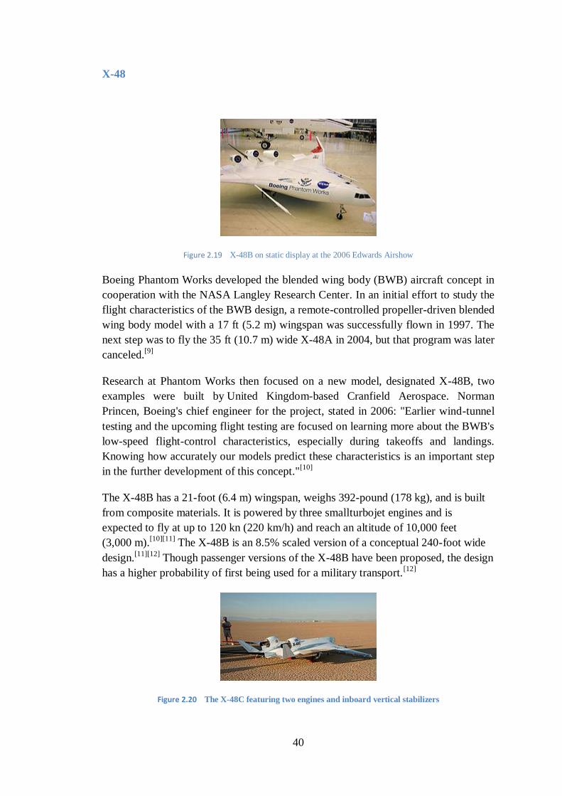
40
X-48
Figure 2.19 X-48B on static display at the 2006 Edwards Airshow
Boeing Phantom Works developed the blended wing body (BWB) aircraft concept in
cooperation with the NASA Langley Research Center. In an initial effort to study the
flight characteristics of the BWB design, a remote-controlled propeller-driven blended
wing body model with a 17 ft (5.2 m) wingspan was successfully flown in 1997. The
next step was to fly the 35 ft (10.7 m) wide X-48A in 2004, but that program was later
canceled.[9]
Research at Phantom Works then focused on a new model, designated X-48B, two
examples were built by United Kingdom-based Cranfield Aerospace. Norman
Princen, Boeing's chief engineer for the project, stated in 2006: "Earlier wind-tunnel
testing and the upcoming flight testing are focused on learning more about the BWB's
low-speed flight-control characteristics, especially during takeoffs and landings.
Knowing how accurately our models predict these characteristics is an important step
in the further development of this concept."[10]
The X-48B has a 21-foot (6.4 m) wingspan, weighs 392-pound (178 kg), and is built
from composite materials. It is powered by three smallturbojet engines and is
expected to fly at up to 120 kn (220 km/h) and reach an altitude of 10,000 feet
(3,000 m).[10][11]
The X-48B is an 8.5% scaled version of a conceptual 240-foot wide
design.[11][12]
Though passenger versions of the X-48B have been proposed, the design
has a higher probability of first being used for a military transport.[12]
Figure 2.20 The X-48C featuring two engines and inboard vertical stabilizers
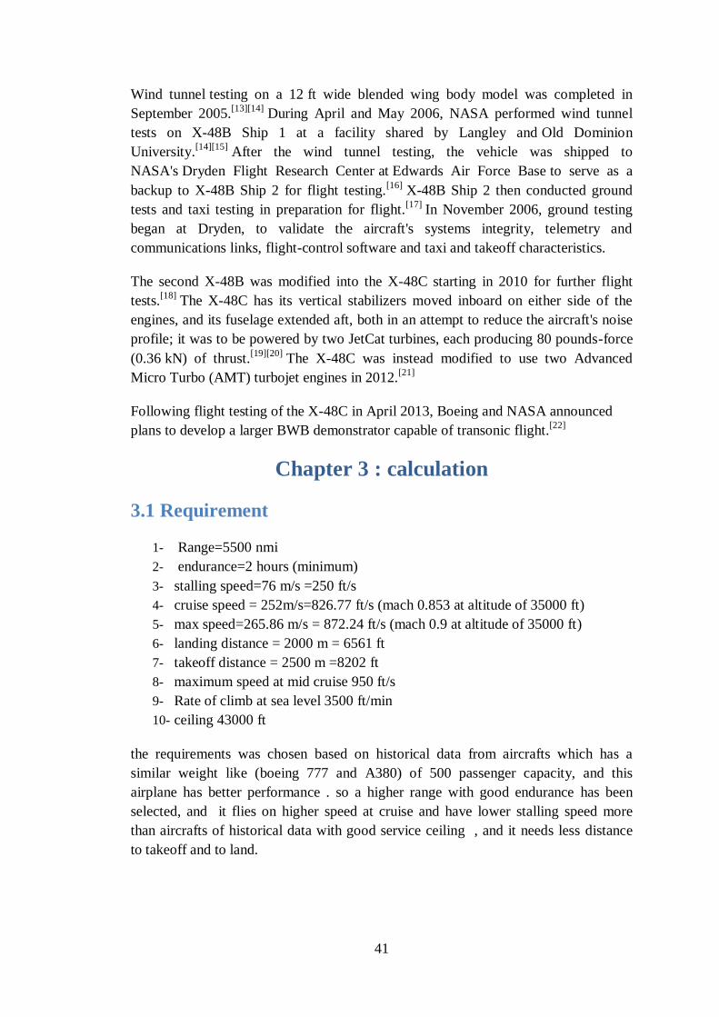
41
Wind tunnel testing on a 12 ft wide blended wing body model was completed in
September 2005.[13][14]
During April and May 2006, NASA performed wind tunnel
tests on X-48B Ship 1 at a facility shared by Langley and Old Dominion
University.[14][15]
After the wind tunnel testing, the vehicle was shipped to
NASA's Dryden Flight Research Center at Edwards Air Force Base to serve as a
backup to X-48B Ship 2 for flight testing.[16]
X-48B Ship 2 then conducted ground
tests and taxi testing in preparation for flight.[17]
In November 2006, ground testing
began at Dryden, to validate the aircraft's systems integrity, telemetry and
communications links, flight-control software and taxi and takeoff characteristics.
The second X-48B was modified into the X-48C starting in 2010 for further flight
tests.[18]
The X-48C has its vertical stabilizers moved inboard on either side of the
engines, and its fuselage extended aft, both in an attempt to reduce the aircraft's noise
profile; it was to be powered by two JetCat turbines, each producing 80 pounds-force
(0.36 kN) of thrust.[19][20]
The X-48C was instead modified to use two Advanced
Micro Turbo (AMT) turbojet engines in 2012.[21]
Following flight testing of the X-48C in April 2013, Boeing and NASA announced
plans to develop a larger BWB demonstrator capable of transonic flight.[22]
Chapter 3 : calculation
3.1 Requirement
1- Range=5500 nmi
2- endurance=2 hours (minimum)
3- stalling speed=76 m/s =250 ft/s
4- cruise speed = 252m/s=826.77 ft/s (mach 0.853 at altitude of 35000 ft)
5- max speed=265.86 m/s = 872.24 ft/s (mach 0.9 at altitude of 35000 ft)
6- landing distance = 2000 m = 6561 ft
7- takeoff distance = 2500 m =8202 ft
8- maximum speed at mid cruise 950 ft/s
9- Rate of climb at sea level 3500 ft/min
10- ceiling 43000 ft
the requirements was chosen based on historical data from aircrafts which has a
similar weight like (boeing 777 and A380) of 500 passenger capacity, and this
airplane has better performance . so a higher range with good endurance has been
selected, and it flies on higher speed at cruise and have lower stalling speed more
than aircrafts of historical data with good service ceiling , and it needs less distance
to takeoff and to land.
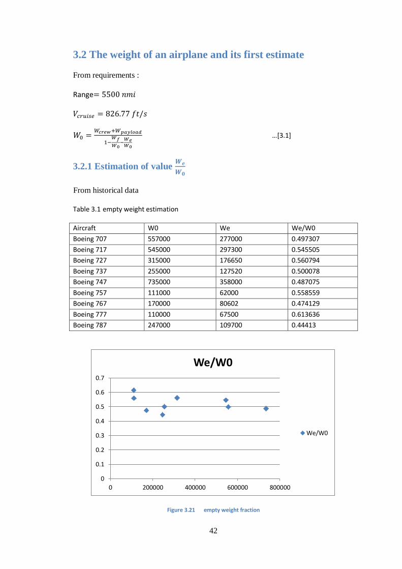
42
3.2 The weight of an airplane and its first estimate
From requirements :
Range
…[2.2]
3.2.1 Estimation of value
From historical data
Table 3. 2 empty weight estimation
We/W0 We W0 Aircraft
0.497307 277000 557000 Boeing 707
0.545505 297300 545000 Boeing 717
0.560794 176650 315000 Boeing 727
0.500078 127520 255000 Boeing 737
0.487075 358000 735000 Boeing 747
0.558559 62000 111000 Boeing 757
0.474129 80602 170000 Boeing 767
0.613636 67500 110000 Boeing 777
0.44413 109700 247000 Boeing 787
Figure 3. 72 empty weight fraction
0
0.1
0.2
0.3
0.4
0.5
0.6
0.7
0 200000 400000 600000 800000
We/W0
We/W0
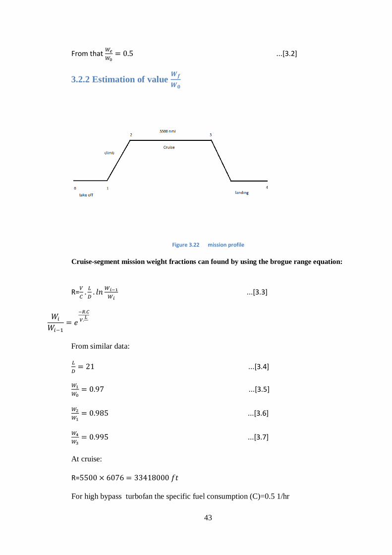
43
From that
...[3.2]
3.2.2 Estimation of value
Figure 3. 77 mission profile
Cruise-segment mission weight fractions can found by using the brogue range equation:
R=
...[3.3]
From similar data:
...[3.4]
...[3.5]
...[3.6]
...[3.7]
At cruise:
R=
For high bypass turbofan the specific fuel consumption (C)=0.5 1/hr
44
C=
...[3.8]
The most efficient cruise velocity for a jet aircraft occurs at a slightly higher velocity
yielding an L\D 86.6% of the maximum L\D
so:
...[3.9]
Then
...[3.10]
...[3.11]
= 1.06 (1-0.698)
= 0.32 ...[3.12]
a 6% allowance for reserve and trapped fuel
3.2.3 Calculation of
NO of Passenger =500
NO of crew =17
From raymer suggests we choose :
45
The total weight :
Fuel weight:
...[3.13]
Tank capacity
...[3.14]
Then the empty weight:
...[3.15]
3.3 Estimation of the critical performance parameters
3.3.1 Maximum lift coefficient
An initial choice of the airfoil section for our airplane design has been made as
follows : at tip section an MH-62 , at root an MH-61 and at the body an MH-93, from
historical designs of models (tailless aircrafts) .
For wing:
Average ( max =
For body:
( )max)root =1.1880 (( max)body =1.3783
Average =
Average ( )max with flap deflection =1.26+0.9=2.16
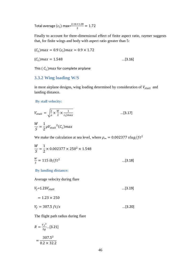
46
Total average ( max=
Finally to account for three-dimensional effect of finite aspect ratio, raymer suggests
that, for finite wings and body with aspect ratio greater than 5:
(
( ...[3.16]
This ( for complete airplane
3.3.2 Wing loading W/S
in most airplane designs, wing loading determined by consideration of and
landing distance.
By stall velocity:
√
...[3.17]
We make the calculation at sea level, where
...[3.18]
By landing distance:
Average velocity during flare
=1.23 ...[3.19]
...[3.20]
The flight path radius during flare
...[3.21]
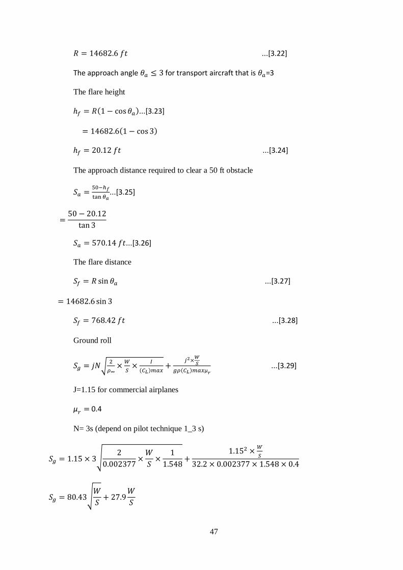
47
...[3.22]
The approach angle for transport aircraft that is =3
The flare height
...[3.23]
...[3.24]
The approach distance required to clear a 50 ft obstacle
...[3.25]
...[3.26]
The flare distance
...[3.27]
...[3.28]
Ground roll
√
...[3.29]
J=1.15 for commercial airplanes
0.4
N= 3s (depend on pilot technique 1_3 s)
√
√
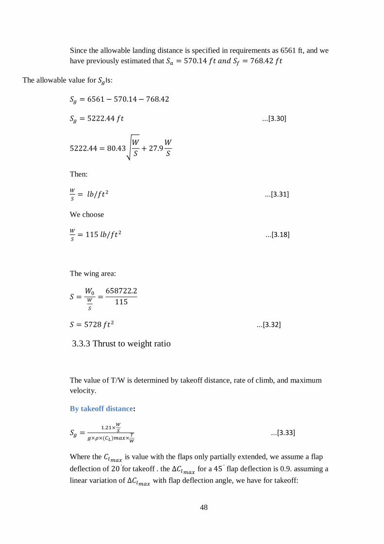
48
Since the allowable landing distance is specified in requirements as 6561 ft, and we
have previously estimated that
Is: The allowable value for
...[3.30]
√
Then:
...[3.31]
We choose
...[3.18]
The wing area:
...[3.32]
3.3.3 Thrust to weight ratio
The value of T/W is determined by takeoff distance, rate of climb, and maximum
velocity.
By takeoff distance:
...[3.33]
Where the is value with the flaps only partially extended, we assume a flap
deflection of for takeoff . the for a flap deflection is 0.9. assuming a
linear variation of with flap deflection angle, we have for takeoff:
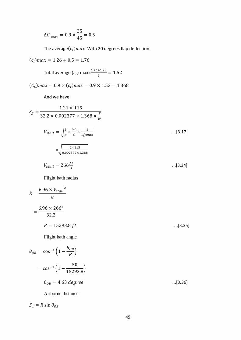
49
The average With 20 degrees flap deflection:
Total average ( max=
And we have:
√
...[3.17]
=√
...[3.34]
Flight bath radius
...[3.35]
Flight bath angle
(
)
(
)
...[3.36]
Airborne distance
50
...[3.37]
Combining the two equation:
...[3.38]
This is the value of required T/W at velocity:
...[3.39]
...[3.40]
Thrust required:
...[3.41]
by maximum speed at mid cruise:
from statistics:
-
Then:
...[3.42]
E=0.85

51
√
√
K=0.0787...[3.43]
AR=
...[3.44]
In level flight, T=D
we assume that the specified associated with level flight at 35000 ft
T=D=
...[3.45]
⁄
...[3.46]
...[3.47]
Mid cruise weight
(
) ...[3.48]
...[3.49]
...[3.50]
...[3.51]
52
⁄
...[3.52]
...[3.53]
by rate of climb:
⁄ (
)
(
)
...[3.54]
√
(
) (
)
...[3.55]
√
(
)
3.4 Configuration layout
3.4.1 Wing configuration
We have two considerations, the geometric shape of the wing and it is location
relative to the fuselage. First we consider the shape.
Wing geometry is describe by (a) aspect ratio, (b) wing sweep, (c) taper ratio, (d)
variation of airfoil shape and thickness along the span, and (e) geometric twist.
1- aspect ratio
...[3.56]
AR= 4.76 S=2465.2
√ ...[3.57]
53
√
...[3.58]
2- wing sweep
we assume that 50%chord sweep=
3- taper ratio
From fig 2.39 , see that for our aspect ratio of 4.76 , the minimum value of δ= 0.002
occurs at taper ratio 0.3
Ć
...[3.59]
Ć ...[3.60]
Ć
(
) ...[3.61]
...[3.62]
...[3.63]
...[3.64]
3.4.2 Fuselage configuration
Nose and Cockpit - Front Fuselage:
for nose:
...[3.65]
For the cockpit length (lcockpit), standards have been prescribed by Raymer
(Reference 1.11,chapter 9). lcockpit for the two member crew is chosen as 100
inches (2.5 m)
..[3.66]
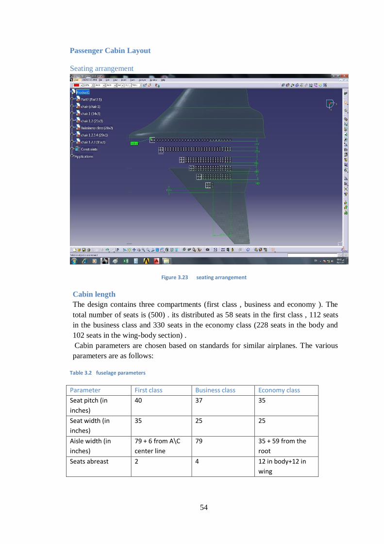
54
Passenger Cabin Layout
Seating arrangement
Figure 3. 72 seating arrangement
Cabin length
The design contains three compartments (first class , business and economy ). The
total number of seats is (500) . its distributed as 58 seats in the first class , 112 seats
in the business class and 330 seats in the economy class (228 seats in the body and
102 seats in the wing-body section) .
Cabin parameters are chosen based on standards for similar airplanes. The various
parameters are as follows:
Table 3. 7 fuselage parameters
Economy class Business class First class Parameter
35 37 40 Seat pitch (in
inches)
25 25 35 Seat width (in
inches)
35 + 59 from the
root
79 79 + 6 from A\C
center line
Aisle width (in
inches)
12 in body+12 in
wing
4 2 Seats abreast
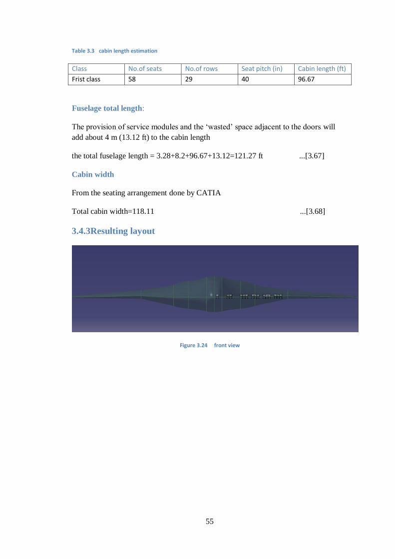
55
Table 3. 2 cabin length estimation
Cabin length (ft) Seat pitch (in) No.of rows No.of seats Class
96.67 40 29 58 Frist class
Fuselage total length:
The provision of service modules and the ‗wasted‘ space adjacent to the doors will
add about 4 m (13.12 ft) to the cabin length
the total fuselage length = 3.28+8.2+96.67+13.12=121.27 ft ...[3.67]
Cabin width
From the seating arrangement done by CATIA
Total cabin width=118.11 ...[3.68]
3.4.3Resulting layout
Figure 3.24 front view
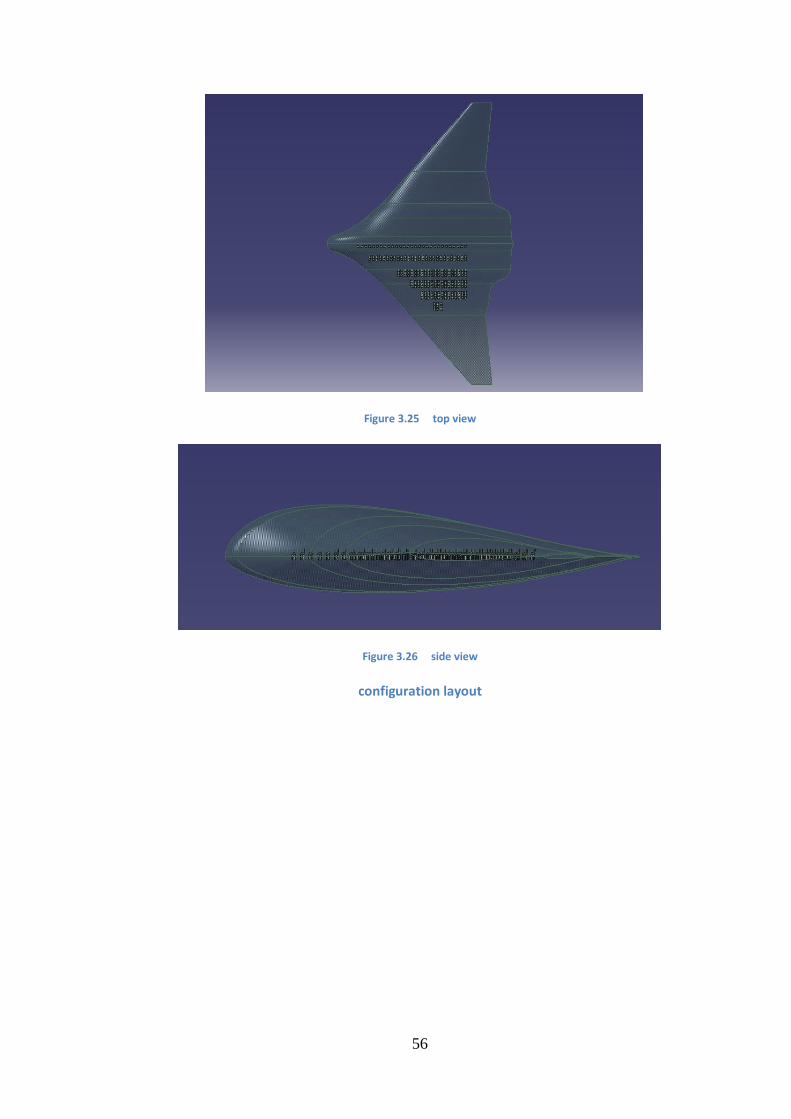
56
Figure 3.25 top view
Figure 3.26 side view
configuration layout
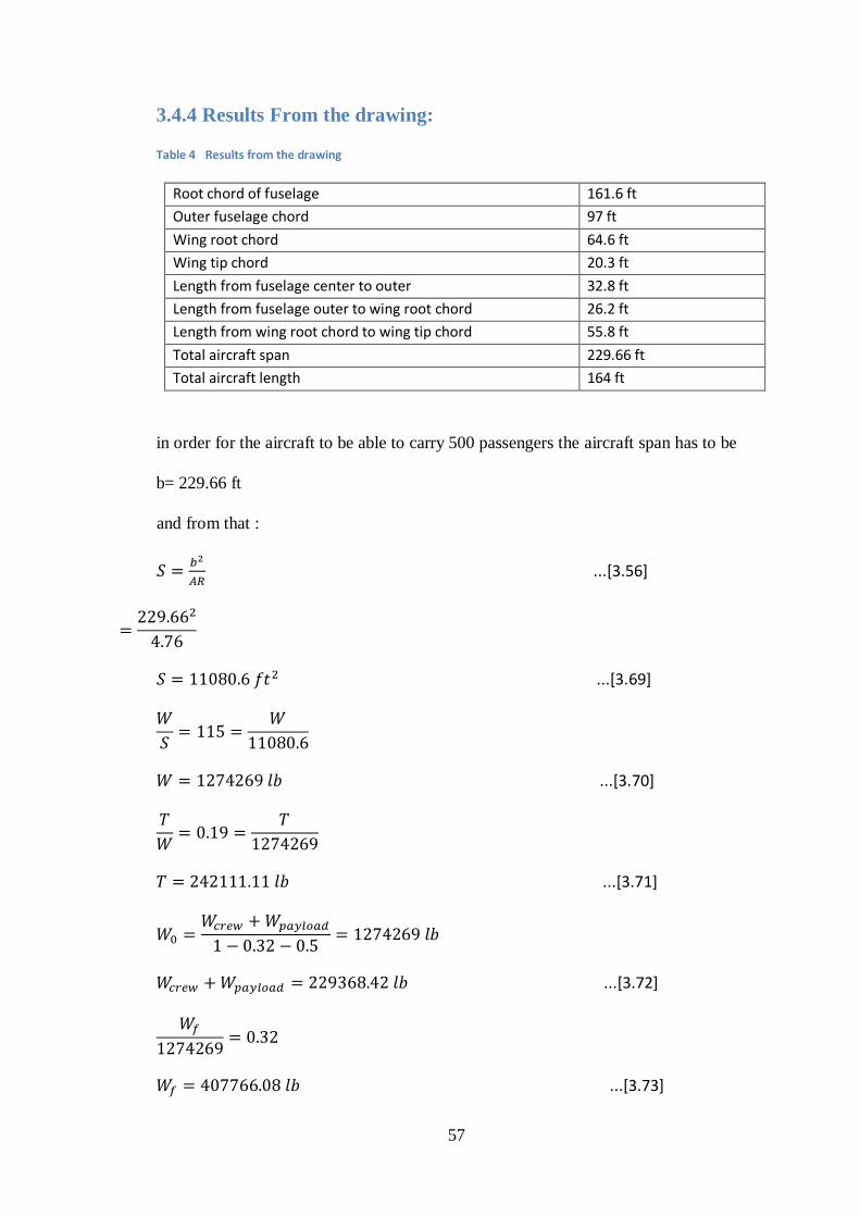
57
3.4.4 Results From the drawing:
Table 4 Results from the drawing
161.6 ft Root chord of fuselage
97 ft Outer fuselage chord
64.6 ft Wing root chord
20.3 ft Wing tip chord
32.8 ft Length from fuselage center to outer
26.2 ft Length from fuselage outer to wing root chord
55.8 ft Length from wing root chord to wing tip chord
229.66 ft Total aircraft span
164 ft Total aircraft length
in order for the aircraft to be able to carry 500 passengers the aircraft span has to be
b= 229.66 ft
and from that :
...[3.56]
...[3.69]
...[3.70]
...[3.71]
...[3.72]
...[3.73]
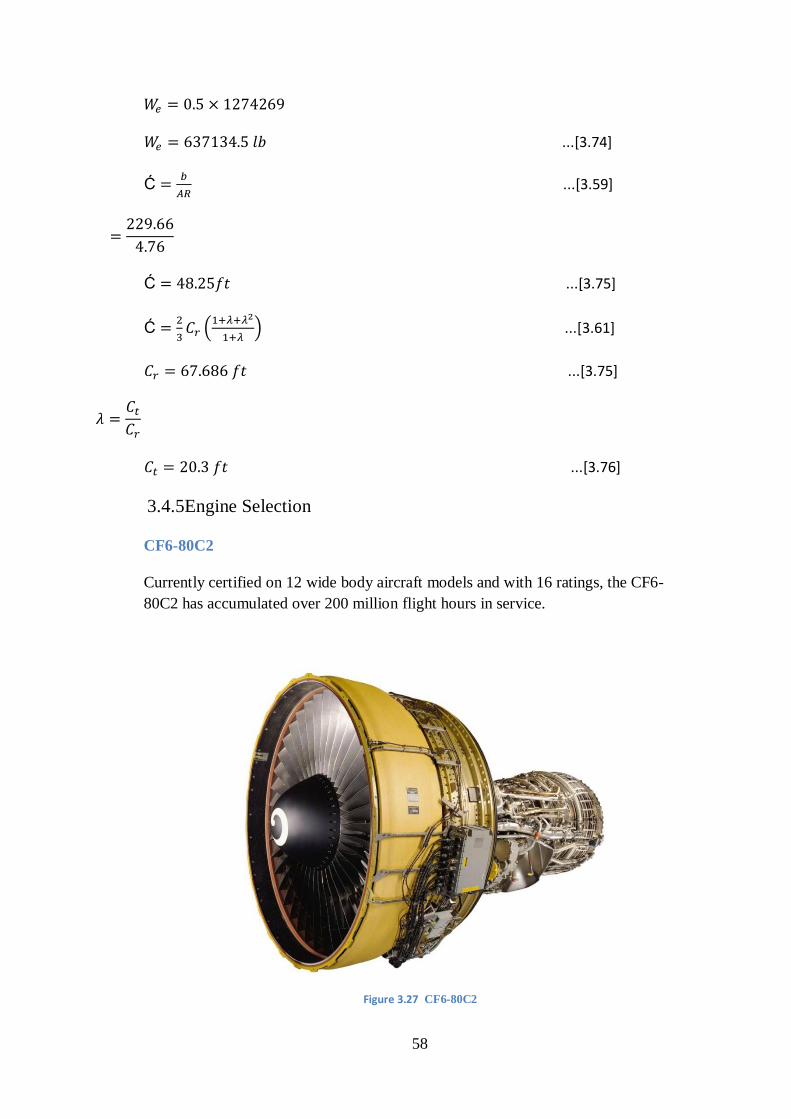
58
...[3.74]
Ć
...[3.59]
Ć ...[3.75]
Ć
(
) ...[3.61]
...[3.75]
...[3.76]
3.4.5Engine Selection
CF6-80C2
Currently certified on 12 wide body aircraft models and with 16 ratings, the CF6-
80C2 has accumulated over 200 million flight hours in service.
Figure 3. 72 CF6-80C2
59
Specification
Type High bypass turbofan engine
Max.thrust 63,500lb
Length 168 in
Airflow 1,790 lb/sec
Bypass ratio 5.3
Pressure ratio 32.6
Weight 9859 lb
3.4.6Center of gravity location: First estimate
Is calculated by summing moments about the nose and dividing by the sum of the
weights the result is
( )
...[3.77]
In the above calculation the weight of the installed engine is taken as 1.4 times the
given dry weight of 9859 lb as suggested by Raymer
Usual design procedure calls for locating the wing relative to the fuselage such that
the mean aerodynamic center of the wing is close to the c.g of the airplane
Raymer suggests that we estimate the weight of wing by multiplying the plan form
area by 2.5
...[3.78]
60
We also assume that the wing aerodynamic center is 25% of the mean aerodynamic
chord from the leading edge, and that the wing center of gravity is at 40% of the mean
aerodynamic chord
...[3.79]
...[3.80]
...[3.81]
3.5 A better weight estimate
Raymer gives an approximate weight buildup for a general aviation airplane as
follows
...[3.82]
...[3.83]
...[3.84]
...[3.85]
...[3.86]
From CATIA we get that
...[3.87]
...[3.88]
Then we have
...[3.89]
...[3.90]
...[3.91]
...[3.92]
...[3.93]
61
...[3.94]
...[3.95]
And from that:
...[3.96]
3.6 Performance analysis
...[3.97]
...[3.98]
...[3.42]
...[3.43]
...[3.16]
...[3.4]
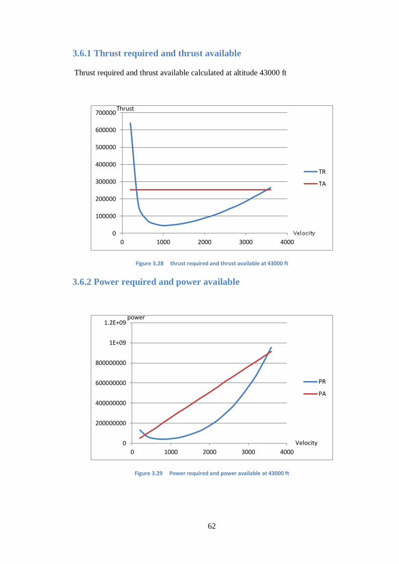
62
3.6.1 Thrust required and thrust available
Thrust required and thrust available calculated at altitude 43000 ft
Figure 3.28 thrust required and thrust available at 43000 ft
3.6.2 Power required and power available
Figure 3.29 Power required and power available at 43000 ft
0
100000
200000
300000
400000
500000
600000
700000
0 1000 2000 3000 4000
TR
TA
0
200000000
400000000
600000000
800000000
1E+09
1.2E+09
0 1000 2000 3000 4000
PR
PA
power
Velocity
Thrust
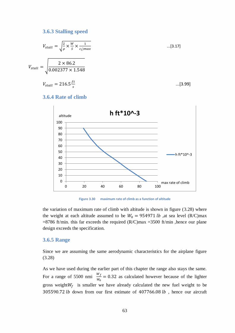
63
3.6.3 Stalling speed
√
...[3.17]
√
...[3.99]
3.6.4 Rate of climb
Figure 3. 23 maximum rate of climb as a function of altitude
the variation of maximum rate of climb with altitude is shown in figure (3.28) where
the weight at each altitude assumed to be ,at sea level (R/C)max
=8786 ft/min. this far exceeds the required (R/C)max =3500 ft/min ,hence our plane
design exceeds the specification.
3.6.5 Range
Since we are assuming the same aerodynamic characteristics for the airplane figure
(3.28)
As we have used during the earlier part of this chapter the range also stays the same.
For a range of 5500 nmi
as calculated however because of the lighter
gross weight is smaller we have already calculated the new fuel weight to be
down from our first estimate of , hence our aircraft
0
10
20
30
40
50
60
70
80
90
100
0 20 40 60 80 100
h ft*10^-3
h ft*10^-3
altitude
max rate of climb
64
design meet the specification for range of 5500nmi and it does this with smaller fuel
load than had previously been calculated.
3.6.6 Landing distance
Average velocity during flare
=1.23 ...[3.19]
...[3.100]
The flight path radius during flare
...[3.21]
...[3.101]
The approach angle for transport aircraft that is =3
The flare height
...[3.23]
...[3.102]
The approach distance required to clear a 50 ft obstacle
...[3.25]
...[3.103]
The flare distance
...[3.27]
65
...[3.104]
Ground roll
√
...[3.29]
J=1.15 for commercial airplanes
0.4
N= 3s (depend on pilot technique 1_3 s)
√
...[3.105]
...[3.106]
3.6.7 Takeoff distance
...[3.33]
Where the is value with the flaps only partially extended, we assume a flap
deflection of for takeoff . the for a flap deflection is 0.9. assuming a
linear variation of with flap deflection angle, we have for takeoff:
The average With 20 degrees flap deflection:
Total average ( max=
66
And we have:
...[3.107]
√
...[3.17]
=√
...[3.108]
Flight bath radius
.
...[3.109]
Flight bath angle
(
) (
)
...[3.110]
Airborne distance
...[3.111]
Combining the two equation:
...[3.112]
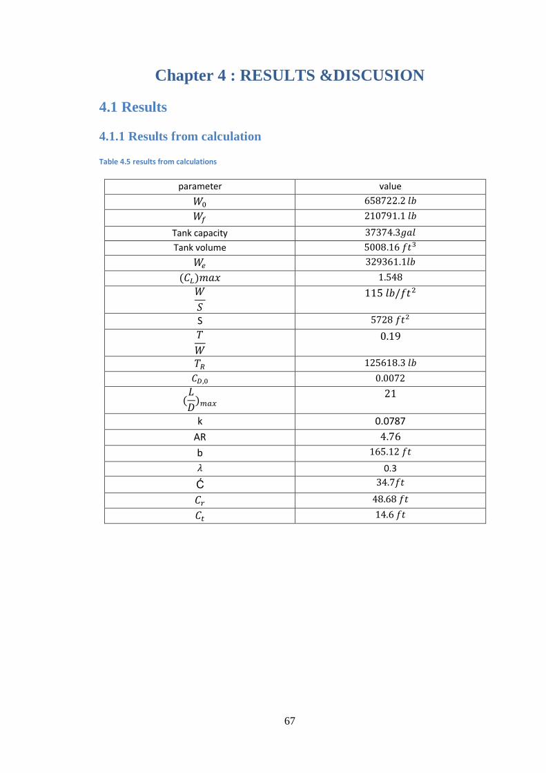
67
Chapter 4 : RESULTS &DISCUSION
4.1 Results
4.1.1 Results from calculation
Table 4. 5 results from calculations
value parameter
Tank capacity
Tank volume
S
0.0787 k
AR
b
0.3
Ć
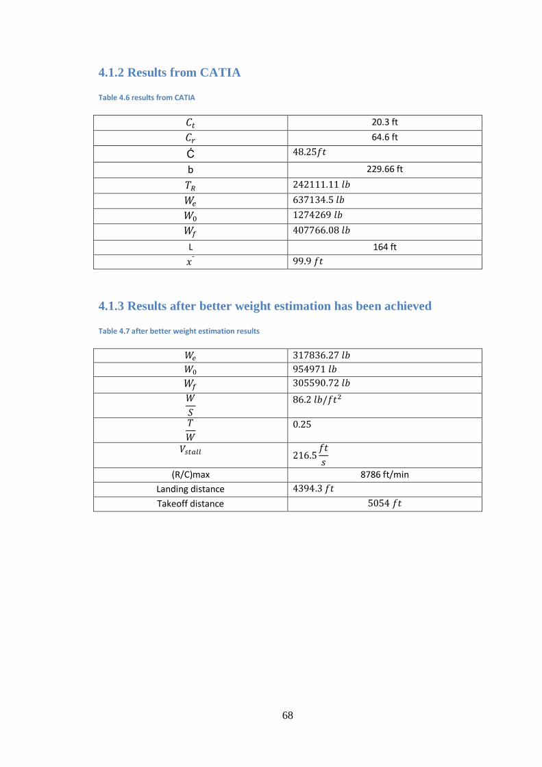
68
4.1.2 Results from CATIA
Table 4.6 results from CATIA
20.3 ft
64.6 ft
Ć
b 229.66 ft
L 164 ft
4.1.3 Results after better weight estimation has been achieved
Table 4.7 after better weight estimation results
(R/C)max 8786 ft/min
Landing distance
Takeoff distance
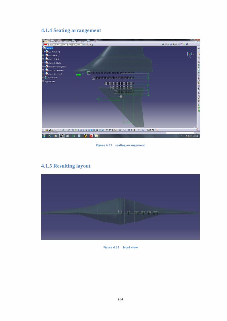
69
4.1.4 Seating arrangement
Figure 4.31 seating arrangement
4.1.5 Resulting layout
Figure 4.32 front view
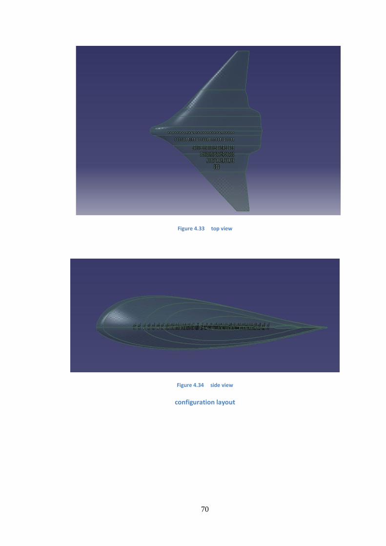
70
Figure 4.33 top view
Figure 4.34 side view
configuration layout
71
4.2 Discussion
One of the main design goals of the BWB is to reduce the total takeoff weight
, and as shown in the result the weight of 500 blended wing body is less than
conventional aircrafts of the same capacity.
Calculations of maximum lift coefficient (CLmax ) for a blended wing body is
very complicated and can not be obtained by applying conventional aircrafts
formula , the method we used here is approximate.
W/S is similar to the value of aircrafts of the same weight
T/W value is acceptable to the total weight of aircraft
The aircraft aspect ratio was somehow low (AR ) because of the small wing
span while the wing area is quite large.
The chosen Airfoils thickness was small we had to scale it up for the aircraft
in order to be able to carry the number of passengers set in the requirement
The value of wing span (b) estimated in the initial calculation was too small ,
it has been replaced with the value obtained from the drawing.
The change in wing span value has led to other changes in wing area (S) ,
weight (W) , and thrust (T) ,as all of their values has increased . as well as
Cmean , Cr and Ct
To obtain the thrust required we chose four high bypass turbofan engines
(CF6-80C2) same as the one used in Boeing 787, each engine is of 63,500lb
maximum thrust.
Centre of gravity first estimation
( )
The location of CG has been estimated regardless the wing existence .
We assumed according to Raymer that:
-the wing aerodynamic centre is 25% often mean aerodynamic chord.
-wing center of gravity is at 40% of the mean aerodynamic chord .
The value of CG is somehow large , and that‘s because the landing gear location and
weight isn‘t considered in the calculation.
The wing exposed planform area & fuselage wetted area values were obtained for the
drawing , to calculate the better weight estimation.
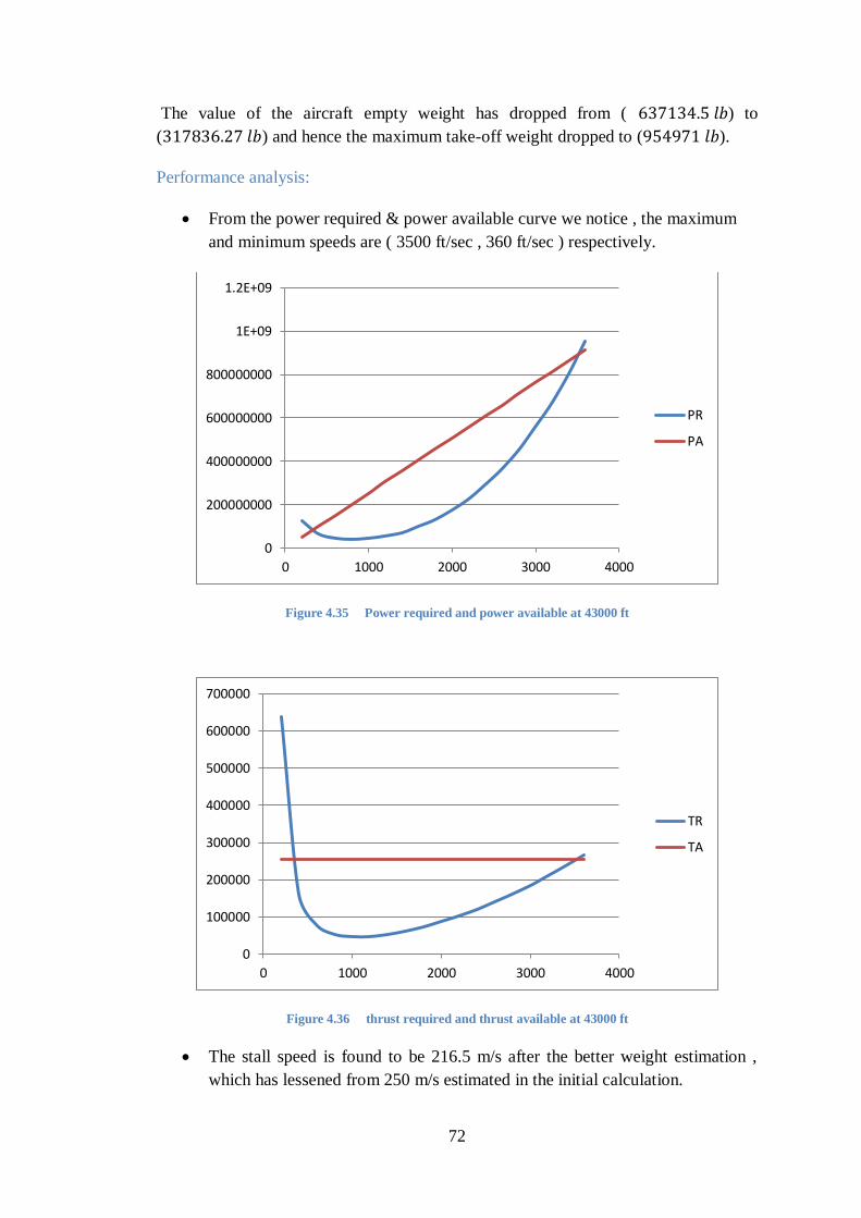
72
The value of the aircraft empty weight has dropped from ( ) to
( ) and hence the maximum take-off weight dropped to ( ).
Performance analysis:
From the power required & power available curve we notice , the maximum
and minimum speeds are ( 3500 ft/sec , 360 ft/sec ) respectively.
Figure 4.35 Power required and power available at 43000 ft
Figure 4.36 thrust required and thrust available at 43000 ft
The stall speed is found to be 216.5 m/s after the better weight estimation ,
which has lessened from 250 m/s estimated in the initial calculation.
0
200000000
400000000
600000000
800000000
1E+09
1.2E+09
0 1000 2000 3000 4000
PR
PA
0
100000
200000
300000
400000
500000
600000
700000
0 1000 2000 3000 4000
TR
TA
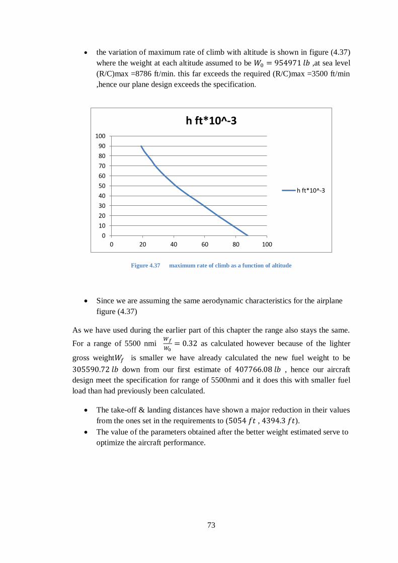
73
the variation of maximum rate of climb with altitude is shown in figure (4.37)
where the weight at each altitude assumed to be ,at sea level
(R/C)max =8786 ft/min. this far exceeds the required (R/C)max =3500 ft/min
,hence our plane design exceeds the specification.
Figure 4.37 maximum rate of climb as a function of altitude
Since we are assuming the same aerodynamic characteristics for the airplane
figure (4.37)
As we have used during the earlier part of this chapter the range also stays the same.
For a range of 5500 nmi
as calculated however because of the lighter
gross weight is smaller we have already calculated the new fuel weight to be
down from our first estimate of , hence our aircraft
design meet the specification for range of 5500nmi and it does this with smaller fuel
load than had previously been calculated.
The take-off & landing distances have shown a major reduction in their values
from the ones set in the requirements to ( , ).
The value of the parameters obtained after the better weight estimated serve to
optimize the aircraft performance.
0
10
20
30
40
50
60
70
80
90
100
0 20 40 60 80 100
h ft*10^-3
h ft*10^-3
74
Chapter 5 : CONCLUSIONS &
RECOMMENDATIONS
5.1 conclusion
The aim of this thesis was to study the design concept of a blended wing body aircraft
through the conceptual design phase . using raymer equations and CATIA software
the final configuration and performance analysis has been achieved . the results have
shown that the aircraft has a better performance, less fuel consumption and less
maximum take-off weight than conventional aircraft.
5.2 Recommendation
airfoil selection
the main problem that appeared during the work on this project is the selection of the
airfoil , as the thickness of the chosen root airfoil was too small. It was hard to fit the
number of passengers that was meant to be fitted in the wing-fuselage area, its
recommended to design a special airfoil for this type of aircrafts taking all the criterias
of design in consideration.
There are several methods for design and analysis of airfoil available for example:
o PROFIL
o XFOIL
distributed proplusion
recent analytic and experimental distributed propulsion studies suggest several
improvement in aircraft perform they include fuel consumption efficiency , noise
abatement , steep climbing for short take-off & landing (STOL) . novel control
approaches and high bypass ratio.it has also been suggested that smaller propulsors
will be cheaper to manufacture and easier to handle during assembly and
maintenance.
stability check
the blended wing body is known to have a major stability problems , in both pitch and
yaw motions , in order to maintain its stability in longitudinal and lateral axis an
implementation of a vertical tail or winglets should be included.
As for the control of the aircraft , its preferable to combine both elevator and aileron
into one control surface due to the absence of horizontal stabilizer . the rudder can
also be implemented in either the vertical stabilizers or the winglets.
75
softwares recommended to analyze stability are , AVL (Athena vortice lattice method)
to offer aerodynamic analysis & trim calculation and dynamic stability analysis .
stability and control digital DATCOM can be used to calculate the static stability ,
control and dynamic derivative characteristics of fixed wing A/C .
5.3 Future work
for those who like to precede the preliminary phase , it includes the wind
tunnel testing and computational fluid dynamic (CFD) calculations of the flow
field around the A/C. major structural and control analysis is also carried out
in this phase.
for the detailed design phase you simply deal with the fabrication of the A/C
to be manufactured , it determines the number , design and location of ribs ,
spars and other structural elements . flight simulators are developed at this
stage .
all of the obtained results (from calculations or drawings) can not be verified
at this stage of design (conceptual phase) , because of the unavailability of
equations , tools and sources. The only way it can be verified is through
suitable wind tunnel to test its aerodynamic characteristics , performance and
ground tests at latter stages of design to examine its stability .
A stress analysis program such as NASTRAN PATRAN should be used to
verify stress analysis on structure.
76
References
Chapter two :
1 Crane 1997,p.224
2 Liebeck, R, ‖Design of the Blended-Wing-Body Subsonic Transport,‖ AIAA-
2002-0002, January 2002.
3 Daggett, David L., Kawai, Ron, and Friedman, Doug, ‖Blended Wing Body
Systems Studies: Boundary Layer
Ingestion Inlets with Active Flow Control,‖ NASA CR-2003-212670, December
2003.
4 Roman, D., Allen, J. B., and Liebeck, R. H., ‖Aerodynamic Design Challenges
of the Blended-Wing-Body
Subsonic Transport,‖ AIAA-2000-4335, August 2000
5 4Holmes, Stanley, ―The Battle over a Radical New Plane,‖ Business Week, Vol.
145, November 25, 2002,
pp. 106-108.
6 Qin, N., Vavalle, A., Le Moigne, A., Laban, M., Hackett, K., and Weinnerfelt,
P.,
―Aerodynamic Considerations of Blended Wing Body Aircraft‖, Progress in
Aerospace
Science, 2004, pp. 321-343
7 Engels, H., Becker, W., and Morris, A., ―Implementation of a Multi-Level
Methodology
Within the E-Design of A Blended Wing Body‖, Aerospace Science and
Technology,
2004, pp. 145-153
8 Liebeck, R.H., Design of the blended wing body subsonic transport. Journal of
Aircraft, 2004. 41(1): p. 10-25.
9 Liebeck, R.H., Blended Wing Body Design Challenges, in AIAA/ICAS
International Air and Space Symposium and Exposition: The Next 100 Years.
2003, American Institute of Aeronautics and Astronautics: Dayton, Ohio. p. 1-
77
12.
6 E.R. Galea, L. Filippidis&Z.Wang, "Evacuation Analysis of 1000+ Seat Blended
Wing Body AircraftConfigurations: Computer Simulations and Full-scale
Evacuation Experiment," Pedestrian andEvacuation Dynamics, pp. 149–151,
2011.
8 R.H. Liebeck, "Design of the Blended Wing Body Subsonic Transport," J. of
Aircraft, vol. 41, no. 1,pp. 10–25, Jan. 2004.
9 M.A. Page, J.P. Whitlock, M.W. Wilks. ―Variable Size Blended Wing Body
Aircraft.‖ U.S Patent 6 568632 B2, May 27, 2003.
10 S. Peigin& B. Epstein, "Computational Fluid Dynamics Driven Optimization of
Blended Wing BodyAircraft," AIAA J., vol. 44, no. 11, pp. 2736–2745, Nov.
2006
11 H.V. de Castro. ―Flying and Handling Qualities of a Fly-by-Wire Blended-Wing-
Body Civil TransportAircraft.‖ Ph.D. thesis, School of Engineering, Cranfield
University,Cranfield, Bedfordshire, U.K., 2003.
12 S. Slouris& N. Qin, "Study of the effects of wing sweep on the aerodynamic
performance of ablended wing body aircraft," J. Automobile Eng., vol. 221, no.
1, pp. 47–55, 2007.
[1] A. L. Bolsunovsky, N. P. Buzoverya, B. I. Gurevich, V. E. Denisov, A. I.
Dunaevsky, L. M. Shkadov, O. V. Sonin, A. J. Udzhuhu, and J. P. Zhurihin
, Flying Wing - Problems and Decisions, Aircraft Design, 4 (2001), pp. 193{219.
[8] A. Diedrich, J. Hileman, D. Tan, K. Willcox, and Z. Spakovszky, Mul-
tidisciplinary Design and Optimization of the Silent Aircraft, in The 44th AIAA
Aerospace Sciences Meeting and Exhibit, Reno, Nevada, United States, no. AIAA
2006-1323, January 2006.
[9] A. J. Diedrich, The Multidisciplinary Design and Optimisation of an Unconven-
tional, Extremely Quiet Transport Aircraft, Master's thesis, Massachusetts Institute
Of Technology, 2005.
[10] E. Galea, L. Filippidis, Z. Wang, and J. Ewer, Fire and Evacuation Analysis
in BWB Aircraft Con_gurations: Computer Simulations and Large-Scale Evacuation
78
Experiment, Aeronautical Journal, 114 (2010), pp. 271{277.
[17] M. D. Guynn, J. E. Freeh, and E. D. Olson, Evaluation of a Hydrogen Fuel
Cell Powered Blended-Wing-Body Aircraft Concept for Reduced Noise and Emis-
sions, tech. rep., NASA/TM-2004-212989, 2004.
[22] IATA, Jet Fuel Price Monitor.
http :==www:iata:org=whatwedo=economics=fuel monitor=Pages=index:aspx,
September 2010.
[25] I. Kroo, Innovations in Aeronautics, in The 42nd AIAA Aerospace Sciences
Meeting, January 5-8, 2004, Reno, NV, no. AIAA 2004-0001, 2004.
[27] D. S. Lee, D. W. Fahey, P. M. Forster, P. J. Newton, R. C. Wit, L. L.
Lim, B. Owen, and R. Sausen, Aviation and Global Climate Change in the 21st
Century, Atmospheric Environment, doi:10.1016/j.atmosenv.2009.04.024 (2009).
[29] R. H. Liebeck, Design of the Blended Wing Body Subsonic Transport, Journal of
Aircraft, 41(1) (2004), pp. 10{25.
[30] ,Blended Wing Body Design Challenges, in The AIAA International Air and
Space Symposium and Exposition: The Next 100 Years, Dayton, Ohio, no. AIAA
2003-2659, July 2003.
[31] R. H. Liebeck, M. A. Page, and B. K. Rawdon, Blended-Wing-Body Subsonic
Commercial Transport, in The 36th Aerospace Sciences Meeting and Exhibit, Reno,
Nevada, United States, no. AIAA 1998-0438, January 1998.
[32] Y. Lui, A. Dowling, H.-C. Shin, and A. Quayle, Experimental Study of
Surface Roughness Noise, in The 13th AIAA/CEAS Aeroacoustics Conference (28th
AIAA Aeroacoustics Conference), no. AIAA-2007-3449, 2007.
[34] R. Mart__nez-Val, E. P_erez, P. Alfaro, and J. P_erez, Conceptual Design of
a Medium Size Flying Wing, Journal of Aerospace Engineering, 221 (2007), pp. 57{
79
66.
[38] M. Meheut, R. Grenon, G. Carrier, M. Defos, and M. Duffau, Aerody-
namic Design of Transonic Flying Wing Con_gurations, in KATnet II: Conference
on \Key Aerodynamic Technologies", Bremen, Germany, 12-14th May 2009, 2009.
[39] B. Mialon and M. Hepperle, Flying Wing Aerodynamics Studies at
ONERA and DLR, in CEAS/KATnet Conference on Key Aerodynamic
Technologies, http://www.onera.fr/daap/ailes-volantes/ying-wing-aerodynamics-
Onera-DLR.pdf, April 2005.
[41] V. Mukhopadhyay, Blended-Wing-Body (BWB) Fuselage Structural Design for
Weight Reduction, in The 46th AIAA/ASME/ASCE/AHS/ASC Structures, Structural
Dynamics, and Materials Conference, no. AIAA 2005-2349, 2005.
[42] V. Mukhopadhyay, J. Sobieszczanski-Sobieski, I. Kosaka, G. Quinn, and
G. Vanderplaats, Analysis, Design, and Optimization of Noncylindrical Fuselage
for Blended-Wing-Body Vehicle, Journal Of Aircraft, 41 (2004), pp. 925{930.
[43] National Geographic, Hitler's Stealth Fighter. Documentary, June 2009.
[46] C. • Osterheld, W. Heinze, and P. Horst, Preliminary Design of a Blended
Wing Body Con_guration Using the Design Tool PrADO, in The Proceedings of the
CEAS Conference on Multidisciplinary Aircraft Design and Optimisation, Cologne,
June 2001.
[47] T. E. Pambagjo, K. Nakahashi, S. Obayashi, and K. Matsushima, An Al-
ternate Con_guration for a Regional Transport Airplane, Transactions of the Japan
Society for Aeronautical and Space Sciences, 45(148) (2002), pp. 94{101.
[48] ,Aerodynamic Design of a Medium Size Blended-Wing-Body Airplane, in The
39th AIAA Aerospace Sciences Meeting and Exhibit, Reno, Nevada, United States,
no. AIAA 2001-129, January 2001.
80
[50] S. Peigin and B. Epstein, Computational Fluid Dynamics Driven Optimization
of Blended Wing Body Aircraft, AIAA Journal, 44(11) (2006), pp. 2736{2745.
[51] A. P. Plas, V. Madani, M. A. Sargeant, E. M. Greitzer, C. A. Hall,
and T. P. Hynes, Performance of a Boundary Layer Ingesting (BLI) Propulsion
System, in The 45th Aerospace Sciences Meeting and Exhibit Conference, Reno,
Nevada, no. AIAA-2007-0450, 2007.
[52] M. A. Potsdam, M. A. Page, and R. H. Liebeck, Blended Wing Body Analysis
and Design, in The 15th AIAA Applied Aerodynamics Conference, Atlanta, Georgia,
no. AIAA 1997-2317, June 1997.
[53] N. Qin, A. Vavalle, A. LeMoigne, M. Laban, K. Hackett, and P. Weinerfelt
, Aerodynamic Considerations of Blended Wing Body Aircraft, Progress in
Aerospace Sciences, 40 (2004), pp. 321{343.
[54] N. Qin, A. Vavalle, and A. L. Moigne, Spanwise Lift Distribution for Blended
Wing Body Aircraft, Journal of Aircraft, 42 (2005), pp. 356{365.
[55] N. Qin, A. Vavalle, A. L. Moigne, M. Laban, K. Hackett, and
P. Weinerfelt, Aerodynamic Studies for Blended Wing Body Aircraft, in The
9th AIAA/ISSMO Symposium on Multidisciplinary Analysis and Optimization,
no. AIAA 2002-5448, 2002.
[58] H. J. D. Reynolds, T. G. Reynolds, and R. J. Hansman, Human Factors
Implications of Continuous Descent Approach Procedures for Noise Abatement, Air
Tra_c Control Quarterly, 14, No. 1 (2006), pp. 25{45.
[59] D. Roman, J. B. Allen, and R. H. Liebeck, Aerodynamic Design Challenges of
the Blended-Wing-Body Subsonic Commercial Transport, in The 18th AIAA Applied
Aerodynamics Conference, Denver, Colorado, United States, no. AIAA-2000-4335,
August 2000.
[60] D. Roman, R. Gilmore, and S. Wakayama, Aerodynamics of High-Subsonic
81
Blended-Wing-Body Con_gurations, in The 41st Aerospace Sciences Meeting and
Exhibit, Reno, Nevada, United States, no. AIAA 2003-554, January 2003.
[62] M. A. Sargeant, T. P. Hynes, W. R. Graham, J. I. Hileman, M. Drela,
and Z. S. Spakovsky, Stability of Hybrid-Wing-Body-Type Aircraft with Center-
body Leading-Edge Carving, Journal Of Aircraft, 47 (2010), pp. 970{974.
[63] S. Siouris and N. Qin, Study of the E_ects of Wing Sweep on the Aerodynamic
Performance of a Blended Wing Body Aircraft, Journal of Aerospace Engineering,
221(1) (2007), pp. 47{55.
[65] N. Stern, The Stern Review on the Economics of Climate Change, Cambridge
University Press, 2007, 2007.
[66] M. Stettner and R. Voss, Aeroelastics, Flight Mechanics and Handling Qual-
ities of the MOB BWB Con_guration, in The 9th AIAA/ISSMO Symposium on
Multidisciplinary Analysis and Optimization, no. AIAA 2002-5449, 2002.
[67] H. Str• uber and M. Hepperle, Aerodynamic Optimisation of a Flying Wing
Transport Aircraft, New Results in Numerical and Experimental Fluid Mechanics
V, 92 (2006), pp. 69{76.
[68] The Boeing Company, Long-Term Market: Current Market Outlook 2010 - 2029,
September 2010.
[69] The Cambridge-MIT Institute, The Silent Aircraft Initiative.
http://silentaircraft.org/, 2006.
[73] A. Velicki, P. Thrash, and D. Jegley, Airframe Development for the Hybrid
Wing Body Aircraft, in The 47th AIAA Aerospace Sciences Meeting Including The
New Horizons Forum and Aerospace Exposition, no. AIAA 2009-932, January 2009.
[74] D. D. Vicroy, Blended-Wing-Body Low-Speed Flight Dynamics: Summary of
Ground Tests and Sample Results, in The 47th AIAA Aerospace Sciences Meeting
82
Including The New Horizons Forum And Aerospace Exposition, no. AIAA 2009-933,
January 2009.
[75] S. Wakayama, Blended-Wing-Body Optimization Problem Setup, in The 8th
AIAA/USAF/NASA/ISSMO Symposium on Multidisciplinary Analysis and
Optimization, Long Beach, CA, no. AIAA 2000-4740, September 2000.
[76] S. Wakayama and I. Kroo, The Challenge and Promise of Blended-Wing-Body
Optimization, in The 7th AIAA/USAF/NASA/ISSMO Symposium on
Multidisciplinary Analysis and Optimization, St. Louis, MO, no. AIAA 1998-4736,
September 1998.
[77] G. Walker and S. D. King, The Hot Topic: What We Can Do About Global
Warming, Greystone Books, 2008.
[78] W. Wong, A. LeMoigne, and N. Qin, Parallel Adjoint-Based Optimisation of a
Blended Wing Body Aircraft with Shock Control Bumps, The Aeronautical Journal,
111, No. 1117 (2006), pp.
1. Swan, Sarah (2006-11-17). "X-45A Unmanned Combat Vehicle on
Display".Aerotech News and Review.
2. The 50th flight: Two X-45s work autonomously as a group and successfully
attack previously undetected targets
3. Boeing news release
4. "Boeing Receives First Engines for X-45C UCAV". Boeing, November 18,
2004.
5. "Boeing Awarded Additional $175 Million for Joint Unmanned Combat Air
Systems Capability Demonstration Program". Boeing, July 11, 2005.
6. "J-UCAS ending", Aviation Week and Space Technology.
7. "Navy's UCAS program", Aviation Week and Space Technology.
8. article; Navy UCAS proposals", Aviation Week and Space Technology
9. "Winner to be selected in late 2007 or early 2008". Aviation Week and Space
Technology.
83
10. "Navy awards UCAS-D contract to Northrop Grumman X-47 team
11. "F/A-18F approaches carrier autonomously, will soon land
autonomously". Aviation Week and Space Technology
12. "Boeing's Phantom Ray - the 'Phoenix' of UCAVs". Aviation Week.
13. "Breaking: Boeing resurrects X-45C as 'Phantom Ray' testbed". Flight Global.
14. US Navy delays UCLASS RFP - Flightglobal.com, December 11, 2012
15. X-45 J-UCAV Joint Unmanned Combat Air System, specifications. airforce-
technology.com[unreliable source?]
16. X-45 Joint Unmanned Combat Air System. Boeing.
1. "Aircraft emissions". The Economist, June 8, 2006. Retrieved: August 12,
2012.
2. Liebeck 2004, p. 10.
3. Liebeck 2004, p. 18.
4. Norris and Wagner 2009, p. 18.
5. Boeing Chronology, 1997–2001, Boeing
6. Liebeck 2004, p. 24.
7. "Boeing to Begin Ground Testing of X-48B Blended Wing Body
Concept." Boeing, October 27, 2006. Retrieved: April 10, 2012.
8. Lorenz III, Phillip. "AEDC testing brings unique blended wing aircraft closer
to flight."AEDC, U.S. Air Force, July 3, 2007. Retrieved: April 10, 2012.
9. Parsch, Andreas. "Boeing X-48." designation-systems.net, November 24,
2009.
10. Koehler, Tom. "Boeing to Begin Ground Testing of X-48B Blended Wing
Body Concept." Boeing, October 27, 2006. Retrieved: October 24, 2010.
11. Warwick, Graham. "British blend: UAV X-planes help Boeing with blended
wing concept." Flight International, May 30, 2006.
12. Jacobs, Karrie. "Thinking Outside the Tube." Wired, February 2007.
Retrieved: April 11, 2007.
84
13. Coppinger, Rob. "X-48B scale model to fly next year." Flight
International, November 22, 2005. Retrieved: April 11, 2007.
14. Morris, Jefferson. "Blended Wing Body Prototype Wrapping Up Wind
Tunnel Tests."AviationWeek.com, May 8, 2006.
15. Barnstorff, Kathy. "The X-48B Blended Wing Body." NASA Langley
Research Center,May 4, 2006. Retrieved: April 11, 2007.
16. Koehler, Tom and Daryl Stephenson. "Boeing Flies Blended Wind Body
Research Aircraft." Boeing, July 26, 2007.
17. Creech, Gray. "X-48B Blended Wing Body Research Aircraft Takes First
Flight."NASA, July 26, 2007. Retrieved: July 26, 2007.
18. "Second X-48B Modified Into X-48C Configuration". NASA Dryden Flight
Research Center, February 11, 2010.
19. "NASA Demonstrates Controllability of X-48B". Aviation Week & Space
Technology, Vol. 172, No. 14, April 12, 2010, p. 19.
20. Mecham, Michael. "New Tests Pending For X-48 Flying Wing." Aviation
Week & Space Technology, September 10, 2010.
21. Norris, Guy. "New Flight Trials For X-51, X-48, Phantom Eye." Aviation
Week, July 2, 2012.
22. "Boeing's X-48C completes flight tests.". UPI
23. Creech, Gray. "Skyray 48 Takes Flight." NASA, September 11, 2007.
Retrieved: July 25, 2011.
24. "Stall Success". Aviation Week & Space Technology, Vol. 169, No. 10,
September 15, 2008, p. 20.
25. Paur, Jason. "NASA's Mini X-Plane Completes Initial Flight Testing." Wired
News, Autopia, April 6, 2010.
26. Creech, Gray. "X-48B BWB Team Completes Phase 1 Test Flights." NASA,
April 6, 2010.
27. Cohen, Aubrey. "NASA-Boeing team done first flight phase of blended wing
body plane." Seattlepi.com, April 6, 2010.
28. Croft, Jon. "NASA, Boeing complete X-48B flight test campaign." Flight
International, April 6, 2010.
85
29. Creech, Gray. "Back in the Air: X-48B Resumes Flight Tests at NASA
Dryden". NASADryden Flight Research Center, September 21, 2010.
30. Terdiman, Daniel. "NASA's futuristic X-48C hybrid wing-body plane takes
flight"cnet.com, August 7, 2012.
31. "NASA And Boeing Fly Their Prototype X-48C For The First Time". NASA,
August 7, 2012. Retrieved: August 12, 2012.
32. "Boeing X-48C Blended Wing Body Research Aircraft Completes Flight
Testing."Boeing
33. Norris, Guy. "First Boeing X-48C Flight Imminent, NASA Says." Aviation
Week, August 2, 2012. Retrieved: August 3, 2012.
34. Parsch, Andreas. "Boeing X-48." Designation-Systems.net, June 2009.
Retrieved: April 7, 2010.
35. "X-48B Blended Wing Body." NASA, February 11, 2010. Retrieved: April 7,
2010.
36. Liebeck, Design of the Blended Wing Body Subsonic Transport
37. M.A. Page et al U.S. Patent No. 6,568,632 B2
1. Dassault official website
2. Broadbent, Mark (January 2013). "NEUROn Become's Europe's First Stealth
Aircraft to Fly". Air International. Vol. 84 no. 1. p. 4. ISSN 0306-5634.
3. French UCAV projects and international nEUROn, December 3, 2010
4. "Leonardo-Finmeccanica's Aircraft Division - NEURON". Leonrdo-
Finmeccanica. Retrieved 29 July 2016.
5. French Senate's report "A. The project nEUROn, launched by France, is
joined by its main European partners"
6. Demonstrator neUROn, DGA/Matthieu Duvelleroy, February 9, 2006
7. "Stars of 2013 Paris Air Show: Russian Su-35; European Neuron UAV: NO
Americans". Breaking Defense. 20 June 2013. Retrieved 23 June 2013.
8. "Drone technology used for pilotless fighter aircraft". BBC News. 19 June
2013. Retrieved 23 June 2013.
9. Dassault Aviation's UAV Logiduc program
86
10. Dassault Aviation's UAV Logiduc program
11. Chirac kicks off six-nation nEUROn UCAV programme, Flight Daily News of
June 14, 2005
12. "Neuron". leonardocompany.com. Retrieved 29 July 2016.
13. Alenia Aereonautica official Neuron data sheet
14. Chirac kicks off six-nation nEUROn UCAV programme, Flight Daily News of
June 14, 2005
15. Europe enters stealth club with Neuron first flight - Flightglobal.com,
December 1, 2012
16. Europe's Neuron Demonstrator Completes Flight Trials In France - Aviation
Week, March 9, 2015
17. nEUROn: success for test campaign in France - Dassault Aviation press
release, March 9, 2015
18. nEUROn European Stealth combat drone has started operational tests in Italy -
The Aviationist, April 16, 2015
19. Neuron completes Italian flight trials - IHS Jane's 360, August 25, 2015
20. Italian Neuron testing ends as Swedish stint begins - Flightglobal.com,
August 25, 2015
21. Premier face-à-face entre le Neuron et le Charles de Gaulle -
Meretmarine.com, July, 2016
22. Le Neuron en essai avec le "Charles de Gaulle" - Air&Cosmos, July, 2016
23. "Award of £120M Anglo-French Defence Co-Operation Contract"
24. The European technology demonstrator nEUROn, Feb. 9, 2006, French
Defence Ministry
1. UNMANNED AERIAL VEHICLES: DOD‘s Demonstration Approach Has
Improved Project Outcomes United States General Accounting Office Report
to the Secretary of Defense, August 1999
2. http://cowboylogic.us/stalking-iran-and-bin-ladin-with-a-drone/
3. Aviation Week & Space Technology. April, 2003
87
Notes
1. Axe, David (13 December 2012). "7 Secret Ways America's Stealth Armada
Stays Off the Radar". Wired. Retrieved 14 December 2012.
2. "The Little-Known Agency That Helped Kill Bin Laden". The Atlantic. 8 May
2011. Retrieved 8 May 2011.
3. Elisha Maldonado, "Iran Denies U.S. Request for Drone Return, Demands
Apology",International Business Times, December 13, 2011.
4. Iran sends toy drone to Obama
5. "General: Iran won't return U.S. drone it claims to have". CNN. 11 December
2011. Retrieved 28 November 2013.
6. Fulghum, David A. (8 December 2009). "RQ-170 Has Links to Intelligence
Loss to China". Aviation Week & Space Technology. Retrieved 9
December 2009.
7. "Mystery UAV operation in Afghanistan". UV Online. 10 April 2009.
Retrieved9 December 2009.
8. Fulghum, David A. (4 December 2009). "U.S. Air Force Reveals Operational
Stealth UAV". Aviation Week. Retrieved 4 December 2009.
9. Sweetman, Bill (11 November 2009). "Another Beast Picture". Aviation Week.
Retrieved 13 December 2009.
10. "RQ-170 Sentinel 'Beast of Kandahar'". Defence Aviation. 26 December
2009. Retrieved 2 December 2010.
11. Tirpak, John A. (February 2010). "Washington Watch: Stealth skywriting;
Watched by Gorgons; Stopping START? ....". Air Force Magazine. Air Force
Association. 93 (2): 6.ISSN 0730-6784. Retrieved 12 December 2011.
12. Fulghum, David A. (4 December 2009). "USAF Confirms Stealthy UAV
Operations".Aviation Week. Retrieved 8 December 2009.
13. Trimble, Stephen (10 December 2009). "RQ-170 not intended to replace
Predators and Reapers". FlightGlobal. The DEW Line blog. Retrieved 11
December 2009.
14. Drew, Christopher (5 May 2011). "Attack on Bin Laden Used Stealthy
Helicopter That Had Been a Secret". The New York Times. Retrieved 6
May 2011.
88
15. Fulghum, David A.; Bill Sweetman (14 December 2009). "Stealth over
Afghanistan". Aviation Week. McGraw-Hill: 26–27.
16. Sweetman, Bill (25 January 2011). "The Beast is Back". Aviation Week.
Retrieved26 January 2011.
17. Shane, Scott; Sanger, David E. (7 December 2011). "Drone Crash in Iran
Reveals Secret U.S. Surveillance Effort". The New York Times. Retrieved 9
December 2011.
18. "Iran shows film of captured US drone". BBC News. 8 December 2011.
19. Hambling, David (8 December 2009). "Mysteries Surround Afghanistan's
Stealth Drone". Wired. Retrieved 8 December 2009.
20. "US Air Force confirms 'Beast of Kandahar' drone". Asiaone. Agence
France-Presse. 9 December 2009. Retrieved 9 December 2009.
21. Hoffman, Michael, "Unveiling the 'Beast of Kandahar'", Military Times, 23
December 2009.
22. "U.S. to base new unmanned spy plane in Korea". JoongAng Daily. 19
December 2009.
23. Sweetman, Bill (16 February 2010). "Beast Sighted In Korea". Aviation Week.
Retrieved 18 February 2010.
24. Fulghum, David A. (8 December 2009). "Beast of Kandahar Is Back in
Action". Aviation Week. Retrieved 11 August 2010.
25. Miller, Greg (18 May 2011). "CIA flew stealth drones into Pakistan to
monitor bin Laden house". The Washington Post. Retrieved 19 May 2011.
26. Paul Richter, David S. Cloud and Alex Rodriguez (27 May 2011). "Angry
Pakistan rejects U.S. appeal, plans to review drone campaign". Los Angeles
Times. Retrieved 28 May2011.
27. Trevithick, Joseph (7 November 2014). "U.S. Stealth Drone Helped Test
Huge Bomb".War is Boring. Retrieved 8 November 2014.
28. Sanger, David E.; Broad, William J. (4 December 2011). "Explosion Seen as
Big Setback to Iran's Missile Program". The New York Times. Retrieved 5
December 2011.
29. "Iran airs footage of downed US drone". Press TV. 8 December 2011.
Retrieved11 December 2011.
89
30. "'Iran military landed US spy drone'". Press TV. 9 December 2011.
Retrieved11 December 2011.
31. "US maintains silence on downed drone". Press TV. 10 December 2011.
Retrieved11 December 2011.
32. "Iran military downs US spy drone". Press TV. 4 December 2011.
Retrieved11 December 2011.
33. "Iran shows film of captured US drone". BBC News. 8 December 2011.
34. Jaffe, Greg; Erdbrink, Thomas (5 December 2011). "Iran says it downed U.S.
stealth drone; Pentagon acknowledges aircraft downing". The Washington
Post. Retrieved5 December 2011.
35. Miller, Greg (6 December 2011). "After drone was lost, CIA tried a head
fake". The Washington Post. Retrieved 8 December 2011.
36. "Iran Captures a U.S. Stealth Drone Intact". 8 December 2011. Retrieved 8
December2011.
37. Dave Majumdar (9 December 2011). "Iran's captured RQ-170: How bad is
the damage?". Air Force Times.
38. "U.S. officials, analysts differ on whether drone in Iran TV video is real".
CNN. 8 December 2011.
39. Orr, Bob (8 December 2011). "U.S. official: Iran does have our drone". CBS
News. Retrieved 11 December 2011.
40. "Iran Says It Is Building Copy of Captured US Drone". The New York Times.
Associated Press. 22 April 2012. Retrieved 22 April 2012.
41. "Iranians Say They Took Secret Data From Drone". The New York Times. 22
April 2012.
42. FarsNews, 22 September 2013.
43. "Iran releases video 'proof' US drone decoded". RT. 7 February 2013.
44. FarsNews, 22 September 2013
45. "Iran says it has copied US drone". Yahoo! News. 12 May 2014.
Retrieved 2014-05-12.
46. Iranian Copy of U.S. Unmanned Stealth Aircraft is a Fake – U.S. Naval
Institute, 12 May 2014
90
47. "Iran carries successful test flight of reverse engineered RQ-170". 10
November 2014.
48. Daily Telegraph"Iran shows off captured US drone". The Telegraph. London.
8 December 2011. Retrieved 8 December 2011.
Chapter three :
1. aircraft performance and design , anderson, jr , umd ,mcgraw-hill 1999
2. EWADE 2007
3. Aircraft design : A conceptual approach by Daniel P. Raymer
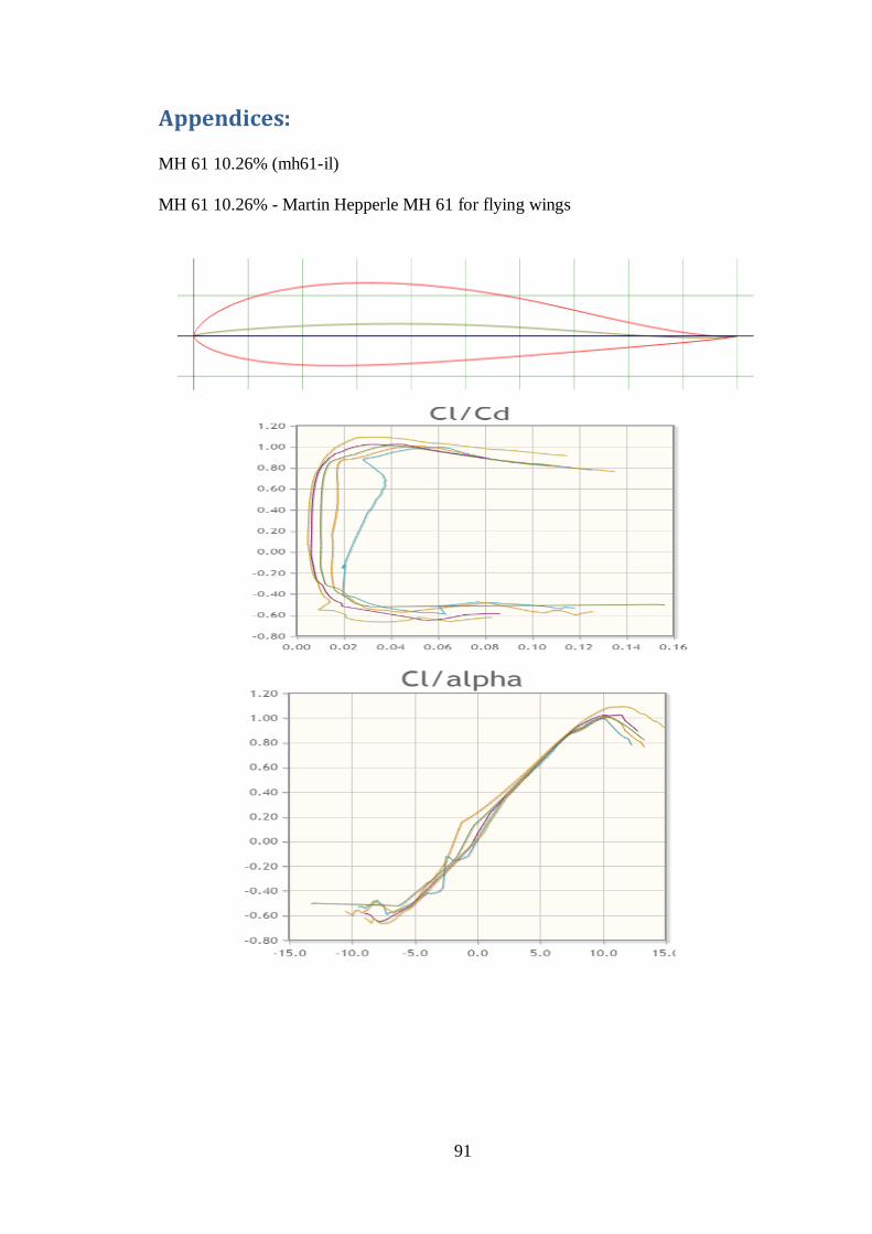
91
Appendices:
MH 61 10.26% (mh61-il)
MH 61 10.26% - Martin Hepperle MH 61 for flying wings
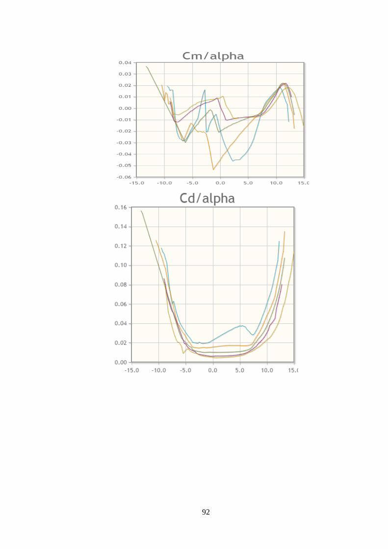
92
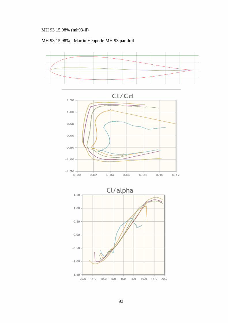
93
MH 93 15.98% (mh93-il)
MH 93 15.98% - Martin Hepperle MH 93 parafoil
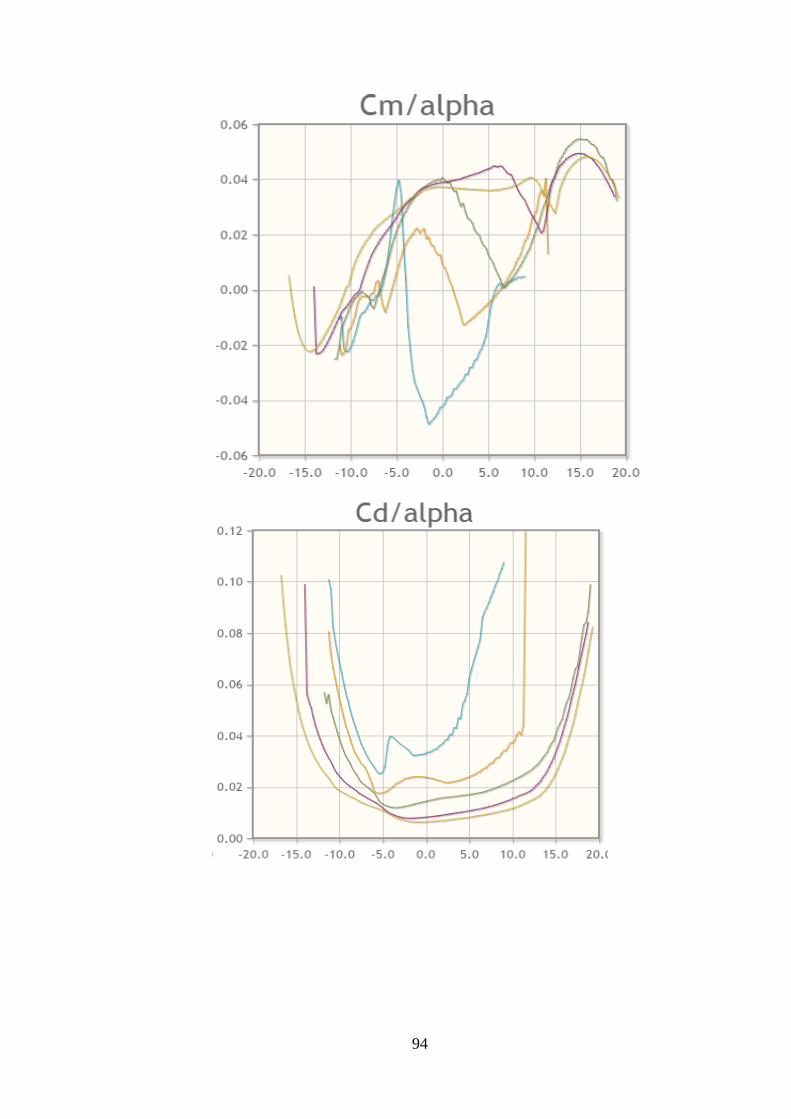
94
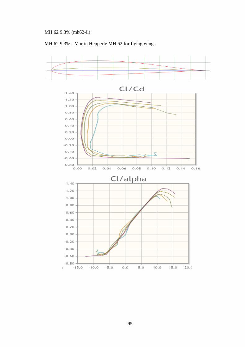
95
MH 62 9.3% (mh62-il)
MH 62 9.3% - Martin Hepperle MH 62 for flying wings

96